Note: The 1997 Report Was - Homeland Security Digital Library
197
Note: The 1997 Report Was Drafted Prior To The Release Of The Results Of The Quadrennial Defense Review (QDR). Consequently, Changes Have Been Made In Certain Programs That Are Not Reflected In the Enclosed Report.
-
Upload
khangminh22 -
Category
Documents
-
view
6 -
download
0
Transcript of Note: The 1997 Report Was - Homeland Security Digital Library
Note: The 1997 Report Was Drafted Prior To The Release Of The Results Of The Quadrennial
Defense Review (QDR). Consequently, Changes Have
Been Made In Certain Programs That Are Not Reflected In the
Enclosed Report.


Prepared by the Ballistic Missile Defense Organization
1997 Report to the Congress on
Ballistic
Missile
Defense
Note: The 1997 Report Was Drafted Prior To The Release Of The Results Of The Quadrennial Defense Review (QDR). Consequently, Changes Have Been Made In Certain Programs That Are Not Reflected In the Enclosed Report.

i
Table Of Contents
List Of Figures
..........................................................................................................................vi
List Of Tables
...........................................................................................................................vii
Chapter 1
Strategy And Objectives
1.1 Introduction .....................................................................................................................1-1
1.2 Ballistic Missile Defense (BMD) Program Priorities ......................................................1-2
1.3 Cooperation with Allies and Friends ...............................................................................1-4
1.4 Anti-Ballistic Missile Treaty ...........................................................................................1-4
1.5 Conclusion .......................................................................................................................1-5
Chapter 2
Theater Missile Defense (TMD)
2.1 Mission and Scope ...........................................................................................................2-1
2.1.1 Joint Theater Air and Missile Defense (JTAMD).............................................2-1
2.2 Threat and Counterproliferation .......................................................................................2-2
2.2.1 Threat ...............................................................................................................2-2
2.2.2 Counterproliferation .........................................................................................2-3
2.3 Doctrine, Tactics, and Training ........................................................................................2-6
2.3.1 Joint Doctrine....................................................................................................2-6
2.3.1.1 Joint Force Structure ......................................................................2-6
2.3.2 Army Doctrine .................................................................................................2-7
2.3.3 Navy Doctrine ..................................................................................................2-9
2.3.4 Air Force Doctrine ...........................................................................................2-9
2.3.5 Marine Corps Doctrine ..................................................................................2-10
2.4 Force Structure ..............................................................................................................2-12
2.4.1 Army ..............................................................................................................2-12
2.4.2 Navy ...............................................................................................................2-12
2.4.3 Air Force ........................................................................................................2-14
2.4.4 Marine Corps .................................................................................................2-15

ii
2.4.5 Joint Theater Missile Defense .......................................................................2-16
2.4.5.1 Joint Theater Early Warning and Dissemination .........................2-16
2.5 TMD Active Defense Framework .................................................................................2-17
2.6 Acquisition Strategy ......................................................................................................2-17
2.7 Master Schedule ............................................................................................................2-19
2.8 Near Term Improvements .............................................................................................2-20
2.8.1 PATRIOT Advanced Capability-3 (PAC-3) .................................................2-20
2.8.2 Marine Corps Theater Missile Defense Initiative (TMDI) ............................2-22
2.8.3 BM/C
4
I Improvements ..................................................................................2-24
2.8.3.1 Early Warning ..............................................................................2-24
2.8.3.2 Sensor Cueing ..............................................................................2-26
2.9 Acquisition Programs ....................................................................................................2-27
2.9.1 Introduction to TMD Core Programs ............................................................2-27
2.9.1.1 Phased Array Tracking to Intercept Of Target (PATRIOT)Advanced Capability-3 (PAC-3) .................................................2-27
2.9.1.2 Navy Area TBMD .......................................................................2-32
2.9.1.3 The Theater High Altitude Area Defense (THAAD) System.......2-39
2.9.1.4 Navy Theater Wide Theater Ballistic Missile Defense (TBMD) .2-45
2.9.2 Corps SAM/Medium Extended Air Defense System (MEADS) ...................2-46
2.9.3 Airborne Laser (ABL) Program......................................................................2-51
2.10 Battle Management/Command, Control, Communications, Computers, andIntelligence (BM/C
4
I) ...................................................................................................2-52
2.10.1 BM/C
4
I Architecture .....................................................................................2-52
2.10.2 BM/C
4
I Thrusts .............................................................................................2-54
2.10.3 Theater Missile Defense BM/C
4
I Integration Group (TBIG) ........................2-56
2.11 Other Programs and Concepts........................................................................................2-60
2.11.1 Boost Phase Intercept (BPI) ...........................................................................2-60
2.11.2 Kinetic Energy Boost Phase Intercept (KE BPI) ............................................2-61
2.11.3 Space Based Infrared System (SBIRS)...........................................................2-61
2.12 Joint Force Activities .....................................................................................................2-62
2.12.1 CINCs’ TMD Assessment Program ..............................................................2-62
2.12.2 Combined Warfare Activities ........................................................................2-64
2.13 TMD Test Program .......................................................................................................2-64

iii
Chapter 3
National Missile Defense (NMD)
3.1 Introduction .....................................................................................................................3-1
3.1.1 System Concept ...............................................................................................3-2
3.2 Threat ...............................................................................................................................3-3
3.2.1 National Intelligence Estimate .........................................................................3-3
3.2.2 Design to Threat ...............................................................................................3-4
3.3 Requirements ...................................................................................................................3-4
3.3.1 National Ballistic Missile Defense (BMD) Capstone RequirementsDocument and NMD Joint Operations Requirements Document (ORD) ........3-4
3.3.2 Concept of Operations (CONOPS) for Ballistic Missile Defense ofNorth America .................................................................................................3-5
3.4 Program Overview ...........................................................................................................3-5
3.5 National Missile Defense Elements .................................................................................3-6
3.5.1 Ground Based Interceptor (GBI) .....................................................................3-7
3.5.2 Ground Based Radar (GBR) ............................................................................3-7
3.5.3 Upgraded Early Warning Radar (UEWR) .......................................................3-9
3.5.4 Battle Management/Command, Control and Communication (BM/C
3
) .......3-10
3.5.5 Space Based Infrared System (SBIRS) ..........................................................3-12
3.6 NMD Test Program .......................................................................................................3-13
3.7 Deployment Readiness ..................................................................................................3-15
3.7.1 Deployment Planning .....................................................................................3-15
3.7.2 Deployment Schedule ....................................................................................3-16
3.7.3 Logistics .........................................................................................................3-16
3.7.4 Facilities Siting and Environmental................................................................3-16
3.7.5 Suitability Assessment ....................................................................................3-16
3.7.6 Producibility and Manufacturing (P&M)........................................................3-17
3.8 System Engineering and Integration (SE&I)..................................................................3-17
Chapter 4
Supporting Technology Development Strategy And Programs
4.1 Technology Investment Strategy .....................................................................................4-1
4.2 Technology Needs ...........................................................................................................4-1

iv
4.3 Program Overview ..........................................................................................................4-2
4.3.1 Unmanned Aerial Vehicle (UAV)-based Boost Phase Intercept (BPI) ...........4-3
4.3.2 Directed Energy Boost Phase Intercept ...........................................................4-4
4.3.3 Advanced Sensor Technology ..........................................................................4-5
4.3.4 Advanced Interceptor Materials and System Technology (AIMST) Program 4-6
4.4 BMD Exploratory Science and Technology Program .....................................................4-7
4.5 Technology Transfer and Dual Use ................................................................................4-8
4.6 Significant Accomplishments in 1996 ............................................................................4-8
Chapter 5
Program Funding
5.1 Funding Summary ...........................................................................................................5-1
Chapter 6
ABM Treaty Compliance
6.1 Introduction .....................................................................................................................6-1
6.2 Existing Compliance Process for BMDO .......................................................................6-1
6.3 BMDO Experiments ........................................................................................................6-2
Chapter 7
International Coordination And Consultation
7.1 Introduction .....................................................................................................................7-1
7.2 Allied Consultations and Participation in Ballistic Missile Defense Programs ...............7-1
7.3 Selective Status of Nations and NATO............................................................................7-2
7.3.1 United Kingdom ..............................................................................................7-2
7.3.2 Germany ..........................................................................................................7-2
7.3.3 France ..............................................................................................................7-2
7.3.4 Italy ..................................................................................................................7-2
7.3.5 The Netherlands ...............................................................................................7-3
7.3.6 NATO ..............................................................................................................7-3
7.3.7 Israel ................................................................................................................7-4

v
7.3.8 Japan .................................................................................................................7-4
7.3.9 Australia ...........................................................................................................7-5
7.3.10 Russia ...............................................................................................................7-5
7.3.11 Central and East Europe ...................................................................................7-5
7.4 Summary ..........................................................................................................................7-5
Chapter 8
Ballistic Missile Defense Countermeasures
8.1 Introduction .....................................................................................................................8-1
8.2 Theater Missile Defense ..................................................................................................8-1
8.3 National Missile Defense .................................................................................................8-2
8.4 Cruise Missile Defense ....................................................................................................8-2
Appendix A
Annual Report To Congress On Ballistic Missile Defense
Appendix B
Current Program, Projects, And Activities – Narrative Description And Status
Appendix C
Acronyms

vi
List Of Figures
Figure 2-1 Summary Of The Theater Ballistic Missile Threat...........................................2-3
Figure 2-2 Counterproliferation And The BMDO Contribution ........................................2-4
Figure 2-3 Counterproliferation Priorities And Shortfalls..................................................2-5
Figure 2-4 Joint Force Structure .........................................................................................2-7
Figure 2-5 TMD Active Defense Mission Drivers ...........................................................2-17
Figure 2-6 TMD Performance Characteristics .................................................................2-18
Figure 2-7 TMD Active Defense Framework ..................................................................2-19
Figure 2-8 TMD Master Schedule....................................................................................2-20
Figure 2-9 PATRIOT Firing Battery ................................................................................2-21
Figure 2-10 TPS-59 Radar And HAWK ............................................................................2-23
Figure 2-11 TMD Active Defense Framework-Core Programs .........................................2-28
Figure 2-12 AEGIS Weapon System..................................................................................2-33
Figure 2-13 STANDARD Missile-2 Modifications ...........................................................2-34
Figure 2-14 The THAAD System.......................................................................................2-39
Figure 2-15 MEADS Role In Layered Missile Defense.....................................................2-50
Figure 2-16 MEADS Description.......................................................................................2-51
Figure 2-17 Spectrum Of Planning, Coordination, And Execution....................................2-53
Figure 2-18 BM/C
4
I Networks ...........................................................................................2-53
Figure 2-19 BM/C
4
I Communications Network ................................................................2-54
Figure 2-20 Three TMD BM/C
4
I Thrusts ..........................................................................2-55
Figure 2-21 TMD Active Defense Framework Core Programs And Other Concepts .......2-61
Figure 3-1 Capability 1 NMD Architecture........................................................................3-2
Figure 3-2 Capability 2 NMD Architecture........................................................................3-3
Figure 3-3 NMD “3+3” Schedule.......................................................................................3-6
Figure 3-4 GBI....................................................................................................................3-8
Figure 3-5 Ground Based Radar - Prototype (GBR-P).......................................................3-9
Figure 3-6 Upgraded Early Warning Radar......................................................................3-10

vii
Figure 3-7 Integrated BM/C
3
............................................................................................3-11
Figure 3-8 SBIRS Satellite ...............................................................................................3-13
Figure 3-9 NMD Deployment Readiness Activities.........................................................3-15
Figure 3-10 System Engineering And Integration In NMD ...............................................3-18
Figure 4-1 Technology Needs ............................................................................................4-3
Figure 4-2 Advanced Technology Schedule.......................................................................4-4
Figure 5-1 Program Element Summary..............................................................................5-2
Figure 5-2 Current Project Funding Profile........................................................................5-5
List Of Tables
Table 1-1 Reporting Requirement Change Summary .......................................................1-2
Table 2-1A PAC-3 Program Cost Summary......................................................................2-30
Table 2-1B PAC-3 Program Milestones ............................................................................2-31
Table 2-1C PAC-3 Technical Milestones ..........................................................................2-31
Table 2-2A Navy Area TBMD Program Cost Summary...................................................2-37
Table 2-2B Navy Area TBMD Program Milestones .........................................................2-38
Table 2-2C Navy Area TBMD Technical Milestones .......................................................2-38
Table 2-3A THAAD Program Cost Summary...................................................................2-42
Table 2-3B THAAD Program Milestones .........................................................................2-43
Table 2-3C THAAD Technical Milestones .......................................................................2-43
Table 2-4A Navy Theater Wide Program Cost Summary .................................................2-47
Table 2-4B Navy Theater Wide Program Milestones........................................................2-48
Table 2-4C Navy Theater Wide Technical Milestones......................................................2-48
Table 4-1 BMDO Technology Dual Use Potential ...........................................................4-9

viii
List Of Tables
Table 2-1A PAC-3 Program Cost Summary......................................................................2-28
Table 2-1B Program Milestones ........................................................................................2-29
Table 2-1C Technical Milestones ......................................................................................2-29
Table 2-2A Sea Based Area TBMD Program Cost Summary ...........................................2-32
Table 2-2B Sea Based Area TBMD Program Milestones .................................................2-33
Table 2-2C Sea Based Area TBMD Technical Milestones ...............................................2-33
Table 2-3A Theater High Altitude Area Defense (THAAD)Program Cost Summary..................................................................................2-38
Table 2-3B THAAD Program Milestones .........................................................................2-39
Table 2-3C THAAD Technical Milestones .......................................................................2-39

Chapter 1
Strategy And Objectives

Strategy And Objectives
1-1
Chapter 1
Strategy And Objectives
1.1 Introduction
This report responds to the annual reporting requirements specified by section 224 of the NationalDefense Authorization Act for Fiscal Years 1990 and 1991 (Public Law 101-189), as amended bysuccessive legislation up to and including section 244 of the National Defense Authorization Actfor Fiscal Year 1997. A complete inventory of relevant legislation outlining reporting require-ments is summarized in Appendix A.
The report describes the overall Ballistic Missile Defense (BMD) strategy and describes the dis-tinct programs and projects included in the overall effort, addresses international participation inBMD research, discusses the certification status of compliance of planned development and test-ing programs with existing arms control agreements, and provides details of current and plannedfunding for BMD. Chapters 2, 3, and 4 describe the program strategy, architecture, and planningfor Theater Missile Defense (TMD), National Missile Defense (NMD), and Advanced Technol-ogy programs, respectively; Chapter 5 describes the funding requirements of the BMD Program;Chapter 6 addresses ABM Treaty compliance; Chapter 7 addresses the status of international con-sultations; and Chapter 8 addresses efforts regarding countermeasures, as they relate to the currentBMD program.
The reporting requirements related to the earlier Strategic Defense Initiative (SDI) programdirected at a phased deployment of defenses to counter a massive Soviet attack have been care-fully considered in developing the report, but are not specifically addressed since they are nolonger required as per the FY 1997 National Defense Authorization Act.
As a result, three of the original FY 1990-91 National Defense Authorization Act reportingrequirements relating to the earlier SDI mission were deleted in their entirety, while two othersdeleted language related specifically to that mission. Figure 1-1 provides a summary of the subse-quent reordering of reporting requirements from their original FY 1990-91 designation to theirFY 1997 redesignation as directed by the National Defense Authorization Act of FY 1997. Eachcurrent reporting requirement is detailed in Appendix A. Table 1-1 also identifies the chapter(s) inwhich each requirement is addressed.
In addition, the Congress introduced a new Program Accountability Report requirement, specifiedin Section 234(e)(1) of the National Defense Authorization Act for Fiscal Year 1996, whichrequires the Secretary of Defense to “describe the technical milestones, the schedule, and the costof each phase of development and acquisition...for each core and follow-on theater missiledefense program.” Section (e)(2) requires the report to include a description of variances in thetechnical milestones, program schedule milestones, and costs compared to both (1) the report sub-mitted the previous year and (2) the report submitted the first (initial) year. This report require-ment is addressed within Chapter 2 as part of the detailed discussion of the TMD Major DefenseAcquisition Programs.

Strategy And Objectives
1-2
1.2 Ballistic Missile Defense (BMD) Program Priorities
Ballistic Missile Defense is an essential element of the U.S. National Military Strategy of flexibleand selective engagement and for the achievement of that strategy’s three components: peacetimeengagement, deterrence and conflict prevention, and fighting and winning our Nation’s wars.
Ballistic Missile Defense is an indispensable part of the peacetime engagement of our ArmedForces, providing opportunities for military-to-military contacts and security assistance programswhich demonstrate commitment to our friends and allies, improving collective military capabili-ties, defending democratic ideals, and otherwise enhancing national security and regional stabil-ity.
Ballistic Missile Defense also contributes to the second component of U.S. National MilitaryStrategy: deterrence and conflict prevention. The presence of BMD capabilities in regions whereU.S. and allied interests are threatened, most significantly in Northeast Asia and the Middle East,will help deter potential aggressors from employing ballistic missiles by increasing the probabil-ity that such use would not be successful.
OriginalRequirement*
Table 1-1. Reporting Requirement Change Summary
CurrentRequirement**
Chapter RequirementAddressed In
244(b)(1)
Original Requirement Deleted
244(b)(2)
Original Requirement Deleted
244(b)(3)
244(b)(4)
244(b)(5) + LanguageDeletions
244(b)(6)
244(b)(7) + LanguageDeletions
Original Requirement Deleted
224(b)(1)
224(b)(3)
224(b)(2)
224(b)(5)
224(b)(6)
224(b)(8)
224(b)(4)
224(b)(7)
224(b)(9)
224(b)(10)
2, 3, & 4
N/A
2, 3, & 4
7
6
5
N/A
8
2, 3, 4, & 8
N/A
* As Designated By Section 224 Of The National Defense Authorization Act For Fiscal Years 1990 And 1991** As Redesignated By Section 244 Of The National Defense Authorization Act For Fiscal Year 1997

Strategy And Objectives
1-3
However, in the event that deterrence fails, the presence of defenses against states employing bal-listic missiles armed with conventional, nuclear, biological, or chemical warheads helps ensurethe third component of U.S. National Military Strategy--that U.S. Armed Forces be able to effec-tively fight and prevail in any armed conflict. In that event, ballistic missile defenses woulddirectly protect United States. and allied armed forces and other valued assets from such an attackthus allowing the Commanders-in-Chief (CINCs) and warfighters to execute their mission moreefficiently and effectively.
To ensure these capabilities, the Department focuses the BMD Program on three distinct priori-ties: (1) TMD, to address the short-range, widely dispersed theater ballistic threat which is hereand now; (2) NMD, to position the United States to defend against a limited ballistic missilethreat; and (3) Advanced Technology, which supports both TMD and NMD, to continue toadvance our capabilities to counter future and possibly more complex threats.
Since early-1996, following the Defense Department’s BMD Program Review, BMDO has beenexecuting a TMD program plan which includes:
• Improving the capability of lower-tier systems, including both land- and sea-baseddefenses to protect critical assets and U.S. and friendly forces in inland and littoral(coastal) areas;
• Proceeding to add, albeit at a slower pace than previously envisioned, upper-tier (widearea) defenses and defenses against longer-range theater missiles, including BoostPhase Intercept (BPI) systems with the Air Force’s Airborne Laser (ABL) Program asthe primary BPI solution, as that threat emerges; and
• Continuing the development of upgraded Battle Management/Command, Control,Communications, Computers, and Intelligence (BM/C
4
I) to improve early warningand dissemination, communications interoperability, and command and control cen-ters for the “family” of TMD systems.
These added capabilities also provide improved lethality and probability of kill through the use ofinterceptors which employ advanced concepts such as directed energy hit-to-kill or improvedguidance techniques combined with fragmentation warheads. Further, the tiered approach pro-vides engagement opportunities throughout all phases of the Theater Ballistic Missile (TBM)flight: at both lower-altitudes and shorter-ranges (lower-tier intercepts within the atmosphere); athigher-altitudes and longer-ranges (upper-tier, exoatmospheric and high endoatmospheric inter-cepts); and during the boost phase (at various ranges) while the missile is over the aggressor’s ter-ritory, for added effectiveness--a layered defensive capability. Finally, other advanced conceptsfor TMD will be demonstrated and/or explored.
The NMD program, the second priority of BMD, is structured as a "deployment readiness" pro-gram that is implemented by a “3+3” strategy. During the next three years the elements of an ini-tial NMD system will be developed to allow an Integrated System Test (IST) in FY 1999. Fromthat point, if a decision is made to do so, a NMD system capable of defending the 50 states against

Strategy And Objectives
1-4
a limited threat could be deployed to achieve an Initial Operational Capability (IOC) within anadditional three years. If the threat does not warrant a deployment decision after the FY 1999 test,additional development and testing will be accomplished, leading to a steadily increasing techni-cal capability always positioned to allow fielding within a three year window. This strategy has theinherent advantage of positioning the United States to be able to defend against a relatively sud-den and unexpected threat from a rogue nation without sacrificing the ability to defend againstmore sophisticated limited threats should that need arise.
The third BMD program priority is the Advanced Technology program to provide technologyoptions for improvements to planned and deployed defenses. The program will invest in highleverage technologies that yield improved capabilities for TMD and NMD interceptors and sen-sors. Particular components that would be developed for each mission would be distinct and sep-arate, but the technology is common to both missions. This investment will provide blockupgrades to baseline systems that were developed, demonstrations to reduce risk and provide amore speedy path for technology insertion, and will prepare the United States for evolving, prolif-erating threats, which may include advanced countermeasures and submunitions. Further, theAdvanced Technology program will explore and demonstrate alternate system approaches (i.e.,Space Based Laser) that can provide major increases in TMD and NMD capability against thecurrent and evolving threat.
1.3 Cooperation with Allies and Friends
As part of broader efforts to enhance the security of U.S. and allied forces against missile strikesand to complement counterproliferation strategy, the United States continues to explore opportu-nities for cooperation with its allies and friends in the area of TMD. The international communityincreasingly recognizes the existence and growth of the threat of missile attack and, as a conse-quence, commitments to TMD study and development efforts by U.S. allies have been increasing.Significant international participation in the BMD program will help achieve the U.S. goal ofdeveloping and deploying interoperable missile defense systems at reduced cost.
1.4 Anti-Ballistic Missile Treaty
The United States has continued to pursue agreements to clarify the 1972 Anti-Ballistic Missile(ABM) Treaty to preserve its viability in the context of the changed technological and politicalcircumstances of the 1990’s. In October 1996, the ABM Treaty’s Standing Consultative Commis-sion (SCC), with the participation of the United States, Russia, Belarus, Kazakhstan, and Ukraine,completed a draft of the so-called “Part 1” agreements. These relate to the multilateral successionto the ABM Treaty, demarcation of lower-velocity TMD systems, and confidence building mea-sures concerning TMD systems. The “Part 1” demarcation agreement would make clear thatTMD systems with interceptor missiles having velocities of 3 km/sec or less are compliant withthe ABM Treaty, provided they are not tested against a ballistic missile target having a velocity orrange greater than 5 km/sec or 3,500 km, respectively. Based on a ministerial-level agreementwith Russia, the United States expected that the “Part 1” agreements would be signed by deputyforeign ministers at the end of October. Discussions also began in the SCC in October on a “Part2” agreement on demarcation of higher-velocity TMD systems. However, late in October, the

Strategy And Objectives
1-5
Russians proposed changes to the documents that were inconsistent with that agreement betweenforeign ministers and unacceptable to the United States. Consequently, the documents were notsigned.
Subsequent discussions at the political level and in a February-March session of the SCC failed toresolve outstanding issues. The deadlock, however, was broken by Presidents Clinton and Yeltsinat the March 20-21 Helsinki Summit. In a Joint Statement at the conclusion of their meetings, thePresidents announced agreement on the elements of a “Part 2” demarcation agreement. Theseelements are; (1) the velocity of TMD ballistic target missiles will not exceed 5/km/sec; (2) therange of TMD ballistic missiles will not exceed 3,500 km; (3) the sides will not develop, test, ordeploy spaced-based TMD interceptors or components based on alternative technologies thatcould substitute for spaced-based TMD interceptors; and (4) the sides will exchange detailedinformation annually on TMD plans and programs. They also reaffirmed the importance of pre-serving the ABM Treaty and enhancing its viability, and declared that they had instructed theirexperts to “complete a demarcation agreement on higher-velocity TMD systems as soon as possi-ble.” SCC #55 convened on May 14, 1997. The Administration continues to believe it is desirable to conclude agreements on demarcationthat would record a clear understanding on the compliance of TMD systems and preclude disputesor ambiguities concerning current and future TMD systems. In any event, however, the UnitedStates has made clear that U.S. TMD programs must and will go forward, and that each side willcontinue to make its own compliance determinations. To date, the Department of Defense (DoD)has determined that all of the core U.S. TMD programs, including Theater High Altitude AreaDefense (THAAD) and Navy Theater Wide (NTW), are compliant as currently planned.
1.5 Conclusion
The U.S. Ballistic Missile Defense Program is a balanced program directed toward developingTMD, a critical component of a U.S. National Security Strategy that focuses on regional crisesand proliferation; developing and testing an evolving NMD capability and maintaining a readinessto deploy such a capability when needed; and exploring advanced technologies essential fordefenses against future threats. The remaining chapters in this report discuss program objectivesin greater detail, describe the programs and projects being pursued to achieve these objectives,and summarize the current status and plans for each program.

Chapter 2
Theater Missile Defense

Theater Missile Defense
2-1
Chapter 2
Theater Missile Defense (TMD)
2.1 Mission and Scope
The mission of Theater Missile Defense (TMD), as defined in the TMD Mission Need Statement(MNS) is "to protect U.S. forces, U.S. allies, and other important countries, including areas ofvital interest to the U.S., from theater missile attacks." The TMD mission includes protection ofpopulation centers, fixed civilian and military assets, and mobile military units.
The MNS also provides a basis for defining the scope of the program in terms of areas of TMDand the threats to be countered. It identifies four elements of TMD, frequently called “pillars”:Attack Operations (AO); Active Defense (AD); Passive Defense (PD); and Battle Management/Command, Control, Communications, Computers, and Intelligence (BM/C
4
I). The scope of theBMDO TMD program is to focus on AD and the associated BM/C
4
I. The MNS defines theatermissiles as “ballistic missiles, cruise missiles, and air-to-surface guided missiles whose target iswithin a theater or which is capable of attacking targets in a theater.”
The Department realizes that an imbalance in activity exists between Ballistic Missile Defense(BMD) and Cruise Missile Defense (CMD). Therefore, the Department has established a newmanagement process to coordinate its requirements activities with the acquisition activities of theServices and the BMDO to develop an integrated Theater Air and Missile Defense (TAMD) strat-egy. A key to this management process is the establishment of the Joint Theater Air and MissileDefense Organization (JTAMDO). In order to integrate effectively and efficiently both therequirements definition and acquisition of TAMD, JTAMDO and BMDO will work together indeveloping a TAMD Master Plan for approval by the Joint Requirements Oversight Council(JROC) and Service and BMD Acquisition Executives.
2.1.1 Joint Theater Air and Missile Defense (JTAMD)
BMDO and JTAMDO have a shared responsibility to provide the Joint Force Commanders withan improved capability to defend against air and missile threats. The JTAMDO will define therequired system interoperabilities and operational architectures and validate mission capabilitiesin coordination with the warfighting CINCs and Military Services. The JTAMDO effort inte-grates warfighter priorities into the Requirements Section of the TAMD Master Plan. BMDOassumes the role of Integration System Architect for theater air, cruise, and ballistic missiledefenses. Jointly with JTAMDO and the Services, BMDO will work to translate the JTAMDO-developed operational architecture into a systems architecture, perform systems engineering atthe architecture level, plan and ensure integrated testing of defense architectures, and lead pro-gram acquisition activities. BMDO will also work closely with Service and joint program officesto develop the Acquisition Section of the TAMD Master Plan.
BMDO expects its program plans to evolve over the next year as the results of on-going studiesbecome available. While JTAMDO is responsible for developing centralized planning for TAMDin collaboration with the CINCs, Joint Staff and Services, the Defense and Component Acquisi-tion Executives, requirements developers, program manager and resource allocation officials willexecute the program in a decentralized manner.

Theater Missile Defense
2-2
JTAMDO and BMDO will work closely to fulfill their responsibilities by using an IntegratedProduct Team (IPT) approach to produce an effective Family of Systems (FoS) architecture,ensure its proper test and evaluation, and to integrate the FoS, which will provide an effective,wide-area missile defense against emerging threats. Toward this end, the Deputy Director,JTAMDO, and the Deputy for Theater Air and Missile Defense, BMDO, are cochairing an Inte-gration IPT (IIPT) to oversee coordination of TAMD architecture and acquisition activities.
Through this process, which includes representatives from BMDO, JTAMDO, the Service Acqui-sition and Requirements communities, the CINCs, Joint Staff, the Office of the Secretary ofDefense (OSD), the Intelligence community, and Defense Advanced Research Projects Agency(DARPA), BMDO and JTAMDO are developing a Master Plan building upon the existing TMDMNS, Joint Doctrine, existing Service programs, the TMD Active Defense Framework, and TMDAcquisition Strategy. The basic elements of these are discussed below.
2.2 Threat and Counterproliferation
2.2.1 Threat
The continuing proliferation of ballistic and cruise missile systems is driving the developmentefforts of U.S. TMD planners. The proliferation of short-range ballistic missiles in the worldtoday poses a direct, immediate threat to many of our allies and to some U.S. forces deployedabroad in defense of our national interests. The current threat includes tens of countries armedwith missiles, hundreds of missile launchers, and thousands of missiles with ranges up to 3,000kilometers. While the threat posed by these systems is largely regional, the trend is clearly in thedirection of systems of increasing range, lethality, accuracy, and sophistication.
Because of their availability, theater missiles are proliferating throughout the world. A wide rangeof capabilities are available depending upon the investment a particular nation is willing to makeand the technologies used. Adding to the complexity of the threat is the wide variety of warheadsincluding high explosives, chemical agents, biological agents in unitary and submunition pay-loads, and nuclear weapons. The evolving threat may also employ countermeasures to reduce theeffectiveness of TMD systems. Thus, the array of TBM threats and their proliferation significantlycomplicates the TMD mission. Figure 2-1 summarizes the current Theater Ballistic Missile(TBM) threat.
The proliferation of precision guidance, potential low observable technologies, and relativelyinexpensive Land Attack Cruise Missiles (LACMs) has given adversaries an alternative forexpanding their air deliverable threats. Such a threat could materialize via several paths, includ-ing: (a) indigenous development using components procured on the world market; (b) modifica-tion of existing unmanned air vehicles or antiship cruise missiles; or (c) the direct procurement ofcomplete missile systems. Adding to BMDO concern is recognition that cruise missiles could beemployed with low observable features and could be seen by our enemies as an attractive deliverymechanism for warheads of mass destruction. Although our intelligence has not yet identified anexisting threat, BMDO is very concerned that a threat could emerge quickly with few early indica-tions.

Theater Missile Defense
2-3
2.2.2 Counterproliferation
In a 1993 foreign policy speech to the United Nations, President Clinton stated that the prolifera-tion of Weapons of Mass Destruction (WMD) and their delivery systems was a significant dangerto U.S. national security and that controlling this proliferation was “one of the most urgent priori-ties.” In response, Congress directed the Department of Defense (DoD) to lead an interagencystudy of Nonproliferation (NP) and Counterproliferation (CP) activities. As part of ongoing direc-tion from Congress, DoD chairs an interagency Counterproliferation Review Committee (CPRC)and reports to Congress annually recommendations pertinent to modifications in programsrequired to address shortfalls in existing and programmed capabilities to counter the proliferationof WMD. This requirement has been extended by the FY 1997 Congressional Authorization Con-ference Report through FY 2000.
Figure 2-2 presents the principal elements of the U.S. strategy to stem proliferation. The high-lighted areas are BMDO's contributions to this effort.
FY 1996 was a year of intense program review and budgetary scrutiny by both the Chairman ofthe Joint Chiefs of Staff (CJCS) and OSD. Specifically in FY 1996, the OASD(PA&E) conducteda Front End Assessment (FEA) of the CP Program Objectives Memorandum (POM). BMDO par-ticipated in the FEA providing scenarios, models, and simulation tools and assessments to demon-strate the relative benefit among active defense, attack operations, and passive defense capability.An important result from the FEA was that active defense is critical, especially early in a crisis.Attack Operations was also assessed as complementary to active defense, sharing cueing systems
TBMCOUNTERMEASURES
- Improving
- Penetration Aids
- Other
WIDE RANGE OF CAPABILITIES
- Range 80 - 3,000 km
- Velocities 1 - 4+ km/sec
VARIOUSWARHEADS
- High Explosive (HE)
- Nuclear, Biological, Chemical (NBC)
- Bulk Or Submunitions
- Extensively Deployed
- Proliferating
Proliferation And Array Of Threats
Complicates Defense
CHARACTERISTICS
Figure 2-1. Summary Of The Theater Ballistic Missile Threat

Theater Missile Defense
2-4
and working to thin the threat later in a crisis to reduce the required active defense inventory andreactive stress loads.
Concurrent with the FEA, the FY 1996 CP Joint Warfare Capabilities Assessment (JWCA) sur-veyed all CINCs and returned an integrated and updated list of CP-related priorities and identifiedshortfalls (Figure 2-3) in capabilities to conduct warfare in a WMD threat environment. TheAssistant to the Secretary of Defense for Nuclear, Chemical and Biological Programs (ATSD(NCB)), who manages the CP program for DoD, takes these CINC recommendations and estab-lishes prioritized Areas for Capability Enhancement (ACE). Theater Ballistic Missile ActiveDefense was assessed #4 and #5 out of the "top 15" on the ACE lists. These two prioritized listshelp focus ATSD(NCB) and the CPRC in supporting budgetary and programmatic priority.
BMDO was also successful in obtaining greater CPRC attention to U.S. programs of internationalcooperation. These international programs are to incorporate regional-specific strategies withassociated effective interoperability solutions for combined warfare. These efforts, such as theNATO's Recognizable Air Picture, will serve as a valuable template for U.S. command and controlrequirements for TAMD.
BMDO will continue to maintain liaison with the ATSD(NCB) and other agencies with CP-related programs. As part of an ongoing investigation into the synergy between attack operations
Figure 2-2. Counterproliferation And The BMDO Contribution
Adapt MilitaryForces To Respond
To Threats
DeterWeapons Use
Through Denial
PreventAcquisition
Roll BackExisting
Capabilities
• Deter Use• Prevent Use; If Necessary• Respond To Threats
9. Update And Implement Defense Policies And Posture Forces To
10. Build A New Consensus In United States And With Allies Against Growing Dangers Of Proliferation
1. Strengthen Nuclear Nonproliferation Norms (NPT, IAEA)
2. Limit The Production Of Weapons-Usable Nuclear Materials
3. Strengthen Multilateral Export Controls (e.g., NSG, Australia Group)
4. Reform U.S. Export Controls
5. Pursue An Activist Regional Nonproliferation Policy
6. Integrate Commercial Space And Nonproliferation Policy (i.e., MTCR Strengthened)
7. Support The Chemical Weapons Convention
8. Strengthen The Biological Weapons Convention
BMDO InternationalCoordination / Consultation
Foreign Military Sales OfU.S. TMD Systems
BMDO Core Programs

Theater Missile Defense
2-5
and active defense, the ATSD(NCB/CP), the principal deputy for CP, has requested that theWMD-related target base studies currently underway in OSD, the Strike JWCA, and the Servicesbe more closely integrated with BMDO's attack operations and active defense assessments.
CINC Priorities POM Improvements Key Shortfalls
1. CP Intelligence Cycle 1. Not Assessed
2. Conventional Response With Minimal Collateral Effects
2. No Procurement Tails For ACTD Products
2. Improve Collateral Effects, Prediction, And Targeting Tools, Weapons Improvements
3. Special Operations Forces Response And Intelligence Collection / Analysis Targeting Covert / Paramilitary / Terrorist Threat
3. Unfunded Special Operations Command Capabilities, Chemical Threat Consequence Management Planning Exercise, Counterterrorism NBC Detection And Warning
3. Improve Nuclear, Biological, And Chemical (NBC) Detection, Weapon Disablement, And Consequence Management
4. Battlefield Nuclear, Biological, And Chemical Detection And Warning
4. Biological Detection, Warning And Reporting; Insufficient Inventory Of All Items
4. Significant Modernization: New Chemical Dectectors, Detection On The Move, First Generation Biological Detectors
5. TMD With Minimum Collateral Effects
5. Insufficient Inventory Of Interceptors
5. 90% Intercept At Air Bases And Ports
6. Defeat Underground Targets6. No Deep Tunnel Capability: No
Procurement Tails For ACTD Products
6. Tunnel Defeat And Denial Technologies Explored
7. Target Plan / Analysis Including Collateral Effects Prediction And Post Strike Assessment
7. No Procurement Tails For ACTD Products
7. Improved Planning Tools, Bomb Damage Assessment, Data Fusion And Munitions Effectiveness Assessment
8. Individual Protection8. Insufficient Quantities;
Protection Of Civilian Port Workers
8. JSList Provides Improved Protection And Wearability
9. Proliferation Pathway Analysis 9. Shortfall Met9. Proliferation Path Analysis Tool
10. CMD / Aircraft Defense With Minimum Collateral Effects
10. Not Assessed
11. Collective Protection 11. Sustained Operations OnAir Base
11. Medical Facility Collective Protection
12. Mobile Target Defeat 12. Not Assessed12. 20%-50% Defeat Capability
13. Offensive Information Warfare 13. Not Assessed
14. CP Consequences Logistics Capability
14. Not Assessed
15. Decontamination 15. Sustained Operations OnAir Base
15. Tech Base Studies Of Nonaqueous And Large Area Decontamination
16. NBC Medical Treatments 16. Not Assessed
Figure 2-3. Counterproliferation Priorities And Shortfalls
Theater Missile Defense
2-6
2.3 Doctrine, Tactics, and Training
The future success of theater missile defenses will depend almost as much on doctrine, tactics, andtraining as on new weapon systems and force structure. To speak of TMD as a purely weaponsdriven program is to miss the magnitude of the problems facing the warfighter. TMD assets aredeveloped, acquired, and tested by the Services with embedded interoperability, survivability,security, and sustainability for withstanding robust defense suppression threats in joint operationalareas. Issues such as decentralized versus centralized control of TMD assets, the integration ofTMD systems with an existing air defense force structure, and the ability to preposition or deployTMD forces into the theater will be dominant themes in the coming years.
2.3.1 Joint Doctrine
The Department of Defense Joint Publication 3-01.5,
Doctrine for Joint Theater Missile Defense
,provides current TMD guidance on missions, command relationships, and responsibilities forcombatant commanders and other joint force commanders, and prescribes doctrine for joint oper-ations and training. The Joint Chiefs of Staff (JCS) is currently staffing Joint Publication 3-01,
Doctrine for Countering Air and Missile Threats,
as replacement doctrine guidance for Joint Pub-lication 3-01.5. When completed, this publication will establish guidance for theater and jointforce commanders to conceptualize, plan, and coordinate joint operations to counter aircraft, mis-sile, and other threats within the air environment. It is further envisioned that JP 3-01 will be sup-ported by two sets of Joint Tactics, Techniques, and Procedures yet to be developed: one foroffensive operations and another for defense operations.
2.3.1.1 Joint Force Structure
Within the theater, the Army, Navy, Air Force, and Marines may be organized under their Servicecomponent commanders and report to the Joint Forces Commander (JFC). Alternatively, theforces may be organized under a Joint Forces Air Component Commander (JFACC), Joint ForcesLand Component Commander (JFLCC), or Joint Forces Maritime Component Commander(JFMCC). In this case, for example, Marine forces may transition from the JFMCC to the JFLCCas they go ashore, and each Joint Force commander may have multiple Service units under itsoperational control.
Two principal players in the Joint Theater Missile Defense (JTMD) area are the JFACC and theArea Air Defense Commander (AADC). The JFC will normally assign overall responsibility forair defense to the AADC. Authority to integrate theater/Joint Operations Area-wide air defenseforces and operations will be delegated to the JFACC/AADC. Air defense operations should becoordinated with other tactical operations, both on and over land and sea. Representation from allcomponents involved should be provided, as appropriate, to the AADC headquarters. The JFC willnormally assign responsibility for the planning and execution of JTMD attack operations orOffensive Counter-air Operations (OCA) outside the other component commander’s areas of oper-ations to the JFACC. Because of the need for the JFACC to maintain theater-wide visibility ofJTMD attack operations and the integrated relationship between attack operations/OCA, activedefense, and the other operational elements of JTMD, the JFC normally assigns the responsibili-ties of the AADC to the JFACC. Figure 2-4 shows a joint force structure.
The joint nature of TMD operations may be most evident in the missile detection and warningstructure established to support the theater JFC and component commanders. BMDO is active inseveral systems, described below, that directly support the joint force structure.

Theater Missile Defense
2-7
Logistics, force deployment, and asset prepositioning will continue to be major concerns to the-ater commanders. The United States has moved from a force structure that was forward based toone that is largely based in the continental United States (CONUS). These CONUS-based assetsmust be deployed to regional theaters, as needed, to support the operational commanders. Theneed to mobilize and transport large inventories of personnel and equipment will stress air, land,and sea lift capabilities. Prioritizing assets for transport in the crucial first days of an overseascampaign will present a critical challenge. During the Gulf War, U.S. TMD forces were alreadyin place, trained, and integrated into the joint force structure when the first enemy missiles werelaunched. The United States and its allies may enter future campaigns under less favorable cir-cumstances. In fact, an enemy may choose to expend the majority of its theater missiles wellbefore U.S. and allied TMD assets can arrive on the scene. The major problems, then, are howmuch force structure should be prepositioned in anticipation of an actual deployment decision,and where and when should TMD forces be programmed into an already overburdened air and sealift system.
The following paragraphs present the Army, Navy, Air Force and Marine Corps doctrine, tactics,training, and force structure overviews for TMD operations.
2.3.2 Army Doctrine
The role of Army TMD is to support the U.S. National Military Strategy of defense against theatermissile attacks by protecting ground forces, conducting precision strikes, and dominating the
Figure 2-4. Joint Force Structure
JointForces
Commander
JFACC / AADC
Army ForcesCommander
ARFOR
Navy ForcesCommander
NAVFOR
Marine ForcesCommander
MARFOR
Air ForcesCommander
AFFOR

Theater Missile Defense
2-8
maneuver battlefield. In fulfilling this role, virtually all operational scenarios envision the deploy-ment of Army TMD forces as part of joint or combined forces. Army TMD provides theaterCINCs with the ability to protect population centers, logistics assets, command and control cen-ters, and other land based forces and critical assets, whether they are ground maneuver units, airbases, or naval port facilities, from the theater missile threat. The Army does this in two ways:first, by destroying enemy missiles (AD), and second, by conducting precision offensive counterstrikes (AO). Army TMD helps CINCs protect, project, and sustain friendly forces by defendingAir and Sea Ports Of Debarkation and Lines Of Communication against theater missile interdic-tion, and by protecting maneuver forces from being destroyed or contained in rear areas.
To establish and maintain an effective TMD capability against all theater missiles, the Armyimplements acquisition, intra-Service integration, and joint and combined interoperability warfareplanning for Army TMD systems. The Army also identifies Army TMD requirements, and per-forms combat development, materiel development, and force development functions (doctrine,training, tactics, and force structure). This ensures resources are programmed to acquire weaponsystems and to support unit activation, deployment, and sustainment after fielding.
Locating and destroying threat missile systems on the ground and in the air with AO and AD sys-tems, preventing and minimizing the damage caused by theater missiles through PD, and integrat-ing those capabilities with efficient C
4
I systems contributes to land force dominance. This enablesthe theater CINC to achieve decisive victory with minimal casualties. The successful integrationof the diverse forces and materiel into the four TMD operational pillars enables the Army toaccomplish its TMD force protection role and allows friendly forces the freedom of groundmaneuver.
Evolving Army TMD doctrine calls for a highly capable and robust ground-based defense that israpidly deployable and sustainable in contingency theaters to support force projection operations.Army TMD doctrine will coincide with TMD joint doctrine and operational principles describedin Joint Publication 3-01.5,
Doctrine for Joint Theater Missile Defense
. Army Field Manual, FM100-5,
Operations
, the authoritative foundation for subordinate Army doctrine, recognizes that thethreat to friendly forces has grown due to the proliferation of WMD and missile delivery systemtechnology. In defining the requirement for force protection in each phase of an operation, FM100-5 calls for a greater role for TMD as an enabler for the generation of combat power. An activeTMD operational concept published by the U.S. Army Training and Doctrine Command (TRA-DOC) as a precursor to more weapon-specific doctrine, describes how a PATRIOT/Corps SAM/MEADS and THAAD task force will operate to provide a near-leak-proof, two-tiered defense ofcritical assets within a theater. PATRIOT/Corps SAM/MEADS will provide protection as thelower-tier system in the enclave or in its primary mission of protecting corps critical assets andmaneuver forces through all phases of force projection operations from early entry through deci-sive operations.
Steps to increase proficiency in TMD will include incorporating the theater missile threat andTMD responses into all levels of training and service school programs of instruction, and captur-ing and understanding the lessons-learned from recent combat experience. TMD will be an inte-gral part of live field training exercises at the combat training centers and the Battle CommandTraining Program, a training tool for corps and division commanders which uses constructive sim-ulation and situational scenarios to execute large unit operations. As part of the Louisiana Maneu-

Theater Missile Defense
2-9
vers and the associated battle laboratories, TMD will be examined in detail to provide the bestpossible combat preparation for commanders, staffs, and soldiers.
2.3.3 Navy Doctrine
The Navy’s strategic statement of the naval role, “from the sea,” emphasizes the need for navalforces that can operate in any littoral (coastal area) theater to provide a forward presence and atimely, power projection capability. Naval forces can be configured to operate alone or in supportof indigenous capability should it exist and, if necessary, to facilitate and support the insertion offollow-on joint or combined expeditionary forces. Accordingly, an important naval role in thepost-Cold War era is to provide a prompt, survivable, and sustainable combat force that can effec-tively project power "from the sea" into theaters of operations.
The inherent mobility of naval forces and their capability for integrated warfighting make them animportant foundation for CINC contingency planning and phased response to regional crises.Navy TMD systems are capable of creating an immediate defensive umbrella for expeditionaryforces as they assemble and move into the theater of operations. If forced entry is required, theNavy's role will be to provide highly survivable active defense, complemented by attack opera-tions against enemy missile sites and other key targets. Where time urgent command and controlof theater air defense is required, the Navy may be assigned duties as the JFACC by the JFC. Asjoint or combined forces continue to insert capability into the theater and begin to move inland,the Navy's role will expand to include managing and defending the logistics pipeline, as well asextending the reach of attack operations. At that time, JFACC responsibilities may move frombeing a JFACC afloat to a JFACC ashore.
Naval forces are ideal for employment in the underdeveloped theater where U.S. ground and airforces are limited in extent or capability or for mitigating the liabilities and uncertainties of for-eign bases. Naval TMD provides immediate, visible support for allies while acting as a nonintru-sive catalyst for increased cooperation among future coalition members. Vital national interestscould be protected from the sea due to optimum positioning flexibility for over water and coastalenemy TBM trajectories. By stationing firing units at sea, rules of engagement may also be moreflexible than for batteries based ashore on foreign soil.
Command and control issues are being updated in operational doctrine and Concepts of Opera-tions (CONOPS) at the training commands and the Naval Doctrine Center. The revised CONOPSwill be incorporated in shore- and sea-based training. Within a theater-level architectural perspec-tive, all functional areas, from intelligence and surveillance to post-engagement assessment, arebeing scrutinized for optimum effectiveness in joint and combined operations. Operational dem-onstrations and experiments are used to verify progress in system engineering and doctrine evolu-tion. Operations of selected fleet units are addressing, as part of a CINC/BMDO-sponsoredassessment program (see Section 2.12.1), key TMD issues in preparation for incorporating TMDinto training and readiness exercises.
2.3.4 Air Force Doctrine
The Air Force considers theater air defense to be a layered defense employing joint operations.The CONOPS is to destroy the threat as far forward as possible. This requires coordinated andrapid offensive counter-air operations to destroy the threat and its infrastructure prior to launch,

Theater Missile Defense
2-10
along with complementary and simultaneous defensive counter-air operations to engage anddestroy targets in flight before they can threaten friendly forces. These offensive and defensive airoperations, coupled with PD, minimize the impact of strikes against allied and U.S. bases andforces. The Air Force's adherence to "global reach/global power" was effectively demonstratedduring Desert Shield by its ability to deploy rapidly and establish the defensive posture that, inturn, allowed the other Services to deploy, disembark, and establish their defenses. There is con-siderable debate over the command of, control of, and relationships among, theater missiledefense, theater air defense, and counter-air operations. The Air Force considers theater airdefense to be the integrated employment of joint forces to destroy or neutralize enemy offensiveaircraft and theater missiles in order to protect friendly forces and vital interests.
The Air Force plays several vital roles in providing a TMD capability to the theater CINCs. TheAir Force is meeting the TBM challenge by integrating a mix of mutually supportive PD, AD, AO,and BM/C
4
I. The Air Force contributes to the campaign through tactical missile warning, cueingto ground-based forces, offensive and defensive counter-air, and air interdiction capabilities.When the Air Force is assigned duties as the JFACC, it plans and directs the use of assets toachieve air superiority.
Air superiority criteria include detecting, identifying, tracking, intercepting, and destroyingenemy aircraft, cruise missiles, theater ballistic missiles, and launchers as well as their associatedsupport infrastructure. Counter-air is the primary mission conducted to attain and maintain airsuperiority. Successful and timely countering of theater missile threats requires improved sensortarget detection, tracking, and identification capabilities; a joint BM/C
4
I architecture that includesdecision aides; and streamlined execution of command and control functions. The connectivitybetween Services will allow for mission planning, integrated targeting, retargeting, multipleengagements, and flexible response options. Procedures and training are being developed toensure the greatest efficiency of a multilayered TMD capability. Attacking mobile targets withinminutes and seconds must become routine and requires full integration of all assets.
BMDO and the U.S. Air Force are pursuing the development and advancement of systems andtechnologies that can conduct the Boost Phase Intercept (BPI) mission. The leading technology isthe Airborne Laser (ABL). A backup boost phase, kinetic energy missile is also being pursued bythe DoD. Current activity is structured to provide an answer to issues relating to operations, forcestructure, and affordability of the ABL. The ABL may provide warfighting capability which cur-rently is nonexistent, i.e., killing missiles in their boost phase to (1) preclude the use of advancedpenetration aids and terminal defense saturation, (2) facilitate multiple engagement opportunities,and (3) put enemy territory at risk from rocket and warhead debris. The BPI capability, in conjunc-tion with terminal defenses, will provide a truly layered defense against TBM threats.
2.3.5 Marine Corps Doctrine
The 1992 Marine Corps TMD Mission Need Statement
outlined the Marine Corps’ requirementfor a TMD capability. As a result, the Marine Corps analyzed the current anti-air warfare doctrineto identify doctrinal changes and analyzed the Marine Air Command and Control System(MACCS) for required equipment improvements.
Marine Corps TMD doctrine is an outgrowth of existing Naval anti-air warfare system doctrine.This involves most of the existing command and control facilities and weapon systems, modified

Theater Missile Defense
2-11
by the expanding threat and new operational concepts. In addition, Marines will capitalize on along tradition of littoral operations to provide a seamless transition of joint expeditionary war-fighting “from the sea” to maneuver ashore. Marine TMD operations will be characterized by flex-ibility, adaptability, and interoperability. Whether fulfilling the mission of the landward sector ofthe Naval TMD umbrella, bridging the transition of JFACC/AADC responsibilities from the Navyto the Army/Air Force inland, or contributing to the joint or combined structure during a sustainedcampaign, Marine doctrine and forces will be capable and compatible. Marine TMD forces arecharacterized by rapid deployability, sustainability, and instant readiness and are able to buildquickly upon forward deployed units and maritime prepositioned forces to provide a CINC a tai-lored, integrated, and interoperable Marine Air Ground Task Force (MAGTF).
Marine Corps TMD operations fall under Marine Corps anti-air warfare system operations injoint, naval expeditionary, and amphibious operations. In joint operations, the Marine componentcommander or MAGTF commander is responsible to the JFC for Marine Corps TMD operationswithin the assigned area of operations. The MAGTF commander may delegate authority to theAviation Combat Element commander for MAGTF TMD operations (exercised through theMarine Tactical Air Command Center). The Aviation Combat Element commander may furtherdelegate authority to the MAGTF active TMD operations within the MAGTF’s area of operationsto Sector Anti-Air Warfare Coordinators (SAAWC)/Tactical Air Operations Center (TAOC). TheMarine Aviation Combat Element and SAAWC/TAOCs coordinate TMD operations with theJFACC and AADC. The MACCS, specifically the radars of the TAOCs/(TPS-59), provide surveil-lance, early warning, and cueing for the MAGTF.
In naval expeditionary and amphibious operations, the MAGTF commander is designated as theCommander, Landing Force. Initially the Navy’s Commander, Amphibious Task Force, is respon-sible for all TMD operations within the amphibious operative area. The Commander, LandingForce, becomes responsible for those sectors of the amphibious operative area assigned by theCommander, Amphibious Task Force, usually the landward sectors, when the means to command,control and defend the sectors are established ashore. Depending on the situation and mission,overall authority for TMD operations in the amphibious operative area can be passed ashore.When agreed to by the Commander, Amphibious Task Force, and Commander, Landing Force,and when the MACCS is capable, overall authority for TMD operations may be passed from theNavy to the Aviation Combat Element commander/AADC. After control is passed ashore, theMarine Aviation Combat Element ashore and SAAWC/TAOC coordinate TMD operations withthe Navy, as required, and with other participating TMD command and control centers andweapon systems of the joint or combined forces.
The Marine Corps identified deficiencies in the MACCS and initiated upgrades to existing weap-ons systems, i.e., the HAWK missile system and the TPS-59 radar to provide a point defense capa-bility for the MAGTF. In addition, the Marine Corps has expressed an interest in Corps Surface toAir Missile/Medium Extended Air Defense System (SAM/MEADS). A joint memorandum ofagreement, signed by the Vice Chief of Staff for the Army and the Assistant Commandant of theMarine Corps, identifies the Marine Corps requirement for Corps SAM/MEADS.

Theater Missile Defense
2-12
2.4 Force Structure
The following sections describe the TMD force structure plans for the Army, Navy, Air Force, andMarine Corps.
2.4.1 Army
The Army’s planned force structure consists of PATRIOT, THAAD, Corps SAM/MEADS, andJoint Tactical Ground Station (JTAGS). Currently, the PATRIOT force structure is comprised of 10operational PATRIOT battalions containing 50 tactical fire units with an additional 4 fire unitsbeing fielded with the Alabama National Guard. Of the U.S. forces, six fire units are being usedfor Southwest Asia rotation and one battalion has been sent to South Korea to support U.S. forces.In addition to the U.S. force, 12 fire units are manned by German forces.
Two THAAD battalions, each with four firing batteries, are planned for fielding early in the nextdecade. The THAAD Program also plans to deliver a functional, developmental prototype systemat the end of its Program Definition/Risk Reduction (PD/RR) phase. This system, referred to asthe THAAD User Operational Evaluation System (UOES), will be used for Engineering and Man-ufacturing Development (EMD)-phase testing and will provide the means for early training. Inthe event of a national emergency, the UOES could become a deployable prototype system. Thissystem will be based at Fort Bliss, Texas, and could be rapidly inserted into any theater using cur-rent military transport aircraft.
The Army plans to deploy six Corps SAM/MEADS battalions starting in 2005 pending an acquisi-tion funding decision in FY 1998. It is envisioned that two Corps SAM battalions, each with threefiring batteries, will support a corps size element. Along with the manpower savings, there will bea marked improvement in strategic and tactical deployability. It will have a C-130 roll-on/roll-offcapability that allows Corps SAM/MEADS to deploy rapidly to theater utilizing less transporta-tion assets.
Five JTAGS units, including two refurbished units, will be fielded starting in FY 1997 to providein-theater processing of DSP satellite data for warning, alerting, and cueing of TBM launches. TheJTAGS units will be deployed in pairs during wartime or contingency operations to ensure avail-ability on a continuous basis. The current plan is to forward-deploy one section of each detach-ment during peacetime. The JTAGS is the in-theater element of the United States Space Command(USSPACECOM) Tactical Event System (TES).
2.4.2 Navy
The Navy Theater Ballistic Missile Defense (TBMD) Program is based on evolving the inherentair defense mission capabilities of AEGIS ships to contend with the unique intercept requirementsposed by TBMs. The first stage of evolving this capability is called the Navy Area TBMD Pro-gram. During this stage the AEGIS combat system will be modified to support area TMD and theSTANDARD Missile-2 will be modified to the Block IVA TBMD configuration. This area defenseprogram will provide a lower-tier or endoatmospheric intercept capability. The second evolution-ary stage of the Navy program will expand the battlespace by building on the combat system ofthe Navy Area TBMD system and developing an exoatmospheric (upper-tier) interceptor to pro-vide a theater-wide TBMD capability to conduct ascent phase intercept against WMD. TBMD

Theater Missile Defense
2-13
capability upgrades will be fully integrated with the AEGIS multi-mission capability in all fourpillars of TMD.
The Navy’s theater air defense architecture supports varying levels of theater-of-operations matu-rity. During the early stages of any conflict, a Navy carrier battle group may be the only U.S. orallied theater air defense capability in the theater. The carrier battle groups provide an initial capa-bility to gain and maintain air control, possibly air superiority, and a complementing capability todefend coastal areas and counter strike against TBM attacks. AEGIS ships within the battle groupcommand and control structure can operate autonomously with or without indications and warn-ing from national sensors. Within the battle group, coordination would be performed via Link-16with Link-11/voice backup for engagement status. Indication and warning messages would beprovided on the Tactical Related Applications Program (TRAP) broadcasts and integrated into thesystem via Tactical Receive Equipment (TRE).
During amphibious operations, the role of the carrier battle group is to maintain air control andprovide defense of forces moving ashore from the sea. AEGIS ships will perform the same func-tions described above for the underdeveloped theater with the additional responsibility of coordi-nating with USMC HAWK batteries for engagement status and cueing. As Army systems or otherallied land forces are inserted into the theater of operations, the role of the carrier battle group willcontinue as before, and the AEGIS ships’ role will be expanded to provide coordinated battlespacecoverage with PATRIOT batteries, e.g., to provide engagement status and cueing. Finally, in amature theater, the carrier battle group with its TMD-capable AEGIS ships, will be available tosupport TBM defense, counter forces, and cueing of other allied systems.
The near term Navy program will use TRAP/TRE and the Joint Tactical Information DistributionSystem (JTIDS) to the greatest extent possible. JTIDS, the Joint/NATO program which uses Tacti-cal Digital Information Link (TADIL-J) or Link-16 messages, has been selected as the principaltactical communications system to support the TBMD mission. Joint or combined combat systemsthat may use the JTIDS network will receive all or portions of this information depending on theirneeds. Joint or combined systems that may use the JTIDS network include Airborne Warning andControl System (AWACS), Joint Surveillance Target Attack Radar System (JSTARS), AirborneBattlefield Command and Control Center (ABCCC), Control and Reporting Center (CRC), AirDefense Tactical Operations Center (ADTOC), PATRIOT, THAAD, E-2, CV/CVN, LHD, LHA,CGN 36/27, DDG 993, TAOC, and HAWK. A Link-11 TBMD capability will be maintained forbackup and beyond-line-of-sight connectivity. The Link-11 TBMD data will be the same as theLink-16 data. New messages are being developed to implement this commonality.
The AEGIS Combat System will be equipped with TRE to provide data to the AEGIS WeaponSystem (AWS) from national assets (procurement and installation will be paid for by the Navy).TRE provides the capability to receive Tactical Data Information Exchange System B (TADIXS-B) and TRAP data.
The current command and control architecture provides a solid foundation for TBMD. The intrin-sic Command and Control (C
2
) capability of the AEGIS Combat System supports a rapidexchange of data over a variety of external C
2
networks. The possible future integration of theNavy’s Joint Maritime Command Information System (JMCIS) will broaden this capability withincreased connectivity to joint Service C
2
systems. Development and integration of overall TBMD

Theater Missile Defense
2-14
battle planning functions into the Area TBMD program are under study, including their incorpora-tion into tactical and operational documentation/doctrine. Computer program modifications tonon-AEGIS Navy command and control participants in support of C
2
have been defined.
The Navy plans to achieve an Area theater ballistic missile defense contingency capability by2000 with a UOES on at least one AEGIS ship. The user evaluation of the UOES in conjunctionwith testing at shore engineering support activities will provide significant opportunity for furtherdevelopment and validation of doctrine and tactics in both Navy and joint or combined warfareenvironments.
2.4.3 Air Force
Theater Air Defense is represented by four pillars--AO, AD, PD and BM/C
4
I. The objective of thefirst pillar of attack operations is to destroy TBM launchers, missiles, support, and command andcontrol infrastructure. In attack operations, destruction of TBMs and their infrastructure on theground as early as possible in their life cycle is the first priority, referred to as prelaunch destruc-tion. This involves preplanned attacks against the manufacturing and logistics infrastructure (theuncommitted phase) and preemptive attack against missiles in the forward area preparing forlaunch (the committed phase). The post-launch phase includes attacks by combat air patrol mis-sions assigned against these time critical targets as well as attacks by redirected or retasked air-craft. Today, the Air Force possesses aircraft and weapons that can be employed to destroy atransporter erector launcher, classified as a soft target. The challenge is detecting and identifyingthese targets and then tasking the most appropriate resources to engage and destroy them withinthe shortest possible timeline. This drives the requirement to improve the connectivity for the cur-rent Theater Air Control System (TACS).
Active defense, the second pillar, protects assets and forces from attack by destroying airbornelaunch platforms and/or theater missiles in flight. Limited in Desert Storm to terminal interceptsby PATRIOT, the future architecture must be able to engage theater ballistic missiles throughoutthe entire missile flight profile. A multilayered defense provides multiple opportunities to negatetheater missiles, increases the probability of kill, and prohibits the enemy from being able tocounter the defensive system with a single technique or countermeasure. The Air Force's principalcontribution to this multilayered architecture will be the development of a BPI capability. Attack-ing in the boost phase offers the greatest potential for eliminating problems associated with thetype of warhead with submunitions that can be released before the missile can be engaged by non-boost phase defenses. Hitting missiles during their boost/ascent phase requires rapid response,since the missiles boost for only 60-150 seconds. By destroying a missile early in the boost phase,the system places the enemy in the potential position of having its own TBMs fall upon its terri-tory. Thus, BPI provides enhanced deterrent capability to the BMD architecture.
The Air Force is acquiring the ABL to meet BPI requirements. The ACAT-ID acquisition programwill integrate a high energy chemical laser, beam control utilizing adaptive optics compensation,and a battle management suite on to a 747-400 wide body aircraft. The development program willdemonstrate the robust, high altitude standoff, theater missile defense capability achievable usingthe ABL. The Air Force is developing and has fully funded the Airborne Laser, which adds speed-of-light to the weapons solution and offers the most immediate promise to achieve the desiredboost phase kills. Just as the time-sensitive nature of attack operations requires improvements inthe TACS structure, so does BPI.

Theater Missile Defense
2-15
The third pillar, passive defense, strives to minimize the effect of theater missiles on U.S. andfriendly forces and their operations. In addition, passive defense provides the capability to effec-tively recover and reconstitute forces following an attack. Effective passive defense employs sev-eral complementary techniques, among them hardening, dispersion, camouflage, cover, con-cealment, and timely warning of threat attacks.
All three of these pillars--AO, AD, and PD -- rest on effective BM/C
4
I. A well-defined and effec-tive BM/C
4
I network will enable the JFACC/AADC to exercise C
2
over battlefield assets. Accu-rate intelligence will enhance the JFACC's ability to make the right decisions and quickly supplythe shooters with the information they need to destroy the enemy.
The Air Force already has a system for conducting counter-air operations--the TACS. The AirForce TACS includes the organization, personnel, procedures, and equipment necessary to plan,direct, control, and coordinate theater air operations. The TACS elements include the Air Opera-tions Center (AOC), Control and Reporting Center (CRC) with its Combat Integration Capability(CIC), AWACS, and JSTARS. The AOC, as the senior element of the TACS, can link national andtheater sensors, intelligence, and communications with other Service or component operationscenters to plan, coordinate, and integrate all the operational elements of TAD into offensive anddefensive counter-air operations. TACS has already worked well for such missions as offensiveand defensive counter-air operations, and the Air Force believes the same system will continue towork for theater missile threats.
The Air Force is responsible for space-based TBM launch detection and warning. Currently,space-based ballistic missile launch detection is accomplished by DSP satellites. Fixed and mobileDSP data processing centers transmit strategic launch detection and missile parameter informationto the Combat Operations Center at Cheyenne Mountain, Colorado. This information is then eval-uated and forwarded to end users such as the National Military Command Center and U.S. forcesworldwide. The Attack and Launch Early Reporting to Theater (ALERT) system processes datafrom multiple DSP satellites at a processing center at Falcon Air Force Base and transmits warn-ing of tactical missile launches over the Tactical Information Broadcast Service (TIBS) and TRAPData Disemination System (TDDS) networks. This processing is done in near real-time to meetin-theater tactical response timeline requirements. DSP data can also be processed directly in thetheater for tactical applications and for processing by other systems.
DoD designated the Air Force its executive agent for theater air defense BM/C
4
I. As the executiveagent, the Air Force is responsible for constructing a theater air defense BM/C
4
I architecture thatwill provide the CINCs a flexible system to integrate joint forces and all operational elementsrequired to counter-air and missile threats. Requirements for TMD BM/C
4
I are being coordinatedwith AF/XOR, the office designated by the Secretary of the Air Force as the Executive Agent forTheater Air Defense.
2.4.4 Marine Corps
The Marine Corps force structure is evolving a TMD capability through the modification andupgrade of existing weapon systems. Initial operating capability will provide TMD detection andengagement in FY 1998. A full operational capability with improved C
2
will be fielded in FY1999-2000. Marine TMD force structure consists of the following elements:

Theater Missile Defense
2-16
• Tactical Air Command Center (TACC). A command and planning level facilitywhich receives, processes, and transmits TBM/aircraft targeting information toother elements via digital data communications. There are four TACCs in the oper-ating forces.
• Tactical Air Operations Center (TAOC). A control and coordination facility whichprovides TBM target data to the weapon elements via digital data. There are sixTAOCs in the operating forces.
• TPS-59 Radar. Provides surveillance, early warning and weapons cueing for theMAGTF. The upgraded version will detect, track, and process TBM targets for theTAOC including launch point estimates and impact point predictions. It will retainits air breathing target detection capabilities. There are 11 TPS-59 radars in theMarine Corps with 6 in the operating forces.
• Air Defense Communications Platform (ADCP). Provides a communications inter-face from the TPS-59 radar at the TAOC for the JTIDS/TADIL-J data network.There will be 12 ADCPs in the operating forces at the HAWK missile system fireunits.
• HAWK missile system. Acquires, tracks, and engages short-range TBM targets.There are 6 batteries of HAWK in the operating forces currently configured to yield12 firing units.
Based on Defense Planning Guidance and Commission on Roles and Missions language, theMarine Corps expects to transfer its Medium Air Defense mission to the U.S. Army at a date basedon expected fielding of Corps SAM/MEADS.
2.4.5 Joint Theater Missile Defense
This section describes the joint force structure and identifies the joint early warning and dissemi-nation systems.
2.4.5.1 Joint Theater Early Warning and Dissemination
After the Gulf War, the Services recognized the need to improve missile threat warning to theirdeployed forces. This need resulted in the creation of three complementary systems to process tac-tical warning data quickly and more accurately and disseminate that information to the theater.Each of the new systems combines inputs from two or more DSP satellites (“stereo” DSP data)with other sources (e.g., national sensors, radar, intelligence) to refine launch point and missiletrajectory predictive ability.
The Air Force has developed a prototype for U.S.-based stereo DSP processing called SHIELD.The fielded capability of SHIELD, designated ALERT, provides theater commanders with contin-uous, accurate launch warning and tracking data. A Navy demonstration of a related technology,begun as Radiant Ivory, will become operational as Tactical Detection and Reporting (TACDAR).Finally, JTAGS is a joint Army-Navy program for in-theater DSP data processing and distribution.It will be formally fielded in FY 1997.

Theater Missile Defense
2-17
2.5 TMD Active Defense Framework
The 1993 Theater Missile Defense Initiative Report to Congress presented a framework and archi-tecture developed from operational and technical attributes. BMDO continuously evaluates theTMD mission, threat characteristics, and doctrine and updates the mission drivers and desiredTMD performance characteristics. The TMD Cost and Operational Effectiveness Analysis(COEA) completed in FY 1996 is an example of a recent evaluation. The TMD COEA reaffirmedthat "a single weapon system cannot meet the entire TMD mission." This continuous processensures that the framework and architecture meet the TMD system requirements. Figure 2-5shows the TMD mission and resultant mission drivers.
The mission drivers are used to identify the key performance characteristics of the TMD system.Figure 2-6 shows the resultant performance characteristics.
An examination of these performance characteristics leads to the conclusion that boost phase,upper, and lower-tier TMD systems consisting of land, sea, and air forces provide the most effec-tive framework for TMD. This framework is shown in Figure 2-7.
As indicated, BM/C
4
I remains the critical element that ties the other elements together.
2.6 Acquisition Strategy
The TMD program continues to be DoD’s top priority in providing U.S. forces a highly effectiveAD capability. As such, the acquisition strategy for the TMD program is geared toward the robust
Figure 2-5. TMD Active Defense Mission Drivers
• U.S. Forces• U.S. Allies• Other Countries• Areas Of Vital
Interest
• Deployability- Intertheater- On Battlefield- Theater Insertion
• Wide Area Defense
• Intercept Full Threat- Short Range- Long Range
• Kill All Warhead Types
• Minimum Damage To Defended Area From Intercepts
• Low Leakage
• Integrated Operation Of All Pillars
TMD Mission
Mission Drivers
Protect
A Single Weapon System CannotMeet Entire TMD Mission

Theater Missile Defense
2-18
and early deployment of improved missile defenses, and to respond quickly to the theater-levelthreat. The DoD’s strategy includes maximizing prior investment in ongoing Service programsand the existing infrastructure, and minimizing risks associated with both developing and intro-ducing the new capabilities into the existing force structure.
In early 1996, the DoD completed a BMD Program Review which reaffirmed the TMD programpriority status. In this review, DoD refined the underlying TMD acquisition strategy to addressincreased program risk areas, enhance overall TMD program balance and affordability, and syn-chronize the program schedule with the existing and emerging missile threats. The current strat-egy also accounts for all FY 1997 funding requested by the President, as well as the funds thatwere added by Congress.
Similar to last year’s plan, the first thrust of the TMD program is to complete the near termimprovements to the missile defense systems that are currently fielded. These include the Army’sPATRIOT Advanced Capability-2 (PAC-2), the Marine Corps’ HAWK missile system, and otherjoint sensor cueing and communications systems. These improvements are nearing completion,resulting in substantial performance gains over which U.S. forces were able to provide during theDesert Storm campaign. The balance of the TMD acquisition strategy focuses on the remainingTMD priority areas, namely:
• Acquisition Programs
- Lower-tier (or area defense) systems;
- Upper-tier (or theater-wide defense) systems;
Figure 2-6. TMD Performance Characteristics
• U.S. Forces• U.S. Allies• Other Countries• Areas Of Vital
Interest
• Deployability- Intertheater- On Battlefield- Theater Insertion
• Wide Area Defense
• Intercept Full Threat- Short Range- Long Range
• Kill All Warhead Types
• Minimum Damage To Defended Area From Intercepts
• Low Leakage
• Integrated Operation Of All Pillars
TMD Mission
Mission Drivers
Protect
A Single Weapon System CannotMeet Entire TMD Mission
Performance Characteristics
• Sustained Forward Deployment• Low Strategic Lift Impact• Battlefield Maneuverability• Forced Entry
• Long-range Intercept• Space Based / Airborne Cueing
• Engage Short-range Threats• Engage Long-range Threats• Negate Penaids• Intercept Before Maneuvering
• Early High Altitude Intercept• Lethality
• Exoatmospheric Distant Engagement• Intercept Over Enemy / Water
• Multiple Shot Opportunities• Multitiers Over Critical Assets• Inland Protection• Littoral Protection• Firepower• Close-in Defense
• Localized Impact Prediction• Accurate Launch Point Estimates• Engage TMD Targets Before Launch• Provide BM/C4I Support

Theater Missile Defense
2-19
• BM/C
4
I Improvements and Upgrades;
• Other Concepts;
• Joint TMD Support Programs.
The current strategy also includes the operational employment of systems developed during thePD/RR and EMD phases of the acquisition process. These UOES serve four purposes: (1) influ-ence the engineering and manufacturing development program by getting users involved early; (2)provide systems for testing, evaluating, and training as part of the normal acquisition process; (3)refine operational doctrine and organization structures; and (4) provide a contingency defensecapability should the need arise in an emergency prior to production and deployment. The acqui-sition program for THAAD and the Navy Area TBMD program include provisions for UOESs.The Air Force ABL PD/RR aircraft will provide some Residual Operations Capability prior to theEMD and production phases.
2.7 Master Schedule
Figure 2-8 shows the master schedule for the TMD core programs. The schedules have beenadjusted to reflect the current year budget (FY 1997) and the FY 1998 President’s Budget.
AAAAAAAAAAAAAAAAAAAAAAAAAAAAAAAAAAAAAAAA
AAAAAAAAAAAA
AAAAAAAAAAAAAAAAAAAAAAAAAAAA
AAAAAAAAAAAAAAAAAAAAAAAAAAAAAAAAAAA
Intercept At Long-range / High AltitudeWide FootprintLong-range ThreatsReduced CollateralDamageAllows MultitiersIntercepts BeforeTarget Maneuvers
•
•••
••
AAAAAAAAAAAAAAAA
Inland ProtectionFirepowerMultitiers Over Critical Defended Assets
•••
Target Destroyed Over EnemyLethality EasierNegates Penaids
•
••
Expands Battlespace - Intercept During AscentLittoral Protection May Be Only Asset AvailableReduces Strategic LiftForward Deployed
•
•
••
Initial Capability ExistsAdditional Shot OpportunityDecoy DiscriminationShort-range ThreatsJoint Capability With Air Defense
•••••
Upper
Lower
Air
BM/C4I
Enhances DefendedFootprintImproves Force Alert And Counterforce TargetingJoint ServiceInteroperabilityExpands Existing Air Defense C3
•
•
•
•
Combination Gives CINC FlexibleDeployment / Employment Options
(Boost)
Early InterceptExpansion Of BattlespaceReduced Lower / Upper- tier SaturationCues Lower / Upper-tier
••
•
•
Land Sea
Figure 2-7. TMD Active Defense Framework

Theater Missile Defense
2-20
2.8 Near Term Improvements
Near term improvements increase existing theater missile defense capabilities until the core pro-grams are available at the end of the decade. These improvements are PATRIOT Advanced Capa-bility-3 (PAC-3) upgrades, TPS-59 radar and HAWK modifications, and BM/C
4
I improvementsincluding sensor cueing upgrades.
2.8.1 PATRIOT Advanced Capability-3 (PAC-3)
Recent upgrades to the PAC-2 system consist of the Quick Reaction Program (QRP) and a Guid-ance Enhancement Missile (GEM). Current upgrades under the PAC-3 Program are packaged intothree configurations. Configuration 1 will complete fielding in FY 1997 while Configuration 2fielding is ongoing. Configuration 3 First Unit Equipped (FUE) is scheduled for FY 1999, andwill include the deployment of PAC-3 missiles to augment the existing inventory of PAC-2 andGEM missiles.
PATRIOT is an air defense guided missile system designed to cope with the air defense threat ofthe 1990s, characterized by defense suppression tactics using saturation, maneuver, and electronic
Figure 2-8. TMD Master Schedule
• HAWK / TPS-59
• PATRIOT
- PAC-2
- PAC-3
• THAAD System
• Navy Area TBMD
• BM/C4I
- JTIDS Terminal
- Early Warning / Cueing
- AOC / CRC
- ADTOC
• SBIRS / SMTS
• ABL
FY 95 FY 96 FY 97 FY 98 FY 99 FY 00 FY 01 FY 02 FY 03System
Test FUE
FY 04
MS III
InitialUOESFDR
LRIPReview
Deliveries
JTAGS
Prototyping
GEM Fielding
PAC-3Missile
FUE
StartFlightTests
StartSystemTest
At SeaFlight Tests
At Sea Flight TestsAt Sea
Flight Tests
Objectives
PD/V Phase
FDS Launch Deployment Decision
CDR Flight Test
Upgrades
System / Program
MS II
MS III
UOES MS III
FUE
MS II
• MEADS
• Navy Theater Wide TBMD
MS II FUE
RRFD
MS IIPDR
WSMR Flight TestsDT / OA

Theater Missile Defense
2-21
countermeasures. The principal element of the PATRIOT organization is the battalion, which con-sists of up to six firing batteries. Battalions normally deploy at echelons above the corps and aspart of the corps air defense artillery brigade. The PATRIOT battery, also referred to as a fire unit,is the smallest element capable of engagement operations. The PATRIOT firing battery, shown inFigure 2-9, includes the fire control section and normally eight Launching Stations (LS), althougha battery has the capability to control up to 16 launching stations. The fire control section consistsof a Radar Set (RS), Engagement Control Station (ECS), Antenna Mast Group (AMG), and Elec-tric Power Plant (EPP).
The need for an anti-tactical missile capability was identified in the 1980s from the deployment oflarge numbers of accurate Soviet tactical ballistic missiles in eastern Europe. The PATRIOTAdvanced Capability-1 (PAC-1) and PAC-2 programs were developed to provide the PATRIOTsystem with additional capabilities to defend itself and critical assets against TBM threats andcontinue to carry out its primary mission.
The PATRIOT QRP was instituted in 1991-1992. This program, designed to identify and fieldimprovements quickly to correct Desert Storm shortcomings, includes emplacement upgrades forrapid, accurate fire unit emplacement, a capability to deploy remote launchers up to 10 km fromthe radar, and radar enhancements to improve TBM detection and increase system survivability.
Figure 2-9. PATRIOT Firing Battery
Up To 16 LaunchingStations (64 Missiles)
Antenna Mast Group Radar Set
Electric Power Plant
EngagementControl Station
Launching Station
Launching Station
Launching Station
Launching Station
Launching Station
Launching Station
Launching Station
Launching Station

Theater Missile Defense
2-22
The QRP configuration of PATRIOT is already operational and deployed in Saudi Arabia. All U.S.PATRIOT fire units have been converted to the QRP configuration.
GEM is a companion program to the QRP. GEM includes engineering improvements to the PAC-2 missile to increase effectiveness and lethality, especially against the Desert Storm-class of TBMthreats, by modifying the receiver and fuzing. GEM fielding began in FY 1995 and a total quantityof 345 (180 new and 165 retrofitted) missiles will be procured by the end of FY 1997.
FY 1996 efforts resulted in the following accomplishments:
• Continued delivery of GEM missiles;
• Completed fielding of QRP-configured National Guard Battalion;
• Completed fielding of the QRP battalions;
• Continued fielding of PAC-3/Configuration 1 upgrades (including GEM deployment);
• Completed FUE for PAC-3/Configuration 2 upgrades.
Work planned for FY 1997:
• Complete delivery of GEM missiles;
• Continue fielding of Configuration 2 upgrades;
• Initiate Flight Test Program for the PAC-3 missile and PAC-3 Configuration 3 system.
2.8.2 Marine Corps Theater Missile Defense Initiative (TMDI)
TPS-59 radar and HAWK weapon system improvements, summarized in Figure 2-10, will providea TMD capability for U.S. Marine Corps operations. The Marine Corps TMD Initiative is jointlyfunded with BMDO and will yield a low-risk, near-term capability for expeditionary forcesagainst short-range ballistic missiles. The program consists of modifying the TPS-59 long-rangeair surveillance radar and the HAWK weapon system to allow detection, tracking, and engage-ment of short-range TBMs. The program will also provide a communications interface by devel-oping an ADCP.
The TPS-59 radar serves as the primary sensor for the Marine TAOC, which is responsible forconducting all Marine Corps anti-air warfare functions including the control of friendly aircraftand missiles. The TPS-59 radar’s mission includes detection of up to 500 targets consisting of amix of aircraft, both fixed and rotary wing, cruise missiles, and tactical ballistic missiles. Themodifications to the TPS-59 radar increase the radar’s ability to detect small radar cross sectiontargets and adds a tactical ballistic missile detection and tracking capability. As a result of thesemodifications, the TPS-59 radar will provide surveillance at ranges out to 400 nautical miles (750kilometers) and at altitudes up to 500,000 feet (150 kilometers).
The HAWK weapon system modifications include upgrades to the battery command post andimprovements to the HAWK missile that increase the missile’s lethality against tactical ballistic

Theater Missile Defense
2-23
missiles. The modified HAWK battery command post will process cueing data from remote sen-sor systems and control the HAWK High Power Illuminator Radar. The improved lethality missilewill incorporate fuze and warhead modifications. Three hundred improved lethality missiles havebeen transferred from the Army to the Marine Corps. Another 700 missile modification kits willbe procured by the end of FY 1997. Production of the battery command post modification kitsbegan during FY 1995. The installation of all battery command post modifications kits was com-pleted during FY 1996.
The ADCP will convert TPS-59 data messages and TADIL-J formatted messages into the intra-battery data link formats required by the HAWK weapon system. The ADCP will also transmitTADIL-J formatted messages to other theater sensors. This communications interface is currentlyin development and initial production will begin in FY 1997.
During FY 1996, the TPS-59 and ADCP completed operational testing and evaluation at WhiteSands Missile Range, New Mexico. A successful TMD demonstration was conducted as part ofthat test. This demonstration, consisting of live fire intercepts of Lance missiles on 50 to 130 kilo-meter trajectories, was highlighted by the multiple simultaneous engagement of a Lance missileand two air breathing threats. A Milestone III decision for the TPS-59 was made in December1996. The Milestone III decision for ADCP is scheduled for FY 1997. No BMDO-funded activi-ties are planned for FY 1998 and beyond.
Figure 2-10. TPS-59 Radar And HAWK
USMC Funded
• Upgrade Of HAWK Launcher To Interface With Digital Missiles
• Upgrade Of HAWK Launcher To Increase Mobility
• TPS-59 Modification Kit Procurement
BMDO Funded
• Upgrade TPS-59 To Provide Enhanced TBM Surveillance And Tracking Capability
• Air Defense Communications Platform To Act As A Node For Tactical Nets
- Make TPS-59 Data Available On A JTIDS Net
• Modify Battery Command Post To Accept TPS-59 Data, For Acquisition By HAWK Illuminator Radar
• Upgrade HAWK Missile Fuze And Warhead For TBM Engagements

Theater Missile Defense
2-24
FY 1996 efforts resulted in the following accomplishments:
• Completed TPS-59 operational testing for Milestone III (Production Decision);
• Completed TMD demonstration;
• Completed Battery Command Post Modifications;
• Initiated Improved Lethality Missile modification procurement;
• Completed HAWK additional fuze modification procurement;
• Initiated ADCP long lead item procurement.
Work planned for FY 1997:
• Complete the evaluation of operational testing results;
• Complete Milestone III (Production Decision) for ADCP;
• Initiate TPS-59 modification kit procurement;
• Initiate ADCP procurement;
• Complete Improved Lethality Missile modification procurement;
• Demonstrate TADIL-J connectivity with other Services/systems.
2.8.3 BM/C
4
I Improvements
Battle Management/Command, Control, Communications, Computers, and Intelligence (BM/C
4
I)is the critical component that ties the family of systems together. While each system of the familycan effectively fulfill its unique mission as a stand-alone element, BM/C
4
I allows the synergy ofsystems to significantly improve effectiveness, increase defended area footprint, and reduce leak-age of hostile missiles through the theater missile defense. Two areas of near term BM/C
4Iimprovements are early warning and dissemination and sensor cueing capabilities. These activi-ties directly support the ongoing developmental efforts described in the BM/C4I in Section 2.10.
2.8.3.1 Early WarningEarly warning improvements address shortcomings from Desert Storm. These improvements pro-vide earlier targeting opportunities for active defense elements and earlier warning for passivedefense. Counterforce strikes may also benefit from better launch point estimates. The comple-mentary programs that provide these improvements are the Air Force’s ALERT Program, theNavy’s TACDAR Program, and the Army-Navy JTAGS Program. The complementary capabilitiesof these programs are integrated within the USSPACECOM Tactical Event System (TES). TESwill meet the TMD requirements for launch detection and warning as tactical processors maturefrom demonstrations to full operational capability.
These early warning programs will interface with the TDDS, TIBS, and other tactical data net-works to provide a robust capability for all Service users. SHIELD (formerly Talon SHIELD) is aBMDO-sponsored design, development, demonstration, and test platform for multisensor data

Theater Missile Defense
2-25
fusion and communications processor. SHIELD, collocated with its operational version, ALERT,at Falcon Air Force Base, Colorado, currently processes and fuses multisensor DSP and classifiedsensor data. The operational ALERT system provides theater commanders with continuous, accu-rate launch warning and tracking data. SHIELD is also the design, development, demonstration,and test platform for JTAGS. ALERT is the first system sponsored by BMDO to achieve opera-tional status. TACDAR processes classified data from a unique sensor. It also provides the data toALERT for fusion with data from other sensor assets. The JTAGS Program is a tactical mobilestereo DSP ground station for use in the theater. JTAGS processes sensor data from up to threeDSP sources. The JTAGS Program utilizes ruggedized hardware and software developed by theBMDO-sponsored Tactical Surveillance Demonstration (TSD) and the Army- and Navy- spon-sored Tactical Surveillance Demonstration Enhancement (TSDE) Programs.
Processor improvements and developmental and operational testing were conducted in FY 1995and continued in FY 1996. Significant SHIELD tests included demonstration of multiple satellitedata fusion against cooperative launches and targets of opportunity. ALERT achieved initial oper-ational capability on March 10, 1995. The Army conducted JTAGS EMD phase technical andoperational tests during FY 1995. The Air Force conducted technical testing for the Space BasedInfrared System (SBIRS)-Low Altitude component flight demonstration system and continueddevelopment during FY 1996. All of these activities will be continued in FY 1997.
FY 1996 efforts resulted in the following accomplishments:
• Using SHIELD, completed integration of a classified suite of surveillance sensors andtransferred capability to ALERT and JTAGS;
• Tri-Service (Army/Navy/Air Force) agreement on SBIRS development of a joint ser-vice common multi-mission mobile processor;
• Demonstrated improved launch detection and early warning performance with targetsof opportunity worldwide;
• Using SHIELD, demonstrated improved data fusion from multiple satellite sensorsworldwide and transferred capability to ALERT and JTAGS;
• Performed risk reduction efforts for SBIRS using SHIELD;
• Completed JTAGS developmental and operational testing;
• Began JTAGS production;
• Continued the rehost of the Composite Tactical Display/Generic Area Limitation Envi-ronment to a Silicon Graphics Incorporated (SGI) platform using SHIELD.
Work planned for FY 1997:
• Continue SHIELD/ALERT test and evaluation activities;
• Initiate JTAGS Pre-Planned Product Improvement (P3I) Fusion effort to implementdata fusion with TACDAR and other potential sensor sources to improve attack opera-tions as well as active and passive defense;

Theater Missile Defense
2-26
• Initiate JTAGS P3I Beacon effort to further reduce DSP line-of-sight errors andimprove support for attack operations;
• Complete SBIRS/JTAGS study on joint common multi-mission mobile processor;
• Develop and demonstrate fusion and processing of other intelligence data usingSHIELD and transfer capability to ALERT;
• Perform risk reduction efforts for the SBIRS using SHIELD;
• Field JTAGS units;
• Complete the rehost of the Composite Tactical Display/Generic Area Limitation Envi-ronment to an SGI platform using SHIELD;
• Conduct experiments on TACDAR auto-release messages to ALERT;
• Investigate and implement TACDAR and ALERT message consolidation.
Work planned for FY 1998:
• Complete SHIELD/ALERT test and evaluation activities;
• Continue risk reduction efforts for the SBIRS SHIELD.
• Implement TACDAR auto-release messages to ALERT first increment;
• Complete implementation of TACDAR and ALERT message consolidation;
• ALERT Full Operational Capability (FOC) on October 1, 1997.
2.8.3.2 Sensor CueingSensor cueing enhances the detection of targets by fire control radar systems. This enhancementresults in reduced radar loading and extended target acquisition range. Radar loading is reducedduring TBM detection and tracking by decreasing the radar's search volume. Extending the targetacquisition range permits the radar to increase its defended area footprints. This increase in rangeis particularly important in non-benign environments, i.e., multi-target, electronic countermea-sures, and inclement weather. Additionally, resulting enhanced beam scheduling improves targetacquisition in non-benign environments while reducing the system's vulnerability to saturationraids and to anti-radiation missiles.
Sensor cueing efforts include development of software to accept cues into current systems and tac-tical cueing and netting demonstrations. TMD weapon systems, such as PATRIOT or THAAD, arecued by other tactical systems and sensors such as JTAGS/ALERT, TPS-75, SPY-1, or TPS-59.Other sensor efforts include tactical processing and application of space sensor data in the ALERTproject and airborne sensor technology development. Sensor cueing efforts provided operationalPATRIOT cueing software during FY 1996. In FY 1997, the cueing demonstrations will transitionto the CINCs' TMD Assessment Program.

Theater Missile Defense
2-27
2.9 Acquisition ProgramsThe TMD acquisition programs include the core programs, Corps SAM/MEADS, and the AirForce’s ABL. The following sections discuss the status of the TMD acquisition programs.
2.9.1 Introduction to TMD Core ProgramsIn FY 1996 there were three core programs: the PATRIOT Advanced Capability-3 (PAC-3), theNavy Area Theater Ballistic Missile Defense, and the Theater High Altitude Area Defense(THAAD) System. The first two are improvements to existing air defense systems which will sig-nificantly enhance lower-tier ballistic missile defense. The third program includes a new missile, anew radar, and associated BM/C4I to provide an upper-tier capability. Beginning in FY 1997,BMDO moved Navy Theater Wide TBMD into the core programs. The four core programs willsignificantly enhance the U.S. TMD capability.
The PAC-3 System will incorporate a new, highly lethal hit-to-kill interceptor and improvementsto the PATRIOT ground radar, launcher, and communication systems.
The Navy Area TBMD Program adds TBM capability to the STANDARD Missile while main-taining its capability against antiship cruise missiles by making changes to its blast fragmentationwarhead and guidance system. It also includes improvements to the AEGIS Weapon System(AWS), AN/SPY-1 radar, the Weapon Control System, and the Command and Decision System.
The THAAD System incorporates a new hit-to-kill missile and radar and a new BM/C4I system.THAAD will provide a capability to engage ballistic missiles at longer ranges and at higher alti-tudes than the other two systems, thus providing the combat commander with a two-tiered defensethat will allow for multiple engagements of incoming missiles with systems that possess differentcapabilities.
The Navy Theater Wide TBMD Program will build on the AEGIS infrastructure by evolving theNavy’s Area TBMD capability through combat system improvements and development of aninterceptor with an exoatmospheric capability.
The combination of the four core systems working autonomously or in unison will greatlyenhance the probability of destroying incoming missiles before they can affect the critical assetsin a theater of operations. Figure 2-11 shows the core programs inserted into the TMD activedefense framework. The following sections discuss the status of the core programs.
2.9.1.1 Phased Array Tracking to Intercept Of Target (PATRIOT)Advanced Capability-3 (PAC-3)
The PAC-3 program will increase system battlespace and lethality capabilities through a series ofupgrades to the PATRIOT ground system and through the use of the new PAC-3 missile (previ-ously called Extended Range Intercept Technology (ERINT)). Planned radar enhancements willincrease detection range; improve target classification, discrimination, and identification; improvethe engagement of targets with reduced radar signatures; increase target handling capability;increase firepower; and enhance survivability. Planned launcher enhancements will increase

Theater Missile Defense
2-28
remote launcher capability, thus extending the battlespace. PAC-3 is designed to counter aircraft,tactical ballistic missiles, and cruise missiles.
The PAC-3 upgrades will be implemented through a series of fielded configurations. Configura-tion One consists of an expanded weapons control computer, optical disk, embedded datarecorder, and pulse doppler processor. Software associated with these hardware improvementsalong with other software improvements will be fielded as part of Configuration One, which hadits FUE in FY 1996.
Configuration Two consists of Communications Enhancements Phase I; two software improve-ments – the counter anti-radiation missile and Classification, Discrimination and Identification(CDI) Phase I; and implementation, via software, of the full capability of the Radar EnhancementsPhase II hardware (the pulse doppler processor fielded in Configuration One). Configuration Twowill be implemented by the Post Deployment Build-4 software and had its FUE in early FY 1997.
BM/C4I
* Emphasizes Programs Underway Or Upgrades To Existing / Fielded Systems
Combination Gives CINC Multi-tier, Multi-shotOpportunties To Protect Critical Assets And Defended Areas
THAAD System(FUE FY 04;UOES FY 99)
PAC-3Configuration Three
(FUE FY 99)
AEGIS With SM-2 Block IVA
(FUE FY 02;UOES Software
FY 98)
Land Sea Air
Upper
Lower
Navy TheaterWide TBMD
Core Program* Other Program And Concepts
Figure 2-11. TMD Active Defense Framework-Core Programs
Boost PhaseIntercept
- Airborne Laser(Air Force)

Theater Missile Defense
2-29
Configuration Three consists of seven major improvements. Four of them are hardware improve-ments: the PAC-3 missile, Radar Enhancements Phase III, CDI Phase III, and Remote Launch/Communications Enhancements Upgrade Phase III. The three software upgrades consist ofPATRIOT/THAAD Interoperability, Joint TMD Interoperability, and Launch Point Determina-tion. Configuration Three will be implemented by Post Deployment Build-5 software and willhave its FUE in late FY 1999.
In the second quarter of FY 1994, the Army selected the ERINT missile for the PAC-3 Program.An independent review of the ERINT selection performed by OSD prior to the PAC-3 DefenseAcquisition Board (DAB) supported the Army decision. ERINT is a hit-to-kill interceptor thatprovides active defense against TBMs and air breathing threats. It uses an onboard active Ka-bandseeker, aerodynamic control vanes, and impulse attitude control thrusters to provide the rapidmaneuvering necessary for a hit-to-kill intercept. Hit-to-kill technology, as opposed to blast frag-mentation, will increase lethality against WMD.
The Dem/Val flight test program, which consisted of two controlled test flights and four guidedtest flights, successfully demonstrated the PAC-3 missile’s hit-to-kill capability against a low alti-tude air breathing target and ballistic tactical target vehicles with simulated chemical submuni-tions and bulk chemical warheads.
Developmental and operational test and evaluation will start in FY 1997 and be completed in thethird quarter of FY 1999. PAC-3 missile fielding will begin in the fourth quarter of FY 1999.
The following tables provide information specified in the Conference Report, Section 234(e)(1)and (2), accompanying S. 1124, the National Defense Authorization Act for Fiscal Year 1996.This requirement calls for “a description of technical milestones, the schedule, and the cost ofeach phase...for each TMD acquisition program.” The requirement also asks for a description ofthe variances in the technical milestones, program schedule milestones, and costs compared toboth (1) the report submitted the previous year, and (2) the report submitted the first (initial) year.Information based on the FY 1997 President’s Budget will be considered the “initial” and “previ-ous” estimate while the FY 1998 President’s Budget will serve as the basis for the “current” esti-mate. Tables 2-1A, 2-1B, and 2-1C provide information on the PATRIOT PAC-3 Program.
FY 1996 efforts resulted in the following accomplishments:
• PAC-3 EMD program was restructured to add schedule and resources to the programto reduce program risk and ensure a successful FUE in the fourth quarter of FY 1999;
• Obtained full materiel release on Configuration One; five of ten U.S. battalions modi-fied;
• Conducted Critical Design Review (CDR) and Initial Production Readiness Reviewsof the PAC-3 missile;
• Continued Radar Phase III modification kit procurement and conducted LPA demo forCDI Phase III and Remote Launch/Communication Enhancements Upgrade kit pro-curement;

Theater Missile Defense
2-30
•T
ran
sfer
Of
Pro
cure
men
t F
un
ds
To
Arm
y B
egin
nin
g In
FY
199
8.
•$1
,349
M In
FY
96
MIL
CO
N T
o S
up
po
rt C
on
stru
ctio
n O
f N
ew M
AB
Fac
ility
At
WS
MR
.
Exp
lan
atio
n O
f V
aria
nce
Fro
m P
revi
ou
s:
Tab
le 2
-1A
. P
AC
-3 P
rogr
am C
ost
Sum
mar
y
To
tal
Pre
vio
us
Yea
rs (
TY
)
Pre
vio
us
Yea
r T
ota
l(B
Y)
FY
97
FY
98
FY
99
FY
00
FY
01
FY
02
FY
03
To
Co
mp
lete
To
tal
(BY
)T
ota
l(T
Y)
101
357 0
473
0
462 0
462
2,53
3
3,90
5 1
6,43
9
0
448 0
448
0
435 0
435
0
398 0
398
0
462 0
462
1,84
5
758 1
2,60
4
RD
T&
E
Pro
c
MIL
CO
N
Co
st
381
219 0
600
206
351 0
557

Theater Missile Defense
2-31
Mile
sto
ne
I - D
em /
Val
•C
on
trac
t A
war
d•
Sys
tem
Req
uir
emen
ts R
evie
w•
Sys
tem
Des
ign
Rev
iew
•D
evel
op
men
t T
est
Mile
sto
ne
II -
EM
D•
Co
ntr
act
Aw
ard
•P
relim
inar
y D
esig
n R
evie
w•
Cri
tica
l Des
ign
Rev
iew
Mile
sto
ne
III -
Pro
du
ctio
n•
LR
IP C
on
trac
t A
war
d•
Fir
st U
nit
Eq
uip
ped
(F
UE
)•
FR
P C
on
trac
t A
war
d
Pro
gra
m S
ched
ule
Mile
sto
nes
Cu
rren
t E
stim
ate
Pre
vio
us
Est
imat
eIn
itia
lE
stim
ate
Exp
lan
atio
n O
f V
aria
nce
Fro
m P
revi
ou
s
Tab
le 2
-1B
. P
AC
-3 P
rogr
am M
ilest
ones
Mile
sto
ne
I - D
em /
Val
•D
evel
op
men
tal T
est
Mile
sto
ne
II -
EM
D•
Dev
elo
pm
ent
Tes
t S
tart
•O
per
atio
nal
Tes
t S
tart
•S
yste
m In
teg
rati
on
Tes
t
Mile
sto
ne
III -
Pro
du
ctio
n•
MS
E S
tart
Tec
hn
ical
Mile
sto
nes
Cu
rren
t E
stim
ate
Pre
vio
us
Est
imat
eIn
itia
lE
stim
ate
Exp
lan
atio
n O
f V
aria
nce
Fro
m P
revi
ou
s
Tab
le 2
-1C
. P
AC
-3 T
echn
ical
Mile
ston
es
1Q F
Y 9
54Q
FY
95
2Q F
Y 9
6
2Q F
Y 9
84Q
FY
99
1Q F
Y 0
0
3Q F
Y 9
72Q
FY
99
4Q F
Y 9
8
4Q F
Y 9
8
1Q F
Y 9
54Q
FY
95
2Q F
Y 9
6
2Q F
Y 9
84Q
FY
99
1Q F
Y 0
0
3Q F
Y 9
72Q
FY
99
4Q F
Y 9
8
4Q F
Y 9
8
1Q F
Y 9
54Q
FY
95
2Q F
Y 9
6
2Q F
Y 9
84Q
FY
99
1Q F
Y 0
0
3Q F
Y 9
72Q
FY
99
4Q F
Y 9
8
4Q F
Y 9
8

Theater Missile Defense
2-32
• Continued TMD/THAAD integration and cueing software program to provide thebasis for interoperability within TMD via JTIDS TADIL-J messages to the THAADbattery tactical operations center;
• Continued Live Fire Testing and Evaluation (LFT&E) testing;
• Participated in Mountain Top Cruise Missile Defense Advanced Concept TechnologyDemonstration (ACTD);
• Conducted Configuration Two contractor development test and evaluation, force devel-opment test and experimentation, and follow-on operational test and evaluation;
• Continued PAC-3 EMD target and test support and risk reduction and mitigationefforts;
• Provided resources for PAC-3 missile assembly building modification.
Work planned for FY 1997:
• Field first Configuration Two-equipped PATRIOT unit;
• Continue PAC-3 missile EMD program with formal flight testing, target and test sup-port, LFT&E effort, and risk reduction and mitigation efforts;
• Continue Radar Phase III modification kit procurement;
• Conduct CDI Phase III PQT, and initiate modification kit procurement;
• Conduct Remote Launch/Communications Enhancement Upgrade PQT;
• Initiate limited procurement of Enhanced Launcher Electronics System and fire solu-tion computer, and Remote Launch/Communications Enhancements Upgrade modifi-cation kits.
Work planned for FY 1998:
• Obtain PAC-3 missile Low Rate Initial Production (LRIP) approval;
• Initiate LRIP of the PAC-3 missile;
• Continue PAC-3 EMD missile flight test program, target and test support, LFT&E test-ing, and risk mitigation efforts;
• Continue Radar Phase III, CDI Phase III, and Remote Launch/CommunicationsEnhancements modification kit procurement;
• Conduct Configuration Three contractor development test and evaluation, and forcedevelopment test and experimentation.
2.9.1.2 Navy Area TBMD The goal of the Navy Area TBMD program is to provide a sea-based TBMD capability by build-

Theater Missile Defense
2-33
ing on the existing AWS. The program will focus on (1) modifying AWS, including the VerticalLaunch System (VLS), to enable TBM detection, tracking, and engagement, and (2) improvingthe STANDARD Missile-2 Block IV (SM-2 Block IV) seeker, autopilot, fuze, and warhead. Fig-ure 2-12 highlights the modifications required for each element of the AWS; Figure 2-13 high-lights the modified SM-2 Block IV (designated SM-2 Block IVA).
The AN/SPY-1 radar computer programs and equipment will be modified to allow search athigher elevations and longer ranges to detect and track ballistic targets while maintaining an Anti-Air Warfare (AAW) capability. The modified AWS will be able to predict intercept points andengagement boundaries for ballistic targets, initialize missiles, conduct firings, and provide uplinkcommands as the missile flies to intercept a TBM.
AEGIS displays and onboard command and decision system computer programs and equipmentwill be modified to display TBM tracks and engagements and to interface with other elements ofthe combat system, as well as with off-ship sensors (e.g., DSP).
The following changes to the baseline SM-2 Block IV will improve intercept performance againstballistic missiles within the atmosphere:
Figure 2-12. AEGIS Weapon System
AEGIS Display System
Mark 2 Mod 1
Command AndDecision System
Mark 2
Radar SystemAN / SPY-1
Vertical Launching
SystemMark 41 Mod 0
Fire Control System Mark
99 Mod 4
Computer Program And Equipment Modifications
Weapons Control System Mark 8
Standard Missile-2
Operational Readiness Test
SystemMark 7
Mods Required For Sea-based Area TBMD

Theater Missile Defense
2-34
• An infrared seeker will increase the probability of direct hits;
• Autopilot modifications will improve missile maneuverability;
• Fuze improvements will increase lethality in high closing rate missile-to-missileencounters; and
• Warhead modifications will improve lethality against TBMD and AAW targets by cap-italizing on engineering analysis and design efforts already completed for thePATRIOT missile.
The test and evaluation program for Navy Area TBMD is an outgrowth of over 20 years of com-puter program development and management, missile development, and AWS engineering. Itincludes early missile hardware integration and flight test, infrared seeker wind tunnel and sledtesting, warhead development using lessons learned from PATRIOT, early at-sea testing of proto-typical computer programs, and extensive land-based development of AWS computer programsand equipment at the Combat System Engineering Development (CSED) site in Moorestown,New Jersey.
A successful at-sea experiment was conducted in June 1995 to demonstrate the extended trackingcapability of the AEGIS Combat System (ACS) and SPY-1 radar acquisition, and the use of off-
Figure 2-13. STANDARD Missile-2 Modifications
New Fuze
Block III ModifiedWarhead
Block IVA
IR Seeker
• Thirty Year Evolution
• SM-2 Block IVA - Retains Block IV Cruise Missile Capability - Risk Mitigation Flights FY 96 - FY 97
- UOES Missiles FY 99
Tartar
Terrier
Block IIBlock IV
Fast Autopilot

Theater Missile Defense
2-35
ship cueing sources. The objectives of the experiment were to: (1) demonstrate SPY-1 radar abil-ity to detect and track a TBM; (2) demonstrate the ability of the AWS to receive a national orremote TBM cue and initiate TBM search, proving TRE interface with AWS and TBM messageprocessing; (3) demonstrate the ability of AWS to support multiunit coordinated TBMD opera-tions through the exchange of TBM data via tactical data links; (4) gather engineering data to sup-port continuing systems design studies to optimize anti-air warfare system and TBMDcapabilities; and (5) gather data to support discrimination algorithm studies. This non-firing exer-cise employed two AEGIS class cruisers to detect and track one dedicated TBM target. Cueing bya space-based warning system or remote sensors and ship-to-ship cueing and data exchange wasdemonstrated. The test occurred at the Pacific Missile Range Facility (PMRF), Barking Sands,Hawaii, using a Sandia National Laboratories STRYPI IX missile. All of the test objectives weresuccessfully completed.
The SM-2 Block IV successfully completed an operational assessment and commenced LRIP inFY 1995. This missile upgrade is the basis for the initial sea-based TBMD capability that focuseson the more numerous, shorter-range, lower-apogee threats. Future efforts will focus on improv-ing the guidance of the Block IVA to effect increased lethality against emerging threats includingchemical submunitions and other WMD. The August 1994 DAB review of Navy TBMD endorsedthis evolutionary approach and approved risk reduction activities leading to a Milestone II DABreview in FY 1997.
A series of progressively challenging flight tests using SM-2 IR Seeker Risk Reduction missiles iscurrently underway at White Sands Missile Range (WSMR). An Engineering Test Round (ETR),successfully flown in August 1996, demonstrated missile functionality and verified aero-thermalmodels. Three Development Test Rounds (DTR) tests are planned against TBM representative tar-gets. DTR-1a, successfully flown at WSMR in January 1997, demonstrated infrared seeker func-tionality and missile lethality with a fragmentation warhead against a Lance target, therebycompleting a critical exit criteria that led to a Milestone II decision in February 1997 to proceed toEMD.
In addition to the early risk reduction test rounds, 13 missiles (including three inert operationalmissiles) will be procured for developmental testing at WSMR. During early EMD, two AEGIScruisers will receive the initial version of the TBMD software, along with minor hardwareupgrades, providing a UOES for user feedback during the development process. This interim sys-tem will provide the opportunity to evaluate organizational and doctrinal concepts in support ofthe follow-on tactical capability. In FY 1999, the initial missiles from the lot of 35 missiles pro-cured for Technical and Operational Evaluation (TECHEVAL and OPEVAL) (beginning in FY2001) will be delivered and could be made available for use by the two UOES cruisers. Based ona predetermined schedule, these missiles will be used in the 25 TECHEVAL and OPEVAL flighttests. The remaining missiles will constitute the UOES inventory, which will provide an interimTBMD capability prior to the installation of tactical software and hardware upgrades in 79 AEGISCruisers and Destroyers, and the initial delivery of LRIP missiles beginning in FY 2001.
The following tables provide information specified in the Conference Report, Section 234(e)(1)and (2), accompanying S. 1124, the National Defense Authorization Act for Fiscal Year 1996.This requirement calls for “a description of technical milestones, the schedule, and the cost ofeach phase...for each TMD acquisition program.” The requirement also asks for a description ofthe variances in the technical milestones, program schedule milestones, and costs compared toboth (1) the report submitted the previous year, and (2) the report submitted the first (initial) year.

Theater Missile Defense
2-36
Information based on the FY 1997 President’s Budget will be considered the “initial” and “previ-ous” estimate while the FY 1998 President’s Budget will serve as the basis for the “current” esti-mate. Tables 2-2A, 2-2B, and 2-2C provide information on the Navy Area TBMD Program.
FY 1996 efforts resulted in the following accomplishments:
• Continued AEGIS computer program and equipment development;
• Conducted AWS UOES TBMD Preliminary Design Review (PDR);
• Developed design specifications;
• Continued detailed missile design and conducted PDR;
• Commenced risk reduction flight tests at WSMR to resolve issues of aero-thermal blur,infrared seeker performance, infrared cover survivability, and model simulation;
• Continued command and control processor development and implementation ofTBMD messages on LINK-11 and LINK-16;
• Commenced procurement of AWS modifications for ships and development sites andsupport and training equipment for shore facilities.
Work planned for FY 1997:
• Complete risk reduction flight tests at WSMR to resolve issues of aero-thermal blur,infrared seeker performance, infrared cover survivability, and model simulation;
• Continue development of tactical computer program, start development of computerprogram design specification, and conduct system design and PDR;
• Commence missile engineering and manufacturing development, conduct CDR, com-plete detailed missile design, initiate fabrication of UOES/WSMR missiles, initiateprocurement of Developmental Test and Operational Test (DT/OT) flight test missiles;
• Continue systems engineering and analysis;
• Procure test targets and conduct test planning;
• Define interface for TBMD-related upgrades to AEGIS and Joint Maritime CommandInformation System (JMCIS);
• Continue command and control processor development;
• Procure AWS modifications for ships and development sites and support and trainingequipment for shore facilities.
Work planned for FY 1998:
• Deliver AEGIS UOES computer program, conduct CDR for tactical program, and ini-tiate tactical program testing at CSED site;
• Deliver WSMR development test missiles;

Theater Missile Defense
2-37
Tab
le 2
-2A
. N
avy
Are
a T
BM
D P
rogr
am C
ost
Sum
mar
y
RD
T&
E
Pro
c
MIL
CO
N
Co
st
To
tal
Pre
vio
us
Yea
rs (
TY
)
633 30 0
663
Pre
vio
us
Yea
r T
ota
l(B
Y)
FY
97
FY
98
FY
99
FY
00
FY
01
FY
02
FY
03
To
Co
mp
lete
To
tal
(BY
)T
ota
l(T
Y)
301 9 0
310
268 15 0
283
227 45 0
272
222
130 0
352
2,05
4
1,65
6 0
3,71
0
159
161 0
320
52 236 0
288
38 225 0
263
154
805 0
959
•T
ran
sfer
Of
Pro
cure
men
t F
un
ds
To
Nav
y B
egin
nin
g In
FY
199
8.
Exp
lan
atio
n O
f V
aria
nce
Fro
m P
revi
ou
s:

Theater Missile Defense
2-38
Mile
sto
ne
I - D
em /
Val
•C
on
trac
t A
war
d•
Sys
tem
Req
uir
emen
ts R
evie
w•
Sys
tem
Des
ign
Rev
iew
•D
evel
op
men
t T
est
Mile
sto
ne
II -
EM
D•
Co
ntr
act
Aw
ard
•P
relim
inar
y D
esig
n R
evie
w•
Cri
tica
l Des
ign
Rev
iew
-M
issi
le•
Cri
tica
l Des
ign
Rev
iew
-A
EG
IS T
acti
cal
Mile
sto
ne
III -
Pro
du
ctio
n•
LR
IP C
on
trac
t A
war
d•
Fir
st U
nit
Eq
uip
ped
(F
UE
)•
FR
P C
on
trac
t A
war
d
Mile
sto
ne
I - D
em /
Val
•D
evel
op
men
tal T
est
Mile
sto
ne
II -
EM
D•
Dev
elo
pm
ent
Tes
t S
tart
-L
and
Bas
ed•
Dev
elo
pm
enta
l Tes
t S
tart
-S
ea B
ased
•O
per
atio
nal
Tes
t S
tart
Mile
sto
ne
III -
Pro
du
ctio
n-
MS
E S
tart
Pro
gra
m S
ched
ule
Mile
sto
nes
Cu
rren
t E
stim
ate
Pre
vio
us
Est
imat
eIn
itia
lE
stim
ate
Exp
lan
atio
n O
f V
aria
nce
Fro
m P
revi
ou
s
Tec
hn
ical
Mile
sto
nes
Cu
rren
t E
stim
ate
Pre
vio
us
Est
imat
eIn
itia
lE
stim
ate
Exp
lan
atio
n O
f V
aria
nce
Fro
m P
revi
ou
s
Tab
le 2
-2B
. N
avy
Are
a T
BM
D P
rogr
am M
ilest
ones
Tab
le 2
-2C
. N
avy
Are
a T
BM
D T
echn
ical
Mile
ston
es
N/A
2Q F
Y 9
72Q
FY
97
3Q F
Y 9
72Q
FY
97
2Q F
Y 9
8
2Q F
Y 0
22Q
FY
01
1Q F
Y 0
23Q
FY
02
4Q F
Y 9
64Q
FY
96
3Q F
Y 9
64Q
FY
96
3Q F
Y 9
7
2Q F
Y 0
13Q
FY
01
2Q F
Y 0
22Q
FY
01
4Q F
Y 9
64Q
FY
96
3Q F
Y 9
64Q
FY
96
3Q F
Y 9
7
2Q F
Y 0
13Q
FY
01
2Q F
Y 0
22Q
FY
01
2Q F
Y 9
74Q
FY
99
3Q F
Y 0
1
4Q F
Y 0
1
2Q F
Y 0
2
4Q F
Y 9
62Q
FY
00
2Q F
Y 0
1
2Q F
Y 0
1
2Q F
Y 0
2
4Q F
Y 9
62Q
FY
00
2Q F
Y 0
1
2Q F
Y 0
1
2Q F
Y 0
2
N/A
Flig
ht
Tes
t D
elay
sA
dju
stm
ent
Of
Tes
t P
lan
s
Ree
valu
atio
n O
f U
OE
S R
equ
irem
ents
ET
R A
nd
DT
R-1
No
Tes
ts C
ause
dE
xten
sive
Del
ays
Flig
ht
Tes
t D
elay
s

Theater Missile Defense
2-39
• Initiate fabrication of at-sea development and operational test missiles;
• Continue systems engineering and analysis;
• Continue implementation of JMCIS TBMD segments and TBMD messages in thecommand and control processor;
• Commence upgrades at PMRF to support DT/OT;
• Continue AWS modifications procurement for ships.
2.9.1.3 The Theater High Altitude Area Defense (THAAD) SystemThe THAAD system, shown in Figure 2-14, is being developed to negate theater ballistic missilesat long range and high altitudes. Its long-range intercept capability will protect broad areas, dis-persed assets, and population centers against TBM attacks. The THAAD system includes radars,BM/C4I units, missiles, launchers, and support equipment. The THAAD radar provides threatearly warning, threat type classification, interceptor fire control, external sensor cueing, launchand impact point estimates for the THAAD system. The THAAD radar is based on state-of-the-art, solid-state, X-band radar technologies. THAAD will be interoperable with both existing andfuture air defense systems. This netted and distributed BM/C4I architecture will provide robustprotection across the TBM threat spectrum. THAAD is pursing integration of THAAD BM/C4I
Figure 2-14. The THAAD System
Launcher
AAAAAAAAAAAAAAAAAAAAAAAAAAAAAAAA
AAAAAAAAA
AAAAAAAAAAAAAAAAAAAAAAAAAAAAAAAAAAAAAAAA
AAAAAAAAAAAAAAAAAAAAAAAAAAAAAAAAAAAAAAAAAA
AAAAAAAAAAAAAAAAAAAAAAAAA
AAAAAAAAAAAAAAAAAAA
Tactical Operations Center (TOC)
PATRIOT
AWACS
AAAAAAAAAAAAAAAAAAAAAAAAAAAAAAAAAAAAAAAAAAA
AAAAAAAAAAAAA
AAAAAAAAAAAAAAAAAAAAAAAAAAAAAAAA
AAAA
AAAAAAAAAAAAAAAAAAAAAAAAAAAAAAAAAAAAAAAAAAAA
THAAD Radar
Launcher
Launcher
CRC / CRP
SatelliteGround Station
THAAD Radar

Theater Missile Defense
2-40
with the Project Manager, Air Defense Command and Control System, to take advantage of previ-ous Army developments that can be incorporated into the THAAD program.
The THAAD missile is a single-stage, solid-fuel missile employing thrust vector technology and adivert and attitude control system. Predicted intercept point and guidance presets are provided bythe THAAD radar to the missile prior to launch. The THAAD missile receives in-flight updatesincluding a target object map for target designation. Terminal guidance data is provided by aninfrared seeker looking through a side-mounted, uncooled window. The seeker window is pro-tected by a shroud that separates prior to terminal homing. The THAAD missile kill vehicle exhib-its enhanced lethality by destroying incoming warheads utilizing kinetic energy impact (hit-to-kill). It is capable of both endoatmospheric and exoatmospheric intercepts.
The THAAD launcher contains a missile-round pallet mounted on a modified U.S. Army Pallet-ized Loading System (PLS) truck. Primary power to the launcher is supplied by lead acid batteriesthat are automatically recharged by a quiet tactical generator. Launch position is determined bythe global positioning system and the launch azimuth by a direction reference unit.
The PD/RR program (formerly referred to as Dem/Val) will develop a design for the objectiveTHAAD system and demonstrate the capabilities of the system in a series of flight tests. The resid-ual hardware resulting from the THAAD PD/RR program, including the UOES option, will beused for a prototype UOES system. The UOES, used primarily for early operational assessment,will also be available for limited use as a contingency capability during a national emergency. TheUOES is projected to consist of 40 missiles with 4 launchers, 2 BM/C4I units, 2 radars, and sup-port equipment. The objective system design will be developed and tested in the EMD phase andwill lead to LRIP and subsequent fielding in FY 2004.
The PD/RR flight test program will be continuing at WSMR during FY 1997. The flight testschedule consists of 11 flight and system tests. The PD/RR flight test program has been revisedfrom 14 to 11 flights in order to allow greater time for data analysis between tests, while still col-lecting all data required to meet the Milestone II exit criteria. The first 9 PD/RR flights support theMilestone decision and the two additional flight tests will serve as backup tests.
THAAD’s first flight occurred on April 21, 1995. This test successfully demonstrated the correctoperation of the THAAD missile propulsion system, booster/kill vehicle separation, seeker shroudcover deployment, collection of seeker data, uplink/downlink communications for the WSMRRadar Interface Unit to the missile, and preplanned command destruct of the missile. The secondflight occurred on July 31, 1995 and, like the first flight, was not a planned intercept attempt anddid not include a target. Objectives accomplished during this test included execution of theTHAAD Energy Management Steering (TEMS) maneuver, booster/kill vehicle separation, andexecution of midcourse guidance maneuvers based on information from the surrogate radar.Because the missile flare did not deploy, the missile was moving faster and higher than its plannedcourse. Missile software plotted a new fly out trajectory to achieve intercept of a simulated targettrajectory, but the flight had to be terminated earlier than planned due to range safety concerns.
The third flight test was the first to involve a target missile, but was an intentional flyby in order tocharacterize the seeker. This test achieved its objectives and also verified the corrective actionstaken as a result of flight test 2. Flight tests 4, 5, and 6 were all unsuccessful attempts to intercept

Theater Missile Defense
2-41
a target. Flight 4 (December 13, 1995) achieved a significant portion of its objectives, but a soft-ware error in the avionics processor caused the missile to perform an errant maneuver during fly-out. Though the missile performed a significant midcourse correction and was on a path tointercept the target, it depleted its divert and attitude control system fuel just prior to intercept. Anintercept was not achieved, but the missile seeker did acquire, track, and designate the target andthe THAAD radar successfully participated in shadow mode. During flight test 5 (March 22,1996), the missile failed to execute in-flight commands following booster separation. The problemwas traced back to an anomalous short circuit during faulty booster separation. This served toreset the avionics processor to prelaunch status and, as a result, the missile continued on a ballistictrajectory until destroyed by range safety. Flight test 6 (July 15, 1996) verified corrective actiontaken after flight test 5 and represented the best overall performance of the THAAD system, butdid not achieve intercept due to a seeker anomaly which caused half of the focal plane array tobecome inoperative. The failure investigation determined the most likely cause was contamina-tion. Flight tests 5 and 6 did successfully demonstrate operation of the THAAD radar in shadowmode.
Flight Test 7 (FT-7) was conducted on March 6, 1997, at White Sands Missile Range. Although abody-to-body intercept was not achieved, the launcher, radar, and BM/C3I segments all performednominally and several important mission criteria were met. Preliminary findings indicate that theDivert and Attitude Control System (DACS) or a component of the DACS malfunctioned. Inves-tigators have created a fault tree and are focusing on the DACS valves or valve drivers. Test per-sonnel are conducting simulations of Flight Test-7 to possibly duplicate the test result anddiscover the exact cause.
The EMD phase of the THAAD Program will begin in FY 1998 with completion of the MilestoneII DAB review and award of the EMD contract.
The following tables provide information specified in the Conference Report, Section 234(e)(1)and (2), accompanying S. 1124, the National Defense Authorization Act for Fiscal Year 1996.This requirement calls for “a description of technical milestones, the schedule, and the cost ofeach phase...for each TMD acquisition program.” The requirement also asks for a description ofthe variances in the technical milestones, program schedule milestones, and costs compared toboth (1) the report submitted the previous year, and (2) the report submitted the first (initial) year.Information based on the FY 1997 President’s Budget will be considered the “initial” and “previ-ous” estimate while the FY 1998 President’s Budget will serve as the basis for the “current” esti-mate. Tables 2-3A, 2-3B, and 2-3C provide information on the THAAD Program.
FY 1996 efforts resulted in the following accomplishments:
• Completed missile flight test program and began system flight test program with
BM/C4I THAAD radar, and PLS launcher;
• Continued THAAD system ground testing to mitigate flight test risk;
• Continued lethality simulation code validation, hit-to-kill lethality analysis, systemthreat assessment, nuclear environment survivability analysis, and hit assessment, dis-crimination, and guidance, navigation and control algorithm development;
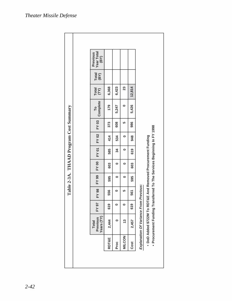
Theater Missile Defense
2-42
Tab
le 2
-3A
. T
HA
AD
Pro
gram
Cos
t Su
mm
ary
•D
oD
Ad
ded
$72
2M T
o R
DT
&E
An
d R
emo
ved
Pro
cure
men
t F
un
din
g
•P
rocu
rem
ent
Fu
nd
ing
Tra
nsf
erre
d T
o T
he
Ser
vice
s B
egin
nin
g In
FY
199
8
RD
T&
E
Pro
c
MIL
CO
N
Co
st
To
tal
Pre
vio
us
Yea
rs (
TY
)
2,44
4 0 13
2,45
7
Pre
vio
us
Yea
r T
ota
l(B
Y)
FY
97
FY
98
FY
99
FY
00
FY
01
FY
02
FY
03
To
Co
mp
lete
To
tal
(BY
)T
ota
l(T
Y)
619 0 0
619
556 0 5
561
595 0 0
595
603 0 0
603
6,36
8
6,42
3 23
12,8
14
585 34 0
619
414
534 0
948
373
608 5
986
179
5,24
7 0
5,42
6
Exp
lan
atio
n O
f V
aria
nce
Fro
m P
revi
ou
s:

Theater Missile Defense
2-43
Mile
ston
e I -
Dem
/ V
al•
Co
ntr
act
Aw
ard
•S
yste
m R
equ
irem
ents
Rev
iew
•S
yste
m D
esig
n R
evie
w•
Dev
elo
pm
ent
Tes
t
Mile
ston
e II
- EM
D•
Co
ntr
act
Aw
ard
•P
relim
inar
y D
esig
n R
evie
w•
Cri
tica
l Des
ign
Rev
iew
Mile
ston
e III
- P
rodu
ctio
n•
LR
IP C
on
trac
t A
war
d•
Fir
st U
nit
Eq
uip
ped
(F
UE
)•
FR
P C
on
trac
t A
war
d
Pro
gra
m S
ched
ule
Mile
sto
nes
Cu
rren
t E
stim
ate
Pre
vio
us
Est
imat
eIn
itia
lE
stim
ate
Exp
lan
atio
n O
f V
aria
nce
Fro
m P
revi
ou
s
Tab
le 2
-3B
. T
HA
AD
Pro
gram
Mile
ston
es
Mile
ston
e I -
Dem
/ V
al•
Dev
elo
pm
enta
l Tes
t
Mile
ston
e II
- EM
D•
Dev
elo
pm
ent
Tes
t S
tart
•O
per
atio
nal
Tes
t S
tart
Mile
ston
e III
- P
rodu
ctio
n•
FU
ETec
hn
ical
Mile
sto
nes
Cu
rren
t E
stim
ate
Pre
vio
us
Est
imat
eIn
itia
lE
stim
ate
Exp
lan
atio
n O
f V
aria
nce
Fro
m P
revi
ou
s
Tab
le 2
-3C
. T
HA
AD
Tec
hnic
al M
ilest
ones
2Q F
Y 9
24Q
FY
92
2Q F
Y 9
53Q
FY
96
3Q F
Y 9
5
2Q F
Y 9
82Q
FY
98
4Q F
Y 9
84Q
FY
00
4Q F
Y 0
42Q
FY
02
4Q F
Y 0
41Q
FY
05
2Q F
Y 9
24Q
FY
92
2Q F
Y 9
53Q
FY
96
3Q F
Y 9
5
2Q F
Y 9
73Q
FY
97
2Q F
Y 9
82Q
FY
99
4Q F
Y 0
41Q
FY
03
2Q F
Y 0
62Q
FY
05
3Q F
Y 9
5
4Q F
Y 0
02Q
FY
02
4Q F
Y 0
4
3Q F
Y 9
5
4Q F
Y 0
02Q
FY
02
2Q F
Y 0
6P
BD
224
Acc
eler
ates
FU
E T
o F
Y 0
4
PD
/ R
R F
ligh
t T
est
Del
ays
PD
/ R
R F
ligh
t T
est
Del
ays
PD
/ R
R F
ligh
t T
est
Del
ays
PD
/ R
R F
ligh
t T
est
Del
ays
PB
D 2
24 A
ccel
erat
es F
UE
To
FY
04
PB
D 2
24 A
ccel
erat
es F
UE
To
FY
04
PB
D 2
24 A
ccel
erat
es F
UE
To
FY
04

Theater Missile Defense
2-44
• Conducted System Design Review (SDR);
• Completed factory string tests on UOES radars and fabrication and integration ofUOES radars and delivery to WSMR;
• Continued integration and testing of JTIDS, launch support, BM/C4I, weapon systemdeck model, and simulation efforts;
• Maintained integrated logistics and product assurance efforts.
Work planned for FY 1997:
• Exercise UOES missile option;
• Conduct Software Specification Review and SDR update;
• Conduct radar characterization tests at WSMR and the United States Army KwajaleinAtoll (USAKA) in conjunction with Theater Critical Measurements Program (TCMP-2);
• Continue system flight test program;
• Begin radar Monolithic Microwave Integrated Circuit producibility and yield improve-ments for EMD;
• Continue nuclear environment survivability analysis;
• Continue hit assessment, discrimination, and guidance, navigation and control algo-rithm development, hit-to-kill lethality analysis, and system threat assessment;
• Continue integration and testing of JTIDS, launch support, BM/C4I, weapon systemdeck model, and simulation efforts.
Work planned for FY 1998:
• Conduct Milestone II DAB review;
• Award EMD Contract;
• Begin software maintenance;
• Continue radar Monolithic Microwave Integrated Circuit producibility and yieldimprovements for EMD;
• Continue objective system design engineering, software independent verification andvalidation, nuclear environment survivability analysis, hit assessment, discrimination,and guidance, navigation and control algorithm development, hit-to-kill lethality anal-ysis, and system threat assessment;
• Continue integration and testing of JTIDS, launch support, BM/C4I, weapon systemdeck model, and simulation efforts;
• Conduct Limited User Test.

Theater Missile Defense
2-45
2.9.1.4 Navy Theater Wide Theater Ballistic Missile Defense (TBMD)The Navy Theater Wide (NTW) TBMD Program will provide an upper-tier, sea-based capabilityto counter medium- to long-range TBM threats. The program builds on the existing AWS andSTANDARD Missile infrastructure as a further evolution to the Navy Area TBMD System. TheAWS will be modified to support exoatmospheric ascent and descent phase engagements. TheSTANDARD Missile Block IV will be modified to include a third stage rocket motor and fourthstage Lightweight Exoatmospheric Projectile (LEAP) kinetic warhead utilizing an infrared seeker.
The current NTW program is consistent with the direction of last year’s BMD Program Review.This program consisted of three parallel efforts. The first of these efforts is a kinetic warheadtechnology assessment. This review is examining technologies including LEAP, THAAD, theAtmospheric Interceptor Technology (AIT) program, and the Exoatmospheric Kill Vehicle (EKV)program. This review will ensure the Department is pursuing the appropriate kinetic warheadsolution for the NTW system. The Department will make a decision on the correct approach forNTW in FY 1998.
In parallel with the technology review, BMDO and the Navy are proceeding to a system levelintercept, called the NTW Flight Demonstration Program (FDP) or AEGIS LEAP Intercept (ALI).The FDP/ALI is using a derivative of the LEAP kinetic warhead used in the previous BMDO andNavy Terrier LEAP intercept attempts. This kinetic warhead will be integrated with componentsof the Navy STANDARD Missile-2 Block IV. The resulting theater-wide missile will be calledthe STANDARD Missile-3 (SM-3). The FDP/ALI flights will be conducted from an AEGIS shipat the PMRF. The Navy will modify an Area TBMD UOES ship as necessary to support the FDP/ALI flights. The current plan includes a series of eight flight tests. The first four, called ControlTest Vehicles (CTVs), develop understanding of this missile through incremental testing. Thesecond four, called Guidance Test Vehicles (GTVs), will intercept a TBM target. The first inter-cept will be approximately the second quarter of FY 2000.
The third portion of the NTW program is risk reduction activities. These activities will examinethe critical risk areas for NTW engineering and develop solutions that will allow BMDO, at theappropriate time, to make an informed decision to enter the EMD phase. In addition, they supportpotential development of an early NTW initial capability (UOES). These risk areas include dis-crimination, lethality, propulsion, divert, kinetic warhead seeker, BM/C3I, ship systems, and sys-tem engineering.
The Department has declared NTW a “core” TMD program. More significantly, the Departmenthas also declared NTW a pre-Major Defense Acquisition Program (MDAP), a program that mayeventually become an MDAP. Accordingly, BMDO and the Navy have initiated the necessarysteps to establish NTW as an acquisition program in compliance with DoD 5000 requirements.
The following tables provide information specified in the Conference Report, Section 234(e)(1)and (2), accompanying S. 1124, the National Defense Authorization Act for Fiscal Year 1996.This requirement calls for “a description of technical milestones, the schedule, and the cost ofeach phase...for each TMD acquisition program.” The requirement also asks for a description ofthe variances in the technical milestones, program schedule milestones, and costs compared toboth (1) the report submitted the previous year, and (2) the report submitted the first (initial) year.Since this year’s report constitutes the first (initial) submission, no variances will be identified or

Theater Missile Defense
2-46
discussed. Information based on the FY 1998 President’s Budget will be considered the “initial”estimate. Tables 2-4A, 2-4B, and 2-4C provide information on the Navy Theater Wide Program.
FY 1996 efforts resulted in the following accomplishments:
• Completed the Navy TBMD COEA Phase I;
• Conducted system and design engineering to support the FDP/ALI flight tests;
• Conducted initial lethality tests for NTW;
• Started the Navy TBMD COEA Phase II to confirm the NTW material alternative.
Work Planned for FY 1997:
• Continue system engineering for the FDP/ALI flight tests;
• Conduct Final Design Review for FDP/ALI missile (SM-3);
• Conduct first flight test (Control Test Vehicle 1);
• Continue LEAP lethality testing;
• Begin Joint Systems Engineering Team studies on kinetic kill vehicle technologies;
• Conduct test of third stage rocket motor;
• Complete Navy TBMD COEA Phase II.
Work Planned for FY 1998:
• Conduct DAB Review to complete Phase 0 activities;
• Continue system engineering for the FDP/ALI flight tests;
• Conduct AWS System Design Review for FDP/ALI;
• Conduct second ALI flight test;
• Conduct ALI target test flight;
• Conduct hover testing of the LEAP SM-3 kinetic warhead.
2.9.2 Corps SAM/Medium Extended Air Defense System (MEADS)The Corps SAM Program was initiated to provide defense of vital corps and division assets asso-ciated with the Army and Marine Corps maneuver forces. The Corps SAM system was beingdeveloped to provide: (1) defense against multiple and simultaneous attacks by Short Range Bal-

Theater Missile Defense
2-47
Tab
le 2
-4A
. N
avy
The
ater
Wid
e P
rogr
am C
ost
Sum
mar
y
RD
T&
E
Pro
c
MIL
CO
N
Co
st
To
tal
Pre
vio
us
Yea
rs (
TY
)
356 0 0
356
Pre
vio
us
Yea
r T
ota
l(B
Y)
FY
97
FY
98
FY
99
FY
00
FY
01
FY
02
FY
03
To
Co
mp
lete
To
tal
(BY
)T
ota
l(T
Y)
304 0 0
304
195 0 0
195
192 0 0
192
191 0 0
191
2,15
5 0 0
2,15
5
191 0 0
191
145 0 0
145
149 0 0
149
432 0 0
432

Theater Missile Defense
2-48
Mile
sto
ne
I - D
em /
Val
•C
on
trac
t A
war
d•
Sys
tem
Req
uir
emen
ts R
evie
w•
Sys
tem
Des
ign
Rev
iew
•D
evel
op
men
t T
est
Mile
sto
ne
II -
EM
D•
Co
ntr
act
Aw
ard
•P
relim
inar
y D
esig
n R
evie
w•
Cri
tica
l Des
ign
Rev
iew
-M
issi
le•
Cri
tica
l Des
ign
Rev
iew
-A
EG
IS T
acti
cal
Mile
sto
ne
III -
Pro
du
ctio
n•
LR
IP C
on
trac
t A
war
d•
Fir
st U
nit
Eq
uip
ped
(F
UE
)•
FR
P C
on
trac
t A
war
d
Mile
sto
ne
I - D
em /
Val
•D
evel
op
men
tal T
est
Mile
sto
ne
II -
EM
D•
Dev
elo
pm
ent
Tes
t S
tart
-L
and
Bas
ed•
Dev
elo
pm
ent
Tes
t S
tart
-S
hip
Bas
ed•
Op
erat
ion
al T
est
Sta
rt•
Sys
tem
Inte
gra
tio
n T
est
Mile
sto
ne
III -
Pro
du
ctio
n•
MS
E S
tart
Pro
gra
m S
ched
ule
Mile
sto
nes
Cu
rren
t E
stim
ate
Pre
vio
us
Est
imat
eIn
itia
lE
stim
ate
Exp
lan
atio
n O
f V
aria
nce
Fro
m P
revi
ou
s
Tec
hn
ical
Mile
sto
nes
Cu
rren
t E
stim
ate
Pre
vio
us
Est
imat
eIn
itia
lE
stim
ate
Exp
lan
atio
n O
f V
aria
nce
Fro
m P
revi
ou
s
Tab
le 2
-4B
. N
avy
The
ater
Wid
e P
rogr
am M
ilest
ones
Tab
le 2
-4C
. N
avy
The
ater
Wid
e T
echn
ical
Mile
ston
es
NA
TB
DT
BD
FY
00
TB
D
TB
D
NA
TB
DT
BD
TB
D
TB
D
TB
D
FY
00
TB
D
TB
D
TB
D
TB
D
TB
D

Theater Missile Defense
2-49
listic Missiles (SRBMs), low cross section cruise missiles, Unmanned Aerial Vehicles (UAVs),and other air breathing threats to the force; (2) immediate deployment for early entry operationswith as few as six C-141 sorties; (3) mobility to move rapidly and protect maneuver force assetsduring offensive operations; (4) a distributed architecture and modular components to increasesurvivability and flexibility of employment in a number of operational configurations; and (5) asignificant increase in firepower while greatly reducing manpower and logistics requirements.
In August 1990, the Corps Air Defense Capability MNS was validated by the JROC. The CorpsSAM program was approved by the DAB to enter the concept definition phase. A Corps SAMOperational Requirements Document (ORD) was jointly developed and approved by the Armyand Marine Corps. The DAB also directed the Corps SAM program to aggressively pursue inter-national cooperation in the development of the Corps SAM system. On February 20, 1995, aStatement of Intent (SOI) was signed with the governments of Germany, France, and Italy tocooperatively develop and produce the MEADS to satisfy the Corps SAM operational require-ments as well as the operational requirements of the other nations. The SOI provides the frame-work for the MEADS Program.
The MEADS Program began as a result of a 1990-92 "Program Cooperative Opportunity Survey."The U.S. Under Secretary of Defense (Acquisition and Technology) (USD(A&T)) invited theGerman Government to cooperate with the United States in the development of a medium-rangeair and missile defense system. The French Government also invited the German Government tojoin the SAMP-T program. In April 1994, a Corps SAM draft Request For Proposal (RFP) wasreleased. The French and German Governments expressed a desire to participate in the CorpsSAM program in June 1994. At this time, MEADS was accepted as the acquisition strategy tomeet the U.S. Corps SAM requirement.
The MEADS SOI approval initiated MEADS Memorandum of Understanding (MOU) negotia-tions. A series of nine MOU negotiation meetings were held between February 1995 and February1996. France withdrew from the MEADS program prior to final approval of the MOU. The MOUwas modified to a trilateral MOU and signed by the United States, Italy, and Germany and enteredinto effect May 28, 1996. The MOU serves as the basis for program execution.
The MEADS will be a lower-tier component of the TMD active defense pillar that will providelow-to-medium altitude air defense, anti-tactical ballistic missile defense, and cruise missiledefense. MEADS will be lightweight and modular in order to be highly transportable and mobile.MEADS will provide protection of maneuver forces and point defense of critical assets from earlyentry through decisive operations against multiple, simultaneous, 360° attacks by various classesof tactical missiles, UAVs, and air breathing threats, which may employ conventional and/orWMD warheads. MEADS will be compatible and interoperable with other Army, Joint Service,and allied systems expected to participate in joint/combined operations in the 21st Century. TheMEADS operational requirements were harmonized between the participant countries and docu-mented in the MEADS Initial International Operational Requirements Document dated February29, 1996.
MEADS will play an important role in a layered missile defense strategy. Approximately 90% ofthe anticipated missile threats fall into the MEADS area of responsibility. These threats drive theMEADS system design towards a highly mobile and capable air defense system able to provide
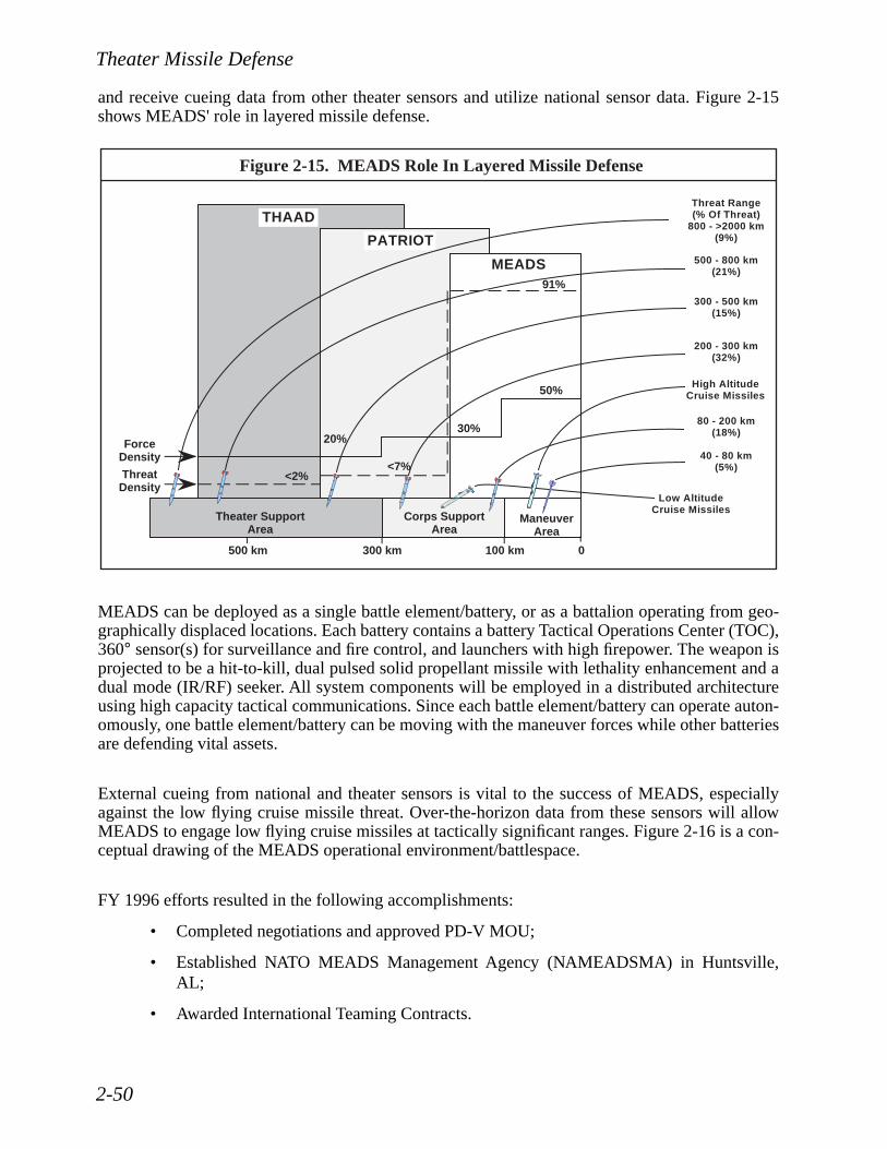
Theater Missile Defense
2-50
and receive cueing data from other theater sensors and utilize national sensor data. Figure 2-15shows MEADS' role in layered missile defense.
MEADS can be deployed as a single battle element/battery, or as a battalion operating from geo-graphically displaced locations. Each battery contains a battery Tactical Operations Center (TOC),360° sensor(s) for surveillance and fire control, and launchers with high firepower. The weapon isprojected to be a hit-to-kill, dual pulsed solid propellant missile with lethality enhancement and adual mode (IR/RF) seeker. All system components will be employed in a distributed architectureusing high capacity tactical communications. Since each battle element/battery can operate auton-omously, one battle element/battery can be moving with the maneuver forces while other batteriesare defending vital assets.
External cueing from national and theater sensors is vital to the success of MEADS, especiallyagainst the low flying cruise missile threat. Over-the-horizon data from these sensors will allowMEADS to engage low flying cruise missiles at tactically significant ranges. Figure 2-16 is a con-ceptual drawing of the MEADS operational environment/battlespace.
FY 1996 efforts resulted in the following accomplishments:
• Completed negotiations and approved PD-V MOU;
• Established NATO MEADS Management Agency (NAMEADSMA) in Huntsville,AL;
• Awarded International Teaming Contracts.
Figure 2-15. MEADS Role In Layered Missile Defense
MEADS
PATRIOT
THAAD
91%
50%
30%20%
<2%<7%
Theater SupportArea
Corps SupportArea
ManeuverArea
0100 km500 km 300 km
Threat Range(% Of Threat)
800 - >2000 km(9%)
500 - 800 km(21%)
300 - 500 km(15%)
200 - 300 km(32%)
High AltitudeCruise Missiles
80 - 200 km(18%)
40 - 80 km(5%)
ForceDensity
ThreatDensity
Low AltitudeCruise Missiles

Theater Missile Defense
2-51
Work planned for FY 1997:
• Initiate PD/V phase;
• Begin negotiations for design and development phase MOU;
• Conduct system requirements review.
Work planned for FY 1998:
• Conduct SDR;
• Continue PD/V phase;
• Release design and development phase RFP.
2.9.3 Airborne Laser (ABL) ProgramThe ABL program entered the PD/RR phase in November 1996, which will demonstrate all nec-essary technologies required for acquiring, tracking, and killing theater ballistic missiles in theboost phase. This will be accomplished by building and testing the prototype ABL aircraft. ThePD/RR phase will be completed in FY 2002 with lethality demonstrations against boostingTBMs. Following successful demonstrations, the program will proceed into a relatively short
Figure 2-16. MEADS Description
Weapon
Dual Mode SeekerHit-To-Kill With EnhancementSolid PropellantHigh Firepower
••••
Communications
AAExternalSources Combined TBM / CM
And AirBreathing Threats
Battery TOC
• HMMWV, SICPS• Distributed Architecture
Sensor(s)• Radar(s) (Search / Fire
Control)• 360° Coverage
Battery #1
Battery #2
Battery #3
Battalion
• Organic Sensors• Batteries
- Launchers- TOCs- Ready Mssiles

Theater Missile Defense
2-52
EMD phase in FY 2003. Production will provide an Initial Operational Capability (IOC) withthree aircraft in FY 2006 and a Full Operational Capability (FOC) of seven aircraft in FY 2008.
2.10 Battle Management/Command, Control, Communications, Computers, and Intelligence (BM/C4I)
Interoperability in Battle Management/Command, Control, Communications, Computers, andIntelligence (BM/C4I) is essential for joint TMD operations. Accordingly, BMDO continues totake an aggressive lead to establish an architecture that all the Services can build upon and isactively pursuing three thrusts, described below, to ensure an effective and joint BM/C4I for TMD.The BMDO TMD BM/C4I program integrates the C3 components of multiple, independentlydeveloped programs into a single, cohesive, seamless system that realizes the maximum synergyof the combined weapons and sensor systems. The primary goal is to provide the warfighter withan integrated TMD capability with the interoperability and flexibility to satisfy a wide range ofthreats and scenarios. From its joint perspective, BMDO oversees the various independent weaponsystems developments and provides guidance, standards, equipment, and system integration andanalysis to integrate the multitude of sensors, interceptors, and tactical command centers into ajoint theater-wide TMD system.
2.10.1 BM/C4I ArchitectureThe TMD BM/C4I architecture is built upon the existing and planned command and control struc-ture for TAD. During FY 1996, the TMD Command and Control Plan (TMD C2 Plan) receivedJoint Staff approval and included an operational architecture based upon the three primary func-tions of joint operations: planning, coordination, and execution. Deliberative planning occurs pri-marily at the higher levels of command and is generally non-real-time. Force coordination takesplace at the tactical commander level (CRC, TAOM, TF TOC, CIC) and involves near real-timedecisions. Execution is accomplished by the direct linkage of the sensor to the shooter to put metalon target and involves real-time actions. Figure 2-17 describes this spectrum of planning, coordi-nation, and execution. The rapid timeframes associated with the execution of TMD requireclosely coordinated command and control for centralized planning and guidance with decentral-ized execution. To ensure optimized planning and guidance, BMDO is focused on accomplishingthe horizontal linkages among the theater-level command and control centers that could bedeployed in various combinations over time from one theater or contingency to another.
The TMD BM/C4I architecture to support the operational architecture for planning, coordination,and execution is built around three overlapping networks: a Joint Planning Network (JPN), a JointData Network (JDN), and a Joint Composite Tracking Network (JCTN). The JPN is a non-real-time/near real-time network building upon the Global Command and Control System (GCCS) tosupport the centralized planning and guidance. The JDN is a near real-time network based prima-rily on the TADIL-J (JTIDS) datalink to provide overall situational awareness and weapon coordi-nation. The JCTN is a real-time network to directly link sensors and shooters from all the Servicesto provide fire quality information to take full advantage of the synergy of multiple systems. Theexecution function will be supported by JCTN, which is a mix of the JDN and the Navy's Cooper-ative Engagement Capability (CEC). Figure 2-18 shows how these networks overlay on the opera-tional functions. Note that the networks overlap. The highest priority for near term imple-mentation is the JDN. Figure 2-19 shows an example of the participants in the JDN. All Services

Theater Missile Defense
2-53
will interoperate via this net, which will allow early cueing of sensors and greater opportunity forTBM engagements. This joint data distribution will contribute to the success of engagements andmitigate leakage of hostile missiles through defenses.
Figure 2-17. Spectrum Of Planning, Coordination, And Execution
TheaterPlanning
Days
Hrs
Min
Sec
JFC AADC TacticalCommanders
FiringUnits
ForceCoordination
Execution
Figure 2-18. BM/C4I Networks
AAAAAAAAAAAAAAAAAAAAAAAAAAAAAAAAAAAAAAAAAAAAAAAA
AAAAAAAAAAAAAAAAAAAAAAAA
TheaterPlanning
Days
Hrs
Min
Sec
JFC AADC TacticalCommanders
FiringUnits
ForceCoordination
Execution
JPN
JDN
JCTN

Theater Missile Defense
2-54
The intelligence portion of the architecture focuses on TIBS and TDDS. TIBS and TDDS are sat-ellite broadcast systems which disseminate information from theater and national intelligenceresources. TMD forces rely on TIBS and TDDS, in combination with the JDN, for receipt oflaunch warning information produced by tactical processors of DSP data (e.g., JTAGS in the the-ater or ALERT/TACDAR in CONUS).
2.10.2 BM/C4I ThrustsBMDO has three major thrusts to the TMD BM/C4I program as illustrated by Figure 2-20.
The first thrust is to improve the timeliness and accuracy of early warning and track data fromspace and airborne IR platforms. The early cueing data can extend the target acquisition range offire control radar systems, and in many cases increase the weapon system's shot opportunities anddefended area. DSP was originally designed to detect strategic ballistic missile launches. Toimprove DSP performance for theater ballistic missiles, BMDO sponsored the Army/Navy-ledTactical Surveillance Demonstration Enhancement Program. The program prototyped a DSP ste-reo processing capability which formed the basis for the currently deployed JTAGS and ALERTground processing stations. The Services now have responsibility for these fielded systems; how-ever, BMDO continues to fund new cueing and warning-related technologies to further enhancethe active defense, passive defense, and attack operations capabilities of TMD systems. JTAGS/
JTIDSJoint
Network
BrIgadeTOC
PATRIOTBatteries
BattalionTask Force
TOC
TDDS/TIBS
THAAD Battery
GBR
OtherSensor
TPS-75
TDDS/TIBS
CRC
BPI
ADTOC
AAWCCIC
E-2
AEGIS
TAOC
ADCP HAWK
Army Air Force
NavyMarine Corps
CG
OtherSensor
TheaterSensor
TPS-59
TDDS/TIBS
CVN LHD
TDDS/TIBS
JTAGS
Figure 2-19. BM/C4I Communications Network
AOCBPI ALERT
AWACSABCCCJSTARS
RiverJoint

Theater Missile Defense
2-55
ALERT have been integrated into the TIBS/TDDS networks to ensure timely dissemination ofwarning and cueing data directly to the shooter. JTAGS/ALERT and the TIBS/TDDS haveimproved Desert Storm warning data accuracy and timeliness by orders of magnitude. DSP willeventually be replaced by SBIRS and TIBS/TDDS will be replaced by the Integrated BroadcastSystem (IBS). BMDO is also working with the Services and USSPACECOM to minimize theimpact to TMD systems during the transition.
The second thrust focuses on the need for a seamless, interoperable joint data net to rapidlyexchange weapon coordination and cueing data and to provide the shooter and the tactical com-mand centers with a consistent air and missile picture. This exchange of track data among unitsover a large area provides the ability to comprehend the battle situation beyond organic sensorrange of individual participants, enhances organic radar acquisition by providing the means forcueing, and provides theater commanders with a consistent tactical picture for decision making.BMDO, with the Services and the Defense Information Systems Agency/Joint InteroperabilityEngineering Organization (DISA/JIEO), selected the Link-16 (TADIL-J) as the primary TMDdatalink and successfully led a joint Service panel to define new data standards to support TMD.The standards have been joint Service and DoD agency-approved and have also been submittedfor NATO acceptance. Several of these message standards have been approved by NATO for test-ing and BMDO has successfully tested the messages on the USMC ADCP. The program officesreceived the new standards described in the second thrust and are in the process of implementingthe necessary software to integrate communication hardware with the various host platforms.BMDO continues to monitor and influence program offices acquisition activities to ensure JTIDS/Link-16 procurement and integration funding and timelines support TMD timelines.
1. Early Warning / Dissemination
Processing / Dissemination A
3. Command And Control Upgrades
Attack OperationsPassive Defense
• Launch Point• Impact Point
• Cueing• Launch Point• Impact Point
ADA TOCTAOC
Planning /Coordination
TFCC / CICAOC / CRC
2. Communications Interoperability
A
- Improved Launch / Impact Point Accuracy- Reduced Timelines
- Service / Allied Interoperability- Seamless Warning / Cueing / Weapon Coordination- Shared Situational Awareness- JTIDS Primary Medium
- Advanced Decision / Planning Aids- Link Into GCCS- Integrate Attack Ops / Passive Defense- Timely Intelligence Data
Figure 2-20. Three TMD BM/C4I Thrusts

Theater Missile Defense
2-56
BMDO sponsored an extensive study initiated in FY 1996 to determine the full value added by asystem such as the Navy’s CEC to TMD. The results of the study will help to better define theJCTN and develop an implementation strategy to satisfy this portion of the BM/C4I architecture.
The third thrust focuses attention on command and control centers at the planning and coordina-tion level of TMD above the weapon systems’ C2 centers. The first element of the thrust is thedetermination of the information that needs to be passed among these centers. BMDO is develop-ing a TMD Information Architecture that defines the processes, data structure, and critical infor-mation exchange requirements for these centers. The next element is the development of softwareapplications and tools to assist in the planning and coordination processes. The Joint National TestFacility (JNTF) is leading a Joint TMD Planner effort which will have common weapons charac-teristics of all the Services in its database and provide the means to provide TMD guidance for theexecuting activities in terms of such activities as defended asset lists and rules of engagement.This application will be consistent with and offered as an application for the GCCS. This thrustputs contingency deployable prototype C2 centers in the field to enhance user experience andinput regarding requirements refinement. A prototype TMD Cell for the United States EuropeanCommand (USEUCOM) has been provided to the CINC, and similar cells will be provided to theUnited States Pacific Command (USPACOM) and the United States Central Command(USCENTCOM) to identify unique requirements in their areas of responsibility. Additionally,BMDO will join the Army efforts to field brigade-level Air Defense Tactical Operations Centers(ADTOC) and support the TMD aspects of this program.
BMDO is employing a Systems Integration and Interoperability contractor to help document anddefine the BM/C4I Architecture. An Interoperability Description Document (IDD) will providedetailed descriptions of the interfaces and functionalities needed between each command and con-trol node. A System Road Map will provide guidance on how and when each of the systems willachieve required interoperability.
In a continuous effort to validate the C4I architecture and to measure the progress of the threeBM/C4I thrusts, BMDO is responsible for testing integrated BM/C4I for TMD. This includesBMDO-sponsored exercises which will use the facilities of the JNTF and the Advanced ResearchCenter (ARC) to refine the information architecture through user interactions, and quantifyingperformance parameters to be met by Service programs. Additionally, BMDO will use end-to-endsimulations, man-in-the-loop tests, and Hardware-In-The-Loop (HWIL) tests to validate BM/C4Irequirements and determine that those requirements have been met. To meet the specific needs ofTMD testing, System Integration Tests (SITs) have been defined which piggyback on live missilefirings. Prior to and following a SIT, a series of HWIL tests will be conducted using the TMDSystem Exerciser (TMDSE) to simulate the operational environment and to drive each elementparticipating via HWIL. As a distributed HWIL, the TMDSE stimulates the TMD data processorsvia a simulated environment to demonstrate TMD system responsiveness and performance as anintegrated whole in scenarios unachievable with live-flight testing.
2.10.3 Theater Missile Defense BM/C4I Integration Group (TBIG)BMDO has established a broad-based IPT with participation by the Services, CINCs, and DoDagencies to work BMDO’s integration and interoperability objectives. That group, the TMD BM/C4I Integration Group (TBIG) meets regularly to share information and to secure the coordinationand collaboration of all affected programs in defining and implementing the appropriate C4I solu-

Theater Missile Defense
2-57
tions for an integrated TMD capability. This information sharing helps identify divergences sothat problems can be solved. The TBIG involves both operators and material developers in sharinginformation that supports Service activities pertaining to programmatic planning, standards, theTMD C4I functional baseline, and interface control documentation. Participation by the unifiedCINCs, in addition to the Service user/operator representatives, provides a current user's perspec-tive.
OSD and the Joint Staff are active TBIG participants. The OSD representatives ensure that initia-tives pursued by the Services/agencies are in consonance with OSD policies for C4I and informa-tion systems. The TBIG meetings also provide an opportunity for OSD to inform the Services/agencies of directives that apply to the TMD community. This exchange of information keeps allparties informed. The Office of the Joint Chiefs of Staff also sends representation to each TBIGmeeting to share information on officially approved joint doctrine, CONOPS, and other efforts toimprove worldwide C2 systems (such as the GCCS) with which the TMD family of systems willeventually interface. The DISA/JIEO provides the technical expertise to implement and define theOSD and Joint Staff policies.
The TBIG has established subordinate working groups to investigate several issues. The TMDSubgroup of the Joint Multi-TADIL Standards Working Group is perhaps the most successfulTBIG effort. The JTIDS Network Management Working Group is tackling the issues of managingthe complex JTIDS network. The T4P Working Group is a forum to coordinate the sensor-to-shooter issues associated with TES, TACDAR, TIBS, and TDDS. A Risk Management group hasbeen formed to focus on specific risk issues and means to eliminate or mitigate the effects of risks.The Information Architecture, previously mentioned, is being developed with the help of a work-ing group established by the TBIG. All these groups provide the information sharing and issueresolution opportunities essential to produce an interoperable BM/C4I system.
FY 1996 efforts resulted in the following accomplishments:
First Thrust: Launch Warning Dissemination.
• Developed multisensor tracking algorithm;
• Implemented situation targeting algorithms;
• Integrated C2 connectivity to national assets.
Second Thrust: Communications Interoperability.
• Conducted modeling and analysis of JTIDS network structure in support of TMD;
• Developed interoperability certification test plan;
• Demonstrated lower-tier/Joint interoperability;
• Updated Information Exchange Requirements (IER);
• Began implementing JTIDS TMD message sets on selected BM/C4I platforms.Started integration on Air Force platforms (Ground Tactical Air Control System, CobraBall, and Rivet Joint);

Theater Missile Defense
2-58
• Initiated study on relaying TMD data to theater areas beyond the line-of-sight limita-tions of a JTIDS network;
• Began work on AEGIS cruiser/JMCIS interface;
• Completed JTIDS TMD message set validation in North East Asia and South WestAsia theaters;
• Defined joint JTIDS Range Extension (JRE) operational and demonstration architec-ture;
• Continued correlation analysis and testing as required in the Modeling, Analysis, andSimulation Center;
• Developed Data Link Handbook;
• Completed debris techniques analysis plan;
• Supported MIDS development.
Third Thrust: Command and Control Upgrades.
• Prototyped the decision support aids for JFACC battle management;
• Developed, simulated, and demonstrated prototypes of the recommended TBMCSapplication for the distributed command and control nodes;
• Completed testing of JTIDS Navy Command and Control Processor (C2P) modifica-tions;
• Conducted TMD war game;
• Conducted tests to refine command and control procedures;
• Continued prototype integration into ADTOC weapon systems of BM/C4I capabilities;
• Began implementation of TBMD modifications necessary for the Advanced CombatDirection System (ACDS);
• Refined Time Critical Target Aid (TCTA) prototype, began software integration intothe Theater Battle Management Core System (TBMCS) databases;
• Conducted Distributed Battle Management (DBM) platform impact assessments onAWACS, JSTARS, and/or the Control Reporting Center;
• Began TMD intelligence planning tool development: completed one country studyand started a second country study;
• Evaluated software maturity for operational tests;
• Integrated JTIDS into USMC ADCP;
• Initiated cue acceptance development for AN/TPS-59 and TAOM TMD upgrades.

Theater Missile Defense
2-59
Work planned for FY 1997:
First Thrust: Launch Warning Dissemination.
• Continue to integrate C2 connectivity to national assets.
Second Thrust: Communications Interoperability.
• Participate in joint TBMD interoperability demonstrations;
• Demonstrate Army enclave interoperability;
• Integrate JTIDS into Army systems and additional Air Force platforms (completeAWACS TMD message set integration, start AWACS fleet upgrade, continue GTACSTMD message set integration, and begin Air Operations Center and Airborne Com-mand and Control Capsule);
• Continue evolution of JMCIS/TBMD segment;
• Complete correlation analysis testing;
• Develop joint JTIDS Range Extension implementation plan.
Third Thrust: Command and Control Upgrades.
• Perform AOC/CRC upgrades for TMD;
• Begin software integration of TMD messages;
• Participate in TBMD workshops;
• Conduct C2 tests to refine C2 procedures;
• Continue implementation of TBMD modifications for ACDS;
• Complete TCTA software integration into TBMCS databases;
• Model and simulate the DBM system concept, begin DBM technology risk mitigation;
• Normalize intelligence preparation of the battlespace country studies;
• Continue TMD intelligence tool development, begin software integration into CombatIntelligence Systems databases;
• Integrate JTIDS into Army systems;
• Field Joint TMD Planner software V1.0.
Work planned for FY 1998:
First Thrust: Launch Warning Dissemination.
• Implement improved correlation software for TIBS/TDDS.

Theater Missile Defense
2-60
Second Thrust: Communications Interoperability.
• Definition of a point-to-point Link-16 STANAG;
• Complete the AEGIS/JMCIS interface control documents;
• Implement TADIL-J onboard the E-2C aircraft;
• Implement TADIL-J onboard additional Air Force platforms;
• Develop TADIL-J range extension software and hardware;
• Continue JTIDS procurement for JDN;
• Initiate actions for a JCTN;
• Distribute joint correlation analysis results and guidance;
• Continue AWACS JTIDS TMD message set fleet upgrade;
• Continue Ground Tactical Air Control System, Air Operations Center, and AirborneCommand and Control Capsule TMD message set integration;
• Develop joint JRE capability in accordance with implementation plan.
Third Thrust: Command and Control Upgrades.
• Upgrade JMCIS TMD software segments;
• Field two Tactical Operations Centers to Active Army brigades;
• Field JTMDP V2.0;
• Develop an automated intelligence database function;
• Deliver TMD Battlefield Situation Display;
• Conduct initial testing of TAOM TMD modifications;
• Continue distributed battle management technology risk mitigation;
• Develop automated intelligence database function.
2.11 Other Programs and ConceptsOther programs and concepts include BPI and SBIRS. The following sections describe theseactivities. Figure 2-21 shows the active defense framework with some of these systems included.
2.11.1 Boost Phase Intercept (BPI)BPI systems are designed to defeat TBMs in the powered portion of flight. This is a time criticalphase of flight in which the BPI systems will detect, target, and destroy TBMs in a matter of sec-onds. Only in this boost phase can U.S. forces actively defend against TBMs and provide a signif-icant deterrence not to launch WMD. With BPI, the enemy must face the potential of havingchemical, biological, or nuclear weapons fall back upon its own territory. The ABL is being

Theater Missile Defense
2-61
developed by the Air Force to accomplish BPI. The UAV BPI is being pursued as a backup to theABL.
2.11.2 Kinetic Energy Boost Phase Intercept (KE BPI)The primary objective of the KE BPI program has been realigned in an effort to develop and dem-onstrate lightweight endoatmospheric vehicle technologies to supporting advanced TMD inter-ceptors.
2.11.3 Space Based Infrared System (SBIRS)The SBIRS Program is an Air Force acquisition effort to develop and field a consolidated space-based nonimaging infrared surveillance system. The SBIRS Program is an essential element ofthe NMD architecture and while space-based tracking is not necessary to the operation ofground-, sea-, or air-based TMD systems, the deployment of SBIRS would enhance the capabili-ties of those systems. A deployed space-based midcourse tracking system will provide a signifi-cant extension of the range and effectiveness of TMD systems, and allow them to operateeffectively under adverse conditions. Also, a space-based midcourse tracking capability may be
BM/C4I
* Emphasizes Programs Underway Or Upgrades To Existing / Fielded Systems
Combination Gives CINC FlexibleDeployment / Employment Options
THAAD System(FUE FY 04;UOES FY 99)
PAC-3Configuration Three
(FUE FY 99)
AEGIS With SM-2 Block IVA
(FUE FY 02;UOES Software
FY 98)
Land Sea Air
Upper
Lower
Navy Theater Wide TBMD
Initial InterceptFY 00
UOES / FUE TBD
Core Program* Other Programs And Concepts
Figure 2-21. TMD Active Defense Framework Core Programs And Other Concepts
Boost PhaseIntercept
Corps SAM / MEADS
DSP TPS-59JTAGSALERT
TACDAR
- Airborne Laser(Air Force)
- UAV BPI (BMDO)

Theater Missile Defense
2-62
needed to augment ground-based radars and extend the range of intercepts against the evolvinglonger range theater missile threats. Providing TMD systems with over-the-horizon sensor cueingwill greatly enhance each system’s performance. SBIRS data can be used to cue the radars(ground- or ship-based) to acquire warheads or it can be used to target the interceptors before theTBMs come within radar range. The additional battlespace gained with space-based midcoursetracking allows more shot opportunities, increases the probability of negating the threat, andallows the threat to be destroyed further from defended assets. This will decrease the probabilityof damage to friendly forces as a result of the intercept and otherwise allow warfighters to main-tain the initiative.
For a more detailed discussion of SBIRS, see section 3.5.5.
2.12 Joint Force ActivitiesJoint force efforts include the Commanders-in-Chief (CINCs') TMD Assessment Program andCombined Warfare Activities. These efforts are discussed below.
2.12.1 CINCs' TMD Assessment ProgramThe CINCs' TMD Assessment Program consists of operational exercises, war games, PlanningExercises (PLANEXs), and Warfare Analysis Laboratory Exercises (WALEXs). This programenhances the two-way communication between BMDO as the developer and the warfightingCINCs who are the end users of TMD systems. In support of the user, the CINCs' TMD Assess-ment Program provides a vehicle for the CINCs to assess their capabilities and shortfalls so thatthey may refine and articulate their TMD requirements and improve their current and future TMDoperational capabilities. The program facilitates the development and refinement of TMD doctrineand CONOPS as part of the CINCs’ and Joint Staff’s overall theater operations plans.
In support of the developer, the CINCs' TMD Assessment Program provides lessons-learnedwhich are fed back into system requirements and the acquisition programs. In FY 1994, the pro-gram name was changed from the CINCs' TMD Experiments Program to the CINCs' TMDAssessment Program to emphasize feeding back lessons-learned into weapons system acquisitionrequirements, and Service and joint doctrine development. From BMDO's perspective, the pro-gram is a valuable vehicle for collecting the earliest data at a low cost on both current and futureTMD system performance in a near tactical operational environment. Although the Joint ForceDirectorate is the BMDO point of contact for this program, all directorates within the BMDODeputy for Theater Air and Missile Defense interact with and benefit from this program.
The objectives of the CINCs' TMD Assessment Program are:
• Improve current TMD capabilities;
• Document user TMD requirements;
• Facilitate development of TMD doctrine/CONOPS;
• Serve as the "bridge" between user and developer;
• Document existing TMD capabilities;
• Gain CINC support for BMDO programs.

Theater Missile Defense
2-63
To conduct the program, representatives from the CINCs' staffs participate in workshops wheredevelopers and the doctrine community brief the latest developments in their respective areas. TheCINCs then develop prioritized goals based upon their past TMD experience and promising newtechnological and doctrinal developments. Working with BMDO's Joint Force Directorate, thesegoals are then translated into an assessment plan for the succeeding two years. The assessmentsare overlaid on established CINC/BMDO-sponsored WALEXs, war games, and live/simulatedexercises to ensure that TMD capabilities are evaluated in the context of the full spectrum of jointand combined force operations. A BMDO-sponsored TMD PLANEX is made available to eachCINC to provide, over a two-day period, basic instruction on the TMD pillars and operations, andto facilitate the design and conduct of TMD exercises and war plan preparation.
The results of the assessments provide operational data directly to the developer, and assist theCINCs in updating their integrated priority lists and operational requirements documents. Les-sons-learned from these assessments support the development and refinement of TMD CONOPS;operational requirements; and joint, combined, and Service doctrine. The CINCs also gain valu-able operational experience in conducting TMD operations, which immediately enhances theplanning and execution of their warfighting capabilities and the development of TMD require-ments for future weapon system deployments. The Joint Force Directorate ensures that lessons-learned are also presented to the acquisition community.
An increasing number of theater commands are participating in the program. From the program'sinception in 1988 until 1993, USEUCOM was the only operational command to participate. In1993, USCENTCOM and U.S. Forces Korea (USFK) joined. In 1994 U.S. Pacific Command(USPACOM) and U.S. Forces Japan (USFJ) began to participate as well. In 1995 U.S. AtlanticCommand (USACOM) joined the program. BMDO provided liaison officers to help USACOMinitiate TMD activities.
Major TMD CINC assessments include Optic Needle, Optic Cobra, Ornate Impact, and numerouswar games. Optic Needle is the TMD portion of USEUCOM exercises and includes CentralEnterprise, Optic Windmill, Matador (NATO exercise), Atlantic Resolve, Cold Fire (NATO Cen-tral Region Exercise), U.S.-U.K. Wargame, and Dynamic Mix (JTF/JFACC exercises). OpticCobra is the TMD portion of Joint USCENTCOM exercises and includes Roving Sands. OpticCobra assesses the ability of USCENTCOM to exercise all four pillars of TMD in both a live andsimulated environment. Ornate Impact is the TMD portion of a USFK command post exercisewhich evaluates all four pillars of TMD in a simulated environment. The Joint Task Force Exer-cise series sponsored by USACOM is the template for increasingly complex TMD assessments.The USPACOM exercises focus on bilateral TMD issues throughout the Pacific basin and prepar-ing U.S. Third Fleet Carrier Battle Groups for deployment to USPACOM and USCENTCOM.
In 1995, BMDO and USACOM concluded a memorandum of understanding establishing threeBMDO liaison officer positions (Army, Navy, and Air Force) at USACOM. These billets provideUSACOM with a TMD cell and the ability to participate more fully in the development and eval-uation of joint, combined doctrine and requirements. Some of the specific liaison officer dutiesinclude planning coordination for USACOM/BMDO-sponsored CINC TMD assessments, plan-ning and coordinating TMD war games, and working USACOM TMD issues and requirements.

Theater Missile Defense
2-64
2.12.2 Combined Warfare ActivitiesThe Combined Warfare programs are joint programs with our allies and friends. These programshave three major objectives. The first objective is to reduce the costs of fielding TMD systems bysharing the cost burden of development, production, and operation. The second objective is to helpour allies and friends understand the impact of the ballistic missile threat on their countries and toaccess innovative foreign technologies, systems, and unique capabilities. The third objective is tofacilitate military ties to define common requirements to help ensure the interoperability of TMDweapon systems used by the United States, its allies, and friends. The FY 1994 Defense Authori-zation Act directed the Secretary of Defense to develop a plan to coordinate development andimplementation of TMD programs with our allies which satisfies these objectives. BMDO pre-pared the plan, entitled "Report to Congress on Plan to Coordinate Development and Implementa-tion of TMD Programs with Allies." The report was submitted to Congress in the fourth quarter ofFY 1994.
In addition, the international cooperative programs support U.S. policies. The programs maystrengthen U.S./allied mutual security commitments and counterproliferation policies and strate-gies. Fully developed programs should result in protection for U.S./allied forces and underpin theNational Command Authorities freedom of action in crisis situations.
BMDO’s approach is to build on the earlier foundation of bilateral research and development pro-grams. These programs have led other countries to recognize existing and emerging threats of bal-listic missile attacks. The strategy for international cooperation complements the TMD acquisitionstrategy for emphasizing near-term improvements, fielding the core programs, and developingadvanced concepts.
2.13 TMD Test ProgramTMD testing consists of individual MDAP testing and TMD “Family of Systems” (FoS) integra-tion and interoperability tests. MDAP TMD test and evaluation efforts will be accomplished bythe individual Service acquisition programs and will encompass all requirements mandated inDoD guidance. These test programs will be fully documented in each acquisition program Testand Evaluation Master Plan (TEMP). Testing to assure interoperability among systems acquiredby an individual Service will generally be executed by that Service but will also be assessed inFoS testing. All tests, including tests of individual acquisition programs and TMD FoS, will beconducted in accordance with existing U.S. treaty obligations.
BMDO will sponsor testing to assure inter- and intra-Service operability and interoperability ofthe TMD Family of Systems with external systems. TMD FoS test requirements are derived fromthe BMD Capstone Operational Requirements Document (ORD), from individual system ORDs,and other documentation such as the TMD Command and Control Plan. TMD FoS requirementsin the Capstone ORD include the responsiveness and effectiveness of the consolidated TMD FoSagainst specific tactical ballistic missile threats; characteristics of the common air picture whichmust be maintained among TMD C2 centers; and specific information exchange requirements.Requirements not addressed in Service-specific test programs are included in the TMD CapstoneTest and Evaluation Master Plan (TEMP), which is a road map for future test planning and coor-dination among test programs, resources, and other organizations. Interoperability certification of

Theater Missile Defense
2-65
each major acquisition program will be provided by the Joint Interoperability Test Command asrequired by DoD Directive 4630.5 and Chairman, Joint Chiefs of Staff Instruction 6212.01A.

Chapter 3
National Missile Defense

National Missile Defense
3-1
Chapter 3
National Missile Defense (NMD)
3.1 Introduction
The Department of Defense (DoD) is working to develop a National Missile Defense (NMD)capability to defend the United States from an emerging Rest-of-World (ROW) rogue state ballis-tic missile threat or against a limited accidental or unauthorized missile launch. Toward this end,DoD established the NMD Deployment Readiness Program, which positions the United States torespond to a threat as it emerges.
In early 1996, DoD completed a comprehensive review of its Ballistic Missile Defense Program,followed by a decision to shift the NMD Program from a technology to a deployment readinessprogram. Current program strategy is based on the “3+3” concept -- a three year development andplanning phase, that, if necessary, could be followed by a three year system development anddeployment phase. DoD is fully committed to the first phase of the “3+3” NMD program. Inresponse to the shift from technology to deployment readiness, the Undersecretary of Defense forAcquisition and Technology (USD(A&T)) designated NMD as an Acquisition Category-ID(ACAT-ID) Major Defense Acquisition Program (MDAP).
NMD funding changed based on Congressional direction and DoD’s NMD program strategy,which will permit the completion of a development program leading to the demonstration of theNMD system in an Integrated System Test (IST) in FY 1999. Funding shifted forward in theFuture Year Defense Program (FYDP) with allocations of approximately an additional $100 mil-lion per year in FY 1997-1998. Congressional funding increases provided $375 million in FY1996 and $325 million in FY 1997 for NMD above DoD’s request.
During the initial development phase of the NMD “3+3” Program, subsystem elements will beintegrated into a limited capability system, culminating with an Integrated System Test (IST) inFY 1999. A decision to deploy could be made as soon as 2000 based on a successful demonstra-tion of system capability and validation of a ballistic missile threat. If the threat and programprogress warrant a decision to deploy, then an Initial Operational Capability, designated as Capa-bility 1, could be deployed as early as 2003. However, if a deployment decision is deferred, theprogram will continue improving the NMD deployment readiness posture by advancing the tech-nology of each element while maintaining the capability to deploy the system within three yearsof a decision--ultimately leading to the development of an objective system capable of defendingagainst more sophisticated threats, designated as Capability 2. The Department’s goal is toachieve an NMD deployment readiness posture that ensures deployment is at most three yearsaway from a decision to deploy. Given the uncertain timing of the threat, the specific scenario inwhich a threat may emerge, and the length of time required to deploy a system to defend againstthese threats, the NMD Deployment Readiness “3+3” strategy accommodates the uncertainty ofthe threat to the United States while allowing an orderly evolution of capability as the technologymatures.

National Missile Defense
3-2
3.1.1 System Concept
If deployment of an NMD system is mandated soon after the FY 1999 IST, an initial architecturecould be in place by 2003. That architecture would consist of the following basic elements inte-grated as a system: (1) a Ground Based Interceptor (GBI) element capable of receiving and pro-cessing in-flight target updates, performing onboard target selection, and providing reliable targetdestruction; (2) a Ground Based Radar (GBR) to act as the primary fire control sensor; (3) anUpgraded Early Warning Radar (UEWR) and other Forward-Based X-band Radars (FBXRs) asrequired; (4) early warning satellites to detect a ballistic missile launch (i.e., the Defense SupportProgram (DSP) satellite or Space Based Infrared System (SBIRS)-High); and (5) a Battle Man-agement/Command, Control, and Communications (BM/C
3
) element for system integration,informed decision making by humans in control, and engagement planning and execution. TheCapability 1 architecture, depicted in Figure 3-1, will meet the threshold values of the user’s oper-ational requirements as established in the Joint Requirements Oversight Council (JROC)-vali-dated National Ballistic Missile Defense (BMD) Capstone Requirements Document (CRD) andJoint Operational Requirements Document (ORD), and will provide high levels of operationaleffectiveness against a limited threat comprising a few simple reentry vehicles from a ROW coun-try.
If the deployment of an NMD system is deferred, the NMD “3+3” Program will continue toimprove the deployable defense system as element technologies advance and new elements areintroduced until the objective system architecture, Capability 2, is attained. Such an architecture
Figure 3-1. Capability 1 NMD Architecture
AAShemya
IFICS
GBIOtis
Fylingdales
Beale
BM/C3
Early Warning Satellite
• GBI (20 At Grand Forks)• GBR At Grand Forks• Forward X-band• UEWRs• BM/C3
MILSATCOM
AA
Thule
A
GBR
ABarrow

National Missile Defense
3-3
would add a constellation of SBIRS-Low space-based sensors to the above-mentioned subsystemelements and would specify sensor and interceptor ground sites that are designated to deal with aspecific threat. A representative architecture that could be deployed and would meet the objectivesystem requirement of providing a high level of protection against a modest number of more com-plex threats is depicted in Figure 3-2.
3.2 Threat
3.2.1 National Intelligence Estimate
A National Intelligence Estimate on the emerging missile threats to North America during thenext 15 years was issued, representing the views of the Director of Central Intelligence with theadvice and assistance of the U.S. Intelligence Community. The Defense Intelligence Agency(DIA)-validated Strategic Threat Assessment (STA) contains the DIA-validated threats which theNMD system is designed to counter.
The intelligence community has concluded that no country, other than the major declared nuclearpowers, will develop or otherwise acquire a ballistic missile in the next 15 years that couldthreaten the contiguous 48 states; only a North Korean missile in development, the Taepo Dong 2,could conceivably have sufficient range to strike portions of Alaska or the far-western HawaiianIslands, but the likelihood of it being operational within five years is very low.
Figure 3-2. Capability 2 NMD Architecture
AShemya
IFICS
GBIOtis
Beale
BM/C3
Early Warning Satellite
• GBI• GBR• SBIRS-Low• Forward X-band Option• BM/C3
MILSATCOM
AAA
GBR
AAAABarrow
AHawaii
SMTS
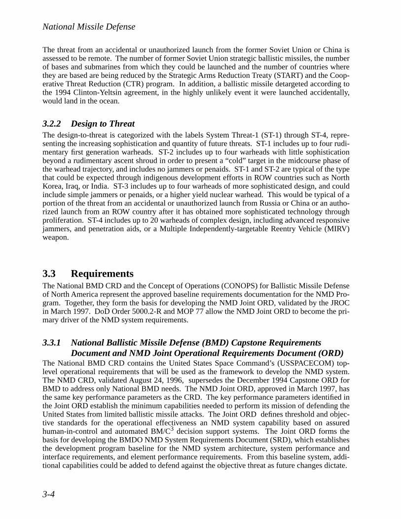
National Missile Defense
3-4
The threat from an accidental or unauthorized launch from the former Soviet Union or China isassessed to be remote. The number of former Soviet Union strategic ballistic missiles, the numberof bases and submarines from which they could be launched and the number of countries wherethey are based are being reduced by the Strategic Arms Reduction Treaty (START) and the Coop-erative Threat Reduction (CTR) program. In addition, a ballistic missile detargeted according tothe 1994 Clinton-Yeltsin agreement, in the highly unlikely event it were launched accidentally,would land in the ocean.
3.2.2 Design to Threat
The design-to-threat is categorized with the labels System Threat-1 (ST-1) through ST-4, repre-senting the increasing sophistication and quantity of future threats. ST-1 includes up to four rudi-mentary first generation warheads. ST-2 includes up to four warheads with little sophisticationbeyond a rudimentary ascent shroud in order to present a “cold” target in the midcourse phase ofthe warhead trajectory, and includes no jammers or penaids. ST-1 and ST-2 are typical of the typethat could be expected through indigenous development efforts in ROW countries such as NorthKorea, Iraq, or India. ST-3 includes up to four warheads of more sophisticated design, and couldinclude simple jammers or penaids, or a higher yield nuclear warhead. This would be typical of aportion of the threat from an accidental or unauthorized launch from Russia or China or an autho-rized launch from an ROW country after it has obtained more sophisticated technology throughproliferation. ST-4 includes up to 20 warheads of complex design, including advanced responsivejammers, and penetration aids, or a Multiple Independently-targetable Reentry Vehicle (MIRV)weapon.
3.3 Requirements
The National BMD CRD and the Concept of Operations (CONOPS) for Ballistic Missile Defenseof North America represent the approved baseline requirements documentation for the NMD Pro-gram. Together, they form the basis for developing the NMD Joint ORD, validated by the JROCin March 1997. DoD Order 5000.2-R and MOP 77 allow the NMD Joint ORD to become the pri-mary driver of the NMD system requirements.
3.3.1 National Ballistic Missile Defense (BMD) Capstone RequirementsDocument and NMD Joint Operational Requirements Document (ORD)
The National BMD CRD contains the United States Space Command’s (USSPACECOM) top-level operational requirements that will be used as the framework to develop the NMD system.The NMD CRD, validated August 24, 1996, supersedes the December 1994 Capstone ORD forBMD to address only National BMD needs. The NMD Joint ORD, approved in March 1997, hasthe same key performance parameters as the CRD. The key performance parameters identified inthe Joint ORD establish the minimum capabilities needed to perform its mission of defending theUnited States from limited ballistic missile attacks. The Joint ORD defines threshold and objec-tive standards for the operational effectiveness an NMD system capability based on assuredhuman-in-control and automated BM/C
3
decision support systems. The Joint ORD forms thebasis for developing the BMDO NMD System Requirements Document (SRD), which establishesthe development program baseline for the NMD system architecture, system performance andinterface requirements, and element performance requirements. From this baseline system, addi-tional capabilities could be added to defend against the objective threat as future changes dictate.

National Missile Defense
3-5
3.3.2 Concept of Operations (CONOPS) for Ballistic Missile Defense ofNorth America
The CONOPS for BMD of North America, validated by the Commander-in-Chief, U.S. SpaceCommand (USCINCSPACE), establishes the operational guidance on the manner in which USS-PACECOM plans to operate and employ the National Missile Defense capability. The CONOPSestablishes the user’s intentions for centralized control of NMD with decentralized executionthrough Service components. The CONOPS also specifies the procedures to ensure the develop-ment of an operationally suitable and effective NMD system, which enables detailed developmentof the BM/C
3
architecture.
3.4 Program Overview
Since passage of the Missile Defense Act (MDA) of 1991, the part of the Ballistic MissileDefense Program designed to protect the United States against a limited strike has evolved from aprogram to acquire a system to a program to be ready to acquire a system for deployment. In July1992 the Secretary of Defense sent Congress a plan to implement the MDA that called for deploy-ment of production hardware in FY 2002 and options for fielding a User Operational EvaluationSystem (UOES) as early as FY 1997. Following the change of administrations in 1993 and anextensive Bottom-Up Review (BUR) of DoD programs, strategic defense objectives changed fromacquiring the Limited Defense System part of the Global Protection Against Limited Strikes(GPALS) program to the NMD Technology Readiness Program. The Technology Readiness Pro-gram was intended to address uncertainty in the timing of when a threat to the United States mightemerge. It was structured to increase the capability of the key elements of a strategic defense sys-tem so that, over time, deployment opportunities of increasing performance capabilities would beavailable. A second key objective of the Technology Readiness Program was to reduce the time todeploy an NMD system by planning efforts such as award of contracts in a manner that wouldsave time after a decision to deploy were made.
In 1994 Congress responded to the Administration’s Technology Readiness Program by endorsinga “hedging” strategy for national missile defense and emphasizing the importance of reducinglead-times for deployment of a very limited, prototypical defense capability against a “rogue”missile threat. Congress stated in the National Defense Authorization Act for FY 1995 that the“...objective (for the NMD program) should be to develop and test, as rapidly as available NMDfunding will permit, a limited, UOES-type capability.” Furthermore, the Secretary of Defensewas asked to study how the Technology Readiness Program could be changed to meet a threatagainst the United States that could emerge at the end of 2000, 2005, or 2010. In 1995, the Direc-tor, BMDO presented to the Congress three excursions that addressed possible changes to thebaseline Technology Readiness Program. One excursion showed how the baseline program couldbe enhanced to reduce risk and support an initial deployment by 2003. A second excursionshowed how an NMD emergency response system could be deployed as early as 2000. A thirdexcursion showed how advanced technology such as active sensors and directed energy could beaccelerated to form a basis for more robust systems than in the NMD baseline program. All threeexcursions required additional funding to the FY 1996 President’s Budget and Department ofDefense Program Objectives Memorandum (POM) for the out-years.
With the completion of DoD’s 1996 Program Update Review of the BMD Program and the result-ant shift of focus from a technology readiness to a deployment readiness program, the Department

National Missile Defense
3-6
decided to proceed with, and fully commit to, the first three years of the “3+3” program. In April1996, the USD(A&T) designated NMD an MDAP ACAT-ID, which is currently in the ProgramDefinition/Risk Reduction (PD/RR) phase. The NMD “3+3” program schedule is shown in Figure3-3.
To accomplish this strategy, the Department spent the additional $375 million appropriationadded to the FY 1996 President’s Budget. In addition, the FY 1997-98 POM levels have beenincreased by $100 million for each year. Furthermore, the Department will spend the additional$325 million appropriated over the FY 1997 President’s Budget.
Currently, BMDO is focusing on developing the documentation for the late-August 1997 NMDProgram Review. Program Review objectives are twofold: (1) to review program and documen-tation status and (2) to establish the NMD milestone schedule.
3.5 National Missile Defense Elements
BMDO is entering a procurement to obtain a Lead System Integrator (LSI) contractor for NMD.The LSI will integrate all NMD element development to include the GBI, GBR, BM/C
3
, UEWR,FBXR, and SBIRS-Low when it becomes available. During an initial concept developmentphase, competing contractors will develop and deliver detailed plans and schedules for the follow-on execution phase, with a goal of providing the most cost-effective design to meet user require-ments. Specifically, for example, contractors are required to conduct life cycle trade studies on
First System Capability
FY 961 2 3 4
FY 971 2 3 4
FY 981 2 3 4
FY 991 2 3 4
FY 001 2 3 4
FY 011 2 3 4
FY 021 2 3 4
FY 031 2 3 4
GBI• EKV Development
• Booster Development
• GBI Integration
Radar• GBR Prototype
• Existing Sensors
BM/C3
• BM/C3
• IFICS
SMTS• FDS
• Pre-EMD
• EMD
Seeker Flights
BM/C3 Capability Increments Available For System Tests
FY 041 2 3 4
System Tests• Flight Tests
• Ground Tests
System MilestonesOIPTOIPT OIPT Readiness
Review
IPRs
1 1aEKV Flights
EKV Down Select
Booster Development
GBI Available For System Tests
USAKA Installation GBR-P Available For System Tests
UEWRExperiments UEWR Development
Legacy + CI1 CI2 CI3 CI4 In-line
Build AndTestPrototype Development
PDR CDR FDS LaunchFDS Available For System Tests
SBIRS LEO Deployment Decision
SRR SDR
IGT1 2 1A
3 2AISTC Integration
NMD SRR NMD IPR NMD IPR NMD CDR
IST
Figure 3-3. NMD “3+3” Schedule
Event
2
Flight And Ground Tests After FY 99 Are To Be Determined

National Missile Defense
3-7
GBI booster options, including Minutemen and other new, modified, or off-the-shelf boosters.Plans and designs for other architecture elements may evolve during the concept development andexecution phases. Accordingly, the system element descriptions which follow reflect the designconcepts of individual development efforts as they currently stand. These elements may differfrom those used in the ultimate LSI design selected for development.
3.5.1 Ground Based Interceptor (GBI)
The GBI element of NMD consists of a nonnuclear Exoatmospheric Kill Vehicle (EKV) mated toa high-speed booster in addition to launch and support equipment. The GBI will be capable ofdestroying intercontinental ballistic missile threats in the midcourse phase of flight based on han-dover from advanced sensors. It uses precommit and in-flight target update data provided byBMD sensors through the BM/C
3
element to determine booster fly-out trajectory, acquire thethreat cluster, and designate the target for KV homing. In the endgame, the EKV seeker is used toidentify the target from among other associated objects and home in on it. After selecting an aimpoint and performing final maneuvers, the EKV hits its target, destroying it by force of impact.Figure 3-4 identifies GBI components and provides a description of its technical characteristics.
Initially, the GBI program will focus on developing and testing the EKV to demonstrate therequired capability for the NMD mission. Two contractors are developing EKVs based on dis-tinctly different technical approaches. As a result of increased funding in FY 1996, the two com-peting efforts will continue through FY 1997. These experiments will reduce intercept flight testrisk by providing the data necessary for the EKV to demonstrate onboard discrimination and tar-get selection prior to intercept flights. Four EKV flight tests will take place in FY 1997-99 beforethe FY 1999 NMD system demonstration.
Beginning in FY 1998, the GBI program will develop a new booster or modify an existing boosterwhich can satisfy NMD coverage and timeline requirements. The required launch and supportequipment will also be developed. When the booster has been tested to ensure proper operationand payload deployment, it will replace the Payload Launch Vehicle (PLV) which is currentlyused in testing and is planned for use as a surrogate booster for the GBI in the FY 1999 IST. Toachieve the objective NMD system capability, the GBI will incorporate increased hardening andany applicable component technology upgrades which have been developed in parallel with theinitial EKV design.
3.5.2 Ground Based Radar (GBR)
A GBR prototype is being developed as part of the three year NMD development phase to supportflight testing and system integration. The NMD Ground Based Radar-Prototype (NMD GBR-P)(Figure 3-5) will leverage off existing TMD GBR technology. The NMD GBR is an incrementalprogram that leverages developments of the Theater High Altitude Area Defense (THAAD) radarprogram to resolve the critical issue associated with development and deployment of an NMDGBR. Beginning in FY 1997, the THAAD Demonstration/Validation (Dem/Val) radar will bereconfigured into GBR-P, providing a cost and risk reduction. The NMD GBR-P effort willdevelop a test bed radar to resolve critical technology issues associated with development of anNMD-GBR and provide the primary fire control sensor to support integrated NMD system testingat the United States Army Kwajalein Atoll (USAKA).

National Missile Defense
3-8
As a primary fire control sensor for the NMD system, the radar performs surveillance, acquisition,track, discrimination, fire control support, and kill assessment. To support precommit, the radarwill plan and schedule its sensor resources to search autonomously or in response to a cueing han-dover, acquire, track, classify/identify and estimate object trajectory parameters. The radar willpass to the engagement planner all objects which it classifies as threat targets or other potentialtargets. The engagement planner will use these data to develop a weapon tasking plan for theinterceptor and for the planning of sensor tasking required for postcommit. In postcommit, theradar schedules its sensor resources to continue tracking the target to provide an In-Flight TargetUpdate (IFTU) and a radar target object map to the assigned interceptor while collecting data toaid in target kill assessment.
Figure 3-4. GBI
System Components
• GBI Is The Weapon Element Of NMD
• Interceptor Development / Testing Is Integrated With NMD System Development / Testing
- FY 1997-98 Sensor Flights (IFT-1 And IFT-2)
- FY 1998-99 Kill Vehicle Flights (IFT-3 And IFT-4)
- FY 1999 NMD System Demonstration
• Focus Is On Deployment Readiness
- “3+3” Development Strategy
Launch Site
AAAAAAA
A
• Kill Vehicle (35-45 kg)- Multispectral Passive LWIR Seeker– HgCdTe Or Si:As FPA
- Guidance And Navigation– IFOG Inertial Measurement Unit– Solid-state Accelerometers
- Divert Propulsion– Liquid Bipropellant– High Acceleration
- Cold Gas Attitude Control System• Booster
- 2 Or 3 Stages- > 7 km/sec Burnout Velocity
Kill Vehicle Characteristics
PropellantTank
Antenna
Batteries
PropellantTank
IntegratedCommunications
Avionics
IMUIR/VisSeeker
ACSThruster
RCSThruster
HeliumTank
PayloadShroud
2nd StageBooster
1st StageBooster
Air Vehicle
Description
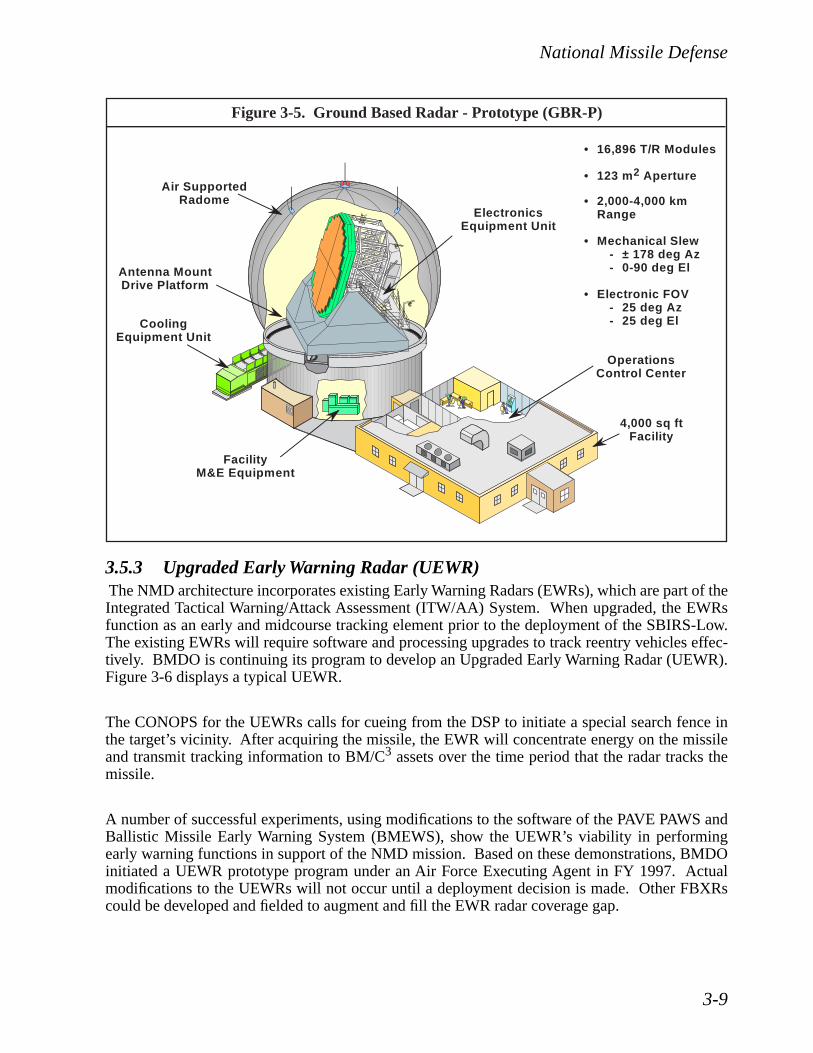
National Missile Defense
3-9
3.5.3 Upgraded Early Warning Radar (UEWR)
The NMD architecture incorporates existing Early Warning Radars (EWRs), which are part of theIntegrated Tactical Warning/Attack Assessment (ITW/AA) System. When upgraded, the EWRsfunction as an early and midcourse tracking element prior to the deployment of the SBIRS-Low.The existing EWRs will require software and processing upgrades to track reentry vehicles effec-tively. BMDO is continuing its program to develop an Upgraded Early Warning Radar (UEWR).Figure 3-6 displays a typical UEWR.
The CONOPS for the UEWRs calls for cueing from the DSP to initiate a special search fence inthe target’s vicinity. After acquiring the missile, the EWR will concentrate energy on the missileand transmit tracking information to BM/C
3
assets over the time period that the radar tracks themissile.
A number of successful experiments, using modifications to the software of the PAVE PAWS andBallistic Missile Early Warning System (BMEWS), show the UEWR’s viability in performingearly warning functions in support of the NMD mission. Based on these demonstrations, BMDOinitiated a UEWR prototype program under an Air Force Executing Agent in FY 1997. Actualmodifications to the UEWRs will not occur until a deployment decision is made. Other FBXRscould be developed and fielded to augment and fill the EWR radar coverage gap.
Figure 3-5. Ground Based Radar - Prototype (GBR-P)
• 16,896 T/R Modules
• 123 m2 Aperture
• 2,000-4,000 km Range
• Mechanical Slew- ± 178 deg Az- 0-90 deg El
• Electronic FOV- 25 deg Az- 25 deg El
4,000 sq ftFacility
CoolingEquipment Unit
AA
ElectronicsEquipment Unit
FacilityM&E Equipment
Air SupportedRadome
OperationsControl Center
Antenna MountDrive Platform
A
AA

National Missile Defense
3-10
3.5.4 Battle Management/Command, Control, and Communication (BM/C
3
)
The NMD BM/C
3
element supports USSPACECOM and the North American Aerospace DefenseCommand (NORAD) Command and Control (C
2
) of the NMD system with integrated C
2
deci-sion support systems and automated engagement planning capabilities. The BM/C
3
elementinterfaces with existing C
2
systems and the NMD elements by a survivable communications sub-system comprised of line-of-sight radio frequency, Military Satellite Communications (MILSAT-COM), landline/fiber-optic communications network, and the In-Flight Interceptor Communica-tions System (IFICS). Figure 3-7 refers to the integrated BM/C
3
network for NMD. The BM/C
3
element functionally integrates the NMD system by supporting inter-element communications,processing sensor and intelligence data to create BM/C
3
knowledge bases that are used to supportbattle planning, C
2
decision making and sensor, interceptor and communications tasking balancedto best support command and human-in-control direction. The BM/C
3
element supports NMDBM/C
3
operations in peacetime and in all phases of conflict.
Additionally, an IFICS prototype is planned for development. The IFICS supports the transmis-sion of BM/C
3
IFTU and Target Object Map (TOM) messages to the in-flight EKV that arerequired to refine targeting information and intercept the intended target. This effort will makeuse of available government communications systems to leverage an NMD IFICS prototypedevelopment.
• EWR (Other Existing Sensors)
- Develop And Demonstrate Upgrades To EWR And Other Existing Sensors In Support Of NMD
- Testing Of Prototype UEWR Software
- Develop UEWR Simulation In Support Of Integrated Ground Tests (IGTs)
Figure 3-6. Upgraded Early Warning Radar

National Missile Defense
3-11
The CONOPS for the BM/C
3
element calls for functionally redundant BM/C
3
personnel andequipment suites located near both the USSPACECOM/NORAD Cheyenne Mountain Center andthe NMD intercept site. The BM/C
3
element design concept supports flexible operational config-urations needed for USSPACECOM/NORAD NMD CONOPS dynamics as well as operationalsurvivability in the event either site is degraded or unavailable.
The BM/C
3
project has successfully developed the initial BM/C
3
Capability Increment One (CI-1) and associated BM/C
3
Test Exerciser (TEx) capabilities, initiated User Assessment processes,and initiated design and development of BM/C
3
Capability Increment Two (CI-2). BM/C
3
CI-1has been integrated into the Integrated Flight Test One (IFT-1) environment with BM/C
3
equip-ment suites at both the Kwajalein Missile Range (KMR) and the BM/C
3
Element Support Centerat the Joint National Test Facility (JNTF) at Falcon AFB, Colorado, supported by a secure highdata rate communications link. The test configuration will address the BM/C
3
element interfaceswith the system test environments, the GBI test article, and will test BM/C
3
CI-1 functionality.BM/C
3
CI-1 will participate in IFT-1 and IFT-2 as well as Integrated System Test Capability(ISTC) Integration Test 1 and 2. BM/C
3
CI-2 will be integrated into this system’s test environ-ment to participate in IFT-3 and IFT-4 and Integrated Ground Test One-A (IGT-1A). CI-3 and CI-4 support test participation of increasingly complete BM/C
3
functionality required for an initialNMD deployment operational capability. Further the BM/C
3
project will continue the successfulseries of BM/C
3
demonstrations utilizing EWR systems to validate BM/C
3
capabilities to coordi-nate tasking of multiple sensor sources, cue sensors, and fuze track data for NMD purposes.
Figure 3-7. Integrated BM/C3
CommOfficer
Sensor And
WarningBattle
AnalystWeapons
OfficerEngagement
PlanningAAAA
PAVE PAWS
PAVE PAWS
PAVE PAWS
PAVE PAWS
DSP BMEWS
CommOfficer
Sensor And
WarningBattle
AnalystWeapons
OfficerEngagement
PlanningAAAA
Unique BM/C3
Components
Common BM/C3 Components
CINC BM/C3
AA
Site BM/C3
EOC
BMDComm
Integrated BM/C3
SMTS
CommonC2
CINCSpecific
SiteSpecific
TestExerciser
CommEP
• Dev Env- Software- Hardware
• Infrastructure Run Time- Software- Hardware

National Missile Defense
3-12
3.5.5 Space Based Infrared System (SBIRS)
The SBIRS Program, a necessary element in the objective NMD system, is an Air Force acquisi-tion effort to field a consolidated space-based nonimaging infrared surveillance system that meetsUnited States needs for missile warning, missile defense, technical intelligence, and battlespacecharacterization for the next two to three decades.
The SBIRS Program includes both high- and low-altitude components. The SBIRS-High compo-nent consists of four satellites in Geosynchronous Earth Orbit (GEO) and two infrared sensors onsatellites in Highly Elliptical Orbit (HEO). The SBIRS-Low component, formerly known asSpace and Missile Tracking System (SMTS), with satellites operating in Low Earth Orbit (LEO),complements SBIRS-High by providing a unique precision midcourse tracking capability to meetobjective system performance in ballistic missile defense (both national and theater). A commonground-based processing capability will replace the DSP processing stations as well as Attack andLaunch Early Reporting to Theater (ALERT) and will be the primary location for SBIRS missionprocessing, mission management, mission planning, and satellite and sensor control.
SBIRS-Low will be composed of multiple rings of small, lightweight spacecraft in low-altitude,inclined orbits. SBIRS-Low will have acquisition and track sensors onboard to detect, track, anddiscriminate missiles in the boost, post-boost, and midcourse phases. The acquisition sensor usesa wide field of view, and a short wavelength infrared scanning sensor to detect bright rocketplumes. As the boosters burn out, the narrow field of view staring tracking sensors take over,using medium and long wavelength infrared and visible detectors to provide precision trackingand discrimination.
The SBIRS-Low component demonstration phase consists of two satellite efforts. The first is theFlight Demonstration System (FDS) to design, build, and fly two satellites which will demonstratecritical system capabilities in a real world environment. The second effort is the Low AltitudeDemonstration System (LADS), which demonstrates critical sensor functions aboard a single sat-ellite and maintains viable competition during the pre-EMD phase of acquisition leading to awardof a single SBIRS-Low EMD contract.
The Office of the Secretary of Defense (OSD) recently directed that funding be provided for aSBIRS-Low initial launch in FY 2004, accelerating the program two years. The program is cur-rently in the PD/RR phase of acquisition. Two contractor teams are currently competing with sep-arate programs. TRW/Hughes is under contract to develop, fabricate, and fly two FDS satellites tobe launched in FY 1999 to demonstrate operations and performance and to validate the design andcosts of the SBIRS-Low concept. In September 1996, Rockwell was awarded a contract to pro-vide risk reduction activities for SBIRS-Low. Rockwell will develop an alternative SBIRS-Lowconcept, LADS, which includes a flight experiment to be launched in FY 1999 and ground dem-onstrations to address additional operational aspects of SBIRS-Low.
Figure 3-8 provides a description of the SBIRS-Low component and a picture of the Flight Dem-onstration System (FDS) satellite.

National Missile Defense
3-13
3.6 NMD Test Program
The NMD Test and Evaluation (T&E) program will be conducted in accordance with the NMD
Test and Evaluation Master Plan (TEMP)
. The NMD TEMP will establish the framework for acomprehensive NMD T&E program. The TEMP will capture a dynamic T&E process thataccommodates an evolving architecture, supports the threat-driven acquisition strategy, baselinesT&E resources, and is consistent with maturing program documentation.
In coordination with the developmental and operational test communities and the NMD programmanager, the System Test director will ensure the effective determination of achieved system per-formance via testing. The NMD test program encompasses a continuum of simulations, IGTs,IFTs, and ISTs to assess the capability of the NMD system to perform the national BMD missionspecified in the Joint ORD. An aggressive simulation program including complex Hardware-in-the-Loop (HWIL) and Software-in-the-Loop (SWIL) simulations will be used to make effectiveuse of limited flight testing opportunities.
The NMD Deployment Readiness T&E program will demonstrate the incremental capability andinteroperability of BM/C
3
systems, GBI, GBR, UEWR, forward-deployed X-Band radar, andspace-based sensor elements of NMD. An evolutionary program of ground and flight tests willculminate with a fully integrated test of these systems in conjunction with IFT-5 in FY 1999. Thistest will demonstrate system performance effectiveness against a representative threat before asystem deployment decision is needed. The T&E Program Integrated Product Team (IPT) estab-lished FY 1999 Test Program Objectives in the NMD TEMP. Numerous IGTs and a total of five
Figure 3-8. SBIRS Satellite
• Short Wave Infrared• Medium Wave Infrared• Medium-long Wave Infrared• Long Wave Infrared• Visible
Spacecraft Description
• Distributed Constellation In Multiple Rings
• Low Altitude, Inclined Orbits
• Small, Lightweight Spacecraft ( 600 kg)
• Wide Field Of View Acquisition Sensor- Horizon-To-Horizon Surveillance To
Acquire And Track Boosters
• Narrow Field Of View Track Sensor- Above And Below-The-Horizon Tracking
Of Boosters And Warheads
• Provides Passive Sensor Technology For Contingency Architectural Options
• Short Wave Infrared
StaringTrack Sensor
ScanningAcquisition Sensor
~~
Essential For Optimum Coverage

National Missile Defense
3-14
IFTs will be conducted prior to the 2000 deployment decision review. Combined DevelopmentTesting and Operational Testing (DT/OT) will also be conducted during the initial developmentphase as a means to support an early deployment decision if necessary.
The NMD ISTC Hardware- and Software-in-the-Loop (HWIL/SWIL) System Test IntegrationLaboratory will be used to evaluate the system interfaces prior to this flight test. The NMD T&Eprogram is based upon an incremental evaluation of the critical technical parameters of the systemas prescribed to the test program in a set of operational requirements from the system engineeringprocess. These critical technical parameters are Engagement Response Time, System TrackingPerformance, System Discrimination Performance, System Engagement Performance, MultipleEngagement Performance, and System Kill Assessment Performance. Key features of the testprogram designed to evaluate these parameters and reduce acquisition risk include:
• Demonstrate integrated system capability and interoperability before the 2000 Deploy-ment Decision;
• Accelerate development of the NMD Capability Test Tool for extensive and repeatableevaluation of element interfaces and system capability;
• Judicious use of flight tests to anchor models and simulations and NMD IntegratedSystem Test Capability Tool;
• Leverage individual element test and simulation opportunities to collect data and eval-uate system issues;
• Maintain focus on system-level functional tests while demonstrating time phasedcapabilities; and
• Reduce cost and delays through exploitation of Targets of Opportunity, demonstra-tions, and system simulations.
Given the prohibitive costs of conducting a statistically representative set of NMD flight tests, thedevelopment and use of the NMD ISTC allows achievement of statistical confidence in the readi-ness assessment of an NMD system to be deployed. The shift in focus to the NMD DeploymentReadiness Program allows the individual element data processors and software to be availablesooner, integrated into the NMD ISTC, and evaluated prior to the FY 1999 IST. This allows earlyidentification of system interface design issues and risk associated with live flight testing. FY1999 Test Program Objectives include demonstration of:
• End-to-end integrated system performance;
• End-to-end target detection, acquisition, tracking, correlation, and handover perfor-mance;
• Real-time discrimination performance;
• NMD system kill assessment capability;
• The ability of the NMD system to develop and coordinate battle engagement plans;prepare, launch, and fly out a designated weapon; and kill a threat representative tar-get;

National Missile Defense
3-15
• Integration, interface compatibility, and performance of the NMD system, subsystemhardware and software, and human-in-control operations.
Modeling and Simulation (M&S) are used in the NMD Deployment Readiness Program to reducethe time, resources, and risks of this highly accelerated development process. Simulations andmodels are used extensively in the T&E program to represent complex environments and over-come the limitations of actual live testing. Areas of particular application include support to testplanning, test design, test execution, and data analysis and reporting. Systems engineering andintegration organizations employ M&S for system requirements trade-offs, balancing, and perfor-mance assessments against a wide range of threat scenarios.
3.7 Deployment Readiness
NMD Deployment Readiness Program efforts are being developed based on the requirement thatan effective, suitable, and sustainable system can be deployed within three years following adeployment decision. The NMD deployment readiness process comprises a series of complimen-tary functional tasks including Deployment Planning, Deployment Schedule, Logistics, FacilitiesSiting and Environmental, Suitability Assessment, and Producibility and Manufacturing, asdepicted in Figure 3-9 and described below.
3.7.1 Deployment Planning
The shift in the NMD Program from technology readiness to deployment readiness has driven an
Figure 3-9. NMD Deployment Readiness Activities
DeploymentReadiness
DeploymentPlanning
DeploymentSchedule
LogisiticsFacilities Siting
And Environmental
SuitabilityAssessment
ProducibilityAnd
Manufacturing
• LCC Inputs• Basing Analysis• Deployment Plan• Support Concepts• Manpower Estimate• Readiness
Assessment• System Training
Concept• Human Systems
Integration
• Schedule Modules• Critical Path
Analysis• Deployment
Schedules
• Training• P, H, S, And T• Software Support• User Requirements• Maintenance
Planning• Spares / Support
Equipment• Contractor
Logisitics Support
• Siting Support• Site Activation Plan• Infrastructure
Design• Environmental
Analysis• Real Property
Acquisition
• R&M• Safety• Human Factors• Early Fielding
Analysis
• Metrology• P&M IPT Charter• P&M Risk
Mitgation• Industrial Base
Assessment

National Missile Defense
3-16
acceleration toward more intensive and integrated planning studies to achieve a more efficientdeployment capability at lowest cost and risk. Integrated deployment planning is keyed to theprogress of technical developments, the results of the FY 1999 IST demonstration, and the antic-ipated threat. The NMD Integrated Deployment Plan (IDP) provides the capability for deploy-ment of an initial capability in three years following the deployment decision. A DeploymentReadiness IPT will develop the NMD IDP, which is a comprehensive and evolving documentwhich provides “system focus” to deployment, integrates system elements, and maintains deploy-ment planning status.
3.7.2 Deployment Schedule
BMDO will continue to conduct critical path analysis of the development and deployment sched-ules to identify time reduction opportunities, resource requirements, and risk areas.
3.7.3 Logistics
Logistics support is a series of activities that will be developed and procured in compliance withthe BMDO-approved system support concept. The NMD Program will plan for and encouragethe use of standard support and test equipment.
3.7.4 Facilities Siting and Environmental
BMDO is conducting facility, site, and National Environmental Protection Act (NEPA) workbased on the North Dakota Area Siting Study for an ABM Treaty-compliant NMD system and hasundertaken many studies to determine the potential consequences to the environment of its pro-grams. BMDO is planning to complete an environmental analysis of nine alternative sites in FY1999. At the same time, as required by NEPA, BMDO is using the DoD’s Environmental ImpactAnalysis Process (EIAP) to integrate environmental considerations into its decision making and toestablish the required timing and scope of environmental impact analysis documentation in sup-port of program decisions.
Preliminary site activation planning is in process for a “prototype site,” a combination of GrandForks AFB, Stanley R. Mickelsen SAFEGUARD Complex (SRMSC), and Minot AFB, to preparefor the Deployment Decision Review. Early planning for site activation at such a site will allowthe development of critical planning data and will greatly reduce deployment risk to an actualdeployment site. Other site activation tasks include writing and executing a site activation plan,providing site facilities and infrastructure, installing and testing, and transition planning.
3.7.5 Suitability Assessment
The NMD Program will implement a comprehensive approach to ensure that human performanceand resource considerations are appropriately and adequately addressed through the identificationof risk areas and mitigation actions that conform to OSD policies and guidance.
In addition, BMDO will also incorporate a structured Reliability and Maintenance program builtaround the NMD systems engineering approach which eliminates specifying availability at thesystem level, relying rather on specifying system effectiveness. Operational availability will beaddressed at the subsystem element level, in response to potential Joint ORD requirements desig-nated at the element level.

National Missile Defense
3-17
3.7.6 Producibility and Manufacturing (P&M)
In early 1996, the updated BMDO P&M Strategy was issued, emphasizing innovative ap-proaches, vision, strategies, tools, and risk reduction processes for P&M issues. A key element inthis process is the P&M Program Integrated Product Team (P&M PIPT), established to addressand resolve risks associated with transitioning BMD systems from development to production.
3.8 System Engineering and Integration (SE&I)
CRD performance and operational parameters for NMD are translated into system developmentparameters and allocated to system elements through the BMDO system engineering process (seeFigure 3-10). Requirements are provided to the NMD development community in the NMDSRD. Further requirements definitions are provided for the elements of the NMD system in theElement Requirements Documents (ERDs). The NMD SE&I Program consists of activities neces-sary to establish the readiness to acquire an NMD system capability consistent with the SRD andERDs.
NMD system engineering efforts will result in the definition of system/element test requirementsfor NMD flight testing scheduled to begin in FY 1997 with EKV seeker flight tests. As elementand system tests are conducted, results will be evaluated against test predictions, system and ele-ment requirements. Where necessary, results will be used to adjust and modify element designs torebalance the NMD system. Refining system-level derived requirements based on demonstratedtests will validate system element integration while ensuring interoperability and compatibilitybetween NMD elements.
BMDO will execute an SE&I process with four principle objectives. One, SE&I will completethe necessary development and integration of an NMD Capability 1 “3+3” system to be ready fordemonstration in FY 1999 based on the threshold requirements in the Joint ORD. Two, SE&I willestablish the objectives and validate the results of the FY 1999 IST. Three, the SE&I process willproduce incremental upgrades of the Capability 1 system on a path toward the Capability 2 sys-tem, consistent with the objective requirements in the Joint ORD. Finally, the SE&I process willenable fielding of the NMD system and subsequent upgrades.
Given the uncertain nature of the ballistic missile threat, the SE&I requirements strategy isdesigned to accommodate both the threshold and objective requirements by setting sights on thehorizon and defining NMD system requirements for Capability 2 while going back and definingCapability 1 requirements which evolve directly to Capability 2, subject to element availability.This strategy rests on three strengths. One, it will provide for the efficient execution of NMDstrategy. Two, it will permit requirements traceability to suit user needs. Three, this SE&Irequirements strategy will meet user requirements for a rapidly deployable Capability 1 whileproviding for an efficient evolution from Capability 1 to Capability 2.

National Missile Defense
3-18
Figure 3-10. System Engineering And Integration In NMD
WhatWho UserHow
BMDOSystem
Element
Component
Unit
System
Element
Component
(Systems Engineers)
(Element Designers)
(ElementConfiguration
Managers)
(Testers)
Spec Tree I&
T P
lans
Standards
Mission
Operations(User)
(User)
Define Decompose
Build
Evaluate Aggregate
Program Offices
Tech Needs
Technology
(Systems Engineering And
Integration)
(Integrator)
A Disciplined Approach To Design, Development And Integration Of An Operationally Effective System

Chapter 4
Supporting Technology DevelopmentStrategy And Programs

Supporting Technology Development Strategy And Programs
4-1
Chapter 4
Supporting Technology Development Strategy And Programs
4.1 Technology Investment Strategy
The Ballistic Missile Defense (BMD) technology investment strategy for sustainable developmentis to acquire systems that meet today's requirements and, at the same time, to anticipate potentialfuture BMD requirements and the technology needs of tomorrow. Accordingly, these BMDefforts concentrate on affordable, high payoff technologies, including those available throughcooperative programs with our allies, that can:
• Enable and assure the continuing vitality and potential National Missile Defense(NMD) and Theater Missile Defense (TMD) improved performance;
• Demonstrate the technology base to defend against advanced threats such as maneu-vering targets, straightforward countermeasures, advanced submunitions, and Weap-ons of Mass Destruction (WMD); and
• Offer alternate system approaches (architectural flexibility) that can provide majorincreases in TMD and NMD capability against the current and evolving threat.
In essence, BMDO is developing the technology essential to meet the BMD mission in futureyears. In accordance with Congressional direction, BMDO maintains the follow-on support tech-nology programs for BMD. Advanced technology efforts that either directly support future TMDand NMD system developments, or hold significant promise for advanced BMD systems, remainunder the management responsibility of BMDO.
4.2 Technology Needs
To maintain the viability of a BMD architecture over time, technologies being developed mustprovide options for improvements to deployed systems or replace those systems with new capabil-ities to respond to a range of needs. Among the most important of these needs are capabilities to:
• Meet straightforward countermeasures such as decoys or electronic countermeasures;
• Cope with threat evolution such as advanced submunitions that improve the effective-ness of the attacking missile, longer range missiles that enlarge the areas that can beattacked, and maneuvering and less observable targets;
• Cope with threat evolution that presents the United States with rapidly developing cri-sis situations where there is insufficient time to deploy short- and mid-range systems toa theater of operation, or with situations where there is no friendly territory or interna-tional waters suitable for deploying such systems; and
• Handle proliferation of ballistic missiles and an increasing number of countries pos-sessing the technology for WMD. This proliferation demands greatly expanded battle
Supporting Technology Development Strategy And Programs
4-2
space, increases the potential for surprise, and leads to the need for rapid deploymentof TMD to counter rapid escalation of a conflict, or for continuous global Boost PhaseIntercept (BPI) coverage.
To prepare to meet these future needs, BMDO is investing in the high leverage technologies thatcan provide:
• The capability to intercept ballistic missiles in their boost phase of flight. Space BasedLaser (SBL) technology could address all of these needs, as well as reduce the burdenon midcourse and terminal-tier defenses. This is also the only advanced technologythat could provide a continuous, global BPI defense;
• Highly effective and affordable concepts for executing boost phase intercepts of ballis-tic missiles using kinetic energy interceptors launched from high-altitude, long-endur-ance Unmanned Aerial Vehicles (UAVs);
• Exoatmospheric and endoatmospheric intercept capability with high probability of killat reduced technical risk and program cost to expand battlespace, increase defendedarea coverage, and provide quick response solutions to theater defense;
• Multisensor detection and tracking that extends through the missile flight path to pro-vide the earliest possible alert, and midcourse tracking; and
• Algorithm development for the identification, discrimination, aim point selection, andkill assessment to support early assured targeting and tracking within the battlespaceenvironment, thereby achieving effective battle management.
Figure 4-1 diagrams the future threat in terms of capabilities needed and potential technologysolutions. Arrows point from each critical technology solution to the mission needs which thatsolution addresses.
4.3 Program Overview
The current advanced technology development program is structured in four major segments:UAV-based Kinetic Energy Boost Phase Intercept, Directed Energy Boost Phase Intercept,Advanced Sensor Technology, and Advanced Interceptor Materials and Systems Technology. Fig-ure 4-2 provides the current schedule for each segment.
Early BPI of ballistic missiles reduces the number of ballistic missiles reaching their terminalphase of flight. Early BPI can cause missile debris to fall on enemy territory and any BPI willcause the missile to fall short of the intended targets. BPI could serve as a powerful deterrentagainst further development, proliferation, or actual use of chemical, biological, or nuclear war-heads. The importance of BPI capability increases significantly as the range of the ballistic mis-sile threat increases and the types of warheads proliferate. Intercept of a missile in its boost phasenear the point of launch enables larger defended areas and simplifies the identification and dis-crimination problems associated with advanced submunitions, and threat penetration aids. Themajor objective of BPI programs is to demonstrate the required technologies in the relevant oper-ational environment in order to establish system utility.

Supporting Technology Development Strategy And Programs
4-3
Continuous, global BPI coverage is essential for rapidly developing situations where there isinsufficient time to deploy a short-range system to the theater or where geography and/or thepolitical environment does not provide suitable territory or international waters for such a deploy-ment.
4.3.1 Unmanned Aerial Vehicle (UAV)-based Boost Phase Intercept (BPI)
The UAV-based BPI program covers two efforts: Task 1 - Boost Phase Intercept System Risk Mit-igation, and Task 2 - Cooperative UAV-based BPI Concepts. Both tasks are based on the IsraeliBoost Phase Intercept System (IBIS) concept and support a cooperative U.S./Israeli risk mitiga-tion initiative. Task 1 will refine (risk mitigate) the IBIS concept of unmanned aerial vehiclesarmed with kinetic energy interceptors to provide the means of destroying thrusting Theater Bal-listic Missiles (TBMs) in their boost phase of flight. Task 2 will leverage off previous and ongo-ing U.S. investments in Infrared Sensors to develop an Infrared Search and Track (IRST)capability able to be deployed on a UAV BPI system. System components to be mitigated includekinetic energy interceptors, UAVs, search and track sensors, and Battle Management/Command,Control, Communications, Computers, and Intelligence (BM/C
4
I). In addition, the Concept OfOperations (CONOPS) will be refined.
The program will develop and demonstrate critical technology elements to support UAV-basedBPI concepts. The program will leverage existing contracts and technologies. Piece part demon-strations will validate critical technologies such as moderate velocity lightweight air-launchedinterceptors, a missile seeker head, and will provide (1) new component and system capabilitieswith reduced costs and risks compared to current weapon systems; (2) reduction of costs and risks
Future Capabilities Needed
• Directed Energy Boost Phase
Intercept
AAAAAAAAAAAAAAAAAAAA
Component TechnologyImprovement
Advanced Concepts
AAAAAAAAAA
AAAAA
AAAAAAAA
A
AAAAAAAAAAAAAAAAAAAAA
AAAAAAAA
AA
• AdvancedSensors
Technology
AAAAAAAAAAAAAAAAAAAAAAAAA
• Advanced Interceptor
Materials And Systems
Technology
Counter Advanced Submunitions
Counter Surprise / Rapid Escalation
Negate Enemy Countermeasures
Enlarge Defended Areas
Expand Battle Space
Address Multiple Target Complexes
Figure 4-1. Technology Needs
• UAV-basedKinetic EnergyBoost Phase
Intercept
AAAAAAAAAA
A
AAAAAAAAAAAAAA
A

Supporting Technology Development Strategy And Programs
4-4
to support an acquisition program; and (3) technical solutions for contingent residual BPI capabil-ities for theater defense.
4.3.2 Directed Energy Boost Phase Intercept
The Directed Energy Boost Phase Intercept Program consists of the Space Based Laser (SBL)Program and the Acquisition, Tracking, Pointing and Fire Control (ATP/FC) program. Thesehigh-power chemical laser components and technologies were developed over the past 15 yearsspecifically for the boost phase intercept mission. These two programs were restructured in FY1996 to reflect Congressional and DoD guidance, which provided $45M of additional funding, aswell as an additional $70M in FY 1997.
The major building blocks have been developed, but system integration and test lie ahead. Theremaining tasks are to integrate the high-power laser with the large optics beam director and testin a ground demonstration Alpha/LAMP Integration (ALI); to integrate and test ATP/FC hardwareand software onboard High Altitude Balloon Experiment (HABE); to integrate laser, beam con-trol, and beam director hardware with ATP/FC hardware and test; and to integrate the hardware ina space-qualified SBL Readiness Demonstrator (SBLRD) vehicle for ground and flight testing.
IndividualPassive /
Active SensorDemo
UAV-based Kinetic EnergyBoost Phase
Intercept
Directed Energy
Boost PhaseIntercept
Advanced Sensor
Technology
FY 95 FY 96 FY 97 FY 98 FY 99 FY 00Technology
AdvancedInterceptor
Materials And System
Technology
IBIS Follow-on U.S. / Israeli Risk
MitigationComplete
Fab AndDeliveryOf ALI
Hardware
ALI SubsystemIntegration
Tests
ALI LowPower Tests
Multi-quantum
Well SensorDemo
Two-colorMultiquantumWell Sensor
Demo
On-focalPlane
ProcessingDemo
IntegratedGround
Active SensorDemos
IntegratedFlight Passive
/ Active SensorDemos
Step-3 Launch
ACTEX-1 Launch
SuperconductorLWIR ADC Demo
LADAR Demo Folded CO2
STRV-2 Experiment Launch
SuperconductorLWIR ADC Demo
EFEX1 Launch
Advanced Ground Power Demo
EFEX2Launch
Figure 4-2. Advanced Technology Schedule
Flight Demo CoDR
ATP ScaledRocket Ground Tests ATP WSMR
Ground Tests
Fabrication Of Uncooled Resonator Annular Optics
U.S. / Israeli Risk
MitigationContract
AIT Seeker Test
AIT Jet InteractionWind Tunnel Test
ALI High-power Tests
Solid-stateLADAR Demo
HABEFlight Test

Supporting Technology Development Strategy And Programs
4-5
In FY 1996 Congress provided additional program funding to continue ALI, accelerate designactivities for a space demonstration, produce a CONOPS, design requirements for an operationalSBL system, and revitalize the SBL technology development efforts. The $45M Congressionaladdition was released in April 1996, obligated within 60 days and fully expended by December1996, allowing BMDO to preserve vital infrastructure, restore the ALI program to its originalscope, and continue the ATP/FC program.
The current plans bring Alpha back to test readiness and, with Congress-added funding, com-pletes ALI high-power tests in FY 1997. The Alpha device and facility have been reactivated andthe test team reconstituted.
The ATP/FC program completed fabrication and test of the illuminator laser that will be used inthe field experiments. Integration into the HABE platform was completed and testing begun.With the FY 1997 Congressional increase, integrated ground testing will be completed in earlyFY 1998, and the first flight test will occur in FY 1999.
4.3.3 Advanced Sensor Technology
This program is an evolutionary effort to improve tracking of ballistic missiles by improving sur-veillance sensors, and advancing signal processing techniques for efficient and definitive identifi-cation and discrimination. Development efforts emphasize compact, adaptable, efficient passiveFocal Plane Arrays (FPA) and precision active optical ranger/illuminators. Integrated detection/signal processing demonstrations are scheduled for FY 1997.
Thereafter, the program develops the next generation of BMD sensing technology. Resources willalso be used to develop data fusion and discrimination. Intermediate milestones address a build-ing block approach of the system hardware and algorithm development. Ground testing of theseintegrated technologies will begin in FY 1998. The ultimate objective will be achieved in a FY2001 flight, using available aircraft platforms, that will demonstrate fusion of surveillance sensordata from radar, Laser Detection And Ranging (LADAR), and Long Wavelength Infrared (LWIR)sensors with onboard signal processing, tracking, and discrimination algorithms. The Proof-Of-Principle (POP) detection, tracking, and discrimination demonstrations are planned to validate thematurity of technology prior to infusion into any acquisition program.
An effort related to the sensor program involves understanding the phenomenology associatedwith target signatures against different backgrounds. BMDO continues this critical technologyprogram and has conducted a number of activities with our allies aimed at extending phenomenol-ogy databases through acquisition and exchange.
The Midcourse Space Experiment (MSX) satellite is BMDO’s only on-orbit platform that couplesa Low Wavelength Infrared/Very Low Wavelength Infrared (LWIR/VLWIR) sensor with state-of-the-art visible and ultraviolet sensors. It will provide high-fidelity optical data on target signaturesand long duration global and seasonable background clutter data. Information from this programwill mitigate design risk, enable optimal system design, and minimize life cycle cost of future sys-tems (e.g., Space Based Infrared System (SBIRS)).

Supporting Technology Development Strategy And Programs
4-6
4.3.4 Advanced Interceptor Materials and System Technology(AIMST) Program
The AIMST program is based on the fundamental premise that technology investment is not anoption but rather a requirement for achieving the BMDO mission. The focus of the program istherefore on providing technologies for BMDO elements which reduce technical risk, enhancecapabilities, and increase affordability. Technology insertion is accomplished through extensiveground, airborne, and space demonstrations. Five major categories are addressed:
1. Technology which will ensure high signal/noise images for interceptor and surveillance opticalsensors; active and passive vibration control and use of noncontaminating optical baffles and lownoise superconducting signal processing electronics.
2. Development of lightweight, high stiffness, advanced composite structures and componentswhich utilize low-cost, single-step fabrication methodologies to provide cost-effective weightgrowth mitigation for all BMDO system elements.
3. Provide essential data to BMDO systems which enable design of effective sensor, surveillanceand interceptor systems. This includes data on performance of critical microelectronic compo-nents in the space radiation environment; Medium Wavelength Infrared (MWIR) background/clutter data at high latitudes as a function of altitude and seasonal variation; micrometeorite anddebris fluence at mission altitudes, response of key materials and coatings to the space environ-ment, and basic engineering data on structural response and sensor window performance duringultrahigh-speed (>3 km/sec at 60 km altitude) endoatmospheric flight. BMDO tests on advancedmaterials for use in Infrared (IR) windows has included samples from several allied nationsincluding the United Kingdom (U.K.) and Japan.
4. Development of interceptor components necessary to achieve long-range threat detection, accu-rate homing guidance, and aim point selection for hit-to-kill interceptors. This includes high-sen-sitivity, uniform passive infrared LWIR seekers, Laser Radar (LADAR), and data fusionprocessing technologies. Emphasis is placed on increasing output power, miniaturization, andwaveform generation to support onboard imaging. The ultimate objective will be achieved ininterceptor flight tests in FY 2002 that will demonstrate onboard fusion of active and passive datato detect, track, and discriminate. The POP demonstrations are planned to validate the maturity ofthe technology and to demonstrate the reduced dependence of interceptors on external sensors toperform hit-to-kill, prior to infusion into any acquisition program.
5. The Atmospheric Interceptor Technology (AIT) portion of the program will develop, integrateand demonstrate the kinetic kill vehicle technologies for performing hypervelocity hit-to-killintercepts of TBMs within the atmosphere. The demonstrations will validate the solutions to crit-ical kinetic kill vehicle technologies and will provide: (1) new capabilities with reduced costs andrisks compared to current interceptor weapons systems, and enhancements to other interceptorsunder development; (2) reduction of technical risks and costs in support acquisition programsthrough direct technology insertions; and (3) technical solutions to provide theater defense inter-ceptor capabilities for contingencies not currently addressed by the TMD system programs.

Supporting Technology Development Strategy And Programs
4-7
The program uses existing contracts and technologies currently under development to reduceschedule and cost, and will be planned and conducted with BMDO, Air Force, Navy, and Armyelements to make maximum use of existing Service infrastructures. The AIT project will partici-pate in the UAV/BPI Studies and the Navy Theater Wide requirements studies. As a result of a$40M plus-up in the appropriated funding level, AIT will conduct the following work in FY1997:
• Complete prototype seeker development and conduct initial hardware-in-the-loop test;
• Conduct cooled window and forebody aero-optic shock tunnel tests;
• Conduct cold-gas jet interaction wind tunnel tests;
• Complete preliminary software specifications;
• Conduct System Requirements Review (SRR);
• Conduct preliminary of solid Divert and Attitude Control System (DACS) and deliverDACS Ground Test Unit;
• Complete integrated avionics unit final design;
• Fabricate and integrate vehicle structures;
• Conduct Preliminary Design Review (PDR) for flight test vehicle; and
• Conduct millimeter wave (RF) technology development.
The Atmospheric Interceptor Technology program has effectively leveraged the expertise andresources of other agencies and allied nations in collaborative multinational, multiagency pro-grams. This approach minimizes direct cost to BMDO and increases the effectiveness of technol-ogy development and demonstration efforts.
4.4 BMD Exploratory Science and Technology Program
The goal of the Exploratory Science and Technology Program is to identify, nurture, develop,demonstrate, and transition innovative ideas and approaches to BMD technology. The projectssponsored by the program are structured to exploit science and technology to improve perfor-mance, weight and volume, producibility, and affordability of future BMD systems. Many exam-ples of successful research, demonstration, and transition are already documented, while manynew ones are in the pipeline.
The Exploratory Science and Technology Program has two major thrusts: The Innovative Scienceand Technology (IS&T) contracted research program, and the Small Business InnovationResearch (SBIR) program. Unlike other BMDO projects that fund near-term technology and test-ing efforts, the IS&T program is an exploratory science and technology initiative that invests seedmoney in high-risk, potentially high pay-off technologies that could significantly change howBMDO develops future systems. Technologies include next generation sensors, power, informa-tion processing, optics, advanced materials, propulsion, and communication. A primary goal is toconduct proof-of-concept demonstrations that transition breakthrough technology to BMD devel-

Supporting Technology Development Strategy And Programs
4-8
opment programs. Planned and funded by BMDO, the bulk of the program is technically man-aged by Science and Technology Agents affiliated with defense and other government researchagencies, with the principal investigators often coming from academia as well as industry.
4.5 Technology Transfer and Dual Use
Much of the research pursued by BMDO has broad application to meeting overall DoD needs andpotential for civil and commercial applications. A second important objective is, therefore, toconduct a portion of the BMDO research efforts in a manner that enhances this technology trans-fer. For ten years, the Office of Technology Applications (OTA) within BMDO has focused onmoving BMD technology out of the DoD and other Federal Laboratories and into the commercialmarket place and other agencies. It has been a model program, working closely with government,universities, and industry. To date, the OTA program documented the following statistics from itscommercialization efforts: 45 new spin-off companies started, 234 new products on the market,551 patents granted, 221 patents pending, 54 new ventures (licensing agreements, strategic alli-ances, third party agreements, partnerships, etc.), and started 33 cooperative research and devel-opment agreements. Each of these emanates from a BMDO-sponsored technology. Table 4-1describes a sampling of BMDO research technologies and their dual use potential.
Often an initial investment of BMDO research and development funding is greatly leveraged byfunding from other government or commercial sources. Activities of BMDO's SBIR are a case inpoint. Market capitalization, the high-tech small business community that the SBIR program sup-ports, is considered just one of the metrics that can be utilized to measure the success of the pro-gram overall.
4.6 Significant Accomplishments in 1996
Some technology accomplishments for 1996 are briefly highlighted. The accomplishments arerepresentative of BMDO's technology program and illustrate the broad spectrum of activitiesrequired to support TMD and NMD.
In the Solar Concentrator Array With Refractive Linear Element (SCARLET) program, the flightqualification for SCARLET I was completed. The next generation design, SCARLET II, was com-pleted and 100 engineering prototypes of the 24% efficient flight solar cell were delivered.
In the Laser Communications (Laser Com) program, a successful mountaintop-to-mountaintop testwas conducted, with a data rate of 1.2 Gbytes per second.
In the Russian Hall Effect Thruster Technology (RHETT) program, RHETT I was successfullyground demonstrated.
The MSX satellite was successfully launched from Vandenberg Air Force Base (AFB) on April 24,1996. Within days it began collecting IR, visible, and Ultraviolet (UV) data on celestial, earthlimb,and hard earth backgrounds. In addition to several cooperative target data collections, the firstMSX Dedicated Target (MDT-II) was successfully launched on August 31, 1996. MSX also suc-

Supporting Technology Development Strategy And Programs
4-9
Sensors• 150 Kelvin Cooler• Indium Antimonide Infrared Arrays
• Quantum Well Infrared Photodector (QWIP) FocalPlane Array (FPA)
• Staring Si Impurity Band Conduction ExtremelySensitive Focal Plane Arrays (FPAs)
• Low Power, Lightweight 65K Cryocooler
Civilian ApplicationsResearch AreaPotential For Military And
Table 4-1. BMDO Technology Dual Use PotentialImpact On BMD
Optoelectronic Devices• High-speed Photonic Networks
• Terabyte Optical Storage
Electronic Devices• Nonvolatile Semiconductor Random Access
Memory (RAM)• Low Temperature (10 degrees Kelvin) Digital
And Analog Superconducting Circuits
Computers• WASP 3-D Wafer Scale “Associative
String” Reconfigurable Processor• 3-D Analog Neural Network Processor 3-DANN
• VIGILANTE - Sensor / Processor
Materials• Wide Bandgap Semiconductors
• Multifunctional Structures
• Successful Flight Of STRV-1 U.S. / U.K.Microsatellites
Rocket Propulsion• Energetic Oxetane Thermoplastic Elastomers
• High-G Solid Divert And Altitude ControlPropulsion
• Flexseal Vectorable Nozzle
Miniature Interceptor Technology• Small, Accurate IMUs, Miniature Sensor Set
Testing, Miniature Propulsion
Power And Propulsion• RHETT Hall Electric Thruster
• Solar Array Technology That Includes Concentra-tors And Dual Bandgap Photovoltaic Materials
• Mirror And Baffle Cooling Of Spacecraft Sensor• Primary Sensor For Objective THAAD Missile
• Higher Operability, Lower 1/f Noise, Higher Radia-tion Hardness And Less Than 5% Of The Cost OfHgCdTe Based FPAs
• FPAs Sensitive In The 4-25 Micron Region, HighSensitivity For Extended Range Sensing
• Long-term Time On-orbit Of Space And Missile
• High Performance Computing And CommunicationsFor Test And Evaluation, Simulation AndBattle Management, Command Control AndCommunications (BM/C3)
• Archival Storage For Test Data
• Long Life Memory For Theater Operations
• Transceivers For Broadband Wireless Backbones ForTelecommunications, High-speed Switching ForCommand And Control Centers (e.g., MMIC)
• Graphics Engine For BM/C3 And Test And Evalua-tion Workstation
• Compact (1 cubic inch) Low Power (1W) Fast FrameSeeker
• Investigates Real-time Detecting Tracking AndDiscrimination
• High Capacity Jam-less Backbone For Sensor-to-Sensor Satellite Downlinks
• Wireless Communications Links For BM/C3 AndTest And Evaluation
• Address Ballistic Missile Submunition Threat
• Orbit Insertion, Faster Orbital Repositioning
• 40% Reduction In Mass, 60% Reduction In Cost,Resistant To Van Allen Radiation
• Cooling For Electronic And Computer Systems• Developed Into Infrared Detector For Civil,
Safety And Law Enforcement IR CameraSystem
• Airborne And Spaceborne Warning Systems,Earth Observation Satellites, Pollution Moni-toring
• Incorporation Into NASA’s Space InfraredTelescope Facility (SIRTF)
• Tactical Infrared Search And Tracking Sys-tems, Cryogenic Computers, NASA Remote
• National Information Infrastructure (NII)
• Large Public Databases, Digital Libraries,Medical, Commercial Video, And OtherArchival Storage Media
• Wireless Communications Smart Highways
• Multimedia Centers
• Visualization Engine For Multimedia
• Powerful Neural Network Processor For Real-time Image Processing And RoboticsComputation
• Teraflop Performance For TargetDiscrimination, Industry Feature Recognition
• All Communication From Space And BetweenSatellites
• International Teleconferencing
• Thin Screen Color Display, PermanentMemory At RAM Access Speeds, ReducedWeight And Volume For Ground Based RadarPower Supplies
• Satellite/Interceptor Systems
• DoD, NASA Applications For LowMechanical Noise Platforms
• Tri-Service Interest Building, Integral Part OfSeveral IR&D Programs
• Highly Maneuverable Missile Systems InsideOr Outside Atmosphere
• Thrust Vector Control For Commercial LaunchSystems
• Addresses Tactical Missile Threat, MiniatureIMUs Offer Low Cost Alternative To CivilianGPS Receiver
• Orbit Insertion, Station Keeping For Satellites,Cooperative Program With Navy
• Cooperative Program With NASA FlightDemonstration Tests Being AugmentedBy Communication Satellite Companies
Communications• Laser Communications (LaserCom) 1 Gbps Transceiver• Miniaturized EHF Transceiver
Capabilities
• Demonstrated True Blue Laser Diode, SiCNonvolatile Random Access MemoriesDesigned GaN Microwave Amplifier
• Integrates Power Distribution, Electronics, AndDamping With Structural Members To ReduceWeight And Volume
• Improved Sensor Performance Due To ReducedNoise
• Propellant Manufacturing Defects Corrected ByReheating And Recasting, Waste And ReclaimedPropellant Reused Without Penalty
• Navy Safe Propulsion For Hit-to-KillInterceptor Systems
• Reduces Cost, Enhances Interceptor Hit-to-KillPerformance

Supporting Technology Development Strategy And Programs
4-10
cessfully tracked and collected data on four aircraft missions and several Resident Space Objects(RSOs), including the space shuttle. Throughout 1996, the MSX program transferred lessons-learned and technology information to the SBIRS community.
In the Directed Energy program, a high-power reactivation test of the Alpha laser device was suc-cessfully completed in September 1996 after being placed in an inactive/maintenance-only modefor over two years.
In ALI, all major assemblies were fabricated, integrated, and tested in the test chamber. In Decem-ber 1996 an Alpha hot flow test was conducted while performing a low-power integration check-out of the ALI beam train. In compliance with Congressional language, design activities for thefollow-on space qualified vehicle ground demonstration were restarted, and the Cost Analysis Re-quirements Document (CARD) was updated with emphasis in the CONOPS, user design require-ments, satellite design, and launch vehicle design. Design reviews for the demonstrator spacevehicle and operational SBL system concepts occurred in December 1996. The SBLRD test facil-ity site selection process was restarted. The facility design, site selection, and preliminary environ-mental assessment for the Space Test Facility will be completed in FY 1997. Design activity forthe SBLRD is continuing.
The Russian cooperative technology programs have been progressing. In August 1996, the RussianGovernment agreed to continue the Russian-American Observation Satellite (RAMOS) program.The Russian Space Industrial Company, NPO
Cometa
, under the auspices of
Rosvoorzhenie
, theRussians Arms Import/Export Agency, agreed to a number of satellite stereo viewing observations.In addition, several innovative aircraft and space sensor projects will be explored with Russia. Inthe Active Geophysical Rocket Experiment (AGRE), beacons for the U.S. MSX satellite were in-tegrated onboard two Russian MR-12 sounding rockets, and were launched in January-February1997 out of the Kapustin Yar range. MSX will observe the launches and high-altitude plasma cloudgenerated by the Russian’s experimental payload.
In the AIT program, cooled window and forebody aero-optical shock tunnel tests were conducted,as well as forebody and airframe vibration tests and field joint validation.

Chapter 5
Program Funding

Program Funding
5-1
Chapter 5
Program Funding
5.1 Funding Summary
BMDO submitted the FY 1998 President’s Budget in accordance with the Congressional instruc-tions set forth in the FY 1997 National Defense Authorization Act. This report reflects severalchanges that occurred in FY 1997 and are proposed for FY 1998. First, NMD became a deploy-ment readiness program. Consequently, NMD deployment readiness projects were organized andfunded in the 2400 series. Second, the Department of Defense implemented several decisions thataffected BMDO funding, including adjustments to the THAAD, Navy Theater Wide, and SBIRSprograms. Another decision transferred BMDO procurement funding to the Services. Beginningin FY 1997, management support costs are allocated to specific BMD projects.
A composite funding perspective, combining all project funding, has also been provided as part ofthe budget justification materials. Figure 5-1 summarizes the total program funding by ProgramElement (PE). Figure 5-2 lists the current projects and provides a funding summary by project.Appendix B provides a narrative description of the activities planned, recent accomplishments,and funding plans for each project. The Congressional Descriptive Summaries (CDS) provided insupport of the FY 1998 President’s Budget request describe this information in greater detail.

Program Funding
5-2
PE 0603861C / 0604861CTHAAD System2260 THAAD RDT&E 482 622 619 556 595
MILCON 0 0 0 5 0Total 482 622 619 561 595
PE 0208863CHAWK2358 HAWK System BM/C
3
Proc 19 19 15 0 0Total 19 19 15 0 0
PE 02028865C / 0604865CPATRIOT Advanced Capability-3Missile2257 PATRIOT RDT&E 382 382 381 206 101
Proc 215 215 219 351* 372*Total 597 597 600 206 101
PE 0208867C / 0603867C / 0604867CNavy Area Missile Defense2263 Sea Based Area Defense
RDT&E 302 302 301 268 227Proc 9 9 9 15* 45*Total 311 311 310 268 227
PE 0603868CNavy Theater Wide Missile Defense1266 Sea Based Theater Wide
RDT&E 58 304 304 195 192Total 58 304 304 195 192
PE 0603869CCorps Surface-to-Air Missile2262 MEADS (Formerly Corps SAM)
RDT&E 56 56 56 48 10Total 56 56 56 48 10
PE 0603870C1292 UAV BPI
RDT&E ** 24 23 13 0Total 24 23 13 0
Figure 5-1. Program Element Summary(In Millions Of Then Year Dollars - Rounded)
Project Number And Title FY 1997Request
FY 1997Appropriated
FY 1997CurrentEstimate
FY 1998Request
FY 1999Programmed
Procurement Funding Transferred To The Services. Not Included In Total PE or BMDO Funding.*** Funds Requested Under PE 0603872C

Program Funding
5-3
PE 0603872C / 0208864CJoint TMD Activities (RDT&E Except ***As Noted)1155 Phenomenology 31 38 391161 Advanced Sensor Technology 3 3 31170 TMD Risk Reduction 23 35 251294 UAV / BPI 1 0 02160 TMD Existing System Mods 22 12 132259 Israeli Cooperative Projects 44 39 393153 Architecture Analyses /
BM/C
3
Initiatives 7 8 83157 Environment, Siting And
FacilitiesRDT&E 6 4 3MILCON 1 2 2
3160 TMD Readiness 2 2 23251 Systems Engr And Tech Supp 51 65 623261 BM/C
3
I ConceptsRDT&E 32 34 36Procurement 20 20* 26*
3265 User Interface 14 15 223270 Threat And Countermeasures 21 28 293352 Modeling And Simulations 64 73 733354 Targets Support 23 28 193359 System Test And Evaluation 43 40 263360 Test Resources 36 31 304000 Operational Support 83 87 85
Subtotal RDT&E 520 526 506 542 514Subtotal MILCON 1 1 1 2 2Subtotal Procurement 20 20 20 20* 26*Total 541 546 527 544 516
(Includes (IncludesMILCON MILCON
& BM/C
3
I) & BM/C
3
I)
PE 0603871C2400 National Missile Defense **** ****
Subtotal RDT&E 508 833 829 504 393Subtotal MILCON 0 0 0 1 13Total 508 833 829 505 406
Figure 5-1. Program Element Summary (Cont’d)(In Millions Of Then Year Dollars - Rounded)
Project Number And Title FY 1997Request
FY 1997Appropriated
FY 1997CurrentEstimate
FY 1998Request
FY 1999Programmed
Encompassed By 1151, 1155, 1267, 1460, 3152, 3153, 3157, 3160, 3265, 3270,3352, 3359, 3360, And 4000
******* During FY 1997, NMD Became A Deployment Readiness Program Consisting Of The 2400 Series Projects Previously
Redefined Project Structure* Procurement Funding Transferred to the Services. Not Included In Total PE or BMDO Funding.

Program Funding
5-4
PE 0602173C / 0603173CSupport Technologies (RDT&E) *** ***1155 Phenomenology 18 27 261161 Advanced Sensor Technology 33 24 231270 Advanced Interceptor Materials
And Systems Technology 68 31 291360 Directed Energy Programs 96 29 281651 IS&T 58 51 501660 Statutory And Mandated
Programs 52 55 503352 Modeling And Simulation 2 2 24000 Management Support 27 30 32
Total 226 366 354 249 240
Subtotal BMDO Funding 2,798 3,653 3,637 2,589 2,287Subtotal BMDO-Related Procurement 0 0 0 386 443Total BMDO-Related Funding 2,798 3,653 3,637 2,975 2,730
Figure 5-1. Program Element Summary (Cont’d)(In Millions Of Then Year Dollars - Rounded)
Project Number And Title FY 1997Request
FY 1997Appropriated
FY 1997CurrentEstimate
FY 1998Request
FY 1999Programmed
Redefined Project Structure***

Program Funding
5-5
1155 Phenomenology 223 69 79 78
1161 Advanced Sensor Technology 145 36 27 26
1170 TMD Risk Reduction 80 23 35 25
1262 MEADS 95 56 48 10
1266 Navy Theater Wide Defense 356 304 195 192
1270 Advanced Interceptor Materials And 64 68 31 29Systems Technologies
1294 UAV BPI 6* 24 13 0
1360 Directed Energy Programs 192 96 29 29
1651 Innovative Science And Technology 818 58 51 50
1660 Statutory And Mandated Programs 390 52 55 50
2160 TMD Existing System Modifications 56 22 12 13
2257 PATRIOT (Includes Risk Reduction) 2,604 600 206 101
2259 Israeli Cooperative Projects 284 44 39 39
2260 THAAD 2,457 619 561 595
2263 Navy Area Defense 663 310 268 227
2358 HAWK System BM/C
3
98 15 0 0
2400 National Missile Defense (Includes 1,682** 829 505 406NMD MILCON)
Figure 5-2. Current Project Funding Profile(In Millions Of Then Year Dollars)
Project Number And Title FY 1998Request
FY 1999Programmed
FY 1997CurrentEstimate
FundsThroughFY 1996
New Project For FY 1996During FY 1997, NMD Became A Deployment Readiness Program. Includes Funds From NMDTechnology Readiness Program
***

Program Funding
5-6
3153 Architecture Analysis / BM/C
3
I Initiatives 36 9 11 11
3157 Environment, Siting and Facilities 48 7 6 5
3160 TMD Readiness 22 2 2 2
3251 Systems Engineering And Technical Support 128 51 65 62
3261 TMD BM/C
3
I (BM/C
3
I Concepts) 120 52 34 36
3265 User Interface 50 14 15 22
3270 Threat And Countermeasures Program 88 29 29 30
3352 Modeling And Simulations 285 99 97 97
3354 Targets Resources 173 23 28 19
3359 System Test And Evaluation 124 43 40 26
3360 Test Resources 124 47 42 41
4000 Operational Support 2,453 143 149 149
Total: 13,864 3,637 2,589 2,287
Figure 5-2. Current Project Funding Profile (Cont’d)(In Millions Of Then Year Dollars)
Project Number And Title FY 1998Request
FY 1999Programmed
FY 1997CurrentEstimate
FundsThroughFY 1996
Chapter 6
ABM Treaty Compliance

ABM Treaty Compliance
6-1
Chapter 6
ABM Treaty Compliance
6.1 Introduction
The 1972 Anti-Ballistic Missile (ABM) Treaty addresses the development, testing, and deploy-ment of ABM systems and components. It should be noted that use of the word "research" doesnot appear in the ABM Treaty and research is not constrained by the Treaty. Neither the UnitedStates nor the Soviet delegation to the Strategic Arms Limitation Talks (SALT I) negotiationschose to place limitations on research, and the ABM Treaty makes no attempt to do so. TheUnited States has traditionally distinguished "research" from "development" as outlined by then-U.S. delegate Dr. Harold Brown in a 1971 statement to the Soviet SALT I delegation. Researchincludes, but is not limited to, concept design and laboratory testing. Development followsresearch and precedes full-scale testing of systems and components designed for actual deploy-ment. Development of a weapon system is usually associated with the construction and field test-ing of one or more prototypes of the system or its major components. However, the constructionof a prototype cannot necessarily be verified by national technical means of verification. There-fore, in large part because of these verification difficulties, the ABM Treaty prohibition on thedevelopment of sea-based, air-based, space-based, and mobile land-based ABM systems, or com-ponents for such systems, applies when a prototype of such a system or its components enters thefield testing stage.
6.2 Existing Compliance Process for BMDO
The Department of Defense (DoD) has in place an effective compliance process (established withthe SALT I agreement in 1972) under which key offices in DoD are responsible for overseeingBMD compliance with all the United States arms control commitments. Under this process, theBallistic Missile Defense Organization (BMDO) and DoD components ensure that the imple-menting program offices adhere to DoD compliance directives and seek guidance from officescharged with oversight responsibility.
Specific responsibilities are assigned by DoD Directive 2060.1, July 31, 1992, "Implementationof, and Compliance With, Arms Control Agreements." The Under Secretary of Defense (Acquisi-tion & Technology) (USD(A&T)), ensures that all DoD programs are in compliance with theUnited States arms control obligations. The Service Secretaries, the Chairman of the Joint Chiefsof Staff, and agency directors ensure the internal compliance of their respective organizations.The DoD General Counsel provides advice and assistance with respect to the implementation ofthe compliance process and interpretation of arms control agreements.
DoD Directive 2060.1 establishes procedures for ensuring the continued compliance of all DoDprograms with existing arms control agreements. Under these procedures, questions of applica-bility of specific agreements are to be referred to the USD(A&T) for resolution on a case-by-casebasis. No project or program which reasonably raises a compliance issue can enter into the test-ing, prototype construction, or deployment phase without prior clearance from the USD(A&T). If

ABM Treaty Compliance
6-2
such a compliance issue is in doubt, USD(A&T) approval is sought. In consultation with theoffice of the DoD General Counsel, Office of the Under Secretary of Defense (Policy), and theJoint Staff, USD(A&T) applies the provisions of the agreements as appropriate. DoD compo-nents, including BMDO, have established internal procedures and offices to monitor and ensureinternal compliance and periodically certify internal compliance to the Office of the Secretary ofDefense.
In 1985, the United States began discussions with allied governments regarding technical cooper-ation on BMD research. To date, the United States has concluded bilateral BMD research Memo-randa of Understanding (MOU) with the United Kingdom, Germany, Israel, Italy, and Japan. Allsuch agreements will be implemented consistent with the United States' international obligationsincluding the ABM Treaty. The United States has established guidelines to ensure that allexchanges of data and research activities are conducted in full compliance with the ABM Treatyobligations not to transfer to other states ABM systems or components limited by the Treaty, norto provide technical descriptions or blueprints specially worked out for the construction of suchsystems or components.
6.3 BMDO Experiments
All BMDO field tests reasonably raising treaty compliance issues must be approved for treatycompliance determinations through the DoD compliance review process. The following majorprograms and experiments, all of which involve field testing, have been approved and either wereconducted during FY 1996 or will be conducted during FY 1997: flights in the Airborne Surveil-lance Testbed (AST) program, a revision of the Airborne Optical Adjunct (AOA) project; HighAltitude Balloon Experiments (HABE); the Midcourse Space Experiment (MSX); AEGIS SPY-1radar and Standard Missile (SM-2 Block IV) modifications (Navy Area Defense Program);HAWK and TPS-59 radar upgrades; Miniature Sensor Technology Integration (MSTI) SatelliteDevelopment Program MSTI-3; PATRIOT PAC-3/ERINT system EMD flight tests; Theater HighAltitude Area Defense (THAAD) interceptor Program Definition/Risk Reduction (PD/RR) flighttests 7-11; Endoatmospheric Aerothermal Mechanics Flight Test Experiments (EFEX); ResidentSpace Objects Rehearsal; Space Technology Research Vehicle 2 Mission (STRV-2) (FY 1998);Stinger With Optimized Radar Distribution (SWORD) program; Space and Missile Tracking Sys-tem (SMTS) (formerly Brilliant Eyes) Flight Demonstration System (FDS) (FY 1998-99) andTHAAD User Operational Evaluation System (UOES) System and Engineering and Manufactur-ing Development (EMD) program (includes interceptor and Theater Missile Defense-GroundBased Radar (TMD-GBR)); Cape Cod PAVE PAWS Doppler Discrimination Experiment; andNational Missile Defense (NMD) Development Readiness Program Integrated Flight Tests 1-2(Involving Exoatmospheric Kill Vehicle (EKV) Sensor Flight Tests). Compliance guidance hasbeen provided for the Israeli Arrow interceptor development program known as the Arrow Contin-uation Experiments (ACES).
In addition, the following data collection activities are approved: High Altitude Observatory(HALO) aircraft; Cobra Judy; Theater Missile Defense Critical Measurements Program (TCMP)II (FY 1997) and III (FY 1998); Russian-American Observation System (RAMOS); Countermea-sures Skunkworks Mission flight-tests 7-10; Active Geophysical Rocket Experiment (AGRE);

ABM Treaty Compliance
6-3
Glory Trip 160 and 162 Target of Opportunity checkout tests; Glory Trip 21 rehearsal; Glory Trip22 PA; Red Tigress III; TMD SITs 96-1A, 96-1B, and 97-1, and the TMD C
3
program.
The following projects are approved activities that are not considered to be in field testing: Alpha/LAMP Integration (ALI) and the High Energy Laser System Test Facility (HELSTF) experimentsand data collection activities. Also, the Joint National Test Bed (JNTB) including the ExperimentControl Center (ECC) has been determined to be compliant with the ABM Treaty.
The following target development projects have been approved: Multi-Service Launch System(MSLS); Strategic Target Systems (STARS); Storm Targets (STORM II/Maneuvering TacticalTarget Vehicle (MTTV)); Hera Target Vehicle; and the short-range Air Drop Target. All BMDOlaunches are reviewed for compliance with the research and development launch provisions of the1987 Intermediate-Range Nuclear Forces Treaty. The Nuclear Risk Reduction Center of theFormer Soviet Union (FSU) will be notified of such launches, as required.
Changes to the above approved experiments and programs are required to be reviewed for compli-ance implications.
The following programs, some of which have not been sufficiently defined for compliance certifi-cation, have not yet been determined to be treaty compliant: Medium Extended Air Defense Sys-tem (MEADS) (also known as the Corps Surface to Air Missile (Corps SAM)); Airborne LaserProgram (ABL); Exoatmospheric Kill Vehicle (EKV) flight tests (FY 1998-2000) (formerly theGround Based Interceptor); Ground Based Radar Prototype (GBR-P) RTD program and theLong-range Air Launch Target.
The NMD deployment readiness program will be conducted in compliance with the ABM Treaty.Depending on its configuration, a deployed NMD system could either be compliant with the ABMTreaty as written, or might require amendment of the treaty’s provisions.

Chapter 7
International Coordination And Consultation

International Coordination And Consultation
7-1
Chapter 7
International Coordination And Consultation
7.1 Introduction
As a result of past participation in Theater Missile Defense (TMD) programs, global proliferationof ballistic missiles, lessons-learned from the Gulf War, and allied politico-military consultationsand discussions, there is greater recognition among our friends and allies of the existing andemerging threat of ballistic missile attack and the need for the development of effective missiledefense systems. Multilateral studies and activities in the North Atlantic Treaty Organization(NATO) Alliance and in unilateral actions by individual nations demonstrate the increased com-mitments to TMD.
7.2 Allied Consultations and Participation in Ballistic MissileDefense Programs
The Department of Defense approach to international participation in the development anddeployment of TMD systems continues to build upon consultations with our allies and the estab-lishment of bilateral and multilateral Research and Development (R&D) programs. Over the pastten years, our allies have contributed over $250 million through cooperative programs which aredirectly related to the U.S. Ballistic Missile Defense (BMD) program, including Theater MissileDefense (TMD). These cooperative R&D programs not only brought highly advanced technolo-gies from abroad, but they also provided our allies with added insights with which to makeinformed decisions regarding their own missile defense requirements. The United Kingdom(U.K.) and Japan are currently involved in studies to determine their national BMD requirementsand policy.
In an effort to achieve economies in the use of national resources and improving point defense ofvital assets and maneuver forces, Germany, Italy, and the United States have agreed to cooperateon the joint development of the Medium Extended Air Defense System (MEADS). The codevel-opment program, which was agreed for inclusion in the NATO structure, will be based on a com-monly agreed military requirement, and to the maximum extent will capitalize upon technologyexisting in the participant nations. A Memorandum of Understanding (MOU) covering theProject Definition/Validation (PD/V) phase of the program was signed in May 1996. Whenfielded, MEADS will provide the three nations, and potentially other NATO nations, with a highlytransportable, low-to-medium altitude, air and missile defense system against a variety of tacticalmissile and air breathing threats.
Consistent with Congressional urging, the United States has taken the initiative within NATO toforge an Alliance-wide consensus on the need for ballistic missile defenses -- defenses that con-tribute significantly to Alliance efforts to deter and defend against the proliferation of weapons ofmass destruction and their associated delivery systems. Several NATO bodies are engaged incomplementary TMD activities including, inter alia, development of a policy framework, MilitaryOperational Requirement (MOR), Extended Air Defense Conceptual Framework, and approaches

International Coordination And Consultation
7-2
and mechanisms for defining opportunities and methods of cooperation and/or collaboration inthe TMD area. This latter area falls under the responsibilities of the Conference of NationalArmaments Directors (CNAD) which has established two NATO ad hoc groups. The first groupexplored opportunities for cooperation in the development and deployment of theater missiledefenses whereas the follow-on ad hoc group focuses on Battle Management/Command, Control,and Communications (BM/C
3
) and the development of technical systems configurations and asso-ciated costs.
7.3 Selective Status of Nations and NATO
7.3.1 United Kingdom (U.K.)
Since 1985, the United States has been actively involved with the U.K. on a variety of mutuallybeneficial BMD data exchanges, scientist and engineer exchanges, joint studies, trials, and exper-iments under an overarching MOU. The U.S. and U.K. are presently involved in a cooperativetechnology demonstration program involving the U.K. Multifunction Electronically ScannedAperture Radar (MESAR) and early warning system experiments. The U.K. investments in theseand similar programs, studies, and trials for over ten years now, have led to a strong relationshipwith the U.K. defense establishment and industry on BMD issues.
In addition to their long-term support of our cooperative activities in BMD R&D, the U.K. hasconcluded a 14-month Pre-Feasibility Study (PFS) to determine its national BMD requirements,including protection of its military forces abroad. The PFS and its associated studies have beenpresented in a report to ministers, and a policy decision regarding BMD systems development willbe forthcoming.
7.3.2 Germany
The United States and Germany have long enjoyed a close, cooperative relationship in air defenseactivities since 1989. This relationship is being further advanced through cooperative efforts inTMD. In addition to its participation in the MEADS program, Germany is proceeding towardPATRIOT PAC-3 upgrades through Configuration 3. The United States and Germany have anongoing cooperative program to enhance interoperability between their respective air defense tac-tical operations centers and in July 1996 entered into an agreement to conduct joint test bed exper-iments and analyses.
7.3.3 France
As a result of the 1994 Defense Ministry White Paper, France initiated an aggressive five yeartechnology development program in BMD to be carried out indigenously and in cooperation withother NATO nations. Although the French government was not prepared to make a financial com-mittment to MEADS, France has shown interest in participating with the United States in otherareas such as early warning, Battle Management/Command, Control, and Communications (BM/C
3
), phenomenology research, and extended air defense simulation modeling.
7.3.4 Italy
Italy is but one of a few NATO countries currently within range of North African tactical ballistic

International Coordination And Consultation
7-3
missiles. Italy's vulnerability to ballistic missile attack was underscored by Libya's Scud missileattack against the Italian island of Lampudusa in the 1980s. The incident provided Italy the impe-tus for exploring replacement of its I-HAWK weapon systems, which culminated in Italy joiningthe United States and Germany in the MEADS codevelopment program. The Italian Ministry ofDefense (MoD) is currently working on a comprehensive plan for air and missile defense thataddresses both the threat and proposed architectures.
7.3.5 The Netherlands
The Netherlands has been a particularly active participant in NATO's extended air defenseimprovement efforts. It is studying requirements with a view toward possible purchase of PAC-3for its operational PATRIOT systems and is in the process of acquiring the U.S. Extended AirDefense Simulation (EADSIM) modeling tool. The Netherlands has also expressed interest in theNavy's planned Standard Missile Block-IVA developments for inclusion in their next generationair defense Frigate 2000.
7.3.6 NATO
NATO's policy supporting an Alliance TMD capability is steadily developing. It began in theearly 1990s with an appreciation of the risks posed to the Alliance by the proliferation of Weaponsof Mass Destruction (WMD) and their delivery means among rogue nations to the south and eastof NATO's periphery. NATO's new Strategic Concept recognized the necessity for protectingNATO's deployed military forces, territory, and population against ballistic missiles with WMD.An integrated NATO concept for extended air defense encompasses the need to defend againstcombined threats consisting of air breathing vehicles, tactical aerodynamic missiles, and ballisticmissiles, and an MOR for Active Theater Ballistic Missile Defense has been prepared by NATO’smajor commands (Supreme Allied Command, Europe (SACEUR) and Supreme Allied Command,Atlantic (SACLANT)). More recently, NATO Defense Ministers have endorsed the SeniorDefense Group on Proliferation (DGP) Phase I Report, which found that extended air defense,including Tactical Ballistic Missile (TBM) defense, was an essential component of NATO'sresponse to the proliferation risk, and that the CNAD should develop options for pursuing a lay-ered defense for NATO’s deployed forces and report back to the North Atlantic Council.
The CNAD established an Extended Air Defense/Theater Missile Defense Ad Hoc WorkingGroup (EAD/TMD AHWG) in 1993, composed of interested nations with resources to contribute,to examine mechanisms and opportunities for cooperation on ballistic missile defense. Thisgroup completed its work in 1995 and submitted its report that identified 19 possible areas forcooperation in TMD, provided an initial plan for proceeding with sensor, weapon, and BM/C
3
activities and, finally, recommended a follow-on group be established to (1) specifically examinerequirements and ways to cooperate/collaborate on missile defense BM/C
3
and (2) develop tech-nical systems configurations for TMD including associated costs. The CNAD endorsed these rec-ommendations and a Missile Defense Ad Hoc Group (MDAHG) was established. The MDAHG,composed of 14 nations, has been given two principal remits: (1) provide an initial focus on TMDBM/C
3
for the CNAD, and (2) develop a range of technical configurations and associated costestimates to inform NATO's Senior DGP who have the task to identify Alliance counterprolifera-tion shortfalls, including TMD, and who will recommend approaches to the North Atlantic Coun-cil on how to address these shortfalls.

International Coordination And Consultation
7-4
7.3.7 Israel
Israel has been actively involved in cooperative missile defense programs with BMDO since1987. Because of the rapidly paced ballistic missile threat in the region, Israel was the first alliednation to declare its intent to field a missile defense system as a national priority. Cooperativeactivities have included: architecture studies; participation in several technology experiments;test bed development, enhancements, and experiments; examination of boost phase intercept con-cepts; and the development of the Arrow interceptor. The ongoing Arrow Continuation Experi-ments (ACES) began in July 1991. With the successful intercept of a target missile in June 1994,and validation of the preprototype design, the Arrow program progressed into the developmentand testing of the downsized, two-stage Arrow 2. The first flight test of the Arrow 2 on July 30,1995, successfully demonstrated the interceptor's propulsion system and aerodynamic controls.The second flight test on February 20, 1996, successfully demonstrated the Arrow 2's focal planearray and booster motor. Its first intercept flight test on August 20, 1996, resulted in a successfulintercept of a target missile. Three more tests of the Arrow II design are planned for the remainderof the ACES Program, which is planned for completion in 1997.
In parallel with the cooperative ACES program, Israel pursued development of the Arrow FireControl Radar, Launch Control Center, and Fire Control Center with its own funding. Because ofthe progress in these Israeli programs and the anticipated success of the cooperative ACES pro-gram, Israel committed to the near term deployment of an active theater missile defense system.The Department of Defense (DoD) and Israeli Ministry of Defense (IMoD) negotiated and onMarch 29, 1996, signed the Arrow Deployability Program (ADP) agreement.
The ADP agreement provides for the integration, test, and evaluation of the Arrow Weapon Sys-tem (AWS), namely, the jointly developed Arrow interceptor and Israeli-developed Fire ControlRadar, Launch Control Center, and Fire Control Center. An interface will be developed forinteroperability between the AWS and U.S. theater missile defense systems. Lethality, kill assess-ment, and producibility will also be jointly examined.
BMDO and IMoD are discussing a follow-on study to a joint boost phase intercept study that wascompleted in January 1996. The follow-on study would further the boost phase intercept conceptdeveloped by Israel and provide the United States unique data for analyses, lessons- learned, andtechnology risk mitigation.
7.3.8 Japan
Regional activity in response to the threat from tactical ballistic missiles, highlighted by the ongo-ing North Korean missile program and last year’s increased China-Taiwan tensions, have height-ened Japanese public and official awareness of TMD issues. Reflecting this awareness, the U.S.-Japan Bilateral Study on Ballistic Missile Defense, currently scheduled to be completed by sum-mer 1997, will help support a decision by Japan on TMD. To support the study, the United Statesprovides defense system performance and threat information to Japan to assist it in making aninformed decision. Additionally, the overarching U.S.-Japan TMD Working Group continuesmeetings aimed at sharing information on general TMD issues.
Other significant TMD-related issues center on the continued Japanese licensed production and

International Coordination And Consultation
7-5
deployment of the upgraded version of PATRIOT (PAC-2) and the recent commissioning of thethird of four programmed AEGIS class destroyers. Additionally, Boeing Aircraft Corporation iscurrently producing E-767 Airborne Warning and Control System (AWACS) aircraft to be pro-vided to Japan via the Foreign Military Sales Program.
7.3.9 Australia
Australia and the United States have established a modest program of cooperation that focuses onactivities which reflect common interests in preventing the proliferation of weapons of massdestruction and affording protection from missile attack. As a result of the March 1994 U.S.-Australia Ministerial talks and the 1994 Australian Defense White Paper, a cooperative projectinvolving sensor/data fusion testing was conducted at the Woomera Missile Range in October1995. A more expansive experiment is scheduled for September 1997.
7.3.10 Russia
BMDO is involved in a number of technology cooperation projects with Russia. Several pro-grams and experiments are planned or underway. The Russian-American Observational Satellite(RAMOS) program is a potential future joint project which will use both U.S. and Russian sensorplatforms and sensors for stereo imaging. The joint Active Geophysical Rocket Experiment(AGRE) program - another project with Russia - investigated the effects of an explosive plasmajet on the ionosphere and evaluated vehicle environmental interactions. Several other small-scalebasic and applied research programs with Russia are currently being sponsored by BMDO.
7.3.11 Central and East Europe
BMDO is exploring opportunities for joint projects on technological research and cooperationwith several countries in Central and East Europe. Dialogue, and in some cases, specific smallprojects, have been started with the Czech Republic and Poland.
7.4 Summary
Allied participation in the CNAD MDAHG, MEADS, national studies, and other areas of TMDcooperation reflect the growing concern within the international community regarding the prolif-eration of ballistic missiles and WMD, and a willingness to address real and perceived limitationsto national defense planning and capabilities. Continued allied participation and cooperation inthe U.S. BMD program provides the framework for developing and deploying affordable, effec-tive and interoperable TMD systems.

Ballistic Missile Defense Countermeasures
Chapter 8

Ballistic Missile Defense Countermeasures
8-1
Chapter 8
Ballistic Missile Defense Countermeasures
8.1 Introduction
Changes in adversary countries’ current operational employment of ballistic missiles in reactionto United States ballistic missile defense have been a critical consideration in developing ballisticmissile defense strategy since the early days of the Strategic Defense Initiative (SDI) program.Public Law 99-145, Section 222 (dated November 8, 1985) states “A strategic defense systemdevelopment, test, and evaluation conducted on the Strategic Defense Initiative Program may notbe deployed in whole or in part unless the President determines and certifies to Congress in writ-ing that - (A) the system is survivable (that is, the system is able to maintain a sufficient degree ofeffectiveness to fulfill its mission, even in the face of determined attacks against it)” and "(B) thesystem is cost effective at the margin to the extent that the system is able to maintain its effective-ness against the offense at less cost than it would take to develop offensive countermeasures andproliferate ballistic missiles necessary to overcome it;...”, To address these concerns, the BMDprogram has within its organizational structure a Countermeasure Integration Program (CMIP).The CMIP mission is to provide a systems engineering approach to help identify risk associatedwith the reactive threat and to help BMD system designers develop options for managing riskassociated with potential threat excursions outside their design space. This process is known asthe Threat Risk Assessment Process (TRAP).
TRAP is a cooperative systems engineering process conducted jointly by the “Blue” systemdevelopers and the BMDO “Red” team of reactive threat experts. The TRAP is a rigorous anddetailed process to identify potential design susceptibilities and then examine if those susceptibil-ities could be easily exploited by Rest-of-World (ROW) countries. The process then attempts toevaluate the likelihood of the exploitation concepts and thus assess the threat risk to the systembeing examined. The BMDO leadership can then develop risk management options which mightrange from accepting the risk to changing the system design.
The BMDO scope of missions has changed to include TMD, NMD, and Cruise Missile Defense(CMD). The CMIP focus has changed along with this expansion of mission from characterizingcountermeasures to being prepared to assess the threat risk associated with any of these programs.
8.2 Theater Missile Defense
Since 1991, the BMD countermeasures program has concentrated on characterizing and analyzingthe potential countermeasures available to ROW countries and the effect of these countermeasureson TMD systems. BMDO completed four extensive analyses (Red-Blue Exchanges) of the effectof potential ROW countermeasures on TMD systems. These Red-Blue Exchanges investigatedand analyzed potential countermeasures. The Red-Blue Exchanges analyzed the impact of somecountermeasures upon the effectiveness of the BM/C
3
architecture, THAAD, PATRIOT PAC-3,MEADS, AEGIS SM-2 Block IVA (both upper- and lower-tier), and Arrow. The CMIP is cur-rently refining the TRA process to meet the needs of the TMD systems engineer.

Ballistic Missile Defense Countermeasures
8-2
The CMIP developed and continues to utilize an innovative method of assessing the difficulty fora ROW-like country to develp, build, and deploy countermeasures. This project, known as theCountermeasures Hands On Program (CHOP), uses a small team of junior engineers to design,fabricate, assemble, and ground or flight test BMD countermeasures in a simulated ROW environ-ment. This information is utilized in the TRA process to resolve issues which are derived fromthe process. Answering the “difficulty” question is extremely important in trying to determine the“likelihood” of a reactive threat concept and thus assessing the risk to a system.
In summary, BMDO has diligently investigated the technical feasibility and difficulty of ROWcountermeasures and their effect upon TMD system performance. This information is shared withthe TMD system developers and intelligence community to prevent surprises and prepare for pos-sible indicators of ROW reactive threat development. This countermeasures work supports theTMD systems engineering process and the threat risk management strategy.
8.3 National Missile Defense
BMDO completed a Red-Blue Exchange on the NMD First Site System in FY 1994. The RedTeam analyzed the susceptibility of the NMD system and devised technologically feasible coun-termeasures from potential adversaries. As with the TMD system, the CMIP is currently refiningthe TRA process to meet the needs of the NMD systems engineer. Specifically, the TRA processwill be utilized to help the NMD systems engineer define the “design-to-threat” that should beused in the design process.
The Countermeasures Program is currently working on a flight experiment, code named “RedCrow,” which will help to characterize and evaluate potential NMD countermeasures. The test iscurrently scheduled to be conducted in FY 1998.
8.4 Cruise Missile Defense
Cruise Missile Defense is in its infancy in BMDO and therefore the CMIP has not conducted anypast Red/Blue exercises or analysis in this area. However, the TRA process is very adaptive tohelp assess the cruise missile threat, particularly when the system description becomes clearer.The Air Force views CMD as part of its Air Defense Mission, and will work closely with BMDOto develop a CMD capability.

Annual Report To Congress OnBallistic Missile Defense
Appendix A

Appendix A
A-1
Annual Report To Congress On Ballistic Missile Defense
Reporting requirements for the Annual Report to Congress on Ballistic Missile Defense as speci-fied by section 224 of the National Defense Authorization Act for Fiscal Years 1990 and 1991, asamended by section 240 of the National Defense Authorization Act for Fiscal Year 1994, asamended by section 234 of the National Defense Authorization Act for Fiscal Year 1996, and asamended by Section 244 of the National Missile Defense Authorization Act for Fiscal Year 1997.
(1) A statement of the basic strategy for research and development being pursued by the Depart-ment under the Ballistic Missile Defense program, including the relative priority being given,respectively, to the development of near-term deployment options and research of longer-termtechnological approaches.
(2) A detailed description of each program or project which is included in the Ballistic MissileDefense program or which otherwise relates to defense against strategic ballistic missiles, includ-ing a technical evaluation of each such program or project and an assessment as to when each canbe brought to full-scale engineering development (Engineering Manufacturing Development,assuming funding as requested or programmed).
(3) The status of consultations with other member nations of the North Atlantic Treaty Organiza-tion, Japan, and other appropriate allies concerning research being conducted in the Ballistic Mis-sile Defense program.
(4) A statement of the compliance of the planned BMD development and testing programs withexisting arms control agreements, including the 1972 Anti-Ballistic Missile Treaty.
(5) A review of possible countermeasures to specific BMD programs, an estimate of the time andcost required to develop each such countermeasure, and an evaluation of the adequacy of theBMD programs described in the report to respond to such countermeasures.
(6) Details regarding funding of programs and projects for the Ballistic Missile Defense program(including the amounts authorized, appropriated, and made available for obligation after undis-tributed reductions or other offsetting reductions were carried out), as follows:
(A) The level of requested and appropriated funding provided for the current fiscal yearfor each program and project in the Ballistic Missile Defense program budgetary pre-sentation materials provided to Congress.
(B) The aggregate amount of funding provided for previous fiscal years (including the cur-rent fiscal year) for each program and project.
(C) The amount requested to be appropriated for each such program and project for thenext fiscal year.
(D) The amount programmed to be requested for each such program and project for thefollowing fiscal year.

Appendix A
A-2
(E) The amount required to reach the next significant milestone for each demonstrationprogram and each major technology program.
(7) Details on what Ballistic Missile Defense program technologies can be developed or deployedwithin the next 5 to 10 years to defend against significant military threats and help accomplishcritical military missions. The missions to be considered include the following:
(A) Defending elements of the Armed Forces abroad and United States allies against tacti-cal ballistic missiles, particularly new and highly accurate shorter-range ballistic mis-siles of Russia armed with conventional, chemical, or nuclear warheads.
(B) Defending against an accidental launch of strategic ballistic missiles against theUnited States.
(C) Any other significant near-term military mission that the application of BMD technol-ogies might help to accomplish.

Current Program, Projects, And Activities -Narrative Description And Status
Appendix B

Appendix B
B-1
PROJECT NUMBER: 1155 PROJECT TITLE: Phenomenology PROGRAM ELEMENT/FUNDING ($ in Thousands):
FY97 FY98 FY99
0603173C RDT&E 18,309 26,740 26,205
PROJECT DESCRIPTION:
To prepare for critical future missile defense needs, advanced technology programs will conduct abalanced program of high leverage technologies that yield improved capabilities across a selectedrange of boost, midcourse, and terminal phase missile defense interceptors, advanced target sen-sors, and innovative science. The objectives of these investments are subsystems with improvedperformance or reduced costs for acquisition programs, and technical solution options to mitigateadvanced and unpredicted threats.
This program provides the United States with the data and predictive tools to generate high confi-dence target signatures for Ballistic Missile Defenses (BMD). This is a critical adjunct to theevaluation of BMD system performance across the full spectrum of threats and engagement sce-narios. This program provides data collection sensors and instruments for use on live-fire missionsand provides analysis of the resulting test data. This program provides predictive models of tar-get signatures in both Radar and Infrared spectrums. This program evaluates and develops algo-rithms for the critical functions of discrimination, target handover, and aim point selection. Thisprogram provides for data storage and retrieval of all BMDO-sponsored tests per statutoryrequirements.
Space-based Phenomenology Program Database Development is the work to expand the databasefor background data through the analysis of Midcourse Space Experiment (MSX) data. Thiseffort will include analysis of the background data for its impact on current and future elements ofthe NMD program, especially the Space Based Infrared System (SBIRS).
Data Collection is the program to provide effective and robust threat signature collection for bal-listic missile defense programs. This program analyzes existing and emerging requirements forsignature data collection capabilities. This program provides mission planning for all BMDO sig-nature collection activities. These activities include providing for the maximum use of existinghigh altitude data collection aircraft to collect ballistic threat signatures in all phases of flight.Signature data dissemination and modeling tie-in with higher level simulations will be developed.Evaluation, development, and employment of several types of potential data collection sensorswill be conducted per the direction of the Office of the Secretary of Defense (OSD). This pro-gram develops responsive access to stored signature data. This program provides exploitation ofnew signatures provided by emerging sensing techniques.

Appendix B
B-2
PROJECT NUMBER: 1155 PROJECT TITLE: Phenomenology PROGRAM ELEMENT/FUNDING ($ in Thousands):
FY97 FY98 FY99
0603872C RDT&E 31,338 37,835 38,622
PROJECT DESCRIPTION:
This project provides the United States with the data and predictive tools to generate high confi-dence target signatures for Ballistic Missile Defenses (BMD). This is a critical adjunct to theevaluation of BMD system performance across the full spectrum of threats and engagement sce-narios. This program provides data collection sensors and instruments for use on live-fire missionsand analysis of the resulting test data. This program provides predictive models of target signa-tures in both Radar and Infrared spectrums. This program evaluates and develops algorithms forthe critical functions of discrimination, target handover, and aim point selection. This programprovides for data storage and retrieval of all Ballistic Missile Defense Organization (BMDO)-sponsored tests per statutory requirements.
Data Centers and Management. Storage, archival and retrieval of signature related data is pro-vided by the BMDO-funded Missile Defense Data Center (MDDC) and Advanced Missile Signa-ture Center (AMSC). The MDDC is the primary repository of THAAD data. Both the MDDCand AMSC meet the statutory requirements for program data archiving.
Data Collection Platforms. This project provides core operating costs for Airborne SurveillanceTestbed (AST) target signature collection sensor and platform. Mission costs for AST are pro-vided by using acquisition programs. This project provided FY96 termination costs for theCOBRA EYE sensor. This project monitors other BMDO signature data collection programs toensure complete coverage and avoid duplication.
Analysis, Algorithms, and Modeling. This project performs analysis of radar and optical data onballistic missile threat signatures and intercept events for the THAAD Radar, THAAD interceptor,and Navy TMD programs. This project develops and evaluates discrimination and kill assessmentalgorithms for THAAD Radar. This project develops signature models and modeling tools appli-cable to TMD threat profiles and flight regimes leveraging off investments made in TMD model-ing and modeling tools.
For analysis this project provides accurate, objective, and timely flight data analysis in support oftarget signature phenomenology characterization and sensor algorithm development and evalua-tion. This includes TMD optical sensor data from THAAD, project 1170, project 3270, and oth-ers. This project provides post-flight characterizations of expected and unexpected target features.Under the guidance of the Target Signatures Working Group (TSWG) develop target models andprovide high fidelity signature sets of THAAD Dem/Val and User Operational Evaluation System(UOES) targets. Evaluate THAAD software aim point selection, discrimination, and handoveralgorithms against Dem/Val targets and UOES threats. Provide analysis and recommendationsfor TMD aim point selection, discrimination, and sensor handover.

Appendix B
B-3
For THAAD Radar algorithms this project develops and analyzes algorithms that have the highestpayoff potential for the critical functions of detection, tracking, bulk classification, typing, dis-crimination, target object map generation, aim point selection, and kill assessment. Maintenanceand upgrades to the simulation facilities required to develop and evaluate these algorithms againstreal and simulated data is provided for. The Lexington Discrimination System (LDS) will beused to merge radar and optical data analysis on a real-time basis for algorithm development andassessment. Specific tasks include: (1) Use LDS to support development and evaluation of objec-tive system algorithms to be installed on the THAAD Radar, THAAD Interceptor, and Navy TMDprograms; (2) Use signature data to identify robust discriminants using field measurements; (3)Develop and deliver individual radar discrimination algorithms based on identified discriminants;(4) Develop, deliver, and exercise on the LDS, algorithms which utilize radar and optical data tofacilitate seeker Target Object Map and aim point selection for THAAD and other TMD systems;and (5) Complete the LDS real-time multiple-sensor, multiple target handling capability and testTMD algorithms/architectures using this capability.
For modeling this project provides high confidence, target and background scene predictions forsensors and BMD systems. These generated scenes are the foundation for high confidence simu-lations of engagements that cannot or will not be flight tested. The high-fidelity, physics-basedmodels, predicted composite scenes, and associated analytic output developed in this task areevaluated against measured data to ensure confidence in simulation results and provide a reliableroute to systems verification and validation. To facilitate this objective, this task also providescrucial data-driven software tools for exploiting measured data and integrating measurementswith simulations in support of technology development, test and evaluation, and acquisitionefforts.
This project also provides for participation in international technical exchange programs in theareas of optical and radar discrimination, reentry, and background and plume phenomenologyinclude: U.S./U.K. Scientific Cooperation Research Exchange (SCORE); use of the U.K.MESAR Radar; NATO Extended Air Defense (EAD)/TMD Ad Hoc Working Group - Plume Phe-nomenology Expert Group (U.S., U.K., France, Canada); U.S./French Bilateral Group - Plumes,Backgrounds, and Reentry Signatures; U.S./Israeli TBM Signature and PhenomenologyResearch; and the U.S./German Phenomenology Research committee.
PROJECT NUMBER: 1161PROJECT TITLE: Advanced Sensor TechnologyPROGRAM ELEMENT/FUNDING ($ in Thousands):
FY97 FY98 FY99
0603173C RDT&E 32,797 24,527 22,743
PROJECT DESCRIPTION:
To prepare for critical future active defense needs, advanced technology programs will conduct abalanced program of high leverage technologies that yield improved capabilities across a selectedrange of boost, midcourse, and terminal phase missile defense interceptors, and advanced targetsensors, as well as advances in innovative science. The objectives of these investments are sub-

Appendix B
B-4
systems with improved performance, reduced costs for acquisition programs, and technical solu-tion options to counter advanced and unpredicted threats.
The Advanced Sensor Technology Program (ASTP) is BMDO's principal advanced sensor pro-gram. ASTP is a joint Army, Navy, Air Force technology development and demonstration pro-gram, managed by BMDO. The purpose of ASTP is to provide the sensor technology needed todetect, track, and discriminate advanced (post-2000) BMD threats. The technologies for ASTPwere chosen through a technology requirements analysis driven by BMD missions, threats, sys-tem requirements, and schedules. Care was taken to avoid duplication with other programs bothwithin and external to BMDO. Starting in FY96, ASTP realigned interceptor-related technologyefforts under Project 1270 to correspond with their discriminating interceptor technology focus.
The three Services and BMDO are developing technologies in their Project Reliance areas ofexpertise. The Air Force is developing passive sensor technology, the Army - ladar technology,and the Navy - radar technology. These technologies will be infused from ASTP into BMDO coreprograms as they mature.
In addition to development of critical component technologies, the three Services, in conjunctionwith BMDO, will combine these critical components in an integrated sensor for demonstratingdata fusion by FY01. Data from the passive, ladar and radar sensors will be combined (fused) in aBMDO-developed fusion processor for tracking and discrimination.
Real-time data fusion is a central focus of ASTP. It is identified by the technical requirementsanalysis as the best solution to the difficult signal processing problem. High-speed data fusionalgorithms are under development by BMDO for this critical need.
Laboratory and field demonstrations of ASTP technologies are being conducted throughout theprogram, starting with advanced focal plane imaging demonstrations conducted at White SandsMissile Range (WSMR) NM in FY95. Larger experiments will permit fusion of radar, infrared,and ladar data beginning in FY96 and FY97, when scaled rocket flights will provide initial collo-cated multi-sensor data for benchmarking of tracking algorithms. The first integrated demonstra-tion of ASTP subsystems will be at the Pacific Missile Range Facility (PMRF), Kauai, Hawaiiground test facility, where radar and optical sensors will detect and track missiles beginning inFY00. Successful performance of the radar-to-system interface and tracking algorithms will sig-nal the transition to the airborne demonstration phase, which begins FY01.
BMDO has selected a Government system integration team led by Naval Research Laboratory/Navy Air Systems Team (NRL/NAST). This System Integrator (SI) will oversee the installationof ASTP equipment at the test ranges, and will integrate the sensors and other equipment into theP-3 aircraft. Additionally, the SI will operate the ASTP equipment during the airborne demonstra-tions.
The technologies under development in ASTP are:Multiple Quantum Well (MQW) Focal Plane Arrays (FPA). MQW FPAs have made rapidprogress in the past three years, and are now available in 256x256 format with quantum efficiency

Appendix B
B-5
approaching 30%. This technology is important due to its potential for high sensitivity, low noise,high uniformity imaging and low production cost.
Simultaneous Multicolor FPAs. FPAs capable of simultaneously measuring two or more Infrared(IR) wavebands will simplify sensor design for both surveillance and interceptor seekers. Theresult will be highly sensitive, discriminating sensors which are more reliable, lighter, and lesscostly than currently available
Smart FPAs. Preprocessing sensor data on or near the FPA greatly improves processing through-out. This provides the overall processing speed needed for real-time data fusion for accomplish-ing multiple target tracking, discrimination, and tracking low-observable targets in clutter.
Imaging Ladar. Miniature Laser Radar (LADAR) integrated with passive sensors will allow pre-cise tracking and discrimination of BMD targets. Ladar capable of range-doppler and 3-dimen-sional imaging are under development. Eye safe ladar is being developed for airborneapplications. The ladar technology is also consistent with interceptor technology requirements.
Radar. Reliable booster detection and tracking through cloud-cover requires radar observations.ASTP is leveraging an existing NRL airborne UHF surveillance radar technology program basedon the APS-145 to demonstrate TBM detection and early ascent phase tracking.
Transmit/Receive (T/R) Modules. The radar T/R Module program will develop and demonstratetechnologies required to increase output power and power added efficiency, and reduce the noisefigure of 10 Ghz (X-band) T/R modules for use in radars.
Real Time Data Fusion Algorithms. Techniques for combining (fusing) data for tracking multipletargets, discrimination, and sensor optimization are under development. The algorithms are criti-cally needed as principal elements of the fusion processor. They are the central focus of the ASTPdata fusion effort.
Russian American Cooperative Programs:
• The RAMOS program is a cooperative effort with Russian scientists and engineers toexchange IR data acquired through remote sensing systems and to develop plans forfuture cooperative space experiments. This program investigates options to leverageoff existing funded experiments to foster a closer working relationship at the technol-ogy level between both nations.
• The AGRE is an upper atmospheric joint research project with Russian scientist, usingRussian launch vehicles and U.S./Russian onboard sensor packages, Russian groundoptical/radar sites, and U.S. MSX satellite to monitor experiments and collect data.
Down Under Early Warning Experiment (DUNDEE). DUNDEE is a cooperative advanced BMDsensor and BM/C
3
technology research demonstration with the Australian Defense Science Tech-nology Organization (DSTO). Objectives are to perform research, demonstration, and post mis-

Appendix B
B-6
sion data reduction using the Australian Jindalee Over-the-Horizon Radar to detect TBM andCruise Missile targets. Specific objectives include: wide area, timely launch detection; targetidentification using plume doppler signature; and trajectory association with satellite detectionreports.
PROJECT NUMBER: 1161PROJECT TITLE: Advanced Sensor TechnologyPROGRAM ELEMENT/FUNDING ($ in Thousands):
FY97 FY98 FY99
0603872C RDT&E 3,334 3,364 3,208
PROJECT DESCRIPTION:
The goal of this program is to develop and demonstrate survivability technologies to ensure thatTheater Ballistic Missile Defense (TMD) systems can perform their mission in all required envi-ronments. Ballistic missile defenses must be able to operate in nuclear environments and againstcountermeasure threats. The requirements for the Survivability program are: define, develop anddemonstrate Survivability Enhancement Options (SEO) for TMD systems; develop and transferSEO technology base to research and development centers and laboratories; provide risk reduc-tions to support THAAD Radar Milestone II.
This program develops and demonstrates survivability technologies to ensure that TMD elementscan perform their mission in all expected hostile threats. Approaches include: studies/analyses;defense suppression threat mitigation technologies development; developing enhanced sheltersapplying Camouflage, Concealment and Deception (CCD), SEO development; ElectromagneticEnvironmental Effects (E3) engineering support, survivability/operability demonstrations, devel-opment of issue resolution approaches; development of Anti-Radiation Missile (ARM) Counter-measure Evaluator (ACE); and hardened technology integration. ACE combines the desirableeffects of low-cost digital simulations and hardware testing of actual ARM hardware in open- andclosed-loop simulations. ACE will be used to develop initial ARM Electronic Countercounter-measure (ECCM) techniques for THAAD/GBR and PAC-3. The multispectral signature of thedeployed THAAD Radar system requires application of extensive CCD technologies which havebeen developed by the Army Labs. Technologies will be available for incorporation into core mis-sile defense systems at Engineering Manufacturing Development (EMD), will provide near-termimprovements to existing systems, and will provide necessary risk reduction evidence to supportTHAAD Radar, and Medium Extended Air Defense System (MEADS) system milestone deci-sions.
This program has developed tools to evaluate THAAD Radar performance under defense suppres-sion threats and in hostile environments. These evaluations support the THAAD Radar MilestoneII decisions. The ACE operational capability was demonstrated. Countermeasures for precisionguided missiles and cruise missiles continued to be developed. CCD techniques applied to theTHAAD Radar were evaluated for effectiveness in battlefield conditions. Requirements for theTHAAD Radar to be protected against electromagnetic environmental effects were reviewed anddesign guidelines were identified.
Appendix B
B-7
PROJECT NUMBER: 1170PROJECT TITLE: TMD Risk ReductionPROGRAM ELEMENT/FUNDING ($ in Thousands):
FY97 FY98 FY99
0603872C RDT&E 23,184 35,267 25,045
PROJECT DESCRIPTION:
This project is the primary BMDO risk mitigation program addressing TMD target/threat signa-ture and the sensor-to-system interface issues for all TMD systems. How potential targets appearto radar and infrared seekers is an important issue which allows TMD acquisition programs tolimit costs by concentrating designs on narrow bands of key threat signature characteristics. Thisproject consists of five elements: TMD Critical Measurements Program (TCMP) which builds,flies, observes, and analyzes targets with signature characteristics similar to those anticipated onforeign threats; the Target Signature Measurements Program which observes and directs the anal-ysis of signatures from BMDO test targets (STORM, Hera, etc.) to obtain target signatureinsights, and which exploits other similar threat signature opportunities; the TMD Seeker Test/Measurements Program which uses an experimental seeker test bed to evaluate emerging missileseeker technologies and to support resolution of unexpected critical problems that emerge duringtheir engineering and testing phases; Kill Assessment Program which investigates the signaturesand results of a target intercept; and the Sapphire Statistical Characterization and Risk Reduction(SSCARR) program which determines window/dome reliability and fabrication techniques. In allcases, the target signature data and the analyses address specific questions relating to how a radarfirst identifies a missile (discrimination), how the radar passes the missile location to a seeker(sensor to seeker handover), how the seeker determines the best place to hit the target (aim pointselection), and how the defender can tell if a missile is destroyed (kill assessment). The core sen-sor costs used in this project to collect target signature data will be provided under projects 1155and 3360. This project funds the specific sensor tasks for each mission.
TMD Critical Measurements Program. This program supports the risk mitigation efforts in TMDsignatures. TCMP is a flight test program where threat representative targets are flown at the Kwa-jalein Missile Range (KMR) or other facilities to observe typical threat-like objects in flight witha sophisticated suite of sensors. These sensors give both target data and representative signaturedata as seen by TMD system sensors. The TCMP program performs the analysis on the dataobtained in these flights. In all cases, the target and threat data and the analysis address the spe-cific areas of discrimination, target object map handover and aim point selection. The hardware,flight instrumentation and data analysis of the TCMP flights are all included in the TCMP budget.TCMP 2 will consist of three medium range flights, in the fourth quarter of FY96 and two in thesecond quarter FY97.
Kill Assessment. This program is developing the technical basis for the TMD architecture battlemanagement decision kill assessment capability. This capability will enable the battle manager torespond nearly real time following a target intercept engagement to cease-fire, to order a secondshot, or to cue the lower tier for appropriate action. This kill assessment capability will also helpmeasure defense system effectiveness and identify threat warhead type. In support of this shoot-look-shoot doctrine, the program is conducting a series of specialized sensor data collections ofTMD interceptor tests, follow-on data analysis, and algorithm development. The most challenging

Appendix B
B-8
aspect is gathering enough pertinent data from various types of intercept scenes to identify andevaluate those observable characteristics serving this decision process. Since opportunities toobserve actual TMD missile intercepts are rare, this program will emphasize ground test measure-ments and construction of analytical models and tools for developing and validating algorithmsfor the TMD acquisition program.
TMD Seeker Test/Measurements: This program provides for the application, integration, andtesting of the latest available seeker technologies into on-going TMD seeker designs. The pro-gram is divided into two parts; the first supports the Seeker Experimental System (SES) which isused to evaluate missile seeker performance functions and the second is a seeker window sapphirematerial characterization effort designed to provide a critical database for designers to evaluateseeker window performance in the high temperature, low altitude flight regime. The SES providesBMDO with independent evaluation of emerging seeker technologies in a realistic system con-text, allowing for risk assessment prior to acquisition commitment. In supporting the solution oftechnical problems arising in seeker acquisition programs, the SES can address a wide range ofdesign and implementation issues such as hardware/software integration and evaluation of seekerfunctional algorithms. The sapphire material test activities serve as risk mitigation for TheaterHigh Altitude Area Defense (THAAD), Navy Standard Block IVA Missile and the Arrow Pro-grams for improved survivability confidence of the seeker window.
Target Signature Measurements. This program funds the per mission costs to acquire data usingsophisticated sensor platforms (Airborne Surveillance Testbed, HALO, Sealite Beam Director,etc.) on BMDO interceptor target flights (LANCE, STORM, Hera, etc.). This program also pro-vides the tasking through the Target Signatures Working Group (TSWG) and the funding for eachmission to the sensor platforms for each flight. The data collected is utilized by the acquisitionprograms, the TSWG, and the Targets Program to establish target in-flight signature characteris-tics for use in hardware development and interceptor algorithm assessment.
SSCARR is a joint effort involving the THAAD, Navy SM Block IVA, and Arrow programs. Dueto its mechanical strength, high thermal conductivity, and high transparency in the mid-waveinfrared, sapphire has become the material of choice for TMD seeker windows and domes.SSCARR employs statistical procedures to determine window/dome reliability for the participat-ing programs. This probability of failure data will allow designers and battle planners to morefully exploit the interceptors’ available battlespace. In addition, diagnostic techniques are beingused in an attempt to demonstrate correlation’s between sapphire surface and volume features and“weak” sapphire, thus providing a sapphire screening technique. Potential follow-on activities toSSCARR include a computational fluid dynamics validation effort with emphasis on problemsrelating to predicting jet interaction effects, an assessment of advanced seeker window technologyto remove blur where extreme accuracy in angle-rate measures are required, and an investigationof the utility of reactive materials on hit-to-kill interceptors.
PROJECT NUMBER: 1262 PROJECT TITLE: Corps SAM/MEADS Concepts PROGRAM ELEMENT/FUNDING ($ in Thousands):

Appendix B
B-9
FY97 FY98 FY99
0603869C RDT&E 56,232 47,956 9,509
PROJECT DESCRIPTION:
The Corps SAM/Medium Extended Air Defense System (MEADS) is an advanced air and missiledefense system. Corps SAM/MEADS is designed to fill a critical void providing highly mobiledefense of maneuver forces from ballistic and cruise missiles and Unmanned Aerial Vehicles(UAVs). In May 1996 the Memorandum of Understanding (MOU) among the U.S., Germany,and Italy was signed. Subsequently, in June 1996, the Charter for the North Atlantic Treaty Orga-nization (NATO) MEADS Design and Development, Production, and Logistics ManagementOrganization (NAMEADSMO) was approved. In accordance with these directives, the NATOMEADS Management Agency (NAMEADSMA) is responsible for the accomplishment of theProject Definition/Validation Phase (PD/V). The objective of the PD/V Phase is (1) to define andvalidate through engineering analyses, simulations and demonstrations a MEADS which is com-pliant with the commonly agreed requirements of the Participants, while taking maximum advan-tage of the technology existing in the countries of the Participants and (2) to define a balancedcooperative Program to develop, produce in single source and support MEADS which has accept-able technical and financial risks for the Participants. The Corps SAM/MEADS National ProductOffice has also been established and will be responsible for planning, budgeting, and coordinatingall U.S. national efforts in support of the MEADS program as well as executing national specifictasks related to satisfying the Corps SAM requirements.
The Corps SAM/MEADS mission and consequently its design is a function of the assets thatCorps SAM/MEADS must protect, the threat against these assets, and the depth and nature of thebattlefield. Corps SAM/MEADS will be designed to deal with shorter range Tactical BallisticMissiles (TBMs), cruise missiles, UAVs, and other air breathing threats. It will be required toprotect critical maneuver force assets throughout all phases of tactical operations and it will beoperating in the division area of the battlefield outside the umbrella of an upper tier system. CorpsSAM/MEADS will be designed to provide: (1) defense against multiple and simultaneous attacksby Short Range Ballistic Missiles (SRBMs), low cross-section cruise missiles, and other air-breathing threats to the force; (2) immediate deployment for early entry operations with as few assix C-141 sorties; (3) mobility to move rapidly and protect maneuver force assets during offensiveoperations; (4) a distributed architecture and modular components to increase survivability andflexibility of employment in a number of operational configurations; and (5) a significant increasein firepower while greatly reducing manpower and logistics requirements. Given these character-istics, Corps SAM/MEADS will be able to rapidly respond to a variety of crisis situations and sat-isfy the needs of the joint operational and tactical commanders.
PROJECT NUMBER: 1266 PROJECT TITLE: Navy Theater Wide MD (Upper Tier) PROGRAM ELEMENT/FUNDING ($ in Thousands):
FY97 FY98 FY99
0603868C RDT&E 304,171 194,898 192,073

Appendix B
B-10
PROJECT DESCRIPTION:
The Navy Theater Wide (NTW) Ballistic Missile Defense (BMD) program builds upon the NavyArea Theater Missile Defense (TMD) program and the national investment in AEGIS ships,weapons systems, and missiles. Two classes of ships are deployed with the AEGIS combat sys-tem: the Ticonderoga Class cruisers and the Arleigh Burke Class destroyers. Navy Theater WideBMD will take advantage key naval forces attributes including overseas presence, mobility, flexi-bility, and sustainability to provide protection of a theater of operations.
The Navy Theater Wide BMD program will provide an exoatmospheric naval regional defensecapability to counter the TBM threat. In accordance with the BMD Program Review in early1996, the Navy Theater Wide program is conducting the following activities: an AEGIS LEAPsystem level intercept demonstration, Kinetic Warhead (KW) technology assessments and conceptdefinition studies, and system engineering efforts to identify key technical risk reduction activitiesincluding discrimination and KW lethality. Since the FY97 President’s Budget request, theDepartment has provided additional funds for FY98-01 to increase testing and conduct more in-depth risk reduction. Ongoing advanced technology studies provide the anticipated objective sys-tem improvements required to meet the evolving threat.
This project is assigned to the Budget Activity and Program Element codes as identified in thisdescriptive summary in accordance with existing Department of Defense policy.
PROJECT NUMBER: 1270 PROJECT TITLE: Advanced Interceptor Materials and Systems Technology PROGRAM ELEMENT/FUNDING ($ in Thousands):
FY97 FY98 FY99
0603173C RDT&E 68,409 31,492 29,412
PROJECT DESCRIPIION:
To prepare for critical future defense needs, advanced technology programs will invest in a bal-anced program of high leverage technologies that yield improved capabilities at affordable costwith lower technical and schedule risks for boost phase and terminal missile defense interceptors,advanced target sensors and future space surveillance and defense systems. The objectives ofthese investments are component and systems technologies with improved performance andreduced costs for acquisition programs, and technical solution options to mitigate advanced andunpredicted threats.
The Advanced Interceptor Materials and Systems Technology (AIMST) program develops anddemonstrates the following for interceptor and space surveillance systems: advanced interceptorsensor processing and power components; multifunctional material and structures; low cost inter-ceptor composite manufacturing processes; and low cost flight test demonstrations. These tech-nologies are critical to the deployment of effective, affordable TMD and NMD systems.
The near term AIMST projects are planned and executed through direct interchange with SystemProgram Offices (SPOs) and prime contractors responsible for fielding current NMD Technology

Appendix B
B-11
Readiness and TMD systems hardware. The execution of this comprehensive technology pro-gram, however, is slowed by funding limitations. This impedes efforts on near term technologiesthat will increase interceptor and sensor performance while lowering deployment costs.
The AIMST program consists of six major task programs: Discriminator Interceptor Technology,Materials and Structures, Power Technology, Endoatmospheric Flight Experiment (EFEX), theSpace Technology Research Vehicle (STRV), and the Atmospheric Interceptor Technology (AIT)programs.
Discriminator Interceptor Technology Program: The Discriminator Interceptor Technology Pro-gram (DITP) develops subsystems necessary to achieve long range threat acquisition and track-ing, accurate homing guidance, robust discrimination, and aim point selection for autonomous hit-to-kill interceptors. Passive infrared sensors, and laser radars (LADARs) are being designed, fab-ricated, and tested. Emphasis is placed on increasing active sensor output power, miniaturization,and ladar waveform generation to support onboard imaging. The primary goal of the DITP pro-gram is interceptor flight demonstrations of the integrated sensor suite, with its data fusion proces-sor and associated discrimination/data fusion algorithms, to demonstrate the performance andreadiness of the advanced subsystems to support future form-fit-function upgrades to NMD andTMD interceptors.
The Materials and Structures Program: The materials and structures program develops and dem-onstrates: advanced, low cost to manufacture, multifunctional, composite structural components;adaptive and passive vibration isolation and suppression systems; optical materials and baffle spe-cialty components; and low temperature superconductor LWIR sensor electronics. This programalso evaluates new high temperature, composite materials for use in manufacturing propulsioncomponents such as ceramic hot gas lines, combustion chambers, nozzles, and exit cones. Manyprojects executed under the Materials and Structures Task, which includes the EFEX and STRVprograms, rely on cofunding from other agencies (AF, USA, DARPA, NASA) or internationalpartners (U.K., Japan). In some cases this cooperative funding represents a substantial portion ofthe total project cost. Reductions in current or future cooperative funding will adversely impactplanned goals and schedules.
Power Technology Program: The power program develops concentrator solar arrays (SCAR-LET); electric generators, thermal management components, and power conditioning for GBR;and batteries for TMD and NMD interceptors. The technologies will improve system perfor-mance in terms of reducing recurring costs, lowering mass and increasing efficiency.
Endoatmospheric Flight Experiment (EFEX) Program: This multiflight test program will useexisting sounding rockets to provide the hypersonic flight environment to validate advanced inter-ceptor technologies. Lightweight, ultrastiff, high temperature, multifunctional structures, opticaland structural thermal control concepts, super-tough optical windows and erosion resistant coat-ings, emergent processing and guidance schemes, miniature inertial systems, advanced shroudconcepts, propulsion systems, and dual mode seekers and aperture will be tested. The flight testresults will be correlated with aerothermal-mechanical test results from ground-based hypersonicand shock tube facilities in the 3 to 4 km/sec velocity and 20 km to 45 km altitude range. Subse-quent tests will emphasize high-g maneuverable flight profiles.

Appendix B
B-12
Space Technology Research Vehicle Program (STRV-1c/d, STRV-2 and STRV-3): The STRV-2Experiment Module will consist of an advanced composite structure supporting the following 6primary payloads: (1) a U.K. provided Mid-Wavelength Infrared (MWIR) experiment; (2) theVibration Isolation Suppression System (VISS); (3) the Space Active Modular Materials Experi-ment System (SAMMES); (4) the Electronic Test Bed (ETB); (5) the Laser CommunicationsExperiment (Lasercom); and (6) the Micro-Meteoroid And Debris (MM&D) experiment. Thelow outgassing, high stiffness and high strength composite structure is part of the overall experi-ment providing critical validation for incorporation of this technology in future systems. Multiplesensors will be used to measure local contamination from all sources, including the compositesused in structures. The primary payloads form an overall integrated payload. MWIR back-ground/clutter data will be obtained using filters specified by the Space and Missile Tracking Sys-tem (SMTS) SPO. Data on the space environment at SMTS mission altitudes and its effects onmaterials, components and systems will be obtained. A one year mission is planned. Efforts havebeen initiated to conduct follow-on cooperative space experiments with the U.K. using micro sat-ellites based on the recent U.S./U.K. STRV 1a/b program. These U.K.-provided micro satellites(STRV 1c/d) have a nominal launch planned for FY99. The experiments to be flown on STRV1c/d include a Quantum Well Infrared Photometer (QWIP) sensor and a multifunctional compos-ite structure. The Space Technology Research Vehicle-3 (STRV-3) will be a U.S.-led multiagency,multinational (U.K., U.S. allies) cooperative space experiment effort. The program is in the pre-liminary discussion stage.
Atmospheric Interceptor Technology (AIT) Program: The AIT program will develop, integrateand demonstrate the critical technologies for performing hypersonic hit-to-kill intercepts of TBMswithin the atmosphere. The demonstrations will validate the solution to critical KKV technolo-gies and will provide: (1) new capabilities with reduced costs/risks compared to current intercep-tor weapons systems, and enhancements to other interceptors under development; (2) reduction oftechnical risks and costs in support of acquisition programs through direct technology insertions;and (3) technical solutions to provide theater defense interceptor capabilities for contingencies notcurrently addressed by the TMD system programs. The program uses existing contracts and tech-nologies currently under development to reduce schedule and cost, and will be planned and con-ducted with BMDO, Air Force, Navy, and Army elements to make maximum use of existingService infrastructures. The AIT project will participate in the UAV/BPI Studies (PMA 1294) andthe Navy Theater Wide requirements studies.
PROJECT NUMBER: 1294 PROJECT TITLE: UAV Boost Phase Intercept PROGRAM ELEMENT/FUNDING ($ in Thousands):
FY97 FY98 FY99
0603870C RDT&E 23,276 12,885 00603872C RDT&E 930 0 0
PROJECT DESCRIPTION:
The Unmanned Aerial Vehicle (UAV)-Based Boost Phase Intercept (BPI) project covers twotasks; Task 1: Cooperative UAV-Based BPI project with Israel, and Task 2: Development of aU.S. UAV-Based BPI Concept. Task 1 is a cooperative U.S./Government of Israel (GOI) BPI pro-gram which involves future development and refinement (risk mitigation) of the Israeli Boost

Appendix B
B-13
Phase Intercept System (IBIS) concept which is planned to destroy tactical ballistic missiles in theboost phase of flight, before engine cutoff, preferably while in enemy territory. This project isbased on the use of UAVs armed with onboard interceptors to provide the means of destroyingenemy missiles in their boosting phase of flight. The first task of this two-part project will providerisk mitigation in the development of the GOI's UAV BPI. Task 2 of this effort develops a U.S.UAV-based BPI system concept. It will develop the system requirements, to include: kineticenergy interceptors, UAVs, search and track sensors, Battle Management, Command, Control,Communications, Computers and Intelligence (BM/C
4
I), and the concept of operations(CONOPS) based on readily available U.S. technologies.
PROJECT NUMBER: 1360 PROJECT TITLE: Directed Energy Programs PROGRAM ELEMENT/FUNDING ($ in Thousands):
FY97 FY98 FY99
0603173C RDT&E 95,930 28,877 28,539
PROJECT DESCRIPTION:
BMDO's charter is to provide for defense against current and future missile threats. An effectivemissile defense against a wide variety of current and near term projected threats will require boostphase intercept capability. The Space Based Laser (SBL) program was created to provide thenation with a highly effective, continuous, global boost phase intercept option for both theater andnational missile defense. While BMDO is pursuing numerous terminal and midcourse interceptconcepts, this program element, project number 1360, contains DoD's only boost phase interceptprogram that can provide national missile defense and operate in all theaters, regardless of size,geometry, or weather conditions. This system also provides many ancillary capabilities, includingair defense, global surveillance and target detection and designation for other systems.
Unique features of an SBL missile defense system include global, 24 hour boost phase interceptcapability and defense against surprise first strikes. SBLs can destroy missiles whose range isgreater than 75 miles, providing a robust first layer for both theater and national missile defenses-in-depth. SBLs do not require prior knowledge of enemy launch site locations. The footprint ofone SBL can cover approximately 10% of the earth. Twenty SBLs could provide overlappingfull-time coverage of missile threats from theaters anywhere. Each SBL would be capable ofdestroying approximately 100 missiles with the initial fuel load. Capability for on-orbit refuelingwould be provided. An SBL system could defend against missiles without putting the lives ofU.S. military personnel at risk. With its long range and speed of light defense, it accomplishesboost phase intercept at the earliest possible moment, offering the highest probability that inter-cepted missile fragments (possibly containing active chemical/biological or nuclear materials)will fall within the attackers territory, not on defended assets.
The Directed Energy Program is structured to address the key critical technical issues: (1) Can achemical laser be built powerful enough to destroy a missile at militarily useful ranges? (Alphaprogram); (2) Can mirrors and optics be built large enough and easily enough? (Large ApertureMirror Program (LAMP) and Large Optical Segment (LOS)); (3) Can the high-power beam becontrolled adequately? (Large Optics Demonstration Experiment, LODE); (4) Can the high-

Appendix B
B-14
power components of a Space Based Laser be integrated on the ground and operated as a system?(Alpha LAMP Integration (ALI)); (5) Can missile targets be acquired and tracked from space andcan a laser be pointed and fired accurately enough? (Acquisition, Tracking, Pointing, and FireControl, ATP/FC); (6) Can these key components be integrated into a functional unit suitable forspace flight and remote operation? (Space Based Laser Readiness Demonstrator (SBLRD)Ground Demonstration); and (7) Can the fully integrated system operate adequately on-orbit?(SBLRD).
Progress To Date. The program has demonstrated that the answer to questions 1 through 3 (andpartially 5) is "yes," and has built devices that perform the respective functions. (1) The Alphaprogram's high energy chemical laser achieved weapons-class power for the first time in 1991. (2)LAMP and LOS demonstrated the ability to build optics of the required size with the successfulfabrication of a 4-meter segmented mirror in 1989 and a key segment of an 11 meter mirror in1993. (3) The Large Optics Demonstration Experiment (LODE) demonstrated the ability to con-trol the projected (or outgoing) beam in low power laser experiments in 1987. (5) The basic tech-nology of acquiring and tracking missiles and pointing a high-power laser beam from ground andspace has been demonstrated by a number of programs. The ATP/FC technologies required (sen-sors, optics, processors, etc.) have been demonstrated at or near performance levels required forthe Space Based Laser. Stable low power laser beam pointing from a space platform was demon-strated at the same precision level required for an operational SBL in 1991 during the flight of theRelay Mirror Experiment (RME).
Current Status. The major building blocks have been developed, but key system integrations andtests lie ahead. Remaining tasks are: to integrate the high-power laser with the large optics beamdirector and test (Alpha-LAMP Integration (ALI)); to integrate and test ATP/FC hardware andsoftware (High Altitude Balloon Experiment (HABE)); to integrate the high-power laser and thelarge optics beam director hardware with ATP/FC hardware and test; to integrate the system in aspace qualified SBL Readiness Demonstrator (SBLRD) vehicle for ground and flight testing.
In FY96, Congress provided additional program funding to continue ALI, accelerate design activ-ities for a space demonstration, produce a Concept Of Operations (CONOPS) and design require-ments for an operational SBL system, and revitalize the SBL technology development efforts.The increased funding allowed us to preserve vital infrastructure, restore the ALI program to itsoriginal scope, and continue the ATP/FC program.
PROJECT NUMBER: 1651 PROJECT TITLE: Innovative Science and Technology PROGRAM ELEMENT/FUNDING ($ in Thousands):
FY97 FY98 FY99
0602173C RDT&E 56,009 50,923 50,0940603173C RDT&E 2,233 0 0

Appendix B
B-15
PROJECT DESCRIPIION:
To prepare to meet critical future active defense needs, advanced technology programs invest inan aggressive program of high leverage technologies that yield markedly improved capabilitiesacross a selected range of boost phase and terminal defense interceptors, advanced target sensors,and innovative science. The objectives of these investments are to provide: (1) component tech-nologies that offer improved performance or reduced costs for BMDO acquisition programs; (2) abetter understanding of the physical processes to support these acquisition programs; and (3) tech-nical solution options to mitigate unpredicted threats. Unlike other BMDO projects that fund nearterm technology and testing efforts, this advanced technology initiative invests seed money inhigh-risk technologies that could significantly change how BMDO develops future systems. Thetechnologies pursued include: next generation sensors, power, information processing, optics,advanced materials, propulsion and communication. This project causes and exploits break-throughs in science that will keep BMD at the foremost edge of what is possible. A primaryproject goal is to conduct proof-of-concept demonstrations that transition technology to develop-ment programs.
Many of today's baseline technologies on BMDO systems like Theater High Altitude AreaDefense (THAAD), PATRIOT Advanced Capability (PAC-3), and Ground Based Radar (GBR)are available due to the wise investment in innovative technologies some 10 years ago. Examplesinclude: indium antimonide and mercury cadmium telluride ultrasensitive infrared detectors; 32-bit radiation hardened Reduced Instruction Set Computer (RISC) processors for image analysis;composite materials for lightweight satellite structures; interferometric fiber-optic gyroscopes forsophisticated guidance and control; and solid-state gallium arsenide transmitter/receivers forBMDO radars. The IST program is the only R&D program in the Defense Department focusedon future BMDO technical requirements.
PROJECT NUMBER: 1660 PROJECT TITLE: Statutory and Mandated Programs PROGRAM ELEMENT/FUNDING ($ in Thousands):
FY97 FY98 FY99
0602173C RDT&E 46,501 51,009 45,3940603173C RDT&E 4,707 4,161 4,113
PROJECT DESCRIPIION:
To prepare for critical future missile defense needs, advanced technology programs will invest in abalanced program of high leverage technologies that yield improved capabilities across a selectedrange of boost phase and terminal missile defense interceptors, advanced target sensors, and inno-vative science. The objectives of these investments are component technologies with improvedperformance or reduced costs for acquisition programs, and technical solution options to mitigateadvanced and unpredicted threats.
Two specific programs in advanced technology are managed under this project:
1. Technology Applications
2. Historically Black Colleges and Universities/Minority Institutions (HBCU/MIs)

Appendix B
B-16
The Technology Applications Program, established in 1986, makes technology from all parts ofBMDO available to federal agencies, state and local governments, and U.S. business and researchinterests. The program objective is to develop and support the transfer of BMD derived technol-ogy to other Department of Defense applications as well as other federal, state and local govern-ment agencies, federal laboratories, universities, and the domestic, commercial, and private sector.Incorporation of these technologies by the private sector and other government agencies can resultin reduced unit costs and further improvements to be made available for applications in BMDOsystems.
The HBCU/MI Program increases and improves the participation of minority colleges and institu-tions in the BMDO program. It also responds to Section 832 of PL 101-510 which establishes aspecific goal for HBCU and MIs within the overall five percent goal for minority business con-tracts and introduces them to BMDO technologies and the particulars of the BMDO procurementprocess.
Each program will focus, to the maximum extent feasible, on innovative technologies in supportof future BMD sensor and interceptor systems. These systems will require processing, sensor,power, propulsion, materials and BM/C
3
capabilities beyond those currently being developed. Animportant goal of each program is to identify, develop, and demonstrate innovative technologieswhich will dramatically improve BMD system performance.
PROJECT NUMBER: 2160 PROJECT TITLE: TMD Existing System Modifications PROGRAM ELEMENT/FUNDING ($ in Thousands):
FY97 FY98 FY99
0603872C RDT&E 22,421 12,328 12,957
PROJECT DESCRIPIION:
This project implements nonmajor defense acquisition program modifications to current andexisting warning and surveillance systems that result in fielded improvements to TMD capabili-ties. This project consists of three programs: Cueing and Netting, SHIELD, and the Extended Air-borne Global Launch Evaluator (EAGLE).
CUEING AND NETTING. The overarching objective of the cueing and netting task is to enablethe U.S. Marine Corps AN/TPS-59 long-range surveillance radar to accept external cues from,and pass cues to, different theater sensors in order to facilitate Theater Ballistic Missile (TBM)identification, location, and tracking. The effort will consist of the development, testing, andoperational demonstration of hardware and software improvements to the radar and other support-ing systems.
SHIELD (Formerly Talon Shield). The SHIELD program is developing a system that receivesand fuses Defense Support Program (DSP) assets, other national intelligence data and SIGINTdata on Theater Ballistic Missile (TBM) events to provide more timely warning of worldwide

Appendix B
B-17
TBM launch point, time, azimuth and impact point prediction to tactical units. As processingimprovements and additional sources are integrated and fused, these upgraded capabilities arepassed to the Air Force Attack and Launch Early Reporting to Theater (ALERT) and the ArmyJoint Tactical Ground Station (JTAGS) programs for incorporation in the operational systems.The system is collocated at the Joint National Test Facility, Falcon Air Force Base, CO withALERT.
Extended Airborne Global Launch Evaluator (EAGLE). The EAGLE is a Commercial Off TheShelf (COTS) and Nondevelopmental Item (NDI) program that will field a detection, tracking,and cueing system against TBM. EAGLE will be compatible with any Boeing 707 type or largerclass aircraft. The prototype is currently planned for installation in the Air Force E-3 AirborneWarning and Control System (AWACS) aircraft. EAGLE represents the integration of severalexisting technologies into a new sensor suite that will add significant leverage to the overall TBMdefense architecture as well as provide significant complementary support to the U.S. and NATOAWACS missions. The principal components of EAGLE are a Wide Area Surveillance Sensor(WASS) from the B-1B program, a High Accuracy Reacquisition Sensor (HARS) from the F-117A Nighthawk program, and a laser range finder from the Navy's Radiant Mist/Outlaw projects.The overall integrator and prime contractor is Boeing in Seattle, Washington. The major subcon-tractors are Texas Instruments in Dallas, Texas and Rockwell International of California. Interna-tional participation is at the second tier subcontractors. Operationally, the EAGLE system willacquire a boosting TBM and track it until shortly after burnout to establish very precise trajectory,launch point, and impact point estimates. This information will be broadcast as a Joint TacticalInformation Distribution System (JTIDS) message which will be used to cue active defense radar,support attack operations against the launchers, and provide improved warning for passivedefense. The trajectory cue will enable fire control radar from a variety of interceptor systems toefficiently focus their energy into a single beam allowing acquisition much sooner than normallyachievable with autonomous operations. This capability maximizes the defended area footprint asrequired by the Joint Requirements Oversight Council (JROC). EAGLE can greatly improve thedefended area against long range theater ballistic missiles versus autonomous operation. In addi-tion, the improved situational awareness provided through BM/C
3
I to the Joint Force Air Compo-nent Commander greatly enhances the coordination of the theater air battle and ballistic missiledefenses.
FY97 Congressional Language mandated that funding be moved from “TMD Existing Systems -EAGLE” to “Airborne Sensor for Ballistic Missile Tracking”. The language also directed theUnder Secretary of Defense for Acquisition and Technology (USD(A&T)) provide a plan to con-gressional defense committees for developing an airborne sensor capability for ballistic missiletracking not later than 19 Jan 97. The language directed that operational user requirements andperspectives and total program cost be given priority consideration in selecting a system to pro-vide this capability. To meet this mandate, the FY97 funds for Task 3 - EAGLE was moved toTask 4 - Airborne Sensor for Ballistic Missile Tracking, the report to Congress written, and pro-gram plan developed for the chosen airborne sensor. The EAGLE program will be allowed to pro-ceed at a slower pace due to the funding limitation while the study is conducted and the reportwritten. The Rivet Joint Technology Transfer program will be given initially $400,000 to partici-pate in the study. Depending on the USD(A&T) decision, an airborne sensor may be chosen toproceed through Engineering, Manufacturing, and Development (EMD) and production.

Appendix B
B-18
PROJECT NUMBER: 2257 PROJECT TITLE: PATRIOT Advanced Capability-3 PROGRAM ELEMENT/FUNDING ($ in Thousands):
FY97 FY98 FY99
0208865C PROC 219,413 0 00604865C RDT&E 381,092 206,057 101,430
PROJECT DESCRIPTION:
PATRIOT is a long-range, mobile, field Army and Corps air defense system, which uses guidedmissiles to simultaneously engage and destroy multiple targets at varying ranges. The PATRIOTAdvanced Capability Level-3 (PAC-3) Upgrade Program is the latest evolution of the phasedmaterial change improvement program to PATRIOT. The material changes will provide improvedperformance across the spectrum for system and threat intercept performance. The materialchanges include a new PAC-3 missile (previously known as ERINT), remote launch capabilities,communications and computer/software improvements, and radar upgrades to enhance systemperformance by improving its multifunction capability for tracking, and target handling capabilityagainst air breathing, ballistic and cruise missile threats. The PATRIOT operates as lower tier ofthe Army's Theater Missile Defense (TMD) task force and is developing the capacity to interactwith the Navy Cooperative Engagement Capability (CEC) system. PATRIOT is pursuing integra-tion of PATRIOT BM/C
3
I with the Project Manager, Air Defense Command and Control Systemsto take advantage of previous Army developments that can be incorporated into the PATRIOT pro-gram.
PROJECT NUMBER: 2259 PROJECT TITLE: Israeli Cooperative Project PROGRAM ELEMENT/FUNDING ($ in Thousands):
FY97 FY98 FY99
0603872C RDT&E 43,892 38,715 38,662
PROJECT DESCRIPTION:
This project includes the Arrow Continuation Experiments (ACES) Project, the Arrow Deploy-ability Project (ADP), the Israeli Test Bed (ITB), Israeli Cooperative Research & Development(R&D), and the Israeli System Architecture and Integration (ISA&I) Project. The United Statesderives considerable benefits from its participation in these projects. The primary benefits are inU.S. gains in technology and technical information that will reduce risks in U.S. TMD develop-ment programs. The United States also benefits from the eventual presence of an anti-ballisticmissile defense system in Israel, which provides deterrence of future tactical ballistic missile(TBM) conflicts in that region. This defensive system also contributes to a more robust defensiveresponse should deterrence fail.
The Israeli Arrow program consists of efforts to develop a ballistic missile defense system. Itincludes the U.S.-Government of Israel (GOI) initiative to assist the GOI development of an anti-

Appendix B
B-19
tactical ballistic missile (ATBM) interceptor and launcher. The program also includes develop-ment of the fire control radar, fire control center and launch control center by the Israelis withoutU.S. participation. Comprised of three phases, this initiative began with the Arrow Experimentsproject (Phase I) that developed the preprototype Arrow I interceptor. The ACES project (PhaseII) is a continuation of Phase I, and consists of critical lethality tests using the Arrow II interceptorupgraded development and test of the Arrow II interceptor. Arrow provides the basis for aninformed GOI engineering and manufacturing decision for an ATBM defense capability. If suc-cessful, the Arrow II will satisfy the Israeli requirement for an interceptor for defense of militaryassets and population centers and will support U.S. technology base requirements for newadvanced anti-tactical ballistic missile technologies that could be incorporated into the U.S. The-ater Missile Defense (TMD) systems.
The third phase is the ADP which began in FY96. This phase of the project will pursue theresearch and development of technologies associated with the deployment of the Arrow WeaponSystem (AWS) and will permit the GOI to make a decision regarding deployment (without finan-cial participation by the United States beyond the R&D stage). This effort will include system-level flight tests of the U.S.-Israeli cooperatively developed Arrow II interceptor supported by theIsraeli-developed fire control radar, fire control center and Launcher Control Center (LCC). Aninterface will be developed for AWS interoperability with U.S. TMD systems. Lethality, killassessment and producibility will continue to be assessed. Subsequent U.S.-Israeli cooperativeR&D on other ballistic missile defense concepts may occur in the future.
The ITB Program is a medium-to-high fidelity theater missile defense simulation that provides thecapability to evaluate potential Israeli missile defenses, aids the Israeli Ministry of Defense(IMoD) in the decision of which defense systems to field, provides insights into command andcontrol in TMD, and trains personnel to function in a TMD environment. A structured set of jointU.S./Israeli experiments is being executed to evaluate the role of missile defenses in both matureand contingency Middle East theater operations. This funding also provides for a portion of theoperation and maintenance of the ITB and for planned enhancements. Completed experimentsidentified additional enhancements needed to improve the ITB as an analysis tool. The enhance-ments incorporated in the ITB to date include radar and weapons models, and a BPI simulationcapability. The BPI enhancement benefited the Israeli BPI study completed in January 1996. Theplanned Adaptive Battle Management Center (ABMC) enhancement will benefit the United Statesby enabling the ITB to simulate a wide variety of command and control and interoperabilityissues.
The Israeli Cooperative R&D program supports the advancement of emerging TMD technologies.This support will advance the technology demonstration phase which will provide for the defenseof the State of Israel. It further supports the U.S. technology base needs for these technologies,and furthers the pursuit of interoperability with U.S. TBMD systems. This task supports efforts indeveloping an interface to allow for interoperability between Israeli TMD systems and U.S.TBMD systems and the implementation of such a system.
The ISA&I tasks provide ongoing analysis and assessment of the baseline, evolutionary, andresponsive threats to support the definition and evaluation of an initial Israeli Reference MissileArchitecture (IRMA), a baseline missile configuration. Evolutionary growth paths to enhance theIRMA robustness against future threats will be identified. Critical TMD system architectureissues and technologies will be analyzed, and the conformance to established requirements of var-

Appendix B
B-20
ious Israeli Anti-tactical Ballistic Missile (ATBM) programs, including the Arrow missile devel-opment activity, the ADP, and the ITB will be conducted. Finally, previously developedsimulations and models will be used selectively to address significant TMD issues. Collectively,the tasks conducted under this cooperatively sponsored ISA&I project will provide criticalinsights and technical data to both the U.S. and Israeli governments for improving near term andevolutionary defenses against ballistic missile threats.
Since program initiation in 1988, Israel successfully improved the performance of its pre-proto-type Arrow I interceptor to the point that it achieved a successful intercept and target destructionin June 1994. Arrow II design and component testing progressed to the successful demonstrationof the new warhead, electro-optical seeker, radar fuse, first stage booster, sustainer booster,launcher canister, and launcher. The ADP International Agreement was signed in March 1996 andPresidential certification was completed in May 1996.
The ITB became operational in the second quarter of FY92. The ITB experiments validated theperformance of the prospective near term Israel Theater Missile Defense System. It providedvaluable insight into the potential role of Human-In-The-Loop (HIL) for a TMD system. Also,the Test bed Product Office at the Space and Strategic Defense Command benefited from theapplication of ITB Project experience to the U.S. and United Kingdom Extended Air Defense TestBed (EADTB) Projects.
The ISA&I Project activities demonstrated that defense of the State of Israel from tactical ballisticmissile (TBM) attacks is feasible and cost-effective. The ISA&I effort analyzed and addressednumerous TMD system issues including HIL, resource allocation, and threat analysis. The UnitedStates benefited from the architecture analysis work, including identification and progress towardresolution of critical TMD system issues such as kill assessment and the lethality study of a novelinterceptor warhead.
PROJECT NUMBER: 2260PROJECT TITLE: THAAD SystemPROGRAM ELEMENT/FUNDING ($ in Thousands):
FY97 FY98 FY99
0603861C RDT&E 341,307 294,647 16,7780604861C RDT&E 277,508 261,480 578,4670604861C MILCON 0 4,565 0
PROJECT DESCRIPTION:
The Theater High Altitude Area Defense (THAAD) System is being designed to negate theaterballistic missiles (TBM) at long ranges and high altitudes. Its long-range intercept capability willmake possible the protection of broad areas, dispersed assets, and population centers against TBMattacks. The THAAD System includes missiles, Palletized Loading System (PLS) launchers, Bat-tle Management/Command, Control, Communications, Computers, Intelligence (BM/C
4
I) units,THAAD Radars, and support equipment. The THAAD Radar (formerly known as Ground BasedRadar) provides threat early warning, threat type classification, interceptor fire control, externalsensor cueing, and launch and impact point estimates for the THAAD System. The THAAD

Appendix B
B-21
Radar is based on state-of-the-art, solid-state, X-band radar technology. THAAD will be interop-erable with both existing and future air defense systems. This netted and distributed BM/C
4
Iarchitecture will provide robust protection against the TBM threat spectrum. THAAD is pursuingintegration of THAAD BM/C
4
I with the Project Manager (PM), Air Defense Command and Con-trol Systems (ADCCS) to take advantage of previous Army developments that can be incorpo-rated into the THAAD program.
The Demonstration/Validation (Dem/Val) program will develop a design for the objectiveTHAAD system and demonstrate the capabilities of the system in a series of 11 flight tests. Theresidual hardware resulting from the THAAD Dem/Val program, including the User OperationalEvaluation System (UOES) missile option, will be used for a prototype system called the UOES.The UOES, used primarily for early operational assessment and for soldiers to influence the finaldesign, will also be available for limited use as a contingency capability during a national emer-gency. The UOES will consist of 40 missiles with 4 launchers, 2 BM/C
4
I units, 2 THAAD Radarsand support equipment. The THAAD system design will be developed and tested in the Engineer-ing, Manufacturing, and Development (EMD) phase leading to low rate initial production andsubsequent fielding in FY04.
During FY95-98 the Dem/Val flight test program will be conducted at White Sands Missile Range(WSMR), New Mexico. The flight test schedule consists of flight and system tests which beganon April 21, 1995 with a successful first flight of the THAAD missile. To date, six flight testshave been conducted with the seventh flight planned for February 1997. The targets for the flighttest program are being developed under the Tactical Missile Defense Targets contract (Project3354).
This project is assigned to the Budget Activity and Program Element codes as identified in thisdescriptive summary in accordance with existing Department of Defense policy.
The THAAD Program continued Dem/Val hardware and software design, development and deliv-ery in support of integration and acceptance testing for flight testing at WSMR. The first Dem/ValTHAAD radar was delivered to WSMR on July 17, 1995, and has participated in flights 3, 4, 5,and 6. The THAAD Dem/Val Radar has performed in the shadow mode to the test range radarand will be the primary sensor on flight 7. The first UOES Radar was delivered to WSMR May 3,1996, and completed range integration and test in September 1996. It will be used for flight test-ing beginning with flight 8 and for the remainder of the Dem/Val flight tests. The first flight wassuccessfully conducted at WSMR on April 21, 1995, proving the THAAD missile propulsion sys-tem booster/kill vehicle separation, seeker shroud cover deployment, seeker data, uplink/downlinkcommunications from the Radar Interface Unit (RIU) to the missile, and preplanned commanddestruct. The second flight was conducted on July 31, 1995, as a planned non-intercept, guidanceand control test. The missile successfully performed the THAAD Energy Management Steering(TEMS) maneuver which resulted in nominal velocities and accelerations. The kill vehicle suc-cessfully maneuvered in response to planned In-Flight Target Updates (IFTUs). The third flightwas a non-intercept fly-by test against a Storm target on October 13, 1995. The missile collectedcritical seeker data and the BM/C
4
I generated the fire control solution and sent the launch com-mand to the interim launcher. During flight 4, on December 13, 1995, much success was demon-strated even though a planned intercept was not accomplished. The PLS launcher was usedsuccessfully for the first time, and the seeker and integrated electronics package demonstrated endgame homing. During flights 4, 5, and 6, the THAAD Radar successfully tracked both the

Appendix B
B-22
THAAD interceptor and the target. During flights 4 and 6, it properly maintained track on theinterceptor and seeker shrouds during shroud separation. All radar mission events, times, anddurations went as predicted in pre-mission analysis. Flight 6 was conducted July 15, 1996. Dataanalysis is being performed to assess the segment performance which all appeared to function asplanned, with the exception of a component failure in the missile seeker. An intercept was notachieved, however, critical data was obtained on how the seeker viewed the target.
PROJECT NUMBER: 2263PROJECT TITLE: Navy Area TMD (Lower Tier)PROGRAM ELEMENT/FUNDING ($ in Thousands):
FY97 FY98 FY99
0208867C PROC 9,151 0 00603867C RDT&E 59,315 0 00604867C RDT&E 241,330 267,822 226,748
PROJECT DESCRIPTION:
The Navy Area Theater Ballistic Missile Defense (TBMD) project builds on the national invest-ment in AEGIS ships, weapon systems, and Navy Standard Missile II (SM-2) Block IV missiles.Two classes of ships continue to be deployed with the AEGIS combat system: the CG-47 Ticond-eroga-class cruisers and the DDG-51 Burke-class destroyers. Navy TBMD will take advantage ofthe attributes of naval forces including overseas presence, mobility, flexibility, and sustainabilityin order to provide protection to debarkation ports, coastal airfields, amphibious objective areas,Allied forces ashore, and other high value sites. Navy assets will provide an option for initialTBMD allowing the insertion of additional land-based TBMD assets and other expeditionaryforces in an opposed environment.
PROJECT NUMBER: 2358PROJECT TITLE: HAWK System BM/C
3
PROGRAM ELEMENT/FUNDING ($ in Thousands)
FY97 FY98 FY99
0208863C PROC 14,665 0 0
PROJECT DESCRIPTION:
The program consists of modifying the U.S. Marine Corps AN/TPS-59 long-range air surveil-lance radar and the HAWK weapon system to allow detection, tracking, and engagement of short-range TBMs and thereby provides a point defense Theater Missile Defense (TMD) capability tothe Marine Air Ground Task Force. The program will also provide a communications interfacebetween the AN/TPS-59 and the HAWK system by developing an Air Defense CommunicationsPlatform (ADCP). This Marine Corps TMD initiative is jointly funded with BMDO and willyield a low-risk, near-term capability for expeditionary forces against short-range ballistic mis-siles.

Appendix B
B-23
The AN/TPS-59 long-range surveillance radar is the primary sensor for the Marine Air ControlSquadron. The (V3) configuration developed under this program was enhanced to provide a TBMtracking and surveillance capability. The radar completed operational test and evaluation in FY96and initial modification kit production will begin in FY97. Installation of the modification kits isscheduled to begin in FY98 and complete in FY99.
The HAWK weapon system modifications include upgrades to the Battery Command Post (BCP)and improvements to the HAWK missile that resulted in a missile configuration called the"improved lethality missile." The modified HAWK BCP will process cueing data to control thehigh-power illuminator radar. The improved lethality missile will incorporate fuse and warheadimprovements to 300 improved lethality missiles that have been transferred from the Army to theMarine Corps. Another 700 improved lethality missile modification kits will be procured andinstalled by the end of FY97. Production of the BCP modification kits began in FY95 and theinstallation of all BCP modifications was completed by the end of FY96.
The Air Defense Communications Platform (ADCP) will convert AN/TPS-59 data messages andTactical Data Information Link-J (TADIL-J) formatted messages into the intra-battery data linkformats required by the HAWK weapon system. The ADCP will also transmit TADIL-J formattedmessages to other theater sensors. This communications interface has completed operational testand evaluation and initial production will begin in FY97. Fielding of the ADCP is scheduled tobegin in FY98 and complete in FY99.
This project is assigned to the Budget Activity and Program Element codes as identified in thisdescriptive summary in accordance with existing Department of Defense policy.
PROJECT NUMBER: 2400 PROJECT TITLE: National Missile DefensePROGRAM ELEMENT/FUNDING ($ in Thousands):
FY97 FY98 FY99
0603871C RDT&E 828,864 504,091 393,085
PROJECT DESCRIPTION:
The objective of the National Missile Defense (NMD) program is to develop and maintain theoption to deploy a cost effective, operationally effective, and Anti-Ballistic Missile (ABM) Treatycompliant system that will protect the United States against limited ballistic missile threats,including accidental or unauthorized launches or Third World threats. In mid 1993, the Depart-ment of Defense (DoD) conducted a Bottom-Up Review (BUR) to select the strategy, force struc-ture, and modernization programs for America's defense in the post-Cold War era. With thedissolution of the Soviet Union, the threat to the U.S. homeland from a deliberate or accidentalballistic missile attack by states of the former Soviet Union (FSU) or the Peoples Republic ofChina (PRC) was judged to be highly unlikely. In addition, the ability of Third World countries toacquire or develop a long range ballistic missile capability in the near future was considereduncertain. As a prudent approach for responding to this uncertain threat, the Department pursued atechnology readiness strategy for National Missile Defense (NMD) to develop and maintain theability to deploy ballistic missile defenses for the United States should a threat emerge.

Appendix B
B-24
In February 1996, the Department completed a comprehensive Ballistic Missile Defense ProgramReview that addressed changes that have occurred in the ballistic missile defense environmentsince the 1993 BUR. For the NMD program, the findings of this review resulted in an adjustmentto the goal of the NMD program and a corresponding adjustment to the Future Years Defense Pro-gram which now includes additional resources in FY96-98 for NMD. The revised goal of theNMD program is to develop, within three years, elements of an initial NMD system that could bedeployed within three additional years after a deployment decision. This approach is commonlyreferred to as the NMD “3+3” program. The path towards accomplishing this goal includes: pro-viding a near term focus to reduce program risk; providing a hedge against the potential of moresophisticated emerging threats; and conducting an integrated NMD system test not later thanFY99. All development efforts will be broadly based to preserve deployment option flexibility fora future decision on deployment of an ABM treaty compliant NMD system.
To achieve this goal, BMDO has initiated an NMD Deployment Readiness Program. In April1996 the USD(A&T) initiated steps to designate NMD as an Acquisition Category (ACAT) 1Dprogram and in July 1996 the program successfully completed its first Overarching IntegratedProduct Team (OIPT) review. The intent of the NMD Deployment Readiness Program is to posi-tion the U.S. to respond to a strategic missile threat as it emerges by shifting emphasis from tech-nology readiness to deployment readiness. This approach focuses on demonstrating an NMDsystem level capability by FY99, and being able to deploy that capability within an additionalthree years, if required to do so by the threat. If no threat materializes at the end of the three yeardevelopment period, evolutionary development will continue on a path towards an objective sys-tem capability and the program will continue to maintain the ability to deploy within three yearsafter a decision is made to do so. With this approach, no commitment to deploy is made until thethreat emerges.
The NMD system is composed of several elements which are required to perform the key func-tions involved in a ballistic missile defense engagement. The Ground Based Radar (GBR) and theSpace Based Infrared System (SBIRS) Low component (previously known as the Space and Mis-sile Tracking System) provide the dual sensor phenomenology required to address the full spec-trum of potential threats. In addition, Upgraded Early Warning Radars (UEWR) are candidatesensors in the event of an early NMD deployment within three years of the FY99 NMD integratedsystem test. SBIRS, which will provide midcourse tracking of targets, is currently managed andfunded by the Air Force. The Ground Based Interceptor (GBI) is the weapon element thatengages and destroys the threat. The Battle Management/Command, Control, and Communica-tions (BM/C
3
) element provides engagement planning and human-in-control management of theengagement.
Concurrent with the development of these elements, technology development efforts focused onachieving an early NMD capability and providing a path to future enhanced capabilities are beingprioritized and funded to the extent possible. In addition, several related activities are being per-formed in support of the development of the NMD system. System Engineering develops theNMD system-level performance and integration requirements and flows these requirements downto the individual elements. NMD Integration activities integrate the individual elements into aunified and coordinated NMD system. Deployment Planning activities focus on the planningrequired to field the NMD system. Test and Evaluation activities provide management of theNMD T&E program. And Program Support provides overall program management and analysissupport. All NMD activity areas are described in more detail below.

Appendix B
B-25
GBR is the primary fire control sensor, providing surveillance, acquisition, tracking, discrimina-tion, fire control support and kill assessment for the NMD system. Prior to commitment of inter-ceptors, the radar performs surveillance autonomously or as cued by SBIRS Low or othersensors, and will acquire, track, classify/identify and estimate trajectory parameters for targets. Inpost-commit, the radar will discriminate and track the target(s), and provide via the In-FlightInterceptor Communications System (IFICS) an In-Flight Target Update (IFTU) and a TargetObject Map (TOM) to the interceptor(s). The GBR is an incremental development programderived from the former NMD-GBR program and will leverage the Theater Missile Defense GBRprogram to resolve the critical radar issues applicable to NMD. A GBR prototype, designated asGBR-P, will be installed at USAKA in FY98 and will be available as part of the FY99 NMD inte-grated system test (IFT-5).
Upgraded Early Warning Radars incorporate the software upgrades and modest hardware changesrequired by the existing Early Warning Radars to support the NMD mission. The UEWRs willdetect, track and count the individual objects in a ballistic missile attack early in their trajectory.The UEWR data can be used for interceptor commit and GBR cueing in the event of an earlydeployment. Depending on the anticipated threat (East Coast or West Coast) at the time of adefense deployment decision, the appropriate BMEWS and/or PAVE PAWS radars will beupgraded for inclusion in the NMD architecture. If needed, other existing forward based radars(such as Cobra Dane or HAVE STARE) could also be used to support NMD.
The Ground Based Interceptor is using an evolutionary acquisition strategy to develop and dem-onstrate the NMD interceptor capability, with an emphasis on accomplishing the NMD integratedsystem test in FY99. The initial focus of GBI development is the Exoatmospheric Kill Vehicle(EKV) which is the most critical and technically challenging part of the GBI. Development of anEKV booster and the associated launch control equipment will begin in FY98. Until boosterdevelopment is complete, EKV flight tests will be flown on the Payload Launch Vehicle (PLV),which is a booster consisting of a Minuteman II second and third stage. EKV sensor flight testsare scheduled for FY97 and EKV interceptor flight tests are scheduled for FY98 and FY99. Thetwo current EKV contractors will be down selected to one in FY98.
The Battle Management, Command, Control And Communications activity uses an evolutionaryapproach to incrementally prototype the BM/C
3
functionality required for the NMD mission, andintegrate and demonstrate an NMD system in step with evolving NMD sensors and interceptorelement capabilities. BM/C
3
prototypes will be integrated and demonstrated at the Joint NationalTest Facility (JNTF) with USSPACECOM/NORAD user participation to refine and focus the BM/C
3
development and system behavior. NMD BM/C
3
supports the NMD command and controlprocess required to provide human-in-control; develop, assess, and select missile defense strate-gies and tactics; fuse and correlate available sensor information for discrimination; integrate andplan the complimentary coordination of NMD sensors and interceptors for maximum system per-formance and kill assessment; provide interface with existing and planned C3 systems; prototypean In-flight Interceptor Communications System (IFICS) for BM/C3-GBI communication.
System Engineering translates user requirements into NMD system-level performance and inte-gration requirements and flows them down to the individual program elements. This results in abalanced system capability, and readiness through incremental element development on a path toan objective system deployment capability. Throughout this process, systems engineering inter-

Appendix B
B-26
acts with and ultimately defines the architecture required to meet and defeat whatever the pre-scribed threat may be. System engineering is an integral part of the components performanceverification, test planning and analysis, deployment planning, user concept of operations(CONOPS) development and evaluation, and command and control (C2) simulation analysisactivities. This effort includes interaction with the user with respect to operational requirements,CONOPS, integration of multi-sensor systems, and operational evaluation of R&D activities insupport of command and control (C2) simulations. Analyses, simulations, and tests are performedto address the system effectiveness and concept of operations of proposed NMD system architec-tures against near and far term ballistic missile threats. These results support activities requiredfor strategic C2 simulations where the CINCs identify roles, missions and requirements for aneffective NMD system.
NMD Integration activities focus on integrating the individual NMD elements into a cohesiveNMD system. The Lead System Integrator (LSI) will have responsibility for integrating the GBI;developing, integrating and demonstrating the NMD system; and developing NMD deploymentoptions. Parallel concept definition study contracts will be awarded in FY97, with down selectand contract award to a single LSI contractor in FY98.
Deployment Planning activities focus on planning and logistics activities which support a deci-sion to deploy, and the deployment of the NMD system if a deployment decision is made. Thedeployment planning effort will be captured in the NMD Integrated deployment Plan. Deploy-ment planning activities also include the identification of critical actions and timelines for fieldingthe NMD system, the identification of actions that would mitigate the risks to deployment, andinitial planning for life cycle logistics support. Other efforts include environmental analyses anddocumentation, site activation planning, human systems integration, site analyses, industrial baseassessments and operational suitability assessments.
Test And Evaluation activities involve providing the planning and management to support theNMD test and evaluation program. Some test infrastructure is provided including the IntegratedSystem Test Capability (ISTC) for NMD HWIL testing and simulation activities, and develop-ment and validation of targets for NMD sensor and EKV intercept tests. Planning includes over-seeing the development and coordination of documentation essential to the conduct of testing --the overall test strategy, the Cost Analysis Requirements Document (CARD), detailed test plans,interface control documents, lethality plans, posttest data analysis plans, and simulation Valida-tion, Verification and Accreditation (VV&A). Management activities include development of theNMD Test and Evaluation Master Plan (TEMP), review and analysis of test results, and coordina-tion of test assets.
Sensor Technology focuses on the development of advanced technologies in infrared focal planes,cryogenics, radiation hardened electronics and signal processing, and optics hardware for theobjective SBIRS Low satellite system. Research and development of components, devices andsubsystems required for the SBIRS Low system will continue, supportive technologies in infraredfocal plane testing, cryocooler development and radiation testing of electronics and optics hard-ware will be pursued.
Program Support provides management and analysis support to the NMD programs in areas suchas cost/schedule/performance assessments, cost estimating and analysis, budget analysis and for-

Appendix B
B-27
mulation, program planning and control, and contract management.
Other NMD Initiatives addresses the USAF NMD initiative to fully explore the USAF NMD con-cept, including utilizing test facilities which provide a realistic and representative test scenario.Specific activities remain under review but may include performing sensor track/data fusion,transmitting in-flight target updates and target object maps to an interceptor, acquiring targetswith a sensor package, and demonstrating that the launch control system meets or exceeds NMDtimeline requirements.
Phenomenology provides the U.S. with the capability to generate high confidence target signa-tures for ballistic missile defenses. This is a critical adjunct to the design and evaluation of NMDsystem performance across the full spectrum of threats and engagement scenarios. This programprovides signature collection sensors for live-fire missions and storage of the resulting test data.This program provides predictive models of target signatures and develops algorithms for the crit-ical functions of discrimination, target handover and aim point selection.
Architecture Analysis/BM/C
3
Initiatives supports an initiative to ensure that system architectureand BM/C
3
are addressed in a coordinated and synergistic manner across all NMD and TMDefforts. Systems analysis work is done to determine the expected operational effectiveness andlife cycle cost impacts of the NMD system based on changing threats, mission requirements,acquisition reform initiatives and advances in technology. It includes implementation withinBMDO of DoD initiatives in C4ISR architectures, technical architecture and open systems.
Threat And Countermeasures defines potential adversary missile forces which the NMD systemcould confront. This includes: (1) Intelligence threat description in the form of an annual report,the NMD System Threat Assessment (NMDSTA); (2) Threat scenario generation; and (3) Coun-termeasure integration, which integrates countermeasures (CM) technology into NMD elements.
Modeling And Simulation provides for the development and validation of modeling and simula-tion (M&S) tools and techniques. This project provides supercomputing resources at the JointNational Test Facility (JNTF) and the Advanced Research Center/Simulation Center (ARC/SC),and the engineering expertise and integration support to operate these facilities.
Test Resources provides the infrastructure to support the NMD test and evaluation program. Testinfrastructure includes common test ranges and instrumentation, and common test beds for NMDHWIL testing and simulation activities. Common ground test facilities include: Kinetic Kill Vehi-cle Hardware-in-the-Loop Simulator (KHILS) at Eglin AFB, FL; Hypervelocity Wind TunnelNumber 9 at the Naval Surface Warfare Center, White Oak, MD; National Hover Test Facility(NHTF) at Edwards AFB, CA; Kinetic Energy Weapon Digital Emulation Center at Huntsville,AL; Aero Optic Evaluation Center (AOEC) at Calspan Corp, Buffalo, NY; Center for ResearchSupport (CERES) at Falcon AFB, CO; Army Missile Optical Range (AMOR) at Huntsville, AL;7V and 10V chambers at Arnold Engineering Development Center (AEDC) in Tullahoma, TN;Portable Optical Sensor Tester (POST) and Characterization of Low Background Mosiacs(CALM) at Rockwell International in Anaheim, CA; Naval Research and Development (NRaD) atthe Naval Command, Control and Ocean Surveillance Center in San Diego, CA; and infrared andblackbody standards at the National Institute of Standards and Technology (NIST) in Gaithers-

Appendix B
B-28
burg, MD. Common range facilities include Kwajalein Missile Range (KMR) in the MarshallIslands; Western Test Range (WTR) at Vandenburg AFB, CA; and the Pacific Missile RangeFacility (PMRF) at Kauai, HI. Common range instrumentation includes special test equipment,data collection assets and range instrumentation upgrades including: High Altitude Observatory(HALO) with the Infrared Imaging System (IRIS) based at Aeromet, Inc. in Tulsa, OK; theRemote Area Safety Aircraft (RASA) based at Point Mugu, CA; the SeaLite Beam Director(SLBD) at White Sands Missile Range, NM; KMR improvements and modernization; and theKwajalein Mobile Range Safety System (KMRSS).
OPERATIONAL SUPPORT provides personnel and related support costs common to all NMDprojects including support to the Office of the Director, Ballistic Missile Defense Organization(BMDO) and his staff located in Washington, DC, as well as BMDO’s Executing Agents withinthe U.S. Army Space and Strategic Defense Command, U.S. Army PEO Missile Defense, U.S.Navy PEO for Theater Defense, U.S. Air Force PEO office and the Joint National Test Facility.This project supports funding for overhead/indirect personnel costs, benefits and infrastructurecosts such as rents, utilities and supplies.
This project is assigned to the Budget Activity and Program Element codes as identified in thisdescriptive summary in accordance with existing Department of Defense policy.
PROJECT NUMBER: 3153PROJECT TITLE: Architecture Analysis and BM/C
3
InitiativesPROGRAM ELEMENT/FUNDING ($ in Thousands):
FY97 FY98 FY99
0603872C RDT&E 6,799 8,273 8,099
PROJECT DESCRIPTION:
This project, which began in FY95, supports two offices within BMDO to ensure that appropriateissues relating to system architecture and Battle Management/Command, Control, and Communi-cations (BM/C
3
) are addressed in a coordinated and synergistic manner across all BMDONational Missile Defense (NMD) and Theater Missile Defense (TMD) efforts. The offices ofArchitecture Integrator and the BM/C
3
Office report directly and independently to the BMDODirector to provide the necessary mission-area oversight of critical BMDO technical issues.
In this project, BMDO supports systems analysis work to determine the expected operational per-formance and effectiveness of missile defense systems under development. Computer simulationmodels are developed and used to investigate architecture and system level capability and toresolve critical technical issues related to the development of specific elements of the architecture.Tradeoffs in alternative elements, specific designs, inventory and integration of systems are con-ducted in detail to determine the most cost effective approach for a particular missile defense mis-sion. The work is performed on a continuing basis in order to determine the impact of changingthreats, mission requirements, and advances in technology. The project provides BMDO with anindependent assessment of the expected effectiveness of major programs under development andrequirements for supporting technology. The work is separated into two program elements, one

Appendix B
B-29
for TMD and the other for NMD.
In this program element the focus is on TMD systems and technology. The primary thrust of thework is to show, through analysis, the need for and the expected performance of different defensesystems under development to handle current and projected missile threats, both ballistic andcruise. Issues such as warhead lethality, system degradation in a severe countermeasure environ-ment, target handover from tracking sensor to missile seeker, effects of netting sensors, etc. aresome of the technical issues addressed in this project.
Future BM/C
3
activities in this project will provide for the mission area oversight and coordina-tion of all BMDO BM/C
3
development and acquisition activities. This effort will provide for thesynergistic evaluation of relevant BM/C
3
technical issues; the formulation of appropriate plans,programs, and policies to facilitate the coordination of all BMD Advanced Development BM/C
3
research, development, and acquisition activities across TMD and NMD program activities; pro-mote appropriate reuse strategies to maximize BMD reuse capabilities; and minimize the duplica-tion of BM/C
3
research and development efforts across all NMD and TMD development efforts.
PROJECT NUMBER: 3157PROJECT TITLE: Environment, Siting, and FacilitiesPROGRAM ELEMENT/FUNDING ($ in Thousands):
FY97 FY98 FY99
0603872C RDT&E 5,972 3,600 3,6400603872C MILCON 1,404 1,965 1,885
PROJECT DESCRIPTION:
Provides environmental program guidance, environmental impact analyses and documentation,real property facility siting, acquisition, and facility operational support for the Ballistic MissileDefense Organization (BMDO) Theater Missile Defense (TMD) system. Plans, programs, bud-gets, and oversees facility acquisition through the Military Construction (MILCON) and RDT&Econstruction programs. Provides guidance and supports BMDO TMD Environmental Assessmentand Environmental Impact Statement process, environmental compliance, pollution prevention,and other environmental efforts for TMD activities. Develops guidance for Executing Agents onfacilities, siting, acquisition, and environmental matters.
PROJECT NUMBER: 3160PROJECT TITLE: TMD ReadinessPROGRAM ELEMENT/FUNDING ($ in Thousands):
FY97 FY98 FY99
0603872C RDT&E 1,709 1,730 1,692

Appendix B
B-30
PROJECT DESCRIPTION:
This project supports Theater Missile Defense projects in the functional areas of manufacturing,logistics supportability and metrology design and support. These diverse functions map directlyinto meeting operational suitability and affordability goals. By focusing on all TMD (BMD)activities and coordinating these efforts between the Services and projects, common cost avoid-ance is realized. TMD readiness activities include producibility and planning for manufacturing,acquisition logistics, metrology, and training. The efforts will concentrate on identifying and ana-lyzing critical TMD systems level deployment, support, Producibility and Manufacturing (P&M)risks, industrial base capability issues and developing mitigation plans for these areas to ensureoperational requirements and BMDO affordability objectives are met. In addition, TMD opera-tional suitability and availability advances and lessons learned are applied to NMD projects. Thiseffort will also focus on the identification of critical TMD metrology requirements; and the devel-opment of national/DOD measurement standards and calibration support for TMD technologyand acquisition programs.
PROJECT NUMBER: 3251PROJECT TITLE: Systems Engineering and Technical SupportPROGRAM ELEMENT/FUNDING ($ in Thousands):
FY97 FY98 FY990603872C RDT&E 50,909 65,260 62,031
PROJECT DESCRIPTION:This project provides system engineering and technical support for the integration of Service-sup-plied weapon systems to facilitate the identification and resolution of inter-Service integration andinteroperability issues; technical and engineering assessments and trade-off studies of TheaterMissile Defense (TMD) system architectures and concepts; support for U.K. developed sensordata fusion methodology; Ballistic Missile Defense (BMD) system survivability oversight andassessment; risk reduction and acquisition streamlining support; modeling, simulation, experi-ment, and flight test support; development and maintenance of technical and programmatic data-bases; and preparation of technical reports, briefings, and programmatic documentationassociated with TMD studies and critical issues.
PROJECT NUMBER: 3261 PROJECT TITLE: TMD BM/C3I (BM/C3I Concepts)PROGRAM ELEMENT/FUNDING ($ in Thousands):
FY97 FY98 FY990208864C PROC 19,696 0 00603872C RDT&E 32,357 34,094 35,864
PROJECT DESCRIPTION:The primary mission of this project is to provide the warfighter with an integrated and interopera-ble Theater Missile Defense (TMD) Battle Management/Command, Control, Communications,

Appendix B
B-31
and Intelligence (BM/C3I) capability having the flexibility to meet a wide range of threats andexpected needs. The BM/C3I architecture for TMD is built upon the existing command and con-trol (C2) structure for Theater Air Defense (TAD) and adds the communications linking TMD C2nodes, weapons, and sensors, and the TMD interfaces to intelligence systems and other support-ing capabilities. The BMDO, from its joint perspective, uses this project to oversee independentweapon systems development and to provide guidance, standards, equipment, integration, andanalysis to maximize the performance of a multitude of sensors, interceptors, and C2 nodes and tosynergize their individual contributions to an integrated Joint theater-wide TMD system. BMDOhas three major thrusts to the TMD BM/C3I integration program.
The first thrust establishes the links and means for receipt of and in-theater dissemination of earlywarning and launch warning information from space-based and intelligence systems external toTMD. This project supports the system engineering of their capability and prototype developmentof items such as improved displays for early in-theater warning information. This project focuseson linking separate external systems into the theater.
The second thrust of the BM/C3I program focuses on communication and interoperability amongTMD weapon systems. Interoperability includes both the communications equipment, and proto-cols as well as the common command and control procedures among different weapons systemsto ensure a truly integrated theater-wide ballistic missile defense system. The cornerstone of TMDinteroperability is the Joint Data Net (JDN) which uses the Joint Tactical Information DistributionSystem (JTIDS) and the Tactical Data Information Link-JTIDS (TADIL-J) message format. Thisproject integrates JTIDS terminals into existing Theater Ballistic Missile Defense (TBMD) C2platforms and provides the necessary software upgrades. This funding is critical for timely inter-Service interoperabiltiy.
The third thrust of the BM/C3I program directs attention to upgrades of Service C2 centers. Vari-ous command center upgrades are included in this project to reduce decision-making time neces-sary to effectively engage ballistic missiles. Again, BMDO leverages off several existing Service-funded theater air defense command center upgrades and this project funds only the specificTMD-related aspects of these upgrades. BMDO's central direction and support of hardware andsoftware developments will produce an integrated C2 capability for TMD.
The joint warfighters and BM/C3I developers evaluate the effects of early warning, improvedinteroperability, integration, and command center upgrades on joint TBMD doctrine through BM/C3I work shops and analysis.
All of the efforts in this project are designed to provide a seamless interoperable architecture toprovide timely warning and information necessary to reduce decision times and allow moreopportunities to efficiently and effectively engage hostile missiles. The end result will kill moremissiles and will reduce casualties to U.S. and other friendly forces.
PROJECT NUMBER: 3265PROJECT TITLE: User InterfacePROGRAM ELEMENT/FUNDING ($ in Thousands):

Appendix B
B-32
FY97 FY98 FY990603872C RDT&E 14,031 14,680 21,976
PROJECT DESCRIPTION:This project provides the Joint Staff and the warfighting Commanders-in-Chief (CINCs) with themeans to ensure that the Theater Missile Defense (TMD) development reflects evolving militaryneeds and the combined warfare capabilities of allies and friends. To accomplish this, there mustbe clearly articulated tactics, doctrine, policies, and procedures. The three areas which providethe information base to effectively transition TMD capabilities into the existing and planned oper-ational activities and war plans are described below.
The project's primary area is focused on the refinement of existing and near term TMD capabili-ties. This is accomplished through the CINC's TMD Assessments Program, which involves theexecution of numerous operationally realistic military exercises. These exercises provide thebasis for the assessment, development, and improvement of TMD capabilities. Specific activitiesinclude the integration of new technology and hardware into the CINC operations, and the inte-gration of User Operational Evaluation Systems (UOES) to examine the effectiveness of architec-tures and operational concepts. UOES is a prototype operational system of hardware andprocedures which will be user operated for field evaluation purposes. Through the AssessmentsProgram, the CINCs develop Battle Management Command, Control, and Communications (BM/C3) architectures, formulate and test operational concepts, and determine or refine operationalrequirements. This program exercises communications architectures and develops operationalconcepts that will enable rapid integration of the PATRIOT Advanced Capability (PAC-3), The-ater High Altitude Area Defense (THAAD), and Navy Area Theater Ballistic Missile Defense(TBMD) into the theater's warfighting capability. In future years, the CINCs' TMD AssessmentProgram will continue to develop ways to improve the CINCs' warfighting capabilities and inte-grate emerging TMD capabilities through simulation and employment of UOES hardware.Within the context of Combined Warfare, the Assessments Program focuses on providing themeans for the U.S. and its allies to develop an understanding of each other's doctrine and commonconcepts of operation, and to determine equipment compatibility and interoperability.
The second area focuses on understanding the changing threat and how to best counter that threat.This is accomplished through the conduct of Warfare Analysis Laboratory Exercises (WALEX).Relying primarily on computer simulation tools and real experiences from the CINC's Assessmentprogram, these exercises are performed to educate the TMD development community concerningthe challenges presented by the theater missile threat. The WALEX provide forums for discussionof complex issues associated with concepts of operation for existing and future capabilities.
The third area focuses on the integration of warfighter operational requirements with near and farterm Ballistic Missile Defense (BMD) program development. TMD programs (e.g., THAAD,Navy TBMD, etc.) are in various stages of development, and are scheduled for future deployment.This project area ensures that the experiences gleaned from such programs as the CINC's Assess-ment program are factored into all TMD programs. These programs are to develop and acquireTMD systems and architectures to (a) deploy theater missile defense capability to protect for-ward-deployed armed forces of the U.S., friends, and allies; and, (b) demonstrate advanced tech-nologies for near-term insertion options and concept development of new systems. Analyses andsimulations address systems effectiveness of proposed TMD system architectures against ballistic

Appendix B
B-33
missile threats to U.S. deployed forces, our allies and friends. Analytical results are also used tosupport activities required for the Defense acquisition process. Theater gaming with the CINCs isalso supported to identify roles, missions, and requirements for TMD.
PROJECT NUMBER: 3270PROJECT TITLE: Threat and Countermeasures ProgramPROGRAM ELEMENT/FUNDING ($ in Thousands):
FY97 FY98 FY990603872C RDT&E 21,419 27,986 29,154
PROJECT DESCRIPTION:Threat and Countermeasures Program. The BMDO Theater Missile Defense (TMD) Threat Pro-gram defines potential adversary military forces, principally Theater Ballistic Missile (TBM)threats. To accomplish this mission, BMDO has a threat development program which is based onintelligence community projections and is traceable to quantifiable analysis. This project pro-duces capstone threat and countermeasure documentation to ensure consistent technical threatdefinitions across all the Services. It does not duplicate Service-unique activities. The programconsists of three component tasks: Intelligence Threat, Countermeasures Integration, and SystemThreat Scenario Generation.
PROJECT NUMBER: 3352PROJECT TITLE: Modeling and SimulationsPROGRAM ELEMENT/FUNDING ($ in Thousands):
FY97 FY98 FY990603173C RDT&E 2,002 1,554 1,898
PROJECT DESCRIPTION:This project provides for the development/modification and validation of Modeling and Simula-tion (M&S) techniques and tools that are critical in assessing the projected, alternative, and dem-onstrated performance capabilities of Theater Missile Defense (TMD) and National MissileDefense (NMD) systems. These large and complex M&S tools require high-performance vectorand parallel processing supercomputers, scalar processors, and advanced graphic workstations foroperation. Portions of this processing capability are housed at the Joint National Test Facility(JNTF) in Colorado Springs, CO, and the Advanced Research Center/Simulation Center (ARC/SC) in Huntsville, AL. These facilities operate in a distributed integrated simulation environmentand host the modeling and simulation war games that provide analysis, integration, demonstra-tion, and performance verification of Ballistic Missile Defense (BMD) systems. These facilitiesand the Joint Missile Defense Network (JMDN), which links BMD contractors, Services, andother DoD government facilities, are utilized by all Services. Procedures are established to ensureefficient utilization of these facilities and to provide Verification, Validation, and Accreditation(VV&A) of the models, simulations, and systems portrayed. This cost-effective approach reducesthe need for more costly live fire missile test programs and establishes requirements for future

Appendix B
B-34
technology needs. It promotes enhancements of M&S technologies that support: the acquisitionprocess; the development of fielding of operational capabilities; and the development of commontools, methodologies, and protocols beneficial to data exchange, integration of various models andsimulations, and software reusability of M&S applications.
Funding for these facilities is distributed through Project 3352. Three Program Elements (PEs)(NMD, TMD, and Support Technology) provided funding. This cost sharing approach ensurescooperation, contributes to achieving synergy across the efforts, and minimizes duplication ofmodeling and simulation resources. The total funding profile remains flat on an annual basis, withadjustments for inflation. For example, the decrease in TMD funding for JNTF in FY97 is offsetby a corresponding increase in NMD funding. These PEs include the costs for operations andmaintenance of these facilities which includes: computer hardware and software; communicationsnetworks; security; and other essential capabilities necessary to develop and operate configurable,multiple experiment test bed environments. This document describes the support technology por-tion of funding for these activities.
PROJECT NUMBER: 3352PROJECT TITLE: Modeling and SimulationsPROGRAM ELEMENT/FUNDING ($ in Thousands):
FY97 FY98 FY990603872C RDT&E 64,180 73,173 72,984
PROJECT DESCRIPTION:This project provides for the development/modification and validation of Modeling and Simula-tion (M&S) techniques and tools that are critical in assessing the projected, alternative, and dem-onstrated performance capabilities of Theater Missile Defense (TMD) and National MissileDefense (NMD) systems. These large and complex M&S tools require high performance vectorand parallel processing supercomputers, scalar processors, and advanced graphic workstations foroperation. Portions of this processing capability are housed at the Joint National Test Facility(JNTF) in Colorado Springs, CO, and the Advanced Research Center/Simulation Center (ARC/SC) in Huntsville, AL. These facilities operate in a distributed integrated simulation environmentand host the modeling and simulation wargames that provide analysis, integration, demonstration,and performance verification of BMD systems. The JNTF and ARC/SC facilities and the JointMissile Defense Network (JMDN), which links BMD Contractors, Services and other DoD gov-ernment facilities, are utilized by all Services. Procedures are established to ensure efficient utili-zation of these facilities and to provide Verification, Validation, and Accreditation (VV&A) of themodels, simulations, and systems portrayed. This cost effective approach reduces the need formore costly live fire missile test programs and establishes requirements for future technologyneeds. It promotes enhancements of M&S technologies that support: the acquisition process; thedevelopment and fielding of operational capabilities; and the development of common tools,methodologies, and protocols beneficial to data exchange, integration of various modeling andsimulations, and software reusability of M&S applications.
This project funds the development, operation, and VV&A of the Extended Air Defense Test Bed(EADTB) and the Extended Air Defense Simulation (EADSIM) which support the analysis

Appendix B
B-35
required for TMD program acquisition and integration. The EADTB is a flexible distributed sim-ulation tool that can determine the performance of existing and conceptual extended air and mis-sile defense systems with the added complexity of theater missile defense threats. This is a multi-node test bed that is comprised of high and medium fidelity models of sensors, environments,weapon systems, threats, and Battle Management Command, Control and Communication (BM/C3) systems. The capabilities of the EADTB are being incrementally developed and accreditedwith the Services. EADSIM is a low to medium detail simulation system that operates on a stand-alone workstation. This simulation is used for architectural analysis of EAD systems and pro-vides user interface for scenario preparation and model description.
M&S activities also funded by this project include: development, enhancement, and maintenanceof the theater test beds and conduct of war games that provide the analysis, integration, demon-stration, and performance verification for TMD systems. It ensures joint usage of simulation toolresources, supports allied and friendly international participation and cooperation in wargamingexercises. This project focuses M&S support in five primary areas: standardization, assessments,development/modification, computer architectures/networks, and program management forBMDO and Service M&S programs.
Funding for these facilities is distributed through Project 3352. Three Program Elements (PEs),(NMD,TMD, and Support Technology) provided funding. This cost sharing approach ensurescooperation, contributes to achieving synergy across the efforts, and minimizes duplication ofmodeling and simulation resources. The total funding profile remains flat on an annual basis, withadjustments for inflation. For example, the decrease in TMD funding for JNTF in FY97 is offsetby a corresponding increase in NMD funding. These PEs include the costs for operations andmaintenance of the JNTF and ARC/SC facilities, and the JMDN which includes: computer hard-ware and software, communications networks, security, and other essential capabilities necessaryto develop and operate reconfigurable, and multiple experiment test bed environments. This doc-ument describes the TMD portion of funding for these activities.
PROJECT NUMBER: 3354PROJECT TITLE: Targets SupportPROGRAM ELEMENT/FUNDING ($ in Thousands):
FY97 FY98 FY990603872C RDT&E 22,842 27,603 18,721
PROJECT DESCRIPIION:This project provides core funding for targets and services needed to support the testing and eval-uation of all Theater Missile Defense (TMD) programs, in particular THAAD, PATRIOT PAC-3,Navy Area TBMD and Navy Theater Wide TBMD, USMC Hawk, and the U.S. Air Force AirBorne Laser (ABL). This project is a segment of the BMDO Consolidated Targets Program(CTP). The CTP mission is to provide threat representative ballistic missile target system supportto interceptor and sensor development and acquisition programs. Each target system is tailoredand reconfigured to meet unique mission requirements for each test. This project funds the devel-opment and demonstration of target systems and Foreign Military Acquisition (FMA) targets to

Appendix B
B-36
support TMD test and evaluation. The TMD programs fund the actual acquisition of Theater tar-gets development of this program. The Theater High Altitude Area Defense (THAAD) system,Patriot Advanced Capability-3 (PAC-3) system, Navy Area TBMD (Lower Tier) and Navy The-ater Wide TBMD (Upper Tier) systems require target system support to accomplish their plannedtest and evaluation. The THAAD program intends to use the Hera target system with plannedlaunches at White Sands, NM and from Wake Island into the Kwajalein Missile Range (KMR)impact area. Additionally, THAAD testing in the Pacific requires short range (200-600 km) andlong range (1,000-2,900 km) target presentations which require development of a long range airlaunch target system. The PAC-3 program will use STORM and Hera targets launched fromWhite Sands and Wake Island. The Navy will use the air launch target launched at Pacific MissileRange Facility (PMRF) (Barking Sands, Kauai, HI). This project is developing a short range (200-600 km) air drop ballistic target and a long range (1,000-2,900 km) winged air-launched target tosatisfy the collective target requirements of THAAD and both Navy programs for multiple simul-taneous engagements, multi-axis scenarios, and short-range and long-range threat target presenta-tions. The project is also developing reentry vehicles to simulate the full range of threat targets.
PROJECT NUMBER: 3359PROJECT TITLE: System Test & EvaluationPROGRAM ELEMENT/FUNDING ($ in Thousands:
FY97 FY98 FY990603872C RDT&E 42,792 40,307 26,444
PROJECT DESCRIPTION:This project provides for BMDO planning, oversight, and coordination of integrated Test andEvaluation activities, as well as inter-Service Test and Evaluation efforts for assessment of theFamily of Systems (FoS). Once the test plans are developed, test resource and target developmentand support is provided. (Test resources located in Project 3360 include test facilities, ranges andtest instrumentation; target development and support is found in Project 3354). The program pro-vides for support to the Major Defense Acquisition Program (MDAP) mandatory Live-Fire Testand Evaluation (LFT&E). This includes estimates of probability of kill of chemical/biologicalsubmunitions, creation of models to determine chemical/biological ground effects, confirmationof damage laws from low mass/high velocity intercepts, confirmation of damage laws from highvelocity rods, development of generic lethality targets. Additionally, this project provides the fol-lowing: independent assessments of the JTMD system; maturity evaluation of technology pro-grams; multiple-fidelity models and simulation to support system development testing; andexecution of independent technical reviews, system analyses and performance evaluations whichcontribute to new or enhanced capabilities; management of the development process, and thedecision-making process related to the allocation of resources. The performance evaluation has asits primary goals the identification and understanding of system-level performance drivers and themitigation of technical risk, and to provide timely answers to critical issues and questions requiredby decision authorities through an annual Consolidated Evaluation Report (CER).
Appendix B
B-37
PROJECT NUMBER: 3360PROJECT TITLE: Test ResourcesPROGRAM ELEMENT/FUNDING($ in Thousands):
FY97 FY98 FY990603872C RDT&E 35,507 30,888 30,201
PROJECT DESCRIPTION:This project provides for BMDO planning, oversight and coordination of integrated test and eval-uation facilities. The project includes inter-element as well as inter-Service test and evaluationefforts, and provides infrastructure for common ground test facilities, ranges and instrumentation.Project 3360 funds the common TMD test infrastructure costs including BMDO use. Individualprograms pay only the direct costs associated with their specific testing efforts.
The mission common ground test facilities include:
• Kinetic Kill Vehicle Hardware-in-the-Loop Simulator (KHILS) at Eglin AFB, FL
• Aero Optic Evaluation Center (AOEC) located at Calspan Corp, Buffalo, NY
• Hypervelocity Wind Tunnel Number 9 (Tunnel 9) at the Naval Surface Warfare Center,White Oak, MD
• National Hover Test Facility (NHTF) at Edwards AFB, CA
• Army Missile Optical Range (AMOR) at the U.S. Army Missile Command, RedstoneArsenal, AL
• Infrared and Blackbody Standards at the National Institute of Standards and Technol-ogy (NIST) in Gaithersburg, MD.
• Hypervelocity Ballistic Range G Light Gas Gun at the Arnold Engineering and Devel-opment Center (AEDC) in Tullahoma, TN
• Captive Carry Capability at the Nevada Test Site
• 7V and 10V Space Chambers at the Arnold Engineering Development Center, Tulla-homa, TN
• Portable Optical Sensor Tester (POST) and the Characterization of Low BackgroundMosaics (CALM) at Rockwell International, Anaheim, CA
• Naval Research and Development (NRaD) facility IR Devices Branch located at theNaval Command, Control and Ocean Surveillance Center, San Diego, CA
• The Center for Research Support (CERES) at the Joint National Test Facility, FalconAFB, CO
The mission common range facilities include national ranges such as:
• White Sands Missile Range (WSMR) located in Las Cruces, NM

Appendix B
B-38
• Kwajalein Missile Range (KMR) located in the South Pacific and the Wake IslandComplex located in the North Pacific Ocean
• Pacific Missile Range Facility (PMRF) located at Kauai, HI
• Gulf Test Range (GTR) located at Eglin AFB, Fort Walton Beach, FL.
The range instrumentation special test equipment, data collection assets, and range instrumenta-tion include:
• High Altitude Observatory (HALO) with the Infrared Imaging System (IRIS) sensor,based at Aeromet, Inc., Tulsa, OK
• Sea-Lite Beam Director (SLBD), based at White Sands Missile Range, Las Cruces,NM
• High Altitude Optical Imaging System (HAOIS), based at White Sands Missile Range,Las Cruces, NM.
• Mobile Range Safety System and Kwajalein Range Safety Control System Upgrades
• NP-3 Aircraft upgrade for remote area safety support.
• Miscellaneous improvements to BMDO infrastructures and support systems
These ground test, range and instrumentation assets provide valuable risk reduction and testimplementation capability in support of the TMD test and evaluation. The ground test facilitiesprovide a cost effective method of testing and evaluating applicable component, subsystem andsystem level technologies. The common range facilities provide a cost effective method of flighttesting missile and target components applicable to the TMD program and FoS, BM/C3 andinteroperability testing. The range instrumentation provides a cost effective capability to collecttarget signature characteristics, phenomenology data, and target/interceptor diagnostics on flighttests. These facilities and capabilities support systems design, verification and validation of targetrealism, and the evaluation of test results.
PROJECT NAME: 4000PROJECT TITLE: Operational SupportPROGRAM ELEMENT/FUNDING ($ in Thousands):
FY97 FY98 FY990603173C RDT&E 26,907 30,206 31,992PROJECT DESCRIPTION:This project provides support in three basic areas: personnel and related support costs; funding tomeet cost fluctuations and contract terminations; and management overhead required for the Sup-port Technology program.
Personnel and related support costs common to all Support Technology projects include support

Appendix B
B-39
of the Office of the Director, Ballistic Missile Defense Organization and his staff located withinthe Washington, DC area, as well as BMDO's Executing Agents within the U.S. Army Space &Strategic Defense Command, U.S. Army PEO Missile Defense, U.S. Navy PEO for TheaterDefense, U.S. Air Force PEO office, and the National Test Facility. This project supports fundingfor overhead/indirect personnel costs, benefits, and infrastructure costs such as rents, utilities,supplies, etc.
The BMDO prioritizes funding within this project to meet operational, contractual, and statutoryfiscal requirements for the Support Technology program. Operational requirements include reim-bursable services acquired through the Defense Business Operating Fund (DBOF), such asaccounting services provided by the Defense Finance and Accounting Service (DFAS). Contrac-tual requirements include reserves for special termination costs on designated contracts and provi-sions for terminating other programs as required. BMDO has additional requirements to providefor foreign currency fluctuations on its limited number of foreign contracts. Finally, statutoryrequirements include funding for charges to canceled appropriations in accordance with PublicLaw 101-510.
Assistance required to support BMDO overhead management functions for the Support Technol-ogy program is contained in this project. This assistance ranges from operational contracts tofully support functions such as ADP operations, Access control offices, and graphics support, tosupportive efforts required, as well as to supplement the BMDO government personnel. Typicalefforts include cost estimating, security management, contracts management, strategic relationsmanagement and information management. These efforts include assessment of technical projectdesign, development and testing, test planning, assessment of technology maturity and technologyintegration across BMDO projects; and support of design reviews and technology interface meet-ings. Program control tasks include assessment of schedule, cost, and performance, with atten-dant documentation of the many related programmatic issues. The requirement for this area isbased on most economical and efficient utilization of contractors versus government personnel.
The Fiscal Year 1996 Defense Authorization Act eliminates the management program elementeffective with the Fiscal Year 1997 President's Budget submission. This overhead managementand indirect program support funding has been realigned in accordance with Public Law 104-106.
PROJECT NAME: 4000PROJECT TITLE: Operational SupportPROGRAM ELEMENT/FUNDING ($ in Thousands):
FY97 FY98 FY990603872C RDT&E 82,876 87,516 84,809PROJECT DESCRIPTION:This project provides support in three basic areas: personnel and related support costs; funding tomeet fluctuation costs and contract terminations; and assistance required to fund support servicecontracts for the Theater Missile Defense (TMD) program.
Personnel and related support costs common to all TMD projects include support of the Office of

Appendix B
B-40
the Director, Ballistic Missile Defense Organization and his staff located within the Washington,D.C. area, as well as BMDO's Executing Agents within the U.S. Army Space & Strategic DefenseCommand, U.S. Army PEO Missile Defense, U.S. Navy PEO for Theater Defense, U.S. Air ForcePEO office, and the National Test Facility. This project supports funding for overhead/indirectpersonnel costs, benefits, and infrastructure costs such as rents, utilities, supplies, etc.
The BMDO prioritizes funding within this project to meet operational, contractual, and statutoryfiscal requirements for the TMD program. Operational requirements include reimbursable ser-vices acquired through the Defense Business Operating Fund (DBOF), such as accounting ser-vices provided by the Defense Finance and Accounting Service (DFAS). Contractualrequirements include reserves for special termination costs on designated contracts and provisionsfor terminating other programs as required. BMDO has additional requirements to provide forforeign currency fluctuations on its limited number of foreign contracts. Finally, statutoryrequirements include funding for charges to canceled appropriations in accordance with PublicLaw 101-510.
Assistance required to support BMDO overhead management functions for the TMD program iscontained in this project. This assistance ranges from operational contracts to fully support func-tions such as ADP operations, automated tool, Access control offices, and graphics support, tosupportive efforts required, as well as to supplement the BMDO government personnel. Typicalefforts include cost estimating, security management, contracts management, strategic relationsmanagement and information management. These efforts include assessment of technical projectdesign, development and testing, test planning, assessment of technology maturity and technologyintegration across BMDO projects; and support of design reviews and technology interface meet-ings. Program control tasks include assessment of schedule, cost, and performance, with atten-dant documentation of the many related programmatic issues. The requirement for this area isbased on most economical and efficient utilization of contractors versus government personnel.
The Fiscal Year 1996 Defense Authorization Act eliminated the management program elementeffective with the Fiscal Year 1997 President's Budget submission. This overhead managementand indirect program support funding has been realigned in accordance with Public Law 104-106.

Acronyms
Appendix C

Appendix C
C-1
Acronyms
AADC Area Air Defense Commander
AAW Anti-Air Warfare
AAWC Anti-Air Warfare Commander
ABCCC Airborne Battlefield Command and Control Center
ABL Airborne Laser
ABM Anti-Ballistic Missile
ABMC Adaptive Battle Management Center
ACAT Acquisition Category
ACCS Airspace Command/Control System
ACDS Advanced Combat Direction System
ACE ARM Countermeasure Evaluator
ACE Areas For Capability Enhancement
ACES Arrow Continuation Experiments
ACS AEGIS Combat System
ACS Altitude Control System
ACTD Advanced Concept Technology Demonstration
AD Active Defense
ADCCS Air Defense Command and Control System
ADCP Air Defense Communications Platform
ADP Arrow Deployability Project
ADP Automated Data Processing
ADTOC Air Defense Tactical Operations Center
AEDC Arnold Engineering Development Center
AEGIS Naval Shipboard Weapon System for TMD
AFB Air Force Base
AGRE Active Geophysical Rocket Experiment

Appendix C
C-2
AHWG Ad Hoc Working Group
AIMST Advanced Interceptor Materials and Systems Technology
AIT Atmospheric Interceptor Technology
ALERT Attack and Launch Early Reporting to Theater
ALI AEGIS LEAP Interceptor
ALI Alpha/LAMP Integration
AMG Antenna Mast Group
AMOR Army Missile Optical Range
AMSC Advanced Missile Signature Center
AO Attack Operations
AOA Airborne Optical Adjunct
AOC Air Operations Center
AOEC Aero Optic Evaluation Center
ARC Advanced Research Center
ARC/SC Advanced Research Center/Simulation Center
ARFOR Air Force Commander
ARM Anti-Radiation Missile
AST Advanced Sensor Technology
AST Airborne Surveillance Testbed
ASTP Advanced Sensor Technology Program
ATBM Anti-Tactical Ballistic Missile
ATP Acquisition, Tracking And Pointing
ATP/FC Acquisition, Tracking, Pointing and Fire Control
ATSD (NCB) Assistant to the Secretary of Defense for Nuclear, Chemical, and Biological Programs
AWACS Airborne Warning and Control System
AWS AEGIS Weapon System
AWS Arrow Weapon System

Appendix C
C-3
BCP Battery Command Post
BES Budget Estimate Submission
BM/C
3
Battle Management/Command, Control, and Communications
BM/C
3
I Battle Management/Command, Control, Communications, and Intelligence
BM/C
4
I Battle Management/Command, Control, Communications, Computers, andIntelligence
BMD Ballistic Missile Defense
BMDO Ballistic Missile Defense Organization
BMEWS Ballistic Missile Early Warning System
BPI Boost Phase Intercept/Interceptor
BUR Bottom-Up Review
C
2
Command and Control
C
2
Sim Command and Control Simulation
C
3
Command, Control, and Communications
C
3
I Command, Control, Communications, and Intelligence
C
4
I Command, Control, Communications, Computers, and Intelligence
CALM Characterization of Low Background Mosaics
CARD Cost Analysis Requirements Document
CDI Classification, Discrimination, and Identification
CDR Critical Design Review
CDS Congressional Descriptive Summaries
CEC Cooperative Engagement Capability
CER Consolidated Evaluation Report
CERES Center for Research Support
CG Cruiser (Guided Missile)
CHOP Countermeasures Hands On Program
CI Capability Increment
CIC Combat Integration Capability

Appendix C
C-4
CINC Commander-in-Chief
CJCS Chairman of the Joint Chiefs of Staff
CM Cruise Missile
CMI Countermeasures Integration
CMIP Countermeasure Integration Program
CNAD Conference of National Armaments Directors
CoDR Conceptual Design Review
COEA Cost and Operational Effectiveness Analysis
CONOPS Concept of Operations
CONUS Continental United States
Corps SAM Corps Surface to Air Missile
COTS Commercial off the Shelf
CP Counterproliferation
CPRC Counterproliferation Review Committee
CRC Control and Reporting Center
CRD Capstone Requirements Document
CRP Communications Relay Platform
CSED Combat System Engineering Development
CTP Consolidated Targets Program
CTR Cooperative Threat Reduction Program
CTV Control Test Vehicle
CVN Aircraft Carrier (Nuclear Powered)
D/S Down Select
DAB Defense Acquisition Board
DACS Divert and Attitude Control System
DARPA Defense Advanced Research Projects Agency
DBM Distributed Battle Management

Appendix C
C-5
DBOF Defense Business Operating Fund
Dem/Val Demonstration and Validation
DFAS Defense Finance and Accounting Service
DGP Defense Group on Proliferation
DIA Defense Intelligence Agency
DISA Defense Information Systems Agency
DITP Discriminator Interceptor Technology Program
DoD Department of Defense
DSP Defense Support Program
DSTO Defense Science Technology Organization
DT/OT Demonstration Test/Operational Test
DT/OT Developmental Testing/Operational Testing
DTR Development Test Round
DUNDEE Down Under Early Warning Experiment
E-2 Hawkeye Aircraft
E3 Electromagnetic Environmental Effects
EA Environmental Assessment
EADTB Extended Air Defense Test Bed
EAD/TMD Extended Air Defense/Theater Air Defense
EADSIM Extended Air Defense Simulation
EAGLE Extended Airborne Global Launch Evaluator
ECC Experiment Control Center
ECCM Electronic Counter-Countermeasure
ECS Engagement Control Station
EFEX Endoatmospheric Aerothermal Flight Test Experiment
EIAP Environmental Impact Analysis Process
EKV Exoatmospheric Kill Vehicle

Appendix C
C-6
EMD Engineering and Manufacturing Development
EOC Element Operations Center
EPP Electric Power Plant
ERD Element Requirements Document
ERINT Extended Range Intercept Technology
ETB Electronic Test Bed
ETR Engineering Test Round
EWR Early Warning Radar
FBXR Forward-Based X-band Radar
FC Fire Control
FDP Flight Demonstration Program
FDS Flight Demonstration System
FEA Front End Assessment
FM Field Manual
FPA Focal Plane Array
FOC Full Operational Capability
FoS Family of Systems
FPA Focal Plane Array
FRP Full Rate Production
FSU Former Soviet Union
FUE First Unit Equipped
FYDP Future Years Defense Program
GBI Ground Based Interceptor
GBR Ground Based Radar
GBR-P Ground Based Radar-Prototype
GCCS Global Command and Control System
GEM Guidance Enhancement Missile

Appendix C
C-7
GEO Geosynchronous Earth Orbit
GOI Government of Israel
GPALS Global Protection Against Limited Strikes
GTACS Ground Tactical Air Control System
GTR Gulf Test Range
GTV Guidance Test Vehicle
HABE High Altitude Balloon Experiment
HALO High Altitude Observatory
HAOIS High Altitude Optical Imaging System
HARS High Accuracy Reacquisition Sensor
HAWK Homing All The Way Killer
HBCU/MI Historically Black Colleges and Universities/Minority Institutions
HE High Explosive
HELSTF High Energy Laser System Test Facility
HEO Highly Elliptical Orbit
HgCdTe Mercury Cadmium Telluride
HIL Human-In-The-Loop
HMMWV High Mobility Multi Wheeled Vehicle
HWIL Hardware-In-The-Loop
HWILT Hardware-In-The-Loop Testing
I-HAWK Improved HAWK
IAEA International Atomic Energy Agency
IBIS Israeli Boost Phase Interceptor System
IBS Integrated Broadcast System
IDD Interoperability Description Document
IDP Integrated Deployment Plan
IER Information Exchange Requirement

Appendix C
C-8
IFICS In-flight Interceptor Communication System
IFOG Interferometric Fiber Optic Gyro
IFT Integrated Flight Test
IFTU In-Flight Target Update
IGT Integrated Ground Test
IIPT Integration Integrated Product Team
IMoD Israeli Ministry of Defense
IMU Inertial Measurement Unit
InSb Indium Antimonide
IOC Initial Operational Capability
IPT Integrated Product Team
IR Infrared
IRIS Infrared Imaging System
IRMA Israeli Reference Missile Architecture
IR/RF Infrared/Radio Frequency
IRST Infrared Search and Track
ISA&I Israeli System Architecture and Integration
IS&T Innovative Science and Technology
IST Integrated System Test
ISTC Integrated System Test Capability
ITB Israeli Test Bed
ITW/AA Integrated Tactical Warning/Attack Assessment
JCS Joint Chiefs of Staff
JCTN Joint Composite Tracking Network
JDN Joint Data Network
JEIO Joint Interoperability Engineering Organization
JFACC Joint Force Air Component Commander

Appendix C
C-9
JFC Joint Forces Commander
JFLCC Joint Forces Land Component Commander
JFMCC Joint Forces Maritime Component Commander
JMCIS Joint Maritime Command Information System
JMDN Joint Missile Defense Network
JNTB Joint National Test Bed
JNTF Joint National Test Facility
JPN Joint Planning Network
JRE JTIDS Range Extension
JROC Joint Requirements Oversight Council
JS List Joint Staff List
JSTARS Joint Surveillance and Target Attack Radar System
JTADS Joint TADIL-A Distribution System
JTAGS Joint Tactical Ground Station
JTAMD Joint Theater Air and Missile Defense
JTAMDO Joint Theater Air and Missile Defense Organization
JTIDS Joint Tactical Information Distribution System
JTMD Joint Theater Missile Defense
JWCA Joint Warfare Capabilities Assessment
KE Kinetic Energy
KHILS Kinetic Kill Vehicle Hardware-In-The-Loop Simulator
KKV Kinetic Kill Vehicle
KMR Kwajalein Missile Range
KMRSS Kwajalein Mobile Range Safety System
KV Kill Vehicle
KW Kinetic Warhead
LACM Land Attack Cruise Missile

Appendix C
C-10
LADAR Laser Detection And Ranging
LADS Low Altitude Demonstration System
LAMP Large Aperture Mirror Program
LCC Launcher Control Center
LDS Lexington Discrimination System
LEAP Lightweight Exoatmospheric Projectile
LEO Low Earth Orbit
LFT&E Live Fire Test and Evaluation
LHA Landing Helicopter Assualt Ship
LINK 11/16 Data Link Systems (JTDS / JTIDS)
LODE Large Optics Demonstration Experiment
LOS Large Optical Segment
LRIP Low-Rate Initial Production
LSI Lead System Integrator
LWIR Long Wavelength Infrared
M&S Materials and Structures
M&S Modeling and Simulation
M/LWIR Medium/Long Wavelength Infrared
MD Missile Defense
MACCS Marine Air Command and Control System
MDAP Major Defense Acquisition Program
MAGTF Marine Air Ground Task Force
MAOC Modular Air Operations Center
MARFOR Marine Forces Commander
MDA Missile Defense Act
MDAP Major Defense Acquisition Program
MDDC Missile Defense Data Center

Appendix C
C-11
MDHAG Missile Defense Ad Hoc Group
MDT MSX Dedicated Target
MEADS Medium Extended Air Defense System
MESAR Multifunction Electronically Scanned Aperture Radar
MIDS Multifunctionsl Information System
MILCON Military Construction
MILSATCOM Military Satellite Communications
MIRV Multiple Independently-Targetable Reentry Vehicle
MM&D Micro-Meteoroid and Debris
MMIC Monolithic Microwave Integrated Circuit
MNS Mission Need Statement
MoD Ministry of Defense
MOR Military Operational Requirement
MOP Memorandum Of Policy
MOU Memorandum Of Understanding
MQW Multiple Quantum Well
M/S Modeling and Simulation
MS II Milestone II
MSE Maintenance Support Equipment
MSLS Multi-Service Launch System
MSTI Miniature Sensor Technology Integration
MSX Midcourse Space Experiment
MTCR Missile Technology Control Regime
MTTV Maneuvering Tactical Target Vehicle
MWIR Mid-Wavelength Infrared
NAMEADSMA NATO MEADS Management Agency
NAMEADSMO NATO MEADS Design and Development, Production, and Logistics

Appendix C
C-12
Management Organization
NASA National Aeronautics and Space Administration
NATO North Atlantic Treaty Organization
NBC Nuclear, Biological, and/or Chemical
NDI Non-Developmental Item
NEPA National Environmental Protection Act
NHTF National Hover Test Facility
NII National Information Infrastructure
NIST National Institute of Standards and Technology
NMD National Missile Defense
NMD-GBR-P National Missile Defense-Ground Based Radar-Prototype
NORAD North American Aerospace Defense Command
NP Nonproliferation
NP-3 Navy Patrol Aircraft
NPT Nuclear Nonproliferation Treaty
NRaD Naval Research and Development
NRL/NAST Naval Research Laboratory/Navy Air Systems Team
NSG Nuclear Suppliers Group
NTW Navy Theater Wide
OASD Office of the Assistant Secretary of Defense
OCA Offensive Counter-air Operations
OIPT Overarching Integrated Product Team
OPEVAL Operational Evaluation
ORD Operational Requirements Document
OSC Optical Signature Code
OSD Office of the Secretary of Defense
OTA Office of Technology Applications

Appendix C
C-13
P
3
I Pre-Planned Product Improvement
P&M Producibility and Manufacturing
PA&E Program Analysis and Evaluation
PAC PATRIOT Advanced Capability
PAC-1 PATRIOT Advanced Capabiliy-1
PAC-2 PATRIOT Advanced Capability Level-2
PAC-3 PATRIOT Advanced Capability Level-3
PATRIOT Phased Array Tracking to Intercept Of Target
PAVE PAWS Position and Velocity Extraction, Phased Array Warning System
PBD Program Budget Decision
PD Passive Defense
PD/V Project Definition/Validation
PDR Preliminary Design Review
PD/RR Program Definition/Risk Reduction
PE Program Element
PEO Program Executive Office
PFS Pre-Feasibility Study
PHST Packaging Handling Storage Transportation
PIPT Program Integrated Product Team
PLANEX Planning Exercise
PLS Palletized Loading System
PLV Payload Launch Vehicle
PM Project Manager
PMRF Pacific Missile Range Facility
POM Program Objectives Memorandum
POP Proof Of Principle
POST Portable Optical Sensor Tester

Appendix C
C-14
PQT Production Qualification Test
PRC Peoples Republic of China
PtSi Platinum Silicide
QRP Quick Reaction Program
QRP Quick Response Program
QWIP Quantum Well Infrared Photometer
R&D Research and Development
RAM Random Access Memory
RAMOS Russian-American Observation Satellites
RASA Remote Area Safety Aircraft
RCS Radar Cross Section
RDT&E Research Development Test and Evaluation
RFP Request For Proposal
RHETT Russian Hall Effect Thruster Technology
RISC Reduced Instruction Set Computer
R&M Reliability and Maintainability
ROW Rest-Of-World
RSO Resident Space Object
RTD Radar Technology Demonstrator
RV Reentry Vehicle
SAAWC Sector Anti-Air Warfare Coordinator
SACEUR Supreme Allied Command, Europe
SACLANT Supreme Allied Command, Atlantic
SALT Strategic Arms Limitation Talks
SAM Surface to Air Missile
SAMMES Space Active Modular Materials Experiment System
SBIR Small Business Innovation Research

Appendix C
C-15
SBIRS Space Based Infrared System
SBL Space Based Laser
SBLRD Space Based Laser Readiness Demonstrator
SCARLET Solar Concentrator Array with Linear Element
SCC Standing Consultative Commission
SCORE Scientific Cooperative Research Exchange
SDI Strategic Defense Initiative
SDR System Design Review
SE&I System Engineering and Integration
SEO Survivability Enhancement Options
SES Seeker Experimental System
SGI Silicon Graphics Incorporated
SI System Integrator
SICPS Standard Integrated Command Post Structure
SIGINT Signals Intelligence
SIRTF Space Infrared Telescope Facility
SIT System Integration Test
SLBD Sea Lite Beam Director
SM Standard Missile
SM-2 Standard Missile-2
SM-3 Standard Missile-3
SMTS Space and Missile Tracking System
SOI Statement Of Intent
SPO System Program Office
SPICE Space Integrated Controls Equipment
SRBM Short Range Ballistic Missile
SRD System Requirements Document

Appendix C
C-16
SRMSC Stanley R. Mickelson SAFEGUARD Complex
SRR System Requirements Review
SSCARR Sapphire Statistical Characterization and Risk Reduction
SSDA Solid State Demonstration Array
SSGM Synthetic Scene Generation Model
SSRT Single Stage Rocket Technology
ST System Threat
STA System Threat Assessment
STANAG Standardization Agreement (NATO)
STARS Strategic Tactical Airborne Range System
STARS Strategic Target System
START Strategic Arms Reduction Treaty
STRV Space Technology Research Vehicle
SWIL Software-In-The-Loop
SWIR Short Wavelength Infrared
SWORD Stinger With Optimized Radar Distribution
TAOM Tactical Air Operations Module
T&E Test and Evaluation
T/R Transmit/Receive
T4P TIBS/TDDS/TACDAR Tactical Processor
TACC Tactical Air Command Center (Marine Corps)
TACC Tactical Air Control Center (Navy)
TACDAR Tactical Detection and Reporting
TACS Theater Air Control System
TAD Theater Air Defense
TADIL Tactical Data Information Link
TADIL-J Tactical Data Information Link-J

Appendix C
C-17
TADIXS Tactical Data Information Exchange System
TAMD Theater Air and Missile Defense
TAOC Tactical Air Operations Center
TAOM Tactical Air Operations Module
TBIG TMD BM/C
4
I Integration Group
TBD To Be Determined
TBM Tactical Ballistic Missile
TBM Theater Ballistic Missile
TBMCS Theater Battle Management Core System
TBMD Tactical Ballistic Missile Defense
TBMD Theater Ballistic Missile Defense
TCMP TMD Critical Measurements Program
TCTA Time Critical Target Aid
TDDS TRAP Data Dissemination System
TECHEVAL Technical Evaluation
TEL Transporter Erector Launcher
T&E Test And Evaluation
TEMP Test and Evaluation Master Plan
TEMS THAAD Energy Management Steering
TES Tactical Event System
TFTOC Task Force Tactical Operations Center
THAAD Theater High Altitude Area Defense
TIBS Tactical Information Broadcast Service
TIWG Test Integration Working Group (Army)
TMD Theater Missile Defense
TMD-GBR Theater Missile Defense - Ground Based Radar
TMDI Theater Missile Defense Initiative

Appendix C
C-18
TMDSE TMD System Exerciser
TOC Tactical Operations Center
TOM Target Object Map
TOPAZ Thermionic Experiment Conversion Active Zone In Core
TPWG Test Plan Working Groups (Air Force)
TRADOC Training And Doctrine Command
TRAP Tactical Related Applications Program
TRAP Threat Risk Assessment Process
TRE Tactical Receive Equipment
TSD Tactical Surveillance Demonstration
TSDE Tactical Surveillance Demonstration Enhancement
TSWG Target Signature Working Group
U.K. United Kingdom
UAV Unmanned Aerial Vehicle
UAV/BPI Unmanned Aerial Vehicle/Boost Phase Intercept
UEWR Upgraded Early Warning Radar
UOES User Operational Evaluation System
USACOM United States Atlantic Command
USAF United States Air Force
USAKA United States Army Kwajalein Atoll
USCENTCOM United States Central Command
USCINCSPACE Commander-in-Chief, United States Space Command
USD(A&T) Under Secretary of Defense (Acquisition & Technology)
USEUCOM United States European Command
USFJ United States Forces Japan
USFK United States Forces Korea
USMC United States Marine Corps

Appendix C
C-19
USPACOM United States Pacific Command
USSPACECOM United States Space Command
UV Ultraviolet
VISS Vibration Isolation Suppression System
VLWIR Very Low Wavelength Infrared
VLS Vertical Launch System
VV&A Validation, Verification, and Accreditation
WALEX Warfare Analysis Laboratory Exercise
WASS Wide Area Surveillance Sensor
WMD Weapons of Mass Destruction
WSMR White Sands Missile Range
WTR Western Test Range