Nor-Cal Products
241
-
Upload
khangminh22 -
Category
Documents
-
view
1 -
download
0
Transcript of Nor-Cal Products


Copyright © 2014, Nor-Cal Products, Inc. All rights reserved. Printed in South Korea.
Tel: 800-824-4166or 530-842-4457
Main Fax: 530-842-9130Sales Fax: 530-841-9189
www.n-c.com
Nor-Cal Products, Inc.1967 South Oregon Street
Yreka, CA 96097 USA

Nor-Cal Products
Ultra-High Vacuum Components Since 1962 • www.n-c.com
Table of Contents
1Nor-Cal Products 4
1.1 A Source of Experience 4
1.2 Markets Served 5
1.3 Standard Components 6
1.4 Custom Components & Services 8
1.5 Mission Statement 9
1.6 Customer Service 10
1.7 Engineering, Research & Development 11
1.8 Manufacturing 12
1.9 Cleaning & Electropolish 14
1.10 Cleanroom Assembly & Packaging 15
1.11 Quality Assurance 16
2Flanges & Fittings 17
2.1 Chain Clamp Component General Information 18 Chain Clamp Flanges & Hardware 19 Chain Clamps 20
2.2 NW Flange General Information 21 NW Flanges & Hardware 22 NW Fittings 27
2.3 ISO Flange General Information 31 ISO Flanges & Hardware 32 ISO Fittings 37
2.4 ASA Flange General Information 40 ASA Flanges & Hardware 41 ASA Fittings 43
2.5 CF Flange General Information 47 CF Mini Flanges 49 CF Flanges & Hardware 50 CF Special Purpose Flanges 58 CF Double-Sided Flanges 60 CF Zero Length Reducer Flanges 61 Aluminum to Stainless Steel Transitions 62 CF Fittings 64
2.6 Wire Seal Flanges 70
2.7 Adapter Fittings General Information 71 Flange-to-Flange Adapters 72 Flange-to-Fitting Adapters 76
2.8 Flexible Hoses & Couplings General Information 80 Flexible Couplings 81 Flexible Stainless Steel Hoses 82 PVC Flexible Hoses 87
2.9 Weld Fittings General Information 88 Weld Fittings 89
3Isolation Valves 95
3.1 Isolation Valves General Information 96
3.2 N-Series Valves 98
3.3 Poppet Valves 100
3.4 Ball Valves 112
3.5 Genesis Modular Valves & Fittings 114 Genesis Stainless Steel Valves 118 Genesis Heaters 120 Genesis Replacement Part Kits 120
3.6 Manual Butterfly Valves 121
3.7 Pendulum Valves 122
3.8 Linear Gate Valves 123
3.9 Bellowless Poppet Valves 126 Leak Valves 126
3.10 Isolation Valve Heaters 127
3.11 Bakeable All Metal Valves 128
4Downstream Pressure Control 129
4.1 General Information 130
4.2 Throttling Butterfly Valves 132 Universal Valve Drives 132
4.3 Throttle Valve Heaters 138
4.4 Throttling Pendulum Valves 139
4.5 Throttling SoftShut Gate Valves 144
4.6 Adaptive Pressure Controllers 147
4.7 Capacitance Diaphragm Gauges 149
4.8 Accessories & Spare Parts 154
5Foreline Traps 155
5.1 General Information 156 Custom Traps & Options 157
5.2 Metal Sieve Traps 158
5.3 Molecular Sieve Traps 160
5.4 Particulate Traps 161
5.5 LPCVD-TEOS Traps 162
5.6 Water Cooled Traps 163
5.7 Liquid Nitrogen Traps 164
5.8 Oil Mist Eliminators 165
5.9 Filters, Hardware & Accessories 166
Nor-Cal Products
Ultra-High Vacuum Components Since 1962 • www.n-c.com
Table of Contents
6Thermal Products 167
6.1 General Information 168
6.2 Designing Heated Systems 171
6.3 Heater Jackets & Insulators 172
6.4 Gasline Heaters & Insulators 176
6.5 HCS-Series Heaters 177
6.6 Heater Controllers 178 Thermostats & Accessories 178
7Chambers & Weldments 179
7.1 General Information 180
7.2 Guide to Vacuum Chamber Design 183
7.3 Bell Jars, Feedthrough Collars & Baseplates 186
7.4 Surface Analysis Chambers 187
7.5 GEC Reference Cell 188
7.6 Custom Weldments 189
7.7 Vacuum Chamber Gallery 190
88.1 General Information 192
8.2 Viewports & Weld Stubs 193
8.3 Glass Adapters & Viewport Shutters 194
9Sample Transfer & Manipulation 195
9.1 General Information 196
9.2 Sample Transfer System 198 Load Lock Chamber 198
9.3 Add-A-Doors 199
9.4 XYZ Manipulators 200 XY Stages 200 Z Translators 201 Linear Motion Thimbles 201
9.5 Utility Hats 202 Alignment Gimbals 202
9.6 Rotary Motion Feedthroughs 203 Linear Motion Feedthroughs 205 Linear/Rotary Motion Feedthroughs 206
9.7 Wobble Sticks 208
In order to meet the changing needs of our customers, we periodically make design revisions to our standard product line. As a result, all
dimensions and specifications are subject to change without notice.
1010.1 General Information 210
10.2 Liquid Feedthroughs 211
10.3 High Voltage Insulators 213
10.4 Electric Feedthroughs 214
11Thin Film Deposition 217
11.1 General Information 218
11.2 Deposition Monitors 219 Oscillators 219
11.3 Crystal Feedthroughs 220
11.4 Crystal Sensors 221
11.5 Cables & Connectors 222 Crystals & Accessories 222
12Index & Order Information 223
12.1 Alphabetical Index 224
12.2 Model Number Index 226
12.3 Domestic Distributors & Representatives 236
12.4 International Distributors & Representatives 237
12.5 Order Information & Warranty 238
12.6 Patents & Trademarks 239
Liquid & Electrical Feedthroughs 209
Viewports, Shutters & Glass Adapters 191
Ultra-High Vacuum Components Since 1962 • www.n-c.com
Nor-Cal Products
4
1SECTION 1.1
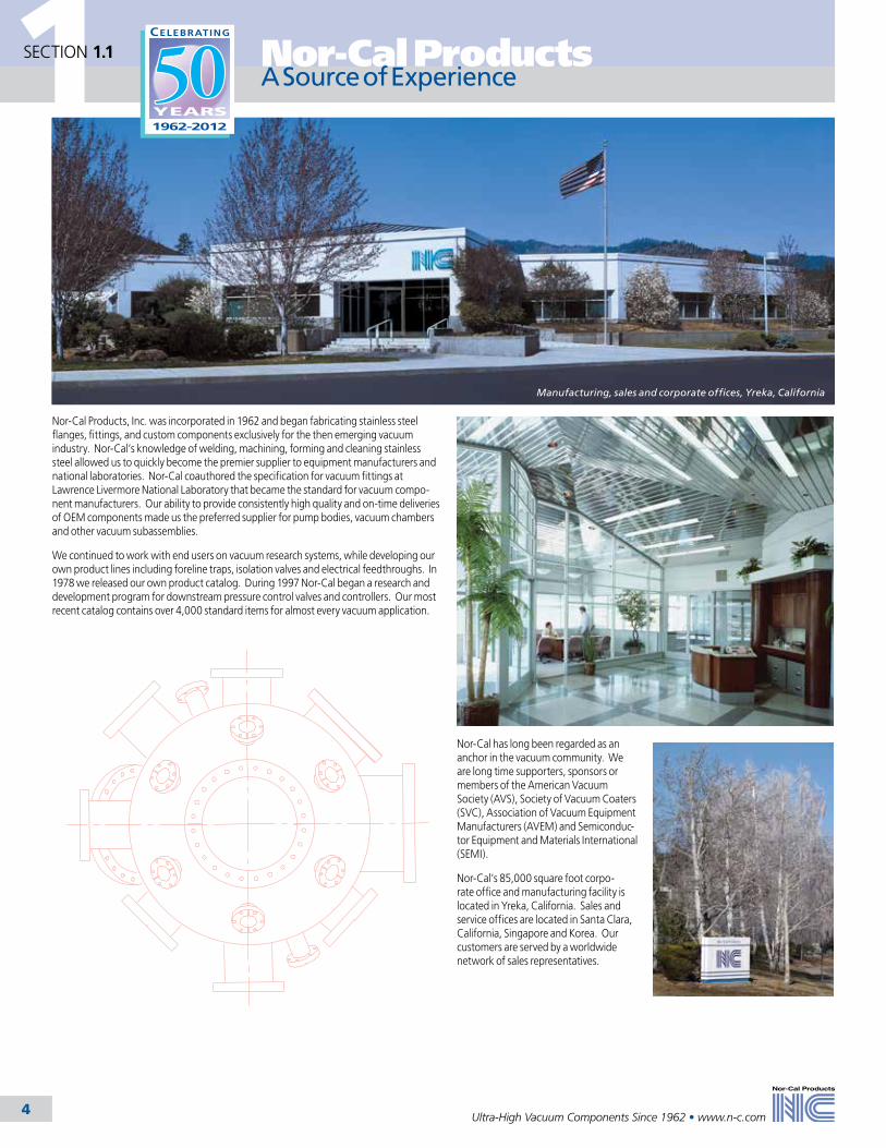
Manufacturing, sales and corporate offices, Yreka, California
A Source of Experience
Nor-Cal Products, Inc. was incorporated in 1962 and began fabricating stainless steel flanges, fittings, and custom components exclusively for the then emerging vacuum industry. Nor-Cal’s knowledge of welding, machining, forming and cleaning stainless steel allowed us to quickly become the premier supplier to equipment manufacturers and national laboratories. Nor-Cal coauthored the specification for vacuum fittings at Lawrence Livermore National Laboratory that became the standard for vacuum compo-nent manufacturers. Our ability to provide consistently high quality and on-time deliveries of OEM components made us the preferred supplier for pump bodies, vacuum chambers and other vacuum subassemblies.
We continued to work with end users on vacuum research systems, while developing our own product lines including foreline traps, isolation valves and electrical feedthroughs. In 1978 we released our own product catalog. During 1997 Nor-Cal began a research and development program for downstream pressure control valves and controllers. Our most recent catalog contains over 4,000 standard items for almost every vacuum application.
Nor-Cal has long been regarded as an anchor in the vacuum community. We are long time supporters, sponsors or members of the American Vacuum Society (AVS), Society of Vacuum Coaters (SVC), Association of Vacuum Equipment Manufacturers (AVEM) and Semiconduc-tor Equipment and Materials International (SEMI).
Nor-Cal’s 85,000 square foot corpo-rate office and manufacturing facility is located in Yreka, California. Sales and service offices are located in Santa Clara, California, Singapore and Korea. Our customers are served by a worldwide network of sales representatives.

Nor-Cal Products
Ultra-High Vacuum Components Since 1962 • www.n-c.com 5
1SECTION 1.2Markets Served
Surface science research end station at Advanced Light Source, Berkeley, California
Thin film deposition systems
Semiconductor process equipment in the service chase of a 200mm fab
Heated forelines and pump exhaust lines in semiconductor subfab
Over the years Nor-Cal’s customer base has been drawn from all segments of the vacuum industry. Our components are used in almost every phase of semiconductor processing. We are a preferred supplier to several semiconductor and compound semiconductor equipment manufacturers. We also supply mechanical contractors during fab construction. Industrial and academic researchers are frequent purchasers of standard, modified standard and custom components for physical, chemical and electrochemical experi-ments. Other customers who have come to value our experience are instrument manufacturers of surface analysis equipment, thin film deposition system manufacturers for solar or industrial coatings, laser device manufacturers and aerospace industries.

1 Nor-Cal Products
6 Ultra-High Vacuum Components Since 1962 • www.n-c.com
SECTION 1.3Standard Components
Flanges, Fittings & HardwareOur flanges are made from 304 stainless steel material, which is specially processed to reduce impurities, grain size and microscopic leak paths. They are available in all commonly used high and ultra-high vacuum flange types, including ASA, NW (ISO-KF), ISO, CF and wire seal flanges. We also offer chain clamps and metal seals to convert a high vacuum NW flange to ultra-high vacuum.
Fittings are available with or without flanges. Weld fittings (without flanges) are typically sold to mechanical contractors for use during the fit up phase of new fab construction.
Nor-Cal Products provides a broad range of adapter fittings in order to connect two dissimilar types of components. They are made from 304 stainless steel and are TIG welded, cleaned and leak checked for vacuum service.
Flexible stainless steel hoses are available in three thicknesses to accommodate many applications and bend radius requirements. Nor-Cal’s flexible couplings have more convolutions than comparable products, resulting in greater flexibility and lower spring rates. Plasticized PVC hoses can be used as a low cost rough vacuum line.
Our electrical feedthroughs are manu-factured from ultra-high vacuum grade materials, such as high alumina ceramic insulators, OFHC copper and nickel conductors, and 304 stainless steel flanges. Types include thermocouple, instrumentation, medium current, high current, BNC, and MHV feedthroughs.
Nor-Cal Products’ liquid and liquid nitrogen feedthroughs are available with or without industry standard Cajon, VCR or Swagelok fittings.
We offer a complete line of UHV compatible flanged viewports, weld stub viewports and viewport shutters. Shutters prevent buildup of process materials on the inside of the viewport window. Glass adapters are use-ful for mounting glass accessories to metal high vacuum systems, or to attach flange mounted components to glass systems.
Isolation ValvesNor-Cal offers vacuum isolation valves for a broad range of sizes, pressures and applications. Our pneumatically actuated poppet valves are standard on semiconductor equipment because of their robust design and edge-welded AM 350 stainless steel bellows, which provide full-opening conductance. Copper seal bonnet and manual all-metal valves are available for UHV applications. N-Series and Genesis modular valves were designed specifically for semiconductor equipment that require
million-cycle reliability, small footprint and low-cost soft start and heating options. Additionally, Nor-Cal provides traditional linear as well as low-
particulate pendulum style gate valves for isolation of high vacuum pumps and UHV chambers. We now also offer a selection of leak valves, manual butterfly valves and pneumatic and manual ball valves.
Electropolishing weld fittings
Valve assembly in Class 1000 clean room
CNC machining
1Nor-Cal Products
7Ultra-High Vacuum Components Since 1962 • www.n-c.com
SECTION 1.3
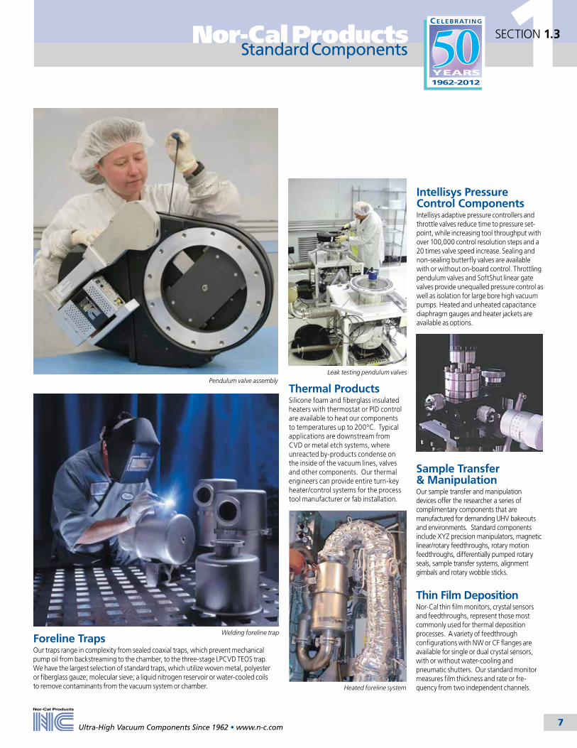
Foreline TrapsOur traps range in complexity from sealed coaxial traps, which prevent mechanical pump oil from backstreaming to the chamber, to the three-stage LPCVD TEOS trap. We have the largest selection of standard traps, which utilize woven metal, polyester or fiberglass gauze; molecular sieve; a liquid nitrogen reservoir or water-cooled coils to remove contaminants from the vacuum system or chamber.
Standard Components
Intellisys Pressure Control ComponentsIntellisys adaptive pressure controllers and throttle valves reduce time to pressure set-point, while increasing tool throughput with over 100,000 control resolution steps and a 20 times valve speed increase. Sealing and non-sealing butterfly valves are available with or without on-board control. Throttling pendulum valves and SoftShut linear gate valves provide unequalled pressure control as well as isolation for large bore high vacuum pumps. Heated and unheated capacitance diaphragm gauges and heater jackets are available as options.
Sample Transfer & ManipulationOur sample transfer and manipulation devices offer the researcher a series of complimentary components that are manufactured for demanding UHV bakeouts and environments. Standard components include XYZ precision manipulators, magnetic linear/rotary feedthroughs, rotary motion feedthroughs, differentially pumped rotary seals, sample transfer systems, alignment gimbals and rotary wobble sticks.
Thin Film Deposition Nor-Cal thin film monitors, crystal sensors and feedthroughs, represent those most commonly used for thermal deposition processes. A variety of feedthrough configurations with NW or CF flanges are available for single or dual crystal sensors, with or without water-cooling and pneumatic shutters. Our standard monitor measures film thickness and rate or fre-quency from two independent channels.
Thermal ProductsSilicone foam and fiberglass insulated heaters with thermostat or PID control are available to heat our components to temperatures up to 200ºC. Typical applications are downstream from CVD or metal etch systems, where unreacted by-products condense on the inside of the vacuum lines, valves and other components. Our thermal engineers can provide entire turn-key heater/control systems for the process tool manufacturer or fab installation.
Welding foreline trap
Heated foreline system
Pendulum valve assembly Leak testing pendulum valves

Ultra-High Vacuum Components Since 1962 • www.n-c.com
Nor-Cal Products
8
1SECTION 1.4
Process Specific TrapsWe have years of experience designing and building custom foreline traps to protect pumps and eliminate buildup of condensable by-products in forelines and exhaust lines. Examples of these include water cooled and particle traps for LPCVD/TEOS, PECVD, metal CVD, MOCVD and metal etch. Others are particle traps for crystal growers, liquid traps for reclamation of photo resist and oil reclamation traps for industrial applications. Often times our customers see a 200% increase in preventative maintenance intervals after installation of one of these traps.
Custom Chambers & System IntegrationWe have developed a reputation at national laboratories, universities and UHV equipment manufacturers for being the premier vacuum chamber fabricator. The quality, appearance and performance of our chambers are unequaled. Our engineering staff can design a chamber from customer sketches or specifications and supply complete manufacturing drawings for customer approval.On request, Nor-Cal can assemble an entire system including chamber, frame, pumps, gauges, valves, manipulators and other components to customer specifications. Our vacuum technicians can complete a thorough qualification of system performance, including time to base pressure and RGA scan, before the system is back filled with nitrogen and shipped to the customer.
WeldmentsBecause Nor-Cal manufactures tees, elbows and other weld fittings in-house, Nor-Cal can fabricate exhaust weldments for semiconductor equipment from a single piece of tubing. Welds and other manufacturing steps are eliminated, improving cleanliness and fit while reducing cost. We have demonstrated as much as 30% savings to our customers using this technique. Comprehensive
Downstream SolutionsOur experience coupled with a broad product offering enables us to integrate components, providing comprehensive solutions to semiconductor fabs and equipment manufacturers. To improve overall system performance and achieve customer defined goals, a thorough evaluation of the system is conducted. A cost of ownership model can be provided showing payback as a result of increased tool utilization and decreased planned and unplanned maintenance costs.
Traps, thermal products, weldments and isolation and pressure control valves can be integrated as turnkey foreline modules. Thermal and vacuum characterization can be performed at Nor-Cal before the assembly is supplied leak checked, blanked off and clean room packaged.
Custom Components & Services
System integration
Research end station
Water-cooled / particle trap for CVD
Custom exhaust weldments

Nor-Cal Products
Ultra-High Vacuum Components Since 1962 • www.n-c.com 9
1SECTION 1.5
David StoneChief Financial Officer
Sean MalloryVice President of
Business Development S.E. Asia
It is our intention to be “The Best In Class”
manufacturing company of stainless steel vacuum components, producing the highest quality at competitive prices
as well as meeting our customer’s required delivery schedule.
We endeavor to maintain a stimulating and challenging work environment that recognizes and rewards our employee’s
contributions.
Nor-Cal will also strive to create, design and add new and appropriate
components to maintain market and technical leadership.
Mission Statement
Tom DeanyPresident & C.E.O.
Tim NilssonVice President of
Marketing
Donald AndersonVice President of
Operations
George LandrethVice President of
Engineering

Ultra-High Vacuum Components Since 1962 • www.n-c.com
Nor-Cal Products
10
1SECTION 1.6
Our Website - www.n-c.com
Customer Service
Sales & MarketingOur corporate sales, marketing and technical support personnel provide prompt, honest answers to your technical questions and can recommend components for your particular vacuum application. Our experience with semiconductor process equipment allows us to provide customers with comprehensive solutions to extend down-stream preventative maintenance intervals and increase throughput dramatically.
Nor-Cal Products sales representatives and stocking distributors are located throughout the United States, Canada, the Pacific Rim and Europe. Their locations, territories and contact information can be found in the back of this catalog or on our website.
Sylvie BouhierManaging DirectorNor-Cal Europe Ltd
Per Cederstav Business Unit Manager
Our website offers around-the-clock access to the most current Nor-Cal product information. RFQs, pre-sales questions, orders, custom component inquiries and technical support questions are all directed immediately to the appropriate personnel. PDF versions of this catalog are available on-line, so you can search over 4000 standard components.
• Complete online catalog features quick ordering and account management options• View or download Nor-Cal catalogs, operator manuals and other technical information • Request print catalogs, CDs, videos and other literature• Place orders and RFQ’s or contact your local Nor-Cal distributor or representative.
• Ask pre-sales or technical questions• Download CAD drawings and 3D solid models• Access new product information and technical data• Subscribe to receive automatic e-mail notification of special offers, new literature and product releases • Track your Nor-Cal UPS or FedEx shipments • Obtain a credit application, RMA and other forms
Back L to R: Monica Coupens, Sales Representative; Melissa MacDonald, Sales Representative; Tom Hagarty, Sales Representative; Denise Wilson, Sales Representative Supervisor
Front L to R: Adriane Fiorucci, Sales Representative; Tami Kohlmann, Sales Representative; Diana Tudor, Sales Manager
Back L to R: Jim Crowley, Product Manager; Tommy Deany, Production Control Manager Front L to R: Todd Wilkins, Business Unit Manager; Randy Michels, Business Unit Manager;
Steve Greuel, Sr.Sales Engineer and UHV Product Manager
Martin SemmlerWestern Regional
Sales Manager
Mike GrandinettiEastern Regional Sales Manager

Nor-Cal Products
Ultra-High Vacuum Components Since 1962 • www.n-c.com 11
1SECTION 1.7
Engineering, Research & Development
3D modeling of foreline trap
Engineering Nor-Cal's engineering staff can design custom components from customer specifications, sketches or drawings and oversee production with in-house tooling and equipment. Our customers benefit from the combined experience of our engineers, whose input during the design phase often results in cost savings during production and a superior product. For our customers who do not have drafting personnel available and require a complex assembly, we will provide complete CAD drawings for approval upon receipt of order.
Nor-Cal's engineering department employs the latest versions of SolidWorkstm drafting and solid modeling software. Drawings may be e-mailed direct to our engineering department at [email protected]. Accept-able file formats are IGES, SAT and STEP. You may also request CAD drawings and download 3D models of our most commonly used standard components from our website.
Research & DevelopmentIn addition to developing new standard products and improving existing ones, our Research and Development depart-ments design and test customer specified products for equipment manufacturers. Our in-house research and development facility has prototype machining capa-bilities. We can also perform pressure, conductance and thermal characterization as well as software and electronic development and testing.
3D model of Genesis modular valve and fittings assembly
Calibration of Intellisys adaptive pressure controllers
Sean Casarotti, Engineering Manager (left) leads engineering meeting

Ultra-High Vacuum Components Since 1962 • www.n-c.com
Nor-Cal Products
12
1SECTION 1.8
Manufacturing
DeliveryAn independent study ranked Nor-Cal Products number one in price and availability out of the five major vacuum component manufacturers. Orders for stock items received in the morning can be shipped that afternoon. Guaranteed overnight delivery is available through-out the continental United States from our corporate headquarters, and also from our stocking distributors’ locations. Exceptional service has won us many loyal customers who have had an assembly line down and been surprised to find that we would weld, clean, leak check and ship a non-stock item the same day without an expedite charge.
Nor-Cal employs a lean manufacturing technique that combines bottleneck man-agement and KANBAN with traditional MRP for production scheduling and capacity planning. Small lot sizes and stan-dardized routings maximize scheduling flexibility and increase visibility of jobs in the manufacturing stream, while reducing manufacturing cycle time. Over the years Nor-Cal has added in-house capabilities, such as chem cleaning and electropolishing, in order to eliminate dependence on outside suppliers. Additionally, this has allowed us to shorten lead times and reduce overall manufacturing costs.
Yreka facility stock room
CNC vertical lathe
CNC machining center
MaterialsNor-Cal Products uses only the highest grade materials for the manufacturing of vacuum compo-nents. Vapor pressure, corrosion resistance and permeability are important considerations taken into account during the material selection process. We start with select grade 304 stainless steel tubing, spheres or roll-ups to fabricate the vacuum vessel. If required, 304L, 316, 316L or 316LN can be supplied. Normally our standard material is in the low carbon range for 304. Flanges and baseplates are made from 304 that has been specially treated to remove impurities inherent in 300 series steels. Special UHV-flanges 4 ½ inches (150mm) OD and smaller can be made from 304 electroslag remelt (ESR) bar stock. ESR is a refining process that produces stainless steel with higher purity, fewer inclusions and more uniform grain structure to eliminate microscopic leak paths. Our standard flange material is certified to meet ASTM A-240 and has less than 0.01% sulfur to prevent sulfur stringers. Grain size is 3 to 6 per ASTM E-112. Maximum inclusion size is 2.5 per ASTM E-45. As specials, 304L and 316L material can be supplied in roll-forged rings.

Nor-Cal Products
Ultra-High Vacuum Components Since 1962 • www.n-c.com 13
1SECTION 1.8
Manufacturing
MachiningMachining procedures are consistent with good UHV practices. Machine coolant is sulfur free to reduce outgassing. All Nor-Cal components are designed to minimize entrapments, which cause virtual leaks under vacuum. State-of-the-art CNC machining equipment is available to produce parts with consistently high quality.
Nor-Cal pulls ports for fittings, weldments, trap and valve bodies and weldments. This eliminates sharp inside corners that can entrap contaminants, and allows faster pumpdown and lower outgassing. Nor-Cal can pull ports for 1⁄2 to 8-inch (50-200mm) diameter tubing, while holding the true position of the port within .030 inch (0.762mm).
Nor-Cal employs a CNC tube bender to form 1⁄2 to 2 inch (13-50mm) diameter elbows and custom exhaust weldments. This allows us to quickly make multiple compound angle bends in a single piece of tubing, while holding .010 inch (0.254mm) tolerance between two bends. Alternate methods of fabrication require welding of several prefabricated parts, resulting in greater incidence of leaks and cumulative tolerance buildup. Using our method, welds and other manufacturing steps are eliminated, improving cleanliness and fit while reducing cost.
CNC Machining Center with dual spindles, live tooling and robotic gantry
GTAW fusion welding
Orbital welding
WeldingGTAW fusion welding is used exclusively for a vacuum-tight metal bond. Purging with an inert gas reduces or eliminates oxygen entrainment and carbide precipi-tation, which cause outgassing. Whenever possible, welds are made on the inside or are full penetration to eliminate entrap-ments and virtual leaks.
Inert environment orbital welding is also available for full penetration flange-to-tube bonding. Orbital welding can be performed on any length tube with diameters from 1/8 to 2 inches (3-50mm).
Ball pulled ports
CNC tube bending
Ultra-High Vacuum Components Since 1962 • www.n-c.com
Nor-Cal Products
14
1SECTION 1.9
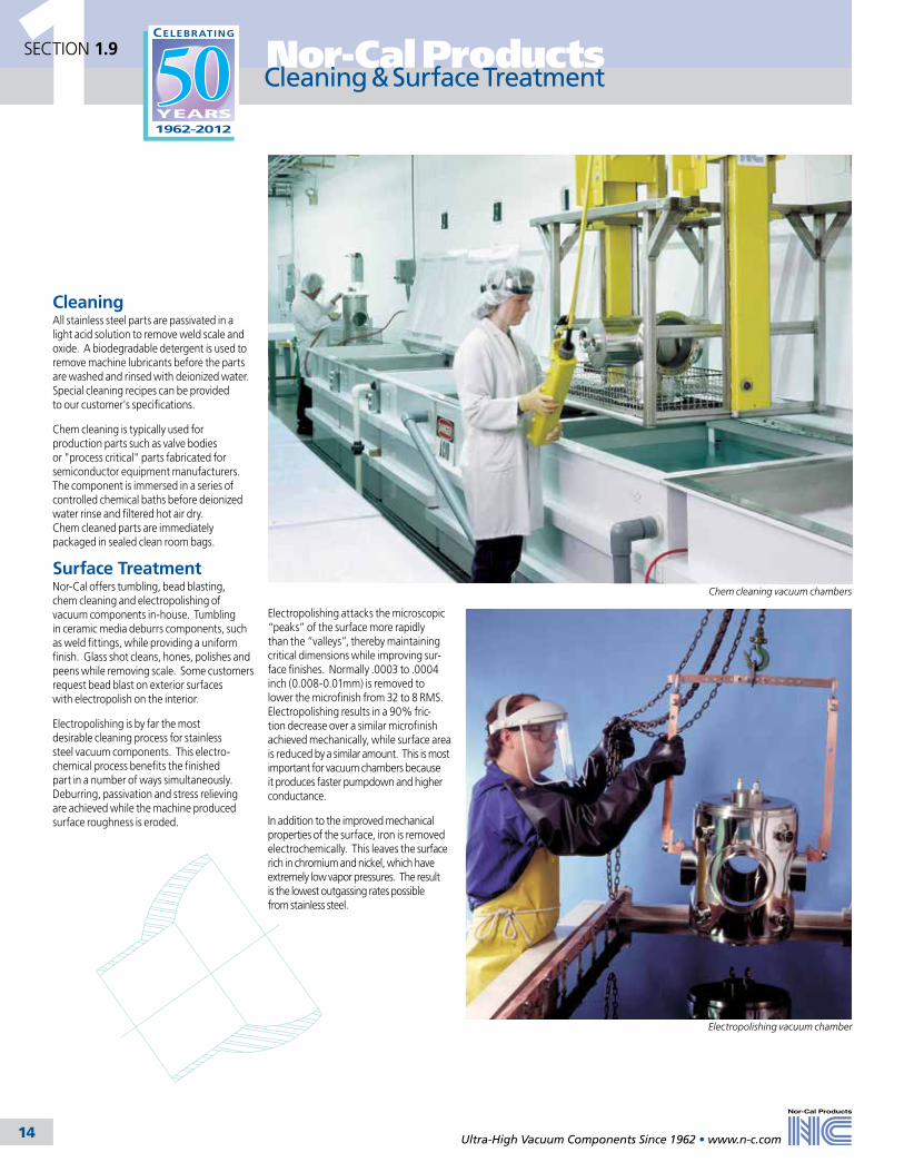
CleaningAll stainless steel parts are passivated in a light acid solution to remove weld scale and oxide. A biodegradable detergent is used to remove machine lubricants before the parts are washed and rinsed with deionized water. Special cleaning recipes can be provided to our customer's specifications.
Chem cleaning is typically used for production parts such as valve bodies or "process critical" parts fabricated for semiconductor equipment manufacturers. The component is immersed in a series of controlled chemical baths before deionized water rinse and filtered hot air dry. Chem cleaned parts are immediately packaged in sealed clean room bags.
Surface TreatmentNor-Cal offers tumbling, bead blasting, chem cleaning and electropolishing of vacuum components in-house. Tumbling in ceramic media deburrs components, such as weld fittings, while providing a uniform finish. Glass shot cleans, hones, polishes and peens while removing scale. Some customers request bead blast on exterior surfaces with electropolish on the interior.
Electropolishing is by far the most desirable cleaning process for stainless steel vacuum components. This electro-chemical process benefits the finished part in a number of ways simultaneously. Deburring, passivation and stress relieving are achieved while the machine produced surface roughness is eroded.
Electropolishing attacks the microscopic “peaks” of the surface more rapidly than the “valleys”, thereby maintaining critical dimensions while improving sur-face finishes. Normally .0003 to .0004 inch (0.008-0.01mm) is removed to lower the microfinish from 32 to 8 RMS. Electropolishing results in a 90% fric-tion decrease over a similar microfinish achieved mechanically, while surface area is reduced by a similar amount. This is most important for vacuum chambers because it produces faster pumpdown and higher conductance.
In addition to the improved mechanical properties of the surface, iron is removed electrochemically. This leaves the surface rich in chromium and nickel, which have extremely low vapor pressures. The result is the lowest outgassing rates possible from stainless steel.
Chem cleaning vacuum chambers
Cleaning & Surface Treatment
Electropolishing vacuum chamber

Nor-Cal Products
Ultra-High Vacuum Components Since 1962 • www.n-c.com 15
1SECTION 1.10
Valve assembly in Class 1000 Clean Room
Nor-Cal has two clean rooms for assembly and packaging of semiconductor valves, UHV systems and components.
Pressure control and isolation valves as well as sample transfer and manipulation devices are assembled, leak checked, tested and packaged in a 3000 square foot Class 1000 clean room, which is subdivided into five areas for assembly, inventory, leak check and other testing. This allows greater visibility, better inventory control and compresses assembly lead times.
System integration, chamber final assembly, testing and packaging are conducted in a 1000 square foot Class 1000 clean room.
Cleanroom Assembly & Packaging
Chamber leak testing after mechanical inspection on chamber qualification test bench
Clean room storage of valve subassemblies
Ultra-High Vacuum Components Since 1962 • www.n-c.com
Nor-Cal Products
16
1SECTION 1.11
Quality Assurance
After extensive audits, Nor-Cal Products, Inc. received Semitech SSQA Preferred Supplier status from two large semiconductor equipment manufacturers.
An ongoing effort is made to control and improve manufacturing processes. Periodic defect analysis results in process improvements with narrower acceptable limits on subsequent production runs. Our goal is to reach six-sigma process capability. Our quality system is ISO certified, SSQA certified and MIL-Q-9858 and MIL-I-45208 approved.
Every weld is leak checked with a helium mass spectrometer to insure a leak rate of 10-9 std. cc/sec or less. Our chamber qualification test benches can be used on components requiring lower leak rates. They were developed for customers who request residual gas analyzer (RGA) scans of their
Quality StatementNor-Cal Products, Inc. is dedicated to continual improvement of our manufactured and purchased goods through the implementation of a carefully planned quality program. Quality improvements at Nor-Cal have been mandated and implemented with the full support of senior management.
It is our belief that quality is built into a product. We will eliminate defects by reducing the variables in all processes relating to manufacturing. We will strive to meet our primary goal of 100% customer acceptance by manufacturing defect-free parts with on-time delivery, competitive pricing and the best possible customer service. Nor-Cal’s use of statistical methods in manu- facturing, training programs and continuous improvement of equipment are evidence of our commitment to this goal.
While management takes the ultimate responsibility for Nor-Cal quality, service and productivity, each employee can take credit for his or her contribution to our success, and is responsible for the implementation of quality in their particular area. We are all participants in the creation of a “quality ethic.” Senior man-agement fosters an atmosphere of cooperation not only throughout Nor-Cal, but also with customers as well as suppliers. Our purpose is to create a team dedicated to the improvement of quality by finding creative solutions to our industries' manufacturing problems.
Building quality into Nor-Cal Products’ components is our most important task.
chambers after a 24 hour vacuum bake. A test bench contains vacuum pumps, gauges, RGA, quartz heaters, nitrogen back fill and a leak detector. Once water and other background are eliminated by the 150°C bakeout, we can provide the customer with customized scans to detect the slightest contamination in the chamber. Whatever the sensitivity of our customer’s application, we can guar-antee that contaminants will be within acceptable limits.
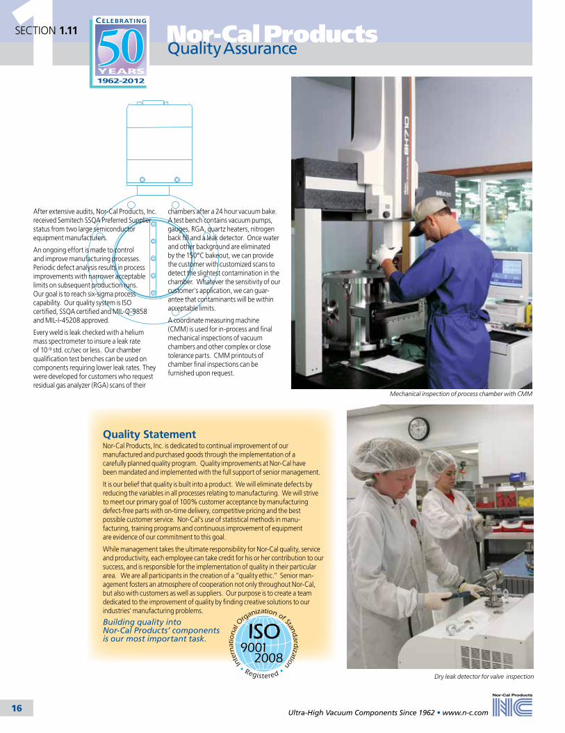
A coordinate measuring machine (CMM) is used for in-process and final mechanical inspections of vacuum chambers and other complex or close tolerance parts. CMM printouts of chamber final inspections can be furnished upon request.
Mechanical inspection of process chamber with CMM
Dry leak detector for valve inspection
17
2
Tel: 800-824-4166or 530-842-4457
Main Fax: 530-842-9130Sales Fax: 530-841-9189
www.n-c.com
Nor-Cal Products, Inc.1967 South Oregon Street
Yreka, CA 96097 USA
Flanges & FittingsSection Two
2.1 Chain Clamp Components & Hardware 18
2.2 NW Flanges & Fittings 21
2.3 ISO Flanges & Fittings 31
2.4 ASA Flanges & Fittings 40
2.5 CF Flanges & Fittings 47
2.6 Wire Seal Flanges 70
2.7 Adapter Fittings 71
2.8 Flexible Hoses & Couplings 80
2.9 Weld Fittings 88

2 Flanges & Fittings
18Ultra-High Vacuum Components Since 1962 • www.n-c.com
Nor-Cal Products stocks a complete line of chain clamps and aluminum metal seals for converting elastomer seal NW (KF) and ISO flanges to UHV metal seals. They provide a number of benefits over elastomer seals: reduced outgas-sing, no permeation, no hydrocarbons, resistance to radiation and short half-life. Aluminum seals are used in high-energy physics, other UHV applications and, in some circumstances, cryogenic applications. Aluminum seals are reliable in high vibration or temperature cycling environments. Chain clamps and NW flanges are the standard vacuum flange for many Japanese semiconductor equip-ment manufacturers. The advantages over using the standard ISO flange are the time and space savings during assembly and the flexibility to form high vacuum or UHV seals.
To install a metal seal on an existing NW flange, simply remove the stan-dard clamp, centering ring and O-ring assembly. Replace them with an aluminum knife edge seal and chain clamp. (See diagram.). Standard ISO claw clamps can be used with alumi-num seals to convert ISO flanges from high vacuum to UHV. Nor-Cal’s large NW flanges are available in 63, 80 and 100 NW sizes from stock. Chain clamps are used to form either elas-tomer or metal seals with large NW flanges.
Aluminum Metal SealsAluminum seals locate on the centering ring groove (inner centering) or outside edge of the flange (outer centering) depending on the size. (Inner and outer centering versions are available for all NW flange sizes.) Aluminum knife-edges are compressed by the sealing surfaces of the mating flanges when the chain clamp or ISO claw clamp is tightened. The resultant seal has a helium leak rate of less than 1x10-11 standard mbar l/sec and can be baked repeatedly to 150˚C. Proper seal-ing occurs even if the flanges are slightly scratched or misaligned. The aluminum alloy is soft enough to make a good seal with reasonable force but will not flow at moderate temperatures. Seals will even work with aluminum flanges.
SPECIFICATIONSTube OD sizes: 3/4 to 4 inches (19.05 to 101.6mm)
Materials Flange: 304 stainless steel Seal: Aluminum
Vacuum range: >1 x 10-11 mbar - UHV
Temperature range: -270ºC to 150ºC
All dimensions are in inches and (mm) unless otherwise noted
Aluminum Knife Edge Seal
Chain Clamp
Large NW FlangesNor-Cal offers blank and bored NW-63, NW-80 and NW-100 flanges that are compatible with other manufacturers’ large QF, KF flanges made to the ISO 2961 specification. They can be used with chain clamps to form elastomer or aluminum metal seals. Elastomer seals are formed with standard ISO centering ring/O-ring assemblies and elastomer chain clamps. UHV connections are formed with alu-minum metal seals and chain clamps intended for use with them. NW flanges are made from 304 stainless steel for 2.5 to 4.0 inch (63.5 to 101.6mm) OD tube sizes. Flanges for tube sizes up to 28 inches (711.2mm) OD, metric tube sizes can be supplied.
Chain Clamp Component General InformationSECTION 2.1

2Flanges & Fittings
19Ultra-High Vacuum Components Since 1962 • www.n-c.com
.098/.079(2.489/2.007)
AB
.236(5.994)
.177/.157(4.496/3.988)
AB
.276(7.010)
BC
D
AE
.470(11.938)
.200 (5.080)
.250 (6.350)
BC
AED
.787(19.990)
.453 (11.506)
.590 (14.986)
.175/.157(4.445/3.734)
.276(7.010)
D
B
A
Diagram A
.173/.157(4.394/3.988)
.276(7.010)
D
BC
Diagram B
Metal Seals & Flanges
MODEL NUMBER
FLANGE
A
B TORQUE
NUMBER CLAMPS*
ISO-63-MS-A ISO-63 3.74 (95.00) 3.47 (88.14) 11.3 Nm 4ISO-80-MS-A ISO-80 4.33 (109.98) 4.06 (103.12) 11.3 Nm 6ISO-100-MS-A ISO-100 5.12 (130.05) 4.84 (122.94) 11.3 Nm 8
* Use with Nor-Cal double or single claw clamps.
MODEL NUMBER
DIAGRAM
FLANGE
A
B
C
D
NW-16-MS-A A NW-16 1.18 (29.97) 0.63 (16.00) - 0.91 (23.11)NW-25-MS-A A NW-25 1.58 (40.13) 0.96 (24.38) - 1.30 (33.02)NW-40-MS-A A NW-40 2.16 (54.86) 1.58 (40.13) - 1.89 (48.01)NW-50-MS-A B NW-50 - 1.97 (50.04) 2.05 (52.07) 2.32 (58.93)NW-63-MS-A B NW-63 - 2.68 (68.07) 2.76 (70.10) 3.03 (76.96)
Aluminum Metal Seals for NW 16-63 Flanges
Aluminum Metal Seals for NW 80-100 FlangesMODEL NUMBER
FLANGE
A
B
NW-80-MS-A NW-80 Tapered 4.49 (114.05) 4.25 (107.95)NW-100-MS-A NW-100 Tapered 5.28 (134.11) 5.04 (128.02)
MODEL NUMBER
DESCRIPTION
A
B
C
D
E
NW-63-250 Bored for 21/2 inch (63mm) tube OD 3.43 (87.12) 2.44 (61.98) 2.76 (70.10) 2.51 (63.75) 2.71 (68.83)NW-63B Blank 3.43 (87.12) - 2.76 (70.10) - -
NW-63 Flanges
MODEL NUMBER
DESCRIPTION
A
B
C
D
E
NW-80-300 Bored for 3 inch (75mm) tube OD 4.49 (114.05) 2.87 (72.90) 3.27 (83.06) 3.01 (76.45) 3.82 (97.03)NW-80B Blank 4.49 (114.05) - 3.27 (83.06) - -NW-100-400 Bored for 4 inch (100mm) tube OD 5.28 (134.11) 3.87 (98.30) 4.02 (102.11) 4.01 (101.85) 4.61 (117.09)NW-100B Blank 5.28 (134.11) - 4.02 (102.11) - -
NW 80-100 Flanges
Aluminum Metal Seals for ISO Flanges
SECTION 2.1

2 Flanges & Fittings
20Ultra-High Vacuum Components Since 1962 • www.n-c.com
.787(19.990)
.157(3.988)
B
A
B
A.787
(19.990)
.157(3.988)
200 1.50(38.10)
B
200
B
A1.50
(38.10)
Nor-Cal Products stocks chain clamps for NW flanges in two styles: one with Teflon coated aluminum links and an uncoated version. The less expensive uncoated version is the preferred choice for sealing standard NW flanges with aluminum metal seals. The uncoated chain clamps can be used with Nor-Cal or other manufactur-ers’ NW flanges with a radius of approximately .060 of an inch (1.5mm) on the outer edge
of the non-sealing side. Most manufac-turers’ NW flanges have this feature. If the flanges to be sealed have a sharp edge, the Teflon coated chain clamps are required to ensure adequate sealing force for aluminum metal seals. Both versions use a single, hex head nut for closure. Stainless steel chain clamps and low cost composite chain clamps are available for elastomer NW connections.
Chain clamps for NW-63 flanges are similar to the NW-16 to 50 sizes. The style to use with NW-63 elastomer seals has a single knob for tightening. The clamp used for sealing aluminum metal
seals has a single hex head nut. Both have uncoated aluminum links, although Teflon coated aluminum versions are available.
Chain clamps for 80 to 100mm flanges are stocked in two styles: one with a single knob for elastomer seals and another with two allen head bolts for aluminum metal seals. Although chain clamps are bakeable to 150˚C, the knobs should not be baked above 60˚C. Chain clamps for tube sizes up to 28 inch (711mm) OD can be supplied on request.
Radius .060
Diagram A
Diagram B
Diagram C
Diagram D
All dimensions are in inches and (mm) unless otherwise noted
Chain Clamps for NW-16 to 50 Flanges – Aluminum LinksMODEL NUMBER
DIAGRAM
APPLICATION
A
B
MAXIMUM TEMPERATURE
TORQUEELASTOMER / METAL
NW-16-CC-AN A Metal or Elastomer Seals 4.53 (115.06) 2.36 (59.94) 150°C 1.017 Nm / 2.486 NmNW-25-CC-AN A Metal or Elastomer Seals 4.92 (124.97) 2.76 (70.10) 150°C 1.469 Nm / 2.938 NmNW-40-CC-AN A Metal or Elastomer Seals 5.32 (135.13) 3.35 (85.09) 150°C 2.034 Nm / 4.406 NmNW-50-CC-AN A Metal or Elastomer Seals 5.98 (151.89) 4.13 (104.90) 150°C 2.486 Nm / 4.971 Nm
Chain Clamps for NW-16 to 50 Flanges - Teflon Coated Links*
MODEL NUMBER
DIAGRAM
APPLICATION
A
B
MAXIMUM TEMPERATURE
TORQUE ELASTOMER / METAL
NW-16-CC-TN A No radius, metal/elastomer 4.53 (115.06) 2.36 (59.94) 150°C 1.017 Nm / 2.486 NmNW-25-CC-TN A No radius, metal/elastomer 4.92 (124.97) 2.76 (70.10) 150°C 1.469 Nm / 2.938 NmNW-40-CC-TN A No radius, metal/elastomer 5.32 (135.13) 3.35 (85.09) 150°C 2.034 Nm / 4.406 NmNW-50-CC-TN A No radius, metal/elastomer 5.98 (151.89) 4.13 (104.90) 150°C 2.486 Nm / 4.971 Nm
*Not radiation resistant
Chain Clamps for NW-63 FlangesMODEL NUMBER
DIAGRAM
APPLICATION
A
B
MAXIMUM TEMPERATURE
TORQUE ELASTOMER / METAL
NW-63-CCV-AN B Elastomer seals only 6.69 (169.93) 4.72 (119.89) 100°C -NW-63-CC-AN A Metal or elastomer seals 6.30 (160.02) 4.72 (119.89) 150°C 2.486 Nm / 4.971 Nm
Chain Clamps for NW-80 to 100 FlangesMODEL NUMBER
DIAGRAM
APPLICATION
A
B
MAXIMUM TEMPERATURE TORQUE
NW-80-CCV-AS D Elastomer seals only 9.61 (244.09) 6.06 (153.92) 150°C -NW-80-CC-TS C Metal seals only - 6.30 (160.02) 150°C 8.474 NmNW-100-CCV-AS D Elastomer seals only 10.08 (256.03) 6.77 (171.98) 150°C - NW-100-CC-TS C Metal seals only - 7.09 (180.09) 150°C 9.943 Nm
SECTION 2.1
Chain Clamps

2
21
SECTION 2.2Flanges & Fittings
Ultra-High Vacuum Components Since 1962 • www.n-c.com
SureSeal Clamp with Lanyard Lock
FlangeO-ring with Centering Ring
Flange
Nor-Cal NW flanges are designed to ISO 2861 specifications for standard USA tube sizes from 3/8 to 2 inches (9.53 to 50.8mm) OD. They are compatible with other manufacturers’ ISO-KF style flanges. NW flanges utilize an aluminum clamp with a single wing nut fastener or a lock-over-center clamp allowing frequent disassembly with-out tools. The vacuum seal is effected by the
NW Flange General Information
SPECIFICATIONSTube OD sizes: 3/8 to 2 inches (9.53 to 50.8mm) Materials Flange: 304 or 316L stainless steel O-rings: Viton, Buna & siliconeFittings Tube finishes: Beadblast standard (Tumbled & electropolish available) Fasteners: Wing nut, SureSeal, bulkhead & chain clamps Vacuum range Elastomer seal: >1 x 10⁻⁸ mbar -High vacuum Metal seal: >1 x 10-11 mbar - UHVTemperature range Viton: -20ºC to 200ºC Silicone: -50º to 230ºC Buna: -30ºC to 110ºC Metal seal: -270˚C to 150˚C
New Products
Nor-Cal trapped centering rings for NW flanges feature easy assembly with exact centering and are appro-priate for vacuum or pressure by externally supporting the sealing ring. Trapped O-rings are intended for use where pressures range from rough vacuum to above atmosphere. Applications include vacuum pump exhaust lines and abatement tools.
Trapped Centering Rings
Flange
O-ring
Centering Ring
Wingnut Clamp
Tube
application of uniform pressure from the clamp on the 15º surface of the 304 stainless steel flanges. The mating flange surfaces compress a Viton O-ring held in place by a centering ring. The resultant seal can be used in vacuum applications of up to 10-8 mbar and baked to 200ºC,
however sustained bak-ing above 150ºC may result in deterioration of
O-rings. Additionally, NW flanges allow components to be rotated before assem-bly for ease of component alignment. NW flanges are available on virtually all Nor-Cal components and fittings. Nor-Cal manufactures a full line of NW adapters so you can add to or build an entire system with NW compo-nents. (See adapters - Section 2.7) NW flanges can also be used with chain clamps and aluminum seals to obtain a UHV seal bakeable to 150ºC. (chain clamps and seals are described in detail in Section 2.1.)
All dimensions are in inches (mm) & weights are in pounds (kg), unless otherwise noted.

2
22
Flanges & FittingsSECTION 2.2
Ultra-High Vacuum Components Since 1962 • www.n-c.com
SECTION 2.2
NW Bored Blank Flanges & Blank Off Caps
NW Bored Blank Flanges (NWB)MODEL NUMBER
DIAGRAM
TUBE OD
A
B
C
NW-10B-038 A 3/8 (9.53) 0.38 (9.65) 0.326 (8.28) 1.18 (29.97)NW-10B-050 A 1/2 (12.70) 0.51 (12.95) 0.451 (11.46) 1.18 (29.97)NW-16B-038 A 3/8 (9.53) 0.38 (9.65) 0.326 (8.28) 1.18 (29.97)NW-16B-050 A 1/2 (12.70) 0.51 (12.95) 0.451 (11.46) 1.18 (29.97)NW-16B-075 B 3/4 (19.05) 0.76 (19.30) 0.68 (17.27) 1.18 (29.97)NW-25B-038 A 3/8 (9.53) 0.38 (9.65) 0.326 (8.28) 1.575 (40.01)NW-25B-050 A 1/2 (12.70) 0.51 (12.95) 0.451 (11.46) 1.575 (40.01)NW-25B-075 A 3/4 (19.05) 0.76 (19.30) 0.715 (18.16) 1.575 (40.01)NW-25B-100 A 1 (25.40) 1.01 (25.65) 0.938 (23.83) 1.575 (40.01)NW-40B-038 A 3/8 (9.53) 0.38 (9.65) .326 (8.28) 2.16 (54.86)NW-40B-050 A 1/2 (12.70) 0.51 (12.95) 0.451 (11.46) 2.16 (54.86)NW-40B-075 A 3/4 (19.05) 0.76 (19.30) 0.715 (18.16) 2.16 (54.86)NW-40B-100 A 1 (25.40) 1.01 (25.65) 0.938 (23.83) 2.16 (54.86)NW-40B-150 A 11/2 (38.10) 1.51 (38.35) 1.438 (36.53) 2.16 (54.86)NW-50B-038 A 3/8 (9.53) 0.38 (9.65) .326 (8.28) 2.95 (74.93)NW-50B-050 A 1/2 (12.70) 0.51 (12.95) 0.451 (11.46) 2.95 (74.93)NW-50B-075 A 3/4 (19.05) 0.76 (19.30) 0.715 (18.16) 2.95 (74.93)NW-50B-100 A 1 (25.40) 1.01 (25.65) 0.938 (23.83) 2.95 (74.93)NW-50B-150 A 11/2 (38.10) 1.51 (38.35) 1.438 (36.53) 2.95 (74.93)NW-50B-200 A 2 (50.80) 2.01 (51.05) 1.938 (49.23) 2.95 (74.93)
316L Blank Off Caps MODEL NUMBER
A
B
NW-16B-316L 0.200 (5.08) 1.18 (29.97)NW-25B-316L 0.200 (5.08) 1.575 (40.01)NW-40B-316L 0.200 (5.08) 2.16 (54.86)NW-50B-316L 0.200 (5.08) 2.95 (74.93)
NW 316L Stainless Steel Bored Blank Flanges (NWB)MODEL NUMBER
DIAGRAM
TUBE OD
A
B
C
NW-25B-100-316L A 1 (25.40) 1.01 (25.65) 0.938 (23.83) 1.575 (40.01)NW-40B-150-316L A 11/2 (38.10) 1.51 (38.35) 1.438 (36.53) 2.16 (54.86)NW-50B-200-316L A 2 (50.80) 2.01 (51.05) 1.938 (49.23) 2.95 (74.93)
Blank Off CapsMODEL NUMBER
A
B
NW-10B 0.200 (5.08) 1.18 (29.97)NW-16B 0.200 (5.08) 1.18 (29.97)NW-25B 0.200 (5.08) 1.575 (40.01)NW-40B 0.200 (5.08) 2.16 (54.86)NW-50B 0.200 (5.08) 2.95 (74.93)
A
B
.150 (3.81)
B
A
C
Diagram A
B
.150(3.81)
A
C
Diagram B
SPECIFICATIONSTube OD sizes: 3/8 to 2 inches (9.53 to 50.8mm)
Materials Flange: 304 or 316L stainless steel O-rings: Viton, Buna & silicone
Fasteners: Wing nut, SureSeal, bulkhead & chain clamps
Vacuum range Elastomer seal: >1 x 10⁻⁸ mbar -High vacuum Metal seal: >1 x 10-11 mbar - UHV
Temperature range Viton: -20ºC to 200ºC Silicone: -50º to 230ºC Buna: -30ºC to 110ºC Metal seal: -270˚C to 150˚C
See Section 2.1 for metal seals
All dimensions are in inches (mm) & weights are in pounds (kg), unless otherwise noted.

2
23
SECTION 2.2Flanges & Fittings
Ultra-High Vacuum Components Since 1962 • www.n-c.com
NW Socket Weld & Weld Neck FlangesSECTION 2.2
.150(3.81)
.500(12.7)
C
A
B
D
E
.100(2.54)
.120(3.05)
C
A
B
D
1.575(40.01)
15
C
D
.672(17.07)
A
.120 (3.05)
E
15o
.100(2.54)
B
Diagram B
NW Socket Weld FlangesMODEL NUMBER
TUBE OD
A
B
C
D
E
NW-10-SW 1/2 (12.70) 1.18 (29.97) 0.48 (12.19) 0.51 (12.95) 0.61 (15.49) -NW-16-SW 3/4 (19.05) 1.18 (29.97) 0.68 (17.27) 0.76 (19.30) 0.798 (20.27) -NW-25-SW 1 (25.40) 1.575 (40.01) 1.031 (26.19) 1.01 (25.65) 1.14 (28.96) 0.938 (23.83)NW-40-SW 11/2 (38.10) 2.16 (54.86) 1.62 (41.15) 1.51 (38.35) 1.64 (41.66) 1.438 (36.53)NW-50-SW 2 (50.80) 2.95 (74.93) 2.06 (52.32) 2.01 (51.05) 2.14 (54.36) 1.938 (49.23)
NW Long Weld Neck FlangesMODEL NUMBER
A
B
C
D
NW-10FL 1.18 (29.97) 0.48 (12.19) 0.38 (9.65) 1/2 (12.70)NW-16FL 1.18 (29.97) 0.68 (17.27) 0.625 (15.88) 3/4 (19.05)NW-25FL 1.575 (40.01) 1.031 (26.19) 0.87 (22.10) 1 (25.40)NW-40FL 2.16 (54.86) 1.62 (41.15) 1.37 (34.80) 11/2 (38.10)NW-50FL 2.95 (74.93) 2.06 (52.32) 1.87 (47.50) 2 (50.80)
NW 316L Stainless Steel Long Weld Neck FlangesMODEL NUMBER
A
B
C
D
NW-25FL-316L 1.575 (40.01) 1.031 (26.19) 0.87 (22.10) 1 (25.40)NW-40FL-316L 2.16 (54.86) 1.62 (41.15) 1.37 (34.80) 11/2 (38.10)NW-50FL-316L 2.95 (74.93) 2.06 (52.32) 1.87 (47.50) 2 (50.80)
NW Short Weld Neck FlangesMODEL NUMBER
DIAGRAM
TUBE OD
A
B
C
D
E
NW-10F A 1/2 (12.70) 1.18 (29.97) 0.48 (12.19) 0.38 (9.65) 1/2 (12.70) 0.5 (12.70)NW-16F B 3/4 (19.05) 1.18 (29.97) 0.68 (17.27) 0.625 (15.88) 3/4 (19.05) 0.56 (14.22)NW-16FB A 3/4 (19.05) 1.18 (29.97) 0.68 (17.27) 0.625 (15.88) 3/4 (19.05) 0.5 (12.70)NW-25F A 1 (25.40) 1.575 (40.01) 1.031 (26.19) .087 (22.10) 1 (25.40) 0.5 (12.70)NW-40F A 11/2 (38.10) 2.16 (54.86) 1.62 (41.15) 1.37 (34.80) 11/2 (38.10) 0.75 (19.05)NW-50F A 2 (50.80) 2.95 (74.93) 2.06 (52.32) 1.87 (47.50) 2 (50.80) 0.75 (19.05)
SPECIFICATIONSTube OD sizes: 3/8 to 2 inches (9.53 to 50.8mm) Materials Flange: 304 or 316L stainless steel O-rings: Viton, Buna & siliconeFasteners: Wing nut, SureSeal, bulkhead & chain clamps Vacuum range Elastomer seal: >1 x 10⁻⁸ mbar -High vacuum Metal seal: >1 x 10-11 mbar - UHVTemperature range Viton: -20ºC to 200ºC Silicone: -50º to 230ºC Buna: -30ºC to 110ºC Metal seal: -270˚C to 150˚C
A
E
B
D
C
15o
Diagram A
.100(2.54)
.120 (3.05)
See Section 2.1 for metal seals
All dimensions are in inches (mm) & weights are in pounds (kg), unless otherwise noted.
2 Flanges & Fittings
24
SECTION 2.2
Ultra-High Vacuum Components Since 1962 • www.n-c.com
NW Bulkhead ClampsMODEL NUMBER
A
B
C
NUMBER OF SCREWS
THROUGH HOLE D
NW-16-BCP 2.00 (50.80) 1.50 (38.10) 0.361 (9.17) 6 0.90 (22.86)NW-25-BCP 2.37 (60.20) 1.89 (48.01) .0387 (9.83) 6 1.26 (32.00)NW-40-BCP 2.94 (74.68) 2.44 (61.98) 0.366 (9.30) 6 1.84(46.74)NW-50-BCP 3.75 (95.25) 3.25 (82.55) 0.404 (10.26) 8 2.35 (59.69)
Bulkhead clamps provide a simple means of fastening an NW flange to a baseplate. Each aluminum clamp is sold with stain-less steel socket head cap screws and washers for attachment. Leave 0.075 inch (2mm) minimum between the bottom of the tapped hole and the inside of the chamber wall.
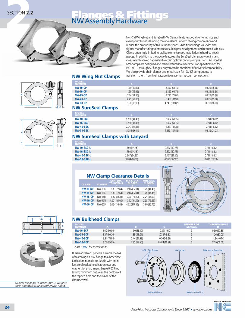
NW Wing Nut ClampsMODEL NUMBER
A
B
C
NW-10-CP 1.69 (42.93) 2.392 (60.76) 0.625 (15.88)NW-16-CP 1.69 (42.93) 2.392 (60.76) 0.625 (15.88)NW-25-CP 2.14 (54.36) 2.796 (71.02) 0.625 (15.88)NW-40-CP 2.75 (69.85) 3.437 (87.30) 0.625 (15.88)NW-50-CP 3.50 (88.90) 4.245 (107.82) 0.710 (18.03)
NW SureSeal ClampsMODEL NUMBER
A
B
C
NW-10-SSC 1.750 (44.45) 2.392 (60.76) 0.741 (18.82)NW-16-SSC 1.750 (44.45) 2.392 (60.76) 0.741 (18.82)NW-40-SSC 2.947 (74.85) 3.437 (87.30) 0.741 (18.82)NW-50-SSC 3.784 (96.11) 4.245 (107.82) 0.836 (21.23)
CB
A
CB
A
B
A
C
D
Bulkhead or BaseplateNW Flange
Bulkhead Clamps NW Centering Ring
10-32 x 5/8" Screws
NW Assembly Hardware
Nor-Cal Wing Nut and SureSeal NW Clamps feature special centering ribs and evenly distributed clamping force to assure uniform O-ring compression and reduce the probability of failure under loads. Additional hinge knuckles and tighter manufacturing tolerances result in precise alignment and reduced side play. Clamp opening is limited to facilitate one-handed installation in hard-to-reach spaces. In addition to the above features, the SureSeal clamp provides instant closure with a fixed geometry to attain optimal O-ring compression. All Nor-Cal NW clamps are designed and manufactured to meet Pneurop specifications for ISO-KF 10 through 50 flanges, so you can be confident of universal compatibility. We also provide chain clamps and metal seals for ISO-KF components to transform them from high vacuum to ultra-high vacuum connections.
0.57 ABC
NW Clamp Clearance Details CLAMP
FLANGE
MIN. DIA. TO INSTALL
A
MAX. DIA. CLOSED
B
MIN. DIA. CLOSED
CNW-10-CP NW-10B 2.86 (72.64) 2.65 (67.31) 1.75 (44.45)NW-16-CP NW-16B 2.86 (72.64) 2.65 (67.31) 1.75 (44.45)NW-25-CP NW-25B 3.32 (84.33) 3.00 (76.20) 2.24 (56.90)NW-40-CP NW-40B 4.00 (101.60) 3.72 (94.49) 2.90 (73.66)NW-50-CP NW-50B 5.45 (138.43) 4.62 (117.35) 3.69 (93.73)
NW SureSeal Clamps with LanyardMODEL NUMBER
A
B
C
NW-10-SSC-L 1.750 (44.45) 2.392 (60.76) 0.741 (18.82)NW-16-SSC-L 1.750 (44.45) 2.392 (60.76) 0.741 (18.82)NW-40-SSC-L 2.947 (74.85) 3.437 (87.30) 0.741 (18.82)NW-50-SSC-L 3.784 (96.11) 4.245 (107.82) 0.836 (21.23)
All dimensions are in inches (mm) & weights are in pounds (kg), unless otherwise noted.
Add “-MS” for metric bolts

2Flanges & Fittings
25
SECTION 2.2
Ultra-High Vacuum Components Since 1962 • www.n-c.com
Nor-Cal offers aluminum and stainless steel centering rings for NW and ISO flanges. Buna, silicone and Viton O-rings are available for NW, while Buna and Viton are stocked for ISO centering rings. Aluminum ISO center-ing rings are provided with an aluminum spacer ring. Stainless steel ISO centering rings are also provided with aluminum spacer rings as an option.
NW Aluminum Centering Rings with O-ringMODEL NUMBER
O-RING MATERIAL
A
B
NW-10-CR-AV Viton 0.478 (12.14) 0.456 (11.58)NW-10-CR-AB Buna 0.478 (12.14) 0.456 (11.58)NW-16-CR-AV Viton 0.669 (16.99) 0.625 (15.88)NW-16-CR-AB Buna 0.669 (16.99) 0.625 (15.88)NW-25-CR-AV Viton 1.024 (26.01) 0.984 (24.99)NW-25-CR-AB Buna 1.024 (26.01) 0.984 (24.99)NW-40-CR-AV Viton 1.614 (41.00) 1.57 (39.88)NW-40-CR-AB Buna 1.614 (41.00) 1.57 (39.88)NW-50-CR-AV Viton 2.047 (51.99) 1.967 (49.96)NW-50-CR-AB Buna 2.047 (51.99) 1.967 (49.96)
NW Stainless Steel Centering Rings with O-ringMODEL NUMBER
O-RING MATERIAL
A
B
NW-10-CR-SV Viton 0.478 (12.14) 0.456 (11.58)NW-10-CR-SS Silicone 0.478 (12.14) 0.456 (11.58)NW-10-CR-SB Buna 0.478 (12.14) 0.456 (11.58)NW-16-CR-SV Viton 0.669 (16.99) 0.625 (15.88)NW-16-CR-SS Silicone 0.669 (16.99) 0.625 (15.88)NW-16-CR-SB Buna 0.669 (16.99) 0.625 (15.88)NW-25-CR-SV Viton 1.024 (26.01) 0.984 (24.99)NW-25-CR-SS Silicone 1.024 (26.01) 0.984 (24.99)NW-25-CR-SB Buna 1.024 (26.01) 0.984 (24.99)NW-40-CR-SV Viton 1.614 (41.00) 1.570 (39.88)NW-40-CR-SS Silicone 1.614 (41.00) 1.570 (39.88)NW-40-CR-SB Buna 1.614 (41.00) 1.570 (39.88)NW-50-CR-SV Viton 2.047 (51.99) 1.967 (49.96)NW-50-CR-SS Silicone 2.047 (51.99) 1.967 (49.96)NW-50-CR-SB Buna 2.047 (51.99) 1.967 (49.96)
NW 316L Stainless Steel Centering Rings with O-ringMODEL NUMBER
O-RING MATERIAL
A
B
NW-25-CR-SV-316L Viton 1.024 (26.01) 0.984 (24.99)NW-40-CR-SV-316L Viton 1.614 (41.00) 1.570 (39.88)NW-50-CR-SV-316L Viton 2.047 (51.99) 1.967 (49.96)
A
B
.310(7.87)
.210(5.33)
.154(3.91)
A
B
.310(7.87)
.210(5.33)
.154(3.91)
A
B
.310(7.87)
.210(5.33)
.154(3.91)
NW Centering Rings
See page 26 for replacement O-rings
All dimensions are in inches (mm) & weights are in pounds (kg), unless otherwise noted.

2 Flanges & Fittings
26
SECTION 2.2
Ultra-High Vacuum Components Since 1962 • www.n-c.com
A
B
.210(5.33)
.154(3.91)
.310(7.87)
A
B
.310(7.87)
.154(3.91)
.210(5.33)
B
A
C
NW Screened Stainless Steel Centering Rings with Viton O-ring
MODEL NUMBER
O-RING MATERIAL
A
B
MESH
NW-25-CR-SV-74 Viton 1.024 (26.01) 0.984 (24.99) 74NW-40-CR-SV-74 Viton 1.614 (41.00) 1.570 (39.88) 74NW-50-CR-SV-74 Viton 2.047 (51.99) 1.967 (49.96) 74
NW Reducer Stainless Steel Centering Rings with Viton O-ringMODEL NUMBER
O-RING MATERIAL
A
B
NW-10/16-CR Viton 0.48 (12.19) 0.67 (17.02)NW-20/25-CR Viton 0.87 (22.10) 1.02 (25.91)NW-32/40-CR Viton 1.34 (34.04) 1.61 (40.89)
Buna and Silicone O-rings available. Call for pricing.
NW Stainless Steel Centering Rings with Viton O-ring and Over Pressure Ring
MODEL NUMBER
DESCRIPTION
NW-10-CR-SV-PR Contains model numbers NW-10-PR and NW-10-CR-SV NW-16-CR-SV-PR Contains model numbers NW-16-PR and NW-16-CR-SV NW-25-CR-SV-PR Contains model numbers NW-25-PR and NW-25-CR-SV NW-40-CR-SV-PR Contains model numbers NW-40-PR and NW-40-CR-SV NW-50-CR-SV-PR Contains model numbers NW-50-PR and NW-50-CR-SV
Buna and Silicone O-rings available. Call for pricing.
Viton O-RingsMODEL NUMBER
FLANGE TYPE
NW-10-OR-V NW-10NW-16-OR-V NW-16NW-25-OR-V NW-25NW-40-OR-V NW-40NW-50-OR-V NW-50
Silicone O-RingsMODEL NUMBER FLANGE
TYPE
NW-10-OR-S NW-10NW-16-OR-S NW-16NW-25-OR-S NW-25NW-40-OR-S NW-40NW-50-OR-S NW-50
Buna O-RingsMODEL NUMBER FLANGE
TYPE
NW-10-OR-B NW-10NW-16-OR-B NW-16NW-25-OR-B NW-25NW-40-OR-B NW-40NW-50-OR-B NW-50
NW Stainless Steel Over Pressure RingsMODEL NUMBER
A
B
C
MAXIMUM PSIG
NW-10-PR 1.25 (31.75) 1.186 (30.12) 0.346 (8.79) 100NW-16-PR 1.25 (31.75) 1.186 (30.12) 0.346 (8.79) 100NW-25-PR 1.66 (42.16) 1.583 (40.21) 0.346 (8.79) 100NW-40-PR 2.25 (57.15) 2.169 (55.09) 0.346 (8.79) 75NW-50-PR 2.75 (69.85) 2.620 (66.55) 0.145 (3.68) 50
NW Centering Rings & Replacement O-rings
For dimensions refer to the centering ring/O-ring assembly drawing
on the previous page and the overpressure ring diagram this page.
NW Stainless Steel Trapped Centering Rings with O-ringMODEL NUMBER
O-RING MATERIAL
A
B
C
NW-10/16-CRT-SV Viton 1.18 (29.97) 0.63 (16.00) 0.91 (23.11)NW-25-CRT-SV Viton 1.58 (40.13) 0.95 (24.13) 1.3 (33.02)NW-40-CRT-SV Viton 2.17 (55.12) 1.58 (40.13) 1.89 (48.01)NW-50-CRT-SV Viton 2.95 (74.93) 1.97 (50.04) 2.32 (58.93)
Buna and Silicone O-rings available. Call for pricing.
A
B
.157(3.99)
.315(8.00)
C
NW trapped centering rings are composed of an aluminum outer ring, Viton O-ring,
and stainless steel centering ring
NW Stainless Steel Captured Centering Rings with Viton O-ringMODEL NUMBER
O-RING MATERIAL A
BMAXIMUM
PSIG
NW-16-CRC-SV Viton 1.25 (31.75) 0.625 (15.88) 100NW-25-CRC-SV Viton 1.66 (42.16) 0.984 (24.99) 100NW-40-CRC-SV Viton 2.25 (57.15) 1.570 (39.88) 75 NW-50-CRC-SV Viton 2.75 (69.85) 1.967 (49.96) 50
Buna and Silicone O-rings available. Call for pricing.
B
.154(3.91)
A
All dimensions are in inches (mm) & weights are in pounds (kg), unless otherwise noted.

2Flanges & Fittings
27
SECTION 2.2
Ultra-High Vacuum Components Since 1962 • www.n-c.com
A
NW Full NipplesMODEL NUMBER
TUBE OD
A
2N-NW-10 1/2 (12.70) 2.50 (63.50)2N-NW-16B 3/4 (19.05) 2.30 (58.42)2N-NW-25B 1 (25.40) 4.06 (103.12)2N-NW-40B 11/2 (38.10) 4.80 (121.92)2N-NW-50B 2 (50.80) 6.30 (160.02)
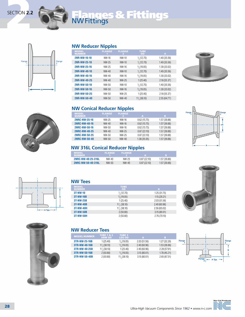
Nor-Cal manufactures a complete line of NW vacuum fittings. The tube portions are fabricated from 304 stainless steel. 316L stainless steel can be supplied on request. Nor-Cal makes its own elbows, and all tees and crosses are made with the pulled-port technique. This allows smooth, crevice-free butt welds to provide the maximum in cleanliness for UHV applications. Bakeout range is up to 200˚C. Nor-Cal fittings are also available with CF, ISO and ASA flanges. Standard finish is bead blasted. Electropolished finish can also be provided as an option. Call for pricing.
NW Half NipplesMODEL NUMBER
TUBE OD
A
1N-NW-10 1/2 (12.70) 1.25 (31.75)1N-NW-16B 3/4 (19.05) 1.15 (29.21)1N-NW-25B 1 (25.40) 2.03 (51.56)1N-NW-40B 11/2 (38.10) 2.40 (60.96)1N-NW-50B 2 (50.80) 3.15 (80.01)
NW Fittings
A
SPECIFICATIONSTube OD sizes: 1/2 to 2 inches (12.7 to 50.8mm) Materials Flange: 304 stainless steel (316L available upon request) O-rings: Viton, Buna & siliconeFittings Tube finishes: Beadblast standard (Tumbled & electropolish available) Fasteners: Wing nut, SureSeal, bulkhead & chain clamps Vacuum range Elastomer seal: >1 x 10⁻⁸ mbar -High vacuum Metal seal: >1 x 10-11 mbar - UHVTemperature range Viton: -20ºC to 200ºC Silicone: -50º to 230ºC Buna: -30ºC to 110ºC Metal seal: -270˚C to 150˚C
See Section 2.1 for metal seals
All dimensions are in inches (mm) & weights are in pounds (kg), unless otherwise noted.
2 Flanges & Fittings
28
SECTION 2.2
Ultra-High Vacuum Components Since 1962 • www.n-c.com
B
A
Flange1
Flange2
NW Conical Reducer NipplesMODEL NUMBER
FLANGE 1
FLANGE 2
A
B
2NRC-NW-25-16 NW-25 NW-16 0.62 (15.75) 1.57 (39.88)2NRC-NW-40-16 NW-40 NW-16 0.62 (15.75) 1.57 (39.88)2NRC-NW-50-16 NW-50 NW-16 0.62 (15.75) 1.57 (39.88)2NRC-NW-40-25 NW-40 NW-25 0.87 (22.10) 1.57 (39.88)2NRC-NW-50-25 NW-50 NW-25 0.87 (22.10) 1.57 (39.88)2NRC-NW-50-40 NW-50 NW-40 1.38 (35.05) 1.57 (39.88)
NW 316L Conical Reducer NipplesMODEL NUMBER
FLANGE 1
FLANGE 2
A
B
2NRC-NW-40-25-316L NW-40 NW-25 0.87 (22.10) 1.57 (39.88)2NRC-NW-50-40-316L NW-50 NW-40 0.87 (22.10) 1.57 (39.88)
NW Fittings
Flange1
Flange2
A
NW Reducer NipplesMODEL NUMBER
FLANGE 1
FLANGE 2
TUBE OD
A
2NR-NW-16-10 NW-16 NW-10 1/2 (12.70) 1.40 (35.56)
2NR-NW-25-10 NW-25 NW-10 1/2 (12.70) 1.40 (35.56)
2NR-NW-25-16 NW-25 NW-16 3/4 (19.05) 1.30 (33.02)
2NR-NW-40-10 NW-40 NW-10 1/2 (12.70) 1.40 (35.56)
2NR-NW-40-16 NW-40 NW-16 3/4 (19.05) 1.30 (33.02)
2NR-NW-40-25 NW-40 NW-25 1 (25.40) 2.18 (55.37)
2NR-NW-50-10 NW-50 NW-10 1/2 (12.70) 1.40 (35.56)
2NR-NW-50-16 NW-50 NW-16 3/4 (19.05) 1.30 (33.02)
2NR-NW-50-25 NW-50 NW-25 1 (25.40) 2.18 (55.37)
2NR-NW-50-40 NW-50 NW-40 11/2 (38.10) 2.55 (64.77)
NW TeesMODEL NUMBER
TUBE OD
A
3T-NW-10 1/2 (12.70) 1.25 (31.75)3T-NW-16B 3/4 (19.05) 1.15 (29.21)3T-NW-25B 1 (25.40) 2.03 (51.56)3T-NW-40B 11/2 (38.10) 2.40 (60.96)3T-NW-40H 11/2 (38.10) 2.56 (65.02)3T-NW-50B 2 (50.80) 3.15 (80.01)3T-NW-50H 2 (50.80) 2.76 (70.10)
NW Reducer TeesMODEL NUMBER TUBE 1 & 2
ARM ODTUBE 3 LEG OD
A
B
3TR-NW-25-16B 1 (25.40) 3/4 (19.05) 2.03 (51.56) 1.27 (32.26)3TR-NW-40-16B 11/2 (38.10) 3/4 (19.05) 2.40 (60.96) 1.53 (38.86)3TR-NW-40-25B 11/2 (38.10) 1 (25.40) 2.40 (60.96) 2.28 (57.91)3TR-NW-50-16B 2 (50.80) 3/4 (19.05) 3.15 (80.01) 1.78 (45.21)3TR-NW-50-40B 2 (50.80) 11/2 (38.10) 3.15 (80.01) 2.65 (67.31)
A
A Typ.
Flange1
Flange2
B
A Typ.Flange3
2Flanges & Fittings
29
SECTION 2.2
Ultra-High Vacuum Components Since 1962 • www.n-c.com
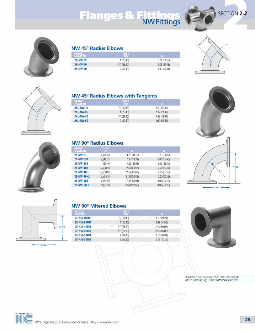
NW 45° Radius Elbows with TangentsMODEL NUMBER
TUBE OD
A
2KL-NW-16 3/4 (19.05) 0.91 (23.11)
2KL-NW-25 1 (25.40) 1.12 (28.45)
2KL-NW-40 11/2 (38.10) 1.68 (42.67)
2KL-NW-50 2 (50.80) 1.99 (50.55)
NW 45° Radius ElbowsMODEL NUMBER
TUBE OD
A
2K-NW-25 1 (25.40) 0.77 (19.56)
2K-NW-40 11/2 (38.10) 1.08 (27.43)
2K-NW-50 2 (50.80) 1.39 (35.31)
A
A
A Typ.
A Typ.
B
A Typ.
A Typ.
NW 90° Radius ElbowsMODEL NUMBER
TUBE OD
A
B
2E-NW-10 1/2 (12.70) 1.25 (31.75) 0.75 (19.05)
2E-NW-16B 3/4 (19.05) 1.15 (29.21) 1.00 (25.40)
2E-NW-25B 1 (25.40) 1.65 (41.91) 1.50 (38.10)
2E-NW-40B 11/2 (38.10) 2.40 (60.96) 2.25 (57.15)
2E-NW-40H 11/2 (38.10) 2.56 (65.02) 2.25 (57.15)
2E-NW-40HL 11/2 (38.10) 5.12 (130.05) 2.25 (57.15)
2E-NW-50B 2 (50.80) 3.15 (80.01) 3.00 (76.20)
2E-NW-50HL 2 (50.80) 5.51 (139.95) 3.00 (76.20)
NW Fittings
NW 90° Mitered ElbowsMODEL NUMBER
TUBE OD
A
2E-NW-16MB 3/4 (19.05) 1.15 (29.21)
2E-NW-25MB 1 (25.40) 2.03 (51.56)
2E-NW-40MB 11/2 (38.10) 2.40 (60.96)
2E-NW-40MH 11/2 (38.10) 2.56 (65.02)
2E-NW-50MB 2 (50.80) 3.15 (80.01)
2E-NW-50MH 2 (50.80) 2.76 (70.10)
All dimensions are in inches (mm) & weights are in pounds (kg), unless otherwise noted.

2 Flanges & Fittings
30
SECTION 2.2
Ultra-High Vacuum Components Since 1962 • www.n-c.com
NW 4-Way CrossesMODEL NUMBER
TUBE OD
A
4C-NW-10 1/2 (12.70) 1.25 (31.75)4C-NW-16B 3/4 (19.05) 1.15 (29.21)4C-NW-25B 1 (25.40) 2.03 (51.56)4C-NW-40B 11/2 (38.10) 2.40 (60.96)4C-NW-40H 11/2 (38.10) 2.56 (65.02)4C-NW-50B 2 (50.80) 3.15 (80.01)4C-NW-50H 2 (50.80) 2.76 (70.10)
NW Reducer CrossesMODEL NUMBER
TUBE 1 & 2 OD
TUBE 3 & 4 OD
A
B
4CR-NW-25-16B 1 (25.40) 3/4 (19.05) 2.03 (51.56) 1.27 (32.26)4CR-NW-40-16B 11/2 (38.10) 3/4 (19.05) 2.40 (60.96) 1.53 (38.86)4CR-NW-40-25B 11/2 (38.10) 1 (25.40) 2.40 (60.96) 2.28 (57.91)4CR-NW-50-16B 2 (50.80) 3/4 (19.05) 3.15 (80.01) 1.78 (45.21)4CR-NW-50-40B 2 (50.80) 11/2 (38.10) 3.15 (80.01) 2.65 (67.31)
NW 5-Way CrossesMODEL NUMBER
TUBE OD
A
5C-NW-16 3/4 (19.05) 1.50 (38.10)5C-NW-25B 1 (25.40) 2.03 (51.56)5C-NW-40B 11/2 (38.10) 2.40 (60.96)5C-NW-50B 2 (50.80) 3.15 (80.01)
NW 6-Way CrossesMODEL NUMBER
TUBE OD
A
6C-NW-16 3/4 (19.05) 1.50 (38.10)6C-NW-25B 1 (25.40) 2.03 (51.56)6C-NW-40B 11/2 (38.10) 2.40 (60.96)6C-NW-50B 2 (50.80) 3.15 (80.01)
A Typ.
Flange1
Flange2
B Typ.
A Typ.
Flange3
Flange4
5th Leg Opposite
A Typ.
A Typ.
6th Leg Opposite
A Typ.
NW Fittings
All dimensions are in inches (mm) & weights are in pounds (kg), unless otherwise noted.

2
31
Flanges & Fittings
Ultra-High Vacuum Components Since 1962 • www.n-c.com
SECTION 2.3
Nor-Cal ISO flanges and hardware are manufactured to the International Standards Organization specification so they can be mated to other manufactur-ers’ ISO flanges. ISO flanges are made from Argon Oxygen Decarburization (AOD) 304 stainless steel. This material is certified to meet ASTM-240 and has less than 0.01% sulfur in order to prevent sulfur stringers. Grain size is 3 to 6 per ASTM E-112.
SPECIFICATIONSGeneral: Optional fastener or nonrotatable flanges with clearance bolt holesNominal OD sizes: ISO-63 to ISO-500Tube OD sizes: 21/2 to 20 inches (63.5-508mm)Materials Flange: 304 or 316L stainless steel O-rings: Viton, Buna Bolts: 18-8 stainless steelVacuum range Elastomer seal: >1 x 10⁻⁸ mbar -High vacuum Metal seal: >1 x 10-11 mbar - UHVTemperature range Viton: -20ºC to 200ºC Buna: -30ºC to 110ºC Metal seal: -270˚C to 150˚C
ISO Flange General Information
Maximum inclusion size is 2.5 per ASTM E-45. Normally our standard material is in the low carbon range for 304 stainless steel. For increased corrosion resistance, some sizes are available from stock in 316L stainless steel.
Optional fastener and nonrotatable ISO flanges are available from stock for 21/2 to 20 inch (63.5-508mm) tube sizes.
Both use a Viton O-ring, held in place by a centering ring, to effect a seal with a vacuum range of 10-8 mbar. ISO components can be baked to 204ºC.
ISO flanges can also be used with standard clamps and aluminum seals to obtain a UHV seal bakeable to 150ºC. Seals are described in detail in Section 2.1 of this catalog.
ISO Flange Assembly InstructionsOptional fastener flanges are joined around the periphery with clamps. Double claw clamps are used when a pair of OF flanges are joined (See diagram A.), or single claw clamps are used to join an OF flange to a tapped nonrotatable on a pump or gate valve. (See diagram B.) This fastening method allows the OF flange to be rotated for ease of component alignment. Additionally, a rotatable bolt ring can be used to fasten an OF flange to a nonrotatable flange using bolts. (See diagram C.) A retainer ring prevents the OF flange from slipping through the bolt ring. Nonrotatable ISO flanges are assembled with bolts. (See diagram D.) They do not allow rotation of bolt holes on mating flanges to align components.
C. Optional Fastener/ Nonrotatable with Rotatable
Bolt Ring and Bolts
D. Nonrotatable/Nonrotatable with bolts
B. Optional Fastener/ Tapped Nonrotatable
with Single Claw Clamp
A. Optional Fastener/ Optional Fastener
with Double Claw Clamp
All dimensions are in inches (mm) & weights are in pounds (kg), unless otherwise noted.

2
32
Flanges & Fittings
Ultra-High Vacuum Components Since 1962 • www.n-c.com
SECTION 2.3
ISO Flanges and Hardware
Seal Side
A
B
A
Seal Side
D
C
BE
C
B
A
Aluminum
Retaining Ring
ISO Optional Fastener FlangesMODEL NUMBER
DIAGRAM
NOMINAL ID
A
B
C
D
E
ISO-63-000-OF A - 3.74 (95.00) 0.47 (11.94) - - -ISO-63-250-OF B 21/2 (63.50) 3.74 (95.00) 0.47 (11.94) 2.438 (61.93) 2.510 (63.75) 0.25 (6.35)ISO-80-000-OF A - 4.331 (110.01) 0.47 (11.94) - - -ISO-80-300-OF B 3 (76.20) 4.331 (110.01) 0.47 (11.94) 2.938 (74.63) 3.010 (76.45) 0.25 (6.35)ISO-100-000-OF A - 5.118 (130.00) 0.47 (11.94) - - -ISO-100-400-OF B 4 (101.60) 5.118 (130.00) 0.47 (11.94) 3.910 (99.31) 4.010 (101.85) 0.25 (6.35)ISO-160-000-OF A - 7.087 (180.00) 0.47 (11.94) - - -ISO-160-600-OF B 6 (152.40) 7.087 (180.01) 0.47 (11.94) 5.875 (149.23) 6.020 (152.91) 0.375 (9.53)ISO-200-000-OF A - 9.449 (240.00) 0.47 (11.94) - - -ISO-200-800-OF B 8 (203.20) 9.449 (240.00) 0.47 (11.94) 7.875 (200.03) 8.020 (203.71) 0.375 (9.53)ISO-250-000-OF A - 11.417 (289.99) 0.47 (11.94) - - -ISO-250-1000-OF B 10 (254.00) 11.417 (289.99) 0.47 (11.94) 9.875 (250.83) 10.020 (254.51) 0.375 (9.53)ISO-320-000-OF A - 14.567 (370.00) 0.67 (17.02) - - -ISO-320-1200-OF B 12 (304.80) 14.567 (370.00) 0.67 (17.02) 11.760 (298.70) 12.020 (305.31) 0.375 (9.53)ISO-320-1275-OF B 12 (304.80) 14.567 (370.00) 0.67 (17.02) 12.420 (315.47) 12.770 (324.36) 0.375 (9.53)ISO-400-000-OF A - 17.716 (449.99) 0.67 (17.02) - - -ISO-400-1600-OF B 16 (406.40) 17.716 (449.99) 0.67 (17.02) 15.624 (396.85) 16.020 (406.91) 0.375 (9.53)ISO-500-000-OF A - 21.653 (549.99) 0.67 (17.02) - - -ISO-500-2000-OF B 20 (508.00) 21.653 (549.99) 0.67 (17.02) 19.624 (498.45) 20.02 (508.51) 0.375 (9.53)
ISO 316L Optional Fastener FlangesMODEL NUMBER
DIAGRAM
NOMINAL ID
A
B
C
D
E
ISO-63-250-OF-316L B 21/2 (63.05) 3.740 (95.00) 0.47 (11.94) 2.438 (61.93) 2.510 (63.75) 0.25 (6.35)ISO-80-300-OF-316L B 3 (76.20) 4.331 (110.01) 0.47 (11.94) 2.938 (74.63) 3.010 (76.45) 0.25 (6.35)ISO-100-400-OF-316L B 4 (101.60) 5.118 (130.00) 0.47 (11.94) 3.910 (99.31) 4.010 (101.85) 0.25 (6.35)
ISO Rotatable Bolt Ring and Retainer RingMODEL NUMBER
FLANGE SIZE
A
B
C
ISO-63-BR ISO-63 4.331 (110.01) 5.118 (130.00) 0.472 (11.99)ISO-80-BR ISO-80 4.921 (124.99) 5.709 (145.01) 0.472 (11.99)ISO-100-BR ISO-100 5.709 (145.01) 6.496 (165.00) 0.472 (11.99)ISO-160-BR ISO-160 7.874 (200.00) 8.858 (224.99) 0.630 (16.00)ISO-200-BR ISO-200 10.236 (259.99) 11.220 (284.99) 0.630 (16.00)ISO-250-BR ISO-250 12.205 (310.01) 13.189 (335.00) 0.630 (16.00)ISO-320-BR ISO-320 15.551 (395.00) 16.732 (424.99) 0.787 (19.99)ISO-400-BR ISO-400 18.898 (480.01) 20.079 (510.01) 0.787 (19.99)ISO-500-BR ISO-500 22.835 (580.01) 24.016 (610.01) 0.787 (19.99)
Replacement Retainer Ring
MODEL NUMBER
ISO-63-RRISO-80-RRISO-100-RRISO-160-RRISO-200-RRISO-250-RRISO-320-RRISO-400-RRISO-500-RR
SPECIFICATIONSGeneral: Optional fastener or nonrotatable flanges with clearance bolt holes
Nominal OD sizes: ISO-63 to ISO-500
Tube OD sizes: 21/2 to 20 inches (63.5-508mm)
Materials Flange: 304 or 316L stainless steel O-rings: Viton, Buna Bolts: 18-8 stainless steel
Vacuum range Elastomer seal: >1 x 10⁻⁸ mbar -High vacuum Metal seal: >1 x 10-11 mbar - UHV
Temperature range Viton: -20ºC to 200ºC Silicone: -50º to 230ºC Buna: -30ºC to 110ºC Metal seal: -270˚C to 150˚C
Diagram A
Diagram B
See Section 2.1 for metal seals
All dimensions are in inches (mm) & weights are in pounds (kg), unless otherwise noted.

2
33
Flanges & Fittings
Ultra-High Vacuum Components Since 1962 • www.n-c.com
SECTION 2.3
ISO Flanges and Hardware
ISO Nonrotatable FlangesMODEL NUMBER
DIAGRAM
NOMINAL ID
A
B
C
D
E
F
BOLT HOLES
BOLT DIAMETER
ISO-63-000N A - 5.118(130.00)
0.472(11.99) - - - 4.331
(110.01) 4 0.359 (9.12)
ISO-63-250N B 21/2
(63.50)5.118
(130.00)0.472
(11.99)2.438
(61.93)2.510
(63.75)0.250 (6.35)
4.331 (110.01) 4 0.359 (9.12)
ISO-80-000N A - 5.709(145.01)
0.472(11.99) - - - 4.921
(124.99) 8 0.359 (9.12)
ISO-80-300N B 31/2
(88.90)5.709
(145.01)0.472
(11.99)2.938
(74.63)3.010
(76.45)0.250 (6.35)
4.921 (124.99) 8 0.359 (9.12)
ISO-100-000N A - 6.496(165.00)
0.472(11.99) - - - 5.709
(145.01) 8 0.359 (9.12)
ISO-100-400N B 4(101.06)
6.496(165.00)
0.472(11.99)
3.910(99.32)
4.010(101.85)
0.250(6.35)
5.709 (145.01) 8 0.359 (9.12)
ISO-160-000N A - 8.858(224.99)
0.630(16.00) - - - 7.874
(200.00) 8 0.438 (11.13)
ISO-160-600N B 6(152.40)
8.858(224.99)
0.630(16.00)
5.875 (149.23)
6.020 (152.91)
0.375 (9.53)
7.874 (200.00) 8 0.438 (11.13)
ISO-200-000N A - 11.220(284.99)
0.630(16.00) - - - 10.236
(259.99) 12 0.438 (11.13)
ISO-200-800N B 8(203.20)
11.220(284.99)
0.630(16.00)
7.875 (200.03)
8.020 (203.71)
0.375 (9.53)
10.236 (259.99) 12 0.438 (11.13)
ISO-250-000N A - 13.189(335.00)
0.630(16.00) - - - 12.205
(310.01) 12 0.438 (11.13)
ISO-250-1000N B 10(254.00)
13.189(335.00)
0.630(16.00)
9.875 (250.83)
10.020 (254.51)
0.375 (9.53)
12.205 (310.01) 12 0.438 (11.13)
ISO-320-000N A - 16.732(424.99)
0.787(19.99) - - - 15.551
(395.00) 12 0.551 (14.00)
ISO-320-1200N B 12(304.80)
16.732(424.99)
0.787(19.99)
11.760 (298.70)
12.020 (305.31)
0.375 (9.53)
15.551 (395.00) 12 0.551 (14.00)
ISO-320-1275N B 12(304.80)
16.732(424.99)
0.787(19.99)
12.420 (315.47)
12.770 (324.36)
0.375 (9.53)
15.551 (395.00) 12 0.551 (14.00)
ISO-400-000N A - 20.079(510.01)
0.787(19.99) - - - 18.898
(480.01) 16 0.551 (14.00)
ISO-400-1600N B 16(406.80)
20.079(510.01)
0.787(19.99)
15.642 (397.31)
16.020 (406.91)
0.375 (9.53)
18.898 (480.01) 16 0.551 (14.00)
ISO-500-000N A - 24.016(610.01)
0.787(19.99) - - - 22.835
(580.01) 16 0.551 (14.00)
ISO-500-2000N B 20(508.00)
24.016(610.01)
0.787(19.99)
19.642 (498.91)
20.020 (508.51)
0.375 (9.53)
22.835 (580.01) 16 0.551 (14.00)
ISO Bolt Kits-MetricMODEL NUMBER
DESCRIPTION
B-ISO-63 (4) SS bolts, nuts & washers, M8 x 40mmB-ISO-80 (8) SS bolts, nuts & washers, M8 x 40mmB-ISO-100 (8) SS bolts, nuts & washers, M8 x 40mmB-ISO-160 (8) SS bolts, nuts & washers, M10 x 50mmB-ISO-200 (12) SS bolts, nuts & washers, M10 x 50mmB-ISO-250 (12) SS bolts, nuts & washers, M10 x 50mmB-ISO-320 (12) SS bolts, nuts & washers, M12 x 60mmB-ISO-400 (16) SS bolts, nuts & washers, M12 x 60mmB-ISO-500 (16) SS bolts, nuts & washers, M12 x 60mm
Seal SideF
A
B
A
D
C
F
BE
Seal Side
SPECIFICATIONSGeneral: Optional fastener or nonrotatable flanges with clearance bolt holesNominal OD sizes: ISO-63 to ISO-500Tube OD sizes: 21/2 to 20 inches (63.5-508mm)Materials Flange: 304 or 316L stainless steel O-rings: Viton, Buna Bolts: 18-8 stainless steelVacuum range Elastomer seal: >1 x 10⁻⁸ mbar -High vacuum Metal seal: >1 x 10-11 mbar - UHVTemperature range Viton: -20ºC to 200ºC Buna: -30ºC to 110ºC Metal seal: -270˚C to 150˚C
Diagram A
Diagram B
Seal SideF
A
B
A
D
C
F
BE
Seal Side
See Section 2.1 for metal seals
All dimensions are in inches (mm) & weights are in pounds (kg), unless otherwise noted.

2
34
Flanges & Fittings
Ultra-High Vacuum Components Since 1962 • www.n-c.com
SECTION 2.3
A
BThread Size
A
B
C
Thread Size
ISO Double Claw Aluminum ClampsMODEL NUMBER
FLANGE SIZE
A
B
THREAD SIZE
CLAMPS REQUIRED
ISO-63-DCP ISO-63 0.94 (23.88) 1.96 (49.78) 5/16-18 4ISO-80-DCP ISO-80 0.94 (23.88) 1.96 (49.78) 5/16-18 8ISO-100-DCP ISO-100 0.94 (23.88) 1.96 (49.78) 5/16-18 8ISO-160-DCP ISO-160 1.10 (27.94) 1.96 (49.78) 5/16-18 8ISO-200-DCP ISO-200 1.10 (27.94) 1.96 (49.78) 5/16-18 12ISO-250-DCP ISO-250 1.10 (27.94) 1.96 (49.78) 5/16-18 12ISO-320-DCP ISO-320 1.34 (34.04) 2.50 (63.50) 7/16-14 12ISO-400-DCP ISO-400 1.34 (34.04) 2.50 (63.50) 7/16-14 16ISO-500-DCP ISO-500 1.34 (34.04) 2.50 (63.50) 7/16-14 16
ISO Single Claw Aluminum ClampsMODEL NUMBER
FLANGE SIZE
A
B
C
THREAD SIZE
CLAMPS REQUIRED
ISO-63-SCP ISO-63 0.94 (23.88) 1.18 (29.97) 0.52 (13.21) 5/16-18 4ISO-80-SCP ISO-80 0.94 (23.88) 1.18 (29.97) 0.52 (13.21) 5/16-18 8ISO-100-SCP ISO-100 0.94 (23.88) 1.18 (29.97) 0.52 (13.21) 5/16-18 8ISO-160-SCP ISO-160 1.10 (27.94) 1.18 (29.97) 0.52 (13.21) 5/16-18 8ISO-200-SCP ISO-200 1.10 (27.94) 1.18 (29.97) 0.52 (13.21) 5/16-18 12ISO-250-SCP ISO-250 1.10 (27.94) 1.18 (29.97) 0.52 (13.21) 5/16-18 12ISO-320-SCP ISO-320 1.34 (34.04) 1.46 (37.08) 0.88 (22.35) 7/16-14 12ISO-400-SCP ISO-400 1.34 (34.04) 1.46 (37.08) 0.88 (22.35) 7/16-14 16ISO-500-SCP ISO-500 1.34 (34.04) 1.46 (37.08) 0.88 (22.35) 7/16-14 16
ISO Single Claw Aluminum Clamps – MetricMODEL NUMBER
FLANGE SIZE
A
B
C
METRIC THREAD SIZE
CLAMPS REQUIRED
ISO-63-SCP-M ISO-63 0.94 (23.88) 1.20 (30.48) 0.40 (10.16) M8 x 1.25 4ISO-80-SCP-M ISO-80 0.94 (23.88) 1.20 (30.48) 0.40 (10.16) M8 x 1.25 8ISO-100-SCP-M ISO-100 0.94 (23.88) 1.20 (30.48) 0.40 (10.16) M8 x 1.25 8ISO-160-SCP-M ISO-160 1.10 (27.94) 1.20 (30.48) 0.40 (10.16) M10 x 1.50 8ISO-200-SCP-M ISO-200 1.10 (27.94) 1.20 (30.48) 0.40 (10.16) M10 x 1.50 12ISO-250-SCP-M ISO-250 1.10 (27.94) 1.20 (30.48) 0.40 (10.16) M10 x 1.50 12ISO-320-SCP-M ISO-320 1.34 (34.04) 1.48 (37.59) 0.79 (20.07) M12 x 1.75 12ISO-400-SCP-M ISO-400 1.34 (34.04) 1.48 (37.59) 0.79 (20.07) M12 x 1.75 16ISO-500-SCP-M ISO-500 1.34 (34.04) 1.48 (37.59) 0.79 (20.07) M12 x 1.75 16
ISO Clamps
All dimensions are in inches (mm) & weights are in pounds (kg), unless otherwise noted.
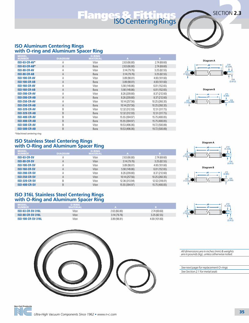
2
35
Flanges & Fittings
Ultra-High Vacuum Components Since 1962 • www.n-c.com
SECTION 2.3
ISO Aluminum Centering Rings with O-ring and Aluminum Spacer Ring
MODEL NUMBER
DIAGRAM
O-RING MATERIAL
A
B
ISO-63-CR-AV* A Viton 2.63 (66.80) 2.74 (69.60)ISO-63-CR-AB* A Buna 2.63 (66.80) 2.74 (69.60)ISO-80-CR-AV A Viton 3.14 (79.76) 3.25 (82.55)ISO-80-CR-AB A Buna 3.14 (79.76) 3.25 (82.55)ISO-100-CR-AV A Viton 3.89 (98.81) 4.00 (101.60)ISO-100-CR-AB A Buna 3.89 (98.81) 4.00 (101.60)ISO-160-CR-AV A Viton 5.90 (149.86) 6.01 (152.65)ISO-160-CR-AB A Buna 5.90 (149.86) 6.01 (152.65)ISO-200-CR-AV A Viton 8.26 (209.80) 8.37 (212.60)ISO-200-CR-AB A Buna 8.26 (209.80) 8.37 (212.60)ISO-250-CR-AV A Viton 10.14 (257.56) 10.25 (260.35)ISO-250-CR-AB A Buna 10.14 (257.56) 10.25 (260.35)ISO-320-CR-AV B Viton 12.32 (312.93) 12.51 (317.75)ISO-320-CR-AB B Buna 12.32 (312.93) 12.51 (317.75)ISO-400-CR-AV B Viton 15.55 (394.97) 15.75 (400.05)ISO-400-CR-AB B Buna 15.55 (394.97) 15.75 (400.05)ISO-500-CR-AV B Viton 19.53 (496.06) 19.72 (500.89)ISO-500-CR-AB B Buna 19.53 (496.06) 19.72 (500.89)
*Machined centering ring.
ISO Stainless Steel Centering Rings with O-Ring and Aluminum Spacer Ring
MODEL NUMBER
DIAGRAM
O-RING MATERIAL
A
B
ISO-63-CR-SV A Viton 2.63 (66.80) 2.74 (69.60)ISO-80-CR-SV A Viton 3.14 (79.76) 3.25 (82.55)ISO-100-CR-SV A Viton 3.89 (98.81) 4.00 (101.60)ISO-160-CR-SV A Viton 5.90 (149.86) 6.01 (152.65)ISO-200-CR-SV A Viton 8.26 (209.80) 8.37 (212.60)ISO-250-CR-SV A Viton 10.14 (257.56) 10.25 (260.35)ISO-320-CR-SV B Viton 12.36 (313.94) 12.52 (318.01)ISO-400-CR-SV B Viton 15.55 (394.97) 15.75 (400.05)
ISO 316L Stainless Steel Centering Rings with O-Ring and Aluminum Spacer Ring
MODEL NUMBER
O-RING MATERIAL
A
B
ISO-63-CR-SV-316L Viton 2.63 (66.80) 2.74 (69.60)ISO-80-CR-SV-316L Viton 3.14 (79.76) 3.25 (82.55)ISO-100-CR-SV-316L Viton 3.89 (98.81) 4.00 (101.60)
BA
.312(7.925)
.210(5.334)
.154(3.912)
BA
.550(13.970)
.275(6.985)
.224(5.690)
ISO Centering Rings
See next page for replacement O-ringsSee Section 2.1 for metal seals
Diagram A
Diagram B
BA
.312(7.925)
.210 (5.334)
.154(3.912)
BA
.550(13.970)
.275(6.985)
.224(5.690)
Diagram A
Diagram B
BA
.312(7.925)
.210 (5.334)
.154(3.912)
All dimensions are in inches (mm) & weights are in pounds (kg), unless otherwise noted.

2
36
Flanges & Fittings
Ultra-High Vacuum Components Since 1962 • www.n-c.com
SECTION 2.3
BA
.550(13.970)
.275(6.985)
.224(5.690)
BA
C
.312(7.952)
.210(5.334)
.154(3.912)
BA
C
.312(7.952)
.210(5.334)
.154(3.912)
ISO Stainless Steel Centering Rings with O-ringMODEL NUMBER
DIAGRAM
O-RING MATERIAL
A
B
ISO-63-CR A Viton 2.63 (66.80) 2.74 (69.60)ISO-80-CR A Viton 3.14 (79.76) 3.25 (82.55)ISO-100-CR A Viton 3.89 (98.81) 4.00 (101.60)ISO-160-CR A Viton 5.90 (149.86) 6.01 (152.65)ISO-200-CR A Viton 8.26 (209.80) 8.37 (212.60)ISO-250-CR A Viton 10.14 (257.56) 10.25 (260.35)ISO-320-CR B Viton 12.32 (312.93) 12.52 (318.01)ISO-400-CR B Viton 15.55 (394.97) 15.74 (399.80)
See below for replacement O-rings.
ISO Screened Stainless Steel Centering Rings with O-ring and Aluminum Spacer Ring
MODEL NUMBER
O-RING MATERIAL
A
B
C
MESH (sq./in.)
ISO-63-CR-SV-16 Viton 2.63 (66.80) 2.74 (69.60) 2.38 (60.45) 16ISO-80-CR-SV-16 Viton 3.14 (79.76) 3.25 (82.55) 2.87 (72.90) 16ISO-100-CR-SV-16 Viton 3.89 (98.81) 4.00 (101.60) 3.50 (88.90) 16ISO-160-CR-SV-16 Viton 5.90 (149.86) 6.01 (152.65) 5.50 (139.70) 16
Includes O-ring. See below for replacement O-rings.
Viton O-RingsMODEL NUMBER
FLANGE TYPE
ISO-63-0R-V ISO-63ISO-80-OR-V ISO-80ISO-100-OR-V ISO-100ISO-160-OR-V ISO-160ISO-200-OR-V ISO-200ISO-250-OR-V ISO-250ISO-320-OR-V ISO-320ISO-400-OR-V ISO-400ISO-500-OR-V ISO-500
Buna O-RingsMODEL NUMBER
FLANGE TYPE
ISO-63-0R-B ISO-63ISO-80-OR-B ISO-80ISO-100-OR-B ISO-100ISO-160-OR-B ISO-160ISO-200-OR-B ISO-200ISO-250-OR-B ISO-250ISO-320-OR-B ISO-320ISO-400-OR-B ISO-400ISO-500-OR-B ISO-500
ISO Centering Rings
See Section 2.1 for metal seals
Diagram A
Diagram B
All dimensions are in inches (mm) & weights are in pounds (kg), unless otherwise noted.

2
37
Flanges & Fittings
Ultra-High Vacuum Components Since 1962 • www.n-c.com
SECTION 2.3
Nor-Cal Products manufactures a complete line of ISO vacuum fittings with optional fastener or nonrotatable flanges. The tube portions are fabricated from 304 stainless steel. For increased resistance to corrosion in downstream semiconductor processes, some ISO flanges and fittings are available in 316L stainless steel. Nor-Cal makes its own elbows, and all tees and crosses are made with the pulled-port tech-nique. This allows smooth, crevice-free butt welds to provide the maximum in cleanliness for UHV applications. Fittings are shown with OF flanges only. To order a fitting with nonrotatable flanges substitute “-N” for “-OF” in the model number. Fittings are also available with CF (Conflat style), NW (ISO-KF compatible) and ASA flanges. Standard finish is bead blasted. Electropolished finish also available. Call for pricing.
ISO Fittings
SPECIFICATIONSGeneral: Optional fastener or nonrotatable flanges with clearance bolt holesNominal OD sizes: ISO-63 to ISO-500Tube OD sizes: 21/2 to 20 inches (63.5-508mm)Tube finish: Beadblast, tumbled, or electropolish Materials Flange: 304 or 316L stainless steel O-rings: Viton, Buna Bolts: 18-8 stainless steelVacuum range Elastomer seal: >1 x 10⁻⁸ mbar - High vacuum Metal seal: >1 x 10-11 mbar - UHVTemperature range Viton: -20ºC to 200ºC Buna: -30ºC to 110ºC Metal seal: -270˚C to 150˚C
AISO 45° Elbows with Tangents
MODEL NUMBER
TUBE OD
A
2KL-ISO-63-OF 21/2 (63.50) 3.25 (82.55)2KL-ISO-80-OF 3 (76.20) 3.93 (99.82)2KL-ISO-100-OF 4 (101.60) 5.03 (127.76)
ISO 90° Mitered ElbowsMODEL NUMBER
TUBE OD
A
2E-ISO-63-OF-M 21/2 (63.50) 3.25 (82.55)2E-ISO-80-OF-M 3 (76.20) 3.50 (88.90)2E-ISO-100-OF-M 4 (101.60) 4.13 (104.90)2E-ISO-160-OF-M 6 (152.40) 5.38 (136.65)2E-ISO-200-OF-M 8 (203.20) 7.38 (187.45)2E-ISO-250-OF-M 10 (254.00) 9.88 (250.95)
ISO 90° Radius ElbowsMODEL NUMBER
TUBE OD
A
B
2E-ISO-63-OF 21/2 (63.50) 4.00 (101.60) 3.75 (95.25)2E-ISO-80-OF 3 (76.20) 4.75 (120.65) 4.50 (114.30)2E-ISO-100-OF 4 (101.60) 6.25 (158.75) 6.00 (152.40)2E-ISO-160-OF 6 (152.40) 9.38 (238.25) 9.00 (228.60)2E-ISO-200-OF 8 (203.20) 12.38 (314.45) 12.00 (304.80)2E-ISO-250-OF 10 (254.00) 15.38 (390.65) 15.00 (381.00)
A
A
B
A
A
See Section 2.1 for metal seals
All dimensions are in inches (mm) & weights are in pounds (kg), unless otherwise noted.

2
38
Flanges & Fittings
Ultra-High Vacuum Components Since 1962 • www.n-c.com
SECTION 2.3
A
Flange1
Flange2
ISO Conical Reducer NipplesMODEL NUMBER
FLANGE 1 FLANGE 2 ATYPE TUBE OD TYPE TUBE OD
2NRC-ISO-80-63-OF ISO-80 3 (76.2) ISO-63 21/2 (63.50) 4.12 (104.65)2NRC-ISO-100-63-OF ISO-100 4 (101.6) ISO-63 21/2 (63.50) 4.12 (104.65)2NRC-ISO-100-80-OF ISO-100 4 (101.6) ISO-80 3 (76.20) 4.12 (104.65)
ISO Fittings
ISO Half NipplesMODEL NUMBER
TUBE OD
A
1N-ISO-63-OF 21/2 (63.50) 3.25 (82.55)1N-ISO-63-OF-V 21/2 (63.50) 4.00 (101.60)1N-ISO-63-OF-H 21/2 (63.50) 3.94 (100.08)1N-ISO-80-OF 3 (76.20) 3.50 (88.90)1N-ISO-80-OF-H 3 (76.20) 3.94 (100.08)1N-ISO-100-OF 4 (101.60) 4.13 (104.90)1N-ISO-100-OF-V 4 (101.60) 5.12 (130.05)1N-ISO-100-OF-H 4 (101.60) 3.94 (100.08)1N-ISO-160-OF 6 (152.40) 5.38 (136.65)1N-ISO-160-OF-V 6 (152.40) 6.44 (163.58)1N-ISO-160-OF-H 6 (152.40) 3.94 (100.08)1N-ISO-200-OF 8 (203.20) 7.38 (187.45)1N-ISO-250-OF 10 (254.00) 9.88 (250.95)1N-ISO-320-OF 12 (304.80) 9.88 (250.95)1N-ISO-400-OF 16 (406.40) 9.88 (250.95)1N-ISO-500-OF 20 (508.00) 9.88 (250.95)
ISO 316L Half NipplesMODEL NUMBER
TUBE OD
A
1N-ISO-63-OF-316L 21/2 (63.50) 3.25 (82.55)1N-ISO-80-OF-316L 3 (76.20) 3.50 (88.90)1N-ISO-100-OF-316L 4 (101.60) 4.13 (104.90)
A
A
3.00
Flange2
Flange1
ISO Full NipplesMODEL NUMBER
TUBE OD
A
2N-ISO-63-OF 21/2 (63.50) 6.50 (165.10)2N-ISO-80-OF 3 (76.20) 7.00 (177.80)2N-ISO-100-OF 4 (101.60) 8.26 (209.80)2N-ISO-160-OF 6 (152.40) 10.76 (273.30)2N-ISO-200-OF 8 (203.20) 14.76 (374.90)2N-ISO-250-OF 10 (254.00) 19.76 (501.90)2N-ISO-320-OF 12 (304.80) 19.76 (501.90)2N-ISO-400-OF 16 (406.40) 19.76 (501.90)2N-ISO-500-OF 20 (508.00) 19.76 (501.90)
ISO Reducer NipplesMODEL NUMBER
FLANGE 1
FLANGE 2
TUBE OD
2NR-ISO-80-63-OF ISO-80 ISO-63 21/2 (63.50)2NR-ISO-100-63-OF ISO-100 ISO-63 21/2 (63.50)2NR-ISO-100-80-OF ISO-100 ISO-80 3 (76.20)2NR-ISO-160-63-OF ISO-160 ISO-63 21/2 (63.50)2NR-ISO-160-80-OF ISO-160 ISO-80 3 (76.20)2NR-ISO-160-100-OF ISO-160 ISO-100 4 (101.60)2NR-ISO-200-63-OF ISO-200 ISO-63 21/2 (63.50)2NR-ISO-200-80-OF ISO-200 ISO-80 3 (76.20)2NR-ISO-200-100-OF ISO-200 ISO-100 4 (101.60)2NR-ISO-200-160-OF ISO-200 ISO-160 6 (152.40)2NR-ISO-250-63-OF ISO-250 ISO-63 21/2 (63.50)2NR-ISO-250-80-OF ISO-250 ISO-80 3 (76.20)2NR-ISO-250-100-OF ISO-250 ISO-100 4 (101.60)2NR-ISO-250-160-OF ISO-250 ISO-160 6 (152.40)2NR-ISO-250-200-OF ISO-250 ISO-200 8 (203.20)
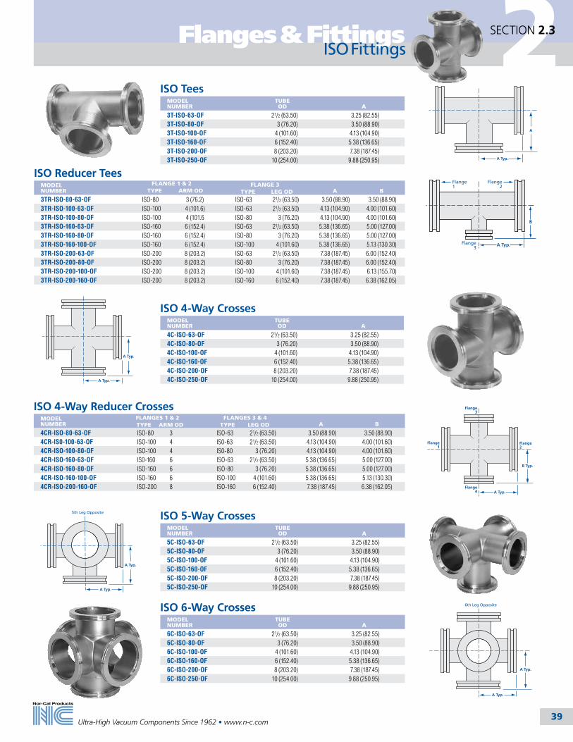
2
39
Flanges & Fittings
Ultra-High Vacuum Components Since 1962 • www.n-c.com
SECTION 2.3
ISO Fittings
A Typ.
A Typ.
Flange1
Flange2
B Typ.
Flange3
Flange4 A Typ.
5th Leg Opposite
A Typ.
A Typ.
6th Leg Opposite
A Typ.
A Typ.
ISO 6-Way CrossesMODELNUMBER
TUBE OD
A
6C-ISO-63-OF 21/2 (63.50) 3.25 (82.55)6C-ISO-80-OF 3 (76.20) 3.50 (88.90)6C-ISO-100-OF 4 (101.60) 4.13 (104.90)6C-ISO-160-OF 6 (152.40) 5.38 (136.65)6C-ISO-200-OF 8 (203.20) 7.38 (187.45)6C-ISO-250-OF 10 (254.00) 9.88 (250.95)
ISO 5-Way CrossesMODEL NUMBER
TUBE OD
A
5C-ISO-63-OF 21/2 (63.50) 3.25 (82.55)5C-ISO-80-OF 3 (76.20) 3.50 (88.90)5C-ISO-100-OF 4 (101.60) 4.13 (104.90)5C-ISO-160-OF 6 (152.40) 5.38 (136.65)5C-ISO-200-OF 8 (203.20) 7.38 (187.45)5C-ISO-250-OF 10 (254.00) 9.88 (250.95)
ISO 4-Way Reducer CrossesMODEL NUMBER
FLANGES 1 & 2 FLANGES 3 & 4 A
BTYPE ARM OD TYPE LEG OD
4CR-ISO-80-63-OF ISO-80 3 ISO-63 21/2 (63.50) 3.50 (88.90) 3.50 (88.90)4CR-IS0-100-63-OF ISO-100 4 IS0-63 21/2 (63.50) 4.13 (104.90) 4.00 (101.60)4CR-ISO-100-80-OF ISO-100 4 IS0-80 3 (76.20) 4.13 (104.90) 4.00 (101.60)4CR-ISO-160-63-OF IS0-160 6 ISO-63 21/2 (63.50) 5.38 (136.65) 5.00 (127.00)4CR-ISO-160-80-OF ISO-160 6 ISO-80 3 (76.20) 5.38 (136.65) 5.00 (127.00)4CR-ISO-160-100-OF ISO-160 6 ISO-100 4 (101.60) 5.38 (136.65) 5.13 (130.30)4CR-ISO-200-160-OF ISO-200 8 ISO-160 6 (152.40) 7.38 (187.45) 6.38 (162.05)
ISO 4-Way CrossesMODEL NUMBER
TUBE OD
A
4C-ISO-63-OF 21/2 (63.50) 3.25 (82.55)4C-ISO-80-OF 3 (76.20) 3.50 (88.90)4C-ISO-100-OF 4 (101.60) 4.13 (104.90)4C-ISO-160-OF 6 (152.40) 5.38 (136.65)4C-ISO-200-OF 8 (203.20) 7.38 (187.45)4C-ISO-250-OF 10 (254.00) 9.88 (250.95)
Flange1
Flange2
B
Flange3
A Typ.
ISO Reducer TeesMODEL NUMBER
FLANGE 1 & 2 FLANGE 3 A
BTYPE ARM OD TYPE LEG OD
3TR-ISO-80-63-OF ISO-80 3 (76.2) ISO-63 21/2 (63.50) 3.50 (88.90) 3.50 (88.90)3TR-ISO-100-63-OF ISO-100 4 (101.6) ISO-63 21/2 (63.50) 4.13 (104.90) 4.00 (101.60)3TR-ISO-100-80-OF ISO-100 4 (101.6 ISO-80 3 (76.20) 4.13 (104.90) 4.00 (101.60)3TR-ISO-160-63-OF ISO-160 6 (152.4) ISO-63 21/2 (63.50) 5.38 (136.65) 5.00 (127.00)3TR-ISO-160-80-OF ISO-160 6 (152.4) ISO-80 3 (76.20) 5.38 (136.65) 5.00 (127.00)3TR-ISO-160-100-OF ISO-160 6 (152.4) ISO-100 4 (101.60) 5.38 (136.65) 5.13 (130.30)3TR-ISO-200-63-OF ISO-200 8 (203.2) ISO-63 21/2 (63.50) 7.38 (187.45) 6.00 (152.40)3TR-ISO-200-80-OF ISO-200 8 (203.2) ISO-80 3 (76.20) 7.38 (187.45) 6.00 (152.40)3TR-ISO-200-100-OF ISO-200 8 (203.2) ISO-100 4 (101.60) 7.38 (187.45) 6.13 (155.70)3TR-ISO-200-160-OF ISO-200 8 (203.2) ISO-160 6 (152.40) 7.38 (187.45) 6.38 (162.05)
A
A Typ.
ISO TeesMODEL NUMBER
TUBE OD
A
3T-ISO-63-OF 21/2 (63.50) 3.25 (82.55)3T-ISO-80-OF 3 (76.20) 3.50 (88.90)3T-ISO-100-OF 4 (101.60) 4.13 (104.90)3T-ISO-160-OF 6 (152.40) 5.38 (136.65)3T-ISO-200-OF 8 (203.20) 7.38 (187.45)3T-ISO-250-OF 10 (254.00) 9.88 (250.95)
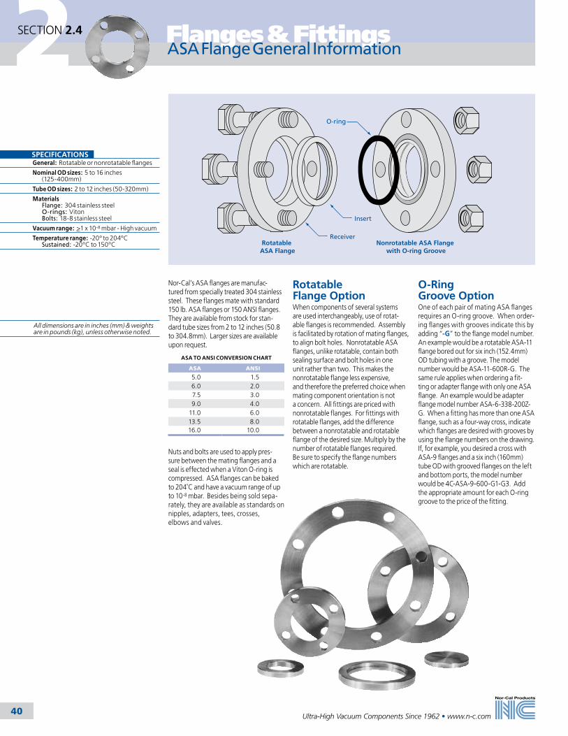
2
40
Flanges & Fittings
Ultra-High Vacuum Components Since 1962 • www.n-c.com
Nor-Cal’s ASA flanges are manufac-tured from specially treated 304 stainless steel. These flanges mate with standard 150 lb. ASA flanges or 150 ANSI flanges. They are available from stock for stan-dard tube sizes from 2 to 12 inches (50.8 to 304.8mm). Larger sizes are available upon request.
ASA TO ANSI CONVERSION CHART
ASA ANSI
5.0 1.56.0 2.07.5 3.09.0 4.0
11.0 6.013.5 8.016.0 10.0
Nuts and bolts are used to apply pres-sure between the mating flanges and a seal is effected when a Viton O-ring is compressed. ASA flanges can be baked to 204˚C and have a vacuum range of up to 10-8 mbar. Besides being sold sepa-rately, they are available as standards on nipples, adapters, tees, crosses, elbows and valves.
SECTION 2.4
ASA Flange General Information
Rotatable ASA Flange
Nonrotatable ASA Flange with O-ring Groove
Insert
O-ring
Receiver
SPECIFICATIONSGeneral: Rotatable or nonrotatable flanges
Nominal OD sizes: 5 to 16 inches (125-400mm)
Tube OD sizes: 2 to 12 inches (50-320mm)
Materials Flange: 304 stainless steel O-rings: Viton Bolts: 18-8 stainless steel
Vacuum range: >1 x 10⁻⁸ mbar - High vacuum
Temperature range: -20º to 204ºC Sustained: -20ºC to 150ºC
Rotatable Flange Option When components of several systems are used interchangeably, use of rotat-able flanges is recommended. Assembly is facilitated by rotation of mating flanges, to align bolt holes. Nonrotatable ASA flanges, unlike rotatable, contain both sealing surface and bolt holes in one unit rather than two. This makes the nonrotatable flange less expensive, and therefore the preferred choice when mating component orientation is not a concern. All fittings are priced with nonrotatable flanges. For fittings with rotatable flanges, add the difference between a nonrotatable and rotatable flange of the desired size. Multiply by the number of rotatable flanges required. Be sure to specify the flange numbers which are rotatable.
O-Ring Groove OptionOne of each pair of mating ASA flanges requires an O-ring groove. When order-ing flanges with grooves indicate this by adding “-G” to the flange model number. An example would be a rotatable ASA-11 flange bored out for six inch (152.4mm) OD tubing with a groove. The model number would be ASA-11-600R-G. The same rule applies when ordering a fit-ting or adapter flange with only one ASA flange. An example would be adapter flange model number ASA-6-338-200Z-G. When a fitting has more than one ASA flange, such as a four-way cross, indicate which flanges are desired with grooves by using the flange numbers on the drawing. If, for example, you desired a cross with ASA-9 flanges and a six inch (160mm) tube OD with grooved flanges on the left and bottom ports, the model number would be 4C-ASA-9-600-G1-G3. Add the appropriate amount for each O-ring groove to the price of the fitting.
All dimensions are in inches (mm) & weights are in pounds (kg), unless otherwise noted.
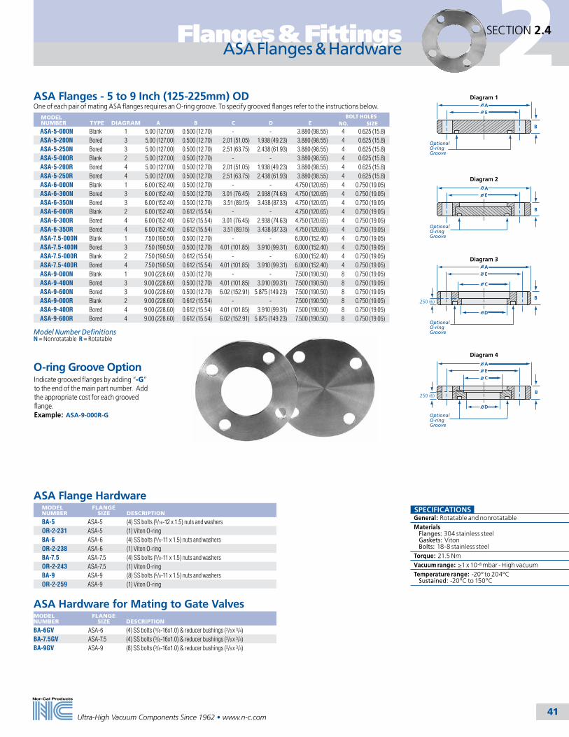
2
41
Flanges & Fittings
Ultra-High Vacuum Components Since 1962 • www.n-c.com
EA
C
D
EA
C
D
OptionalO-ringGroove
OptionalO-ringGroove
OptionalO-ringGroove
OptionalO-ringGroove
Diagram 1
Diagram 2
Diagram 3
Diagram 4
.250 (6)
.250 (6)
B
B
B
B
EA
EA
SECTION 2.4
ASA Flanges & Hardware
ASA Flange HardwareMODEL NUMBER
FLANGE SIZE
DESCRIPTION
BA-5 ASA-5 (4) SS bolts (9/16-12 x 1.5) nuts and washers OR-2-231 ASA-5 (1) Viton O-ringBA-6 ASA-6 (4) SS bolts (5/8-11 x 1.5) nuts and washers OR-2-238 ASA-6 (1) Viton O-ringBA-7.5 ASA-7.5 (4) SS bolts (5/8-11 x 1.5) nuts and washers OR-2-243 ASA-7.5 (1) Viton O-ringBA-9 ASA-9 (8) SS bolts (5/8-11 x 1.5) nuts and washersOR-2-259 ASA-9 (1) Viton O-ring
ASA Hardware for Mating to Gate ValvesMODEL NUMBER
FLANGE SIZE
DESCRIPTION
BA-6GV ASA-6 (4) SS bolts (3/8-16x1.0) & reducer bushings (3/8 x 3/4)BA-7.5GV ASA-7.5 (4) SS bolts (3/8-16x1.0) & reducer bushings (3/8 x 3/4)BA-9GV ASA-9 (8) SS bolts (3/8-16x1.0) & reducer bushings (3/8 x 3/4)
SPECIFICATIONSGeneral: Rotatable and nonrotatableMaterials Flanges: 304 stainless steel Gaskets: Viton Bolts: 18-8 stainless steelTorque: 21.5 NmVacuum range: >1 x 10⁻⁸ mbar - High vacuumTemperature range: -20º to 204ºC Sustained: -20ºC to 150ºC
ASA Flanges - 5 to 9 Inch (125-225mm) ODOne of each pair of mating ASA flanges requires an O-ring groove. To specify grooved flanges refer to the instructions below.
MODEL NUMBER
TYPE
DIAGRAM
A
B
C
D
E
BOLT HOLESNO. SIZE
ASA-5-000N Blank 1 5.00 (127.00) 0.500 (12.70) - - 3.880 (98.55) 4 0.625 (15.8)ASA-5-200N Bored 3 5.00 (127.00) 0.500 (12.70) 2.01 (51.05) 1.938 (49.23) 3.880 (98.55) 4 0.625 (15.8)ASA-5-250N Bored 3 5.00 (127.00) 0.500 (12.70) 2.51 (63.75) 2.438 (61.93) 3.880 (98.55) 4 0.625 (15.8)ASA-5-000R Blank 2 5.00 (127.00) 0.500 (12.70) - - 3.880 (98.55) 4 0.625 (15.8)ASA-5-200R Bored 4 5.00 (127.00) 0.500 (12.70) 2.01 (51.05) 1.938 (49.23) 3.880 (98.55) 4 0.625 (15.8)ASA-5-250R Bored 4 5.00 (127.00) 0.500 (12.70) 2.51 (63.75) 2.438 (61.93) 3.880 (98.55) 4 0.625 (15.8)ASA-6-000N Blank 1 6.00 (152.40) 0.500 (12.70) - - 4.750 (120.65) 4 0.750 (19.05)ASA-6-300N Bored 3 6.00 (152.40) 0.500 (12.70) 3.01 (76.45) 2.938 (74.63) 4.750 (120.65) 4 0.750 (19.05)ASA-6-350N Bored 3 6.00 (152.40) 0.500 (12.70) 3.51 (89.15) 3.438 (87.33) 4.750 (120.65) 4 0.750 (19.05)ASA-6-000R Blank 2 6.00 (152.40) 0.612 (15.54) - - 4.750 (120.65) 4 0.750 (19.05)ASA-6-300R Bored 4 6.00 (152.40) 0.612 (15.54) 3.01 (76.45) 2.938 (74.63) 4.750 (120.65) 4 0.750 (19.05)ASA-6-350R Bored 4 6.00 (152.40) 0.612 (15.54) 3.51 (89.15) 3.438 (87.33) 4.750 (120.65) 4 0.750 (19.05)ASA-7.5-000N Blank 1 7.50 (190.50) 0.500 (12.70) - - 6.000 (152.40) 4 0.750 (19.05)ASA-7.5-400N Bored 3 7.50 (190.50) 0.500 (12.70) 4.01 (101.85) 3.910 (99.31) 6.000 (152.40) 4 0.750 (19.05)ASA-7.5-000R Blank 2 7.50 (190.50) 0.612 (15.54) - - 6.000 (152.40) 4 0.750 (19.05)ASA-7.5-400R Bored 4 7.50 (190.50) 0.612 (15.54) 4.01 (101.85) 3.910 (99.31) 6.000 (152.40) 4 0.750 (19.05)ASA-9-000N Blank 1 9.00 (228.60) 0.500 (12.70) - - 7.500 (190.50) 8 0.750 (19.05)ASA-9-400N Bored 3 9.00 (228.60) 0.500 (12.70) 4.01 (101.85) 3.910 (99.31) 7.500 (190.50) 8 0.750 (19.05)ASA-9-600N Bored 3 9.00 (228.60) 0.500 (12.70) 6.02 (152.91) 5.875 (149.23) 7.500 (190.50) 8 0.750 (19.05)ASA-9-000R Blank 2 9.00 (228.60) 0.612 (15.54) - - 7.500 (190.50) 8 0.750 (19.05)ASA-9-400R Bored 4 9.00 (228.60) 0.612 (15.54) 4.01 (101.85) 3.910 (99.31) 7.500 (190.50) 8 0.750 (19.05)ASA-9-600R Bored 4 9.00 (228.60) 0.612 (15.54) 6.02 (152.91) 5.875 (149.23) 7.500 (190.50) 8 0.750 (19.05)
Indicate grooved flanges by adding “-G” to the end of the main part number. Add the appropriate cost for each grooved flange. Example: ASA-9-000R-G
O-ring Groove Option
Model Number Definitions N = Nonrotatable R = Rotatable

2
42
Flanges & Fittings
Ultra-High Vacuum Components Since 1962 • www.n-c.com
ASA Flange HardwareMODEL NUMBER
SIZE
DESCRIPTION
BA-11 ASA-11 (8) SS bolts (3/4-10 x 2.25) nuts and washersOR-2-266 ASA-11 (1) Viton O-ringBA-13.5 ASA-13.5 (8) SS bolts (3/4-10 x 2.25) nuts and washersOR-2-274 ASA-13.5 (1) Viton O-ringBA-16 ASA-16 (12) SS bolts (3/4-10 x 2.25) nuts and washers OR-2-278 ASA-16 (1) Viton O-ring
ASA Hardware for Mating to Gate ValvesMODEL NUMBER
SIZE
DESCRIPTION
BA-11GV ASA-11 (8) SS bolts (3/8-16 x 1.0)BA-16GV ASA-16 (12) SS bolts (3/8-16 x 1.0)
ASA Flanges & Hardware
ASA Flanges - 11 to 16 Inch (285-400mm) ODOne of each pair of mating ASA flanges requires an O-ring groove. To specify grooved flanges refer to the instructions below.
MODEL NUMBER
TYPE
DIAGRAM
A
B
C
D
BOLT HOLESNO. SIZE
ASA-11-000N Blank 1 11.00 (279.40) - - 9.500 (251.3) 8 0.812 (20.62)ASA-11-600N Bored 3 11.00 (279.40) 6.02 (152.91) 5.875 (149.225) 9.500 (251.3) 8 0.812 (20.62)ASA-11-800N Bored 3 11.00 (279.40) 8.02 (203.71) 7.875 (200.025) 9.500 (251.3) 8 0.812 (20.62)ASA-11-000R Blank 2 11.00 (279.40) - - 9.500 (251.3) 8 0.812 (20.62)ASA-11-600R Bored 4 11.00 (279.40) 6.02 (152.91) 5.875 (149.225) 9.500 (251.3) 8 0.812 (20.62)ASA-11-800R Bored 4 11.00 (279.40) 8.02 (203.71) 7.875 (200.025) 9.500 (251.3) 8 0.812 (20.62)ASA-13.5-000N Blank 1 13.50 (343.90) - - 11.750 (298.45) 8 0.812 (20.62)ASA-13.5-800N Bored 3 13.50 (343.90) 8.02 (203.71) 7.875 (200.025) 11.750 (298.45) 8 0.812 (20.62)ASA-13.5-1000N Bored 3 13.50 (343.90) 10.03 (254.76) 9.875 (250.825) 11.750 (298.45) 8 0.812 (20.62)ASA-13.5-000R Blank 2 13.50 (343.90) - - 11.750 (298.45) 8 0.812 (20.62)ASA-13.5-800R Bored 4 13.50 (343.90) 8.02 (203.71) 7.875 (200.025) 11.750 (298.45) 8 0.812 (20.62)ASA-13.5-1000R Bored 4 13.50 (343.90) 10.03 (254.76) 9.875 (250.825) 11.750 (298.45) 8 0.812 (20.62)ASA-16-000N Blank 1 16.00 (406.40) - - 14.250 (361.95) 12 0.812 (20.62)ASA-16-1000N Bored 3 16.00 (406.40) 10.03 (254.76) 9.875 (250.825) 14.250 (361.95) 12 0.812 (20.62)ASA-16-1200N Bored 3 16.00 (406.40) 12.03 (305.56) 11.875 (301.625) 14.250 (361.95) 12 0.812 (20.62)ASA-16-000R Blank 2 16.00 (406.40) - - 14.250 (361.95) 12 0.812 (20.62)ASA-16-1000R Bored 4 16.00 (406.40) 10.03 (254.76) 9.875 (250.825) 14.250 (361.95) 12 0.812 (20.62)ASA-16-1200R Bored 4 16.00 (406.40) 12.03 (305.56) 11.875 (301.625) 14.250 (361.95) 12 0.812 (20.62)
Model Number Definitions N = Nonrotatable R = Rotatable
SPECIFICATIONSGeneral: Rotatable and nonrotatable
Material Flanges: 304 stainless steel Gaskets: Viton Bolts: 18-8 stainless steel
Torque: 21.5 Nm
Vacuum range: >1 x 10⁻⁸ mbar - High vacuum
Temperature range: -20° to 204ºC Operating: -20ºC to 150ºC
DA
DA
B
C
D
A
DA
B
C
OptionalO-ringGroove
OptionalO-ringGroove
OptionalO-ringGroove
OptionalO-ringGroove
Diagram 1
Diagram 2
Diagram 3
Diagram 4
.750(19.050)
.375
.375
.750(19.050)
.750(19.050)
.750(19.050)
O-ring Groove Option
SECTION 2.4
Indicate grooved flanges by adding “-G” to the end of the main part number. Add the appropriate cost for each grooved flange. Example: ASA-9-000R-G
All dimensions are in inches (mm) & weights are in pounds (kg), unless otherwise noted.

2
43
Flanges & Fittings
Ultra-High Vacuum Components Since 1962 • www.n-c.com
Nor-Cal manufactures a complete line of flanged vacuum component fittings. The tube portions are fabricated from 304 stainless steel. On request, 316 stainless steel can be supplied. Nor-Cal makes its own elbows, and all tees and crosses are made with the pulled-port technique. This allows smooth, crevice-free butt welds to provide the maximum in cleanliness for UHV applications. Bake-out range is up to 200°C. Nor-Cal fittings are also available with CF (Conflat style), NW and ISO flanges.
ASA Half NipplesOne of each pair of mating ASA flanges requires an O-ring groove. To specify grooved flanges refer to the instructions below.
MODEL NUMBER
FLANGE OD
TUBE OD
A
1N-ASA-5-200 5.00 (127.00) 2 (50.80) 3.25 (82.55)1N-ASA-5-250 5.00 (127.00) 21/2 (63.50) 3.25 (82.55)1N-ASA-5-250V 5.00 (127.00) 21/2 (63.50) 4.00 (101.60)1N-ASA-6-300 6.00 (152.40) 3 (76.20) 3.50 (88.90)1N-ASA-7.5-400 7.50 (190.50) 4 (101.60) 4.13 (104.90)1N-ASA-7.5-400V 7.50 (190.50) 4 (101.60) 5.12 (130.05)1N-ASA-9-400 9.00 (228.60) 4 (101.60) 4.13 (104.90)1N-ASA-9-400V 9.00 (228.60) 4 (101.60) 5.12 (130.05)1N-ASA-9-600 9.00 (228.60) 6 (152.40) 2.25 (133.35)1N-ASA-9-600V 9.00 (228.60) 6 (152.40) 6.31 (160.27)1N-ASA-11-600 11.00 (279.40) 6 (152.40) 5.38 (136.65)1N-ASA-11-600V 11.00 (279.40) 6 (152.40) 6.44 (163.58)1N-ASA-11-800 11.00 (279.40) 8 (203.20) 7.38 (187.45)1N-ASA-13.5-800 13.50 (342.90) 8 (203.20) 7.75 (196.85)1N-ASA-13.5-1000 13.50 (342.90) 10 (254.00) 9.88 (250.95)1N-ASA-16-1000 16.00 (406.40) 10 (254.00) 9.88 (250.95)1N-ASA-16-1200 16.00 (406.40) 12 (304.80) 9.88 (250.95)
ASA Full NipplesOne of each pair of mating ASA flanges requires an O-ring groove. To specify grooved flanges refer to the instructions below.
MODEL NUMBER
FLANGE OD
TUBE OD
A
2N-ASA-5-200N 5.00 (127.00) 2 (50.80) 6.50 (165.10)2N-ASA-5-250N 5.00 (127.00) 21/2 (63.50) 6.50 (165.10)2N-ASA-5-250NV 5.00 (127.00) 21/2 (63.50) 8.00 (203.20)2N-ASA-6-300N 6.00 (152.40) 3 (76.20) 7.00 (177.80)2N-ASA-7.5-400N 7.50 (190.50) 4 (101.60) 8.26 (209.80)2N-ASA-7.5-400NV 7.50 (190.50) 4 (101.60) 10.24 (260.10)2N-ASA-9-400N 9.00 (228.60) 4 (101.60) 8.26 (209.80)2N-ASA-9-400NV 9.00 (228.60) 4 (101.60) 10.24 (260.10)2N-ASA-9-600N 9.00 (228.60) 6 (152.40) 10.50 (266.70)2N-ASA-9-600NV 9.00 (228.60) 6 (152.40) 12.62 (320.55)2N-ASA-11-600N 11.00 (279.40) 6 (152.40) 10.76 (273.30)2N-ASA-11-600NV 11.00 (279.40) 6 (152.40) 12.88 (327.15)2N-ASA-11-800N 11.00 (279.40) 8 (203.20) 14.76 (374.90)2N-ASA-13.5-800N 13.50 (342.90) 8 (203.20) 15.50 (393.70)2N-ASA-13.5-1000N 13.50 (342.90) 10 (254.00) 19.76 (501.90)2N-ASA-16-1000N 16.00 (406.40) 10 (254.00) 19.76 (501.90)2N-ASA-16-1200N 16.00 (406.40) 12 (304.80) 19.76 (501.90)
A
A
Flange 1
Flange2
ASA Fittings
O-ring Groove Option Indicate grooved flanges by adding “-G +Flange number from drawing” to the end of main part number. Add the appropriate cost for each grooved flange. Example: 4C-ASA-9-600-G1-G3
SECTION 2.4
SPECIFICATIONSGeneral: Rotatable and nonrotatableMaterials Flanges: 304 stainless steel Gaskets: Viton Bolts: 18-8 stainless steelTorque: 21.5 NmVacuum range: >1 x 10⁻⁸ mbar - High vacuumTemperature range: -20º to 204ºC Sustained: -20ºC to 150ºC
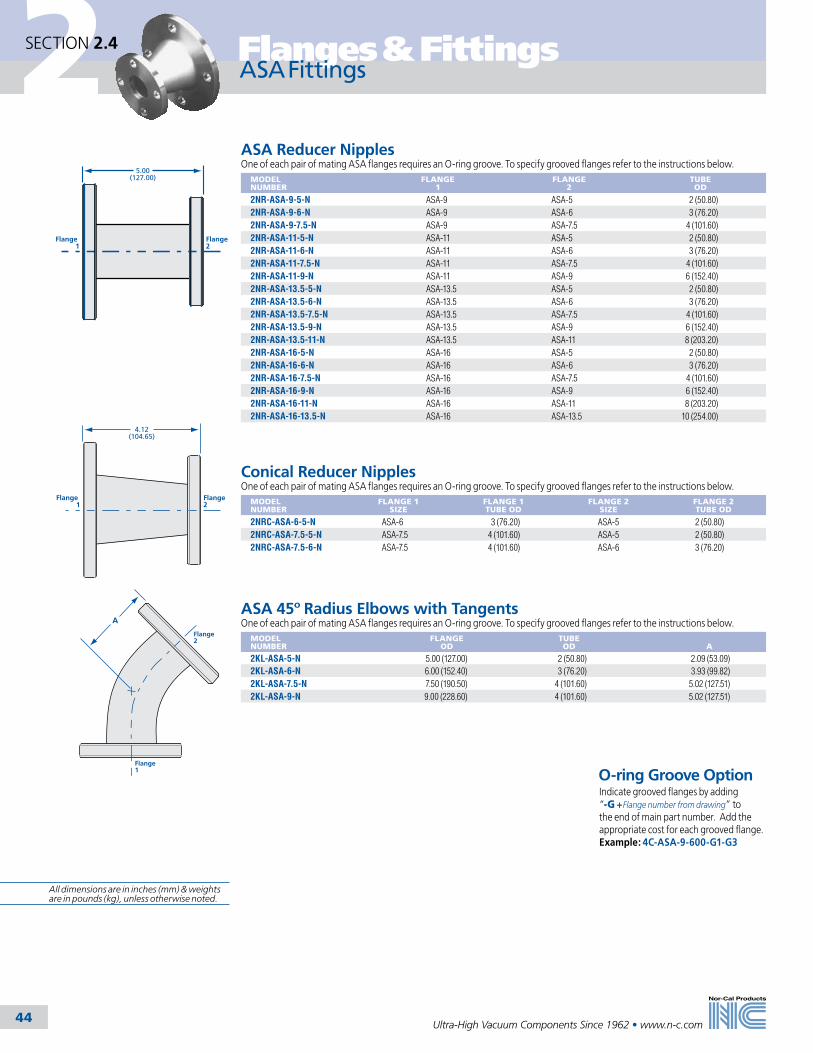
2
44
Flanges & Fittings
Ultra-High Vacuum Components Since 1962 • www.n-c.com
5.00(127.00)
Flange 1
Flange2
Flange 1
4.12(104.65)
Flange2
A
Flange 1
Flange 2
ASA Reducer NipplesOne of each pair of mating ASA flanges requires an O-ring groove. To specify grooved flanges refer to the instructions below.
MODEL NUMBER
FLANGE 1
FLANGE 2
TUBE OD
2NR-ASA-9-5-N ASA-9 ASA-5 2 (50.80)2NR-ASA-9-6-N ASA-9 ASA-6 3 (76.20)2NR-ASA-9-7.5-N ASA-9 ASA-7.5 4 (101.60)2NR-ASA-11-5-N ASA-11 ASA-5 2 (50.80)2NR-ASA-11-6-N ASA-11 ASA-6 3 (76.20)2NR-ASA-11-7.5-N ASA-11 ASA-7.5 4 (101.60)2NR-ASA-11-9-N ASA-11 ASA-9 6 (152.40)2NR-ASA-13.5-5-N ASA-13.5 ASA-5 2 (50.80)2NR-ASA-13.5-6-N ASA-13.5 ASA-6 3 (76.20)2NR-ASA-13.5-7.5-N ASA-13.5 ASA-7.5 4 (101.60)2NR-ASA-13.5-9-N ASA-13.5 ASA-9 6 (152.40)2NR-ASA-13.5-11-N ASA-13.5 ASA-11 8 (203.20)2NR-ASA-16-5-N ASA-16 ASA-5 2 (50.80)2NR-ASA-16-6-N ASA-16 ASA-6 3 (76.20)2NR-ASA-16-7.5-N ASA-16 ASA-7.5 4 (101.60)2NR-ASA-16-9-N ASA-16 ASA-9 6 (152.40)2NR-ASA-16-11-N ASA-16 ASA-11 8 (203.20)2NR-ASA-16-13.5-N ASA-16 ASA-13.5 10 (254.00)
Conical Reducer NipplesOne of each pair of mating ASA flanges requires an O-ring groove. To specify grooved flanges refer to the instructions below.
MODEL NUMBER
FLANGE 1 SIZE
FLANGE 1 TUBE OD
FLANGE 2 SIZE
FLANGE 2 TUBE OD
2NRC-ASA-6-5-N ASA-6 3 (76.20) ASA-5 2 (50.80)2NRC-ASA-7.5-5-N ASA-7.5 4 (101.60) ASA-5 2 (50.80)2NRC-ASA-7.5-6-N ASA-7.5 4 (101.60) ASA-6 3 (76.20)
ASA 45º Radius Elbows with TangentsOne of each pair of mating ASA flanges requires an O-ring groove. To specify grooved flanges refer to the instructions below.
MODEL NUMBER
FLANGE OD
TUBE OD
A
2KL-ASA-5-N 5.00 (127.00) 2 (50.80) 2.09 (53.09)2KL-ASA-6-N 6.00 (152.40) 3 (76.20) 3.93 (99.82)2KL-ASA-7.5-N 7.50 (190.50) 4 (101.60) 5.02 (127.51)2KL-ASA-9-N 9.00 (228.60) 4 (101.60) 5.02 (127.51)
ASA FittingsSECTION 2.4
O-ring Groove Option Indicate grooved flanges by adding “-G +Flange number from drawing” to the end of main part number. Add the appropriate cost for each grooved flange. Example: 4C-ASA-9-600-G1-G3
All dimensions are in inches (mm) & weights are in pounds (kg), unless otherwise noted.
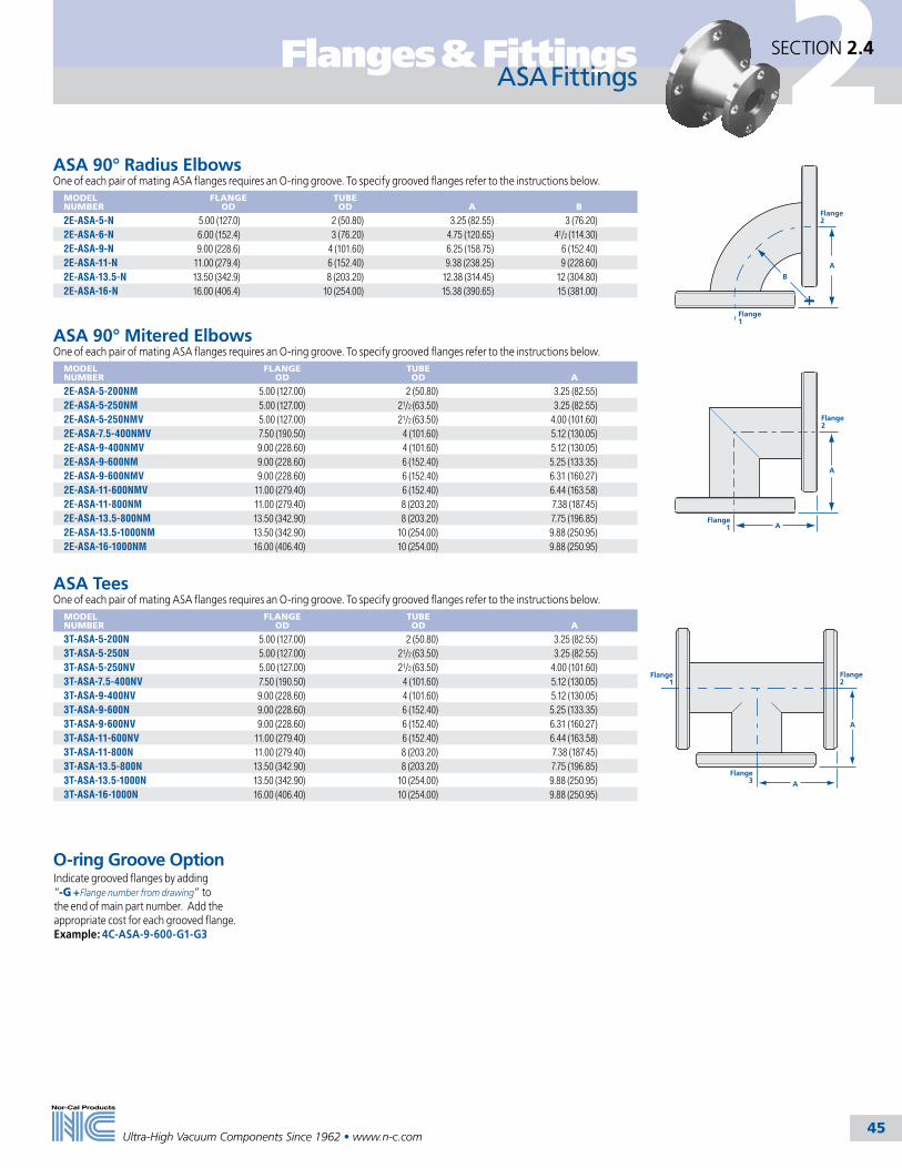
2
45
Flanges & Fittings
Ultra-High Vacuum Components Since 1962 • www.n-c.com
ASA 90° Mitered ElbowsOne of each pair of mating ASA flanges requires an O-ring groove. To specify grooved flanges refer to the instructions below.
MODEL NUMBER
FLANGE OD
TUBE OD
A
2E-ASA-5-200NM 5.00 (127.00) 2 (50.80) 3.25 (82.55)2E-ASA-5-250NM 5.00 (127.00) 21/2 (63.50) 3.25 (82.55)2E-ASA-5-250NMV 5.00 (127.00) 21/2 (63.50) 4.00 (101.60)2E-ASA-7.5-400NMV 7.50 (190.50) 4 (101.60) 5.12 (130.05)2E-ASA-9-400NMV 9.00 (228.60) 4 (101.60) 5.12 (130.05)2E-ASA-9-600NM 9.00 (228.60) 6 (152.40) 5.25 (133.35)2E-ASA-9-600NMV 9.00 (228.60) 6 (152.40) 6.31 (160.27)2E-ASA-11-600NMV 11.00 (279.40) 6 (152.40) 6.44 (163.58)2E-ASA-11-800NM 11.00 (279.40) 8 (203.20) 7.38 (187.45)2E-ASA-13.5-800NM 13.50 (342.90) 8 (203.20) 7.75 (196.85)2E-ASA-13.5-1000NM 13.50 (342.90) 10 (254.00) 9.88 (250.95)2E-ASA-16-1000NM 16.00 (406.40) 10 (254.00) 9.88 (250.95)
ASA 90° Radius ElbowsOne of each pair of mating ASA flanges requires an O-ring groove. To specify grooved flanges refer to the instructions below.
MODEL NUMBER
FLANGE OD
TUBE OD
A
B
2E-ASA-5-N 5.00 (127.0) 2 (50.80) 3.25 (82.55) 3 (76.20)2E-ASA-6-N 6.00 (152.4) 3 (76.20) 4.75 (120.65) 41/2 (114.30)2E-ASA-9-N 9.00 (228.6) 4 (101.60) 6.25 (158.75) 6 (152.40)2E-ASA-11-N 11.00 (279.4) 6 (152.40) 9.38 (238.25) 9 (228.60)2E-ASA-13.5-N 13.50 (342.9) 8 (203.20) 12.38 (314.45) 12 (304.80)2E-ASA-16-N 16.00 (406.4) 10 (254.00) 15.38 (390.65) 15 (381.00)
A
AFlange
1
Flange2
A
B
Flange 1
Flange2
ASA TeesOne of each pair of mating ASA flanges requires an O-ring groove. To specify grooved flanges refer to the instructions below.
MODEL NUMBER
FLANGE OD
TUBE OD
A
3T-ASA-5-200N 5.00 (127.00) 2 (50.80) 3.25 (82.55)3T-ASA-5-250N 5.00 (127.00) 21/2 (63.50) 3.25 (82.55)3T-ASA-5-250NV 5.00 (127.00) 21/2 (63.50) 4.00 (101.60)3T-ASA-7.5-400NV 7.50 (190.50) 4 (101.60) 5.12 (130.05)3T-ASA-9-400NV 9.00 (228.60) 4 (101.60) 5.12 (130.05)3T-ASA-9-600N 9.00 (228.60) 6 (152.40) 5.25 (133.35)3T-ASA-9-600NV 9.00 (228.60) 6 (152.40) 6.31 (160.27)3T-ASA-11-600NV 11.00 (279.40) 6 (152.40) 6.44 (163.58)3T-ASA-11-800N 11.00 (279.40) 8 (203.20) 7.38 (187.45)3T-ASA-13.5-800N 13.50 (342.90) 8 (203.20) 7.75 (196.85)3T-ASA-13.5-1000N 13.50 (342.90) 10 (254.00) 9.88 (250.95)3T-ASA-16-1000N 16.00 (406.40) 10 (254.00) 9.88 (250.95)
Flange3
A
A
Flange1
Flange2
ASA FittingsSECTION 2.4
O-ring Groove Option Indicate grooved flanges by adding “-G +Flange number from drawing” to the end of main part number. Add the appropriate cost for each grooved flange. Example: 4C-ASA-9-600-G1-G3

2
46
Flanges & Fittings
Ultra-High Vacuum Components Since 1962 • www.n-c.com
ASA Fittings
ASA 4-Way CrossesOne of each pair of mating ASA flanges requires an O-ring groove. To specify grooved flanges refer to the instructions below.
MODEL NUMBER
FLANGE OD
TUBE OD
A
4C-ASA-5-200N 5.00 (127.00) 2 (50.80) 3.25 (82.55)4C-ASA-5-250N 5.00 (127.00) 21/2 (63.50) 3.25 (82.55)4C-ASA-5-250NV 5.00 (127.00) 21/2 (63.50) 4.00 (101.60)4C-ASA-7.5-400NV 7.50 (190.50) 4 (101.60) 5.12 (130.05)4C-ASA-9-400NV 9.00 (228.60) 4 (101.60) 5.12 (130.05)4C-ASA-9-600N 9.00 (228.60) 6 (152.40) 5.25 (133.35)4C-ASA-9-600NV 9.00 (228.60) 6 (152.40) 6.31 (160.27)4C-ASA-11-600NV 11.00 (279.40) 6 (152.40) 6.44 (163.58)4C-ASA-11-800N 11.00 (279.40) 8 (203.20) 7.38 (187.45)4C-ASA-13.5-800N 13.50 (342.90) 8 (203.20) 7.75 (196.85)4C-ASA-13.5-1000N 13.50 (342.90) 10 (254.00) 9.88 (250.95)4C-ASA-16-1000N 16.00 (406.40) 10 (254.00) 9.88 (250.95)
A Typ.
A Typ.Flange 3
Flange1
Flange2
Flange 4
ASA 5-Way CrossesOne of each pair of mating ASA flanges requires an O-ring groove. To specify grooved flanges refer to the instructions below.
MODEL NUMBER
FLANGE OD
TUBE OD
A
5C-ASA-5-200N 5.00 (127.00) 2 (50.80) 3.25 (82.55)5C-ASA-5-250N 5.00 (127.00) 21/2 (63.50) 3.25 (82.55)5C-ASA-5-250NV 5.00 (127.00) 21/2 (63.50) 4.00 (101.60)5C-ASA-7.5-400NV 7.50 (190.50) 4 (101.60) 5.12 (130.05)5C-ASA-9-400NV 9.00 (228.60) 4 (101.60) 5.12 (130.05)5C-ASA-9-600N 9.00 (228.60) 6 (152.40) 5.25 (133.35)5C-ASA-9-600NV 9.00 (228.60) 6 (152.40) 6.31 (160.27)5C-ASA-11-600NV 11.00 (279.40) 6 (152.40) 6.44 (163.58)5C-ASA-11-800N 11.00 (279.40) 8 (203.20) 7.38 (187.45)5C-ASA-13.5-800N 13.50 (342.90) 8 (203.20) 7.75 (196.85)5C-ASA-13.5-1000N 13.50 (342.90) 10 (254.00) 9.88 (250.95)5C-ASA-16-1000N 16.00 (406.40) 10 (254.00) 9.88 (250.95)
ASA 6-Way CrossesOne of each pair of mating ASA flanges requires an O-ring groove. To specify grooved flanges refer to the instructions below.
MODEL NUMBER
FLANGE OD
TUBE OD
A
6C-ASA-5-200N 5.00 (127.00) 2 (50.80) 3.25 (82.55)6C-ASA-5-250N 5.00 (127.00) 21/2 (63.50) 3.25 (82.55)6C-ASA-5-250NV 5.00 (127.00) 21/2 (63.50) 4.00 (101.60)6C-ASA-7.5-400NV 7.50 (190.50) 4 (101.60) 5.12 (130.05)6C-ASA-9-400NV 9.00 (228.60) 4 (101.60) 5.12 (130.05)6C-ASA-9-600N 9.00 (228.60) 6 (152.40) 5.25 (133.35)6C-ASA-9-600NV 9.00 (228.60) 6 (152.40) 6.31 (160.27)6C-ASA-11-600NV 11.00 (279.40) 6 (152.40) 6.44 (163.58)6C-ASA-11-800N 11.00 (279.40) 8 (203.20) 7.38 (187.45)6C-ASA-13.5-800N 13.50 (342.90) 8 (203.20) 7.75 (196.85)6C-ASA-13.5-1000N 13.50 (342.90) 10 (254.00) 9.88 (250.95)6C-ASA-16-1000N 16.00 (406.40) 10 (254.00) 9.88 (250.95)
A Typ.
A Typ.Flange 3
Flange 1
Flange2
Flange 4
Flange 5
A Typ.
A Typ.Flange 3
Flange1
Flange2
Flange 4
Flange 5
Flange 6(other side)
SECTION 2.4
O-ring Groove Option Indicate grooved flanges by adding “-G +Flange number from drawing” to the end of main part number. Add the appropriate cost for each grooved flange. Example: 4C-ASA-9-600-G1-G3All dimensions are in inches (mm) & weights
are in pounds (kg), unless otherwise noted.

2
Ultra-High Vacuum Components Since 1962 • www.n-c.com 47
Flanges & Fittings SECTION 2.5
SPECIFICATIONSGeneral: Rotatable or nonrotatable with tapped or clearance bolt holesNominal OD sizes: 11/3 to 161/2 inches (34-419mm)Tube OD sizes: 1/4 to 14 inches (6-350mm)Materials Flange: 304 stainless steel (316L available on request) Gaskets: Viton, copper or silver plated Bolts: 18-8 stainless steel or silver platedVacuum range Metal seal: >1 x 10-13 mbar - UHV Elastomer seal: >1 x 10⁻⁸ mbar - High vacuumTemperature range Metal seal: -200ºC to 450ºC Elastomer seal: -20ºC to 150ºC
Nor-Cal CF flanges are compatible with other Conflat style flanges and are available in sizes from 11/3 to 161/2 inch (33.96-419.1mm) OD for 1/4 to 14 inch (6.35-355.6mm) tube diameters. Normally our standard material is in the low carbon range for 304. Flanges are made from 304 that has been specially treated to remove impurities inherent in 300 series steels. Special UHV-flanges 4 ½ inches (114.3mm) OD and smaller can be made from 304 electroslag remelt (ESR) bar stock. ESR is a refining process that produces stainless steel with higher purity, fewer inclusions and more uniform grain structure to eliminate microscopic leak paths. Our standard flange material is certified to meet ASTM A-240 and has less than 0.01% sulfur to prevent sulfur string-ers. Grain size is 3 to 6 per ASTM E-112. Maximum inclusion size is 2.5 per ASTM E-45. As specials, 304L and 316L mate-
rial can be supplied in roll-forged rings.Machining is consistent with good UHV practice. Machine coolant is sulfur free to reduce outgassing. State-of-the-art CNC machine centers are used to produce flanges with consistent high quality. Flanges are machine washed in approved aqueous detergent after machining. Chem-cleaning and clean room packaging are available.
CF flanges utilize an OFHC copper gasket to produce a vacuum tight seal up to 10-13 mbar, even when baked repeatedly to 450ºC. When the copper gasket is compressed between the knife edges of CF flanges, its material flows laterally to fill surface imperfections.
OFHC Copper Gasket
Metric Flanges and HardwareNor-Cal now stocks bored metric tapped CF flanges in 23/4, 41/2, 6, 8 and 10 inch (69.85, 114.3, 152.5, 203.2 and 254mm) ODs. Other sizes are available upon request. Fasteners for metric flanges are stocked for each flange size.
CF Flange General Information
New Products
Nor-Cal offers CF flanges in rotatable as well as nonrotatable versions. (Refer to diagram on page 48.) When components of several systems are used interchangeably, the use of rotatable flanges is recommended. Assembly is facilitated by rotating the receiver portion of the flange to align its bolt holes with those of the mating flange. The insert is welded to the tube or component and contains the knife edge portion of the CF flange.
Nonrotatable CF flanges, unlike rotatable, contain both sealing surface and bolt holes in one unit. This makes the nonrotatable flange less expensive, and therefore the preferred choice when mating component orientation is not a concern. All fittings are priced with a rotatable flange opposing a nonrotat-able. For fittings with all nonrotatable flanges subtract the difference in price between a rotatable and nonrotatable flange of the desired size multiplied by the number of additional nonrotatable flanges.
Silver plated Gaskets and BoltsWe are now offering silver plated cop-per gaskets and bolt kits in a variety of sizes. Silver plated copper gaskets are recommended when the use of pure copper is unacceptable. Silver plated bolt kits offer an alternative to using anti-seize thread lubricant.
All dimensions are in inches (mm) & weights are in pounds (kg), unless otherwise noted.

2
Ultra-High Vacuum Components Since 1962 • www.n-c.com 48
Flanges & FittingsSECTION 2.5
RotatableNonrotatable
Plate Nut
Nut
Receiver
Insert
Gasket
1. Apply a small amount of high temperature anti-seize compound to the bolt threads.2. Check that both flange surfaces are clean and sealing edges are free from nicks and scratches.3. Using clean, lint free gloves, unpack gasket.4. Place gasket in the knife edge counterbore of nonrotatable flange. 5. Align the mating hole pattern and leak test grooves.6. Install the proper bolts and tighten hand tight. Check to see that the flange faces are parallel.7. Tighten the bolts 1/4 to 1/2 turns using a star pattern until the flange faces are metal to metal. 8. Torque the fasteners to the listed value using the same pattern.
Assembly Instructions for Nor-Cal CF (Conflat) Flanges
Fastening HardwareCF flanges are available with tapped or untapped holes. Tapped flanges are available in UNC/UNF or metric threads. Tapped flanges have through holes, so bolts may protrude slightly from the back of the flange when fastened to an untapped flange. Untapped CF flanges can be fastened to each other with stainless steel bolts and hex nuts or plate nuts. Plate nuts center themselves over two adjacent holes and can be held in place with one finger while the bolts are tightened. They are available for most flange sizes from 11/3 to 10 inch (33.96-254mm) ODs. As an alternative to hex head bolts, 12-point bolts are available for CF flanges from 23/4 to 10 inch (33.96 to 354mm) ODs. Silver plated bolts eliminate the need for anti-seize compound in clean room environments.
Torque Specifications* NOMINAL
ODBOLT SIZE TORQUE IN NM
11/3 (34) 8-32 (M4) 3.221/8 (54) 1/4 - 28 (M6) 12.423/4 (70) 1/4 - 28 (M6) 12.433/8 (86) 5/16 - 24 (M8) 21.5
41/2 (114) 5/16 - 24 (M8) 21.545/8 (117) 5/16 - 24 (M8) 21.5
6 (152) 5/16 - 24 (M8) 21.563/4 (171) 5/16 - 24 (M8) 21.5
8 (203) 5/16 - 24 (M8) 21.510 (254) 5/16 - 24 (M8) 21.512 (305) 5/16 - 24 (M8) 21.5
131/4 (337) 3/8 - 24 (M8) 39.0
14 (356) 3/8 - 24 (M8) 39.0141/2 (368) 3/8 - 24 (M8) 39.0161/2 (419) 3/8 - 24 (M8) 39.0
* Specifications for Nor-Cal supplied fasteners only
CF Flange Assembly Instructions
SPECIFICATIONSGeneral: Rotatable or nonrotatable flanges with tapped or clearance bolt holes
Nominal OD sizes: 11/3 to 161/2 inches (34-419mm)
Tube sizes: 1/4 to 14 inches (6.35-355.6mm)
Materials Flange: 304 stainless steel (316L available on request) Gaskets: Viton, copper or silver plated Bolts: 18-8 stainless steel or silver plated
Vacuum range Metal seal: >1 x 10-13 mbar - UHV Elastomer seal: >1 x 10⁻⁸ mbar - High vacuum
Temperature Range Metal seal: -200ºC to 450ºC Elastomer seal: -20ºC to 150ºC
All dimensions are in inches (mm) & weights are in pounds (kg), unless otherwise noted.

2
Ultra-High Vacuum Components Since 1962 • www.n-c.com 49
Flanges & Fittings
Model Number DefinitionsN = Nonrotatable, clearance bolt holes NT = Nonrotatable, tapped bolt holes R = Rotatable, clearance bolt holes RT = Rotatable, tapped bolt holes K=Weld neck with weld prep BK=Weld neck without weld prep Add -M4= Metric Thread
SECTION 2.5
CF Mini FlangesMODEL NUMBER TYPE
DIAGRAM
A
BOLT HOLES
DIAMETER OR THREAD
133-000N Blank A - 6 .172133-000NK Blank weld neck with weld prep G - 6 .172133-025N Bored D .255 (6.48) 6 .172133-038N Bored D .0380 (9.65) 6 .172133-050N Bored D 0.505 (12.83) 6 .172133-075N Counterbored for tube OD E 0.625 (15.88) 6 .172133-075NK Bored weld neck with weld prep G 0.625 (15.88) 6 .172133-075NBK Bored weld neck without weld prep F 0.625 (15.88) 6 .172133-000NT Blank A 6 8-32133-000NKT Blank weld neck with weld prep G 6 8-32133-025NT Bored D .255 (6.48) 6 8-32133-038NT Bored D .0380 (9.65) 6 8-32133-050NT Bored D 0.505 (12.83) 6 8-32133-075NT Counterbored for tube OD E 0.625 (15.88) 6 8-32133-075NKT Bored weld neck with weld prep G 0.625 (15.88) 6 8-32133-075NBKT Bored weld neck without weld prep F 0.625 (15.88) 6 8-32133-000R Blank B 6 .172133-000RK Blank weld neck with weld prep H 6 .172133-025R Bored C .255 (6.48) 6 .172133-038R Bored C .0380 (9.65) 6 .172133-050R Bored C 0.505 (12.83) 6 .172133-075R Bored C 0.625 (15.88) 6 .172133-075RK Bored weld neck with weld prep H 0.625 (15.88) 6 .172133-075RBK Bored weld neck without weld prep I 0.625 (15.88) 6 .172133-000RT Blank B 6 8-32133-000RKT Blank weld neck with weld prep H 6 8-32133-025RT Bored C .255 (6.48) 6 8-32133-038RT Bored C .0380 (9.65) 6 8-32133-050RT Bored C 0.505 (12.83) 6 8-32133-075RT Bored C 0.625 (15.88) 6 8-32133-075RKT Bored weld neck with weld prep H 0.625 (15.88) 6 8-32133-075RBKT Bored weld neck without weld prep I 0.625 (15.88) 6 8-32
CF mini flanges are manufactured to the same high standard as our other CF flanges for 1⁄4, 3⁄8, 1⁄2, and 3⁄4 inch (6.35, 9.53, 12.7 and 19.05mm) OD tube sizes. Nor-Cal offers special purpose, double-sided and zero-length reducer mini flanges along with fittings, view-ports and feedthroughs in this size, so we can supply all the components necessary to build a complete table-top, small laboratory or gas handling system from stock.
Diagram H
CF Mini Flanges and Hardware
Diagram A1.330
(33.78)1.062
(26.98)
.300(7.62)
Diagram E
.755(19.18)
.175(4.45)
A
1.330(33.78)
1.062(26.98)
.300(7.62)
Diagram G
.672(17.07)
.060(1.52)
A
1.330(33.78)
1.062(26.98)
.500(12.70)
.750(19.05)
Diagram B1.330
(33.78)1.062
(26.98)
.300(7.62)
Diagram C
1.330(33.78)
1.062(26.98)
.300(7.62)
A
A
1.330(33.78)
1.062(26.98)
.672(17.07)
.750(19.05)
.500(12.70).060
(1.52)
Diagram D
A
1.330(33.78)
1.062(26.98)
.300(7.62)
SPECIFICATIONSGeneral: Rotatable and nonrotatable with tapped or clearance bolt holesMaterials Flanges: 304 stainless steel (316L available upon request) Gaskets: Copper, Viton or silver plated Bolts: 18-8 stainless steel or silver platedTorque: 3.2 NmVacuum range Metal seal: >1 x 10-13 mbar - UHV Elastomer seal: >1x 10⁻⁸ mbar - High vacuumTemperature Range Metal seal: -200ºC to 450ºC Elastomer seal: -20ºC to 150ºC
CF Mini Flange HardwareMODEL NUMBER
DESCRIPTION
G-133 (10) OFHC copper gasketsG-133-SP (10) Silver plated copper gasketsG-133V (5) Viton gasketsB-133 (25) SS 8-32 x .75 inch bolts, nuts & washersB-133T (25) SS 8-32 x .56 inch bolts & washersB-133-SP (25) Silver plated SS 8-32 x .75 inch bolts, nuts & washersB-133T-SP (25) Silver plated SS 8-32 x .56 inch bolts & washersNP-075 (24) 8-32 plate nuts. See page 63.KNP-075 (12) Plate nuts and (24) 8-32 x .75 inch bolts
A
1.330(33.78)
1.062(26.98)
.500(12.70)
.750(19.05)
A
.500(12.70)
.750(19.05)
1.330(33.78)
1.062(26.98)
Diagram I Diagram F
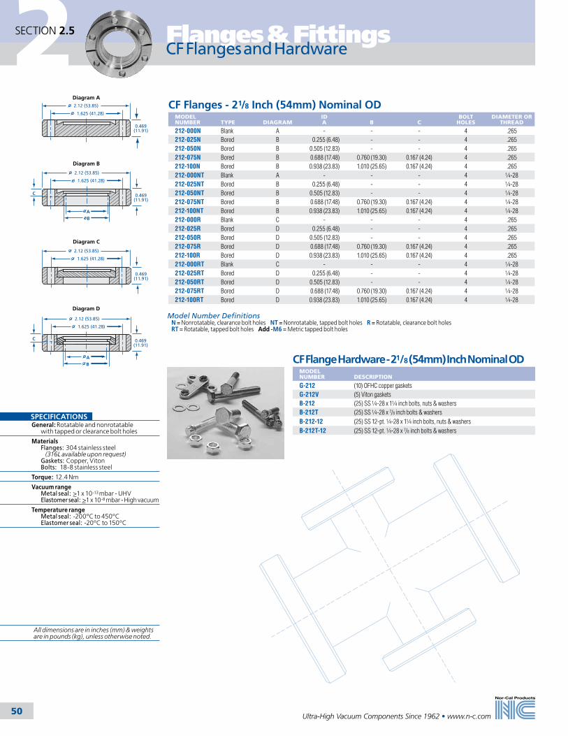
2
Ultra-High Vacuum Components Since 1962 • www.n-c.com 50
Flanges & Fittings
Model Number DefinitionsN = Nonrotatable, clearance bolt holes NT = Nonrotatable, tapped bolt holes R = Rotatable, clearance bolt holes RT = Rotatable, tapped bolt holes Add -M6 = Metric tapped bolt holes
SECTION 2.5
CF Flanges - 21/8 Inch (54mm) Nominal ODMODEL NUMBER
TYPE
DIAGRAM
ID A
B
C
BOLT HOLES
DIAMETER OR THREAD
212-000N Blank A - - - 4 .265212-025N Bored B 0.255 (6.48) - - 4 .265212-050N Bored B 0.505 (12.83) - - 4 .265212-075N Bored B 0.688 (17.48) 0.760 (19.30) 0.167 (4.24) 4 .265212-100N Bored B 0.938 (23.83) 1.010 (25.65) 0.167 (4.24) 4 .265212-000NT Blank A - - - 4 1⁄4-28212-025NT Bored B 0.255 (6.48) - - 4 1⁄4-28212-050NT Bored B 0.505 (12.83) - - 4 1⁄4-28212-075NT Bored B 0.688 (17.48) 0.760 (19.30) 0.167 (4.24) 4 1⁄4-28212-100NT Bored B 0.938 (23.83) 1.010 (25.65) 0.167 (4.24) 4 1⁄4-28212-000R Blank C - - - 4 .265212-025R Bored D 0.255 (6.48) - - 4 .265212-050R Bored D 0.505 (12.83) - - 4 .265212-075R Bored D 0.688 (17.48) 0.760 (19.30) 0.167 (4.24) 4 .265212-100R Bored D 0.938 (23.83) 1.010 (25.65) 0.167 (4.24) 4 .265212-000RT Blank C - - - 4 1⁄4-28212-025RT Bored D 0.255 (6.48) - - 4 1⁄4-28212-050RT Bored D 0.505 (12.83) - - 4 1⁄4-28212-075RT Bored D 0.688 (17.48) 0.760 (19.30) 0.167 (4.24) 4 1⁄4-28212-100RT Bored D 0.938 (23.83) 1.010 (25.65) 0.167 (4.24) 4 1⁄4-28
CF Flange Hardware - 21/8 (54mm) Inch Nominal ODMODEL NUMBER
DESCRIPTION
G-212 (10) OFHC copper gasketsG-212V (5) Viton gasketsB-212 (25) SS 1⁄4-28 x 11⁄4 inch bolts, nuts & washersB-212T (25) SS 1⁄4-28 x 7/8 inch bolts & washersB-212-12 (25) SS 12-pt. 1⁄4-28 x 11⁄4 inch bolts, nuts & washersB-212T-12 (25) SS 12-pt. 1⁄4-28 x 7/8 inch bolts & washers
CF Flanges and Hardware
SPECIFICATIONSGeneral: Rotatable and nonrotatable with tapped or clearance bolt holes
Materials Flanges: 304 stainless steel (316L available upon request) Gaskets: Copper, Viton Bolts: 18-8 stainless steel
Torque: 12.4 Nm
Vacuum range Metal seal: >1 x 10-13 mbar - UHV Elastomer seal: >1 x 10⁻⁸ mbar - High vacuum
Temperature range Metal seal: -200ºC to 450ºC Elastomer seal: -20ºC to 150ºC
C
AB
C
AB
Diagram A
Diagram B
Diagram C
Diagram D
2.12 (53.85)
1.625 (41.28)
2.12 (53.85)
1.625 (41.28)
2.12 (53.85)
1.625 (41.28)
2.12 (53.85)
1.625 (41.28)
0.469(11.91)
0.469(11.91)
0.469(11.91)
0.469(11.91)
All dimensions are in inches (mm) & weights are in pounds (kg), unless otherwise noted.

2
Ultra-High Vacuum Components Since 1962 • www.n-c.com 51
Flanges & Fittings
Model Number DefinitionsN = Nonrotatable, clearance bolt holes NT = Nonrotatable, tapped bolt holes R = Rotatable, clearance bolt holes RT = Rotatable, tapped bolt holes Add -M6 = Metric tapped bolt holes
SECTION 2.5
CF Flanges - 23/4 Inch (70mm) Nominal OD MODEL NUMBER
TYPE
DIAGRAM
ID A
B
C
BOLT HOLES
DIAMETER OR THREAD
275-000N Blank A - - - 6 .265275-025N Bored B 0.255 (6.48) - - 6 .265275-050N Bored B 0.505 (12.83) - - 6 .265275-075N Bored B 0.688 (17.48) 0.760 (19.30) 0.209 (5.31) 6 .265275-100N Bored B 0.938 (23.83) 1.010 (25.65) 0.209 (5.31) 6 .265275-125N Bored B 1.188 (30.18) 1.260 (32.00) 0.209 (5.31) 6 .265275-150N Bored B 1.438 (36.53) 1.510 (38.35) 0.209 (5.31) 6 .265275-162N Bored B 1.560 (39.62) 1.635 (41.53) 0.209 (5.31) 6 .265275-175N Bored B 1.620 (41.15) 1.760 (44.70) 0.209 (5.31) 6 .265275-000NT Blank A - - - 6 1⁄4-28275-025NT Bored B 0.255 (6.48) - - 6 1⁄4-28275-050NT Bored B 0.505 (12.83) - - 6 1⁄4-28275-075NT Bored B 0.688 (17.48) 0.760 (19.30) 0.209 (5.31) 6 1⁄4-28275-100NT Bored B 0.938 (23.83) 1.010 (25.65) 0.209 (5.31) 6 1⁄4-28275-125NT Bored B 1.188 (30.18) 1.260 (32.00) 0.209 (5.31) 6 1⁄4-28275-150NT Bored B 1.438 (36.53) 1.510 (38.35) 0.209 (5.31) 6 1⁄4-28275-162NT Bored B 1.560 (39.62) 1.635 (41.53) 0.209 (5.31) 6 1⁄4-28275-175NT Bored B 1.620 (41.15) 1.760 (44.70) 0.209 (5.31) 6 1⁄4-28275-000R Blank C - - - 6 .265275-025R Bored D 0.255 (6.48) - - 6 .265275-050R Bored D 0.505 (12.83) - - 6 .265275-075R Bored D 0.688 (30.18) 0.760 (19.30) 0.209 (5.31) 6 .265275-100R Bored D 0.938 (23.83) 1.010 (25.65) 0.209 (5.31) 6 .265275-125R Bored D 1.188 (30.18) 1.260 (32.00) 0.209 (5.31) 6 .265275-150R Bored D 1.438 (36.53) 1.510 (38.35) 0.209 (5.31) 6 .265275-000RT Blank C - - - 6 1⁄4-28275-025RT Bored D 0.255 (6.48) - - 6 1⁄4-28275-050RT Bored D 0.505 (12.83) - - 6 1⁄4-28275-075RT Bored D 0.688 (30.18) 0.760 (19.30) 0.209 (5.31) 6 1⁄4-28275-100RT Bored D 0.938 (23.83) 1.010 (25.65) 0.209 (5.31) 6 1⁄4-28275-125RT Bored D 1.188 (30.18) 1.260 (32.00) 0.209 (5.31) 6 1⁄4-28275-150RT Bored D 1.438 (36.53) 1.510 (38.35) 0.209 (5.31) 6 1⁄4-28
CF Flange Hardware - 23/4 (70mm) Inch Nominal ODMODEL NUMBER
DESCRIPTION
G-275 (10) OFHC copper gasketsG-275V (5) Viton gasketsG-275-SP (10) Silver plated copper gasketsB-275 (25) SS 1/4-28 x 11/4 inch bolts, nuts & washersB-275T (25) SS 1/4-28 x 1 inch bolts & washersB-275-12 (25) SS 12-pt. 1/4-28 x 11/4 inch bolts, nuts & washersB-275-12-SP (25) Silver plated SS 12-pt. 1/4-28 x 11/4 inch bolts, nuts & washersB-275T-12 (25) SS 12-pt. 1/4-28 x 1 inch bolts & washersB-275T-12-SP (25) Silver plated SS 12-pt. 1/4-28 x 7/8 inch bolts & washersB-275T-M (25) SS (metric) M6 x 1.00 x 25mm bolts & washersNP-150 (24) 1⁄4-28 plate nuts. See page 63KNP-150 (12) Plate nuts, (24) 1/4-28 x 11/4 inch bolts & washersKNP-150-12 (12) Plate nuts, (24) 12-pt. 1/4-28 x 11/4 inch bolts & washers
CF Flanges and Hardware
SPECIFICATIONSGeneral: Rotatable and nonrotatable with tapped or clearance holesMaterials Flanges: 304 stainless steel (316L available upon request) Gaskets: Copper, Viton or silver plated Bolts: 18-8 stainless steel or silver platedTorque: 12.4 NmVacuum range Metal seal: >1 x 10-13 mbar - UHV Elastomer seal: >1 x 10⁻⁸ mbar - High vacuumTemperature Range Metal seal: -200ºC to 450ºC Elastomer seal: -20ºC to 150ºC
C
AB
C
AB
Diagram A
Diagram B
Diagram C
Diagram D
2.73 (69.34)
2.312 (58.73)
0.500(12.70)
0.500(12.70)
0.500(12.70)
0.500(12.70)
2.73 (69.34)
2.312 (58.73)
2.73 (69.34)
2.312 (58.73)
2.73 (69.34)
2.312 (58.73)
All dimensions are in inches (mm) & weights are in pounds (kg), unless otherwise noted.

2
Ultra-High Vacuum Components Since 1962 • www.n-c.com 52
Flanges & Fittings
Model Number DefinitionsN = Nonrotatable, clearance bolt holes NT = Nonrotatable, tapped bolt holes R = Rotatable, clearance bolt holes RT = Rotatable, tapped bolt holes Add -M8 = Metric tapped bolt holes
SECTION 2.5
CF Flanges - 33/8 Inch (86mm) Nominal ODMODEL NUMBER
TYPE
DIAGRAM
OD A
ID B
C
D
E
F
BOLT HOLES
DIAMETER OR THREAD
338-000N Blank A 3.36 (85.34) - - - 2.850 (72.39) 0.687 (17.45) 8 .332338-150N Bored B 3.36 (85.34) 1.438 (36.53) 1.510 (38.35) 0.225 (5.72) 2.850 (72.39) 0.687 (17.45) 8 .332338-200N Bored B 3.36 (85.34) 1.938 (49.23) 2.010 (51.05) 0.225 (5.72) 2.850 (72.39) 0.687 (17.45) 8 .332338-000NT Blank A 3.36 (85.34) - - - 2.850 (72.39) 0.687 (17.45) 8 5⁄16-24338-150NT Bored B 3.36 (85.34) 1.438 (36.53) 1.510 (38.35) 0.225 (5.72) 2.850 (72.39) 0.687 (17.45) 8 5⁄16-24338-200NT Bored B 3.36 (85.34) 1.938 (49.23) 2.010 (51.05) 0.225 (5.72) 2.850 (72.39) 0.687 (17.45) 8 5⁄16-24338-000R Blank C 3.36 (85.34) - - - 2.850 (72.39) 0.687 (17.45) 8 .332338-150R Bored D 3.36 (85.34) 1.438 (36.53) 1.510 (38.35) 0.225 (5.72) 2.850 (72.39) 0.687 (17.45) 8 .332338-200R Bored D 3.36 (85.34) 1.938 (49.23) 2.010 (51.05) 0.225 (5.72) 2.850 (72.39) 0.687 (17.45) 8 .332338-000RT Blank C 3.36 (85.34) - - - 2.850 (72.39) 0.687 (17.45) 8 5⁄16-24338-150RT Bored D 3.36 (85.34) 1.438 (36.53) 1.510 (38.35) 0.225 (5.72) 2.850 (72.39) 0.687 (17.45) 8 5⁄16-24338-200RT Bored D 3.36 (85.34) 1.938 (49.23) 2.010 (51.05) 0.225 (5.72) 2.850 (72.39) 0.687 (17.45) 8 5⁄16-24
CF Flange Hardware - 33/8 Inch (86mm) Nominal ODMODEL NUMBER
DESCRIPTION
G-338 (10) OFHC copper gasketsG-338-SP (10) Silver plated copper gasketsG-338V (1) Viton gasketB-338 (25) SS 5⁄16-24 x 13/4 inch bolts, nuts & washersB-338T (25) SS 5⁄16-24 x 11/4 inch bolts & washersB-338-12 (25) SS 12-pt. 5⁄16-24 x 13/4 inch bolts, nuts & washersB-338T-12 (25) SS 12-pt. 5⁄16-24 x 11/4 inch bolts & washersB-338-12-SP (25) Silver plated SS 12-pt. 5/16-24 x 13/4 inch bolts, nuts & washersB-338T-12-SP (25) Silver plated SS 12-pt. 5/16-24 x 11/4 inch bolts, washersNP-200 (24) 5⁄16-24 plate nuts. See page 63KNP-200 (16) Plate nuts, (32) 5⁄16-24 x 13/4 inch bolts & washersKNP-200-12 (16) Plate nuts, (32) 12-pt. 5⁄16-24 x 13/4 inch bolts & washers
CF Flanges - 41/2 Inch (114mm) Nominal ODMODEL NUMBER
TYPE
DIAGRAM
OD A
ID B
C
D
E
F
BOLT HOLES
DIAMETER OR THREAD
450-000N Blank A 4.47 (113.54) - - - 3.628 (92.15) 0.687 (17.45) 8 .332450-150N Bored B 4.47 (113.54) 1.438 (36.53) 1.510 (38.35) 0.375 (9.53) 3.628 (92.15) 0.687 (17.45) 8 .332450-200N Bored B 4.47 (113.54) 1.938 (49.23) 2.010 (51.05) 0.375 (9.53) 3.628 (92.15) 0.687 (17.45) 8 .332450-250N Bored B 4.47 (113.54) 2.438 (61.93) 2.510 (63.75) 0.375 (9.53) 3.628 (92.15) 0.687 (17.45) 8 .332450-000NT Blank A 4.47 (113.54) - - - 3.628 (92.15) 0.687 (17.45) 8 5⁄16-24450-150NT Bored B 4.47 (113.54) 1.438 (36.53) 1.510 (38.35) 0.375 (9.53) 3.628 (92.15) 0.687 (17.45) 8 5⁄16-24450-200NT Bored B 4.47 (113.54) 1.938 (49.23) 2.010 (51.05) 0.375 (9.53) 3.628 (92.15) 0.687 (17.45) 8 5⁄16-24450-250NT Bored B 4.47 (113.54) 2.438 (61.93) 2.510 (63.75) 0.375 (9.53) 3.628 (92.15) 0.687 (17.45) 8 5⁄16-24450-000R Blank C 4.47 (113.54) - - - 3.628 (92.15) 0.750 (19.05) 8 .332450-150R Bored D 4.47 (113.54) 1.438 (36.53) 1.510 (38.35) 0.375 (9.53) 3.628 (92.15) 0.750 (19.05) 8 .332450-200R Bored D 4.47 (113.54) 1.938 (49.23) 2.010 (51.05) 0.375 (9.53) 3.628 (92.15) 0.750 (19.05) 8 .332450-250R Bored D 4.47 (113.54) 2.438 (61.93) 2.510 (63.75) 0.375 (9.53) 3.628 (92.15) 0.750 (19.05) 8 .332450-000RT Blank C 4.47 (113.54) - - - 3.628 (92.15) 0.750 (19.05) 8 5⁄16-24450-150RT Bored D 4.47 (113.54) 1.438 (36.53) 1.510 (38.35) 0.375 (9.53) 3.628 (92.15) 0.750 (19.05) 8 5⁄16-24450-200RT Bored D 4.47 (113.54) 1.938 (49.23) 2.010 (51.05) 0.375 (9.53) 3.628 (92.15) 0.750 (19.05) 8 5⁄16-24450-250RT Bored D 4.47 (113.54) 2.438 (61.93) 2.510 (63.75) 0.375 (9.53) 3.628 (92.15) 0.750 (19.05) 8 5⁄16-24
CF Flange Hardware - 41/2 Inch (114mm) Nominal ODMODEL NUMBER
DESCRIPTION
G-450 (10) OFHC copper gasketsG-450-SP (10) Silver plated copper gasketsG-450V (1) Viton gasketB-450 (25) SS 5⁄16-24 x 2 inch bolts, nuts & washersB-450T (25) SS 5⁄16-24 x 11/4 inch bolts & washersB-450-12 (25) SS 12-pt. 5⁄16-24 x 2 inch bolts, nuts & washersB-450T-12 (25) SS 12-pt. 5⁄16-24 x 11/4 inch bolts & washersB-450-12-SP (25) Silver plated SS 12-pt. 5/16-24 x 2 inch bolts, nuts & washersB-450T-12-SP (25) Silver plated SS 12-pt. 5/16-24 x 11/4 inch bolts & washersB-450-M (25) SS (metric) M8 x 1.25 x 35mm bolts & washersNP-250 (24) 5⁄16-24 plate nuts. See page 63KNP-250 (16) Plate nuts, (32) 5⁄16-24 x 2 inch bolts & washersKNP-250-12 (16) Plate nuts, (32) 12-pt. 5⁄16-24 x 2 inch bolts & washers
CF Flanges and Hardware
SPECIFICATIONSGeneral: Rotatable and nonrotatable with tapped or clearance bolt holes
Materials Flanges: 304 stainless steel (316L available upon request) Gaskets: Copper, Viton or silver plated Bolts: 18-8 stainless steel or silver plated
Torque: 21.5 Nm
Vacuum range Metal seal: >1 x 10-13 mbar- UHV Elastomer seal: >1 x 10⁻⁸ mbar - High vacuum
Temperature range Metal seal: -200ºC to 450ºC Elastomer seal: -20ºC to 150ºC
F
E
A
F
E
A
D
BC
F
E
A
F
E
A
D
BC
Diagram A
Diagram B
Diagram C
Diagram D
All dimensions are in inches (mm) & weights are in pounds (kg), unless otherwise noted.

2
Ultra-High Vacuum Components Since 1962 • www.n-c.com 53
Flanges & Fittings
Model Number DefinitionsN = Nonrotatable, clearance bolt holes NT = Nonrotatable, tapped bolt holes R = Rotatable, clearance bolt holes RT = Rotatable, tapped bolt holes Add -M8 = Metric tapped bolt holes
SECTION 2.5
CF Flanges - 45/8 Inch (117mm) Nominal ODMODEL NUMBER
TYPE
DIAGRAM
OD A
ID B
C
D
E
F
BOLT HOLES
DIAMETER OR THREAD
462-000N Blank A 4.61 (117.09) - - 0.812 (20.62) - 4.030 (102.36) 10 .332462-300N Bored B 4.61 (117.09) 2.938 (74.63) 3.010 (76.45) 0.812 (20.62) 0.281 (7.14) 4.030 (102.36) 10 .332462-000NT Blank A 4.61 (117.09) - - 0.812 (20.62) - 4.030 (102.36) 10 5⁄16-24462-300NT Bored B 4.61 (117.09) 2.938 (74.63) 3.010 (76.45) 0.812 (20.62) 0.281 (7.14) 4.030 (102.36) 10 5⁄16-24462-000R Blank C 4.61 (117.09) - - 0.812 (20.62) - 4.030 (102.36) 10 .332462-300R Bored D 4.61 (117.09) 2.938 (74.63) 3.010 (76.45) 0.812 (20.62) 0.281 (7.14) 4.030 (102.36) 10 .332462-000RT Blank C 4.61 (117.09) - - 0.812 (20.62) - 4.030 (102.36) 10 5⁄16-24462-300RT Bored D 4.61 (117.09) 2.938 (74.63) 3.010 (76.45) 0.812 (20.62) 0.281 (7.14) 4.030 (102.36) 10 5⁄16-24
CF Flange Hardware - 45/8 Inch (117mm) Nominal ODMODEL NUMBER
DESCRIPTION
G-462 (10) OFHC copper gasketsG-462V (1) Viton gasketB-462 (25) SS 5⁄16-24 x 21/4 inch bolts, nuts & washersB-462T (25) SS 5⁄16-24 x 11/4 inch bolts & washersB-462-12 (25) SS 12-pt. 5⁄16-24 x 21/4 inch bolts, nuts & washersB-462T-12 (25) SS 12-pt. 5⁄16-24 x 11/4 inch bolts & washersNP-300 (24) 5⁄16-24 plate nuts. See page 63KNP-300 (20) Plate nuts, (40) 5⁄16-24 x 21/4 inch bolts & washersKNP-300-12 (20) Plate nuts, (40) 12-pt. 5⁄16-24 x 21/4 inch bolts & washers
CF Flanges - 6 Inch (152mm) Nominal ODMODEL NUMBER
TYPE
DIAGRAM
OD A
ID B
C
D
E
F
BOLT HOLES
DIAMETER OR THREAD
600-000N Blank A 5.97 (151.64) - - 0.781 (19.84) - 5.128 (130.25) 16 .332600-400N Bored B 5.97 (151.64) 3.910 (99.31) 4.010 (101.85) 0.781 (19.84) 0.438 (11.13) 5.128 (130.25) 16 .332600-000NT Blank A 5.97 (151.64) - - 0.781 (19.84) - 5.128 (130.25) 16 5⁄16-24600-400NT Bored B 5.97 (151.64) 3.910 (99.31) 4.010 (101.85) 0.781 (19.84) 0.438 (11.13) 5.128 (130.25) 16 5⁄16-24600-000R Blank C 5.97 (151.64) - - 0.844 (21.44) - 5.128 (130.25) 16 .332600-400R Bored D 5.97 (151.64) 3.910 (99.31) 4.010 (101.85) 0.844 (21.44) 0.438 (11.13) 5.128 (130.25) 16 .332600-000RT Blank C 5.97 (151.64) - - 0.844 (21.44) - 5.128 (130.25) 16 5⁄16-24600-400RT Bored D 5.97 (151.64) 3.910 (99.31) 4.010 (101.85) 0.844 (21.44) 0.438 (11.13) 5.128 (130.25) 16 5⁄16-24
CF Flange Hardware - 6 Inch (152mm) Nominal ODMODEL NUMBER
DESCRIPTION
G-600 (10) OFHC copper gasketsG-600V (1) Viton gasketG-600-SP (10) Silver plated copper gasketsB-600 (25) SS 5⁄16-24 x 21/4 inch bolts, nuts & washersB-600T (25) SS 5⁄16-24 x 11/4 inchbolts & washersB-600-12 (25) SS 12-pt. 5⁄16-24 x 21/4 inch bolts, nuts & washersB-600T-12 (25) SS 12-pt. 5⁄16-24 x 11/4 inch bolts & washersB-600-12-SP (25) Silver plated SS 12-pt. 5⁄16-24 x 21/4 inch bolts, nuts & washersB-600T-12-SP (25) Silver plated SS 12-pt. 5⁄16-24 x 11/4 inch bolts & washersB-600T-M (25) SS (metric) M8 x 11/4 x 35mm bolts & washersNP-400 (24) 5⁄16-24 plate nuts. See page 63KNP-400 (16) Plate nuts (32) 5⁄16-24 x 21/4 inch bolts & washersKNP-400-12 (16) Plate nuts (32) 12-pt. 5⁄16-24 x 21/4 inch bolts & washers
CF Flanges and Hardware
D
F
A
D
F
A
E
BC
D
F
A
D
F
A
E
BC
Diagram A
Diagram B
Diagram C
Diagram D
SPECIFICATIONSGeneral:Rotatable and nonrotatable with tapped or clearance bolt holesMaterials Flanges: 304 stainless steel (316L available upon request) Gaskets: Copper, Viton and silver plated Bolts: 18-8 stainless steel and silver platedTorque: 21.5 NmVacuum range Metal seal: >1 x 10-13 mbar - UHV Elastomer seal: >1 x 10⁻⁸ mbar - High vacuumTemperature Range Metal seal: -200ºC to 450ºC Elastomer seal: -20ºC to 150ºC
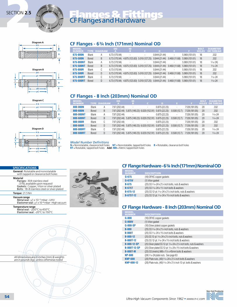
2
Ultra-High Vacuum Components Since 1962 • www.n-c.com 54
Flanges & FittingsSECTION 2.5
CF Flanges - 63/4 Inch (171mm) Nominal ODMODEL NUMBER
TYPE
DIAGRAM
OD A
ID B
C
D
E
F
BOLT HOLES
DIAMETER OR THREAD
675-000N Blank A 6.73 (170.94) - - 0.844 (21.44) - 5.969 (151.61) 18 .332675-500N Bored B 6.73 (170.94) 4.875 (123.83) 5.010 (127.25) 0.844 (21.44) 0.460 (11.68) 5.969 (151.61) 18 .332675-000NT Blank A 6.73 (170.94) - - 0.844 (21.44) - 5.969 (151.61) 18 5⁄16-24)675-500NT Bored B 6.73 (170.94) 4.875 (123.83) 5.010 (127.25) 0.844 (21.44) 0.460 (11.68) 5.969 (151.61) 18 5⁄16-24675-000R Blank C 6.73 (170.94) - - 0.844 (21.44) - 5.969 (151.61) 18 .332675-500R Bored D 6.73 (170.94) 4.875 (123.83) 5.010 (127.25) 0.844 (21.44) 0.460 (11.68) 5.969 (151.61) 18 .332675-000RT Blank C 6.73 (170.94) - - 0.844 (21.44) - 5.969 (151.61) 18 5⁄16-24675-500RT Bored D 6.73 (170.94) 4.875 (123.83) 5.010 (127.25) 0.844 (21.44) 0.460 (11.68) 5.969 (151.61) 18 5⁄16-24
CF Flange Hardware - 63/4 Inch (171mm) Nominal ODMODEL NUMBER
DESCRIPTION
G-675 (10) OFHC copper gasketsG-675V (1) Viton gasketB-675 (25) SS 5⁄16-24 x 21/4 inch bolts, nuts & washersB-675T (25) SS 5⁄16-24 x 11/2 inch bolts & washersB-675-12 (25) SS 12-pt. 5⁄16-24 x 21/4 inch bolts, nuts & washersB-675T-12 (25) SS 12-pt. 5⁄16-24 x 13/4 inch bolts & washers
CF Flanges - 8 Inch (203mm) Nominal ODMODEL NUMBER
TYPE
DIAGRAM
OD A
ID B
C
D
E
F
BOLT HOLES
DIAMETER OR THREAD
800-000N Blank A 7.97 (202.44) - - 0.875 (22.23) - 7.128 (181.05) 20 .332800-600N Bored B 7.97 (202.44) 5.875 (149.23) 6.020 (152.91) 0.875 (22.23) 0.500 (12.7) 7.128 (181.05) 20 .332800-000NT Blank A 7.97 (202.44) - - 0.875 (22.23) - 7.128 (181.05) 20 5⁄16-24800-600NT Bored B 7.97 (202.44) 5.875 (149.23) 6.020 (152.91) 0.875 (22.23) 0.500 (12.7) 7.128 (181.05) 20 5⁄16-24800-000R Blank C 7.97 (202.44) - - 0.875 (22.23) - 7.128 (181.05) 20 .332800-600R Bored D 7.97 (202.44) 5.875 (149.23) 6.020 (152.91) 0.875 (22.23) 0.500 (12.7) 7.128 (181.05) 20 .332800-000RT Blank C 7.97 (202.44) - - 0.875 (22.23) - 7.128 (181.05) 20 5⁄16-24800-600RT Bored D 7.97 (202.44) 5.875 (149.23) 6.020 (152.91) 0.875 (22.23) 0.500 (12.7) 7.128 (181.05) 20 5⁄16-24
CF Flange Hardware - 8 Inch (203mm) Nominal ODMODEL NUMBER
DESCRIPTION
G-800 (10) OFHC copper gasketsG-800V (1) Viton gasketG-800-SP (10) Silver plated copper gasketsB-800 (25) SS 5⁄16-24 x 21/4 inch bolts, nuts & washersB-800T (25) SS 5⁄16-24 x 13/4 inch bolts & washersB-800-12 (25) SS 12-pt. 5⁄16-24 x 21/4 inch bolts, nuts & washersB-800T-12 (25) SS 12-pt. 5⁄16-24 x 13/4 inch bolts & washersB-800-12-SP (25) Silver plated SS 12-pt. 5/16-24 x 21/4 inch bolts, nuts & washersB-800T-12-SP (25) Silver plated SS 12-pt. 5/16-24 x 13/4 inch bolts & washersB-800T-M (25) SS (metric) M8 x 11/4 x 45mm bolts & washersNP-600 (24) 5⁄16-24 plate nuts. See page 63KNP-600 (20) Plate nuts, (40) 5⁄16-24 x 21/4 inch bolts & washersKNP-600-12 (20) Plate nuts, (40) 5⁄16-24 x 21/4 inch 12-pt. bolts & washers
CF Flanges and Hardware
SPECIFICATIONSGeneral: Rotatable and nonrotatable with tapped or clearance bolt holes
Material Flanges: 304 stainless steel (316L available upon request) Gaskets: Copper, Viton or silver plated Bolts: 18-8 stainless steel or silver plated
Torque: 21.5 Nm
Vacuum range Metal seal: >1 x 10-13 mbar - UHV Elastomer seal: >1 x 10⁻⁸ mbar - High vacuum
Temperature range Metal seal: -200ºC to 450ºC Elastomer seal: -20ºC to 150ºC
Model Number DefinitionsN = Nonrotatable, clearance bolt holes NT = Nonrotatable, tapped bolt holes R = Rotatable, clearance bolt holes RT = Rotatable, tapped bolt holes Add -M8 = Metric tapped bolt holes
D
F
A
D
F
A
E
BC
D
F
A
D
F
A
E
BC
Diagram A
Diagram B
Diagram C
Diagram D
All dimensions are in inches (mm) & weights are in pounds (kg), unless otherwise noted.

2
Ultra-High Vacuum Components Since 1962 • www.n-c.com 55
Flanges & Fittings SECTION 2.5
CF Flanges - 10 Inch (254mm) Nominal ODMODEL NUMBER
TYPE
DIAGRAM
OD A
ID B
C
D
E
F
BOLT HOLES
DIAMETER OR THREAD
1000-000N Blank A 9.97 (253.24) - - 0.968 (24.59) - 9.128 (231.85) 24 .3321000-800N Bored B 9.97 (253.24) 7.875 (200.03) 8.020 (203.71) 0.968 (24.59) 0.500 (12.70) 9.128 (231.85) 24 .3321000-000NT Blank A 9.97 (253.24) - - 0.968 (24.59) - 9.128 (231.85) 24 5⁄16-241000-800NT Bored B 9.97 (253.24) 7.875 (200.03) 8.020 (203.71) 0.968 (24.59) 0.500 (12.70) 9.128 (231.85) 24 5⁄16-241000-000R Blank C 9.97 (253.24) - - 0.968 (24.59) - 9.128 (231.85) 24 .3321000-800R Bored D 9.97 (253.24) 7.875 (200.03) 8.020 (203.71) 0.968 (24.59) 0.500 (12.70) 9.128 (231.85) 24 .3321000-000RT Blank C 9.97 (253.24) - - 0.968 (24.59) - 9.128 (231.85) 24 5⁄16-241000-800RT Bored D 9.97 (253.24) 7.875 (200.03) 8.020 (203.71) 0.968 (24.59) 0.500 (12.70) 9.128 (231.85) 24 5⁄16-24
CF Flange Hardware - 10 Inch (254mm) Nominal ODMODEL NUMBER
DESCRIPTION
G-1000 (10) OFHC copper gasketsG-1000V (1) Viton gasket G-1000-SP (10) Silver plated copper gasketsB-1000 (25) SS 5⁄16-24 x 21/2 inch bolts, nuts & washersB-1000T (25) SS 5⁄16-24 x 13/4 inch bolts & washersB-1000-12 (25) SS 12-pt. 5⁄16-24 x 21/2 inch bolts, nuts & washersB-1000T-12 (25) SS 12-pt. 5⁄16-24 x 13/4 inch bolts & washersB-1000-12-SP (25) Silver plated SS 12-pt. 5/16-24 x 21/2 inch bolts, nuts & washersB-1000T-12-SP (25) Silver plated SS 12-pt. 5/16-24 x 13/4 inch bolts & washersB-1000T-M (25) SS (metric) M8 x 11/4 x 45mm bolts & washersNP-800 (24) 5⁄16-24 plate nuts. See page 63KNP-800 (24) Plate nuts, (48) 5⁄16-24 x 21/4 inch bolts & washersKNP-800-12 (24) Plate nuts, (48) 12-pt. 5⁄16-24 x 21/4 inch bolts & washers
CF Flanges - 12 Inch (305mm) Nominal ODMODEL NUMBER
TYPE
DIAGRAM
OD A
ID B
C
D
E
F
BOLT HOLES
DIAMETER OR THREAD
1200-000N Blank A 12.00 (304.80) - - 1.125 (28.58) - 11.181 (284) 32 .3321200-1000N Bored B 12.00 (304.80) 9.875 (250.83) 10.020 (254.51) 1.125 (28.58) 0.500 (12.70) 11.181 (284) 32 .3321200-000NT Blank A 12.00 (304.80) - - 1.125 (28.58) - 11.181 (284) 32 5⁄16-241200-1000NT Bored B 12.00 (304.80) 9.875 (250.83) 10.020 (254.51) 1.125 (28.58) 0.500 (12.70) 11.181 (284) 32 5⁄16-241200-000R Blank C 12.00 (304.80) - - 1.125 (28.58) - 11.181 (284) 32 .3321200-1000R Bored D 12.00 (304.80) 9.875 (250.83) 10.020 (254.51) 1.125 (28.58) 0.500 (12.70) 11.181 (284) 32 .3321200-000RT Blank C 12.00 (304.80) - - 1.125 (28.58) - 11.181 (284) 32 5⁄16-241200-1000RT Bored D 12.00 (304.80) 9.875 (250.83) 10.020 (254.51) 1.125 (28.58) 0.500 (12.70) 11.181 (284) 32 5⁄16-24
CF Flange Hardware - 12 Inch (305mm) Nominal ODMODEL NUMBER
DESCRIPTION
G-1200 (1) OFHC copper gasketB-1200 (32) SS 5⁄16-24 x 3 inch bolts, nuts & washersB-1200T (32) SS 5⁄16-24 x 13/4 inch bolts & washers
CF Flanges and Hardware
SPECIFICATIONSGeneral: Rotatable and nonrotatable with tapped or clearance bolt holesMaterial Flanges: 304 stainless steel (316L available upon request) Gaskets: Copper, Viton or silver plated Bolts: 18-8 stainless steel or silver platedTorque: 21.5 NmVacuum range Metal seal: >1 x 10-13 mbar - UHV Elastomer seal: >1 x 10⁻⁸ mbar - High vacuumTemperature Range Metal seal: -200ºC to 450ºC Elastomer seal: -20ºC to 150ºC
Model Number DefinitionsN = Nonrotatable, clearance bolt holes NT = Nonrotatable, tapped bolt holes R = Rotatable, clearance bolt holes RT = Rotatable, tapped bolt holes Add -M8 = Metric tapped bolt holes
D
F
A
D
F
A
E
BC
D
F
A
D
F
A
E
BC
Diagram A
Diagram B
Diagram C
Diagram D

2
Ultra-High Vacuum Components Since 1962 • www.n-c.com 56
Flanges & FittingsSECTION 2.5
CF Flanges - 131/4 Inch (337mm) Nominal ODMODEL NUMBER
TYPE
DIAGRAM
OD A
ID B
C
D
E
BOLT HOLES
DIAMETER OR THREAD
1325-000N Blank A 13.25 (336.55) - - - 12.055 (306.20) 30 .3901325-1000N Bored B 13.25 (336.55) 9.875 (250.83) 10.020 (254.51) 0.500 (12.70) 12.055 (306.20) 30 .3901325-000NT Blank A 13.25 (336.55) - - - 12.055 (306.20) 30 3⁄8-241325-1000NT Bored B 13.25 (336.55) 9.875 (250.83) 10.020 (254.51) 0.500 (12.70) 12.055 (306.20) 30 3⁄8-241325-000R Blank C 13.25 (336.55) - - - 12.055 (306.20) 30 .3901325-1000R Bored D 13.25 (336.55) 9.875 (250.83) 10.020 (254.51) 0.500 (12.70) 12.055 (306.20) 30 .3901325-000RT Blank C 13.25 (336.55) - - - 12.055 (306.20) 30 3⁄8-241325-1000RT Bored D 13.25 (336.55) 9.875 (250.83) 10.020 (254.51) 0.500 (12.70) 12.055 (306.20) 30 3⁄8-24
CF Flange Hardware -131/4 Inch (337mm) Nominal ODMODEL NUMBER
DESCRIPTION
G-1325 (1) OFHC copper gasketG-1325V (1) Viton gasket B-1325 (30) SS 3⁄8-24 x 3 inch bolts, nuts & washersB-1325T (30) SS 3⁄8-24 x 2 inch bolts & washers
CF Flanges - 14 Inch (356mm) Nominal ODMODEL NUMBER
TYPE
DIAGRAM
OD A
ID B
C
D
E
BOLT HOLES
DIAMETER OR THREAD
1400-000N Blank A 14.00 (355.60) - - - 12.810 (325.37) 30 .3901400-1200N Bored B 14.00 (355.60) 11.875 (301.63) 12.030 (305.56) 0.500 (12.70) 12.810 (325.37) 30 .3901400-000NT Blank A 14.00 (355.60) - - - 12.810 (325.37) 30 3⁄8-241400-1200NT Bored B 14.00 (355.60) 11.875 (301.63) 12.030 (305.56) 0.500 (12.70) 12.810 (325.37) 30 3⁄8-241400-000R Blank C 14.00 (355.60) - - - 12.810 (325.37) 30 .3901400-1200R Bored D 14.00 (355.60) 11.875 (301.63) 12.030 (305.56) 0.500 (12.70) 12.810 (325.37) 30 .3901400-000RT Blank C 14.00 (355.60) - - - 12.810 (325.37) 30 3⁄8-241400-1200RT Bored D 14.00 (355.60) 11.875 (301.63) 12.030 (305.56) 0.500 (12.70) 12.810 (325.37) 30 3⁄8-24
CF Flange Hardware - 14 Inch (356mm) Nominal ODMODEL NUMBER
DESCRIPTION
G-1400 (1) OFHC copper gasketG-1400V (1) Viton gasket B-1400 (30) SS 3⁄8-24 x 3 inch bolts, nuts & washersB-1400T (30) SS 3⁄8-24 x 2 inch bolts & washers
CF Flanges and Hardware
SPECIFICATIONSGeneral: Rotatable and nonrotatable with tapped or clearance bolt holes
Material Flanges: 304 stainless steel (316L available upon request) Gaskets: Copper, Viton Bolts: 18-8 stainless steel
Torque: 39.0 Nm
Vacuum range Metal seal: >1 x 10-13 mbar - UHV Elastomer seal: >1 x 10⁻⁸ mbar - High vacuum
Temperature range Metal seal: -200ºC to 450ºC Elastomer seal: -20ºC to 150ºC
E
A
E
A
D
BC
E
A
E
A
D
BC
Diagram A
Diagram B
Diagram C
Diagram D
1.125(28.58)
1.125(28.58)
1.125(28.58)
1.125(28.58)
Model Number DefinitionsN = Nonrotatable, clearance bolt holes NT = Nonrotatable, tapped bolt holes R = Rotatable, clearance bolt holes RT = Rotatable, tapped bolt holes Add -M8 = Metric tapped bolt holes
All dimensions are in inches (mm) & weights are in pounds (kg), unless otherwise noted.

2
Ultra-High Vacuum Components Since 1962 • www.n-c.com 57
Flanges & Fittings SECTION 2.5
CF Flanges - 141/2 Inch (368mm) Nominal ODMODEL NUMBER
TYPE
DIAGRAM
OD A
ID B
C
D
E
BOLT HOLES
DIAMETER OR THREAD
1450-000N Blank A 14.50 (368.30) Blank - - 13.310 (338.07) 32 0.3901450-1200N Bored B 14.50 (368.30) 11.875 (301.63) 12.020 (305.31) 0.500 (12.70) 13.310 (338.07) 32 0.3901450-000NT Blank A 14.50 (368.30) Blank - - 13.310 (338.07) 32 3⁄8-241450-1200NT Bored B 14.50 (368.30) 11.875 (301.63) 12.020 (305.31) 0.500 (12.70) 13.310 (338.07) 32 3⁄8-241450-000R Blank C 14.50 (368.30) Blank - - 13.310 (338.07) 32 0.3901450-1200R Bored D 14.50 (368.30) 11.875 (301.63) 12.020 (305.31) 0.500 (12.70) 13.310 (338.07) 32 0.3901450-000RT Blank C 14.50 (368.30) Blank - - 13.310 (338.07) 32 3⁄8-241450-1200RT Bored D 14.50 (368.30) 11.875 (301.63) 12.020 (305.31) 0.500 (12.70) 13.310 (338.07) 32 3⁄8-24
CF Flange Hardware - 141/2 Inch (368mm) Nominal OD
MODEL NUMBER
DESCRIPTION
G-1450 (1) OFHC copper gasketB-1450 (32) SS 3⁄8-24 x 3 inch bolts, nuts & washersB-1450T (32) SS 3⁄8-24 x 2 inch bolts & washers
CF Flanges - 161/2 Inch (419mm) Nominal ODMODEL NUMBER
TYPE
DIAGRAM
OD A
ID B
C
D
E
BOLT HOLES
DIAMETER OR THREAD
1650-000N Blank A 16.50 (419.10) Blank - - 15.310 (388.87) 36 0.3901650-1400N Bored B 16.50 (419.10) 13.750 (349.25) 14.020 (356.11) 0.500 (12.70) 15.310 (388.87) 36 0.3901650-000NT Blank A 16.50 (419.10) Blank - - 15.310 (388.87) 36 3⁄8-241650-1400NT Bored B 16.50 (419.10) 13.750 (349.25) 14.020 (356.11) 0.500 (12.70) 15.310 (388.87) 36 3⁄8-241650-000R Blank C 16.50 (419.10) Blank - - 15.310 (388.87) 36 0.3901650-1400R Bored D 16.50 (419.10) 13.750 (349.25) 14.020 (356.11) 0.500 (12.70) 15.310 (388.87) 36 0.3901650-000RT Blank C 16.50 (419.10) Blank - - 15.310 (388.87) 36 3⁄8-241650-1400RT Bored D 16.50 (419.10) 13.750 (349.25) 14.020 (356.11) 0.500 (12.70) 15.310 (388.87) 36 3⁄8-24
CF Flange Hardware - 161/2 Inch (419mm) Nominal OD
MODEL NUMBER
DESCRIPTION
G-1650 (1) OFHC copper gasketG-1650V (1) Viton gasketB-1650 (36) SS 3⁄8-24 x 3 inch bolts, nuts & washersB-1650T (36) SS 3⁄8-24 x 2 inch bolts & washers
CF Flanges and Hardware
SPECIFICATIONSGeneral: Rotatable and nonrotatable with tapped or clearance bolt holesMaterial Flanges: 304 stainless steel (316L available upon request) Gaskets: Copper, Viton Bolts: 18-8 stainless steelTorque: 39 Nm.Vacuum range Metal seal: >1 x 10-13 mbar - UHV Elastomer seal: >1 x 10⁻⁸ mbar - High vacuumTemperature range Metal seal: -200ºC to 450ºC Elastomer seal: -20ºC to 150ºC
E
A
E
A
D
BC
E
A
E
A
D
BC
Diagram A
Diagram B
Diagram C
Diagram D
1.125(28.58)
1.125(28.58)
1.125(28.58)
1.125(28.58)
Model Number DefinitionsN = Nonrotatable, clearance bolt holes NT = Nonrotatable, tapped bolt holes R = Rotatable, clearance bolt holes RT = Rotatable, tapped bolt holes Add -M8 = Metric tapped bolt holes
All dimensions are in inches (mm) & weights are in pounds (kg), unless otherwise noted.

2
Ultra-High Vacuum Components Since 1962 • www.n-c.com 58
Flanges & FittingsSECTION 2.5
CF Double-Sided Special Purpose FlangesMODEL NUMBER
FLANGE OD
FEATURE
DIAGRAM
A
B
133-D1 1.33 (33.78) (1) 1⁄16 inch (1.59) NPT hole A 0.25 (6.35) 0.50 (12.70)275-D1 2.75 (69.85) (1) 1⁄8 inch (3.18) NPT hole A 0.38 (9.65) 0.75 (19.05)133-D2 1.33 (33.78) (2) 1⁄16 inch (1.59) NPT holes B 0.25 (6.35) 0.50 (12.70)275-D2 2.75 (69.85) (2) 1⁄8 inch (3.18) NPT holes B 0.38 (9.65) 0.75 (19.05)133-DT 1.33 (33.78) Thermocouple gauge tube C 0.25 (6.35) 0.50 (12.70)275-DT 2.75 (69.85) Thermocouple gauge tube C 0.38 (9.65) 0.75 (19.05)133-DV 1.33 (33.78) Up-to-air valve D 0.25 (6.35) 0.50 (12.70)275-DV 2.75 (69.85) Up-to-air valve D 0.38 (9.65) 0.75 (19.05)133-DV-1⁄4 MVCR 1.33 (33.78) Up-to-air valve & 1⁄4 inch (6.35) Cajon male VCR fitting on valve D 0.25 (6.35) 0.50 (12.70)275-DV-1⁄4 MVCR 2.75 (69.85) Up-to-air valve & 1⁄4 inch (6.35) Cajon male VCR fitting on valve D 0.38 (9.65) 0.75 (19.05)133-DV-1⁄4 FVCR 1.33 (33.78) Up-to-air valve & 1⁄4 inch (6.35) Cajon female VCR fitting on valve D 0.25 (6.35) 0.50 (12.70)275-DV-1⁄4 FVCR 2.75 (69.85) Up-to-air valve & 1⁄4 inch (6.35) Cajon female VCR fitting on valve D 0.38 (9.65) 0.75 (19.05)133-DV-1⁄4 SWAG 1.33 (33.78) Up-to-air valve & 1⁄4 inch (6.35) Swagelok fitting on valve D 0.25 (6.35) 0.50 (12.70)275-DV-1⁄4 SWAG 2.75 (69.85) Up-to-air valve & 1⁄4 inch (6.35) Swagelok fitting on valve D 0.38 (9.65) 0.75 (19.05)133-D1V 1.33 (33.78) (1) 1⁄16 inch (1.59) NPT hole & up-to-air valve F 0.25 (6.35) 0.50 (12.70)275-D1V 2.75 (69.85) (1) 1⁄8 inch (3.18) NPT hole & up-to-air valve F 0.38 (9.65) 0.75 (19.05)133-DTV 1.33 (33.78) Thermocouple gauge tube & up-to-air valve E 0.25 (6.35) 0.50 (12.70)275-DTV 2.75 (69.85) Thermocouple gauge tube & up-to-air valve E 0.38 (9.65) 0.75 (19.05)
133-DTV-1⁄4 MVCR 1.33 (33.78) Thermocouple gauge tube & up-to-air valve with 1⁄4 inch (6.35) Cajon male VCR fitting on valve E 0.25 (6.35) 0.50 (12.70)
275-DTV-1⁄4 MVCR 2.75 (69.85) Thermocouple gauge tube & up-to-air valve with 1⁄4 inch (6.35) Cajon male VCR fitting on valve E 0.38 (9.65) 0.75 (19.05)
133-DTV-1⁄4 FVCR 1.33 (33.78) Thermocouple gauge tube & up-to-air valve with 1⁄4 inch (6.35) Cajon female VCR fitting on valve E 0.25 (6.35) 0.50 (12.70)
275-DTV-1⁄4 FVCR 2.75 (69.85) Thermocouple gauge tube & up-to-air valve with 1⁄4 inch (6.35) Cajon female VCR fitting on valve E 0.38 (9.65) 0.75 (19.05)
133-DTV-1⁄4 SWAG 1.33 (33.78) Thermocouple gauge tube & up-to-air valve with 1⁄4 inch (6.35) Swagelok fitting on valve E 0.25 (6.35) 0.50 (12.70)
275-DTV-1⁄4SWAG 2.75 (69.85) Thermocouple gauge tube & up-to-air valve with 1⁄4 inch (6.35) Swagelok fitting on valve E 0.38 (9.65) 0.75 (19.05)
275-DS-MINI 2.75 (69.85) (1) 1.33 inch (33.78) OD side port G 0.38 (9.65) 0.75 (19.05)
Nor-Cal’s special purpose CF flanges are used as roughing accessories, accommodating thermocouple gauge tubes, up-to-air valves and/or NPT threaded fittings. Double-sided flanges are provided with one or more radially tapped holes. Blank flanges are provided with a single concentric 1/8 NPT tapped hole. Hardware for special purpose flanges is located on the appropriate flange size pages.
CF Special Purpose Flanges
WELD
Optional fitting
Diagram D
BA
Diagram A
1200
Diagram B
Diagram C
SPECIFICATIONSGeneral:Nonrotatable with clearance bolt holes
Material Flanges:304 stainless steel (316L available on request) Gaskets: Copper, Viton Bolts: 18-8 stainless steel
Torque: See page 48
Vacuum range Metal seal: >1 x 10-13 mbar - UHV Elastomer seal: >1 x 10⁻⁸ mbar - High vacuum
Temperature range Metal seal: -200ºC to 450ºC Elastomer seal: -20ºC to 150ºC
Diagram E
WELD
Optional fitting
WELD
Optional fitting
Diagram F
WELD 1.33 ODCF Flange
Diagram G
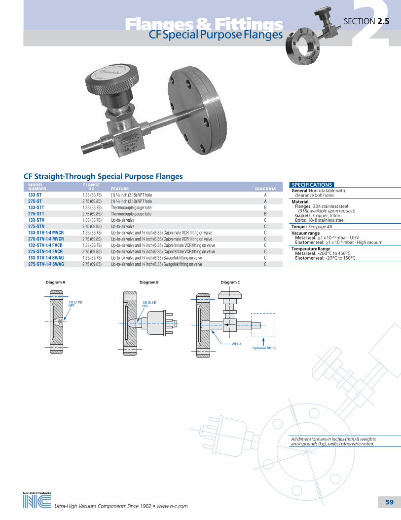
2
Ultra-High Vacuum Components Since 1962 • www.n-c.com 59
Flanges & Fittings SECTION 2.5
CF Special Purpose Flanges
CF Straight-Through Special Purpose FlangesMODEL NUMBER
FLANGE OD
FEATURE
DIAGRAM
133-ST 1.33 (33.78) (1) 1⁄8 inch (3.18) NPT hole A275-ST 2.75 (69.85) (1) 1⁄8 inch (3.18) NPT hole A133-STT 1.33 (33.78) Thermocouple gauge tube B275-STT 2.75 (69.85) Thermocouple gauge tube B133-STV 1.33 (33.78) Up-to-air valve C275-STV 2.75 (69.85) Up-to-air valve C133-STV-1⁄4 MVCR 1.33 (33.78) Up-to-air valve and 1⁄4 inch (6.35) Cajon male VCR fitting on valve C275-STV-1⁄4 MVCR 2.75 (69.85) Up-to-air valve and 1⁄4 inch (6.35) Cajon male VCR fitting on valve C133-STV-1⁄4 FVCR 1.33 (33.78) Up-to-air valve and 1⁄4 inch (6.35) Cajon female VCR fitting on valve C275-STV-1⁄4 FVCR 2.75 (69.85) Up-to-air valve and 1⁄4 inch (6.35) Cajon female VCR fitting on valve C133-STV-1⁄4 SWAG 1.33 (33.78) Up-to-air valve and 1⁄4 inch (6.35) Swagelok fitting on valve C275-STV-1⁄4 SWAG 2.75 (69.85) Up-to-air valve and 1⁄4 inch (6.35) Swagelok fitting on valve C
1/8 (3.18)NPT
Diagram A
1/8 (3.18)NPT
Diagram B
WELDOptional fitting
Diagram C
SPECIFICATIONSGeneral:Nonrotatable with clearance bolt holesMaterial Flanges: 304 stainless steel (316L available upon request) Gaskets: Copper, Viton Bolts: 18-8 stainless steelTorque: See page 48Vacuum range Metal seal: >1 x 10-13 mbar - UHV Elastomer seal: >1 x 10⁻⁸ mbar - High vacuumTemperature Range Metal seal: -200ºC to 450ºC Elastomer seal: -20ºC to 150ºC
All dimensions are in inches (mm) & weights are in pounds (kg), unless otherwise noted.

2
Ultra-High Vacuum Components Since 1962 • www.n-c.com 60
Flanges & FittingsSECTION 2.5
CF Double-Sided Flanges - 11/3 thru 14 Inch (34-356mm) Nominal OD
MODEL NUMBER
NOMINAL OD
MADE FROM
A
B
133-000D 11⁄3 (34) 133-000N - 0.300 (7.62)133-025D 11⁄3 (34) 133-000N 0.255 (6.48) 0.300 (7.62)133-038D 11⁄3 (34) 133-000N 0.380 (9.65) 0.300 (7.62)133-050D 11⁄3 (34) 133-000N 0.505 (12.83) 0.300 (7.62)133-075D 11⁄3 (34) 133-000N 0.630 (16.00) 0.300 (7.62)133-000DS 11⁄3 (34) 133-000NS - 0.500 (12.7)133-075DS 11⁄3 (34) 133-000NS 0.630 (16.00) 0.500 (12.7)212-000D 21⁄8 (54) 212-000N - 0.470 (11.94)212-100D 21⁄8 (54) 212-000N 1.010 (25.65) 0.470 (11.94)275-000D 21⁄8 (54) 275-000N - 0.500 (12.7)275-025D 23⁄4 (70) 275-000N 0.255 (6.48) 0.500 (12.7)275-050D 23⁄4 (70) 275-000N 0.505 (12.83) 0.500 (12.7)275-075D 23⁄4 (70) 275-000N 0.760 (19.30) 0.500 (12.7)275-100D 23⁄4 (70) 275-000N 1.010 (25.65) 0.500 (12.7)275-125D 23⁄4 (70) 275-000N 1.260 (32.00) 0.500 (12.7)275-150D 23⁄4 (70) 275-000N 1.510 (38.35) 0.500 (12.7)275-000DS 23⁄4 (70) 275-000NS - 0.750 (19.05)275-150DS 23⁄4 (70) 275-000NS 1.510 (38.35) 0.750 (19.05)338-000D 33⁄8 (86) 338-000N - 0.687 (17.45)338-150D 33⁄8 (86) 338-000N 1.510 (38.35) 0.687 (17.45)338-200D 33⁄8 (86) 338-000N 2.010 (51.05) 0.687 (17.45)450-000D 41⁄2 (114) 450-000N - 0.687 (17.45)450-150D 41⁄2 (114) 450-000N 1.510 (38.35) 0.687 (17.45)450-200D 41⁄2 (114) 450-000N 2.010 (51.05) 0.687 (17.45)450-250D 41⁄2 (114) 450-000N 2.510 (63.75) 0.687 (17.45)462-000D 45⁄8 (117) 462-000N - 0.812 (20.62)462-300D 45⁄8 (117) 462-000N 3.010 (76.45) 0.812 (20.62)600-000D 6 (152) 600-000N - 0.781 (19.84)600-400D 6 (152) 600-000N 4.010 (101.85) 0.781 (19.84)675-000D 63⁄4 (171) 675-000N - 0.844 (21.44)675-500D 63⁄4 (171) 675-000N 5.010 (127.25) 0.844 (21.44)800-000D 8 (203) 800-000N - 0.875 (22.23)800-600D 8 (203) 800-000N 6.020 (152.91) 0.875 (22.23)1000-000D 10 (254) 1000-000N - 0.968 (24.59)1000-800D 10 (254) 1000-000N 8.020 (203.71) 0.968 (24.59)1325-000D 131⁄4 (337) 1325-000N - 1.125 (28.58)1325-1000D 131⁄4 (337) 1325-000N 10.020 (254.51) 1.125 (28.58)1400-000D 14 (356) 1400-000N - 1.125 (28.58)1400-1200D 14 (356) 1400-000N 12.020 (305.31) 1.125 (28.58)
B
A
Nor-Cal’s double-sided flanges are identical to standard CF flanges except the same gasket-sealing detail is machined into both faces of the flange. These flanges can be inserted between like-sized flanges as spacers, orifice plates, or when radially drilled, as custom penetrations into vacuum systems.
CF Double-Sided Flange HardwareMODEL NUMBER
NOMINAL OD
DESCRIPTION
G-133 11⁄3 (34) (10) OFHC copper gasketsG-133V 11⁄3 (34) (5) Viton gasketsB-133D 11⁄3 (34) (5) SS 8-32 x 11/4 inch bolts, nuts and washersG-212 21⁄8 (54)) (10) OFHC copper gasketsG-212V 21⁄8 (54) (5) Viton gasketsB-212D 21⁄8 (54) (25) SS 1⁄4-28 x 13/4 inch bolts, nuts and washersG-275 23⁄4 (70) (10) OFHC copper gasketsG-275V 23⁄4 (70) (5) Viton gasketsB-275DS 23⁄4 (70) (25) SS 1⁄4-28 x 2 inch bolts, nuts and washersB-275D 23⁄4 (70) (25) SS 1⁄4-28 x 13/4 inch bolts, nuts and washersKNP-150D 23⁄4 (70) (6) Plate nuts, 1⁄4-28 x 2 inch (12) bolts and washersG-338 33⁄8 (86) (10) OFHC copper gasketsG-338V 33⁄8 (86) (1) Viton gasketsB-338D 33⁄8 (86) (25) SS 5⁄16-24 x 21/2 inch bolts, nuts and washersG-450 41⁄2 (114) (10) OFHC copper gasketsG-450V 41⁄2 (114) (1) Viton gasketsB-450D 41⁄2 (114) (25) SS 5⁄16-24 x 323/4 inch bolts, nuts and washersG-462 45⁄8 (117) (10) OFHC copper gasketsG-462V 45⁄8 (117) (1) Viton gasketsB-462D 45⁄8 (117) (25) SS 5⁄16-24 x 3 inch bolts, nuts and washersG-600 6 (152) (10) OFHC copper gasketsG-600V 6 (152) (1) Viton gasketsB-600D 6 (152) (25) SS 5⁄16-24 x 3 inch bolts, nuts and washersG-675 63⁄4 (171) (10) OFHC copper gasketsG-675V 63⁄4 (171) (1) Viton gasketsB-675D 63⁄4 (171) (25) SS 5⁄16-24 x 3 inch bolts, nuts and washersG-800 8 (203) (10) OFHC copper gasketsG-800V 8 (203) (1) Viton gasketsB-800D 8 (203) (25) SS 5⁄16-24 x 3 inch bolts, nuts & washersG-1000 10 (254) (10) OFHC copper gasketsG-1000V 10 (254) (1) Viton gasketsB-1000D 10 (254) (25) SS 5⁄16-24 x 31/2 inch bolts, nuts and washersG-1325 131⁄4 (337) (1) OFHC copper gasketsG-1325V 131⁄4 (337) (1) Viton gaskets
CF Double-Sided Flanges
SPECIFICATIONSGeneral: Nonrotatable with clearance bolt holes
Material Flanges: 304 stainless steel (316L available upon request) Gaskets: Copper, Viton Bolts: 18-8 stainless steel
Torque: See page 48
Vacuum range Metal seal: >1 x 10-13 mbar - UHV Elastomer seal: >1 x 10⁻⁸ mbar - High vacuum
Temperature range Metal seal: -200ºC to 450ºC Elastomer seal: -20ºC to 150ºC
DS = Thicker than standard flange D = Double-sided flange, nonrotatable
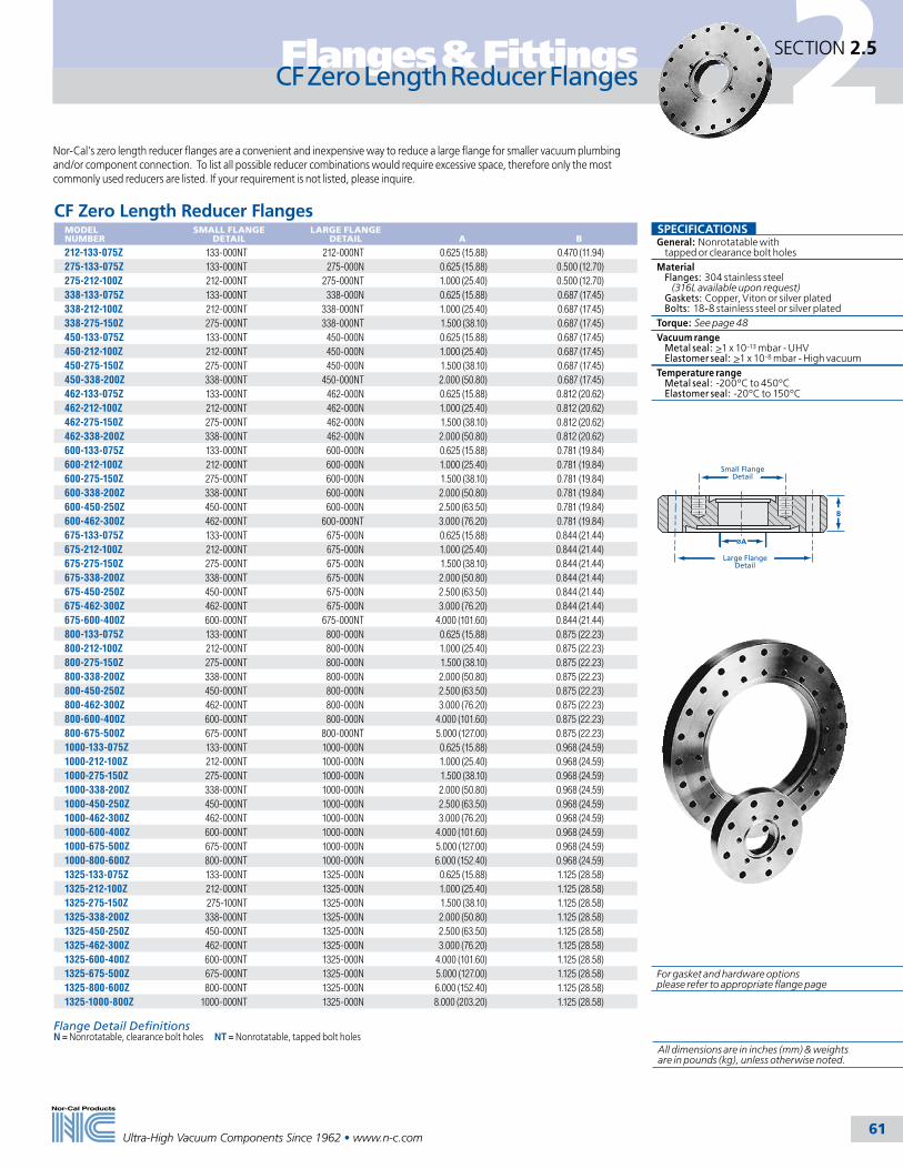
2
Ultra-High Vacuum Components Since 1962 • www.n-c.com 61
Flanges & Fittings SECTION 2.5
CF Zero Length Reducer FlangesMODEL NUMBER
SMALL FLANGE DETAIL
LARGE FLANGE DETAIL
A
B
212-133-075Z 133-000NT 212-000NT 0.625 (15.88) 0.470 (11.94)275-133-075Z 133-000NT 275-000N 0.625 (15.88) 0.500 (12.70)275-212-100Z 212-000NT 275-000NT 1.000 (25.40) 0.500 (12.70)338-133-075Z 133-000NT 338-000N 0.625 (15.88) 0.687 (17.45)338-212-100Z 212-000NT 338-000NT 1.000 (25.40) 0.687 (17.45)338-275-150Z 275-000NT 338-000NT 1.500 (38.10) 0.687 (17.45)450-133-075Z 133-000NT 450-000N 0.625 (15.88) 0.687 (17.45)450-212-100Z 212-000NT 450-000N 1.000 (25.40) 0.687 (17.45)450-275-150Z 275-000NT 450-000N 1.500 (38.10) 0.687 (17.45)450-338-200Z 338-000NT 450-000NT 2.000 (50.80) 0.687 (17.45)462-133-075Z 133-000NT 462-000N 0.625 (15.88) 0.812 (20.62)462-212-100Z 212-000NT 462-000N 1.000 (25.40) 0.812 (20.62)462-275-150Z 275-000NT 462-000N 1.500 (38.10) 0.812 (20.62)462-338-200Z 338-000NT 462-000N 2.000 (50.80) 0.812 (20.62)600-133-075Z 133-000NT 600-000N 0.625 (15.88) 0.781 (19.84)600-212-100Z 212-000NT 600-000N 1.000 (25.40) 0.781 (19.84)600-275-150Z 275-000NT 600-000N 1.500 (38.10) 0.781 (19.84)600-338-200Z 338-000NT 600-000N 2.000 (50.80) 0.781 (19.84)600-450-250Z 450-000NT 600-000N 2.500 (63.50) 0.781 (19.84)600-462-300Z 462-000NT 600-000NT 3.000 (76.20) 0.781 (19.84)675-133-075Z 133-000NT 675-000N 0.625 (15.88) 0.844 (21.44)675-212-100Z 212-000NT 675-000N 1.000 (25.40) 0.844 (21.44)675-275-150Z 275-000NT 675-000N 1.500 (38.10) 0.844 (21.44)675-338-200Z 338-000NT 675-000N 2.000 (50.80) 0.844 (21.44)675-450-250Z 450-000NT 675-000N 2.500 (63.50) 0.844 (21.44)675-462-300Z 462-000NT 675-000N 3.000 (76.20) 0.844 (21.44)675-600-400Z 600-000NT 675-000NT 4.000 (101.60) 0.844 (21.44)800-133-075Z 133-000NT 800-000N 0.625 (15.88) 0.875 (22.23)800-212-100Z 212-000NT 800-000N 1.000 (25.40) 0.875 (22.23)800-275-150Z 275-000NT 800-000N 1.500 (38.10) 0.875 (22.23)800-338-200Z 338-000NT 800-000N 2.000 (50.80) 0.875 (22.23)800-450-250Z 450-000NT 800-000N 2.500 (63.50) 0.875 (22.23)800-462-300Z 462-000NT 800-000N 3.000 (76.20) 0.875 (22.23)800-600-400Z 600-000NT 800-000N 4.000 (101.60) 0.875 (22.23)800-675-500Z 675-000NT 800-000NT 5.000 (127.00) 0.875 (22.23)1000-133-075Z 133-000NT 1000-000N 0.625 (15.88) 0.968 (24.59)1000-212-100Z 212-000NT 1000-000N 1.000 (25.40) 0.968 (24.59)1000-275-150Z 275-000NT 1000-000N 1.500 (38.10) 0.968 (24.59)1000-338-200Z 338-000NT 1000-000N 2.000 (50.80) 0.968 (24.59)1000-450-250Z 450-000NT 1000-000N 2.500 (63.50) 0.968 (24.59)1000-462-300Z 462-000NT 1000-000N 3.000 (76.20) 0.968 (24.59)1000-600-400Z 600-000NT 1000-000N 4.000 (101.60) 0.968 (24.59)1000-675-500Z 675-000NT 1000-000N 5.000 (127.00) 0.968 (24.59)1000-800-600Z 800-000NT 1000-000N 6.000 (152.40) 0.968 (24.59)1325-133-075Z 133-000NT 1325-000N 0.625 (15.88) 1.125 (28.58)1325-212-100Z 212-000NT 1325-000N 1.000 (25.40) 1.125 (28.58)1325-275-150Z 275-100NT 1325-000N 1.500 (38.10) 1.125 (28.58)1325-338-200Z 338-000NT 1325-000N 2.000 (50.80) 1.125 (28.58)1325-450-250Z 450-000NT 1325-000N 2.500 (63.50) 1.125 (28.58)1325-462-300Z 462-000NT 1325-000N 3.000 (76.20) 1.125 (28.58)1325-600-400Z 600-000NT 1325-000N 4.000 (101.60) 1.125 (28.58)1325-675-500Z 675-000NT 1325-000N 5.000 (127.00) 1.125 (28.58)1325-800-600Z 800-000NT 1325-000N 6.000 (152.40) 1.125 (28.58)1325-1000-800Z 1000-000NT 1325-000N 8.000 (203.20) 1.125 (28.58)
Nor-Cal’s zero length reducer flanges are a convenient and inexpensive way to reduce a large flange for smaller vacuum plumbing and/or component connection. To list all possible reducer combinations would require excessive space, therefore only the most commonly used reducers are listed. If your requirement is not listed, please inquire.
B
A
Large FlangeDetail
Small FlangeDetail
CF Zero Length Reducer Flanges
SPECIFICATIONSGeneral: Nonrotatable with tapped or clearance bolt holesMaterial Flanges: 304 stainless steel (316L available upon request) Gaskets: Copper, Viton or silver plated Bolts: 18-8 stainless steel or silver platedTorque: See page 48Vacuum range Metal seal: >1 x 10-13 mbar - UHV Elastomer seal: >1 x 10⁻⁸ mbar - High vacuumTemperature range Metal seal: -200ºC to 450ºC Elastomer seal: -20ºC to 150ºC
Flange Detail DefinitionsN = Nonrotatable, clearance bolt holes NT = Nonrotatable, tapped bolt holes
For gasket and hardware options please refer to appropriate flange page
All dimensions are in inches (mm) & weights are in pounds (kg), unless otherwise noted.

2
Ultra-High Vacuum Components Since 1962 • www.n-c.com 62
Flanges & FittingsSECTION 2.5
E
C
B
F
Chamfer .020"(.51) x 45
.25"(6.35)
1.70
" (4
3.18
)
StainlessSteel
Aluminum
45
Applications• Accelerators• Synchrotrons• Semiconductor processing
Nor-Cal's new Aluminum to Stainless Steel Transitions provide a reliable UHV seal for aluminum vacuum systems. An explosion bonded composite of alu-minum, stainless steel and two other UHV materials make these transitions leak tight at UHV pressures. Transitions are welded to a stainless steel CF flange as a complete unit ready to weld to your aluminum chamber or beamline, or the transition can be purchased separately for welding to your own CF flange.
The explosion bonds have been tested for tensile, shear and thermal stress. Testing included thermal quench-ing from 773ºK to 77°K. This process has shown vacuum integrity to better than 5 x 10⁻¹⁰ standard cc per second with wall thickness as thin as 0.025 inch (6.35mm). Each unit is thermally cycled to 300°C. Helium leak testing is done before and after thermal cycling.
Aluminum to Stainless Steel TransitionsMODEL NUMBER
DESCRIPTION
A
B
C
D
E
ALST-075-CF Nonrotatable CF 1.33 (33.78) 0.50 (12.70) 0.750 (19.05) 2.20 (55.88) 1.00 (25.40)ALST-075 Transition only - 0.50 (12.70) 0.750 (19.05) - 1.00 (25.40)ALST-150-CF Nonrotatable CF 2.73 (69.34) 1.25 (31.75) 1.500 (38.10) 1.91 (48.51) 1.75 (44.45)ALST-150 Transition only - 1.25 (31.75) 1.500 (38.10) - 1.75 (44.45)ALST-250-CF Nonrotatable CF 4.47 (113.54) 2.25 (57.15) 2.500 (63.50) 2.08 (52.83) 2.75 (69.85)ALST-250 Transition only - 2.25 (57.15) 2.500 (63.50) - 2.75 (69.85)ALST-400-CF Nonrotatable CF 5.97 (151.64) 3.75 (95.25) 4.000 (101.60) 2.14 (54.36) 4.25 (107.95)ALST-400 Transition only - 3.75 (95.25) 4.000 (101.60) - 4.25 (107.95)ALST-600-CF Nonrotatable CF 7.97 (202.44) 5.75 (146.05) 6.000 (152.40) 2.20 (55.88) 6.25 (158.75)ALST-600 Transition only - 5.75 (146.05) 6.000 (152.40) - 6.25 (158.75)ALST-800-CF Nonrotatable CF 9.97 (253.24) 7.75 (196.85) 8.000 (203.20) 2.20 (55.88) 8.25 (209.55)ALST-800 Transition only - 7.75 (196.85) 8.000 (203.20) - 8.25 (209.55)
A
E
C
B
D
.25"(6.35)
Aluminum to Stainless Steel Transitions
SPECIFICATIONSGeneral:Nonrotatable with clearance bolt holes
Material Flanges: 304 stainless steel (316L available upon request) Gaskets: Copper, Viton or silver plated Bolts: 18-8 stainless steel or silver plated
Torque: 21.5 Nm.
Vacuum range Metal seal: >1 x 10-13 mbar - UHV Elastomer seal: >1 x 10⁻⁸ mbar - High vacuum
Temperature range Metal seal: -200ºC to 450ºC Elastomer seal: -20ºC to 150ºC
All dimensions are in inches (mm) & weights are in pounds (kg), unless otherwise noted.

2
Ultra-High Vacuum Components Since 1962 • www.n-c.com 63
Flanges & Fittings SECTION 2.5
Plate Nuts
C
B
D
A
C
A
B
D
Nor-Cal manufactures plate nuts for most sizes of CF flanges from 11/3 to 10 inches (33.96 TO 254mm) OD. These handy backing nuts center themselves over two adjacent bolt holes on the back side of a flange and can be held in place with one finger while bolts are tightened with a single wrench. Plate nuts are perfect for those hard to reach (and see) spaces that are encountered during system assembly and service.
Plate Nut for11/3 (33.78) and 23/4 (69.85) Flanges
Plate Nut forFlanges larger than 23/4 (69.85)
Plate NutsMODEL NUMBER
FLANGE OD
THREAD SIZE
A
B
C
D
NP-075 11/3 (40) 8-32 0.80 (20.32) 0.3 (7.62) 0.53 (13.46) 0.15 (3.81)NP-150 23/4 (70) 1⁄4-28 1.59 (40.39) 0.5 (12.70) 1.15 (29.21) 0.18 (4.57)NP-150M 23/4 (70) M6 1.59 (40.39) 0.5 (12.70) 1.15 (29.21) 0.18 (4.57)NP-200 33/8 (86) 5⁄16-24 1.75 (44.45) 0.5 (12.70) 1.09 (27.69) 0.22 (5.59)NP-250 41/2 (114) 5⁄16-24 2.03 (51.56) 0.5 (12.70) 1.39 (35.31) 0.22 (5.59)NP-250M 41/2 (114) M8 2.03 (51.56) 0.5 (12.70) 1.39 (35.31) 0.22 (5.59)NP-300 45/8 (117) 5⁄16-24 1.75 (44.45) 0.5 (12.70) 1.25 (31.75) 0.22 (5.59)NP-400 6 (152) 5⁄16-24 1.75 (44.45) 0.5 (12.70) 1.00 (25.40) 0.22 (5.59)NP-400M 6 (152) M8 1.75 (44.45) 0.5 (12.70) 1.00 (25.40) 0.22 (5.59)NP-600 8 (200) 5⁄16-24 1.75 (44.45) 0.5 (12.70) 1.12 (28.45) 0.22 (5.59)NP-600M 8 (200) M8 1.75 (44.45) 0.5 (12.70) 1.12 (28.45) 0.22 (5.59)NP-800 10 (254) 5⁄16-24 1.75 (44.45) 0.5 (12.70) 1.19 (30.23) 0.22 (5.59)
All plate nuts – 24 per package
Plate Nut Assembly Kits with Hex Head BoltsMODEL NUMBER
FLANGE OD
DESCRIPTION
KNP-075 11/3 (34) (12) Plate nuts (24) SS 8-32 x 3/4 inch bolts and washersKNP-150 23/4 (70) (12) Plate nuts (24) SS 1⁄4-28 x 11/4 inch bolts and washersKNP-200 33/8 (86) (16) Plate nuts (32) SS 5⁄16-24 x 13/4 inch bolts and washersKNP-250 41/2 (114) (16) Plate nuts (32) SS 5⁄16-24 x 2 inch bolts and washersKNP-300 45/8 (117) (20) Plate nuts (40) SS 5⁄16-24 x 21/4 inch bolts and washers KNP-400 6 (152) (16) Plate nuts (32) SS 5⁄16-24 x 21/4 inch bolts and washersKNP-600 8 (200) (16) Plate nuts (32) SS 5⁄16-24 x 21/4 inch bolts and washers KNP-800 10 (254) (24) Plate nuts (48) SS 5⁄16-24 x 21/2 inch bolts and washers
Plate Nut Assembly Kits with 12-pt. BoltsMODEL NUMBER
FLANGE OD
DESCRIPTION
KNP-150-12 23/4 (70) (12) Plate nuts (24) SS 12-pt. 1⁄4-28 x 11/4 inch bolts and washersKNP-200-12 33/8 (86) (16) Plate nuts (32) SS 12-pt. 5⁄16-24 x 13/4 inch bolts and washersKNP-250-12 41/2 (114) (16) Plate nuts (32) SS 12-pt. 5⁄16-24 x 2 inch bolts and washersKNP-300-12 45/8 (117) (20) Plate nuts (40) SS 12-pt. 5⁄16-24 x 21/4 inch bolts and washersKNP-400-12 6 (152) (16) Plate nuts (32) SS 12-pt. 5⁄16-24 x 21/4 inch bolts and washersKNP-600-12 8 (200) (20) Plate nuts (49) SS 12-pt. 5⁄16-24 x 21/4 inch bolts and washersKNP-800-12 10 (254) (24) Plate nuts (48) SS 12-pt. 5⁄16-24 x 21/2 inch bolts and washers
All dimensions are in inches (mm) & weights are in pounds (kg), unless otherwise noted.
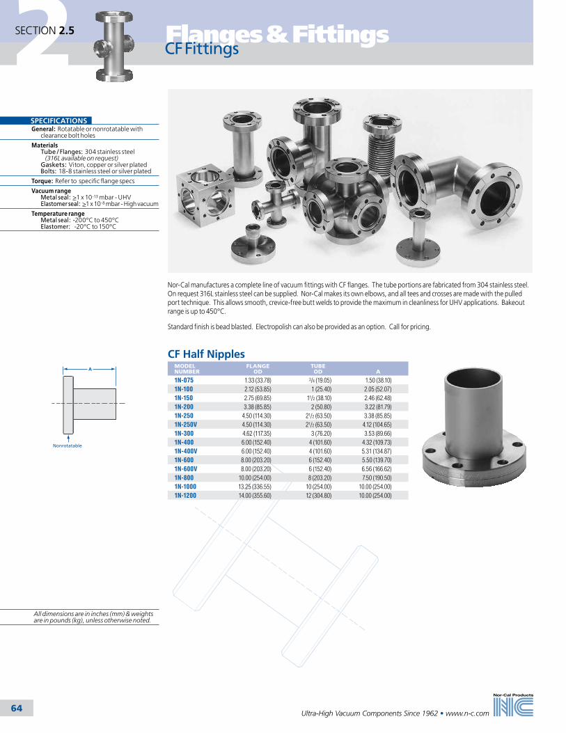
2
Ultra-High Vacuum Components Since 1962 • www.n-c.com 64
Flanges & FittingsSECTION 2.5
Nor-Cal manufactures a complete line of vacuum fittings with CF flanges. The tube portions are fabricated from 304 stainless steel. On request 316L stainless steel can be supplied. Nor-Cal makes its own elbows, and all tees and crosses are made with the pulled port technique. This allows smooth, crevice-free butt welds to provide the maximum in cleanliness for UHV applications. Bakeout range is up to 450°C.
Standard finish is bead blasted. Electropolish can also be provided as an option. Call for pricing.
A
Nonrotatable
CF Half NipplesMODEL NUMBER
FLANGE OD
TUBE OD
A
1N-075 1.33 (33.78) 3/4 (19.05) 1.50 (38.10)1N-100 2.12 (53.85) 1 (25.40) 2.05 (52.07)1N-150 2.75 (69.85) 11/2 (38.10) 2.46 (62.48)1N-200 3.38 (85.85) 2 (50.80) 3.22 (81.79)1N-250 4.50 (114.30) 21/2 (63.50) 3.38 (85.85)1N-250V 4.50 (114.30) 21/2 (63.50) 4.12 (104.65)1N-300 4.62 (117.35) 3 (76.20) 3.53 (89.66)1N-400 6.00 (152.40) 4 (101.60) 4.32 (109.73)1N-400V 6.00 (152.40) 4 (101.60) 5.31 (134.87)1N-600 8.00 (203.20) 6 (152.40) 5.50 (139.70)1N-600V 8.00 (203.20) 6 (152.40) 6.56 (166.62)1N-800 10.00 (254.00) 8 (203.20) 7.50 (190.50)1N-1000 13.25 (336.55) 10 (254.00) 10.00 (254.00)1N-1200 14.00 (355.60) 12 (304.80) 10.00 (254.00)
CF Fittings
SPECIFICATIONSGeneral: Rotatable or nonrotatable with clearance bolt holes
Materials Tube / Flanges: 304 stainless steel (316L available on request) Gaskets: Viton, copper or silver plated Bolts: 18-8 stainless steel or silver plated
Torque: Refer to specific flange specs
Vacuum range Metal seal: >1 x 10-13 mbar - UHV Elastomer seal: >1 x 10⁻⁸ mbar - High vacuum
Temperature range Metal seal: -200ºC to 450ºC Elastomer: -20ºC to 150ºC
All dimensions are in inches (mm) & weights are in pounds (kg), unless otherwise noted.

2
Ultra-High Vacuum Components Since 1962 • www.n-c.com 65
Flanges & Fittings SECTION 2.5
CF Full NipplesMODEL NUMBER
FLANGE OD
TUBE OD
A
2N-075 1.33 (33.78) 3/4 (19.05) 3.00 (76.20)2N-100 2.12 (53.85) 1 (25.40) 4.10 (104.14)2N-150 2.75 (69.85) 11/2 (38.10) 4.92 (124.97)2N-200 3.38 (85.85) 2 (50.80) 6.44 (163.58)2N-250 4.50 (114.30) 21/2 (63.50) 6.76 (171.70)2N-250V 4.50 (114.30) 21/2 (63.50) 8.24 (209.3)2N-300 4.62 (117.35) 3 (76.20) 7.06 (179.32)2N-400 6.00 (152.40) 4 (101.60) 8.64 (219.46)2N-400V 6.00 (152.40) 4 (101.60) 10.62 (269.75)2N-600 8.00 (203.20) 6 (152.40) 11.00 (279.40)2N-600V 8.00 (203.20) 6 (152.40) 13.12 (333.25)2N-800 10.00 (254.00) 8 (203.20) 15.00 (381.00)2N-1000 13.25 (336.55) 10 (254.00) 20.00 (508.00)2N-1200 14.00 (355.60) 12 (304.80) 20.00 (508.00)
A
RotatableNonrotatable
5.00(127.00)
RotatableNonrotatable
Flange1
Flange2
CF Reducer NipplesMODEL NUMBER
FLANGE 1 OD
FLANGE 2 OD
TUBE OD
2NR-600-275 6.00 (152.40) 23/4 (69.85) 1.50 (38.10)2NR-800-275 8.00 (203.20) 23/4 (69.85) 1.50 (38.10)2NR-800-450 8.00 (203.20) 41/2 (114.30) 2.50 (63.50)2NR-800-600 8.00 (203.20) 6 (152.40) 4.00 (101.60)2NR-1000-275 10.00 (254.00) 23/4 (69.85) 1.50 (38.10)2NR-1000-450 10.00 (254.00) 41/2 (114.30) 2.50 (63.50)2NR-1000-600 10.00 (254.00) 6 (152.40) 4.00 (101.60)2NR-1000-800 10.00 (254.00) 8 (203.20) 6.00 (152.40)2NR-1325-1000 13.25 (336.55) 10 (254.00) 8.00 (203.20)2NR-1400-1200 14.00 (355.60) 12 (304.80) 10.00 (254.00)
CF Conical Reducer NipplesMODEL NUMBER
FLANGE 1 OD
FLANGE 1 TUBE OD
FLANGE 2 OD
FLANGE 2 TUBE OD
A
2NRC-212-133 2.12 (53.85) 1 (25.40) 1.33 (33.78) 3/4 (19.05) 2.04 (51.82)2NRC-275-133 2.75 (69.85) 11/2 (38.10) 1.33 (33.78) 3/4 (19.05) 3.08 (78.23)2NRC-275-212 2.75 (69.85) 11/2 (38.10) 2.12 (53.85) 1 (25.40) 2.75 (69.85)2NRC-338-212 3.38 (85.85) 2 (50.80) 2.12 (53.85) 1 (25.40) 2.77 (70.36)2NRC-338-275 3.38 (85.85) 2 (50.80) 2.75 (69.85) 11/2 (38.10) 2.81 (71.37)2NRC-450-275 4.50 (114.3) 21/2 (63.50) 2.75 (69.85) 11/2 (38.10) 2.96 (75.18)2NRC-450-338 4.50 (114.3) 21/2 (63.50) 3.38 (85.85) 2 (50.80) 2.98 (75.69)2NRC-462-275 4.62 (117.35) 3 (76.20) 2.75 (69.85) 11/2 (38.10) 4.12 (104.65)2NRC-462-338 4.62 (117.35) 3 (76.20) 3.38 (85.85) 2 (50.80) 4.13 (104.90)2NRC-462-450 4.62 (117.35) 3 (76.20) 4.50 (114.30) 21/2 (63.50) 4.28 (108.71)2NRC-600-338 6.00 (152.40) 4 (101.60) 3.38 (85.85) 2 (50.80) 4.29 (108.97)2NRC-600-450 6.00 (152.40) 4 (101.60) 4.50 (114.30) 21/2 (63.50) 4.44 (112.78)2NRC-600-462 6.00 (152.40) 4 (101.60) 4.62 (117.35) 3 (76.20) 4.34 (110.24)
A
RotatableNonrotatable
Flange1
Flange2
CF Fittings
Note: Reducer nipples with other CF flanges and different lengths are available upon request.
All dimensions are in inches (mm) & weights are in pounds (kg), unless otherwise noted.

2
Ultra-High Vacuum Components Since 1962 • www.n-c.com 66
Flanges & FittingsSECTION 2.5
Both Flanges Rotatable
A Typ.
B
CF Fittings
CF 90° Mitered ElbowsMODEL NUMBER
FLANGE OD
TUBE OD
A
2E-075M 1.33 (33.78) 3/4 (19.05) 1.50 (38.10)2E-100M 2.12 (53.85) 1 (25.40) 2.05 (52.07)2E-150M 2.75 (69.85) 11/2 (38.10) 2.46 (62.48)2E-200M 3.38 (85.85) 2 (50.80) 3.22 (81.79)2E-250M 4.50 (114.30) 21/2 (63.50) 3.38 (85.85)2E-250MV 4.50 (114.30) 21/2 (63.50) 4.12 (104.65)2E-300M 4.62 (117.35) 3 (76.20) 3.53 (89.66)2E-400M 6.00 (152.40) 4 (101.60) 4.32 (109.73)2E-400MV 6.00 (152.40) 4 (101.60) 5.31 (134.87)2E-500M 6.75 (171.45) 5 (127.00) 4.71 (119.63)2E-600M 8.00 (203.20) 6 (152.40) 5.50 (139.70)2E-600MV 8.00 (203.20) 6 (152.40) 6.56 (166.62)2E-800M 10.00 (254.00) 8 (203.20) 7.50 (190.50)2E-1000M 13.25 (336.55) 10 (254.00) 10.00 (254.00)
A Typ.
Both Flanges Rotatable
CF 90º Radius ElbowsMODEL NUMBER
FLANGE OD
TUBE OD
A
B
2E-075 1.33 (33.78) 3/4 (19.05) 1.50 (38.10) 1.00 (25.40)2E-100 2.12 (52.85) 1 (25.40) 1.67 (42.42) 1.50 (38.10)2E-150 2.75 (69.85) 11/2 (38.10) 2.46 (62.48) 2.25 (57.15)2E-200 3.38 (85.85) 2 (50.80) 3.22 (81.79) 3.00 (76.20)2E-250 4.50 (114.30) 21/2 (63.50) 4.12 (104.65) 3.75 (95.25)2E-300 4.62 (117.35) 3 (76.20) 4.78 (121.41) 4.50 (114.30)2E-400 6.00 (152.40) 4 (101.60) 6.44 (163.58) 6.00 (152.40)2E-600 8.00 (203.20) 6 (152.40) 9.50 (241.30) 9.00 (228.60)2E-800 10.00 (254.00) 8 (203.20) 12.50 (317.50) 12.00 (304.80)2E-1000 13.25 (336.55) 10 (254.00) 15.50 (393.70) 15.00 (381.00)
CF 45° Radius Elbow with TangentsMODEL NUMBER
FLANGE OD
TUBE OD
A
2KL-075 1.33 (33.78) 3/4 (19.05) 0.94 (23.88)2KL-100 2.12 (53.85) 1 (25.40) 1.14 (28.96)2KL-150 2.75 (69.85) 11/2 (38.10) 1.74 (44.20)2KL-200 3.38 (85.85) 2 (50.80) 2.07 (52.58)2KL-250 4.50 (114.30) 21/2 (63.50) 3.37 (85.60)2KL-300 4.62 (117.35) 3 (76.20) 3.96 (100.58)2KL-400 6.00 (152.40) 4 (101.60) 5.22 (132.59)
Both Flanges Rotatable
A
All dimensions are in inches (mm) & weights are in pounds (kg), unless otherwise noted.
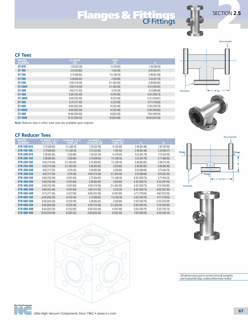
2
Ultra-High Vacuum Components Since 1962 • www.n-c.com 67
Flanges & Fittings SECTION 2.5
Flange1
Flange2
B
Rotatable
Nonrotatable
A Typ.
Flange3
Rotatable
Nonrotatable
A Typ.
CF TeesMODEL NUMBER
FLANGE OD
TUBE OD
A
3T-075 1.33 (33.78) 3/4 (19.05) 1.50 (38.10)3T-100 2.12 (53.85) 1 (25.40) 2.05 (52.07)
3T-150 2.75 (69.85) 11/2 (38.10) 2.46 (62.48)
3T-200 3.38 (85.85) 2 (50.80) 3.22 (81.79)3T-250 4.50 (114.30) 21/2 (63.50) 3.38 (85.85)3T-250V 4.50 (114.30) 21/2 (63.50) 4.12 (104.65)3T-300 4.62 (117.35) 3 (76.20) 3.53 (89.66)3T-400 6.00 (152.40) 4 (101.60) 4.32 (109.73)3T-400V 6.00 (152.40) 4 (101.60) 5.31 (134.87)3T-500 6.75 (171.45) 5 (127.00) 4.71 (119.63)3T-600 8.00 (203.20) 6 (152.40) 5.50 (139.70)3T-600V 8.00 (203.20) 6 (152.40) 6.56 (166.62)3T-800 10.00 (254.00) 8 (203.20) 7.50 (190.50)3T-1000 13.25 (336.55) 10 (254.00) 10.00 (254.00)
Note: Reducer tees in other tube sizes are available upon request.
CF Reducer TeesMODEL NUMBER
FLANGE 1 & 2 FLANGE OD
FLANGE 1 & 2 TUBE OD
FLANGE 3 FLANGE OD
FLANGE 3 TUBE OD
A
B
3TR-150-075 2.75 (69.85) 11/2 (38.10) 1.33 (33.78) 3/4 (19.05) 2.46 (62.48) 1.87 (47.50)3TR-150-100 2.75 (69.85) 11/2 (38.10) 2.12 (53.85) 1 (25.40) 2.46 (62.48) 2.29 (58.17)3TR-200-075 3.38 (85.85) 2 (50.80) 1.33 (33.78) 3/4 (19.05) 3.22 (81.79) 2.13 (54.10)3TR-200-150 3.38 (85.85) 2 (50.80) 2.75 (69.85) 11/2 (38.10) 3.22 (81.79) 2.71 (68.83)3TR-250-150 4.50 (114.30) 21/2 (63.50) 2.75 (69.85) 11/2 (38.10) 3.38 (85.85) 2.96 (75.18)3TR-250-200 4.50 (114.30) 21/2 (63.50) 3.38 (85.85) 2 (50.80) 3.38 (85.85) 3.48 (88.39)3TR-300-200 4.62 (117.35) 3 (76.20) 3.38 (85.85) 2 (50.80) 3.53 (89.66) 3.73 (94.74)3TR-300-250 4.62 (117.35) 3 (76.20) 4.50 (114.3)0 21/2 (63.50) 3.53 (89.66) 3.63 (92.20)3TR-400-150 6.00 (152.40) 4 (101.60) 2.75 (69.85) 11/2 (38.10) 4.32 (109.73) 3.71 (94.23)3TR-400-200 6.00 (152.40) 4 (101.60) 3.38 (85.85) 2 (50.80) 4.32 (109.73) 4.23 (107.44)3TR-400-250 6.00 (152.40) 4 (101.60) 4.50 (114.30) 21/2 (63.50) 4.32 (109.73) 4.13 (104.90)3TR-400-300 6.00 (152.40) 4 (101.60) 4.62 (117.35) 3 (76.20) 4.32 (109.73) 4.03 (102.36)3TR-500-400 6.75 (171.45) 5 (127.00) 6.00 (152.40) 4 (101.60) 4.71 (119.63) 4.82 (122.43)3TR-600-150 8.00 (203.20) 6 (152.40) 2.75 (69.85) 11/2 (38.10) 5.50 (139.70) 4.71 (119.63)3TR-600-200 8.00 (203.20) 6 (152.40) 3.38 (85.85) 2 (50.80) 5.50 (139.70) 5.23 (132.84)3TR-600-250 8.00 (203.20) 6 (152.40) 4.50 (114.30) 21/2 (63.50) 5.50 (139.70) 5.13 (130.30)3TR-600-400 8.00 (203.20) 6 (152.60) 6.00 (152.40) 4 (101.60) 5.50 (139.70) 5.32 (135.13)3TR-800-600 10.00 (254.00) 8 (203.20) 8.00 (203.20) 6 (152.40) 7.50 (190.50) 6.50 (165.10)
CF Fittings
All dimensions are in inches (mm) & weights are in pounds (kg), unless otherwise noted.

2
Ultra-High Vacuum Components Since 1962 • www.n-c.com 68
Flanges & FittingsSECTION 2.5
CF 6-Way Cube CrossesMODEL NUMBER
NOMINAL FLANGE SIZE
A
6C-075-CU 1.33 (33.78) 0.67 (17.02)6C-150-CU 2.75 (69.85) 1.37 (34.80)6C-250-CU 4.50 (114.30) 2.24 (56.90)6C-400-CU 6 (152.40) 2.98 (75.69)6C-600-CU 8.00 (203.20) 3.98 (101.09)
Rotatable
Flange1
Flange2
Nonrotatable
A Typ.
Flange3
Flange4
B Typ.
CF Reducer CrossesMODEL NUMBER
FLANGE 1& 2 FLANGE OD
FLANGE 1 & 2 TUBE OD
FLANGE 3 & 4 FLANGE OD
FLANGE 3 & 4 TUBE OD
A
B
4CR-150-075 2.75 (69.85) 11/2 (38.10) 1.33 (33.78) 3/4 (19.05) 2.46 (62.48) 1.87 (47.50)4CR-150-100 2.75 (69.85) 11/2 (38.10) 2.12 (53.85) 1 (25.40) 2.46 (62.48) 2.29 (58.17)4CR-200-075 3.38 (85.85) 2 (50.80) 1.33 (33.78) 3/4 (19.05) 3.22 (81.79) 2.13 (54.10)4CR-200-150 3.38 (85.85) 2 (50.80) 2.75 (69.85) 11/2 (38.10) 3.22 (81.79) 2.71 (68.83)4CR-250-150 4.50 (114.30) 21/2 (63.50) 2.75 (69.85) 11/2 (38.10) 3.38 (85.85) 2.96 (75.18)4CR-250-200 4.50 (114.30) 21/2 (63.50) 3.38 (85.85) 2 (50.80) 3.38 (85.85) 3.48 (88.39)4CR-300-200 4.62 (117.35) 3 (76.20) 3.38 (85.85) 2 (50.80) 3.53 (89.66) 3.73 (94.74)4CR-300-250 4.62 (117.35) 3 (76.20) 4.50 (114.30) 21/2 (63.50) 3.53 (89.66) 3.63 (92.2)4CR-400-150 6.00 (152.40) 4 (101.60) 2.75 (69.85) 11/2 (38.10) 4.32 (109.73) 3.71 (94.23)4CR-400-200 6.00 (152.40) 4 (101.60) 3.38 (85.85) 2 (50.80) 4.32 (109.73) 4.23 (107.44)4CR-400-250 6.00 (152.40) 4 (101.60) 4.50 (114.30) 21/2 (63.50) 4.32 (109.73) 4.13 (104.90)4CR-400-300 6.00 (152.40) 4 (101.60) 4.62 (117.35) 3 (76.20) 4.32 (109.73) 4.03 (102.36)4CR-500-400 6.75 (171.45) 5 (127.00) 6.00 (152.40) 4 (101.60) 4.71 (119.63) 4.82 (122.43)4CR-600-150 8.00 (203.20) 6 (152.40) 2.75 (69.85) 11/2 (38.10) 5.50 (139.70) 4.71 (119.63)4CR-600-200 8.00 (203.20) 6 (152.40) 3.38 (85.85) 2 (50.80) 5.50 (139.70) 5.23 (132.84)4CR-600-250 8.00 (203.20) 6 (152.40) 4.50 (114.30) 21/2 (63.50) 5.50 (139.70) 5.13 (130.30)4CR-600-400 8.00 (203.20) 6 (152.40) 6.00 (152.40) 4 (101.60) 5.50 (139.70) 5.32 (135.13)4CR-800-600 10.00 (254.00) 6 (152.40) 8.00 (203.20) 6 (152.40) 7.50 (190.50) 6.50 (165.10)
CF Fittings
A Typical
Note: Other reducer combinations can be supplied upon request.
Note: Cube crosses are available in other sizes upon request
All dimensions are in inches (mm) & weights are in pounds (kg), unless otherwise noted.
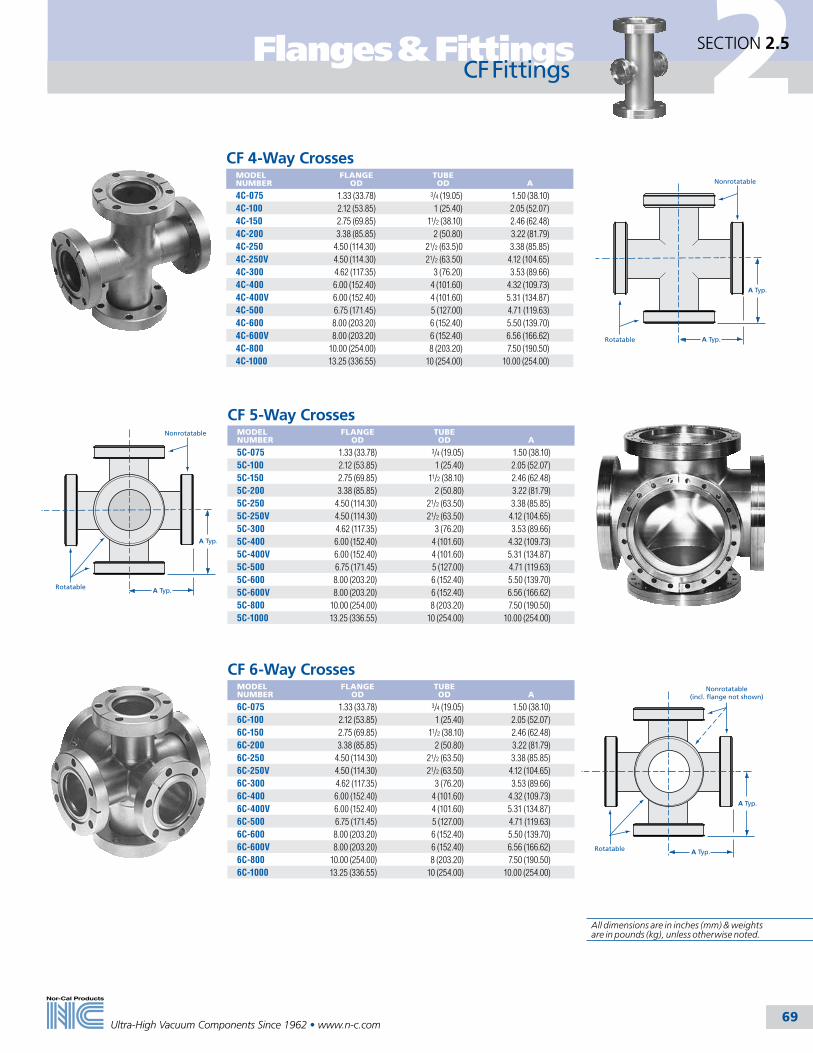
2
Ultra-High Vacuum Components Since 1962 • www.n-c.com 69
Flanges & Fittings SECTION 2.5
CF Fittings
CF 6-Way CrossesMODEL NUMBER
FLANGE OD
TUBE OD
A
6C-075 1.33 (33.78) 3/4 (19.05) 1.50 (38.10)6C-100 2.12 (53.85) 1 (25.40) 2.05 (52.07)6C-150 2.75 (69.85) 11/2 (38.10) 2.46 (62.48)6C-200 3.38 (85.85) 2 (50.80) 3.22 (81.79)6C-250 4.50 (114.30) 21/2 (63.50) 3.38 (85.85)6C-250V 4.50 (114.30) 21/2 (63.50) 4.12 (104.65)6C-300 4.62 (117.35) 3 (76.20) 3.53 (89.66)6C-400 6.00 (152.40) 4 (101.60) 4.32 (109.73)6C-400V 6.00 (152.40) 4 (101.60) 5.31 (134.87)6C-500 6.75 (171.45) 5 (127.00) 4.71 (119.63)6C-600 8.00 (203.20) 6 (152.40) 5.50 (139.70)6C-600V 8.00 (203.20) 6 (152.40) 6.56 (166.62)6C-800 10.00 (254.00) 8 (203.20) 7.50 (190.50)6C-1000 13.25 (336.55) 10 (254.00) 10.00 (254.00)
CF 5-Way CrossesMODEL NUMBER
FLANGE OD
TUBE OD
A
5C-075 1.33 (33.78) 3/4 (19.05) 1.50 (38.10)5C-100 2.12 (53.85) 1 (25.40) 2.05 (52.07)5C-150 2.75 (69.85) 11/2 (38.10) 2.46 (62.48)5C-200 3.38 (85.85) 2 (50.80) 3.22 (81.79)5C-250 4.50 (114.30) 21/2 (63.50) 3.38 (85.85)5C-250V 4.50 (114.30) 21/2 (63.50) 4.12 (104.65)5C-300 4.62 (117.35) 3 (76.20) 3.53 (89.66)5C-400 6.00 (152.40) 4 (101.60) 4.32 (109.73)5C-400V 6.00 (152.40) 4 (101.60) 5.31 (134.87)5C-500 6.75 (171.45) 5 (127.00) 4.71 (119.63)5C-600 8.00 (203.20) 6 (152.40) 5.50 (139.70)5C-600V 8.00 (203.20) 6 (152.40) 6.56 (166.62)5C-800 10.00 (254.00) 8 (203.20) 7.50 (190.50)5C-1000 13.25 (336.55) 10 (254.00) 10.00 (254.00)
A Typ.
Rotatable
Nonrotatable
A Typ.
A Typ.
Rotatable
Nonrotatable(incl. flange not shown)
A Typ.
A Typ.
Rotatable
Nonrotatable
A Typ.
CF 4-Way CrossesMODEL NUMBER
FLANGE OD
TUBE OD
A
4C-075 1.33 (33.78) 3/4 (19.05) 1.50 (38.10)4C-100 2.12 (53.85) 1 (25.40) 2.05 (52.07)4C-150 2.75 (69.85) 11/2 (38.10) 2.46 (62.48)4C-200 3.38 (85.85) 2 (50.80) 3.22 (81.79)4C-250 4.50 (114.30) 21/2 (63.5)0 3.38 (85.85)4C-250V 4.50 (114.30) 21/2 (63.50) 4.12 (104.65)4C-300 4.62 (117.35) 3 (76.20) 3.53 (89.66)4C-400 6.00 (152.40) 4 (101.60) 4.32 (109.73)4C-400V 6.00 (152.40) 4 (101.60) 5.31 (134.87)4C-500 6.75 (171.45) 5 (127.00) 4.71 (119.63)4C-600 8.00 (203.20) 6 (152.40) 5.50 (139.70)4C-600V 8.00 (203.20) 6 (152.40) 6.56 (166.62)4C-800 10.00 (254.00) 8 (203.20) 7.50 (190.50)4C-1000 13.25 (336.55) 10 (254.00) 10.00 (254.00)
All dimensions are in inches (mm) & weights are in pounds (kg), unless otherwise noted.

2
Ultra-High Vacuum Components Since 1962 • www.n-c.com 70
Flanges & FittingsSECTION 2.6
Wire Seal Flanges
Nor-Cal’s wire seal flanges are designed for use on bell jars, custom vacuum chambers and related systems. Standard sizes range from 12 to 27 inch (305 to 686mm) nominal OD for tube sizes from 10 to 24 inch (254 to 609.6mm) OD. A male and female flange compress a 0.080 inch (20.32mm) diameter OFHC copper wire to effect a seal. Gasket flow is confined by the geometry of the flange surfaces to the area of the seal. Minor nicks and scratches within this contact area are filled with crushed copper wire providing a seal that is leak tight at 10-13 mbar after repeated bake out to 450˚C. Solid blanks are standard. Dished head blanks are offered as a lower cost alternative.
Male Bored
Female BlankWire Seal
Wire Seal Flange Gaskets and Bolt SetsMODEL NUMBER
FLANGE OD
DESCRIPTION
QUANTITY
WG-12 12.375 (314.33) Copper gasket 1WB-12 12.375 (314.33) SS 3⁄8-24 x 21⁄2 bolts and nuts 24WG-14 14.625 (371.48) Copper gasket 1WB-14 14.625 (371.48) SS 3⁄8-24 x 21⁄2 bolts and nuts 32WG-17 17.250 (438.15) Copper gasket 1WB-17 17.250 (438.15) SS 1⁄2-20 x 23⁄4 bolts and nuts 36WG-19 19.562 (496.87) Copper gasket 1WB-19 19.562 (496.87) SS 1⁄2-20 x 3 bolts and nuts 36WG-22 22.125 (561.98) Copper gasket 1WB-22 22.125 (561.98) SS 5⁄8-18 x 31⁄2 bolts and nuts 36WG-27 27.125 (688.98) Copper gasket 1WB-27 27.125 (688.98) SS 5⁄8-18 x 4 bolts and nuts 40
1. Apply a small amount of high temperature anti-seize compound to the bolt threads.2. Check that both flange surfaces are clean and sealing edges are free from nicks and scratches.3. Using clean, lint free gloves, unpack gasket.4. Place seal over the sealing area on the male flange. 5. Align the mating flange hole pattern and leak test grooves.6. Install the proper bolts and tighten hand tight. Check to see that the flange faces are parallel.7. Tighten the bolts 1/4 to 1/2 turns using a circular clockwise pattern until the flange faces are metal to metal. 8. Torque the fasteners until leak tight using the same pattern. Never exceed maximum torque.
Wire Seal Flange Assembly Instructions
Torque Specifications NOMINAL
ODBOLT SIZE
MAX. TORQUE NM
12 (305) 3/8 - 24 29.414 (356) 3/8 - 24 29.417 (432) 1/2 - 20 61.119 (483) 1/2 - 20 61.122 (559) 5/8 - 18 140.627 (686) 5/8 - 18 140.6
Wire Seal FlangesMODEL NUMBER
OD A
B
C
D
E
F
BOLT HOLES
WS-12-000M 12.375 (314.33) - - 1.13 (28.70) - 11.343 (288.11) 24WS-12-1000M 12.375 (314.33) 9.750 (247.65) 10.020 (254.51) 1.13 (28.70) 0.630 (16.00) 11.343 (288.11) 24WS-12-000F 12.375 (314.33) - - 1.13 (28.70) - 11.343 (288.11) 24WS-12-1000F 12.375 (314.33) 9.750 (247.65) 10.020 (254.51) 1.13 (28.70) 0.630 (16.00) 11.343 (288.11) 24WS-14-000M 14.625 (371.48) - - 1.13 (28.70) - 13.593 (345.26) 32WS-14-1200M 14.625 (371.48) 11.750 (298.45) 12.020 (305.31) 1.13 (28.70) 0.630 (16.00) 13.593 (345.26) 32WS-14-000F 14.625 (371.48) - - 1.13 (28.70) - 13.593 (345.26) 32WS-14-1200F 14.625 (371.48) 11.750 (298.45) 12.020 (305.31) 1.13 (28.70) 0.630 (16.00) 13.593 (345.26) 32WS-17-000M 17.250 (438.15) - - 1.13 (28.70) - 15.718 (399.24) 36WS-17-1400M 17.250 (438.15) 13.750 (349.25) 14.020 (356.11) 1.13 (28.70) 0.630 (16.00) 15.718 (399.24) 36WS-17-000F 17.250 (438.15) - - 1.13 (28.70) - 15.718 (399.24) 36WS-17-1400F 17.250 (438.15) 13.750 (349.25) 14.020 (356.11) 1.13 (28.70) 0.630 (16.00) 15.718 (399.24) 36WS-19-000M 19.562 (496.87) - - 1.31 (33.27) - 17.875 (454.03) 36WS-19-1600M 19.562 (496.87) 15.750 (400.05) 16.020 (406.91) 1.31 (33.27) 0.630 (16.00) 17.875 (454.03) 36WS-19-000F 19.562 (496.87) - - 1.31 (33.27) - 17.875 (454.03) 36WS-19-1600F 19.562 (496.87) 15.750 (400.05) 16.020 (406.91) 1.31 (33.27) 0.630 (16.00) 17.875 (454.03) 36WS-22-000M 22.125 (561.98) - - 1.50 (38.10) - 20.187 (512.75) 36WS-22-1800M 22.125 (561.98) 17.750 (450.85) 18.020 (457.71) 1.50 (38.10) 1.000 (25.40) 20.187 (512.75) 36WS-22-000F 22.125 (561.98) - - 1.50 (38.10) - 20.187 (512.75) 36WS-22-1800F 22.125 (561.98) 17.750 (450.85) 18.020 (457.71) 1.50 (38.10) 1.000 (25.40) 20.187 (512.75) 36WS-27-000M 27.125 (688.98) - - 1.75 (44.45) - 25.843 (656.41) 40WS-27-2400M 27.125 (688.98) 23.625 (600.08) 24.020 (610.11) 1.75 (44.45) 1.125 (28.58) 25.843 (656.41) 40WS-27-000F 27.125 (688.98) - - 1.75 (44.45) - 25.843 (656.41) 40WS-27-2400F 27.125 (688.98) 23.625 (600.08) 24.020 (610.11) 1.75 (44.45) 1.125 (28.58) 25.843 (656.41) 40
Model Number DefinitionsM = Male flange F = Female flange
D
F
A
DE
F
A
B
C
Female Bored
Female Blank
E
F
A
B
C
D
Male Bored
D
F
AMale Blank
SPECIFICATIONSGeneral: Nonrotatable flanges with clearance bolt holes
Nominal OD sizes: 123/8 to 271/8 inches (314 to 689mm)
Tube OD sizes: 10 to 24 inches (254 to 609.6mm)
Materials Flange: 304 stainless steel (316L available on request) Gaskets: Copper Bolts: 18-8 stainless steel
Vacuum range: ≥1 x 10-13 mbar - UHV
Temperature range: -200º to 450ºC
All dimensions are in inches (mm) & weights are in pounds (kg), unless otherwise noted.

2Adapter Fittings
Ultra-High Vacuum Components Since 1962 • www.n-c.com 71
SECTION 2.7
General Information
Adapter FittingsNor-Cal Products provides a broad range of adapter fittings in order to connect two dissimilar types of components. They are made from 304 or 316L stainless steel and are TIG welded, cleaned and leak checked for vacuum service. Tube finishes are normally bead blasted. However, tumbled or electropolished finish can be provided upon request. Flanges and nipples used to adapt different sizes of the same flange type are called reducers. They are listed in the flanges and fittings section for the particular flange type. For exam-ple, CF zero length reducer flanges are listed in the CF section of Flanges and Fittings.
Flange-to-Flange AdaptersFlange-to-flange adapter fittings are used as a transition between two dissimilar flange types. We offer adapter fittings with flange combinations for CF (Conflat), NW (ISO-KF), ISO and ASA (ANSI) components as standards. We frequently provide other flange combinations as specials. These include wire seal, JIS, MESC, and other flanges. Flange-to-flange adapter nipples usually have a short length of straight tubing between the two flanges. Where possible, we offer conical adapters as an option to reduce conductance loss at the opening of the larger flange. Nor-Cal also offers adapter tees and crosses with ISO and NW flanges. ASA to CF adapter flanges are also found in this section.
Flange-to-Fitting Adapters Flange-to-fitting adapters are commonly used on chamber ports to connect flanges to special fittings. Nor-Cal offers these with CF, NW, ISO and ASA flanges for Swagelok, male and female VCR, quick disconnect, male and female NPT, ball socket and Welch pump fittings as standards. Other combinations can be supplied quickly as specials.
SPECIFICATIONSMaterials: 304 or 316L stainless steelVacuum range Metal seal: >1 x 10-13 mbar - UHV Elastomer seal: >1 x 10⁻⁸ mbar - High vacuumTemperature range Metal seal: -200ºC to 450ºC Elastomer seal: -20ºC to 150ºC
All dimensions are in inches (mm) & weights are in pounds (kg), unless otherwise noted.

2 Adapter Fittings
Ultra-High Vacuum Components Since 1962 • www.n-c.com 72
SECTION 2.7
Flange-to-Flange
NW to CF Conical Adapter Nipples MODEL NUMBER
FLANGE 1 TYPE NOM. TUBE OD
FLANGE 2 TYPE NOM. TUBE OD
A
ANC-NW-16-212 NW-16 3/4 (19.05) 2.12 CF 1 (25.40) 1.69 (42.93)ANC-NW-16-275 NW-16 3/4 (19.05) 2.75 CF 11/2 (38.10) 2.73 (69.34)ANC-NW-25-133 NW-25 1 (25.40) 1.33 CF 3/4 (19.05) 2.03 (51.56)ANC-NW-25-275 NW-25 1 (25.40) 2.75 CF 11/2 (38.10) 2.73 (69.34)ANC-NW-25-338 NW-25 1 (25.40) 3.38 CF 2 (50.80) 2.75 (69.85)ANC-NW-40-133 NW-40 11/2 (38.10) 1.33 CF 3/4 (19.05) 3.03 (76.96)ANC-NW-40-212 NW-40 11/2 (38.10) 2.12 CF 1 (25.40) 2.69 (68.33)ANC-NW-40-338 NW-40 11/2 (38.10) 3.38 CF 2 (50.80) 2.75 (69.85)ANC-NW-40-450 NW-40 11/2 (38.10) 4.50 CF 21/2 (63.50) 2.90 (73.66)ANC-NW-40-462 NW-40 11/2 (38.10) 4.62 CF 3 (76.20) 4.06 (103.12)ANC-NW-50-212 NW-50 2 (50.80) 2.12 CF 1 (25.40) 2.69 (68.33)ANC-NW-50-275 NW-50 2 (50.80) 2.75 CF 11/2 (38.10) 2.73 (69.34)ANC-NW-50-450 NW-50 2 (50.80) 4.50 CF 21/2 (63.50) 2.90 (73.66)ANC-NW-50-462 NW-50 2 (50.80) 4.62 CF 3 (76.50) 4.06 (103.12)ANC-NW-50-600 NW-50 2 (50.80) 6.00 CF 4 (101.60) 4.21 (106.93)
NW to CF Adapter NipplesMODEL NUMBER
FLANGE 1 TYPE
FLANGE 2 TYPE
NOM. TUBE OD
AN-NW-10-133 NW-10 1.33 CF 1/2 (12.70)AN-NW-16-133 NW-16 1.33 CF 3/4 (19.05)AN-NW-25-212 NW-25 2.12 CF 1 (25.40)AN-NW-40-275 NW-40 2.75 CF 11/2 (38.10)AN-NW-50-133 NW-50 1.33 CF 3/4 (19.05)AN-NW-50-338 NW-50 3.38 CF 2 (50.80)
A
Flange1
Flange2
Flange1
Flange2
2.00(50.8)
Flange2
A
Flange1
NW to ASA Conical Adapter NipplesMODEL NUMBER
FLANGE 1 TYPE NOM. TUBE OD
FLANGE 2 TYPE NOM. TUBE
OD A
ANC-NW-25-ASA-5 NW-25 1 (25.40) ASA-5 2 (50.80) 2.78 (70.61)ANC-NW-40-ASA-5 NW-40 11/2 (38.10) ASA-5 21/2 (63.50) 2.78 (70.61)ANC-NW-40-ASA-6 NW-40 11/2 (38.10) ASA-6 3 (76.20) 4.03 (102.36)ANC-NW-50-ASA-5 NW-50 2 (50.80) ASA-5 21/2 (63.50) 2.78 (70.61)ANC-NW-50-ASA-6 NW-50 2 (50.80) ASA-6 3 (76.20) 4.03 (102.36)ANC-NW-50-ASA-7.5 NW-50 2 (50.80) ASA-7.5 4 (101.60) 4.03 (102.36)
NW to ASA Adapter NipplesMODEL NUMBER
FLANGE 1 TYPE
FLANGE 2 TYPE
NOM. TUBE OD
AN-NW-16-ASA-5 NW-16 ASA-5 3/4 (19.05)AN-NW-16-ASA-6 NW-16 ASA-6 3/4 (19.05)AN-NW-16-ASA-7.5 NW-16 ASA-7.5 3/4 (19.05)AN-NW-16-ASA-9 NW-16 ASA-9 3/4 (19.05)AN-NW-16-ASA-11 NW-16 ASA-11 3/4 (19.05)AN-NW-25-ASA-6 NW-25 ASA-6 1 (25.40)AN-NW-25-ASA-7.5 NW-25 ASA-7.5 1 (25.40)AN-NW-25-ASA-9 NW-25 ASA-9 1 (25.40)AN-NW-25-ASA-11 NW-25 ASA-11 1 (25.40)AN-NW-40-ASA-7.5 NW-40 ASA-7.5 11/2 (38.10)AN-NW-40-ASA-9 NW-40 ASA-9 11/2 (38.10)AN-NW-40-ASA-11 NW-40 ASA-11 11/2 (38.10)AN-NW-50-ASA-9 NW-50 ASA-9 2 (50.80)AN-NW-50-ASA-11 NW-50 ASA-11 2 (50.80)
Note: Add suffix “-G” to model number if O-Ring Groove is required on ASA flange. Call for ASA groove prices.
Flange1
Flange2
2.00(50.8)
SPECIFICATIONSMaterials: 304 stainless steel (316L available upon request)
Vacuum range: >1 x 10⁻⁸ mbar - High vacuum
Temperature range: -20ºC to 150ºC

2Adapter Fittings
Ultra-High Vacuum Components Since 1962 • www.n-c.com 73
SECTION 2.7Flange-to-Flange
NW to ISO Conical Adapter NipplesMODEL NUMBER
FLANGE 1 TYPE NOM. TUBE OD
FLANGE 2 TYPE NOM. TUBE OD
A
ANC-NW-40-ISO-63 NW-40 11/2 (38.10) ISO-63 21/2 (63.50) 2.78 (70.61)ANC-NW-40-ISO-80 NW-40 11/2 (38.10) ISO-80 3 (76.20) 4.03 (102.36)ANC-NW-50-ISO-63 NW-50 2 (50.80) ISO-63 21/2 (63.50) 2.78 (70.61)ANC-NW-50-ISO-80 NW-50 2 (50.80) ISO-80 3 (76.20) 4.03 (102.36)ANC-NW-50-ISO-100 NW-50 2 (50.80) ISO-100 4 (101.60) 4.03 (102.36)
NW to ISO Adapter TeesMODEL NUMBER
FLANGE 1 TYPE NOM. TUBE OD
FLANGE 2 TYPE NOM. TUBE OD
A
B
3TA-NW-40-ISO-63-OF ISO-63 21/2 (63.50) NW-40 11/2 (38.10) 3.25 (82.55)
2.90 (73.66)
3TA-NW-40-ISO-80-OF ISO-80 3 (76.20) NW-40 11/2 (38.10) 3.50 (88.90)
3.15 (80.01)
3TA-NW-40-ISO-100-OF ISO-100 4 (101.60) NW-40 11/2 (38.10) 4.13 (104.90)
3.65 (92.71)
3TA-NW-40-ISO-160-OF ISO-160 6 (152.40) NW-40 11/2 (38.10) 5.38 (136.65)
4.65 (118.11)
3TA-NW-50-ISO-63-OF ISO-63 21/2 (63.50) NW-50 2 (50.80) 3.25 (82.55)
3.40 (86.36)
3TA-NW-50-ISO-80-OF ISO-80 3 (76.20) NW-50 2 (50.80) 3.50 (88.90)
3.65 (92.71)
3TA-NW-50-ISO-100-OF ISO-100 4 (101.60) NW-50 2 (50.80) 4.13 (104.90)
4.15 (105.41)
3TA-NW-50-ISO-160-OF ISO-160 6 (152.40) NW-50 2 (50.80) 5.38 (136.65)
5.15 (130.81)
NW to ISO Adapter CrossesMODEL NUMBER
FLANGE 1 TYPE NOM. TUBE OD
FLANGE 2 TYPE NOM. TUBE OD
A
B
4CA-NW-40-ISO-63-OF ISO-63 21/2 (63.50) NW-40 11/2 (38.10) 3.25 (82.55)
2.90 (73.66)
4CA-NW-40-ISO-80-OF ISO-80 3 (76.20) NW-40 11/2 (38.10) 3.50 (88.90)
3.15 (80.01)
4CA-NW-40-ISO-100-OF ISO-100 4 (101.60) NW-40 11/2 (38.10) 4.13 (104.90)
3.65 (92.71)
4CA-NW-40-ISO-160-OF ISO-160 6 (152.4) NW-40 11/2 (38.10) 5.38 (136.65)
4.65 (118.11)
4CA-NW-50-ISO-63-OF ISO-63 21/2 (63.50) NW-50 2 (50.80) 3.25 (82.55)
3.40 (86.36)
4CA-NW-50-ISO-80-OF ISO-80 3 (76.20) NW-50 2 (50.80) 3.50 (88.90)
3.65 (92.71)
4CA-NW-50-ISO-100-OF ISO-100 4 (101.60) NW-50 2 (50.80) 4.13 (104.90)
4.15 (105.41)
4CA-NW-50-ISO-160-OF ISO-160 6 (152.40) NW-50 2 (50.80) 5.38 (136.65)
5.15 (130.81)
A
Flange1
Flange2
1.75 (44.45)
Flange1
Flange2
Flange1
Flange2B
A Typ.
Flange3
Flange1
Flange2
BTyp.
A Typ.
Flange3
Flange4
NW to ISO Adapter NipplesMODEL NUMBER
FLANGE 1 TYPE
FLANGE 2 TYPE
NOM. TUBE OD
AN-NW-16-ISO-63-OF NW-16 ISO-63 3/4 (19.05)AN-NW-25-ISO-63-OF NW-25 ISO-63 1 (25.40)AN-NW-25-ISO-80-OF NW-25 ISO-80 1 (25.40)AN-NW-25-ISO-100-OF NW-25 ISO-100 1 (25.40)AN-NW-40-ISO-100-OF NW-40 ISO-100 11/2 (38.10)AN-NW-50-ISO-160-OF NW-50 ISO-160 2 (50.80)
SPECIFICATIONSMaterials: 304 stainless steel (316L available upon request)Vacuum range: >1 x 10⁻⁸ mbar - High vacuumTemperature range: -20ºC to 150ºC
All dimensions are in inches (mm) & weights are in pounds (kg), unless otherwise noted.

2 Adapter Fittings
Ultra-High Vacuum Components Since 1962 • www.n-c.com 74
SECTION 2.7
Flange-to-Flange
CF to ISO Conical Adapter NipplesMODEL NUMBER
FLANGE 1 FLANGE 2 ATYPE NOM. TUBE OD TYPE NOM. TUBE OD
ANC-275-ISO-63-OF 2.75 CF 11/2 (40) ISO-63-OF 21/2 (63) 2.83 (71.88)ANC-275-ISO-80-OF 2.75 CF 11/2 (40) ISO-80-OF 3 (75) 4.08 (103.63)ANC-338-ISO-63-OF 3.38 CF 2 (50) ISO-63-OF 21/2 (63) 2.85 (72.39)ANC-338-ISO-80-OF 3.38 CF 2 (50) ISO-80-OF 3 (75) 4.10 (104.14)ANC-338-ISO-100-OF 3.38 CF 2 (50) ISO-100-OF 4 (100) 4.10 (104.14)ANC-450-ISO-80-OF 4.50 CF 21/2 (63) ISO-80-OF 3 (75) 4.25 (107.95)ANC-450-ISO-100-OF 4.50 CF 21/2 (63) ISO-100-OF 4 (100) 4.25 (107.95)ANC-462-ISO-63-OF 4.62 CF 3 (75) ISO-63-OF 21/2 (63) 4.16 (105.66)ANC-462-ISO-100-OF 4.62 CF 3 (75) ISO-100-OF 4 (100) 4.16 (105.66)ANC-600-ISO-63-OF 6.00 CF 4 (100) ISO-63-OF 21/2 (63) 4.31 (109.47)ANC-600-ISO-80-OF 6.00 CF 4 (100) ISO-80-OF 3 (75) 4.31 (109.47)
CF to ISO Adapter NipplesMODEL NUMBER
FLANGE 1 TYPE
FLANGE 2 TYPE
NOM. TUBE OD
AN-450-ISO-63-OF 4.50 CF ISO-63-OF 21/2 (63.50)AN-462-ISO-80-OF 4.62 CF ISO-80-OF 3 (76.20)AN-600-ISO-100-OF 6.00 CF ISO-100-OF 4 (101.60)AN-800-ISO-160-OF 8.00 CF ISO-160-OF 6 (152.40)AN-1000-ISO-200-OF 10.00 CF ISO-200-OF 8 (203.20)
ISO to ASA Adapter NipplesMODEL NUMBER
FLANGE 1 TYPE
FLANGE 2 TYPE
NOM. TUBE OD
AN-ISO-63-OF-ASA-11 ISO-63 ASA-11 21/2 (63.50)AN-ISO-80-OF-ASA-6 ISO-80 ASA-6 3 (76.20)AN-ISO-80-OF-ASA-11 ISO-80 ASA-11 3 (76.20)AN-ISO-100-OF-ASA-7.5 ISO-100 ASA-7.5 4 (101.60)AN-ISO-100-OF-ASA-9 ISO-100 ASA-9 4 (101.60)AN-ISO-100-OF-ASA-11 ISO-100 ASA-11 4 (101.60)AN-ISO-160-OF-ASA-9 ISO-160 ASA-9 6 (152.40)AN-ISO-160-OF-ASA-11 ISO-160 ASA-11 6 (152.40)AN-ISO-200-OF-ASA-11 ISO-200 ASA-11 8 (203.20)AN-ISO-200-OF-ASA-13.5 ISO-200 ASA-13.5 8 (203.20)
Note: Add suffix “-G” to model number if O-ring groove is required on ASA flange. Call for groove prices.
ISO to ASA Conical Adapter NipplesMODEL NUMBER
FLANGE 1 TYPE NOM. TUBE OD
FLANGE 2 TYPE NOM. TUBE OD
A
ANC-ISO-63-OF-ASA-5 ISO-63 21/2 (63.50) ASA-5 2 (50.80) 2.88 (73.15)
ANC-ISO-63-OF-ASA-6 ISO-63 21/2 (63.50) ASA-6 3 (76.20) 4.13 (104.90)
ANC-ISO-63-OF-ASA-7.5 ISO-63 21/2 (63.50) ASA-7.5 4 (101.60) 4.13 (104.90)
ANC-ISO-80-OF-ASA-5 ISO-80 3 (76.20) ASA-5 2 (50.80) 4.13 (104.90)
ANC-ISO-80-OF-ASA-7.5 ISO-80 3 (76.20) ASA-7.5 4 (101.60) 4.13 (104.90)
ANC-ISO-100-OF-ASA-5 ISO-100 4 (101.60) ASA-5 2 (50.80) 4.13 (104.90)
ANC-ISO-100-OF-ASA-6 ISO-100 4 (101.60) ASA-6 3 (76.20) 4.13 (104.90)Note: Add suffix “-G” to model number if O-ring groove is required on ASA flange. Call for groove prices.
Flange1
Flange2
A
5.00127.00
Flange1
Flange2
5.00127.00
Flange1
Flange2
Flange2
Flange1
A
SPECIFICATIONSMaterials: 304 or stainless steel (316L available upon request)
Vacuum range: >1 x 10⁻⁸mbar - High vacuum
Temperature range: -20ºC to 150ºC
All dimensions are in inches (mm) & weights are in pounds (kg), unless otherwise noted.

2Adapter Fittings
Ultra-High Vacuum Components Since 1962 • www.n-c.com 75
SECTION 2.7
Flange-to-Flange
A
Flange1
Flange2
RotatableNon-Rotatable
5.00127.00
Flange1
Flange2
Rotatable Non-RotatableCF to ASA Adapter Nipples
MODEL NUMBER
FLANGE 1 TYPE
FLANGE 2 TYPE
NOMINAL TUBE OD
AN-133-ASA-5 1.33 CF ASA-5 3/4 (19.05)AN-133-ASA-6 1.33 CF ASA-6 3/4 (19.05)AN-212-ASA-6 2.12 CF ASA-6 1 (25.40)AN-462-ASA-6 4.62 CF ASA-6 3 (76.20)AN-133-ASA-7.5 1.33 CF ASA-7.5 3/4 (19.05)AN-212-ASA-7.5 2.12 CF ASA-7.5 1 (25.40)AN-275-ASA-7.5 2.75 CF ASA-7.5 11/2 (38.10)AN-133-ASA-9 1.33 CF ASA-9 3/4 (19.05)AN-212-ASA-9 2.12 CF ASA-9 1 (25.40)AN-275-ASA-9 2.75 CF ASA-9 11/2 (38.10)AN-338-ASA-9 3.38 CF ASA-9 2 (50.80)AN-450-ASA-9 4.50 CF ASA-9 21/2 (63.50)AN-462-ASA-9 4.62 CF ASA-9 3 (76.20)AN-600-ASA-9 6.00 CF ASA-9 4 (101.60)AN-133-ASA-11 1.33 CF ASA-11 3/4 (19.05)AN-212-ASA-11 2.12 CF ASA-11 1 (25.40)AN-275-ASA-11 2.75 CF ASA-11 11/2 (38.10)AN-338-ASA-11 3.38 CF ASA-11 2 (50.80)AN-450-ASA-11 4.50 CF ASA-11 21/2 (63.50)AN-462-ASA-11 4.62 CF ASA-11 3 (76.20)AN-600-ASA-11 6.00 CF ASA-11 4 (101.60)AN-800-ASA-11 8.00 CF ASA-11 6 (152.40)AN-133-ASA-13.5 1.33 CF ASA-13.5 3/4 (19.05)AN-212-ASA-13.5 2.12 CF ASA-13.5 1 (25.40)AN-275-ASA-13.5 2.75 CF ASA-13.5 11/2 (38.10)AN-338-ASA-13.5 3.38 CF ASA-13.5 2 (50.80)AN-450-ASA-13.5 4.50 CF ASA-13.5 21/2 (63.50)AN-462-ASA-13.5 4.62 CF ASA-13.5 3 (76.20)AN-600-ASA-13.5 6.00 CF ASA-13.5 4 (101.60)AN-800-ASA-13.5 8.00 CF ASA-13.5 6 (152.40)AN-1000-ASA-13.5 10.00 CF ASA-13.5 8 (203.20)AN-133-ASA-16 1.33 CF ASA-16 3/4 (19.05)AN-212-ASA-16 2.12 CF ASA-16 1 (25.40)AN-275-ASA-16 2.75 CF ASA-16 11/2 (38.01)AN-338-ASA-16 3.38 CF ASA-16 2 (50.80)AN-450-ASA-16 4.50 CF ASA-16 21/2 (63.50)AN-462-ASA-16 4.62 CF ASA-16 3 (76.20)AN-600-ASA-16 6.00 CF ASA-16 4 (101.60)AN-800-ASA-16 8.00 CF ASA-16 6 (152.40)AN-1000-ASA-16 10.00 CF ASA-16 8 (203.20)AN-1325-ASA-16 13.25 CF ASA-16 10 (254.00)
Note: Add suffix “-G” to model number if O-ring groove is required on ASA flange. Call for groove prices.
CF to ASA Conical Adapter NipplesMODEL NUMBER
FLANGE 1 TYPE NOM. TUBE OD
FLANGE 2 TYPE NOM. TUBE OD
A
ANC-212-ASA-5 2.12 CF 1 (25.40) ASA-5 2 (50.80) 2.79 (70.87)ANC-275-ASA-5 2.75 CF 11/2 (38.10) ASA-5 2 (50.80) 2.83 (71.88)ANC-275-ASA-6 2.75 CF 11/2 (38.10) ASA-6 3 (76.20) 4.08 (103.63)ANC-338-ASA-5 3.38 CF 2 (50.80) ASA-5 21/2 (63.50) 2.85 (72.38)ANC-338-ASA-6 3.38 CF 2 (50.80) ASA-6 3 (76.20) 4.10 (104.14)ANC-338-ASA-7.5 3.38 CF 2 (50.80) ASA-7.5 4 (101.60) 4.10 (104.14)ANC-450-ASA-5 4.50 CF 2 (50.80) ASA-5 2 (50.80) 3.00 (76.20)ANC-450-ASA-6 4.50 CF 21/2 (63.50) ASA-6 3 (76.20) 4.25 (107.95)ANC-450-ASA-7.5 4.50 CF 21/2 (63.50) ASA-7.5 4 (101.60) 4.25 (107.95)ANC-462-ASA-5 4.62 CF 3 (76.20) ASA-5 2 (50.80) 4.16 (105.66)ANC-462-ASA-7.5 4.62 CF 3 (76.20) ASA-7.5 4 (101.60) 4.16 (105.66)ANC-600-ASA-5 6.00 CF 4 (101.60) ASA-5 2 (50.80) 4.31 (109.47)ANC-600-ASA-6 6.00 CF 4 (101.60) ASA-6 3 (76.20) 4.31 (109.47)
Note: Add suffix “-G” to model number if O-ring groove is required on ASA flange. Call for ASA groove prices.
SPECIFICATIONSMaterials: 304 or stainless steel (316L available upon request)Vacuum range: >1 x 10⁻⁸ mbar - High vacuumTemperature range: -20ºC to 150ºC
All dimensions are in inches (mm) & weights are in pounds (kg), unless otherwise noted.
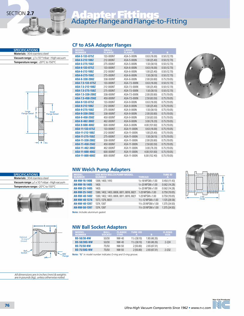
2 Adapter Fittings
Ultra-High Vacuum Components Since 1962 • www.n-c.com 76
SECTION 2.7
Adapter Flange and Flange-to-Fitting
CF to ASA Adapter FlangesMODEL NUMBER
SMALL FLANGE
LARGE FLANGE
A
B
ASA-5-133-075Z 133-000NT ASA-5-000N 0.63 (16.00) 0.50 (12.70)ASA-5-212-100Z 212-000NT ASA-5-000N 1.00 (25.40) 0.50 (12.70)ASA-5-275-150Z 275-000NT ASA-5-000N 1.50 (38.10) 0.50 (12.70)ASA-6-133-075Z 133-000NT ASA-6-000N 0.63 (16.00) 0.50 (12.70)ASA-6-212-100Z 212-000NT ASA-6-000N 1.00 (25.40) 0.50 (12.70)ASA-6-275-150Z 275-000NT ASA-6-000N 1.50 (38.10) 0.50 (12.70)ASA-6-338-200Z 338-000NT ASA-6-000N 2.00 (50.80) 0.75 (19.05)ASA-7.5-133-075Z 133-000NT ASA-7.5-000N 0.63 (16.00) 0.50 (12.70)ASA-7.5-212-100Z 212-000NT ASA-7.5-000N 1.00 (25.40) 0.50 (12.70)ASA-7.5-275-150Z 275-000NT ASA-7.5-000N 1.50 (38.10) 0.50 (12.70)ASA-7.5-338-200Z 338-000NT ASA-7.5-000N 2.00 (50.80) 0.75 (19.05)ASA-7.5-450-250Z 450-000NT ASA-7.5-000N 2.50 (63.50) 0.75 (19.05)ASA-9-133-075Z 133-000NT ASA-9-000N 0.63 (16.00) 0.75 (19.05)ASA-9-212-100Z 212-000NT ASA-9-000N 1.00 (25.40) 0.75 (19.05)ASA-9-275-150Z 275-000NT ASA-9-000N 1.50 (38.10) 0.75 (19.05)ASA-9-338-200Z 338-000NT ASA-9-000N 2.00 (50.80) 0.75 (19.05)ASA-9-450-250Z 450-000NT ASA-9-000N 2.50 (63.50) 0.75 (19.05)ASA-9-462-300Z 462-000NT ASA-9-000N 3.00 (76.20) 0.75 (19.05)ASA-9-600-400Z 600-000NT ASA-9-000N 4.00 (101.60) 0.75 (19.05)ASA-11-133-075Z 133-000NT ASA-11-000N 0.63 (16.00) 0.75 (19.05)ASA-11-212-100Z 212-000NT ASA-11-000N 1.00 (25.40) 0.75 (19.05)ASA-11-275-150Z 275-000NT ASA-11-000N 1.50 (38.10) 0.75 (19.05)ASA-11-338-200Z 338-000NT ASA-11-000N 2.00 (50.80) 0.75 (19.05)ASA-11-450-250Z 450-000NT ASA-11-000N 2.50 (63.50) 0.75 (19.05)ASA-11-462-300Z 462-000NT ASA-11-000N 3.00 (76.20) 0.75 (19.05)ASA-11-600-400Z 600-000NT ASA-11-000N 4.00 (101.60) 0.75 (19.05)ASA-11-800-600Z 800-000NT ASA-11-000N 6.00 (152.40) 0.75 (19.05)
NW Welch Pump AdaptersMODEL NUMBER
USE WITH WELCH PUMP MODEL NUMBER
THREAD
TUBE ID A
AN-NW-16-1400 1399, 1400, 1410 3/8-18 NPSM x 1.00 0.450 (11.43)AN-NW-16-1405 1405 3/4-20 NPSM x 1.00 0.562 (14.28)AN-NW-25-1405 1405 3/4-20 NPSM x 1.00 0.562 (14.28)AN-NW-25-1402 1380, 1402, 1403, 8806, 8811, 8816, 8821 1-20 NPSM x 1.00 0.750 (19.05)AN-NW-40-1402 1380, 1402, 1403, 8806, 8811, 8816, 8821 1-20 NPSM x 1.00 0.750 (19.05)AN-NW-40-1376 1373, 1376, 8831 11/2-12 NPSM x 1.00 1.125 (28.58)AN-NW-40-1397 1374, 1397 13/4-20 NPSM x 1.00 1.375 (34.93)AN-NW-50-1397 1374, 1397 13/4-20 NPSM x 1.00 1.375 (34.93)
Note: Includes aluminum gasket
2.9073.66
A
A SmallFlange Detail
B
LargeFlange Detail
SPECIFICATIONSMaterials: 304 stainless steel
Vacuum range: >1 x 10⁻⁸ mbar - High vacuum
Temperature range: -20ºC to 150ºC
SPECIFICATIONSMaterials: 304 stainless steel
Vacuum range: >1 x 10⁻⁸ mbar - High vacuum
Temperature range: -20ºC to 150ºC
NW Ball Socket AdaptersMODEL NUMBER
BALL SOCKET
FLANGE TYPE
TUBE OD A
B
O-RING SIZE
BS-50/30-NW 50/30 NW-40 11/2 (38.10) 1.90 (48.26) -BS-50/30G-NW 50/30 NW-40 11/2 (38.10) 1.90 (48.26) 2-224BS-75/50-NW 75/50 NW-50 2 (50.80) 2.65 (67.31) -BS-75/50G-NW 75/50 NW-50 2 (50.80) 2.65 (67.31) 2-232
Note: “G” in model number indicates O-ring and O-ring groove.
BallSocket NW
Flange
B
A
OptionalO-ring
Groove
All dimensions are in inches (mm) & weights are in pounds (kg), unless otherwise noted.
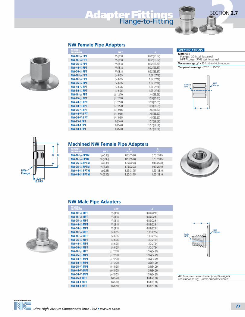
2Adapter Fittings
Ultra-High Vacuum Components Since 1962 • www.n-c.com 77
SECTION 2.7
Flange-to-Fitting
A
NWFlangeFemale
NPT
A
MaleNPT
NWFlange
NW Male Pipe AdaptersMODEL NUMBER
NPT
A
NW-10-1/8 MPT 1/8 (3.18) 0.89 (22.61)NW-16-1/8 MPT 1/8 (3.18) 0.89 (22.61)NW-25-1/8 MPT 1/8 (3.18) 0.89 (22.61)NW-40-1/8 MPT 1/8 (3.18) 0.89 (22.61)NW-50-1/8 MPT 1/8 (3.18) 0.89 (22.61)NW-10-1/4 MPT 1/4 (6.35) 1.10 (27.94)NW-16-1/4 MPT 1/4 (6.35) 1.10 (27.94)NW-25-1/4 MPT 1/4 (6.35) 1.10 (27.94)NW-40-1/4 MPT 1/4 (6.35) 1.10 (27.94)NW-50-1/4 MPT 1/4 (6.35) 1.10 (27.94)NW-16-1/2 MPT 1/2 (12.70) 1.35 (34.29)NW-25-1/2 MPT 1/2 (12.70) 1.35 (34.29)NW-40-1/2 MPT 1/2 (12.70) 1.35 (34.29)NW-50-1/2 MPT 1/2 (12.70) 1.35 (34.29)NW-25-3/4 MPT 3/4 (19.05) 1.35 (34.29)NW-40-3/4 MPT 3/4 (19.05) 1.35 (34.29)NW-50-3/4 MPT 3/4 (19.05) 1.35 (34.29)NW-25-1 MPT 1 (25.40) 1.64 (41.66)NW-40-1 MPT 1 (25.40) 1.64 (41.66)NW-50-1 MPT 1 (25.40) 1.64 (41.66)
NW Female Pipe AdaptersMODEL NUMBER
NPT
A
NW-10-1/8 FPT 1/8 (3.18) 0.92 (23.37)NW-16-1/8 FPT 1/8 (3.18) 0.92 (23.37)NW-25-1/8 FPT 1/8 (3.18) 0.92 (23.37)NW-40-1/8 FPT 1/8 (3.18) 0.92 (23.37)NW-50-1/8 FPT 1/8 (3.18) 0.92 (23.37)NW-10-1/4 FPT 1/4 (6.35) 1.07 (27.18)NW-16-1/4 FPT 1/4 (6.35) 1.07 (27.18)NW-25-1/4 FPT 1/4 (6.35) 1.07 (27.18)NW-40-1/4 FPT 1/4 (6.35) 1.07 (27.18)NW-50-1/4 FPT 1/4 (6.35) 1.07 (27.18)NW-16-1/2 FPT 1/2 (12.70) 1.44 (36.58)NW-25-1/2 FPT 1/2 (12.70) 1.39 (35.31)NW-40-1/2 FPT 1/2 (12.70) 1.39 (35.31)NW-50-1/2 FPT 1/2 (12.70) 1.39 (35.31)NW-25-3/4 FPT 3/4 (19.05) 1.45 (36.83)NW-40-3/4 FPT 3/4 (19.05) 1.45 (36.83)NW-50-3/4 FPT 3/4 (19.05) 1.45 (36.83)NW-25-1 FPT 1 (25.40) 1.57 (39.88)NW-40-1 FPT 1 (25.40) 1.57 (39.88)NW-50-1 FPT 1 (25.40) 1.57 (39.88)
SPECIFICATIONSMaterials Flanges: 304 stainless steel NPT Fittings: 316L stainless steelVacuum range: >1 x 10⁻⁶ mbar - High vacuumTemperature range: -20ºC to 150ºC
Machined NW Female Pipe AdaptersMODEL NUMBER NPT
AFLAT
BOD
NW-16-1/8-FPTM 1/8 (3.18) .625 (15.88) 0.75 (19.05)NW-16-1/4-FPTM 1/4 (6.35) .625 (15.88) 0.75 (19.05)NW-25-1/8-FPTM 1/8 (3.18) .875 (22.23) 1.00 (25.40)NW-25-1/4-FPTM 1/4 (6.35) .875 (22.23) 1.00 (25.40)NW-40-1/8-FPTM 1/8 (3.18) 1.25 (31.75) 1.50 (38.10)NW-40-1/4-FPTM 1/4 (6.35) 1.25 (31.75) 1.50 (38.10)
A B
NW Flange
.62515.875
All dimensions are in inches (mm) & weights are in pounds (kg), unless otherwise noted.
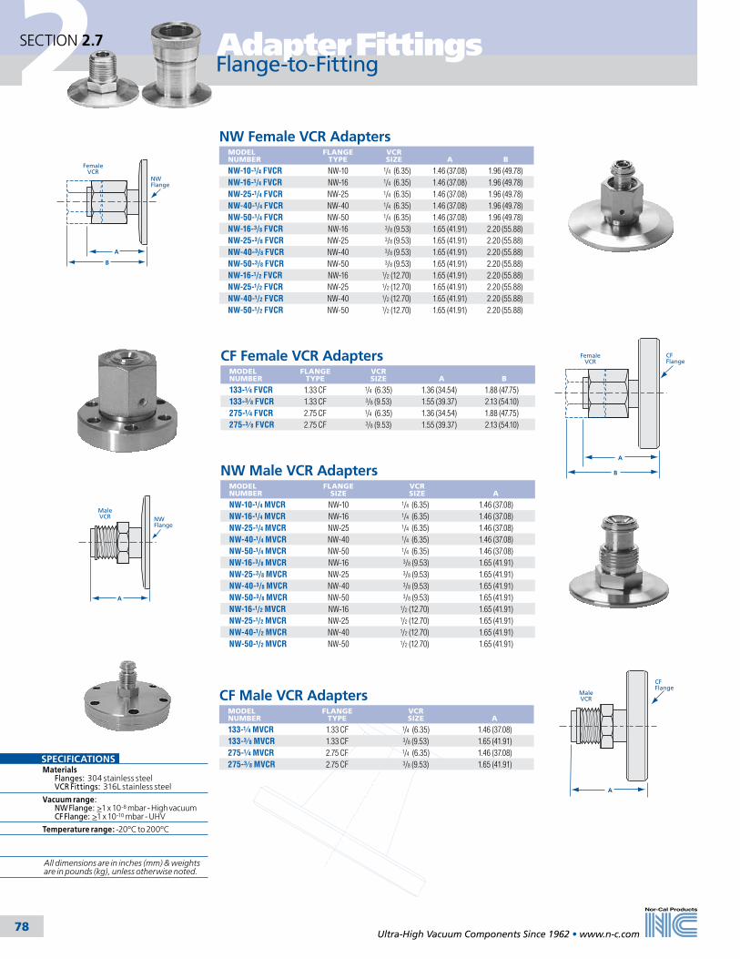
2 Adapter Fittings
Ultra-High Vacuum Components Since 1962 • www.n-c.com 78
SECTION 2.7
Flange-to-Fitting
NW Female VCR AdaptersMODEL NUMBER
FLANGE TYPE
VCR SIZE
A
B
NW-10-1/4 FVCR NW-10 1/4 (6.35) 1.46 (37.08) 1.96 (49.78)NW-16-1/4 FVCR NW-16 1/4 (6.35) 1.46 (37.08) 1.96 (49.78)NW-25-1/4 FVCR NW-25 1/4 (6.35) 1.46 (37.08) 1.96 (49.78)NW-40-1/4 FVCR NW-40 1/4 (6.35) 1.46 (37.08) 1.96 (49.78)NW-50-1/4 FVCR NW-50 1/4 (6.35) 1.46 (37.08) 1.96 (49.78)NW-16-3/8 FVCR NW-16 3/8 (9.53) 1.65 (41.91) 2.20 (55.88)NW-25-3/8 FVCR NW-25 3/8 (9.53) 1.65 (41.91) 2.20 (55.88)NW-40-3/8 FVCR NW-40 3/8 (9.53) 1.65 (41.91) 2.20 (55.88)NW-50-3/8 FVCR NW-50 3/8 (9.53) 1.65 (41.91) 2.20 (55.88)NW-16-1/2 FVCR NW-16 1/2 (12.70) 1.65 (41.91) 2.20 (55.88)NW-25-1/2 FVCR NW-25 1/2 (12.70) 1.65 (41.91) 2.20 (55.88)NW-40-1/2 FVCR NW-40 1/2 (12.70) 1.65 (41.91) 2.20 (55.88)NW-50-1/2 FVCR NW-50 1/2 (12.70) 1.65 (41.91) 2.20 (55.88)
NW Male VCR AdaptersMODEL NUMBER
FLANGE SIZE
VCR SIZE
A
NW-10-1/4 MVCR NW-10 1/4 (6.35) 1.46 (37.08)NW-16-1/4 MVCR NW-16 1/4 (6.35) 1.46 (37.08)NW-25-1/4 MVCR NW-25 1/4 (6.35) 1.46 (37.08)NW-40-1/4 MVCR NW-40 1/4 (6.35) 1.46 (37.08)NW-50-1/4 MVCR NW-50 1/4 (6.35) 1.46 (37.08)NW-16-3/8 MVCR NW-16 3/8 (9.53) 1.65 (41.91)NW-25-3/8 MVCR NW-25 3/8 (9.53) 1.65 (41.91)NW-40-3/8 MVCR NW-40 3/8 (9.53) 1.65 (41.91)NW-50-3/8 MVCR NW-50 3/8 (9.53) 1.65 (41.91)NW-16-1/2 MVCR NW-16 1/2 (12.70) 1.65 (41.91)NW-25-1/2 MVCR NW-25 1/2 (12.70) 1.65 (41.91)NW-40-1/2 MVCR NW-40 1/2 (12.70) 1.65 (41.91)NW-50-1/2 MVCR NW-50 1/2 (12.70) 1.65 (41.91)
CF Male VCR AdaptersMODEL NUMBER
FLANGE TYPE
VCR SIZE
A
133-1⁄4 MVCR 1.33 CF 1/4 (6.35) 1.46 (37.08)133-3⁄8 MVCR 1.33 CF 3/8 (9.53) 1.65 (41.91)275-1⁄4 MVCR 2.75 CF 1/4 (6.35) 1.46 (37.08)275-3⁄8 MVCR 2.75 CF 3/8 (9.53) 1.65 (41.91)
CF Female VCR AdaptersMODEL NUMBER
FLANGE TYPE
VCR SIZE
A
B
133-1⁄4 FVCR 1.33 CF 1/4 (6.35) 1.36 (34.54) 1.88 (47.75)133-3⁄8 FVCR 1.33 CF 3/8 (9.53) 1.55 (39.37) 2.13 (54.10)275-1⁄4 FVCR 2.75 CF 1/4 (6.35) 1.36 (34.54) 1.88 (47.75)275-3⁄8 FVCR 2.75 CF 3/8 (9.53) 1.55 (39.37) 2.13 (54.10)
B
NWFlange
FemaleVCR
A
A
NWFlange
MaleVCR
A
CFFlange
FemaleVCR
B
A
CFFlange
MaleVCR
SPECIFICATIONSMaterials Flanges: 304 stainless steel VCR Fittings: 316L stainless steel
Vacuum range: NW Flange: >1 x 10⁻⁸ mbar - High vacuum CF Flange: >1 x 10⁻¹⁰ mbar - UHV
Temperature range: -20ºC to 200ºC
All dimensions are in inches (mm) & weights are in pounds (kg), unless otherwise noted.

2Adapter Fittings
Ultra-High Vacuum Components Since 1962 • www.n-c.com 79
SECTION 2.7
NW Swagelok AdaptersMODEL NUMBER
FLANGE TYPE
ID A
ID B
NW-10-1/4 SWAG NW-10 1/4 (6.35) 1.47 (37.34)NW-16-1/4 SWAG NW-16 1/4 (6.35) 1.47 (37.34)NW-25-1/4 SWAG NW-25 1/4 (6.35) 1.47 (37.34)NW-40-1/4 SWAG NW-40 1/4 (6.35) 1.47 (37.34)NW-50-1/4 SWAG NW-50 1/4 (6.35) 1.47 (37.34)NW-10-3/8 SWAG NW-10 3/8 (9.53) 1.63 (41.40)NW-16-3/8 SWAG NW-16 3/8 (9.53) 1.63 (41.40)NW-25-3/8 SWAG NW-25 3/8 (9.53) 1.63 (41.40)NW-40-3/8 SWAG NW-40 3/8 (9.53) 1.63 (41.40)NW-50-3/8 SWAG NW-50 3/8 (9.53) 1.63 (41.40)
CF Swagelok AdaptersMODEL NUMBER
FLANGE TYPE
ID A
ID B
133-1⁄4 SWAG 1.33 CF 1/4 (6.35) 1.37 (34.80)133-3⁄8 SWAG 1.33 CF 3/8 (9.53) 1.58 (40.13)275-1⁄4 SWAG 2.75 CF 1/4 (6.35) 1.37 (34.80)275-3⁄8 SWAG 2.75 CF 3/8 (9.53) 1.54 (39.12)
B
CFFlange
Swagelok
A
NWFlange
A
Swagelok
B
SPECIFICATIONSMaterials Flanges: 304 stainless steel Swagelok Fittings: 316L stainless steelVacuum range: >1 x 10⁻⁶ mbar - High vacuumTemperature range NW Flange: -20ºC to 200ºC CF Flange: -200ºC to 450ºC
C
B A
C
B A
NW Quick Disconnect AdaptersMODEL NUMBER
FLANGE TYPE
ID A
ID B
C
NW-10-1/4 QD NW-10 1/4 (6.35) 0.187 (4.75) 1.48 (37.59)NW-16-1/4 QD NW-16 1/4 (6.35) 0.187 (4.75) 1.48 (37.59)NW-25-1/4 QD NW-25 1/4 (6.35) 0.187 (4.75) 1.48 (37.59)NW-40-1/4 QD NW-40 1/4 (6.35) 0.187 (4.75) 1.48 (37.59)NW-10-3/8 QD NW-10 3/8 (9.53) 0.281 (7.14) 1.62 (41.15)NW-16-3/8 QD NW-16 3/8 (9.53) 0.281 (7.14) 1.62 (41.15)NW-25-3/8 QD NW-25 3/8 (9.53) 0.281 (7.14) 1.62 (41.15)NW-40-3/8 QD NW-40 3/8 (9.53) 0.281 (7.14) 1.62 (41.15)NW-16-1/2 QD NW-16 1/2 (12.70) 0.406 (10.31) 1.79 (45.47)NW-25-1/2 QD NW-25 1/2 (12.70) 0.406 (10.31) 1.79 (45.47)NW-40-1/2 QD NW-40 1/2 (12.70) 0.406 (10.31) 1.79 (45.47)NW-50-1/2 QD NW-50 1/2 (12.70) 0.406 (10.31) 1.79 (45.47)NW-25-3/4 QD NW-25 3/4 (19.05) 0.625 (15.88) 1.93 (49.02)NW-40-3/4 QD NW-40 3/4 (19.05) 0.625 (15.88) 1.93 (49.02)NW-50-3/4 QD NW-50 3/4 (19.05) 0.625 (15.88) 1.93 (49.02)NW-40-1 QD NW-40 1 (25.40) 0.875 (22.23) 1.95 (49.53)NW-50-1 QD NW-50 1 (25.40) 0.875 (22.23) 1.95 (49.53)
Note: On request, NW Quick Disconnects can be provided bored through for the tube OD. Add “-BT” suffix to the part number and call for price. Example: NW-10-1/4 QD-BT
CF Quick Disconnect AdaptersMODEL NUMBER
FLANGE OD
ID A
ID B
C
133-1⁄4 QD 1.33 CF 1/4 (6.35) 3⁄16 (4.76) 1.39 (35.31)133-3⁄8 QD 1.33 CF 3/8 (9.53) 9⁄32 (7.14) 1.53 (38.86)133-1⁄2 QD 1.33 CF 1/2 (12.70) 13⁄32 (10.32) 1.70 (43.18)275-1⁄4 QD 2.75 CF 1/4 (6.35) 3⁄16 (4.76) 1.39 (35.31)275-3⁄8 QD 2.75 CF 3/8 (9.53) 9⁄32 (7.14) 1.53 (38.86)275-1⁄2 QD 2.75 CF 1/2 (12.70) 13⁄32 (10.32) 1.70 (43.18)275-3⁄4 QD 2.75 CF 3/4 (19.05) 5⁄8 (15.88) 1.99 (50.55)275-1 QD 2.75 CF 1 (25.40) 7⁄8 (22.23) 2.01 (51.05)
Note: On request, CF Quick Disconnects can be provided bored through for the tube OD. Add “-BT” suffix to the part number and call for price. Example: 133-1⁄4 QD-BT
SPECIFICATIONSMaterials Flanges: 304 stainless steel QD Fittings: 316L stainless steelVacuum range: >1 x 10⁻⁸ mbar- High vacuumTemperature range: -20ºC to 150ºC
Flange-to-Fitting
All dimensions are in inches (mm) & weights are in pounds (kg), unless otherwise noted.

Flexible Hoses & Couplings
80
2SECTION 2.8
Ultra-High Vacuum Components Since 1962 • www.n-c.com
General Information
Flexible Vacuum ConnectionsFlexible vacuum connections are typi-cally made by using edge welded bellows, hydroformed flexible couplings and hoses or PVC hoses. Edge welded bellows provide the greatest stroke and flexibility, but are the most susceptible to dam-age. Edge welded bellows are also more expensive than the other flexible connec-tions. Nor-Cal Products offers flexible couplings and flexible hoses as stan-dards. Edge welded bellows assemblies can be provided in a variety of materials as specials. PVC hose offers a low cost alternative to stainless steel flexible hoses.
Flexible HosesFlexible stainless steel hoses are available in 3/4 to 4 inch (19.05-101.6mm) diam-eters in standard lengths of 12, 18, 24 and 36 inches (304.8, 457.2, 609.6 and 914.4mm) with NW, ISO, CF and ASA flanges. Hoses with NW and ISO flanges are also available In 10, 20 and 40 Inch (metric equivalent) lengths. CF and ASA flanged hoses have one rotatable and one nonrotatable flange for ease of bolt hole alignment. ASA flanged hoses may require an O-ring groove on one flange for proper installation. Be sure to spec-ify. NW to CF adapter hoses provide a flexible transition between components with NW and CF flanges. NW hoses are available in medium wall “FH-” (0.010 Inch (.254mm) wall thickness), heavy wall “TH-” (0.017 Inches (.432mm)), and thin wall “LH-” (0.006 Inches (.152mm)). Thin wall hose is the perfect choice for applications requiring increased flexibility. Protective braiding is offered as a standard for NW and CF medium wall tubing “FHB-” in diameters up to and including 4 inches (101.6mm).
SPECIFICATIONSNominal ID sizes Bellows: 3/4 to 4 inch (19.05-101.6mm) PVC Hose: 1/2 to 2 inch (12.7-50.8mm) Flex Couplings: 3/8 to 12 inch (9.53-304.8mm)
Flange Types: NW, ISO, CF, ASA
Materials Bellows: 316L or 321 stainless steel PVC Hose: Wire reinforced polyvinyl chloride Flanges: 304 stainless steel (316L available on request)
Vacuum Range Metal seal: >1 x 10⁻¹⁰ mbar - UHV Elastomer seal: >1 x 10⁻⁸ mbar - High vacuum PVC Hose: >1 x 10⁻² Rough vacuum
Temperature Range Metal seal: -200ºC to 450ºC Elastomer seal: -20ºC to 150ºC PVC Hose: -4ºC to 65ºC
Options: Protective braided sleeving
All dimensions are in inches (mm) & weights are in pounds (kg), unless otherwise noted.
Spring rates are called out in pounds/inch
PVC HosesPlasticized PVC hoses can be used as a low cost rough vacuum line. An embedded spiral wire prevents the wall from collapsing under vacuum. Unlike edge welded bellows, flexible couplings and hoses, which are UHV compatible, PVC hoses should be used for rough vacuum due to their higher outgassing rate. Although it can be bent relatively easily, it cannot be com-pressed or extended. Order by the foot with or without NW flanges. Each length includes two hose clamps for installation.
MinimumStatic Bend
Radius(permanently bent)
Bend radii are listed for each wall thickness and
diameter, while the hose is under vacuum.
Flexible CouplingsPressurizing the inside of thin wall stainless steel tubing inside a mold forms convolutions in flexible couplings and hoses. Generally speaking, when comparing flexible couplings to hoses, they are thinner walled, have more convolutions per inch resulting in greater flexibility and stroke, and are used for alignment or vibration isolation rather than as roughing lines. Being thinner, flexible couplings are more susceptible to mechanical damage than hoses. Nor-Cal’s flexible couplings have more convolutions than comparable products, resulting in greater flexibil-ity and lower spring rates. Maximum compression for flexible couplings is typically 20% of the convolution (flex-ible) length. Extension is typically 10%. Couplings are available in 321 or 316L stainless steel in various lengths with NW, ISO, CF and ASA flanges.
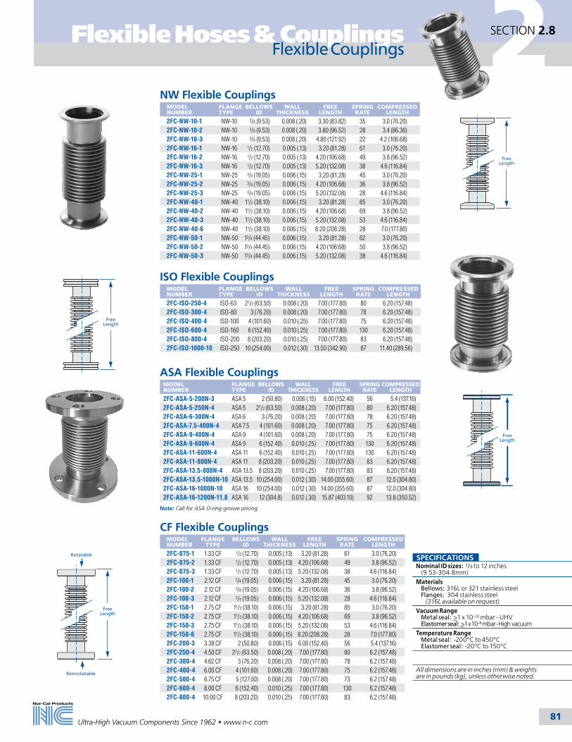
Flexible Hoses & Couplings
81
2SECTION 2.8
Ultra-High Vacuum Components Since 1962 • www.n-c.com
Flexible Couplings
FreeLength
NW Flexible CouplingsMODEL NUMBER
FLANGE TYPE
BELLOWS ID
WALL THICKNESS
FREE LENGTH
SPRING RATE
COMPRESSED LENGTH
2FC-NW-10-1 NW-10 3/8 (9.53) 0.008 (.20) 3.30 (83.82) 35 3.0 (76.20)2FC-NW-10-2 NW-10 3/8 (9.53) 0.008 (.20) 3.80 (96.52) 28 3.4 (86.36)2FC-NW-10-3 NW-10 3/8 (9.53) 0.008 (.20) 4.80 (121.92) 22 4.2 (106.68)2FC-NW-16-1 NW-16 1/2 (12.70) 0.005 (.13) 3.20 (81.28) 61 3.0 (76.20)2FC-NW-16-2 NW-16 1/2 (12.70) 0.005 (.13) 4.20 (106.68) 49 3.8 (96.52)2FC-NW-16-3 NW-16 1/2 (12.70) 0.005 (.13) 5.20 (132.08) 38 4.6 (116.84)2FC-NW-25-1 NW-25 3/4 (19.05) 0.006 (.15) 3.20 (81.28) 45 3.0 (76.20)2FC-NW-25-2 NW-25 3/4 (19.05) 0.006 (.15) 4.20 (106.68) 36 3.8 (96.52)2FC-NW-25-3 NW-25 3/4 (19.05) 0.006 (.15) 5.20 (132.08) 28 4.6 (116.84)2FC-NW-40-1 NW-40 11/2 (38.10) 0.006 (.15) 3.20 (81.28) 85 3.0 (76.20)2FC-NW-40-2 NW-40 11/2 (38.10) 0.006 (.15) 4.20 (106.68) 69 3.8 (96.52)2FC-NW-40-3 NW-40 11/2 (38.10) 0.006 (.15) 5.20 (132.08) 53 4.6 (116.84)2FC-NW-40-6 NW-40 11/2 (38.10) 0.006 (.15) 8.20 (208.28) 28 7.0 (177.80)2FC-NW-50-1 NW-50 13/4 (44.45) 0.006 (.15) 3.20 (81.28) 62 3.0 (76.20)2FC-NW-50-2 NW-50 13/4 (44.45) 0.006 (.15) 4.20 (106.68) 50 3.8 (96.52)2FC-NW-50-3 NW-50 13/4 (44.45) 0.006 (.15) 5.20 (132.08) 38 4.6 (116.84)
ISO Flexible CouplingsMODEL NUMBER
FLANGE TYPE
BELLOWS ID
WALL THICKNESS
FREE LENGTH
SPRING RATE
COMPRESSED LENGTH
2FC-ISO-250-4 ISO-63 21/2 (63.50) 0.008 (.20) 7.00 (177.80) 80 6.20 (157.48)2FC-ISO-300-4 ISO-80 3 (76.20) 0.008 (.20) 7.00 (177.80) 78 6.20 (157.48)2FC-ISO-400-4 ISO-100 4 (101.60) 0.010 (.25) 7.00 (177.80) 75 6.20 (157.48)2FC-ISO-600-4 ISO-160 6 (152.40) 0.010 (.25) 7.00 (177.80) 130 6.20 (157.48)2FC-ISO-800-4 ISO-200 8 (203.20) 0.010 (.25) 7.00 (177.80) 83 6.20 (157.48)2FC-ISO-1000-10 ISO-250 10 (254.00) 0.012 (.30) 13.50 (342.90) 87 11.40 (289.56)
FreeLength
ASA Flexible CouplingsMODEL NUMBER
FLANGE TYPE
BELLOWS ID
WALL THICKNESS
FREE LENGTH
SPRING RATE
COMPRESSED LENGTH
2FC-ASA-5-200N-3 ASA 5 2 (50.80) 0.006 (.15) 6.00 (152.40) 56 5.4 (137.16)2FC-ASA-5-250N-4 ASA 5 21/2 (63.50) 0.008 (.20) 7.00 (177.80) 80 6.20 (157.48)2FC-ASA-6-300N-4 ASA 6 3 (76.20) 0.008 (.20) 7.00 (177.80) 78 6.20 (157.48)2FC-ASA-7.5-400N-4 ASA 7.5 4 (101.60) 0.008 (.20) 7.00 (177.80) 75 6.20 (157.48)2FC-ASA-9-400N-4 ASA 9 4 (101.60) 0.008 (.20) 7.00 (177.80) 75 6.20 (157.48)2FC-ASA-9-600N-4 ASA 9 6 (152.40) 0.010 (.25) 7.00 (177.80) 130 6.20 (157.48)2FC-ASA-11-600N-4 ASA 11 6 (152.40) 0.010 (.25) 7.00 (177.80) 130 6.20 (157.48)2FC-ASA-11-800N-4 ASA 11 8 (203.20) 0.010 (.25) 7.00 (177.80) 83 6.20 (157.48)2FC-ASA-13.5-800N-4 ASA 13.5 8 (203.20) 0.010 (.25) 7.00 (177.80) 83 6.20 (157.48)2FC-ASA-13.5-1000N-10 ASA 13.5 10 (254.00) 0.012 (.30) 14.00 (355.60) 87 12.0 (304.80)2FC-ASA-16-1000N-10 ASA 16 10 (254.00) 0.012 (.30) 14.00 (355.60) 87 12.0 (304.80)2FC-ASA-16-1200N-11.8 ASA 16 12 (304.8) 0.012 (.30) 15.87 (403.10) 92 13.8 (350.52)
Note: Call for ASA O-ring groove pricing
FreeLength
Rotatable
Nonrotatable
FreeLength
CF Flexible CouplingsMODEL NUMBER
FLANGE TYPE
BELLOWS ID
WALL THICKNESS
FREE LENGTH
SPRING RATE
COMPRESSED LENGTH
2FC-075-1 1.33 CF 1/2 (12.70) 0.005 (.13) 3.20 (81.28) 61 3.0 (76.20)2FC-075-2 1.33 CF 1/2 (12.70) 0.005 (.13) 4.20 (106.68) 49 3.8 (96.52)2FC-075-3 1.33 CF 1/2 (12.70) 0.005 (.13) 5.20 (132.08) 38 4.6 (116.84)2FC-100-1 2.12 CF 3/4 (19.05) 0.006 (.15) 3.20 (81.28) 45 3.0 (76.20)2FC-100-2 2.12 CF 3/4 (19.05) 0.006 (.15) 4.20 (106.68) 36 3.8 (96.52)2FC-100-3 2.12 CF 3/4 (19.05) 0.006 (.15) 5.20 (132.08) 28 4.6 (116.84)2FC-150-1 2.75 CF 11/2 (38.10) 0.006 (.15) 3.20 (81.28) 85 3.0 (76.20)2FC-150-2 2.75 CF 11/2 (38.10) 0.006 (.15) 4.20 (106.68) 69 3.8 (96.52)2FC-150-3 2.75 CF 11/2 (38.10) 0.006 (.15) 5.20 (132.08) 53 4.6 (116.84)2FC-150-6 2.75 CF 11/2 (38.10) 0.006 (.15) 8.20 (208.28) 28 7.0 (177.80)2FC-200-3 3.38 CF 2 (50.80) 0.006 (.15) 6.00 (152.40) 56 5.4 (137.16)2FC-250-4 4.50 CF 21/2 (63.50) 0.008 (.20) 7.00 (177.80) 80 6.2 (157.48)2FC-300-4 4.62 CF 3 (76.20) 0.008 (.20) 7.00 (177.80) 78 6.2 (157.48)2FC-400-4 6.00 CF 4 (101.60) 0.008 (.20) 7.00 (177.80) 75 6.2 (157.48)2FC-500-4 6.75 CF 5 (127.00) 0.008 (.20) 7.00 (177.80) 73 6.2 (157.48)2FC-600-4 8.00 CF 6 (152.40) 0.010 (.25) 7.00 (177.80) 130 6.2 (157.48)2FC-800-4 10.00 CF 8 (203.20) 0.010 (.25) 7.00 (177.80) 83 6.2 (157.48)
SPECIFICATIONSNominal ID sizes: 3/8 to 12 inches (9.53-304.8mm)Materials Bellows: 316L or 321 stainless steel Flanges: 304 stainless steel (316L available on request)Vacuum Range Metal seal: >1 x 10⁻¹⁰ mbar - UHV Elastomer seal: >1 x 10⁻⁸ mbar - High vacuumTemperature Range Metal seal: -200ºC to 450ºC Elastomer seal: -20ºC to 150ºC
All dimensions are in inches (mm) & weights are in pounds (kg), unless otherwise noted.

Flexible Hoses & Couplings
82
2SECTION 2.8
Ultra-High Vacuum Components Since 1962 • www.n-c.com
Flexible Stainless Steel Hoses
Length
SPECIFICATIONSNominal ID sizes: 3/4 to 4 inch (19.05-101.6mm)
Materials Bellows: 321 stainless steel Tube ends: 304 stainless steel
Vacuum Range: >1 x 10⁻¹⁰ mbar - UHV
Temperature Range: -200ºC to 450ºC
Options: Protective braided sleeving
All dimensions are in inches (mm) & weights are in pounds (kg), unless otherwise noted.
MODEL NUMBER
NOMINAL ID
HOSE OD
OVERALL LENGTH
WALL THICKNESS
STATIC BEND RADIUS
FH-075-12 3/4 (19.05) 1.11 (28.19) 12 (304.80) 0.008 (.20) 1.26 (32.00)FH-075-18 3/4 (19.05) 1.11 (28.19) 18 (457.20) 0.008 (.20) 1.26 (32.00)FH-075-24 3/4 (19.05) 1.11 (28.19) 24 (609.60) 0.008 (.20) 1.26 (32.00)FH-075-36 3/4 (19.05) 1.11 (28.19) 36 (914.40) 0.008 (.20) 1.26 (32.00)FH-100-12 1 (25.40) 1.37 (34.80) 12 (304.80) 0.008 (.20) 1.46 (37.08)FH-100-18 1 (25.40) 1.37 (34.80) 18 (457.20) 0.008 (.20) 1.46 (37.08)FH-100-24 1 (25.40) 1.37 (34.80) 24 (609.60) 0.008 (.20) 1.46 (37.08)FH-100-36 1 (25.40) 1.37 (34.80) 36 (914.40) 0.008 (.20) 1.46 (37.08)FH-150-12 11/2 (38.10) 2.06 (52.32) 12 (304.80) 0.010 (.25) 2.16 (54.86)FH-150-18 11/2 (38.10) 2.06 (52.32) 18 (457.20) 0.010 (.25) 2.16 (54.86)FH-150-24 11/2 (38.10) 2.06 (52.32) 24 (609.60) 0.010 (.25) 2.16 (54.86)FH-150-36 11/2 (38.10) 2.06 (52.32) 36 (914.40) 0.010 (.25) 2.16 (54.86)FH-200-12 2 (50.80) 2.55 (64.77) 12 (304.80) 0.012 (.30) 3.50 (88.90)FH-200-18 2 (50.80) 2.55 (64.77) 18 (457.20) 0.012 (.30) 3.50 (88.90)FH-200-24 2 (50.80) 2.55 (64.77) 24 (609.60) 0.012 (.30) 3.50 (88.90)FH-200-36 2 (50.80) 2.55 (64.77) 36 (914.40) 0.012 (.30) 3.50 (88.90)FH-250-12 21/2 (63.50) 3.34 (84.84) 12 (304.80) 0.016 (.41) 4.25 (107.95)FH-250-18 21/2 (63.50) 3.34 (84.84) 18 (457.20) 0.016 (.41) 4.25 (107.95)FH-250-24 21/2 (63.50) 3.34 (84.84) 24 (609.60) 0.016 (.41) 4.25 (107.95)FH-250-36 21/2 (63.50) 3.34 (84.84) 36 (914.40) 0.016 (.41) 4.25 (107.95)FH-300-12 3 (76.20) 3.99 (101.35) 12 (304.80) 0.016 (.41) 6.00 (152.40)FH-300-18 3 (76.20) 3.99 (101.35) 18 (457.20) 0.016 (.41) 6.00 (152.40)FH-300-24 3 (76.20) 3.99 (101.35) 24 (609.60) 0.016 (.41) 6.00 (152.40)FH-300-36 3 (76.20) 3.99 (101.35) 36 (914.40) 0.016 (.41) 6.00 (152.40)FH-400-12 4 (101.60) 4.83 (122.68) 12 (304.80) 0.016 (.41) 8.60 (218.44)FH-400-18 4 (101.60) 4.83 (122.68) 18 (457.20) 0.016 (.41) 8.60 (218.44)FH-400-24 4 (101.60) 4.83 (122.68) 24 (609.60) 0.016 (.41) 8.60 (218.44)FH-400-36 4 (101.60) 4.83 (122.68) 36 (914.40) 0.016 (.41) 8.60 (218.44)
Flexible Stainless Steel Hoses without Flanges

Flexible Hoses & Couplings
83
2SECTION 2.8
Ultra-High Vacuum Components Since 1962 • www.n-c.com
Flexible Stainless Steel Hoses
NW Flexible Stainless Steel Hoses – Medium WallMODEL NUMBER
FLANGE TYPE
NOMINAL ID
HOSE OD
OVERALL LENGTH
WALL THICKNESS
STATIC BEND RADIUS
FH-075-10-2NW NW-16 3/4 (19.05) 1.11 (28.19) 10 (254.00) 0.008 (.20) 1.26 (32.00)FH-075-12-2NW NW-16 3/4 (19.05) 1.11 (28.19) 12 (304.80) 0.008 (.20) 1.26 (32.00)FH-075-18-2NW NW-16 3/4 (19.05) 1.11 (28.19) 18 (457.20) 0.008 (.20) 1.26 (32.00)FH-075-20-2NW NW-16 3/4 (19.05) 1.11 (28.19) 20 (508.00) 0.008 (.20) 1.26 (32.00)FH-075-24-2NW NW-16 3/4 (19.05) 1.11 (28.19) 24 (609.60) 0.008 (.20) 1.26 (32.00)FH-075-36-2NW NW-16 3/4 (19.05) 1.11 (28.19) 36 (914.40) 0.008 (.20) 1.26 (32.00)FH-075-40-2NW NW-16 3/4 (19.05) 1.11 (28.19) 40 (1016.00) 0.008 (.20) 1.26 (32.00)FH-100-10-2NW NW-25 1 (25.40) 1.37 (34.80) 10 (254.00) 0.008 (.20) 1.46 (37.08)FH-100-12-2NW NW-25 1 (25.40) 1.37 (34.80) 12 (304.80) 0.008 (.20) 1.46 (37.08)FH-100-18-2NW NW-25 1 (25.40) 1.37 (34.80) 18 (457.20) 0.008 (.20) 1.46 (37.08)FH-100-20-2NW NW-25 1 (25.40) 1.37 (34.80) 20 (508.00) 0.008 (.20) 1.46 (37.08)FH-100-24-2NW NW-25 1 (25.40) 1.37 (34.80) 24 (609.60) 0.008 (.20) 1.46 (37.08)FH-100-36-2NW NW-25 1 (25.40) 1.37 (34.80) 36 (914.40) 0.008 (.20) 1.46 (37.08)FH-100-40-2NW NW-25 1 (25.40) 1.37 (34.80) 40 (1016.00) 0.008 (.20) 1.46 (37.08)FH-150-10-2NW NW-40 11/2 (38.10) 2.06 (52.32) 10 (254.00) 0.010 (.25) 2.16 (54.86)FH-150-12-2NW NW-40 11/2 (38.10) 2.06 (52.32) 12 (304.80) 0.010 (.25) 2.16 (54.86)FH-150-18-2NW NW-40 11/2 (38.10) 2.06 (52.32) 18 (457.20) 0.010 (.25) 2.16 (54.86)FH-150-20-2NW NW-40 11/2 (38.10) 2.06 (52.32) 20 (508.00) 0.010 (.25) 2.16 (54.86)FH-150-24-2NW NW-40 11/2 (38.10) 2.06 (52.32) 24 (609.60) 0.010 (.25) 2.16 (54.86)FH-150-36-2NW NW-40 11/2 (38.10) 2.06 (52.32) 36 (914.40) 0.010 (.25) 2.16 (54.86)FH-150-40-2NW NW-40 11/2 (38.10) 2.06 (52.32) 40 (1016.00) 0.010 (.25) 2.16 (54.86)FH-200-10-2NW NW-50 2 (50.80) 2.55 (64.77) 10 (254.00) 0.012 (.30) 3.50 (88.90)FH-200-12-2NW NW-50 2 (50.80) 2.55 (64.77) 12 (304.80) 0.012 (.30) 3.50 (88.90)FH-200-18-2NW NW-50 2 (50.80) 2.55 (64.77) 18 (457.20) 0.012 (.30) 3.50 (88.90)FH-200-20-2NW NW-50 2 (50.80) 2.55 (64.77) 20 (508.00) 0.012 (.30) 3.50 (88.90)FH-200-24-2NW NW-50 2 (50.80) 2.55 (64.77) 24 (609.60) 0.012 (.30) 3.50 (88.90)FH-200-36-2NW NW-50 2 (50.80) 2.55 (64.77) 36 (914.40) 0.012 (.30) 3.50 (88.90)FH-200-40-2NW NW-50 2 (50.80) 2.55 (64.77) 40 (1016.00) 0.012 (.30) 3.50 (88.90)
NW Flexible Stainless Steel Hoses – Thin WallMODEL NUMBER
FLANGE TYPE
NOMINAL ID
HOSE OD
OVERALL LENGTH
WALL THICKNESS
STATIC BEND RADIUS
LH-075-10-2NW NW-16 3/4 (19.05) 1.02 (25.91) 10 (254.00) 0.006 (.15) 3.0 (76.20)LH-075-12-2NW NW-16 3/4 (19.05) 1.02 (25.91) 12 (304.80) 0.006 (.15) 3.0 (76.20)LH-075-18-2NW NW-16 3/4 (19.05) 1.02 (25.91) 18 (457.20) 0.006 (.15) 3.0 (76.20)LH-075-24-2NW NW-16 3/4 (19.05) 1.02 (25.91) 24 (609.60) 0.006 (.15) 3.0 (76.20)LH-075-36-2NW NW-16 3/4 (19.05) 1.02 (25.91) 36 (914.40) 0.006 (.15) 3.0 (76.20)LH-100-10-2NW NW-25 1 (25.40) 1.37 (34.80) 10 (254.00) 0.006 (.15) 4.0 (101.60)LH-100-12-2NW NW-25 1 (25.40) 1.37 (34.80) 12 (304.80) 0.006 (.15) 4.0 (101.60)LH-100-18-2NW NW-25 1 (25.40) 1.37 (34.80) 18 (457.20) 0.006 (.15) 4.0 (101.60)LH-100-24-2NW NW-25 1 (25.40) 1.37 (34.80) 24 (609.60) 0.006 (.15) 4.0 (101.60)LH-100-36-2NW NW-25 1 (25.40) 1.37 (34.80) 36 (914.40) 0.006 (.15) 4.0 (101.60)LH-150-10-2NW NW-40 11/2 (38.10) 1.91 (48.51) 10 (254.00) 0.006 (.15) 6.0 (152.40)LH-150-12-2NW NW-40 11/2 (38.10) 1.91 (48.51) 12 (304.80) 0.006 (.15) 6.0 (152.40)LH-150-18-2NW NW-40 11/2 (38.10) 1.91 (48.51) 18 (457.20) 0.006 (.15) 6.0 (152.40)LH-150-24-2NW NW-40 11/2 (38.10) 1.91 (48.51) 24 (609.60) 0.006 (.15) 6.0 (152.40)LH-150-36-2NW NW-40 11/2 (38.10) 1.91 (48.51) 36 (914.40) 0.006 (.15) 6.0 (152.40)LH-200-10-2NW NW-50 2 (50.80) 2.45 (62.23) 10 (254.00) 0.006 (.15) 7.5 (190.50)LH-200-12-2NW NW-50 2 (50.80) 2.45 (62.23) 12 (304.80) 0.006 (.15) 7.5 (190.50)LH-200-18-2NW NW-50 2 (50.80) 2.45 (62.23) 18 (457.20) 0.006 (.15) 7.5 (190.50)LH-200-24-2NW NW-50 2 (50.80) 2.45 (62.23) 24 (609.60) 0.006 (.15) 7.5 (190.50)LH-200-36-2NW NW-50 2 (50.80) 2.45 (62.23) 36 (914.40) 0.006 (.15) 7.5 (190.50)
Length
SPECIFICATIONSNominal ID sizes: 3/4 to 2 inch (19.05 -50.8mm)Materials Hose: 321 stainless steel Tube ends: 304 stainless steel Flanges: 304 stainless steel (316L available on request)Vacuum Range Metal seal: >1 x 10⁻¹⁰ mbar - UHV Elastomer seal: >1 x 10⁻⁸ mbar - High vacuumTemperature Range Metal seal: -200ºC to 450ºC Elastomer seal: -20ºC to 150ºC Options: Protective braided sleeving
Larger hose IDs and other flange configurations available upon request.
All dimensions are in inches (mm) & weights are in pounds (kg), unless otherwise noted.

Flexible Hoses & Couplings
84
2SECTION 2.8
Ultra-High Vacuum Components Since 1962 • www.n-c.com
Flexible Stainless Steel Hoses
Length
NW Flexible Stainless Steel Hoses – Thick WallMODEL NUMBER
FLANGE TYPE
NOMINAL ID
HOSE OD
OVERALL LENGTH
WALL THICKNESS
STATIC BEND RADIUS
TH-075-10-2NW NW-16 3/4 (19.05) 1.10 (27.94) 10 (254.00) 0.017 (.43) 2.13 (54.10)TH-075-20-2NW NW-16 3/4 (19.05) 1.10 (27.94) 20 (508.00) 0.017 (.43) 2.13 (54.10)TH-075-40-2NW NW-16 3/4 (19.05) 1.10 (27.94) 40 (1016.00) 0.017 (.43) 2.13 (54.10)TH-100-10-2NW NW-25 1 (25.40) 1.50 (38.10) 10 (254.00) 0.017 (.43) 2.88 (73.15)TH-100-20-2NW NW-25 1 (25.40) 1.50 (38.10) 20 (508.00) 0.017 (.43) 2.88 (73.15)TH-100-40-2NW NW-25 1 (25.40) 1.50 (38.10) 40 (1016.00) 0.017 (.43) 2.88 (73.15)TH-150-10-2NW NW-40 11/2 (38.10) 2.10 (53.34) 10 (254.00) 0.020 (.51) 3.50 (88.90)TH-150-20-2NW NW-40 11/2 (38.10) 2.10 (53.34) 20 (508.00) 0.020 (.51) 3.50 (88.90)TH-150-40-2NW NW-40 11/2 (38.10) 2.10 (53.34) 40 (1016.00) 0.020 (.51) 3.50 (88.90)TH-200-10-2NW NW-50 2 (50.80) 2.63 (66.80) 10 (254.00) 0.020 (.51) 5.25 (133.35)TH-200-20-2NW NW-50 2 (50.80) 2.63 (66.80) 20 (508.00) 0.020 (.51) 5.25 (133.35)TH-200-40-2NW NW-50 2 (50.80) 2.63 (66.80) 40 (1016.00) 0.020 (.51) 5.25 (133.35)
NW/CF Flexible Stainless Steel Adapter Hoses – Medium WallMODEL NUMBER
FLANGE 1 TYPE
FLANGE 2 TYPE
NOMINAL ID
HOSE OD
OVERALL LENGTH
WALL THICKNESS
STATIC BEND RADIUS
FH-075-12-NW-CF NW-16 CF-1.33 3/4 (19.05) 1.11 (28.19) 12 (304.80) 0.008 (.20) 1.26 (32.00)FH-075-18-NW-CF NW-16 CF-1.33 3/4 (19.05) 1.11 (28.19) 18 (457.20) 0.008 (.20) 1.26 (32.00)FH-075-24-NW-CF NW-16 CF-1.33 3/4 (19.05) 1.11 (28.19) 24 (609.60) 0.008 (.20) 1.26 (32.00)FH-075-36-NW-CF NW-16 CF-1.33 3/4 (19.05) 1.11 (28.19) 36 (914.40) 0.008 (.20) 1.26 (32.00)FH-150-12-NW-CF NW-40 CF-2.75 11/2 (38.10) 2.06 (52.32) 12 (304.80) 0.010 (.25) 2.16 (54.86)FH-150-18-NW-CF NW-40 CF-2.75 11/2 (38.10) 2.06 (52.32) 18 (457.20) 0.010 (.25) 2.16 (54.86)FH-150-24-NW-CF NW-40 CF-2.75 11/2 (38.10) 2.06 (52.32) 24 (609.60) 0.010 (.25) 2.16 (54.86)FH-150-36-NW-CF NW-40 CF-2.75 11/2 (38.10) 2.06 (52.32) 36 (914.40) 0.010 (.25) 2.16 (54.86)
ISO Flexible Stainless Steel Hoses – Thick WallMODEL NUMBER
FLANGE TYPE
NOMINAL ID
HOSE OD
OVERALL LENGTH
WALL THICKNESS
STATIC BEND RADIUS
TH-250-20-2ISO ISO-63 21/2 (63.50) 3.10 (78.74) 20 (508.00) 0.020 (.51) 8.00 (203.20)TH-250-40-2ISO ISO-63 21/2 (63.50) 3.10 (78.74) 40 (1016.00) 0.020 (.51) 8.00 (203.20)TH-300-20-2ISO ISO-80 3 (76.20) 3.92 (99.57) 20 (508.00) 0.020 (.51) 9.00 (228.60)TH-300-40-2ISO ISO-80 3 (76.20) 3.92 (99.57) 40 (1016.00) 0.020 (.51) 9.00 (228.60)TH-400-20-2ISO ISO-100 4 (101.60) 4.82 (122.43) 20 (508.00) 0.020 (.51) 13.00 (330.20)TH-400-40-2ISO ISO-100 4 (101.60) 4.82 (122.43) 40 (1016.00) 0.020 (.51) 13.00 (330.20)
ISO Flexible Stainless Steel Hoses – Medium WallMODEL NUMBER
FLANGE TYPE
NOMINAL ID
HOSE OD
OVERALL LENGTH
WALL THICKNESS
STATIC BEND RADIUS
FH-250-10-2ISO ISO-63 21/2 (63.50) 3.34 (84.84) 10 (254.00) 0.016 (.41) 3.15 (80.01)FH-250-12-2ISO ISO-63 21/2 (63.50) 3.34 (84.84) 12 (304.80) 0.016 (.41) 3.15 (80.01)FH-250-18-2ISO ISO-63 21/2 (63.50) 3.34 (84.84) 18 (457.20) 0.016 (.41) 3.15 (80.01)FH-250-20-2ISO ISO-63 21/2 (63.50) 3.34 (84.84) 20 (508.00) 0.016 (.41) 3.15 (80.01)FH-250-24-2ISO ISO-63 21/2 (63.50) 3.34 (84.84) 24 (609.60) 0.016 (.41) 3.15 (80.01)FH-250-36-2ISO ISO-63 21/2 (63.50) 3.34 (84.84) 36 (914.40) 0.016 (.41) 3.15 (80.01)FH-250-40-2ISO ISO-63 3 (76.20) 3.99 (101.35) 40 (1016.00) 0.016 (.41) 3.15 (80.01)FH-300-10-2ISO ISO-80 3 (76.20) 3.99 (101.35) 10 (254.00) 0.016 (.41) 3.82 (97.03)FH-300-12-2ISO ISO-80 3 (76.20) 3.99 (101.35) 12 (304.80) 0.016 (.41) 3.82 (97.03)FH-300-18-2ISO ISO-80 3 (76.20) 3.99 (101.35) 18 (457.20) 0.016 (.41) 3.82 (97.03)FH-300-20-2ISO ISO-80 3 (76.20) 3.99 (101.35) 20 (508.00) 0.016 (.41) 3.82 (97.03)FH-300-24-2ISO ISO-80 3 (76.20) 3.99 (101.35) 24 (609.60) 0.016 (.41) 3.82 (97.03)FH-300-36-2ISO ISO-80 3 (76.20) 3.99 (101.35) 36 (914.40) 0.016 (.41) 3.82 (97.03)FH-300-40-2ISO ISO-80 4 (101.60) 4.83 (122.68) 40 (1016.00) 0.016 (.41) 3.82 (97.03)FH-400-10-2lSO ISO-100 4 (101.60) 4.83 (122.68) 10 (254.00) 0.016 (.41) 4.45 (113.03)FH-400-12-2lSO ISO-100 4 (101.60) 4.83 (122.68) 12 (304.80) 0.016 (.41) 4.45 (113.03)FH-400-18-2ISO ISO-100 4 (101.60) 4.83 (122.68) 18 (457.20) 0.016 (.41) 4.45 (113.03)FH-400-20-2ISO ISO-100 4 (101.60) 4.83 (122.68) 20 (508.00) 0.016 (.41) 4.45 (113.03)FH-400-24-2ISO ISO-100 4 (101.60) 4.83 (122.68) 24 (609.60) 0.016 (.41) 4.45 (113.03)FH-400-36-2ISO ISO-100 4 (101.60) 4.83 (122.68) 36 (914.40) 0.016 (.41) 4.45 (113.03)FH-400-40-2ISO ISO-100 4 (101.60) 4.83 (122.68) 40 (1016.00) 0.016 (.41) 4.45 (113.03)
Length
CFFlange
NWFlange
Nonrotatable
Length
SPECIFICATIONSNominal ID sizes: 3/4 to 4 inch (19.05-101.6mm)
Materials Hose: 321 stainless steel Tube ends: 304 stainless steel Flanges: 304 stainless steel (316L available on request)
Vacuum Range Metal seal: >1 x 10⁻¹⁰ mbar - UHV Elastomer seal: >1 x 10⁻⁸ mbar - High vacuum
Temperature Range Metal seal: -200ºC to 450ºC Elastomer seal: -20ºC to 150ºC
Options: Protective braided sleeving
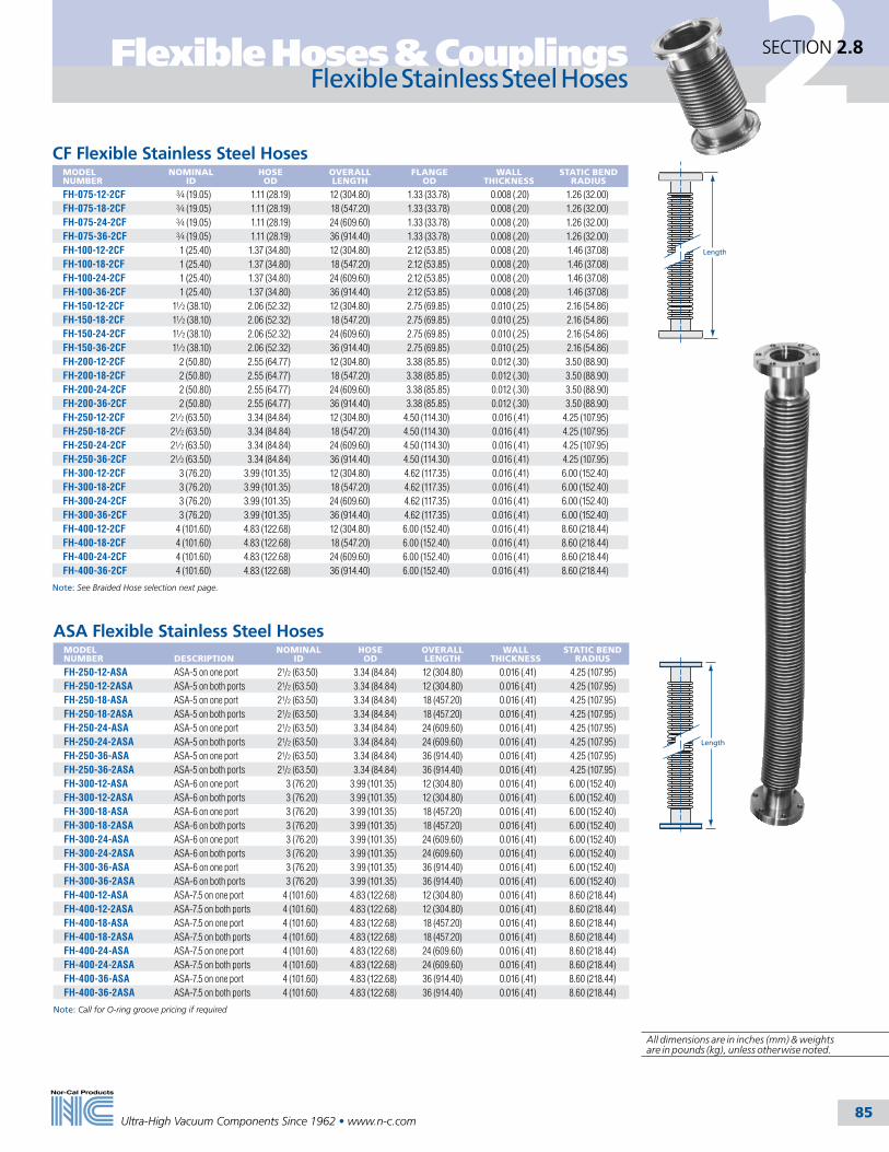
Flexible Hoses & Couplings
85
2SECTION 2.8
Ultra-High Vacuum Components Since 1962 • www.n-c.com
ISO Flexible Stainless Steel Hoses – Thick WallMODEL NUMBER
FLANGE TYPE
NOMINAL ID
HOSE OD
OVERALL LENGTH
WALL THICKNESS
STATIC BEND RADIUS
TH-250-20-2ISO ISO-63 21/2 (63.50) 3.10 (78.74) 20 (508.00) 0.020 (.51) 8.00 (203.20)TH-250-40-2ISO ISO-63 21/2 (63.50) 3.10 (78.74) 40 (1016.00) 0.020 (.51) 8.00 (203.20)TH-300-20-2ISO ISO-80 3 (76.20) 3.92 (99.57) 20 (508.00) 0.020 (.51) 9.00 (228.60)TH-300-40-2ISO ISO-80 3 (76.20) 3.92 (99.57) 40 (1016.00) 0.020 (.51) 9.00 (228.60)TH-400-20-2ISO ISO-100 4 (101.60) 4.82 (122.43) 20 (508.00) 0.020 (.51) 13.00 (330.20)TH-400-40-2ISO ISO-100 4 (101.60) 4.82 (122.43) 40 (1016.00) 0.020 (.51) 13.00 (330.20)
CF Flexible Stainless Steel HosesMODEL NUMBER
NOMINAL ID
HOSE OD
OVERALL LENGTH
FLANGE OD
WALL THICKNESS
STATIC BEND RADIUS
FH-075-12-2CF 3⁄4 (19.05) 1.11 (28.19) 12 (304.80) 1.33 (33.78) 0.008 (.20) 1.26 (32.00)FH-075-18-2CF 3⁄4 (19.05) 1.11 (28.19) 18 (547.20) 1.33 (33.78) 0.008 (.20) 1.26 (32.00)FH-075-24-2CF 3⁄4 (19.05) 1.11 (28.19) 24 (609.60) 1.33 (33.78) 0.008 (.20) 1.26 (32.00)FH-075-36-2CF 3⁄4 (19.05) 1.11 (28.19) 36 (914.40) 1.33 (33.78) 0.008 (.20) 1.26 (32.00)FH-100-12-2CF 1 (25.40) 1.37 (34.80) 12 (304.80) 2.12 (53.85) 0.008 (.20) 1.46 (37.08)FH-100-18-2CF 1 (25.40) 1.37 (34.80) 18 (547.20) 2.12 (53.85) 0.008 (.20) 1.46 (37.08)FH-100-24-2CF 1 (25.40) 1.37 (34.80) 24 (609.60) 2.12 (53.85) 0.008 (.20) 1.46 (37.08)FH-100-36-2CF 1 (25.40) 1.37 (34.80) 36 (914.40) 2.12 (53.85) 0.008 (.20) 1.46 (37.08)FH-150-12-2CF 11⁄2 (38.10) 2.06 (52.32) 12 (304.80) 2.75 (69.85) 0.010 (.25) 2.16 (54.86)FH-150-18-2CF 11⁄2 (38.10) 2.06 (52.32) 18 (547.20) 2.75 (69.85) 0.010 (.25) 2.16 (54.86)FH-150-24-2CF 11⁄2 (38.10) 2.06 (52.32) 24 (609.60) 2.75 (69.85) 0.010 (.25) 2.16 (54.86)FH-150-36-2CF 11⁄2 (38.10) 2.06 (52.32) 36 (914.40) 2.75 (69.85) 0.010 (.25) 2.16 (54.86)FH-200-12-2CF 2 (50.80) 2.55 (64.77) 12 (304.80) 3.38 (85.85) 0.012 (.30) 3.50 (88.90)FH-200-18-2CF 2 (50.80) 2.55 (64.77) 18 (547.20) 3.38 (85.85) 0.012 (.30) 3.50 (88.90)FH-200-24-2CF 2 (50.80) 2.55 (64.77) 24 (609.60) 3.38 (85.85) 0.012 (.30) 3.50 (88.90)FH-200-36-2CF 2 (50.80) 2.55 (64.77) 36 (914.40) 3.38 (85.85) 0.012 (.30) 3.50 (88.90)FH-250-12-2CF 21⁄2 (63.50) 3.34 (84.84) 12 (304.80) 4.50 (114.30) 0.016 (.41) 4.25 (107.95)FH-250-18-2CF 21⁄2 (63.50) 3.34 (84.84) 18 (547.20) 4.50 (114.30) 0.016 (.41) 4.25 (107.95)FH-250-24-2CF 21⁄2 (63.50) 3.34 (84.84) 24 (609.60) 4.50 (114.30) 0.016 (.41) 4.25 (107.95)FH-250-36-2CF 21⁄2 (63.50) 3.34 (84.84) 36 (914.40) 4.50 (114.30) 0.016 (.41) 4.25 (107.95)FH-300-12-2CF 3 (76.20) 3.99 (101.35) 12 (304.80) 4.62 (117.35) 0.016 (.41) 6.00 (152.40)FH-300-18-2CF 3 (76.20) 3.99 (101.35) 18 (547.20) 4.62 (117.35) 0.016 (.41) 6.00 (152.40)FH-300-24-2CF 3 (76.20) 3.99 (101.35) 24 (609.60) 4.62 (117.35) 0.016 (.41) 6.00 (152.40)FH-300-36-2CF 3 (76.20) 3.99 (101.35) 36 (914.40) 4.62 (117.35) 0.016 (.41) 6.00 (152.40)FH-400-12-2CF 4 (101.60) 4.83 (122.68) 12 (304.80) 6.00 (152.40) 0.016 (.41) 8.60 (218.44)FH-400-18-2CF 4 (101.60) 4.83 (122.68) 18 (547.20) 6.00 (152.40) 0.016 (.41) 8.60 (218.44)FH-400-24-2CF 4 (101.60) 4.83 (122.68) 24 (609.60) 6.00 (152.40) 0.016 (.41) 8.60 (218.44)FH-400-36-2CF 4 (101.60) 4.83 (122.68) 36 (914.40) 6.00 (152.40) 0.016 (.41) 8.60 (218.44)
Note: See Braided Hose selection next page.
Length
ASA Flexible Stainless Steel HosesMODEL NUMBER
DESCRIPTION
NOMINAL ID
HOSE OD
OVERALL LENGTH
WALL THICKNESS
STATIC BEND RADIUS
FH-250-12-ASA ASA-5 on one port 21/2 (63.50) 3.34 (84.84) 12 (304.80) 0.016 (.41) 4.25 (107.95)FH-250-12-2ASA ASA-5 on both ports 21/2 (63.50) 3.34 (84.84) 12 (304.80) 0.016 (.41) 4.25 (107.95)FH-250-18-ASA ASA-5 on one port 21/2 (63.50) 3.34 (84.84) 18 (457.20) 0.016 (.41) 4.25 (107.95)FH-250-18-2ASA ASA-5 on both ports 21/2 (63.50) 3.34 (84.84) 18 (457.20) 0.016 (.41) 4.25 (107.95)FH-250-24-ASA ASA-5 on one port 21/2 (63.50) 3.34 (84.84) 24 (609.60) 0.016 (.41) 4.25 (107.95)FH-250-24-2ASA ASA-5 on both ports 21/2 (63.50) 3.34 (84.84) 24 (609.60) 0.016 (.41) 4.25 (107.95)FH-250-36-ASA ASA-5 on one port 21/2 (63.50) 3.34 (84.84) 36 (914.40) 0.016 (.41) 4.25 (107.95)FH-250-36-2ASA ASA-5 on both ports 21/2 (63.50) 3.34 (84.84) 36 (914.40) 0.016 (.41) 4.25 (107.95)FH-300-12-ASA ASA-6 on one port 3 (76.20) 3.99 (101.35) 12 (304.80) 0.016 (.41) 6.00 (152.40)FH-300-12-2ASA ASA-6 on both ports 3 (76.20) 3.99 (101.35) 12 (304.80) 0.016 (.41) 6.00 (152.40)FH-300-18-ASA ASA-6 on one port 3 (76.20) 3.99 (101.35) 18 (457.20) 0.016 (.41) 6.00 (152.40)FH-300-18-2ASA ASA-6 on both ports 3 (76.20) 3.99 (101.35) 18 (457.20) 0.016 (.41) 6.00 (152.40)FH-300-24-ASA ASA-6 on one port 3 (76.20) 3.99 (101.35) 24 (609.60) 0.016 (.41) 6.00 (152.40)FH-300-24-2ASA ASA-6 on both ports 3 (76.20) 3.99 (101.35) 24 (609.60) 0.016 (.41) 6.00 (152.40)FH-300-36-ASA ASA-6 on one port 3 (76.20) 3.99 (101.35) 36 (914.40) 0.016 (.41) 6.00 (152.40)FH-300-36-2ASA ASA-6 on both ports 3 (76.20) 3.99 (101.35) 36 (914.40) 0.016 (.41) 6.00 (152.40)FH-400-12-ASA ASA-7.5 on one port 4 (101.60) 4.83 (122.68) 12 (304.80) 0.016 (.41) 8.60 (218.44)FH-400-12-2ASA ASA-7.5 on both ports 4 (101.60) 4.83 (122.68) 12 (304.80) 0.016 (.41) 8.60 (218.44)FH-400-18-ASA ASA-7.5 on one port 4 (101.60) 4.83 (122.68) 18 (457.20) 0.016 (.41) 8.60 (218.44)FH-400-18-2ASA ASA-7.5 on both ports 4 (101.60) 4.83 (122.68) 18 (457.20) 0.016 (.41) 8.60 (218.44)FH-400-24-ASA ASA-7.5 on one port 4 (101.60) 4.83 (122.68) 24 (609.60) 0.016 (.41) 8.60 (218.44)FH-400-24-2ASA ASA-7.5 on both ports 4 (101.60) 4.83 (122.68) 24 (609.60) 0.016 (.41) 8.60 (218.44)FH-400-36-ASA ASA-7.5 on one port 4 (101.60) 4.83 (122.68) 36 (914.40) 0.016 (.41) 8.60 (218.44)FH-400-36-2ASA ASA-7.5 on both ports 4 (101.60) 4.83 (122.68) 36 (914.40) 0.016 (.41) 8.60 (218.44)
Note: Call for O-ring groove pricing if required
Length
Flexible Stainless Steel Hoses
All dimensions are in inches (mm) & weights are in pounds (kg), unless otherwise noted.

Flexible Hoses & Couplings
86
2SECTION 2.8
Ultra-High Vacuum Components Since 1962 • www.n-c.com
NW Flexible Stainless Steel Braided HosesMODEL NUMBER
FLANGE TYPE
NOMINAL ID
HOSE OD
OVERALL LENGTH
WALL THICKNESS
STATIC BEND RADIUS
FHB-075-12-2NW NW-16 3/4 (19.05) 11/4 (31.75) 12 (304.80) 0.008 (.20) 2.09 (53.09)FHB-075-18-2NW NW-16 3/4 (19.05) 11/4 (31.75) 18 (457.20) 0.008 (.20) 2.09 (53.09)FHB-075-20-2NW NW-16 3/4 (19.05) 11/4 (31.75) 20 (508.00) 0.008 (.20) 2.09 (53.09)FHB-075-24-2NW NW-16 3/4 (19.05) 11/4 (31.75) 24 (609.60) 0.008 (.20) 2.09 (53.09)FHB-075-36-2NW NW-16 3/4 (19.05) 11/4 (31.75) 36 (914.40) 0.008 (.20) 2.09 (53.09)FHB-075-40-2NW NW-16 3/4 (19.05) 11/4 (31.75) 40 (1016.00) 0.008 (.20) 2.09 (53.09)FHB-100-12-2NW NW-25 1 (25.40) 15/8 (41.28) 12 (304.80) 0.008 (.20) 2.52 (64.01)FHB-100-18-2NW NW-25 1 (25.40) 15/8 (41.28) 18 (457.20) 0.008 (.20) 2.52 (64.01)FHB-100-20-2NW NW-25 1 (25.40) 15/8 (41.28) 20 (508.00) 0.008 (.20) 2.52 (64.01)FHB-100-24-2NW NW-25 1 (25.40) 15/8 (41.28) 24 (609.60) 0.008 (.20) 2.52 (64.01)FHB-100-36-2NW NW-25 1 (25.40) 15/8 (41.28) 36 (914.40) 0.008 (.20) 2.52 (64.01)FHB-100-40-2NW NW-25 1 (25.40) 15/8 (41.28) 40 (1016.00) 0.008 (.20) 2.52 (64.01)FHB-150-12-2NW NW-40 11/2 (38.10) 21/4 (57.15) 12 (304.80) 0.010 (.25) 3.86 (98.04)FHB-150-18-2NW NW-40 11/2 (38.10) 21/4 (57.15) 18 (457.20) 0.010 (.25) 3.86 (98.04)FHB-150-20-2NW NW-40 11/2 (38.10) 21/4 (57.15) 20 (508.00) 0.010 (.25) 3.86 (98.04)FHB-150-24-2NW NW-40 11/2 (38.10) 21/4 (57.15) 24 (609.60) 0.010 (.25) 3.86 (98.04)FHB-150-36-2NW NW-40 11/2 (38.10) 21/4 (57.15) 36 (914.40) 0.010 (.25) 3.86 (98.04)FHB-150-40-2NW NW-40 11/2 (38.10) 21/4 (57.15) 40 (1016.00) 0.010 (.25) 3.86 (98.04)FHB-200-12-2NW NW-50 2 (50.80) 23/4 (69.85) 12 (304.80) 0.012 (.30) 4.72 (119.89)FHB-200-18-2NW NW-50 2 (50.80) 23/4 (69.85) 18 (457.20) 0.012 (.30) 4.72 (119.89)FHB-200-20-2NW NW-50 2 (50.80) 23/4 (69.85) 20 (508.00) 0.012 (.30) 4.72 (119.89)FHB-200-24-2NW NW-50 2 (50.80) 23/4 (69.85) 24 (609.60) 0.012 (.30) 4.72 (119.89)FHB-200-36-2NW NW-50 2 (50.80) 23/4 (69.85) 36 (914.40) 0.012 (.30) 4.72 (119.89)FHB-200-40-2NW NW-50 2 (50.80) 23/4 (69.85) 40 (1016.00) 0.012 (.30) 4.72 (119.89)
Length
CF Flexible Stainless Steel Braided HosesMODEL NUMBER
NOMINAL ID
HOSE OD
OVERALL LENGTH
FLANGE OD
WALL THICKNESS
STATIC BEND RADIUS
FHB-075-12-2CF 3/4 (19.05) 11/4 (31.75) 12 (304.80) 1.33 (33.78) 0.008 (.20) 2.09 (53.09)FHB-075-18-2CF 3/4 (19.05) 11/4 (31.75) 18 (457.20) 1.33 (33.78) 0.008 (.20) 2.09 (53.09)FHB-075-24-2CF 3/4 (19.05) 11/4 (31.75) 24 (609.60) 1.33 (33.78) 0.008 (.20) 2.09 (53.09)FHB-075-36-2CF 3/4 (19.05) 11/4 (31.75) 36 (914.40) 1.33 (33.78) 0.008 (.20) 2.09 (53.09)FHB-100-12-2CF 1 (25.40) 15/8 (41.28) 12 (304.80) 2.12 (53.85) 0.008 (.20) 2.52 (64.01)FHB-100-18-2CF 1 (25.40) 15/8 (41.28) 18 (457.20) 2.12 (53.85) 0.008 (.20) 2.52 (64.01)FHB-100-24-2CF 1 (25.40) 15/8 (41.28) 24 (609.60) 2.12 (53.85) 0.008 (.20) 2.52 (64.01)FHB-100-36-2CF 1 (25.40) 15/8 (41.28) 36 (914.40) 2.12 (53.85) 0.008 (.20) 2.52 (64.01)FHB-150-12-2CF 11/2 (38.10) 21/4 (57.15) 12 (304.80) 2.75 (69.85) 0.010 (.25) 3.86 (98.04)FHB-150-18-2CF 11/2 (38.10) 21/4 (57.15) 18 (457.20) 2.75 (69.85) 0.010 (.25) 3.86 (98.04)FHB-150-24-2CF 11/2 (38.10) 21/4 (57.15) 24 (609.60) 2.75 (69.85) 0.010 (.25) 3.86 (98.04)FHB-150-36-2CF 11/2 (38.10) 21/4 (57.15) 36 (914.40) 2.75 (69.85) 0.010 (.25) 3.86 (98.04)FHB-200-12-2CF 2 (50.80) 23/4 (69.85) 12 (304.80) 3.38 (85.85) 0.012 (.30) 4.72 (119.89)FHB-200-18-2CF 2 (50.80) 23/4 (69.85) 18 (457.20) 3.38 (85.85) 0.012 (.30) 4.72 (119.89)FHB-200-24-2CF 2 (50.80) 23/4 (69.85) 24 (609.60) 3.38 (85.85) 0.012 (.30) 4.72 (119.89)FHB-200-36-2CF 2 (50.80) 23/4 (69.85) 36 (914.40) 3.38 (85.85) 0.012 (.30) 4.72 (119.89)
Length
Braided Stainless Steel Flexible Hoses
SPECIFICATIONSNominal ID sizes: 3/4 to 2 inch (19.05-50.8mm)
Materials Bellows: 321 stainless steel Tube ends: 304 stainless steel Flanges: 304 stainless steel (316L available on request)
Vacuum Range Metal seal: >1 x 10⁻¹⁰ mbar - UHV Elastomer seal: >1 x 10⁻⁸ mbar - High vacuum
Temperature Range Metal seal: -200ºC to 450ºC Elastomer seal: -20ºC to 150ºC
Larger hose IDs and other flange configurations available upon request.

Flexible Hoses & Couplings
87
2SECTION 2.8
Ultra-High Vacuum Components Since 1962 • www.n-c.com
PVC Hoses with NW FlangesMODEL NUMBER
FLANGE TYPE
NOMINAL ID
HOSE OD
OVERALL LENGTH
STATIC BEND RADIUS
PVC-050-12-2NW NW-10 1/2 (12.70) 0.813 (20.65) 12 (304.80) 2.00 (50.80)PVC-050-24-2NW NW-10 1/2 (12.70) 0.813 (20.65) 24 (609.60) 2.00 (50.80)PVC-050-36-2NW NW-10 1/2 (12.70) 0.813 (20.65) 36 (914.40) 2.00 (50.80)PVC-050-72-2NW NW-10 1/2 (12.70) 0.813 (20.65) 72 (1828.80) 2.00 (50.80)PVC-075-12-2NW NW-16 3/4 (19.05) 1.125 (28.58) 12 (304.80) 3.00 (76.20)PVC-075-24-2NW NW-16 3/4 (19.05) 1.125 (28.58) 24 (609.60) 3.00 (76.20)PVC-075-36-2NW NW-16 3/4 (19.05) 1.125 (28.58) 36 (914.40) 3.00 (76.20)PVC-075-72-2NW NW-16 3/4 (19.05) 1.125 (28.58) 72 (1828.80) 3.00 (76.20)PVC-100-12-2NW NW-25 1 (25.40) 1.375 (34.93) 12 (304.80) 4.00 (101.60)PVC-100-24-2NW NW-25 1 (25.40) 1.375 (34.93) 24 (609.60) 4.00 (101.60)PVC-100-36-2NW NW-25 1 (25.40) 1.375 (34.93) 36 (914.40) 4.00 (101.60)PVC-100-72-2NW NW-25 1 (25.40) 1.375 (34.93) 72 (1828.80) 4.00 (101.60)PVC-150-12-2NW NW-40 11/2 (38.10) 2.000 (50.80) 12 (304.80) 6.00 (152.40)PVC-150-24-2NW NW-40 11/2 (38.10) 2.000 (50.80) 24 (609.60) 6.00 (152.40)PVC-150-36-2NW NW-40 11/2 (38.10) 2.000 (50.80) 36 (914.40) 6.00 (152.40)PVC-150-72-2NW NW-40 11/2 (38.10) 2.000 (50.80) 72 (1828.80) 6.00 (152.40)PVC-200-12-2NW NW-50 2 (50.80) 2.500 (63.50) 12 (304.80) 8.00 (203.20)PVC-200-24-2NW NW-50 2 (50.80) 2.500 (63.50) 24 (609.60) 8.00 (203.20)PVC-200-36-2NW NW-50 2 (50.80) 2.500 (63.50) 36 (914.40) 8.00 (203.20)PVC-200-72-2NW NW-50 2 (50.80) 2.500 (63.50) 72 (1828.80) 8.00 (203.20)
Length
PVC Flexible Hoses
PVC Flexible HosesEach length includes two hose clamps for installation.
MODEL NUMBER
NOMINAL ID
HOSE OD
STATIC BEND RADIUS
PVC-050 1/2 (12.70) 0.813 (20.65) 2.00 (50.80)PVC-075 3/4 (19.05) 1.125 (28.58) 3.00 (76.20)PVC-100 1 (25.40) 1.375 (34.93) 4.00 (101.60)PVC-150 11/2 (38.10) 2.000 (50.80) 6.00 (152.40)PVC-200 2 (50.80) 2.500 (63.50) 8.00 (203.20)
Note: To order specify length required in feet as follows: PVC-100-5.0 and PVC-200-10.0
PVC Hose NipplesMODEL NUMBER
FLANGE TYPE
NIPPLE MATERIAL
A
B
1HN-NW-10-050 NW-10 304 SS 0.50 (12.70) 1.26 (32.00)1HN-NW-16-075 NW-16 304 SS 0.75 (19.05) 1.26 (32.00)1HN-NW-25-100 NW-25 304 SS 1.00 (25.40) 1.50 (38.10)1HN-NW-40-150 NW-40 304 SS 1.50 (38.10) 1.97 (50.04)1HN-NW-50-200 NW-50 304 SS 2.00 (50.80) 2.17 (55.12)
Length
ID
OD
B.500
NWFlange
A
SPECIFICATIONSNominal ID sizes: 1/2 to 2 inch (12.7-50.8mm)Materials Hose: Wire reinforced polyvinyl chloride (PVC) Nipples: 304 stainless steel Flanges: 304 stainless steel (316L available on request)Vacuum Range: >1 x 10⁻² Rough vacuumMaximum Temperature: -4º to 65ºC

2 Weld Fittings
88Ultra-High Vacuum Components Since 1962 • www.n-c.com
SECTION 2.9
General Information
Tumbled FinishBeadblasted Finish
Nor-Cal Products has manufactured stainless steel weld fittings for nearly forty five years. We worked with Law-rence Livermore National Laboratory in the 1960’s to develop their specification for vacuum piping, which has become the standard in the industry. Weld fittings are commonly used in vacuum roughing lines on semiconductor process equipment and for forelines and pump exhaust lines in semiconductor subfabs.
All tees and crosses are fabricated with the pulled-port technique and full penetration butt welds. This provides crevice-free weld joints and the maximum in cleanliness for UHV applications. Weld fittings are avail-able from stock in 304 stainless steel, and some sizes are stocked in 316L stainless steel for additional corrosion resistance. All weld fittings are available with various flange combinations. See appropriate section.
SPECIFICATIONSTube OD sizes: 1/2 to 12 inches (12.7- 304.8mm)
Materials: 304 or 316L stainless steel
Vacuum range: ≥1 x 10-13 mbar
Temperature range: -200º to 450ºC
Tube FinishesThe standard finish for all weld fittings is tumbled, although there are some fittings that are not available with the tumbled finish. These weld fittings are bead-blasted and are designated by a “-B” suffix on the part number. (See photo at right) All weld fittings can be electropolished on request. Call for pricing.
All dimensions are in inches (mm) & weights are in pounds (kg), unless otherwise noted.
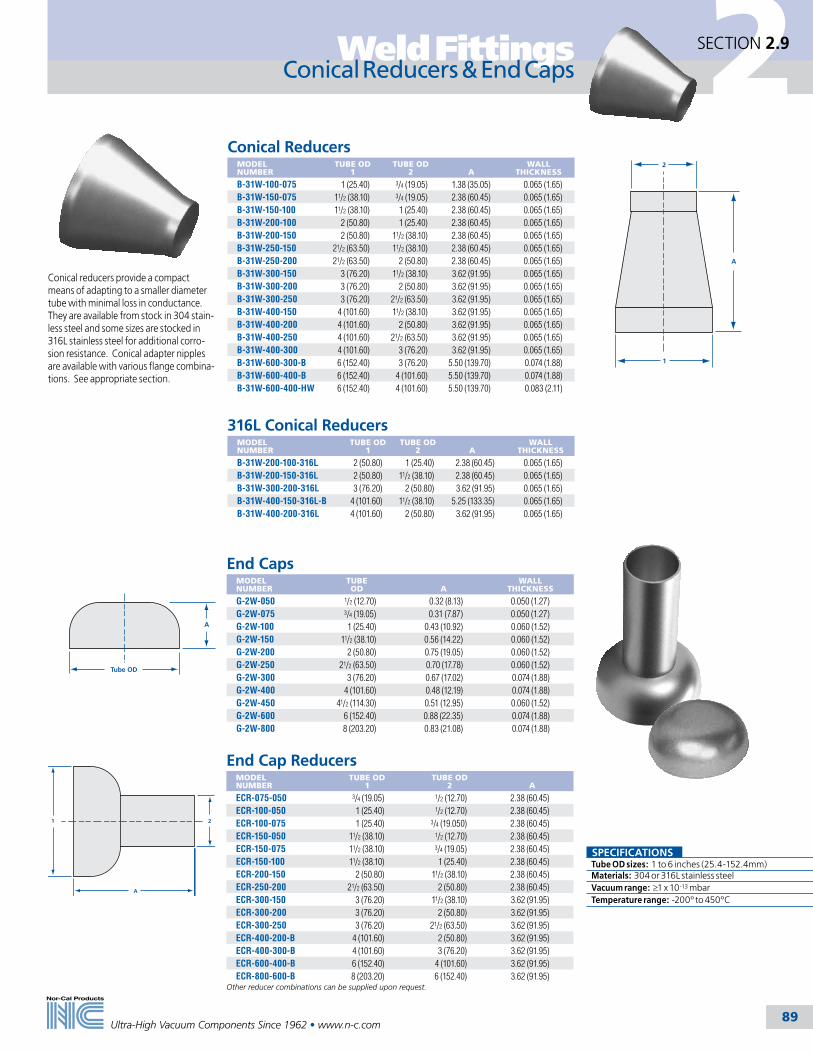
2Weld Fittings
89Ultra-High Vacuum Components Since 1962 • www.n-c.com
SECTION 2.9
Conical reducers provide a compact means of adapting to a smaller diameter tube with minimal loss in conductance. They are available from stock in 304 stain-less steel and some sizes are stocked in 316L stainless steel for additional corro-sion resistance. Conical adapter nipples are available with various flange combina-tions. See appropriate section.
A
1
2
Conical ReducersMODEL NUMBER
TUBE OD 1
TUBE OD 2
A
WALL THICKNESS
B-31W-100-075 1 (25.40) 3/4 (19.05) 1.38 (35.05) 0.065 (1.65)B-31W-150-075 11/2 (38.10) 3/4 (19.05) 2.38 (60.45) 0.065 (1.65)B-31W-150-100 11/2 (38.10) 1 (25.40) 2.38 (60.45) 0.065 (1.65)B-31W-200-100 2 (50.80) 1 (25.40) 2.38 (60.45) 0.065 (1.65)B-31W-200-150 2 (50.80) 11/2 (38.10) 2.38 (60.45) 0.065 (1.65)B-31W-250-150 21/2 (63.50) 11/2 (38.10) 2.38 (60.45) 0.065 (1.65)B-31W-250-200 21/2 (63.50) 2 (50.80) 2.38 (60.45) 0.065 (1.65)B-31W-300-150 3 (76.20) 11/2 (38.10) 3.62 (91.95) 0.065 (1.65)B-31W-300-200 3 (76.20) 2 (50.80) 3.62 (91.95) 0.065 (1.65)B-31W-300-250 3 (76.20) 21/2 (63.50) 3.62 (91.95) 0.065 (1.65)B-31W-400-150 4 (101.60) 11/2 (38.10) 3.62 (91.95) 0.065 (1.65)B-31W-400-200 4 (101.60) 2 (50.80) 3.62 (91.95) 0.065 (1.65)B-31W-400-250 4 (101.60) 21/2 (63.50) 3.62 (91.95) 0.065 (1.65)B-31W-400-300 4 (101.60) 3 (76.20) 3.62 (91.95) 0.065 (1.65)B-31W-600-300-B 6 (152.40) 3 (76.20) 5.50 (139.70) 0.074 (1.88)B-31W-600-400-B 6 (152.40) 4 (101.60) 5.50 (139.70) 0.074 (1.88)B-31W-600-400-HW 6 (152.40) 4 (101.60) 5.50 (139.70) 0.083 (2.11)
Conical Reducers & End Caps
316L Conical ReducersMODEL NUMBER
TUBE OD 1
TUBE OD 2
A
WALL THICKNESS
B-31W-200-100-316L 2 (50.80) 1 (25.40) 2.38 (60.45) 0.065 (1.65)B-31W-200-150-316L 2 (50.80) 11/2 (38.10) 2.38 (60.45) 0.065 (1.65)B-31W-300-200-316L 3 (76.20) 2 (50.80) 3.62 (91.95) 0.065 (1.65)B-31W-400-150-316L-B 4 (101.60) 11/2 (38.10) 5.25 (133.35) 0.065 (1.65)B-31W-400-200-316L 4 (101.60) 2 (50.80) 3.62 (91.95) 0.065 (1.65)
SPECIFICATIONSTube OD sizes: 1 to 6 inches (25.4-152.4mm)Materials: 304 or 316L stainless steelVacuum range: ≥1 x 10-13 mbarTemperature range: -200º to 450ºC
End Cap ReducersMODEL NUMBER
TUBE OD 1
TUBE OD 2
A
ECR-075-050 3/4 (19.05) 1/2 (12.70) 2.38 (60.45)ECR-100-050 1 (25.40) 1/2 (12.70) 2.38 (60.45)ECR-100-075 1 (25.40) 3/4 (19.050) 2.38 (60.45)ECR-150-050 11/2 (38.10) 1/2 (12.70) 2.38 (60.45)ECR-150-075 11/2 (38.10) 3/4 (19.05) 2.38 (60.45)ECR-150-100 11/2 (38.10) 1 (25.40) 2.38 (60.45)ECR-200-150 2 (50.80) 11/2 (38.10) 2.38 (60.45)ECR-250-200 21/2 (63.50) 2 (50.80) 2.38 (60.45)ECR-300-150 3 (76.20) 11/2 (38.10) 3.62 (91.95)ECR-300-200 3 (76.20) 2 (50.80) 3.62 (91.95)ECR-300-250 3 (76.20) 21/2 (63.50) 3.62 (91.95)ECR-400-200-B 4 (101.60) 2 (50.80) 3.62 (91.95)ECR-400-300-B 4 (101.60) 3 (76.20) 3.62 (91.95)ECR-600-400-B 6 (152.40) 4 (101.60) 3.62 (91.95)ECR-800-600-B 8 (203.20) 6 (152.40) 3.62 (91.95)
Other reducer combinations can be supplied upon request.
1
A
2
End CapsMODEL NUMBER
TUBE OD
A
WALL THICKNESS
G-2W-050 1/2 (12.70) 0.32 (8.13) 0.050 (1.27)G-2W-075 3/4 (19.05) 0.31 (7.87) 0.050 (1.27)G-2W-100 1 (25.40) 0.43 (10.92) 0.060 (1.52)G-2W-150 11/2 (38.10) 0.56 (14.22) 0.060 (1.52)G-2W-200 2 (50.80) 0.75 (19.05) 0.060 (1.52)G-2W-250 21/2 (63.50) 0.70 (17.78) 0.060 (1.52)G-2W-300 3 (76.20) 0.67 (17.02) 0.074 (1.88)G-2W-400 4 (101.60) 0.48 (12.19) 0.074 (1.88)G-2W-450 41/2 (114.30) 0.51 (12.95) 0.060 (1.52)G-2W-600 6 (152.40) 0.88 (22.35) 0.074 (1.88)G-2W-800 8 (203.20) 0.83 (21.08) 0.074 (1.88)
Tube OD
A

2 Weld Fittings
90Ultra-High Vacuum Components Since 1962 • www.n-c.com
SECTION 2.9
Elbows
A
180° Return Bend Radius ElbowsMODEL NUMBER
TUBE OD
WALL THICKNESS
A
G-2WU-050 1/2 (12.70) 0.049 (1.24) 0.75 (19.05)G-2WU-075 3/4 (19.05) 0.035 (0.89) 1.00 (25.40)G-2WU-100 1 (25.40) 0.065 (1.65) 1.50 (38.10)G-2WU-150 11/2 (38.10) 0.065 (1.65) 2.25 (57.15)G-2WU-200 2 (50.80) 0.065 (1.65) 3.00 (76.20)
Nor-Cal Products offers 180° return bend radius elbows in sizes up to 2 inches (50.8mm) OD and 45º and 90º radius elbows in sizes up to 10 inches (254mm) OD. Radius elbows offer the highest conductance geometry in a tube bend. All elbows are available from stock in 304 stainless steel, and some sizes are stocked in 316L stainless steel for additional corro-sion resistance. We have added several 45º and 90º elbows with tangents to match other commonly available dimensions. Look for the HW suffix for elbows that match HPS weld fitting dimensions, for example. Elbows are also available with various flange combinations. See appropriate section.
SPECIFICATIONSTube OD sizes: 1/2 to 10 inches (12.7-254mm)
Materials: 304 or 316L stainless steel
Vacuum range: ≥1 x 10-13 mbar
Temperature range: -200º to 450ºC
45° Radius ElbowsMODEL NUMBER
TUBE OD
WALL THICKNESS
A
B
316L
TANGENT
G-2WK-050 1/2 (12.70) 0.049 (1.24) 0.31 (7.87) 0.75 (19.05)G-2WK-075 3/4 (19.05) 0.035 (0.89) 0.41 (10.41) 1.00 (25.40)G-2WK-075T 3/4 (19.05) 0.065 (1.65) 0.41 (10.41) 1.13 (28.70)G-2KL-075 3/4 (19.05) 0.035 (0.89) 0.76 (19.30) 1.00 (25.40) P
G-2WK-100 1 (25.40) 0.065 (1.65) 0.62 (15.75) 1.50 (38.10)G-2WK-100-316L 1 (25.40) 0.065 (1.65) 0.62 (15.75) 1.50 (38.10) P
G-2KL-100 1 (25.40) 0.065 (1.65) 0.97 (24.64) 1.50 (38.10) P
G-2KL-100HW 1 (25.40) 0.065 (1.65) 1.19 (30.23) 1.50 (38.10) P
G-2KL-100-316L 1 (25.40) 0.065 (1.65) 0.97 (24.64) 1.50 (38.10) P P
G-2WK-150 11/2 (38.10) 0.065 (1.65) 0.93 (23.62) 2.25 (57.15)G-2WK-150-316L 11/2 (38.10) 0.065 (1.65) 0.93 (23.62) 2.25 (57.15) P
G-2KL-150 11/2 (38.10) 0.065 (1.65) 1.53 (35.86) 2.25 (57.15) P
G-2KL-150HW 11/2 (38.10) 0.065 (1.65) 1.63 (41.40) 2.25 (57.15) P
G-2KL-150-316L 11/2 (38.10) 0.065 (1.65) 1.53 (35.86) 2.25 (57.15) P P
G-2WK-200 2 (50.80) 0.065 (1.65) 1.24 (31.50) 3.00 (76.20)G-2WK-200-316L 2 (50.80) 0.065 (1.65) 1.24 (31.50) 3.00 (76.20) P
G-2KL-200 2 (50.80) 0.065 (1.65) 1.84 (46.74) 3.00 (76.20) P
G-2KL-200HW 2 (50.80) 0.065 (1.65) 2.31 (58.67) 3.00 (76.20) P
G-2KL-200-316L 2 (50.80) 0.065 (1.65) 1.84 (46.74) 3.00 (76.20) P P
G-2WK-250 21/2 (63.50) 0.065 (1.65) 1.55 (39.37) 3.75 (95.25)G-2WK-250-316L 21/2 (63.50) 0.065 (1.65) 1.55 (39.37) 3.75 (95.25) P
G-2KL-250 21/2 (63.50) 0.065 (1.65) 3.00 (76.20 3.75 (95.25) P
G-2WK-300 3 (76.20) 0.065 (1.65) 1.86 (47.24) 4.50 (114.30)G-2WK-300-316L 3 (76.20) 0.065 (1.65) 1.86 (47.24) 4.50 (114.30) P
G-2KL-300 3 (76.20) 0.065 (1.65) 3.68 (93.47) 4.50 (114.30) P
G-2KL-300-316L 3 (76.20) 0.065 (1.65) 3.68 (93.47) 4.50 (114.30) P P
G-2WK-400 4 (101.60) 0.083 (2.11) 2.49 (63.25) 6.00 (152.40)G-2WK-400-316L 4 (101.60) 0.083 (2.11) 2.49 (63.25) 6.00 (152.40) P
G-2KL-400 4 (101.60) 0.083 (2.11) 4.78 (121.41) 6.00 (152.40) P
G-2KL-400HW 4 (101.60) 0.083 (2.11) 4.81 (122.17) 6.00 (152.40) P
G-2KL-400-316L 4 (101.60) 0.083 (2.11) 4.78 (121.41) 6.00 (152.40) P P
G-2WK-600-B 6 (152.40) 0.083 (2.11) 3.73 (94.74) 9.00 (228.60)
G-2WK-800-B 8 (203.20) .109 -.134 (2.77-3.40) 4.97 (126.24) 12.00 (304.80)
G-2WK-1000-B 10 (254.00) .109 -.134 (2.77-3.40) 6.21 (157.73) 15.00 (381.00)
A
B
45o
B
45o
A
Elbow with Tangent
Elbow without Tangent
All dimensions are in inches (mm) & weights are in pounds (kg), unless otherwise noted.

2Weld Fittings
91Ultra-High Vacuum Components Since 1962 • www.n-c.com
SECTION 2.9
A Typ.
90° Mitered ElbowMODEL NUMBER
TUBE OD
WALL THICKNESS
A
E-075M 3/4 (19.05) 0.035 (0.89) 1.00 (25.40)E-100M 1 (25.40) 0.065 (1.65) 1.88 (47.75)E-150M 11/2 (38.10) 0.065 (1.65) 2.25 (57.15)E-150MH 11/2 (38.10) 0.065 (1.65) 2.41 (61.21)E-200M 2 (50.80) 0.065 (1.65) 3.00 (76.20)E-200MH 2 (50.80) 0.065 (1.65) 2.61 (66.29)E-250M 21/2 (63.50) 0.065 (1.65) 3.00 (76.20)E-250MV 21/2 (63.50) 0.065 (1.65) 3.75 (95.25)E-300M 3 (76.20) 0.065 (1.65) 3.25 (82.55)E-400M 4 (101.60) 0.083 (2.11) 3.88 (98.55)E-400MV-B 4 (101.60) 0.083 (2.11) 4.87 (123.70)E-500M-B 5 (127.00) 0.083 (2.11) 4.25 (107.95)E-600M-B 6 (152.40) 0.083 (2.11) 5.00 (127.00)E-600MV-B 6 (152.40) 0.083 (2.11) 6.06 (153.92)E-800M-B 8 (203.20) 0.120 (3.05) 7.00 (177.80)E-1000M-B 10 (254.00) 0.120 (3.05) 9.50 (241.30)
Ball SocketsMODEL NUMBER
ID
TUBE OD
A
O-RING SIZE
BS-50/30 2 (50.80) 11/2 (38.10) 1.75 (19.05) -BS-50/30-G 2 (50.80) 11/2 (38.10) 1.75 (19.05) 2-224BS-75/50 3 (76.20) 2 (50.80) 2.50 (63.50) -BS-75/50-G 3 (76.20) 2 (50.80) 2.50 (63.50) 2-232
Note: “G” suffix in model number indicates O-ring and O-ring groove are provided.
ID TubeOD
A
Elbows & Ball Sockets
A Typ.
B
90° Radius ElbowsMODEL NUMBER
TUBE OD
WALL THICKNESS
A
B
316L
TANGENT
G-2WC-050 1/2 (12.70) 0.049 (1.24) 0.75 (19.05) 0.75 (19.05)G-2WC-075 3/4 (19.05) 0.035 (0.89) 1.00 (25.40) 1.00 (25.40)G-2WC-075H 3/4 (19.05) 0.035 (0.89) 1.42 (36.07) 1.00 (25.40) P
G-2WC-100 1 (25.40) 0.065 (1.65) 1.50 (38.10) 1.50 (38.10)G-2WC-100-316L 1 (25.40) 0.065 (1.65) 1.50 (38.10) 1.50 (38.10) P
G-2WC-100H 1 (25.40) 0.065 (1.65) 1.82 (46.23) 1.50 (38.10) P
G-2WC-100HW 1 (25.40) 0.065 (1.65) 2.06 (52.32) 1.50 (38.10) P
G-2WC-100H-316L 1 (25.40) 0.065 (1.65) 1.82 (46.23) 1.50 (38.10) P P
G-2WC-150 11/2 (38.10) 0.065 (1.65) 2.25 (57.15) 2.25 (57.15)G-2WC-150-316L 11/2 (38.10) 0.065 (1.65) 2.25 (57.15) 2.25 (57.15) P
G-2WC-150H 11/2 (38.10) 0.065 (1.65) 2.41 (61.21) 2.25 (57.15) P
G-2WC-150HW 11/2 (38.10) 0.065 (1.65) 2.94 (74.68) 2.25 (57.15) P
G-2WC-150HL 11/2 (38.10) 0.065 (1.65) 4.97 (126.24) 2.25 (57.15) P
G-2WC-150H-316L 11/2 (38.10) 0.065 (1.65) 2.41 (61.21) 2.25 (57.15) P P
G-2WC-200 2 (50.80) 0.065 (1.65) 3.00 (76.20) 3.00 (76.20)G-2WC-200-316L 2 (50.80) 0.065 (1.65) 3.00 (76.20) 3.00 (76.20) P
G-2WC-200H 2 (50.80) 0.065 (1.65) 4.06 (103.12) 3.00 (76.20) P
G-2WC-200HL 2 (50.80) 0.065 (1.65) 5.36 (136.14) 3.00 (76.20) P
G-2WC-200H-316L 2 (50.80) 0.065 (1.65) 4.06 (103.12) 3.00 (76.20) P P
G-2WC-250 21/2 (63.50) 0.065 (1.65) 3.75 (95.25) 3.75 (95.25)G-2WC-250-316L 21/2 (63.50) 0.065 (1.65) 3.75 (95.25) 3.75 (95.25) P
G-2WC-250H 21/2 (63.50) 0.065 (1.65) 5.19 (131.83) 3.75 (95.25) P
G-2WC-300 3 (76.20) 0.065 (1.65) 4.50 (114.30) 4.50 (114.30)G-2WC-300-316L 3 (76.20) 0.065 (1.65) 4.50 (114.30) 4.50 (114.30) P
G-2WC-300H 3 (76.20) 0.065 (1.65) 6.31 (160.27) 4.50 (114.30) P
G-2WC-400 4 (101.60) 0.083 (2.11) 6.00 (152.40) 6.00 (152.40)G-2WC-400-316L 4 (101.60) 0.083 (2.11) 6.00 (152.40) 6.00 (152.40) P
G-2WC-400H 4 (101.60) 0.083 (2.11) 8.31 (211.07) 6.00 (152.40) P
G-2WC-600-B 6 (152.40) 0.109 (2.77) 9.00 (228.60) 9.00 (228.60)
G-2WC-800-B 8 (203.20) .109 -.134 (2.77-3.40) 12.00 (304.80) 12.00 (304.80)
G-2WC-1000-B 10 (254.00) .109 -.134 (2.77-3.40) 15.00 (381.00) 15.00 (381.00)
BA Typ.
SPECIFICATIONSTube OD sizes: 1/2 to 10 inches (12.7-254mm)Materials: 304 stainless steel (316L available upon request)Vacuum range: ≥1 x 10-13 mbarTemperature range: -200º to 450ºC
Elbow with Tangent
Elbow without Tangent

2 Weld Fittings
92Ultra-High Vacuum Components Since 1962 • www.n-c.com
SECTION 2.9
Tees
SPECIFICATIONSTube OD sizes: 1/2 to 10 inches (12.7-254mm)
Materials: 304 or stainless steel (316L available upon request)
Vacuum range: ≥1 x 10-13 mbar
Temperature range: -200º to 450ºC
TeesMODEL NUMBER
TUBE OD
WALL THICKNESS
A
G-7W-050 1/2 (12.70) 0.049 (1.24) 0.75 (19.05)G-7W-075 3/4 (19.05) 0.035 (0.89) 1.00 (25.40)G-7W-075HW 3/4 (19.05) 0.065 (1.65) 1.88 (47.75)G-7W-075T 3/4 (19.05) 0.065 (1.65) 1.00 (25.40)G-7W-100 1 (25.40) 0.065 (1.65) 1.88 (47.75)G-7W-150 11/2 (38.10) 0.065 (1.65) 2.25 (57.15)G-7W-150H 11/2 (38.10) 0.065 (1.65) 2.41 (61.21)G-7W-200 2 (50.80) 0.065 (1.65) 3.00 (76.20)G-7W-200H 2 (50.80) 0.065 (1.65) 2.61 (66.29)G-7W-250 21/2 (63.50) 0.065 (1.65) 3.00 (76.20)G-7W-250V 21/2 (63.50) 0.065 (1.65) 3.75 (95.25)G-7W-300 3 (76.20) 0.065 (1.65) 3.25 (82.55)G-7W-400 4 (101.60) 0.083 (2.11) 3.88 (98.55)G-7W-400V 4 (101.60) 0.083 (2.11) 4.87 (123.70)G-7W-500-B 5 (127.00) 0.083 (2.11) 4.25 (107.95)G-7W-600-B 6 (152.40) 0.083 (2.11) 5.00 (127.00)G-7W-600V-B 6 (152.40) 0.083 (2.11) 6.06 (153.92)G-7W-800-B 8 (203.20) 0.120 (3.05) 7.00 (177.80)G-7W-1000-B 10 (254.00) 0.120 (3.05) 9.50 (241.30)
A Typ.
Reducer TeesMODEL NUMBER
TUBE 1 & 2 ARM OD
TUBE 3 LEG OD
A
B
G-7WR-100-050 1 (25.40) 1/2 (12.70) 1.88 (47.75) 1.00 (25.40)G-7WR-100-075 1 (25.40) 3/4 (19.05) 1.88 (47.75) 1.12 (28.45)G-7WR-150-050 11/2 (38.10) 1/2 (12.70) 2.25 (57.15) 1.25 (31.75)G-7WR-150-075 11/2 (38.10) 3/4 (19.05) 2.25 (57.15) 1.38 (35.05)G-7WR-150-100 11/2 (38.10) 1 (25.40) 2.25 (57.15) 2.13 (54.10)G-7WR-200-050 2 (50.80) 1/2 (12.70) 3.00 (76.20) 1.50 (38.10)G-7WR-200-075 2 (50.80) 3/4 (19.05) 3.00 (76.20) 1.63 (41.40)G-7WR-200-100 2 (50.80) 1 (25.40) 3.00 (76.20) 2.38 (60.45)G-7WR-200-150 2 (50.80) 11/2 (38.10) 3.00 (76.20) 2.50 (63.50)G-7WR-250-150 21/2 (63.50) 11/2 (38.10) 3.00 (76.20) 2.75 (69.85)G-7WR-250-200 21/2 (63.50) 2 (50.80) 3.00 (76.20) 3.25 (82.55)G-7WR-300-150 3 (76.20) 11/2 (38.10) 3.25 (82.55) 3.00 (76.20)G-7WR-300-200 3 (76.20) 2 (50.80) 3.25 (82.55) 3.50 (88.90)G-7WR-300-250 3 (76.20) 21/2 (63.50) 3.25 (82.55) 3.25 (82.55)G-7WR-400-150-B 4 (101.60) 11/2 (38.10) 3.88 (98.55) 3.50 (88.90)G-7WR-400-200-B 4 (101.60) 2 (50.80) 3.88 (98.55) 4.00 (101.60)G-7WR-400-250-B 4 (101.60) 21/2 (63.50) 3.88 (98.55) 3.75 (95.25)G-7WR-400-300-B 4 (101.60) 3 (76.20) 3.88 (98.55) 3.75 (95.25)G-7WR-500-400-B 5 (127.00) 4 (101.60) 4.25 (107.95) 4.38 (111.25)G-7WR-600-150-B 6 (152.40) 11/2 (38.10) 5.00 (127.00) 4.50 (114.30)G-7WR-600-200-B 6 (152.40) 2 (50.80) 5.00 (127.00) 5.00 (127.00)G-7WR-600-250-B 6 (152.40) 21/2 (63.50) 5.00 (127.00) 4.75 (120.65)G-7WR-600-400-B 6 (152.40) 4 (101.60) 5.00 (127.00) 4.88 (123.95)G-7WR-600-500-B 6 (152.40) 5 (127.00) 5.00 (127.00) 4.75 (120.65)G-7WR-800-600-B 8 (203.20) 6 (152.40) 7.00 (177.80) 6.00 (152.40)
Tube1
Tube2
A Typ. Tube3
B Typ.
304 stainless steel tees and reducer tees are fabricated with the pulled-port technique and full penetration welds. This provides crevice-free weld joints and the maximum in cleanliness for UHV applications. Other sizes are available on request. We have added tees to match other commonly available dimensions. Look for the HW suffix for tees that match HPS weld fitting dimen-sions, for example. These fittings are also offered with various flange combinations. See appropriate flange section.
All dimensions are in inches (mm) & weights are in pounds (kg), unless otherwise noted.

2Weld Fittings
93Ultra-High Vacuum Components Since 1962 • www.n-c.com
SECTION 2.9
Crosses
A Typ.
304 stainless steel crosses and reducer crosses are offered in a wide range of sizes as standard products. All crosses are fabricated with the pulled-port technique and full penetration butt welds. This provides crevice-free weld joints and the maximum in cleanliness for UHV applications. As always, other sizes are available on request. These fittings are offered with various flange combinations. See appropriate sections.
A Typ.
4-Way CrossesMODEL NUMBER
TUBE OD
WALL THICKNESS
A
G-9W-050 1/2 (12.70) 0.049 (1.24) 0.75 (19.05)G-9W-075 3/4 (19.05) 0.035 (.89) 1.00 (25.40)G-9W-100 1 (25.40) 0.065 (1.65) 1.88 (47.75)G-9W-150 11/2 (38.10) 0.065 (1.65) 2.25 (57.15)G-9W-150H 11/2 (38.10) 0.065 (1.65) 2.41 (61.21)G-9W-200 2 (50.80) 0.065 (1.65) 3.00 (76.20)G-9W-200H 2 (50.80) 0.065 (1.65) 2.61 (66.29)G-9W-250 21/2 (63.50) 0.065 (1.65) 3.00 (76.20)G-9W-250V 21/2 (63.50) 0.065 (1.65) 3.75 (95.25)G-9W-300 3 (76.20) 0.065 (1.65) 3.25 (82.55)G-9W-400 4 (101.60) 0.083 (2.11) 3.88 (98.55)G-9W-400V 4 (101.60) 0.083 (2.11) 4.87 (123.70)G-9W-500-B 5 (127.00) 0.083 (2.11) 4.25 (107.95)G-9W-600-B 6 (152.40) 0.083 (2.11) 5.00 (127.00)G-9W-600V-B 6 (152.40) 0.083 (2.11) 6.06 (153.92)G-9W-800-B 8 (203.20) 0.120 (3.05) 7.00 (177.80)G-9W-1000-B 10 (254.00) 0.120 (3.05) 9.50 (241.30)
5-Way CrossesMODEL NUMBER
TUBE OD
WALL THICKNESS
A
G-10W-075 3/4 (19.05) 0.035 (0.89) 1.00 (25.40)G-10W-100 1 (25.40) 0.065 (1.65) 1.88 (47.75)G-10W-150 11/2 (38.10) 0.065 (1.65) 2.25 (57.15)G-10W-200 2 (50.80) 0.065 (1.65) 3.00 (76.20)G-10W-250 21/2 (63.50) 0.065 (1.65) 3.00 (76.20)G-10W-250V 21/2 (63.50) 0.065 (1.65) 3.75 (95.25)G-10W-300-B 3 (76.20) 0.065 (1.65) 3.25 (82.55)G-10W-400-B 4 (101.60) 0.083 (2.11) 3.88 (98.55)G-10W-400V-B 4 (101.60) 0.083 (2.11) 4.87 (123.70)G-10W-500-B 5 (127.00) 0.083 (2.11) 4.25 (107.95)G-10W-600-B 6 (152.40) 0.083 (2.11) 5.00 (127.00)G-10W-600V-B 6 (152.40) 0.083 (2.11) 6.06 (153.92)G-10W-800-B 8 (203.20) 0.120 (3.05) 7.00 (177.80)G-10W-1000-B 10 (254.00) 0.120 (3.05) 9.50 (241.30)
6-Way CrossesMODEL NUMBER
TUBE OD
WALL THICKNESS
A
G-11W-075 3/4 (19.05) 0.035 (0.89) 1.00 (25.40)G-11W-100 1 (25.40) 0.065 (1.65) 1.88 (47.75)G-11W-150 11/2 (38.10) 0.065 (1.65) 2.25 (57.15)G-11W-200 2 (50.80) 0.065 (1.65) 3.00 (76.20)G-11W-250 21/2 (63.50) 0.065 (1.65) 3.00 (76.20)G-11W-250V 21/2 (63.50) 0.065 (1.65) 3.75 (95.25)G-11W-300-B 3 (76.20) 0.065 (1.65) 3.25 (82.55)G-11W-400-B 4 (101.60) 0.083 (2.11) 3.88 (98.55)G-11W-400V-B 4 (101.60) 0.083 (2.11) 4.87 (123.70)G-11W-500-B 5 (127.00) 0.083 (2.11) 4.25 (107.95)G-11W-600-B 6 (152.40) 0.083 (2.11) 5.00 (127.00)G-11W-600V-B 6 (152.40) 0.083 (2.11) 6.06 (153.92)G-11W-800-B 8 (203.20) 0.120 (3.05) 7.00 (177.80)G-11W-1000-B 10 (254.00) 0.120 (3.05) 9.50 (241.30)
A Typ.

2 Weld Fittings
94Ultra-High Vacuum Components Since 1962 • www.n-c.com
SECTION 2.9
Reducer CrossesMODEL NUMBER
TUBE 1 & 2 ARM OD
TUBE 3 & 4 LEG OD
A
M
G-9WR-100-050 1 (25.40) 1/2 (12.70) 1.88 (47.75) 1.00 (25.40)G-9WR-100-075 1 (25.40) 3/4 (19.05) 1.88 (47.75) 1.12 (28.45)G-9WR-150-050 11/2 (38.10) 1/2 (12.70) 2.25 (57.15) 1.25 (31.75)G-9WR-150-075 11/2 (38.10) 3/4 (19.05) 2.25 (57.15) 1.38 (35.05)G-9WR-150-100 11/2 (38.10) 1 (25.40) 2.25 (57.15) 2.13 (54.10)G-9WR-200-050 2 (50.80) 1/2 (12.70) 3.00 (76.20) 1.50 (38.10)G-9WR-200-075 2 (50.80) 3/4 (19.05) 3.00 (76.20) 1.63 (41.40)G-9WR-200-150 2 (50.80) 11/2 (38.10) 3.00 (76.20) 2.50 (63.50)G-9WR-250-150 21/2 (63.50) 11/2 (38.10) 3.00 (76.20) 2.75 (69.85)G-9WR-250-200 21/2 (63.50) 2 (50.80) 3.00 (76.20) 3.25 (82.55)G-9WR-300-150 3 (76.20) 11/2 (38.10) 3.25 (82.55) 3.00 (76.20)G-9WR-300-200 3 (76.20) 2 (50.80) 3.25 (82.55) 3.50 (88.90)G-9WR-300-250 3 (76.20) 21/2 (63.50) 3.25 (82.55) 3.25 (82.55)G-9WR-400-150-B 4 (101.60) 11/2 (38.10) 3.88 (98.55) 3.50 (88.90)G-9WR-400-200-B 4 (101.60) 2 (50.80) 3.88 (98.55) 4.00 (101.60)G-9WR-400-250-B 4 (101.60) 21/2 (63.50) 3.88 (98.55) 3.75 (95.25)G-9WR-400-300-B 4 (101.60) 3 (76.20) 3.88 (98.55) 3.75 (95.25)G-9WR-500-400-B 5 (127.00) 4 (101.60) 4.25 (107.95) 4.38 (111.25)G-9WR-600-150-B 6 (152.40) 11/2 (38.10) 5.00 (127.00) 4.50 (114.30)G-9WR-600-200-B 6 (152.40) 2 (50.80) 5.00 (127.00) 5.00 (127.00)G-9WR-600-250-B 6 (152.40) 21/2 (63.50) 5.00 (127.00) 4.75 (120.65)G-9WR-600-300-B 6 (152.40) 3 (76.20) 5.00 (127.00) 4.75 (120.65)G-9WR-600-400-B 6 (152.40) 4 (101.60) 5.00 (127.00) 4.88 (123.95)G-9WR-600-500-B 6 (152.40) 5 (127.00) 5.00 (127.00) 4.75 (120.65)G-9WR-800-600-B 8 (203.20) 6 (152.40) 7.00 (177.80) 6.00 (152.40)
Other reducer combinations can be supplied upon request.
Tube1
Tube2
M Typ.
A Typ.
Tube3
Tube4
304 & 316L Stainless Steel TubingNor-Cal’s consumption of stainless steel tubing for its own products makes it possible to offer 304 and 316L stainless steel tubing in lengths up to 20 feet. 304 stainless steel tubing standard finishes are white pickled (Number 1 unpolished), bright annealed or polished OD and ID, depending on the size. 316L stainless steel tubing is offered with a bright annealed finish only. Bright annealed and polished tubing has been pickled and passivated. Polished tube can be described as No. 4 polished. The surface meets ASTM A270, and has received a 150 grit polish on the OD and 180 grit on the ID. Special cleaning, materials and surface finishes are available for an additional charge.
MODEL NUMBER
SURFACE FINISH
TUBE OD
TUBE ID
WALL THICKNESS
SST-050 Bright annealed 1/2 (12.70) 0.402 (10.21) 0.049 (1.24)SST-075 Bright annealed 3/4 (19.05) 0.680 (17.27) 0.035 (0.89)SST-075-316L Bright annealed 3/4 (19.05) 0.680 (17.27) 0.035 (0.89)SST-100 Polished ID & OD 1 (25.40) 0.870 (22.10) 0.065 (1.65)SST-100-316L Bright annealed 1 (25.40) 0.870 (22.10) 0.065 (1.65)SST-125 Bright annealed 11/4 (31.75) 1.120 (28.45) 0.065 (1.65)SST-150 Polished ID & OD 11/2 (38.10) 1.370 (34.80) 0.065 (1.65)SST-150-316L Bright annealed 11/2 (38.10) 1.370 (34.80) 0.065 (1.65)SST-162 Bright annealed 15/8 (41.28) 1.490 (37.85) 0.065 (1.65)SST-175 Bright annealed 13/4 (44.45) 1.630 (41.40) 0.065 (1.65)SST-200 Polished ID & OD 2 (50.80) 1.870 (47.50) 0.065 (1.65)SST-200-316L Bright annealed 2 (50.80) 1.870 (47.50) 0.065 (1.65)SST-250 Polished ID & OD 21/2 (63.5) 2.370 (60.20) 0.065 (1.65)SST-250-316L Bright annealed 21/2 (63.5) 2.370 (60.20) 0.065 (1.65)SST-300 Polished ID & OD 3 (76.20) 2.870 (72.90) 0.065 (1.65)SST-300-316L Bright annealed 3 (76.20) 2.870 (72.90) 0.065 (1.65)SST-400 Polished ID & OD 4 (101.60) 3.834 (97.38) 0.083 (2.11)SST-400-316L Bright annealed 4 (101.60) 3.834 (97.38) 0.083 (2.11)SST-500 White pickled 5 (127.00) 4.834 (122.78) 0.083 (2.11)SST-600 White pickled 6 (152.40) 5.834 (148.18) 0.083 (2.11)SST-800 White pickled 8 (203.20) 7.760 (197.10) 0.120 (3.05)SST-1000 White pickled 10 (254.00) 9.760 (247.90) 0.120 (3.05)SST-1200 White pickled 12 (304.80) 11.760 (298.70) 0.120 (3.05)
* Cutting fee applies, call for pricing. To order specify length required in feet as follows: SST-400-20.0 (20” length of 4” OD tube) SST-150-316L-20.0 (20” length of 1.5” OD tube)
SPECIFICATIONSTube OD sizes: 1/2 to 12 inches (12.7-304.8mm)
Materials: 304 or 316L stainless steel
Finishes: Bright Annealed, polished ID & OD & white pickled
Vacuum range: ≥1 x 10-13 mbar
Temperature range: -200º to 450ºC
SPECIFICATIONSTube OD sizes: 3/4 to 12 inches (19.05-304.8mm)
Materials: 304 or stainless steel (316L available upon request)
Vacuum range: ≥1 x 10-13 mbar
Temperature range: -200º to 450ºC
Reducer Crosses & Stainless Steel Tubing
All dimensions are in inches (mm) & weights are in pounds (kg), unless otherwise noted.
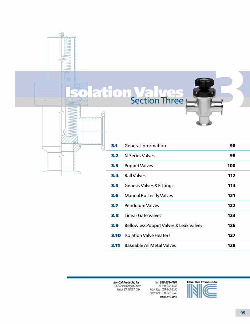
95
3
Tel: 800-824-4166or 530-842-4457
Main Fax: 530-842-9130Sales Fax: 530-841-9189
www.n-c.com
Nor-Cal Products, Inc.1967 South Oregon Street
Yreka, CA 96097 USA
3.1 General Information 96
3.2 N-Series Valves 98
3.3 Poppet Valves 100
3.4 Ball Valves 112
3.5 Genesis Valves & Fittings 114
3.6 Manual Butterfly Valves 121
3.7 Pendulum Valves 122
3.8 Linear Gate Valves 123
3.9 Bellowless Poppet Valves & Leak Valves 126
3.10 Isolation Valve Heaters 127
3.11 Bakeable All Metal Valves 128
Isolation ValvesSection Three
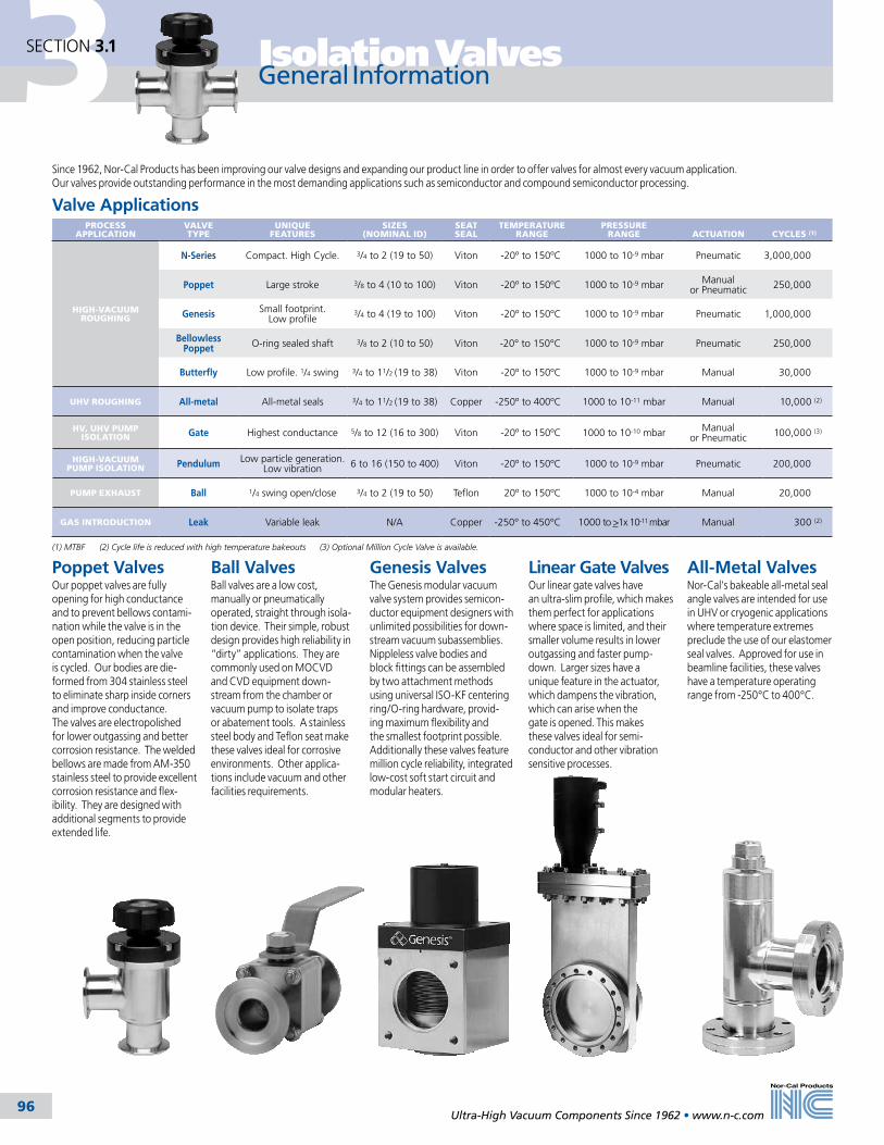
3 Isolation Valves
Ultra-High Vacuum Components Since 1962 • www.n-c.com 96
SECTION 3.1
General Information
Since 1962, Nor-Cal Products has been improving our valve designs and expanding our product line in order to offer valves for almost every vacuum application. Our valves provide outstanding performance in the most demanding applications such as semiconductor and compound semiconductor processing.
Valve ApplicationsPROCESS
APPLICATIONVALVE TYPE
UNIQUE FEATURES
SIZES (NOMINAL ID)
SEAT SEAL
TEMPERATURE RANGE
PRESSURE RANGE
ACTUATION
CYCLES (1)
HIGH-VACUUM ROUGHING
N-Series Compact. High Cycle. 3/4 to 2 (19 to 50) Viton -20º to 150ºC 1000 to 10-9 mbar Pneumatic 3,000,000
Poppet Large stroke 3/8 to 4 (10 to 100) Viton -20º to 150ºC 1000 to 10-9 mbar Manual or Pneumatic 250,000
Genesis Small footprint. Low profile
3/4 to 4 (19 to 100) Viton -20º to 150ºC 1000 to 10-9 mbar Pneumatic 1,000,000
Bellowless Poppet O-ring sealed shaft 3/8 to 2 (10 to 50) Viton -20° to 150°C 1000 to 10-9 mbar Pneumatic 250,000
Butterfly Low profile. 1/4 swing 3/4 to 11/2 (19 to 38) Viton -20º to 150ºC 1000 to 10-9 mbar Manual 30,000
UHV ROUGHING All-metal All-metal seals 3/4 to 11/2 (19 to 38) Copper -250º to 400ºC 1000 to 10-11 mbar Manual 10,000 (2)
HV, UHV PUMP ISOLATION Gate Highest conductance 5/8 to 12 (16 to 300) Viton -20º to 150ºC 1000 to 10-10 mbar Manual
or Pneumatic 100,000 (3)
HIGH-VACUUM PUMP ISOLATION Pendulum Low particle generation.
Low vibration 6 to 16 (150 to 400) Viton -20º to 150ºC 1000 to 10-9 mbar Pneumatic 200,000
PUMP EXHAUST Ball 1/4 swing open/close 3/4 to 2 (19 to 50) Teflon 20º to 150ºC 1000 to 10-4 mbar Manual 20,000
GAS INTRODUCTION Leak Variable leak N/A Copper -250° to 450°C 1000 to >1x 10-11 mbar Manual 300 (2)
(1) MTBF (2) Cycle life is reduced with high temperature bakeouts (3) Optional Million Cycle Valve is available.
All-Metal ValvesNor-Cal’s bakeable all-metal seal angle valves are intended for use in UHV or cryogenic applications where temperature extremes preclude the use of our elastomer seal valves. Approved for use in beamline facilities, these valves have a temperature operating range from -250°C to 400°C.
Genesis ValvesThe Genesis modular vacuum valve system provides semicon-ductor equipment designers with unlimited possibilities for down-stream vacuum subassemblies. Nippleless valve bodies and block fittings can be assembled by two attachment methods using universal ISO-KF centering ring/O-ring hardware, provid-ing maximum flexibility and the smallest footprint possible. Additionally these valves feature million cycle reliability, integrated low-cost soft start circuit and modular heaters.
Linear Gate ValvesOur linear gate valves have an ultra-slim profile, which makes them perfect for applications where space is limited, and their smaller volume results in lower outgassing and faster pump-down. Larger sizes have a unique feature in the actuator, which dampens the vibration, which can arise when the gate is opened. This makes these valves ideal for semi-conductor and other vibration sensitive processes.
Ball ValvesBall valves are a low cost, manually or pneumatically operated, straight through isola-tion device. Their simple, robust design provides high reliability in “dirty” applications. They are commonly used on MOCVD and CVD equipment down-stream from the chamber or vacuum pump to isolate traps or abatement tools. A stainless steel body and Teflon seat make these valves ideal for corrosive environments. Other applica-tions include vacuum and other facilities requirements.
Poppet ValvesOur poppet valves are fully opening for high conductance and to prevent bellows contami-nation while the valve is in the open position, reducing particle contamination when the valve is cycled. Our bodies are die-formed from 304 stainless steel to eliminate sharp inside corners and improve conductance. The valves are electropolished for lower outgassing and better corrosion resistance. The welded bellows are made from AM-350 stainless steel to provide excellent corrosion resistance and flex-ibility. They are designed with additional segments to provide extended life.

3Isolation Valves
Ultra-High Vacuum Components Since 1962 • www.n-c.com 97
SECTION 3.1
General Information
Standard Options• Normally open pneumatic actuation• Microswitch position indication• Special O-rings• Various air solenoid voltages• Fitting options for bypass lines• Heater jackets, insulators and controllers
Custom Features • Special port lengths and configurations for drop-in compatibility with other manufacturer’s valves• Custom flange configurations • Special position indicators• Pump out ports• Custom finishes• Gate shields for linear gate valve O-rings
Machined Ball ValvesOur new ball valves are a low cost, manually or pneumatically operated, straight through isolation device. Their simple, robust design provides high reliability in “dirty” applications. They are commonly used on MOCVD and CVD equipment downstream from the chamber or vacuum pump to isolate traps or abatement tools. A stainless steel body and Teflon seat make these valves ideal for corrosive environments. A quarter turn of the handle quickly switches the valve from open to close. They are available with NW-16 through NW-50 flanges as standards. Heater jackets are available to reduce process by-product accumulation.
N-Series Poppet Valves The new N-Series poppet valves are an innovative, compact design with an MTBF of 3 million cycles. A bellows-sealed stem and electropolished stainless steel body provides long life even in the most demanding applica-tions. Standard pneumatic actuation is normally closed. N-series valves are available in right angle or angle-in-line body styles with tube ends, NW flanges and CF rotatable flanges. Optional air solenoids are available in multiple voltages and can be ordered factory installed or as separate kits for easy field installation.
Manual Butterfly ValvesThese Viton O-ring sealed valves provide a low-cost alternative to bellows sealed gate valves. Quarter-turn actuation, small footprint and the shortest possible gas path make manual butterfly valves the preferred choice for many applications.
New Products
Leak ValvesLeak valves are used for controlling gas introduction into high and ultra-high vacuum systems. They utilize an optically flat sapphire poppet and a metal seal seat, allowing bakeout temperatures to 450ºC.
Spring-to-close pneumatic actuator with gate shield
Custom fitting option
Custom valve manifold
Custom ValvesNor-Cal frequently provides custom and modified standard isolation valves to meet our customer’s specific requirements. Single or multiple valves can be integrated with manifolds, chambers and other components. Many special features can be specified by adding options. See page 98.

3 Isolation Valves
Ultra-High Vacuum Components Since 1962 • www.n-c.com 98
SECTION 3.2
N-Series Valves
SPECIFICATIONSNominal Port OD’s: ¾ (19), 1 (25) and 1 ½ (38) inches (mm)
Materials
Body: Electropolished 304 stainless steel Bellows: Welded AM-350 stainless steel Bonnet seal: Viton Poppet seal: Viton Other O-ring compounds available
Actuation: Spring / Pneumatic Air-to-open, spring-to-close
Helium leak tested: <10-9 mbar l/sec.
Operating Temperature: 150°C Max.
Supply Pressure: 60 to100 psig (4-7 bar)
Differential pressure: Maximum 20psi (1.4bar) differential across the valve seat
Maximum temperature with Viton seals: 150ºC Max
Vacuum Range: 1000 to 1x10⁻⁹ mbar
Options: Solenoids, optical sensors, Heater jackets and controllers available for all valves.
The new N-Series poppet valves are an innovative, compact design with an MTBF of 3 million cycles. A bellows-sealed stem and electropolished stainless steel body provides long life even in the most demanding applications. Standard pneumatic actuation is normally closed (Air-to-Open / Spring-to-Close). N-series valves are available in right angle or angle-in-line body styles with tube ends, NW flanges or CF rotatable flanges. Optional air solenoids are available in multiple voltages and can be ordered
factory installed or as separate kits for easy field installation.
Mounting slots for optional position indi-cators are incorporated into the actuator body resulting in a reduction in overall size and elimination of the risk of physical damage to the sensors. Sensors are eas-ily installed without adjustment. Optical switch sensors indicate both the open & closed valve positions. It is possible for each valve to have two sensors installed for redundancy. Position indicators can
be ordered factory installed or as separate kits for easy field installation.
One rebuild kit fits the four valve sizes from NW-16 through NW-50 to reduce maintenance inventory costs. Viton O-ring seals are standard, however the valve is designed to accept alternate seal compounds to satisfy your application requirements.
PositionIndicator
O-ringType
Air Solenoid
ValveModel Number
O-ring Material OptionsSEAL MATERIAL
CODE
Viton Default (no code)Kalrez 4079 -K79Kalrez 8085 -K85Kalrez 8575 -K75Kalrez 9100 -K91Chemraz E38 -C38Dupra 192 -D19Perlast G74P -PP7
Example: NAP-150-NW-NPN-K91-S11 Right angle N-Series valve with 1.5 inch(38.1) bore, NW-40 flanges, optical position indicators, Kalrez 9100 O-rings, 120VAC and air solenoid option.
N-Series OptionsPlease use the following part numbering tree to add the appropriate options to a standard N-Series valve model number. See tables below for option codes.
Air Solenoid OptionDESCRIPTION CODE KIT
120VAC, 50/60 Hz -S11 N-S11-K24VDC -S21 N-S21-K240VAC, 50/60 Hz -S31 N-S31-K24VAC, 50/60 Hz -S41 N-S41-K
Position Indicator OptionDESCRIPTION CODE KIT
Optical - main valve open & closed NPN N-NPN-KOptical - main valve open & closed PNP N-PNP-KAll dimensions are in inches (mm) & weights
are in pounds (kg), unless otherwise noted.
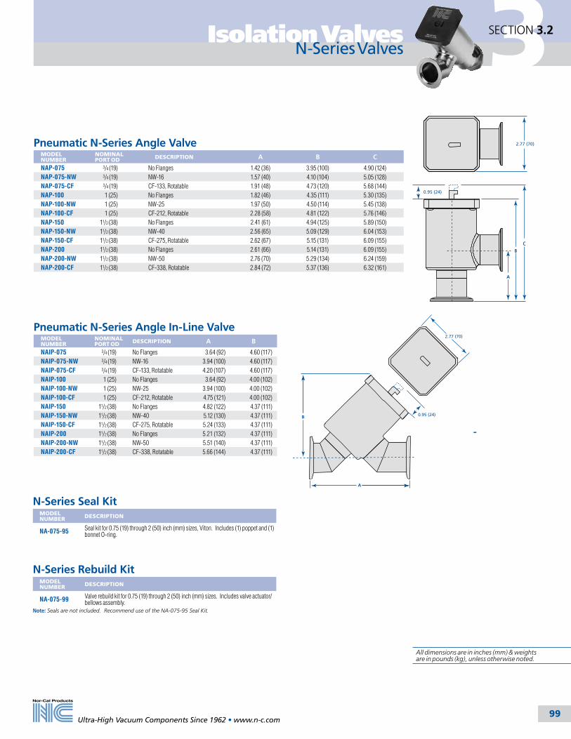
3Isolation Valves
Ultra-High Vacuum Components Since 1962 • www.n-c.com 99
SECTION 3.2
N-Series Valves
A
B
C
2.77 (70)
0.95 (24)
2.77 (70)
B
A
0.95 (24)
Pneumatic N-Series Angle Valve
MODEL NUMBER
NOMINALPORT OD DESCRIPTION A B C
NAP-075 3/4 (19) No Flanges 1.42 (36) 3.95 (100) 4.90 (124)NAP-075-NW 3/4 (19) NW-16 1.57 (40) 4.10 (104) 5.05 (128)NAP-075-CF 3/4 (19) CF-133, Rotatable 1.91 (48) 4.73 (120) 5.68 (144)NAP-100 1 (25) No Flanges 1.82 (46) 4.35 (111) 5.30 (135)NAP-100-NW 1 (25) NW-25 1.97 (50) 4.50 (114) 5.45 (138)NAP-100-CF 1 (25) CF-212, Rotatable 2.28 (58) 4.81 (122) 5.76 (146)NAP-150 11/2 (38) No Flanges 2.41 (61) 4.94 (125) 5.89 (150)NAP-150-NW 11/2 (38) NW-40 2.56 (65) 5.09 (129) 6.04 (153)NAP-150-CF 11/2 (38) CF-275, Rotatable 2.62 (67) 5.15 (131) 6.09 (155)NAP-200 11/2 (38) No Flanges 2.61 (66) 5.14 (131) 6.09 (155)NAP-200-NW 11/2 (38) NW-50 2.76 (70) 5.29 (134) 6.24 (159)NAP-200-CF 11/2 (38) CF-338, Rotatable 2.84 (72) 5.37 (136) 6.32 (161)
Pneumatic N-Series Angle In-Line Valve
MODEL NUMBER
NOMINALPORT OD DESCRIPTION A B
NAIP-075 3/4 (19) No Flanges 3.64 (92) 4.60 (117)NAIP-075-NW 3/4 (19) NW-16 3.94 (100) 4.60 (117)NAIP-075-CF 3/4 (19) CF-133, Rotatable 4.20 (107) 4.60 (117)NAIP-100 1 (25) No Flanges 3.64 (92) 4.00 (102)NAIP-100-NW 1 (25) NW-25 3.94 (100) 4.00 (102)NAIP-100-CF 1 (25) CF-212, Rotatable 4.75 (121) 4.00 (102)NAIP-150 11/2 (38) No Flanges 4.82 (122) 4.37 (111)NAIP-150-NW 11/2 (38) NW-40 5.12 (130) 4.37 (111)NAIP-150-CF 11/2 (38) CF-275, Rotatable 5.24 (133) 4.37 (111)NAIP-200 11/2 (38) No Flanges 5.21 (132) 4.37 (111)NAIP-200-NW 11/2 (38) NW-50 5.51 (140) 4.37 (111)NAIP-200-CF 11/2 (38) CF-338, Rotatable 5.66 (144) 4.37 (111)
N-Series Seal KitMODEL NUMBER DESCRIPTION
NA-075-95 Seal kit for 0.75 (19) through 2 (50) inch (mm) sizes, Viton. Includes (1) poppet and (1) bonnet O-ring.
N-Series Rebuild KitMODEL NUMBER DESCRIPTION
NA-075-99 Valve rebuild kit for 0.75 (19) through 2 (50) inch (mm) sizes. Includes valve actuator/bellows assembly.
Note: Seals are not included. Recommend use of the NA-075-95 Seal Kit.
All dimensions are in inches (mm) & weights are in pounds (kg), unless otherwise noted.

3 Isolation Valves
Ultra-High Vacuum Components Since 1962 • www.n-c.com 100 101
SECTION 3.3
ConstructionBodies are die-formed from 304 stainless steel to eliminate sharp inside corners and improve conductance. The valves are electropolished for faster pumpdown, lower outgassing and better corrosion resistance. The welded bellows are made from AM-350 stainless steel to provide corrosion resistance and excellent flexibility. The bellows fully retract from the side port when the valve is open, eliminating buildup of by-products on the bellows and subsequent particle generation during operation. They are designed with additional segments to provide extended life. Nor-Cal valves can be operated in any position and actuators can be removed quickly for routine inspection without disassembling the system.
ModelsOur poppet valves are available in most port configurations with CF, NW, ISO or ASA flanges. Valves through 3 inch (76mm) OD’s are available with manual or pneumatic actuators and Viton or copper bonnet seals. Valves over 3 inches (76mm) are available with pneumatic actuators only. Custom port lengths, flange configurations and bellowless valves are also available.
Vacuum RangePoppet seals have helium leak rates of <10-9 mbar l/sec. Viton bonnet sealed valves can be used in the 10-9 mbar range, while copper bonnet seal valves are suited for use in the 10-10 range.
Copper Bonnet SealCopper bonnet seal poppet valves with CF flanges provide metal seals between the inside of the valve and the atmo-sphere. They are available in all standard sizes and port configurations.
Valve ActuationManually operated valves utilize Acme threads and a self-lubricating bronze nut for fewer turns and smooth, trouble-free operation. Pneumatic valves are normally air-to-open, spring-to-close in port ODs through 2 inches (50mm) for immediate closure in case of electrical or air failure. Larger valves are normally air-to-open, air-to-close. This actuation option is avail-able on all valves. Most sizes are available with air-to open, air-to-close with spring assist as an option. Operating air pressure for all pneumatic valves is 60 to 80 psig (4-5.5 bar).
Thermal ProductsAll Nor-Cal poppet valves and gate valves can be provided with silicone foam or fiberglass insulated heater jackets to reduce resident time of corrosives or particle buildup in semicon-ductor applications. These jackets are available with PID controllers or thermo-stats with high temperature shutoffs. Jacket and control specifications can be tailored to meet your specific needs. Call for price and model number. Refer to Section 11, Thermal Products, for more information.
Poppet Valve Conductance (Liters per second)The conductance values in the table below have been calculated for air at room temperature using the formulas for tubes and elbows presented in the third edition of Roth’s Vacuum Technology: Cv=182(D4/L’)P for viscous flow or Cm=12(D3/L’) for molecular flow. Port lengths without flanges and inner diameters for the valve sizes and configurations were used. This method is an approximation, use values accordingly.
NOMINALPORT OD
ANGLE OR TEE VISCOUS MOLECULAR
ANGLE-IN-LINE VISCOUS MOLECULAR
IN-LINE VISCOUS MOLECULAR
STRAIGHT-THROUGH VISCOUS MOLECULAR
1/2 (13) 60 3 - - 45 2 - -3/4 (19. 135 5 120 4 105 4 90 41 (25) 391 12 286 9 270 8 - -
11/8 (28) - - - - - - 436 1111/2 (38) 1925 37 1324 25 1263 24 1203 23
2 (50) 4677 65 3459 48 3113 44 - -21/2 (63) 12332 136 7505 83 7610 84 - -
3 (76) 23263 217 12558 115 14258 130 - -4 (100) 57994 396 - - 34577 236 - -
Note: P=air at 1 mbar. L’=Laxial +1.33(0/180)D for elbows.
Poppet Valve General Information
SPECIFICATIONSNominal port ODs: 3/8 to 4 inch (10-102mm)
Body: Electropolished 304 stainless steel Bellows: Welded AM-350 stainless steel Bonnet seal: Viton or Copper Poppet seal: Viton Other O-ring compounds available
Flanges: CF, NW, ISO or ASA
Maximum temperature with Viton seals See bakeability chart this page Sustained: <150°C Intermittent: <204°C
Helium leak tested: <10-9 mbar l/sec.
Vacuum range Viton bonnet seal: > 1 x 10⁻⁹ mbar - High Vacuum Copper bonnet seal: > 1 x 10⁻¹⁰ mbar - UHV
Manual actuation: Bronze nuts/ACME threads
Pneumatic actuation: Normally closed Operating Pressure: 60 to 80 psig 3/4 to 2 inch (19-50) ODs: Air-to-open/ spring-to-close 21/2 to 4 inch (63-101) ODs: Air-to-open/air- to-close
Differential pressure: Maximum 20psi (1.4bar) differential across the valve seat
Options: See facing page.
Thermal: Heater jackets and controllers available for all valves. Call for details
Valve rebuild kits are on page 111
All dimensions are in inches (mm) & weights are in pounds (kg), unless otherwise noted.
BakeabilityThe valve’s bakeout temperature should not exceed that of the elastomer that is used in it. See chart below. Standard Viton sealed valves are bakeable to 150ºC sustained and 204°C for intermittent periods. However, the Viton O-rings begin to take a set at 150°C. High temperature Kalrez O-rings are available as an option.
BONNET/POPPET SEAL
APPLICATION
PNEUMATIC VALVES OPEN CLOSED
MANUAL VALVES OPEN CLOSED
Viton General purpose 150°C 120°C 150°C 120°CKalrez 4079 High temperature 280°C 220°C 280°C 220°CKalrez 2037 Chemical resistant 218°C 218°C 218°C 218°C
Chemraz Chemical resistant 210°C 210°C 210°C 210°CSilicone High temperature 232°C 232°C 232°C 232°C
ESVP cutaway
view
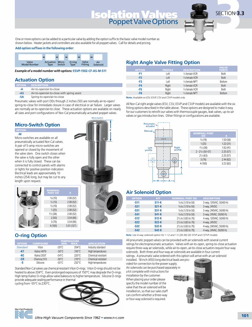
Ultra-High Vacuum Components Since 1962 • www.n-c.com 100 101
3Isolation Valves SECTION 3.3
Actuation OptionOPTION DESCRIPTION
-A Air-to-open/air-to-close-AS Air-to-open/air-to-close with spring assist-SA Spring-to-open/air-to-close
Pneumatic valves with port ODs through 2 inches (50) are normally air-to-open/spring-to-close for immediate closure in case of electrical or air failure. Larger valves are normally air-to-open/air-to close. These actuation options are available on nearly all sizes and port configurations of Nor-Cal pneumatically actuated poppet valves.
Poppet Valve Options
One or more options can be added to a particular valve by adding the option suffix to the basic valve model number as shown below. Heater jackets and controllers are also available for all poppet valves. Call for details and pricing.
Add option suffixes in the following order:
O-ring Option
OPTION
COMPOUNDTEMPERATURE MIN. MAX.
APPLICATION
Standard Viton -29°C 204°C Industry standard -KT Kalrez 4079 -50°C 316°C High temperatures-KC Kalrez 2037 -54°C 220°C Chemical resistant-CR Chemraz 513 -30°C 210°C Chemical resistant-S Silicone -55°C 232°C High temperatures
Standard Nor-Cal valves use chemical resistant Viton O-rings. Viton O-rings should not be heated to above 204°C. Even prolonged exposures of 150°C may degrade the O-rings. High temp Kalrez O-rings allow valve bakeouts to higher temperature. Silicone O-rings provide adequate sealing performance in thermal cycling from -55°C to 230°C.
All pneumatic poppet valves can be provided with air solenoids with several current ratings for electropneumatic actuation. Valves with air-to-open, spring-to-close actuation require three-way air solenoids, while air-to-open, air-to-close actuators require four-way solenoids. Both three and four-way air solenoids are available in four current ratings. A pneumatic valve ordered with this option will arrive with an air solenoid installed. 18 inch (450) long electrical leads are pro-vided for connection to the power supply. Air solenoids can be purchased separately in a kit complete with instructions for installation by the customer. When placing your order please specify the model number of the valve that the air solenoid will be installed on, so that our sales staff can confirm whether a three-way or four-way solenoid is required.
Air Solenoid OptionOPTION KIT NOMINAL PORT OD DESCRIPTION
-S11 S11-K 3/8 to 2 (10 to 50) 3-way, 120VAC, 50/60 Hz-S21 S21-K 3/8 to 2 (10 to 50) 3-way, 24VDC-S31 S31-K 3/8 to 2 (10 to 50) 3-way, 240VAC, 50/60 Hz-S41 S41-K 3/8 to 2 (10 to 50) 3-way, 24VAC, 50/60 Hz-S12 S12-K 21/2 to 3 (63 to 76) 4-way, 120VAC, 50/60 Hz-S22 S22-K 21/2 to 3 (63 to 76) 4-way, 24VDC-S32 S32-K 21/2 to 3 (63 to 76) 4-way, 240VAC, 50/60 Hz-S42 S42-K 21/2 to 3 (63 to 76) 4-way, 24VAC, 50/60 Hz
Note: Use 4-way solenoid option for 1.12 and 1.5 (28-38) OD STVP and CSTVP models.
Micro-Switch OptionOPTION
-MMicro-switches are available on all pneumatically actuated Nor-Cal valves. A pair of 5-amp micro-switches are opened or closed by the movement of the valve stem. One switch closes when the valve is fully open and the other when it is fully closed. These can be connected to control panels with alarms or lights for positive position indication. Electrical leads are approximately 10 inches (254) long, but may be cut to any length upon request.
Right Angle Valve Fitting Option
OPTION
PROFILE DESCRIPTION
VALVE PORTS
-F1 Left 1⁄4 female VCR Both-F2 Left 3⁄8 female VCR Both-F3 Left 1⁄8 female NPT Bottom-F4 Right 1⁄4 female VCR Both-F5 Right 3⁄8 female VCR Both-F6 Right 1⁄8 female NPT Bottom
Note: Available on ESV, ESVP, CSV and CSVP models only.
All Nor-Cal right angle valves (ESV, CSV, ESVP and CSVP models) are available with the six fitting options described in the table above. These options are designed to make it easy for our customers to retrofit our valves with thermocouple gauges, leak valves, up-to-air valves or gas introduction lines. Other fittings or configurations are available.
A
A
A
Right profile
Left profile
Pneumatic actuator
Manual
Valve Model Number
ActuationType
O-ringType
Micro-Switch
ValveFitting
Air Solenoid
Example of a model number with options: ESVP-1502-CF-AS-M-S11
NOMINAL PORT OD
E
3/8 (10) 2.06 (52)1/2 (13) 2.06 (52)3/4 (19) 2.06 (52)1 (25) 2.06 (52)
11/2 (38) 2.06 (52)2 (50) 3.54 (90)3 (76) 3.54 (90)
4 (100) 5.01 (127)
NOMINAL PORT OD
A
3/4 (19) 1.50 (38)1 (25) 1.22 (31)
11/2 (38) 1.62 (41)2 - 21/4 (50-57) 2.25 (57)
21/2 (63) 2.25 (57)3 (76) 2.44 (62)4 (100) 3.22 (82)
E
Micro-Switch

3 Isolation Valves
Ultra-High Vacuum Components Since 1962 • www.n-c.com 102 103
SECTION 3.3
Manual Viton Seal Angle ValvesMODEL NUMBER
NOMINAL PORT OD
DESCRIPTION
A
B
C
D
ESV-038 3/8 (10) No flanges 1.50 (38.1) 4.06 (103) 4.44 (113) 2.25 (57)ESV-0382-CF 3/8 (10) Rotatable 1.33 CF 1.60 (40.6) 4.16 (106) 4.54 115) 2.25 (57)ESV-0382-NWB 3/8 (10) NW-10B 1.65 (41.9) 4.21 (107) 4.59 (117) 2.25 (57)ESV-050 1/2 (13) No flanges 1.50 (38.1) 4.06 (103) 4.56 (116) 2.25 (57)ESV-0502-CF 1/2 (13) Rotatable 1.33 CF 1.60 (40.6) 4.16 (106) 4.66 (118) 2.25 (57)ESV-0502-NWB 1/2 (13) NW-10B 1.65 (41.9) 4.21 (107) 4.71 (120) 2.25 (57)ESV-075 3/4 (19) No flanges 2.00 (50.8) 4.56 (116) 5.31 (135) 2.25 (57)ESV-0752-CF 3/4 (19) Rotatable 1.33 CF 2.50 (63.5) 5.06 (129) 5.81 (148) 2.25 (57)ESV-0752-NWB 3/4 (19) NW-16B 2.15 (54.6) 4.71 (120) 5.46 (139) 2.25 (57)ESV-100 1 (25) No flanges 1.88 (47.8) 4.32 (110) 5.32 (135) 2.25 (57)ESV-1002-CF 1 (25) Rotatable 2.12 CF 2.05 (52.1) 4.49 (114) 5.49 (139) 2.25 (57)ESV-1002-NWB 1 (25) NW-25B 2.03 (51.6) 4.47 (114) 5.47 (139) 2.25 (57)ESV-150 11/2 (38) No flanges 2.25 (57.2) 5.63 (143) 7.13 (181) 3.00 (76)ESV-1502-CF 11/2 (38) Rotatable 2.75 CF 2.46 (62.5) 5.84 (148) 7.34 (186) 3.00 (76)ESV-1502-NWB 11/2 (38) NW-40B 2.40 (62.0) 5.78 (147) 7.28 (185) 3.00 (76)ESV-200 2 (50) No flanges 3.25 (82.6) 7.85 (199) 9.85 (250) 3.50 (89)ESV-2002-CF 2 (50) Rotatable 3.38 CF 3.48 (88.4) 8.08 (205) 10.08 (256) 3.50 (89)ESV-2002-NWB 2 (50) NW-50B 3.40 (86.4) 8.00 (203) 10.00 (254) 3.50 (89)ESV-2002-ASA 2 (50) Rotatable ASA-5-200R 3.50 (88.9) 8.10 (206) 10.10 (257) 3.50 (89)ESV-250 21/2 (63) No flanges 3.00 (76.2) 8.27 (210) 10.77 (274) 4.00 (102)ESV-2502-CF 21/2 (63) Rotatable 4.50 CF 3.38 (85.9) 8.65 (220) 11.15 (283) 4.00 (102)ESV-2502-ISO 21/2 (63) ISO-63-250-OF 3.25 (82.6) 8.52 (216) 11.02 (280) 4.00 (102)ESV-2502-ASA 21/2 (63) Rotatable ASA-5-250R 3.25 (82.6) 8.52 (216) 11.02 (280) 4.00 (102)ESV-300 3 (76) No flanges 3.25 (82.6) 8.68 (220) 11.68 (297) 4.50 (114)ESV-3002-CF 3 (76) Rotatable 4.62 CF 3.53 (89.7) 8.96 (228) 11.96 (304) 4.50 (114)ESV-3002-ISO 3 (76) ISO-80-300-OF 3.50 (89.0) 8.93 (227) 11.93 (303) 4.50 (114)ESV-3002-ASA 3 (76) Rotatable ASA-6-300R 3.50 (89.0) 8.93 (227) 11.93 (303) 4.50 (114)
Manual Angle Valves
A
A
C
B
D Manual Copper Seal Bonnet Angle ValvesMODEL NUMBER
NOMINAL PORT OD
DESCRIPTION
A
B
C
D
CSV-038 3/8 (10) No flanges 1.50 (38.1) 4.06 (103) 4.44 (113) 2.73 (69)CSV-0382-CF 3/8 (10) Rotatable 1.33 CF 1.60 (40.6) 4.16 (106) 4.54 115) 2.73 (69)CSV-050 1/2 (13) No flanges 1.50 (38.1) 4.06 (103) 4.56 (116) 2.73 (69)CSV-0502-CF 1/2 (13) Rotatable 1.33 CF 1.60 (40.6) 4.16 (106) 4.66 (118) 2.73 (69)CSV-075 3/4 (19) No flanges 2.00 (50.8) 4.56 (116) 5.31 (135) 2.73 (69)CSV-0752-CF 3/4 (19) Rotatable 1.33 CF 2.50 (63.5) 5.06 (129) 5.81 (148) 2.73 (69)CSV-100 1 (25) No flanges 1.88 (47.8) 4.32 (110) 5.32 (135) 2.73 (69)CSV-1002-CF 1 (25) Rotatable 2.12 CF 2.05 (52.1) 4.49 (114) 5.49 (139) 2.73 (69)CSV-150 11/2 (38) No flanges 2.25 (57.2) 5.63 (143) 7.13 (181) 3.25 (83)CSV-1502-CF 11/2 (38) Rotatable 2.75 CF 2.46 (62.5) 5.84 (148) 7.34 (186) 3.25 (83)CSV-200 2 (50) No flanges 3.25 (82.6) 7.85 (199) 9.85 (250) 4.05 (103)CSV-2002-CF 2 (50) Rotatable 3.38 CF 3.48 (88.4) 8.08 (205) 10.08 (256) 4.05 (103)CSV-250 21/2 (63) No flanges 3.00 (76.2) 8.27 (210) 10.77 (274) 4.61 (117)CSV-2502-CF 21/2 (63) Rotatable 4.50 CF 3.38 (85.9) 8.65 (220) 11.15 (283) 4.61 (117)CSV-300 3 (76) No flanges 3.25 (82.6) 8.68 (220) 11.68 (297) 5.62 (143)CSV-3002-CF 3 (76) Rotatable 4.62 CF 3.53 (89.7) 8.96 (228) 11.96 (304) 5.62 (143)
ESV O-ring KitsMODEL NUMBER
NOMINALPORT OD
ESV-075-95 3/8-1 (10-25)ESV-150-95 11/2 (38)ESV-200-95 2 (50)ESV-250-95 21/2 (63)ESV-300-95 3 (76)
CSV O-ring & Gasket Kits
MODEL NUMBER NOMINALPORT OD
CSV-075-95 3/8-1 (10-25)CSV-150-95 11/2 (38)CSV-200-95 2 (50)CSV-250-95 21/2 (63)CSV-300-95 3 (76)
SPECIFICATIONSPort ODs: 3/8 to 3 inches (10 to 76mm)
Materials Body: Electropolished 304 stainless steel Bellows: Welded AM-350 stainless steel Bonnet seal: Copper or Viton Poppet seal: Viton Other O-ring compounds available
Actuation: Self-lubricating bronze nuts with ACME threads
Differential pressure: Maximum 20psi (1.4bar) differential across the valve seat
Maximum temperature with Viton seals Sustained: <150°C Intermittent: <204°C
Vacuum range Viton bonnet seal: >1x 10⁻⁹ mbar - High Vacuum Copper bonnet seal: >1x 10⁻¹⁰ mbar - UHV
Options: Fittings and O-rings. See page 101
Thermal: Heater jackets and controllers available for all valves. See page 127
Valve rebuild kits available. See page 111

3Isolation Valves
Ultra-High Vacuum Components Since 1962 • www.n-c.com 103
SECTION 3.3
102 103
Pneumatic Angle Valves
Pneumatic Viton Seal Angle ValvesMODEL NUMBER
NOMINAL PORT OD
DESCRIPTION
A
B
C
D
ESVP-038 3/8 (10) No flanges 1.50 (38.1) 3.62 (92) 5.77 (147) 2.25 (57)ESVP-0382-CF 3/8 (10) Rotatable 1.33 CF 1.60 (40.6) 3.72 (95) 5.87 (149) 2.25 (57)ESVP-0382-NWB 3/8 (10) NW-10B 1.65 (41.9) 3.77 (96) 5.92 (150) 2.25 (57)ESVP-050 1/2 (13) No flanges 1.50 (38.1) 3.62 (92) 5.77 (147) 2.25 (57)ESVP-0502-CF 1/2 (13) Rotatable 1.33 CF 1.60 (40.6) 3.72 (95) 5.87 (149) 2.25 (57)ESVP-0502-NWB 1/2 (13) NW-10B 1.65 (41.9) 3.77 (96) 5.92 (150) 2.25 (57)ESVP-075 3/4 (19) No flanges 2.00 (50.8) 4.12 (105) 6.26 (159) 2.25 (57)ESVP-0752-CF 3/4 (19) Rotatable 1.33 CF 2.50 (63.5) 4.62 (117) 6.76 (171) 2.25 (57)ESVP-0752-NWB 3/4 (19) NW-16B 2.15 (54.6) 4.27 (109) 6.41 (163) 2.25 (57)ESVP-100 1 (25) No flanges 1.88 (47.8) 3.88 (98.6) 6.02 (152) 2.25 (57)ESVP-1002-CF 1 (25) Rotatable 2.12 CF 2.05 (52.1) 4.05 (103) 6.19 (157) 2.25 (57)ESVP-1002-NWB 1 (25) NW-25B 2.03 (51.6) 4.03 (102) 6.17 (157) 2.25 (57)ESVP-150 11/2 (38) No flanges 2.25 (57.2) 4.98 (127) 7.56 (192) 3.00 (76)ESVP-1502-CF 11/2 (38) Rotatable 2.75 CF 2.46 (62.5) 5.19 (132) 7.77 (197) 3.00 (76)ESVP-1502-NWB 11/2 (38) NW-40B 2.40 (61.0) 5.13 (130) 7.71 (196) 3.00 (76)ESVP-200 2 (50) No flanges 3.25 (82.6) 6.74 (171) 11.23 (285) 3.50 (89)ESVP-2002-CF 2 (50) Rotatable 3.38 CF 3.48 (88.4) 6.97 (177) 11.46 (291) 3.50 (89)ESVP-2002-NWB 2 (50) NW-50B 3.40 (86.4) 6.89 (175) 11.38 (289) 3.50 (89)ESVP-2002-ASA 2 (50) Rotatable ASA-5-200R 3.50 (88.9) 6.99 (178) 11.48 (292) 3.50 (89)ESVP-250 21/2 (63) No flanges 3.00 (76.2) 7.18 (182) 10.1 (257) 4.00 (100)ESVP-2502-CF 21/2 (63) 4.50 CF 3.38 (85.9) 7.56 (192) 10.48 (266) 4.00 (100)ESVP-2502-ISO 21/2 (63) ISO-63-250-OF 3.25 (82.6) 7.43 (189) 10.35 (263) 4.00 (100)ESVP-2502-ASA 21/2 (63) Rotatable ASA-5-250R 3.25 (82.6) 7.43 (189) 10.35 (263) 4.00 (100)ESVP-300 3 (76) No flanges 3.25 (82.6) 7.62 (194) 11.00 (297) 4.5 (114)ESVP-3002-CF 3 (76) Rotatable 4.62 CF 3.53 (90.0) 7.90 (201) 11.28 (287) 4.5 (114)ESVP-3002-ISO 3 (76) ISO-80-300-OF 3.50 (88.9) 7.87 (200) 11.25 (286) 4.5 (114)ESVP-3002-ASA 3 (76) Rotatable ASA-6-300R 3.50 (88.9) 7.87 (200) 11.25 (286) 4.5 (114)ESVP-400 4 (100) No flanges 4.22 (107) 9.55 (243) 14.99 (381) 6.50 (165)ESVP-4002-CF 4 (100) Rotatable 6.00 CF 4.66 (118) 9.99 (254) 15.43 (392) 6.50 (165)ESVP-4002-ISO 4 (100) ISO-100-400-OF 4.47 (114) 9.80 (249) 15.24 (387) 6.50 (165)ESVP-4002-ASA 4 (100) Rotatable ASA-7.5-400R 4.47 (114) 9.80 (249) 15.24 (387) 6.50 (165)
ESVP O-Ring KitsMODEL NUMBER
NOMINALPORT OD
ESVP-075-95 3/8-1 (10-25)ESVP-150-95 11/2 (38)ESVP-200-95 2 (50)ESVP-250-95 21/2 (63)ESVP-300-95 3 (76)ESVP-400-95 4 (100)
CSVP O-Ring & Gasket Kits
MODEL NUMBER
NOMINALPORT OD
CSVP-075-95 3/8-1 (10-25)CSVP-150-95 11/2 (38)CSVP-200-95 2 (50)CSVP-250-95 21/2 (63)CSVP-300-95 3 (76)CSVP-400-95 4 (100)
A
A
C
B
D
Pneumatic Copper Seal Bonnet Angle ValvesMODEL NUMBER
NOMINAL PORT OD
DESCRIPTION
A
B
C
D
CSVP-038 3/8 (10) No flanges 1.50 (38.1) 3.75 (95) 5.77 (147) 2.73 (69)CSVP-0382-CF 3/8 (10) Rotatable 1.33 CF 1.60 (40.6) 3.85 (98) 5.82 (148) 2.73 (69)CSVP-050 1/2 (13) No flanges 1.50 (38.1) 3.75 (95) 5.77 (147) 2.73 (69)CSVP-0502-CF 1/2 (13) Rotatable 1.33 CF 160 (40.6) 3.85 (98) 5.82 (148) 2.73 (69)CSVP-075 3/4 (19) No flanges 2.00 (50.8) 4.25 (108) 6.26 (159) 2.73 (69)CSVP-0752-CF 3/4 (19) Rotatable 1.33 CF 2.50 (63.5) 4.75 (121) 6.76 (172) 2.73 (69)CSVP-100 1 (25) No flanges 1.88 (47.8) 4.00 (102) 6.02 (153) 2.73 (69)CSVP-1002-CF 1 (25) Rotatable 2.12 CF 2.05 (52.1) 4.17 (106) 6.19 (157) 2.73 (69)CSVP-150 11/2 (38) No flanges 2.25 (57.2) 4.98 (126) 7.56 (192) 3.25 (83)CSVP-1502-CF 11/2 (38) Rotatable 2.75 CF 2.46 (62.5) 5.19 (132) 7.77 (197) 3.25 (83)CSVP-200 2 (50) No flanges 3.25 (82.6) 6.62 (168) 11.23 (285) 4.05 (103)CSVP-2002-CF 2 (50) Rotatable 3.38 CF 3.48 (88.4) 6.85 (174) 11.45 (291) 4.05 (103)CSVP-250 21/2 (63) No flanges 3.00 (76.2) 7.18 (182) 10.10 (257) 4.61 (117)CSVP-2502-CF 21/2 (63) Rotatable 4.50 CF 3.38 (85.9) 7.56 (192) 10.48 (266) 4.61 (117)CSVP-300 3 (76) No flanges 3.25 (82.6) 7.62 (194) 11.00 (279) 5.62 (143)CSVP-3002-CF 3 (76) Rotatable 4.62 CF 3.53 (89.7) 7.90 (201) 11.28 (287) 5.62 (143)CSVP-400 4 (100) No flanges 4.22 (107) 9.55 (243) 14.99 (381) 6.73 (171)CSVP-4002-CF 4 (100) Rotatable 6.00 CF 4.66 (118) 9.99 (254) 15.43 (392) 6.73 (171)
SPECIFICATIONSPort ODs: 3/8 to 4 inches (10-100mm)Materials Body: Electropolished 304 stainless steel Bellows: Welded AM-350 stainless steel Bonnet seal: Copper or Viton Poppet seal: Viton Other O-ring compounds availableActuation: Normally closed 3/8 to 2 inch (10-50) ODs: Air-to-open, spring-to-close 21/2 to 4 inch (63-100) ODs: Air-to-open, air-to-close See page 101 for more actuation options Operating pressure: 60 to 80 psig (4-5.5 bar) Differential pressure: Maximum 6 psi (0.4 bar) differential across the valve seatMaximum temperature with Viton seals Sustained: <150°C Intermittent: <204°C Vacuum range Viton bonnet seal: >1x 10⁻⁹ mbar - High Vacuum Copper bonnet seal: >1x 10⁻¹⁰ mbar - UHVOptions: Fittings, O-rings, air solenoids, micro-switches and actuators. See page 101Thermal: Heater jackets and controllers available for all valves. See page 127
All dimensions are in inches (mm) & weights are in pounds (kg), unless otherwise noted.
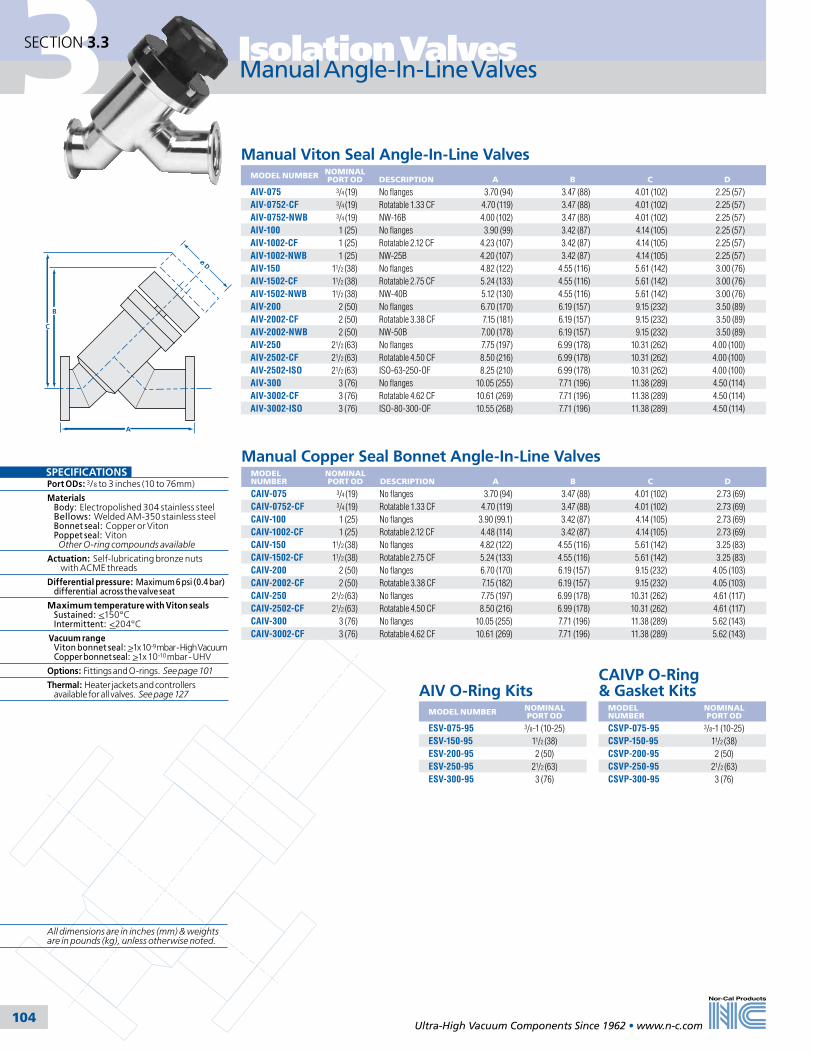
3 Isolation Valves
Ultra-High Vacuum Components Since 1962 • www.n-c.com 104
SECTION 3.3
Manual Copper Seal Bonnet Angle-In-Line ValvesMODEL NUMBER
NOMINALPORT OD
DESCRIPTION
A
B
C
D
CAIV-075 3/4 (19) No flanges 3.70 (94) 3.47 (88) 4.01 (102) 2.73 (69)CAIV-0752-CF 3/4 (19) Rotatable 1.33 CF 4.70 (119) 3.47 (88) 4.01 (102) 2.73 (69)CAIV-100 1 (25) No flanges 3.90 (99.1) 3.42 (87) 4.14 (105) 2.73 (69)CAIV-1002-CF 1 (25) Rotatable 2.12 CF 4.48 (114) 3.42 (87) 4.14 (105) 2.73 (69)CAIV-150 11/2 (38) No flanges 4.82 (122) 4.55 (116) 5.61 (142) 3.25 (83)CAIV-1502-CF 11/2 (38) Rotatable 2.75 CF 5.24 (133) 4.55 (116) 5.61 (142) 3.25 (83)CAIV-200 2 (50) No flanges 6.70 (170) 6.19 (157) 9.15 (232) 4.05 (103)CAIV-2002-CF 2 (50) Rotatable 3.38 CF 7.15 (182) 6.19 (157) 9.15 (232) 4.05 (103)CAIV-250 21/2 (63) No flanges 7.75 (197) 6.99 (178) 10.31 (262) 4.61 (117)CAIV-2502-CF 21/2 (63) Rotatable 4.50 CF 8.50 (216) 6.99 (178) 10.31 (262) 4.61 (117)CAIV-300 3 (76) No flanges 10.05 (255) 7.71 (196) 11.38 (289) 5.62 (143)CAIV-3002-CF 3 (76) Rotatable 4.62 CF 10.61 (269) 7.71 (196) 11.38 (289) 5.62 (143)
AIV O-Ring KitsMODEL NUMBER NOMINAL
PORT OD
ESV-075-95 3/8-1 (10-25)ESV-150-95 11/2 (38)ESV-200-95 2 (50)ESV-250-95 21/2 (63)ESV-300-95 3 (76)
CAIVP O-Ring & Gasket Kits
MODEL NUMBER
NOMINALPORT OD
CSVP-075-95 3/8-1 (10-25)CSVP-150-95 11/2 (38)CSVP-200-95 2 (50)CSVP-250-95 21/2 (63)CSVP-300-95 3 (76)
Manual Angle-In-Line Valves
B
A
C
D
SPECIFICATIONSPort ODs: 3/8 to 3 inches (10 to 76mm)
Materials Body: Electropolished 304 stainless steel Bellows: Welded AM-350 stainless steel Bonnet seal: Copper or Viton Poppet seal: Viton Other O-ring compounds available
Actuation: Self-lubricating bronze nuts with ACME threads
Differential pressure: Maximum 6 psi (0.4 bar) differential across the valve seat
Maximum temperature with Viton seals Sustained: <150°C Intermittent: <204°C
Vacuum range Viton bonnet seal: >1x 10⁻⁹ mbar - High Vacuum Copper bonnet seal: >1x 10⁻¹⁰ mbar - UHV
Options: Fittings and O-rings. See page 101
Thermal: Heater jackets and controllers available for all valves. See page 127
Manual Viton Seal Angle-In-Line ValvesMODEL NUMBER NOMINAL
PORT OD DESCRIPTION
A
B
C
D
AIV-075 3/4 (19) No flanges 3.70 (94) 3.47 (88) 4.01 (102) 2.25 (57)AIV-0752-CF 3/4 (19) Rotatable 1.33 CF 4.70 (119) 3.47 (88) 4.01 (102) 2.25 (57)AIV-0752-NWB 3/4 (19) NW-16B 4.00 (102) 3.47 (88) 4.01 (102) 2.25 (57)AIV-100 1 (25) No flanges 3.90 (99) 3.42 (87) 4.14 (105) 2.25 (57)AIV-1002-CF 1 (25) Rotatable 2.12 CF 4.23 (107) 3.42 (87) 4.14 (105) 2.25 (57)AIV-1002-NWB 1 (25) NW-25B 4.20 (107) 3.42 (87) 4.14 (105) 2.25 (57)AIV-150 11/2 (38) No flanges 4.82 (122) 4.55 (116) 5.61 (142) 3.00 (76)AIV-1502-CF 11/2 (38) Rotatable 2.75 CF 5.24 (133) 4.55 (116) 5.61 (142) 3.00 (76)AIV-1502-NWB 11/2 (38) NW-40B 5.12 (130) 4.55 (116) 5.61 (142) 3.00 (76)AIV-200 2 (50) No flanges 6.70 (170) 6.19 (157) 9.15 (232) 3.50 (89)AIV-2002-CF 2 (50) Rotatable 3.38 CF 7.15 (181) 6.19 (157) 9.15 (232) 3.50 (89)AIV-2002-NWB 2 (50) NW-50B 7.00 (178) 6.19 (157) 9.15 (232) 3.50 (89)AIV-250 21/2 (63) No flanges 7.75 (197) 6.99 (178) 10.31 (262) 4.00 (100)AIV-2502-CF 21/2 (63) Rotatable 4.50 CF 8.50 (216) 6.99 (178) 10.31 (262) 4.00 (100)AIV-2502-ISO 21/2 (63) ISO-63-250-OF 8.25 (210) 6.99 (178) 10.31 (262) 4.00 (100)AIV-300 3 (76) No flanges 10.05 (255) 7.71 (196) 11.38 (289) 4.50 (114)AIV-3002-CF 3 (76) Rotatable 4.62 CF 10.61 (269) 7.71 (196) 11.38 (289) 4.50 (114)AIV-3002-ISO 3 (76) ISO-80-300-OF 10.55 (268) 7.71 (196) 11.38 (289) 4.50 (114)
All dimensions are in inches (mm) & weights are in pounds (kg), unless otherwise noted.

3Isolation Valves
Ultra-High Vacuum Components Since 1962 • www.n-c.com 105
SECTION 3.3
Pneumatic Angle-In-Line Valves
Pneumatic Viton Seal Angle-In-Line ValvesMODEL NUMBER
NOMINALPORT OD
DESCRIPTION
A
B
C
AIVP-075 3/4 (19) No flanges 3.70 (94) 4.32 (110) 2.25 (57)AIVP-0752-CF 3/4 (19) Rotatable 1.33 CF 4.70 (119) 4.32 (110) 2.25 (57)AIVP-0752-NWB 3/4 (19) NW-16B 4.00 (102) 4.32 (110) 2.25 (57)AIVP-100 1 (25) No flanges 3.90 (99) 4.27 (108) 2.25 (57)AIVP-1002-CF 1 (25) Rotatable 2.12 CF 4.23 (107) 4.27 (108) 2.25 (57)AIVP-1002-NWB 1 (25) NW-25B 4.20 (107) 4.27 (108) 2.25 (57)AIVP-150 11/2 (38) No flanges 4.82 (122) 5.69 (145) 3.00 (76)AIVP-1502-CF 11/2 (38) Rotatable 2.75 CF 5.24 (133) 5.69 (145) 3.00 (76)AIVP-1502-NWB 11/2 (38) NW-40B 5.12 (130) 5.69 (145) 3.00 (76)AIVP-200 2 (50) No flanges 6.70 (170) 7.94 (202) 3.50 (89)AIVP-2002-CF 2 (50) Rotatable 3.38 CF 7.15 (182) 7.94 (202) 3.50 (89)AIVP-2002-NWB 2 (50) NW-50B 7.00 (178) 7.94 (202) 3.50 (89)AIVP-250 21/2 (63) No flanges 7.75 (197) 7.64 (194) 4.00 (100)AIVP-2502-CF 21/2 (63) Rotatable 4.50 CF 8.50 (216) 7.64 (194) 4.00 (100)AIVP-2502-ISO 21/2 (63) ISO-63-250-OF 8.25 (210) 7.64 (194) 4.00 (100)AIVP-300 3 (76) No flanges 10.05 (255) 8.7 (221) 4.50 (114)AIVP-3002-CF 3 (76) Rotatable 4.62 CF 10.61 (269) 8.7 (221) 4.50 (114)AIVP-3002-ISO 3 (76) ISO-80-300-OF 10.55 (268) 8.7 (221) 4.50 (114)
Pneumatic Copper Seal Bonnet Angle-In-Line ValvesMODEL NUMBER
NOMINALPORT OD
DESCRIPTION
A
B
C
CAIVP-075 3/4 (19) No flanges 3.70 (94) 4.32 (110) 2.73 (69)CAIVP-0752-CF 3/4 (19) Rotatable 1.33 CF 4.70 (119) 4.32 (110) 2.73 (69)CAIVP-100 1 (25) No flanges 3.90 (99) 4.27 (108) 2.73 (69)CAIVP-1002-CF 1 (25) Rotatable 2.12 CF 4.48 (114) 4.27 (108) 2.73 (69)CAIVP-150 11/2 (38) No flanges 4.82 (122) 5.69 (145) 3.25 (82)CAIVP-1502-CF 11/2 (38) Rotatable 2.75 CF 5.24 (133) 5.69 (145) 3.25 (82)CAIVP-200 2 (50) No flanges 6.70 (170) 7.94 (202) 4.05 (103)CAIVP-2002-CF 2 (50) Rotatable 3.38 CF 7.15 (182) 7.94 (202) 4.05 (103)CAIVP-250 21/2 (63) No flanges 7.75 (197) 7.64 (194) 4.61 (117)CAIVP-2502-CF 21/2 (63) Rotatable 4.50 CF 8.50 (216) 7.64 (194) 4.61 (117)CAIVP-300 3 (76) No flanges 10.05 (255) 8.70 (221) 5.62 (143)CAIVP-3002-CF 3 (76) Rotatable 4.62 CF 10.61 (269) 8.70 (221) 5.62 (143)
AIVP O-Ring KitsMODEL NUMBER NOMINAL
PORT OD
ESVP-075-95 3/8-1 (10-25)ESVP-150-95 11/2 (38)ESVP-200-95 2 (50)ESVP-250-95 21/2 (63)ESVP-300-95 3 (76)
CAIVP O-Ring & Gasket Kits
MODEL NUMBER
NOMINALPORT OD
CSVP-075-95 3/8-1 (10-25)CSVP-150-95 11/2 (38)CSVP-200-95 2 (50)CSVP-250-95 21/2 (63)CSVP-300-95 3 (76)
A
B
C
SPECIFICATIONSPort ODs: 3/8 to 3 inches (10 to 76mm). Materials Body: Electropolished 304 stainless steel Bellows: Welded AM-350 stainless steel Bonnet seal: Copper or Viton Poppet seal: Viton Other O-ring compounds availableActuation: Normally closed 3/8 to 2 inch (9.5-50.8mm) ODs: Air-to-open, spring-to-close 21/2 to 3 inch (63.5-76.2mm) ODs: Air-to-open, air-to-close See page 101 for more actuation options Operating pressure: 60 to 80 psig (4-5.5 bar) Differential pressure: Maximum 6 psi (0.4 bar) differential across the valve seatMaximum temperature with Viton seals Sustained: <150°C Intermittent: <204°C Vacuum range Viton bonnet seal: >1x 10⁻⁹ mbar - High Vacuum Copper bonnet seal: >1x 10⁻¹⁰ mbar - UHVOptions: Fittings, O-rings, air solenoids, micro-switches and actuators. See page 101Thermal: Heater jackets and controllers available for all valves. See page 127
All dimensions are in inches (mm) & weights are in pounds (kg), unless otherwise noted.

3 Isolation Valves
Ultra-High Vacuum Components Since 1962 • www.n-c.com 106
SECTION 3.3
Manual Viton Seal In-Line ValvesMODEL NUMBER
NOMINALPORT OD
DESCRIPTION
A
B
C
D
E
F
ILV-038 3/8 (10) No flanges 1.50 (38.1) 0.94 (24) 1.50 (38) 4.06 (103) 2.25 (57) 4.44 (113)ILV-0382-CF 3/8 (10) Rotatable 1.33 CF 1.60 (40.6) 0.94 (24) 1.50 (38) 4.06 (103) 2.25 (57) 4.44 (113)ILV-0382-NWB 3/8 (10) NW-10B 1.65 (41.91 0.94 (24) 1.50 (38) 4.06 (103) 2.25 (57) 4.44 (113)ILV-050 1/2 (13) No flanges 1.50 (38.1) 1.00 (25) 1.62 (41) 4.19 (106) 2.25 (57) 4.69 (119)ILV-0502-CF 1/2 (13) Rotatable 1.33 CF 1.60 (40.6) 1.00 (25) 1.62 (41) 4.19 (106) 2.25 (57) 4.69 (119)ILV-0502-NWB 1/2 (13) NW-10B 1.65 (41.9) 1.00 (25) 1.62 (41) 4.19 (106) 2.25 (57) 4.69 (119)ILV-075 3/4 (19) No flanges 2.00 (50.8) 1.12 (28) 1.87 (47) 4.44 (113) 2.25 (57) 5.19 (132)ILV-0752-CF 3/4 (19) Rotatable 1.33 CF 2.50 (63.5) 1.12 (28) 1.87 (47) 4.44 (113) 2.25 (57) 5.19 (132)ILV-0752-NWB 3/4 (19) NW-16B 2.15 (54.6) 1.12 (28) 1.87 (47) 4.44 (113) 2.25 (57) 5.19 (132)ILV-100 1 (25) No flanges 1.88 (47.8) 1.37 (35) 2.25 (57) 4.69 (119) 2.25 (57) 5.69 (145)ILV-1002-CF 1 (25) Rotatable 2.12 CF 2.05 (52.1) 1.37 (35) 2.25 (57) 4.69 (119) 2.25 (57) 5.69 (145)ILV-1002-NWB 1 (25) NW-25B 2.03 (51.6) 1.37 (35) 2.25 (57) 4.69 (119) 2.25 (57) 5.69 (145)ILV-150 11/2 (38) No flanges 2.25 (57.2) 1.88 (48) 3.12 (79) 6.52 (166) 3.00 (76) 8.02 (204)ILV-1502-CF 11/2 (38) Rotatable 2.75 CF 2.46 (56.5) 1.88 (48) 3.12 (79) 6.52 (166) 3.00 (76) 8.02 (204)ILV-1502-NWB 11/2 (38) NW-40B 2.40 (61.0) 1.88 (48) 3.12 (79) 6.52 (166) 3.00 (76) 8.02 (204)ILV-200 2 (50) No flanges 3.25 (82.6) 2.62 (67) 4.12 (105) 8.73 (222) 3.50 (89) 10.73 (273)ILV-2002-CF 2 (50) Rotatable 3.38 CF 3.48 (88.4) 2.62 (67) 4.12 (105) 8.73 (222) 3.50 (89) 10.73 (273)ILV-2002-NWB 2 (50) NW-50B 3.40 (86.4) 2.62 (67) 4.12 (105) 8.73 (222) 3.50 (89) 10.73 (273)ILV-2002-ASA 2 (50) Rotatable ASA-5-200R 3.50 (88.9) 2.62 (67) 4.12 (105) 8.73 (222) 3.50 (89) 10.73 (273)ILV-250 21/2 (63) No flanges 3.00 (76.2) 3.12 (79) 4.93 (125) 10.2 (259) 4.00 (102) 12.7 (323)ILV-2502-CF 21/2 (63) Rotatable 4.50 CF 3.38 (85.9) 3.12 (79) 4.93 (125) 10.2 (259) 4.00 (102) 12.7 (323)ILV-2502-ISO 21/2 (63) ISO-63-250-OF 3.25 (82.6) 3.12 (79) 4.93 (125) 10.2 (259) 4.00 (102) 12.7 (323)ILV-2502-ASA 21/2 (63) Rotatable ASA-5-250R 3.25 (82.6) 3.12 (79) 4.93 (125) 10.2 (259) 4.00 (102) 12.7 (323)ILV-300 3 (76) No flanges 3.25 (82.6) 3.68 (93) 5.62 (143) 11.04 (280) 4.50 (114) 14.04 (357)ILV-3002-CF 3 (76) Rotatable 4.62 CF 3.53 (89.7) 3.68 (93) 5.62 (143) 11.04 (280) 4.50 (114) 14.04 (357)ILV-3002-ISO 3 (76) ISO-80-300-OF 3.50 (88.9) 3.68 (93) 5.62 (143) 11.04 (280) 4.50 (114) 14.04 (357)ILV-3002-ASA 3 (76) Rotatable ASA-6-300R 3.50 (88.9) 3.68 (93) 5.62 (143) 11.04 (280) 4.50 (114) 14.04 (357)
ILV O-Ring KitsMODEL NUMBER NOMINAL
PORT OD
ESV-075-95 3/8-1 (10-25)ESV-150-95 11/2 (38)ESV-200-95 2 (50)ESV-250-95 21/2 (63)ESV-300-95 3 (76)
CILV O-Ring and Gasket Kits
MODEL NUMBER NOMINALPORT OD
CSV-075-95 3/8-1 (10-25)CSV-150-95 11/2 (38)CSV-200-95 2 (50)CSV-250-95 21/2 (63)CSV-300-95 3 (76)
Manual Copper Seal Bonnet In-Line ValvesMODEL NUMBER
NOMINALPORT OD
DESCRIPTION
A
B
C
D
E
F
CILV-038 3/8 (10) No flanges 1.50 (38.1) 0.94 (24) 1.50 (38) 4.06 (103) 2.73 (69) 4.44 (113)CILV-0382-CF 3/8 (10) Rotatable 1.33 CF 1.60 (40.6) 0.94 (24) 1.50 (38) 4.06 (103) 2.73 (69) 4.44 (113)CILV-050 1/2 (13) No flanges 1.50 (38.1) 1.00 (25) 1.62 (41) 4.19 (106) 2.73 (69) 4.69 (119)CILV-0502-CF 1/2 (13) Rotatable 1.33 CF 1.60 (40.6) 1.00 (25) 1.62 (41) 4.19 (106) 2.73 (69) 4.69 (119)CILV-075 3/4 (19) No flanges 2.00 (50.8) 1.12 (28) 1.87 (47) 4.44 (113) 2.73 (69) 5.19 (132)CILV-0752-CF 3/4 (19) Rotatable 1.33 CF 2.50 (63.5) 1.12 (28) 1.87 (47) 4.44 (113) 2.73 (69) 5.19 (132)CILV-100 1 (25) No flanges 1.88 (47.8) 1.37 (35) 2.25 (57) 4.69 (119) 2.73 (69) 5.69 (145)CILV-1002-CF 1 (25) Rotatable 2.12 CF 2.05 (52.1) 1.37 (35) 2.25 (57) 4.69 (119) 2.73 (69) 5.69 (145)CILV-150 11/2 (38) No flanges 2.25 (57.2) 1.88 (48) 3.12 (79) 6.52 (166) 3.25 (83) 8.02 (204)CILV-1502-CF 11/2 (38) Rotatable 2.75 CF 2.46 (62.5) 1.88 (48) 3.12 (79) 6.52 (166) 3.25 (83) 8.02 (204)CILV-200 2 (50) No flanges 3.25 (82.6) 2.62 (67) 4.12 (105) 8.73 (222) 4.05 (103) 10.73 (273)CILV-2002-CF 2 (50) Rotatable 3.38 CF 3.48 (88.4) 2.62 (67) 4.12 (105) 8.73 (222) 4.05 (103) 10.73 (273)CILV-250 21/2 (63) No flanges 3.00 (76.2) 3.12 (79) 4.93 (125) 10.2 (259) 4.61 (117) 12.7 (323)CILV-2502-CF 21/2 (63) Rotatable 4.50 CF 3.38 (85.9) 3.12 (79) 4.93 (125) 10.2 (259) 4.61 (117) 12.7 (323)CILV-300 3 (76) No flanges 3.25 (82.6) 3.62 (92) 5.55 (141) 11.04 (280) 5.62 (143) 14.04 (357)CILV-3002-CF 3 (76) Rotatable 4.62 CF 3.53 (89.7) 3.62 (92) 5.55 (141) 11.04 (280) 5.62 (143) 14.04 (357)
C
A
B
F
D
A
E
Manual In-Line Valves
SPECIFICATIONSPort ODs: 3/8 to 3 inches (10 to 76mm)
Materials Body: Electropolished 304 stainless steel Bellows: Welded AM-350 stainless steel Bonnet seal: Copper or Viton Poppet seal: Viton Other O-ring compounds available
Actuation: Self-lubricating bronze nuts with ACME threads
Differential pressure: Maximum 6 psi (0.4 bar) differential across the valve seat
Maximum temperature with Viton seals Sustained: <150°C Intermittent: <204°C
Vacuum range Viton bonnet seal: >1x 10⁻⁹ mbar - High Vacuum Copper bonnet seal: >1x 10⁻¹⁰ mbar - UHV
Options: Fittings and O-rings. See page 101
Thermal: Heater jackets and controllers available for all valves. See page 127
All dimensions are in inches (mm) & weights are in pounds (kg), unless otherwise noted.

3Isolation Valves
Ultra-High Vacuum Components Since 1962 • www.n-c.com 107
SECTION 3.3
Pneumatic In-Line Valves
Pneumatic Viton Seal In-Line ValvesMODEL NUMBER
NOMINALPORT OD
DESCRIPTION
A
B
C
D
E
F
ILVP-038 3/8 (10) No flanges 1.50 (38.1) 0.94 (24) 1.50 (38) 3.62 (92) 2.25 (57) 5.76 (146)ILVP-0382-CF 3/8 (10) Rotatable 1.33 CF 1.60 (40.6) 0.94 (24) 1.50 (38) 3.62 (92) 2.25 (57) 5.76 (146)ILVP-0382-NWB 3/8 (10) NW-10B 1.65 (41.9) 0.94 (24) 1.50 (38) 3.62 (92) 2.25 (57) 5.76 (146)ILVP-050 1/2 (12) No flanges 1.50 (38.1) 1.00 (25) 1.62 (41) 3.75 (95) 2.25 (57) 5.89 (150)ILVP-0502-CF 1/2 (12) Rotatable 1.33 CF 1.60 (40.6) 1.00 (25) 1.62 (41) 3.75 (95) 2.25 (57) 5.89 (150)ILVP-0502-NWB 1/2 (12) NW-10B 1.65 (41.9) 1.00 (25) 1.62 (41) 3.75 (95) 2.25 (57) 5.89 (150)ILVP-075 3/4 (19) No flanges 2.00 (50.8) 1.12 (28) 1.87 (47) 4.00 (102) 2.25 (57) 6.14 (156)ILVP-0752-CF 3/4 (19) Rotatable 1.33 CF 2.50 (63.5) 1.12 (28) 1.87 (47) 4.00 (102) 2.25 (57) 6.14 (156)ILVP-0752-NWB 3/4 (19) NW-16B 2.15 (54.6) 1.12 (28) 1.87 (47) 4.00 (102) 2.25 (57) 6.14 (156)ILVP-100 1 (25) No flanges 1.88 (47.8) 1.37 (35) 2.25 (57) 4.25 (108) 2.25 (57) 6.39 (162)ILVP-1002-CF 1 (25) Rotatable 2.12 CF 2.05 (52.1) 1.37 (35) 2.25 (57) 4.25 (108) 2.25 (57) 6.39 (162)ILVP-1002-NWB 1 (25) NW-25B 2.03 (51.6) 1.37 (35) 2.25 (57) 4.25 (108) 2.25 (57) 6.39 (162)ILVP-150 11/2 (38) No flanges 2.25 (57.2) 1.88 (48) 3.12 (79) 5.86 (149) 3.00 (76) 8.45 (215)ILVP-1502-CF 11/2 (38) Rotatable 2.75 CF 2.46 (62.5) 1.88 (48) 3.12 (79) 5.86 (149) 3.00 (76) 8.45 (215)ILVP-1502-NWB 11/2 (38) NW-40B 2.40 (61.0) 1.88 (48) 3.12 (79) 5.86 (149) 3.00 (76) 8.45 (215)ILVP-200 2 (50) No flanges 3.25 (82.6) 2.62 (67) 4.12 (105) 7.62 (194) 3.50 (89) 12.11 (308)ILVP-2002-CF 2 (50) Rotatable 3.38 CF 3.48 (88.4) 2.62 (67) 4.12 (105) 7.62 (194) 3.50 (89) 12.11 (308)ILVP-2002-NWB 2 (50) NW-50B 3.40 (86.4) 2.62 (67) 4.12 (105) 7.62 (194) 3.50 (89) 12.11 (308)ILVP-2002-ASA 2 (50) Rotatable ASA-5-200R 3.50 (88.9) 2.62 (67) 4.12 (105) 7.62 (194) 3.50 (89) 12.11 (308)ILVP-250 21/2 (63) No flanges 3.00 (76.2) 3.12 (79) 4.93 (125) 9.11 (231) 4.00 (102) 12.03 (306)ILVP-2502-CF 21/2 (63) Rotatable 4.50 CF 3.38 (85.9) 3.12 (79) 4.93 (125) 9.11 (231) 4.00 (102) 12.03 (306)ILVP-2502-ISO 21/2 (63) ISO-63-250-OF 3.25 (82.6) 3.12 (79) 4.93 (125) 9.11 (231) 4.00 (102) 12.03 (306)ILVP-2502-ASA 21/2 (63) Rotatable ASA-5-250R 3.50 (88.9) 3.12 (79) 4.93 (125) 9.11 (231) 4.00 (102) 12.03 (306)ILVP-300 3 (76) NNo flanges 3.25 (82.6) 3.68 (93) 5.62 (143) 9.98 (253) 4.50 (114) 13.38 (340)ILVP-3002-CF 3 (76) Rotatable 4.62 CF 3.53 (89.7) 3.68 (93) 5.62 (143) 9.98 (253) 4.50 (114) 13.38 (340)ILVP-3002-ISO 3 (76) ISO-80-300-OF 3.50 (88.9) 3.68 (93) 5.62 (143) 9.98 (253) 4.50 (114) 13.38 (340)ILVP-3002-ASA 3 (76) Rotatable ASA-6-300R 3.50 (88.9) 3.68 (93) 5.62 (143) 9.98 (253) 4.50 (114) 13.38 (340)ILVP-400 4 (100) No flanges 4.22 (107) 4.88 (124) 7.38 (187) 12.83 (326) 6.50 (165) 18.27 (464)ILVP-4002-CF 4 (100) Rotatable 6.00 CF 4.66 (118) 4.88 (124) 7.38 (187) 12.83 (326) 6.50 (165) 18.27 (464)ILVP-4002-ISO 4 (100) ISO-100-400-OF 4.47 (114) 4.88 (124) 7.38 (187) 12.83 (326) 6.50 (165) 18.27 (464)ILVP-4002-ASA 4 (10) Rotatable ASA-7.5-400R 4.47 (114) 4.88 (124) 7.38 (187) 12.83 (326) 6.50 (165) 18.27 (464)
Pneumatic Copper Seal Bonnet In-Line ValvesMODEL NUMBER
NOMINALPORT OD
DESCRIPTION
A
B
C
D
E
F
CILVP-038 3/8 (10) No flanges 1.50 (38.1) 0.94 (24) 1.50 (38) 3.74 (95) 2.73 (69) 5.76 (146)CILVP-0382-CF 3/8 (10) Rotatable 1.33 CF 1.60 (40.6) 0.94 (24) 1.50 (38) 3.74 (95) 2.73 (69) 5.76 (146)CILVP-050 1/2 (12) No flanges 1.50 (38.1) 1.00 (25) 1.62 (41) 3.88 (99) 2.73 (69) 5.89 (150)CILVP-0502-CF 1/2 (12) Rotatable 1.33 CF 1.60 (40.6) 1.00 (25) 1.62 (41) 3.88 (99) 2.73 (69) 5.89 (150)CILVP-075 3/4 (19) No flanges 2.00 (50.8) 1.12 (28) 1.87 (47) 4.12 (105) 2.73 (69) 6.14 (156)CILVP-0752-CF 3/4 (19) Rotatable 1.33 CF 2.50 (63.5) 1.12 (28) 1.87 (47) 4.12 (105) 2.73 (69) 6.14 (156)CILVP-100 1 (25) No flanges 1.88 (47.8) 1.37 (35) 2.25 (57) 4.38 (111) 2.73 (69) 6.39 (162)CILVP-1002-CF 1 (25) Rotatable 2.12 CF 2.05 (52.1) 1.37 (35) 2.25 (57) 4.38 (111) 2.73 (69) 6.39 (162)CILVP-150 11/2 (38) No flanges 2.25 (57.2) 1.88 (48) 3.12 (79) 5.86 (149) 3.25 (83) 8.44 (214)CILVP-1502-CF 11/2 (38) Rotatable 2.75 CF 2.46 (62.5) 1.88 (48) 3.12 (79) 5.86 (149) 3.25 (83) 8.44 (214)CILVP-200 2 (50) No flanges 3.25 (82.6) 2.62 (67) 4.12 (105) 7.50 (191) 4.05 (103) 12.11 (308)CILVP-2002-CF 2 (50) Rotatable 3.38 CF 3.48 (88.4) 2.62 (67) 4.12 (105) 7.50 (191) 4.05 (103) 12.11 (308)CILVP-250 21/2 (63) No flanges 3.00 (76.2) 3.12 (79) 4.93 (125) 9.11 (231) 4.61 (117) 12.03 (306)CILVP-2502-CF 21/2 (63) Rotatable 4.50 CF 3.38 (85.9) 3.12 (79) 4.93 (125) 9.11 (231) 4.61 (117) 12.03 (306)CILVP-300 3 (76) No flanges 3.25 (82.6) 3.62 (92) 5.55 (141) 9.98 (253) 5.62 (143) 13.38 (340)CILVP-3002-CF 3 (76) Rotatable 4.62 CF 3.53 (89.7) 3.62 (92) 5.55 (141) 9.98 (253) 5.62 (143) 13.38 (340)CILVP-400 4 (100) No flanges 4.22 (107) 4.88 (124) 7.38 (187) 12.83 (326) 6.73 (171) 18.27 (464)CILVP-4002-CF 4 (100) Rotatable 6.00 CF 4.66 (118) 4.88 (124) 7.38 (187) 12.83 (326) 6.73 (171) 18.27 (464)
ILVP O-Ring KitsMODEL NUMBER
NOMINALPORT OD
ESVP-075-95 3/8-1 (10-25)ESVP-150-95 11/2 (38)ESVP-200-95 2 (50)ESVP-250-95 21/2 (63)ESVP-300-95 3 (76)ESVP-400-95 4 (100)
CILVP O-Ring & Gasket Kits
MODEL NUMBER NOMINALPORT OD
CSVP-075-95 3/8-1 (10-25)CSVP-150-95 11/2 (38)CSVP-200-95 2 (50)CSVP-250-95 21/2 (63)CSVP-300-95 3 (76)CSVP-400-95 4 (100)
C
B
F
D
A
E
A
SPECIFICATIONSPort ODs: 3/8 to 4 inches (10 to 100mm)Materials Body: Electropolished 304 stainless steel Bellows: Welded AM-350 stainless steel Bonnet seal: Copper or Viton Poppet seal: Viton Other O-ring compounds availableActuation: Normally closed 3/8 to 2 inch (9.5-50.8mm) ODs: Air-to-open, spring-to-close 21/2 to 4 inch (63.5-102mm) ODs: Air-to-open, air-to-close See page 101 for more actuation options Operating pressure: 60 to 80 psig (4-5.5 bar) Differential pressure: Maximum 6 psi (0.4 bar) differential across the valve seatMaximum temperature with Viton seals Sustained: <150°C Intermittent: <204°C Vacuum range Viton bonnet seal: >1x 10⁻⁹ mbar - High Vacuum Copper bonnet seal: >1x 10⁻¹⁰ mbar - UHVOptions: Fittings, O-rings, air solenoids, micro-switches and actuators. See page 101Thermal: Heater jackets and controllers available for all valves. See page 127
All dimensions are in inches (mm) & weights are in pounds (kg), unless otherwise noted.
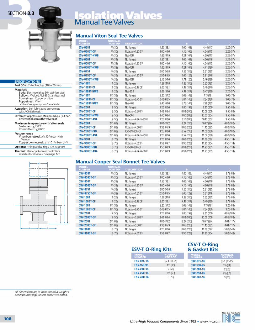
3 Isolation Valves
Ultra-High Vacuum Components Since 1962 • www.n-c.com 108
SECTION 3.3
Manual Viton Seal Tee ValvesMODEL NUMBER
NOMINALPORT OD
DESCRIPTION
A
B
C
D
ESV-038T 3/8 (10) No flanges 1.50 (38.1) 4.06 (103) 4.44 (113) 2.25 (57)ESV-0383T-CF 3/8 (10) Rotatable 1.33 CF 1.60 (40.6) 4.16 (106) 4.54 (115) 2.25 (57)ESV-0383T-NWB 3/8 (10) NW-10B 1.65 (41.9) 4.21 (107) 4.59 (117) 2.25 (57)ESV-050T 1/2 (12) No flanges 1.50 (38.1) 4.06 (103) 4.56 (116) 2.25 (57)ESV-0503T-CF 1/2 (12) Rotatable 1.33 CF 1.60 (40.6) 4.16 (106) 4.54 (115) 2.25 (57)ESV-0503T-NWB 1/2 (12) NW-10B 1.65 (41.9) 4.21 (107) 4.71 (120) 2.25 (57)ESV-075T 3/4 (19) No flanges 2.00 (50.8) 4.56 (116) 5.31 (135) 2.25 (57)ESV-0753T-CF 3/4 (19) Rotatable 1.33 CF 2.50 (63.5) 5.06 (129) 5.81 (148) 2.25 (57)ESV-0753T-NWB 3/4 (19) NW-16B 2.15 (54.6) 4.71 (120) 5.46 (139) 2.25 (57)ESV-100T 1 (25) No flanges 1.88 (47.8) 4.32 (110) 5.32 (135) 2.25 (57)ESV-1003T-CF 1 (25) Rotatable 2.12 CF 2.05 (52.1) 4.49 (114) 5.49 (140) 2.25 (57)ESV-1003T-NWB 1 (25) NW-25B 2.03 (51.6) 4.47 (114) 5.47 (139) 2.25 (57)ESV-150T 11/2 (38) No flanges 2.25 (57.2) 5.63 (143) 7.13 (181) 3.00 (76)ESV-1503T-CF 11/2 (38) Rotatable 2.75 CF 2.46 (62.5) 5.84 (148) 7.34 (186) 3.00 (76)ESV-1503T-NWB 11/2 (38) NW-40B 2.40 (61.0) 5.78 (147) 7.28 (185) 3.00 (76)ESV-200T 2 (50) No flanges 3.25 (82.6) 7.85 (199) 9.85 (250) 3.50 (89)ESV-2003T-CF 2 (50) Rotatable 3.38 CF 3.48 (88.4) 8.08 (205) 10.08 (256) 3.50 (89)ESV-2003T-NWB 2 (50) NW-50B 3.40 (86.4) 8.00 (203) 10.00 (254) 3.50 (89)ESV-2003T-ASA 2 (50) Rotatable ASA-5-200R 3.25 (82.6) 8.10 (206) 10.10 (257) 3.50 (89)ESV-250T 21/2 (63) No flanges 3.00 (76.2) 8.27 (210) 10.77 (274) 4.00 (100)ESV-2503T-CF 21/2 (63) Rotatable 4.50 CF 3.38 (85.9) 8.65 (220) 11.15 (283) 4.00 (100)ESV-2503T-ISO 21/2 (63) ISO-63-250-OF 3.25 (82.6) 8.52 (216) 11.02 (280) 4.00 (100)ESV-2503T-ASA 21/2 (63) Rotatable ASA-5-250R 3.25 (82.6) 8.52 (216) 11.02 (280) 4.00 (100)ESV-300T 3 (76) No flanges 3.25 (82.6) 8.68 (220) 11.68 (297) 4.50 (114)ESV-3003T-CF 3 (76) Rotatable 4.62 CF 3.53 (89.7) 8.96 (228) 11.96 (304) 4.50 (114)ESV-3003T-ISO 3 (76) ISO-80-300-OF 3.50 (88.9) 8.93 (227) 11.93 (303) 4.50 (114)ESV-3003T-ASA 3 (76) Rotatable ASA-6-300R 3.50 (88.9) 8.93 (227) 11.93 (303) 4.50 (114)
A
C
B
A
D
A
Manual Copper Seal Bonnet Tee ValvesMODEL NUMBER
NOMINALPORT OD
DESCRIPTION
A
B
C
D
CSV-038T 3/8 (10) No flanges 1.50 (38.1) 4.06 (103. 4.44 (113) 2.73 (69)CSV-0383T-CF 3/8 (10) Rotatable 1.33 CF 1.60 (40.6) 4.16 (106) 4.54 (115) 2.73 (69)CSV-050T 1/2 (12) No flanges 1.50 (38.1) 4.06 (103) 4.56 (116) 2.73 (69)CSV-0503T-CF 1/2 (12) Rotatable 1.33 CF 1.60 (40.6) 4.16 (106) 4.66 (118) 2.73 (69)CSV-075T 3/4 (19) No flanges 2.00 (50.8) 4.56 (116) 5.31 (135) 2.73 (69)CSV-0753T-CF 3/4 (19) Rotatable 1.33 CF 2.50 (63.5) 5.06 (129) 5.81 (148) 2.73 (69)CSV-100T 1 (25) No flanges 1.88 (47.8) 4.32 (110) 5.32 (135) 2.73 (69)CSV-1003T-CF 1 (25) Rotatable 2.12 CF 2.05 (52.1) 4.49 (114) 5.49 (139) 2.73 (69)CSV-150T 11/2 (38) No flanges 2.25 (57.2) 5.63 (143) 7.13 (181) 3.25 (83)CSV-1503T-CF 11/2 (38) Rotatable 2.75 CF 2.46 (62.5) 5.84 (148) 7.34 (186) 3.25 (83)CSV-200T 2 (50) No flanges 3.25 (82.6) 7.85 (199) 9.85 (250) 4.05 (103)CSV-2003T-CF 2 (50) Rotatable 3.38 CF 3.48 (88.4) 8.08 (205) 10.08 (256) 4.05 (103)CSV-250T 21/2 (63) No flanges 3.00 (76.2) 8.27 (210) 10.77 (274) 4.61 (117)CSV-2503T-CF 21/2 (63) Rotatable 3.38 CF 3.38 (85.9) 8.65 (220) 11.15 (283) 4.61 (117)CSV-300T 3 (76) No flanges 3.25 (82.6) 8.68 (220) 11.68 (297) 5.62 (143)CSV-3003T-CF 3 (76) Rotatable 4.62 CF 3.53 (89.7) 8.96 (228) 11.96 (304) 5.62 (143)
ESV-T O-Ring KitsMODEL NUMBER
NOMINALPORT OD
ESV-075-95 3/8-1 (10-25)ESV-150-95 11/2 (38)ESV-200-95 2 (50)ESV-250-95 21/2 (63)ESV-300-95 3 (76)
CSV-T O-Ring & Gasket Kits
MODEL NUMBER
NOMINALPORT OD
CSV-075-95 3/8-1 (10-25)CSV-150-95 11/2 (38)CSV-200-95 2 (50)CSV-250-95 21/2 (63)CSV-300-95 3 (76)
Manual Tee Valves
SPECIFICATIONSPort ODs: 3/8 to 3 inches (10 to 76mm)
Materials Body: Electropolished 304 stainless steel Bellows: Welded AM-350 stainless steel Bonnet seal: Copper or Viton Poppet seal: Viton Other O-ring compounds available
Actuation: Self-lubricating bronze nuts with ACME threads
Differential pressure: Maximum 6 psi (0.4 bar) differential across the valve seat
Maximum temperature with Viton seals Sustained: <150°C Intermittent: <204°C
Vacuum range Viton bonnet seal: >1x 10⁻⁹ mbar - High Vacuum Copper bonnet seal: >1x 10⁻¹⁰ mbar - UHV
Options: Fittings and O-rings. See page 101
Thermal: Heater jackets and controllers available for all valves. See page 127
All dimensions are in inches (mm) & weights are in pounds (kg), unless otherwise noted.
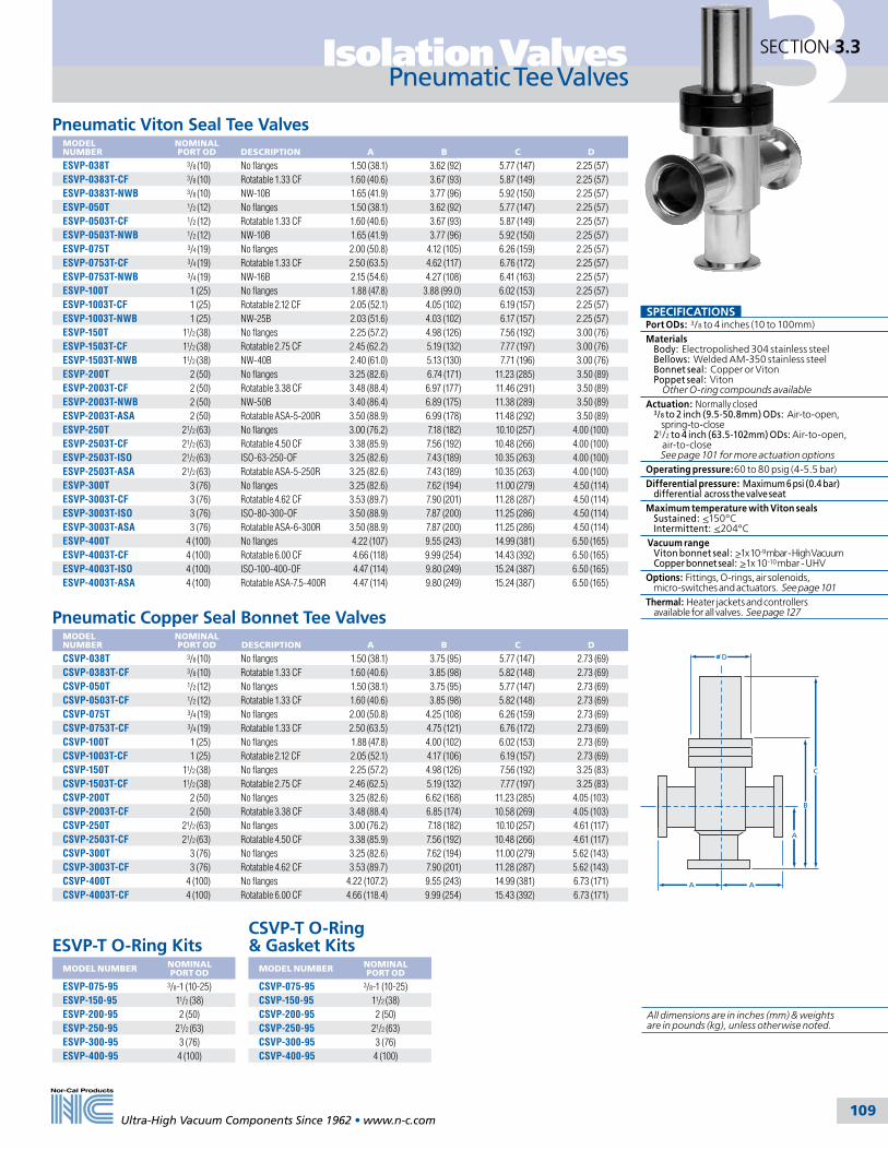
3Isolation Valves
Ultra-High Vacuum Components Since 1962 • www.n-c.com 109
SECTION 3.3
Pneumatic Tee Valves
Pneumatic Viton Seal Tee ValvesMODEL NUMBER
NOMINALPORT OD
DESCRIPTION
A
B
C
D
ESVP-038T 3/8 (10) No flanges 1.50 (38.1) 3.62 (92) 5.77 (147) 2.25 (57)ESVP-0383T-CF 3/8 (10) Rotatable 1.33 CF 1.60 (40.6) 3.67 (93) 5.87 (149) 2.25 (57)ESVP-0383T-NWB 3/8 (10) NW-10B 1.65 (41.9) 3.77 (96) 5.92 (150) 2.25 (57)ESVP-050T 1/2 (12) No flanges 1.50 (38.1) 3.62 (92) 5.77 (147) 2.25 (57)ESVP-0503T-CF 1/2 (12) Rotatable 1.33 CF 1.60 (40.6) 3.67 (93) 5.87 (149) 2.25 (57)ESVP-0503T-NWB 1/2 (12) NW-10B 1.65 (41.9) 3.77 (96) 5.92 (150) 2.25 (57)ESVP-075T 3/4 (19) No flanges 2.00 (50.8) 4.12 (105) 6.26 (159) 2.25 (57)ESVP-0753T-CF 3/4 (19) Rotatable 1.33 CF 2.50 (63.5) 4.62 (117) 6.76 (172) 2.25 (57)ESVP-0753T-NWB 3/4 (19) NW-16B 2.15 (54.6) 4.27 (108) 6.41 (163) 2.25 (57)ESVP-100T 1 (25) No flanges 1.88 (47.8) 3.88 (99.0) 6.02 (153) 2.25 (57)ESVP-1003T-CF 1 (25) Rotatable 2.12 CF 2.05 (52.1) 4.05 (102) 6.19 (157) 2.25 (57)ESVP-1003T-NWB 1 (25) NW-25B 2.03 (51.6) 4.03 (102) 6.17 (157) 2.25 (57)ESVP-150T 11/2 (38) No flanges 2.25 (57.2) 4.98 (126) 7.56 (192) 3.00 (76)ESVP-1503T-CF 11/2 (38) Rotatable 2.75 CF 2.45 (62.2) 5.19 (132) 7.77 (197) 3.00 (76)ESVP-1503T-NWB 11/2 (38) NW-40B 2.40 (61.0) 5.13 (130) 7.71 (196) 3.00 (76)ESVP-200T 2 (50) No flanges 3.25 (82.6) 6.74 (171) 11.23 (285) 3.50 (89)ESVP-2003T-CF 2 (50) Rotatable 3.38 CF 3.48 (88.4) 6.97 (177) 11.46 (291) 3.50 (89)ESVP-2003T-NWB 2 (50) NW-50B 3.40 (86.4) 6.89 (175) 11.38 (289) 3.50 (89)ESVP-2003T-ASA 2 (50) Rotatable ASA-5-200R 3.50 (88.9) 6.99 (178) 11.48 (292) 3.50 (89)ESVP-250T 21/2 (63) No flanges 3.00 (76.2) 7.18 (182) 10.10 (257) 4.00 (100)ESVP-2503T-CF 21/2 (63) Rotatable 4.50 CF 3.38 (85.9) 7.56 (192) 10.48 (266) 4.00 (100)ESVP-2503T-ISO 21/2 (63) ISO-63-250-OF 3.25 (82.6) 7.43 (189) 10.35 (263) 4.00 (100)ESVP-2503T-ASA 21/2 (63) Rotatable ASA-5-250R 3.25 (82.6) 7.43 (189) 10.35 (263) 4.00 (100)ESVP-300T 3 (76) No flanges 3.25 (82.6) 7.62 (194) 11.00 (279) 4.50 (114)ESVP-3003T-CF 3 (76) Rotatable 4.62 CF 3.53 (89.7) 7.90 (201) 11.28 (287) 4.50 (114)ESVP-3003T-ISO 3 (76) ISO-80-300-OF 3.50 (88.9) 7.87 (200) 11.25 (286) 4.50 (114)ESVP-3003T-ASA 3 (76) Rotatable ASA-6-300R 3.50 (88.9) 7.87 (200) 11.25 (286) 4.50 (114)ESVP-400T 4 (100) No flanges 4.22 (107) 9.55 (243) 14.99 (381) 6.50 (165)ESVP-4003T-CF 4 (100) Rotatable 6.00 CF 4.66 (118) 9.99 (254) 14.43 (392) 6.50 (165)ESVP-4003T-ISO 4 (100) ISO-100-400-OF 4.47 (114) 9.80 (249) 15.24 (387) 6.50 (165)ESVP-4003T-ASA 4 (100) Rotatable ASA-7.5-400R 4.47 (114) 9.80 (249) 15.24 (387) 6.50 (165)
A
C
B
A
D
A
Pneumatic Copper Seal Bonnet Tee ValvesMODEL NUMBER
NOMINALPORT OD
DESCRIPTION
A
B
C
D
CSVP-038T 3/8 (10) No flanges 1.50 (38.1) 3.75 (95) 5.77 (147) 2.73 (69)CSVP-0383T-CF 3/8 (10) Rotatable 1.33 CF 1.60 (40.6) 3.85 (98) 5.82 (148) 2.73 (69)CSVP-050T 1/2 (12) No flanges 1.50 (38.1) 3.75 (95) 5.77 (147) 2.73 (69)CSVP-0503T-CF 1/2 (12) Rotatable 1.33 CF 1.60 (40.6) 3.85 (98) 5.82 (148) 2.73 (69)CSVP-075T 3/4 (19) No flanges 2.00 (50.8) 4.25 (108) 6.26 (159) 2.73 (69)CSVP-0753T-CF 3/4 (19) Rotatable 1.33 CF 2.50 (63.5) 4.75 (121) 6.76 (172) 2.73 (69)CSVP-100T 1 (25) No flanges 1.88 (47.8) 4.00 (102) 6.02 (153) 2.73 (69)CSVP-1003T-CF 1 (25) Rotatable 2.12 CF 2.05 (52.1) 4.17 (106) 6.19 (157) 2.73 (69)CSVP-150T 11/2 (38) No flanges 2.25 (57.2) 4.98 (126) 7.56 (192) 3.25 (83)CSVP-1503T-CF 11/2 (38) Rotatable 2.75 CF 2.46 (62.5) 5.19 (132) 7.77 (197) 3.25 (83)CSVP-200T 2 (50) No flanges 3.25 (82.6) 6.62 (168) 11.23 (285) 4.05 (103)CSVP-2003T-CF 2 (50) Rotatable 3.38 CF 3.48 (88.4) 6.85 (174) 10.58 (269) 4.05 (103)CSVP-250T 21/2 (63) No flanges 3.00 (76.2) 7.18 (182) 10.10 (257) 4.61 (117)CSVP-2503T-CF 21/2 (63) Rotatable 4.50 CF 3.38 (85.9) 7.56 (192) 10.48 (266) 4.61 (117)CSVP-300T 3 (76) No flanges 3.25 (82.6) 7.62 (194) 11.00 (279) 5.62 (143)CSVP-3003T-CF 3 (76) Rotatable 4.62 CF 3.53 (89.7) 7.90 (201) 11.28 (287) 5.62 (143)CSVP-400T 4 (100) No flanges 4.22 (107.2) 9.55 (243) 14.99 (381) 6.73 (171)CSVP-4003T-CF 4 (100) Rotatable 6.00 CF 4.66 (118.4) 9.99 (254) 15.43 (392) 6.73 (171)
ESVP-T O-Ring KitsMODEL NUMBER NOMINAL
PORT OD
ESVP-075-95 3/8-1 (10-25)ESVP-150-95 11/2 (38)ESVP-200-95 2 (50)ESVP-250-95 21/2 (63)ESVP-300-95 3 (76)ESVP-400-95 4 (100)
CSVP-T O-Ring & Gasket Kits
MODEL NUMBER NOMINALPORT OD
CSVP-075-95 3/8-1 (10-25)CSVP-150-95 11/2 (38)CSVP-200-95 2 (50)CSVP-250-95 21/2 (63)CSVP-300-95 3 (76)CSVP-400-95 4 (100)
SPECIFICATIONSPort ODs: 3/8 to 4 inches (10 to 100mm)Materials Body: Electropolished 304 stainless steel Bellows: Welded AM-350 stainless steel Bonnet seal: Copper or Viton Poppet seal: Viton Other O-ring compounds availableActuation: Normally closed 3/8 to 2 inch (9.5-50.8mm) ODs: Air-to-open, spring-to-close 21/2 to 4 inch (63.5-102mm) ODs: Air-to-open, air-to-close See page 101 for more actuation options Operating pressure:60 to 80 psig (4-5.5 bar) Differential pressure: Maximum 6 psi (0.4 bar) differential across the valve seatMaximum temperature with Viton seals Sustained: <150°C Intermittent: <204°C Vacuum range Viton bonnet seal: >1x 10⁻⁹ mbar - High Vacuum Copper bonnet seal: >1x 10⁻¹⁰ mbar - UHVOptions: Fittings, O-rings, air solenoids, micro-switches and actuators. See page 101Thermal: Heater jackets and controllers available for all valves. See page 127
All dimensions are in inches (mm) & weights are in pounds (kg), unless otherwise noted.

3 Isolation Valves
Ultra-High Vacuum Components Since 1962 • www.n-c.com 110
SECTION 3.3
Manual Copper Seal Bonnet Straight-Through ValvesMODEL NUMBER
PORT ID
NOMINALPORT OD
DESCRIPTION
A
B
C
D
CSTV-075 0.65 (16.5) 3/4 (19) No flanges 5.00 (127) 3.51 (89) 4.71 (120) 2.73 (69)CSTV-0752-CF 0.65 (16.5) 3/4 (19) Rotatable 1.33 CF 6.00 (152) 3.51 (89) 4.71 (120) 2.73 (69)CSTV-150 1.38 (35.1) 11/2 (38) No flanges 7.00 (178) 5.47 (139) 7.69 (195) 4.05 (103)CSTV-1502-CF 1.38 (35.1) 11/2 (38) Rotatable 2.75 CF 7.42 (188) 5.47 (139) 7.69 (195) 4.05 (103)
CSTV O-Ring & Gasket Kits
MODEL NUMBER
NOMINALPORT OD
CSV-075-95 3/4 (19)CSV-150-95 11/2 (38)
Pneumatic Viton Seal Straight-Through ValvesMODEL NUMBER
PORT ID
NOMINALPORT OD
DESCRIPTION
A
B
C
STVP-075 0.65 (16.5) 3/4 (19) No flanges 5.00 (127) 3.92 (100) 2.25 (57)STVP-0752-CF 0.65 (16.5) 3/4 (19) Rotatable 1.33 CF 6.00 (152) 3.92 (100) 2.25 (57)STVP-0752-NWB 0.65 (16.5) 3/4 (19) NW-16B 5.30 (135) 3.92 (100) 2.25 (57)STVP-112 1.00 (25.4) 11/8 (29) No flanges 5.50 (140) 5.10 (130) 3.00 (76)STVP-1122-CF 1.00 (25.4) 11/8 (29) Rotatable 2.12 CF 5.83 (148) 5.10 (130) 3.00 (76)STVP-1122-NWB 1.00 (25.4) 11/8 (29) NW-40B 5.80 (147) 5.10 (130) 3.00 (76)STVP-150 1.38 (35.1) 11/2 (38) No flanges 7.00 (178) 6.11 (155) 3.50 (89)STVP-1502-CF 1.38 (35.1) 11/2 (38) Rotatable 2.75 CF 7.42 (188) 6.11 (155) 3.50 (89)STVP-1502-NWB 1.38 (35.1) 11/2 (38) NW-40B 7.30 (185) 6.11 (155) 3.50 (89)
Pneumatic Copper Seal Bonnet Straight-Through ValvesMODEL NUMBER
PORT ID
NOMINALPORT OD
DESCRIPTION
A
B
C
CSTVP-075 0.65 (16.5) 3/4 (19) No flanges 5.00 (127) 3.92 (100) 2.73 (69)CSTVP-0752-CF 0.65 (16.5) 3/4 (19) Rotatable 1.33 CF 6.00 (152) 3.92 (100) 2.73 (69)CSTVP-150 1.38 (35.0) 11/2 (38) No flanges 7.00 (178) 6.11 (155) 4.05 (103)CSTVP-1502-CF 1.38 (35.0) 11/2 (38) Rotatable 2.75 CF 7.42 (188) 6.11 (155) 4.05 (103)
B
C
A
STVP O-Ring KitsMODEL NUMBER
NOMINALPORT OD
ESVP-075-95 3/4 (19)STVP-112-95 11/8 (29)STVP-150-95 11/2 (38)
CSTVP O-Ring & Gasket Kits
MODEL NUMBER
NOMINALPORT OD
CSVP-075-95 3/4 (19)CSTVP-150-95 11/2 (38)
C B
D
A
Straight-Through Valves
STV O-Ring KitsMODEL NUMBER
NOMINALPORT OD
ESV-075-95 3/4 (19)STV-112-95 11/8 (29)STV-150-95 11/2 (38)
Manual Viton Seal Straight-Through ValvesMODEL NUMBER
PORT ID
NOMINALPORT OD
DESCRIPTION
A
B
C
D
STV-075 0.65 (16.5) 3/4 (19) No flanges 5.00 (127) 3.30 (84) 4.50 (114) 2.25 (57)STV-0752-CF 0.65 (16.5) 3/4 (19) Rotatable 1.33 CF 6.00 (152) 3.30 (84) 4.50 (114) 2.25 (57)STV-0752-NWB 0.65 (16.5) 3/4 (19) NW-16B 5.30 (135) 3.30 (84) 4.50 (114) 2.25 (57)STV-112 1.00 (25.4) 11/8 (29) No flanges 5.50 (140) 3.86 (98) 5.15 (131) 3.00 (76)STV-1122-CF 1.00 (25.4) 11/8 (29) Rotatable 2.12 CF 5.83 (148) 3.86 (98) 5.15 (131) 3.00 (76)STV-1122-NWB 1.00 (25.4) 11/8 (29) NW-40B 5.80 (147) 3.86 (98) 5.15 (131) 3.00 (76)STV-150 1.38 (35.1) 11/2 (38) No flanges 7.00 (178) 5.47 (139) 7.69 (195) 3.50 (89)STV-1502-CF 1.38 (35.1) 11/2 (38) Rotatable 2.75 CF 7.42 (188) 5.47 (139) 7.69 (195) 3.50 (89)STV-1502-NWB 1.38 (35.1) 11/2 (38) NW-40B 7.30 (185) 5.47 (139) 7.69 (195) 3.50 (89)
SPECIFICATIONSPort ODs: 3/4 to 11/2 inches (19 to 38mm)
Materials Body: Electropolished 304 stainless steel Bellows: Welded AM-350 stainless steel Bonnet seal: Copper or Viton Poppet seal: Viton Other O-ring compounds available
Manual actuation: Self-lubricating bronze nuts with ACME threads
Pneumatic actuation: Normally closed 3 /4 inch (19.05mm) ODs: Air-to-open, spring-to-close 11/8 to 11/2 inch (29-38mm) ODs: Air-to-open, air-to-close See page 99 for more actuation options
Operating pressure: 60 to 80 psig (4-5.5 bar)
Differential pressure: Maximum 20psi (1.4bar) differential across the valve seat
Maximum temperature with Viton seals Sustained: <150°C Intermittent: <204°C
Vacuum range Viton bonnet seal: >1x 10⁻⁹ mbar - High Vacuum Copper bonnet seal: >1x 10⁻¹⁰ mbar - UHV
Options: Fittings, O-rings, air solenoids, micro-switches and actuators. See page 101
Thermal: Heater jackets and controllers available for all valves. See page 127
All dimensions are in inches (mm) & weights are in pounds (kg), unless otherwise noted.
Straight-Through ValvesStraight-Through Valves

3Isolation Valves
Ultra-High Vacuum Components Since 1962 • www.n-c.com 111
SECTION 3.3
Replacement Parts & Rebuild Kits
Bellows Assembly KitsMODEL NUMBER
CONTENTS (See drawing)
FOR VALVE MODEL NUMBERS
CSV-075-16K 6, 16, 17 CSV, CILV, CAIV, CSTV, manual or pneumatic, -038 to -100CSV-150-16K 6, 16, 17 CSV, CILV, CAIV, CSTV, manual or pneumatic, -150CSV-200-16K 6, 16, 17 CSV, CILV, CAIV, manual or pneumatic, -200CSV-250-16K 6, 16, 17 CSV, CILV, CAIV, manual or pneumatic, -250CSV-300-16K 6, 16, 17 CSV, CILV, CAIV, manual or pneumatic, -300CSVP-400-16K 6, 16, 17 CSVP and CILVP-400ESV-075-16K 6, 16, 17 ESV, ILV and AIV, manual or pneumatic, -038 to -100ESV-150-16K 6, 16, 17 ESV, ILV and AIV-150, manual or pneumaticESV-200-16K 6, 16, 17 ESV, ILV and AIV-200, manualESVP-200-16K 6, 16, 17 ESVP, ILVP and AIVP-200, pneumaticESV-250-16K 6, 16, 17 ESV, ILV and AIV-250, manualESVP-250-16K 6, 16, 17 ESV, ILV and AIV-250, pneumaticESV-300-16K 6, 16, 17 ESV, ILV and AIV-300, manualESVP-300-16K 6, 16, 17 ESV, ILV and AIV-300, pneumaticESVP-400-16K 16, 17 ESV, ILV and AIV-400, manual or pneumatic
Complete Valve Rebuild KitsContains all items except valve body (#7), refer to kit contents diagram at right.
MODEL NUMBER
FOR VALVE MODEL NUMBERS
CSV-075-99 CSV, CILV and CAIV, -038 to -100CSV-150-99 CSV, CILV and CAIV-150CSV-200-99 CSV, CILV and CAIV-200CSV-250-99 CSV, CILV and CAIV-250CSV-300-99 CSV, CILV and CAIV-300CSVP-075-99 CSVP, CILVP and CAIVP, -038 to -100CSVP-150-99 CSVP, CILVP and CAIVP-150CSVP-200-99 CSVP, CILVP and CAIVP-200CSVP-250-99 CSVP, CILVP and CAIVP-250CSVP-300-99 CSVP, CILVP and CAIVP-300CSVP-400-99 CSVP, CILVP and CAIVP-400ESV-075-99 ESV, ILV, AIV, STV, -038 to -100ESV-150-99 ESV, ILV, AIV, STV, -150ESV-200-99 ESV, ILV and AIV-200ESV-250-99 ESV, ILV and AIV-250ESV-300-99 ESV, ILV and AIV-300ESVP-075-99 ESVP, ILVP, AIVP, STVP, -038 to -100ESVP-150-99 ESVP, ILVP, AIVP, STVP, -150ESVP-200-99 ESVP, ILVP and AIVP-200ESVP-250-99 ESVP, ILVP and AIVP-250ESVP-300-99 ESVP, ILVP and AIVP-300ESVP-400-99 ESVP, ILVP and AIVP-400STV-112-99 STV-112STVP-112-99 STVP-112STV-150-99 STV-150STVP-150-99 STVP-150
Kit Contents Diagram 1. Air cylinder 2. Stem O-ring* 3. Retaining plate 4. Center plate 5. Stem shaft 6. Set screw 7. Body 8. Air filter 9. Air cylinder spring 10. Jam nut 11. Spring retainer 12. Piston cup 13. Bonnet screws 14. Air cylinder O-ring 15. Body flange O-ring or gasket 16. Bellows assembly 17. Poppet O-ring* 2 inch (50) ID valves are assembled with two stem O-rings.
1
2*
3
4
5
6
7
16
17
15
14
9
10
1213
8
11
O-Ring or Gasket KitsMODEL NUMBER
KIT CONTENTS (See drawing)
FOR VALVE MODEL NUMBERS
ESV-075-95 2, 14, 15, 17 ESV, AIV, ILV, ESV-T, STV, -038 to -100ESV-150-95 2, 14, 15, 17 ESV, AIV, ILV, ESV-T, -150ESV-200-95 2, 14, 15, 17 ESV, AIV, ILV, ESV-T, -200ESV-250-95 2, 14, 15, 17 ESV, AIV, ILV, ESV-T, -250ESV-300-95 2, 14, 15, 17 ESV, AIV, ILV, ESV-T, -300STV-112-95 2, 14, 15, 17 STV-112STV-150-95 2, 14, 15, 17 STV-150ESVP-075-95 2, 14, 15, 17 ESVP, AIVP, ILVP, ESVP-T, STVP, -038 to -100ESVP-150-95 2, 14, 15, 17 ESVP, AIVP, ILVP, ESVP-T, -150ESVP-200-95 2, 14, 15, 17 ESVP, AIVP, ILVP, ESVP-T, -200ESVP-250-95 2, 14, 15, 17 ESVP, AIVP, ILVP, ESVP-T, -250ESVP-300-95 2, 14, 15, 17 ESVP, AIVP, ILVP, ESVP-T, -300ESVP-400-95 2, 14, 15, 17 ESVP, AIVP, ILVP, ESVP-T, -400STVP-112-95 2, 14, 15, 17 STVP-112STVP-150-95 2, 14, 15, 17 STVP-150CSV-075-95 2, 14, 15, 17 CSV, CAIV, CILV, CSTV, -038 to -100CSV-150-95 2, 14, 15, 17 CSV, CAIV, CILV, -150CSV-200-95 2, 14, 15, 17 CSV, CAIV, CILV, -200CSV-250-95 2, 14, 15, 17 CSV, CAIV, CILV, -250CSV-300-95 2, 14, 15, 17 CSV, CAIV, CILV, -300CSTV-150-95 2, 14, 15, 17 CSTV-150CSVP-075-95 2, 14, 15, 17 CSVP, CAIVP, CILVP, CSTVP, -038 to -100CSVP-150-95 2, 14, 15, 17 CSVP, CAIVP, CILVP, -150CSVP-200-95 2, 14, 15, 17 CSVP, CAIVP, CILVP, -200CSVP-250-95 2, 14, 15, 17 CSVP, CAIVP, CILVP, -250CSVP-300-95 2, 14, 15, 17 CSVP, CAIVP, CILVP, -300CSVP-400-95 2, 14, 15, 17 CSVP, CAIVP, CILVP, -400CSTVP-150-95 2, 14, 15, 17 CSTVP-150

3 Isolation Valves
Ultra-High Vacuum Components Since 1962 • www.n-c.com 112
SECTION 3.4
Ball Valves
SPECIFICATIONSPort OD’s: ¾, 1, 1 ½ and 2 inches (19, 25, 38 and 50mm)
Materials: Body: 316L stainless steel Ball: 316L stainless steel Stem seal: Viton (other O-ring compounds available) Ball seal: Teflon
Actuation: Manual and pneumatic/spring
Helium Leak Rates: <1x10⁻⁹ mbar l/sec to atmosphere, <1x10⁻⁷mbar l/sec across the seat.
Operating Temperature: 150°C Max.
Supply Pressure (pneumatic/spring version): 60-100 psig (4-7 bar)
Vacuum Range: 1000 to 1x10⁻⁴ mbar
Options: Heater jackets and controllers available for all valves.
Ball valves are a low cost, manually or pneumatically operated, straight through isolation device. Their simple, robust design provides high reliability in “dirty” applications. They are commonly used on MOCVD and CVD equipment down-stream from the chamber or vacuum pump to isolate traps or abatement tools. A stainless steel body and Teflon seat make these valves ideal for corrosive envi-ronments. A quarter turn of the handle quickly switches the valve from open to close. They are available with NW-16 through NW-50 flanges as stan-dards. Heater jackets are available to reduce process by-product accumulation.
ActuatorType
O-ringType
PositionIndicator
Air Solenoid
ValveModel Number
Air Solenoid Option - BVPCODE KIT DESCRIPTION
-S11 BVP-S11-K 120VAC, 50/60 Hz-S21 BVP-S21-K 24VDC-S31 BVP-S31-K 240VAC, 50/60 Hz-S41 BVP-S41-K 24VAC, 50/60 Hz-S12 BVP-S12-K 120VAC, 50/60 Hz (Use with -A actuator option)-S22 BVP-S22-K 24VDC (Use with -A actuator option)-S32 BVP-S32-K 240VAC, 50/60 Hz (Use with -A actuator option)-S42 BVP-S42-K 24VAC, 50/60 Hz (Use with -A actuator option)
Actuator Option - BVPDESCRIPTION CODE
Air-to-Open/Spring-to-Close (Normally Closed) (Default)Spring-to-Open/Air-to-Close (Normally Open) -SAAir-to-Open/Air-to-Close -A
Actuator Option - BVMCODE DESCRIPTION
(Default) Non-locking handle-L Locking handle
O-ring Material OptionCODE DESCRIPTION
Default (no code) Viton-K79 Kalrez 4079-K85 Kalrez 8085-K75 Kalrez 8575-K91 Kalrez 9100-C38 Chemraz E38-D19 Dupra 192-PP7 Perlast G74P
Position Indicator Option - BVP Open/closed position indicators detect the valve position. 24 VDC powered.
DESCRIPTION CODE KIT
Optical sensor NPN B-NPN-KPNP B-PNP-K
Example: BVP-2004-NW-NPN-S21 Pneumatic ball valve with 1.5 inch (38) ball ID, NW-50 flanges, air-to-open/ spring-to-close, position indicators and 24VDC air solenoid.
Ball Valve OptionsPlease use the following part numbering tree to add the appropriate options to a standard ball valve model number. See tables below for option codes.
All dimensions are in inches (mm) & weights are in pounds (kg), unless otherwise noted.

3Isolation Valves
Ultra-High Vacuum Components Since 1962 • www.n-c.com 113
SECTION 3.4
E
A
F
B
C
D
E
C
D
B
A
F
Manual Ball Valve - BVMMODEL NUMBER
NOMINALPORT OD
BALLID DESCRIPTION
A B C D E F
BVM-0751 0.75 (19) 0.56 (14.2) No Flanges 4.36 (110.7) 1.85 (47) 2.94 (75) 1.85 (47) 5.80 (147) 0.93 (24)BVM-0751-NW 0.75 (19) 0.56 (14.2) NW-16 3.47 (88.1) 1.85 (47) 2.94 (75) 1.85 (47) 5.80 (147) 0.93 (24)BVM-1001-NW 0.75 (19) 0.56 (14.2) NW-25 3.93 (99.8) 1.85 (47) 2.94 (75) 1.85 (47) 5.80 (147) 0.93 (24)BVM-1002 1.0 (25) 0.85 (21.6) No Flanges 4.78 (121.4) 2.13 (54) 3.33 (85) 1.90 (48) 6.20 (157) 0.98 (25)BVM-1002-NW 1.0 (25) 0.85 (21.6) NW-25 3.93 (99.8) 2.13 (54) 3.33 (85) 1.90 (48) 6.20 (157) 0.98 (25)BVM-1502-NW 1.0 (25) 0.85 (21.6) NW-40 4.66 (118.4) 2.13 (54) 3.33 (85) 1.90 (48) 6.20 (157) 0.98 (25)BVM-1503 1.5 (38) 1.25 (31.8) No Flanges 4.59 (142.0) 2.80 (71) 4.04 (103) 2.80 (71) 7.20 (183) 1.40 (36)BVM-1503-NW 1.5 (38) 1.25 (31.8) NW-40 4.66 (118.4) 2.80 (71) 4.04 (103) 2.80 (71) 7.20 (183) 1.40 (36)BVM-2003-NW 1.5 (38) 1.25 (31.8) NW-50 4.97 (126.2) 2.80 (71) 4.04 (103) 2.80 (71) 7.20 (183) 1.40 (36)BVM-2004 2.0 (50) 1.50 (38.1) No Flanges 6.25 (159.0) 3.33 (85) 4.56 (116) 3.33 (85) 7.20 (183) 1.66 (42)BVM-2004-NW 2.0 (50) 1.50 (38.1) NW-50 4.97 (126.2) 3.33 (85) 4.56 (116) 3.33 (85) 7.20 (183) 1.66 (42)
Call for information on larger sizes.
Ball Valve Seal KitMODEL NUMBER DESCRIPTION
BVM-1-95 Teflon seats, Viton Flange SealsBVM-2-95 Teflon seats, Viton Flange SealsBVM-3-95 Teflon seats, Viton Flange SealsBVM-4-95 Teflon seats, Viton Flange Seals
Ball Valve Rebuild KitMODEL NUMBER DESCRIPTION
BVM-1-99 -95 Seal Kit, SS ball, shaft bushings and sealsBVM-2-99 -95 Seal Kit, SS ball, shaft bushings and sealsBVM-3-99 -95 Seal Kit, SS ball, shaft bushings and sealsBVM-4-99 -95 Seal Kit, SS ball, shaft bushings and seals
Pneumatic Ball Valve - BVPMODEL NUMBER
NOMINALPORT OD BALL ID DESCRIPTION A B C D E F
BVP-0751 0.75 (19) 0.56 (14.2) No Flanges 4.36 (110.7) 10.20 (259) 6.62 (168) 1.85 (47) 2.77 (70) 0.93 (24)BVP-0751-NW 0.75 (19) 0.56 (14.2) NW-16 3.47 (88.1) 10.20 (259) 6.62 (168) 1.85 (47) 2.77 (70) 0.93 (24)BVP-1001-NW 0.75 (19) 0.56 (14.2) NW-25 3.93 (99.8) 10.20 (259) 6.62 (168) 1.85 (47) 2.77 (70) 0.93 (24)BVP-1002 1.0 (25) 0.85 (21.6) No Flanges 4.78 (121.4) 10.20 (259) 6.90 (175) 1.90 (48) 2.77 (70) 0.98 (25)BVP-1002-NW 1.0 (25) 0.85 (21.6) NW-25 3.93 (99.8) 10.20 (259) 6.90 (175) 1.90 (48) 2.77 (70) 0.98 (25)BVP-1502-NW 1.0 (25) 0.85 (21.6) NW-40 4.66 (118.4) 10.20 (259) 6.90 (175) 1.90 (48) 2.77 (70) 0.98 (25) BVP-1503 1.5 (38) 1.25 (31.8) No Flanges 5.59 (142.0) 10.20 (259) 7.57 (192) 2.80 (71) 2.77 (70) 1.40 (36)BVP-1503-NW 1.5 (38) 1.25 (31.8) NW-40 4.66 (118.4) 10.20 (259) 7.57 (192) 2.80 (71) 2.77 (70) 1.40 (36)BVP-2003-NW 1.5 (38) 1.25 (31.8) NW-50 4.97 (126.2) 10.20 (259) 7.57 (192) 2.80 (71) 2.77 (70) 1.40 (36)BVP-2004 2.0 (50) 1.50 (38.1) No Flanges 6.25 (159.0) 10.20 (259) 8.10 (206) 3.33 (85) 2.77 (70) 1.66 (42)BVP-2004-NW 2.0 (50) 1.50 (38.1) NW-50 4.97 (126.2) 10.20 (259) 8.10 (206) 3.33 (85) 2.77 (70) 1.66 (42)
Call for information on larger sizes.
SPECIFICATIONSPort OD’s: ¾, 1, 1 ½ and 2 inches (19, 25, 38 and 50mm)Materials: Body: 316L stainless steel Ball: 316L stainless steel Stem seal: Viton (other O-ring compounds available) Ball seal: TeflonActuation: Manual and pneumatic/springHelium Leak Rates: <1x10⁻⁹ mbar l/sec to atmosphere, <1x10⁻⁷ mbar l/sec across the seat.Operating Temperature: 150°C Max.Supply Pressure (pneumatic/spring version): 60-100 psig (4-7 bar)Vacuum Range: 1000 to 1x10⁻⁴ mbarOptions: Heater jackets and controllers available for all valves.
All dimensions are in inches (mm) & weights are in pounds (kg), unless otherwise noted.
*
*B Actuator option -A (air-to-open / air-to-close) reduces dimension to 6.76” (172).
Ball Valves
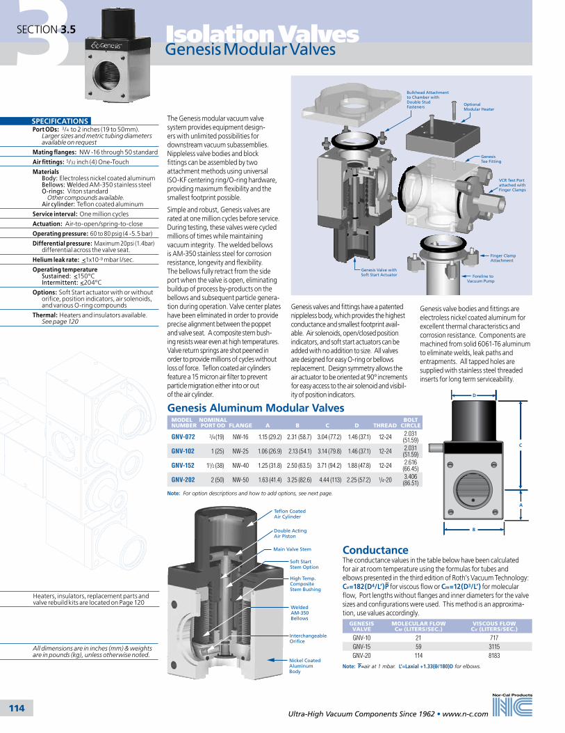
3 Isolation Valves
Ultra-High Vacuum Components Since 1962 • www.n-c.com 114
SECTION 3.5
Bulkhead Attachment to Chamber with Double Stud Fasteners
Optional Modular Heater
Genesis Valve with Soft Start Actuator
Genesis Tee Fitting
VCR Test Portattached withFinger Clamps
Finger ClampAttachment
Foreline to Vacuum Pump
Genesis Modular Valves
The Genesis modular vacuum valve system provides equipment design-ers with unlimited possibilities for downstream vacuum subassemblies. Nippleless valve bodies and block fittings can be assembled by two attachment methods using universal ISO-KF centering ring/O-ring hardware, providing maximum flexibility and the smallest footprint possible.
Simple and robust, Genesis valves are rated at one million cycles before service. During testing, these valves were cycled millions of times while maintaining vacuum integrity. The welded bellows is AM-350 stainless steel for corrosion resistance, longevity and flexibility. The bellows fully retract from the side port when the valve is open, eliminating buildup of process by-products on the bellows and subsequent particle genera-tion during operation. Valve center plates have been eliminated in order to provide precise alignment between the poppet and valve seat. A composite stem bush-ing resists wear even at high temperatures. Valve return springs are shot peened in order to provide millions of cycles without loss of force. Teflon coated air cylinders feature a 15 micron air filter to prevent particle migration either into or out of the air cylinder.
SPECIFICATIONSPort ODs: 3/4 to 2 inches (19 to 50mm). Larger sizes and metric tubing diameters available on request
Mating flanges: NW -16 through 50 standard
Air fittings: 5/32 inch (4) One-Touch
Materials Body: Electroless nickel coated aluminum Bellows: Welded AM-350 stainless steel O-rings: Viton standard Other compounds available. Air cylinder: Teflon coated aluminum
Service interval: One million cycles
Actuation: Air-to-open/spring-to-close
Operating pressure: 60 to 80 psig (4 -5.5 bar)
Differential pressure: Maximum 20psi (1.4bar) differential across the valve seat.
Helium leak rate: <1x10⁻⁹ mbar l/sec.
Operating temperature Sustained: <150ºC Intermittent: <204ºC
Options: Soft Start actuator with or without orifice, position indicators, air solenoids, and various O-ring compounds
Thermal: Heaters and insulators available. See page 120
Genesis Aluminum Modular ValvesMODEL NUMBER
NOMINALPORT OD
FLANGE
A
B
C
D
THREAD
BOLT CIRCLE
GNV-072 3/4 (19) NW-16 1.15 (29.2) 2.31 (58.7) 3.04 (77.2) 1.46 (37.1) 12-24 2.031 (51.59)
GNV-102 1 (25) NW-25 1.06 (26.9) 2.13 (54.1) 3.14 (79.8) 1.46 (37.1) 12-24 2.031 (51.59)
GNV-152 11/2 (38) NW-40 1.25 (31.8) 2.50 (63.5) 3.71 (94.2) 1.88 (47.8) 12-24 2.616 (66.45)
GNV-202 2 (50) NW-50 1.63 (41.4) 3.25 (82.6) 4.44 (113) 2.25 (57.2) 1/4-20 3.406 (86.51)
Note: For option descriptions and how to add options, see next page.
Genesis valves and fittings have a patented nippleless body, which provides the highest conductance and smallest footprint avail-able. Air solenoids, open/closed position indicators, and soft start actuators can be added with no addition to size. All valves are designed for easy O-ring or bellows replacement. Design symmetry allows the air actuator to be oriented at 90º increments for easy access to the air solenoid and visibil-ity of position indicators.
Genesis valve bodies and fittings are electroless nickel coated aluminum for excellent thermal characteristics and corrosion resistance. Components are machined from solid 6061-T6 aluminum to eliminate welds, leak paths and entrapments. All tapped holes are supplied with stainless steel threaded inserts for long term serviceability.
A
C
B
D
Heaters, insulators, replacement parts and valve rebuild kits are located on Page 120
ConductanceThe conductance values in the table below have been calculated for air at room temperature using the formulas for tubes and elbows presented in the third edition of Roth’s Vacuum Technology: Cv=182(D4/L’)P for viscous flow or Cm=12(D3/L’) for molecular flow, Port lengths without flanges and inner diameters for the valve sizes and configurations were used. This method is an approxima-tion, use values accordingly.
GENESIS VALVE
MOLECULAR FLOW CM (LITERS/SEC.)
VISCOUS FLOW CV (LITERS/SEC.)
GNV-10 21 717GNV-15 59 3115GNV-20 114 8183
Note: P=air at 1 mbar. L’=Laxial +1.33(0/180)D for elbows.
Teflon Coated Air Cylinder
Main Valve Stem
Double ActingAir Piston
Soft Start Stem Option
High Temp.CompositeStem Bushing
Interchangeable Orifice
Welded AM-350 Bellows
Nickel CoatedAluminumBody
All dimensions are in inches (mm) & weights are in pounds (kg), unless otherwise noted.

3Isolation Valves
Ultra-High Vacuum Components Since 1962 • www.n-c.com 115
SECTION 3.5
A
C
B
D
Genesis Modular Valve Options
Position Indicator OptionNor-Cal’s CE certified, shielded, open/closed position indicators detect the piston position in the valve’s air cylinder. The technician has a visual indication of power to the circuit (12 to 24 VDC) and the valve position, as does the operator watching the panel. With the soft start option only one position indicator can be provided for the fully open position. Operating temperature range is -25ºC to 70ºC for valves with position indica-tors. Call for more information on heated valves with position indicators.
OPTION
VALVE ACTUATOR
DESCRIPTION
-P1O Soft Start/Standard 1 position indicator - main valve open only-P1C Standard 1 position indicator - main valve closed only-P2 Standard 2 position indicators - main valve open & closed
Refer to diagram below for dimensions.
Air Solenoid OptionLow 1.8 wattage, CE certified air solenoids in several current ratings can be provided on the valve, ready to attach to the house air supply. One three-way air solenoid is required for a standard Genesis valve and two three-way air solenoids are required for a soft start version. This option includes 24 inch (610) quick disconnect electrical leads and 5/32 inch (4) one-touch air fittings. Remote mount required on heated valves. Air solenoids can also be supplied as a kit with assembly hardware and instructions. Kit part numbers are in the second column below.
OPTION
KIT
ACTUATOR
DESCRIPTION
QUANTITY
-A11 A11-K Standard 120 VAC, 50/60 Hz 1-A21 A21-K Standard 24 VDC 1-A31 A31-K Standard 240 VAC, 50/60 Hz 1-A41 A41-K Standard 24 VAC, 50/60 Hz 1-B11 B11-K Soft Start 120 VAC, 50/60 Hz 2-B21 B21-K Soft Start 24 VDC 2-B31 B31-K Soft Start 240 VAC, 50/60 Hz 2-B41 B41-K Soft Start 24 VAC, 50/60 Hz 2
Refer to diagram at left for dimensions.
Follow this part tree to add one or more options to a Genesis valve. Add options to the basic valve part number in the order shown. Example: GNV-152-S2-P10-KT-B21
Orifice Option Position Indicator O-ringValve Model Number Air Solenoid
Air Solenoid & Position Indicator Dimensions
Valve heaters, insulators, rebuild and replacement part kits are located on page 120
O-ring OptionGenesis modular valves use chemical resistant Viton O-rings for closure. Viton O-rings should not be heated to above 204°C. Even prolonged exposures of 150°C may degrade the O-rings. High temp Kalrez O-rings allow valve bakeouts to 220°C inter-mittently or 170°C for extended periods. Silicone O-rings provide adequate sealing performance in thermal cycling from -55°C to 230°C.
OPTION
COMPOUND
TEMPERATURE MIN. MAX.
DESCRIPTION
Standard Viton -29ºC 204ºC Industry standard -KT Kalrez 4079 -50ºC 316ºC High temperatures-KC Kalrez 2037 -54ºC 220ºC Chemical resistant-CR Chemraz 513 -30ºC 210ºC Chemical resistant-S Silicone -55ºC 232ºC Extreme temps
Orifice Parts & KitsMODEL NUMBER
VALVE SIZE
ORIFICE SIZE
GNV-075-SO-1 3/4 - 2 (19-50) .070 (1.8)GNV-075-SO-2 3/4 - 2 (19-50) .109 (2.8)GNV-075-SO-3 3/4 - 2 (19-50) .147 (3.7)GNV-075-SO-K 3/4 - 2 (19-50) Kit*GNV-075-SO-T All Wrench
* Kits include all orifice sizes and an installation wrench for the specified valve size
Orifice Option
OPTIONVALVE SIZE
ORIFICE SIZE
-S0 No orifice-S1 3/4 - 2 (19-50) .147 (3.7)-S2 3/4 - 2 (19-50) .109 (2.8)-S3 3/4 - 2 (19-50) .070 (1.8)
NOTE: Refer to diagrams for orifice selection
Soft Start Valve Actuator OptionFor reduced particle contamination in load locks and process chambers, Genesis valves can be provided with a patented low cost soft start actuator with no increase in valve size. A double-acting air piston, opens a soft start circuit inside the valve when air is supplied to the top of the air cylinder. The soft start by-pass opening can be provided fully open or with a specified orifice, depending on the desired pumpdown. (See diagram.) After the chamber has been pumped from atmosphere to the desired cross over pressure, the main valve circuit is opened by supplying air to the bottom of the air cylinder. Each circuit can be operated independently and is air-to-open, spring-to-close.
800
700
600
500
400
300
200
100
0
TIME (Seconds)
Ch
amb
er P
ress
ure
(To
rr)
0 30 60 90 120 150 180 210
No Orifice0.147" Orifice0.109" Orifice0.070" Orifice
11/2 & 2 inch valves tested on a 30 liter chamber
Diagram A - TYPICAL PUMP-DOWN WITH SOFT-START
11/2 or 2 inch valve on 30 Liter Chamber
TIME (Seconds)
800
700
600
500
400
300
200
100
0
0 5 10 15 20 25 30 35 40 45
Open valve at desired cross-over pressure
Open soft-start with 0.070" orifice
Main ValveOnly
Ch
amb
er P
ress
ure
(To
rr)
Valve/Orifice Pumpdown Curves Charts
SIZE A B C D
3/4 (19) 2.55 (64.8)
4.82 (122)
3.76 (95.5)
1.66 (42.2)
1 (25) 2.55 (64.8)
4.82 (122)
3.76 (95.5)
1.66 (42.2)
11/2 (38) 2.73 (69.3)
5.31 (135)
4.06 (103)
1.82 (46.2)
2 (50) 3.11 (79.0)
6.05 (154)
4.42 (112)
2.03 (51.6)
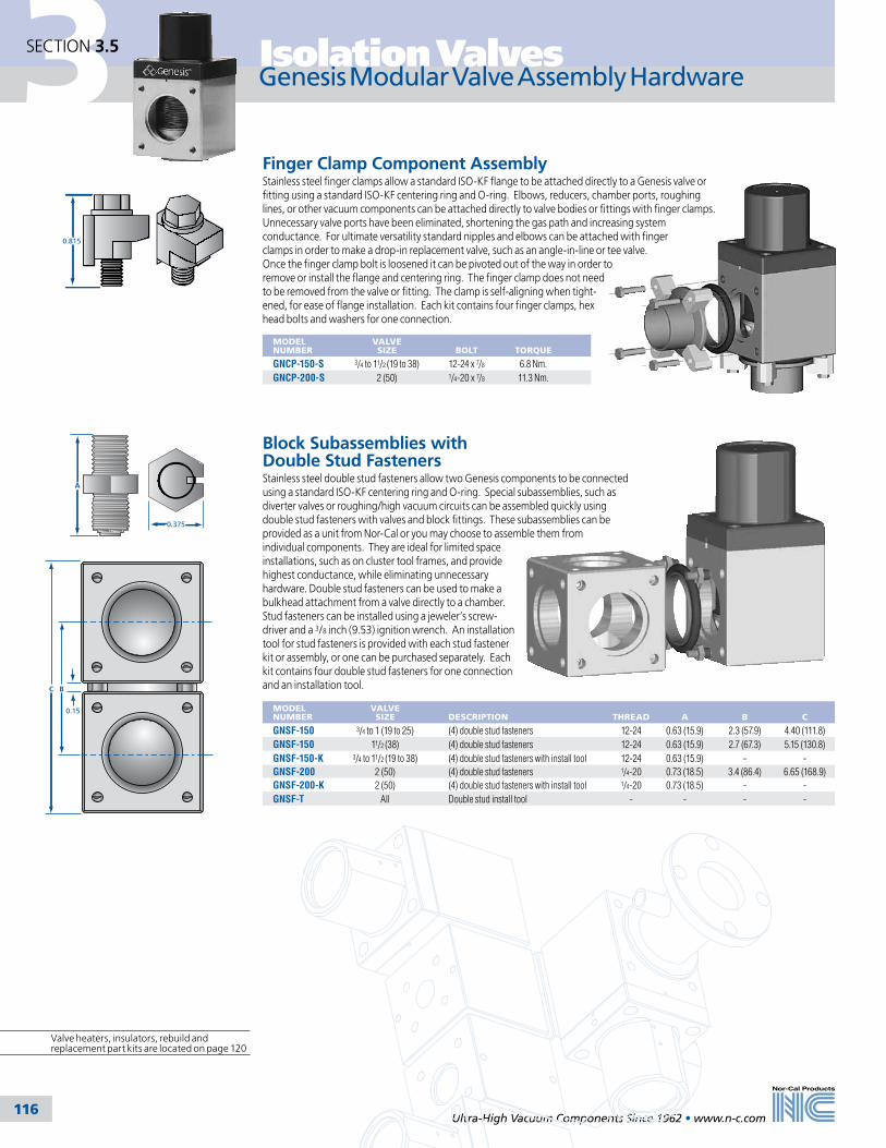
3 Isolation Valves
Ultra-High Vacuum Components Since 1962 • www.n-c.com 116
SECTION 3.5
Genesis Modular Valve Assembly Hardware
0.815
C B
0.15
0.375
A
MODEL NUMBER
VALVE SIZE
BOLT
TORQUE
GNCP-150-S 3/4 to 11/2 (19 to 38) 12-24 x 7/8 6.8 Nm.GNCP-200-S 2 (50) 1/4-20 x 7/8 11.3 Nm.
MODEL NUMBER
VALVE SIZE
DESCRIPTION
THREAD
A
B
C
GNSF-150 3/4 to 1 (19 to 25) (4) double stud fasteners 12-24 0.63 (15.9) 2.3 (57.9) 4.40 (111.8)GNSF-150 11/2 (38) (4) double stud fasteners 12-24 0.63 (15.9) 2.7 (67.3) 5.15 (130.8)GNSF-150-K 3/4 to 11/2 (19 to 38) (4) double stud fasteners with install tool 12-24 0.63 (15.9) - -GNSF-200 2 (50) (4) double stud fasteners 1/4-20 0.73 (18.5) 3.4 (86.4) 6.65 (168.9)GNSF-200-K 2 (50) (4) double stud fasteners with install tool 1/4-20 0.73 (18.5) - -GNSF-T All Double stud install tool - - - -
Block Subassemblies with Double Stud FastenersStainless steel double stud fasteners allow two Genesis components to be connected using a standard ISO-KF centering ring and O-ring. Special subassemblies, such as diverter valves or roughing/high vacuum circuits can be assembled quickly using double stud fasteners with valves and block fittings. These subassemblies can be provided as a unit from Nor-Cal or you may choose to assemble them from individual components. They are ideal for limited space installations, such as on cluster tool frames, and provide highest conductance, while eliminating unnecessary hardware. Double stud fasteners can be used to make a bulkhead attachment from a valve directly to a chamber. Stud fasteners can be installed using a jeweler’s screw-driver and a 3/8 inch (9.53) ignition wrench. An installation tool for stud fasteners is provided with each stud fastener kit or assembly, or one can be purchased separately. Each kit contains four double stud fasteners for one connection and an installation tool.
Finger Clamp Component AssemblyStainless steel finger clamps allow a standard ISO-KF flange to be attached directly to a Genesis valve or fitting using a standard ISO-KF centering ring and O-ring. Elbows, reducers, chamber ports, roughing lines, or other vacuum components can be attached directly to valve bodies or fittings with finger clamps. Unnecessary valve ports have been eliminated, shortening the gas path and increasing system conductance. For ultimate versatility standard nipples and elbows can be attached with finger clamps in order to make a drop-in replacement valve, such as an angle-in-line or tee valve. Once the finger clamp bolt is loosened it can be pivoted out of the way in order to remove or install the flange and centering ring. The finger clamp does not need to be removed from the valve or fitting. The clamp is self-aligning when tight-ened, for ease of flange installation. Each kit contains four finger clamps, hex head bolts and washers for one connection.
Valve heaters, insulators, rebuild and replacement part kits are located on page 120
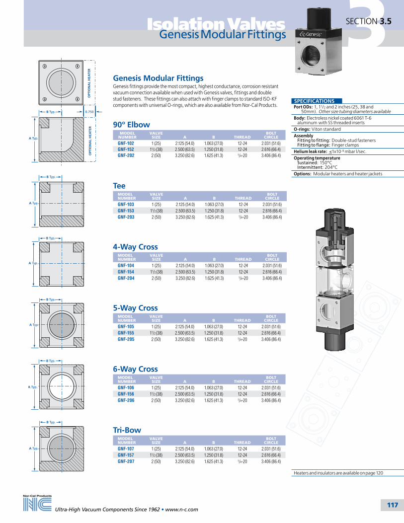
3Isolation Valves
Ultra-High Vacuum Components Since 1962 • www.n-c.com 117
SECTION 3.5
Genesis Modular Fittings
SPECIFICATIONSPort ODs: 1, 11/2 and 2 inches (25, 38 and 50mm). Other size tubing diameters availableBody: Electroless nickel coated 6061 T-6 aluminum with SS threaded insertsO-rings: Viton standardAssembly Fitting to fitting: Double-stud fasteners Fitting to flange: Finger clampsHelium leak rate: <1x10⁻⁹ mbar l/sec. Operating temperature Sustained: 150ºC Intermittent: 204ºCOptions: Modular heaters and heater jackets
4-Way CrossMODEL NUMBER
VALVE SIZE
A
B
THREAD
BOLT CIRCLE
GNF-104 1 (25) 2.125 (54.0) 1.063 (27.0) 12-24 2.031 (51.6)GNF-154 11/2 (38) 2.500 (63.5) 1.250 (31.8) 12-24 2.616 (66.4)GNF-204 2 (50) 3.250 (82.6) 1.625 (41.3) 1/4-20 3.406 (86.4)
5-Way CrossMODEL NUMBER
VALVE SIZE
A
B
THREAD
BOLT CIRCLE
GNF-105 1 (25) 2.125 (54.0) 1.063 (27.0) 12-24 2.031 (51.6)GNF-155 11/2 (38) 2.500 (63.5) 1.250 (31.8) 12-24 2.616 (66.4)GNF-205 2 (50) 3.250 (82.6) 1.625 (41.3) 1/4-20 3.406 (86.4)
6-Way CrossMODEL NUMBER
VALVE SIZE
A
B
THREAD
BOLT CIRCLE
GNF-106 1 (25) 2.125 (54.0) 1.063 (27.0) 12-24 2.031 (51.6)GNF-156 11/2 (38) 2.500 (63.5) 1.250 (31.8) 12-24 2.616 (66.4)GNF-206 2 (50) 3.250 (82.6) 1.625 (41.3) 1/4-20 3.406 (86.4)
Genesis Modular FittingsGenesis fittings provide the most compact, highest conductance, corrosion resistant vacuum connection available when used with Genesis valves, fittings and double stud fasteners. These fittings can also attach with finger clamps to standard ISO-KF components with universal O-rings, which are also available from Nor-Cal Products.
90º ElbowMODEL
NUMBERVALVE SIZE
A
B
THREAD
BOLT CIRCLE
GNF-102 1 (25) 2.125 (54.0) 1.063 (27.0) 12-24 2.031 (51.6)GNF-152 11/2 (38) 2.500 (63.5) 1.250 (31.8) 12-24 2.616 (66.4)GNF-202 2 (50) 3.250 (82.6) 1.625 (41.3) 1/4-20 3.406 (86.4)
TeeMODEL NUMBER
VALVE SIZE
A
B
THREAD
BOLT CIRCLE
GNF-103 1 (25) 2.125 (54.0) 1.063 (27.0) 12-24 2.031 (51.6)GNF-153 11/2 (38) 2.500 (63.5) 1.250 (31.8) 12-24 2.616 (66.4)GNF-203 2 (50) 3.250 (82.6) 1.625 (41.3) 1/4-20 3.406 (86.4)
Tri-BowMODEL NUMBER
VALVE SIZE
A
B
THREAD
BOLT CIRCLE
GNF-107 1 (25) 2.125 (54.0) 1.063 (27.0) 12-24 2.031 (51.6)GNF-157 11/2 (38) 2.500 (63.5) 1.250 (31.8) 12-24 2.616 (66.4)GNF-207 2 (50) 3.250 (82.6) 1.625 (41.3) 1/4-20 3.406 (86.4)
B Typ.
A Typ.
B Typ.
A Typ.
B Typ.
A Typ.
OPT
ION
AL
HEA
TER
OPT
ION
AL
HEA
TER
0.750B Typ.
A Typ.
B Typ.
A Typ.
B Typ.
A Typ.
Heaters and insulators are available on page 120

3 Isolation Valves
Ultra-High Vacuum Components Since 1962 • www.n-c.com 118
SECTION 3.5
Genesis stainless steel poppet valves offer equipment designers the high performance and optimized conductance of Genesis modular valves in Nor-Cal’s standard stainless steel poppet valve body. These simple, robust valves are available with standard and soft start air-to-open/spring-to-close actuation in port sizes from 3/4 to 4 inches (19.05-101.6mm). Viton O-ring seals are standard. Other O-ring compounds, open/closed position indicators and air solenoids are available as options. Heater jackets and insulators are also available.
During testing, the valves were cycled millions of times while maintaining vacuum integrity. The welded bellows is AM-350 for corrosion resistance, longevity and flexibility. The bellows fully retracts from the side port when the valve is open, eliminating buildup of process by-products on the bellows and subsequent particle generation during operation. Valve center plates have been eliminated in order to provide precise alignment between the poppet and valve seat. A composite stem bushing resists wear even at high temperatures. Valve return springs are shot peened in order to provide millions of cycles without loss of force. Teflon coated air cylinders feature a 15 micron air filter to prevent particle migration either into or out of the air cylinder. All valves are designed for easy O-ring or bellows replacement. Design symmetry allows the air actuator to be oriented at 90º increments for easy access to the air solenoid and visibility of position indicators.
For reduced particle contamination in load locks and process chambers, Genesis stainless steel valves are offered with a patented low cost soft start actuator with no increase in valve size. A double-acting air piston, opens a soft start circuit inside the valve when air is supplied to the top of the air cylinder. The soft start by-pass opening can be provided fully open or with a specified orifice, depend-ing on the desired pump down. After the chamber has been pumped from atmosphere to the desired cross over pressure, the main valve circuit is opened by supplying air to the bottom of the air cylinder. Each circuit can be operated independently and is air-to-open/spring-to-close. Soft start Genesis stainless steel valves are offered standard with no orifice. Various orifice size options and multiple size orifice kits are available. See next page.
Genesis Stainless Steel Valves
Genesis Stainless Steel Angle ValvesMODEL NUMBER
ACTUATION
FLANGE TYPE
NOMINALPORT OD
A
B
C
D
E
GNVS-072-NWB Standard NW-16 3/4 (19) 1.50 (38.1) 3.40 (86) 4.78 (121) 1.46 (37) 2.13 (54)GNVS-072-NWB-S0 Soft Start NW-16 3/4 (19) 1.50 (38.1) 3.40 (86) 4.78 (121) 1.46 (37) 2.13 (54)GNVS-102-NWB Standard NW-25 1 (25) 2.42 (61.47) 4.19 (106) 5.57 (141) 1.46 (37) 2.13 (54)GNVS-102-NWB-S0 Soft Start NW-25 1 (25) 2.42 (61.47) 4.19 (106) 5.57 (141) 1.46 (37) 2.13 (54)GNVS-152-NWB Standard NW-40 11/2 (38) 2.49 (63.2) 4.51 (115) 6.20 (157) 1.88 (48) 2.50 (63)GNVS-152-NWB-S0 Soft Start NW-40 11/2 (38) 2.49 (63.2) 4.51 (115) 6.20 (157) 1.88 (48) 2.50 (63)GNVS-202-NWB Standard NW-50 2 (50) 3.22 (81.9) 5.56 (141) 7.66 (195) 2.25 (57) 3.25 (83)GNVS-202-NWB-S0 Soft Start NW-50 2 (50) 3.22 (81.9) 5.56 (141) 7.66 (195) 2.25 (57) 3.25 (83)GNVS-302-ISO Standard ISO-80 3 (76) 3.86 (98.0) 7.33 (186) 10.85 (276) 4.13 (105) 5.45 (138)GNVS-302-ISO-S0 Soft Start ISO-80 3 (76) 3.86 (98.0) 7.33 (186) 10.85 (276) 4.13 (105) 5.45 (138)GNVS-402-ISO Standard ISO-100 4 (100) 4.25 (108) 8.38 (213) 13.04 (331) 5.00 (127) 6.40 (163)GNVS-402-ISO-S0 Soft Start ISO-100 4 (100) 4.25 (108) 8.38 (213) 13.04 (331) 5.00 (127) 6.40 (163)
A
A
B
C
DE
AC
B
DE
Genesis Stainless Steel Angle-In-Line ValvesMODEL NUMBER
ACTUATION
FLANGE TYPE
NOMINALPORT OD
A
B
C
D
E
GNVSAI-072-NWB Standard NW-16 3/4 (19) 4.20 (107) 3.76 (95) 4.37 (111) 1.46 (37) 2.13 (54)GNVSAI-072-NWB-S0 Soft Start NW-16 3/4 (19) 4.20 (107) 3.76 (95) 4.37 (111) 1.46 (37) 2.13 (54)GNVSAI-102-NWB Standard NW-25 1 (25) 4.00 (102) 3.85 (98) 4.63 (118) 1.46 (37) 2.13 (54)GNVSAI-102-NWB-S0 Soft Start NW-25 1 (25) 4.00 (102) 3.85 (98) 4.63 (118) 1.46 (37) 2.13 (54)GNVSAI-152-NWB Standard NW-40 11/2 (38) 5.12 (130) 4.47 (114) 5.28 (134) 1.88 (48) 2.50 (63)GNVSAI-152-NWB-S0 Soft Start NW-40 11/2 (38) 5.12 (130) 4.47 (114) 5.28 (134) 1.88 (48) 2.50 (63)GNVSAI-202-NWB Standard NW-50 2 (50) 7.00 (178) 5.79 (147) 7.00 (178) 2.25 (57) 3.25 (83)GNVSAI-202-NWB-S0 Soft Start NW-50 2 (50) 7.00 (178) 5.79 (147) 7.00 (178) 2.25 (57) 3.25 (83)GNVSAI-302-ISO Standard ISO-80 3 (76) 10.55 (268) 8.88 (226) 11.62 (295) 4.13 (105) 5.45 (138)GNVSAI-302-ISO-S0 Soft Start ISO-80 3 (76) 10.55 (268) 8.88 (226) 11.62 (295) 4.13 (105) 5.45 (138)GNVSAI-402-ISO Standard ISO-100 4 (100) 12.00 (305) 10.75 (273) 13.81 (351) 5.00 (127) 6.40 (163)GNVSAI-402-ISO-S0 Soft Start ISO-100 4 (100) 12.00 (305) 10.75 (273) 13.81 (351) 5.00 (127) 6.40 (163)
SPECIFICATIONSPort ODs: 3/4 to 4 inches (19 to 100mm). Larger sizes and metric tubing diameters available on request
Mating flanges: NW -16 through ISO-100 standard
Air fittings: 5/32 inch(4mm) One-Touch
Materials Body: 304 stainless steel Bellows: Welded AM-350 stainless steel O-rings: Viton standard (Other compounds available.) Air cylinder: Teflon coated aluminum
Service interval: One million cycles
Actuation: Normally closed Air-to-open/spring-to-close
Operating pressure: 60 to 80 psig (4-5.5 bar)
Differential pressure: Maximum 20psi (1.4bar) differential across the valve seat
Helium leak rate: <1x10⁻⁹ mbar l/sec.
Operating temperature Sustained: <150ºC Intermittent: <204ºC
Option: Air solenoids, open/closed position indicators, soft start with various orifice sizes and various O-ring compounds
Valve rebuild and replacement part kits are available on page 120
Conductance This table has been calculated in liters per second for air at room temperature using the formulas for tubes and elbows presented in the third edition of Roth’s Vacuum Technology.
Cv=182(D4/L’)P for vis-cous flow or Cm=12(D3/L’) for molecular flow Note: Calculations were based on port lengths without flanges and inner diameters for the valve sizes and configurations. P = air at 1 mbar. L’=Laxial +1.33(0/180)D for elbows.
NOMINALPORT OD
ANGLE VISCOUS MOLECULAR
ANGLE-IN-LINE VISCOUS MOLECULAR
1/2 (13) 60 3 - -3/4 (19) 135 5 120 41 (25) 391 12 285 9
11/8 (29) - - - -11/2 (38) 1925 37 1324 25
2 (50) 4677 65 3459 4821/2 (63) 12332 136 7505 83
3 (76) 23763 217 12558 1154 (100) 57994 396 - -

3Isolation Valves
Ultra-High Vacuum Components Since 1962 • www.n-c.com 119
SECTION 3.5
Orifice OptionGenesis stainless steel valves with Soft Start actuation come standard with no orifice. To order these valves with an orifice replace the “S0” part number suffix with one of the following options. Example: Change standard valve part number GNVS-072-NWB-S0 to GNVS-072-NWB-S1.
ORIFICE OPTION
VALVE SIZE
ORIFICE SIZE
-S0 No orifice-S1 3/4 to 2 (19-50) .147 (3.7)-S2 3/4 to 2 (19-50) .109 (2.8)-S3 3/4 to 2 (19-50) .070 (1.8)-S4 3 & 4 (76 & 100) .055 (1.4)-S5 3 & 4 (76 & 100) .093 (2.4)-S6 3 & 4 (76 & 100) .128 (3.3)-S7 3 & 4 (76 & 100) .201 (5.1)
NOTE: Refer to diagrams for orifice option selection
Genesis Stainless Steel Valve Options
Open/Closed Position Indicator OptionNor-Cal’s CE certified, shielded, open/closed position indicators detect the piston position in the valve’s air cylinder. The technician has a visual indication of power to the circuit (12 to 24 VDC) and the valve position, as does the operator watching the panel. With the soft start option only one position indicator can be provided for the fully open position. Operating temperature range is -25ºC to 70ºC for valves with position indicators. Call for more information on high temperature position indicators.
OPTION
VALVE ACTUATOR
DESCRIPTION
-P1O Soft Start/Standard 1 position indicator - main valve open only-P1C Standard 1 position indicator - main valve closed only-P2 Standard 2 position indicators - main valve open & closed
Air Solenoid OptionLow 1.8 wattage, CE certified three-way air solenoids can be provided on the valve in sev-eral electrical current ratings, with 24 inch (610mm) quick disconnect electrical leads, and 5/32 inch (3.97mm) one-touch air fittings - ready to attach to the house air supply. One sole-noid is required for standard Genesis stainless valves. Two solenoids are required for soft start versions. Remote mount is required on heated valves. Air solenoid kits with assembly hardware and instructions are available. Kit part numbers are in the second column below.
OPTION
KIT
ACTUATOR
DESCRIPTION
QUANTITY
-A11 A11-K Standard 120 VAC, 50/60 Hz 1-A21 A21-K Standard 24 VDC 1-A31 A31-K Standard 240 VAC, 50/60 Hz 1-A41 A41-K Standard 24 VAC, 50/60 Hz 1-B11 B11-K Soft Start 120 VAC, 50/60 Hz 2-B21 B21-K Soft Start 24 VDC 2-B31 B31-K Soft Start 240 VAC, 50/60 Hz 2-B41 B41-K Soft Start 24 VAC, 50/60 Hz 2
O-ring OptionStandard Genesis valves are furnished with Viton O-rings which are resistant to most chemicals, but should not be heated to temperatures in excess 204ºC. Even prolonged exposures of 150ºC may degrade the O-rings. High temperature Kalrez O-rings allow the valve to be heated to 220ºC intermittently or 170ºC for prolonged periods .
Follow this part tree to add one or more options to a Genesis valve. Add options to the basic valve part number in the order shown.
Example: GNVSAI-302-ISO-P1O-KT-A11
800
700
600
500
400
300
200
100
0
TIME (Seconds)C
ham
ber
Pre
ssu
re (
Torr
)
0 30 60 90 120 150 180 210
No Orifice0.147" Orifice0.109" Orifice0.070" Orifice
11/2 & 2 inch valves tested on a 30 liter chamber
800
700
600
500
400
300
200
100
0
TIME (Seconds)
Ch
amb
er P
ress
ure
(To
rr)
0 30 60 90 120
3 and 4 inch valves tested with various Soft-Start orifices on a 30 liter chamber and 232 CFM Edwards mechanical blower pump package.
No Orifice0.201" Orifice0.128" Orifice 0.093" Orifice 0.055" Orifice
10 20 40 50 70 80 100 110
OPTION
COMPOUND
APPLICATIONS
-KT 4079 Kalrez High temperature-KC 2037 Kalrez Chemical resistant -CR 513 Chemraz Chemical resistant -S Silicone Extreme temperatures
Orifice Option Position Indicator O-ringValve Model Number Air Solenoid
Valve/Orifice Pumpdown Curves Charts
ORIFICE REPLACEMENTS
VALVE SIZE
ORIFICE SIZE
GNV-075-S0-1 3/4 to 2 (19-50) .070 (1.8)GNV-075-S0-2 3/4 to 2 (19-50) .109 (2.8)GNV-075-S0-3 3/4 to 2 (19-50) .147 (3.7)GNV-300-S0-1 3 & 4 (76 & 100) .055 (1.4)GNV-300-S0-2 3 & 4 (76 & 100) .093 (2.4)GNV-300-S0-3 3 & 4 (76 & 100) .128 (3.3)GNV-300-S0-4 3 & 4 (76 & 100) .201 (5.1)GNV-075-S0-K 3/4 to 2 (19-50) Kit*GNV-300-S0-K 3 & 4 (76 & 100) Kit*GNV-075-S0-T 3/4 to 4 (76 & 100) Wrench
* Kits include all orifice sizes and an installation wrench for the specified valve size

3 Isolation Valves
Ultra-High Vacuum Components Since 1962 • www.n-c.com 120
SECTION 3.5
Viton O-Ring KitsIncludes bellows O-ring and poppet O-ring. Other O-ring compounds are available on request.
KIT NUMBER
VALVE SIZE
ACTUATOR
GNV-100-95 3/4 & 1 (19 & 25) Standard GNV-100-95-S0 3/4 & 1 (19 & 25) Soft Start GNV-150-95 11/2 (38) Standard GNV-150-95-S0 11/2 (38) Soft Start GNV-200-95 2 (50) Standard GNV-200-95-S0 2 (50) Soft Start GNV-300-95 3 (76) Standard GNV-300-95-S0 3 (76) Soft Start GNV-400-95 4 (100) Standard GNV-400-95-S0 4 (100) Soft Start
Genesis Heaters & Replacement Kits
Bellows assembly
Genesis Valve Assembly Kits and Replacement HardwareThe kits below are for use with Genesis modular valves and with Genesis stainless steel valves. First maintenance is recommended at one million cycles, depending on the cleanliness of the process. Typical valve service will require O-ring replacement.
Bellows Assembly KitsIncludes bellows, top flange and poppet weldment assembly. Requires O-ring kit to seal.
KIT NUMBER
VALVE SIZE
ACTUATOR
GNV-100-16 3/4 & 1 (19 & 25) StandardGNV-100-16-S0 3/4 & 1 (19 & 25) Soft StartGNV-150-16 11/2 (38) StandardGNV-150-16-S0 11/2 (38) Soft StartGNV-200-16 2 (50) StandardGNV-200-16-S0 2 (50) Soft StartGNV-300-16 3 (76) StandardGNV-300-16-S0 3 (76) Soft StartGNV-400-16 4 (100) StandardGNV-400-16-S0 4 (100) Soft Start
Valve Rebuild KitsIncludes all standard parts except valve body and position indicator. Your valve’s position indicator type must be specified when ordering. Example: GNV-150-99-S0-P10
KIT NUMBER
VALVE SIZE
ACTUATOR
GNV-100-99 3/4 & 1 (19 & 25) StandardGNV-100-99-S0 3/4 & 1 (19 & 25) Soft StartGNV-150-99 11/2 (38) StandardGNV-150-99-S0 11/2 (38) Soft StartGNV-200-99 2 (50) StandardGNV-200-99-S0 2 (50) Soft StartGNV-300-99 3 (76) StandardGNV-300-99-S0 3 (76) Soft StartGNV-400-99 4 (100) StandardGNV-400-99-S0 4 (100) Soft Start
SPECIFICATIONSCompatible Valves: Genesis Modular Valves Heaters and controllers for stainless steel Genesis Valves available. Call for details.
Insulator Body: 1/2 inch (13mm) thick, trimable, molded silicone construction. Touch safe exterior
Heater Voltage: 120 or 240 VAC standard Set points: 120ºC or 150ºC Manual reset: 200ºC with over temp shutoff Low temperature alert: standard on 11/2 and 2 inch (38-50mm) valves
Connections Power cord: 12 inch (305mm) with AMP 3-pin Alert cords: Two 12 inch (305mm) with AMP MR connectors standard on 11/2 & 2 (38 & 50mm) inch valves
Certification Insulators: UL 94 V-O Heaters: UL listed. CE certification pending
HeatersMODEL NUMBER
VALVE SIZE
SET POINT
WATTS
A
HT-GN-100-120-1 3/4 & 1 (19 & 25) 120ºC 120 2.13 (54)HT-GN-100-150-1 3/4 & 1 (19 & 25) 150ºC 120 2.13 (54)HT-GN-150-120-1 11/2 (38) 120ºC 120 2.50 (63)HT-GN-150-150-1 11/2 (38) 150ºC 120 2.50 (63)HT-GN-200-120-1 2 (50) 120ºC 160 3.25 (83)HT-GN-200-150-1 2 (50) 150ºC 160 3.25 (83)
NOTE: Replace “-1” with “-2” for 240V heaters.
Heater InsulatorsMODEL NUMBER
VALVE SIZE
B
C
D
E
F
HI-GNV-100 3/4 & 1 (19 & 25) 6.00 (152) 4.50 (114) 3.13 (80) 2.50 (63) 3.64 (92)HI-GNV-150 11/2 (38) 6.63 (168) 5.00 (127) 3.63 (92) 2.88 (73) 4.25 (108)HI-GNV-200 2 (50) 8.00 (203) 5.88 (149) 4.38 (111) 3.31 (84) 5.00 (127)
Genesis Modular Valve Heaters & InsulatorsA unique, UL listed modular heater provides 120ºC or 150ºC internal temperatures in valves or fittings at a fraction of the cost of other heaters. Genesis heaters use thick film technology to provide uniform heat throughout the component. Each heater contains a control set point and a resetable high temperature shut off. The 11/2 and 2 inch (38.1 and 50.8mm) sizes also have a low temperature alert that can be connected to a remote alarm. Each thermostat can be replaced without destroying the heater. The same heater can be attached to a valve body or fitting with two screws. A trim-to-fit, molded insulator covers the heated component and mating flanges. These clean room compatible insulators are constructed of 1/2 inch (12.7mm) thick molded silicone. When in use, the exterior surface remains touch-safe. Insulators meet UL 94 V-O requirements. Insulators for other components are available upon request. Heater jackets and controllers for Genesis Stainless Steel Valves are available. Call for information and pricing.
Molded Insulator
Modular Thick Film Heater
ResetableHigh Temp Thermostat
Replaceable Set Point Thermostat
Heater Power CordsMODEL NUMBER
LENGTH
HT-GN-PCD-6 6 ft. HT-GN-PCD-12 12 ft.
F
D
A
0.75
EC
B
Op
tio
nal
Hea
ter
All dimensions are in inches (mm) & weights are in pounds (kg), unless otherwise noted.
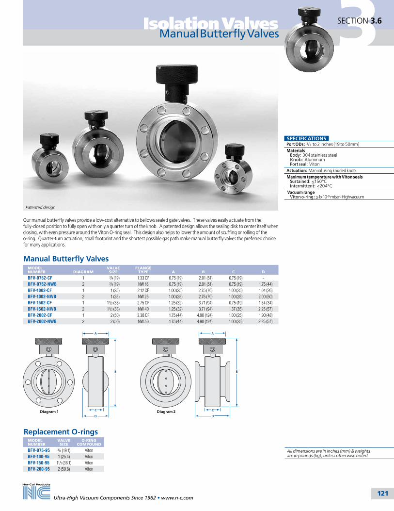
3Isolation Valves
Ultra-High Vacuum Components Since 1962 • www.n-c.com 121
SECTION 3.6
Manual Butterfly Valves
A
B
C
D
A
B
C
DDiagram 1 Diagram 2
SPECIFICATIONSPort ODs: 3/4 to 2 inches (19 to 50mm)Materials Body: 304 stainless steel Knob: Aluminum Port seal: VitonActuation: Manual using knurled knobMaximum temperature with Viton seals Sustained: <150°C Intermittent: <204°C Vacuum range Viton o-ring: >1x 10⁻⁹ mbar - High vacuum
Our manual butterfly valves provide a low-cost alternative to bellows sealed gate valves. These valves easily actuate from the fully-closed position to fully open with only a quarter turn of the knob. A patented design allows the sealing disk to center itself when closing, with even pressure around the Viton O-ring seal. This design also helps to lower the amount of scuffing or rolling of the o-ring. Quarter-turn actuation, small footprint and the shortest possible gas path make manual butterfly valves the preferred choice for many applications.
Patented design
All dimensions are in inches (mm) & weights are in pounds (kg), unless otherwise noted.
MODEL NUMBER
VALVE SIZE
O-RING COMPOUND
BFV-075-95 3/4 (19.1) VitonBFV-100-95 1 (25.4) VitonBFV-150-95 11/2 (38.1) VitonBFV-200-95 2 (50.8) Viton
Replacement O-rings
MODEL NUMBER
DIAGRAM
VALVE SIZE
FLANGE TYPE
A
B
C
D
BFV-0752-CF 1 3/4 (19) 1.33 CF 0.75 (19) 2.01 (51) 0.75 (19) -BFV-0752-NWB 2 3/4 (19) NW 16 0.75 (19) 2.01 (51) 0.75 (19) 1.75 (44)BFV-1002-CF 1 1 (25) 2.12 CF 1.00 (25) 2.75 (70) 1.00 (25) 1.04 (26)BFV-1002-NWB 2 1 (25) NW 25 1.00 (25) 2.75 (70) 1.00 (25) 2.00 (50)BFV-1502-CF 1 11/2 (38) 2.75 CF 1.25 (32) 3.71 (94) 0.75 (19) 1.34 (34)BFV-1502-NWB 2 11/2 (38) NW 40 1.25 (32) 3.71 (94) 1.37 (35) 2.25 (57)BFV-2002-CF 1 2 (50) 3.38 CF 1.75 (44) 4.90 (124) 1.00 (25) 1.90 (48)BFV-2002-NWB 2 2 (50) NW 50 1.75 (44) 4.90 (124) 1.00 (25) 2.25 (57)
Manual Butterfly Valves

3 Isolation Valves
Ultra-High Vacuum Components Since 1962 • www.n-c.com 122
SECTION 3.7
Isolation Pendulum Valves
Isolation Pendulum ValvesMODEL NUMBER
NOMINAL ID
A
B
C
D
E
F G
WEIGHT IN LBS.
IPV-600-ISO-160 6 (150) 3.15 (80) 3.78 (96) 15.9 (404) 12.2 (310) 5.32 (135) 5.87 (149) 8.5 (216) 40 lbs.IPV-800-ISO-200 8 (200) 3.46 (88) 3.78 (96) 19.9 (505) 14.4 (366) 6.5 (165) 5.28 (134) 9.29 (236) 49 lbs.IPV-1000-ISO-250 10 (254) 3.94 (100) 3.78 (96) 23.8 (605) 16.6 (422) 8.46 (215) 5.47 (139) 9.49 (241) 62 lbs.IPV-1200-ISO-320 12 (300) 4.72 (120) 4.06 (103) 30.2 (767) 22 (559) 10.6 (269) 7.24 (184) 12.8 (325) 123 lbs.IPV-1400-JIS-350 14 (350) 4.92 (125) 4.06 (103) 32.3 (820) 22 (559) 12.2 (310) 7.64 (194) 12.8 (325) 143 lbs.IPV-1600-ISO-400 16 (400) 5.91 (150) 5 (127) 36 (914) 24.7 (627) 12.8 (325) 7.83 (199) 15 (381) 231 lbs.
Note: Other sizes and flange configurations available. Call for details. See page 141 for bolt hole specifications. N-MxL
Nor-Cal Products’ pneumatically actuated isolation pendulum valves contain the same pat-ented Penduroll mechanism that is found in the Intellisys throttling pendulum valves. These valves offer the user a highly reliable, compact and low cost alternative to competitive designs. In addition, the smooth actuation results in low particle generation and rapid open-to-close speeds.
In-situ serviceability of the valve is made possible through the incorporation of a removable bonnet cover. The entire gate assembly and sealing O-ring can be accessed without removing the valve from the system, making regular inspections, cleanings and O-ring replacements quick and easy.
The valve body can be heated to 150ºC with optional heater jackets. Call for information and pricing.
SPECIFICATIONSMaterials Body: Cast aluminum A356.0 Valve plate: Aluminum 6061-T6 Other parts: A6061, A7075, SS304, SS316, Inconel X-750 and Viton Seals: Viton standard. Kalrez, Chemraz, Perlast and other materials available Body and plate surface treatment Bare aluminum standard. Hard Type III anodizing optional
Compressed air source CDA or equivalent at 65 to 85 psig
Differential pressure With valve fully sealed: 1.02 bar maximum across the valve plate While opening the valve 20 mbar (DN160 and DN200) 24 mbar (DN250) 29 mbar (DN350)
Operating pressure: 3.8 × 10⁻⁸ to 1000 mbar
Heating or bakeout capabilities
Body: 150ºC maximum with optional heater kits Actuator: 60ºC maximum
Ambient operating temps: 0 - 60ºC
Helium Leak rate: <10-9 mbar l/sec across seat and to atmosphere (1 × 10⁻⁶ mbar·l/sec He for hard anodized body or gate)
Maximum speed: Customer adjustable depending on size
Reliability: 99% confidence level in clean environment O-ring cycle life: 200K cycles open to fully closed MTBF: >10,000 hrs. continuous operation
Options: Heater jackets, other O-ring materials and flange configurations available
Heated pendulum valve assembly in our 3000 square foot Class 1000 clean room
G
F
Position R(Default)
Position T
E
D
E C
D
(Maintenance Space)
A
B
N-MxL
All dimensions are in inches (mm) & weights are in pounds (kg), unless otherwise noted.
JIS Flange O-Rings
SIZE O-RINGS
350 OR-JIS-350

3Isolation Valves
Ultra-High Vacuum Components Since 1962 • www.n-c.com 123
SECTION 3.8
Gate Valve General Information & Options
Nor-Cal stainless steel gate valves share with our poppet valves the innovative design, highest grade materials and superior workmanship that has made us a major supplier of valves to the vacuum industry. The estimated service interval on these valves is 100,000 cycles, depending on the application.
Our gate valves have an ultra-slim profile which makes them perfect for applications where space is limited, and their smaller volume results in lower outgassing and faster pumpdown. Larger sizes have a unique feature in the actuator which damp-ens the vibration which can arise when the gate is opened. This makes these valves ideal for semiconductor and other vibration sensitive processes. The carriage assembly and actuator can be removed without disassembling the body from the system for easy maintenance. The 304 stainless steel bodies are vacuum furnace brazed to 1100°C at 10-6 mbar before being electropol-ished inside and out. The welded AM-350 bellows have a short stroke for a longer cycle life.
Nor-Cal gate valves are available with NW (ISO-KF), ISO (clamp and bolt type), CF and ASA flanges in port sizes from 5/8 to 12 inches (16-300mm). Larger sizes are available upon request. Choose from manual or pneumatic actuation and Viton or copper seal bonnet.
Nor-Cal gate valves with Viton seal bonnet and gate and standard Reed-switch position indicators are bakeable to 150°C, as long as the actuator is not baked above 60°C. A gate valve with copper seal bonnet, Viton gate and micro-switch option can be baked to 200°C, except for the actuator. With the air solenoid and posi-tion indicators removed, a copper seal bonnet valve with high temperature Kalrez gate O-ring can be baked to 250°C with the gate in the open position. Silicone heater jackets for bakeouts up to 200°C can be provided. Please call for pricing.
Gate Valve OptionsOne or more options can be ordered by adding the option suffix to the basic valve model number. Please add the option suffixes in the following order:
Valve Model Number O-ring Type Micro-Switch Air Solenoid
Air SolenoidsOPTION DESCRIPTION
-S12 4-way, 120V AC, 60 Hz-S22 4-way, 24V DC-S32 4-way, 240V AC, 50/60 Hz-S42 4-way, 24V AC, 50/60 Hz
Air solenoids require 4 watts of power to actuate. Solenoids are mounted on all Viton seal bonnet gate valves with 4 inch (100mm) ID and larger. Solenoids for Viton seal bonnet gate valves with under 4 inch (100mm) ID and all sizes of copper seal gate valves are shipped unmounted with the valve.
O-rings
OPTION
COMPOUNDTEMPERATURE MIN. MAX.
DESCRIPTION
Standard Viton -29ºC 204ºC Industry standard -KT Kalrez 4079 -50ºC 316ºC High temperatures-KC Kalrez 2037 -54ºC 220ºC Chemical resistant.-CR Chemraz 513 -30ºC 210ºC Chemical resistant-S Silicone -55ºC 232ºC Extreme temperatures
Micro-Switch OPTION
-MMicro-switches are available on all pneumatically actuated Nor-Cal valves. One switch closes when the valve is fully open and the other when it is fully closed. These can be connected to control panels with alarms or lights for positive position indication.
Silicone heater jackets for bakeouts up to 200°C can be provided for all gate valves.
(See page 127 for details.)
SPECIFICATIONSGeneral Nominal IDs: 5/8 to 12 inch (16 to 300mm) Helium leak rate: <2x10⁻⁹ mbar l/sec.Materials Body: 304 SS vacuum furnace brazed body Bellows: Welded AM-350 O-ring: Viton (standard) Other compounds available.Finish: Electropolished inside and outMaximum pressure differential At opening: 20 mbar Closed: 1000 mbar in either directionVacuum range Viton Seal Bonnet: >10-9 mbar Copper Seal Bonnet: >10-10 mbarTemperature range Viton Seal Bonnet: <150°C Copper Seal Bonnet: <200°C with CF flanges and gate in open positionPneumatically actuated: Air-to-Open, Air-to-Close (standard) 80 psig (5.5 bar) max. air pressure (Higher operating pressures available upon request) Position indicator: Reed-switch position indicator, standard on 1.5” (38) and larger valvesManually actuated Acme threads for fewer turnsThermal: Heater jackets and controllers available. Call for information and pricingOptions: • Air solenoid • Microswitch position indicator • O-ring compounds • Spring-to-Close Option • Million Cycle Option • High pressure air actuator
Example: GVMP-4002-CF-KT-S22

3 Isolation Valves
Ultra-High Vacuum Components Since 1962 • www.n-c.com 124
SECTION 3.8
Gate Valves
G
B
A
E
C
DF
Handles extend on all 10" and 12" manual gate valves
To order gate valve replacement O-rings, pin and bearing kits or O-ring/gasket kits, you must provide us with your valve’s serial number.
Manually Operated Viton Seal Gate ValvesMODEL NUMBER
NOM. ID
FLANGE TYPE
L/SEC (molecular)
A
B
C
D
E
F
G
GV-0622-NW 5/8 (16) NW-16 12 2.39 (61) 1.75 (44) 2.96 (75.2) 1.49 (38) 1.80 (46) 1.88 (48) 1.31 (33)GV-0622-CF 5/8 (16) 1.33 CF 12 2.39 (61) 1.75 (44) 1.56 (39.6) 1.49 (38) 1.80 (46) 1.88 (48) 1.31 (33)GV-1502-NW 11/2 (38) NW-40 98 4.69 (119) 3.40 (86) 1.99 (50.6) 2.00 (50) 3.61 (92) 3.31 (84) 2.45 (62)GV-1502-CF 11/2 (38) 2.75 CF 130 4.69 (119) 3.40 (86) 2.03 (51.6) 2.00 (50) 3.61 (92) 3.31 (84) 2.45 (62)GV-2002-NW 2 (50) NW-50 220 5.60 (142) 4.12 (105) 1.99 (50.6) 2.00 (50) 3.61 (92) 3.81 (97) 2.96 (75)GV-2002-CF 2 (50) 3.38 CF 300 5.60 (142) 4.12 (105) 2.28 (57.9) 2.00 (50) 3.61 (92) 3.81 (97) 2.96 (75)GV-2502-CF 21/2 (63) 4.50 CF 520 6.50 (165) 4.81 (122) 2.40 (61.0) 2.00 (50) 3.61 (92) 4.37 (111) 3.52 (89)GV-2502-ASA 21/2 (63) ASA-6* 610 6.50 (165) 4.81 (122) 2.03 (51.6) 2.00 (50) 3.61 (92) 4.37 (111) 3.52 (89)GV-2502-ISO 21/2 (63) ISO-63 610 6.50 (165) 4.81 (122) 2.03 (51.6) 2.00 (50) 3.61 (92) 4.37 (111) 3.52 (89)GV-2502-ISO-OF 21/2 (63) ISO-63-OF 320 6.50 (165) 4.81 (122) 3.46 (87.9) 2.00 (50) 3.61 (92) 4.37 (111) 3.52 (89)GV-3002-CF 3 (76) 4.62 CF 840 7.70 (196) 5.77 (147) 2.53 (64.3) 2.00 (50) 3.61 (92) 4.94 (125) 4.28 (109)GV-3002-ASA 3 (76) ASA-7.5* 1,070 7.70 (196) 5.77 (147) 2.03 (51.6) 2.00 (50) 3.61 (92) 4.94 (125) 4.28 (109)GV-3002-ISO 3 (76) ISO-80 1,070 7.70 (196) 5.77 (147) 1.97 (50.0) 2.00 (50) 3.61 (92) 4.94 (125) 4.28 (109)GV-3002-ISO-OF 3 (76) ISO-80-OF 550 7.70 (196) 5.77 (147) 3.84 (97.5) 2.00 (50) 3.61 (92) 4.94 (125) 4.28 (109)GV-4002-CF 4 (100) 6.00 CF 1,700 10.76 (273) 8.13 (207) 2.97 (75.4) 3.11 (79) 7.90 (201) 7.00 (178) 5.65 (144)GV-4002-ASA 4 (100) ASA-9* 2,100 10.76 (273) 8.13 (207) 2.41 (61.2) 3.11 (79) 7.90 (201) 7.00 (178) 5.65 (144)GV-4002-ISO 4 (100) ISO-100 2,100 10.76 (273) 8.13 (207) 2.41 (61.2) 3.11 (79) 7.90 (201) 7.00 (178) 5.65 (144)GV-4002-ISO-OF 4 (100) ISO-100-OF 1,400 10.76 (273) 8.13 (207) 4.25 (108) 3.11 (79) 7.90 (201) 7.00 (178) 5.65 (144)GV-6002-CF 6 (150) 8.00 CF 5,400 14.07 (357) 10.64 (270) 3.17 (80.5) 3.11 (79) 7.90 (201) 8.75 (222) 7.55 (192)GV-6002-ASA 6 (150) ASA-11* 7,100 14.07 (357) 10.64 (270) 2.41 (61.2) 3.11 (79) 7.90 (201) 8.75 (222) 7.55 (192)GV-6002-ISO 6 (150) ISO-160 7,100 14.07 (357) 10.64 (270) 2.36 (59.9) 3.11 (79) 7.90 (201) 8.75 (222) 7.55 (192)GV-6002-ISO-OF 6 (150) ISO-160-OF 4,000 14.07 (357) 10.64 (270) 4.25 (108) 3.11 (79) 7.90 (201) 8.75 (222) 7.55 (192)GV-8002-CF 8 (200) 10.00 CF 12,200 18.42 (468) 13.93 (354) 3.35 (85.1) 3.11 (79) 7.90 (201) 11.25 (286) 10.02 (255)GV-8002-ASA 8 (200) ASA-11* 14,500 18.42 (468) 13.93 (354) 2.76 (70.1) 3.11 (79) 7.90 (201) 11.25 (286) 10.02 (255)GV-8002-ISO 8 (200) ISO-200 15,200 18.42 (468) 13.93 (354) 2.66 (67.5) 3.11 (79) 7.90 (201) 11.25 (286) 10.02 (255)GV-8002-ISO-OF 8 (200) ISO-200-OF 9,500 18.42 (468) 13.93 (354) 4.25 (108) 3.11 (79) 7.90 (201) 11.25 (286) 10.02 (255)GV-10002-CF 10 (254) 12.00 CF 24,900 24.04 (611) 18.30 (465) 3.65 (92.7) 8.98 (228) 12.00 (305) 13.44 (341) 11.99 (305)GV-10002-ASA 10 (254) ASA-16* 24,800 24.04 (611) 18.30 (465) 3.15 (80.0) 8.98 (228) 12.00 (305) 13.44 (341) 11.99 (305)GV-10002-ISO 10 (254) ISO-250 26,900 24.04 (611) 18.30 (465) 3.15 (80.0) 8.98 (228) 12.00 (305) 13.44 (341) 11.99 (305)GV-10002-ISO-OF 10 (254) ISO-250-OF 15,400 24.04 (611) 18.30 (465) 5.51 (140) 8.98 (228) 12.00 (305) 13.44 (341) 11.99 (305)GV-12002-CF 12 (300) 14.00 CF 34,600 28.89 (734) 22.03 (560) 3.89 (98.8) 8.98 (228) 12.00 (305) 15.9 (404) 14.28 (363)GV-12002-ASA 12 (300) ASA-16* 42,800 28.89 (734) 22.03 (560) 3.15 (80.0) 8.98 (228) 12.00 (305) 15.9 (404) 14.28 (363)GV-12002-ISO 12 (300) ISO-320 42,800 28.89 (734) 22.03 (560) 3.15 (80.0) 8.98 (228) 12.00 (305) 15.9 (404) 14.28 (363)
*Note: All ASA flanged valves are provided without O-ring grooves. Grooves can be provided on request.
Manually Operated Copper Seal Bonnet Gate ValvesMODEL NUMBER
NOM. ID
FLANGE TYPE
L/SEC (molecular)
A
B
C
D
E
F
G
GVM-0622-CF 5/8 (16) 1.33 CF 12 2.39 (61) 1.75 (44) 1.56 (39.6) 1.49 (38) 1.80 (46) 1.88 (47.8) 1.31 (33)
GVM-1502-CF 11/2 (38) 2.75 CF 130 4.69 (119) 3.40 (86) 2.03 (51.6) 2.00 (50) 3.57 (91) 3.31 (84.1) 2.45 (62)
GVM-2002-CF 2 (50) 3.38 CF 300 5.60 (142) 4.12 (105) 2.28 (57.9) 2.00 (50) 3.61 (92) 3.81 (96.8) 2.96 (75)GVM-2502-CF 21/2 (63) 4.50 CF 520 6.50 (165) 4.81 (122) 2.40 (61.0) 2.00 (50) 3.61 (92) 4.37 (111) 3.52 (89)GVM-3002-CF 3 (76) 4.62 CF 840 7.70 (196) 5.77 (147) 2.53 (64.3) 2.00 (50) 3.61 (92) 5.24 (133) 4.28 (109)GVM-4002-CF 4 (100) 6.00 CF 1,700 10.76 (273) 8.13 (207) 2.97 (75.4) 3.11 (79) 7.90 (201) 7.00 (178) 5.65 (144)GVM-6002-CF 6 (150) 8.00 CF 5,400 14.07 (357) 10.64 (207) 3.17 (80.5) 3.11 (79) 7.90 (201) 8.75 (222) 7.55 (192)GVM-8002-CF 8 (200) 10.00 CF 12,200 18.42 (468) 13.93 (354) 3.35 (85.1) 3.11 (79) 7.90 (201) 11.25 (286) 10.02 (255)GVM-10002-CF 10 (254) 12.00 CF 24,900 24.04 (611) 18.30 (465) 3.65 (92.7) 8.98 (228) 12.12 (308) 13.44 (341) 11.99 (305)GVM-12002-CF 12 (300) 14.00 CF 34,600 28.89 (734) 22.03 (560) 3.89 (98.8) 8.98 (228) 12.12 (308) 15.90 (404) 14.28 (363)
SPECIFICATIONSGeneral Nominal IDs: 5/8 to 12 inch (16 to 300mm) Helium leak rate: <2x10⁻⁹ mbar l/sec.
Materials Body: 304 SS vacuum furnace brazed body Bellows: Welded AM-350 O-ring: Viton (standard) Other compounds available.
Finish: Electropolished inside and out
Maximum pressure differential At opening: 20 mbar Closed: 1000 mbar in either direction
Vacuum range Viton seal bonnet: >10-9 mbar Copper seal bonnet: >10-10 mbar
Temperature range Viton Seal Bonnet: <150°C Copper Seal Bonnet: <200°C with CF flanges and gate in open position
Manually actuated Acme threads for fewer turns
Options: • O-ring compounds • Spring-to-Close Option • Million Cycle Option • Heater Jackets
All dimensions are in inches (mm) & weights are in pounds (kg), unless otherwise noted.

3Isolation Valves
Ultra-High Vacuum Components Since 1962 • www.n-c.com 125
SECTION 3.8
Gate Valves
G
B
A
E
C
DF
To order gate valve replacement O-rings, pin and bearing kits or O-ring/gasket kits, you must provide us with your valve’s serial number.
Manually Operated Viton Seal Gate ValvesMODEL NUMBER
NOM. ID
FLANGE TYPE
L/SEC (molecular)
A
B
C
D
E
F
G
GV-0622-NW 5/8 (16) NW-16 12 2.39 (61) 1.75 (44) 2.96 (75.2) 1.49 (38) 1.80 (46) 1.88 (48) 1.31 (33)GV-0622-CF 5/8 (16) 1.33 CF 12 2.39 (61) 1.75 (44) 1.56 (39.6) 1.49 (38) 1.80 (46) 1.88 (48) 1.31 (33)GV-1502-NW 11/2 (38) NW-40 98 4.69 (119) 3.40 (86) 1.99 (50.6) 2.00 (50) 3.61 (92) 3.31 (84) 2.45 (62)GV-1502-CF 11/2 (38) 2.75 CF 130 4.69 (119) 3.40 (86) 2.03 (51.6) 2.00 (50) 3.61 (92) 3.31 (84) 2.45 (62)GV-2002-NW 2 (50) NW-50 220 5.60 (142) 4.12 (105) 1.99 (50.6) 2.00 (50) 3.61 (92) 3.81 (97) 2.96 (75)GV-2002-CF 2 (50) 3.38 CF 300 5.60 (142) 4.12 (105) 2.28 (57.9) 2.00 (50) 3.61 (92) 3.81 (97) 2.96 (75)GV-2502-CF 21/2 (63) 4.50 CF 520 6.50 (165) 4.81 (122) 2.40 (61.0) 2.00 (50) 3.61 (92) 4.37 (111) 3.52 (89)GV-2502-ASA 21/2 (63) ASA-6* 610 6.50 (165) 4.81 (122) 2.03 (51.6) 2.00 (50) 3.61 (92) 4.37 (111) 3.52 (89)GV-2502-ISO 21/2 (63) ISO-63 610 6.50 (165) 4.81 (122) 2.03 (51.6) 2.00 (50) 3.61 (92) 4.37 (111) 3.52 (89)GV-2502-ISO-OF 21/2 (63) ISO-63-OF 320 6.50 (165) 4.81 (122) 3.46 (87.9) 2.00 (50) 3.61 (92) 4.37 (111) 3.52 (89)GV-3002-CF 3 (76) 4.62 CF 840 7.70 (196) 5.77 (147) 2.53 (64.3) 2.00 (50) 3.61 (92) 4.94 (125) 4.28 (109)GV-3002-ASA 3 (76) ASA-7.5* 1,070 7.70 (196) 5.77 (147) 2.03 (51.6) 2.00 (50) 3.61 (92) 4.94 (125) 4.28 (109)GV-3002-ISO 3 (76) ISO-80 1,070 7.70 (196) 5.77 (147) 1.97 (50.0) 2.00 (50) 3.61 (92) 4.94 (125) 4.28 (109)GV-3002-ISO-OF 3 (76) ISO-80-OF 550 7.70 (196) 5.77 (147) 3.84 (97.5) 2.00 (50) 3.61 (92) 4.94 (125) 4.28 (109)GV-4002-CF 4 (100) 6.00 CF 1,700 10.76 (273) 8.13 (207) 2.97 (75.4) 3.11 (79) 7.90 (201) 7.00 (178) 5.65 (144)GV-4002-ASA 4 (100) ASA-9* 2,100 10.76 (273) 8.13 (207) 2.41 (61.2) 3.11 (79) 7.90 (201) 7.00 (178) 5.65 (144)GV-4002-ISO 4 (100) ISO-100 2,100 10.76 (273) 8.13 (207) 2.41 (61.2) 3.11 (79) 7.90 (201) 7.00 (178) 5.65 (144)GV-4002-ISO-OF 4 (100) ISO-100-OF 1,400 10.76 (273) 8.13 (207) 4.25 (108) 3.11 (79) 7.90 (201) 7.00 (178) 5.65 (144)GV-6002-CF 6 (150) 8.00 CF 5,400 14.07 (357) 10.64 (270) 3.17 (80.5) 3.11 (79) 7.90 (201) 8.75 (222) 7.55 (192)GV-6002-ASA 6 (150) ASA-11* 7,100 14.07 (357) 10.64 (270) 2.41 (61.2) 3.11 (79) 7.90 (201) 8.75 (222) 7.55 (192)GV-6002-ISO 6 (150) ISO-160 7,100 14.07 (357) 10.64 (270) 2.36 (59.9) 3.11 (79) 7.90 (201) 8.75 (222) 7.55 (192)GV-6002-ISO-OF 6 (150) ISO-160-OF 4,000 14.07 (357) 10.64 (270) 4.25 (108) 3.11 (79) 7.90 (201) 8.75 (222) 7.55 (192)GV-8002-CF 8 (200) 10.00 CF 12,200 18.42 (468) 13.93 (354) 3.35 (85.1) 3.11 (79) 7.90 (201) 11.25 (286) 10.02 (255)GV-8002-ASA 8 (200) ASA-11* 14,500 18.42 (468) 13.93 (354) 2.76 (70.1) 3.11 (79) 7.90 (201) 11.25 (286) 10.02 (255)GV-8002-ISO 8 (200) ISO-200 15,200 18.42 (468) 13.93 (354) 2.66 (67.5) 3.11 (79) 7.90 (201) 11.25 (286) 10.02 (255)GV-8002-ISO-OF 8 (200) ISO-200-OF 9,500 18.42 (468) 13.93 (354) 4.25 (108) 3.11 (79) 7.90 (201) 11.25 (286) 10.02 (255)GV-10002-CF 10 (254) 12.00 CF 24,900 24.04 (611) 18.30 (465) 3.65 (92.7) 8.98 (228) 12.00 (305) 13.44 (341) 11.99 (305)GV-10002-ASA 10 (254) ASA-16* 24,800 24.04 (611) 18.30 (465) 3.15 (80.0) 8.98 (228) 12.00 (305) 13.44 (341) 11.99 (305)GV-10002-ISO 10 (254) ISO-250 26,900 24.04 (611) 18.30 (465) 3.15 (80.0) 8.98 (228) 12.00 (305) 13.44 (341) 11.99 (305)GV-10002-ISO-OF 10 (254) ISO-250-OF 15,400 24.04 (611) 18.30 (465) 5.51 (140) 8.98 (228) 12.00 (305) 13.44 (341) 11.99 (305)GV-12002-CF 12 (300) 14.00 CF 34,600 28.89 (734) 22.03 (560) 3.89 (98.8) 8.98 (228) 12.00 (305) 15.9 (404) 14.28 (363)GV-12002-ASA 12 (300) ASA-16* 42,800 28.89 (734) 22.03 (560) 3.15 (80.0) 8.98 (228) 12.00 (305) 15.9 (404) 14.28 (363)GV-12002-ISO 12 (300) ISO-320 42,800 28.89 (734) 22.03 (560) 3.15 (80.0) 8.98 (228) 12.00 (305) 15.9 (404) 14.28 (363)
*Note: All ASA flanged valves are provided without O-ring grooves. Grooves can be provided on request.
Manually Operated Copper Seal Bonnet Gate ValvesMODEL NUMBER
NOM. ID
FLANGE TYPE
L/SEC (molecular)
A
B
C
D
E
F
G
GVM-0622-CF 5/8 (16) 1.33 CF 12 2.39 (61) 1.75 (44) 1.56 (39.6) 1.49 (38) 1.80 (46) 1.88 (47.8) 1.31 (33)
GVM-1502-CF 11/2 (38) 2.75 CF 130 4.69 (119) 3.40 (86) 2.03 (51.6) 2.00 (50) 3.57 (91) 3.31 (84.1) 2.45 (62)
GVM-2002-CF 2 (50) 3.38 CF 300 5.60 (142) 4.12 (105) 2.28 (57.9) 2.00 (50) 3.61 (92) 3.81 (96.8) 2.96 (75)GVM-2502-CF 21/2 (63) 4.50 CF 520 6.50 (165) 4.81 (122) 2.40 (61.0) 2.00 (50) 3.61 (92) 4.37 (111) 3.52 (89)GVM-3002-CF 3 (76) 4.62 CF 840 7.70 (196) 5.77 (147) 2.53 (64.3) 2.00 (50) 3.61 (92) 5.24 (133) 4.28 (109)GVM-4002-CF 4 (100) 6.00 CF 1,700 10.76 (273) 8.13 (207) 2.97 (75.4) 3.11 (79) 7.90 (201) 7.00 (178) 5.65 (144)GVM-6002-CF 6 (150) 8.00 CF 5,400 14.07 (357) 10.64 (207) 3.17 (80.5) 3.11 (79) 7.90 (201) 8.75 (222) 7.55 (192)GVM-8002-CF 8 (200) 10.00 CF 12,200 18.42 (468) 13.93 (354) 3.35 (85.1) 3.11 (79) 7.90 (201) 11.25 (286) 10.02 (255)GVM-10002-CF 10 (254) 12.00 CF 24,900 24.04 (611) 18.30 (465) 3.65 (92.7) 8.98 (228) 12.12 (308) 13.44 (341) 11.99 (305)GVM-12002-CF 12 (300) 14.00 CF 34,600 28.89 (734) 22.03 (560) 3.89 (98.8) 8.98 (228) 12.12 (308) 15.90 (404) 14.28 (363)
Pneumatically Actuated Copper Seal Bonnet Gate ValvesMODEL NUMBER
NOM. ID
FLANGE TYPE
L/SEC (molecular)
A
B
C
D
E
F
G
GVMP-0622-CF 5/8 (16) 1.33 CF 12 2.39 (61) 1.75 (44) 1.56 (39.6) 1.00 (25) 2.55 (65) 1.88 (48) 1.31 (33)GVMP-1502-CF 11/2 (38) 2.75 CF 130 4.69 (119) 3.4 (86) 2.03 (51.6) 2.00 (50) 5.29 (134) 3.31 (84) 2.45 (62)GVMP-2002-CF 2 (50) 3.38 CF 300 5.6 (142) 4.12 (105) 2.28 (57.9) 2.00 (50) 5.29 (134) 3.81 (97) 2.96 (75)GVMP-2502-CF 21/2 (63) 4.50 CF 520 6.5 (165) 4.81 (122) 2.4 (61.0) 2.00 (50) 5.29 (134) 4.37 (111) 3.52 (89.4)GVMP-3002-CF 3 (76) 4.62 CF 840 7.7 (196) 5.77 (147) 2.53 (64.3) 2.00 (50) 5.29 (134) 5.24 (133) 4.28 (109)GVMP-4002-CF 4 (100) 6.00 CF 1,700 10.76 (273) 8.13 (207) 2.97 (75.4) 2.97 (75) 6.95 (177) 7.00 (178) 5.65 (144)GVMP-6002-CF 6 (150) 8.00 CF 5,400 14.07 (357) 10.64 (270) 3.17 (80.5) 2.97 (75) 6.95 (177) 8.75 (222) 7.55 (192)GVMP-8002-CF 8 (200) 10.00 CF 12,200 18.42 (468) 13.93 (354) 3.35 (85.1) 2.97 (75) 6.95 (177) 11.25 (286) 10.02 (255)GVMP-10002-CF 10 (254) 12.00 CF 24,900 24.04 (611) 18.3 (465) 3.65 (92.7) 4.75 (121) 9.47 (241) 13.44 (341) 11.99 (305)GVMP-12002-CF 12 (300) 14.00 CF 34,600 28.89 (734) 22.03 (560) 3.89 (98.8) 4.75 (121) 9.47 (241) 15.9 (404) 14.28 (363)
Pneumatically Actuated Viton Seal Gate ValvesMODEL NUMBER
NOM. ID
FLANGE TYPE
L/SEC (molecular)
A
B
C
D
E
F
G
GVP-0622-NW 5/8 (16) NW-16 12 2.39 (61) 1.75 (44) 2.96 (75.2) 1.00 (25) 2.55 (65) 1.88 (48) 1.31 (33)GVP-0622-CF 5/8 (16) 1.33 CF 12 2.39 (61) 1.75 (44) 1.56 (39.6) 1.00 (25) 2.55 (65) 1.55 (39) 1.31 (33)GVP-1502-NW 11/2 (38) NW-40 98 4.69 (119) 3.40 (86) 1.99 (50.6) 2.00 (50) 5.29 (134) 3.31 (84) 2.45 (62)GVP-1502-CF 11/2 (38) 2.75 CF 130 4.69 (119) 3.40 (86) 2.03 (51.6) 2.00 (50) 5.29 (134) 3.31 (84) 2.45 (62)GVP-2002-NW 2 (50) NW-50 220 5.60 (142) 4.12 (105) 1.99 (50.6) 2.00 (50) 5.29 (134) 3.81 (97) 2.96 (75)GVP-2002-CF 2 (50) 3.38 CF 300 5.60 (142) 4.12 (105) 2.28 (57.9) 2.00 (50) 5.29 (134) 3.81 (97) 2.96 (75)GVP-2502-CF 21/2 (63) 4.50 CF 520 6.50 (165) 4.81 (122) 2.40 (61.0) 2.45 (62) 5.29 (134) 4.37 (111) 3.52 (89)GVP-2502-ASA 21/2 (63) ASA-6* 610 6.50 (165) 4.81 (122) 2.03 (51.6) 2.45 (62) 5.29 (134) 4.37 (111) 3.52 (89)GVP-2502-ISO 21/2 (63) ISO-63 610 6.50 (165) 4.81 (122) 2.03 (51.6) 2.45 (62) 5.29 (134) 4.37 (111) 3.52 (89)GVP-2502-ISO-OF 21/2 (63) ISO-63-OF 320 6.50 (165) 4.81 (122) 3.46 (87.9) 2.45 (62) 5.29 (134) 4.37 (111) 3.52 (89)GVP-3002-CF 3 (76) 4.62 CF 840 7.7 (196) 5.77 (147) 2.53 (64.3) 2.45 (62) 5.29 (134) 4.94 (125) 4.28 (109)GVP-3002-ASA 3 (76) ASA-7.5* 1,070 7.7 (196) 5.77 (147) 2.03 (51.6) 2.45 (62) 5.29 (134) 4.94 (125) 4.28 (109)GVP-3002-ISO 3 (76) ISO-80 1,070 7.7 (196) 5.77 (147) 1.97 (50.0) 2.45 (62) 5.29 (134) 4.94 (125) 4.28 (109)GVP-3002-ISO-OF 3 (76) ISO-80-OF 550 7.7 (196) 5.77 (147) 3.84 (97.5) 2.45 (62) 5.29 (134) 4.94 (125) 4.28 (109)GVP-4002-CF 4 (100) 6.00 CF 1,700 10.76 (273) 8.13 (207) 2.97 (75.4) 2.97 (75) 6.95 (177) 7.00 (178) 5.65 (144)GVP-4002-ASA 4 (100) ASA-9* 2,100 10.76 (273) 8.13 (207) 2.41 (61.2) 2.97 (75) 6.95 (177) 7.00 (178) 5.65 (144)GVP-4002-ISO 4 (100) ISO-100 2,100 10.76 (273) 8.13 (207) 2.41 (61.2) 2.97 (75) 6.95 (177) 7.00 (178) 5.65 (144)GVP-4002-ISO-OF 4 (100) ISO-100-OF 1,400 10.76 (273) 8.13 (207) 4.25 (108) 2.97 (75) 6.95 (177) 7.00 (178) 5.65 (144)GVP-6002-CF 6 (150) 8.00 CF 5,400 14.07 (357) 10.64 (270) 3.17 (80.5) 2.97 (75) 6.95 (177) 8.75 (222) 7.55 (192)GVP-6002-ASA 6 (150) ASA-11* 7,100 14.07 (357) 10.64 (270) 2.41 (61.2) 2.97 (75) 6.95 (177) 8.75 (222) 7.55 (192)GVP-6002-ISO 6 (150) ISO-160 7,100 14.07 (357) 10.64 (270) 2.36 (59.9) 2.97 (75) 6.95 (177) 8.75 (222) 7.55 (192)GVP-6002-ISO-OF 6 (150) ISO-160-OF 4,000 14.07 (357) 10.64 (270) 4.25 (108) 2.97 (75) 6.95 (177) 8.75 (222) 7.55 (192)GVP-8002-CF 8 (200) 10.00 CF 12,200 18.42 (468) 13.93 (354) 3.35 (85.1) 2.97 (75) 6.95 (177) 11.25 (286) 10.02 (255)GVP-8002-ASA 8 (200) ASA-11* 14,500 18.42 (468) 13.93 (354) 2.76 (70.1) 2.97 (75) 6.95 (177) 11.25 (286) 10.02 (255)GVP-8002-ISO 8 (200) ISO-200 15,200 18.42 (468) 13.93 (354) 2.66 (67.6) 2.97 (75) 6.95 (177) 11.25 (286) 10.02 (255)GVP-8002-ISO-OF 8 (200) ISO-200-OF 9,500 18.42 (468) 13.93 (354) 4.25 (108) 2.97 (75) 6.95 (177) 11.25 (286) 10.02 (255)GVP-10002-CF 10 (254) 12.00 CF 24,900 24.04 (611) 18.30 (465) 3.65 (92.7) 4.75 (121) 9.47 (241) 13.44 (341) 11.9 (305)GVP-10002-ASA 10 (254) ASA-16* 24,800 24.04 (611) 18.30 (465) 3.15 (80.0) 4.75 (121.) 9.47 (241) 13.44 (341) 11.9 (305)GVP-10002-ISO 10 (254) ISO-250 26,900 24.04 (611) 18.30 (465) 3.15 (80.0) 4.75 (121) 9.47 (241) 13.44 (341) 11.9 (305)GVP-10002-ISO-OF 10 (254) ISO-250-OF 15,400 24.04 (611) 18.30 (465) 5.51 (140) 4.75 (121) 9.47 (241) 13.44 (341) 11.9 (305)GVP-12002-CF 12 (300) 14.00 CF 34,600 28.89 (734) 22.03 (560) 3.89 (98.8) 4.75 (121) 9.47 (241) 15.90 (404) 14.28 (363)GVP-12002-ASA 12 (300) ASA-16* 42,800 28.89 (734) 22.03 (560) 3.15 (80.0) 4.75 (121) 9.47 (241) 15.90 (404) 14.28 (363)GVP-12002-ISO 12 (300) ISO-320 42,800 28.89 (734) 22.03 (560) 3.15 (80.0) 4.75 (121) 9.47 (241) 15.90 (404) 14.28 (363)
*Note: All ASA flanged valves are provided without O-ring grooves. Grooves can be provided on request
SPECIFICATIONSGeneral Nominal IDs: 5/8 to 12 inch (16 to 300mm) Helium leak rate: <2x10⁻⁹ mbar l/sec.Materials Body: 304 SS vacuum furnace brazed body Bellows: Welded AM-350 O-ring: Viton (standard) Other compounds available.Finish: Electropolished inside and outMaximum pressure differential At opening: 20 mbar Closed: 1000 mbar in either directionVacuum range Viton seal bonnet: >10-9 mbar Copper seal bonnet: >10-10 mbarTemperature range Viton seal bonnet: <150°C Copper seal bonnet: <200°C with CF flanges and gate in open positionPneumatically actuated: Air-to-Open, Air-to-Close (standard) 80 psig (5.5 bar) max. air pressure (Higher operating pressures available upon request) Position indicator: Reed-switch position indicator, standard on 1.5” (38) and larger valvesOptions: • Air solenoid • Microswitch position indicator • O-ring compounds • Spring-to-Close Option • Million Cycle Option • High pressure air actuator • Heater Jackets
All dimensions are in inches (mm) & weights are in pounds (kg), unless otherwise noted.

3 Isolation Valves
Ultra-High Vacuum Components Since 1962 • www.n-c.com 126
SECTION 3.9
Bellowless Poppet Valves & Leak Valves
A
A
C
B
D
SPECIFICATIONSNominal Port ODs: 3/8 to 11/2 inches (10 to 38mm)
Materials Body: Electropolished 304 stainless steel Bonnet seal: Viton Poppet seal: Viton Other O-ring compounds available
Actuation: Normally closed 3/8 to 11/2 inch (10 to 38mm) ODs: Air-to-open, spring-to-close See page 101 for actuation options
Operating pressure: 60 to 80 psig (4-5.5 bar)
Differential pressure Port side: Maximum 100 psig (7 bar) Poppet: Maximum 6psi (0.4 bar) differential across the valve seat.
Maximum temperature with Viton seals Sustained: <150°C Intermittent: <204°C
Vacuum range: >1x 10⁻⁹ mbar - High Vacuum
Options: Fittings, O-rings, air solenoids, micro-switches and actuators. See page 101
Replacement O-Ring & Valve Rebuild KitsMODEL NUMBER
NOMINALPORT OD
DESCRIPTION
ESVP-075-95-5 3/8-1 (10-25) O-ring kitESVP-150-95-5 11/2 (38) O-ring kit
ESVP-075-99-5 3/8-1 (10-25) Complete rebuild kit, includes all valve parts except valve body
ESVP-150-99-5 11/2 (38) Complete rebuild kit, includes all valve parts except valve body
Nonrotatable
Rotatable
1.190(30.23)
1.717(43.61)
1.298(32.97)
4.350(110.49)
1.750(44.45)
SPECIFICATIONSMaterials Body: Electropolished 304 stainless steel Flanges Inlet: 1.33 CF, rotatable, clearance bolt holes Outlet: 2.75 CF, nonrotatable, clearance bolt holes Poppet: Sapphire Poppet seat: Copper
Actuation: Manual, adjustable set point
Maximum temperature Sustained: <250°C Intermittent: <450°C
Vacuum range: >1x 10-11 mbar - UHV
Minimum leak rate Normal: 1x10⁻¹⁰ mbar l/sec. Non-condensible gas: 1x10⁻⁸ mbar l/sec.
Inlet gas pressure: maximum 500 psig (34 bar)
Poppet seat life Unbaked: 250 to 300 closures <250ºC: 80 to 100 closures <450ºC: 20 to 30 closures
Leak ValvesLeak valves are used for controlling gas introduction into high- and ultra-high vacuum systems. They utilize an optically flat sapphire poppet and a metal seal seat, allowing bakeout temperatures to 450ºC. These valves are manually actuated by a cantilever arm with precision adjustment threads. The adjustment knobs can be set to allow controlled leak rates as small as 1x10⁻¹⁰ mbar l/sec. Replacement sapphire and gasket assemblies are available. Call for pricing.
MODEL NUMBER
LL-275-133
All dimensions are in inches (mm) & weights are in pounds (kg), unless otherwise noted.
MODEL NUMBER
NOMINALPORT OD
FLANGE TYPE
L/SEC (molecular)
A
B
C
D
ESVP-0382-NWB-5 3/8 (10) NW-10B 0.66 1.65 (41.9) 3.77 (96) 5.92 (150) 2.25 (57)ESVP-0752-NWB-5 3/4 (19) NW-16B 5.00 2.15 (54.6) 4.27 (108) 6.41 (163) 2.25 (57)ESVP-1002-NWB-5 1 (25) NW-25B 12.00 2.03 (51.6) 4.03 (102) 6.17 (157) 2.25 (57)ESVP-1502-NWB-5 11/2 (38) NW-40B 128.00 2.40 (61.0) 5.13 (130) 7.71 (196) 3.00(76)
Pneumatic Bellowless Angle ValvesRight angle bellowless poppet valves are now available in sizes from 3/8 thru 11/2 inches (9.53-38.1mm). These valves are typically used for applications with large differential pressures, extremely high cycle rates or “dirty” processes that cause frequent bellows failures. Poppet shafts are sealed with double O-rings. Heater jackets and other port and flange configurations are available on request.
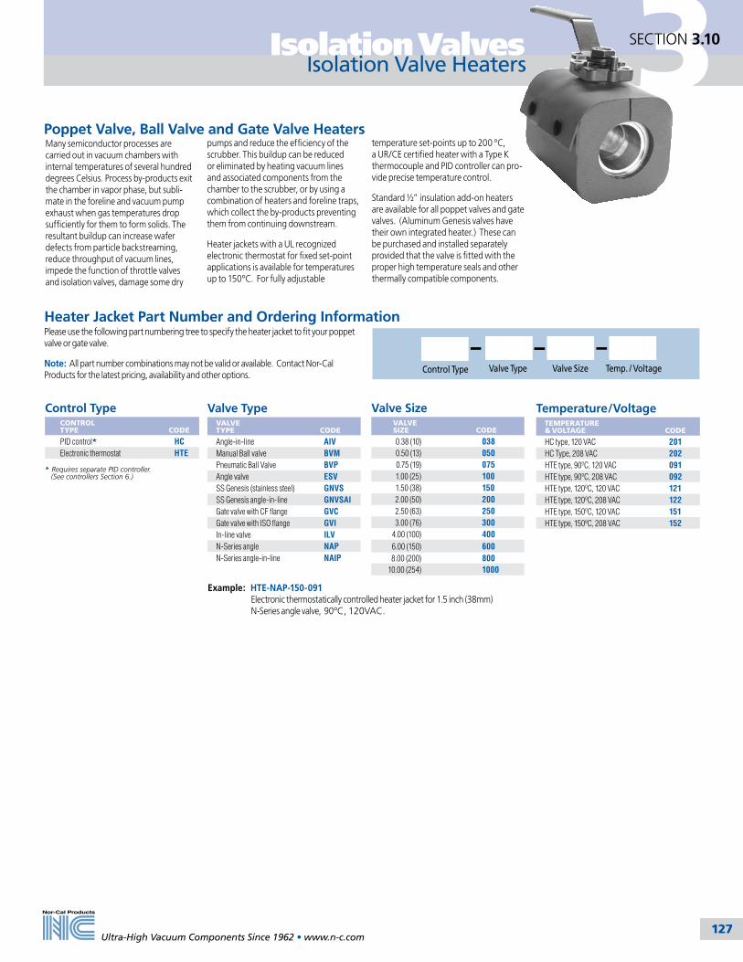
127
3Isolation Valves
Ultra-High Vacuum Components Since 1962 • www.n-c.com 127
SECTION 3.10
Isolation Valve Heaters
Control Type Valve Size Temp. / VoltageValve Type
Control TypeCONTROL TYPE
CODE
PID control* HCElectronic thermostat HTE
Valve SizeVALVE SIZE
CODE
0.38 (10) 038 0.50 (13) 050 0.75 (19) 075 1.00 (25) 100 1.50 (38) 150 2.00 (50) 200 2.50 (63) 250 3.00 (76) 300
4.00 (100) 400 6.00 (150) 600 8.00 (200) 80010.00 (254) 1000
Temperature/VoltageTEMPERATURE & VOLTAGE
CODE
HC type, 120 VAC 201HC Type, 208 VAC 202HTE type, 90ºC, 120 VAC 091HTE type, 90ºC, 208 VAC 092HTE type, 120ºC, 120 VAC 121HTE type, 120ºC, 208 VAC 122HTE type, 150ºC, 120 VAC 151HTE type, 150ºC, 208 VAC 152
Heater Jacket Part Number and Ordering InformationPlease use the following part numbering tree to specify the heater jacket to fit your poppet valve or gate valve.
Note: All part number combinations may not be valid or available. Contact Nor-Cal Products for the latest pricing, availability and other options.
Example: HTE-NAP-150-091 Electronic thermostatically controlled heater jacket for 1.5 inch (38mm) N-Series angle valve, 90ºC, 120VAC.
* Requires separate PID controller. (See controllers Section 6.)
Valve TypeVALVE TYPE
CODE
Angle-in-line AIVManual Ball valve BVMPneumatic Ball Valve BVPAngle valve ESVSS Genesis (stainless steel) GNVSSS Genesis angle-in-line GNVSAIGate valve with CF flange GVCGate valve with ISO flange GVIIn-line valve ILVN-Series angle NAPN-Series angle-in-line NAIP
Many semiconductor processes are carried out in vacuum chambers with internal temperatures of several hundred degrees Celsius. Process by-products exit the chamber in vapor phase, but subli-mate in the foreline and vacuum pump exhaust when gas temperatures drop sufficiently for them to form solids. The resultant buildup can increase wafer defects from particle backstreaming, reduce throughput of vacuum lines, impede the function of throttle valves and isolation valves, damage some dry
pumps and reduce the efficiency of the scrubber. This buildup can be reduced or eliminated by heating vacuum lines and associated components from the chamber to the scrubber, or by using a combination of heaters and foreline traps, which collect the by-products preventing them from continuing downstream.
Heater jackets with a UL recognized electronic thermostat for fixed set-point applications is available for temperatures up to 150ºC. For fully adjustable
temperature set-points up to 200 ºC, a UR/CE certified heater with a Type K thermocouple and PID controller can pro-vide precise temperature control.
Standard ½” insulation add-on heaters are available for all poppet valves and gate valves. (Aluminum Genesis valves have their own integrated heater.) These can be purchased and installed separately provided that the valve is fitted with the proper high temperature seals and other thermally compatible components.
Poppet Valve, Ball Valve and Gate Valve Heaters

3 Isolation Valves
Ultra-High Vacuum Components Since 1962 • www.n-c.com 128
SECTION 3.11
C
Indicator collar with set screw
Closure nut
321 stainless steel bellows
Copper poppet seal
B
A
A
S.S. knifeedge seal
Bakeable All Metal Valves
MODEL NUMBER
NOMINALPORT OD
FLANGE TYPE
CONDUCTANCE (L/sec )MOLECULAR VISCOUS
A
(OPEN) B
C
AMV-0752-CF 3/4 (19) Rotatable 1.33 CF 3 56 1.50 (38) 5.40 (137) 1.50 (38)AMV-1502-CF 11/2 (38) Rotatable 2.75 CF 10 356 2.45 (62) 6.87 (175) 1.50 (38)
NOTE: Port lengths that match other manufacturers’ products are available upon request.
Replacement SealsMODEL NUMBER
NOMINALPORT OD
AMV-075-95 0.75 (19)AMV-150-95 1.50 (38)
Nor-Cal’s metal seal angle valves are intended for use in UHV or cryogenic applications where temperature extremes preclude the use of our elastomer seal valves. Approved for use in beamline facilities, these valves have a temperature operating range from -250°C to 400°C. Heater jackets and controllers are available on request.
The pulled-port method is used for the fabrication of the stainless steel bodies resulting in higher conductance and better cleanliness. Heater jackets and controllers are available on request.
The life of the copper poppet seal is dependent upon the temperature at which the valve is used. Maximum temperature bakeouts may require copper poppet seal replacement after 50 cycles, while hundreds of cycles are possible with moderate bakeouts. As many as 10,000 cycles have been obtained from the same seal during testing.
A dial indicator at the top of the valve indicates the proper torque for closure and also when the seal should be replaced. The copper poppet seal is easily replaced by opening the valve with a slotted screw driver. The seal is removed through the side port and a new one replaced in a like manner. After seal replacement the valve must be torqued to a higher value than during normal operation to make it seat. Do not exceed the maximum torque
Torque SpecificationsMODEL NUMBER
SEATINGNm
NORMALNm
MAXIMUM Nm
AMV-075-CF 6.8 5.6 13.6AMV-150-CF 13.6 11.3 22.6
specifications. (See torque specifica-tions table.) After closing the valve to its normal torque value loosen the set screw below the closure nut, rotate the indica-tor to the furthest counter-clockwise line on top of the valve and retighten the set
screw. The valve may be closed to this mark indefinitely. Periodic checks with a torque wrench will indicate seat wear and the proper mark to use for alignment. When the indicator has reached the last mark we recommend seal replacement.
SPECIFICATIONSPort ODs: 3/4 and 11/2 inch (19 to 38mm)
Finish: Electropolished
Assembly: Clean room
Materials Pulled port body: 304 stainless steel Bellows: Formed 321 stainless steel Poppet seal: OFHC Copper
Actuation: Manual using self-lubricating bronze nuts with ACME threads
Operating temperature: -250ºC to 400ºC
Maximum bakeout temperature Open: 400°C Closed: 300°C
Vacuum rated: >1x 10⁻¹⁰ mbar - UHV
Helium leak rate: <10-10 mbar l/sec.
Options: Heater jackets and controllers
All dimensions are in inches (mm) & weights are in pounds (kg), unless otherwise noted.
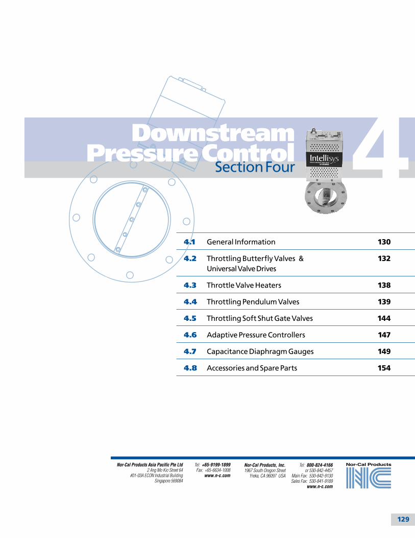
129
4
Tel: 800-824-4166or 530-842-4457
Main Fax: 530-842-9130Sales Fax: 530-841-9189
www.n-c.com
Nor-Cal Products, Inc.1967 South Oregon Street
Yreka, CA 96097 USA
Nor-Cal Products Asia Pacific Pte Ltd2 Ang Mo Kio Street 64
#01-03A ECON Industrial BuildingSingapore 569084
Tel: +65-9199-1899Fax: +65-6634-1008
www.n-c.com
Section Four
4.1 General Information 130
4.2 Throttling Butterfly Valves & 132 Universal Valve Drives
4.3 Throttle Valve Heaters 138
4.4 Throttling Pendulum Valves 139
4.5 Throttling Soft Shut Gate Valves 144
4.6 Adaptive Pressure Controllers 147
4.7 Capacitance Diaphragm Gauges 149
4.8 Accessories and Spare Parts 154
Downstream Pressure Control

4 Downstream Pressure Control
Ultra-High Vacuum Components Since 1962 • www.n-c.com 130
General InformationSECTION 4.1
Nor-Cal Products offers unequalled performance with the Intellisys down-stream pressure control products, providing measurable process benefits through higher resolution, speed and reliability. These benefits are the direct result of two core functions embedded in all Intellisys control systems.
First, a unique patented closed-loop motor control technology, which is a combination of electronics hardware and software, resides in every Intellisys controller. This allows Intellisys control valves to be operated at high rates of speed and with extremely fine positional resolution, while using standard off-the-shelf stepper motors.
Second, capitalizing on the high motor speed and fine resolution is an adaptive pressure control algorithm that yields near flawless pressure control perfor-mance over a wide range of system conditions without the need to “tune” or “learn” PID parameters.
Adding to the pressure control system benefits is a host of valve functions and features aimed at optimizing control performance and reliability. These include the selection of direct driven valves that eliminate the use of costly and unreliable gear heads or belt drives. Furthermore, none of the Intellisys con-trol valves rely on mechanical or optical switches to determine the valve stroke end-points. Instead, bulletproof hard stops that are sensed by the closed-loop motor position feedback signals serve as the open and closed indicators. Last, all Intellisys control valves, regard-less of type, have been designed with controllability and conductance in mind.
Optimally designed throttle plates and actuation mechanisms therefore provide an essential contribution to the overall behavior and performance of the downstream pressure control system.
ProductsEvery complete downstream pressure control system design incorporates three components including a throttle valve, valve controller and pressure (vacuum) gauge. Nor-Cal Products has products available in all of these categories.
The selection of throttle valves includes families of butterfly, pendulum, and gate valves. The choice of valve depends on the intended application, but each is available in a wide range of sizes and flange types with many optional functions and features, and all of them feature the closed-loop motor control capability that results in high speed and ultra-fine resolution. In addition, Nor-Cal offers the Universal Valve Drive (UVD) – a motor drive product that can be tailored to fit most other manufacturers’ valves. Doing so can greatly improve pressure control performance characteristics of existing valves at a reduced cost.
Adaptive pressure controllers are available for each type of valve or valve drive, and generally come in two styles. The stand-alone buried box controllers are ideal for applications where expanded communi-cations or user interfaces are desired. For installations where installation space is of concern, the on-valve IQ-series control-lers may be a preferred choice. Regardless of type, all Intellisys controllers are pow-ered by Digital Signal Processors (DSP) and have many available host communications
New Products
interfaces such as RS-232, RS-485, DeviceNet, and Analog/TTL.
Nor-Cal capacitance diaphragm gauges (CDG) feature an utlra-stable ceramic diaphragm and advanced digital circuitry in all unheated and heated models. The gauges are available in all common ranges and can be supplied with most popular pipe fittings and connector types.
Intellisys TechnologyMany users want to know more about the underlying closed-loop control technology that forms the backbone of Intellisys control systems. Whereas the finer details of this technology are, for obvious reasons, closely guarded, Nor-Cal is still happy to provide educational mate-rial for the sake of eliminating some of the “mystique” surrounding the technol-ogy or simply satisfying anyone’s curious mind. To this end, the following page contains excerpts from a feature article that was written for and published by Semiconductor International magazine. Also, please visit us on the web at www.n-c.com or give our Intellisys technical support staff a call at 800-824-4166.
Intellisys - The Fastest, Most Precise Pressure Control System
Capacitance Diaphragm GaugesNor-Cal proudly announces the availabil-ity of ultra stable ceramic sensor gauges featuring digital circuitry, one push but-ton zero and a convenient service port. The gauges exhibit second-to-none short and long term stability, shorter warm-up times and excellent recovery from atmospheric bursts.
Intellisys Next Generation IQ+ Controller Responding to emerging industry requirements, Nor-Cal now has a fully RoHS compliant and DeviceNet certi-fied adaptive pressure controller called the IQ+. It is similar in function and appearance to the earlier line of IQ-controllers, but features a much advanced pressure control algorithm for improved control during difficult conditions. The IQ+ on-board con-troller can be used with most throttle valves and it offers a popular fail safe battery backup option and add-on gauge power.
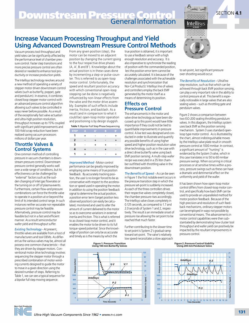
4
Ultra-High Vacuum Components Since 1962 • www.n-c.com 131
Downstream Pressure Control
From any given position (step), the motor can be moved to an adjacent position by changing the current going to the four respective drive phases (A, A’, B and B’). Knowledge about the actual position is in these cases done by incrementing a step-or pulse-coun-ter. This is referred to as open-loop motor control. Unfortunately, the speed and resultant position accuracy with which conventional open-loop stepping can be done is negatively influenced by non-linear effects from the valve and the motor drive assem-bly. Examples of such effects include inertia, friction, and backlash. As a result (and in comparison to what it could be) open-loop motor operation and positioning is by design sluggish.
Improved Method - Motor control performance can be greatly improved by employing some means of true position feedback. By accurately tracking posi-tion, the user is no longer forced to be as conservative with respect to the accelera-tion or speed used in operating the motor. In addition to using the position feedback signal to determine the actual position, a position error term (target position less observed position) can easily be calcu-lated, monitored and used to alter the amount of current delivered to the motor so as to overcome variations in external inertia and friction. This is what is referred to as closed-loop motor control, and it enables the motor to be driven to its full torque-speed potential. Since the knowl-edge of position can only be as accurate and timely as is the means by which the
General InformationSECTION 4.1
Vacuum process tool throughput and yield rates can be significantly affected by the performance level of chamber pres-sure control. Faster step transitions and more precise pressure control are often desired or needed to enhance tool pro-ductivity or increase production yields.
The Intellisys technology revolves around a new method of operating a variety of stepper motor driven downstream control valves (such as butterfly, poppet, gate and pendulum). In essence, it combines closed loop stepper motor control with an advanced pressure control algorithm allowing such valves to be controlled in ways never before possible. As a result of the exceptionally fast valve actuation and ultra-high position resolution, throughput increases up to 15% coupled with significant yield improvements and 100-fold scrap reduction have been realized saving vacuum processors millions of dollars per year.
Throttle Valves & Control SystemsOne common method of controlling pressure in vacuum chambers is down-stream pressure control. Downstream pressure control generally works well over a wide range of conditions, but its effectiveness can be challenged by “external” factors such as the sud-den changing of inlet gas flowrates or the turning on or off of plasma events. Furthermore, certain flow-and pressure combinations can force the throttle valve to operate in a position at or beyond the limit of its intended control range. In such instances neither accurate nor repeatable pressure control may be feasible. Alternatively, pressure control may be feasible but not in a fast and efficient manner. As a result semiconductor wafer yield and throughput suffer.
Existing Technology - At present, throttle valves are available from a host of manufacturers and tool OEMs. As differ-ent as the various valves may be, almost all possess one common characteristic – that they are driven by stepper motors. Con-ventional motor drive technology involves sequencing the stepper motor through a prescribed combination of motor wind-ing currents designed to guide the motor to move in a given direction using the desired number of steps. Referring to Table 1, we can see a typical sequence for a bipolar full step moving sequence.
Table 1: Bipolar Full Step Phase Sequencing
STEP A A’ B B’
1 + - - +
2 - + - +
3 - + + -
4 + - + -
1 + - - +
true position is obtained, it is important to use a feedback sensor with a high enough resolution and accuracy. It is also imperative to synchronize the reading of position with the commanded position, lest the position error term cannot be accurately calculated. It is because of the challenges associated with the achievable resolution and synchronization that Nor-Cal Products’ Intellisys line of valves and controllers employ the back EMF generated by the motor itself as a means of determining its position.
Effects on Pressure ControlThe enhancements in the motor and valve drive technology as have been dis-cussed up to this point would have little importance if they could not be tied to quantifiable improvements in pressure control. A live test was designed and con-ducted in order to illustrate and quantify any possible benefits of using higher speed and higher position resolution valve drive technology, such as in the case with a direct drive butterfly valve using back EMF position sensing. A multi-step wafer recipe was executed in a 35 liter cham-ber outfitted with throttling valve in the downstream position.
The Benefits of Speed – As can be seen in Figure 1 the first notable event occurs in the pressure transition step in which the pressure set-point is suddenly increased. As each of the three controllers drives their respective valves completely closed, the chamber pressure rises accordingly. The Intellisys valve closes completely in 0.125 seconds, as compared to 1.7 and 2.0 seconds of System 1 and 2, respec-tively. The result is an immediate onset of pressure rise allowing the set point to be reached that much faster.
Further contributing to the slower time to set point is System 2’s gradual ramp toward set-point. The valve’s relatively low speed necessitates a slow approach
to set-point, lest significant pressure over-shooting would occur.
The Benefits of Resolution – Ultrafine step resolution, such as that which can be achieved through back EMF position sensing, can play a very important role in the ability to control pressure at all. This benefit is espe-cially noticeable in large valves that are also sealing valves – such as throttling gate and pendulum valves.
Figure 2 shows a comparison between two ISO-200 sealing throttling pendulum valves. In this diagram, the Intellisys system uses back EMF as the position sensing mechanism. System 3 uses standard open-loop type motor control. As is illustrated by the chart, almost indistinguishable moves by the Intellisys valve plate result in smooth pressure control at 1000 mmbar. In contrast, a significant amount of “hunting” is evidenced by the System 3 valve, which in this case translates in to 50 to 60 mmbar pressure swings. When occurring in critical processes or at sensitive times within a pro-cess, pressure swings such as these can have a dramatic and detrimental effect on the uniformity and yield of the wafer.
It has been shown how open-loop motor control differs from closed-loop motor con-trol, and specifically how back EMF can be used to provide an unparalleled method for motor position feedback. Because of the high precision and resolution of such feed-back mechanisms, ordinary stepper motors can be employed in ways not possible by conventional means. The advancements in motor control capabilities were then sub-stantiated by demonstrating how cluster tool throughput and wafer yield can positively be impacted by the resultant improvements in pressure control.
Increase Vacuum Processing Throughput and Yield Using Advanced Downstream Pressure Control Methods
Figure 2: Pressure Control Stability Using 200 mm Pendulum Valve
100
80
60
40
20
01000
800
600
400
200
0 Val
ve P
osi
tio
n (
% O
pen
)
Pres
sure
(m
Torr
)
Time (Seconds)0 2 4 6 8 10 12
Intellisys
V-1
P-2
P-1
V-2
Figure 1: Pressure Transition Using 100 mm Butterfly Valves
20
16
12
8
4
01000
800
600
400
200
0 Val
ve P
osi
tio
n (
% O
pen
)
Pres
sure
(m
Torr
)
Time (Seconds)0 201 2 3 4 5 6 7 8 9 10 11 12 13 14 15 16 17 18 19
P-3
V-3Intellisys
Intellisys

4 Downstream Pressure Control
Ultra-High Vacuum Components Since 1962 • www.n-c.com 132
Visual Throttle Plate IndicatorHard
Stop
Direct-driveMotor
Oldham Coupling
PrecisionShaft Bearings
PrecisionShaft
Bearings
OptionalHeater Jacket
Special Flush NW Clamps
Dual O-rings
Dual O-rings
High Efficiency Thermal Insulator
Motor Drive toValve Body Interface
OptimallyDesigned
Throttle Plate
}
}
Universal Valve Drive (UVD)Universal Valve Drives (UVD) can be used to retrofit and upgrade other manufacturers’ valves, including butterfly, vane, flapper and other ¼- or ½-turn valve types. The resulting performance often comes close of that of a standard Intellisys system but at a fraction of the cost. Drive-to-valve adapters for most manu-facturers have already been designed, and others can be easily made upon request. The UVD is currently only available with a geared drive.
Throttling Butterfly Valves
The Intellisys throttling butterfly valves (TBV) are available in a wide range of sizes and flange types and come standard with compact and low cost direct drives. More powerful geared drives are available as an option. Both styles use long time proven and reliable off-the-shelf stepper motors that deliver smooth operation, high actuation speed and ultra-fine position resolution. Intellisys TBVs are non-seal-ing and are therefore not suitable as isolation valves.
When combined with an Intellisys con-troller, the fast response Nor-Cal TBVs enable vacuum systems to reach process pressures sooner, reducing cycle time and increasing throughput. Furthermore, the high precision valve movement assures pressure control accuracy at 0.25% of set point, and often well within. Available controllers for TBVs include the buried box APC-family and, in most cases, the on-valve IQ and IQ+ series.
Features and Benefits• Higher system throughput• Optimally designed throttle plate for improved controllability• Smallest footprint available• Direct drive motor for more compact and reliable design• Fully serviceable valve motor subassembly• 316 stainless steel and Viton seals on all wetted parts. Other seal materials are available.• High open conductance• Low closed conductance
High actuation speed and ultra-fine position resolution
Please call with mating valve information such as: manufacturer, shaft diameter, adapter configuration, etc.
UVD90-G Specific Mating Valve Details
SECTION 4.2
2.42
6.20
2.58
3.23
.18
2.58(65.5)
2.42(61.5)
(4.6)
6.20(157)
(82)
All dimensions are in inches (mm) & weights are in pounds (kg), unless otherwise noted.

4
Ultra-High Vacuum Components Since 1962 • www.n-c.com 133
Downstream Pressure Control Throttling Butterfly Valves
SECTION 4.2
B
2.42(61.5)
2.58(65.5)
3.23(82.0)
6.20(157)
C
A
.18(4.6)
D
2.42(61.5)
2.58(65.5)
3.23(82)
4.56(116)
C
AB
.18(4.6)
D
Seal Material OptionsSEAL MATERIAL
CODE
Viton Default (no code)Kalrez 4079 -K79Kalrez 8085 -K85Kalrez 8575 -K75Kalrez 9100 -K91Chemraz E38 -C38Dupra 192 -D19Perlast G74P -PP7
Direct Drive Throttling Butterfly Valves MODELNUMBER
NOMINALID
FLANGE TYPE A B C D WEIGHT
TBVP-D-100-NW-25 1 (25) NW-25 2.25 (57.1) 2.75 (69.8) 6.68 (169.7) 6.99 (177.6) 5.5 (2.5)TBVP-D-150-NW-40 1.5 (38) NW-40 2.25 (57.1) 2.75 (69.8) 6.68 (169.7) 1.39 (35.3) 5.3 (2.4)TBVP-D-200-NW-50 2 (50) NW-50 2.00 (50.8) 3.36 (85.3) 6.99 (177.5) 1.98 (50.3) 5.5 (2.5)TBVP-D-250-ISO-63 2.5 (63) ISO-63 1.00 (25.4) 5.12 (130.0) 7.44 (189.0) 2.44 (62.0) 7.5 (3.4)TBVP-D-300-ISO-80 3 (76) ISO-80 1.00 (25.4) 5.71 (145.0) 7.76 (197.1) 2.94 (74.7) 8.8 (4.0)TBVP-D-400-ISO-100 4 (100) ISO-100 1.00 (25.4) 6.50 (165.1) 8.19 (208.0) 3.85 (97.8) 9.5 (4.3)
Gear Drive Throttling Butterfly Valves MODELNUMBER
NOMINALID
FLANGE TYPE A B C D WEIGHT
TBVP-G-600-ISO-160 6 (150) ISO-160 1.62 (41.1) 8.90 (226.1) 10.5 (266.7) 5.67 (144.0) 21.8 (9.9)TBVP-G-800-ISO-200 8 (200) ISO-200 1.62 (41.1) 11.2 (284.5) 12.5 (317.5) 7.87 (199.9) 28.5 (12.9)TBVP-G-1000-ISO-250 10 (250) ISO-250 1.62 (41.1) 13.2 (335.3) 13.5 (342.9) 9.88 (250.9) 38.0 (17.3)
Direct Drive Gear Drive
Example: TBVP-G-600-ISO-160-K75 Gear drive TBV with 6 inch bore, ISO 160 flanges and Kalrez 8575 O-rings.
SPECIFICATIONSGeneral
Compatible Controllers: Direct drive: 200-series Geared drive: 100-seres buried box Valve position: Visual indicator
Construction
Wetted materials: 316 stainless steel, seal material (see below)Seals: Viton standard. Kalrez, Chemraz, Perlast and other materials available on request.
Operation
Motor power input: Supplied by BQC controller.Differential pressure: 1.1 bar maximum across the valve plateForced heating capabilities: Valves may be heated up to 200ºC with optional external heaters, provided seal and coupling material is specified to handle such temperatures. Process gas temperature capabilities: For process gas temperatures in excess of 100ºC, please consult with Nor-Cal Intellisys technical support for proper selection of seal materials and other design considerations.Ambient operating conditions: 0 - 60ºC @ 0 - 95% humidity Leak rate: 1 × 10⁻⁹ mbar·liter/sec He
Inherent performance
Maximum speed: Open to closed in 125 msec (direct), 250 msec (geared)Control resolution: 3.2 arc second (direct), 0.2 arc second (geared)Maximum torque: 280 in-oz (direct), 2100 in-oz (geared)
Pressure Control Performance (when used with an Intellisys controller)
Accuracy: The greater of 5 mV or 0.25% of readingRepeatability: Within 2.5 mV or 0.12% of readingControl range: 0.5% - 100% of the vacuum gauge range
Reliability (99% confidence level, in clean environment)
O-ring cycle life: 5 million open- close cycles MTBF: >50,000 hrs. continuous operation
Approvals
CE (EMC and machinery directives)
All dimensions are in inches (mm) & weights are in pounds (kg), unless otherwise noted.

4 Downstream Pressure Control
Ultra-High Vacuum Components Since 1962 • www.n-c.com 134
Throttling Butterfly ValvesSECTION 4.2
IQ Throttling Butterfly Valves MODELNUMBER
NOM.ID
FLANGE TYPE A B C D WEIGHT
TBV-IQA-100-NW-25 1 (25) NW-25 2.25 (57.1) 2.75 (69.8) 8.34 (211.8) 0.87 (22.1) 5.5 (2.5)TBV-IQA-150-NW-40 1.5 (38) NW-40 2.25 (57.1) 2.75 (69.8) 8.34 (211.8) 1.39 (35.31) 5.3 (2.4)TBV-IQA-200-NW-50 2 (50) NW-50 2.00 (50.8) 3.36 (85.3) 8.65 (219.7) 1.98 (50.3) 5.5 (2.5)TBV-IQA-250-ISO-63 2.5 (63) ISO-63 1.00 (25.4) 5.12 (130.0) 9.10 (231.1) 2.44 (62.0) 7.5 (3.4)TBV-IQA-300-ISO-80 3 (76) ISO-80 1.00 (25.4) 5.71 (145.0) 9.42 (239.3) 2.94 (74.7) 8.8 (4.0)TBV-IQA-400-ISO-100 4 (100) ISO-100 1.00 (25.4) 6.50 (165.1) 9.85 (250.2) 3.85 (97.8) 9.5 (4.3)TBV-IQA-600-ISO-160 6 (150) ISO-160 1.62 (41.1) 8.90 (226.1) 10.4 (264.2) 5.87 (149.1) 21.8 (9.9)TBV-IQA-800-ISO-200 8 (200) ISO-200 1.62 (41.1) 11.2 (284.5) 12.4 (315.0) 7.87 (199.9) 28.5 (12.9)TBV-IQA-1000-ISO-250 10 (250) ISO-250 1.62 (41.1) 13.2 (335.3) 13.3 (337.8) 9.88 (250.9) 38.0 (17.3)TBV-IQA-1200-ISO-320 12 (300) ISO-320 1.62(41.1) 16.73 (424.9) 15.35 (389.9) 12.31(312.7) 51 (23.2)
SPECIFICATIONSGeneral
Controller Options: IQA: Analog / TTL / RS232 interface IQD: DeviceNet / RS232 interface IQD2: DeviceNet / RS232 interface, no power via DN connector IQE: Ethernet / RS232 interface IQR: RS485 interfaceValue position: Visual indicator
Construction
Wetted materials: 316 stainless steel, seal material (see below)Seals: Viton standard. Kalrez, Chemraz, Perlast and other materials available on request (see below)
Operation
Power input: +24 VDCDifferential pressure: 1.1 bar maximum across valve plateForced heating capabilities: Valves may be heated up to 150ºC with optional external heaters.Process gas temperature capabilities: For process gas temperatures in excess of 100ºC, please consult with Nor-Cal Intellisys technical support for proper design considerations. Ambient operating conditions: 0 - 60ºC @ 0 - 95% humidity Leak rate: 1 × 10⁻⁹ mbar·liter/sec He
Inherent performance
Open to close speed: 125 msecControl resolution: 3.2 arc second Maximum torque: 1 in - 4 in : 280 in-ozMaximum torque: 6 in - 10 in :700 in-oz
Pressure control performance Accuracy: The greater of 5mV or 0.25% of reading
Repeatability: Within 2.5mV or 0.12% of reading Control range: 0.5% - 100% of the vacuum gauge range
Reliability (99% confidence level, in clean environment)
O-ring cycle life: 5 million open-close cyclesMTBF: >50,000 hours continuous operation
Approvals
CE (EMC and machinery directives)
Note: IQA can be replaced with IQD, IQD2, IQE, and IQR
B
C
A
6.23(158)
D
.62 (15.8)
4.47(114) .18
(4.6)
2.73(69.3)
2.89(73.4)
Seal Material OptionsSEAL MATERIAL
CODE
Viton Default (no code)Kalrez 4079 -K79Kalrez 8085 -K85Kalrez 8575 -K75Kalrez 9100 -K91Chemraz E38 -C38Dupra 192 -D19Perlast G74P -PP7
Example: TBV-IQD-400-ISO-100-C38 IQD TBV with 4 inch bore, ISO 100 flanges and Chemraz E38 O-rings.
All dimensions are in inches (mm) & weights are in pounds (kg), unless otherwise noted.
4.47(114)
A
.62 (15.8)
6.23(158)
C
BD
.18(4.6)
2.73(69.3)
2.89(73.4)

4
Ultra-High Vacuum Components Since 1962 • www.n-c.com 135
Downstream Pressure Control Throttling Butterfly Valves
SECTION 4.2
IQ+ Throttling Butterfly Valves
MODELNUMBER
NOM.ID
FLANGE TYPE A B C D WEIGHT
TBV-QPD-NW-25 1 (25) NW-25 2.25 (57.1) 2.75 (69.8) 8.34 (211.8) 0.87 (22.1) 5.5 (2.5)TBV-QPD-NW-40 1.5 (38) NW-40 2.25 (57.1) 2.75 (69.8) 8.34 (211.8) 1.39 (35.3) 5.3 (2.4)TBV-QPD-NW-50 2 (50) NW-50 2.00 (50.8) 3.36 (85.3) 8.65 (219.7) 1.98 (50.3) 5.5 (2.5)TBV-QPD-ISO-63 2.5 (63) ISO-63 1.00 (25.4) 5.12 (130.0) 9.10 (231.1) 2.44 (62.0) 7.5 (3.4)TBV-QPD-ISO-80 3 (76) ISO-80 1.00 (25.4) 5.71 (145.0) 9.42 (239.3) 2.94 (74.7) 8.8 (4.0)TBV-QPD-ISO-100 4 (100) ISO-100 1.00 (25.4) 6.50 (165.1) 9.85 (250.2) 3.85 (97.8) 9.5 (4.3)TBV-QPD-ISO-160 6 (150) ISO-160 1.62 (41.1) 8.90 (226.1) 10.4 (264.2) 5.87 (149.1) 21.8 (9.9)TBV-QPD-ISO-200 8 (200) ISO-200 1.62 (41.1) 11.2 (284.5) 12.4 (315.0) 7.87 (199.9) 28.5 (12.9)TBV-QPD-ISO-250 10 (250) ISO-250 1.62 (41.1) 13.2 (335.3) 13.3 (337.8) 9.88 (250.9) 38.0 (17.3)TBV-QPD-ISO-320 12 (300) ISO-320 1.62 (41.1) 16.73 (424.9) 15.35 (389.9) 12.31 (312.7) 51 (23.2)
Note: QPD can be replaced with QPDB, QPDG and QPDBG
Example: TBV-QPDBG-400-ISO-100-C38 IQ+ TBV with DeviceNet, battery backup, guage power, 4 inch bore, ISO 100 flanges and Chemraz E38 O-rings.
SPECIFICATIONSGeneral
Controller Options: QPD: DeviceNet / RS232 interface QPDB: DeviceNet / RS232 interface, with battery back-up QPDG: DeviceNet / RS232 interface, with gauge power QPDBG: DeviceNet / RS232 interface, with battery back-up and gauge power Contact the factory for other interfaces such as Analog, TTL, RS-485 and Ethernet. Valve position: Visual indicator
Construction
Wetted materials: 316 stainless steel, seal material (see below)Seals: Viton standard. Kalrez, Chemraz, Perlast and other materials available on request.
Operation
Power input: +24 VDC Differential pressure: 1.1 bar maximum across the valve plateForced heating capabilities: Valves may be heated up to 150ºC with optional external heaters. Process gas temperature capabilities: For process gas temperatures in excess of 100ºC, please consult with Nor-Cal Intellisys technical support for proper selection of seal materials and other design considerations.Ambient operating conditions: 0 - 60ºC @ 0 - 95% humidity Leak rate: 1 × 10⁻⁹ mbar·liter/sec He
Inherent performance
Open to close speed: 125 msecControl resolution: 0.4 arc secondMaximum torque: 1”– 4”: 280 in-oz 6”– 10”: 700 in-oz
Pressure Control Performance (when used with an Intellisys controller)
Algorithm: Improved for better stability and faster transitions Accuracy: The greater of 5 mV or 0.25% of readingRepeatability: Within 2.5mV or 0.12% of reading Control range: 0.5% - 100% of the vacuum gauge range
Reliability (99% confidence level, in clean environment)
O-ring cycle life: 5 million open- close cycles MTBF: >50,000 hrs. continuous
Approvals
RoHS compliantODVA certified DeviceNet CE (EMC and machinery directives)
Nor-Cal’s new IQ+ controller is available on the complete line of regular and seal-ing Throttling Butterfly Valves (TBV and TBVS) turning what is very good perfor-mance into best-in-class process control. The IQ+ controller is an on-valve integral control & drive unit that is fully RoHS com-pliant with 100% lead-free circuit board content. User interfaces include an ODVA certified DeviceNet protocol and physical layer, as well as standard RS-232 com-munications. Gauge power capabilities have been upgraded to a full 1500 mA at
+/- 15 VDC in order to power two heated CDG’s directly from the IQ+ unit. In addi-tion, a battery backup feature is available that can be used to bring the valve to a fail-closed or fail-open safe position in the event of system power loss. Last, the IQ+ adaptive pressure control algorithm has been significantly improved to better deal with difficult control situations, in particu-lar at conditions that typically occur at low pressures and low flows.
For larger system pressure control requir-ing multiple pumps and forelines, such as
on flat panel, industrial coating or photo-voltaic tools, it is easily possible to gang up to ten valves together. Multi-valve Master/ Slave system control like this is facilitated via the Nor-Cal-Net intervalve communi-cations system. One IQ+ operated valve serves as the master with communica-tions to the host tool, gauge input and has direct command over the control position of the remaining slave valves. The IQ+ controlled butterfly valves are the right answer to any new or challenging pressure control application.
All dimensions are in inches (mm) & weights are in pounds (kg), unless otherwise noted.
B
6.23(158)
C
A D
4.47(114)
.62 (15.8)
2.73(69.3)
2.89(73.4)
.18(4.6)4.47
(114)
A
.62 (15.8)
6.23(158)
C
BD
.18(4.6)
2.73(69.3)
2.89(73.4)
Seal Material OptionsSEAL MATERIAL
CODE
Viton Default (no code)Kalrez 4079 -K79Kalrez 8085 -K85Kalrez 8575 -K75Kalrez 9100 -K91Chemraz E38 -C38Dupra 192 -D19Perlast G74P -PP7

4 Downstream Pressure Control
Ultra-High Vacuum Components Since 1962 • www.n-c.com 136
Sealing Throttling Butterfly ValvesSECTION 4.2
IntellisysTM Combination Butterfly Valve with Maximum Dynamic Range
SPECIFICATIONSGeneral
Controller Options: QP: RS232 interface QPA: Analog / TTL / RS232 interface QPD: DeviceNet / RS232 interface QPM: EtherCAT interface QPR: RS485 Interface QPS: Slave controller (used for master/ slave systems)Valve position: Visual indicator
Construction
Body materials: 6061 Aluminum, hard anadized aluminum or 316 stainless steel, Seals: Viton standard. Kalrez, Chemraz, Perlast and other materials available on request.
Operation
Power input: +24 VDC Differential pressure: 1.2 bar maximum across the valve plateValve bakeout capabilities: Valves may be heated up to 150ºC with optional external heaters. Process gas temperature capabilities: For process gas temperatures in excess of 100ºC, please consult with Nor-Cal Intellisys technical support for proper design considerations.Ambient operating conditions: 0 - 45ºC @ 0 - 95% humidity Shaft Leak rate: 1 × 10⁻⁹ mbar.l/sec He (SS, AL) 1 × 10⁻⁶ mbar.l/sec He (HA)Plate Leak rate: 1 × 10⁻⁸ mbar.l/sec He (SS, AL) 1 × 10⁻⁵ mbar.l/sec He (HA)Inherent performanceOpen to close speed: 0.5 – 0.8 secondsControl resolution: 0.5 arc secondMaximum torque: 2100 in-oz
Pressure Control Performance
Accuracy: The greater of 5 mV or 0.25% of readingRepeatability: Within 2.5mV or 0.12% of reading Control range: 0.5% - 100% of the vacuum gauge range
Reliability (99% confidence level, in clean environment)
MTBF: >10,000 hrs. continuous
Approvals CE (EMC and machinery directives)
Nor-Cal has upgraded its sealing butter-fly valve technology to provide a broader and more robust product line. Available in either stainless steel or aluminum, the STBV-product is a dual function valve capable of acting both as foreline isola-tion- and down-stream pressure control valve. The isolation function is rated up to 1 x 10⁻⁹ mbar · l / sec depending on the choice of seal and body material, and is actuated through a dual cam self-locking linkage arrangement. The new valve ranges in sizes from 1 ½ to 4 inch (38-100mm) nominal ID’s.
The dynamic range, or controllable con-ductance, of these valves spans from 0.01 liters/sec at closed for the 40mm size up to 600 liters/sec using the 100mm size valve in the full open position. When combined with the IntellisysTM on-board IQ+ controller, the STBV valves can be used to control chamber pressures up to 1 bar and beyond, even with very low gas flow rates. The ultra-fine motor resolution of the IQ+ controller enables extremely precise valve plate movement resulting in very smooth and stable system pressures.
Process by-product mitigation is accom-plished by heating the valve body, either by use of heater jackets or integral cartridge heaters. The STBV valves can be baked out to 120ºC as long as precautions are taken to ensure the IQ+ controller does not exceed 45ºC.
Seal Material OptionsSEAL MATERIAL
CODE
Viton Default (no code)Kalrez 8085 -K85Kalrez 8575 -K75Kalrez 9100 -K91Chemraz E38 -C38Dupra 192 -D19Perlast G74P -PP7
Flapper O-ring SizesFLANGE SIZE
CODE
NW-40 OR-2-213NW-50 OR-2-223ISO-63 OR-2-228ISO-80 OR-2-232ISO-100 OR-2-237

4
Ultra-High Vacuum Components Since 1962 • www.n-c.com 137
Downstream Pressure Control Sealing Throttling Butterfly Valves
SECTION 4.2
All dimensions are in inches (mm) & weights are in pounds (kg), unless otherwise noted.
IntellisysTM Combination Butterfly Valve with Maximum Dynamic Range
MODELNUMBER
NOM.ID
FLANGE TYPE A B C D WEIGHT
(AL & HA)WEIGHT
(SS)
STBV-QPA-NW-40-xx 1.5 NW-40 2.25 (57.2) 2.75 (69.9) 10.33 (262.4) 1.21 (30.7) 6.7 (3.0) 7.7 (3.5)STBV-QPA-NW-50-xx 2 NW-50 2.00 (50.8) 3.36 (85.3) 10.64 (270.3) 1.77 (45.0) 6.9 (3.1) 8.3 (3.8)STBV-QPA-ISO-63-xx 2.5 ISO-63 1.00 (25.4) 5.12 (130.0) 11.44 (290.6) 2.49 (63.2) 8.0 (3.6) 10.8 (4.9)STBV-QPA-ISO-80-xx 3 ISO-80 1.00 (25.4) 5.71 (145.0) 11.77 (299.0) 2.95 (74.9) 8.3 (3.8) 11.6 (5.3)STBV-QPA-ISO-100-xx 4 ISO-100 1.00 (25.4) 6.50 (165.0) 12.21 (310.1) 3.62 (91.9) 9.3 (4.2) 13.0 (5.9)
Note: QPA can be replaced with QP, QPD, QPM, QPR or QPSNote: “xx” deignates the body material, AL for aluminum, HA for hard anodized aluminum and SS for stainless steel
Example: STBV-QPDBG-ISO-100-C38 IQ+ STBV with DeviceNet, battery backup, gauage power, 4 inch bore, ISO 100 flanges and Chemraz E38 O-rings.
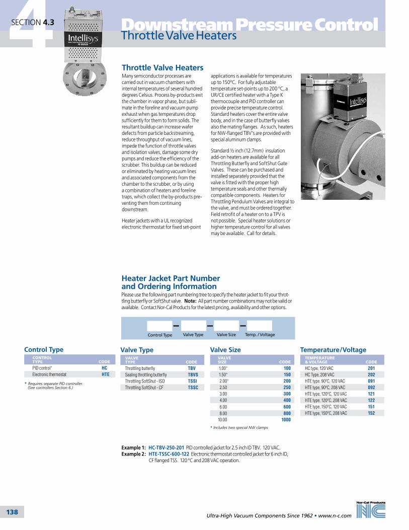
Throttling Butterfly Valves (TBV)
Throttle Valve HeatersMany semiconductor processes are carried out in vacuum chambers with internal temperatures of several hundred degrees Celsius. Process by-products exit the chamber in vapor phase, but subli-mate in the foreline and vacuum pump exhaust when gas temperatures drop sufficiently for them to form solids. The resultant buildup can increase wafer defects from particle backstreaming, reduce throughput of vacuum lines, impede the function of throttle valves and isolation valves, damage some dry pumps and reduce the efficiency of the scrubber. This buildup can be reduced or eliminated by heating vacuum lines and associated components from the chamber to the scrubber, or by using a combination of heaters and foreline traps, which collect the by-products pre-venting them from continuing downstream.
Heater jackets with a UL recognized electronic thermostat for fixed set-point
SECTION 4.2
Control Type Valve Size Temp. / VoltageValve Type
Control TypeCONTROL TYPE
CODE
PID control* HCElectronic thermostat HTE
Valve SizeVALVE SIZE
CODE
1.00* 100 1.50* 150 2.00* 200 2.50 250 3.00 300 4.00 400 6.00 600 8.00 80010.00 1000
Temperature/VoltageTEMPERATURE & VOLTAGE
CODE
HC type, 120 VAC 201HC Type, 208 VAC 202HTE type, 90ºC, 120 VAC 091HTE type, 90ºC, 208 VAC 092HTE type, 120ºC, 120 VAC 121HTE type, 120ºC, 208 VAC 122HTE type, 150ºC, 120 VAC 151HTE type, 150ºC, 208 VAC 152
Heater Jacket Part Number and Ordering InformationPlease use the following part numbering tree to specify the heater jacket to fit your throt-tling butterfly or SoftShut valve. Note: All part number combinations may not be valid or available. Contact Nor-Cal Products for the latest pricing, availability and other options.
Example 1: HC-TBV-250-201 PID controlled jacket for 2.5 inch ID TBV. 120 VAC. Example 2: HTE-TSSC-600-122 Electronic thermostat controlled jacket for 6 inch ID, CF flanged TSS. 120 ºC and 208 VAC operation.
4 Downstream Pressure Control
138
4 Downstream Pressure Control
Ultra-High Vacuum Components Since 1962 • www.n-c.com 138
Throttle Valve HeatersSECTION 4.3
* Requires separate PID controller. (See controllers Section 6.)
* Includes two special NW clamps
Valve TypeVALVE TYPE
CODE
Throttling butterfly TBVSealing throttling butterfly TBVSThrottling SoftShut - ISO TSSIThrottling SoftShut - CF TSSC
applications is available for temperatures up to 150ºC. For fully adjustable temperature set-points up to 200 ºC, a UR/CE certified heater with a Type K thermocouple and PID controller can provide precise temperature control. Standard heaters cover the entire valve body, and in the case of butterfly valves also the mating flanges. As such, heaters for NW-flanged TBV’s are provided with special aluminum clamps.
Standard ½ inch (12.7mm) insulation add-on heaters are available for all Throttling Butterfly and SoftShut Gate Valves. These can be purchased and installed separately provided that the valve is fitted with the proper high temperature seals and other thermally compatible components. Heaters for Throttling Pendulum Valves are integral to the valve, and must be ordered together. Field retrofit of a heater on to a TPV is not possible. Special heater solutions or higher temperature control for all valves may be available. Call for details.

Throttling Pendulum Valves (TPV)
Nor-Cal’s line of Intellisys pendulum valves provides equipment manufacturers with unmatched pressure control performance and low particle generation. Other pen-dulum valves use one actuation method to move the gate and another method to seal, creating an “out of control” area near the closed position. To compensate for this, system designers often add secondary bypass lines with costly throttling butterfly valves for high pres-sure, high flow regimes, such as NF3 cleans. Intellisys pendulum valves utilize the same exclusive closed loop motor technology as other Nor-Cal control valves, but also feature a patented Penduroll actuator mechanism to move the sealing gate rapidly across the valve bore and transition to the axial direction. The result is precise pressure control over the entire valve stroke, most notably near the closed position. The Intellisys control system is the only choice for demanding 300mm Etch and CVD applications which require fast, accurate pressure control across the entire range of critical process flows and chamber pressures.
Features and Benefits• Space saving, low cost design• Low particle generation• High reliability• Easy maintenance, split body allows O-ring replacement without removing valve from system• Body can be heated up to 150ºC with optional heater jackets• Available in ISO and JIS flange styles
The Intellisys closed loop motor control monitors and controls the exact position of the valve’s gate mechanism. When combined with an Intellisys adaptive pressure controller, the pendulum valves provide up to 160 million steps of posi-tional resolution to position the gate exactly where it needs to be to control pressure or to seal. In addition, the Nor-Cal control system’s speed of actua-tion is unequaled in providing optimal transient response, pressure set-point stability and overall process improve-ment. The APC’s adaptive algorithm outperforms “learn modes” by optimiz-ing phase and gain settings in real time during varying chamber pressure and flow conditions.
In-situ serviceability of the valve is made possible through the incorporation of a removable bonnet cover. The entire gate assembly and sealing O-ring can be accessed without removing the valve from the system, making regular inspections, cleanings and O-ring replacements quick and easy.
Chamber
Competitor's Throttling Pendulum Valve
HighVacuumPump
HighVacuumPump
To Rough Pump
To Rough Pump
Throttling Butterfly Valve with Controller
Isolation Valve Isolation
Valve
TM
Nor-Cal'sIntellisysThrottling Pendulum Valve
TBV and Controller eliminated with Intellisys TPVsystem.
Savings of approximately $5000.00
Chamber
Unmatched Pressure Control Performance and Low Particle GenerationNor-Cal Products also offers pneumati-cally actuated isolation pendulum valves that contain the same patented Penduroll mechanism that is found in the throttling valves. For more information about these valves, please refer to the Isolation Valves section of this catalog.
SECTION 4.3
Chamber
Competitor's Throttling Pendulum Valve
HighVacuumPump
HighVacuumPump
To Rough Pump
To Rough Pump
Throttling Butterfly Valve with Controller
Isolation Valve Isolation
Valve
TM
Nor-Cal'sIntellisysThrottling Pendulum Valve
TBV and Controller eliminated with Intellisys TPVsystem.
Savings of approximately $5000.00
Chamber
Ultra-High Vacuum Components Since 1962 • www.n-c.com 139
Downstream Pressure Control 4Throttling Pendulum Valves SECTION 4.4
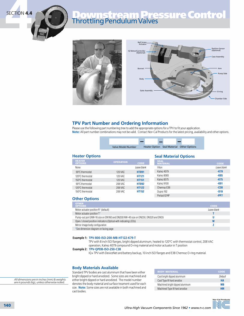
4 Downstream Pressure Control
Ultra-High Vacuum Components Since 1962 • www.n-c.com 140
Throttling Pendulum Valves
Other OptionsOTHER OPTIONS
CODE
Motor actuator position R* (default) Leave blankMotor actuator position T* TPump-out port (NW-16 size on DN160 and DN200 NW-40 size on DN250, DN320 and DN35 UOpen / closed position indicators (Optical with indicating LEDs) WMirror image body configuration Z
*See dimension diagram on facing page
BODY MATERIAL CODE
Cast bright dipped aluminum Default
Cast Type III hard anodize HAMachined bright dipped aluminum MBMachined Type III hard anodize HM
Heater Options HEATER OPTIONS OPERATION
CODE
None Leave blank
90ºC thermostat 120 VAC HT091
120ºC thermostat 120 VAC HT121150ºC thermostat 120 VAC HT151 90ºC thermostat 208 VAC HT092120ºC thermostat 208 VAC HT122150ºC thermostat 208 VAC HT152
O-ring
Chamber Side
Pump Side
Arm
Case Assembly
Position Sensor (Optional)
Ball Screw Actuator
IQ Motor/Controller (Optional)
Bonnet
Body
Gate Assembly
Example 1: TPV-800-ISO-200-MB-HT122-K79-T TPV with 8 inch ISO flanges, bright dipped aluminum, heated to 120ºC with thermostat control, 208 VAC operation, Kalrez 4079 compound O-ring material and motor actuator in T position Example 2: TPV-QPDB-ISO-250-C38 IQ+ TPV with DeviceNet and battery backup, 10 inch ISO flanges and E38 Chemraz O-ring material.
SECTION 4.4
TPV Part Number and Ordering InformationPlease use the following part numbering tree to add the appropriate options for a TPV to fit your application. Note: All part number combinations may not be valid. Contact Nor-Cal Products for the latest pricing, availability and other options.
Heater Option Other OptionsSeal MaterialValve Model Number
Seal Material OptionsSEAL MATERIAL
CODE
Viton Leave blank
Kalrez 4079 -K79Kalrez 8085 -K85Kalrez 8575 -K75Kalrez 9100 -K91Chemraz E38 -C38Dupra 192 -D19Perlast G74P -PP7
Body Materials AvailableStandard TPV bodies are cast aluminum that have been either bright dipped or hard anodized. Some sizes are machined and either bright dipped or hard anodized. The model number denotes the body material and surface treament used for each size. Note: Some sizes are not available in both machined and cast bodies.
All dimensions are in inches (mm) & weights are in pounds (kg), unless otherwise noted.

4
Ultra-High Vacuum Components Since 1962 • www.n-c.com 141
Downstream Pressure Control Throttling Pendulum Valves
E C
D
B
A
F
Maintenance Space
Position R(Default)
Position T
N-MxL
SECTION 4.4
SPECIFICATIONSGeneral
Compatible controllers: 800-series APC buried box controllers
Construction
Wetted materials Body: Cast aluminum A356.0 (machined billet aluminum 6061-T6 in 8” size) Valve plate: Aluminum 6061-T6 Other parts: A6061, A7075, SS304, SS316, Inconel X-750 and Viton Seals: Viton standard. Kalrez, Chemraz, Perlast and other materials available Body and plate surface treatment: Bare aluminum standard, hard Type III anodizing optional
Operation
Motor power input: Supplied by BQC controller. Refer to APC section.Differential pressure: With valve fully sealed: 1.1 bar maximum across the valve plate While opening the valve 27 mbar (DN160 and DN200) 32 mbar (DN250) 39 mbar (DN320 & DN350)Operating pressure: 3.8 × 10⁻⁸ to 1 barHeating or bakeout capabilities: Body: 150ºC maximum with optional heater kits Actuator: 60ºC maximumAmbient operating conditions: 0 - 60ºC @ 0 - 95% humidity, noncondensing Leak rate: 1 × 10⁻⁹ mbar·liter/sec He with Viton seals across seat and to atmosphere (1 × 10⁻⁶ mbar·liter/sec He for hard anodized body or gate) Derated with some perfluoro-elastomers
Inherent performance
Maximum speed: Open to closed in 2 to 5 seconds, depending on sizeControl resolution: 16 to 40 million steps, open to closed, depending on size
Pressure control performance (when used with an Intellisys controller)
Accuracy: The greater of 5 mV or 0.25% of readingRepeatability: Within 2.5 mV or 0.12% of readingControl range: 0.5% - 100% of the vacuum gauge range
Reliability (99% confidence level, in clean environment)
O-ring cycle life: 1 million cycles open to control closed. 200K cycles open to fully closed.MTBF: >10,000 hrs. continuous operation
Approvals
CE (EMC and machinery directives)
Options Body & seal matrial, drive & heater (see options page this section)
Throttling Pendulum Valves
JIS Flange O-Rings
SIZE O-RINGS
150 OR-JIS-150
200 OR-JIS-200
250 OR-JIS-250
320 OR-JIS-320
350 OR-JIS-350
MODEL NUMBER NOM. ID
FLANGETYPE A B C D E F N M L WEIGHT
TPVP-600-ISO-160 6 ISO-160 3.15 (80.0)
3.78 (96.0)
15.9 (403)
12.2 (310)
5.31 (135)
8.50 (216) 8 M10 (10) 40
(18.0)
TPVP-600-ISO-160-HA 6 ISO-160 3.15 (80.0)
3.78 (96.0)
15.9 (403)
12.2 (310)
5.31 (135)
8.50 (216) 8 M10 (10) 40
(18.0)
TPVP-800-ISO-200-MB 8 ISO-200 3.46 (87.9)
3.78 (96.0)
19.9(506)
14.4 (266)
6.50 (165)
9.29 (236) 12 M10 (10) 49
(22.2)
TPVP-800-ISO-200-HM 8 ISO-200 3.46 (87.9)
3.78 (96.0)
19.9 (506)
14.4(266)
6.50 (165)
9.29 (236) 12 M10 (10) 49
(22.2)
TPVP-1000-ISO-250 10 ISO-250 3.94 (100)
3.78 (96.0)
23.8 (605)
16.6 (422)
8.46 (215)
9.49(241) 12 M10 (10) 62
(28.1)
TPVP-1000-ISO-250-HA 10 ISO-250 3.94 (100)
3.78 (96.0)
23.8 (605)
16.6 (422)
8.46 (215)
9.49 (241) 12 M10 (10) 62
(28.1)
TPVP-1200-ISO-320 12 ISO-320 4.72 (120)
4.06 (103)
30.2 (767)
22.0 (559)
10.6 (269)
12.8(325) 12 M12 (18) 123
(55.8)
TPVP-1200-ISO-320-HA 12 ISO-320 4.72 (120)
4.06 (103)
30.2 (767)
22.0 (559)
10.6 (269)
12.8 (325) 12 M12 (18) 123
(55.8)
TPVP-600-JIS-150 6 JIS-150 3.15 (80.0)
3.78 (96.0)
15.9 (403)
12.2 (310)
5.31 (135)
8.50 (216) 8 M10 (10) 40
(18.0)
TPVP-600-JIS-150-HA 6 JIS-150 3.15 (80.0)
3.78 (96.0)
15.9(403)
12.2 (310)
5.31 (135)
8.50 (216) 8 M10 (10) 40
(18.0)
TPVP-800-JIS-200-MB 8 JIS-200 3.46 (87.9)
3.78 (96.0)
19.9 (506)
14.4 (266)
6.50(165)
9.29 (236) 8 M12 (12) 49
(22.2)
TPVP-800-JIS-200-HM 6 JIS-200 3.46 (87.9)
3.78 (96.0)
19.9(506)
14.4(266)
6.50 (165)
9.29S (236) 8 M12 (12) 49
(22.2)
TPVP-1000-JIS-250 10 JIS-250 3.94 (100)
3.78 (96.0)
23.8(605)
16.6(422)
8.46 (215)
9.49 (241) 12 M12 (12) 62
(28.1)
TPVP-1000-JIS-250-HA 10 JIS-250 3.94 (100)
3.78 (96.0)
23.8 (605)
16.6(422)
8.46 (215)
9.49 (241) 12 M12 (12) 62
(28.1)
TPVP-1200-JIS-300 12 JIS-300 4.72 (120)
4.06 (103)
30.2 (767)
22.0 (559)
10.6 (269)
12.8 (325) 12 M12 (18) 123
(55.8)
TPVP-1200-JIS-300-HA 12 JIS-300 4.72 (120)
4.06 (103)
30.2 (767)
22.0 (559)
10.6(269)
12.8 (325) 12 M12 (18) 123
(55.8)
TPVP-1400-JIS-350 4 JIS-350 4.92 (125)
4.06 (103)
32.3(820)
22.0 (559)
12.2 (310)
12.8 (325) 12 M12 (18) 143
(64.9)
TPVP-1400-JIS-350-HA 14 JIS-350 4.92(125)
4.06 (103)
32.3 (820)
22.0 (559)
12.2(310)
12.8 (325) 12 M12 (18) 143
(64.9)
Note: N=Number bolt holes M=Thread bolt diameter L=Thread depth

4 Downstream Pressure Control
Ultra-High Vacuum Components Since 1962 • www.n-c.com 142
SECTION 4.4
Throttling Pendulum Valves
SPECIFICATIONSGeneral
Controller Options: IQA: Analog / TTL / RS232 interface IQD: DeviceNet / RS232 interface IQD2: DeviceNet / RS232 interface, no power via DN connector IQE: Ethernet / RS232 interface IQR: RS485 interface
Construction
Wetted materials: Body: Cast aluminum A356.0 (machined billet aluminum 6061-T6 in 8” size) Valve plate: Aluminum 6061-T6 Other parts: A6061, A7075, SS304, SS316, Inconel X-750 and Viton Seals: Viton standard. Kalrez, Chemraz, Perlast and other materials available Body and plate surface treatment: Bare aluminum standard, hard Type III anodizing optional
Operation
IQ controller power input: +24 VDC, +/- 10% Differential pressure: With valve fully sealed: 1.1 bar maximum cross the valve plate While opening the valve: 27 mbar (DN160 & DN200); 32 mbar (DN250); 29 mbar (DN320 & DN350) Operating pressure: 3.8 × 10⁻⁸ to 1 barHeating or bakeout capabilities: Body: 150ºC maximum with optional heater kits Actuator: 60ºC maximum Ambient operating conditions: 0 - 45ºC @ 0 - 95% humidity, non-condensing Leak rate: 1 × 10⁻⁹ mbar·liter sec-1 He Viton seals across seat and to atmosphere (1 × 10⁻⁶ mbar·liter sec-1 He for hard anodized body or gate). Derated with some perfluoro-elastomers.
Inherent performance
Maximum speed: Open to closed in 2 to 5 seconds, depending on size Control resolution: 16 to 40 million steps, open to closed, depending on size
Pressure control performance (when used with an Intellisys controller)
Accuracy: The greater of 5mV or 0.25% of reading Repeatability: Within 2.5mV or 0.12% of reading Control range: 0.5% - 100%of the vacuum gauge range
Reliability (99% confidence level, in clean environment)
O-ring cycle life: 1 million cycles open to control closed. 200K cycles open to fully closed.MTBF: >10,000 hrs. continuous operation
Approvals
CE (EMC and machinery directives)
Options Body & seal material, drive & heater (see options page this section)
IQ Throttling Pendulum Valves
TPV-IQA-600-JIS-150 6 JIS-150 3.15 (80.0)
3.78 (96.0)
15.9(403)
12.2 (310)
5.31 (135)
8.50 (216) 8 M10 (10) 40
(18.0)
TPV-IQA-600-JIS-150-HA 6 JIS-150 3.15 (80.0)
3.78 (96.0)
15.9(403)
12.2 (310)
5.31 (135)
8.50 (216) 8 M10 (10) 40
(18.0)
TPV-IQA-800-JIS-200-MB 8 JIS-200 3.46 (87.9)
3.78 (96.0)
19.9(506)
14.4 (266)
6.50 (165)
9.29 (236) 8 M12 (12) 49
(22.2)
TPV-IQA-800-JIS-200-HM 8 JIS-200 3.46 (87.9)
3.78(96.0)
19.9(506)
14.4 (266)
6.50 (165)
9.29 (236) 8 M12 (12) 49
(22.2)
TPV-IQA-1000-JIS-250 10 JIS-250 3.94 (100)
3.78 (96.0)
23.8(605)
16.6 (422)
8.46 (215)
9.49 (241) 12 M12 (12) 62
(28.1)
TPV-IQA-1000-JIS-250-HA 10 JIS-250 3.94 (100)
3.78 (96.0)
23.8 (605)
16.6 (422)
8.46 (215)
9.49 (241) 12 M12 (12) 62
(28.1)
TPV-IQA-1200-JIS-300 12 JIS-300 4.72 (120)
4.06 (103)
30.2 (767)
22.0 (559)
10.6 (269)
12.8 (325) 12 M12 (18) 123
(55.8)
TPV-IQA-1200-JIS-300-HA 12 JIS-300 4.72 (120)
4.06 (103)
30.2 (767)
22.0 (559)
10.6 (269)
12.8 (325) 12 M12 (18) 123
(55.8)
TPV-IQA-1400-JIS-350 14 JIS-350 4.92 (125)
4.06 (103)
32.3 (820)
22.0 (559)
12.2 (310)
12.8 (325) 12 M12 (18) 143
(64.9)
TPV-IQA-1400-JIS-350-HA 14 JIS-350 4.92 (125)
4.06 (103)
32.3 (820)
22.0 (559)
12.2 (310)
12.8 (325) 12 M12 (18) 143
(64.9)
NOTE: IQA can be replaced with IQD, IQD2, IQE and IQR
MODEL NUMBER NOM.ID
FLANGETYPE A B C D E F N M L WEIGHT
TPV-IQA-600-ISO-160 6 ISO-160 3.15 (80.0)
3.78 (96.0)
15.9 (403)
12.2 (310)
5.31 (135)
8.50 (216) 8 M10 (10) 40
(18.0)
TPV-IQA-600-ISO-160-HA 6 ISO-160 3.15 (80.0)
3.78(96.0)
15.9 (403)
12.2 (310)
5.31 (135)
8.50 (216) 8 M10 (10) 40
(18.0)
TPV-IQA-800-ISO-200-MB 8 ISO-200 3.46 (87.9)
3.78 (96.0)
19.9 (506)
14.4 (266)
6.50 (165)
9.29 (236) 12 M10 (10) 49
(22.2)
TPV-IQA-800-ISO-200-HM 8 ISO-200 3.46 (87.9)
3.78 (96.0)
19.9 (506)
14.4 (266)
6.50 (165)
9.29 (236) 12 M10 (10) 49
(22.2)
TPV-IQA-1000-ISO-250 10 ISO-250 3.94 (100)
3.78 (96.0)
23.8 (605)
16.6 (422)
8.46 (215)
9.49 (241) 12 M10 (10) 62
(28.1)
TPV-IQA-1000-ISO-250-HA 10 ISO-250 3.94(100)
3.78 (96.0)
23.8(605)
16.6 (422)
8.46 (215)
9.49 (241) 12 M10 (10) 62
(28.1)
TPV-IQA-1200-ISO-320 12 ISO-320 4.72 (120)
4.06 (103)
30.2(767)
22.0 (559)
10.6 (269)
12.8 (325) 12 M12 (18) 123
(55.8)
TPV-IQA-1200-ISO-320-HA 12 ISO-320 4.72 (120)
4.06 (103)
30.2(767)
22.0 (559)
10.6 (269)
12.8 (325) 12 M12 (18) 123
(55.8)
N=Number bolt holes M=Thread bolt diameter L=Thread depth
IQ and IQ+ TPV
All dimensions are in inches (mm) & weights are in pounds (kg), unless otherwise noted.
E CE C
G
F
Position R(Default)
Position T
D
N-MxL
A
B
Battery Backup (Optional on IQ+ only)

4
Ultra-High Vacuum Components Since 1962 • www.n-c.com 143
Downstream Pressure Control
MODEL NUMBER NOM.ID
FLANGETYPE A B C D E F N M L WEIGHT
TPV-QPD-ISO-160 6 ISO-160 3.15 (80.0)
3.78 (96.0)
15.9 (403)
12.2 (310)
5.31(135)
8.50(216) 8 M10 (10) 40
(18.0)
TPV-QPD-ISO-160-HA 6 ISO-160 3.15 (80.0)
3.78(96.0)
15.9 (403)
12.2 (310)
5.31(135)
8.50(216) 8 M10 (10) 40
(18.0)
TPV-QPD-ISO-200-MB 8 ISO-200 3.46 (87.9)
3.78 (96.0)
19.9 (506)
14.4 (266)
6.50(165)
9.29(236) 12 M10 (10) 49
(22.2)
TPV-QPD-ISO-200-HM 8 ISO-200 3.46 (87.9)
3.78 (96.0)
19.9 (506)
14.4 (266)
6.50(165)
9.29(236) 12 M10 (10) 49
(22.2)
TPV-QPD-ISO-250 10 ISO-250 3.94 (100)
3.78 (96.0)
23.8 (605)
16.6 (422)
8.46(215)
9.49(241) 12 M10 (10) 62
(28.1)
TPV-QPD-ISO-250-HA 10 ISO-250 3.94(100)
3.78 (96.0)
23.8(605)
16.6(422)
8.46(215)
9.49(241) 12 M10 (10) 62
(28.1)
TPV-QPD-ISO-320 12 ISO-320 4.72 (120)
4.06 (103)
30.2(767)
22.0(559)
10.6(269)
12.8(325) 12 M12 (18) 123
(55.8)
TPV-QPD-ISO-320-HA 12 ISO-320 4.72 (120)
4.06 (103)
30.2(767)
22.0(559)
10.6(269)
12.8(325) 12 M12 (18) 123
(55.8)
SECTION 4.4
Throttling Pendulum Valves
IQ+ Throttling Pendulum Valves
JIS Flange O-Rings
SIZE O-RINGS
150 OR-JIS-150
200 OR-JIS-200
250 OR-JIS-250
300 OR-JIS-300
350 OR-JIS-350
SPECIFICATIONSGeneral
Controller Options: QPD: DeviceNet / RS232 interface QPDB: DeviceNet / RS232 interface, with battery backup QPDG: DeviceNet / RS232 interface, with gauge power QPDBG: DeviceNet / RS232 interface, with battery backup and gauge powerContact the factory for other interfaces, such as Analog, TTL, RS-485 and Ethernet.
Construction
Wetted materials Body: Cast aluminum A356.0 (machined billet aluminum 6061-T6 in 8 inch size) Valve plate: Aluminum 6061-T6 Other parts: A6061, A7075, SS304, SS316, Inconel X-750 and Viton Seals: Viton standard. Kalrez, Chemraz, Perlast and other materials available Body and plate surface treatment: Bare aluminum standard, hard Type III anodizing optional
Operation
Power input: +24 VDCDifferential pressure: With valve fully sealed: 1.1 bar maximum across the valve plate While opening the valve: 27 mbar (DN160 and DN200) 32 mbar (DN250) 39 mbar (DN320 & DN350)Operating pressure: 3.8 × 10⁻⁸ to 1 barHeating or bakeout capabilities: Body: 150ºC maximum with optional heater kits Actuator: 60ºC maximumAmbient operating conditions: 0 - 45ºC @ 0 - 95% humidity, non-condensing Leak rate: 1 × 10⁻⁹ mbar·liter/sec He with Viton seals across seat and to atmosphere (1 × 10⁻⁶ mbar·liter/sec He for hard anodized body or gate) Derated with some perfluoro-elastomers
Inherent performance
Maximum speed: Open to closed in 2 to 5 seconds, depending on sizeControl resolution: 64 to 160 million steps, open to closed, depending on size
Pressure control performance (when used with an Intellisys controller)
Accuracy: The greater of 5 mV or 0.25% of readingRepeatability: Within 2.5 mV or 0.12% of readingControl range: 0.5% - 100% of the vacuum gauge range
Reliability (99% confidence level, in clean environment)
O-ring cycle life: 1 million cycles open to control closed. 200K cycles open to fully closed.MTBF: >10,000 hrs. continuous operation
Approvals
RoHS compliantODVA certified DeviceNet CE (EMC and machinery directives)
Options Body & seal matrial, drive & heater (see options page this section)
Nor-Cal’s new IQ+ controller is available on the complete line of Throttling Pen-dulum Valves (TPV) turning what is very good performance into best-in-class
process control. The IQ+ controller is an on-valve integral control & drive unit that is fully RoHS compliant with 100% lead-free circuit board content. User interfaces include an ODVA certified DeviceNet protocol and physical layer, as well as standard RS-232 communica-tions. Gauge power capabilities have been upgraded to a full 1500 mA at +/- 15 VDC in order to power two heated CDG’s directly from the IQ+ unit. In addition, a battery back-up feature is available that can be used to bring the valve to a fail-closed or fail-open safe position in the event of system power loss. Last, the IQ+ adaptive pressure control algorithm has been significantly improved to better deal with diffi-cult control situations, in particular at conditions that typically occur at low pressures and low flows.
TPV-QPD-JFF-150 6 JIS-150 3.15 (80.0)
3.78 (96.0)
15.9(403)
12.2(310)
5.31(135)
8.50(216) 8 M10 (10) 40
(18.0)
TPV-QPD-JFF-150-HA 6 JIS-150 3.15 (80.0)
3.78 (96.0)
15.9(403)
12.2(310)
5.31(135)
8.50(216) 8 M10 (10) 40
(18.0)
TPV-QPD-JFF-200-MB 8 JIS-200 3.46 (87.9)
3.78 (96.0)
19.9(506)
14.4(266)
6.50(165)
9.29(236) 8 M12 (12) 49
(22.2)
TPV-QPD-JFF-200-HM 8 JIS-200 3.46 (87.9)
3.78(96.0)
19.9(506)
14.4(266)
6.50(165)
9.29(236) 8 M12 (12) 49
(22.2)
TPV-QPD-JFF-250 10 JIS-250 3.94 (100)
3.78 (96.0)
23.8(605)
16.6(422)
8.46(215)
9.49(241) 12 M12 (12) 62
(28.1)
TPV-QPD-JFF-250-HA 10 JIS-250 3.94 (100)
3.78 (96.0)
23.8 (605)
16.6(422)
8.46(215)
9.49(241) 12 M12 (12) 62
(28.1)
TPV-QPD-JFF-300 12 JIS-300 4.72 (120)
4.06 (103)
30.2 (767)
22.0(559)
10.6(269)
12.8(325) 12 M12 (18) 123
(55.8)
TPV-QPD-JFF-300-HA 12 JIS-300 4.72 (120)
4.06 (103)
30.2 (767)
22.0(559)
10.6(269)
12.8(325) 12 M12 (18) 123
(55.8)
TPV-QPD-JFF-350 14 JIS-350 4.92 (125)
4.06 (103)
32.3 (820)
22.0(559)
12.2(310)
12.8(325) 12 M12 (18) 143
(64.9)
TPV-QPD-JFF-350-HA 14 JIS-350 4.92 (125)
4.06 (103)
32.3 (820)
22.0(559)
12.2(310)
12.8(325) 12 M12 (18) 143
(64.9)
NOTE: QPD can be replaced with QPDB, QPDG and QPDBG N=Number bolt holes M=Thread bolt diameter L=Thread depth
For larger system pressure control requir-ing multiple pumps and forelines, such as on flat panel, industrial coating or photovoltaic tools, it is easily possible to gang up to ten valves together. Multi-valve Master/ Slave system control like this is facilitated via the Nor-Cal-Net inter-valve communications system. One IQ+ operated valve serves as the master with communications to the host tool, gauge input and has direct command over the control position of the remaining slave valves. The IQ+ controlled pendulum valves are the right answer to any new or challenging pressure control application.

4 Downstream Pressure Control
Ultra-High Vacuum Components Since 1962 • www.n-c.com 144
Throttling SoftShut gate valves offer the equipment manufacturer a stainless steel material alternative to the Nor-Cal line of aluminum pendulum valves, without compromising on pressure control perfor-mance and particle generation. Like the Intellisys pendulum valves, the TSS valves use one common actuation method to move the gate across the valve bore all the way to the sealed position. A “lock over center” feature means that all throt-tling SoftShut valves remain fully sealed even when power is removed. Further-more, the design of the throttling gate mechanism permits pressure control over an expanded range. The result is precise
Throttling SoftShut Gate Valves SECTION 4.5
The Stainless Steel Alternative to Aluminum Pendulum Valves
Particle Data Comparison
1
10
100
1000
10000
0 25000 50000 75000 100000 125000 150000# Open-Close Cycles
Part
icle
Co
un
t(l
og
10 s
cale
)
TSS <1.0 micronTSS >1.0 micronCOMP <1.0 micronCOMP >1.0 micron
Test stopped near130,000 cycles
Competitor's Valve seizedafter 36,000 cycles
Intellisys SoftShut valves offer the lowest particle generationIsolation and throttling gate valves have historically received questionable ratings in the area of particulate generation. This is attributable to the relatively large number of moving parts of the gate slide- and actuation mechanism, and especially when those parts are in metal-to-metal contact with each other. Overcoming particle generation concerns was a paramount goal in the design effort of the SoftShut valve. In short, the number of moving parts and metal-to-metal surface contact were both minimized. And when moving parts had to be used, they were designed in either entirely out of the gas process stream or shielded from that stream as much as possible. The results of this design focus speak for themselves, as is evident in the adjacent chart. A SoftShut valve and an equivalent competitive gate valve of the same size were tested under identical circumstances, in which they were cycled open-to-closed continuously while a particle count was recorded every 10 cycles.
The particle measurement was taken in the volume upstream of the test valve in order to simulate what one might expect to find in the process chamber. As the data indicates, the competitive valve generated one to two orders of magnitude more particles throughout
pressure control over the entire spectrum of flow rates and pressures thereby eliminating the need for bypass lines con-taining separate pressure control valves.
The Intellisys closed loop motor control monitors and controls the exact position of the valve’s gate mechanism. When combined with an Intellisys adaptive pressure controller, the TSS gate valves provide over 6 million steps of positional resolution to position the gate exactly where it needs to be to control pressure or to seal. In addition, the Nor-Cal control system’s speed of actuation is unequaled in providing optimal transient response,
pressure set-point stability and overall process improvement. The APC’s adaptive algorithm outperforms “learn modes” by optimizing phase and gain settings in real time during varying chamber pressure and flow conditions.
In-situ serviceability of the valve is made possible through the incorporation of a removable rear plate cover. The entire gate assembly and sealing O-ring can be accessed without removing the valve from the system, making regular inspections, cleanings and O-ring replacements quick and easy.
the test and it failed completely after only 36,000 cycles. The SoftShut valve, on the other hand, showed a near constant particle generation trend until the test was stopped at a cycle count of 130,000.
Other OptionsSeal MaterialValve Model Number
TSS Part Number and Ordering InformationPlease use the following part numbering tree to add the appropriate options for a TSS to fit your application. Note: All part number combinations may not be valid. Contact Nor-Cal Products for the latest pricing, availability and other options.
Example: TSS-IQD2-600-ISO-160-V 6 inch TSS valve with IQD2 controller, ISO-160 flanges and Viton O-ring seals
Other OptionsOTHER OPTIONS CODE
Motor actuator position R (default) Leave blankMotor actuator position T TPumpout port (NW-16 on 5 through 8 inch size and NW-40 on 10 inch size) U
Seal Material OptionsSEAL MATERIAL
CODE
Viton (Bonded) Leave blank
Viton (O-ring) -VKalrez 4079 -K79Kalrez 8085 -K85Kalrez 8575 -K75Kalrez 9100 -K91Chemraz E38 -C38Dupra 192 -D19Perlast G74P -PP7
All dimensions are in inches (mm) & weights are in pounds (kg), unless otherwise noted.

4
Ultra-High Vacuum Components Since 1962 • www.n-c.com 145
Downstream Pressure Control Throttling SoftShut Gate Valves
SECTION 4.5
SPECIFICATIONSGeneral
Compatible controllers: 700-series APC buried box controllers Valve position: Visual indicator
Construction
Wetted materials: 304 stainless steel, phosphor-bronze guide pins and Viton sealsSeals: Viton standard. Kalrez, Chemraz and Perlast and other materials available l
Operation
Power input: Supplied by APC controller. Refer to APC section.Differential pressure: With valve fully sealed: 2.1 bar max, all sizes (except DN250 at 1.3 bar max) While opening the valve: 1 bar max (DN63, DN80, DN100 and DN160) 307 mbar max (DN200 and DN250) Operating pressure: 1.0 × 10⁻⁸ to 1 barHeating or bakeout capabilities: Body: 150ºC maximum with heater kits Actuator: 60ºC maximumAmbient operating conditions: 0 - 60ºC @ 0 - 95% humidity, noncondensing Leak rate: 1 × 10⁻⁹ mbar·liter/sec He across seat and to atmosphere
Inherent performance
Maximum speed: Open to closed in 1 to 3 seconds, depending on sizeControl resolution: 12 to 48 million steps, depending on valve size
Pressure control performance (when used with an Intellisys controller)
Accuracy: The greater of 5 mV or 0.25% of reading Repeatability: Within 2.5 mV or 0.12% of readingControl range: 0.5% - 100% of the vacuum gauge range
Reliability (99% confidence level, in clean environment)
O-ring cycle life: 1 million cycles open to control closed. 200K cycles open to fully closed.MTBF: >10,000 hrs. continuous operation
Approvals
CE (EMC and Low Voltage Directives)
Position R(Default)
Position T
I
B
C
D
E
F G
H
A
N-MxL
MODEL NUMBER
NOM. ID
FLANGETYPE A B C D E F G H I N M L WT.
TSS-250-ISO-63 2.5 ISO-63 10.2 (260)
5.83 (148)
11.8 (299)
4.37 (111)
2.60 (67.0)
2.76 (70.1)
5.12 (130)
2.76 (70.1)
5.44 (138) 4 M8 (17) 19
(8.6)
TSS-300-ISO-80 3 ISO-80 10.4 (265)
6.30 (160)
12.6 (319)
5.04 (128)
2.68 (68.0)
3.27 (83.0)
5.71 (145)
2.76 (70.1)
5.33 (135) 8 M8 (14) 27
(12.3)
TSS-400-ISO-100 4 ISO-100 11.1 (281)
7.17 (182)
15.0 (381)
5.91 (150)
2.90 (73.0)
4.02 (102)
6.50 (165)
2.76 (70.1)
5.61 (143) 8 M8 (15) 36
(16.3)
TSS-600-ISO-160 6 ISO-160 12.5 (318)
10.1 (256)
19.3 (489)
8.78 (223)
3.10 (78.0)
6.02 (153)
8.86 (225)
3.15 (80.0)
6.04 (153) 8 M10 (16) 61
(27.7)
TSS-800-ISO-200 8 ISO-200 13.7 (349)
12.4 (315)
23.4 (594)
11.1 (283)
3.20 (82.0)
8.39 (213)
11.2 (285)
3.15 (80.0)
6.41 (163) 12 M10 (15) 87
(39.5)
TSS-1000-ISO-250 10 ISO-250 14.7 (374)
14.4 (366)
27.5 (699)
13.1 (333)
3.50 (90.0)
10.3 (261)
13.2 (335)
3.94 (100)
6.96 (177) 12 M10 (21) 114
(51.8)
Throttling SoftShut Valves
TSS-250-CF-450 2.5 CF-450 I 10.2 (260)
5.80 (148)
11.8 (299)
4.37 (111)
2.60 (67.0)
2.76 (70.1)
4.45 (113)
2.76 (70.1)
5.44 (138) 8 M8 (17) 19
(8.6)
TSS-400-CF-600 4 CF-600 11.1 (281)
7.20 (182)
15.0 (381)
5.91 (150)
2.90 (73.0)
4.00 (102)
5.95 (151)
2.76 (70.1)
5.61 (143) 16 M8 (15) 36
(16.3)
TSS-600-CF-800 6 CF-800 12.5 (318)
10.1 (256)
19.3 (489)
8.78 (223)
3.10 (78.0)
6.00 (153)
8.00 (203)
3.15 (80.0)
6.04 (153) 20 M8 (17) 61
(27.7)
TSS-800-CF-1000 8 CF-1000 13.7 (349)
12.4 (315)
23.4 (594)
11.1 (283)
3.20 (82.0)
7.99 (203)
10.7 (273)
3.15 (80.0)
6.41 (163) 24 M8 (15) 87
(39.5)
TSS-1000-CF-1200 10 CF-1200 14.7 (374)
14.4 (366)
27.5 (699)
13.1 (333)
3.50 (90.0)
10.0 (254)
12.0 (305)
3.94 (100)
6.96 (177) 32 M8 (20) 114
(51.8)N=Number bolt holes M=Thread bolt diameter L=Thread depth
All dimensions are in inches (mm) & weights are in pounds (kg), unless otherwise noted.
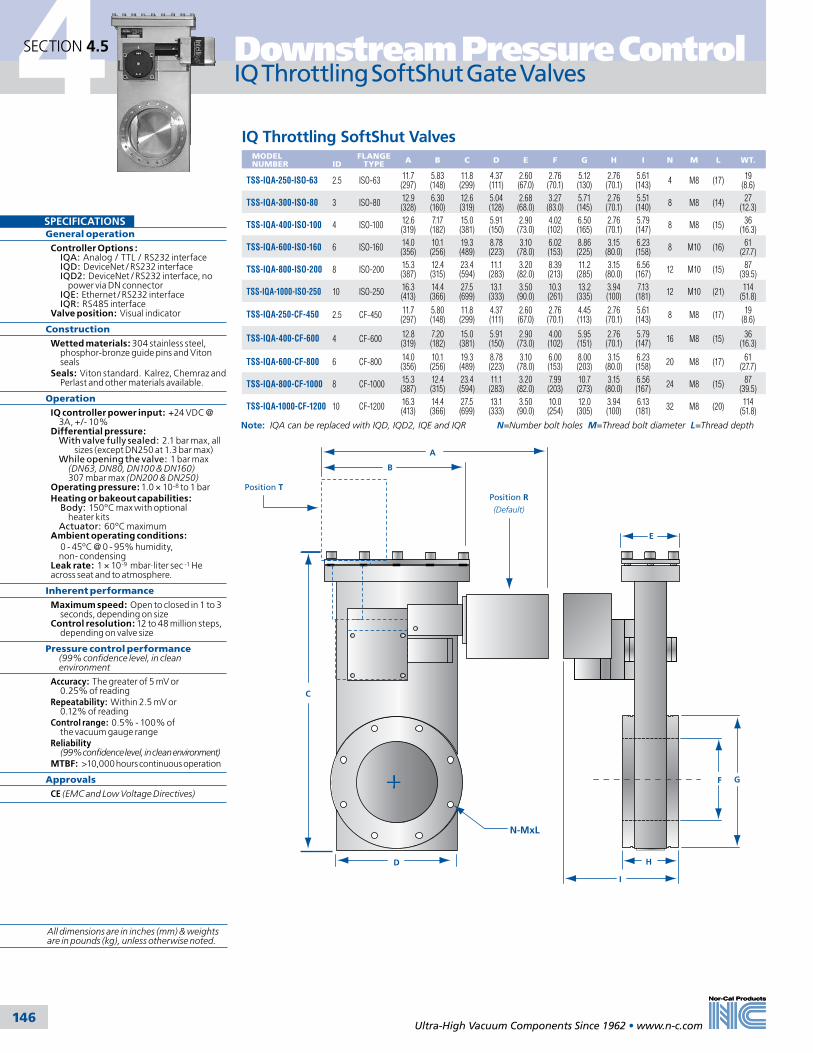
4 Downstream Pressure Control
Ultra-High Vacuum Components Since 1962 • www.n-c.com 146146
SPECIFICATIONSGeneral operation
Controller Options : IQA: Analog / TTL / RS232 interface IQD: DeviceNet / RS232 interface IQD2: DeviceNet / RS232 interface, no power via DN connector IQE: Ethernet / RS232 interface IQR: RS485 interface Valve position: Visual indicator
Construction
Wetted materials: 304 stainless steel, phosphor-bronze guide pins and Viton seals Seals: Viton standard. Kalrez, Chemraz and Perlast and other materials available.
Operation
IQ controller power input: +24 VDC @ 3A, +/- 10% Differential pressure: With valve fully sealed: 2.1 bar max, all sizes (except DN250 at 1.3 bar max) While opening the valve: 1 bar max (DN63, DN80, DN100 & DN160) 307 mbar max (DN200 & DN250) Operating pressure: 1.0 × 10⁻⁸ to 1 bar Heating or bakeout capabilities: Body: 150ºC max with optional heater kits Actuator: 60ºC maximum Ambient operating conditions: 0 - 45ºC @ 0 - 95% humidity, non- condensing Leak rate: 1 × 10⁻⁹ mbar·liter sec -1 He across seat and to atmosphere.
Inherent performance
Maximum speed: Open to closed in 1 to 3 seconds, depending on size Control resolution: 12 to 48 million steps, depending on valve size
Pressure control performance (99% confidence level, in clean environment
Accuracy: The greater of 5 mV or 0.25% of readingRepeatability: Within 2.5 mV or 0.12% of readingControl range: 0.5% - 100% of the vacuum gauge rangeReliability (99% confidence level, in clean environment)MTBF: >10,000 hours continuous operation
Approvals
CE (EMC and Low Voltage Directives)
IQ Throttling SoftShut Gate Valves SECTION 4.5
MODEL NUMBER
ID
FLANGETYPE A B C D E F G H I N M L WT.
TSS-IQA-250-ISO-63 2.5 ISO-63 11.7 (297)
5.83 (148)
11.8 (299)
4.37 (111)
2.60 (67.0)
2.76 (70.1)
5.12 (130)
2.76 (70.1)
5.61 (143) 4 M8 (17) 19
(8.6)
TSS-IQA-300-ISO-80 3 ISO-80 12.9 (328)
6.30 (160)
12.6 (319)
5.04 (128)
2.68 (68.0)
3.27 (83.0)
5.71 (145)
2.76 (70.1)
5.51 (140) 8 M8 (14) 27
(12.3)
TSS-IQA-400-ISO-100 4 ISO-100 12.6 (319)
7.17 (182)
15.0 (381)
5.91 (150)
2.90 (73.0)
4.02 (102)
6.50 (165)
2.76 (70.1)
5.79 (147) 8 M8 (15) 36
(16.3)
TSS-IQA-600-ISO-160 6 ISO-160 14.0 (356)
10.1 (256)
19.3 (489)
8.78 (223)
3.10 (78.0)
6.02 (153)
8.86 (225)
3.15 (80.0)
6.23 (158) 8 M10 (16) 61
(27.7)
TSS-IQA-800-ISO-200 8 ISO-200 15.3 (387)
12.4 (315)
23.4 (594)
11.1 (283)
3.20 (82.0)
8.39 (213)
11.2 (285)
3.15 (80.0)
6.56 (167) 12 M10 (15) 87
(39.5)
TSS-IQA-1000-ISO-250 10 ISO-250 16.3 (413)
14.4 (366)
27.5 (699)
13.1 (333)
3.50 (90.0)
10.3 (261)
13.2 (335)
3.94 (100)
7.13 (181) 12 M10 (21) 114
(51.8)
TSS-IQA-250-CF-450 2.5 CF-450 I 11.7 (297)
5.80 (148)
11.8 (299)
4.37 (111)
2.60 (67.0)
2.76 (70.1)
4.45 (113)
2.76 (70.1)
5.61 (143) 8 M8 (17) 19
(8.6)
TSS-IQA-400-CF-600 4 CF-600 12.8 (319)
7.20 (182)
15.0 (381)
5.91 (150)
2.90 (73.0)
4.00 (102)
5.95 (151)
2.76 (70.1)
5.79 (147) 16 M8 (15) 36
(16.3)
TSS-IQA-600-CF-800 6 CF-800 14.0 (356)
10.1 (256)
19.3 (489)
8.78 (223)
3.10 (78.0)
6.00 (153)
8.00 (203)
3.15 (80.0)
6.23 (158) 20 M8 (17) 61
(27.7)
TSS-IQA-800-CF-1000 8 CF-1000 15.3 (387)
12.4 (315)
23.4 (594)
11.1 (283)
3.20 (82.0)
7.99 (203)
10.7 (273)
3.15 (80.0)
6.56 (167) 24 M8 (15) 87
(39.5)
TSS-IQA-1000-CF-1200 10 CF-1200 16.3 (413)
14.4 (366)
27.5 (699)
13.1 (333)
3.50 (90.0)
10.0 (254)
12.0 (305)
3.94 (100)
6.13 (181) 32 M8 (20) 114
(51.8)
IQ Throttling SoftShut Valves
Note: IQA can be replaced with IQD, IQD2, IQE and IQR N=Number bolt holes M=Thread bolt diameter L=Thread depth
Position R(Default)
Position T
I
B
C
D
E
F G
H
A
N-MxL
All dimensions are in inches (mm) & weights are in pounds (kg), unless otherwise noted.

Adaptive Pressure Controllers 4Downstream Pressure Control
Ultra-High Vacuum Components Since 1962 • www.n-c.com 147
SECTION 4.6
The Intellisys Adaptive Pressure Controller (APC) provides advanced control system performance by combining closed loop motor control with adaptive pressure control. APCs are available in two basic configurations – the buried box style and the new on-valve IQ-series. The patented closed loop motor control technology, found at the core of the Intellisys con-troller technology, results in 250 times
greater motor positional resolution at 10-20 times the speed compared to other existing technologies. The adaptive pres-sure control algorithm eliminates pressure over- and under-shoots as well as ringing during process step transitions.
APC controllers are available for all of Nor-Cal’s Intellisys control valves and
Advanced Control System Performance
SPECIFICATIONSGeneral
Construction material Chassis:5052-aluminum Power input: +24 VDC +/-10%, 100W max (600W nonminal) power input Battery back-up: Optional Ambient operating conditions: 0 - 45ºC @ 0 - 95%humidity, non-condensing
System interface
Serial communication: RS-232 or RS-485 on DB-15 female connector..Analog/TTL communication: Four (4) analog I/O and seven (7) TTL I/O on DB-25 female connector DeviceNet communication: Micro-style 5-pin male connector Analog setpoint input: 0-10 or 0-5 VDC linearly proportional to pressure or valve position Pressure output: 0-10 VDC analog out- put proportional to pressure, one for each vacuum gauge attached Valve position output: 0-10 VDC or 0-5 VDC analog output proportional to valve position
Device interface
Gauge connection: Differential analog signal input with ±15 VDC power output to one or two gauges Valve connection: DB-15 female connector provides power and transmits position information required to operate the high performance valve
User Interface
Switches: Valve open & close, and mutli- position rotary switches for communications settings Indicating LED’s Power, Fault, Control, Valve open and closed, DeviceNet: Mod and Net
Pressure Control Performance
Accuracy: The greater of 5 mV or 0.25% of reading Repeatability: Within 2.5 mV or 0.12% of readingControl range: 0.5% - 100% of the vacuum gauge rangeReliability (99% confidence level, in clean environment)MTBF: >50,000 hours continuous operationApprovalsCE (EMC and Low Voltage Directives) NRTL (United States) SCC (Canada) EU Directives(Europe)
Low Voltage Controllers
Low Voltage Controllers with DeviceNetMODEL NUMBER FOR USE WITH BATTERY
BACK-UP WEIGHT
APC-100L-D Geared Butterfly Valves (TBV-G-xxx) NO 1.6 (0.7)APC-100L-DB Geared Butterfly Valves (TBV-G-xxx) YES 2.5 (1.1)APC-200L-D Direct Drive Butterfly Valves (TBV-D-xxx) NO 1.6 (0.7)APC-200L-DB Direct Drive Butterfly Valves (TBV-D-xxx) YES 2.5 (1.1)APC-300L-D Sealing Butterfly Valves (TBVS-G-xxx) NO 1.6 (0.7)APC-300L-DB Sealing Butterfly Valves (TBVS-G-xxx) YES 2.5 (1.1)APC-700L-D SoftShut Linear Gate Valves (TSS-xxx) NO 1.6 (0.7)APC-700L-DB SoftShut Linear Gate Valves (TSS-xxx) YES 2.5 (1.1)APC-800L-D Pendulum Valves (TPV-xxx) NO 1.6 (0.7)APC-800L-DB Pendulum Valves (TPV-xxx) YES 2.5 (1.1)
MODEL NUMBER FOR USE WITH BATTERY
BACK-UP WEIGHT
APC-100L-A Geared Butterfly Valves (TBV-G-xxx) NO 1.6 (0.7)APC-100L-AB Geared Butterfly Valves (TBV-G-xxx) YES 2.5 (1.1)APC-200L-A Direct Drive Butterfly Valves (TBV-D-xxx) NO 1.6 (0.7)APC-200L-AB Direct Drive Butterfly Valves (TBV-D-xxx) YES 2.5 (1.1)APC-300L-A Sealing Butterfly Valves (TBVS-G-xxx) NO 1.6 (0.7)APC-300L-AB Sealing Butterfly Valves (TBVS-G-xxx) YES 2.5 (1.1)APC-700L-A SoftShut Linear Gate Valves (TSS-xxx) NO 1.6 (0.7)APC-700L-AB SoftShut Linear Gate Valves (TSS-xxx) YES 2.5 (1.1)APC-800L-A Pendulum Valves (TPV-xxx) NO 1.6 (0.7)APC-800L-AB Pendulum Valves (TPV-xxx) YES 2.5 (1.1)
2.51
5.74 5.69
4.78
2.51
5.74 5.69
4.78
drives, and can be supplied with auto-ranging AC, or low voltage DC power supplies. Depending on the model and intended valve operation, users can choose from additional optional features such as battery back-up, local and remote displays and a range of communication modes including Analog/TTL, RS-232 and RS-485 serial, as well as DeviceNet.
All dimensions are in inches (mm) & weights are in pounds (kg), unless otherwise noted.

4 Downstream Pressure Control
Ultra-High Vacuum Components Since 1962 • www.n-c.com 148
SECTION 4.6
A/C Adaptive Pressure Controllers
Adaptive Pressure Controllers
SPECIFICATIONSConstruction
Construction material Chassis: 5052-aluminum Power input: 100-240 VAC, 50-60Hz, 100W max (60W nominal) power input. Battery Back-up: N/A Ambient operating conditions: 0 - 45ºC @ 0 - 95% humidity, non-condensing
System interface
Serial communication: RS-232 or RS-485 on DB-9 female connector. Analog / TTL communication: Six (6) analog I/O and thirteen (13) TTL I/O on DB-37 female connector DeviceNet communication: N/A Analog setpoint input: 0-10 or 0-5 VDC linearly proportional tp pressure or valve position Pressure output: 0-10 VDC analog output proportional to pressure, one for each vacuum gauge attached Valve position output: 0-10 VDC or 0-5 VDC analog output proportional to valve position
Device interface
Gauge connection: Differential analog signal input with ±15 VDC power output to one or two gauges Valve connection: DB-15 female connector provides power and transmits position information required to operate the high performance valve
User interface
Switches: Power ON / OFF, Valve OPEN / CLOSE Indicating LEDs: Power, Fault, Control, Valve open and closed Graphic display: N/A (Touch screen LCD on listed model)
Pressure control performance
Accuracy: The greater of 5 mV or 0.25% of reading Repeatability: Within 2.5 mV or 0.12% of reading Control range: 0.5% - 100% of the vacuum gauge range
Reliability (99% confidence level, in clean environment)
MTBF: >50,000 hours continuous operation
Approvals
CE (EMC and Low Voltage Directives) NRTL (United States) SCC (Canada) EU Directives(Europe)
A/C Adaptive Pressure Controllers with Touch ScreenMODEL NUMBER FOR USE WITH BATTERY BACK-UP WEIGHT
APC-150-A Geared Butterfly Valves (TBV-G-xxx) NO 4.2 (1.9)APC-250-A Direct Drive Butterfly Valves (TBV-D-xxx) NO 4.2 (1.9)APC-350-A Sealing Butterfly Valves (TBVS-G-xxx) NO 4.2 (1.9)APC-750-A SoftShut Linear Gate Valves (TSS-xxx) NO 4.2 (1.9)APC-850-A Pendulum Valves (TPV-xxx) NO 4.2 (1.9)
MODEL NUMBER FOR USE WITH BATTERY BACK-UP WEIGHT
APC-100-A Geared Butterfly Valves (TBV-G-xxx) NO 3.5 (1.6)APC-200-A Direct Drive Butterfly Valves (TBV-D-xxx) NO 3.5 (1.6)APC-300-A Sealing Butterfly Valves (TBVS-G-xxx) NO 3.5 (1.6)APC-700-A SoftShut Linear Gate Valves (TSS-xxx) NO 3.5 (1.6)APC-800-A Pendulum Valves (TPV-xxx) NO 3.5 (1.6)
7.00
3.46
10.60
IntellisysTM
ADAPTIVE PRESSURE CONTROLLER
CLOSED
OPEN
CONTROL
FAULT
POWER
CLOSEDCLOSED
OPENOPEN
CONTROLCONTROL
FAULTFAULT
POWERPOWER
8.50
3.50
10.60
VALVEVALVE TTL/ANALOG I/OTTL/ANALOG I/O
GAUGE 1GAUGE 1SW1SW1
POWER
!100-240V~50-60 Hz
POWER
!!100-240V~50-60 Hz SERIALSERIALGAUGE 2GAUGE 2
POWER
ON
OFF
I
OPOWER
ON
OFF
I
O
8.00
3.50
VALVEVALVE
POWER
TTL/ANALOG I/OTTL/ANALOG I/O
GAUGE 1GAUGE 1SW1SW1
!!100-240V~50-60 Hz
SERIALSERIALGAUGE 2GAUGE 2
6.50
2.75
DEPTH: 10.60 ”
All dimensions are in inches (mm) & weights are in pounds (kg), unless otherwise noted.
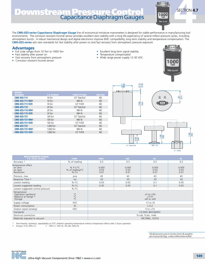
½" FVCR
NW - 16
1.50 (38)
½" Tube End
2.06
(5
2)0.
15 (
3.8)
1.69
(
43)
SPANZERO .87
(21)
0.94
(
24) 1.
09
(28
)
Ultra-High Vacuum Components Since 1962 • www.n-c.com 149
1) Non-linearity, hysteresis, repeatability at 25°C ambient operating temperature without temperature effects after 2 hours operation.2) Incease 10 to 90% F.S. 3) 18% Cr, 10% Ni, 3% Mo, 69% Fe
Capacitance Diaphragm Gauges Downstream Pressure Control
The CMG-025-series Capacitance Diaphragm Gauge line of economical miniature manometers is designed for stable performance in manufacturing tool environments. The corrosion resistant Inconel sensor provides excellent zero stability with a long life expectancy of several million pressure cycles, including atmospheric bursts. A robust mechanical design and digital electronics improve EMC compatibility, long term stability and temperature compensation. The CMG-025-series sets new standards for fast stability after power on and fast recovery from atmospheric pressure exposure.
Advantages• Full scale ranges from 10 Torr to 1000 Torr • Excellent long term signal stability• Fast stability after power on • Temperature compensated• Fast recovery from atmospheric pressure • Wide range power supply 12-30 VDC• Corrosion resistant Inconel sensor
MEASUREMENT RANGE F.S. (FULL SCALE) TORR 1000 100 20 10
Accuracy 1) % of reading 0.5 0.5 0.5 0.5
Temperature effecton zeroon spanResolution
% F.S./°C% of reading/°C
% F.S.
0.0050.030.01
0.0050.030.01
0.0050.030.01
0.0050.030.01
Pressure, max. psia 45 45 45 45Response Time 2) ms 20 20 20 20Lowest reading % F.S. 0.05 0.05 0.1 0.05Lowest suggested reading % F.S. 0.05 0.05 0.1 0.05Lowest suggested control pressure % F.S.Temperature Operation (ambient) Bakeout at flange 3)
Storage
°C°C°C
+5 to +50 ≤110
-40 to +65
Supply voltage VDC 12 to 32Power consumption W ≤ 0.2Output signal (analog) VDC 0 to +10Standards CE:EMG 89/336/EECElectrical connection D-sub, 9 pin, maleMaterials exposed to vacuum INCONEL, SS316
MODEL NUMBER F.S. RANGE TUBE FITTING HEATED
CMG-025-T11 10 Torr 1/2” Tube End NOCMG-025-T11-NW1 10 Torr NW-16 NOCMG-025-T11-VCR 10 Torr 1/2” FVCR NOCMG-025-T12 20 Torr 1/2” Tube End NOCMG-025-T12-NW1 20 Torr NW-16 NOCMG-025-T12-VCR 20 Torr NW-16 NOCMG-025-T21 100 Torr 1/2” Tube End NOCMG-025-T21-NW1 100 Torr NW-16 NOCMG-025-T21-VCR 100 Torr 1/2” FVCR NOCMG-025-T31 1,000 Torr 1/2” Tube End NOCMG-025-T31-NW1 1,000 Torr NW-16 NOCMG-025-T31-VCR 1,000 Torr 1/2” FVCR NO
4SECTION 4.7
All dimensions are in inches (mm) & weights are in pounds (kg), unless otherwise noted.

4 Downstream Pressure Control
Ultra-High Vacuum Components Since 1962 • www.n-c.com 150
SECTION 4.7
Capacitance Diaphragm Gauges
Measurements of Superior Accuracy and Repeatability
½" FVCR
NW - 16
2.17 (55)
1.33 CF½" Tube End
2.72
(6
9)0.
15 (
3.8)
1.73
(4
4)
RUN ZERO
1 2 SP 1.33
(33.
8)
1) Non-linearity, hysteresis, repeatability at 25°C ambient operating temperature without temperature effects after 2 hours operation.2) Incease 10 to 90% F.S. 3) Non operation4) 28% Ni, 23% Co, 49% Fe 5) 18% Cr, 10% Ni, 3% Mo, 69% Fe
The CDG025-series Capacitance Diaphragm Gauge line of highly accurate temperature compensated manometers is designed for stable performance in harsh manufacturing tool environments. Advanced digital electronics improve gauge performance and offer easy handling features such as one push button zero function and set point adjustment. The corrosion resistant ultra pure ceramic sensor provides excellent zero stability with a long life expectancy of several million pressure cycles, including atmospheric bursts. A robust mechanical design and digital electronics improve EMC compatibility, long term stability and temperature compensation. The CDG025-series sets new standards for fast stability after power on and fast recovery from atmospheric pressure exposure.
Advantages• Full scale ranges from 1 Torr to 1000 Torr • Temperature compensated • Excellent long term signal stability• Fast stability after power on • Sensor protected from contamination• Fast recovery from atmospheric pressure • One push button zero function• Corrosion resistant ceramic sensor • Wide range power supply
MODEL NUMBER F.S. RANGE TUBE FITTING HEATED
CDG025-T01 1 Torr 1/2” Tube End NOCDG025-T01-CF 1 Torr 1.33” CF NOCDG025-T01-NW1 1 Torr NW-16 NOCDG025-T01-VCR 1 Torr 1/2” FVCR NOCDG025-T02 2 Torr 1/2” Tube End NOCDG025-T02-CF 2 Torr 1.33” CF NOCDG025-T02-NW1 2 Torr NW-16 NOCDG025-T02-VCR 2 Torr 1/2” FVCR NOCDG025-T11 10 Torr 1/2” Tube End NOCDG025-T11-CF 10 Torr 1.33” CF NOCDG025-T11-NW1 10 Torr NW-16 NOCDG025-T11-VCR 10 Torr 1/2” FVCR NOCDG025-T12 20 Torr 1/2” Tube End NOCDG025-T12-CF 20 Torr 1.33” CF NOCDG025-T12-NW1 20 Torr NW-16 NOCDG025-T12-VCR 20 Torr 1/2” FVCR NOCDG025-T21 100 Torr 1/2” Tube End NOCDG025-T21-CF 100 Torr 1.33” CF NOCDG025-T21-NW1 100 Torr NW-16 NOCDG025-T21-VCR 100 Torr 1/2” FVCR NOCDG025-T31 1,000 Torr 1/2” Tube End NOCDG025-T31-CF 1,000 Torr 1.33” CF NOCDG025-T31-NW1 1,000 Torr NW-16 NOCDG025-T31-VCR 1,000 Torr 1/2” FVCR NO
MEASUREMENT RANGE F.S. (FULL SCALE) TORR 1000 100 20/10 2/1
Accuracy 1) % of reading 0.2 0.2 0.2 0.2
Temperature effecton zeroon spanResolution
% F.S./°C% of reading/°C
% F.S.
0.0050.01
0.003
0.0050.01
0.003
0.0050.01
0.003
0.0150.01
0.003
Pressure, max. kPa (absolute) 400 260 260 260Response Time 2) ms 30 30 30 30Lowest reading % F.S. 0.01Lowest suggested reading % F.S. 0.05Lowest suggested control pressure % F.S. 0.05Temperature Operation (ambient) Bakeout at flange 3)
Storage
°C°C°C
+5 to +50 ≤110
-40 to +65
Supply voltage VDC 14 to +30Power consumption W ≤1Output signal (analog) VDC 0 to +10Degree of protection IP 30Standards EN 61000-6-2, EN 6100-6-3, EN 61010, UL 61010-1, CSA 22.2 No. 61010-1, RoHSElectrical connection D-sub, 15 pin, male
Materials exposed to vacuum Aluminum oxide ceramic (A203), Vacon 704), stainless steel (AISI 316L 5)), AgCuTi hard solder, sealing glass
INTERNAL VOLUMEin3 (cm3)
WEIGHT grams
1/2“ Tube End 0.22 ( 3.6) 310NW - 16 0.22 ( 3.6) 3301.33 CF 0.22 ( 3.6) 3501/2“ FVCR® 0.22 ( 3.6) 370
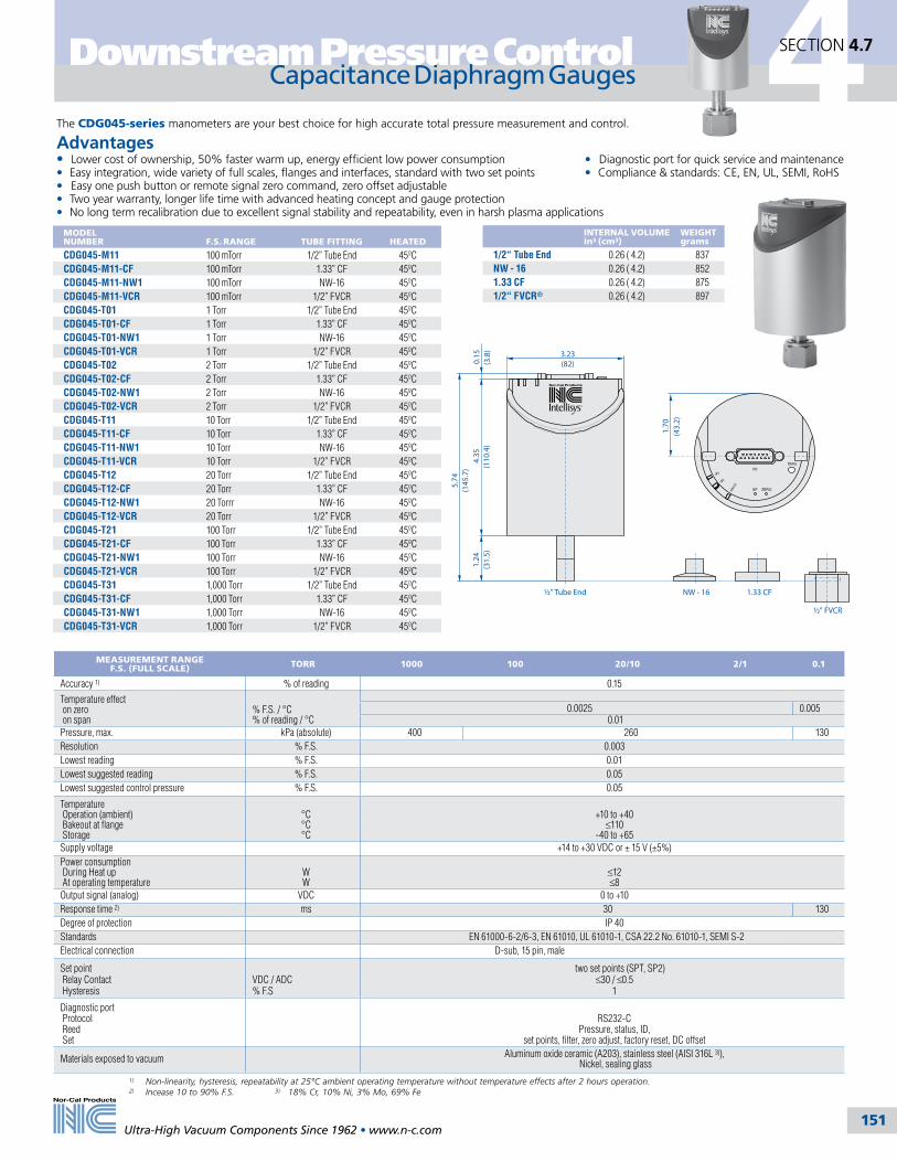
SP1
SP2
STAT
US
½" FVCR
NW - 16
3.23(82)
5.74
(145
.7)
1.33 CF½" Tube End
1.70
(43.
2)
4.35
(110
.4)
0.15
(3.8
)1.
24(3
1.5)
Capacitance Diaphragm Gauges 4
Ultra-High Vacuum Components Since 1962 • www.n-c.com
Downstream Pressure Control
151
SECTION 4.7
1) Non-linearity, hysteresis, repeatability at 25°C ambient operating temperature without temperature effects after 2 hours operation.2) Incease 10 to 90% F.S. 3) 18% Cr, 10% Ni, 3% Mo, 69% Fe
The CDG045-series manometers are your best choice for high accurate total pressure measurement and control.
Advantages• Lower cost of ownership, 50% faster warm up, energy efficient low power consumption • Diagnostic port for quick service and maintenance• Easy integration, wide variety of full scales, flanges and interfaces, standard with two set points • Compliance & standards: CE, EN, UL, SEMI, RoHS• Easy one push button or remote signal zero command, zero offset adjustable• Two year warranty, longer life time with advanced heating concept and gauge protection• No long term recalibration due to excellent signal stability and repeatability, even in harsh plasma applications
MEASUREMENT RANGE F.S. (FULL SCALE) TORR 1000 100 20/10 2/1 0.1
Accuracy 1) % of reading 0.15
Temperature effect on zero on span
% F.S. / °C% of reading / °C
0.0025 0.005 0.01
Pressure, max. kPa (absolute) 400 260 130Resolution % F.S. 0.003Lowest reading % F.S. 0.01Lowest suggested reading % F.S. 0.05Lowest suggested control pressure % F.S. 0.05
Temperature Operation (ambient) Bakeout at flange Storage
°C°C°C
+10 to +40 ≤110
-40 to +65Supply voltage +14 to +30 VDC or ± 15 V (±5%)Power consumption During Heat up At operating temperature
WW
≤12 ≤8
Output signal (analog) VDC 0 to +10Response time 2) ms 30 130Degree of protection IP 40Standards EN 61000-6-2/6-3, EN 61010, UL 61010-1, CSA 22.2 No. 61010-1, SEMI S-2Electrical connection D-sub, 15 pin, male
Set point Relay Contact Hysteresis
VDC / ADC% F.S
two set points (SPT, SP2) ≤30 / ≤0.5
1
Diagnostic port Protocol Reed Set
RS232-C Pressure, status, ID,
set points, filter, zero adjust, factory reset, DC offset
Materials exposed to vacuum Aluminum oxide ceramic (A203), stainless steel (AISI 316L 3)), Nickel, sealing glass
MODEL NUMBER F.S. RANGE TUBE FITTING HEATED
CDG045-M11 100 mTorr 1/2” Tube End 45ºCCDG045-M11-CF 100 mTorr 1.33” CF 45ºCCDG045-M11-NW1 100 mTorr NW-16 45ºCCDG045-M11-VCR 100 mTorr 1/2” FVCR 45ºCCDG045-T01 1 Torr 1/2” Tube End 45ºCCDG045-T01-CF 1 Torr 1.33” CF 45ºCCDG045-T01-NW1 1 Torr NW-16 45ºCCDG045-T01-VCR 1 Torr 1/2” FVCR 45ºCCDG045-T02 2 Torr 1/2” Tube End 45ºCCDG045-T02-CF 2 Torr 1.33” CF 45ºCCDG045-T02-NW1 2 Torr NW-16 45ºCCDG045-T02-VCR 2 Torr 1/2” FVCR 45ºCCDG045-T11 10 Torr 1/2” Tube End 45ºCCDG045-T11-CF 10 Torr 1.33” CF 45ºCCDG045-T11-NW1 10 Torr NW-16 45ºCCDG045-T11-VCR 10 Torr 1/2” FVCR 45ºCCDG045-T12 20 Torr 1/2” Tube End 45ºCCDG045-T12-CF 20 Torr 1.33” CF 45ºCCDG045-T12-NW1 20 Torrr NW-16 45ºCCDG045-T12-VCR 20 Torr 1/2” FVCR 45ºCCDG045-T21 100 Torr 1/2” Tube End 45ºCCDG045-T21-CF 100 Torr 1.33” CF 45ºCCDG045-T21-NW1 100 Torr NW-16 45ºCCDG045-T21-VCR 100 Torr 1/2” FVCR 45ºCCDG045-T31 1,000 Torr 1/2” Tube End 45ºCCDG045-T31-CF 1,000 Torr 1.33” CF 45ºCCDG045-T31-NW1 1,000 Torr NW-16 45ºCCDG045-T31-VCR 1,000 Torr 1/2” FVCR 45ºC
INTERNAL VOLUMEin3 (cm3)
WEIGHT grams
1/2“ Tube End 0.26 ( 4.2) 837NW - 16 0.26 ( 4.2) 8521.33 CF 0.26 ( 4.2) 8751/2“ FVCR® 0.26 ( 4.2) 897

MODEL NUMBER F.S. RANGE TUBE FITTING HEATED
CDG100-M11 100 mTorr 1/2” Tube End 100ºCCDG100-M11-CF 100 mTorr 1.33” CF 100ºCCDG100-M11-NW1 100 mTorr NW-16 100ºCCDG100-M11-VCR 100 mTorr 1/2” FVCR 100ºCCDG100-T01 1 Torr 1/2” Tube End 100ºCCDG100-T01-CF 1 Torr 1.33” CF 100ºCCDG100-T01-NW1 1 Torr NW-16 100ºCCDG100-T01-VCR 1 Torr 1/2” FVCR 100ºCCDG100-T02 2 Torr 1/2” Tube End 100ºCCDG100-T02-CF 2 Torr 1.33” CF 100ºCCDG100-T02-NW1 2 Torr NW-16 100ºCCDG100-T02-VCR 2 Torr 1/2” FVCR 100ºCCDG100-T11 10 Torr 1/2” Tube End 100ºCCDG100-T11-CF 10 Torr 1.33” CF 100ºCCDG100-T11-NW1 10 Torr NW-16 100ºCCDG100-T11-VCR 10 Torr 1/2” FVCR 100ºCCDG100-T12 20 Torr 1/2” Tube End 100ºCCDG100-T12-CF 20 Torr 1.33” CF 100ºCCDG100-T12-NW1 20 Torr NW-16 100ºCCDG100-T12-VCR 20 Torr 1/2” FVCR 100ºCCDG100-T21 100 Torr 1/2” Tube End 100ºCCDG100-T21-CF 100 Torr 1.33” CF 100ºCCDG100-T21-NW1 100 Torr NW-16 100ºCCDG100-T21-VCR 100 Torr 1/2” FVCR 100ºCCDG100-T31 1,000 Torr 1/2” Tube End 100ºCCDG100-T31-CF 1,000 Torr 1.33” CF 100ºCCDG100-T31-NW1 1,000 Torr NW-16 100ºCCDG100-T31-VCR 1,000 Torr 1/2” FVCR 100ºC
4 Downstream Pressure Control
Ultra-High Vacuum Components Since 1962 • www.n-c.com 152
SECTION 4.7
Capacitance Diaphragm Gauges
SP1
SP2
STAT
US
½" FVCR
NW - 16
3.23(82)
5.74
(145
.7)
1.33 CF½" Tube End1.
70
(43.
2)
4.35
(110
.4)
0.15
(3.8
)1.
24(3
1.5)
1) Non-linearity, hysteresis, repeatability at 25°C ambient operating temperature without temperature effects after 2 hours operation.2) Incease 10 to 90% F.S. 3) 18% Cr, 10% Ni, 3% Mo, 69% Fe
CDG100-series gauges are temperature controlled at 100°C for superior performance in demanding semiconductor and plasma processes.
Advantages• Lower cost of ownership, 50% faster warm up, energy efficient low power consumption • Diagnostic port for quick service and maintenance• Easy integration, wide variety of full scales, flanges and interfaces, standard with two set points • Compliance & standards: CE, EN, UL, SEMI, RoHS• Easy one push button or remote signal zero command, zero offset adjustable• Two year warranty, longer life time with advanced heating concept and gauge protection• No long term recalibration due to excellent signal stability and repeatability, even in harsh plasma applications
MEASUREMENT RANGE F.S. (FULL SCALE) TORR 1000 100 20/10 2/1 0.1
Accuracy 1) % of reading 0.2 0.4
Temperature effect on zero on span
% F.S./ °C% of reading / °C
0.00025 0.005 0.02
Pressure, max. kPa (absolute) 400 260 130Resolution % F.S. 0.003Lowest reading % F.S. 0.01Lowest suggested reading % F.S. 0.05Lowest suggested control pressure % F.S. 0.05Temperature Operation (ambient) Bakeout at flange Storage
°C°C°C
+10 to +50 ≤110
-40 to +65
Supply voltage +14 to +30 VDC or ± 15 V (±5%)Power consumption During Heat up At operating temperature
WW
≤15 ≤10
Output signal (analog) VDC 0 to +10Response time 2) ms 30 130Degree of protection IP 40Standards EN 61000-6-2/6-3, EN 61010, UL 61010-1, CSA 22.2 No. 61010-1, SEMI S-2Electrical connection D-sub, 15 pin, male
Set point Relay Contact Hysteresis
VDC / ADC% F.S
two set points (SPT, SP2) ≤30 / ≤0.5
1
Diagnostic port Protocol Read Set
RS232-C
Pressure, status, ID, set points, filter, zero adjust, factory reset, DC offset
Materials exposed to vacuum Aluminum oxide ceramic (A203), stainless steel (AISI 316L 3)), Nickel, sealing glass
INTERNAL VOLUMEin3 (cm3)
WEIGHT grams
1/2“ Tube End 0.26 ( 4.2) 837NW - 16 0.26 ( 4.2) 8521.33 CF 0.26 ( 4.2) 8751/2“ FVCR® 0.26 ( 4.2) 897
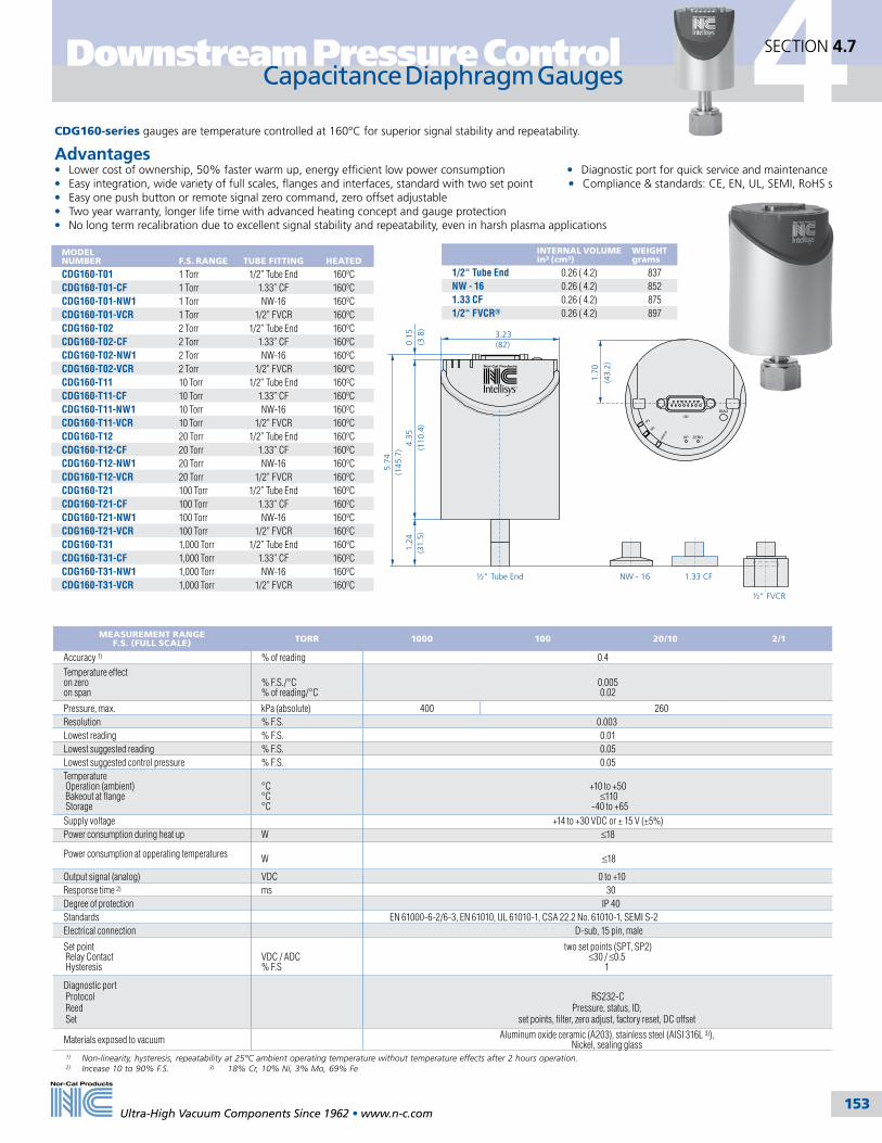
Capacitance Diaphragm Gauges 4
Ultra-High Vacuum Components Since 1962 • www.n-c.com 153
Downstream Pressure Control SECTION 4.7
SP1
SP2
STAT
US
½" FVCR
NW - 16
3.23(82)
5.74
(145
.7)
1.33 CF½" Tube End
1.70
(43.
2)
4.35
(110
.4)
0.15
(3.8
)1.
24(3
1.5)
CDG160-series gauges are temperature controlled at 160°C for superior signal stability and repeatability.
Advantages• Lower cost of ownership, 50% faster warm up, energy efficient low power consumption • Diagnostic port for quick service and maintenance• Easy integration, wide variety of full scales, flanges and interfaces, standard with two set point • Compliance & standards: CE, EN, UL, SEMI, RoHS s• Easy one push button or remote signal zero command, zero offset adjustable• Two year warranty, longer life time with advanced heating concept and gauge protection• No long term recalibration due to excellent signal stability and repeatability, even in harsh plasma applications
1) Non-linearity, hysteresis, repeatability at 25°C ambient operating temperature without temperature effects after 2 hours operation.2) Incease 10 to 90% F.S. 3) 18% Cr, 10% Ni, 3% Mo, 69% Fe
INTERNAL VOLUMEin3 (cm3)
WEIGHT grams
1/2“ Tube End 0.26 ( 4.2) 837NW - 16 0.26 ( 4.2) 8521.33 CF 0.26 ( 4.2) 8751/2“ FVCR® 0.26 ( 4.2) 897
MODEL NUMBER F.S. RANGE TUBE FITTING HEATED
CDG160-T01 1 Torr 1/2” Tube End 160ºCCDG160-T01-CF 1 Torr 1.33” CF 160ºCCDG160-T01-NW1 1 Torr NW-16 160ºCCDG160-T01-VCR 1 Torr 1/2” FVCR 160ºCCDG160-T02 2 Torr 1/2” Tube End 160ºCCDG160-T02-CF 2 Torr 1.33” CF 160ºCCDG160-T02-NW1 2 Torr NW-16 160ºCCDG160-T02-VCR 2 Torr 1/2” FVCR 160ºCCDG160-T11 10 Torr 1/2” Tube End 160ºCCDG160-T11-CF 10 Torr 1.33” CF 160ºCCDG160-T11-NW1 10 Torr NW-16 160ºCCDG160-T11-VCR 10 Torr 1/2” FVCR 160ºCCDG160-T12 20 Torr 1/2” Tube End 160ºCCDG160-T12-CF 20 Torr 1.33” CF 160ºCCDG160-T12-NW1 20 Torr NW-16 160ºCCDG160-T12-VCR 20 Torr 1/2” FVCR 160ºCCDG160-T21 100 Torr 1/2” Tube End 160ºCCDG160-T21-CF 100 Torr 1.33” CF 160ºCCDG160-T21-NW1 100 Torr NW-16 160ºCCDG160-T21-VCR 100 Torr 1/2” FVCR 160ºCCDG160-T31 1,000 Torr 1/2” Tube End 160ºCCDG160-T31-CF 1,000 Torr 1.33” CF 160ºCCDG160-T31-NW1 1,000 Torr NW-16 160ºCCDG160-T31-VCR 1,000 Torr 1/2” FVCR 160ºC
MEASUREMENT RANGE F.S. (FULL SCALE) TORR 1000 100 20/10 2/1
Accuracy 1) % of reading 0.4
Temperature effecton zeroon span
% F.S./°C% of reading/°C
0.005 0.02
Pressure, max. kPa (absolute) 400 260Resolution % F.S. 0.003Lowest reading % F.S. 0.01Lowest suggested reading % F.S. 0.05Lowest suggested control pressure % F.S. 0.05Temperature Operation (ambient) Bakeout at flange Storage
°C°C°C
+10 to +50 ≤110
-40 to +65Supply voltage +14 to +30 VDC or ± 15 V (±5%)Power consumption during heat up W ≤18
Power consumption at opperating temperatures W ≤18
Output signal (analog) VDC 0 to +10Response time 2) ms 30Degree of protection IP 40Standards EN 61000-6-2/6-3, EN 61010, UL 61010-1, CSA 22.2 No. 61010-1, SEMI S-2Electrical connection D-sub, 15 pin, male
Set point Relay Contact Hysteresis
VDC / ADC% F.S
two set points (SPT, SP2) ≤30 / ≤0.5
1
Diagnostic port Protocol Reed Set
RS232-C Pressure, status, ID,
set points, filter, zero adjust, factory reset, DC offset
Materials exposed to vacuum Aluminum oxide ceramic (A203), stainless steel (AISI 316L 3)), Nickel, sealing glass
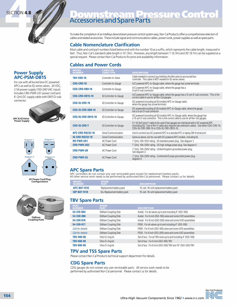
4
Ultra-High Vacuum Components Since 1962 • www.n-c.com 154
Downstream Pressure Control
Power Supply APC-PSM-DB15For use with all buried box DC powered APCs as well as IQ-series valves. 24 VDC, 2.5A power supply (100-240 VAC input). Includes CRD-PWR-US1 power cord and 6’ (2m) DC supply cable with DB15 D-sub connector.
SECTION 4.8
Accessories and Spare Parts
To make the completion of an Intellisys downstream pressure control system easy, Nor-Cal Products offers a comprehensive selection of cables and related accessories. These include signal and communications cables, power cords, power supplies as well as spare parts.
Cable Nomenclature ClarificationMost cable and cord part numbers listed below end with the number 10 as a suffix, which represents the cable length, measured in feet. Thus, Nor-Cal’s standard cable length is 10’ (3m). However, any length between 1’ (0.3m) and 30’ (9.1m) can be supplied as a special request. Please contact Nor-Cal Products for price and availability information.
Cables and Power CordsMODEL NUMBER
CABLE OR CORD TYPE
DESCRIPTION
TBV-CRD-10 Controller-to-Valve Cable needed to connect any Intellisys throttle valve to any buried box controller. This cable is NOT needed for IQ-series valves.
CDG-CRD-10 Controller-to-Gauge A/C powered APC-to-Gauge cable, where the gauge has screw terminals
CDG-CRD-DB9-10 Controller-to-Gauge A/C powered APC-to-Gauge cable, where the gauge has a 9-pin D-sub connector
CDG-CRD-DB15-10 IQ Controller-to-Gauge A/C powered APC-to-Gauge cable, where the gauge has a 15-pin D-sub connector. This is the correct cable to use for all Nor-Cal gauges.
CDG-IQ-CRD-10 IQ Controller-to-Gauge DC powered (including all IQ models) APC-to-Gauge cable, where the gauge has screw terminals
CDG-IQ-CRD-DB9-10 IQ Controller-to-Gauge DC powered(including all IQ models) APC-to-Gauge cable, where the gauge has a 9-pin D-sub connector
CDG-IQ-CRD-DB15-10 IQ Controller-to-Gauge DC powered (including all IQ models) APC-to-Gauge cable, where the gauge has a 15-pin D-sub connector. This is the correct cable to use for all Nor-Cal gauges.
CDG-IQ-CRD-Y IQ Controller-to-GaugeA 1’ (0.3m) long Y-cable to be used if two gauges are interfaced with a DC powered APC (including IQ). Use of this Y-cable also requires two extension cables. Use either CDG-CRD-10, CDG-IQ-CRD-DB9-10 or CDG-IQ-CRD-DB15-10.
APC-CRD-RS232-10 Serial Communication Use to connect any AC powered APC to a standard PC or laptop DB-9 serial port.
IQ-CRD-RS232-10 Serial Communication Same as above, but for use with DC powered APC models, including IQ.
RD-PWR-US1 AC Power Cord 7’ (2m), 10A-125V rating. US standard power plug. See diagram 1.
CRD-PWR-US2 AC Power Cord 7’ (2m), 10A-250V rating. US high voltage power plug. See diagram 2.
CRD-PWR-UK AC Power Cord 7’ (2m), 10A-250V rating. United Kingdom grounded power plug. See diagram 3.
CRD-PWR-EU AC Power Cord 7’ (2m), 10A-250V rating. Continental Europe grounded power plug.diagram 4.
Diagram 1 Diagram 2
Diagram 3 Diagram 4
APC Spare PartsAPC controllers do not contain any user serviceable parts except for replacement battery packs. All other service work needs to be performed by authorized Nor-Cal personnel. Please contact us for details.
MODEL NUMBER
SPARE PART
DESCRIPTION
APC-BAT-1518 Replacement battery pack 15-cell, 18-volt replacement battery pack
IQP-BAT-1518 IQ+ Replacement battery pack 15-cell, 18-volt replacement battery pack
TBV Spare PartsPART NUMBER
SPARE PART
DESCRIPTION
54-310-004 Oldham Coupling Disk Acetal. For all valves up to and including 4” (ISO-100)
54-330-006 Oldham Coupling Disk Acetal. For 6 inch (ISO-160) valve and some UVD assemblies.
54-330-016 Oldham Coupling Disk Acetal. For 8 inch (ISO-200) valve and some UVD assemblies
54-330-017 Oldham Coupling Disk PEEK. For all valves up to and including 4” (ISO-100)
Call for details Oldham Coupling Disk PEEK. For 6 inch (ISO-160) valve and some UVD assemblies.
Call for details Oldham Coupling Disk PEEK. For 8 inch (ISO-200) valve and some UVD assemblies
TBV-400-90 Viton O-ring kit. Set of four. For all TBV sizes up to and including 4” (ISO-100)
TBV-600-90 Viton O-ring kit. Set of four. For 6 inch (ISO-160) TBV
TBV-800-90 Viton O-ring kit. Set of four. For 8 inch (ISO-200) TBV and 10” (ISO-250) TBV
Oldham Coupling Hubs
AC Power Cord Plug Configurations
APC & IQ Valve Power Supply
TPV and TSS Spare PartsPlease contact Nor-Cal Products technical support department for details.
CDG Spare Parts CDG gauges do not contain any user serviceable parts. All service work needs to be performed by authorized Nor-Cal personnel. Please contact us for details.

155155
5
Tel: 800-824-4166or 530-842-4457
Main Fax: 530-842-9130Sales Fax: 530-841-9189
www.n-c.com
Nor-Cal Products, Inc.1967 South Oregon Street
Yreka, CA 96097 USA
5.1 General Information 156
5.2 Metal Sieve Traps 158
5.3 Molecular Sieve Traps 160
5.4 Particulate Traps 161
5.5 LPCVD-TEOS Traps 162
5.6 Water-Cooled Traps 163
5.7 Liquid Nitrogen Traps 164
5.8 Oil Mist Eliminators 165
5.9 Filters, Hardware & Accessories 166
Foreline TrapsSection Five

5 Foreline Traps
156
SECTION 5.1
Ultra-High Vacuum Components Since 1962 • www.n-c.com
General Information
Since 1962, Nor-Cal Products has been designing and building standard and custom foreline traps for the vacuum industry. These traps range in complex-ity from the sealed coaxial traps, which prevent oil backstreaming, to the triple-pass water cooled traps, which remove condensible gasses that contaminate mechanical pump oil or other parts of the system. Often times our custom-ers see a 200% increase in preventative maintenance intervals after installing one of these traps.
All traps disassemble easily with a Viton O-ring and V-clamp, with the exception of our sealed coaxial metal sieve traps which have a one piece body. The two piece body allows for easy removal for cleaning or filter replacement.
The standard trap body finish is beadblast. Electropolish inside and out is available upon request. Electropolished traps are easier to clean because the surface is more highly polished than the standard bead-blast finish. Nickleplating is also available for additional corrosion resistance.
Trap Selection GuideTRAP TYPE METAL SIEVE MOLECULAR COLD PARTICULATE
FILTER MATERIAL STAINLESS STEEL COPPER ZEOLITE LN2 H2O POLYESTER FIBERGLASS
TRA
P A
PP
LIC
ATI
ON
OIL BACKSTREAM •• •• •• •••
WATER VAPOR •• •••
ORGANICS •• •
ACID VAPORS ••
PARTICLES <149ºC • • ••• •••
PARTICLES <370ºC • • •••
CONDENSIBLES - LOW VAPOR PRESSURE •• •• ••• •••
CONDENSIBLES - HIGH VAPOR PRESSURE • • ••• •
Blank - Trap is not appropriate for this application • - Good performance for this application •• - Better performance for this application ••• - Best performance for this application
Electropolish finish is available on all traps
Custom water and metal sieve multistage trap
TIG Fusion Welding
Semiconductor Process Temperature Guide
20
TEMPERATURE (oC)200
Solid Phase
Vapor Phase
Recommended internal temperature for specified pressure
30 40 50 60 70 80 90 100 110 120 130 140 150 160 170 180 190FOR
ELIN
E PR
ESSU
RE
(To
rr)
100.000
0.001
0.010
0.100
1.000
10.000
Aluminum Etch (AIC13) PECVD Nitride (NH4) 2 SiF6 LPCVD Nitride (NH4CI)
All dimensions are in inches (mm) & weights are in pounds (kg), unless otherwise noted.
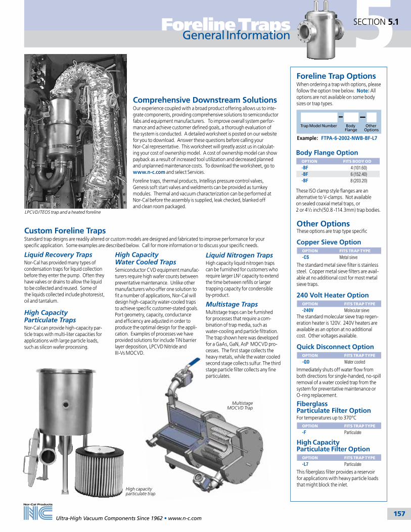
5Foreline Traps
157
SECTION 5.1
Ultra-High Vacuum Components Since 1962 • www.n-c.com
General Information
Comprehensive Downstream SolutionsOur experience coupled with a broad product offering allows us to inte-grate components, providing comprehensive solutions to semiconductor fabs and equipment manufacturers. To improve overall system perfor-mance and achieve customer defined goals, a thorough evaluation of the system is conducted. A detailed worksheet is posted on our website for you to download. Answer these questions before calling your Nor-Cal representative. This worksheet will greatly assist us in calculat-ing your cost of ownership model. A cost of ownership model can show payback as a result of increased tool utilization and decreased planned and unplanned maintenance costs. To download the worksheet, go to www.n-c.com and select Services.
Foreline traps, thermal products, Intellisys pressure control valves, Genesis soft start valves and weldments can be provided as turnkey modules. Thermal and vacuum characterization can be performed at Nor-Cal before the assembly is supplied, leak checked, blanked off and clean room packaged.
Other OptionsThese options are trap type specific
Copper Sieve Option OPTION FITS TRAP TYPE
-CS Metal sieve
The standard metal sieve filter is stainless steel. Copper metal sieve filters are avail-able at no additional cost for most metal sieve traps.
240 Volt Heater OptionOPTION FITS TRAP TYPE
-240V Molecular sieveThe standard molecular sieve trap regen-eration heater is 120V. 240V heaters are available as an option at no additional cost. Other voltages available.
Quick Disconnect OptionOPTION FITS TRAP TYPE
-QD Water cooled
Immediately shuts off water flow from both directions for single-handed, no-spill removal of a water cooled trap from the system for preventative maintenance or O-ring replacement.
Fiberglass Particulate Filter OptionFor temperatures up to 370ºC
OPTION FITS TRAP TYPE
-F Particulate
High Capacity Particulate Filter Option
OPTION FITS TRAP TYPE
-L7 Particulate
This fiberglass filter provides a reservoir for applications with heavy particle loads that might block the inlet.
Body Flange OptionOPTION FITS BODY OD
-BF 4 (101.60)-BF 6 (152.40)-BF 8 (203.20)
These ISO clamp style flanges are an alternative to V-clamps. Not available on sealed coaxial metal traps, or 2 or 41/2 inch(50.8 -114.3mm) trap bodies.
Example: FTPA-6-2002-NWB-BF-L7
Trap Model Number Body Flange
Other Options
Foreline Trap OptionsWhen ordering a trap with options, please follow the option tree below. Note: All options are not available on some body sizes or trap types.
Custom Foreline TrapsStandard trap designs are readily altered or custom models are designed and fabricated to improve performance for your specific application. Some examples are described below. Call for more information or to discuss your specific needs.
Liquid Recovery TrapsNor-Cal has provided many types of condensation traps for liquid collection before they enter the pump. Often they have valves or drains to allow the liquid to be collected and reused. Some of the liquids collected include photoresist, oil and tantalum.
High Capacity Particulate TrapsNor-Cal can provide high-capacity par-ticle traps with multi-liter capacities for applications with large particle loads, such as silicon wafer processing.
High Capacity Water Cooled TrapsSemiconductor CVD equipment manufac-turers require high wafer counts between preventative maintenance. Unlike other manufacturers who offer one solution to fit a number of applications, Nor-Cal will design high-capacity water-cooled traps to achieve specific customer-stated goals. Port geometry, capacity, conductance and efficiency are adjusted in order to produce the optimal design for the appli-cation. Examples of processes we have provided solutions for include TiN barrier layer deposition, LPCVD Nitride and III-Vs MOCVD.
Liquid Nitrogen TrapsHigh capacity liquid nitrogen traps can be furnished for customers who require larger LN2 capacity to extend the time between refills or larger trapping capacity for condensible by-product.
Multistage TrapsMultistage traps can be furnished for processes that require a com-bination of trap media, such as water-cooling and particle filtration. The trap shown here was developed for a GaAs, GaN, AsP MOCVD pro-cesses. The first stage collects the heavy metals, while the water cooled second stage collects sulfur. The third stage particle filter collects any fine particulates.
High capacity particulate trap
LPCVD/TEOS trap and a heated foreline
Multistage MOCVD Trap
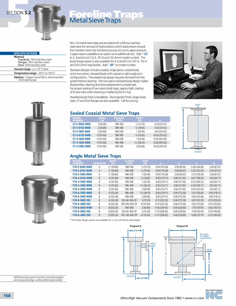
5
158
SECTION 5.2 Foreline Traps
Ultra-High Vacuum Components Since 1962 • www.n-c.com
A
INLET
OUTLET
Metal Sieve Traps
SPECIFICATIONSMaterial Trap Body: 304 stainless steel Flanges: 304 stainless steel Sieve: 304 stainless steel
Vacuum range: >1 x 10⁻⁸ mbar
Temperature range: -20ºC to 150ºC
Options: Copper sieve filters, electropolish, ISO body flange
Nor-Cal metal sieve traps are provided with a fibrous stainless steel sieve for removal of hydrocarbons which backstream toward the chamber when the mechanical pump oil is at its vapor pressure. Copper sieve is available as an option at no additional cost. Add “-CS” to 2, 4 and 6 inch (12.4, 101.6 and 152.4mm) model number. The body flange option is also available for 4, 6 and 8 inch (101.6, 152.4 and 203.2mm) trap bodies. Add “-BF” to model number.
Standard designs include a sealed, single piece, coaxial body and a two-piece, clamped body with coaxial or right angle port configurations. The sealed trap design requires removal from the system before cleaning. The two-piece clamped body design makes disassembly, cleaning and sieve replacement a simple task. For proper sealing of two-piece body traps, apply a light coating of Krytox lube when cleaning or replacing the O-ring.
Standard body finish is beadblast. Electropolish finish, larger body sizes, CF and ASA flanges are also available. Call for pricing.
Angle Metal Sieve TrapsMODEL NUMBER
DIAGRAM
BODY OD
FLANGE TYPE
PORT OD
A
B
C
D
FTA-2-0502-NWB A 2* (50.80) NW-10B 1/2 (12.70) 6.94 (176.28) 3.56 (90.42) 5.38 (136.65) 2.65 (67.31)FTA-2-0752-NWB A 2* (50.80) NW-16B 3/4 (19.05) 6.94 (176.28) 3.56 (90.42) 5.25 (133.35) 2.65 (67.31)FTA-2-1002-NWB A 2* (50.80) NW-25B 1 (25.40) 6.94 (176.28) 3.56 (90.42) 5.13 (130.30) 2.65 (67.31)FTA-4-0752-NWB B 4 (101.60) NW-16B 3/4 (19.05) 8.65 (219.71) 4.80 (121.92) 6.67 (169.42) 3.65 (92.71)FTA-4-1002-NWB B 4 (101.60) NW-25B 1 (25.40) 8.65 (219.71) 4.80 (121.92) 6.55 (166.37) 3.65 (92.71)FTA-4-1502-NWB B 4 (101.60) NW-40B 11/2 (38.10) 8.65 (219.71) 4.80 (121.92) 6.29 (159.77) 3.65 (92.71)FTA-4-2002-NWB B 4 (101.60) NW-50B 2 (50.80) 8.65 (219.71) 4.80 (121.92) 6.04 (153.42) 3.65 (92.71)FTA-6-1502-NWB B 6 (152.40) NW-40B 11/2 (38.10) 8.65 (219.71) 6.90 (175.26) 5.15 (130.81) 4.65 (118.11)FTA-6-2002-NWB B 6 (152.40) NW-50B 2 (50.80) 8.65 (219.71) 6.90 (175.26) 4.90 (124.46) 4.65 (118.11)FTA-6-3002-ISO B 6 (152.40) ISO-80-300-OF 3 (76.20) 8.75 (222.25) 6.90 (175.26) 4.87 (123.70) 4.75 (120.65)FTA-6-4002-ISO B 6 (152.40) ISO-100-400-OF 4 (101.60) 8.75 (222.25) 6.90 (175.26) 4.56 (115.82) 4.75 (120.65)FTA-8-2002-NWB B 8 (203.20) NW-50B 2 (50.80) 11.65 (295.91) 9.00 (228.60) 7.78 (197.61) 5.65 (143.51)FTA-8-3002-ISO B 8 (203.20) ISO-80-300-OF 3 (76.20) 11.75 (298.45) 9.00 (228.60) 7.38 (187.45) 5.75 (146.05)FTA-8-4002-ISO B 8 (203.20) ISO-100-400-OF 4 (101.60) 11.75 (298.45) 9.00 (228.60) 6.88 (174.75) 5.75 (146.05)
Air space for higher conductance
C
D
INLET
A
OUTLET
B
Diagram B
C
B
INLET
OUTLETD
A
Diagram A
All dimensions are in inches (mm) & weights are in pounds (kg), unless otherwise noted.
* ISO body flange option not available for 2 inch (50.8mm) trap bodies
MODEL NUMBER
BODY OD
FLANGE TYPE
PORT OD
A
CT-2-0502-NWB 2 (50.80) NW-10B 1/2 (12.70) 8.43 (214.12)CT-2-0752-NWB 2 (50.80) NW-16B 3/4 (19.05) 8.43 (214.12)CT-2-1002-NWB 2 (50.80) NW-25B 1 (25.40) 8.43 (214.12)CT-4-0752-NWB 4 (101.60) NW-16B 3/4 (19.05) 10.30 (261.62)CT-4-1002-NWB 4 (101.60) NW-25B 1 (25.40) 10.30 (261.62)CT-4-1502-NWB 4 (101.60) NW-40B 11/2 (38.10) 10.30 (261.62)CT-4-2002-NWB 4 (101.60) NW-50B 2 (50.80) 10.30 (261.62)
Sealed Coaxial Metal Sieve Traps
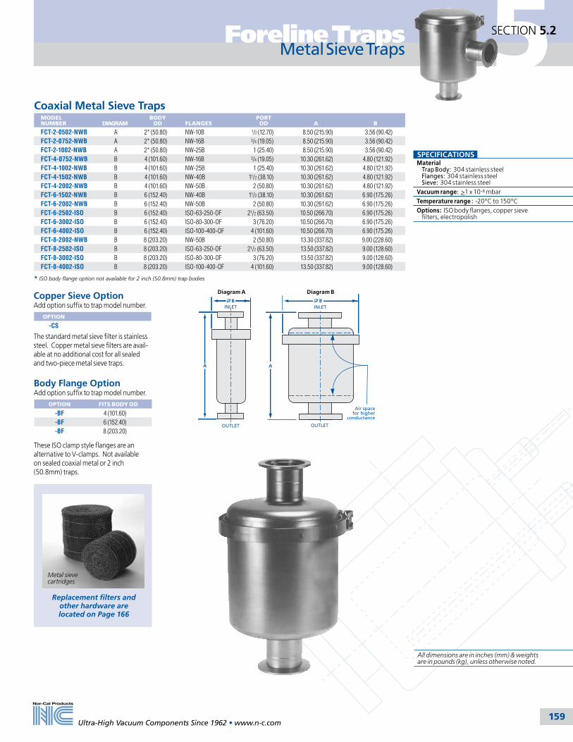
5Foreline Traps
159
SECTION 5.2
Ultra-High Vacuum Components Since 1962 • www.n-c.com
Metal Sieve Traps
Coaxial Metal Sieve TrapsMODEL NUMBER
DIAGRAM
BODY OD
FLANGES
PORT OD
A
B
FCT-2-0502-NWB A 2* (50.80) NW-10B 1/2 (12.70) 8.50 (215.90) 3.56 (90.42)FCT-2-0752-NWB A 2* (50.80) NW-16B 3/4 (19.05) 8.50 (215.90) 3.56 (90.42)FCT-2-1002-NWB A 2* (50.80) NW-25B 1 (25.40) 8.50 (215.90) 3.56 (90.42)FCT-4-0752-NWB B 4 (101.60) NW-16B 3/4 (19.05) 10.30 (261.62) 4.80 (121.92)FCT-4-1002-NWB B 4 (101.60) NW-25B 1 (25.40) 10.30 (261.62) 4.80 (121.92)FCT-4-1502-NWB B 4 (101.60) NW-40B 11/2 (38.10) 10.30 (261.62) 4.80 (121.92)FCT-4-2002-NWB B 4 (101.60) NW-50B 2 (50.80) 10.30 (261.62) 4.80 (121.92)FCT-6-1502-NWB B 6 (152.40) NW-40B 11/2 (38.10) 10.30 (261.62) 6.90 (175.26)FCT-6-2002-NWB B 6 (152.40) NW-50B 2 (50.80) 10.30 (261.62) 6.90 (175.26)FCT-6-2502-ISO B 6 (152.40) ISO-63-250-OF 21/2 (63.50) 10.50 (266.70) 6.90 (175.26)FCT-6-3002-ISO B 6 (152.40) ISO-80-300-OF 3 (76.20) 10.50 (266.70) 6.90 (175.26)FCT-6-4002-ISO B 6 (152.40) ISO-100-400-OF 4 (101.60) 10.50 (266.70) 6.90 (175.26)FCT-8-2002-NWB B 8 (203.20) NW-50B 2 (50.80) 13.30 (337.82) 9.00 (228.60)FCT-8-2502-ISO B 8 (203.20) ISO-63-250-OF 21/2 (63.50) 13.50 (337.82) 9.00 (128.60)FCT-8-3002-ISO B 8 (203.20) ISO-80-300-OF 3 (76.20) 13.50 (337.82) 9.00 (128.60)FCT-8-4002-ISO B 8 (203.20) ISO-100-400-OF 4 (101.60) 13.50 (337.82) 9.00 (128.60)
* ISO body flange option not available for 2 inch (50.8mm) trap bodies
A
BINLET
OUTLET
Diagram A
A
Air spacefor higher
conductance
INLET
OUTLET
B
Diagram B
SPECIFICATIONSMaterial Trap Body: 304 stainless steel Flanges: 304 stainless steel Sieve: 304 stainless steelVacuum range: >1 x 10⁻⁸ mbarTemperature range : -20ºC to 150ºC Options: ISO body flanges, copper sieve filters, electropolish
Metal sieve cartridges
Replacement filters and other hardware are located on Page 166
Copper Sieve OptionAdd option suffix to trap model number.
OPTION
-CS
The standard metal sieve filter is stainless steel. Copper metal sieve filters are avail-able at no additional cost for all sealed and two-piece metal sieve traps.
Body Flange OptionAdd option suffix to trap model number.
OPTION FITS BODY OD
-BF 4 (101.60)-BF 6 (152.40)-BF 8 (203.20)
These ISO clamp style flanges are an alternative to V-clamps. Not available on sealed coaxial metal or 2 inch (50.8mm) traps.
All dimensions are in inches (mm) & weights are in pounds (kg), unless otherwise noted.

5
160
SECTION 5.3 Foreline Traps
Ultra-High Vacuum Components Since 1962 • www.n-c.com
These traps perform a dual function. A zeolite desiccant removes hydrocarbons which backstream toward the chamber when the mechanical pump oil is at it’s vapor pressure. Also, the zeolite traps water vapor and other gasses before they reach the mechanical pump and contaminate the pump oil. Depending on the process, this can reduce the oil change frequency significantly.
Nor-Cal’s molecular sieve trap utilizes the two-piece trap design for ease of maintenance and zeolite replacement. For maximum conductance the sieve material is contained in a suspended basket fabricated from perforated 304 stainless steel. This design provides conductance to the sieve at the top of the basket as well as around the periphery. A mid-basket baffle causes the gas to enter one-half of the basket and to exit the other half.
When initializing a trap, replacing the sieve or when base pressure cannot be achieved, the sieve should be regenerated by turning on the heater for a few hours and running the mechanical pump with it’s ballast valve open. The frequency and duration of sieve regeneration is dependent upon the kind and amount of gasses produced by the particular application. To replace the sieve, remove the trap end that contains the heater and remove the nut at the end of the basket. Dump the expired sieve material, replace with new, reattach the basket/end plate then perform the regeneration process outlined above.
A molecular sieve charge and regeneration heater are included with every trap. 208V-240V regeneration heater is available as an option. Other voltages and wattages are available upon request. The heater is held in place allowing the trap to be mounted in any position. Standard finish is beadblasted. Electropolish finish, other body and flange configurations, and larger body sizes are available.
C
B
INLET
OUTLET
A
In-Line Molecular Sieve TrapsMODEL NUMBER
BODY OD
FLANGE TYPE
PORT OD
REGENERATION HEATER RATING*
A
B
C
FTM-4-0752-NWB 4 (101.60) NW-16B 3/4 (19.05) 120V / 42W 6.20 (157.48) 7.30 (185.42) 3.50 (88.90)FTM-4-1002-NWB 4 (101.60) NW-25B 1 (25.40) 120V / 42W 6.20 (157.48) 7.30 (185.42) 3.50 (88.90)FTM-4-1502-NWB 4 (101.60) NW-40B 11/2 (38.10) 120V / 42W 6.20 (157.48) 7.30 (185.42) 3.50 (88.90)FTM-6-1502-NWB 6 (152.40) NW-40B 11/2 (38.10) 120V / 230W 8.10 (205.74) 9.30 (236.22) 4.10 (104.14)FTM-6-2002-NWB 6 (152.40) NW-50B 2 (50.80) 120V / 230W 8.10 (205.74) 9.30 (236.22) 4.10 (104.14)FTM-8-2002-NWB 8 (203.20) NW-50B 2 (50.80) 120V / 350W 13.00 (330.20) 11.30 (287.02) 6.75 (171.45)FTM-8-2502-ISO 8 (203.20) ISO-63-250-OF 21/2 (63.50) 120V / 350W 13.00 (330.20) 11.50 (287.02) 6.75 (171.45)FTM-8-3002-ISO 8 (203.20) ISO-80-300-OF 3 (76.20) 120V / 350W 13.00 (330.20) 11.50 (287.02) 6.75 (171.45)FTM-8-4002-ISO 8 (203.20) ISO-100-400-OF 4 (101.60) 120V / 350W 13.00 (330.20) 11.50 (287.02) 6.75 (171.45)
Molecular Sieve Traps
Angle Molecular Sieve TrapsMODEL NUMBER
BODY OD
FLANGE TYPE
PORT OD
REGENERATION HEATER RATING*
A
B
C
FTMA-4-0752-NWB 4 (101.60) NW-16B 3/4 (19.05) 120V / 42W 7.85 (199.39) 6.55 (166.37) 3.65 (92.71)FTMA-4-1002-NWB 4 (101.60) NW-25B 1 (25.40) 120V / 42W 7.85 (199.39) 6.55 (166.37) 3.65 (92.71)FTMA-4-1502-NWB 4 (101.60) NW-40B 11/2 (38.10) 120V / 42W 7.85 (199.39) 6.55 (166.37) 3.65 (92.71)FTMA-6-1502-NWB 6 (152.40) NW-40B 11/2 (38.10) 120V / 230W 9.75 (247.65) 7.75 (196.85) 4.65 (118.11)FTMA-6-2002-NWB 6 (152.40) NW-50B 2 (50.80) 120V / 230W 9.75 (247.65) 7.75 (196.85) 4.65 (118.11)FTMA-8-2002-NWB 8 (203.20) NW-50B 2 (50.80) 120V / 350W 14.65 (372.11) 11.53 (292.86) 5.65 (143.51)FTMA-8-2502-ISO 8 (203.20) ISO-63-250-OF 21/2 (63.50) 120V / 350W 14.75 (374.65) 11.63 (292.86) 5.75 (146.05)FTMA-8-3002-ISO 8 (203.20) ISO-80-300-OF 3 (76.20) 120V / 350W 14.75 (374.65) 11.63 (292.86) 5.75 (146.05)FTMA-8-4002-ISO 8 (203.20) ISO-100-400-OF 4 (101.60) 120V / 350W 14.75 (374.65) 11.63 (292.86) 5.75 (146.05)
Straight-In-Line Molecular Sieve TrapsMODEL NUMBER
BODY OD
FLANGE TYPE
PORT OD
REGENERATION HEATER RATING*
A
B
C
FTMS-4-0752-NWB 4 (101.60) NW-16B 3/4 (19.05) 120V / 42W 7.00 (177.80) 7.30 (185.42) 3.50 (88.90)FTMS-4-1002-NWB 4 (101.60) NW-25B 1 (25.40) 120V / 42W 7.00 (177.80) 7.30 (185.42) 3.50 (88.90)FTMS-4-1502-NWB 4 (101.60) NW-40B 11/2 (38.10) 120V / 42W 7.00 (177.80) 7.30 (185.42) 3.50 (88.90)FTMS-6-1502-NWB 6 (152.40) NW-40B 11/2 (38.10) 120V / 230W 7.00 (177.80) 9.30 (236.22) 3.50 (88.90)FTMS-6-2002-NWB 6 (152.40) NW-50B 2 (50.80) 120V / 230W 7.00 (177.80) 9.30 (236.22) 3.50 (88.90)FTMS-8-2002-NWB 8 (203.20) NW-50B 2 (50.80) 120V / 350W 10.00 (254.00) 11.30 (287.02) 5.00 (127.00)FTMS-8-2502-ISO 8 (203.20) ISO-63-250-OF 21/2 (63.50) 120V / 350W 10.00 (254.00) 11.50 (292.10) 5.00 (127.00)FTMS-8-3002-ISO 8 (203.20) ISO-80-300-OF 3 (76.20) 120V / 350W 10.00 (254.00) 11.50 (292.10) 5.00 (127.00)FTMS-8-4002-ISO 8 (203.20) ISO-100-400-OF 4 (101.60) 120V / 350W 10.00 (254.00) 11.50 (292.10) 5.00 (127.00)
C
B
INLETOUTLET
A
B
OUTLET
A
C
INLET
SPECIFICATIONSMaterial Body: 304 stainless steel Flanges: 304 stainless steel Desiccant: Zeolite 13X, 1/8 inch pellets
Vacuum range: >1 x 10⁻⁸ mbar
Temperature range: -20ºC to 150ºC
Options: 240V regeneration heaters and ISO body flanges See page 175
Gas Path In
GasPathOut
AnnularBaffle
Heater
Sieve Removable End
*208V-240V Heater Option208V-240V heaters are available as an option at no additional cost. Other voltages available. Add option suffix to the end of the trap model number
OPTION DESCRIPTION
-240V 208V-240V heater Regeneration heater and Zeolite charge
Replacement charges,
heaters & other hardware are
located on Page 166
All dimensions are in inches (mm) & weights are in pounds (kg), unless otherwise noted.

5Foreline Traps
161
SECTION 5.4
Ultra-High Vacuum Components Since 1962 • www.n-c.com
These traps remove particles that might enter the mechanical pump and contaminate the oil. Standard traps include a polyester felt filter traps particles over 10 microns in size at 98% efficiency. Filters can be cleaned with a vacuum cleaner. Suitable for process temperatures from ambient to 149ºC. Filters with other micron ratings are available upon request.
Woven, 10 micron fiberglass filters are available as an option. They provide a much longer service life than a polyester filter. Fiberglass filter is required for temperatures greater than 149ºC. Maximum fiberglass filter temperature is 370ºC. Filters with other micron ratings are available upon request.
The high capacity fiberglass filter option, shown in the diagram below, provides a reservoir for applications with heavy particle loads that might block the inlet. The high capacity filter option is not available for 8 inch (203.2mm) bodies.
The two-piece trap body and 304 stainless steel construction allow these traps to be easily cleaned. For proper sealing, apply a light coating of Krytox lube when cleaning or replacing the O-ring. Standard finish is beadblast. Electropolish finish, larger body sizes, ultra-high capacity and custom flange configurations available. Call for pricing.
Standard Length Filter
High Capacity Filter Option Add "-L7" suffix to the
trap model number
INLET INLET
OUTLETOUTLET
Particulate Traps
Angle Particulate TrapsMODEL NUMBER
BODY OD
FLANGES
PORT OD
A
B
C
D
FTPA-6-1502-NWB 6 (152.40) NW-40B 11/2 (38.10) 13.90 (353.06) 6.90 (175.26) 10.40 (264.16) 4.65 (118.11)FTPA-6-2002-NWB 6 (152.40) NW-50B 2 (50.80) 13.90 (353.06) 6.90 (175.26) 10.15 (257.81) 4.65 (118.11)FTPA-8-1502-NWB 8* (203.20) NW-40B 11/2 (38.10) 13.90 (353.06) 9.00 (228.60) 10.40 (264.16) 5.65 (143.51)FTPA-8-2002-NWB 8* (203.20) NW-50B 2 (50.80) 13.90 (353.06) 9.00 (228.60) 10.15 (257.81) 5.65 (143.51)FTPA-8-3002-ISO 8* (203.20) ISO-80 2 (50.80) 19.35 (491.49) 9.00 (228.60) 15.25 (387.35) 5.65 (143.51)FTPA-8-4002-ISO 8* (203.20) ISO-100 2 (50.80) 19.35 (491.49) 9.00 (228.60) 15.25 (387.35) 5.65 (143.51)
* High capacity filter not available for 8 inch (203.2mm) body
Coaxial Particulate TrapsMODEL NUMBER
BODY OD
FLANGES
PORT OD
A
B
FTPS-6-1502-NWB 6 (152.40) NW-40B 11/2 (38.10) 16.30 (414.02) 6.90 (175.26)FTPS-6-2002-NWB 6 (152.40) NW-50B 2 (50.80) 16.30 (414.02) 6.90 (175.26)FTPS-8-1502-NWB 8* (203.20) NW-40B 11/2 (38.10) 16.30 (414.02) 9.00 (228.60)FTPS-8-2002-NWB 8* (203.20) NW-50B 2 (50.80) 16.30 (414.02) 9.00 (228.60)FTPS-8-3002-ISO 8* (203.20) ISO-80 2 (50.80) 16.50 (419.10) 9.00 (228.60)FTPS-8-4002-ISO 8* (203.20) ISO-100 2 (50.80) 16.50 (419.10) 9.00 (228.60)
* High capacity filter not available for 8 inch (203.2mm) body
B
INLET
A
OUTLET
D
INLET
A
OUTLET
C
B
SPECIFICATIONSMaterial Trap Body: 304 stainless steel Flanges: 304 stainless steel Filter: polyester or fiberglassVacuum range: >1 x 10⁻⁸ mbarTemperature range: -20ºC to 150ºC Options: ISO body flanges, woven fiberglass or high capacity fiberglass filter, electropolish
Replacement filters and other hardware are located on Page 166
Fiberglass Filter OptionThe fiberglass filter option is appropriate for applications with temperatures up to 370ºC. The high capacity fiberglass filter provides a reservoir for applications with heavy particle loads that might block the inlet. Add option suffix to the end of the trap model number.
OPTION FILTER TYPE
-F Fiberglass-L7 High capacity All dimensions are in inches (mm) & weights
are in pounds (kg), unless otherwise noted.

5
162
SECTION 5.5 Foreline Traps
Ultra-High Vacuum Components Since 1962 • www.n-c.com
LPCVD-TEOS Single & Multi-Stage Traps
Increase your system’s throughput and extend preventative maintenance intervals by 2X or more with Nor-Cal Products’ LPCVD/TEOS multistage foreline traps. The first stage is a stainless steel gauze filter which collects crystal-line TEOS before it reaches downstream piping and isolation valves. The second stage is a 10 micron fiberglass filter which removes silicon dioxide which causes frequent PM’s in throttling butterfly valves. The third and final stage is a reservoir which collects liquid TEOS without restricting foreline conductance. The two-piece trap body and 304 stainless steel construction allow these traps to be easily cleaned. Standard finish is beadblasted. Electropolish is available on request.
BOUTLET
AC
INLET
OUTLET
A
INLETB
One Stage LPCVD-TEOS TrapsIncludes one stainless steel gauze filter
MODEL NUMBER
BODY OD
PORT CONFIGURATION
FLANGES
PORT ID
A
B
C
FTT1S-8-3002-ISO 8 (203.20) Coaxial ISO-80 3 (76.20) 16.84 (427.74) 9.00 (228.6) -FTT1A-8-3002-ISO 8 (203.20) Angle ISO-80 3 (76.20) 15.09 (383.29) 5.75 (146.05) 12.06 (306.32)FTT1S-8-4002-ISO 8 (203.20) Coaxial ISO-100 4 (101.60) 16.84 (427.74) 9.00 (228.6) -FTT1A-8-4002-ISO 8 (203.20) Angle ISO-100 4 (101.60) 15.09 (383.29) 5.75 (146.05) 12.06 (306.32)
Two Stage LPCVD-TEOS TrapsIncludes one stainless steel gauze filter and one 10 micron fiberglass filter
MODEL NUMBER
BODY OD
PORT CONFIGURATION
FLANGES
PORT ID
A
B
C
FTT2S-8-3002-ISO 8 (203.20) Coaxial ISO-80 3 (76.20) 19.12 (485.65) 9.45 (240.03) -FTT2A-8-3002-ISO 8 (203.20) Angle ISO-80 3 (76.20) 21.00 (533.40) 5.75 (146.05) 18.00 (457.20)FTT2S-8-4002-ISO 8 (203.20) Coaxial ISO-100 4 (101.60) 19.12 (485.65) 9.45 (240.03) -FTT2A-8-4002-ISO 8 (203.20) Angle ISO-100 4 (101.60) 21.00 (433.40) 5.75 (146.05) 18.00 (457.20)
Three Stage LPCVD-TEOS TrapsIncludes one stainless steel gauze filter, one 10 micron fiberglass filter, and a built-in liquid collection reservoir
MODEL NUMBER
BODY OD
PORT CONFIGURATION
FLANGES
PORT ID
A
B
C
FTT3S-8-3002-ISO 8 (203.20) Coaxial ISO-80 3 (76.20) 19.12 (485.65) 9.45 (240.03) -FTT3A-8-3002-ISO 8 (203.20) Angle ISO-80 3 (76.20) 21.00 (533.40) 5.75 (146.05) 18.00 (457.20)FTT3S-8-4002-ISO 8 (203.20) Coaxial ISO-100 4 (101.60) 19.12 (485.65) 9.45 (240.03) -FTT3A-8-4002-ISO 8 (203.20) Angle ISO-100 4 (101.60) 21.00 (433.40) 5.75 (146.05) 18.00 (457.20)
SPECIFICATIONSMaterial Trap Body: 304 stainless steel Flanges: 304 stainless steel Filter: Stainless steel gauze
Vacuum range: >1 x 10⁻⁸ mbar
Temperature range: -20ºC to 150ºC
Coaxial
Angle
Replacement filters and other hardware are located on Page 166
All dimensions are in inches (mm) & weights are in pounds (kg), unless otherwise noted.

5Foreline Traps
163
SECTION 5.6
Ultra-High Vacuum Components Since 1962 • www.n-c.com
Water cooled traps protect mechanical pumps and other downstream components from condensible process gasses and their by-products. They can extend or eliminate preventa-tive maintenance intervals and pump overhauls. Nor-Cal’s unique water cooled traps have up to three coils of corrosion resistant 316L stainless steel tubing to provide a large cold surface area. Internal baffles combined with the coils create a perilous path for the gas flow, maximizing resident time and increasing contact between the gas and the coils. Depending on the application, house water or refrigerated water can be used to achieve the required temperature to cause by-products to pass from gas to solid phase. (See chart on page 156) A 30 to 50 psi water supply is required. Anticipate a 1 gpm flow rate at 30 psi.
The two-piece trap body and 304 stainless steel construction allow these traps to be easily cleaned. Standard finish is beadblast. For proper sealing, apply a light coating of Krytox lube when cleaning or replacing the O-ring. Quick Disconnect Fittings immediately shut off water flow from both directions for single handed, no-spill removal of the trap for preventative maintenance or O-ring replacement. Add “-QD” to the trap model number and $200.00 to price. Electropolish finish, larger body sizes and CF or ASA flanges are also available.
Angle Water Cooled TrapsMODEL NUMBER
DIAGRAM
BODY OD
FLANGES
PORT OD
A
B
C
D
FTWA-4.5-1502-NWB C 41/2 (114.30) NW-40B 11/2 (38.10) 7.55 (191.77) 5.28 (134.11) 3.90 (99.06) 6.05 (153.67)FTWA-4.5-2002-NWB C 41/2 (114.30) NW-50B 2 (50.80) 7.55 (191.77) 5.28 (134.11) 3.90 (99.06) 6.05 (153.67)FTWA-6-1502-NWB D 6 (152.40) NW-40B 11/2 (38.10) 8.65 (219.71) 6.90 (175.26) 4.65 (118.11) 5.40 (137.16)FTWA-6-2002-NWB D 6 (152.40) NW-50B 2 (50.80) 8.65 (219.71) 6.90 (175.26) 4.65 (118.11) 5.40 (137.16)FTWA-6-2502-ISO D 6 (152.40) ISO-63-250-OF 21/2 (63.50) 8.75 (222.25) 6.90 (175.26) 4.75 (120.65) 5.50 (139.70)FTWA-6-3002-ISO D 6 (152.40) ISO-80-300-OF 3 (76.20) 8.75 (222.25) 6.90 (175.26) 4.75 (120.65) 5.50 (139.70)FTWA-8-2002-NWB D 8 (203.20) NW-50B 2 (50.80) 11.65 (295.91) 9.00 (228.60) 5.65 (143.51) 6.77 (171.96)FTWA-8-2502-ISO D 8 (203.20) ISO-63-250-OF 21/2 (63.50) 11.75 (298.45) 9.00 (228.60) 5.75 (146.05) 7.87 (199.90)FTWA-8-3002-ISO D 8 (203.20) ISO-80-300-OF 3 (76.20) 11.75 (298.45) 9.00 (228.60) 5.75 (146.05) 6.87 (174.50)FTWA-8-4002-ISO D 8 (203.20) ISO-100-400-OF 4 (101.60) 11.75 (298.45) 9.00 (228.60) 5.75 (146.05) 6.87 (174.50)
*NOTE: ISO body flange option not available for 41/2 inch (114.3mm) bodies
Water Cooled Traps
Coaxial Water Cooled TrapsMODEL NUMBER
DIAGRAM
BODY OD
FLANGE TYPE
PORT OD
A
B
FTWS-4.5-1502-NWB A 41/2 (114.30) NW-40B 11/2 (38.10) 9.75 (247.65) 5.28 (134.11)FTWS-4.5-2002-NWB A 41/2 (114.30) NW-50B 2 (50.80) 9.75 (247.65) 5.28 (134.11)FTWS-6-1502-NWB B 6 (152.40) NW-40B 11/2 (38.10) 10.30 (261.62) 6.90 (175.26)FTWS-6-2002-NWB B 6 (152.40) NW-50B 2 (50.80) 10.30 (261.62) 6.90 (175.26)FTWS-6-2502-ISO B 6 (152.40) ISO-63-250-OF 21/2 (63.50) 10.50 (266.70) 6.90 (175.26)FTWS-6-3002-ISO B 6 (152.40) ISO-80-300-OF 3 (76.20) 10.50 (266.70) 6.90 (175.26)FTWS-8-2002-NWB B 8 (203.20) NW-50B 2 (50.80) 13.30 (337.82) 9.00 (228.60)FTWS-8-2502-ISO B 8 (203.20) ISO-63-250-OF 21/2 (63.50) 13.50 (342.90) 9.00 (228.60)FTWS-8-3002-ISO B 8 (203.20) ISO-80-300-OF 3 (76.20) 13.50 (342.90) 9.00 (228.60)FTWS-8-4002-ISO B 8 (203.20) ISO-100-400-OF 4 (101.60) 13.50 (342.90) 9.00 (228.60)
*NOTE: ISO body flange option not available for 41/2 inch (114.3mm) bodies
SPECIFICATIONSMaterial Trap Body: 304 stainless steel Flanges: 304 stainless steel Water Coils: 316L stainless steelVacuum range: >1 x 10⁻⁸ mbarTemperature range: -20ºC to 150ºC Options: ISO body flanges and quick disconnect fittings. See page 157
A
INLET
OUTLET3/8" OD Tube Typ
1" Min.
B
Diagram A
A
3/8" OD Tube Typ.INLET
OUTLET
1" Min.
B
Diagram B
AD
3/8" OD Tube Typ.
INLET
OUTLET
1" Min.
CB
Diagram C
A
D
3/8" OD Tube Typ.
B
INLET
OUTLET
1" Min.
C
Diagram D
Quick disconnect fittings & mounting hardware are
located on Page 166
Quick Disconnect Option Add option suffix to trap model number.
OPTION FITS TRAP TYPE
-QD Water cooled
Immediately shuts off water flow from both directions for single-handed, no-spill removal of a water cooled trap from the system for preventative maintenance or O-ring replacement.

5
164
SECTION 5.7 Foreline Traps
Ultra-High Vacuum Components Since 1962 • www.n-c.com
Angle Dual-Tube Liquid Nitrogen TrapsMODEL NUMBER
BODY OD
FLANGES
PORT OD
A
B
C
D
LN2 RESERVOIR
NTDA-4-0752-NWB 4 (101.60) NW-16B 3/4 (19.05) 13.15 (334.01) 4.80 (121.92) 7.18 (182.37) 3.65 (92.71) 0.75 LiterNTDA-4-1002-NWB 4 (101.60) NW-25B 1 (25.40) 13.15 (334.01) 4.80 (121.92) 7.06 (182.37) 3.65 (92.71) 0.75 LiterNTDA-4-1502-NWB 4 (101.60) NW-40B 11/2 (38.10) 13.15 (334.01) 4.80 (121.92) 6.80 (172.72) 3.65 (92.71) 0.75 LiterNTDA-6-1502-NWB 6 (152.40) NW-40B 11/2 (38.10) 15.85 (402.59) 6.90 (175.26) 8.40 (213.36) 4.65 (118.11) 1.60 LiterNTDA-6-2002-NWB 6 (152.40) NW-50B 2 (50.80) 15.85 (402.59) 6.90 (175.26) 8.15 (207.01) 4.65 (118.11) 1.60 LiterNTDA-8-1502-NWB 8 (203.20) NW-40B 11/2 (38.10) 16.90 (429.26) 9.00 (228.60) 9.15 (232.41) 5.65 (143.51) 4.00 LiterNTDA-8-2002-NWB 8 (203.20) NW-50B 2 (50.80) 16.90 (429.26) 9.00 (228.60) 8.90 (226.06) 5.65 (143.51) 4.00 Liter
Fill Tube4 & 6" (101.6 & 152.4) body:1/4" (6.35) OD8" (203.2) body: 3/8" (9.53) OD
A
B
INLET
OUTLET
C
D
Vent Tube4 & 6" (101.6 & 152.4) body: 3/8" (9.53) OD 8" (203.2) body: 1/2" (12.7) OD
Nor-Cal’s liquid nitrogen traps remove condensible gasses before they enter the mechanical pump and contaminate the oil. They also prevent mechanical pump oil vapors from contaminating the vacuum chamber. These traps actually act as a pump producing lower base pressures and faster pump down. Dual-tube traps can be attached to an automatic fill device, eliminating the necessity of manually refilling the reservoir with liquid nitrogen.
The two-piece trap body and 304 stainless steel construction allow these traps to be easily cleaned without disassembling the sys-tem. For proper sealing, apply a light coating of Krytox lube when cleaning or replacing the O-ring. Coaxial port configurations, ISO, CF or ASA flanges, electropolish finish and drain fittings are available.
1.00 (24.5) OD x .87 (22.1) IDFill & Vent Tube
A
B
INLETOUTLET
C
A
B
INLET
OUTLET
C
D
1.00 (25.4) OD x .87 (22.1) IDFill & Vent Tube
In-Line Liquid Nitrogen TrapsMODEL NUMBER
BODY OD
FLANGES
PORT OD
A
B
C
LN2 RESERVOIR
FTN-4-0752-NWB 4 (101.60) NW-16B 3/4 (19.05) 11.50 (292.10) 7.30 (185.42) 3.70 (93.98) 0.75 LiterFTN-4-1002-NWB 4 (101.60) NW-25B 1 (25.40) 11.50 (292.10) 7.30 (185.42) 3.70 (93.98) 0.75 LiterFTN-4-1502-NWB 4 (101.60) NW-40B 11/2 (38.10) 11.50 (292.10) 7.30 (185.42) 3.70 (93.98) 0.75 LiterFTN-6-1502-NWB 6 (152.40) NW-40B 11/2 (38.10) 14.20 (360.68) 9.30 (236.22) 4.50 (114.30) 1.60 LiterFTN-6-2002-NWB 6 (152.40) NW-50B 2 (50.80) 14.20 (360.68) 9.30 (236.22) 4.50 (114.30) 1.60 LiterFTN-8-1502-NWB 8 (203.20) NW-40B 11/2 (38.10) 15.25 (387.35) 11.30 (287.02) 5.00 (127.00) 4.00 LiterFTN-8-2002-NWB 8 (203.20) NW-50B 2 (50.80) 15.25 (387.35) 11.30 (287.02) 5.00 (127.00) 4.00 Liter
Angle Liquid Nitrogen TrapsMODEL NUMBER
BODY OD
FLANGES
PORT OD
A
B
C
D
LN2
RESERVOIR
FTNA-4-0752-NWB 4 (101.60) NW-16B 3/4 (19.05) 13.15 (334.01) 4.80 (121.92) 7.18 (182.37) 3.65 (92.71) 0.75 LiterFTNA-4-1002-NWB 4 (101.60) NW-25B 1 (25.40) 13.15 (334.01) 4.80 (121.92) 7.06 (182.37) 3.65 (92.71) 0.75 LiterFTNA-4-1502-NWB 4 (101.60) NW-40B 11/2 (38.10) 13.15 (334.01) 4.80 (121.92) 6.80 (172.72) 3.65 (92.71) 0.75 LiterFTNA-6-1502-NWB 6 (152.40) NW-40B 11/2 (38.10) 15.85 (402.59) 6.90 (175.26) 8.40 (213.36) 4.65 (118.11) 1.60 LiterFTNA-6-2002-NWB 6 (152.40) NW-50B 2 (50.80) 15.85 (402.59) 6.90 (175.26) 8.15 (207.01) 4.65 (118.11) 1.60 LiterFTNA-8-1502-NWB 8 (203.20) NW-40B 11/2 (38.10) 16.90 (429.26) 9.00 (228.60) 9.15 (232.41) 5.65 (143.51) 4.00 LiterFTNA-8-2002-NWB 8 (203.20) NW-50B 2 (50.80) 16.90 (429.26) 9.00 (228.60) 8.90 (226.06) 5.65 (143.51) 4.00 Liter
Liquid Nitrogen Traps
In-Line Dual-Tube Liquid Nitrogen TrapsMODEL NUMBER
BODY OD
FLANGES
PORT OD
A
B
C
LN2 RESERVOIR
NTD-4-0752-NWB 4 (101.60) NW-16B 3/4 (19.05) 11.50 (292.10) 3.70 (93.98) 7.30 (185.42) 0.75 LiterNTD-4-1002-NWB 4 (101.60) NW-25B 1 (25.40) 11.50 (292.10) 3.70 (93.98) 7.30 (185.42) 0.75 LiterNTD-4-1502-NWB 4 (101.60) NW-40B 11/2 (38.10) 11.50 (292.10) 3.70 (93.98) 7.30 (185.42) 0.75 LiterNTD-6-1502-NWB 6 (152.40) NW-40B 11/2 (38.10) 14.20 (360.68) 4.50 (114.30) 9.30 (236.22) 1.60 LiterNTD-6-2002-NWB 6 (152.40) NW-50B 2 (50.80) 14.20 (360.68) 4.50 (114.30) 9.30 (236.22) 1.60 LiterNTD-8-1502-NWB 8 (203.20) NW-40B 11/2 (38.10) 15.25 (387.35) 5.00 (127.00) 11.30 (287.02) 4.00 LiterNTD-8-2002-NWB 8 (203.20) NW-50B 2 (50.8) 15.25 (387.35) 5.00 (127.00) 11.30 (287.02) 4.00 Liter
A
B
INLETOUTLET
C
Fill Tube4 & 6" (101.6 & 152.4) body:1/4" (6.35) OD8" (203.2) body: 3/8" (9.53) ODVent Tube4 & 6" (101.6 & 152.4) body: 3/8" (9.53) OD 8" (203.2) body: 1/2" (12.7) OD
SPECIFICATIONSMaterial Trap Body: 304 stainless steel Flanges: 304 stainless steel
Vacuum range: >1 x 10⁻⁸ mbar
Temperature range: -20ºC to 150ºC
Options: ISO body flanges. See page 141
Refill Time Table for Single Tube LN2 Traps
TRAP DIAMETER
HOURS
4 inch (101.60) 56 inch (152.40) 88 inch (203.20) 12
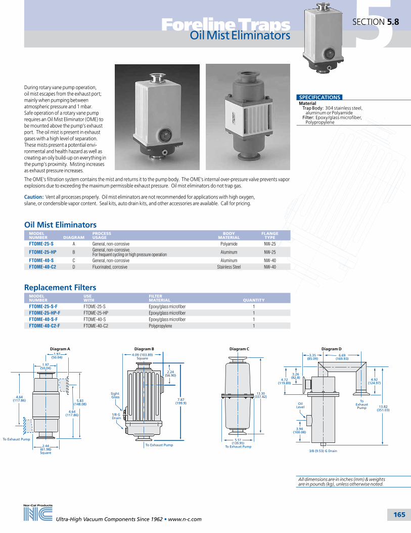
5Foreline Traps
165
SECTION 5.8
Ultra-High Vacuum Components Since 1962 • www.n-c.com
Oil Mist Eliminators
During rotary vane pump operation, oil mist escapes from the exhaust port; mainly when pumping between atmospheric pressure and 1 mbar. Safe operation of a rotary vane pump requires an Oil Mist Eliminator (OME) to be mounted above the pump’s exhaust port. The oil mist is present in exhaust gases with a high level of separation. These mists present a potential envi-ronmental and health hazard as well as creating an oily build-up on everything in the pump’s proximity. Misting increases as exhaust pressure increases.
The OME’s filtration system contains the mist and returns it to the pump body. The OME’s internal over-pressure valve prevents vapor explosions due to exceeding the maximum permissible exhaust pressure. Oil mist eliminators do not trap gas.
Caution: Vent all processes properly. Oil mist eliminators are not recommended for applications with high oxygen, silane, or condensible vapor content. Seal kits, auto drain kits, and other accessories are available. Call for pricing.
Oil Mist EliminatorsMODEL NUMBER
DIAGRAM
PROCESS USAGE
BODY MATERIAL
FLANGE TYPE
FTOME-25-S A General, non-corrosive Polyamide NW-25
FTOME-25-HP B General, non-corrosive. For frequent cycling or high pressure operation Aluminum NW-25
FTOME-40-S C General, non-corrosive Aluminum NW-40FTOME-40-C2 D Fluorinated, corrosive Stainless Steel NW-40
Replacement FiltersMODEL NUMBER
USE WITH
FILTER MATERIAL
QUANTITY
FTOME-25-S-F FTOME-25-S Epoxy/glass microfiber 1FTOME-25-HP-F FTOME-25-HP Epoxy/glass microfiber 1FTOME-40-S-F FTOME-40-S Epoxy/glass microfiber 1FTOME-40-C2-F FTOME-40-C2 Polypropylene 1
SPECIFICATIONSMaterial Trap Body: 304 stainless steel, aluminum or Polyamide Filter: Epoxy/glass microfiber, Polypropylene
To Exhaust Pump
13.30(337.82)
5.51(139.95)
ToExhaustPump
6.69(169.93)
3.35(85.09)
4.72(119.89)
3.26(82.8)
13.82(351.03)
4.92(124.97)
OilLevel
3/8 (9.53) G Drain
3.94(100.08)
To Exhaust Pump
4.09 (103.89)Square
7.87(199.9)
2.24(56.90)
Sight Glass
1/8 G Drain
1.97(50.04)
1.97(50.04)
5.83(148.08)
4.64(117.86)
2.44(61.98)Square
To Exhaust Pump
4.64(117.86)
Diagram DDiagram CDiagram BDiagram A
All dimensions are in inches (mm) & weights are in pounds (kg), unless otherwise noted.

5
166
SECTION 5.9 Foreline Traps
Ultra-High Vacuum Components Since 1962 • www.n-c.com
Filters, Hardware & Accessories
Body ClampsBody clamps for use with all trap types
MODEL NUMBER
BODY OD
NW-50-CP 2 (50.80)
FT-4-CP 4 (101.60)FT-4.5-CP 41/2 (114.30)FT-6-CP 6 (152.40)
FT-8-CP 8 (203.20) below S/N292800
50248 8 (203.20) above S/N 292800
FT-CP-B T-bolt kit*
* T-bolt kits include replacement bolts and nuts for all size V-band clamps and brackets.
Metal Sieve Trap Replacement FiltersMODEL NUMBER
BODY OD
DESCRIPTION
FT-2-SS 2 (50.80) Stainless steel gauzeFT-2-CS 2 (50.80) Copper gauzeFT-4-SS 4 (101.60) Stainless steel gauzeFT-4-CS 4 (101.60) Copper gauzeFT-6-SS 6 (152.40) Stainless steel gauzeFT-6-CS 6 (152.40) Copper gauzeFT-8-SS 8 (203.20) Stainless steel gauze
Metal sieve trap filters
Particulate trap filters
Particulate Trap Replacement FiltersMODEL NUMBER
BODY OD
FILTER LENGTH
DESCRIPTION
FT-6-PP 6 or 8 (152.40 or 203.20) 111/2 (292.10) Polyester felt, 10 micronFT-6-PF 6 or 8 (152.40 or 203.20) 111/2 (292.10) Woven fiberglass, 10 micronFT-6-PF-L7 6 (152.40) 71/2 (190.50) Woven fiberglass filter, 10 micronFT-8-PR 8 (152.40) 111/2 (292.10) Polypropylene filter, 10 micron
Water Cooled Trap FittingsMODEL NUMBER
BODY OD
DESCRIPTION
FTW-QD All Quick disconnect fittings kit (DESO)FTW-4.5-OR 41/2 (114.30) Internal Viton O-ring used in this body size only
Body O-ringsFor use with all foreline trap types.
MODEL NUMBER
BODY OD
NW-50-OR-V 2 (50.80)FT-4-OR 4 (101.60)FT-4.5-OR 41/2 (114.30)FT-6-OR 6 (152.40)
FT-8-OR 8 (203.20) belowS/N 292800
FT-8-OR-821 8 ( 203.20) above S/N 292800
Trap mounting bracket
Mounting BracketsFor mounting all 6 inch trap types.
MODEL NUMBER
BODY OD
FT-6-MB 6 (152.40)
Molecular Sieve Trap Replacement ChargesMODEL NUMBER
BODY OD
DESCRIPTION
FT-4-MS 4 (101.60) 1 lb. Zeolite charge, 4 inch (101.60) trap requires 3/4 lb.FT-6-MS 6 (152.40) 2 lb. Zeolite charge, 6 inch (152.40) trap requires 11/2 lb. FT-8-MS 8 (203.20) 5 lb. Zeolite charge, 8 inch (203.20) trap requires 43/4 lb.
Molecular Sieve Trap Replacement HeatersMODEL NUMBER
BODY OD
DESCRIPTION
FT-4-HRF-240V 4 (101.60) Rated at 240V, 42WFT-4-HRF 4 (101.60) Rated at 120V, 42WFT-6-HR 6 (152.40) Rated at 120V, 230WFT-6-HR-240V 6 (152.40) Rated at 240V, 42WFT-8-HR 8 (203.20) Rated at 120V, 350WFT-8-HR-240V 8 (203.20) Rated at 240V, 350W
Molecular sieve trap charge
Molecular sieve trap heaters
LPCVD-TEOS Trap Replacement FiltersMODEL NUMBER
BODY OD
FILTER MATERIAL
FITS TRAPS
FT-8-SS 8 (203.20) Stainless steel gauze FTT1FT-8-SS-5 8 (203.20) Stainless steel gauze FTT2 and FTT3FT-8-PF-5 8 (203.20) Woven fiberglass FTT2 and FTT3

167
6
Tel: 800-824-4166or 530-842-4457
Main Fax: 530-842-9130Sales Fax: 530-841-9189
www.n-c.com
Nor-Cal Products, Inc.1967 South Oregon Street
Yreka, CA 96097 USA
Thermal Products
Section Six
6.1 General Information 168
6.2 Designing Heated Systems 171
6.3 Heater Jackets & Insulators 172
6.4 Gas Line Heaters & Insulators 176
6.5 HCS-Series Heaters & Insulators 177
6.6 Controllers, Thermostats & Accessories 178

168
6 Thermal ProductsSECTION 6.1
Ultra-High Vacuum Components Since 1962 • www.n-c.com
General Information
All dimensions are called out in inches unless otherwise noted
Custom HeatersThe experience gained designing heaters for our standard products has allowed us to provide thermal components for special applications. We have drawn from a number of heating technologies (silicon, fiberglass, cartridge, strip, band, tubular and thick film) in order to provide the most cost-effective solutions. Custom components include heated traps, Kapton and tube internal vacuum chamber heaters, gas delivery systems, ion pump heaters and others. Custom heater jackets for specific agency compliance, (i.e. CE, NEC 427, Semi S2-93) are also available.
High Temperature Cloth Heater JacketsNor-Cal offers a complete line of high temperature cloth heater jackets and insulators. Heating elements are helical wound resistive wire on a fiberglass core. This allows the wire to expand during thermal cycling with minimal metal fatigue. Jackets with fiberglass insulation and fiberglass based cloth can attain temperatures up to 482ºC. Various types and thicknesses of insulation can be provided to meet specific requirements. A major benefit of cloth heater jackets is their durability and ease of removal/reinstallation for system cleaning and maintenance. Nor-Cal cloth heater jackets are sewn for an exact fit upon the piece to be heated or insulated.
Heater jackets, controllers and accesso-ries reduce build-up of semiconductor process by-products in valves and other exhaust line components, while reducing particle generation and system down-time. Uniform line heating will minimize condensation and particle build-up in gas delivery and pump lines. Condensa-tion and particle build-up will begin when temperatures and/or pressure falls below vapor phase. ( See diagrams next page)
1/2 Inch Thick Heater JacketsFor heating applications where external temperatures are of concern, 1/2 inch thick insulated heater jackets are now available as a standard product. These jackets maintain a lower external temperature than the traditional 1/4 inch heater jackets.
Electronic Thermostat OptionAs an option, we now offer electronic thermostats for fixed set-point thermal applications. These devices have an extended life (up to 10 times or more) than standard thermostat life. In addition, temperature variations are typically ± 3°C, a major improve-ment over typical thermostats’ ± 15°C. Our electronic thermostats include a thermocouple sensor and power switch compactly integrated into the heater’s power cable. A single thermo-stat may be attached to several heater jackets on the same line to reduce system costs. Call for more details.
New Products
Heater Jackets Nor-Cal’s silicone rubber modular heater jackets and insulators are available in 1/4 or 1/2 inch thicknesses. Straight lengths are available from 2 to 36 inches. Trimable heater jackets (-T) allow up to one inch to be trimmed off for custom test ports and odd lengths. Elbows, conical reducers and tees are available to accommodate tube ODs up to 4 inches. These can be used in combination with controllers, sensors or thermostats to apply and regulate heat to the most complex line designs, optimizing system performance.
ControllersNor-Cal offers a variety of temperature control options. Up to 32 zone, full process control is possible with front panel console controllers which feature set points and alarms. PC control is avail-able on select controllers using standard software programs. Thermostat control, thermal fuses, up-to-temperature sensors, etc. are available on request.
Valve Heaters All of Nor-Cal’s isolation and pressure control valves can be provided with silicone foam or fiberglass insulated heater jackets to reduce resident time of corrosives or particle build-up in semiconductor and other applications. Please call for more information.
Gas Line HeatersNor-Cal’s upstream gas line heaters and insulators offer quick delivery from stock for heating gas delivery lines, such as BCl3 and WF6. They are made from silicone rubber heater material insulated with 1/4 inch closed cell silicone rubber sponge and feature quick ON/OFF instal-lation with snap closures. Heaters can be linked/daisy chained to a maximum of 10 amps. Insulators trim-to-fit to insure 100% line coverage. UL Listed.
Heated annular rings
with PID controller for plasma chamber
High temperature fiberglass cloth heater jacket
Custom high temperature valve heater jacket
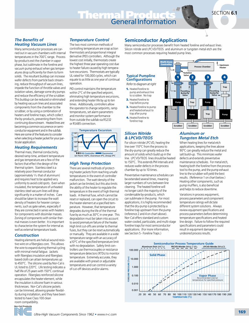
169
6Thermal Products SECTION 6.1
Ultra-High Vacuum Components Since 1962 • www.n-c.com
General Information
Semiconductor ApplicationsMany semiconductor processes benefit from heated foreline and exhaust lines. Silicon nitride and LPCVD/TEOS and aluminum or tungsten metal etch are the most common processes requiring heated pump lines.
Silicon Nitride & LPCVD/TEOS For silicon nitride LPCVD, heating the line over 110ºC from the process to the dry-pump can greatly reduce the amount of solids which build up in the line. LPCVD/TEOS lines should be heated to 150ºC. This extends PM intervals and reduces wafer defects in the process chamber by up to 10 times.
Preventative maintenance schedules can be extended several times, meaning larger numbers of runs between line cleaning. The heated foreline will no longer catch the majority of the condensable by-products, which can sublimate in the pump. For most applications, it is highly recommended that the dry-pump is protected by a foreline trap upstream from the pump (reference 2 and 4 on chart above). Nor-Cal offers standard and custom water-cooled, particulate, and multi-stage foreline traps for most semiconductor applications. (For more information, see Section 5 - Foreline Traps.)
Throttling Butterfly
Valve
Trap
Trap
Pump
Pump Pump
Scrubber ScrubberScrubberScrubber
1 2 3 4
Process Chamber
Isolation Valve
Upstream Heater
Multi-Zone Controller
Throttling Butterfly
Valve
Fore
line
Exh
aust
Lin
e
Trap
Pump
Heating RequirementsThermal mass, thermal conductivity, desired ramp time, ambient temperature and gas temperature are a few of the factors that effect the design of the thermal system. Stainless steel is a relatively poor thermal conductor (approximately 1/12 that of aluminum) and requires heat to be applied very uniformly to avoid cold spots. Even when insulated, the temperature of unheated stainless steel vacuum lines will drop significantly in a matter of inches. Care should be taken to increase the watt density of heaters for heavier compo-nents, such as gate valves, especially if they are connected in series with heaters for components with dissimilar masses. Zoning of components with similar ther-mal masses is even better. It is important to characterize the system for internal as well as external temperature loads.
ConstructionHeating elements are helical wound resis-tive wire on a fiberglass core. This allows the wire to expand during thermal cycling with minimal metal fatigue. Jackets with fiberglass insulation and fiberglass based cloth can attain temperatures up to 450°C. The silicone used by Nor-Cal is UL listed to 220°C. Life testing indicates a half life of 25 years with 150°C continual operation. Fiberglass reinforced silicone encapsulates the heater element, while the insulation is silicone foam in various thicknesses. Nor-Cal’s silicone jackets can be trimmed, allowing greater flexibil-ity during installation, and they have been tested to have Class 100 clean room compatibility.
Semiconductor Process Temperature GuideAluminum Etch (AIC13) PECVD Nitride (NH4) 2 SiF6 LPCVD Nitride (NH4CI)
20TEMPERATURE (oC)
200
Solid Phase
Vapor PhaseRecommended internal
temperature for specified pressure
30 40 50 60 70 80 90 100 110 120 130 140 150 160 170 180 190
FOR
ELIN
E PR
ESSU
RE
(To
rr)
100.000
0.001
0.010
0.100
1.000
10.000
Temperature ControlThe two most common methods of controlling temperature are snap action thermostats and proportional integral derivative (PID) controllers. Although the lowest cost initially, thermostats create the highest three year operating cost due to heater failure caused by high tempera-ture excursions. Thermostats are typically UL rated for 100,000 cycles, which can equate to as little as one year of continual operation.
PID control maintains the temperature within 2°C of the specified setpoint, eliminating high temperature excursions, and extending heater life by up to ten times. Additionally, controllers allow the operator to change setpoints, ramp temperatures, set alarm parameters and monitor system performance from outside the subfab via RS232 or RS485 connection.
High Temp ProtectionThere are several methods of protect-ing heater jackets from reaching unsafe temperatures in the event of controller malfunction. The watt density of the jacket can be limited, but this also limits the ability of the heater to regulate the temperature in the event of high thermal loads. A thermal fuse, which cannot be reset or replaced, can open the circuit to the heater element at a specified tem-perature. However, that temperature degrades during the life of the thermal fuse by as much as 30°C in one year. This degradation must be taken into account to avoid premature failure of the heater. High limit cut-offs are similar to thermal fuses, but they can be reset automatically or manually. They are available in a wide temperature range with an accuracy of ±10°C of the specified temperature limit with no degradation. Safety limit con-trollers use thermocouples or resistance temperature detectors (RTDs) to monitor temperature. Extremely accurate, they are available with preset or adjustable temperatures and can control a variety of cut-off devices and/or alarms.
The Benefits of Heating Vacuum LinesMany semiconductor processes are car-ried out in vacuum chambers with internal temperatures in the 700˚C range. Process by-products exit the chamber in vapor phase, but sublimate in the foreline and vacuum pump exhaust when gas temper-atures drop sufficiently for them to form solids. The resultant buildup can increase wafer defects from particle back stream-ing, reduce throughput of vacuum lines, impede the function of throttle valves and isolation valves, damage some dry pumps and reduce the efficiency of the scrubber. This buildup can be reduced or eliminated by heating vacuum lines and associated components from the chamber to the scrubber, or by using a combination of heaters and foreline traps, which collect the by-products, preventing them from continuing downstream. Heated lines are becoming a common occurrence on semi-conductor equipment and in the subfab. Here are some of the features to consider when selecting a heater jacket for your par-ticular application.
Temperature Excursion
Set Point:150ºC, Overshoot: 9ºC, Droop:9ºC
160º
140º
145º
150º
155º
PID Controller Thermostat
TEM
PER
ATU
RE
(oC
) Aluminum or Tungsten Metal EtchWhen heating lines for metal etch applications, keeping the lines above 90ºC can greatly reduce the metal and salt build-up. This minimizes wafer defects and extends preventative maintenance schedules. For metal etch, heating both the foreline from the process tool to the pump, and the pump exhaust line to the scrubber will yield the best results. (Reference 1 on chart below.) Heating other components, such as pump mufflers, is also beneficial and helps to reduce downtime.
Variations in process equipment, process parameters and component temperature ratings will dictate different system solutions. Always review equipment specifications and process parameters before determining temperature specifications and heated line design. Failure to follow the required specifications and parameters could result in equipment damage or undesired process results.
Typical Pumpline ConfigurationsRefer to diagram at right1. Heated foreline to pump and exhaust line to scrubber. No trap2. Heated foreline to trap before pump3. Heated foreline to pump and heated exhaust to trap after pump4. Heated foreline to foreline trap

170
6 Thermal ProductsSECTION 6.1
Ultra-High Vacuum Components Since 1962 • www.n-c.com
General Information
Features• Even heating up to 200°C• High temperature cloth heaters for heating up to 450ºC• Easy on/off with reclosable fasteners• Trimable, tight contact fit• 1/4 or 1/2 inch thick closed cell silicone rubber • 1/4 to 2 inch fiberglass based insulation for cloth heaters• 120V or 208V standard, 208V available at no charge, replace “-3” with “-2” in model number, other voltages are also available• Heaters are interconnectable up to a 10A circuit• Integrates with standard controllers • Built-in insulation with insulated lead wires• UL recognized construction• One year warranty
Benefits• Reduced system downtime• Improved heat transfer minimizing cold spots• Clean room compatible• Combine standard parts to cover custom lines• Adjustable temperatures• Modular heating system
Heating Element Silicone Rubber
Silicone Sponge Insulation
SnapFastener
Silicone RubberOuter Jacket
1/4 Inch 1/2 Inch
Jacket Thickness
6050 70 80 90 100 110 120 130 140 150 160 170
40
50
60
70
80
90
Exte
rnal
Sur
face
Tem
pera
ture
(ºC
)
Internal/External Temperature Comparison
Internal Temperature (ºC)
SPECIFICATIONSMaterials Heater jacket: Reinforced silicone rubber fabric Insulator: 1/4 or 1/2 inch thick closed-cell silicone rubber foam Fasteners: 1/2 inch diameter metal snaps with nylon cover standard
Electrical Watt density: 1 to 2 inch diameter: 1.5 W/in2
3 to 4 inch diameter: 1.25 W/in2
Voltage: 120V or 208V standard, other voltages available Power leads: 4 inch long #18 AWG, UL 180/CSA 10A rated Connectors: Positive locking Mate-N-Lok
Temperature range: < 200°C
Thermocouple pocket is built-in to all straight length heaters three inch long and greater. Shown with optional thermocouple installed.
All trimable jackets allow for up to one inch of insulation to be removed. This allows you to cover almost any line completely.
Self-adhesive kapton thermocouples are available for heaters without thermocouple pockets.
Need to heat a line in a hurry? Nor-Cal maintains a large inventory of heaters for 11/2, 2 and 4 inch tubing, elbows and flanges. Standard voltage is 120V. Nearly all heaters are available with 208V at no extra charge, replace “-3” with “-2” in model number. Other voltages are also available. Elbow and tee heaters fit both tube ending and flanged style weld fittings. Custom heaters for valves and other components are also available.

171Ultra-High Vacuum Components Since 1962 • www.n-c.com
6Thermal Products SECTION 6.2
Heater Jacket SelectionAfter measuring your system using the instructions on the facing page, choose the heater segments you will need from this product guide. List the model numbers with your notes.
Trimable heaters solve the problem of odd straight section lengths. For exam-ple, for a 141/2 inch section, combine a 12 inch trimable and a 3 inch heater. The 12 inch heater can be cut to a mini-mum of 11 inches. Cut 1/2 inch from the 12 inch heater to make a 111/2 inch length. Place cut edge towards the 3 inch heater to maximize temperature uniformity.
Designing Heated Systems
• Heaters can be connected together end-to-end in order to form a larger single circuit which then can be controlled as one “zone.”• A single line may contain multiple zones, depending on the length and the complexity. Use the following rules of thumb when grouping sets of heaters into zones.• The maximum amperage per zone is 10 amps, or 1200 watts. Please use the part number list to calculate the total wattage of your heated line. Dividing by 1080 will give you the approximate number of zones required. • Split zones at natural break points, such as at a flange, elbow or valve.• Each component, such as a gate valve, needs to be controlled with a separate control circuit. This is due to the difference in thermal mass between them and lengths of tubing. • Temperature sensors (thermocouples) can be placed easily in any straight heater three inches long and up. These heaters have a built-in thermocouple pocket for easy installation of the sensor. Self-adhesive Kapton thermocouples are available for heaters without thermocouple pockets.
• Remove labels and residual glue with methanol or another solvent before attaching the heater jacket. Operating the heater on a component with a label can cause discoloration or scorching of the jacket and may cause the label to ignite and damage the heater.• When choosing where to place the thermocouples for each zone, start at the process tool, placing the first thermocouple two to four feet from the outlet of the process.• The jacket should fit tightly for optimum heat transfer. Loose areas can draw higher wattage and damage the insulation and/or heater element. Note: Heater must be attached to the component when in operation.• Do not immerse the heaters in water or cleaning solutions.
36" straightHeater Jacket
Conical ReducerHeater
Y Heater
90º Elbow
Ball ValveHeater
TrimableLength
Flange Heater
TrimableLengths
Gate Valve Heater
BellowsHeater
Flange Heater
45º ElbowHeater
Straight Heater
HEATED EXHAUST LINEHEATED FORELINE
HC-FLG-400-ISO-3 (3X)HC-2WC-400-3
HC-400-6T-3
HC-400-6-3
HC-2WK-400-3
HC-400-12T-3
90º Elbow
5.5
.25 Test Port
11.4
6.0 R
6.0 R
2.0
2.0
6.5
4.0
5.7
14.0
45º Elbow
Heater Jacket Measurement
& SelectionThis is a simple pumpline measurement and heater
selection example.
Zone Layout and Heater Installation
See Thermal Products Worksheet on our website
www.n-c.com
To achieve the optimal benefit from your Nor-Cal heating system, maximum heated coverage is needed. To accomplish this, measurement of the vacuum line is neces-sary. For best results, please contact your Nor-Cal representative for assistance.
Line MeasurementUse the following guidelines to develop an approximate measurement to use for component selection and control zone layout. NOTE: To measure quickly, work from one end of the line to the other. Measure one component at a time. Component drawings are not necessary if detailed measurement notes are taken.
DIAMETER: Verify the line diameter by measuring the circumference (distance around the outside of the tubing) of a common straight section within the line.
DIAMETER CIRCUMFERENCE
1.50” 4.71”2.00” 6.28”3.00” 9.42”4.00” 12.57”
STRAIGHT SECTIONS: Measure the length of a straight section referencing the backside of the flange or the center-line of the weld fitting.
45º and 90º ELBOWS: Measure the “L” dimension from the backside of the flange to the centerline of the opposing leg. Refer to specific heater drawings located in this catalog.
TEE: Measure the “L” dimension.
FLEXIBLE SECTIONS: Measure the bel-lows OD and the length. (See specific heater drawing.) Note: The length must be measured under compression with full vacuum pulled. If there is a noticeable “twisting” on the flexible section, adjust-ment of the line may be needed for proper heater installation.
FLANGE: Note flange type and measure.
VALVES and OTHER SHAPES: Nor-Cal has a large selection of existing heater designs for valves, reducers and other components. Note manufacturer, size and model number.
172Ultra-High Vacuum Components Since 1962 • www.n-c.com
6 Thermal ProductsSECTION 6.3
1/4” Thick Heater Jackets – 11/2” Tube ODMODEL NUMBER
WATTS* 120 or 208V
POCKET Thermocouple
TRIMABLE
LENGTH L
HC-150-2-3 14 2HC-150-2T-3 7** P 2HC-150-3-3 22 P 3HC-150-3T-3 14 P P 3HC-150-4-3 29 P 4HC-150-4T-3 22 P P 4HC-150-5-3 36 P 5HC-150-5T-3 29 P P 5HC-150-6-3 43 P 6HC-150-6T-3 36 P P 6HC-150-12-3 85 P 12HC-150-12T-3 78 P P 12HC-150-18-3 128 P 18HC-150-24-3 170 P 24HC-150-24T-3 163 P P 24HC-150-30-3 213 P 30HC-150-36-3 255 P 36HC-150-36T-3 248 P P 36
* For 208V heaters replace the “-3” with “-2” at the end of the model number. ** 208V is not available.
Heater Jackets
1/2” Thick Heater Jackets – 11/2” Tube ODMODEL NUMBER
WATTS* 120 or 208V
POCKET Thermocouple
TRIMABLE
LENGTH L
HC2-150-2-3 14 2HC2-150-2T-3 7** P P 2HC2-150-3-3 22 P 3HC2-150-3T-3 14 P P 3HC2-150-4-3 29 P 4HC2-150-4T-3 22 P P 4HC2-150-5-3 36 P 5HC2-150-5T-3 29 P P 5HC2-150-6-3 43 P 6HC2-150-6T-3 36 P P 6HC2-150-12-3 85 P 12HC2-150-12T-3 78 P P 12HC2-150-18-3 128 P 18HC2-150-24-3 170 P 24HC2-150-24T-3 163 P P 24HC2-150-30-3 213 P 30HC2-150-36-3 255 P 36HC2-150-36T-3 248 P P 36
* For 208V heaters replace the “-3” with “-2” at the end of the model number. ** 208V is not available.
SPECIFICATIONSMaterials Heater jacket: Reinforced silicone rubber fabric Insulator: 1/4 or 1/2 inch thick closed-cell silicone rubber foam Fasteners: 1/2 inch diameter metal snaps with nylon cover standard
Electrical Watt density: 1 to 2 inch diameter: 1.5 W/in2
3 to 4 inch diameter: 1.25 W/in2
Voltage: 120V or 208V standard, other voltages available Power leads: 4 inch long #18 AWG, UL 1180/CSA 10A rated Connectors: Positive locking Mate-N-Lok
Temperature range: <200°C
1/4” Thick Heater Jackets – 2” Tube ODMODEL NUMBER
WATTS* 120 or 208V
POCKET Thermocouple
TRIMABLE
LENGTH L
HC-200-2-3 19 2HC-200-2T-3 10 P 2HC-200-3-3 29 P 3HC-200-3T-3 19 P P 3HC-200-4-3 38 P 4HC-200-4T-3 29 P P 4HC-200-5-3 48 P 5HC-200-5T-3 38 P P 5HC-200-6-3 57 P 6HC-200-6T-3 47 P P 6HC-200-7T-3 57 P P 7HC-200-8T-3 68 P P 8HC-200-9T-3 75 P P 9HC-200-10T-3 85 P P 10HC-200-11T-3 95 P P 11HC-200-12-3 114 P 12HC-200-12T-3 104 P P 12HC-200-18-3 170 P 18HC-200-24-3 227 P 24HC-200-24T-3 217 P P 24HC-200-30-3 283 P 30HC-200-36-3 340 P 36HC-200-36T-3 330 P P 36
* For 208V heaters replace the “-3” with “-2” at the end of the model number.
1/2” Thick Heater Jackets – 2” Tube ODMODEL NUMBER
WATTS* 120 or 208V
POCKET Thermocouple
TRIMABLE
LENGTH L
HC2-200-2-3 19 2HC2-200-2T-3 10 P 2HC2-200-3-3 29 P 3HC2-200-3T-3 19 P P 3HC2-200-4-3 38 P 4HC2-200-4T-3 29 P P 4HC2-200-5-3 48 P 5HC2-200-5T-3 38 P P 5HC2-200-6-3 57 P 6HC2-200-6T-3 47 P P 6HC2-200-7T-3 57 P P 7HC2-200-8T-3 68 P P 8HC2-200-9T-3 75 P P 9HC2-200-10T-3 85 P P 10HC2-200-11T-3 95 P P 11HC2-200-12-3 114 P 12HC2-200-12T-3 104 P P 12HC2-200-18-3 170 P 18HC2-200-24-3 227 P 24HC2-200-24T-3 217 P P 24HC2-200-30-3 283 P 30HC2-200-36-3 340 P 36HC2-200-36T-3 330 P P 36
* For 208V heaters replace the “-3” with “-2” at the end of the model number.
Installation of Nor-Cal’s modular heaters help produce consistent process yields by reducing the build-up of by-products in valves and other exhaust line components. Even line heating minimizes cold spots, greatly reducing particle generation - the cause of most unscheduled maintenance downtime. See page 169-171 for more information on heated lines.
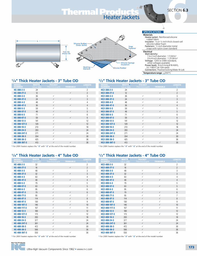
173Ultra-High Vacuum Components Since 1962 • www.n-c.com
6Thermal Products SECTION 6.3
Heater Jackets
Tube OD(Heater ID)
L
1/4” Thick Heater Jackets - 3” Tube ODMODEL NUMBER
WATTS* 120 or 208V
POCKET Thermocouple
TRIMABLE
LENGTH L
HC-300-2-3 24 2HC-300-2T-3 12 P 2HC-300-3-3 36 P 3HC-300-3T-3 24 P P 3HC-300-4-3 48 P 4HC-300-4T-3 36 P P 4HC-300-5-3 59 P 5HC-300-5T-3 48 P P 5HC-300-6-3 71 P 6HC-300-6T-3 59 P P 6HC-300-12-3 141 P 12HC-300-12T-3 129 P P 12HC-300-18-3 213 P 18HC-300-24-3 283 P 24HC-300-24T-3 271 P P 24HC-300-30-3 354 P 30HC-300-36-3 425 P 36HC-300-36T-3 413 P P 36
* For 208V heaters replace the “-3” with “-2” at the end of the model number.
1/2” Thick Heater Jackets - 3” Tube ODMODEL NUMBER
WATTS* 120 or 208V
POCKET Thermocouple
TRIMABLE
LENGTH L
HC2-300-2-3 24 2HC2-300-2T-3 12 P 2HC2-300-3-3 36 P 3HC2-300-3T-3 24 P P 3HC2-300-4-3 48 P 4HC2-300-4T-3 36 P P 4HC2-300-5-3 59 P 5HC2-300-5T-3 48 P P 5HC2-300-6-3 71 P 6HC2-300-6T-3 59 P P 6HC2-300-12-3 141 P 12HC2-300-12T-3 129 P P 12HC2-300-18-3 213 P 18HC2-300-24-3 283 P 24HC2-300-24T-3 271 P P 24HC2-300-30-3 354 P 30HC2-300-36-3 425 P 36HC2-300-36T-3 413 P P 36
* For 208V heaters replace the “-3” with “-2” at the end of the model number.
1/4” Thick Heater Jackets - 4” Tube ODMODEL NUMBER
WATTS* 120 or 208V
POCKET Thermocouple
TRIMABLE
LENGTH L
HC-400-2-3 32 2HC-400-2T-3 16 P 2HC-400-3-3 48 P 3HC-400-3T-3 32 P P 3HC-400-4-3 63 P 4HC-400-4T-3 48 P P 4HC-400-5-3 79 P 5HC-400-5T-3 63 P P 5HC-400-6-3 95 P 6HC-400-6T-3 79 P P 6HC-400-7T-3 95 P P 7HC-400-8T-3 114 P P 8HC-400-9T-3 130 P P 9HC-400-10T-3 146 P P 10HC-400-11T-3 157 P P 11HC-400-12-3 189 P 12HC-400-12T-3 173 P P 12HC-400-18-3 283 P 18HC-400-24-3 377 P 24HC-400-24T-3 361 P P 24HC-400-30-3 472 P 30HC-400-36-3 566 P 36HC-400-36T-3 550 P P 36
* For 280V heaters replace the “-3” with “-2” at the end of the model number.
1/2” Thick Heater Jackets - 4” Tube ODMODEL NUMBER
WATTS* 120 or 208V
POCKET Thermocouple
TRIMABLE
LENGTH L
HC2-400-2-3 32 2HC2-400-2T-3 16 P 2HC2-400-3-3 48 P 3HC2-400-3T-3 32 P P 3HC2-400-4-3 63 P 4HC2-400-4T-3 48 P P 4HC2-400-5-3 79 P 5HC2-400-5T-3 63 P P 5HC2-400-6-3 95 P 6HC2-400-6T-3 79 P P 6HC2-400-7T-3 95 P P 7HC2-400-8T-3 114 P P 8HC2-400-9T-3 130 P P 9HC2-400-10T-3 146 P P 10HC2-400-11T-3 157 P P 11HC2-400-12-3 189 P 12HC2-400-12T-3 173 P P 12HC2-400-18-3 283 P 18HC2-400-24-3 377 P 24HC2-400-24T-3 361 P P 24HC2-400-30-3 472 P 30HC2-400-36-3 566 P 36HC2-400-36T-3 550 P P 36
* For 208V heaters replace the “-3” with “-2” at the end of the model number.
Heating Element Silicone Rubber
Silicone Sponge Insulation
SnapFastener
Silicone RubberOuter Jacket
SPECIFICATIONSMaterials Heater jacket: Reinforced silicone rubber fabric Insulator: 1/4 or 1/2 inch thick closed-cell silicone rubber foam Fasteners: 1/2 inch diameter metal snaps with nylon cover standardElectrical Watt density: 1 to 2 inch diameter: 1.5 W/in2
3 to 4 inch diameter: 1.25 W/in2
Voltage: 120V or 208V standard, other voltages available Power leads: 4 inch long #18 AWG, UL 1180/CSA 10A rated Connectors: Positive locking Mate-N-LokTemperature range: <200°C

174Ultra-High Vacuum Components Since 1962 • www.n-c.com
6 Thermal ProductsSECTION 6.3
SPECIFICATIONSMaterials Heater jacket: Reinforced silicone rubber fabric Insulator: 1/4 or 1/2 inch thick closed-cell silicone rubber foam Fasteners: 1/2 inch diameter metal snaps with nylon cover standard
Fit: Formed elbows and tees fit weld fittings and flanged style tubing
Electrical Watt density: 1 to 2 inch diameter: 1.5 W/in2
3 to 4 inch diameter: 1.25 W/in2
Voltage: 120V or 208V standard, other voltages available Power leads: 4 inch long #18 AWG, UL 1180/CSA 10A rated Connectors: Positive locking Mate-N-Lok
Temperature range: <200°C
1/4 ” Thick Heater Jackets – 90° Radius Elbow MODEL NUMBER
TANGENT
TUBE OD
LENGTH L
RADIUS R
WATTS* 120 or 240V
HC-2WC-150-3 11/2 2.00 2.25 25HC-2WC-150HW-3 P 11/2 2.68 2.25 36HC-2WC-200-3 2 2.75 3.00 45HC-2WC-200HW-3 P 2 3.81 3.00 65HC-2WC-300-3 3 4.00 4.50 93HC-2WC-300HW-3 P 3 5.81 4.50 141HC-2WC-400-3 4 5.50 6.00 149HC-2WC-400HW-3 P 4 7.81 6.00 217
* For 208V heaters replace the “-3” with “-2” at the end of the model number.
1/4 ” Thick Heater Jackets – 45° Radius ElbowMODEL NUMBER
TANGENT
TUBE OD
LENGTH L
RADIUS R
WATTS* 120 or 240V
HC-2WK-150-3 11/2 0.69 2.25 13HC-2KL-150HW-3 P 11/2 1.38 2.25 23HC-2WK-200-3 2 1.00 3.00 23HC-2KL-200HW-3 P 2 2.06 3.00 44HC-2WK-300-3 3 1.37 4.50 47HC-2KL-300HW-3 P 3 3.18 4.50 95HC-2WK-400-3 4 2.00 6.00 70HC-2KL-400HW-3 P 4 4.31 6.00 148
* For 208V heaters replace the “-3” with “-2” at the end of the model number.
Heater Jackets
R
L
L
R
1/2 ” Thick Heater Jackets – 90° Radius Elbow MODEL NUMBER
TANGENT
TUBE OD
LENGTH L
RADIUS R
WATTS* 120 or 240V
HC2-2WC-150-3 11/2 2.00 2.25 25HC2-2WC-150HW-3 P 11/2 2.68 2.25 36HC2-2WC-200-3 2 2.75 3.00 45HC2-2WC-200HW-3 P 2 3.81 3.00 65HC2-2WC-300-3 3 4.00 4.50 93HC2-2WC-300HW-3 P 3 5.81 4.50 141HC2-2WC-400-3 4 5.50 6.00 149HC2-2WC-400HW-3 P 4 7.81 6.00 217
* For 208V heaters replace the “-3” with “-2” at the end of the model number.
1/2 ” Thick Heater Jackets – 45° Radius ElbowMODEL NUMBER
TANGENT
TUBE OD
LENGTH L
RADIUS R
WATTS* 120 or 240V
HC2-2WK-150-3 11/2 0.69 2.25 13HC2-2KL-150HW-3 P 11/2 1.38 2.25 23HC2-2WK-200-3 2 1.00 3.00 23HC2-2KL-200HW-3 P 2 2.06 3.00 44HC2-2WK-300-3 3 1.37 4.50 47HC2-2KL-300HW-3 P 3 3.18 4.50 95HC2-2WK-400-3 4 2.00 6.00 70HC2-2KL-400HW-3 P 4 4.31 6.00 148
* For 208V heaters replace the “-3” with “-2” at the end of the model number.

175Ultra-High Vacuum Components Since 1962 • www.n-c.com
6Thermal Products SECTION 6.3
L
L
Tee Heater JacketsMODEL NUMBER
THICKNESS
TUBE OD
LENGTH L
WATTS* 120 or 240V
HC-7W-150-3 1/4 11/2 2 37HC2-7W-150-3 1/2 11/2 2 37HC-7W-200-3 1/4 2 23/4 69HC2-7W-200-3 1/2 2 23/4 69HC-7W-300-3 1/4 3 3 99HC2-7W-300-3 1/2 3 3 99HC-7W-400-3 1/4 4 35/8 140HC2-7W-400-3 1/2 4 35/8 140
* For 208V heaters replace the “-3” with “-2” at the end of the model number.
SPECIFICATIONSMaterials Heater jacket: Reinforced silicone rubber fabric Insulator: 1/4 or 1/2 inch thick closed-cell silicone rubber foam Fasteners: 1/2 inch diameter metal snaps with nylon cover standardElectrical Watt density: 1 to 2 inch diameter: 1.5 W/in2
3 to 4 inch diameter: 1.25 W/in2
Voltage: 120V or 208V standard, other voltages available Power leads: 4 inch long #18 AWG, UL 1180/CSA 10A rated Connectors: Positive locking Mate-N-LokTemperature range: <200°C
Tube OD (Heater ID)
A
Tube OD (Heater ID)
B
L
Conical Heater JacketsMODEL NUMBER
THICKNESS
A
B
LENGTH L
WATTS* @ 120V
HC-200-150-3 1/4 11/2 2 13/8 12HC2-200-150-3 1/2 11/2 2 13/8 12HC-300-200-3 1/4 2 3 27/16 24HC2-300-200-3 1/2 2 3 27/16 24HC-400-200-3 1/4 2 4 25/8 31HC2-400-200-3 1/2 2 4 25/8 31HC-400-300-3 1/4 3 4 25/8 36HC2-400-300-3 1/2 3 4 25/8 36
* For 208V heaters replace the “-3” with “-2” at the end of the model number.
NW & ISO Flange Heater Jackets MODEL NUMBER
THICKNESS
FLANGE TYPE
NOMINAL TUBE OD
WATTS* @ 120V
HC-FLG-150-NW-3 1/4 NW-40 11/2 10HC2-FLG-150-NW-3 1/2 NW-40 11/2 10HC-FLG-200-NW-3 1/4 NW-50 2 15HC2-FLG-200-NW-3 1/2 NW-50 2 15HC-FLG-300-ISO-3 1/4 ISO-80 3 35HC2-FLG-300-ISO-3 1/2 ISO-80 3 35HC-FLG-400-ISO-3 1/4 ISO-100 4 82HC2-FLG-400-ISO-3 1/2 ISO-100 4 82
* For 208V heaters replace the “-3” with “-2” at the end of the model number.
NW & ISO Flange Insulators MODEL NUMBER
THICKNESS
FLANGE TYPE
NOMINAL TUBE OD
HI-FLG-100-NW-1 1/4 NW-25 1HI-FLG-150-NW-1 1/4 NW-40 11/2
HI2-FLG-150-NW-1 1/2 NW-40 11/2
HI-FLG-200-NW-1 1/4 NW-50 2HI2-FLG-200-NW-1 1/2 NW-50 2HI-FLG-300-ISO-1 1/4 ISO-80 3HI2-FLG-300-ISO-1 1/2 ISO-80 3HI-FLG-400-ISO-1 1/4 ISO-100 4HI2-FLG-400-ISO-1 1/2 ISO-100 4
Heater Jackets & Flange Insulators
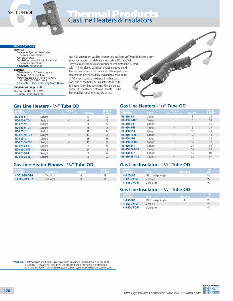
176Ultra-High Vacuum Components Since 1962 • www.n-c.com
6 Thermal ProductsSECTION 6.4
Gas Line Heaters - 1/4” Tube ODMODEL NUMBER
TYPE
TYPE J Thermocouple
LENGTH
WATTS @ 120V
HC-025-6-1 Straight 6 12HC-025-6-TC-1 Straight P 6 12HC-025-9-1 Straight 9 18HC-025-9-TC-1 Straight P 9 18HC-025-12-1 Straight 12 24HC-025-12-TC-1 Straight P 12 24HC-025-18-1 Straight 18 36HC-025-18-TC-1 Straight P 18 36HC-025-24-1 Straight 24 48HC-025-24-TC-1 Straight P 24 48HC-025-36-1 Straight 36 72HC-025-36-TC-1 Straight P 36 72
Gas Line Insulators - 1/4” Tube ODMODEL NUMBER
TYPE
TRIMABLE
TUBE OD
HI-025-18T 18 inch straight length P 1/4HI-025-7W-M Micro-tee 1/4HI-025-2WC-M Micro-elbow 1/4
SPECIFICATIONSMaterials Heater and jacket: Reinforced silicone rubber fabric Color: Orange Insulation: 1/4 inch thick closed-cell silicone rubber foam Fasteners: Nylon snap
Electrical Watt density: 2.5 W/In2 typical Voltage: 120V standard Power leads: 3 inch long #18 AWG, UL 1180/CSA 10A rated Connectors: Positive locking Mate-N-Lok
Temperature range: <200°C
Thermocouples: #30 AWG, Type J, Teflon insulated
Nor-Cal’s upstream gas line heaters and insulators offer quick delivery from stock for heating gas delivery lines,such as BCl3 and WF6. They are made from silicone rubber heater material insulated with 1/4 inch closed cell silicone rubber sponge and feature quick ON/OFF installation with snap closures. Heaters can be linked/daisy chained to a maximum of 10 amps. Lead pair extends 3 inches past each end of the heaters. Insulators trim-to-fit to insure 100% line coverage. Flexible elbow heaters fit most radius elbows. Meets UL94HB flammability requirements. UL Listed.
Gas Line Heaters - 1/2” Tube ODMODEL NUMBER
TYPE
TYPE J Thermocouple
LENGTH
WATTS @ 120V
HC-050-6-1 Straight 6 24HC-050-6-TC-1 Straight P 6 24HC-050-9-1 Straight 9 36HC-050-9-TC-1 Straight P 9 36HC-050-12-1 Straight 12 48HC-050-12-TC-1 Straight P 12 48HC-050-18-1 Straight 18 72HC-050-18-TC-1 Straight P 18 72HC-050-24-1 Straight 24 96HC-050-24-TC-1 Straight P 24 96HC-050-36-1 Straight 36 144HC-050-36-TC-1 Straight P 36 144
Warning: Upstream gas line heater jackets are not designed for hazardous or outdoor locations. They are not designed for total or partial immersion and should only be installed on grounded metallic tubing systems or GFI protected circuit.
Gas Line Heaters & Insulators
Gas Line Heater Elbows - 1/4” Tube ODMODEL NUMBER
TANGENTS
LENGTH
WATTS @ 120V
HC-025-2WC-1-1 Two 1 inch 6 12HC-025-2WC-5-1 One 5 inch 9 18
Gas Line Insulators - 1/2” Tube ODMODEL NUMBER
TYPE
TRIMABLE
TUBE OD
HI-050-18T 18 inch straight length 4 1/2
HI-050-7W-M Micro-tee 1/2
HI-050-2WC-M Micro-elbow 1/2

177
Thermal Products
Ultra-High Vacuum Components Since 1962 • www.n-c.com
6SECTION 6.5
HCS-Series Heaters
HCS-Series Heaters (¼” and ½” OD Tube) MODEL NUMBER TUBE OD MINIMUM
LENGTHMAXIMUM
LENGTH WATTS@120V
HCS-025-8-1* 1/4 8 10 12HCS-025-11-1* 1/4 11 14.5 17HCS-025-15-1 1/4 15 19 22HCS-025-19-1 1/4 19 24 28HCS-025-24-1 1/4 24 30.5 36HCS-025-31-1 1/4 31 40 47HCS-025-40-1 1/4 40 51 60HCS-025-50-1 1/4 50 64 76HCS-025-60-1 1/4 60 76.5 90HCS-050-7-1* 1/2 7 10 17HCS-050-10-1* 1/2 10 15 25HCS-050-14-1 1/2 14 21 35HCS-050-19-1 1/2 19 29.5 49HCS-050-25-1 1/2 25 38.5 64HCS-050-31-1 1/2 31 47.5 79HCS-050-39-1 1/2 39 59.5 99HCS-050-50-1 1/2 50 74 123HCS-050-60-1 1/2 60 92.5 154
* Note: 240V not available in these sizes.
(240V heaters can be ordered by changing the last “-1” to “-2”)
MODEL NUMBER DESCRIPTION
HIS-025-18 INS,1/4” Spiral Wrap,18” LongHIS-025-2WC-M INS,1/4” Spiral Wrap,Micro ElbowHIS-025-7W-M INS,1/4” Spiral Wrap,Micro TeeHIS-025-VCR INS,1/4” Spiral Wrap,VCR UnionHIS-038-18 INS,3/8” Spiral Wrap,18” LongHIS-038-2WC-M INS,3/8” Spiral Wrap,Micro ElbowHIS-038-7W-M INS,3/8” Spiral Wrap,Micro TeeHIS-038-VCR INS,3/8” Spiral Wrap,VCR UnionHIS-050-18 INS,1/2” Spiral Wrap,18” LongHIS-050-2WC-M INS,1/2” Spiral Wrap,Micro ElbowHIS-050-7W-M INS,1/2” Spiral Wrap,Micro TeeHIS-050-VCR INS,1/2” Spiral Wrap,VCR Union
HCS-Series Insulators (3/8” Thick Insulation)
SPECIFICATIONSMaterials Color: Orange Heater: Spiral formed reinforced silicone rubber fabricElectrical Watt density: Max. 2.0 W/in² at 100% coverage, 80% coverage recommended Voltage: 120V or 240V* Leads: 12” long pair located on one end, #18 AWG, UL 1180/CSA 10A rated Connectors: Positive locking AMP Mate-N-LokTemperature range: <200°C
SPECIFICATIONSMaterials Color: Insulation and outer jacket – orange Insulator: 3/8” thick closed cell silicone rubber Fasteners: Cleanroom strapsTemperature range: <200°C

178
Thermal Products
Ultra-High Vacuum Components Since 1962 • www.n-c.com
6SECTION 6.6
Controllers, Thermostats & Accessories
ControllersMODEL NUMBER
VOLTAGE
MAX. AMP OUTPUT / ZONE
ZONES
AC PLUG
HC-SDC15-1-1 120V 10 1 Straight bladeHC-SDC15-1-2 208-240V 10 1 SchukoHC-SDC15-2-1 120V 5 2 Straight bladeHC-SDC15-2-2 208-240V 5 2 Schuko
Electronic ThermostatsNor-Cal offers UL recognized electronic thermostats for fixed set-point thermal applications. Electronic thermostats replace the thermocouple/controller assembly on a heater with a single device attached to the heater jacket. These devices have an extended life of over 10 times the standard thermostat life. In addition, temperature variations are typically ± 3°C, a major improvement over typical thermostats’ ± 15°C. These thermostats include a thermocouple sensor and power switching compactly integrated into the heater’s power cable. A single thermostat may be attached to several heater jackets on the same line to reduce system costs. They are prepro-grammed with the thermal set point you request. Call for more details.
Heater ControllersHC-SD series digital indicating, microprocessor-based heater controllers are available with a single temperature sensor input from a thermocouple or RTD sensor, and control outputs for one, two and four zones. These low-cost, self contained controllers’ feature a programmable alarm, small panel footprint and operate at ±0.25% accuracy. The outputs may operate in a variety of modes including: heat, alarm and timer. The countdown timer function operates in a choice of delay-ON, delay-OFF, signal-ON or signal-OFF modes. Front panel lock capability rounds out the feature set. Other features include EIA-485 Modbus serial communication, 1/32 DIN package, Nema 4x control console and a universal power supply.
Thermocouples & CablesMODEL NUMBER
DESCRIPTION*
LENGTH IN FEET
HC-TC-K-1 K-type with one foot lead and mini-connector 1HC-TC-K-8 K-type with eight foot lead and mini-connector 8HC-TC-K-KAP-8 K-type kapton with eight foot lead and mini-connector 8HC-TC-CRD-K-6 K-type thermocouple extension cable with connectors 6HC-TC-CRD-K-10 K-type thermocouple extension cable with connectors 10HC-TC-CRD-K-25 K-type thermocouple extension cable with connectors 25
*Most items available in various lengths and in J-type also. Call for pricing and information.
Control Cables and AccessoriesMODEL NUMBER
DESCRIPTION
LENGTH IN FEET
HC-PLG Termination for end of last heater, 2 prong MNL plug -HC-PLG-2C Termination for end of last heater, 2 prong MNL cap -HC-PLG-3C Termination for end of last heater, 3 prong MNL cap -HC-PLG-3P Termination for end of last heater, 3 prong MNL plug -HC-PCRD-6 SD3 controller to heater or 2 circuit MNL extension, 2 circuit plug, 2 circuit cap 6HC-PCRD-6-3 SD3 controller to heater, 2 circuit plug, 3 circuit MNL cap 6HC-PCRD-6-3B SD3 controller to cloth heater, 2 circuit plug, 3 circuit MNL cap, center ground 6HC-PCRD-CPC-6-2 SDC15 controller to heater, CPC, 2 circuit MNL cap 6HC-PCRD-CPC-6-3 SDC15 controller to heater, CPC, 3 circuit MNL cap 6HC-PCRD-CPC-6-3B SDC15 controller to cloth heater, CPC, 3 circuit MNL cap, center ground 6HT-CRD-6-2P 120V straight wall to 2 circuit MNL plug 6HT-CRD-6-3P 120V straight wall to 3 circuit MNL plug (GNV heater) 6
Nor-Cal is your source for temperature controllers. Full thermal control of the process is available through front panel controls including set points and alarms. Timers and digital readouts are standard on some models. Enclosures are either Nema 4, 4x or 12. Most controllers are RS232/485 compatible. Choose from 1, 2, 4 and 8 zone controllers. Line voltage is from 100V to 240V. Custom voltages and zoning is available on request. PC control using standard software programs is available. Nor-Cal heater controllers come with a three year warranty.
The Effect of Temperature Excursion on Heater LifePID Controllers result in temperature control accuracy of ± 2ºC, and extend heater element life by up to 10 times. Although the lowest cost initially, thermostats create the highest 3 year operating cost due to heater failure caused by temperature excursions. (See chart below) Although the highest cost initially, PID control-lers with SCR Burst Firing create the lowest 3 year operating cost due to it’s ability to eliminate temperature excursions. This can extend heater life up to 10 times.
Set point:150ºC, Overshoot: 9ºC, Droop:9ºC
160º
140º
145º
150º
155º
PID Controller Thermostat
TEM
PER
ATU
RE
(oC
) TIME

179
7
Tel: 800-824-4166or 530-842-4457
Main Fax: 530-842-9130Sales Fax: 530-841-9189
www.n-c.com
Nor-Cal Products, Inc.1967 South Oregon Street
Yreka, CA 96097 USA
Chambers & Weldments
Section Seven
7.1 General Information 180
7.2 Guide to Vacuum Chamber Design 183
7.3 Bell Jars, Feedthrough Collars & Baseplates 186
7.4 Surface Analysis Chamber 187
7.5 GEC Reference Cell 188
7.6 Weldments 189
7.7 Vacuum Chamber Gallery 190
7
180
Chambers & WeldmentsSECTION 7.1
Ultra-High Vacuum Components Since 1962 • www.n-c.com
General Information
Nor-Cal Products has earned a reputation as a world-class manufacturer of high and ultra-high vacuum chambers. The quality, appearance and performance of our chambers are unequaled. We supply single chambers designed from customer specifications for university or national laboratory research projects, as well as production quantity chambers that are built-to-print for equipment manufactur-ers. Thin-film deposition and compound semiconductor processing are common applications for our high-vacuum, O-ring sealed chambers that operate at pres-sures down to 1x10⁻⁹ mbar. Vacuum fired 316L stainless steel, electropolishing and metal seals are recommended for ultra-high vacuum surface science chambers that operate at pressures in the 1x10-
11 mbar range. Nor-Cal can fabricate vacuum chambers up to approximately 5 x 5 x 5 feet (1.52 x 1.52 x 1.52 Meters)with doors, stands, water jackets and Mumetal shields. (Consult the factory for exact capabilities.) We offer a complete line of vacuum chamber accessories that include load locks, sample transfer and positioning devices, liquid and electrical feedthroughs, viewports and roughing components.
All dimensions are in inches unless otherwise noted
“The system utilizes several types of analyzers around the analysis chamber. Designed to be ergonomic and user-friendly, the system’s frame components are on the floor level, maximizing accessibility to the research instruments. Electropolished 316L vacuum fired stainless steel was selected for the chambers in order to obtain a base pressure less than 3x10-11 mbar. Based on previous projects, we selected Nor-Cal Products to manufacture the vacuum chambers and components. We are very pleased with their quality, service and on-time delivery.”
Jan-Olof Forsell Design Manager, Gammadata Scienta and SSRL
Vacuum coating chamber
“This vacuum system was optimized for investigations into the magnetic properties of a wide range of materials using soft x-rays from synchrotron radiation sources. For such work, ultra high vacuum is necessary and this Nor-Cal Products chamber has a base pressure of 5x10-11 mbar after baking. The use of independent rotary stages for positioning of the sample and in-vacuum electromag-net provide a very high degree of flexibility by allowing any combination of sample surface and applied field relative to the incident soft x-rays.”Dr. Jonathan Hunter-Dunn MAX-Lab Lund University, Sweden
“I would like to reiterate how impressed we’ve been by the professional service we’ve received from Nor-Cal Products. I’ve inter-acted with engineers and salespeople from many vacuum equipment suppliers. It never fails to surprise me how uneven the service is. Salespeople are often uncommu-nicative, giving the impression that they’re not in the least bit interested in your business, and technical people often don’t know their products. It’s incredibly refreshing, therefore, to interact with people, such as those at Nor-Cal, who are both courteous and well informed.”
Susan Watson, PhD Department of Physics, University of California, San Diego
MOCVD reactor chamber

181Ultra-High Vacuum Components Since 1962 • www.n-c.com
7SECTION 7.1
ManufacturingMachining procedures are consistent with good UHV practices. Machine cool-ant is sulfur-free to reduce outgassing. All Nor-Cal components are designed to minimize entrapments that cause virtual leaks under vacuum. State-of-the-art CNC machining equipment is used to produce parts with consistently high quality.
GTAW fusion welding is used exclusively for a vacuum-tight metal bond. Purging with an inert gas reduces or eliminates oxygen entrainment and carbide precipi-tation that cause outgassing. Whenever possible welds are made on the inside, or are full penetration to eliminate entrap-ments and virtual leaks. External stitch welds are used in conjunction with internal vacuum welds for structural reinforcement, as necessary.
MaterialsNor-Cal Products uses 304 stainless steel tubing, spheres or roll-ups to fabricate vacuum vessels; however, 304L, 316, 316L or 316LN stainless steel can also be supplied. We have found that optimal vacuum performance can be obtained by using 2B rolled sheet with no secondary grinding for the body followed by electropolishing after ports are welded. Normally our standard material is dual certified 304/304L low carbon range stainless steel.
Flanges and baseplates are made from 304 stainless steel that has been specially treated to remove impurities inherent in 300 series steels. Special UHV-flanges 4 ½ inches (114.3mm) OD and smaller can be made from 304 electroslag remelt (ESR) bar stock. ESR is a refining process that produces stainless steel with higher purity, fewer inclusions and more uniform grain structure to eliminate microscopic leak paths.
Our standard flange material is certified to meet ASTM A-240 and has less than 0.01% sulfur to prevent sulfur string-ers. Grain size is 3 to 6 per ASTM E-112. Maximum inclusion size is 2.5 per ASTM E-45. Roll-forged rings, Mumetal, alumi-num and other materials can be supplied upon request.
CleaningA biodegradable detergent is used to remove machine lubricants before the parts are washed and rinsed with deion-ized water. Nor-Cal offers in-house bead blasting, chem cleaning and electropol-ishing of vacuum chambers. Glass shot cleans, hones, polishes and peens while removing scale. Some customers request bead blast on the exterior of the chamber with electropolish on the interior.
Electropolishing is considered the most desirable cleaning and surface condition-ing process for stainless steel vacuum chambers. It is an electrochemical process that benefits the finished part in a number of ways simultaneously. Deburring, pas-sivation and stress relieving are achieved while the machine-produced surface roughness is eroded. Electropolishing attacks the microscopic “peaks” of the surface more rapidly than the “valleys”; thereby maintaining critical dimensions while improving surface finishes. Nor-mally .0003 to .0004 inches (.00762 to .01016mm) would be removed to lower the microfinish from 32 to 8 RMS. Elec-tropolishing a 2B stainless steel rolled sheet achieves approximately a 90% reduction in surface area. This is most important for vacuum chambers because
Engineering As part of our commitment to quality and customer satisfaction, Nor-Cal’s engineering staff thoroughly reviews each custom vacuum component for manufacturability before the produc-tion process begins. All customers benefit from the combined experi-ence of our engineers, whose input during the design and production phase often results in cost savings and a superior product. Questions regarding design, specifications and testing are directed back to the customer for final approval.
Our engineers design from customer specifications, sketches or drawings and oversee custom component production using existing tooling and facilities. For our customers who do not have drafting person-nel available and require a complex assembly, we can provide complete CAD drawings for approval after receipt of order. Nor-Cal’s engineer-ing department employs the latest versions of SolidWorkstm draft-ing and solid modeling software. Drawings may be e-mailed direct to our engineering department at [email protected]. Acceptable file formats are IGES, SAT and STEP. You may also request CAD drawings and download 3D models of our most commonly used standard compo-nents from our website.
it produces faster pumpdown and a lower base pressure. In addition to the improved mechanical properties of the surface, iron is removed electrochemically. This leaves the surface rich in chromium and nickel, which have extremely low vapor pressures. The result is the lowest outgassing rates possible from stainless steel. Having an in-house facility allows Nor-Cal to do multi-step elec-tropolish in order to reduce “shadowed” areas on chambers with difficult geometries. Our electropolish tanks can accommodate chambers up to 60 x 50 x 65 inches (1.52 x 1.27 x 1.65 Meters).
All stainless steel parts are descaled and passivated in an acid solution to remove weld scale and other oxide layers. This process leaves the surface free from most contaminants that might impact the vacuum environment or promote intergranular corrosion. (Contact our factory for Ion Chromatography (I.C.) test data.) Chem cleaning can be used as a final cleaning step for chambers up to 35 x 53 x 33 inches (889 x 1346.2 x 838.2mm) to remove organic and metallic contaminants. The chamber is immersed in a series of controlled chemical baths and deionized water rinses and dried using filtered air. Chem cleaning results in the cleanest surface possible for ultra high vacuum components. (Contact our factory for I.C. test data.)
Chambers & WeldmentsGeneral Information

7
182
Chambers & WeldmentsSECTION 7.1
Ultra-High Vacuum Components Since 1962 • www.n-c.com
PackagingVacuum chambers and other large components are packaged appropriately for truck, ship or airfreight to our customer’s location. Unless specified otherwise, flanges are covered with aluminum foil to prevent internal contamination and scratching of the flange faces. Protective plastic covers are placed over the foil for additional protection. The chamber is then wrapped in 4 mil plastic and placed in a wooden crate. Foam is injected into plastic “pillows” which expand to fill the voids in the crate, suspending the chamber inside. Depending on customer specifications for systems, after qualification the chambers can be disassembled or purged with nitrogen gas, clean room packaged and shipped. Alternatively, some chambers have been packaged and shipped under vacuum.
General Information
InspectionNor-Cal uses the most up-to-date equipment and procedures for the inspection of vacuum chambers. Every weld is leak checked with a helium mass spectrometer to insure leak rates of 1x10⁻⁹ mbar l/sec. or less. Mechanical inspection is accomplished with a coordinate measuring machine (CMM). We can provide our customers with CMM inspection reports of their chambers on request.
Our chamber qualification and test equipment is available to customers for an additional fee who request residual gas analysis (RGA) scans and leak checks of their chamber after vacuum baking. The test equipment includes vacuum pumps, gauges, RGA, quartz heaters, nitrogen back fill and a leak detector. Chamber bake out is achieved with high intensity infrared radiant lamps that are strategically placed throughout the chamber. Baking under vacuum removes high and low molecular weight volatile compounds. Non-water cooled UHV chambers are typically baked for at least 24 hours at 150˚C. (The maximum temperature of system components such as seals, chamber materials, valves, etc. may limit maximum baking temperatures.) Uniform bakeout temperature is
achieved by wrapping the associated system components in high temperature fiberglass materials.
FramesFrames are usually constructed from 1½ or 2 inch (38.1 or 28.8mm) mild steel box tubing, which is powder coated. However, aluminum or a variety of other materials are available. In addition to leveling pads and castor wheels, we can design and fabricate frames with precision rotational and linear bearings for moving components, such as chamber lids. Integrated hoist assemblies, pump mounting, cabinets and panel rack mounting are also available.
System IntegrationNor-Cal can assemble an entire sys-tem including chamber, frame, pumps, gauges, valves, manipulators and other components to customer specifications in our 1,100 square foot, class 1000, final assembly area. After completion our vacuum technicians can complete a thor-ough system qualification, including bake out, RGA scan and leak check using the procedures described above. Addition-ally, a functional test is performed on all system hardware.
Leak testing of chamber on chamber qualification test bench
System integration
Mechanical inspection of process chamber with CMM (coordinate measuring machine)
After cool down our RGA will provide partial pressure data, determining the level of residual volatile compounds. Typical scans produce atomic mass levels below 1x10⁻⁹ mbar for atomic masses greater than or equal to 44. Total sys-tem pressures are between 5x10⁻⁹ and 7x10⁻¹⁰ mbar. Chamber design, seals and pumps used, and the maximum bake temperature over time effect the residual gas composition and ultimate pressures reached. Following chamber scanning, chambers are leak tested using a NIST traceable helium mass spectrometer leak detector with a final allowable leak rate of 1x10⁻¹⁰ mbar l/sec. or less.
Chamber frame with precision linear bearings

183Ultra-High Vacuum Components Since 1962 • www.n-c.com
7Chambers & Weldments SECTION 7.2
Cylindrical Cylindrical chamber bodies come in a variety of sizes and are made of tubing or roll-ups. The base plate and lid of the chamber can be made from die-formed dished heads, hemi-spheres or blank flanges. Dished heads and hemispheres are lighter and typically less expen-sive than machined flanges. This configuration is commonly used for analyzer chambers with multiple levels and targets, and for processing chambers with carousels or robotic arms.
Spheres and Hemispheres Spun hemispheres can be purchased in a wide range of standard sizes and welded together to form a spherical body. Often a large tube is attached to the bottom of the sphere for attachment of the pump. A number of smaller, radial ports can be positioned around the sphere for attachment of the load lock and various instruments. This is a common configuration for UHV analyzer chambers with a single target. This configuration is lighter, less expensive to manufacture and has less Internal volume than cylindrical configurations with machined lids.
RectangularRectangular chambers are generally more expensive than other configurations. However, they may be the preferred choice because of a requirement for accessibility, or when large chamber mass is required for vibration dampening. Rectangular chambers are fabricated from plate material that is welded, or they are machined from solid billets. Depending on material thickness and span, stiffening bars may be required to prevent deflection of the walls while the chamber is under vacuum.
Guide to Vacuum Chamber Design
Water Cooled ChambersNor-Cal Products frequently provides water cooled cham-bers and flanges for diffusion, CVD, and other high temperature vacuum applications. Normally the construc-tion techniques involve water channels or double walled construction. Water channels require considerable hand fitting and therefore tend to be more expensive than double walled construction. Double wall water-cooled chambers are fitted with internal baffles to provide consistent circula-tion throughout the chamber, resulting in excellent internal temperature uniformity.
Water-cooled chambers manufactured by Nor-Cal undergo a rigorous leak test to insure that they are free from water leaks. First the water cavities are stressed by pressurizing them with dry nitrogen. The water cavity is then pumped down with a helium leak detector, while helium is applied with a probe to all welds on the inside and outside of the chamber. (Consult the factory for pressure and integrity acceptance criteria.)
Water channel construction
Double wall construction
Outer H2O Jacket Wall Water Outlet
Water InletBaffles
Inner H2O / Chamber Wall
The information presented on the following three pages is provided as a general guideline to the vacuum engineer or end user to aid in the design of their vacuum chamber. In addition to the specific areas which are discussed, these considerations should be addressed when designing a vacuum chamber:
Chamber Material 304SS, 304LSS, 316SS, 316LSS, aluminum, etc.
Vacuum Level Base pressure and
acceptable leak rate
Surface treatment Glass bead finish,
electropolish, chemical clean, etc.
Special Requirements Vacuum bakeout,
vacuum fire or RGA scan.
Additional Hardware Blank-off flanges,
manipulators, viewports, etc.
Required Inspection Reports CMM inspection report printouts
or certificate of conformance and/or material certificates
By first determining the basic design parameters from those mentioned above, the actual process of designing, specifying and estimating the cost of your chamber will follow more smoothly. Nor-Cal sales estimators are available for any assistance you require. Engineering drawings can be e-mailed directly to [email protected].
Typical Chamber Configurations
Double Wall Construction

184Ultra-High Vacuum Components Since 1962 • www.n-c.com
7 Chambers & WeldmentsSECTION 7.2
Guide to Vacuum Chamber Design
Chamber Wall ThicknessRecommended minimum wall thicknesses are listed in the table below. Thicker walled material should be specified for chambers with ports having angular tolerances of less than 1/2º, or for processes that require large mass for vibration dampening.
CHAMBER DIAMETER
WALL THICKNESS
Under 17 inches (431.80) 0.120 (3.05)17 through 28 inches (431.80-711.20) 0.188 (4.78)
Over 28 inches (711.20) 0.250 (6.35)
Roll upsRoll ups are formed from 2B rolled finish, flat sheet that is formed into a cylinder and stitch welded on the outside seam, before apply-ing a vacuum weld to the inside. They can be obtained in a range of wall thicknesses and any diameters. Dished head and sphere diameters are typically available in the United States in nominal inch sizes.
Standard TolerancesUnless otherwise specified by the customer, standard tolerances will be adhered to during fabrication. These tolerances are acceptable for most analytical or process vacuum equipment and can normally be achieved without secondary machining operations after welding. Tighter tolerances required for specific applications are frequently provided for a slightly higher cost. Stan-dard tolerances for machined dimensions are ± .005 inches (.13mm) (although tolerances of ± .002 inches (.51mm) are commonly held on critical flange dimensions). Standard tolerance for any welded dimension, such as a port length or chamber height up to 24 inches (609.60mm), is ± .020 inches (.51mm) ± .060 inch (1.52mm) for chambers >24 inches (609.60mm), but <72 inches (1828.80mm)in length). Standard tolerance for polar and azimuthal angles is ± 1/2°.
Bolt Pattern OrientationOur components are manufactured with the primary axis straddling adjacent bolt holes on the mounting flange (American Standard). Most components can be furnished with the axis passing through a bolt hole axis (European Standard) on request. Leak check groove orientation should be indicated on drawings if critical.
NW Bulkhead DetailFLANGE TYPE
BOLT CIRCLE
THREAD SIZE
THREAD DEPTH
BLIND TAPPED HOLES
THROUGH HOLE
NW-16 1.50 (38.10) 10-32 0.300 (7.62) 6 0.90 (22.86)NW-25 1.89 (48.01) 10-32 0.300 (7.62) 6 1.26 (32.00)NW-40 2.44 (61.98) 10-32 0.300 (7.62) 6 1.84 (46.74)NW-50 3.25 (82.55) 10-32 0.300 (7.62) 8 2.35 (59.69)
Bulkhead or baseplateNW flange
Bulkhead clamps NW centering ring
10-32 x 5/8" screws
NW Clamp ClearanceFLANGE
SIZE
Min. Dia. to Install
A
Max. Dia. Closed
B
Min. Dia. Closed
CNW-10 2.86 (72.64) 2.65 (67.31) 1.75 (44.45)NW-16 2.86 (72.64) 2.65 (67.31) 1.75 (44.45)NW-25 3.32 (84.33) 3.00 (76.20) 2.24 (56.90)NW-40 4.00 (101.60) 3.72 (94.49) 2.90 (73.66)NW-50 5.45 (138.43) 4.62 (117.35) 3.69 (93.73)
.57 AB
C
Port LengthsPort lengths should be sufficiently long to allow the flange bolts to be inserted into the bolt holes from the underside of the flange unless tapped flanges are used. When designing chambers we typically dimension the ports so there is a minimum of three times the flange thickness from the port flange face to the outer wall of the chamber. If design-ing a chamber which utilizes NW clamps for assembly please refer to the chart below for clamp clearance details. TOLERANCE
MEASUREMENTS
Machined dimensions ± 0.005 (.13)Welded dimensions up to 24 ± 0.020 (.51)Welded dimensions over 24 ± 0.060 (1.52)Focal length ± 0.020 (.51)Port alignments ±1/2°
TubingNor-Cal stocks a broad variety of 304, 304L and 316L stainless steel tubing sizes that can be used for ports. Usually the port flange determines the diameter of the port tubing, but oversized tubing (i.e., 1¾ inch (44.45mm) OD tubing for 2¾ inch (69.85mm) OD CF flanges) is occasionally used for additional clearance for instrumentation. The table below lists common tubing sizes used for vacuum chamber ports.
TUBE OD
TUBE ID
WALLTHICKNESS
1/2 (12.70) 0.402 (10.21) 0.049 (1.24)3/4 (19.05) 0.680 (17.27) 0.035 (0.89)1 (25.40) 0.870 (22.10) 0.065 (1.65)
11/4 (31.75) 1.120 (28.45) 0.065 (1.65)11/2 (38.10) 1.370 (34.80) 0.065 (1.65)15/8 (41.28) 1.490 (37.85) 0.065 (1.65)13/4 (44.45) 1.630 (41.40) 0.065 (1.65)
2 (50.80) 1.870 (47.50) 0.065 (1.65)21/2 (63.50) 2.370 (60.20) 0.065 (1.65)
3 (76.20) 2.870 (72.90) 0.065 (1.65)4 (101.60) 3.834 (97.38) 0.083 (2.11)5 (127.00) 4.834 (122.78) 0.083 (2.11)6 (152.40) 5.834 (148.18) 0.083 (2.11)8 (203.20) 7.760 (197.10) 0.120 (3.05)
10 (254.00) 9.760 (247.90) 0.120 (3.05)12 (304.80) 11.760 (298.70) 0.120 (3.05)
AMERICAN EUROPEAN
Primary Axis
A/2A
STANDARD CHAMBER DIMENSIONS
Through Hole
Thread Depth
Bulkhead or Baseplate
Bolt Circle
Bulkhead/Baseplate Detail
Nor-Cal can manufacture vacuum chambers with metric size tubes, roll-ups, and spheres, however inch sized materials are more readily available in the US and can be furnished for a lower price. For further clarification, contact an estimator at the factory or see our website.
All dimensions are in inches (mm) & weights are in pounds (kg), unless otherwise noted.

185Ultra-High Vacuum Components Since 1962 • www.n-c.com
7Chambers & Weldments SECTION 7.2
Focal Length
A
P
Height
0 Z
A = Azimuthal Angle P = Polar Angle
0
0,0 X,Y
Focal Length
Flange Type Specify the flange type and size for each port. You must also specify rotatable or non-rotatable, and whether tapped flanges are required.
Port Tube OD Port tube diameter and wall thickness
Target Point Define using X,Y,Z coordinates.
Focal Length The focal length, or distance from the flange face to the target.
Azimuthal Angle Establish 0º on one of the axes when viewing the chamber along its centerline. Indicate the clockwise degree of angle from 0º to the centerline of the port.
Polar Angle The polar angle between the chamber’s vertical axis and the port centerline.
Instrument Type Define the instrument to be attached to each port.
Guide to Vacuum Chamber Design
Vacuum Chamber Port Configuration WorksheetPORT
NUMBERFLANGE
TYPETUBE OD
TARGET POINT
FOCAL LENGTH
AZIMUTHAL ANGLE
POLAR ANGLE
INSTRUMENT TYPE
Polar 0o
Polar 180o
Azimuthal 0o
Azimuthal 270o
Azimuthal 180o
Azimuthal 90o
Y Axis X Axis
Z Axis
2.0
8.0
Target PointB (2,0,8)
Port 1
Target Point A (0,0,8)
(0,0,0)
HOW TO SPECIFY CHAMBER PORTS
When specifying chamber ports, first dimension the main chamber body. Secondly, dimension levels with one or more targets from one end of the chamber. This provides the machinist and inspector with a common reference point for all levels. Once targets are established either on the centerline of the chamber or referenced from the centerline at each level, ports may be completely described with the following information.
Note: 0,0,0 (X,Y,Z) is typically the center point of the base flange face.
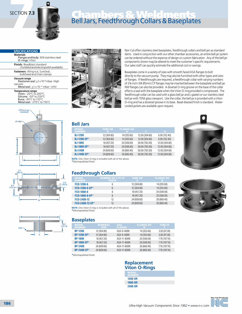
186
Chambers & Weldments
Ultra-High Vacuum Components Since 1962 • www.n-c.com
7SECTION 7.3
Bell Jars, Feedthrough Collars & Baseplates
Nor-Cal offers stainless steel baseplates, feedthrough collars and bell jars as standard items. Used in conjunction with our other chamber accessories, an entire bell jar system can be ordered without the expense of design or custom fabrication. Any of the bell jar components shown may be altered to meet the customer’s specific requirements. Our sales staff can quickly estimate the additional cost or savings.
Baseplates come in a variety of sizes with smooth faced ASA flanges to bolt directly to the vacuum pump. They may also be furnished with other types and sizes of flanges. If feedthroughs are required, a feedthrough collar with varying numbers of 2¾ inch ( 69.85mm) CF flanges may be inserted between the baseplate and bell jar. NW flanges can also be provided. A dovetail O-ring groove on the base of the collar effects a seal with the baseplate when the Viton O-ring provided is compressed. The feedthrough collar can be used with a glass bell jar and L-gasket or our stainless steel bell jar with 7056 glass viewport. Like the collar, the bell jar is provided with a Viton O-ring and has a dovetail groove in its base. Bead-blasted finish is standard. Water-cooled jackets are available upon request.
Bell JarsMODEL NUMBER
TUBE OD A
FLANGE OD B
C
D
BJ-1200 12 (304.80) 14 (355.60) 12.00 (304.80) 6.00 (152.40)BJ-1200-EP* 12 (304.80) 14 (355.60) 12.00 (304.80) 6.00 (152.40)BJ-1800 18 (457.20) 20 (508.00) 30.00 (762.00) 12.00 (304.80)BJ-1800-EP* 18 (457.20) 20 (508.00) 30.00 (762.00) 12.00 (304.80)BJ-2400 24 (609.60) 26 (660.40) 30.00 (762.00) 12.00 (304.80)BJ-2400-EP* 24 (609.60) 26 (660.40) 30.00 (762.00) 12.00 (304.80)
NOTE: One Viton O-ring is included with all of the above. *Electropolished finish.
Feedthrough CollarsMODEL NUMBER
NUMBER OF 2.75 CF PORTS
TUBE OD A
FLANGE OD B
FCO-1200-6 6 12 (304.80) 14 (355.60)FCO-1200-6-EP* 6 12 (304.80) 14 (355.60)FCO-1800-8 8 18 (457.20) 20 (508.00)FCO-1800-8-EP* 8 18 (457.20) 20 (508.00)FCO-2400-12 12 24 (609.60) 26 (660.40)FCO-2400-12-EP* 12 24 (609.60) 26 (660.40)
NOTE: One Viton O-ring is included with all of the above. *Electropolished finish.
BaseplatesMODEL NUMBER
NOMINAL SIZE
ASA FLANGE
FLANGE OD B
TUBE ID C
BP-1200 12 (304.80) ASA-9-400N 14 (355.60) 3.83 (97.28)BP-1200-EP* 12 (304.80) ASA-9-400N 14 (355.60) 3.83 (97.28)BP-1800 18 (457.20) ASA-11-800N 20 (508.00) 7.76 (197.10)BP-1800-EP* 18 (457.20) ASA-11-800N 20 (508.00) 7.76 (197.10)BP-2400 24 (609.60) ASA-11-800N 26 (660.40) 7.76 (197.10)BP-2400-EP* 24 (609.60) ASA-11-800N 26 (660.40) 7.76 (197.10)
*Electropolished finish.
Replacement Viton O-Rings
MODEL NUMBER
1200-OR1800-OR2400-OR
D
VP-400
Lifting LugStandard
C
A
B
3.0(76.2)6.0
(152.4)
A
B
1.5(38.1)
4.0(101.6)
B
C
ASA
SPECIFICATIONSMaterials Flanges and body: 304 stainless steel O-rings: Viton
Finish: Beadblast standard (Tumbled and electropolish available)
Fasteners: Wing nut, SureSeal, bulkhead and chain clamps
Vacuum range Elastomer seal: >1 x 10⁻⁸ mbar -High vacuum Metal seal: >1 x 10-11 mbar - UHV
Temperature range Viton: -20ºC to 200ºC Silicone: -50º to 230ºC Buna: -30ºC to 110ºC Metal seal: -270˚C to 150˚C
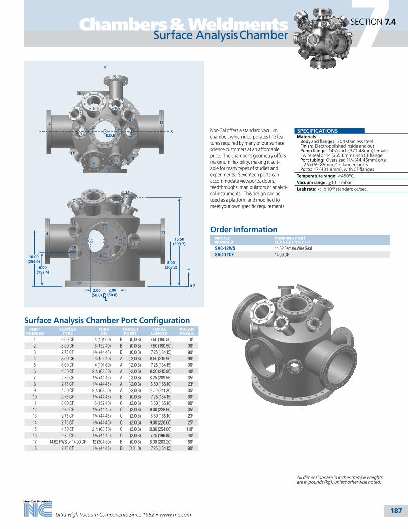
187
Chambers & Weldments
Ultra-High Vacuum Components Since 1962 • www.n-c.com
7SECTION 7.4
C
B
E
6.00(152.4)
15.50(393.7)
12
14
13
3
8
9
8.00(203.2)
2.00(50.8)
11
17
10
18
4
10.00(254.0)
12
13
14
16
5
15
CA
B,D,E
114
9
6
1
7
7
8
183
2
+
0 Z
Y
X
2.00(50.8)
Surface Analysis Chamber
Order InformationMODEL NUMBER
PUMPING PORT FLANGE (PORT 17)
SAC-12WS 14.62 Female Wire SealSAC-12CF 14.00 CF
Nor-Cal offers a standard vacuum chamber, which incorporates the fea-tures required by many of our surface science customers at an affordable price. The chamber’s geometry offers maximum flexibility, making it suit-able for many types of studies and experiments. Seventeen ports can accommodate viewports, doors, feedthroughs, manipulators or analyti-cal instruments. This design can be used as a platform and modified to meet your own specific requirements.
SPECIFICATIONSMaterials Body and flanges: 304 stainless steel Finish: Electropolished inside and out Pump flange: 145/8 inch (371.48mm) female wire seal or 14 (355.6mm) inch CF flange Port tubing: Oversized 13/4 (44.45mm) on all 23/4 (69.85mm) CF flanged ports Ports: 17 (431.8mm), with CF flangesTemperature range: <450ºC.Vacuum range: >10-10 mbarLeak rate: <1 x 10⁻⁹ standard cc/sec.
Surface Analysis Chamber Port ConfigurationPORT
NUMBERFLANGE
TYPETUBE OD
TARGET POINT
FOCAL LENGTH
POLAR ANGLE
1 6.00 CF 4 (101.60) B (0,0,8) 7.50 (190.50) 0º2 8.00 CF 6 (152.40) B (0,0,8) 7.50 (190.50) 90º3 2.75 CF 13/4 (44.45) B (0,0,8) 7.25 (184.15) 90º4 8.00 CF 6 (152.40) A (-2,0,8) 8.50 (215.90) 90º5 6.00 CF 4 (101.60) A (-2,0,8) 7.25 (184.15) 90º6 4.50 CF 21/2 (63.50) A (-2,0,8) 8.50 (215.90) 40º7 2.75 CF 13/4 (44.45) A (-2,0,8) 8.25 (209.55) 35º8 2.75 CF 13/4 (44.45) A (-2,0,8) 6.50 (165.10) 23º9 4.50 CF 21/2 (63.50) A (-2,0,8) 9.50 (241.30) 35º10 2.75 CF 13/4 (44.45) E (0,0,6) 7.25 (184.15) 90º11 8.00 CF 6 (152.40) C (2,0,8) 8.50 (165.10) 90º12 2.75 CF 13/4 (44.45) C (2,0,8) 9.00 (228.60) 35º13 2.75 CF 13/4 (44.45) C (2,0,8) 6.50 (165.10) 23º14 2.75 CF 13/4 (44.45) C (2,0,8) 9.00 (228.60) 25º15 4.50 CF 21/2 (63.50) C (2,0,8) 10.00 (254.00) 110º16 2.75 CF 13/4 (44.45) C (2,0,8) 7.75 (196.85) 40º17 14.62 FWS or 14.00 CF 12 (304.80) B (0,0,8) 8.00 (203.20) 180º18 2.75 CF 13/4 (44.45) D (0,0,10) 7.25 (184.15) 90º
All dimensions are in inches (mm) & weights are in pounds (kg), unless otherwise noted.

188
Chambers & Weldments
Ultra-High Vacuum Components Since 1962 • www.n-c.com
7SECTION 7.5
GEC Reference Cell
The design for this system was developed at the 1988 Gaseous Electronics Confer-ence (GEC) for research projects utilizing radio frequency (rf) discharges in various gasses at a frequency of 13.56 MHz. The reference cell concept grew out of a need to provide an experimental platform for comparing plasma mea-surements carried out in a number of separate but identical chambers. The basic purpose of the reference cell is to provide a comparison between measure-ments performed on identical discharge sources by different groups to establish the necessary and sufficient conditions defining reproducible plasma parameters and establishing a reference rf-excited plasma that allows others to define and calibrate diagnostic measurements and theoretical models.
The cell is a conventional, twelve-inch (304.8mm) diameter, UHV chamber with a pair of 10 cm diameter, water-cooled, parallel plate electrodes. A unique pumpout well provides uniform pumping in the chamber. Since the reference cell’s inception, Nor-Cal has worked with Sandia National Lab’s design team In order to improve manufacturability and offer standard options requested by individual research groups. These options include: moveable upper electrode, RGA sampling port, wafer transfer, inductively coupled coil and heated annular ring.
Detailed bill of materials and mechanical drawings of the GEC Reference Cell can be
downloaded from the Vacuum Chambers section of our web site.
www.n-c.com
GEC Reference Cell System ComponentsDESCRIPTION
Plasma reactor chamberPumpout weldmentNon-moveable upper electrode assemblyMoveable upper electrode assemblyLower electrode assemblyLower electrode (mass spectrometer test)Lower wafer transfer electrodeBase weldment (aluminum)Lower pumping manifold assemblyInductive coil assemblyHeated annular ring assembly with controller
SPECIFICATIONSMaterials Flanges and body: 304 stainless steel Flange type: CF Finish: Electropolished, inside and out
Vacuum range: >1 x 10⁻¹⁰ mbar - UHV
Temperature range: -270˚C to 450˚C
Plasma Reactor Chamber
Pumput Weldment
Lower Pumping Manifold
Upper Electrode Assembly
Base Weldment
GEC heated annular ring assembly with controller

189Ultra-High Vacuum Components Since 1962 • www.n-c.com
7SECTION 7.6
Because we manufacture tees, elbows and other weld fittings in-house, Nor-Cal can also fabricate exhaust weldments and other special assemblies for semiconductor equipment from a single piece of tubing by utilizing some or all of the techniques described below. Welds and other manufacturing steps are eliminated, improving cleanliness and fit while reducing cost. We have demonstrated as much as 30% savings to our customers using this technique.
CNC Tube BendingNor-Cal employs a computer numeri-cally controlled (CNC) tube bender to form elbows and custom exhaust weld-ments. This enables us to quickly make multiple compound angle bends in a single piece of tubing, while holding .010 inch (.25mm)tolerance between bends. Alternate methods of fabrication require welding of several prefabricated parts, resulting in greater incidence of leaks and cumulative tolerance buildup. Using our method, several welds and other manu-facturing steps are eliminated, improving cleanliness and fit while reducing cost. Nor-Cal has tooling for 3/4, 1, 1 1/2 and 2-inch (19.05, 25.4, 38.1 & 50.8mm) tubing. Custom or metric tubing diameters are available upon request.
Ball Pulled PortsNor-Cal manufactures tees, crosses, valve bodies, ion pump bodies and custom exhaust weldments with ball pulled ports. A hydraulic press is used to pull a ball through a small opening in the tubing to create a smooth, crevice-free opening. The formed metal is then trimmed perpendicular to the centerline of the tube, allowing a straight tube to be welded to the port with a full penetration butt weld. Alternate methods of port fabrication require boring the hole, coping the end of the tube and welding from the outside. Nor-Cal can pull ports for ½ to 10 inch (12.7 to 254mm) diame-ter tubing, while holding the true position of the port within .030 inch (.76mm).
SPECIFICATIONSMaterials Tube ODs: 1/4 to 10 inch (6.35 to 254mm) Tubes and flanges: 304 stainless steel (316L available on request) Finish: Electropolished or beadblasted Flange types: CF, NW, ISO and ASA Temperature range Metal seal: -270ºC to 450ºC Elastomer seal: -20ºC to 200ºCVacuum range Metal seal: > 10-11 mbar - UHV Elastomer seal: > 10-8 mbar - High Vacuum
Orbital WeldingInert environment orbital welding is also available for repeatable and precise full penetration flange-to-tube welds. This automated process eliminates the variables associated with hand welding, such as rotation speed and the width of the heat affected zone (HAZ). Orbital welding can be performed on any length tube with diameters from 1/8 to 4 inches (3.18 to 101.6mm).
Custom WeldmentsChambers & Weldments
All dimensions are in inches (mm) & weights are in pounds (kg), unless otherwise noted.

190
Chambers & Weldments
Ultra-High Vacuum Components Since 1962 • www.n-c.com
7SECTION 7.7
Vacuum Chamber Gallery
ESCA electron spectrometer
Cornell University Physics Department surface science chamber
Custom OLED (Organic Light Emitting Device) System by Trovato Mfg. Inc., incorporating a Nor-Cal high vacuum chamber
High vacuum chamber used to house an X-ray scanner in the Sandia National Laboratory LIGA project
Multi-chamber custom research and development system consisting of three chambers and a variety of sample transfer and manipulation devices
Ultra-high vacuum research chamber
Chamber with door manufactured for Edwards Air Force Base
Ultra-high vacuum research system
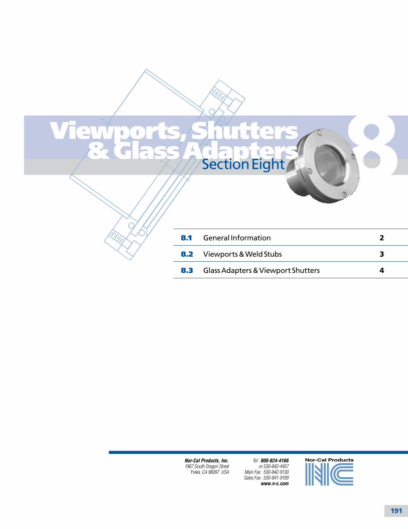
191
Tel: 800-824-4166or 530-842-4457
Main Fax: 530-842-9130Sales Fax: 530-841-9189
www.n-c.com
Nor-Cal Products, Inc.1967 South Oregon Street
Yreka, CA 96097 USA
8.1 General Information 2
8.2 Viewports & Weld Stubs 3
8.3 Glass Adapters & Viewport Shutters 4
8Viewports, Shutters & Glass Adapters
Section Eight
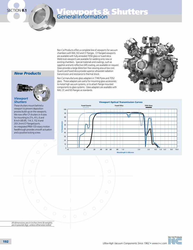
8 Viewports & Shutters
192
SECTION 8.1
Ultra-High Vacuum Components Since 1962 • www.n-c.com
General Information
Nor-Cal Products offers a complete line of viewports for vacuum chambers with NW, ISO and CF flanges. CF flanged viewports are available with fully annealed 7056 glass or fused silica. Weld stub viewports are available for welding onto new or existing chambers. Special materials and coatings, such as sapphire and anti-reflective (AR) coating, are available on request. Glass provides a large distortion free viewing area at low cost. Quartz and fused silica provide superior ultraviolet radiation transmission and resistance to thermal shock.
Nor-Cal manufactures glass adapters in 7740 Pyrex and 7052 glass. These adapters are useful for mounting glass accessories to metal high vacuum systems, or to attach flange mounted components to glass systems. Glass adapters are available with NW, CF, and ISO flanges as standards.
Viewport Optical Transmission Curves
Wavelength in Microns
% T
ran
smis
sio
n
100
0
90
80
70
60
50
40
30
20
10
.10 .20 .30 .40 .50 .60 .80 1.0 2.0 3.0 4.0 5.0 6.0 10.08.0
Fused Quartz Fused Silica 7056 Glass
New Products
Viewport ShuttersThese shutters mount behind a viewport to prevent deposition process build-up on the viewports. We now offer CF shutters in 4 sizes for mounting to 23/4, 41/2, 6 and 8 inch (69.85, 114.3, 152.4 and 203.2mm)CF flanged ports. An integrated PRM-133 rotary motion feedthrough provides smooth actuation and a positive locking screw.
All dimensions are in inches (mm) & weights are in pounds (kg), unless otherwise noted.
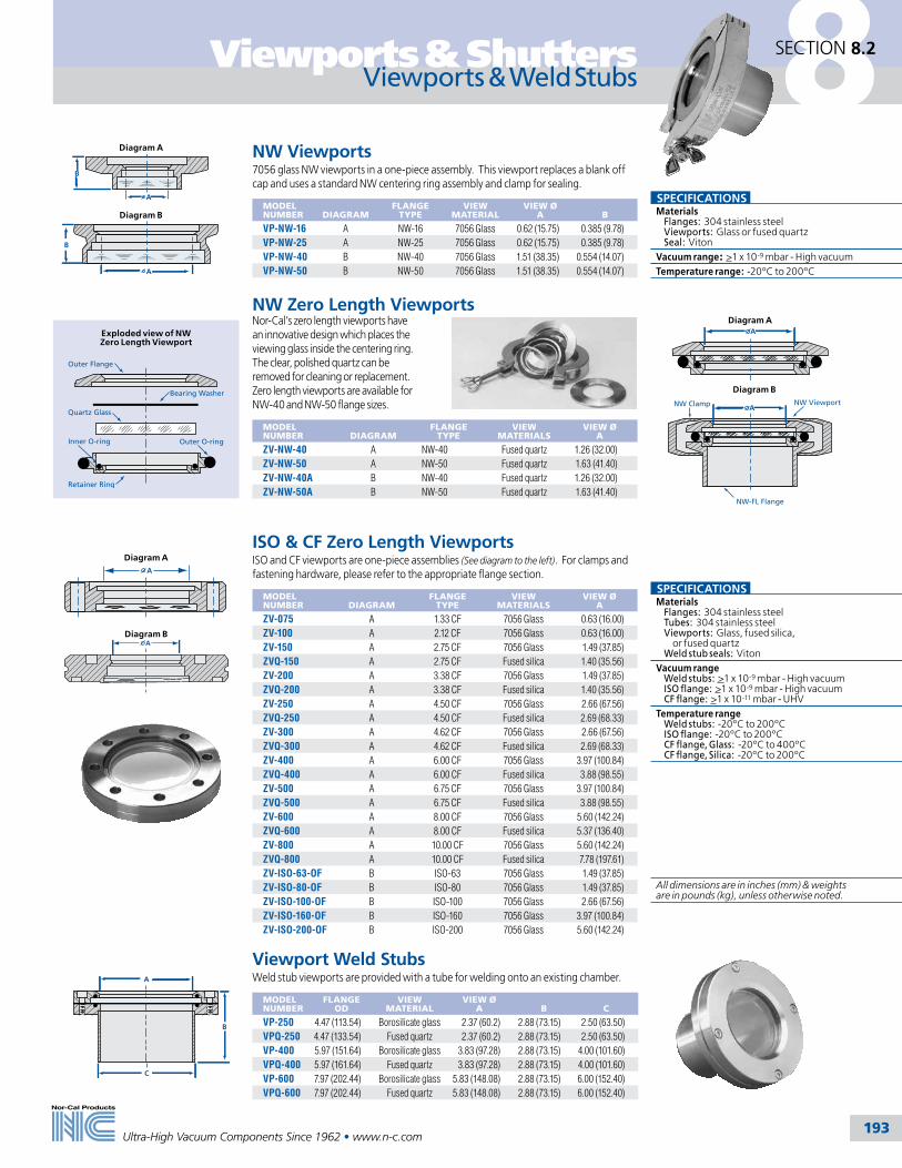
Viewports & Shutters
193Ultra-High Vacuum Components Since 1962 • www.n-c.com
8SECTION 8.2
Viewports & Weld Stubs
NW Viewports7056 glass NW viewports in a one-piece assembly. This viewport replaces a blank off cap and uses a standard NW centering ring assembly and clamp for sealing.
MODEL NUMBER
DIAGRAM
FLANGE TYPE
VIEW MATERIAL
VIEW Ø A
B
VP-NW-16 A NW-16 7056 Glass 0.62 (15.75) 0.385 (9.78)VP-NW-25 A NW-25 7056 Glass 0.62 (15.75) 0.385 (9.78)VP-NW-40 B NW-40 7056 Glass 1.51 (38.35) 0.554 (14.07)VP-NW-50 B NW-50 7056 Glass 1.51 (38.35) 0.554 (14.07)
B
A
Diagram B
A
B
Diagram A
NW Clamp
NW-FL Flange
NW ViewportA
Diagram AA
Diagram B
Inner O-ring
Outer Flange
Bearing Washer
Quartz Glass
Outer O-ring
Retainer Ring
Exploded view of NW Zero Length Viewport
SPECIFICATIONSMaterials Flanges: 304 stainless steel Tubes: 304 stainless steel Viewports: Glass, fused silica, or fused quartz Weld stub seals: VitonVacuum range Weld stubs: >1 x 10⁻⁹ mbar - High vacuum ISO flange: >1 x 10⁻⁹ mbar - High vacuum CF flange: >1 x 10-11 mbar - UHVTemperature range Weld stubs: -20ºC to 200ºC ISO flange: -20ºC to 200ºC CF flange, Glass: -20ºC to 400ºC CF flange, Silica: -20ºC to 200ºC
NW Zero Length ViewportsNor-Cal’s zero length viewports have an innovative design which places the viewing glass inside the centering ring. The clear, polished quartz can be removed for cleaning or replacement. Zero length viewports are available for NW-40 and NW-50 flange sizes.
MODEL NUMBER
DIAGRAM
FLANGE TYPE
VIEW MATERIALS
VIEW Ø A
ZV-NW-40 A NW-40 Fused quartz 1.26 (32.00)ZV-NW-50 A NW-50 Fused quartz 1.63 (41.40)ZV-NW-40A B NW-40 Fused quartz 1.26 (32.00)ZV-NW-50A B NW-50 Fused quartz 1.63 (41.40)
ISO & CF Zero Length ViewportsISO and CF viewports are one-piece assemblies (See diagram to the left). For clamps and fastening hardware, please refer to the appropriate flange section.
MODEL NUMBER
DIAGRAM
FLANGE TYPE
VIEW MATERIALS
VIEW Ø A
ZV-075 A 1.33 CF 7056 Glass 0.63 (16.00)ZV-100 A 2.12 CF 7056 Glass 0.63 (16.00)ZV-150 A 2.75 CF 7056 Glass 1.49 (37.85)ZVQ-150 A 2.75 CF Fused silica 1.40 (35.56)ZV-200 A 3.38 CF 7056 Glass 1.49 (37.85)ZVQ-200 A 3.38 CF Fused silica 1.40 (35.56)ZV-250 A 4.50 CF 7056 Glass 2.66 (67.56)ZVQ-250 A 4.50 CF Fused silica 2.69 (68.33)ZV-300 A 4.62 CF 7056 Glass 2.66 (67.56)ZVQ-300 A 4.62 CF Fused silica 2.69 (68.33)ZV-400 A 6.00 CF 7056 Glass 3.97 (100.84)ZVQ-400 A 6.00 CF Fused silica 3.88 (98.55)ZV-500 A 6.75 CF 7056 Glass 3.97 (100.84)ZVQ-500 A 6.75 CF Fused silica 3.88 (98.55)ZV-600 A 8.00 CF 7056 Glass 5.60 (142.24)ZVQ-600 A 8.00 CF Fused silica 5.37 (136.40)ZV-800 A 10.00 CF 7056 Glass 5.60 (142.24)ZVQ-800 A 10.00 CF Fused silica 7.78 (197.61)ZV-ISO-63-OF B ISO-63 7056 Glass 1.49 (37.85)ZV-ISO-80-OF B ISO-80 7056 Glass 1.49 (37.85)ZV-ISO-100-OF B ISO-100 7056 Glass 2.66 (67.56)ZV-ISO-160-OF B ISO-160 7056 Glass 3.97 (100.84)ZV-ISO-200-OF B ISO-200 7056 Glass 5.60 (142.24)
A
A
Viewport Weld StubsWeld stub viewports are provided with a tube for welding onto an existing chamber.
MODEL NUMBER
FLANGE OD
VIEW MATERIAL
VIEW Ø A
B
C
VP-250 4.47 (113.54) Borosilicate glass 2.37 (60.2) 2.88 (73.15) 2.50 (63.50)VPQ-250 4.47 (133.54) Fused quartz 2.37 (60.2) 2.88 (73.15) 2.50 (63.50)VP-400 5.97 (151.64) Borosilicate glass 3.83 (97.28) 2.88 (73.15) 4.00 (101.60)VPQ-400 5.97 (161.64) Fused quartz 3.83 (97.28) 2.88 (73.15) 4.00 (101.60)VP-600 7.97 (202.44) Borosilicate glass 5.83 (148.08) 2.88 (73.15) 6.00 (152.40)VPQ-600 7.97 (202.44) Fused quartz 5.83 (148.08) 2.88 (73.15) 6.00 (152.40)
A
B
C
Diagram A
Diagram B
SPECIFICATIONSMaterials Flanges: 304 stainless steel Viewports: Glass or fused quartz Seal: VitonVacuum range: >1 x 10⁻⁹ mbar - High vacuumTemperature range: -20ºC to 200ºC
All dimensions are in inches (mm) & weights are in pounds (kg), unless otherwise noted.
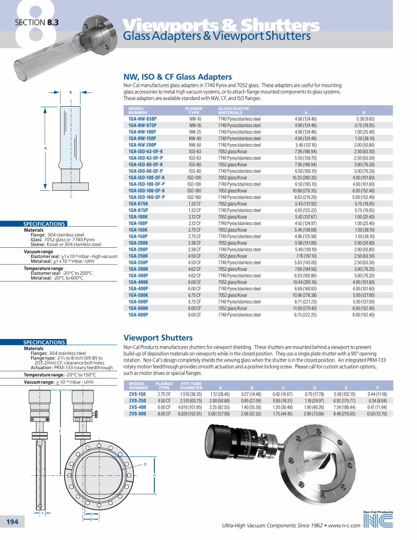
Viewports & Shutters
194Ultra-High Vacuum Components Since 1962 • www.n-c.com
8SECTION 8.3
Glass Adapters & Viewport Shutters
NW, ISO & CF Glass AdaptersNor-Cal manufactures glass adapters in 7740 Pyrex and 7052 glass. These adapters are useful for mounting glass accessories to metal high vacuum systems, or to attach flange mounted components to glass systems. These adapters are available standard with NW, CF, and ISO flanges.
MODEL NUMBER
FLANGE TYPE
GLASS/SLEEVE MATERIALS
A
B
1GA-NW-038P NW-10 7740 Pyrex/stainless steel 4.90 (124.46) 0.38 (9.65)1GA-NW-075P NW-16 7740 Pyrex/stainless steel 4.90 (124.46) 0.75 (19.05)1GA-NW-100P NW-25 7740 Pyrex/stainless steel 4.90 (124.46) 1.00 (25.40)1GA-NW-150P NW-40 7740 Pyrex/stainless steel 4.90 (124.46) 1.50 (38.10)1GA-NW-200P NW-50 7740 Pyrex/stainless steel 5.40 (137.16) 2.00 (50.80)1GA-ISO-63-OF-K ISO-63 7052 glass/Kovar 7.36 (186.94) 2.50 (63.50)1GA-ISO-63-OF-P ISO-63 7740 Pyrex/stainless steel 5.50 (139.70) 2.50 (63.50)1GA-ISO-80-OF-K ISO-80 7052 glass/Kovar 7.36 (186.94) 3.00 (76.20)1GA-ISO-80-OF-P ISO-80 7740 Pyrex/stainless steel 6.50 (165.10) 3.00 (76.20)1GA-ISO-100-OF-K ISO-100 7052 glass/Kovar 10.25 (260.35) 4.00 (101.60)1GA-ISO-100-OF-P ISO-100 7740 Pyrex/stainless steel 6.50 (165.10) 4.00 (101.60)1GA-ISO-160-OF-K ISO-160 7052 glass/Kovar 10.88 (276.35) 6.00 (152.40)1GA-ISO-160-OF-P ISO-160 7740 Pyrex/stainless steel 8.63 (219.20) 6.00 (152.40)1GA-075K 1.33 CF 7052 glass/Kovar 5.43 (137.92) 0.75 (19.05)1GA-075P 1.33 CF 7740 Pyrex/stainless steel 4.93 (125.22) 0.75 (19.05)1GA-100K 2.12 CF 7052 glass/Kovar 5.42 (137.67) 1.00 (25.40)1GA-100P 2.12 CF 7740 Pyrex/stainless steel 4.92 (124.97) 1.00 (25.40)1GA-150K 2.75 CF 7052 glass/Kovar 5.46 (138.68) 1.50 (38.10)1GA-150P 2.75 CF 7740 Pyrex/stainless steel 4.96 (125.98) 1.50 (38.10)1GA-200K 3.38 CF 7052 glass/Kovar 5.98 (151.89) 2.00 (50.80)1GA-200P 3.38 CF 7740 Pyrex/stainless steel 5.48 (139.19) 2.00 (50.80)1GA-250K 4.50 CF 7052 glass/Kovar 7.76 (197.10) 2.50 (63.50)1GA-250P 4.50 CF 7740 Pyrex/stainless steel 5.63 (143.00) 2.50 (63.50)1GA-300K 4.62 CF 7052 glass/Kovar 7.66 (194.56) 3.00 (76.20)1GA-300P 4.62 CF 7740 Pyrex/stainless steel 6.53 (165.86) 3.00 (76.20)1GA-400K 6.00 CF 7052 glass/Kovar 10.44 (265.18) 4.00 (101.60)1GA-400P 6.00 CF 7740 Pyrex/stainless steel 6.69 (169.93) 4.00 (101.60)1GA-500K 6.75 CF 7052 glass/Kovar 10.96 (278.38) 5.00 (127.00)1GA-500P 6.75 CF 7740 Pyrex/stainless steel 8.71 (221.23) 5.00 (127.00)1GA-600K 8.00 CF 7052 glass/Kovar 11.00 (279.40) 6.00 (152.40)1GA-600P 8.00 CF 7740 Pyrex/stainless steel 8.75 (222.25) 6.00 (152.40)
SPECIFICATIONSMaterials Flange: 304 stainless steel Glass: 7052 glass or 7740 Pyrex Sleeve: Kovar or 304 stainless steel
Vacuum range Elastomer seal: >1 x 10⁻⁸ mbar - High vacuum Metal seal: >1 x 10⁻¹⁰ mbar - UHV
Temperature range Elastomer seal: -20ºC to 200ºC Metal seal: -20ºC to 400ºC
B
A
Viewport ShuttersNor-Cal Products manufactures shutters for viewport shielding. These shutters are mounted behind a viewport to prevent build-up of deposition materials on viewports while in the closed position. They use a single plate shutter with a 90º opening rotation. Nor-Cal’s design completely shields the viewing glass when the shutter is in the closed position. An integrated PRM-133 rotary motion feedthrough provides smooth actuation and a positive locking screw. Please call for custom actuation options, such as motor drives or special flanges.
MODEL NUMBER
FLANGE TYPE
FITS TUBE DIAMETER
A
B
C
D
E
F
ZVS-150 2.75 CF 1.510 (38.35) 1.12 (28.45) 0.57 (14.48) 0.42 (10.67) 0.70 (17.78) 5.99 (152.15) 0.44 (11.18)ZVS-250 4.50 CF 2.510 (63.75) 2.00 (50.80) 0.85 (21.59) 0.65 (16.51) 1.18 (29.97) 6.92 (175.77) 0.34 (8.64)ZVS-400 6.00 CF 4.010 (101.85) 3.25 (82.55) 1.40 (35.56) 1.20 (30.48) 1.90 (48.26) 7.34 (186.44) 0.47 (11.94)ZVS-600 8.00 CF 6.020 (152.91) 5.00 (127.00) 2.06 (52.32) 1.75 (44.45) 2.90 (73.66) 8.49 (215.65) 0.50 (12.70)
D
C
B
A
F
E
SPECIFICATIONSMaterials Flanges: 304 stainless steel Flange type: 23/4 to 8 inch (69.85 to 203.2mm) CF, clearance bolt holes Actuation: PRM-133 rotary feedthrough
Temperature range: -20ºC to 150ºC
Vacuum range: > 10-10 mbar - UHV

195195
9
Tel: 800-824-4166or 530-842-4457
Main Fax: 530-842-9130Sales Fax: 530-841-9189
www.n-c.com
Nor-Cal Products, Inc.1967 South Oregon Street
Yreka, CA 96097 USA
Sample Transfer & Manipulation
Section Nine
9.1 General Information 196
9.2 Sample Transfer System & Load Lock Chamber 198
9.3 Add-A-Doors 199
9.4 Manipulators, Stages & Translators 200
9.5 Utility Hat & Alignment Gimbals 202
9.6 Motion Feedthroughs 203
9.7 Wobble Sticks 208
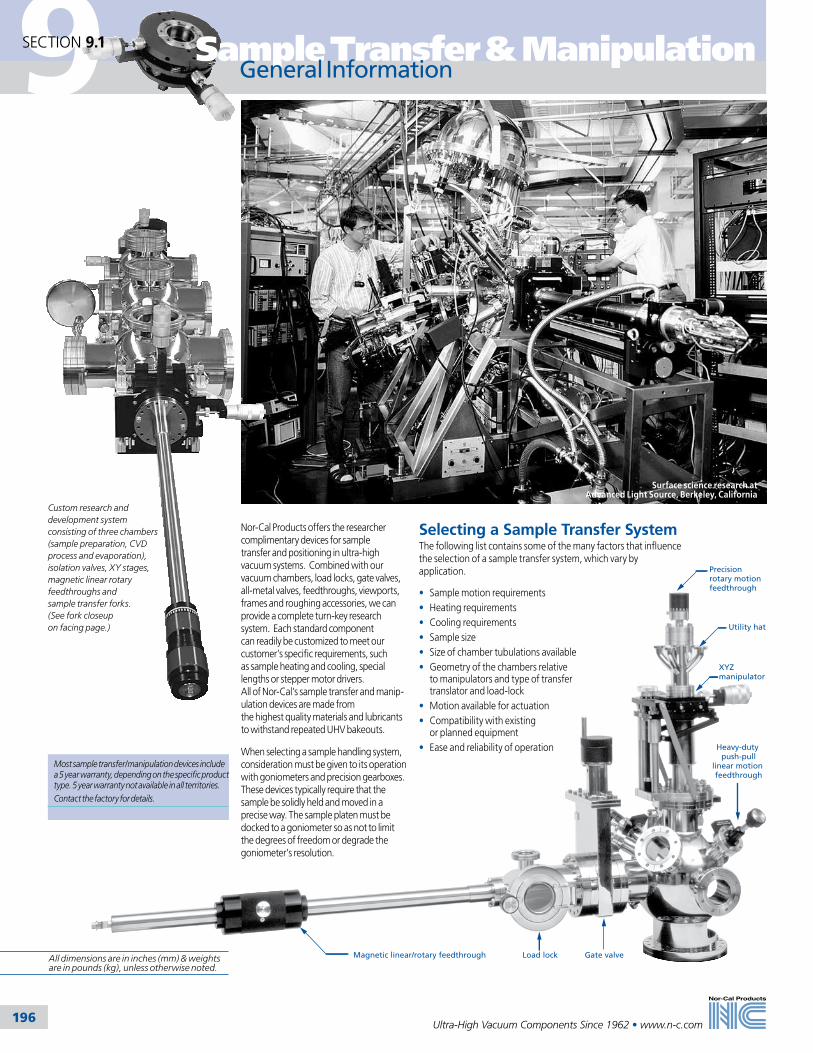
9
196
Sample Transfer & Manipulation
Ultra-High Vacuum Components Since 1962 • www.n-c.com
Precision rotary motion feedthrough
Utility hat
XYZmanipulator
Gate valveLoad lockMagnetic linear/rotary feedthrough
Heavy-duty push-pull
linear motion feedthrough
General Information
Nor-Cal Products offers the researcher complimentary devices for sample transfer and positioning in ultra-high vacuum systems. Combined with our vacuum chambers, load locks, gate valves, all-metal valves, feedthroughs, viewports, frames and roughing accessories, we can provide a complete turn-key research system. Each standard component can readily be customized to meet our customer’s specific requirements, such as sample heating and cooling, special lengths or stepper motor drivers. All of Nor-Cal’s sample transfer and manip-ulation devices are made from the highest quality materials and lubricants to withstand repeated UHV bakeouts.
When selecting a sample handling system, consideration must be given to its operation with goniometers and precision gearboxes. These devices typically require that the sample be solidly held and moved in a precise way. The sample platen must be docked to a goniometer so as not to limit the degrees of freedom or degrade the goniometer’s resolution.
Selecting a Sample Transfer SystemThe following list contains some of the many factors that influence the selection of a sample transfer system, which vary by application.
• Sample motion requirements• Heating requirements• Cooling requirements• Sample size• Size of chamber tubulations available• Geometry of the chambers relative to manipulators and type of transfer translator and load-lock• Motion available for actuation• Compatibility with existing or planned equipment• Ease and reliability of operation
SECTION 9.1
Surface science research at Advanced Light Source, Berkeley, California
Custom research and development system consisting of three chambers (sample preparation, CVD process and evaporation), isolation valves, XY stages, magnetic linear rotary feedthroughs and sample transfer forks. (See fork closeup on facing page.)
All dimensions are in inches (mm) & weights are in pounds (kg), unless otherwise noted.
Most sample transfer/manipulation devices include a 5 year warranty, depending on the specific product type. 5 year warranty not available in all territories. Contact the factory for details.

9
197
Sample Transfer & Manipulation
Ultra-High Vacuum Components Since 1962 • www.n-c.com
Terminology
Bolt Pattern OrientationOur components are manufactured with the primary axis straddling adjacent bolt holes on the mounting flange (American standard). Most components can be furnished with the axis passing through a bolt hole axis (European standard) on request. Some equipment is field adjustable.
AMERICAN
EUROPEAN
Primary Axis
A/2
A
XYZ ManipulatorA manipulator is a 3-axis (X,Y,Z) position-ing device. For most applications, the instrument hardware is mounted outside the vacuum chamber, with a welded bel-lows providing a flexible vacuum curtain. The X axis passes in front of the vertical, mechanical structure, or “backframe,” with the Y axis moving to and away from the backframe. The Z axis is perpen-dicular to the X and Y axes and moves up and down directly against the vacuum pressure differential. The polar axis is the same as the Z axis.
The limit of X and Y travel is normally a circular pattern. Range is indicated as a vector sum. This means a ± .50 inch (12.7mm) range of X and Y allows the polar axis to be moved anywhere inside a 1.00 inch (25.4mm) diameter circle. The sum of the X and Y vectors is limited to .50 inch (12.7mm). Square pattern XY stages are available as options on some models.
Z TranslatorA translator is a single axis positioning device, utilizing a bellows as a vacuum seal. Referred to as a “Z only” stage, this axis is normally perpendicular to the chamber. This causes the Z axis to work directly against the force from the pressure differential.
XY StageThe XY stage provides the X and Y axes only. No Z motion is available.
Polar RotationThe polar axis is the same as the Z axis. Rotation about the polar axis is com-monly achieved by mounting a rotary feedthrough at the center of the traveling flange of a manipulator or translator. This degree of freedom can also be achieved with a differentially pumped rotary seal.
Azimuthal AxisThe azimuthal axis is perpendicular to the polar axis. Sample azimuthal rotation refers to rotation of the sample about an axis normal to the sample face and perpendicular to the polar axis.
Tilt MotionTilt refers to changing the polar axis with respect to the X, Y and Z axes. This is usually done at the traveling flange of a 3-axis manipulator or other exterior mounting stage. Tilt range is often limited by the bellows ID and the OD of the probe passing through the bellows. The maximum angle practical is about ±7 .̊ When used in this manner, translation in X, Y and (slightly) Z will occur with adjust-ment of the tilt angle. Tilt stages are available in single or dual axis units.
Flip MotionFlip motion is the changing of an axis normal to the sample face from parallel (or coaxial) to the polar axis to coaxial with the azi-muthal axis. The range of this change of axis may be 90 ,̊ 180˚ or full 360 .̊
Transferaxis
Azimuthal rotation
Flip
Polar axis
Polarrotation
Sample Transfer and HeatingSample transfer may reduce heating performance at high temperatures. The ideal transfer system for heating the sample to the highest temperatures should use thin sample plates made of appropriate material placed as close to the heater as possible. Thick, high mass, sample plates reduce thermal response and lower peak heating temperatures.
Sample Transfer and CoolingSample transfer may reduce cooling performance at low temperatures. The ideal transfer system for cooling the sample to the lowest temperatures should use thin, highly conductive, sample plates that contact the dewar with a large surface area. Thick, high mass, sample plates reduce thermal response and reduce peak cooling performance.
Types of Motion Used For Transfer Actuation• Linear Motion — linear movement of the sample along any axis• Rotary Motion — rotary motion about any axis• Tilt Motion — angular positioning movement of the horizontal or orthogonal axis. The weight of the sample, plate, fork and translator can cause deflection that misaligns the axis of transfer. A tilt stage can be used to re-align the axis to enable a transfer
Transfer Components• Sample Platen — the transferable plate that holds the sample• Sample Fork — attaches to a transfer arm from the load-lock and holds the sample platen
SECTION 9.1
Polar axis
Tilt motion
Flip motion
Travelingflange
Azimuthal rotation
Base flange(underneath)
Azimuthalaxis
Polar rotation
X axis
Z axis
Y axis
TRANSFER AXES
Sample transfer fork
• Sample Dock — attaches to a work station (manipulator) and holds the platen for processing or positioning the sample
Fork and Dock Configurations• Axial Fork — a sample fork with the plane of the sample platen face orthogonal to the axis of the transfer arm on which the fork is mounted• Radial Fork — a sample fork with the plane of the sample platen face parallel to the axis of the transfer arm on which the fork is mounted• Axial Dock — a sample dock with the plane of the sample platen face orthog onal to the axis of the manipulator on which the dock is mounted• Radial Dock — a sample dock with the plane of the sample platen face parallel to the axis of the manipulator to which the dock is mounted
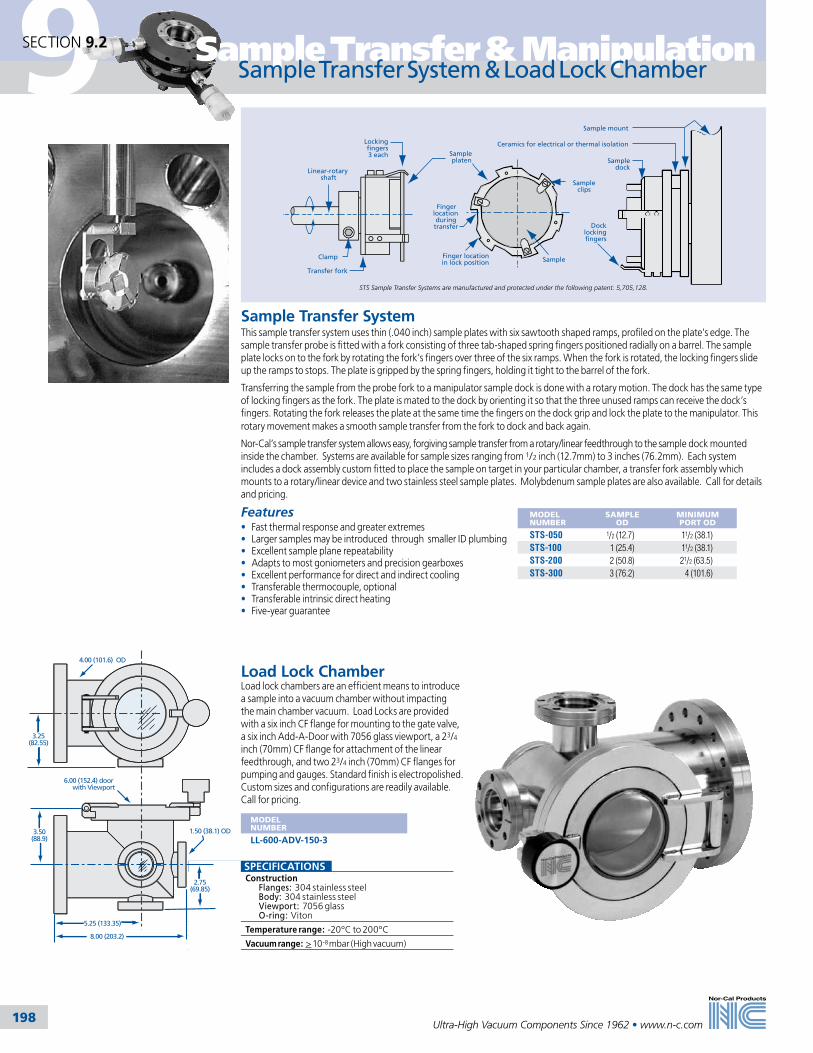
9
198
Sample Transfer & Manipulation
Ultra-High Vacuum Components Since 1962 • www.n-c.com
SPECIFICATIONS Construction Flanges: 304 stainless steel Body: 304 stainless steel Viewport: 7056 glass O-ring: Viton
Temperature range: -20ºC to 200ºC
Vacuum range: > 10-8 mbar (High vacuum)
MODEL NUMBER
SAMPLE OD
MINIMUM PORT OD
STS-050 1/2 (12.7) 11/2 (38.1)STS-100 1 (25.4) 11/2 (38.1)STS-200 2 (50.8) 21/2 (63.5)STS-300 3 (76.2) 4 (101.6)
Sample Transfer SystemThis sample transfer system uses thin (.040 inch) sample plates with six sawtooth shaped ramps, profiled on the plate’s edge. The sample transfer probe is fitted with a fork consisting of three tab-shaped spring fingers positioned radially on a barrel. The sample plate locks on to the fork by rotating the fork’s fingers over three of the six ramps. When the fork is rotated, the locking fingers slide up the ramps to stops. The plate is gripped by the spring fingers, holding it tight to the barrel of the fork.
Transferring the sample from the probe fork to a manipulator sample dock is done with a rotary motion. The dock has the same type of locking fingers as the fork. The plate is mated to the dock by orienting it so that the three unused ramps can receive the dock’s fingers. Rotating the fork releases the plate at the same time the fingers on the dock grip and lock the plate to the manipulator. This rotary movement makes a smooth sample transfer from the fork to dock and back again.
Nor-Cal’s sample transfer system allows easy, forgiving sample transfer from a rotary/linear feedthrough to the sample dock mounted inside the chamber. Systems are available for sample sizes ranging from 1/2 inch (12.7mm) to 3 inches (76.2mm). Each system includes a dock assembly custom fitted to place the sample on target in your particular chamber, a transfer fork assembly which mounts to a rotary/linear device and two stainless steel sample plates. Molybdenum sample plates are also available. Call for details and pricing.
Features• Fast thermal response and greater extremes• Larger samples may be introduced through smaller ID plumbing• Excellent sample plane repeatability• Adapts to most goniometers and precision gearboxes• Excellent performance for direct and indirect cooling• Transferable thermocouple, optional• Transferable intrinsic direct heating• Five-year guarantee
Docklockingfingers
Sampledock
Sample mount
Ceramics for electrical or thermal isolation
Linear-rotary shaft
Clamp
Transfer fork
Finger locationduring
transfer
Finger location in lock position Sample
Sampleclips
Lockingfingers3 each Sample
platen
1.50 (38.1) OD3.50(88.9)
5.25 (133.35)
8.00 (203.2)
6.00 (152.4) door with Viewport
4.00 (101.6) OD
3.25(82.55)
2.75(69.85)
Load Lock ChamberLoad lock chambers are an efficient means to introduce a sample into a vacuum chamber without impacting the main chamber vacuum. Load Locks are provided with a six inch CF flange for mounting to the gate valve, a six inch Add-A-Door with 7056 glass viewport, a 23/4 inch (70mm) CF flange for attachment of the linear feedthrough, and two 23/4 inch (70mm) CF flanges for pumping and gauges. Standard finish is electropolished. Custom sizes and configurations are readily available. Call for pricing.
MODEL NUMBER
LL-600-ADV-150-3
Sample Transfer System & Load Lock ChamberSECTION 9.2
STS Sample Transfer Systems are manufactured and protected under the following patent: 5,705,128.

9
199
Sample Transfer & Manipulation
Ultra-High Vacuum Components Since 1962 • www.n-c.com
Viewport Optical Transmission Curves
Wavelength in Microns
% T
ran
smis
sio
n
100
0
90
80
70
60
50
40
30
20
10
.10 .20 .30 .40 .50 .60 .80 1.0 2.0 3.0 4.0 5.0 6.0 10.08.0
7056 GlassFused Silica
Existing port
Add-A-Door
B
Open diameterA
A
C
B
Open diameter
View diameter
Add-A-DoorsMODEL NUMBER
FLANGE TYPE
A
B
AD-275 2.75 CF 1.380 (35.05) 0.500 (12.70)AD-450 4.50 CF 2.435 (61.85) 0.687 (17.45)AD-600 6.00 CF 3.917 (99.49) 0.781 (19.84)AD-800 8.00 CF 5.875 (149.23) 0.875 (22.23)AD-1000 10.00 CF 7.875 (200.03) 0.968 (24.59)
Add-A-Doors with Viewport – 7056 GlassMODEL NUMBER
FLANGE TYPE
A
B
C
ADV-450 4.50 CF 2.435 (61.85) 0.69 (17.53) 1.49 (37.85)ADV-600 6.00 CF 3.917 (99.49) 1.00 (25.40) 2.65 (67.31)ADV-800 8.00 CF 5.875 (149.23) 1.20 (30.48) 3.88 (98.55)ADV-1000 10.00 CF 7.875 (200.03) 1.30 (33.02) 5.60 (142.24)
Add-A-Doors with Viewport – Fused SilicaMODEL NUMBER
FLANGE TYPE
A
B
C
ADVQ-450 4.50 CF 2.435 (61.85) 0.74 (18.80) 1.40 (35.56)ADVQ-600 6.00 CF 3.917 (99.49) 1.02 (25.91) 2.69 (68.33)ADVQ-800 8.00 CF 5.875 (149.23) 1.21 (30.73) 3.88 (98.55)ADVQ-1000 10.00 CF 7.875 (200.03) 1.28 (32.51) 5.38 (136.65)
An Add-A-Door can provide easy access to a vacuum system when elastomer seals are acceptable. The hinged, Viton sealed door is quickly bolted to an existing CF (Conflat style) flanged chamber port. The door is opened easily by turning a knurled knob. These doors are available for 23/4 to 10 inch (70 to 254mm) OD flanges with a solid metal door or with a viewport. Standard finish is electropolished. Custom sizes can be supplied upon request.
Add-A-Doors SECTION 9.3
SPECIFICATIONS Construction Body: 304 stainless steel Flange: 23/4 to 10 inch (70 to 254mm) CF Door: Blank, 7056 glass, or fused silica O-ring: Viton standardTemperature range: -20ºC to 200ºCVacuum range: > 10-8 mbar (High vacuum)
All dimensions are in inches (mm) & weights are in pounds (kg), unless otherwise noted.
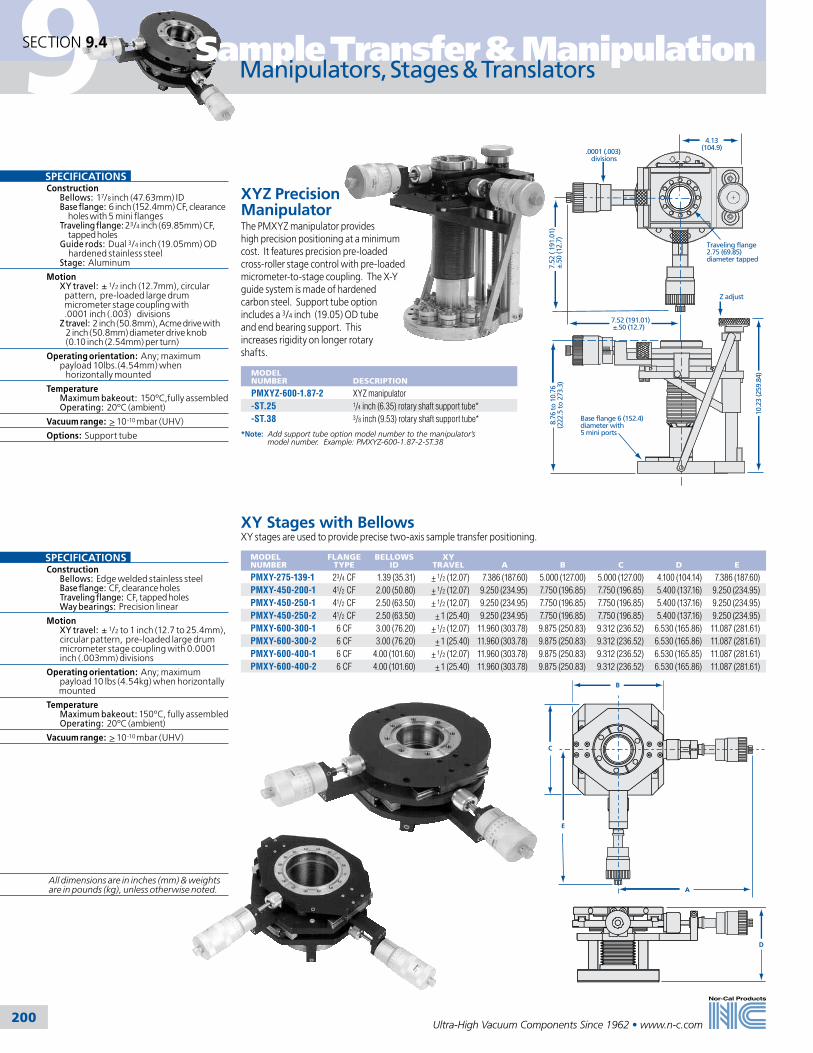
9
200
Sample Transfer & Manipulation
Ultra-High Vacuum Components Since 1962 • www.n-c.com
4.13(104.9).0001 (.003)
divisions
Traveling flange2.75 (69.85)diameter tapped
Z adjust
7.52 (191.01) ±.50 (12.7)
7.52
( 19
1.01
)±.
50 (1
2.7)
10.2
3 (2
59.8
4)
Base flange 6 (152.4)diameter with5 mini ports
8.76
to 1
0.76
(222
.5 to
273
.3)
XYZ Precision ManipulatorThe PMXYZ manipulator provides high precision positioning at a minimum cost. It features precision pre-loaded cross-roller stage control with pre-loaded micrometer-to-stage coupling. The X-Y guide system is made of hardened carbon steel. Support tube option includes a 3/4 inch (19.05) OD tube and end bearing support. This increases rigidity on longer rotary shafts.
MODEL NUMBER
DESCRIPTION
PMXYZ-600-1.87-2 XYZ manipulator-ST.25 1/4 inch (6.35) rotary shaft support tube*-ST.38 3/8 inch (9.53) rotary shaft support tube*
*Note: Add support tube option model number to the manipulator’s model number. Example: PMXYZ-600-1.87-2-ST.38
XY Stages with BellowsXY stages are used to provide precise two-axis sample transfer positioning.
MODEL NUMBER
FLANGE TYPE
BELLOWS ID
XY TRAVEL
A
B
C
D
E
PMXY-275-139-1 23/4 CF 1.39 (35.31) + 1/2 (12.07) 7.386 (187.60) 5.000 (127.00) 5.000 (127.00) 4.100 (104.14) 7.386 (187.60)PMXY-450-200-1 41/2 CF 2.00 (50.80) + 1/2 (12.07) 9.250 (234.95) 7.750 (196.85) 7.750 (196.85) 5.400 (137.16) 9.250 (234.95)PMXY-450-250-1 41/2 CF 2.50 (63.50) + 1/2 (12.07) 9.250 (234.95) 7.750 (196.85) 7.750 (196.85) 5.400 (137.16) 9.250 (234.95)PMXY-450-250-2 41/2 CF 2.50 (63.50) + 1 (25.40) 9.250 (234.95) 7.750 (196.85) 7.750 (196.85) 5.400 (137.16) 9.250 (234.95)PMXY-600-300-1 6 CF 3.00 (76.20) + 1/2 (12.07) 11.960 (303.78) 9.875 (250.83) 9.312 (236.52) 6.530 (165.86) 11.087 (281.61)PMXY-600-300-2 6 CF 3.00 (76.20) + 1 (25.40) 11.960 (303.78) 9.875 (250.83) 9.312 (236.52) 6.530 (165.86) 11.087 (281.61)PMXY-600-400-1 6 CF 4.00 (101.60) + 1/2 (12.07) 11.960 (303.78) 9.875 (250.83) 9.312 (236.52) 6.530 (165.85) 11.087 (281.61)PMXY-600-400-2 6 CF 4.00 (101.60) + 1 (25.40) 11.960 (303.78) 9.875 (250.83) 9.312 (236.52) 6.530 (165.86) 11.087 (281.61)
Manipulators, Stages & Translators
A
B
C
E
D
SECTION 9.4
SPECIFICATIONS Construction Bellows: 17/8 inch (47.63mm) ID Base flange: 6 inch (152.4mm) CF, clearance holes with 5 mini flanges Traveling flange: 23/4 inch (69.85mm) CF, tapped holes Guide rods: Dual 3/4 inch (19.05mm) OD hardened stainless steel Stage: Aluminum
Motion XY travel: ± 1/2 inch (12.7mm), circular pattern, pre-loaded large drum micrometer stage coupling with .0001 inch (.003) divisions Z travel: 2 inch (50.8mm), Acme drive with 2 inch (50.8mm) diameter drive knob (0.10 inch (2.54mm) per turn)
Operating orientation: Any; maximum payload 10lbs.(4.54mm) when horizontally mounted
Temperature Maximum bakeout: 150ºC,fully assembled Operating: 20ºC (ambient)
Vacuum range: > 10-10 mbar (UHV)
Options: Support tube
SPECIFICATIONS Construction Bellows: Edge welded stainless steel Base flange: CF, clearance holes Traveling flange: CF, tapped holes Way bearings: Precision linear
Motion XY travel: ± 1/2 to 1 inch (12.7 to 25.4mm), circular pattern, pre-loaded large drum micrometer stage coupling with 0.0001 inch (.003mm) divisions
Operating orientation: Any; maximum payload 10 lbs (4.54kg) when horizontally mounted
Temperature Maximum bakeout: 150ºC, fully assembled Operating: 20ºC (ambient)
Vacuum range: > 10-10 mbar (UHV)
All dimensions are in inches (mm) & weights are in pounds (kg), unless otherwise noted.
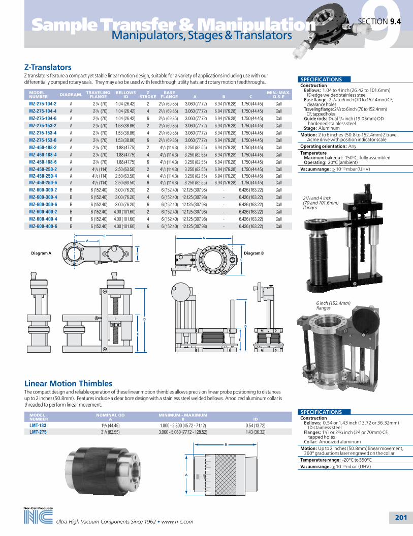
9
201
Sample Transfer & Manipulation
Ultra-High Vacuum Components Since 1962 • www.n-c.com
Z-TranslatorsZ translators feature a compact yet stable linear motion design, suitable for a variety of applications including use with our differentially pumped rotary seals. They may also be used with feedthrough utility hats and rotary motion feedthroughs.
MODEL NUMBER DIAGRAM. TRAVELING
FLANGEBELLOWS
IDZ
STROKEBASE
FLANGE A
B
C
MIN.-MAX. D & E
MZ-275-104-2 A 23/4 (70) 1.04 (26.42) 2 23/4 (69.85) 3.060 (77.72) 6.94 (176.28) 1.750 (44.45) Call
MZ-275-104-4 A 23/4 (70) 1.04 (26.42) 4 23/4 (69.85) 3.060 (77.72) 6.94 (176.28) 1.750 (44.45) Call
MZ-275-104-6 A 23/4 (70) 1.04 (26.42) 6 23/4 (69.85) 3.060 (77.72) 6.94 (176.28) 1.750 (44.45) Call
MZ-275-153-2 A 23/4 (70) 1.53 (38.86) 2 23/4 (69.85) 3.060 (77.72) 6.94 (176.28) 1.750 (44.45) Call
MZ-275-153-4 A 23/4 (70) 1.53 (38.86) 4 23/4 (69.85) 3.060 (77.72) 6.94 (176.28) 1.750 (44.45) Call
MZ-275-153-6 A 23/4 (70) 1.53 (38.86) 6 23/4 (69.85) 3.060 (77.72) 6.94 (176.28) 1.750 (44.45) Call
MZ-450-188-2 A 23/4 (70) 1.88 (47.75) 2 41/2 (114.3) 3.250 (82.55) 6.94 (176.28) 1.750 (44.45) Call
MZ-450-188-4 A 23/4 (70) 1.88 (47.75) 4 41/2 (114.3) 3.250 (82.55) 6.94 (176.28) 1.750 (44.45) Call
MZ-450-188-6 A 23/4 (70) 1.88 (47.75) 6 41/2 (114.3) 3.250 (82.55) 6.94 (176.28) 1.750 (44.45) Call
MZ-450-250-2 A 41/2 (114) 2.50 (63.50) 2 41/2 (114.3) 3.250 (82.55) 6.94 (176.28) 1.750 (44.45) CallMZ-450-250-4 A 41/2 (114) 2.50 (63.50) 4 41/2 (114.3) 3.250 (82.55) 6.94 (176.28) 1.750 (44.45) CallMZ-450-250-6 A 41/2 (114) 2.50 (63.50) 6 41/2 (114.3) 3.250 (82.55) 6.94 (176.28) 1.750 (44.45) Call
MZ-600-300-2 B 6 (152.40) 3.00 (76.20) 2 6 (152.40) 12.125 (307.98) - 6.426 (163.22) Call
MZ-600-300-4 B 6 (152.40) 3.00 (76.20) 4 6 (152.40) 12.125 (307.98) - 6.426 (163.22) Call
MZ-600-300-6 B 6 (152.40) 3.00 (76.20) 6 6 (152.40) 12.125 (307.98) - 6.426 (163.22) Call
MZ-600-400-2 B 6 (152.40) 4.00 (101.60) 2 6 (152.40) 12.125 (307.98) - 6.426 (163.22) Call
MZ-600-400-4 B 6 (152.40) 4.00 (101.60) 4 6 (152.40) 12.125 (307.98) - 6.426 (163.22) Call
MZ-600-400-6 B 6 (152.40) 4.00 (101.60) 6 6 (152.40) 12.125 (307.98) - 6.426 (163.22) Call
Manipulators, Stages & TranslatorsSECTION 9.4
SPECIFICATIONS Construction Bellows: 1.04 to 4 inch (26.42 to 101.6mm) ID edge welded stainless steel Base flange: 23/4 to 6 inch (70 to 152.4mm) CF, clearance holes Traveling flange: 23/4 to 6 inch (70 to 152.4mm) CF, tapped holes Guide rods: Dual 3/4 inch (19.05mm) OD hardened stainless steel Stage: AluminumMotion: 2 to 6 inches (50.8 to 152.4mm) Z travel, Acme drive with position indicator scaleOperating orientation: AnyTemperature Maximum bakeout: 150ºC, fully assembled Operating: 20ºC (ambient)Vacuum range: > 10-10 mbar (UHV)
6 inch (152.4mm) flanges
BA
C
D
E
Diagram A
A
C
E
D
Diagram B
A
B
Linear Motion ThimblesThe compact design and reliable operation of these linear motion thimbles allows precision linear probe positioning to distances up to 2 inches (50.8mm). Features include a clear bore design with a stainless steel welded bellows. Anodized aluminum collar is threaded to perform linear movement.
MODEL NUMBER
NOMINAL OD A
MINIMUM - MAXIMUM B
ID
LMT-133 13/4 (44.45) 1.800 - 2.800 (45.72 - 71.12) 0.54 (13.72)LMT-275 31/4 (82.55) 3.060 - 5.060 (77.72 - 128.52) 1.43 (36.32)
SPECIFICATIONS Construction Bellows: 0.54 or 1.43 inch (13.72 or 36.32mm) ID stainless steel Flanges: 11/3 or 23/4 inch (34 or 70mm) CF, tapped holes Collar: Anodized aluminumMotion: Up to 2 inches (50.8mm) linear movement, 360º graduations laser engraved on the collarTemperature range: -20ºC to 350ºCVacuum range: > 10-10 mbar (UHV)
23/4 and 4 inch (70 and 101.6mm) flanges

9
202
Sample Transfer & Manipulation
Ultra-High Vacuum Components Since 1962 • www.n-c.com
45º
5.00
(127
.00)
4.40
(111
.76)
2.2 (55.88)Typical
45º
3/4 (19.05) ODTypical
Clearance bolt holes
Clearance bolt holes (x4)
Tapped bolt holes
Utility HatFeedthroughs can be mounted to the base flange of the XYZ Manipulator or to a utility hat. A utility hat is the pre-ferred method when X-Y movements of the sample will cause excessive flexing and abrading of utility lines in vacuum. The utility hat can be mounted between the precision rotary feedthrough and the traveling flange on top of the XYZ to provide X-Y movement of utility lines with the sample. Additionally, the utility hat can be used on top of a differentially pumped rotary seal to allow 360º polar rotation of utility lines along with the sample.( See photo next page.) The standard utility hat comes with a 13/4 inch (44.45mm) tube, two 23/4 inch (69.85mm) CF flanges and four 11/3 inch (34mm) CF ports for mounting feedthroughs. Standard finish is electropolished. Custom sizes can be supplied upon request.
MODEL NUMBER
UH-175-2-133-4
Utility Hat & Alignment GimbalsSECTION 9.5
7.20 (182.88)Typical
6.60 (167.64)Typical
2.75 (69.85) Flange detail tapped
2.75 (69.85) Flange tapped
4.50(114.3)
±5.50
2.63(66.8)
Alignment GimbalsAlignment gimbals allow a precise angle alignment to be established (and repeated) between two flanges. When the base flange of a gimbal is attached to the chamber flange (or traveling stage of a positioning device) and a probe is attached to the tilting flange, probe angle and tip position can be changed. Alignment gimbals were designed as an inexpensive method to align docking systems and actuate sample transfers. Gimbals cantilever the (horizontal) load when the linear feedthrough flange and the load lock are horizontally mounted and can also compensate for droop in long horizontal mounted linear feedthrough probes. Single axis alignment gimbals are also available. Call for pricing and availability.
MODEL NUMBER
DESCRIPTION
AG-275-150 Knurled knob adjustment on both axesAG-275-150-M1 Micrometer adjustment on one axis, knurled knob on the other axisAG-275-150-M2 Micrometer adjustment on both axes
Shown with micrometer option “-M2”
SPECIFICATIONS Construction Bellows: 11/2 inch (38.1mm) ID stainless steel Flanges: 23/4 inch (70mm) CF, tapped holes Pivots: Roller bearing
Motion: ± 5º XY adjustment range, knurled knob adjustment
Operating orientation: Any
Temperature Maximum bakeout: 200ºC Operating: 20ºC (ambient)
Vacuum range: > 10-10 mbar (UHV)
Options: Micrometers “-M1” and “-M2”
SPECIFICATIONS Construction Material: 304 stainless steel Flanges: CF, tapped and clearance holes see diagram for details Finish: Electropolished
Operating orientation: Any
Temperature range: -200ºC to 450ºC
Vacuum range: > 10-10 mbar (UHV)

9
203
Sample Transfer & Manipulation
Ultra-High Vacuum Components Since 1962 • www.n-c.com
Utility hat with a differentially pumped rotary seal and a rotary motion feedthrough
1st stageroughing
port Vernierscale
E
B
H
D
C
G
F
A
Fixed flange
Rotating flange
Graduateddial
2nd stagehigh vacuum
port Graduated dial
Differentially Pumped Rotary SealsDifferentially pumped rotary seals provide 360º of continuous rotation through the vacuum wall of a UHV system. They have two stages of differential pumping isolated by graphite-impregnated, expanded, Teflon seals on special sealing surfaces. A pre-loaded ball bearing set accurately controls the rotating stage position, allowing the unit to be successfully used with manipulators and other precision positioning devices. For easier and more accurate angle adjustment, a worm drive fine adjust option is available. Rotary seals are also available with an anti-backlash stepping or synchronous motor drive. Sizes up to 4 inch (101.6mm).ID are standard, while larger sizes are available on request.
MODEL NUMBER
ID
NOMINAL OD
A
B
C
D
E
F
G
H
VERTICAL PAYLOAD*
HORIZONTAL PAYLOAD*
RS-150 1.53 (38.86)
23/4 (69.85)
4.50(114.30)
2.99(75.95)
1.00(25.40)
3.18(80.77)
2.75(69.85)
0.49(12.45)
0.13(3.30) 60º 54
(24.3)30
(13.5)
RS-150-W 1.53 (38.86)
23/4 (69.85)
5.13(130.30)
3.38(85.85)
1.00(25.40)
4.95(125.73)
2.75(69.85)
0.49(12.45)
0.37(9.40) 60º 54
(24.3)30
(13.5)
RS-250 2.53 (64.26)
41/2 (114.3)
5.75(146.05)
3.64(92.46)
1.36(34.54)
3.58(90.93)
4.50(114.30)
0.49(12.45)
0.03(0.76) 45º 90
(40.5)38
(17.1)
RS-250-W 2.53 (64.26)
41/2 (114.30)
6.38(162.05)
4.20(106.68)
1.36(34.54)
6.11(155.19)
4.50(114.30)
0.49(12.45)
0.41(10.41) 45º 90
(40.5)38
(17.1)
RS-400 4.03 (102.36)
6 (152.40)
7.75(196.85)
4.57(116.08)
1.68(42.67)
4.34(110.24)
6.02(152.91)
0.37(9.40)
0.06(1.52) 45º 144
(64.8)66
(29.7)
RS-400-W 4.03 (102.36)
6(152.40)
8.50(215.90)
8.25(209.55)
1.68(42.67)
9.28(235.71)
6.02(152.91)
0.37(9.40)
0.54(13.72) 45º 144
(64.8)66
(29.7)
*Note: Standard maximum payloads with center of gravity within 10% of the RS ID from the RS centerline when vertical, within one ID of the RS from the RS flange face when horizontal, and certain other size restrictions are met – consult factory.
Rotary Motion FeedthroughsSECTION 9.6
SPECIFICATIONS Construction Flanges: CF, tapped holes, one rotational and one stationary T-wrench included for adjustmentMotion: 360º rotation, two stage, differentially pumped with 360º vernier scaleOperating orientation: AnyTemperature Maximum bakeout: 150ºC Operating: 20ºC (ambient)Vacuum range: > 10-11 mbar (UHV)Readability: Standard scale 1.0º, mechanical counter 0.1º, micro stepped motor drive required for maximum resolutionOptions: Fine adjust worm drive “-W“, digital counters, stepper motors and other sizes available
All dimensions are in inches (mm) & weights are in pounds (kg), unless otherwise noted.

9
204
Sample Transfer & Manipulation
Ultra-High Vacuum Components Since 1962 • www.n-c.com
Motorized Rare Earth Magnetic Rotary Motion FeedthroughThe rare earth magnetic series rotary drives are designed to provide exceptional, long life performance. They are UHV compatible and are an excellent option to conventional bellows sealed and other rotary devices. They can be adapted to pulsed laser deposition (PLD) target clocking and continuous rotation of targets and substrates, as well as applications that require small profiles and high perfor-mance. There are no sliding seals or magnets in vacuum and stray magnetic fields are virtually nonexistent. The in-vacuum armature is made of paramagnetic materials with stainless steel and silicon nitride bearings and is capable of repeated bake-out to 200ºC with magnets removed. Out-of-vacuum bearings are accessible for lubrication and the magnet drive is easily removable.
MODEL NUMBER
FLANGE TYPE
SHAFT OD
SHAFT LENGTH
MRRE-275-038 2.75 CF 0.375 (9.53) 2.75 (69.85)
1/4 Inch Precision Rotary Motion FeedthroughsPrecision rotary feedthroughs provide 360º continuous rotation and may be used to define a polar axis for a sample or probe or to actuate a mechanical device, such as a shutter, inside the vacuum chamber. Typically used for polar rotation on top of an XYZ manipulator.
MODEL NUMBER
FLANGE TYPE
SHAFT OD
SHAFT LENGTH
PRM-133 1.33 CF 0.25 (6.35) 3.26 (82.80)PRM-275 2.75 CF 0.25 (6.35) 3.26 (82.80)
4.60 (116.84)(dependant on
motor type)6.00
(152.4)2.75
(69.85)
0.375(9.53)
23/4 (69.85) mounting flange3.00 (76.2)
2.40(60.96)
Motor
4.7(119.38)
9.0 to 24(228.6 to 609.6)
.375 (9.53) OD shaft
Drum dialPosition lock
.75(19.05)
360o3.13(79.5)
1.12(28.45)
Rotary Motion FeedthroughsSECTION 9.6
3/8 Inch Precision Rotary Motion FeedthroughPrecision rotary feedthroughs are commonly used to define a polar axis for a sample or probe. They provide 360º continuous rotation and are mounted on top of XYZ manipulators and other stages. They are also used separately where precision angular orientation is needed.
MODEL NUMBER
FLANGE TYPE
SHAFT OD
SHAFT LENGTH
PRM-275-038-24 2.75 CF 3/8 (9.53) 24.00 (609.60)
SPECIFICATIONS Construction Mounting flange: 23/4 (70mm) CF, clearance holes Rotary probe: 3/8 inch (9.53mm) Drive: Motor drive with controller, manual drive knob with position lock Bearings: 4,000,000 revolutions before service
Motion: 360º continuous with variable speed
Operating orientation: Any
Temperature Maximum bakeout: 200ºC, with drive removed Operating: 20ºC (ambient)
Vacuum range: > 10-10 mbar (UHV)
Torque Motor: 50 ounce-inches (.353 Nm) Feedthrough: 150 ounce-inches (1.059 Nm)
Speed: 5 to 95 RPM
Options: Higher torque motors, different speed ranges
SPECIFICATIONS Construction Mounting flange: 11/3 or 23/4 (34 or 70mm) CF, clearance holes Rotary shaft: 1/4 inch (6.35mm) Drive: Manually actuated Attachment: 8-32 tapped hole
Motion: 360º continuous, with 360º graduations on knob and locking screw
Operating orientation: Any
Temperature range: -20ºC to 150ºC
Vacuum range: > 10-10 mbar (UHV)
Torque: 50 ounce-inches (.353 Nm)
Options: Tapped holes, special lengths
SPECIFICATIONS Construction Bellows: Welded stainless steel Mounting flange: 23/4 (70mm) CF, clearance holes Rotary shaft: 3/8 inch (9.53mm) Drive: Manually actuated
Motion: 360º continuous, 0.10º resolution (1º graduations on dial), maximum run-out 0.005 inches (.13mm)
Operating orientation: Any
Temperature Maximum bakeout: 200ºC Operating: 20ºC (ambient)
Vacuum range: > 10-10 mbar (UHV)
Torque: 1,100 ounce-inches (7.768 Nm)
Options: Custom shaft lengths: 9 to 23 inches (228.6 to 584.2mm). Change model number suffix “–24” Additional charges will apply. Example: PRM-275-038–12 (indicates 12 inch (304.8mm)shaft),field-mountable shaft extensions, fine adjust and motor drives
1.75(44.45)
3.27(83.06)
3.26(82.8)
.25 (6.35) 8-32 tapped hole for attachment
11/3 or 23/4 (33.78 or 69.85)mounting flange

9
205
Sample Transfer & Manipulation
Ultra-High Vacuum Components Since 1962 • www.n-c.com
A
23/4 (70) CF flangeFour
10-32holes
1.30(33.02)
B
Heavy-Duty Push-Pull Linear Motion FeedthroughsManually operated linear motion positioning device designed for UHV applications.
MODEL NUMBER
FLANGE TYPE
TRAVEL
MINIMUM – MAXIMUM A B
HLM-275-2 2.75 CF 2 (50.80) 1.1 - 3.1 (27.94 - 78.74) 6.75 (171.45)HLM-275-3 2.75 CF 3 (76.20) 1.4 - 4.4 (35.56 - 111.76) 8.07 (204.98)HLM-275-4 2.75 CF 4 (101.60) 1.7 - 5.7 (43.18 - 144.78) 9.38 (238.25)
Pneumatically Actuated Linear Motion FeedthroughCommonly used as positioning devices for shutters and beam stoppers.
MODEL NUMBER
FLANGE TYPE
SHAFT OD
TRAVEL
ALM-133-2 1.33 CF 0.25 (6.35) 2 (50.80)ALM-133-4 1.33 CF 0.25 (6.35) 4 (101.60)AVC-24 Solenoid
10.00 (254)
3.00(76.2)
0.50(12.7)
Stroke
0.25(6.35)0.61
(15.49)1.50(38.1)Air cylinderSolenoid
A
0.50 (12.7)
3.00 (76.2)
0.61(15.49)
0.25(6.35)
Stroke
1.50 (38.1)
Linear Vacuum FeedthroughManually operated linear motion positioning device with rotary actuation.
MODEL NUMBER
FLANGE TYPE
LINEAR TRAVEL
SHAFT OD
RLM-133-2 1.33 CF 2 (50.80) 0.25 (6.35)RLM-133-4 1.33 CF 4 (101.60) 0.25 (6.35)RLM-275-2 2.75 CF 2 (50.80) 0.25 (6.35)RLM-275-4 2.75 CF 4 (101.60) 0.25 (6.35)
Linear Motion FeedthroughsSECTION 9.6
SPECIFICATIONS Construction Bellows: Welded stainless steel, sealed Mounting flange: 11/3 (34mm) CF, clearance holes Linear probe: 1/4 inch (6.35mm) OD Cylinder: 3/4 inch (19.05mm) ID Bushing: MacorMotion Linear: 2 to 4 inch (50.8 to 101.6mm) travel, pneumatically actuated Operating air pressure: 50 to 150 psiOperating orientation: AnyTemperature Maximum bakeout: 200ºC Operating: 20ºC (ambient)Vacuum range: > 10-10 mbar (UHV)Options: 23/4 inch (69.85) OD flange, solenoid 24VDC or per customer requirements
SPECIFICATIONS Construction Bellows: Welded stainless steel, sealed Mounting Flange: 23/4 (70mm) CF, clearance holesMotion: 2, 3 and 4 inch (50.08, 76.2 and 101.6mm) linear travel withOperating orientation: AnyTemperature range: -20ºC to 250ºCVacuum range: > 10-10 mbar (UHV)Maximum lateral load: 20 pounds
SPECIFICATIONS Construction Bellows: Welded stainless steel, sealed Mounting flange: 11/3 or 23/4 (34 or 70mm) CF, clearance holes Linear shaft: 1/4 inch (6.35mm) OD Drive: All ball bearingMotion: 2 or 4 inch (50.8 or 101.6mm) linear travel, 20 turns/inch (25.4) rotary actuation, position indicatorOperating orientation: AnyTemperature Maximum bakeout: 200ºC Operating: 20ºC (ambient)Vacuum range: > 10-10 mbar (UHV)Options: Longer strokes
Shown with optional ACV-24 solenoid. Additional cost applies.
All dimensions are in inches (mm) & weights are in pounds (kg), unless otherwise noted.

9
206
Sample Transfer & Manipulation
Ultra-High Vacuum Components Since 1962 • www.n-c.com
Linear/Rotary Motion Feedthroughs
Coaxial Magnetic Linear/Rotary FeedthroughMagnetically-coupled linear/rotary feedthroughs offer unparalleled smooth rotary motion for medium to long stroke sample introduc-tion and transfer of light loads. The coaxial design features a 3/4 inch (19.05mm) linear support tube with rotary bearing in the tip to guide the 1/4 inch (6.35mm) rotary probe. In addition to rotary motion, the design includes a linear driver, for additional axial force and tactile feedback.
SOFT-TOUCH MAGNET ASSEMBLY OPTION (-ST)
Soft touch magnet assembly utilizes dynamically loaded full-bearing support to increase tactile feedback.
MODEL NUMBER
DESCRIPTION
MLRC-275-36 36 inch (914.4) strokeMLRC-275-42 42 inch (1066.8) strokeMLRC-275-48 48 inch (1219.2) stroke-ST Soft-touch magnet assembly option (Add -ST to model number)
Magnetic Linear/Rotary FeedthroughMagnetically coupled feedthroughs offer exceptional linear/rotary motion for short to medium stroke sample introduction and transfer of light loads. The standard magnetic driver package provides more than 150 ounce-inches (1.059 Nm) of torque and four pounds of linear force. The inside traveler has no magnets, but it is made of magnetically permeable material.
LIGHT-TOUCH MAGNET ASSEMBLY OPTION (-LT)• Utilizes dynamically loaded full-bearing support to increase tactile feedback • Heavy-duty linear magnet driver increases linear force to 15 pounds (6.75 kg)
MODEL NUMBER
DESCRIPTION
MLR-275-050-24 24 inch (609.6) strokeMLR-275-050-36 36 inch (914.4) stroke-LT Light-touch magnet assembly option (Add -LT to the model number)
SECTION 9.6
MLR Linear Rotary Feedthroughs are manufactured and protected under the following patent: 5,514,925
23/4 (70) diametermounting flange
Adjustablelinear limits
3.47(88.14)
8.04 + stroke (204.22)11.04 + stroke (-LT) (280.42)
6.87 (-LT) (174.50)
Magnet assembly
3.5(88.9) 0.5
(12.7)
11.73 + stroke
Magnetic drive assembly
Adjustable linear limits
3/8-24 nutfor long strokerear support
0.75 (19.05) non-rotating shaft
23/4 (70) standard mounting flange
2.5(63.5)
.25 (6.35)
1.0 (25.4)
SPECIFICATIONS Construction Mounting flange: 23/4 (70mm) CF, clearance holes Linear shaft: 3/4 inch (19.05mm) Rotary probe: 1/4 inch (6.35mm) Drive: Removable neodymium iron boron magnet Bearings: Precision internal guide
Motion Linear: Up to 48 inch (1219.2mm) Rotary: 360º continuous
Operating orientation: Horizontal
Temperature Maximum bakeout: 200ºC, drive removed Operating: 20ºC (ambient)
Vacuum range: > 10-10 mbar (UHV)
Linear force: 15 pounds (6.75 kg)
Torque: 150 ounce-inches (1.059 Nm)
Options: Soft-touch magnet (-ST)
SPECIFICATIONS Construction Mounting flange: 23/4 (70mm) CF, clearance holes Probe: 1/2 inch (12.7mm) OD stainless steel tubular probe Drive: Removable neodymium iron boron magnet Bearings: 8 stainless steel
Motion Linear: 24 and 36 inch (609.6 and 914.4mm), adjustable stops Rotary: 360º continuous rotation, with 0º to 360º indication
Operating orientation: Horizontal
Maximum temperature: 200ºC with drive removed
Vacuum range: > 10-10 mbar (UHV)
Linear force: 4 pounds (1.8 kg)
Torque: 150 ounce-inches (1.059 Nm)
Options: Light-touch magnet (-LT)
All dimensions are in inches (mm) & weights are in pounds (kg), unless otherwise noted.

9
207
Sample Transfer & Manipulation
Ultra-High Vacuum Components Since 1962 • www.n-c.com
9.0(228.6)
0.50 (12.7)
Stroke
0.125(3.18)
0.375(9.53) 1.1
(27.94)
3.2 (81.28)0.75(19.05)
8.80(223.52)
Positionlock
23/4 (70) diameter mounting flange
Precision Linear/Rotary Motion FeedthroughMODEL NUMBER
DESCRIPTION
STROKE
PLR-275-050 Stand-alone device or used when coupled with a gearbox to control polar and azimuthal rotation of a sample
1/2 (12.70)
Differentially Pumped Linear/Rotary Motion FeedthroughMODEL NUMBER
SEAL
DESCRIPTION
MAXIMUM A
OLR-275-10 Viton Manually operated, for medium vacuum applications 15.20 (386.08)
1.0 (25.4)0.25 (6.35)
A
VCR pumpingport
Set collar
23/4 (70) diameter mounting flange
Linear/Rotary Motion FeedthroughsSECTION 9.6
SPECIFICATIONS Construction Feedthrough: stainless steel Mounting flange: 23/4 (70mm) CF, clearance holes Probe: 1/4 inch(6.35mm) OD Seal: Differentially pumped Viton O-ring Body insert: TeflonMotion Linear: 24 inch (609.6mm), clamp type stop collar Rotary: 360º continuous rotationOperating orientation: AnyTemperature range: -20ºC to 150ºCVacuum range: > 10-5 mbar (Medium vacuum)
SPECIFICATIONS Construction Mounting flange: 23/4 (70mm) CF, clearance holes Linear probe: 1/8 inch (3.18mm) OD Rotary tube: 3/8 inch (9.53mm) OD, 9 inch (228.6mm) length Bearings: Precision internal guideMotion Linear: 1/2 inch (12.7mm), micrometer adjusted Rotary: 360º continuous, 0.1º resolution in 1.0º graduations with position lockOperating orientation: AnyTemperature Maximum bakeout: 200ºC Operating: 20ºC (ambient)Vacuum range: > 10-8 mbar (UHV)
All dimensions are in inches (mm) & weights are in pounds (kg), unless otherwise noted.

9
208
Sample Transfer & Manipulation
Ultra-High Vacuum Components Since 1962 • www.n-c.com
B
C
A
Rotary position lock
35o Samplehook
Chamber flange
Clearance required forfull 44o working angle
Linear position lock
Linear limit adjust
Push knob for pincer release(pincer option)
1.50 (38.1) minimum
1.16 (29.46)
.85(21.59)
Sample plate
Pincer option
2.63(66.8)
44o
Wobble SticksWBL wobble sticks offer a simple means of positioning samples in vacuum by permitting Z-axis and tilt movements. All stainless steel construction designed for use in high vacuum or UHV environments.
MODEL NUMBER
FLANGE TYPE
FLEX ANGLE*
A
B
MIN. - MAX. C
WBL-133 1.33 CF ± 22° 6 (152.40) 0.12 (3.05) 3 - 31/2 (76.20 - 88.90)WBL-275 2.75 CF ± 30° 10 (254.00) 0.25 (6.35) 33/4 - 6 (95.25 - 152.40)WBL-NW-16 NW-16 ± 22° 6 (152.40) 0.12 (3.05) 3 - 31/2 (76.20 - 88.90)WBL-NW-40 NW-40 ± 30° 10 (254.00) 0.25 (6.35) 33/4 - 6 (95.25 - 152.40)
* Mating flange may restrict flexible angle
Rotary Wobble SticksRWS wobble sticks provide Z-axis, polar rotation, and polar axis tilt to allow tip positioning inside a vacuum chamber. They offer an inexpensive alternative for sample introduction and manipulation.
MODEL NUMBER
FLANGE TYPE
FLEX ANGLE*
ZSTROKE
RWS-275-4 2.75 CF + 22º 4 (101.60)RWS-275-8 2.75 CF + 22º 8 (203.20)-PS Single Jaw Pincer Option Add -PS to model number
* Mating flange may restrict flexible angle
Wobble SticksSECTION 9.7
SPECIFICATIONS Construction Bellows: Welded stainless steel Mounting flange: CF or NW Shaft OD: 1/8 or 1/4 inch (3.18 or 6.35mm) Drive: Manually actuated
Motion: +22º or +30º tilt
Operating orientation: Any
Temperature range Metal seal: 450ºC Elastomerseal: 200ºC
Vacuum range Metal seal: > 10-10 mbar (UHV) Elastomerseal: > 10-8 mbar (High Vacuum)
SPECIFICATIONS Construction Bellows: Welded stainless steel, independent for Z and theta Mounting flange: 23/4 (70mm) CF , clearance holes Tip: Pre-fitted with hook Drive: Manually actuated
Motion Rotary: 360º probe rotation via rotary motion feedthrough Linear: 4 or 8 inch (101.6 or 203.2mm) stroke Tilt: +22º
Operating orientation: Any
Temperature Maximum bakeout: 200ºC Operating: 20ºC (ambient)
Vacuum range: > 10-10 mbar (UHV)
Options: Single-jaw pincer (add “-PS” to model number), double-jaw Omicron and other pincers upon request
All dimensions are in inches (mm) & weights are in pounds (kg), unless otherwise noted.

209
10
Tel: 800-824-4166or 530-842-4457
Main Fax: 530-842-9130Sales Fax: 530-841-9189
www.n-c.com
Nor-Cal Products, Inc.1967 South Oregon Street
Yreka, CA 96097 USA
10.1 General Information 210
10.2 Liquid Feedthroughs 211
10.3 High Voltage Insulators 213
10.4 Electric Feedthroughs 214
Liquid & Electrical Feedthroughs
Section Ten
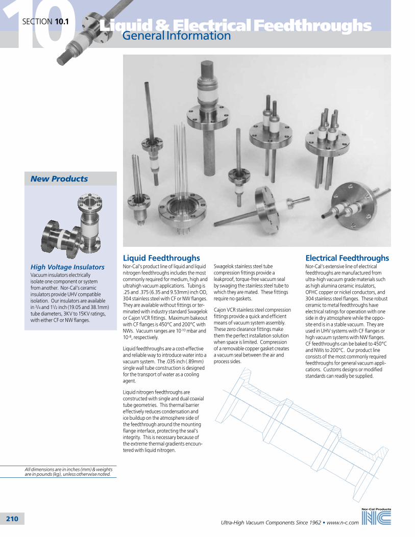
10
210
Liquid & Electrical FeedthroughsSECTION 10.1
Ultra-High Vacuum Components Since 1962 • www.n-c.com
High Voltage InsulatorsVacuum insulators electrically isolate one component or system from another. Nor-Cal’s ceramic insulators provide UHV compatible isolation. Our insulators are available in 3/4 and 11/2 inch (19.05 and 38.1mm) tube diameters, 3KV to 15KV ratings, with either CF or NW flanges.
General Information
Electrical FeedthroughsNor-Cal’s extensive line of electrical feedthroughs are manufactured from ultra-high vacuum grade materials such as high alumina ceramic insulators, OFHC copper or nickel conductors, and 304 stainless steel flanges. These robust ceramic to metal feedthroughs have electrical ratings for operation with one side in dry atmosphere while the oppo-site end is in a stable vacuum. They are used in UHV systems with CF flanges or high vacuum systems with NW flanges. CF feedthroughs can be baked to 450°C and NWs to 200°C. Our product line consists of the most commonly required feedthroughs for general vacuum appli-cations. Customs designs or modified standards can readily be supplied.
Liquid FeedthroughsNor-Cal’s product line of liquid and liquid nitrogen feedthroughs includes the most commonly required for medium, high and ultrahigh vacuum applications. Tubing is .25 and .375 (6.35 and 9.53mm) inch OD, 304 stainless steel with CF or NW flanges. They are available without fittings or ter-minated with industry standard Swagelok or Cajon VCR fittings. Maximum bakeout with CF flanges is 450ºC and 200ºC with NWs. Vacuum ranges are 10-10 mbar and 10-8, respectively.
Liquid feedthroughs are a cost-effective and reliable way to introduce water into a vacuum system. The .035 inch (.89mm) single wall tube construction is designed for the transport of water as a cooling agent.
Liquid nitrogen feedthroughs are constructed with single and dual coaxial tube geometries. This thermal barrier effectively reduces condensation and ice buildup on the atmosphere side of the feedthrough around the mounting flange interface, protecting the seal’s integrity. This is necessary because of the extreme thermal gradients encoun-tered with liquid nitrogen.
Swagelok stainless steel tube compression fittings provide a leakproof, torque-free vacuum seal by swaging the stainless steel tube to which they are mated. These fittings require no gaskets.
Cajon VCR stainless steel compression fittings provide a quick and efficient means of vacuum system assembly. These zero clearance fittings make them the perfect installation solution when space is limited. Compression of a removable copper gasket creates a vacuum seal between the air and process sides.
New Products
All dimensions are in inches (mm) & weights are in pounds (kg), unless otherwise noted.

211
Liquid & Electrical Feedthroughs
Ultra-High Vacuum Components Since 1962 • www.n-c.com
10SECTION 10.2
Liquid Feedthroughs
All dimensions for optional fittings are referenced from the seal face
Dual Liquid FeedthroughsMODEL NUMBER
FLANGE
TUBE FITTINGS
TUBE OD
A
B
LFT-NW-40-2-025 NW-40 None 0.250 (6.35) 3.00 (76.20) 4.00 (101.60)LFT-NW-40-2-025-4SW NW-40 4 Swagelok 0.250 (6.35) 4.01 (101.85) 5.01 (127.25)LFT-NW-40-2-025-4MVCR NW-40 4 MVCR 0.250 (6.35) 4.03 (102.36) 5.03 (127.76)LFT-NW-50-2-025 NW-50 None 0.250 (6.35) 3.00 (76.20) 4.00 (101.60)LFT-NW-50-2-025-4SW NW-50 4 Swagelok 0.250 (6.35) 4.01 (101.85) 5.01 (127.25)LFT-NW-50-2-025-4MVCR NW-50 4 MVCR 0.250 (6.35) 4.03 (102.36) 5.03 (127.76)LFT-150-2-025 2.75 CF None 0.250 (6.35) 3.00 (76.20) 4.00 (101.60)LFT-150-2-025-4SW 2.75 CF 4 Swagelok 0.250 (6.35) 4.01 (101.85) 5.01 (127.25)LFT-150-2-025-4MVCR 2.75 CF 4 MVCR 0.250 (6.35) 4.03 (102.36) 5.03 (127.76)LFT-150-2-038 2.75 CF None 0.375 (9.53) 3.00 (76.20) 4.00 (101.60)
Single Liquid FeedthroughsMODEL NUMBER
FLANGE
TUBE FITTINGS
TUBE OD
A
B
LFT-NW-16-1-025 NW-16 None 0.250 (6.35) 3.00 (76.20) 4.00 (101.60)LFT-NW-25-1-025 NW-25 None 0.250 (6.35) 3.00 (76.20) 4.00 (101.60)LFT-NW-25-1-025-2SW NW-25 2 Swagelok 0.250 (6.35) 4.01 (101.85) 5.01 (127.25)LFT-NW-25-1-025-2MVCR NW-25 2 MVCR 0.250 (6.35) 4.03 (102.36) 5.03 (127.76)LFT-NW-40-1-025 NW-40 None 0.250 (6.35) 3.00 (76.20) 4.00 (101.60)LFT-NW-40-1-025-2SW NW-40 2 Swagelok 0.250 (6.35) 4.01 (101.85) 5.01 (127.25)LFT-NW-40-1-025-2MVCR NW-40 2 MVCR 0.250 (6.35) 4.03 (102.35) 5.03 (127.76)LFT-NW-40-1-038 NW-40 None 0.375 (9.53) 3.00 (76.20) 4.00 (101.60)LFT-NW-50-1-025 NW-50 None 0.250 (6.35) 3.00 (76.20) 4.00 (101.60)LFT-NW-50-1-025-2SW NW-50 2 Swagelok 0.250 (6.35) 4.01 (101.85) 5.01 (127.25)LFT-NW-50-1-025-2MVCR NW-50 2 MVCR 0.250 (6.35) 4.03 (102.36) 5.03 (127.76)LFT-NW-50-1-038 NW-50 None 0.375 (9.53) 3.00 (76.20) 4.00 (101.60)LFT-075-1-025 1.33 CF None 0.250 (6.35) 3.00 (76.20) 4.00 (101.60)LFT-075-1-038 2.75 CF None 0.375 (9.53) 3.00 (76.20) 4.00 (101.60)LFT-150-1-025 2.75 CF None 0.250 (6.35) 3.00 (76.20) 4.00 (101.60)LFT-150-1-025-2SW 2.75 CF 2 Swagelok 0.250 (6.35) 4.01 (101.85) 5.01 (127.25)LFT-150-1-025-2MVCR 2.75 CF 2 MVCR 0.250 (6.35) 4.03 (102.36) 5.03 (127.76)LFT-150-1-038 2.75 CF None 0.375 (9.53) 3.00 (76.20) 4.00 (101.60)
BA
BA
SPECIFICATIONSMaterials Flange: 304 stainless steelVacuum range Metal seal: >10-10 mbar (UHV) Elastomer seal: >10-8 mbar (High vacuum)Temperature range Metal seal: -270°C to 450°C Elastomer seal: -20ºC to 200ºC
SPECIFICATIONSMaterials Flange: 304 stainless steelVacuum range Metal seal: >10-10 mbar (UHV) Elastomer seal: >10-8 mbar (High vacuum)Temperature range Metal seal: -270°C to 450°C Elastomer seal: -20ºC to 200ºC
All dimensions are in inches (mm) & weights are in pounds (kg), unless otherwise noted.

212Ultra-High Vacuum Components Since 1962 • www.n-c.com
10SECTION 10.2 Liquid & Electrical FeedthroughsLiquid Nitrogen Feedthroughs
Single Liquid Nitrogen FeedthroughsMODEL NUMBER
FLANGE
TUBE FITTINGS
TUBE OD
A
B
LNF-NW-16-1-025 NW-16 None 0.250 (6.35) 5.50 (139.70) 4.50 (114.30)LNF-NW-25-1-025 NW-25 None 0.250 (6.35) 5.50 (139.70) 4.50 (114.30)LNF-NW-25-1-025-2SW NW-25 2 Swagelok 0.250 (6.35) 6.51 (165.35) 5.51 (139.95)LNF-NW-25-1-025-2MVCR NW-25 2 MVCR 0.250 (6.35) 6.53 (165.86) 5.53 (140.46)LNF-NW-40-1-025 NW-40 None 0.250 (6.35) 5.50 (139.70) 4.50 (114.30)LNF-NW-40-1-025-2SW NW-40 2 Swagelok 0.250 (6.35) 6.51 (165.35) 5.51 (139.95)LNF-NW-40-1-025-2MVCR NW-40 2 MVCR 0.250 (6.35) 6.53 (165.86) 5.53 (140.46)LNF-NW-40-1-038 NW-40 None 0.375 (9.53) 5.50 (139.70) 4.50 (114.30)LNF-NW-50-1-025 NW-50 None 0.250 (6.35) 5.50 (139.70) 4.50 (114.30)LNF-NW-50-1-025-2SW NW-50 2 Swagelok 0.250 (6.35) 6.51 (165.35) 5.51 (139.95)LNF-NW-50-1-025-2MVCR NW-50 2 MVCR 0.250 (6.35) 6.53 (165.86) 5.53 (140.46)LNF-NW-50-1-038 NW-50 None 0.375 (9.53) 5.50 (139.70) 4.50 (114.30)LNF-075-1-025 1.33 CF None 0.250 (6.35) 5.50 (139.70) 4.50 (114.30)LNF-075-1-038 1.33 CF None 0.375 (9.53) 5.50 (139.70) 4.50 (114.30)LNF-150-1-025 2.75 CF None 0.250 (6.35) 5.50 (139.70) 4.50 (114.30)LNF-150-1-025-2SW 2.75 CF 2 Swagelok 0.250 (6.35) 6.51 (165.35) 5.51 (139.95)LNF-150-1-025-2MVCR 2.75 CF 2 MVCR 0.250 (6.35) 6.53 (165.86) 5.53 (140.46)LNF-150-1-038 2.75 CF None 0.375 (9.53) 5.50 (139.70) 4.50 (114.30)
Dual Liquid Nitrogen FeedthroughsMODE NUMBER
FLANGE
TUBE FITTINGS
TUBE
A
B
C
D
LNF-NW-40-2-025 NW-40 None 0.250 (6.35) 6.50 (165.10) 3.50 (88.90) 5.50 (139.70) 4.50 (114.30)LNF-NW-40-2-025-4SW NW-40 4 Swagelok 0.250 (6.35) 7.51 (190.75) 4.51 (114.55) 6.51 (165.35) 5.51 (139.95)LNF-NW-40-2-025-4MVCR NW-40 4 MVCR 0.250 (6.35) 7.53 (191.26) 4.53 (115.06) 6.53 (165.86) 5.53 (140.46)LNF-NW-50-2-025 NW-50 None 0.250 (6.35) 6.50 (165.10) 3.50 (88.90) 5.50 (139.70) 4.50 (114.30)LNF-NW-50-2-025-4SW NW-50 4 Swagelok 0.250 (6.35) 7.51 (190.75) 4.51 (114.55) 6.51 (165.35) 5.51 (139.95)LNF-NW-50-2-025-4MVCR NW-50 4 MVCR 0.250 (6.35) 7.53 (191.26) 4.53 (115.06) 6.53 (165.86) 5.53 (140.46)LNF-150-2-025 2.75 CF None 0.250 (6.35) 6.50 (165.10) 3.50 (88.90) 5.50 (139.70) 4.50 (114.30)LNF-150-2-025-4SW 2.75 CF 4 Swagelok 0.250 (6.35) 7.51 (190.75) 4.51 (114.55) 6.51 (165.35) 5.51 (139.95)LNF-150-2-025-4MVCR 2.75 CF 4 MVCR 0.250 (6.35) 7.53 (191.26) 4.53 (115.06) 6.53 (165.86) 5.53 (140.46)LNF-150-2-038 2.75 CF None 0.375 (9.53) 6.50 (165.10) 3.50 (88.90) 5.50 (139.70) 4.50 (114.30)
A B
A
C D
B
SPECIFICATIONSMaterials Flange: 304 stainless steel
Vacuum range Metal seal: >10-10 mbar (UHV) Elastomer seal: >10-8 mbar (High vacuum)
Temperature range Metal seal: -270°C to 450°C Elastomer seal: -20ºC to 200ºC
SPECIFICATIONSMaterials Flange: 304 stainless steel
Vacuum range Metal seal: >10-10 mbar (UHV) Elastomer seal: >10-8 mbar (High vacuum)
Temperature range Metal seal: -270°C to 450°C Elastomer seal: -20ºC to 200ºC
All dimensions for optional fittings are referenced from the seal face
All dimensions are in inches (mm) & weights are in pounds (kg), unless otherwise noted.

213Ultra-High Vacuum Components Since 1962 • www.n-c.com
10SECTION 10.3Liquid & Electrical FeedthroughsHigh Voltage Insulators
Vacuum insulators (also known as vacuum breaks and isola-tors) are used to electrically isolate one component or system from another. Nor-Cal uses a ceramic insulator with 95% minimum aluminum oxide content, which is silver brazed to two Kovar sleeves, creating a UHV compatible insulator. The insulator is then welded to the appropriate vacuum flange. Standard vacuum insulators are available in two tube diameters, 3/4 and 11/2 inches (19.05 and 38.1mm). The 3/4 inch (19.05mm) size is rated up to 10KV, while the 11/2 inch (38.1mm) size is offered in two voltage ratings (3KV and 15KV). All three voltage ratings are available with either two NW (ISO-KF) flanges for high vacuum applications or with one non-rotatable and rotatable CF (Conflat) flange for ultra-high vacuum applications. Other sizes, current ratings and flange combinations are available on request.
CF High Voltage InsulatorsMODEL NUMBER
TUBE OD
MAX. VOLTAGE (KV)
A
B
C
D
E
F
HVI-075-10 3/4 (19.05) 10 3.62 (91.95) 1.00 (25.40) 0.63 (16.00) 1.33 (33.78) 1.04 (26.42) 0.75 (19.05)HVI-150-3 11/2 (38.10) 3 2.65 (67.31) 0.25 (6.35) 1.37 (34.80) 2.73 (69.34) 1.66 (42.16) 1.25 (31.75)HVI-150-15 11/2 (38.10) 15 4.20 (106.68) 2.00 (50.80) 1.37 (34.80) 2.73 (69.34) 1.66 (42.16) 1.25 (31.75)
NW High Voltage InsulatorsMODEL NUMBER
TUBE OD
MAX. VOLTAGE (KV)
A
B
C
D
E
F
HVI-NW-16-10 3/4 (19.05) 10 3.62 (91.95) 1.00 (25.40) 0.63 (16.00) 1.18 (29.97) 1.04 (26.42) 0.75 (19.05)HVI-NW-40-3 11/2 (38.10) 3 2.28 (57.91) 0.25 (6.35) 1.37 (34.80) 2.16 (54.86) 1.66 (42.16) 1.25 (31.75)HVI-NW-40-15 11/2 (38.10) 15 4.03 (102.36) 2.00 (50.8) 1.37 (34.80) 2.16 (54.86) 1.66 (42.16) 1.25 (31.75)
E
F
A
B
C D
A
B
C D
E
F
SPECIFICATIONSMaterials Flanges: 304 stainless steel Sleeve: Kovar Insulator: Ceramic (95% aluminum oxide content) Magnetic: YesVacuum range Metal seal: >10-13 mbar (UHV) Elastomer seal: >10-8 mbar (High vacuum)Temperature range Metal seal: <450°C Elastomer seal: <150ºC sustained, <200ºC intermittent Gradient: 25ºC/minute maximum
All dimensions are in inches (mm) & weights are in pounds (kg), unless otherwise noted.

214Ultra-High Vacuum Components Since 1962 • www.n-c.com
10SECTION 10.4 Liquid & Electrical FeedthroughsElectrical Feedthroughs
Water Cooled Medium Current Copper FeedthroughsThese water cooled electrical feedthroughs transmit power and coolants simultaneously. They conduct higher current loads than solid rod conductors of equal size when properly cooled. Grounding of system is necessary for safety.
MODEL NUMBER
FLANGE
NUMBER OF FEEDTHROUGHS
A
B
MCF-NW-16-1W NW-16 1 3.23 (82.04) 4.03 (102.36)MCF-NW-25-1W NW-25 1 3.23 (82.04) 4.03 (102.36)MCF-NW-40-1W NW-40 1 3.13 (79.50) 4.13 (104.90)MCF-NW-40-2W NW-40 2 3.23 (82.04) 4.03 (102.36)MCF-NW-40-3W NW-40 3 3.23 (82.04) 4.03 (102.36)MCF-NW-40-4W NW-40 4 3.23 (82.04) 4.03 (102.36)MCF-NW-50-1W NW-50 1 3.13 (79.50) 4.13 (104.90)MCF-NW-50-2W NW-50 2 3.23 (82.04) 4.03 (102.36)MCF-NW-50-3W NW-50 3 3.23 (82.04) 4.03 (102.36)MCF-NW-50-4W NW-50 4 3.23 (82.04) 4.03 (102.36)MCF-075-1W 1.33 CF 1 3.21 (81.53) 4.05 (102.87)MCF-150-1W 2.75 CF 1 3.18 (80.77) 4.08 (103.63)MCF-150-2W 2.75 CF 2 3.18 (80.77) 4.08 (103.63)MCF-150-3W 2.75 CF 3 3.18 (80.77) 4.08 (103.63)MCF-150-4W 2.75 CF 4 3.18 (80.77) 4.08 (103.63)
Medium Current Nickel FeedthroughsThe nickel rod conductors on these electrical feedthroughs offer an alternative to copper for use in environments and processes that attack copper surfaces.
MODEL NUMBER
FLANGE
NUMBER OF FEEDTHROUGHS
A
B
MCF-NW-16-1N NW-16 1 3.23 (82.04) 4.03 (102.36)MCF-NW-25-1N NW-25 1 3.23 (82.04) 4.03 (102.36)MCF-NW-40-1N NW-40 1 3.13 (79.50) 4.13 (104.90)MCF-NW-40-2N NW-40 2 3.23 (82.04) 4.03 (102.36)MCF-NW-40-3N NW-40 3 3.23 (82.04) 4.03 (102.36)MCF-NW-40-4N NW-40 4 3.23 (82.04) 4.03 (102.36)MCF-NW-50-1N NW-50 1 3.13 (79.50) 4.13 (104.90)MCF-NW-50-2N NW-50 2 3.23 (82.04) 4.03 (102.36)MCF-NW-50-3N NW-50 3 3.23 (82.04) 4.03 (102.36)MCF-NW-50-4N NW-50 4 3.23 (82.04) 4.03 (102.36)MCF-075-1N 1.33 CF 1 3.21 (81.53) 4.05 (102.87)MCF-150-1N 2.75 CF 1 3.18 (80.77) 4.08 (103.63)MCF-150-2N 2.75 CF 2 3.18 (80.77) 4.08 (103.63)MCF-150-3N 2.75 CF 3 3.18 (80.77) 4.08 (103.63)MCF-150-4N 2.75 CF 4 3.18 (80.77) 4.08 (103.63)
BA
1.0(25.4)
.25(6.35)
.875(22.23)
.875(22.23)
.950(24.13)
SPECIFICATIONSMaterials Flange: 304 stainless steel Conductors: OFHC copper tube Insulator: Alumina ceramic
Electrical Voltage: 12 KVDC
Vacuum range Metal seal: >10-10 mbar (UHV) Elastomer seal: >10-8 mbar (High vacuum)
Temperature range Metal seal: -270°C to 450°C Elastomer seal: -20ºC to 200ºC
SPECIFICATIONSMaterials Flange: 304 stainless steel Conductors: Nickel rod Insulator: Alumina ceramic
Electrical Voltage: 12 KVDC Current: 56 Amps
Connector: Use with vacuum connector MCF-VC (see page 216)
Vacuum range Metal seal: >10-10 mbar (UHV) Elastomer seal: >10-8 mbar (High vacuum)
Temperature range Metal seal: -270°C to 450°C Elastomer seal: -20ºC to 200ºC
BA
1.0(25.4)
.25(6.35)
.875(22.23)
.875(22.23)
.950(24.13)
Medium Current Copper FeedthroughsThese electrical feedthroughs transmit either high voltage, high current or a combination of both. They are used for sample heating, in-vacuum coating, electron beam evaporation, sputtering and other high vacuum applications. High-purity, high-strength, low-loss alumina ceramic surfaces maximize strike and creep distances. The air-side ceramic surfaces have a high temperature glass coating which reduces surface roughness and contamination.
MODEL NUMBER
FLANGE
NUMBER OF FEEDTHROUGHS
A
B
MCF-NW-16-1 NW-16 1 3.23 (82.04) 4.03 (102.36)MCF-NW-25-1 NW-25 1 3.23 (82.04) 4.03 (102.36)MCF-NW-40-1 NW-40 1 3.13 (79.50) 4.13 (104.90)MCF-NW-40-2 NW-40 2 3.23 (82.04) 4.03 (102.36)MCF-NW-40-3 NW-40 3 3.23 (82.04) 4.03 (102.36)MCF-NW-40-4 NW-40 4 3.23 (82.04) 4.03 (102.36)MCF-NW-50-1 NW-50 1 3.13 (79.50) 4.13 (104.90)MCF-NW-50-2 NW-50 2 3.23 (82.04) 4.03 (102.36)MCF-NW-50-3 NW-50 3 3.23 (82.04) 4.03 (102.36)MCF-NW-50-4 NW-50 4 3.23 (82.04) 4.03 (102.36)MCF-075-1 1.33 CF 1 3.21 (81.53) 4.05 (102.87)MCF-150-1 2.75 CF 1 3.18 (80.77) 4.08 (103.63)MCF-150-2 2.75 CF 2 3.18 (80.77) 4.08 (103.63)MCF-150-3 2.75 CF 3 3.18 (80.77) 4.08 (103.63)MCF-150-4 2.75 CF 4 3.18 (80.77) 4.08 (103.63)
BA
1.0(25.4)
.25(6.35)
.875(22.23)
.875(22.23)
.950(24.13)
SPECIFICATIONSMaterials Flange: 304 stainless steel Conductors: OFHC copper Insulator: Alumina ceramic
Electrical Voltage: 5 KVDC Current: 150 Amps
Connector: Use with vacuum connector MCF-VC (see page 216)
Vacuum range Metal seal: >10-10 mbar (UHV) Elastomer seal: >10-8 mbar (High vacuum)
Temperature range Metal seal: -270°C to 450°C Elastomer seal: -20ºC to 200ºC
All dimensions are in inches (mm) & weights are in pounds (kg), unless otherwise noted.
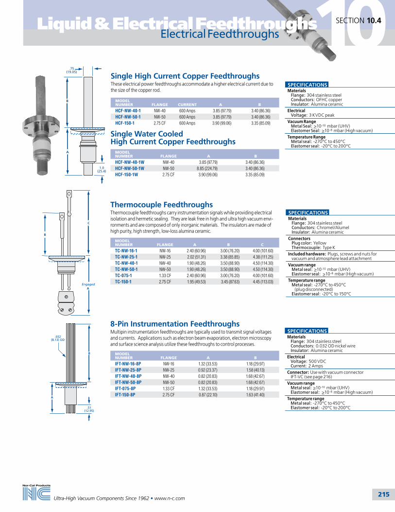
215
Liquid & Electrical Feedthroughs
Ultra-High Vacuum Components Since 1962 • www.n-c.com
10SECTION 10.4
Electrical Feedthroughs
SPECIFICATIONSMaterials Flange: 304 stainless steel Conductors: Chromel/Alumel Insulator: Alumina ceramicConnectors Plug color: Yellow Thermocouple: Type KIncluded hardware: Plugs, screws and nuts for vacuum and atmosphere lead attachmentVacuum range Metal seal: >10-10 mbar (UHV) Elastomer seal: >10-8 mbar (High vacuum)Temperature range Metal seal: -270°C to 450°C (plug disconnected) Elastomer seal: -20ºC to 150ºC
8-Pin Instrumentation FeedthroughsMultipin instrumentation feedthroughs are typically used to transmit signal voltages and currents. Applications such as electron beam evaporation, electron microscopy and surface science analysis utilize these feedthroughs to control processes.
MODEL NUMBER
FLANGE
A
B
IFT-NW-16-8P NW-16 1.32 (33.53) 1.18 (29.97)IFT-NW-25-8P NW-25 0.92 (23.37) 1.58 (40.13)IFT-NW-40-8P NW-40 0.82 (20.83) 1.68 (42.67)IFT-NW-50-8P NW-50 0.82 (20.83) 1.68 (42.67)IFT-075-8P 1.33 CF 1.32 (33.53) 1.18 (29.97)IFT-150-8P 2.75 CF 0.87 (22.10) 1.63 (41.40)
Thermocouple FeedthroughsThermocouple feedthroughs carry instrumentation signals while providing electrical isolation and hermetic sealing. They are leak free in high and ultra high vacuum envi-ronments and are composed of only inorganic materials. The insulators are made of high purity, high strength, low-loss alumina ceramic.
MODEL NUMBER
FLANGE
A
B
C
TC-NW-16-1 NW-16 2.40 (60.96) 3.00 (76.20) 4.00 (101.60)TC-NW-25-1 NW-25 2.02 (51.31) 3.38 (85.85) 4.38 (111.25)TC-NW-40-1 NW-40 1.90 (48.26) 3.50 (88.90) 4.50 (114.30)TC-NW-50-1 NW-50 1.90 (48.26) 3.50 (88.90) 4.50 (114.30)TC-075-1 1.33 CF 2.40 (60.96) 3.00 (76.20) 4.00 (101.60)TC-150-1 2.75 CF 1.95 (49.53) 3.45 (87.63) 4.45 (113.03)
C
B
AEngaged
A
.51(12.95)
B
.032(8.13) OD
SPECIFICATIONSMaterials Flange: 304 stainless steel Conductors: 0.032 OD nickel wire Insulator: Alumina ceramicElectrical Voltage: 500 VDC Current: 2 AmpsConnector: Use with vacuum connector IFT-VC (see page 216)Vacuum range Metal seal: >10-10 mbar (UHV) Elastomer seal: >10-8 mbar (High vacuum)Temperature range Metal seal: -270°C to 450°C Elastomer seal: -20ºC to 200ºC
Single High Current Copper FeedthroughsThese electrical power feedthroughs accommodate a higher electrical current due to the size of the copper rod.
MODEL NUMBER
FLANGE
CURRENT
A
B
HCF-NW-40-1 NW-40 600 Amps 3.85 (97.79) 3.40 (86.36)HCF-NW-50-1 NW-50 600 Amps 3.85 (97.79) 3.40 (86.36)HCF-150-1 2.75 CF 600 Amps 3.90 (99.06) 3.35 (85.09)
Single Water Cooled High Current Copper Feedthroughs
MODEL NUMBER
FLANGE
A
B
HCF-NW-40-1W NW-40 3.85 (97.79) 3.40 (86.36)HCF-NW-50-1W NW-50 8.85 (224.79) 3.40 (86.36)HCF-150-1W 2.75 CF 3.90 (99.06) 3.35 (85.09)
SPECIFICATIONSMaterials Flange: 304 stainless steel Conductors: OFHC copper Insulator: Alumina ceramicElectrical Voltage: 3 KVDC peakVacuum Range Metal Seal: >10-10 mbar (UHV) Elastomer Seal: >10-8 mbar (High vacuum)Temperature Range Metal seal: -270°C to 450°C Elastomer seal: -20ºC to 200ºC
A
1.0(25.4)
.75(19.05)
B

216Ultra-High Vacuum Components Since 1962 • www.n-c.com
10SECTION 10.4 Liquid & Electrical FeedthroughsElectrical Feedthroughs & Connectors
BNC Coaxial FeedthroughsThe BNC (Bayonet Naval Connection) electrical feedthrough consists of two concentric conductor paths which are separated and insulated with high-purity alumina ceramic. It is commonly used in 50 to 70 ohm low power instrumentation lines.
MODEL NUMBER
FLANGE
NUMBER OF FEEDTHROUGHS
A
B
C
BNC-NW-16-1 NW-16 1 1.43 (36.32) 0.32 (8.13) -BNC-NW-25-1 NW-25 1 1.43 (36.32) 0.32 (8.13) -BNC-NW-40-1 NW-40 1 1.33 (33.78) 0.42 (10.67) -BNC-NW-40-2 NW-40 2 1.33 (33.78) 0.42 (10.67) 0.75 (19.05)BNC-NW-40-3 NW-40 3 1.33 (33.78) 0.42 (10.67) 0.75 (19.05)BNC-NW-40-4 NW-40 4 1.43 (36.32) 0.32 (8.13) 0.90 (22.86)BNC-NW-50-1 NW-50 1 1.33 (33.78) 0.42 (10.67) -BNC-NW-50-2 NW-50 2 1.33 (33.78) 0.42 (10.67) 0.75 (19.05)BNC-NW-50-3 NW-50 3 1.33 (33.78) 0.42 (10.67) 0.75 (19.05)BNC-NW-50-4 NW-50 4 1.33 (33.78) 0.42 (10.67) 0.90 (22.86)BNC-075-1 1.33 CF 1 1.41 (35.81) 0.34 (8.640) -BNC-150-1 2.75 CF 1 1.38 (35.05) 0.37 (9.40) -BNC-150-2 2.75 CF 2 1.38 (35.05) 0.37 (9.40) 0.95 (24.13)BNC-150-3 2.75 CF 3 1.38 (35.05) 0.37 (9.40) 0.95 (24.13)BNC-150-4 2.75 CF 4 1.38 (35.05) 0.37 (9.40) 0.95 (24.13)
BAAtmosphere Plug Included
.50 (12.7)Ref.
C
SPECIFICATIONSMaterials Flange: 304 stainless steel Conductors: Stainless steel Insulator: Alumina ceramic
Electrical Voltage: 500 VDC @10-4 mbar Current: 3 Amps
Connector: Use with vacuum connector BNC-VC (see below), atmosphere connector included
Vacuum range Metal seal: >10-10 mbar (UHV) Elastomer seal: >10-8 mbar (High vacuum)
Temperature range Metal seal: -270°C to 450°C Elastomer seal: -20ºC to 200ºC
MHV Coaxial FeedthroughsThe MHV (Miniature High Voltage or High Voltage BNC) electrical feedthroughs operate in medium to high power with higher voltage requirements. MHV and BNC feedthroughs look similar but are very different in electrical rating. They should never be cross-mated since their electrical ratings are not compatible.
MODEL NUMBER
FLANGE
NUMBER OF FEEDTHROUGHS
A
B
C
MHV-NW-16-1 NW-16 1 1.43 (36.32) 0.25 (6.35) -MHV-NW-25-1 NW-25 1 1.43 (36.32) 0.25 (6.25) -MHV-NW-40-1 NW-40 1 1.33 (33.78) 0.35 (8.89) -MHV-NW-40-2 NW-40 2 1.33 (33.78) 0.35 (8.89) 0.75 (19.05)MHV-NW-40-3 NW-40 3 1.33 (33.78) 0.35 (8.89) 0.75 (19.05)MHV-NW-40-4 NW-40 4 1.43 (36.32) 0.25 (6.35) 0.90 (22.86)MHV-NW-50-1 NW-50 1 1.33 (33.78) 0.35 (8.89) -MHV-NW-50-2 NW-50 2 1.33 (33.78) 0.35 (8.89) 0.75 (19.05)MHV-NW-50-3 NW-50 3 1.33 (33.78) 0.35 (8.89) 0.75 (19.05)MHV-NW-50-4 NW-50 4 1.33 (33.78) 0.35 (8.89) 0.90 (22.86)MHV-075-1 1.33 CF 1 1.41 (35.81) 0.27 (6.86) -MHV-150-1 2.75 CF 1 1.38 (35.05) 0.30 (7.62) -MHV-150-2 2.75 CF 2 1.38 (35.05) 0.30 (7.62) 0.95 (24.13)MHV-150-3 2.75 CF 3 1.38 (35.05) 0.30 (7.62) 0.95 (24.13)MHV-150-4 2.75 CF 4 1.38 (35.05) 0.30 (7.62) 0.95 (24.13)
BAAtmosphere Plug Included
.50 (12.7)Ref.
C
SPECIFICATIONSMaterials Flange: 304 stainless steel Conductors: Stainless steel Insulator: Alumina ceramic
Electrical Voltage: 5 KV Current: 3 Amps
Connector: Use with vacuum connector MCF-VC (see below), atmosphere connector included
Vacuum range Metal seal: >10-10 mbar (UHV) Elastomer seal: >10-8 mbar (High vacuum)
Temperature range Metal seal: -270°C to 450°C Elastomer seal: -20ºC to 200ºC
Electrical Feedthrough ConnectorsMODEL NUMBER USE
WITH MATERIAL
MAXIMUM CURRENT (AMPS)
QUANTITY
MCF-VC Medium Current Beryllium Copper with SS Screws 100 10 per Pkg.BNC-VC BNC and MHV Beryllium Copper with SS Screws 15 10 per Pkg.IFT-VC 8-Pin Instrumentation Beryllium Copper 10 10 per Pkg.
.260(6.6)
1.00 (25.4)
.50 (12.7)
Accepts wire up to .050 (1.27)Diameter
Medium Current Connector BNC & MHV Connector
Socket accepts .094 (2.39) Diameter Pin
Socket accepts .032(.81) Diameter Pin
.69 (17.53) .62 (15.75)
.25 Diameter
Accepts wire up to .032 (.81)Diameter
.062 (1.57)Diameter
8-Pin InstrumentationConnector
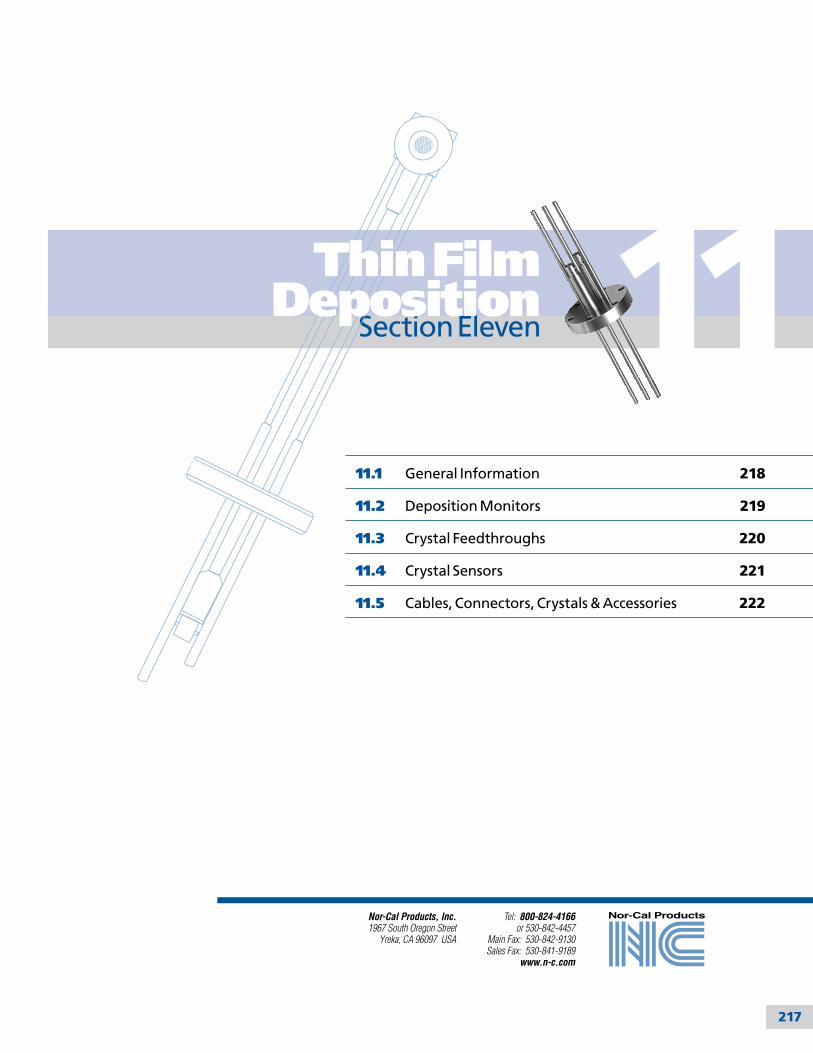
217
11
Tel: 800-824-4166or 530-842-4457
Main Fax: 530-842-9130Sales Fax: 530-841-9189
www.n-c.com
Nor-Cal Products, Inc.1967 South Oregon Street
Yreka, CA 96097 USA
11.1 General Information 218
11.2 Deposition Monitors 219
11.3 Crystal Feedthroughs 220
11.4 Crystal Sensors 221
11.5 Cables, Connectors, Crystals & Accessories 222
Section Eleven
Thin Film Deposition

11
218
SECTION 11.1
Ultra-High Vacuum Components Since 1962 • www.n-c.com
Thin Film DepositionGeneral Information
Nor-Cal offers an extensive selec-tion of commonly used quartz crystal feedthroughs, sensors and multi-channel monitors, cables, quartz crystals, acces-sories and replacement parts for use in semiconductor, optical and industrial thermal deposition processes. Custom feedthroughs are available with a variety of flanges in all sizes.
Our coating instrumentation products support one of the more popular meth-ods of thin film measurement and rate control - the crystal monitor, which uti-lizes the piezo-electric properties of a quartz crystal.
The electrical characteristics of the crys-tal, which is held in place by the sensor, change during deposition. Single sensors are generally used for short deposition runs, whereas, dual sensors allow for longer runs. Dual sensors require an air line to operate a pneumatic shutter which covers one crystal at a time. The sensor is either welded to the feedthrough or attached with connectors. Most sensors are available with cooling lines.
The application determines the correct choice of sensor. The sensor determines compatible feedthroughs and cabling. The chamber determines the appropriate feedthrough and flange. For applica-tion temperatures up to 150ºC, electrical
connection between the sensor and feedthrough is accomplished with a vac-uum coaxial cable. A bakeable, one piece sensor/feedthrough replaces the standard in-vac cable with a stainless steel high-temp coaxial line for high temperature applications up to 300ºC.
The feedthrough is the air-to-vacuum connection between the sensor and the oscillator. The feedthrough transfers the quartz crystal’s piezo-electric vibra-tions to the oscillator via a short coaxial cable. The oscillator conditions the signals
MonitorSource Shutter
Sensor
Substrate
Source
Ground Wire
10' CableOscillator
Holder & Crystal
In-Vac Cable
Feedthrough
6" (152.4) Cable
Cabling from Oscillator to Sensor must not exceed 48 inch(1219.2mm) (See page 222 for cable selections)
and transfers them to the monitor via another coaxial cable. The monitor then measures, interprets and displays the thickness, rate and frequency of depo-sition. Nor-Cal’s thin film deposition monitors are available with up to six independent channels to read six sensors. Each sensors’ rate, thickness and frequency can be read from the RS-232 port, and placed in a spreadsheet formatted file for later inspection. Each sensor requires its own cabling and oscil-lator. Contact our sales staff for help with your system configuration.
Typical Thin Film Coating System
All dimensions are in inches (mm) & weights are in pounds (kg), unless otherwise noted.

219Ultra-High Vacuum Components Since 1962 • www.n-c.com
Thin Film Deposition 11SECTION 11.2
Deposition Monitors & Oscillators
SPECIFICATIONSDimensions: 8.38 x 3.50 x 7.75 inches (212.85 x 88.9 x 196.85mm)Connections Inputs: 4 digital, 2 or 6 sensor Outputs: 4 relay, analog rate & thickness PC: RS-232 portDisplay: Alphanumeric LEDFrequency: 6.0 to 4.0 MHz, programmableRate averaging: 1 to 20 readingsFrequency resolution: 0.1 HzThickness resolution: 1 ÅRate resolution: 0.1 or 0.01 Å/s selectableMeasurement rate: 0.15 to 2 seconds
3.82 (97.03)
MonitorBNC Connection (Male)
FeedthroughBNC Connection (Female)
2.25 (57.15)
.88(22.35)
1.13(28.7)
RemoteOscillator
Deposition MonitorsOur deposition monitors measure film thickness/rate or frequency using crystals as the sensor device. Independent channels monitor different films or average different sensors together to provide a more uniform deposition measurement. These monitors are Class 1 Equipment CE approved. Included are a RS-232 cable and Windows software. This software will allow you to change the monitor’s parameters, save process readings in Excel formatted files, and operate the monitor remotely. Mounting brackets are included, rack-mount extenders are available on request
MODEL NUMBER
CRYSTAL INPUTS
POWER INPUT
TEMPERATURE RANGE
FREQUENCY RANGE
CM-2 2 120/240 VAC, 20 VA 0º to 50ºC 6.0 to 4.0 MHzCM-6 6 120/240 VAC, 20 VA 0º to 50ºC 6.0 to 4.0 MHz
Remote OscillatorsOscillators condition the signal from the crystal sensor to the controller. They are housed in a die-cast aluminum body. BNC connectors are used to interface with the monitor and sensor. Refer to the diagram on this page for installation and to page 222 of the catalog for cabling and accessories. In-vacuum oscillators are available. Call for information and pricing.
MODEL NUMBER
TEMPERATURE RANGE
FREQUENCY RANGE
CO-A 10º to 40ºC 6.0 to 4.0 MHz
Thin film deposition systems
All dimensions are in inches (mm) & weights are in pounds (kg), unless otherwise noted.

220Ultra-High Vacuum Components Since 1962 • www.n-c.com
Thin Film Deposition11SECTION 11.3
Crystal Feedthroughs
1 Inch Bolt Crystal FeedthroughsMODEL NUMBER
SENSOR CONNECTIONS
IN VAC CONNECTOR
EXTERNAL CONNECTOR
COOLING LINES
COMPRESSION FITTINGS
AIR LINES
CF-100-1 1 Microdot BNC - -CF-100-1-W 1 Microdot BNC 2 -CF-100-1-WC 1 Microdot BNC 2 P -CFP-100-2-W 2 Microdot Microdot 2 1
Note: 1.25 inch (31.75) bolt feedthroughs are available. Call for pricing.
CF Flanged Crystal FeedthroughsMODEL NUMBER
FLANGE TYPE
SENSOR CONNECTIONS
IN VAC CONNECTOR
EXTERNAL CONNECTOR
COOLING LINES
COMPRESSION FITTINGS
AIR LINES
CF-133-1 1.33 CF 1 Microdot BNC - -CF-275-1-W 2.75 CF 1 Microdot BNC 2 -CF-275-1-WC 1.33 CF 1 Microdot BNC 2 P -CFP-275-2-W 2.75 CF 2 Microdot BNC 2 1
Note: ISO, NW, and ASA flanged feedthroughs are available upon request. Call for pricing.
9.00(228.6)
2.50(63.5)
2 Microdot Connectors
2 BNC Connectors
2.75 CF Flange
2.75 CF Flange
SS Tubes: 3/16 (4.76) OD .128 (3.25) ID
4.00(101.6)
Microdot Connector
1/8" (3.18) Compression Fittings
2.00(50.8)
1.10(27.94)
2.75 CF Flange
BNC Connector
1.33 CF Mini Flange
Microdot Connector
2.50(63.5)
BNC Connector
9.00(228.6)
2.00(50.8)
Microdot Connector
BNC Connector
2.75 CF Flange
2.75 CF Flange
SS Tubes: 3/16 (4.76) OD .128 (3.25) ID
4.00(101.6)
SPECIFICATIONSMaterials Feedthrough: 304 stainless steel
Vacuum range: >1 x 10⁻⁹ mbar (High vacuum)
Temperature range: <150ºC
Leak rate: <10-9 l/sec
Baseplate thickness: 1 inch (25.4mm) maximum
1.70(43.18)
Microdot Connector
BNC Connector
1.50 (38.1) Hex
1.00 (25.4)
CF-100-1
12.00 (304.8)
SS Tubes: 3/16 (4.76) OD .128 (3.25) ID
BNC Connector
1.70(43.18)
5.30(134.62)
Microdot Connector
1.50 (38.1) Hex1.00 (25.4)
CF-100-1-W
1.70(43.18)
5.01 (127.25)3.70 (93.98)
1/8 (3.18) CompressionFittings
BNC Connector
Microdot Connector
1.50 (38.1) Hex
1.00 (25.4)
CF-100-1-WC
SS Tubes: 3/16 (4.76) OD .128 (3.25) ID
12.00 (304.8)
Microdot Connectors
Microdot Connectors
1.70(43.18)
5.30(134.62)
1.00(25.4)
1.5 (38.1) Hex1.00 (25.4)
CFP-100-2-W
CF-133-1
CF-275-1-WC
CFP-275-2-W
CF-275-1-W
SPECIFICATIONSMaterials Flanges: 304 stainless steel Flange sizes: 11/3 to 23/4 CF Feedthrough: 304 stainless steel
Vacuum range: >1 x 10⁻⁹ mbar (High vacuum)
Temperature range: <150ºC
Leak rate: <10-9 l/sec
All dimensions are in inches (mm) & weights are in pounds (kg), unless otherwise noted.

221Ultra-High Vacuum Components Since 1962 • www.n-c.com
Thin Film Deposition 11SECTION 11.4
Crystal Sensors
Single Crystal SensorsMODEL NUMBER
SENSORS
MOUNTING BRACKET
SENSOR ORIENTATION
WATER COOLED
CS-1 1 P 0° CS-1-W 1 0° P
CS-1-W-RA 1 90° P
Microdot Connector
1.10(27.94)
.975(24.77)
Crystal Sensor Mounting Holes
Microdot Connector
1.10
(27.
94)
Cooling Lines
Crystal Sensor .125 (3.18) OD SS Tube
Crystal Sensor
30.00(762)
30.00(762)
Microdot Connector 1.00(25.4)
.57(14.48)
1.00(25.4)
Back Cover Plate
Cooling Lines.125 (3.18) OD SS Tube
30.00 (762)
Microdot Connectors
Crystal Sensor
1.03(26.16)
1.29(32.77)
2.60 (66.04)
Shutter Actuator
Air Line
Two Cooling Lines
Shutter
.125 (3.18) OD SS Tube
.125 (3.18) OD SS TubeDeposition Shield for Actuator Piston
Specify length and bend4.25 (107.95)
BNC Connector
.25 (6.35) Rigid 304 SS Coaxial Tube
2.75 CF Flange
3.50 (88.9)
Crystal Sensor
30.00 (762)
Microdot Connectors1.35
(34.29)
Air Line .125 (3.18) OD SS Tube
3.75
(95
.25)
Shu
tter
Ext
end
ed Cooling Line .125 (3.18) OD SS Tube
Cooling Line .125 (3.18) OD SS Tube
Pneumatic Actuator
Dual Crystal SensorsMODEL NUMBER
SENSORS
SENSOR ORIENTATION
PNEUMATIC SHUTTER
WATER COOLED
CSP-2-W 2 0° P P
CSP-2-W-RA 2 90° P P
Bakeable Crystal SensorsMODEL NUMBER
FLANGE TYPE
DESCRIPTION
TEMPERATURE RANGE
WATER COOLED
CSH-275-1-W 2.75 CF Single sensor with feedthrough <300°C P
SPECIFICATIONSMaterials Body: 304 stainless steel Crystals: 6 MHz gold and aluminum alloyVacuum range: >1x 10⁻⁹ mbar (High Vacuum)Temperature range: <225ºCCustom lengths and bends available for all sensors.Cables, crystals and accessories are on page 222.
CS-1-WCS-1
CS-1-W-RA
CSP-2-WCSP-2-W-RA
All dimensions are in inches (mm) & weights are in pounds (kg), unless otherwise noted.
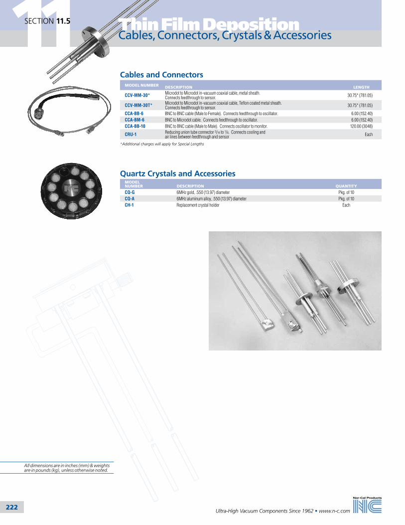
222Ultra-High Vacuum Components Since 1962 • www.n-c.com
Thin Film Deposition11SECTION 11.5
Cables, Connectors, Crystals & Accessories
Cables and ConnectorsMODEL NUMBER
DESCRIPTION
LENGTH
CCV-MM-30* Microdot to Microdot in-vacuum coaxial cable, metal sheath. Connects feedthrough to sensor. 30.75* (781.05)
CCV-MM-30T* Microdot to Microdot in-vacuum coaxial cable, Teflon coated metal sheath. Connects feedthrough to sensor. 30.75* (781.05)
CCA-BB-6 BNC to BNC cable (Male to Female). Connects feedthrough to oscillator. 6.00 (152.40)CCA-BM-6 BNC to Microdot cable. Connects feedthrough to oscillator. 6.00 (152.40)CCA-BB-10 BNC to BNC cable (Male to Male). Connects oscillator to monitor. 120.00 (3048)
CRU-1 Reducing union tube connector 3/16 to 1/8. Connects cooling and air lines between feedthrough and sensor Each
*Additional charges will apply for Special Lengths
Quartz Crystals and AccessoriesMODEL NUMBER
DESCRIPTION
QUANTITY
CQ-G 6MHz gold, .550 (13.97) diameter Pkg. of 10CQ-A 6MHz aluminum alloy, .550 (13.97) diameter Pkg. of 10CH-1 Replacement crystal holder Each
All dimensions are in inches (mm) & weights are in pounds (kg), unless otherwise noted.

223
12
Tel: 800-824-4166or 530-842-4457
Main Fax: 530-842-9130Sales Fax: 530-841-9189
www.n-c.com
Nor-Cal Products, Inc.1967 South Oregon Street
Yreka, CA 96097 USA
12.1 Alphabetical Index 224
12.2 Model Number Index 226
12.3 Domestic Distributors & Sales Representatives 236
12.4 International Distributors & Sales Representatives 237
12.5 Order Information & Warranty 238
12.6 Patents & Trademarks 239
Index &
Order InformationSection Twelve

224
12SECTION 12.1 Index
Ultra-High Vacuum Components Since 1962 • www.n-c.com
Alphabetical Index
AAdapters See also Fittings, Adapter 71–79All-Metal Valves 128Aluminum Metal Seals 19Aluminum to Stainless Steel Transitions 62ASA Fittings See also Fittings, Weld & Flanged 43–46ASA Flanges See also Flanges 40–42
BBakeable Valves 128Ball Valves 112Bellows See Flexible CouplingsBolt Kits See Fasteners, FlangeBulkhead Clamps 24
CCapacitance Diaphragm Gauges 149Centering Rings See also Seals, Flange
ISO Flange Centering Rings 35–36Aluminum Centering Rings 35Screened Centering Rings 36Stainless Steel Centering Rings 35–36
NW Flange Centering Rings 25–26Aluminum Aluminum Centering Rings 25Overpressure Rings 26Stainless Steel Centering Rings 25Trapped Centering Rings 26
CF Fittings See also Fittings, Weld & Flanged 64–69CF Flanges See also Flanges 47–61Chambers 179–190
Bell Jars 186GEC Reference Cell 188Guide to Chamber Design 183–185Surface Analysis 187
Clamps See also Fasteners, FlangeChain Clamps 20Genesis Finger Clamps 116ISO Flange Clamps
Double Claw 34Single Claw 34
NW Flange Clamps 24Bulkhead 24SureSeal 24Wing Nut 24
Cleaning & Surface Treatment 14Cleanroom Assembly & Packaging 15Controllers See Thermal Products; See also Valves, Intellisys Pressure Control
Couplings 81Crosses See Fittings, Weld & FlangedCustomer Service 10Custom Components & Services 8
DDeposition Equipment See Thin Film DepositionDistributors 232–233Downstream Pressure Control 129-154
EEngineering, Research & Development 11
FFasteners, Flange See also Clamps
ASA Flange Fasteners 41, 42ASA Flange Gate Valve Mating Hardware 41–42CF Flange Fasteners
Double-Sided Flange Fasteners 60Mini Flange Fasteners 49Plate Nuts 63Silver Plated Flange Fasteners 51–55Standard Flange Fasteners 50–57
ISO Flange Fasteners 33Wire Seal Flange Fasteners 70
Fasteners, Genesis Double Stud 116Feedthroughs 209–216
Crystal Feedthroughs See Thin Film DepositionElectrical Feedthroughs 194
BNC 200
Connectors 200High Current 199High Voltage Insulators 210, 213Instrumentation 215Medium Current 214MHV 216Thermocouple 215
Liquid Feedthroughs 210, 211Liquid Nitrogen Feedthroughs 212Utility Hat 202
Fittings, Adapter 71–79Ball Socket
NW 76Weld 91
Flange to Flange 72–76Glass Adapters 194Pipe 77Quick Disconnect 79Swagelok 79VCR 78Welch Pump, NW Flanged 76Fittings, Genesis Modular 117
Fittings, Weld & FlangedCrosses, 4-Way Fittings
ASA 46CF 69ISO 39NW 30Weld 93
Crosses, 5-Way FittingsASA 46CF 69ISO 39NW 30Weld 93
Crosses, 6-Way FittingsASA 46CF 69CF, Cube 68ISO 39NW 30Weld 93
Crosses, Reducer FittingsCF 68ISO 39NW 30Weld 94
Elbows, 180° Radius FittingsWeld 90
Elbows, 45° Radius FittingsNW 29Weld 90
Elbows, 45° with TangentsWeld 90
Elbows, 45° with Tangent FittingsASA 44CF 66ISO 37NW 29
Elbows, 90° Mitered FittingsASA 45CF 66ISO 37NW 29Weld 91
Elbows, 90° Radius FittingsASA 45CF 66ISO 37NW 29Weld 91
End Cap FittingsWeld 89
Flexible Couplings 81Flexible Hoses 82Nipples, Conical Reducer Fittings
CF 65ISO 38NW 28
Nipples, Full FittingsASA 43CF 65
ISO 38NW 27
Nipples, Half FittingsASA 43CF 64ISO 38NW 27
Nipples, NW to PVC Hose Fittings 87Nipples, Reducer Fittings
ASA 44CF 65ISO 38NW 28
Reducers, Conical FittingsWeld 89
Reducers, End Cap FittingsWeld 89
Tees, ReducerCF 67ISO 39NW 28Weld 92
Tee FittingsASA 45CF 67ISO 39NW 28Weld 92
Tube Finishes Fittings 88Tubing Fittings 94
Flanges See also Centering Rings; Clamps; Fasteners, Flange; Seals, Flange; Fittings, Weld & FlangedASA Flanges 40–43CF Flanges 47–61
Assembly 48Double-Sided 60Metal Seal 18-19Mini 49NW Tapered 19Reducer, Zero Length 61Special Purpose, Double-Sided 58Special Purpose, Straight-Through 59Standard 50–57
ISO Flanges 31–33Assembly Instructions 31Nonrotatable 33Optional Fastener 32Rotatable Bolt Ring and Retainer Ring 32
NW Flanges 21–23Blank Off Cap Flanges 22Bored Blank Flanges (NWB) 22Socket Weld Flanges 23Weld Neck Flanges 23
Wire Seal Flanges 70Flexible Couplings 81Flexible Hoses 80, 82–87
Adapter Hose 84ASA Hose 85CF Hose 85
Braided 86Flangeless Hose 82ISO Hose 84NW Hose
Braided 86Medium Wall 83PVC 87Thick Wall 84Thin Wall 83
PVC Hose & Nipples 87Foreline Traps 155–166
Custom Traps 157Liquid Nitrogen Traps 157, 164LPCVD-TEOS Traps 162Metal Sieve Traps 158–159Molecular Sieve Traps 160Multistage Traps 157, 162Oil Mist Eliminators 165Options 157

225
12SECTION 12.1Index
Ultra-High Vacuum Components Since 1962 • www.n-c.com
Alphabetical IndexParticulate Traps 157, 161Selection Guide 156Trap Hardware & Replacement Parts
Body Clamps 166Fittings, Quick Disconnect 166Mounting Brackets 166Replacement Filters 166Replacement Heaters 166
Water Cooled Traps 163
GGaskets See Seals, FlangeGas Line Heaters See Thermal ProductsGate Valves See Valves, Isolation; See also Valves, Pressure Control
Gauges, Capacitance Diaphragm 149Genesis Modular Fittings 117Genesis Modular Valves 114–120Genesis Stainless Steel Valves 118Glass Adapters 194
HHeaters See Thermal ProductsHoses See Flexible Hoses
I-J-KIntellisys See Valves, Downstream Pressure ControlIQ & IQ+ Throttling Valves 134-146ISO Fittings 37–39ISO Flanges See also Flanges 31–36Isolation Valves 95-128
LLeak Valves 126Load Lock Chambers 198
MMachined NW Female Pipe Adapters 77Manipulators See Sample Transfer & ManipulationManufacturing 12–13Markets Served 5Metal Seals See Seals, FlangeMission Statement 9
NN-Series Valves 98-99NW Fittings See also Fittings, Weld & Flanged 27–30NW Flanges See also Flanges 21–26
OO-Rings See Appropriate Product CatagoriesOil Mist Eliminators 165Order Information 238
PPendulum Valves See Valves, Isolation; See also Valves, Intellisys Pressure Control
Plate Nuts 63Poppet Valves See also Valves, Isolation 98–109Pressure Control See Valves, Intellisys Pressure ControlPVC Hose 87
QQuality Assurance 16
RRebuild Kits See Appropriate Product Catagories
SSample Transfer & Manipulation 195–208
Manipulators 196–208Alignment Gimbals 202Linear/Rotary Motion 205–207
Coaxial Magnetic Feedthrough 206Differentially Pumped Feedthrough 207Magnetic Feedthrough 206
Precision Motion Feedthrough 207Linear Motion
Heavy-Duty Push-Pull 205Linear Vacuum Feedthrough 205Pneumatic Linear Feedthrough 205Thimbles 201
Rotary Motion 204Motorized Rare Earth Magnetic Feedthrough 204Precision Rotary Feedthroughs 204Rotary Seals 203
Utility Hat 202Wobble Sticks 208XYZ Precision Manipulator 200XY Stages 200Z-Translators 201
Sample Transfer 195–208Add-A-Doors 199Load Lock Chambers 198Sample Transfer Systems 198Utility Hat 202
Terminology 197Seals, Flange See also Centering Rings
Aluminum Metal Seals 18–19ASA O-Rings 41, 42CF Gaskets
Double-Sided Flanges 60Mini Flanges 49Standard Flanges 50–57
ISO O-Rings 36NW O-Rings 26Wire Seal Gaskets 70
Seals, Trap Body 166Seals, Vacuum Chamber
Bell Jar O-Rings 186Seals, Valve
All Metal Valve Seals 128Ball Valve Seals 112-113Genesis Modular Valve Seals 115, 119-120Manual Valve Seals
Angle 102Angle-In-Line 104Butterfly 121In-Line 106Straight-Through 110Tee 108
Pneumatic Valve SealsAngle 103Angle-In-Line 105Bellowless 126In-Line 107N-Series 98Straight-Through 110Tee 109
Shutters 194Silver Plated Bolts See Fasteners, FlangeSilver Plated Gaskets See Seals, Flange: CF GasketsStandard Components 6–7SureSeal Clamps 24
TThermal Products 167–178
Accessories 178Benefits 169-169Designing Heated Systems 171Electronic Thermostat Option 168, 178Heater Controllers 178Heater Jackets 172–178
Conical 175Elbows, 45° Radius 174Elbows, 90° Radius 174Flange 175Gas Line 176Genesis Valves 120Spiral 178Straight 172–174Tee 175Throttling Valve 138
Insulators, Flange 175Insulators, Gas Line 176Insulators, Spiral 177Thermocouples 178
Thin Film Deposition 217-222
Cables 222Connectors 222Crystals & Crystal Holders 222Crystal Feedthroughs 220Crystal Sensors 221Deposition Monitors 219Remote Oscillators 219
Throttling Butterfly Valves 132–137Throttling Pendulum Valves 140–143Throttling SoftShut Gate Valves 144–146Trademark References 239Transitions, Aluminum to Stainless Steel 62Traps See also Foreline Traps 167-178Tube Bending 189Tubing 94
UUniversal Valve Drive 132
VValves, Intellisys Pressure Control 129–154
Accessories 154Adaptive Pressure Controllers 147Cables 154Gauges, CDG 149, 153IQ Throttling Valves 134–146Spare Parts 154Throttling Butterfly Valves 132–137
Heater Jackets & Controllers 138Throttling Pendulum Valves 139–143Throttling SoftShut Gate Valves 144–146Universal Valve Drive 132
Valves, Isolation 95–126All-Metal Valves 128Applications 96Ball Valves 112-113Bellowless Valves 126Custom Valves 97Genesis Valves 114–120
Bellows Kits 120Heaters & Insulators 120Modular Valves 114–120
Conductance 114Fittings 117Options 119
Rebuild Kits 120Stainless Steel Valves 118
Conductance 118Options 119
Leak Valves 126Linear Gate Valves 123–125
Manual 124Options 123Pneumatic 125
Manual Butterfly Valves 121Pendulum Valves 122N-Series Valves 98-99Poppet Valves 100-111
Bellows Kits 111Conductance 100Manual Valves
Angle 102Angle-In-Line 104In-Line 106Straight-Through 110Tee 108
Options 101Pneumatic Valves
Angle 103Angle-In-Line 105In-Line 107Straight-Through 111Tee 109
Rebuild Kits 111Viewports 191-194Viewport Shutters 194
WWeldments 189Weld Fittings See also Fittings, Weld & Flanged 88–94Wing Nut Clamps 24Wire Seal Flanges See also Flanges 70

226
12SECTION 12.2 Index
Ultra-High Vacuum Components Since 1962 • www.n-c.com
Model Number Index Model Number Index
133133-000DS 60133-000D 60133-000N 49133-000NK 49133-000NKT 49133-000NT 49133-000R 49133-000RK 49133-000RKT 49133-000RT 49133-025D 60133-025N 49133-025NT 49133-025R 49133-025RT 49133-038D 60133-038N 49133-038NT 49133-038R 49133-038RT 49133-050D 60133-050N 49133-050NT 49133-050R 49133-050RT 49133-075DS 60133-075D 60133-075N 49133-075NBK 49133-075NBKT 49133-075NK 49133-075NKT 49133-075NT 49133-075R 49133-075RBK 49133-075RBKT 49133-075RK 49133-075RKT 49133-075RT 49133-1/2 QD 79133-1/4 FVCR 78133-1/4 MVCR 78133-1/4 QD 79133-1/4 SWAG 79133-3/8 FVCR 78133-3/8 MVCR 78133-3/8 QD 79133-3/8 SWAG 79133-D1 58133-D1V 58133-D2 58133-DT 58133-DTV 58133-DTV-1/4 FVCR 58133-DTV-1/4 MVCR 58133-DTV-1/4 SWAG 58133-DV 58133-DV-1/4 FVCR 58133-DV-1/4 MVCR 58133-DV-1/4 SWAG 58133-ST 59133-STT 59133-STV 59133-STV-1/4 FVCR 59133-STV-1/4 MVCR 59133-STV-1/4 SWAG 59
212212-000D 60
212-000N 50212-000NT 50212-000R 50212-000RT 50212-025N 50212-025NT 50212-025R 50212-025RT 50212-050N 50212-050NT 50212-050R 50212-050RT 50212-075N 50212-075NT 50212-075R 50212-075RT 50212-100D 60212-100N 50212-100NT 50212-100R 50212-100RT 50212-133-075Z 61
275275-000D 60275-000DS 60275-000N 51275-000NT 51275-000R 51275-000RT 51275-025D 60275-025N 51275-025NT 51275-025R 51275-025RT 51275-050D 60275-050N 51275-050NT 51275-050R 51275-050RT 51275-075D 60275-075N 51275-075NT 51275-075R 51275-075RT 51275-1/2 QD 79275-1/4 FVCR 78275-1/4 MVCR 78275-1/4 QD 79275-1/4 SWAG 79275-100D 60275-100N 51275-100NT 51275-100R 51275-100RT 51275-125D 60275-125N 51275-125NT 51275-125R 51275-125RT 51275-133-075Z 61275-150D 60275-150DS 60275-150N 51275-150NT 51275-150NT-M 51275-150R 51275-150RT 51275-162N 51275-162NT 51275-175N 51
275-175NT 51275-1 QD 79275-212-100Z 61275-3/4 QD 79275-3/8 FVCR 78275-3/8 MVCR 78275-3/8 QD 79275-3/8 SWAG 79275-D1 58275-D1V 58275-D2 58275-DS-MINI 58275-DT 58275-DTV 58275-DTV-1/4SWAG 58275-DTV-1/4 FVCR 58275-DTV-1/4 MVCR 58275-DV 58275-DV-1/4 FVCR 58275-DV-1/4 MVCR 58275-DV-1/4 SWAG 58275-ST 59275-STT 59275-STV 59275-STV-1/4 FVCR 59275-STV-1/4 MVCR 59275-STV-1/4 SWAG 59
338338-000D 60338-000N 52338-000NT 52338-000R 52338-000RT 52338-133-075Z 61338-150D 60338-150N 52338-150NT 52338-150R 52338-150RT 52338-200D 60338-200N 52338-200NT 52338-200R 52338-200RT 52338-212-100Z 61338-275-150Z 61
450450-000D 60450-000N 52450-000NT 52450-000R 52450-000RT 52450-133-075Z 61450-150D 60450-150N 52450-150NT 52450-150R 52450-150RT 52450-200D 60450-200N 52450-200NT 52450-200R 52450-200RT 52450-212-100Z 61450-250D 60450-250N 52450-250NT 52450-250NT-M 52450-250R 52450-250RT 52450-275-150Z 61450-338-200Z 61
462462-000D 60462-000N 53462-000NT 53462-000R 53462-000RT 53462-133-075Z 61
462-212-100Z 61462-275-150Z 61462-300D 60462-300N 53462-300NT 53462-300R 53462-300RT 53462-338-200Z 61
50050248 157
600600-000D 60600-000N 53600-000NT 53600-000R 53600-000RT 53600-133-075Z 61600-212-100Z 61600-275-150Z 61600-338-200Z 61600-400D 60600-400N 53600-400NT 53600-400NT-M 53600-400R 53600-400RT 53600-450-250Z 61600-462-300Z 61
675675-000D 60675-000N 54675-000NT 54675-000R 54675-000RT 54675-133-075Z 61675-212-100Z 61675-275-150Z 61675-338-200Z 61675-450-250Z 61675-462-300Z 61675-500D 60675-500N 54675-500NT 54675-500R 54675-500RT 54675-600-400Z 61
6C6C-075 696C-075-CU 686C-100 696C-1000 696C-150 696C-150-CU 686C-200 696C-250 696C-250-CU 686C-250V 696C-300 696C-400 696C-400-CU 686C-400V 696C-500 696C-600 696C-600-CU 686C-600V 696C-800 696C-ASA-11-600NV 466C-ASA-11-800N 466C-ASA-13.5-1000N 466C-ASA-13.5-800N 466C-ASA-16-1000N 466C-ASA-5-200N 466C-ASA-5-250N 466C-ASA-5-250NV 466C-ASA-7.5-400NV 466C-ASA-9-400NV 466C-ASA-9-600N 46
6C-ASA-9-600NV 466C-ISO-100-OF 396C-ISO-160-OF 396C-ISO-200-OF 396C-ISO-250-OF 396C-ISO-63-OF 396C-ISO-80-OF 396C-NW-16 306C-NW-25B 306C-NW-40B 306C-NW-50B 30
800800-000D 60800-000N 54800-000NT 54800-000R 54800-000RT 54800-133-075Z 61800-212-100Z 61800-275-150Z 61800-338-200Z 61800-450-250Z 61800-462-300Z 61800-600-400Z 61800-600D 60800-600N 54800-600NT 54800-600NT-M 54800-600R 54800-600RT 54800-675-500Z 61
10001000-000D 601000-000N 551000-000NT 551000-000R 551000-000RT 551000-133-075Z 611000-212-100Z 611000-275-150Z 611000-338-200Z 611000-450-250Z 611000-462-300Z 611000-600-400Z 611000-675-500Z 611000-800-600Z 611000-800D 601000-800N 551000-800NT 551000-800NT-M 551000-800R 551000-800RT 55
12001200-000N 551200-000NT 551200-000R 551200-000RT 551200-1000N 551200-1000NT 551200-1000R 551200-1000RT 551200-OR 186
13251325-000D 601325-000N 561325-000NT 561325-000R 561325-000RT 561325-1000-800Z 611325-1000D 601325-1000N 561325-1000NT 561325-1000R 561325-1000RT 561325-133-075Z 611325-212-100Z 611325-275-150Z 61
1325-338-200Z 611325-450-250Z 611325-462-300Z 611325-600-400Z 611325-675-500Z 611325-800-600Z 61
14001400-000D 601400-000N 561400-000NT 561400-000R 561400-000RT 561400-1200D 601400-1200N 561400-1200NT 561400-1200R 561400-1200RT 56
14501450-000N 571450-000NT 571450-000R 571450-000RT 571450-1200N 571450-1200NT 571450-1200R 571450-1200RT 57
16501650-000N 571650-000NT 571650-000R 571650-000RT 571650-1400N 571650-1400NT 571650-1400R 571650-1400RT 57
18001800-OR 186
24002400-OR 186
1GA1GA-075K 1941GA-075P 1941GA-100K 1941GA-100P 1941GA-150K 1941GA-150P 1941GA-200K 1941GA-200P 1941GA-250K 1941GA-250P 1941GA-300K 1941GA-300P 1941GA-400K 1941GA-400P 1941GA-500K 1941GA-500P 1941GA-600K 1941GA-600P 1941GA-ISO-100-OF-K 1941GA-ISO-100-OF-P 1941GA-ISO-160-OF-K 1941GA-ISO-160-OF-P 1941GA-ISO-63-OF-K 1941GA-ISO-63-OF-P 1941GA-ISO-80-OF-K 1941GA-ISO-80-OF-P 1941GA-NW-038P 1941GA-NW-075P 1941GA-NW-100P 1941GA-NW-150P 1941GA-NW-200P 178
This model number index is organized numerically then alphabetically by the digits before the first dash in the part number. If you have a custom part number or your part number is not listed,
you may contact us by phone or via our website for information on your product.
1-800-824-4166 www.n-c.com
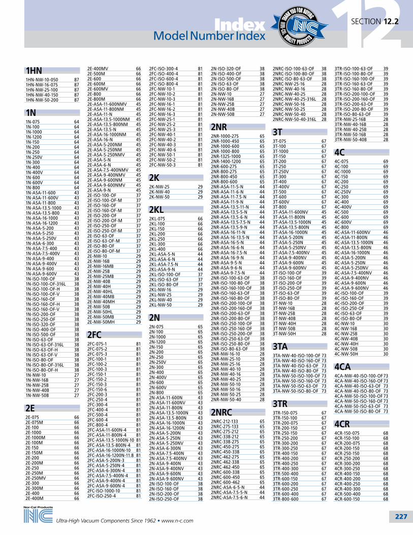
227
12SECTION 12.2Index
Ultra-High Vacuum Components Since 1962 • www.n-c.com
Model Number Index
1HN1HN-NW-10-050 871HN-NW-16-075 871HN-NW-25-100 871HN-NW-40-150 871HN-NW-50-200 87
1N1N-075 641N-100 641N-1000 641N-1200 641N-150 641N-200 641N-250 641N-250V 641N-300 641N-400 641N-400V 641N-600 641N-600V 641N-800 641N-ASA-11-600 431N-ASA-11-600V 431N-ASA-11-800 431N-ASA-13.5-1000 431N-ASA-13.5-800 431N-ASA-16-1000 431N-ASA-16-1200 431N-ASA-5-200 431N-ASA-5-250 431N-ASA-5-250V 431N-ASA-6-300 431N-ASA-7.5-400 431N-ASA-7.5-400V 431N-ASA-9-400 431N-ASA-9-400V 431N-ASA-9-600 431N-ASA-9-600V 431N-ISO-100-OF 381N-ISO-100-OF-316L 381N-ISO-100-OF-H 381N-ISO-100-OF-V 381N-ISO-160-OF 381N-ISO-160-OF-H 381N-ISO-160-OF-V 381N-ISO-200-OF 381N-ISO-250-OF 381N-ISO-320-OF 381N-ISO-400-OF 381N-ISO-500-OF 381N-ISO-63-OF 381N-ISO-63-OF-316L 381N-ISO-63-OF-H 381N-ISO-63-OF-V 381N-ISO-80-OF 381N-ISO-80-OF-316L 381N-ISO-80-OF-H 381N-NW-10 271N-NW-16B 271N-NW-25B 271N-NW-40B 271N-NW-50B 27
2E2E-075 662E-075M 662E-100 662E-1000 662E-1000M 662E-100M 662E-150 662E-150M 662E-200 662E-200M 662E-250 662E-250M 662E-250MV 662E-300 662E-300M 662E-400 662E-400M 66
2E-400MV 662E-500M 662E-600 662E-600M 662E-600MV 662E-800 662E-800M 662E-ASA-11-600NMV 452E-ASA-11-800NM 452E-ASA-11-N 452E-ASA-13.5-1000NM 452E-ASA-13.5-800NM 452E-ASA-13.5-N 452E-ASA-16-1000NM 452E-ASA-16-N 452E-ASA-5-200NM 452E-ASA-5-250NM 452E-ASA-5-250NMV 452E-ASA-5-N 452E-ASA-6-N 452E-ASA-7.5-400NMV 452E-ASA-9-400NMV 452E-ASA-9-600NM 452E-ASA-9-600NMV 452E-ASA-9-N 452E-ISO-100-OF 372E-ISO-100-OF-M 372E-ISO-160-OF 372E-ISO-160-OF-M 372E-ISO-200-OF 372E-ISO-200-OF-M 372E-ISO-250-OF 372E-ISO-250-OF-M 372E-ISO-63-OF 372E-ISO-63-OF-M 372E-ISO-80-OF 372E-ISO-80-OF-M 372E-NW-10 292E-NW-16B 292E-NW-16MB 292E-NW-25B 292E-NW-25MB 292E-NW-40B 292E-NW-40H 292E-NW-40HL 292E-NW-40MB 292E-NW-40MH 292E-NW-50B 292E-NW-50HL 292E-NW-50MB 292E-NW-50MH 29
2FC2FC-075-1 812FC-075-2 812FC-075-3 812FC-100-1 812FC-100-2 812FC-100-3 812FC-150-1 812FC-150-2 812FC-150-3 812FC-150-6 812FC-200-3 812FC-250-4 812FC-300-4 812FC-400-4 812FC-500-4 812FC-600-4 812FC-800-4 812FC-ASA-11-600N-4 812FC-ASA-11-800N-4 812FC-ASA-13.5-1000N-10 812FC-ASA-13.5-800N-4 812FC-ASA-16-1000N-10 812FC-ASA-16-1200N-11.8 812FC-ASA-5-200N-3 812FC-ASA-5-250N-4 812FC-ASA-6-300N-4 812FC-ASA-7.5-400N-4 812FC-ASA-9-400N-4 812FC-ASA-9-600N-4 812FC-ISO-1000-10 812FC-ISO-250-4 81
2FC-ISO-300-4 812FC-ISO-400-4 812FC-ISO-600-4 812FC-ISO-800-4 812FC-NW-10-1 812FC-NW-10-2 812FC-NW-10-3 812FC-NW-16-1 812FC-NW-16-2 812FC-NW-16-3 812FC-NW-25-1 812FC-NW-25-2 812FC-NW-25-3 812FC-NW-40-1 812FC-NW-40-2 812FC-NW-40-3 812FC-NW-40-6 812FC-NW-50-1 812FC-NW-50-2 812FC-NW-50-3 81
2K2K-NW-25 292K-NW-40 292K-NW-50 29
2KL2KL-075 662KL-100 662KL-150 662KL-200 662KL-250 662KL-300 662KL-400 662KL-ASA-5-N 442KL-ASA-6-N 442KL-ASA-7.5-N 442KL-ASA-9-N 442KL-ISO-100-OF 372KL-ISO-63-OF 372KL-ISO-80-OF 372KL-NW-16 292KL-NW-25 292KL-NW-40 292KL-NW-50 29
2N2N-075 652N-100 652N-1000 652N-1200 652N-150 652N-200 652N-250 652N-250V 652N-300 652N-400 652N-400V 652N-600 652N-600V 652N-800 652N-ASA-11-600N 432N-ASA-11-600NV 432N-ASA-11-800N 432N-ASA-13.5-1000N 432N-ASA-13.5-800N 432N-ASA-16-1000N 432N-ASA-16-1200N 432N-ASA-5-200N 432N-ASA-5-250N 432N-ASA-5-250NV 432N-ASA-6-300N 432N-ASA-7.5-400N 432N-ASA-7.5-400NV 432N-ASA-9-400N 432N-ASA-9-400NV 432N-ASA-9-600N 432N-ASA-9-600NV 432N-ISO-100-OF 382N-ISO-160-OF 382N-ISO-200-OF 382N-ISO-250-OF 38
2N-ISO-320-OF 382N-ISO-400-OF 382N-ISO-500-OF 382N-ISO-63-OF 382N-ISO-80-OF 382N-NW-10 272N-NW-16B 272N-NW-25B 272N-NW-40B 272N-NW-50B 27
2NR2NR-1000-275 652NR-1000-450 652NR-1000-600 652NR-1000-800 652NR-1325-1000 652NR-1400-1200 652NR-600-275 652NR-800-275 652NR-800-450 652NR-800-600 652NR-ASA-11-5-N 442NR-ASA-11-6-N 442NR-ASA-11-7.5-N 442NR-ASA-11-9-N 442NR-ASA-13.5-11-N 442NR-ASA-13.5-5-N 442NR-ASA-13.5-6-N 442NR-ASA-13.5-7.5-N 442NR-ASA-13.5-9-N 442NR-ASA-16-11-N 442NR-ASA-16-13.5-N 442NR-ASA-16-5-N 442NR-ASA-16-6-N 442NR-ASA-16-7.5-N 442NR-ASA-16-9-N 442NR-ASA-9-5-N 442NR-ASA-9-6-N 442NR-ASA-9-7.5-N 442NR-ISO-100-63-OF 382NR-ISO-100-80-OF 382NR-ISO-160-100-OF 382NR-ISO-160-63-OF 382NR-ISO-160-80-OF 382NR-ISO-200-100-OF 382NR-ISO-200-160-OF 382NR-ISO-200-63-OF 382NR-ISO-200-80-OF 382NR-ISO-250-100-OF 382NR-ISO-250-160-OF 382NR-ISO-250-200-OF 382NR-ISO-250-63-OF 382NR-ISO-250-80-OF 382NR-ISO-80-63-OF 382NR-NW-16-10 282NR-NW-25-10 282NR-NW-25-16 282NR-NW-40-10 282NR-NW-40-16 282NR-NW-40-25 282NR-NW-50-10 282NR-NW-50-16 282NR-NW-50-25 282NR-NW-50-40 28
2NRC2NRC-212-133 652NRC-275-133 652NRC-275-212 652NRC-338-212 652NRC-338-275 652NRC-450-275 652NRC-450-338 652NRC-462-275 652NRC-462-338 652NRC-462-450 652NRC-600-338 652NRC-600-450 652NRC-600-462 652NRC-ASA-6-5-N 442NRC-ASA-7.5-5-N 442NRC-ASA-7.5-6-N 44
2NRC-ISO-100-63-OF 382NRC-ISO-100-80-OF 382NRC-ISO-80-63-OF 382NRC-NW-25-16 282NRC-NW-40-16 282NRC-NW-40-25 282NRC-NW-40-25-316L 282NRC-NW-50-16 282NRC-NW-50-25 282NRC-NW-50-40 282NRC-NW-50-40-316L 28
3T3T-075 673T-100 673T-1000 673T-150 673T-200 673T-250 673T-250V 673T-300 673T-400 673T-400V 673T-500 673T-600 673T-600V 673T-800 673T-ASA-11-600NV 453T-ASA-11-800N 453T-ASA-13.5-1000N 453T-ASA-13.5-800N 453T-ASA-16-1000N 453T-ASA-5-200N 453T-ASA-5-250N 453T-ASA-5-250NV 453T-ASA-7.5-400NV 453T-ASA-9-400NV 453T-ASA-9-600N 453T-ASA-9-600NV 453T-ISO-100-OF 393T-ISO-160-OF 393T-ISO-200-OF 393T-ISO-250-OF 393T-ISO-63-OF 393T-ISO-80-OF 393T-NW-10 283T-NW-16B 283T-NW-25B 283T-NW-40B 283T-NW-40H 283T-NW-50B 283T-NW-50H 28
3TA3TA-NW-40-ISO-100-OF 733TA-NW-40-ISO-160-OF 733TA-NW-40-ISO-63-OF 733TA-NW-40-ISO-80-OF 733TA-NW-50-ISO-100-OF 733TA-NW-50-ISO-160-OF 733TA-NW-50-ISO-63-OF 733TA-NW-50-ISO-80-OF 73
3TR3TR-150-075 673TR-150-100 673TR-200-075 673TR-200-150 673TR-250-150 673TR-250-200 673TR-300-200 673TR-300-250 673TR-400-150 673TR-400-200 673TR-400-250 673TR-400-300 673TR-500-400 673TR-600-150 673TR-600-200 673TR-600-250 673TR-600-400 673TR-800-600 67
3TR-ISO-100-63-OF 393TR-ISO-100-80-OF 393TR-ISO-160-100-OF 393TR-ISO-160-63-OF 393TR-ISO-160-80-OF 393TR-ISO-200-100-OF 393TR-ISO-200-160-OF 393TR-ISO-200-63-OF 393TR-ISO-200-80-OF 393TR-ISO-80-63-OF 393TR-NW-25-16B 283TR-NW-40-16B 283TR-NW-40-25B 283TR-NW-50-16B 283TR-NW-50-40B 28
4C4C-075 694C-100 694C-1000 694C-150 694C-200 694C-250 694C-250V 694C-300 694C-400 694C-400V 694C-500 694C-600 694C-600V 694C-800 694C-ASA-11-600NV 464C-ASA-11-800N 464C-ASA-13.5-1000N 464C-ASA-13.5-800N 464C-ASA-16-1000N 464C-ASA-5-200N 464C-ASA-5-250N 464C-ASA-5-250NV 464C-ASA-7.5-400NV 464C-ASA-9-400NV 464C-ASA-9-600N 464C-ASA-9-600NV 464C-ISO-100-OF 394C-ISO-160-OF 394C-ISO-200-OF 394C-ISO-250-OF 394C-ISO-63-OF 394C-ISO-80-OF 394C-NW-10 304C-NW-16B 304C-NW-25B 304C-NW-40B 304C-NW-40H 304C-NW-50B 304C-NW-50H 30
4CA4CA-NW-40-ISO-100-OF 734CA-NW-40-ISO-160-OF 734CA-NW-40-ISO-63-OF 734CA-NW-40-ISO-80-OF 734CA-NW-50-ISO-100-OF 734CA-NW-50-ISO-160-OF 734CA-NW-50-ISO-63-OF 734CA-NW-50-ISO-80-OF 73
4CR4CR-150-075 684CR-150-100 684CR-200-075 684CR-200-150 684CR-250-150 684CR-250-200 684CR-300-200 684CR-300-250 684CR-400-150 684CR-400-200 684CR-400-250 684CR-400-300 684CR-500-400 684CR-600-150 68

228
12SECTION 12.2 Index
Ultra-High Vacuum Components Since 1962 • www.n-c.com
4CR-600-200 684CR-600-250 684CR-600-400 684CR-800-600 684CR-IS0-100-63-OF 394CR-ISO-100-80-OF 394CR-ISO-160-100-OF 394CR-ISO-160-63-OF 394CR-ISO-160-80-OF 394CR-ISO-200-160-OF 394CR-ISO-80-63-OF 394CR-NW-25-16B 304CR-NW-40-16B 304CR-NW-40-25B 304CR-NW-50-16B 304CR-NW-50-40B 30
5454-310-004 15454-330-006 15454-330-016 15454-330-017 154
5C5C-075 695C-100 695C-1000 695C-150 695C-200 695C-250 695C-250V 695C-300 695C-400 695C-400V 695C-500 695C-600 695C-600V 695C-800 695C-ASA-11-600NV 465C-ASA-11-800N 465C-ASA-13.5-1000N 465C-ASA-13.5-800N 465C-ASA-16-1000N 465C-ASA-5-200N 465C-ASA-5-250N 465C-ASA-5-250NV 465C-ASA-7.5-400NV 465C-ASA-9-400NV 465C-ASA-9-600N 465C-ASA-9-600NV 465C-ISO-100-OF 395C-ISO-160-OF 395C-ISO-200-OF 395C-ISO-250-OF 395C-ISO-63-OF 395C-ISO-80-OF 395C-NW-16 305C-NW-25B 305C-NW-40B 305C-NW-50B 30
A11A11-K 115A11-K 119
A21A21-K 115A21-K 119
A31A31-K 115A31-K 119
A41A41-K 115A41-K 119
ADAD-1000 199AD-275 199AD-450 199AD-600 199AD-800 199
ADVADV-1000 199ADV-450 199ADV-600 199ADV-800 199
ADVQADVQ-1000 199ADVQ-450 199ADVQ-600 199ADVQ-800 199
AGAG-275-150 202AG-275-150-M1 202AG-275-150-M2 202
AIVAIV-075 104AIV-0752-CF 104AIV-0752-NWB 104AIV-100 104AIV-1002-CF 104AIV-1002-NWB 104AIV-150 104AIV-1502-CF 104AIV-1502-NWB 104AIV-200 104AIV-2002-CF 104AIV-2002-NWB 104AIV-250 104AIV-2502-CF 104AIV-2502-ISO 104AIV-300 104AIV-3002-CF 104AIV-3002-ISO 104
AIVPAIVP-075 105AIVP-0752-CF 105AIVP-0752-NWB 105AIVP-100 105AIVP-1002-CF 105AIVP-1002-NWB 105AIVP-150 105AIVP-1502-CF 105AIVP-1502-NWB 105AIVP-200 105AIVP-2002-CF 105AIVP-2002-NWB 105AIVP-250 105AIVP-2502-CF 105AIVP-2502-ISO 105AIVP-300 105AIVP-3002-CF 105AIVP-3002-ISO 105
ALMALM-133-2 205ALM-133-4 205
ALSTALST-075-CF 62ALST-075 62ALST-150 62ALST-150-CF 62ALST-250 62ALST-250-CF 62
ALST-400 62ALST-400-CF 62ALST-600 62ALST-600-CF 62ALST-800 62ALST-800-CF 62
AMVAMV-075-95 128AMV-075-CF 128AMV-0752-CF 128AMV-150-95 128AMV-150-CF 128AMV-1502-CF 128
ANAN-1000-ASA-13.5 75AN-1000-ASA-16 75AN-1000-ISO-200-OF 74AN-1325-ASA-16 75AN-133-ASA-11 75AN-133-ASA-13.5 75AN-133-ASA-16 75AN-133-ASA-5 75AN-133-ASA-6 75AN-133-ASA-7.5 75AN-133-ASA-9 75AN-212-ASA-11 75AN-212-ASA-13.5 75AN-212-ASA-16 75AN-212-ASA-6 75AN-212-ASA-7.5 75AN-212-ASA-9 75AN-275-ASA-11 75AN-275-ASA-13.5 75AN-275-ASA-16 75AN-275-ASA-7.5 75AN-275-ASA-9 75AN-338-ASA-11 75AN-338-ASA-13.5 75AN-338-ASA-16 75AN-338-ASA-9 75AN-450-ASA-11 75AN-450-ASA-13.5 75AN-450-ASA-16 75AN-450-ASA-9 75AN-450-ISO-63-OF 74AN-462-ASA-11 75AN-462-ASA-13.5 75AN-462-ASA-16 75AN-462-ASA-6 75AN-462-ASA-9 75AN-462-ISO-80-OF 74AN-600-ASA-11 75AN-600-ASA-13.5 75AN-600-ASA-16 75AN-600-ASA-9 75AN-600-ISO-100-OF 74AN-800-ASA-11 75AN-800-ASA-13.5 75AN-800-ASA-16 75AN-800-ISO-160-OF 74AN-ISO-100-OF-ASA-11 74AN-ISO-100-OF-ASA-7.5 74AN-ISO-100-OF-ASA-9 74AN-ISO-160-OF-ASA-11 74AN-ISO-160-OF-ASA-9 74AN-ISO-200-OF-ASA-11 74AN-ISO-200-OF-ASA-13.5 74AN-ISO-63-OF-ASA-11 74AN-ISO-80-OF-ASA-11 74AN-ISO-80-OF-ASA-6 74AN-NW-10-133 72AN-NW-16-133 72AN-NW-16-1400 76AN-NW-16-1405 76AN-NW-16-ASA-11 72AN-NW-16-ASA-5 72AN-NW-16-ASA-6 72AN-NW-16-ASA-7.5 72AN-NW-16-ASA-9 72AN-NW-16-ISO-63-OF 73
AN-NW-25-1402 76AN-NW-25-1405 76AN-NW-25-212 72AN-NW-25-ASA-11 72AN-NW-25-ASA-6 72AN-NW-25-ASA-7.5 72AN-NW-25-ASA-9 72AN-NW-25-ISO-100-OF 73AN-NW-25-ISO-63-OF 73AN-NW-25-ISO-80-OF 73AN-NW-40-1376 76AN-NW-40-1397 76AN-NW-40-1402 76AN-NW-40-275 72AN-NW-40-ASA-11 72AN-NW-40-ASA-7.5 72AN-NW-40-ASA-9 72AN-NW-40-ISO-100-OF 73AN-NW-50-133 72AN-NW-50-1397 76AN-NW-50-338 72AN-NW-50-ASA-11 72AN-NW-50-ASA-9 72AN-NW-50-ISO-160-OF 73
ANCANC-212-ASA-5 75ANC-275-ASA-5 75ANC-275-ASA-6 75ANC-275-ISO-63-OF 74ANC-275-ISO-80-OF 74ANC-338-ASA-5 75ANC-338-ASA-6 75ANC-338-ASA-7.5 75ANC-338-ISO-100-OF 74ANC-338-ISO-63-OF 74ANC-338-ISO-80-OF 74ANC-450-ASA-5 75ANC-450-ASA-6 75ANC-450-ASA-7.5 75ANC-450-ISO-100-OF 74ANC-450-ISO-80-OF 74ANC-462-ASA-5 75ANC-462-ASA-7.5 75ANC-462-ISO-100-OF 74ANC-462-ISO-63-OF 74ANC-600-ASA-5 75ANC-600-ASA-6 75ANC-600-ISO-63-OF 74ANC-600-ISO-80-OF 74ANC-ISO-100-OF-ASA-5 74ANC-ISO-100-OF-ASA-6 74ANC-ISO-63-OF-ASA-5 74ANC-ISO-63-OF-ASA-6 74ANC-ISO-63-OF-ASA-7.5 74ANC-ISO-80-OF-ASA-5 74ANC-ISO-80-OF-ASA-7.5 74ANC-NW-16-212 72ANC-NW-16-275 72ANC-NW-25-133 72ANC-NW-25-275 72ANC-NW-25-338 72ANC-NW-25-ASA-5 72ANC-NW-40-133 72ANC-NW-40-212 72ANC-NW-40-338 72ANC-NW-40-450 72ANC-NW-40-462 72ANC-NW-40-ASA-5 72ANC-NW-40-ASA-6 72ANC-NW-40-ISO-63 73ANC-NW-40-ISO-80 73ANC-NW-50-212 72ANC-NW-50-275 72ANC-NW-50-450 72ANC-NW-50-462 72ANC-NW-50-600 72ANC-NW-50-ASA-5 72ANC-NW-50-ASA-6 72ANC-NW-50-ASA-7.5 72ANC-NW-50-ISO-100 73ANC-NW-50-ISO-63 73ANC-NW-50-ISO-80 73
APCAPC-100-A 148APC-150-A 148APC-200-A 148APC-250-A 148 APC-300-A 148APC-350-A 148APC-700-A 148APC-750-A 148APC-800-A 148APC-850-A 148APC-100L-A 147APC-100L-AB 147APC-200L-A 147APC-200L-AB 147APC-300L-A 147APC-300L-AB 147APC-700L-A 147APC-700L-AB 147APC-800L-A 147APC-800L-AB 147APC-100L-D 147APC-100L-DB 147APC-200L-D 147APC-200L-DB 147APC-300L-D 147APC-300L-DB 147APC-700L-D 147APC-700L-DB 147APC-800L-D 147APC-800L-DB 147APC-BAT-1518 154APC-CRD-RS232-10 154
ASAASA-11-000N 42ASA-11-000R 42ASA-11-133-075Z 76ASA-11-212-100Z 76ASA-11-275-150Z 76ASA-11-338-200Z 76ASA-11-450-250Z 76ASA-11-462-300Z 76ASA-11-600-400Z 76ASA-11-600N 42ASA-11-600R 42ASA-11-800-600Z 76ASA-11-800N 42ASA-11-800R 42ASA-13.5-000N 42ASA-13.5-000R 42ASA-13.5-1000N 42ASA-13.5-1000R 42ASA-13.5-800N 42ASA-13.5-800R 42ASA-16-000N 42ASA-16-000R 42ASA-16-1000N 42ASA-16-1000R 42ASA-16-1200N 42ASA-16-1200R 42ASA-5-000N 41ASA-5-000R 41ASA-5-133-075Z 76ASA-5-200N 41ASA-5-200R 41ASA-5-212-100Z 76ASA-5-250N 41ASA-5-250R 41ASA-5-275-150Z 76ASA-6-000N 41ASA-6-000R 41ASA-6-133-075Z 76ASA-6-212-100Z 76ASA-6-275-150Z 76ASA-6-300N 41ASA-6-300R 41ASA-6-338-200Z 76ASA-6-350N 41ASA-6-350R 41ASA-7.5-000N 41ASA-7.5-000R 41ASA-7.5-133-075Z 76
ASA-7.5-212-100Z 76ASA-7.5-275-150Z 76ASA-7.5-338-200Z 76ASA-7.5-400N 41ASA-7.5-400R 41ASA-7.5-450-250Z 76ASA-9-000N 41ASA-9-000R 41ASA-9-133-075Z 76ASA-9-212-100Z 76ASA-9-275-150Z 76ASA-9-338-200Z 76ASA-9-400N 41ASA-9-400R 41ASA-9-450-250Z 76ASA-9-462-300Z 76ASA-9-600-400Z 76ASA-9-600N 41ASA-9-600R 41
BB-1000 55B-1000-12 55B-1000-12-SP 55B-1000D 60B-1000T 55B-1000T-12 55B-1000T-12-SP 55B-1000T-M 55B-1200 55B-1200T 55B-1325 56B-1325T 56B-133 49B-133-SP 49B-133D 60B-133T 49B-133T-SP 49B-1400 56B-1400T 56B-1450 57B-1450T 57B-1650 57B-1650T 57B-212 50B-212-12 50B-212D 60B-212T 50B-212T-12 50B-275 51B-275-12 51B-275-12-SP 51B-275D 60B-275DS 60B-275T 51B-275T-12 51B-275T-12-SP 51B-275T-M 51B-31W-100-075 89B-31W-150-075 89B-31W-150-100 89B-31W-200-100 89B-31W-200-100-316L 89B-31W-200-150 89B-31W-200-150-316L 89B-31W-250-150 89B-31W-250-200 89B-31W-300-150 89B-31W-300-200 89B-31W-300-200-316L 89B-31W-300-250 89B-31W-400-150-316L-B 89B-31W-400-150-B 89B-31W-400-200 89B-31W-400-200-316L 89B-31W-400-250 89B-31W-400-300 89B-31W-400-300 89B-31W-600-300-B 89B-31W-600-400-B 89B-31W-600-400-HW 89B-338 52B-338-12 52B-338-12-SP 52
Model Number Index Model Number Index

229
12SECTION 12.2Index
Ultra-High Vacuum Components Since 1962 • www.n-c.com
B-338D 60B-338T 52B-338T-12 52B-338T-12-SP 52B-450 52B-450-12 52B-450-12-SP 52B-450-M 52B-450D 60B-450T 52B-450T-12 52B-450T-12-SP 52B-462 53B-462-12 53B-462D 60B-462T 53B-462T-12 53B-600 53B-600-12 53B-600-12-SP 53B-600D 60B-600T 53B-600T-12 53B-600T-12-SP 53B-600T-M 53B-675 54B-675-12 54B-675D 60B-675T 54B-675T-12 54B-800 54B-800-12 54B-800-12-SP 54B-800D 60B-800T 54B-800T-12 54B-800T-12-SP 54B-800T-M 54B-ISO-100 33B-ISO-160 33B-ISO-200 33B-ISO-250 33B-ISO-320 33B-ISO-400 33B-ISO-500 33B-ISO-63 33B-ISO-80 33
B11B11-K 115B11-K 119
B21B21-K 115B21-K 119
B31B31-K 115B31-K 119
B41B41-K 115B41-K 119
BABA-11 42BA-11GV 42BA-13.5 42BA-16 42BA-16GV 42BA-5 41BA-6 41BA-6GV 41BA-7.5 41BA-7.5GV 41BA-9 41BA-9GV 41
BFVBFV-075-95 121BFV-0752-CF 121 BFV-0752-NWB 121BFV-100-95 136, 137BFV-150-95 136, 137 BFV-200-95 136, 137 BFV-1002-CF 121BFV-1002-NWB 121 BFV-150-95 121BFV-1502-CF 121BFV-1502-NWB 121BFV-200-95 121BFV-2002-CF 121BFV-2002-NWB 121
BJBJ-1200 186BJ-1200-EP 186BJ-1800 186BJ-1800-EP 186BJ-2400 186BJ-2400-EP 186
BNCBNC-075-1 216BNC-150-1 216BNC-150-2 216BNC-150-3 216BNC-150-4 216BNC-NW-16-1 216BNC-NW-25-1 216BNC-NW-40-1 216BNC-NW-40-2 216BNC-NW-40-3 216BNC-NW-40-4 216BNC-NW-50-1 216BNC-NW-50-2 216BNC-NW-50-3 216BNC-NW-50-4 216BNC-VC 216
BPBP-1200 186BP-1200-EP 186BP-1800 186BP-1800-EP 186BP-2400 186BP-2400-EP 186
BSBS-50/30 91BS-50/30-G 91BS-50/30-NW 76BS-50/30G-NW 76BS-75/50 91BS-75/50-G 91BS-75/50-NW 76BS-75/50G-NW 76
BVMBVM-0751 113BVM-0751-NW 113BVM-1-95 113 BVM-1-99 113BVM-2-95 113BVM-2-99 113 BVM-3-95 113BVM-3-99 113BVM-4-95 113BVM-4-99 113BVM-1001-NW 113BVM-1002 113BVM-1002-NW 113BVM-1502-NW 113BVM-1503 113BVM-1503-NW 113BVM-2003-NW 113
BVM-2004 113BVM-2004-NW 113
BVPBVP-511-K 112BVP-521-K 112BVP-531-K 112BVP-541-K 112BVP-512-K 112BVP-522-K 112BVP-532-K 112BVP-542-K 112BVP-0751 113BVP-0751-NW 113BVP-1001-NW 113BVP-1002 113BVP-1002-NW 113BVP-1502-NW 113BVP-1503 113BVP-1503-NW 113BVP-2003-NW 113BVP-2004 113BVP-2004-NW 113
CAIVCAIV-075 104CAIV-0752-CF 104CAIV-100 104CAIV-1002-CF 104CAIV-150 104CAIV-1502-CF 104CAIV-200 104CAIV-2002-CF 104CAIV-250 104CAIV-2502-CF 104CAIV-300 104CAIV-3002-CF 104
CAIVPCAIVP-075 105CAIVP-0752-CF 105CAIVP-100 105CAIVP-1002-CF 105CAIVP-150 105CAIVP-1502-CF 105CAIVP-200 105CAIVP-2002-CF 105CAIVP-250 105CAIVP-2502-CF 105CAIVP-300 105CAIVP-3002-CF 105
CCACCA-BB-10 222CCA-BB-6 222CCA-BM-6 222
CCVCCV-MM-30 222CCV-MM-30T 222
CDGCDG-CRD-10 154CDG-CRD-DB15-10 154CDG-CRD-DB9-10 154CDG-IQ-CRD-10 154CDG-IQ-CRD-DB15-10 154CDG-IQ-CRD-DB9-10 154CDG-IQ-CRD-Y 154CDG025-T01 150CDG025-T01-CF 150CDG025-T01-NW1 150CDG025-T01-VCR 150CDG025-T02 150CDG025-T02-CF 150CDG025-T02-NW1 150CDG025-T02-VCR 150CDG025-T11 150
CDG025-T11-CF 150CDG025-T11-NW1 150CDG025-T11-VCR 150CDG025-T12 150CDG025-T12-CF 150CDG025-T12-NW1 150CDG025-T12-VCR 150CDG025-T21 150CDG025-T21-CF 150CDG025-T21-NW1 150CDG025-T21-VCR 150CDG025-T31 150CDG025-T31-CF 150CDG025-T31-NW1 150CDG025-T31-VCR 150CDG045-M11 151CDG045-M11-CF 151CDG045-M11-NW1 151CDG045-M11-VCR 151CDG045-T01 151CDG045-T01-CF 151CDG045-T01-NW1 151CDG045-T01-VCR 151CDG045-T02 151CDG045-T02-CF 151CDG045-T02-NW1 151CDG045-T02-VCR 151CDG045-T11 151CDG045-T11-CF 151CDG045-T11-NW1 151CDG045-T11-VCR 151CDG045-T12 151CDG045-T12-CF 151CDG045-T12-NW1 151CDG045-T12-VCR 151CDG045-T21 151CDG045-T21-CF 151CDG045-T21-NW1 151CDG045-T21-VCR 151CDG045-T31 151CDG045-T31-CF 151CDG045-T31-NW1 151CDG045-T31-VCR 151CDG100-M11 152CDG100-M11-CF 152CDG100-M11-NW1 152CDG100-M11-VCR 152CDG100-T01 152CDG100-T01-CF 152CDG100-T01-NW1 152CDG100-T01-VCR 152CDG100-T02 152CDG100-T02-CF 152CDG100-T02-NW1 152CDG100-T02-VCR 152CDG100-T11 152CDG100-T11-CF 152CDG100-T11-NW1 152CDG100-T11-VCR 152CDG100-T12 152CDG100-T12-CF 152CDG100-T12-NW1 152CDG100-T12-VCR 152CDG100-T21 152CDG100-T21-CF 152CDG100-T21-NW1 152CDG100-T21-VCR 152CDG100-T31 152CDG100-T31-CF 152CDG100-T31-NW1 152CDG100-T31-VCR 152CDG160-T01 153CDG160-T01-CF 153CDG160-T01-NW1 153CDG160-T01-VCR 153CDG160-T02 153CDG160-T02-CF 153CDG160-T02-NW1 153CDG160-T02-VCR 153CDG160-T11 153CDG160-T11-CF 153CDG160-T11-NW1 153CDG160-T11-VCR 153CDG160-T12 153CDG160-T12-CF 149CDG160-T12-NW1 153
CDG160-T12-VCR 153CDG160-T21 153CDG160-T21-CF 153CDG160-T21-NW1 153CDG160-T21-VCR 153CDG160-T31 153CDG160-T31-CF 153CDG160-T31-NW1 153CDG160-T31-VCR 153
CFCF-100-1 220CF-100-1-W 220CF-100-1-WC 220CF-133-1 220CF-275-1-W 220CF-275-1-WC 220
CFPCFP-100-2-W 220CFP-275-2-W 220
CHCH-1 222
CILVCILV-038 106CILV-0382-CF 106CILV-050 106CILV-0502-CF 106CILV-075 106CILV-0752-CF 106CILV-100 106CILV-1002-CF 106CILV-150 106CILV-1502-CF 106CILV-200 106CILV-2002-CF 106CILV-250 106CILV-2502-CF 106CILV-300 106CILV-3002-CF 106
CILVPCILVP-038 107CILVP-0382-CF 107CILVP-050 107CILVP-0502-CF 107CILVP-075 107CILVP-0752-CF 107CILVP-100 107CILVP-1002-CF 107CILVP-150 107CILVP-1502-CF 107CILVP-200 107CILVP-2002-CF 107CILVP-250 107CILVP-2502-CF 107CILVP-300 107CILVP-3002-CF 107CILVP-400 107CILVP-4002-CF 107
CMCM-2 219CM-6 219
CMGCMG-025-T11 149CMG-025-T11-NW1 149CMG-025-T11-VCR 149CMG-025-T12 149CMG-025-T12-NW1 149CMG-025-T12-VCR 149CMG-025-T21 149CMG-025-T21-NW1 149
CMG-025-T21-VCR 149CMG-025-T31 149CMG-025-T31-NW1 149CMG-025-T31-VCR 149
COCO-A 219
CQCQ-A 222CQ-G 222
CRDCRD-PWR-EU 154CRD-PWR-UK 154CRD-PWR-US2 154
CRUCRU-1 222
CSCS-1 221CS-1-W 221CS-1-W-RA 221
CSHCSH-275-1-W 221
CSPCSP-2-W 221CSP-2-W-RA 221
CSTVCSTV-075 110CSTV-0752-CF 110CSTV-150 110CSTV-150-95 110CSTV-1502-CF 110
CSTVPCSTVP-0752-CF 110CSTVP-075 110CSTVP-075-95 110CSTVP-150 110CSTVP-150-95 110CSTVP-150-95 110CSTVP-1502-CF 110
CSVCSV-038 102CSV-0382-CF 102CSV-0383T-CF 108CSV-038T 108CSV-050 102CSV-0502-CF 102CSV-0503T-CF 108CSV-050T 108CSV-075 102CSV-075-16K 111CSV-075-95 104CSV-075-95 106CSV-075-95 108CSV-075-95 110CSV-075-95 111CSV-075-99 111CSV-0752-CF 102CSV-0753T-CF 109CSV-075T 109CSV-100 102CSV-1002-CF 102CSV-1003T-CF 109CSV-100T 109CSV-150 102
Model Number Index
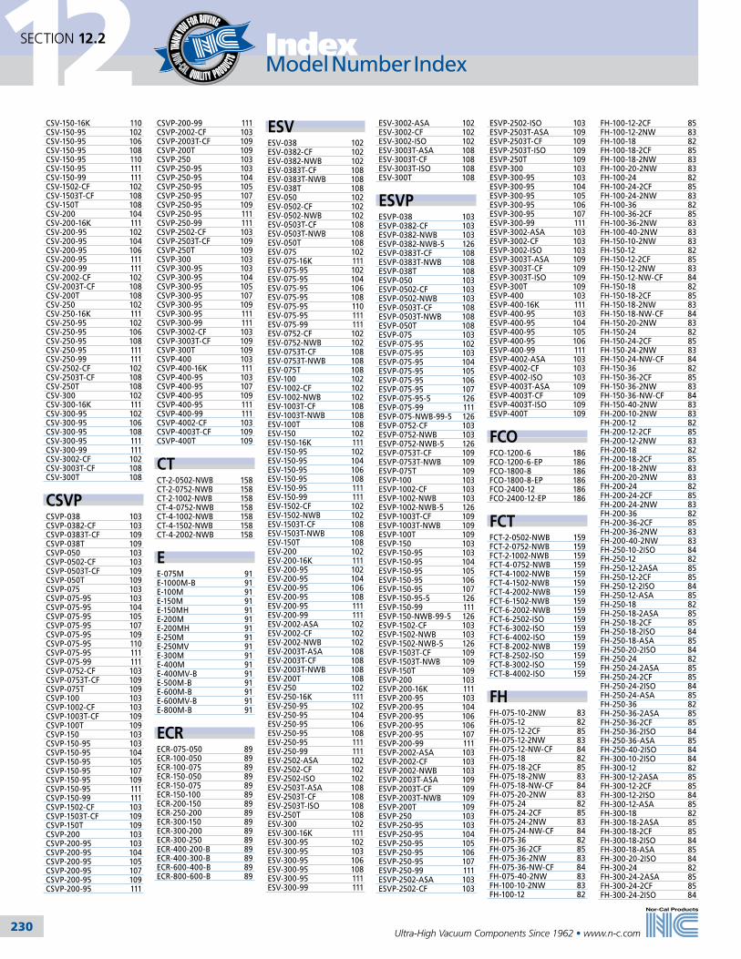
230
12SECTION 12.2 Index
Ultra-High Vacuum Components Since 1962 • www.n-c.com
CSV-150-16K 110CSV-150-95 102CSV-150-95 106CSV-150-95 108CSV-150-95 110CSV-150-95 111CSV-150-99 111CSV-1502-CF 102CSV-1503T-CF 108CSV-150T 108CSV-200 104CSV-200-16K 111CSV-200-95 102CSV-200-95 104CSV-200-95 106CSV-200-95 111CSV-200-99 111CSV-2002-CF 102CSV-2003T-CF 108CSV-200T 108CSV-250 102CSV-250-16K 111CSV-250-95 102CSV-250-95 106CSV-250-95 108CSV-250-95 111CSV-250-99 111CSV-2502-CF 102CSV-2503T-CF 108CSV-250T 108CSV-300 102CSV-300-16K 111CSV-300-95 102CSV-300-95 106CSV-300-95 108CSV-300-95 111CSV-300-99 111CSV-3002-CF 102CSV-3003T-CF 108CSV-300T 108
CSVPCSVP-038 103CSVP-0382-CF 103CSVP-0383T-CF 109CSVP-038T 109CSVP-050 103CSVP-0502-CF 103CSVP-0503T-CF 109CSVP-050T 109CSVP-075 103CSVP-075-95 103CSVP-075-95 104CSVP-075-95 105CSVP-075-95 107CSVP-075-95 109CSVP-075-95 110CSVP-075-95 111CSVP-075-99 111CSVP-0752-CF 103CSVP-0753T-CF 109CSVP-075T 109CSVP-100 103CSVP-1002-CF 103CSVP-1003T-CF 109CSVP-100T 109CSVP-150 103CSVP-150-95 103CSVP-150-95 104CSVP-150-95 105CSVP-150-95 107CSVP-150-95 109CSVP-150-95 111CSVP-150-99 111CSVP-1502-CF 103CSVP-1503T-CF 109CSVP-150T 109CSVP-200 103CSVP-200-95 103CSVP-200-95 104CSVP-200-95 105CSVP-200-95 107CSVP-200-95 109CSVP-200-95 111
CSVP-200-99 111CSVP-2002-CF 103CSVP-2003T-CF 109CSVP-200T 109CSVP-250 103CSVP-250-95 103CSVP-250-95 104CSVP-250-95 105CSVP-250-95 107CSVP-250-95 109CSVP-250-95 111CSVP-250-99 111CSVP-2502-CF 103CSVP-2503T-CF 109CSVP-250T 109CSVP-300 103CSVP-300-95 103CSVP-300-95 104CSVP-300-95 105CSVP-300-95 107CSVP-300-95 109CSVP-300-95 111CSVP-300-99 111CSVP-3002-CF 103CSVP-3003T-CF 109CSVP-300T 109CSVP-400 103CSVP-400-16K 111CSVP-400-95 103CSVP-400-95 107CSVP-400-95 109CSVP-400-95 111CSVP-400-99 111CSVP-4002-CF 103CSVP-4003T-CF 109CSVP-400T 109
CTCT-2-0502-NWB 158CT-2-0752-NWB 158CT-2-1002-NWB 158CT-4-0752-NWB 158CT-4-1002-NWB 158CT-4-1502-NWB 158CT-4-2002-NWB 158
EE-075M 91E-1000M-B 91E-100M 91E-150M 91E-150MH 91E-200M 91E-200MH 91E-250M 91E-250MV 91E-300M 91E-400M 91E-400MV-B 91E-500M-B 91E-600M-B 91E-600MV-B 91E-800M-B 91
ECRECR-075-050 89ECR-100-050 89ECR-100-075 89ECR-150-050 89ECR-150-075 89ECR-150-100 89ECR-200-150 89ECR-250-200 89ECR-300-150 89ECR-300-200 89ECR-300-250 89ECR-400-200-B 89ECR-400-300-B 89ECR-600-400-B 89ECR-800-600-B 89
ESVESV-038 102ESV-0382-CF 102ESV-0382-NWB 102ESV-0383T-CF 108ESV-0383T-NWB 108ESV-038T 108ESV-050 102ESV-0502-CF 102ESV-0502-NWB 102ESV-0503T-CF 108ESV-0503T-NWB 108ESV-050T 108ESV-075 102ESV-075-16K 111ESV-075-95 102ESV-075-95 104ESV-075-95 106ESV-075-95 108ESV-075-95 110ESV-075-95 111ESV-075-99 111ESV-0752-CF 102ESV-0752-NWB 102ESV-0753T-CF 108ESV-0753T-NWB 108ESV-075T 108ESV-100 102ESV-1002-CF 102ESV-1002-NWB 102ESV-1003T-CF 108ESV-1003T-NWB 108ESV-100T 108ESV-150 102ESV-150-16K 111ESV-150-95 102ESV-150-95 104ESV-150-95 106ESV-150-95 108ESV-150-95 111ESV-150-99 111ESV-1502-CF 102ESV-1502-NWB 102ESV-1503T-CF 108ESV-1503T-NWB 108ESV-150T 108ESV-200 102ESV-200-16K 111ESV-200-95 102ESV-200-95 104ESV-200-95 106ESV-200-95 108ESV-200-95 111ESV-200-99 111ESV-2002-ASA 102ESV-2002-CF 102ESV-2002-NWB 102ESV-2003T-ASA 108ESV-2003T-CF 108ESV-2003T-NWB 108ESV-200T 108ESV-250 102ESV-250-16K 111ESV-250-95 102ESV-250-95 104ESV-250-95 106ESV-250-95 108ESV-250-95 111ESV-250-99 111ESV-2502-ASA 102ESV-2502-CF 102ESV-2502-ISO 102ESV-2503T-ASA 108ESV-2503T-CF 108ESV-2503T-ISO 108ESV-250T 108ESV-300 102ESV-300-16K 111ESV-300-95 102ESV-300-95 103ESV-300-95 106ESV-300-95 108ESV-300-95 111ESV-300-99 111
ESV-3002-ASA 102ESV-3002-CF 102ESV-3002-ISO 102ESV-3003T-ASA 108ESV-3003T-CF 108ESV-3003T-ISO 108ESV-300T 108
ESVPESVP-038 103ESVP-0382-CF 103ESVP-0382-NWB 103ESVP-0382-NWB-5 126ESVP-0383T-CF 108ESVP-0383T-NWB 108ESVP-038T 108ESVP-050 103ESVP-0502-CF 103ESVP-0502-NWB 103ESVP-0503T-CF 108ESVP-0503T-NWB 108ESVP-050T 108ESVP-075 103ESVP-075-95 102ESVP-075-95 103ESVP-075-95 104ESVP-075-95 105ESVP-075-95 106ESVP-075-95 107ESVP-075-95-5 126ESVP-075-99 111ESVP-075-NWB-99-5 126ESVP-0752-CF 103ESVP-0752-NWB 103ESVP-0752-NWB-5 126ESVP-0753T-CF 109ESVP-0753T-NWB 109ESVP-075T 109ESVP-100 103ESVP-1002-CF 103ESVP-1002-NWB 103ESVP-1002-NWB-5 126ESVP-1003T-CF 109ESVP-1003T-NWB 109ESVP-100T 109ESVP-150 103ESVP-150-95 103ESVP-150-95 104ESVP-150-95 105ESVP-150-95 106ESVP-150-95 107ESVP-150-95-5 126ESVP-150-99 111ESVP-150-NWB-99-5 126ESVP-1502-CF 103ESVP-1502-NWB 103ESVP-1502-NWB-5 126ESVP-1503T-CF 109ESVP-1503T-NWB 109ESVP-150T 109ESVP-200 103ESVP-200-16K 111ESVP-200-95 103ESVP-200-95 104ESVP-200-95 106ESVP-200-95 106ESVP-200-95 107ESVP-200-99 111ESVP-2002-ASA 103ESVP-2002-CF 103ESVP-2002-NWB 103ESVP-2003T-ASA 109ESVP-2003T-CF 109ESVP-2003T-NWB 109ESVP-200T 109ESVP-250 103ESVP-250-95 103ESVP-250-95 104ESVP-250-95 105ESVP-250-95 106ESVP-250-95 107ESVP-250-99 111ESVP-2502-ASA 103ESVP-2502-CF 103
ESVP-2502-ISO 103ESVP-2503T-ASA 109ESVP-2503T-CF 109ESVP-2503T-ISO 109ESVP-250T 109ESVP-300 103ESVP-300-95 103ESVP-300-95 104ESVP-300-95 105ESVP-300-95 106ESVP-300-95 107ESVP-300-99 111ESVP-3002-ASA 103ESVP-3002-CF 103ESVP-3002-ISO 103ESVP-3003T-ASA 109ESVP-3003T-CF 109ESVP-3003T-ISO 109ESVP-300T 109ESVP-400 103ESVP-400-16K 111ESVP-400-95 103ESVP-400-95 104ESVP-400-95 105ESVP-400-95 106ESVP-400-99 111ESVP-4002-ASA 103ESVP-4002-CF 103ESVP-4002-ISO 103ESVP-4003T-ASA 109ESVP-4003T-CF 109ESVP-4003T-ISO 109ESVP-400T 109
FCOFCO-1200-6 186FCO-1200-6-EP 186FCO-1800-8 186FCO-1800-8-EP 186FCO-2400-12 186FCO-2400-12-EP 186
FCTFCT-2-0502-NWB 159FCT-2-0752-NWB 159FCT-2-1002-NWB 159FCT-4-0752-NWB 159FCT-4-1002-NWB 159FCT-4-1502-NWB 159FCT-4-2002-NWB 159FCT-6-1502-NWB 159FCT-6-2002-NWB 159FCT-6-2502-ISO 159FCT-6-3002-ISO 159FCT-6-4002-ISO 159FCT-8-2002-NWB 159FCT-8-2502-ISO 159FCT-8-3002-ISO 159FCT-8-4002-ISO 159
FHFH-075-10-2NW 83FH-075-12 82FH-075-12-2CF 85FH-075-12-2NW 83FH-075-12-NW-CF 84FH-075-18 82FH-075-18-2CF 85FH-075-18-2NW 83FH-075-18-NW-CF 84FH-075-20-2NW 83FH-075-24 82FH-075-24-2CF 85FH-075-24-2NW 83FH-075-24-NW-CF 84FH-075-36 82FH-075-36-2CF 85FH-075-36-2NW 83FH-075-36-NW-CF 84FH-075-40-2NW 83FH-100-10-2NW 83FH-100-12 82
FH-100-12-2CF 85FH-100-12-2NW 83FH-100-18 82FH-100-18-2CF 85FH-100-18-2NW 83FH-100-20-2NW 83FH-100-24 82FH-100-24-2CF 85FH-100-24-2NW 83FH-100-36 82FH-100-36-2CF 85FH-100-36-2NW 83FH-100-40-2NW 83FH-150-10-2NW 83FH-150-12 82FH-150-12-2CF 85FH-150-12-2NW 83FH-150-12-NW-CF 84FH-150-18 82FH-150-18-2CF 85FH-150-18-2NW 83FH-150-18-NW-CF 84FH-150-20-2NW 83FH-150-24 82FH-150-24-2CF 85FH-150-24-2NW 83FH-150-24-NW-CF 84FH-150-36 82FH-150-36-2CF 85FH-150-36-2NW 83FH-150-36-NW-CF 84FH-150-40-2NW 83FH-200-10-2NW 83FH-200-12 82FH-200-12-2CF 85FH-200-12-2NW 83FH-200-18 82FH-200-18-2CF 85FH-200-18-2NW 83FH-200-20-2NW 83FH-200-24 82FH-200-24-2CF 85FH-200-24-2NW 83FH-200-36 82FH-200-36-2CF 85FH-200-36-2NW 83FH-200-40-2NW 83FH-250-10-2ISO 84FH-250-12 82FH-250-12-2ASA 85FH-250-12-2CF 85FH-250-12-2ISO 84FH-250-12-ASA 85FH-250-18 82FH-250-18-2ASA 85FH-250-18-2CF 85FH-250-18-2ISO 84FH-250-18-ASA 85FH-250-20-2ISO 84FH-250-24 82FH-250-24-2ASA 85FH-250-24-2CF 85FH-250-24-2ISO 84FH-250-24-ASA 85FH-250-36 82FH-250-36-2ASA 85FH-250-36-2CF 85FH-250-36-2ISO 84FH-250-36-ASA 85FH-250-40-2ISO 84FH-300-10-2ISO 84FH-300-12 82FH-300-12-2ASA 85FH-300-12-2CF 85FH-300-12-2ISO 84FH-300-12-ASA 85FH-300-18 82FH-300-18-2ASA 85FH-300-18-2CF 85FH-300-18-2ISO 84FH-300-18-ASA 85FH-300-20-2ISO 84FH-300-24 82FH-300-24-2ASA 85FH-300-24-2CF 85FH-300-24-2ISO 84
Model Number Index Model Number Index

231
12SECTION 12.2Index
Ultra-High Vacuum Components Since 1962 • www.n-c.com
FH-300-24-ASA 85FH-300-36 82FH-300-36-2ASA 85FH-300-36-2CF 85FH-300-36-2ISO 84FH-300-36-ASA 85FH-300-40-2ISO 84FH-400-10-2lSO 84FH-400-12 82FH-400-12-2ASA 85FH-400-12-2CF 85FH-400-12-2lSO 84FH-400-12-ASA 85FH-400-18 82FH-400-18-2ASA 85FH-400-18-2CF 85FH-400-18-2ISO 84FH-400-18-ASA 85FH-400-20-2ISO 84FH-400-24 82FH-400-24-2ASA 85FH-400-24-2CF 85FH-400-24-2ISO 84FH-400-24-ASA 85FH-400-36 82FH-400-36-2ASA 85FH-400-36-2CF 85FH-400-36-2ISO 84FH-400-36-ASA 85FH-400-40-2ISO 84
FHBFHB-075-12-2CF 86FHB-075-12-2NW 86FHB-075-18-2CF 86FHB-075-18-2NW 86FHB-075-20-2NW 86FHB-075-24-2CF 86FHB-075-24-2NW 86FHB-075-36-2CF 86FHB-075-36-2NW 86FHB-075-40-2NW 86FHB-100-12-2CF 86FHB-100-12-2NW 86FHB-100-18-2CF 86FHB-100-18-2NW 86FHB-100-20-2NW 86FHB-100-24-2CF 86FHB-100-24-2NW 86FHB-100-36-2CF 86FHB-100-36-2NW 86FHB-100-40-2NW 86FHB-150-12-2CF 86FHB-150-12-2NW 86FHB-150-18-2CF 86FHB-150-18-2NW 86FHB-150-20-2NW 86FHB-150-24-2CF 86FHB-150-24-2NW 86FHB-150-36-2CF 86FHB-150-36-2NW 86FHB-150-40-2NW 86FHB-200-12-2CF 86FHB-200-12-2NW 86FHB-200-18-2CF 86FHB-200-18-2NW 86FHB-200-20-2NW 86FHB-200-24-2CF 86FHB-200-24-2NW 86FHB-200-36-2CF 86FHB-200-36-2NW 86FHB-200-40-2NW 86
FTFT-2-CS 166FT-2-SS 166FT-4-CP 166FT-4-CS 166FT-4-HR 166FT-4-HR-240V 166FT-4-MS 166FT-4-OR 166FT-4-SS 166
FT-4.5-CP 166FT-4.5-OR 166FT-6-CP 166FT-6-CS 166FT-6-HR 166FT-6-HR-240V 166FT-6-MB 166FT-6-MS 166FT-6-OR 166FT-6-PF 166FT-6-PF-L7 166FT-6-PP 166FT-6-SS 166FT-8-CP 166FT-8-CS 166FT-8-HR 166FT-8-HR-240V 166FT-8-MS 166FT-8-OR 166FT-8-PF-5 166FT-8-PR 166FT-8-SS 166FT-8-SS-5 166FT-CP-B 166
FTAFTA-2-0502-NWB 158FTA-2-0752-NWB 158FTA-2-1002-NWB 158FTA-4-0752-NWB 158FTA-4-1002-NWB 158FTA-4-1502-NWB 158FTA-4-2002-NWB 158FTA-6-1502-NWB 158FTA-6-2002-NWB 158FTA-6-3002-ISO 158FTA-6-4002-ISO 158FTA-8-2002-NWB 158FTA-8-3002-ISO 158FTA-8-4002-ISO 158
FTMFTM-4-0752-NWB 160FTM-4-1002-NWB 160FTM-4-2-NWB 160FTM-6-1502-NWB 160FTM-6-2002-NWB 160FTM-8-2002-NWB 160FTM-8-2502-ISO 160FTM-8-3002-ISO 160FTM-8-4002-ISO 160
FTMAFTMA-4-0752-NWB 160FTMA-4-1002-NWB 160FTMA-4-1502-NWB 160FTMA-6-1502-NWB 160FTMA-6-2002-NWB 160FTMA-8-2002-NWB 160FTMA-8-2502-ISO 160FTMA-8-3002-ISO 160FTMA-8-4002-ISO 160
FTMSFTMS-4-0752-NWB 160FTMS-4-1002-NWB 160FTMS-4-1502-NWB 160FTMS-6-1502-NWB 160FTMS-6-2002-NWB 160FTMS-8-2002-NWB 160FTMS-8-2502-ISO 160FTMS-8-3002-ISO 160FTMS-8-4002-ISO 160
FTNFTN-4-0752-NWB 164FTN-4-1002-NWB 164FTN-4-1502-NWB 164FTN-6-1502-NWB 164
FTN-6-2002-NWB 164FTN-8-1502-NWB 164FTN-8-2002-NWB 164
FTNAFTNA-4-0752-NWB 164FTNA-4-1002-NWB 164FTNA-4-1502-NWB 164FTNA-6-1502-NWB 164FTNA-6-2002-NWB 164FTNA-8-1502-NWB 164FTNA-8-2002-NWB 164
FTOMEFTOME-25-HP 165FTOME-25-HP-F 165FTOME-25-S 165FTOME-25-S-F 165FTOME-40-C2 165FTOME-40-C2-F 165FTOME-40-S 165FTOME-40-S-F 165
FTPAFTPA-6-1502-NWB 161FTPA-6-2002-NWB 161FTPA-8-1502-NWB 161FTPA-8-2002-NWB 161FTPA-8-3002-ISO 161FTPA-8-4002-ISO 161
FTPSFTPS-6-1502-NWB 161FTPS-6-2002-NWB 161FTPS-8-1502-NWB 161FTPS-8-2002-NWB 161FTPS-8-3002-ISO 161FTPS-8-4002-ISO 161
FTT1AFTT1A-8-3002-ISO 162FTT1A-8-4002-ISO 162
FTT1SFTT1S-8-3002-ISO 162FTT1S-8-4002-ISO 162
FTT2AFTT2A-8-3002-ISO 162FTT2A-8-4002-ISO 162
FTT2SFTT2S-8-3002-ISO 162FTT2S-8-4002-ISO 162
FTT3AFTT3A-8-3002-ISO 162FTT3A-8-4002-ISO 162
FTT3SFTT3S-8-3002-ISO 162FTT3S-8-4002-ISO 162
FTWFTW-4.5-OR 165FTW-QD 166
FTWAFTWA-4.5-1502-NWB 163FTWA-4.5-2002-NWB 163
FTWA-6-1502-NWB 163FTWA-6-2002-NWB 163FTWA-6-2502-ISO 163FTWA-6-3002-ISO 163FTWA-8-2002-NWB 163FTWA-8-2502-ISO 163FTWA-8-3002-ISO 163FTWA-8-4002-ISO 163
FTWSFTWS-4.5-1502-NWB 163FTWS-4.5-2002-NWB 163FTWS-6-1502-NWB 163FTWS-6-2002-NWB 163FTWS-6-2502-ISO 163FTWS-6-3002-ISO 163FTWS-8-2002-NWB 163FTWS-8-2502-ISO 163FTWS-8-3002-ISO 163FTWS-8-4002-ISO 163
GG-1000 55G-1000 60G-1000-SP 55G-1000V 55G-1000V 60G-10W-075 93G-10W-100 93G-10W-1000-B 93G-10W-150 93G-10W-200 93G-10W-250 93G-10W-250V 93G-10W-300-B 93G-10W-400-B 93G-10W-400V-B 93G-10W-500-B 93G-10W-600-B 93G-10W-600V-B 93G-10W-800-B 93G-11W-075 93G-11W-100 93G-11W-1000-B 93G-11W-150 93G-11W-200 93G-11W-250 93G-11W-250V 93G-11W-300-B 93G-11W-400-B 93G-11W-400V-B 93G-11W-500-B 93G-11W-600-B 93G-11W-600V-B 93G-11W-800-B 93G-1200 55G-1325 56G-1325 60G-1325V 56G-1325V 60G-133 49G-133 60G-133-SP 49G-133V 49G-133V 60G-1400 56G-1400V 56G-1450 57G-1650 57G-1650V 57G-212 50G-212 60G-212V 50G-212V 60G-275 51G-275 60G-275-SP 51G-275V 51G-275V 60G-2KL-075 90G-2KL-100 90G-2KL-100-316L 90G-2KL-100HW 90
G-2KL-150 90G-2KL-150-316L 90G-2KL-150HW 90G-2KL-200 90G-2KL-200-316L 90G-2KL-200HW 90G-2KL-250 90G-2KL-300 90G-2KL-300-316L 90G-2KL-400 90G-2KL-400-316L 90G-2KL-400HW 90G-2W-050 89G-2W-075 89G-2W-100 89G-2W-150 89G-2W-200 89G-2W-250 89G-2W-300 89G-2W-400 89G-2W-450 89G-2W-600 89G-2W-800 89G-2WC-050 91G-2WC-075 91G-2WC-075H 91G-2WC-100 91G-2WC-100-316L 91G-2WC-1000-B 91G-2WC-100H 91G-2WC-100H-316L 91G-2WC-100HW 91G-2WC-150 91G-2WC-150-316L 91G-2WC-150H 91G-2WC-150H-316L 91G-2WC-150HL 91G-2WC-150HW 91G-2WC-200 91G-2WC-200-316L 91G-2WC-200H 91G-2WC-200H-316L 91G-2WC-200HL 91G-2WC-250 91G-2WC-250-316L 91G-2WC-250H 91G-2WC-300 91G-2WC-300-316L 91G-2WC-300H 91G-2WC-400 91G-2WC-400-316L 91G-2WC-400H 91G-2WC-600-B 91G-2WC-800-B 91G-2WK-050 90G-2WK-075 90G-2WK-075T 90G-2WK-100 90G-2WK-1000-B 90G-2WK-100-316L 90G-2WK-150 90G-2WK-150-316L 90G-2WK-200 90G-2WK-200-316L 90G-2WK-250 90G-2WK-250-316L 90G-2WK-300 90G-2WK-300-316L 90G-2WK-400 90G-2WK-400-316L 90G-2WK-600-B 90G-2WK-800-B 90G-2WU-050 90G-2WU-075 90G-2WU-100 90G-2WU-150 90G-2WU-200 90G-338 52G-338 60G-338-SP 52G-338V 52G-338V 60G-450 52G-450 60G-450-SP 52G-450V 52
G-450V 60G-462 53G-462 60G-462V 53G-462V 60G-600 53G-600 60G-600-SP 53G-600V 53G-600V 60G-675 54G-675 60G-675V 54G-675V 60G-7W-050 92G-7W-075 92G-7W-075HW 92G-7W-075T 92G-7W-100 92G-7W-1000-B 92G-7W-150 92G-7W-150H 92G-7W-200 92G-7W-200H 92G-7W-250 92G-7W-250V 92G-7W-300 92G-7W-400 92G-7W-400V 92G-7W-500-B 92G-7W-600-B 92G-7W-600V-B 92G-7W-800-B 92G-7WR-100-050 92G-7WR-100-075 92G-7WR-150-050 92G-7WR-150-075 92G-7WR-150-100 92G-7WR-200-050 92G-7WR-200-075 92G-7WR-200-100 92G-7WR-200-150 92G-7WR-250-150 92G-7WR-250-200 92G-7WR-300-150 92G-7WR-300-200 92G-7WR-300-250 92G-7WR-400-150-B 92G-7WR-400-200-B 92G-7WR-400-250-B 92G-7WR-400-300-B 92G-7WR-500-400-B 92G-7WR-600-150-B 92G-7WR-600-200-B 92G-7WR-600-250-B 92G-7WR-600-400-B 92G-7WR-600-500-B 92G-7WR-800-600-B 92G-800 54G-800 60G-800-SP 54G-800V 54G-800V 60G-9W-050 93G-9W-075 93G-9W-100 93G-9W-1000-B 93G-9W-150 93G-9W-150H 93G-9W-200 93G-9W-200H 93G-9W-250 93G-9W-250V 93G-9W-300 93G-9W-400 93G-9W-400V 93G-9W-500-B 93G-9W-600-B 93G-9W-600V-B 93G-9W-800-B 93G-9WR-100-050 94G-9WR-100-075 94G-9WR-150-050 94G-9WR-150-075 94G-9WR-150-100 94
Model Number Index

232
12SECTION 12.2 Index
Ultra-High Vacuum Components Since 1962 • www.n-c.com
G-9WR-200-050 94G-9WR-200-075 94G-9WR-200-150 94G-9WR-250-150 94G-9WR-250-200 94G-9WR-300-150 94G-9WR-300-200 94G-9WR-300-250 94G-9WR-400-150-B 94G-9WR-400-200-B 94G-9WR-400-250-B 94G-9WR-400-300-B 94G-9WR-500-400-B 94G-9WR-600-150-B 94G-9WR-600-200-B 94G-9WR-600-250-B 94G-9WR-600-300-B 94G-9WR-600-400-B 94G-9WR-600-500-B 94G-9WR-800-600-B 94
GNCPGNCP-150-S 116GNCP-200-S 116
GNFGNF-102 117GNF-103 117GNF-104 117GNF-105 117GNF-106 117GNF-107 117GNF-152 117GNF-153 117GNF-154 117GNF-155 117GNF-156 117GNF-157 117GNF-202 117GNF-203 117GNF-204 117GNF-205 117GNF-206 117GNF-207 117
GNSFGNSF-150 116GNSF-150 116GNSF-150-K 116GNSF-200 116GNSF-200-K 116GNSF-T 116
GNVGNV-072 114GNV-075-SO-1 115GNV-075-SO-1 119GNV-075-SO-2 115GNV-075-SO-2 119GNV-075-SO-3 115GNV-075-SO-3 119GNV-075-SO-K 115GNV-075-SO-K 119GNV-075-SO-T 115GNV-075-SO-T 119GNV-100-16 120GNV-100-16-S0 120GNV-100-95 120GNV-100-95-S0 120GNV-100-99 120GNV-100-99-S0 120GNV-102 114GNV-150-16 120GNV-150-16-S0 120GNV-150-95 120GNV-150-95-S0 120GNV-150-99 120GNV-150-99-S0 120GNV-152 114GNV-200-16 120
GNV-200-16-S0 120GNV-200-95 120GNV-200-95-S0 120GNV-200-99 120GNV-200-99-S0 120GNV-202 114GNV-300-SO-1 119GNV-300-SO-2 119GNV-300-SO-3 119GNV-300-SO-4 119GNV-300-SO-K 119GNV-300-16 120GNV-300-16-S0 120GNV-300-95 120GNV-300-95-S0 120GNV-300-99 120GNV-300-99-S0 120GNV-400-16 120GNV-400-16-S0 120GNV-400-95 120GNV-400-95-S0 120GNV-400-99 120GNV-400-99-S0 120
GNVSGNVS-072-NWB 118GNVS-072-NWB-SO 118GNVS-102-NWB 118GNVS-102-NWB-SO 118GNVS-152-NWB 118GNVS-152-NWB-SO 118GNVS-202-NWB 118GNVS-202-NWB-SO 118GNVS-302-ISO 118GNVS-302-ISO-SO 118GNVS-402-ISO 118GNVS-402-ISO-SO 118
GNVSAIGNVSAI-072-NWB 118GNVSAI-072-NWB-SO 118GNVSAI-102-NWB 118GNVSAI-102-NWB-SO 118GNVSAI-152-NWB 118GNVSAI-152-NWB-SO 118GNVSAI-202-NWB 118GNVSAI-202-NWB-SO 118GNVSAI-302-ISO 118GNVSAI-302-ISO-SO 118GNVSAI-402-ISO 118GNVSAI-402-ISO-SO 118
GVGV-0622-CF 124 GV-0622-NW 124GV-10002-ASA 124GV-10002-CF 124GV-10002-ISO 124GV-10002-ISO-OF 124GV-12002-ASA 124GV-12002-CF 124GV-12002-ISO 124GV-12002-ISO-OF 124GV-1502-CF 124GV-1502-NW 124GV-2002-CF 124GV-2002-NW 124GV-2502-ASA 124GV-2502-CF 124GV-2502-ISO 124GV-2502-ISO-OF 124GV-3002-ASA 124GV-3002-CF 124GV-3002-ISO 124GV-3002-ISO-OF 124GV-4002-ASA 124GV-4002-CF 124GV-4002-ISO 124GV-4002-ISO-OF 124GV-6002-ASA 124GV-6002-CF 124GV-6002-ISO 124
GV-6002-ISO-OF 124GV-8002-ASA 124GV-8002-CF 124GV-8002-ISO 124GV-8002-ISO-OF 124
GVMGVM-0622-CF 124GVM-10002-CF 124GVM-12002-CF 124GVM-1502-CF 124GVM-2002-CF 124GVM-2502-CF 124GVM-3002-CF 124GVM-4002-CF 124GVM-6002-CF 124GVM-8002-CF 124
GVMPGVMP-0622-CF 125GVMP-10002-CF 125GVMP-12002-CF 125GVMP-1502-CF 125GVMP-2002-CF 125GVMP-2502-CF 125GVMP-3002-CF 125GVMP-4002-CF 125GVMP-6002-CF 125GVMP-8002-CF 125
GVPGVP-0622-CF 125GVP-0622-NW 125GVP-10002-ASA 125GVP-10002-CF 125GVP-10002-ISO 125GVP-10002-ISO-OF 125GVP-12002-ASA 125GVP-12002-CF 125GVP-12002-ISO 125GVP-12002-ISO-OF 125GVP-1502-CF 125GVP-1502-NW 125GVP-2002-CF 125GVP-2002-NW 125GVP-2502-ASA 125GVP-2502-CF 125GVP-2502-ISO 125GVP-2502-ISO-OF 125GVP-3002-ASA 125GVP-3002-CF 125GVP-3002-ISO 125GVP-3002-ISO-OF 125GVP-4002-ASA 125GVP-4002-CF 125GVP-4002-ISO 125GVP-4002-ISO-OF 125GVP-6002-ASA 125GVP-6002-CF 125GVP-6002-ISO 125GVP-6002-ISO-OF 125GVP-8002-ASA 125GVP-8002-CF 125GVP-8002-ISO 125GVP-8002-ISO-OF 125
HCHC-025-12-1 176HC-025-12-TC-1 176HC-025-18-1 176HC-025-18-TC-1 176HC-025-24-1 176HC-025-24-TC-1 176HC-025-2WC-1-1 176HC-025-2WC-5-1 176HC-025-36-1 176HC-025-36-TC-1 176HC-025-6-1 176HC-025-6-TC-1 176HC-025-9-1 176
HC-025-9-TC-1 176HC-050-12-1 176HC-050-12-TC-1 176HC-050-18-1 176HC-050-18-TC-1 176HC-050-24-1 176HC-050-24-TC-1 176HC-050-36-1 176HC-050-36-TC-1 176HC-050-6-1 176HC-050-6-TC-1 176HC-050-9-1 176HC-050-9-TC-1 176HC-150-12-3 172HC-150-12T-3 172HC-150-18-3 172HC-150-2-3 172HC-150-24-3 172HC-150-24T-3 172HC-150-2T-3 172HC-150-3-3 172HC-150-30-3 172HC-150-36-3 172HC-150-36T-3 172HC-150-3T-3 172HC-150-4-3 172HC-150-4T-3 172HC-150-5-3 172HC-150-5T-3 172HC-150-6-3 172HC-150-6T-3 172HC-200-10T-3 172HC-200-11T-3 172HC-200-12-3 172HC-200-12T-3 172HC-200-150-3 175HC-200-18-3 172HC-200-2-3 172HC-200-24-3 172HC-200-24T-3 172HC-200-2T-3 172HC-200-3-3 172HC-200-30-3 172HC-200-36-3 172HC-200-36T-3 172HC-200-3T-3 172HC-200-4-3 172HC-200-4T-3 172HC-200-5-3 172HC-200-5T-3 172HC-200-6-3 172HC-200-6T-3 172HC-200-7T-3 172HC-200-8T-3 172HC-200-9T-3 172HC-2KL-150HW-3 174HC-2KL-200HW-3 174HC-2KL-300HW-3 174HC-2KL-400HW-3 174HC-2WC-150-3 174HC-2WC-150HW-3 174HC-2WC-200-3 174HC-2WC-200HW-3 174HC-2WC-300-3 174HC-2WC-300HW-3 174HC-2WC-400-3 174HC-2WC-400HW-3 174HC-2WK-150-3 174HC-2WK-200-3 174HC-2WK-300-3 174HC-2WK-400-3 174HC-300-12-3 173HC-300-12T-3 173HC-300-18-3 173HC-300-2-3 173HC-300-200-3 175HC-300-24-3 173HC-300-24T-3 173HC-300-2T-3 173HC-300-3-3 173HC-300-30-3 173HC-300-36-3 173HC-300-36T-3 173HC-300-3T-3 173HC-300-4-3 173HC-300-4T-3 173
HC-300-5-3 173HC-300-5T-3 173HC-300-6-3 173HC-300-6T-3 173HC-400-10T-3 173HC-400-11T-3 173HC-400-12-3 173HC-400-12T-3 173HC-400-18-3 173HC-400-2-3 173HC-400-200-3 175HC-400-24-3 173HC-400-24T-3 173HC-400-2T-3 173HC-400-3-3 173HC-400-30-3 173HC-400-300-3 175HC-400-36-3 173HC-400-36T-3 173HC-400-3T-3 173HC-400-4-3 173HC-400-4T-3 173HC-400-5-3 173HC-400-5T-3 173HC-400-6-3 173HC-400-6T-3 173HC-400-7T-3 173HC-400-8T-3 173HC-400-9T-3 173HC-7W-150-3 175HC-7W-200-3 175HC-7W-300-3 175HC-7W-400-3 175HC-FLG-150-NW-3 175HC-FLG-200-NW-3 175HC-FLG-300-ISO-3 175HC-FLG-400-ISO-3 175HC-PCRD-6 178HC-PCRD-6-3 178HC-PCRD-6-3B 178HC-PCRD-CPC-6-2 178HC-PCRD-CPC-6-3 178HC-PCRD-CPC-6-3B 178HC-PLG 178HC-PLG-2C 178HC-PLG-3C 178HC-PLG-3P 178HC-SD3S-1-1 178HC-SD3S-1-2 178HC-SD3C-2-1E 178HC-SDC15-1-1 178HC-SDC15-1-2 178HC-SDC15-2-1 178HC-SDC15-2-2 178HC-TBV-(All models) 138HC-TC-CRD-K-10 178HC-TC-CRD-K-25 178HC-TC-CRD-K-6 178HC-TC-K-1 178HC-TC-K-8 178VHC-TC-K-KAP-8 178
HC2HC2-150-12-3 173HC2-150-12T-3 173HC2-150-18-3 173HC2-150-2-3 173HC2-150-24-3 173HC2-150-24T-3 173HC2-150-2T-3 173HC2-150-3-3 173HC2-150-30-3 173HC2-150-36-3 173HC2-150-36T-3 173HC2-150-3T-3 173HC2-150-4-3 173HC2-150-4T-3 173HC2-150-5-3 173HC2-150-5T-3 173HC2-150-6-3 173HC2-150-6T-3 173HC2-200-10T-3 173HC2-200-11T-3 173HC2-200-12-3 173
HC2-200-12T-3 173HC2-200-150-3 173HC2-200-18-3 173HC2-200-2-3 173HC2-200-24-3 173HC2-200-24T-3 173HC2-200-2T-3 173HC2-200-3-3 173HC2-200-30-3 173HC2-200-36-3 173HC2-200-36T-3 173HC2-200-3T-3 173HC2-200-4-3 173HC2-200-4T-3 173HC2-200-5-3 173HC2-200-5T-3 173HC2-200-6-3 173HC2-200-6T-3 173HC2-200-7T-3 173HC2-200-8T-3 173HC2-200-9T-3 173HC2-2KL-150HW-3 174HC2-2KL-200HW-3 174HC2-2KL-300HW-3 174HC2-2KL-400HW-3 174HC2-2WC-150-3 174HC2-2WC-150HW-3 174HC2-2WC-200-3 174HC2-2WC-200HW-3 174HC2-2WC-300-3 174HC2-2WC-300HW-3 174HC2-2WC-400-3 174HC2-2WC-400HW-3 174HC2-2WK-150-3 174HC2-2WK-200-3 174HC2-2WK-300-3 174HC2-2WK-400-3 174HC2-300-12-3 173HC2-300-12T-3 173HC2-300-18-3 173HC2-300-2-3 173HC2-300-200-3 175HC2-300-24-3 173HC2-300-24T-3 173HC2-300-2T-3 173HC2-300-3-3 173HC2-300-30-3 173HC2-300-36-3 173HC2-300-36T-3 173HC2-300-3T-3 173HC2-300-4-3 173HC2-300-4T-3 173HC2-300-5-3 173HC2-300-5T-3 173HC2-300-6-3 173HC2-300-6T-3 173HC2-400-10T-3 173HC2-400-11T-3 173HC2-400-12-3 173HC2-400-12T-3 173HC2-400-18-3 173HC2-400-2-3 173HC2-400-200-3 175HC2-400-24-3 173HC2-400-24T-3 173HC2-400-2T-3 173HC2-400-3-3 173HC2-400-30-3 173HC2-400-300-3 175HC2-400-36-3 173HC2-400-36T-3 173HC2-400-3T-3 173HC2-400-4-3 173HC2-400-4T-3 173HC2-400-5-3 173HC2-400-5T-3 173HC2-400-6-3 173HC2-400-6T-3 173HC2-400-7T-3 173HC2-400-8T-3 173HC2-400-9T-3 173HC2-7W-150-3 175HC2-7W-200-3 175HC2-7W-300-3 175
Model Number Index Model Number Index

233
12SECTION 12.2Index
Ultra-High Vacuum Components Since 1962 • www.n-c.com
HC2-7W-400-3 175HC2-FLG-150-NW-3 175HC2-FLG-200-NW-3 175HC2-FLG-300-ISO-3 175HC2-FLG-400-ISO-3 175
HCFHCF-150-1 215HCF-150-1W 215HCF-NW-40-1 215HCF-NW-40-1W 215HCF-NW-50-1 215HCF-NW-50-1W 215
HCSHCS-025-8-1 177HCS-025-11-1 177HCS-025-15-1 177HCS-025-19-1 177HCS-025-24-1 177HCS-025-31-1 177HCS-025-40-1 177HCS-025-50-1 177HCS-025-60-1 177HCS-050-7-1* 177HCS-050-10-1* 177HCS-050-14-1 177 HCS-050-19-1 177HCS-050-25-1 177HCS-025-31-1 177HCS-050-39-1 177HCS-050-50-1 177HCS-050-60-1 177HIS-025-18 177HIS-025-2WC-M 177HIS-025-7W-M 177HIS-025-VCR 177HIS-038-18 177HIS-038-2WC-M 177HIS-038-7W-M 177HIS-038-VCR 177HIS-050-18 177HIS-050-2WC-M 177HIS-050-7W-M 177HIS-050-VCR 177
HIHI-025-18T 176HI-025-2WC-M 176HI-025-7W-M 176HI-050-18T 176HI-050-2WC-M 176HI-050-7W-M 176HI-FLG-100-NW-1 175HI-FLG-150-NW-1 175HI-FLG-200-NW-1 175HI-FLG-300-ISO-1 175HI-FLG-400-ISO-1 175HI-GNV-100 120HI-GNV-150 120HI-GNV-200 120
HI2HI2-FLG-150-NW-1 175HI2-FLG-200-NW-1 175HI2-FLG-300-ISO-1 175HI2-FLG-400-ISO-1 175
HLMHLM-275-2 205HLM-275-3 205HLM-275-4 205
HTHT-CRD-10 177HT-CRD-6 177HT-CRD-6-2P 178HT-CRD-6-3 177
HT-CRD-6-3P 178HT-GN-100-120-1 120HT-GN-100-150-1 120HT-GN-150-120-1 120HT-GN-150-150-1 120HT-GN-200-120-1 120HT-GN-200-150-1 120HT-GN-PCD-12 120HT-GN-PCD-6 120HT-TBV-(All models) 138
HMHVI-075-10 213HVI-150-15 213HVI-150-3 213HVI-NW-16-10 213HVI-NW-40-15 213HVI-NW-40-3 213
IFTIFT-075-8P 215IFT-150-8P 215IFT-NW-16-8P 215IFT-NW-25-8P 215IFT-NW-40-8P 215IFT-NW-50-8P 215IFT-VC 215
ILVILV-038 106ILV-0382-CF 106ILV-0382-NWB 106ILV-050 106ILV-0502-CF 106ILV-0502-NWB 106ILV-075 106ILV-0752-CF 106ILV-0752-NWB 106ILV-100 106ILV-1002-CF 106ILV-1002-NWB 106ILV-150 106ILV-1502-CF 106ILV-1502-NWB 106ILV-200 106ILV-2002-ASA 106ILV-2002-CF 106ILV-2002-NWB 106ILV-250 106ILV-2502-ASA 106ILV-2502-CF 106ILV-2502-ISO 106ILV-300 106ILV-3002-ASA 106ILV-3002-CF 106ILV-3002-ISO 106
ILVPILVP-038 107ILVP-0382-CF 107ILVP-0382-NWB 107ILVP-050 107ILVP-0502-CF 107ILVP-0502-NWB 107ILVP-075 107ILVP-0752-CF 107ILVP-0752-NWB 107ILVP-100 107ILVP-1002-CF 107ILVP-1002-NWB 107ILVP-150 107ILVP-1502-CF 107ILVP-1502-NWB 107ILVP-200 107ILVP-2002-ASA 107ILVP-2002-CF 107ILVP-2002-NWB 107ILVP-250 107ILVP-2502-ASA 107ILVP-2502-CF 107ILVP-2502-ISO 107
ILVP-300 107ILVP-3002-ASA 107ILVP-3002-CF 107ILVP-3002-ISO 107ILVP-400 107ILVP-4002-ASA 107ILVP-4002-CF 107ILVP-4002-ISO 107
IPVIPV-1000-ISO-250 122IPV-1200-ISO-320 122IPV-1400-JIS-350 122IPV-1600-ISO-400 122IPV-600-ISO-160 122IPV-800-ISO-200 122
IQIQ-CRD-RS232-10 154IQP-BAT-1518 154
ISOISO-100-000-OF 32ISO-100-000N 33ISO-100-400-OF 32ISO-100-400-OF-316L 32ISO-100-400N 33ISO-100-BR 32ISO-100-CR 36ISO-100-CR-AB 35ISO-100-CR-AV 35ISO-100-CR-SV 35ISO-100-CR-SV-16 36ISO-100-CR-SV-316L 35ISO-100-DCP 34ISO-100-MS-A 19ISO-100-OR-B 36ISO-100-OR-V 36ISO-100-RR 32ISO-100-SCP 34ISO-100-SCP-M 34ISO-160-000-OF 32ISO-160-000N 33ISO-160-600-OF 32ISO-160-600N 33ISO-160-BR 32ISO-160-CR 36ISO-160-CR-AB 35ISO-160-CR-AV 35ISO-160-CR-SV 35ISO-160-CR-SV-16 36ISO-160-DCP 34ISO-160-OR-B 36ISO-160-OR-V 36ISO-160-RR 32ISO-160-SCP 34ISO-160-SCP-M 34ISO-200-000-OF 32ISO-200-000N 33ISO-200-800-OF 32ISO-200-800N 33ISO-200-BR 32ISO-200-CR 36ISO-200-CR-AB 35ISO-200-CR-AV 35ISO-200-CR-SV 35ISO-200-DCP 34ISO-200-OR-B 36ISO-200-OR-V 36ISO-200-RR 32ISO-200-SCP 34ISO-200-SCP-M 34ISO-250-000-OF 32ISO-250-000N 33ISO-250-1000-OF 32ISO-250-1000N 33ISO-250-BR 32ISO-250-CR 36ISO-250-CR-AB 35ISO-250-CR-AV 35ISO-250-CR-SV 35ISO-250-DCP 34
ISO-250-OR-B 36ISO-250-OR-V 36ISO-250-RR 32ISO-250-SCP 34ISO-250-SCP-M 34ISO-320-000-OF 32ISO-320-000N 33ISO-320-1200-OF 32ISO-320-1200N 33ISO-320-1275-OF 32ISO-320-1275N 33ISO-320-BR 32ISO-320-CR 36ISO-320-CR-AB 35ISO-320-CR-AV 35ISO-320-CR-SV 35ISO-320-DCP 34ISO-320-OR-B 36ISO-320-OR-V 36ISO-320-RR 32ISO-320-SCP 34ISO-320-SCP-M 34ISO-400-000-OF 32ISO-400-000N 33ISO-400-1600-OF 32ISO-400-1600N 33ISO-400-BR 32ISO-400-CR 36ISO-400-CR-AB 35ISO-400-CR-AV 35ISO-400-CR-SV 35ISO-400-DCP 34ISO-400-OR-B 36ISO-400-OR-V 36ISO-400-RR 32ISO-400-SCP 34ISO-400-SCP-M 34ISO-500-000-OF 32ISO-500-000N 33ISO-500-2000-OF 32ISO-500-2000N 33ISO-500-BR 32ISO-500-CR-AB 35ISO-500-CR-AV 35ISO-500-DCP 34ISO-500-OR-B 36ISO-500-OR-V 36ISO-500-RR 32ISO-500-SCP 34ISO-500-SCP-M 34ISO-63-000-OF 32ISO-63-000N 33ISO-63-0R-B 36ISO-63-0R-V 36ISO-63-250-OF 32ISO-63-250-OF-316L 32ISO-63-250N 33ISO-63-BR 32ISO-63-CR 36ISO-63-CR-AB 35ISO-63-CR-AV 35ISO-63-CR-SV 35ISO-63-CR-SV-16 36ISO-63-CR-SV-316L 35ISO-63-DCP 34ISO-63-MS-A 19ISO-63-RR 32ISO-63-SCP 34ISO-63-SCP-M 34ISO-80-000-OF 32ISO-80-000N 33ISO-80-300-OF 32ISO-80-300-OF-316L 32ISO-80-300N 33ISO-80-BR 32ISO-80-CR 36ISO-80-CR-AB 35ISO-80-CR-AV 35ISO-80-CR-SV 35ISO-80-CR-SV-16 36ISO-80-CR-SV-316L 35ISO-80-DCP 34ISO-80-MS-A 19ISO-80-OR-B 36ISO-80-OR-V 36ISO-80-RR 32
Model Number Index
ISO-80-SCP 34ISO-80-SCP-M 3463
LFTLFT-075-1-025 211LFT-075-1-038 211LFT-150-1-025 211LFT-150-1-025-2MVCR 211LFT-150-1-025-2SW 211LFT-150-1-038 211LFT-150-2-025 211LFT-150-2-025-4MVCR 211LFT-150-2-025-4SW 211LFT-150-2-038 211LFT-NW-16-1-025 211LFT-NW-25-1-025 211LFT-NW-25-1-025-2SW 211LFT-NW-40-1-025 211LFT-NW-40-1-025-2SW 211LFT-NW-40-1-038 211LFT-NW-40-2-025 211LFT-NW-40-2-025-4SW 211LFT-NW-50-1-025 211LFT-NW-50-1-025-2SW 211LFT-NW-50-1-038 211LFT-NW-50-2-025 211LFT-NW-50-2-025-4SW 211
LHLH-075-10-2NW 83LH-075-12-2NW 83LH-075-18-2NW 83LH-075-24-2NW 83LH-075-36-2NW 83LH-100-10-2NW 83LH-100-12-2NW 83LH-100-18-2NW 83LH-100-24-2NW 83LH-100-36-2NW 83LH-150-10-2NW 83LH-150-12-2NW 83LH-150-18-2NW 83LH-150-24-2NW 83LH-150-36-2NW 83LH-200-10-2NW 83LH-200-12-2NW 83LH-200-18-2NW 83LH-200-24-2NW 83LH-200-36-2NW 83
LLLL-275-133 126LL-600-ADV-150-3 198
LMTLMT-133 201LMT-275 201
LNFLNF-075-1-025 212LNF-075-1-038 212LNF-150-1-025 212LNF-150-1-025-2MVCR 212LNF-150-1-025-2SW 212LNF-150-1-038 212LNF-150-2-025 212LNF-150-2-025-4MVCR 212LNF-150-2-025-4SW 212LNF-150-2-038 212LNF-NW-16-1-025 212LNF-NW-25-1-025 212LNF-NW-25-1-025-2SW 212LNF-NW-40-1-025 212LNF-NW-40-1-025-2SW 212LNF-NW-40-1-038 212LNF-NW-40-2-025 212LNF-NW-40-2-025-4SW 212LNF-NW-50-1-025 212
LNF-NW-50-1-025-2SW 212LNF-NW-50-1-038 212LNF-NW-50-2-025 212LNF-NW-50-2-025-4SW 212
MCFMCF-075-1 214MCF-075-1N 214MCF-075-1W 214MCF-150-1 214MCF-150-1N 214MCF-150-1W 214MCF-150-2 214MCF-150-2N 214MCF-150-2W 214MCF-150-3 214MCF-150-3N 214MCF-150-3W 214MCF-150-4 214MCF-150-4N 214MCF-150-4W 214MCF-NW-16-1 214MCF-NW-16-1N 214MCF-NW-16-1W 214MCF-NW-25-1 214MCF-NW-25-1N 214MCF-NW-25-1W 214MCF-NW-40-1 214MCF-NW-40-1N 214MCF-NW-40-1W 214MCF-NW-40-2 214MCF-NW-40-2N 214MCF-NW-40-2W 214MCF-NW-40-3 214MCF-NW-40-3N 214MCF-NW-40-3W 214MCF-NW-40-4 214MCF-NW-40-4N 214MCF-NW-40-4W 214MCF-NW-50-1 214MCF-NW-50-1N 214MCF-NW-50-1W 214MCF-NW-50-2 214MCF-NW-50-2N 214MCF-NW-50-2W 214MCF-NW-50-3 214MCF-NW-50-3N 214MCF-NW-50-3W 214MCF-NW-50-4 214MCF-NW-50-4N 214MCF-NW-50-4W 214MCF-VC 216
MHVMHV-075-1 216MHV-150-1 216MHV-150-2 216MHV-150-3 216MHV-150-4 216MHV-NW-16-1 216MHV-NW-25-1 216MHV-NW-40-1 216MHV-NW-40-2 216MHV-NW-40-3 216MHV-NW-40-4 216MHV-NW-50-1 216MHV-NW-50-2 216MHV-NW-50-3 216MHV-NW-50-4 216
MLRMLR-275-050-24 206MLR-275-050-36 206
MLRCMLRC-275-36 206MLRC-275-42 206MLRC-275-48 206
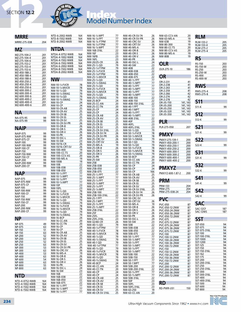
234
12SECTION 12.2 Index
Ultra-High Vacuum Components Since 1962 • www.n-c.com
Model Number Index Model Number Index
MRREMRRE-275-038 204
MZMZ-275-104-2 201MZ-275-104-4 201MZ-275-104-6 201MZ-275-153-2 201MZ-275-153-4 201MZ-275-153-6 201MZ-450-188-2 201MZ-450-188-4 201MZ-450-188-6 201MZ-450-250-2 201MZ-450-250-4 201MZ-450-250-6 201MZ-600-300-2 201MZ-600-300-4 201MZ-600-300-6 201MZ-600-400-2 201MZ-600-400-4 201MZ-600-400-6 201
NANA-075-95 99NA-075-99 99
NAIPNAIP-075 99NAIP-075-NW 99NAIP-075-CF 99NAIP-100 99NAIP-100-NW 99NAIP-100-CF 99NAIP-150 99NAIP-150-NW 99NAIP-150-CF 99NAIP-200 99NAIP-200-NW 99NAIP-200-CF 99
NAPNAP-075 99NAP-075-NW 99NAP-075-CF 99NAP-100 99NAP-100-NW 99NAP-100-CF 99NAP-150 99NAP-150-NW 99NAP-150-CF 99NAP-200 99NAP-200-NW 99NAP-200-CF 99
NPNP-075 49NP-075 63NP-150 51NP-150 63NP-200 52NP-200 63NP-250 52NP-250 63NP-300 53NP-300 63NP-400 53NP-400 63NP-600 54NP-600 63NP-800 55NP-800 63
NTDNTD-4-0752-NWB 164NTD-4-1002-NWB 164NTD-4-1502-NWB 164NTD-6-1502-NWB 164
NTD-6-2002-NWB 164NTD-8-1502-NWB 164NTD-8-2002-NWB 164
NTDANTDA-4-0752-NWB 164NTDA-4-1002-NWB 164NTDA-4-1502-NWB 164NTDA-6-1502-NWB 164NTDA-6-2002-NWB 164NTDA-8-1502-NWB 164NTDA-8-2002-NWB 164
NWNW-10-1/4 FVCR 78NW-10-1/4 MVCR 78NW-10-1/4 QD 79NW-10-1/4 SWAG 79NW-10-3/8 QD 79NW-10-3/8 SWAG 79NW-10-CP 24NW-10-CP 24NW-10-CR-AB 25NW-10-CR-AV 25NW-10-CR-SB 25NW-10-CR-SS 25NW-10-CR-SV 25NW-10-CR-SV-PR 26NW-10-OR-B 26NW-10-OR-S 26NW-10-OR-V 26NW-10-PR 26NW-10-SSC-L 24NW-10-SW 23NW-10/16-CR 26NW-10/16-CRT-SV 26NW-100-400 19NW-100-CC-TS 20NW-100-CCV-AS 20NW-100-MS-A 19NW-100B 19NW-10B 22NW-10B-038 22NW-10B-050 22NW-10-1/4 FPT 77NW-10-1/4 MPT 77NW-10-1/8 FPT 77NW-10-1/8 MPT 77NW-10F 23NW-10FL 23NW-16-1/2 QD 79NW-16-1/4 FVCR 78NW-16-1/4 MVCR 78NW-16-1/4 QD 79NW-16-1/4 SWAG 79NW-16-3/8 FVCR 78NW-16-3/8 MVCR 78NW-16-3/8 QD 79NW-16-3/8 SWAG 79NW-16-BCP 24NW-16-CC-AN 20NW-16-CC-TN 20NW-16-CP 24NW-16-CP 24NW-16-CR-AB 25NW-16-CR-AV 25NW-16-CR-SB 25NW-16-CR-SS 25NW-16-CR-SV 25NW-16-CR-SV-PR 26NW-16-CRC-SV 26NW-16-MS-A 19NW-16-OR-B 26NW-16-OR-S 26NW-16-OR-V 26NW-16-PR 26NW-16-SSC-L 24NW-16-SW 23NW-16B 22NW-16B-038 22NW-16B-050 22NW-16B-075 22NW-16-1/2 FPT 77NW-16-1/2 MPT 77NW-16-1/4 FPT 77
NW-16-1/4 MPT 77NW-16-1/8 FPT 77NW-16-1/8 FTPM 77NW-16-1/4 FTPM 77NW-16-1/8 MPT 77NW-16B-316L 22NW-16F 23NW-16FB 23NW-16FL 23NW-20/25-CR 26NW-25-1/2 QD 79NW-25-1/4 FTPM 79NW-25-1/4 FVCR 78NW-25-1/8 FTPM 79NW-25-1/4 MVCR 78NW-25-1/4 QD 79NW-25-1/4 SWAG 79NW-25-3/4 QD 79NW-25-3/8 FVCR 78NW-25-3/8 MVCR 78NW-25-3/8 QD 79NW-25-3/8 SWAG 79NW-25-BCP 24NW-25-CC-AN 20NW-25-CC-TN 20NW-25-CP 24NW-25-CP 24NW-25-CR-AB 25NW-25-CR-AV 25NW-25-CR-SB 25NW-25-CR-SS 25NW-25-CR-SV 25NW-25-CR-SV-316L 25NW-25-CR-SV-74 26NW-25-CR-SV-PR 26NW-25-CRC-SV 26NW-25-CRT-SV 26NW-25-MS-A 19NW-25-OR-B 26NW-25-OR-S 26NW-25-OR-V 26NW-25-PR 26NW-25-SW 23NW-25B 22NW-25B-038 22NW-25B-050 22NW-25B-075 22NW-25-1/2 FPT 77NW-25-1/2 MPT 77NW-25-1/4 FPT 77NW-25-1/4 MPT 77NW-25-1/8 FPT 77NW-25-1/8 MPT 77NW-25B-100 22NW-25B-100-316L 22NW-25-1 FPT 77NW-25-1 MPT 77NW-25-3/4 FPT 77NW-25-3/4 MPT 77NW-25B-316L 22NW-25F 23NW-25FL 23NW-25FL-316L 23NW-32/40-CR 26NW-40-1/2 QD 79NW-40-1/4 FTPM 77NW-40-1/4 FVCR 78NW-40-1/4 MVCR 78NW-40-1/4 QD 79NW-40-1/4 SWAG 79NW-40-1 QD 79 NW-40-1/8 FTPM 77NW-40-3/4 QD 79NW-40-3/8 FVCR 78NW-40-3/8 MVCR 78NW-40-3/8 QD 79NW-40-3/8 SWAG 79NW-40-BCP 24NW-40-CC-AN 20NW-40-CC-TN 20NW-40-CP 24NW-40-CP 24NW-40-CR-AB 25NW-40-CR-AV 25NW-40-CR-SB 25NW-40-CR-SS 25NW-40-CR-SV 25NW-40-CR-SV-316L 25
NW-40-CR-SV-74 26NW-40-CR-SV-PR 26NW-40-CRC-SV 26NW-40-CRT-SV 26NW-40-MS-A 19NW-40-OR-B 26NW-40-OR-S 26NW-40-OR-V 26NW-40-PR 26NW-40-SSC-L 24NW-40-SW 23NW-40B 22NW-40B-038 22NW-40B-050 22NW-40B-075 22NW-40-1/2 FPT 77NW-40-1/2 MPT 77NW-40-1/4 FPT 77NW-40-1/4 MPT 77NW-40-1/8 FPT 77NW-40-1/8 MPT 77NW-40B-100 22NW-40B-150 22NW-40B-150-316L 22NW-40-1 FPT 77NW-40-1 MPT 77NW-40-3/4 FPT 77NW-40-3/4 MPT 77NW-40B-316L 22NW-40F 23NW-40FL 23NW-40FL-316L 23NW-50-1/2 QD 79NW-50-1/4 FVCR 78NW-50-1/4 MVCR 78NW-50-1/4 SWAG 79NW-50-1 QD 79NW-50-3/4 QD 79NW-50-3/8 FVCR 78NW-50-3/8 MVCR 78NW-50-3/8 SWAG 79NW-50-BCP 24NW-50-CC-AN 20NW-50-CC-TN 20NW-50-CP 24NW-50-CP 24NW-50-CP 166NW-50-CR-AB 25NW-50-CR-AV 25NW-50-CR-SB 25NW-50-CR-SS 25NW-50-CR-SV 25NW-50-CR-SV-316L 25NW-50-CR-SV-74 26NW-50-CR-SV-PR 26NW-50-CRC-SVNW-50-CRT-SV 26NW-50-MS-A 19NW-50-OR-B 26NW-50-OR-S 26NW-50-OR-V 26NW-50-PR 26NW-50-SSC-L 24NW-50-SW 23NW-50B 22NW-50B-038 22NW-50B-050 22NW-50B-075 22NW-50-1/2 FPT 77NW-50-1/2 MPT 77NW-50-1/4 FPT 77NW-50-1/4 MPT 77NW-50-1/8 FPT 77NW-50-1/8 MPT 77NW-50B-100 22NW-50B-150 22NW-50-1 FPT 77NW-50-1 MPT 77NW-50B-200 22NW-50B-200-316L 22NW-50-3/4 FPT 77NW-50-3/4 MPT 77NW-50B-316L 22NW-50F 23NW-50FL 23NW-50FL-316L 23NW-63-250 19NW-63-CC-AN 20
NW-63-CCV-AN 20NW-63-MS-A 19NW-63B 19NW-80-300 19NW-80-CC-TS 20NW-80-CCV-AS 20NW-80-MS-A 19NW-80B 19
OLROLR-275-10 186
OROR-2-231 41OR-2-238 41OR-2-243 41OR-2-259 41OR-2-266 42OR-2-274 42OR-2-278 42OR-JIS-150 141, 143OR-JIS-200 141, 143OR-JIS-250 141, 143OR-JIS-320 141, 143OR-JIS-350 141, 143
PLRPLR-275-050 207
PMXYPMXY-275-139-1 200PMXY-450-200-1 200PMXY-450-250-1 200PMXY-450-250-2 200PMXY-600-300-1 200PMXY-600-300-2 200PMXY-600-400-1 200PMXY-600-400-2 200
PMXYZPMXYZ-600-1.87-2 200
PRMPRM-133 204PRM-275 204PRM-275-038-24 204
PVCPVC-050 87PVC-050-12-2NW 87PVC-050-24-2NW 87PVC-050-36-2NW 87PVC-050-72-2NW 87PVC-075 87PVC-075-12-2NW 87PVC-075-24-2NW 87PVC-075-36-2NW 87PVC-075-72-2NW 87PVC-100 87PVC-100-12-2NW 87PVC-100-24-2NW 87PVC-100-36-2NW 87PVC-100-72-2NW 87PVC-150 87PVC-150-12-2NW 87PVC-150-24-2NW 87PVC-150-36-2NW 87PVC-150-72-2NW 87PVC-200 87PVC-200-12-2NW 87PVC-200-24-2NW 87PVC-200-36-2NW 87PVC-200-72-2NW 87
RDRD-PWR-US1 150
RLMRLM-133-2 205RLM-133-4 205RLM-275-2 205RLM-275-4 205
RSRS-150 203RS-150-W 203RS-250 203RS-250-W 203RS-400 203RS-400-W 203
RWSRWS-275-4 208RWS-275-8 208
S11S11-K 99
S12S12-K 99
S21S21-K 99
S22S22-K 99
S31S31-K 99
S32S32-K 99
S41S41-K 99
S42S42-K 99
SACSAC-12CF 187SAC-12WS 187
SSTSST-050 94SST-075 94SST-075-316L 94SST-100 94SST-100-316L 94SST-1000 94SST-1200 94SST-125 94SST-150 94SST-150-316L 94SST-162 94SST-175 94SST-200 94SST-200-316L 94SST-250 94SST-250-316L 94SST-300 94SST-300-316L 94SST-400 94SST-400-316L 94SST-500 94SST-600 94SST-800 94

235
12SECTION 12.2Index
Ultra-High Vacuum Components Since 1962 • www.n-c.com
Model Number Index
This model number index is organized numerically then alphabetically by the digits before the first
dash in the part number. If you have a custom part number or your part number is not listed, you may
contact us by phone or via our website for information on your product.
1-800-824-4166 www.n-c.com
TCTC-075-1 215TC-150-1 215TC-NW-16-1 215TC-NW-25-1 215TC-NW-40-1 215TC-NW-50-1 215
THTH-075-10-2NW 84TH-075-20-2NW 84TH-075-40-2NW 84TH-100-10-2NW 84TH-100-20-2NW 84TH-100-40-2NW 84TH-150-10-2NW 84TH-150-20-2NW 84TH-150-40-2NW 84TH-200-10-2NW 84TH-200-20-2NW 84TH-200-40-2NW 84TH-250-20-2ISO 84TH-250-40-2ISO 84TH-300-20-2ISO 84TH-300-40-2ISO 84TH-400-20-2ISO 84TH-400-40-2ISO 84
TPVTPV-600-ISO-160 142TPV-600-ISO-160.-HA 142TPV-800-ISO-200-MB 142TPV-800-1SO-200-HM 142TPV-1000-ISO-250 142TPV-1000-ISO-250-HA 142TPV-1200-ISO-320 142TPV-1200-ISO-320-HA 142TPV-600-JIS-150 142TPV-600-JIS-150-HA 142TPV-800-JIS-200-MB 142TPV-800-JIS-200-HM 142TPV-1000-JIS-250 142TPV-1000-JIS-250-HA 142TPV-1200-JIS-320 142TPV-1200-JIS-320-HA 142TPV-1400-JIS-350 142TPV-1400-JIS-350-HA 142TPV-IQA-600-ISO-160 142TPV-IQA-600-ISO-160.-HA 142TPV-IQA-800-ISO-200-MB 142TPV-IQA-800-1SO-200-HM 142TPV-IQA-1000-ISO-250 142TPV-IQA-1000-ISO-250-HA 142TPV-IQA-1200-ISO-320 142TPV-IQA-1200-ISO-320-HA 142TPV-IQA-1400-JIS-350 142TPV-IQA-1400-JIS-350-HA 142TPV-QPD-ISO-160 143TPV-QPD-ISO-160-HA 143TPV-QPD-ISO-200-MB 143TPV-QPD-ISO-200-HM 143TPV-QPD-ISO-250 143TPV-QPD-ISO-250-HA 143TPV-QPD-ISO-320 143TPV-QPD-ISO-320-HA 143 TPV-QPD-JFF-150 143TPV-QPD-JFF-150-HA 143TPV-QPD-JFF-200-MB 143TPV-QPD-JFF-200-HM 143TPV-QPD-JFF-250 143TPV-QPD-JFF-250-HA 143TPV-QPD-JFF-320 143TPV-QPD-JFF-320-HA 143TPV-QPD-JFF-350 143TPV-QPD-JFF-350-HA 143
TSSTSS-250-ISO-63 145TSS-300-ISO-80 145TSS-400-ISO-100 145TSS-600-ISO-160 145TSS-800-ISO-200 145
STSSTS-050 198STS-100 198STS-200 198STS-300 198
STBVSTBV-QPA-NW-40-xx 137STBV-QPA-NW-50-xx 137STBV-QPA-ISO-63-xx 137STBV-QPA-ISO-80-xx 137STBV-QPA-ISO-100-xx 137
STVSTV-075 110STV-0752-CF 110STV-0752-NWB 110STV-112 110STV-112-95 110STV-112-95 110STV-112-99 110STV-1122-CF 110STV-1122-NWB 110STV-150 110STV-150-95 110STV-150-95 110STV-150-99 110STV-1502-CF 110STV-1502-NWB 110
STVPSTVP-075 110STVP-0752-CF 110STVP-0752-NWB 110STVP-112-95 110STVP-112-95 110STVP-112-99 110STVP-1122-CF 110STVP-1122-NWB 110STVP-112 110STVP-150-95 110STVP-150-95 110STVP-150-99 110STVP-1502-CF 110STVP-1502-NWB 110STVP-150 110
TBVTBV-400-90 154TBV-600-90 154TBV-800-90 154TBV-D-100-NW-25 133TBV-D-150-NW-40 133TBV-D-200-NW-50 133TBV-D-250-ISO-63 133TBV-D-300-ISO-80 133TBV-D-400-ISO-100 133TBV-G-600-ISO-160 133TBV-G-800-ISO-200 133TBV-G-1000-ISO-250 133TBV-IQA-100-NW-25 134TBV-IQA-150-NW-40 134TBV-IQA-150-NW-50 134 TBV-IQA-250-ISO-63 134TBV-IQA-300-ISO-80 134TBV-IQA-400-ISO-100 134TBV-IQA-600-ISO-160 134TBV-IQA-800-ISO-200 134TBV-IQA-1000-ISO-250 134TBV-QPD-NW-25 135TBV-QPD-NW-40 135TBV-QPD-NW-50 135TBV-QPD-ISO-63 135TBV-OPD-ISO-80 135TBV-OPD-ISO-100 135TBV-OPD-ISO-160 135TBV-OPD-ISO-200 135TBV-OPD-ISO-250 135
TSS-1000-ISO-250 145TSS-250-CF-450 145TSS-400-ICF-600 145 TSS-600-CF-800 145TSS-800-CF-1000 145TSS-1000-CF-1200 145TSS-IQA-250-ISO-63 146TSS-IQA-300-ISO-80 146TSS-IQA-400-ISO-100 146TSS-IQA-600-ISO-160 146TSS-IQA-800-ISO-200 146TSS-IQA-1000-ISO-250 146TSS-IQA-250-CF-450 146TSSI-QA-400-ICF-600 146 TSS-IQA-600-CF-800 146TSS-IQA-800-CF-1000 146TSS-IQA-1000-CF-1200 146
UHUH-175-2-133-4 202
UVD90UVD90-G-(All drives) 132
VPVP-250 193VP-400 193VP-600 193VP-NW-16 193VP-NW-25 193VP-NW-40 193VP-NW-50 193
VPQVPQ-250 193VPQ-400 193VPQ-600 193
WBWB-12 70WB-14 70WB-17 70WB-19 70WB-22 70WB-27 70
WBLWBL-133 208WBL-275 208WBL-NW-16 208WBL-NW-40 208
WGWG-12 70WG-14 70WG-17 70WG-19 70WG-22 70WG-27 70
WSWS-12-000F 70WS-12-000M 70WS-12-1000F 70WS-12-1000M 70WS-14-000F 70WS-14-000M 70WS-14-1200F 70WS-14-1200M 70WS-17-000F 70WS-17-000M 70WS-17-1400F 70WS-17-1400M 70WS-19-000F 70WS-19-000M 70WS-19-1600F 70WS-19-1600M 70
WS-22-000F 70WS-22-000M 70WS-22-1800F 70WS-22-1800M 70WS-27-000F 70WS-27-000M 70WS-27-2400F 70WS-27-2400M 70
ZVZV-075 193ZV-100 193ZV-150 193ZV-200 193ZV-250 193ZV-300 193ZV-400 193ZV-500 193ZV-600 193ZV-800 193ZV-ISO-100-OF 193ZV-ISO-160-OF 193ZV-ISO-200-OF 193ZV-ISO-63-OF 193ZV-ISO-80-OF 193ZV-NW-40 193ZV-NW-40A 193ZV-NW-50 193ZV-NW-50A 193
ZVQZVQ-150 193ZVQ-200 193ZVQ-250 193ZVQ-300 193ZVQ-400 193ZVQ-500 193ZVQ-600 193ZVQ-800 193
ZVSZVS-150 194ZVS-250 194ZVS-400 194ZVS-600 194

Order Information12
237Ultra-High Vacuum Components Since 1962 • www.n-c.com
International Distributors & Sales RepresentativesSECTION 12.4
Lena TanRegional Sales Manager
Nor-Cal Products Asia Pacific Pte. Ltd.Serangoon Garden Post OfficeP.O. Box 428, Singapore 915531
2 Ang Mo Kio Street 64 #01-03AECON Industrial BuildingSingapore 569084
Ph: +65 9199-1899/+65 6634-1228Fax: +65 6634-1008
IT JangRegional Sales Manager
Nor-Cal Korea1st floor, 39-2, Nojak-ro 4-gil,Hwaseong-si, Gyeonggi-do,445-160, Republic of Korea
Ph: +82-31-8003-1341Fax: +82-31-8003-1342
[email protected]: +82-10-7554-0117
In the United Kingdom Nor-Cal UK Ltd.
The Byre, Park Lane Garsdon, Malmesbury
Wiltshire SN16 9NPUnited Kingdom
Tel: +44(0)1666 861 221 Fax: +44(0)1666 861 223
www.norcaluk.com

Order Information12
237Ultra-High Vacuum Components Since 1962 • www.n-c.com
International Distributors & Sales RepresentativesSECTION 12.4
IT JangRegional Sales Manager
Nor-Cal Korea1st floor, 39-2, Nojak-ro 4-gil, Hwaseong-si, Gyeonggi-do, 445-160, Republic of Korea
Ph: +82-31-8003-1341 Fax: +82-31-8003-1342
[email protected]: +82-10-7554-0117
Lena TanRegional Sales Manager
Nor-Cal Products Asia Pacific Pte. Ltd.Serangoon Garden Post OfficeP.O. Box 428, Singapore 915531
2 Ang Mo Kio Street 64 #01-03AECON Industrial BuildingSingapore 569084
Ph: +65 9199-1899/+65 6634-1228Fax: +65 6634-1008
Sylvie BouhierRegional Sales Manager
Nor-Cal Europe Ltd.Suite D, Dittons Engineering ParkDittons Road, Polegate BN26 6HYUnited Kingdom
Ph: +44 (0)1323 810 854
[email protected]: +44 (0)799 057 1405

Order Information12
238Ultra-High Vacuum Components Since 1962 • www.n-c.com
Order Information & Warranty
WarrantyProducts manufactured by Nor-Cal Products, Inc. (hereinafter referred to as “Nor-Cal”) are warranted against defects in material and workmanship for a period of twelve (12) months from the date of shipment from Nor-Cal to the buyer. Any modification to the product by the buyer or their agent voids this warranty. Liability under this warranty is expressly, limited to replacement or repair (at Nor-Cal’s option) of defective parts. Nor-Cal may at any time discharge its warranty as to any of its products by refunding the purchase price and taking back the products. This warranty applies only to parts manufac-tured, and labor provided, by Nor-Cal under valid warranty claims received by Nor-Cal within the applicable warranty period and shall be subject to the terms and conditions hereof.
Expendable items such as tubes, heaters, sources, bellows, etc., by their nature may not function for one year; if such items fail to give reasonable service for a reasonable period of time, as determined solely by Nor-Cal, they will be repaired or replaced by Nor-Cal at its election.
All warranty replacement or repair of parts shall be limited to equipment malfunctions which, in the sole opinion of Nor-Cal, are due or traceable to defects in original materials or workmanship. Malfunctions caused by abuse or neglect of the equip-ment are expressly not covered by this warranty. Nor-Cal expressly disclaims responsibility for any loss or damage caused by the use of its products other than in accordance with proper operating and safety procedures. Reasonable care must be taken by the user to avoid hazards.
In-warranty repaired or replacement parts are warranted only for the remaining unexpired portion of the original warranty period applicable to the parts which have been repaired or replaced.
After expiration of the applicable warranty period, the buyer shall be charged at Nor-Cal’s then current prices for parts and labor plus transportation.
Except as stated herein, Nor-Cal makes no warranty, expressed or implied (either in fact or by operation of law), statutory or otherwise: and, except as stated herein, Nor-Cal shall have no liability for special or consequential damages of any kind or from any cause arising out of the sale, installation, or use of any of its products. Statements made by any person, including representatives of Nor-Cal, which are inconsistent or in conflict with the terms of this warranty shall not be binding upon Nor-Cal unless reduced to writing and approved by an officer of Nor-Cal.
CancellationsAny request by customers for cancellation in total or part of any purchase order must be approved at the sole discretion of Nor-Cal Products and shall be subject to the following conditions:
1. Nor-Cal must receive written notice of Request for Cancellation, stating the reasons therefore.
2. Customer shall be liable for payment of the following charges to Nor-Cal in the event of cancellation.A. For all charges incurred (including overhead, G&A, and profit) prior to the date that notice of cancellation is received by Nor-Cal for all parts peculiar to customer’s requirements. Upon payment by customer of these charges such parts become the property of the customer, Nor-Cal will store said parts for a reasonable period of time pending the receipt of customer’s instruction for disposition. Such storage is at the customer’s risk and may be subject to storage charges if stored by Nor-Cal for longer than 30 days from the cancellation date; plusB. Charges to convert modified standard parts for return to Nor-Cal’s inventory; plus C. A restocking charge
OrdersTo place an order, request catalogs or obtain information about our products and services call 800-824-4166 or 530-842-4457. You may also make requests from our website, www.n-c.com.
Minimum OrdersThe minimum domestic order that will be processed is $40.00. The minimum inter-national order is $100.00.
Terms of PaymentTerms are net 30 days from the date of invoice once credit has been approved. Otherwise terms are COD. Visa, Mastercard or American Express charges are accepted.
Establishing CreditContact our sales department to establish credit with Nor-Cal Products. You may download a credit application from our website under Customer Service.
DiscountsOEM and quantity discounts are available to qualified customers.
ShipmentShipments will be UPS Surface, Prepay and Add, unless quoted otherwise.
FOB PointAll shipments are FOB Yreka, California unless quoted otherwise.
Pricing & DimensionsIn order to meet the changing needs of our customers we periodically make design revisions in our standard product line. As a result, the dimensions, pricing and specifications are subject to change without notice. International pricing may also vary.
Return PolicyMerchandise may be returned at the sole discretion of Nor-Cal Products, but not more than 60 days after shipment. A fee may be charged for restocking the item. An RMA number must be obtained from Nor-Cal before returning any merchan-dise. RMA forms in printable PDF format can be downloaded from our website under Customer Support.
SECTION 12.5

Order Information12
239Ultra-High Vacuum Components Since 1962 • www.n-c.com
Patents & Trademarks
Other registered patents and trademarks:Magnetic Linear/Rotary Feedthroughs are manufactured under patent number 5514925 Sample Transfer Systems are manufactured under patent number 5705128 Alumel is a registered trademark of Hoskins Manufacturing Company Amp Mate-N-Lok is a registered trademark of the Amp Company AutoCAD is a registered trademark of AutoDesk Corporation Inventor is a registered trademark of AutoDesk Corporation Cajon is a registered trademark of The Cajon Company Chemraz is a registered trademark of Green Tweed Company Chromel is a registered trademark of Hoskins Manufacturing Company Conflat is a registered trademark of Varian Associates DeviceNet is a trademark of the Open DeviceNet Vendor Association (ODVA) Inconel is a registered trademark of Inco Alloys KF is a registered trademark of Leybold Vacuum Products Kalrez is a registered trademark of DuPont Dow Elastomers Kovar is a registered trademark of Westinghouse Electric Corporation Macor is a registered trademark of Corning, Inc. Mate-N-Lok is a registered trademark of AMP Company Microdot is a registered trademark of Microdot Corporation Modbus is a registered trademark of Scheider Automation Incorporated OFHC is a registered trademark of American Metals Climax, Inc. Omicron is a registered trademark of Omicron Corporation GmbH Penduroll is a registered trademark of V-Tex Corporation Perlast is a registered trademark of PPE Limited Pyrex is a registered trademark of Corning Glass Works SoftShut is a registered trademark of Thermo Vacuum Generators SolidWorks is a registered trademark of Dessault Systémes SolidWorks Corp. Swagelok is a registered trademark of Crawford Fittings Company Teflon is a registered trademark of DuPont Dow Elastomers UL is a registered trademark of Underwriters Laboratories, Inc. VCR is a registered trademark of The Cajon Company Viton is a registered trademark of DuPont Dow Elastomers Windows is a registered trademark of Microsoft Corporation
Nor-Cal Products, Inc. patents and trademarks:Genesis Modular Valves are manufactured under patent number 6289932 Intellisys Pressure Control Products are manufactured under patent number 6612331 Genesis is a trademark of Nor-Cal Products, Inc. Intellisys is a registered trademark of Nor-Cal Products, Inc.
SECTION 12.6

240
Notes
Ultra-High Vacuum Components Since 1962 • www.n-c.com


![Sitti Ghaiyah dan Anisa Nor Fitria [Energi Terbarukan]](https://static.fdokumen.com/doc/165x107/63169096c32ab5e46f0dd650/sitti-ghaiyah-dan-anisa-nor-fitria-energi-terbarukan.jpg)