No 5414 - Fisheries and Oceans Canada Library
82
Fisheries ek oceans LIBRA.Ry • No. 5414 ISSN 0704-3716 Canadian Translation of Fisheries and Aquatic Sciences OCT 17 1988 Weights of fishing gear and equipment for calcula int ilmorm i , , rnu the stability of fishing vessels Pêchss. A. Farstad Original title: Redskaps- og utstyrsvekter ved beregning av fiskefartoyers stabilitet In: Fiskeriteknologisk Forskningsinstitutt. Rapport J 11, 1988, 68 p. Original language: Norwegian Available from: Canada Institute for Scientific and Technical Information National Research Council Ottawa, Ontario, Canada KlA 0S2 1988 82 typescript pages
-
Upload
khangminh22 -
Category
Documents
-
view
0 -
download
0
Transcript of No 5414 - Fisheries and Oceans Canada Library

Fisheries ek oceans LIBRA.Ry
•
No. 5414
ISSN 0704-3716
Canadian Translation of Fisheries and Aquatic Sciences
OCT 17 1988
Weights of fishing gear and equipment for calcula int ilmorm i,, rnu the stability of fishing vessels Pêchss.
A. Farstad
Original title: Redskaps- og utstyrsvekter ved beregning av fiskefartoyers stabilitet
In: Fiskeriteknologisk Forskningsinstitutt. Rapport J 11, 1988, 68 p.
Original language: Norwegian
Available from: Canada Institute for Scientific and Technical Information
National Research Council Ottawa, Ontario, Canada KlA 0S2
1988
82 typescript pages

TRANSLATION BUREAU BUREAU DES TRADUCTIONS
*
1 41, Department of the Secretary Secrétariat d'État o' State of Canada du Canada
MULTILINGUAL SERVICES DIVISION — DIVISION DES SERVICES MULTILINGUES
Clients No.—No du client Department — Ministère Division/Branch — Division/Direction City — Ville
gl,...., li
Bureau No.—No.du bureau Language — Langue Translator (Initials) — Traducteur (Initiales)
3 2W -e7C Lc. it, t- <:,..), f ,r\-' / (..- - 4 f., V
WEIGHTS OF FISHING GEAR AND EQUIPMENT
FOR CALCULATING THE STABILITY
OF FISHING VESSELS
BY
ARNE FARSTAD
(Redskaps- og utstyrsvekter ved beregning av fiskefartbyers stabilitet).
Report No. J 11. Institute of Fishery Technology Research.
Trondheim, Norway March, 1988
UNEDITED TRAN5LATION For iMormation oMy
TRADUCTION I•1:5N REVISEE
Information sothoment
SEC 5-25 (86-02)
Canae

ABSTRACT.
The basic principles of vessel stability are first discued,
followed by comments on problem areas and sources of error in the
performance of inclIning experiments.This experiment is the most
common method used to determine the stability of a vessel under
various loading conditions.
As a result of increased demands for catch efficiency as
well as results of follow-up controls of stability data, it has
become evident that there are requirements for updated weight
data for gear and equipment . These can contribute to better
agreement between the gear weights that are being used in vessel
stability calculations and the si_ze, weight and location of the
equipment that is actually taken onboard.
The chief message of the report is therefore tables and
diagrams that show the range of variations in the dry weights of
gear and equipment.
The examples are intended to serve as a checklist and
references for stability calculations for individual vessels.
Three key words.
. Fishing methods
Gear weights
Stability

3
PREFACE.
The report contains a summary in the form of tables and
diagrams of available information on gear and equipment depending
on fishing method and vessel size. The objective is to improve
the basic information available for stability calculations of
fishing vessels.
Weight data presented in this report have been obtained from
questionnaires and follow - up interviews with vessel owners and
gear manufacturers.
The author would hereby like to thank all those that
contributed information to the study.
The work has become relatively extensive, and it is our hope
that shipyards, naval and marine consultants and government
authorities can find useful information to assist them in their
work.
The study has been financed through a grant from efficiency
improvement funds through the Norwegian Ministry of Fisheries.
The work of collecting weight data, working these up and
preparing the report has been chiefly carried out by staff at the
FTFI Vessel Section in Trondheim and the Fishing Gear and Methods
Section in Bergen.
Assistance was also received from Marintek Ltd.
Trondheim, March 2, 1988
A. Farstad

52 54
56 60 63
67 68
70 80 82
TABLE OF CONTENTS
is
PAGE 9 1. INTRODUCTION
2. VESSEL SAFETY - STABILITY 11 2.1 Effect of permanent ballast and other measures 14 2.2 Effect of permanent ballast 16 2.3 Effect of closed in superstructures 18 2.4 Upsetting and righting moments 20 2.5 The Inclininy Experiment 22 2.6 Example of well documented inclining test report27
3. QUESTIONNAIRE SENT TO A SELECTION OF VESSEL OWNERS 31
4. EXAMPLES THAT SHOW THE DIMENSIONS OF ONBOARD GEAR AND EQUIPMENT BY FISHING METHOD AND SIZE OF VESSEL 35
5. FISHING METHOD: GILLNETTING AND LONGLINING 44 5.1 Gear- and equipment weight for gillnetting and
longlining 46
6. FISHING METHOD: SCOTTISH SEINING 48 6.1 Gear-and equipment weight for Scottish seining 50
7. FISHING METHOD: TRAWLING 7.1 Gear- and equipment weights for trawling
8. FISHING METHOD: PURSE SEINING 8.1 Gear-and equipment weights for purse seining 8.2 Water uptake of seine twine
9. CONTROL OF GEAR- AND EQUIPMENT WEIGHTS USED IN STABILITY CALCULATIONS FOR A SELECTION OF VESSELS 9.1 Selection of vessels 9.2 Registered gear- and equipment weights for
a selection of existing fishing vessels 9.3 Evaluation of the results 9.4 Suggestions for measures to be taken

5
SUMMARY AND CONCLUSIONS
Inclining experiments or tests for the determination of
stability data (weight and determination of center of gravity)
are carried out both for new and for rebuilt vessels before the
vessel is fully equipped and ready to sail.
Final stability data are obtained - by adding the weights
missing which usually includes gear and spare equipment.
Key words for measures taken to meet demands for increased
catch efficiency in the fishing fleet are:
- more gear
- larger gear
- new equipment and methods for gear handling
The conclusion of developments having taken place over'the
past 15 years must be:
- generally higher weights for gear and equipment
- higher center of gravity for gear handling.
An analysis of stability calculations shows that gear
weights and spare equipment used in the calculations are often
underestimated and are often in poor agreement with the equipment
taken onboard at various times.
• Equipment specifications are generally not very detailed and
makes it difficult to control if the weights given are
correct or at least in right ballpark.It is possible that
o

stability requirements can be met by utilizing low weights and a
center of gravity that is too low when operating close to limit
values.Development trends in the fishing fleet and statistics
over wrecks and damage at sea shows that the spotlight should
primarily be on small and medium size vessels for the followiny
reasons:
- Gear and equipment weights have a relatively greater
influence on stability on small than on large vessels because the
weights comprise a larger part of the displacement.
- Limitations on length and tonnage that are imposed as part
of regulations and licensing are mostly found in vessels under
110 feet.
- There is a greater tendency for increasingly smaller
vessels to take in use non- traditional fishing methods and
larger size gear.
- Lack of space onboard can be the reason for moving spare
equipment to a location that varies considerably from the
location specified in the calculations.
The objective of this work has been to procure and present
as best possible an up-to-date and correct picture of the total
equipment carried by vessels pursuing various fisheries.
The Chief message of the report is therefore a presentation
of equipment weights or proposals for minimum requirements for
gear- and associate equipment weights depending on fishing method
and vessel size.
.1

7
The results are presented in the form of tables and diagram,-,
for each fishing method.
Relatively wide variations must here necessarily be accepted
both regarding size and weight.
The examples in the report show the extent of gear and spare
equipment onboard for various fishing methods ; these are
intendcd to be used as check lists for the determination of the
weight to be used in stability calculations for the individual
vessels.
The values in the tables must only be used as a kind of
guide for the total weight used in stability calculations for the
vessel and fishing method in question.
The most important development trends within individual
fishing method are briefly described.
Studies of stability calculations for about 50 existing
vessels show an extensive underestimation of gear weights for all
fishing methods compared to the values used as basis for
calculation with equipment weights taken from the tables. It
must be emphasized that both the method of selection, the numbers
and the distribution of the vessels are not statistically valid
to apply to the fleet as a whole.
The conclusion of this random sampling control is that, with
few exceptions, vessel stability is poorer than that claimed in
the stability documents.

8
Proposal for Measures.
1. The study documented that there is clearly a demand for
better and more detailed specifications of gear and spare
equipment in stability calculations.
The examples in the report that shows the size and weight of
year and equipment for various fishing methods can be used as a
check list.
2. There is a requirement for improved competence in this area
by naval- and ships consultants, s.hip yards and governmental
agencies.
3. For combination vessels, the spotlight should illuminate the
unfavorable conditions that can occur during fishing operations
with respect to equipment and stability.
Opportunities for individual vessels to use water ballast to
improve stability must be evaluated in this connection.

9
1. INTRODUCTION
The objective of this study is, depending on vesE:el
fishing method and gear, to suggest a range, limited by min. and
max. values, fOr weights of gear and spare equipment to be
included in stability calculations. Exemptions from these limit
values will of course occur since the weight data given cari only
be a guide ; it is the actual weight that should be used as basis
for the calculations when final stability is to be determined.
The background is that both for new construction and
existing vessels being rebuilt , inclining experiments to
determine stability and center of gravity are usually performed
without gear on board and without the vessel being fully equipped
for a fishing trip.
A study of inclining test reports and inquiries from vessel
owners in connection with disputes with shipyards regarding
stability, has unfortunately shown that underestimation of gear
weights and reserve equipment occurs frequently.
For vessels with skimpy margins to stability requirements,
the use of low values for gear weights can represent a danger and
be a contributing factor to near accidents and shipwrecks.
As known, weight alone is not decisive for calculating
vertical moment; it is just as important to utilize the correct
center of gravity for gear and the spare equipment taken on
bnard.
Different arrangements and operating procedures indicate
tir

I 0
that individual analysis of each vessel is necessary.
For vessels equipped with two seine bins and who for some
periods have two complete seines onboard, calculations must be
based on the most unfavorable stability conditions encountered.
In this connection it should be pointed out that for all
gear types, and especially for purse seining, there is much
"tailoring" to accommodate special customer requirements. Vessels
equipped for the same fishery can therefore exhibit large
variations with respect to gear weights, amount of equipment and
vertical placement of equipment on board.
Weight increase as a result of water uptake applies to all
gear types, but is most applicable in connection with purse
seining.
Practical experiments that have been carried out show weight
increases relative to a dry seine , and the parameters that are
of greatest importance are discussed under the chapter On purse
seines.

1J_
2. VESSEL SAFETY- STABILITY
First a short description of the most common expressions for
vessel stability: .
l
Left side of Figure 1 shows a cross section of a vessel
floating upright in calm water.
G is the center of gravity of the vessel; the weight of the
vessel that corresponds to displacement acts vertically downwards
at this point. _
B is the center of buoyancy ; it is the point through which
the upward thrust of water surrounding the vessel may be
considered to act. It is a force equal to the weight of water
displaced by the vessel. The force acts vertically upwards
through points B and G.
When the vessel,as in the drawing to the left, is upright or

12
is in static equilibrium, the buoyancy is equal to the weight of
the vessel; G is as shown in the figure located above B.
K is called the keel point and is usually the point of
Interception of the center line with the midship section. All
vertical distances are measured with K as basis.
KG is the distance of the center of gravity above the base
line for a certain vessel load and/or equipment status.
To the right on Figure 1 the vessel heels at an angle
due to an external force. Assuming that none of the cargo,
equipment or other weights are shifting, G will be in the same
position after heeling.
The underwater volume of the vessel will, however, change
geometric shape and B will move to position B' when sideways
stable equilibrium has been reached. A vertical line through B'
will intercept the center line of the vessel in M.
M is called the metacenter of the vessel, and the height GM
the initial metacenter height of the vessel.
At small heeling angles (under 5-7 0 ), M will remain in the
same place and the GM value will be an expression of initial
stability at small heeling angle.s. A low GM- value means a
crank" vessel with relàtively sluggish movements, while the
opposite, a high GM- value, means a "stiff" vessel with a short
roll period.
For a heeling vessel under dynamic conditions, the upwards
force through B' and the weight in G will create a force couple
that will turn the vessel towards the upright position again.

13
The force couple lever GZ is designated the righting lever
and is an important measure for the stability of the vessel. From
the figure it can be seen that as long as GM is positive, i.e. M
is located above G , the righting lever GZ is then positive and
the vessel ha l3 the ability to right itself after heeling to one
or the other side.
GZ varies with the angle of heel,and is dependent on form
stability, displacement and loading conditions and it can be seen
from Fig. 1 that the expression for GZ becomes:
GZ = KY - KG sin'
The formula consists of 2 parts.
KY is dependent on the shape of the hull both over - and
under water, freeboard and any waterproof superstructures and
deck structures that will be buoyant at larger angles of heel. KY
for a vessel will vary with heeling angle and displacement.
The last part of the equation applies to the overall center
of gravity location for the actual loading condition calculated
on the basis of data for lightship, cargo, bunkers, gear,
supplies etc.
It can be seen from thé expression for GZ that the reducing
link increases when G is moved upwards and also with increasing
angle of heel.

0.6
0.4
0.2
4'0 Si> N. 60 496 9-- 0-
r e ng ev nk e 1 •)
+0 .2
ANGLE OF HEEL (°)
19
2.1. Effect of permanent ballast and other constructive measures.
FIGURE A
Figure A shows a nearshore fishing vessel with GZ- curve for
a certain loading- and equipment condition. Except for
requirements for extending the GZ- curve, the curve shows that
stability requirements have been met.

15
It can be seen that GZ=0 at an angle of heel of ca. 53°. At
this heel the vessel no longer has a righting moment, and if no
other forces act on the vessel, it will maintain this list in
socalled unstable. equilibrium. If forces from waves, wind or as a
result of water penetration affect the vessel, the heel will
increase. GZ will then become negative and the vessel will
capsize. This can therefore happen even if the stability is good
at small or moderate angles of heel.

0.6
Fis . 8 0.4
0.2
0 5O %4% O %D 80 90
• Krengevinkel ( é )
ANGLE OF HEEL (°) 0.2
16
2.2 Effect of permanent ballast.
FIGURE B
Figure B shows an alternate method to improve the righting
moment of a vessel by choosing to install permanent ballast in
the bottom of the hold. This results in a displacement of the
center of gravity downwards from G to G' and GM increases to dm ;
the vessel will have a quick, jerky motion in the water and the

17
roll period decreases.
By looking at the GZ- curve, it can be seen that the values
have become higher, but an undesirable negative secondary effect
is that th c of the stable area has been somewhat reduced.
Due to the extra weight from th L 1-1a.st, the freeboar,2., and,
thereby form stability, has been reduced. This method has
therefore not improved the ability of the vessel to right itself
after a sudden list , as for example caused by a breaker or heavy
seas.

62 (m) 0.6
0.4
50 ‘4° 70 8o 90 Xrengevinkel
0.2
0.2
10
18
2.3. Effect of closed in superstructures.
ANGLE OF HEEL (°)
Figure C shows an alternate method whereby a closed
forecastle head and a corresponding closed- in superstructure aft
on both sides have been built; only the midships area is open.
What often happens is that GM is somewhat reduced since the

19
weight of the added superstructures causes a raising of the
overall center of gravity G. A reduction of GM can, however, be
avoided by the use of a permanent ballast.
The righting moment GZ has not increased, but has a
considerably larger area. This is due to the fact thut whcil tL
baiting house (superstructure) and forecastle head, which are
assumed to be watertight, enter the water at large heeling
angles,they will have a righting moment that yields resistance to
further heeling.
The result is that enclosed superstructures causes reduced
stability at small heeling angles while the righting arm GZ is
improved considerably at large heeling angles.
In practice the existing stability of the vessel will be
decisive for choice of procedure. A combination of permanent
ballast and enclosed superstructures will often give a good
result. The ability of a vessel to right itself after heeling
badly is different, but an important assumption that must be made
is that hull, superstructure and deck houses are tight against
water penetration.
Increase of freeboard as a result of lengthening etc. acts
in the same manner as superstructure, namely to increase reserve
buoyancy and thereby contribute to increasing the area or extent
of the curve. Sheer in the deck has corresponding effect.
Increasing the width of the vessel will improve the initial
stability (GM) (the stiffness), but does not contribute much to
the area under the GZ- curve.

20
2.4. Upsetting -and righting moment.
If the GZ- values are multiplied with the weight of the
vessel (displacement) for a certain loading state, the righting
moment will be given as a function of the angle of heel:
M = GZ .4
The area under this curve between two angles of heel is an
expression for the work required to heel the vessel from one
angle of heel to the other.
The whole area between the curve and the x-axis is an
expression for the work required to heel the vessel from the
upright to a capsizing position.
The curve gives an expression of the vessels resistance to
heeling.In other words,when exposed to a constant heeling moment,
a vessel will heel until there is balance between the heeling
moment MK and the righting moment Mr .
44Z • .
qZ» • k•
x KRENGEWlen •
ANGLE OF HEEL

21
Kinetic energy at heeling anglecpi is expressed by the area A K
The rolling movement will stop at heeling angle 1P2 when kinetic
energy is absorbed by the work A r .
It must be emphasized here that this applies to stability in
still water. In waves and heavy seas other conditions will also
apply and influence the stability. Critical situations can occur
wilL-11 smaller vessels are running before the seas and have
approximately the same speed as the waves so that the top of a
wave can stabilize itself midships. The vessel "rides" on top of
the waves, and if the waves come in on the quarter, a heeling
moment is also added. The vessel looses waterline area, which
means loss of stability, reduced initial stability (GM) and
reduce righting arm GZ. In such situations where the stern is
lifted by a wave midships, the steering can also be lost. The
vessel cari go into a form of broaching-to and be swamped.
There is , however, large differences between vessels to be
exposed to such situations. Vessel stability, hull shape, use of
speed and the skipper's knowledge of the vessel and their
limitations will be decisive.

23
what can be done to "save the day" when a new or rebuilt vessel
is ready for delivery and indications are that there are
stability problems.
In some cases it might be enough to pull a little in the
right direction when reading the data during the inclining
experiment to save the situation. However, some re-inspection
after shipwrecks have shown that there could have been
manipulations of data that could not be defended. These could be
connected with the following:
- Permission to carry out inclining experiments during
inclement weather increases the opportunities for manipulations.
- Inspection of the draught marks forward and aft is not
done; the marks can be placed too high and the displacement
calculated is less than the actual value.
- Control weighing of the inclining weights used is not done
and the actual weights can be less than those used in the
calculations.
- It is possible to err in a favorable direction when
recording the values by moving weights and in measuring the
oscillation of the pendulum. .
- Inclining experiments are permitted to be performed even
if much equipment to come onboard is missing; in this connection
underestimation and omission of weights.
- The value for KM used is too low; error or wrong reading
of hydrostatic data; consideration of trim has been neglected.

22
2.5. The inclining experiment.
To carry out what is commonly known as an official inclining
experiment is the ,most common method for final determination of
weight and center of gravity for a fully equipped vessel. The
experiment must be carried out in the presence of a
representative from the Survey of Shipping ( Vessel Inspection)
and calculation of data for the Lightship Condition shall be
assembled and sent to Norwegian shipping authorities for
approval. In principle the experiments consist of moving known
weights along a cross section of the vessel, calculation of
heeling moments and heeling angles based on measurements ( see
figure on next page).
Average GM value is calculated based on at least 4 inclining
experiments; the value for KM is then found for the actual trim
from hydrostatic data, and the KG value for the vessel can be
determined.
The actual procedures may seem clear, but in my opinion
there have been some problems with control routines.
Sources of error.
If we disregard calculation errors that are difficult to
eliminate completely, there are several reasons why stability
data for a vessel are not correct.
Inclining experiments are usually carried out in a hectic
final phase of construction, and questions can be raised about

13 1
1
6M ' A •
w d
KRENGE PROVE FOR gesreetizof ps j,4 TA
INCLINING EXPERIMENT TO DETERMINE LIGHTSHIP DATA
- 66 . = ed
e
6A1 . = displacement of heeling vesse:
à deft. *r foal' soon krenier •

25
It is not my opinion that the bodies executing and
controlling these functions only consist of "criminal robbers",
but here as in other occupations, some fail and are not doing
their jobs well enough.
The representative from thu Bureau of Shipping (Ships
Inspection) shall also be present to oversee and inspect, but it
has happened that he has been unable to be present.
There are examples that skipper and crew after having taken
over a new vessel have been so skeptical of the stability of the
vessel that they have demanded a new inspection. Where FTFI have
been involved in these reinspections, serious faults have been
found and confirmed the skipper's suspicions.
The Lightship weight increases with vessel age .
In connection with alterations and rebuildings, the Ships
Inspection demands that owners, shipyard or consultant shall
notify of changes that can have an influence on the stability of
the vessel.
In these cases there can, unfortunately, arise conflicts
between owner and shipyard since involvement of the Ships
Inspection usually means extra cost for the owner. There are
examples where the owner has threatened to go to another yard if
the requirement for reportimg to the Ships Inspection is
followed.
Without reporting the Ships Inspestion has no opportunity
l'sp,C, ,JCI ■ cq4 5r:%-elenlent
it%;..iifil:3;;L)■ ••
•

26
to find out about rebuildings before getting suspicious about
reports from later inspections. Only then can contact be made
with the owner to clear up what took place and demand the
necessary calculations.
Weight increases as a result of normal maintenance and the
raising of standards of interiors will always occur as years go
by. Even if this occurs slowly and not very dramatically the
total can gradually be considerable and influence the stability.
If a new inclining experiment is therefore not carried out after
rebuilding, but only a correction made to the last experiment by
adding or subtracting weights as a direct result of the
rebuilding, one will not get a correct picture of the vessel
stability.
In general we wish to request both owner and yard to carry
out a stability check of the vessel before the rebuilding
contract is let and thereby confirm that further work is on a
sound basis.

LL
Sit Die.
1•
1
left 1 i- biLiwde e' 36 ;
pus f.s.sfet 7. 1 1
Lpr.
1
1
27
2.6. Example of a well documented inclining experiment.
Th(, attached report from an inclining experiment for a new
vessel from a shipyard gives the impression of good planning
wher .reading of draughts during thc inclining experiment waE,
done from reference points marked off over the stipulated
floating waterline. This in combination with freeboard
determination midships seems to be a reliable basis for
determining correct draught and displacement.
Lightship data from inclining experiment.
Draught of inclined vessel.
Draught readings spt.2 are made from center punch marks 3.50 m.
over center line (" keel rabbet") and correspondingly spt. 36
from marks 2.50 m. above center line.

20
VANNL INJE WATERLINE
TRIM LINE
sputelNG
spt. 2 spt.36
A P P
10,35
203 17,02
28
Sketch showing calculation of recorded draughts at punch
- marks to the position where the draught marks are marked.
Trim on Lpp ( according to line drawing) 1035 mm.
Draughts above basis in A.P. and F.P.
, d = 3,01 + (3,01 - 2,06) • 203 1-7-707 AAP
1 65- d F = 2,06 - (3,01 - 2,06) • min' = FP
3,12 m
1.97m

b KR. Mt3 Taft?,
208.20 TONN 204.92 Mt3 203.12 M13
9.486 M IRA AP 3.665 M 0.BL. 3.665 M 0.BL.
29
The attached printout documents that hydrostatic data are
determined for the actual waterline of the inclined vessel. This
is an important condition to be able to determine correct KM-
value.
1:LJRVEEtl_ AD DATA DATAEASE — —1 — —DAT ABASE
- - :2 ( E; E: L_ 7T- E= F: -
DA(M) OF(M) VOL(M3) OEPL(T) Lce(n) vce(m) Lcr(n) gml- (m)
#3.122 1.971 202.87 207.95 9.435 1.694 8.826 4.274 -
3.222 2.071 216.51 221.92 9.396 1.756 8.809 4.224
fE. : : : : : : : : +le fe fe- fe- fe- : : : : : : : : : : : : ed• BERFENTNG A • I E: -r s p
fee :er CALCULATIJN OF LIGHT SHIP
: : : : :
SP.e. . FOS TEKST VOLUM EGENV. LCG KG
i ii****:.4.1.:meiuxeiiiPmi•Nneiee.H.:*f.4***miEi(eer..›eiouumer.e.HEY.Y.:ïi4e.y.e.me..x.m*:“.
•
1 1 SHIP DURING INCLINING EXPERJ 207.95 1.000 9.545 3.67 2 INCLINING WEIGHTS 1.25- 1.000 12.000 6.7C
. 3 TOWIG HAWSER - ..10 1.000 20.000 4.70 4 GEAR 1 .70 1.000 4.000 4.70 5 2 MEN ON TOP OF TANK .15- 1.000 12.000 1.90 6 2 MEN ON SHELTERDECK .15- 1.000 12.000 6.85
DISPLACEMENT,LIGISHIP VOLUME LIGH5SHIP EG 1.016) . VOLUME LIGHT'SHIP (EG 1.025) . "
LCG LIGHTSHIP KG LIGHTCHIP KG LIGHTSHIP (CORRECTED)
DA LIGHTSHIP OF LIGHTSHIP GM LIGHTSHIP (Itg....K6) Il

30
Calculation of loading state.
Excerpts of calculat ions of Lightship data ,shown cri
previous page, must be considered as an ideal situation that
should be aimed for before the inclining experiment is performed.
- The vessel is fully equipped and with minimum correction
for weights to go ashore and onboard. -
- The inclining experiment is done with all tanks empty.
- The number of sources of error is reduced to a minimum and
a good basis for determining the correct lightship created.
Equipment included in the expression "VEGN" (Gear) should be
better specified.
To determine lightship data as correctly as possible is an
important condition for getting reliable results in later
calculations of loading states. Documentation of relatively large
numbers of weights of equipment missing can, however, be
incomplete and the Ships Inspection has few possibilities for
checking if the data given are probable or correct since the
information is not enough detailed and poorly specified.
A such well known omnibus item as discussed in this report
deals with gear and spares and to what extent there is agreement
between the weight and gear placement used in the calculations
and what is really brought onboard.

31
3. QUESTIONNAIRE SENT TO A SELECTION OF VESSEL OWNERS
Oui most important partners in collecting, editing and
updating gear weights have been:
Vessel owners/Managers/Skippers
Gear manufacturers
As part of the study we have therefore prepared and sent out
a questionnaire with information on the objective of the study,
to ca. 70 vessel owners with questions on :
a. Fishing operations and areas in 1986.
b. Amount of gear,gear dimensions and spares taken onboard
for the fishing methods used.
C. Weights of gear and spares and weight increase when wet.
The background for the question on weight estimate under c)
is connected with our experience that owners traditionally are
asked about gear weights by shipyards, naval architects and other
institutions that carry out stability calculations.
A comparison of these weight estimates for the same fishing
methods between vessels can give an indication of the reliability
and validity of these data.
In preparing and editing questionnaires, it was stressed
that answers should be brief and not involve much work. In
addition, a stamped, self addressed envelope was enclosed.
A reminder was given by telephone ca. 1 month after the
letter was sent out, but in spite of these efforts, we only
received answers from 24 of the 70, i.e. ca. one third.

32
The number was in our estimation a little low, and it lias
therefore been necessary to use other sources of information to
supplement the information.This has chiefly taken the form of
interviews with gear manufacturers and inspections onLuDrd
vessels by staff from FTFI and Marintek A/S.
RESULTS OF THE STUDY
Conclusions based on this study are:
1. Most vessel owners give reliable information on amount of gear
and dimensions for equipment in use, but are somewhat careless in
reporting the extent of their spares.
2. There is reason to be critical of the owners own evaluation
of the total weight of gear and spares.
The answers given indicate in general a considerable
underestimate of gear weights onboard.
The same applies to opinions on the differences between dry
and wet weights.
•

TRENDS - CONSEQUENCES p.22
To achieve satisfactory financial results to meet econorhic
obligations and give the crew fair shares, most vessel have had
to fish more intensively. The following general initiatives
should be mentioned in this connection:
- Poorer catch rates are compensated for by increasing the
amount and size of gear.
- Investments in new gear and equipment to increase
efficiency due to the competitive situation on the fishing
grounds.
- More processing onboard to increase the value of the
catch.
- Higher processing capacity onboard to avoid delays in
periods with good fishing.
- In the trawl- and purse seine fishery there has been an
increasing interest in fish behavior in the catch phase.
- Instruments for viewing and controlling gear and fish
while fishing have been profitable investments.
- Use of underwater camera to study the behavior of
different fish species towards fishing gears, and increased
cooperation between users and producers in developing gear suited
for the behavior of various species.
- Measures to lower noise from vessels and gear that might
scare the fish.

34
The objectives of these measures have primarily been
increased catch efficiency and value and therefore increased
profitability. This objective has been met for our factory
vessels and parts of thL trawler fleet in the past 2-3 years.
The fleet renewal that has taken place within this sector,
shows the following trends:
- Generally a sharp increase in the capital investment
represented by the fleet.
- Larger capacity- and space requirements.
- Larger propulsion- and auxiliary power requirements.
- Larger physical dimensions of new vessels.
- Priorization of investments that are assumed to result in
cost reductions.
- Increased risk for investments.

-) r ..) .)
4. EXAMPLES THAT SHOW THE DIMENSIONS OF ONBOARD GEAR AND
EQUIPMENT BY FISHING METHOD AND VESSEL SIZE.
Fishing methods:
Vessel size:
Herring purse seining- Crab fishing with
traps.
SJark, ce. 35 feet.
5pecifications of gear and equipment.
SEINE WEIGHT (kg)
Seine 162 x 35 fathoms 2300
Purse wire (14 mm, 300 fathoms) 350 2 (two) fish cages ea. 250 kg. 500
1 (one) dipnet (brail) 20
4 (four) fish cage poles ea. 25 kg. 100 10 (ten) anchors ea. 12 kg. 120 10 (ten) floats ea. 3 kg. 30
10 (ten) coils rope ea. 20 kg 200
TOTAL 3620 kg.
CRAB TRAPS
The gear used consists of 12 - 14 strings with 15 traps per string.
Normal fishing cycle is setting and hauling by string.
Maximum weight onboard when setting/hauling when about half
the gear can be onboard at the same time.
90 traps with sinkers ea. 40 kg 3600 kg.
Catch of crabs 1000 "
TOTAL 4600 kg.

Fishing method:
p.24
Vessel size:
Shrimp trawling
36
Large sJark of ca. 40 feet
Gear and equipment specifications Weight(kg)
2 (two) trawl doors ea. 300 kg. 600
2 x 1000 m.,12 mm. trawl wire on drum (0.50 kg/m) 1000
1 (one) trawl net in use 200
1 (one) trawl net in reserve 200
Bobbins, chain, floats (balls) etc. 700
Other spares 200
TOTAL 2900 kg.
Fishing method:
Vessel size:
Shrimp trawling
60 - 65 feet
Gear and equipment specifications; Weight,kg
2 (two) trawl doors ea. 700 kg 1400
2 x 1000 m., 14 mm. trawl wire on drum (0.68 kg/m) 1360
4 x 40 m., 14 mm. sweep wire and hauler (?)(0.68 kg/m) 110
1 (one) trawl net in use 380
1 (one) trawl net as spare 380
Rubber (open) bobbins, floats (balls) etc. 400
Spare equipment _ln_
TOTAL 4430 kg

37
Fishing method: Pollock purse seining p.25
Vessel size: 50 - 60 feet.
Fishing gear and equipment specifications WeLght(kq)
Pollock purse seine (200 x 35 fathoms) 3000
Pursu wire on drum ( 16 mm , 500 m ) 350
5 (five) fish cages ea. 250 kg 1250
1 (one) brail net 50
15 fish cage poles , 1=5.5 m ea. 25 kg. 375
15 anchors ea. 30 kg 450
20 floats ea. 5 kg. 100
10 coils rope 120 m ea. 50 kg. 500
Various spare equipment 125
TOTAL 6200 kg
Fishing method: Gillnetting
Vessel size: ca. 49 feet large sjark.
Fishing gear and equipment specifications Weight(kg)
220 gillnets ea. 15 kg 3300
Mechanical equipment 600
15 weights ea. 40 kg 600
15 anchors ea. 45 kg 680
12 high fliers e:12, gC LI 240
220 sinkers, rings ea. 1 kg 220
1250 floating rings ea. 0.4 kg 500
Spare equipment onboard 300
TOTAL 6440 kg.

Fishing method:
Vessel size:
Tub longlining
ca. 65 feet
38
Fishing gear and equipment specifications Weight(kg)
100 tubs baited line ea. 35 kg. 3500
Line card(?) 40
16 weights ea. 180 fathoms ea. 40 kg 640
16 anchors ea. 30 kg. 480
20 high fliers ea. 20 kg. 400
Reserve equipment 300
TOTAL 5360 kg.
Fishing method:
Vessel size:
Autoline longlining
ca. 110 feet
Fishing gear and spare equipment specifications Weight(kg)
Magazine for 35000 hooks 1100
De-hooker, hook cleaner, line card(?) 80
Line coller 100
Splitter, de-twister 120
Baiting machine 350
Thawing tub for bait + bait cutter 550
Line + spare 1500
16 weights ea. 180 fathoms ea. 40 kg 640
16 anchors ea. 30 kg 480
20 high flyers, floats ea. 20 kg. 400
Spare weights, anchors, hooks,gangions etc. 650
TOTAL 5970 kg.

39
Fishing method : Scottish seining Vessel size: ca. 60 - 70 feet.
Fishing gear and equipment specifications Weight(kg)
Seine rope, dimensions 3 1/4"
2 x 8 coils ea. 120 fathoms on each reel (140 kg/coil) 2240
2 rope reels ea. 400 kg. 800
1 seine net with bridles ea. 400 kg. 400
3 nets as spares ea. 200 kg 600
Various spare equipment 200
TOTAL 4240 kg
Fishing method: Scottish seining
Vessel size: Ca. 75 - 90 feet
Fishing gear and equipment specifications Weight(kg)
Seine rope, dimension 3 1/2", length 3600 m. 2400
(8 coils ea. 150 kg. on each drum)
2 rope reels ea. 400 kg 800
2 seine nets with bridles ea 400 kg. 800
4 seine nets ea. 200 kg 800
Reserve equipment 400
TOTAL 5200 kg.

Fishing method:
Vessel size:
90
Scottish seining p.28
ca. 90 feet (special vessel).
•
Fishing gear and equipment specifications Weight(kg) 4 rope reels ea. 400 kg 1600
2 x 5 coils ea. 150 kg on one set of reels 1500
2 x 10 coils ea. 150 kg on other reel set 3000
2 seine nets in readiness on deck ea. 400 kg 800
2 sets of bridles per net ea. 300 kg. 600
4 reserve nets ea. 200 kg. 800
Spare equipment 500
TOTAL 8800 kg.
Fishing method : Shrimp trawling in the Barents Sea
Vessel size: ca. 120 feet. Engine output 500 HP.
Fishing gear and equipment specifications Weight (kg)
2 (two) 5 sq. m trawl doors ea. 1050 kg 2100
2 (two) 4.5 sq.m spare doors ea 900 kg. 1800
2 x 1500 m , 18 mm steel wire on drum ( 1.18 kg/m) 3540
500 m , 18 mm trawlwire in reserve (1.18 kg/m) 590
2 x 70, 16 mm in use ( 0.90 kg/m) 130
400 m, 14 and 16 mm in reserve ( 0.80 kg/m) 320
1 set gear + trawl net ' 900
1 set gear in reserve 400
. 2 trawl nets in reserve ea. 500 kg. 1000
Various spare equipment 500
TOTAL 12,800 kg.

41
Fishing method: Pollock purse seining p.29
Vessel size: ca. 85 feet.
Fishing gear and equipment specifications. Weight (kg)
Large seine: (360. x 85) fathoms 7500
Shallow seine: (245 x 70) fathoms 3500
2 x 1000 m., 16 mm wire on drum (0.93 kg/m) 1860
1 seine (small) boat 2000
8 fish cages ea. 300 kg. 2400
1 brail net 50
15 anchors ea. 30 kg. 450
20 floats ea. 5 kg. 100
Ropes and various spares 540
TOTAL 18,400 kg.
Fishing method:
Vessel size:
Shrimp trawling in the Barents Sea - Year
around operation.
ca. 100 feet. Engine output: 850 BHp.
Gear and equipment specifications Weight(kg)
2 trawl doors ea. 1400 kg. 2800
2 spare doors ea. 1200 kg 2400
2 x 1500 m, 20 mm trawl wire on drum (1.45 kg/m) 4350
500 m., 20 mm trawl wire in reserve (1.45 kg/m) 730
2 x 180 m, 12 mm/18mm sweeps/bridlès in use(0.90 kg/m) 320
400 m, 12 mm/ 18 mm in reserve (0.90 kg/m) 360
1 set gear + trawl net in use 900
1 set gear in reserve 400
2 trawl nets in reserve ea. 500 kg. 1000
Various spare equipment 500
TOTAL 13,750 kg.

4 o
42
Fishing method: Herring- and industrial fish trawling. p.30
Vessel size: Ca. 100 feet.
Fishing gear and equtpment specifications. Weight(kg)
2 trawl doors ea. 1080 ky. 2160
2 x 1250 m, 16 mm trawl wire on drum 1950
4 x 140 m , 16 mm sweep wires and bridles 440
Gear, chan and floats 450
1 trawl net in use 500
1 spare trawl 500
Total 6000 kg.
Fishing method: Cod (groundfish) trawling (small trawler)
Vessel size: Ca. 110 feet
Fishing gear and equipment specifications. Weight(kg) 2 trawl doors ea. 1200 kg. 2400
2 spares ea. 1200 kg. 2400
2 x 1300 m, 18 mm trawl wire on drum (1.18 kg/m). 3070
4 x 120 m, 18 mm sweeps and bridles ( 1.18 kg/m) 570
Gear, chains, floats 1500
1 trawl net + 2 in reserve ea. 600 kg. 1800
Spare shoes for doors + etc. ca. 600
TOTAL ca. 12,340 kg.
43
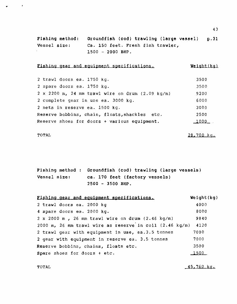
Fishing method: Groundfish (cod) trawling (large vessel) p.31 Vessel size: Ca. 150 feet. Fresh fish trawler,
1500 - 2000 BHP.
Fishing gear and equipment specifications. Weight(kg)
2 trawl doors ea. 1750 kg. 3500
2 spare doors ea. 1750 kg. 3500
2 x 2200 m, 24 mm trawl wire on drum (2.09 kg/m) 9200
2 complete gear in use ea. 3000 kg. 6000
2 nets in reserve ea. 1500 kg. 3000
Reserve bobbins, chain, floats,shackles etc. 2500
Reserve shoes for doors + various equipment. 1000
TOTAL 28,700 kg.
Fishing method : Groundfish (cod) trawling (large vessels)
Vessel size: ca. 170 feet (factory vessels)
2500 - 3500 BHP.
Fishing gear and equipment specifications. Weight(kg)
2 trawl doors ea. 2000 kg 4000
4 spare doors ea. 2000 kg. 8000
2 x 2000 m , 26 mm trawl wire on drum (2.46 kg/m) 9840
2000 m, 26 mm trawl wire as reserve - in coil (2.46 kg/m) 4120
2 trawl gear with equipment in use, ea.3.5 tonnes 7000
2 gear with equipment in reserve ea. 3.5 tonnes 7000
Reserve bobbins, chains, floats etc. 3500
Spare shoes for doors + etc. 1500
4
TOTAL 45,760 kg.

44
5. FISHING METHOD: GILLNETTING AND LONGLINING p.32
For fishing vessels in the size range 25 - 120 feet, this is
definitely the most common fishing method along the coast.
It is well known and accepted that the catch efficiency of
passive fishing gear types is dependent on fish species, fish
size, fish concentration and gear density. Recent studies have in
addition shown that effects on vision and odor stimuli are of
great importance for behavior and activity in the vicinity of
gear. For example, a considerable ihcrease in catchrates for
longline has been achieved by changing hook size, hook types,
bait size and type, materials and colors, hook distances etc.
Common for these gear types is that a changeover to new and
lighter materials has resulted in a considerable reduction in
weight. On the other side , however, the fishing intensity has
increased; more gillnets and hooks are being fished per fisherman
than before and new equipment for mechanizing operations are
being taken in use.
Developments have therefore in total meant increased weights
for gear and spares.
There are considerable differences between districts with
respect to type and amount of gear used due to the following:
* Fishing area- distance to fishing grounds
* Operational- type and amount of gear.
* Vessel sizes - number of crew.
* Fish species - utilization of catch - landing
opportunities.
* Bottom, depth and current conditions etc.
The above mentioned conditions that are of great operational
importance, usually require local adjustments and can to a
certain degree affect outfitting requirements and therefore gear
and equipment weights.
It must be considered an impossible task to include all the
variations that exist, and we do not attempt that in this study.

45
The objective is to find usable average values for each fishing
method.
The results of our studies are shown in the diagrams and
tables in the following pages.
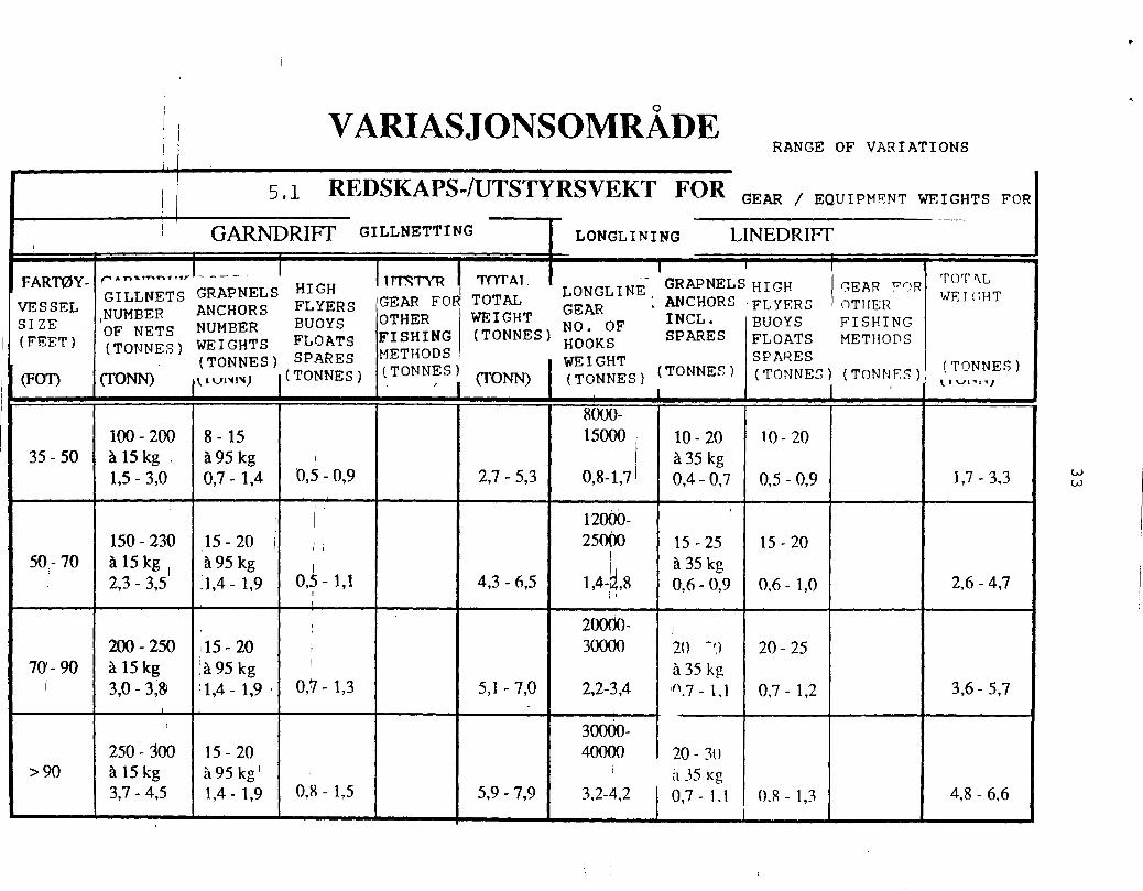
VARIASJONSOMRADE i RANGE OF VARIATIONS
I 5 . 1 REDSKAPS-/UTSTYRSVEKT FOR GEAR / EQUIPMFNT WEIGHTS FOR
GARNDRIFT G I LLNETT I NG LONGL I NI NG LINEDRIFT _...
FARTOY- e" " "' - ' ' - - œ InSTYR TOTAU TOTNL
GILLNETs GRAPNELS HIGH GRAPNEL S H I GH (TEAR FOR
VESSEL NUMBER ANCHORS FLYERS GEAR FO" TOTAL
LONGLINE- GEAR :ANCHORS FLYERS OTHER
WEI(-1HT
SIZE OF NETS NUMBER BUOYS OTHER WEIGHT
NO. OF INCL. BUOYS FISHING
(FEET) HOOKS SPARES FLOATS METHODS (TONNES) WEIGHTS FLOATS F I SH I NG ( TONNES )
( TONNES ) SPARES METHODS
WEIGHT SPARES
(FOT) (TONN) i viv IN ) (TONNES) (TONNES) (TONN) I ( TONNES ) ( TONNES ) ( TONNES ) ( TONNF7)( TONNES )
! 8000-
100 - 200 8-15 15000 i 10 - 20 10 - 20
35 - 50 à 15 kg . à 95 kg , il à 35 kg : 1,5 - 3,0 0,7- 1,4 0,5 - 0,9 2,7 - 5,3 0,8-1,7 1 0,4 - 0,7 0,5 - 0,9 1,7 - 3,3
12000- 150 - 3'0 15 - 20 25000 15 - 25 15 - 20
50,-70 à 15 kg à 95 kg 1 . I à 35 kg
i 2,3 - 3,5 :1,4 - 1,9 0,5 - 1,1 4,3 - 6,5 1,4-,8 0,6 - 0,9 0,6 - 1,0 2,6 - 4,7 , i
20000- i 200 - 250 '15 - 20 30000 20 -'.) 20 - 25
70-90 à 15 kg ;à 95 kg ' à 35 kg i 3,0 - 3,& '1,4 - 1,9 . 0,7- 1,3 5,1 -7,0 2,2-3,4 'n.7 - 1,1 0,7- 1,2 3,6 - 5,7
,
300O0- 250 - 300 15 - 20 40000 20- 30
>90 à 15 kg à 95 kg' , i it 35 kg 3,7 - 4,5 1,4 - 1,9 0, 8 - 1 , 5 5,9 - 7,9 3,2-4,2 0,7 - 1.1 0.8- 1,3 4,8 - 6,6

VEKTDIAGRAM LINEBRUK
TORR VEKT REDSKAP & UTSTYR (TONN)
40 50 60 70 80 90 100 110 120
FARTOYSTORRELSE
DUI' WEIGHT
GEAR AND
EQUIPMENT
( TONNES )
5
DRY WEI GHT
GEAR AND
EQUIPMENT
TONNES
TORR VEKT REDSKAP & UTSTYR (TONN)
5
Mal
47
p . 4 WEIGHT DIAGRAM LONGLINE GEAR
VESSEL SI ZE, FEET
WEIGHT DIAGRAM GILLNET GEAR
VEKTDIA GRAM GARNBRUK
40 50 60 70 80 90 100 110
VESSEL S I ZE ( FEET ) FARTOYSTORRELSE
120
98
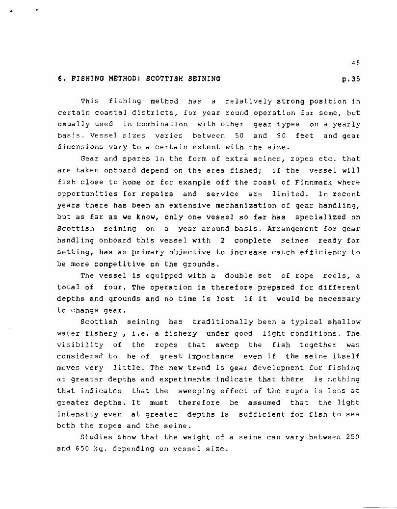
6. FISHING METHOD: SCOTTISH SEINING p.35
This fishing method has a relatively strong position in
certain coastal districts, for year round operation for some, but
usually used in combination with other gear types on a yearly
basis. Vessel sizes varies between 50 and 90 feet and gear
dimensions vary to a certain extent with the size.
Gear and spares in the form of extra seines, ropes etc. that
are taken onboard depend on the area fished; if the vessel will
fish close to home or for example off the coast of Finnmark where
opportunities for repairs and service are limited. In recent
years there has been an extensive mechanization of gear handling,
but as far as we know, only one vessel so far has specialized on
Scottish seining on a year around basis. Arrangement for gear
handling onboard this vessel with 2 complete seines ready for
setting, has as primary objective to increase catch efficiency to
be more competitive on the grounds.
The vessel is equipped with a double set of rope reels, a
total of four. The operation is therefore prepared for different
depths and grounds and no time is lost if it would be necessary
to change gear.
Scottish seining has traditionally been a typical shallow
water fishery , i.e. a fishery under good light conditions. The
visibility of the ropes that sweep the fish together was
considered to be of great importance even if the seine itself
moves very little. The new trend is gear development for fishing
at greater depths and experiments indicate that there is nothing
that indicates that the sweeping effect of the ropes is less at
greater depths. It must therefore be assumed that the light
intensity even at greater depths is sufficient for fish to see
both the ropes and the seine.
Studies show that the weight of a seine can vary between 250
and 650 kg. depending on vessel size.

49
p.36
The following examples show the results of weighing
experiments of Scottish seine nets for a vessel ca. 80 feet.
Small seine
180 mesh courlene seine w/ rope wings
Dropper chains
Butterfly etc.
TOTAL
Weight
230 kg.
180 "
40 "
450 kg.
Large seine
210 mesh nylon seine with long wings
Dropper chains
Butterfly etc.
TOTAL
310 kg.
300 "
40 "
650 kg

0 1[7. A TAT A Cl "Ire—ui■ Tc-Id-N. IM ar-I.
RANOE OF VARIATIONO
6 1 I GEAR / EQUIPMENT WEIGHTS FOR SCOTTISH SEINING FISHING
. .
_ TOTAL , ' ROPE SPARES ROPE
VESSEL ENGINE I LENGTH SEINE + SEINES FOR REELS DRY
SI ZE OUTPUT I DIM . BRIDLES IN REPAIR . WEI GHT WEIGHT
r- • , WEIGHT RESERVE AND GEAR &
(FEET) (HP) ,( TONNES ) MAINT. ( TONNES ) EQUI P . 0 u1•41.4) (TONNES) (TONNES'(TONNES) (TONNES)
, Coils
2 x 5 kveiler 1 stk. à 220 m
10 - 50 200 - 450 0 = 3 1/4" 150 kg/kveil k g /f ' il , i 1 1,4 - 1.,5 : 0,3 _ 0,5 0,3 0,1 I
■ 2,1 - 2,6 ,
i
2 x 7 kveiler 2 - 4 stk. 2 stk. à 220 m à 200 kg à 400 kg
50 -70 350 - 650 0 = 3 1/4"
1,9 - 2,2 0,6 - 0,9 : 0,4 - 0,8 0,2 - 0,4 0,8 3,8 - 5,0 i
2 stk 2 x 8 kveiler 3-4 stk. à 400 k: à 220 m à 300 kg
0 -90 450 - 800 0 = 3 1/2" à 160 kg/kVeil 2,4 - 2,7 0,7 - 1,1 0,9 - 1,3 0,4 - 0,7 0,8 5,2 - 6,6
1 .

WEIGHT DIAGRAM SCOTTISH SEINE GEAR
51
DRY WEIGHT
GEAR AND
EQUIPMENT
(TONNES)
f TORR VEKT REDSKAP & UTS TYR ÇTONN)
5
40 50 60 70 8.0 50
FARTOYSTORRELSE (FOT)--....
VES227 SIZE (FEET)

52
7. FISHING METHOD: TRAWLING p.39
The best known and common methods are cod( groundfish)
trawling, shrimp trawling, capelin trawling and trawling for
industrial fish (meal and oil).
Within .each • of these there are a number of different gear
and sizes to fit the user ( vessel size, engine size etc.). The
actual weights of gear and spares will therefore differ
considerably if the gear for large and small trawlers are
compared.
It would for instance be an obvious connection between the
size of spare equipment and the fishing operation of the vessel
(length of trip, product spectrum, fishing area etc.) If we use
as an example a vessel trawling for shrimp in the summer, the
trips must be based on icing the catch and are therefore limited
due to raw material quality. An operation like this means that
there will be little spare gear and equipment onboard.
Measures to increase the catch efficiency have been the
trend in recent years, and of concrete measures can be mentioned:
- Installation of more energy efficient and quiet propulsion
systems with larger pulling power. This has primarily meant
better towing power and efficiency, especially under poor weather
conditions, but it also makes it possible to tow trawls with
larger dimensions.
- Deck arrangements with double trawl tracks on the trawl
deck means that lost time can be reduced and effective fishing
time increased by using 2 complete trawls alternately during
fishing operations.
- There seems to be a growing interest in all countries to
obtain knowledge on fish behavior in relation to gear in the
water.
- Fish spotting equipment is being introduced where fish
species and sizes can be determined from the echograms.
- Sensors are mounted on the gear for continuous
surveillance of important gear parameters such as:

53
* distance between trawl doors
* height and geometry of trawl opening
* amount of fish in the trawl
- There is increasing interest and understanding among
fishermen on the requirements for effective management and
control and optimal exploitation of resources meant to be a
common resource. These measures will be 'important in this
respect:
* selective properties and mesh sizes of gear to reduce the
bycatch and killing of undersize fish
* protecting growing-up areas for young fish
* inspection activity.

0,2 - 0,4
0,2 - 0,4
1,4- 2,2
0,8 - 1,2
3,7 - 5,8
3,6-,5,2
0,6- 1,0
0,8 - 1,4
1,5- 3,0
1,5 - 2,0
1,4 - 2,0
1,4 - 2,0
3,0 -
2,0 - 3,0
2,0 - 2,5
2,0 - 3,0
4,0- ,2
- 0-6.0
0,7-1,4
1,2-1,8
REKE-TRAL
TORSKE- TRAL
0,5.- 1,0
0,5 - 1,0
6,3- 10,8
6,7- 11,0
14,8-18,9
12,9-18,0
17,9-22,7
21,0-31,0
»MI
1,0- 1,2
1,0- 1,2
RANGE OF VARIATIONS
GEAR / EQUIPMENT WEIGHT FOR TRAWLING 7 .1 . REDS ____,DRIFT
VESSEL SIZE
(FEET) t..1 J.
ENGINE OUTPUT
(HP)
nucuryur
TRAWI . SPARE
TYPE TRAWL TRAWL
Dn'.)17 DOORS
(TWO) (TONNES) (TONNES) ,-,--.
TRAWL WIRE WARPS SWEEPS ,ETC (TONNES)
SPARE. WIRE SWEEPS GEAR (TONNES)
TRAWLS t GEAR ETC
(TONNES)
SPARE TRAWL NETS
(TONNES)
VARIOUS EQUTPMENT FOR REP. & MAINT. (TONNES)
TOTAL DRY WEIGHT
(TONNES)
REKE-TRÀL
250 - 450 TORSKEI 'MAL
REKE-TRÀL
70- 90 TORSKE- TRAL
90- 120 I 800-1500
REKE- 'MAL 3,0-3,5
120 - 150 1000-2000 ToRsecs. TRAL 3,0-3,5
2,0 - 2,4
2,0 - 2,4
2,4 - 3,0
3,0 - 3,5
1,0- 1,2
1,0- 1,2
1,8 - 2,2
2,0 - 3,6
4,0- 4,6
4,0 - 5,0
4,0 - 5,0
5,0 - 7,0
0,4 - 0,6
0,4 - 0,6
0,5- 1,2
0,5 - 1,0
4,0
0,5 - 1,2
1,5 - 2,0 I 1,0 - 1,5
2,0 - 3,0 1,0 - 2,0
50 - 70
shrimp trawl
400 - 800 cd traY1
1,4-2,4
1,4-20
2,4-3,2
2,0-3,2
>150 >2000 TORSKE- 3 5_4 0 TRÀI,
7,0 - 8,0 9,0- 10,0 3,0 -4,0 6,0 - 7,0 6,0 - 7,0 I 3,0 - 5,0 37,5-43,0

55
P.42
42
WEIGHT DIAGRAM SHRIMP TRAWLING GEAR
TORR VEKT REDSKAP & UTS TYR (TONN)
FREEZING ONBOAP
.../eee FRESH DELIVERY ASHORE SA '‘J...• • •• ■ ••••■3—■••■...•
50 100 150
FARTOYSTORRELSE (FOT)---10»-
20
Me,
10 -I
FRYSING OMBORD
WEIGK
GEAR AND
EQUIPMENT
(TONNES,
TORR VEKT REDSKAP & UTSTYR (TONN)
1----4
DRY WEIGHT
GEAR AND
EQUIPMENT
(TONNES) 40
30
20 -I
10 H
VESSEL SIZE, FEET
WEIGHT DIAGRAM COD (GROUNDFISH) TRAWLING GEAR
VEKTDIAGRAM TORSKETRÂL FACTCPY VESSE.
FARTOY
STORTRÀLER-BRUK LARGE TRAWLEF GEAr:
SMÂTRÂLER-BRUK
SMALL TRAWLER GEAR
S-1-1 100
1 1 1 1 1 150
1 1 t 200
FARTOYSTORRELSE (FOT)--00.-
VESSEL SIZE (FEET)

56
8. FISHING METHOD : PURSE SEINING p.43
This gear type incorporates a varied selection of sizes,
mesh sizes, materials and twine thickness for catching various
pelagic fish species in coastal and distant waters. Gear
manufacturers have traditionally a wide product spectrum to meet
different requirements; from owners of sjarks of ca. 35 feet to
our largest purse seiners of over 200 feet. The amount of gear
and spares to be taken onboard in the outfitting stage will
depend on the following:
- Vessel size, space available (bin capacity)
- Gear type
- Pelagic fish species
- Area of catch - distance from home port
- Utilization of catch
- Owners personal judgement
If one should briefly attempt to give a description of
developments in this sector in the past 10 - 20 years, the
following key words come to mind:
- Catch efficiency
- New materials
- Mechanization
The following concrete developments should be mentioned:
- New vessels and many existing vessels are arranged with
two seine bins and can in periods have two complete seines
onboard (large - and shallow seines). This is often a permanent
arrangement on the largest seiners.
- Smaller vessels tend to become compressed versions of the
larger purse seiners.
- Through the years developments have been towards larger
physical dimensions of seine gear and equipment.
- Requirements for increased sinking speed have resulted in
a considerable increase in lead weight.
- Larger dimensions, especially depth and lead weight, has

57
resulted in higher strength requirements for seine twine. The
following measures have been taken to meet these requirements:
* increased thread size
* changing of mesh shape (4-sided,6-sided)(square/hexagonal)
* new materials with better strength properties
- Some gear' manufacturers claim that the largest North Sea
seines with a weight of close to 28 tonnes seem to represent a
limit.
- Seine manufacture is a labor intensive, competitive
industry with high requirements for cost reducing measures.
- In recent years there has been a tendency to outfit sjarks
with purse seines in seasons they are not fishing groundfish with
passive gear.
EXAMPLES OF NAMES, DIMENSIONS AND WEIGHTS OF SEINES. p.45
The following examples illustrate a representative selection
of the products included in purse seining.
SPRAT SEINE
Dimensions: L - 200 - 250 fathoms (f.), D - 40-50 f.
Twine: 84 "omfar"*), thread no. 1.5 - 2.0
Lead weight: ca. 700-1000 kg.
Total weight:ca. 2500 - 3100 kg.
SMALL HERRING SEINE ( COASTAL SEINE)
Dimensions: L - 160 - 190 f., D - 30 - 40 f.
Twine: 40 - 42 "omfar", thread no.3.
Lead weight: ca. 250 - 400 kg:
Total weight:ca. 2000 - 3.000 kg.
*) "Omfar" = number of meshes per "alenfl= 62.7 cm.

58
MEDIUM SIZE HERRING SEINE
Dimensions: L - 260 -300 f., D - 50 - 60 f.
Twine: 40 - 42 nomfar", thread no. 5.
Lead weight: ca. 1000 - 1400 kg.
Total weight: ca. 6000 - 8500 kg.
SMALL POLLOCK SEINE ( SHALLOW SEINE).
Dimensions: L - 220 - 250 f., D - 10 - 50 f.
Twine: 22 - 26 omfar, thread no. 4 - 5.
Lead weight: ca. 1000 - 1200 kg.
Total weight: ca. 3500 - 5000 kg.
LARGE POLLOCK SEINE ( "BIG SEINE")
Dimensions: L 34 - 370 f., D - 70 - 80 f.
Twine: 22 - 26 omfar, thread no. 6.
Lead weight: ca. 1500 - 2000 kg.
Total weight: ca. 7000 - 9500 kg.
MACKEREL SEINE ( NORTH SEA SEINE) p.46
Dimensions: L - 350 - 370 f., D - 80 - 90 f.
Twine: 40 omfar,thread no.6&8, ca. 11,000-13,500kg
Lead weight: ca. 4600-5300 kg.
Rings: ca. 2500-3000 kg.
Floats: ca. 1400-1700 kg.
Rope: ca. 1500-1800 kg.
Total weight: ca.21,000-25,300 kg.

59
CAPELIN SEINE
Dimensions: L - 300 - 320 f., D - 80 - 90 f.
Twine: 64 omfar, thread no.5.
Lead weight: ca. 4000 - 4500 kg.
Even if the dimensions are smaller than a North Sea seine,
considerable more twine is used due to the small mesh size. The
total weight will be in the same order of magnitude, between 20
and 25 tonnes.
-4.
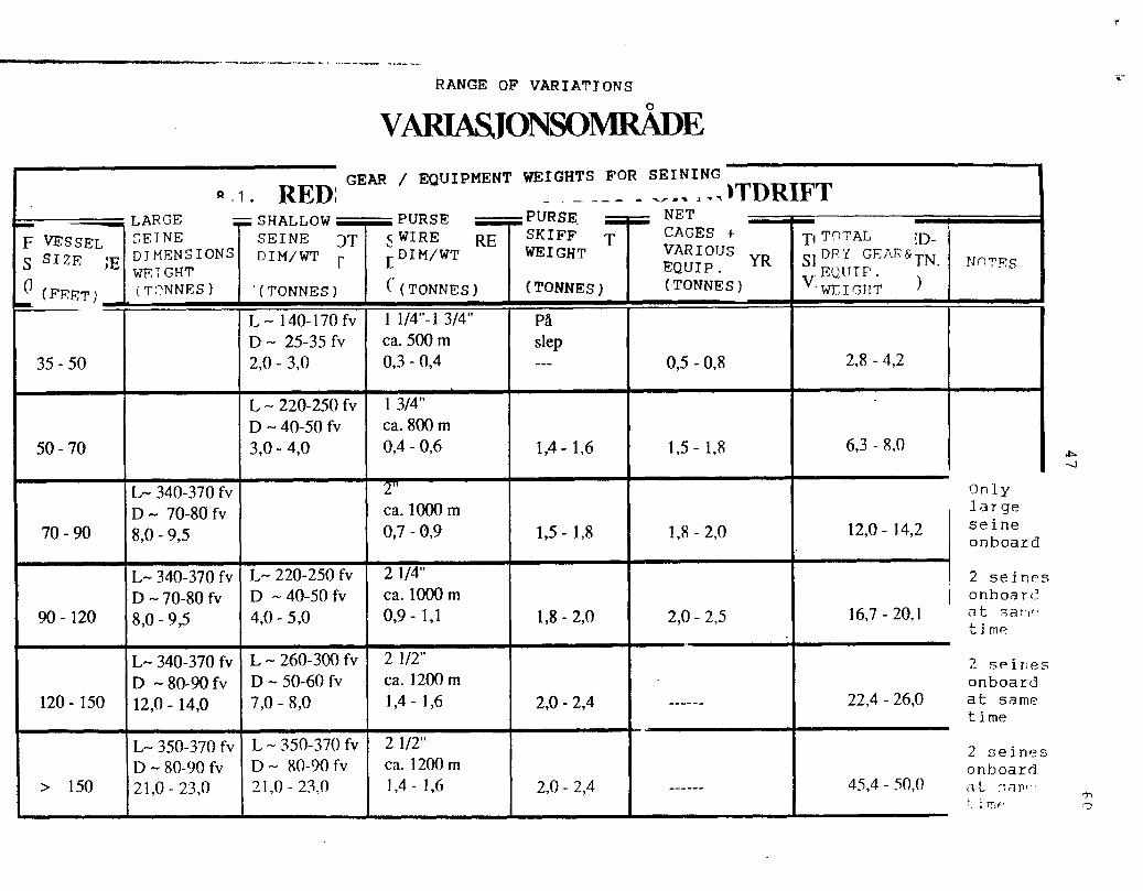
RANGE OF VARIATIONS
VARIASJONSONIRÀDE
RED: GEAR / EQUIPMENT
SHALLOW PURSE SEINE DT sWIRE RE DIM/WT r r um/wT
l (TONNES) Ç(TONNES)
WEIGHTS FOR SEINING
_ _ _ _ )TDRIFT PURSE NET SKIFF T CAGES + WEIGHT VARIOUS
EQUIP. YR
(TONNES) (TONNES)
g .1.
L0 N-P
LARGE ,
F VESsEL r,EINE s SIzE lE DIMENSIONS
rm WEGHT
ET) (TnNNES)
T1 TnTAL D- err! GEAR& TN.
EQUIP. V WEIGHT )
NnTES
35 - 50
L 140-170 fv D 25-35 fv 2,0 - 3,0
1 1/4"-1 3/4" ca. 500 m 0,3 - 0,4
Pâ slep
0,5 - 0,8 2,8 - 4,2
50- 70
L - 220-250 fv 40-50 fv
3,0 - 4,0
1 3/4" ca. 800 m 0,4 - 0,6 1,4- 1,6 1,5 - 1,8 6,3 - 8,0
90- 120
70 - 90
L- 340-370 fir 70-80 fv
8,0 - 9,5
L- 340-370 fv 70-80 fv
8,0 - 9,5
L- 220-250 fv - 40-50 fv
4,0 - 5,0
1,5 - 1,8
1,8 - 2,0 2,0 - 2,5
1,8 - 2,0
120 - 150
L- 340-370 fv D - 80-90 fv 12,0 - 14,0
L 260-300 fv D - 50-60 fv 7,0 - 8,0 2,0 - 2,4
> 150
L- 350-370 fv - 80-90 fv
21,0 - 23,0
L 350-370 fv D - 80-90 fv 21,0 - 23,0 2,0 - 2,4
2 " ca. 1000 m 0,7 - 0,9
2 1/4" ca. 1000m 0,9- 1,1
2 1/2" ca. 1200 m 1,4 - 1,6
2 1/2" ca. 1200m 1,4 - 1,6
12,0 - 14,2
16,7 - 20,1
22,4 - 26,0
45,4 - 50,0
Only large seine onboard
2 seines onboare.7 at 7-.;a1..1 ,- time
2 seines onboard at same time
2 seines onboard at lam-
jrrii. '71

WEIGHT,
(DRY SEINE)
TONNES
VEKT (TORRNOT)
30TONN _
20-
101
5
61
p.48
WEIGHT DIAGRAM
MACKEREL, HERRING AND CAPELIN SEINES
VEKTDIAGRAM MAKRELL- SILD- OG LODDENOT
NORTH SEA/CAPELIN SEINE
NORDSJ0-/LODDENOT
HERRING/MACKEREL SEINE
SELDE-/MAKRELLNOT
110 150
FARTOYSTORRELSE(FOT)--Ar.
VESSEL SIZE (FEET)
WEIGHT DIAGRAM HERRING SEINE
VEKTDIAGRAM SILDNOT WEIGHT
(DRY SEINE)
TONNES VEKT
1 (TORRNOT) 10 - TONN
MELLOMSTOR NOT
MEDIUM SIZE SEINE
LITASELDNOT SMALL HERRING SEINE
(KYSTNOT) (COASTAL (INSHORE) SEINE)
40 50 60 70 80 90 100 FARTOYSTORRELSE (FOT)
WEI GHT
(DRY SEINE)
TONNES
-VEKTDIAGRAM SEINOT
1 5 -;
GRUNTN-NOT
SHALLOW SEINE
1
VEKT (TORR NOT) TONN io
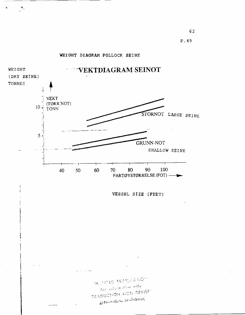
62
p. 49
WEIGHT DIAGRAM POLLOCK SEINE
40 50 60 70 80 90 100 FARTOYSTORRELSE (FOT)
VESSEL SIZE (FEET)
•1,7 ,
f-;•:1; \ne;:.• •

63
8,2 Water uptake of twine
The weights of seines in bins on open decks used in
stability calculations are usually dry weight.
To obtain data of water uptake and water content in seines
after hauling and weight reduction following draining, the FTFI
Fishing Gear and Methods Branch was asked to carry out a series
of weight experiments of seine twine.
WEIGHING METHOD
For the weighing experiments a SALTER spring balance model
235 was used with a range of 0 - 150 kg. and 1/2 kg. divisions.
The seine pieces were first weighed dry and then soaked in
the sea for 3 - 4 hours at about 2 m. depth.
The first weighing was done immediately after being taken
from the sea (within 1 min) and then with increasing time
intervals up to 90 minutes. A weighing was also done after 15
hours.
Each individual piece of twine was placed in a net bag of
courlene that hung in the balance during the whole drainage
period.
The experiments were carried out in February/March 1988 and
the air temperature varied between -2 to +7 degrees C.
RESULTS AND COMMENTS
Selection of samples for measuring the water content
encompassed both new and used twine of various thread thickness
and mesh size, with knots (E/K) and knotless (U/K), see table on
next page.
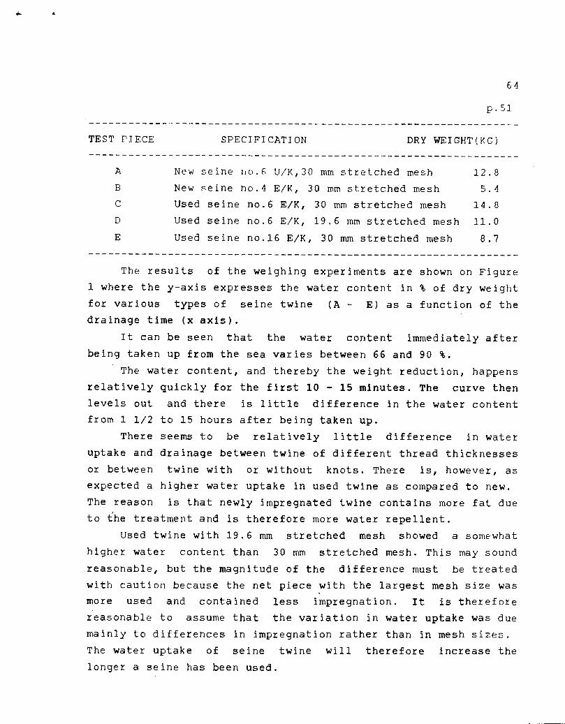
64
p.51
TEST PIECE SPECIFICATION DRY WEIGHT(KC)
A New seine no.6 U/K,30 mm stretched mesh 12.8
New seine no.4 E/K, 30 mm stretched mesh 5.4
Used seine no.6 E/K, 30 mm stretched mesh 14.8
D Used seine no.6 E/K, 19.6 mm stretched mesh 11.0
Used seine no.16 E/K, 30 mm stretched mesh 8.7
The results of the weighing experiments are shown on Figure
1 where the y-axis expresses the water content in % of dry weight
for various types of seine twine (A - E) as a function of the drainage time (x axis).
It can be seen that the water content immediately after
being taken up from the sea varies between 66 and 90 %.
The water content, and thereby the weight reduction, happens
relatively quickly for the first 10 - 15 minutes. The curve then levels out and there is little difference in the water content from 1 1/2 to 15 hours after being taken up.
There seems to be relatively little difference in water
uptake and drainage between twine of different thread thicknesses
or between twine with or without knots. There is, however, as
expected a higher water uptake in used twine as compared to new.
The reason is that newly impregnated twine contains more fat due
to the treatment and is therefore more water repellent.
Used twine with 19.6 mm stretched mesh showed a somewhat
higher water content than 30 mm stretched mesh. This may sound
reasonable, but the magnitude of the difference must be treated
with caution because the net piece with the largest mesh size was
more used and contained less impregnation. It is therefore
reasonable to assume that the variation in water uptake was due
mainly to differences in impregnation rather than in mesh sizes.
The water uptake of seine twine will therefore increase the
longer a seine has been used.

65
The rate of drainage was approximately the same for all
•the twines regardless of the original water uptake. This shows
that the higher the water uptake the larger the water content of
the seine will be over time. It should be made clear that these
experiments were made with very small pieces of twine and the
samples hung in a netbag with best condition possible for
drainage. The test method deviates from actual conditions on
vessels where some water will run off when forced through the
power block and during transport to the bins.
Considerable quantities of water still follow the seine to the bin where the seine is tightly packed and where drainage can
only occur via grate openings in the side of the vessel. It must
therefore be assumed that drainage is slower than in these
experiments.
Nylon fibre can absorb 10 - 12 % water. When a seine is
soaked, water will also adhere to the thread in mesh sides and
knots depending on the degree of impregnation. Large amounts of free water will also accumulate between the meshes in the seine.
The free water will first drain off, but it will take a long time
before the adhered and absorbed water is removed since this will
have to be dried out.
CONCLUSION
Based on these small scale experiments, there is reason to
assume that the water uptake and thereby the weight increase is
not less in practical fishing. The conclusion must therefore be
that the water content in the seine twine after a period of 2
hours after hauling comprises an additional weight of at least
30% compared with a dry seine and that the water content is not
reduced significantly during storage in the seine bin.
• Water uptake and drainage varies insignificantly with thread
size and mesh size and between.seine with or without knots. There
is, however, a large difference in water uptake between new and
use seine twine; the water uptake increases with increasing use
of the seine.

i••••••••••••••
100
90
-a __0
1 1 1 1 1 1 1 1 1 /7/1
Tidsi Fig 1.
TIME PERIOD (MINUTES)
FIGURE 1. WATER CONTENT IN NETI.
(JI
% W
ATE
R CO
NT
EN
T
80
-0 70 0 -c 60
sE 50
o 40
e 30
--Fl A B
--A d 0D
—111- - • E
1/!! ..... . ............
0 .0
p . -////
////- - - -
20
10
0 10 20 30 40 50 60 70 80 90 15 timer

67
9. CONTROL OF GEAR- AND EQUIPMENT WE/GHTS USED IN STABILITY CALCULATIONS FOR A SELECTION OF VESSELS
For the purpose of comparison and to see if the gear and
equipment weights used in stability calculations is closc to
actual weights, a study of the stability books of 50 fishing
vessels were carried out. Most of the vessel that were sent
questionnaires were included in this sample.
To be able to carry out the study as rationally as possible,
we applied , and were given permission, to access the archives in
the Directorate of Shipping where vessel folders containing
stability data are found. Our application was approved subject to
the data being used and presented without identifying the
individual vessels. On the basis of stability calculations and
descriptions, the following data were registered and noted for
each vessel
- Vessel length in feet
- Fishing methods/combinations
- Year built, number of rebuildings, owners.
- Number of stability calculations carried out and date of
the last calculation
- Degree of detail in the description of gear and equipment
in the calculations
- Control of, and comments to, the location of the center of
gravity used for gear and equipment in the calculations.
- Gear and equipment weights used in the last stability
calculation.
44

68
9.1. Selection of Vessels
In carrying out spot checks, we did some preliminary studies on the connection between gear weights, vessel sizes and stabilities , and indicationL, are that we should spotlight small
and medium size vessels for the following reasons:
-Gear weights have a relatively greater influence on the
stability of small rather than on large vessels since the weights
comprise a relatively larger part of the displacement.
- For vessels under 110 feet, most of the existing length-
and tonnage limitations used are part of regulations.
- There has been a tendency to take in use non-traditional
fishing methods on small and medium size vessels. The fishery has
taken place so far off shore that a certificate to 200 n. miles
has been necessary.
- Space restraints can be the reason for alternative storage
of spare gear that deviates from the original which was used in
the calculations.
The study included existing vessels chiefly in the size
range between 60 and 100 feet where a representative selection of
fishing methods is included.
An illustrated list of vessels was used that shows pictures
of the vessels and gives name, year built, change of ownership,
main dimensions and arrangements , and the following criteria
were of importance for the choice of vessels:
-Vessel size- Fishing method- Area fished
- Length- LIE relationship
- Arrangement - Equipment
- Main engine size
- Year built- number of rebuildings and owners
- Estimate of gear and equipment weights according to the
weight diagram for the fishing gear in question
- Lightship data and center of gravity for this condition
- Calculation of weight difference in % between used and

69
estimated weights
A summary of these registrations are given on pages 70 -78.
In the same table we have from the weight diagrams for the
respective fishing methods estimated and tabled probable gear-
and equipment weights, calculated deviation in percent between
weights used in the calculations and estimated weights from
weight diagram.
The last column in the table gives an estimate of the
vertical shift of the overall center of gravity that the
corrections given will represent.

JESSEL ZE
FISHING METHOD/ COMB.
:FEET)
58 Trâl TR A'12 r-,
Sntimmmd 'cOTT.SEIVF,
Trâl Snurrevad
Rekietrà1
Snurrevad
Reketrà1 Garn GI LLNET 1985
1984
1984
Not PURSE SEINE SnurreVàd 1981
Not SnurreNrad
YEAR VEf7f7 EL BUILT
WHEN LAST STABIL. CALCUL. MADE
(YEAR)
kRPEARS ' 1EWHAT
LO‘s
ok
Noe lavt SOMEWHAT LOW
ok
ok
ok
1 .)1(
- 100,0
- 48,1
58
58
60
1984
1986
1985
mem j stores
Trâlutstyr Dorer Wire
Trâlutstyr Trâldorer
Not 1981 G-q,Snurpewire
Notnoser NET -pke-E-S
Not 1981 Wire
Notposer
0,5
0,80 0,90 1,00
0,80 1,40
4,50 0,80
4,5 0,8 0,9
%.uni-mvu umetn mwvirnmni wniunio apu uvnrcmlu.. urect-bm ur UKRVIT/ CONTROL OF GEAR / EQUIPMENT WEIGHTS AND OVERALL CENTER OF GRAVITY (ONTROLL AV RF IN STABILITY CALCULATIONS ;BEREGNING
sHHIMP Reketrâl TRAWL
58 Snurrevad 1984
1984
1981
DESCRIPT. GEAR/EQ UTP * COMMENT
AND
EQUIP WEIGHT USED IN STABiLIT TO OF GEAR
CALC. OVERALL CENTER OF GRAVITY
VEKT-A VVIK
WFT .71HT DEVIATION IN %
- 100,0
- 66,0
- 81,8
- 20,9
- 20,9
GEAR ON DECK 1984 GEAR IN STORES 2,0
TelutstmEAR 1986 Trâldorer DO OR S0,90
Trâlwire J 1,00
GEAR ON DECK Fisker.pAdekk 1,5
GEAR/EQUI° WEIGHTS ACCORD. TO WEIGHT DIAGRAMS (TONNES)
4,0
4,0
4,0
4,50
4,0
7,5
7,5
CALCUL. RAISING OF OVERALL CENTER OF GRAVITY (CM)
3
2
3
3
5
2
2
(TONNES)
I

:ONTROLL AV REDSKAPS-/UTSTYRSVEKTER OG FELLESTYNGDEPUNKT I STABILITETSBEREGNING
RUN- DRIFTS- FARTOYETS NÀR BE- REDSKAPS- KOMMEN- REDSKAPS-/ VEKT- BEREGNET ORRELSE FORM./ BYGGEÀR SISTE SKRIVELSE /UTSTYRS- TARER TIL UTSTYRS- AVVIK HEVING
KOMB. STAB. AV VEKT BENYTTET VEKT I AV FELLES BEREGN. REDSKAPER BENYTTET FELLES FOLGE I T.PKT. BLE OG UTSTYR I STAB. T.PKT. VEKTDIA- UTFORT BEREGN. GRAMMER
(FOT) (AR) (AR) (TONN) (TONN) (%) (CM)
Reketel TrAlutstyr 0,80 60 Garn 1985 1985 Tilldorer 1,40 ok 4,0 - 81,8 5
Reketr5.1 62 Line 1961 1983 Vegn Sear 2,70 Ndelavt 4,0 - 48,1 3
ReketrAl Virker 62 Line/garn 1961 1983 Vegn 2,70
1 I noe lavt 4,0 - 48,1 3
Reketrà1 Virker 63 Line/garn 1974 , 1982 TrAlutstyr 3,50 , noe lavt 4,5 - 28,6 3
. Reketr5.1 ca
63 Line 1974 1982 Telutstyr 3,5 20-30 cm 5,5 - 57,0 4 Garn for lavt
Pol 1 cdk seine on stern
Seinot Seinot pi hekk
64 Reketrà1 1981 1981 Nod-At pA slep 5,00 ok 7,0 - 40,0 4 Tow;rg skiff
Reketill Wire 1,20 ca. e 65 Snurrevad 1985 1985 Trâlerer 1,00 20-30 cm 6,50 - 54,0 4
Goa , •„ (Hje Bruk pli trommél 1,00 for lavt
Bruk 0 dekk 1,00 gear on der.V
i
Fiskeutstyr 65 Trâl 1979 19% pâ dekk 5,0 ok 6,0 - 20,0 2
,
(J1 co

KONTROLL AV REDSKAPS-/UTSTYRSVEKTER OG FELLESTYNGDEPUNKT I STABILITETSBEREGNING •
FARM- DRIFTS- FARTOYETS NAR BE- REDSKAPS- KOMMEN- REDSKAPS -/ VEKT.. BEREGNET STORRELSE FORM./ BYGGEAR SISTE SKRIVELSE /UTSTYRS- TARER TIL UTSTYRS- AVVIK HEVING
KOMB. STAB. AV VEKT BENY 1 1 LT VEKT f AV FELLES BEREGN. REDSKAPER BENYTTET FELLES FOLGE 1 T.PKT. BLE OG UTSTYR I STAB. T.PKT. VEKTDIA- UTFORT BEREGN. GRAMMER
(FOT) (AR) (AR) (TO NN) (TONN) (%) (CM)
Line ca. 20 cm 65 Garn 1966 1984 . Garnbruk 2,50 for lavt 4,50 - 80,0 3
Tràlbruk 65 Reketrâl 1978 1980 Reservebruk 6,0 ok 6,00 ---
i Fiskeutstyr 65 Trâl 1979 1986 pà dekk 5,0 ok 6,0 - 20,0 2
Fishing gear
on deck
Rekettll Trà1d0rer 1,5 65 Garn 1955 1987 Div. gear 0,8 ok 5,0 - 56,2 4
Trâler 0,9
Line Gillnet gear Virker 65 Garn 1966 1984 Garnbruk 2,5 noelavt 4,5 - 80,0 3
Tràlbruk 65 Reketràl 1978 1980 Reservebruk 6,0 ok 6,0 0,0 0
Reketrâl Trà1d0rer 1,5 65 Garn 1955 1987 Div.garn 0,8 ok 5,00 - 56,0 4
Trâler 0,9
Rekerri11 68 Garn 1981 1982 Vegn 2,0 ok 5.5 - 175.0 4
L.

KONTROLL AV REDSKAPS-/UTSTYRSVEKTER OG FELLESTYNGDEPUNKT I STABILITETSBEREGNING
FARTOY- DRIFTS- FARTOYETS NAR BE- REDSKAPS- KOMMEN- REDSKAPS-/ VEKT- BEREGNET STORRELSE FORM./ BYGGEÂR SISTE SKRIVELSE /UTSTYRS- TARER TIL UTSTYRS- AVVIK HEVING
KOMB. STAB. AV VEKT BENYTTET VEKT I AV FELLES BEREGN. REDSICAPER BENYTTET FELLES FOLGE r T.PKT. BLE OG UTSTYR I STAB. T.PKT. VEKTDIA- UTFORT BEREGN. GRAMMER
(FOI) (AR) (AR) (TONN) (TONN) (%) (CM)
Relcetrà1 68 Garn 1981 1982 Vegn 2,0 ok 5,50 - 175,0 4
• Not I Seinoter 5,0
70 Snutrèvad 1978 1979 Seiposer 0,8 ok 12,0 - 40,4 3 1
' Arbeidsbàt 2,0 Div. 0,75
I Reketràl Trà1dorer 1
70 Torsketràl 1967 ' 1986 Tràl pà 2,20 ok 6,50 -150,0 7 trommel Drum ,
15°1 I ock Not Seinoter 5,0 70 Snuirevad 1978 1970 I Sciposer 0,8 ok 12,0 - 52,0 3
Wor k boat Arbeidsbàt 2,0 Div 0,75
Fiskeutstyr Virker 72 SnurreVad 1982 1982 Reservebruk 4,21 noe lavt 4,50 - 6,8 0
Seinot Stor not 6,0 ,
75 Snurrevad 1985 1985 Liten not 2,0 ok 14,50 - 48,0 5 Lettbât 1,8

76
76
76
76
76
Bruk Lettbât
Fiskeutstyr
Bruk Lettbât
Fiskeutstyr
Wire Trâl pâ trommel Trâldorer
Notbruk Al.bât
Not pâ dekk
Notbruk Al.bât
1978
1953
1985
1953
1969
1974
1955
1974
1986
1984
1985
1984
1983
1978
1980
1978
ok
Nde lavt
ok
Virker noe lavt
Virker noe lavt
.k
ok
- 104,8
- 22,0
- 104,8
- 25,0
- 55,5
- 126,0
- 180,0
- 1 16,0
4
2
4
2
4
4
6
4
KONTR OLL AV RED SKAPS-/UT STYRSVE KTER OG F ELLESTY NGDEPUNK T I STABH ,ITETSBER EGNING
FARTOY-STORRELSE
(FOI)
DRIFTS - FORM./ KOMB.
FARTOYETS BYGGEÀR
(AR)
NAR SISTE STAB. BEREGN. BLE UTFORT (AR)
BE-SKRIVELSE AV REDSKAPER OG UTSTYR
REDS KAPS-fUTSTYRS-VEKT BENYTTET I STAB.
BEREGN. (TONN)
KOMMEN-TARER TIL BENYTIET FELLES T.PKT.
REDSKAPS UTSTYRS-VEKT I FOLGE VEKTDIA-GRAMMER (TONN)
VEKT-AVVIK
(%)
BEREGNET HEVING AV FELLES T.PKT..
(CM)
76
76
76
Snurrevad , Not Garn
Line Garn
Snurrevad Not
Line Garn
Trâl
Not Garn
Reketill Not
Not Garn
2,50 1,65
4,40
2,50 1,65
4,40
3,60
0,50 0,40
3,0 1,2
2,5
3,0 1.1
9,5
5,4 '
9,50
5,50
7,0
9,50
7,0
9,5

KONTROLL AV REDSKAPS-/UTSTYRSVEKTER OG FELLESTYNGDEPUNKT I STABILITETSBEREGNING
FARM- DRIFTS- FARTOYETS NÀR BE- REDSKAPS- KOMMEN- REDSKAPS-/ VEKT- BEREGNET
STORRELSE FORM./ BYGGEÀR SISTE SKRIVELSE /UTSTYRS- TARER TIL UTSTYRS- AVVIK HEVING KOMB. STAB. AV VEKT BENYTTET VEKT I AV FELLES
BEREGN. REDSKAPER BENYTIET FELLES FOLGE 1 T.PKT. BLE OG UTSTYR I STAB. T.PKT. VEKTDIA- UTFORT BEREGN. GRAMMER
(FOI) (AR) (AR) (TONN) (TONN) (%) (CM)
Wire 3,6 76 Tràl 1969 1983 Tràl pà Noe lavt 7,0 ' -66,0 5
trommel 0,5 Trà1d0rer 0,4
1 Reketill ' I Not pà dekk 76 ' Not 1955 1980 (siden 1960) 2,5 --- 7,0 - 180,0
Reketrà1 Trà1dorer 1,76 77 Garn 1958 1985 Tràl pà tro. 0,80 ok 7,0 - 59,0 4
Res. tràl 0,40 Nett ru!! 0,80
Rekeirà1 Trà1dorer 1,76 77 Garn 1958 1985 Nettrull 1,60 ok 7,0 - 86,0 5
Reserretrà1 0,40
Garn 78 Line
1 1 1964 1984 Vegn 1,50 ok 5,0 - 233,0 4
Garn 78 Line l i 1964 1984 Vegn 1,50 ok 5,0 - 233,3 4
Reketrâl Virker
78 Garn 1975 1977 . Vegn 2,0 noe lavt 7,0 - 250,0 7

78
79
80
82
83
90
92
1976
1977
1985
1987
1958
1978
1975
1985
1984
1985
1987
1984
1987
1985
Redskaper
Dorer Trâlwire 2 stk. reketr.
TrOldorer Trâl m/gear Trâlwire, di
Utrustnings Redskaper
Trâlwire Dorer Trâ1
En detaljert og presis beskrivelse
Trâltrommel Dorer Wire
2,0
1,50 1,85 0,80
5,30
5,86
2,0 1,6 1,3
16,0
6,70
For lavt
ok
Virker noelavt
ok
ok
.ic
ok
7,0
7,0
7,5
8,0
7,5
16,0
15,0
- 250,0
- 68,7
- 41,5
-36,5
-53,0
- 123,9
5
4
KONTR OLL AV RED SKAPS-/UT STYRSVE KTER OG F ELLESTY NGDEPUNK T I STABII ,ITETSBER EGNING
FARM-STORRELSE
(FOT)
DRiFTS-FOIkM./ KOMB.
FARTOYETS BYGGEÂR
(AR)
NÀR SISTE STAB. BEREGN. BLE UTFORT (AR)
BE-SKRIVELSE AV REDSKAPER OG UTSTYR
REDSKAPS-/UTSTYRS-VEKT BENYTTET I STAB.
BEREGN. (TONN)
KOMMEN-TARER TIL BENYTTET FELLES T.PKT.
REDSKAPS-/ UTSTYRS-VEKT I FOLGE VEKTDIA-GRAMMER (TONN)
VEKT-AVVIK
(%)
BEREGNET HEVING AV FELLES T.PKT.
(CM)
Reketrâl Not
ReketrOl Garn ,
Reketill Gatn
Reketrâl Garn
ReicetrOl Gam
Reketrâl
Reketrâl
2
3
3
7

KONTROLL AV REDSKAPS-/UTSTYRSVEKTER OG FELLESTYNGDEPUNKT I STABILITETSBEREGNING
FARTOY- DRIFTS- FARTOYETS NAR BE- REDSKAPS- KOMMEN- REDSKAPS-/ VEKT- BEREGNET STORRELSE FORM./ BYGGEÀR SISTE SKRIVELSE /UTSTYRS- TARER TIL UTST'YRS- AVVIK HEVING
KOMB. STAB. AV VEKT BENYTTET VEKT I AV FELLES BEREGN. REDSKAPER BENYTTET FELLES FOLGE 1 T.PKT. BLE OG UTSTYR I STAB. T.PKT. VEKTDIA- UTFORT BEREGN. GRAMMER
(FOT) (AR) (AR) (TONN) (TONN) (%) (Cm)
Reketràl Tràlwire 1,00 93 Garn 1978 1982 Tràlutstyr 2,00 ok 11,00 • - 266,6 8
Sildetràl 95 Industritràl 1965 1982 Bruk 3,00 ok 6,5 - 117,0 5
1
97 Torskeirà1 1979 1984 Redskaper 10,0 ok 15,0 - 50,0 3
Seihot 108 Sildnot 1957 1978 Not 10,5 Noe lavt 17,0 - 61,9 5
Industri- Wire 2,00 110 tràl 1956 1985 Not 1,35 Noe lavt 9,0 - 68,2 4
. 1 Dorer 2,00
Wire 3,20 110 ReketrAl 1957 1983 Trà1dorer 2,00 ok 18,00 - 170,6 7
Trâl pà tr. 0,75 Reserve 0,70
Reketràl Tràlbrett 2,2 110 Not 1961 1987 Not pà sh.dk_ 1,0 Noe lavt 14,5 - 159,6 5
Not i fiskerom 2,0
,

KONTROLL AV REDSKAPS-/UTSTYRSVEKTER OG FELLESTYNGDEPUNKT I STABILITETSBEREGNING
FARTOY- DRIFTS- FARTOYETS NAR BE- REDSKAPS- KOMMEN- REDSKAPS-/ VEKT.. BEREGNET STORRELSE FORM./ BYGGEAR SISTE SKRIVELSE /UTSTYRS- TARER T1L UTSTYRS- AVVIK HEVING
KOMB ' STAB. AV VEKT BENYTTET VEKT I AV FELLES I BEREGN. REDKAPER BENYTTET FELLES FOLGE 1 T.PKT. BLE OG UTSTYR I STAB. T.PKT. VEKTDIA- UTFORT BEREGN. GRAMMER
(FOT) (AR) (AR) (TO NN) (TONN) (%) (CM)
125 Reketrâl 1968 1987 Fiskeutstyr 4,00 For lavt 16,00 - 300,0 8 1
Malcrellnot
125 Sildenot 1956 1977 Not i binge 10,0 ok 21,0 - 110,0 '5 Loddenoti
Trà1dorer
139 Reketrâl 1986 1986 Trâlgear 4,1 ok 20,0 - 153,1 5 Trâlnot Reserve not, 3,8 dorer, gear
154 Reketrâl 1986 1986 Redskaper 32,6 ok 26,0 ---- ----
_
79
9.3. Evaluation of results
Even if objections can be raised against both the method of
selection and the number of vessels included in the study, the
results indicate that the assumptions and basic information that
parts of the stabilization calculations are based on can often be
faulty.
It should be made clear that for many of these vessels the
correction of gear weights indicated will not result in
corrections large enough to place approved stability states in
danger, but with few exemptions , the results indicate that
vessel stabilities are poorer than those given in the stability
papers. The state of each vessel and the magnitude of the
deviation will be decisive; vessels with small margins to certain
stability criteria can have problems and would need to take
corrective measures. It should be made clear that the reference-
and comparative weights given must only be considered to be a
guide and are not final. It is the actual weight onboard the
individual vessels that is to be used for calculations, and it
could be possible that there are gear that deviate considerably
from the average values read off from the attached weight
diagrams.Regardless of consequences or not, the study has exposed
a somewhat variable, but still extensive underestimation of gear
weights. The reason for this sad state can be many, and the
following questions are obvious:
- Is there a conscious manipulation of data or is it an
expression of lack of competence in this area by authorities or
companies?
- The defamatory statement above can be justified in the
cases where the stability is in a borderline area, but there is
no reasonable explanation for deviations where the margins are
• wide enough that no adverse consequences would result in using
the correct values.
-There is much prestige involved for the naval architects or
consultants, the shipyard and the owners to be able to complete a

job successfully. A possible explanation can in many cases be
that the gear weights are used as a "balancing entry'?
- Could it be that the loading of gear usually occurs at
another place after the vessel has left the yard and that what
happens after the responsibility has been transferred to the
owners doe5 not concern the yard?
- Do shipyards and consultants still use the most convenient
solution by asking the owner or skipper about gear weights in a
hectic final phase and using these data where certainly much har..;
been left out in the final calculations?
- A vague definition of the state "lighfship" can be the
reason for varying routines and practices; equipment that belongs
under gear could be camouflaged and be included in the nligqship
state".
The moral of a sad story like this is that it leads to
doubts about the purpose of paying large sums of money for
socalled "expert advice" when spot tests show that many shipyards
and ships consultants seem to lack the ability to evaluate the
whole in these cases. An example is that scrap and rubbish
onboard is being counted when unloaded and deducted from lightship data. Corrections for free liquid surfaces in tanks are
being performed, while serious underestimations of gear weights
that have a greater influence on the results are not priorized to
the same degree.
Some of the explanation must be found within these
statements, but to find "scapegoats" should not be a priority,
rather to present suggestions for correcting the problem.
A lack of reaction after serious accidents in the fishing
fleet is often the beginning of reactions from relatives and
colleagues on what has to be done before the authorities react.
Accidents or events ashore that would have been likely to
result in serious accidents or injuries can have repercussions
and the police can be asked to ascertain if any of the parties
have been irresponsible. In some cases the event can lead to
litigation in civil courts.

8t
9.4. Suggestions for measures.
1. Requirements for better and more detailed specifications of
gear and spare equipment in the calculations. The calculations
given in this report can be a guid e .
2. To develop a comprehensive selection of diagrams of gear and
equipment weights related to vessel sizes and fishing methods.
There is no doubt a need for improving the examples in this
report.
3. There is an obvious need for improving and raising the level
of competence in this field within the authorities, companies and
control bodies that with governmental approval are carrying out
these functions.
4. In my opinion there is a requirement for a more precise
definition of the lightship state for fishing vessels where the
most unfavorable condition is included; gear weights will here
form a considerable contribution for some fishing methods. The
actual opportunities that the individual vessel have for use of
water ballast or fuel oil to improve stability must be evaluated
in this connection.