NJDEP-EDI (Electronic Data Interchange) Manual - NJ.gov
66
STATE OF NEW JERSEY DEPARTMENT OF ENVIRONMENTAL PROTECTION ELECTRONIC DATA INTERCHANGE MANUAL Christine Todd Whitman, Governor Robert C. Shinn, Jr. Commissioner
-
Upload
khangminh22 -
Category
Documents
-
view
0 -
download
0
Transcript of NJDEP-EDI (Electronic Data Interchange) Manual - NJ.gov

STATE OF NEW JERSEYDEPARTMENT OF ENVIRONMENTAL
PROTECTION
ELECTRONIC DATA INTERCHANGEMANUAL
Christine Todd Whitman, GovernorRobert C. Shinn, Jr. Commissioner
Table of ContentsElectronic Data Interchange Manual
August 1, 1997
Introduction . . . . . . . . . . . . . . . . . . . . . . . . . . . . . . . . . . . . . . . . . . . . . . . . . . . . . . . . . . . INT-1
Background . . . . . . . . . . . . . . . . . . . . . . . . . . . . . . . . . . . . . . . . . . . . . . . . . . . . . . . . . . 1Organization of the Manual . . . . . . . . . . . . . . . . . . . . . . . . . . . . . . . . . . . . . . . . . . . . . . 1How to Get Copies of This Manual . . . . . . . . . . . . . . . . . . . . . . . . . . . . . . . . . . . . . . . . 1EDI Concept and Components . . . . . . . . . . . . . . . . . . . . . . . . . . . . . . . . . . . . . . . . . . . . 2Benefits of Using EDI . . . . . . . . . . . . . . . . . . . . . . . . . . . . . . . . . . . . . . . . . . . . . . . . . . 2Transfer Mechanisms and File Formats . . . . . . . . . . . . . . . . . . . . . . . . . . . . . . . . . . . . . . 3
Electronic Bulletin Board System . . . . . . . . . . . . . . . . . . . . . . . . . . . . . . . . . . . . . . . . . EBB-1
What is a BBS? . . . . . . . . . . . . . . . . . . . . . . . . . . . . . . . . . . . . . . . . . . . . . . . . . . . . . . . 2What is the NJDEP BBS? . . . . . . . . . . . . . . . . . . . . . . . . . . . . . . . . . . . . . . . . . . . . . . . 2Why a BBS? . . . . . . . . . . . . . . . . . . . . . . . . . . . . . . . . . . . . . . . . . . . . . . . . . . . . . . . . . 2Why Isn’t This Information on the Internet? . . . . . . . . . . . . . . . . . . . . . . . . . . . . . . . . . . 2What Do I Need to Call the NJDEP BBS? . . . . . . . . . . . . . . . . . . . . . . . . . . . . . . . . . . . 3My Modem Connects to the NJDEP BBS, Now What? . . . . . . . . . . . . . . . . . . . . . . . . . 3The NJDEP BBS Welcome Screen . . . . . . . . . . . . . . . . . . . . . . . . . . . . . . . . . . . . . . . . . 4The NJDEP BBS Opening Screen . . . . . . . . . . . . . . . . . . . . . . . . . . . . . . . . . . . . . . . . . 5The NJDEP BBS Bulletin Menu . . . . . . . . . . . . . . . . . . . . . . . . . . . . . . . . . . . . . . . . . . . 6The NJDEP Main File Menu . . . . . . . . . . . . . . . . . . . . . . . . . . . . . . . . . . . . . . . . . . . . . 7The NJDEP BBS Main Message Menu . . . . . . . . . . . . . . . . . . . . . . . . . . . . . . . . . . . . 12What If I Have Problems Connecting to the NJDEP BBS? . . . . . . . . . . . . . . . . . . . . . . 14
Geographic Information System, Mapping and Digital Data Standards . . . . . . . . . . . GIS-1
Summary . . . . . . . . . . . . . . . . . . . . . . . . . . . . . . . . . . . . . . . . . . . . . . . . . . . . . . . . . . . . 21.0 Introduction . . . . . . . . . . . . . . . . . . . . . . . . . . . . . . . . . . . . . . . . . . . . . . . . . . . . . . . 32.0 Basemaps . . . . . . . . . . . . . . . . . . . . . . . . . . . . . . . . . . . . . . . . . . . . . . . . . . . . . . . . . 33.0 Map Compilation . . . . . . . . . . . . . . . . . . . . . . . . . . . . . . . . . . . . . . . . . . . . . . . . . . . 8
3.1 Photo-interpretation . . . . . . . . . . . . . . . . . . . . . . . . . . . . . . . . . . . . . . . . . . . 83.2 Recompilation . . . . . . . . . . . . . . . . . . . . . . . . . . . . . . . . . . . . . . . . . . . . . . . 8
4.0 Data Automation . . . . . . . . . . . . . . . . . . . . . . . . . . . . . . . . . . . . . . . . . . . . . . . . . . . 95.0 Data Transfer . . . . . . . . . . . . . . . . . . . . . . . . . . . . . . . . . . . . . . . . . . . . . . . . . . . . . 106.0 Documentation . . . . . . . . . . . . . . . . . . . . . . . . . . . . . . . . . . . . . . . . . . . . . . . . . . . . 117.0 Global Positioning System . . . . . . . . . . . . . . . . . . . . . . . . . . . . . . . . . . . . . . . . . . . 118.0 National Map Accuracy Standards . . . . . . . . . . . . . . . . . . . . . . . . . . . . . . . . . . . . . 139.0 Data Dictionary . . . . . . . . . . . . . . . . . . . . . . . . . . . . . . . . . . . . . . . . . . . . . . . . . . . 1410.0 References . . . . . . . . . . . . . . . . . . . . . . . . . . . . . . . . . . . . . . . . . . . . . . . . . . . . . . 17

Radon . . . . . . . . . . . . . . . . . . . . . . . . . . . . . . . . . . . . . . . . . . . . . . . . . . . . . . . . . . . . . . . RAD-1
1.0 Introduction . . . . . . . . . . . . . . . . . . . . . . . . . . . . . . . . . . . . . . . . . . . . . . . . . . . . . . . 12.0 Electronic Submittal Requirements and Process for Radon Monthly Reports . . . . . . 1 Table: Radon 1 . . . . . . . . . . . . . . . . . . . . . . . . . . . . . . . . . . . . . . . . . . . . . . . . . . . . 2
Right to Know . . . . . . . . . . . . . . . . . . . . . . . . . . . . . . . . . . . . . . . . . . . . . . . . . . . . . . . . RTK-1
1.0 Introduction . . . . . . . . . . . . . . . . . . . . . . . . . . . . . . . . . . . . . . . . . . . . . . . . . . . . . . . 12.0 Electronic Submittal Requirements and Process for the Community Right to Know Survey Using an Executable File . . . . . . . . . . . . . . . . . . . . . . . . . . . . . . . . . . 13.0 PC AnyWhere Special Instructions and Use . . . . . . . . . . . . . . . . . . . . . . . . . . . . . . . 34.0 Facility Submission Interface Specification . . . . . . . . . . . . . . . . . . . . . . . . . . . . . . . . 4
Site Remediation . . . . . . . . . . . . . . . . . . . . . . . . . . . . . . . . . . . . . . . . . . . . . . . . . . . . . . . . SR-1
1.0 Introduction . . . . . . . . . . . . . . . . . . . . . . . . . . . . . . . . . . . . . . . . . . . . . . . . . . . . . . 12.0 Electronic Submittal Requirements and Process for HazSite Option . . . . . . . . . . . . . 2
3.0 Electronic Submittal Requirements and Process for Lotus-Compatible Spreadsheet Option.. . . . . . . . . . . . . . . . . . . . . . . . . . . . . . . . . . . . . . . . . . . . . . . . . . . 64.0 Data Transmission . . . . . . . . . . . . . . . . . . . . . . . . . . . . . . . . . . . . . . . . . . . . . . . . . . 85.0 Data Compression . . . . . . . . . . . . . . . . . . . . . . . . . . . . . . . . . . . . . . . . . . . . . . . . . . 96.0 Discussion of Fields . . . . . . . . . . . . . . . . . . . . . . . . . . . . . . . . . . . . . . . . . . . . . . . . . 9
NEW JERSEY DEPARTMENT OF ENVIRONMENTAL PROTECTION
___________________________________________________________________
ELECTRONIC DATA INTERCHANGE MANUAL
A Guidance Document
For
Use by Entities Reporting Certain Data to the Department
__________________________________________________________________
DISCLAIMER
All product names and services identified throughout this document aretrademarks or registered trademarks of their respective companies. They are usedthroughout this document in editorial fashion only. No such use, or the use of anytrade name, is intended to convey endorsement or other affiliation with this documentor the Department of Environmental Protection.
Furthermore, this document has not been promulgated by the department as arule. Therefore, it does not have a rule's legal force and effect. If any difference isfound between this document and the corresponding rules and/or forms package, therules and the forms package in all cases and interpretations take precedence over thisdocument.

INT-1
Introduction
Background
The Department of Environmental Protection (DEP), recognizing that Electronic Data Interchange(EDI) offers time and cost savings for both the department and the regulated community, is workingto make EDI the cornerstone of its information exchange process.
This manual is a guidance document for using EDI with those departmental offices that currently haveoperational procedures for electronic interchange. It is designed to provide the regulated communitywith a single source of information that will minimize confusion and provide for quick access toinformation on specific programs or applications.
The DEP intends to develop, as much as possible, uniform methods for EDI. Use of the department’sElectronic Bulletin Board as a common vehicle for data exchange has, in some cases, provided somedegree of uniformity. In the earliest stages of EDI development, however, different offices within thedepartment established a variety of independent methods. This guide will explain those methods.
As EDI use increases among existing programs and new programs become involved, the departmentexpects that processes will become more uniform, providing multi-program users with a singlemethodology.
Organization of the Manual
The manual consists of this introductory section followed by several self-contained sections devotedto individual programs which provide for EDI. The department’s electronic Bulletin Board Systemand the Mapping and Digital Data Standards of its Geographic Information System are also treatedseparately. All sections are ordered alphabetically.
How to Get Copies of this Manual or Offer Comments/Suggestions
Copies of this manual may be obtained by calling the DEP Public Access Center at (609) 777-DEP3or by writing to the department at the following address:
Department of Environmental ProtectionOffice of Communications
Public Access CenterP.O. Box 402
Trenton, New Jersey 08625-0402
Copies may also be downloaded from the departmental Bulletin Board by dialing (609) 292-2006.See the Electronic Bulletin Board System section for a detailed description of the departmentalBulletin Board.
Comments and/or suggestions are encouraged and should be sent to the address listed above or tothe Bulletin Board’s System Operator (SYSOP).
INT-2
EDI Concept and Components
The problem with trying to define EDI is that this acronym is vague and often confused with manythings, including electronic mail and fax document transmission. Some definitions attempt to behighly specialized, while others convey a broad concept.
For the purpose of this manual, the following definition applies: "EDI is the electronic transmissionof standard business documents in predefined format from one company's business computerapplication to its trading partner's business computer application." There are five key componentsin this definition: 1) electronic transmission, 2) standard business documents, 3) predefined format,4) business application, and 5) trading partner. The nuances of these phrases must be understoodto fully comprehend the meaning of EDI.
Although its meaning is obvious, electronic transmission is central to the EDI concept. Since oneof the primary purposes of EDI is to speed the communication of information, it is more efficient todo this electronically than manually through the post office or a messenger service. What iselectronically transmitted are standard business documents, which would include periodic reports,permit or registration forms, surveys, plus any other related documents. Standard documents mustbe converted into a predefined format so they may be easily understood by each computer. Thisincludes naming or identifying each field or data element with a standard name, specifying the lengthor maximum size of the data elements, identifying them as mandatory or optional, and sequencing thedata elements in preestablished order. The phrase business application refers to the "computerapplication to computer application" transmission of information. Linking the two businessapplications helps avoid redundant data entry. The last key phrase, trading partners, is unique toEDI. In the definition listed above, a trading partner is another company, government agency orperson with whom the company transacts business, including customers, suppliers, and specificgovernment agencies.
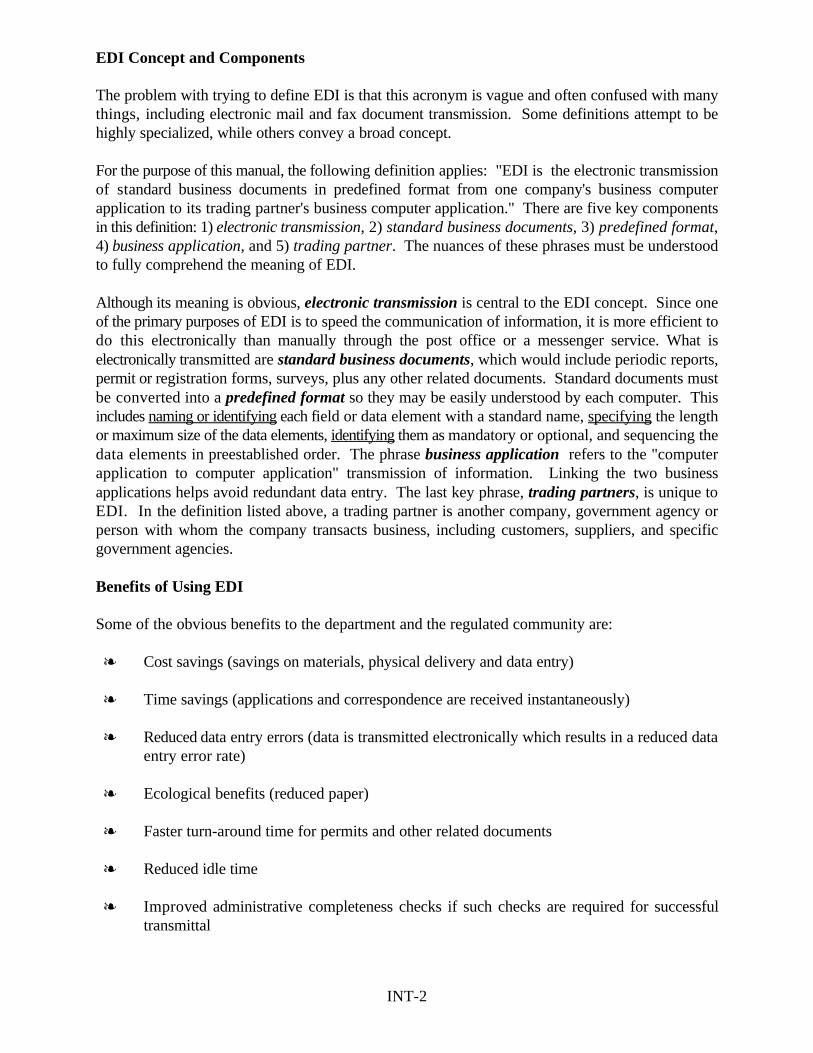
Benefits of Using EDI
Some of the obvious benefits to the department and the regulated community are:
É Cost savings (savings on materials, physical delivery and data entry)
É Time savings (applications and correspondence are received instantaneously)
É Reduced data entry errors (data is transmitted electronically which results in a reduced dataentry error rate)
É Ecological benefits (reduced paper)
É Faster turn-around time for permits and other related documents
É Reduced idle time
É Improved administrative completeness checks if such checks are required for successfultransmittal

INT-3
É Improved working relationships (the department provides a friendlier face to the regulatedcommunity)
Transfer Mechanisms and File Formats and Protocols
Transfer mechanisms are quite varied among individual departmental offices doing EDI. They includedial-up into the departmental BBS as well as diskette, tape and CD-ROM transfer.
Value Added Networks (VANs) are not used at the present time. The Internet is being considered.
File formats are varied as well, including ASCII, DBF, Lotus and various binaries.
EBB-1
New Jersey Department of EnvironmentalProtection’s
Electronic Bulletin Board System
NJDEP BBSUser Guide
ver.1.0
(609) 292-2006
EBB-2
NJDEP BBS - User Guide
What is a BBS?
BBS stands for Bulletin Board System. A BBS is a system which enables a user to connect his orher computer through a modem to another computer using the phone line. The BBS then runssoftware that allows a user to perform certain commands from the remote computer or terminal.
What is the NJDEP BBS?
The New Jersey Department of Environmental Protection’s Electronic Bulletin Board System(NJDEP BBS) is a computerized bulletin board system to assist the Department in communicationswith the environmental community, regulated community, and the general public. The NJDEP BBSsupports up to 4 dial-in sessions simultaneously.
Why a BBS?
A BBS allows electronic communication. Some uses include:
C Publishing without paper. Catalogs, policies, technical manuals/papers, applicationforms, meeting schedules, etc., can be viewed online, or downloaded to a user’scomputer for later viewing, printing, etc.
C Newsletters. Instant updates to activities within the Department, hearing schedules,file locations, etc., can all be listed in a continually updated newsletter.
C Electronic mail (Messaging). Got a question? Send instant mail to the Department.Respond to a posted message. Instead of wasting time searching for the right person,just post a message on the BBS and wait for others to respond. Messaging helpseveryone.
Why isn’t this information on the Internet?
The Department of Environmental Protection has a page on the World Wide Web, under the Stateof New Jersey Web Page (http://www.nj.state.us). However, the NJDEP BBS allows theDepartment to provide up-to-the-minute bulletins and newsletters, expanded file postings with searchcapabilities, message-response forums, and much greater flexibility in file storage. For the same typeof service on a web page, additional File Transfer Protocol (FTP) sites for file access would beneeded. To access the BBS from the Internet, Telnet access would be required. This is a feature wehope to provide in the near future. The Department is currently looking to provide some of theinformation currently on the BBS on its World Wide Web page.
EBB-3
What do I need to call the NJDEP BBS?
System requirements: a PC or Mac computer, a modem (1200 bps - 14,400 bps), and acommunications software package.
Modem settings: 8 data bits, No parity, 1 stop bit, terminal emulation, ANSI (provided the ansi.sysdriver is loaded in your config.sys) or RIP graphics (RIP supported communications softwarerequired), and a baud rate of up to 19,200 bps. Have your modem call (609) 292-2006.
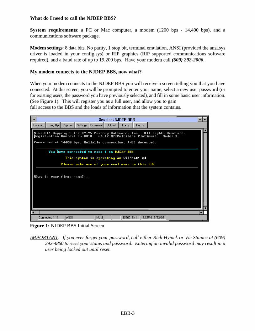
My modem connects to the NJDEP BBS, now what?
When your modem connects to the NJDEP BBS you will receive a screen telling you that you haveconnected. At this screen, you will be prompted to enter your name, select a new user password (orfor existing users, the password you have previously selected), and fill in some basic user information.(See Figure 1). This will register you as a full user, and allow you to gain full access to the BBS and the loads of information that the system contains.
Figure 1: NJDEP BBS Initial Screen
IMPORTANT: If you ever forget your password, call either Rich Hyjack or Vic Staniec at (609)292-4860 to reset your status and password. Entering an invalid password may result in auser being locked out until reset.
EBB-4
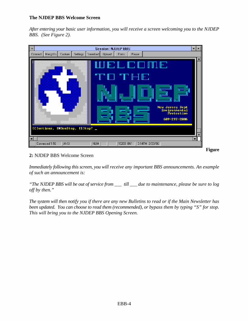
The NJDEP BBS Welcome Screen
After entering your basic user information, you will receive a screen welcoming you to the NJDEPBBS. (See Figure 2).
Figure2: NJDEP BBS Welcome Screen
Immediately following this screen, you will receive any important BBS announcements. An exampleof such an announcement is:
“The NJDEP BBS will be out of service from ___ till ___ due to maintenance, please be sure to logoff by then.”
The system will then notify you if there are any new Bulletins to read or if the Main Newsletter hasbeen updated. You can choose to read them (recommended), or bypass them by typing “S” for stop.This will bring you to the NJDEP BBS Opening Screen.
EBB-5
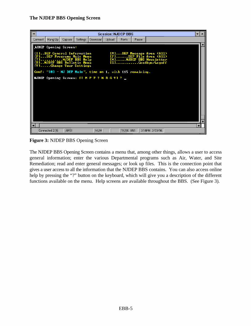
The NJDEP BBS Opening Screen
Figure 3: NJDEP BBS Opening Screen
The NJDEP BBS Opening Screen contains a menu that, among other things, allows a user to accessgeneral information; enter the various Departmental programs such as Air, Water, and SiteRemediation; read and enter general messages; or look up files. This is the connection point thatgives a user access to all the information that the NJDEP BBS contains. You can also access onlinehelp by pressing the “?” button on the keyboard, which will give you a description of the differentfunctions available on the menu. Help screens are available throughout the BBS. (See Figure 3).

EBB-6
The NJDEP BBS Bulletin Menu
Figure 4: NJDEP BBS Bulletin Menu Screen
The NJDEP BBS Bulletin Menu has bullets that highlight late-breaking information covering a broadrange of topics and users. It is similar to a newsletter, except that the bulletin menu contains separatespecific issues. The advantage to having a bulletin menu is that the bulletins are downloadable. TheNJDEP BBS Bulletin Menu contains a Glossary of Terms and an explanation of what exactly theNJDEP BBS is. It also contains what we have entitled as Late Breaking DEP News. These issuesare recommended reading since they are the topics that users have suggested are most important tothem, or that the Department feels are important enough to be singled out (See Figure 4).
EBB-7
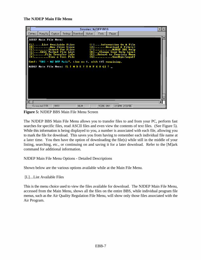
The NJDEP Main File Menu
Figure 5: NJDEP BBS Main File Menu Screen
The NJDEP BBS Main File Menu allows you to transfer files to and from your PC, perform fastsearches for specific files, read ASCII files and even view the contents of text files. (See Figure 5).While this information is being displayed to you, a number is associated with each file, allowing youto mark the file for download. This saves you from having to remember each individual file name ata later time. You then have the option of downloading the file(s) while still in the middle of yourlisting, searching, etc., or continuing on and saving it for a later download. Refer to the [M]arkcommand for additional information.
NJDEP Main File Menu Options - Detailed Descriptions
Shown below are the various options available while at the Main File Menu.
[L]....List Available Files
This is the menu choice used to view the files available for download. The NJDEP Main File Menu,accessed from the Main Menu, shows all the files on the entire BBS, while individual program filemenus, such as the Air Quality Regulation File Menu, will show only those files associated with theAir Program.
EBB-8
Additional help is available after selecting this command.
[N].....New Files Since [N]
This option is most commonly used to check for new files uploaded since the last time you were onthe BBS, or more specifically, since the last time you used this function. Selecting this optiondisplays a prompt similar to below:
New files, [L]ast new 05/21/92 19:20, [O]ther date, [D]ays old? [L]
Shown below is a description of the available options.
[L]ast new 05/21/92 19:20 -
The date and time stored in this option indicates the last time you used the [N]ew FilesSince [N] option. Each time you use this option, the system automatically maintains thisinformation in your user record. This is useful when checking for files that have beenuploaded to the system (that you haven't seen before) since the last date and timeindicated. This is the default response and the most commonly used.
[O]ther date -
This option allows you to specify the date from which you wish to start searching for newfiles. Selecting this option displays a prompt similar to below:Enter date to search from? [05/21/92]
Entering the desired date will then reset the previous value to the new date.
[D]ays old -
This feature is handy when you want the system to set the date search criteria back aspecified number of days. This is useful in saving the number of keystrokes required andthe mental thought process of figuring out valid days in a month. Selecting this optionbrings up the following prompt:
Enter number of days to search? [ ]
Specifying the number here will cause the system to calculate the number of days previousto the current date and start the search from that time. In other words, if the current dateis 05/21/92 and you specify 15 days, the new date to search from will automatically bereset to 05/06/92.
Once the date has been specified using any of the above methods, the system will displaythe following sub-prompt:
File area [1-59], [L]ist, [H]elp, [Q]uit, [ENTER = All]?

EBB-9
From here, you specify the actual file area(s) through which the system will search. Additionalinformation is available by selecting the [H]elp option.
[S]........Search for Files
The search function allows you to locate files on the BBS using a user specified set of searchcriteria. Files can be searched for matches on file name, description, uploader and so on.Additional information is available after selecting this option.
[E]........Edit Marked File List
This option is used to edit the list of files previously [M]arked for download. You can add,delete and clear the entire list of files selected. Information about transfer time for each file,and totals on Kbytes and transfer time are displayed. This list is maintained only for thecurrent logon. If after marking files for download you decide not to download them andlogoff, the list will automatically be cleared. Additional help is available after this commandis chosen.
[F]......File Transfer Info
This option presents extensive information on various file transfer protocols available,including Xmodem, Ymodem, Zmodem, ASCII, and others. It can give you help on whatprotocols are fastest and which should be used in different situations.
[V]....View a text file
This option allows you to read any file stored in ASCII text while on-line. This option willallow you to read a file as long as it has one of the following extensions: DOC, TXT, ANS,ASC, SCR, or BAS.
[I].....Information on a File
This menu choice prompts you for the file name you're interested in. Depending on thesystem configuration, it's possible to leave out the file name’s extension (.ZIP) and yet stillselect the desired file. This saves you from having to enter in the complete file name each andevery time. The default file name extension can vary from system to system.
After checking for a valid file name, the system will then proceed to display information aboutthe selected file in the Full/Detailed file description mode. This option is also available whenlisting files for download.
[D]......Download a File(s)
This option allows transferring files from the BBS system to your computer. There are anumber of different methods of transferring files which are fully explained in the [F]ileTransfer Info option from this menu.
EBB-10
Following a request for download, you will be prompted for the name of the file (or files) todownload if you haven't previously marked them. If you haven't previously defined a defaultfile transfer protocol (see Main Menu option [Y]our Settings), you will be prompted to enterwhich one to use followed by a choice of whether or not to be automatically logged off afterthe transfer is complete.
When the BBS indicates it's "Ready to Send” you should begin your own local transferprocedures using the same protocol selected when the download was started.The NJDEP BBS will allow you to download files using internal batch protocols such asYmodem and Zmodem and selected external protocols like MobyZmodem and PUMA. Evenusing non-batch protocols like Xmodem, Xmodem/CRC, you can queue up to 99 files forrepetitive auto-download. This is, of course, subject to the limitation imposed by the SysOpfor your security level.
This option is also available when listing files for download. This makes for fast and easydownloading without having to return to the File Menu.
[?]..........NJDEP BBS Help
Displays the help file.
[H]..Change User Help Level
The NJDEP BBS supports three different levels of menu prompts. Selecting this optionpresents the following sub-prompt:
Current help level is set at: NOVICE
[N]ovice : Complete menus, full command line.
[R]egular : No menus, command line only.
[E]xpert : No menus or command line.
Help level desired [N R E] ? ? [N]
Below is an explanation of the above options.
[N]ovice -
The first and default value for new users is the Novice level. At this level, the user ispresented with full, dynamic monochrome or color menus, a command line promptcontaining the name of current menu area (Main, Message, File) and the first characterfor a particular option in the current menu. The characters presented agree with the letterdesignator selected for that option.
[R]egular -
EBB-11
This is the second level. At this level, only the current conference number/description,time and command line option letter designators are displayed. No menus are displayedat this level. Shown below is a sample display prompt.
Conf: "[0] - Main Message Area", time on 1, with 59 left
MAIN MENU: [M F C B P I Q V Y S U O G H ? J W T] ? [ ]
[E]xpert -
The final and highest level is the Expert level. At this level, only the current conferencenumber and description along with the menu name are displayed. Shown below is asample display prompt.
General Message Area (0), MAIN MENU: ? [ ]
Selecting this level requires a reasonable understanding of all the options. It'sprimarily designed for speed. If at any time you forget what a certain option letter is,pressing [?] at any of the menus will present you with a HELP screen showing all thepossible options.
The HELP LEVEL command is available in ALL major menus and the usage isexactly the same in each of them.
[X].Return to Previous Menu
Exits the Program File Menu and returns to the Program Main Menu.
[G].........Goodbye/Log-Off
Terminates the current connection and disconnects. If your current Help level is set tothe NOVICE mode, choosing this option gives you a way to back out of the commandby displaying the following prompt:
Are you sure you wish to logoff? [Y]
If you respond with a Yes, then normal logoff procedures are begun. Otherwise, the BBS willassume the command has been entered in error, and will return you to the current menu.

EBB-12
If your current help level settings are set to REGULAR or EXPERT, this extra prompt willno longer be displayed as the BBS assumes that you know the commands well enough todeliberately wish to logoff. This command is available in ALL major menus and performsexactly the same in each of them.
The NJDEP BBS Main Message Menu
Figure 6: NJDEP BBS Main Message Menu Screen
The NJDEP BBS Main Message Menu Screen allows you to read or post messages for differenttopics and to different users. (See Figure 6). It provides an easy and convenient way ofcommunicating with the Department and others.
NJDEP Main Message Menu Options - Detailed Description
[R]...........Read Messages
This command allows you to select which messages you want to read, from what conferencesand with any possible search conditions. You can read your previously unread personal mailand any messages entered as public in any of the available conferences. Reading can be doneusing a number of command line options, and extensive help information is available afterselecting this option.
[?]............Command Help
Displays the Help screen.
EBB-13
[S].......Scan for Messages
This command allows you to scan messages in specified conferences for user-suppliedinformation. Extensive matching capabilities exist with the wide range of searchableparameters. After messages are found, they are displayed in a line by line fashion and can bemarked for easy retrieval when using the Read message function. Extensive help informationis available after selecting this option.
[U]......Update Conf Scan/Read This option updates the current conference to scan or read new messages.
[E].....Enter a New Message
Selecting this option allows you to enter a message to a specific user on the system oraddressed to ALL. This message can be left in one of the local conferences or possibly in oneof the Echomail or Netmail type conferences without having to join that conference first;merely select the desired conference number at the prompt.
Several type of editors are available to you including a full screen type editor. Carbon copiesof this message can also be sent to other people at the same time. Additional help is availableafter selecting this option.
[T].......Transfer QWK Mail
This option runs a special program to create QWK compatible downloadable mail packetsfrom the BBS. These packets usually contain a complete list of new files, recently updatedbulletins, all your new mail from specific conferences and so on. This is used when you preferto do your message reading and replying offline. This option saves you the online time whenreading your mail, especially if you are calling the system long distance.
This option requires you to have a special offline message reader like OLX from MustangSoftware Inc. to properly handle these special QWK mail packets. Additional information isavailable after selecting this option.
[J].....Join Conference
Selecting this option allows you to access all message areas, such as messages within the AirQuality Regulation Message Menu, from the Main Message Area.
[X].Return to Previous Menu
Exits the Message Menu and returns to the Previous Menu.
[F]...............File Menu
Takes you directly to the current Program File Menu where file uploadsand downloads are available.

EBB-14
[G].........Goodbye/Log-Off
Terminates the current connection and disconnects. If your current Help level is set to theNOVICE mode, choosing this option gives you a way to back out of the command bydisplaying the following prompt:
Are you sure you wish to logoff? [Y]
If you7 respond with a Yes, then normal logoff procedures are begun. Otherwise, the BBS willassume the command has been entered in error, and will return you to the current menu.
If your current help level settings are set to REGULAR or EXPERT, this extra prompt willno longer be displayed as the BBS assumes that you know the commands well enough todeliberately wish to logoff. This command is available in ALL major menus and performsexactly the same in each of them.
What if I have problems connecting to the NJDEP BBS?
Problems connecting to the BBS can occur for several reasons. Before giving up, or calling thesysops, check the following to see if any of these apply to you:
C Line noise: There could be what is known as line noise, where the phone service ingeneral has a lot of traffic and your modem is receiving incorrect information. Hang upand redial the BBS.
C System busy: All four incoming phone lines are busy. Keep trying to redial the BBS.Other much larger BBSs currently run at four incoming phone lines with little or notrouble, so the situation is probably only temporary.
C System is down: Yes, believe it or not, this system does occasionally go down. TheNJDEP BBS currently resides on a departmental network server. If problems arise onthat server, the problems may directly affect the operations of the BBS. Other problemshave arisen due to maintenance on the BBS or because of a power outage in the building.Most of the situations are temporary, so it is recommended that you just periodically retryconnecting to the system. If the system goes down over a weekend, chances are that itwill be down until Monday. Be patient and try again Monday morning.
C Incorrect modem settings: Be sure that your modem is set at the settings listed earlier inthis guide. Sometimes a modem is configured, but the user forgets to save the settings.Double-check the settings or consult your user manual.
C Incorrect communications software configuration: Check your users manual for yourmodem first. Your modem may not have been installed correctly.
If additional assistance is needed, please contact either Richard Hyjack or Victor Staniec, the NJDEPBBS sysops (system operators), at (609) 292-4860.
GIS-1
New Jersey Department of Environmental ProtectionGeographic Information System
Mapping the Present to Protect New Jersey's Future
Mapping and Digital Data
Standards
Prepared by:
New Jersey Department of Environmental ProtectionOffice of Information Resources ManagementBureau of Geographic Information AnalysisP.O. Box 428Trenton, NJ 08625-0428
July, 1997
GIS-2
SUMMARY
The New Jersey Department of Environmental Protection (DEP) has developed a GeographicInformation System (GIS) for use by the Department for the storage and analysis of cartographic(mapped) and related environmental scientific and regulatory database information. A GIS is acomputer mapping system used in the analysis of geographic data and databases. By AdministrativeOrder, Commissioner Shinn has required that mapped information be submitted to the DEP accordingto the standards of this document such that the data can be input to the DEP/GIS. This documentdetails three important GIS concepts regarding the creation, capture and delivery of mappedinformation.
First, all basemaps regardless of scale must meet a definable standard, such as the UnitedStates National Map Accuracy Standard (NMAS) referenced in this document, or be of surveyquality. This will guarantee true positional accuracy of data layers. The NJDEP has produced a seriesof photobase maps at quad (1:24000) and quarterquad (1:12000) scales which meet NMAS andwhich are available from DEP Maps and Publications; (609) 777-1039.
Secondly, geographic data shall be mapped in state plane coordinates (SPC). SPC means ageographic reference system in the horizontal plane describing the position of points or features withrespect to other points in New Jersey. The official survey base of the state is known as the NewJersey State Plane Coordinate System whose geodetic positions have been adjusted on the NorthAmerican Datum of 1983 (NAD83) as per Chapter 218, Laws of New Jersey 1989. Although thisofficial survey base is defined in meters, the NJDEP will accept and prefers state plane coordinatesin survey feet.
Thirdly, geographic data must be delivered to the DEP in digital format, as shown in Table2 of this document. There are several different formats such as a simple space delimited ASCII fileof coordinates, a .DWG file from AutoCad, or an Arc/Info export file, depending on the mappingrequirements.
For more information concerning GIS, GIS standards, the user community in New Jersey,data availability, and Global Positioning System (GPS) the 1997 New Jersey GIS Resource Guideis available from DEP Maps and Publications, Trenton, NJ, (609) 777-1039, on CD-ROM. GISdigital Environmental Resource data on CD-ROM is also available from Maps and Publications.
Note: Rules, contracts and/or other regulatory documents from DEP programs may specifyitems required such as content, format or media.
GIS-3
MAPPING AND DIGITAL DATA STANDARDS FOR THE NEW JERSEY DEPARTMENT OF ENVIRONMENTAL PROTECTION
GEOGRAPHIC INFORMATION SYSTEM
1.0 INTRODUCTION
Geographic Information System (GIS) technology has become a state-of-the-art tool forinnovative efforts nationally to protect the natural environment and public health. The New JerseyDepartment of Environmental Protection (DEP) acquired GIS software (ARC/INFO) in 1987 toprovide technical and analytical support to the DEP's decision-making process. To adequately protectthe environment, the NJDEP must make decisions based on sound, accurate spatial data. Thisdocument details the basic standards for creating, converting and encoding analog spatial data intoa digital form for use on a GIS.
The DEP/GIS is administered by the Bureau of Geographic Information and Analysis (BGIA).The BGIA is responsible for the day to day operations of the system, training, data base development,pilot applications, GIS research, and user support. In support of these roles, the BGIA has establisha core set of standards for all data development and input for the DEP/GIS. Basic standards willensure consistent data quality and documentation, provide for compatibility between data sets,facilitate interactive analysis and ensure the quality of results derived from the DEP/GIS. For moreinformation concerning GIS, aerial photography, geodetic control, and global positioning (GPS), askfor the 1997 New Jersey GIS Resource Guide from Maps and Publications; (609) 777-1039 on CD-ROM. For digital GIS data, ask for the GIS Resource Data CD-ROMs also from Maps andPublications.
Geographic data must be delivered to the DEP in digital format, according to Table 2 of thisdocument. This can be as simple as an ASCII file of coordinates, space delimited on 3.5' diskette, toa .DWG file from AutoCad, to an Arc/Info export file, depending on the mapping requirements.
2.0 BASEMAPS
Cartographic (locational) data input into the GIS must be derived from or mapped togeoreferenced basemaps that meet or exceed National Map Accuracy Standards (NMAS) or be ofsurvey quality. Recompiling data from sources which are not planimetric to georeferenced basemapsis always required. Basemaps at any scale should always meet NMAS at a minimum (Section 8.0).Data (point locations) derived from GPS technology must also meet a standard and be documented(Section 7.0).

GIS-4
Figure 1: 1991 Photoquad Index
The concept of a stable base georeferenced basemap or overlay is referred to as "GIScompatible" throughout this document. Stable base site maps of large scale, produced by surveying,mapping or photogrammetric firms may qualify as GIS compatible if they contain a minimum of fourregistration tics in the New Jersey State Plane Coordinate System, North American Datum 1983(NAD83), the official survey base of New Jersey.
Over the years the DEP has produced several series of quality basemaps which are GIScompatible. In several cases these maps are synoptic and statewide, such as the photo basemapsassociated with the 1991 and 1986 overflights. In other cases the basemaps cover specific areas only,such as the 1977-78 Tidelands photo basemaps. The basemaps described here were produced onstable base mylar, are photo-images, and meet a definable mapping standard. These maps in mylarand paper are acceptable basemaps which should be used whenever possible to generate GIScompatible data and/or to use as a recompilation base. The various basemap sources are describedbelow.
All the maps described herein with the exception of the 1991/92 products are referenced inNAD27. For this reason, the 1991 basemap quads (1:24000) and quarterquads (1:12000) series,referenced in NAD83, are highlyrecommended over all other sourceslisted for mapping at these scales(See Basemap Availability).
1991 Aerial Photographs andBasemaps
In February and March of1991 the DEP and the United StatesGeological Survey (USGS) flew ajoint high altitude aerial mission overNew Jersey, producing a set ofquarterquad centered color infrared(CIR) photos at 1:40000. Theseframes are available from the USGSNational Earth Science InformationCenter; (703) 648-6045. The framesare available for review at theTidelands Element, 9 Ewing Street,Trenton. The DEP then created a setof hardcopy chronoflex quarterquad(1:12000) and photoquad basemaps(1:24000) for the public andregulated community to meet therequirements of DEP mandatedmapping (Figure 1, Table 1). This
GIS-5
series of maps is referenced in SPC in NAD83. Paper prints are available from Maps and Publications(see Basemap Availability). This series of maps represents the best maps at these two scales formapping. Soft copy digital images of both quads and quarterquads are also available at both scales.
1986 Freshwater Wetlands Quarterquad Maps (1:12000)
The passage of the Freshwater Wetlands Act of 1987 required the DEP to produce acomposite map of the freshwater wetlands for the state. The Department recommended andsubsequently produced a set of 624 chronoflex photo quarterquads for the entire state from theMarch 1986 overflight. The quarterquads meet NMAS. The maps represent a good source for bothphoto-interpretation and recompilation at a county, municipal or site level.
1986 Photoquad Basemaps (1:24000)
The Department sponsored a statewide overflight in March 1986 and produced a completeset of stable base photoquads at 1:24000. The control for the production of these basemaps was themylar USGS 7.5-Minute topoquads. The photoquads have been widely used both to create datalayers and to recompile other data sources from paper or non-planimetric sources. Paper prints areavailable from Maps and Publications (see Basemap Availability).
1977/78 Tidelands Basemaps (1:2400)
The DEP produced a series of 1:2400 base maps for the coastal zone that include all tidalareas in the state to delineate the State's claim to all tide-flowed lands. The series consists of 1,628photo basemaps. These maps are rectified products which meet NMAS below the ten foot contour.The photo-image is late summer of 1977 and 1978.
USGS 7.5-Minute Series Topoquad Basemaps (1:24000)
The USGS has published an entire series of 172 topographic maps for the state at a scale of1:24000. The base information ranged from the late 1940's to the 1980's with photo-updates into the1990's. Because these maps vary in source date, and because the DEP has produced more accurateand current basemaps (1991), the USGS Topoquads series is not recommended except as reference.
GIS-6
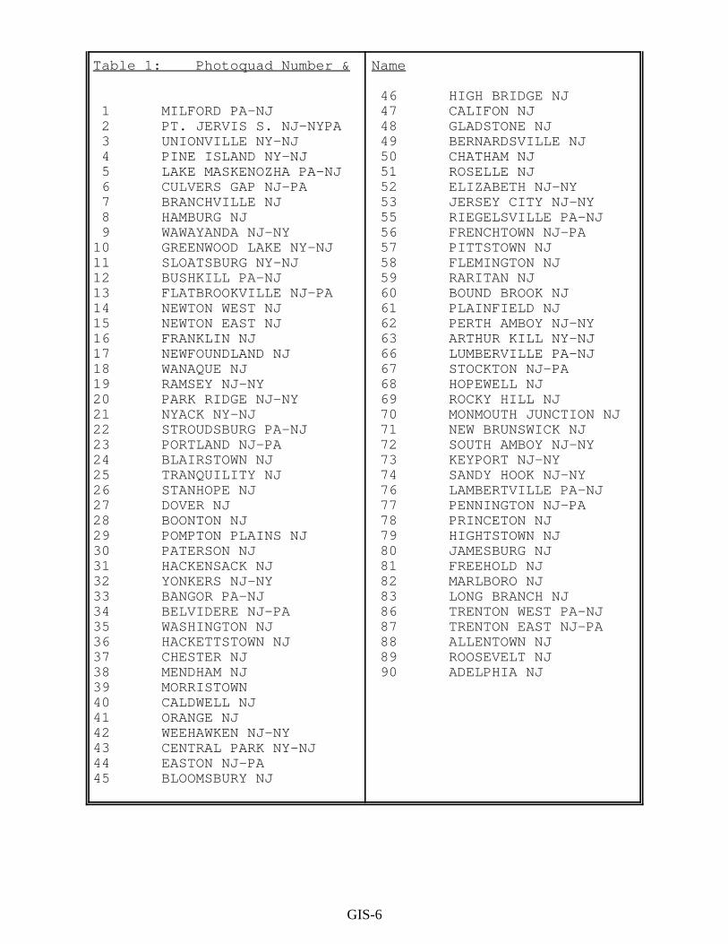
Table 1: Photoquad Number & Name
1 MILFORD PA-NJ 47 CALIFON NJ 2 PT. JERVIS S. NJ-NYPA 48 GLADSTONE NJ 3 UNIONVILLE NY-NJ 49 BERNARDSVILLE NJ 4 PINE ISLAND NY-NJ 50 CHATHAM NJ 5 LAKE MASKENOZHA PA-NJ 51 ROSELLE NJ 6 CULVERS GAP NJ-PA 52 ELIZABETH NJ-NY 7 BRANCHVILLE NJ 53 JERSEY CITY NJ-NY 8 HAMBURG NJ 55 RIEGELSVILLE PA-NJ 9 WAWAYANDA NJ-NY 56 FRENCHTOWN NJ-PA10 GREENWOOD LAKE NY-NJ 57 PITTSTOWN NJ11 SLOATSBURG NY-NJ 58 FLEMINGTON NJ12 BUSHKILL PA-NJ 59 RARITAN NJ13 FLATBROOKVILLE NJ-PA 60 BOUND BROOK NJ14 NEWTON WEST NJ 61 PLAINFIELD NJ15 NEWTON EAST NJ 62 PERTH AMBOY NJ-NY16 FRANKLIN NJ 63 ARTHUR KILL NY-NJ17 NEWFOUNDLAND NJ 66 LUMBERVILLE PA-NJ18 WANAQUE NJ 67 STOCKTON NJ-PA19 RAMSEY NJ-NY 68 HOPEWELL NJ20 PARK RIDGE NJ-NY 69 ROCKY HILL NJ21 NYACK NY-NJ 70 MONMOUTH JUNCTION NJ22 STROUDSBURG PA-NJ 71 NEW BRUNSWICK NJ23 PORTLAND NJ-PA 72 SOUTH AMBOY NJ-NY24 BLAIRSTOWN NJ 73 KEYPORT NJ-NY25 TRANQUILITY NJ 74 SANDY HOOK NJ-NY26 STANHOPE NJ 76 LAMBERTVILLE PA-NJ27 DOVER NJ 77 PENNINGTON NJ-PA28 BOONTON NJ 78 PRINCETON NJ29 POMPTON PLAINS NJ 79 HIGHTSTOWN NJ30 PATERSON NJ 80 JAMESBURG NJ31 HACKENSACK NJ 81 FREEHOLD NJ32 YONKERS NJ-NY 82 MARLBORO NJ33 BANGOR PA-NJ 83 LONG BRANCH NJ34 BELVIDERE NJ-PA 86 TRENTON WEST PA-NJ35 WASHINGTON NJ 87 TRENTON EAST NJ-PA36 HACKETTSTOWN NJ 88 ALLENTOWN NJ37 CHESTER NJ 89 ROOSEVELT NJ38 MENDHAM NJ 90 ADELPHIA NJ39 MORRISTOWN40 CALDWELL NJ41 ORANGE NJ42 WEEHAWKEN NJ-NY43 CENTRAL PARK NY-NJ44 EASTON NJ-PA45 BLOOMSBURY NJ
46 HIGH BRIDGE NJ
GIS-7
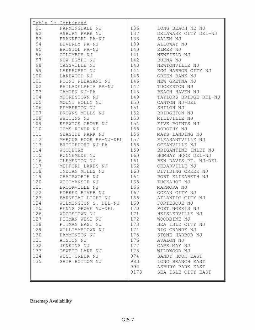
Table 1: Continued 91 FARMINGDALE NJ 136 LONG BEACH NE NJ 92 ASBURY PARK NJ 137 DELAWARE CITY DEL-NJ 93 FRANKFORD PA-NJ 138 SALEM NJ 94 BEVERLY PA-NJ 139 ALLOWAY NJ 95 BRISTOL PA-NJ 140 ELMER NJ 96 COLUMBUS NJ 141 NEWFIELD NJ 97 NEW EGYPT NJ 142 BUENA NJ 98 CASSVILLE NJ 143 NEWTONVILLE NJ 99 LAKEHURST NJ 144 EGG HARBOR CITY NJ100 LAKEWOOD NJ 145 GREEN BANK NJ101 POINT PLEASANT NJ 146 NEW GRETNA NJ102 PHILADELPHIA PA-NJ 147 TUCKERTON NJ103 CAMDEN NJ-PA 148 BEACH HAVEN NJ104 MOORESTOWN NJ 149 TAYLORS BRIDGE DEL-NJ105 MOUNT HOLLY NJ 150 CANTON NJ-DEL106 PEMBERTON NJ 151 SHILOH NJ107 BROWNS MILLS NJ 152 BRIDGETON NJ108 WHITING NJ 153 MILLVILLE NJ109 KESWICK GROVE NJ 154 FIVE POINTS NJ110 TOMS RIVER NJ 155 DOROTHY NJ111 SEASIDE PARK NJ 156 MAYS LANDING NJ112 MARCUS HOOK PA-NJ-DEL 157 PLEASANTVILLE NJ113 BRIDGEPORT NJ-PA 158 OCEANVILLE NJ114 WOODBURY 159 BRIGANTINE INLET NJ115 RUNNEMEDE NJ 160 BOMBAY HOOK DEL-NJ116 CLEMENTON NJ 161 BEN DAVIS PT. NJ-DEL117 MEDFORD LAKES NJ 162 CEDARVILLE NJ118 INDIAN MILLS NJ 163 DIVIDING CREEK NJ119 CHATSWORTH NJ 164 PORT ELIZABETH NJ120 WOODMANSIE NJ 165 TUCKAHOE NJ121 BROOKVILLE NJ 166 MARMORA NJ122 FORKED RIVER NJ 167 OCEAN CITY NJ123 BARNEGAT LIGHT NJ 168 ATLANTIC CITY NJ124 WILMINGTON S. DEL-NJ 169 FORTESCUE NJ125 PENNS GROVE NJ-DEL 170 PORT NORRIS NJ126 WOODSTOWN NJ 171 HEISLERVILLE NJ127 PITMAN WEST NJ 172 WOODBINE NJ128 PITMAN EAST NJ 173 SEA ISLE CITY NJ129 WILLIAMSTOWN NJ 174 RIO GRANDE NJ130 HAMMONTON NJ 175 STONE HARBOR NJ131 ATSION NJ 176 AVALON NJ132 JENKINS NJ 177 CAPE MAY NJ133 OSWEGO LAKE NJ 178 WILDWOOD NJ134 WEST CREEK NJ 974 SANDY HOOK EAST135 SHIP BOTTOM NJ 983 LONG BRANCH EAST
992 ASBURY PARK EAST9173 SEA ISLE CITY EAST
Basemap Availability

GIS-8
Paper prints of 1986 and 1991 photo basemaps may be obtained from the NJDEP Maps andPublications; (609) 777-1039, as well as paper prints of most USGS quadrangles. Paper prints fromthe 1977/78 series are available from the Tidelands Element (609) 292-2573. Other basemaps thatmeet NMAS may be available from the private sector.
Mylar photo basemaps from 1991, 1986 and 1977/78 and the digital imagery from 1991 maybe obtained from the DEP contractor, MARKHURD, Minneapolis, MN (1-800-MAP-HURD).
Digital Imagery
The NJDEP produced digital imagery from the 1991 overflight which is available at cost fromMarkhurd Corp., Minneapolis, MN (1-800-MAP-HURD). The data can be obtained at 5 ft (quarterquad tile) resolution or 10 ft (quad tile) resolution as black and white CIR digital files.
The State Mapping Advisory Committee, Aerial Photo Subcommittee, is producing a 1995/97statewide digital imagery CIR product in partnership with the USGS, National Mapping Division.This imagery will meet the USGS standard of quarterquad tiles, CIR (3 bands), 1 meter resolution,in NAD83 in meters and will be available sometime in late 1997 or early 1998, through the EROSCenter, National Archive. Aerial photography of the state will also be available from the Eros DataCenter. Some of the 1995 photos are available now.
3.0 MAP COMPILATION
Mapped information comes from a variety of sources which are not always GIS compatible.Consequently, each source must be evaluated to determine whether redrafting is necessary to preparethe data for entry into the GIS. Much of the data required for the GIS can be derived directly fromthe photo-interpretation of aerial photos to rectified photo basemaps.
3.1 PHOTO -INTERPRETATION
Today's GIS data development efforts rely to a large degree on the derivation of themes fromthe stereoscopic interpretation of aerial photos. The DEP has used this technique in conjunction withvarious photo basemaps to produce land use/land cover and freshwater wetland coverages, forinstance. The DEP maintains an extensive library of current and historical color infrared, color andpanchromatic photographs from the 1930's to the present. The bulk of this photography is held bythe Tidelands Management Program (TMP). The TMP offers light tables, photo basemaps andstereoscopes as well as some instruction on set up to assist the public and regulated community. Thisservice is available at a modest fee and is well worth the effort, particularly if the data are to becaptured in the GIS.
Delineators should be intimately familiar with the classification system being employed priorto producing data for input into the GIS. Care should be taken in choosing an appropriate standardclassification system. If non-standard classification systems are used, the contractor shall fullydescribe the system.
3.2 RECOMPILATION
GIS-9
Recompilation involves the redrafting of features from one source to a more accurate,planimetric source based on identifiable features. This method is commonly used to give moreaccuracy to data which has been delineated on sources of unknown or unspecified quality or papermanuscripts. It is also commonly used to transfer data delineated on or to unrectified photographyto a rectified or orthophoto basemap based on a series of local fits of common photo-identifiablefeatures, such as roads.
To date, this technique has been employed to redraft the USDA, Natural ResourceConservation Service (NRCS) soils data from the soil survey atlas sheets to orthophotoquads. Thetechnique for accomplishing this is detailed in Photobase Map Compilation (USDA, 1984). Thismanuscript is an excellent technical guide for recompilation.
Other data sources without photo-images may be recompiled to planimetric sources by usingother coincident features. For instance, grids on source data may be generated and plotted toplanimetric basemaps and used as a guide for the redrafting of information which would otherwisenot be usable in a digital form. This has been used to draft historical purveyor boundaries from oldatlas sheets to the photoquads, for instance. Whatever the technique, a data dictionary form must becompleted describing the recompilation techniques employed.
4.0 DATA AUTOMATION
The conversion of analog data to digital data is a critical step in the creation of a digitaldatabase in the GIS. GPS derived points are captured digitally and do not require automation (Section7.0). Tablet digitizing is the most common method, however, scanning is gaining popularityparticularly when large data development projects are involved. For tablet digitizing, a manuscript’slines should be clear and complete with no gaps or shortfalls. Operators should not interpret anddigitize at the same time. The digitizer should concentrate solely on capturing the exact nature of thelinework. All maps shall be edge matched prior to digitization to eliminate cartographic errors andreduce digital problems.
Heads up digitizing is a new digitizing technique which is useful for capturing data or updatesfrom digital imagery. The BGIA is currently evaluating this technique and will issue standards in thenear future.
Digital accuracy shall be evaluated by proof plotting the digital data to the base at the samescale as the manuscript and overlaying the data to the original map. The linework should be digitizedin such a way as to create a digital copy which is within +/- one line width of thr original. Edits canbe flagged and corrected such that the standard is met.
The coding of features should follow an approved classification system as adopted by stateand federal agencies. These codes follow specifications of organizations responsible for deriving andmaintaining the data. For example, the DEP uses the Cowardin et al. (1979) system for theClassification of Wetland and Subaqueous Lands in the United States as adopted by the NationalWetlands Inventory of the U.S. Fish and Wildlife Service. In addition the Department supports amodified version of Anderson et al. (1976), USGS, for classifying land use/land cover. For prototypeclassification schemes, clear concise documentation describing the classes is required.
All attribute coding shall be 100% correctly coded. Code sheets shall also be provided, listing
GIS-10
the code and full description of each code. All documentation shall be delivered in hard copy and ondiskette. Codes shall also be described in the Data Dictionary (Section 9.0).
5.0 DATA TRANSFER
At a minimum, for the delivery of coordinates and simple database, data shall be submittedin an ASCII flat file format on 3.5 diskette. For instance, data from a word processor can be savedto an ASCII text file for delivery.
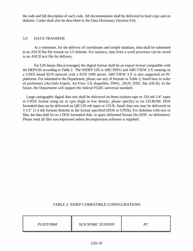
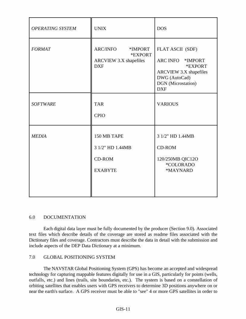
For GIS binary files (coverages) the digital format shall be an export format compatible withthe DEP/GIS according to Table 2. The NJDEP GIS is ARC/INFO and ARCVIEW 3.X running ona UNIX based SUN network with a SUN 1000 server. ARCVIEW 3.X is also supported on PCplatforms. For submittal to the Department, please use any of formats in Table 2, listed here in orderof preference (Arc/Info Export, ArcView 3.X shapefiles, DWG, .DGN, DXF, flat ASCII). In thefuture, the Department will support the federal FGDC universal standard.
Large cartographic digital data sets shall be delivered on 8mm exabyte tape or 150 mb 1/4" tapesin UNIX format using tar or cpio (high or low density, please specify) or on CD-ROM. DOSformatted data can be delivered on QIC120 mb tapes or CD-R. Small data sets may be delivered on3 1/2" (1.4 mb format) diskette in the format specified (DOS or UNIX). For diskettes with text orfiles, the data shall be on a DOS formatted disk, in space delimited format file (SDF, no delimiters).Please send all files uncompressed unless decompression software is supplied.
TABLE 2: NJDEP COMPATIBLE CONFIGURATIONS
PLATFORM SUN SPARC STATION PC
GIS-11
OPERATING SYSTEM UNIX DOS
FORMAT ARC/INFO *IMPORT FLAT ASCII (SDF) *EXPORTARCVIEW 3.X shapefiles ARC INFO *IMPORTDXF *EXPORT
ARCVIEW 3.X shapefilesDWG (AutoCad)DGN (Microstation)DXF
SOFTWARE TAR VARIOUS
CPIO
MEDIA 150 MB TAPE 3 1/2" HD 1.44MB
3 1/2" HD 1.44MB CD-ROM
CD-ROM 120/250MB QIC12O
EXABYTE *MAYNARD *COLORADO
6.0 DOCUMENTATION
Each digital data layer must be fully documented by the producer (Section 9.0). Associatedtext files which describe details of the coverage are stored as readme files associated with theDictionary files and coverage. Contractors must describe the data in detail with the submission andinclude aspects of the DEP Data Dictionary at a minimum.
7.0 GLOBAL POSITIONING SYSTEM
The NAVSTAR Global Positioning System (GPS) has become an accepted and widespreadtechnology for capturing mappable features digitally for use in a GIS, particularly for points (wells,outfalls, etc.) and lines (trails, site boundaries, etc.). The system is based on a constellation oforbiting satellites that enables users with GPS receivers to determine 3D positions anywhere on ornear the earth's surface. A GPS receiver must be able to "see" 4 or more GPS satellites in order to
GIS-12
determine positions. GPS is a useful tool in capturing data digitally with the ability of outputting thedata in NAD83 in State Plane Coordinate feet which can then be loaded directly into a GIS system.The following description is provided for those unfamiliar with GPS but who are considering thistechnology to meet the digital standards of NJDEP.
The range of accuracy afforded by GPS is +/- 100 meters to sub-centimeter. The accuracyof any coordinates collected with GPS will depend on several factors: Receiver type (carrier phasevs. code based), the GPS conditions under which the coordinate data is collected (number of satellitesand satellite geometry), whether the quality of the locations are enhanced through differentialprocessing, and the data collection technique (field procedures) by the GPS receiver operator. GPSaccuracies are not expressed in absolute terms. Rather they are expressed as a value such as 5 meters2dRMS. What this really means is that roughly 95% of the horizontal (x,y) values are within 5 metersof truth.
Receiver Classes and Accuracy Capabilities
The two general classes of GPS receivers provide two very different methods by which GPSsignals are processed and, therefore, different accuracy capabilities. Carrier phase receivers usecharacteristics of the GPS signal (i.e., wavelength) to determine positions, while code based (C/Acode) receivers rely on information imbedded in the signal.
Using correct GPS survey techniques and under the right conditions, carrier phase receiverscan produce extremely accurate locations (even to a few millimeters 2dRMS). Carrier phasereceivers should be used for determining locations that require a high level of accuracy. For a GIS,carrier phase receivers should be used for establishing a very accurate geodetic control network onwhich very accurate base maps could be generated. GIS feature locations can be determined withcarrier phase receivers if the mapping project requires features to be mapped to a very high degreeof accuracy (to within 1 meter). Carrier phase GPS operation is more difficult and sometimesimpossible in areas that are less GPS friendly. These would include areas with significant obstructions(buildings and tree canopy) that might block or weaken GPS signals.
In most cases, feature mapping for a GIS can be accomplished with data collected with a codebased GPS receiver. The DEP recommends that code based GPS receivers for GIS data collectionbe 6 or more channels (enabling better performance under adverse conditions), and be capable ofstoring position fix data (allowing post processed differential corrections). All GPS data collectedfor NJDEP's GIS must be differentially corrected, either in a post process step or in real time. Ifcorrect procedures and proper techniques are employed, code based receivers should provide adegree of horizontal accuracy acceptable for most mapping applications (to within 5 meters 2dRMS).Code based receivers cannot be relied upon for accurate elevation data. Elevation values derived bycode based GPS receivers may be in error 2 to 4 times the error of the horizontal measurement.
For point features (well locations, sampling stations, pollution sources, etc.) a sample of 200position fixes must be collected with PDOP < 6. Linear features (trails, shoreline boundaries, etc.)may also be mapped using GPS by storing position fixes while tracing the feature on foot or invehicle.
Sources of GPS Base Data

GIS-13
There are several sources of GPS base data in New Jersey. This reference data is necessaryfor differential GPS. For greater accuracy, users should obtain base data from the source nearest theproject area.
The DEP/BGIA operates a Trimble Navigation Pathfinder Community Base Station inTrenton. This station stores GPS base data and makes the files available through an electronicbulletin board system (BBS). The phone number to access the BBS is (609) 633-0511. The logginghours of the receiver are Monday through Friday, 7 am to 7 pm. The BBS is operational seven daysa week, 24 hours a day. The base data collected by this station can only be used to differentiallycorrect data from Trimble code based receivers (Pathfinder series). In order for the data to becompatible with other GPS receiver manufacturer's (such as Magellan, or Garmin) file formats, theTrimble file format must be converted to RINEX format. DEP does not provide RINEX base files.
The U.S. Environmental Protection Agency's Region II office located in Edison operates asimilar station. The phone number to access the BBS is (908) 321-6663. The logging hours of thestation are seven days a week, 7 am to 7 pm. The BBS is operational seven days a week, 24 hoursa day.
The National Oceanic and Atmospheric Administration (NOAA) operates a ContinuouslyOperating Reference Station (CORS) at Sandy Hook, as part of a network of stations to support postprocessing applications. This station provides code range and carrier phase GPS data in the RINEXformat. Data can be obtained via the INTERNET (ftp proton.ngs.noaa.gov) and is available for 21days. This station also broadcasts differential GPS corrections to support real-time positioning andnavigation applications. For more information contact the National Geodetic Survey at (301) 731-3208.
For more information refer to the 1997 New Jersey GIS Resource Guide.
8.0 NATIONAL MAP ACCURACY STANDARDS
United States National Map Accuracy StandardsU.S. Bureau of the Budget, Revised June 17, 1947
With a view to the utmost economy and expedition in producing maps which fulfill not onlythe broad needs for standard or principal maps, but also the reasonable particular needs of individualagencies, standards of accuracy for published maps are defined as follows.
1. Horizontal accuracy. For maps on publication scales larger than 1:20,000, not more than 10%of the points tested shall be in error by more than 1/30 inch. These limits of accuracy shall apply inall cases to positions of well-defined points only. Well-defined points are those that are easily visibleor recoverable on the ground, such as the following: monuments or markers, such as bench marks,property boundary monuments; intersections of roads, railroads, etc.; corners of large buildings orstructures (or center points of small buildings); etc. In general what is well-defined will also bedetermined by what is plottable on the scale of the map within 1/100 inch. Thus, while theintersection of two road or property lines meeting at right angles would come within a sensibleinterpretation, identification of the intersection of such lines meeting at an acute angle would
GIS-14
obviously not be practicable within 1/100 inch. Similarly, features not identifiable upon the groundwithin close limits are not to be considered as test points within the limits quoted, even though theirpositions may be scaled closely upon the map. In this class would come timber lines, soil boundaries,etc.
2. Vertical Accuracy, as applied to contour maps on all publication scales, shall be such that not morethan 10 percent of the elevations tested shall be in error more than one-half the contour interval. Inchecking elevations taken from the map, the apparent vertical error may be decreased by assuminga horizontal displacement within the permissible horizontal error for a map of that scale.
3. The accuracy of any map may be tested by comparing the positions of points whose locations orelevations are shown upon it with corresponding positions as determined by surveys of a higheraccuracy. Tests shall be made by the producing agency, which shall also determine which of its mapsare to be tested, and the extent of such testing.
4. Published maps meeting these accuracy requirements shall note this fact on their legends, asfollows: "This map complies with National Map Accuracy Standards."
5. Published maps whose errors exceed those aforestated shall omit from their legends all mentionof standard accuracy.
6. When a published map is a considerable enlargement of a map drawing (manuscript) or of apublished map, that fact shall be stated in the legend. For example, "This map is an enlargement ofa 1:20000-scale map drawing," or "This map is an enlargement of a 1:24000-scale published map."
7. To facilitate ready interchange and use of basic information for map construction among all Federalmapmaking agencies, feasible and consistent with the uses to which the map is to be put, maps shallconform to latitude and longitude boundaries, being 15 minutes of latitude and longitude, or 7.5minutes, or 3-3/4 minutes in size. (from Thompson, 1987).
9.0 DATA DICTIONARY
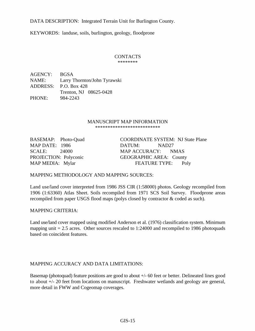
The following is a sample data dictionary for the Integrated Terrain Unit for BurlingtonCounty, NJ. In the future, DEP Data Dictionaries will conform with Federal Geographic DataCommittee (FGDC) standards.
DATA DICTIONARY ***************
COVERAGE NAME: buritum
GIS-15
DATA DESCRIPTION: Integrated Terrain Unit for Burlington County.
KEYWORDS: landuse, soils, burlington, geology, floodprone
CONTACTS
********
AGENCY: BGSANAME: Larry Thornton/John TyrawskiADDRESS: P.O. Box 428 Trenton, NJ 08625-0428PHONE: 984-2243
MANUSCRIPT MAP INFORMATION**************************
BASEMAP: Photo-Quad COORDINATE SYSTEM: NJ State PlaneMAP DATE: 1986 DATUM: NAD27SCALE: 24000 MAP ACCURACY: NMASPROJECTION: Polyconic GEOGRAPHIC AREA: CountyMAP MEDIA: Mylar FEATURE TYPE: Poly
MAPPING METHODOLOGY AND MAPPING SOURCES:
Land use/land cover interpreted from 1986 JSS CIR (1:58000) photos. Geology recompiled from1906 (1:63360) Atlas Sheet. Soils recompiled from 1971 SCS Soil Survey. Floodprone areasrecompiled from paper USGS flood maps (polys closed by contractor & coded as such).
MAPPING CRITERIA:
Land use/land cover mapped using modified Anderson et al. (1976) classification system. Minimummapping unit = 2.5 acres. Other sources rescaled to 1:24000 and recompiled to 1986 photoquadsbased on coincident features.
MAPPING ACCURACY AND DATA LIMITATIONS:
Basemap (photoquad) feature positions are good to about +/- 60 feet or better. Delineated lines goodto about +/- 20 feet from locations on manuscript. Freshwater wetlands and geology are general,more detail in FWW and Cogeomap coverages.
GIS-16
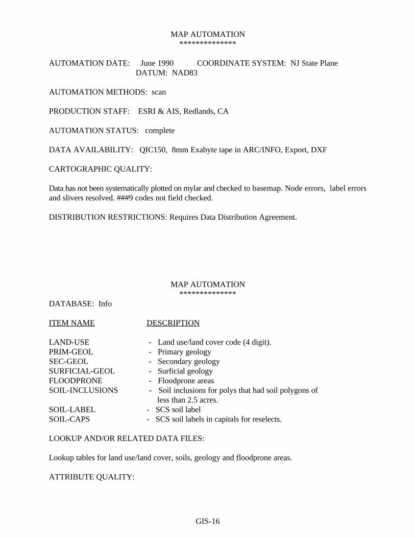
MAP AUTOMATION**************
AUTOMATION DATE: June 1990 COORDINATE SYSTEM: NJ State Plane DATUM: NAD83
AUTOMATION METHODS: scan
PRODUCTION STAFF: ESRI & AIS, Redlands, CA
AUTOMATION STATUS: complete
DATA AVAILABILITY: QIC150, 8mm Exabyte tape in ARC/INFO, Export, DXF
CARTOGRAPHIC QUALITY:
Data has not been systematically plotted on mylar and checked to basemap. Node errors, label errorsand slivers resolved. ###9 codes not field checked.
DISTRIBUTION RESTRICTIONS: Requires Data Distribution Agreement.
MAP AUTOMATION**************
DATABASE: Info
ITEM NAME DESCRIPTION
LAND-USE - Land use/land cover code (4 digit).PRIM-GEOL - Primary geologySEC-GEOL - Secondary geologySURFICIAL-GEOL - Surficial geologyFLOODPRONE - Floodprone areasSOIL-INCLUSIONS - Soil inclusions for polys that had soil polygons of less than 2.5 acres.SOIL-LABEL - SCS soil labelSOIL-CAPS - SCS soil labels in capitals for reselects.
LOOKUP AND/OR RELATED DATA FILES:
Lookup tables for land use/land cover, soils, geology and floodprone areas.
ATTRIBUTE QUALITY:

RAD-1
Frequencies run to check for valid attributes. Land use codes containing ###9 require fieldverification. LOOKUP TABLE DESCRIPTIONS: BURBDRK.LUT Bedrock geology (primary, secondary). BURSOILS.LUT Soils (consult the Soil Survey).BURFLOOD.LUT Floodprone areas. BURSOILINC.LUT Soil inclusions. BURLU.LUT Land use/land cover. BURSURF.LUT Surficial geology.
10.0 REFERENCES
Anderson, J.R., et al., 1979, A Land Use and Land Cover Classification System for Use with RemoteSensor Data, U.S. Department of Interior, Geologic Survey Professional Paper 964. 28pp.
Cowardin, L.M., et al., 1976, Classification of Wetland and Deepwater Habitats of the UnitedStates, U.S. Department of Interior, U.S. Fish and Wildlife Service, FWS/OBS-79/31. 103pp.
U.S. Department of Agriculture, Soil Conservation Service, 1984, Photobase Map Compilation,Technical Specifications, National Instruction No. 170-301. 30pp
Radon
1.0 Introduction
Radon Measurement Monthly Reports are used for the reporting of radon test results required as partof N.J.A.C. 7:28-27.28 (Certification of Radon Testers and Mitigators).

RAD-2
To simplify this reporting requirement, the department provides for the electronic submission ofRadon Measurement monthly reports.
2.0 Electronic Submittal Requirements and Process for Radon Monthly Reports
Help number (Radon Program): (609) 984-5425, (609) 984-5557 or toll-free within New Jersey at1-800-648-0394. Mailing address: DEP- Radon Section, P.O. Box 415, Trenton, NJ 08625-0415.
The following procedures for electronic submittal must be followed by a facility wishing toparticipate.
1. Facilities wishing to participate in electronic submittal should contact the Radon Program helpnumber to coordinate test transmittals and to resolve problems. If requested, a copy of theregulations, the Measurement monthly report form, directions for completing the form, a copyof the field names and specifications, as well as a copy of the Local Names publication willbe provided. The Local Names publication is very helpful in determining the incorporatedname of the municipality (required on the report form) as well as the corresponding countyname.
2. Radon Measurement Monthly Reports are due by the first day of the second month followingthe testing period (i.e., January measurements are to be reported by March 1), pursuant toN.J.A.C. 7:28-27.28(a). Failure to submit a Radon Measurement Monthly Report incompliance with the aforementioned regulation will result in an enforcement violation.
3. Data submissions must be on either a 3 ½ or a 5 1/4 diskette (high or low density), IBMcompatible, and can be in the form of an ASCII (text) file, dBASE file, a Lotus file or aSymphony file.
4. A facility is required to submit, with its data diskette, a cover letter containing the name andaddress of its measurement business, name and phone number of the contact person, as wellas the Measurement Specialist’s signature, certifying the data contained on the diskette. Aseparate diskette must be submitted for each month. The diskette must be labeled with thename of the business, the business certification number, month the data is for and the nameof the file contained on the diskette. If you would like to have the diskette returned afterprocessing, please note this in the cover letter.
5. The format for reporting data is provided in the following Radon 1 table. Detailedinstructions regarding the format are also provided in the Radon 1 table.
Table: Radon 1
Listed below are the fields that must be contained on the data diskette. Fields must be reported inthe same order as listed; do not omit any fields or report additional fields. If a dBASE file issubmitted, the field types and widths must match those specified. If an ASCII test file is submitted,all character data must be surrounded by quotes and separated by a comma. If submitting datautilizing Lotus or Symphony, do not skip lines between records and do not report results as a lessthan (<) value. Less than values should be reported as the lowest detectible limit (i.e., <0.5 should
RAD-3
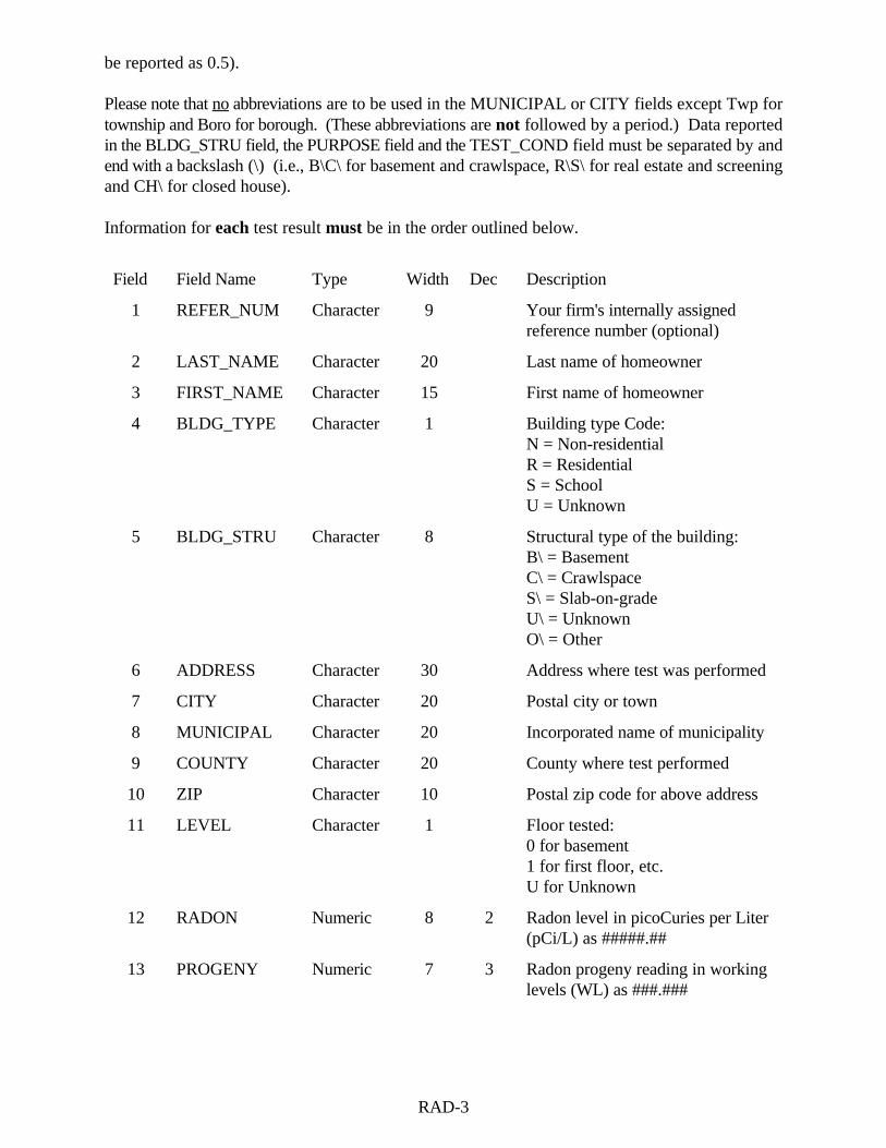
be reported as 0.5).
Please note that no abbreviations are to be used in the MUNICIPAL or CITY fields except Twp fortownship and Boro for borough. (These abbreviations are not followed by a period.) Data reportedin the BLDG_STRU field, the PURPOSE field and the TEST_COND field must be separated by andend with a backslash (\) (i.e., B\C\ for basement and crawlspace, R\S\ for real estate and screeningand CH\ for closed house).
Information for each test result must be in the order outlined below.
Field Field Name Type Width Dec Description
1 REFER_NUM Character 9 Your firm's internally assignedreference number (optional)
2 LAST_NAME Character 20 Last name of homeowner
3 FIRST_NAME Character 15 First name of homeowner
4 BLDG_TYPE Character 1 Building type Code:N = Non-residentialR = ResidentialS = SchoolU = Unknown
5 BLDG_STRU Character 8 Structural type of the building:B\ = BasementC\ = CrawlspaceS\ = Slab-on-gradeU\ = UnknownO\ = Other
6 ADDRESS Character 30 Address where test was performed
7 CITY Character 20 Postal city or town
8 MUNICIPAL Character 20 Incorporated name of municipality
9 COUNTY Character 20 County where test performed
10 ZIP Character 10 Postal zip code for above address
11 LEVEL Character 1 Floor tested:0 for basement1 for first floor, etc.U for Unknown
12 RADON Numeric 8 2 Radon level in picoCuries per Liter(pCi/L) as #####.##
13 PROGENY Numeric 7 3 Radon progeny reading in workinglevels (WL) as ###.###
RAD-4
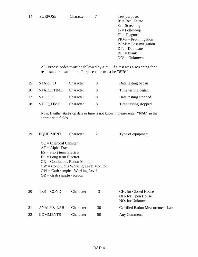
14 PURPOSE Character 7 Test purpose:R\ = Real EstateS\ = ScreeningF\ = Follow-upD\ = DiagnosticPRM\ = Pre-mitigationPOM\ = Post-mitigationDP\ = DuplicateBL\ = BlankNO\ = Unknown
All Purpose codes must be followed by a "\"; if a test was a screening for areal estate transaction the Purpose code must be "S\R\".
15 START_D Character 8 Date testing began
16 START_TIME Character 8 Time testing began
17 STOP_D Character 8 Date testing stopped
18 STOP_TIME Character 8 Time testing stopped
Note: If either start/stop date or time is not known, please enter "N/A" in theappropriate fields.
19 EQUIPMENT Character 2 Type of equipment:
CC = Charcoal CanisterAT = Alpha TrackES = Short term ElectretEL = Long term ElectretCR = Continuous Radon MonitorCW = Continuous Working Level MonitorGW = Grab sample - Working LevelGR = Grab sample - Radon
20 TEST_COND Character 3 CH\ for Closed HouseOH\ for Open HouseNO\ for Unknown
21 ANALYZ_LAB Character 30 Certified Radon Measurement Lab
22 COMMENTS Character 50 Any Comments
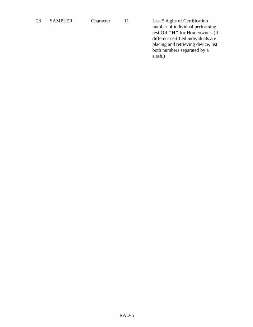
RAD-5
23 SAMPLER Character 11 Last 5 digits of Certificationnumber of individual performingtest OR "H" for Homeowner. (Ifdifferent certified individuals areplacing and retrieving device, listboth numbers separated by aslash.)

RTK-1
Right to Know
1.0 Introduction
The Bureau of Chemical Release Information and Prevention (BCRIP) is responsible foradministering the Community Right to Know (CRTK) Program. This program is mandated by theWorker and Community Right to Know Act (N.J.S.A. 34:5A) and the federal Emergency Planningand Community Right to Know Act (EPCRA), also known as Title III of the Superfund Amendmentsand Reauthorization Act (SARA). These laws require certain businesses to report hazardoussubstances used, stored or manufactured at, or released from, their facilities. Chemical inventoryinformation is collected on the Community Right to Know survey form. The BCRIP currentlycollects chemical inventory information on the CRTK survey distributed to approximately 33,000facilities.
To perform the regulatory activities in an efficient manner, the BCRIP has implemented asystem for facilities to submit Community Right to Know surveys electronically. The system uses anexecutable file which allows users to download screens to input CRTK inventory data andelectronically submit that data to the BCRIP.
In order to implement electronic submission, an executable file is available. In addition,facilities may use their own software.
The required procedures that use the executable file are described first, followed by a briefdescription of the requirements for submission for a facility using its own software.
2.0 Electronic Submittal Requirements and Process for the Community Right to Know SurveyUsing an Executable File
Help number: Bureau of Chemical Release Information and Prevention (609) 292-6714
The following procedure for electronic submittal must be used for facilities choosing to usethe executable file developed by the department.
1. The facility staff must use the Community Right to Know Survey reporting instructions thatare mailed to facilities required by state and federal law to report inventories of hazardoussubstances which are stored, produced or used at a place where business is conducted(facility) in New Jersey. Copies are available upon request to the agency help number.
2. The facility staff must use the Right to Know Public Access System Manual. Copies arecirculated to facilities and are available upon request to the Agency Help number. In addition,the manual is available for downloading from the departmental Bulletin Board System.
See the Electronic Bulletin Board System section for a detailed description of thedepartmental Bulletin Board. For reference, some pertinent Bulletin Board information is asfollows:
Bulletin Board number : (609) 292-2006System Op number: (609) 292-4860Communications parameters: 8 data bits, no parity, 1 stop bit (8, N, 1)

RTK-2
Modem Speed: 1200 - 14,400 bps
3. The facility staff must become familiar with the use of the communications software PCAnyWhere prior to downloading the executable file.
The PC AnyWhere use is described in the section “PC AnyWhere Special Instruction andUse” which appears as a separate section following these instructions.
4. The facility staff must log on to the RTKPAS using PC AnyWhere with the followingparameters:
Phone number: (609) 633-6099Terminal Emulation VT-100Baud Rate: 9600/2400/1200Data Bits: 8Stop Bits: 1Parity: NoneFile Transfer: XMODEM/CRCEcho: Off
5. Select the Download Software. The Right to Know Public Access System (RTKPAS)provides facility submission software to facilities to enter and remotely upload the CommunityRight to Know survey. Select "FacSub" from the main menu on the Right to Know PublicAccess System (RTKPAS). There are two submenu options, 1) Download Software and 2)Upload Survey.
When the download software option is selected, a message will display the approximate timerequired to download the software and the amount of disk space required on the receivingPC. At this point, the user may cancel or proceed with the download. The user will beprompted for the 11 digit EIN number and the facility name. If the employer's correct nameand EIN number are entered, the software will retrieve the current facility informationprovided in the latest survey. The following information will be downloaded with thesoftware: facility name and mailing address; facility location (if different from mailingaddress); number of employees; number of NJ facilities reported; facility emergency contactperson, and phone number. If an employer's correct name and EIN number are not entered,only the software will be downloaded.
The software download includes an installation program, input fields to enter data requiredon the CRTK survey form and tables that provide the Environmental Hazardous SubstanceList (EHSL), container codes, inventory ranges, and storage condition codes for pressure andtemperature.
6. Once the software has been downloaded, the user may disconnect from the RTKPAS and runthe installation program to install the software on the facility PC. The software will allow theuser to enter survey information into several data entry screens. Some of the informationentered will be verified by comparison to data in tables which were downloaded with thesoftware.
RTK-3
7. When the survey is completed, the information will be compressed into a file to be loaded tothe RTKPAS. The user must complete the following steps in order to upload the survey tothe Bureau of Chemical Release Information and Prevention:
a. Sign the certification that the information to be transmitted is true, accurate and complete.
b. Log on to the Right to Know Public Access System as described previously and usethe "upload option" on the menu to send survey information. Enter the 11 digitemployer identification number (EIN) and the company name as it appears on thecurrent Community Right to Know survey form for the facility.
c. Verify that the survey was successfully uploaded by confirming that "The survey wasuploaded successfully" is displayed on the screen. If that message does not appear,disconnect and try to resend the survey. If, again, the message does not appear,contact the agency help number.
d. Mail Part 1 of the survey with the signed certification to BCRIP. Include the eight (8)digit identifier (password) that you entered in the file. Include the date and time thatappears on the last line of the upload survey screen and keep a copy for your records.This information is used to identify the data-set uploaded.
3.0 PC AnyWhere Special Instructions and Use
PC AnyWhere, version 4.5, is the communication software to be used to enable multiple,simultaneous users dialing into the BCRIP's chatterbox communication server to download andupload information.
The employer or authorized representative must certify that electronically submitted data istrue, accurate and complete. The certification, which will include the alpha-numeric identifier(password) used by the company when preparing the file, must be received by the Department beforethe data is accepted.
The following describes how to use and configure PC AnyWhere for DOS and Windowswhen downloading and uploading files.
PC AnyWhere for DOS:
PC AnyWhere for DOS downloads files to and uploads from the current directory. Thismeans that before starting a PC AnyWhere session, the user should go to the directory wherethe files to be uploaded reside or where the files to be downloaded should be placed.Specifically, if a user wants to download the Facility Submission software, he/she shouldcreate a new directory for the Facility Submission software and go to that directory beforeusing PC AnyWhere to dial into the Public Access System. The user should also be in thesame directory before using PC AnyWhere to dial into the Right to Know Public AccessSystem (RTKPAS) and uploading the completed survey. To run PC AnyWhere from thisdirectory, the user should make sure the directory in which PC AnyWhere resides is in his/herdefault search path. For example, if the command PATH=C:\AWLAN were executed eithermanually or by the user's AUTOEXEC.BAT file, the user would be able to run PC AnyWherefrom any directory on his/her C: drive.
RTK-4
PC AnyWhere for Windows:
PC AnyWhere for Windows downloads files to and uploads from the working directorydefined by the Properties function of Program Manager. If a user wants to download theFacility Submission software and later upload the completed survey, he/she should create anew directory where the Facility Submission software and survey will reside. WhenPC AnyWhere is added as an item to a group within Windows, the user should selectProperties and change the Working Directory to the new directory. The user may alsoactivate PC AnyWhere and select Configuration and File Transfer and then select the DefaultDownload Directory.
Printing in PC AnyWhere:
To set up PC AnyWhere to print to the user's own local printer, the user should perform thefollowing steps:
< select Remote Operation and press Enter at the PC AnyWhere Main Menu; < select Remote Preferences and press Enter at the Remote Operation Menu; < select Remote Access Session and press Enter at the Remote Preferences Menu; < select Print Destination and press Enter at the Remote Access Session Menu; < select Print to Remote Only and press Enter at the Print Destination Menu; < press Escape to exit Remote Access Session menu; < select Yes and press Enter at the Save Changes prompt; press Escape to exit the
Remote Preferences Menu and return to the Main Menu.
4.0 Facility Submission Interface Specification
Facilities using their own software to track facility and chemical information mayelectronically submit the information to the BCRIP by creating and uploading the databases describedin the "Data Defnition Document -Facility Information” and “Data Definition Document-ChemicalInformation” tables which follow this section.
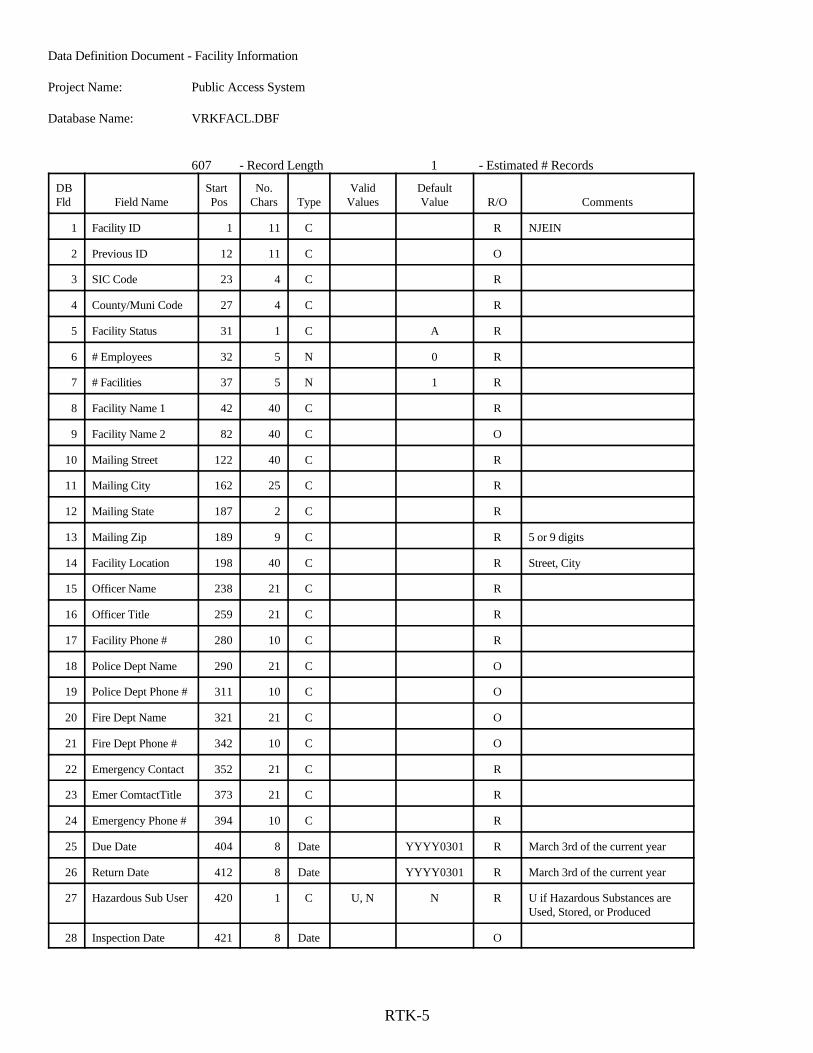
RTK-5
Data Definition Document - Facility Information
Project Name: Public Access System
Database Name: VRKFACL.DBF
607 - Record Length 1 - Estimated # Records
DB Start No. Valid DefaultFld Field Name Pos Chars Type Values Value R/O Comments
1 Facility ID 1 11 C R NJEIN
2 Previous ID 12 11 C O
3 SIC Code 23 4 C R
4 County/Muni Code 27 4 C R
5 Facility Status 31 1 C A R
6 # Employees 32 5 N 0 R
7 # Facilities 37 5 N 1 R
8 Facility Name 1 42 40 C R
9 Facility Name 2 82 40 C O
10 Mailing Street 122 40 C R
11 Mailing City 162 25 C R
12 Mailing State 187 2 C R
13 Mailing Zip 189 9 C R 5 or 9 digits
14 Facility Location 198 40 C R Street, City
15 Officer Name 238 21 C R
16 Officer Title 259 21 C R
17 Facility Phone # 280 10 C R
18 Police Dept Name 290 21 C O
19 Police Dept Phone # 311 10 C O
20 Fire Dept Name 321 21 C O
21 Fire Dept Phone # 342 10 C O
22 Emergency Contact 352 21 C R
23 Emer ComtactTitle 373 21 C R
24 Emergency Phone # 394 10 C R
25 Due Date 404 8 Date YYYY0301 R March 3rd of the current year
26 Return Date 412 8 Date YYYY0301 R March 3rd of the current year
27 Hazardous Sub User 420 1 C U, N N R U if Hazardous Substances areUsed, Stored, or Produced
28 Inspection Date 421 8 Date O

DB Start No. Valid DefaultFld Field Name Pos Chars Type Values Value R/O Comments
RTK-6
29 Facility Fax # 429 10 C O
30 FEIN 439 12 C O
31 Lab # 451 5 C O R&D lab exemption approvalnumber
32 EPCRA? 456 1 C Y, N N R Y if reporting under EPCRA only
33 Hazardous A? 457 1 C Y, N Y R Y if Hazardous Substances areUsed, Stored, or Produced in anyquantity
34 Hazardous B? 458 1 C Y, N Y R Y if Hazardous Substances areUsed, Stored, or Produced atquantities exceeding regulatedthresholds
35 Operations 1 459 70 C R Operations/business conducted atfacility
36 Operations 2 529 70 C O
37 Information 599 1 C Y, N N R Y if information changed sinceChanged last submittal
38 Password 600 8 C R Password supplied with SurveyPackage

RTK-7
Data Definition Document - Chemical Information
Project Name: Public Access System
Database Name: VRKSUB.DBF
159 - Record Length - Estimated # Records
DB Start No. Valid DefaultFld Field Name Pos Chars Type Values Value R/O Comments
1 Transaction Code 1 1 C O
2 Facility ID 2 11 C R Copy from VRKACL.DBF
3 Company Name 13 10 C R Copy first 20 characters ofFacility Name 1 fromVRKFACL.DBF
4 A 23 1 C O
5 Survey Year 24 4 C Current - 1 R
6 B 28 1 C O
7 Survey Type 29 6 C DEQ094 R
8 C 35 1 C O
9 Substance # 36 8 C O
10 Substance Name 44 30 C R
11 CAS # 74 10 C O Strip dashes
12 DOT # 84 4 C O
13 Percent Mixture 88 2 C M-Mixture M RCode P-Pure
14 Physical State 90 1 C S-Solid L RL-LiquidG-Gas
15 Trade Secret 91 1 C Y, blank blank O
16 Hazard Code 1 92 2 C 70-Fire O69-Pressure68-Reactive67-Acute Health66-Chronic Health
17 Hazard Code 2 94 2 C Same as OCode 1
18 Hazard Code 3 96 2 C Same as OCode 1
19 Hazard Code 4 98 2 C Same as OCode 1
20 Hazard Code 5 100 2 C Same as OCode 1

DB Start No. Valid DefaultFld Field Name Pos Chars Type Values Value R/O Comments
RTK-8
21 Max Daily Inventory 102 2 C RCode
22 Avg Daily Inventory 104 2 C RCode
23 Days on Site 106 3 C 1 - 365 R
24 Container Code 109 2 C R
25 Pressure Code 111 2 C R
26 Temperature Code 113 2 C R
27 Location 115 45 C R
SR-1
Site Remediation
1.0 Introduction
The Site Remediation Program (SRP) has adopted a process for Electronic Data Interchange (EDI)to facilitate data integration and thereby help the SRP make more informed cleanup decisions,respond accurately to questions, improve the quality and timeliness of data review, and efficientlyperform its mandated functions.
The Technical Requirements for Site Remediation (N.J.A.C. 7:26E), herein called the Tech Rules,require electronic submittal of analytical results of environmental samples (see 3.13(c)3v). There arethree ways to develop and submit the required information:
1. Use of the Hazardous Site Information Application (HazSite),2. Submittal in a Lotus-compatible spreadsheet format,3. Though not stated in Tech Rules, a .DBF (FoxPro, dBASE) file format is acceptable.
HazSite is a Windows-based, stand-alone database application created by the SRP. The Lotus-compatible spreadsheet format has been developed for the convenience of parties submittingelectronic data who may be using other software to process their data. Submitting data using thespreadsheet option requires strict adherence to the format defined herein.
Availability of HazSite application:Through the department's Bulletin Board System ((609) 292-2006; file: HAZSITE4.ZIP).Through the department’s Home Page, http://www.state.nj.us/dep/srp. Select “Regulations and
Guidance” topic.By requesting a diskette copy from the SRP; (609) 633-1380.
Availability of Lotus-compatible spreadsheet format:Available in hard copy in this EDI Manual.Through the department's Bulletin Board System ((609) 292-2006; file SRP-EDI).Through the department’s Home Page, http://www.state.nj.us/dep/srp. Select “Regulations and
Guidance” topic.By requesting a diskette copy of the SRP section of the EDI Manual; (609) 633-1380.
Availability of the .DBF file format:Through the department’s Home Page, http://www.state.nj.us/dep/srp. Select “Regulations
Guidance” topic.Available in hard copy in this EDI Manual.
The user may transmit the required data to SRP via diskette or through the department's BulletinBoard System. For more information, see Section 4.0 Data Transmission in this Manual.
Provided below are the requirements and processes for developing and submitting information viaHazSite, the Lotus-compatible spreadsheet format, and the .DBF file structure. The datadefinitions are also provided in section 6.0 Discussion of Fields of this manual.
Help number (Bureau of Planning and Systems): (609) 633-1380.
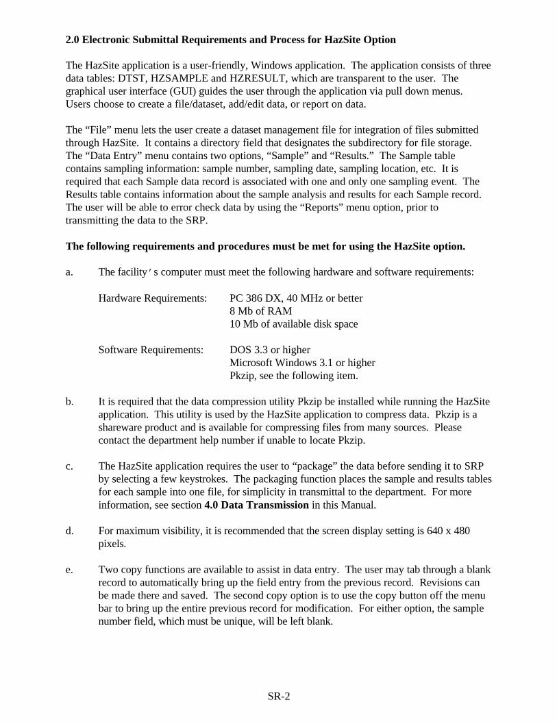
SR-2
2.0 Electronic Submittal Requirements and Process for HazSite Option
The HazSite application is a user-friendly, Windows application. The application consists of threedata tables: DTST, HZSAMPLE and HZRESULT, which are transparent to the user. Thegraphical user interface (GUI) guides the user through the application via pull down menus. Users choose to create a file/dataset, add/edit data, or report on data.
The “File” menu lets the user create a dataset management file for integration of files submittedthrough HazSite. It contains a directory field that designates the subdirectory for file storage. The “Data Entry” menu contains two options, “Sample” and “Results.” The Sample tablecontains sampling information: sample number, sampling date, sampling location, etc. It isrequired that each Sample data record is associated with one and only one sampling event. TheResults table contains information about the sample analysis and results for each Sample record. The user will be able to error check data by using the “Reports” menu option, prior totransmitting the data to the SRP.
The following requirements and procedures must be met for using the HazSite option.
a. The facility’s computer must meet the following hardware and software requirements:
Hardware Requirements: PC 386 DX, 40 MHz or better8 Mb of RAM10 Mb of available disk space
Software Requirements: DOS 3.3 or higherMicrosoft Windows 3.1 or higherPkzip, see the following item.
b. It is required that the data compression utility Pkzip be installed while running the HazSiteapplication. This utility is used by the HazSite application to compress data. Pkzip is ashareware product and is available for compressing files from many sources. Pleasecontact the department help number if unable to locate Pkzip.
c. The HazSite application requires the user to “package” the data before sending it to SRPby selecting a few keystrokes. The packaging function places the sample and results tablesfor each sample into one file, for simplicity in transmittal to the department. For moreinformation, see section 4.0 Data Transmission in this Manual.
d. For maximum visibility, it is recommended that the screen display setting is 640 x 480pixels.
e. Two copy functions are available to assist in data entry. The user may tab through a blankrecord to automatically bring up the field entry from the previous record. Revisions canbe made there and saved. The second copy option is to use the copy button off the menubar to bring up the entire previous record for modification. For either option, the samplenumber field, which must be unique, will be left blank.
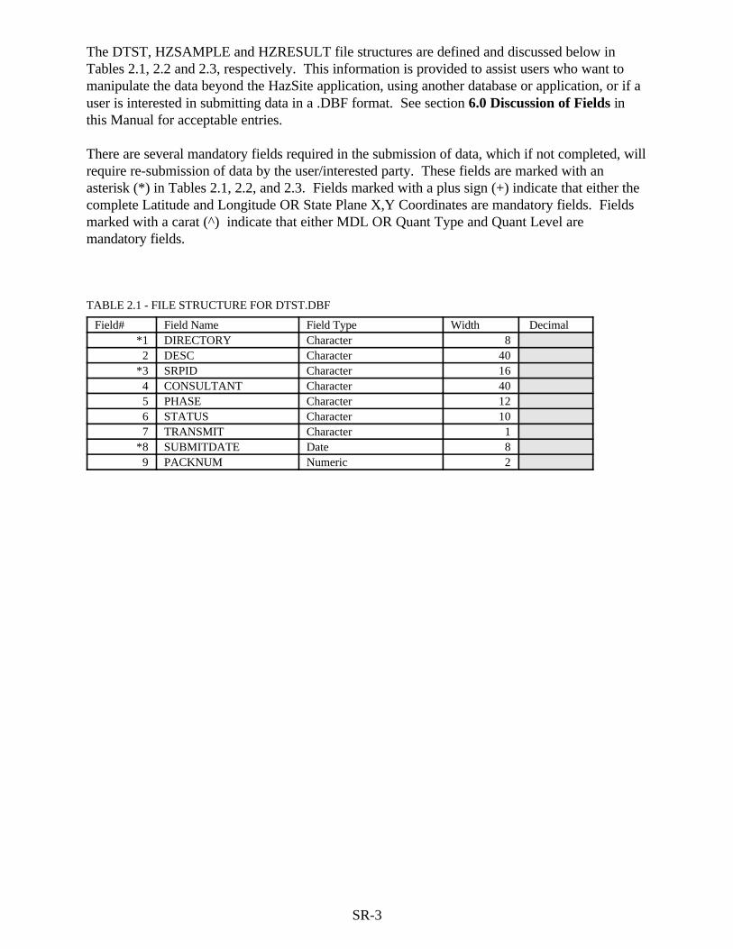
SR-3
The DTST, HZSAMPLE and HZRESULT file structures are defined and discussed below inTables 2.1, 2.2 and 2.3, respectively. This information is provided to assist users who want tomanipulate the data beyond the HazSite application, using another database or application, or if auser is interested in submitting data in a .DBF format. See section 6.0 Discussion of Fields inthis Manual for acceptable entries.
There are several mandatory fields required in the submission of data, which if not completed, willrequire re-submission of data by the user/interested party. These fields are marked with anasterisk (*) in Tables 2.1, 2.2, and 2.3. Fields marked with a plus sign (+) indicate that either thecomplete Latitude and Longitude OR State Plane X,Y Coordinates are mandatory fields. Fieldsmarked with a carat (^) indicate that either MDL OR Quant Type and Quant Level aremandatory fields.
TABLE 2.1 - FILE STRUCTURE FOR DTST.DBF
Field# Field Name Field Type Width Decimal*1 DIRECTORY Character 8
2 DESC Character 40*3 SRPID Character 16
4 CONSULTANT Character 405 PHASE Character 126 STATUS Character 107 TRANSMIT Character 1
*8 SUBMITDATE Date 89 PACKNUM Numeric 2
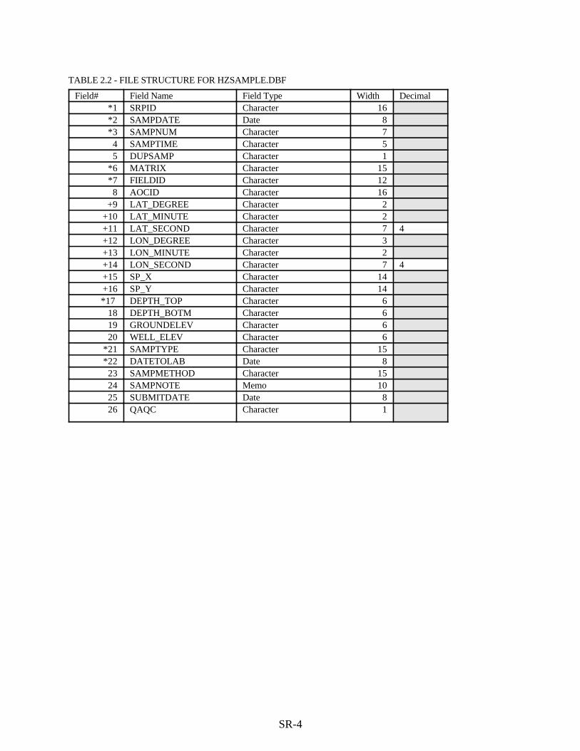
SR-4
TABLE 2.2 - FILE STRUCTURE FOR HZSAMPLE.DBF
Field# Field Name Field Type Width Decimal*1 SRPID Character 16*2 SAMPDATE Date 8*3 SAMPNUM Character 7
4 SAMPTIME Character 55 DUPSAMP Character 1
*6 MATRIX Character 15*7 FIELDID Character 12
8 AOCID Character 16+9 LAT_DEGREE Character 2
+10 LAT_MINUTE Character 2+11 LAT_SECOND Character 7 4+12 LON_DEGREE Character 3+13 LON_MINUTE Character 2+14 LON_SECOND Character 7 4+15 SP_X Character 14+16 SP_Y Character 14*17 DEPTH_TOP Character 6
18 DEPTH_BOTM Character 619 GROUNDELEV Character 620 WELL_ELEV Character 6
*21 SAMPTYPE Character 15*22 DATETOLAB Date 8
23 SAMPMETHOD Character 1524 SAMPNOTE Memo 1025 SUBMITDATE Date 826 QAQC Character 1

SR-5
TABLE 2.3 - FILE STRUCTURE FOR HZRESULT.DBF
Field# Field Name Field Type Width Decimal*1 SRPID Character 16*2 SAMPDATE Date 8*3 SAMPNUM Character 7*4 LABID Character 12*5 DANALYZ Date 8
6 LABNAME Character 20*7 NJDLABCERT Character 5*8 RESULTTYPE Character 1*9 ANALTPARAM Character 6010 CAS Character 1511 FILTUNFILT Character 1
*12 CONC Character 12*13 CONCUNITS Character 15
14 QAQUAL Character 7^15 MDL Character 12^16 QUANTTYPE Character 8^17 QUANTLEVEL Character 12*18 ANLYS_MTHD Character 15
19 QAQC Character 1
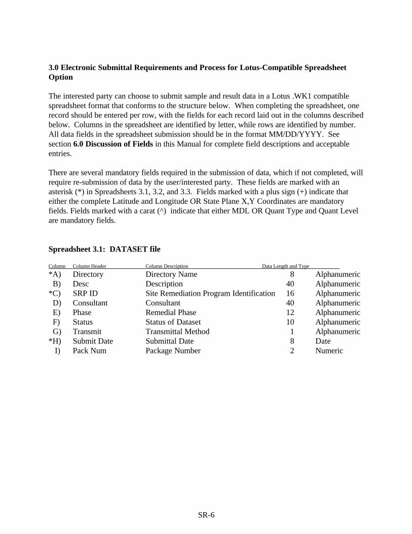
SR-6
3.0 Electronic Submittal Requirements and Process for Lotus-Compatible Spreadsheet Option
The interested party can choose to submit sample and result data in a Lotus .WK1 compatiblespreadsheet format that conforms to the structure below. When completing the spreadsheet, onerecord should be entered per row, with the fields for each record laid out in the columns describedbelow. Columns in the spreadsheet are identified by letter, while rows are identified by number. All data fields in the spreadsheet submission should be in the format MM/DD/YYYY. Seesection 6.0 Discussion of Fields in this Manual for complete field descriptions and acceptableentries.
There are several mandatory fields required in the submission of data, which if not completed, willrequire re-submission of data by the user/interested party. These fields are marked with anasterisk (*) in Spreadsheets 3.1, 3.2, and 3.3. Fields marked with a plus sign (+) indicate thateither the complete Latitude and Longitude OR State Plane X,Y Coordinates are mandatoryfields. Fields marked with a carat (^) indicate that either MDL OR Quant Type and Quant Levelare mandatory fields.
Spreadsheet 3.1: DATASET file
Column Column Header Column Description Data Length and Type
*A) Directory Directory Name 8 Alphanumeric B) Desc Description 40 Alphanumeric*C) SRP ID Site Remediation Program Identification 16 Alphanumeric D) Consultant Consultant 40 Alphanumeric E) Phase Remedial Phase 12 Alphanumeric F) Status Status of Dataset 10 Alphanumeric G) Transmit Transmittal Method 1 Alphanumeric*H) Submit Date Submittal Date 8 Date I) Pack Num Package Number 2 Numeric

SR-7
Spreadsheet 3.2: SAMPLE file
Column Column Header Column Description Data Length and Type
*A) SRP ID Site Remediation Program Identification 16 Alphanumeric*B) Sample Date Sample collection date (MM/DD/YYYY) 8 Date *C) Sample Number Unique identification number for sample 7 Alphanumeric D) Sample Time Sample collection time 5 Alphanumeric E) Duplicate Duplicate sample (Yes/No field) 1 Alphanumeric*F) Matrix Acceptable entries defined in section 6.0 15 Alphanumeric*G) Field ID Field Number for Sample 12 Alphanumeric H) AOC ID Area of Concern (text or number) 16 Alphanumeric +I) Lat Degrees Latitude Degrees 2 Alphanumeric+J) Lat Minutes Latitude Minutes 2 Alphanumeric+K) Lat Seconds Latitude Seconds 7 Alphanumeric+L) Lon Degrees Longitude Degrees 3 Alphanumeric+M) Lon Minutes Longitude Minutes 2 Alphanumeric+N) Lon Seconds Longitude Seconds 7 Alphanumeric+O) SP X-Coord State Plane X Coordinate 14 Alphanumeric+P) SP Y-Coord State Plane Y Coordinate 14 Alphanumeric*Q) Depth Top Depth at top of sample (ft) 6 Alphanumeric R) Depth Botm Depth at bottom of sample (ft) 6 Alphanumeric S) Ground Elev Ground Elevation (ft) 6 Alphanumeric T) Well Elev Well Elevation (ft) 6 Alphanumeric*U) Sample Type Acceptable entries defined in section 6.0 15 Alphanumeric*V) Date to Lab Date sample was delivered to lab 8 Date W) Sample Meth Field sampling method 15 Alphanumeric X) Sample Note Notes about Sample Method or Type 10 Memo Y) Submit Date Date samples submitted to Lab 8 Date Z) QAQC Leave Blank, NJDEP use only 1 Alphanumeric
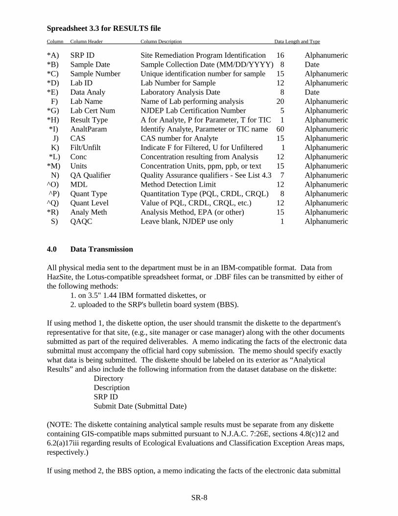
SR-8
Spreadsheet 3.3 for RESULTS file
Column Column Header Column Description Data Length and Type
*A) SRP ID Site Remediation Program Identification 16 Alphanumeric*B) Sample Date Sample Collection Date (MM/DD/YYYY) 8 Date*C) Sample Number Unique identification number for sample 15 Alphanumeric*D) Lab ID Lab Number for Sample 12 Alphanumeric*E) Data Analy Laboratory Analysis Date 8 Date F) Lab Name Name of Lab performing analysis 20 Alphanumeric*G) Lab Cert Num NJDEP Lab Certification Number 5 Alphanumeric*H) Result Type A for Analyte, P for Parameter, T for TIC 1 Alphanumeric *I) AnaltParam Identify Analyte, Parameter or TIC name 60 Alphanumeric J) CAS CAS number for Analyte 15 Alphanumeric K) Filt/Unfilt Indicate F for Filtered, U for Unfiltered 1 Alphanumeric *L) Conc Concentration resulting from Analysis 12 Alphanumeric*M) Units Concentration Units, ppm, ppb, or text 15 Alphanumeric N) QA Qualifier Quality Assurance qualifiers - See List 4.3 7 Alphanumeric^O) MDL Method Detection Limit 12 Alphanumeric ^P) Quant Type Quantitation Type (PQL, CRDL, CRQL) 8 Alphanumeric^Q) Quant Level Value of PQL, CRDL, CRQL, etc.) 12 Alphanumeric*R) Analy Meth Analysis Method, EPA (or other) 15 Alphanumeric S) QAQC Leave blank, NJDEP use only 1 Alphanumeric
4.0 Data Transmission
All physical media sent to the department must be in an IBM-compatible format. Data fromHazSite, the Lotus-compatible spreadsheet format, or .DBF files can be transmitted by either ofthe following methods:
1. on 3.5" 1.44 IBM formatted diskettes, or2. uploaded to the SRP's bulletin board system (BBS).
If using method 1, the diskette option, the user should transmit the diskette to the department'srepresentative for that site, (e.g., site manager or case manager) along with the other documentssubmitted as part of the required deliverables. A memo indicating the facts of the electronic datasubmittal must accompany the official hard copy submission. The memo should specify exactlywhat data is being submitted. The diskette should be labeled on its exterior as “AnalyticalResults” and also include the following information from the dataset database on the diskette:
DirectoryDescriptionSRP IDSubmit Date (Submittal Date)
(NOTE: The diskette containing analytical sample results must be separate from any diskettecontaining GIS-compatible maps submitted pursuant to N.J.A.C. 7:26E, sections 4.8(c)12 and6.2(a)17iii regarding results of Ecological Evaluations and Classification Exception Areas maps,respectively.)
If using method 2, the BBS option, a memo indicating the facts of the electronic data submittal

SR-9
must accompany the official hard copy submission, and must indicate to the site/case managerwhere the information is located (i.e., filename, date of BBS transmission, etc.). The memoshould specify exactly what data is being submitted. The submission should be labeled as“Analytical Results” and also include the following information from the dataset database:
DirectoryDescriptionSRP IDSubmit Date (Submittal Date)
For further information about access to the BBS, see the section in the NJDEP EDI Manual onthe Electronic Bulletin Board System, or contact the Bureau of Planning & Systems at (609) 633-1380.
5.0 Data Compression
Data is to be submitted in a compressed format, using the Pkzip compression utility. Pkzip is ashareware product and is available for compressing files from many sources. Contact the Bureauof Planning & Systems at (609) 633-1380 if you are unable to locate Pkzip.
6.0 Discussion of Fields
This description of fields is organized by Table (DTST, HZSAMPLE, HZRESULT), and the fieldorder corresponds to the field structure outlined in the Tables 2.1, 2.2 and 2.3. The field name inCAPS is the .DBF file structure field name from the HazSite application. The name of the columnheaders for the Lotus-compatible spreadsheet (.WK1) is provided in parentheses. When workingin HazSites directly, it is suggested that the user refer to the Help menu for data definitions, asthey more accurately correspond to the field name and order in the HazSite application.
There are several mandatory fields required in the submission of data, which if not completed, willrequire re-submission of data by the user/interested party. These fields are marked with anasterisk (*) below. Fields marked with a plus sign (+) indicate that either the complete Latitudeand Longitude OR State Plane X,Y Coordinates are mandatory fields. Fields marked with a carat(^) indicate that either MDL OR Quant Type and Quant Level are mandatory fields.
DTST Table
* DIRECTORY (Directory)Designates the subdirectory for file storage.
DESC (Desc) Description of the dataset being submitted, including site name.
* SRPID (SRP ID) This is the SRP identification number. For Responsible Party sites, it is commonlyreferred to as the Case Number. For Publicly Funded sites, it is the 16 digitnumber, usually the EPA ID, beginning with “NJ”.
CONSULTANT (Consultant)Name of the primary consulting firm collecting samples and compiling reports.
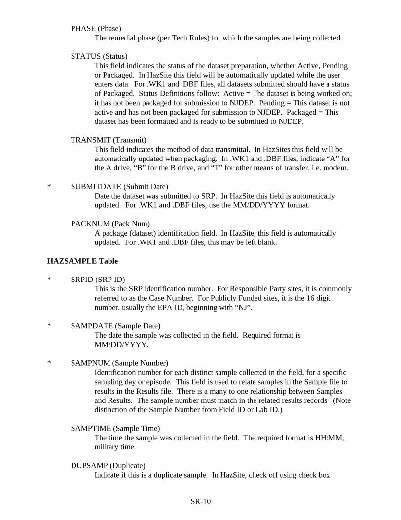
SR-10
PHASE (Phase)The remedial phase (per Tech Rules) for which the samples are being collected.
STATUS (Status)This field indicates the status of the dataset preparation, whether Active, Pendingor Packaged. In HazSite this field will be automatically updated while the userenters data. For .WK1 and .DBF files, all datasets submitted should have a statusof Packaged. Status Definitions follow: Active = The dataset is being worked on;it has not been packaged for submission to NJDEP. Pending = This dataset is notactive and has not been packaged for submission to NJDEP. Packaged = Thisdataset has been formatted and is ready to be submitted to NJDEP.
TRANSMIT (Transmit)This field indicates the method of data transmittal. In HazSites this field will beautomatically updated when packaging. In .WK1 and .DBF files, indicate “A” forthe A drive, “B” for the B drive, and “T” for other means of transfer, i.e. modem.
* SUBMITDATE (Submit Date)Date the dataset was submitted to SRP. In HazSite this field is automaticallyupdated. For .WK1 and .DBF files, use the MM/DD/YYYY format.
PACKNUM (Pack Num)A package (dataset) identification field. In HazSite, this field is automaticallyupdated. For .WK1 and .DBF files, this may be left blank.
HAZSAMPLE Table
* SRPID (SRP ID)This is the SRP identification number. For Responsible Party sites, it is commonlyreferred to as the Case Number. For Publicly Funded sites, it is the 16 digitnumber, usually the EPA ID, beginning with “NJ”.
* SAMPDATE (Sample Date)The date the sample was collected in the field. Required format isMM/DD/YYYY.
* SAMPNUM (Sample Number)Identification number for each distinct sample collected in the field, for a specificsampling day or episode. This field is used to relate samples in the Sample file toresults in the Results file. There is a many to one relationship between Samplesand Results. The sample number must match in the related results records. (Notedistinction of the Sample Number from Field ID or Lab ID.)
SAMPTIME (Sample Time)The time the sample was collected in the field. The required format is HH:MM,military time.
DUPSAMP (Duplicate)Indicate if this is a duplicate sample. In HazSite, check off using check box
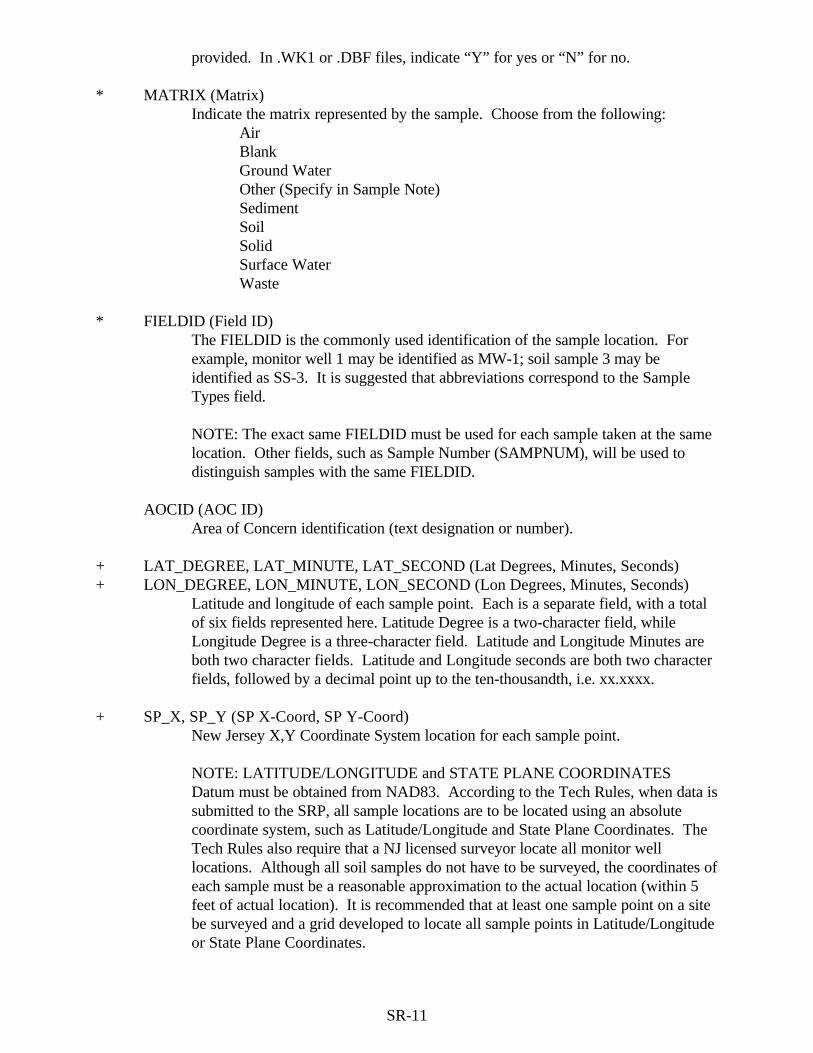
SR-11
provided. In .WK1 or .DBF files, indicate “Y” for yes or “N” for no.
* MATRIX (Matrix)Indicate the matrix represented by the sample. Choose from the following:
AirBlankGround WaterOther (Specify in Sample Note)SedimentSoilSolidSurface WaterWaste
* FIELDID (Field ID)The FIELDID is the commonly used identification of the sample location. Forexample, monitor well 1 may be identified as MW-1; soil sample 3 may beidentified as SS-3. It is suggested that abbreviations correspond to the SampleTypes field.
NOTE: The exact same FIELDID must be used for each sample taken at the samelocation. Other fields, such as Sample Number (SAMPNUM), will be used todistinguish samples with the same FIELDID.
AOCID (AOC ID)Area of Concern identification (text designation or number).
+ LAT_DEGREE, LAT_MINUTE, LAT_SECOND (Lat Degrees, Minutes, Seconds)+ LON_DEGREE, LON_MINUTE, LON_SECOND (Lon Degrees, Minutes, Seconds)
Latitude and longitude of each sample point. Each is a separate field, with a totalof six fields represented here. Latitude Degree is a two-character field, whileLongitude Degree is a three-character field. Latitude and Longitude Minutes areboth two character fields. Latitude and Longitude seconds are both two characterfields, followed by a decimal point up to the ten-thousandth, i.e. xx.xxxx.
+ SP_X, SP_Y (SP X-Coord, SP Y-Coord)New Jersey X,Y Coordinate System location for each sample point.
NOTE: LATITUDE/LONGITUDE and STATE PLANE COORDINATESDatum must be obtained from NAD83. According to the Tech Rules, when data issubmitted to the SRP, all sample locations are to be located using an absolutecoordinate system, such as Latitude/Longitude and State Plane Coordinates. TheTech Rules also require that a NJ licensed surveyor locate all monitor welllocations. Although all soil samples do not have to be surveyed, the coordinates ofeach sample must be a reasonable approximation to the actual location (within 5feet of actual location). It is recommended that at least one sample point on a sitebe surveyed and a grid developed to locate all sample points in Latitude/Longitudeor State Plane Coordinates.

SR-12
NOTE: EITHER the Latitude/Longitude fields or the State Plane Coordinatefields are mandatory fields requiring data entry. The only exception to this rule atthis time is if the sample being analyzed is a “blank,” and this must be noted in theMatrix field in the Sample file.
* DEPTH_TOP (Depth Top)Depth (in feet) to the top of the sample, measured from the ground surface.
NOTE: For ground water sampling, use only the DEPTH_TOP field. In this field,record the depth to the top of the static water level (after purging) from theground surface (measured from outermost well casing and subtracting the distanceto the ground surface).
NOTE: For ground water sampling, when taking a sample from the bottom of awell (i.e., DNAPL sampling), use the DEPTH_TOP field to record the depth tothe point where the sample was taken from the ground surface (measured fromoutermost well casing and subtracting the distance to the ground surface).
NOTE: For potable wells or other non-applicable instances, enter “N/A”.
DEPTH_BOTM (Depth Botm)Depth (in feet) to the bottom of the sample, measured from the ground surface.
NOTE: Subsurface soil sampling is usually conducted at specific intervals (i.e.,.5-1.5 feet). Use the DEPTH_TOP and DEPTH_BOTM fields to record theinterval at which the soil sample was taken. The reference for the samplinginterval must be the ground surface. If the sample is a surface soil sample, recorda "0" in both the DEPTH_TOP and the DEPTH_BOTM fields.
GROUNDELEV (Ground Elev)The height of the sample point in feet above mean sea level (MSL). May beestimated based on a single surveyed reference point, such as a monitor well.
WELL_ELEV (Well Elev)Note the well elevation in feet above mean sea level (MSL).
* SAMPTYPE (Sample Type)Indicate the type of sample collected. Choose from the following:
Air Stripper Monitor WellBackground Other (Specify in Sample Note field)Blank Potable WellBuilding Floor Sanitary SewerBuilding Wall Septic SystemDebris SludgeDrum Standing WaterEffluent Storm SewerFlowing Water Subsurface SoilInfluent Surface WaterInjection Well Test Pit

SR-13
Leachate
* DATETOLAB (Date to Lab)Date the sample was delivered to the laboratory for analysis. Required format isMM/DD/YYYY.
SAMPMETHOD (Sample Meth)Sampling method or instrument by which the sample was physically obtained (i.e.,hand auger, split spoon, etc.)
SAMPNOTE (Sample Note)Memo field. To be used for explanation of "Other" in the Sample Matrix andSample Type fields. May also be used to further explain Sample Method.
SUBMITDATE (Submit Date)The date the package was submitted to SRP. In HazSite this field is automaticallyupdated. For .WK1 and .DBF files, the required format is MM/DD/YYYY.
QAQC (QAQC)Internal field for NJDEP use only. HazSite users will not see this field. For .WK1and .DBF, leave blank.
HZRESULT Table
* SRPID (SRP ID)This is the SRP identification number. For Responsible Party sites, it is commonlyreferred to as the Case Number. For Publicly Funded sites, it is the 16 digitnumber, usually the EPA ID, beginning with “NJ”.
* SAMPDATE (Sample Date)The date the sample was collected in the field. Required format isMM/DD/YYYY.
* SAMPNUM (Sample Number)Identification number for each distinct sample collected in the field, for a specificsampling day or episode. This field is used to relate samples in the Sample file toresults in the Results file. There is a many to one relationship between Samplesand Results. The sample number must match in the related results records. (Notedistinction of the Sample Number from Field ID or Lab ID.)
* LABID (Lab ID)Identification number given to the specific sample by the laboratory.
* DANALYZ (Date Analy)Date the sample analysis was completed. Required format is MM/DD/YYYY.
LABNAME (Lab Name)Name of the laboratory performing the analysis.
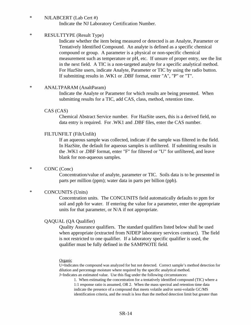
SR-14
* NJLABCERT (Lab Cert #)Indicate the NJ Laboratory Certification Number.
* RESULTTYPE (Result Type)Indicate whether the item being measured or detected is an Analyte, Parameter orTentatively Identified Compound. An analyte is defined as a specific chemicalcompound or group. A parameter is a physical or non-specific chemicalmeasurement such as temperature or pH, etc. If unsure of proper entry, see the listin the next field. A TIC is a non-targeted analyte for a specific analytical method.For HazSite users, indicate Analyte, Parameter or TIC by using the radio button. If submitting results in .WK1 or .DBF format, enter "A", "P" or "T".
* ANALTPARAM (AnaltParam)Indicate the Analyte or Parameter for which results are being presented. Whensubmitting results for a TIC, add CAS, class, method, retention time.
CAS (CAS)Chemical Abstract Service number. For HazSite users, this is a derived field, nodata entry is required. For .WK1 and .DBF files, enter the CAS number.
FILTUNFILT (Filt/Unfilt)If an aqueous sample was collected, indicate if the sample was filtered in the field. In HazSite, the default for aqueous samples is unfiltered. If submitting results inthe .WK1 or .DBF format, enter "F" for filtered or "U" for unfiltered, and leaveblank for non-aqueous samples.
* CONC (Conc)Concentration/value of analyte, parameter or TIC. Soils data is to be presented inparts per million (ppm); water data in parts per billion (ppb).
* CONCUNITS (Units)Concentration units. The CONCUNITS field automatically defaults to ppm forsoil and ppb for water. If entering the value for a parameter, enter the appropriateunits for that parameter, or N/A if not appropriate.
QAQUAL (QA Qualifier)Quality Assurance qualifiers. The standard qualifiers listed below shall be usedwhen appropriate (extracted from NJDEP laboratory services contract). The fieldis not restricted to one qualifier. If a laboratory specific qualifier is used, thequalifier must be fully defined in the SAMPNOTE field.
OrganicU=Indicates the compound was analyzed for but not detected. Correct sample’s method detection fordilution and percentage moisture where required by the specific analytical method.J=Indicates an estimated value. Use this flag under the following circumstances:
1. When estimating the concentration for a tentatively identified compound (TIC) where a1:1 response ratio is assumed, OR 2. When the mass spectral and retention time dataindicate the presence of a compound that meets volatile and/or semi-volatile GC/MSidentification criteria, and the result is less than the method detection limit but greater than

SR-15
zero, OR 3. When the retention time data indicates the presence of a compound that meetsthe pesticide/Aroclor criteria and the result is less than the method detection limit but greaterthan zero. NOTE: The “J” reporting flag shall not be used, and the compound not reportedas identified for pesticide/Aroclor results less than the method detection limit, if the technicaljudgment of the pesticide residue analysis specialist determines that the peak used forcompound identification is from instrument noise or other interferences. The sample’smethod detection limit corrected for dilution and percent moisture where required by thespecific analytical method should be used.
N=Indicates presumptive evidence of a compound. Use only for tentatively identified compounds,where the identification is based on a mass spectral library search. Apply to all TIC results. Do notuse for generic characterizations, such as “unknown chlorinated hydrocarbon.”P=Use for pesticide/Aroclor target analytes with greater than 25% difference for detectedconcentrations between the two GC columns. Report the lower of the two values and flag with thiscode. C=Use for pesticide identification confirmed by GC/MS analysis. If the attempted confirmation isunsuccessful do not use this flag. Use another flag defined by your laboratory for explanations. B=Use if the analyte is found in the blank as well as the sample. It indicates probable blankcontamination. It warns the data user to take appropriate actions. Use for both positively identifiedand tentatively identified target compounds.E=Use for identification of compounds with concentrations exceeding the GC/MS calibration rangefor that specific analysis. Dilute the sample if one or more of the compounds has a response greaterthan full scale, and reanalyze. Flag such compounds with “E.” If the dilution of the extract causedany compound identified in the first analysis to fall below the calibration range in the second analysis,flag the results for the second analysis “D.” Affix the “DL” suffix to the sample number of the dilutedsample and report both analyses.D=Use for identification of compounds in an analysis at a secondary dilution factor. Flag if a sampleor extract is reanalyzed at a higher dilution factor. Flag the reanalyzed sample or extract with “DL.” This alerts the user that there are discrepancies between reported concentrations possibly due to thedilution.A=Indicates that the tentatively identified compound is a suspected aldol condensation product.
InorganicE=The reported value is estimated because of interference. Include an explanatory note in thenonconformance summary if the problem applies to all the samples, or in the individual form if it is anisolated problem.M=Duplicate injection precision not met.N=Spiked sample recovery not within control limits.S=Reported value determined by the "Method of Standard Additions" (MSA).W=Post digestion spike for Furnace AA analysis not within control limits, absorbence is less
than 50% of the spike absorbence.*=Duplicate analysis not within control limits.X=Ion chromatographic peaks outside the 5% acceptance window.+=Correlation coefficient for the MSA is less than 0.995.
^ MDL (MDL)Method Detection Limit (per N.J.A.C. 7:18 regarding laboratory certification). Ifentering data in this field for a common parameter and there is no applicable MDL,enter N/A.
^ QUANTTYPE (Quant Type) The lowest concentration above background noise level that an instrument canreliably detect. Acceptable entries, in order of preference, are the PracticalQuantitation Level (PQL), the Contract Required Quantitation Level (CRQL), orthe Contract Required Detection Limit (CRDL), etc. If entering data in this fieldfor a common parameter and there is no applicable result, enter N/A.

SR-16
^ QUANTLEVEL (Quant Level)The value of the PQL, CRQL, CRDL, etc. If entering data in this field for acommon parameter and there is no applicable quantitation level, enter N/A.
NOTE: Either the MDL or the QuantType/QuantLevel fields are mandatory fieldsrequiring data entry for each Analyte or TIC for which results are being submitted.If results are submitted for a Parameter and there is no applicable MDL, QuantType or Quant Level, enter N/A.
* ANLYS_MTHD (Analy Method)This field identifies the analytical method used. The field must contain the methodnumber/name preceded by the organization in which the test originated. Ifmethods listed have been revised after date of publication of HazSites and thisManual, choose the most current version/update of the method. If entering data inthis field for a common parameter and there is no applicable analytical method, addN/A.
QAQC (QAQC)
Internal field for NJDEP use only. HazSite users will not see this field. For .WK1and .DBF, leave blank.