Polly Pocket & Ninja Turtles: A Content Analysis of Gender ...
Upload
marilu1727Category
view
0download
0
Ninja ZX-6RNinja ZX-6R ABS
MotorcycleService Manual


This quick reference guide will assistyou in locating a desired topic or pro-cedure.•Bend the pages back to match theblack tab of the desired chapter num-ber with the black tab on the edge ateach table of contents page.
•Refer to the sectional table of contentsfor the exact pages to locate the spe-cific topic required.
Quick Reference Guide
General Information 1 jPeriodic Maintenance 2 jFuel System (DFI) 3 jCooling System 4 jEngine Top End 5 jClutch 6 jEngine Lubrication System 7 jEngine Removal/Installation 8 jCrankshaft/Transmission 9 jWheels/Tires 10 jFinal Drive 11 jBrakes 12 jSuspension 13 jSteering 14 jFrame 15 jElectrical System 16 jSelf-Diagnosis System 17 jAppendix 18 j


Ninja ZX-6RNinja ZX-6R ABS
MotorcycleService Manual
All rights reserved. No parts of this publication may be reproduced, stored in a retrieval system, ortransmitted in any form or by any means, electronic mechanical photocopying, recording or otherwise,without the prior written permission of Quality Assurance Division/Motorcycle & Engine Company/KawasakiHeavy Industries, Ltd., Japan.
No liability can be accepted for any inaccuracies or omissions in this publication, although every possiblecare has been taken to make it as complete and accurate as possible.
The right is reserved to make changes at any time without prior notice and without incurring an obligationto make such changes to products manufactured previously. See your Motorcycle dealer for the latestinformation on product improvements incorporated after this publication.
All information contained in this publication is based on the latest product information available at the timeof publication. Illustrations and photographs in this publication are intended for reference use only and maynot depict actual model component parts.
© 2012 Kawasaki Heavy Industries, Ltd. First Edition (0) : Jul. 25, 2012
LIST OF ABBREVIATIONSA ampere(s) lb pound(s)ABDC after bottom dead center m meter(s)AC alternating current min minute(s)ATDC after top dead center N newton(s)BBDC before bottom dead center Pa pascal(s)BDC bottom dead center PS horsepowerBTDC before top dead center psi pound(s) per square inch°C degree(s) Celsius r revolutionDC direct current rpm revolution(s) per minuteF farad(s) TDC top dead center°F degree(s) Fahrenheit TIR total indicator readingft foot, feet V volt(s)g gram(s) W watt(s)h hour(s) Ω ohm(s)L liter(s)
COUNTRY AND AREA CODESAT Austria GB United KingdomAU Australia ID IndonesiaBR Brazil SEA Southeast AsiaCA Canada US United StatesCAL California WVTA
(FULL H)WVTA Model with Honeycomb
Catalytic Converter (Full Power)CH Switzerland GB WVTA
(FULL H)WVTA Model with Honeycomb Catalytic
Converter (Left Side Traffic FullPower)
DE Germany WVTA(78.2 H)
WVTA Model with Honeycomb CatalyticConverter (Restricted Power)
EUR Europe

EMISSION CONTROL INFORMATION
To protect the environment in which we all live, Kawasaki has incorporated crankcase emis-sion (1) and exhaust emission (2) control systems in compliance with applicable regulations ofthe United States Environmental Protection Agency and California Air Resources Board. Addi-tionally, Kawasaki has incorporated an evaporative emission control system (3) in compliancewith applicable regulations of the California Air Resources Board on vehicles sold in Californiaonly.1. Crankcase Emission Control SystemThis system eliminates the release of crankcase vapors into the atmosphere. Instead, the vapors
are routed through an oil separator to the intake side of the engine. While the engine is operating,the vapors are drawn into combustion chamber, where they are burned along with the fuel and airsupplied by the fuel injection system.
2. Exhaust Emission Control SystemThis system reduces the amount of pollutants discharged into the atmosphere by the exhaust
of this motorcycle. The fuel, ignition, and exhaust systems of this motorcycle have been carefullydesigned and constructed to ensure an efficient engine with low exhaust pollutant levels.
The exhaust system of this model motorcycle manufactured primarily for sale in California in-cludes a catalytic converter system.
3. Evaporative Emission Control SystemVapors caused by fuel evaporation in the fuel system are not vented into the atmosphere. In-
stead, fuel vapors are routed into the running engine to be burned, or stored in a canister whenthe engine is stopped.
The Clean Air Act, which is the Federal law covering motor vehicle pollution, contains what iscommonly referred to as the Act’s “tampering provisions”.
“Sec. 203(a) The following acts and the causing thereof are prohibited...(3)(A) for any person to remove or render inoperative any device or element of design installed
on or in a motor vehicle or motor vehicle engine in compliance with regulations under thistitle prior to its sale and delivery to the ultimate purchaser, or for any manufacturer or dealerknowingly to remove or render inoperative any such device or element of design after suchsale and delivery to the ultimate purchaser.
(3)(B) for any person engaged in the business of repairing, servicing, selling, leasing, or tradingmotor vehicles or motor vehicle engines, or who operates a fleet of motor vehicles know-ingly to remove or render inoperative any device or element of design installed on or in amotor vehicle or motor vehicle engine in compliance with regulations under this title follow-ing its sale and delivery to the ultimate purchaser...”
NOTEThe phrase “remove or render inoperative any device or element of design” has been generally
interpreted as follows.1. Tampering does not include the temporary removal or rendering inoperative of de-
vices or elements of design in order to perform maintenance.2. Tampering could include.
a.Maladjustment of vehicle components such that the emission standards are ex-ceeded.
b.Use of replacement parts or accessories which adversely affect the performanceor durability of the motorcycle.
c.Addition of components or accessories that result in the vehicle exceeding the stan-dards.
d.Permanently removing, disconnecting, or rendering inoperative any component orelement of design of the emission control systems.
WE RECOMMEND THAT ALL DEALERS OBSERVE THESE PROVISIONS OF FEDERALLAW, THE VIOLATION OF WHICH IS PUNISHABLE BY CIVIL PENALTIES NOT EXCEEDING$10 000 PER VIOLATION.

TAMPERING WITH NOISE CONTROL SYSTEM PROHIBITED
Federal law prohibits the following acts or the causing thereof. (1) The removal or renderinginoperative by any person other than for purposes of maintenance, repair, or replacement, of anydevice or element of design incorporated into any new vehicle for the purpose of noise controlprior to its sale or delivery to the ultimate purchaser or while it is in use, or (2) the use of thevehicle after such device or element of design has been removed or rendered inoperative byany person.
Among those acts presumed to constitute tampering are the acts listed below.•Replacement of the original exhaust system or muffler with a component not in compliance
with Federal regulations.• Removal of the muffler(s) or any internal portion of the muffler(s).• Removal of the air box or air box cover.•Modifications to the muffler(s) or air intake system by cutting, drilling, or other means if such
modifications result in increased noise levels.

Foreword
This manual is designed primarily for use bytrained mechanics in a properly equipped shop.However, it contains enough detail and basic in-formation to make it useful to the owner who de-sires to perform his own basic maintenance andrepair work. A basic knowledge of mechanics,the proper use of tools, and workshop proce-dures must be understood in order to carry outmaintenance and repair satisfactorily. When-ever the owner has insufficient experience ordoubts his ability to do the work, all adjust-ments, maintenance, and repair should be car-ried out only by qualified mechanics.
In order to perform the work efficiently andto avoid costly mistakes, read the text, thor-oughly familiarize yourself with the proceduresbefore starting work, and then do the work care-fully in a clean area. Whenever special tools orequipment are specified, do not use makeshifttools or equipment. Precision measurementscan only be made if the proper instruments areused, and the use of substitute tools may ad-versely affect safe operation.
For the duration of the warranty period,we recommend that all repairs and scheduledmaintenance be performed in accordance withthis service manual. Any owner maintenance orrepair procedure not performed in accordancewith this manual may void the warranty.
To get the longest life out of your vehicle.• Follow the Periodic Maintenance Chart in the
Service Manual.• Be alert for problems and non-scheduled
maintenance.• Use proper tools and genuine Kawasaki Mo-
torcycle parts. Special tools, gauges, andtesters that are necessary when servicingKawasaki motorcycles are introduced by theService Manual. Genuine parts provided asspare parts are listed in the Parts Catalog.
• Follow the procedures in this manual care-fully. Don’t take shortcuts.
• Remember to keep complete records of main-tenance and repair with dates and any newparts installed.
How to Use This ManualIn this manual, the product is divided into
its major systems and these systems make upthe manual’s chapters. The Quick Reference
Guide shows you all of the product’s systemand assists in locating their chapters. Eachchapter in turn has its own comprehensive Ta-ble of Contents.
For example, if you want stick coil information,use the Quick Reference Guide to locate theElectrical System chapter. Then, use the Tableof Contents on the first page of the chapter tofind the Stick Coil section.
Whenever you see symbols, heed their in-structions! Always follow safe operating andmaintenance practices.
DANGERDANGER indicates a hazardous situa-tion which, if not avoided, will result indeath or serious injury.
WARNINGWARNING indicates a hazardous situa-tion which, if not avoided, could resultin death or serious injury.
NOTICENOTICE is used to address practices notrelated to personal injury.
This manual contains four more symbolswhich will help you distinguish different typesof information.
NOTEThis note symbol indicates points of par-
ticular interest for more efficient and con-venient operation.
• Indicates a procedural step or work to bedone.Indicates a procedural sub-step or how to do
the work of the procedural step it follows. Italso precedes the text of a NOTE.Indicates a conditional step or what action totake based on the results of the test or inspec-tion in the procedural step or sub-step it fol-lows.In most chapters an exploded view illustration
of the system components follows the Table ofContents. In these illustrations you will find theinstructions indicating which parts require spec-ified tightening torque, oil, grease or a lockingagent during assembly.


GENERAL INFORMATION 1-1
1
General InformationTable of Contents
Before Servicing ..................................................................................................................... 1-2Model Identification................................................................................................................. 1-7General Specifications............................................................................................................ 1-10Unit Conversion Table ............................................................................................................ 1-13

1-2 GENERAL INFORMATIONBefore Servicing
Before starting to perform an inspection service or carry out a disassembly and reassembly opera-tion on a motorcycle, read the precautions given below. To facilitate actual operations, notes, illustra-tions, photographs, cautions, and detailed descriptions have been included in each chapter wherevernecessary. This section explains the items that require particular attention during the removal andreinstallation or disassembly and reassembly of general parts.
Especially note the following.Battery Ground
Before completing any service on the motorcycle, discon-nect the battery cables from the battery to prevent the en-gine from accidentally turning over. Disconnect the groundcable (–) first and then the positive (+). When completedwith the service, first connect the positive (+) cable to thepositive (+) terminal of the battery then the negative (–) ca-ble to the negative terminal.
Edges of PartsLift large or heavy parts wearing gloves to prevent injury
from possible sharp edges on the parts.
SolventUse a high flash-point solvent when cleaning parts. High
flash-point solvent should be used according to directionsof the solvent manufacturer.
Cleaning Vehicle before DisassemblyClean the vehicle thoroughly before disassembly. Dirt or
other foreign materials entering into sealed areas during ve-hicle disassembly can cause excessive wear and decreaseperformance of the vehicle.
GENERAL INFORMATION 1-3Before Servicing
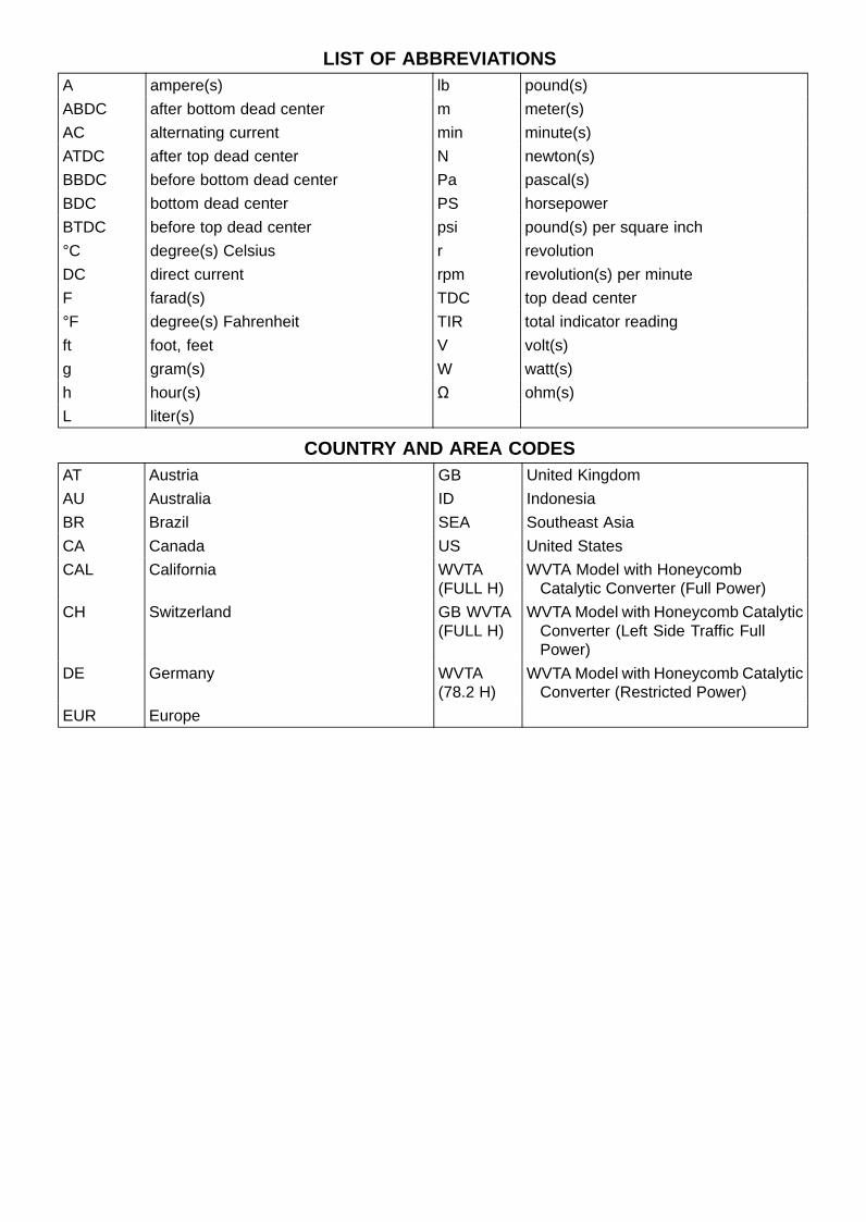
Arrangement and Cleaning of Removed PartsDisassembled parts are easy to confuse. Arrange the
parts according to the order the parts were disassembledand clean the parts in order prior to assembly.
Storage of Removed PartsAfter all the parts including subassembly parts have been
cleaned, store the parts in a clean area. Put a clean clothor plastic sheet over the parts to protect from any foreignmaterials that may collect before re-assembly.
InspectionReuse of worn or damaged parts may lead to serious ac-
cident. Visually inspect removed parts for corrosion, discol-oration, or other damage. Refer to the appropriate sectionsof this manual for service limits on individual parts. Replacethe parts if any damage has been found or if the part is be-yond its service limit.
Replacement PartsReplacement parts must be KAWASAKI genuine or
recommended by KAWASAKI. Gaskets, O-rings, oil seals,grease seals, circlips, cotter pins or self-locking nuts mustbe replaced with new ones whenever disassembled.
Assembly OrderIn most cases assembly order is the reverse of disassem-
bly, however, if assembly order is provided in this ServiceManual, follow the procedures given.

1-4 GENERAL INFORMATIONBefore Servicing
Tightening SequenceGenerally, when installing a part with several bolts, nuts,
or screws, start them all in their holes and tighten them toa snug fit. Then tighten them according to the specified se-quence to prevent case warpage or deformation which canlead to malfunction. Conversely when loosening the bolts,nuts, or screws, first loosen all of them by about a quar-ter turn and then remove them. If the specified tighteningsequence is not indicated, tighten the fasteners alternatingdiagonally.
Tightening TorqueIncorrect torque applied to a bolt, nut, or screw may
lead to serious damage. Tighten fasteners to the specifiedtorque using a good quality torque wrench.
ForceUse common sense during disassembly and assembly,
excessive force can cause expensive or hard to repair dam-age. When necessary, remove screws that have a non-permanent locking agent applied using an impact driver.Use a plastic-faced mallet whenever tapping is necessary.
Gasket, O-ringHardening, shrinkage, or damage of both gaskets and
O-rings after disassembly can reduce sealing performance.Remove old gaskets and clean the sealing surfaces thor-oughly so that no gasket material or other material remains.Install the new gaskets and replace the used O-rings whenre-assembling.
Liquid Gasket, Non-permanent Locking AgentFor applications that require Liquid Gasket or a
Non-permanent Locking Agent, clean the surfaces sothat no oil residue remains before applying liquid gasket ornon-permanent locking agent. Do not apply them exces-sively. Excessive application can clog oil passages andcause serious damage.

GENERAL INFORMATION 1-5Before Servicing
PressFor items such as bearings or oil seals that must be
pressed into place, apply small amount of oil to the con-tact area. Be sure to maintain proper alignment and usesmooth movements when installing.
Ball Bearing and Needle BearingDo not remove pressed ball or needle unless removal is
absolutely necessary. Replace with new ones wheneverremoved. Press bearings with the manufacturer and sizemarks facing out. Press the bearing into place by puttingpressure on the correct bearing race as shown.
Pressing the incorrect race can cause pressure betweenthe inner and outer race and result in bearing damage.
Oil Seal, Grease SealDo not remove pressed oil or grease seals unless removal
is necessary. Replace with new ones whenever removed.Press new oil seals with manufacture and size marks facingout. Make sure the seal is aligned properly when installing.
Apply specified grease to the lip of seal before installingthe seal.
Circlips, Cotter PinsReplace the circlips or cotter pins that were removed with
new ones. Take care not to open the clip excessively wheninstalling to prevent deformation.

1-6 GENERAL INFORMATIONBefore Servicing
LubricationIt is important to lubricate rotating or sliding parts during
assembly to minimize wear during initial operation. Lubri-cation points are called out throughout this manual, applythe specific oil or grease as specified.
Direction of Engine RotationWhen rotating the crankshaft by hand, the free play
amount of rotating direction will affect the adjustment. Ro-tate the crankshaft to positive direction (clockwise viewedfrom output side).
Electrical WiresA two-color wire is identified first by the primary color and
then the stripe color. Unless instructed otherwise, electricalwires must be connected to those of the same color.
InstrumentUse a meter that has enough accuracy for an accurate
measurement. Read the manufacture’s instructions thor-oughly before using the meter. Incorrect values may leadto improper adjustments.

GENERAL INFORMATION 1-7Model Identification
ZX636ED (US and CA Models) Left Side View
ZX636ED (US and CA Models) Right Side View

1-8 GENERAL INFORMATIONModel Identification
ZX636ED (EUR Models) Left Side View
ZX636ED (EUR Models) Right Side View
GENERAL INFORMATION 1-9Model Identification
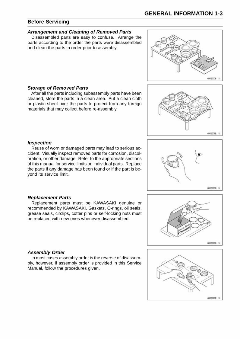
ZX636FD (EUR Models) Left Side View
ZX636FD (EUR Models) Right Side View
Frame Number Engine Number

1-10 GENERAL INFORMATIONGeneral Specifications
Items ZX636ED/FDDimensions
Overall Length 2 085 mm (82.09 in.)Overall Width 705 mm (27.8 in.)Overall Height 1 115 mm (43.90 in.)Wheelbase 1 395 mm (54.92 in.)Road Clearance 130 mm (5.12 in.)Seat Height 830 mm (32.7 in.)Curb Mass:
ZX636ED 192 kg (423 lb)ZX636FD 194 kg (428 lb)Front:
ZX636ED 98 kg (216 lb)ZX636FD 99 kg (218 lb)
Rear:ZX636ED 94 kg (207 lb)ZX636FD 95 kg (209 lb)
Fuel Tank Capacity 17 L (4.5 US gal)Performance
Minimum Turning Radius 3.4 m (11.2 ft)Engine
Type 4-stroke, DOHC, 4-cylinderCooling System Liquid-cooledBore and Stroke 67.0 × 45.1 mm (2.64 × 1.78 in.)Displacement 636 cm³ (38.8 cu in.)Compression Ratio 12.9:1Maximum Horsepower 96.4 kW (131 PS) at 13 500 r/min (rpm),
(WVTA (78.2 H)) 78.2 kW (106 PS) at 13 500 r/min (rpm),(SEA) 95.0 kW (129 PS) at 13 000 r/min (rpm),(CA), (CAL), (US) – – –
Maximum Torque 71 N·m (7.2 kgf·m, 52 ft·lb) at 11 500 r/min (rpm),(WVTA (78.2 H)) 61 N·m (6.2 kgf·m, 45 ft·lb) at 10 800 r/min(rpm),(CA), (CAL), (US) – – –
Carburetion System FI (Fuel Injection), KEIHIN TTK38 × 4Starting System Electric starterIgnition System Battery and coil (transistorized)Timing Advance Electronically advanced (IC igniter in ECU)Ignition Timing From 12.5° BTDC at 1 300 r/min (rpm) to 36.4° BTDC at 4 800
r/min (rpm)Spark Plug NGK CR9ECylinder Numbering Method Left to right, 1-2-3-4Firing Order 1-2-4-3

GENERAL INFORMATION 1-11General Specifications
Items ZX636ED/FDValve Timing:
Intake:Open 44° (BTDC)Close 67° (ABDC)Duration 291°
Exhaust:Open 58° (BBDC)Close 20° (ATDC)Duration 258°
Lubrication System Forced lubrication (wet sump with oil cooler)Engine Oil:
Type API SG, SH, SJ, SL or SM with JASO MA, MA1 or MA2Viscosity SAE 10W-40Capacity 3.6 L (3.8 US qt)
Drive TrainPrimary Reduction System:
Type GearReduction Ratio 1.900 (76/40)
Clutch Type Wet multi discTransmission:
Type 6-speed, constant mesh, return shiftGear Ratios:
1st 2.846 (37/13)2nd 2.200 (33/15)3rd 1.850 (37/20)4th 1.600 (32/20)5th 1.421 (27/19)6th 1.300 (26/20)
Final Drive System:Type Chain driveReduction Ratio 2.688 (43/16)Overall Drive Ratio 6.638 at Top gear
FrameType Tubular, diamondCaster (Rake Angle) 23.5°Trail 101 mm (3.98 in.)Front Tire:
Type TubelessSize 120/70ZR17 M/C (58 W)Rim Size J17M/C × MT3.50
Rear Tire:Type TubelessSize 180/55ZR17 M/C (73 W)Rim Size J17M/C × MT5.50

1-12 GENERAL INFORMATIONGeneral Specifications
Items ZX636ED/FDFront Suspension:
Type Telescopic fork (upside-down)Wheel Travel 120 mm (4.72 in.)
Rear Suspension:Type Swingarm (uni-trak)Wheel Travel 134 mm (5.28 in.)
Brake Type:Front Dual discsRear Single disc
Electrical EquipmentBattery 12 V 8 AhHeadlight:
Type Semi-sealed beamBulb:
High 12 V 55 W (quartz-halogen)Low 12 V 55 W (quartz-halogen)
Tail/Brake Light LEDAlternator:
Type Three-phase ACRated Output 26 A/14 V at 5 000 r/min (rpm)
Specifications are subject to change without notice, and may not apply to every country.

GENERAL INFORMATION 1-13Unit Conversion Table
Prefixes for Units:
Prefix Symbol Powermega M × 1 000 000kilo k × 1 000centi c × 0.01milli m × 0.001micro µ × 0.000001
Units of Mass:kg × 2.205 = lbg × 0.03527 = oz
Units of Volume:L × 0.2642 = gal (US)L × 0.2200 = gal (IMP)L × 1.057 = qt (US)L × 0.8799 = qt (IMP)L × 2.113 = pint (US)L × 1.816 = pint (IMP)mL × 0.03381 = oz (US)mL × 0.02816 = oz (IMP)mL × 0.06102 = cu in.
Units of Force:N × 0.1020 = kgN × 0.2248 = lbkg × 9.807 = Nkg × 2.205 = lb
Units of Length:km × 0.6214 = milem × 3.281 = ftmm × 0.03937 = in.
Units of Torque:N·m × 0.1020 = kgf·mN·m × 0.7376 = ft·lbN·m × 8.851 = in·lbkgf·m × 9.807 = N·mkgf·m × 7.233 = ft·lbkgf·m × 86.80 = in·lb
Units of Pressure:kPa × 0.01020 = kgf/cm²kPa × 0.1450 = psikPa × 0.7501 = cmHgkgf/cm² × 98.07 = kPakgf/cm² × 14.22 = psicmHg × 1.333 = kPa
Units of Speed:km/h × 0.6214 = mph
Units of Power:kW × 1.360 = PSkW × 1.341 = HPPS × 0.7355 = kWPS × 0.9863 = HP
Units of Temperature:


PERIODIC MAINTENANCE 2-1
2
Periodic MaintenanceTable of Contents
Periodic Maintenance Chart ................................................................................................... 2-3Torque and Locking Agent...................................................................................................... 2-5Specifications ......................................................................................................................... 2-11Special Tools .......................................................................................................................... 2-13Periodic Maintenance Procedures.......................................................................................... 2-14
Fuel System (DFI)................................................................................................................ 2-14Air Cleaner Element Replacement.................................................................................... 2-14Idle Speed Inspection ....................................................................................................... 2-15Idle Speed Adjustment...................................................................................................... 2-15Throttle Control System Inspection................................................................................... 2-15Engine Vacuum Synchronization Inspection..................................................................... 2-16Fuel System...................................................................................................................... 2-19Fuel Hose Replacement ................................................................................................... 2-20Evaporative Emission Control System Inspection (CAL Model) ....................................... 2-22
Cooling System.................................................................................................................... 2-23Coolant Level Inspection................................................................................................... 2-23Cooling System................................................................................................................. 2-23Coolant Change................................................................................................................ 2-23Water Hose and O-ring Replacement............................................................................... 2-26
Engine Top End ................................................................................................................... 2-27Valve Clearance Inspection .............................................................................................. 2-27Valve Clearance Adjustment............................................................................................. 2-28Air Suction System Damage Inspection............................................................................ 2-30
Clutch................................................................................................................................... 2-31Clutch Operation Inspection ............................................................................................. 2-31
Engine Lubrication System.................................................................................................. 2-32Engine Oil Change............................................................................................................ 2-32Oil Filter Replacement ...................................................................................................... 2-33
Wheels/Tires........................................................................................................................ 2-34Air Pressure Inspection..................................................................................................... 2-34Wheels and Tires .............................................................................................................. 2-34Wheel Bearing Damage Inspection .................................................................................. 2-35
Final Drive............................................................................................................................ 2-36Drive Chain Lubrication Condition Inspection ................................................................... 2-36Drive Chain Slack Inspection ............................................................................................ 2-36Drive Chain Slack Adjustment .......................................................................................... 2-37Wheel Alignment Inspection ............................................................................................. 2-38Drive Chain Wear Inspection ............................................................................................ 2-38Chain Guide Wear Inspection ........................................................................................... 2-39
Brakes.................................................................................................................................. 2-39Brake System.................................................................................................................... 2-39Brake Fluid Level Inspection............................................................................................. 2-40Brake Fluid Change .......................................................................................................... 2-41Brake Hose and Pipe Replacement.................................................................................. 2-43Master Cylinder Rubber Parts Replacement .................................................................... 2-46Caliper Rubber Parts Replacement .................................................................................. 2-47Brake Pad Wear Inspection .............................................................................................. 2-51Brake Light Switch Operation Inspection .......................................................................... 2-51
Suspension.......................................................................................................................... 2-52Suspension System .......................................................................................................... 2-52

2-2 PERIODIC MAINTENANCE
Steering ............................................................................................................................... 2-53Steering Play Inspection ................................................................................................... 2-53Steering Play Adjustment.................................................................................................. 2-54Steering Stem Bearing Lubrication ................................................................................... 2-55
Electrical System ................................................................................................................. 2-56Lights and Switches Operation Inspection........................................................................ 2-56Headlight Aiming Inspection ............................................................................................. 2-58Sidestand Switch Operation Inspection ............................................................................ 2-59Engine Stop Switch Operation Inspection......................................................................... 2-60Spark Plug Replacement .................................................................................................. 2-61
Others .................................................................................................................................. 2-61Chassis Parts Lubrication ................................................................................................ 2-61Condition of Bolts, Nuts and Fasteners Tightness Inspection .......................................... 2-62
PERIODIC MAINTENANCE 2-3Periodic Maintenance Chart
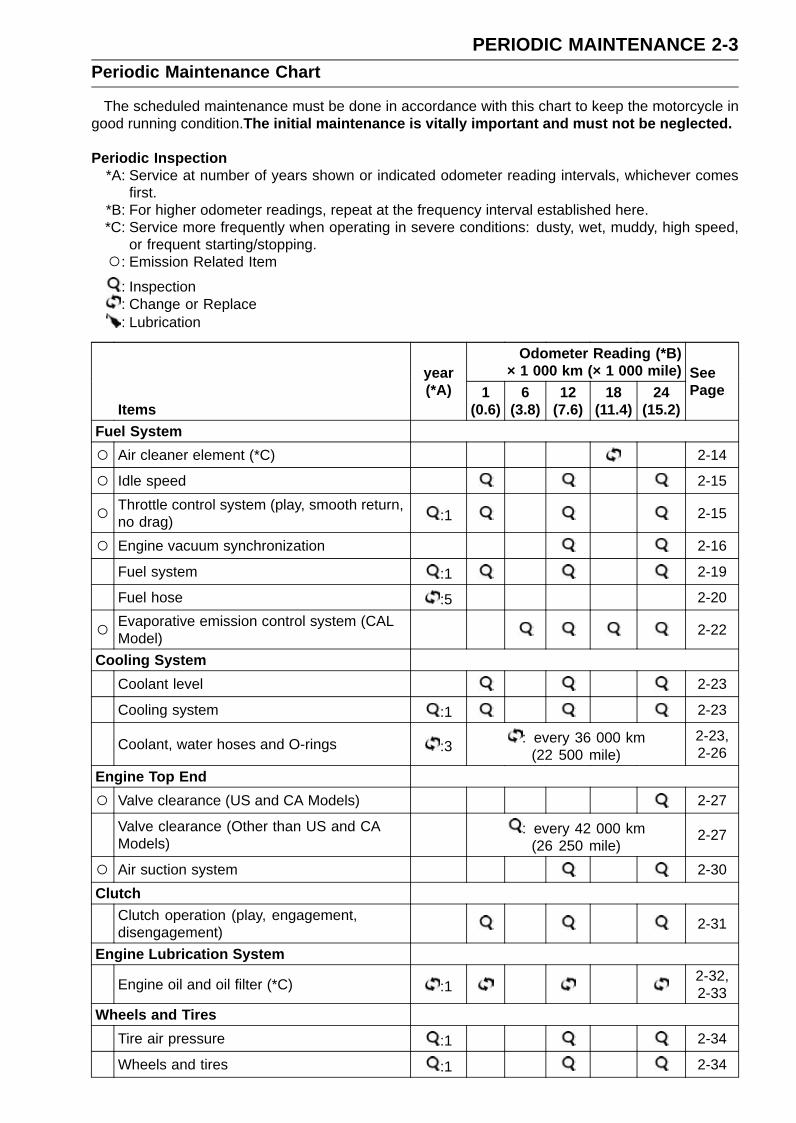
The scheduled maintenance must be done in accordance with this chart to keep the motorcycle ingood running condition.The initial maintenance is vitally important and must not be neglected.
Periodic Inspection*A: Service at number of years shown or indicated odometer reading intervals, whichever comes
first.*B: For higher odometer readings, repeat at the frequency interval established here.*C: Service more frequently when operating in severe conditions: dusty, wet, muddy, high speed,
or frequent starting/stopping.: Emission Related Item
: Inspection: Change or Replace: Lubrication
Odometer Reading (*B)× 1 000 km (× 1 000 mile)
Items
year(*A) 1
(0.6)6
(3.8)12
(7.6)18
(11.4)24
(15.2)
SeePage
Fuel System Air cleaner element (*C) 2-14
Idle speed 2-15
Throttle control system (play, smooth return,no drag) :1 2-15
Engine vacuum synchronization 2-16
Fuel system :1 2-19
Fuel hose :5 2-20
Evaporative emission control system (CALModel) 2-22
Cooling SystemCoolant level 2-23
Cooling system :1 2-23
Coolant, water hoses and O-rings :3 : every 36 000 km(22 500 mile)
2-23,2-26
Engine Top End Valve clearance (US and CA Models) 2-27
Valve clearance (Other than US and CAModels)
: every 42 000 km(26 250 mile)
2-27
Air suction system 2-30Clutch
Clutch operation (play, engagement,disengagement) 2-31
Engine Lubrication System
Engine oil and oil filter (*C) :12-32,2-33
Wheels and TiresTire air pressure :1 2-34
Wheels and tires :1 2-34

2-4 PERIODIC MAINTENANCEPeriodic Maintenance Chart
Odometer Reading (*B)× 1 000 km (× 1 000 mile)
Items
year(*A) 1
(0.6)6
(3.8)12
(7.6)18
(11.4)24
(15.2)
SeePage
Wheel bearing damage :1 2-35Final Drive
Drive chain lubrication condition (*C) : every 600 km (400 mile) 2-36
Drive chain slack (*C) : every 1 000 km (600 mile) 2-36
Drive chain wear (*C) 2-38
Drive chain guide wear 2-39Brakes
Brake system :1 2-39
Brake fluid level :0.5 2-40
Brake fluid (front and rear) :2 2-41
Brake hose/rubber parts of brake mastercylinder and caliper :4 : every 48 000 km
(30 000 mile)
2-43,2-46,2-47
Brake pad wear (*C) 2-51
Brake light switch operation 2-51Suspension
Suspension system :1 2-52Steering
Steering play :1 2-53
Steering stem bearings :2 2-55Electrical System
Electrical system :1 2-56
Spark plugs 2-61Others
Chassis parts :1 2-61
Condition of bolts, nuts and fasteners 2-62

PERIODIC MAINTENANCE 2-5Torque and Locking Agent
The following tables list the tightening torque for the major fasteners requiring use of anon-permanent locking agent or silicone sealant etc.
Letters used in the “Remarks” column mean:AL: Tighten the two clamp bolts alternately two times to ensure even tightening torque.G: Apply grease.L: Apply a non-permanent locking agent.
M: Apply molybdenum disulfide grease.MO: Apply molybdenum disulfide oil solution.
(mixture of the engine oil and molybdenum disulfide grease in a weight ratio 10:1)R: Replacement PartsS: Follow the specified tightening sequence.Si: Apply silicone grease.
SS: Apply silicone sealant.
TorqueFastener
N·m kgf·m ft·lbRemarks
Fuel System (DFI)Air Cleaner Housing Assembly Screws 1.2 0.12 11 in·lbAir Cleaner Housing Clamp Bolts 2.0 0.20 18 in·lbAir Intake Duct Mounting Bolts 9.8 1.0 87 in·lb LAir Intake Duct Assembly Screws 1.5 0.15 13 in·lbCrankshaft Sensor Bolts 5.9 0.60 52 in·lbDelivery Pipe Assy Mounting Screws 3.43 0.35 30 in·lbExhaust Butterfly Valve Actuator Mounting Screws 4.3 0.44 38 in·lbExhaust Butterfly Valve Actuator Pulley Bolt 4.9 0.50 43 in·lbFuel Pump Bolts 9.8 1.0 87 in·lb L, SGear Position Switch Screws 2.9 0.30 26 in·lb LIntake Air Temperature Sensor Screw 1.2 0.12 11 in·lbOxygen Sensor (Equipped Models) 25 2.5 18Throttle Body Assy Holder Bolts 12 1.2 106 in·lb LThrottle Body Assy Holder Clamp Bolts 2.9 0.30 26 in·lbThrottle Cable Holder Plate Bolt 3.9 0.40 35 in·lb LThrottle Case Screws 3.5 0.36 31 in·lbWater Temperature Sensor 12 1.2 106 in·lb
Cooling SystemCoolant By-pass Fitting Bolt 8.8 0.90 78 in·lb LCoolant Drain Bolt (Cylinder) 9.8 1.0 87 in·lbCoolant Drain Bolt (Water Pump) 8.8 0.90 78 in·lbHeat Insulation Plate Bolt 3.9 0.40 35 in·lb LImpeller Bolt 9.8 1.0 87 in·lbOil Cooler Mounting Bolts 20 2.0 15Radiator Upper Bolts 9.8 1.0 87 in·lbThermostat Housing Cover Bolts 5.9 0.60 52 in·lbWater Hose Clamp Screws 3.0 0.31 27 in·lbWater Hose Fitting Bolts 9.8 1.0 87 in·lbWater Pump Cover Bolts 12 1.2 106 in·lb LWater Temperature Sensor 12 1.2 106 in·lb

2-6 PERIODIC MAINTENANCETorque and Locking Agent
TorqueFastener
N·m kgf·m ft·lbRemarks
Engine Top EndAir Suction Valve Cover Bolts 9.8 1.0 87 in·lb LBreather Hose Fitting 15 1.5 11 LCamshaft Cap Bolts 12 1.2 106 in·lb SCamshaft Chain Tensioner Cap Bolt 20 2.0 15Camshaft Chain Tensioner Mounting Bolts 11 1.1 97 in·lbCamshaft Sprocket Bolts 15 1.5 11 LCoolant Drain Bolt (Cylinder) 9.8 1.0 87 in·lb
Cylinder Head Bolts (M9) see thetext ← ← MO, S
Cylinder Head Bolts (M6) 12 1.2 106 in·lb SCylinder Head Cover Bolts 9.8 1.0 87 in·lb SExhaust Butterfly Valve Actuator Mounting Screws 4.3 0.44 38 in·lbExhaust Butterfly Valve Actuator Pulley Bolt 4.9 0.50 43 in·lbExhaust Butterfly Valve Cable Locknuts 5.0 0.51 44 in·lbFront Camshaft Chain Guide Bolt (Lower) 12 1.2 106 in·lbFront Camshaft Chain Guide Bolt (Upper) 25 2.5 18Muffler Body Mounting Bolt 25 2.5 18Premuffler Chamber Bracket Bolt 40 4.1 30Premuffler Chamber Mounting Bolt 40 4.1 30Muffler Body End Cover Bolts 7.0 0.71 62 in·lb LSpark Plugs 13 1.3 115 in·lbStarter Clutch Bolt Cap 2.9 0.30 26 in·lbThrottle Body Assy Holder Bolts 12 1.2 106 in·lb LThrottle Body Assy Holder Clamp Bolts 2.9 0.30 26 in·lbTiming Inspection Cap 2.9 0.30 26 in·lbUpper Camshaft Chain Guide Bolts 12 1.2 106 in·lb SWater Passage Plugs 19.6 2.00 14.5 L
ClutchClutch Cover Bolts (M6, L = 40 mm) 9.8 1.0 87 in·lbClutch Cover Bolts (M6, L = 25 mm) 9.8 1.0 87 in·lbClutch Hub Nut 135 13.8 100 RClutch Lever Clamp Bolts 7.8 0.80 69 in·lb SClutch Stopper Bolts 8.8 0.90 78 in·lbOil Filler Plug – – – Hand-tighten
Engine Lubrication SystemAir Bleed Bolt 9.8 1.0 87 in·lbEngine Oil Drain Bolt 29 3.0 21Impeller Bolt 9.8 1.0 87 in·lbOil Cooler Mounting Bolts 20 2.0 15Oil Cooler/Oil Filter Case Mounting Bolts 20 2.0 15 LOil Filter 17 1.7 13 G, ROil Filter Guard Bolts 4.0 0.41 35 in·lb L

PERIODIC MAINTENANCE 2-7Torque and Locking Agent
TorqueFastener
N·m kgf·m ft·lbRemarks
Oil Filter Holder Bolt 25 2.5 18 LOil Jet Nozzles 2.9 0.30 26 in·lbOil Pan Bolts 9.8 1.0 87 in·lb SOil Passage Plug 17 1.7 13Oil Passage Plugs (Taper) 20 2.0 15 LOil Pressure Relief Valve 15 1.5 11 LOil Pressure Switch 15 1.5 11 SSOil Pressure Switch Terminal Bolt 1.5 0.15 13 in·lb GOil Pump Drive Gear Bolt 9.8 1.0 87 in·lb LWater Pump Cover Bolts 12 1.2 106 in·lb L
Engine Removal/InstallationAdjusting Collar Locknuts 49 5.0 36 SAdjusting Collars 9.8 1.0 87 in·lb S, (M)Left Front Engine Mounting Bolt 44 4.5 32 SLower Engine Mounting Nut 44 4.5 32 R, SMiddle Engine Mounting Nut 44 4.5 32 R, SRight Front Engine Mounting Bolt 44 4.5 32 S
Crankshaft/TransmissionBearing Holder Screws 4.9 0.50 43 in·lb LBreather Hose Fitting 15 1.5 11 LBreather Plate Bolts 9.8 1.0 87 in·lb L
Connecting Rod Big End Nuts see thetext ← ← MO
Crankcase Bolt (M8, L = 90 mm) 27 2.8 20 SCrankcase Bolts (M8, L = 95 mm) 31 3.2 23 MO, SCrankcase Bolts (M8, L = 75 mm) 27 2.8 20 SCrankcase Bolts (M6, L = 68 mm) 12 1.2 106 in·lb SCrankcase Bolts (M6, L = 50 mm) 12 1.2 106 in·lbGear Position Switch Screws 2.9 0.30 26 in·lb LGear Positioning Lever Bolt 12 1.2 106 in·lbIdle Gear Cover Bolts 9.8 1.0 87 in·lbOil Jet Nozzles 2.9 0.30 26 in·lbOil Passage Nozzle 4.9 0.50 43 in·lbOil Passage Plug 17 1.7 13Oil Passage Plugs (Taper) 20 2.0 15 LRace Holder Screws 4.9 0.50 43 in·lb LShift Drum Cam Holder Bolt 12 1.2 106 in·lb LShift Pedal Mounting Bolt 25 2.5 18 LShift Shaft Return Spring Pin 28 2.9 21 LStarter Clutch Bolt 49 5.0 36Starter Clutch Cover Bolt (L = 20 mm) 9.8 1.0 87 in·lbStarter Clutch Cover Bolts (L = 30 mm) 9.8 1.0 87 in·lbTransmission Case Bolt (M6) 9.8 1.0 87 in·lb

2-8 PERIODIC MAINTENANCETorque and Locking Agent
TorqueFastener
N·m kgf·m ft·lbRemarks
Transmission Case Bolts (M8) 20 2.0 15Wheels/Tires
Front Axle Clamp Bolts 20 2.0 15 ALFront Axle 127 13.0 93.7Rear Axle Nut 127 13.0 93.7
Final DriveChain Guide Bolts 12 1.2 106 in·lb LEngine Sprocket Cover Bolts (L = 45 mm) 9.8 1.0 87 in·lbEngine Sprocket Cover Bolts (L = 55 mm) 9.8 1.0 87 in·lbEngine Sprocket Cover Damper Screws 3.0 0.31 27 in·lbEngine Sprocket Nut 147 15.0 108 MORear Axle Nut 127 13.0 93.7Rear Sprocket Nuts 59 6.0 44 R
BrakesBleed Valves 7.8 0.80 69 in·lbBrake Hose Banjo Bolts 25 2.5 18Brake Lever Pivot Bolt 1.0 0.10 8.9 in·lb SiBrake Lever Pivot Bolt Locknut 5.9 0.60 52 in·lbBrake Pedal Mounting Bolt 34 3.5 25 LFront Brake Disc Mounting Bolts 27 2.8 20 LFront Brake Light Switch Screw 1.2 0.12 11 in·lbFront Brake Pad Pins 17 1.7 13Front Brake Reservoir Cap Stopper Screw 1.2 0.12 11 in·lbFront Caliper Mounting Bolts 34 3.5 25Brake Pipe Banjo Bolts (L = 20.8 mm) (KIBS EquippedModels) 23 2.3 17
Brake Pipe Banjo Bolt (L = 32.3 mm) (KIBS EquippedModels) 23 2.3 17
Brake Pipe Joint Nuts (KIBS Equipped Models) 18 1.8 13Front Master Cylinder Bleed Valve 5.4 0.55 48 in·lbFront Master Cylinder Clamp Bolts 11 1.1 97 in·lb SRear Brake Disc Mounting Bolts 27 2.8 20 LRear Master Cylinder Mounting Bolts 25 2.5 18Rear Master Cylinder Push Rod Locknut 17 1.7 13Rear Brake Pad Pin 17 1.7 13Rear Brake Pad Pin Plug 2.45 0.25 22 in·lbRear Caliper Pin Bolt 27 2.8 20 Si
SuspensionFront Axle Clamp Bolts 20 2.0 15 ALFront Fork Top Plugs 35 3.6 26Lower Front Fork Clamp Bolts 23 2.3 17 ALLower Rear Shock Absorber Nut 34 3.5 25 RPiston Rod Guide Case 90 9.2 66

PERIODIC MAINTENANCE 2-9Torque and Locking Agent
TorqueFastener
N·m kgf·m ft·lbRemarks
Rear Shock Absorber Bracket Nut 59 6.0 44Swingarm Pivot Adjusting Collar Locknut 98 10.0 72Swingarm Pivot Shaft 20 2.0 15Swingarm Pivot Shaft Nut 108 11.0 79.7Tie-Rod Nuts 59 6.0 44 RRocker Arm Bolt 34 3.5 25Upper Front Fork Clamp Bolts 20 2.0 15Upper Rear Shock Absorber Nut 34 3.5 25 R
SteeringHandlebar Clamp Bolts 25 2.5 18Handlebar Positioning Bolts 9.8 1.0 87 in·lb LLeft Switch Housing Screws 3.5 0.36 31 in·lbLower Front Fork Clamp Bolts 23 2.3 17 ALRight Switch Housing Screws 3.5 0.36 31 in·lbSteering Stem Head Bolt 78 8.0 58 LSteering Stem Nut 27 2.8 20Throttle Case Screws 3.5 0.36 31 in·lbUpper Front Fork Clamp Bolts 20 2.0 15
FrameFront Fender Mounting Bolts 3.9 0.40 35 in·lbFront Footpeg Bracket Bolts 25 2.5 18 LRear Footpeg Bracket Bolts 25 2.5 18Rear Frame Bolts (M10) 44 4.5 32 LRear Frame Bolts (M8) 25 2.5 18 LSidestand Bolt 29 3.0 21 SSidestand Bracket Bolts 49 5.0 36 LSidestand Switch Bolt 8.8 0.90 78 in·lb LSidestand Nut 44 4.5 32 R, SWindshield Mounting Bolts 0.42 0.043 3.7 in·lb
Electrical SystemAlternator Cover Bolts 9.8 1.0 87 in·lbAlternator Lead Holding Plate Bolt 9.8 1.0 87 in·lb LAlternator Rotor Bolt 155 15.8 114Crankshaft Sensor Bolts 5.9 0.60 52 in·lbEngine Ground Cable Terminal Bolt 9.8 1.0 87 in·lbFront Brake Light Switch Screw 1.2 0.12 11 in·lbFront Turn Signal Light Mounting Screw 1.2 0.12 11 in·lbFuel Pump Bolts 9.8 1.0 87 in·lb L, SGear Position Switch Screws 2.9 0.30 26 in·lb LLeft Switch Housing Screws 3.5 0.36 31 in·lbLicense Plate Light Cover Screws 1.0 0.10 8.9 in·lbLicense Plate Light Mounting Nuts 3.5 0.36 31 in·lbMeter Unit Mounting Screws 1.2 0.12 11 in·lb

2-10 PERIODIC MAINTENANCETorque and Locking Agent
TorqueFastener
N·m kgf·m ft·lbRemarks
Oil Pressure Switch 15 1.5 11 SSOil Pressure Switch Terminal Bolt 1.5 0.15 13 in·lb GOxygen Sensor (Equipped Models) 25 2.5 18Regulator/Rectifier Bracket Screws 1.2 0.12 11 in·lbRight Switch Housing Screws 3.5 0.36 31 in·lbSidestand Switch Bolt 8.8 0.90 78 in·lb LSpark Plugs 13 1.3 115 in·lbStarter Clutch Bolt Cap 2.9 0.30 26 in·lbStarter Clutch Cover Bolt (L = 20 mm) 9.8 1.0 87 in·lbStarter Clutch Cover Bolts (L = 30 mm) 9.8 1.0 87 in·lbStarter Motor Cable Terminal Bolt 2.9 0.30 26 in·lbStarter Motor Mounting Bolts 9.8 1.0 87 in·lbStator Coil Bolts 12 1.2 106 in·lb LWater Temperature Sensor 12 1.2 106 in·lbThe table below, relating tightening torque to thread diameter, lists the basic torque for the bolts and
nuts. Use this table for only the bolts and nuts which do not require a specific torque value. All of thevalues are for use with dry solvent-cleaned threads.
Basic Torque for General FastenersTorqueThreads Diameter
(mm) N·m kgf·m ft·lb5 3.4 ∼ 4.9 0.35 ∼ 0.50 30 ∼ 43 in·lb6 5.9 ∼ 7.8 0.60 ∼ 0.80 52 ∼ 69 in·lb8 14 ∼ 19 1.4 ∼ 1.9 10 ∼ 13.5
10 25 ∼ 34 2.6 ∼ 3.5 19 ∼ 2512 44 ∼ 61 4.5 ∼ 6.2 33 ∼ 4514 73 ∼ 98 7.4 ∼ 10.0 54 ∼ 7216 115 ∼ 155 11.5 ∼ 16.0 83 ∼ 11518 165 ∼ 225 17.0 ∼ 23.0 125 ∼ 16520 225 ∼ 325 23.0 ∼ 33.0 165 ∼ 240

PERIODIC MAINTENANCE 2-11Specifications
Item Standard Service LimitFuel System (DFI)
Throttle Grip Free Play 2 ∼ 3 mm (0.08 ∼ 0.12 in.) – – –Idle Speed 1 300 ±50 r/min (rpm) – – –Throttle Body Vacuum 33.4 ±1.33 kPa (251 ±10 mmHg) at idle speed – – –Bypass Screws (Turn Out) 0 ∼ 2 1/2 (for reference) – – –Air Cleaner Element Viscous paper element – – –
Cooling SystemCoolant:
Type (Recommended) Permanent type of antifreeze – – –Color Green – – –Mixed Ratio Soft water 50%, coolant 50% – – –Freezing Point –35°C (–31°F) – – –Total Amount 2.5 L (2.6 US qt) – – –
Engine Top EndValve Clearance:
Exhaust 0.24 ∼ 0.31 mm (0.0094 ∼ 0.0122 in.) – – –Intake 0.13 ∼ 0.19 mm (0.0051 ∼ 0.0075 in.) – – –
ClutchClutch Lever Free Play 2 ∼ 3 mm (0.08 ∼ 0.12 in.) – – –
Engine Lubrication SystemEngine Oil:
Type API SG, SH, SJ, SL or SM with JASO MA, MA1or MA2
– – –
Viscosity SAE 10W-40 – – –Capacity 2.8 L (3.0 US qt) (when filter is not removed) – – –
3.1 L (3.3 US qt) (when filter is removed) – – –3.6 L (3.8 US qt) (when engine is completely dry) – – –
Level Between upper and lower level lines (Wait 2 ∼ 3minutes after idling or running)
– – –
Wheels/TiresTread Depth:
Front 3.6 mm (0.14 in.) 1 mm (0.04 in.)(AT, CH, DE) 1.6
mm (0.06 in.)Rear 5.1 mm (0.20 in.) Up to 130 km/h
(80 mph): 2 mm(0.08 in.)
Over 130 km/h(80 mph): 3 mm
(0.12 in.)Air Pressure (when Cold):
Front Up to 180 kg (397 lb) load:250 kPa (2.50 kgf/cm², 36 psi)
– – –
Rear Up to 180 kg (397 lb) load:290 kPa (2.90 kgf/cm², 42 psi)
– – –

2-12 PERIODIC MAINTENANCESpecifications
Item Standard Service LimitFinal Drive
Drive Chain Slack 30 ∼ 40 mm (1.2 ∼ 1.6 in.) – – –Drive Chain Wear (20-linkLength)
317.5 ∼ 318.2 mm (12.50 ∼ 12.53 in.) 319 mm (12.6 in.)
Standard Chain:Make ENUMA – – –Type EK520RMX/3D – – –Link 112 links – – –
BrakesBrake Fluid:
Grade DOT4 – – –Brake Pad LiningThickness:
Front 4.0 mm (0.16 in.) 1 mm (0.04 in.)Rear 5.0 mm (0.20 in.) 1 mm (0.04 in.)
Brake Light Timing:Front Pulled ON – – –Rear On after about 10 mm (0.39 in.) of pedal travel – – –
Electrical SystemSpark Plug:
Type NGK CR9E – – –Gap 0.7 ∼ 0.8 mm (0.028 ∼ 0.031 in.) – – –

PERIODIC MAINTENANCE 2-13Special Tools
Inside Circlip Pliers:57001-143
Steering Stem Nut Wrench:57001-1100
Jack:57001-1238
Oil Filter Wrench:57001-1249
Pilot Screw Adjuster, C:57001-1292
Vacuum Gauge:57001-1369
Throttle Sensor Setting Adapter:57001-1538
Extension Tube:57001-1578
Jack Attachment:57001-1608

2-14 PERIODIC MAINTENANCEPeriodic Maintenance Procedures
Fuel System (DFI)Air Cleaner Element Replacement
NOTEIn dusty areas, the element should be replaced more
frequently than the recommended interval.
WARNINGIf dirt or dust is allowed to pass through into thethrottle body assy, the throttle may become stuck,possibly causing accident. Replace the air cleanerelement according to the maintenance chart.
NOTICEIf dirt gets through into the engine, excessive en-gine wear and possibly engine damage will occur.
•Remove the fuel tank (see Fuel Tank Removal in the FuelSystem (DFI) chapter).
• Disconnect the intake air temperature sensor lead con-nector [A].
• Remove:Screws [B]Upper Air Cleaner Housing [C]
•Discard the air cleaner element [A].
• Install a new element [A] so that the screen side [B] facesupward.
NOTICEUse only the recommended air cleaner element(Kawasaki part number 11013-0036). Using anotherair cleaner element will wear the engine prema-turely or lower the engine performance.
• Install the upper air cleaner housing (see Air CleanerHousing Assembly in the Fuel System (DFI) chapter).

PERIODIC MAINTENANCE 2-15Periodic Maintenance Procedures
Idle Speed Inspection•Start the engine and warm it up thoroughly.•With the engine idling, turn the handlebar to both sides
[A].If handlebar movement changes the idle speed, thethrottle cables may be improperly adjusted or incorrectlyrouted, or damaged. Be sure to correct any of theseconditions before riding (see Throttle Control SystemInspection and Cable, Wire, and Hose Routing section inthe Appendix chapter).
WARNINGOperation with improperly adjusted, incorrectlyrouted or damaged cables could result in an unsaferiding condition. Follow the service manual to bemake sure to correct any of these conditions.
•Check the idle speed.If the idle speed is out of specified range, adjust it.
Idle SpeedStandard: 1 300 ±50 r/min (rpm)
Idle Speed Adjustment•Start the engine and warm it up thoroughly.• Turn the adjusting screw [A] until the idle speed is correct.Open and close the throttle a few times to make sure that
the idle speed is within the specified range. Readjust ifnecessary.
Throttle Control System Inspection•Check the throttle grip free play [A].
If the free play is incorrect, adjust the throttle cables.
Throttle Grip Free PlayStandard: 2 ∼ 3 mm (0.08 ∼ 0.12 in.)
•Check that the throttle grip [B] moves smoothly from fullopen to close, and the throttle closes quickly and com-pletely by the return spring in all steering positions.If the throttle grip does not return properly, check the throt-tle cables routing, grip free play, and cable damage. Thenlubricate the throttle cable.
•Run the engine at the idle speed, and turn the handlebarall the way to the right and left to ensure that the idle speeddoes not change.If the idle speed increases, check the throttle cable freeplay and the cable routing.

2-16 PERIODIC MAINTENANCEPeriodic Maintenance Procedures
If necessary, adjust the throttle cable as follows.• Loosen the locknuts [A] [B].• Screw both throttle cable adjusters [C] [D] to give the
throttle grip plenty of play.• Turn the decelerator cable adjuster [C] until it has no play
when the throttle grip is completely closed.• Tighten the locknut [A].• Turn the accelerator cable adjuster [D] until 2 ∼ 3 mm
(0.08 ∼ 0.12 in.) of throttle grip play is obtained.• Tighten the locknut [B].
If the free play can not be adjusted with the adjusters,replace the cable.
Engine Vacuum Synchronization InspectionNOTE
These procedures are explained on the assumption thatthe intake and exhaust systems of the engine are ingood condition.
•Situate the motorcycle so that it is vertical.• Remove:
Fuel Tank (see Fuel Tank Removal in the Fuel System(DFI) chapter)Air Cleaner Housing (see Air Cleaner Housing Removalin the Fuel System (DFI) chapter)Fuel Hose (see Fuel Hose Replacement)
• Pull off the rubber caps [A] and vacuum hose [B] from thefittings of each throttle body.
• For the CAL Model, pull off the vacuum hoses.
•Connect a vacuum gauge and hoses [A] (Special Tool:57001-1369) to the fittings on the throttle body.Special Tool - Vacuum Gauge: 57001-1369
•Connect a highly accurate tachometer lead [B] to one ofthe stick coil primary leads.

PERIODIC MAINTENANCE 2-17Periodic Maintenance Procedures
•Plug the air switching valve hose end [A] and air cleanerhousing fitting [B].
• Install the air cleaner housing (see Air Cleaner HousingInstallation in the Fuel System (DFI) chapter).
• Connect the following parts temporarily.Fuel Pump Lead Connector [A]Extension Tube [B]
Special Tool - Extension Tube: 57001-1578
•Start the engine and warm it up thoroughly.•Check the idle speed, using a highly accurate tachometer
[A].
Idle SpeedStandard: 1 300 ±50 r/min (rpm)
If the idle speed is out of the specified range, adjust it withthe adjusting screw (see Idle Speed Adjustment).
NOTICEDo not measure the idle speed by the tachometer ofthe meter unit.
•While idling the engine, inspect the throttle body vacuum,using the vacuum gauge [B].
Throttle Body VacuumStandard: 33.4 ±1.33 kPa (251 ±10 mmHg) at idle speed

2-18 PERIODIC MAINTENANCEPeriodic Maintenance Procedures
If any vacuum is not within specifications, adjust the by-pass screws [A].View from Rear [B]
Special Tool - Pilot Screw Adjuster, C [C]: 57001-1292
•Adjust the each vacuum (#1 ∼ #4) to the standard value.•Open and close the throttle valves after each measure-
ment.
NOTEDo not turn the center adjusting screw [D].
•Check the vacuums as before.If all vacuums are within the specification range, finish theengine vacuum synchronization.If any vacuum can not be adjusted within the specification,replace the bypass screws #1 ∼ #4 with new ones, referto the following procedure.
•Remove the throttle body assy (see Throttle Body AssyRemoval in the Fuel System (DFI) chapter).
• Turn in the bypass screw [A] with counting the number ofturns until it seals fully but not tightly. Record the numberof turns.
•Remove:Bypass ScrewSpring [B]Washer [C]O-ring [D]
•Check the bypass screw hole in the throttle body for car-bon deposits.If any carbons accumulate, wipe the carbons off from thehole, using a cotton pad penetrated with a high flash-pointsolvent.
• Replace the bypass screw, spring, washer and O-ring asa set.
• Turn in the bypass screw until it seats fully but not tightly.
NOTICEDo not over-tighten the bypass screw. The taperedportion [E] of the bypass screw could be damaged.
PERIODIC MAINTENANCE 2-19Periodic Maintenance Procedures
•Back out the same number of turns counted when firstturned in. This is to set the screw to its original position.
NOTEA throttle body has different “turns out” of the bypass
screw for each individual unit. On setting the bypassscrew, use the “turns out” determined during disassem-bly.
•Repeat the same procedure for other bypass screws.•Repeat the synchronization.
If the vacuums are correct, check the output voltage ofthe main throttle sensor (see Main Throttle Sensor OutputVoltage Inspection in the Self-Diagnosis System chapter).Special Tool - Throttle Sensor Setting Adapter: 57001
-1538
Main Throttle Sensor Output VoltageConnections to Adapter:
Degital Meter (+) → R (sensor Y/W) leadDegital Meter (–) → BK (sensor G) lead
Standard: DC 1.02 ∼ 1.06 V at idle throttle opening
If the output voltage is out of the standard, check the inputvoltage of the main throttle sensor (see Main Throttle Sen-sor Input Voltage Inspection in the Self-Diagnosis Systemchapter).
• Remove the vacuum gauge hoses and install the rubbercaps and vacuum hose on the original position.
• For CAL Model, install the vacuum hoses.Run the vacuum hose according to Cable, Wire, and Hose
Routing section in the Appendix chapter.• Install the removed parts (see appropriate chapters).
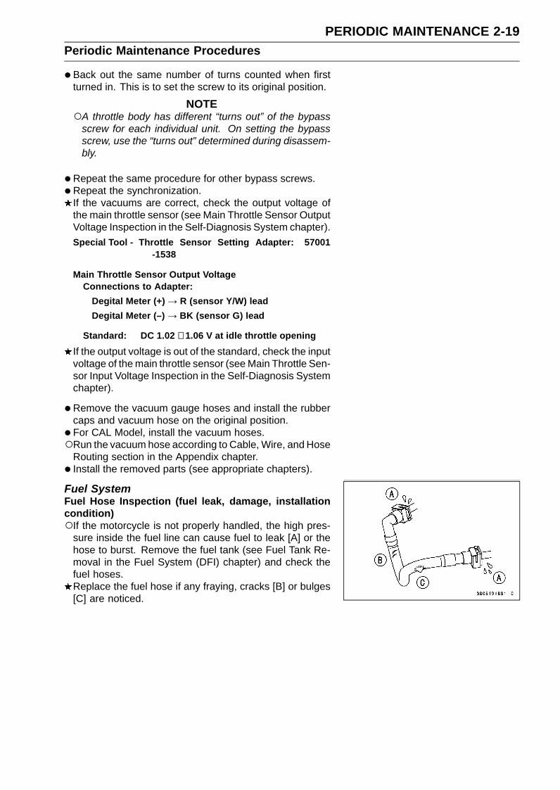
Fuel SystemFuel Hose Inspection (fuel leak, damage, installationcondition)If the motorcycle is not properly handled, the high pres-
sure inside the fuel line can cause fuel to leak [A] or thehose to burst. Remove the fuel tank (see Fuel Tank Re-moval in the Fuel System (DFI) chapter) and check thefuel hoses.Replace the fuel hose if any fraying, cracks [B] or bulges[C] are noticed.
2-20 PERIODIC MAINTENANCEPeriodic Maintenance Procedures
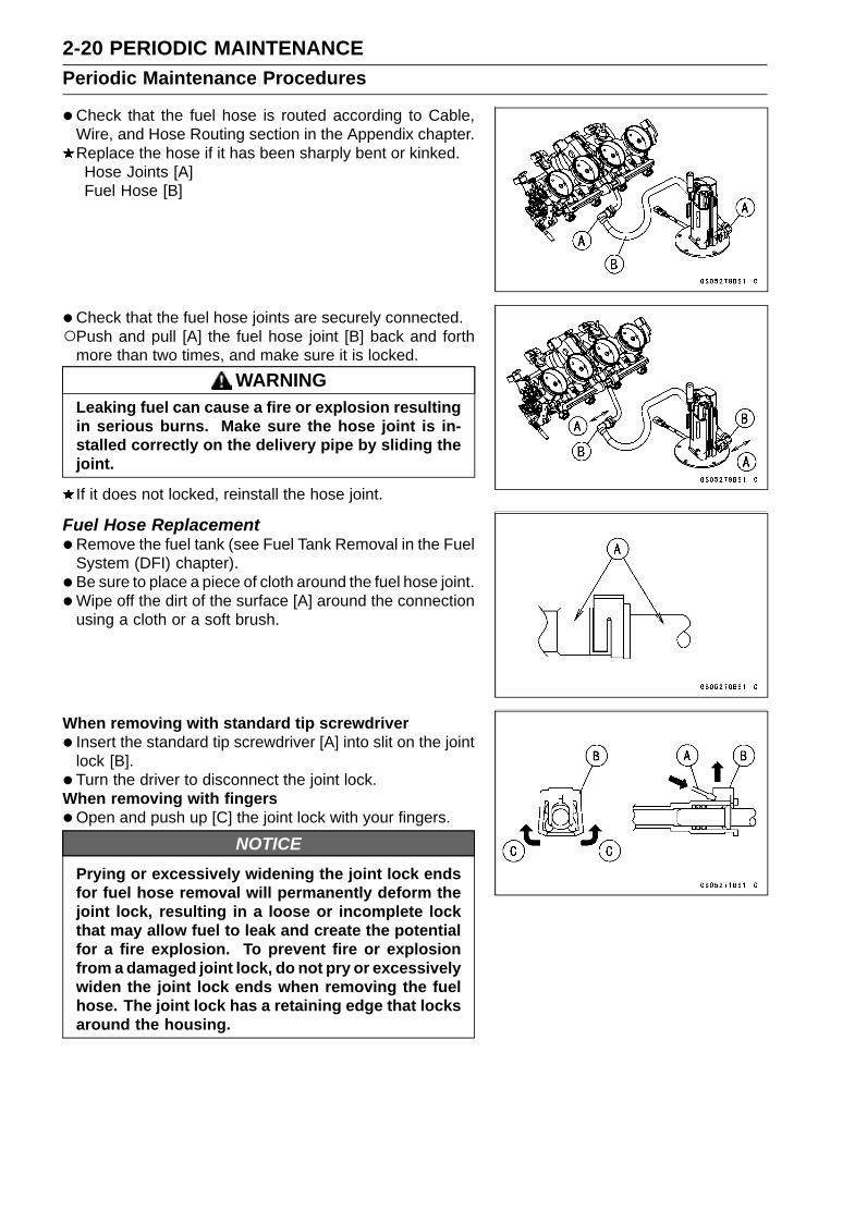
•Check that the fuel hose is routed according to Cable,Wire, and Hose Routing section in the Appendix chapter.Replace the hose if it has been sharply bent or kinked.Hose Joints [A]Fuel Hose [B]
•Check that the fuel hose joints are securely connected.Push and pull [A] the fuel hose joint [B] back and forth
more than two times, and make sure it is locked.WARNING
Leaking fuel can cause a fire or explosion resultingin serious burns. Make sure the hose joint is in-stalled correctly on the delivery pipe by sliding thejoint.
If it does not locked, reinstall the hose joint.
Fuel Hose Replacement•Remove the fuel tank (see Fuel Tank Removal in the Fuel
System (DFI) chapter).• Be sure to place a piece of cloth around the fuel hose joint.•Wipe off the dirt of the surface [A] around the connection
using a cloth or a soft brush.
When removing with standard tip screwdriver• Insert the standard tip screwdriver [A] into slit on the joint
lock [B].• Turn the driver to disconnect the joint lock.When removing with fingers•Open and push up [C] the joint lock with your fingers.
NOTICEPrying or excessively widening the joint lock endsfor fuel hose removal will permanently deform thejoint lock, resulting in a loose or incomplete lockthat may allow fuel to leak and create the potentialfor a fire explosion. To prevent fire or explosionfrom a damaged joint lock, do not pry or excessivelywiden the joint lock ends when removing the fuelhose. The joint lock has a retaining edge that locksaround the housing.

PERIODIC MAINTENANCE 2-21Periodic Maintenance Procedures
•Pull the fuel hose joint [A] out of the delivery pipe [B].
WARNINGFuel is flammable and explosive under certain con-ditions and can cause severe burns. Be preparedfor fuel spillage; any spilled fuel must be completelywiped up immediately. When the fuel hose is dis-connected, fuel spills out from the hose and thepipe. Cover the hose connection with a clean shoptowel to prevent fuel spillage.
•Clean the delivery pipe.•Cover the delivery pipe with the vinyl bag to keep it clean.
•Remove the vinyl bag on the pipe.•Check that there are no flaws, burrs, and adhesion of
foreign materials on the delivery pipe [A].
• Replace the fuel hose [A] with a new one.•Run the fuel hose correctly (see Cable, Wire, and Hose
Routing section in the Appendix chapter).• Insert [B] the fuel hose joint [C] straight onto the delivery
pipe until the hose joint clicks.• Push [D] the joint lock [E].
• Push and pull [A] the fuel hose joint [B] back and forthmore than two times and make sure it is locked and doesnot come off.
WARNINGLeaking fuel can cause a fire or explosion resultingin severe burns. Make sure the fuel hose joint isinstalled correctly on the delivery pipe and that itdoesn’t leak.If it comes off, reinstall the hose joint.
• Install the fuel tank (see Fuel Tank Installation in the FuelSystem (DFI) chapter).
• Start the engine and check the fuel hose for leaks.

2-22 PERIODIC MAINTENANCEPeriodic Maintenance Procedures
Evaporative Emission Control System Inspection(CAL Model)• Inspect the canister as follows.Remove the purge valve from the canister bracket (see
Purge Valve Removal/Installation in the Self-DiagnosisSystem chapter).Disconnect the hoses [A].
Remove:Upper Fairing Assembly (see Upper Fairing AssemblyRemoval in the Frame chapter)Screws [A]
Visually inspect the canister [B] for cracks or other dam-age.If the canister has any cracks or bad damage, replace itwith a new one.
NOTEThe canister is designed to work well through the motor-
cycle’s life without any maintenance if it is used undernormal conditions.
• Inspect the purge valve (see Purge Valve Inspection inthe Self-Diagnosis System chapter).Check that the hoses are securely connected and clips
are in position.Replace any kinked, deteriorated or damaged hoses.Run the hoses according to Cable, Wire, and Hose Rout-
ing section in the Appendix chapter.When installing the hoses, avoid sharp bending, kinking,
flattening or twisting, and run the hoses with a minimum ofbending so that the emission flow will not be obstructed.
PERIODIC MAINTENANCE 2-23Periodic Maintenance Procedures
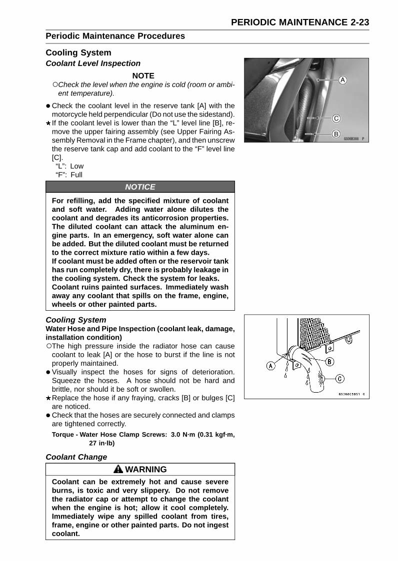
Cooling SystemCoolant Level Inspection
NOTECheck the level when the engine is cold (room or ambi-
ent temperature).
•Check the coolant level in the reserve tank [A] with themotorcycle held perpendicular (Do not use the sidestand).If the coolant level is lower than the “L” level line [B], re-move the upper fairing assembly (see Upper Fairing As-sembly Removal in the Frame chapter), and then unscrewthe reserve tank cap and add coolant to the “F” level line[C].“L”: Low“F”: Full
NOTICEFor refilling, add the specified mixture of coolantand soft water. Adding water alone dilutes thecoolant and degrades its anticorrosion properties.The diluted coolant can attack the aluminum en-gine parts. In an emergency, soft water alone canbe added. But the diluted coolant must be returnedto the correct mixture ratio within a few days.If coolant must be added often or the reservoir tankhas run completely dry, there is probably leakage inthe cooling system. Check the system for leaks.Coolant ruins painted surfaces. Immediately washaway any coolant that spills on the frame, engine,wheels or other painted parts.
Cooling SystemWater Hose and Pipe Inspection (coolant leak, damage,installation condition)The high pressure inside the radiator hose can cause
coolant to leak [A] or the hose to burst if the line is notproperly maintained.
• Visually inspect the hoses for signs of deterioration.Squeeze the hoses. A hose should not be hard andbrittle, nor should it be soft or swollen.Replace the hose if any fraying, cracks [B] or bulges [C]are noticed.
•Check that the hoses are securely connected and clampsare tightened correctly.Torque - Water Hose Clamp Screws: 3.0 N·m (0.31 kgf·m,
27 in·lb)
Coolant ChangeWARNING
Coolant can be extremely hot and cause severeburns, is toxic and very slippery. Do not removethe radiator cap or attempt to change the coolantwhen the engine is hot; allow it cool completely.Immediately wipe any spilled coolant from tires,frame, engine or other painted parts. Do not ingestcoolant.

2-24 PERIODIC MAINTENANCEPeriodic Maintenance Procedures
•Remove:Upper Fairing Assembly (see Upper Fairing AssemblyRemoval in the Frame chapter)Radiator Cap [A]
Remove the radiator cap in two steps. First turn the capcounterclockwise to the first stop. Then push and turn itfurther in the same direction and remove the cap.
• Place a container under the drain bolt [A] of the waterpump cover.
•Drain the coolant from the radiator by removing the drainbolt.
• Remove:Bolt [A]Cap [B]
• Pour the coolant into a container.• Install the coolant reserve tank [C] and tighten the bolt.• Tighten the drain bolt with new gasket.
Torque - Coolant Drain Bolt (Water Pump): 8.8 N·m (0.90kgf·m, 78 in·lb)
•Fill the radiator up to the radiator filler neck [A] withcoolant, and install the radiator cap.
NOTEPour in the coolant slowly so that it can expel the air
from the engine and radiator.
•Fill the reserve tank up to the “F” level line with coolant,and install the cap (see Coolant Level Inspection).
NOTICESoft or distilled water must be used with the an-tifreeze (see below for antifreeze) in the cooling sys-tem.If hard water is used in the system, it causes scalesaccumulation in the water passages, and consider-ably reduces the efficiency of the cooling system.

PERIODIC MAINTENANCE 2-25Periodic Maintenance Procedures
Water and Coolant Mixture Ratio (Recommended)Soft Water: 50%Coolant: 50%Freezing Point: –35°C (–31°F)Total Amount: 2.5 L (2.6 US qt)
NOTEChoose a suitable mixture ratio by referring to the
coolant manufacturer’s directions.
•Bleed the air from the cooling system as follows.Start the engine with the radiator cap removed and run it
until no more air bubbles [A] can be seen in the coolant.Tap the radiator hoses to force any air bubbles caught
inside.Stop the engine and add coolant up to the radiator filler
neck.• Install the radiator cap.• Start the engine, warm it up thoroughly until the radiator
fan turns on and then stop the engine.•Check the coolant level in the reserve tank after the en-
gine cools down.If the coolant level is lower than the “L” level line, addcoolant to the “F” level line (see Coolant Level Inspection).
NOTICEDo not add more coolant above the “F” level line.

2-26 PERIODIC MAINTENANCEPeriodic Maintenance Procedures
Water Hose and O-ring Replacement•Drain the coolant (see Coolant Change).•Remove:
Upper Fairing Assembly (see Upper Fairing AssemblyRemoval in the Frame chapter)Oil Cooler [A] (see Oil Cooler Removal in the EngineLubrication System chapter)Thermostat Housing Cover [B] (see Thermostat HousingRemoval in the Cooling System chapter)Water Pump Cover [C] (see Water Pump Removal in theCooling System chapter)Fitting [D]
•Replace the hoses [E] and O-rings [F] with new ones.• Apply grease to the new O-rings.•Run the new hoses according to Cable, Wire, and Hose
Routing section in the Appendix chapter.• Tighten:
Torque - Water Hose Clamp Screws: 3.0 N·m (0.31 kgf·m,27 in·lb)
• Install the removed parts (see appropriate chapters).• Fill the coolant (see Coolant Change).•Check the cooling system for leaks.
PERIODIC MAINTENANCE 2-27Periodic Maintenance Procedures
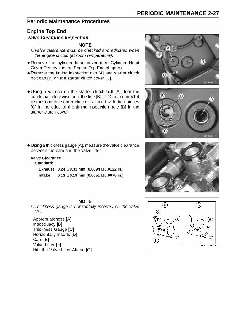
Engine Top EndValve Clearance Inspection
NOTEValve clearance must be checked and adjusted when
the engine is cold (at room temperature).
•Remove the cylinder head cover (see Cylinder HeadCover Removal in the Engine Top End chapter).
• Remove the timing inspection cap [A] and starter clutchbolt cap [B] on the starter clutch cover [C].
• Using a wrench on the starter clutch bolt [A], turn thecrankshaft clockwise until the line [B] (TDC mark for #1,4pistons) on the starter clutch is aligned with the notches[C] in the edge of the timing inspection hole [D] in thestarter clutch cover.
•Using a thickness gauge [A], measure the valve clearancebetween the cam and the valve lifter.
Valve ClearanceStandard:
Exhaust 0.24 ∼ 0.31 mm (0.0094 ∼ 0.0122 in.)Intake 0.13 ∼ 0.19 mm (0.0051 ∼ 0.0075 in.)
NOTEThickness gauge is horizontally inserted on the valve
lifter.
Appropriateness [A]Inadequacy [B]Thickness Gauge [C]Horizontally Inserts [D]Cam [E]Valve Lifter [F]Hits the Valve Lifter Ahead [G]

2-28 PERIODIC MAINTENANCEPeriodic Maintenance Procedures
When positioning #1 piston TDC at the end of thecompression stroke:Intake Valve Clearance of #1 and #3 CylindersExhaust Valve Clearance of #1 and #2 CylindersMeasuring Valve [A]
When positioning #4 piston TDC at the end of thecompression stroke:Intake Valve Clearance of #2 and #4 CylindersExhaust Valve Clearance of #3 and #4 CylindersMeasuring Valve [A]
If the valve clearance is not within the specified range,first record the clearance, and then adjust it.
Valve Clearance Adjustment•To change the valve clearance, remove the camshafts
(see Camshaft Removal in the Engine Top End chapter)and valve lifters.
•Replace the shim with one of a different thickness.
NOTEMark and record the locations of the valve lifters and
shims so that they can be reinstalled in their originalpositions.
•Clean the shim to remove any dust or oil.•Measure the thickness of the removed shim [A].• Select a new shim thickness calculation as follows.
a + b – c = d[a] Present Shim Thickness[b] Measured Valve Clearance[c] Specified Valve Clearance [Mean Value = 0.275 mm
(Exhaust), 0.160 mm (Intake)][d] Replace Shim Thickness
Example (Exhaust):1.600 + 0.33 – 0.275 = 1.655 mm
Exchange the shim for the 1.675 size shim.
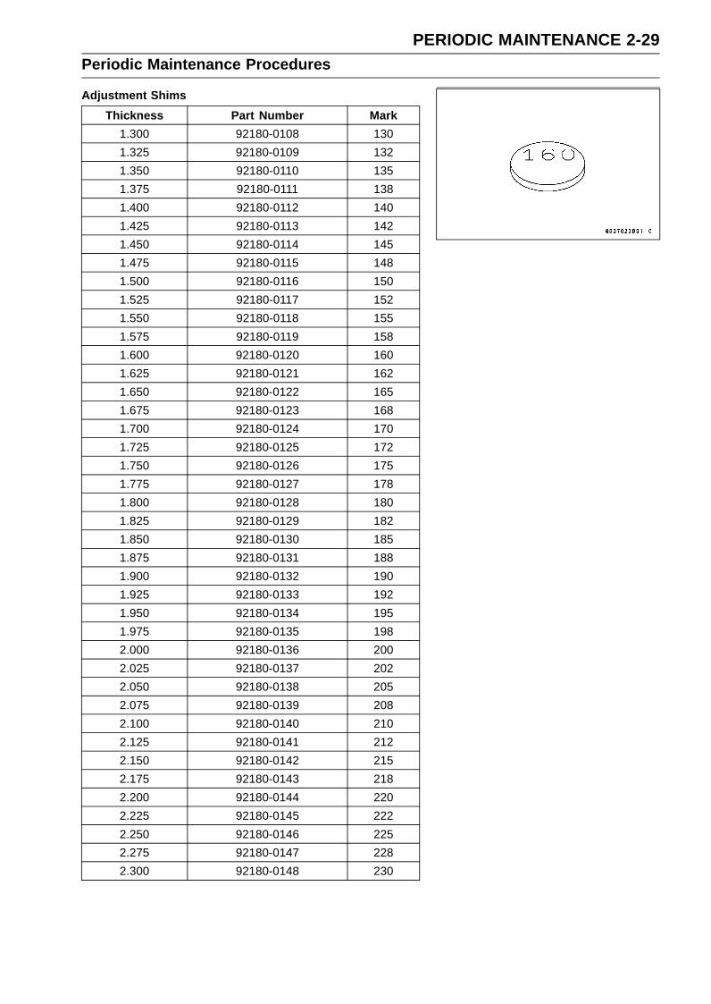
PERIODIC MAINTENANCE 2-29Periodic Maintenance Procedures
Adjustment ShimsThickness Part Number Mark
1.300 92180-0108 1301.325 92180-0109 1321.350 92180-0110 1351.375 92180-0111 1381.400 92180-0112 1401.425 92180-0113 1421.450 92180-0114 1451.475 92180-0115 1481.500 92180-0116 1501.525 92180-0117 1521.550 92180-0118 1551.575 92180-0119 1581.600 92180-0120 1601.625 92180-0121 1621.650 92180-0122 1651.675 92180-0123 1681.700 92180-0124 1701.725 92180-0125 1721.750 92180-0126 1751.775 92180-0127 1781.800 92180-0128 1801.825 92180-0129 1821.850 92180-0130 1851.875 92180-0131 1881.900 92180-0132 1901.925 92180-0133 1921.950 92180-0134 1951.975 92180-0135 1982.000 92180-0136 2002.025 92180-0137 2022.050 92180-0138 2052.075 92180-0139 2082.100 92180-0140 2102.125 92180-0141 2122.150 92180-0142 2152.175 92180-0143 2182.200 92180-0144 2202.225 92180-0145 2222.250 92180-0146 2252.275 92180-0147 2282.300 92180-0148 230

2-30 PERIODIC MAINTENANCEPeriodic Maintenance Procedures
NOTICEBe sure to remeasure the clearance after selectinga shim. The clearance can be out of the specifiedrange because of the shim tolerance.
If there is no valve clearance, use a shim that is a fewsizes smaller, and remeasure the valve clearance.
•When installing the shim, face the marked side toward thevalve lifter. At this time, apply engine oil to the shim orthe valve lifter to keep the shim in place during camshaftinstallation.
NOTICEDo not put shim stock under the shim. This maycause the shim to pop out at high rpm, causing ex-tensive engine damage.Do not grind the shim. This may cause it to fracture,causing extensive engine damage.
•Apply molybdenum disulfide oil solution to the valve liftersurface and install the lifter.
• Install the camshafts (see Camshaft Installation in the En-gine Top End chapter).
• Recheck the valve clearance and readjust if necessary.• Install the removed parts (see appropriate chapters).
Air Suction System Damage Inspection•Disconnect the air switching valve hose [A] from the lower
air cleaner housing [B] (see Air Cleaner Housing Removalin the Fuel System (DFI) chapter).
• Connect the following parts temporarily.Fuel Pump Lead Connector [A]Extension Tube [B]Air Cleaner Housing (see Air Cleaner Housing Installa-tion in the Fuel System (DFI) chapter)
Special Tool - Extension Tube: 57001-1578
PERIODIC MAINTENANCE 2-31Periodic Maintenance Procedures
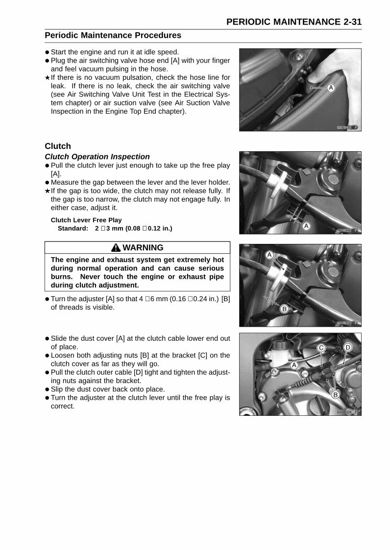
•Start the engine and run it at idle speed.• Plug the air switching valve hose end [A] with your finger
and feel vacuum pulsing in the hose.If there is no vacuum pulsation, check the hose line forleak. If there is no leak, check the air switching valve(see Air Switching Valve Unit Test in the Electrical Sys-tem chapter) or air suction valve (see Air Suction ValveInspection in the Engine Top End chapter).
ClutchClutch Operation Inspection•Pull the clutch lever just enough to take up the free play
[A].•Measure the gap between the lever and the lever holder.
If the gap is too wide, the clutch may not release fully. Ifthe gap is too narrow, the clutch may not engage fully. Ineither case, adjust it.
Clutch Lever Free PlayStandard: 2 ∼ 3 mm (0.08 ∼ 0.12 in.)
WARNINGThe engine and exhaust system get extremely hotduring normal operation and can cause seriousburns. Never touch the engine or exhaust pipeduring clutch adjustment.
•Turn the adjuster [A] so that 4 ∼ 6 mm (0.16 ∼ 0.24 in.) [B]of threads is visible.
• Slide the dust cover [A] at the clutch cable lower end outof place.
• Loosen both adjusting nuts [B] at the bracket [C] on theclutch cover as far as they will go.
• Pull the clutch outer cable [D] tight and tighten the adjust-ing nuts against the bracket.
• Slip the dust cover back onto place.• Turn the adjuster at the clutch lever until the free play is
correct.
2-32 PERIODIC MAINTENANCEPeriodic Maintenance Procedures
•Push the release lever [A] toward the front of the motor-cycle until it becomes hard to turn.At this time, the release lever should have the proper an-
gle shown.60° [B]
If the angle is wrong, check the clutch and release partsfor wear.
WARNINGToo much cable play can prevent clutch disengage-ment and cause an accident resulting in serious in-jury or death. When adjusting the clutch or replac-ing the cable, be sure the upper end of the clutchouter cable is fully seated in its fitting, or it couldslip into place later, creating enough cable play toprevent clutch disengagement.
•After the adjustment, start the engine and check that theclutch does not slip and that it releases properly.
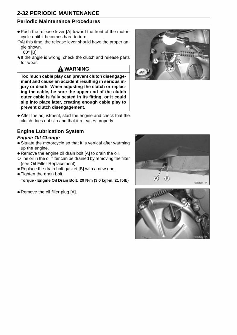
Engine Lubrication SystemEngine Oil Change•Situate the motorcycle so that it is vertical after warming
up the engine.•Remove the engine oil drain bolt [A] to drain the oil.The oil in the oil filter can be drained by removing the filter
(see Oil Filter Replacement).• Replace the drain bolt gasket [B] with a new one.• Tighten the drain bolt.
Torque - Engine Oil Drain Bolt: 29 N·m (3.0 kgf·m, 21 ft·lb)
•Remove the oil filler plug [A].

PERIODIC MAINTENANCE 2-33Periodic Maintenance Procedures
•Pour in the specified type and amount of oil.
Recommended Engine OilType: API SG, SH, SJ, SL or SM with JASO MA,
MA1 or MA2Viscosity: SAE 10W-40Capacity: 2.8 L (3.0 US qt) (when filter is not removed)
3.1 L (3.3 US qt) (when filter is removed)3.6 L (3.8 US qt) (when engine is completelydry)
NOTEDo not add any chemical additive to the oil.Oils fulfilling
the above requirements are fully formulated and provideadequate lubrication for both the engine and the clutch.Although 10W-40 engine oil is the recommended oil
for most conditions, the oil viscosity may need to bechanged to accommodate atmospheric conditions inyour riding area.
•Replace the O-ring of the oil filler plug with a new one.• Apply engine oil to the new O-ring.• Install the oil filler plug.
Torque - Oil Filler Plug: Hand-tighten
•Check the oil level (see Oil Level Inspection in the EngineLubrication System chapter).
Oil Filter Replacement•Drain the engine oil (see Engine Oil Change).•Remove the oil filter [A] with the oil filter wrench [B].
Special Tool - Oil Filter Wrench: 57001-1249
•Replace the filter with a new one.• Apply grease to the gasket [A] before installation.• Tighten the filter with the oil filter wrench.
Special Tool - Oil Filter Wrench: 57001-1249
Torque - Oil Filter: 17 N·m (1.7 kgf·m, 13 ft·lb)
NOTEHand tightening of the oil filter can not be allowed since
it does not reach to this tightening torque.
•Pour in the specified type and amount of oil (see EngineOil Change).

2-34 PERIODIC MAINTENANCEPeriodic Maintenance Procedures
Wheels/TiresAir Pressure Inspection•Remove the air valve cap.•Measure the tire air pressure with an air pressure gauge
[A] when the tires are cold (that is, when the motorcyclehas not been ridden more than a mile during the past 3hours).
• Install the air valve cap.Adjust the tire air pressure according to the specificationsif necessary.
Air Pressure (when Cold)Front: Up to 180 kg (397 lb) load:
250 kPa (2.50 kgf/cm², 36 psi)Rear: Up to 180 kg (397 lb) load:
290 kPa (2.90 kgf/cm², 42 psi)
Wheels and TiresWheel/Tire Damage Inspection•Remove any imbedded stones [A] or other foreign parti-
cles [B] from tread.• Visually inspect the tire for cracks and cuts, and replace
the tire if necessary. Swelling or high spots indicate inter-nal damage, requiring tire replacement.
• Visually inspect the wheel for cracks, cuts and dents dam-age.If any damage is found, replace the wheel if necessary.
Tire Tread Wear InspectionAs the tire tread wears down, the tire becomes more sus-
ceptible to puncture and failure. An accepted estimate isthat 90% of all tire failures occur during the last 10% of treadlife (90% worn). So it is false economy and unsafe to usethe tires until they are bald.•Measure the tread depth at the center of the tread with a
depth gauge [A]. Since the tire may wear unevenly, takemeasurement at several places.If any measurement is less than the service limit, replacethe tire (see Tire Removal/Installation in the Wheels/Tireschapter).
Tread DepthStandard:
Front 3.6 mm (0.14 in.)Rear 5.1 mm (0.20 in.)
ServiceLimit:
Front 1 mm (0.04 in.)(AT, CH, DE) 1.6 mm (0.06 in.)
Rear 2 mm (0.08 in.) (Up to 130 km/h (80 mph))3 mm (0.12 in.) (Over 130 km/h (80 mph))

PERIODIC MAINTENANCE 2-35Periodic Maintenance Procedures
WARNINGSome replacement tires may adversely affect han-dling and cause an accident resulting in serious in-jury or death. To ensure proper handling and sta-bility, use only the recommended standard tires forreplacement, inflated to the standard pressure.
NOTEMost countries may have their own regulations a mini-
mum tire tread depth: be sure to follow them.Check and balance the wheel when a tire is replaced
with a new one.
Wheel Bearing Damage Inspection•Raise the front wheel off the ground with the jack (see
Front Wheel Removal in the Wheels/Tires chapter).Special Tools - Jack: 57001-1238
Jack Attachment: 57001-1608
•Turn the handlebar all the way to the right or left.• Inspect the roughness of the front wheel bearing by push-
ing and pulling [A] the wheel.• Spin [B] the front wheel lightly, and check for smoothly
turn, roughness, binding or noise.If roughness, binding or noise is found, remove the frontwheel and inspect the wheel bearing (see Front WheelRemoval, Hub Bearing Inspection in the Wheels/Tireschapter).
• Raise the rear wheel off the ground with the stand (seeRear Wheel Removal in the Wheels/Tires chapter).
• Inspect the roughness of the rear wheel bearing by push-ing and pulling [A] the wheel.
• Spin [B] the rear wheel lightly, and check for smoothlyturn, roughness, binding or noise.If roughness, binding or noise is found, remove the rearwheel and inspect the wheel bearing (see Rear Wheel Re-moval, Hub Bearing Inspection in the Wheels/Tires chap-ter) and coupling (see Coupling Bearing Inspection in theFinal Drive chapter).
2-36 PERIODIC MAINTENANCEPeriodic Maintenance Procedures
Final DriveDrive Chain Lubrication Condition Inspection• If a special lubricant is not available, a heavy oil such as
SAE 90 is preferred to a lighter oil because it will stay onthe chain longer and provide better lubrication.
• If the chain appears especially dirty, clean it before lubri-cation.
NOTICEThe O-rings between the side plates seal in the lu-bricant between the pin and the bushing. To avoiddamaging the O-rings and resultant loss of lubri-cant, observe the following rules.Use only kerosene or diesel oil for cleaning of theO-ring of the drive chain. Any other cleaning solu-tion such as gasoline will cause deterioration andswelling of the O-ring. Immediately blow the chaindry with compressed air after cleaning. Completecleaning and drying the chain within 10 minutes.
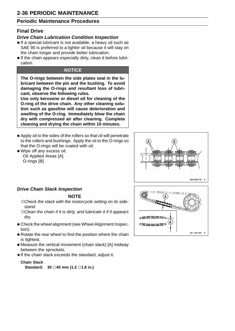
•Apply oil to the sides of the rollers so that oil will penetrateto the rollers and bushings. Apply the oil to the O-rings sothat the O-rings will be coated with oil.
•Wipe off any excess oil.Oil Applied Areas [A]O-rings [B]
Drive Chain Slack InspectionNOTE
Check the slack with the motorcycle setting on its side-stand.Clean the chain if it is dirty, and lubricate it if it appears
dry.
•Check the wheel alignment (see Wheel Alignment Inspec-tion).
• Rotate the rear wheel to find the position where the chainis tightest.
•Measure the vertical movement (chain slack) [A] midwaybetween the sprockets.If the chain slack exceeds the standard, adjust it.
Chain SlackStandard: 30 ∼ 40 mm (1.2 ∼ 1.6 in.)

PERIODIC MAINTENANCE 2-37Periodic Maintenance Procedures
Drive Chain Slack Adjustment•Remove the cotter pin [A], and loosen the rear axle nut
[B].• Loosen the both chain adjuster locknuts [C].
If the chain is too loose, turn out the left and right chainadjusters [D] evenly.If the chain is too tight, turn in the left and right chainadjusters evenly, and kick the wheel forward.
• Turn both chain adjusters evenly until the drive chain hasthe correct amount of slack. To keep the chain and wheelproperly aligned, the notch [E] on the left wheel alignmentindicator [F] should align with the same swingarm mark orposition [G] that the right indicator notch aligns with.
WARNINGMisalignment of the wheel will result in abnormalwear and may result in an unsafe riding condition.Be sure the wheel is properly aligned.
•Tighten the both chain adjuster locknuts securely.• Tighten the rear axle nut.
Torque - Rear Axle Nut: 127 N·m (13.0 kgf·m, 93.7 ft·lb)
•Turn the wheel, measure the chain slack again at the tight-est position, and readjust if necessary.
• Insert a new cotter pin [A].
NOTEWhen inserting the cotter pin, if the slots in the nut do
not align with the cotter pin hole in the axle, tighten thenut clockwise [B] up to next alignment.It should be within 30 degrees.Loosen once and tighten again when the slot goes past
the nearest hole.
•Bend the cotter pin [A] over the nut.
WARNINGA loose axle nut can lead to an accident resulting inserious injury or death. Tighten the axle nut to theproper torque and install a new cotter pin.

2-38 PERIODIC MAINTENANCEPeriodic Maintenance Procedures
Wheel Alignment Inspection•Check that the notch [A] on the left alignment indicator [B]
aligns with the same swingarm mark or position [C] thatthe right alignment indicator notch aligns with.If they do not, adjust the chain slack and align the wheelalignment (see Drive Chain Slack Adjustment).
NOTEWheel alignment can be also checked using the
straightedge or string method.
WARNINGMisalignment of the wheel will result in abnormalwear and may result in an unsafe riding condition.Be sure the wheel is properly aligned.
Drive Chain Wear Inspection•Remove the chain cover (see Drive Chain Removal in the
Final Drive chapter).• Rotate the rear wheel to inspect the drive chain for dam-
aged rollers, and loose pins and links.If there is any irregularity, replace the drive chain.Lubricate the drive chain if it appears dry.
• Stretch the chain taut by hanging a 10 kg (22 lb) weight[A] on the chain.
•Measure the length of 20 links [B] on the straight part [C] ofthe chain from the pin center of the 1st pin to the pin centerof the 21st pin. Since the chain may wear unevenly, takemeasurements at several places.If any measurements exceed the service limit, replace thechain. Also, replace the front and rear sprockets when thedrive chain is replaced.
Drive Chain 20-link LengthStandard: 317.5 ∼ 318.2 mm (12.50 ∼ 12.53 in.)Service Limit: 319 mm (12.6 in.)
WARNINGA chain that breaks or jumps off the sprocketscould snag on the engine sprocket or lock therear wheel, severely damaging the motorcycle andcausing it to go out of control. Inspect the chain fordamage and proper adjustment before each ride.If chain wear exceeds the service limit, replace itwith the standard chain. It is an endless type andshould not be cut for installation.
Standard ChainMake: ENUMAType: EK520RMX/3DLink: 112 links
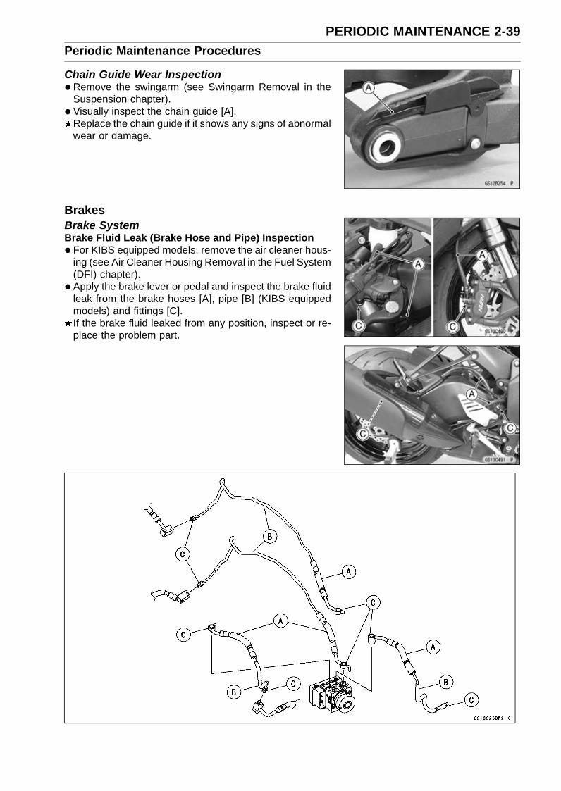
PERIODIC MAINTENANCE 2-39Periodic Maintenance Procedures
Chain Guide Wear Inspection•Remove the swingarm (see Swingarm Removal in the
Suspension chapter).• Visually inspect the chain guide [A].
Replace the chain guide if it shows any signs of abnormalwear or damage.
BrakesBrake SystemBrake Fluid Leak (Brake Hose and Pipe) Inspection•For KIBS equipped models, remove the air cleaner hous-
ing (see Air Cleaner Housing Removal in the Fuel System(DFI) chapter).
• Apply the brake lever or pedal and inspect the brake fluidleak from the brake hoses [A], pipe [B] (KIBS equippedmodels) and fittings [C].If the brake fluid leaked from any position, inspect or re-place the problem part.

2-40 PERIODIC MAINTENANCEPeriodic Maintenance Procedures
Brake Hose and Pipe Damage and Installation Condi-tion Inspection•For KIBS equipped models, remove the air cleaner hous-
ing (see Air Cleaner Housing Removal in the Fuel System(DFI) chapter).
• Inspect the brake hoses, pipe and fittings for deteriora-tion, cracks and signs of leakage.The high pressure inside the brake line can cause fluid
to leak [A] or the hose, pipe (KIBS equipped models) toburst if the line is not properly maintained. Bend and twistthe rubber hose while examining it.Replace the hose and pipe (KIBS equipped models) if anycrack [B], bulge [C] or leakage is noticed.Tighten any brake hose banjo bolts and brake pipe banjobolts.Torque - Brake Hose Banjo Bolts: 25 N·m (2.5 kgf·m, 18
ft·lb)Brake Pipe Banjo Bolts (KIBS Equipped Models):
23 N·m (2.3 kgf·m, 17 ft·lb)Brake Pipe Joint Nuts (KIBS Equipped Models):
18 N·m (1.8 kgf·m, 13 ft·lb)
• Inspect the brake hose and pipe routing.If any brake hose and pipe routing is incorrect, run thebrake hose and pipe according to Cable, Wire, and HoseRouting section in the Appendix chapter.
Brake Operation Inspection• Inspect the operation of the front and rear brake by run-
ning the vehicle on the dry road.If the brake operation is insufficiency, inspect the brakesystem.
WARNINGWhen test riding the vehicle, be aware of surround-ing traffic for your safety.
Brake Fluid Level Inspection•Check that the brake fluid level in the front brake reservoir
[A] is above the lower level line [B].
NOTEHold the reservoir horizontal by turning the handlebar
when checking brake fluid level.
If the fluid level is lower than the lower level line, fill thereservoir to the upper level line [C].Remove the stopper [D].

PERIODIC MAINTENANCE 2-41Periodic Maintenance Procedures
•Check that the brake fluid level in the rear brake reservoir[A] is above the lower level line [B].If the fluid level is lower than the lower level line, fill thereservoir to the upper level line [C].Remove the bolt [D].
WARNINGMixing brands and types of brake fluid can reducethe brake system’s effectiveness and cause an ac-cident resulting in injury or death. Do not mix twobrands of brake fluid. Change the brake fluid in thebrake line completely if the brake fluid must be re-filled but the type and brand of the brake fluid thatis already in the reservoir are unidentified.
Recommended Disc Brake FluidGrade: DOT4
•Follow the procedure below to install the front/rear brakefluid reservoir cap correctly.First, tighten the brake fluid reservoir cap [B] clockwise
[C] by hand until slight resistance is felt indicating thatthe cap is seated on the reservoir body, then tighten thecap an additional 1/6 turn [D] while holding the brake fluidreservoir body [A].
• Install the stopper (see Brake Line Bleeding in the Brakeschapter).
Brake Fluid ChangeNOTE
The procedure to change the front brake fluid is as fol-lows. Changing the rear brake fluid is the same as forthe front brake.
• Level the brake fluid reservoir.• Remove:
Screw [A]Stopper [B]Front Brake Reservoir Cap [C]Diaphragm PlateDiaphragm

2-42 PERIODIC MAINTENANCEPeriodic Maintenance Procedures
•Remove the rubber cap [A] from the bleed valve on thecaliper.
• Attach a clear plastic hose [B] to the bleed valve, and runthe other end of the hose into a container.
• Fill the reservoir with fresh specified brake fluid.
•Change the brake fluid.Repeat this operation until fresh brake fluid comes out
from the plastic hose or the color of the fluid changes.1. Open the bleed valve [A].2. Apply the brake and hold it [B].3. Close the bleed valve [C].4. Release the brake [D].
NOTEThe fluid level must be checked often during the chang-
ing operation and replenished with fresh brake fluid. Ifthe fluid in the reservoir runs out any time during thechanging operation, the brakes will need to be bledsince air will have entered the brake line.Front Brake: Repeat the above steps for the other
caliper.
•Remove the clear plastic hose.• Install the diaphragm and reservoir cap.
• Follow the procedure below to install the front/rear brakefluid reservoir cap correctly.First, tighten the front/rear brake fluid reservoir cap [B]
clockwise [C] by hand until slight resistance is felt indi-cating that the cap is seated on the reservoir body, thentighten the cap an additional 1/6 turn [D] while holding thebrake fluid reservoir body [A].
• Install the stopper on the reservoir.• Tighten:
Torque - Front Brake Reservoir Cap Stopper Screw: 1.2N·m (0.12 kgf·m, 11 in·lb)
•Tighten the bleed valve, and install the rubber cap.Torque - Bleed Valves: 7.8 N·m (0.80 kgf·m, 69 in·lb)
•After changing the fluid, check the brake for good brakingpower, no brake drag, and no fluid leakage.If necessary, bleed the air from the lines.
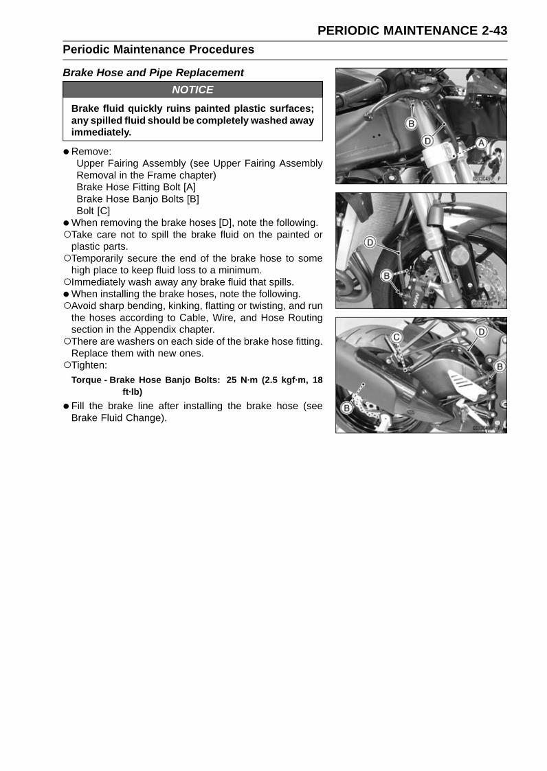
PERIODIC MAINTENANCE 2-43Periodic Maintenance Procedures
Brake Hose and Pipe ReplacementNOTICE
Brake fluid quickly ruins painted plastic surfaces;any spilled fluid should be completely washed awayimmediately.
•Remove:Upper Fairing Assembly (see Upper Fairing AssemblyRemoval in the Frame chapter)Brake Hose Fitting Bolt [A]Brake Hose Banjo Bolts [B]Bolt [C]
•When removing the brake hoses [D], note the following.Take care not to spill the brake fluid on the painted or
plastic parts.Temporarily secure the end of the brake hose to some
high place to keep fluid loss to a minimum.Immediately wash away any brake fluid that spills.•When installing the brake hoses, note the following.Avoid sharp bending, kinking, flatting or twisting, and run
the hoses according to Cable, Wire, and Hose Routingsection in the Appendix chapter.There are washers on each side of the brake hose fitting.
Replace them with new ones.Tighten:
Torque - Brake Hose Banjo Bolts: 25 N·m (2.5 kgf·m, 18ft·lb)
•Fill the brake line after installing the brake hose (seeBrake Fluid Change).

2-44 PERIODIC MAINTENANCEPeriodic Maintenance Procedures
•For KIBS equipped models; note the following.
NOTEWhen removing the brake pipes and hoses on the hy-
draulic unit, remove them according to each assemblyof the exploded view in the Brakes chapter.
•Remove:Air Cleaner Housing (see Air Cleaner Housing Removalin the Fuel System (DFI) chapter)Upper Fairing Assembly (see Upper Fairing AssemblyRemoval in the Frame chapter)Swingarm (see Swingarm Removal in the Suspensionchapter)Brake Pipe Banjo Bolts [A]Brake Pipe Joint Nuts [B]Brake Hose Banjo Bolts [C]Bolts [D]Clamps
• There are washers on each side of the brake hose andpipe fitting. Replace them with new ones when installing.
• Before installing the brake pipe, check to see that there isno damage on the threads of the brake pipe joint nut.If there is any damage, replace the damaged parts withnew ones.
NOTETighten the brake pipe joint nut and banjo bolt at both
ends of the brake pipe temporarily and then tightenthem to the specified torque.
• Install the brake pipes and brake hoses to the specifiedangle (see Cable, Wire, and Hose Routing section in theAppendix chapter).
• Tighten the brake pipe joint nuts with the flare nut wrench.• Tighten:
Torque - Brake Hose Banjo Bolts: 25 N·m (2.5 kgf·m, 18ft·lb)
Brake Pipe Joint Nuts: 18 N·m (1.8 kgf·m, 13 ft·lb)Brake Pipe Banjo Bolts: 23 N·m (2.3 kgf·m, 17 ft·lb)
•Fill the brake line after installing the brake hose and pipe(see Brake Fluid Change).
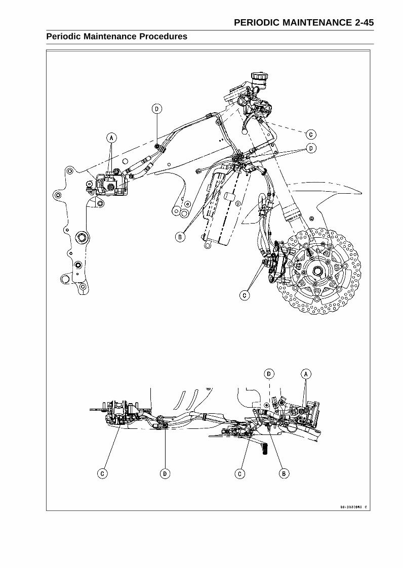
PERIODIC MAINTENANCE 2-45Periodic Maintenance Procedures

2-46 PERIODIC MAINTENANCEPeriodic Maintenance Procedures
Master Cylinder Rubber Parts ReplacementFront Master Cylinder Disassembly•Remove the front master cylinder (see Front Master Cylin-
der Removal in the Brakes chapter).• Remove the seal cover [A], circlip [B], connector [C] and
O-ring [D].Special Tool - Inside Circlip Pliers: 57001-143
•Unscrew the locknut [E] and pivot bolt [F], and remove thebrake lever.
• Remove the bleed valve [G] and rubber cap [H].• Remove the piston assembly [I] as follows.Remove the dust cover and push rod.Remove the circlip [J].Pull out the piston (with primary cup and secondary cup).Remove the return spring and spring guide.•Replace:
Seal Cover [A]Circlip [B]O-ring [D]Rubber Cap [H]Piston Assembly [I]Circlip [J]Diaphragm [K]
Rear Master Cylinder Disassembly•Remove the rear master cylinder (see Rear Master Cylin-
der Removal in the Brakes chapter).• Remove the circlip [A], connector [B] and O-ring [C].
Special Tool - Inside Circlip Pliers: 57001-143
•Slide the dust cover [D] out of place, and remove the cir-clip [E].
• Pull out the push rod assembly [F].• Remove the piston assembly [G] and return spring.
NOTICEDo not remove the secondary cup from the pistonsince removal will damage it.
•Replace:Circlip [A]O-ring [C]Circlip [E]Push Rod Assembly [F]Piston Assembly [G]Diaphragm [H]

PERIODIC MAINTENANCE 2-47Periodic Maintenance Procedures
Master Cylinder Assembly•Before assembly, clean all parts including the master
cylinder with brake fluid or alcohol.
NOTICEExcept for the disc pads and disc, use only discbrake fluid, isopropyl alcohol, or ethyl alcohol forcleaning brake parts. Do not use any other fluid forcleaning these parts. Gasoline, engine oil, or anyother petroleum distillate will cause deterioration ofthe rubber parts. Oil spilled on any part will be diffi-cult to wash off completely, and will eventually de-teriorate the rubber used in the disc brake.
•Apply brake fluid to the new parts and to the inner wall ofthe cylinder.
• Take care not to scratch the piston or the inner wall of thecylinder.
• Apply silicone grease to the followings.Front: Brake Lever Pivot BoltRear: Dust Cover of Push Rod Assembly
• For the front master cylinder, tighten the brake lever pivotbolt and the locknut.Torque - Brake Lever Pivot Bolt: 1.0 N·m (0.10 kgf·m, 8.9
in·lb)Brake Lever Pivot Bolt Locknut: 5.9 N·m (0.60
kgf·m, 52 in·lb)
•For the front master cylinder, install the bleed valve andrubber cap.Torque - Front Master Cylinder Bleed Valve: 5.4 N·m (0.55
kgf·m, 48 in·lb)
Caliper Rubber Parts ReplacementFront Caliper Disassembly• Loosen the front caliper pad pins [A] and banjo bolt [B]
and tighten them loosely.•Remove:
Front Caliper [C] (see Front Caliper Removal in theBrakes chapter)Brake Pads (see Front Brake Pad Removal in the Brakeschapter)
•Hold the pistons nearest the oil passage [A] with thebands [B].

2-48 PERIODIC MAINTENANCEPeriodic Maintenance Procedures
•Using compressed air, remove the pistons.Cover the caliper opening with a clean heavy cloth [A].Lightly apply compressed air [B] to the oil passage.
WARNINGThe piston in the brake caliper can crush hands andfingers. Never place your hand or fingers in front ofthe piston.
Pull out the pistons by hand.
•Remove the dust seals [A] and fluid seals [B].• Cut the band.•Repeat the previous step to remove the pistons from the
other side of the caliper body.•Remove the bleed valve and rubber cap.
Front Caliper Assembly•Clean the caliper parts except for the pads.
NOTICEFor cleaning the parts, use only disc brake fluid,isopropyl alcohol, or ethyl alcohol.
• Install the bleed valve and rubber cap.Torque - Bleed Valves: 7.8 N·m (0.80 kgf·m, 69 in·lb)
•Replace the fluid seals [A] with new ones.Apply silicone grease to the fluid seals, and install them
into the cylinders by hand.•Replace the dust seals [B] with new ones if they are dam-
aged.Apply silicone grease to the dust seals, and install them
into the cylinders by hand.
• Apply brake fluid to the outside of the pistons, and pushthem into each cylinder by hand.
• Install the removed parts (see appropriate chapters).•Wipe up any spilled brake fluid on the caliper with wet
cloth.

PERIODIC MAINTENANCE 2-49Periodic Maintenance Procedures
Rear Caliper Disassembly•Remove:
Rear Caliper (see Rear Caliper Removal in the Brakeschapter)Brake Pads (see Rear Brake Pad Removal in the Brakeschapter)Rear Caliper Pin Bolt [A]Caliper Bracket [B]
•Remove:Pad Spring [A]Dust Boot [B]
•Using compressed air, remove the piston.Cover the caliper opening with a clean heavy cloth [A].Remove the piston by lightly applying compressed air [B]
to where the brake line fits into the caliper.
WARNINGThe piston in the brake caliper can crush hands andfingers. Never place your hand or fingers in front ofthe piston.
•Remove the dust seal and fluid seal.• Remove the bleed valve and rubber cap.
Rear Caliper Assembly•Clean the caliper parts except for the pads.
NOTICEFor cleaning the parts, use only disc brake fluid,isopropyl alcohol, or ethyl alcohol.
• Install the bleed valve and rubber cap.Torque - Bleed Valves: 7.8 N·m (0.80 kgf·m, 69 in·lb)

2-50 PERIODIC MAINTENANCEPeriodic Maintenance Procedures
•Replace the fluid seal [A] with a new one.Apply silicone grease to the fluid seal, and install it into
the cylinder by hand.•Replace the dust seal [B] with a new one.Apply silicone grease to the dust seal, and install it into
the cylinder by hand.
• Install the pad spring [A] in the caliper as shown.• Apply brake fluid to the outside of the piston [B], and push
it into the cylinder by hand.•Replace the and dust boot [C].
• Install the pad spring [A] on the caliper bracket as shown.• Apply a silicone grease to the caliper bracket shaft [B].• Replace the friction boot [C].• Assemble the caliper and the caliper bracket.• Apply silicone grease to the rear caliper pin bolt.• Tighten:
Torque - Rear Caliper Pin Bolt: 27 N·m (2.8 kgf·m, 20 ft·lb)
• Install the pads (see Rear Brake Pad Installation in theBrakes chapter).
•Wipe up any spilled brake fluid on the caliper with wetcloth.

PERIODIC MAINTENANCE 2-51Periodic Maintenance Procedures
Brake Pad Wear Inspection•Remove the brake pads (see Front/Rear Brake Pad Re-
moval in the Brakes chapter).• Check the lining thickness [A] of the pads in each caliper.
If the lining thickness of either pad is less than the servicelimit [B], replace both pads in the caliper as a set.Front Brake Pad [C]Rear Brake Pad [D]
Pad Lining ThicknessStandard:
Front 4.0 mm (0.16 in.)Rear 5.0 mm (0.20 in.)
Service Limit: 1 mm (0.04 in.)
Brake Light Switch Operation Inspection•Turn the ignition switch on.• The brake light (LED) [A] should go on when the brake
lever is applied or after the brake pedal is depressedabout 10 mm (0.39 in.).
If it does not, adjust the brake light switch.•While holding the switch body, turn the adjusting nut to
adjust the switch.Switch Body [A]Adjusting Nut [B]Light sooner as the body rises [C]Light later as the body lowers [D]
NOTICETo avoid damaging the electrical connections in-side the switch, be sure that the switch body doesnot turn during adjustment.

2-52 PERIODIC MAINTENANCEPeriodic Maintenance Procedures
If it does not go on, inspect or replace the following parts.Battery (see Charging Condition Inspection in the Elec-trical System chapter)Brake Light (LED) (see Tail/Brake Light (LED) RemovalInstallation in the Electrical System chapter)Main Fuse 30 A and Brake Light/Horn Fuse 7.5 A (seeFuse Inspection in the Electrical System chapter)Front Brake Light Switch [A] (see Switch Inspection inthe Electrical System chapter)Rear Brake Light Switch (see Switch Inspection in theElectrical System chapter)Harness (see Wiring Inspection in the Electrical Systemchapter)
SuspensionSuspension SystemFront Forks/Rear Shock Absorber Operation Inspec-tion•Pump the forks down and up [A] 4 or 5 times, and inspect
the smooth stroke.If the forks do not smoothly or noise is found, inspect thefork oil level or fork clamps (see Front Fork Oil Change inthe Suspension chapter).
• Pump the rear seat down and up [A] 4 or 5 times, andinspect the smooth stroke.If the shock absorber does not smoothly stroke or noiseis found, inspect the oil leak (see Rear Shock AbsorberOil Leak Inspection).
Front Fork Oil Leak Inspection•Visually inspect the front forks [A] for oil leakage.
Replace or repair any defective parts, if necessary.

PERIODIC MAINTENANCE 2-53Periodic Maintenance Procedures
Rear Shock Absorber Oil Leak Inspection•Visually inspect the shock absorber [A] for oil leakage.
If the oil leakage is found on it, replace the shock absorberwith a new one.
Rocker Arm Operation Inspection•Pump the seat down and up 4 or 5 times, and inspect the
smooth stroke.If the rocker arm [A] does not smoothly stroke or noiseis found, inspect the fasteners and bearings (see RockerArm/Tie-Rod Bearing, Sleeve Inspection in the Suspen-sion chapter).In this photo, the left lower fairing has been removed for
clarity.
Tie-Rod Operation Inspection•Pump the seat down and up 4 or 5 times, and inspect the
smooth stroke.If the tie-rod [A] do not smoothly stroke or noise is found,inspect the fasteners and tie-rod bearings (see RockerArm/Tie-Rod Bearing, Sleeve Inspection in the Suspen-sion chapter).In this photo, the left lower fairing has been removed for
clarity.
SteeringSteering Play Inspection•Raise the front wheel off the ground with the jack (see
Front Wheel Removal in the Wheels/Tires chapter).Special Tools - Jack: 57001-1238
Jack Attachment: 57001-1608
•With the front wheel pointing straight ahead, alternatelytap each end of the handlebar. The front wheel shouldswing fully left and right from the force of gravity until thefork hits the stop.If the wheel binds or catches before the stop, the steeringis too tight.
• Feel for steering looseness by pushing and pulling [A] theforks.If you feel looseness, the steering is too loose.
NOTEThe cables and wiring will have some effect on the mo-
tion of the fork which must be taken into account.Be sure the leads and cables are properly routed.The bearings must be in good condition and properly
lubricated in order for any test to be valid.

2-54 PERIODIC MAINTENANCEPeriodic Maintenance Procedures
Steering Play Adjustment•Remove:
Steering Stem Head with Handlebars (see HandlebarRemoval in the Steering chapter).Fuel Tank (see Fuel Tank Removal in the Fuel System(DFI) chapter)
• Bend the claws [A] of the claw washer straighten.•Remove:
Steering Stem Locknut [B]Claw Washer
• Adjust the steering using the steering stem nut wrench[A].Special Tool - Steering Stem Nut Wrench: 57001-1100If the steering is too tight, loosen the stem nut [B] a fractionof a turn.If the steering is too loose, tighten the stem nut a fractionof a turn.
NOTETurn the stem nut 1/8 turn at time maximum.
• Install the claw washer [A] so that its bent side [B] facesupward, and engage the bent claws with the grooves ofstem locknut [C].
• Hand tighten the stem locknut until it touches the clawwasher.
•Hand tighten the stem locknut clockwise until the clawsare aligned with the second groove of stem nut [D], andbend the 2 claws downward [E].
• Install the stem head.• Apply a non-permanent locking agent to the threads of
the steering stem head bolt.• Install the washer, and temporary tighten the stem head
bolt.
NOTETighten the upper front fork clamp bolts first, next the
stem head bolt.
Torque - Upper Front Fork Clamp Bolts: 20 N·m (2.0 kgf·m,15 ft·lb)
Steering Stem Head Bolt: 78 N·m (8.0 kgf·m, 58ft·lb)
WARNINGIf the handlebar does not turn to the steering stop itmay cause an accident resulting in injury or death.Be sure the cables, harnesses and hoses are routedproperly and do not interfere with handlebar move-ment (see Cable, Wire, and Hose Routing section inthe Appendix chapter).
•Check the steering again.If the steering is still too tight or too loose, repeat the ad-justment.
• Install the removed parts (see appropriate chapters).

PERIODIC MAINTENANCE 2-55Periodic Maintenance Procedures
Steering Stem Bearing Lubrication•Remove the steering stem (see Stem, Stem Bearing Re-
moval in the Steering chapter).• Using a high flash-point solvent, wash the upper and
lower ball bearings [A] in the cages, and wipe the upperand lower outer races, which are press-fitted into theframe head pipe, clean off grease and dirt.
• Visually check the outer races and the ball bearings.Replace the bearing assemblies if they show wear ordamage.
• Pack the upper and lower ball bearings in the cages withgrease, and apply a light coat of grease to the upper andlower outer races.
• Install the steering stem (see Stem, Stem Bearing Instal-lation in the Steering chapter).
• Adjust the steering (see Steering Play Adjustment).

2-56 PERIODIC MAINTENANCEPeriodic Maintenance Procedures
Electrical SystemLights and Switches Operation InspectionFirst Step•Set the gear position in the neutral position.• Turn the ignition switch on.• The following lights should go on according to below table.City Lights [A] Go onTaillight (LED) [B] Goes onLicense Plate Light [C] Goes onMeter Panel Illumination Light (LED) [D] Goes onMeter Panel LCD [E] Goes onGreen Neutral Indicator Light (LED) [F] Goes onOil Pressure Warning Symbol [G] and RedWarning Indicator Light (LED) [H] Goes on
Yellow ABS Indicator Light (LED) [I] (KIBSEquipped Models) Goes on
If the light does not go on, inspect or replace the followingparts.Battery (see Charging Condition Inspection in the Elec-trical System chapter)City Light Bulb (see City Light Bulb Replacement in theElectrical System chapter)License Plate Light Bulb (see License Plate Light BulbReplacement in the Electrical System chapter)Meter Panel LCD (see Meter Unit Inspection in the Elec-trical System chapter)Green Neutral Indicator Light (LED) (see Meter Unit In-spection in the Electrical System chapter)Red Warning Indicator Light (LED) (Oil Pressure Warn-ing) (see Meter Unit Inspection in the Electrical Systemchapter)Meter Panel Illumination Light (LED) (see Meter Unit In-spection in the Electrical System chapter)ECU (see ECU Power Supply Inspection in the Fuel Sys-tem (DFI) chapter)Main Fuse 30 A, Meter Fuse 7.5 A and Brake Light/HornFuse 7.5 A (see Fuse Inspection in the Electrical Systemchapter)Ignition Switch (see Switch Inspection in the ElectricalSystem chapter)Oil Pressure Switch (see Switch Inspection in the Elec-trical System chapter)Gear Position Switch (see Gear Position Switch Inspec-tion in the Electrical System chapter)Harness (see Wiring Inspection in the Electrical Systemchapter)Yellow ABS Indicator Light (LED) (KIBS Equipped Mod-els) (see Yellow ABS Indicator Light (LED) Inspection inthe Brakes chapter)

PERIODIC MAINTENANCE 2-57Periodic Maintenance Procedures
•Turn the ignition switch off.• The all lights should go off.For models equipped with an immobilizer system, red
warning indicator light (LED) will blinks. Refer to the Im-mobilizer System (Equipped Models) section in the Elec-trical System chapter).If the light does not go off, replace the ignition switch.
Second Step•Turn the ignition switch on.• Turn on the turn signal switch [A] (left or right position).• The left or right turn signal lights [B] (front and rear) ac-
cording to the switch position should blink.• The green turn signal indicator light (LED) [C] in the meter
unit should blink.If the each light does not blink, inspect or replace the fol-lowing parts.Turn Signal Light Bulb (see Turn Signal Light Bulb Re-placement in the Electrical System chapter)Green Turn Signal Indicator Light (LED) (see Meter UnitInspection in the Electrical System chapter)Turn Signal Relay Fuse 7.5 A (see Fuse Inspection inthe Electrical System chapter)Turn Signal Switch (see Switch Inspection in the Electri-cal System chapter)Turn Signal Relay (see Turn Signal Relay Inspection inthe Electrical System chapter)Harness (see Wiring Inspection in the Electrical Systemchapter)
• Push the turn signal switch.• The turn signal lights and green turn signal indicator light
(LED) should go off.If the light does not go off, inspect or replace the followingparts.Turn Signal Switch (see Switch Inspection in the Electri-cal System chapter)Turn Signal Relay (see Turn Signal Relay Inspection inthe Electrical System chapter)
Third Step•Set the dimmer switch [A] to low beam position.• Start the engine.• The low beam headlight should go on.
If the low beam headlight does not go on, inspect or re-place the following parts.Headlight Low Beam Bulb (see Headlight Bulb Replace-ment in the Electrical System chapter)Headlight Fuse 15 A (see Fuse Inspection in the Electri-cal System chapter)Dimmer Switch (see Switch Inspection in the ElectricalSystem chapter)Headlight Relay (see Relay Circuit Inspection in theElectrical System chapter)Harness (see Wiring Inspection in the Electrical Systemchapter)
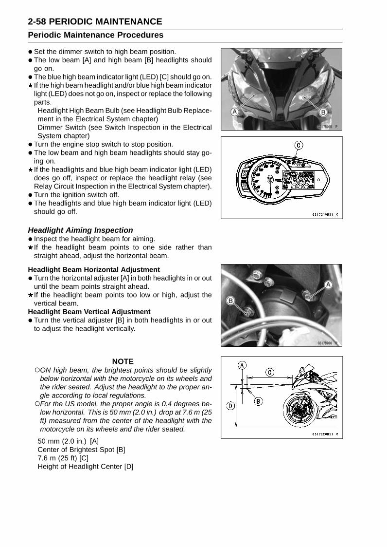
2-58 PERIODIC MAINTENANCEPeriodic Maintenance Procedures
•Set the dimmer switch to high beam position.• The low beam [A] and high beam [B] headlights should
go on.• The blue high beam indicator light (LED) [C] should go on.
If the high beam headlight and/or blue high beam indicatorlight (LED) does not go on, inspect or replace the followingparts.Headlight High Beam Bulb (see Headlight Bulb Replace-ment in the Electrical System chapter)Dimmer Switch (see Switch Inspection in the ElectricalSystem chapter)
• Turn the engine stop switch to stop position.• The low beam and high beam headlights should stay go-
ing on.If the headlights and blue high beam indicator light (LED)does go off, inspect or replace the headlight relay (seeRelay Circuit Inspection in the Electrical System chapter).
• Turn the ignition switch off.• The headlights and blue high beam indicator light (LED)
should go off.
Headlight Aiming Inspection• Inspect the headlight beam for aiming.
If the headlight beam points to one side rather thanstraight ahead, adjust the horizontal beam.
Headlight Beam Horizontal Adjustment•Turn the horizontal adjuster [A] in both headlights in or out
until the beam points straight ahead.If the headlight beam points too low or high, adjust thevertical beam.
Headlight Beam Vertical Adjustment•Turn the vertical adjuster [B] in both headlights in or out
to adjust the headlight vertically.
NOTEON high beam, the brightest points should be slightly
below horizontal with the motorcycle on its wheels andthe rider seated. Adjust the headlight to the proper an-gle according to local regulations.For the US model, the proper angle is 0.4 degrees be-
low horizontal. This is 50 mm (2.0 in.) drop at 7.6 m (25ft) measured from the center of the headlight with themotorcycle on its wheels and the rider seated.
50 mm (2.0 in.) [A]Center of Brightest Spot [B]7.6 m (25 ft) [C]Height of Headlight Center [D]

PERIODIC MAINTENANCE 2-59Periodic Maintenance Procedures
Sidestand Switch Operation Inspection•Raise the rear wheel off the ground with the stand (see
Rear Wheel Removal in the Wheels/Tires chapter).• Inspect the sidestand switch [A] operation accordance to
below table.
Sidestand Switch Operation
Sidestand GearPosition
ClutchLever
EngineStart
EngineRun
Up Neutral Released Starts Continuerunning
Up Neutral Pulled in Starts Continuerunning
Up In Gear Released Does notstart
Continuerunning
Up In Gear Pulled in Starts Continuerunning
Down Neutral Released Starts Continuerunning
Down Neutral Pulled in Starts Continuerunning
Down In Gear Released Does notstart Stops
Down In Gear Pulled in Does notstart Stops

2-60 PERIODIC MAINTENANCEPeriodic Maintenance Procedures
If the sidestand switch operation does not work, inspector replace the following parts.Battery (see Charging Condition Inspection in the Elec-trical System chapter)Main Fuse 30 A (see Fuse Inspection in the ElectricalSystem chapter)Ignition Fuse 15 A (see Fuse Inspection in the ElectricalSystem chapter)Ignition Switch (see Switch Inspection in the ElectricalSystem chapter)Sidestand Switch (see Switch Inspection in the ElectricalSystem chapter)Engine Stop Switch (see Switch Inspection in the Elec-trical System chapter)Starter Button (see Switch Inspection in the ElectricalSystem chapter)Gear Position Switch (see Gear Position Switch Inspec-tion in the Electrical System chapter)Starter Lockout Switch (see Switch Inspection in theElectrical System chapter)Starter Relay (see Starter Relay Inspection in the Elec-trical System chapter)Relay Box (see Relay Circuit Inspection in the ElectricalSystem chapter)Starter Circuit Relay (see Relay Circuit Inspection in theElectrical System chapter)Harness (see Wiring Inspection in the Electrical Systemchapter)
If the all parts are good condition, replace the ECU (seeECU Removal/Installation in the Fuel System (DFI) chap-ter).
Engine Stop Switch Operation InspectionFirst Step•Turn the ignition switch on.• Set the gear position in the neutral position.• Turn the engine stop switch to stop position [A].• Push the starter button.• The engine does not start.
If the engine starts, inspect or replace the engine stopswitch (see Switch Inspection in the Electrical Systemchapter).
Second Step•Turn the ignition switch on.• Set the gear position in the neutral position.• Turn the engine stop switch to run position [A].• Push the starter button and start the engine.• Turn the engine stop switch to stop position.• Immediately the engine should be stop.
If the engine does not stop, inspect or replace the enginestop switch (see Switch Inspection in the Electrical Sys-tem chapter).If the engine stop switch is good condition, replace theECU (see ECU Removal/Installation in the Fuel System(DFI) chapter).

PERIODIC MAINTENANCE 2-61Periodic Maintenance Procedures
Spark Plug Replacement•Remove the stick coils (see Stick Coil Removal in the
Electrical System chapter).• Remove the spark plugs using the 16 mm (0.63 in.) plug
wrench [A] vertically.• Replace the spark plugs with new ones.
Standard Spark PlugType: NGK CR9E
• Insert the spark plug vertically into the spark plug holewith the spark plug installed in the plug wrench [A], andfinger-tighten it first.
NOTICEIf tightening the spark plug with the wrench in-clined, the insulator of the spark plug may break.
•Tighten:Torque - Spark Plugs: 13 N·m (1.3 kgf·m, 115 in·lb)
• Install the stick coils (see Stick Coil Installation in the Elec-trical System chapter).
• After installation, be sure the stick coils are installed se-curely by pulling up them lightly.
OthersChassis Parts Lubrication•Before lubricating each part, clean off any rusty spots with
rust remover and wipe off any grease, oil, dirt, or grime.• Lubricate the points listed below with indicated lubricant.
NOTEWhenever the vehicle has been operated under
wet or rainy conditions, or especially after using ahigh-pressure water spray, perform the general lubri-cation.
Pivots: Lubricate with Grease.Brake LeverBrake PedalClutch LeverRear Master Cylinder Push Rod Joint PinSidestand
Points: Lubricate with Grease.Clutch Inner Cable Upper and Lower Ends [A]Throttle Inner Cable Upper and Lower Ends
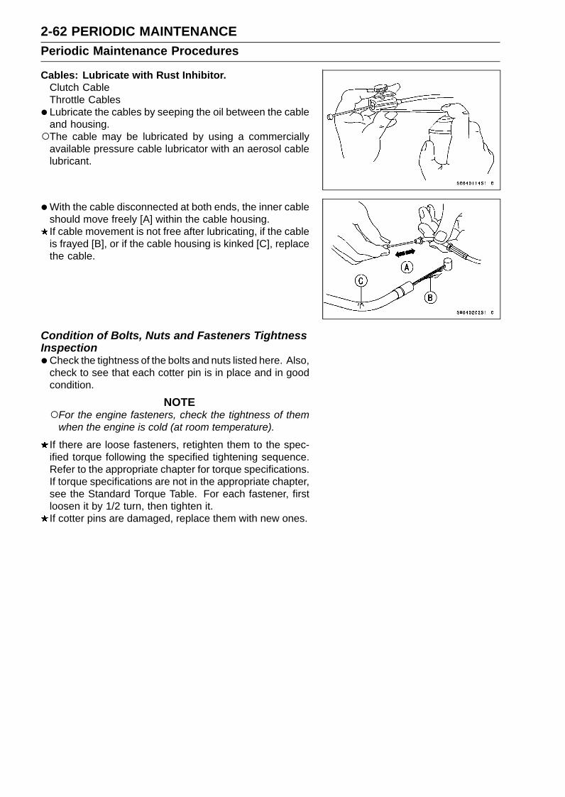
2-62 PERIODIC MAINTENANCEPeriodic Maintenance Procedures
Cables: Lubricate with Rust Inhibitor.Clutch CableThrottle Cables
• Lubricate the cables by seeping the oil between the cableand housing.The cable may be lubricated by using a commercially
available pressure cable lubricator with an aerosol cablelubricant.
•With the cable disconnected at both ends, the inner cableshould move freely [A] within the cable housing.If cable movement is not free after lubricating, if the cableis frayed [B], or if the cable housing is kinked [C], replacethe cable.
Condition of Bolts, Nuts and Fasteners TightnessInspection•Check the tightness of the bolts and nuts listed here. Also,
check to see that each cotter pin is in place and in goodcondition.
NOTEFor the engine fasteners, check the tightness of them
when the engine is cold (at room temperature).
If there are loose fasteners, retighten them to the spec-ified torque following the specified tightening sequence.Refer to the appropriate chapter for torque specifications.If torque specifications are not in the appropriate chapter,see the Standard Torque Table. For each fastener, firstloosen it by 1/2 turn, then tighten it.If cotter pins are damaged, replace them with new ones.

PERIODIC MAINTENANCE 2-63Periodic Maintenance Procedures
Bolt, Nut and Fastener to be checkedEngine:
Clutch Lever Pivot Bolt LocknutEngine Mounting Bolts and NutsExhaust Pipe Clamp BoltExhaust Pipe Holder NutsMuffler Body Clamp BoltMuffler Body Mounting BoltPremuffler Chamber Bracket BoltPremuffler Chamber Mounting BoltRadiator Bolts
Wheels:Front Axle Clamp BoltsFront AxleRear Axle NutRear Axle Nut Cotter Pin
Brakes:Brake Lever Pivot Bolt LocknutBrake Pedal BoltCaliper Mounting BoltsFront Master Cylinder Clamp BoltsRear Master Cylinder Mounting BoltsRear Master Cylinder Push Rod Joint Cotter Pin
Suspension:Front Fork Clamp BoltsRear Shock Absorber NutsSwingarm Pivot Shaft NutTie-Rod NutsRocker Arm Nut
Steering:Handlebar Clamp BoltsSteering Stem Head Bolt
Others:Footpeg Bracket BoltsFront Fender Mounting BoltsRear Frame BoltsSidestand BoltSidestand Bracket Bolts

FUEL SYSTEM (DFI) 3-1
3
Fuel System (DFI)Table of Contents
Exploded View................................... 3-2DFI System........................................ 3-8DFI Parts Location............................. 3-18Specifications .................................... 3-22Special Tools and Sealant ................. 3-23DFI Servicing Precautions ................. 3-24
DFI Servicing Precautions .............. 3-24Troubleshooting the DFI System ....... 3-26
Outline ............................................ 3-26Inquiries to Rider............................. 3-30
DFI System Troubleshooting Guide .. 3-33Warning Indicator Light (LED) ........... 3-38
Yellow Engine Warning/RedWarning Indicator Light (LED)Inspection.................................. 3-38
ECU................................................... 3-39ECU Identification ........................ 3-39ECU Removal .............................. 3-39ECU Installation ........................... 3-40ECU Power Supply Inspection..... 3-41
CAN Communication Line ................. 3-44CAN Communication Line
Resistance Inspection ............... 3-44DFI Power Source ............................. 3-46
ECU Fuse Removal ..................... 3-46ECU Fuse Installation .................. 3-46ECU Fuse Inspection ................... 3-46ECU Main Relay
Removal/Installation.................. 3-46ECU Main Relay Inspection ......... 3-46
Fuel Line............................................ 3-47Fuel Pressure Inspection ............. 3-47Fuel Flow Rate Inspection ........... 3-48
Fuel Pump ......................................... 3-50Fuel Pump Removal .................... 3-50Fuel Pump Installation ................. 3-51Fuel Pump Operation Inspection . 3-51Fuel Pump Operating Voltage
Inspection.................................. 3-52Pressure Regulator Removal....... 3-53Fuel Filter Cleaning...................... 3-53
Fuel Injectors ..................................... 3-55Fuel Injector Removal/Installation 3-55Fuel Injector Audible Inspection... 3-55Fuel Injector Resistance
Inspection.................................. 3-55
Fuel Injector Power SourceVoltage Inspection..................... 3-56
Fuel Injector Output VoltageInspection.................................. 3-57
Fuel Injector Fuel Line Inspection 3-58Throttle Grip and Cables ................... 3-61
Free Play Inspection .................... 3-61Free Play Adjustment................... 3-61Cable Installation ......................... 3-61Cable Lubrication ......................... 3-61
Throttle Body Assy ............................ 3-62Idle Speed Inspection .................. 3-62Synchronization Inspection/Ad-
justment..................................... 3-62Throttle Body Assy Removal........ 3-62Throttle Body Assy Installation..... 3-63Throttle Body Assy Disassembly . 3-64Throttle Body Assy Assembly ...... 3-65
Air Cleaner......................................... 3-66Air Cleaner Element
Removal/Installation.................. 3-66Air Cleaner Element Inspection ... 3-66Air Cleaner Oil Draining ............... 3-66Air Cleaner Housing Removal...... 3-66Air Cleaner Housing Installation... 3-67Air Cleaner Housing Disassembly 3-68Air Cleaner Housing Assembly .... 3-68
Air Line .............................................. 3-70Air Intake Duct Removal .............. 3-70Air Intake Duct Installation ........... 3-70Air Intake Duct Disassembly ........ 3-70Air Intake Duct Assembly............. 3-71
Fuel Tank........................................... 3-72Fuel Tank Removal ...................... 3-72Fuel Tank Installation ................... 3-74Fuel Tank and Cap Inspection ..... 3-76Fuel Tank Cleaning ...................... 3-76
Evaporative Emission Control System(CAL Model).................................... 3-77
Parts Removal/Installation ........... 3-77Hose Inspection ........................... 3-77Purge Valve Inspection ................ 3-77Canister Inspection ..................... 3-77
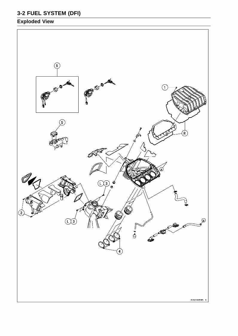
3-2 FUEL SYSTEM (DFI)Exploded View

FUEL SYSTEM (DFI) 3-3Exploded View
TorqueNo. Fastener
N·m kgf·m ft·lbRemarks
1 Air Cleaner Housing Assembly Screws 1.2 0.12 11 in·lb2 Air Intake Duct Assembly Screws 1.5 0.15 13 in·lb3 Air Intake Duct Mounting Bolts 9.8 1.0 87 in·lb L4 Air Cleaner Housing Clamp Bolts 2.0 0.20 18 in·lb5. Immobilizer System Equipped ModelsL: Apply a non-permanent locking agent.R: Replacement Parts
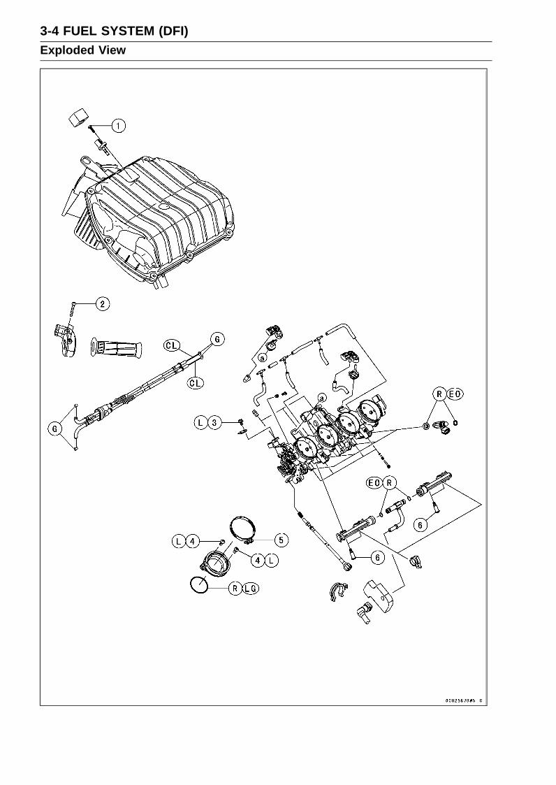
3-4 FUEL SYSTEM (DFI)Exploded View
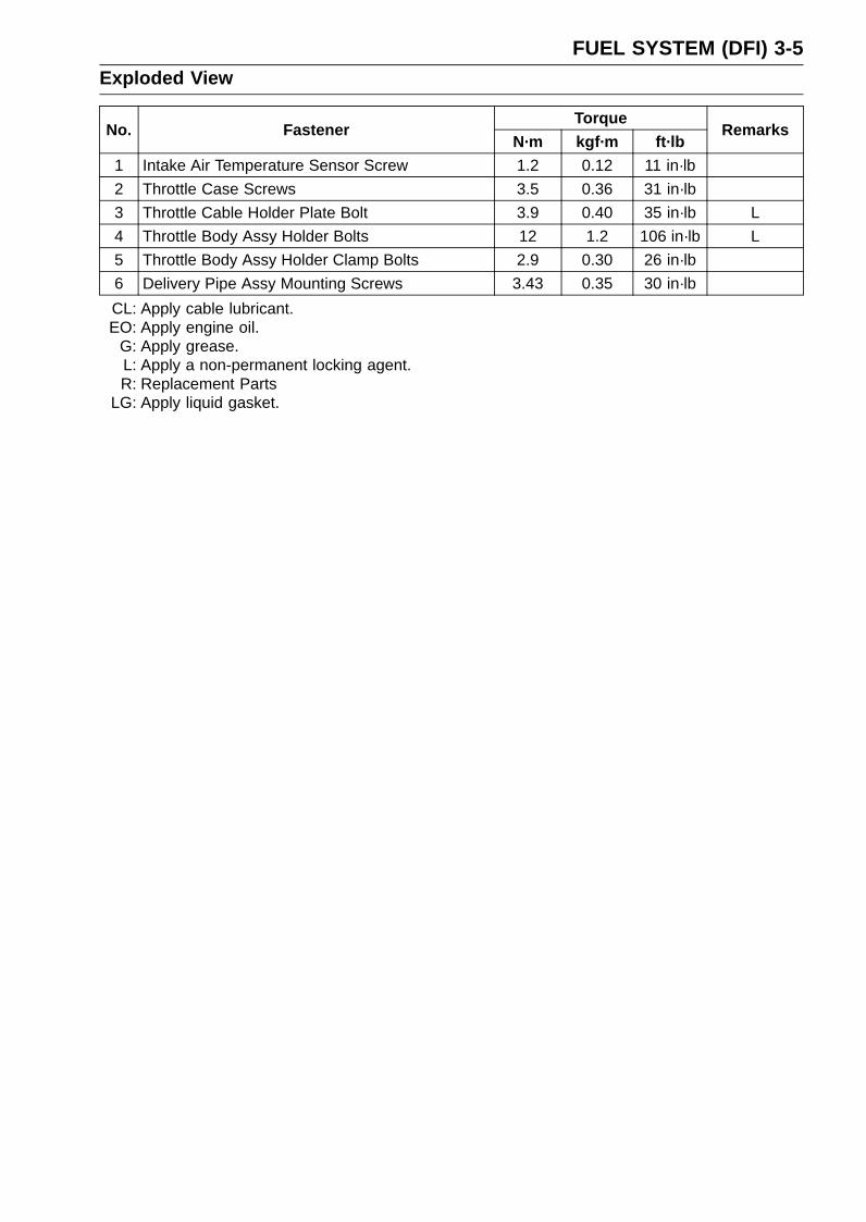
FUEL SYSTEM (DFI) 3-5Exploded View
TorqueNo. Fastener
N·m kgf·m ft·lbRemarks
1 Intake Air Temperature Sensor Screw 1.2 0.12 11 in·lb2 Throttle Case Screws 3.5 0.36 31 in·lb3 Throttle Cable Holder Plate Bolt 3.9 0.40 35 in·lb L4 Throttle Body Assy Holder Bolts 12 1.2 106 in·lb L5 Throttle Body Assy Holder Clamp Bolts 2.9 0.30 26 in·lb6 Delivery Pipe Assy Mounting Screws 3.43 0.35 30 in·lbCL: Apply cable lubricant.EO: Apply engine oil.
G: Apply grease.L: Apply a non-permanent locking agent.R: Replacement Parts
LG: Apply liquid gasket.

3-6 FUEL SYSTEM (DFI)Exploded View

FUEL SYSTEM (DFI) 3-7Exploded View
TorqueNo. Fastener
N·m kgf·m ft·lbRemarks
1 Crankshaft Sensor Bolts 5.9 0.60 52 in·lb2 Water Temperature Sensor 12 1.2 106 in·lb3 Exhaust Butterfly Valve Actuator Mounting Screws 4.3 0.44 38 in·lb4 Exhaust Butterfly Valve Actuator Pulley Bolt 4.9 0.50 43 in·lb5 Fuel Pump Bolts 9.8 1.0 87 in·lb L, S6 Gear Position Switch Screws 2.9 0.30 26 in·lb L7 Oxygen Sensor (Equipped Models) 25 2.5 188. Other than CAL Model9. CAL Model
10. ECU Guard (GB WVTA (FULL H) and WVTA (78.2 H) Models)G: Apply grease.L: Apply a non-permanent locking agent.R: Replacement PartsS: Follow the specified tightening sequence.

3-8 FUEL SYSTEM (DFI)DFI System
DFI System

FUEL SYSTEM (DFI) 3-9DFI System
1. ECU2. Battery 12 V 8 Ah3. Intake Air Temperature Sensor4. Subthrottle Valve Actuator5. Subthrottle Sensor6. Fuel Injectors7. Delivery Pipe Assy8. Vehicle-down Sensor9. Fuel Filter
10. Pressure Regulator11. Fuel Pump12. Oxygen Sensor (Equipped Models)13. Exhaust Butterfly Valve Actuator14. Intake Air Pressure Sensor #115. Intake Air Pressure Sensor #216. Main Throttle Sensor17. Crankshaft Sensor18. Water Temperature Sensor19. Gear Position Switch20. Wheel Rotation Sensors21. Air Flow22. Fuel Flow

3-10 FUEL SYSTEM (DFI)DFI System
DFI System Wiring Diagram
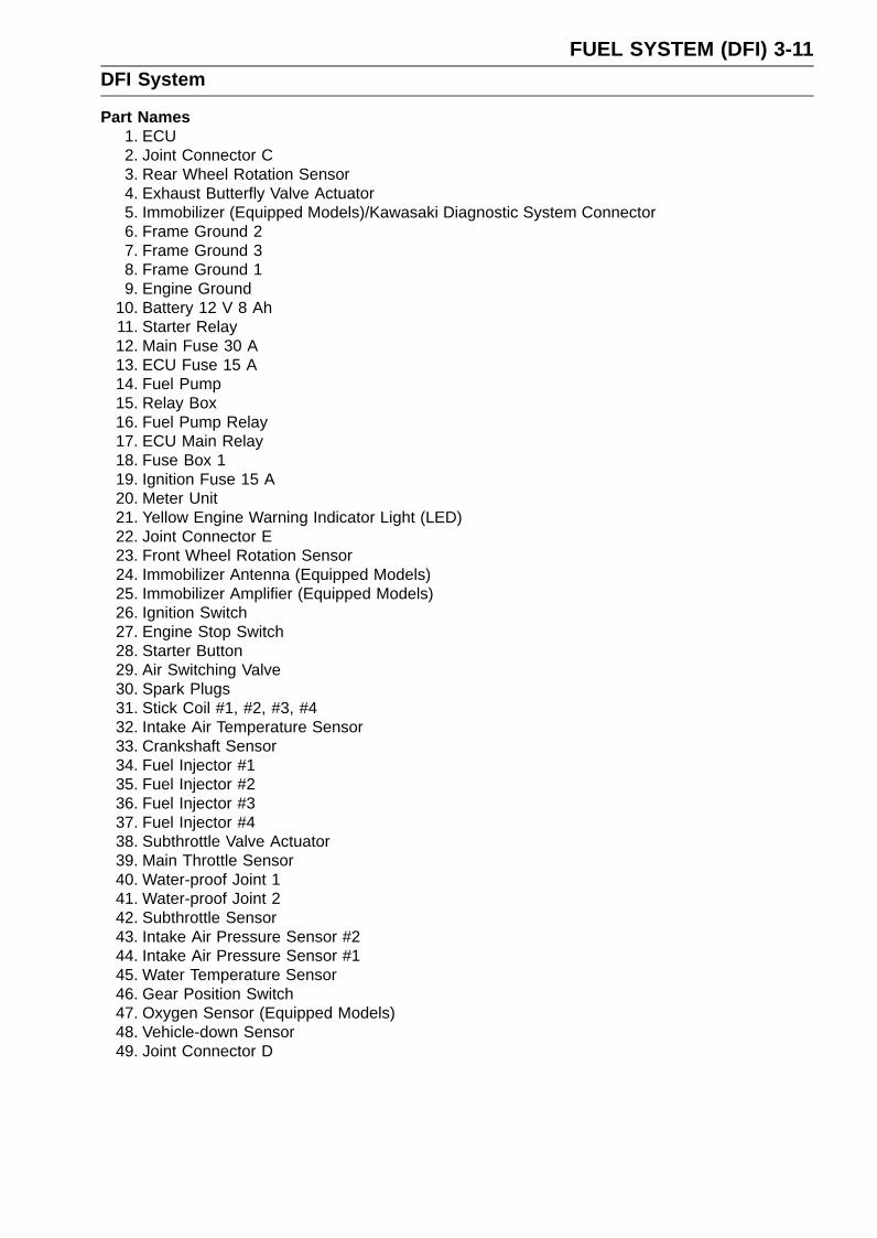
FUEL SYSTEM (DFI) 3-11DFI System
Part Names1. ECU2. Joint Connector C3. Rear Wheel Rotation Sensor4. Exhaust Butterfly Valve Actuator5. Immobilizer (Equipped Models)/Kawasaki Diagnostic System Connector6. Frame Ground 27. Frame Ground 38. Frame Ground 19. Engine Ground
10. Battery 12 V 8 Ah11. Starter Relay12. Main Fuse 30 A13. ECU Fuse 15 A14. Fuel Pump15. Relay Box16. Fuel Pump Relay17. ECU Main Relay18. Fuse Box 119. Ignition Fuse 15 A20. Meter Unit21. Yellow Engine Warning Indicator Light (LED)22. Joint Connector E23. Front Wheel Rotation Sensor24. Immobilizer Antenna (Equipped Models)25. Immobilizer Amplifier (Equipped Models)26. Ignition Switch27. Engine Stop Switch28. Starter Button29. Air Switching Valve30. Spark Plugs31. Stick Coil #1, #2, #3, #432. Intake Air Temperature Sensor33. Crankshaft Sensor34. Fuel Injector #135. Fuel Injector #236. Fuel Injector #337. Fuel Injector #438. Subthrottle Valve Actuator39. Main Throttle Sensor40. Water-proof Joint 141. Water-proof Joint 242. Subthrottle Sensor43. Intake Air Pressure Sensor #244. Intake Air Pressure Sensor #145. Water Temperature Sensor46. Gear Position Switch47. Oxygen Sensor (Equipped Models)48. Vehicle-down Sensor49. Joint Connector D

3-12 FUEL SYSTEM (DFI)DFI System
DFI System Wiring Diagram (KIBS Equipped Models)
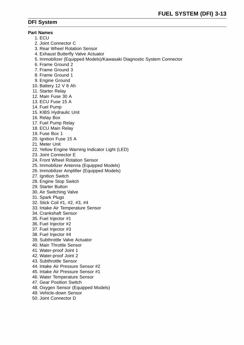
FUEL SYSTEM (DFI) 3-13DFI System
Part Names1. ECU2. Joint Connector C3. Rear Wheel Rotation Sensor4. Exhaust Butterfly Valve Actuator5. Immobilizer (Equipped Models)/Kawasaki Diagnostic System Connector6. Frame Ground 27. Frame Ground 38. Frame Ground 19. Engine Ground
10. Battery 12 V 8 Ah11. Starter Relay12. Main Fuse 30 A13. ECU Fuse 15 A14. Fuel Pump15. KIBS Hydraulic Unit16. Relay Box17. Fuel Pump Relay18. ECU Main Relay19. Fuse Box 120. Ignition Fuse 15 A21. Meter Unit22. Yellow Engine Warning Indicator Light (LED)23. Joint Connector E24. Front Wheel Rotation Sensor25. Immobilizer Antenna (Equipped Models)26. Immobilizer Amplifier (Equipped Models)27. Ignition Switch28. Engine Stop Switch29. Starter Button30. Air Switching Valve31. Spark Plugs32. Stick Coil #1, #2, #3, #433. Intake Air Temperature Sensor34. Crankshaft Sensor35. Fuel Injector #136. Fuel Injector #237. Fuel Injector #338. Fuel Injector #439. Subthrottle Valve Actuator40. Main Throttle Sensor41. Water-proof Joint 142. Water-proof Joint 243. Subthrottle Sensor44. Intake Air Pressure Sensor #245. Intake Air Pressure Sensor #146. Water Temperature Sensor47. Gear Position Switch48. Oxygen Sensor (Equipped Models)49. Vehicle-down Sensor50. Joint Connector D

3-14 FUEL SYSTEM (DFI)DFI System
Color Codes:BK: BlackBL: BlueBR: BrownCH: ChocolateDG: Dark Green
G: Green
GY: GrayLB: Light BlueLG: Light Green
O: OrangeP: Pink
PU: PurpleR: RedV: Violet
W: WhiteY: Yellow

FUEL SYSTEM (DFI) 3-15DFI System
This page intentionally left blank.
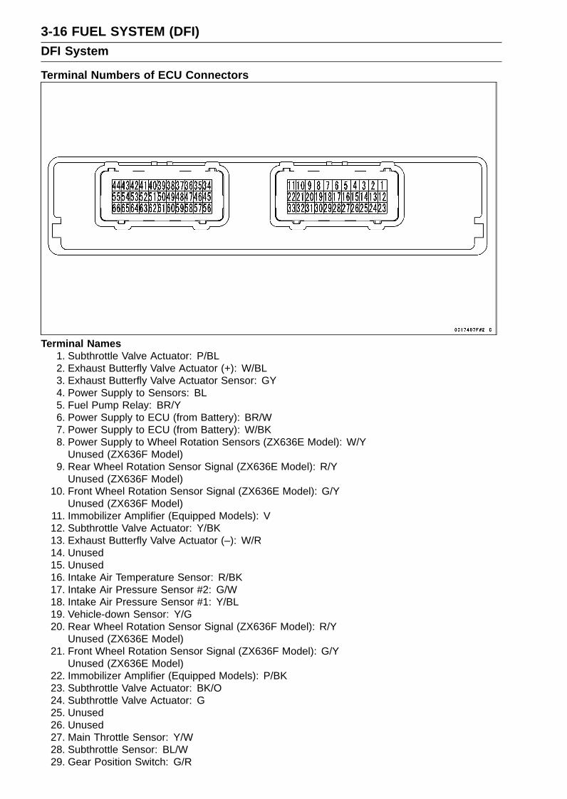
3-16 FUEL SYSTEM (DFI)DFI System
Terminal Numbers of ECU Connectors
Terminal Names1. Subthrottle Valve Actuator: P/BL2. Exhaust Butterfly Valve Actuator (+): W/BL3. Exhaust Butterfly Valve Actuator Sensor: GY4. Power Supply to Sensors: BL5. Fuel Pump Relay: BR/Y6. Power Supply to ECU (from Battery): BR/W7. Power Supply to ECU (from Battery): W/BK8. Power Supply to Wheel Rotation Sensors (ZX636E Model): W/Y
Unused (ZX636F Model)9. Rear Wheel Rotation Sensor Signal (ZX636E Model): R/Y
Unused (ZX636F Model)10. Front Wheel Rotation Sensor Signal (ZX636E Model): G/Y
Unused (ZX636F Model)11. Immobilizer Amplifier (Equipped Models): V12. Subthrottle Valve Actuator: Y/BK13. Exhaust Butterfly Valve Actuator (–): W/R14. Unused15. Unused16. Intake Air Temperature Sensor: R/BK17. Intake Air Pressure Sensor #2: G/W18. Intake Air Pressure Sensor #1: Y/BL19. Vehicle-down Sensor: Y/G20. Rear Wheel Rotation Sensor Signal (ZX636F Model): R/Y
Unused (ZX636E Model)21. Front Wheel Rotation Sensor Signal (ZX636F Model): G/Y
Unused (ZX636E Model)22. Immobilizer Amplifier (Equipped Models): P/BK23. Subthrottle Valve Actuator: BK/O24. Subthrottle Valve Actuator: G25. Unused26. Unused27. Main Throttle Sensor: Y/W28. Subthrottle Sensor: BL/W29. Gear Position Switch: G/R

FUEL SYSTEM (DFI) 3-17DFI System
30. Water Temperature Sensor: W/G31. External Communication Line (Immobilizer System (Equipped Models)/*KDS): LG/BK32. Unused33. Oxygen Sensor (Equipped Models): BL/Y34. Starter Button: R/BK35. Ground for Exhaust Butterfly Valve Actuator: P36. CAN Communication Line (Low): LB37. CAN Communication Line (High): GY/BL38. Ground for Control System: BK/BL39. Ground for Fuel System: BK/Y40. Fuel Injector #3: BL/O41. Fuel Injector #2: BL/R42. Fuel Injector #1: BL/BK43. Stick Coil #4: BK/G44. Stick Coil #1: BK45. Starter Lockout Switch: R/G46. Sidestand Switch: G/BK47. Unused48. External Communication Line (Immobilizer System (Equipped Models)/*KDS): GY/W49. Ground for Sensors: G50. Radiator Fan Relay: Y/BL51. Oxygen Sensor Heater (Equipped Models): P/BK52. Unused53. Unused54. Fuel Injector #4: BL/G55. Stick Coil #2: BK/R56. Engine Stop Switch: R57. Unused58. Unused59. Crankshaft Sensor (–): Y/BK60. Crankshaft Sensor (+): Y61. Purge Valve (CAL Model): R/Y62. Air Switching Valve: R/BL63. Unused64. Unused65. Ground for Ignition System: BK/Y66. Stick Coil #3: BK/O
*: KDS (Kawasaki Diagnostic System)

3-18 FUEL SYSTEM (DFI)DFI Parts Location
Main Throttle Sensor [A]Subthrottle Sensor [B]Subthrottle Valve Actuator [C]Intake Air Pressure Sensor #2 [D]Stick Coils #1, #2, #3, #4 [E]Air Switching Valve [F]Intake Air Pressure Sensor #1 [G]
Water Temperature Sensor [A]Fuel Injectors #1, #2, #3, #4 [B]
Battery 12 V 8 Ah [A]Exhaust Butterfly Valve Actuator [B]
Main Fuse 30 A [A]ECU Fuse 15 A [B]
ECU [A]Relay Box [B] (Fuel Pump Relay, Radiator Fan Relay)

FUEL SYSTEM (DFI) 3-19DFI Parts Location
Vehicle-down Sensor [A]Immobilizer (Equipped Models)/Kawasaki DiagnosticSystem Connector [B]
Fuel Pump [A]
Intake Air Temperature Sensor [A]
Crankshaft Sensor [A]
Gear Position Switch [A]

3-20 FUEL SYSTEM (DFI)DFI Parts Location
Fuse Box 1 [A]
Ignition Key [A] (Transponder, Immobilizer SystemEquipped Models)Immobilizer Antenna [B] (Equipped Models)Ignition Switch [C]Yellow Engine Warning Indicator Light (LED) [D]
Immobilizer Amplifier [A] (Equipped Models)
Oxygen Sensor [A] (Equipped Models)
Front Wheel Rotation Sensor [A]

FUEL SYSTEM (DFI) 3-21DFI Parts Location
Rear Wheel Rotation Sensor [A]
Purge Valve [A] (CAL Model)
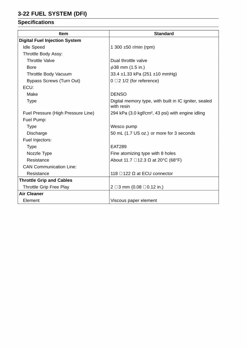
3-22 FUEL SYSTEM (DFI)Specifications
Item StandardDigital Fuel Injection System
Idle Speed 1 300 ±50 r/min (rpm)Throttle Body Assy:
Throttle Valve Dual throttle valveBore 38 mm (1.5 in.)Throttle Body Vacuum 33.4 ±1.33 kPa (251 ±10 mmHg)Bypass Screws (Turn Out) 0 ∼ 2 1/2 (for reference)
ECU:Make DENSOType Digital memory type, with built in IC igniter, sealed
with resinFuel Pressure (High Pressure Line) 294 kPa (3.0 kgf/cm², 43 psi) with engine idlingFuel Pump:
Type Wesco pumpDischarge 50 mL (1.7 US oz.) or more for 3 seconds
Fuel Injectors:Type EAT289Nozzle Type Fine atomizing type with 8 holesResistance About 11.7 ∼ 12.3 Ω at 20°C (68°F)
CAN Communication Line:Resistance 118 ∼ 122 Ω at ECU connector
Throttle Grip and CablesThrottle Grip Free Play 2 ∼ 3 mm (0.08 ∼ 0.12 in.)
Air CleanerElement Viscous paper element

FUEL SYSTEM (DFI) 3-23Special Tools and Sealant
Oil Pressure Gauge, 5 kgf/cm²:57001-125
Hand Tester:57001-1394
Needle Adapter Set:57001-1457
Extension Tube:57001-1578
Fuel Pressure Gauge Adapter:57001-1593
Fuel Hose:57001-1607
Measuring Adapter:57001-1700
Liquid Gasket, TB1211:56019-120
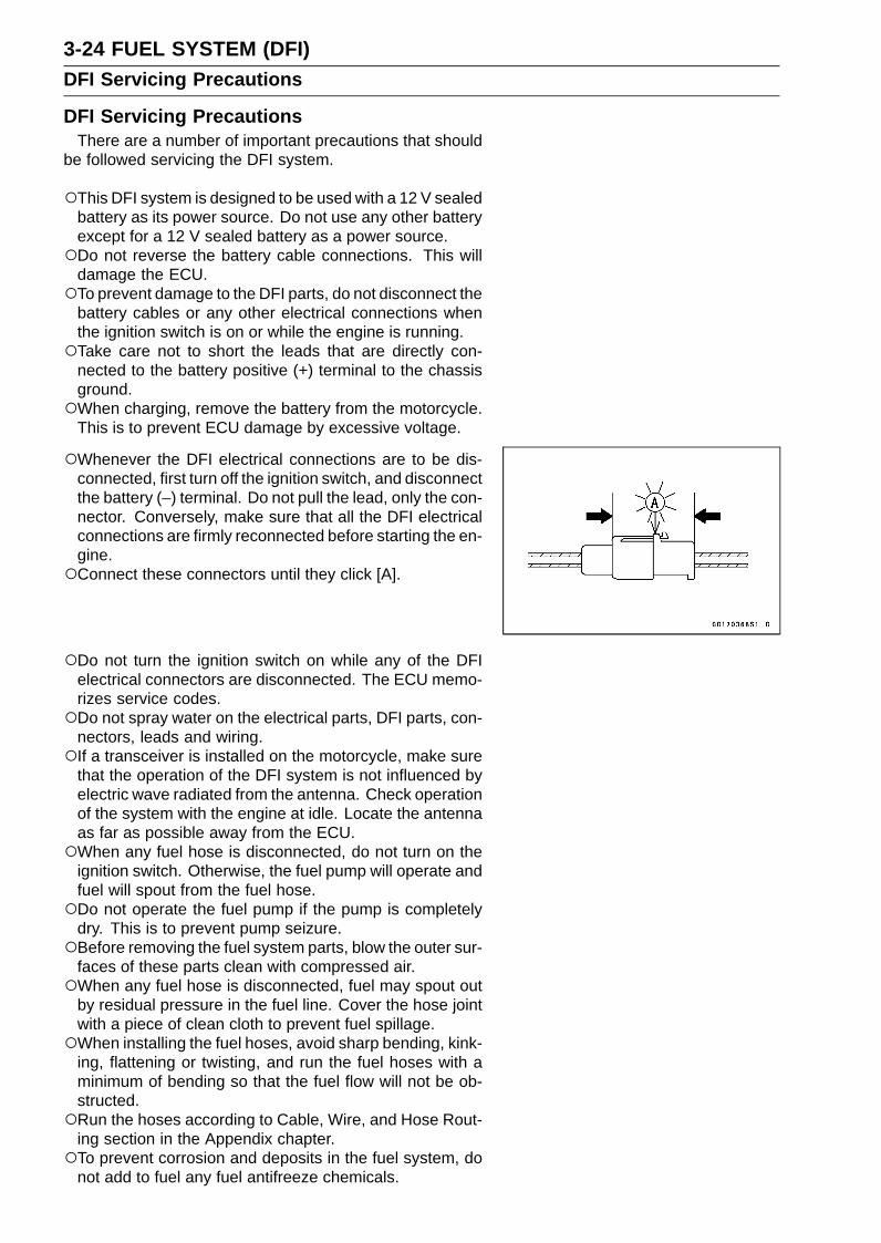
3-24 FUEL SYSTEM (DFI)DFI Servicing Precautions
DFI Servicing PrecautionsThere are a number of important precautions that should
be followed servicing the DFI system.
This DFI system is designed to be used with a 12 V sealedbattery as its power source. Do not use any other batteryexcept for a 12 V sealed battery as a power source.Do not reverse the battery cable connections. This will
damage the ECU.To prevent damage to the DFI parts, do not disconnect the
battery cables or any other electrical connections whenthe ignition switch is on or while the engine is running.Take care not to short the leads that are directly con-
nected to the battery positive (+) terminal to the chassisground.When charging, remove the battery from the motorcycle.
This is to prevent ECU damage by excessive voltage.
Whenever the DFI electrical connections are to be dis-connected, first turn off the ignition switch, and disconnectthe battery (–) terminal. Do not pull the lead, only the con-nector. Conversely, make sure that all the DFI electricalconnections are firmly reconnected before starting the en-gine.Connect these connectors until they click [A].
Do not turn the ignition switch on while any of the DFIelectrical connectors are disconnected. The ECU memo-rizes service codes.Do not spray water on the electrical parts, DFI parts, con-
nectors, leads and wiring.If a transceiver is installed on the motorcycle, make sure
that the operation of the DFI system is not influenced byelectric wave radiated from the antenna. Check operationof the system with the engine at idle. Locate the antennaas far as possible away from the ECU.When any fuel hose is disconnected, do not turn on the
ignition switch. Otherwise, the fuel pump will operate andfuel will spout from the fuel hose.Do not operate the fuel pump if the pump is completely
dry. This is to prevent pump seizure.Before removing the fuel system parts, blow the outer sur-
faces of these parts clean with compressed air.When any fuel hose is disconnected, fuel may spout out
by residual pressure in the fuel line. Cover the hose jointwith a piece of clean cloth to prevent fuel spillage.When installing the fuel hoses, avoid sharp bending, kink-
ing, flattening or twisting, and run the fuel hoses with aminimum of bending so that the fuel flow will not be ob-structed.Run the hoses according to Cable, Wire, and Hose Rout-
ing section in the Appendix chapter.To prevent corrosion and deposits in the fuel system, do
not add to fuel any fuel antifreeze chemicals.
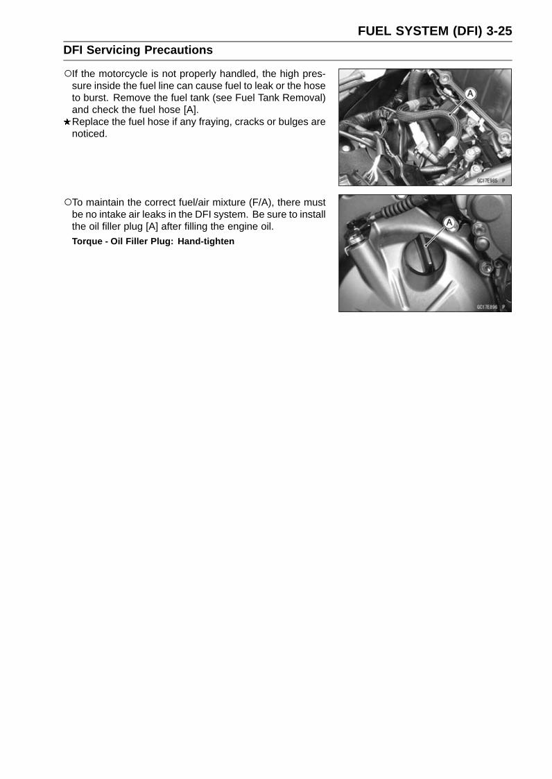
FUEL SYSTEM (DFI) 3-25DFI Servicing Precautions
If the motorcycle is not properly handled, the high pres-sure inside the fuel line can cause fuel to leak or the hoseto burst. Remove the fuel tank (see Fuel Tank Removal)and check the fuel hose [A].Replace the fuel hose if any fraying, cracks or bulges arenoticed.
To maintain the correct fuel/air mixture (F/A), there mustbe no intake air leaks in the DFI system. Be sure to installthe oil filler plug [A] after filling the engine oil.Torque - Oil Filler Plug: Hand-tighten

3-26 FUEL SYSTEM (DFI)Troubleshooting the DFI System
OutlineWhen a problem occurs with DFI system, the yellow en-
gine warning indicator light (LED) [A] goes on to alert therider.
For models equipped with an immobilizer system, the redwarning indicator light (LED) [A] and immobilizer warningsymbol [B] blink, when a problem occurs in the system.
With the engine stopped and turned in the self-diagnosismode, the service code [A] is displayed on the LCD (LiquidCrystal Display) by the number of two digits.
If the problem is with the following parts, the ECU cannot recognize these problem. Therefore, the yellow enginewarning indicator light (LED) does not go on, and servicecode is not displayed.
Fuel PumpFuel Pump RelayFuel InjectorsStick Coil Secondary Wiring and Ground WiringECU Main Relay

FUEL SYSTEM (DFI) 3-27Troubleshooting the DFI System
When the service code [A] is displayed, for first ask therider about the conditions [B] of trouble, and then start todetermine the cause [C] of problem.
As a pre-diagnosis inspection, check the ECU for groundand power supply, the fuel line for no fuel leaks, and forcorrect pressure. The pre-diagnosis items are not indicatedby the yellow engine warning indicator light (LED).
Don’t rely solely on the DFI self-diagnosis function, usecommon sense.
Even when the DFI system is operating normally, the yel-low engine warning indicator light (LED) goes on may bedisplayed under strong electrical interference. Additionalmeasures are not required. Turn the ignition switch off tostop the indicator light.
If the yellow engine warning indicator light (LED) of themotorcycle brought in for repair still goes on, check the ser-vice code.
When the repair has been done, the yellow engine warn-ing indicator light (LED) goes off. But the service codesstored in memory of the ECU are not erased to preservethe problem history. The problem history can be referredusing the KDS (Kawasaki Diagnostic System) when solv-ing unstable problems.
When the motorcycle is down, the vehicle-down sensoroperates and the ECU shuts off the fuel pump relay, fuelinjectors and ignition system. The ignition switch is left on. Ifthe starter button is pushed, the electric starter turns but theengine does not start. When the starter button is pushed,the yellow engine warning indicator light (LED) blinks butthe service code is not displayed. To start the engine again,raise the motorcycle, turn the ignition switch off, and thenon.
Much of the DFI system troubleshooting work consistsof confirming continuity of the wiring. The DFI parts areassembled and adjusted with precision, and it is impossibleto disassemble or repair them.
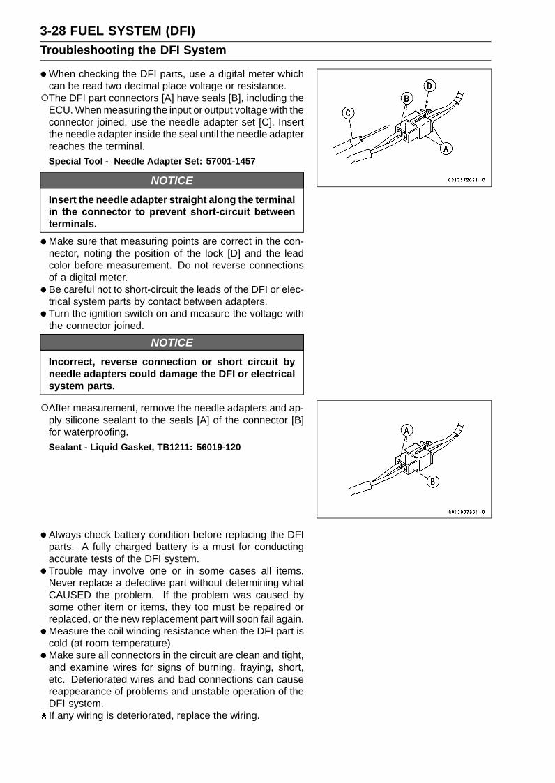
3-28 FUEL SYSTEM (DFI)Troubleshooting the DFI System
•When checking the DFI parts, use a digital meter whichcan be read two decimal place voltage or resistance.The DFI part connectors [A] have seals [B], including the
ECU. When measuring the input or output voltage with theconnector joined, use the needle adapter set [C]. Insertthe needle adapter inside the seal until the needle adapterreaches the terminal.Special Tool - Needle Adapter Set: 57001-1457
NOTICEInsert the needle adapter straight along the terminalin the connector to prevent short-circuit betweenterminals.
•Make sure that measuring points are correct in the con-nector, noting the position of the lock [D] and the leadcolor before measurement. Do not reverse connectionsof a digital meter.
• Be careful not to short-circuit the leads of the DFI or elec-trical system parts by contact between adapters.
• Turn the ignition switch on and measure the voltage withthe connector joined.
NOTICEIncorrect, reverse connection or short circuit byneedle adapters could damage the DFI or electricalsystem parts.
After measurement, remove the needle adapters and ap-ply silicone sealant to the seals [A] of the connector [B]for waterproofing.Sealant - Liquid Gasket, TB1211: 56019-120
•Always check battery condition before replacing the DFIparts. A fully charged battery is a must for conductingaccurate tests of the DFI system.
• Trouble may involve one or in some cases all items.Never replace a defective part without determining whatCAUSED the problem. If the problem was caused bysome other item or items, they too must be repaired orreplaced, or the new replacement part will soon fail again.
•Measure the coil winding resistance when the DFI part iscold (at room temperature).
•Make sure all connectors in the circuit are clean and tight,and examine wires for signs of burning, fraying, short,etc. Deteriorated wires and bad connections can causereappearance of problems and unstable operation of theDFI system.If any wiring is deteriorated, replace the wiring.

FUEL SYSTEM (DFI) 3-29Troubleshooting the DFI System
•Pull each connector [A] apart and inspect it for corrosion,dirt, and damage.If the connector is corroded or dirty, clean it carefully. If itis damaged, replace it. Connect the connectors securely.
• Check the wiring for continuity.Use the wiring diagram to find the ends of the lead which
is suspected of being a problem.Connect the hand tester between the ends of the leads.
Special Tool - Hand Tester: 57001-1394Set the tester to the × 1 Ω range, and read the tester.
If the tester does not read 0 Ω, the lead is defective. Re-place the lead or the main harness.
If both ends of a harness [A] are far apart, ground [B] theone end [C], using a jumper lead [D] and check the con-tinuity between the end [E] and the ground [F]. This en-ables to check a long harness for continuity. If the harnessis open, repair or replace the harness.
When checking a harness [A] for short circuit, open oneend [B] and check the continuity between the other end[C] and ground [D]. If there is continuity, the harness hasa short circuit to ground, and it must be repaired or re-placed.
•Narrow down suspicious locations by repeating the con-tinuity tests from the ECU connectors.If no abnormality is found in the wiring or connectors, theDFI parts are the next likely suspects. Check the part,starting with input and output voltages. However, there isno way to check the ECU itself.If an abnormality is found, replace the affected DFI part.If no abnormality is found in the wiring, connectors, andDFI parts, replace the ECU.

3-30 FUEL SYSTEM (DFI)Troubleshooting the DFI System
DFI Diagnosis Flow Chart
Inquiries to RiderEach rider reacts to problems in different ways, so it is important to confirm what kind of symptoms
the rider has encountered.Try to find out exactly what problem occurred under exactly what conditions by asking the rider;
knowing this information may help you reproduce the problem.The following sample diagnosis sheet will help prevent you from overlooking any areas, and will
help you decide if it is a DFI system problem, or a general engine problem.

FUEL SYSTEM (DFI) 3-31Troubleshooting the DFI System
Sample Diagnosis SheetRider name: Registration No. (license plate No.): Year of initial registration:Model: Engine No.: Frame No.:Date problem occurred: Mileage:
Environment when problem occurred.Weather fine, cloudy, rain, snow, always, other:Temperature hot, warm, cold, very cold, always, other:Problemfrequency
chronic, often, once
Road street, highway, mountain road ( uphill, downhill), bumpy, pebbleAltitude normal, high (about 1 000 m or more)
Motorcycle conditions when problem occurred. goes on immediately after turning the ignition switch on, and goes off after about
1 second (normal) goes on immediately after turning the ignition switch on, goes off after about 1
second, and goes on again after about 4 seconds (ECU communication error) goes on immediately after turning the ignition switch on, and stays on [DFI
problem]
Yellow enginewarningindicator light(LED)
does not go on after turning the ignition switch on [light (LED), meter unit fault] Starts blinking about 1 seconds after ignition switch on, and the immobilizer
warning symbol on the LCD starts blinking (immobilizer system problem). Does not go on about 1 seconds after ignition switch on (meter unit fault).
Red warningindicator light(LED)
light up (battery, oil pressure, water temperature, immobilizer or meter unitproblem)
starter motor not rotating. starter motor rotating but engine do not turn over. starter motor and engine do not turn over. no fuel flow ( no fuel in tank, no fuel pump sound). no spark.
Startingdifficulty
other: right after starting. when opening throttle grip. when closing throttle grip. when moving off. when stopping the motorcycle. when cruising.
Engine stalls
other:

3-32 FUEL SYSTEM (DFI)Troubleshooting the DFI System
very low idle speed, very high idle speed, rough idle speed. battery voltage is low (charge the battery). spark plug loose (tighten it). spark plug dirty, broken, or gap maladjusted (remedy it). backfiring. afterfiring. hesitation when acceleration. engine oil viscosity too high. brake dragging. engine overheating. clutch slipping.
Poor runningat low speed
other: spark plug loose (tighten it). spark plug dirty, broken, or gap maladjusted (remedy it). spark plug incorrect (replace it). knocking (fuel poor quality or incorrect, → use high-octane gasoline). brake dragging. clutch slipping. engine overheating. engine oil level too high. engine oil viscosity too high.
Poor runningor no power athigh speed
other:
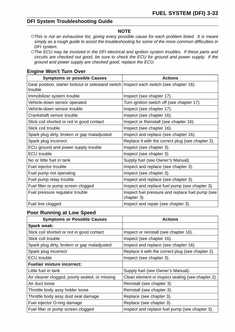
FUEL SYSTEM (DFI) 3-33DFI System Troubleshooting Guide
NOTEThis is not an exhaustive list, giving every possible cause for each problem listed. It is meant
simply as a rough guide to assist the troubleshooting for some of the more common difficulties inDFI system.The ECU may be involved in the DFI electrical and ignition system troubles. If these parts and
circuits are checked out good, be sure to check the ECU for ground and power supply. If theground and power supply are checked good, replace the ECU.
Engine Won’t Turn OverSymptoms or possible Causes Actions
Gear position, starter lockout or sidestand switchtrouble
Inspect each switch (see chapter 16).
Immobilizer system trouble Inspect (see chapter 17).Vehicle-down sensor operated Turn ignition switch off (see chapter 17).Vehicle-down sensor trouble Inspect (see chapter 17).Crankshaft sensor trouble Inspect (see chapter 16).Stick coil shorted or not in good contact Inspect or Reinstall (see chapter 16).Stick coil trouble Inspect (see chapter 16).Spark plug dirty, broken or gap maladjusted Inspect and replace (see chapter 16).Spark plug incorrect Replace it with the correct plug (see chapter 2).ECU ground and power supply trouble Inspect (see chapter 3).ECU trouble Inspect (see chapter 3).No or little fuel in tank Supply fuel (see Owner’s Manual).Fuel injector trouble Inspect and replace (see chapter 3).Fuel pump not operating Inspect (see chapter 3).Fuel pump relay trouble Inspect and replace (see chapter 3).Fuel filter or pump screen clogged Inspect and replace fuel pump (see chapter 3).Fuel pressure regulator trouble Inspect fuel pressure and replace fuel pump (see
chapter 3).Fuel line clogged Inspect and repair (see chapter 3).
Poor Running at Low SpeedSymptoms or Possible Causes Actions
Spark weak:Stick coil shorted or not in good contact Inspect or reinstall (see chapter 16).Stick coil trouble Inspect (see chapter 16).Spark plug dirty, broken or gap maladjusted Inspect and replace (see chapter 16).Spark plug incorrect Replace it with the correct plug (see chapter 2).ECU trouble Inspect (see chapter 3).Fuel/air mixture incorrect:Little fuel in tank Supply fuel (see Owner’s Manual).Air cleaner clogged, poorly sealed, or missing Clean element or inspect sealing (see chapter 2).Air duct loose Reinstall (see chapter 3).Throttle body assy holder loose Reinstall (see chapter 3).Throttle body assy dust seal damage Replace (see chapter 3).Fuel injector O-ring damage Replace (see chapter 3).Fuel filter or pump screen clogged Inspect and replace fuel pump (see chapter 3).

3-34 FUEL SYSTEM (DFI)DFI System Troubleshooting Guide
Symptoms or Possible Causes ActionsFuel pressure regulator trouble Inspect fuel pressure and replace fuel pump (see
chapter 3).Fuel line clogged Inspect and repair (see chapter 3).Intake air pressure sensor #1 trouble Inspect (see chapter 17).Intake air pressure sensor #2 trouble Inspect (see chapter 17).Water temperature sensor trouble Inspect (see chapter 17).Intake air temperature sensor trouble Inspect (see chapter 17).Main throttle sensor trouble Inspect (see chapter 17).Subthrottle sensor trouble Inspect (see chapter 17).Subthrottle valve actuator trouble Inspect (see chapter 17).Unstable (rough) idling:Fuel pressure too low or too high Inspect (see chapter 3).Fuel injector trouble Inspect (see chapter 3).Main throttle sensor trouble Inspect (see chapter 17).Subthrottle sensor trouble Inspect (see chapter 17).Subthrottle valve actuator trouble Inspect (see chapter 17).Engine vacuum not synchronizing Inspect and adjust (see chapter 2).Intake air pressure sensor #1 trouble Inspect (see chapter 17).Intake air pressure sensor #2 trouble Inspect (see chapter 17).Water temperature sensor trouble Inspect (see chapter 17).Intake air temperature sensor trouble Inspect (see chapter 17).Engine stalls easily:Spark plug dirty, broken or gap maladjusted Inspect and replace (see chapter 16).Stick coil trouble Inspect (see chapter 16).Main throttle sensor trouble Inspect (see chapter 17).Subthrottle sensor trouble Inspect (see chapter 17).Subthrottle valve actuator trouble Inspect (see chapter 17).Intake air pressure sensor #1 trouble Inspect (see chapter 17).Intake air pressure sensor #2 trouble Inspect (see chapter 17).Water temperature sensor trouble Inspect (see chapter 17).Intake air temperature sensor trouble Inspect (see chapter 17).Fuel pump trouble Inspect (see chapter 3).Fuel injector trouble Inspect (see chapter 3).Fuel pressure too low or too high Inspect (see chapter 3).Fuel pressure regulator trouble Inspect fuel pressure and replace fuel pump (see
chapter 3).Fuel line clogged Inspect and repair (see chapter 3).Poor acceleration:Fuel pressure too low Inspect (see chapter 3).Water or foreign matter in fuel Change fuel. Inspect and clean fuel system (see
chapter 3).Fuel filter or pump screen clogged Inspect and replace fuel pump (see chapter 3).Fuel pump trouble Inspect (see chapter 3).Fuel injector trouble Inspect (see chapter 3).Main throttle sensor trouble Inspect (see chapter 17).
FUEL SYSTEM (DFI) 3-35DFI System Troubleshooting Guide
Symptoms or Possible Causes ActionsSubthrottle sensor trouble Inspect (see chapter 17).Subthrottle valve actuator trouble Inspect (see chapter 17).Intake air pressure sensor #1 trouble Inspect (see chapter 17).Intake air pressure sensor #2 trouble Inspect (see chapter 17).Water temperature sensor trouble Inspect (see chapter 17).Intake air temperature sensor trouble Inspect (see chapter 17).Spark plug dirty, broken or gap maladjusted Inspect and replace (see chapter 16).Stick coil trouble Inspect (see chapter 16).Stumble:Fuel pressure too low Inspect (see chapter 3).Fuel injector trouble Inspect (see chapter 3).Main throttle sensor trouble Inspect (see chapter 17).Subthrottle sensor trouble Inspect (see chapter 17).Subthrottle valve actuator trouble Inspect (see chapter 17).Intake air pressure sensor #1 trouble Inspect (see chapter 17).Intake air pressure sensor #2 trouble Inspect (see chapter 17).Water temperature sensor trouble Inspect (see chapter 17).Intake air temperature sensor trouble Inspect (see chapter 17).Surge:Unstable fuel pressure Fuel pressure regulator trouble (Inspect and
replace fuel pump) or kinked fuel line (Inspectand replace fuel pump) (see chapter 3).
Fuel injector trouble Inspect (see chapter 3).Water temperature sensor trouble Inspect (see chapter 17).Backfiring when deceleration:Spark plug dirty, broken or gap maladjusted Inspect and replace (see chapter 16).Fuel pressure too low Inspect (see chapter 3).Fuel pump trouble Inspect (see chapter 3).Main throttle sensor trouble Inspect (see chapter 17).Subthrottle sensor trouble Inspect (see chapter 17).Subthrottle valve actuator trouble Inspect (see chapter 17).Intake air pressure sensor #1 trouble Inspect (see chapter 17).Intake air pressure sensor #2 trouble Inspect (see chapter 17).Water temperature sensor trouble Inspect (see chapter 17).Intake air temperature sensor trouble Inspect (see chapter 17).Air switching valve trouble Inspect and replace (see chapter 16).Air suction valve trouble Inspect and replace (see chapter 5).After fire:Spark plug burned or gap maladjusted Replace (see chapter 2).Fuel injector trouble Inspect (see chapter 3).Intake air pressure sensor #1 trouble Inspect (see chapter 17).Intake air pressure sensor #2 trouble Inspect (see chapter 17).Water temperature sensor trouble Inspect (see chapter 17).Intake air temperature sensor trouble Inspect (see chapter 17).
3-36 FUEL SYSTEM (DFI)DFI System Troubleshooting Guide
Symptoms or Possible Causes ActionsOther:Intermittent any DFI fault and its recovery Check that DFI connectors are clean and tight,
and examine leads for signs of burning or fraying(see chapter 3).
Poor Running or No Power at High SpeedSymptoms or Possible Causes Actions
Firing incorrect:Stick coil shorted or not in good contact Inspect or Reinstall (see chapter 16).Stick coil trouble Inspect (see chapter 16).Spark plug dirty, broken or gap maladjusted Inspect and replace (see chapter 16).Spark plug incorrect Replace it with the correct plug (see chapter 2).ECU trouble Inspect (see chapter 3).Fuel/air mixture incorrect:Air cleaner clogged, poorly sealed, or missing Clean element or inspect sealing (see chapter 2).Air duct loose Reinstall (see chapter 3).Throttle body assy holder loose Reinstall (see chapter 3).Throttle body assy dust seal damage Replace (see chapter 3).Water or foreign matter in fuel Change fuel. Inspect and clean fuel system (see
chapter 3).Fuel injector O-ring damage Replace (see chapter 3).Fuel injector clogged Inspect and repair (see chapter 3).Fuel line clogged Inspect and repair (see chapter 3).Fuel pump operates intermittently and often DFIfuse blows.
Fuel pump bearings may wear. Replace the fuelpump (see chapter 3).
Fuel pump trouble Inspect (see chapter 3).Intake air pressure sensor #1 trouble Inspect (see chapter 17).Intake air pressure sensor #2 trouble Inspect (see chapter 17).Cracked or obstructed intake air pressure sensor#1 and #2 vacuum hoses
Inspect and repair or replace (see chapter 3).
Water temperature sensor trouble Inspect (see chapter 17).Intake air temperature sensor trouble Inspect (see chapter 17).Main throttle sensor trouble Inspect (see chapter 17).Subthrottle sensor trouble Inspect (see chapter 17).Subthrottle valve actuator trouble Inspect (see chapter 17).Knocking:Fuel poor quality or incorrect Fuel change (Use the gasoline recommended in
the Owner’s Manual).Spark plug incorrect Replace it with the correct plug (see chapter 2).Stick coil trouble Inspect (see chapter 16).ECU trouble Inspect (see chapter 3).Engine vacuum not synchronizing Inspect and adjust (see chapter 2).Intake air pressure sensor #1 trouble Inspect (see chapter 17).Intake air pressure sensor #2 trouble Inspect (see chapter 17).Water temperature sensor trouble Inspect (see chapter 17).Intake air temperature sensor trouble Inspect (see chapter 17).

FUEL SYSTEM (DFI) 3-37DFI System Troubleshooting Guide
Symptoms or Possible Causes ActionsMiscellaneous:Subthrottle sensor trouble Inspect (see chapter 17).Subthrottle valve actuator trouble Inspect (see chapter 17).Throttle valves will not fully open Inspect throttle cables and lever linkage (see
chapter 3).Engine overheating - Water temperature sensoror crankshaft sensor trouble
(see Overheating of Troubleshooting Guide inchapter 18)
Air switching valve trouble Inspect and replace (see chapter 16).Air suction valve trouble Inspect and replace (see chapter 5).Exhaust Smokes Excessively:(Black smoke)Air cleaner element clogged Clean element (see chapter 2).Fuel pressure too high Inspect (see chapter 3).Fuel injector trouble Inspect (see chapter 3).Water temperature sensor trouble Inspect (see chapter 17).Intake air temperature sensor trouble Inspect (see chapter 17).(Brown smoke)Air duct loose Reinstall (see chapter 3).Fuel pressure too low Inspect (see chapter 3).Water temperature sensor trouble Inspect (see chapter 17).Intake air temperature sensor trouble Inspect (see chapter 17).
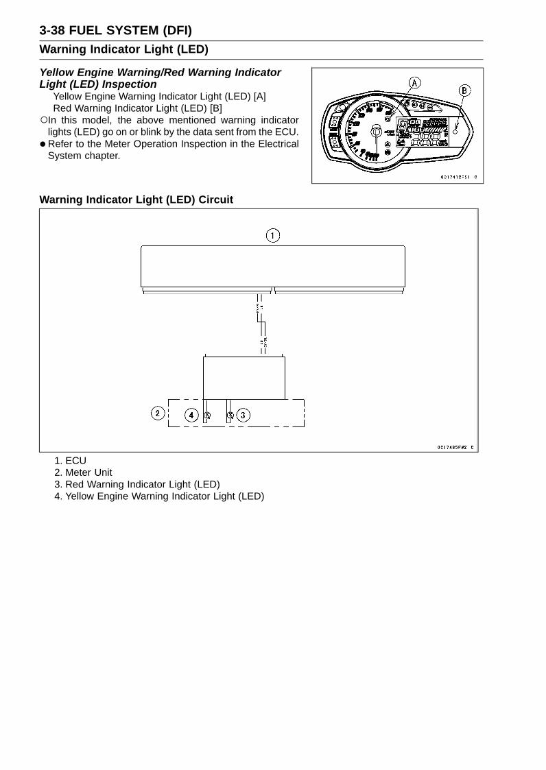
3-38 FUEL SYSTEM (DFI)Warning Indicator Light (LED)
Yellow Engine Warning/Red Warning IndicatorLight (LED) Inspection
Yellow Engine Warning Indicator Light (LED) [A]Red Warning Indicator Light (LED) [B]
In this model, the above mentioned warning indicatorlights (LED) go on or blink by the data sent from the ECU.
•Refer to the Meter Operation Inspection in the ElectricalSystem chapter.
Warning Indicator Light (LED) Circuit
1. ECU2. Meter Unit3. Red Warning Indicator Light (LED)4. Yellow Engine Warning Indicator Light (LED)

FUEL SYSTEM (DFI) 3-39ECU
ECU IdentificationMost countries have their own regulations, so each ECU
has different characteristic. So, do not confuse ECU witheach other and use only the ECU for your model. Other-wise, the motorcycle cannot clear the regulation.
ECU IdentificationPart Number [A] Specification
US, without Immobilizer21175-0810
CA, without ImmobilizerAU, with ImmobilizerID, with ImmobilizerWVTA (FULL H), with Immobilizer
21175-0811
GB WVTA (FULL H), with Immobilizer21175-0812 CAL, without Immobilizer21175-0813 SEA, with Immobilizer21175-0814 WVTA (78.2 H), with Immobilizer21175-0835 BR, with Immobilizer
ECU RemovalNOTICE
Never drop the ECU especially on a hard surface.Such a shock to the ECU can damage it.
•Remove the front seat cover (see Seat Cover Removal inthe Frame chapter).
• Remove the turn signal relay [A] from the rear fender.•Remove the relay box [B] from the rubber protector.
•Open the clamp [A].• Disconnect the ECU connectors [B].
• Remove:ECU [A] (with Rubber Protector [B])
Lift up the ECU with rubber protector to clear the projec-tions [C].

3-40 FUEL SYSTEM (DFI)ECU
•For GB WVTA (FULL H) and WVTA (78.2 H) models, notethe following.Using a small chisel or other suitable tool, remove the
screws [A].Remove:
Upper Guard [B]Lower Guard [C]
ECU Installation• Install:
ECU [A] (in Rubber Protector [B])Insert the slits of the rubber protector to the projections
[C] of the rear fender.
• For GB WVTA (FULL H) and WVTA (78.2 H) models, notethe following.Install:
Lower Guard [A]Upper Guard [B]
Tighten the new screws [C] using the Kawasaki genuinescrews of which threads are coated with locking agent.
• Connect the ECU connectors [A].• Hold the main harness to the clamp [B].
• Install:Relay Box [A]Turn Signal Relay [B]Front Seat Cover (see Seat Cover Installation in theFrame chapter)

FUEL SYSTEM (DFI) 3-41ECU
ECU Power Supply Inspection•Remove the front seat cover (see Seat Cover Removal in
the Frame chapter).• Visually inspect the ECU connectors.
If the connector is clogged with mud or dust, blow it offwith compressed air.
• Remove the ECU (see ECU Removal).• Visually inspect the terminals [A] of the ECU and main
harness connectors.If the terminals of the main harness connectors are dam-aged, replace the main harness.If the terminals of the ECU connectors are damaged, re-place the ECU.
• Turn the ignition switch off.• Disconnect the ECU connectors.
Gray Connector [A]• Set the hand tester [B] to the × 1 Ω range and check the
following wiring for continuity.Special Tool - Hand Tester: 57001-1394
ECU Grounding InspectionConnections:
(I) BK/Y leads (ECUterminal 39 or 65)BK/BL leads (ECUterminal 38)
←→ Battery (–) Terminal
(II) Engine Ground ←→ Battery (–) TerminalCriteria:
Both: 0 Ω
If no continuity, check the connectors, the engine groundlead, or main harness, and repair or replace them if nec-essary.

3-42 FUEL SYSTEM (DFI)ECU
If the wiring is good, check the power source voltage ofthe ECU.
NOTEBe sure the battery is fully charged.
•Connect the ECU connectors.•Connect a digital meter [A] to the connector (black) [B]
with the needle adapter set.Special Tool - Needle Adapter Set: 57001-1457
ECU Power Supply InspectionConnections:(I) Digital Meter (+) → Terminal 6 (BR/W)
Digital Meter (–) → Battery (–) terminal(II) Digital Meter (+) → Terminal 7 (W/BK)
Digital Meter (–) → Battery (–) terminalIgnition Switch OFF:
Terminal 6 (BR/W): 0 VTerminal 7 (W/BK): Battery Voltage
Ignition Switch ON:All: Battery Voltage
If the reading is out of the specification, check the follow-ing.Main Fuse 30 A (see Fuse Inspection in the ElectricalSystem chapter)ECU Fuse 15 A (see Fuse Inspection in the ElectricalSystem chapter)ECU Main Relay (see Relay Circuit Inspection in theElectrical System chapter)Power Source Wiring (see wiring diagram in this section)

FUEL SYSTEM (DFI) 3-43ECU
ECU Power Source Circuit
1. ECU2. Joint Connector C3. Frame Ground 24. Frame Ground 35. Frame Ground 16. Engine Ground7. Battery 12 V 8 Ah8. Starter Relay9. Main Fuse 30 A
10. ECU Fuse 15 A11. Relay Box12. ECU Main Relay13. Fuse Box 114. Ignition Fuse 15 A15. Joint Connector E16. Ignition Switch17. Joint Connector D

3-44 FUEL SYSTEM (DFI)CAN Communication Line
CAN Communication Line Resistance InspectionIn this model, resistors for CAN communication line are
built in the ECU [A] and meter unit.• Refer to the Meter Unit Inspection in the Electrical System
chapter for the resistor in the meter unit.• Turn the ignition switch off.• Remove:
ECU (see ECU Removal)
•Connect a digital meter [A] to the ECU connector (gray)[B].
•Measure the resistance of the CAN communication lineresistor.Special Tool - Hand Tester: 57001-1394
CAN Communication Line Resistance (at ECUConnector)
Connections: Terminal 36 ←→ Terminal 37Standard: 118 ∼ 122 Ω
If the reading is out of the range, replace the ECU (seeECU Removal/Installation).If the reading is within the range, resistor of the ECU forCAN communication line is normal.
• Check the wiring for continuity of the CAN communicationline (see wiring diagram in this section).Special Tool - Hand Tester: 57001-1394If the wiring is open, repair or replace the main harness.

FUEL SYSTEM (DFI) 3-45CAN Communication Line
CAN Communication Line Circuit
1. ECU2. KIBS Hydraulic Unit (Equipped Models)3. Meter Unit

3-46 FUEL SYSTEM (DFI)DFI Power Source
ECU Fuse Removal•Refer to the 30 A Main/15 A ECU Fuse Removal in the
Electrical System chapter.
ECU Fuse InstallationIf a fuse fails during operation, inspect the DFI system todetermine the cause, and then replace it with a new fuseof proper amperage.
•Refer to the Fuse Installation in the Electrical Systemchapter.
ECU Fuse Inspection•Refer to the Fuse Inspection in the Electrical System
chapter.
ECU Main Relay Removal/InstallationThe ECU main relay is built in the relay box [A].• Refer to the Relay Box Removal in the Electrical System
chapter.
ECU Main Relay Inspection•Refer to the Relay Circuit Inspection in the Electrical Sys-
tem chapter.

FUEL SYSTEM (DFI) 3-47Fuel Line
Fuel Pressure InspectionNOTE
Be sure the battery is fully charged.
•Remove:Fuel Tank Bolts [A]Fuel Hose (see Fuel Hose Replacement in the PeriodicMaintenance chapter)
Be sure to place a piece of cloth around the fuel outletpipe of the fuel pump and the delivery pipe of the throttlebody assy.
WARNINGFuel is flammable and explosive under certain con-ditions and can cause severe burns. Be preparedfor fuel spillage; any spilled fuel must be completelywiped up immediately. When the fuel hose is dis-connected, fuel spills out from the hose and thepipe because of residual pressure. Cover the hoseconnection with a piece of clean cloth to preventfuel spillage.
• Install the fuel pressure gauge adapter [A] and fuel hoses(Special Tool: 57001-1607) [B] between the fuel outletpipe and delivery pipe.
• Secure the fuel hoses with the clamps.•Connect the pressure gauge [C] to the fuel pressure
gauge adapter.Special Tools - Oil Pressure Gauge, 5 kgf/cm²: 57001-125
Fuel Pressure Gauge Adapter: 57001-1593Fuel Hose: 57001-1607
WARNINGFuel is extremely flammable and can be explosiveunder certain conditions resulting in serious injuryor death. Do not try to start the engine with the fuelhoses disconnected.
•Turn the engine stop switch run position.• Turn the ignition switch on.The fuel pump should operate for 3 seconds, and then
should stop.
NOTEAfter turning on the engine stop switch and ignition
switch, inspect the fuel leakage from the connectedportion of the special tools.
NOTICEDo not drive the fuel pump for 3 seconds or morewithout the fuel in the fuel tank. If the fuel pump isdriven without the fuel, it may be damaged.
•Start the engine, and let it idle.•Measure the fuel pressure with the engine idling.
Fuel Pressure (with Engine Idling)Standard: 294 kPa (3.0 kgf/cm², 43 psi)
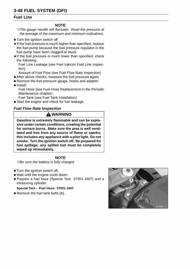
3-48 FUEL SYSTEM (DFI)Fuel Line
NOTEThe gauge needle will fluctuate. Read the pressure at
the average of the maximum and minimum indications.
•Turn the ignition switch off.If the fuel pressure is much higher than specified, replacethe fuel pump because the fuel pressure regulator in thefuel pump have been clogged or stuck.If the fuel pressure is much lower than specified, checkthe following.Fuel Line Leakage (see Fuel Injector Fuel Line Inspec-tion)Amount of Fuel Flow (see Fuel Flow Rate Inspection)
• After above checks, measure the fuel pressure again.•Remove the fuel pressure gauge, hoses and adapter.• Install:
Fuel Hose (see Fuel Hose Replacement in the PeriodicMaintenance chapter)Fuel Tank (see Fuel Tank Installation)
• Start the engine and check for fuel leakage.
Fuel Flow Rate InspectionWARNING
Gasoline is extremely flammable and can be explo-sive under certain conditions, creating the potentialfor serious burns. Make sure the area is well venti-lated and free from any source of flame or sparks;this includes any appliance with a pilot light. Do notsmoke. Turn the ignition switch off. Be prepared forfuel spillage; any spilled fuel must be completelywiped up immediately.
NOTEBe sure the battery is fully charged.
•Turn the ignition switch off.•Wait until the engine cools down.• Prepare a fuel hose (Special Tool: 57001-1607) and a
measuring cylinder.Special Tool - Fuel Hose: 57001-1607
•Remove the fuel tank bolts [A].

FUEL SYSTEM (DFI) 3-49Fuel Line
•Open the fuel tank cap [A] to lower the pressure in thetank.
•Remove the fuel hose from the fuel pump (see Fuel TankRemoval).Be sure to place a piece of cloth around the fuel outlet
pipe of the fuel pump.
WARNINGFuel is flammable and explosive under certain con-ditions and can cause severe burns. Be preparedfor fuel spillage; any spilled fuel must be completelywiped up immediately. When the fuel hose is dis-connected, fuel spills out from the hose and thepipe because of residual pressure. Cover the hoseconnection with a piece of clean cloth to preventfuel spillage.
•Connect the prepared fuel hose [A] to the fuel outlet pipe.• Secure the fuel hose with a clamp.• Insert the fuel hose into the measuring cylinder [B].
WARNINGWipe off spilled out fuel immediately.Be sure to hold the measuring cylinder vertical.
•Close the fuel tank cap.• Turn the engine stop switch to run position.• Turn the ignition switch on.The fuel pump should operate for 3 seconds, and then
should stop.
NOTICEDo not drive the fuel pump for 3 seconds or morewithout the fuel in the fuel tank. If the fuel pump isdriven without the fuel, it may be damaged.
•Measure the discharge for 3 seconds.Repeat this operation several times.
Amount of Fuel FlowStandard: 50 mL (1.7 US oz.) or more for 3 seconds
•Turn the ignition switch off.If the fuel flow is much less than the specified, replace thefuel pump (see Fuel Pump Removal/Installation).
• Install the fuel tank (see Fuel Tank Installation).• Start the engine and check for fuel leakage.

3-50 FUEL SYSTEM (DFI)Fuel Pump
Fuel Pump RemovalWARNING
Gasoline is extremely flammable and can be explo-sive under certain conditions, creating the potentialfor serious burns. Make sure the area is well venti-lated and free from any source of flame or sparks;this includes any appliance with a pilot light. Do notsmoke. Turn the ignition switch off. Disconnect thebattery (–) terminal. To avoid fuel spills, draw it fromthe tank when the engine is cold. Be prepared forfuel spillage; any spilled fuel must be completelywiped up immediately.
NOTICENever drop the fuel pump especially on a hard sur-face. Such a shock to the pump can damage it.
•Draw the fuel out from the fuel tank with a commerciallyavailable electric pump.
•Remove the fuel tank (see Fuel Tank Removal).Be careful of fuel spillage from the fuel tank since fuel still
remains in the fuel tank and fuel pump. Plug the fuel pipeof the fuel tank.
• Turn the fuel tank upside down.•Unscrew the fuel pump bolts [A], and take out the fuel
pump [B].
NOTICEDo not pull the leads of the fuel pump. If they arepulled, the lead terminals may be damaged.
•Discard the fuel pump gasket [A].

FUEL SYSTEM (DFI) 3-51Fuel Pump
Fuel Pump Installation•Remove dirt or dust from the fuel pump [A] by lightly ap-
plying compressed air.• Replace the fuel pump gasket with a new one.
•Check that the fuel pump terminal [A] and band [B] are inplace.
• Apply a non-permanent locking agent to the threads ofthe fuel pump bolts.
• Tighten the fuel pump bolts [C] to a snug fit.• Tighten the fuel pump bolts alternating diagonally.
Torque - Fuel Pump Bolts: 9.8 N·m (1.0 kgf·m, 87 in·lb)
•Tighten the fuel pump bolts again to check the tightness.
Fuel Pump Operation InspectionNOTE
Be sure the battery is fully charged.
•Turn the engine stop switch to run position.• Turn the ignition switch on and make sure that the fuel
pump operates (make light sounds) for 3 seconds, andthen stops.
• Turn the ignition switch off.If the pump does not operate as described above, checkthe operating voltage (see Fuel Pump Operating VoltageInspection).

3-52 FUEL SYSTEM (DFI)Fuel Pump
Fuel Pump Operating Voltage InspectionNOTE
Be sure the battery is fully charged.
•Turn the ignition switch off.• Remove the front seat (see Front Seat Removal in the
Frame chapter).• Disconnect the fuel pump lead connector and connect
the measuring adapter [A] between these connectors asshown.Main Harness [B]Fuel Pump [C]
Special Tool - Measuring Adapter: 57001-1700
•Connect a digital meter [D] to the measuring adapterleads.
Fuel Pump Operating VoltageConnections to Adapter:
Digital Meter (+) → R (pump BK/Y) leadDigital Meter (–) → BK (pump BK/W) lead
•Measure the operating voltage with engine stopped andwith the connector joined.
• Turn the engine stop switch run position.• Turn the ignition switch on.
Operating VoltageStandard: Battery Voltage for 3 seconds, and then 0 V
•Turn the ignition switch off.If the reading stays on battery voltage and never shows 0V, check the fuel pump relay (see Relay Circuit Inspectionin the Electrical System chapter).If the fuel pump relay is normal, check the ECU for itsground and power supply (see ECU Power Supply In-spection).If the ground and power supply are good, replace the ECU(see ECU Removal/Installation).If there is still no battery voltage, check the fuel pump re-lay (see Relay Circuit Inspection in the Electrical Systemchapter).If the fuel pump relay is normal, check the wiring for con-tinuity (see wiring diagram in this section).Special Tool - Hand Tester: 57001-1394If the wiring is good, check the ECU for its ground andpower supply (see ECU Power Supply Inspection).If the ground and power supply are good, replace the ECU(see ECU Removal/Installation).If the reading is in specification, but the pump does not op-erate, replace the fuel pump (see Fuel Pump Removal/In-stallation).

FUEL SYSTEM (DFI) 3-53Fuel Pump
Pressure Regulator RemovalThe pressure regulator [A] is built into the fuel pump and
can not be removed.
Fuel Filter CleaningThe fuel filter [A] is built into the fuel pump and can not be
cleaned or checked.If the fuel filter is suspected of clogging or being damaged,replace it with the fuel pump as a set.

3-54 FUEL SYSTEM (DFI)Fuel Pump
Fuel Pump Circuit
1. ECU2. Joint Connector C3. Frame Ground 24. Engine Ground5. Battery 12 V 8 Ah6. Stater Relay7. Main Fuse 30 A8. ECU Fuse 15 A9. Fuel Pump
10. Relay Box11. Fuel Pump Relay12. Fuse Box 113. Ignition Fuse 15 A14. Joint Connector E15. Ignition Switch16. Engine Stop Switch

FUEL SYSTEM (DFI) 3-55Fuel Injectors
Fuel Injector Removal/Installation•Refer to the Throttle Body Assy Disassembly/Assembly.
Fuel Injector Audible InspectionNOTE
Be sure the battery is fully charged.
•Remove:Fuel Tank (see Fuel Tank Removal)Fuel Hose (see Fuel Hose Replacement in the PeriodicMaintenance chapter)
•Connect the following parts temporarily.Fuel Pump Lead Connector [A]Extension Tube [B]
Special Tool - Extension Tube: 57001-1578
•Start the engine, and let it idle.• Apply the standard tip screwdriver [A] to the fuel injector
[B]. Put the grip end onto your ear, and listen whether thefuel injector is clicking or not.A sound scope can also be used.The click interval becomes shorter as the engine speed
rises.•Do the same for the other fuel injectors.
If all the fuel injectors click at a regular intervals, the fuelinjectors are normal.
• Turn the ignition switch off.If any fuel injector does not click, check the fuel injectorresistance (see Fuel Injector Resistance Inspection).
Fuel Injector Resistance Inspection•Remove:
Fuel Tank (see Fuel Tank Removal)•Disconnect:
Air Cleaner Dain Hose [A]Breather Hose [B]Fuel Injector Connector [C]
•Connect a digital meter to the terminals in each fuel injec-tor [A].
•Measure the fuel injector resistance.
Fuel Injector ResistanceStandard: About 11.7 ∼ 12.3 Ω at 20°C (68°F)
If the reading is out of the standard, replace the fuel in-jector.If the reading is within the standard, check the powersource voltage (see Fuel Injector Power Source VoltageInspection).
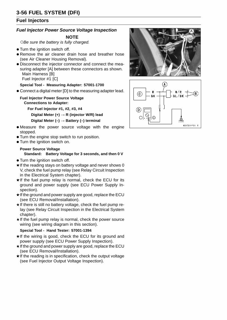
3-56 FUEL SYSTEM (DFI)Fuel Injectors
Fuel Injector Power Source Voltage InspectionNOTE
Be sure the battery is fully charged.
•Turn the ignition switch off.• Remove the air cleaner drain hose and breather hose
(see Air Cleaner Housing Removal).• Disconnect the injector connector and connect the mea-
suring adapter [A] between these connectors as shown.Main Harness [B]Fuel Injector #1 [C]
Special Tool - Measuring Adapter: 57001-1700
•Connect a digital meter [D] to the measuring adapter lead.
Fuel Injector Power Source VoltageConnections to Adapter:
For Fuel Injector #1, #2, #3, #4Digital Meter (+) → R (injector W/R) leadDigital Meter (–) → Battery (–) terminal
•Measure the power source voltage with the enginestopped.
• Turn the engine stop switch to run position.• Turn the ignition switch on.
Power Source VoltageStandard: Battery Voltage for 3 seconds, and then 0 V
•Turn the ignition switch off.If the reading stays on battery voltage and never shows 0V, check the fuel pump relay (see Relay Circuit Inspectionin the Electrical System chapter).If the fuel pump relay is normal, check the ECU for itsground and power supply (see ECU Power Supply In-spection).If the ground and power supply are good, replace the ECU(see ECU Removal/Installation).If there is still no battery voltage, check the fuel pump re-lay (see Relay Circuit Inspection in the Electrical Systemchapter).If the fuel pump relay is normal, check the power sourcewiring (see wiring diagram in this section).Special Tool - Hand Tester: 57001-1394If the wiring is good, check the ECU for its ground andpower supply (see ECU Power Supply Inspection).If the ground and power supply are good, replace the ECU(see ECU Removal/Installation).If the reading is in specification, check the output voltage(see Fuel Injector Output Voltage Inspection).

FUEL SYSTEM (DFI) 3-57Fuel Injectors
Fuel Injector Output Voltage InspectionNOTE
Be sure the battery is fully charged.
•Turn the ignition switch off.• Remove the ECU (see ECU Removal).Do not disconnect the ECU connector.• Connect a digital meter [A] to the connector [B] with the
needle adapter set.Special Tool - Needle Adapter Set: 57001-1457
Fuel Injector Output VoltageConnections to ECU Connector:
For Fuel Injector #1Digital Meter (+) → BL/BK lead (ECU terminal 42)Digital Meter (–) → Battery (–) terminal
For Fuel Injector #2Digital Meter (+) → BL/R lead (ECU terminal 41)Digital Meter (–) → Battery (–) terminal
For Fuel Injector #3Digital Meter (+) → BL/O lead (ECU terminal 40)Digital Meter (–) → Battery (–) terminal
For Fuel Injector #4Digital Meter (+) → BL/G lead (ECU terminal 54)Digital Meter (–) → Battery (–) terminal
•Measure the output voltage with the engine stopped andwith the connector joined.
• Turn the engine stop switch to run position.• Turn the ignition switch on.
Output VoltageStandard: Battery Voltage for 3 seconds, and then 0 V
•Turn the ignition switch off.If the reading is in specification, check the ECU for itsground and power supply (see ECU Power Supply In-spection).If the ground and power supply are good, replace the ECU(see ECU Removal/Installation).

3-58 FUEL SYSTEM (DFI)Fuel Injectors
If the reading is out of the specification, remove the ECUand check the wiring for continuity between main harnessconnectors.Special Tool - Hand Tester: 57001-1394Disconnect the ECU and injector connector.
Wiring Continuity InspectionECU Connector (Gray)[A] ←→ Fuel Injector Connector
[B]For Fuel Injector #1 [C]
BL/BK lead (ECU terminal 42) [D]For Fuel Injector #2
BL/R lead (ECU terminal 41)For Fuel Injector #3
BL/O lead (ECU terminal 40)For Fuel Injector #4
BL/G lead (ECU terminal 54)
If the wiring is good, check the ECU for its ground andpower supply (see ECU Power Supply Inspection).If the ground and power supply are good, replace the ECU(see ECU Removal/Installation).
Fuel Injector Fuel Line Inspection•Remove:
Fuel Tank (see Fuel Tank Removal)Fuel Hose (see Fuel Hose Replacement in the PeriodicMaintenance chapter)
Be sure to place a piece of cloth around the fuel outletpipe of the fuel pump and the delivery pipe of the throttlebody assy.
WARNINGFuel is flammable and explosive under certain con-ditions and can cause severe burns. Be preparedfor fuel spillage; any spilled fuel must be completelywiped up immediately. When the fuel hose is dis-connected, fuel spills out from the hose and thepipe because of residual pressure. Cover the hoseconnection with a piece of clean cloth to preventfuel spillage.
•Check the fuel injector line for leakage as follows.Connect a commercially available vacuum/pressure
pump [A] to the nipple of the delivery pipe [B] with thefuel hose [C] (both ends with the clamps [D]) as shown.Apply soap and water solution to the areas [E] as shown.Watching the pressure gauge, squeeze the pump lever,
and build up the pressure until the pressure reaches themaximum pressure.
Injector Fuel Line Maximum PressureStandard: 300 kPa (3.06 kgf/cm², 43 psi)
NOTICEDuring pressure testing, do not exceed the maxi-mum pressure for which the system is designed.

FUEL SYSTEM (DFI) 3-59Fuel Injectors
Watch the gauge for at least 6 seconds.If the pressure holds steady, the fuel line is good.If the pressure drops at once or if bubbles are found in thearea, the fuel line is leaking. Replace the delivery pipeassy, injectors and related parts.Repeat the leak test, and check the fuel line for no leak-
age.• Install:
Fuel Hose (see Fuel Hose Replacement in the PeriodicMaintenance chapter)Fuel Tank (see Fuel Tank Removal)
• Start the engine and check for fuel leakage.

3-60 FUEL SYSTEM (DFI)Fuel Injectors
Fuel Injector Circuit
1. ECU2. Joint Connector C3. Frame Ground 24. Engine Ground5. Battery 12 V 8 Ah6. Starter Relay7. Main Fuse 30 A8. ECU Fuse 15 A9. Relay Box
10. Fuel Pump Relay11. Fuse Box 112. Ignition Fuse 15 A13. Joint Connector E14. Ignition Switch15. Engine Stop Switch16. Fuel Injector #117. Fuel Injector #218. Fuel Injector #319. Fuel Injector #4

FUEL SYSTEM (DFI) 3-61Throttle Grip and Cables
Free Play Inspection•Refer to the Throttle Control System Inspection in the Pe-
riodic Maintenance chapter.
Free Play Adjustment•Refer to the Throttle Control System Inspection in the Pe-
riodic Maintenance chapter.
Cable Installation• Install the throttle cables in accordance with the Cable,
Wire, and Hose Routing section in the Appendix chapter.• Install the lower ends of the throttle cables in the throttle
pulley on the throttle body assy after installing the upperends of the throttle cables in the grip.
• After installation, adjust each cable properly (see ThrottleControl System Inspection in the Periodic Maintenancechapter).
WARNINGOperation with incorrectly routed or improperly ad-justed cables could result in an unsafe riding con-dition. Be sure the cables are routed correctly andproperly adjusted.
Cable Lubrication•Refer to the Chassis Parts Lubrication in the Periodic
Maintenance chapter.
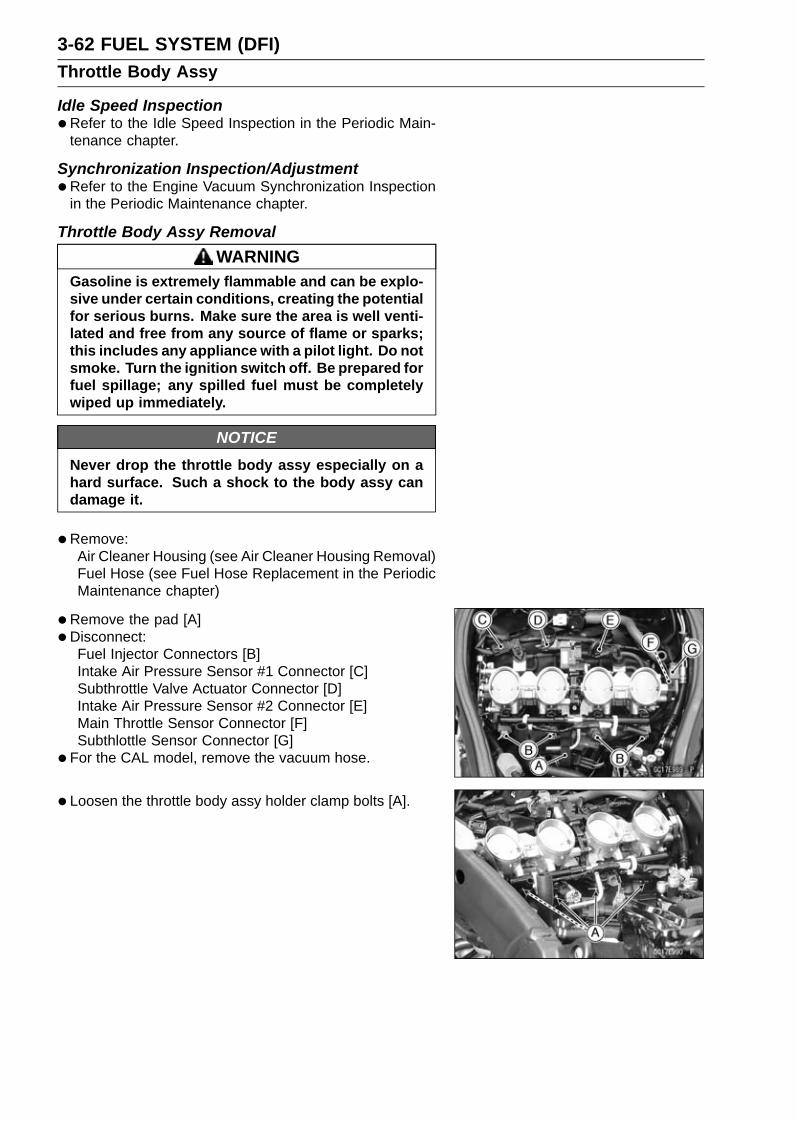
3-62 FUEL SYSTEM (DFI)Throttle Body Assy
Idle Speed Inspection•Refer to the Idle Speed Inspection in the Periodic Main-
tenance chapter.
Synchronization Inspection/Adjustment•Refer to the Engine Vacuum Synchronization Inspection
in the Periodic Maintenance chapter.
Throttle Body Assy RemovalWARNING
Gasoline is extremely flammable and can be explo-sive under certain conditions, creating the potentialfor serious burns. Make sure the area is well venti-lated and free from any source of flame or sparks;this includes any appliance with a pilot light. Do notsmoke. Turn the ignition switch off. Be prepared forfuel spillage; any spilled fuel must be completelywiped up immediately.
NOTICENever drop the throttle body assy especially on ahard surface. Such a shock to the body assy candamage it.
•Remove:Air Cleaner Housing (see Air Cleaner Housing Removal)Fuel Hose (see Fuel Hose Replacement in the PeriodicMaintenance chapter)
•Remove the pad [A]•Disconnect:
Fuel Injector Connectors [B]Intake Air Pressure Sensor #1 Connector [C]Subthrottle Valve Actuator Connector [D]Intake Air Pressure Sensor #2 Connector [E]Main Throttle Sensor Connector [F]Subthlottle Sensor Connector [G]
• For the CAL model, remove the vacuum hose.
• Loosen the throttle body assy holder clamp bolts [A].

FUEL SYSTEM (DFI) 3-63Throttle Body Assy
•Disconnect the adjusting screw [A] from the clamp.
•Remove the throttle body assy from the throttle body assyholders.
•Remove:Bolt [A]Holder Plate [B]Throttle Cable Lower Ends
•After removing the throttle body assy, stuff pieces of lint-free, clean cloth into the throttle body assy holders.
NOTICEIf dirt gets into the engine, excessive engine wearand possible engine damage will occur.
Throttle Body Assy Installation•Apply a thin coat of grease to the throttle cable lower ends.• Fit the accelerator cable end and the decelerator cable
end into the throttle pulley.• Install the holder plate [A] securely.• Apply a non-permanent locking agent to the threads of
the holder plate bolt [B], and tighten it.Torque - Throttle Cable Holder Plate Bolt: 3.9 N·m (0.40
kgf·m, 35 in·lb)
• Install the throttle body assy holder clamp, and tighten theclamp bolts (see Throttle Body Assy Holder Installation inthe Engine Top End chapter).
• Turn the throttle grip and make sure that the throttle pulleymoves smoothly and return by spring force.
•Run the leads and hoses correctly (see Cable, Wire, andHose Routing section in the Appendix chapter).
• Install the removed parts (see appropriate chapters).• Adjust:
Throttle Grip Free Play (see Throttle Control System In-spection in the Periodic Maintenance chapter)Idle Speed (see Idle Speed Adjustment in the PeriodicMaintenance chapter)

3-64 FUEL SYSTEM (DFI)Throttle Body Assy
Throttle Body Assy Disassembly
1. Throttle Body Assy2. Subthrottle Valve Actuator3. Main Throttle Sensor4. Subthrottle Sensor5. Fuel Injectors6. Delivery Pipe Assy7. Intake Air Pressure Sensor #18. Intake Air Pressure Sensor #2
NOTICEDo not remove, disassemble or adjust the mainthrottle sensor, subthrottle sensor, subthrottlevalve actuator, throttle link mechanism and throttlebody assy, because they are adjust or set surely atthe manufacturer. Adjustment of these parts couldresult in poor performance, requiring replacementof the throttle body assy.
•Remove the throttle body assy (see Throttle Body AssyRemoval).
• Remove the screws [A] to pull out the fuel injectors [B]from the throttle body assy together with the delivery pipeassy [C].
NOTEDo not damage the insertion portions of the injectors
when they are pulled out from the throttle body.
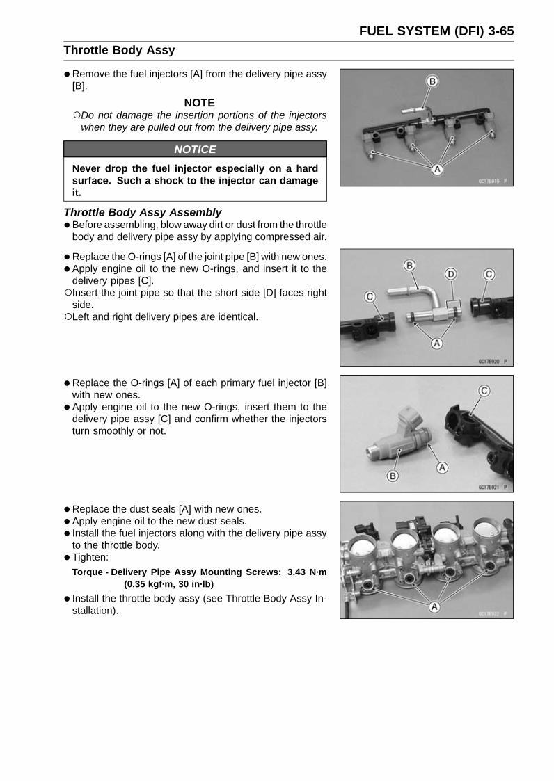
FUEL SYSTEM (DFI) 3-65Throttle Body Assy
•Remove the fuel injectors [A] from the delivery pipe assy[B].
NOTEDo not damage the insertion portions of the injectors
when they are pulled out from the delivery pipe assy.
NOTICENever drop the fuel injector especially on a hardsurface. Such a shock to the injector can damageit.
Throttle Body Assy Assembly•Before assembling, blow away dirt or dust from the throttle
body and delivery pipe assy by applying compressed air.
• Replace the O-rings [A] of the joint pipe [B] with new ones.• Apply engine oil to the new O-rings, and insert it to the
delivery pipes [C].Insert the joint pipe so that the short side [D] faces right
side.Left and right delivery pipes are identical.
• Replace the O-rings [A] of each primary fuel injector [B]with new ones.
• Apply engine oil to the new O-rings, insert them to thedelivery pipe assy [C] and confirm whether the injectorsturn smoothly or not.
• Replace the dust seals [A] with new ones.• Apply engine oil to the new dust seals.• Install the fuel injectors along with the delivery pipe assy
to the throttle body.• Tighten:
Torque - Delivery Pipe Assy Mounting Screws: 3.43 N·m(0.35 kgf·m, 30 in·lb)
• Install the throttle body assy (see Throttle Body Assy In-stallation).

3-66 FUEL SYSTEM (DFI)Air Cleaner
Air Cleaner Element Removal/Installation•Refer to the Air Cleaner Element Replacement in the Pe-
riodic Maintenance chapter.
Air Cleaner Element Inspection•Remove the air cleaner element (see Air Cleaner Element
Replacement in the Periodic Maintenance chapter).• Visually check the element [A] for tears or breaks.
If the element has any tears or breaks, replace the ele-ment.
Air Cleaner Oil DrainingA drain hose is connected to the bottom of the air cleaner
to drain water or oil accumulated in the cleaner part.• Remove the upper fairing assembly (see Upper Fairing
Assembly Removal in the Frame chapter).• Visually check the catch tank [A] of the drain hose, if the
water or oil accumulates in the tank.If any water or oil accumulates in the catch tank, removethe catch tank from the drain hose and drain it.
WARNINGOil on tires will make them slippery and can causean accident and injury. Be sure to reinstall the catchtank after draining.
Air Cleaner Housing Removal•Remove the fuel tank (see Fuel Tank Removal).• Free the lead from the clamp [A].• Disconnect the intake air temperature sensor lead con-
nector [B].• Remove the bolt [C].
• Disconnect:Air Cleaner Drain Hose [A]Breather Hose [B]

FUEL SYSTEM (DFI) 3-67Air Cleaner
• Loosen the air cleaner housing clamp bolt [A] on bothsides.
•Disconnect the air switching valve hose [A] from the aircleaner housing [B].
Air Cleaner Housing Installation• Install the clamp bolt heads [A] outside as shown.• Install the air switching valve hose to the air cleaner hous-
ing, so that white paint of the hose [B] is turned to the frontside rib.
• Install the air cleaner housing on the throttle body assy.Push in the ducts [C] touch the stopper [D] of the throttle
body.• Tighten:
Torque - Air Cleaner Housing Clamp Bolts: 2.0 N·m (0.20kgf·m, 18 in·lb)
•Run the leads and hoses correctly (see Cable, Wire, andHose Routing section in the Appendix chapter).
• Install the removed parts (see appropriate chapters).• Tighten the bolt [E] securely.

3-68 FUEL SYSTEM (DFI)Air Cleaner
Air Cleaner Housing Disassembly•Remove:
Air Cleaner Housing (see Air Cleaner Housing Removal)Intake Air Temperature Sensor (see Intake Air Temper-ature Sensor Removal/Installation in the Self-DiagnosisSystem chapter)Clamps [A]Ducts [B]Air Cleaner Element [C] (see Air Cleaner Element Re-placement in the Periodic Maintenance chapter)
Air Cleaner Housing Assembly• Install the ducts [A] to the air cleaner housing.Fit the projections [B] of the duct into the slits on the air
cleaner housing.Do not twist the ducts.
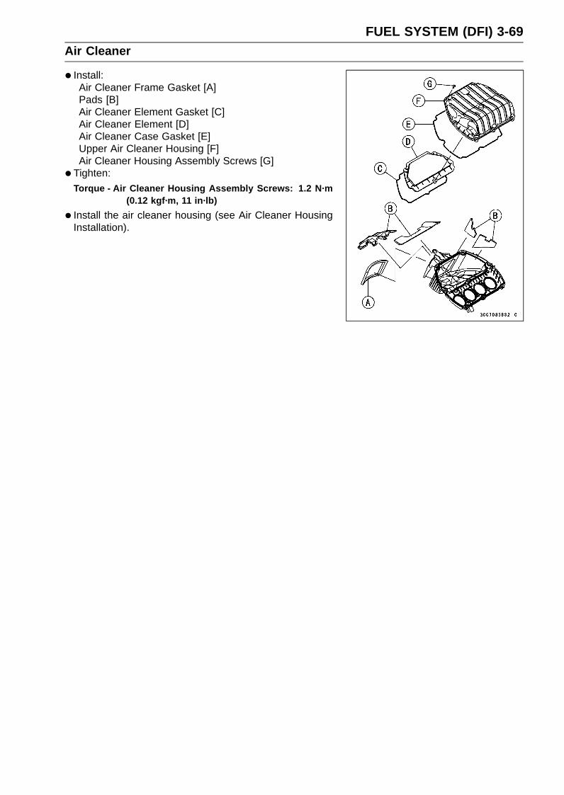
FUEL SYSTEM (DFI) 3-69Air Cleaner
• Install:Air Cleaner Frame Gasket [A]Pads [B]Air Cleaner Element Gasket [C]Air Cleaner Element [D]Air Cleaner Case Gasket [E]Upper Air Cleaner Housing [F]Air Cleaner Housing Assembly Screws [G]
• Tighten:Torque - Air Cleaner Housing Assembly Screws: 1.2 N·m
(0.12 kgf·m, 11 in·lb)
• Install the air cleaner housing (see Air Cleaner HousingInstallation).

3-70 FUEL SYSTEM (DFI)Air Line
Air Intake Duct Removal•Remove:
Upper Fairing Assembly (see Upper Fairing AssemblyRemoval in the Frame chapter)Meter Bracket (see Meter Unit Removal/Installation inthe Electrical System chapter)
• Free the leads [A].• Remove:
Air Intake Duct Mounting Bolts [B] (Both Sides)Air Intake Duct [C]
Air Intake Duct Installation•Check that the pad [A] is in place on the air intake duct.• Apply a non-permanent locking agent to the threads of
the air intake duct mounting bolts, and tighten them.Torque - Air Intake Duct Mounting Bolts: 9.8 N·m (1.0
kgf·m, 87 in·lb)
•Run the lead correctly (see Cable, Wire, and Hose Rout-ing section in the Appendix chapter).
• Install the removed parts (see appropriate chapters).
Air Intake Duct Disassembly•Remove:
Air Intake Duct (see Air Intake Duct Removal)Pad [A]Seal [B] and Screen [C]Air Intake Duct Assembly Screws [D]Holder [E]Pipe [F]

FUEL SYSTEM (DFI) 3-71Air Line
Air Intake Duct Assembly•Assembly is the reverse of disassembly.• Fit the projections [A] of the holder [B] to the hole of the
air intake ducts.• Tighten:
Torque - Air Intake Duct Assembly Screws: 1.5 N·m (0.15kgf·m, 13 in·lb)
• Install the pad so that the open side [A] faces downward.
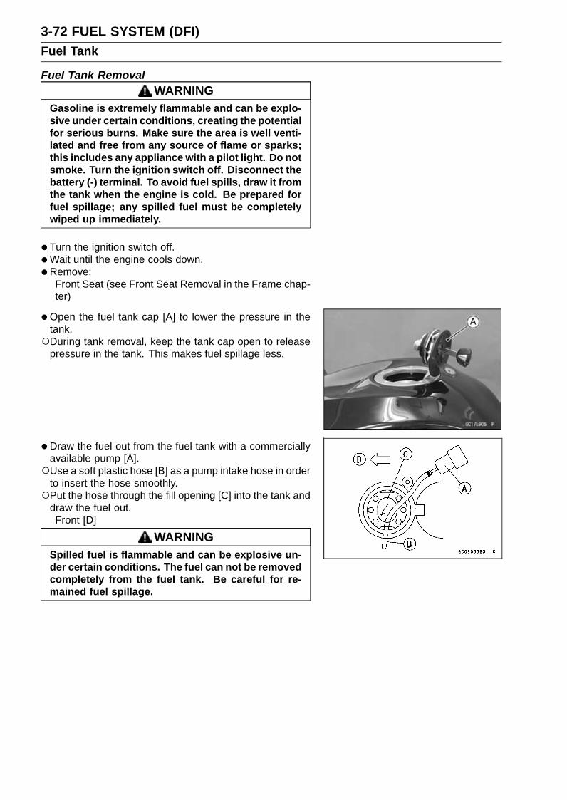
3-72 FUEL SYSTEM (DFI)Fuel Tank
Fuel Tank RemovalWARNING
Gasoline is extremely flammable and can be explo-sive under certain conditions, creating the potentialfor serious burns. Make sure the area is well venti-lated and free from any source of flame or sparks;this includes any appliance with a pilot light. Do notsmoke. Turn the ignition switch off. Disconnect thebattery (-) terminal. To avoid fuel spills, draw it fromthe tank when the engine is cold. Be prepared forfuel spillage; any spilled fuel must be completelywiped up immediately.
•Turn the ignition switch off.•Wait until the engine cools down.•Remove:
Front Seat (see Front Seat Removal in the Frame chap-ter)
•Open the fuel tank cap [A] to lower the pressure in thetank.During tank removal, keep the tank cap open to release
pressure in the tank. This makes fuel spillage less.
•Draw the fuel out from the fuel tank with a commerciallyavailable pump [A].Use a soft plastic hose [B] as a pump intake hose in order
to insert the hose smoothly.Put the hose through the fill opening [C] into the tank and
draw the fuel out.Front [D]
WARNINGSpilled fuel is flammable and can be explosive un-der certain conditions. The fuel can not be removedcompletely from the fuel tank. Be careful for re-mained fuel spillage.

FUEL SYSTEM (DFI) 3-73Fuel Tank
•Remove:Fuel Tank Bolts [A]
• Slide the dust cover [A].•Open the clamp [B].• Disconnect:
Battery (–) Terminal [C]Fuel Pump Lead Connector [D]Fuel Tank Drain Hose [E]Fuel Tank Breather Hose [F]
•Remove:Fuel Tank Bolt [G]
• Be sure to place a piece of cloth around the fuel hose joint.•Wipe off the dirt of the surface [A] around the connection
using a cloth or a soft brush.
When removing with standard tip screwdriver• Insert the standard tip screwdriver [A] into slit on the joint
lock [B].• Turn the driver to disconnect the joint lock.When removing with fingers•Open and push up [C] the joint lock with your fingers.
NOTICEPrying or excessively widening the joint lock endsfor fuel hose removal will permanently deform thejoint lock, resulting in a loose or incomplete lockthat may allow fuel to leak and create the potentialfor a fire explosion. To prevent fire or explosionfrom a damaged joint lock, do not pry or excessivelywiden the joint lock ends when removing the fuelhose. The joint lock has a retaining edge that locksaround the housing.

3-74 FUEL SYSTEM (DFI)Fuel Tank
•Pull the fuel hose joint [A] out of the outlet pipe.
WARNINGFuel is flammable and explosive under certain con-ditions and can cause severe burns. Be preparedfor fuel spillage; any spilled fuel must be completelywiped up immediately. When the fuel hose is dis-connected, fuel spills out from the hose and thepipe. Cover the hose connection with a clean shoptowel to prevent fuel spillage.
•Close the fuel tank cap.•Remove the fuel tank, and place a it on a flat surface.Do not apply the load to the fuel outlet pipe of the fuel
pump.
•Clean the pipe [A].• Cover the pipe and the hose joint [B] with the vinyl bags
[C] to keep it clean.
Fuel Tank Installation•Note the above WARNING (see Fuel Tank Removal).• Run the hoses correctly (see Cable, Wire, and Hose Rout-
ing section in the Appendix chapter).• Check that the dampers [A] and pad [B] are in place on
the frame and the fuel tank.If the dampers and pad are damaged or deteriorated, re-place them.

FUEL SYSTEM (DFI) 3-75Fuel Tank
•When installing the pad [A] and hooks [B], install them asshown.16 mm (0.63 in.) [C]View A [D]View B [E]
•Remove the vinyl bag on the pipe and fuel hose joint.• Check the joint lock for deformation and wear.
If the joint lock is deformed, replace the fuel hose with anew one.
•Check that there are no flaws, burrs, and adhesion offoreign materials on the delivery pipe [A].
• Apply engine oil to the pipe.
• Insert [A] the fuel hose joint [B] straight onto the fuel outletpipe until the hose joint clicks.
• Push [C] the joint lock [D] until the hose joint clicks.

3-76 FUEL SYSTEM (DFI)Fuel Tank
•Push and pull [A] the fuel hose joint [B] back and forthmore than two times, and make sure it is locked and doesnot come off.
WARNINGLeaking fuel can cause a fire or explosion resultingin serious burns. Make sure the hose joint is in-stalled correctly on the delivery pipe by sliding thejoint.
If it comes off, reinstall the hose joint.• Connect the fuel pump lead connector and the battery (–)
terminal (see Battery Installation in the Electrical Systemchapter).
• Installed removed parts (see appropriate chapters).
Fuel Tank and Cap Inspection•Visually inspect the gasket [A] on the tank cap for any
damage.Replace the gasket if it is damaged.
•Check to see if the water drain pipe [B] and fuel breatherpipe [C] in the tank are not clogged. Check the tank capbreather also.If they are clogged, remove the tank and drain it, and thenblow the breather free with compressed air.
NOTICEDo not apply compressed air to the air vent holes[D] in the tank cap. This could cause damage andclogging of the labyrinth in the cap.
Fuel Tank CleaningWARNING
Gasoline and low flash-point solvents can beflammable and/or explosive and cause severeburns. Clean the tank in a well-ventilated area, andtake care that there are no sparks or flame any-where near the working area. Do not use gasolineor low flash-point solvents to clean the tank.
•Remove:Fuel Tank (see Fuel Tank Removal)Fuel Pump (see Fuel Pump Removal)
• Pour some high flash-point solvent into the fuel tank andshake the tank to remove dirt and fuel deposits.
• Draw the solvent out of the fuel tank.•Dry the tank with compressed air.• Install:
Fuel Pump (see Fuel Pump Installation)Fuel Tank (see Fuel Tank Installation)

FUEL SYSTEM (DFI) 3-77Evaporative Emission Control System (CAL Model)
The Evaporative Emission Control System routes fuel va-pors from the fuel system into the running engine or storesthe vapors in a canister when the engine is stopped. Al-though no adjustments are required, a thorough visual in-spection must be made at the intervals specified by the Pe-riodic Maintenance Chart.
Parts Removal/InstallationWARNING
Gasoline is extremely flammable and can be ex-plosive under certain conditions. Turn the ignitionswitch off. Do not smoke. Make sure the area iswell ventilated and free from any source of flameor sparks; this includes any appliance with a pilotlight.
NOTICEIf gasoline, solvent, water or any other liquid entersthe canister, the canister’s vapor absorbing capac-ity is greatly reduced. If the canister does becomecontaminated, replace it with a new one.
•Connect the hoses according to the diagram of the sys-tem (see Cable, Wire, and Hose Routing section in theAppendix chapter). Make sure they do not get pinched orkinked.
Hose Inspection•Refer to the Evaporative Emission Control System In-
spection (CAL Model) in the Periodic Maintenance chap-ter.
Purge Valve Inspection•Refer to the Purge Valve Inspection in the Self-Diagnosis
System chapter.
Canister Inspection•Refer to the Evaporative Emission Control System In-
spection (CAL Model) in the Periodic Maintenance chap-ter.


COOLING SYSTEM 4-1
4
Cooling SystemTable of Contents
Exploded View........................................................................................................................ 4-2Coolant Flow Chart................................................................................................................. 4-4Specifications ......................................................................................................................... 4-6Special Tools and Sealant ...................................................................................................... 4-7Coolant ................................................................................................................................... 4-8
Coolant Deterioration Inspection....................................................................................... 4-8Coolant Level Inspection................................................................................................... 4-8Coolant Draining ............................................................................................................... 4-8Coolant Filling ................................................................................................................... 4-8Pressure Testing ............................................................................................................... 4-8Cooling System Flushing .................................................................................................. 4-9Coolant Reserve Tank Removal ....................................................................................... 4-9Coolant Reserve Tank Installation .................................................................................... 4-9
Water Pump............................................................................................................................ 4-10Water Pump Removal....................................................................................................... 4-10Water Pump Installation.................................................................................................... 4-10Water Pump Inspection..................................................................................................... 4-10Water Pump Impeller Disassembly/Assembly .................................................................. 4-10Water Pump Impeller Inspection....................................................................................... 4-10Water Pump Housing Disassembly .................................................................................. 4-10Water Pump Housing Assembly ....................................................................................... 4-11Mechanical Seal Inspection .............................................................................................. 4-11
Radiator .................................................................................................................................. 4-12Radiator and Radiator Fan Removal ................................................................................ 4-12Radiator and Radiator Fan Installation ............................................................................. 4-13Radiator Inspection ........................................................................................................... 4-13Radiator Cap Inspection ................................................................................................... 4-14Radiator Filler Neck Inspection ......................................................................................... 4-14Heat Insulation Plate Removal.......................................................................................... 4-15Heat Insulation Plate Installation....................................................................................... 4-15
Thermostat ............................................................................................................................. 4-16Thermostat Removal......................................................................................................... 4-16Thermostat Installation...................................................................................................... 4-16Thermostat Inspection ...................................................................................................... 4-16
Hoses and Pipes .................................................................................................................... 4-18Hose Installation ............................................................................................................... 4-18Hose Inspection ................................................................................................................ 4-18
Water Temperature Sensor .................................................................................................... 4-19Water Temperature Sensor Removal/Installation ............................................................. 4-19Water Temperature Sensor Inspection ............................................................................. 4-19

4-2 COOLING SYSTEMExploded View

COOLING SYSTEM 4-3Exploded View
TorqueNo. Fastener
N·m kgf·m ft·lbRemarks
1 Heat Insulation Plate Bolt 3.9 0.40 35 in·lb L2 Radiator Upper Bolts 9.8 1.0 87 in·lb3 Coolant By-pass Fitting Bolt 8.8 0.90 78 in·lb L4 Water Hose Clamp Screws 3.0 0.31 27 in·lb5 Oil Cooler Mounting Bolts 20 2.0 156 Water Temperature Sensor 12 1.2 106 in·lb7 Thermostat Housing Cover Bolts 5.9 0.60 52 in·lb8 Coolant Drain Bolt (Cylinder) 9.8 1.0 87 in·lb9 Water Hose Fitting Bolts 9.8 1.0 87 in·lb
10 Water Pump Cover Bolts 12 1.2 106 in·lb L11 Coolant Drain Bolt (Water Pump) 8.8 0.90 78 in·lb12 Impeller Bolt 9.8 1.0 87 in·lb13. ZX636E Model
HG: Apply high-temperature grease.L: Apply a non-permanent locking agent.
LG: Apply liquid gasket.R: Replacement PartsW: Apply water.

4-4 COOLING SYSTEMCoolant Flow Chart
1. Radiator2. Radiator Fan3. Radiator Cap4. Radiator Overflow Hose5. Reserve Tank Overflow Hose6. Reserve Tank7. Air Bleeder Hose8. Oil Cooler Intake Hose9. Oil Cooler
10. Water Pump11. Cylinder Jacket12. Oil Cooler Outlet Hose13. Cylinder Head Jacket14. Hot Coolant15. Cold Coolant

COOLING SYSTEM 4-5Coolant Flow Chart
Permanent type antifreeze is used as a coolant to protect the cooling system from rust and corrosion.When the engine starts, the water pump turns and the coolant circulates.
The thermostat is a wax pellet type which opens or closes with coolant temperature changes. Thethermostat continuously changes its valve opening to keep the coolant temperature at the proper level.When coolant temperature is less than 55°C (131°F), the thermostat closes so that the coolant flowis restricted through the air bleeder hole, causing the engine to warm up more quickly. When coolanttemperature is more than 58 ∼ 62°C (136 ∼ 144°F), the thermostat opens and the coolant flows.
When the coolant temperature goes up beyond 100°C (212°F), the radiator fan relay conducts tooperate the radiator fan. The radiator fan draws air through the radiator core when there is not suffi-cient air flow such as at low speeds. This increases up the cooling action of the radiator. When thecoolant temperature is below 97.5°C (208°F), the fan relay opens and the radiator fan stops.
In this way, this system controls the engine temperature within narrow limits where the engine op-erates most efficiently even if the engine load varies.
The system is pressurized by the radiator cap to suppress boiling and the resultant air bubbleswhich can cause engine overheating. As the engine warms up, the coolant in the radiator and thewater jacket expands. The excess coolant flows through the radiator cap and hose to the reserve tankto be stored there temporarily. Conversely, as the engine cools down, the coolant in the radiator andthe water jacket contracts, and the stored coolant flows back to the radiator from the reserve tank.
The radiator cap has two valves. One is a pressure valve which holds the pressure in the systemwhen the engine is running. When the pressure exceeds 93 ∼ 123 kPa (0.95 ∼ 1.25 kgf/cm², 13 ∼ 18psi), the pressure valve opens and releases the pressure to the reserve tank. As soon as pressureescapes, the valve closes, and keeps the pressure at 93 ∼ 123 kPa (0.95 ∼ 1.25 kgf/cm², 13 ∼ 18 psi).When the engine cools down, another small valve (vacuum valve) in the cap opens. As the coolantcools, the coolant contracts to form a vacuum in the system. The vacuum valve opens and allows thecoolant from the reserve tank to enter the radiator.
4-6 COOLING SYSTEMSpecifications
Item StandardCoolant Provided when Shipping
Type (Recommended) Permanent type of antifreeze (soft water and ethyleneglycol plus corrosion and rust inhibitor chemicals foraluminum engines and radiators)
Color GreenMixed Ratio Soft water 50%, coolant 50%Freezing Point –35°C (–31°F)Total Amount 2.5 L (2.6 US qt) (Reserve tank full level, including
radiator and engine)Radiator Cap
Relief Pressure 93 ∼ 123 kPa (0.95 ∼ 1.25 kgf/cm², 13 ∼ 18 psi)Thermostat
Valve Opening Temperature 58 ∼ 62°C (136 ∼ 144°F)Valve Full Opening Lift 8 mm (0.31 in.) or more at 75°C (167°F)
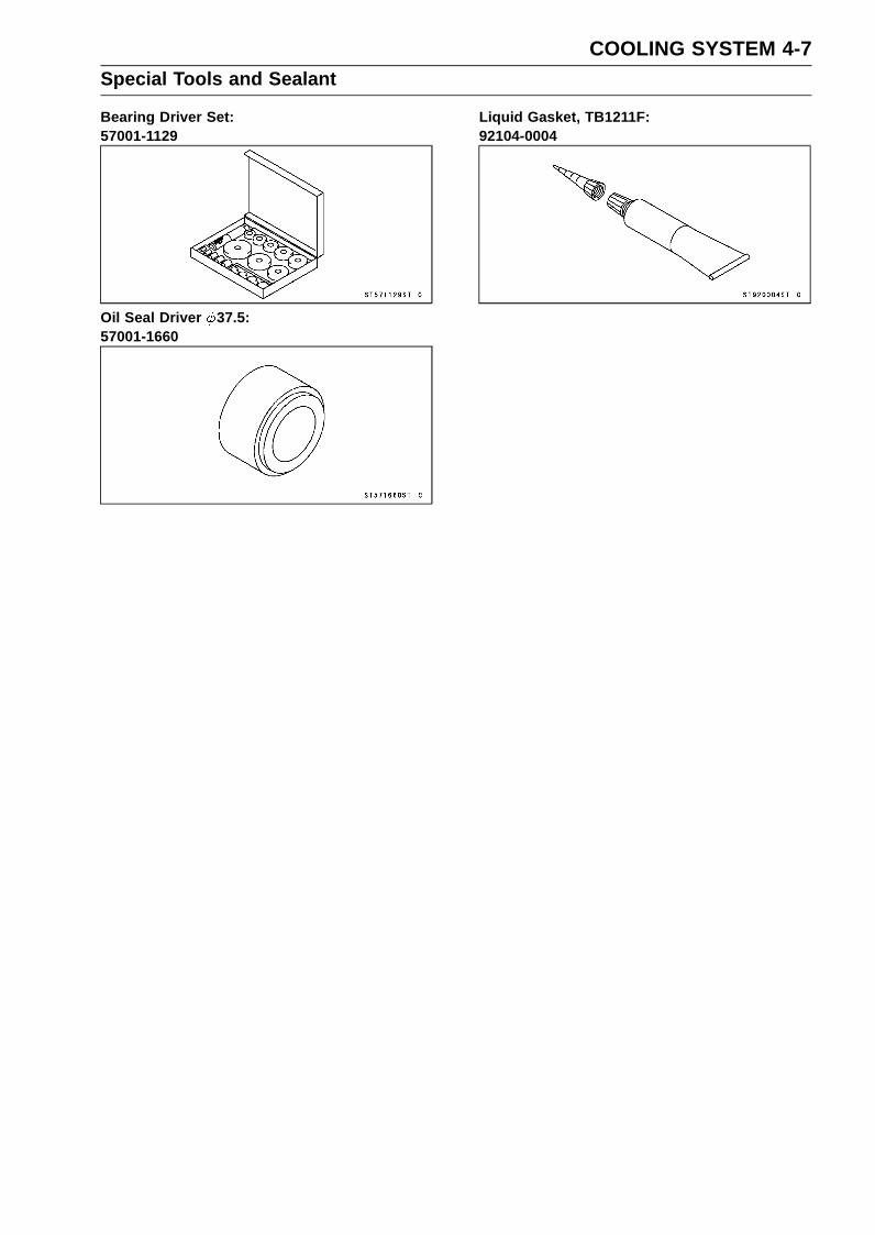
COOLING SYSTEM 4-7Special Tools and Sealant
Bearing Driver Set:57001-1129
Oil Seal Driver 37.5:57001-1660
Liquid Gasket, TB1211F:92104-0004

4-8 COOLING SYSTEMCoolant
Coolant Deterioration Inspection•Remove the upper fairing assembly (see Upper Fairing
Assembly Removal in the Frame chapter).• Visually inspect the coolant in the reserve tank [A].
If whitish cotton-like wafts are observed, aluminum partsin the cooling system are corroded. If the coolant isbrown, iron or steel parts are rusting. In either case, flushthe cooling system.If the coolant gives off an abnormal smell, check for acooling system leak. It may be caused by exhaust gasleaking into the cooling system.
Coolant Level Inspection•Refer to the Coolant Level Inspection in the Periodic Main-
tenance chapter.
Coolant Draining•Refer to the Coolant Change in the Periodic Maintenance
chapter.
Coolant Filling•Refer to the Coolant Change in the Periodic Maintenance
chapter.
Pressure Testing•Remove:
Upper Fairing Assembly (see Upper Fairing AssemblyRemoval in the Frame chapter)Radiator Cap [A]
Remove the radiator cap in two steps. First turn the capcounterclockwise to the first stop. Then push and turn itfurther in the same direction and remove the cap.
• Install the cooling system pressure tester [A] on the fillerneck.
NOTEWet the cap sealing surfaces with water or coolant to
prevent pressure leaks.
•Build up pressure in the system carefully until the pres-sure reaches 123 kPa (1.25 kgf/cm², 18 psi).
NOTICEDuring pressure testing, do not exceed the pres-sure for which the system is designed. The maxi-mum pressure is 123 kPa (1.25 kgf/cm², 18 psi).
•Watch the gauge for at least 6 seconds.If the pressure holds steady, the system is all right.If the pressure drops and no external source is found,check for internal leaks. Droplets in the engine oil indicateinternal leakage. Check the cylinder head gasket and thewater pump.
•Remove the pressure tester, replenish the coolant, andinstall the radiator cap.
• Install the upper fairing assembly (see Upper Fairing As-sembly Installation in the Frame chapter).

COOLING SYSTEM 4-9Coolant
Cooling System FlushingOver a period of time, the cooling system accumulates
rust, scale, and lime in the water jacket and radiator. Whenthis accumulation is suspected or observed, flush the cool-ing system. If this accumulation is not removed, it will clogup the water passage and considerable reduce the effi-ciency of the cooling system.•Drain the cooling system (see Coolant Change in the Pe-
riodic Maintenance chapter).• Fill the cooling system with fresh water mixed with a flush-
ing compound.
NOTICEDo not use a flushing compound which is harmful tothe aluminum engine and radiator. Carefully followthe instructions supplied by the manufacturer of thecleaning product.
•Warm up the engine, and run it at normal operating tem-perature for about ten minutes.
• Stop the engine, and drain the cooling system.• Fill the system with fresh water.•Warm up the engine and drain the system.•Repeat the previous two steps once more.• Fill the system with a permanent type coolant and bleed
the air from the system (see Coolant Change in the Peri-odic Maintenance chapter).
Coolant Reserve Tank Removal•Remove:
Upper Fairing Assembly (see Upper Fairing AssemblyRemoval in the Frame chapter)Bolt [A]
•Remove the cap [B] and poor the coolant into a container.• Remove:
Radiator Overflow Hose [C]Reserve Tank Overflow Hose [D]Coolant Reserve Tank [E]
Coolant Reserve Tank Installation• Install the following to the coolant reserve tank [A].
Gasket [B]Cap [C]Collar [D]
• Install the coolant reserve tank and tighten the bolt [E].• Run the hoses correctly (see Cable, Wire, and Hose Rout-
ing section in the Appendix chapter).• Fill the coolant reserve tank with coolant (see Coolant
Change in the Periodic Maintenance chapter).

4-10 COOLING SYSTEMWater Pump
Water Pump Removal•Refer to the Oil Pump Removal in the Engine Lubrication
System chapter.
Water Pump Installation•Refer to the Oil Pump Installation in the Engine Lubrica-
tion System chapter.
Water Pump Inspection•Remove the left lower fairing (see Lower Fairing Removal
in the Frame chapter).• Check the drainage outlet passage [A] at the bottom of
the water pump body for coolant leaks.If the mechanical seal is damaged, the coolant leaksthrough the seal and drains through the passage. Re-place the mechanical seal unit (see Water Pump HousingDisassembly/Assembly).
Water Pump Impeller Disassembly/Assembly•Remove the water pump impeller (see Oil Pump Removal
in the Engine Lubrication System chapter).• The sealing seat [A] and rubber seal [B] may be removed
easily by hand.• Apply water around the surfaces of the rubber seal and
sealing seat.• Install the rubber seal and sealing seat into the impeller by
pressing them by hand until the seat stops at the bottomof the hole.
• Install the water pump impeller (see Oil Pump Installationin the Engine Lubrication System chapter).
Water Pump Impeller Inspection•Remove the water pump cover (see Oil Pump Removal
in the Engine Lubrication System chapter).• Visually inspect the impeller [A].
If the surface is corroded or if the blades are damaged,replace the impeller.
Water Pump Housing DisassemblyNOTICE
Do not damage the hole wall of the water pumphousing.
• Insert a bar [A] into the pump housing [B], and hammerevenly around the circumference of the mechanical sealbottom [C].

COOLING SYSTEM 4-11Water Pump
•Take the oil seal [A] out of the housing [B] with a hook [C].
Water Pump Housing AssemblyNOTICE
Do not reuse the mechanical seal and oil seal.
•Apply high-temperature grease to the oil seal lips [A].• Press the new oil seal into the housing with a bearing
driver [B] until it stops at the bottom surface [C] of thehousing.Special Tool - Bearing Driver Set: 57001-1129
NOTICEBe careful not to damage the sealing surface of themechanical seal.
•Press the new mechanical seal into the housing with theoil seal driver [A] until its flange [B] touches the surface[C] of the housing.Special Tool - Oil Seal Driver 37.5: 57001-1660
Mechanical Seal Inspection•Remove the impeller (see Oil Pump Removal in the En-
gine Lubrication System chapter).• Visually inspect the mechanical seal.
If any one of the parts is damaged, replace the mechani-cal seal as a unit.Impeller Sealing Seat Surface [A]Rubber Seal [B]Mechanical Seal [C]

4-12 COOLING SYSTEMRadiator
Radiator and Radiator Fan Removal•Drain:
Coolant (see Coolant Change in the Periodic Mainte-nance chapter)
•Remove:Air Cleaner Housing (see Air Cleaner Housing Removalin the Fuel System (DFI) chapter)Coolant Reserve Tank (see Coolant Reserve Tank Re-moval)
• Slide the dust cover [A].•Open the clamp [B].• Disconnect the radiator fan motor lead connector [C].
• Loosen the water hose clamp screw [A].• Disconnect the water hose [B].• Remove:
CapRadiator Upper Bolt (Left) [C] and Horn
• Loosen the water hose clamp screw [A].• Disconnect:
Water Hose [B]Air Bleeder Hose [C]
•Remove:Radiator Lower Bolt [D]Cap (ZX636E Model)Radiator Upper Bolt (Right) [E]Radiator [F]
NOTICEDo not touch the radiator core. This could damagethe radiator fins, resulting in loss of cooling effi-ciency.
•Remove:Radiator Fan Mounting Bolts [A]Radiator Fan [B]

COOLING SYSTEM 4-13Radiator
Radiator and Radiator Fan InstallationIf the radiator bracket [A] was removed, install it.
• Install the radiator fan to the radiator.• Tighten the radiator fan mounting bolts.•When installing the pads [B], install it so that the corners
[C] align.•Run the radiator fan motor lead correctly (see Cable,
Wire, and Hose Routing section in the Appendix chapter).• Install the rubber dampers [D] and collars [E] as shown.Face the small diameter side of the damper to the collar.• Install the horn [F].• Tighten:
Torque - Radiator Upper Bolts [G]: 9.8 N·m (1.0 kgf·m, 87in·lb)
•Tighten the radiator lower bolt [H].• Install the caps [I].
ZX636E Model [J]
• Install the hoses and clamps (see Cable, Wire, and HoseRouting section in the Appendix chapter).
• Tighten:Torque - Water Hose Clamp Screws: 3.0 N·m (0.31 kgf·m,
27 in·lb)
• Install the removed parts (see appropriate chapters).
Radiator Inspection•Remove the radiator (see Radiator and Radiator Fan Re-
moval).• Check the radiator core.
If there are obstructions to air flow, remove them.If the corrugated fins [A] are deformed, carefullystraighten them.If the air passages of the radiator core are blocked morethan 20% by unremovable obstructions or irreparably de-formed fins, replace the radiator with a new one.

4-14 COOLING SYSTEMRadiator
NOTICEWhen cleaning the radiator with steam cleaner, becareful of the following to prevent radiator damage:Keep the steam gun [A] away more than 0.5 m (1.6ft) [B] from the radiator core.Hold the steam gun perpendicular [C] (not oblique[D]) to the core surface.Run the steam gun, following the core fin direction.
Radiator Cap Inspection•Remove:
Upper Fairing Assembly (see Upper Fairing AssemblyRemoval in the Frame chapter)Radiator Cap
•Check the condition of the bottom [A] and top [B] valveseals and valve spring [C].If any one of them shows visible damage, replace the capwith a new one.
• Install the cap [A] on a cooling system pressure tester [B].
NOTEWet the cap sealing surfaces with water or coolant to
prevent pressure leaks.
•Watching the pressure gauge, pump the pressure testerto build up the pressure until the relief valve opens: thegauge needle flicks downward. Stop pumping and mea-sure leak time at once. The relief valve must open withinthe specified range in the table below and the gauge handmust remain within the same range at least 6 seconds.
Radiator Cap Relief PressureStandard: 93 ∼ 123 kPa (0.95 ∼ 1.25 kgf/cm², 13 ∼ 18
psi)
If the cap can not hold the specified pressure or if it holdstoo much pressure, replace it with a new one.
Radiator Filler Neck Inspection•Remove:
Upper Fairing Assembly (see Upper Fairing AssemblyRemoval in the Frame chapter)Radiator Cap
•Check the radiator filler neck for signs of damage.•Check the condition of the top and bottom sealing seats
[A] in the filler neck. They must be smooth and clean forthe radiator cap to function properly.

COOLING SYSTEM 4-15Radiator
Heat Insulation Plate Removal•Remove:
Radiator (see Radiator and Radiator Fan Removal)•Open the clamps [A].
•Open the clamp [A].• Free the lead from the clamp [B].
• Free the right switch housing lead and front wheel rotationsensor lead from the clamp on the right side of the heatinsulation plate.
•Remove:Heat Insulation Plate Bolt [A]Heat Insulation Plate [B]
Clear the projections [C] from the frame.
Heat Insulation Plate Installation• Installation is the reverse of removal.• Apply a non-permanent locking agent to the threads of
the heat insulation plate bolt and tighten it.Torque - Heat insulation Plate Bolt: 3.9 N·m (0.40 kgf·m, 35
in·lb)
•Run the leads correctly (see Cable, Wire, and Hose Rout-ing section in the Appendix chapter).

4-16 COOLING SYSTEMThermostat
Thermostat Removal•Remove the oil cooler (see Oil Cooler Removal in the En-
gine Lubrication System chapter)• Loosen the water hose clamp screw [A].• Disconnect the water hose [B].• Remove:
Thermostat Housing Cover Bolts [C]Thermostat Housing Cover [D]Thermostat
Thermostat Installation• Install the thermostat [A] in the housing so that the air
bleeder hole [B] is on top.
•Replace the O-ring [A] with a new one.• Apply liquid gasket to any three positions of the new O
-ring to prevent it from coming off.Sealant - Liquid Gasket, TB1211F: 92104-0004
• Install a new O-ring into the thermostat housing cover [B].• Tighten:
Torque - Thermostat Housing Cover Bolts [C]: 5.9 N·m(0.60 kgf·m, 52 in·lb)
•Confirm that the thermostat is installed correctly.• Install the water hose and tighten the clamp (see Cable,
Wire, and Hose Routing section in the Appendix chapter).Torque - Water Hose Clamp Screw: 3.0 N·m (0.31 kgf·m, 27
in·lb)
• Install the removed parts (see appropriate chapters).
Thermostat Inspection•Remove the thermostat (see Thermostat Removal).• Inspect the thermostat valve [A] at room temperature.
If the valve is open, replace the thermostat with a newone.
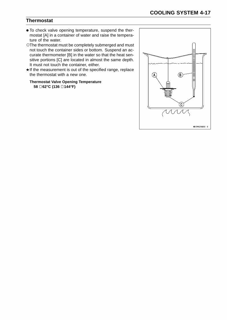
COOLING SYSTEM 4-17Thermostat
•To check valve opening temperature, suspend the ther-mostat [A] in a container of water and raise the tempera-ture of the water.The thermostat must be completely submerged and must
not touch the container sides or bottom. Suspend an ac-curate thermometer [B] in the water so that the heat sen-sitive portions [C] are located in almost the same depth.It must not touch the container, either.If the measurement is out of the specified range, replacethe thermostat with a new one.
Thermostat Valve Opening Temperature58 ∼ 62°C (136 ∼ 144°F)

4-18 COOLING SYSTEMHoses and Pipes
Hose Installation• Install the hoses and pipes, being careful to follow bend-
ing direction. Avoid sharp bending, kinking, flattening ortwisting.
•Run the hoses (see Cable, Wire, and Hose Routing sec-tion in the Appendix chapter).
• Install the clamp [A] as near as possible to the hose endto clear the raised rib of the fitting. This will prevent thehoses from working loose.The clamp screws should be positioned correctly to pre-
vent the clamps from contacting the other parts.• Tighten:
Torque - Water Hose Clamp Screws: 3.0 N·m (0.31 kgf·m,27 in·lb)
Hose Inspection•Refer to the Radiator Hose and Pipe Inspection in the
Periodic Maintenance chapter.

COOLING SYSTEM 4-19Water Temperature Sensor
Water Temperature Sensor Removal/Installation•Refer to the Water Temperature Sensor Removal/Instal-
lation in the Self-Diagnosis System chapter.
Water Temperature Sensor Inspection•Refer to the Water Temperature Sensor Inspection in the
Electrical System chapter.


ENGINE TOP END 5-1
5
Engine Top EndTable of Contents
Exploded View................................... 5-2Exhaust System Identification ........... 5-6Specifications .................................... 5-8Special Tools and Sealant ................. 5-9Clean Air System............................... 5-11
Air Suction Valve Removal........... 5-11Air Suction Valve Installation........ 5-11Air Suction Valve Inspection ........ 5-12Air Switching Valve Removal ....... 5-12Air Switching Valve Installation .... 5-12Air Switching Valve Operation
Test............................................ 5-13Air Switching Valve Unit Test ....... 5-13Clean Air System Hose
Inspection.................................. 5-13Cylinder Head Cover ......................... 5-14
Cylinder Head Cover Removal .... 5-14Cylinder Head Cover Installation . 5-14
Camshaft Chain Tensioner ................ 5-16Camshaft Chain Tensioner
Removal .................................... 5-16Camshaft Chain Tensioner
Installation ................................. 5-17Camshaft, Camshaft Chain ............... 5-18
Camshaft Removal ...................... 5-18Camshaft Installation ................... 5-19Camshaft, Camshaft Cap Wear
Inspection.................................. 5-23Camshaft Runout Inspection........ 5-24Cam Wear Inspection .................. 5-24Camshaft Chain Removal ............ 5-24
Cylinder Head.................................... 5-25
Cylinder CompressionMeasurement ............................ 5-25
Cylinder Head Removal ............... 5-26Cylinder Head Installation ............ 5-26Cylinder Head Warp Inspection ... 5-28
Valves ................................................ 5-29Valve Clearance Inspection ......... 5-29Valve Removal ............................. 5-29Valve Installation .......................... 5-29Valve Guide Removal .................. 5-29Valve Guide Installation ............... 5-30Valve-to-Guide Clearance
Measurement (WobbleMethod) ..................................... 5-30
Valve Seat Inspection .................. 5-31Valve Seat Repair ........................ 5-31
Throttle Body Assy Holder................. 5-36Throttle Body Assy Holder
Removal .................................... 5-36Throttle Body Assy Holder
Installation ................................. 5-36Muffler................................................ 5-37
Muffler Body Removal.................. 5-37Muffler Body Installation............... 5-38Premuffler Chamber Removal ..... 5-39Premuffler Chamber Installation .. 5-40Exhaust Pipe Removal................. 5-41Exhaust Pipe Installation.............. 5-42Exhaust Butterfly Valve Cable
Removal .................................... 5-43Exhaust Butterfly Valve Cable
Installation ................................. 5-44
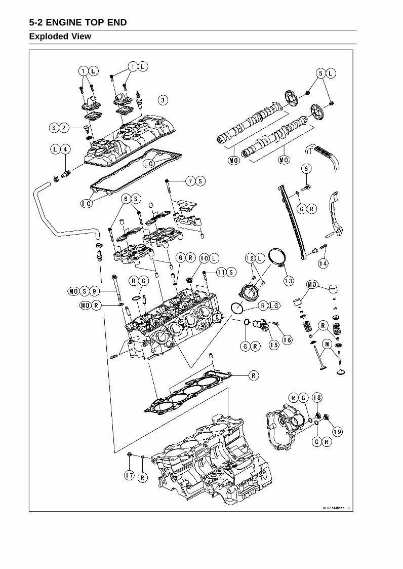
5-2 ENGINE TOP ENDExploded View

ENGINE TOP END 5-3Exploded View
TorqueNo. Fastener
N·m kgf·m ft·lbRemarks
1 Air Suction Valve Cover Bolts 9.8 1.0 87 in·lb L2 Cylinder Head Cover Bolts 9.8 1.0 87 in·lb S3 Spark Plugs 13 1.3 115 in·lb4 Breather Hose Fitting 15 1.5 11 L5 Camshaft Sprocket Bolts 15 1.5 11 L6 Camshaft Cap Bolts 12 1.2 106 in·lb S7 Upper Camshaft Chain Guide Bolts 12 1.2 106 in·lb S8 Front Camshaft Chain Guide Bolt (Upper) 25 2.5 18
9 Cylinder Head Bolts (M9) see thetext ← ← MO, S
10 Water Passage Plugs 19.6 2.00 14.5 L11 Cylinder Head Bolts (M6) 12 1.2 106 in·lb S12 Throttle Body Assy Holder Bolts 12 1.2 106 in·lb L13 Throttle Body Assy Holder Clamp Bolts 2.9 0.30 26 in·lb14 Front Camshaft Chain Guide Bolt (Lower) 12 1.2 106 in·lb15 Camshaft Chain Tensioner Cap Bolt 20 2.0 1516 Camshaft Chain Tensioner Mounting Bolts 11 1.1 97 in·lb17 Coolant Drain Bolt (Cylinder) 9.8 1.0 87 in·lb18 Starter Clutch Bolt Cap 2.9 0.30 26 in·lb19 Timing Inspection Cap 2.9 0.30 26 in·lb
G: Apply grease.L: Apply a non-permanent locking agent.
LG: Apply liquid gasket.M: Apply molybdenum disulfide grease.
MO: Apply molybdenum disulfide oil solution.(mixture of the engine oil and molybdenum disulfide grease in a weight ratio 10:1)
R: Replacement PartsS: Follow the specified tightening sequence.

5-4 ENGINE TOP ENDExploded View

ENGINE TOP END 5-5Exploded View
TorqueNo. Fastener
N·m kgf·m ft·lbRemarks
1 Exhaust Butterfly Valve Actuator Pulley Bolt 4.9 0.50 43 in·lb
2 Exhaust Butterfly Valve Actuator MountingScrews 4.3 0.44 38 in·lb
3 Muffler Body Mounting Bolt 25 2.5 184 Muffler Body End Cover Bolts 7.0 0.71 62 in·lb L5 Premuffler Chamber Mounting Bolt 40 4.1 306 Premuffler Chamber Bracket Bolt 40 4.1 307 Exhaust Butterfly Valve Cable Locknuts 5.0 0.51 44 in·lbL: Apply a non-permanent locking agent.R: Replacement Parts

5-6 ENGINE TOP ENDExhaust System Identification
Exhaust Pipe Mark Position [A]
Premuffler Chamber Mark Position [A]
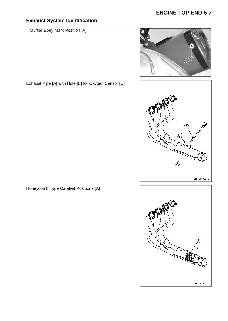
ENGINE TOP END 5-7Exhaust System Identification
Muffler Body Mark Position [A]
Exhaust Pipe [A] with Hole [B] for Oxygen Sensor [C]
Honeycomb Type Catalyst Positions [A]

5-8 ENGINE TOP ENDSpecifications
Item Standard Service LimitCamshafts
Cam Height:Exhaust 33.343 ∼ 33.457 mm (1.3127 ∼ 1.3172 in.) 33.24 mm (1.309 in.)Intake 34.743 ∼ 34.857 mm (1.3678 ∼ 1.3723 in.) 34.64 mm (1.364 in.)
Camshaft Journal/CamshaftCap Clearance
0.038 ∼ 0.081 mm (0.0015 ∼ 0.0032 in.) 0.17 mm (0.0067 in.)
Camshaft Journal Diameter 23.940 ∼ 23.962 mm (0.9425 ∼ 0.9434 in.) 23.91 mm (0.941 in.)Camshaft Bearing InsideDiameter
24.000 ∼ 24.021 mm (0.9449 ∼ 0.9457 in.) 24.08 mm (0.948 in.)
Camshaft Runout TIR 0.02 mm (0.0008 in.) or less TIR 0.1 mm (0.004 in.)Cylinder Head
Cylinder Compression (Usable Range)1 050 ∼ 1 598 kPa (10.7 ∼ 16.3 kgf/cm², – – –152 ∼ 232 psi) at 300 r/min (rpm)
Cylinder Head Warp – – – 0.05 mm (0.002 in.)Valves
Valve Clearance:Exhaust 0.24 ∼ 0.31 mm (0.0094 ∼ 0.0122 in.) – – –Intake 0.13 ∼ 0.19 mm (0.0051 ∼ 0.0075 in.) – – –
Valve Head Thickness:Exhaust 1.0 mm (0.039 in.) 0.5 mm (0.020 in.)Intake 0.5 mm (0.020 in.) 0.3 mm (0.012 in.)
Valve Stem Bend TIR 0.01 mm (0.0004 in.) or less TIR 0.05 mm (0.002 in.)Valve Stem Diameter:
Exhaust 3.955 ∼ 3.970 mm (0.1557 ∼ 0.1563 in.) 3.94 mm (0.155 in.)Intake 3.975 ∼ 3.990 mm (0.1565 ∼ 0.1571 in.) 3.96 mm (0.156 in.)
Valve Guide Inside Diameter:Exhaust 4.000 ∼ 4.012 mm (0.1575 ∼ 0.1580 in.) 4.08 mm (0.161 in.)Intake 4.000 ∼ 4.012 mm (0.1575 ∼ 0.1580 in.) 4.08 mm (0.161 in.)
Valve/Valve GuideClearance (Wobble Method):
Exhaust 0.08 ∼ 0.16 mm (0.0031 ∼ 0.0063 in.) 0.36 mm (0.014 in.)Intake 0.03 ∼ 0.10 mm (0.0012 ∼ 0.0039 in.) 0.30 mm (0.012 in.)
Valve Seat Cutting Angle 32°, 45°, 60° – – –Valve Seating Surface:
Width:Exhaust 0.8 ∼ 1.2 mm (0.031 ∼ 0.047 in.) – – –Intake 0.5 ∼ 1.0 mm (0.020 ∼ 0.039 in.) – – –
Outside Diameter:Exhaust 22.8 ∼ 23.0 mm (0.898 ∼ 0.906 in.) – – –Intake 26.93 ∼ 27.13 mm (1.060 ∼ 1.068 in.) – – –
Valve Spring Free Length:Exhaust 41.01 mm (1.615 in.) 40.2 mm (1.583 in.)Intake 39.99 mm (1.574 in.) 39.0 mm (1.535 in.)

ENGINE TOP END 5-9Special Tools and Sealant
Compression Gauge, 20 kgf/cm²:57001-221
Valve Spring Compressor Assembly:57001-241
Valve Seat Cutter, 45° - 24.5:57001-1113
Valve Seat Cutter, 32° - 25:57001-1118
Valve Seat Cutter, 32° - 30:57001-1120
Valve Seat Cutter Holder Bar:57001-1128
Valve Spring Compressor Adapter, 20:57001-1154
Valve Seat Cutter, 45° - 30:57001-1187
Valve Guide Arbor, 4:57001-1273
Valve Guide Reamer, 4:57001-1274

5-10 ENGINE TOP ENDSpecial Tools and Sealant
Valve Seat Cutter Holder, 4:57001-1275
Valve Seat Cutter, 60° - 25:57001-1328
Valve Seat Cutter, 60° - 27:57001-1409
Valve Guide Driver:57001-1564
Compression Gauge Adapter, M10 × 1.0:57001-1601
L-Shape Hose:57001-1606
Valve Guide Driver Attachment, C:57001-1624
Spacer:57001-1786
Liquid Gasket, TB1211F:92104-0004
Liquid Gasket, TB1216B:92104-1064

ENGINE TOP END 5-11Clean Air System
Air Suction Valve Removal•Remove:
Air Switching Valve (see Air Switching Valve Removal)Air Suction Valve Cover Bolts [A] (Both Sides)Air Suction Valve Cover [B] (Both Sides)
•Remove the air suction valve [A] on both sides.
Air Suction Valve Installation• Install the air suction valve so that opening [A] of the reed
faces the rear and downward.
• Apply a non-permanent locking agent to the threads ofthe air suction valve cover bolts [A], and tighten them.Torque - Air Suction Valve Cover Bolts: 9.8 N·m (1.0 kgf·m,
87 in·lb)
• Install the air switching valve (see Air Switching Valve In-stallation).

5-12 ENGINE TOP ENDClean Air System
Air Suction Valve Inspection•Remove the air suction valve (see Air Suction Valve Re-
moval).• Visually inspect the reeds [A] for cracks, folds, warps,
heat damage or other damage.If there is any doubt as to the condition of the reeds, re-place the air suction valve as an assembly.
•Check the reed contact areas [B] of the valve holder forgrooves, scratches, any signs of separation from theholder or heat damage.If there is any doubt as to the condition of the reed contactareas, replace the air suction valve as an assembly.If any carbon or other foreign particles have accumulatedbetween the reed and the reed contact area, wash thevalve assembly clean with a high flash-point solvent.
NOTICEDo not scrape off the deposits with a scraper as thiscould damage the rubber, requiring replacement ofthe suction valve assembly.
Air Switching Valve RemovalNOTICE
Never drop the air switching valve especially on ahard surface. Such a shock to the air switchingvalve can damaged it.
•Remove the air cleaner housing (see Air Cleaner HousingRemoval in the Fuel System (DFI) chapter).
• Disconnect the connector [A].• Disconnect the hoses [B] from the air suction valve cov-
ers, and remove the air switching valve [C].
Air Switching Valve Installation• Install the air switching valve [A] with hose [B] as shown.
Front [C]Left Side View [D]White Paint [E]

ENGINE TOP END 5-13Clean Air System
Air Switching Valve Operation Test•Refer to the Air Suction System Damage Inspection in the
Periodic Maintenance chapter.
Air Switching Valve Unit Test•Refer to the Air Switching Valve Unit Test in the Electrical
System chapter.
Clean Air System Hose Inspection•Be certain that all the hoses are routed without being flat-
tened or kinked, and are connected correctly to the aircleaner housing, air switching valve and air suction valvecovers.If they are not, correct them. Replace them if they aredamaged.
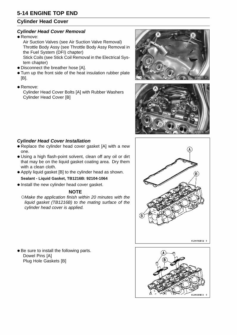
5-14 ENGINE TOP ENDCylinder Head Cover
Cylinder Head Cover Removal•Remove:
Air Suction Valves (see Air Suction Valve Removal)Throttle Body Assy (see Throttle Body Assy Removal inthe Fuel System (DFI) chapter)Stick Coils (see Stick Coil Removal in the Electrical Sys-tem chapter)
•Disconnect the breather hose [A].• Turn up the front side of the heat insulation rubber plate
[B].
• Remove:Cylinder Head Cover Bolts [A] with Rubber WashersCylinder Head Cover [B]
Cylinder Head Cover Installation•Replace the cylinder head cover gasket [A] with a new
one.•Using a high flash-point solvent, clean off any oil or dirt
that may be on the liquid gasket coating area. Dry themwith a clean cloth.
• Apply liquid gasket [B] to the cylinder head as shown.Sealant - Liquid Gasket, TB1216B: 92104-1064
• Install the new cylinder head cover gasket.
NOTEMake the application finish within 20 minutes with the
liquid gasket (TB1216B) to the mating surface of thecylinder head cover is applied.
•Be sure to install the following parts.Dowel Pins [A]Plug Hole Gaskets [B]

ENGINE TOP END 5-15Cylinder Head Cover
• Install the cylinder head cover.• Install the rubber washers [A] with the metal side faces
upward.
• Tighten the cover bolts following the specified tighteningsequence.Torque - Cylinder Head Cover Bolts: 9.8 N·m (1.0 kgf·m, 87
in·lb)
•When installing the breather hose fitting [A], note the fol-lowing.Apply a non-permanent locking agent to the threads of
the breather hose fitting, and tighten it.Torque - Breather Hose Fitting: 15 N·m (1.5 kgf·m, 11 ft·lb)
• Install the heat insulation rubber plate (see Cable, Wire,and Hose Routing section in the Appendix chapter).
• Install the removed parts (see appropriate chapters).

5-16 ENGINE TOP ENDCamshaft Chain Tensioner
Camshaft Chain Tensioner RemovalNOTICE
This is a non-return type camshaft chain tensioner.The push rod does not return to its original positiononce it moves out to take up camshaft chain slack.Observe all the rules listed below.When removing the tensioner, do not take out themounting bolts only halfway. Retightening themounting bolts from this position could damagethe tensioner and the camshaft chain. Once thebolts are loosened, the tensioner must be removedand reset as described in “Camshaft Chain Ten-sioner Installation”.Do not turn over the crankshaft while the tensioneris removed. This could upset the camshaft chaintiming, and damage the valves.
•Remove:Right Fairing Cover (see Fairing Cover Removal in theFrame chapter)Right Side Cover (see Side Cover Removal in the Framechapter)Bolt [A] and Washer
•Remove the bolt [A].• Free the clutch cable from the bracket [B].
NOTECover the bracket with a cloth to avoid damaging other
parts.
•Remove:Cap Bolt [A]Washer [B]

ENGINE TOP END 5-17Camshaft Chain Tensioner
•Remove:Spring [A]Rod [B]
•Remove:Camshaft Chain Tensioner Mounting Bolts [A]Camshaft Tensioner Body [B]
Camshaft Chain Tensioner Installation•Replace the O-ring [A] with a new one.• Apply grease to the new O-ring.•Release the stopper [B] and push the push rod [C] into
the interior of the tensioner body [D].• Install the tensioner body so that the stopper faces up-
ward.
• Tighten:Torque - Camshaft Chain Tensioner Mounting Bolts [A]: 11
N·m (1.1 kgf·m, 97 in·lb)
• Install:Rod [B]Spring [C]Washer [D]
• Tighten:Torque - Camshaft Chain Tensioner Cap Bolt [E]: 20 N·m
(2.0 kgf·m, 15 ft·lb)
• Install the removed parts (see appropriate chapters).

5-18 ENGINE TOP ENDCamshaft, Camshaft Chain
Camshaft Removal•Remove the cylinder head cover (see Cylinder Head
Cover Removal).• Remove the timing inspection cap [A] and starter clutch
bolt cap [B] on the starter clutch cover [C].
• Using a wrench on the starter clutch bolt [A], turn thecrankshaft clockwise until the line [B] (TDC mark for #1,4pistons) on the starter clutch is aligned with the notches[C] in the edge of the timing inspection hole [D] in thestarter clutch cover.
If the starter clutch cover was removed, perform the nextprocedure.Using a wrench on the starter clutch bolt [A], turn the
crankshaft clockwise until the line [B] (TDC mark for #1,4pistons) on the starter clutch [C] is aligned with the matingsurface [D] of the crankcase.

ENGINE TOP END 5-19Camshaft, Camshaft Chain
•Remove the camshaft chain tensioner (see CamshaftChain Tensioner Removal).
• Loosen the upper camshaft chain guide bolts andcamshaft cap bolts as shown sequence [1 ∼ 20], andremove them.
•Remove:Upper Camshaft Chain Guide [A]Camshaft Caps [B]Camshafts [C]
• Stuff a clean cloth into the chain tunnel to keep any partsfrom dropping into the crankcase.
•Remove:Camshaft Sprocket Bolts [A]Camshaft Sprockets
NOTICEThe crankshaft may be turned while the camshaftsare removed. Always pull the chain taut while turn-ing the crankshaft. This avoids kinking the chainon the lower (crankshaft) sprocket. A kinked chaincould damage both the chain and the sprocket.
Camshaft InstallationNOTE
The exhaust camshaft has a 2716 EX mark [A] and theintake camshaft has a 2716 IN mark [B]. Be careful notto mix up these shafts.

5-20 ENGINE TOP ENDCamshaft, Camshaft Chain
• Install the camshaft sprockets as shown.#4 Cam Positions [A]Intake Camshaft Sprocket [B]Exhaust Camshaft Sprocket [C]
The intake camshaft sprocket and exhaust camshaftsprocket are identical.
• Apply a non-permanent locking agent to the threads ofthe camshaft sprocket bolts and tighten them.Torque - Camshaft Sprocket Bolts: 15 N·m (1.5 kgf·m, 11
ft·lb)
•Apply molybdenum disulfide oil solution [A] to all camparts, journals and tappets.If a new camshaft is to be used, apply a thin coat of molyb-denum disulfide grease to the cam surfaces.
•Using a wrench on the starter clutch bolt [A], turn thecrankshaft clockwise until the line [B] (TDC mark for #1,4pistons) on the starter clutch is aligned with the notches[C] in the edge of the timing inspection hole [D] in thestarter clutch cover.
NOTICEThe crankshaft may be turned while the camshaftsare removed. Always pull the chain taut while turn-ing the crankshaft. This avoids kinking the chainon the lower (crankshaft) sprocket. A kinked chaincould damage both the chain and the sprocket.
If the starter clutch cover was removed, perform the nextprocedure.Using a wrench on the starter clutch bolt [A], turn the
crankshaft clockwise until the line [B] (TDC mark for #1,4pistons) on the starter clutch [C] is aligned with the matingsurface [D] of the crankcase.
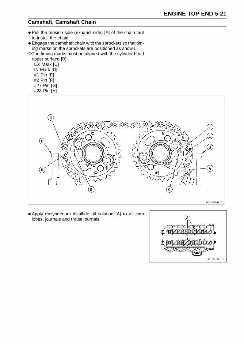
ENGINE TOP END 5-21Camshaft, Camshaft Chain
•Pull the tension side (exhaust side) [A] of the chain tautto install the chain.
• Engage the camshaft chain with the sprockets so that tim-ing marks on the sprockets are positioned as shown.The timing marks must be aligned with the cylinder head
upper surface [B].EX Mark [C]IN Mark [D]#1 Pin [E]#2 Pin [F]#27 Pin [G]#28 Pin [H]
• Apply molybdenum disulfide oil solution [A] to all camlobes, journals and thrust journals.

5-22 ENGINE TOP ENDCamshaft, Camshaft Chain
•Replace the O-rings with new ones.• Apply grease to the new O-rings• Install:
O-rings [A]Dowel Pins [B]O-rings [C]Dowel Pins [D]
• Install the camshaft caps and upper camshaft chain guide[A] as shown.“R” Mark [B]“L” Mark [C]
• First tighten the all camshaft cap bolts evenly to seat thecamshaft in place, then tighten all bolts following the spec-ified tightening sequence.Torque - Camshaft Cap Bolts (1 ∼ 10, 13 ∼ 20):
First: 5.9 N·m (0.60 kgf·m, 52 in·lb)Final: 12 N·m (1.2 kgf·m, 106 in·lb)
Upper Camshaft Chain Guide Bolts (11, 12):First: 5.9 N·m (0.60 kgf·m, 52 in·lb)Final: 12 N·m (1.2 kgf·m, 106 in·lb)

ENGINE TOP END 5-23Camshaft, Camshaft Chain
• Install the camshaft chain tensioner (see Camshaft ChainTensioner Installation).
• Turn the crankshaft 2 turns clockwise to allow the ten-sioner to expand and recheck the camshaft chain timing.
•Replace the O-ring of the timing inspection cap and starterclutch bolt cap with new ones.
• Apply grease to the new O-rings.• Tighten:
Torque - Timing Inspection Cap: 2.9 N·m (0.30 kgf·m, 26in·lb)
Starter Clutch Bolt Cap: 2.9 N·m (0.30 kgf·m, 26in·lb)
• Install the cylinder head cover (see Cylinder Head CoverInstallation).
Camshaft, Camshaft Cap Wear Inspection•Remove the camshaft caps (see Camshaft Removal).• Cut the strips of plastigage (press gauge) to journal width.
Place a strip on each journal parallel to the camshaft in-stalled in the correct position.
• Tighten the camshaft cap bolts and upper camshaft chainguide bolts to the specified torque (see Camshaft Instal-lation).
NOTEDo not turn the camshaft when the plastigage is be-
tween the journal and camshaft cap.
•Remove the camshaft cap again, measure each clear-ance between the camshaft journal and the camshaft capusing plastigage [A].
Camshaft Journal/Camshaft Cap ClearanceStandard: 0.038 ∼ 0.081 mm (0.0015 ∼ 0.0032 in.)Service Limit: 0.17 mm (0.0067 in.)
If any clearance exceeds the service limit, measure thediameter of each camshaft journal with a micrometer.
Camshaft Journal DiameterStandard: 23.940 ∼ 23.962 mm (0.9425 ∼ 0.9434 in.)Service Limit: 23.91 mm (0.941 in.)
If the camshaft journal diameter is less than the servicelimit, replace the camshaft with a new one and measurethe clearance again.If the clearance still remains out of the service limit, re-place the cylinder head unit.

5-24 ENGINE TOP ENDCamshaft, Camshaft Chain
Camshaft Runout Inspection•Remove the camshafts (see Camshaft Removal).• Set the camshaft in a camshaft alignment jig or on V
blocks.•Measure the runout with a dial gauge [A] at the specified
place as shown.If the runout exceeds the service limit, replace thecamshaft.
Camshaft RunoutStandard: TIR 0.02 mm (0.0008 in.) or lessService Limit: TIR 0.1 mm (0.004 in.)
Cam Wear Inspection•Remove the camshafts (see Camshaft Removal).•Measure the height [A] of each cam with a micrometer.
If the cams are worn down past the service limit, replacethe camshaft.
Cam HeightStandard:
Exhaust 33.343 ∼ 33.457 mm (1.3127 ∼ 1.3172 in.)Intake 34.743 ∼ 34.857 mm (1.3678 ∼ 1.3723 in.)
Service Limit:Exhaust 33.24 mm (1.309 in.)Intake 34.64 mm (1.364 in.)
Camshaft Chain Removal•Split the crankcase (see Crankcase Splitting in the Crank-
shaft/Transmission chapter).• Remove the camshaft chain [A] from the crankshaft
sprocket.

ENGINE TOP END 5-25Cylinder Head
Cylinder Compression MeasurementNOTE
Use the battery which is fully charged.
•Warm up the engine thoroughly.• Stop the engine.•Remove the spark plugs (see Spark Plug Replacement in
the Periodic Maintenance chapter).
• Attach the compression gauge [A] and adapter [B] firmlyinto the spark plug hole.
•Using the starter motor, turn the engine over with the throt-tle fully open until the compression gauge stops rising; thecompression is the highest reading obtainable.Special Tools - Compression Gauge, 20 kgf/cm²: 57001-221
Compression Gauge Adapter, M10 × 1.0:57001-1601
L-Shape Hose: 57001-1606
Cylinder CompressionUsable Range: 1 050 ∼ 1 598 kPa (10.7 ∼ 16.3 kgf/cm²,
152 ∼ 232 psi) at 300 r/min (rpm)
•Repeat the measurement for the other cylinders.• Install the spark plugs (see Spark Plug Replacement in
the Periodic Maintenance chapter).
The following table should be consulted if the obtainable compression reading is not within the us-able range.
Problem Diagnosis Remedy (Action)Carbon accumulation on piston and incombustion chamber possibly due todamaged valve stem oil seal and/ordamaged piston oil rings (This may beindicated by white exhaust smoke).
Remove the carbon deposits andreplace damaged parts if necessary.
Cylindercompressionis higher thanusable range.
Incorrect cylinder head gasket thickness Replace the gasket with a standard part.Gas leakage around cylinder head Replace damaged check gasket and
cylinder head warp.Bad condition of valve seating Repair if necessary.Incorrect valve clearance Adjust the valve clearance.Incorrect piston/cylinder clearance Replace the piston and/or cylinder.Piston seizure Inspect the cylinder and replace/repair
the cylinder and/or piston as necessary.
Cylindercompressionis lower thanusable range.
Bad condition of piston ring and/or pistonring grooves
Replace the piston and/or the pistonrings.

5-26 ENGINE TOP ENDCylinder Head
Cylinder Head Removal•Remove:
Engine (see Engine Removal in the Engine Removal/In-stallation chapter)Thermostat Housing (see Thermostat Removal in theCooling System chapter)Cylinder Head Cover (see Cylinder Head Cover Re-moval)Camshafts (see Camshaft Removal)Coolant Drain Bolt (Cylinder) [A]Washer [B]
•Remove the front camshaft chain guide bolt (upper) [A].
• Remove:Front Camshaft Chain Guide Bolt (Lower) [A]CollarFront Camshaft Chain Guide [B]Dowel Pin [C]Rear Camshaft Chain Guide [D]
• Loosen the M6 and M9 cylinder head bolts as shown se-quence [1 ∼ 12], and remove them with washers.
•Remove the cylinder head.
Cylinder Head InstallationNOTE
The camshaft cap is machined with the cylinder head,so if a new cylinder head is installed, use the cap thatis supplied with the new head.
• Install the dowel pins.•Replace the cylinder head gasket with a new one.•Replace the cylinder head bolt washers with new ones.• Apply molybdenum disulfide oil solution to both sides [A]
of the cylinder head bolt washers and the threads [B] ofthe head bolts [C].

ENGINE TOP END 5-27Cylinder Head
•Tighten the M9 cylinder head bolts following the tighteningsequence [1 ∼ 10].First, tighten the bolts with 15 N·m (1.5 kgf·m, 11 ft·lb) of
torque.Next, in accordance with the following table tighten the
bolts with the specified torque. And using a torque anglegauge [A], tighten the bolts with the specified angle.
OrderCylinder
Head Bolts(M9)
New BoltTorque N·m(kgf·m, ft·lb)
or Angle
Used BoltTorque N·m(kgf·m, ft·lb)
or Angle1 [1] → [2] 35 (3.6, 26) 33 (3.4, 24)2 [1] → [2] 50° ±3 50° ±33 [3] → [4] 35 (3.6, 26) 33 (3.4, 24)4 [3] → [4] 50° ±3 50° ±35 [5] → [6] 35 (3.6, 26) 33 (3.4, 24)6 [5] → [6] 50° ±3 50° ±37 [7] → [8] 30 (3.1, 22) 28 (2.9, 21)8 [7] → [8] 50° ±3 50° ±39 [9] → [10] 35 (3.6, 26) 33 (3.4, 24)
10 [9] → [10] 50° ±3 50° ±3
• Tighten the M6 cylinder head bolts as shown sequence[11, 12].Torque - Cylinder Head Bolts (M6): 12 N·m (1.2 kgf·m, 106
in·lb)
• Install:Dowel Pin [A]Rear Camshaft Chain Guide [B]Front Camshaft Chain Guide [C]New O-ring [D]Collar [E]
• Tighten:Torque - Front Camshaft Chain Guide Bolt (Upper) [F]: 25
N·m (2.5 kgf·m, 18 ft·lb)Front Camshaft Chain Guide Bolt (Lower) [G]: 12
N·m (1.2 kgf·m, 106 in·lb)

5-28 ENGINE TOP ENDCylinder Head
•Replace the washer [A] with a new one.• Tighten:
Torque - Coolant Drain Bolt (Cylinder) [B]: 9.8 N·m (1.0kgf·m, 87 in·lb)
• Install the removed parts (see appropriate chapters).
Cylinder Head Warp Inspection•Clean the cylinder head.• Lay a straightedge across the lower surface of the cylinder
head at several positions.•Use a thickness gauge [A] to measure the space between
the straightedge [B] and the head.
Cylinder Head WarpStandard: – – –Service Limit: 0.05 mm (0.002 in.)
If the cylinder head is warped more than the service limit,replace it.If the cylinder head is warped less than the service limit,repair the head by rubbing the lower surface on emerypaper secured to a surface plate (first No. 200, then No.400).

ENGINE TOP END 5-29Valves
Valve Clearance Inspection•Refer to the Valve Clearance Inspection in the Periodic
Maintenance chapter.
Valve Removal•Remove the cylinder head (see Cylinder Head Removal).• Remove the valve lifter and shim.
NOTEMark and record the valve lifter and shim locations so
they can be installed in their original positions.
•Using the valve spring compressor assembly, remove thevalve.Special Tools - Valve Spring Compressor Assembly [A]:
57001-241Valve Spring Compressor Adapter, 20 [B]:
57001-1154
Valve Installation•Replace the oil seal with a new one.• Apply a thin coat of molybdenum disulfide grease to the
valve stem before valve installation.• Install the springs so that the closed coil end faces down-
wards.Valve Stem [A]Oil Seal [B]Spring Seat [C]Closed Coil End [D]Valve Spring [E]:
EX - Purple PaintIN - Blue Paint
Retainer [F]Split Keepers [G]
Valve Guide Removal•Remove:
Valve (see Valve Removal)Oil SealSpring Seat
•Heat the area around the valve guide to 120 ∼ 150°C (248∼ 302°F), and hammer lightly on the valve guide arbor [A]to remove the guide from the top of the head.
NOTICEDo not heat the cylinder head with a torch. This willwarp the cylinder head. Soak the cylinder head inoil and heat the oil.
Special Tool - Valve Guide Arbor, 4: 57001-1273

5-30 ENGINE TOP ENDValves
Valve Guide Installation•Apply engine oil to the valve guide outer surface before
installation.•Heat the area around the valve guide hole to about 120 ∼
150°C (248 ∼ 302°F).
NOTICEDo not heat the cylinder head with a torch. This Willwarp the cylinder head. Soak the cylinder head andheat the oil.
Exhaust•Using the valve guide driver [A] and attachment [B], press
and insert the valve guide in until the attachment surface[C] touches the head surface [D].13.3 ∼ 13.5 mm (0.52 ∼ 0.53 in.) [E]
Special Tools - Valve Guide Driver: 57001-1564Valve Guide Driver Attachment, C: 57001
-1624
Intake•Using the valve guide driver [A] and attachment [B], press
and insert the valve guide in until the attachment surface[C] touches the head surface [D].12.6 ∼ 12.8 mm (0.496 ∼ 0.504 in.) [E]
Special Tools - Valve Guide Driver: 57001-1564Valve Guide Driver Attachment, C: 57001
-1624Spacer: 57001-1786 [F]
•Ream the valve guide with valve guide reamer [A], evenif the old guide is reused.Special Tool - Valve Guide Reamer, 4: 57001-1274
Valve-to-Guide Clearance Measurement (WobbleMethod)
If a small bore gauge is not available, inspect the valveguide wear by measuring the valve to valve guide clearancewith the wobble method as indicated below.• Insert a new valve [A] into the guide [B] and set a dial
gauge against the stem perpendicular to it as close aspossible to the cylinder head mating surface.
•Move the stem back and forth [C] to measure valve/valveguide clearance.
•Repeat the measurement in a direction at a right angle tothe first.If the reading exceeds the service limit, replace the guide.

ENGINE TOP END 5-31Valves
NOTEThe reading is not actual valve/valve guide clearance
because the measuring point is above the guide.
Valve/Valve Guide Clearance (Wobble Method)Standard:
Exhaust 0.08 ∼ 0.16 mm (0.0031 ∼ 0.0063 in.)Intake 0.03 ∼ 0.10 mm (0.0012 ∼ 0.0039 in.)
Service Limit:Exhaust 0.36 mm (0.014 in.)Intake 0.30 mm (0.012 in.)
Valve Seat Inspection•Remove the valve (see Valve Removal).• Check the valve seating surface [A] between the valve [B]
and valve seat [C].Measure the outside diameter [D] of the seating pattern
on the valve seat.If the outside diameter is too large or too small, repair theseat (see Valve Seat Repair).
Valve Seating Surface Outside DiameterStandard:
Exhaust 22.8 ∼ 23.0 mm (0.898 ∼ 0.906 in.)Intake 26.93 ∼ 27.13 mm (1.060 ∼ 1.068 in.)
Measure the seat width [E] of the portion where there isno build-up carbon (white portion) of the valve seat with avernier caliper.Good [F]
If the width is too wide [G], too narrow [H] or uneven [J],repair the seat (see Valve Seat Repair).
Valve Seating Surface WidthStandard:
Exhaust 0.8 ∼ 1.2 mm (0.031 ∼ 0.047 in.)Intake 0.5 ∼ 1.0 mm (0.020 ∼ 0.039 in.)
Valve Seat Repair•Repair the valve seat with the valve seat cutters [A].
Special Tools - Valve Seat Cutter Holder Bar [B]: 57001-1128
Valve Seat Cutter Holder, 4 [C]: 57001-1275
[For Exhaust Valve Seat]Valve Seat Cutter, 45° - 24.5: 57001-1113Valve Seat Cutter, 32° - 25: 57001-1118Valve Seat Cutter, 60° - 25: 57001-1328
[For Intake Valve Seat]Valve Seat Cutter, 45° - 30: 57001-1187Valve Seat Cutter, 32° - 30: 57001-1120Valve Seat Cutter, 60° - 27: 57001-1409
If the manufacturer’s instructions are not available, usethe following procedure.
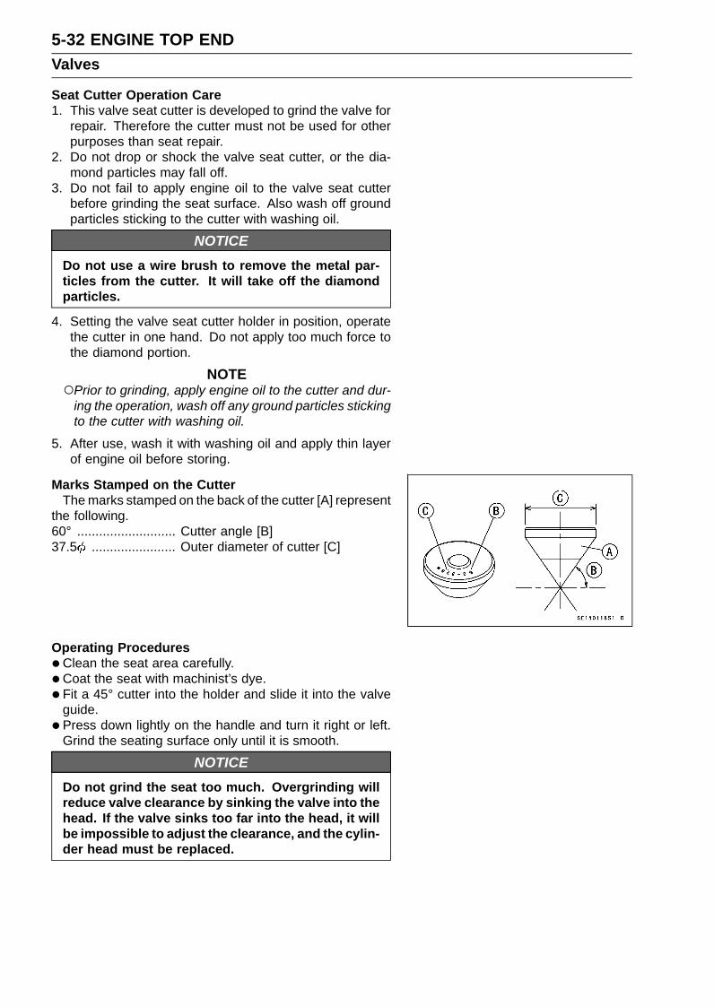
5-32 ENGINE TOP ENDValves
Seat Cutter Operation Care1. This valve seat cutter is developed to grind the valve for
repair. Therefore the cutter must not be used for otherpurposes than seat repair.
2. Do not drop or shock the valve seat cutter, or the dia-mond particles may fall off.
3. Do not fail to apply engine oil to the valve seat cutterbefore grinding the seat surface. Also wash off groundparticles sticking to the cutter with washing oil.
NOTICEDo not use a wire brush to remove the metal par-ticles from the cutter. It will take off the diamondparticles.
4. Setting the valve seat cutter holder in position, operatethe cutter in one hand. Do not apply too much force tothe diamond portion.
NOTEPrior to grinding, apply engine oil to the cutter and dur-
ing the operation, wash off any ground particles stickingto the cutter with washing oil.
5. After use, wash it with washing oil and apply thin layerof engine oil before storing.
Marks Stamped on the CutterThe marks stamped on the back of the cutter [A] represent
the following.60° ........................... Cutter angle [B]37.5 ....................... Outer diameter of cutter [C]
Operating Procedures•Clean the seat area carefully.• Coat the seat with machinist’s dye.• Fit a 45° cutter into the holder and slide it into the valve
guide.• Press down lightly on the handle and turn it right or left.
Grind the seating surface only until it is smooth.
NOTICEDo not grind the seat too much. Overgrinding willreduce valve clearance by sinking the valve into thehead. If the valve sinks too far into the head, it willbe impossible to adjust the clearance, and the cylin-der head must be replaced.
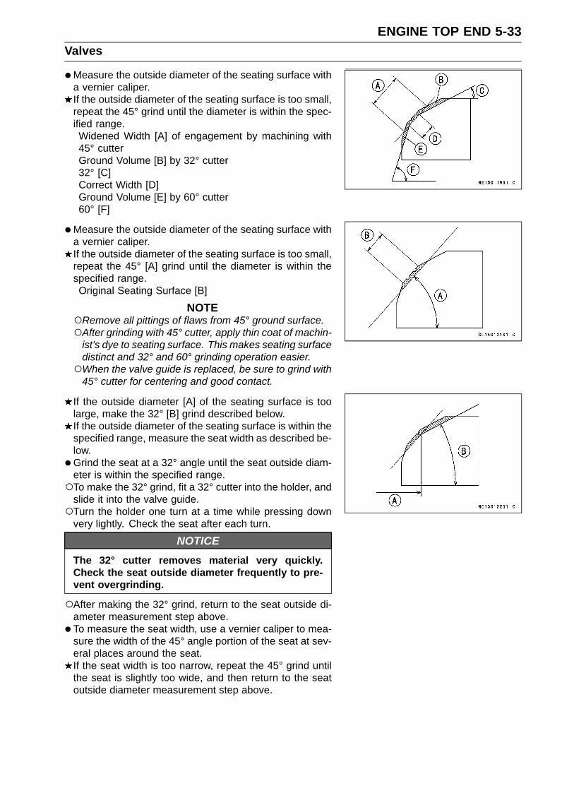
ENGINE TOP END 5-33Valves
•Measure the outside diameter of the seating surface witha vernier caliper.If the outside diameter of the seating surface is too small,repeat the 45° grind until the diameter is within the spec-ified range.Widened Width [A] of engagement by machining with45° cutterGround Volume [B] by 32° cutter32° [C]Correct Width [D]Ground Volume [E] by 60° cutter60° [F]
•Measure the outside diameter of the seating surface witha vernier caliper.If the outside diameter of the seating surface is too small,repeat the 45° [A] grind until the diameter is within thespecified range.Original Seating Surface [B]
NOTERemove all pittings of flaws from 45° ground surface.After grinding with 45° cutter, apply thin coat of machin-
ist’s dye to seating surface. This makes seating surfacedistinct and 32° and 60° grinding operation easier.When the valve guide is replaced, be sure to grind with
45° cutter for centering and good contact.
If the outside diameter [A] of the seating surface is toolarge, make the 32° [B] grind described below.If the outside diameter of the seating surface is within thespecified range, measure the seat width as described be-low.
•Grind the seat at a 32° angle until the seat outside diam-eter is within the specified range.To make the 32° grind, fit a 32° cutter into the holder, and
slide it into the valve guide.Turn the holder one turn at a time while pressing down
very lightly. Check the seat after each turn.
NOTICEThe 32° cutter removes material very quickly.Check the seat outside diameter frequently to pre-vent overgrinding.
After making the 32° grind, return to the seat outside di-ameter measurement step above.
• To measure the seat width, use a vernier caliper to mea-sure the width of the 45° angle portion of the seat at sev-eral places around the seat.If the seat width is too narrow, repeat the 45° grind untilthe seat is slightly too wide, and then return to the seatoutside diameter measurement step above.
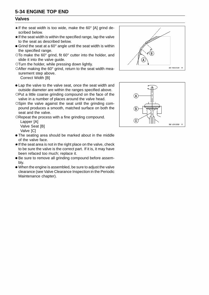
5-34 ENGINE TOP ENDValves
If the seat width is too wide, make the 60° [A] grind de-scribed below.If the seat width is within the specified range, lap the valveto the seat as described below.
•Grind the seat at a 60° angle until the seat width is withinthe specified range.To make the 60° grind, fit 60° cutter into the holder, and
slide it into the valve guide.Turn the holder, while pressing down lightly.After making the 60° grind, return to the seat width mea-
surement step above.Correct Width [B]
• Lap the valve to the valve seat, once the seat width andoutside diameter are within the ranges specified above.Put a little coarse grinding compound on the face of the
valve in a number of places around the valve head.Spin the valve against the seat until the grinding com-
pound produces a smooth, matched surface on both theseat and the valve.Repeat the process with a fine grinding compound.
Lapper [A]Valve Seat [B]Valve [C]
• The seating area should be marked about in the middleof the valve face.If the seat area is not in the right place on the valve, checkto be sure the valve is the correct part. If it is, it may havebeen refaced too much; replace it.
• Be sure to remove all grinding compound before assem-bly.
•When the engine is assembled, be sure to adjust the valveclearance (see Valve Clearance Inspection in the PeriodicMaintenance chapter).

ENGINE TOP END 5-35Valves

5-36 ENGINE TOP ENDThrottle Body Assy Holder
Throttle Body Assy Holder Removal•Remove:
Throttle Body Assy (see Throttle Body Assy Removal inthe Fuel System (DFI) chapter)Clamps [A]Throttle Body Assy Holder Bolts [B]Throttle Body Assy Holders [C]
Throttle Body Assy Holder Installation•Replace the O-rings [A] with new ones.• Apply liquid gasket to any three positions of the O-rings
to prevent it from coming off, and install them.Sealant - Liquid Gasket, TB1211F: 92104-0004
• Install the holders [B] as shown.Recession [C]
• Apply a non-permanent locking agent to the threads ofthe throttle body assy holder bolts [D], and tighten them.Torque - Throttle Body Assy Holder Bolts: 12 N·m (1.2
kgf·m, 106 in·lb)
•Fit the hole of the clamp [A] to the projection [B] of theholder [C].25° [D]10° [E]
• Install:Throttle Body Assy (see Throttle Body Assy Installationin the Fuel System (DFI) chapter)

ENGINE TOP END 5-37Muffler
WARNINGThe muffler can become extremely hot during nor-mal operation and cause severe burns. Do not re-move the muffler while it is hot.
Muffler Body Removal•Remove the lower ends of the exhaust butterfly valve ca-
bles from the pulley of the muffler body (see Exhaust But-terfly Valve Cable Removal).
• Loosen the muffler body clamp bolt [A].• Remove the muffler body mounting bolt [B], and pull out
the muffler body [C] backward from the premuffler cham-ber.

5-38 ENGINE TOP ENDMuffler
Muffler Body Installation•Replace the premuffler chamber gasket [A] with a new
one.• Install the muffler body gasket to the premuffler chamber
[B] until it is bottomed so that the chamfer side [C] facesmuffler body [D].About 4.0 mm (0.16 in.) [E]
• Install the muffler body clamp [F] as shown.Insert the projection [G] into the slot [H].• Replace the muffler body mounting nut [I].• Install the muffler body.• Tighten the muffler body mounting bolt [J] and muffler
body clamp bolt [K].Torque - Muffler Body Mounting Bolt: 25 N·m (2.5 kgf·m, 18
ft·lb)
• Install the lower ends of the exhaust butterfly valve ca-bles, and adjust the cables correctly (see Exhaust Butter-fly Valve Cable Installation).
• Thoroughly warm up the engine, wait until the enginecools down, retighten all the bolts.
• Install the removed parts (see appropriate chapters).

ENGINE TOP END 5-39Muffler
Premuffler Chamber Removal•Remove:
Muffler Body (see Muffler Body Removal)Cotter Pin [A]
• Loosen the rear axle nut [B].• Loosen the both chain adjuster locknuts [C].• Remove the drive chain from the rear sprocket.• Pull the rear wheel backward.
•Remove:Guard Bolts [A]Premuffler Chamber Guard [B]
• Loosen the exhaust pipe clamp bolt [A].• Remove the bolts [B].• Pull out the premuffler chamber backward from the ex-
haust pipe.

5-40 ENGINE TOP ENDMuffler
Premuffler Chamber Installation•Replace the exhaust pipe gasket [A] with a new one.• Install the exhaust pipe gasket to the exhaust pipe [B] until
it is bottomed so that the chamfer side [C] faces premufflerchamber [D].About 4.0 mm (0.16 in.) [E]
• Install the exhaust pipe clamp [F] as shown.Insert the projection [G] into the slot [H].• Install the premuffler chamber and bracket [I].• Tighten the premuffler chamber mounting bolt [J], bracket
bolt [K] and exhaust pipe clamp bolt [L] securely.Torque - Premuffler Chamber Mounting Bolt: 40 N·m (4.1
kgf·m, 30 ft·lb)Premuffler Chamber Bracket Bolt: 40 N·m (4.1
kgf·m, 30 ft·lb)
• Install the premuffler chamber guard [M], and tighten theguard bolt [N].
• Install the removed parts (see appropriate chapters).• Thoroughly warm up the engine, wait until the engine
cools down, retighten all the bolts.

ENGINE TOP END 5-41Muffler
Exhaust Pipe Removal•Remove:
Radiator (see Radiator and Radiator Fan Removal in theCooling System chapter)Oxygen Sensor (Equipped Models) (see Oxygen Sen-sor Removal (Equipped Models) in the Electrical Systemchapter)Exhaust Pipe Clamp Bolt [A]
•Remove the exhaust pipe holder nuts [A], and pull out theexhaust pipe forward from the premuffler chamber.

5-42 ENGINE TOP ENDMuffler
Exhaust Pipe Installation•Replace the exhaust pipe gaskets [A] [B] with new ones.• Install the exhaust pipe gasket [B] to the exhaust pipe
[C] until it is bottomed so that the chamfer side [D] facespremuffler chamber [E].About 4.0 mm (0.16 in.) [F]
• Install the exhaust pipe clamp [G] as shown.Insert the projection [H] into the slot [I].• Install the exhaust pipe.• Turn the [UP] mark to the top of the exhaust pipe holders
[J].• Tighten the following bolt and nuts securely.
Exhaust Pipe Holder Nuts [K]Exhaust Pipe Clamp Bolt [L]
• Install the removed parts (see appropriate chapters).• Thoroughly warm up the engine, wait until the engine
cools down, retighten all the bolts and nuts.
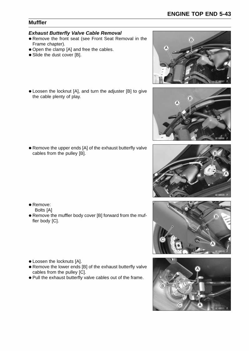
ENGINE TOP END 5-43Muffler
Exhaust Butterfly Valve Cable Removal•Remove the front seat (see Front Seat Removal in the
Frame chapter).•Open the clamp [A] and free the cables.• Slide the dust cover [B].
• Loosen the locknut [A], and turn the adjuster [B] to givethe cable plenty of play.
•Remove the upper ends [A] of the exhaust butterfly valvecables from the pulley [B].
• Remove:Bolts [A]
•Remove the muffler body cover [B] forward from the muf-fler body [C].
• Loosen the locknuts [A].• Remove the lower ends [B] of the exhaust butterfly valve
cables from the pulley [C].• Pull the exhaust butterfly valve cables out of the frame.

5-44 ENGINE TOP ENDMuffler
Exhaust Butterfly Valve Cable Installation•Confirm whether pulley [A] is an angle shown.
41.7° ±7° [B]This position is original position of the pulley.
NOTECorrect the position electrically after confirming use is
discontinued and there is no damage when differingfrom the angle of shown.
NOTICEDo not correct the pulley position with the tool,forcibly. The actuator damage will occur.
If the angle is wrong, adjust the pulley (see Exhaust But-terfly Valve Actuator Installation in the Self-Diagnosis Sys-tem chapter).
• Run the exhaust butterfly valve cables correctly (seeCable, Wire, and Hose Routing section in the Appendixchapter).
• Install the lower ends of the exhaust butterfly valve cablesto the pulley of the muffler body as shown.Open Cable [A] (White Locknut)Close Cable [B] (Black Locknut)
• Tighten:Torque - Exhaust Butterfly Valve Cable Locknuts [C]: 5.0
N·m (0.51 kgf·m, 44 in·lb)
•Fit the slot [A] of the muffler cover [B] to the damper [C]of the muffler body, and tighten the bolts.

ENGINE TOP END 5-45Muffler
• Install the upper ends of the exhaust butterfly valve ca-bles to the pulley of the exhaust butterfly valve actuator,following the specified installing sequence.First, install the close cable (black) [A].Second, install the open cable (white) [B].Third, stretch the open cable (white) by using the adjuster
[C].Turn the adjuster counterclockwise until the play of the
open cable becomes no play.Fourth, turn the adjuster of the open cable clockwise by
1/2 to 1 rotation.Lastly, tighten the adjuster locknut of the open cable se-
curely.• After installation, cover the dust cover on the adjuster as
shown.15 mm (0.59 in.) or less [D]
• Fix the exhaust butterfly valve cables with the clamp [E].• After connecting the cables, turn the ignition switch on
and make sure that the pulley turns clockwise and coun-terclockwise, then it returns clockwise slightly.


CLUTCH 6-1
6
ClutchTable of Contents
Exploded View........................................................................................................................ 6-2Specifications ......................................................................................................................... 6-4Special Tool and Sealant ........................................................................................................ 6-5Clutch Lever and Cable .......................................................................................................... 6-6
Clutch Lever Free Play Inspection .................................................................................... 6-6Clutch Lever Free Play Adjustment .................................................................................. 6-6Cable Removal ................................................................................................................. 6-6Cable Installation .............................................................................................................. 6-6Cable Lubrication .............................................................................................................. 6-6Clutch Lever Installation.................................................................................................... 6-6
Clutch Cover........................................................................................................................... 6-7Clutch Cover Removal ...................................................................................................... 6-7Clutch Cover Installation ................................................................................................... 6-7Release Shaft Removal .................................................................................................... 6-7Release Shaft Installation ................................................................................................. 6-8Clutch Cover Disassembly................................................................................................ 6-8Clutch Cover Assembly..................................................................................................... 6-9
Clutch ..................................................................................................................................... 6-10Clutch Removal................................................................................................................. 6-10Clutch Installation.............................................................................................................. 6-11Clutch Plate Assembly Length Measurement ................................................................... 6-15Clutch Plate, Wear, Damage Inspection ........................................................................... 6-15Clutch Plate Warp Inspection............................................................................................ 6-15Clutch Spring Free Length Measurement ......................................................................... 6-16Clutch Housing Finger Inspection ..................................................................................... 6-16Clutch Housing Spline Inspection ..................................................................................... 6-16Clutch Pressure Plate and Clutch Hub Inspection ............................................................ 6-16
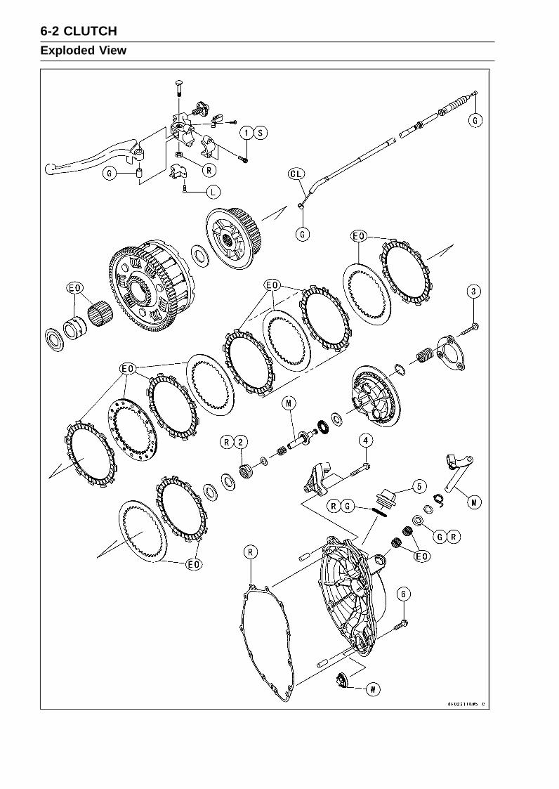
6-2 CLUTCHExploded View
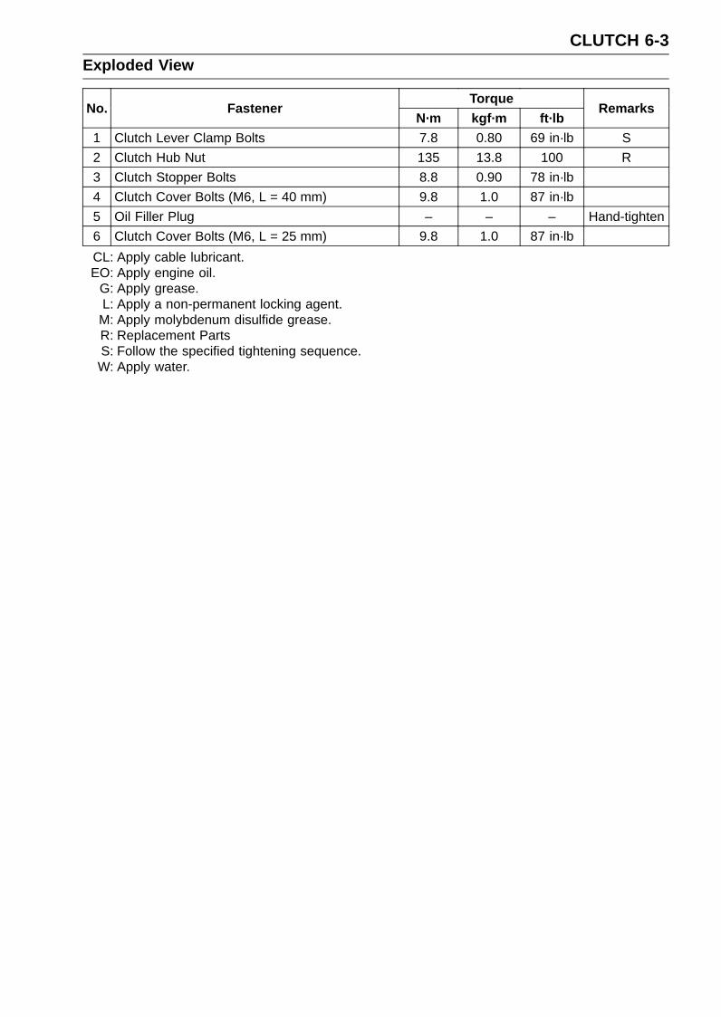
CLUTCH 6-3Exploded View
TorqueNo. Fastener
N·m kgf·m ft·lbRemarks
1 Clutch Lever Clamp Bolts 7.8 0.80 69 in·lb S2 Clutch Hub Nut 135 13.8 100 R3 Clutch Stopper Bolts 8.8 0.90 78 in·lb4 Clutch Cover Bolts (M6, L = 40 mm) 9.8 1.0 87 in·lb5 Oil Filler Plug – – – Hand-tighten6 Clutch Cover Bolts (M6, L = 25 mm) 9.8 1.0 87 in·lbCL: Apply cable lubricant.EO: Apply engine oil.
G: Apply grease.L: Apply a non-permanent locking agent.
M: Apply molybdenum disulfide grease.R: Replacement PartsS: Follow the specified tightening sequence.W: Apply water.

6-4 CLUTCHSpecifications
Item Standard Service LimitClutch Lever Free Play 2 ∼ 3 mm (0.08 ∼ 0.12 in.) – – –Clutch
Clutch Plate Assembly Length 40.5 ∼ 41.3 mm (1.59 ∼ 1.63 in.) – – –Friction Plate Thickness 2.72 ∼ 2.88 mm (0.107 ∼ 0.113 in.) 2.5 mm (0.098 in.)Friction and Steel Plate Warp 0.15 mm (0.0059 in.) or less 0.3 mm (0.012 in.)Clutch Spring Free Length 48.38 mm (1.905 in.) 46.3 mm (1.82 in.)

CLUTCH 6-5Special Tool and Sealant
Clutch Holder:57001-1243
Crankcase Splitting Tool Assembly:57001-1362
Clutch Plate Holder:57001-1788
Liquid Gasket, TB1211F:92104-0004

6-6 CLUTCHClutch Lever and Cable
Clutch Lever Free Play Inspection•Refer to the Clutch Operation Inspection in the Periodic
Maintenance chapter.
Clutch Lever Free Play Adjustment•Refer to the Clutch Operation Inspection in the Periodic
Maintenance chapter.
Cable Removal•Remove:
Air Cleaner Housing (see Air Cleaner Housing Removalin the Fuel System (DFI) chapter)
• Slide the dust cover [A] at the clutch cable lower end outof place.
• Loosen the nuts [B], and slide the lower end of the clutchcable to give the cable plenty of play.
• Screw in the adjuster [A].• Line up the slots [B] in the clutch lever and adjuster, and
then free the cable from the lever.• Free the clutch inner cable tip from the clutch release
lever.• Remove the clutch cable out of the frame.
Cable Installation•Run the clutch cable correctly (see Cable, Wire, and Hose
Routing section in the Appendix chapter).• Adjust the clutch cable (see Clutch Operation Inspection
in the Periodic Maintenance chapter).• Install the removed parts (see appropriate chapters).
Cable Lubrication•Refer to the Chassis Parts Lubrication in the Periodic
Maintenance chapter.
Clutch Lever Installation• Install the clutch lever so that the mating surface [A] of the
clutch lever clamp is aligned with the punch mark [B] ofthe handlebar.
• Tighten the upper clamp bolt first, and then the lowerclamp bolt.There will be a gap at the lower part of the clamp after
tightening.Torque - Clutch Lever Clamp Bolts: 7.8 N·m (0.80 kgf·m, 69
in·lb)

CLUTCH 6-7Clutch Cover
Clutch Cover Removal•Drain the engine oil (see Engine Oil Change in the Peri-
odic Maintenance chapter).• Remove:
Right Lower Fairing (see Lower Fairing Removal in theFrame chapter)Clutch Cable Lower End [A] (see Cable Removal)Clutch Cover Bolts [B]Bracket [C]
• Turn the release lever [A] counterclockwise as shown,and remove the clutch cover [B].About 90° [C]
Clutch Cover Installation•Using a cleaning fluid, clean off any oil or dirt that may be
on the liquid gasket coating area. Dry them with a cleancloth
• Apply liquid gasket to the area [A] where the mating sur-face of the crankcase touches the clutch cover gasket.Sealant - Liquid Gasket, TB1211F: 92104-0004
•Be sure that the dowel pins [B] are in position.•Replace the clutch cover gasket with a new one.
• Install the bracket [A].• Tighten:
Torque - Clutch Cover Bolts: 9.8 N·m (1.0 kgf·m, 87 in·lb)
L = 40 mm (1.57 in.) [B]L = 25 mm (0.98 in.) [C]
Release Shaft RemovalNOTICE
Do not remove the clutch release lever and shaftassembly unless it is absolutely necessary. If re-moved, the oil seal replacement may be required.
•Remove the clutch cover (see Clutch Cover Removal).• Pull the release lever and shaft assembly [A] straight out
of the clutch cover.
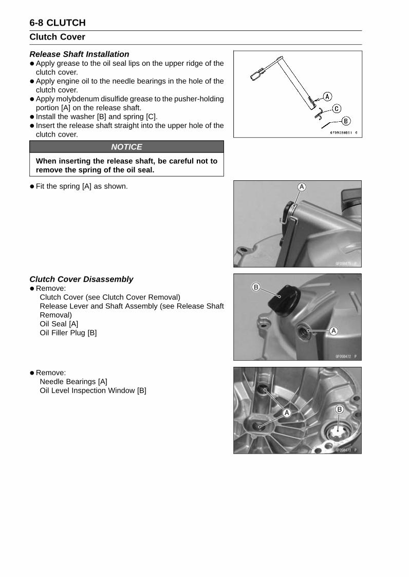
6-8 CLUTCHClutch Cover
Release Shaft Installation•Apply grease to the oil seal lips on the upper ridge of the
clutch cover.• Apply engine oil to the needle bearings in the hole of the
clutch cover.• Apply molybdenum disulfide grease to the pusher-holding
portion [A] on the release shaft.• Install the washer [B] and spring [C].• Insert the release shaft straight into the upper hole of the
clutch cover.
NOTICEWhen inserting the release shaft, be careful not toremove the spring of the oil seal.
•Fit the spring [A] as shown.
Clutch Cover Disassembly•Remove:
Clutch Cover (see Clutch Cover Removal)Release Lever and Shaft Assembly (see Release ShaftRemoval)Oil Seal [A]Oil Filler Plug [B]
•Remove:Needle Bearings [A]Oil Level Inspection Window [B]

CLUTCH 6-9Clutch Cover
Clutch Cover Assembly•Replace the needle bearings and oil seal with new ones.
NOTEInstall the needle bearings so that the manufacture’s
mark face out.
• Install the needle bearings [A] and oil seal [B] position asshown.Press the lower bearing, do not protrude from the boss
[C] of the clutch cover.Press the upper bearing so that the bearing surface [D] is
flush with the housing end of clutch cover [E].Press the oil seal until the bottom.• Apply grease to the oil seal lips.
• Apply water to the rubber portion [A] of the oil level in-spection window.
• Press the oil level inspection window so that its projection[B] faces inside of the clutch cover [C].
• Replace the O-ring [A] of the oil filler plug [B] with a newone.
• Apply grease to the new O-ring.• Tighten:
Torque - Oil Filler Plug: Hand-tighten

6-10 CLUTCHClutch
Clutch Removal•Remove:
Clutch Cover (see Clutch Cover Removal)Starter Clutch Bolt Cap [A]
•Using a wrench on the starter clutch bolt, turn the crank-shaft clockwise until the clutch stopper bolts [A] reachesthe position as shown.
• Set the special tools as shown to hold the clutch stopperplate.Special Tools - Crankcase Splitting Tool Assembly [A]:
57001-1362Clutch Plate Holder [B]: 57001-1788
128 mm [C] (57001-1362)139 mm [D] (57001-1788)173 mm [E] (57001-1788)
• Screw the center bolt [F] of the crankcase splitting toolassembly tightly.
• Remove the clutch stopper bolts [A].• Remove the crankcase splitting tool assembly and clutch
plate holder.• Remove:
Clutch Stopper PlateClutch Springs
•Remove:Clutch Pressure Plate [A] (with Shim, Bearing, Pusher[B], Spring and Washer)Friction Plates and Steel Plates

CLUTCH 6-11Clutch
•Hold the sub clutch hub [A] steady with the clutch holder[B], and remove the nut [C] and washers.Special Tool - Clutch Holder: 57001-1243
Use the clutch holder with sharpened hook nose by grind-ing.Special Tool - Clutch Holder: 57001-1243Grind the hook nose by 0.5 mm (0.02 in.) as shown.
•Remove:Clutch Hub [A]Spacer [B]
•Using the two 4 mm (0.16 in.) bolts [A], pull out the sleeve[B], needle bearing [C] and clutch housing [D].
• Remove the spacer.
Clutch Installation• Install the spacer [A] so that the stepped side [B] faces
inward.
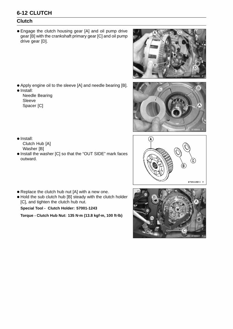
6-12 CLUTCHClutch
•Engage the clutch housing gear [A] and oil pump drivegear [B] with the crankshaft primary gear [C] and oil pumpdrive gear [D].
• Apply engine oil to the sleeve [A] and needle bearing [B].• Install:
Needle BearingSleeveSpacer [C]
• Install:Clutch Hub [A]Washer [B]
• Install the washer [C] so that the “OUT SIDE” mark facesoutward.
•Replace the clutch hub nut [A] with a new one.•Hold the sub clutch hub [B] steady with the clutch holder
[C], and tighten the clutch hub nut.Special Tool - Clutch Holder: 57001-1243
Torque - Clutch Hub Nut: 135 N·m (13.8 kgf·m, 100 ft·lb)

CLUTCH 6-13Clutch
• Install the friction plates [A] and steel plates [B] alternatelyas shown.Thick Steel Plate [C]
NOTICEIf new dry friction plates and steel plates are in-stalled, apply engine oil to the surfaces of eachplate to avoid clutch plate seizure.
Install the last friction plate and steel plate later with theclutch pressure plate.
• Apply molybdenum disulfide grease to the pusher end [A].• Install the washer [B], spring [C], bearing [D] and shim [E]
to the pusher.• Install the pusher to the drive shaft [F] direction as shown.
• Put the last friction plate [A] and steel plate [B] on theclutch pressure plate [C] and install them.
• Install the last friction plate so that the tangs [A] fit into thegrooves in the housing as shown.
NOTEMake sure that the clutch pressure plate is installed
without a gap.

6-14 CLUTCHClutch
•Be sure to install the spring seats on the clutch pressureplate.
• Install:Clutch SpringsClutch Stopper Plate [A]
• Tighten the clutch stopper bolts by hand.Hold the clutch pressure plate by hand while tightening
the clutch stopper bolts.• Check the clutch stopper bolts position is correct (see
Clutch Removal).
• Set the special tools.Refer to the Clutch Removal for setting the special tools.
Special Tools - Crankcase Splitting Tool Assembly: 57001-1362
Clutch Plate Holder: 57001-1788
•To press the clutch springs, tighten the center bolt [A] ofthe crankcase splitting tool assembly until the clutch stop-per plate stops.The clutch stopper plate stops in contact with the boss of
the clutch hub.
NOTICETightening the center bolt of the crankcase splittingtool assembly too much may damage the specialtools.
•Tighten:Torque - Clutch Stopper Bolts [A]: 8.8 N·m (0.90 kgf·m, 78
in·lb)
•Remove the crankcase splitting tool assembly and clutchplate holder.
• Install:Clutch Cover (see Clutch Cover Installation)

CLUTCH 6-15Clutch
Clutch Plate Assembly Length Measurement•Assemble the following parts.
Clutch Hub [A]Friction Plates [B]Steel Plates [C]Clutch Pressure Plate [D]Spring Seats [E]Clutch Springs [F]Clutch Stopper Plate [G]Clutch Stopper Bolts [H]
Torque - Clutch Stopper Bolts: 8.8 N·m (0.90 kgf·m, 78in·lb)
•Measure the clutch plate assembly length [I].
Clutch Plate Assembly Length40.5 ∼ 41.3 mm (1.59 ∼ 1.63 in.)
NOTEThe length of the clutch plate assembly changes by the
steel plate thickness.
Clutch Plate, Wear, Damage Inspection•Visually inspect the friction and steel plates for signs of
seizure, overheating (discoloration), or uneven wear.•Measure the thickness of each friction plate [A] at several
points.If any plates show signs of damage, or if they have wornpast the service limit, replace them with new ones.
Friction Plate ThicknessStandard: 2.72 ∼ 2.88 mm (0.107 ∼ 0.113 in.)Service Limit: 2.5 mm (0.098 in.)
Clutch Plate Warp Inspection•Place each friction plate or steel plate on a surface plate
and measure the gap between the surface plate [A] andeach friction plate or steel plate [B] with a thickness gauge[C]. The gap is the amount of friction or steel plate warp.If any plate is warped over the service limit, replace it witha new one.
Friction and Steel Plate WarpStandard: 0.15 mm (0.0059 in.) or lessService Limit: 0.3 mm (0.012 in.)
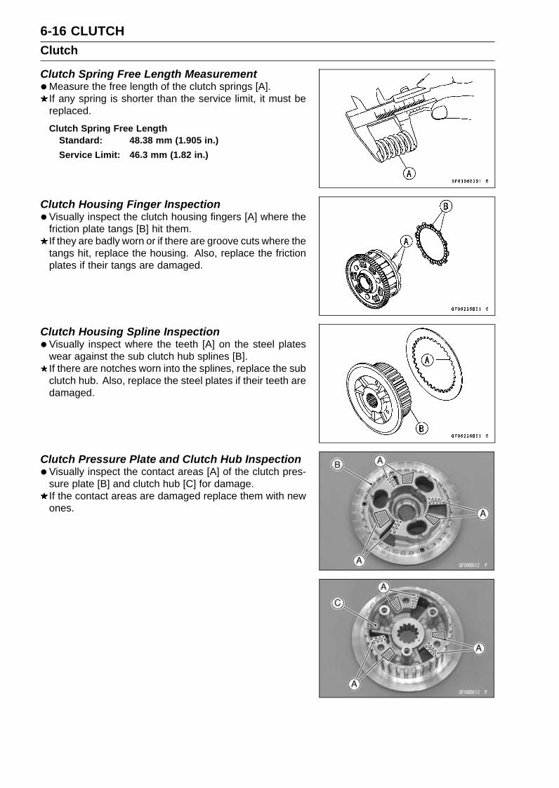
6-16 CLUTCHClutch
Clutch Spring Free Length Measurement•Measure the free length of the clutch springs [A].
If any spring is shorter than the service limit, it must bereplaced.
Clutch Spring Free LengthStandard: 48.38 mm (1.905 in.)Service Limit: 46.3 mm (1.82 in.)
Clutch Housing Finger Inspection•Visually inspect the clutch housing fingers [A] where the
friction plate tangs [B] hit them.If they are badly worn or if there are groove cuts where thetangs hit, replace the housing. Also, replace the frictionplates if their tangs are damaged.
Clutch Housing Spline Inspection•Visually inspect where the teeth [A] on the steel plates
wear against the sub clutch hub splines [B].If there are notches worn into the splines, replace the subclutch hub. Also, replace the steel plates if their teeth aredamaged.
Clutch Pressure Plate and Clutch Hub Inspection•Visually inspect the contact areas [A] of the clutch pres-
sure plate [B] and clutch hub [C] for damage.If the contact areas are damaged replace them with newones.
ENGINE LUBRICATION SYSTEM 7-1
7
Engine Lubrication SystemTable of Contents
Exploded View........................................................................................................................ 7-2Engine Oil Flow Chart............................................................................................................. 7-4Specifications ......................................................................................................................... 7-7Special Tools and Sealant ...................................................................................................... 7-8Engine Oil and Oil Filter.......................................................................................................... 7-9
Oil Level Inspection........................................................................................................... 7-9Engine Oil Change............................................................................................................ 7-9Oil Filter Replacement ...................................................................................................... 7-9
Oil Pan.................................................................................................................................... 7-10Oil Pan Removal ............................................................................................................... 7-10Oil Pan Installation ............................................................................................................ 7-10
Oil Pressure Relief Valve........................................................................................................ 7-11Oil Pressure Relief Valve Removal ................................................................................... 7-11Oil Pressure Relief Valve Installation ................................................................................ 7-12Oil Pressure Relief Valve Inspection................................................................................. 7-13
Oil Pump................................................................................................................................. 7-14Oil Pump Removal ............................................................................................................ 7-14Oil Pump Installation ......................................................................................................... 7-15Oil Pump Drive Gear Removal.......................................................................................... 7-16Oil Pump Drive Gear Installation....................................................................................... 7-16Oil Pump Drive Gear Shaft Removal ................................................................................ 7-16Oil Pump Drive Gear Shaft Installation ............................................................................. 7-17
Oil Cooler................................................................................................................................ 7-18Oil Cooler Removal........................................................................................................... 7-18Oil Cooler Installation........................................................................................................ 7-18Oil Cooler/Oil Filter Case Removal ................................................................................... 7-19Oil Cooler/Oil Filter Case Installation ................................................................................ 7-19
Oil Pressure Measurement..................................................................................................... 7-21Oil Pressure Measurement ............................................................................................... 7-21
Oil Pressure Switch ................................................................................................................ 7-22Oil Pressure Switch Removal ........................................................................................... 7-22Oil Pressure Switch Installation ........................................................................................ 7-22

7-2 ENGINE LUBRICATION SYSTEMExploded View

ENGINE LUBRICATION SYSTEM 7-3Exploded View
TorqueNo. Fastener
N·m kgf·m ft·lbRemarks
1 Air Bleed Bolt 9.8 1.0 87 in·lb2 Oil Cooler/Oil Filter Case Mounting Bolts 20 2.0 15 L3 Oil Cooler Mounting Bolts 20 2.0 154 Oil Filter Holder Bolt 25 2.5 18 L5 Oil Filter 17 1.7 13 G, R6 Oil Filter Guard Bolts 4.0 0.41 35 in·lb L7 Oil Jet Nozzles 2.9 0.30 26 in·lb8 Oil Passage Plugs (Taper) 20 2.0 15 L9 Oil Pressure Switch Terminal Bolt 1.5 0.15 13 in·lb G
10 Oil Pressure Switch 15 1.5 11 SS11 Water Pump Cover Bolts 12 1.2 106 in·lb L12 Oil Pump Drive Gear Bolt 9.8 1.0 87 in·lb L13 Oil Passage Plug 17 1.7 1314 Impeller Bolt 9.8 1.0 87 in·lb15 Engine Oil Drain Bolt 29 3.0 2116 Oil Pressure Relief Valve 15 1.5 11 L17 Oil Pan Bolts 9.8 1.0 87 in·lb SEO: Apply engine oil.
G: Apply grease.HG: Apply high-temperature grease.
L: Apply a non-permanent locking agent.M: Apply molybdenum disulfide grease.
MO: Apply molybdenum disulfide oil solution.(mixture of the engine oil and molybdenum disulfide grease in a weight ratio 10:1)
R: Replacement PartsS: Follow the specified tightening sequence.
SS: Apply silicone sealant.W: Apply water.

7-4 ENGINE LUBRICATION SYSTEMEngine Oil Flow Chart

ENGINE LUBRICATION SYSTEM 7-5Engine Oil Flow Chart
1. Intake Camshaft2. Exhaust Camshaft3. Camshaft Oil Passage4. Oil Filter5. Oil Cooler6. Oil Jet7. Oil Pressure Switch8. Drive Shaft Oil Passage9. Output Shaft Oil Passage
10. Oil Screen11. Oil Pressure Relief Valve12. Oil Pump13. Main Oil Passage14. Crankshaft Oil Passage15. Alternator Oil Passage

7-6 ENGINE LUBRICATION SYSTEMEngine Oil Flow Chart
1. Blowby Gas

ENGINE LUBRICATION SYSTEM 7-7Specifications
Item StandardEngine Oil
Type API SG, SH, SJ, SL or SM with JASO MA, MA1 or MA2Viscosity SAE 10W-40Capacity 2.8 L (3.0 US qt) (when filter is not removed)
3.1 L (3.3 US qt) (when filter is removed)3.6 L (3.8 US qt) (when engine is completely dry)
Level Between upper and lower level lines (Wait 2 ∼ 3 minutes afteridling or running)
Oil Pressure MeasurementOil Pressure 93 ∼ 123 kPa (0.95 ∼ 1.25 kgf/cm², 13 ∼ 18 psi) at 4 000 r/min
(rpm), Oil Temperature 90°C (194°F)

7-8 ENGINE LUBRICATION SYSTEMSpecial Tools and Sealant
Outside Circlip Pliers:57001-144
Oil Pressure Gauge, 10 kgf/cm²:57001-164
Oil Pressure Gauge Adapter, PT3/8:57001-1233
Liquid Gasket, TB1211:56019-120

ENGINE LUBRICATION SYSTEM 7-9Engine Oil and Oil Filter
WARNINGVehicle operation with insufficient, deteriorated,or contaminated engine oil will cause acceleratedwear and may result in engine seizure, accident,and injury. Check the oil level before each use andchange the oil and filter according to the periodicmaintenance chart.
Oil Level Inspection•Check that the engine oil level is between the upper [A]
and lower [B] levels in the oil level inspection window.
NOTESituate the motorcycle so that it is perpendicular to the
ground.If the motorcycle has just been used, wait several min-
utes for all the oil to drain down.If the oil has just been changed, start the engine and
run it for several minutes at idle speed. This fills the oilfilter with oil. Stop the engine, then wait several minutesuntil the oil settles.
NOTICERacing the engine before the oil reaches every partcan cause engine seizure.If the engine oil gets extremely low or if the oil pumpor oil passages clog up or otherwise do not func-tion properly, the red warning indicator light (LED)and oil pressure warning symbol will light. If thislight stays on when the engine is running aboveidle speed, stop the engine immediately and find thecause.If the oil level is too high, remove the excess oil, using asyringe or some other suitable device.If the oil level is too low, add the correct amount of oilthrough the oil filler opening. Use the same type andmake of oil that is already in the engine.
NOTEIf the engine oil type and make are unknown, use any
brand of the specified oil to top off the level in preferenceto running the engine with the oil level low. Then at yourearliest convenience, change the oil completely.
Engine Oil Change•Refer to the Engine Oil Change in the Periodic Mainte-
nance chapter.
Oil Filter Replacement•Refer to the Oil Filter Replacement in the Periodic Main-
tenance chapter.
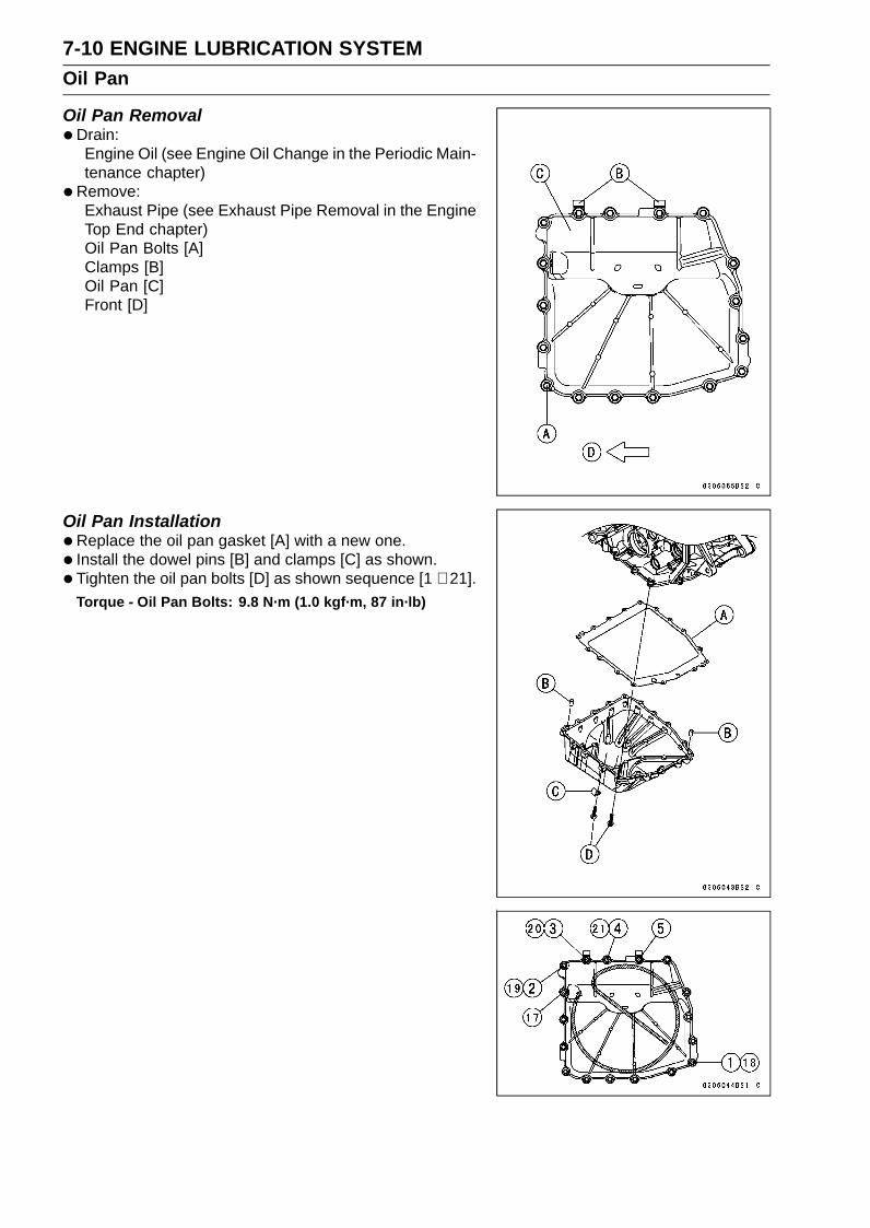
7-10 ENGINE LUBRICATION SYSTEMOil Pan
Oil Pan Removal•Drain:
Engine Oil (see Engine Oil Change in the Periodic Main-tenance chapter)
•Remove:Exhaust Pipe (see Exhaust Pipe Removal in the EngineTop End chapter)Oil Pan Bolts [A]Clamps [B]Oil Pan [C]Front [D]
Oil Pan Installation•Replace the oil pan gasket [A] with a new one.• Install the dowel pins [B] and clamps [C] as shown.• Tighten the oil pan bolts [D] as shown sequence [1 ∼ 21].
Torque - Oil Pan Bolts: 9.8 N·m (1.0 kgf·m, 87 in·lb)

ENGINE LUBRICATION SYSTEM 7-11Oil Pressure Relief Valve
Oil Pressure Relief Valve Removal•Remove:
Oil Pan (see Oil Pan Removal)Oil Screen [A]
•Remove the oil pressure relief valve [A].
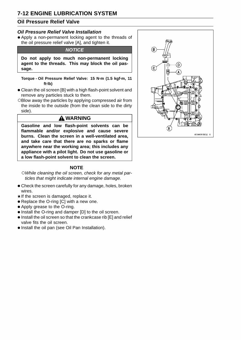
7-12 ENGINE LUBRICATION SYSTEMOil Pressure Relief Valve
Oil Pressure Relief Valve Installation•Apply a non-permanent locking agent to the threads of
the oil pressure relief valve [A], and tighten it.
NOTICEDo not apply too much non-permanent lockingagent to the threads. This may block the oil pas-sage.
Torque - Oil Pressure Relief Valve: 15 N·m (1.5 kgf·m, 11ft·lb)
•Clean the oil screen [B] with a high flash-point solvent andremove any particles stuck to them.Blow away the particles by applying compressed air from
the inside to the outside (from the clean side to the dirtyside).
WARNINGGasoline and low flash-point solvents can beflammable and/or explosive and cause severeburns. Clean the screen in a well-ventilated area,and take care that there are no sparks or flameanywhere near the working area; this includes anyappliance with a pilot light. Do not use gasoline ora low flash-point solvent to clean the screen.
NOTEWhile cleaning the oil screen, check for any metal par-
ticles that might indicate internal engine damage.
•Check the screen carefully for any damage, holes, brokenwires.If the screen is damaged, replace it.
• Replace the O-ring [C] with a new one.• Apply grease to the O-ring.• Install the O-ring and damper [D] to the oil screen.• Install the oil screen so that the crankcase rib [E] and relief
valve fits the oil screen.• Install the oil pan (see Oil Pan Installation).

ENGINE LUBRICATION SYSTEM 7-13Oil Pressure Relief Valve
Oil Pressure Relief Valve Inspection•Remove the oil pressure relief valve (see Oil Pressure
Relief Valve Removal).• Check to see if the valve [A] slides smoothly when push-
ing it in with a wooden or other soft rod, and see if it comesback to its seat by spring [B] pressure.
NOTEInspect the valve in its assembled state. Disassembly
and assembly may change the valve performance.
If any rough spots are found during above inspection,wash the valve clean with a high flash-point solvent andblow out any foreign particles that may be in the valve withcompressed air.
WARNINGGasoline and low flash-point solvents can beflammable and/or explosive and cause severeburns. Clean the oil pressure relief valve in awell-ventilated area, and take care that there are nosparks or flame anywhere near the working area;this includes any appliance with a pilot light. Donot use gasoline or a low flash-point solvent toclean the oil pressure relief valve.
If cleaning does not solve the problem, replace the oilpressure relief valve as an assembly. The oil pressurerelief valve is precision made with no allowance for re-placement of individual parts.

7-14 ENGINE LUBRICATION SYSTEMOil Pump
Oil Pump Removal•Drain:
Coolant (see Coolant Change in the Periodic Mainte-nance chapter)Engine Oil (see Engine Oil Change in the Periodic Main-tenance chapter)
•Remove:Water Pump Cover Bolts [A]Water Pump Cover [B]
• Loosen the water hose clamp screw [C].• Disconnect the water hose [D].
• Loosen the water hose clamp screw [A].• Disconnect the water hose [B].• Remove:
Impeller Bolt [C] and WasherImpeller [D]
• Install the impeller bolt [A] temporary.
•Using the impeller bolt [A], remove the oil (water) pump[B] as an assembly.
•Remove the outer rotor [C] and impeller bolt.
• Remove:Water Pump Body [A]Oil Pump Cover [B]Inner Rotor [C]Pin [D]Oil (Water) Pump Shaft [E]

ENGINE LUBRICATION SYSTEM 7-15Oil Pump
Oil Pump Installation• Install the outer rotor [A] into the crankcase.• Install the pin [B] and inner rotor [C] to the oil (water) pump
shaft [D], and install the assy.Turn the pump shaft so that the slot [E] in its shaft fits onto
the projection [F] of the pump drive gear shaft.
• Fit the pin [A] of the oil pump cover [B] into the hole [C] inthe crankcase.
•Replace the O-ring [A] with a new one.• Install the dowel pins [B].• Fit the dowel pins of the crankcase into the holes [C] in
the water pump body [D].
• Apply coolant to the seating surface [A] on the impeller.• Install the impeller, washer and bolt.• Tighten:
Torque - Impeller Bolt: 9.8 N·m (1.0 kgf·m, 87 in·lb)
• Install the water hose [A] and hose clamp [B] as shown.White Mark [C]
• Tighten:Torque - Water Hose Clamp Screws: 3.0 N·m (0.31 kgf·m,
27 in·lb)
•Replace the O-ring [D] with a new one.• Install the dowel pins [E] and water pump cover.• Apply a non-permanent locking agent to the threads of
the water pump cover bolts, and tighten them.Torque - Water Pump Cover Bolts: 12 N·m (1.2 kgf·m, 106
in·lb)

7-16 ENGINE LUBRICATION SYSTEMOil Pump
•Align the line [A] of the water pump cover and the whitemark [B] of the water hose [C].
• Install the water hose clamp [D] as shown.• Tighten:
Torque - Water Hose Clamp Screws: 3.0 N·m (0.31 kgf·m,27 in·lb)
Oil Pump Drive Gear Removal•Remove the clutch (see Clutch Removal in the Clutch
chapter).• Fit the suitable tool into the hole of the oil passage plug
[A].
• Hold the oil pump drive gear [A] steady with the suitabletool [B], and remove the oil pump drive gear bolt [C].
• Remove the oil pump drive gear.
Oil Pump Drive Gear Installation•Align the groove [A] of the oil pump drive gear to the oil
pump drive gear shaft [B] to install the oil pump drive gear.• Apply a non-permanent locking agent to the threads of
the oil pump drive gear bolt.• Hold the oil pump drive gear steady with the suitable tool,
and tighten the bolt.Torque - Oil Pump Drive Gear Bolt: 9.8 N·m (1.0 kgf·m, 87
in·lb)
Oil Pump Drive Gear Shaft Removal•Remove:
Oil Pump Drive Gear (see Oil Pump Drive Gear Re-moval)Oil Pan (see Oil Pan Removal)Oil Screen (see Oil Pressure Relief Valve Removal)Circlip [A]Washer [B]Oil Pump Drive Gear Shaft [C]
Special Tool - Outside Circlip Pliers: 57001-144
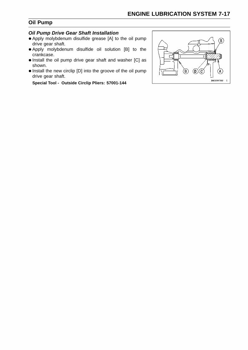
ENGINE LUBRICATION SYSTEM 7-17Oil Pump
Oil Pump Drive Gear Shaft Installation•Apply molybdenum disulfide grease [A] to the oil pump
drive gear shaft.• Apply molybdenum disulfide oil solution [B] to the
crankcase.• Install the oil pump drive gear shaft and washer [C] as
shown.• Install the new circlip [D] into the groove of the oil pump
drive gear shaft.Special Tool - Outside Circlip Pliers: 57001-144

7-18 ENGINE LUBRICATION SYSTEMOil Cooler
Oil Cooler Removal•Drain:
Coolant (see Coolant Change in the Periodic Mainte-nance chapter)Engine Oil (see Engine Oil Change in the Periodic Main-tenance chapter)
•Remove:Starter Motor (see Starter Motor Removal in the Electri-cal System chapter)
• Loosen the water hose clamp screw [A].• Disconnect the water hose [B].
• Loosen the water hose clamp screw [A].• Disconnect the water hose [B].• Remove:
Oil Cooler Mounting Bolts [C]Oil Cooler [D]
Oil Cooler Installation•Replace the O-ring [A] with a new one.
• Install the oil cooler [A].• Tighten:
Torque - Oil Cooler Mounting Bolts [B]: 20 N·m (2.0 kgf·m,15 ft·lb)
• Install the water hoses and hose clamps (see Cable, Wire,and Hose Routing section in the Appendix chapter).
• Tighten:Torque - Water Hose Clamp Screws: 3.0 N·m (0.31 kgf·m,
27 in·lb)
• Install the removed parts (see appropriate chapters).• Pour:
Coolant (see Coolant Change in the Periodic Mainte-nance chapter)Engine Oil (see Engine Oil Change in the Periodic Main-tenance chapter)

ENGINE LUBRICATION SYSTEM 7-19Oil Cooler
Oil Cooler/Oil Filter Case Removal•Remove:
Oil Filter (see Oil Filter Replacement in the PeriodicMaintenance chapter)Oil Cooler (see Oil Cooler Removal)Oil Filter Guard Bolts [A]Oil Filter Guard [B]
•Remove:Oil Cooler/Oil Filter Case Mounting Bolts [A]
•Remove:Oil Cooler/Oil Filter Case Mounting Bolts [A]Oil Cooler/Oil Filter Case [B]
Remove the oil filter holder bolt [C] as necessary.
Oil Cooler/Oil Filter Case InstallationIf the crankcase was disassembled, pour the engine oilinto the oil passage [A] until O-ring insert portion [B] ofthe upper crankcase.

7-20 ENGINE LUBRICATION SYSTEMOil Cooler
If the oil filter holder bolt [A] was removed, install it.Apply a non-permanent locking agent to the threads of
the oil filter holder bolt, and tighten it.Torque - Oil Filter Holder Bolt: 25 N·m (2.5 kgf·m, 18 ft·lb)
•Replace the O-rings [A] with new ones.• Apply grease to the new O-rings.
• Install the oil cooler/oil filter case.• Apply a non-permanent locking agent to the threads of the
oil cooler/oil filter case mounting bolts, and tighten them.Torque - Oil Cooler/Oil Filter Case Mounting Bolts: 20 N·m
(2.0 kgf·m, 15 ft·lb)
• Install the oil filter guard.• Apply a non-permanent locking agent to the threads of
the oil filter guard bolts, and tighten them.Torque - Oil Filter Guard Bolts: 4.0 N·m (0.41 kgf·m, 35
in·lb)
• Install:Oil Cooler (see Oil Cooler Installation)Oil Filter (see Oil Filter Replacement in the PeriodicMaintenance chapter)

ENGINE LUBRICATION SYSTEM 7-21Oil Pressure Measurement
Oil Pressure Measurement•Remove:
Right Lower Fairing (see Lower Fairing Removal in theFrame chapter)Oil Passage Plug [A]
• Attach the adapter [A] and gauge [B] to the plug hole.Special Tools - Oil Pressure Gauge, 10 kgf/cm²: 57001-164
Oil Pressure Gauge Adapter, PT3/8: 57001-1233
•Start the engine and warm up the engine.•Run the engine at the specified speed, and read the oil
pressure gauge.
Oil PressureStandard: 93 ∼ 123 kPa (0.95 ∼ 1.25 kgf/cm², 13 ∼ 18
psi) at 4 000 r/min (rpm), Oil Temperature90°C (194°F)
If the reading is much lower than the standard, checkthe oil pump, relief valve, and/or crankshaft bearing in-sert wear immediately.If the reading is much higher than the standard, check theoil passages for clogging.
• Stop the engine.•Remove the oil pressure gauge and adapter.
WARNINGHot oil can cause severe burns. Beware of hot en-gine oil that will drain through the oil passage whenthe gauge adapter is removed.
•Apply a non-permanent locking agent to the oil passageplug, and install it.Torque - Oil Passage Plug (Taper): 20 N·m (2.0 kgf·m,
15 ft·lb)

7-22 ENGINE LUBRICATION SYSTEMOil Pressure Switch
Oil Pressure Switch Removal•Drain the engine oil (see Engine Oil Change in the Peri-
odic Maintenance chapter).• Remove the right lower fairing (see Lower Fairing Re-
moval in the Frame chapter).• Slide the switch cover [A].• Remove:
Switch Terminal Bolt [B]Oil Pressure Switch [C]
Oil Pressure Switch Installation•Using a high flash-point solvent, clean off any oil or dirt
that may be on the liquid gasket coating area. Dry themwith a clean cloth.
• Apply liquid gasket to the threads of the oil pressureswitch, and tighten it.Sealant - Liquid Gasket, TB1211: 56019-120
Torque - Oil Pressure Switch: 15 N·m (1.5 kgf·m, 11 ft·lb)
• Install the switch lead [A] as shown.Front View [B]
• Apply grease to the terminal.• Tighten:
Torque - Oil Pressure Switch Terminal Bolt: 1.5 N·m (0.15kgf·m, 13 in·lb)
• Install the switch cover.• Install the removed parts (see appropriate chapters).

ENGINE REMOVAL/INSTALLATION 8-1
8
Engine Removal/InstallationTable of Contents
Exploded View........................................................................................................................ 8-2Special Tool ............................................................................................................................ 8-4Engine Removal/Installation ................................................................................................... 8-5
Engine Removal................................................................................................................ 8-5Engine Installation............................................................................................................. 8-7

8-2 ENGINE REMOVAL/INSTALLATIONExploded View

ENGINE REMOVAL/INSTALLATION 8-3Exploded View
TorqueNo. Fastener
N·m kgf·m ft·lbRemarks
1 Adjusting Collar Locknuts 49 5.0 36 S2 Right Front Engine Mounting Bolt 44 4.5 32 S3 Left Front Engine Mounting Bolt 44 4.5 32 S4 Adjusting Collars 9.8 1.0 87 in·lb S, (M)5 Middle Engine Mounting Nut 44 4.5 32 R, S6 Lower Engine Mounting Nut 44 4.5 32 R, S
S: Follow the specified tightening sequence.M: Apply molybdenum disulfide grease.

8-4 ENGINE REMOVAL/INSTALLATIONSpecial Tool
Engine Mount Nut Wrench:57001-1450

ENGINE REMOVAL/INSTALLATION 8-5Engine Removal/Installation
Engine Removal•Support the rear part of the swingarm with a stand.• Squeeze the brake lever slowly and hold it with a band
[A].
WARNINGMotorcycle may fall over unexpectedly resulting inan accident or injury. Be sure to hold the front brakewhen removing the engine.
NOTICEBe sure to hold the front brake when removing theengine, or the motorcycle may fall over. The engineor the motorcycle could be damaged.
•Drain:Engine Oil (see Engine Oil Change in the Periodic Main-tenance chapter)Coolant (see Coolant Change in the Periodic Mainte-nance chapter)
•Remove:Upper Fairing Assembly (see Upper Fairing AssemblyRemoval in the Frame chapter)Coolant Reserve Tank (see Coolant Reserve Tank Re-moval in the Cooling System chapter)Fuel Tank (see Fuel Tank Removal in the Fuel System(DFI) chapter)Air Cleaner Housing (see Air Cleaner Housing Removalin the Fuel System (DFI) chapter)Throttle Body Assy (see Throttle Body Assy Removal inthe Fuel System (DFI) chapter)Clutch Cable Lower End (see Cable Removal in theClutch chapter)Radiator (see Radiator and Radiator Fan Removal in theCooling System chapter)Heat Insulation Plate (see Heat Insulation Plate Re-moval in the Cooling System chapter)Exhaust Pipe (see Exhaust Pipe Removal in the EngineTop End chapter)Shift Lever (see Shift Pedal Removal in the Crank-shaft/Transmission chapter)Engine Sprocket (see Engine Sprocket Removal in theFinal Drive chapter)
•Remove the air switching valve [A] (see Air SwitchingValve Removal in the Engine Top End chapter).
• Disconnect:Stick Coil Connectors [B]Water Temperature Sensor Connector (see Wa-ter Temperature Sensor Removal/Installation in theSelf-Diagnosis System chapter)Starter Motor Cable (see Starter Motor Removal in theElectrical System chapter)Gear Position Switch/Sidestand Switch Lead Connector[C]Crankshaft Sensor/Oil Pressure Switch Lead Connector[D]

8-6 ENGINE REMOVAL/INSTALLATIONEngine Removal/Installation
•Free the lead from the clamps [A].• Disconnect the sidestand switch lead connector [B].
• Remove the engine ground cable terminal bolt [A].
• Remove:Bolt [A]
• Support the engine with a suitable stand [A].Put a plank [B] onto the suitable stand for engine balance.
•Remove:Left Front Engine Mounting Bolt [A]

ENGINE REMOVAL/INSTALLATION 8-7Engine Removal/Installation
•Remove:Right Front Engine Mounting Bolt [A]Middle Engine Mounting Nut [B]Lower Engine Mounting Nut
NOTEHold the mounting bolt not to turn when loosening the
middle and lower engine mounting nuts.
•Using the engine mount nut wrench [A], loosen the lock-nuts [B].Special Tool - Engine Mount Nut Wrench: 57001-1450
•Using the Hexagon Wrench, turn the adjusting collars [A]counterclockwise to make the gap between the engineand adjusting collar.
• Turn the lower engine mounting bolt clockwise to makethe gap between the adjusting collar and frame.
• Pull out the engine mounting bolts.• Using the stand, take out the engine.
Engine Installation•Apply molybdenum disulfide grease to the threads of the
adjusting collar [A].• Install the adjusting collar to crankcase backside until end
of the threads.

8-8 ENGINE REMOVAL/INSTALLATIONEngine Removal/Installation
• Install the adjusting collars [A] to the frame until end of thethreads.
•Replace the engine mounting nuts with new ones.• Support the engine with a suitable stand.Put a plank onto the suitable stand for engine balance.Support the engine until all bolts have been tightened.
• Install the engine mounting bolts and nuts, following thespecified installing sequence.First, tighten the following bolts and nuts temporarily.
Lower Engine Mounting Bolt [A] and NutMiddle Engine Mounting Bolt [B] and NutLeft Front Engine Mounting Bolt [C]Right Front Engine Mounting Bolt [D]

ENGINE REMOVAL/INSTALLATION 8-9Engine Removal/Installation
Second, tighten the left front engine mounting bolt [A].Frame [B]Engine [C]
Torque - Left Front Engine Mounting Bolt: 44 N·m (4.5kgf·m, 32 ft·lb)
Third, tighten the lower engine mounting bolt [A] coun-terclockwise until the adjusting collar [B] touches [C] theframe [D].Fourth, tighten the adjusting collar [E] counterclockwise
until the adjusting collar touches [C] the engine [D].Fifth, tighten the adjusting collars [B] and [E] .
Torque - Adjusting Collars: 9.8 N·m (1.0 kgf·m, 87 in·lb)Sixth, tighten the adjusting collar locknut [F].
Special Tool - Engine Mount Nut Wrench: 57001-1450
Torque - Adjusting Collar Locknut: 49 N·m (5.0 kgf·m, 36ft·lb)
Seventh, tighten the lower and middle engine mountingnuts.Torque - Lower Engine Mounting Nut [G]: 44 N·m (4.5
kgf·m, 32 ft·lb)Middle Engine Mounting Nut [H]: 44 N·m (4.5
kgf·m, 32 ft·lb)
NOTEHold the mounting bolt not to turn when tightening the
middle and lower engine mounting nuts.
Eighth, remove the right front engine mounting bolt [A],and tighten the adjusting collar [B] counterclockwise untilthe clearance [C] between the engine [D] and collar cometo 0 mm (0 in.).Ninth, tighten the adjusting collar locknut [E].
Special Tool - Engine Mount Nut Wrench: 57001-1450
Torque - Adjusting Collar Locknut: 49 N·m (5.0 kgf·m, 36ft·lb)
Lastly, tighten the right front engine mounting bolt.Torque - Right Front Engine Mounting Bolt: 44 N·m (4.5
kgf·m, 32 ft·lb)

8-10 ENGINE REMOVAL/INSTALLATIONEngine Removal/Installation
•Run the leads, cables and hoses correctly (see Cable,Wire, and Hose Routing section in the Appendix chapter).
• Install the removed parts (see appropriate chapters).• Adjust:
Throttle Cables (see Throttle Control System Inspectionin the Periodic Maintenance chapter)Clutch Cable (see Clutch Operation Inspection in the Pe-riodic Maintenance chapter)Drive Chain (see Drive Chain Slack Inspection in thePeriodic Maintenance chapter)
• Fill the engine with engine oil (see Engine Oil Change inthe Periodic Maintenance chapter).
• Fill the engine with coolant (see Coolant Change in thePeriodic Maintenance chapter).
CRANKSHAFT/TRANSMISSION 9-1
9
Crankshaft/TransmissionTable of Contents
Exploded View................................... 9-2Specifications .................................... 9-6Special Tools and Sealants ............... 9-9Crankcase ......................................... 9-11
Crankcase Splitting ...................... 9-11Crankcase Assembly ................... 9-12
Crankshaft and Connecting Rods...... 9-17Crankshaft Removal .................... 9-17Crankshaft Installation ................. 9-17Connecting Rod Removal ............ 9-18Connecting Rod Installation ......... 9-19Crankshaft/Connecting Rod
Cleaning .................................... 9-22Connecting Rod Bend Inspection 9-22Connecting Rod Twist Inspection. 9-22Connecting Rod Big End Side
Clearance Inspection ................ 9-23Connecting Rod Big End
Bearing Insert/Crankpin WearInspection.................................. 9-23
Crankshaft Side ClearanceInspection.................................. 9-25
Crankshaft Runout Inspection...... 9-25Crankshaft Main Bearing
Insert/Journal Wear Inspection . 9-25Pistons............................................... 9-28
Piston Removal............................ 9-28Piston Installation......................... 9-29Cylinder (Upper Crankcase) Wear
Inspection.................................. 9-30Piston Wear Inspection ................ 9-30Piston Ring, Piston Ring Groove
Wear Inspection ........................ 9-30Piston Ring Groove Width
Inspection.................................. 9-31Piston Ring Thickness Inspection 9-31Piston Ring End Gap Inspection .. 9-31
Starter Idle Gear and Starter Clutch .. 9-32Starter Idle Gear Removal ........... 9-32Starter Idle Gear Installation ........ 9-32Starter Clutch Removal................ 9-34Starter Clutch Installation ............ 9-34Starter Clutch Disassembly.......... 9-34Starter Clutch Assembly .............. 9-35Starter Clutch Inspection.............. 9-35
Transmission ..................................... 9-37Transmission Assy Removal........ 9-37Transmission Assy Disassembly . 9-37Transmission Assy Assembly ...... 9-37Transmission Assy Installation..... 9-39Transmission Shaft Removal ....... 9-40Transmission Shaft Installation .... 9-40Transmission Shaft Disassembly. 9-40Transmission Shaft Assembly...... 9-40Shift Drum and Fork Removal...... 9-44Shift Drum and Fork Installation... 9-44Shift Drum Disassembly............... 9-44Shift Drum Assembly ................... 9-44Shift Fork Bending Inspection ...... 9-44Shift Fork/Gear Groove Wear
Inspection.................................. 9-44Shift Fork Guide Pin/Drum
Groove Wear Inspection ........... 9-45Gear Dog and Gear Dog Hole
Damage Inspection ................... 9-45External Shift Mechanism.................. 9-46
Shift Pedal Removal .................... 9-46Shift Pedal Installation ................. 9-46External Shift Mechanism
Removal .................................... 9-46External Shift Mechanism
Installation ................................. 9-47External Shift Mechanism
Inspection.................................. 9-48
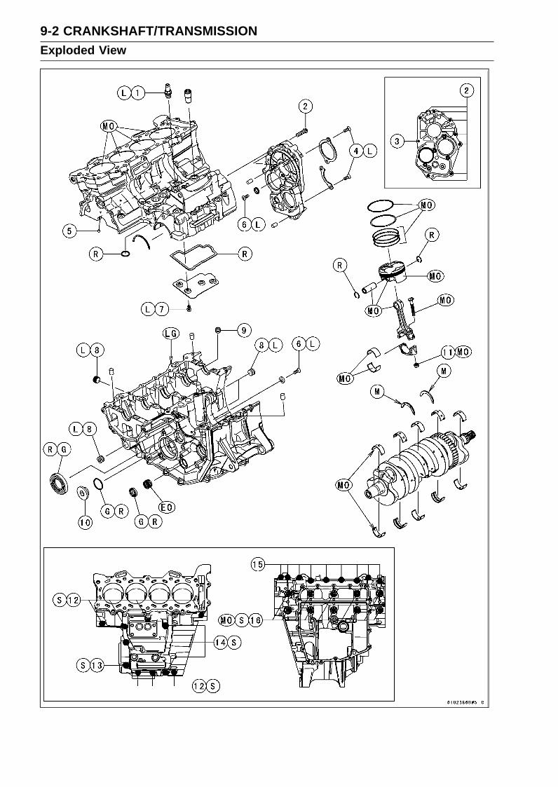
9-2 CRANKSHAFT/TRANSMISSIONExploded View

CRANKSHAFT/TRANSMISSION 9-3Exploded View
TorqueNo. Fastener
N·m kgf·m ft·lbRemarks
1 Breather Hose Fitting 15 1.5 11 L2 Transmission Case Bolts (M8) 20 2.0 153 Transmission Case Bolt (M6) 9.8 1.0 87 in·lb4 Bearing Holder Screws 4.9 0.50 43 in·lb L5 Oil Jet Nozzles 2.9 0.30 26 in·lb6 Race Holder Screws 4.9 0.50 43 in·lb L7 Breather Plate Bolts 9.8 1.0 87 in·lb L8 Oil Passage Plugs (Taper) 20 2.0 15 L9 Oil Passage Nozzle 4.9 0.50 43 in·lb
10 Oil Passage Plug 17 1.7 1311 Connecting Rod Big End Nuts see the text ← ← MO12 Crankcase Bolts (M6, L = 68 mm) 12 1.2 106 in·lb S13 Crankcase Bolt (M8, L = 90 mm) 27 2.8 20 S14 Crankcase Bolts (M8, L = 75 mm) 27 2.8 20 S15 Crankcase Bolts (M6, L = 50 mm) 12 1.2 106 in·lb16 Crankcase Bolts (M8, L = 95 mm) 31 3.2 23 MO, SEO: Apply engine oil.
G: Apply grease.L: Apply a non-permanent locking agent.
LG: Apply liquid gasket.M: Apply molybdenum disulfide grease.
MO: Apply molybdenum disulfide oil solution.(mixture of the engine oil and molybdenum disulfide grease in a weight ratio 10:1)
R: Replacement PartsS: Follow the specified tightening sequence.

9-4 CRANKSHAFT/TRANSMISSIONExploded View
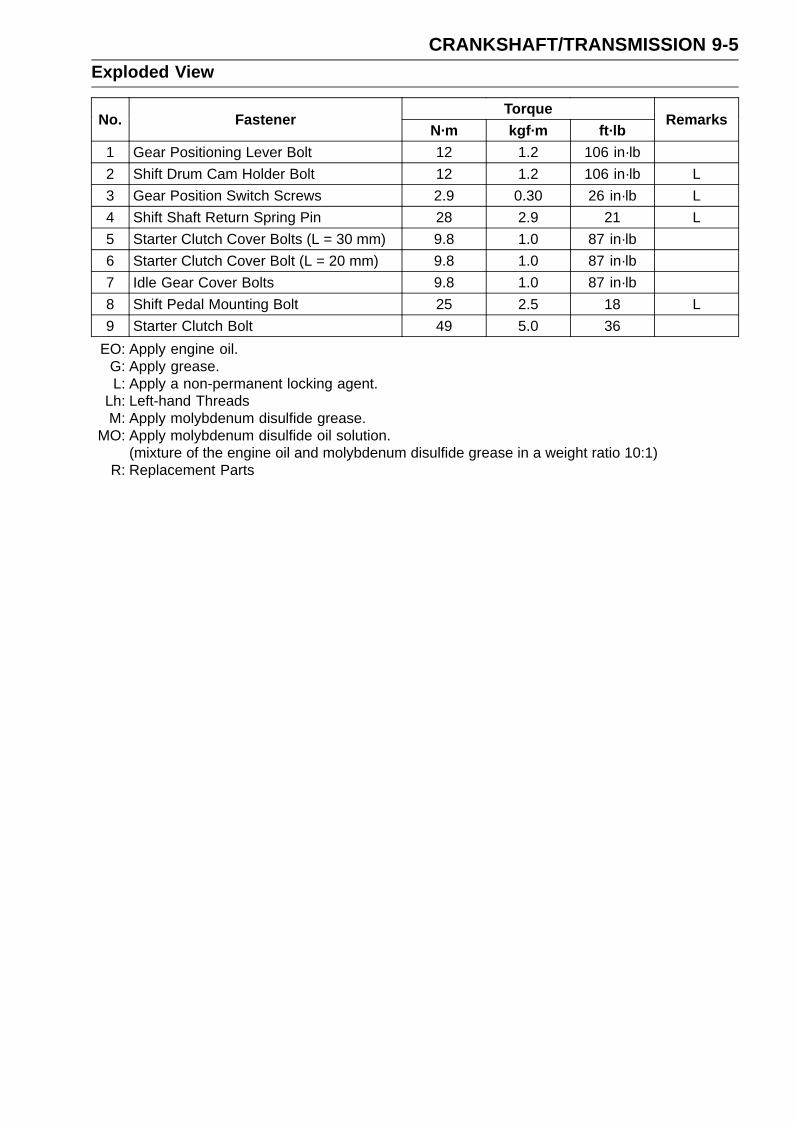
CRANKSHAFT/TRANSMISSION 9-5Exploded View
TorqueNo. Fastener
N·m kgf·m ft·lbRemarks
1 Gear Positioning Lever Bolt 12 1.2 106 in·lb2 Shift Drum Cam Holder Bolt 12 1.2 106 in·lb L3 Gear Position Switch Screws 2.9 0.30 26 in·lb L4 Shift Shaft Return Spring Pin 28 2.9 21 L5 Starter Clutch Cover Bolts (L = 30 mm) 9.8 1.0 87 in·lb6 Starter Clutch Cover Bolt (L = 20 mm) 9.8 1.0 87 in·lb7 Idle Gear Cover Bolts 9.8 1.0 87 in·lb8 Shift Pedal Mounting Bolt 25 2.5 18 L9 Starter Clutch Bolt 49 5.0 36
EO: Apply engine oil.G: Apply grease.L: Apply a non-permanent locking agent.
Lh: Left-hand ThreadsM: Apply molybdenum disulfide grease.
MO: Apply molybdenum disulfide oil solution.(mixture of the engine oil and molybdenum disulfide grease in a weight ratio 10:1)
R: Replacement Parts
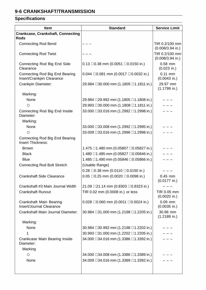
9-6 CRANKSHAFT/TRANSMISSIONSpecifications
Item Standard Service LimitCrankcase, Crankshaft, ConnectingRods
Connecting Rod Bend – – – TIR 0.2/100 mm(0.008/3.94 in.)
Connecting Rod Twist – – – TIR 0.2/100 mm(0.008/3.94 in.)
Connecting Rod Big End SideClearance
0.13 ∼ 0.38 mm (0.0051 ∼ 0.0150 in.) 0.58 mm(0.023 in.)
Connecting Rod Big End BearingInsert/Crankpin Clearance
0.044 ∼ 0.081 mm (0.0017 ∼ 0.0032 in.) 0.11 mm(0.0043 in.)
Crankpin Diameter: 29.984 ∼ 30.000 mm (1.1805 ∼ 1.1811 in.) 29.97 mm(1.1799 in.)
Marking:None 29.984 ∼ 29.992 mm (1.1805 ∼ 1.1808 in.) – – – 29.993 ∼ 30.000 mm (1.1808 ∼ 1.1811 in.) – – –
Connecting Rod Big End InsideDiameter:
33.000 ∼ 33.016 mm (1.2992 ∼ 1.2998 in.) – – –
Marking:None 33.000 ∼ 33.008 mm (1.2992 ∼ 1.2995 in.) – – – 33.009 ∼ 33.016 mm (1.2996 ∼ 1.2998 in.) – – –
Connecting Rod Big End BearingInsert Thickness:
Brown 1.475 ∼ 1.480 mm (0.05807 ∼ 0.05827 in.) – – –Black 1.480 ∼ 1.485 mm (0.05827 ∼ 0.05846 in.) – – –Blue 1.485 ∼ 1.490 mm (0.05846 ∼ 0.05866 in.) – – –
Connecting Rod Bolt Stretch (Usable Range)0.28 ∼ 0.38 mm (0.0110 ∼ 0.0150 in.) – – –
Crankshaft Side Clearance 0.05 ∼ 0.25 mm (0.0020 ∼ 0.0098 in.) 0.45 mm(0.0177 in.)
Crankshaft #3 Main Journal Width 21.09 ∼ 21.14 mm (0.8303 ∼ 0.8323 in.) – – –Crankshaft Runout TIR 0.02 mm (0.0008 in.) or less TIR 0.05 mm
(0.0020 in.)Crankshaft Main BearingInsert/Journal Clearance
0.028 ∼ 0.060 mm (0.0011 ∼ 0.0024 in.) 0.09 mm(0.0035 in.)
Crankshaft Main Journal Diameter: 30.984 ∼ 31.000 mm (1.2198 ∼ 1.2205 in.) 30.96 mm(1.2189 in.)
Marking:None 30.984 ∼ 30.992 mm (1.2198 ∼ 1.2202 in.) – – –1 30.993 ∼ 31.000 mm (1.2202 ∼ 1.2205 in.) – – –
Crankcase Main Bearing InsideDiameter:
34.000 ∼ 34.016 mm (1.3386 ∼ 1.3392 in.) – – –
Marking 34.000 ∼ 34.008 mm (1.3386 ∼ 1.3389 in.) – – –None 34.009 ∼ 34.016 mm (1.3389 ∼ 1.3392 in.) – – –

CRANKSHAFT/TRANSMISSION 9-7Specifications
Item Standard Service LimitCrankshaft Main Bearing InsertThickness:
Brown, Yellow 1.491 ∼ 1.495 mm (0.05870 ∼ 0.05886 in.) – – –Black, Green 1.495 ∼ 1.499 mm (0.05886 ∼ 0.05902 in.) – – –Blue, Purple 1.499 ∼ 1.503 mm (0.05902 ∼ 0.05917 in.) – – –
Cylinder , PistonsCylinder (Upper Crankcase) InsideDiameter
67.000 ∼ 67.012 mm (2.6378 ∼ 2.6383 in.) 67.09 mm(2.6413 in.)
Piston Diameter 66.960 ∼ 66.975 mm (2.6362 ∼ 2.6368 in.) 66.81 mm(2.6303 in.)
Piston/Cylinder Clearance 0.025 ∼ 0.052 mm (0.0010 ∼ 0.0020 in.) – – –Piston Ring/Groove Clearance:
Top 0.03 ∼ 0.07 mm (0.0012 ∼ 0.0028 in.) 0.17 mm(0.0067 in.)
Second 0.03 ∼ 0.07 mm (0.0012 ∼ 0.0028 in.) 0.17 mm(0.0067 in.)
Piston Ring Groove Width:Top 0.82 ∼ 0.84 mm (0.0323 ∼ 0.0331 in.) 0.92 mm
(0.036 in.)Second 0.82 ∼ 0.84 mm (0.0323 ∼ 0.0331 in.) 0.92 mm
(0.036 in.)Piston Ring Thickness:
Top 0.77 ∼ 0.79 mm (0.0303 ∼ 0.0311 in.) 0.70 mm(0.028 in.)
Second 0.77 ∼ 0.79 mm (0.0303 ∼ 0.0311 in.) 0.70 mm(0.028 in.)
Piston Ring End Gap:Top 0.12 ∼ 0.22 mm (0.0047 ∼ 0.0087 in.) 0.5 mm
(0.020 in.)Second 0.30 ∼ 0.45 mm (0.0118 ∼ 0.0177 in.) 0.8 mm
(0.031 in.)Transmission
Shift Fork Ear Thickness 5.9 ∼ 6.0 mm (0.232 ∼ 0.236 in.) 5.8 mm(0.228 in.)
Gear Groove Width 6.05 ∼ 6.15 mm (0.238 ∼ 0.242 in.) 6.25 mm(0.246 in.)
Shift Fork Guide Pin Diameter 5.9 ∼ 6.0 mm (0.232 ∼ 0.236 in.) 5.8 mm(0.228 in.)
Shift Drum Groove Width 6.05 ∼ 6.20 mm (0.238 ∼ 0.244 in.) 6.3 mm(0.248 in.)

9-8 CRANKSHAFT/TRANSMISSIONSpecifications
Connecting Rod Big End Bearing Insert SelectionBearing InsertCon-rod Big End
Inside DiameterMarking
Crankpin DiameterMarking Size Color Part Number
None Brown 92139-0167None None Black 92139-0166
None Blue 92139-0165
Crankshaft Main Bearing Insert SelectionBearing Insert*Crankcase Main
Bearing InsideDiameter Marking
Crankshaft MainJournal Diameter
Marking Size Color Part Number Journal Nos.
92139-0247 1, 5Brown
92139-0250 2, 4 1Yellow 92139-0253 3
92139-0246 1, 5Black
92139-0249 2, 4None 1Green 92139-0252 3
92139-0246 1, 5Black
92139-0249 2, 4 NoneGreen 92139-0252 3
92139-0245 1, 5Blue
92139-0248 2, 4None NonePurple 92139-0251 3
*: The bearing inserts for Nos. 2 and 4 journals have an oil groove, respectively.
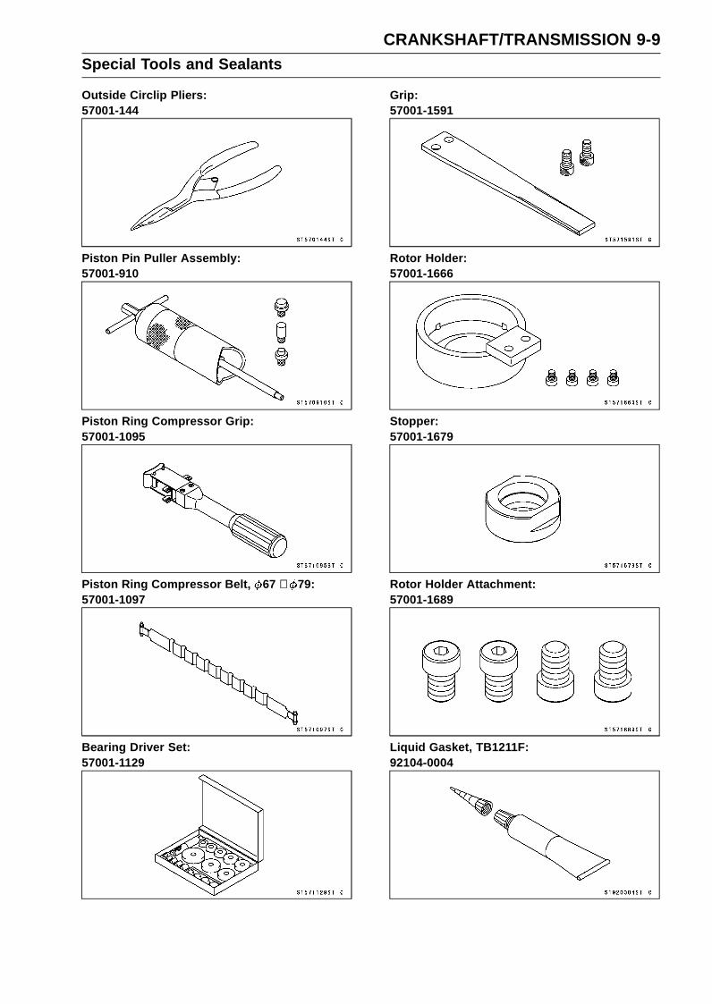
CRANKSHAFT/TRANSMISSION 9-9Special Tools and Sealants
Outside Circlip Pliers:57001-144
Piston Pin Puller Assembly:57001-910
Piston Ring Compressor Grip:57001-1095
Piston Ring Compressor Belt, 67 ∼ 79:57001-1097
Bearing Driver Set:57001-1129
Grip:57001-1591
Rotor Holder:57001-1666
Stopper:57001-1679
Rotor Holder Attachment:57001-1689
Liquid Gasket, TB1211F:92104-0004
9-10 CRANKSHAFT/TRANSMISSIONSpecial Tools and Sealants
Liquid Gasket, TB1216B:92104-1064

CRANKSHAFT/TRANSMISSION 9-11Crankcase
Crankcase Splitting•Remove the engine (see Engine Removal in the Engine
Removal/Installation chapter).• Set the engine on a clean surface and hold the engine
steady while parts are being removed.•Remove:
Crankshaft Sensor (see Crankshaft Sensor Removal inthe Electrical System chapter)Starter Clutch (see Starter Clutch Removal)Cylinder Head (see Cylinder Head Removal in the En-gine Top End chapter)Starter Motor (see Starter Motor Removal in the Electri-cal System chapter)Clutch (see Clutch Removal in the Clutch chapter)Oil Pump (see Oil Pump Removal in the Engine Lubri-cation System chapter)Alternator Rotor (see Alternator Rotor Removal in theElectrical System chapter)Oil Cooler/Oil Filter Case (see Oil Cooler/Oil Filter CaseRemoval in the Engine Lubrication System chapter)Oil Pan (see Oil Pan Removal in the Engine LubricationSystem chapter)Oil Screen (see Oil Pressure Relief Valve Removal in theEngine Lubrication System chapter)External Shift Mechanism (see External Shift Mecha-nism Removal)Transmission Assy (see Transmission Assy Removal)
•Remove the upper crankcase bolts, following the speci-fied sequence.Firstly, loosen the M6 bolts [A].Secondly, loosen the M8 bolts [B].
• Remove the lower crankcase bolts, following the specifiedsequence.Firstly, loosen the M6 bolts [A].Lastly, loosen the M8 bolts [B] as shown sequence [1 ∼
10].• Tap lightly around the crankcase mating surface with a
plastic mallet, and split the crankcase.Take care not to damage the crankcase.

9-12 CRANKSHAFT/TRANSMISSIONCrankcase
Crankcase AssemblyNOTICE
The upper and lower crankcase halves are ma-chined at the factory in the assembled state, so thecrankcase halves must be replaced as a set.
•With a high flash-point solvent, clean off the mating sur-faces of the crankcase halves and wipe dry.
WARNINGGasoline and low flash-point solvents can beflammable and/or explosive and cause severeburns. Clean the crankcase in a well-ventilatedarea, and take care that there are no sparks orflame anywhere near the working area; this in-cludes any appliance with a pilot light. Do not usegasoline or a low flash-point solvent to clean thecrankcase.
•Using compressed air, blow out the oil passages in thecrankcase halves.
Upper Crankcase Assembly•When installing the breather plate note the following.Replace the gasket [A] with a new one.
Apply a non-permanent locking agent to the threads ofthe bolts [A] and tighten them.Torque - Breather Plate Bolts: 9.8 N·m (1.0 kgf·m, 87 in·lb)

CRANKSHAFT/TRANSMISSION 9-13Crankcase
•Press the fitting [A] until it is bottomed.Special Tool - Bearing Driver Set: 57001-1129
•Apply a non-permanent locking agent to the threads ofthe breather hose fitting [B] and tighten it.View from Upside [C]
Torque - Breather Hose Fitting: 15 N·m (1.5 kgf·m, 11 ft·lb)
• Install the plug [D] so that the plug surface [E] is flush withthe end of the hole.View from Left Side [F]
• Install the oil jet nozzles [A], and tighten them.Torque - Oil Jet Nozzles: 2.9 N·m (0.30 kgf·m, 26 in·lb)
• Install:Position Ring [B]Ball Bearing [C]
Lower Crankcase Assembly•Press the race [A] so that the big stepped side faces to
inside of the crankcase until it is bottomed.• Install the race holder [B] as shown.• Apply a non-permanent locking agent to the threads of
the race holder screw [C].• Tighten:
Torque - Race Holder Screws: 4.9 N·m (0.50 kgf·m, 43 in·lb)
•Apply a non-permanent locking agent to the oil passageplugs [D].
• Tighten:Torque - Oil Passage Plugs (Taper): 20 N·m (2.0 kgf·m, 15
ft·lb)View from Right Side [E]View from Front Side [F]

9-14 CRANKSHAFT/TRANSMISSIONCrankcase
•Press the new needle bearing [A] for the shift shaft sothat its marked side faces outside [B] and its surface [C]is flush with the end of the hole.
• Install the new oil seal [D] so that its surface [E] is flushwith the end of the hole.
• Apply grease to the oil seal lips.•Replace the O-ring [F] with a new one.• Apply grease to the O-ring.• Tighten:
Torque - Oil Passage Plug [G]: 17 N·m (1.7 kgf·m, 13 ft·lb)View from Left Side [H]
• Install the oil passage nozzle [A], and tighten it.Torque - Oil Passage Nozzle: 4.9 N·m (0.50 kgf·m, 43 in·lb)
Crankcase Halves Assembly• Install:
Crankshaft (see Crankshaft Installation)Connecting Rods (see Connecting Rod Installation)Dowel Pins [A]O-rings [B]
• Before fitting the lower case on the upper case, check thefollowing.Be sure to hang the camshaft chain [C] on the crankshaft.

CRANKSHAFT/TRANSMISSION 9-15Crankcase
•Using a high flash-point solvent, clean off any oil or dirtthat may be on the liquid gasket, coating area. Dry themwith a clean cloth.
• Apply liquid gasket [A] to the mating surface of the lowercrankcase half.Sealant - Liquid Gasket, TB1216B: 92104-1064
NOTEEspecially, apply a sealant so that it shall be filled up on
the groove [B].Do not apply liquid gasket to the inside of the grooves
[C].
NOTICEDo not apply liquid gasket around the crankshaftmain bearing inserts and oil passage.
•Fit the lower crankcase half to the upper crankcase half.
NOTEMake the application finish within 20 minutes when
the liquid gasket to the mating surface of the lowercrankcase half is applied.Moreover fit the case and tighten the bolts just after
application of the liquid gasket.

9-16 CRANKSHAFT/TRANSMISSIONCrankcase
•The M8 bolts [A] has a copper plated washer [B], replaceit with a new one.
• Apply molybdenum disulfide oil solution to both sides [C]of the washers and threads [D] of M8 bolts.
• Tighten the lower crankcase bolts using the followingsteps.Following the sequence numbers on the lower crankcase
half, tighten M8 bolts [1 ∼ 10] with copper plated washers.Torque - Crankcase Bolts (M8) [A]:
First: 15 N·m (1.5 kgf·m, 11 ft·lb)Final: 31 N·m (3.2 kgf·m, 23 ft·lb)
Install the clamp [B], and tighten the M6 bolts [C].Torque - Crankcase Bolts (M6): 12 N·m (1.2 kgf·m, 106 in·lb)
•Tighten the upper crankcase bolts using the followingsteps.Replace the M8 bolt washers [A] with new ones.Tighten the M8 bolts with washers.
Torque - Crankcase Bolts (M8): 27 N·m (2.8 kgf·m, 20 ft·lb)L = 90 mm (3.54 in.) [B]L = 75 mm (2.95 in.) [C]
Tighten the M6 bolts [D].Torque - Crankcase Bolts (M6): 12 N·m (1.2 kgf·m, 106 in·lb)
•After tightening all crankcase bolts, check the followingitems.Wipe up the liquid gasket that seeps out around the
crankcase mating surface.Crankshaft turns freely.• Install the removed parts (see appropriate chapters).
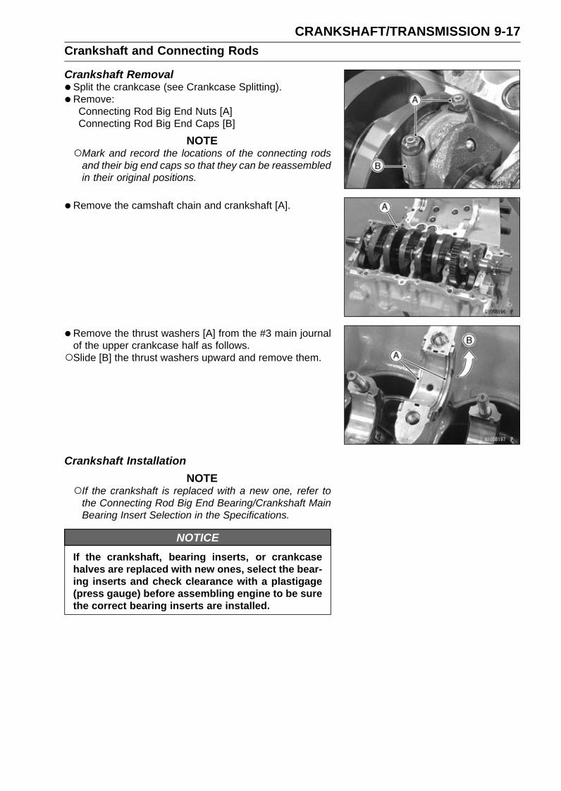
CRANKSHAFT/TRANSMISSION 9-17Crankshaft and Connecting Rods
Crankshaft Removal•Split the crankcase (see Crankcase Splitting).• Remove:
Connecting Rod Big End Nuts [A]Connecting Rod Big End Caps [B]
NOTEMark and record the locations of the connecting rods
and their big end caps so that they can be reassembledin their original positions.
•Remove the camshaft chain and crankshaft [A].
• Remove the thrust washers [A] from the #3 main journalof the upper crankcase half as follows.Slide [B] the thrust washers upward and remove them.
Crankshaft InstallationNOTE
If the crankshaft is replaced with a new one, refer tothe Connecting Rod Big End Bearing/Crankshaft MainBearing Insert Selection in the Specifications.
NOTICEIf the crankshaft, bearing inserts, or crankcasehalves are replaced with new ones, select the bear-ing inserts and check clearance with a plastigage(press gauge) before assembling engine to be surethe correct bearing inserts are installed.

9-18 CRANKSHAFT/TRANSMISSIONCrankshaft and Connecting Rods
•Apply molybdenum disulfide oil solution to the crankshaftmain bearing inserts.
• Install the crankshaft [A] with the camshaft chain [B] hang-ing on it.
• Install the connecting rod big end caps (see ConnectingRod Installation).
NOTEThe thrust washer [A] has oil grooves [B] on the one
side.The thrust washers are identical.
•Apply molybdenum disulfide grease [C] to the oil grooveside [D] of the thrust washers.
• Slide [E] the thrust washer of the one side into the grooveof the #3 main journal so that the oil grooves face outward.
•Move the crankshaft to the left or right, and then slide thethrust washer of the other side into the groove of the #3main journal in the same way.
• After installation, confirm that the blue-painted edges [F]of the thrust washers are positioned as shown.Front [G]
Connecting Rod Removal•Refer to the Piston Removal.

CRANKSHAFT/TRANSMISSION 9-19Crankshaft and Connecting Rods
Connecting Rod InstallationNOTICE
To minimize vibration, the connecting rods shouldhave the same weight mark.
Big End Cap [A]Connecting Rod [B]Weight Mark, Alphabet [C]Diameter Mark [D]: “” or no mark
NOTICEIf the connecting rods, big end bearing inserts, orcrankshaft are replaced with new ones, select thebearing insert and check clearance with a plasti-gage (press gauge) before assembling engine to besure the correct bearing inserts are installed.
•Apply molybdenum disulfide oil solution to the inner sur-face of the upper and lower bearing inserts [A].
• Apply molybdenum disulfide oil solution to the threads [B]and seating surface [C] of the connecting rod nuts.
• Install the inserts so that their nails [D] are on the sameside and fit them into the recess of the connecting rod andcap.
NOTICEWrong application of oil and grease could causebearing damage.
When installing the inserts [A], be careful not to damagethe insert surface with the edge of the connecting rod [B]or the cap [C]. One way to install inserts is as follows.Installation [D] to CapInstallation [E] to Connecting RodPush [F]Spare Dowel Pin [G]Connecting Rod Bolts [H]
•Remove debris and clean the surface of inserts.• Install the cap on the connecting rod, aligning the weight
and diameter marks.
• Install the crankshaft (see Crankshaft Installation).• Install each connecting rod on its original crankpin.The connecting rod big end is bolted using the “plastic
region fastening method”.This method precisely achieves the needed clamping
force without exceeding it unnecessarily, allowing theuse of thinner, lighter bolts further decreasing connectingrod weight.There are two types of the plastic region fastening. One is
a bolt length measurement method and other is a rotationangle method. Observe one of the following two, but thebolt length measurement method is preferable becausethis is a more reliable way to tighten the big end nuts.

9-20 CRANKSHAFT/TRANSMISSIONCrankshaft and Connecting Rods
NOTICEThe connecting rod bolts are designed to stretchwhen tightened. Never reuse the connecting rodbolts. See the table below for correct bolt and nutusage.
NOTICEBe careful not to overtighten the nuts.The bolts must be positioned on the seating surfacecorrectly to prevent the bolt heads from hitting thecrankcase.
(1) Bolt Length Measurement Method•Be sure to clean the bolts, nuts, and connecting rods
thoroughly with a high flash-point solvent, because thenew connecting rods, bolts, and nuts are treated with ananti-rust solution.
WARNINGGasoline and low flash-point solvents can beflammable and/or explosive and cause severeburns. Clean the bolts, nuts, and connecting rodsin a well-ventilated area, and take care that thereare no sparks or flame anywhere near the workingarea; this includes any appliance with a pilot light.Do not use gasoline or a low flash-point solvent toclean them.
NOTICEImmediately dry the bolts and nuts with com-pressed air after cleaning. Clean and dry the boltsand nuts completely.
• Install new bolts and nuts in reused connecting rod.If the connecting rod assembly was replaced, use thebolts and nuts attached to the new connecting rod assem-bly.
• Apply a small amount of molybdenum disulfide oil solutionto the following portions.Threads [A] of Nuts and BoltsSeating Surfaces [B] of Nuts and Connecting Rods

CRANKSHAFT/TRANSMISSION 9-21Crankshaft and Connecting Rods
•Dent both bolt head and bolt tip with a punch as shown.• Before tightening, use a point micrometer to measure the
length of new connecting rod bolts and record the valuesto find the bolt stretch.Connecting Rod [A]Dent here with a punch [B].Nuts [C]Fit micrometer pins into dents [D].
• Tighten the big end nuts until the bolt elongation reachesthe length specified as follows.
Bolt Length aftertightening – Bolt Length before
tightening = Bolt Stretch
Connecting Rod Bolt StretchUsable Range: 0.28 ∼ 0.38 mm (0.0110 ∼ 0.0150 in.)
•Check the length of the connecting rod bolts.If the stretch is more than the usable range, the bolt hasstretched too much. An overelongated bolt may break inuse.
(2) Rotation Angle MethodIf you don’t have a point micrometer, you may tighten thenuts using the “Rotation Angle Method”.
• Be sure to clean the bolts, nuts and connecting rods thor-oughly with a high flash-point solvent, because the newconnecting rods, bolts and nuts are treated with an anti-rust solution.
WARNINGGasoline and low flash-point solvents can beflammable and/or explosive and cause severeburns. Clean the bolts, nuts, and connecting rodsin a well-ventilated area, and take care that thereare no sparks or flame anywhere near the workingarea; this includes any appliance with a pilot light.Do not use gasoline or a low flash-point solvent toclean them.
NOTICEImmediately dry the bolts and nuts with com-pressed air after cleaning.Clean and dry the bolts and nuts completely.
• Install new bolts and nuts in reused connecting rod.If the connecting rod assembly was replaced, use thebolts and nuts attached to the new connecting rod assem-bly.
• Apply a small amount of molybdenum disulfide oil solutionto the following portions.Threads [A] of Nuts and BoltsSeating Surfaces [B] of Nuts and Connecting Rods

9-22 CRANKSHAFT/TRANSMISSIONCrankshaft and Connecting Rods
•First, tighten the nuts with 12.8 N·m (1.3 kgf·m, 113 in·lb)of torque.
•Next, tighten the nuts 175°.Using a torque angle gauge [A], tighten the nuts specified
angle.ConnectingRod Assy Bolt Nut Torque + Angle
N·m (kgf·m, in·lb)Attached tonew con-rod
Attached tonew con-rodNew
New New
12.8 (1.3, 113)+ 175°
UsedReplace thebolts withnew ones
Replace thenuts with newones
12.8 (1.3, 113)+ 175°
Crankshaft/Connecting Rod Cleaning•After removing the connecting rods from the crankshaft,
clean them with a high flash-point solvent.• Blow the crankshaft oil passages with compressed air to
remove any foreign particles or residue that may haveaccumulated in the passages.
Connecting Rod Bend Inspection•Remove the connecting rod big end bearing inserts, and
reinstall the connecting rod big end cap.• Select an arbor [A] of the same diameter as the connect-
ing rod big end, and insert the arbor through the connect-ing rod big end.
• Select an arbor of the same diameter as the piston pinand at least 100 mm (3.94 in.) long, and insert the arbor[B] through the connecting rod small end.
•On a surface plate, set the big-end arbor on V block [C].•With the connecting rod held vertically, use a height
gauge to measure the difference in the height of thearbor above the surface plate over a 100 mm (3.94 in.)length to determine the amount of connecting rod bend.If the connecting rod bend exceeds the service limit, theconnecting rod must be replaced.
Connecting Rod BendService Limit: TIR 0.2/100 mm (0.008/3.94 in.)
Connecting Rod Twist Inspection•With the big-end arbor [A] still on V block [C], hold the
connecting rod horizontally and measure the amount thatthe arbor [B] varies from being paralleled with the surfaceplate over a 100 mm (3.94 in.) length of the arbor to de-termine the amount of connecting rod twist.If the connecting rod twist exceeds the service limit, theconnecting rod must be replaced.
Connecting Rod TwistService Limit: TIR 0.2/100 mm (0.008/3.94 in.)

CRANKSHAFT/TRANSMISSION 9-23Crankshaft and Connecting Rods
Connecting Rod Big End Side ClearanceInspection•Measure connecting rod big end side clearance.Insert a thickness gauge [A] between the big end and ei-
ther crank web to determine clearance.
Connecting Rod Big End Side ClearanceStandard: 0.13 ∼ 0.38 mm (0.0051 ∼ 0.0150 in.)Service Limit: 0.58 mm (0.023 in.)
If the clearance exceeds the service limit, replace the con-necting rod with new one and then check clearance again.If the clearance is too large after connecting rod replace-ment, the crankshaft also must be replaced.
Connecting Rod Big End Bearing Insert/CrankpinWear Inspection•Remove the connecting rod big end (see Connecting Rod
Removal).• Cut strips of plastigage (press gauge) to crankpin width.
Place a strip on the crankpin parallel to the crankshaftinstalled in the correct position.
• Tighten the connecting rod big end nuts to the specifiedtorque (see Connecting Rod Installation).
NOTEDo not move the connecting rod and crankshaft during
clearance measurement.
•Remove the connecting rod big end again, measure eachclearance between the bearing insert and crankpin [A] us-ing plastigage (press gauge) [B].
NOTICEAfter measurement, replace the connecting rodbolts and nuts.
Connecting Rod Big End Bearing Insert/CrankpinClearance
Standard: 0.044 ∼ 0.081 mm (0.0017 ∼ 0.0032 in.)Service Limit: 0.11 mm (0.0043 in.)
If the clearance is within the standard, no bearing replace-ment is required.If the clearance is between 0.082 mm (0.0032 in.) andthe service limit (0.11 mm, 0.0043 in.), replace the bear-ing inserts [A] with inserts painted blue [B]. Check in-sert/crankpin clearance with the plastigage. The clear-ance may exceed the standard slightly, but it must not beless than the minimum in order to avoid bearing seizure.If the clearance exceeds the service limit, measure thediameter of the crankpins.
Crankpin DiameterStandard: 29.984 ∼ 30.000 mm (1.1805 ∼ 1.1811 in.)Service Limit: 29.97 mm (1.1799 in.)
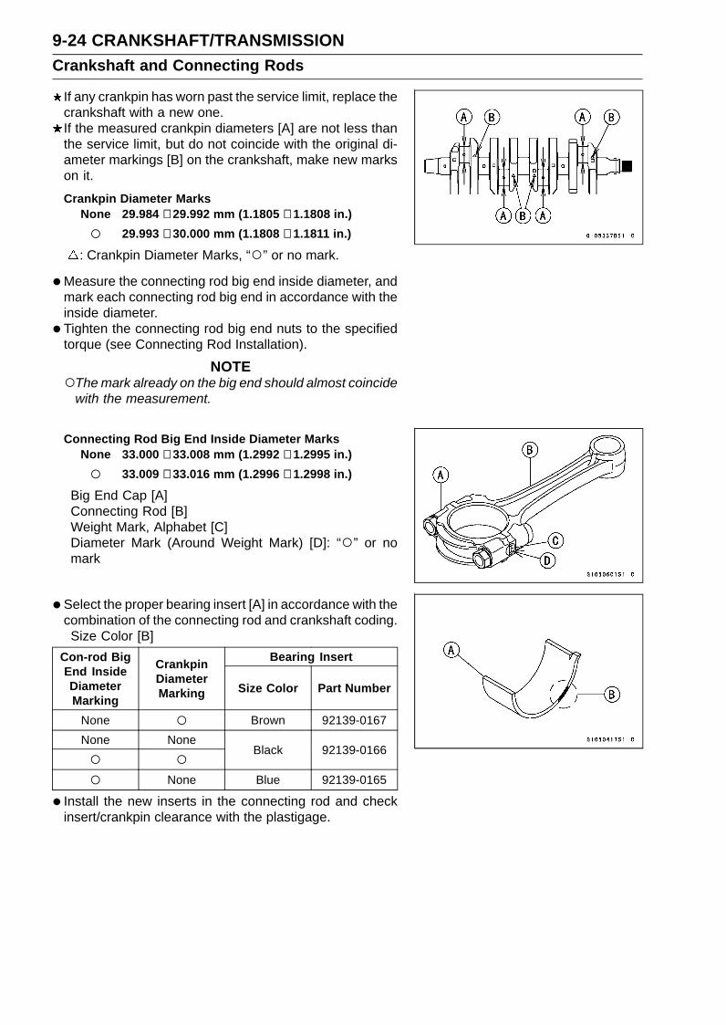
9-24 CRANKSHAFT/TRANSMISSIONCrankshaft and Connecting Rods
If any crankpin has worn past the service limit, replace thecrankshaft with a new one.If the measured crankpin diameters [A] are not less thanthe service limit, but do not coincide with the original di-ameter markings [B] on the crankshaft, make new markson it.
Crankpin Diameter MarksNone 29.984 ∼ 29.992 mm (1.1805 ∼ 1.1808 in.)
29.993 ∼ 30.000 mm (1.1808 ∼ 1.1811 in.)
: Crankpin Diameter Marks, “” or no mark.
•Measure the connecting rod big end inside diameter, andmark each connecting rod big end in accordance with theinside diameter.
• Tighten the connecting rod big end nuts to the specifiedtorque (see Connecting Rod Installation).
NOTEThe mark already on the big end should almost coincide
with the measurement.
Connecting Rod Big End Inside Diameter MarksNone 33.000 ∼ 33.008 mm (1.2992 ∼ 1.2995 in.)
33.009 ∼ 33.016 mm (1.2996 ∼ 1.2998 in.)
Big End Cap [A]Connecting Rod [B]Weight Mark, Alphabet [C]Diameter Mark (Around Weight Mark) [D]: “” or nomark
•Select the proper bearing insert [A] in accordance with thecombination of the connecting rod and crankshaft coding.Size Color [B]
Bearing InsertCon-rod BigEnd InsideDiameterMarking
CrankpinDiameterMarking Size Color Part Number
None Brown 92139-0167None None
Black 92139-0166
None Blue 92139-0165
• Install the new inserts in the connecting rod and checkinsert/crankpin clearance with the plastigage.

CRANKSHAFT/TRANSMISSION 9-25Crankshaft and Connecting Rods
Crankshaft Side Clearance Inspection• Insert a thickness gauge [A] between the thrust washer
[B] on the crankcase and the crank web [C] at the #3 mainjournal to determine clearance.If the clearance exceeds the service limit, replace thethrust washers as a set and check the width of the crank-shaft #3 main journal.
Crankshaft Side ClearanceStandard: 0.05 ∼ 0.25 mm (0.0020 ∼ 0.0098 in.)Service Limit: 0.45 mm (0.0177 in.)
•Measure the width [A] of the crankshaft #3 main journal[B].If the measurement exceeds the standard, replace thecrankshaft.
Crankshaft #3 Main Journal WidthStandard: 21.09 ∼ 21.14 mm (0.8303 ∼ 0.8323 in.)
Crankshaft Runout Inspection•Measure the crankshaft runout.
If the measurement exceeds the service limit, replace thecrankshaft.
Crankshaft RunoutStandard: TIR 0.02 mm (0.0008 in.) or lessService Limit: TIR 0.05 mm (0.0020 in.)
Crankshaft Main Bearing Insert/Journal WearInspection•Split the crankcase (see Crankcase Splitting).• Cut strips of plastigage (press gauge) to journal width.• Place a strip on each journal parallel to the crankshaft
installed in the correct position.• Tighten the crankcase bolts to the specified torque (see
Crankcase Assembly).
NOTEDo not turn the crankshaft during clearance measure-
ment.Journal clearance less than 0.025 mm (0.00098 in.) can
not be measured by plastigage [A], however, using gen-uine parts maintains the minimum standard clearance.
•Split the crankcase again, measure each clearance be-tween the bearing insert and journal [B] using plastigage(press gauge).
Crankshaft Main Bearing Insert/Journal ClearanceStandard: 0.028 ∼ 0.060 mm (0.0011 ∼ 0.0024 in.)Service Limit: 0.09 mm (0.0035 in.)
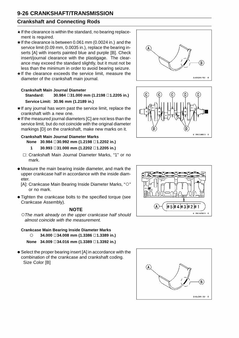
9-26 CRANKSHAFT/TRANSMISSIONCrankshaft and Connecting Rods
If the clearance is within the standard, no bearing replace-ment is required.If the clearance is between 0.061 mm (0.0024 in.) and theservice limit (0.09 mm, 0.0035 in.), replace the bearing in-serts [A] with inserts painted blue and purple [B]. Checkinsert/journal clearance with the plastigage. The clear-ance may exceed the standard slightly, but it must not beless than the minimum in order to avoid bearing seizure.If the clearance exceeds the service limit, measure thediameter of the crankshaft main journal.
Crankshaft Main Journal DiameterStandard: 30.984 ∼ 31.000 mm (1.2198 ∼ 1.2205 in.)Service Limit: 30.96 mm (1.2189 in.)
If any journal has worn past the service limit, replace thecrankshaft with a new one.If the measured journal diameters [C] are not less than theservice limit, but do not coincide with the original diametermarkings [D] on the crankshaft, make new marks on it.
Crankshaft Main Journal Diameter MarksNone 30.984 ∼ 30.992 mm (1.2198 ∼ 1.2202 in.)
1 30.993 ∼ 31.000 mm (1.2202 ∼ 1.2205 in.)
: Crankshaft Main Journal Diameter Marks, “1” or nomark.
•Measure the main bearing inside diameter, and mark theupper crankcase half in accordance with the inside diam-eter.[A]: Crankcase Main Bearing Inside Diameter Marks, “”
or no mark.
• Tighten the crankcase bolts to the specified torque (seeCrankcase Assembly).
NOTEThe mark already on the upper crankcase half should
almost coincide with the measurement.
Crankcase Main Bearing Inside Diameter Marks 34.000 ∼ 34.008 mm (1.3386 ∼ 1.3389 in.)
None 34.009 ∼ 34.016 mm (1.3389 ∼ 1.3392 in.)
•Select the proper bearing insert [A] in accordance with thecombination of the crankcase and crankshaft coding.Size Color [B]
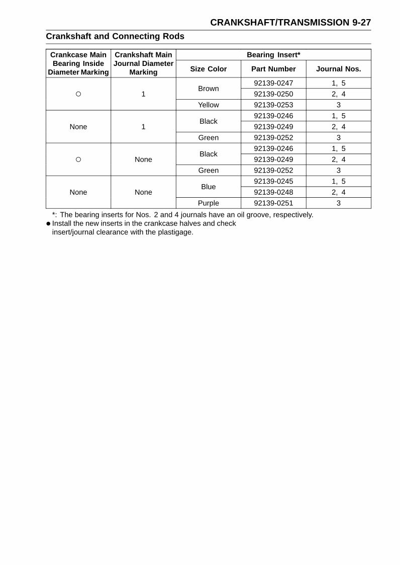
CRANKSHAFT/TRANSMISSION 9-27Crankshaft and Connecting Rods
Bearing Insert*Crankcase MainBearing Inside
Diameter Marking
Crankshaft MainJournal Diameter
Marking Size Color Part Number Journal Nos.
92139-0247 1, 5Brown
92139-0250 2, 4 1Yellow 92139-0253 3
92139-0246 1, 5Black
92139-0249 2, 4None 1Green 92139-0252 3
92139-0246 1, 5Black
92139-0249 2, 4 NoneGreen 92139-0252 3
92139-0245 1, 5Blue
92139-0248 2, 4None NonePurple 92139-0251 3
*: The bearing inserts for Nos. 2 and 4 journals have an oil groove, respectively.• Install the new inserts in the crankcase halves and check
insert/journal clearance with the plastigage.

9-28 CRANKSHAFT/TRANSMISSIONPistons
Piston Removal•Remove:
Crankshaft (see Crankshaft Removal)•Remove the piston together with the connecting rod to the
cylinder head side.
NOTICEDiscard the connecting rod bolts and nuts. To pre-vent damage to the crankpin surfaces, do not al-low the connecting rod bolts to bump against thecrankpins.
•Remove the piston pin snap ring [A] (Both Sides).
• Using the piston pin puller assembly [A], remove the pis-ton pin.Special Tool - Piston Pin Puller Assembly: 57001-910
•Remove the piston from the connecting rod.
•Carefully spread the ring opening with your thumbs andthen push up on the opposite side of the ring [A] to removeit.
• Remove the 3-piece oil ring with your thumbs in the samemanner.

CRANKSHAFT/TRANSMISSION 9-29Pistons
Piston InstallationNOTE
If a new piston is used, use new piston ring.
•Apply molybdenum disulfide oil solution to the oil ring ex-pander, and install the oil ring expander [A] in the bottompiston ring groove so the ends [B] not butt together.
• Apply molybdenum disulfide oil solution to the oil ring steelrails, and install the oil ring steel rails, one above the ex-pander and one below it.Spread the rail with your thumbs, but only enough to fit
the rail over the piston.Release the rail into the bottom piston ring groove.
NOTEThe oil ring rails have no “top” or “bottom”.
•Apply molybdenum disulfide oil solution to the pistonrings.
NOTEDo not mix up the top and second ring.
• Install the top ring [A] so that the “R” mark [B] faces up.• Install the second ring [C] so that the “RN” mark [D] faces
up.
• Apply molybdenum disulfide oil solution to the piston pinsand piston journals.
• Fit a new piston pin snap ring into the side of the pistonso that the ring opening [A] does not coincide with the slit[B] of the piston pin hole.When installing the piston pin snap ring, compress it only
enough to install it and no more.
NOTICEDo not reuse snap rings, as removal weakens anddeforms them. They could fall out and score thecylinder wall.
•The piston ring openings must be positioned as shown.The openings of the oil ring steel rails must be about 30∼ 40° of angle from the opening of the top ring.Top Ring [A]Second Ring [B]Upper Oil Ring Steel Rail [C]Lower Oil Ring Steel Rail [D]Oil Ring Expander [E]Dent [F]30 ∼ 40° [G]

9-30 CRANKSHAFT/TRANSMISSIONPistons
•Apply molybdenum disulfide oil solution to the cylinderbore and piston skirt.
• Install the piston with its dent mark [A] facing exhaust side.•Using the piston ring compressor assembly [B] to install
the piston from the cylinder head side.Special Tools - Piston Ring Compressor Grip: 57001-1095
Piston Ring Compressor Belt, 67 ∼ 79:57001-1097
• Install:Crankshaft (see Crankshaft Installation)Connecting Rod Big End Caps (see Connecting Rod In-stallation)
Cylinder (Upper Crankcase) Wear Inspection•Since there is a difference in cylinder wear (upper
crankcase) in different directions, take a side-to-side anda front-to-back measurement at each of the two locations(total of four measurements) as shown.If any of the cylinder inside diameter measurements ex-ceeds the service limit, replace the crankcase.10 mm (0.39 in.) [A]60 mm (2.36 in.) [B]
Cylinder (Upper Crankcase) Inside DiameterStandard: 67.000 ∼ 67.012 mm (2.6378 ∼ 2.6383 in.)Service Limit: 67.09 mm (2.6413 in.)
Piston Wear Inspection•Measure the outside diameter [A] of each piston 5 mm
(0.20 in.) [B] up from the bottom of the piston at a rightangle to the direction of the piston pin.If the measurement is under service limit, replace the pis-ton.
Piston DiameterStandard: 66.960 ∼ 66.975 mm (2.6362 ∼ 2.6368 in.)Service Limit: 66.81 mm (2.6303 in.)
Piston Ring, Piston Ring Groove Wear Inspection•Check for uneven groove wear by inspecting the ring seat-
ing.The rings should fit perfectly parallel to groove surfaces.If not, replace the piston and all the piston rings.
•With the piston rings in their grooves, make several mea-surements with a thickness gauge [A] to determine pistonring/groove clearance.
Piston Ring/Groove ClearanceStandard:
Top 0.03 ∼ 0.07 mm (0.0012 ∼ 0.0028 in.)Second 0.03 ∼ 0.07 mm (0.0012 ∼ 0.0028 in.)
Service Limit:Top 0.17 mm (0.0067 in.)Second 0.17 mm (0.0067 in.)

CRANKSHAFT/TRANSMISSION 9-31Pistons
Piston Ring Groove Width Inspection•Measure the piston ring groove width.Use a vernier caliper at several points around the piston.
Piston Ring Groove WidthStandard:
Top [A] 0.82 ∼ 0.84 mm (0.0323 ∼ 0.0331 in.)Second [B] 0.82 ∼ 0.84 mm (0.0323 ∼ 0.0331 in.)
Service Limit:Top 0.92 mm (0.036 in.)Second 0.92 mm (0.036 in.)
If the width of any of the two grooves is wider than theservice limit at any point, replace the piston.
Piston Ring Thickness Inspection•Measure the piston ring thickness.Use the micrometer to measure at several points around
the ring.
Piston Ring ThicknessStandard:
Top [A] 0.77 ∼ 0.79 mm (0.0303 ∼ 0.0311 in.)Second [B] 0.77 ∼ 0.79 mm (0.0303 ∼ 0.0311 in.)
Service Limit:Top 0.70 mm (0.028 in.)Second 0.70 mm (0.028 in.)
If any of the measurements is less than the service limiton either of the rings, replace all the rings.
NOTEWhen using new rings in a used piston, check for un-
even groove wear. The rings should fit perfectly parallelto the groove sides. If not, replace the piston.
Piston Ring End Gap Inspection•Place the piston ring [A] inside the cylinder (upper
crankcase), using the piston to locate the ring squarelyin place. Set it close to the bottom of the cylinder, wherecylinder wear is low.
•Measure the gap [B] between the ends of the ring with athickness gauge.
Piston Ring End GapStandard:
Top 0.12 ∼ 0.22 mm (0.0047 ∼ 0.0087 in.)Second 0.30 ∼ 0.45 mm (0.0118 ∼ 0.0177 in.)
Service Limit:Top 0.5 mm (0.020 in.)Second 0.8 mm (0.031 in.)
If the end gap of either ring is greater than the servicelimit, replace all the rings.

9-32 CRANKSHAFT/TRANSMISSIONStarter Idle Gear and Starter Clutch
Starter Idle Gear Removal•Remove:
Upper Fairing Assembly (see Upper Fairing AssemblyRemoval in the Frame chapter)Idle Gear Cover Bolts [A]Idle Gear Cover [B]
•Remove the idle gear (starter motor side) [A] with the shaft[B].
• Remove:Starter Clutch Cover Bolts [A]Starter Clutch Cover [B]
•Remove the idle gear (starter clutch side) [A] with theshaft [B].
Starter Idle Gear Installation•Apply molybdenum disulfide grease [A] to the idle gear
shaft (starter clutch side) [B].• Fit the pin [C] into the groove [D] of the crankcase.
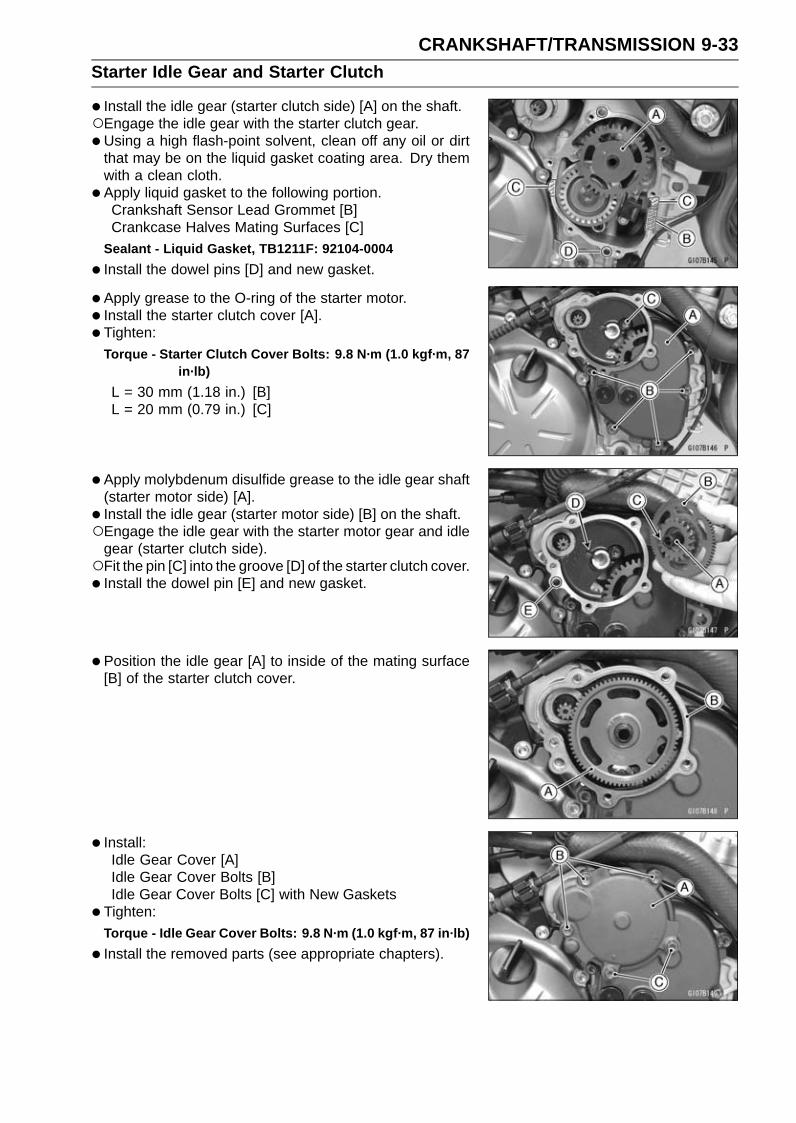
CRANKSHAFT/TRANSMISSION 9-33Starter Idle Gear and Starter Clutch
• Install the idle gear (starter clutch side) [A] on the shaft.Engage the idle gear with the starter clutch gear.•Using a high flash-point solvent, clean off any oil or dirt
that may be on the liquid gasket coating area. Dry themwith a clean cloth.
• Apply liquid gasket to the following portion.Crankshaft Sensor Lead Grommet [B]Crankcase Halves Mating Surfaces [C]
Sealant - Liquid Gasket, TB1211F: 92104-0004
• Install the dowel pins [D] and new gasket.
• Apply grease to the O-ring of the starter motor.• Install the starter clutch cover [A].• Tighten:
Torque - Starter Clutch Cover Bolts: 9.8 N·m (1.0 kgf·m, 87in·lb)
L = 30 mm (1.18 in.) [B]L = 20 mm (0.79 in.) [C]
• Apply molybdenum disulfide grease to the idle gear shaft(starter motor side) [A].
• Install the idle gear (starter motor side) [B] on the shaft.Engage the idle gear with the starter motor gear and idle
gear (starter clutch side).Fit the pin [C] into the groove [D] of the starter clutch cover.• Install the dowel pin [E] and new gasket.
• Position the idle gear [A] to inside of the mating surface[B] of the starter clutch cover.
• Install:Idle Gear Cover [A]Idle Gear Cover Bolts [B]Idle Gear Cover Bolts [C] with New Gaskets
• Tighten:Torque - Idle Gear Cover Bolts: 9.8 N·m (1.0 kgf·m, 87 in·lb)
• Install the removed parts (see appropriate chapters).

9-34 CRANKSHAFT/TRANSMISSIONStarter Idle Gear and Starter Clutch
Starter Clutch Removal•Remove:
Alternator Cover (see Alternator Cover Removal in theElectrical System chapter)Starter Clutch Cover (see Starter Idle Gear Removal)Idle Gear (Starter Clutch Side) (see Starter Idle GearRemoval)
•Remove the starter clutch bolt [A], while holding the al-ternator rotor steady with the rotor holder (see AlternatorRotor Removal in the Electrical System chapter).Special Tools - Grip: 57001-1591
Rotor Holder: 57001-1666Stopper: 57001-1679Rotor Holder Attachment: 57001-1689
•Remove:Washer [B]Starter Clutch [C]
Starter Clutch Installation• Install the starter clutch [A] on the crankshaft [B] with their
teeth [C] aligned.• Install the washer.• Tighten the starter clutch bolt, while holding the alternator
rotor steady with the rotor holder (see Alternator RotorInstallation in the Electrical System chapter).Special Tools - Grip: 57001-1591
Rotor Holder: 57001-1666Stopper: 57001-1679Rotor Holder Attachment: 57001-1689
Torque - Starter Clutch Bolt: 49 N·m (5.0 kgf·m, 36 ft·lb)
• Install the removed parts (see appropriate chapters).
Starter Clutch Disassembly•Remove the starter clutch (see Starter Clutch Removal).• Remove the starter clutch gear [A] from the starter clutch
[B].• Remove the needle bearing [C].
• Remove the snap ring [A].• Remove the one-way clutch [B] from the starter clutch
case [C].
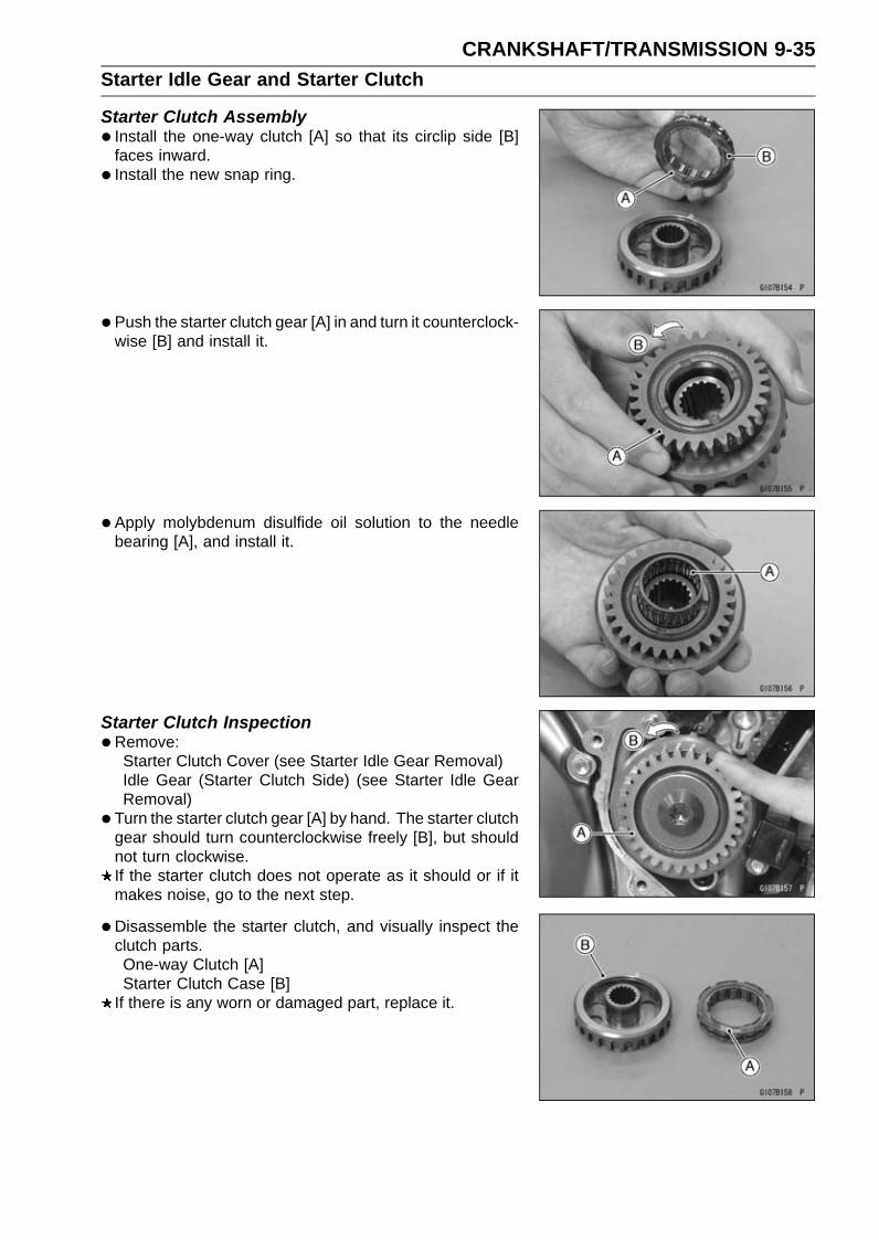
CRANKSHAFT/TRANSMISSION 9-35Starter Idle Gear and Starter Clutch
Starter Clutch Assembly• Install the one-way clutch [A] so that its circlip side [B]
faces inward.• Install the new snap ring.
• Push the starter clutch gear [A] in and turn it counterclock-wise [B] and install it.
• Apply molybdenum disulfide oil solution to the needlebearing [A], and install it.
Starter Clutch Inspection•Remove:
Starter Clutch Cover (see Starter Idle Gear Removal)Idle Gear (Starter Clutch Side) (see Starter Idle GearRemoval)
• Turn the starter clutch gear [A] by hand. The starter clutchgear should turn counterclockwise freely [B], but shouldnot turn clockwise.If the starter clutch does not operate as it should or if itmakes noise, go to the next step.
•Disassemble the starter clutch, and visually inspect theclutch parts.One-way Clutch [A]Starter Clutch Case [B]
If there is any worn or damaged part, replace it.

9-36 CRANKSHAFT/TRANSMISSIONStarter Idle Gear and Starter Clutch
Examine the starter clutch gear [A] as well. Replace theclutch gear if it is worn or damaged.

CRANKSHAFT/TRANSMISSION 9-37Transmission
Transmission Assy Removal•Remove:
Engine Sprocket (see Engine Sprocket Removal in theFinal Drive chapter)Gear Position Switch (see Gear Position Switch Re-moval in the Electrical System chapter)Collar [A]O-ring [B]
•Remove:Clutch (see Clutch Removal in the Clutch chapter)Shift Shaft Assembly (see External Shift Mechanism Re-moval)Transmission Case Bolts [A]
If the transmission assy is to be disassembled, removethe following.Gear Positioning Lever Bolt [B]Gear Positioning Lever [C], Spring and Collar
•Remove the transmission assy [D] from the crankcase.
Transmission Assy Disassembly•Remove the transmission assy (see Transmission Assy
Removal).• Remove the following from the transmission case [A].
Shift Rods [B]Shift Forks [C]Drive Shaft [D]Output Shaft [E]
•Remove:Bearing Holder Screws [A]Bearing Holder [B]Shift Drum Assembly [C]
Transmission Assy Assembly•Press the race [A] in the transmission case [B] so that the
big stepped side [C] faces to transmission gears side untilit is bottomed.Special Tool - Bearing Driver Set: 57001-1129
• Install the race holder [D] as shown.• Apply a non-permanent locking agent to the threads of
the race holder screw [E].• Tighten:
Torque - Race Holder Screws: 4.9 N·m (0.50 kgf·m, 43 in·lb)
• Install the dowel pins [F] in the transmission case untilthey are bottomed.

9-38 CRANKSHAFT/TRANSMISSIONTransmission
•Press the ball bearing [A] in the transmission case [B] sothat the stepped side faces outside until it is bottomed.Special Tool - Bearing Driver Set: 57001-1129
• Install the bearing holder [C] as shown.• Apply a non-permanent locking agent to the threads of
the bearing holder screws [D].• Tighten:
Torque - Bearing Holder Screws: 4.9 N·m (0.50 kgf·m, 43in·lb)
•Apply a non-permanent locking agent to the shift shaftreturn spring pin.
• Tighten:Torque - Shift Shaft Return Spring Pin: 28 N·m (2.9 kgf·m,
21 ft·lb)
• Install:Shift Drum Assembly [A]Bearing Holder [B]
Install the bearing holder so that the taper side faces out-side.
• Apply a non-permanent locking agent to the threads ofthe bearing holder screws [C].
• Tighten:Torque - Bearing Holder Screws: 4.9 N·m (0.50 kgf·m, 43
in·lb)

CRANKSHAFT/TRANSMISSION 9-39Transmission
• Install the drive shaft [A] and output shaft [B] as a set inthe transmission case [C].
• Install the shift forks as shown.The shift fork [D] for drive shaft gears has the short ears.The shift forks [E] [F] for output shaft gears have the long
ears.The shift fork [E] has R mark [G].The shift fork [F] has L mark [H].• Install the shift rods so that the ends of the rods are same
height.The shift rod [I] of the drive shaft side is shorter than the
shift rod [J] of the output shaft side.• Apply molybdenum disulfide oil solution to the transmis-
sion gears (x marks) [K].• Install the spacer [L] on the output shaft.• Apply grease to the O-ring [M] and install it to its position
on the output shaft.
Transmission Assy Installation•Be sure that the dowel pins are in position.• Install the transmission assy on the crankcase.• Tighten:
Torque - Transmission Case Bolts (M8) [A]: 20 N·m (2.0kgf·m, 15 ft·lb)
Transmission Case Bolts (M6) [B]: 9.8 N·m (1.0kgf·m, 87 in·lb)

9-40 CRANKSHAFT/TRANSMISSIONTransmission
• Install the gear positioning lever (see External Shift Mech-anism Installation).
• Set the gear positioning lever to the neutral position [A].• Check that the drive and output shaft turn freely.
• Apply grease to the new O-ring [A] and install it to its po-sition on the output shaft [B].
• Install the collar [C].•When installing the oil seal [D], install it as follows.Apply grease to the oil seal lips.Apply soap and water solution to the outer circumference
of the oil seal so that it will go into place smoothly.Press the oil seal to the crankcase so that the surface of
the oil seal is flush with the surface of the crankcase asshown.
• Install the removed parts (see appropriate chapters).
Transmission Shaft Removal•Refer to the Transmission Assy Disassembly.
Transmission Shaft Installation•Refer to the Transmission Assy Assembly.
Transmission Shaft Disassembly•Remove the transmission shafts (see Transmission Shaft
Removal).• Remove the circlips, and then disassemble the transmis-
sion shafts.Special Tool - Outside Circlip Pliers: 57001-144
•The 5th gear [A] on the output shaft has three steel ballsassembled into it for the positive neutral finder mecha-nism. Remove the 5th gear.Set the output shaft in a vertical position holding the 3rd
gear [B].Spin the 5th gear quickly [C] and pull it off upward.
Transmission Shaft Assembly•Apply molybdenum disulfide oil solution to the sliding sur-
faces of the gears and shafts.• Install the gear bushings [A] on the shaft with their holes
[B] aligned.

CRANKSHAFT/TRANSMISSION 9-41Transmission
•Replace any circlips removed with new ones.• Install the circlip [A] on the drive shaft [B] so that the punch
mark [C] faces the washer [D] and position the opening [E]as shown.
• Install the circlip [A] on the output shaft [B] so that thepunch mark [C] faces the washer [D] and position theopening [E] as shown.
• The drive shaft gears can be recognized by size: the gearwith the smallest diameter is 1st gear, and the largest oneis 6th gear. Be sure that all parts are put back in the cor-rect sequence and all circlips and washers are properly inplace.
• Install the 3rd/4th gear onto the drive shaft with their oilholes aligned.
• Install the 5th and 6th gear bushings onto the drive shaftwith their oil holes aligned.
• The output shaft gears can be recognized by size: thegear with the largest diameter is 1st gear, and the small-est one is 6th gear. Be sure that all parts are put backin the correct sequence and all circlips and washers areproperly in place.
• Install the 6th gears onto the output shaft with their oilholes aligned.
• Install the 1st, 2nd and 3rd/4th gear bushings onto theoutput shaft with their oil holes aligned.

9-42 CRANKSHAFT/TRANSMISSIONTransmission
•Fit the steel balls into the 5th gear holes in the outputshaft.5th Gear [A]Output Shaft [B]Steel Balls [C]
NOTICEDo not apply grease to the balls to hold them inplace. This will cause the positive neutral findermechanism to malfunction.
After assembling the 5th gear with steel balls in place onthe output shaft, check the ball-locking effect that the 5thgear does not come out of the output shaft when movingit up and down by hand.
•Check that each gear spins or slides freely on the trans-mission shafts without binding after assembly.

CRANKSHAFT/TRANSMISSION 9-43Transmission
1. 1st Gear2. 2nd Gear3. 3rd Gear4. 4th Gear5. 5th Gear6. 6th (Top) Gear7. Drive Shaft8. Output Shaft9. O-ring
10. Spacer11. Bushing12. Washer, 40 mm (1.57 in.)13. Bushing
14. Toothed Washer, 40 mm (1.57 in.)15. Circlip16. Steel Ball17. Bushing18. Washer, 32 mm (1.26 in.)19. Needle Bearing20. Circlip21. Bushing22. Toothed Washer, 34 mm (1.34 in.)23. Circlip24. Washer, 34 mm (1.34 in.)25. Bushing

9-44 CRANKSHAFT/TRANSMISSIONTransmission
Shift Drum and Fork Removal•Refer to the Transmission Assy Disassembly.
Shift Drum and Fork Installation•Refer to the Transmission Assy Assembly.
Shift Drum Disassembly•Remove the shift drum (see Transmission Assy Disas-
sembly).•While holding the shift drum with a vise, remove the shift
drum cam holder bolt [A].• Remove:
Shift Drum Cam [B]Dowel Pin [C]Ball Bearings [D]Shift Drum [E]
Shift Drum Assembly•Press the ball bearing [A] on the shift drum [B] until it is
bottomed.• Install:
Ball Bearing [C]Dowel Pin [D] and Shift Drum Cam [E]
Align the pin with the groove in the shift drum cam.•Apply a non-permanent locking agent to the threads of
the shift drum cam holder bolt [F] and tighten it.Torque - Shift Drum Cam Holder Bolt: 12 N·m (1.2 kgf·m,
106 in·lb)
Shift Fork Bending Inspection•Visually inspect the shift forks, and replace any fork that is
bent. A bent fork could cause difficulty in shifting, or allowthe transmission to jump out of gear when under power.90° [A]
Shift Fork/Gear Groove Wear Inspection•Measure the thickness of the shift fork ears [A], and mea-
sure the width [B] of the gear grooves.If the thickness of a shift fork ear is less than the servicelimit, the shift fork must be replaced.
Shift Fork Ear ThicknessStandard: 5.9 ∼ 6.0 mm (0.232 ∼ 0.236 in.)Service Limit: 5.8 mm (0.228 in.)
If the gear groove is worn over the service limit, the gearmust be replaced.
Gear Groove WidthStandard: 6.05 ∼ 6.15 mm (0.238 ∼ 0.242 in.)Service Limit: 6.25 mm (0.246 in.)
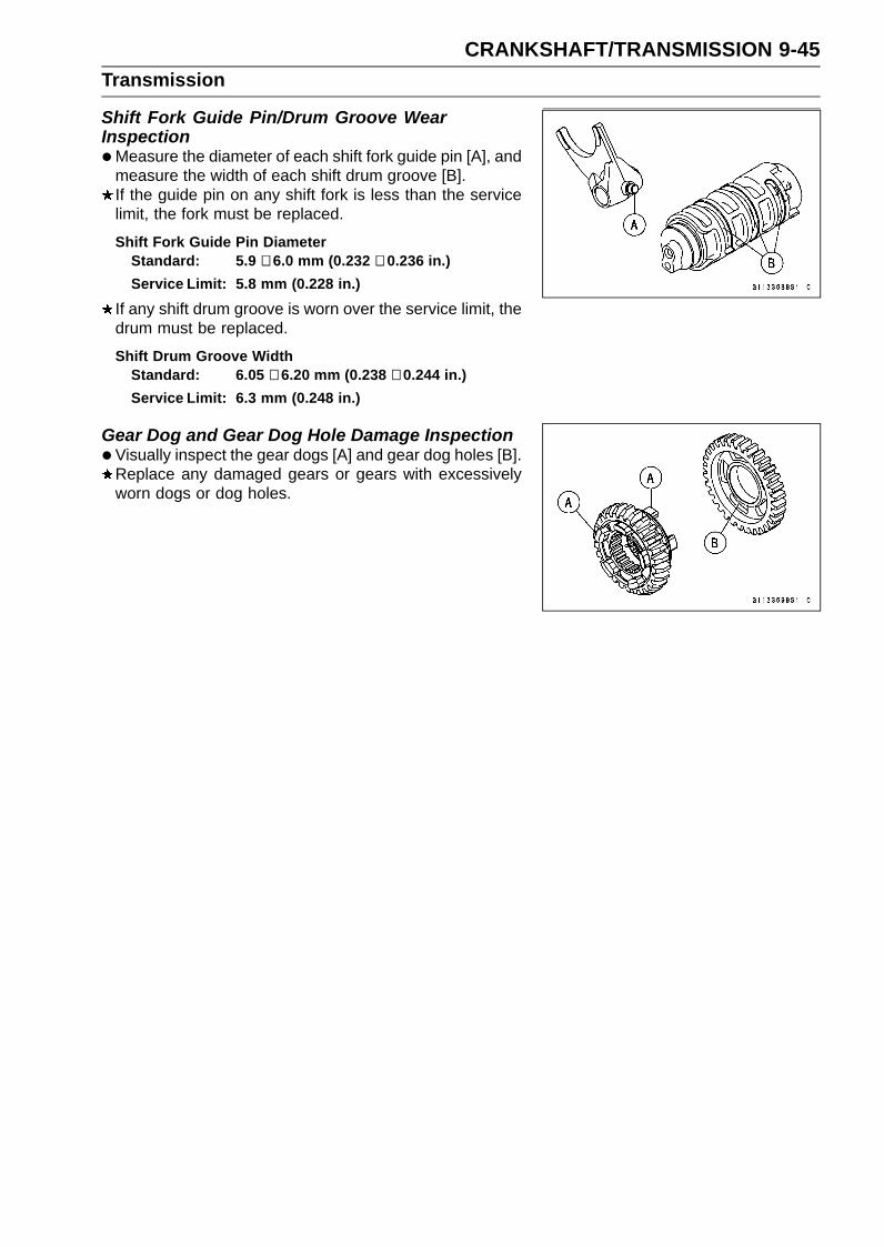
CRANKSHAFT/TRANSMISSION 9-45Transmission
Shift Fork Guide Pin/Drum Groove WearInspection•Measure the diameter of each shift fork guide pin [A], and
measure the width of each shift drum groove [B].If the guide pin on any shift fork is less than the servicelimit, the fork must be replaced.
Shift Fork Guide Pin DiameterStandard: 5.9 ∼ 6.0 mm (0.232 ∼ 0.236 in.)Service Limit: 5.8 mm (0.228 in.)
If any shift drum groove is worn over the service limit, thedrum must be replaced.
Shift Drum Groove WidthStandard: 6.05 ∼ 6.20 mm (0.238 ∼ 0.244 in.)Service Limit: 6.3 mm (0.248 in.)
Gear Dog and Gear Dog Hole Damage Inspection•Visually inspect the gear dogs [A] and gear dog holes [B].
Replace any damaged gears or gears with excessivelyworn dogs or dog holes.
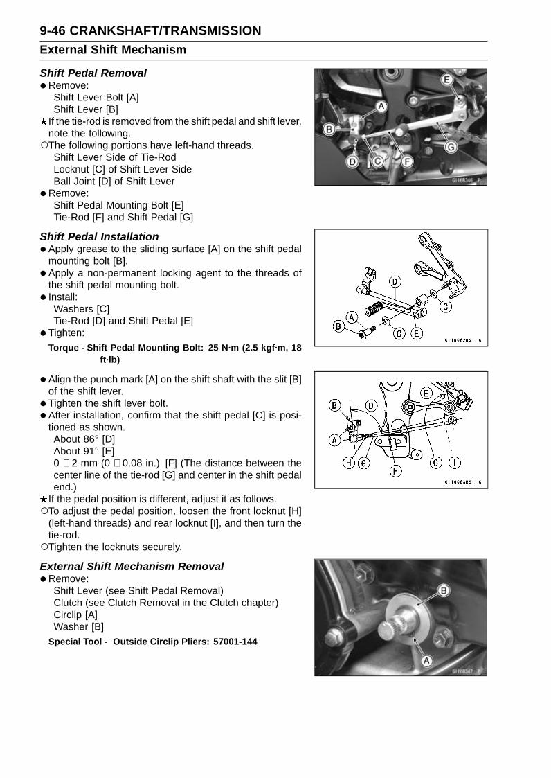
9-46 CRANKSHAFT/TRANSMISSIONExternal Shift Mechanism
Shift Pedal Removal•Remove:
Shift Lever Bolt [A]Shift Lever [B]
If the tie-rod is removed from the shift pedal and shift lever,note the following.The following portions have left-hand threads.
Shift Lever Side of Tie-RodLocknut [C] of Shift Lever SideBall Joint [D] of Shift Lever
•Remove:Shift Pedal Mounting Bolt [E]Tie-Rod [F] and Shift Pedal [G]
Shift Pedal Installation•Apply grease to the sliding surface [A] on the shift pedal
mounting bolt [B].• Apply a non-permanent locking agent to the threads of
the shift pedal mounting bolt.• Install:
Washers [C]Tie-Rod [D] and Shift Pedal [E]
• Tighten:Torque - Shift Pedal Mounting Bolt: 25 N·m (2.5 kgf·m, 18
ft·lb)
•Align the punch mark [A] on the shift shaft with the slit [B]of the shift lever.
• Tighten the shift lever bolt.• After installation, confirm that the shift pedal [C] is posi-
tioned as shown.About 86° [D]About 91° [E]0 ∼ 2 mm (0 ∼ 0.08 in.) [F] (The distance between thecenter line of the tie-rod [G] and center in the shift pedalend.)
If the pedal position is different, adjust it as follows.To adjust the pedal position, loosen the front locknut [H]
(left-hand threads) and rear locknut [I], and then turn thetie-rod.Tighten the locknuts securely.
External Shift Mechanism Removal•Remove:
Shift Lever (see Shift Pedal Removal)Clutch (see Clutch Removal in the Clutch chapter)Circlip [A]Washer [B]
Special Tool - Outside Circlip Pliers: 57001-144

CRANKSHAFT/TRANSMISSION 9-47External Shift Mechanism
•Remove:Shift Shaft Assembly [A]Washer [B]
•Remove:Gear Positioning Lever Bolt [A]Gear Positioning Lever [B]Collar and Spring [C]
External Shift Mechanism Installation• Install the gear positioning lever [A] as shown.• Install:
Spring [B]Collar [C]
• Tighten:Torque - Gear Positioning Lever Bolt [D]: 12 N·m (1.2 kgf·m,
106 in·lb)
•Replace the oil seal [A] with a new one.• Apply grease to the lips of the grease seal.
• Install:Shift Shaft Assembly [A] and Washer
Fit the hole [B] and return spring pin [C].

9-48 CRANKSHAFT/TRANSMISSIONExternal Shift Mechanism
•Replace the circlip [A] with a new one.• Install:
CirclipSpecial Tool - Outside Circlip Pliers: 57001-144Fit the circlip into the groove of the shift shaft securely.• Install the removed parts (see appropriate chapters).
External Shift Mechanism Inspection•Examine the shift shaft [A] for any damage.
If the shaft is bent, straighten or replace it.If the serration [B] is damaged, replace the shaft.If the springs [C] are damaged in any way, replace them.If the shift mechanism arm [D] is damaged in any way,replace the shaft.
• Check the return spring pin [A] is not loose.If it is loose, unscrew it, apply a non-permanent lockingagent to the threads, and tighten it.Torque - Shift Shaft Return Spring Pin: 28 N·m (2.9 kgf·m,
21 ft·lb)
•Check the gear positioning lever [B] and spring [C] forbreaks or distortion.If the lever or spring are damaged in any way, replacethem.
•Visually inspect the shift drum cam [D].If they are badly worn or if they show any damage, replaceit.

WHEELS/TIRES 10-1
10
Wheels/TiresTable of Contents
Exploded View........................................................................................................................ 10-2Specifications ......................................................................................................................... 10-4Special Tools .......................................................................................................................... 10-5Wheels (Rims) ........................................................................................................................ 10-6
Front Wheel Removal ....................................................................................................... 10-6Front Wheel Installation .................................................................................................... 10-6Rear Wheel Removal........................................................................................................ 10-7Rear Wheel Installation..................................................................................................... 10-8Wheel Inspection .............................................................................................................. 10-9Axle Inspection.................................................................................................................. 10-10Balance Inspection............................................................................................................ 10-10Balance Adjustment .......................................................................................................... 10-10Balance Weight Removal.................................................................................................. 10-11Balance Weight Installation............................................................................................... 10-11
Tires........................................................................................................................................ 10-13Air Pressure Inspection/Adjustment.................................................................................. 10-13Tire Inspection .................................................................................................................. 10-13Tire Removal..................................................................................................................... 10-13Tire Installation.................................................................................................................. 10-13Tire Repair ........................................................................................................................ 10-15
Hub Bearing............................................................................................................................ 10-16Hub Bearing Removal....................................................................................................... 10-16Hub Bearing Installation.................................................................................................... 10-16Hub Bearing Inspection..................................................................................................... 10-16Hub Bearing Lubrication ................................................................................................... 10-17

10-2 WHEELS/TIRESExploded View

WHEELS/TIRES 10-3Exploded View
TorqueNo. Fastener
N·m kgf·m ft·lbRemarks
1 Front Axle Clamp Bolts 20 2.0 15 AL2 Front Axle 127 13.0 93.73 Rear Axle Nut 127 13.0 93.7
AL: Tighten the two clamp bolts alternately two times to ensure even tightening torque.HG: Apply high-temperature grease.
R: Replacement PartsWL: Apply soap and water solution or rubber lubricant.
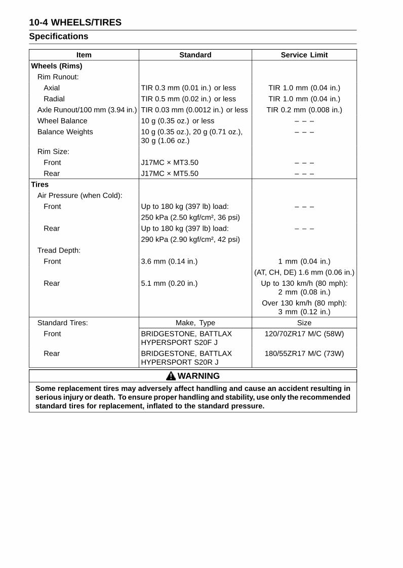
10-4 WHEELS/TIRESSpecifications
Item Standard Service LimitWheels (Rims)
Rim Runout:Axial TIR 0.3 mm (0.01 in.) or less TIR 1.0 mm (0.04 in.)Radial TIR 0.5 mm (0.02 in.) or less TIR 1.0 mm (0.04 in.)
Axle Runout/100 mm (3.94 in.) TIR 0.03 mm (0.0012 in.) or less TIR 0.2 mm (0.008 in.)Wheel Balance 10 g (0.35 oz.) or less – – –Balance Weights 10 g (0.35 oz.), 20 g (0.71 oz.),
30 g (1.06 oz.)– – –
Rim Size:Front J17MC × MT3.50 – – –Rear J17MC × MT5.50 – – –
TiresAir Pressure (when Cold):
Front Up to 180 kg (397 lb) load: – – –250 kPa (2.50 kgf/cm², 36 psi)
Rear Up to 180 kg (397 lb) load: – – –290 kPa (2.90 kgf/cm², 42 psi)
Tread Depth:Front 3.6 mm (0.14 in.) 1 mm (0.04 in.)
(AT, CH, DE) 1.6 mm (0.06 in.)Rear 5.1 mm (0.20 in.) Up to 130 km/h (80 mph):
2 mm (0.08 in.)Over 130 km/h (80 mph):
3 mm (0.12 in.)Standard Tires: Make, Type Size
Front BRIDGESTONE, BATTLAXHYPERSPORT S20F J
120/70ZR17 M/C (58W)
Rear BRIDGESTONE, BATTLAXHYPERSPORT S20R J
180/55ZR17 M/C (73W)
WARNINGSome replacement tires may adversely affect handling and cause an accident resulting inserious injury or death. To ensure proper handling and stability, use only the recommendedstandard tires for replacement, inflated to the standard pressure.

WHEELS/TIRES 10-5Special Tools
Bearing Driver Set:57001-1129
Jack:57001-1238
Bearing Remover Head, 25 × 28:57001-1346
Bearing Remover Shaft, 13:57001-1377
Jack Attachment:57001-1608
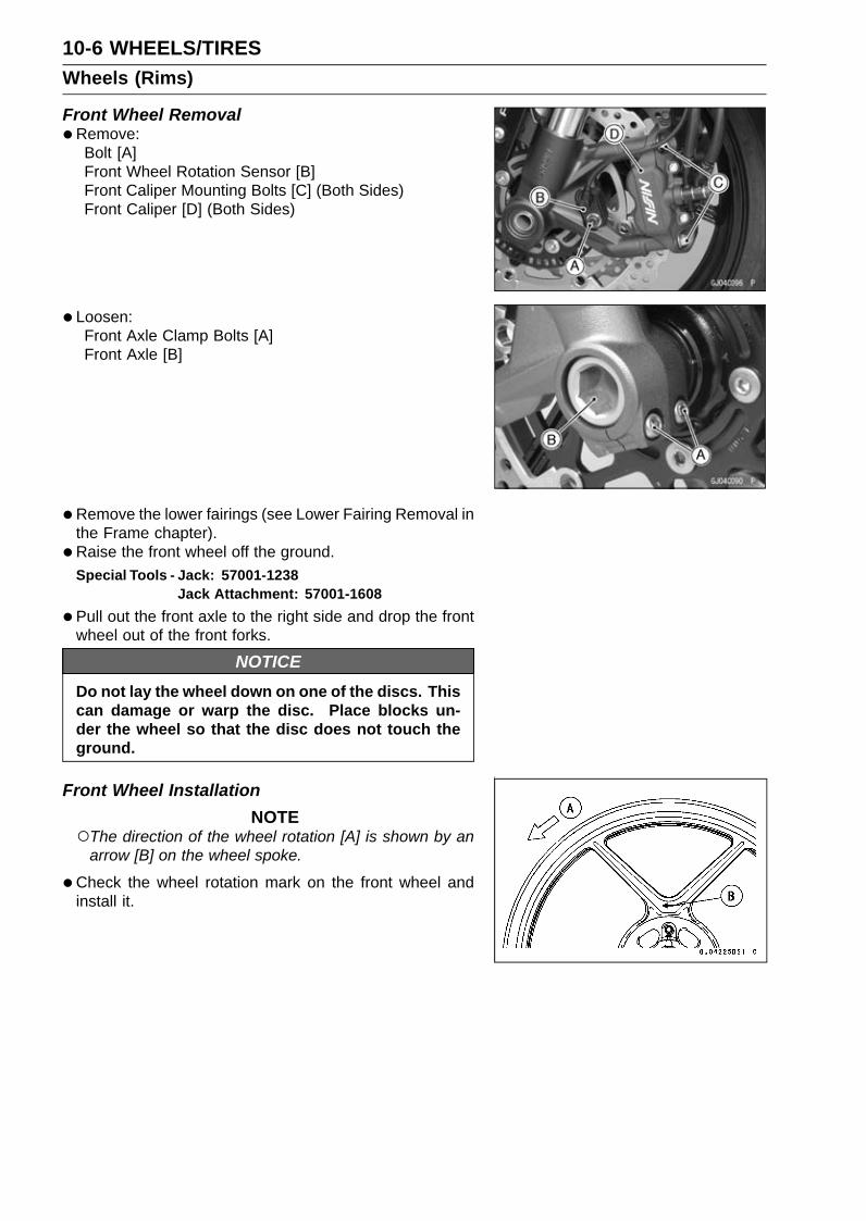
10-6 WHEELS/TIRESWheels (Rims)
Front Wheel Removal•Remove:
Bolt [A]Front Wheel Rotation Sensor [B]Front Caliper Mounting Bolts [C] (Both Sides)Front Caliper [D] (Both Sides)
• Loosen:Front Axle Clamp Bolts [A]Front Axle [B]
•Remove the lower fairings (see Lower Fairing Removal inthe Frame chapter).
• Raise the front wheel off the ground.Special Tools - Jack: 57001-1238
Jack Attachment: 57001-1608
•Pull out the front axle to the right side and drop the frontwheel out of the front forks.
NOTICEDo not lay the wheel down on one of the discs. Thiscan damage or warp the disc. Place blocks un-der the wheel so that the disc does not touch theground.
Front Wheel InstallationNOTE
The direction of the wheel rotation [A] is shown by anarrow [B] on the wheel spoke.
•Check the wheel rotation mark on the front wheel andinstall it.

WHEELS/TIRES 10-7Wheels (Rims)
•Apply high-temperature grease to the grease seal lips.• Fit the collars [A] on the both sides of the hub.The collars are identical.• Insert the front axle [B] from the right side.• Tighten:
Torque - Front Axle: 127 N·m (13.0 kgf·m, 93.7 ft·lb)Front Axle Clamp Bolts [C]Viewed from Rear [D]
• Before tightening the front axle clamp bolts on the rightfront fork leg, pump the front fork up and down 4 or 5times to allow the right front fork leg to seat on the frontaxle.
NOTEPut a block in front of the front wheel to stop moving.
•Tighten:Torque - Front Axle Clamp Bolts: 20 N·m (2.0 kgf·m, 15 ft·lb)
NOTETighten the two clamp bolts alternately two times to en-
sure even tightening torque.
• Install the removed parts (see appropriate chapters).• Check the front brake effectiveness (see Brake Operation
Inspection in the Periodic Maintenance chapter).
WARNINGAfter servicing, it takes several applications of thebrake lever before the brake pads contact the disc,which could result in increased stopping distanceand cause an accident resulting in injury or death.Do not attempt to ride the motorcycle until a firmbrake lever is obtained by pumping the lever untilthe pads are against the disc.
Rear Wheel Removal•Raise the rear wheel off the ground with the stand [A].

10-8 WHEELS/TIRESWheels (Rims)
•Remove the rear wheel rotation sensor from the caliperbracket (see Rear Wheel Rotation Sensor Removal in theBrakes chapter).
• Remove:Cotter Pin [A]Rear Axle Nut [B]Washer [C]Rear Axle [D] (from Right Side)
•Remove the drive chain [A] from the rear sprocket towardthe left.
•Move the rear wheel back and remove it.
NOTICEDo not lay the wheel on the ground with the discfacing down. This can damage or warp the disc.Place blocks under the wheel so that the disc doesnot touch the ground.
Rear Wheel Installation•Apply high-temperature grease to the grease seal lips.• Fit the collars on the both sides of the hub.
Left Side Collar [A]Right Side Collar [B] (with Flange)
• Engage the drive chain with the rear sprocket.• Install the caliper bracket [A] onto the stopper [B] of the
swingarm.• Insert the rear axle from the right side of the wheel.• Install the washer and rear axle nut.• Adjust the drive chain slack before tightening the rear
axle nut (see Drive Chain Slack Inspection in the PeriodicMaintenance chapter).
• Tighten:Torque - Rear Axle Nut: 127 N·m (13.0 kgf·m, 93.7 ft·lb)
• Insert a new cotter pin [A].
NOTEWhen inserting the cotter pin, if the slots in the nut do
not align with the cotter pin hole in the axle, tighten thenut clockwise [B] up to next alignment.It should be within 30 degrees.Loosen once and tighten again when the slot goes past
the nearest hole.

WHEELS/TIRES 10-9Wheels (Rims)
•Bend the cotter pin [A] over the nut.
WARNINGA loose axle nut can lead to an accident resulting inserious injury or death. Tighten the axle nut to theproper torque and install a new cotter pin.
• Install the rear wheel rotation sensor (see Rear WheelRotation Sensor Installation in the Brakes chapter).
• Check the rear brake effectiveness (see Brake OperationInspection in the Periodic Maintenance chapter).
WARNINGAfter servicing, it takes several applications of thebrake pedal before the brake pads contact the disc,which could result in increased stopping distanceand cause an accident resulting in injury or death.Do not attempt to ride the motorcycle until a firmbrake pedal is obtained by pumping the pedal untilthe pads are against the disc.
Wheel Inspection•Raise the front/rear wheel off the ground.
Special Tools - Jack: 57001-1238Jack Attachment: 57001-1608
•Spin the wheel lightly, and check for roughness or binding.If roughness or binding is found, replace the hub bearings(see Hub Bearing Removal/Installation).
• Inspect the wheel for small cracks, dents, bending, orwarp.If there is any damage to the wheel, replace the wheel.
• Remove the wheel, and support it with the tire by the axle.•Measure the rim runout, axial [A] and radial [B], with a dial
gauge.If rim runout exceeds the service limit, check the hub bear-ings (see Hub Bearing Inspection).If the problem is not due to the bearings, replace thewheel.
Rim Runout (with tire installed)Standard:
Axial TIR 0.3 mm (0.01 in.) or lessRadial TIR 0.5 mm (0.02 in.) or less
Service Limit:Axial TIR 1.0 mm (0.04 in.)Radial TIR 1.0 mm (0.04 in.)

10-10 WHEELS/TIRESWheels (Rims)
WARNINGDamaged wheel parts may fail and cause an acci-dent resulting in serious injury or death. Never at-tempt to repair a damaged wheel part. If the wheelpart is damaged, it must be replaced with a new one.
Axle Inspection•Remove the front and rear axles (see Front/Rear Wheel
Removal).• Visually inspect the front and rear axle for damages.
If the axle is damaged or bent, replace it.• Place the axle in V blocks that are 100 mm (3.94 in.) [A]
apart, and set a dial gauge [B] on the axle at a pointhalfway between the blocks. Turn [C] the axle to mea-sure the runout. The difference between the highest andlowest dial readings is the amount of runout.If axle runout exceeds the service limit, replace the axle.
Axle Runout/100 mm (3.94 in.)Standard: TIR 0.03 mm (0.0012 in.) or lessService Limit: TIR 0.2 mm (0.008 in.)
Balance Inspection•Remove the front and rear wheels (see Front/Rear Wheel
Removal).• Support the wheel so that it can be spun freely.• Spin the wheel lightly, and mark [A] the wheel at the top
when the wheel stops.Repeat this procedure several times. If the wheel stops
of its own accord in various positions, it is well balanced.If the wheel always stops in one position, adjust the wheelbalance (see Balance Adjustment).
Balance Adjustment• If the wheel always stops in one position, provisionally
attach a balance weight [A] on the rim at the marking usingadhesive tape.
•Rotate the wheel 1/4 turn [B], and see whether or not thewheel stops in this position. If it does, the correct balanceweight is being used.If the wheel rotates and the weight goes up, replace theweight with the next heavier size. If the wheel rotates andthe weight goes down, replace the weight with the nextlighter size. Repeat these steps until the wheel remainsat rest after being rotated 1/4 turn.
•Rotate the wheel another 1/4 turn and then another 1/4turn to see if the wheel is correctly balanced.
•Repeat the entire procedure as many times as necessaryto achieve correct wheel balance.
• Permanently install the balance weight.

WHEELS/TIRES 10-11Wheels (Rims)
Balance Weight Removal• Insert standard tip screwdrivers [A] [B] between the rib [C]
and weight [D] as shown.• Pry the balance weight with two screwdrivers and remove
the balance weight.• Discard the used balance weight.
NOTICEDo not tap the screwdrivers. The rim could be dam-aged.
Balance Weight Installation•Check if the weight portion has any play on the blade [A]
and clip [B].If it does, discard it.
WARNINGUnbalanced wheels can create an unsafe ridingcondition. If the balance weight has any play onthe rib of the rim, the blade and/or clip have beenstretched. Replace the loose balance weight. Donot reuse used balance weight.
Balance WeightPart Number Weight41075-0007 10 g (0.35 oz.)41075-0008 20 g (0.71 oz.)41075-0009 30 g (1.06 oz.)
NOTEBalance weights are available from Kawasaki dealers
in 10, 20 and 30 grams (0.35, 0.71 and 1.06 oz.) sizes.An imbalance of less than 10 grams (0.35 oz.) will notusually affect running stability.Do not use four or more balance weight (more than 90
gram, 3.2 oz.). If the wheel requires an excess balanceweight, disassemble the wheel to find the cause.
•Slip the balance weight [A] onto the rib [B] by pushing orlightly hammering [C] the clip [D].Left Side [E]Right Side [F]
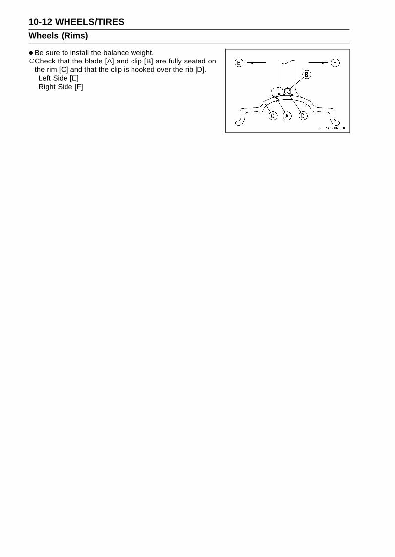
10-12 WHEELS/TIRESWheels (Rims)
•Be sure to install the balance weight.Check that the blade [A] and clip [B] are fully seated on
the rim [C] and that the clip is hooked over the rib [D].Left Side [E]Right Side [F]

WHEELS/TIRES 10-13Tires
Air Pressure Inspection/Adjustment•Refer to the Air Pressure Inspection in the Periodic Main-
tenance chapter.
Tire Inspection•Refer to the Wheel/Tire Damage Inspection in the Peri-
odic Maintenance chapter.
Tire Removal•Remove:
Wheels (see Front/Rear Wheel Removal)Valve Core (Let out the air)
• To maintain wheel balance, mark the valve stem positionon the tire with chalk so that the tire can be reinstalled inthe same position.Chalk Mark or Yellow Mark [A]Valve Stem [B]Align [C]
• Lubricate the tire beads and rim flanges on both sides witha soap and water solution or rubber lubricant. This helpsthe tire beads slip off the rim flanges.
NOTICENever lubricate with engine oil or petroleum distil-lates because they will deteriorate the tire.
•Remove the tire from the rim using a suitable commer-cially available tire changer.
NOTEThe tires cannot be removed with hand tools because
they fit the rims too tightly.
Tire InstallationWARNING
Mixing tire brands and types can adversely affecthandling and cause an accident resulting in injuryor death. Always use the same manufacturer’s tireson both front and rear wheels.
• Inspect the rim and tire, and replace them if necessary.•Clean the sealing surfaces of the rim and tire, and smooth
the sealing surfaces of the rim with a fine emery cloth ifnecessary.
•Remove the air valve and discard it.
NOTICEReplace the air valve whenever the tire is replaced.Do not reuse the air valve.

10-14 WHEELS/TIRESTires
• Install a new valve in the rim.Remove the valve cap, lubricate the stem seal [A] with a
soap and water solution or rubber lubricant, and pull [B]the valve stem through the rim from the inside out until itsnaps into place.
NOTICEDo not use engine oil or petroleum distillates to lu-bricate the stem because they will deteriorate therubber.
The air valve is as shown.Valve Cap [A]Valve Core [B]Stem Seal [C]Valve Stem [D]Valve Seat [E]Valve Opened [F]
•Check the tire rotation mark on the front and rear tires andinstall them on the rim accordingly.Tire Rotation Mark [A]Rotating Direction [B]
• Position the tire on the rim so that the valve [A] align withthe tire balance mark [B] (the chalk mark made duringremoval, or the yellow paint mark on a new tire).
• Install the tire bead over the rim flange using a suitablecommercially available tire changer.
• Lubricate the tire beads and rim flanges with a soap andwater solution or rubber lubricant to help seat the tirebeads in the sealing surfaces of the rim while inflating thetire.
•Center the rim in the tire beads, and inflate the tire withcompressed air until the tire beads seat in the sealingsurfaces.
WARNINGOverinflating a tire can cause it to explode, causingserious injury or death. Be sure to install the valvecore whenever inflating the tire, and do not inflatethe tire to more than 400 kPa (4.0 kgf/cm², 57 psi).

WHEELS/TIRES 10-15Tires
•Check to see that the rim lines [A] on both sides of the tiresidewalls are parallel with the rim flanges.If the rim flanges and tire sidewall rim lines are not parallel,remove the valve core.
• Lubricate the rim flanges and tire beads.• Install the valve core and inflate the tire again.• After the tire beads seat in the rim flanges, check for air
leakage.Inflate the tire slightly above standard inflation.Use a soap and water solution or submerge the tire, and
check for bubbles that would indicate leakage.• Adjust the air pressure to the specified pressure (see Air
Pressure Inspection in the Periodic Maintenance chap-ter).
• Install the air valve cap.• Adjust the wheel balance (see Balance Adjustment).
Tire RepairCurrently two types of repair for tubeless tires have come
into wide use. One type is called a temporary (external) re-pair which can be carried out without removing the tire fromthe rim, and the other type is called permanent (internal)repair which requires tire removal. It is generally under-stood that higher running durability is obtained by perma-nent (internal) repairs than by temporary (external) ones.Also, permanent (internal) repairs have the advantage ofpermitting a thorough examination for secondary damagenot visible from external inspection of the tire. For thesereasons, Kawasaki does not recommend temporary (exter-nal) repair. Only appropriate permanent (internal) repairsare recommended. Repair methods may vary slightly frommake to make. Follow the repair methods indicated by themanufacturer of the repair tools and materials so that saferesults can be obtained.

10-16 WHEELS/TIRESHub Bearing
Hub Bearing Removal•Remove the wheels (see Front/Rear Wheel Removal),
and take out the following.CollarsCoupling (Out of rear hub)Grease Seals
•Use the bearing remover to remove the hub bearings [A].
NOTICEDo not lay the wheel on the ground with the discfacing down. This can damage or warp the disc.Place blocks under the wheel so that the disc doesnot touch the ground.
Special Tools - Bearing Remover Head, 25 × 28 [B]:57001-1346
Bearing Remover Shaft, 13 [C]: 57001-1377
Hub Bearing Installation•Before installing the hub bearings, blow any dirt or foreign
particles out of the hub with compressed air to preventcontamination of the bearings.
•Replace the bearings with new ones.• Install the bearings by using the bearing driver set which
does not contact the bearing inner race.
NOTEInstall the bearings so that the marked side faces out.
•Press in each right the bearing [A] until they are bottomed.Special Tool - Bearing Driver Set [B]: 57001-1129
•Replace the grease seals with new ones.• Press in the grease seals [A] so that the seal surface is
flush [B] with the end of the hole.Apply high-temperature grease to the grease seal lips.
Special Tool - Bearing Driver Set [C]: 57001-1129
Hub Bearing InspectionSince the hub bearings are made to extremely close tol-
erances, the clearance can not normally be measured.
NOTEDo not remove any bearings for inspection. If any bear-
ings are removed, they will need to be replaced withnew ones.
•Turn each bearing in the hub back and forth [A] whilechecking for plays, roughness, or binding.If bearing play, roughness or binding is found, replace thebearing.
• Examine the bearing seal [B] for tears or leakage.If the seal is torn or is leaking, replace the bearing.
WHEELS/TIRES 10-17Hub Bearing
Hub Bearing LubricationNOTE
Since the hub bearings are packed with grease andsealed, lubrication is not required.

FINAL DRIVE 11-1
11
Final DriveTable of Contents
Exploded View ....................................................................................................................... 11-2Specifications ........................................................................................................................ 11-4Special Tools .......................................................................................................................... 11-5Drive Chain............................................................................................................................. 11-6
Drive Chain Slack Inspection ............................................................................................ 11-6Drive Chain Slack Adjustment .......................................................................................... 11-6Wheel Alignment Inspection/Adjustment .......................................................................... 11-6Drive Chain Wear Inspection ............................................................................................ 11-6Drive Chain Lubrication..................................................................................................... 11-6Drive Chain Guide Wear Inspection.................................................................................. 11-6Drive Chain Removal/Installation...................................................................................... 11-6
Sprocket, Coupling ................................................................................................................. 11-10Engine Sprocket Removal ................................................................................................ 11-10Engine Sprocket Installation ............................................................................................. 11-10Engine Sprocket Cover Disassembly................................................................................ 11-11Engine Sprocket Cover Assembly .................................................................................... 11-11Rear Sprocket Removal.................................................................................................... 11-12Rear Sprocket Installation................................................................................................. 11-12Coupling Installation.......................................................................................................... 11-12Coupling Bearing Removal ............................................................................................... 11-13Coupling Bearing Installation ............................................................................................ 11-13Coupling Bearing Inspection ............................................................................................. 11-13Coupling Bearing Lubrication............................................................................................ 11-13Coupling Damper Inspection............................................................................................. 11-14Sprocket Wear Inspection................................................................................................. 11-14Rear Sprocket Warp Inspection ........................................................................................ 11-14

11-2 FINAL DRIVEExploded View

FINAL DRIVE 11-3Exploded View
TorqueNo. Fastener
N·m kgf·m ft·lbRemarks
1 Engine Sprocket Cover Bolts (L = 55) 9.8 1.0 87 in·lb2 Engine Sprocket Cover Bolts (L = 45) 9.8 1.0 87 in·lb3 Engine Sprocket Cover Damper Screws 3.0 0.31 27 in·lb4 Chain Guide Bolts 12 1.2 106 in·lb L5 Engine Sprocket Nut 147 15.0 108 MO6 Rear Axle Nut 127 13.0 93.77 Rear Sprocket Nuts 59 6.0 44 RG: Apply grease.
HG: Apply high-temperature grease.HO: Apply heavy oil.
L: Apply a non-permanent locking agent.MO: Apply molybdenum disulfide oil solution.
(mixture of the engine oil and molybdenum disulfide grease in a weight ratio 10:1)R: Replacement Parts
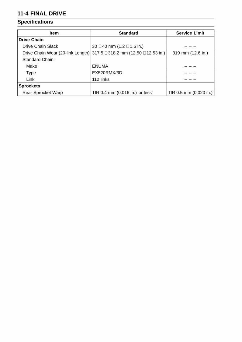
11-4 FINAL DRIVESpecifications
Item Standard Service LimitDrive Chain
Drive Chain Slack 30 ∼ 40 mm (1.2 ∼ 1.6 in.) – – –Drive Chain Wear (20-link Length) 317.5 ∼ 318.2 mm (12.50 ∼ 12.53 in.) 319 mm (12.6 in.)Standard Chain:
Make ENUMA – – –Type EX520RMX/3D – – –Link 112 links – – –
SprocketsRear Sprocket Warp TIR 0.4 mm (0.016 in.) or less TIR 0.5 mm (0.020 in.)

FINAL DRIVE 11-5Special Tools
Inside Circlip Pliers:57001-143
Bearing Driver Set:57001-1129

11-6 FINAL DRIVEDrive Chain
Drive Chain Slack Inspection•Refer to the Drive Chain Slack Inspection in the Periodic
Maintenance chapter.
Drive Chain Slack Adjustment•Refer to the Drive Chain Slack Adjustment in the Periodic
Maintenance chapter.
Wheel Alignment Inspection/Adjustment•Refer to the Wheel Alignment Inspection in the Periodic
Maintenance chapter.
Drive Chain Wear Inspection•Refer to the Drive Chain Wear Inspection in the Periodic
Maintenance chapter.
Drive Chain Lubrication•Refer to the Drive Chain Lubrication Condition Inspection
in the Periodic Maintenance chapter.
Drive Chain Guide Wear Inspection•Refer to the Chain Guide Wear Inspection in the Periodic
Maintenance chapter.
Drive Chain Removal/InstallationNOTE
Since the drive chain is installed through the swingarm,The chain can not be removed other than by cutting it.Prepare the new link pin, link plate, grease seals, andtools for rejoining the chain.
•Remove:Front Footpeg Bracket Bolts [A]Front Footpeg Bracket [B]
•Remove:Bolts [A]Quick Rivet [B]Chain Cover [C]
Push the central pin, and then remove the quick rivet.
NOTICEFor safety, if the drive chain shall be replaced, re-place it using a recommended tool.
Recommended Tool - Type: EK Joint Tool #50Brand: ENUMA

FINAL DRIVE 11-7Drive Chain
Body [A]Handlebar [B]Cutting and Riveting Pin [C]For Cutting [D]For Riveting [E]Plate Holder (A) [F]Plate Holder (B) [G]Gauge [H]
•Grind [A] the pin head to make it flat.• Set the cutting and riveting pin [B] as shown.
• Screw the pin holder until it touches the link pin.• Be sure that the cutting pin hits center of the link pin.
• Screw the handlebar [A] into the body.• Turn the pin holder with the wrench [B] clockwise to ex-
tract the link pin.
•Replace the link pin, link plate and grease seals.• Apply grease to the link pins [A] and grease seals [B] [C].• Engage the drive chain on the engine and rear sprockets.• Insert the link pins in the drive chain ends.• Install the grease seals.• Install the link plate so that the mark [D] faces out.• Push the link plate by hand or plier to fix it.• Be sure to set the grease seals correctly.
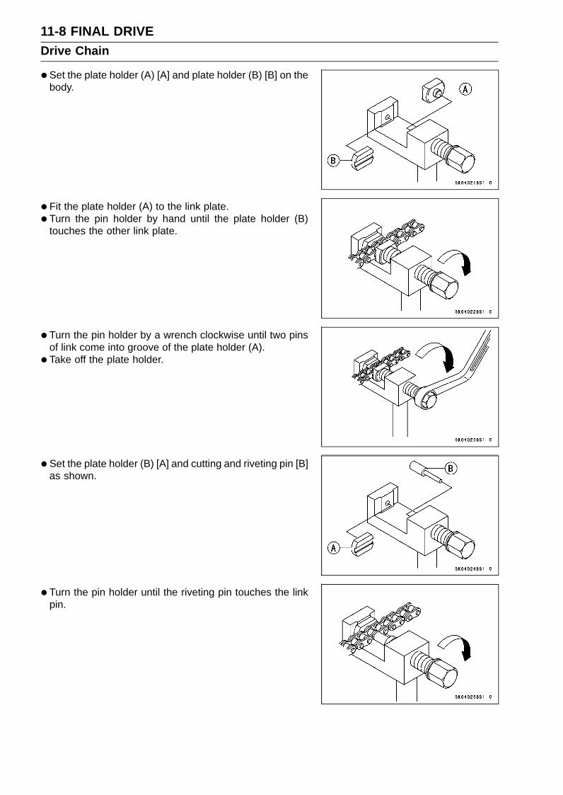
11-8 FINAL DRIVEDrive Chain
•Set the plate holder (A) [A] and plate holder (B) [B] on thebody.
• Fit the plate holder (A) to the link plate.• Turn the pin holder by hand until the plate holder (B)
touches the other link plate.
• Turn the pin holder by a wrench clockwise until two pinsof link come into groove of the plate holder (A).
• Take off the plate holder.
• Set the plate holder (B) [A] and cutting and riveting pin [B]as shown.
• Turn the pin holder until the riveting pin touches the linkpin.

FINAL DRIVE 11-9Drive Chain
•Turn the wrench clockwise until the tip of riveting pin hitsof the link pin.
•Rivet it.• Same work for the other link pin.
• After staking, check the staked area of the link pin forcracks.
•Measure the outside diameter [A] of the link pin and linkplates width [B].
Link Pin Outside DiameterStandard: 5.6 ∼ 6.0 mm (0.22 ∼ 0.24 in.)
Link Plates Outside WidthStandard: 16.40 ∼ 16.55 mm (0.646 ∼ 0.652 in.)
If the reading exceeds the specified length, cut and rejointhe chain again.
•Check:Movement of the Rollers
• Adjust the drive chain slack after installing the chain (seeDrive Chain Slack Adjustment in the Periodic Mainte-nance chapter).
• Install the chain cover [A].• Apply a non-permanent locking agent to the threads of
the bolts [B] and tighten them.•Set the quick rivet [C] and push the core of it.• Install the front footpeg bracket.• Apply a non-permanent locking agent to the threads of
the front footpeg bracket bolts, and tighten them.Torque - Front Footpeg Bracket Bolts: 25 N·m (2.5 kgf·m,
18 ft·lb)

11-10 FINAL DRIVESprocket, Coupling
Engine Sprocket Removal•Remove:
Engine Sprocket Cover Bolts [A]Engine Sprocket Cover [B]
• Flatten out the bended washer [A].• Remove the engine sprocket nut [B] and washer.
NOTEWhen loosening the engine sprocket nut, hold the rear
brake on.
•Raise the rear wheel off the ground with the stand.• Loosen the drive chain (see Drive Chain Slack Adjust-
ment in the Periodic Maintenance chapter).• Pull the engine sprocket [A] with drive chain [B] off the
output shaft [C].• Disengage the drive chain from the engine sprocket.
Engine Sprocket Installation•Replace the sprocket washer and axle cotter pin.• Install the engine sprocket [A] onto the output shaft.• Apply molybdenum disulfide oil solution to the threads
and seating surface of the engine sprocket nut.• Tighten:
Torque - Engine Sprocket Nut: 147 N·m (15.0 kgf·m, 108ft·lb)
NOTETighten the engine sprocket nut while applying the rear
brake.
•After torquing the engine sprocket nut, bend [B] the oneside of the washer over the nut.
• Adjust the drive chain slack after installing the enginesprocket (see Drive Chain Slack Adjustment in the Pe-riodic Maintenance chapter).

FINAL DRIVE 11-11Sprocket, Coupling
• Install:Engine Sprocket Cover [A]
• Tighten:Torque - Engine Sprocket Cover Bolts [B]: 9.8 N·m (1.0
kgf·m, 87 in·lb)
Engine Sprocket Cover Disassembly•Remove:
Engine Sprocket Cover (see Engine Sprocket Removal)Chain Guide Bolts [A]Chain Guide [B]
•Remove:Engine Sprocket Cover Damper Screws [A]Damper [B]
Engine Sprocket Cover Assembly•Fit the grooves of the damper [A] to the ribs [B] of the
engine sprocket cover [C].• Tighten:
Torque - Engine Sprocket Cover Damper Screws [D]: 3.0N·m (0.31 kgf·m, 27 in·lb)
• Install the chain guide [E].• Apply a non-permanent locking agent to the threads of
the chain guide bolts [F], and tighten them.Torque - Chain Guide Bolts: 12 N·m (1.2 kgf·m, 106 in·lb)
• Install:Engine Sprocket Cover (see Engine Sprocket Installa-tion)

11-12 FINAL DRIVESprocket, Coupling
Rear Sprocket Removal•Remove the rear wheel (see Rear Wheel Removal in the
Wheels/Tires chapter).
NOTICEDo not lay the wheel on the ground with the discfacing down. This can damage or warp the disc.Place blocks under the wheel so that the disc doesnot touch the ground.
•Remove:Rear Sprocket Nuts [A]Rear Sprocket [B]
Rear Sprocket Installation• Install the sprocket facing the tooth number marking [A]
outward.•Replace the rear sprocket nuts with new ones.• Tighten:
Torque - Rear Sprocket Nuts: 59 N·m (6.0 kgf·m, 44 ft·lb)
• Install the rear wheel (see Rear Wheel Installation in theWheels/Tires chapter).
Coupling Installation•Apply high-temperature grease to the following.
Coupling Grease Seal Lips [A]Coupling Internal Surface [B]Ball Bearing [C]
• Install:Collar [A]Coupling

FINAL DRIVE 11-13Sprocket, Coupling
Coupling Bearing Removal•Remove:
CouplingGrease SealCirclip [A]
Special Tool - Inside Circlip Pliers: 57001-143
•Remove the bearing [A] by tapping from the wheel side.Special Tool - Bearing Driver Set [B]: 57001-1129
Coupling Bearing Installation•Replace the bearing with a new one.• Press in the bearing [A] until it is bottomed.
Special Tool - Bearing Driver Set [B]: 57001-1129
•Pack the bearing with high-temperature grease.•Replace the circlip with a new one.
Special Tool - Inside Circlip Pliers: 57001-143
•Replace the grease seal with a new one.• Press in the grease seal so that the seal surface is flush
with the end of the hole.Apply high-temperature grease to the grease seal lips.
Special Tool - Bearing Driver Set: 57001-1129
Coupling Bearing InspectionSince the coupling bearing is made to extremely close
tolerances, the clearance can not normally be measured.
NOTEIt is not necessary to remove the coupling bearing for
inspection. If the bearing is removed, it will need to bereplaced with a new one.
•Turn the bearing in the coupling back and forth [A] whilechecking for plays, roughness or binding.If the bearing play, roughness or binding is found, replacethe bearing.
Coupling Bearing Lubrication•Pack the bearing with high-temperature grease. Turn the
bearing around by hand a few times to make sure thegrease is distributed uniformly inside the bearing.

11-14 FINAL DRIVESprocket, Coupling
Coupling Damper Inspection•Remove the rear wheel coupling, and inspect the rubber
dampers [A].• Replace the damper if it appears damaged or deterio-
rated.
Sprocket Wear Inspection•Visually inspect the engine and rear sprocket teeth for
wear and damage.If the teeth are worn as illustrated, replace the sprocket,and inspect the drive chain wear (see Drive Chain WearInspection in the Periodic Maintenance chapter).Worn Tooth (Engine Sprocket) [A]Worn Tooth (Rear Sprocket) [B]Direction of Rotation [C]
NOTEIf a sprocket requires replacement, the chain is proba-
bly worn also. When replacing a sprocket, inspect thechain.
Rear Sprocket Warp Inspection•Raise the rear wheel off the ground with the stand so that
it will turn freely.• Set a dial gauge [A] against the rear sprocket [B] near the
teeth as shown, and rotate [C] the rear wheel to measurethe sprocket runout (warp). The difference between thehighest and lowest dial gauge readings is the amount ofrunout (warp).If the runout exceeds the service limit, replace the rearsprocket.
Rear Sprocket WarpStandard: TIR 0.4 mm (0.016 in.) or lessService Limit: TIR 0.5 mm (0.020 in.)
BRAKES 12-1
12
BrakesTable of Contents
Exploded View ....................................................................................................................... 12-3Specifications ........................................................................................................................ 12-10Special Tools .......................................................................................................................... 12-11Brake Lever, Brake Pedal....................................................................................................... 12-12
Brake Lever Position Adjustment...................................................................................... 12-12Brake Pedal Position Inspection ...................................................................................... 12-12Brake Pedal Position Adjustment ..................................................................................... 12-12Brake Pedal Removal ....................................................................................................... 12-12Brake Pedal Installation .................................................................................................... 12-13
Calipers .................................................................................................................................. 12-15Front Caliper Removal ...................................................................................................... 12-15Rear Caliper Removal....................................................................................................... 12-15Caliper Installation ............................................................................................................ 12-16Front Caliper Disassembly................................................................................................ 12-16Front Caliper Assembly..................................................................................................... 12-16Rear Caliper Disassembly ................................................................................................ 12-16Rear Caliper Assembly ..................................................................................................... 12-16Caliper Fluid Seal Damage Inspection.............................................................................. 12-17Caliper Dust Seal Damage Inspection .............................................................................. 12-17Rear Caliper Dust Boot and Friction Boot Damage Inspection......................................... 12-17Caliper Piston and Cylinder Damage Inspection .............................................................. 12-18Rear Caliper Holder Shaft Wear Inspection...................................................................... 12-18
Brake Pads............................................................................................................................. 12-19Front Brake Pad Removal................................................................................................. 12-19Front Brake Pad Installation.............................................................................................. 12-19Rear Brake Pad Removal ................................................................................................ 12-20Rear Brake Pad Installation .............................................................................................. 12-20Brake Pad Wear Inspection .............................................................................................. 12-20
Master Cylinder ...................................................................................................................... 12-21Front Master Cylinder Removal ........................................................................................ 12-21Front Master Cylinder Installation ..................................................................................... 12-21Rear Master Cylinder Removal......................................................................................... 12-22Rear Master Cylinder Installation...................................................................................... 12-23Front Master Cylinder Disassembly .................................................................................. 12-24Rear Master Cylinder Disassembly................................................................................... 12-24Master Cylinder Assembly ................................................................................................ 12-24Master Cylinder Inspection (Visual Inspection)................................................................. 12-24
Brake Disc .............................................................................................................................. 12-25Brake Disc Removal ......................................................................................................... 12-25Brake Disc Installation ...................................................................................................... 12-25Brake Disc Wear Inspection.............................................................................................. 12-25Brake Disc Warp Inspection.............................................................................................. 12-26
Brake Fluid ............................................................................................................................. 12-27Brake Fluid Level Inspection............................................................................................. 12-27Brake Fluid Change .......................................................................................................... 12-27Brake Line Bleeding.......................................................................................................... 12-27
Brake Hose............................................................................................................................. 12-31Brake Hose Removal/Installation...................................................................................... 12-31Brake Hose Inspection...................................................................................................... 12-31
KIBS (Equipped Models) ........................................................................................................ 12-32

12-2 BRAKES
Parts Location ................................................................................................................... 12-32KIBS Servicing Precautions .............................................................................................. 12-36KIBS Troubleshooting Outline........................................................................................... 12-38Inquiries to Rider............................................................................................................... 12-41Self-diagnosis Outline ....................................................................................................... 12-43ABS and KIBS Indicator Lights (LED) Inspection ............................................................. 12-44KIBS Hydraulic Unit Removal ........................................................................................... 12-44KIBS Hydraulic Unit Installation ........................................................................................ 12-45KIBS Hydraulic Unit Inspection ......................................................................................... 12-46Front Wheel Rotation Sensor Removal ............................................................................ 12-46Front Wheel Rotation Sensor Installation ......................................................................... 12-47Rear Wheel Rotation Sensor Removal ............................................................................. 12-47Rear Wheel Rotation Sensor Installation .......................................................................... 12-48Wheel Rotation Sensor Inspection.................................................................................... 12-48Wheel Rotation Sensor Air Gap Inspection ...................................................................... 12-49Wheel Rotation Sensor Rotor Inspection.......................................................................... 12-49KIBS Solenoid Valve Relay Fuse (15 A) Removal............................................................ 12-50KIBS Motor Relay Fuse (25 A) Removal .......................................................................... 12-50Fuse Installation................................................................................................................ 12-50Fuse Inspection................................................................................................................. 12-50

BRAKES 12-3Exploded View
This page intentionally left blank.
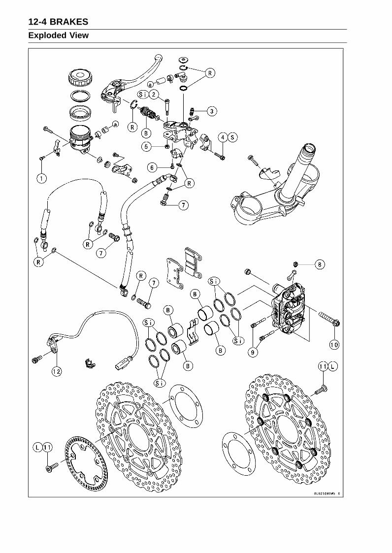
12-4 BRAKESExploded View

BRAKES 12-5Exploded View
TorqueNo. Fastener
N·m kgf·m ft·lbRemarks
1 Front Brake Reservoir Cap Stopper Screw 1.2 0.12 11 in·lb2 Brake Lever Pivot Bolt 1.0 0.10 8.9 in·lb Si3 Front Master Cylinder Bleed Valve 5.4 0.55 48 in·lb4 Front Master Cylinder Clamp Bolts 11 1.1 97 in·lb S5 Brake Lever Pivot Bolt Locknut 5.9 0.60 52 in·lb6 Front Brake Light Switch Screw 1.2 0.12 11 in·lb7 Brake Hose Banjo Bolts 25 2.5 188 Bleed Valves 7.8 0.80 69 in·lb9 Front Brake Pad Pins 17 1.7 13
10 Front Caliper Mounting Bolts 34 3.5 2511 Front Brake Disc Mounting Bolts 27 2.8 20 L12. Front Wheel Rotation SensorB: Apply brake fluid.L: Apply a non-permanent locking agent.R: Replacement PartsS: Follow the specified tightening sequence.Si: Apply silicone grease.

12-6 BRAKESExploded View

BRAKES 12-7Exploded View
TorqueNo. Fastener
N·m kgf·m ft·lbRemarks
1 Brake Hose Banjo Bolts 25 2.5 182 Rear Master Cylinder Mounting Bolts 25 2.5 183 Brake Pedal Mounting Bolt 34 3.5 25 L4 Rear Caliper Pin Bolt 27 2.8 20 Si5 Bleed Valve 7.8 0.80 69 in·lb6 Rear Brake Pad Pin Plug 2.45 0.25 22 in·lb7 Rear Brake Pad Pin 17 1.7 138 Rear Brake Disc Mounting Bolts 27 2.8 20 L9 Rear Master Cylinder Push Rod Locknut 17 1.7 1310. Rear Wheel Rotation SensorB: Apply brake fluid.L: Apply a non-permanent locking agent.R: Replacement PartsSi: Apply silicone grease.

12-8 BRAKESExploded View
KIBS Equipped Models

BRAKES 12-9Exploded View
TorqueNo. Fastener
N·m kgf·m ft·lbRemarks
1 Brake Hose Banjo Bolts 25 2.5 182 Brake Pipe Joint Nuts 18 1.8 133 Brake Pipe Banjo Bolts (L = 20.8) 23 2.3 174 Brake Pipe Banjo Bolt (L = 32.3) 23 2.3 175. KIBS Hydraulic UnitR: Replacement Parts
NOTEWhen disassembling the brake hose and pipe, disassemble them by the unit as shown in the
exploded view.

12-10 BRAKESSpecifications
Item Standard Service LimitBrake Lever, Brake Pedal
Brake Lever Position 6-way adjustable (to suit rider) – – –Brake Lever Free Play Non-adjustable – – –Pedal Free Play Non-adjustable – – –Pedal Position About 75 mm (2.95 in.) below top of
footpeg– – –
Brake PadsLining Thickness:
Front 4.0 mm (0.16 in.) 1 mm (0.04 in.)Rear 5.0 mm (0.20 in.) 1 mm (0.04 in.)
Brake DiscsThickness:
Front 4.8 ∼ 5.2 mm (0.19 ∼ 0.20 in.) 4.5 mm (0.18 in.)Rear 4.8 ∼ 5.2 mm (0.19 ∼ 0.20 in.) 4.5 mm (0.18 in.)
Runout:Front TIR 0.15 mm (0.006 in.) or less TIR 0.3 mm (0.01 in.)Rear TIR 0.20 mm (0.008 in.) or less TIR 0.3 mm (0.01 in.)
KIBS (Equipped Models)Wheel Rotation Sensor AirGap:
Front 0.4 ∼ 1.6 mm (0.02 ∼ 0.06 in.) – – –Rear 0.4 ∼ 1.6 mm (0.02 ∼ 0.06 in.) – – –
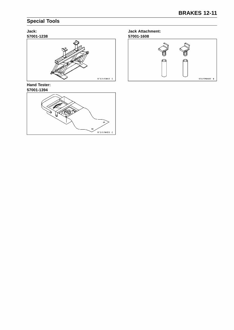
BRAKES 12-11Special Tools
Jack:57001-1238
Hand Tester:57001-1394
Jack Attachment:57001-1608

12-12 BRAKESBrake Lever, Brake Pedal
Brake Lever Position AdjustmentThe brake lever adjuster has 6 positions so that the brake
lever position can be adjusted to suit the operator’s hand.• Push the lever forward and turn the adjuster [A] to align
the number with the arrow mark [B] on the lever.The distance from the grip to the lever is minimum at num-
ber 6 and maximum at number 1.
Brake Pedal Position Inspection•Check that the brake pedal [A] is in the correct position.
Footpeg [B]
Pedal PositionStandard: About 75 mm (2.95 in.) [C] below top of
footpeg
If it is incorrect, adjust the brake pedal position.
Brake Pedal Position AdjustmentNOTE
Usually it is not necessary to adjust the pedal position,but always adjust it when push rod locknut has beenloosened.
• Loosen the locknut [A] and turn the push rod with the hexhead [B] to achieve the correct pedal position.If the length [C] shown is 70 ±1 mm (2.8 ±0.04 in.), thepedal position will be within the standard range.
• Tighten:Torque - Rear Master Cylinder Push Rod Locknut: 17 N·m
(1.7 kgf·m, 13 ft·lb)
•Check the brake light switch operation (see Brake LightSwitch Operation Inspection in the Periodic Maintenancechapter).
Brake Pedal Removal•Remove:
Rear Master Cylinder Mounting Bolts [A]Foot Guard [B]Front Footpeg Bracket Bolts [C]

BRAKES 12-13Brake Lever, Brake Pedal
•Remove:Cotter Pin [A]Joint Pin [B]Rear Brake Light Switch Spring [C]Return Spring [D]
•Remove the brake pedal mounting bolt [E] and take outthe brake pedal.
Brake Pedal Installation•Apply grease to the footpeg pivot shaft [A].• Install:
Bushing [B]Brake Pedal [C]
• Apply a non-permanent locking agent to the threads ofthe brake pedal mounting bolt [D], and tighten it.Torque - Brake Pedal Mounting Bolt: 34 N·m (3.5 kgf·m, 25
ft·lb)
•Hook the return spring [A] on the brake pedal and frontfootpeg bracket [B] as shown.
•Hook the rear brake light switch spring [C] on the switchand return spring as shown.
•Replace the cotter pin [A] with a new one.• Insert the cotter pin and bend the pin ends [B].

12-14 BRAKESBrake Lever, Brake Pedal
• Install the front footpeg bracket.• Apply a non-permanent locking agent to the threads of
the front footpeg bracket bolts, and tighten them.Torque - Front Footpeg Bracket Bolts: 25 N·m (2.5 kgf·m,
18 ft·lb)
• Install the rear master cylinder [A] and foot guard.
NOTEDepress the brake pedal [B] and then align the holes of
the master cylinder.After installation, check that the rear brake light switch
spring is hooked on the return spring.
•Apply a non-permanent locking agent to the threads ofthe front bracket bolts, and tighten them.Torque - Rear Master Cylinder Mounting Bolts: 25 N·m (2.5
kgf·m, 18 ft·lb)
•Check the brake pedal position (see Brake Pedal PositionInspection).

BRAKES 12-15Calipers
Front Caliper Removal•Remove:
Bolt [A]Front Wheel Rotation Sensor [B]
• Loosen the banjo bolt [C] at the brake hose lower end,and tighten it loosely.
•Remove the caliper mounting bolts [D], and detach thecaliper [E] from the disc.
•Unscrew the banjo bolt and remove the brake hose fromthe caliper (see Brake Hose and Pipe Replacement in thePeriodic Maintenance chapter).
NOTICEImmediately wash away any brake fluid that spills.
Rear Caliper Removal•Remove:
Bolt [A]Rear Wheel Rotation Sensor [B]
• Loosen the banjo bolt [C] at the brake hose lower end,and tighten it loosely.
• Loosen the rear caliper pin bolt [D].• Remove the rear wheel (see Rear Wheel Removal in the
Wheels/Tires chapter).
• Unscrew the banjo bolt and remove the brake hoses fromthe caliper (see Brake Hose and Pipe Replacement in thePeriodic Maintenance chapter).
NOTICEImmediately wash away any brake fluid that spills.

12-16 BRAKESCalipers
Caliper Installation• Install the caliper and brake hose lower end.For the front caliper, be sure to install the collars [A].Replace the washers on each side of hose fitting with new
ones.Touch the brake hoses to the stopper of the caliper.• Tighten:
Torque - Front Caliper Mounting Bolts: 34 N·m (3.5 kgf·m,25 ft·lb)
Rear Caliper Pin Bolt: 27 N·m (2.8 kgf·m, 20 ft·lb)Brake Hose Banjo Bolts: 25 N·m (2.5 kgf·m, 18
ft·lb)
•Check the fluid level in the brake reservoirs.• Bleed the brake line (see Brake Line Bleeding).• Check the brake for good braking power, no brake drag,
and no fluid leakage.
WARNINGAfter servicing, it takes several applications of thebrake lever or pedal before the brake pads contactthe disc, which could result in increased stoppingdistance and cause an accident resulting in injuryor death. Do not attempt to ride the motorcycle untila firm brake lever or pedal is obtained by pumpingthe lever or pedal until the pads are against the disc.
Front Caliper Disassembly•Refer to the Caliper Rubber Parts Replacement in the Pe-
riodic Maintenance chapter.
Front Caliper Assembly•Refer to the Caliper Rubber Parts Replacement in the Pe-
riodic Maintenance chapter.
Rear Caliper Disassembly•Refer to the Caliper Rubber Parts Replacement in the Pe-
riodic Maintenance chapter.
Rear Caliper Assembly•Refer to the Caliper Rubber Parts Replacement in the Pe-
riodic Maintenance chapter.

BRAKES 12-17Calipers
Caliper Fluid Seal Damage InspectionThe fluid seal (piston seal) [A] is placed around the pis-
ton to maintain clearance between the pad and the disc. Ifthe seal is in a poor condition, it could lead the pad to wearexcessively or the brake to drag, which may cause the tem-perature of the discs or the brake fluid to increase.•Replace the fluid seal if it exhibits any of the conditions
listed below.Brake fluid leakage around the pad.Brakes overheat.Considerable difference in inner and outer pad wear.Seal and piston are stuck together.
If the fluid seal is replaced, replace the dust seal [B] aswell. Also, replace all seals every other time the pads arechanged.
Caliper Dust Seal Damage Inspection•Check that the dust seals [A] are not cracked, worn,
swollen, or otherwise damaged.If they show any damage, replace the dust seals with newones.Pistons [B]Fluid Seals [C]
Rear Caliper Dust Boot and Friction Boot DamageInspection•Check that the dust boot [A] and friction boot [B] are not
cracked, worn, swollen, or otherwise damaged.If they show any damage, replace it.

12-18 BRAKESCalipers
Caliper Piston and Cylinder Damage Inspection•Visually inspect the pistons [A] and cylinder surfaces [B].
Replace the caliper if the cylinder and piston are badlyscores or rusty.
Rear Caliper Holder Shaft Wear InspectionThe caliper body must slide smoothly on the caliper holder
shafts [A]. If the body does not slide smoothly, one pad willwear more than the other, pad wear will increase, and con-stant drag on the disc will raise brake and brake fluid tem-perature.•Check to see that the caliper holder shafts are not badly
worn or stepped, and that the rubber boots are not dam-aged.If the rubber boot is damaged, replace the rubber boot. Toreplace the rubber boot, remove the pads and the caliperbracket.If the caliper holder shaft is damage, replace the caliperbracket.

BRAKES 12-19Brake Pads
Front Brake Pad Removal• Loosen the pad pins [A].• Remove the front caliper with the hose installed (see Front
Caliper Removal).• Remove:
Pad PinsBrake Pads
Front Brake Pad Installation•Check that the pad spring [A] is in place on the caliper.• Push the caliper pistons in by hand as far as they will go.
• Install the brake pads [A] on the pad spring correctly.Fit the pad into the groove of the caliper.
• Tighten the pad pins temporarily.Push down the pin holder [A] and insert the pad pin [B].• Install the front caliper (see Caliper Installation).• Tighten:
Torque - Front Brake Pad Pins: 17 N·m (1.7 kgf·m, 13 ft·lb)
WARNINGAfter servicing, it takes several applications of thebrake lever before the brake pads contact the disc,which could result in increased stopping distanceand cause an accident resulting in injury or death.Do not attempt to ride the motorcycle until a firmbrake lever is obtained by pumping the lever untilthe pads are against the disc.

12-20 BRAKESBrake Pads
Rear Brake Pad Removal•Remove:
Pad Pin Plug [A]Pad Pin [B]Brake Pads [C]
Rear Brake Pad Installation•Check that the pad spring is in place on the caliper.• Push the caliper piston in as far as it will go.• Install the piston side pad [A] first, and then another pad.Fit the brake pad end into the recess [B] of the caliper
bracket.• Install the pad pin and the plug.• Tighten:
Torque - Rear Brake Pad Pin: 17 N·m (1.7 kgf·m, 13 ft·lb)Rear Brake Pad Pin Plug: 2.45 N·m (0.25 kgf·m, 22
in·lb)
WARNINGAfter servicing, it takes several applications of thebrake pedal before the brake pads contact the disc,which could result in increased stopping distanceand cause an accident resulting in injury or death.Do not attempt to ride the motorcycle until a firmbrake pedal is obtained by pumping the pedal untilthe pads are against the disc.
Brake Pad Wear Inspection•Refer to the Brake Pad Wear Inspection in the Periodic
Maintenance chapter.
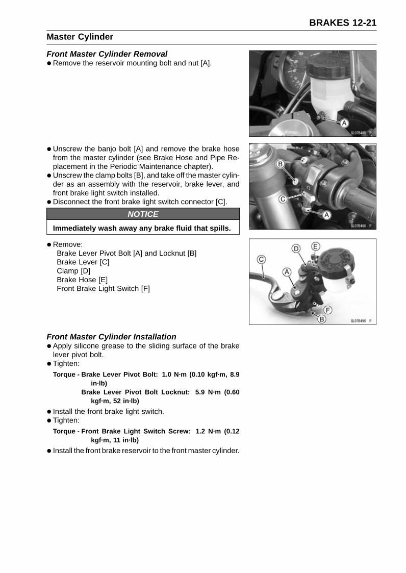
BRAKES 12-21Master Cylinder
Front Master Cylinder Removal•Remove the reservoir mounting bolt and nut [A].
• Unscrew the banjo bolt [A] and remove the brake hosefrom the master cylinder (see Brake Hose and Pipe Re-placement in the Periodic Maintenance chapter).
• Unscrew the clamp bolts [B], and take off the master cylin-der as an assembly with the reservoir, brake lever, andfront brake light switch installed.
•Disconnect the front brake light switch connector [C].
NOTICEImmediately wash away any brake fluid that spills.
•Remove:Brake Lever Pivot Bolt [A] and Locknut [B]Brake Lever [C]Clamp [D]Brake Hose [E]Front Brake Light Switch [F]
Front Master Cylinder Installation•Apply silicone grease to the sliding surface of the brake
lever pivot bolt.• Tighten:
Torque - Brake Lever Pivot Bolt: 1.0 N·m (0.10 kgf·m, 8.9in·lb)
Brake Lever Pivot Bolt Locknut: 5.9 N·m (0.60kgf·m, 52 in·lb)
• Install the front brake light switch.• Tighten:
Torque - Front Brake Light Switch Screw: 1.2 N·m (0.12kgf·m, 11 in·lb)
• Install the front brake reservoir to the front master cylinder.
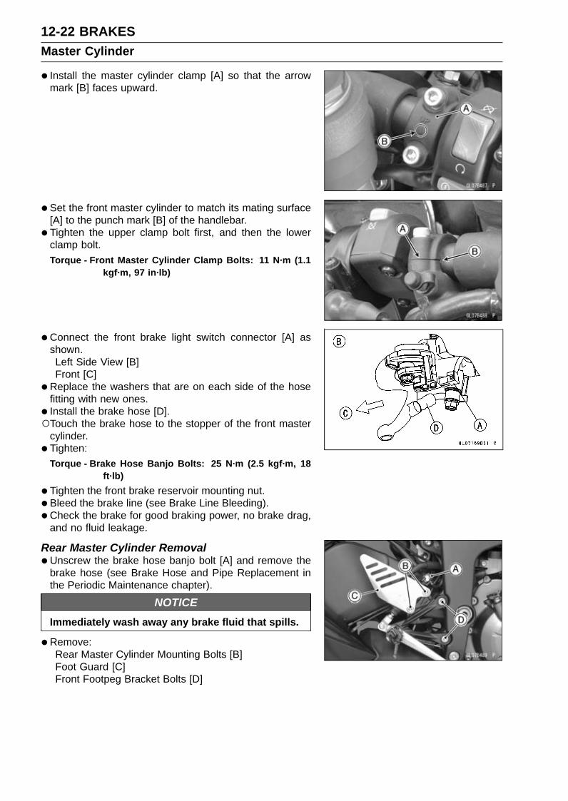
12-22 BRAKESMaster Cylinder
• Install the master cylinder clamp [A] so that the arrowmark [B] faces upward.
• Set the front master cylinder to match its mating surface[A] to the punch mark [B] of the handlebar.
• Tighten the upper clamp bolt first, and then the lowerclamp bolt.Torque - Front Master Cylinder Clamp Bolts: 11 N·m (1.1
kgf·m, 97 in·lb)
•Connect the front brake light switch connector [A] asshown.Left Side View [B]Front [C]
•Replace the washers that are on each side of the hosefitting with new ones.
• Install the brake hose [D].Touch the brake hose to the stopper of the front master
cylinder.• Tighten:
Torque - Brake Hose Banjo Bolts: 25 N·m (2.5 kgf·m, 18ft·lb)
•Tighten the front brake reservoir mounting nut.• Bleed the brake line (see Brake Line Bleeding).• Check the brake for good braking power, no brake drag,
and no fluid leakage.
Rear Master Cylinder Removal•Unscrew the brake hose banjo bolt [A] and remove the
brake hose (see Brake Hose and Pipe Replacement inthe Periodic Maintenance chapter).
NOTICEImmediately wash away any brake fluid that spills.
•Remove:Rear Master Cylinder Mounting Bolts [B]Foot Guard [C]Front Footpeg Bracket Bolts [D]
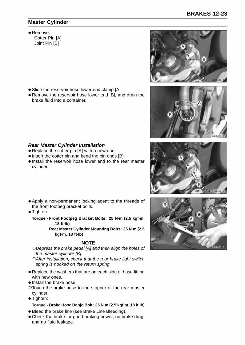
BRAKES 12-23Master Cylinder
•Remove:Cotter Pin [A]Joint Pin [B]
• Slide the reservoir hose lower end clamp [A].• Remove the reservoir hose lower end [B], and drain the
brake fluid into a container.
Rear Master Cylinder Installation•Replace the cotter pin [A] with a new one.• Insert the cotter pin and bend the pin ends [B].• Install the reservoir hose lower end to the rear master
cylinder.
• Apply a non-permanent locking agent to the threads ofthe front footpeg bracket bolts.
• Tighten:Torque - Front Footpeg Bracket Bolts: 25 N·m (2.5 kgf·m,
18 ft·lb)Rear Master Cylinder Mounting Bolts: 25 N·m (2.5
kgf·m, 18 ft·lb)
NOTEDepress the brake pedal [A] and then align the holes of
the master cylinder [B].After installation, check that the rear brake light switch
spring is hooked on the return spring.
•Replace the washers that are on each side of hose fittingwith new ones.
• Install the brake hose.Touch the brake hose to the stopper of the rear master
cylinder.• Tighten:
Torque - Brake Hose Banjo Bolt: 25 N·m (2.5 kgf·m, 18 ft·lb)
•Bleed the brake line (see Brake Line Bleeding).• Check the brake for good braking power, no brake drag,
and no fluid leakage.

12-24 BRAKESMaster Cylinder
Front Master Cylinder Disassembly•Refer to the Master Cylinder Rubber Parts Replacement
in the Periodic Maintenance chapter.
Rear Master Cylinder Disassembly•Refer to the Master Cylinder Rubber Parts Replacement
in the Periodic Maintenance chapter.
Master Cylinder Assembly•Refer to the Master Cylinder Rubber Parts Replacement
in the Periodic Maintenance chapter.
Master Cylinder Inspection (Visual Inspection)•Remove the master cylinders (see Front/Rear Master
Cylinder Removal).• Disassemble the front and rear master cylinders (see
Master Cylinder Rubber Parts Replacement in the Peri-odic Maintenance chapter).
• Check that there are no scratches, rust or pitting on theinner wall [A] of each master cylinder and on the outsideof each piston [B].If a master cylinder or piston shows any damage, replacethem.
• Inspect the primary cup [C] and secondary cup [D].If a cup is worn, damaged softened (rotted), or swollen,the piston assembly should be replaced to renew thecups.If fluid leakage is noted at the brake lever, the piston as-sembly should be replaced to renew the cups.
•Check the dust covers [E] for damage.If they are damaged, replace them.
•Check the piston return springs [F] for any damage.If the springs are damaged, replace them.
•Check that relief port [G] and supply port [H] are notplugged.If the relief port becomes plugged, the brake pads willdrag on the disc. Blow the ports clean with compressedair.Front Master Cylinder [I]Rear Master Cylinder [J]

BRAKES 12-25Brake Disc
Brake Disc Removal•Remove the wheels (see Front/Rear Wheel Removal in
the Wheels/Tires chapter).• Remove the brake disc mounting bolts [A], and take off
the disc [B].• Remove the wheel rotation sensor rotor [C].
Brake Disc Installation•Replace the gaskets with new ones.• Install the brake disc on the wheel so that the marked side
[A] faces out.Front Brake Discs [B]Rear Brake Disc [C]
• Install the wheel rotation sensor rotor on the brake disc.When installing the rear wheel rotation sensor rotor, the
bended end faces to disc side.• Apply a non-permanent locking agent to the threads of
the brake disc mounting bolts.• Tighten:
Torque - Brake Disc Mounting Bolts: 27 N·m (2.8 kgf·m, 20ft·lb)
Brake Disc Wear Inspection•Measure the thickness of each disc [A] at the point where
it has worn the most.If the disc has worn past the service limit, replace it.Measuring Area [B]
Brake Discs ThicknessStandard:
Front 4.8 ∼ 5.2 mm (0.19 ∼ 0.20 in.)Rear 4.8 ∼ 5.2 mm (0.19 ∼ 0.20 in.)
Service Limit:Front 4.5 mm (0.18 in.)Rear 4.5 mm (0.18 in.)

12-26 BRAKESBrake Disc
Brake Disc Warp Inspection•Raise the wheel off the ground with jack.
Special Tools - Jack: 57001-1238Jack Attachment: 57001-1608
For front disc inspection, turn the handlebar fully to oneside.
• Set up a dial gauge against the disc [A] as shown andmeasure disc runout, while turning [B] the wheel by hand.If runout exceeds the service limit, replace the disc.
Disc RunoutStandard:
Front TIR 0.15 mm (0.006 in.) or lessRear TIR 0.20 mm (0.008 in.) or less
Service Limit: TIR 0.3 mm (0.01 in.)

BRAKES 12-27Brake Fluid
Brake Fluid Level Inspection•Refer to the Brake Fluid Level Inspection in the Periodic
Maintenance chapter.
Brake Fluid Change•Refer to the Brake Fluid Change in the Periodic Mainte-
nance chapter.
Brake Line BleedingThe brake fluid has a very low compression coefficient so
that almost all the movement of the brake lever or pedalis transmitted directly to the caliper for braking action. Air,however, is easily compressed. When air enters the brakelines, brake lever or pedal movement will be partially usedin compressing the air. This will make the lever or pedal feelspongy, and there will be a loss in braking power.
WARNINGAir in the brake lines diminish braking performanceand can cause an accident resulting in injury ordeath. If the brake lever or pedal has a soft or"spongy" feeling mushy when it is applied, theremight be air in the brake lines or the brake may bedefective. Do not operate the vehicle and servicethe brake system immediately.
NOTEThe procedure to bleed the front brake line is as follows.
Bleeding the rear brake line is the same as for the frontbrake.
•Remove:Screw [A]Stopper [B]Front Brake Reservoir Cap [C]
•Remove:Bolt [A]Rear Brake Reservoir Cap [B]

12-28 BRAKESBrake Fluid
•Remove:Diaphragm PlateDiaphragm
•Fill the reservoir with fresh brake fluid to the upper levelline in the reservoir.
• Slowly pump the brake lever several times until no airbubbles can be seen rising up through the fluid from theholes at the bottom of the reservoir.
• Remove the rubber cap [A] from the bleed valve on thefront master cylinder.
• Attach a clear plastic hose [B] to the bleed valve, and runthe other end of the hose into a container.
• Bleed the brake line and the master cylinder.Repeat this operation until no more air can be seen com-
ing out into the plastic hose.1. Pump the brake lever until it becomes hard, and apply
the brake and hold it [A].2. Quickly open and close [B] the bleed valve while hold-
ing the brake applied.3. Release the brake [C].
NOTEThe fluid level must be checked often during the bleed-
ing operation and replenished with fresh brake fluid asnecessary. If the fluid in the reservoir runs completelyout any time during bleeding, the bleeding operationmust be done over again from the beginning since airwill have entered the line.
•Remove the clear plastic hose.• Tighten the bleed valve, and install the rubber cap.
Torque - Front Master Cylinder Bleed Valve: 5.4 N·m (0.55kgf·m, 48 in·lb)
•Remove the rubber cap [A] from the bleed valve on thecaliper.
• Attach a clear plastic hose [B] to the bleed valve, and runthe other end of the hose into a container.

BRAKES 12-29Brake Fluid
•Bleed the brake line and the caliper.Repeat this operation until no more air can be seen com-
ing out into the plastic hose.1. Pump the brake lever until it becomes hard, and apply
the brake and hold it [A].2. Quickly open and close [B] the bleed valve while hold-
ing the brake applied.3. Release the brake [C].
NOTEThe fluid level must be checked often during the bleed-
ing operation and replenished with fresh brake fluid asnecessary. If the fluid in the reservoir runs completelyout any time during bleeding, the bleeding operationmust be done over again from the beginning since airwill have entered the line.Tap the brake hose lightly from the caliper to the reser-
voir for more complete bleeding.Front Brake: First bleeding the right caliper then repeat
the above steps for the left caliper.
•Remove the clear plastic hose.• Install:
DiaphragmDiaphragm PlateFront Brake Reservoir Cap
• Follow the procedure below to install the front/rear brakefluid reservoir cap correctly.First, tighten the brake fluid reservoir cap [B] clockwise
[C] by hand until slight resistance is felt indicating thatthe cap is seated on the reservoir body, then tighten thecap an additional 1/6 turn [D] while holding the brake fluidreservoir body [A].
• Install the stopper and screw.• Tighten:
Torque - Front Brake Reservoir Cap Stopper Screw: 1.2N·m (0.12 kgf·m, 11 in·lb)
• Install the rear brake reservoir, and tighten the bolt.• Tighten the bleed valve, and install the rubber cap.
Torque - Bleed Valves: 7.8 N·m (0.80 kgf·m, 69 in·lb)
•Check the fluid level (see Brake Fluid Level Inspection inthe Periodic Maintenance chapter).
• After bleeding is done, check the brake for good brakingpower, no brake drag, and no fluid leakage.

12-30 BRAKESBrake Fluid
WARNINGWhen working with the disc brake, observe the pre-cautions listed below.•Never reuse old brake fluid.•Do not use fluid from a container that has been left
unsealed or that has been open for a long time.•Do not mix two types and brands of fluid for use
in the brake. This lowers the brake fluid boilingpoint and could cause the brake to be ineffective.It may also cause the rubber brake parts to dete-riorate.
•Don’t leave the reservoir cap off for any length oftime to avoid moisture contamination of the fluid.
•Don’t change the fluid in the rain or when a strongwind is blowing.
•Except for the disc pads and disc, use only discbrake fluid, isopropyl alcohol, or ethyl alcohol forcleaning of the brake parts. Do not use any otherfluid for cleaning these parts. Gasoline, engineoil, or any other petroleum distillate will cause de-terioration of the rubber parts. Oil spilled on anypart will be difficult to wash off completely and willeventually deteriorate the rubber used in the discbrake.
•When handling the disc pads or disc, be carefulthat no disc brake fluid or any oil gets on them.Clean off any fluid or oil that inadvertently gets onthe pads or disc with a high flash-point solvent.Do not use one which will leave an oily residue.Replace the pads with new ones if they cannot becleaned satisfactorily.
•Brake fluid quickly ruins painted surfaces; anyspilled fluid should be completely wiped up im-mediately.
• If any of the brake line fittings or the bleed valve isopened at any time, the AIR MUST BE BLED FROMTHE BRAKE LINE.

BRAKES 12-31Brake Hose
Brake Hose Removal/Installation•Refer to the Brake Hose and Pipe Replacement in the
Periodic Maintenance chapter.
Brake Hose Inspection•Refer to the Brake Hose and Pipe Damage and Instal-
lation Condition Inspection in the Periodic Maintenancechapter.

12-32 BRAKESKIBS (Equipped Models)
Parts LocationNOTE
The front and rear wheel rotation sensors and rotors arestandard parts of this motorcycle.
Front Wheel Rotation Sensor [A]Front Wheel Rotation Sensor Rotor [B]
Rear Wheel Rotation Sensor [A]Rear Wheel Rotation Sensor Rotor [B]
Yellow ABS Indicator Light (LED) [A]Yellow Warning Indicator Light [B]KIBS Warning Symbol [C]
KIBS Hydraulic Unit [A]
Fuse Box 3 [A]

BRAKES 12-33KIBS (Equipped Models)
KIBS Kawasaki Self-Diagnosis System Connector [A]

12-34 BRAKESKIBS (Equipped Models)
KIBS System Circuit
1. Ignition Switch2. Front Brake Light Switch3. ECU4. Rear Wheel Rotation Sensor5. Rear Brake Light Switch6. Frame Ground 57. Frame Ground 48. Engine Ground9. Battery 12 V 8 Ah
10. Starter Relay11. Main Fuse 30 A12. Fuse Box 3
13. KIBS Solenoid Valve Relay Fuse 15 A14. KIBS Motor Relay Fuse 25 A15. KIBS Kawasaki Self-diagnosis System Connector16. KIBS Hydraulic Unit17. Fuse Box 118. Brake Light/Horn Fuse 7.5 A19. Ignition Fuse 15 A20. Meter Unit21. Yellow ABS Indicator Light (LED)22. Yellow Warning Indicator Light (LED)23. Joint Connector E24. Front Wheel Rotation Sensor
Color Codes:BK: BlackBL: BlueBR: BrownCH: ChocolateDG: Dark Green
G: Green
GY: GrayLB: Light BlueLG: Light Green
O: OrangeP: Pink
PU: PurpleR: RedV: Violet
W: WhiteY: Yellow
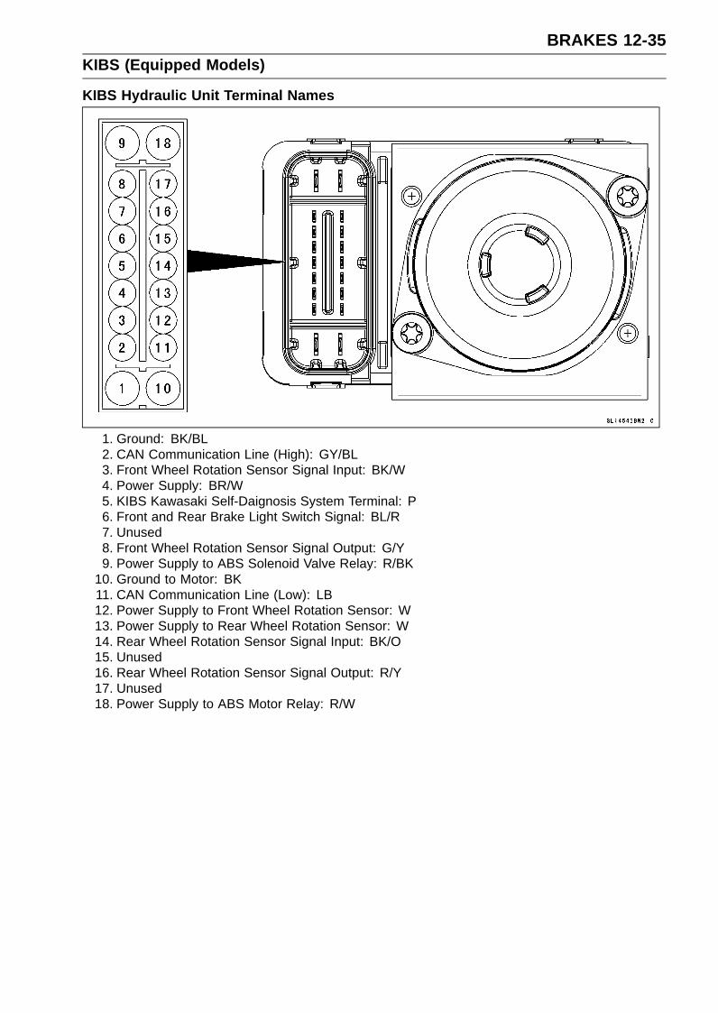
BRAKES 12-35KIBS (Equipped Models)
KIBS Hydraulic Unit Terminal Names
1. Ground: BK/BL2. CAN Communication Line (High): GY/BL3. Front Wheel Rotation Sensor Signal Input: BK/W4. Power Supply: BR/W5. KIBS Kawasaki Self-Daignosis System Terminal: P6. Front and Rear Brake Light Switch Signal: BL/R7. Unused8. Front Wheel Rotation Sensor Signal Output: G/Y9. Power Supply to ABS Solenoid Valve Relay: R/BK
10. Ground to Motor: BK11. CAN Communication Line (Low): LB12. Power Supply to Front Wheel Rotation Sensor: W13. Power Supply to Rear Wheel Rotation Sensor: W14. Rear Wheel Rotation Sensor Signal Input: BK/O15. Unused16. Rear Wheel Rotation Sensor Signal Output: R/Y17. Unused18. Power Supply to ABS Motor Relay: R/W

12-36 BRAKESKIBS (Equipped Models)
KIBS Servicing PrecautionsThere are a number of important precautions that should
be followed servicing the KIBS.This KIBS is designed to be used with a 12 V sealed bat-
tery as its power source. Do not use any other batteryexcept for a 12 V sealed battery as a power source.Do not reverse the battery cable connections. This will
damage the KIBS hydraulic unit.To prevent damage to the KIBS parts, do not discon-
nect the battery cables or any other electrical connectionswhen the ignition switch is on or while the engine is run-ning.Take care not to short the leads that are directly con-
nected to the battery positive (+) terminal to the chassisground.Do not turn the ignition switch on while any of the KIBS
electrical connectors are disconnected. The KIBS hy-draulic unit memorizes service codes.Do not spray water on the electrical parts, KIBS parts,
connectors, leads and wiring.If a transceiver is installed on the motorcycle, make sure
that the operation of the KIBS is not influenced by electricwave radiated from the antenna. Locate the antenna asfar as possible away from the KIBS hydraulic unit.Whenever the KIBS electrical connections are to be dis-
connected, first turn off the ignition switch.The KIBS parts should never be struck sharply, as with
a hammer, or allowed to fall on a hard surface. Such ashock to the parts can damage them.The KIBS parts cannot be disassembled. Even if a fault
is found, do not try to disassemble and repair the KIBSparts, replace it.The KIBS has many brake lines, pipes, and leads. And
the KIBS cannot detect problems with the conventionalbraking system (brake disc wear, unevenly worn brakepad, and other mechanical faults). To prevent trouble,check the brake lines and pipes for correct routing andconnection, the wiring for correct routing, and the brakesfor proper braking power. Be sure to check for fluid leak-age, and bleed the brake line thoroughly.
WARNINGAir in the brake lines diminish braking performanceand can cause an accident resulting in injury ordeath. If any of the brake line fittings, including theKIBS hydraulic unit joint nuts, or the bleed valve isopened at any time, the air must be bled completelyfrom the brake line. If the brake lever has a softor "spongy" feeling mushy when it is applied, theremight be air in the brake lines or the brake may bedefective. Do not operate the vehicle and servicethe brake system immediately.
NOTICEDo not ride the motorcycle with air in the brake line,or the KIBS could malfunction.

BRAKES 12-37KIBS (Equipped Models)
The yellow ABS indicator light (LED) [A] and yellow warn-ing indicator light (LED)/KIBS warning symbol [B] maylight if the tire pressure is incorrect, a non-recommendedtire is installed, or the wheel is deformed. If the indica-tor light lights, remedy the problem and clear the servicecode.
WARNINGUse of non-recommended tires may cause malfunc-tioning of KIBS and can lead to extended brakingdistance resulting in an accident causing seriousinjury or death. Always use recommended stan-dard tires for this motorcycle.
The yellow ABS indicator light (LED) may come on if theengine is run with the motorcycle on a stand and the trans-mission in gear. If the indicator light comes on, just turnthe ignition switch off, then clear service code b 42, whichindicates a “Faulty front wheel rotation sensor”.When the KIBS operates, the KIBS makes noise and the
rider feels the reaction force on the brake lever and brakepedal. This is a normal condition. It informs the rider thatthe KIBS is operating normally.Service codes detected once by the KIBS hydraulic unit
will be memorized in the KIBS hydraulic unit.A fully charged battery is a must for conducting reliable
self-diagnosis. Test run the motorcycle at a speed of morethan 20 km/h (12 mph) to see that the yellow ABS indica-tor light (LED) and yellow warning indicator light (LED) donot come on. Finally, test run the motorcycle at a speedof more than 30 km/h (20 mph) and brake suddenly to seethat the motorcycle stops without loss of steering controland the KIBS operates normally (The reaction force gen-erated is felt in the brake lever and pedal.). This com-pletes the final inspection.

12-38 BRAKESKIBS (Equipped Models)
KIBS Troubleshooting OutlineWhen an abnormality in the system occurs, the yellow
ABS indicator light (LED) and yellow warning indicator light(LED) light up and the KIBS warning symbol are displayedon the LCD (Liquid Crystal Display) to alert the rider. Inaddition, the nature of the fault is stored in the memoryof the KIBS hydraulic unit and FI ECU, and when in theself-diagnosis mode, the service code [A] is displayed onthe LCD by the “b” and the number of two digits. When re-pair has been done, the both warning indicator lights (LED)and KIBS warning symbol go off and service codes are notdisplayed. But the service codes stored in memory of theKIBS hydraulic unit ECU and FI ECU are not erased to pre-serve the problem history.
When, due to a malfunction, the yellow ABS indicatorlight (LED) and yellow warning indicator light (LED) remainlit, get a thorough understanding of the background be-fore starting the repair work. Ask the rider about the con-ditions [B] under which the problem occurred and try todetermine the cause [C]. Do not rely solely on the KIBSand DFI self-diagnosis function, use common sense; checkthe brakes for proper braking power, and brake fluid level,search for leaks, etc.
Even when the KIBS and DFI are operating normally, theyellow ABS indicator light (LED) and yellow warning indica-tor light (LED) may light up and the KIBS warning symbolare displayed on the LCD under the conditions listed below.Turn the ignition switch off to go off the indicator lights andthe KIBS warning symbol.After continuous riding on a rough road.When the engine is started with the stand raised and the
transmission engaged, and the rear wheel turns.When accelerating so abruptly that the front wheel leaves
the ground.When the KIBS has been subjected to strong electrical
interference.When tire pressure is abnormal. Adjust tire pressure.When a tire different in size from the standard size is being
used. Replace with standard size.When the wheel is deformed. Replace the wheel.
Much of the KIBS troubleshooting work consists of con-firming continuity of the wiring. The KIBS parts are assem-bled and adjusted by the manufacturer, so there is no needto disassemble or repair them. Replace the KIBS hydraulicunit.
The basic troubleshooting procedures are listed below.•Carry out pre-diagnosis inspections as a preliminary in-
spection.•Determine the fault using the self-diagnosis function.•Check wiring and connections from the KIBS hydraulic
unit connector to the suspected faulty KIBS part, usingthe hand tester.Special Tool - Hand Tester: 57001-1394

BRAKES 12-39KIBS (Equipped Models)
•Visually inspect the wiring for signs of burning or fraying.If any wiring is poor, replace the damaged wiring.
• Pull each connector apart and inspect it for corrosion, dirtand damage.If the connector is corroded or dirty, clean it carefully. If itis damaged, replace it.
• Check the wiring for continuity.Use the wiring diagram to find the ends of the lead which
is suspected of being a problem.Connect the hand tester between the ends of the leads.
Special Tool - Hand Tester: 57001-1394Set the tester to the × 1 Ω range, and read the tester.
If the tester does not read 0 Ω, the lead is defective. Re-place the main harness [A] if necessary.
•Narrow down suspicious parts and close in on the faultyKIBS part by repeating the continuity tests.If no abnormality is found in the wiring or connectors, theKIBS parts are the next likely suspects. Check each partone by one.If an abnormality is found, replace the affected KIBS part.

12-40 BRAKESKIBS (Equipped Models)
KIBS Diagnosis Flow Chart

BRAKES 12-41KIBS (Equipped Models)
Inquiries to RiderEach rider reacts to problems in different ways, so it is important to confirm what kind of condition
the rider is dissatisfied with.Try to find out exactly what problem occurs under exactly what conditions by asking the rider; know-
ing this information may help you reproduce the problem in the shop.The diagnosis sheet will help prevent you from overlooking any keys, so always use it.
Sample Diagnosis SheetRider name: Registration No. (license plate No.):Year of initial registration: Model:Engine No.: Frame No.:Date problem occurred: Frequency:Weather: Mileage:Phenomenon Brake lever vibration or noise
Pedal vibration or noise Indicator light blinks Indicator light remains lit up Braking distance too long Abnormal brake lever movement Abnormal pedal movement KIBS not working KIBS works but indicator light doesn’t light up KIBS operating too frequently
Engine conditions atproblem
At start-up After starting At 5 000 r/min (rpm) or more
Road conditions Slippery road ( snow, gravel, other ) Rough surface Other
Driving conditions High-speed cornering Driving 10 km/h (6 mph) or above Driving below 10 km/h (6 mph) When stopping When turning
Brake application Gradual Abrupt
Other conditions Large brake lever stroke Large pedal stroke

12-42 BRAKESKIBS (Equipped Models)
Pre-Diagnosis Inspection 1

BRAKES 12-43KIBS (Equipped Models)
Pre-Diagnosis Inspection 2
Self-diagnosis OutlineRefer to the Self-Diagnosis System chapter for the self-diagnosis or service code.
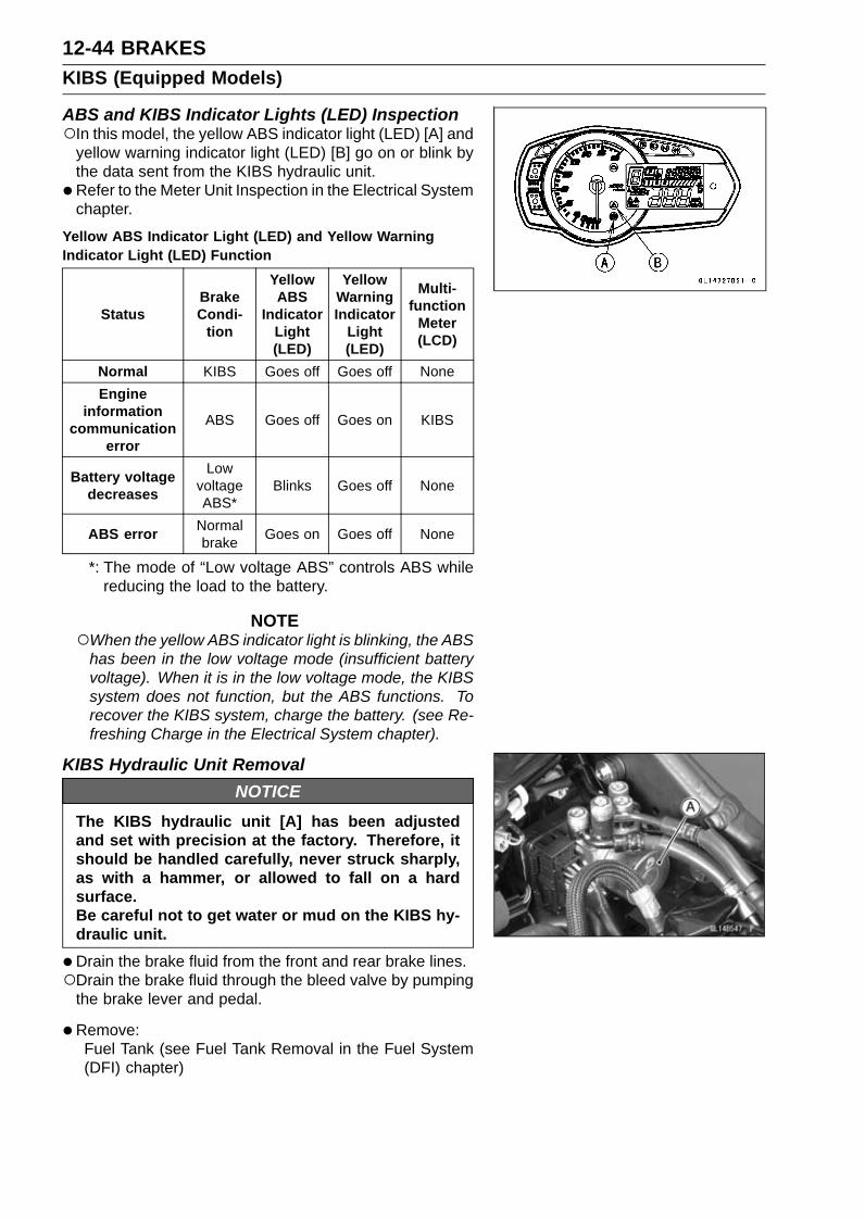
12-44 BRAKESKIBS (Equipped Models)
ABS and KIBS Indicator Lights (LED) InspectionIn this model, the yellow ABS indicator light (LED) [A] and
yellow warning indicator light (LED) [B] go on or blink bythe data sent from the KIBS hydraulic unit.
• Refer to the Meter Unit Inspection in the Electrical Systemchapter.
Yellow ABS Indicator Light (LED) and Yellow WarningIndicator Light (LED) Function
StatusBrakeCondi-
tion
YellowABS
IndicatorLight(LED)
YellowWarningIndicator
Light(LED)
Multi-function
Meter(LCD)
Normal KIBS Goes off Goes off NoneEngine
informationcommunication
error
ABS Goes off Goes on KIBS
Battery voltagedecreases
LowvoltageABS*
Blinks Goes off None
ABS error Normalbrake Goes on Goes off None
*: The mode of “Low voltage ABS” controls ABS whilereducing the load to the battery.
NOTEWhen the yellow ABS indicator light is blinking, the ABS
has been in the low voltage mode (insufficient batteryvoltage). When it is in the low voltage mode, the KIBSsystem does not function, but the ABS functions. Torecover the KIBS system, charge the battery. (see Re-freshing Charge in the Electrical System chapter).
KIBS Hydraulic Unit RemovalNOTICE
The KIBS hydraulic unit [A] has been adjustedand set with precision at the factory. Therefore, itshould be handled carefully, never struck sharply,as with a hammer, or allowed to fall on a hardsurface.Be careful not to get water or mud on the KIBS hy-draulic unit.
•Drain the brake fluid from the front and rear brake lines.Drain the brake fluid through the bleed valve by pumping
the brake lever and pedal.
• Remove:Fuel Tank (see Fuel Tank Removal in the Fuel System(DFI) chapter)

BRAKES 12-45KIBS (Equipped Models)
•Clean the KIBS hydraulic unit.
NOTICEClean all fittings on the KIBS hydraulic unit and therear master cylinder because dirt around the banjobolts could contaminate the brake fluid in the lineduring removal/installation.Spread over a shop towel around the KIBS hy-draulic unit before removing the brake line so thatbrake fluid does not leak on the parts.
•Open the clamp [A].• Pull the lever [B] backward to disconnect the KIBS hy-
draulic unit connector [C].
• Remove:Brake Pipe Banjo Bolts [A]
NOTICEBrake fluid quickly ruins painted plastic surfaces;any spilled fluid should be completely washed awayimmediately.
•Remove the bolts [A].• Remove the KIBS hydraulic unit [B] together with the
bracket.Clear the bracket from the KIBS hydraulic unit rubber
cover.
•Remove the bolts [A] and bracket.
NOTICEThe KIBS hydraulic unit has been adjusted and setwith precision at the factory. Do not try to disas-semble and repair the KIBS hydraulic unit.
KIBS Hydraulic Unit InstallationNOTICE
Brake fluid quickly ruins painted plastic surfaces;any spilled fluid should be completely washed awayimmediately.

12-46 BRAKESKIBS (Equipped Models)
• Install the KIBS hydraulic unit together with the bracket,and tighten the bolts.Fit the bracket and KIBS hydraulic unit rubber cover (see
Cable, Wire, and Hose Routing section in the Appendixchapter).
• Replace the washers that are on each side of pipe fittingwith new ones.
• Install the brake pipes (see Cable, Wire, and Hose Rout-ing section in the Appendix chapter).
• Tighten:Torque - Brake Pipe Banjo Bolts: 23 N·m (2.3 kgf·m, 17 ft·lb)
•Pull the lever [A] forward to connect the KIBS hydraulicunit connector [B].
• Bleed the brake line (see Brake Line Bleeding).• Check the brake for good braking power, no brake drag,
and no fluid leakage.• Install the fuel tank (see Fuel Tank Installation in the Fuel
System (DFI) chapter).
KIBS Hydraulic Unit Inspection•Remove the KIBS hydraulic unit (see KIBS Hydraulic Unit
Removal).• Visually inspect the connector terminals [A].
Replace the KIBS hydraulic unit or main harness if eitherof the terminals are cracked, bent, or otherwise damaged.If the KIBS hydraulic unit connector is clogged with mudor dust, blow it off with compressed air.
• Visually inspect the KIBS hydraulic unit.Replace the KIBS hydraulic unit if any of them arecracked, or otherwise damaged.
Front Wheel Rotation Sensor RemovalNOTICE
The wheel rotation sensor should be handled care-fully, never struck sharply, as with a hammer, or al-lowed to fall on a hard surface since the wheel rota-tion sensor is precision made. Be careful not to getwater or mud on the wheel rotation sensor.Do not try to disassemble or repair the wheel rota-tion sensor.

BRAKES 12-47KIBS (Equipped Models)
•Remove:Air Cleaner Housing (see Air Cleaner Housing Removalin the Fuel System (DFI) chapter)
• Slide the dust cover [A].•Open the clamp [B].• Disconnect the front wheel rotation sensor lead connector
[C].
• Clear the sensor lead from the clamps [A].• Remove:
Bolt [B]Front Wheel Rotation Sensor [C]
Front Wheel Rotation Sensor Installation• Installation is the reverse of removal.Run the lead correctly (see Cable, Wire, and Hose Rout-
ing section in the Appendix chapter).
Rear Wheel Rotation Sensor RemovalNOTICE
The wheel rotation sensor should be handled care-fully, never struck sharply, as with a hammer, or al-lowed to fall on a hard surface since the wheel rota-tion sensor is precision made. Be careful not to getwater or mud on the wheel rotation sensor.Do not try to disassemble or repair the wheel rota-tion sensor.

12-48 BRAKESKIBS (Equipped Models)
•Remove:Fuel Tank (see Fuel Tank Removal in the Fuel System(DFI) chapter)
• Slide the dust cover [A].• Disconnect the rear wheel rotation sensor lead connector
[B].
• Clear the sensor lead from the clamps [A].
• Clear the sensor lead from the clamps [A].• Remove:
Bolt [B]Rear Wheel Rotation Sensor [C]
Rear Wheel Rotation Sensor Installation• Installation is the reverse of removal.Route the lead correctly (see Cable, Wire, and Hose
Routing section in the Appendix chapter).
Wheel Rotation Sensor Inspection•Remove the front wheel rotation sensor [A] from the front
fork.•Remove the rear wheel rotation sensor [B] from the
caliper bracket.• Visually inspect the wheel rotation sensors.
Replace the wheel rotation sensor if it is cracked, bent, orotherwise damaged.

BRAKES 12-49KIBS (Equipped Models)
Wheel Rotation Sensor Air Gap Inspection•Raise the front/rear wheel off the ground (see Front/Rear
Wheel Removal in the Wheels/Tires chapter).•Measure the air gap between the sensor and sensor rotor
at several points by turning the wheel slowly.Thickness Gauge [A]
Wheel Rotation Sensor Air GapStandard:
Front 0.4 ∼ 1.6 mm (0.02 ∼ 0.06 in.)Rear 0.4 ∼ 1.6 mm (0.02 ∼ 0.06 in.)
NOTEThe sensor air gap cannot be adjusted.
If the air gap is not within the specification, inspect the hubbearing (see Hub Bearing Inspection in the Wheels/Tireschapter), sensor installation condition and sensor (seeWheel Rotation Sensor Inspection).
Wheel Rotation Sensor Rotor Inspection•Remove:
Wheels (see Front/Rear Wheel Removal in theWheels/Tires chapter)Brake Disc Mounting Bolts [A]Sensor Rotor [B]Front Wheel [C]Rear Wheel [D]

12-50 BRAKESKIBS (Equipped Models)
•Visually inspect the wheel rotation sensor rotor.If the rotor is deformed or damaged (chipped teeth [A]),replace the sensor rotor with a new one.If there is iron or other magnetic deposits [B], remove thedeposits.
• Install:Front Brake Disc [A]Front Wheel Rotation Sensor Rotor [B]Rear Brake Disc [C]Rear Wheel Rotation Sensor Rotor [D]
When installing the rear wheel rotation sensor rotor, thebended end [E] faces to disc side.Install the brake discs (see Brake Disc Installation).
KIBS Solenoid Valve Relay Fuse (15 A) Removal•Refer to the Fuse Box Fuse Removal in the Electrical Sys-
tem chapter.
KIBS Motor Relay Fuse (25 A) Removal•Refer to the Fuse Box Fuse Removal in the Electrical Sys-
tem chapter.
Fuse Installation• If a fuse fails during operation, inspect the electrical sys-
tem to determine the cause, and then replace it with anew fuse of proper amperage (see Fuse Installation in theElectrical System chapter).
Fuse Inspection•Remove the fuses (see KIBS Solenoid Valve Relay Fuse
(15 A)/KIBS Motor Relay Fuse (25 A) Removal).• Refer to the Fuse Inspection in the Electrical System
chapter.

SUSPENSION 13-1
13
SuspensionTable of Contents
Exploded View........................................................................................................................ 13-2Specifications ......................................................................................................................... 13-6Special Tools .......................................................................................................................... 13-7Front Fork ............................................................................................................................... 13-9
Rebound Damping Force Adjustment............................................................................... 13-9Compression Damping Force Adjustment ........................................................................ 13-9Spring Preload Adjustment ............................................................................................... 13-10Front Fork Removal (Each Fork Leg) ............................................................................... 13-10Front Fork Installation (Each Fork Leg) ............................................................................ 13-11Front Fork Oil Change ...................................................................................................... 13-12Front Fork Disassembly .................................................................................................... 13-20Front Fork Assembly......................................................................................................... 13-20Inner Tube Inspection ....................................................................................................... 13-21Dust Seal Inspection ......................................................................................................... 13-21Spring Tension Inspection................................................................................................. 13-22
Rear Shock Absorber ............................................................................................................. 13-23Rebound Damping Force Adjustment............................................................................... 13-23Compression Damping Force Adjustment ........................................................................ 13-23Spring Preload Adjustment ............................................................................................... 13-23Rear Shock Absorber Removal ........................................................................................ 13-24Rear Shock Absorber Installation ..................................................................................... 13-25Rear Shock Absorber Inspection ...................................................................................... 13-25Rear Shock Absorber Scrapping ...................................................................................... 13-26
Swingarm................................................................................................................................ 13-27Swingarm Removal........................................................................................................... 13-27Swingarm Installation........................................................................................................ 13-27Swingarm Bearing Removal ............................................................................................. 13-28Swingarm Bearing Installation .......................................................................................... 13-29Swingarm Bearing, Sleeve Inspection .............................................................................. 13-30Swingarm Bearing Lubrication .......................................................................................... 13-30
Tie-Rod, Rocker Arm.............................................................................................................. 13-31Tie-Rod Removal .............................................................................................................. 13-31Tie-Rod Installation ........................................................................................................... 13-31Rocker Arm Removal........................................................................................................ 13-31Rocker Arm Installation..................................................................................................... 13-32Tie-Rod and Rocker Arm Bearing Removal...................................................................... 13-33Tie-Rod and Rocker Arm Bearing Installation................................................................... 13-33Rocker Arm/Tie-Rod Bearing, Sleeve Inspection ............................................................. 13-35Rocker Arm/Tie-Rod Bearing Lubrication ......................................................................... 13-35
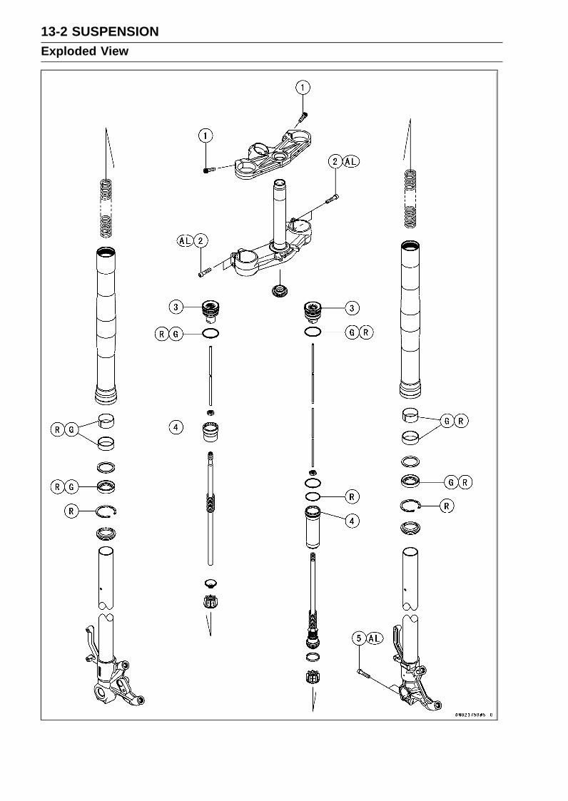
13-2 SUSPENSIONExploded View
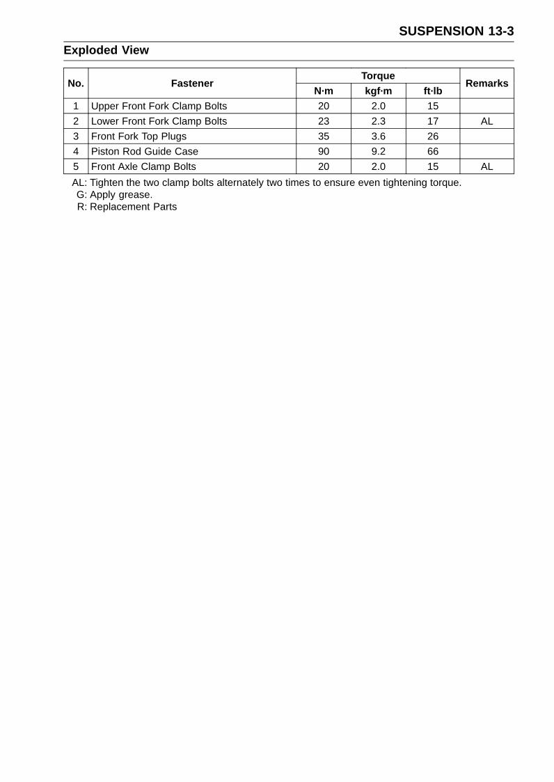
SUSPENSION 13-3Exploded View
TorqueNo. Fastener
N·m kgf·m ft·lbRemarks
1 Upper Front Fork Clamp Bolts 20 2.0 152 Lower Front Fork Clamp Bolts 23 2.3 17 AL3 Front Fork Top Plugs 35 3.6 264 Piston Rod Guide Case 90 9.2 665 Front Axle Clamp Bolts 20 2.0 15 ALAL: Tighten the two clamp bolts alternately two times to ensure even tightening torque.G: Apply grease.R: Replacement Parts

13-4 SUSPENSIONExploded View

SUSPENSION 13-5Exploded View
TorqueNo. Fastener
N·m kgf·m ft·lbRemarks
1 Rear Shock Absorber Bracket Nut 59 6.0 442 Swingarm Pivot Shaft Nut 108 11.0 79.73 Swingarm Pivot Shaft 20 2.0 154 Swingarm Pivot Adjusting Collar Locknut 98 10.0 725 Upper Rear Shock Absorber Nut 34 3.5 25 R6 Rocker Arm Bolt 34 3.5 257 Lower Rear Shock Absorber Nut 34 3.5 25 R8 Tie-Rod Nuts 59 6.0 44 RG: Apply grease.R: Replacement Parts

13-6 SUSPENSIONSpecifications
Item StandardFront Fork (Per One Unit)
Fork Inner Tube Diameter 41 mm (1.6 in.)Air Pressure Atmospheric pressure (Non-adjustable)Rebound Damper Setting 4 1/2 turns out from the fully clockwise position
(Usable Range: 0 ←→ 5 1/2 turns out)Compression Damper Setting 6 turns out from the fully clockwise position
(Usable Range: 0 ←→ 7 turns out)Fork Spring Preload Setting 5 turns in from the fully counterclockwise position
(Usable Range: 0 ←→ 20 turns in)Fork Oil:
Recommended Oil SHOWA SS-47 or equivalentAmount:
Right Front Fork Approx. 460 mL (15.6 US oz.) (when changing oil)538 ±2.5 mL (18.2 ±0.085 US oz.) (after disassembly andcompletely dry)
Left Front Fork Approx. 480 mL (16.2 US oz.) (when changing oil)566 ±2.5 mL (19.1 ±0.085 US oz.) (after disassembly andcompletely dry)
Oil Level:Right Front Fork 90 ±2 mm (3.54 ±0.08 in.) (fully compressed, below from
the top of outer tube)Left Front Fork 80 ±2 mm (3.15 ±0.08 in.) (fully compressed, below from
the top of outer tube)Fork Spring Free Length 256 mm (10.08 in.) (Service Limit: 251 mm (9.88 in.))
Rear Shock AbsorberRebound Damper Setting 1 1/2 turns out from the fully clockwise position
(Usable Range: 0 ←→ 3 turns out)Compression Damper Setting 2 1/2 turns out from the fully clockwise position
(Usable Range: 0 ←→ 5 turns out)Spring Preload Setting Position:
Standard Spring length: 205 mm (8.07 in.)Usable Range Spring length: 199 ∼ 209 mm (7.83 ∼ 8.23 in.) (stronger to
weaker)Gas Pressure 980 kPa (10.0 kgf/cm², 142 psi, Non-adjustable)

SUSPENSION 13-7Special Tools
Inside Circlip Pliers:57001-143
Oil Seal & Bearing Remover:57001-1058
Bearing Driver Set:57001-1129
Jack:57001-1238
Fork Oil Seal Driver, 41:57001-1288
Fork Oil Level Gauge:57001-1290
Hook Wrench T=3.2 R37:57001-1539
Swingarm Pivot Nut Wrench:57001-1597
Jack Attachment:57001-1608
Needle Bearing Driver, 17/ 18:57001-1609

13-8 SUSPENSIONSpecial Tools
Needle Bearing Driver, 28:57001-1610
Spacer, 18:57001-1636
Spacer, 28:57001-1637
Hook Wrench:57001-1641
Needle Bearing Driver, 20 & Spacer, 28:57001-1678
Top Plug Wrench (45 mm):57001-1741
Rod Guide Case Wrench, 33 mm:57001-1744

SUSPENSION 13-9Front Fork
Rebound Damping Force Adjustment•To adjust the rebound damping force, turn the rebound
damping adjuster [A].The standard adjuster setting is the 4 1/2 turns out from
the fully clockwise position.
The damping force can be left soft for average riding. Butit should be adjusted harder for high speed riding or ridingwith a passenger. If the damping feels too soft or too stiff,adjust it in accordance with the following table.
Rebound Damping Force AdjustmentAdjusterPosition
DampingForce Setting Load Road Speed
5 1/2turns out Weak Soft Light Good Low
↑ ↑ ↑ ↑ ↑ ↑↓ ↓ ↓ ↓ ↓ ↓0 Strong Hard Heavy Bad High
Compression Damping Force Adjustment•To adjust the compression damping force, turn the com-
pression damping adjuster [A].The standard adjuster setting is the 6 turns out from the
fully clockwise position.
The damping force can be left soft for average riding. Butit should be adjusted harder for high speed riding or ridingwith a passenger. If the damping feels too soft or too stiff,adjust it in accordance with the following table.
Compression Damping Force AdjustmentAdjusterPosition
DampingForce Setting Load Road Speed
7 turns out Weak Soft Light Good Low↑ ↑ ↑ ↑ ↑ ↑↓ ↓ ↓ ↓ ↓ ↓0 Strong Hard Heavy Bad High

13-10 SUSPENSIONFront Fork
Spring Preload Adjustment•To adjust the spring preload, turn the spring preload ad-
juster [A].The standard adjuster setting is the 5 turns in from the
fully counterclockwise position.
The spring preload can be left soft for average riding. Butit should be adjusted harder for high speed riding or ridingwith a passenger. If the spring action feels too soft or toostiff, adjust it in accordance with the following table.
Spring ActionAdjusterPosition
DampingForce Setting Load Road Speed
0 Weak Soft Light Good Low↑ ↑ ↑ ↑ ↑ ↑↓ ↓ ↓ ↓ ↓ ↓
20 turns in Strong Hard Heavy Bad High
Front Fork Removal (Each Fork Leg)•Remove:
Front Wheel (see Front Wheel Removal in theWheels/Tires chapter)Front Fender (see Front Fender Removal in the Framechapter)Inner Fairing (see Inner Fairing Removal in the Framechapter)
Loosen the front fork top plug [A] beforehand if the forkleg is to be disassembled.Special Tool - Top Plug Wrench (45 mm): 57001-1741 [B]
NOTELoosen the top plug after loosening the handlebar
clamp bolt [C] and upper front fork clamp bolt [D].
• Loosen:Handlebar Clamp Bolt [A]Upper Front Fork Clamp Bolt [B]Lower Front Fork Clamp Bolts [C]
•With a twisting motion, work the fork leg down and out.

SUSPENSION 13-11Front Fork
Front Fork Installation (Each Fork Leg)• Install the fork so that the top end [A] of the outer tube as
shown.7 mm (0.28 in.) [B]Steering Stem Head [C]
• Tighten:Torque - Lower Front Fork Clamp Bolts: 23 N·m (2.3 kgf·m,
17 ft·lb)
NOTETighten the two lower front fork clamp bolts alternately
two times to ensure even tightening torque.
Torque - Front Fork Top Plugs: 35 N·m (3.6 kgf·m, 26 ft·lb)
NOTETighten the front fork top plug [A] before tightening the
handlebar clamp bolt and upper front fork clamp bolt.The torque of front fork top plug is specified to 35 N·m
(3.6 kgf·m, 26 ft·lb) however, when you use the topplug wrench (special tool: 57001-1741) [B], reduce thetorque to 90% of the specified value [31 N·m (3.2 kgf·m,23 ft·lb)] due to the distance [C] between the center ofthe square hole, where the torque wrench [D] is fitted,and that of the octagonal hole of the wrench.This torque value [31 N·m (3.2 kgf·m, 23 ft·lb)] is ap-
plicable when you use a torque wrench whose lengthgives leverage of approximately 310 mm (12.2 in.) be-tween the grip point to the center of the coupling square.To obtain the correct tightening torque with your torque
wrench, you need to calculate as follows.
Formula:a × b ÷ (b + c) = d
[a] Specified torque[b] Length from center of square hole to grip point[c] Offset = 44 mm[d] Tightening torque
For an example:35 N·m ×310 ÷ (310 + 44) = 31 N·m
•Tighten:Torque - Upper Front Fork Clamp Bolts: 20 N·m (2.0 kgf·m,
15 ft·lb)Handlebar Clamp Bolts: 25 N·m (2.5 kgf·m, 18
ft·lb)
• Install the removed parts (see appropriate chapters).• Adjust:
Spring Preload (see Spring Preload Adjustment)Rebound Damping Force (see Rebound Damping ForceAdjustment)Compression Damping Force (see Compression Damp-ing Force Adjustment)
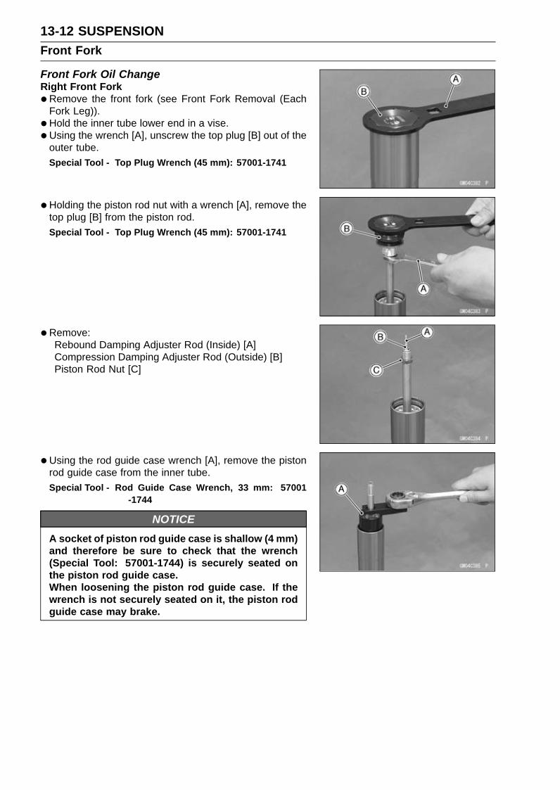
13-12 SUSPENSIONFront Fork
Front Fork Oil ChangeRight Front Fork•Remove the front fork (see Front Fork Removal (Each
Fork Leg)).• Hold the inner tube lower end in a vise.•Using the wrench [A], unscrew the top plug [B] out of the
outer tube.Special Tool - Top Plug Wrench (45 mm): 57001-1741
•Holding the piston rod nut with a wrench [A], remove thetop plug [B] from the piston rod.Special Tool - Top Plug Wrench (45 mm): 57001-1741
•Remove:Rebound Damping Adjuster Rod (Inside) [A]Compression Damping Adjuster Rod (Outside) [B]Piston Rod Nut [C]
•Using the rod guide case wrench [A], remove the pistonrod guide case from the inner tube.Special Tool - Rod Guide Case Wrench, 33 mm: 57001
-1744
NOTICEA socket of piston rod guide case is shallow (4 mm)and therefore be sure to check that the wrench(Special Tool: 57001-1744) is securely seated onthe piston rod guide case.When loosening the piston rod guide case. If thewrench is not securely seated on it, the piston rodguide case may brake.
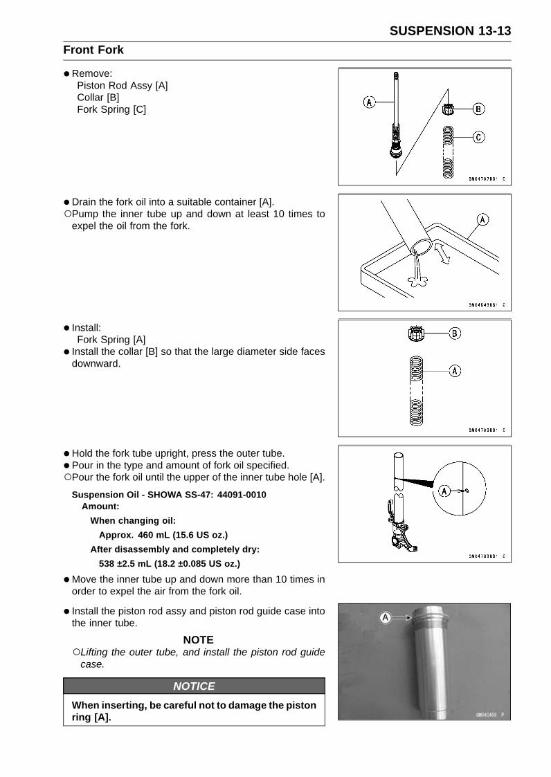
SUSPENSION 13-13Front Fork
•Remove:Piston Rod Assy [A]Collar [B]Fork Spring [C]
•Drain the fork oil into a suitable container [A].Pump the inner tube up and down at least 10 times to
expel the oil from the fork.
• Install:Fork Spring [A]
• Install the collar [B] so that the large diameter side facesdownward.
•Hold the fork tube upright, press the outer tube.• Pour in the type and amount of fork oil specified.Pour the fork oil until the upper of the inner tube hole [A].
Suspension Oil - SHOWA SS-47: 44091-0010Amount:
When changing oil:Approx. 460 mL (15.6 US oz.)
After disassembly and completely dry:538 ±2.5 mL (18.2 ±0.085 US oz.)
•Move the inner tube up and down more than 10 times inorder to expel the air from the fork oil.
• Install the piston rod assy and piston rod guide case intothe inner tube.
NOTELifting the outer tube, and install the piston rod guide
case.
NOTICEWhen inserting, be careful not to damage the pistonring [A].

13-14 SUSPENSIONFront Fork
•Hold the inner tube bottom by a vise.•Using the rod guide case wrench [A], tighten the piston
rod guide case to the inner tube.Special Tool - Rod Guide Case Wrench, 33 mm: 57001
-1744
Torque - Piston Rod Guide Case: 90 N·m (9.2 kgf·m, 66 ft·lb)
NOTEThe tightening torque of the piston rod guide case is
specified to 90 N·m (9.2 kgf·m, 66 ft·lb), however in useof the rod guide case wrench (special tool: 57001-1744)[A] you reduce the torque to about 90% of the specifiedvalue [81 N·m (8.3 kgf·m, 60 ft·lb)] due to the offset [B]of the wrench square hole.This torque value [81 N·m (8.3 kgf·m, 60 ft·lb)] is appli-
cable when you use a wrench whose length [C] givesleverage of approximately 450 mm (17.7 in.) betweenthe grip point [D] to the center of the coupling square.To obtain the correct tightening torque with your torque
wrench, you need to calculate as follows.
Formula:a × b ÷ (b + c) = d
[a] Specified torque[b] Length from center of square hole to grip point[c] Offset = 50 mm[d] Tightening torque
For an example:90 N·m × 450 ÷ (450 + 50) = 81 N·m
NOTICEA socket of piston rod guide case is shallow (4 mm)and therefore be sure to check that the wrench(Special Tool: 57001-1744) is securely seated onthe piston rod guide case.When tightening the piston rod guide case. If thewrench is not securely seated on it, the piston rodguide case may brake.
• Install the piston rod nut [A] until it is bottomed.• Install:
Compression Damping Adjuster Rod (Outside) [B]Rebound Damping Adjuster Rod (Inside) [C]

SUSPENSION 13-15Front Fork
•Replace the O-ring [A] with a new one.• Apply grease to the new O-ring.• Install the top plug [B] to the piston rod.•Holding the top plug with a wrench [C], tighten the piston
rod nut against the top plug.Special Tool - Top Plug Wrench (45 mm): 57001-1741
•Pour the fork oil of the remainder until the upper [A] of thepiston rod guide case [B].
•Move the piston rod assy up and down more than 10 timesin order to expel all the air from the fork oil.
•Move the outer tube up and down more than 10 times inorder to expel all the air from the fork oil.
•Measure the oil level as follows.Hold the inner tube vertically in a vise.Wait until the oil level settles.With the fork fully compressed, insert a tape measure or
rod into the piston rod guide case [A], and measure thedistance [B] from the top [C] of the outer tube [D] to theoil.
Oil Level (fully compressed)Standard: 90 ±2 mm (3.54 ±0.08 in.)
NOTEFork oil level may also be measured using the fork oil
level gauge [E].
Special Tool - Fork Oil Level Gauge: 57001-1290Pull the handle slowly to pump out the excess oil until the
oil no longer comes out.If no oil is pumped out, there is insufficient oil in the innertube. Pour in enough oil, then pump out the excess oil asshown above.
• Lift the outer tube.•Using the wrench, tighten the top plug temporary.
Special Tool - Top Plug Wrench (45 mm): 57001-1741
• Install the front fork (see Front Fork Installation (Each ForkLeg)).
NOTEAfter installing the front fork, adjust the damping force
correctly.

13-16 SUSPENSIONFront Fork
Left Front Fork•Remove the front fork (see Front Fork Removal (Each
Fork Leg)).• Turn the spring preload adjuster fully counterclockwise for
removing the piston rod assy easily.• Hold the inner tube lower end in a vise.•Using the wrench [A], unscrew the top plug [B] out of the
outer tube.Special Tool - Top Plug Wrench (45 mm): 57001-1741
•Holding the piston rod nut with a wrench [A], remove thetop plug [B] from the piston rod.Special Tool - Top Plug Wrench (45 mm): 57001-1741
•Remove:Spring Preload Adjuster Rod [A]Piston Rod Nut [B]
•Using the rod guide case wrench [A], remove the pistonrod guide case from the inner tube.Special Tool - Rod Guide Case Wrench, 33 mm: 57001
-1744
NOTICEA socket of piston rod guide case is shallow (4 mm)and therefore be sure to check that the wrench(Special Tool: 57001-1744) is securely seated onthe piston rod guide case.When loosening the piston rod guide case. If thewrench is not securely seated on it, the piston rodguide case may brake.
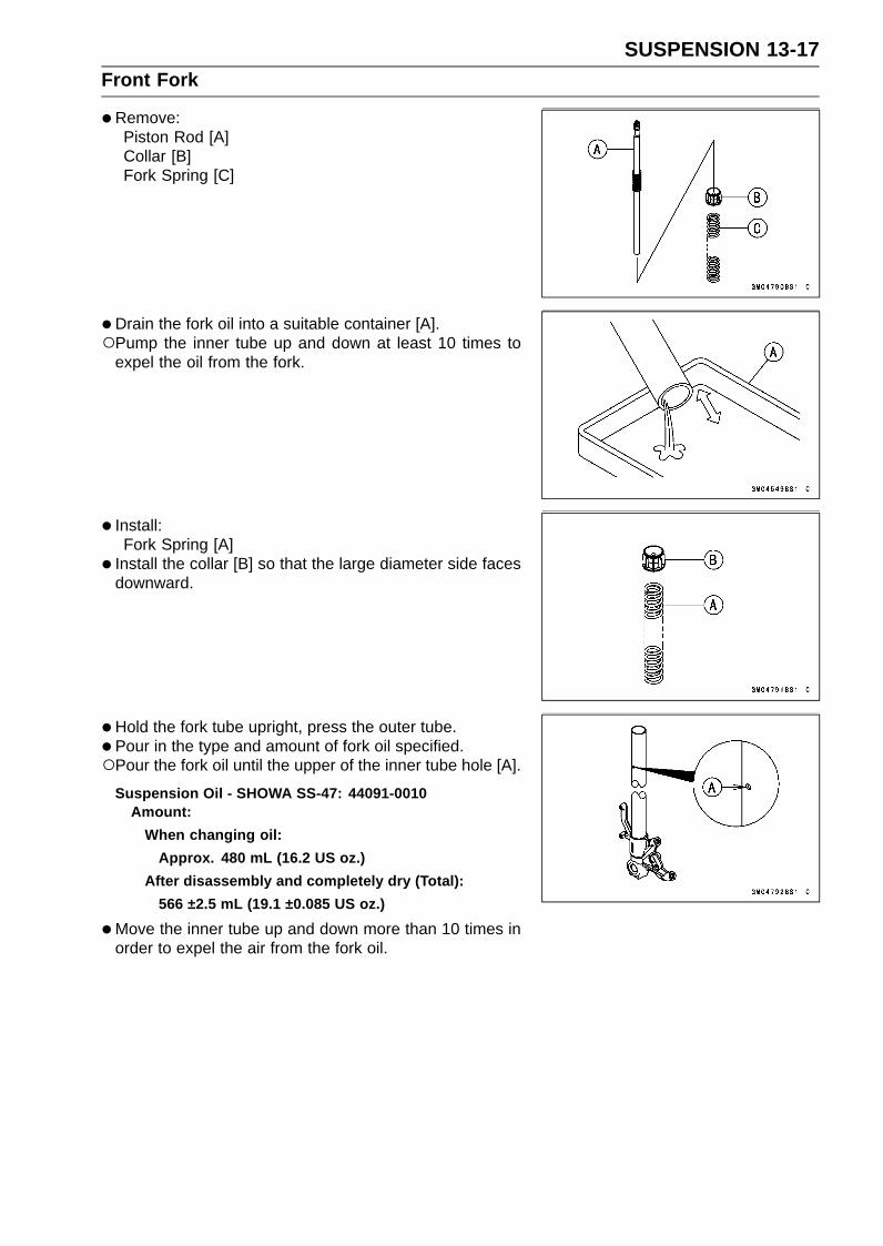
SUSPENSION 13-17Front Fork
•Remove:Piston Rod [A]Collar [B]Fork Spring [C]
•Drain the fork oil into a suitable container [A].Pump the inner tube up and down at least 10 times to
expel the oil from the fork.
• Install:Fork Spring [A]
• Install the collar [B] so that the large diameter side facesdownward.
•Hold the fork tube upright, press the outer tube.• Pour in the type and amount of fork oil specified.Pour the fork oil until the upper of the inner tube hole [A].
Suspension Oil - SHOWA SS-47: 44091-0010Amount:
When changing oil:Approx. 480 mL (16.2 US oz.)
After disassembly and completely dry (Total):566 ±2.5 mL (19.1 ±0.085 US oz.)
•Move the inner tube up and down more than 10 times inorder to expel the air from the fork oil.

13-18 SUSPENSIONFront Fork
• Insert the piston rod into the inner tube.•Hold the inner tube bottom by a vise.•Using rod guide case wrench [A], tighten the piston rod
guide case to the inner tube.Special Tool - Rod Guide Case Wrench, 33 mm: 57001
-1744
Torque - Piston Rod Guide Case: 90 N·m (9.2 kgf·m, 66 ft·lb)
NOTEThe tightening torque of the piston rod guide case is
specified to 90 N·m (9.2 kgf·m, 66 ft·lb), however in useof the rod guide case wrench (special tool: 57001-1744)[A] you reduce the torque to about 93% of the specifiedvalue [81 N·m (8.3 kgf·m, 60 ft·lb)] due to the offset [B]of the wrench square hole.This torque value [81 N·m (8.3 kgf·m, 60 ft·lb)] is appli-
cable when you use a wrench whose length [C] givesleverage of approximately 450 mm (17.7 in.) betweenthe grip point [D] to the center of the coupling square.To obtain the correct tightening torque with your torque
wrench, you need to calculate as follows.
Formula:a × b ÷ (b + c) = d
[a] Specified torque[b] Length from center of square hole to grip point[c] Offset = 50 mm[d] Tightening torque
For an example:90 N·m × 450 ÷ (450 + 50) = 81 N·m
NOTICEA socket of piston rod guide case is shallow (4 mm)and therefore be sure to check that the wrench(Special Tool: 57001-1744) is securely seated onthe piston rod guide case.When tightening the piston rod guide case. If thewrench is not securely seated on it, the piston rodguide case may brake.
• Install the piston rod nut [A] until it is bottomed.• Install:
Spring Preload Adjuster Rod [B]
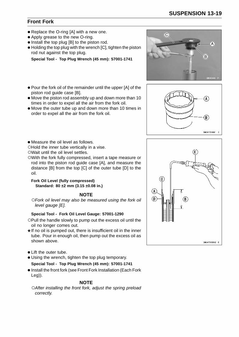
SUSPENSION 13-19Front Fork
•Replace the O-ring [A] with a new one.• Apply grease to the new O-ring.• Install the top plug [B] to the piston rod.•Holding the top plug with the wrench [C], tighten the piston
rod nut against the top plug.Special Tool - Top Plug Wrench (45 mm): 57001-1741
•Pour the fork oil of the remainder until the upper [A] of thepiston rod guide case [B].
•Move the piston rod assembly up and down more than 10times in order to expel all the air from the fork oil.
•Move the outer tube up and down more than 10 times inorder to expel all the air from the fork oil.
•Measure the oil level as follows.Hold the inner tube vertically in a vise.Wait until the oil level settles.With the fork fully compressed, insert a tape measure or
rod into the piston rod guide case [A], and measure thedistance [B] from the top [C] of the outer tube [D] to theoil.
Fork Oil Level (fully compressed)Standard: 80 ±2 mm (3.15 ±0.08 in.)
NOTEFork oil level may also be measured using the fork oil
level gauge [E].
Special Tool - Fork Oil Level Gauge: 57001-1290Pull the handle slowly to pump out the excess oil until the
oil no longer comes out.If no oil is pumped out, there is insufficient oil in the innertube. Pour in enough oil, then pump out the excess oil asshown above.
• Lift the outer tube.•Using the wrench, tighten the top plug temporary.
Special Tool - Top Plug Wrench (45 mm): 57001-1741
• Install the front fork (see Front Fork Installation (Each ForkLeg)).
NOTEAfter installing the front fork, adjust the spring preload
correctly.

13-20 SUSPENSIONFront Fork
Front Fork Disassembly•Remove the front fork (see Front Fork Removal (Each
Fork Leg)).• Drain the fork oil (see Front Fork Oil Change).•Remove the dust seal [A] from the outer tube.•Remove the circlip [B].
Special Tool - Inside Circlip Pliers: 57001-143
•Separate the outer tube from the inner tube.
•Remove the following parts from the inner tube.Slide Bushing [A]Guide Bushing [B]Washer [C]Oil Seal [D]Circlip [E]Dust Seal [F]
Front Fork Assembly•Replace the following parts with new ones.
Slide BushingGuide BushingOil SealCirclip
• Install the following parts to the inner tube [A].Dust Seal [B]Circlip [C]
Special Tool - Inside Circlip Pliers: 57001-143
•Apply grease to the oil seal lips.• Install the oil seal [A] so that the stamp side faces lower
side.• Install the washer [B].• Install the guide bushing [C] so that the slit of it is posi-
tioned perpendicular to the traveling direction.• Install the slide bushing [D] so that the slit of it is positioned
perpendicular to the traveling direction.• Apply grease to the slide and guide bushings and oil seal.

SUSPENSION 13-21Front Fork
• Insert the inner tube to the outer tube.• After installing the washer, install the oil seal [A] by using
the fork oil seal driver [B].Special Tool - Fork Oil Seal Driver, 41: 57001-1288
• Install the circlip and dust seal.• Pour in the specified type of oil (see Front Fork Oil
Change).
Inner Tube Inspection•Visually inspect the inner tube [A].
If there is any damage, replace the inner tube. Sincedamage to the inner tube damages the oil seal and dustseal, replace the oil seal and dust seal whenever the innertube is replaced.
NOTICEIf the inner tube is badly bent or creased, replaceit. Excessive bending, followed by subsequentstraightening, can weaken the inner tube.
•Temporarily assemble the inner tube [A] and outer tube[B], and pump [C] them back and forth manually to checkfor smooth operation.If you feel binding or catching, the inner and outer tubesmust be replaced.
WARNINGA straightened inner or outer fork tube may fall inuse, possibly causing an accident resulting in seri-ous injury or death. Replace a badly bent or dam-aged inner or outer tube and inspect the other tubecarefully before reusing it.
Dust Seal Inspection• Inspect the dust seals [A] for any signs of deterioration or
damage.Replace it if necessary.

13-22 SUSPENSIONFront Fork
Spring Tension Inspection•Since a spring becomes shorter as it weakens, check its
free length [A] to determine its condition.If the spring of either fork leg is shorter than the servicelimit, it must be replaced. If the length of a replacementspring and that of the remaining spring vary greatly, theremaining spring should also be replaced in order to keepthe fork legs balanced for motorcycle stability.
Spring Free LengthStandard: 256 mm (10.08 in.)Service Limit: 251 mm (9.88 in.)

SUSPENSION 13-23Rear Shock Absorber
Rebound Damping Force Adjustment•To adjust the rebound damping force, turn the rebound
damping adjuster [A] to the desired position.The standard adjuster setting is the 1 1/2 turns out from
the fully clockwise position.
Rebound Damping Force AdjustmentAdjusterPosition
DampingForce Setting Load Road Speed
3 turns out Weak Soft Light Good Low↑ ↑ ↑ ↑ ↑ ↑↓ ↓ ↓ ↓ ↓ ↓0 Strong Hard Heavy Bad High
Compression Damping Force Adjustment•To adjust the compression damping force, turn the com-
pression damping adjuster [A] to the desired position.The standard adjuster setting is the 2 1/2 turns out from
the fully clockwise position.
Compression Damping Force AdjustmentAdjusterPosition
DampingForce Setting Load Road Speed
5 turns out Weak Soft Light Good Low↑ ↑ ↑ ↑ ↑ ↑↓ ↓ ↓ ↓ ↓ ↓0 Strong Hard Heavy Bad High
Spring Preload Adjustment•Remove the rear shock absorber from the frame (see
Rear Shock Absorber Removal).• Loosen the locknut and turn out the adjusting nut to free
the spring.Special Tool - Hook Wrench T=3.2 R37: 57001-1539

13-24 SUSPENSIONRear Shock Absorber
•To adjust the spring preload, turn in the adjusting nut [A]to the desired position and tighten the locknut [B].Spring Length [C]
Spring Preload SettingStandard: Spring length 205 mm (8.07 in.)Usable Range: Spring length 199 ∼ 209 mm (7.83 ∼
8.23 in.)
•Remove:Front Footpeg Bracket Bolts [A]Front Footpeg Bracket [B]
• To adjust the spring preload, turn in the adjusting nut tothe desired position and tighten the locknut by using hookwrenches [A] with the rear shock absorber attached theframe.Special Tools - Hook Wrench T=3.2 R37: 57001-1539
Hook Wrench: 57001-1641If the spring action feels too soft or too stiff, adjust it.
Spring AdjustmentAdjusterPosition
DampingForce Setting Load Road Speed
209 mm(8.23 in.) Weak Soft Light Good Low
↑ ↑ ↑ ↑ ↑ ↑↓ ↓ ↓ ↓ ↓ ↓
199 mm(7.83 in.) Strong Hard Heavy Bad High
Rear Shock Absorber Removal•Remove:
Lower Fairings (see Lower Fairing Removal in the Framechapter)Premuffler Chamber (see Premuffler Chamber Removalin the Engine Top End chapter)
• Squeeze the brake lever slowly and hold it with a band[A].
WARNINGBe sure to hold the front brake when removing theshock absorber, or the motorcycle may fall over. Itcould cause an accident and injury.
•Raise the rear wheel off the ground with the jack.Special Tools - Jack: 57001-1238
Jack Attachment: 57001-1608

SUSPENSION 13-25Rear Shock Absorber
•Remove:Lower Rear Shock Absorber Nut [A] and BoltUpper Tie-Rod Nut [B] and BoltUpper Rear Shock Absorber Nut [C] and Bolt
• Remove the rear shock absorber [D] downward.
Rear Shock Absorber Installation•Replace the following nuts with new ones.
Rear Shock Absorber NutsTie-Rod Nut (Upper)
• Tighten:Torque - Rear Shock Absorber Nuts: 34 N·m (3.5 kgf·m, 25
ft·lb)Tie-Rod Nuts: 59 N·m (6.0 kgf·m, 44 ft·lb)
•When installing the rear shock absorber bracket [A], notethe following.Replace the cotter pin [B] with a new one.Install:
Spacer [C]Rear Shock Absorber Bracket
Tighten:Torque - Rear Shock Absorber Bracket Nut [D]: 59 N·m (6.0
kgf·m, 44 ft·lb)Insert the cotter pin and bend the pin ends.
Rear Shock Absorber Inspection•Remove the rear shock absorber (see Rear Shock Ab-
sorber Removal).• Visually inspect the following items.
Smooth StrokeOil LeakageCrack or Dent
If there is any damage to the rear shock absorber, replaceit.
• Visually inspect the rubber bushing [A].If it show any signs of damage, replace it.

13-26 SUSPENSIONRear Shock Absorber
Rear Shock Absorber ScrappingWARNING
Pressurized nitrogen may explode when heated.The rear shock contains nitrogen gas. To avoidan explosion, do not incinerate the shock bodywithout first releasing the nitrogen and removingthe shraeder valve.
•Remove the rear shock absorber (see Rear Shock Ab-sorber Removal).
• Drill the hole [A] of the reservoir tank using about 2 mm(0.08 in.) drillbit.
WARNINGPressurized gas can cause injury. Do not point thedrill toward your face or body.

SUSPENSION 13-27Swingarm
Swingarm Removal•Remove:
Rear Wheel (see Rear Wheel Removal in theWheels/Tires chapter)Chain Cover (see Drive Chain Removal in the Final Drivechapter)Engine Sprocket (see Engine Sprocket Removal in theFinal Drive chapter)Mud Guard (see Mud Guard Removal in the Framechapter)Rear Shock Absorber (see Rear Shock Absorber Re-moval)Swingarm Pivot Shaft Nut [A]
•Using the swingarm pivot nut wrench [A], loosen theswingarm pivot adjusting collar locknut [B].Special Tool - Swingarm Pivot Nut Wrench: 57001-1597
•Turn the swingarm pivot shaft [A] counterclockwise to freethe adjusting collar from the swingarm.Make the gap between the adjusting collar and swingarm.• Pull out the pivot shaft to the right side and remove the
swingarm.
Swingarm Installation•Visually inspect the chain guide [A].
Replace the chain guide if it shows any signs of abnormalwear or damage.Apply a non-permanent locking agent to the threads of
the chain guide bolt [B].
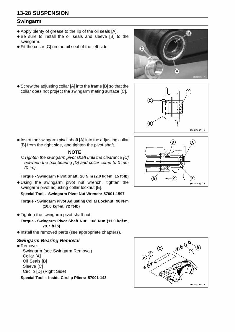
13-28 SUSPENSIONSwingarm
•Apply plenty of grease to the lip of the oil seals [A].• Be sure to install the oil seals and sleeve [B] to the
swingarm.• Fit the collar [C] on the oil seal of the left side.
• Screw the adjusting collar [A] into the frame [B] so that thecollar does not project the swingarm mating surface [C].
• Insert the swingarm pivot shaft [A] into the adjusting collar[B] from the right side, and tighten the pivot shaft.
NOTETighten the swingarm pivot shaft until the clearance [C]
between the ball bearing [D] and collar come to 0 mm(0 in.).
Torque - Swingarm Pivot Shaft: 20 N·m (2.0 kgf·m, 15 ft·lb)
•Using the swingarm pivot nut wrench, tighten theswingarm pivot adjusting collar locknut [E].Special Tool - Swingarm Pivot Nut Wrench: 57001-1597
Torque - Swingarm Pivot Adjusting Collar Locknut: 98 N·m(10.0 kgf·m, 72 ft·lb)
•Tighten the swingarm pivot shaft nut.Torque - Swingarm Pivot Shaft Nut: 108 N·m (11.0 kgf·m,
79.7 ft·lb)
• Install the removed parts (see appropriate chapters).
Swingarm Bearing Removal•Remove:
Swingarm (see Swingarm Removal)Collar [A]Oil Seals [B]Sleeve [C]Circlip [D] (Right Side)
Special Tool - Inside Circlip Pliers: 57001-143
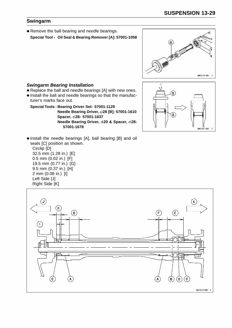
SUSPENSION 13-29Swingarm
•Remove the ball bearing and needle bearings.Special Tool - Oil Seal & Bearing Remover [A]: 57001-1058
Swingarm Bearing Installation•Replace the ball and needle bearings [A] with new ones.• Install the ball and needle bearings so that the manufac-
turer’s marks face out.Special Tools - Bearing Driver Set: 57001-1129
Needle Bearing Driver, 28 [B]: 57001-1610Spacer, 28: 57001-1637Needle Bearing Driver, 20 & Spacer, 28:
57001-1678
• Install the needle bearings [A], ball bearing [B] and oilseals [C] position as shown.Circlip [D]32.5 mm (1.28 in.) [E]0.5 mm (0.02 in.) [F]19.5 mm (0.77 in.) [G]9.5 mm (0.37 in.) [H]2 mm (0.08 in.) [I]Left Side [J]Right Side [K]

13-30 SUSPENSIONSwingarm
Swingarm Bearing, Sleeve InspectionNOTICE
Do not remove the bearings for inspection. Re-moval may damage them.
• Inspect the needle bearings [A] and ball bearing installedin the swingarm.The rollers and ball in a bearing normally wear very little,
and wear is difficult to measure. Instead of measuring,visually inspect the bearing for abrasion, discoloration, orother damage.If the needle bearing, and sleeve [B] show any sings ofabnormal wear, discoloration, or damage, replace themas a set.
• Turn the bearing in the swingarm back and forth [A] whilechecking for plays, roughness, or binding.If bearing play, roughness, or binding is found, replacethe bearing.
• Examine the bearing seal [B] for tears or leakage.If the seal is torn or is leaking, replace the bearing.
Swingarm Bearing LubricationNOTE
Since the bearing are packed with grease and sealed,lubrication is not required.

SUSPENSION 13-31Tie-Rod, Rocker Arm
Tie-Rod Removal•Remove:
Lower Fairings (see Lower Fairing Removal in the Framechapter)Premuffler Chamber (see Premuffler Chamber Removalin the Engine Top End chapter)
• Squeeze the brake lever slowly and hold it with a band[A].
WARNINGMotorcycle may fall over unexpectedly resulting inan accident or injury. Be sure to hold the front brakewhen removing the tie-rod.
•Raise the rear wheel off the ground with the jack.Special Tools - Jack: 57001-1238
Jack Attachment: 57001-1608
•Remove:Upper Tie-Rod Nut [A] and BoltLower Tie-Rod Nut [B] and BoltTie-Rods [C]
Tie-Rod Installation•Apply grease to the inside of the oil seals.• Install the tie-rods so that the marked side faces [A] out-
side.•Replace the tie-rod nuts with new ones.• Tighten:
Torque - Tie-Rod Nuts: 59 N·m (6.0 kgf·m, 44 ft·lb)
• Install the removed parts (see appropriate chapters).
Rocker Arm Removal•Remove:
Lower Fairings (see Lower Fairing Removal in the Framechapter)Premuffler Chamber (see Premuffler Chamber Removalin the Engine Top End chapter)
• Squeeze the brake lever slowly and hold it with a band[A].
WARNINGMotorcycle may fall over unexpectedly resulting inan accident or injury. Be sure to hold the front brakewhen removing the rocker arm.
•Raise the rear wheel off the ground with the jack.Special Tools - Jack: 57001-1238
Jack Attachment: 57001-1608
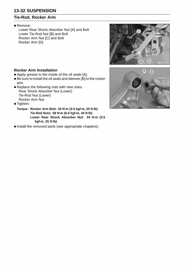
13-32 SUSPENSIONTie-Rod, Rocker Arm
•Remove:Lower Rear Shock Absorber Nut [A] and BoltLower Tie-Rod Nut [B] and BoltRocker Arm Nut [C] and BoltRocker Arm [D]
Rocker Arm Installation•Apply grease to the inside of the oil seals [A].• Be sure to install the oil seals and sleeves [B] to the rocker
arm.•Replace the following nuts with new ones.
Rear Shock Absorber Nut (Lower)Tie-Rod Nut (Lower)Rocker Arm Nut
• Tighten:Torque - Rocker Arm Bolt: 34 N·m (3.5 kgf·m, 25 ft·lb)
Tie-Rod Nuts: 59 N·m (6.0 kgf·m, 44 ft·lb)Lower Rear Shock Absorber Nut: 34 N·m (3.5
kgf·m, 25 ft·lb)
• Install the removed parts (see appropriate chapters).
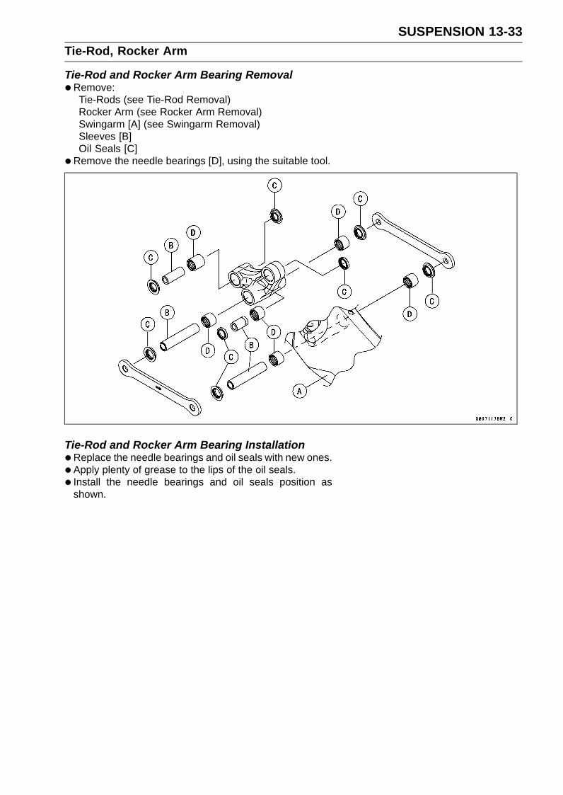
SUSPENSION 13-33Tie-Rod, Rocker Arm
Tie-Rod and Rocker Arm Bearing Removal•Remove:
Tie-Rods (see Tie-Rod Removal)Rocker Arm (see Rocker Arm Removal)Swingarm [A] (see Swingarm Removal)Sleeves [B]Oil Seals [C]
•Remove the needle bearings [D], using the suitable tool.
Tie-Rod and Rocker Arm Bearing Installation•Replace the needle bearings and oil seals with new ones.• Apply plenty of grease to the lips of the oil seals.• Install the needle bearings and oil seals position as
shown.

13-34 SUSPENSIONTie-Rod, Rocker Arm
Screw the needle bearing driver [A] into the driver holder[B].
NOTEFor a bearing of inside diameter 18, select the press-
ing side of the needle bearing driver according to itspressing depth.
Insert the needle bearing driver into the needle bearing[C] and press the needle bearing into the housing untilthe driver contacts the end surface of the housing.Bearing Pressing Depth: 5.5 mm (0.22 in.) [D]5.0 mm (0.20 in.) [E]Spacer, 18 [F] Thickness: 0.5 mm (0.02 in.)
NOTEWhen pressing in the needle bearings to the 5.5 mm
(0.22 in.) depth, adjust the pressing depth with thespacer.Install the needle bearings so that the marked side
faces out.
Special Tools - Bearing Driver Set: 57001-1129Needle Bearing Driver, 17/ 18: 57001
-1609Spacer, 18: 57001-1636

SUSPENSION 13-35Tie-Rod, Rocker Arm
Needle Bearings [A]Oil Seals [B]Rear Shock Absorber [C]Tie-Rods [D]Rocker Arm [E]Swingarm [F]7.5 mm (0.30 in.) [G]5.0 mm (0.20 in.) [H]5.5 mm (0.22 in.) [I]Front [J]Right Side [K]Left Side [L]
Rocker Arm/Tie-Rod Bearing, Sleeve InspectionNOTICE
Do not remove the bearings for inspection. Re-moval may damage them.
•Visually inspect the rocker arm, or tie-rod sleeves [A] andneedle bearings [B].
• The rollers in a needle bearing normally wear very little,and wear is difficult to measure. Instead of measuring,inspect the bearing for abrasion, color change, or otherdamage.If there is any doubt as to the condition of any of the nee-dle bearings or sleeve, replace the sleeve and needlebearings as a set.
Rocker Arm/Tie-Rod Bearing LubricationNOTE
Since the bearings are packed with grease, lubricationis not required.

STEERING 14-1
14
SteeringTable of Contents
Exploded View........................................................................................................................ 14-2Special Tools .......................................................................................................................... 14-4Steering .................................................................................................................................. 14-5
Steering Inspection ........................................................................................................... 14-5Steering Adjustment.......................................................................................................... 14-5
Steering Stem......................................................................................................................... 14-6Stem, Stem Bearing Removal........................................................................................... 14-6Stem, Stem Bearing Installation........................................................................................ 14-7Steering Stem Bearing Lubrication ................................................................................... 14-9Steering Stem Warp Inspection ........................................................................................ 14-9Stem Cap Deterioration, Damage Inspection ................................................................... 14-10
Handlebar ............................................................................................................................... 14-11Handlebar Removal .......................................................................................................... 14-11Handlebar Installation ....................................................................................................... 14-12

14-2 STEERINGExploded View

STEERING 14-3Exploded View
TorqueNo. Fastener
N·m kgf·m ft·lbRemarks
1 Handlebar Clamp Bolts 25 2.5 182 Handlebar Positioning Bolts 9.8 1.0 87 in·lb L3 Left Switch Housing Screws 3.5 0.36 31 in·lb4 Right Switch Housing Screws 3.5 0.36 31 in·lb5 Throttle Case Screws 3.5 0.36 31 in·lb6 Steering Stem Head Bolt 78 8.0 58 L7 Upper Front Fork Clamp Bolts 20 2.0 158 Steering Stem Nut 27 2.8 209 Lower Front Fork Clamp Bolts 23 2.3 17 AL
AD: Apply adhesive.AL: Tighten the two clamp bolts alternately two times to ensure even tightening torque.G: Apply grease.L: Apply a non-permanent locking agent.

14-4 STEERINGSpecial Tools
Bearing Puller:57001-135
Head Pipe Outer Race Press Shaft:57001-1075
Steering Stem Nut Wrench:57001-1100
Steering Stem Bearing Driver, 42.5:57001-1344
Steering Stem Bearing Driver Adapter, 41.5:57001-1345
Head Pipe Outer Race Driver, 55:57001-1446

STEERING 14-5Steering
Steering Inspection•Refer to the Steering Play Inspection in the Periodic Main-
tenance chapter.
Steering Adjustment•Refer to the Steering Play Adjustment in the Periodic
Maintenance chapter.

14-6 STEERINGSteering Stem
Stem, Stem Bearing Removal•Remove:
Fuel Tank (see Fuel Tank Removal in the Fuel System(DFI) chapter)Upper Fairing Assembly (see Upper Fairing AssemblyRemoval in the Frame chapter)Front Wheel (see Front Wheel Removal in theWheels/Tires chapter)Front Fender (see Front Fender Removal in the Framechapter)Steering Stem Head with Handlebars (see HandlebarRemoval)Front Forks (see Front Fork Removal in the Suspensionchapter)
• For other than KIBS equipped models, remove the brakehose fitting bolt from the steering stem.
•Bend the claws [A] of the claw washer straighten.•Remove the steering stem locknut [B].
Special Tool - Steering Stem Nut Wrench: 57001-1100
•Remove the claw washer.
• Pushing up the stem base [A], and remove the steeringstem nut [B].Special Tool - Steering Stem Nut Wrench [C]: 57001-1100
•Remove:Steering StemStem Cap [D]WasherUpper Ball Bearing Inner Race and Ball Bearing
• To remove the ball bearing outer races [A] pressed intothe head pipe [B], insert a bar [C] into the recesses ofhead pipe, and applying it to both recess alternately ham-mer it to drive the race out.
NOTEIf either steering stem bearing is damaged, it is recom-
mended that both the upper and lower bearings (includ-ing outer races) should be replaced with new ones.

STEERING 14-7Steering Stem
•Remove the lower ball bearing [A] from the steering stem.
•Remove the lower bearing inner race (with its grease seal)[A] which is pressed onto the steering stem [B] with thebearing puller [C], suitable collar [D] and adapter [E].Special Tool - Bearing Puller: 57001-135
Stem, Stem Bearing Installation•Replace the bearing outer races with new ones.•Drive them into the head pipe at the same time.
Special Tools - Head Pipe Outer Race Press Shaft [A]:57001-1075
Head Pipe Outer Race Driver, 55 [B]: 57001-1446
•Apply grease to the outer races.
•Replace the bearing inner races and oil seal with newones.
• Apply grease to the oil seal.• Install the oil seal [A] on the steering stem, and drive the
lower ball bearing inner race [B] applied the grease ontothe stem.Special Tools - Steering Stem Bearing Driver, 42.5 [C]:
57001-1344Steering Stem Bearing Driver Adapter,
41.5 [D]: 57001-1345
•Apply grease to the lower ball bearing [A], and install itonto the steering stem.The lower and upper ball bearings are identical.• Apply grease to the upper ball bearing [B] and inner race
[C].
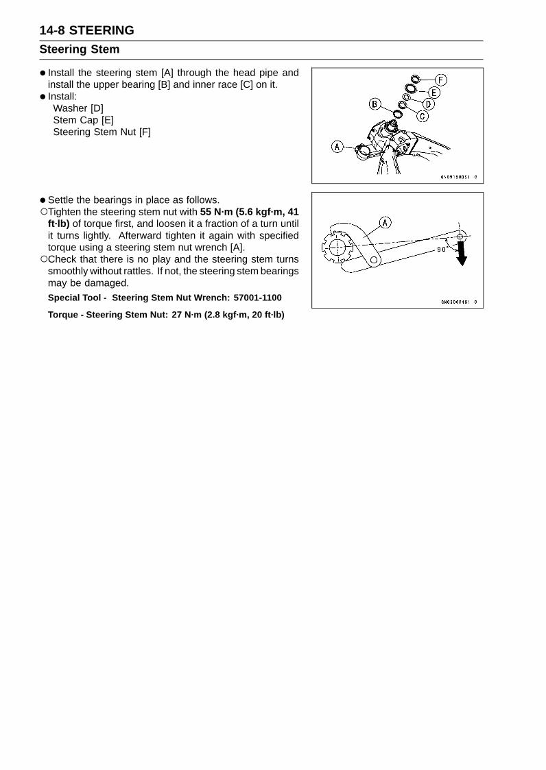
14-8 STEERINGSteering Stem
• Install the steering stem [A] through the head pipe andinstall the upper bearing [B] and inner race [C] on it.
• Install:Washer [D]Stem Cap [E]Steering Stem Nut [F]
• Settle the bearings in place as follows.Tighten the steering stem nut with 55 N·m (5.6 kgf·m, 41
ft·lb) of torque first, and loosen it a fraction of a turn untilit turns lightly. Afterward tighten it again with specifiedtorque using a steering stem nut wrench [A].Check that there is no play and the steering stem turns
smoothly without rattles. If not, the steering stem bearingsmay be damaged.Special Tool - Steering Stem Nut Wrench: 57001-1100
Torque - Steering Stem Nut: 27 N·m (2.8 kgf·m, 20 ft·lb)

STEERING 14-9Steering Stem
• Install the claw washer [A] so that its bent side [B] facesupward, and engage the bent claws with the grooves ofstem locknut [C].
• Hand tighten the stem locknut until it touches the clawwasher.
•Hand tighten the stem locknut clockwise until the clawsare aligned with the second groove of stem nut [D], andbend the 2 claws downward [E].
• Install the stem head.• Apply a non-permanent locking agent to the threads of
the steering stem head bolt.• Install the washer, and temporary tighten the stem head
bolt.• Install the front forks (see Front Fork Installation in the
Suspension chapter).
NOTETighten the upper front fork clamp bolts first, next the
stem head bolt, last the lower front fork clamp bolts.Tighten the two lower front fork clamp bolts alternately
two times to ensure even tightening torque.
Torque - Upper Front Fork Clamp Bolts: 20 N·m (2.0 kgf·m,15 ft·lb)
Steering Stem Head Bolt: 78 N·m (8.0 kgf·m, 58ft·lb)
Lower Front Fork Clamp Bolts: 23 N·m (2.3 kgf·m,17 ft·lb)
Handlebar Clamp Bolts: 25 N·m (2.5 kgf·m, 18ft·lb)
WARNINGIf the handlebar does not turn to the steering stop itmay cause an accident resulting in injury or death.Be sure the cables, harnesses and hoses are routedproperly and do not interfere with handlebar move-ment (see Cable, Wire, and Hose Routing section inthe Appendix chapter).
• Install the removed parts (see appropriate chapters).
Steering Stem Bearing Lubrication•Refer to the Steering Stem Bearing Lubrication in the Pe-
riodic Maintenance chapter.
Steering Stem Warp Inspection•Whenever the steering stem is removed, or if the steering
can not be adjusted for smooth action, check the steeringstem for straightness.If the steering stem [A] is bent, replace the steering stem.

14-10 STEERINGSteering Stem
Stem Cap Deterioration, Damage InspectionReplace the stem cap if its seal lip [A] shows damage.
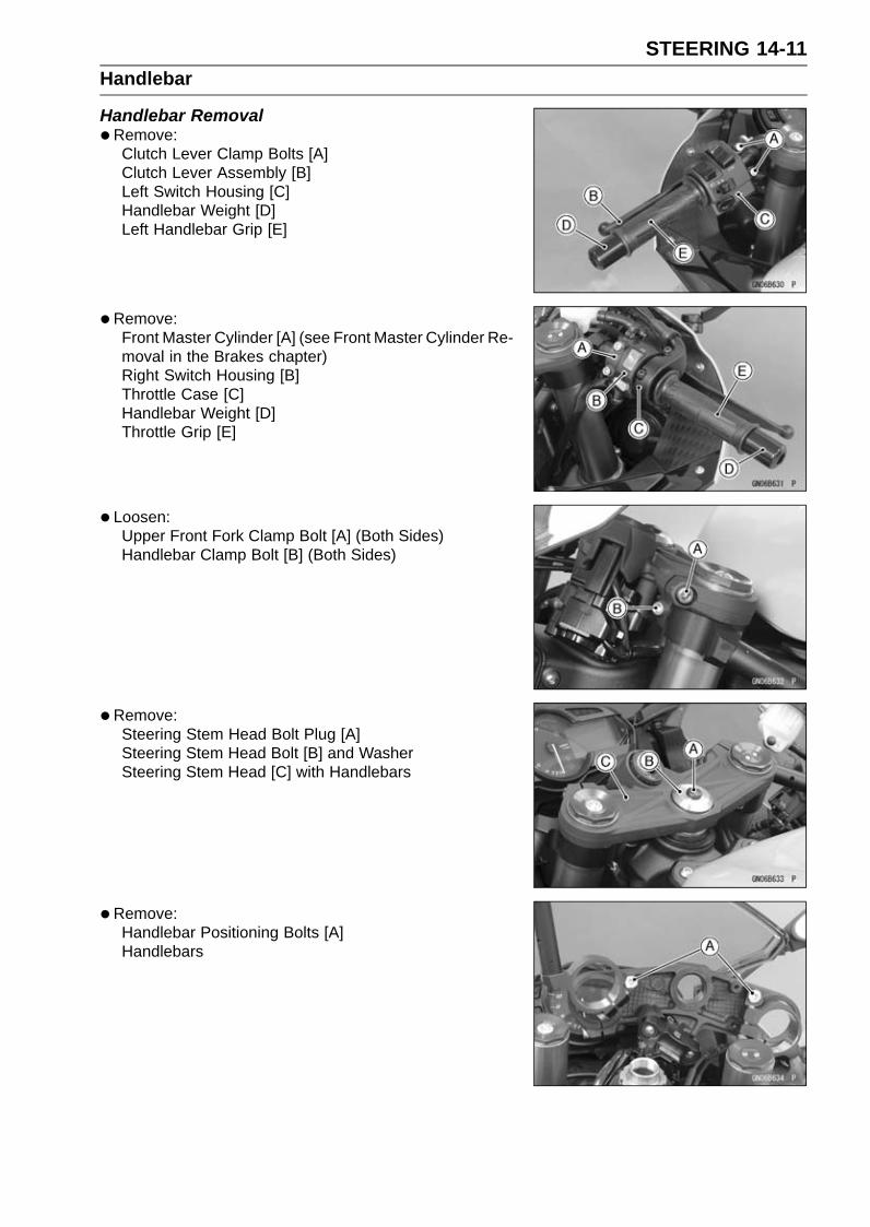
STEERING 14-11Handlebar
Handlebar Removal•Remove:
Clutch Lever Clamp Bolts [A]Clutch Lever Assembly [B]Left Switch Housing [C]Handlebar Weight [D]Left Handlebar Grip [E]
•Remove:Front Master Cylinder [A] (see Front Master Cylinder Re-moval in the Brakes chapter)Right Switch Housing [B]Throttle Case [C]Handlebar Weight [D]Throttle Grip [E]
• Loosen:Upper Front Fork Clamp Bolt [A] (Both Sides)Handlebar Clamp Bolt [B] (Both Sides)
•Remove:Steering Stem Head Bolt Plug [A]Steering Stem Head Bolt [B] and WasherSteering Stem Head [C] with Handlebars
•Remove:Handlebar Positioning Bolts [A]Handlebars

14-12 STEERINGHandlebar
Handlebar Installation•Apply a non-permanent locking agent to the threads of
the handlebar positioning bolts and tighten them.Torque - Handlebar Positioning Bolts: 9.8 N·m (1.0 kgf·m,
87 in·lb)
• Install the steering stem head with handlebars.• Apply a non-permanent locking agent to the threads of
the steering stem head bolt.• Install the washer [A] and steering stem head bolt [B].• Tighten:
Torque - Steering Stem Head Bolt: 78 N·m (8.0 kgf·m, 58ft·lb)
Upper Front Fork Clamp Bolts: 20 N·m (2.0 kgf·m,15 ft·lb)
Handlebar Clamp Bolts: 25 N·m (2.5 kgf·m, 18ft·lb)
NOTETighten the steering stem head bolt before tightening
the upper front fork clamp bolts and handlebar clampbolts.
WARNINGIf the handlebar does not turn to the steering stop itmay cause an accident resulting in injury or death.Be sure the cables, harnesses and hoses are routedproperly and do not interfere with handlebar move-ment (see Cable, Wire, and Hose Routing section inthe Appendix chapter).
• Install the steering stem head bolt plug to the steeringstem head bolt.
• Apply adhesive cement to the inside of the left handlebargrip.
• Install the left handlebar grip, throttle grip and left/righthandlebar weight.
• Apply a non-permanent locking agent to the threads ofthe handlebar weight bolts, and tighten them.
• Install the left and right switch housings.Fit the projection [A] into a hole [B] in the handlebar.• Tighten:
Torque - Switch Housing Screws: 3.5 N·m (0.36 kgf·m, 31in·lb)

STEERING 14-13Handlebar
• Install the throttle cable tips [A].• Install the throttle case.Fit the projection [B] into a hole [C] in the handlebar.• Tighten:
Torque - Throttle Case Screws: 3.5 N·m (0.36 kgf·m, 31in·lb)
• Install:Clutch Lever Assembly (see Clutch Lever Installation inthe Clutch chapter)Front Master Cylinder (see Front Master Cylinder Instal-lation in the Brakes chapter)


FRAME 15-1
15
FrameTable of Contents
Exploded View................................... 15-2Seats ................................................. 15-8
Front Seat Removal ..................... 15-8Front Seat Installation .................. 15-8Rear Seat Removal...................... 15-8Rear Seat Installation................... 15-8
Fairings.............................................. 15-9Lower Fairing Removal ................ 15-9Lower Fairing Installation ............. 15-9Lower Fairing Disassembly.......... 15-9Upper Fairing Assembly Removal 15-9Upper Fairing Assembly
Installation ................................. 15-11Middle Fairing Removal ............... 15-11Middle Fairing Installation ............ 15-11Center Fairing Removal/Installa-
tion ............................................ 15-11Inner Fairing Removal.................. 15-12Inner Fairing Installation............... 15-12Fairing Cover Removal ................ 15-12Fairing Cover Installation ............. 15-12
Side Covers ....................................... 15-13Inner Cover Removal ................... 15-13Inner Cover Installation ................ 15-13Side Cover Removal .................... 15-13Side Cover Installation ................. 15-13Tank Cover Removal.................... 15-14
Tank Cover Installation................. 15-15Seat Covers....................................... 15-16
Seat Cover Removal.................... 15-16Seat Cover Installation................. 15-16
Fenders ............................................. 15-17Front Fender Removal ................. 15-17Front Fender Installation .............. 15-17Rear Fender Removal.................. 15-17Rear Fender Installation............... 15-18Flap Removal............................... 15-19Flap Installation............................ 15-19
Frame ................................................ 15-20Rear Frame Rear Removal.......... 15-20Rear Frame Rear Installation....... 15-20Rear Frame Front Removal ......... 15-20Rear Frame Front Installation ...... 15-20Frame Inspection ......................... 15-20
Windshield ......................................... 15-21Windshield Removal .................... 15-21Windshield Installation ................. 15-21
Guard................................................. 15-22Mud Guard Removal.................... 15-22Mud Guard Installation................. 15-22
Sidestand........................................... 15-23Sidestand Removal...................... 15-23Sidestand Installation................... 15-23
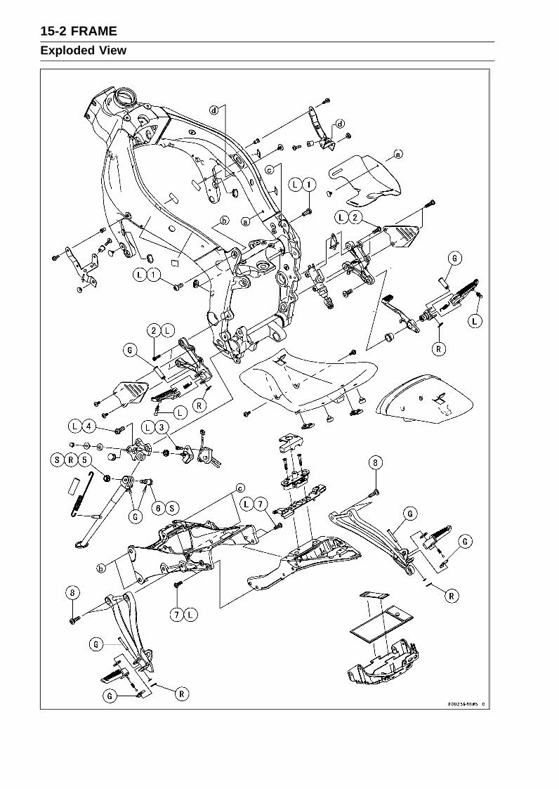
15-2 FRAMEExploded View

FRAME 15-3Exploded View
TorqueNo. Fastener
N·m kgf·m ft·lbRemarks
1 Rear Frame Bolts (M10) 44 4.5 32 L2 Front Footpeg Bracket Bolts 25 2.5 18 L3 Sidestand Switch Bolt 8.8 0.90 78 in·lb L4 Sidestand Bracket Bolts 49 5.0 36 L5 Sidestand Nut 44 4.5 32 R, S6 Sidestand Bolt 29 3.0 21 S7 Rear Frame Bolts (M8) 25 2.5 18 L8 Rear Footpeg Bracket Bolts 25 2.5 18G: Apply grease.L: Apply a non-permanent locking agent.R: Replacement Parts

15-4 FRAMEExploded View
FRAME 15-5Exploded View
TorqueNo. Fastener
N·m kgf·m ft·lbRemarks
1 Front Fender Mounting Bolts 3.9 0.40 35 in·lb2. US, CA and CAL ModelsL: Apply a non-permanent locking agent.R: Replacements Parts

15-6 FRAMEExploded View
FRAME 15-7Exploded View
TorqueNo. Fastener
N·m kgf·m ft·lbRemarks
1 Windshield Mounting Bolts 0.42 0.043 3.7 in·lb

15-8 FRAMESeats
Front Seat Removal•Remove:
Side Covers (see Side Cover Removal)Bolt [A] (Both Sides)
•Remove the seat [B] forward while lifting up the front partof the seat.
Front Seat Installation•Slip the seat hook [A] under the rib [B] on the rear frame
front.• Tighten the bolts.
Rear Seat Removal• Insert the ignition switch key [A] into the seat lock.• Pull up the front part of the seat [B] upward while turning
the key clockwise, and remove it forward.
Rear Seat Installation•Slip the seat hook [A] under the rib [B] on the rear frame
rear.• Insert the seat latches [C] into the latch holes [D].• Push down the seat until the lock clicks.

FRAME 15-9Fairings
Lower Fairing Removal•Remove:
Quick Rivets [A]Bolts and Washers [B]
•Clear the hook [C] with the standard tip screwdriver.• Pull the lower fairing [D] outward to clear the hooks [E],
and remove the lower fairing.
Lower Fairing Installation• Insert the hooks [A] into the slots [B].• Hook the hook [C] to the middle fairing.• Install the bolts and washers.
Lower Fairing Disassembly•Remove the lower fairing (see Lower Fairing Removal).• Remove the screws [A].• Clear the hooks [B] and remove the lower fairing cover
[C].
Upper Fairing Assembly Removal•Remove:
Inner Cover (see Inner Cover Removal)Side Cover (see Side Cover Removal)Fairing Cover (see Fairing Cover Removal)Lower Fairing (see Lower Fairing Removal)Inner Fairing (see Inner Fairing Removal)Windshield (see Windshield Removal)Bolt [A] and Washer (Both Sides)
•Remove the fuse box [A].• Disconnect the regulator/rectifier connectors [B].

15-10 FRAMEFairings
•Disconnect (Left Side):Front Turn Signal Light Lead Connector [A]Head Light Lead Connector [B]City Light Lead Connector [C]
•Disconnect (Right Side):Front Turn Signal Light Lead Connector [A]Head Light Lead Connector [B]City Light Lead Connector [C]
•Remove (Both Sides):Bolts [A]Rear View Mirror [B]
•Remove the bolts [A].
• Remove the upper fairing assembly [A] forward.

FRAME 15-11Fairings
Upper Fairing Assembly Installation• Installation is the reverse of removal.• Run the hoses, leads and harness correctly (see Cable,
Wire, and Hose Routing section in the Appendix chapter).• Insert the coolant reserve tank overflow hose [A] to the
hole [B] of the middle fairing.
Middle Fairing Removal•Remove:
Upper Fairing Assembly (see Upper Fairing AssemblyRemoval)Headlight (see Headlight Removal/Installation in theElectrical System chapter)Screws [A]Middle Fairing [B]
Middle Fairing Installation•Check that the pads are in place on the middle fairing.Fit the pad [A] on the rib [B] for the fairing cover.Align the pad [C] with the line [D] on the middle fairing.
• Install the middle fairing so that the tabs [A] fit the slots[B].
• Install the screws.
Center Fairing Removal/Installation•Remove:
Upper Fairing Assembly (see Upper Fairing AssemblyRemoval)Headlight (see Headlight Removal/Installation in theElectrical System chapter)Screws [A]Center Fairing [B]
•When installing the center fairing, fit the tabs [C] to theslots.

15-12 FRAMEFairings
Inner Fairing Removal•Remove:
Clamps [A]Quick Rivets [B]
•Remove (Both Sides):Quick Rivets [A]Inner Fairing [B]
Inner Fairing Installation•Fit the hooks [A] of the inner fairings.• Insert the tab [B] into the rib [C] on the upper fairing.• Install the quick rivets and clamps.
Fairing Cover Removal•Remove:
Bolts [A] and WasherQuick Rivet [B]
•Clear the projection [C].• Pull the fairing cover [D] backward to clear the hook [E],
and remove the fairing cover.
Fairing Cover Installation• Insert the hook [A] into the slot [B].• Fit the tabs [C] and projection [D] to the slots [E] and hole
[F].• Install the quick rivet, bolt and washer.
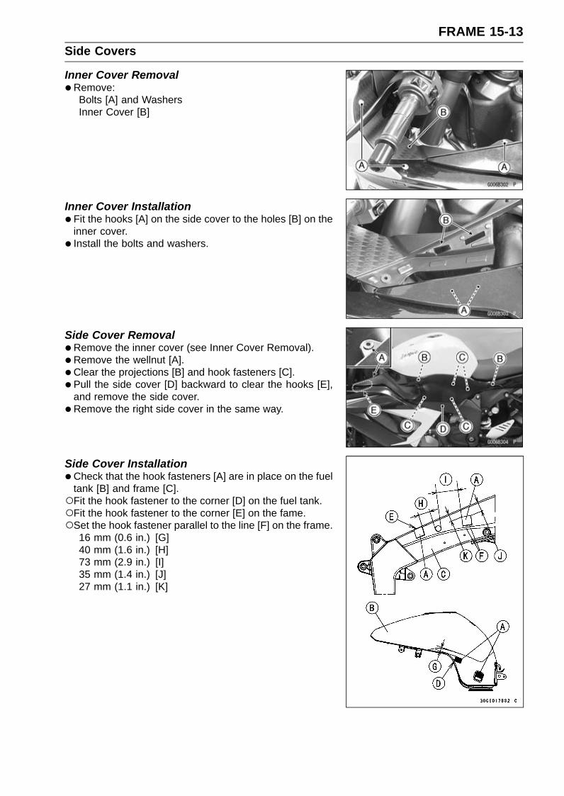
FRAME 15-13Side Covers
Inner Cover Removal•Remove:
Bolts [A] and WashersInner Cover [B]
Inner Cover Installation•Fit the hooks [A] on the side cover to the holes [B] on the
inner cover.• Install the bolts and washers.
Side Cover Removal•Remove the inner cover (see Inner Cover Removal).• Remove the wellnut [A].• Clear the projections [B] and hook fasteners [C].• Pull the side cover [D] backward to clear the hooks [E],
and remove the side cover.•Remove the right side cover in the same way.
Side Cover Installation•Check that the hook fasteners [A] are in place on the fuel
tank [B] and frame [C].Fit the hook fastener to the corner [D] on the fuel tank.Fit the hook fastener to the corner [E] on the fame.Set the hook fastener parallel to the line [F] on the frame.
16 mm (0.6 in.) [G]40 mm (1.6 in.) [H]73 mm (2.9 in.) [I]35 mm (1.4 in.) [J]27 mm (1.1 in.) [K]

15-14 FRAMESide Covers
•Check that the pads [A] and hook fasteners [B] are inplace on the side cover.Set the pad and hook fasteners to the convex [C] on the
side cover.Fit the pad to the rim end [D].Fit the pad to the corner [E] on the rib.
1 mm (0.04 in.) [F]Detail Y [G]Section X- X [H]
• Insert the hooks [A] into the slots [B].• Insert the projections [C] into the holes [D], and fit the hook
fasteners.• Install the wellnut.
Tank Cover Removal•Remove the side cover (see Side Cover Removal).• Remove the bolt [A].• Clear the projection [B], and remove the tank cover [C].

FRAME 15-15Side Covers
Tank Cover Installation•Check that the dampers [A] are in place on the side cover.• Insert the projection [B] into the hole [C].• Tighten the bolt.
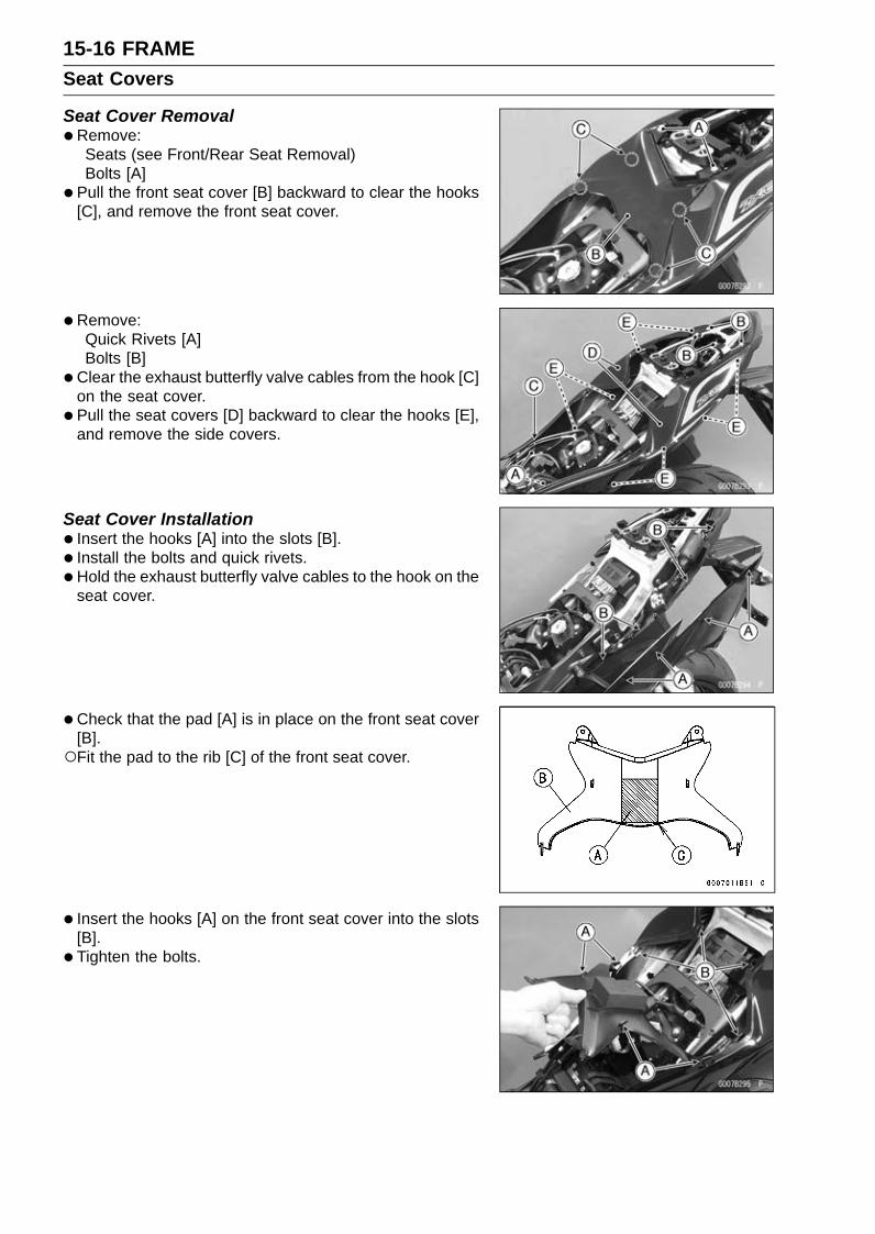
15-16 FRAMESeat Covers
Seat Cover Removal•Remove:
Seats (see Front/Rear Seat Removal)Bolts [A]
• Pull the front seat cover [B] backward to clear the hooks[C], and remove the front seat cover.
• Remove:Quick Rivets [A]Bolts [B]
•Clear the exhaust butterfly valve cables from the hook [C]on the seat cover.
• Pull the seat covers [D] backward to clear the hooks [E],and remove the side covers.
Seat Cover Installation• Insert the hooks [A] into the slots [B].• Install the bolts and quick rivets.•Hold the exhaust butterfly valve cables to the hook on the
seat cover.
• Check that the pad [A] is in place on the front seat cover[B].Fit the pad to the rib [C] of the front seat cover.
• Insert the hooks [A] on the front seat cover into the slots[B].
• Tighten the bolts.

FRAME 15-17Fenders
Front Fender Removal•Remove the front wheel (see Front Wheel Removal).• Clear the brake hoses and wheel rotation sensor lead
from the clamps [A] (both sides).• Remove:
Bolts [B] and Washers (Both Sides)Front Fender [C]
Front Fender Installation•Tighten:
Torque - Front Fender Mounting Bolts: 3.9 N·m (0.40 kgf·m,35 in·lb)
Rear Fender Removal•Remove:
Fuel Tank (see Fuel Tank Removal in the Fuel System(DFI) chapter)Battery (see Battery Removal in the Electrical Systemchapter)Flap (see Flap Removal).
• Pull the tail/brake light cover [A] backward to clear thehooks [B], and remove the tail/brake light cover.
• Remove:Seat Lock Cover [A]Seat Lock Cable [B]
•Disconnect the starter motor cable [A] from the starterrelay [B].

15-18 FRAMEFenders
•Disconnect:Vehicle-down Sensor Connector [A]Tail/Brake Light Lead Connector [B]
•Remove the clamps [C].
• Remove:Exhaust Butterfly Valve Actuator [A] (see Exhaust But-terfly Valve Actuator Removal in the Fuel System (DFI)chapter)ECU (with Relay Box) [B]Turn signal Relay [C]Fuse Box [D]Bolts [E]Bolts and Nuts [F]Pad [G]Clamps [H]
•Remove the rear fender backward.
Rear Fender Installation• Installation is the reverse of removal.• Run the cables, leads, harness and hoses correctly (see
Cable, Wire, and Hose Routing section in the Appendixchapter).
• Check that the pad [A] in place on the rear fender [B].5 mm (0.20 in.) [C]
• Insert the hooks [A] on the tail/brake light cover into theslits [B] on the rear fender.

FRAME 15-19Fenders
Flap Removal•Remove the seat cover (see Seat Cover Removal).• Disconnect:
Turn Signal Relay Lead Connectors [A]License Plate Light Lead Connector [B]
•Clear the lead from the clamp [C].
• Remove:Flap Mounting Bolts [A]Clamp [B]Flap
Flap Installation• Installation is the reverse of removal.• Run the cables, leads, harness and hoses correctly (see
Cable, Wire, and Hose Routing section in the Appendixchapter).
• Apply a non-permanent locking agent to the threads ofthe flap mounting bolts.

15-20 FRAMEFrame
Rear Frame Rear Removal•Remove:
Rear Fender (see Rear Fender Removal)Rear Frame Bolts (M8) [A] (Both Sides)Rear Frame Rear [B]
Rear Frame Rear Installation•Check that the pads [A] are in place on the rear frame
rear.Align the pads with the line [B] on the rear frame rear.• Apply a non-permanent locking agent to the threads of
the rear frame bolts (M8) and tighten them.Torque - Rear Frame Bolts (M8): 25 N·m (2.5 kgf·m, 18 ft·lb)
Rear Frame Front Removal•Remove:
Rear Frame Rear (see Rear Frame Rear Removal)Rear Footpeg Bracket Bolts [A] (Both Sides)Muffler Body Mounting Bolts [B]Rear Footpeg Brackets [C]Rear Frame Bolt (M10) [D] (Both Sides)Rear Frame Front [E]
Rear Frame Front Installation•Apply a non-permanent locking agent to the threads of
the rear frame bolts (M10) and tighten them.Torque - Rear Frame Bolts (M10): 44 N·m (4.5 kgf·m, 32
ft·lb)Rear Footpeg Bracket Bolts: 25 N·m (2.5 kgf·m, 18
ft·lb)Muffler Body Mounting Bolt: 25 N·m (2.5 kgf·m, 18
ft·lb)
Frame Inspection•Visually inspect the frame for cracks, dents, bending, or
warp.If there is any damage to the frame, replace it.
WARNINGA repaired frame may fail in use, possibly causingan accident resulting in injury or death. If the frameis bent, dented, cracked, or warped, replace it.
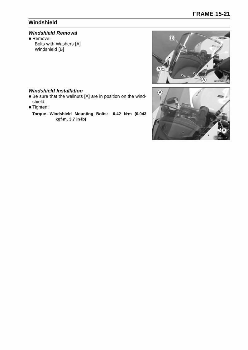
FRAME 15-21Windshield
Windshield Removal•Remove:
Bolts with Washers [A]Windshield [B]
Windshield Installation•Be sure that the wellnuts [A] are in position on the wind-
shield.• Tighten:
Torque - Windshield Mounting Bolts: 0.42 N·m (0.043kgf·m, 3.7 in·lb)
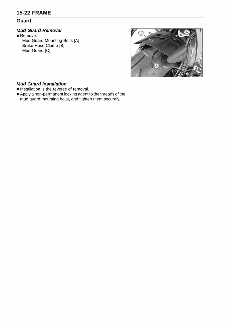
15-22 FRAMEGuard
Mud Guard Removal•Remove:
Mud Guard Mounting Bolts [A]Brake Hose Clamp [B]Mud Guard [C]
Mud Guard Installation• Installation is the reverse of removal.• Apply a non-permanent locking agent to the threads of the
mud guard mounting bolts, and tighten them securely.

FRAME 15-23Sidestand
Sidestand Removal•Raise the rear wheel off the ground with the stand [A].
• Remove:Sidestand Switch Bolt [A]Sidestand Switch [B]
•Remove:Spring [A]Sidestand Nut [B]Sidestand Bolt [C]Sidestand [D]
Sidestand Installation•Apply grease to the sliding area [A] of the sidestand [B].• Replace the sidestand nut [C] with a new one.• Tighten the sidestand bolt [D], and then lock it with the
sidestand nut.Torque - Sidestand Bolt: 29 N·m (3.0 kgf·m, 21 ft·lb)
Sidestand Nut: 44 N·m (4.5 kgf·m, 32 ft·lb)
•Hook the spring [E] so that the long spring end faces up-ward.Install the spring hook direction as shown.• Install the sidestand switch [F].• Apply a non-permanent locking agent to the threads of
the sidestand switch bolt [G], and tighten it.Torque - Sidestand Switch Bolt: 8.8 N·m (0.90 kgf·m, 78
in·lb)


ELECTRICAL SYSTEM 16-1
16
Electrical SystemTable of Contents
Exploded View........................................................................................................................ 16-3Specifications ......................................................................................................................... 16-10Special Tools and Sealant ...................................................................................................... 16-11Parts Location......................................................................................................................... 16-13Wiring Diagram (US, CA and CAL Models)............................................................................ 16-16Wiring Diagram (Other than US, CA and CAL Models).......................................................... 16-18Wiring Diagram (KIBS Equipped Models: US, CA and CAL Models) .................................... 16-20Wiring Diagram (KIBS Equipped Models: Other than US, CA and CAL Models) .................. 16-22Precautions............................................................................................................................. 16-24Electrical Wiring...................................................................................................................... 16-25
Wiring Inspection .............................................................................................................. 16-25Battery .................................................................................................................................... 16-26
Battery Removal ............................................................................................................... 16-26Battery Installation ............................................................................................................ 16-26Battery Activation .............................................................................................................. 16-27Precautions ....................................................................................................................... 16-29Interchange....................................................................................................................... 16-30Charging Condition Inspection.......................................................................................... 16-30Refreshing Charge............................................................................................................ 16-30
Charging System.................................................................................................................... 16-32Alternator Cover Removal................................................................................................. 16-32Alternator Cover Installation.............................................................................................. 16-32Stator Coil Removal .......................................................................................................... 16-32Stator Coil Installation ....................................................................................................... 16-33Alternator Rotor Removal ................................................................................................. 16-33Alternator Rotor Installation .............................................................................................. 16-33Charging Voltage Inspection ............................................................................................. 16-35Alternator Inspection ......................................................................................................... 16-35Regulator/Rectifier Inspection........................................................................................... 16-37
Ignition System....................................................................................................................... 16-39Crankshaft Sensor Removal ............................................................................................. 16-39Crankshaft Sensor Installation .......................................................................................... 16-39Crankshaft Sensor Inspection........................................................................................... 16-40Crankshaft Sensor Peak Voltage Inspection..................................................................... 16-40Stick Coil Removal............................................................................................................ 16-41Stick Coil Installation......................................................................................................... 16-41Stick Coil Inspection.......................................................................................................... 16-41Stick Coil Primary Peak Voltage Inspection ...................................................................... 16-42Spark Plug Removal ......................................................................................................... 16-42Spark Plug Installation ...................................................................................................... 16-42Spark Plug Condition Inspection....................................................................................... 16-43Interlock Operation Inspection .......................................................................................... 16-43IC Igniter Inspection .......................................................................................................... 16-44
Electric Starter System........................................................................................................... 16-47Starter Motor Removal...................................................................................................... 16-47Starter Motor Installation................................................................................................... 16-47Starter Motor Disassembly................................................................................................ 16-48Starter Motor Assembly .................................................................................................... 16-48Brush Inspection ............................................................................................................... 16-49Commutator Cleaning and Inspection............................................................................... 16-50

16-2 ELECTRICAL SYSTEM
Armature Inspection.......................................................................................................... 16-50Brush Lead Inspection ...................................................................................................... 16-50Left-hand End Cover Assembly Inspection....................................................................... 16-51Starter Relay Inspection.................................................................................................... 16-51
Lighting System...................................................................................................................... 16-53Headlight Beam Horizontal Adjustment ............................................................................ 16-53Headlight Beam Vertical Adjustment................................................................................. 16-53Headlight Bulb Replacement ............................................................................................ 16-53City Light Bulb Replacement............................................................................................. 16-54Headlight Removal/Installation ......................................................................................... 16-54Tail/Brake Light (LED) Removal/Installation...................................................................... 16-55License Plate Light Bulb Replacement ............................................................................. 16-55Turn Signal Light Bulb Replacement ................................................................................ 16-57Turn Signal Relay Inspection ............................................................................................ 16-59
Air Switching Valve ................................................................................................................. 16-61Air Switching Valve Operation Test ................................................................................... 16-61Air Switching Valve Unit Test ............................................................................................ 16-61
Radiator Fan System.............................................................................................................. 16-63Fan Motor Inspection ........................................................................................................ 16-63
Meter, Gauge, Indicator Unit................................................................................................... 16-64Meter Unit Removal/Installation ........................................................................................ 16-64Meter Unit Disassembly .................................................................................................... 16-64Meter Operation Inspection............................................................................................... 16-65Meter System Inspection .................................................................................................. 16-68Meter Unit Inspection ........................................................................................................ 16-69
Immobilizer System (Equipped Models) ................................................................................. 16-74Operational Cautions ........................................................................................................ 16-74Key Registration................................................................................................................ 16-74Immobilizer System Parts Replacement ........................................................................... 16-92Immobilizer System Inspection ......................................................................................... 16-93
Immobilizer System (Equipped Models) ................................................................................. 16-94Switches and Sensors............................................................................................................ 16-95
Brake Light Timing Inspection........................................................................................... 16-95Brake Light Timing Adjustment ......................................................................................... 16-95Switch Inspection .............................................................................................................. 16-95Water Temperature Sensor Inspection ............................................................................. 16-96Fuel Reserve Switch Inspection........................................................................................ 16-96Oxygen Sensor Removal (Equipped Models)................................................................... 16-97Oxygen Sensor Installation (Equipped Models)................................................................ 16-97Oxygen Sensor Inspection (Equipped Models)................................................................. 16-97Oxygen Sensor Heater Inspection (Equipped Models)..................................................... 16-98Gear Position Switch Removal ......................................................................................... 16-98Gear Position Switch Installation ...................................................................................... 16-99Gear Position Switch Inspection ....................................................................................... 16-99
Relay Box ............................................................................................................................... 16-101Relay Box Removal .......................................................................................................... 16-101Relay Circuit Inspection .................................................................................................... 16-101Diode Circuit Inspection .................................................................................................... 16-102
Fuse........................................................................................................................................ 16-10330 A Main/15 A ECU Fuse Removal................................................................................. 16-103Fuse Box Fuse Removal................................................................................................... 16-103Fuse Installation................................................................................................................ 16-103Fuse Inspection................................................................................................................. 16-104

ELECTRICAL SYSTEM 16-3Exploded View
This page intentionally left blank.
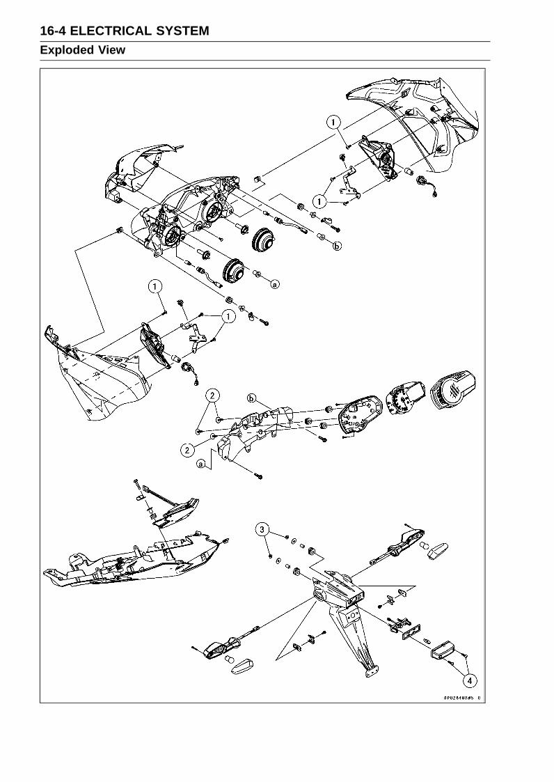
16-4 ELECTRICAL SYSTEMExploded View

ELECTRICAL SYSTEM 16-5Exploded View
TorqueNo. Fastener
N·m kgf·m ft·lbRemarks
1 Front Turn Signal Light Mounting Screw 1.2 0.12 11 in·lb2 Meter Unit Mounting Screws 1.2 0.12 11 in·lb3 License Plate Light Mounting Nuts 3.5 0.36 31 in·lb4 License Plate Light Cover Screws 1.0 0.10 8.9 in·lb
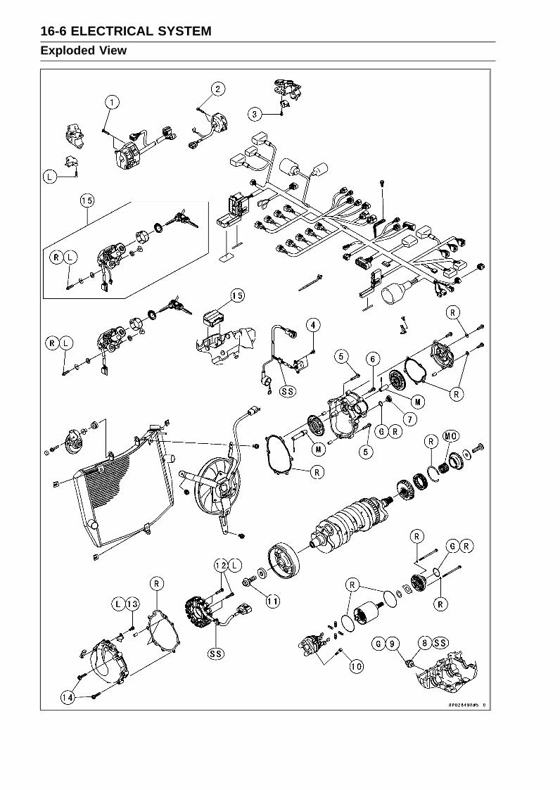
16-6 ELECTRICAL SYSTEMExploded View

ELECTRICAL SYSTEM 16-7Exploded View
TorqueNo. Fastener
N·m kgf·m ft·lbRemarks
1 Left Switch Housing Screws 3.5 0.36 31 in·lb2 Right Switch Housing Screws 3.5 0.36 31 in·lb3 Front Brake Light Switch Screw 1.2 0.12 11 in·lb4 Crankshaft Sensor Bolts 5.9 0.60 52 in·lb5 Starter Clutch Cover Bolts (L = 30 mm) 9.8 1.0 87 in·lb6 Starter Clutch Cover Bolt (L = 20 mm) 9.8 1.0 87 in·lb7 Starter Clutch Bolt Cap 2.9 0.30 26 in·lb8 Oil Pressure Switch 15 1.5 11 SS9 Oil Pressure Switch Terminal Bolt 1.5 0.15 13 in·lb G
10 Starter Motor Mounting Bolts 9.8 1.0 87 in·lb11 Alternator Rotor Bolt 155 15.8 11412 Stator Coil Bolts 12 1.2 106 in·lb L13 Alternator Lead Holding Plate Bolt 9.8 1.0 87 in·lb L14 Alternator Cover Bolts 9.8 1.0 87 in·lb15. Immobilizer System Equipped ModelsG: Apply grease.L: Apply a non-permanent locking agent.
M: Apply molybdenum disulfide grease.MO: Apply molybdenum disulfide oil solution.
(mixture of the engine oil and molybdenum disulfide grease in a weight ratio 10:1)R: Replacement Parts
SS: Apply silicone sealant.

16-8 ELECTRICAL SYSTEMExploded View
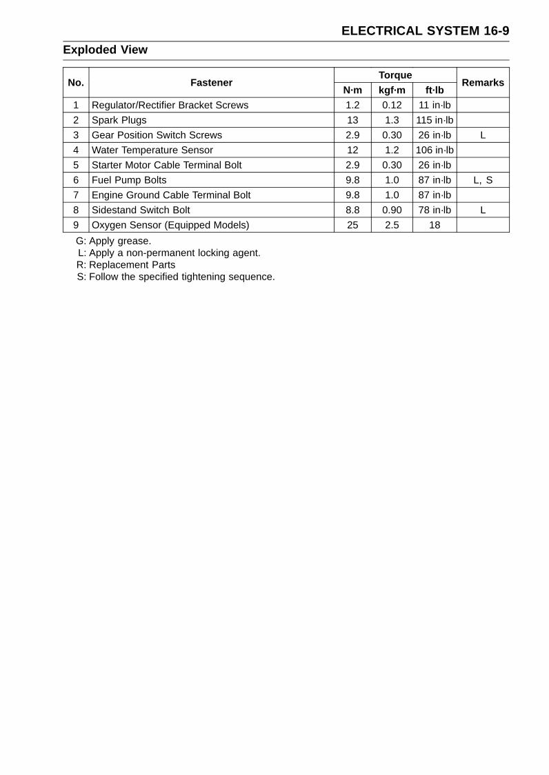
ELECTRICAL SYSTEM 16-9Exploded View
TorqueNo. Fastener
N·m kgf·m ft·lbRemarks
1 Regulator/Rectifier Bracket Screws 1.2 0.12 11 in·lb2 Spark Plugs 13 1.3 115 in·lb3 Gear Position Switch Screws 2.9 0.30 26 in·lb L4 Water Temperature Sensor 12 1.2 106 in·lb5 Starter Motor Cable Terminal Bolt 2.9 0.30 26 in·lb6 Fuel Pump Bolts 9.8 1.0 87 in·lb L, S7 Engine Ground Cable Terminal Bolt 9.8 1.0 87 in·lb8 Sidestand Switch Bolt 8.8 0.90 78 in·lb L9 Oxygen Sensor (Equipped Models) 25 2.5 18G: Apply grease.L: Apply a non-permanent locking agent.R: Replacement PartsS: Follow the specified tightening sequence.
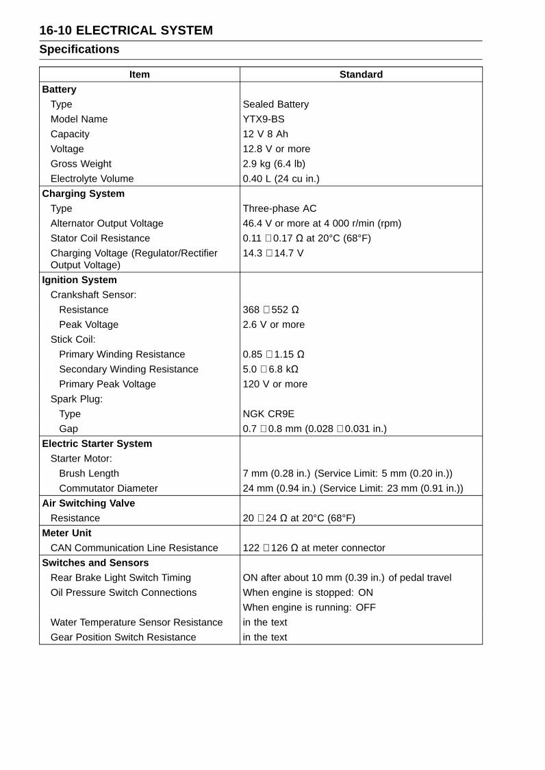
16-10 ELECTRICAL SYSTEMSpecifications
Item StandardBattery
Type Sealed BatteryModel Name YTX9-BSCapacity 12 V 8 AhVoltage 12.8 V or moreGross Weight 2.9 kg (6.4 lb)Electrolyte Volume 0.40 L (24 cu in.)
Charging SystemType Three-phase ACAlternator Output Voltage 46.4 V or more at 4 000 r/min (rpm)Stator Coil Resistance 0.11 ∼ 0.17 Ω at 20°C (68°F)Charging Voltage (Regulator/RectifierOutput Voltage)
14.3 ∼ 14.7 V
Ignition SystemCrankshaft Sensor:
Resistance 368 ∼ 552 ΩPeak Voltage 2.6 V or more
Stick Coil:Primary Winding Resistance 0.85 ∼ 1.15 ΩSecondary Winding Resistance 5.0 ∼ 6.8 kΩPrimary Peak Voltage 120 V or more
Spark Plug:Type NGK CR9EGap 0.7 ∼ 0.8 mm (0.028 ∼ 0.031 in.)
Electric Starter SystemStarter Motor:
Brush Length 7 mm (0.28 in.) (Service Limit: 5 mm (0.20 in.))Commutator Diameter 24 mm (0.94 in.) (Service Limit: 23 mm (0.91 in.))
Air Switching ValveResistance 20 ∼ 24 Ω at 20°C (68°F)
Meter UnitCAN Communication Line Resistance 122 ∼ 126 Ω at meter connector
Switches and SensorsRear Brake Light Switch Timing ON after about 10 mm (0.39 in.) of pedal travelOil Pressure Switch Connections When engine is stopped: ON
When engine is running: OFFWater Temperature Sensor Resistance in the textGear Position Switch Resistance in the text
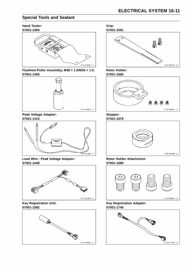
ELECTRICAL SYSTEM 16-11Special Tools and Sealant
Hand Tester:57001-1394
Flywheel Puller Assembly, M38 × 1.5/M35 × 1.5:57001-1405
Peak Voltage Adapter:57001-1415
Lead Wire - Peak Voltage Adapter:57001-1449
Key Registration Unit:57001-1582
Grip:57001-1591
Rotor Holder:57001-1666
Stopper:57001-1679
Rotor Holder Attachment:57001-1689
Key Registration Adapter:57001-1746
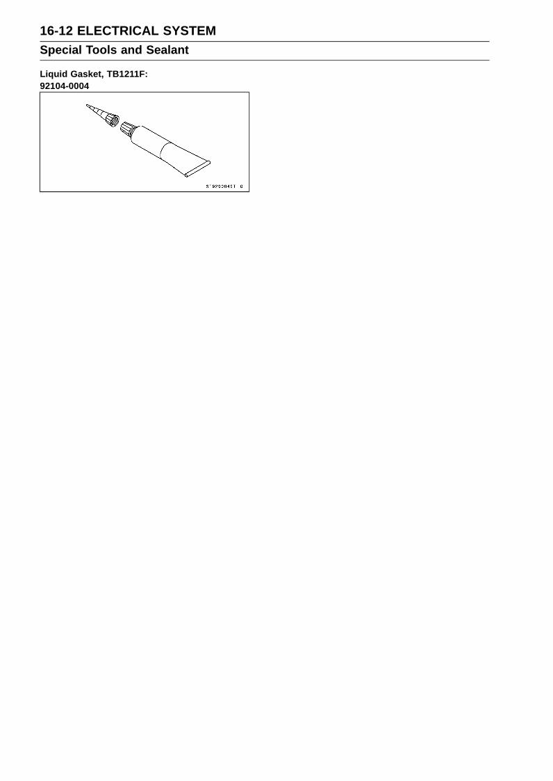
16-12 ELECTRICAL SYSTEMSpecial Tools and Sealant
Liquid Gasket, TB1211F:92104-0004

ELECTRICAL SYSTEM 16-13Parts Location
This page intentionally left blank.

16-14 ELECTRICAL SYSTEMParts Location
ELECTRICAL SYSTEM 16-15Parts Location
1. Immobilizer Amplifier (Equipped Models)2. Ignition Switch
(Immobilizer Equipped Models: Including Immobilizer Antenna)3. Starter Lockout Switch4. Starter Relay5. Battery 12 V 8 Ah6. ECU7. Relay Box8. Turn Signal Relay9. Gear Position Switch
10. Sidestand Switch11. Alternator12. Fan Motor13. Water Temperature Sensor14. Starter Motor15. Stick Coils16. Air Switching Valve17. Meter Unit18. Front Brake Light Switch19. Spark Plugs20. Crankshaft Sensor21. Oil Pressure Switch22. Oxygen Sensor (Equipped Models)23. Rear Brake Light Switch24. Fuel Reserve Switch25. Fuel Pump26. Fuse Box 127. Fuse Box 228. Regulator/Rectifier

16-16 ELECTRICAL SYSTEMWiring Diagram (US, CA and CAL Models)

ELECTRICAL SYSTEM 16-17Wiring Diagram (US, CA and CAL Models)

16-18 ELECTRICAL SYSTEMWiring Diagram (Other than US, CA and CAL Models)

ELECTRICAL SYSTEM 16-19Wiring Diagram (Other than US, CA and CAL Models)

16-20 ELECTRICAL SYSTEMWiring Diagram (KIBS Equipped Models: US, CA and CAL Models)

ELECTRICAL SYSTEM 16-21Wiring Diagram (KIBS Equipped Models: US, CA and CAL Models)

16-22 ELECTRICAL SYSTEMWiring Diagram (KIBS Equipped Models: Other than US, CA and CAL Models)

ELECTRICAL SYSTEM 16-23Wiring Diagram (KIBS Equipped Models: Other than US, CA and CAL Models)

16-24 ELECTRICAL SYSTEMPrecautions
There are a number of important precautions that aremusts when servicing electrical systems. Learn and ob-serve all the rules below.Do not reverse the battery cable connections. This will
burn out the diodes on the electrical parts.Always check battery condition before condemning other
parts of an electrical system. A fully charged battery is amust for conducting accurate electrical system tests.The electrical parts should never be struck sharply, as
with a hammer, or allowed to fall on a hard surface. Sucha shock to the parts can damage them.To prevent damage to electrical parts, do not disconnect
the battery cables or any other electrical connectionswhen the ignition switch is on, or while the engine isrunning.Because of the large amount of current, never keep the
starter button pushed when the starter motor will not turnover, or the current may burn out the starter motor wind-ings.Take care not to short the cables that are directly con-
nected to the battery positive (+) terminal to the chassisground.Troubles may involve one or in some cases all items.
Never replace a defective part without determining whatCAUSED the failure. If the failure was caused by someother item or items, they must be repaired or replaced, orthe new replacement will soon fail again.Make sure all connectors in the circuit are clean and tight,
and examine leads for signs of burning, fraying, etc. Poorleads and bad connections will affect electrical systemoperation.Measure coil and winding resistance when the part is cold
(at room temperature).

ELECTRICAL SYSTEM 16-25Electrical Wiring
Wiring Inspection•Visually inspect the wiring for signs of burning, fraying,
etc.If any wiring is poor, replace the damaged wiring.
• Pull each connector [A] apart and inspect it for corrosion,dirt, and damage.If the connector is corroded or dirty, clean it carefully. If itis damaged, replace it.
• Check the wiring for continuity.Use the wiring diagram to find the ends of the lead which
is suspected of being a problem.Connect the hand tester between the ends of the leads.
Special Tool - Hand Tester: 57001-1394Set the tester to the × 1 Ω range, and read the tester.
If the tester does not read 0 Ω, the lead is defective. Re-place the lead or the wiring harness [A] if necessary.

16-26 ELECTRICAL SYSTEMBattery
Battery Removal•Turn off the ignition switch.•Remove the front seat (see Front Seat Removal in the
Frame chapter).• Slide the red cap [A].• Disconnect the negative (–) cable [B] and then positive
(+) cable [C].
NOTICEBe sure to disconnect the negative (–) cable first.
•Remove the band [D].
• Remove the battery [A] from the rear fender.
Battery Installation•Visually inspect the surface of the battery container.
If any signs of cracking or electrolyte leakage from thesides of the battery.
• Put the battery into the rear fender so that the positive (+)terminal faces right side of the motorcycle.
• Install the band [A].• Connect the positive (+) cable [B] (red cap) to the positive
(+) terminal first, and then the negative (–) cable [C] to thenegative (–) terminal.
• Apply a light coat of grease on the terminals to preventcorrosion.
•Cover the positive (+) terminal with the red cap [D].
NOTICEIf each battery cable is not correctly disconnectedor connected, sparks can arise at electrical connec-tions, causing damage to electrical and DFI parts.

ELECTRICAL SYSTEM 16-27Battery
Battery ActivationElectrolyte Filling•Make sure that the model name [A] of the electrolyte con-
tainer matches the model name [B] of the battery. Thesenames must be the same.
Battery Model NameZX636E/F: YTX9-BS
NOTICEEach battery comes with its own specific elec-trolyte container; using the wrong container mayoverfill the battery with incorrect electrolyte, whichcan shorten battery life and deteriorate battery per-formance. Be sure to use the electrolyte containerwith the same model name as the battery since theelectrolyte volume and specific gravity vary withthe battery type.
NOTICEDo not remove the aluminum sealing sheet [A] fromthe filler ports [B] until just prior to use. Be sure touse the dedicated electrolyte container for correctelectrolyte volume.
DANGERSulfuric acid in battery electrolyte can cause severeburns. To prevent burns, wear protective clothingand safety glasses when handling electrolyte. Ifthe electrolyte comes in contact with your skin oreyes, wash the area with liberal amounts of waterand seek medical attention for more severe burns.
•Place the battery on a level surface.•Check to see that the sealing sheet has no peeling, tears,
or holes in it.• Remove the sealing sheet.
NOTEThe battery is vacuum sealed. If the sealing sheet has
leaked air into the battery, it may require a longer initialcharge.
•Remove the electrolyte container from the vinyl bag.•Detach the strip of caps [A] from the container and set
aside, these will be used later to seal the battery.
NOTEDo not pierce or otherwise open the sealed cells [B] of
the electrolyte container. Do not attempt to separateindividual cells.

16-28 ELECTRICAL SYSTEMBattery
•Place the electrolyte container upside down with the sixsealed cells into the filler ports of the battery. Hold thecontainer level, push down to break the seals of all sixcells. You will see air bubbles rising into each cell as theports fill.
NOTEDo not tilt the electrolyte container.
•Check the electrolyte flow.If no air bubbles [A] are coming up from the filler ports, orif the container cells have not emptied completely, tap thecontainer [B] a few times.
NOTEBe careful not to have the battery fall down.
•Keep the container in place. Don’t remove the containerfrom the battery, the battery requires all the electrolytefrom the container for proper operation.
NOTICERemoval of the container before it is completelyempty can shorten the service life of the battery.Do not remove the container until it is completelyempty.
•After filling, let the battery sit for 20 ∼ 60 minutes with theelectrolyte container kept in place, which is required forthe electrolyte to fully permeate into the plates.
•Make sure that the container cells have emptied com-pletely, and remove the container from the battery.
• Place the strip of caps [A] loosely over the filler ports,press down firmly with both hands to seat the strip of capsinto the battery (don’t pound or hammer). When properlyinstalled, the strip of caps will be level with the top of thebattery.
NOTICEOnce the strip of caps is installed onto the battery,never remove the caps, nor add water or electrolyteto the battery.
NOTECharging the battery immediately after filling can
shorten service life.

ELECTRICAL SYSTEM 16-29Battery
Initial Charge•Newly activated sealed batteries require an initial charge.
Standard Charge: 0.9 A × 5 ∼ 10 hours
If using a recommended battery charger, follow thecharger’s instructions for newly activated sealed battery.
Kawasaki-recommended chargers:Battery Mate 150-9OptiMate PRO 4-S/PRO S/PRO2Yuasa MB-2040/2060Christie C10122S
If the above chargers are not available, use equivalentone.
• Let battery sit 30 minutes after initial charge, then checkvoltage using a voltmeter. (Voltage immediately aftercharging becomes temporarily high. For accurate mea-suring, let the battery sit for given time.)
NOTECharging rates will vary depending on how long the
battery has been stored, temperature, and the type ofcharger used. If voltage is not at least 12.8 V, repeatcharging cycle.To ensure maximum battery life and customer satisfac-
tion, it is recommended the battery be load tested atthree times its amp-hour rating for 15 seconds.Re-check voltage and if less than 12.8 V repeat thecharging cycle and load test. If still below 12.8 V thebattery is defective.
Precautions1) No need of topping-up
No topping-up is necessary in this battery until it ends its life under normal use. Forcibly pryingoff the seal cap to add water is very dangerous. Never do that.
2) Refreshing chargeIf an engine will not start, a horn sounds weak, or lamps are dim, it indicates the battery has been
discharged. Give refresh charge for 5 to 10 hours with charge current shown in the specification(see Refreshing Charge).
When a fast charge is inevitably required, do it following precisely the maximum charge currentand time conditions indicated on the battery.
NOTICEThis battery is designed to sustain no unusual deterioration if refresh-charged accordingto the method specified above. However, the battery’s performance may be reduced no-ticeably if charged under conditions other than given above. Never remove the seal capduring refresh charge.If by chance an excessive amount of gas is generated due to overcharging, the relief valvereleases the gas to keep the battery normal.
3) When you do not use the motorcycle for months.Give a refresh charge before you store the motorcycle and store it with the negative cable re-
moved. Give a refresh charge once a month during storage.4) Battery life
If the battery will not start the engine even after several refresh charges, the battery has ex-ceeded its useful life. Replace it (Provided, however, the vehicle’s starting system has no prob-lem).

16-30 ELECTRICAL SYSTEMBattery
DANGERBatteries produce an explosive gas mixture of hydrogen and oxygen that can cause seri-ous injury and burns if ignited. Keep the battery away from sparks and open flames duringcharging. When using a battery charger, connect the battery to the charger before turningon the charger. This procedure prevents sparks at the battery terminals which could igniteany battery gases. The electrolyte contains sulfuric acid. Be careful not to have it touchyour skin or eyes. If touched, wash it off with liberal amount of water and seek medial at-tention for more severe burns.
InterchangeA sealed battery can fully display its performance only when combined with a proper vehicle electric
system. Therefore, replace a sealed battery only on a motorcycle which was originally equipped witha sealed battery.
Be careful, if a sealed battery is installed on a motorcycle which had an ordinary battery as originalequipment, the sealed battery’s life will be shortened.
Charging Condition InspectionBattery charging condition can be checked by measuring
battery terminal voltage with a digital voltmeter [A].• Remove the battery (see Battery Removal).•Measure the battery terminal voltage.
NOTEMeasure with a digital voltmeter which can be read one
decimal place voltage.
If the reading is 12.8 V or more, no refresh charge is re-quired, however, if the read is below the specified, refreshcharge is required.
Battery Terminal VoltageStandard: 12.8 V or more
Terminal Voltage (V) [A]Battery Charge Rate (%) [B]Good [C]Refresh charge is required [D]
Refreshing Charge•Remove the battery [A] (see Battery Removal).• Do refresh charge by following method according to the
battery terminal voltage.
WARNINGThis battery is sealed type. Never remove sealingcap [B] even at charging. Never add water. Chargewith current and time as stated below.

ELECTRICAL SYSTEM 16-31Battery
Terminal Voltage: 11.5 ∼ less than 12.8 VStandard Charge 0.9 A × 5 ∼ 10 h (see following chart)Quick Charge 4 A × 1 h
NOTICEIf possible, do not quick charge. If quick charge isdone unavoidably, do standard charge later on.
Terminal Voltage: less than 11.5 VCharging Method: 0.9 A × 20 h
NOTEIncrease the charging voltage to a maximum voltage of
25 V if the battery will not accept current initially. Chargefor no more than 5 minutes at the increased voltage thencheck if the battery is drawing current. If the batterywill accept current decrease the voltage and charge bythe standard charging method described on the batterycase. If the battery will not accept current after 5 min-utes, replace the battery.
Battery [A]Battery Charger [B]Standard Value [C]Current starts to flow [D]
•Determine the battery condition after refresh charge.Determine the condition of the battery left for 30 minutes
after completion of the charge by measuring the terminalvoltage according to the table below.
Criteria Judgement12.8 V or higher Good
12.0 ∼ lower than 12.8 V Charge insufficient → Rechargelower than 12.0 V Unserviceable → Replace

16-32 ELECTRICAL SYSTEMCharging System
Alternator Cover Removal•Remove:
Upper Fairing Assembly (see Upper Fairing AssemblyRemoval in the Frame chapter)
• Free the lead from the clamp [A] and hook [B].
• Remove:Alternator Cover Bolts [A]Alternator Cover [B]
Alternator Cover Installation•Using a high flash-point solvent, clean off any oil or dirt
that may be on the liquid gasket coating area. Dry themwith a clean cloth.
• Apply liquid gasket to the alternator lead grommet andcrankcase halves mating surface [A] on the front and rearsides of the cover mount.Sealant - Liquid Gasket, TB1211F: 92104-0004
•Check that dowel pins [B] are in place on the crankcase.•Replace the alternator cover gasket with a new one.• Tighten:
Torque - Alternator Cover Bolts: 9.8 N·m (1.0 kgf·m, 87in·lb)
•Run the lead correctly (see Cable, Wire, and Hose Rout-ing section in the Appendix chapter).
Stator Coil Removal•Remove:
Alternator Cover (see Alternator Cover Removal)Alternator Lead Holding Plate Bolt [A] and Plate [B]Alternator Lead Grommet [C]Stator Coil Bolts [D]
•Remove the stator coil [E] from the alternator cover.
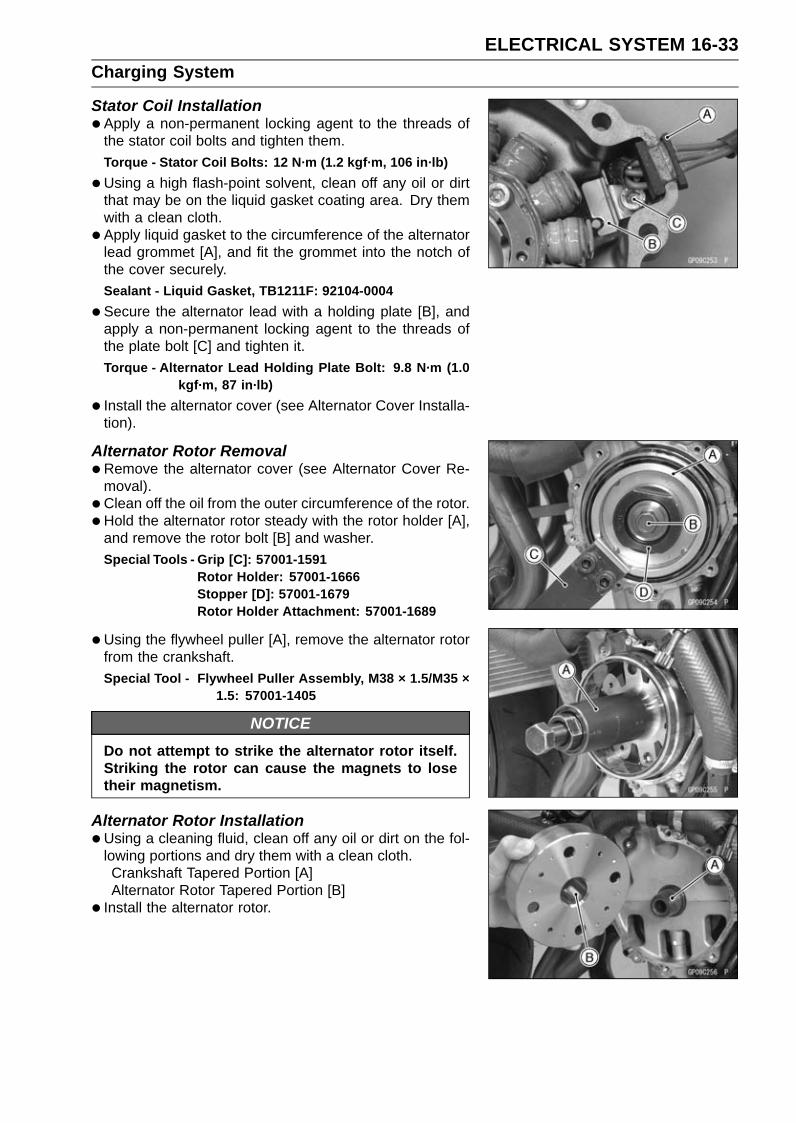
ELECTRICAL SYSTEM 16-33Charging System
Stator Coil Installation•Apply a non-permanent locking agent to the threads of
the stator coil bolts and tighten them.Torque - Stator Coil Bolts: 12 N·m (1.2 kgf·m, 106 in·lb)
•Using a high flash-point solvent, clean off any oil or dirtthat may be on the liquid gasket coating area. Dry themwith a clean cloth.
• Apply liquid gasket to the circumference of the alternatorlead grommet [A], and fit the grommet into the notch ofthe cover securely.Sealant - Liquid Gasket, TB1211F: 92104-0004
•Secure the alternator lead with a holding plate [B], andapply a non-permanent locking agent to the threads ofthe plate bolt [C] and tighten it.Torque - Alternator Lead Holding Plate Bolt: 9.8 N·m (1.0
kgf·m, 87 in·lb)
• Install the alternator cover (see Alternator Cover Installa-tion).
Alternator Rotor Removal•Remove the alternator cover (see Alternator Cover Re-
moval).• Clean off the oil from the outer circumference of the rotor.• Hold the alternator rotor steady with the rotor holder [A],
and remove the rotor bolt [B] and washer.Special Tools - Grip [C]: 57001-1591
Rotor Holder: 57001-1666Stopper [D]: 57001-1679Rotor Holder Attachment: 57001-1689
•Using the flywheel puller [A], remove the alternator rotorfrom the crankshaft.Special Tool - Flywheel Puller Assembly, M38 × 1.5/M35 ×
1.5: 57001-1405
NOTICEDo not attempt to strike the alternator rotor itself.Striking the rotor can cause the magnets to losetheir magnetism.
Alternator Rotor Installation•Using a cleaning fluid, clean off any oil or dirt on the fol-
lowing portions and dry them with a clean cloth.Crankshaft Tapered Portion [A]Alternator Rotor Tapered Portion [B]
• Install the alternator rotor.
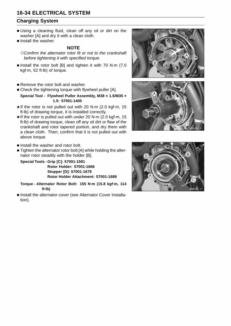
16-34 ELECTRICAL SYSTEMCharging System
•Using a cleaning fluid, clean off any oil or dirt on thewasher [A] and dry it with a clean cloth.
• Install the washer.
NOTEConfirm the alternator rotor fit or not to the crankshaft
before tightening it with specified torque.
• Install the rotor bolt [B] and tighten it with 70 N·m (7.0kgf·m, 52 ft·lb) of torque.
•Remove the rotor bolt and washer.•Check the tightening torque with flywheel puller [A].
Special Tool - Flywheel Puller Assembly, M38 × 1.5/M35 ×1.5: 57001-1405
If the rotor is not pulled out with 20 N·m (2.0 kgf·m, 15ft·lb) of drawing torque, it is installed correctly.If the rotor is pulled out with under 20 N·m (2.0 kgf·m, 15ft·lb) of drawing torque, clean off any oil dirt or flaw of thecrankshaft and rotor tapered portion, and dry them witha clean cloth. Then, confirm that it is not pulled out withabove torque.
• Install the washer and rotor bolt.• Tighten the alternator rotor bolt [A] while holding the alter-
nator rotor steadily with the holder [B].Special Tools - Grip [C]: 57001-1591
Rotor Holder: 57001-1666Stopper [D]: 57001-1679Rotor Holder Attachment: 57001-1689
Torque - Alternator Rotor Bolt: 155 N·m (15.8 kgf·m, 114ft·lb)
• Install the alternator cover (see Alternator Cover Installa-tion).
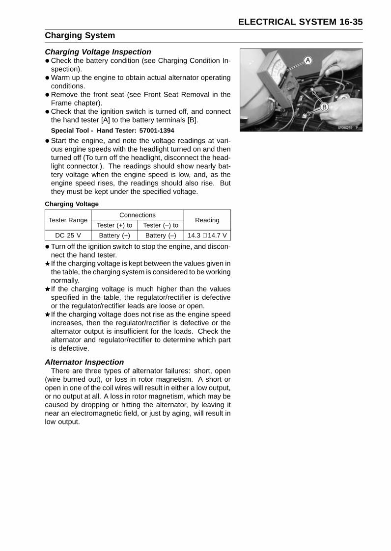
ELECTRICAL SYSTEM 16-35Charging System
Charging Voltage Inspection•Check the battery condition (see Charging Condition In-
spection).•Warm up the engine to obtain actual alternator operating
conditions.•Remove the front seat (see Front Seat Removal in the
Frame chapter).• Check that the ignition switch is turned off, and connect
the hand tester [A] to the battery terminals [B].Special Tool - Hand Tester: 57001-1394
•Start the engine, and note the voltage readings at vari-ous engine speeds with the headlight turned on and thenturned off (To turn off the headlight, disconnect the head-light connector.). The readings should show nearly bat-tery voltage when the engine speed is low, and, as theengine speed rises, the readings should also rise. Butthey must be kept under the specified voltage.
Charging VoltageConnections
Tester RangeTester (+) to Tester (–) to
Reading
DC 25 V Battery (+) Battery (–) 14.3 ∼ 14.7 V
• Turn off the ignition switch to stop the engine, and discon-nect the hand tester.If the charging voltage is kept between the values given inthe table, the charging system is considered to be workingnormally.If the charging voltage is much higher than the valuesspecified in the table, the regulator/rectifier is defectiveor the regulator/rectifier leads are loose or open.If the charging voltage does not rise as the engine speedincreases, then the regulator/rectifier is defective or thealternator output is insufficient for the loads. Check thealternator and regulator/rectifier to determine which partis defective.
Alternator InspectionThere are three types of alternator failures: short, open
(wire burned out), or loss in rotor magnetism. A short oropen in one of the coil wires will result in either a low output,or no output at all. A loss in rotor magnetism, which may becaused by dropping or hitting the alternator, by leaving itnear an electromagnetic field, or just by aging, will result inlow output.

16-36 ELECTRICAL SYSTEMCharging System
•To check the alternator output voltage, do the followingprocedures.Turn the ignition switch off.Remove the left inner cover (see Inner Cover Removal in
the Frame chapter).Disconnect the alternator lead connector [A].Connect the hand tester as shown in the table 1.
Special Tool - Hand Tester: 57001-1394Start the engine.Run it at the rpm given in the table 1.Note the voltage readings (total 3 measurements).
Table 1 Alternator Output Voltage at 4 000 r/min (rpm)ConnectionsTester
Range Tester (+) to Tester (–) toReading
AC 250 V One BK lead Another BK lead 46.4 V ormore
If the output voltage shows the value in the table, the al-ternator operates properly. The regulator/rectifier is dam-aged.If the output voltage shows a much lower reading thanthat given in the table, stop the engine and inspect thestator coil resistance.
•Check the stator coil resistance as follows.Stop the engine.Connect the hand tester as shown in the table 2.
Special Tool - Hand Tester: 57001-1394Note the readings (total 3 measurements).
Table 2 Stator Coil Resistance at 20°C (68°F)ConnectionsTester
Range Tester (+) to Tester (–) toReading
× 1 Ω One BK lead Another BK lead 0.11 ∼ 0.17 Ω
If there is more resistance than shown in the table, or nohand tester reading (infinity) for any two leads, the statorhas an open lead and must be replaced. Much less thanthis resistance means the stator is shorted, and must bereplaced.
•Using the highest resistance range of the hand tester,measure the resistance between each of the white leadsand chassis ground.Any hand tester reading less than infinity (∞) indicates ashort, necessitating stator replacement.If the stator coil has normal resistance, but the voltagecheck showed the alternator to be defective; then the rotormagnets have probably weakened, and the rotor must bereplaced.

ELECTRICAL SYSTEM 16-37Charging System
Regulator/Rectifier Inspection•Remove:
Left Inner Cover (see Inner Cover Removal in the Framechapter)Bolts [A]
•Disconnect the connectors [A].• Remove:
Regulator/Rectifier [B]
• Set the hand tester to the × 1 kΩ range and make themeasurements shown in the table.Special Tool - Hand Tester: 57001-1394
•Connect the hand tester to the regulator/rectifier.If the tester readings are not as specified, replace theregulator/rectifier.
NOTICEUse only Kawasaki Hand Tester 57001-1394 for thistest. A tester other than the Kawasaki Hand Testermay show different readings.If a megger or a meter with a large capacity batteryis used, the regulator/rectifier will be damaged.
Regulator/Rectifier Resistance (Unit: kΩ)Tester (+) Lead Connection
Terminal BK1 BK2 BK3 W BK/W BK/Y
BK1 – 2.5 ∼7.5
2.5 ∼7.5
3.0 ∼9.0
2.5 ∼7.5
1.5 ∼4.5
BK2 2.5 ∼7.5 – 2.5 ∼
7.53.0 ∼9.0
2.5 ∼7.5
1.5 ∼4.5
BK3 2.5 ∼7.5
2.5 ∼7.5 – 3.0 ∼
9.0 0 1.5 ∼4.5
W ∞ ∞ ∞ – ∞ ∞
BK/W 2.5 ∼7.5
2.5 ∼7.5 0 3.0 ∼
9.0 – 1.5 ∼4.5
(–)*
BK/Y 1.5 ∼4.5
1.5 ∼4.5
1.5 ∼4.5
3.5 ∼10.5
1.5 ∼4.5 –
(−)*: Tester (−) Lead Connection
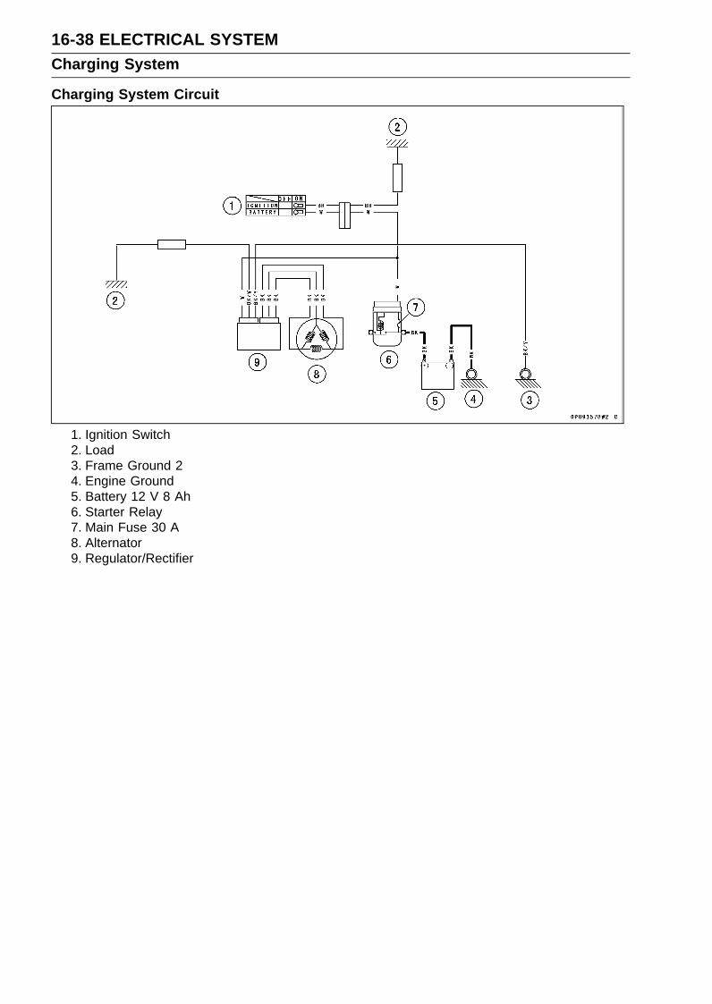
16-38 ELECTRICAL SYSTEMCharging System
Charging System Circuit
1. Ignition Switch2. Load3. Frame Ground 24. Engine Ground5. Battery 12 V 8 Ah6. Starter Relay7. Main Fuse 30 A8. Alternator9. Regulator/Rectifier

ELECTRICAL SYSTEM 16-39Ignition System
WARNINGThe ignition system produces extremely high volt-age. Do not touch the spark plug, ignition coil or ig-nition coil lead while the engine is running, or youcould receive a severe electrical shock.
NOTICEDo not disconnect the battery cables or any otherelectrical connections when the ignition switch ison, or while the engine is running. This is to preventECU damage.Do not install the battery backwards. The negativeside is grounded. This is to prevent damage to theECU.
Crankshaft Sensor Removal•Remove:
Fuel Tank (see Fuel Tank Removal in the Fuel System(DFI) chapter)
•Disconnect the crankshaft sensor lead connector [A].
• Remove:Idle Gear (Starter Clutch Side) (see Starter Idle GearRemoval in the Crankshaft/Transmission chapter)Bolts [A]Crankshaft Sensor Lead Grommet [B]Crankshaft Sensor [C]
Crankshaft Sensor Installation•Tighten:
Torque - Crankshaft Sensor Bolts [A]: 5.9 N·m (0.60 kgf·m,52 in·lb)
•Using a high flash-point solvent, clean off any oil or dirtthat may be on the liquid gasket coating area. Dry themwith a clean cloth.
• Apply liquid gasket to the circumference of the crankshaftsensor lead grommet [B], and fit the grommet into thenotch of the crankcase securely.Sealant - Liquid Gasket, TB1211F: 92104-0004
•Run the crankshaft sensor lead correctly (see Cable,Wire, and Hose Routing section in the Appendix chapter).
• Install the removed parts (see appropriate chapters).

16-40 ELECTRICAL SYSTEMIgnition System
Crankshaft Sensor Inspection•Disconnect the crankshaft sensor lead connector (see
Crankshaft Sensor Removal).• Set the hand tester [A] to the × 10 Ω range and connect it
to the crankshaft sensor lead connector [B].Special Tool - Hand Tester: 57001-1394
Crankshaft Sensor ResistanceConnections:
Meter (+) → BK/Y leadMeter (–) → BK lead
Standard: 368 ∼ 552 Ω
If there is more resistance than the specified value, thecoil has an open lead and must be replaced. Much lessthan this resistance means the coil is shorted, and mustbe replaced.
•Using the highest resistance range of the tester, measurethe resistance between the crankshaft sensor leads andchassis ground.Any tester reading less than infinity (∞) indicates a short,necessitating replacement of the crankshaft sensor.
Crankshaft Sensor Peak Voltage InspectionNOTE
Be sure the battery is fully charged.Using the peak voltage adapter [A] is more reliable way
to determine the condition of the crankshaft sensor thancrankshaft sensor internal resistance measurements.
•Disconnect the crankshaft sensor lead connector (seeCrankshaft Sensor Removal).
• Set the hand tester [B] to the DC 10 V range, and connectit peak voltage adapter.Special Tools - Hand Tester: 57001-1394
Peak Voltage Adapter: 57001-1415Type: KEK-54-9-B
•Connect the adapter to the terminals of the crankshaftsensor lead connector [C].
Connections:Crankshaft Sensor
Lead ConnectorPeak Voltage
Adapter Hand Tester
BK/Y lead ← R lead → (+)BK lead ← BK lead → (–)
•Turn the engine stop switch to run position.• Turn the ignition switch on.• Pushing the starter button, turn the engine 4 ∼ 5 seconds
with the transmission in neutral to measure the crankshaftsensor peak voltage.
•Repeat the measurements 5 or more times.
Crankshaft Sensor Peak VoltageStandard: 2.6 V or more
If the reading is less than the standard, inspect the crank-shaft sensor (see Crankshaft Sensor Inspection).

ELECTRICAL SYSTEM 16-41Ignition System
Stick Coil Removal•Remove the air cleaner housing (see Air Cleaner Housing
Removal in the Fuel System (DFI) chapter).• Disconnect the stick coil connectors [A].• Pull out the stick coils [B] upward.First, turn the stick coil by 90 degrees, and then pull it out
by twisting the coil head to the left and right while holdingit securely by hand.
NOTICEDo not pry the connector part of the coil while re-moving the coil.
Stick Coil Installation•Apply a thin coat of grease [A] to the stick coils for easy
installation.• Insert the stick coils [B] so that the coil heads align with
the lines [C] on the cylinder head cover.
NOTICEDo not tap the coil head while installing the coil.
•After installation, be sure the stick coils are installed se-curely by pulling up them lightly.
• Run the leads correctly (see Cable, Wire, and Hose Rout-ing section in the Appendix chapter).
• Install the removed parts (see appropriate chapters).
Stick Coil Inspection•Remove the stick coils (see Stick Coil Removal).•Measure the primary winding resistance [A] as follows.Connect the hand tester between the coil terminals.Set the tester to the × 1 Ω range, and read the tester.•Measure the secondary winding resistance [B] as follows.Connect the tester between the plug terminal and (–) coil
terminal.Set the tester to the × 1 kΩ range and read the tester.
Stick Coil Winding ResistancePrimary Windings: 0.85 ∼ 1.15 ΩSecondary Windings: 5.0 ∼ 6.8 kΩ
If the tester does not read as specified, replace the coil.
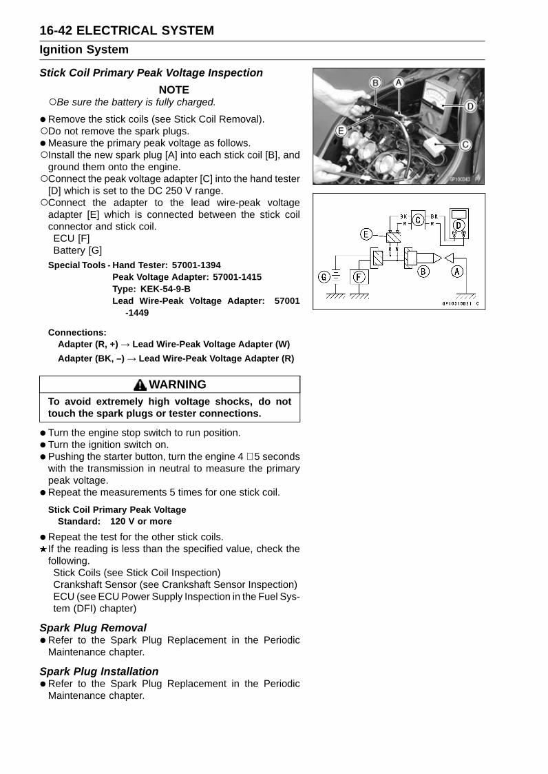
16-42 ELECTRICAL SYSTEMIgnition System
Stick Coil Primary Peak Voltage InspectionNOTE
Be sure the battery is fully charged.
•Remove the stick coils (see Stick Coil Removal).Do not remove the spark plugs.•Measure the primary peak voltage as follows.Install the new spark plug [A] into each stick coil [B], and
ground them onto the engine.Connect the peak voltage adapter [C] into the hand tester
[D] which is set to the DC 250 V range.Connect the adapter to the lead wire-peak voltage
adapter [E] which is connected between the stick coilconnector and stick coil.ECU [F]Battery [G]
Special Tools - Hand Tester: 57001-1394Peak Voltage Adapter: 57001-1415Type: KEK-54-9-BLead Wire-Peak Voltage Adapter: 57001
-1449
Connections:Adapter (R, +) → Lead Wire-Peak Voltage Adapter (W)Adapter (BK, –) → Lead Wire-Peak Voltage Adapter (R)
WARNINGTo avoid extremely high voltage shocks, do nottouch the spark plugs or tester connections.
•Turn the engine stop switch to run position.• Turn the ignition switch on.• Pushing the starter button, turn the engine 4 ∼ 5 seconds
with the transmission in neutral to measure the primarypeak voltage.
•Repeat the measurements 5 times for one stick coil.
Stick Coil Primary Peak VoltageStandard: 120 V or more
•Repeat the test for the other stick coils.If the reading is less than the specified value, check thefollowing.Stick Coils (see Stick Coil Inspection)Crankshaft Sensor (see Crankshaft Sensor Inspection)ECU (see ECU Power Supply Inspection in the Fuel Sys-tem (DFI) chapter)
Spark Plug Removal•Refer to the Spark Plug Replacement in the Periodic
Maintenance chapter.
Spark Plug Installation•Refer to the Spark Plug Replacement in the Periodic
Maintenance chapter.

ELECTRICAL SYSTEM 16-43Ignition System
Spark Plug Condition Inspection•Remove the spark plugs (see Spark Plug Replacement in
the Periodic Maintenance chapter).• Visually inspect the spark plugs.
If the spark plug center electrode [A] and/or side elec-trode [B] are corroded or damaged, or if the insulator [C]is cracked, replace the plug.If the spark plug is dirtied or the carbon is accumulated,replace the spark plug.
•Measure the gap [D] with a wire-type thickness gauge.If the gap is incorrect, replace the spark plug.
Spark Plug Gap: 0.7 ∼ 0.8 mm (0.028 ∼ 0.031 in.)
•Use the standard spark plug or its equivalent.
Standard Spark PlugType: NGK CR9E
Interlock Operation Inspection•Raise the rear wheel off the ground with the stand [A].
1st Check•Start the engine to the following conditions.
Condition:Transmission Gear → 1st PositionClutch Lever → ReleaseSidestand → Down or Up
Turn the ignition switch on and push the starter button.Then the starter motor should not turn when the starter
system circuit is normality.If the engine is started, inspect the starter lockout switch,gear position switch and relay box.
2nd Check•Start the engine to the following conditions.
Condition:Transmission Gear → 1st PositionClutch Lever → Pulled inSidestand → Up
Turn the ignition switch on and push the starter button.Then the starter motor should turn when the starter sys-
tem circuit is normality.If the starter motor does not turn, inspect the starter lock-out switch, sidestand switch, relay box and starter relay.
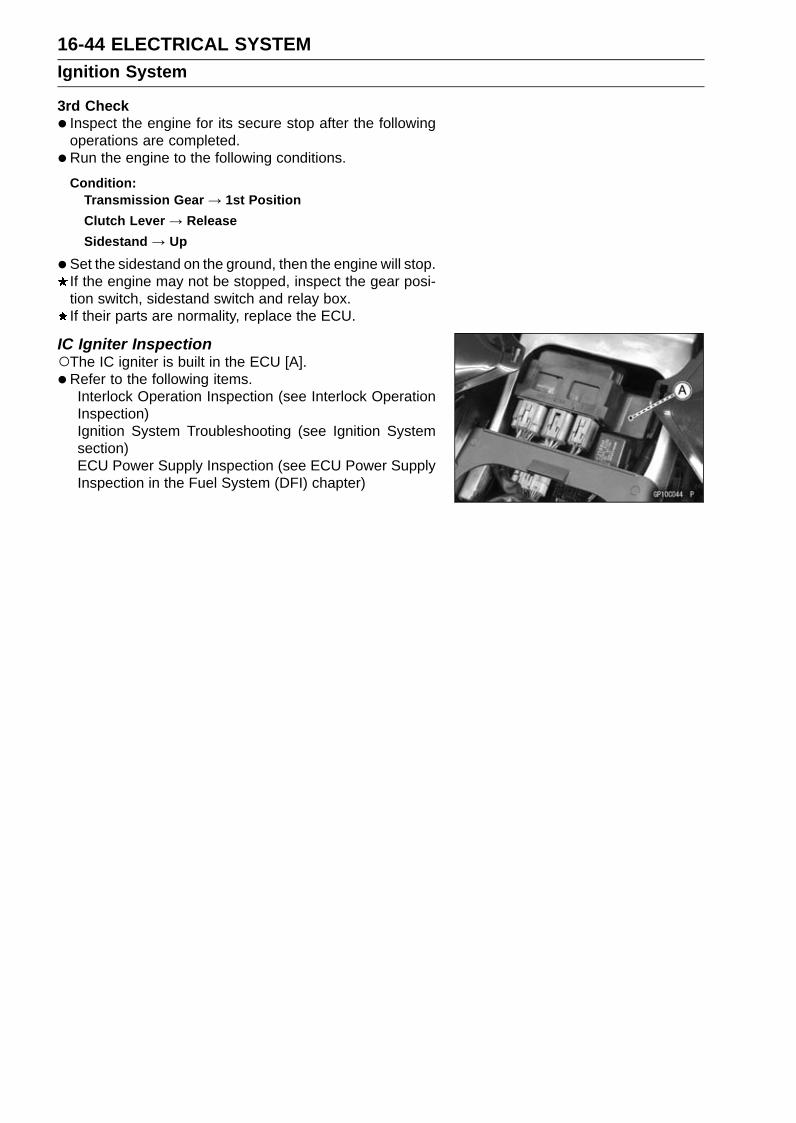
16-44 ELECTRICAL SYSTEMIgnition System
3rd Check• Inspect the engine for its secure stop after the following
operations are completed.•Run the engine to the following conditions.
Condition:Transmission Gear → 1st PositionClutch Lever → ReleaseSidestand → Up
•Set the sidestand on the ground, then the engine will stop.If the engine may not be stopped, inspect the gear posi-tion switch, sidestand switch and relay box.If their parts are normality, replace the ECU.
IC Igniter InspectionThe IC igniter is built in the ECU [A].• Refer to the following items.
Interlock Operation Inspection (see Interlock OperationInspection)Ignition System Troubleshooting (see Ignition Systemsection)ECU Power Supply Inspection (see ECU Power SupplyInspection in the Fuel System (DFI) chapter)

ELECTRICAL SYSTEM 16-45Ignition System
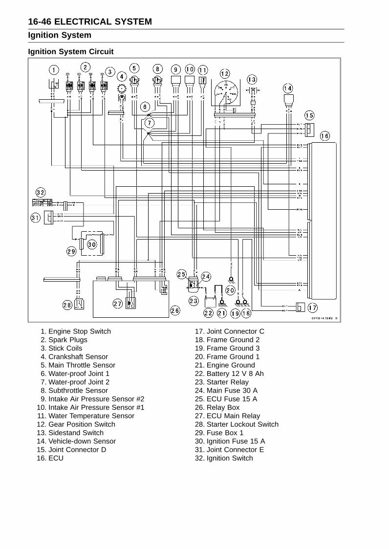
16-46 ELECTRICAL SYSTEMIgnition System
Ignition System Circuit
1. Engine Stop Switch2. Spark Plugs3. Stick Coils4. Crankshaft Sensor5. Main Throttle Sensor6. Water-proof Joint 17. Water-proof Joint 28. Subthrottle Sensor9. Intake Air Pressure Sensor #2
10. Intake Air Pressure Sensor #111. Water Temperature Sensor12. Gear Position Switch13. Sidestand Switch14. Vehicle-down Sensor15. Joint Connector D16. ECU
17. Joint Connector C18. Frame Ground 219. Frame Ground 320. Frame Ground 121. Engine Ground22. Battery 12 V 8 Ah23. Starter Relay24. Main Fuse 30 A25. ECU Fuse 15 A26. Relay Box27. ECU Main Relay28. Starter Lockout Switch29. Fuse Box 130. Ignition Fuse 15 A31. Joint Connector E32. Ignition Switch

ELECTRICAL SYSTEM 16-47Electric Starter System
Starter Motor Removal•Remove:
Fuel Tank (see Fuel Tank Removal in the Fuel System(DFI) chapter)Starter Clutch Cover (see Starter Idle Gear Removal inthe Crankshaft/Transmission chapter)
• For KIBS equipped models, remove the KIBS hydraulicunit (see KIBS Hydraulic Unit Removal in the Brakeschapter).
• Slide out the rubber cap [A].• Remove the starter motor cable terminal bolt [B].• Remove the starter motor mounting bolts [C].• Remove the starter motor [D] from the right side of the
motorcycle.
Starter Motor InstallationNOTICE
Do not tap the starter motor shaft or body. Tappingthe shaft or body could damage the motor.
•Clean the starter motor legs [A] and crankcase [B] wherethe starter motor is ground.
•Replace the O-ring [A] with a new one.• Apply grease to the new O-ring.• Tighten the starter motor mounting bolts temporarily.• Install the starter clutch cover (see Starter Idle Gear In-
stallation in the Crankshaft/Transmission chapter).• Tighten:
Torque - Starter Motor Mounting Bolts: 9.8 N·m (1.0 kgf·m,87 in·lb)

16-48 ELECTRICAL SYSTEMElectric Starter System
• Install the starter motor cable [A] as shown.• Tighten:
Torque - Starter Motor Cable Terminal Bolt [B]: 2.9 N·m(0.30 kgf·m, 26 in·lb)
•Slide back the rubber cap to the original position.• Install the removed parts (see appropriate chapters).
Starter Motor Disassembly•Remove:
Starter Motor (see Starter Motor Removal)Starter Motor Through Bolts [A]
•Remove:Right-hand End Cover [A]Left-hand End Cover [B]Armature [C]Yoke [D]
Starter Motor Assembly•Apply a thin coat of grease to the oil seal [A].• Fit the dent [B] of the toothed washer [C] on the projection
right-hand end cover.• Install the washer [D].

ELECTRICAL SYSTEM 16-49Electric Starter System
•Press the springs holding the brush leads with suitableclips [A] as shown.
• Put the armature [B] among the brushes.
• Install the new O-rings [A] as shown.
• Align the groove [A] in the left-hand end cover and thehollow mark [B] on the yoke.
• Align the hollow mark [A] on the right-hand end cover andthe hollow mark [B] on the yoke.
Brush Inspection•Measure the length [A] of each brush.
If any is worn down to the service limit, replace the left-hand end cover assembly.
Starter Motor Brush LengthStandard: 7 mm (0.28 in.)Service Limit: 5 mm (0.20 in.)

16-50 ELECTRICAL SYSTEMElectric Starter System
Commutator Cleaning and Inspection•Smooth the commutator surface [A] if necessary with fine
emery cloth [B], and clean out the grooves.
•Measure the diameter [A] of the commutator [B].If the commutator diameter is less than the service limit,replace the starter motor with a new one .
Commutator DiameterStandard: 24 mm (0.94 in.)Service Limit: 23 mm (0.91 in.)
Armature Inspection•Using the × 1 Ω hand tester range, measure the resis-
tance between any two commutator segments [A].Special Tool - Hand Tester: 57001-1394If there is a high resistance or no reading (∞) between anytwo segments, a winding is open and the starter motormust be replaced.
•Using the highest hand tester range, measure the resis-tance between the segments and the shaft [B].If there is any reading at all, the armature has a short andthe starter motor must be replaced.
NOTEEven if the foregoing checks show the armature to be
good, it may be defective in some manner not readilydetectable with the hand tester. If all other starter motorand starter motor circuit components check good, butthe starter motor still does not turn over or only turnsover weakly, replace the starter motor with a new one.
Brush Lead Inspection•Using the × 1 Ω hand tester range, measure the resis-
tance as shown.Terminal and Positive Brush [A]Left-hand End Cover and Negative Brush [B]
Special Tool - Hand Tester: 57001-1394If there is not close to zero ohms, the brush lead has anopen. Replace the left-hand end cover assembly.
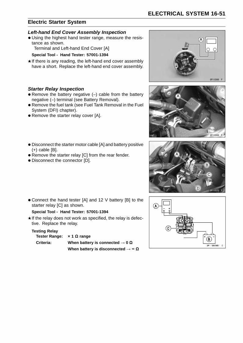
ELECTRICAL SYSTEM 16-51Electric Starter System
Left-hand End Cover Assembly Inspection•Using the highest hand tester range, measure the resis-
tance as shown.Terminal and Left-hand End Cover [A]
Special Tool - Hand Tester: 57001-1394If there is any reading, the left-hand end cover assemblyhave a short. Replace the left-hand end cover assembly.
Starter Relay Inspection•Remove the battery negative (–) cable from the battery
negative (–) terminal (see Battery Removal).• Remove the fuel tank (see Fuel Tank Removal in the Fuel
System (DFI) chapter).• Remove the starter relay cover [A].
• Disconnect the starter motor cable [A] and battery positive(+) cable [B].
• Remove the starter relay [C] from the rear fender.•Disconnect the connector [D].
• Connect the hand tester [A] and 12 V battery [B] to thestarter relay [C] as shown.Special Tool - Hand Tester: 57001-1394If the relay does not work as specified, the relay is defec-tive. Replace the relay.
Testing RelayTester Range: × 1 Ω rangeCriteria: When battery is connected → 0 Ω
When battery is disconnected → ∞ Ω
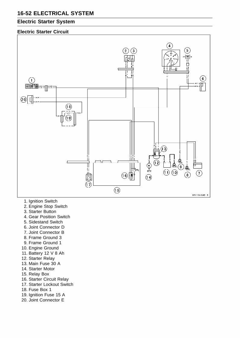
16-52 ELECTRICAL SYSTEMElectric Starter System
Electric Starter Circuit
1. Ignition Switch2. Engine Stop Switch3. Starter Button4. Gear Position Switch5. Sidestand Switch6. Joint Connector D7. Joint Connector B8. Frame Ground 39. Frame Ground 1
10. Engine Ground11. Battery 12 V 8 Ah12. Starter Relay13. Main Fuse 30 A14. Starter Motor15. Relay Box16. Starter Circuit Relay17. Starter Lockout Switch18. Fuse Box 119. Ignition Fuse 15 A20. Joint Connector E

ELECTRICAL SYSTEM 16-53Lighting System
This motorcycle adopt the daylight system and have aheadlight relay in the relay box. The headlight does notgo on when the ignition switch and the engine stop switchare first turned on. The headlight comes on after the starterbutton is released and stays on until the ignition switch isturned off. The headlight will go out momentarily wheneverthe starter button is pressed and come back on when thebutton is released.
Headlight Beam Horizontal Adjustment•Refer to the Headlight Aiming Inspection in the Periodic
Maintenance chapter.
Headlight Beam Vertical Adjustment•Refer to the Headlight Aiming Inspection in the Periodic
Maintenance chapter.
Headlight Bulb Replacement•Disconnect:
Dust Cover [A]
•Disconnect:Headlight Connector [A]Hook [B]
•Remove:Headlight Bulb
NOTICEWhen handling the quartz-halogen bulb, nevertouch the glass portion with bare hands. Alwaysuse a clean cloth. Oil contamination from hands ordirty rags can reduce bulb life or cause the bulb toexplode.
NOTEClean off any contamination that inadvertently gets on
the bulb with alcohol or soap and water solution.
•Replace the headlight bulb with a new one.• Fit the projection [A] of the bulb in the hollow [B] of the
headlight.• Install the hook.
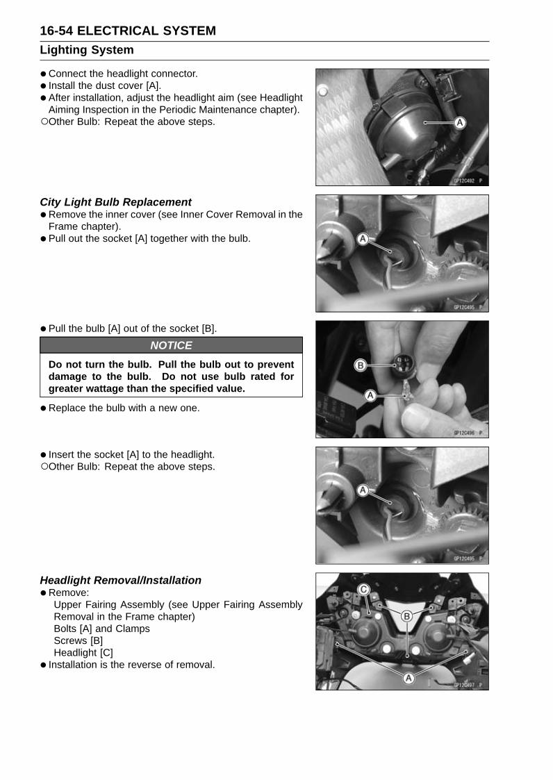
16-54 ELECTRICAL SYSTEMLighting System
•Connect the headlight connector.• Install the dust cover [A].• After installation, adjust the headlight aim (see Headlight
Aiming Inspection in the Periodic Maintenance chapter).Other Bulb: Repeat the above steps.
City Light Bulb Replacement•Remove the inner cover (see Inner Cover Removal in the
Frame chapter).• Pull out the socket [A] together with the bulb.
• Pull the bulb [A] out of the socket [B].
NOTICEDo not turn the bulb. Pull the bulb out to preventdamage to the bulb. Do not use bulb rated forgreater wattage than the specified value.
•Replace the bulb with a new one.
• Insert the socket [A] to the headlight.Other Bulb: Repeat the above steps.
Headlight Removal/Installation•Remove:
Upper Fairing Assembly (see Upper Fairing AssemblyRemoval in the Frame chapter)Bolts [A] and ClampsScrews [B]Headlight [C]
• Installation is the reverse of removal.

ELECTRICAL SYSTEM 16-55Lighting System
Tail/Brake Light (LED) Removal/Installation•Remove:
Tail/Brake Light Cover (see Rear Fender Removal in theFrame chapter)
• Slide the dust cover [A].•Open the clamp [B].• Disconnect the tail/brake light lead connector [C].• Remove:
Bolts [D] and ClampTail/Brake Light (LED) [E]
• Installation is the reverse of removal.• Run the lead correctly (see Cable, Wire, and Hose Rout-
ing section in the Appendix chapter).
License Plate Light Bulb Replacement•Remove:
License Plate Light Cover Screws [A]License Plate Light Cover [B]
• Pull the bulb [A] out of the socket [B].
NOTICEDo not turn the bulb. Pull the bulb out to preventdamage to the bulb. Do not use bulb rated forgreater wattage than the specified value.
•Replace the bulb with a new one.• Tighten:
Torque - License Plate Light Cover Screws: 1.0 N·m (0.10kgf·m, 8.9 in·lb)

16-56 ELECTRICAL SYSTEMLighting System
Headlight/Tail Light Circuit
1. Ignition Switch2. Frame Ground 13. Tail/Brake Light (LED)4. License Plate Light 12 V 5 W5. Joint Connector B6. Frame Ground 37. Frame Ground 28. Engine Ground9. Battery 12 V 8 Ah
10. Starter Relay11. Main Fuse 30 A12. Alternator13. Regulator/Rectifier14. Relay Box
15. Headlight Circuit Relay16. Fuse Box 117. Brake Light/Horn Fuse 7.5 A18. Ignition Fuse 15 A19. Dimmer Switch20. Passing Button21. Left City Light 12 V 5 W22. Headlight (HI) 12 V 55 W23. Headlight (LO) 12 V 55 W24. Right City Light 12 V 5 W25. Joint Connector A26. Meter Unit27. Blue High Beam Indicator Light (LED)

ELECTRICAL SYSTEM 16-57Lighting System
Turn Signal Light Bulb ReplacementFront Turn Signal Light•Remove:
Upper Fairing Assembly (see Upper Fairing AssemblyRemoval in the Frame chapter)Front Turn Signal Light Screws [A]Front Turn Signal Light [B]
• Turn the socket [A] counterclockwise and pull out thesocket together with the bulb.
• Push and turn the front turn signal light bulb [A] counter-clockwise and remove it.
• Replace the bulb with a new one.
• Insert the new bulb [A] by aligning its left and right pins [B]with the left and right grooves [C] in the socket, and turnthe bulb clockwise.Turn the bulb about 15°.
• Fit the large projection [A] of the socket into the largegroove [B] of the turn signal light.Small Projection [C]
• Turn the front turn signal light bulb clockwise.

16-58 ELECTRICAL SYSTEMLighting System
• Install:Front Turn Signal Light [A]Bracket [B]
• Tighten:Torque - Front Turn Signal Light Mounting Screws [C]: 1.2
N·m (0.12 kgf·m, 11 in·lb)Other Bulb: Repeat the above steps.
Rear Turn Signal Light•Remove:
Screw [A]Rear Turn Signal Light Lens
•Push and turn the rear turn signal light bulb [A] counter-clockwise and remove it.
• Replace the bulb with a new one.
• Insert the new bulb [A] by aligning its left and right pins [B]with the left and right grooves [C] in the socket, and turnthe bulb clockwise.Turn the bulb about 15°.
• Fit the projection [A] of the lens into the groove [B] of theturn signal light.
• Tighten the screw.Other Bulb: Repeat the above steps.

ELECTRICAL SYSTEM 16-59Lighting System
Turn Signal Relay Inspection•Remove the front seat cover (see Seat Cover Removal in
the Frame chapter).• Pull out the turn signal relay [A] backward, and remove it
from the rear fender.•Disconnect the connector.
• Connect one 12 V battery and turn signal lights as indi-cated, and count how many times the lights blink for oneminute.Turn Signal Relay [A]Turn Signal Lights [B]12 V Battery [C]
If the lights do not blink as specified, replace the turn sig-nal relay.
Testing Turn Signal RelayLoad
The Number of TurnSignal Lights Wattage (W)
Blinking Times(c/m*)
1** 10 140 ∼ 2502 20 75 ∼ 95
(*): Cycle(s) per minute(**): Corrected to “one light burned out”.

16-60 ELECTRICAL SYSTEMLighting System
Turn Signal Light Circuit
1. Ignition Switch2. Rear Right Turn Signal Light 12 V 10 W3. Rear Left Turn Signal Light 12 V 10 W4. Joint Connector B5. Frame Ground 36. Frame Ground 17. Engine Ground8. Battery 12 V 8 Ah9. Starter Relay
10. Main Fuse 30 A11. Turn Signal Relay12. Turn Signal Switch13. Fuse Box 214. Turn Signal Relay Fuse 7.5 A15. Front Left Turn Signal Light 12 V 10 W16. Front Right Turn Signal Light 12 V 10 W17. Joint Connector A18. Meter Unit19. Green Turn Signal Indicator Light (LED)

ELECTRICAL SYSTEM 16-61Air Switching Valve
Air Switching Valve Operation Test•Refer to the Air Suction System Damage Inspection in the
Periodic Maintenance chapter.
Air Switching Valve Unit Test•Remove the air switching valve (see Air Switching Valve
Removal in the Engine Top End chapter).• Set the hand tester [A] to the × 1 Ω range and connect it
to the air switching valve terminals as shown.Special Tool - Hand Tester: 57001-1394
Air Switching Valve ResistanceStandard: 20 ∼ 24 Ω at 20°C (68°F)
If the resistance reading is out of the specified value, re-place it with a new one.
•Connect the 12 V battery [A] to the air switching valveterminals as shown.
• Blow the air to the intake air duct [A], and make sure doesnot flow the blown air from the outlet air ducts [B].
• Disconnect the 12 V battery.• Blow the air to the intake air duct [A] again, and make sure
flow the blown air from the outlet air ducts [B].If the air switching valve dose not operate as described,replace it with a new one.
NOTETo check air flow through the air switching valve, just
blow through the air switching valve hose (intake side)[C].

16-62 ELECTRICAL SYSTEMAir Switching Valve
Air Switching Valve Circuit
1. Ignition Switch2. Air Switching Valve3. Joint Connector D4. ECU5. Frame Ground 36. Engien Ground7. Battery 12 V 8 Ah8. Starter Relay9. Main Fuse 30 A
10. ECU Fuse 15 A11. Frame Ground 112. Relay Box13. ECU Main Relay14. Fuse Box 115. Ignition Fuse 15 A16. Joint Connector E

ELECTRICAL SYSTEM 16-63Radiator Fan System
Fan Motor Inspection•Remove the air cleaner housing (see Air Cleaner Housing
Removal in the Fuel System (DFI) chapter).• Slide the dust cover [A].• Disconnect the connector [B].• Using an auxiliary leads, supply battery power to the fan
motor.If the fan does not rotate, the fan motor is defective andmust be replaced.
Radiator Fan Circuit
1. Ignition Switch2. Fan Motor3. Water Temperature Sensor4. Water-proof Joint 25. Joint Connector D6. ECU7. Frame Ground 38. Engine Ground9. Battery 12 V 8 Ah
10. Starter Relay11. Main Fuse 30 A12. Frame Ground 113. Relay Box14. Radiator Fan Relay15. Fuse Box 116. Ignition Fuse 15 A17. Fan Fuse 15 A18. Joint Connector E

16-64 ELECTRICAL SYSTEMMeter, Gauge, Indicator Unit
Meter Unit Removal/Installation•Remove:
Upper Fairing Assembly (see Upper Fairing AssemblyRemoval in the Frame chapter)
•Disconnect:Meter Unit Connector [A]Immobilizer Amplifier Connector [B] (Equipped Models)
•Remove the bolts [C].
• Remove:Bolts [A]CollarMeter Bracket with Meter Unit [B]
•Remove:Meter Unit Mounting Screws [A]Meter Unit [B]
NOTICEPlace the meter unit so that the face is up. If a meterunit is left upside down or sideways for any lengthof time, it will malfunction.
• Installation is the reverse of removal.• Tighten:
Torque - Meter Unit Mounting Screws: 1.2 N·m (0.12 kgf·m,11 in·lb)
•Run the lead correctly (see Cable, Wire, and Hose Rout-ing section in the Appendix chapter).
Meter Unit Disassembly•Remove:
Meter Unit (see Meter Unit Removal/Installation)Screws [A]Lower Meter Cover [B]
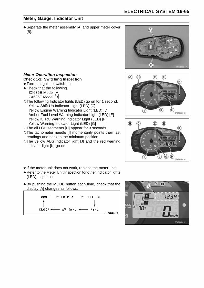
ELECTRICAL SYSTEM 16-65Meter, Gauge, Indicator Unit
•Separate the meter assembly [A] and upper meter cover[B].
Meter Operation InspectionCheck 1-1: Switching Inspection•Turn the ignition switch on.•Check that the following.
ZX636E Model [A]ZX636F Model [B]
The following Indicator lights (LED) go on for 1 second.Yellow Shift Up Indicator Light (LED) [C]Yellow Engine Warning Indicator Light (LED) [D]Amber Fuel Level Warning Indicator Light (LED) [E]Yellow KTRC Warning Indicator Light (LED) [F]Yellow Warning Indicator Light (LED) [G]
The all LCD segments [H] appear for 3 seconds.The tachometer needle [I] momentarily points their last
readings and back to the minimum position.The yellow ABS indicator light [J] and the red warning
indicator light [K] go on.
If the meter unit does not work, replace the meter unit.• Refer to the Meter Unit Inspection for other indicator lights
(LED) inspection.
• By pushing the MODE button each time, check that thedisplay [A] changes as follows.

16-66 ELECTRICAL SYSTEMMeter, Gauge, Indicator Unit
• Indicate the ODO mode.• By pushing the RESET button each time while the MODE
button pushed in, check that the display [A] changes asfollows.
NOTEMile/Km Display can alternate between English and
metric modes (mile and km) in the digital meter. Makesure that km or mile according to local regulations iscorrectly displayed before riding.
If the display function does not work, replace the meterunit.
• By pushing (0.3 ∼ 0.4 seconds) the KTRC button [A] atthe left handlebar switch housing each time, check thatthe KTRC indicator symbol changes to going on.If the indicator symbol does not work, check the followingparts.KTRC Button (see Switch Inspection)Wiring (see Meter Unit Circuit)
If the above parts are good, replace the meter unit and/orECU.

ELECTRICAL SYSTEM 16-67Meter, Gauge, Indicator Unit
•By pushing (0.3 ∼ 0.4 seconds) the power mode button[A] at the left handlebar switch housing each time, checkthat the power mode symbol changes to going on.If the display function does not work, check the followingparts.Power Mode Button (see Switch Inspection)Wiring (see Meter Unit Circuit)
If the above parts are good, replace the meter unit and/orECU.
Check 1-2: Gear Position Indication Inspection•Turn the ignition switch on.The green neutral indicator light (LED) [A] goes on when
the transmission gear is neutral position.
• Set the low gear position, and check that the displaychanges to 1 mark [A] and the green neutral indicatorlight (LED) goes off.
• Using the suitable stand, raise the rear wheel off theground.
•Rotate the rear wheel by hand or start the engine, andchange the gear position.
•Check that the display corresponding to each gear posi-tion (1, 2, 3, 4, 5 or 6) appears.If the display function does not work, check the followingparts.Gear Position Switch (see Gear Position Switch Inspec-tion)Wiring (see Meter Unit Circuit)
If the above parts are good, replace the meter unit and/orECU.

16-68 ELECTRICAL SYSTEMMeter, Gauge, Indicator Unit
Meter System InspectionCheck 2-1: Speedometer Inspection•Using the suitable stand, raise the rear wheel off the
ground.•Rotate the rear wheel by hand or start the engine.•Check that the display changes speedometer.
If the display function does not work, check the followingparts.Rear Wheel Rotation Sensor (see Wheel Rotation Sen-sor Inspection in the Brakes chapter)ECU (ECU Power Supply Inspection in the Fuel System(DFI) chapter)Wiring (see Meter Unit Circuit)
If the above parts are good, replace the meter unit.
Check 2-2: Fuel Level Warning Inspection•Disconnect the fuel pump lead connector [A] (see Fuel
Tank Removal in the Fuel System (DFI) chapter).Main Harness [B]
•Connect the resistor [C] (about 100 Ω) to the fuel pumplead connector terminal as shown in the figure.
• Turn the ignition switch on.• After about 5 seconds, amber fuel level warning indicator
light (LED) [A] goes on and “FUEL” [B] blinks.If the display and indicator light (LED) function does notwork, replace the meter unit.
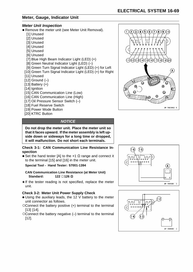
ELECTRICAL SYSTEM 16-69Meter, Gauge, Indicator Unit
Meter Unit Inspection•Remove the meter unit (see Meter Unit Removal).
[1] Unused[2] Unused[3] Unused[4] Unused[5] Unused[6] Unused[7] Blue High Beam Indicator Light (LED) (+)[8] Green Neutral Indicator Light (LED) (–)[9] Green Turn Signal Indicator Light (LED) (+) for Left
[10] Green Turn Signal Indicator Light (LED) (+) for Right[11] Unused[12] Ground (–)[13] Battery (+)[14] Ignition[15] CAN Communication Line (Low)[16] CAN Communication Line (High)[17] Oil Pressure Sensor Switch (–)[18] Fuel Reserve Switch[19] Power Mode Button[20] KTRC Button
NOTICEDo not drop the meter unit. Place the meter unit sothat it faces upward. If the meter assembly is left up-side down or sideways for a long time or dropped,it will malfunction. Do not short each terminals.
Check 3-1: CAN Communication Line Resistance In-spection•Set the hand tester [A] to the ×1 Ω range and connect it
to the terminal [15] and [16] in the meter unit.Special Tool - Hand Tester: 57001-1394
CAN Communication Line Resistance (at Meter Unit)Standard: 122 ∼ 126 Ω
If the tester reading is not specified, replace the meterunit.
Check 3-2: Meter Unit Power Supply Check•Using the auxiliary leads, the 12 V battery to the meter
unit connector as follows.Connect the battery positive (+) terminal to the terminal
[13] [14].Connect the battery negative (–) terminal to the terminal
[12].
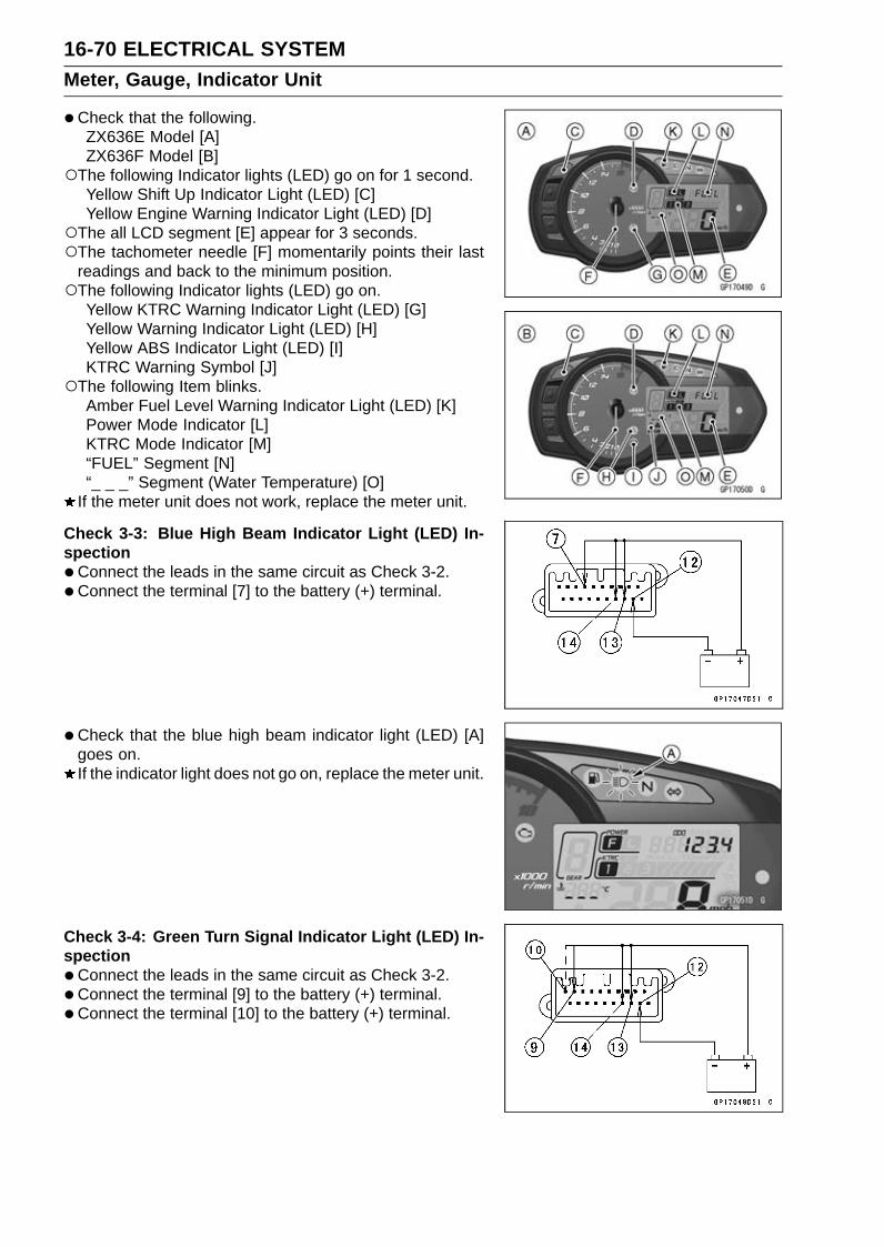
16-70 ELECTRICAL SYSTEMMeter, Gauge, Indicator Unit
•Check that the following.ZX636E Model [A]ZX636F Model [B]
The following Indicator lights (LED) go on for 1 second.Yellow Shift Up Indicator Light (LED) [C]Yellow Engine Warning Indicator Light (LED) [D]
The all LCD segment [E] appear for 3 seconds.The tachometer needle [F] momentarily points their last
readings and back to the minimum position.The following Indicator lights (LED) go on.
Yellow KTRC Warning Indicator Light (LED) [G]Yellow Warning Indicator Light (LED) [H]Yellow ABS Indicator Light (LED) [I]KTRC Warning Symbol [J]
The following Item blinks.Amber Fuel Level Warning Indicator Light (LED) [K]Power Mode Indicator [L]KTRC Mode Indicator [M]“FUEL” Segment [N]“_ _ _” Segment (Water Temperature) [O]
If the meter unit does not work, replace the meter unit.
Check 3-3: Blue High Beam Indicator Light (LED) In-spection•Connect the leads in the same circuit as Check 3-2.•Connect the terminal [7] to the battery (+) terminal.
• Check that the blue high beam indicator light (LED) [A]goes on.If the indicator light does not go on, replace the meter unit.
Check 3-4: Green Turn Signal Indicator Light (LED) In-spection•Connect the leads in the same circuit as Check 3-2.•Connect the terminal [9] to the battery (+) terminal.• Connect the terminal [10] to the battery (+) terminal.

ELECTRICAL SYSTEM 16-71Meter, Gauge, Indicator Unit
•Check that the green turn signal indicator light (LED) [A]goes on.If the indicator light does not go on, replace the meter unit.
Check 3-5: Red Warning Indicator Light (LED) (Oil Pres-sure Warning) Inspection•Connect the leads in the same circuit as Check 3-2.•Connect the terminal [17] to the battery (–) terminal.
• Check that the oil pressure warning symbol [A] and thered warning indicator light (LED) [B] go on.If the indicator light does not go on, replace the meter unit.
Check 3-6: Green Neutral Indicator Light (LED) Inspec-tion•Connect the leads in the same circuit as Check 3-2.•Connect the terminal [8] to the battery (–) terminal.
• Check that the green neutral indicator light (LED) [A] goeson.If the indicator light does not go on, replace the meter unit.

16-72 ELECTRICAL SYSTEMMeter, Gauge, Indicator Unit
Meter Unit Circuit (ZX636E Model)
1. Ignition Switch2. Oil Pressure Switch3. Crankshaft Sensor4. Water-proof Joint 25. Water Temperature Sensor6. Gear Position Switch7. ECU8. Joint Connector C9. Rear Wheel Rotation Sensor
10. Frame Ground 211. Frame Ground 112. Engine Ground
13. Battery 12 V 8 Ah14. Starter Relay15. Main Fuse 30 A16. Fuel Reserve Switch17. Mode Switch18. Dimmer Switch19. Turn Signal Switch20. Fuse Box 121. Meter Fuse 7.5 A22. Ignition Fuse 15 A23. Joint Connector E24. Meter Unit
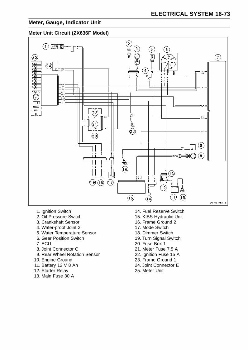
ELECTRICAL SYSTEM 16-73Meter, Gauge, Indicator Unit
Meter Unit Circuit (ZX636F Model)
1. Ignition Switch2. Oil Pressure Switch3. Crankshaft Sensor4. Water-proof Joint 25. Water Temperature Sensor6. Gear Position Switch7. ECU8. Joint Connector C9. Rear Wheel Rotation Sensor
10. Engine Ground11. Battery 12 V 8 Ah12. Starter Relay13. Main Fuse 30 A
14. Fuel Reserve Switch15. KIBS Hydraulic Unit16. Frame Ground 217. Mode Switch18. Dimmer Switch19. Turn Signal Switch20. Fuse Box 121. Meter Fuse 7.5 A22. Ignition Fuse 15 A23. Frame Ground 124. Joint Connector E25. Meter Unit

16-74 ELECTRICAL SYSTEMImmobilizer System (Equipped Models)
This motorcycle is equipped with an immobilizer system to protect the motorcycle from theft. Thissystem provides a theft proof device by means of matching a code between the inbuilt key transponderand ECU. If the code does not match, ignition system, injectors, subthrottle valve actuator and exhaustbutterfly valve actuator will not operate and the engine will not start.Abstract•Do not keep more than one immobilizer key of any system on a key ring. Jamming of the key code
signal may occur and the operation of the system may be affected.• The red warning indicator light (LED) will blink for a period of 24 hours once the ignition switch has
been switched off and the key removed. This blinking can be set to on or off as desired by holdingthe MODE and RESET buttons down for 2 seconds within 20 seconds of switching the ignition off.
• If all coded keys are lost the ECU and ignition switch will have to be replaced.• The immobilizer system can not function until the ignition key code is registered in the ECU.•A total of five keys can be registered in the ECU at any one time.Operational Cautions1. Do not put two keys of any immobilizer system on the same key ring.2. Do not submerge any key in water.3. Do not expose any key to excessively high temperature.4. Do not place any key close to magnet.5. Do not place a heavy item on any key.6. Do not grind any key or alter its shape.7. Do not disassemble the plastic part of any key.8. Do not drop the key and/or apply any shocks to the key.9. When a ignition key is lost, the user should go to his dealer to invalidate the lost key registration
in the ECU.10.When the all ignition keys are lost, the user should go to his dealer and have a new ECU installed
and register the ignition keys.
NOTENo.9 and 10 are strongly recommended to the customer to ensure security of the motorcycle.
Key RegistrationCase 1: When the ignition key has been lost or addi-tional spare ignition key is required.•Prepare a new spare ignition key.•Cut the key in accordance with the shape of the current
ignition key.•Remove the rear seat (see Rear Seat Removal in the
Frame chapter).• Remove the immobilizer/Kawasaki diagnostic system
connector cap [A].
• Connect the key registration unit [A] and key registrationadapter [B] as shown.Special Tools - Key Registration Unit: 57001-1582
Key Registration Adapter: 57001-1746
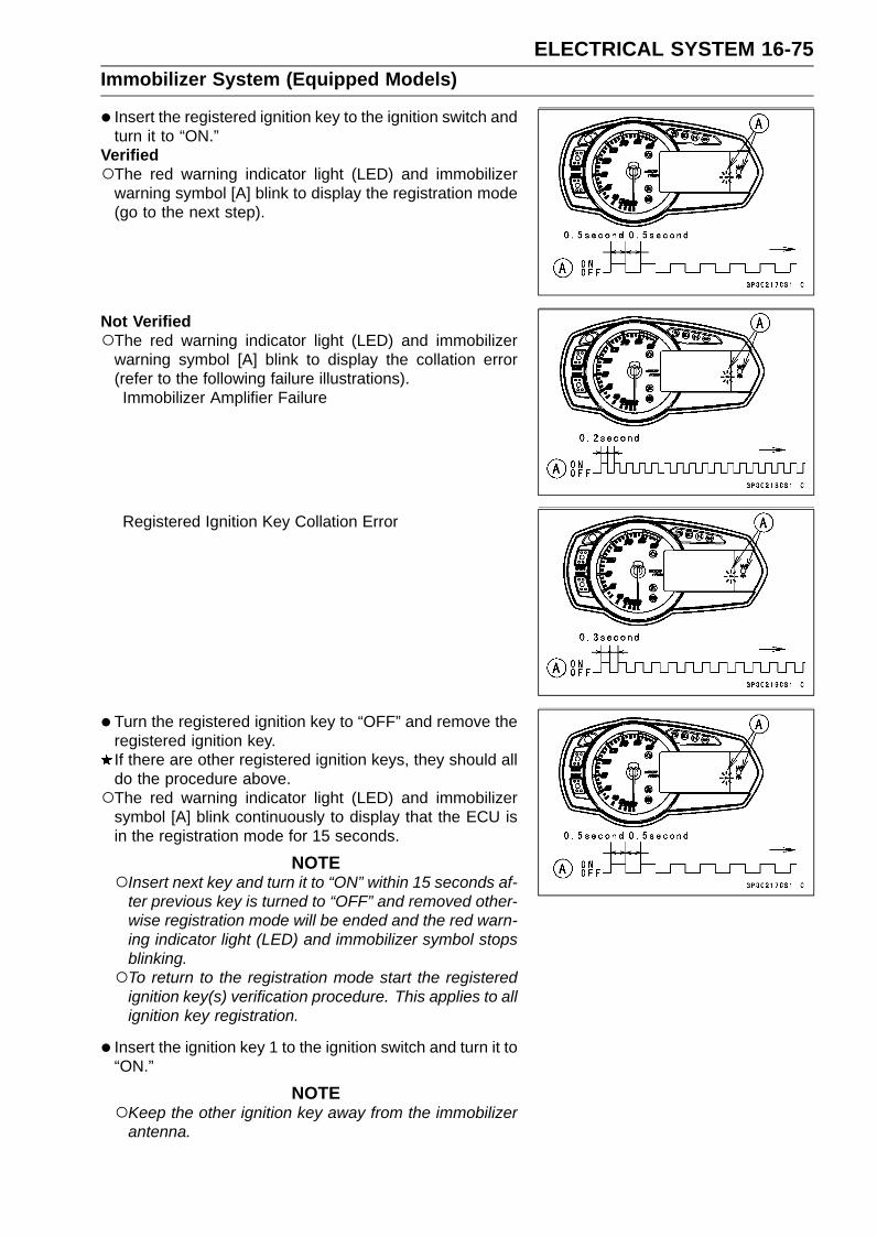
ELECTRICAL SYSTEM 16-75Immobilizer System (Equipped Models)
• Insert the registered ignition key to the ignition switch andturn it to “ON.”
VerifiedThe red warning indicator light (LED) and immobilizer
warning symbol [A] blink to display the registration mode(go to the next step).
Not VerifiedThe red warning indicator light (LED) and immobilizer
warning symbol [A] blink to display the collation error(refer to the following failure illustrations).Immobilizer Amplifier Failure
Registered Ignition Key Collation Error
• Turn the registered ignition key to “OFF” and remove theregistered ignition key.If there are other registered ignition keys, they should alldo the procedure above.The red warning indicator light (LED) and immobilizer
symbol [A] blink continuously to display that the ECU isin the registration mode for 15 seconds.
NOTEInsert next key and turn it to “ON” within 15 seconds af-
ter previous key is turned to “OFF” and removed other-wise registration mode will be ended and the red warn-ing indicator light (LED) and immobilizer symbol stopsblinking.To return to the registration mode start the registered
ignition key(s) verification procedure. This applies to allignition key registration.
• Insert the ignition key 1 to the ignition switch and turn it to“ON.”
NOTEKeep the other ignition key away from the immobilizer
antenna.

16-76 ELECTRICAL SYSTEMImmobilizer System (Equipped Models)
If there is any problem in the registration, the red warningindicator light (LED) and immobilizer warning symbol [A]blink to display the collation error.Immobilizer Amplifier Failure
When Registered Ignition Key is Inserted.
Ignition Key Collation Error
• The ignition key 1 is successfully registered in the ECU.The red warning indicator light (LED) and immobilizer
warning symbol [A] blink 3 times and stops for 1 secondand then repeats this cycle.

ELECTRICAL SYSTEM 16-77Immobilizer System (Equipped Models)
•Turn the ignition key 1 to “OFF” and remove the ignitionkey 1.The red warning indicator light (LED) and immobilizer
warning symbol [A] blink to display the registration mode.
NOTETurn to “OFF” the ignition switch and wait for the period
of 15 seconds or more. The registration mode automat-ically finishes and the red warning indicator light (LED)and immobilizer warning symbol will switch off.This procedure registered the registered ignition key
and one ignition key.Continue with the procedure to register the second and
later keys before the 15 seconds period has elapsed.
• Insert the ignition key 2 to the ignition switch and turn it to“ON.”
If there is any problem in the registration, the red warningindicator light (LED) and immobilizer warning symbol [A]blink to display the collation error.Immobilizer Amplifier Failure
When Registered Ignition Key is Inserted.
Ignition Key Collation Error
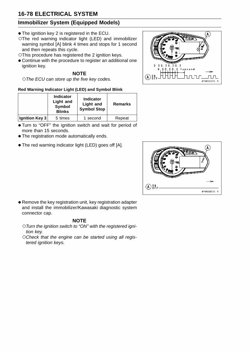
16-78 ELECTRICAL SYSTEMImmobilizer System (Equipped Models)
•The ignition key 2 is registered in the ECU.The red warning indicator light (LED) and immobilizer
warning symbol [A] blink 4 times and stops for 1 secondand then repeats this cycle.This procedure has registered the 2 ignition keys.•Continue with the procedure to register an additional one
ignition key.
NOTEThe ECU can store up the five key codes.
Red Warning Indicator Light (LED) and Symbol BlinkIndicatorLight andSymbolBlinks
IndicatorLight and
Symbol StopRemarks
Ignition Key 3 5 times 1 second Repeat
• Turn to “OFF” the ignition switch and wait for period ofmore than 15 seconds.
• The registration mode automatically ends.
• The red warning indicator light (LED) goes off [A].
• Remove the key registration unit, key registration adapterand install the immobilizer/Kawasaki diagnostic systemconnector cap.
NOTETurn the ignition switch to “ON” with the registered igni-
tion key.Check that the engine can be started using all regis-
tered ignition keys.
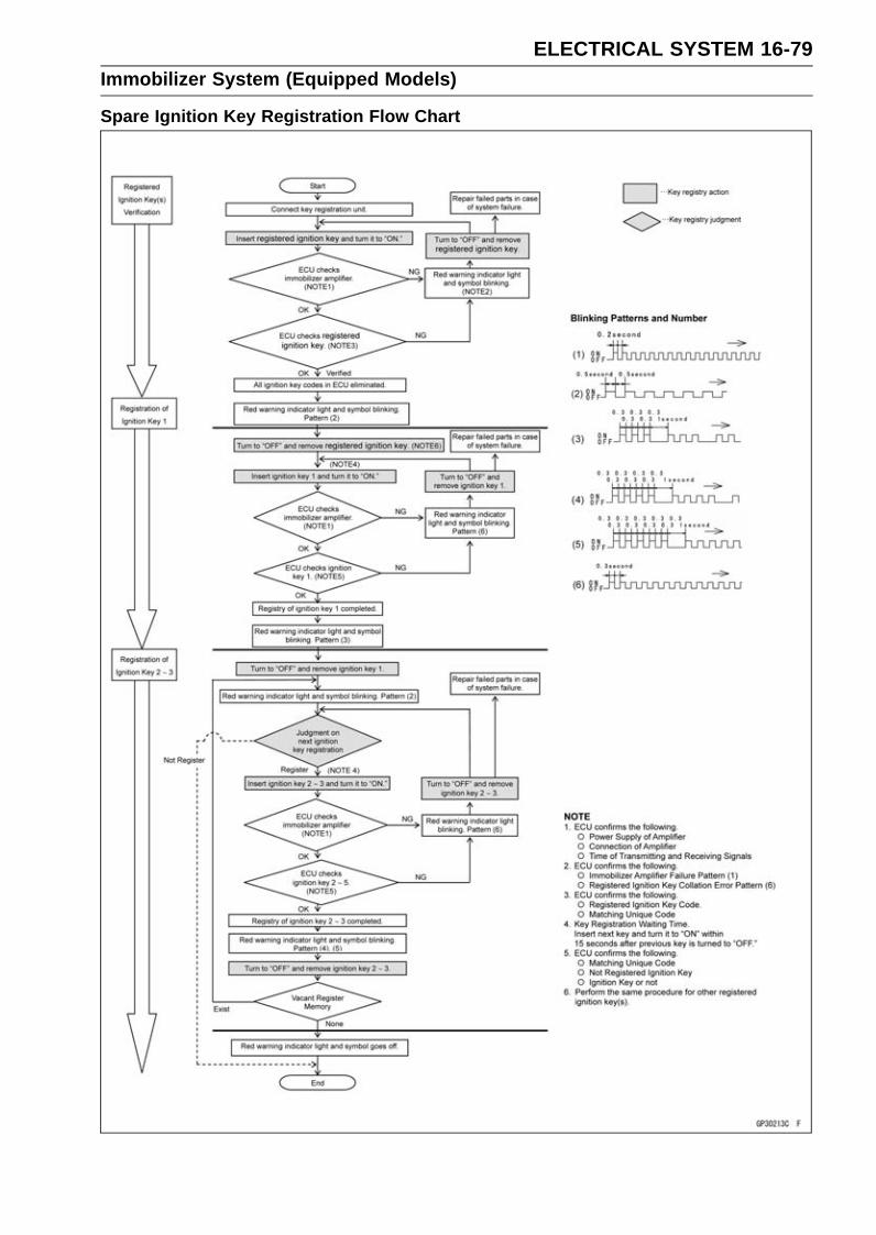
ELECTRICAL SYSTEM 16-79Immobilizer System (Equipped Models)
Spare Ignition Key Registration Flow Chart

16-80 ELECTRICAL SYSTEMImmobilizer System (Equipped Models)
Case 2: When the ignition switch is faulty and to bereplaced.•Prepare a new ignition switch [A] and two new ignition
keys [B].These parts are available as a set. Prepare the current
registered ignition key [C].
• Remove:Ignition Switch and Immobilizer Antenna (see Immobi-lizer System Parts Replacement)Rear Seat (see Rear Seat Removal in the Frame chap-ter)
•Remove the immobilizer/Kawasaki diagnostic systemconnector cap [A].
• Connect the key registration unit [A] and key registrationadapter [B] as shown.Special Tools - Key Registration Unit: 57001-1582
Key Registration Adapter: 57001-1746
•Connect:New Ignition Switch Lead Connector [A]Current Immobilizer Antenna Lead Connector [B]
NOTEKeep the ignition switches more than 15 cm (5.9 in.).
New Ignition Switch [C]Current Ignition Switch [D]
• Insert the current registered ignition key [A] at the currentignition switch [B].
• Insert the new ignition key 1 [C] to the new ignition switch[D] and turn it to “ON.”

ELECTRICAL SYSTEM 16-81Immobilizer System (Equipped Models)
The red warning indicator light (LED) and immobilizerwarning symbol [A] blink 1 time and stops for 1 secondand repeats this cycle.
Not VerifiedThe red warning indicator light (LED) and immobilizer
warning symbol [A] blink to display the collation error.Immobilizer Amplifier Failure
Registered Ignition Key Collation Error
• Turn to “OFF” and remove the new ignition key 1.
NOTEInsert the next key and turn it to “ON” within 15 sec-
onds after previous key is turned to “OFF” and removedotherwise registration mode will be ended and the redwarning indicator light (LED) and immobilizer warningsymbol stops blinking.
VerifiedThe red warning indicator light (LED) and immobilizer
warning symbol [A] blink to display the ECU is in theregistration mode (go to the next step).
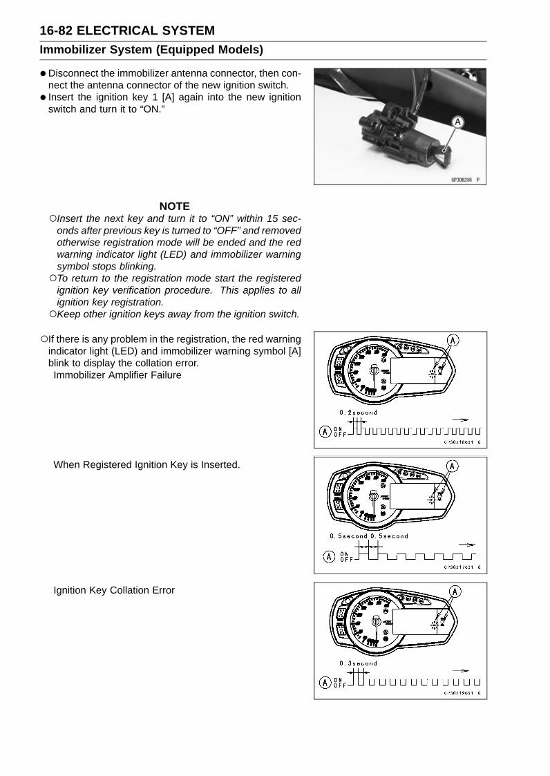
16-82 ELECTRICAL SYSTEMImmobilizer System (Equipped Models)
•Disconnect the immobilizer antenna connector, then con-nect the antenna connector of the new ignition switch.
• Insert the ignition key 1 [A] again into the new ignitionswitch and turn it to “ON.”
NOTEInsert the next key and turn it to “ON” within 15 sec-
onds after previous key is turned to “OFF” and removedotherwise registration mode will be ended and the redwarning indicator light (LED) and immobilizer warningsymbol stops blinking.To return to the registration mode start the registered
ignition key verification procedure. This applies to allignition key registration.Keep other ignition keys away from the ignition switch.
If there is any problem in the registration, the red warningindicator light (LED) and immobilizer warning symbol [A]blink to display the collation error.Immobilizer Amplifier Failure
When Registered Ignition Key is Inserted.
Ignition Key Collation Error

ELECTRICAL SYSTEM 16-83Immobilizer System (Equipped Models)
•The ignition key 1 is successfully registered in the ECU.The red warning indicator light (LED) and immobilizer
warning symbol [A] blink 2 times and stops for 1 secondand then repeats this cycle to indicate successful regis-tering of ignition key 1.
• Turn to “OFF” and remove ignition key 1.The red warning indicator light (LED) and immobilizer
warning symbol [A] blink to display the registration mode.
NOTETurn to “OFF” the ignition switch and wait for the period
more than 15 seconds. The registration mode automat-ically ends and red warning indicator light (LED) goesoff.This procedure has , registered the registered ignition
key and one ignition key.Continue the procedure to program the second and
later keys.
• Insert the ignition key 2 to the ignition switch and turn it to“ON.”
If there is any problem in the registration, the red warningindicator light (LED) and immobilizer warning symbol [A]blink to display the collation error.Immobilizer Amplifier Failure
When Registered Ignition Key is Inserted.

16-84 ELECTRICAL SYSTEMImmobilizer System (Equipped Models)
Ignition Key Collation Error
• The ignition key 2 is successfully registered in the ECU.The red warning indicator light (LED) and immobilizer
warning symbol [A] blink 3 times and stops for 1 secondand then repeat this cycle to indicate successful pro-gramming of ignition key 2.
• Turn to “OFF” the ignition switch and wait for period morethan 15 seconds.
• The registration mode automatically ends.
• The red warning indicator light (LED) goes off [A].
• Remove the key registration unit, key registration adapterand install the immobilizer/Kawasaki diagnostic systemconnector cap.
NOTETurn the ignition switch to “ON” with the registered igni-
tion key.Check that the engine can be started using all regis-
tered ignition keys.
• Install the new ignition switch (see Immobilizer SystemParts Replacement).
Case 3: When the ECU is faulty and has to be replaced.•Prepare a new ECU [A] and current registered ignition
key(s) [B].
NOTEThe key registration unit is not required.After replacing the ECU, be sure to register the 2 ignition
keys. If the 2 keys are not registered, the engine cannot be started.

ELECTRICAL SYSTEM 16-85Immobilizer System (Equipped Models)
•Replace the ECU [A] (see ECU Removal/Installation inthe Fuel System (DFI) chapter).
• Insert the current registered ignition key into the ignitionswitch and turn it to “ON.”
If there is any problem in the registration, the red warningindicator light (LED) and immobilizer warning symbol [A]blink to display the collation error.Immobilizer Amplifier Failure
Registered Ignition Key Collation Error
• The registered ignition key is registered in the ECU.The red warning indicator light (LED) and immobilizer
warning symbol [A] blink 1 time and stops for 1 secondand the repeats this cycle to indicate successful registra-tion of the registered ignition key.

16-86 ELECTRICAL SYSTEMImmobilizer System (Equipped Models)
•Turn to “OFF” the registered ignition key and remove it.The red warning indicator light (LED) and immobilizer
warning symbol [A] blink to display the registration mode.
NOTEInsert next key and turn it to “ON” within 15 seconds af-
ter previous key is turned to “OFF” and removed other-wise registration mode will be ended and the red warn-ing indicator light (LED) goes off.To return to the registration mode start the registered
ignition key verification procedure. This applies to allignition key registration.
• Insert the other remaining registered ignition key to theignition switch and turn it to “ON.”
NOTEKeep the other ignition keys away from the immobilizer
antenna.
If there is any problem in the registration, the red warningindicator light (LED) and immobilizer warning symbol [A]blink to display the collation error.Immobilizer Amplifier Failure
When Registered Ignition Key is Inserted.
Ignition Key Collation Error

ELECTRICAL SYSTEM 16-87Immobilizer System (Equipped Models)
•The other remaining ignition key is registered in the ECU.The red warning indicator light (LED) and immobilizer
warning symbol [A] blink 2 times and stops for 1 secondand then repeats this cycle to indicate successful regis-tration of ignition key.
• Turn to “OFF” the ignition switch and wait for period morethan 15 seconds.
• The registration mode automatically ends.
• The red warning indicator light (LED) goes off [A].
NOTETurn the ignition switch to “ON” with the registered igni-
tion key.Check that the engine can be started using all regis-
tered ignition keys.
Case 4: When all registered ignition keys are faulty orlost.
The all registered ignition keys replacement is consideredvery rare case. However if it is required, the following isnecessary.
NOTEThe ECU must be replaced with a new one because
the registered ignition key code that is registered in thecurrent ECU can not be rewritten.
•Prepare a new ECU [A] and 2 new ignition keys [B].
NOTEThe key registration unit is not required.The key registration process is same as the electric con-
trol unit replacement.
• Insert the first ignition key into the ignition switch and turnit to “ON.”

16-88 ELECTRICAL SYSTEMImmobilizer System (Equipped Models)
If there is any problem in the registration, the red warningindicator light (LED) and immobilizer warning symbol [A]blink to display the collation error.Immobilizer Amplifier Failure
Ignition Key Collation Error
• The first ignition key is registered in the ECU.The red warning indicator light (LED) and immobilizer
warning symbol [A] blink 1 time and stops for 1 secondand the repeats this cycle to indicate successful registra-tion of the first ignition key.
• Turn to “OFF” the first ignition key and remove it.• The red warning indicator light (LED) and immobilizer
warning symbol [A] blink to display the registration mode.
NOTEInsert next key and turn it to “ON” within 15 seconds af-
ter previous key is turned to “OFF” and removed other-wise registration mode will be ended and the red warn-ing indicator light (LED) goes off.To return to the registration mode start the registered
ignition key verification procedure. This applies to allignition key registration.
• Insert the second ignition key to the ignition switch andturn it to “ON.”
NOTEKeep the other ignition keys away from the immobilizer
antenna.

ELECTRICAL SYSTEM 16-89Immobilizer System (Equipped Models)
If there is any problem in the registration, the red warningindicator light (LED) and immobilizer warning symbol [A]blink to display the collation error.Immobilizer Amplifier Failure
When Registered Ignition Key is Inserted
Ignition Key Collation Error
• The second ignition key is registered in the ECU.The red warning indicator light (LED) and immobilizer
warning symbol [A] blink 2 times and stops for 1 secondand then repeats this cycle to indicate successful regis-tration of second ignition key.
• Turn to “OFF” the ignition switch and wait for period morethan 15 seconds.
• The registration mode automatically ends.
•Red warning indicator light (LED) [A] goes off.

16-90 ELECTRICAL SYSTEMImmobilizer System (Equipped Models)
NOTETurn the ignition switch to “ON” with the registered igni-
tion key.Check that the engine can be started using all regis-
tered ignition keys.

ELECTRICAL SYSTEM 16-91Immobilizer System (Equipped Models)
All Keys Initial Registration Flow Chart
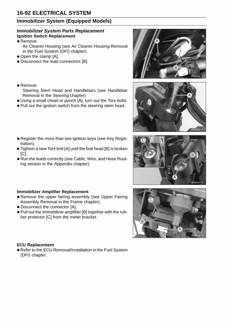
16-92 ELECTRICAL SYSTEMImmobilizer System (Equipped Models)
Immobilizer System Parts ReplacementIgnition Switch Replacement•Remove:
Air Cleaner Housing (see Air Cleaner Housing Removalin the Fuel System (DFI) chapter)
•Open the clamp [A].• Disconnect the lead connectors [B].
• Remove:Steering Stem Head and Handlebars (see HandlebarRemoval in the Steering chapter)
•Using a small chisel or punch [A], turn out the Torx bolts.• Pull out the ignition switch from the steering stem head.
•Register the more than two ignition keys (see Key Regis-tration).
• Tighten a new Torx bolt [A] until the bolt head [B] is broken[C].
• Run the leads correctly (see Cable, Wire, and Hose Rout-ing section in the Appendix chapter).
Immobilizer Amplifier Replacement•Remove the upper fairing assembly (see Upper Fairing
Assembly Removal in the Frame chapter).• Disconnect the connector [A].• Pull out the immobilizer amplifier [B] together with the rub-
ber protector [C] from the meter bracket.
ECU Replacement•Refer to the ECU Removal/Installation in the Fuel System
(DFI) chapter.

ELECTRICAL SYSTEM 16-93Immobilizer System (Equipped Models)
Immobilizer Relational Parts Replacement ChartFailed or Lost Part
IgnitionKey
IgnitionSwitch Amplifier ECU
IgnitionKey •
IgnitionSwitch •
Amplifier •*
ECU •* Replacement Part
• Main Replacement Part
Additional Replacement Part
Immobilizer System Inspection•Refer to the Immobilizer Amplifier and Blank Key Detec-
tion section in the Fuel System (DFI) chapter.

16-94 ELECTRICAL SYSTEMImmobilizer System (Equipped Models)
Immobilizer System Circuit
1. Ignition Switch2. Joint Connector D3. ECU4. Immobilizer/Kawasaki Diagnostic System Connector5. Frame Ground 16. Engine Ground7. Battery 12 V 8 Ah8. Starter Relay9. Main Fuse 30 A
10. Fuse Box 111. Ignition Fuse 15 A12. Meter Unit13. Red Warning Indicator Light (LED)14. Joint Connector E15. Immobilizer Antenna16. Immobilizer Amplifier

ELECTRICAL SYSTEM 16-95Switches and Sensors
Brake Light Timing Inspection•Refer to the Brake Light Switch Operation Inspection in
the Periodic Maintenance chapter.
Brake Light Timing Adjustment•Refer to the Brake Light Switch Operation Inspection in
the Periodic Maintenance chapter.
Switch Inspection•Using a hand tester, check to see that only the connec-
tions shown in the table have continuity.Special Tool - Hand Tester: 57001-1394For the switch housings and the ignition switch, refer to
the tables in the Wiring Diagram.If the switch has an open or short, repair it or replace itwith a new one.
Rear Brake Light Switch Connections
Sidestand Switch Connections
Oil Pressure Switch Connections*
*: Engine lubrication system is in good condition.

16-96 ELECTRICAL SYSTEMSwitches and Sensors
Water Temperature Sensor Inspection•Remove the water temperature sensor (see Wa-
ter Temperature Sensor Removal/Installation in theSelf-Diagnosis System chapter).
• Suspend the sensor [A] in a container of coolant so thatthe temperature-sensing projection [C] is submerged.
• Suspend an accurate thermometer [B] with temperature-sensing projection located in almost the same depth withthe sensor.
NOTEThe sensor and thermometer must not touch the con-
tainer side or bottom.
•Place the container over a source of heat and gradu-ally raise the temperature of the coolant while stirring thecoolant gently.
• Using the hand tester, measure the internal resistance ofthe sensor.If the hand tester does not show the specified values, re-place the sensor.
Water Temperature Sensor ResistanceTemperature Resistance (kΩ)–20°C (–4°F) *18.80 ±2.370°C (32°F) *(about 6.544)
40°C (104°F) 1.136 ±0.095100°C (212°F) 0.1553 ±0.0070
*: Reference Information
Fuel Reserve Switch Inspection•Fill the fuel tank with fuel and close the fuel tank cap.•Remove the front seat (see Front Seat Removal in the
Frame chapter).•Open the clamps.• Slide the dust cover [A].• Disconnect the fuel pump lead connector [B].
• Connect the test light [A] (12 V 3.4 W bulb in a socketwith leads) and the 12 V battery [B] to the fuel pump leadconnector [C].
Connections:Battery (+) → 12 V 3.4 W Bulb (One Side)12 V 3.4 W Bulb (Other Side) → R/BK lead [D]Battery (–) → BK/W lead [E]
If the test light turn on, the reserve switch is defective.Replace the fuel pump.
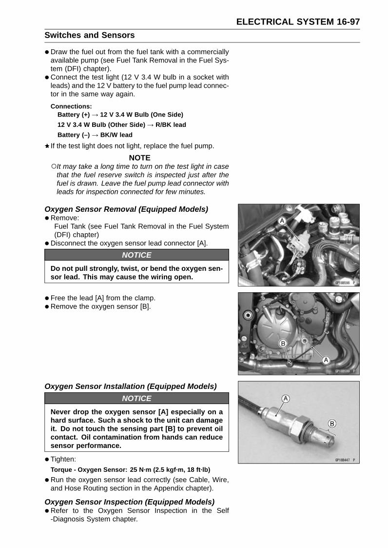
ELECTRICAL SYSTEM 16-97Switches and Sensors
•Draw the fuel out from the fuel tank with a commerciallyavailable pump (see Fuel Tank Removal in the Fuel Sys-tem (DFI) chapter).
• Connect the test light (12 V 3.4 W bulb in a socket withleads) and the 12 V battery to the fuel pump lead connec-tor in the same way again.
Connections:Battery (+) → 12 V 3.4 W Bulb (One Side)12 V 3.4 W Bulb (Other Side) → R/BK leadBattery (–) → BK/W lead
If the test light does not light, replace the fuel pump.
NOTEIt may take a long time to turn on the test light in case
that the fuel reserve switch is inspected just after thefuel is drawn. Leave the fuel pump lead connector withleads for inspection connected for few minutes.
Oxygen Sensor Removal (Equipped Models)•Remove:
Fuel Tank (see Fuel Tank Removal in the Fuel System(DFI) chapter)
•Disconnect the oxygen sensor lead connector [A].
NOTICEDo not pull strongly, twist, or bend the oxygen sen-sor lead. This may cause the wiring open.
•Free the lead [A] from the clamp.•Remove the oxygen sensor [B].
Oxygen Sensor Installation (Equipped Models)NOTICE
Never drop the oxygen sensor [A] especially on ahard surface. Such a shock to the unit can damageit. Do not touch the sensing part [B] to prevent oilcontact. Oil contamination from hands can reducesensor performance.
•Tighten:Torque - Oxygen Sensor: 25 N·m (2.5 kgf·m, 18 ft·lb)
•Run the oxygen sensor lead correctly (see Cable, Wire,and Hose Routing section in the Appendix chapter).
Oxygen Sensor Inspection (Equipped Models)•Refer to the Oxygen Sensor Inspection in the Self
-Diagnosis System chapter.

16-98 ELECTRICAL SYSTEMSwitches and Sensors
Oxygen Sensor Heater Inspection (EquippedModels)•Refer to the Oxygen Sensor Heater Resistance Inspec-
tion in the Self-Diagnosis System chapter.
Gear Position Switch Removal•Remove:
Engine Sprocket Cover (see Engine Sprocket Removalin the Final Drive chapter)Left Lower Fairing (see Lower Fairing Removal in theFrame chapter)Fuel Tank (see Fuel Tank Removal in the Fuel System(DFI) chapter)
•Disconnect the connector [A].
•Open the clamps [A].
• Remove:Gear Position Switch Screws [A]Holding Plate [B]Gear Position Switch
•Remove the pins [A] and springs from the shift drum.
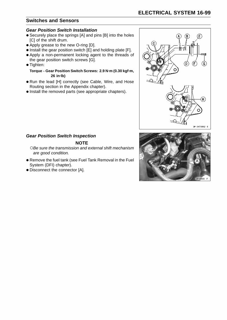
ELECTRICAL SYSTEM 16-99Switches and Sensors
Gear Position Switch Installation•Securely place the springs [A] and pins [B] into the holes
[C] of the shift drum.• Apply grease to the new O-ring [D].• Install the gear position switch [E] and holding plate [F].• Apply a non-permanent locking agent to the threads of
the gear position switch screws [G].• Tighten:
Torque - Gear Position Switch Screws: 2.9 N·m (0.30 kgf·m,26 in·lb)
•Run the lead [H] correctly (see Cable, Wire, and HoseRouting section in the Appendix chapter).
• Install the removed parts (see appropriate chapters).
Gear Position Switch InspectionNOTE
Be sure the transmission and external shift mechanismare good condition.
•Remove the fuel tank (see Fuel Tank Removal in the FuelSystem (DFI) chapter).
• Disconnect the connector [A].

16-100 ELECTRICAL SYSTEMSwitches and Sensors
•Set the hand tester [A] to the × 1 kΩ or × 100 Ω rangeand connect it to the terminals in the connector [B] andground.When changing the gear position from lower gear to
higher gear, raise the rear wheel off the ground with thestand and rotate the rear wheel by hand.Internal Circuit [C][1] LG Lead[2] G/R Lead[3] BK Lead
Special Tool - Hand Tester: 57001-1394
Gear Position Switch Resistance (Unit: kΩ)Connections
GearPosition [1]-Ground [2]-Ground [3]-Ground
Neutral about 0 8.64 ∼ 9.54 about 01st – 2.22 ∼ 2.46 about 02nd – 1.42 ∼ 1.58 about 03rd – 0.955 ∼ 1.055 about 04th – 0.644 ∼ 0.711 about 05th – 0.410 ∼ 0.453 about 06th – 0.241 ∼ 0.266 about 0
If the tester reading is not as specified, replace the gearposition switch with a new one.

ELECTRICAL SYSTEM 16-101Relay Box
Relay Box Removal•Remove the front seat cover (see Seat Cover Removal in
the Frame chapter).• Disconnect the connectors [A].• Pull out the relay box [B] from the rubber protector [C].
NOTEThe relay box has relays and diodes. The relays and
diodes can not be removed.
Relay Circuit Inspection•Remove the relay box (see Relay Box Removal).• Check conductivity of the following numbered terminals
by connecting the hand tester and one 12 V battery to therelay box as shown (see Relay Box Internal Circuit in thissection).If the tester does not read as specified, replace the relaybox.
Relay Circuit Inspection (with the battery disconnected)Tester Connection Tester Reading (Ω)
Headlight CircuitRelay 1-3 ∞
7-6 ∞ECU Main Relay
4-5 Not ∞*7-8 ∞
Fuel Pump Relay9-10 Not ∞*11-16 ∞
Starter Circuit Relay11-12 ∞17-20 ∞
Fan Relay18-19 Not ∞*
*: The actual reading varies with the hand tester used.
Relay Circuit Inspection (with the battery connected)Battery
Connection(+) (–)
TesterConnection
TesterReading (Ω)
2-11 1-3 0ECU Main Relay
4-5 7-6 0Fuel Pump Relay 9-10 7-8 0Fan Relay 18-19 17-20 0
BatteryConnection
(+) (–)
Tester ConnectionDC 25 V Range
(+) (–)
TesterReading (V)
StarterCircuit Relay 16-12 11-12 Battery
Voltage
(+): Apply positive lead.(–): Apply negative lead.

16-102 ELECTRICAL SYSTEMRelay Box
Diode Circuit Inspection•Remove the relay box (see Relay Box Removal).• Check conductivity of the following pairs of terminals (see
Relay Box Internal Circuit in this section).
Diode Circuit Inspection
Tester Connection 1-11, 2-11, 12-13, 12-15, 12-16, 13-14,13-15
The resistance should be low in one direction and morethan 10 times as much in the other direction. If any diodeshows low or high in both directions, the diode is defectiveand the relay box must be replaced.
NOTEThe actual meter reading varies with the meter or tester
used and the individual diodes, but generally speaking,the lower reading should be from zero to one half thescale.
Relay Box Internal Circuit
A: Headlight Circuit RelayB: ECU Main RelayC: Fuel Pump RelayD: Starter Circuit RelayE: Fan Relay

ELECTRICAL SYSTEM 16-103Fuse
30 A Main/15 A ECU Fuse Removal•Remove:
Fuel Tank (see Fuel Tank Removal in the Fuel System(DFI) chapter)Starter Relay Cover [A]
• Pull out the fuses [A] from the starter relay with needlenose pliers.
Fuse Box Fuse Removal•Remove the left inner cover (see Inner Cover Removal in
the Frame chapter).• Unlock the hook [A] to lift up the lid.
Fuse Box 1 [B]Fuse Box 2 [C]
• Pull the fuses [A] straight out of the fuse box with needlenose pliers.
Fuse InstallationIf a fuse fails during operation, inspect the electrical sys-tem to determine the cause, and then replace it with anew fuse of proper amperage.
• Install the fuse box fuses on the original position as spec-ified on the lid.
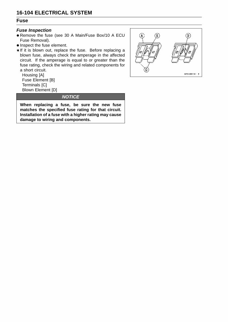
16-104 ELECTRICAL SYSTEMFuse
Fuse Inspection•Remove the fuse (see 30 A Main/Fuse Box/10 A ECU
Fuse Removal).• Inspect the fuse element.
If it is blown out, replace the fuse. Before replacing ablown fuse, always check the amperage in the affectedcircuit. If the amperage is equal to or greater than thefuse rating, check the wiring and related components fora short circuit.Housing [A]Fuse Element [B]Terminals [C]Blown Element [D]
NOTICEWhen replacing a fuse, be sure the new fusematches the specified fuse rating for that circuit.Installation of a fuse with a higher rating may causedamage to wiring and components.
SELF-DIAGNOSIS SYSTEM 17-1
17
Self-Diagnosis SystemTable of Contents
Specifications ......................................................................................................................... 17-4Special Tools .......................................................................................................................... 17-6Self-Diagnosis ........................................................................................................................ 17-7
Self-Diagnosis Outline ...................................................................................................... 17-7Self-Diagnosis Procedures ............................................................................................... 17-8Self-Diagnosis Flow Chart ................................................................................................ 17-10Service Code Reading ...................................................................................................... 17-11Service Code Erasing ....................................................................................................... 17-11Backups ............................................................................................................................ 17-13
Main Throttle Sensor (Service Code 11) ................................................................................ 17-16Main Throttle Sensor Removal/Adjustment ...................................................................... 17-16Main Throttle Sensor Input Voltage Inspection ................................................................. 17-16Main Throttle Sensor Resistance Inspection .................................................................... 17-17Main Throttle Sensor Output Voltage Inspection .............................................................. 17-17
Intake Air Pressure Sensor #1 (Service Code 12).................................................................. 17-20Intake Air Pressure Sensor #1 Removal........................................................................... 17-20Intake Air Pressure Sensor #1 Installation........................................................................ 17-20Intake Air Pressure Sensor #1 Input Voltage Inspection................................................... 17-21Intake Air Pressure Sensor #1 Output Voltage Inspection................................................ 17-22
Intake Air Temperature Sensor (Service Code 13)................................................................. 17-26Intake Air Temperature Sensor Removal .......................................................................... 17-26Intake Air Temperature Sensor Installation ....................................................................... 17-26Intake Air Temperature Sensor Output Voltage Inspection ............................................... 17-27Intake Air Temperature Sensor Resistance Inspection ..................................................... 17-28
Water Temperature Sensor (Service Code 14) ...................................................................... 17-29Water Temperature Sensor Removal/Installation ............................................................. 17-29Water Temperature Sensor Output Voltage Inspection..................................................... 17-29Water Temperature Sensor Resistance Inspection........................................................... 17-30
Intake Air Pressure Sensor #2 (Service Code 16).................................................................. 17-31Intake Air Pressure Sensor #2 Removal........................................................................... 17-31Intake Air Pressure Sensor #2 Installation........................................................................ 17-31Intake Air Pressure Sensor #2 Input Voltage Inspection................................................... 17-32Intake Air Pressure Sensor #2 Output Voltage Inspection................................................ 17-33
Crankshaft Sensor (Service Code 21).................................................................................... 17-35Crankshaft Sensor Removal/Installation........................................................................... 17-35Crankshaft Sensor Resistance Inspection ........................................................................ 17-35Crankshaft Sensor Peak Voltage Inspection..................................................................... 17-35
Rear Wheel Rotation Sensor Signal (Service Code 24)......................................................... 17-37Rear Wheel Rotation Sensor Signal Inspection................................................................ 17-37
Gear Position Switch (Service Code 25) ................................................................................ 17-40Gear Position Switch Removal/Installation ....................................................................... 17-40Gear Position Switch Resistance Inspection .................................................................... 17-40Gear Position Switch Output Voltage Inspection .............................................................. 17-40
Front Wheel Rotation Sensor Signal (Service Code 27) ........................................................ 17-42Front Wheel Rotation Sensor Signal Inspection ............................................................... 17-42
Vehicle-down Sensor (Service Code 31)................................................................................ 17-45Vehicle-down Sensor Removal ......................................................................................... 17-45Vehicle-down Sensor Installation ...................................................................................... 17-45Vehicle-down Sensor Input Voltage Inspection................................................................. 17-46Vehicle-down Sensor Output Voltage Inspection .............................................................. 17-47
17-2 SELF-DIAGNOSIS SYSTEM
Subthrottle Sensor (Service Code 32).................................................................................... 17-49Subthrottle Sensor Removal/Adjustment .......................................................................... 17-49Subthrottle Sensor Input Voltage Inspection..................................................................... 17-49Subthrottle Sensor Output Voltage Inspection .................................................................. 17-50Subthrottle Sensor Resistance Inspection ........................................................................ 17-52
Oxygen Sensor - not activated (Service Code 33, Equipped Models) ................................... 17-53Oxygen Sensor Removal/Installation................................................................................ 17-53Oxygen Sensor Inspection................................................................................................ 17-53
Exhaust Butterfly Valve Actuator Sensor (Service Code 34).................................................. 17-57Exhaust Butterfly Valve Actuator Sensor Removal/Installation......................................... 17-57Exhaust Butterfly Valve Actuator Sensor Input Voltage Inspection................................... 17-57Exhaust Butterfly Valve Actuator Sensor Output Voltage Inspection ................................ 17-58Exhaust Butterfly Valve Actuator Sensor Resistance Inspection ...................................... 17-59
Immobilizer Amplifier (Service Code 35, Equipped Models) .................................................. 17-60Antenna Resistance Inspection ........................................................................................ 17-60Amplifier Input Voltage Inspection..................................................................................... 17-60
Blank Key Detection (Service Code 36, Equipped Models) ................................................... 17-61Ignition Key Inspection...................................................................................................... 17-61
ECU Communication Error (Service Code 39) ....................................................................... 17-62ECU Communication Line Inspection ............................................................................... 17-62
Stick Coils #1, #2, #3, #4: (Service Code 51, 52, 53, 54) ...................................................... 17-64Stick Coil Removal/Installation.......................................................................................... 17-64Stick Coil Primary Winding Resistance Inspection ........................................................... 17-64Stick Coil Input Voltage Inspection.................................................................................... 17-64
Radiator Fan Relay (Service Code 56)................................................................................... 17-66Radiator Fan Relay Removal/Installation.......................................................................... 17-66Radiator Fan Relay Inspection.......................................................................................... 17-66
Subthrottle Valve Actuator (Service Code 62) ........................................................................ 17-67Subthrottle Valve Actuator Removal ................................................................................. 17-67Subthrottle Valve Actuator Inspection ............................................................................... 17-67Subthrottle Valve Actuator Resistance Inspection ............................................................ 17-67Subthrottle Valve Actuator Input Voltage Inspection ......................................................... 17-68
Exhaust Butterfly Valve Actuator (Service Code 63) .............................................................. 17-70Exhaust Butterfly Valve Actuator Removal ....................................................................... 17-70Exhaust Butterfly Valve Actuator Installation .................................................................... 17-70Exhaust Butterfly Valve Actuator Inspection ..................................................................... 17-72Exhaust Butterfly Valve Actuator Resistance Inspection .................................................. 17-73
Air Switching Valve (Service Code 64) ................................................................................... 17-74Air Switching Valve Removal/Installation .......................................................................... 17-74Air Switching Valve Inspection .......................................................................................... 17-74
Oxygen Sensor Heater (Service Code 67, Equipped Models) ............................................... 17-75Oxygen Sensor Heater Removal/Installation .................................................................... 17-75Oxygen Sensor Heater Resistance Inspection ................................................................. 17-75Oxygen Sensor Heater Power Source Voltage Inspection ............................................... 17-76
Oxygen Sensor - Incorrect Output Voltage (Service Code 94 (Equipped Models))................ 17-78Oxygen Sensor Removal/Installation................................................................................ 17-78Oxygen Sensor Inspection................................................................................................ 17-78
KIBS Hydraulic Unit Communication Error (Service Code 1b, KIBS Equipped Models) ........ 17-81KIBS Hydraulic Unit Communication Line Inspection ....................................................... 17-81
Purge Valve (Service Code 3A) (CAL Model)......................................................................... 17-83Purge Valve Removal/Installation ..................................................................................... 17-83Purge Valve Inspection ..................................................................................................... 17-83
KIBS Service Codes (KIBS Equipped Models)....................................................................... 17-86Solenoid Valve Inspection (Service Code b 13, b 14, b 17, b 18)..................................... 17-86KIBS Solenoid Valve Relay Inspection (Service Code b 19) ............................................ 17-86Front, Rear Wheel Rotation Difference Abnormal Inspection (Service Code b 25) .......... 17-86KIBS Motor Relay Inspection (Service Code b 35) ........................................................... 17-86

SELF-DIAGNOSIS SYSTEM 17-3
Front Wheel Rotation Sensor Signal Abnormal (Service Code b 42) ............................... 17-87Front Wheel Rotation Sensor Wiring Inspection (Service Code b 43) .............................. 17-88Rear Wheel Rotation Sensor Signal Abnormal (Service Code b 44)................................ 17-88Rear Wheel Rotation Sensor Wiring Inspection (Service Code b 45)............................... 17-89Power Supply Voltage Inspection (Low-Voltage) (Service Code b 52) ............................. 17-89Power Supply Voltage Inspection (Over-Voltage) (Service Code b 53) ............................ 17-90ECU Inspection (Service Code b 55) ................................................................................ 17-90CAN Communication (Transmission)/CAN Bus OFF Monitor Inspection (Service Code
b 57) CAN Communication (Reception) Monitor Inspection (Service Code b 58) ......... 17-90Output Fluid Pressure Sensor (Front Brake) Wiring Inspection (Service Code b 83)....... 17-91Output Fluid Pressure Sensor (Front Brake) Offset Abnormal (Service Code b 84) ........ 17-91Fluid Pressure Sensor Supply Voltage Inspection (Service Code b 89) ........................... 17-91

17-4 SELF-DIAGNOSIS SYSTEMSpecifications
Item StandardDigital Fuel Injection System
Main Throttle Sensor:Input Voltage DC 4.75 ∼ 5.25 VOutput Voltage DC 1.02 ∼ 1.06 V at idle throttle opening
DC 4.30 ∼ 4.34 V at full throttle opening (for reference)Resistance 4 ∼ 6 kΩ
Intake Air Pressure Sensor #1/#2:Input Voltage DC 4.75 ∼ 5.25 VOutput Voltage DC 3.80 ∼ 4.20 V at standard atmospheric pressure (see
this text for details)Intake Air Temperature Sensor:
Output Voltage About DC 2.25 ∼ 2.50 V at 20°C (68°F)Resistance 5.4 ∼ 6.6 kΩ at 0°C (32°F)
0.29 ∼ 0.39 kΩ at 80°C (176°F)Water Temperature Sensor:
Output Voltage About DC 2.80 ∼ 2.97 V at 20°C (68°F)Vehicle-down Sensor:
Input Voltage DC 4.75 ∼ 5.25 VOutput Voltage with sensor tilted 60 ∼ 70° or more right or left: DC 0.65
∼ 1.35 Vwith sensor arrow mark pointed up: DC 3.55 ∼ 4.45 V
Subthrottle Sensor:Input Voltage DC 4.75 ∼ 5.25 VOutput Voltage DC 1.08 ∼ 1.12 V at subthrottle valve full close position
DC 4.48 ∼ 4.52 V at subthrottle valve full open position(for reference)
Resistance 4 ∼ 6 kΩSubthrottle Valve Actuator:
Resistance About 5.2 ∼ 7.8 ΩInput Voltage About DC 8.5 ∼ 10.5 V and then 0 V or
About DC 8.5 ∼ 10.5 VOxygen Sensor (Equipped Models):
Output Voltage (Rich) DC 0.8 V or moreOutput Voltage (Lean) DC 0.24 V or lessHeater Resistance 6.7 ∼ 10.5 Ω at 20°C (68°F)
Exhaust Butterfly Valve ActuatorSensor:
Input Voltage DC 4.75 ∼ 5.25 VOutput Voltage DC 3.46 ∼ 3.76 V at pulley original positionResistance 4 ∼ 6 kΩ
Immobilizer Antenna (EquippedModels):
Resistance About 3.0 ∼ 4.6 ΩExhaust Butterfly Valve Actuator:
Resistance 5 ∼ 200 Ω (for reference)

SELF-DIAGNOSIS SYSTEM 17-5Specifications
Item StandardPurge Valve:
Resistance 30 ∼ 34 Ω at 20°C (68°F)KIBS System (Equipped Models)
Wheel Rotation Sensor Air Gap:Front 0.4 ∼ 1.6 mm (0.02 ∼ 0.06 in.)Rear 0.4 ∼ 1.6 mm (0.02 ∼ 0.06 in.)
CAN Communication LineResistance 30 ∼ 70 Ω
CAN Communication Line/GroundResistance 5 ∼ 30 kΩ
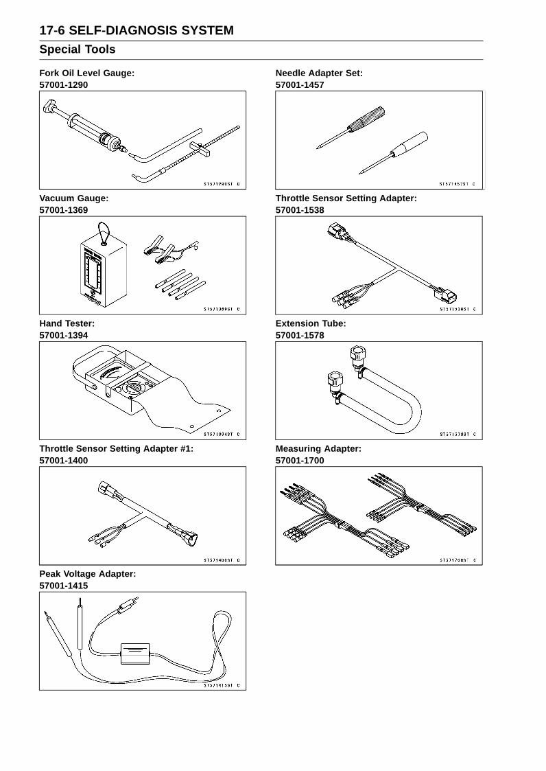
17-6 SELF-DIAGNOSIS SYSTEMSpecial Tools
Fork Oil Level Gauge:57001-1290
Vacuum Gauge:57001-1369
Hand Tester:57001-1394
Throttle Sensor Setting Adapter #1:57001-1400
Peak Voltage Adapter:57001-1415
Needle Adapter Set:57001-1457
Throttle Sensor Setting Adapter:57001-1538
Extension Tube:57001-1578
Measuring Adapter:57001-1700

SELF-DIAGNOSIS SYSTEM 17-7Self-Diagnosis
Self-Diagnosis OutlineThe self-diagnosis system is monitoring the following
mechanisms.DFI System and Ignition SystemKTRC SystemImmobilizer System (Equipped Models)KIBS and ABS (Equipped Models)
The following indicator lights (LED) are used for symbolsof below table.
LED Color Indicator Symbols
Red [A]Oil PressureBatteryImmobilizer (Equipped Models)
Yellow [B] FIYellow [C] KTRC
Yellow [D] KTRCKIBS (Equipped Models)
Yellow [E] ABS (Equipped Models)
ZX636E Model [F]ZX636F Model [G]
The self-diagnosis system has two modes and can beswitched to another mode by operating the meter unit.
User ModeThe ECU notifies the rider of troubles in DFI system,
ignition system, KTRC system and immobilizer system(equipped models) by lighting or blinking the yellow enginewarning indicator light (LED) [A], red warning indicator light(LED) [B], yellow KTRC warning indicator light (LED) [C],yellow warning indicator light [D] and warning symbols [E]when DFI, ignition, KTRC and immobilizer system partsare faulty, and initiates fail-safe function. In case of serioustroubles, ECU stops the injection and ignition operations.
ZX636E Model [F]ZX636F Model [G]

17-8 SELF-DIAGNOSIS SYSTEMSelf-Diagnosis
For KIBS and ABS system (equipped models), the KIBShydraulic unit notifies the rider of troubles in KIBS and ABSsystem by lighting or blinking the yellow ABS indicator light(LED) [A], yellow warning indicator light (LED) [B] and KIBSwarning symbol [C] when KIBS and ABS parts are faulty,and initiates fail-safe function.
Dealer ModeThe LCD (Liquid Crystal Display) displays the service
code(s) [A] to show the problem(s) which the above systemhas at the moment of diagnosis.
Self-Diagnosis ProceduresNOTE
Use a fully charged battery when conductingself-diagnosis. Otherwise, the light (LED) and symboldo not light or blink.
•Turn the ignition switch on.When a problem occurs with DFI system and ignition sys-
tem, the yellow engine warning indicator light (LED) [A]goes on to alert the rider.For models equipped with KTRC system, the yellow en-
gine warning indicator light (LED), yellow KTRC warn-ing indicator light (LED) [B], yellow warning indicator light(LED) [C] and KTRC warning symbol [D] go on, when aproblem occurs in the system.ZX636E Model [E]ZX636F Model [F]
When a problem occurs with immobilizer system(equipped models), the red warning indicator light(LED) [A] and immobilizer warning symbol [B] blink.

SELF-DIAGNOSIS SYSTEM 17-9Self-Diagnosis
For models equipped with ABS system (equipped mod-els), the yellow ABS indicator light (LED) [A] goes on,when a problem occurs in the system. However, whenthe yellow ABS indicator light (LED) goes off after the mo-torcycle runs at approx. 5 km/h (3.1 mph) or above, theABS is normal.For models equipped with KIBS system (equipped mod-
els), the yellow warning indicator light (LED) [B] and KIBSwarning symbol [C] go on, when a problem occurs in thesystem.
•Push the MODE button [A] to display the odometer [B].
• Push the MODE button [A] for more than two seconds.• The service code [B] is displayed on the LCD by the num-
ber of two digits (The service code of the KIBS and ABSadds “b" at the left side of the code.).
• Any of the following procedures ends self-diagnosis.When the service code is displayed on the LCD, push the
MODE button for more than two seconds. The display willreturn to the odometer.When the ignition switch is turned off.

17-10 SELF-DIAGNOSIS SYSTEMSelf-Diagnosis
Self-Diagnosis Flow Chart
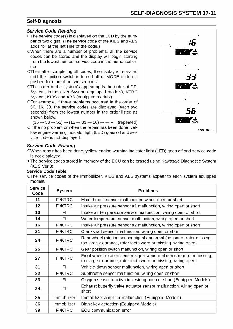
SELF-DIAGNOSIS SYSTEM 17-11Self-Diagnosis
Service Code ReadingThe service code(s) is displayed on the LCD by the num-
ber of two digits. (The service code of the KIBS and ABSadds “b" at the left side of the code.)When there are a number of problems, all the service
codes can be stored and the display will begin startingfrom the lowest number service code in the numerical or-der.Then after completing all codes, the display is repeated
until the ignition switch is turned off or MODE button ispushed for more than two seconds.The order of the system’s appearing is the order of DFI
System, Immobilizer System (equipped models), KTRCSystem, KIBS and ABS (equipped models).For example, if three problems occurred in the order of
56, 16, 33, the service codes are displayed (each twoseconds) from the lowest number in the order listed asshown below.(16 → 33 → 56) → (16 → 33 → 56) →→ ····· (repeated)
If the no problem or when the repair has been done, yel-low engine warning indicator light (LED) goes off and ser-vice code is not displayed.
Service Code ErasingWhen repair has been done, yellow engine warning indicator light (LED) goes off and service code
is not displayed.The service codes stored in memory of the ECU can be erased using Kawasaki Diagnostic System(KDS Ver.3).
Service Code TableThe service codes of the immobilizer, KIBS and ABS systems appear to each system equipped
models.ServiceCode System Problems
11 FI/KTRC Main throttle sensor malfunction, wiring open or short12 FI/KTRC Intake air pressure sensor #1 malfunction, wiring open or short13 FI Intake air temperature sensor malfunction, wiring open or short14 FI Water temperature sensor malfunction, wiring open or short16 FI/KTRC Intake air pressure sensor #2 malfunction, wiring open or short21 FI/KTRC Crankshaft sensor malfunction, wiring open or short
24 FI/KTRC Rear wheel rotation sensor signal abnormal (sensor or rotor missing,too large clearance, rotor tooth worn or missing, wiring open)
25 FI/KTRC Gear position switch malfunction, wiring open or short
27 FI/KTRC Front wheel rotation sensor signal abnormal (sensor or rotor missing,too large clearance, rotor tooth worn or missing, wiring open)
31 FI Vehicle-down sensor malfunction, wiring open or short32 FI/KTRC Subthrottle sensor malfunction, wiring open or short33 FI Oxygen sensor inactivation, wiring open or short (Equipped Models)
34 FI Exhaust butterfly valve actuator sensor malfunction, wiring open orshort
35 Immobilizer Immobilizer amplifier malfunction (Equipped Models)36 Immobilizer Blank key detection (Equipped Models)39 FI/KTRC ECU communication error

17-12 SELF-DIAGNOSIS SYSTEMSelf-Diagnosis
ServiceCode System Problems
51 FI/KTRC Stick coil #1 malfunction, wiring open or short52 FI/KTRC Stick coil #2 malfunction, wiring open or short53 FI/KTRC Stick coil #3 malfunction, wiring open or short54 FI/KTRC Stick coil #4 malfunction, wiring open or short56 FI Radiator fan relay malfunction, wiring open or short62 FI/KTRC Subthrottle valve actuator malfunction, wiring open or short63 FI Exhaust butterfly valve actuator malfunction, wiring open or short64 FI Air switching valve malfunction, wiring open or short
67 FI Oxygen sensor heater malfunction, wiring open or short (EquippedModels)
94 FI Oxygen sensor malfunction, wiring open or short (Equipped models)1b KIBS KIBS hydraulic unit communication error (Equipped Models)3A FI Purge valve malfunction, wiring open or short (CAL model)
b 13 ABS Rear intake solenoid valve trouble (open, temperature abnormal)b 14 ABS Rear outlet solenoid valve trouble (open, temperature abnormal)b 17 ABS Front intake solenoid valve trouble (open, temperature abnormal)b 18 ABS Front outlet solenoid valve trouble (open, temperature abnormal)
b 19 ABS KIBS solenoid valve relay trouble (wiring shorted or open, stuck relay(ON or OFF) or dropout)
b 25 ABS Front, rear wheel rotation difference abnormal (substandard tire,sensor rotor teeth number wrong)
b 35 ABS KIBS motor relay trouble [wiring shorted or open, stuck relay (ON orOFF)]
b 42 ABS Front wheel rotation sensor signal abnormal (sensor or rotor missing,too large clearance, rotor tooth worn or missing)
b 43 ABS Front wheel rotation sensor wiring (wiring shorted or open, connectorbad connection)
b 44 ABS Rear wheel rotation sensor signal abnormal (sensor or rotor missing,too large clearance, rotor tooth worn or missing)
b 45 ABS Rear wheel rotation sensor wiring (wiring shorted or open, connectorbad connection)
b 52 ABS Power supply voltage abnormal (under-voltage)b 53 ABS Power supply voltage abnormal (over-voltage)b 55 ABS ECU trouble (ECU operation abnormal)b 57 KIBS CAN communication (transmission)/CAN bus monitor malfunctionb 58 KIBS CAN communication (reception) monitor malfunction
b 83 ABS Output fluid pressure sensor (front brake) trouble (voltage abnormal,wiring shorted or open)
b 84 ABS Output fluid pressure sensor (front brake) trouble (offset abnormal)b 89 ABS Fluid pressure sensor supply voltage abnormal

SELF-DIAGNOSIS SYSTEM 17-13Self-Diagnosis
Notes:The ECU may be involved in these problems. If all the parts and circuits checked out good, be sure
to check the ECU for ground and power supply. If the ground and power supply are checked good,replace the ECU.When no service code is displayed, the electrical parts of the DFI system has no fault, and the
mechanical parts of the DFI system and the engine are suspect.BackupsThe ECU takes the following measures to prevent engine damage when the DFI, ignition, KTRC or
immobilizer system parts have troubles.ServiceCodes
Parts orFunction
Output Signal UsableRange or Criteria Backups by ECU
11 Main ThrottleSensor
Output Voltage0.2 ∼ 4.8 V
If the main throttle sensor system fails (theoutput voltage is out of the usable range,wiring short or open), the ECU locks ignitiontiming into the ignition timing at closed throttleposition and sets the DFI in the D-J method (1).
12Intake AirPressure
Sensor #1
Intake Air Pressure(Absolute)Pv = 57 ∼ 890 mmHg
If the intake air pressure sensor #1 systemfails (the signal is out of the usable range,wiring short or open), the ECU sets the DFIin the α-N method (2).
13Intake Air
TemperatureSensor
Intake Air TemperatureTa = – 47 ∼ + 178°C
If the intake air temperature sensor systemfails (the signal is out of the usable range,wiring short or open), the ECU sets Ta at 30°C.
14Water
TemperatureSensor
Water TemperatureTw = – 30 ∼ + 120°C
If the water temperature sensor system fails(the signal is out of the usable range, wiringshort or open), the ECU sets Tw at 80°C andthe radiator fan operates.
16Intake AirPressure
Sensor #2
Atmospheric Pressure(Absolute)Pa = 57 ∼ 890 mmHg
If the intake air pressure sensor #2 systemfails (the signal is out of the usable range,wiring short or open), the ECU sets Pa at 760mmHg (the standard atmospheric pressure).
21 CrankshaftSensor
Crankshaft sensor mustsend 22 signals to the ECUat the 1 cranking.
If the crankshaft sensor fails, the engine stopsby itself.
24Rear Wheel
RotationSensor
Rear wheel rotation sensormust send 50 signals tothe ECU at the 1 rotation ofthe wheel.
If the rear wheel rotation sensor system fails(the signal is missing, wiring open), the ECUstops the KTRC control.
25Gear
PositionSwitch
Output Voltage0.51 ∼ 4.73 V
If the gear position switch system fails (nosignal, wiring short or open), the ECU set thetop (6th) gear position.
27
Front WheelRotationSensorSignal
Front wheel rotation sensormust send 48 signals tothe ECU at the 1 rotation ofthe wheel.
If the front wheel rotation sensor system fails(the signal is missing, wiring open), the ECUstops the KTRC control.
31Vehicle-downSensor
Output Voltage0.10 ∼ 4.84 V
If the vehicle-down sensor system has failures(the output voltage is out of the usable range,wiring short or open), the ECU shuts off thefuel pump relay, the fuel injectors and theignition system.

17-14 SELF-DIAGNOSIS SYSTEMSelf-Diagnosis
ServiceCodes
Parts orFunction
Output Signal UsableRange or Criteria Backups by ECU
32 SubthrottleSensor
Output Voltage0.15 ∼ 4.85 V
If the subthrottle sensor system fails (theoutput voltage is out of the usable range, wiringshort or open), the ECU drive the subthrottlevalve to the full closed position, and it stopsthe current to the subthrottle valve actuator.
33
OxygenSensor
(EquippedModels)
The oxygen sensor isactive and sensor mustsend signals (outputvoltage) continuously tothe ECU.
If the oxygen sensor is not activated, the ECUstops the feedback mode of the oxygen sensor.
34
ExhaustButterfly
ValveActuatorSensor
Output Voltage 0.1 ∼ 4.8 V
If the exhaust butterfly valve sensor systemfails (the output voltage is out of the usablerange, wiring short or open), the ECU locksthe exhaust butterfly valve at full open positionnear, and it stops the current to the exhaustbutterfly valve actuator.
35
ImmobilizerAmplifier
(EquippedModels)
– If the immobilizer system fails (no signal, wiringshort or open), the vehicle is no start and run.
36 Ignition Key The ignition key must useregister key.
If the blank key or broken key is used, thevehicle is no start and run.
39 ECUThe ECU sends the data tothe meter unit through theCAN communication line.
–
51 Stick Coil #1*
The ECU sendssignals (output voltage)continuously to the stickcoil.
If the stick coil #1 primary winding has failures(no signal, wiring short or open), the ECUshuts off the injector #1 to stop fuel to thecylinder #1, though the engine keeps running.
52 Stick Coil #2*
The ECU sendssignals (output voltage)continuously to the stickcoil.
If the stick coil #2 primary winding has failures(no signal, wiring short or open), the ECUshuts off the injector #2 to stop fuel to thecylinder #2, though the engine keeps running.
53 Stick Coil #3*
The ECU sendssignals (output voltage)continuously to the stickcoil.
If the stick coil #3 primary winding has failures(no signal, wiring short or open), the ECUshuts off the injector #3 to stop fuel to thecylinder #3, though the engine keeps running.
54 Stick Coil #4*
The ECU sendssignals (output voltage)continuously to the stickcoil.
If the stick coil #4 primary winding has failures(no signal, wiring short or open), the ECUshuts off the injector #4 to stop fuel to thecylinder #4, though the engine keeps running.
56 Radiator FanRelay
When the radiator fan relayis OFF, the relay is opened. –
62Subthrottle
ValveActuator
The actuator operatesopen and close of thesubthrottle valve by thepulse signal from the ECU.
If the subthrottle valve actuator fails (thesignal is out to the usable range, wiring shortor open), the ECU stops the current to theactuator.

SELF-DIAGNOSIS SYSTEM 17-15Self-Diagnosis
ServiceCodes
Parts orFunction
Output Signal UsableRange or Criteria Backups by ECU
63
ExhaustButterfly
ValveActuator
The actuator operatesopen and close of theexhaust butterfly valve bythe pulse signal from theECU.
If the exhaust butterfly valve actuator fails (thesignal is out to the usable range, wiring shortor open), the ECU stops the current to theactuator.
64 Air SwitchingValve
The air switching valvecontrols the flow of thesecondary air by openingand shutting the solenoidvalve.
–
67
OxygenSensorHeater
(EquippedModels)
The oxygen sensor heaterraises temperature ofthe sensor for its earlieractivation.
If the oxygen sensor heater fails (wiring shortor open), the ECU stops the current to theheater, and it stops the feedback mode of theoxygen sensor.
94
OxygenSensor
(EquippedModels)
The oxygen sensor mustsend signals (outputvoltage) continuously tothe ECU
If the oxygen sensor output voltage is incorrect,the ECU stops oxygen sensor feed back mode.
1b KIBS
The KIBS hydraulic unitsends the data (for statusof KIBS hydraulic unit)to the meter unit andECU through the CANcommunication line.
If the communication data is not sent, the ECUstops the KTRC control.
3A Purge Valve(CAL Model)
The purge valve controlsthe flow of the secondaryair by opening and shuttingthe solenoid valve.
–
Note:(1): D-J Method: When the engine load is light like at idling or low speed, the ECU determines the
injection quantity by calculating from the throttle vacuum (vacuum sensor output voltage) andengine speed (crankshaft sensor output voltage). This method is called D-J method.
(2): α-N Method: As the engine speed increases, and the engine load turns middle to heavy, theECU determines the injection quantity by calculating from the throttle opening (throttle sensoroutput voltage) and the engine speed. This method is called α-N method.
*: This depends on the number of stopped cylinders.

17-16 SELF-DIAGNOSIS SYSTEMMain Throttle Sensor (Service Code 11)
The main throttle sensor is a rotating variable resistor thatchange output voltage according to throttle operating. TheECU senses this voltage change and determines fuel injec-tion quantity, and ignition timing according to engine rpm,and throttle opening.
Input Terminal [A]: BLOutput Terminal [B]: Y/WGround Terminal [C]: G
Main Throttle Sensor Removal/AdjustmentNOTICE
Do not remove or adjust the main throttle sensor [A]since it has been adjusted and set with precision atthe factory.Never drop the throttle body assy especially on ahard surface. Such a shock to the main throttle sen-sor can damage it.
Main Throttle Sensor Input Voltage InspectionNOTE
Be sure the battery is fully charged.
•Turn the ignition switch off.• Remove the air cleaner housing (see Air Cleaner Housing
Removal in the Fuel System (DFI) chapter).• Disconnect the main throttle sensor connector [A].
• Connect the setting adapter [A] between the harness con-nector and main throttle sensor connector.Special Tool - Throttle Sensor Setting Adapter: 57001
-1538
•Connect a digital meter to the setting adapter leads.
Main Throttle Sensor Input VoltageConnections to Adapter:
Digital Meter (+) → W (sensor BL) leadDigital Meter (–) → BK (sensor G) lead
•Measure the input voltage with the engine stopped andwith the connector joined.
• Turn the ignition switch on.
Input VoltageStandard: DC 4.75 ∼ 5.25 V
•Turn the ignition switch off.If the reading is within the standard, check the main throt-tle sensor resistance (see Main Throttle Sensor Resis-tance Inspection).

SELF-DIAGNOSIS SYSTEM 17-17Main Throttle Sensor (Service Code 11)
If the reading is out of the standard, remove the ECU andcheck the wiring for continuity between harness connec-tors.Special Tool - Hand Tester: 57001-1394Disconnect the ECU and sensor connectors.
Wiring Continuity InspectionECU Connector [A] ←→
Main Throttle Sensor Connector [B]BL lead (ECU terminal 4) [C]G lead (ECU terminal 49) [D]
If the wiring is good, check the ECU for its ground andpower supply (see ECU Power Supply Inspection in theFuel System (DFI) chapter).If the ground and power supply are good, replace the ECU(see ECU Removal/Installation in the Fuel System (DFI)chapter).
Main Throttle Sensor Resistance Inspection•Turn the ignition switch off.• Disconnect the main throttle sensor connector.• Connect a digital meter [A] to the main throttle sensor
connector [B].•Measure the main throttle sensor resistance.
Main Throttle Sensor ResistanceConnections:
BL lead [C] ← → G lead [D]Standard: 4 ∼ 6 kΩ
If the reading is out of the standard, replace the throttlebody assy.If the reading is within the standard, check the output volt-age (see Main Throttle Sensor Output Voltage Inspec-tion).
Main Throttle Sensor Output Voltage Inspection•Measure the output voltage at the main throttle sensor in
the same way as input voltage inspection, note the follow-ing.Disconnect the main throttle sensor connector and con-
nect the setting adapter [A] between these connectors.Special Tool - Throttle Sensor Setting Adapter: 57001
-1538
Main Throttle Sensor Output VoltageConnections to Adapter:
Digital Meter (+) → R (sensor Y/W) leadDigital Meter (–) → BK (sensor G) lead
Install the following parts temporarily.Air Cleaner Housing (see Air Cleaner Housing Installa-tion in the Fuel System (DFI) chapter)Fuel Tank (see Fuel Tank Installation in the Fuel System(DFI) chapter)

17-18 SELF-DIAGNOSIS SYSTEMMain Throttle Sensor (Service Code 11)
•Start the engine and warm it up thoroughly.•Check idle speed to ensure the throttle opening is correct
(see Idle Speed Inspection in the Periodic Maintenancechapter).
Idle SpeedStandard: 1 300 ±50 r/min (rpm)
•Turn the ignition switch off.•Measure the output voltage with the engine stopped, and
with the connector joined.• Turn the ignition switch on.
Output VoltageStandard: DC 1.02 ∼ 1.06 V at idle throttle opening
DC 4.30 ∼ 4.34 V at full throttle opening (forreference)
NOTEOpen the throttle, confirm the output voltage will be
raise.The standard voltage refers to the value when the volt-
age reading at the Input Voltage Inspection shows 5 Vexactly.When the input voltage reading shows other than 5 V,
derive a voltage range as follows.Example:In the case of a input voltage of 4.75 V.1.02 × 4.75 ÷ 5.00 = 0.969 V1.04 × 4.75 ÷ 5.00 = 1.007 VThus, the valid range is 0.969 ∼ 1.007 V
•Turn the ignition switch off.If the reading is out of the standard, replace the throttlebody assy.
If the reading is within the standard, remove the ECU andcheck the wiring for continuity between harness connec-tors.Special Tool - Hand Tester: 57001-1394Disconnect the ECU and sensor connectors.
Wiring Continuity InspectionECU Connector [A] ←→
Main Throttle Sensor Connector [B]Y/W lead (ECU terminal 27) [C]G lead (ECU terminal 49) [D]
If the wiring is good, check the ECU for its ground andpower supply (see ECU Power Supply Inspection in theFuel System (DFI) chapter).If the ground and power supply are good, replace the ECU(see ECU Removal/Installation in the Fuel System (DFI)chapter).

SELF-DIAGNOSIS SYSTEM 17-19Main Throttle Sensor (Service Code 11)
Main Throttle Sensor Circuit
1. ECU2. Main Throttle Sensor3. Subthrottle Sensor4. Water-proof Joint 15. Water-proof Joint 2

17-20 SELF-DIAGNOSIS SYSTEMIntake Air Pressure Sensor #1 (Service Code 12)
Intake Air Pressure Sensor #1 RemovalNOTICE
Never drop the intake air pressure sensor #1 espe-cially on a hard surface. Such a shock to the sensorcan damage it.
•Remove:Air Cleaner Housing (see Air Cleaner Housing Removalin the Fuel System (DFI) chapter)
•Disconnect:Intake Air Pressure Sensor #1 Connector [A]
•Disconnect the intake air pressure sensor #1 [B] from thebracket [C].
• Disconnect the vacuum hose [A].• Remove the rubber damper [B] from the intake air pres-
sure sensor #1 [C].
Intake Air Pressure Sensor #1 InstallationNOTE
The intake air pressure sensor #1 is the same part asthe intake air pressure sensor #2.
• Installation is basically the reverse of removal.• Position the intake air pressure sensor #1 [A] between the
projections [B] on the rubber damper.
• Install the rubber damper [A] on the bracket [B].

SELF-DIAGNOSIS SYSTEM 17-21Intake Air Pressure Sensor #1 (Service Code 12)
Intake Air Pressure Sensor #1 Input VoltageInspection
NOTEBe sure the battery is fully charged.
•Turn the ignition switch off.• Remove the air cleaner housing (see Air Cleaner Housing
Removal in the Fuel System (DFI) chapter).• Disconnect the intake air pressure sensor #1 connector
and connect the measuring adapter [A] between theseconnectors.[B] Main Harness[C] Intake Air Pressure Sensor #1
Special Tool - Measuring Adapter: 57001-1700
•Connect a digital meter [D] to the measuring adapterleads.
Intake Air Pressure Sensor #1 Input VoltageConnections to Adapter:
Digital Meter (+) → R (sensor BL) leadDigital Meter (–) → BK (sensor G) lead
•Measure the input voltage with the engine stopped andwith the connector joined.
• Turn the ignition switch on.
Input VoltageStandard: DC 4.75 ∼ 5.25 V
•Turn the ignition switch off.If the reading is within the standard, check the output volt-age (see Intake Air Pressure Sensor #1 Output VoltageInspection).
If the reading is out of the standard, remove the ECUand check the wiring for continuity between main harnessconnectors.Special Tool - Hand Tester: 57001-1394Disconnect the ECU and sensor connectors.
Wiring Continuity InspectionECU Connector [A] ←→
Intake Air Pressure Sensor #1 Connector [B]BL lead (ECU terminal 4) [C]G lead (ECU terminal 49) [D]
If the wiring is good, check the ECU for its ground andpower supply (see ECU Power Supply Inspection in theFuel System (DFI) chapter).If the ground and power supply are good, replace the ECU(see ECU Removal/Installation in the Fuel System (DFI)chapter).

17-22 SELF-DIAGNOSIS SYSTEMIntake Air Pressure Sensor #1 (Service Code 12)
Intake Air Pressure Sensor #1 Output VoltageInspection•Measure the output voltage at the intake air pressure sen-
sor #1 in the same way as input voltage inspection, notethe following.Disconnect the intake air pressure sensor #1 connector
and connect the measuring adapter [A] between theseconnectors.[B] Main Harness[C] Intake Air Pressure Sensor #1[D] Digital Meter
Special Tool - Measuring Adapter: 57001-1700
Intake Air Pressure Sensor #1 Output VoltageConnections to Adapter:
Digital Meter (+) → Y (sensor Y/BL) leadDigital Meter (–) → BK (sensor G) lead
•Measure the output voltage with the engine stopped andwith the connector joined.
• Turn the ignition switch on.
Output VoltageUsable Range: DC 3.80 ∼ 4.20 V at standard
atmospheric pressure (101.32 kPa,76 cmHg)
NOTEThe output voltage changes according to local atmo-
spheric pressure.
•Turn the ignition switch off.If the reading is out of the usable range, replace the sen-sor.
If the reading is within the usable range, remove the ECUand check the wiring for continuity between main harnessconnector.Special Tool - Hand Tester: 57001-1394Disconnect the ECU and sensor connectors.
Wiring Continuity InspectionECU Connector [A] ←→
Intake Air Pressure Sensor #1 Connector [B]Y/BL lead (ECU terminal 18) [C]G lead (ECU terminal 49) [D]

SELF-DIAGNOSIS SYSTEM 17-23Intake Air Pressure Sensor #1 (Service Code 12)
If the wiring is good, check the sensor for various vacuum.•Remove the intake air pressure sensor #1 [A] and discon-
nect the vacuum hose from the sensor.•Connect an auxiliary hose [B] to the intake air pressure
sensor #1.• Temporarily install the intake air pressure sensor #1.Connect a digital meter [C], vacuum gauge [D], the fork oil
level gauge [E] and the measuring adapter to the intakeair pressure sensor #1.Special Tools - Fork Oil Level Gauge: 57001-1290
Vacuum Gauge: 57001-1369Measuring Adapter: 57001-1700
Intake Air Pressure Sensor #1 Output VoltageConnections to Adapter:
Digital Meter (+) → Y (sensor Y/BL) leadDigital Meter (–) → BK (sensor G) lead
Turn the ignition switch on.Measure the intake air pressure sensor #1 output voltage
from various vacuum readings, while pulling the handle ofthe fork oil level gauge.Check the intake air pressure sensor #1 output voltage,
using the following formula and chart.Suppose:
Pg: Vacuum Pressure (Gauge) of Throttle BodyPl: Local Atmospheric Pressure (Absolute) measured by
a barometerPv: Vacuum Pressure (Absolute) of Throttle BodyVv: Sensor Output Voltage (V)
thenPv = Pl – Pg
For example, suppose the following data is obtained:Pg = 8 cmHg (Vacuum Gauge Reading)Pl = 70 cmHg (Barometer Reading)Vv = 3.2 V (Digital Meter Reading)
thenPv = 70 – 8 = 62 cmHg (Absolute)
Plot this Pv (62 cmHg) at a point [1] on the chart and draw avertical line through the point. Then, you can get the usablerange [2] of the sensor output voltage.
Usable range = 3.08 ∼ 3.48 VPlot Vv (3.2 V) on the vertical line. → Point [3].Results: In the chart, Vv is within the usable range andthe sensor is normal.
If the reading is out of the usable range, replace the sen-sor.If the reading is within the usable range, check the ECUfor its ground and power supply (see ECU Power SupplyInspection in the Fuel System (DFI) chapter).If the ground and power supply are good, replace the ECU(see ECU Removal/Installation in the Fuel System (DFI)chapter).

17-24 SELF-DIAGNOSIS SYSTEMIntake Air Pressure Sensor #1 (Service Code 12)
ID: IdlingPs: Standard Atmospheric Pressure (Absolute)Pv: Throttle Vacuum Pressure (Absolute)ST: Standard of Sensor Output Voltage (V)TO: Throttle Full OpenUR: Usable Range of Sensor Output Voltage (V)Vv: Intake Air Pressure Sensor #1 Output Voltage (V) (Digital Meter Reading)
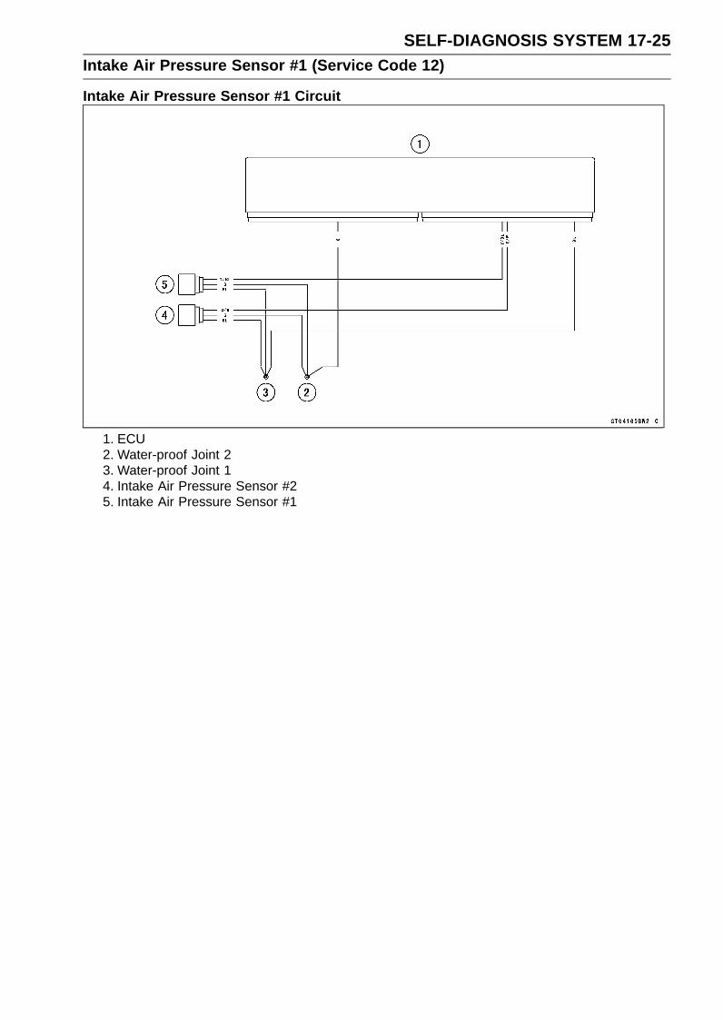
SELF-DIAGNOSIS SYSTEM 17-25Intake Air Pressure Sensor #1 (Service Code 12)
Intake Air Pressure Sensor #1 Circuit
1. ECU2. Water-proof Joint 23. Water-proof Joint 14. Intake Air Pressure Sensor #25. Intake Air Pressure Sensor #1
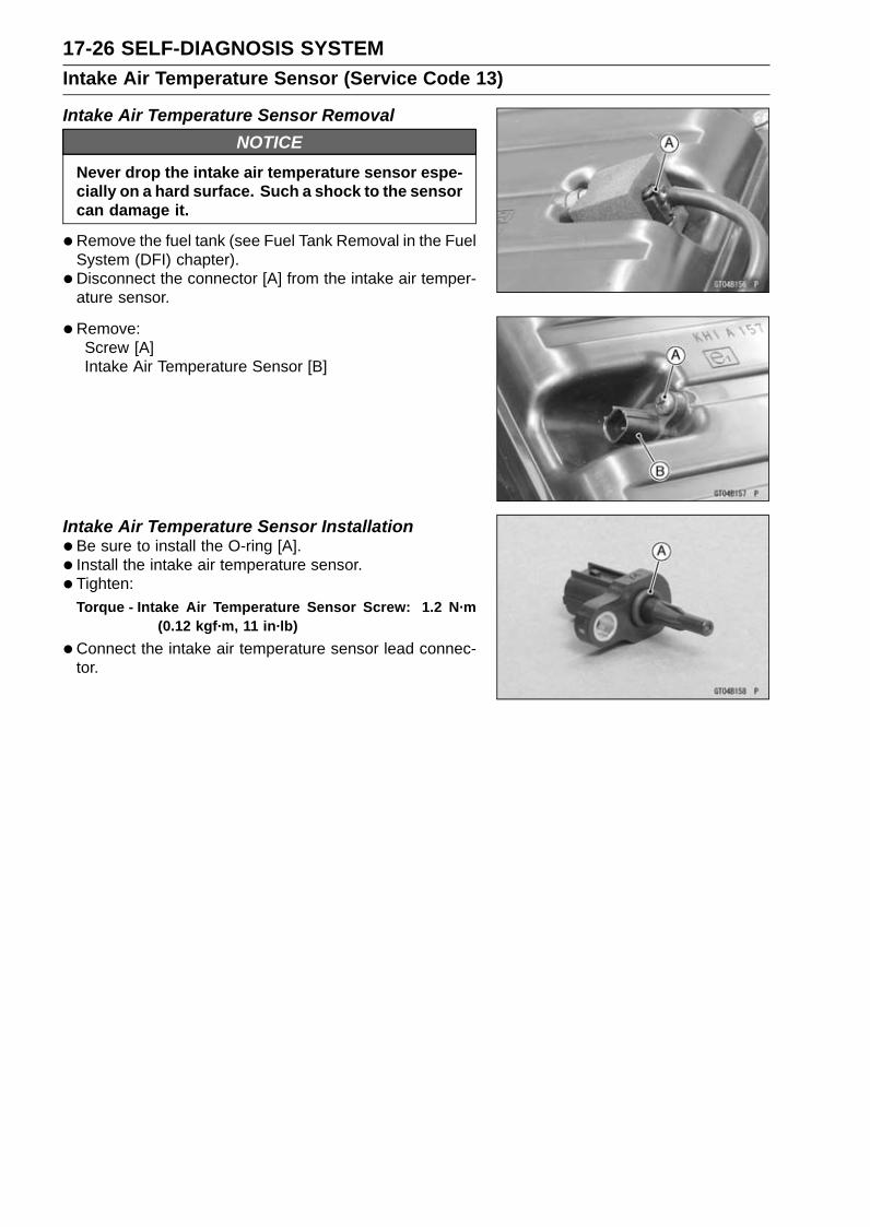
17-26 SELF-DIAGNOSIS SYSTEMIntake Air Temperature Sensor (Service Code 13)
Intake Air Temperature Sensor RemovalNOTICE
Never drop the intake air temperature sensor espe-cially on a hard surface. Such a shock to the sensorcan damage it.
•Remove the fuel tank (see Fuel Tank Removal in the FuelSystem (DFI) chapter).
• Disconnect the connector [A] from the intake air temper-ature sensor.
•Remove:Screw [A]Intake Air Temperature Sensor [B]
Intake Air Temperature Sensor Installation•Be sure to install the O-ring [A].• Install the intake air temperature sensor.• Tighten:
Torque - Intake Air Temperature Sensor Screw: 1.2 N·m(0.12 kgf·m, 11 in·lb)
•Connect the intake air temperature sensor lead connec-tor.

SELF-DIAGNOSIS SYSTEM 17-27Intake Air Temperature Sensor (Service Code 13)
Intake Air Temperature Sensor Output VoltageInspection
NOTEBe sure the battery is fully charged.
•Turn the ignition switch off.• Remove the fuel tank (see Fuel Tank Removal in the Fuel
System (DFI) chapter).• Disconnect the intake air temperature sensor connector
and connect the measuring adapter [A] between theseconnectors as shown.Main Harness [B]Intake Air Temperature Sensor [C]
Special Tool - Measuring Adapter: 57001-1700
•Connect a digital meter [D] to the harness adapter leads.
Intake Air Temperature Sensor Output VoltageConnections to Adapter:
Digital Meter (+) → R (sensor R/BK) leadDigital Meter (–) → BK (sensor G) lead
•Measure the output voltage with the engine stopped andthe connector joined.
• Turn the ignition switch on.
Output VoltageStandard: About DC 2.25 ∼ 2.50 V at 20°C (68°F)
NOTEThe output voltage changes according to the intake air
temperature.
•Turn the ignition switch off.If the reading is within the standard, check the ECU forits ground, and power supply (see ECU Power SupplyInspection in the Fuel System (DFI) chapter).If the ground and power supply are good, replace the ECU(see ECU Removal/Installation in the Fuel System (DFI)chapter).
If the reading is out of the standard, remove the ECUand check the wiring for continuity between main harnessconnectors.Special Tool - Hand Tester: 57001-1394Disconnect the ECU and sensor connectors.
Wiring InspectionECU Connector [A] ←→
Intake Air Temperature Sensor Connector [B]R/BK lead (ECU terminal 16) [C]G lead (ECU terminal 49) [D]
If the wiring is good, check the intake air temperature sen-sor resistance (see Intake Air Temperature Sensor Resis-tance Inspection).

17-28 SELF-DIAGNOSIS SYSTEMIntake Air Temperature Sensor (Service Code 13)
Intake Air Temperature Sensor ResistanceInspection•Remove the intake air temperature sensor (see Intake Air
Temperature Sensor Removal).• Suspend the sensor [A] in a container of machine oil so
that the heat-sensitive portion is submerged.• Suspend a thermometer [B] with the heat-sensitive por-
tion [C] located in almost the same depth with the sensor.
NOTEThe sensor and thermometer must not touch the con-
tainer side or bottom.
•Place the container over a source of heat and graduallyraise the temperature of the oil while stirring the oil gentlyfor even temperature.
•Using a digital meter, measure the internal resistanceof the sensor across the terminals at the temperaturesshown in the following.
Intake Air Temperature Sensor ResistanceStandard: 5.4 ∼ 6.6 kΩ at 0°C (32°F)
0.29 ∼ 0.39 kΩ at 80°C (176°F)
If the reading is out of the standard, replace the sensor.If the reading is within the standard, but the problem stillexists, replace the ECU (see ECU Removal/Installation inthe Fuel System (DFI) chapter).
Intake Air Temperature Sensor Circuit
1. ECU2. Water-proof Joint 23. Intake Air Temperature Sensor

SELF-DIAGNOSIS SYSTEM 17-29Water Temperature Sensor (Service Code 14)
Water Temperature Sensor Removal/InstallationNOTICE
Never drop the water temperature sensor especiallyon a hard surface. Such a shock to the sensor candamage it.
•Remove the throttle body assy (see Throttle Body AssyRemoval in the Fuel System (DFI) chapter).
• Drain the coolant (see Coolant Change in the PeriodicMaintenance chapter).
• Disconnect the water temperature sensor lead connector.• Remove:
Water Temperature Sensor [A] with O-ring•Replace the O-ring with a new one and apply soap and
water solution to it.• Tighten:
Torque - Water Temperature Sensor: 12 N·m (1.2 kgf·m, 106in·lb)
•Fill the engine with coolant and bleed the air from the cool-ing system (see Coolant Change in the Periodic Mainte-nance chapter).
Water Temperature Sensor Output VoltageInspection
NOTEBe sure the battery is fully charged.
•Turn the ignition switch off.• Remove the throttle body assy (see Throttle Body Assy
Removal in the Fuel System (DFI) chapter).
• Disconnect the water temperature sensor connector andconnect the measuring adapter [A] between these con-nectors as shown.Main Harness [B]Water Temperature Sensor [C]
Special Tool - Measuring Adapter: 57001-1700
•Connect a digital meter [D] to the measuring adapterleads.
Water Temperature Sensor Output VoltageConnections to Adapter:
Digital Meter (+) → R (sensor W/G) leadDigital Meter (–) → BK (sensor G) lead
•Measure the output voltage with the engine stopped andthe connector joined.
• Turn the ignition switch on.
Output VoltageStandard: About DC 2.80 ∼ 2.97 V at 20°C (68°F)
NOTEThe output voltage changes according to the coolant
temperature in the engine.
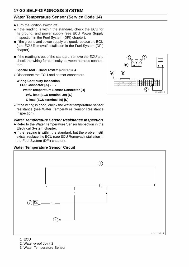
17-30 SELF-DIAGNOSIS SYSTEMWater Temperature Sensor (Service Code 14)
•Turn the ignition switch off.If the reading is within the standard, check the ECU forits ground, and power supply (see ECU Power SupplyInspection in the Fuel System (DFI) chapter).If the ground and power supply are good, replace the ECU(see ECU Removal/Installation in the Fuel System (DFI)chapter).
If the reading is out of the standard, remove the ECU andcheck the wiring for continuity between harness connec-tors.Special Tool - Hand Tester: 57001-1394Disconnect the ECU and sensor connectors.
Wiring Continuity InspectionECU Connector [A] ←→
Water Temperature Sensor Connector [B]W/G lead (ECU terminal 30) [C]G lead (ECU terminal 49) [D]
If the wiring is good, check the water temperature sensorresistance (see Water Temperature Sensor ResistanceInspection).
Water Temperature Sensor Resistance Inspection•Refer to the Water Temperature Sensor Inspection in the
Electrical System chapter.If the reading is within the standard, but the problem stillexists, replace the ECU (see ECU Removal/Installation inthe Fuel System (DFI) chapter).
Water Temperature Sensor Circuit
1. ECU2. Water-proof Joint 23. Water Temperature Sensor

SELF-DIAGNOSIS SYSTEM 17-31Intake Air Pressure Sensor #2 (Service Code 16)
Intake Air Pressure Sensor #2 RemovalNOTICE
Never drop the intake air pressure sensor #2 espe-cially on a hard surface. Such a shock to the sensorcan damage it.
•Remove:Air Cleaner Housing (see Air Cleaner Housing Removalin the Fuel System (DFI) chapter)
•Disconnect:Intake Air Pressure Sensor #2 Connector [A]
•Disconnect the intake air pressure sensor #2 [B] from thebracket [C].
• Disconnect the vacuum hose [A].• Remove the rubber damper [B] from the intake air pres-
sure sensor #2 [C].
Intake Air Pressure Sensor #2 InstallationNOTE
The intake air pressure sensor #2 is the same part asthe intake air pressure sensor #1.
• Installation is basically the reverse of removal.• Position the intake air pressure sensor #2 [A] between the
projections [B] on the rubber damper.
• Install the rubber damper [A] on the bracket [B].

17-32 SELF-DIAGNOSIS SYSTEMIntake Air Pressure Sensor #2 (Service Code 16)
Intake Air Pressure Sensor #2 Input VoltageInspection
NOTEBe sure the battery is fully charged.
•Turn the ignition switch off.• Remove the air cleaner housing (see Air Cleaner Housing
Removal in the Fuel System (DFI) chapter).• Disconnect the intake air pressure sensor #2 connector
and connect the measuring adapter [A] between theseconnectors.[B] Main Harness[C] Intake Air Pressure Sensor #2
Special Tool - Measuring Adapter: 57001-1700
•Connect a digital meter [D] to the measuring adapterleads.
Intake Air Pressure Sensor #2 Input VoltageConnections to Adapter:
Digital Meter (+) → R (sensor BL) leadDigital Meter (–) → BK (sensor G) lead
•Measure the input voltage with the engine stopped andwith the connector joined.
• Turn the ignition switch on.
Input VoltageStandard: DC 4.75 ∼ 5.25 V
•Turn the ignition switch off.If the reading is within the standard, check the output volt-age (see Intake Air Pressure Sensor #2 Output VoltageInspection).
If the reading is out of the standard, remove the ECUand check the wiring for continuity between main harnessconnectors.Special Tool - Hand Tester: 57001-1394Disconnect the ECU and sensor connectors.
Wiring Continuity InspectionECU Connector [A] ←→
Intake Air Pressure Sensor #2 Connector [B]BL lead (ECU terminal 4) [C]G lead (ECU terminal 49) [D]
If the wiring is good, check the ECU for its ground andpower supply (see ECU Power Supply Inspection in theFuel System (DFI) chapter).If the ground and power supply are good, replace the ECU(see ECU Removal/Installation in the Fuel System (DFI)chapter).

SELF-DIAGNOSIS SYSTEM 17-33Intake Air Pressure Sensor #2 (Service Code 16)
Intake Air Pressure Sensor #2 Output VoltageInspection•Measure the output voltage at the intake air pressure sen-
sor #2 in the same way as input voltage inspection, notethe following.Disconnect the intake air pressure sensor #2 connector
and connect the measuring adapter [A] between theseconnectors.[B] Main Harness[C] Intake Air Pressure Sensor #2[D] Digital Meter
Special Tool - Measuring Adapter: 57001-1700
Intake Air Pressure Sensor #2 Output VoltageConnections to Adapter:
Digital Meter (+) → Y (sensor G/W) leadDigital Meter (–) → BK (sensor G) lead
•Measure the output voltage with the engine stopped andwith the connector joined.
• Turn the ignition switch on.
Output VoltageUsable Range: DC 3.80 ∼ 4.20 V at standard
atmospheric pressure (101.32 kPa, 76cmHg absolute)
NOTEThe output voltage changes according to the local at-
mospheric pressure.
•Turn the ignition switch off.If the reading is out of the usable range, replace the sen-sor.
If the reading is within the usable range, remove the ECUand check the wiring for continuity between main harnessconnector.Special Tool - Hand Tester: 57001-1394Disconnect the ECU and sensor connectors.
Wiring Continuity InspectionECU Connector [A] ←→
Intake Air Pressure Sensor #2 Connector [B]G/W lead (ECU terminal 17) [C]G lead (ECU terminal 49) [D]
If the wiring is good, check the sensor for various vac-uum (see Intake Air Pressure Sensor #1 Output VoltageInspection).

17-34 SELF-DIAGNOSIS SYSTEMIntake Air Pressure Sensor #2 (Service Code 16)
Intake Air Pressure Sensor #2 Circuit
1. ECU2. Water-proof Joint 23. Water-proof Joint 14. Intake Air Pressure Sensor #25. Intake Air Pressure Sensor #1

SELF-DIAGNOSIS SYSTEM 17-35Crankshaft Sensor (Service Code 21)
The crankshaft sensor has no power source, and whenthe engine stops, the crankshaft sensor generates no sig-nals.
Crankshaft Sensor Removal/Installation•Refer to the Crankshaft Sensor Removal/Installation in
the Electrical System chapter.
Crankshaft Sensor Resistance Inspection•Refer to the Crankshaft Sensor Inspection in the Electrical
System chapter.If the reading is within the standard, check the peak volt-age (see Crankshaft Sensor Peak Voltage Inspection).
Crankshaft Sensor Peak Voltage Inspection•Refer to the Crankshaft Sensor Peak Voltage Inspection
in the Electrical System chapter.If the reading is within the standard, remove the ECU andcheck the wiring for continuity between harness connec-tors.Special Tool - Hand Tester: 57001-1394Disconnect the ECU and sensor connectors.
Wiring Continuity InspectionECU Connector [A] ←→
Crankshaft Sensor Connector [B]Y/BK lead (ECU terminal 59) [C]Y lead (ECU terminal 60) [D]
If the wiring is good, check the ECU for its ground andpower supply (see ECU Power Supply Inspection in theFuel System (DFI) chapter).If the ground and power supply are good, replace the ECU(see ECU Removal/Installation in the Fuel System (DFI)chapter).

17-36 SELF-DIAGNOSIS SYSTEMCrankshaft Sensor (Service Code 21)
Crankshaft Sensor Circuit
1. ECU2. Crankshaft Sensor

SELF-DIAGNOSIS SYSTEM 17-37Rear Wheel Rotation Sensor Signal (Service Code 24)
Rear Wheel Rotation Sensor Signal InspectionThe rear wheel rotation sensor sends the signal to the
ECU through the KIBS hydraulic unit (KIBS equippedmodels). For other than KIBS equipped models, thesignal is sent directly to the ECU.The ECU uses the rear wheel rotation sensor signal for
motorcycle speed and KTRC control.The service code 24 is detected with the ECU.• Inspect the wheel rotation sensor air gap (see Wheel Ro-
tation Sensor Air Gap Inspection in the Brakes chapter).• Inspect the wheel rotation sensor rotor (see Wheel Rota-
tion Sensor Rotor Inspection in the Brakes chapter).•When the service code 24 and following service codes
(for KIBS) are displayed at the same time, inspect the rearwheel rotation sensor.Service Code b 44 (see Rear Wheel Rotation SensorSignal Abnormal)Service Code b 45 (see Rear Wheel Rotation SensorWiring Inspection)
•When only service code 24 is displayed, do the followinginspection procedures.
•Disconnect:ECU Connectors (see ECU Removal in the Fuel System(DFI) chapter)Rear Wheel Rotation Sensor Lead ConnectorKIBS Hydraulic Unit Connector (see KIBS Hydraulic UnitRemoval in the Brakes chapter)
• For KIBS equipped models, check the wiring for continuitybetween harness connectors.Special Tool - Hand Tester: 57001-1394
Wiring Continuity InspectionECU Connector [A] ← →
KIBS Hydraulic Unit Connector [B]R/Y lead (ECU terminal 20, KIBS Hydraulic Unitterminal 16) [C]
Wiring Continuity InspectionKIBS Hydraulic Unit Connector [A] ← →
Rear Wheel Rotation Sensor Connector [B]BK/O lead (KIBS Hydraulic Unit Connector terminal14) [C]W/G lead (KIBS Hydraulic Unit Connector terminal13) [D]

17-38 SELF-DIAGNOSIS SYSTEMRear Wheel Rotation Sensor Signal (Service Code 24)
•For other than KIBS equipped models, check the wiringfor continuity between harness connectors.Special Tool - Hand Tester: 57001-1394
Wiring Continuity InspectionECU Connector [A] ← →
Rear Wheel Rotation Sensor Connector [B]W/Y lead (ECU terminal 8) [C]R/Y lead (ECU terminal 9) [D]
If the wiring is good, check the ECU for its ground andpower supply (see ECU Power Supply Inspection in theFuel System (DFI) chapter).If the ground and power supply are good, replace the ECU(see ECU Removal/Installation in the Fuel System (DFI)chapter).
Wheel Rotation Sensor Circuit (KIBS Equipped Models)
1. ECU2. Rear Wheel Rotation Sensor3. KIBS Hydraulic Unit4. Front Wheel Rotation Sensor

SELF-DIAGNOSIS SYSTEM 17-39Rear Wheel Rotation Sensor Signal (Service Code 24)
Wheel Rotation Sensor Circuit (other than KIBS Equipped Models)
1. ECU2. Rear Wheel Rotation Sensor3. Front Wheel Rotation Sensor

17-40 SELF-DIAGNOSIS SYSTEMGear Position Switch (Service Code 25)
Gear Position Switch Removal/Installation•Refer to the Gear Position Switch Removal/Installation in
the Electrical System chapter.
Gear Position Switch Resistance Inspection•Refer to the Gear Position Switch Inspection in the Elec-
trical System chapter.If the reading is as the specified, check the output voltage(see Gear Position Switch Output Voltage Inspection).
Gear Position Switch Output Voltage InspectionNOTE
Be sure the battery is fully charged.
•Turn the ignition switch off.• Remove the fuel tank (see Fuel Tank Removal in the Fuel
System (DFI) chapter).• Disconnect the sidestand switch/gear position switch lead
connector [A].
• Connect the measuring adapter [A] between the main har-ness connector and sidestand switch/gear position switchlead connector as shown.Main Harness [B]To Gear Position Switch [C]To Sidestand Switch [D]
Special Tool - Measuring Adapter: 57001-1700
•Connect a digital meter [E] to the measuring adapter lead.
Gear Position Switch Output VoltageConnections to Adapter:
Digital Meter (+) → R (sensor G/R) leadDigital Meter (–) → Frame Ground terminal
•Measure the switch input voltage with the engine stoppedand with the connector joined.
• Turn the ignition switch on.When changing the gear position from lower gear to
higher gear, raise the rear wheel off the ground with asuitable stand and rotate the rear wheel by hand.
Output Voltage at 1 ∼ 6 Gear PositionsStandard:
1st About DC 3.0 V2nd About DC 2.5 V3rd About DC 2.0 V4th About DC 1.5 V5th About DC 1.1 V6th About DC 0.7 V

SELF-DIAGNOSIS SYSTEM 17-41Gear Position Switch (Service Code 25)
•Turn the ignition switch off.If the reading is out of the standard, check the wiring forcontinuity, using the wiring diagram in this section.Special Tool - Hand Tester: 57001-1394If the wiring is good, check the ECU for its ground andpower supply (see ECU Power Supply Inspection in theFuel System (DFI) chapter).If the ground and power supply are good, replace the ECU(see ECU Removal/Installation in the Fuel System (DFI)chapter).
Gear Position Switch Circuit
1. ECU2. Frame Ground 13. Relay Box4. Meter Unit5. Gear Position Switch
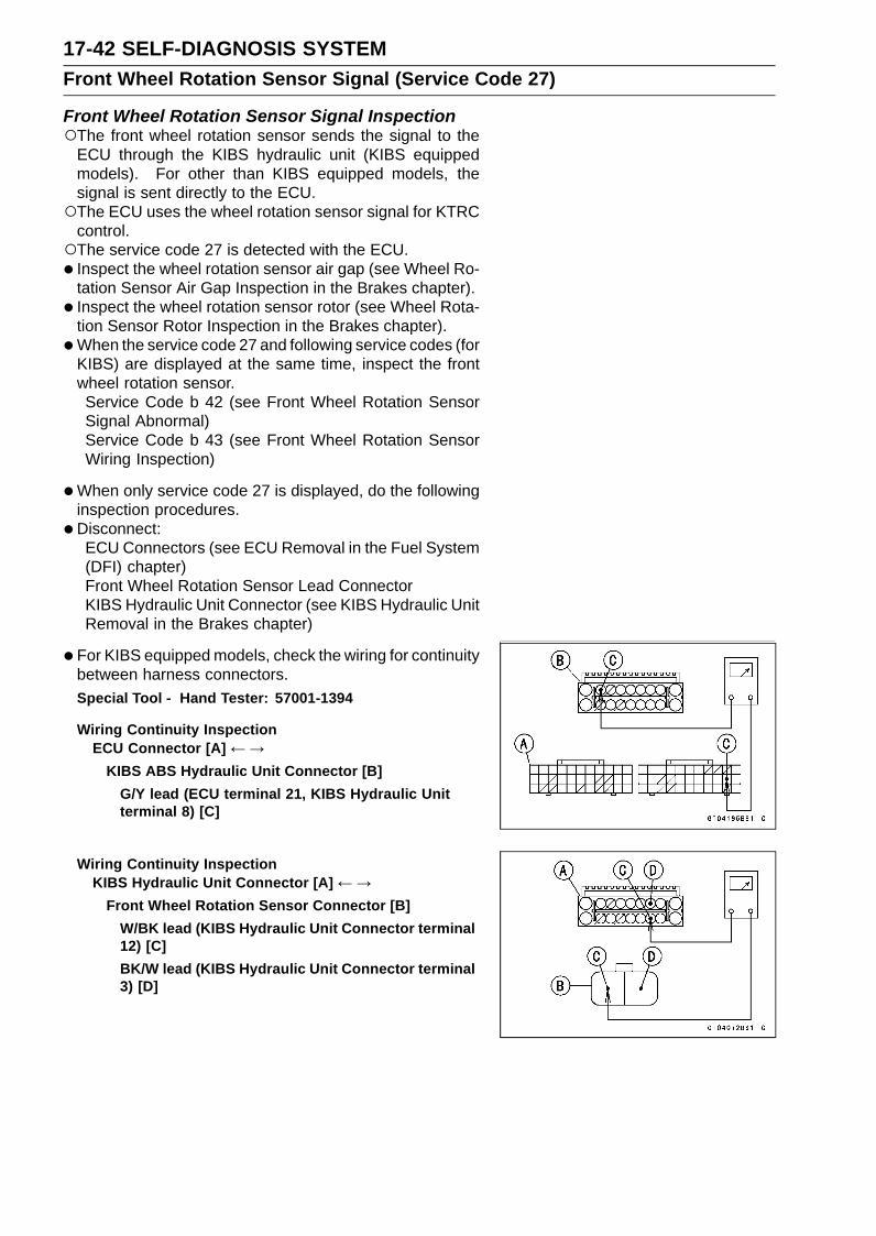
17-42 SELF-DIAGNOSIS SYSTEMFront Wheel Rotation Sensor Signal (Service Code 27)
Front Wheel Rotation Sensor Signal InspectionThe front wheel rotation sensor sends the signal to the
ECU through the KIBS hydraulic unit (KIBS equippedmodels). For other than KIBS equipped models, thesignal is sent directly to the ECU.The ECU uses the wheel rotation sensor signal for KTRC
control.The service code 27 is detected with the ECU.• Inspect the wheel rotation sensor air gap (see Wheel Ro-
tation Sensor Air Gap Inspection in the Brakes chapter).• Inspect the wheel rotation sensor rotor (see Wheel Rota-
tion Sensor Rotor Inspection in the Brakes chapter).•When the service code 27 and following service codes (for
KIBS) are displayed at the same time, inspect the frontwheel rotation sensor.Service Code b 42 (see Front Wheel Rotation SensorSignal Abnormal)Service Code b 43 (see Front Wheel Rotation SensorWiring Inspection)
•When only service code 27 is displayed, do the followinginspection procedures.
•Disconnect:ECU Connectors (see ECU Removal in the Fuel System(DFI) chapter)Front Wheel Rotation Sensor Lead ConnectorKIBS Hydraulic Unit Connector (see KIBS Hydraulic UnitRemoval in the Brakes chapter)
• For KIBS equipped models, check the wiring for continuitybetween harness connectors.Special Tool - Hand Tester: 57001-1394
Wiring Continuity InspectionECU Connector [A] ← →
KIBS ABS Hydraulic Unit Connector [B]G/Y lead (ECU terminal 21, KIBS Hydraulic Unitterminal 8) [C]
Wiring Continuity InspectionKIBS Hydraulic Unit Connector [A] ← →
Front Wheel Rotation Sensor Connector [B]W/BK lead (KIBS Hydraulic Unit Connector terminal12) [C]BK/W lead (KIBS Hydraulic Unit Connector terminal3) [D]

SELF-DIAGNOSIS SYSTEM 17-43Front Wheel Rotation Sensor Signal (Service Code 27)
•For other than KIBS equipped models, check the wiringfor continuity between harness connectors.Special Tool - Hand Tester: 57001-1394
Wiring Continuity InspectionECU Connector [A] ← →
Front Wheel Rotation Sensor Connector [B]W/Y lead (ECU terminal 8) [C]G/Y lead (ECU terminal 10) [D]
If the wiring is good, check the ECU for its ground andpower supply (see ECU Power Supply Inspection in theFuel System (DFI) chapter).If the ground and power supply are good, replace the ECU(see ECU Removal/Installation in the Fuel System (DFI)chapter).
Wheel Rotation Sensor Circuit (KIBS Equipped Models)
1. ECU2. Rear Wheel Rotation Sensor3. KIBS Hydraulic Unit4. Front Wheel Rotation Sensor

17-44 SELF-DIAGNOSIS SYSTEMFront Wheel Rotation Sensor Signal (Service Code 27)
Wheel Rotation Sensor Circuit (other than KIBS Equipped Models)
1. ECU2. Rear Wheel Rotation Sensor3. Front Wheel Rotation Sensor

SELF-DIAGNOSIS SYSTEM 17-45Vehicle-down Sensor (Service Code 31)
This sensor has a weight [A] with two magnets inside,and sends a signal to the ECU. But when the motorcyclebanks 60 ∼ 70° or more to either side (in fact falls down),the weight turns and the signal changes. The ECU sensesthis change, and stops the fuel pump relay, the fuel injectorsand the ignition system.
Hall IC [B]When the motorcycle is down, the ignition switch is left
ON. If the starter button is pushed, the electric starter turnsbut the engine does not start. To start the engine again,raise the motorcycle, turn the ignition switch off, and thenturn it on.
Vehicle-down Sensor [A]Ground Terminal [B]: GOutput Terminal [C]: Y/GInput Terminal [D]: BL
Vehicle-down Sensor RemovalNOTICE
Never drop the vehicle-down sensor especially ona hard surface. Such a shock to the sensor candamage it.
•Remove:Right Seat Cover (see Seat Cover Removal in the Framechapter)
•Disconnect the connector [A].• Remove:
Bolts and Nuts [B]Vehicle-down Sensor [C]
Vehicle-down Sensor Installation•Be sure to install the rubber dampers [A] and collars [B]
on the bracket.

17-46 SELF-DIAGNOSIS SYSTEMVehicle-down Sensor (Service Code 31)
•The UP mark [A] of the sensor should face upward.
WARNINGIncorrect installation of the vehicle-down sensorcould cause sudden loss of engine power. Therider could lose balance during certain riding situ-ations for an accident resulting in injury or death.Ensure that the vehicle-down sensor is held inplace by the sensor bracket.
Vehicle-down Sensor Input Voltage InspectionNOTE
Be sure the battery is fully charged.
•Turn the ignition switch off.• Disconnect the vehicle-down sensor connector and con-
nect the measuring adapter [A] between these connectorsas shown.Main Harness [B]Vehicle-down Sensor [C]
Special Tool - Measuring Adapter: 57001-1700
•Connect a digital meter [D] to the measuring adapterleads.
Vehicle-down Sensor Input VoltageConnections to Adapter:
Digital Meter (+) → R (sensor BL) leadDigital Meter (–) → BK (sensor G) lead
•Measure the input voltage with the engine stopped andwith the connector joined.
• Turn the ignition switch on.
Input VoltageStandard: DC 4.75 ∼ 5.25 V
•Turn the ignition switch off.If the reading is within the standard, check the output volt-age (see Vehicle-down Sensor Output Voltage Inspec-tion).
If the reading is out of the standard, remove the ECUand check the wiring for continuity between main harnessconnectors.Special Tool - Hand Tester: 57001-1394Disconnect the ECU and sensor connectors.
Wiring Continuity InspectionECU Connector [A] ←→
Vehicle-down Sensor Connector [B]BL lead (ECU terminal 4) [C]G lead (ECU terminal 49) [D]
If the wiring is good, check the ECU for its ground andpower supply (see ECU Power Supply Inspection in theFuel System (DFI) chapter).If the ground and power supply are good, replace the ECU(see ECU Removal/Installation in the Fuel System (DFI)chapter).

SELF-DIAGNOSIS SYSTEM 17-47Vehicle-down Sensor (Service Code 31)
Vehicle-down Sensor Output Voltage Inspection•Remove the vehicle-down sensor.•Connect the measuring adapter [A] to the vehicle-down
sensor connectors as shown.Special Tool - Measuring Adapter: 57001-1700Main Harness [B]Vehicle-down Sensor [C]
•Connect a digital meter [D] to the measuring adapterleads.
Vehicle-down Sensor Output VoltageConnections to Adapter:
Digital Meter (+) → W (sensor Y/G) leadDigital Meter (–) → BK (sensor G) lead
•Hold the sensor vertically.•Measure the output voltage with the engine stopped, and
with the connector joined.• Turn the ignition switch on.• Tilt the sensor 60 ∼ 70° or more [A] right or left, then hold
the sensor almost vertical with the arrow mark pointed up[B], and measure the output voltage.
Output VoltageStandard: With sensor tilted 60 ∼ 70° or more right or
left: DC 0.65 ∼ 1.35 VWith sensor arrow mark pointed up: DC3.55 ∼ 4.45 V
•Turn the ignition switch off.If the reading is out of the standard, replace the sensor.

17-48 SELF-DIAGNOSIS SYSTEMVehicle-down Sensor (Service Code 31)
If the reading is within the standard, remove the ECU andcheck the wiring for continuity between main harness con-nectors.Special Tool - Hand Tester: 57001-1394Disconnect the ECU and sensor connectors.
Wiring Continuity InspectionECU Connector [A] ←→
Vehicle-down Sensor Connector [B]Y/G lead (ECU terminal 19) [C]G lead (ECU terminal 49) [D]
If the wiring is good, check the ECU for its ground andpower supply (see ECU Power Supply Inspection in theFuel System (DFI) chapter).If the ground and power supply are good, replace the ECU(see ECU Removal/Installation in the Fuel System (DFI)chapter).
Vehicle-down Sensor Circuit
1. ECU2. Water-proof Joint 13. Water-proof Joint 24. Vehicle-down Sensor

SELF-DIAGNOSIS SYSTEM 17-49Subthrottle Sensor (Service Code 32)
The subthrottle sensor is a rotating variable resistor thatchange output voltage according to throttle operating. TheECU senses this voltage change and determines fuel injec-tion quantity, and ignition timing according to engine rpm,and throttle opening.
Input Terminal [A]: BLOutput Terminal [B]: BL/WGround Terminal [C]: G
Subthrottle Sensor Removal/AdjustmentNOTICE
Do not remove or adjust the subthrottle sensor [A]since it has been adjusted and set with precision atthe factory.Never drop the throttle body assy especially on ahard surface. Such a shock to the subthrottle sen-sor can damage it.
Subthrottle Sensor Input Voltage InspectionNOTE
Be sure the battery is fully charged.
•Turn the ignition switch off.• Remove the air cleaner housing (see Air Cleaner Housing
Removal in the Fuel System (DFI) chapter).• Disconnect the subthrottle sensor connector and connect
the harness adapter [A] between these connectors.Special Tool - Throttle Sensor Setting Adapter: 57001
-1538
•Connect a digital meter to the harness adapter leads.
Subthrottle Sensor Input VoltageConnections to Adapter:
Digital Meter (+) → W (sensor BL) leadDigital Meter (–) → BK (sensor G) lead
•Measure the input voltage with the engine stopped andwith the connector joined.
• Turn the ignition switch on.
Input VoltageStandard: DC 4.75 ∼ 5.25 V
•Turn the ignition switch off.If the reading is within the standard, check the output volt-age (see Subthrottle Sensor Output Voltage Inspection).
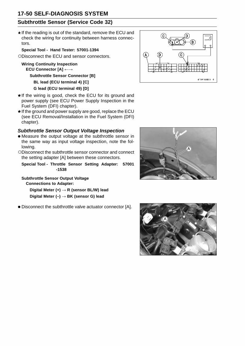
17-50 SELF-DIAGNOSIS SYSTEMSubthrottle Sensor (Service Code 32)
If the reading is out of the standard, remove the ECU andcheck the wiring for continuity between harness connec-tors.Special Tool - Hand Tester: 57001-1394Disconnect the ECU and sensor connectors.
Wiring Continuity InspectionECU Connector [A] ←→
Subthrottle Sensor Connector [B]BL lead (ECU terminal 4) [C]G lead (ECU terminal 49) [D]
If the wiring is good, check the ECU for its ground andpower supply (see ECU Power Supply Inspection in theFuel System (DFI) chapter).If the ground and power supply are good, replace the ECU(see ECU Removal/Installation in the Fuel System (DFI)chapter).
Subthrottle Sensor Output Voltage Inspection•Measure the output voltage at the subthrottle sensor in
the same way as input voltage inspection, note the fol-lowing.Disconnect the subthrottle sensor connector and connect
the setting adapter [A] between these connectors.Special Tool - Throttle Sensor Setting Adapter: 57001
-1538
Subthrottle Sensor Output VoltageConnections to Adapter:
Digital Meter (+) → R (sensor BL/W) leadDigital Meter (–) → BK (sensor G) lead
•Disconnect the subthrottle valve actuator connector [A].

SELF-DIAGNOSIS SYSTEM 17-51Subthrottle Sensor (Service Code 32)
•Measure the output voltage with the engine stopped withthe connector joined.
• Turn the ignition switch on.•Measure the output voltage when the subthrottle valves
are fully opened by hand.
Output VoltageStandard: DC 1.08 ∼ 1.12 V at subthrottle valve full
close positionDC 4.48 ∼ 4.52 V at subthrottle valve fullopen position (for reference)
NOTEOpen the subthrottle valves, confirm the output voltage
will be raise.The standard voltage refers to the value when the volt-
age reading at the Input Voltage Inspection shows 5 Vexactly.When the input voltage reading shows other than 5 V,
derive a voltage range as follows.Example:In the case of a input voltage of 4.75 V.1.08 × 4.75 ÷ 5.00 = 1.026 V1.12 × 4.75 ÷ 5.00 = 1.064 VThus, the valid range is 1.026 ∼ 1.064 V
•Turn the ignition switch off.If the reading is out of the standard, check the subthrot-tle sensor resistance (see Subthrottle Sensor ResistanceInspection).
If the reading is within the standard, remove the ECU andcheck the wiring for continuity between harness connec-tors.Special Tool - Hand Tester: 57001-1394Disconnect the ECU and sensor connectors.
Wiring Continuity InspectionECU Connector [A] ←→
Subthrottle Sensor Connector [B]BL/W lead (ECU terminal 28) [C]G lead (ECU terminal 49) [D]
If the wiring is good, check the ECU for its ground andpower supply (see ECU Power Supply Inspection in theFuel System (DFI) chapter).If the ground and power supply are good, replace the ECU(see ECU Removal/Installation in the Fuel System (DFI)chapter).
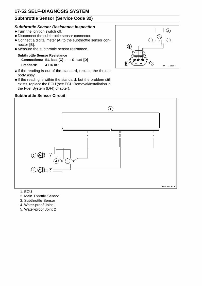
17-52 SELF-DIAGNOSIS SYSTEMSubthrottle Sensor (Service Code 32)
Subthrottle Sensor Resistance Inspection•Turn the ignition switch off.• Disconnect the subthrottle sensor connector.• Connect a digital meter [A] to the subthrottle sensor con-
nector [B].•Measure the subthrottle sensor resistance.
Subthrottle Sensor ResistanceConnections: BL lead [C] ←→ G lead [D]Standard: 4 ∼ 6 kΩ
If the reading is out of the standard, replace the throttlebody assy.If the reading is within the standard, but the problem stillexists, replace the ECU (see ECU Removal/Installation inthe Fuel System (DFI) chapter).
Subthrottle Sensor Circuit
1. ECU2. Main Throttle Sensor3. Subthrottle Sensor4. Water-proof Joint 15. Water-proof Joint 2

SELF-DIAGNOSIS SYSTEM 17-53Oxygen Sensor - not activated (Service Code 33, Equipped Models)
Oxygen Sensor Removal/Installation•Refer to the Oxygen Sensor Removal/Installation
(Equipped Models) in the Electrical System chapter.
Oxygen Sensor Inspection•Remove:
Fuel Tank (see Fuel Tank Removal in the Fuel System(DFI) chapter)
•Disconnect:Oxygen Sensor Lead Connector [A]
•Connect the measuring adapter [A] between the harnessconnector and oxygen sensor lead connector.Main Harness [B]Oxygen Sensor [C]
Special Tool - Measuring Adapter: 57001-1700
•Connect a digital meter [D] to the measuring adapterleads.
Oxygen Sensor Output VoltageConnections to Adapter:
Digital Meter (+) → R (sensor BK) leadDigital Meter (–) → BK (sensor GY) lead
•Remove the air switching valve [A] (see Air SwitchingValve Removal in the Engine Top End chapter).Do not disconnect the air switching valve connector [B].
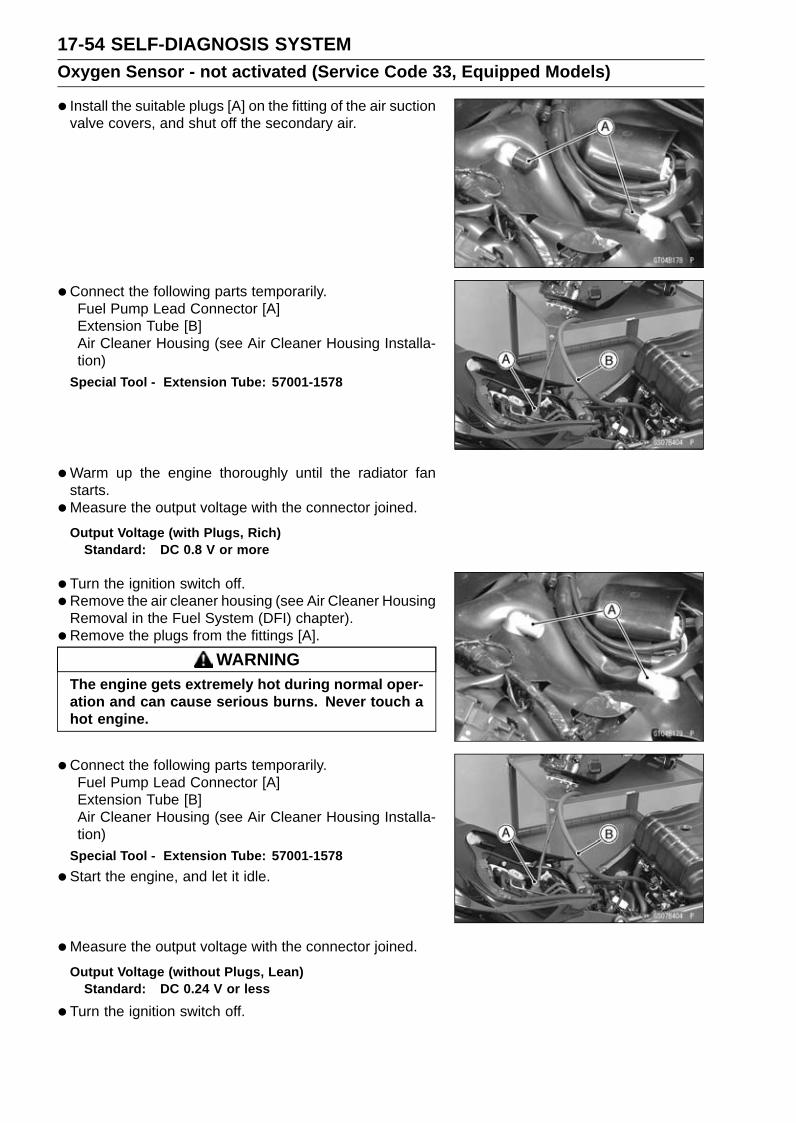
17-54 SELF-DIAGNOSIS SYSTEMOxygen Sensor - not activated (Service Code 33, Equipped Models)
• Install the suitable plugs [A] on the fitting of the air suctionvalve covers, and shut off the secondary air.
• Connect the following parts temporarily.Fuel Pump Lead Connector [A]Extension Tube [B]Air Cleaner Housing (see Air Cleaner Housing Installa-tion)
Special Tool - Extension Tube: 57001-1578
•Warm up the engine thoroughly until the radiator fanstarts.
•Measure the output voltage with the connector joined.
Output Voltage (with Plugs, Rich)Standard: DC 0.8 V or more
•Turn the ignition switch off.• Remove the air cleaner housing (see Air Cleaner Housing
Removal in the Fuel System (DFI) chapter).• Remove the plugs from the fittings [A].
WARNINGThe engine gets extremely hot during normal oper-ation and can cause serious burns. Never touch ahot engine.
•Connect the following parts temporarily.Fuel Pump Lead Connector [A]Extension Tube [B]Air Cleaner Housing (see Air Cleaner Housing Installa-tion)
Special Tool - Extension Tube: 57001-1578
•Start the engine, and let it idle.
•Measure the output voltage with the connector joined.
Output Voltage (without Plugs, Lean)Standard: DC 0.24 V or less
•Turn the ignition switch off.

SELF-DIAGNOSIS SYSTEM 17-55Oxygen Sensor - not activated (Service Code 33, Equipped Models)
If the reading is out of the standard (with plugs: 0.8 V ormore, without plugs: 0.24 V or less), remove the ECU andcheck the wiring for continuity between harness connec-tors.Special Tool - Hand Tester: 57001-1394Disconnect the ECU and sensor connectors.
Wiring Continuity InspectionECU Connector [A] ←→
Oxygen Sensor Connector [B]BL/Y lead (ECU terminal 33) [C]G lead (ECU terminal 49) [D]
If the wiring is good, replace the sensor.If the reading is within the standard (with plugs: 0.8 Vor more, without plugs: 0.24 V or less), check the ECUfor its ground and power supply (see ECU Power SupplyInspection in the Fuel System (DFI) chapter).If the ground and power supply are good, replace the ECU(see ECU Removal/Installation in the Fuel System (DFI)chapter).

17-56 SELF-DIAGNOSIS SYSTEMOxygen Sensor - not activated (Service Code 33, Equipped Models)
Oxygen Sensor Circuit
1. ECU2. Frame Ground 33. Engine Ground4. Battery 12 V 8 Ah5. Starter Relay6. Main Fuse 30 A7. ECU Fuse 15 A8. Relay Box9. ECU Main Relay
10. Fuse Box 111. Ignition Fuse 15 A12. Joint Connector E13. Ignition Switch14. Water-proof Joint 215. Oxygen Sensor

SELF-DIAGNOSIS SYSTEM 17-57Exhaust Butterfly Valve Actuator Sensor (Service Code 34)
Exhaust Butterfly Valve Actuator SensorRemoval/Installation
The exhaust butterfly valve actuator sensor is built in theexhaust butterfly valve actuator. So, the sensor itself cannot be removed. Remove the exhaust butterfly valve actu-ator (see Exhaust Butterfly Valve Actuator Removal).
Exhaust Butterfly Valve Actuator Sensor InputVoltage Inspection
NOTEBe sure the battery is fully charged.
•Turn the ignition switch off.• Remove the front seat (see Front Seat Removal in the
Frame chapter).• Disconnect the exhaust butterfly valve actuator sensor
lead connector (3 pins connector) and connect the har-ness adapter [A] between these connector.Special Tool - Throttle Sensor Setting Adapter #1: 57001
-1400
•Connect a digital meter to the harness adapter leads.
Exhaust Butterfly Valve Actuator Sensor Input VoltageConnections to Adapter:
Digital Meter (+) → Y/W (actuator W) leadDigital Meter (−) → BK/BL (actuator BK) lead
•Measure the input voltage with the engine stopped andwith the connector joined.
• Turn the ignition switch on.
Input VoltageStandard: DC 4.75 ∼ 5.25 V
•Turn the ignition switch off.If the reading is within the standard, check the output volt-age (see Exhaust Butterfly Valve Actuator Sensor OutputVoltage Inspection).
If the reading is out of the standard, remove the ECUand check the wiring for continuity between main harnessconnectors.Disconnect the ECU and sensor connectors.
Wiring InspectionECU Connector [A] ←→Exhaust Butterfly Valve Actuator Sensor Connector [B]
BL lead (ECU terminal 4) [C]G lead (ECU terminal 49) [D]
If the wiring is good, check the ECU for its ground andpower supply (see ECU Power Supply Inspection in theFuel System (DFI) chapter).If the ground and power supply are good, replace the ECU(see ECU Removal/Installation in the Fuel System (DFI)chapter).

17-58 SELF-DIAGNOSIS SYSTEMExhaust Butterfly Valve Actuator Sensor (Service Code 34)
Exhaust Butterfly Valve Actuator Sensor OutputVoltage Inspection
NOTEBefore this inspection, confirm the pulley is original
position (see Exhaust Butterfly Valve Actuator Installa-tion).
•Disconnect:3 Pins Connector [A]2 Pins Connector [B]
•Connect the harness adapter [A] between the 3 pins con-nectors.Special Tool - Throttle Sensor Setting Adapter #1: 57001
-1400
•Connect a digital meter to the harness adapter leads.
Exhaust Butterfly Valve Actuator Sensor Output VoltageConnections to Adapter:
Digital Meter (+) → BL (actuator Y) leadDigital Meter (−) → BK/BL (actuator BK) lead
•Measure the output voltage at the 3 pins connector of theexhaust butterfly valve actuator when the pulley is originalposition.
• Turn the ignition switch on.
Output VoltageStandard: DC 3.46 ∼ 3.76 V at pulley original position
•Turn the ignition switch off.If the reading is out of the standard, check the exhaustbutterfly valve actuator sensor resistance (see ExhaustButterfly Valve Actuator Sensor Resistance Inspection).
If the reading is within the standard, remove the ECU andcheck the wiring for continuity between main harness con-nectors.Disconnect the ECU and sensor connectors.
Wiring InspectionECU Connector [A] ←→Exhaust Butterfly Valve Actuator Sensor Connector [B]
GY lead (ECU terminal 3) [C]G lead (ECU terminal 49) [D]
If the wiring is good, check the ECU for its ground andpower supply (see ECU Power Supply Inspection in theFuel System (DFI) chapter).If the ground and power supply are good, replace the ECU(see ECU Removal/Installation in the Fuel System (DFI)chapter).

SELF-DIAGNOSIS SYSTEM 17-59Exhaust Butterfly Valve Actuator Sensor (Service Code 34)
Exhaust Butterfly Valve Actuator SensorResistance Inspection•Turn the ignition switch off.• Disconnect the exhaust butterfly valve actuator sensor
connector (3 pins connector) [A] (see Exhaust ButterflyValve Actuator Sensor Input Voltage Inspection).
• Connect a digital meter [B] to the exhaust butterfly valveactuator sensor connector.
•Measure the exhaust butterfly valve actuator sensor re-sistance.
Exhaust Butterfly Valve Actuator Sensor ResistanceConnections: W lead [C] ←→ BK lead [D]Standard: 4 ∼ 6 kΩ
If the reading is out of the standard, replace the exhaustbutterfly valve actuator.If the reading within the standard, but the problem stillexists, replace the ECU (see ECU Removal/Installationin the Fuel System (DFI) chapter).
Exhaust Butterfly Valve Actuator Sensor Circuit
1. ECU2. Exhaust Butterfly Valve Actuator3. Water-proof Joint 24. Water-proof Joint 1

17-60 SELF-DIAGNOSIS SYSTEMImmobilizer Amplifier (Service Code 35, Equipped Models)
Antenna Resistance Inspection•Turn the ignition switch off.• Remove the air cleaner housing (see Air Cleaner Housing
Removal in the Fuel System (DFI) chapter).
• Slide the dust cover [A].• Disconnect the antenna lead connector [B].•Measure the antenna resistance.
Antenna ResistanceConnections: BK lead ←→ BK/W leadStandard: About 3.0 ∼ 4.6 Ω
If the reading is out of the standard, replace the ignitionswitch (see Immobilizer System Parts Replacement in theElectrical System chapter).If the reading is within the standard, check the wiring tothe amplifier (see Immobilizer System Circuit).If the wiring is good, check the input voltage of the ampli-fier (see Amplifier Input Voltage Inspection).
Amplifier Input Voltage InspectionNOTE
Be sure the battery is fully charged.
•Turn the ignition switch off.• Remove the upper fairing assembly (see Upper Fairing
Assembly Removal in the Frame chapter).Do not disconnect the connectors.•Connect a digital meter to the amplifier connector [A] with
needle adapter set.Special Tool - Needle Adapter Set: 57001-1457
Amplifier Input VoltageConnections to Amplifier Connector:
Digital Meter (+) → BR/W leadDigital Meter (–) → BK/BL lead
•Measure the input voltage with the engine stopped andwith the connector joined.
• Turn the ignition switch on.Input Voltage
Standard: Battery Voltage
•Turn the ignition switch off.If the reading is out of the standard, check the wiring (seeImmobilizer System Circuit).If the reading is within the standard, check the wiring toECU (see Immobilizer System Circuit).If the wiring is good, replace the amplifier (see Immobi-lizer System Parts Replacement in the Electrical Systemchapter).

SELF-DIAGNOSIS SYSTEM 17-61Blank Key Detection (Service Code 36, Equipped Models)
•This code appears in the following conditions.The transponder [A] in the ignition key is malfunction.When the spare key of unregistration is used.When the ignition key is registered in the registered ECU.• Therefore, the service code 36 will disappear when the
above issue is solved.
Ignition Key Inspection•Register the ignition key correctly (see Key Registration
in the Electrical System chapter).If the service code 36 appears again, the transponder inthe key is malfunction, replace it.
Immobilizer System Circuit
1. Ignition Switch2. Joint Connector D3. ECU4. Immobilizer/Kawasaki
Diagnostic SystemConnector
5. Frame Ground 1
6. Engine Ground7. Battery 12 V 8 Ah8. Starter Relay9. Main Fuse 30 A
10. Fuse Box 111. Ignition Fuse 15 A12. Meter Unit
13. Red Warning Indicator Light(LED)
14. Joint Connector E15. Immobilizer Antenna16. Immobilizer Amplifier

17-62 SELF-DIAGNOSIS SYSTEMECU Communication Error (Service Code 39)
ECU Communication Line InspectionWhen the data is not sent from the ECU to the meter unit
for more than about 5 seconds, the service code 39 isdisplayed.The data is sent through the CAN communication line.The service code 39 is detected with the meter unit.
When the user mode, this communication error goes onthe following items.Yellow Engine Warning Indicator Light (LED) [A]Yellow KTRC Warning Indicator Light (LED) [B]Yellow Warning Indicator Light (LED) [C]KTRC Warning Symbol [D]ZX636E [E]ZX636F [F]
• Inspect the CAN communication line resistance (see CANCommunication Line Resistance Inspection in the FuelSystem (DFI) chapter).If the CAN communication line resistance is normal,check the wiring according following procedure.
•Remove the ECU and meter unit, check the wiring forcontinuity between main harness connector.Disconnect the ECU and meter unit connectors.
Special Tool - Hand Tester: 57001-1394
Wiring InspectionECU Connector [A] ←→ Meter Unit Connector [B]
LB lead (ECU terminal 36) [C]GY/BL lead (ECU terminal 37) [D]
If the wiring is good, check the meter unit (see Meter UnitInspection in the Electrical System chapter).If the meter unit is normal, replace the ECU (see ECURemoval/Installation).
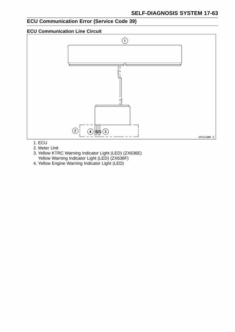
SELF-DIAGNOSIS SYSTEM 17-63ECU Communication Error (Service Code 39)
ECU Communication Line Circuit
1. ECU2. Meter Unit3. Yellow KTRC Warning Indicator Light (LED) (ZX636E)
Yellow Warning Indicator Light (LED) (ZX636F)4. Yellow Engine Warning Indicator Light (LED)

17-64 SELF-DIAGNOSIS SYSTEMStick Coils #1, #2, #3, #4: (Service Code 51, 52, 53, 54)
Stick Coil #1: Service Code 51Stick Coil #2: Service Code 52Stick Coil #3: Service Code 53Stick Coil #4: Service Code 54
Stick Coil Removal/Installation•Refer to the Stick Coil Removal/Installation in the Electri-
cal System chapter.
Stick Coil Primary Winding Resistance Inspection•Refer to the Stick Coil Inspection in the Electrical System
chapter.If the reading is within the standard, check the input volt-age (see Stick Coil Input Voltage Inspection).
Stick Coil Input Voltage InspectionNOTE
Be sure the battery is fully charged.
•Turn the ignition switch off.• Remove the ECU (see ECU Removal in the Fuel System
(DFI) chapter).Do not disconnect the ECU connectors.•Connect a digital meter [A] to the connector [B] with the
needle adapter set.Special Tool - Needle Adapter Set: 57001-1457
Stick Coil Input VoltageConnections to ECU Connector:
For Stick Coil #1Digital Meter (+) → BK lead (terminal 44)Digital Meter (–) → Frame Ground terminal
For Stick Coil #2Digital Meter (+) → BK/R lead (terminal 55)Digital Meter (–) → Frame Ground terminal
For Stick Coil #3Digital Meter (+) → BK/O lead (terminal 66)Digital Meter (–) → Frame Ground terminal
For Stick Coil #4Digital Meter (+) → BK/G lead (terminal 43)Digital Meter (–) → Frame Ground terminal
•Measure the input voltage to each primary winding of thestick coils with the engine stopped, and with the connec-tors joined.
• Turn the engine stop switch to run position.• Turn the ignition switch on.
Input VoltageStandard: Battery Voltage
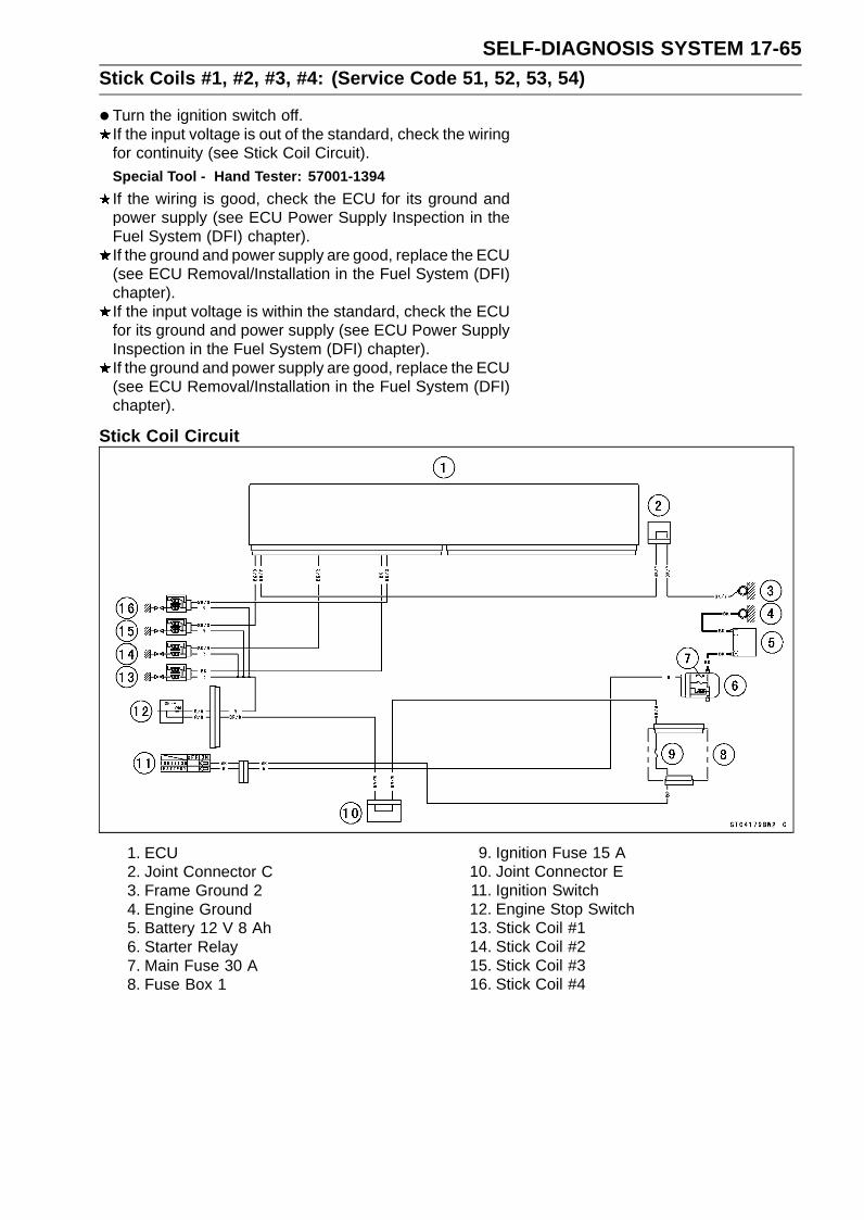
SELF-DIAGNOSIS SYSTEM 17-65Stick Coils #1, #2, #3, #4: (Service Code 51, 52, 53, 54)
•Turn the ignition switch off.If the input voltage is out of the standard, check the wiringfor continuity (see Stick Coil Circuit).Special Tool - Hand Tester: 57001-1394If the wiring is good, check the ECU for its ground andpower supply (see ECU Power Supply Inspection in theFuel System (DFI) chapter).If the ground and power supply are good, replace the ECU(see ECU Removal/Installation in the Fuel System (DFI)chapter).If the input voltage is within the standard, check the ECUfor its ground and power supply (see ECU Power SupplyInspection in the Fuel System (DFI) chapter).If the ground and power supply are good, replace the ECU(see ECU Removal/Installation in the Fuel System (DFI)chapter).
Stick Coil Circuit
1. ECU2. Joint Connector C3. Frame Ground 24. Engine Ground5. Battery 12 V 8 Ah6. Starter Relay7. Main Fuse 30 A8. Fuse Box 1
9. Ignition Fuse 15 A10. Joint Connector E11. Ignition Switch12. Engine Stop Switch13. Stick Coil #114. Stick Coil #215. Stick Coil #316. Stick Coil #4

17-66 SELF-DIAGNOSIS SYSTEMRadiator Fan Relay (Service Code 56)
Radiator Fan Relay Removal/InstallationThe radiator fan relay is built in the relay box [A].• Refer to the Relay Box Removal in the Electrical System
chapter.
Radiator Fan Relay Inspection•Refer to the Relay Circuit Inspection in the Electrical Sys-
tem chapter.If the radiator fan relay is normal, check the wiring forcontinuity, using the wiring diagram in this section.Special Tool - Hand Tester: 57001-1394If the wiring is good, check the ECU for its ground andpower supply (see ECU Power Supply Inspection in theFuel System (DFI) chapter).If the ground and power supply are good, replace the ECU(see ECU Removal/Installation in the Fuel System (DFI)chapter).
Radiator Fan Circuit
1. Ignition Switch2. Fan Motor3. Water Temperature Sensor4. Water-proof Joint 25. Joint Connector D6. ECU7. Frame Ground 38. Engine Ground9. Battery 12 V 8 Ah
10. Starter Relay11. Main Fuse 30 A12. Frame Ground 113. Relay Box14. Radiator Fan Relay15. Fuse Box 116. Ignition Fuse 15 A17. Fan Fuse 15 A18. Joint Connector E

SELF-DIAGNOSIS SYSTEM 17-67Subthrottle Valve Actuator (Service Code 62)
Subthrottle Valve Actuator RemovalNOTICE
Do not remove the subthrottle valve actuator [A]since it has been adjusted and set with precisionat the factory.Never drop the throttle body assy especially on ahard surface. Such a shock to the subthrottle valveactuator can damage it.
Subthrottle Valve Actuator InspectionNOTE
Be sure the battery is fully charged.
•Remove the air cleaner housing (see Air Cleaner HousingRemoval in the Fuel System (DFI) chapter).
• Turn the ignition switch on.•Check to see that all the subthrottle valves [A] open and
close smoothly.• Turn the ignition switch off.
If the subthrottle valves do not operate, check the sub-throttle valve actuator resistance (see Subthrottle ValveActuator Resistance Inspection).
Subthrottle Valve Actuator Resistance Inspection•Turn the ignition switch off.• Remove the air cleaner housing (see Air Cleaner Housing
Removal in the Fuel System (DFI) chapter).• Disconnect the subthrottle valve actuator connector [A].
• Connect a digital meter to the subthrottle valve actuatorconnector [A].
•Measure the subthrottle valve actuator resistance.
Subthrottle Valve Actuator ResistanceConnections: Y/BK lead [1] ←→ P/BL lead [2]
G lead [3] ←→ BK/O lead [4]Standard: About 5.2 ∼ 7.8 Ω
If the reading is out of the standard, replace the throttlebody assy.If the reading is within the standard, check the input volt-age (see Subthrottle Valve Actuator Input Voltage Inspec-tion).

17-68 SELF-DIAGNOSIS SYSTEMSubthrottle Valve Actuator (Service Code 62)
Subthrottle Valve Actuator Input VoltageInspection
NOTEBe sure the battery is fully charged.
•Turn the ignition switch to OFF.•Disconnect the subthrottle valve actuator connector and
connect the measuring adapter [A] between these con-nectors as shown.Main Harness [B]Subthrottle Valve Actuator [C]
Special Tool - Measuring Adapter: 57001-1700
•Connect the peak voltage adapter [D] and a digital meter[E] to the measuring adapter leads.Special Tool - Peak Voltage Adapter: 57001-1415
Type: KEK-54-9-B
Subthrottle Valve Actuator Input VoltageConnections to Adapter:
(I) Digital Meter (+) → R (actuator BK/O) leadDigital Meter (–) → Battery (–) terminal
(II) Digital Meter (+) → BK (actuator G) leadDigital Meter (–) → Battery (–) terminal
(III) Digital Meter (+) → W (actuator P/BL) leadDigital Meter (–) → Battery (–) terminal
(IV) Digital Meter (+) → Y (actuator Y/BK) leadDigital Meter (–) → Battery (–) terminal
•Measure the actuator input voltage with the enginestopped and with the connector joined.
• Turn the ignition switch on.
Input VoltageStandard: About DC 8.5 ∼ 10.5 V and then 0 V or
About DC 8.5 ∼ 10.5 V
•Turn the ignition switch off.If the reading is in specification, but the actuator does notoperate, replace the throttle body assy.

SELF-DIAGNOSIS SYSTEM 17-69Subthrottle Valve Actuator (Service Code 62)
If the reading is out of the specification, remove the ECUand check the wiring for continuity between main harnessconnector.Special Tool - Hand Tester: 57001-1394Disconnect the ECU and actuator connectors.
Wiring Continuity InspectionECU Connector [A] ←→
Subthrottle Valve Actuator Connector [B]G lead (ECU terminal 24) [C]BK/O lead (ECU terminal 23) [D]P/BL lead (ECU terminal 1) [E]Y/BK lead (ECU terminal 12) [F]
If the wiring is good, check the ECU for its ground andpower supply (see ECU Power Supply Inspection in theFuel System (DFI) chapter).If the ground and power supply are good, replace the ECU(see ECU Removal/Installation in the Fuel System (DFI)chapter).
Subthrottle Valve Actuator Circuit
1. ECU2. Subthrottle Valve Actuator

17-70 SELF-DIAGNOSIS SYSTEMExhaust Butterfly Valve Actuator (Service Code 63)
Exhaust Butterfly Valve Actuator RemovalNOTICE
Never drop the exhaust butterfly valve actuator es-pecially on a hard surface. Such a shock to the ac-tuator can damage it.
•Disconnect the exhaust butterfly valve cable upper ends(see Exhaust Butterfly Cable Removal in the Engine TopEnd chapter).
•Open the clamp [A].• Slide the dust cover [B].
• Disconnect the connectors [A].• Remove:
Screws [B] and WashersExhaust Butterfly Valve Actuator [C]
•Remove the pulley bolt while holding the pulley [A] with asuitable tool [B].
NOTICEIf the pulley bolt is removed without holding, theactuator damage will occur.
•Remove the pulley from the actuator.
Exhaust Butterfly Valve Actuator Installation• Install the pulley [A] on the actuator so that the hole side
[B] align with the groove [C] on the shaft.Make sure that the groove on the shaft is pointing toward
the center of the screw [D].If the shaft position is incorrect, refer to the following
NOTE and procedures to electrically adjust the shaftposition.

SELF-DIAGNOSIS SYSTEM 17-71Exhaust Butterfly Valve Actuator (Service Code 63)
• Install the pulley [A] on the actuator as shown.• Tighten the pulley bolt [B] while holding the pulley with the
suitable tool [C].Torque - Exhaust Butterfly Valve Actuator Pulley Bolt: 4.9
N·m (0.50 kgf·m, 43 in·lb)
NOTICEIf the pulley bolt is tightened without holding, theactuator damage will occur.
•After tightening the pulley bolt, confirm whether pulley [A]is an angle as shown.41.7° ±7° [B]
This position is original position of the pulley.
NOTECorrect the position electrically after confirming the use
is discontinued and there is no damage when differingfrom the angle as shown.
NOTICEDo not correct the pulley position with the tool,forcibly. The actuator damage will occur.
If the pulley angle is wrong, adjust the angle as follows.Connect:
2 pins Connector3 pins Connector
Turn the ignition switch on.Confirm the pulley turns clockwise or counterclockwise
then it stops at the original position.

17-72 SELF-DIAGNOSIS SYSTEMExhaust Butterfly Valve Actuator (Service Code 63)
If the pulley position has not been returned to the originalposition, electrically adjust the shaft position as follows.Disconnect:
2 pins Connector3 pins Connector
Turn the pulley to the original position by turning it clock-wise or counterclockwise by connecting the battery to the2 pin connector terminals. To turn the pulley gradually,intermittently connect the battery positive (+) terminal tothe 2 pin connector terminal while connecting the batterynegative (–) terminal to the connector.Pink (–) lead terminal [A]Gray (+) lead terminal [B]
Clockwise:Pink (–) lead terminal to battery (–) terminalGray (+) lead terminal to battery (+) terminal
Counterclockwise:Pink (–) lead terminal to battery (+) terminalGray (+) lead terminal to battery (–) terminal
Reconnect the 2 pins connector and 3 pins connector, andturn the ignition switch on.Make sure that the pulley turns clockwise and then coun-
terclockwise.The pulley should returns to the original position.Turn the ignition switch off.
If the pulley does not return to the original position, checkthe exhaust butterfly valve actuator resistance (see Ex-haust Butterfly Valve Actuator Resistance Inspection).
• Be sure to install the washers [A] on the exhaust butterflyvalve actuator [B].
• Tighten:Torque - Exhaust Butterfly Valve Actuator Mounting
Screws [C]: 4.3 N ·m (0.44 kgf ·m, 38 in·lb)
• Install the upper ends of the exhaust butterfly valve ca-bles (see Exhaust Butterfly Valve Cable Installation in theEngine Top End chapter).
Exhaust Butterfly Valve Actuator InspectionNOTE
Be sure the battery is fully charged
•Remove the front seat (see Front Seat Removal in theFrame chapter).
• Turn the ignition switch on.• In the left side view of the motorcycle, check to see
the pulley [A] clockwise [B] and counterclockwise [C]smoothly.The pulley turns clockwise and then counterclockwise,
and clockwise again.• Turn the ignition switch off.
If the pulley does not operate, check the exhaust butter-fly valve actuator resistance (see Exhaust Butterfly ValveActuator Inspection Resistance Inspection).

SELF-DIAGNOSIS SYSTEM 17-73Exhaust Butterfly Valve Actuator (Service Code 63)
Exhaust Butterfly Valve Actuator ResistanceInspection•Turn the ignition switch off.• Disconnect the exhaust butterfly valve actuator lead con-
nector (2 pins connector) [A].• Set the hand tester to the × 1 Ω range and connect it to
the exhaust butterfly valve actuator connector.Special Tool - Hand Tester: 57001-1394
•Measure the exhaust butterfly valve actuator resistance.
Exhaust Butterfly Valve Actuator ResistanceConnections: P lead ←→ GY leadStandard: 5 ∼ 200 Ω (for reference)
If the reading is 0 or infinity (∞) Ω, replace the exhaustbutterfly valve actuator.
If the reading is in specification, remove the ECU andcheck the wiring for continuity between main harness con-nectors.Disconnect the ECU and actuator connectors.
Wiring InspectionECU Connector [A] ←→
Exhaust Butterfly Valve Actuator Connector [B]W/BL lead (ECU terminal 2) [C]W/R lead (ECU terminal 13) [D]
If the wiring is good, check the ECU for its ground andpower supply (see ECU Power Supply Inspection in theFuel System (DFI) chapter).If the ground and power supply are good, replace the ECU(see ECU Removal/Installation in the Fuel System (DFI)chapter).
Exhaust Butterfly Valve Actuator Circuit
1. ECU2. Exhaust Butterfly Valve Actuator

17-74 SELF-DIAGNOSIS SYSTEMAir Switching Valve (Service Code 64)
Air Switching Valve Removal/Installation•Refer to the Air Switching Valve Removal/Installation in
the Engine Top End chapter.
Air Switching Valve Inspection•Refer to the Air Switching Valve Unit Test in the Electrical
System chapter.If the air switching valve [A] is normal, check the wiringfor continuity (see Air Switching Valve Circuit).Special Tool - Hand Tester: 57001-1394If the wiring is good, check the ECU for its ground andpower supply (see ECU Power Supply Inspection in theFuel System (DFI) chapter).If the ground and power supply are good, replace the ECU(see ECU Removal/Installation in the Fuel System (DFI)chapter).
Air Switching Valve Circuit
1. Ignition Switch2. Air Switching Valve3. Joint Connector D4. ECU5. Frame Ground 36. Engine Ground7. Battery 12 V 8 Ah8. Starter Relay
9. Main Fuse 30 A10. ECU Fuse 15 A11. Frame Ground 112. Relay Box13. ECU Main Relay14. Fuse Box 115. Ignition Fuse 15 A16. Joint Connector E

SELF-DIAGNOSIS SYSTEM 17-75Oxygen Sensor Heater (Service Code 67, Equipped Models)
Oxygen Sensor Heater Removal/InstallationThe oxygen sensor heater is built in the oxygen sensor.
So, the heater itself can not be removed. Remove the oxy-gen sensor (see Oxygen Sensor Removal (Equipped Mod-els) in the Electrical System chapter).
Oxygen Sensor Heater Resistance Inspection•Turn the ignition switch off.• Remove the fuel tank (see Fuel Tank Removal in the Fuel
System (DFI) chapter).• Disconnect the oxygen sensor lead connector [A].
• Connect a digital meter [A] to the terminals in the oxygensensor lead connector [B].
•Measure the oxygen sensor heater resistance.
Oxygen Sensor Heater ResistanceConnections: W lead [C] ←→ W lead [D]Standard: 6.7 ∼ 10.5 Ω at 20° (68°F)
If the reading is out of the standard, replace the sensor.If the reading is within the standard, check the powersource voltage (see Oxygen Sensor Heater PowerSource Voltage Inspection).

17-76 SELF-DIAGNOSIS SYSTEMOxygen Sensor Heater (Service Code 67, Equipped Models)
Oxygen Sensor Heater Power Source VoltageInspection
NOTEBe sure the battery is fully charged.
•Turn the ignition switch off.• Remove the fuel tank (see Fuel Tank Removal in the Fuel
System (DFI) chapter).• Disconnect the oxygen sensor lead connector and con-
nect the measuring adapter [A] between these connec-tors as shown.Main Harness [B]Oxygen Sensor [C]
Special Tool - Measuring Adapter: 57001-1700
•Connect a digital meter [D] to the measuring adapter lead.
Oxygen Sensor Heater Power Source VoltageConnections to Adapter:
Digital Meter (+) → R (main harness BR/W) leadDigital Meter (–) → Frame Ground terminal
•Measure the power source voltage with the enginestopped and with the connector joined.
• Turn the ignition switch on
Power Source VoltageStandard: Battery Voltage
•Turn the ignition switch off.If the reading is in specification, but the problem still ex-ists, replace the ECU (see ECU Removal/Installation inthe Fuel System (DFI) chapter).If the reading is out of the standard, check the following.ECU Fuse 15 A (see Fuse Inspection in the ElectricalSystem chapter)Power Source Wiring (see Oxygen Sensor Circuit)
If the fuse and wiring are good, remove the ECU andcheck the wiring for continuity between harness connec-tors.Special Tool - Hand Tester: 57001-1394Disconnect the ECU and sensor connectors.
Wiring Continuity InspectionECU Connector [A] ←→
Oxygen Sensor Connectors [B]P/BK lead (ECU terminal 51) [C]
If the wiring is good, check the ECU for its ground andpower supply (see ECU Power Supply Inspection in theFuel System (DFI) chapter).If the ground and power supply are good, replace the ECU(see ECU Removal/Installation in the Fuel System (DFI)chapter).

SELF-DIAGNOSIS SYSTEM 17-77Oxygen Sensor Heater (Service Code 67, Equipped Models)
Oxygen Sensor Circuit
1. ECU2. Frame Ground 33. Engine Ground4. Battery 12 V 8 Ah5. Starter Relay6. Main Fuse 30 A7. ECU Fuse 15 A8. Relay Box9. ECU Main Relay
10. Fuse Box 111. Ignition Fuse 15 A12. Joint Connector E13. Ignition Switch14. Water-proof Joint 215. Oxygen Sensor

17-78 SELF-DIAGNOSIS SYSTEMOxygen Sensor - Incorrect Output Voltage (Service Code 94 (Equipped Models))
Oxygen Sensor Removal/Installation•Refer to the Oxygen Sensor Removal/Installation
(Equipped Models) in the Electrical System chapter.
Oxygen Sensor Inspection•Warm up the engine thoroughly until the radiator fan
starts.• Turn the ignition switch off.• Remove:
Fuel Tank (see Fuel Tank Removal in the Fuel System(DFI) chapter)
•Disconnect:Oxygen Sensor Lead Connector [A]
•Connect the measuring adapter [A] between the mainharness connector and oxygen sensor lead connector asshown.Main Harness [B]Oxygen Sensor [C]
Special Tool - Measuring Adapter: 57001-1700
•Connect a digital meter [D] to the measuring adapterleads.
Oxygen Sensor Output VoltageConnections to Adapter:
Digital Meter (+) → R (sensor BK) leadDigital Meter (−) → BK (sensor GY) lead
•Remove the air switching valve [A] (see Air SwitchingValve Removal in the Engine Top End chapter).Do not disconnect the air switching valve connector [B].

SELF-DIAGNOSIS SYSTEM 17-79Oxygen Sensor - Incorrect Output Voltage (Service Code 94 (Equipped Models))
• Install the suitable plugs [A] on the fitting of the air suctionvalve covers, and shut off the secondary air.
• Connect the following parts temporarily.Fuel Pump Lead Connector [A]Extension Tube [B]Air Cleaner Housing (see Air Cleaner Housing Installa-tion)
Special Tool - Extension Tube: 57001-1578
•Start the engine, and let it idle.•Measure the output voltage with the connector joined.
Output Voltage (with Plugs)Standard: DC 0.8 V or more
•Next, remove the plugs from the fittings [A] with idling.•Measure the output voltage with the connector joined.
Output Voltage (without Plugs)Standard: DC 0.24 V or less
•Turn the ignition switch off.If the reading is out of the standard (with plugs: DC 0.8V or more, without plugs: DC 0.24 V or less), check thefollowing.Fuel Pressure (see Fuel Pressure Inspection in the FuelSystem (DFI) chapter)Fuel Injector (see Fuel Injector section)
If the fuel pressure and fuel injectors are good, replacethe sensor.If the reading is within the standard (with plugs: DC 0.8V or more, without plugs: DC 0.24 V or less), check theECU for its ground and power supply (see ECU PowerSupply Inspection in the Fuel System (DFI) chapter).If the ground and power supply are good, replace the ECU(see ECU Removal/Installation in the Fuel System (DFI)chapter).
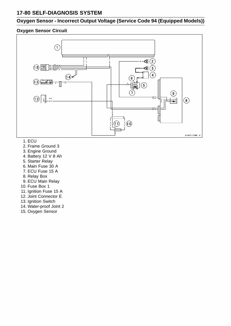
17-80 SELF-DIAGNOSIS SYSTEMOxygen Sensor - Incorrect Output Voltage (Service Code 94 (Equipped Models))
Oxygen Sensor Circuit
1. ECU2. Frame Ground 33. Engine Ground4. Battery 12 V 8 Ah5. Starter Relay6. Main Fuse 30 A7. ECU Fuse 15 A8. Relay Box9. ECU Main Relay
10. Fuse Box 111. Ignition Fuse 15 A12. Joint Connector E13. Ignition Switch14. Water-proof Joint 215. Oxygen Sensor
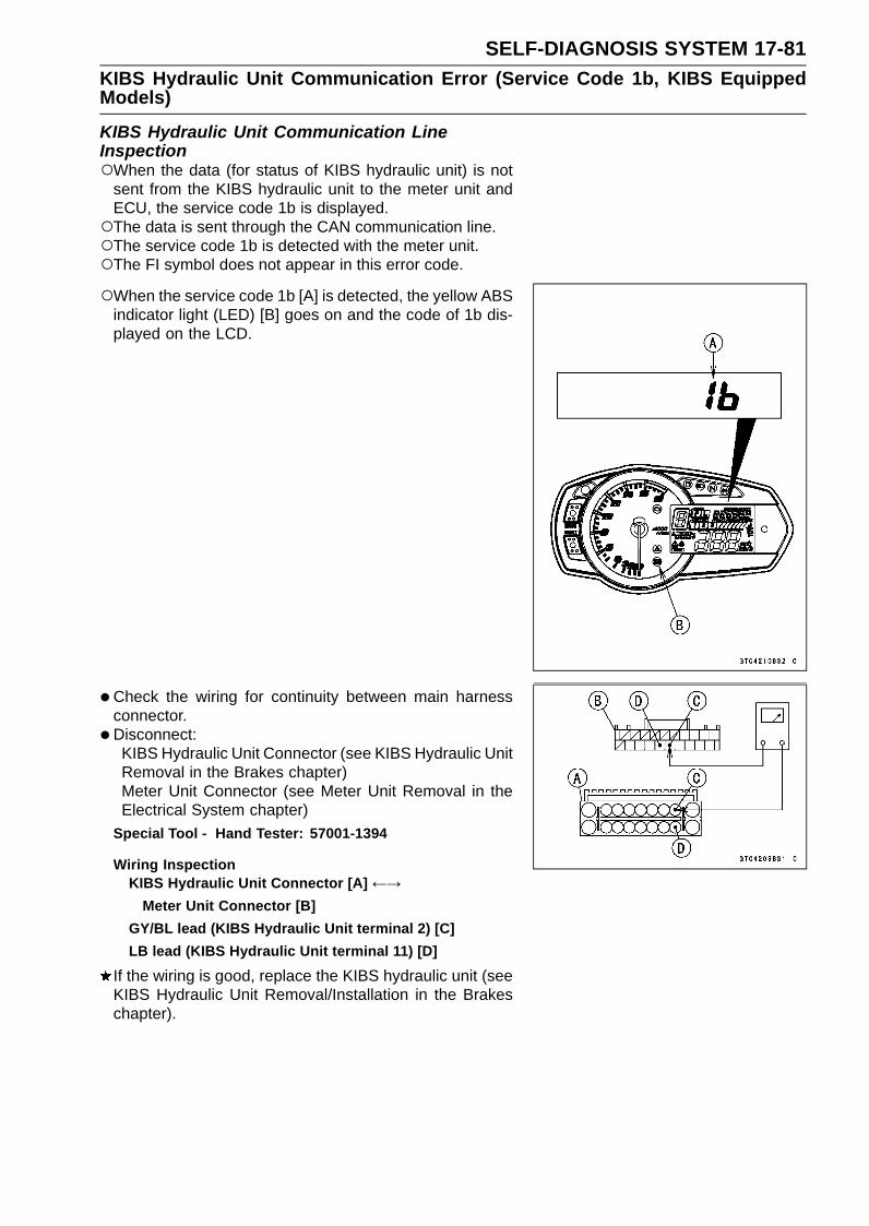
SELF-DIAGNOSIS SYSTEM 17-81KIBS Hydraulic Unit Communication Error (Service Code 1b, KIBS EquippedModels)
KIBS Hydraulic Unit Communication LineInspectionWhen the data (for status of KIBS hydraulic unit) is not
sent from the KIBS hydraulic unit to the meter unit andECU, the service code 1b is displayed.The data is sent through the CAN communication line.The service code 1b is detected with the meter unit.The FI symbol does not appear in this error code.
When the service code 1b [A] is detected, the yellow ABSindicator light (LED) [B] goes on and the code of 1b dis-played on the LCD.
•Check the wiring for continuity between main harnessconnector.
• Disconnect:KIBS Hydraulic Unit Connector (see KIBS Hydraulic UnitRemoval in the Brakes chapter)Meter Unit Connector (see Meter Unit Removal in theElectrical System chapter)
Special Tool - Hand Tester: 57001-1394
Wiring InspectionKIBS Hydraulic Unit Connector [A] ←→
Meter Unit Connector [B]GY/BL lead (KIBS Hydraulic Unit terminal 2) [C]LB lead (KIBS Hydraulic Unit terminal 11) [D]
If the wiring is good, replace the KIBS hydraulic unit (seeKIBS Hydraulic Unit Removal/Installation in the Brakeschapter).
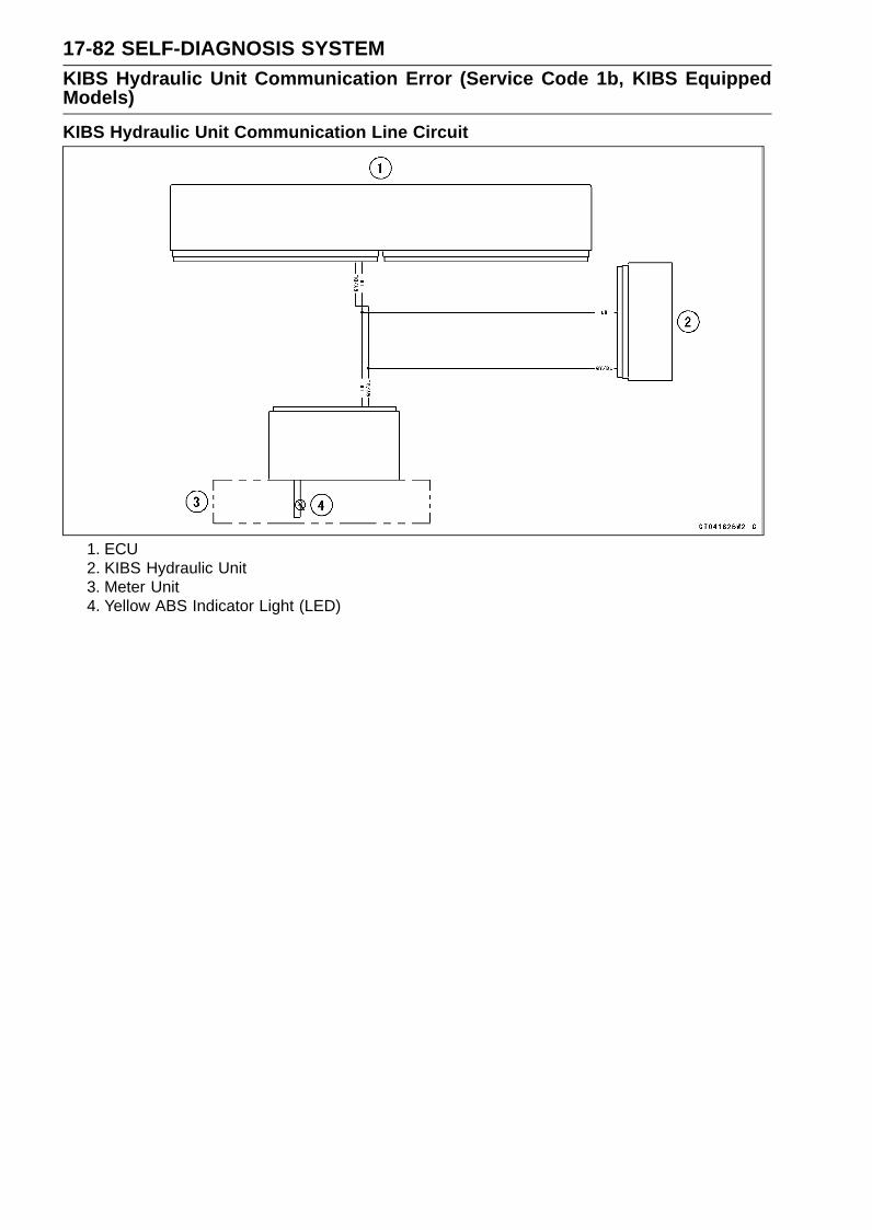
17-82 SELF-DIAGNOSIS SYSTEMKIBS Hydraulic Unit Communication Error (Service Code 1b, KIBS EquippedModels)
KIBS Hydraulic Unit Communication Line Circuit
1. ECU2. KIBS Hydraulic Unit3. Meter Unit4. Yellow ABS Indicator Light (LED)

SELF-DIAGNOSIS SYSTEM 17-83Purge Valve (Service Code 3A) (CAL Model)
Purge Valve Removal/Installation•Remove:
Right Fairing Cover (see Fairing Cover Removal in theFrame chapter)Right Side Cover (see Side Cover Removal in the Framechapter)Bolt [A] and Washer
•Disconnect the connector [A].• Remove the nut [B].
• Disconnect the tubes [A].• Remove the purge valve [B].
• Installation is the reverse of removal.Run the tubes correctly (see Cable, Wire, and Hose Rout-
ing section in the Appendix chapter).
Purge Valve Inspection•Remove the purge valve (see Purge Valve Removal/In-
stallation).• Set the hand tester [A] to the × 1 Ω range and connect it
to the purge valve terminals as shown.Special Tool - Hand Tester: 57001-1394
Purge Valve ResistanceStandard: 30 ∼ 34 Ω at 20°C (68°F)
If the resistance reading is out of the specified value, re-place it with a new one.
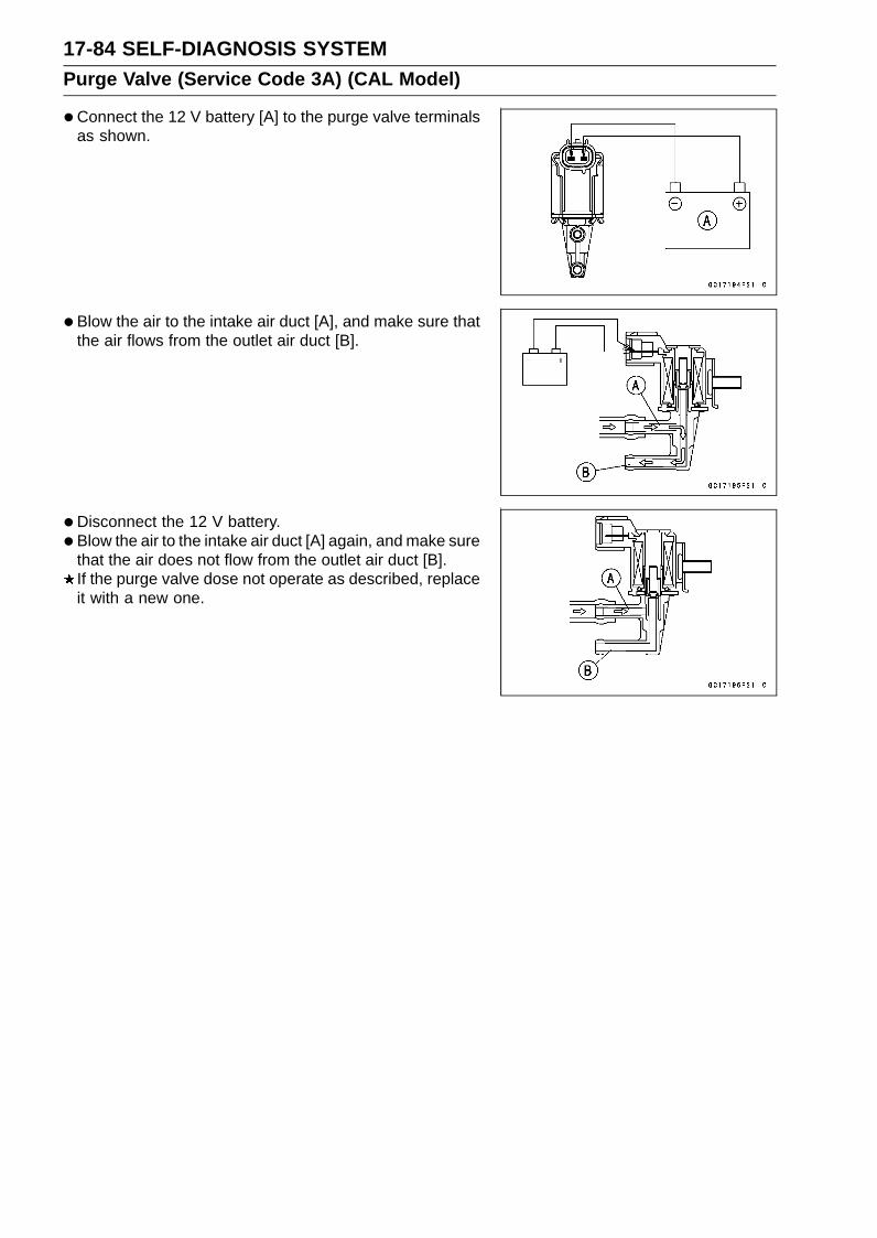
17-84 SELF-DIAGNOSIS SYSTEMPurge Valve (Service Code 3A) (CAL Model)
•Connect the 12 V battery [A] to the purge valve terminalsas shown.
• Blow the air to the intake air duct [A], and make sure thatthe air flows from the outlet air duct [B].
• Disconnect the 12 V battery.• Blow the air to the intake air duct [A] again, and make sure
that the air does not flow from the outlet air duct [B].If the purge valve dose not operate as described, replaceit with a new one.

SELF-DIAGNOSIS SYSTEM 17-85Purge Valve (Service Code 3A) (CAL Model)
Purge Valve Circuit
1. ECU2. Frame Ground 33. Engine Ground4. Battery 12 V 8 Ah5. Starter Relay6. Main Fuse 30 A7. ECU Fuse 15 A8. Relay Box9. ECU Main Relay
10. Fuse Box 111. Ignition Fuse 15 A12. Joint Connector E13. Ignition Switch14. Purge Valve

17-86 SELF-DIAGNOSIS SYSTEMKIBS Service Codes (KIBS Equipped Models)
Solenoid Valve Inspection (Service Code b 13, b14, b 17, b 18)The solenoid valve is built in the KIBS Hydraulic Unit [A].
Therefore the solenoid valve cannot be checked directly.• Perform the Pre-Diagnosis Inspection 1 and 2 (see In-
quiries to Rider in the Brakes chapter).If any of these service codes appears even if all checksare ended, replace the KIBS hydraulic unit.If the service code does not appear, the KIBS system nor-mal (temporary failure).
KIBS Solenoid Valve Relay Inspection (ServiceCode b 19)The KIBS solenoid valve relay is built in the KIBS Hy-
draulic Unit. Therefore the relay cannot be checked di-rectly.
• Perform the Pre-Diagnosis Inspection 1 and 2 (see In-quiries to Rider in the Brakes chapter).If this service code appears even if all checks are ended,replace the KIBS hydraulic unit.If the service code does not appear, the KIBS system nor-mal (temporary failure).
Front, Rear Wheel Rotation Difference AbnormalInspection (Service Code b 25)•Check the following and correct the faulty part.
Incorrect Tire PressureTires not recommended for the motorcycle were installed(incorrect tire size).Deformation of Wheel or TireMissing Teeth or Clogging with Foreign Matter of SensorRotor (see Wheel Rotation Sensor Rotor Inspection inthe Brakes chapter)
If the all parts corrected, go to next step.
• Perform the Pre-Diagnosis Inspection 1 and 2 (see In-quiries to Rider in the Brakes chapter).If this service code appears even if all checks are ended,replace the KIBS hydraulic unit.If the service code does not appear, the KIBS system nor-mal (temporary failure).
KIBS Motor Relay Inspection (Service Code b 35)•Check the KIBS motor relay fuse (25 A) [A] (see Fuse
Inspection in the Electrical System chapter)If the fuse is good, check the wiring continuity as follows.Disconnect:
Battery Positive Cable (see Battery Removal in the Elec-trical System chapter)KIBS Hydraulic Unit Lead Connector (see KIBS Hy-draulic Unit Removal in the Brakes chapter)

SELF-DIAGNOSIS SYSTEM 17-87KIBS Service Codes (KIBS Equipped Models)
Check the wiring continuity between the positive cableterminal [A] of the battery and R/W lead terminal [B] inthe KIBS Hydraulic Unit Lead Connector [C].If the wiring is open, replace or repair the harness (seeKIBS System Circuit in the Brakes chapter).If the wiring is good, go to next step.
The KIBS motor relay is built in the KIBS Hydraulic Unit.Therefore the relay cannot be checked directly.
• Perform the Pre-Diagnosis Inspection 1 and 2 (see In-quiries to Rider in the Brakes chapter).If this service code appears even if all checks are ended,replace the KIBS hydraulic unit.If the service code does not appear, the KIBS system nor-mal (temporary failure).
Front Wheel Rotation Sensor Signal Abnormal(Service Code b 42)•Measure the air gap between the front wheel rotation sen-
sor and sensor rotor.Thickness Gauge [A]
Air GapStandard: 0.4 ∼ 1.6 mm (0.02 ∼ 0.06 in.)
If the measurement is not the standard, check each partfor deformation and looseness and correct accordingly.If the measurement is the standard, go to next step.
•Check that there is iron or other magnetic deposits be-tween the sensor and sensor rotor, and the sensor rotorslots for obstructions.
•Check the installation condition of the sensor for loose-ness.
•Check the sensor and sensor rotor tip for deformation ordamage (e.g., chipped sensor rotor teeth).If the sensor and sensor rotor in bad condition, removethe any deposits. Install the proper part or replace faultypart.If the all items are good, go to next step.
• Perform the Pre-Diagnosis Inspection 1 and 2 (see In-quiries to Rider in the Brakes chapter).If this service code appears even if all checks are ended,replace the KIBS hydraulic unit.If the service code does not appear, the KIBS system nor-mal (temporary failure).

17-88 SELF-DIAGNOSIS SYSTEMKIBS Service Codes (KIBS Equipped Models)
Front Wheel Rotation Sensor Wiring Inspection(Service Code b 43)•Disconnect the front wheel rotation sensor lead connec-
tor [A] (see Front Wheel Rotation Sensor Removal in theBrakes chapter).
• Disconnect the KIBS hydraulic unit lead connector (seeKIBS Hydraulic Unit Removal in the Brakes chapter).
• Check the wiring continuity of the W lead and Y lead.Front Wheel Rotation Sensor Lead Connector [A]KIBS Hydraulic Unit Lead Connector [B]W Lead Terminals [C]Y Lead terminals [D]
If the wiring is open, replace or repair the harness (seeKIBS System Circuit in the Brakes chapter).If the wiring is good, go to next step.
• Perform the Pre-Diagnosis Inspection 1 and 2 (see In-quiries to Rider in the Brakes chapter).If this service code appears even if all checks are ended,replace the front wheel rotation sensor (see Front WheelRotation Sensor Removal in the Brakes chapter).
• Still, when it is not good, replace the KIBS hydraulic unit.If the service code does not appear, the KIBS system nor-mal (temporary failure).
Rear Wheel Rotation Sensor Signal Abnormal(Service Code b 44)•Measure the air gap between the rear wheel rotation sen-
sor and sensor rotor.Thickness Gauge [A]
Air GapStandard: 0.4 ∼ 1.6 mm (0.02 ∼ 0.06 in.)
If the measurement is not the standard, check each partfor deformation and looseness and correct accordingly.If the measurement is the standard, go to next step.
•Check that there is iron or other magnetic deposits be-tween the sensor and sensor rotor, and the sensor rotorslots for obstructions.
•Check the installation condition of the sensor for loose-ness.
•Check the sensor and sensor rotor tip for deformation ordamage (e.g., chipped sensor rotor teeth).If the sensor and sensor rotor in bad condition, removethe any deposits. Install the proper part or replace faultypart.If the all items are good, go to next step.
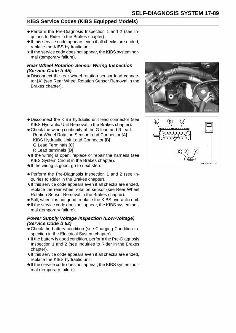
SELF-DIAGNOSIS SYSTEM 17-89KIBS Service Codes (KIBS Equipped Models)
•Perform the Pre-Diagnosis Inspection 1 and 2 (see In-quiries to Rider in the Brakes chapter).If this service code appears even if all checks are ended,replace the KIBS hydraulic unit.If the service code does not appear, the KIBS system nor-mal (temporary failure).
Rear Wheel Rotation Sensor Wiring Inspection(Service Code b 45)•Disconnect the rear wheel rotation sensor lead connec-
tor [A] (see Rear Wheel Rotation Sensor Removal in theBrakes chapter).
• Disconnect the KIBS hydraulic unit lead connector (seeKIBS Hydraulic Unit Removal in the Brakes chapter).
• Check the wiring continuity of the G lead and R lead.Rear Wheel Rotation Sensor Lead Connector [A]KIBS Hydraulic Unit Lead Connector [B]G Lead Terminals [C]R Lead terminals [D]
If the wiring is open, replace or repair the harness (seeKIBS System Circuit in the Brakes chapter).If the wiring is good, go to next step.
• Perform the Pre-Diagnosis Inspection 1 and 2 (see In-quiries to Rider in the Brakes chapter).If this service code appears even if all checks are ended,replace the rear wheel rotation sensor (see Rear WheelRotation Sensor Removal in the Brakes chapter).
• Still, when it is not good, replace the KIBS hydraulic unit.If the service code does not appear, the KIBS system nor-mal (temporary failure).
Power Supply Voltage Inspection (Low-Voltage)(Service Code b 52)•Check the battery condition (see Charging Condition In-
spection in the Electrical System chapter).If the battery is good condition, perform the Pre-DiagnosisInspection 1 and 2 (see Inquiries to Rider in the Brakeschapter).If this service code appears even if all checks are ended,replace the KIBS hydraulic unit.If the service code does not appear, the KIBS system nor-mal (temporary failure).

17-90 SELF-DIAGNOSIS SYSTEMKIBS Service Codes (KIBS Equipped Models)
Power Supply Voltage Inspection (Over-Voltage)(Service Code b 53)•Check the charging voltage (see Charging Voltage In-
spection in the Electrical System chapter).If the charging voltage is good, perform the Pre-DiagnosisInspection 1 and 2 (see Inquiries to Rider in the Brakeschapter).If this service code appears even if all checks are ended,replace the KIBS hydraulic unit.If the service code does not appear, the KIBS system nor-mal (temporary failure).
ECU Inspection (Service Code b 55)This ECU is built in the KIBS Hydraulic Unit. Therefore
the ECU cannot be checked directly.• Perform the Pre-Diagnosis Inspection 1 and 2 (see In-
quiries to Rider in the Brakes chapter).If this service code appears even if all checks are ended,replace the KIBS hydraulic unit.If the service code does not appear, the KIBS system nor-mal (temporary failure).
CAN Communication (Transmission)/CANBus OFF Monitor Inspection(Service Code b 57)CAN Communication (Reception)Monitor Inspection (Service Code b 58)•Disconnect the KIBS hydraulic unit lead connector (see
KIBS Hydraulic Unit Removal in the Brakes chapter).
•Measure the CAN communication line resistance.KIBS Hydraulic Unit Lead Connector [A]GY/BL Lead Terminal [B]LB Lead Terminal [C]
Special Tool - Hand Tester: 57001-1394
CAN Communication Line ResistanceStandard: 30 ∼ 70 Ω
If the reading is out of the standard, go to Check 1.If the reading is the standard, go to Check 2.
Check 1•Check the CAN communication line resistance of follow-
ing parts.Meter Unit (see Meter Unit Inspection in the ElectricalSystem chapter)ECU (see CAN Communication Line Resistance Inspec-tion in the Fuel System (DFI) chapter)

SELF-DIAGNOSIS SYSTEM 17-91KIBS Service Codes (KIBS Equipped Models)
Check 2•Measure the resistance between the GY/BL [A] or LB [B]
terminal and ground [C].KIBS Hydraulic Unit Lead Connector [D]
Special Tool - Hand Tester: 57001-1394
CAN Communication Line/Ground ResistanceStandard: 5 ∼ 30 kΩ
If the reading is out of the standard, replace or repair themain harness.If the reading is the standard, go to next step.
• Perform the Pre-Diagnosis Inspection 1 and 2 (see In-quiries to Rider in the Brakes chapter).If this service code appears even if all checks are ended,replace the KIBS hydraulic unit.If the service code does not appear, the KIBS system nor-mal (temporary failure).
Output Fluid Pressure Sensor (Front Brake)Wiring Inspection (Service Code b 83)The Output Fluid Pressure Sensor is built in the KIBS Hy-
draulic Unit. Therefore the sensor cannot be checked di-rectly.
• Perform the Pre-Diagnosis Inspection 1 and 2 (see In-quiries to Rider in the Brakes chapter).If this service code appears even if all checks are ended,replace the KIBS hydraulic unit.
Output Fluid Pressure Sensor (Front Brake) OffsetAbnormal (Service Code b 84)The Output Fluid Pressure Sensor is built in the KIBS Hy-
draulic Unit. Therefore the sensor cannot be checked di-rectly.
• Perform the Pre-Diagnosis Inspection 1 and 2 (see In-quiries to Rider in the Brakes chapter).If this service code appears even if all checks are ended,replace the KIBS hydraulic unit.If the service code does not appear, the KIBS system nor-mal (temporary failure).
Fluid Pressure Sensor Supply Voltage Inspection(Service Code b 89)The Fluid Pressure Sensors are built in the KIBS Hy-
draulic Unit. Therefore the voltage cannot be checkeddirectly.
• Perform the Pre-Diagnosis Inspection 1 and 2 (see In-quiries to Rider in the Brakes chapter).If this service code appears even if all checks are ended,replace the KIBS hydraulic unit.If the service code does not appear, the KIBS system nor-mal (temporary failure).


APPENDIX 18-1
18
AppendixTable of Contents
Cable, Wire, and Hose Routing .............................................................................................. 18-2Troubleshooting Guide ........................................................................................................... 18-47

18-2 APPENDIXCable, Wire, and Hose Routing
APPENDIX 18-3Cable, Wire, and Hose Routing
1. Immobilizer Amplifier Connector (Equipped Models)2. Run the right switch housing lead to the inside of the front fork. Run the right switch housing
lead to the upside of the steering stem.3. Cover the right turn signal light lead connector, headlight lead connector and city light lead con-
nector with the rubber cover.4. Run the meter lead and immobilizer amplifier lead (equipped models) to the upside of the rib of
the air intake duct.5. Run the left switch housing lead to the inside of the front fork. Run the left switch housing lead
to the upside of the steering stem.6. Hold the harness at the white tape position of the harness to the hook of the air intake duct.7. Cover the left turn signal light lead connector, headlight lead connector and city light lead con-
nector with the rubber cover.8. Hold the harness with the clamp, and insert the projections of the clamp into the inner fairing.9. Install the pad so that there is no space between the pad and bracket.
10. Hold the meter lead with the clamp, and install the clamp to the air intake duct.11. Run the main harness to the outside of the front fork.12. Check that the main harness does not swing.

18-4 APPENDIXCable, Wire, and Hose Routing

APPENDIX 18-5Cable, Wire, and Hose Routing
1. Clutch Cable2. Throttle Cable (Accelerator)3. Throttle Cable (Decelerator)4. Run the throttle cables between the steering stem head and clutch cable.5. Align the white character on the accelerator cable with the clamp.6. Align the clutch cable with the tab on the fuel tank bracket.7. Clamp (Hold the clutch cable at the blue tape position.)8. Clamp (Hold the throttle cables.)9. Run the brake pipes between the frame and air cleaner housing (KIBS equipped models).
10. Run the throttle cables between the frame and air cleaner housing.11. Run the clutch cable under the throttle cables.12. Run the brake hose to the inside of the right switch housing lead. Run the brake hose to the
upside of the steering stem.13. Run the right switch housing lead to the outside of the brake pipes (KIBS equipped models).14. Clamp (Hold the right switch housing lead and front wheel rotation sensor lead.)

18-6 APPENDIXCable, Wire, and Hose Routing
1. Regulator/Rectifier Connectors2. Clamp (Hold the alternator lead.)3. Run the alternator lead through the clamp of the bracket.4. Fuse Box5. Hold the main harness with the clamp, and insert the projection of the clamp into the inner fairing.6. Inside of Left Fame7. Hold the main harness with the clamp, and insert the projection of the clamp into the frame.8. Hold the main harness with the clamp, and insert the projection of the clamp into the bracket.

APPENDIX 18-7Cable, Wire, and Hose Routing
1. Clamp (Hold the city light lead and head light lead.)2. Clamp (Hold the right turn signal light lead, and face the open side of the clamp to the outside.
Hold the left side lead in the same way.)3. Hold the harness with the clamp, and insert the projections of the clamp into the inner fairing.4. Shove the rubber cover under the headlight.5. Run the main harness under the regulator/rectifier bracket.6. Hone Lead
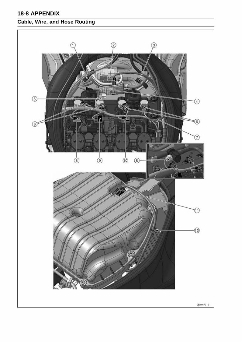
18-8 APPENDIXCable, Wire, and Hose Routing

APPENDIX 18-9Cable, Wire, and Hose Routing
1. Clamp (Hold the left switch housing lead, immobilizer antenna lead (equipped models) and ig-nition switch lead, and face the open side of the clamp to the left side.)
2. Cover the left switch housing lead connector, immobilizer antenna lead connector (equippedmodes) and ignition switch lead connector with the rubber cover.
3. Clamp (Hold the right switch housing lead, radiator fan lead and front wheel rotation sensorlead, and face the open side of the clamp to the left side.)
4. Cover the right switch housing lead connector, radiator fan lead connector and front wheel ro-tation sensor lead connector with the rubber cover.
5. Air Switching Valve Connector6. Stick Coil Connectors7. Intake Air Temperature Sensor Lead8. Intake Air Pressure Sensor #1 Connector9. Subthrottle Valve Actuator Connector
10. Intake Air Pressure Sensor #2 Connector11. Intake Air Temperature Sensor Connector12. Clamp (Hold the intake air temperature sensor lead.)

18-10 APPENDIXCable, Wire, and Hose Routing
APPENDIX 18-11Cable, Wire, and Hose Routing
1. Run the fuel injector lead under the fuel injector #1. Run the fuel injector lead to the upside ofthe fuel injector #2.
2. Clamps (Hold the delivery pipe and fuel injector lead at the white tape position of the fuel injectorlead, and face the open side of the clamp downward.)
3. Fuel Injector Lead4. Face the clamp to the backward.5. Run the breather hose to the upside of the main harness.6. Cover the frame ground terminal with the heat insulation rubber plate.7. Fuel Injector Connectors8. Do not pinch the main harness at the left side of the throttle body assy.9. Throttle Position Sensor Connector
10. Oxygen Sensor lead Connector (Equipped Models)11. Insert the fuel pipe into the pad. Install the pad to the upside of the oxygen sensor connector
(equipped models) and crankshaft sensor connector.12. Crankshaft Senor Connector13. Run the battery positive lead connector to the upside of the other leads and hoses.14. Water Temperature Sensor Connector15. Run the gear position sensor lead into the slit of the heat insulation rubber plate.

18-12 APPENDIXCable, Wire, and Hose Routing

APPENDIX 18-13Cable, Wire, and Hose Routing
1. Run the KIBS brake pipes (KIBS equipped models) and battery cable to the inside of the exhaustbutterfly cables.
2. Rear Brake Light Switch Lead3. Rear Wheel Rotation Sensor Lead4. Starter Relay5. Cover the rear wheel rotation sensor lead connector and rear brake light switch lead connector
with the rubber cover.6. Battery Negative Cable7. Battery Positive Cable8. Hold the main harness with the clamp, and install the clamp to the rear fender.9. Run the battery negative cable under the other leads.
10. Run the battery positive lead under the rubber cover.11. Face the frame ground terminal to the front.12. Clamp [Hold the battery positive lead and KIBS hydraulic unit lead (KIBS equipped models).]13. Run the rear brake light switch lead and rear wheel rotation sensor lead into the slit of the KIBS
hydraulic unit rubber cover (KIBS equipped models).14. Band (Hold the rear wheel rotation sensor lead, rear brake light switch lead and starter relay
lead near the starter relay connector.)

18-14 APPENDIXCable, Wire, and Hose Routing
APPENDIX 18-15Cable, Wire, and Hose Routing
1. Main Harness2. Breather Hose3. Run the air cleaner drain hose, fuel tank breather hose and fuel tank drain hose to the inside of
the breather hose and idle adjusting cable. Run the main harness to the outside of the breatherhose and idle adjusting cable.
4. Run the air cleaner drain hose to the inside of the water hose. Run the air cleaner drain hoseto the outside of the alternator lead.
5. Air Cleaner Drain Hose6. Run the idle adjusting cable to the inside of the main harness.7. Idle Adjusting Screw8. Clamps (Hold the gear position switch lead and sidestand switch lead.)9. Sidestand Switch Lead
10. Run the fuel tank drain hose and fuel tank breather hose to the inside of the gear position switchlead.
11. Fuel Tank Breather Hose12. Fuel Tank Drain Hose13. Run the green painted hose (CAL model), clutch cable and blue painted hose (CAL model) in
order from the inside.14. Run the clutch cable through the clamp of the bracket.15. Run the clutch cable to the outside of the water hose.16. Run the oxygen sensor lead (equipped models) and crankshaft sensor lead to the inside of the
water hose. Do not slack the crankshaft sensor lead to the front side.17. Run the oil pressure switch lead and oxygen sensor lead (equipped models) through the clamp
of the engine.18. Run the coolant reserve tank over flow hose through the hole of the left middle fairing.19. Crankshaft Sensor Lead20. Run the crankshaft sensor lead under the camshaft chain tensioner.

18-16 APPENDIXCable, Wire, and Hose Routing
1. Fuel Tank Drain Hose2. Fuel Tank Breather Hose3. Run the fuel tank breather hose under the fuel tank bracket.4. Run the fuel pump lead under the fuel tank breather hose.5. Run the fuel pump lead to the front of the fuel pump pipe. Run the fuel pump lead between the
fuel tank and fuel hose.6. Fuel Pump Lead7. Turn the fuel tank breather hose to the bottom left.8. Pad

APPENDIX 18-17Cable, Wire, and Hose Routing
1. Run the air cleaner drain hose, fuel tank drain hose and fuel tank breather hose into the hole ofthe heat insulation rubber plate.
2. Run the main harness, fuel tank breather hose and fuel tank drain hose in order from the bottom.3. Check that the hole of the catch tank of the fuel tank breather hose does not face downward.4. Run the starter motor lead into the hole of the rear fender.5. Install the heat insulation rubber plate under the other parts.

18-18 APPENDIXCable, Wire, and Hose Routing

APPENDIX 18-19Cable, Wire, and Hose Routing
1. Cover the fuel pump lead connector and exhaust butterfly valve actuator lead connector withthe rubber cover.
2. Clamp (Hold the end of rubber cover.)3. ECU Connectors4. Relay Box Connectors5. Turn Signal Relay Connector6. Hold the main harness with the clamp, and install the clamp to rear fender.7. Joint Connector (with the harness tape)8. Fuse Box (KIBS Equipped Models)9. Main Harness
10. Run the main harness to the side of the ribs of the rear fender and fender bracket, and shovethe main harness. Take care not to pinch the main harness.
11. Align the hole of the fuse bracket with the projection of the rear fender.

18-20 APPENDIXCable, Wire, and Hose Routing
APPENDIX 18-21Cable, Wire, and Hose Routing
1. Hold the main harness with the clamp, and install the clamp to rear fender.2. Install the trim.3. Cover the left turn signal light lead connector, right turn signal light lead connector, license plate
light lead connector and tail/brake light lead connector with rubber cover. Place the rubber coverbetween the rear frame rear and rear fender.
4. Clamp (Hold the left turn signal light lead, right turn signal light lead, license plate light lead andtail/brake light lead.)
5. Install the pad so that the pad aligns with the line of the center on the rear fender and line of thecorner on the rear fender.
6. Run the left turn signal light lead, right turn signal light lead and license plate light lead throughthe clamp.
7. Run the diagnosis system leads to the upside of the other leads.8. Run the vehicle-down sensor lead under the other lead.9. Vehicle-down Sensor Connector
10. KIBS Self-Diagnosis System Connector (Equipped Models)11. Kawasaki Diagnostic System Connector12. Tail/Brake Light Lead13. Run the left turn signal light lead, right turn signal light lead and license plate light lead into the
hole.14. Hold the left turn signal light lead, right turn signal light lead and license plate light lead.

18-22 APPENDIXCable, Wire, and Hose Routing
1. Clamp (Hold the fuel pump lead and exhaust butterfly valve cables so that the exhaust butterflyvalve cables are lined up side by side.)
2. Hold the exhaust butterfly valve cables with the hook of the seat cover.3. Run the rear wheel rotation sensor lead to the outside of the exhaust butterfly valve cables. Run
the rear wheel rotation sensor lead to inside of the KIBS brake pipes (KIBS equipped models).4. Clamps (Hold the rear wheel rotation sensor lead and brake hose so that the rear wheel rotation
sensor lead is outside.)5. Run the exhaust butterfly valve cables between the frame and KIBS brake pipes (KIBS equipped
models), and shove the exhaust butterfly valve cables to the front.6. Run the starter motor lead to the inside of the brake hoses and lead.7. Run the exhaust butterfly valve cables through the clamp of the bracket.

APPENDIX 18-23Cable, Wire, and Hose Routing
1. Run the gear position switch lead between the water temperature sensor and water hose con-nected to the thermostat.
2. Water hose (to Oil Cooler)3. Gear Position Switch Lead4. Run the gear position switch lead to the right side of the water hose connected to the oil cooler.5. Run the gear position switch lead between the thermostat housing and water hose connected
to the oil cooler.

18-24 APPENDIXCable, Wire, and Hose Routing
1. Gear Position Switch Lead2. Hold the idle adjusting screw cable end and water hose with the clamp.3. Run the gear position switch lead between the water hoses.4. Run the alternator lead under the water hose.5. Do not slack the gear position switch lead in this position.6. Clamps (Hold the gear position switch lead.)7. Hold the lead at the PVC tube portion.
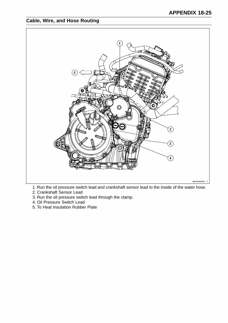
APPENDIX 18-25Cable, Wire, and Hose Routing
1. Run the oil pressure switch lead and crankshaft sensor lead to the inside of the water hose.2. Crankshaft Sensor Lead3. Run the oil pressure switch lead through the clamp.4. Oil Pressure Switch Lead5. To Heat Insulation Rubber Plate

18-26 APPENDIXCable, Wire, and Hose Routing
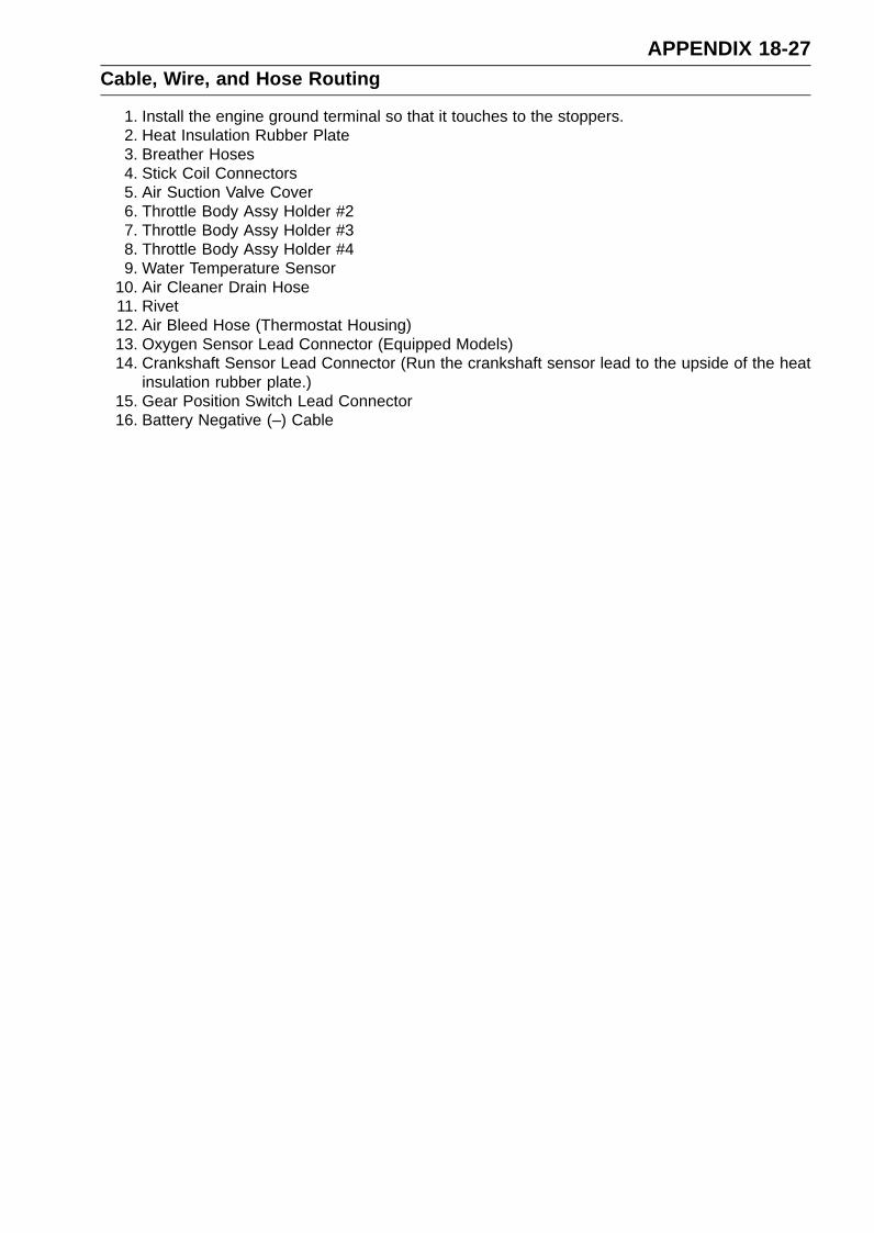
APPENDIX 18-27Cable, Wire, and Hose Routing
1. Install the engine ground terminal so that it touches to the stoppers.2. Heat Insulation Rubber Plate3. Breather Hoses4. Stick Coil Connectors5. Air Suction Valve Cover6. Throttle Body Assy Holder #27. Throttle Body Assy Holder #38. Throttle Body Assy Holder #49. Water Temperature Sensor
10. Air Cleaner Drain Hose11. Rivet12. Air Bleed Hose (Thermostat Housing)13. Oxygen Sensor Lead Connector (Equipped Models)14. Crankshaft Sensor Lead Connector (Run the crankshaft sensor lead to the upside of the heat
insulation rubber plate.)15. Gear Position Switch Lead Connector16. Battery Negative (–) Cable
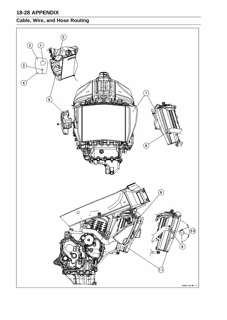
18-28 APPENDIXCable, Wire, and Hose Routing

APPENDIX 18-29Cable, Wire, and Hose Routing
1. Install the rubber cover onto the radiator cap.2. Install the hole of the rubber cover on the projection of the heat insulation rubber plate.3. Run the reserve tank overflow hose into the cover.4. Rubber Cover5. Radiator Cap6. Coolant Reserve Tank7. Pad (Left Side)8. Clamps9. Install the reserve tank overflow hose so that the 60° bending side of the hose is upside (radiator
cap side).10. 40° or more11. Pad (Right Side)
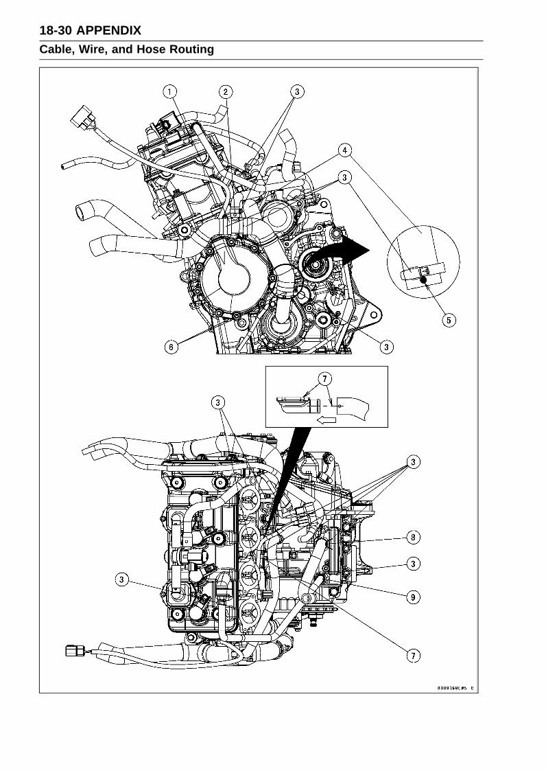
18-30 APPENDIXCable, Wire, and Hose Routing

APPENDIX 18-31Cable, Wire, and Hose Routing
1. Install the water hose so that the yellow paint mark faces upside.2. Install the water hose so that the white paint mark faces left side.3. Install the clamp as shown.4. Water Hose5. Install the water hose so that the white paint mark faces left side.6. Align the white paint mark of the water hose with the projection on the water pump cover.7. Align the center line of the white paint mark on the water hose parallel to the fitting matching
surface.8. Install the breather hose so that the white paint mark faces backward.9. Install the breather hose so that the white paint mark faces backward.

18-32 APPENDIXCable, Wire, and Hose Routing
1. Front Brake Hoses2. Clamps (Hold the front brake hose.)3. Clamps (Hold the front brake hose and front wheel rotation sensor lead.)4. Front Wheel Rotation Sensor Lead5. Run the front wheel rotation sensor lead through the clamp.6. Front Wheel Rotation Sensor7. Clamp (Hold the front wheel rotation sensor.)

APPENDIX 18-33Cable, Wire, and Hose Routing
1. Clamps (Hold the rear brake hose and rear wheel rotation sensor lead.)2. Rear Brake Hose3. Run the rear brake hose to the inside of the mud guard.4. Clamp (Hold the rear brake hose.)5. Clamp (Hold the rear wheel rotation sensor lead.)6. Rear Wheel Rotation Sensor Lead7. Rear Wheel Rotation Sensor
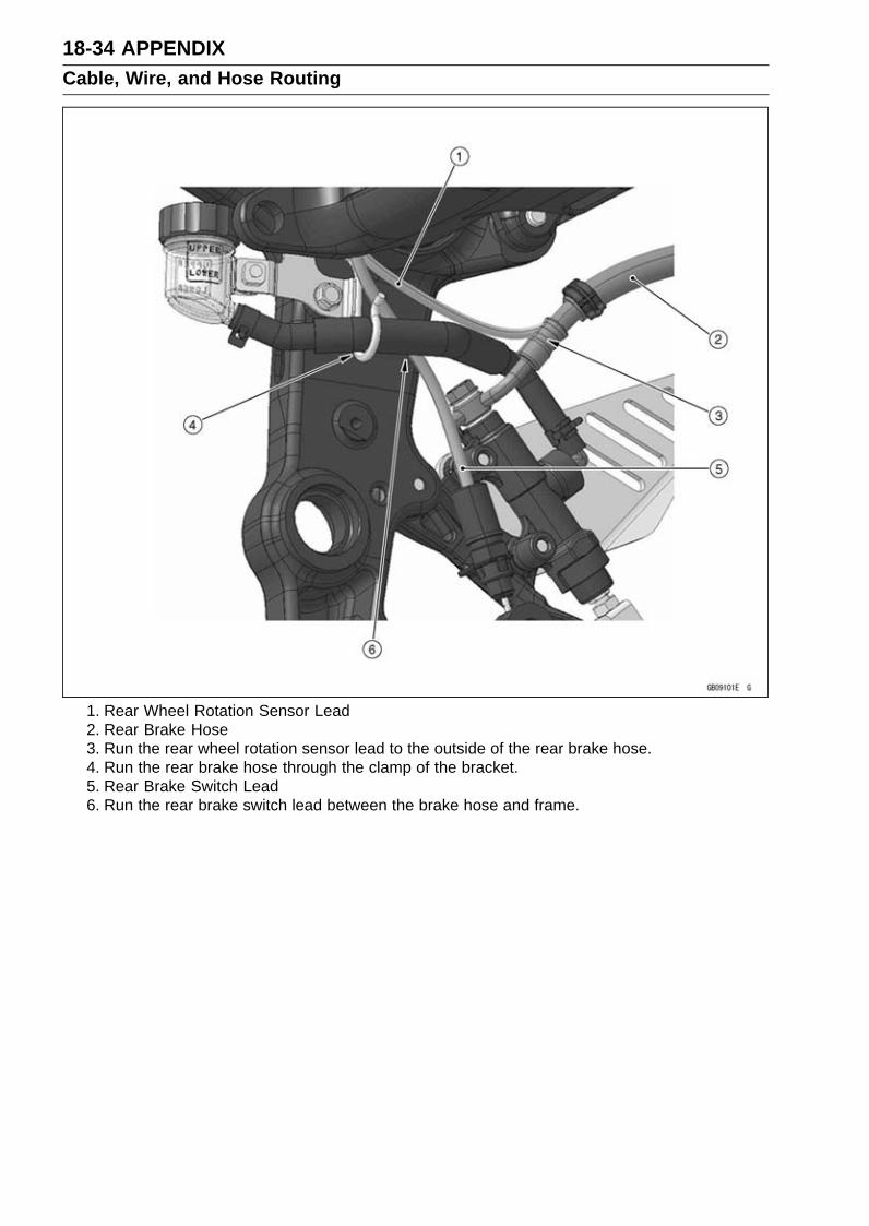
18-34 APPENDIXCable, Wire, and Hose Routing
1. Rear Wheel Rotation Sensor Lead2. Rear Brake Hose3. Run the rear wheel rotation sensor lead to the outside of the rear brake hose.4. Run the rear brake hose through the clamp of the bracket.5. Rear Brake Switch Lead6. Run the rear brake switch lead between the brake hose and frame.

APPENDIX 18-35Cable, Wire, and Hose Routing
KIBS Equipped Models
1. Rear Wheel Rotation Sensor Lead2. Rear Brake Hose3. Run the KIBS brake pipes to the side of the frame.4. Run the rear wheel rotation sensor lead to the outside of the rear brake hose.5. Run the rear wheel rotation sensor lead, KBS brake pipes and rear brake switch lead in order
from the inside.6. Run the rear brake hose through the clamp of the bracket.7. Run the rear brake switch lead between the brake pipes.8. Rear Brake Switch Lead

18-36 APPENDIXCable, Wire, and Hose Routing
KIBS Equipped Models
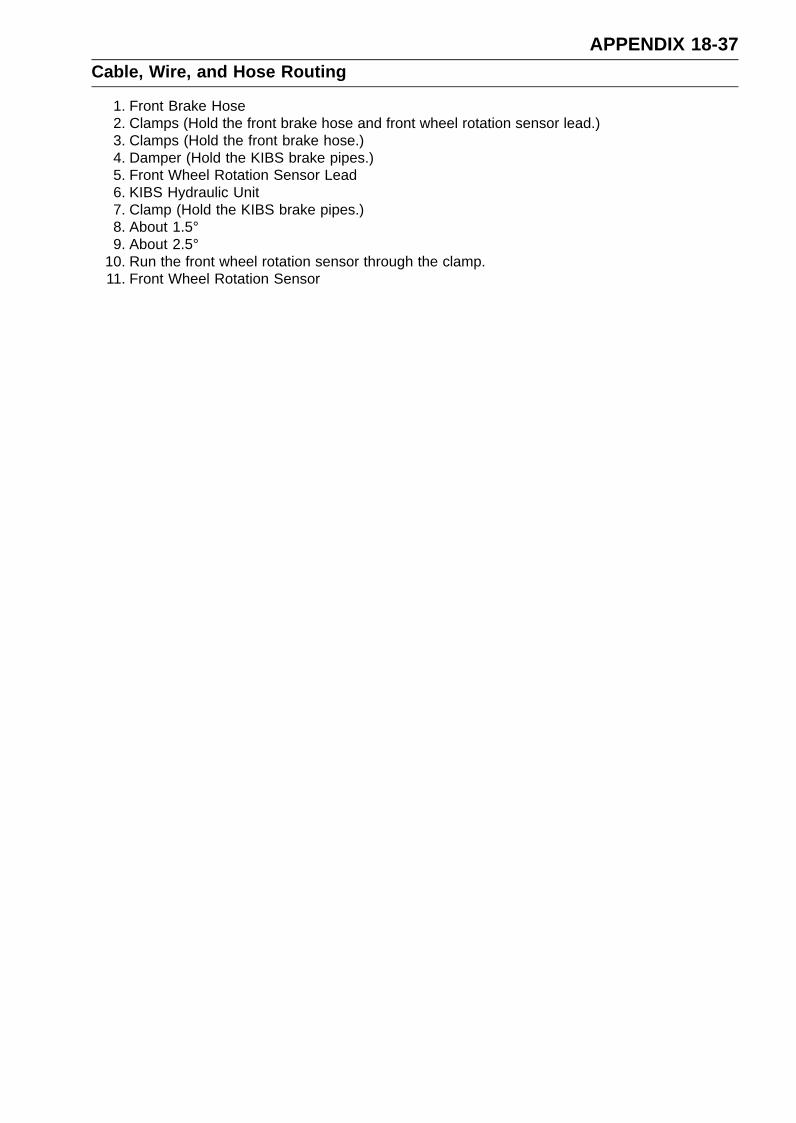
APPENDIX 18-37Cable, Wire, and Hose Routing
1. Front Brake Hose2. Clamps (Hold the front brake hose and front wheel rotation sensor lead.)3. Clamps (Hold the front brake hose.)4. Damper (Hold the KIBS brake pipes.)5. Front Wheel Rotation Sensor Lead6. KIBS Hydraulic Unit7. Clamp (Hold the KIBS brake pipes.)8. About 1.5°9. About 2.5°
10. Run the front wheel rotation sensor through the clamp.11. Front Wheel Rotation Sensor

18-38 APPENDIXCable, Wire, and Hose Routing
KIBS Equipped Models

APPENDIX 18-39Cable, Wire, and Hose Routing
1. Rear Brake Hose2. Rear Wheel Rotation Sensor Lead3. Clamps (Hold the rear brake hose and rear wheel rotation sensor lead.)4. Clamp (Hold the rear wheel rotation sensor lead.)5. Clamp (Hold the rear brake hose.)6. About 30°7. About 38.5°8. Rear Wheel Rotation Sensor9. About 18.1°
10. About 25°11. Run the rear brake hose to the inside of the mud guard.
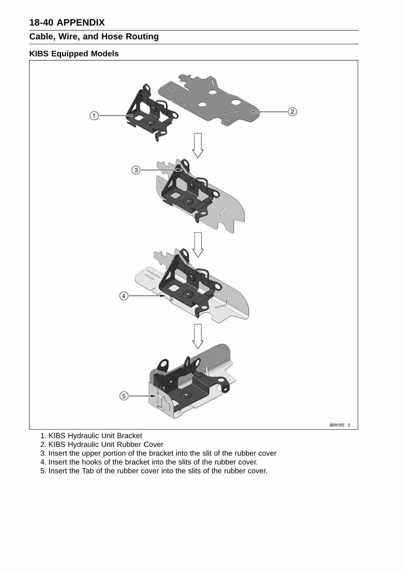
18-40 APPENDIXCable, Wire, and Hose Routing
KIBS Equipped Models
1. KIBS Hydraulic Unit Bracket2. KIBS Hydraulic Unit Rubber Cover3. Insert the upper portion of the bracket into the slit of the rubber cover4. Insert the hooks of the bracket into the slits of the rubber cover.5. Insert the Tab of the rubber cover into the slits of the rubber cover.

APPENDIX 18-41Cable, Wire, and Hose Routing
KIBS Equipped Models
1. Pad2. Install the pad to the lower side of the KIBS brake pipes.3. Align the dent of the pad with the bolt of the hydraulic unit.

18-42 APPENDIXCable, Wire, and Hose Routing
1. Pad2. Quick Rivet3. Install the pad to the upside of the frame ground.4. Run the harnesses to the upside of the pad.
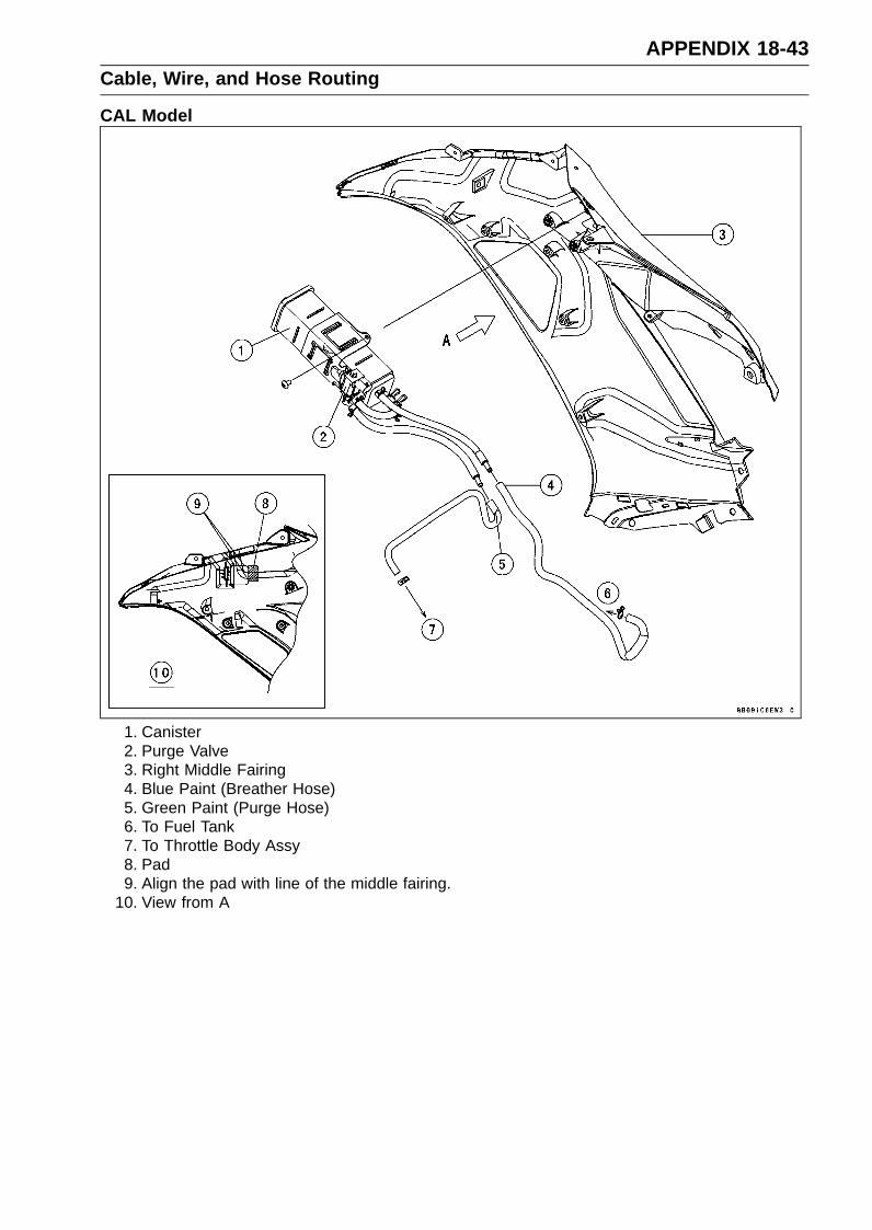
APPENDIX 18-43Cable, Wire, and Hose Routing
CAL Model
1. Canister2. Purge Valve3. Right Middle Fairing4. Blue Paint (Breather Hose)5. Green Paint (Purge Hose)6. To Fuel Tank7. To Throttle Body Assy8. Pad9. Align the pad with line of the middle fairing.
10. View from A
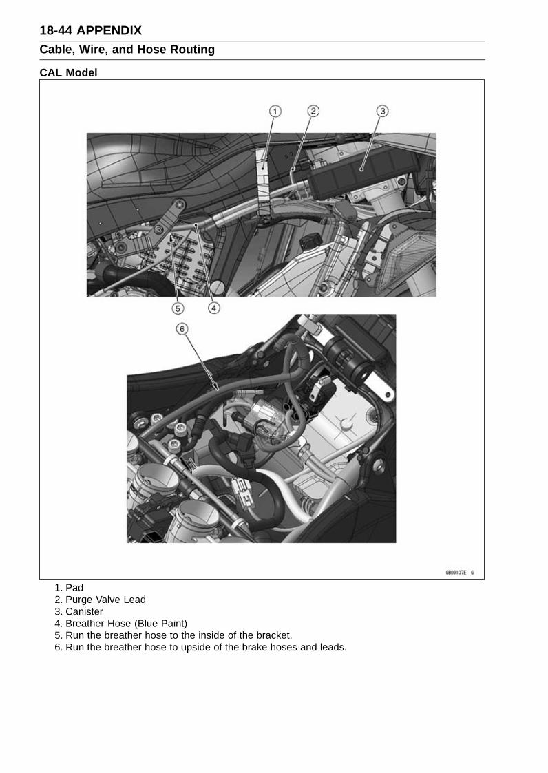
18-44 APPENDIXCable, Wire, and Hose Routing
CAL Model
1. Pad2. Purge Valve Lead3. Canister4. Breather Hose (Blue Paint)5. Run the breather hose to the inside of the bracket.6. Run the breather hose to upside of the brake hoses and leads.

APPENDIX 18-45Cable, Wire, and Hose Routing
CAL Model
1. Run the purge hose under the air switching valve hose and clutch cable. Run the purge hoseto the upside of the stick coil leads.
2. Purge Hose (Green Paint)3. Run the breather hose under the water hose.4. Breather Hose (Blue Paint)5. Run the breather hose to the upside of the brake hoses and leads.6. Run the fuel pump lead under the breather hose (blue paint).7. Clamp (Hold the right switch housing lead, radiator fan lead, front wheel rotation sensor lead
and purge valve lead.)

18-46 APPENDIXCable, Wire, and Hose Routing
CAL Model
1. Run the fuel pump lead to the front of the fuel pump pipe. Run the fuel pump lead between thefuel tank and fuel hose.
2. Breather Hose (Blue Paint)3. Run the air cleaner drain hose and fuel tank drain hose into the hole of the heat insulation rubber
plate. Run the air cleaner drain hose and fuel tank drain hose under the water temperaturesensor lead and fuel injector lead.
4. Run the breather hose to upside of the brake hoses and lead.5. Pad
APPENDIX 18-47Troubleshooting Guide
NOTERefer to the Fuel System chapter for most
of DFI trouble shooting guide.This is not an exhaustive list, giving every
possible cause for each problem listed. Itis meant simply as a rough guide to assistthe troubleshooting for some of the morecommon difficulties.
Engine Doesn’t Start, StartingDifficulty:
Starter motor not rotating:Ignition and engine stop switch not ONStarter lockout switch or gear position
switch troubleStarter motor troubleBattery voltage lowStarter relay not contacting or operatingStarter button not contactingStarter system wiring shorted or openIgnition switch troubleEngine stop switch troubleMain 30 A or ignition fuse blown
Starter motor rotating but engine doesn’tturn over:
Vehicle-down sensor (DFI) coming offImmobilizer system trouble (Equipped Mod-
els)Starter clutch troubleStarter idle gear trouble
Engine won’t turn over:Valve seizureValve lifter seizureCylinder, piston seizureCrankshaft seizureConnecting rod small end seizureConnecting rod big end seizureTransmission gear or bearing seizureCamshaft seizureStarter idle gear seizure
No fuel flow:No fuel in tankFuel pump troubleFuel tank air vent obstructedFuel filter cloggedFuel line clogged
No spark; spark weak:Vehicle-down sensor (DFI) coming offIgnition switch not ONEngine stop switch turned to stop positionClutch lever not pulled in or gear not in neu-
tralBattery voltage lowImmobilizer system trouble (Equipped Mod-
els)Spark plug dirty, broken, or gap malad-
justed
Spark plug incorrectStick coil shorted or not in good contactStick coil troubleECU troubleGear position, starter lockout, or sidestand
switch troubleCrankshaft sensor troubleIgnition switch or engine stop switch
shortedStarter system wiring shorted or openMain 30 A or ignition fuse blown
Fuel/air mixture incorrect:Bypass screw maladjustedAir passage cloggedAir cleaner clogged, poorly sealed, or miss-
ingLeak from oil filler cap, crankcase breather
hose or air cleaner drain hose.Compression Low:
Spark plug looseCylinder head not sufficiently tightened
downCylinder, piston wornPiston ring bad (worn, weak, broken, or
sticking)Piston ring/groove clearance excessiveCylinder head gasket damagedCylinder head warpedValve spring broken or weakNo valve clearanceValve not seating properly (valve bent,
worn, or carbon accumulation on theseating surface)
Poor Running at Low Speed:Spark weak:
Battery voltage lowImmobilizer system trouble (Equipped Mod-
els)Stick coil troubleStick coil shorted or not in good contactSpark plug dirty, broken, or maladjustedSpark plug incorrectECU troubleCrankshaft sensor trouble
Fuel/air mixture incorrect:Bypass screw maladjustedAir passage cloggedAir bleed pipe bleed holes cloggedPilot passage cloggedAir cleaner clogged, poorly sealed, or miss-
ingFuel tank air vent obstructedFuel pump troubleFuel to injector insufficientFuel line cloggedThrottle body assy holder loose

18-48 APPENDIXTroubleshooting Guide
Air cleaner housing holder looseCompression low:
Spark plug looseCylinder head not sufficiently tightened
downNo valve clearanceCylinder, piston wornPiston ring bad (worn, weak, broken, or
sticking)Piston ring/groove clearance excessiveCylinder head gasket damagedCylinder head warpedValve spring broken or weakValve not seating properly (valve bent,
worn, or carbon accumulation on theseating surface)
Camshaft cam wornRun-on (dieseling):
Ignition switch troubleEngine stop switch troubleFuel injector troubleLoosen terminal of battery (–) cable or ECU
ground leadCarbon accumulating on valve seating sur-
faceEngine overheating
Other:ECU troubleThrottle body assy not synchronizingEngine oil viscosity too highDrive train troubleBrake draggingClutch slippingEngine overheatingAir suction valve troubleAir switching valve trouble
Poor Running or No Power at HighSpeed:
Firing incorrect:Spark plug dirty, broken, or maladjustedSpark plug incorrectStick coil shorted or not in good contactStick coil troubleECU trouble
Fuel/air mixture incorrect:Air cleaner clogged, poorly sealed, or miss-
ingThrottle body assy holder looseAir cleaner housing holder looseWater or foreign matter in fuelFuel to fuel injector insufficientFuel tank air vent obstructedFuel line cloggedFuel pump trouble
Compression low:Spark plug loose
Cylinder head not sufficiently tighteneddown
No valve clearanceCylinder, piston wornPiston ring bad (worn, weak, broken, or
sticking)Piston ring/groove clearance excessiveCylinder head gasket damagedCylinder head warpedValve spring broken or weakValve not seating properly (valve bent,
worn, or carbon accumulation on theseating surface.)
Knocking:Carbon built up in combustion chamberFuel poor quality or incorrectSpark plug incorrectECU trouble
Miscellaneous:Throttle valve won’t fully openBrake draggingClutch slippingEngine overheatingEngine oil level too highEngine oil viscosity too highDrive train troubleCamshaft cam wornAir suction valve troubleAir switching valve troubleCatalytic converter melt down due to muffler
overheating (KLEEN)
Overheating:Firing incorrect:
Spark plug dirty, broken, or maladjustedSpark plug incorrectECU trouble
Muffler overheating:For KLEEN, do not run the engine even if
with only one cylinder misfiring or poorrunning (Request the nearest service fa-cility to correct it)
For KLEEN, do not push-start with a deadbattery (Connect another full-chargedbattery with jumper cables, and start theengine using the electric starter)
For KLEEN, do not start the engine undermisfire due to spark plug fouling or poorconnection of the stick coil
For KLEEN, do not coast the motorcyclewith the ignition switch off (Turn the igni-tion switch ON and run the engine)
ECU troubleFuel/air mixture incorrect:
Throttle body assy holder looseAir cleaner housing holder looseAir cleaner poorly sealed, or missing

APPENDIX 18-49Troubleshooting Guide
Air cleaner cloggedCompression high:
Carbon built up in combustion chamberEngine load faulty:
Brake draggingClutch slippingEngine oil level too highEngine oil viscosity too highDrive train trouble
Lubrication inadequate:Engine oil level too lowEngine oil poor quality or incorrect
Oil cooler incorrect:Oil cooler clogged
Water temperature meter incorrect:Water temperature meter brokenWater temperature sensor broken
Coolant incorrect:Coolant level too lowCoolant deterioratedWrong coolant mixed ratio
Cooling system component incorrect:Radiator fin damagedRadiator cloggedThermostat troubleRadiator cap troubleRadiator fan relay troubleFan motor brokenFan blade damagedWater pump not turningWater pump impeller damaged
Over Cooling:Water temperature meter incorrect:
Water temperature meter brokenWater temperature sensor broken
Cooling system component incorrect:Thermostat trouble
Clutch Operation Faulty:Clutch slipping:
Friction plate worn or warpedSteel plate worn or warpedClutch spring broken or weakClutch hub or housing unevenly wornNo clutch lever playClutch inner cable troubleClutch release mechanism trouble
Clutch not disengaging properly:Clutch plate warped or too roughClutch spring compression unevenEngine oil deterioratedEngine oil viscosity too highEngine oil level too highClutch housing frozen on drive shaftClutch hub nut looseSub clutch hub spline damaged
Clutch friction plate installed wrongClutch lever play excessiveClutch release mechanism trouble
Gear Shifting Faulty:Doesn’t go into gear; shift pedal doesn’treturn:
Clutch not disengagingShift fork bent or seizedGear stuck on the shaftGear positioning lever bindingShift return spring weak or brokenShift return spring pin looseShift ratchet assembly spring brokenShift ratchet assembly brokenShift pawl broken
Jumps out of gear:Shift fork ear worn, bentGear groove wornGear dogs and/or dog holes wornShift drum groove wornGear positioning lever spring weak or bro-
kenShift fork guide pin wornDrive shaft, output shaft, and/or gear
splines wornOvershifts:
Gear positioning lever spring weak or bro-ken
Shift ratchet assembly spring weak or bro-ken
Abnormal Engine Noise:Knocking:
ECU troubleCarbon built up in combustion chamberFuel poor quality or incorrectSpark plug incorrectOverheating
Piston slap:Cylinder/piston clearance excessiveCylinder, piston wornConnecting rod bentPiston pin, piston pin hole worn
Valve noise:Valve clearance incorrectValve spring broken or weakCamshaft bearing wornValve lifter worn
Other noise:Connecting rod small end clearance exces-
siveConnecting rod big end clearance exces-
sivePiston ring/groove clearance excessivePiston ring worn, broken, or stuckPiston ring groove worn

18-50 APPENDIXTroubleshooting Guide
Piston seizure, damageCylinder head gasket leakingExhaust pipe leaking at cylinder head con-
nectionCrankshaft runout excessiveEngine mounting portions looseCrankshaft bearing wornPrimary gear worn or chippedCamshaft chain tensioner troubleCamshaft chain, sprocket, guide wornAir suction valve damagedAir switching valve damagedAlternator rotor looseCatalytic converter melt down due to muffler
overheating (KLEEN)Exhaust butterfly valve cable loose
Abnormal Drive Train Noise:Clutch noise:
Clutch damper weak or damagedClutch housing/friction plate clearance ex-
cessiveClutch housing gear wornWrong installation of outside friction plate
Transmission noise:Bearings wornTransmission gear worn or chippedMetal chips jammed in gear teethEngine oil insufficient
Drive line noise:Drive chain adjusted improperlyDrive chain wornRear and/or engine sprocket wornChain lubrication insufficientRear wheel misaligned
Abnormal Frame Noise:Front fork noise:
Oil insufficient or too thinSpring weak or broken
Rear shock absorber noise:Shock absorber damaged
Disc brake noise:Pad installed incorrectlyPad surface glazedDisc warpedCaliper trouble
Other noise:Bracket, nut, bolt, etc. not properly
mounted or tightened
Warning Indicator Light (Oil PressureWarning) Doesn’t Go OFF:
Engine oil pump damagedEngine oil screen cloggedEngine oil filter clogged
Engine oil level too lowEngine oil viscosity too lowCamshaft bearing wornCrankshaft bearing wornOil pressure switch damagedWiring faultyRelief valve stuck openO-ring at the oil passage in the crankcase
damaged
Exhaust Smokes Excessively:White smoke:
Piston oil ring wornCylinder wornValve oil seal damagedValve guide wornEngine oil level too high
Black smoke:Air cleaner clogged
Brown smoke:Air cleaner housing holder looseAir cleaner poorly sealed or missing
Handling and/or StabilityUnsatisfactory:
Handlebar hard to turn:Cable routing incorrectHose routing incorrectWiring routing incorrectSteering stem nut too tightSteering stem bearing damagedSteering stem bearing lubrication inade-
quateSteering stem bentTire air pressure too low
Handlebar shakes or excessively vibrates:Tire wornSwingarm pivot bearing wornRim warped, or not balancedWheel bearing wornHandlebar clamp bolt looseSteering stem nut looseFront, rear axle runout excessiveEngine mounting portions loose
Handlebar pulls to one side:Frame bentWheel misalignmentSwingarm bent or twistedSwingarm pivot shaft runout excessiveSteering maladjustedFront fork bentRight and left front fork oil level uneven
Shock absorption unsatisfactory:(Too hard)Front fork oil excessiveFront fork oil viscosity too highRear shock absorber adjustment too hard

APPENDIX 18-51Troubleshooting Guide
Tire air pressure too highFront fork bent(Too soft)Tire air pressure too lowFront fork oil insufficient and/or leakingFront fork oil viscosity too lowRear shock adjustment too softFront fork, rear shock absorber spring weakRear shock absorber oil leaking
Brake Doesn’t Hold:Air in the brake linePad or disc wornBrake fluid leakageDisc warpedContaminated padBrake fluid deterioratedPrimary or secondary cup damaged in master
cylinderMaster cylinder scratched inside
Battery Trouble:Battery discharged:
Charge insufficientBattery faulty (too low terminal voltage)Battery cable making poor contactLoad excessive (e.g., bulb of excessive
wattage)Ignition switch troubleAlternator troubleWiring faultyRegulator/rectifier trouble
Battery overcharged:Alternator troubleRegulator/rectifier troubleBattery faulty

MODEL APPLICATIONYear Model Beginning Frame No.
2013 ZX636ED JKBZXJE1DA000001JKBZX636EEA000001
2013 ZX636FD JKBZXJF1DA000001JKBZX636EFA000001
:This digit in the frame number changes from one machine to another.
Part No.99924-1462-01 Printed in Japan
Copyright © 2022 FDOKUMEN


![@_ YR]WhRj ^R[`c 4RSZ_Ve cV[ZX e`URj - Daily Pioneer](https://static.fdokumen.com/doc/165x107/631f50b94573ad0c3e030007/-yrwhrj-rc-4rszve-cvzx-eurj-daily-pioneer.jpg)