NEW INSTRUMENT CALIBRATION FACILITY FOR THE DOE ...
14
NEW INSTRUMENT CALIBRATION FACILITY FOR THE DOE SAVANNAH RIVER SITE W. H. Wilkie® E. J. Polz® Abstract - A new laboratory facility is being designed, constructed, and equipped at ■ the Savannah River Site (SRS) as a fiscal year 1992 line item project. This facility will provide space and equipment for test, evaluation, repair, maintenance, and calibration of radiation monitoring instrumentation. The project will replace an obsolete facility and will allow implementation of program upgrades necessary to meet ANSI N323 requirements and National Voluntary Laboratory Accreditation Program (NVLAP) criteria for accreditation of federally owned secondary calibration laboratories. An outline of the project is presented including description, scope, cost, management organization, chronology, and current status. Selected design criteria and their impacts on the project are discussed. The upgraded SRS calibration program is described, and important features of the new facility and equipment that will accommodate this program are listed. The floor plan for the facility is shown, and equipment summaries and functional descriptions for each area are provided. PROJECT DESCRIPTION Design Strategy and Facility Classification The Health Protection (HP) Instrument Calibration Facility Project will build and equip a single-story structure having an approximate floor area of 26,000 square feet. The facility is being designed as a "green field" project in an undeveloped section of the Site with no constraints imposed by existing structures or unusual topography or geological conditions. The design is being prepared by Ebasco through a Project Engineering Services Contract (PESC). The design will meet (or will provide the capability for the program to meet) the applicable requirements of the partial list of key codes and standards shown in Table 1. 0) Westinghouse Savannah River Company (WSRC), Health Protection Department, 735-A Savannah River Site, Aiken, South Carolina 29808. 371
-
Upload
khangminh22 -
Category
Documents
-
view
3 -
download
0
Transcript of NEW INSTRUMENT CALIBRATION FACILITY FOR THE DOE ...
NEW INSTRUMENT CALIBRATION FACILITY FOR THE
DOE SAVANNAH RIVER SITE
W. H. Wilkie®E. J. Polz®
Abstract - A new laboratory facility is being designed, constructed, and equipped at ■ the Savannah River Site (SRS) as a fiscal year 1992 line item project. This facility
will provide space and equipment for test, evaluation, repair, maintenance, and calibration of radiation monitoring instrumentation. The project will replace an obsolete facility and will allow implementation of program upgrades necessary to meet ANSI N323 requirements and National Voluntary Laboratory Accreditation Program (NVLAP) criteria for accreditation of federally owned secondary calibration laboratories. An outline of the project is presented including description, scope, cost, management organization, chronology, and current status. Selected design criteria and their impacts on the project are discussed. The upgraded SRS calibration program is described, and important features of the new facility and equipment that will accommodate this program are listed. The floor plan for the facility is shown, and equipment summaries and functional descriptions for each area are provided.
PROJECT DESCRIPTION
Design Strategy and Facility Classification
The Health Protection (HP) Instrument Calibration Facility Project will build and equip a single-story structure having an approximate floor area of 26,000 square feet. The facility is being designed as a "green field" project in an undeveloped section of the Site with no constraints imposed by existing structures or unusual topography or geological conditions. The design is being prepared by Ebasco through a Project Engineering Services Contract (PESC). The design will meet (or will provide the capability for the program to meet) the applicable requirements of the partial list of key codes and standards shown in Table 1.
0) Westinghouse Savannah River Company (WSRC), Health Protection Department, 735-A Savannah River Site, Aiken, South Carolina 29808.
371

A lump sum fixed price contract will be issued for constructing and equipping the facility as a "turn key" product. The project is a 1992 line item with a total estimated cost (TEC) of $20,600,000. An estimated total project cost of $24,400,000 consists of the TEC plus $3,800,000 from the Site operating budget used to fund supporting activities not covered by project TEC. Table 2 lists cost details for the project.
A Hazards Assessment Document (HAD) prepared in accordance with U.S. Department of Energy (DOE) requirements (DOE 5480.23 as supplemented by DOE-STD-027-92) has resulted in a determination that the overall hazard classification for the facility is GENERAL USE NONNUCLEAR. An analysis of the radioactive source inventory in accordance with DOE-STD-027-92 found that the facility will be below the threshold of a Category 3 hazard which supports the conclusions of the HAD. Therefore, a Safety Analysis Report will not be required.
The new facility will provide all the laboratories, offices, shops; testing and calibration equipment, furniture, and support space needed for the SRS instrument program. It will support routine repair, maintenance, and calibration activities for portable instruments. The facility will provide extensive capabilities for instrument testing and evaluation in accordance with ANSI N323 Section 3 and ANSI N42.17A for new instruments as well as for instruments in service. In addition, the facility will be equipped to provide the capability for performing specialized tests in support of the external dosimetry program and for testing and evaluating fixed radiation monitoring equipment.
Chronology
Major milestones for the project are listed in Table 3. Although this list indicates a long time line between project inception and completion, it should be emphasized that the schedule is very aggressive with a few brief periods of low activity for reviews and procurement actions.
Project Management
Management of major projects within DOE is very involved and, in addition to specific annual Congressional budget authorization, requires multiple justifications, independent reviews, funding approvals, etc. Figure 1 diagrams the interactions of the key organizations. A project team responsible for the day-to-day work on the project has a membership drawn from the organizations depending on the current project activities. This team meets weekly or as required and conducts project business using a consensus management style. This approach is working well and is proving to be very effective in ensuring that all applicable requirements are met while avoiding big surprises that frequently have plagued projects not coordinated in this manner. The team approach is believed to be especially prudent in view of the rapidly evolving mission objectives and project management requirements within the DOE complex.
CURRENT PROGRAM DESCRIPTION AND PROJECT JUSTIFICATION
The Calibration Group of the HP Technology Section is responsible for providing and maintaining an inventory of portable radiation monitoring instruments for supporting SRS operations. This involves procuring, testing, evaluating, and approving new portable instruments for SRS use and for calibrating, maintaining, and repairing this equipment. The group also is responsible for providing technical advice and approval for installed radiation monitoring instruments used in radiation protection applications, e.g., equipment for monitoring area radiation, laundry contamination, and
372

breathing air. The current inventory of portable equipment includes approximately 4,000 radiation and contamination monitoring instruments and 5,500 direct-reading quartz fiber and electronic dosimeters. Approximately 15,000 survey instrument calibrations and 11,000 test cycles for direct reading dosimeters are performed per year. The demand for calibrated instruments has continued to climb steadily even as the DOE mission for SRS has been shifting away from nuclear material production in response to world politics.
The current facility for the calibration program was constructed in 1952 and is no longer adequate to meet DOE technical and program requirements. It was determined that expansion and renovation of the existing calibration facility would not be cost effective because:
• It is located in a congested and highly developed part of the site.
• Asbestos in wall panels and floor tiles mandates expensive construction techniques for protecting health.
• Compliance with the access requirements related to safeguards and security and radiation protection would significantly complicate the expansion and renovation work.
• The present program could not be effectively managed with concurrent construction for renovation and expansion.
Therefore, the new facility is being designed to meet present needs and to provide the capability for future expansion should this be required to support the evolving DOE mission objectives for the SRS.
FLOOR PLAN AND SELECTED ROOM DESCRIPTIONS
Floor Layout
The floor plan shown in Figure 2 is intended to support efficient operation by grouping areas requiring heavy staff interaction, frequent instrument movement between rooms, or centralized equipment control and monitoring. An additional design objective is to minimize construction costs, e.g., by grouping together the rooms requiring poured concrete shielding, simplifying the building footprint, and locating the equipment rooms (electrical, mechanical, telecommunications) to ensure convenient access and maintainability. For as low as reasonably achievable (ALARA) reasons, the administrative and personnel service areas were placed to maximize distances from the production support areas containing gamma and neutron irradiators. Figure 3 shows the location of the various categories of space and lists percentages of the total floor area.
Control Room
The operating stations for the Low Scatter, X-ray Beam, and the Gamma Beam Rooms will be located in the Control Room. An additional operating station will be provided for video process and surveillance functions. Normal access to the above mentioned rooms will be through the Control Room as an additional safety feature.
373

Low Scatter Room
One of the most notable features of the facility is the Low Scatter Room which will provide the capability for performing primary instrument calibrations and dosimeter testing. The room geometry is 40 ft x 40 ft x 40 ft with, a single irradiation position located at the geometric center of the room. An aluminum grating working level will be provided slightly below the mid-height of the room. Parametric studies were performed to see if the addition of boron in the concrete would be practical for reducing the fluence rate of low-energy neutrons back into the room. It was determined that the addition of 0.1 % boron by weight into the concrete would reduce the low-energy scatter in the room by a factor of approximately 16.
Well Room
Four well-type irradiators will be located in this room. The room is an elongated rectangle with concrete partitions between the wells along the narrow axis of the room to minimize cross talk (radiation interference).
Performance and Environmental Testing Laboratory
The Performance and Environmental Testing Laboratory (PETL) will be used both for evaluating new equipment and for conducting routine periodic testing as specified in ANSI N323 and detailed ANSI N42.17A. Large radiation monitoring systems will be brought into the PETL through a roll-up door opening onto a covered loading area.
ADDITIONAL FEATURES
Video Systems
Extensive use will be made of video equipment in the facility. Color cameras for safety surveillance and high-resolution black and white cameras for monitoring processes will be provided. To prevent confusion during video switching all cameras will be equipped with character generators giving the camera ID, which will be displayed on any monitor switched to that camera. Facility lighting is being designed to minimize glare from instrument meter faces.
The process monitoring cameras for the Well Room will have pan, tilt, and zoom capability and will be mounted on a ceiling-mounted positioning track which will allow positioning to minimize parallax distortion when viewing instrument faces. The process monitoring cameras for the X-ray, Gamma Beam, and Low Scatter Rooms will be rigidly mounted to the instrument positioning tracks and will travel with the instruments during repositioning. Each room will have a portable monitor for use in setting up the cameras for test viewing.
The surveillance cameras with remote pan tilt and zoom capability are an additional safety feature for the rooms in which a potential for significant radiation exposure of personnel exists. Facility operating procedures will require a search of the areas both in person and by using the video surveillance systems prior to activation of the irradiation equipment.
Each surveillance and process camera shall first feed and be controlled from the operating console for that room. The video signal also will feed a video workstation in the Control Room and can be
374
monitored or recorded at any time. Controls for the remotely controllable cameras also will be provided at the video workstation. However, control must first be turned over from the equipment control station by a technician to prevent interfering with any tests in progress. A 19-inch monitor will be provided in the overhead of the Control Room to provide viewing of the rooms and processes by visitors and interested parties without entering the rooms.
Computer Network
A network of IBM-compatible computers will be used for maintenance, repair, test, process tracking, and calibration data collection. Workstations will be set up with bar code reading equipment to scan in the ID of equipment and access appropriate information to lead the technicians through the various procedures required in the facility. On-screen procedures will prompt for the appropriate data entry. Error checking will give immediate feedback of incorrect data entry. All data will be collected from workstations over the network to update the master databases on the network server located in the Records Room. Local printers will provide a hard-copy calibration certificate for review and signature of calibration technicians and for printing calibration labels for the instrument.
Shielding
A design objective is to provide shielding that reduces dose rates to facility staff to below 0.25 mrem/h to the extent practicable and further reduces dose rates within ALARA considerations. Extensive parametric shielding studies were performed, and alternative designs were evaluated against an ALARA criterion of $15,000 per annual person-rem saved. Also, it was necessary for the shielding to be sufficient to minimize radiation interference with a whole body counting facility to be constructed nearby. The most difficult problems related to the shielding specifications were calculating neutron and gamma dose rates at the entrances of labyrinths and optimizing the designs to minimize loss of floor space while allowing convenient movement of staff and equipment through passageways and labyrinths.
Radiation Sources
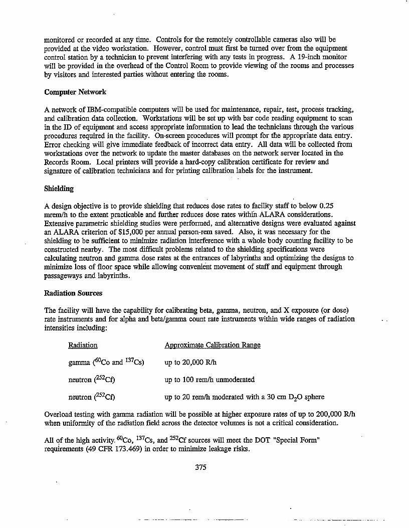
The facility will have the capability for calibrating beta, gamma, neutron, and X exposure (or dose) rate instruments and for alpha and beta/gamma count rate instruments within wide ranges of radiation intensities including:
Radiation Approximate Calibration Range
gamma (^Co and 137Cs) up to 20,000 R/h
neutron (252Cf) up to 100 rem/h unmoderated
neutron (252Cf) up to 20 rem/h moderated with a 30 cm D20 sphere
Overload testing with gamma radiation will be possible at higher exposure rates of up to 200,000 R/h when uniformity of the radiation field across the detector volumes is not a critical consideration.
All of the high activity. 60Co, 137Cs, and 252Cf sources will meet the DOT "Special Form" requirements (49 CFR 173.469) in order to minimize leakage risks.
375

Various types of irradiation equipment are being specified for the facility. Count rate type instruments will be calibrated using small plated sources. The irradiation systems for the facility are listed in Table 4 along with descriptions and expected primary uses. All irradiation equipment for the facility will incorporate instrument positioning fixtures that will provide reproducible geometry during calibration and/or testing. Design considerations for the major equipment include:
• fail-safe design to low-exposure conditions on error, loss of power, or manual trip of conveniently located scram buttons
• computer-controlled operation of major equipment with consideration for a consistent graphical operating interface to ease training on equipment operation
• precise positioning of the sources or the instruments using two independent systems for redundancy
• . integration of computer control, calibration data collection, and environmental conditionmonitoring
• video monitoring of process functions with recording capability
• ease of maintenance including source removal to safe locations to facilitate equipment maintenance
• source selection to provide a wide range of dose rates
• provisions for remotely changing instrument ranges where practical.
Truck Loading/Unloading Facilities
A grade-level loading area will be equipped with a hydraulic platform which can conveniently be adjusted to match the height of the bed of any size truck. Hydraulic loading equipment is believed to be cost effective and will eliminate the need ifor a below-grade ramp with the accompanying problems due to drainage, trash accumulation, and safety.
SUMMARY
The project to build and equip a new instrument calibration facility at SRS is on schedule and under budget due to management support at all organizational levels and to the efforts of a multidisciplined project team. The facility is expected to be capable of meeting future radiation monitoring instrument needs for the SRS regardless of how the DOE mission evolves, whether it be production support, waste management, decommissioning, environmental restoration, or a combination of activities.
Irradiation Equipment
376

REFERENCES
49 CFR 173.469. "Tests for Special Form Radioactive Materials." U.S. Code of Federal Regulations.
U.S. Department of Energy (DOE). 1992. "Hazard Categorization and Accident Analysis Techniques for Compliance with DOE Order 5480.23, Nuclear Safety Analysis Reports." DOE-STD- 1027-92, Washington, D.C.
U.S. Department of Energy (DOE). 1992. "Nuclear Safety Analysis Reports." DOE Order 5480.23, Washington, D.C.
377
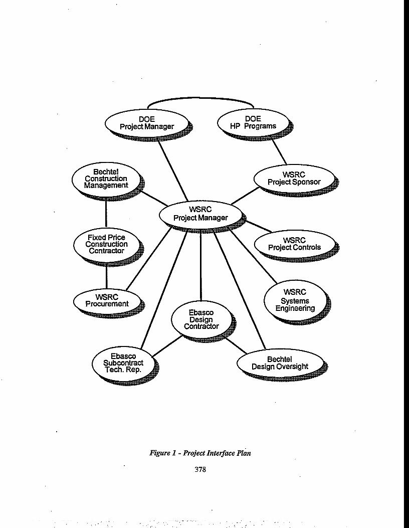
Figure 1 - Project Interface Plan
378
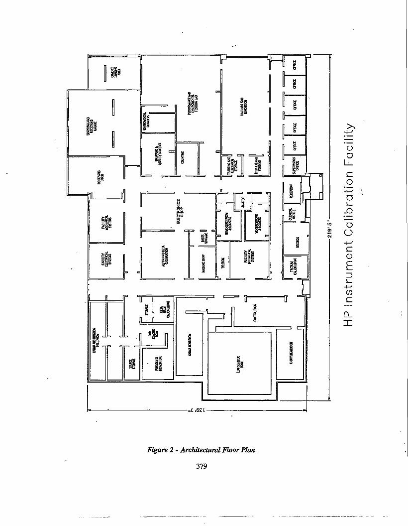
Figure 2 - Architectural Floor Plan
379
HP
Inst
rum
ent
Cal
ibra
tion
Fac
ility
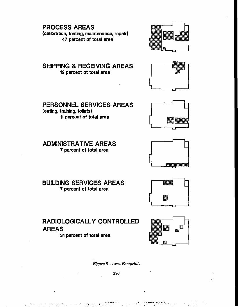
PROCESS AREAS(calibration, testing, maintenance, repair)
47 percent of total area
SHIPPING & RECEIVING AREAS12 percent ot total area
PERSONNEL SERVICES AREAS(eating, training, toilets)
11 percent of total area
ADMINISTRATIVE AREAS7 percent of total area
BUILDING SERVICES AREAS7 percent of total area
RADIOLOGICALLY CONTROLLED AREAS
31 percent of total area
Figure 3 - Area Footprints

Table 1 - List o f Key Codes and Standards
DOE Documents
5400.5
5480.4
5480.7
5480.11
6430.1A
N 5480.6
ANSI Standards
ANSI N42.17A
ANSI N323
ANSI N543
NIST Documents
Radiation Protection for the Public and the Environment. 2/8/90
Environmental Protection. Safety and Health Protection Standards. 5/16/89
Fire Protection. 11/16/87
Radiation Protection or Occupational Workers. 12/21/88
General Design Criteria. 4/6/89
Radiological Control Manual. 6/92
Performance Specifications or Health Protection Instrumentation - Portable Instrumentation or Use in Normal Environmental Conditions. 1989
Radiation Protection Instrumentation Test & Calibration. 1978
General Safety Standard or Installations Using Nonmedical X-rav and Sealed Gamma-Rav Sources. 1974
Criteria for the Operation Federally-owned Secondary Calibration Laboratories (Ionizing Radiation1). 1990
NVLAP Program Handbook. Secondary Calibration Laboratory or Ionizing Radiation - Requirements or Accreditation
381
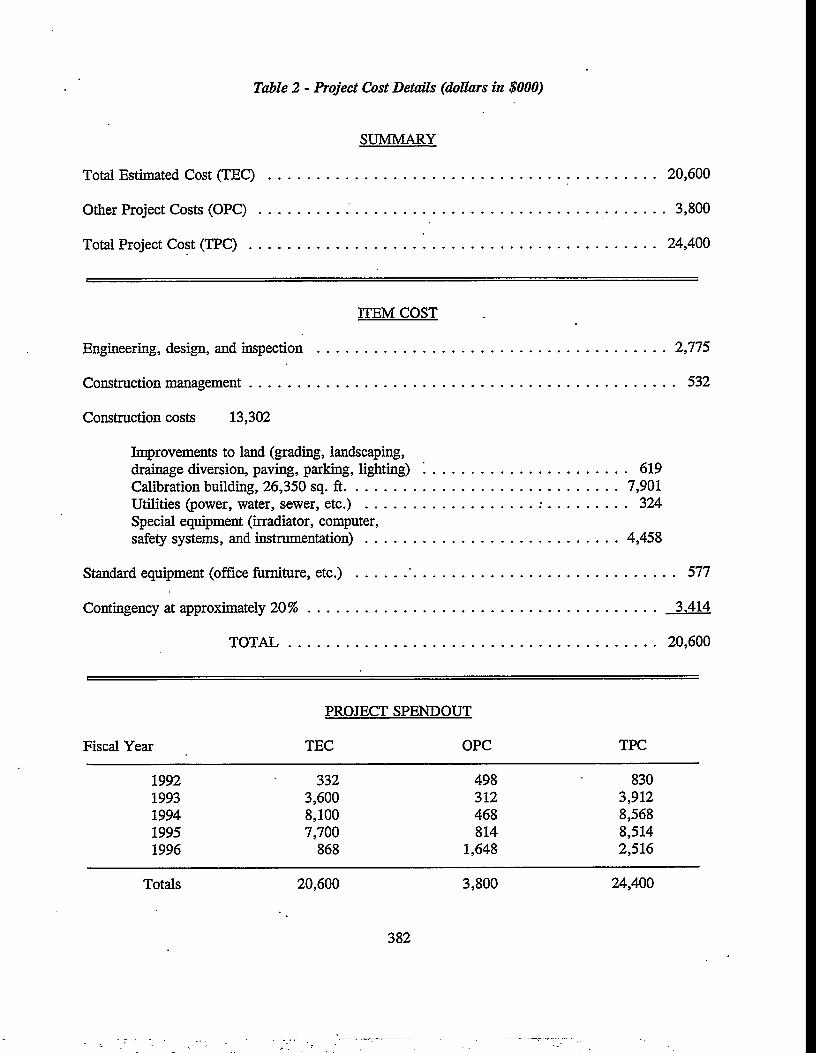
Table 2 - Project Cost Details (dollars in $000)
SUMMARY
Total Estimated Cost (TEC) ...................................................................................................... 20,600
Other Project Costs (O P C ).......................................................................................................... 3,800
Total Project Cost (T P C )........................................... ' . ............................................................ 24,400
ITEM COST
Engineering, design, and inspection ........................................................................................... 2,775
Construction management................................................................................................................ 532
Construction costs 13,302
Improvements to land (grading, landscaping,drainage diversion, paving, parking, lighting) ' . ................................................... 619Calibration building, 26,350 sq. ft........................................................................7,901
Utilities (power, water, sewer, etc.) ........................................... .-...................... 324Special equipment (irradiator, computer,safety systems, and instrumentation).................................................................. 4,458
Standard equipment (office furniture, etc.) ............. ' ..................................................................... 577
Contingency at approximately 2 0 % ........................................................................................... 3,414
TO TA L................................................................................................ 20,600
PROJECT SPENDOUT
Fiscal Year TEC OPC TPC
1992 332 498 8301993 3,600 312 3,9121994 8,100 468 8,5681995 7,700 814 8,5141996 868 1,648 2,516
Totals 20,600 3,800 24,400
382

Table 3 - Chronology
Milestone Date
Need for new facility identified .............................................................................................. 1/89
Functional Performance Requirements document issu ed ....................................................... 2/90
Functional Design Criteria document issued . . . . ............................................................... 5/90
Conceptual Design Report submitted to DOE . ....................................................................... 5/90
Project Validation hearing........................................................................................................ 6/90
Project Authorization issued ................................................................................................... 3/92
Title I design (30% level) complete......................................................................................... 8/92
Procurement of lump sum contractor initiated ....................................................................... 7/93
Title II design (90% level) complete...................................................................................... 6/93
Construction start,................................................................................................. .................... 2/94
Title HI design (100% level) complete................................................................................... 10/95
Project complete....................................................................................................................... 10/95
Approval to commence operations ......................................................................................... 3/96
383

Table 4 - Major Irradiation Equipment
LABORATORY EQUIPMENT PRIMARY USES
Low Scatter Free-air, low scatter, irradiator system with four positioning tracks.
60Co 20 Ci 137Cs 100 Ci 137Cs 2.2 Ci 137Cs 0.05 Ci 252Cf 4 mg 252Cf 0.3 mg 252Cf 0.03 mg
Primary calibrations of transfer instruments and general testing. Cf-252 sources may be used bare or with moderation by a 30 cm diameter D20 sphere.
Gamma Beam Beam type irradiator system with a single positioning track.
60Co 6,000 Ci 60Co 75 Ci 60Co i .... 1 Ci 137Cs 5,000 Ci 137Cs 62 Ci 137Cs 1 Ci
Primary and high range calibrations; overload response testing. .
X-ray Beam 320 kV constant potential X-ray generator and a single positioning track
Low energy calibration and testing; dosimeter irradiation.
Beta Beam Beta beam irradiator system and a single positioning track.
Free field beta calibration and testing.
90Sr/Y90Sr/Y209'j’i147Pm
50 mCi 2 mCi
0.5 mCi 14 mCi
Well Irradiator Four independent well-irradiator systems with single sources:
137Cs 20 Ci 137Cs 20 Ci 137Cs 0.5 Ci ^ C s 0.01 mg
Production calibration of gamma and neutron instruments.
PanoramicIrradiator
A single source:
137Cs 1.2 Ci
Dosimeter irradiation and testing.
384