New Combined Adaptive (NCA) Algorithm for Smart Antenna System Applications
10
This article was downloaded by: [Thamer M Jamel] On: 25 June 2014, At: 09:30 Publisher: Taylor & Francis Informa Ltd Registered in England and Wales Registered Number: 1072954 Registered office: Mortimer House, 37-41 Mortimer Street, London W1T 3JH, UK IETE Journal of Research Publication details, including instructions for authors and subscription information: http://www.tandfonline.com/loi/tijr20 New Combined Adaptive (NCA) Algorithm for Smart Antenna System Applications Thamer M. Jamel a a Department of Electrical and Computer Engineering, University of Missouri, Columbia, MO 65211, USA Published online: 19 Jun 2014. To cite this article: Thamer M. Jamel (2014) New Combined Adaptive (NCA) Algorithm for Smart Antenna System Applications, IETE Journal of Research, 60:2, 119-127 To link to this article: http://dx.doi.org/10.1080/03772063.2014.901570 PLEASE SCROLL DOWN FOR ARTICLE Taylor & Francis makes every effort to ensure the accuracy of all the information (the “Content”) contained in the publications on our platform. However, Taylor & Francis, our agents, and our licensors make no representations or warranties whatsoever as to the accuracy, completeness, or suitability for any purpose of the Content. Any opinions and views expressed in this publication are the opinions and views of the authors, and are not the views of or endorsed by Taylor & Francis. The accuracy of the Content should not be relied upon and should be independently verified with primary sources of information. Taylor and Francis shall not be liable for any losses, actions, claims, proceedings, demands, costs, expenses, damages, and other liabilities whatsoever or howsoever caused arising directly or indirectly in connection with, in relation to or arising out of the use of the Content. This article may be used for research, teaching, and private study purposes. Any substantial or systematic reproduction, redistribution, reselling, loan, sub-licensing, systematic supply, or distribution in any form to anyone is expressly forbidden. Terms & Conditions of access and use can be found at http:// www.tandfonline.com/page/terms-and-conditions
-
Upload
uotechnology -
Category
Documents
-
view
0 -
download
0
Transcript of New Combined Adaptive (NCA) Algorithm for Smart Antenna System Applications
This article was downloaded by: [Thamer M Jamel]On: 25 June 2014, At: 09:30Publisher: Taylor & FrancisInforma Ltd Registered in England and Wales Registered Number: 1072954 Registered office: Mortimer House,37-41 Mortimer Street, London W1T 3JH, UK
IETE Journal of ResearchPublication details, including instructions for authors and subscription information:http://www.tandfonline.com/loi/tijr20
New Combined Adaptive (NCA) Algorithm for SmartAntenna System ApplicationsThamer M. Jamelaa Department of Electrical and Computer Engineering, University of Missouri, Columbia, MO65211, USAPublished online: 19 Jun 2014.
To cite this article: Thamer M. Jamel (2014) New Combined Adaptive (NCA) Algorithm for Smart Antenna SystemApplications, IETE Journal of Research, 60:2, 119-127
To link to this article: http://dx.doi.org/10.1080/03772063.2014.901570
PLEASE SCROLL DOWN FOR ARTICLE
Taylor & Francis makes every effort to ensure the accuracy of all the information (the “Content”) containedin the publications on our platform. However, Taylor & Francis, our agents, and our licensors make norepresentations or warranties whatsoever as to the accuracy, completeness, or suitability for any purpose of theContent. Any opinions and views expressed in this publication are the opinions and views of the authors, andare not the views of or endorsed by Taylor & Francis. The accuracy of the Content should not be relied upon andshould be independently verified with primary sources of information. Taylor and Francis shall not be liable forany losses, actions, claims, proceedings, demands, costs, expenses, damages, and other liabilities whatsoeveror howsoever caused arising directly or indirectly in connection with, in relation to or arising out of the use ofthe Content.
This article may be used for research, teaching, and private study purposes. Any substantial or systematicreproduction, redistribution, reselling, loan, sub-licensing, systematic supply, or distribution in anyform to anyone is expressly forbidden. Terms & Conditions of access and use can be found at http://www.tandfonline.com/page/terms-and-conditions
New Combined Adaptive (NCA) Algorithm for SmartAntenna System Applications
Thamer M. Jamel
Department of Electrical and Computer Engineering, University of Missouri, Columbia, MO 65211, USA
ABSTRACT
This paper proposes a new combined algorithm for performance enhancement of smart antenna systems in mobilecommunications. The new combined algorithm (NCA) uses sample matrix inversion (SMI) initialization with a modifiedversion of normalized least mean square (NLMS) algorithm (MNLMS). The MNLMS algorithm is regarded as time-vary-ing regularization parameter e(k) that is fixed in the conventional NLMS algorithm. The MNLMS algorithm uses a recip-rocal of the estimation error square term in the denominator of the learning rate of NLMS instead of fixedregularization parameter (e). Through simulation results of smart antennas for an additive white Gaussian noise chan-nel model, the NCA algorithm achieves about 15 and 19 dB improvement in interference suppression compared withNLMS and another proposed previously matrix inversion NLMS (MI-NLMS) algorithms, respectively. While the NLMSalgorithm starts to converge from 50 iterations, the MI-NLMS and NCA algorithms start to converge from the initialiteration. Moreover, when this algorithm applied for the Rayleigh fading channel with a Jakes power spectral density,it provides about 7 dB improvements over NLMS and MI-NLMS algorithms and starts converge from the initial itera-tion. The NCA provides improved performance in weight stability for both channels.
Keywords:Sample matrix inversion (SMI), Least mean square (LMS), Normalized LMS (NLMS), Smart antenna, Time-varyingregularization parameter.
1. INTRODUCTION
Smart antennas have alternately been called digitalbeamformed arrays or adaptive arrays (when adaptivealgorithms are employed) [1]. Generally, least meansquare (LMS) algorithm is widely used due to its rela-tively low computational complexity, good stabilityproperties, and relatively good robustness againstimplementation errors [2]. However, the LMS algo-rithm has poor convergence rate, which reduces thesystem performance. To increase the convergence rate,LMS algorithm is modified by normalization, which isknown as normalized LMS (NLMS) [3].
The variable step-size LMS (VSSLMS) algorithms aimto improve the convergence of the LMS algorithm,while preserving the steady-state performance. TheNLMS algorithm is an extension of the VSSLMS algo-rithm which selects a different step-size value e for eachiteration of the algorithm. This step size is proportionalto the inverse of the total power of the instantaneousinput signal [2].
Using VSSNLMS algorithm improves the performancein terms of convergence speed, steady state, and track-ing capability .Many approaches of time-varying stepsize for NLMS algorithm, like error normalized step-size
LMS, robust VSSLMS, and error-data normalized stepsize LMS and others are reported [4�14].
Sulyman and Zerguine [5] presented a VSSNLMS algo-rithm. The idea used is to change the time-varyingstep-size parameter in such a way that the change isproportional to the negative of the gradient of thesquared-estimation error with respect to the conver-gence parameter.
Mandic presented a generalized normalized gradientdescent (GNGD) algorithm [6]. The GNGD representsan extension of the NLMS algorithm by means of anadditional gradient adaptive term in the denominator ofthe learning rate of NLMS. Benesty [7] introduced anew, easy to implement, nonparametric VSS-NLMSalgorithm that employs the mean-square error (MSE)and the estimated system noise power to control thestep-size update. Choi, Shin, and Song [8] then proposeda robust regularized NLMS filter, which uses a normal-ized gradient to update the regularization parameter.
Mandic introduced another scheme with hybrid filterstructure to further improve the steady-state misadjust-ment of the GNGD [9]. Chan and co-workers [10] intro-duced a new noise-constrained NLMS (NC-NLMS)adaptive filtering which is based on the NC-LMS
IETE JOURNAL OF RESEARCH | VOL 60 | NO 2 | APR 2014 119
Dow
nloa
ded
by [
Tha
mer
M J
amel
] at
09:
30 2
5 Ju
ne 2
014
framework and it gives rise to a VSSLMS. Lee and co-workers [11] presented an almost tuning-free general-ized square-error-regularized NLMS algorithm. Leeand co-workers introduced the inverse of weightedsquare error as the regularization parameter for theNLMS algorithm [12,13]. Huang and Lee [14] presenteda new nonparametric algorithm, which employs theMSE and the estimated system noise power to controlthe step-size update.
All these algorithms suffer from preselect of different con-stant parameters in the initial state of adaptive processingor have high computational complexity. In this paper, anew modified version of the NLMS algorithm (MNLMS)is proposed which making the compensation term (e) inthe denominator of the NLMS step-size time varying (i.e.eðkÞ) by the reciprocal of estimation error square. Whilemost VSS algorithms need to tune several parameters forbetter performance, the MNLMS algorithm is tuned free(i.e. nonparametric). Then this MNLMS is combined withsample matrix inversion (SMI) algorithm.
The SMI algorithm is conceptually one of the simplestand quickest of adaptive algorithms in comparison tothe LMS algorithm. The advantage of the SMI is that itconverges faster than any adaptive method, and therate of convergence does not depend on the power levelof the signals [15]. However, there is always a residualMSE in the SMI algorithm that is greater than the LMSalgorithm. Moreover, since the weight initialization isarbitrary in the standard LMS algorithm, it can takelonger to converge because the initial weights may notbe similar to the final solution. Therefore, many papersproposed techniques to accelerate the convergence ofthe LMS algorithm through the use of SMI initializationof the weight vector [16�22].
This paper presents a method which takes advantage ofboth the SMI and a new proposed MNLMS algorithm.The idea is to use an SMI method to determine the ini-tial weights for MNLMS algorithm. By using thisapproach, both the convergence time in MNLMS andthe residual MSE are decreased.
Authors in [20] proposed combination of SMI andNLMS algorithms and they called it as matrix inversionNLMS (MI-NLMS). They applied it in smart antennasystem with four element array and for the sake of sim-plicity they used radio channel with multipath free andnondispersive with additive white Gaussian noise(AWGN) [20]. In this paper, the performance of MI-NLMS algorithm will be compared with NCA algo-rithm for both radio channels AWGN and the Rayleighfading channel with a Jakes power spectral density.
Our paper is organized as follows: In Section 2, the clas-sical adaptive algorithms such as LMS and NLMS
algorithms for smart antennas will be reviewed. In Sec-tion 3, the new proposed MNLMS algorithm will beintroduced. In Section4, analysis of the new step-sizemethod for MNLMS algorithm will be presented, andin Section 5, the new combination of SMI with MNLMSalgorithms will be given. In Section6, the simulationresults of the proposed algorithm as well as simulationresults of NLMS, and MI-NLMS are presented in detail.Finally, in Section 7, we conclude the paper with a com-prehensive set of simulation results.
2. AN OVERVIEW OF THE LMS AND NLMSALGORITHMS
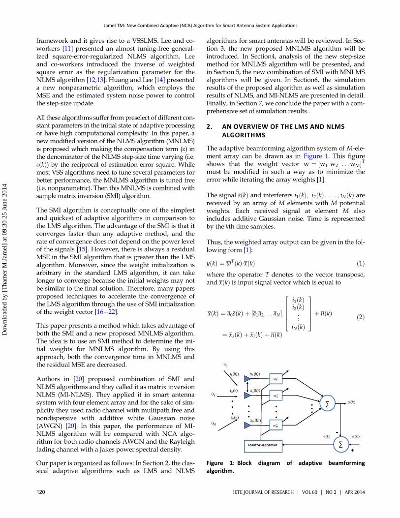
The adaptive beamforming algorithm system of M-ele-ment array can be drawn as in Figure 1. This figureshows that the weight vector w ¼ ½w1 w2 . . .wM�Tmust be modified in such a way as to minimize theerror while iterating the array weights [1].
The signal sðkÞ and interferers i1ðkÞ; i2ðkÞ; . . . ; iNðkÞ arereceived by an array of M elements with M potentialweights. Each received signal at element M alsoincludes additive Gaussian noise. Time is representedby the kth time samples.
Thus, the weighted array output can be given in the fol-lowing form [1]:
yðkÞ ¼ wTðkÞ�xðkÞ ð1Þwhere the operator T denotes to the vector transpose,and xðkÞ is input signal vector which is equal to
xðkÞ ¼ a0sðkÞ þ ½a1a2 : : : aN �:i1ðkÞi2ðkÞ...
iNðkÞ
26664
37775þ nðkÞ
¼ xsðkÞ þ xiðkÞ þ nðkÞ
ð2Þ
Figure 1: Block diagram of adaptive beamformingalgorithm.
Jamel TM: New Combined Adaptive (NCA) Algorithm for Smart Antenna System Applications
120 IETE JOURNAL OF RESEARCH | VOL 60 | NO 2 | APR 2014
Dow
nloa
ded
by [
Tha
mer
M J
amel
] at
09:
30 2
5 Ju
ne 2
014
with xsðkÞ is the desired signal vector, xiðkÞ is the inter-fering signals vector, nðkÞ is the zero mean Gaussiannoise for each channel, and ai is the M-element arraysteering vector for ui direction of arrival.
Error signal is defined as the difference of desired sig-nal dðkÞ and output signal yðkÞ,
eðkÞ ¼ dðkÞ � wTðkÞxðkÞ ð3ÞBy using the gradient of cost function, the weight vectorof LMS is
wðkþ 1Þ ¼ wðkÞ þ meðkÞxðkÞ ð4Þ
The parameter m is the step-size parameter, whichassigned a small positive value. To ensure stability (orconvergence) of the LMS algorithm, the step-sizeparameter is bounded by the following equation [2]:
0 < m <2
tr½R� ð5Þ
where R is the correlation matrix. Note that all theelements on the main diagonal of R equal to rð0Þ. Sincerð0Þ is itself equal to the mean square value ofthe input at each of the M taps in finite impulseresponse (FIR) filter, then the trace of R is [2]
tr ½R� ¼ M rð0Þ ð6Þ
The condition for convergence of the LMS algorithm inthe mean square will be [2]
0 < m <2
tapweight powerð7Þ
The LMS algorithm uses a constant step size m propor-tional to the stability bound,
mMAX ¼ 2M rð0Þ ð8Þ
Knowledge on signal statistic rð0Þ is not available. More-over, the statistics of rð0Þ may be changed over time, andwe wish to adjust m accordingly. We can compute a tem-porary estimate of the signal power by [2]
rð0Þ ¼ 1M
xTðkÞxðkÞ ð9Þ
Then the “normalized” mMAXðkÞ is given by [2]
mMAXðkÞ ¼2
xTðkÞxðkÞ ð10Þ
This is the upper limit of step size; therefore, the practi-cal equation for the step size used for NLMS is [2]
mNLMSðkÞ ¼u0
eþ xTðkÞxðkÞ ð11Þ
where u0 is small positive constant, e is called regulariza-tion parameter and is added to avoid denominator beingzero when the data at any instant are zero. The finalweight vector for NLMS algorithm can be updated by [2]
wðkþ 1Þ ¼ wðkÞ þ m0
eþ xðkÞ2 eðkÞxðkÞ ð12Þ
where
jjxðkÞ2jj ¼ xTðkÞxðkÞ ð13Þ
The small constant e in the NLMS algorithm has fixedeffect in step-size parameter and may cause a reductionin its value. This reduction in step size affects the con-vergence rate and weight stability of the NLMS algo-rithm. Therefore, time-varying e is proposed in thispaper as shown in the next section.
3. MODIFIED NORMALIZE LEAST SQUAREALGORITHM
The proposed MNLMS algorithm introduces a new wayof choosing the step size. For the MNLMS algorithm, theerror signal may be used to avoid denominator beingzero and to control the step size in each iteration.According to this approach, the e parameter can be set as
eðkÞ ¼ 1eðkÞ2 ð14Þ
Thus, the proposed new step-size formula can be writ-ten as
mMNLMSðkÞ ¼m0
eðkÞ þ jjxðkÞjj2 ð15Þ
Clearly, mMNLMSðkÞ is controlled by normalization ofboth reciprocal of the squared norm of the error andthe input data vectors. Therefore, the weight vector ofMNLMS algorithm is
wðkþ 1Þ ¼ wðkÞ þ u0eðkÞ þ jjxðkÞjj2Þ eðkÞxðkÞ ð16Þ
The eðkÞ parameter in Equation (16) is proportional tothe reciprocal of estimation squared norm of the errorvector, eðkÞ. As can be seen from Equation (16), the stepsize of MNLMS reduces and increases according to theerror signal of the adaptive system and the weight vec-tor will be updated to track any changes in the environ-ments as shown in Equation (16). In other words, when
Jamel TM: New Combined Adaptive (NCA) Algorithm for Smart Antenna System Applications
IETE JOURNAL OF RESEARCH | VOL 60 | NO 2 | APR 2014 121
Dow
nloa
ded
by [
Tha
mer
M J
amel
] at
09:
30 2
5 Ju
ne 2
014
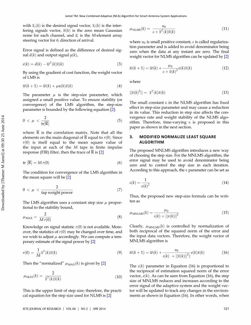
the error signal is large at the beginning of the adapta-tion process, eðkÞ is small and the step size is large inorder to reduce the error quickly. However, when errorsignal is small in steady state, eðkÞ is large and the stepsize is small in order to get a low level of misadjustmentas shown in Figure 2. This prevents the update weightsfrom diverging and makes the MNLMS more stableand converges faster than NLMS algorithms.
4. ANALYSIS FOR THE STEP-SIZE METHOD OFMNLMS ALGORITHM
In this section, we will give an approximate perfor-mance analysis for the proposed time-varying step-sizealgorithm. Following a similar approach used in [5,23],the proposed algorithm adapts the step-size sequenceusing Equation (16), which reduces the squared-estima-tion error at each time instant.
The weight coefficients of the proposed algorithm areupdating as in Equation (16). This is rewritten as
wðkþ 1Þ ¼ wðkÞ þ mMNLMSðkÞeðkÞxðkÞ ð17Þ
Let wðkÞ� denote the optimal coefficient vector beingtracked, and assume it is time varying according to
wðkþ 1Þ� ¼ wðkÞ� þ pðkÞ ð18Þ
where pðkÞ is the disturbance process that is a zero-mean white process. Also, let zðkÞ is the optimum esti-mation error process defined as
zðkÞ ¼ dðkÞ � xTðkÞwðkÞ� ð19Þor
dðkÞ ¼ zðkÞ þ xTðkÞwðkÞ� ð20Þ
Let vðkÞ denote the coefficient misadjustment vector,
vðkÞ ¼ wðkÞ � wðkÞ� ð21Þ
Starting with the error, eðkÞ expression in Equation (3),and substituting Equations (20) and (21) in Equation (3)for dðkÞ and vðkÞ; respectively, then the expression inEquation (3) can be rewritten as
eðkÞ ¼ zðkÞ þ xTðkÞwðkÞ� � xTðkÞwðkÞeðkÞ ¼ zðkÞ � vTðkÞxTðkÞ
ð22Þ
Taking expected value of Equation (22) after squaringit, then
E½e2ðkÞ� ¼ jmin þ s2ðxÞtr½GðkÞ� ð23Þ
where jmin ¼ E½z2ðkÞ� is the minimum MSE, s2ðxÞ ¼E½x2ðkÞ�, and GðkÞ ¼ E½vðkÞvTðkÞ� is the second momentmatrix of the misadjustment vector [5].
Figure 2: (a) Profile change of e(k) parameter and (b) profile change of step-size parameters (mmnlms(k)) of MNLMS algorithm.
Jamel TM: New Combined Adaptive (NCA) Algorithm for Smart Antenna System Applications
122 IETE JOURNAL OF RESEARCH | VOL 60 | NO 2 | APR 2014
Dow
nloa
ded
by [
Tha
mer
M J
amel
] at
09:
30 2
5 Ju
ne 2
014

Substituting Equations (20)�(22) into Equation (17), wecan easily show that
vðkþ 1Þ ¼�I � mMNLMSðkÞxTðkÞxðkÞ
�vðkÞ
þ mMNLMSðkÞxðkÞzðkÞ � pðkÞð24Þ
Then using the independence assumption, the uncorre-lated of mMNLMSðkÞ with xðkÞ and zðkÞ, and the fact thatpðkÞ is zero mean [5,23], the recursion for the meanbehaviour of the weight vector is given by
E½vðkþ 1Þ� ¼ ½I � E½mMNLMSðkÞ� E½xTðkÞxðkÞ��E½vðkÞ�ð25Þ
It is easy to show that the convergence of the algorithmin the mean takes place if the average value of the step-size parameter is confined in the following range:
0 < E½mMNLMSðkÞ� < 2 ð26Þ
5. THE NEW PROPOSED COMBINEDALGORITHM (NCA)
For the new proposed combined (NCA) algorithm, theSMI algorithm is utilized to determine the optimumweight vectors assigned to each of the antenna elementsof the array instead of arbitrary value before calculatingthe final weight vector. The weight coefficients derivedfrom SMI algorithm are set as initial coefficients andare updated by introducing MNLMS algorithms. TheNCA algorithm updates the weight vectors accordingto the following equations:
The correlation matrix Rxx and correlation vector r canbe estimated by [1]
Rxx ¼ 1K
XKk¼1
xðkÞxTðkÞ ð27Þ
r ¼ 1K
XK
k¼1d�ðkÞxðkÞ ð28Þ
where k represents the number of samples.
The SMI algorithm updates the weight vectors as
wSMI ¼ Rxx�1r ð29Þ
Then the weight vector that is estimated by SMI is usedas an initial weight vector for MNLMS algorithm. Thenthe output and the error signals for MNLMS algorithm
are given as
yðkÞ ¼ wTðkÞxðkÞ ð30ÞeðkÞ ¼ dðkÞ � wTðkÞxðkÞ ð31Þ
The final update weight vector of the NCA algorithm is
wðkÞ ¼ wðkÞ þ mMNLMSðkÞeðkÞxðkÞ¼ wðkÞ þ m0
1eðkÞ2 þ xðkÞ2
eðkÞxðkÞ ð32Þ
6. SIMULATION RESULTS
In this section, the NLMS, MI-NLMS, and NCA algo-rithms are evaluated and simulated for smart antennaapplications.
For the purpose of illustration and comparison, in allsimulations presented here, a linear array consisting ofM ¼ 8 isotropic elements with d ¼ 0:5l element spacingis used under the following conditions:
� Input signal SðkÞ ¼ sin�2pftðkÞ
�with f ¼ 1
T¼ 900
MHz and t ¼ ð1 : kÞ � T=k; where k is the number ofsample intervals and T is the time period.
� Desired angle of arrival (AOA) of u0 ¼ 0� and twointerfering signals, i1 and i2 with two AOAs,u1 ¼ 30�; u2 ¼ �20�.
� All weight vectors are initially set to zero.� Desired signal dðkÞ ¼ SðkÞ.� Initial step-size parameter m0 for NLMS is set to 1.� Regularization parameter (e) for NLMS is set to1e�12.
� Zero mean Gaussian noise with variance s2n ¼ 0: 001
is added to the input signal for each element in thearray.
An analytical model is presented for evaluating the per-formance of a smart antenna system employing anarray antenna operating in the presence of AWGN andRayleigh fading environment.
6.1 Simulation of Jakes Fading Model
The Jakes fading model, which is used in the simula-tions, also known as the Sum of Sinusoids model, is adeterministic method for simulating time-correlatedRayleigh fading waveforms and is still widely usedtoday. The model assumes that N equal strength raysarrive at a moving receiver with uniformly distributedarrival angles an, such that ray n experiences a Dopplershift vn ¼ vm cosðanÞ; where vn ¼ 2pfcv=c is the maxi-mum Doppler frequency shift, v is the vehicle speed, fcis the carrier frequency, and c is the speed of light. As a
Jamel TM: New Combined Adaptive (NCA) Algorithm for Smart Antenna System Applications
IETE JOURNAL OF RESEARCH | VOL 60 | NO 2 | APR 2014 123
Dow
nloa
ded
by [
Tha
mer
M J
amel
] at
09:
30 2
5 Ju
ne 2
014
result, the fading waveform can be modelled with N0 þ1 complex oscillator, where N0 ¼ (N/2 � 1)/2. Thisleads to the equation [24],
TkðtÞ ¼ffiffiffiffiffiffiffiffiffiffiffiffiffiffiffi
12N þ 1
r n2XN0
n¼1ðcosbn þ jsinbnÞcosðvncosant
þunhÞ þffiffiffi2
pcosðvmt þ u0hÞ
oð33Þ
where h is the waveform index, h ¼ 1, 2,. . ., N0 and λ isthe wavelength of the transmitted carrier frequency.Here bn ¼ pn=ðN0 þ 1Þ. To generate the multiple wave-forms, Jakes suggests using
unh ¼ pnN0 þ 1
þ 2pðh� 1ÞN0 þ 1
ð34Þ
The output was shown as a power spectrum, with thevariation of the signal power in the y axis and the sam-pling time (or the sample number) on the x axis,
ThðtÞ ¼ffiffiffiffiffiffi2N0
s XN0
n¼1ðcosbn þ jsinbnÞcosðvncosant þ unhÞg
nð35Þ
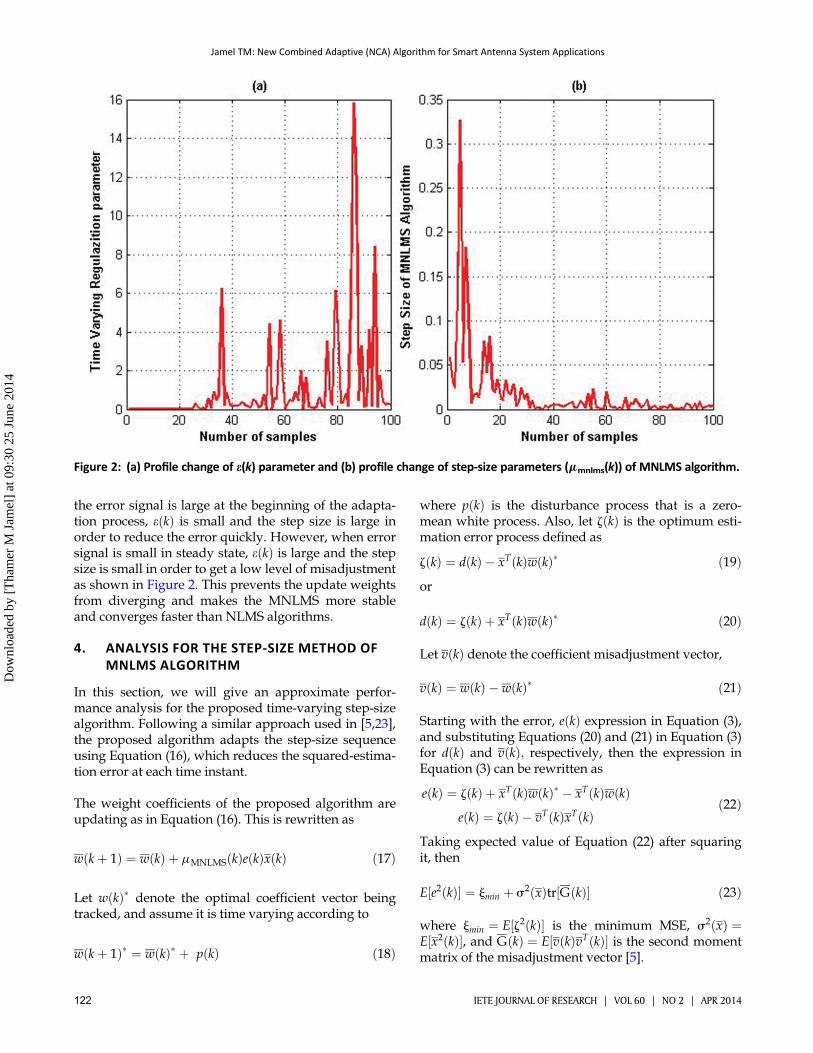
A software simulation using MATLAB software wascarried out using the Jakes model described above andthe inputs included the vehicle speed v (in km/h), thecentral carrier frequency fc in MHz, the symbol fre-quency fs in kbps, the number of sub-channels U, andthe number of channel coefficients to generate M. Topresent a worst case scenario, a Doppler frequency fd of117 Hz, corresponding to a mobility of 140 km/h at900 MHz, is used in the simulation.
The Rayleigh envelope that results for inputs of v ¼140 km/h, fc ¼ 900 MHz, fs ¼ 500 kbps, U ¼ 3, andM ¼
1,000,000 is shown in Figure 3, where U is the numberof sub-channels, and M is the number of channelcoefficients.
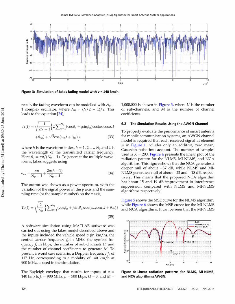
6.2 The Simulation Results Using the AWGN Channel
To properly evaluate the performance of smart antennafor mobile communication systems, an AWGN channelmodel is required that each received signal at elementm in Figure 1 includes only an additive, zero mean,Gaussian noise into account. The number of samplesused is K ¼ 200. Figure 4 presents the linear plot of theradiation pattern for the NLMS, MI-NLMS, and NCAalgorithms. This figure shows that the NCA generates adeeper null of about �37 dB, while NLMS and MI-NLMS generate a null of about �22 and�18 dB, respec-tively. This means that the proposed NCA algorithmhas about 15 and 19 dB improvement in interferencesuppression compared with NLMS and MI-NLMSalgorithms respectively.
Figure 5 shows the MSE curve for the NLMS algorithm,while Figure 6 shows the MSE curve for the MI-NLMSand NCA algorithms. It can be seen that the MI-NLMS
Figure 3: Simulation of Jakes fading model with v = 140 km/h.
Figure 4: Linear radiation patterns for NLMS, MI-NLMS,and NCA algorithms/AWGN.
Jamel TM: New Combined Adaptive (NCA) Algorithm for Smart Antenna System Applications
124 IETE JOURNAL OF RESEARCH | VOL 60 | NO 2 | APR 2014
Dow
nloa
ded
by [
Tha
mer
M J
amel
] at
09:
30 2
5 Ju
ne 2
014

and proposed NCA algorithms can achieve faster con-vergence (initial iteration) than the NLMS algorithm(iteration 50). Moreover, the NCA shows low level oferror in the steady state compared to both NLMS andMI-NLMS algorithms. In this case, the steady-state
error for NLMS is almost 0.0542, whereas for MI-NLMSis almost 11.25e�05 and NCA is almost 7.1957e�05 ataround 20 iterations. Figure 7 shows the magnitudeestimation for one element weight (w8) for each algo-rithm. As can be observed from this figure, the MI-NLMS and NCA start convergence towards the opti-mum (desired) weight from the initial iteration. On thecontrary, the NLMS algorithm starts to converge fromthe arbitrary weight value to the optimum weightvalue. It is evident that the weight converges to its opti-mum value for MI-NLMS and NCA algorithms quicklyand without fluctuation compared with the NLMSalgorithm.
6.3 The Simulation Results Using the Rayleigh FadingChannel with Jakes Model
The proposed NCA algorithm is simulated and com-pared with standard NLMS and MI-NLMS algorithmsover Rayleigh fading channel with Jakes model (shownin Figure 3) when the number of samples used is 600.
Figure 8 presents the linear plot of the radiation patternfor the NLMS, MI-NLMS, and NCA algorithms. Thisfigure shows that the NCA generates a deeper null ofabout �33 dB while NLMS and MI-NLMS generate a
Figure 5: MSE for NLMS/AWGN.
Figure 6: MSE for MI-NLMS and NCA/AWGN.
Figure 7: Magnitude of one-array weight for NLMS andMI-NLMS, NCA algorithms/AWGN.
Figure 8: Linear radiation patterns for NLMS, MI-NLMS,and NCA algorithms/Rayleigh channel.
Jamel TM: New Combined Adaptive (NCA) Algorithm for Smart Antenna System Applications
IETE JOURNAL OF RESEARCH | VOL 60 | NO 2 | APR 2014 125
Dow
nloa
ded
by [
Tha
mer
M J
amel
] at
09:
30 2
5 Ju
ne 2
014
null of about �26 dB towards the interferer. It is clearthat NCA algorithm gives about 7 dB improvementsover NLMS and MI-NLMS algorithms, respectively.
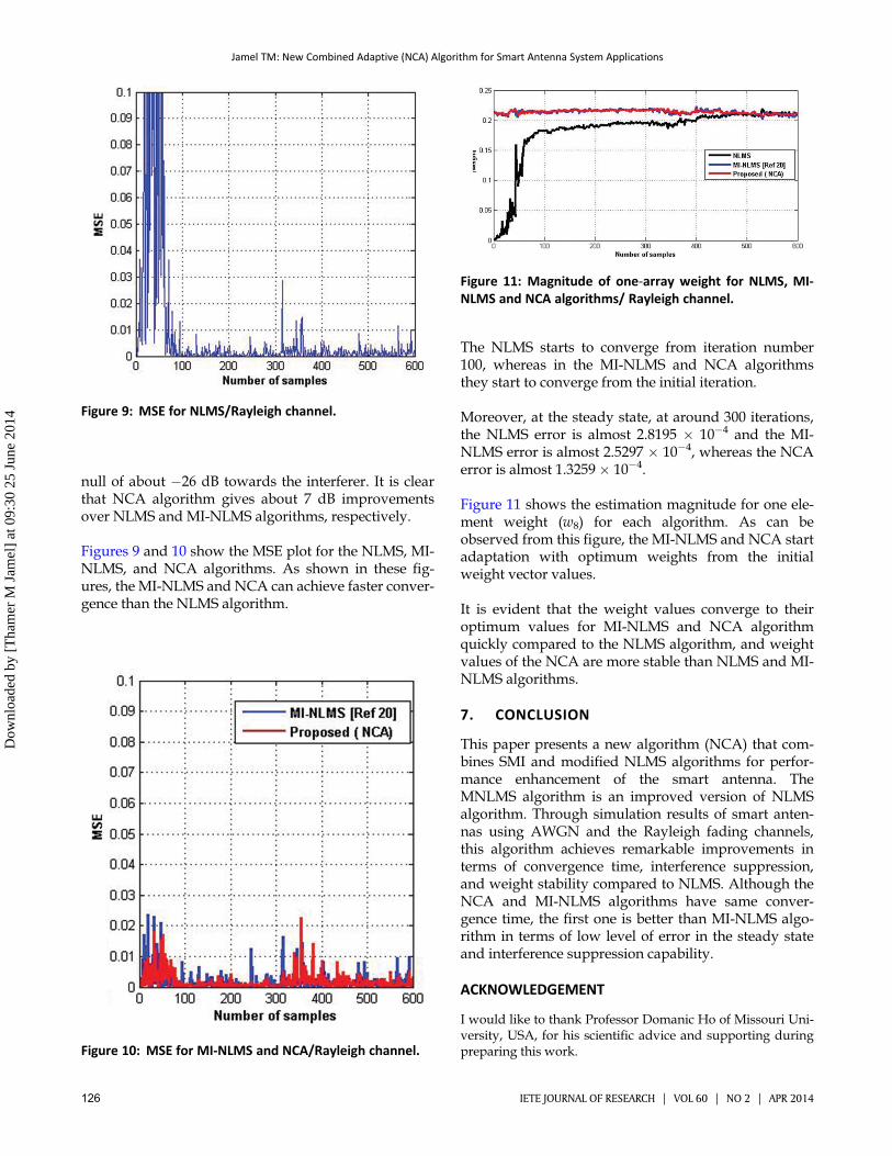
Figures 9 and 10 show the MSE plot for the NLMS, MI-NLMS, and NCA algorithms. As shown in these fig-ures, the MI-NLMS and NCA can achieve faster conver-gence than the NLMS algorithm.
The NLMS starts to converge from iteration number100, whereas in the MI-NLMS and NCA algorithmsthey start to converge from the initial iteration.
Moreover, at the steady state, at around 300 iterations,the NLMS error is almost 2.8195 � 10�4 and the MI-NLMS error is almost 2.5297 � 10�4, whereas the NCAerror is almost 1.3259 � 10�4.
Figure 11 shows the estimation magnitude for one ele-ment weight (w8) for each algorithm. As can beobserved from this figure, the MI-NLMS and NCA startadaptation with optimum weights from the initialweight vector values.
It is evident that the weight values converge to theiroptimum values for MI-NLMS and NCA algorithmquickly compared to the NLMS algorithm, and weightvalues of the NCA are more stable than NLMS and MI-NLMS algorithms.
7. CONCLUSION
This paper presents a new algorithm (NCA) that com-bines SMI and modified NLMS algorithms for perfor-mance enhancement of the smart antenna. TheMNLMS algorithm is an improved version of NLMSalgorithm. Through simulation results of smart anten-nas using AWGN and the Rayleigh fading channels,this algorithm achieves remarkable improvements interms of convergence time, interference suppression,and weight stability compared to NLMS. Although theNCA and MI-NLMS algorithms have same conver-gence time, the first one is better than MI-NLMS algo-rithm in terms of low level of error in the steady stateand interference suppression capability.
ACKNOWLEDGEMENT
I would like to thank Professor Domanic Ho of Missouri Uni-versity, USA, for his scientific advice and supporting duringpreparing this work.Figure 10: MSE for MI-NLMS and NCA/Rayleigh channel.
Figure 9: MSE for NLMS/Rayleigh channel.
Figure 11: Magnitude of one-array weight for NLMS, MI-NLMS and NCA algorithms/ Rayleigh channel.
126 IETE JOURNAL OF RESEARCH | VOL 60 | NO 2 | APR 2014
Jamel TM: New Combined Adaptive (NCA) Algorithm for Smart Antenna System Applications
Dow
nloa
ded
by [
Tha
mer
M J
amel
] at
09:
30 2
5 Ju
ne 2
014

REFERENCES
1. F. B. Gross, Smart Antenna for Wireless Communication. Fairfax, VA:McGraw-Hill, Inc, 2005.
2. S. Haykin, Adaptive Filter Theory, 4th ed. Englewood Cliffs, NJ: Pren-tice Hall, 2002.
3. A. H. Sayed, Fundamentals of Adaptive Filtering. New York: Wiley,2003.
4. A. D. Poularikas, and Z. M. Ramadan, Adaptive Filtering Primer withMATLAB. Florida: CRC Press, 2006.
5. A. I. Sulyman, and A. Zerguine, “Convergence and steady-state analy-sis of a variable step-size NLMS algorithm,” Signal Process., Vol. 83,pp. 1255�1273, Jun. 2003.
6. D. P. Mandic, “A generalized normalized gradient descent algo-rithm,” IEEE Signal Process. Lett., Vol. 11, no. 2, pp. 115�8, Feb.2004.
7. J. Benesty, Q. Montreal, H. Rey, L. Rey Vega, and S. Tressens, “A non-parametric VSS NLMS algorithm,” IEEE Signal Process. Lett., Vol. 13,no. 10, pp. 581�584, Oct. 2006.
8. Y. S. Choi, H. C. Shin, and W. J. Song, “Robust regularization for nor-malized LMS algorithms,” IEEE Trans. Circuits Syst II, Express Briefs,Vol. 53, no. 8, pp. 627�631, Aug. 2006.
9. D. Mandic, P. Vayanos, C. Boukis, B. Jelfs, S. L. Goh, T. Gautama, andT. Rutkowski, “Collaborative adaptive learning using hybrid filters,”in Proceedings of 2007 IEEE ICASSP, Honolulu, Apr. 15�20, 2007 pp.III 921�924.
10. S. C. Chan, Z. G. Zhang, Y. Zhou, and Y. Hu, “A new noise-constrainednormalized least mean squares adaptive filtering algorithm,” pre-sented at the IEEE Asia Pacific Conference on Circuits and Systems,APCCAS, Macao, Nov. 30�Dec. 3, 2008, pp. 197�200.
11. J. Lee, H. C. Huang, and Y. N. Yang, “The generalized square-error-regularized LMS algorithm,” in Proceedings of WCECS 2008, SanFrancisco, CA, Oct. 22�4, 2008, pp. 157�160.
12. J. Lee, H. C. Huang, Y. N. Yang, and S. Q. Huang, “A square-error-based regularization for Normalized LMS algorithms,” in Proceedingsof the International Multiconference of Engineers and Computer Sci-entists, Hong Kong, Mar. 2008, Vol. II, pp. 19�21.
13. J. Lee, J. -W. Chen, and H. -C. Huang, “Performance comparison ofvariable step-size NLMS algorithms,” Proceedings of the World
Congress on Engineering and Computer Science, Vol. I, San Fran-cisco, CA, Oct. 20�2, 2009, pp. 178�81.
14. H.-C. Huang, and J. Lee, “A new variable step-size NLMS algorithmand its performance analysis,” IEEE Trans Signal Process., Vol. 60, no.4, pp. 2055�60. Apr. 2012.
15. C. A. Balanis, and I. Panayiotis, Introduction to Smart Antennas, 1sted. San Rafael, CA: Morgan & Claypool Publishers, 2007.
16. R. Yonezawa, K. Hirata, T. Kirimoto, and I. Chiba, “A combination oftwo adaptive algorithms SMI and CMA,” in IEEE Global Telecommu-nications Conference, GLOBECOM 1998. The Bridge to Global Inte-gration, Sydney, 1998, Vol. 6, pp. 3181�3186.
17. D. Paradimitriou, and I. O. Vardiambasis, “Hybrid algorithms foradaptive array systems,” Proceedings of the fourth InternationalConference on Telecommunications and Informatics, TELE-INFO’05,Prague, Mar. 13�5, 2005, pp. 176�82, Article no. 32.
18. R. M. Shubair, A. Merri, and W. Jessmi, “Improved adaptive beam-forming using a hybrid LMS/SMI approach,”. in Second IFIP Interna-tional Conference on Wireless and Optical CommunicationsNetworks,WOCN, Dubia, Mar. 6�8, 2005, pp. 603�606.
19. R. M. Shubair, “Robust adaptive beamforing using LMS algorithm withSMI initialization,” in IEEE International Symposium on Antennas andPropagation Society,Washington, DC, Jul. 3�8, 2005, Vol. 4A, pp. 2�5.
20. T. I. Mohammad, and A. A. R. Zainol, “MI-NLMS adaptive beamform-ing algorithm for smart antenna system applications,” J. ZhejiangUniv. Sci. A, Vol. 7, no. 10, pp. 1709�1716, Oct. 2006.
21. K. R. Shankar Kumar, and T. Gunasekaran, “Performance analysis ofadaptive beamforming algorithms for microstrip smart antennas,”TECHNIA � Int. J. Comput. Sci. Commun. Technol., Vol. 2, no. 1, pp.305�309, Jul. 2009.
22. S. Mubeen, A. Prasad, and A. Jhansi Rani, “Smart antenna: Its algo-rithms and implementation,” Int. J. Adv. Res. Comput. Sci. Softw.Eng., Vol. 2, no. 4, pp. 97�101, Apr. 2012.
23. J. Mathews, and Z. Xie, “A stochastic gradient adaptive filter withgradient adaptive step size.” IEEE Trans. signal process., Vol. 41, no.6, pp. 2075�2087, June, 1993.
24. V. A. Silva, T. Abrao, and P. J. E. Jeszensky, “Statistically correct simu-lation models for the generation of multiple uncorrelated Rayleighfading waveforms,” IEEE Eighth International Symposium on SpreadSpectrum Techniques and Applications, Sydney, Aug. 30�Sep. 2,2004, pp. 472�76.
AuthorThamer M. Jamel was born in Baghdad, Iraq in1961. He graduated from the University of Tech-nology with a bachelor’s degree in electronicsengineering in 1983. He received a master’sdegree in digital communications engineeringfrom the University of Technology in 1990 and adoctoral degree in communication engineeringfrom the University of Technology in 1997. He isan associate professor in the Communication
Engineering branch, Electrical Engineering Department at University ofTechnology, Baghdad, Iraq. Currently, he is a visitor scholar in the Electricaland Computer Engineering Department at University of Missouri, Columbia,MO. His research interests include adaptive signal processing, neural net-works, DSP microprocessors, FPGA, and modern digital communicationssystems.
E-mail: [email protected]
DOI: 10.1080/03772063.2014.901570; Copyright © 2014 by the IETE
IETE JOURNAL OF RESEARCH | VOL 60 | NO 2 | APR 2014 127
Jamel TM: New Combined Adaptive (NCA) Algorithm for Smart Antenna System Applications
Dow
nloa
ded
by [
Tha
mer
M J
amel
] at
09:
30 2
5 Ju
ne 2
014