Network Security - Prof. Kaderali
448
Prof. Dr.-Ing. Firoz Kaderali Network Security
-
Upload
khangminh22 -
Category
Documents
-
view
2 -
download
0
Transcript of Network Security - Prof. Kaderali

Prof. Dr.-Ing. Firoz Kaderali
Network Security

Das Werk ist urheberrechtlich geschützt. Die dadurch begründeten Rechte, insbesondere das Recht der Vervielfältigung und Verbreitung sowie der Übersetzungund des Nachdrucks, bleiben, auch bei nur auszugsweiser Verwertung, vorbehalten. Kein Teil des Werkes darf in irgendeiner Form (Druck, Fotokopie, Mikrofilmoder ein anderes Verfahren) ohne schriftliche Genehmigungdes Autors reproduziert oder unter Verwendung elektronischer Systeme verarbeitet, vervielfältigtoder verbreitet werden.

iii
Author
Prof. Dr.-Ing. Firoz Kaderali
1963 - 69 Studied theoretical electrical engineering at the TechnischeHochschule Darmstadt
1969 - 74 Assistant at the Faculty of Electrical Engineering at the TechnischeHochschule Darmstadt
1974 Doctorate (Promotion) at the Faculty of Electrical Engineering,Technische Hochschule Darmstadt, Subject: Network Theory
1974 - 76 Dozent für Statistische Signaltheorie at the Technischen HochschuleDarmstadt
1976 - 81 Member of the Research Center at SEL (ITT)/Stuttgart. Projektleaderof Bundespost study and Fieldtrial DIGON (Digital Local AreaNetwork)
1981 - 86 Head of the Department System Development/Large Systems atTelefonbau und Normalzeit/Frankfurt Development of ISDN-PABXs
Since 1986 Professor for Communications Systems at the FernUniversität HagenMain interests: Communications Systems, Networks and Protocols;Network Security
1989 - 94 Head of the regional telecommunications initiative TELETECH NRW(Consultant and supervisor of over 120 Telecommunications Projects)
1990 - 96 Member of the ISDN Research Commission NRW (Projects on ISDNApplicationsdesign and Technology Assessment)
Since 1992 Director of the Research Institute of Telecommunications (FTK) inDortmund, Hagen and Wuppertal, Joint Institute of the UniversitiesHagen (Electrical Engineering) and Wuppertal (Economy)
1995 - 2001 Member of management of mediaNRW, an initiative to promote thedevelopment and spreading of multimedia-applications as a wholeand interactive services in enterprises, private households, and thepublic sector
1999 - 2003 Chairman of the research alliance Data SecurityNorthrhein-Westphalia
2000 - 2002 Chairman of the advisory board of GITS (Gesellschaft fürIT-Sicherheit) in Bochum, Germany
Since 2002 Chairman of the open source initiative Campus Source

iv Table of Contents
Table of Contents
Author . . . . . . . . . . . . . . . . . . . . . . . . . . . . . . . . . . . . . . . . . . . . . . . . . . .. . . . . . . . . . . . . . . . . . . . . iiiProf. Dr.-Ing. Firoz Kaderali . . . . . . . . . . . . . . . . . . . . . . . . .. . . . . . . . . . . . . . . . iii
1 Introduction . . . . . . . . . . . . . . . . . . . . . . . . . . . . . . . . . . . . . . . . . . . . . . . . . . .. . . . . . . . . . . . . . 11.1 IT-Security in a networked world . . . . . . . . . . . . . . . . . . . .. . . . . . . . . . . . . . . . 11.2 Overview of this course . . . . . . . . . . . . . . . . . . . . . . . . . . . .. . . . . . . . . . . . . . . . . . 31.3 Basics . . . . . . . . . . . . . . . . . . . . . . . . . . . . . . . . . . . . . . . . . .. . . . . . . . . . . . . . . . . . . . . . . 31.4 Internet Security Protocols . . . . . . . . . . . . . . . . . . . . . . .. . . . . . . . . . . . . . . . . . . . 31.5 World Wide Web Security . . . . . . . . . . . . . . . . . . . . . . . . . . . .. . . . . . . . . . . . . . . . 41.6 Anonymity Techniques .. . . . . . . . . . . . . . . . . . . . . . . . . . . .. . . . . . . . . . . . . . . . . . 51.7 Packet Filters and Firewall Systems . . . . . . . . . . . . . . . . .. . . . . . . . . . . . . . . . 51.8 Application Layer Security. . . . . . . . . . . . . . . . . . . . . . . .. . . . . . . . . . . . . . . . . . . 61.9 Security in Wireless and Mobile Networks . . . . . . . . . . . . .. . . . . . . . . . . . 71.10 Electronic Payment Systems . . . . . . . . . . . . . . . . . . . . . . .. . . . . . . . . . . . . . . . . . 81.11 Security Aspects in Mobile Agent Systems . . . . . . . . . . . .. . . . . . . . . . . . . 91.12 Copyright Protection . . . . . . . . . . . . . . . . . . . . . . . . . . . .. . . . . . . . . . . . . . . . . . . . . 91.13 Intrusion Detection . . . . . . . . . . . . . . . . . . . . . . . . . . . . .. . . . . . . . . . . . . . . . . . . . . . 101.14 Recommended literature for this course . . . . . . . . . . . . .. . . . . . . . . . . . . . . . 11
2 Basics. . . . . . . . . . . . . . . . . . . . . . . . . . . . . . . . . . . . . . . . . . . . . . . . . . .. . . . . . . . . . . . . . . . . . . . . . 122.1 Host and network security. . . . . . . . . . . . . . . . . . . . . . . . . .. . . . . . . . . . . . . . . . . . 12
2.1.1 Types of attacks. . . . . . . . . . . . . . . . . . . . . . . . . . . . . . . .. . . . . . . . . . . . 122.1.2 Types of attackers. . . . . . . . . . . . . . . . . . . . . . . . . . . . . .. . . . . . . . . . . . 132.1.3 Security models .. . . . . . . . . . . . . . . . . . . . . . . . . . . . . . .. . . . . . . . . . . . 15
2.2 Basic techniques in communication networks . . . . . . . . . .. . . . . . . . . . . . 172.3 The Internet protocol family . . . . . . . . . . . . . . . . . . . . . . .. . . . . . . . . . . . . . . . . . 23
2.3.1 The history of the Internet. . . . . . . . . . . . . . . . . . . . . . .. . . . . . . . . . 232.3.2 Internet protocol stack . . . . . . . . . . . . . . . . . . . . . . . . .. . . . . . . . . . . . 242.3.3 IP . . . . . . . . . . . . . . . . . . . . . . . . . . . . . . . . . . . . . . . . . . . .. . . . . . . . . . . . . . . 262.3.4 ICMP .. . . . . . . . . . . . . . . . . . . . . . . . . . . . . . . . . . . . . . . . .. . . . . . . . . . . . . 292.3.5 UDP .. . . . . . . . . . . . . . . . . . . . . . . . . . . . . . . . . . . . . . . . . .. . . . . . . . . . . . . 302.3.6 TCP . . . . . . . . . . . . . . . . . . . . . . . . . . . . . . . . . . . . . . . . . . .. . . . . . . . . . . . . 322.3.7 Security problems with the IP protocol family .. . . . . .. . . . 352.3.8 Common Internet services and their security risks. . .. . . . 38
3 Internet Security Protocols . . . . . . . . . . . . . . . . . . . . . . . . . . . . . . . . . . . . . . . . . . . . . . . . .413.1 Security at the Network Access Layer. . . . . . . . . . . . . . . . .. . . . . . . . . . . . . . 413.2 Security at the IP Layer . . . . . . . . . . . . . . . . . . . . . . . . . . . .. . . . . . . . . . . . . . . . . . 42
3.2.1 IPSec Overview.. . . . . . . . . . . . . . . . . . . . . . . . . . . . . . . .. . . . . . . . . . . 433.2.2 IPSec Architecture. . . . . . . . . . . . . . . . . . . . . . . . . . . . .. . . . . . . . . . . . 453.2.3 Encapsulating Security Payload (ESP) . . . . . . . . . . . . .. . . . . . 483.2.4 Authentication Header (AH) . . . . . . . . . . . . . . . . . . . . . .. . . . . . . . 513.2.5 Security Association (SA). . . . . . . . . . . . . . . . . . . . . . .. . . . . . . . . . 53

Table of Contents v
3.2.6 IPSec Key Management . . . . . . . . . . . . . . . . . . . . . . . . . . . .. . . . . . . 553.2.7 IPSec Policy . . . . . . . . . . . . . . . . . . . . . . . . . . . . . . . . . . .. . . . . . . . . . . . 573.2.8 IPSec Implementation .. . . . . . . . . . . . . . . . . . . . . . . . . .. . . . . . . . . . 593.2.9 IPSec Protocol Processing: An Example . . . . . . . . . . . . .. . . . 603.2.10 Deployment Examples of Securing Network Traffic
with IPSec. . . . . . . . . . . . . . . . . . . . . . . . . . . . . . . . . . . . . . . . . .. . . . . . . . 643.2.11 Summary . . . . . . . . . . . . . . . . . . . . . . . . . . . . . . . . . . . . . .. . . . . . . . . . . . . 67
3.3 Security at the Transport Layer . . . . . . . . . . . . . . . . . . . . .. . . . . . . . . . . . . . . . . 683.3.1 Secure Shell (SSH) . . . . . . . . . . . . . . . . . . . . . . . . . . . . . .. . . . . . . . . . 693.3.2 Secure Socket Layer (SSL) . . . . . . . . . . . . . . . . . . . . . . . .. . . . . . . 753.3.3 Transport Layer Security (TLS) . . . . . . . . . . . . . . . . . . .. . . . . . . 863.3.4 Summary . . . . . . . . . . . . . . . . . . . . . . . . . . . . . . . . . . . . . . .. . . . . . . . . . . . 89
3.4 Security at the Application Layer . . . . . . . . . . . . . . . . . . .. . . . . . . . . . . . . . . . . 893.5 Summary . . . . . . . . . . . . . . . . . . . . . . . . . . . . . . . . . . . . . . . . .. . . . . . . . . . . . . . . . . . . . . 90
4 World Wide Web Security . . . . . . . . . . . . . . . . . . . . . . . . . . . . . . . . . . . . . . . . . . . . . . . . . .914.1 Introduction . . . . . . . . . . . . . . . . . . . . . . . . . . . . . . . . . . . .. . . . . . . . . . . . . . . . . . . . . . . 914.2 Authentication and the Web . . . . . . . . . . . . . . . . . . . . . . . . .. . . . . . . . . . . . . . . . . 924.3 Server-side security . . . . . . . . . . . . . . . . . . . . . . . . . . . . .. . . . . . . . . . . . . . . . . . . . . . 93
4.3.1 Authentication and access restriction . . . . . . . . . . . .. . . . . . . . . 934.3.2 CGI scripts . . . . . . . . . . . . . . . . . . . . . . . . . . . . . . . . . . . .. . . . . . . . . . . . . 1024.3.3 Server logs and privacy.. . . . . . . . . . . . . . . . . . . . . . . . .. . . . . . . . . . 103
4.4 Client-side security . . . . . . . . . . . . . . . . . . . . . . . . . . . . .. . . . . . . . . . . . . . . . . . . . . . 1044.4.1 SSL . . . . . . . . . . . . . . . . . . . . . . . . . . . . . . . . . . . . . . . . . . .. . . . . . . . . . . . . . 1054.4.2 JavaScript . . . . . . . . . . . . . . . . . . . . . . . . . . . . . . . . . . . .. . . . . . . . . . . . . . 1054.4.3 Java . . . . . . . . . . . . . . . . . . . . . . . . . . . . . . . . . . . . . . . . . .. . . . . . . . . . . . . . . 1084.4.4 ActiveX . . . . . . . . . . . . . . . . . . . . . . . . . . . . . . . . . . . . . . .. . . . . . . . . . . . . 1114.4.5 Cookies . . . . . . . . . . . . . . . . . . . . . . . . . . . . . . . . . . . . . . .. . . . . . . . . . . . . 112
5 Anonymity Techniques. . . . . . . . . . . . . . . . . . . . . . . . . . . . . . . . . . . . . . . . . . . . . . . . . . .. . 1175.1 Introduction . . . . . . . . . . . . . . . . . . . . . . . . . . . . . . . . . . . .. . . . . . . . . . . . . . . . . . . . . . . 1175.2 The Mix-concept. . . . . . . . . . . . . . . . . . . . . . . . . . . . . . . . . .. . . . . . . . . . . . . . . . . . . . 118
5.2.1 Sender anonymity . . . . . . . . . . . . . . . . . . . . . . . . . . . . . . .. . . . . . . . . . 1215.2.2 Return address and recipient anonymity . . . . . . . . . . . .. . . . . 1225.2.3 Mutual anonymity . . . . . . . . . . . . . . . . . . . . . . . . . . . . . . .. . . . . . . . . . 1235.2.4 Anonymity services . . . . . . . . . . . . . . . . . . . . . . . . . . . . .. . . . . . . . . . 123
5.3 DC-network . . . . . . . . . . . . . . . . . . . . . . . . . . . . . . . . . . . . . .. . . . . . . . . . . . . . . . . . . . . 125
6 Packet filters and firewall systems. . . . . . . . . . . . . . . . . . . . . . . . . . . . . . . . . . . . . . . . .1316.1 Packet filtering . . . . . . . . . . . . . . . . . . . . . . . . . . . . . . . . . .. . . . . . . . . . . . . . . . . . . . . . 133
6.1.1 Packet filters and the IP protocol family. . . . . . . . . . . .. . . . . . 1346.1.2 Packet filtering for FTP sessions. . . . . . . . . . . . . . . . . .. . . . . . . . 1356.1.3 Stateful inspection .. . . . . . . . . . . . . . . . . . . . . . . . . . .. . . . . . . . . . . . . 1366.1.4 Network Address Translation (NAT) . . . . . . . . . . . . . . . .. . . . . 1376.1.5 Packet filters for the Linux operating system .. . . . . . .. . . . 140
6.2 Circuit-level gateways .. . . . . . . . . . . . . . . . . . . . . . . . . .. . . . . . . . . . . . . . . . . . . . . 1466.3 Application-level gateways and proxy servers . . . . . . . .. . . . . . . . . . . . . . 148

vi Table of Contents
6.4 Architectures and network topologies . . . . . . . . . . . . . . .. . . . . . . . . . . . . . . . 1506.4.1 Screening router . . . . . . . . . . . . . . . . . . . . . . . . . . . . . . .. . . . . . . . . . . . 1516.4.2 Dual-homed host . . . . . . . . . . . . . . . . . . . . . . . . . . . . . . . .. . . . . . . . . . 1516.4.3 Screened host . . . . . . . . . . . . . . . . . . . . . . . . . . . . . . . . . .. . . . . . . . . . . . 1526.4.4 Screened subnet. . . . . . . . . . . . . . . . . . . . . . . . . . . . . . . .. . . . . . . . . . . . 153
6.5 Further Reading. . . . . . . . . . . . . . . . . . . . . . . . . . . . . . . . . .. . . . . . . . . . . . . . . . . . . . . 154
7 Application Layer Security . . . . . . . . . . . . . . . . . . . . . . . . . . . . . . . . . . . . . . . . . . . . . . . . .1557.1 Introduction . . . . . . . . . . . . . . . . . . . . . . . . . . . . . . . . . . . .. . . . . . . . . . . . . . . . . . . . . . . 1557.2 Remote Terminal Access . . . . . . . . . . . . . . . . . . . . . . . . . . . .. . . . . . . . . . . . . . . . . 1577.3 File Transfer . . . . . . . . . . . . . . . . . . . . . . . . . . . . . . . . . . . .. . . . . . . . . . . . . . . . . . . . . . 1587.4 Network File Systems . . . . . . . . . . . . . . . . . . . . . . . . . . . . . .. . . . . . . . . . . . . . . . . . 1597.5 Secure Electronic Mail With S/MIME .. . . . . . . . . . . . . . . . .. . . . . . . . . . . . 163
7.5.1 Structure Of Email Messages . . . . . . . . . . . . . . . . . . . . . .. . . . . . . 1647.5.2 The Email Header . . . . . . . . . . . . . . . . . . . . . . . . . . . . . . . .. . . . . . . . . 1657.5.3 Securing MIME-based Emails With S/MIME .. . . . . . . . . . 173
7.6 Executable Content . . . . . . . . . . . . . . . . . . . . . . . . . . . . . . .. . . . . . . . . . . . . . . . . . . . 1777.6.1 Binary Mail Attachments . . . . . . . . . . . . . . . . . . . . . . . . .. . . . . . . . 1787.6.2 Helper Applications And Plug-ins . . . . . . . . . . . . . . . . .. . . . . . . 1797.6.3 Scripting Languages . . . . . . . . . . . . . . . . . . . . . . . . . . . .. . . . . . . . . . . 1807.6.4 Java Applets . . . . . . . . . . . . . . . . . . . . . . . . . . . . . . . . . . .. . . . . . . . . . . . 1837.6.5 ActiveX Controls . . . . . . . . . . . . . . . . . . . . . . . . . . . . . . .. . . . . . . . . . . 185
8 Security in Wireless and Mobile Networks. . . . . . . . . . . . . . . . . . . . . . . . . . . . . . .1878.1 Development of Mobile Networks . . . . . . . . . . . . . . . . . . . . .. . . . . . . . . . . . . . 1878.2 Security Mechanisms in GSM Networks . . . . . . . . . . . . . . . . .. . . . . . . . . . . 190
8.2.1 Brief Overview of GSM Networks . . . . . . . . . . . . . . . . . . . .. . . 1918.2.2 Specific Security Threats . . . . . . . . . . . . . . . . . . . . . . . .. . . . . . . . . . 1978.2.3 The Subscriber Identity Module (SIM) . . . . . . . . . . . . . .. . . . . 1998.2.4 Security Services . . . . . . . . . . . . . . . . . . . . . . . . . . . . . .. . . . . . . . . . . . 2008.2.5 Realisation of Security Services . . . . . . . . . . . . . . . . .. . . . . . . . . 2068.2.6 SIM Application Toolkit . . . . . . . . . . . . . . . . . . . . . . . . .. . . . . . . . . 211
8.3 Security in UMTS .. . . . . . . . . . . . . . . . . . . . . . . . . . . . . . . . .. . . . . . . . . . . . . . . . . . 2128.3.1 Architecture of UMTS .. . . . . . . . . . . . . . . . . . . . . . . . . . .. . . . . . . . 2128.3.2 Security Principles of UMTS .. . . . . . . . . . . . . . . . . . . . .. . . . . . . 2158.3.3 Authentication and Key Agreement (AKA) . . . . . . . . . . . .. . 2178.3.4 Encryption of the Communication .. . . . . . . . . . . . . . . . .. . . . . . 2228.3.5 Integrity Protection . . . . . . . . . . . . . . . . . . . . . . . . . . .. . . . . . . . . . . . . 2248.3.6 Securing the Core Network Domain. . . . . . . . . . . . . . . . . .. . . . 226
8.4 Security in WAP .. . . . . . . . . . . . . . . . . . . . . . . . . . . . . . . . . .. . . . . . . . . . . . . . . . . . . 2308.4.1 Introduction to WAP.. . . . . . . . . . . . . . . . . . . . . . . . . . . .. . . . . . . . . . 2318.4.2 The WAP Protocol Stack . . . . . . . . . . . . . . . . . . . . . . . . . . .. . . . . . . 2328.4.3 Wireless Transport Layer Security (WTLS) . . . . . . . . . .. . . 2348.4.4 End-to-end Security in a WAP Connection . . . . . . . . . . . .. . 2388.4.5 Other Security Components of WAP .. . . . . . . . . . . . . . . . .. . . 240
8.5 Security in Bluetooth .. . . . . . . . . . . . . . . . . . . . . . . . . . . .. . . . . . . . . . . . . . . . . . . . 2408.5.1 Introduction to the Bluetooth Technology. . . . . . . . . .. . . . . . 241

Table of Contents vii
8.5.2 Bluetooth Protocol Stack . . . . . . . . . . . . . . . . . . . . . . . .. . . . . . . . . . 2428.5.3 Security Features and Keys . . . . . . . . . . . . . . . . . . . . . . .. . . . . . . . 2448.5.4 Authentication . . . . . . . . . . . . . . . . . . . . . . . . . . . . . . . .. . . . . . . . . . . . . 2478.5.5 Encryption . . . . . . . . . . . . . . . . . . . . . . . . . . . . . . . . . . . .. . . . . . . . . . . . . 2488.5.6 Security Weaknesses . . . . . . . . . . . . . . . . . . . . . . . . . . . .. . . . . . . . . . 249
8.6 Security in IEEE 802.11.. . . . . . . . . . . . . . . . . . . . . . . . . . .. . . . . . . . . . . . . . . . . . 2508.6.1 Wired Equivalent Privacy (WEP) . . . . . . . . . . . . . . . . . . .. . . . . . 250
8.6.1.1 Authentication . . . . . . . . . . . . . . . . . . . . . . . . . . . . . .. 2508.6.1.2 Privacy and Integrity Mechanisms of WEP 2548.6.1.3 Weaknesses of WEP .. . . . . . . . . . . . . . . . . . . . . . . . 256
8.6.2 Wi-Fi Protected Access (WPA) . . . . . . . . . . . . . . . . . . . . .. . . . . . 2578.6.2.1 Temporal Key Integrity Protocol (TKIP) . . . 2588.6.2.2 Authentication in WPA .. . . . . . . . . . . . . . . . . . . . . 261
8.6.3 Robust Security Network (RSN). . . . . . . . . . . . . . . . . . . .. . . . . . 2648.6.4 Summary . . . . . . . . . . . . . . . . . . . . . . . . . . . . . . . . . . . . . . .. . . . . . . . . . . . 266
9 Electronic Payment Systems. . . . . . . . . . . . . . . . . . . . . . . . . . . . . . . . . . . . . . . . . . . . . . . .2689.1 Motivation . . . . . . . . . . . . . . . . . . . . . . . . . . . . . . . . . . . . . .. . . . . . . . . . . . . . . . . . . . . . 2689.2 Characteristics . . . . . . . . . . . . . . . . . . . . . . . . . . . . . . . . .. . . . . . . . . . . . . . . . . . . . . . . 2689.3 Classification of Payment Mechanisms: State of the Art . .. . . . . . . . . 2699.4 Overview of Some Typical Systems of Categories . . . . . . . .. . . . . . . . . 270
9.4.1 Credit Card-based Payment Systems–SET .. . . . . . . . . . .. . . 2719.4.2 Electronic Check–NetBill . . . . . . . . . . . . . . . . . . . . . . .. . . . . . . . . . 2819.4.3 Electronic Cash Systems–Ecash . . . . . . . . . . . . . . . . . . .. . . . . . . 2869.4.4 Micropayment Systems–Millicent .. . . . . . . . . . . . . . . .. . . . . . . 292
10 Security Aspects in Mobile Agent Systems. . . . . . . . . . . . . . . . . . . . . . . . . . . . . . .29810.1 An Overview of Agent Technology and the Mobile Agent Paradigm298
10.1.1 Overview of agent technology . . . . . . . . . . . . . . . . . . . .. . . . . . . . 29810.1.2 The Mobile Agent Paradigm .. . . . . . . . . . . . . . . . . . . . . .. . . . . . . 29910.1.3 Advantages and Disadvantages of the Mobile Agent
Paradigm . . . . . . . . . . . . . . . . . . . . . . . . . . . . . . . . . . . . . . . . . . .. . . . . . . . 30110.1.4 Survey of Mobile Agent Systems .. . . . . . . . . . . . . . . . . .. . . . . . 30310.1.5 Research in the Area of Mobile Agent . . . . . . . . . . . . . . .. . . . 304
10.2 Security in a Mobile Agent System.. . . . . . . . . . . . . . . . . .. . . . . . . . . . . . . . . 30610.2.1 Introduction .. . . . . . . . . . . . . . . . . . . . . . . . . . . . . . . .. . . . . . . . . . . . . . . 30610.2.2 Classification of Security Threats. . . . . . . . . . . . . . .. . . . . . . . . . 30610.2.3 A Survey of Host Protection Methods .. . . . . . . . . . . . . .. . . . . 30910.2.4 A Survey of Mobile Agent Protection Methods.. . . . . . .. . 312
11 Copyright Protection . . . . . . . . . . . . . . . . . . . . . . . . . . . . . . . . . . . . . . . . . . . . . . . . . . .. . . . . 31811.1 Watermarking . . . . . . . . . . . . . . . . . . . . . . . . . . . . . . . . . . .. . . . . . . . . . . . . . . . . . . . . . 31811.2 Fingerprinting .. . . . . . . . . . . . . . . . . . . . . . . . . . . . . . . .. . . . . . . . . . . . . . . . . . . . . . . . 321
12 Intrusion Detection . . . . . . . . . . . . . . . . . . . . . . . . . . . . . . . . . . . . . . . . . . . . . . . . . . .. . . . . . .32212.1 Introduction . . . . . . . . . . . . . . . . . . . . . . . . . . . . . . . . . . .. . . . . . . . . . . . . . . . . . . . . . . . 32212.2 Intrusions.. . . . . . . . . . . . . . . . . . . . . . . . . . . . . . . . . . . .. . . . . . . . . . . . . . . . . . . . . . . . . 323
12.2.1 Protocol related Attacks . . . . . . . . . . . . . . . . . . . . . . .. . . . . . . . . . . . 324
viii Table of Contents
12.2.1.1 ARP Attacks . . . . . . . . . . . . . . . . . . . . . . . . . . . . . . . . .32412.2.1.2 IP Spoofing. . . . . . . . . . . . . . . . . . . . . . . . . . . . . . . . . .. 32612.2.1.3 TCP Connection Hijacking.. . . . . . . . . . . . . . . . . 328
12.2.2 Remote Access Attacks . . . . . . . . . . . . . . . . . . . . . . . . . .. . . . . . . . . 33012.2.2.1 Password Attacks . . . . . . . . . . . . . . . . . . . . . . . . . . . .33012.2.2.2 Buffer Overflows . . . . . . . . . . . . . . . . . . . . . . . . . . . . 333
12.2.3 Malware . . . . . . . . . . . . . . . . . . . . . . . . . . . . . . . . . . . . . .. . . . . . . . . . . . . . 33512.2.3.1 Viruses . . . . . . . . . . . . . . . . . . . . . . . . . . . . . . . . . . . .. . . 33612.2.3.2 Worms .. . . . . . . . . . . . . . . . . . . . . . . . . . . . . . . . . . . . .. . 33812.2.3.3 Trojans . . . . . . . . . . . . . . . . . . . . . . . . . . . . . . . . . . . .. . . 339
12.3 Intrusion Detection . . . . . . . . . . . . . . . . . . . . . . . . . . . . .. . . . . . . . . . . . . . . . . . . . . . 34012.3.1 Intrusion Detection: Basic Principles and Concepts. . . . . 34012.3.2 Intrusion Detection Types and Approaches . . . . . . . . .. . . . . 342
12.3.2.1 Host-based Intrusion Detection . . . . . . . . . . . . . 34212.3.2.2 Network-based Intrusion Detection . . . . . . . . . 346
12.4 Major Intrusion Detection Modelling Techniques . . . . .. . . . . . . . . . . . . 34712.4.1 Anomaly Detection: Statistical Approaches. . . . . . .. . . . . . . 348
12.4.1.1 Univariate Analysis: Mean and StandardDeviation Model . . . . . . . . . . . . . . . . . . . . . . . . . . . . . 348
12.4.1.2 Multivariate Analysis . . . . . . . . . . . . . . . . . . . . . . .. 35012.4.2 Misuse Detection . . . . . . . . . . . . . . . . . . . . . . . . . . . . . .. . . . . . . . . . . . 352
12.4.2.1 Rule based Misuse Detection (PatternMatching) . . . . . . . . . . . . . . . . . . . . . . . . . . . . . . . . . . . . 353
A Distributions . . . . . . . . . . . . . . . . . . . . . . . . . . . . . . . . . . . . . . . . . . . . . . . . . . .. . . . . . . . . . . . . .359A.1 Normal Distribution . . . . . . . . . . . . . . . . . . . . . . . . . . . . . .. . . . . . . . . . . . . . . . . . . . 359A.2 The Chi-Square Distribution . . . . . . . . . . . . . . . . . . . . . . .. . . . . . . . . . . . . . . . . . 360A.3 Fisher´s Distribution .. . . . . . . . . . . . . . . . . . . . . . . . . . .. . . . . . . . . . . . . . . . . . . . . . 362
Solutions for Exercises. . . . . . . . . . . . . . . . . . . . . . . . . . . . . . . . . . . . . . . . . . . . . . . . . . .. . . 363
Assignments. . . . . . . . . . . . . . . . . . . . . . . . . . . . . . . . . . . . . . . . . . . . . . . . . . .. . . . . . . . . . . . . . .371
Solutions for Assignments. . . . . . . . . . . . . . . . . . . . . . . . . . . . . . . . . . . . . . . . . . . . . . . . . .387
References. . . . . . . . . . . . . . . . . . . . . . . . . . . . . . . . . . . . . . . . . . . . . . . . . . .. . . . . . . . . . . . . . . . .419

1
1 Introduction
1.1 IT-Security in a networked world
The Internet is a world-wide network of computers, which hasgrown historically.The resulting work space (Cyberspace) is full of dangers, since protection from Cyberspace
attacks on computers and their communication is incomplete. This is essentiallydue to the fact that during the development of the language ofthe Internet, theTransport Control Protocol/Internet Protocol (TCP/IP), security aspects were notTCP/IP
taken in to consideration. For example TCP/IP in the wide-spread version 4 doesnot know of encryption (not even the encryption of passwords). Furthermore thesender addresses of a message can easily be forged and even complete messagescan be forged or redirected by the intermediate nodes of the network, the routers.When using the Internet for both private and commercial applications it is thereforenecessary to take additional security measures.
If an unauthorized person gains access to a computer or a communication network,data is in danger of being spied on, forged or deleted. Even the computer or networkitself can be tampered with or crash. Depending on the application affected, anattack can have diverse and sometimes even disastrous consequences. Attacks rangefrom industrial espionage and spying on public offices to theforgery and preventionof business and financial transactions. Personal privacy can also be affected.
The problems faced by Internet Security which are presentedhere, are only oneaspect of Network Security dealt with in this course. Similar security problems can,in principle, be identified in every network and protocol, both wired and wireless.The number and scale of these IT-Systems has been constantlygrowing for severalyears and as a result of that, IT-Security has become more andmore significant.
This becomes clear when the number and variety of attacks on network security isregarded. The following list provides a small selection of incidences:
I Love You Virus, Mai 2000Estimated damage: 15 Bil. $
Code Red Worm, July 2001Self-replicating malicious code that exploits a known vulnerability in Micro-soft IIS servers. Performs Distributed Denial of Service (DDoS) attack onwww1.whitehouse.gov.
Beagle mass-mailing Worm, January 2004Distributes by using its own SMTP engine and over P2P-Networks. Works asSpam-Relay. Deactivates Virus-Scanners and other security related software.
Phatbot Worm/Botnet, April 2004Distributes by using backdoors of other Worms and Viruses aswell as a widerange of exploits and via mass-mailing. Builds remote controllable P2P net-

2 1 Introduction
works for e.g. DDoS attacks and SPAM actions. ”Features” could be extendedremotely on a modular basis.
EPOC.Cabir Virus, June 2004First Bluetooth-Virus.
Spoofing attack July 2004on German credit institute “Postbank”.
This list represents only a small excerpt of current incidents. Further occurrencescan be found almost daily in the press. The large number of successful attacks ondata and network security does not equate with the amount of technical securitymeasures currently available. An analysis of threating scenarios leads to the follo-wing table:
Threats Security Measures
Eavesdropping Encryption
Falsifying of Messages Authentication of Messages(Digital Signatures)
Wrong Personalization Authentication of Persons
Observing Anonymity Techniques (e.g. Mixes)
Copyright Infringement Digital Watermarks
Viruses, Worms, Trojans, Spoofing Virus-Scanners, Firewalls, IntrusionDetection
Ad-ware Ad- and Malware-Scanner
Spam Spam-Filters
A detailed analysis of these technical security measures (which are mostly basedon hard cryptological methods) would go beyond the scope of this introduction.However from the author’s opinion, these methods are adequate to provide reaso-nable data and network security. In practice however the useof these methods isinsufficient. This again is on the one hand because of the lackof user know-howand technical personnel (the lack of perception of dangers also belongs to this) andon the other hand because of the lack of suitability of these products and service foreveryday life. With respect to the scope of network security, significance should beplaced on education as well as on research and development.
In this course unit the application of above mentioned security mesures in currentnetworks and protocols is elaborated in more detail.

1.2 Overview of this course 3
1.2 Overview of this course
The CourseNetwork Securityconsists of two parts:Network Security IandNetworkSecurity II. Each part consists of seven course units. The seven course units of Net-work Security I cover the six chapters: Introduction, Basics, Internet Security Pro-tocols, World Wide Web Security, Anonymity Techniques, Packet Filters and Fire-wall Systems. Network Security II covers six chapters: Application Layer Security,Security in Wireless and Mobile Networks, Electronic Payment Systems, SecurityAspects in Mobile Agent Systems, Copyright Protection and Intrusion Detection.
The following sections provide an overview of the contents of Chapters 2-12.
This chapter closes with a list of references and recommended readings.
1.3 Basics
In order to deal with network security, some basic knowledgeis required. The kindsof attackers and attack scenarios on hosts and networks mustbe known as well asthe security models and levels which can be extrapolated from them.
Furthermore a fundamental understanding of the basic techniques of communica-tion networks is necessary. Knowledge and an understandingof the seven layersof the OSI reference model, the utilized switching techniques and the componentsinvolved in communication networks is of fundamental importance.
Additionally one should be familiar with the internet protocol family, should befamiliar with the emergence and the history of the internet as well as the structureof the internet protocol stack. The fundamental protocols of the internet layer (IP)and the transport layer (TCP, UDP and ICMP) are of significantimportance alongwith the security problems of the IP protocol family and common internet services.
An outline of this basic knowledge is given in Chapter 2.
1.4 Internet Security Protocols
The Internet protocol suite (TCP/IP) has been designed without consideration ofsecurity. It is very easy to spoof IP addresses, manipulate DNS and to eavesdrop thelinks.
Recently several cryptographic protocols have been proposed, specified, and partlyimplemented in the Internet and the WWW. The development of Internet standardsfor security (i.e. RFCs2 published as a standard track document) has been slow.The first RFC to introduce a security-oriented protocol intothe TCP/IP suite didnot appear until 1987, with the publication of the first e-mail security protocol spe-cifications. In the following years, a number of security-oriented Internet protocols
2 Request for Comment

4 1 Introduction
were developed and are recently at various stages in the Internet standardisation pro-cess. Internet standards are formally developed under the auspices of theInternetInternet Society, IAB,
IETF, IRTF Society, whose technical arm is theInternet Architecture Board (IAB) . IAB con-sists of two taskforces:Internet Research Task Force (IRTF)andInternet Engi-neering Task Force (IETF). IETF consists of a large number of working groups(WG), where the bulk of standard development takes place. Despite the greatlyincreased activity in security standards in the IETF, the Internet is still not comple-tely secure (the protocols developed must be used!).
In chapter 3 we outline and briefly discuss some Internet security protocols. In thecase of TCP/IP based networks, cryptographic security protocols can operate at anylayer of the corresponding communications protocol suite.There are many propo-sals for providing security services at the network access,IP, transport and applica-tion layer. Here we focus on theIPSecset of security protocols in the IP layer andIPSec
two transport layer security protocols, namely thesecure sockets layer (SSL)andSSL, TSL
thetransport layer security (TLS) protocols.
1.5 World Wide Web Security
The World Wide Web was originally developed as a publishing medium for publicdocuments and therefore provided few controls for restricting access to information.As a wider range of documents and services appeared on the web, improved securityfacilities to satisfy the new requirements were needed.
There are basically three overlapping types of security risks regarding the WorldWide Web ([Ste98]):
1. Bugs or misconfiguration problems in the Web server.
2. Browser-side risks.
3. Interception of network data sent from browser to server or vice versa bynetwork eavesdropping.
Following a short introduction, chapter 4 deals with the principles of authenticationin the sessionlessHypertext Transfer Protocol (HTTP) and then in Section 4.3Hypertext Transfer
Protocol (HTTP) “Server-side security” and Section 4.4 “Client-side security” with the first two ofthe above-mentioned risks. Measures to protect from the third risk are dealt with inChapter 3.

1.6 Anonymity Techniques 5
1.6 Anonymity Techniques
The objective of encryption is to achieve confidentiality ofinformation. However,the fact that two people communicate is not disguised. The frequent opinionThosewho do not have to hide something need not be anonymousmay apply to everydaylife but is not relevant in communication networks like the Internet, where vastpossibilities for data recording and data mining are available.
For example, each user leaves traces when an e-mail is sent: all computers involvedin the transport know both the sender and the receiver of the message. If this – asin most cases – is not encrypted, the content can be observed.This also applies toother services such as FTP (File Transfer Protocol), chat sessions or newsgroups.
There are examples of everyday life where not only the content of a message butalso sender, receiver, and the fact that they communicated,are anonymous:
• Paying cash is an anonymous business. The payer cannot be identified via thecoins used.
• Phone calls to charitable organizations (Samaritans, helpfor drug addicts etc)have to be anonymous. Such a guarantee is also desired by anonymous news-groups in electronic networks.
• Box numbers in newspapers: the name of the person who advertised remainsunknown.
If we transfer these examples into electronic communications environments, it isoften difficult to satisfy both the demand for anonymity and reliability. Many solu-tions for the problems mentioned, do not achieve complete anonymity, they onlyachieve pseudo anonymity where a trustworthy third party carries out the anonymi-zation.
Chapter 5 deals with some basic ideas of anonymity used in theMix- and theDC- Mix-concept,DC-conceptconceptand introduces the following four basic types of anonymity:Sender Anony-
mity, Recipient Anonymity, Mutual Anonymity and Unobservability.
1.7 Packet Filters and Firewall Systems
With host security you enforce the security of each host machine separately andmake the effort to avoid or alleviate all the known security problems that mightaffect that particular host. Host security is hard to achieve and does not scale inthe sense that as the number of hosts increases, the ability to ensure that securityis at a high level for each host decreases. On the other hand, anetwork securitymodel concentrates on controlling network access to your various hosts and theservices they offer, rather than on securing them one by one.Network securityapproaches include building intermediate systems to protect your internal systemsand networks, using strong authentification approaches, like public-key or one-timepasswords, and using encryption and integrity checks to protect particularly sensi-tive data as it transits the network through routers.

6 1 Introduction
In Chapter 6, we discuss possible solutions to achieve network security withpacketPacket Filters
filters and/orfirewalls (firewall systems). There are many different definitions ofFirewall Systems
the term ”firewall” in the literature. A firewall represents ablockade between aprivately owned and protected intranet, that is assumed to be secure and its usersare trusted, and another network, typically a publicly owned network or the Internet.The later is assumed not to be secure and not trustworthy. Thepurpose of the firewallis to prevent unwanted and unauthorized communication intoor out of the protectednetwork.
In [CB94] a firewall system is defined as a collection of components placed betweentwo networks that collectively have the following properties:
1. All traffic from inside to outside, and vice versa, must pass through the fire-wall.
2. Only authorized traffic, as defined by the local security policy, will be allowedto pass.
3. The firewall system itself is immune to penetration.
These properties are design goals. A failure in one aspect does not necessarily meanthat the collection is not a firewall, but simply that it is nota good one. Consequently,there are different grades of security that a firewall can achieve. Note that there mustbe a local security policy when the rules of the firewall systems are established.
Other definitions of firewall systems include connections and data streams frominside to outside and vice versa and must be strongly authenticated by users. Inthis case, the firewall system has to operate at higher layersin a communicationprotocol stack where information about users is available.These systems require theuse ofapplication gateways. Systems which only operate at lower layers withoutApplication Gateways
authentification information about the end users or connections are called packetfilters. For the sake of clarity, in Chapter 6 we make a clear distinction betweenpacket filters (operating at the network layer, Internet layer or transport layer in theInternet protocol stack) and firewalls operating at some higher layer.
The contents of Chapter 6 are categorized in five parts. Beginning with part 1 whichdeals with packet filtering followed by part 2 and 3 which introduce circuit-leveland application-level gateways. Part 4 discusses how to setup network topologiesfor packet filters or firewall systems to make an intranet secure and finally, part 5lists some further reading.
1.8 Application Layer Security
Users interact at the application layer of the OSI referencemodel for communica-tion. The application layer must be protected as vigorouslyas the other layers of theOSI model.
Providing security at the application layer is also the mostflexible, because thescope and strength of the protection can be tailored to meet the specific needs of

1.9 Security in Wireless and Mobile Networks 7
the application [Opp00]. With this approach, application protocols must be modi-fied to provide security services as well as programs writtenfor these protocols.A disadvantage is that these new applications must be available to both commu-nication parties. For example, S-HTTP (Secure Hypertext Transfer Protocol) is asecurity-enhanced HTTP protocol. An S-HTTP session requires the availability ofan S-HTTP-capable client and an S-HTTP-capable server.
The focus of Chapter 7 is on security issues intrinsic to the application layer.
There are many application protocols and services layered on top of TCP and UDP(User Datagram Protocol). The most important of them will beoutlined next. Foreach application protocol, we will focus on its security weaknesses and give alter-natives, or security-enhancements proposed to provide thesecurity required. So inChapter 7, we will deal with:
1. Remote terminal access, implemented by the Telnet remotelogin protocol.
2. File transfer, implemented by the file transfer protocol (FTP).
3. The network file system (NFS) which uses RPC (Remote Procedure Call) toprovide transparent file access over a network.
The topics S/MIME and executable content which are subject to network securitywill be introduced in Chapter 7.
1.9 Security in Wireless and Mobile Networks
Mobile networks have become a very attractive channel for the provision of electro-nic services: They are available almost anytime, anywhere,and the user acceptanceof mobile devices is high. As a result, there is an ever increasing amount of servicesoffered by mobile networks. They range from simple speech and information ser-vices to sensitive applications like banking or electroniccommerce. But this is notthe only reason that the security of data and signalling of information play a veryimportant role. Communication traffic can be eavesdropped by everyone with verysimple devices due to the very sensitive radio path of the data.
In Chapter 8 we will a have brief look at the development of mobile networks todate. The main discourse in Chapter 8 concentrates on the security in GSM net- GSM, UMTS, WAP,
WLAN, Bluetoothworks. Further topics are the security mechanisms inUMTS networks, in theWAPprotocol, inWLAN and in theBluetooth standard.

8 1 Introduction
1.10 Electronic Payment Systems
With the rapid growth of the Internet, and particularly the World Wide Web(WWW), a major new industry has developed worldwide – electronic commerce.Online auctions, shopping portals and online book stores have become routine inour daily life. Also in areas of communication and transactions between govern-ment and public authorities with citizens (so-calledG2C) and inbusiness to busi-G2C
B2B ness (B2B)the Internet and the WWW are used for more efficiency and for fasterand more comfortable completion of real world processes. But whenever transac-tions are involved, in most applications payment is made in traditional ways. Themost common payment method used in the WWW today is Credit-Cards.
Electronic payment systems enable secure payment (transfer of funds between dif-ferent parties) in insecure network environments using newly developed cryptogra-phic techniques. Most of us are familiar with electronic payment: we check ouraccount balance and tenants transfer rent, gas, water and electricity bills via on-lineinternet services, etc. Electronic payment systems can be characterized in severalways: by the way in which money transfer is organized or by thetype of informationto be exchanged. Existing payment systems are Credit Card-based, electronic check,electronic cash and micropayment systems. Furthermore, electronic cash systemsmay be distinguished ason-line or off-line systemsaccording to whether banks areon-line, off-line
systems involved during the payment process. Electronic cash resembles conventional cash.In Credit Card-based systems, bank accounts of customers are transferred via opennetworks and money is represented by numbers in the accounts. The Micropaymentsystem is a special group in which the value of money per transaction is small andfixed with lower security requirements.
Various secure network payment schemes have been developedat universities anddifferent research institutes as well as commercial organizations. Some of themhave undergone small scale testing and some of them have beenproven to fail forsome reasons (for example, some unconditional privacy protecting systems couldbe eventually misused by criminals for blackmailing or money laundering).
New technologies, including new security tools, new cryptographic algorithms andnew protocols are needed to protect privacy during transactions and to make thesystems more secure, more efficient and more acceptable to organizations and indi-viduals.
Chapter 9 introduces the main technologies involved in mostpayment systemscurrently available to network users. The characteristicsof electronic payment sys-tems are described in Section 9.2. We classify electronic payment systems in Sec-tion 9.3 and explain some systems from each category in Section 9.4. Chapter 9ends with a bird’s eye view on the future of electronic payment systems.

1.11 Security Aspects in Mobile Agent Systems 9
1.11 Security Aspects in Mobile Agent Systems
Over the last decade, computer systems have evolved from centralized computingdevices supporting static applications, into client-server environments that allowcomplex forms of distributed computing. Throughout this evolution limited formsof code mobility have existed: the earliest being remote jobentry terminals used tosubmit programs to a central computer and the latest being Java applets downloadedfrom web servers into web browsers.
A new phase of evolution is now under way that goes one step further, allowingcomplete mobility of cooperating applications among supporting platforms to forma large-scale distributed system. This evolutionary path is themobile agent tech- mobile agent
technologynology. The mobile agent technology offers a new computing paradigm in which aprogram in the form of a software agent or a mobile agent, can start the executionof its code on a host computer, transfer itself to another agent-enabled host on thenetwork, and resume the execution of the code on the new host.
The challenges of mobile agents lie in the lack of proven applications, security,infrastructure and standards. Applications using mobile agent technology are, forexample e-Commerce, Software distribution, Information retrieval, System admi-nistration and Network management. Infrastructures can beviewed as systemcomponents. In a mobile agent system, these infrastructures (i.e. communication,naming ser- vice, controlling and locating) should be provided. Communicationdefines how a mobile agent communicates with other mobile agents. Some existingcommu- nication protocols are message passing protocol andsynchronous com-munication. Naming service is the process of efficiently naming a mobile agent insuch a way that each mobile agent possesses a unique name. In other words, givena mobile agent’s name, one can identify the owner of this mobile agent and dis-tinguish this mobile agent from other mobile agents belonging to the same owner.Locating is the process of locating the current position of amobile agent in the sys-tem. Controlling is composed of how mobile agents migrate (i.e. code serialization),how a visited host executes a visiting mobile agent.
Standards characterize general rules for applications using mobile agent implemen-tations. Security is hard to achieve for mobile agents. It isgenerally composed ofprotecting mobile agents from malicious hosts and protecting hosts from maliciousmobile agents. In Chapter 10, we emphasize security issues of mobile agent sys-tems. The contents of Chapter 10 are categorized into four parts. Beginning withpart 1 which provides an introduction to the agent technology. Part 2 demonstratesthe history of the mobile agent concept. Part 3 introduces anoverview of mobileagent systems. And finally, part 4 explains explicitly security issues of mobile agentsystems.
1.12 Copyright Protection
Not everything on the Internet is public domain and may be taken without permis-sion from the creator/owner. Copyright is the protection ofpublished works. There

10 1 Introduction
are some technologies that can be used to protect and enforcecopyrights on workspublished on the Internet. Two of these technologies arewatermarking andfinger-watermarking,
fingerprinting printing .
Copyright protection becomes more difficult in the digital world than in the ana-logue world. A copy of digital data can be easy, inexpensive,and quickly createdand distributed. Moreover, such a copy is not distinguishable from the original3.
In Chapter 11 we will a have brief look at Copyright protection.
1.13 Intrusion Detection
With an increasing number of interconnected devices, modern technology can beused to it´s fullest potential, but, at the same time the potential risk of attacks whichcan be insider misuse, theft of proprietary information, viruses, software vulne-rabilities, etc. also rises. With regard to vulnerabilities reported to the ComputerEmergency Response Team (CERT), there was an increase of a factor of 32 in thepast ten years (http://www.cert.org). Further, it can be observed that the attacks arealso becoming more sophisticated – from password guessing at the beginning tomore advanced attacks today such as malicious code attacks,website defacement,Distributed Denial of Service (DDoS), etc.
The Internet is an open and distributed system and a securitychallenge, especiallyas this open system becomes more complex. This, along with growing interconnec-tivity 4, the complexity of applications, operating systems and related protocols offe-red via the network as well as subconscious security behaviour of many users haveled to a growth in security threats. One of the measures used to fight against thesesecurity threats is Intrusion Detection.
The idea behind the technique of detecting intruders is thatwhen an intruder getsinto a third party system, he leaves traces behind or behavesdifferently compared tothe normal user. This means that if methods or mechanisms canbe found to carefullyanalyse the dataproduced, there is a greater chance of detecting a violation of thesystem policy and hence the intruders. Depending on how the data is collected andanalysed we speak ofHost-based Intrusion Detection Systems (HIDS), whereHIDS
the software is installed on a single host or ofNetwork based Intrusion DetectionNIDS
System (NIDS), whereby the IDS Software monitors a network segment or a com-plete network. To detect attacks on information systems, basically two approachescan be distinguished:
• Anomaly Detection (Statistical Approaches, Bayesian Networks, Neural Net-Anomaly Detection
works, etc.) and
• Misuse Detection(Pattern Matching, State Transition Analysis, etc.).Misuse Detection
3 In the analog world, as the number of copies increases, the quality of these copies decreases.
4 The number of Internet hosts increased from 4.852.000 in January 1995 to 394.991.609 inJanuary 2006 (http://www.isc.org)
1.14 Recommended literature for this course 11
In Anomaly Detection a profile of the variable to be analysed is made e.g. the use ofresources (CPU usage) or typical user behaviour (login behaviour, execution orderand frequency of programs, etc.), this is also called the long term profile and is com-pared with the actual realisation of the variable (short term profile). If the differencebetween long term and short term behaviour exceeds an a priori defined threshold,the event can then be seen as an anomaly [Den87].
A different approach is followed in Misuse Detection whereby attack specific signa-tures are stored in the signature database. The data stream is then systematicallyanalysed by searching for these attack signatures in the data stream. If a matchoccurs, there is an intrusion.
In the first part of Chapter 12, the basic principles which areprimordial for theunderstanding of intrusions are introduced. We then present a brief scenario on howintrusions are prepared and subsequently different types of intrusions (protocol rela-ted intrusions, remote access intrusions, Malicious code,etc.) are dealt with. In thesecond part we show why traditional security mechanisms such as Access Con-trol Lists (ACLs) and Firewalls fail to solve the intrusion related problems we arefacing today. In closing, we deal with Intrusion Detection,introduce concepts andinvestigate methods and where required, related techniques in greater detail.
1.14 Recommended literature for this course
There are many good reference books for communication techniques and crypto-graphy. Here we mention some books which can be useful for further study.
For the general topic of communication techniques: [Kad91], [Kad95], [KDS+00],[Tan00] and [Spu00].
For the special topic on Internet protocols and services: [Los99], [Fei99], [Com00]and [KDS+00].
For a general understanding of cryptographic definitions, algorithms and proto-cols we recommend the following books and courses: [MOV96],[Sti95], [Sch96],[Buc99] and [KCL+00].
For the special topic on network and Internet security: [Smi97], [Fuh98], [FRU00],[Opp00], [DH99] and [Eck06].

12 2 Basics
2 Basics
2.1 Host and network security
Internet and mobile networks, like GSM (Global System for Mobile Communica-tions) and UMTS (Universal Mobile Telecommunications System), are marvelousadvanced technologies that provide access to information,and the ability to publishinformation, in revolutionary ways. But there is also a major danger that providesthe ability to destroy information or to gain illegitimate access to services of net-works or computers, which are connected through this networks. The beforemen-tioned network technologies are widely used not only for personal use, but also forconfidential exchanges, like purchase, contracts and electronic payments transacti-ons, betweenbusiness and consumers (B2C), business and business (B2B)andB2C, B2B, G2C
governments and their citizen (G2C).
This course describes on the one side the risks of currently used protocols and net-work services and on the other side methods to make network protocols and servicesmore secure with the use of cryptographic primitives and protocols against activeor passive attackers. Under active attacks we understand that an attacker intercepts,changes or deletes protocol messages or he gets unauthorized control over a com-puter or a resource.
2.1.1 Types of attacks
Suppose a computer is connected to the Internet. The data andthe resources ofthe computer and the communication between the computer with others can beobject of passive or active attacks. The computer or networkadministrator muston the one hand protect the data and resources of computers from non-authorizedpersons. And on the other hand secure protocols have to be used to access infor-mation and resources of the computer for authorized personson remote computers.The following characteristics of the data on the computer have to be protected:access, secrecy and integrity. For messages of network protocols secrecy, integrityand authenticity should be guaranteed.
The attacks on systems and networks can be categorised into the following threebasic types of attacks([ZCC00]):basic types of attacks
1. Intrusion
The most common attacks on systems are intrusions, people want be able touse your computer or resources as if they are legitimate users on your system.There are a dozens of ways to get access for an attacker. They range fromsocial engineering attacks, guessing login names and passwords, to intercep-ting password based authentification protocols or just finding a hole in thesystem, where no authentication is needed. Secure authentication methodswith passwords, firewalls and intrusion detection systems are ways to block,log or control these types of attacks.

2.1 Host and network security 13
2. Denial of service
A denial of service attack is one that is aimed entirely at preventing you fromusing your own computers or network services. These attacksare launched byflooding a network or a computer with messages, so that regular messages toor from your computers have no chance to reach their destination. An intruderfloods a system or network with messages, processes, or network requests sothat no real work can be done. The system or network spends allits timeresponding to messages and requests, and can’t satisfy any of them. Floodingis the simplest and most common way to carry out denial of service attacks,but one can also disable services, reroute them, or replace them.
It is close to impossible to supress all denial of service attacks. Wheneveryou want some services like electronic mail or remote login on your system,they can be flooded. A good security shield is to secure your intranet with afirewall system separating your local area network from the Internet. Floodingattacks are considered unsporting by many attackers, because they are notvery difficult to carry out. In most cases flooding attacks arepointless, becauseno secret information is derived.
3. Information theft
Many types of attacks allow an attacker to get data without ever having todirectly use your computer. Usually these attacks exploit Internet servicesor network protocols that are intended to give out information, inducing theservices to give out more information than was intended, or to give it tothe wrong people. These services include the WWW service viathe HTTP(Hypertext Transfer Protocol) protocol, the FTP (File Transfer Protocol), thefinger service, and many more. Many Internet services like Samba or NFS(Network File System) are designed for use on local area networks, and donot have the type or degree of security that would allow them to be used safelyacross the Internet. Information theft does not need to be active or particularlytechnical.
2.1.2 Types of attackers
Next, we will describe thetypes of attackersyou find on the Internet. There aretypes of attackers
many ways to categorize these attackers ([ZCC00]). All attackers share certain cha-racteristics. They do not want to be caught, so they try to tarn themselves, concealtheir identity and their real geographic location. If they gain access to your system,they will certainly attempt to preserve that access, if possible, by building in addi-tional ways to get access. Also they can use your computer to launch attacks onother sites to conceal their real geographic location.
1. Joyriders
Joyriders are bored people looking for amusement. They break in becausethey think you might have interesting data, or because it would be amusing

14 2 Basics
to use your computer, or because they have nothing better to do. They arecurious but not actively malicious. Joyriders are particularly attracted to well-known sites and uncommon computers.
2. Vandals
Vandals are out to do damage, either because they get their kick from destroy-ing things, or because they do not like you. When a vandal getsaccess to yournetwork or computer, you will notice it. Fortunately, vandals are fairly rare.Most of them go for straightforward destruction, which is unpleasant but rela-tively easily detected and repaired. Im most circumstances, deleting your data,or even ruining your computer equipment, is not the worst thing one could doto you, but is what vandals do. Unfortunately, it is that nearly impossible tostop a determined vandal. Certain attacks are particularlyattractive to vandalsbut not to other types of attackers. For example, denial of service attacks arenot attractive to joyriders, while joyriders are around in your system, they arejust as interested as you are in having your computers, running, and availableto the Internet.
3. Scorekeepers
Many intruders follow in an updated version of an ancient tradition. Theycollect merits, based on the number and types of systems theybreak into.Like joyriders and vandals, scorekeepers may prefer sites of particular inte-rest. Breaking into something well known and well defended,is usually worthmore points to them. However, they also attack anything theycan get at. Theygo for quantity as well as quality. They will certainly gather valuable infor-mation and keep it for later use. They will probably try to leave themselvesways to get back in later and will use your machines as a platform to attackothers. Many scorekeepers are not technical experts but useprograms andscripts written by other people and follow instructions on how to use them.
4. Spies
Some attackers break into computers to get information, that can be directlyconverted into money or further access, e.g. credit card numbers, or networkaccess information. As far as known, serious computer-based espionage ismuch rarer, outside of traditional espionage circles. Espionage is much moredifficult to detect than break-ins. An information theft need not leave anytraces at all, and even intrusions are relatively rarely detected immediately.Good spies break in, copy data and leave without disturbing anything.
In practical terms, most organisations can not prevent spies from succeeding.The precautions that governments and firms take to protect sensitive dataon computers are complex and expensive. The precautions include electro-magnetic shielding, careful access control, and absolutely no connections tounsecured or open networks.

2.1 Host and network security 15
Much of security is about trust in software implementations, hardware and persons.The question is: ”Who do you trust to do what?” The world does not work unlessyou trust some people to do some things, and security people sometimes seem totake an overly suspicious attitude, trusting nobody. Why shouldn’t you trust yourusers, or well known software vendors?
2.1.3 Security models
After having outlined basic attack scenarios on computers and networks, we willnow describe somesecurity modelsand levels to protect your machines: security models
1. No Security
The simplest possible approach is to put no effort at all intosecurity, and runwhatever minimal security your software and hardware vendors provide youas default. In this model anything that is possible is allowed to everybody.This security model was also introduced in former releases of Linux distri-butions: All possible network services were enabled. The default settings innewer Linux distributions enable only a few network services as default.
2. Security through obscurity
Another possible security model is the one commonly referred to as securitythrough obscurity. In this model, a system is assumed to be secure simplyno relevant information about the security model is available - its existence,contents, security measures, or anything else. This approach seldom worksfor long and is not recommended.
3. Host security
Probably the most common model for computer security is hostsecurity. Inthis model you enforce the security of each host machine separately and makethe effort to avoid or alleviate all known security problemsthat might affectthat particular host.
The major impediment of effective host security in modern computing envi-ronments is the complexity and the diversity of these environments. Mostenvironments include machines from multiple vendors, eachwith its ownoperating system, and each with its own set of security problems. Even if thesite has machines from one vendor, different releases of thesame operatingsystem often have significantly different security problems. Even if all thesemachines are from a single vendor and run a single release of the same ope-rating system different system configurations can bring different subsystemsinto play and lead to different sets of security problems. The sheer number ofmachines at some sites can make securing them all difficult.
It takes a significant amount of ongoing work to effectively implement andmaintain host security. Even if all the work is done correctly, host security

16 2 Basics
still often fails due to bugs in vendor software, or due to a lack of suitablysecure software for some required functions.
Host security also relies on the good intentions and the skill of everyone whohas privileged access to any machine. As the number of machines increases,the number of privileged users increases as well. Securing amachine is muchmore difficult than attaching a maschine to a network, so insecure machinesappear on your network as unexpected surprises.
A host security model may be highly appropriate for small sites with extremesecurity requirements. Indeed, all sites should include some level of host secu-rity in their overall security plan. Even if you adopt a network security modelas we describe below, certain system components in the configuration of amachine will benefit from host security.
4. Network security
As environments grow larger and more diverse and as securingthem on ahost-by-host basis grows more difficult, more sites turn to anetwork secu-rity model. A network security model concentrates on controlling networkaccess to various hosts and the services they offer, rather than on securingthem one by one. Network security approaches include building firewallsto protect your internal systems and networks, using strongauthenticationapproaches, like public-key or one-time passwords, and using encryption andintegrity checks to protect particularly sensitive data asit transits the networkthrough routers.
A site can get tremendous leverage from its security effortsby using a net-work security model. For example, a single network firewall of the type wediscuss in chapter 6 can protect hundreds, or even thousandsof machinesagainst attacks from networks beyond the firewall, regardless of the level ofhost security of individual machines at the site. The network security modelis a necessary, but not a sufficient approach to get overall security. Also theprotocols and services, which are visible and accessible from outside yournetwork must be configured well and include security mechanisms.
This kind of leverage depends on the ability to control the access points to thenetwork. At sites that are very large or widely distributed,it may be impossi-ble for one group of people to even identify all of the access points, much lesscontrol them. At this point, the network security model is nolonger sufficient,and it is necessary to use layered security, combining a variety of differentsecurity approaches.
No security model can solve all problems. No security model can prevent a hostileperson with legitimate access from purposefully damaging your site or taking con-fidential information out of it. And, no security model can take care of managementproblems.
In the next section (Section 2.2) we describe basic communication techniques andthe basic communication model for network protocols: OSI (Open System Inter-

2.2 Basic techniques in communication networks 17
connection) of the ISO (International Standardization of Organizations). This modeldescribes a layered model for communication processes. Themost widely used pro-tocol is the IP protocol family with its services. Many network services are buildand implemented via the IP protocol. We will describe the basic facts about theIP protocol in Section 2.3. This enables you to analyse the security risks of the IPprotocol and its services and to understand and build secureprotocols over IP.
2.2 Basic techniques in communication networks
A network consists of nodes and links. Nodes are abstract representations of com-munication and transmission equipment. In thess nodes a subset of communica-tion functions is implemented and may be separated into layers as explained below.Links are physical transmission facilities, e.g. copper orfibre optical cables, to inter-connect nodes. The simplest form of a computer network consists of two nodesconnected by a single link. The communication in networks iscontrolled by a com-plex set of rules, the protocols.
In the 1970’s, a number of companies and university departments developed com-puter networks. Each company used a different structure or architecture for its net-works, as there are many different ways in which network functions can be organi-zed. Despite their differences, the various architecturesused in these early networkswere all organised in to layers. Introducing a layered modelalways means to grouprelated functions together and implement communications software in a modularmanner. Such a group of related communication functions is called a layer of acommunication model.
In the late 1970’ies, ISO proposed an architecture model (ISO 7498-1and later ISO 7498-1, X.200
asITU-T recommendation X.200 (International Telecommunication Union)) cal-led the Open System Interconnection (OSI) model ([ISO84]).The OSI model is alayered architecture dividing network functions into seven conceptual layers. Thenetwork functions should realise the behaviour of a protocol.
The OSI model was an international effort to create standards for computer andgeneric application services. The OSI reference model permits the interconnectionof systems of different origins at different layers of this model. The OSI modelis not concerned with the internal architecture of systems but with their externalbehaviour. Seven standardised layers correspond to two groups of functions: Thetransmission oriented layers and the application orientedlayers (see Fig. 2.2-1).

18 2 Basics
1 Physical Layer
application oriented layers
transmission oriented layers2 Data Link Layer
3 Network Layer
4 Transport Layer
5 Session Layer6 Presentation Layer
7 Application Layer
Layer Group
Fig. 2.2-1: The seven layers of the OSI reference model for communication.
The functions in each layer are as follows ([KDS+00]):
1. Physical Layer: Layer 1 provides physical support to transfer the data betweenthe end points of a link. It specifies electrical, mechanical, procedural, andfunctional rules of exchange. This layer is the only one in the OSI modelthat physically interfaces with a physical layer of anotherend point. Thereare different ways and topologies to connect network nodes together: a bussystem, through a centralized switching unit, a ring topology, etc.
2. Data Link Layer: Layer 2 permits the error free exchange ofdata on a com-munication link. It may also provide link level flow control and synchronisa-tion. Also, in some cases the access to the network is controlled in this layer.Communication interfaces are identified by a so called MAC address (MediaAccess Control Address). Example: This layer defines the framing, addres-sing and checksumming of Ethernet packets.
3. Network Layer: Layer 3 provides services such as routing,network level flow,and congestion control. It defines the protocols capable of routing the datathrough one or more intermediate communication nodes.
4. Transport Layer: Layer 4 guarantees a constant quality ofservice for datatransfer to the higher layers regardless of the type of network actually used.QoS may be defined in terms of delay, loss rate, and priority assignment.
5. Session Layer: Layer 5 defines the organization of the dialogue betweendistant applications. It is responsible for session establishment betweendistant applications. Furthermore, it provides support during connection reco-very in case of failure and disruption of communication between processes atthe end points. At this layer usually the login names of usersat the end pointsof communication are accessible.
6. Presentation Layer: Layer 6 permits systems which exchange data to inter-pret these independent of their syntactical representation in the system. Pre-sentation layers of end points may exchange control information in order tonegotiate a common data format syntax.
7. Application Layer: Layer 7 provides an interface to the user, e.g. an applica-tion program such as e-mail or file transfer.

2.2 Basic techniques in communication networks 19
In the OSI model, communication between corresponding layers and adjacent layersis subject to strict rules. A lower layer(N-1) is service provider to its immediateupper layer(N) . An upper layer is user of services from the lower layer. Neighbou-ring layers are isolated from each other and communicate only by using so calledprimitives. A layered communication model is also called aprotocol stack. protocol stack
In each layer (except perhaps at the application layer), a packet has two parts: theheader and the body. The header contains protocol information relevant to that layer,while the body contains the data for that layer, which often consists of a wholepacket from the next layer in the protocol stack. Each layer treats the informationit gets from the layer above it as data, and applies its own header to this data.At each layer, the packet contains all of the information passed from the higherlayer. This process of preserving the data while attaching anew header is known asencapsulation. encapsulation
Fig. 2.2-2: An exemplary network
In Fig. 2.2-2 a typical network model between two computers (or users)A andB lin-ked across a network is shown. The two computers are not connected directly phy-sically, there are intermediate network unitsCandD. In the network (intermediate)nodes, likeCandD in the figure, only the layers 1 to 3 are usually implemented.
In the following paragraphs we will describe the main principles ofswitching tech- switching techniques
niques in communication networks. Basically, we differentiate two switching prin-ciples between two communicating processesA andB through a network, namelycircuit switched and packet-switched communication.

20 2 Basics
1. Circuit Switchingcircuit switching
In circuit switching, the communication partnersA andB exclusively use acommunication link or channel across the network during thewhole commu-nication process. Nobody else can use this link or channel atthe same time.The switching process can be subdivided into three phases:
a. Setup Phase:A indicates to the relevant switching unit that he wants tocommunicate withB. The switching unit informsB aboutA’s request. IfB agrees, the link betweenA andB is exclusively reserved.
b. Connection Phase:A andB exchange information over the channel.
c. Termination Phase: Both communication partners can inform the swit-ching unit that the communication is completed.
2. Packet Switchingpacket switching
In packet switching, the message which is to be transmitted from A to B
is divided into packets. Each packet is provided with destination and con-trol information and is separately transmitted via the network. Packet swit-ching can be realized in two different operational modes: connectionless andconnection-oriented:
a. Connectionless mode (or datagram mode): Each packet of the commu-nication process is provided with destination and control information aswell as a sequence number. In this case no setup and termination phase isrequired. The packets are sent to the destination independent from eachother. Thus, packets can take different paths across the network and pos-sibly overtake each other. By using a sequence number for each of thepackets, the receiver can reorder the packets and reassemble them to theoriginal message. The datagram packet mode is also used in the Internetprotocol IP and UDP. A special case of connectionless packetswitchingis the message switching. In this case the whole message is sent withinone packet from the sender to the receiver. In contrast to circuit swit-ching, no direct path of transmission exists between the participants butthe message is stored temporarily in intermediate nodes. The messageis provided with address and control information, temporarily stored inintermediate switching units, and after passing several switching unitstransferred to the receiver.
b. Connection-oriented mode: Before starting transmission in theconnection-oriented transmission mode, the path from participant A
to B across the network is determined. Thus a virtual circuit is set up.Similar to circuit switching we can distinguish three different phasesof a virtual circuit: The setup, the connection and the terminationphase. Each transmitted packet takes the same path via the network.In this way, the packets arrive at their destination in correct order andno additional sequence number is required. Packets which belong to

2.2 Basic techniques in communication networks 21
a virtual circuit only need reduced address information to reach theirdestination. Consequently, the packet overhead is reduced. During theconnection phase of the virtual circuit, the links contained in its trans-mission path are not exclusively available for it alone but may also beused by other virtual circuits in the network as well. An example for anconnection-oriented protocol is the Internet protocol TCP.
Computer networks can be divided into several categories depending on their size:
1. LAN (Local Area Network): In a LAN personal computers, workstations,printers and servers are connected locally. A LAN can extendup to about10km. Examples of LAN technologies are: Ethernet, FDDI, etc.
2. MAN (Metropolitan Area Network): A MAN extends across a city or a dis-trict within a city, across the area of a bigger enterprise ora university. AWAN can extend up to about 100km.
3. WAN (Wide Area Network): AWAN connects computers or smaller networkswithin one or several countries.
4. GAN (Global Area Network): A GAN connects computers distributed all overthe world. It is realized by attaching different LANs and MANs with publicor private long distance links.
Due to technical reasons, it is not always possible to attacheach node to one parti-cular network. Furthermore, it may be preferable due to performance and securityreasons to include certain nodes in different networks. This may be to avoid networkcongestion or to restrict access to ensure data security. Apart from these aspects itmay be desired to link comparable or technically different networks together. The-refore special network nodes exist, calledgatewaysin general. Examples are hubs,gateway
bridges, or routers. A gateway connects technically different networks leading toa heterogeneous network. Two similar networks can be attached via a bridge. Abridge supports less functionality than a router which connects different types ofnetworks. Gateways can operate on different layers in the protocol stack.
The binding elements between different networks arerouters. A router is a special routers
kind of network node which is connected to multiple physicalnetworks via interfa-ces. For example, in packet-switched networks the traffic onthe networks consistsof packets (datagrams) which originate and end in the terminal equipment of theusers hosts and are forwarded by the routers according to therouter tables. Theserouting tables are stored in the routers and specify the path, the next interface of therouter or the next node the datagrams will take through the network. These routingtables can be updated statically or dynamically. In a routerthe headers in the packetscould be modified.
An important communication principle is theclient-server architecture. The ope- client-serverarchitectureration modes of central computers started with batch processing. They further deve-
loped to time-sharing processes. In this case, several computers, called terminals,are connected to the central computer via data communication links. The jobs of
22 2 Basics
the terminals are processed piecewise in parallel by the central computer. Sincethe 1970’ies microprocessors with increasing speed and decreasing size are comingup constantly. This has resulted in a growing use of microcomputers allowing theuser to work independently. But the need to connect computers has not decreased.Networking computers allow to share peripheral equipment such as printers andperform distributed computing. A distributed system is usually realised in form ofa client- server architecture. The server is a fast computerwith high amount of sto-rage capacity offering its service to clients. At the servera server program for thatservice is started. The server program waits for requests from the clients on a specialnetwork port. If a request message arrives at the server, it processes the request, andsends a response message to the client. Connection-less andconnection-orientedclient-server services are possible.
In ISO Standard 7498-2[ISO89] (adopted asrecommendation X.800 by ITU-T)ISO 7498-2, X.800
general elements of a security architecture for communication protocols based onthe OSI reference model are defined. The objective of OSI is topermit the inter-connection of heterogeneous computer systems so that useful communication bet-ween application processes may be achieved. At various times, security controlsmust be executed in order to protect the information exchanged between the app-lication processes. Such controls should make the cost of improperly obtaining ormodifying data greater than the potential value of doing so,or to make the timerequired to obtain the data improperly so large that the value of the data is lost.X.800 defines the general security-related architectural elements which can be app-lied appropriately in the circumstances for which protection of communication bet-ween open systems is required. It establishes, within the framework of the referencemodel, guidelines and constraints to improve existing recommendations or to deve-lop new recommendations in the context of the basic OSI reference model in orderto allow secure communications and thus provide a consistent approach to securityin OSI. X.800 extends the basic reference model to cover security aspects whichare general architectural elements of communications protocols, but which are notdiscussed in the basic reference model. Scope and field of application of X.800 are:
1. Providing a general description of security services andrelated mechanisms,which may be provided by the reference model.
2. Definition of positions within the reference model where the services andmechanisms may be provided.
Basic security services and mechanisms and their appropriate placement have beenidentified for all layers of the basic reference model. In addition, the architecturalrelationships of the security services and mechanisms to the reference model havebeen identified. Additional security measures may be neededin end systems, instal-lations and organizations. These measures apply in variousapplication contexts.The definition of security services needed to support such additional security mea-sures is outside the scope of X.800. X.800 is a very abstract and general definitionof security services.

2.3 The Internet protocol family 23
2.3 The Internet protocol family
In this section we describe the basic facts about the protocols used in the Internet,namely the IP protocol family. This protocol family is used to transmit and providethe well known services and protocols on the Internet like FTP, SMTP, HTTP, ... .An overview of these services is given in Section 2.3.8. The Internet protocol familymainly consists of the following protocols: IP (Internet Protocol), ICMP (InternetControl Message Protocol), UDP (User Datagram Protocol), and TCP (TransportControl Protocol). We will describe these protocols and their message formats inmore detail in the following sections. There are a lot of security problems in the IPprotocol family and the services, which are based on these protocols (Section 2.3.7).
2.3.1 The history of the Internet
The basic task of the Internet is to globally transport data from one location to ano-ther, independently of the network protocols used at the OSIlayer 1 and 2. Thisallows communication among users, exchange of informationas well as collabora-tive use of software and computers.
Todays Internet can be traced back to theArpanet. The Arpanet was funded by theArpanet
Advanced Research Projects Agency (ARPA) in the U.S. Department of Defense(DoD). The development of the Arpanet began in 1966 as an experiment to test thenew packet switching technology and protocols that could beused for distributedcomputing. In 1969, the Arpanet consisted of four packet switched nodes, connec-ting a few computers and terminals. Until 1972 when the first package for electronicmail was written, the two main applications of the Arpanet where remote compu-ting and file transfer. Electronic mail became of growing importance so that onlyone year later three quarters of the Arpanet traffic arouse from electronic mails.
The packet switching technology of the Arpanet was so successful that ARPA alsoapplied it to radio communication and satellite communication. But due to the dif-ferent environments of the three networks, certain parameters such as the packetsize were different. To be able to integrate these three networks, in 1974, a firstapproach to the transmission control protocol was published. This approach wassplit in 1978 and led to the protocols providing the foundation of the Internet. TheArpanet became just one of the connected networks. In the years 1982-1983, theArpanet converted from its original network (NCP) to the IP protocol family. In1983, the name server was developed at the University of Wisconsin. Since then,it was no longer necessary to know the IP network number of thedestination hosta packet should be sent to. This led to the introduction of theDomain Name Sys-tem (DNS) about one year later. In the following years the Arpanet was extendedto include computer science research groups and companies.In 1990, the originalArpanet was finally shut down and replaced by the so called Internet. At CERN(European Laboratory for Particle Physics), a distributedhypermedia technology tofacilitate the international exchange of research information using the Internet wasproposed in 1989. Two years later, a prototype of the World Wide Web in form of

24 2 Basics
a WWW server and browser supporting HTTP (Hypertext Transfer Protocol) wasdeveloped at CERN.
In 1986 theIAB (Internet Architecture Board) established theIETF (InternetIAB, IETF
Engineering Task Force). The IETF is a large open international community ofnetwork designers, operators, vendors, and researchers concerned with the evo-lution of the Internet architecture and the smooth operation of the Internet. It isopen to any interested individual. The actual technical work of the IETF is donein its working groups, which are organized by topic into several areas (e.g., rou-ting, transport, security, etc.). Much of the work is handled via mailing lists. TheIETF holds meetings three times per year. The IETF working groups develope andspecify new protocols or publish informal documents. At thebeginning of develo-ping a new protocol for the IP protocol family an Internet Draft has to be publishedby the IETF. After discussion and further developing of the new protocol the revi-sed document can get the status of an RFC (Request for Comments) ([Cha92]).Fundamental RFCs, like the specification of the IP, TCP or UDPprotocols getthe status of an Internet Standard. The Internet Drafts and RFCs are published athttp://www.ietf.org.
2.3.2 Internet protocol stack
There is no official Internet network model as there is in caseof OSI. But basedon the protocol standards that have been developed, the communication tasks of theseveral Internet protocols can be organized into four relatively independent layers(see Table 2.3-1). This model is also called the TCP/IP protocol stack.
Tab. 2.3-1: The TCP/IP protocol stack.
Layer Examples of protocols
Application Layer FTP, Telnet, HTTP, SMTP, . . .
Transport Layer TCP, UDP, ICMP, . . .
Internet Layer IP
Network Access Layer Ethernet, FDDI, ATM, GSM, ISDN, . . .
At the application layer, the packets simply consist of the data to be transferred. Forexample, a part of a file being transferred during an FTP session or a keystroke fromthe user on the terminal during a Telnet session. As this packet moves to the trans-port layer, the Transmission Control Protocol (TCP) or the User Datagram Protocol(UDP) preserves the data from the previous layer and attaches a header to it. At thenext lower layer, the Internet layer, the Internet Protocol(IP) considers the entirepacket, which is now consisting of the TCP or UDP header and the data from theapplication layer, to be data and attaches its own IP header.Finally, at the networklayer, Ethernet or another network protocol, it considers the entire IP packet passedto it to be data and attaches its own header (see Fig. 2.3-1). At the other side of thecommunication, this process is reversed. As the data is passed up from one layer tothe next layer, each header is stripped off by its respectivelayer.

2.3 The Internet protocol family 25
Fig. 2.3-1: The building of packets in the Internet protocol model.
The tasks in each layer of the TCP/IP protocol stack are as follows:
1. Network Access Layer
This layer corresponds to the physical and data link layer ofthe OSI model.This network access layer is concerned with the exchange of data betweenan end system and the network to which it is attached. It is responsible forthe access to and transmission of data across a network for two end systemswhich are attached to the same physical network. Also the tasks of the datalink layer of the OSI model has to be realized in the network access layer. Atthe data link layer, data is usually organized into units called frames. Eachframe has a header that includes address and control information and a trailerthat is used for error detection or correction.
2. IP Layer (or Network layer)
This layer corresponds to the Network Layer of the OSI model.At the IPlayer, data is routed across gateways or routers. The IP protocol operates atthis layer to transport and route packets across networks independent of thenetwork medium. Data may traverse a single link or may be relayed acrossseveral links through intermediate network nodes, like routers and gateways.The packet format of IP packets is outlined in Fig. 2.3-3. TheIP layer opera-tes connectionless because every IP packet is transported and routed indepen-dently and IP does not guarantee reliable or in-sequence of datagrams.
3. Transport Layer
This layer corresponds to the transport layer in the OSI model. The transportlayer manages the flow of data between two hosts. It relies on two trans-port protocols, TCP (Transmission Control Protocol) and UDP (User Data-gram Protocol). TCP provides reliable data communication to applications asa connection oriented service. It contains mechanisms which guarantee thatdata is delivered error-free, without omissions and in-sequence. UDP is clas-sified as a connectionless protocol. It is much simpler as TCPand does notthan offer reliability guarantees, flow control, nor error-recovery measures. Itis sometimes used in place of TCP in situations where the fullservice of TCPis not needed.
4. Application Layer
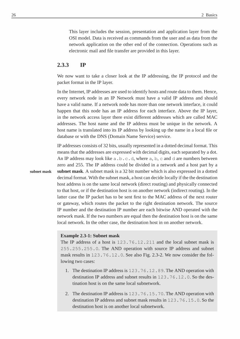
26 2 Basics
This layer includes the session, presentation and application layer from theOSI model. Data is received as commands from the user and as data from thenetwork application on the other end of the connection. Operations such aselectronic mail and file transfer are provided in this layer.
2.3.3 IP
We now want to take a closer look at the IP addressing, the IP protocol and thepacket format in the IP layer.
In the Internet, IP addresses are used to identify hosts and route data to them. Hence,every network node in an IP Network must have a valid IP address and shouldhave a valid name. If a network node has more than one network interface, it couldhappen that this node has an IP address for each interface. Above the IP layer,in the network access layer there exist different addresseswhich are called MACaddresses. The host name and the IP address must be unique in the network. Ahost name is translated into its IP address by looking up the name in a local file ordatabase or with the DNS (Domain Name Service) service.
IP addresses consists of 32 bits, usually represented in a dotted decimal format. Thismeans that the addresses are expressed with decimal digits,each separated by a dot.An IP address may look likea.b.c.d , wherea, b, c andd are numbers betweenzero and 255. The IP address could be divided in a network and ahost part by asubnet mask. A subnet mask is a 32 bit number which is also expressed in a dottedsubnet mask
decimal format. With the subnet mask, a host can decide locally if the the destinationhost address is on the same local network (direct routing) and physically connectedto that host, or if the destination host is on another network(indirect routing). In thelatter case the IP packet has to be sent first to the MAC addressof the next routeror gateway, which routes the packet to the right destinationnetwork. The sourceIP number and the destination IP number are each bitwise AND operated with thenetwork mask. If the two numbers are equal then the destination host is on the samelocal network. In the other case, the destination host in on another network.
Example 2.3-1: Subnet maskThe IP address of a host is123.76.12.211 and the local subnet mask is255.255.255.0 . The AND operation with source IP address and subnetmask results in123.76.12.0 . See also Fig. 2.3-2. We now consider the fol-lowing two cases:
1. The destination IP address is123.76.12.89 . The AND operation withdestination IP address and subnet results in123.76.12.0 . So the des-tination host is on the same local subnetwork.
2. The destination IP address is123.76.15.70 . The AND operation withdestination IP address and subnet mask results in123.76.15.0 . So thedestination host is on another local subnetwork.

2.3 The Internet protocol family 27
Fig. 2.3-2: Network for Example 2.3-1. There are two local networks, which are connectedthrough a router. The router has two network interfaces, each connected to one localnetwork and with IP address123.76.12.254 and123.76.15.254 . On eachlocal network there are two hosts.
Fig. 2.3-3: The IP packet format. The numbers are bit positions. A word is formed by 32 bits.
In the IP layer, the IP packet is made up of two parts: the IP header and the IPbody (payload), as shown in Fig. 2.3-3. Our description follows the current versionof IP, namely Version 4 orIPv4 ([Pos81b]). The latest versionIPv6 has already IPv4, IPv6
been standardized and deployed experimentally ([DH98]). TheIP packet contains IP packet format
the following fields.
1. Version (4 bit): This field indicates the version of the used IP protocol. IPv4is currently used.
2. IHL (Internet header length, 4 bit): Consists of the length of the header of theIP datagram in words (32 bits). The minimum length of the IP header is 20byte.

28 2 Basics
3. TOS (type of service, 8 bit): This field consists of eight bits, but only four bitsare actually used to make type of service requests to routers. Often this fieldis unused and holds the value zero.
4. Total Length (16 bit): The value stored in this field represents the entire data-gram length, including the header (in bytes).
5. Identification (16 bit): The originating host specifies a unique 16- bit identi-fier for every datagram. This identification is required as the datagrams maybe fragmented on their way through an internetwork. Fragmentation of IPdatagrams can occur when they cross network boundaries between networkswhich may have different maximum transfer units (MTUs) at the networkaccess layer. Notice also the following two items.
6. Flags (5 bit): The first of these bits is unused, the other two are used to controlthe way a datagram is fragmented. If the DF (don’t fragment) bit is set to 1,the datagram must not be fragmented. If the datagram has to befragmented,the router throws it away and sends an error message to the sending host.When the MF (more fragments) bit is set to 1, then the datagramis one ofseveral fragments, but not the last one. If the MF bit is set to0 this indicatesthat this datagram is the last of the number of datagrams or that the datagramhas not been fragmented.
7. Fragment Offset (13 bit): This number informs the receiver how many units(one unit equals eight byte) the current datagram is apart from the start of theoriginal.
8. Time to Live (TTL, 8bit): This field indicates how long a datagram is allowedto exist after entering the internetwork. The maximum TTL is255. As a data-gram is forwarded by a router, its TTL is decremented by one. If the TTL hasreached zero, the datagram is discarded and the router sendsan error messageto the sending host.
9. Protocol (8 bit): In this field, the protocol number of the next higher layer(ICMP (=1), TCP (=6), UDP (=17), . . . ) is identified. This protocol numbersare defined in [RP94].
10. Header Checksum (16 bit): This field contains a checksum of the IP header.By computing a checksum, the intermediate routers and the destination hostcan detect transmission errors in the IP header.
11. Source Address (32 bit)
12. Destination Address (32 bit): Special destination addresses are:127.0.0.1
(the local host),255.255.255.255 (all hosts on the local subnetwork).
13. Options (variable bit length): Up to 40 extra IP header bytes are available tocarry one or more options. The options that are included in a datagram arechosen by the sending application. Examples are:
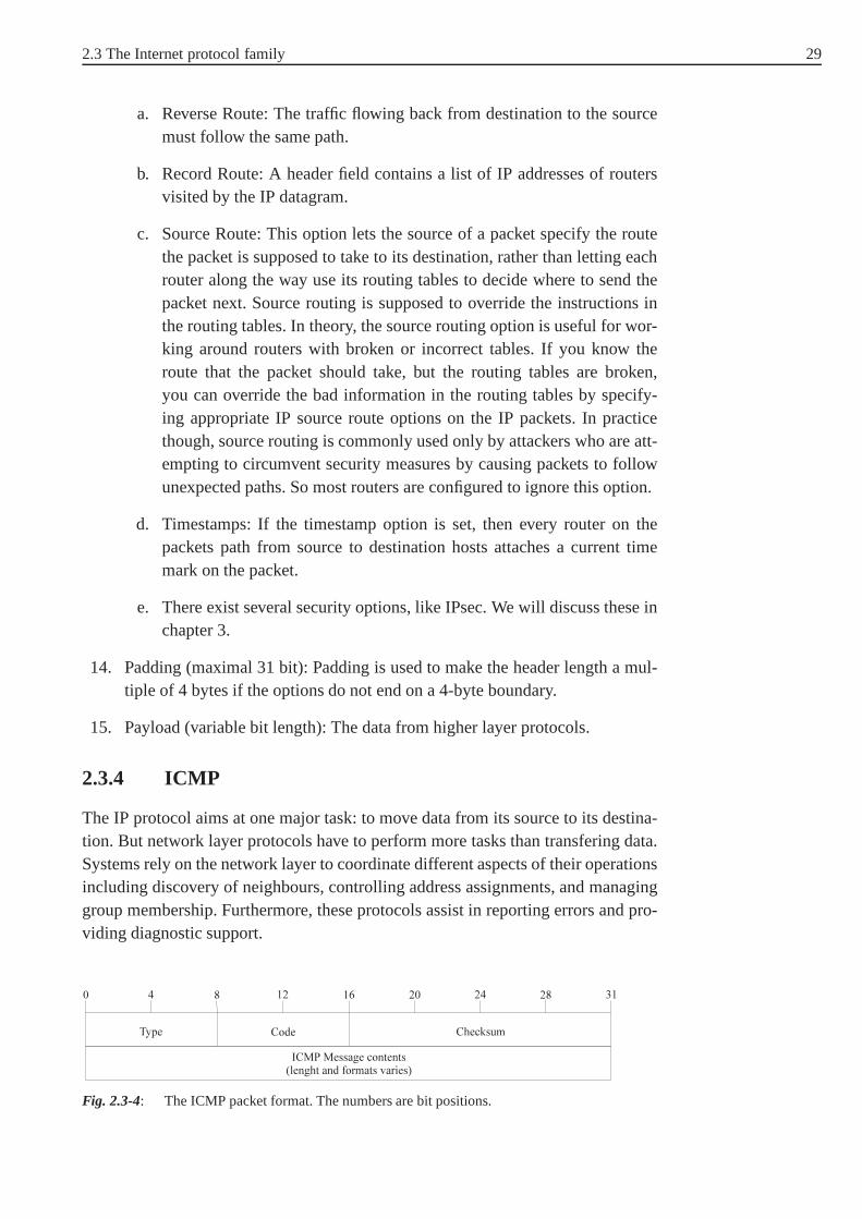
2.3 The Internet protocol family 29
a. Reverse Route: The traffic flowing back from destination tothe sourcemust follow the same path.
b. Record Route: A header field contains a list of IP addressesof routersvisited by the IP datagram.
c. Source Route: This option lets the source of a packet specify the routethe packet is supposed to take to its destination, rather than letting eachrouter along the way use its routing tables to decide where tosend thepacket next. Source routing is supposed to override the instructions inthe routing tables. In theory, the source routing option is useful for wor-king around routers with broken or incorrect tables. If you know theroute that the packet should take, but the routing tables arebroken,you can override the bad information in the routing tables byspecify-ing appropriate IP source route options on the IP packets. Inpracticethough, source routing is commonly used only by attackers who are att-empting to circumvent security measures by causing packetsto followunexpected paths. So most routers are configured to ignore this option.
d. Timestamps: If the timestamp option is set, then every router on thepackets path from source to destination hosts attaches a current timemark on the packet.
e. There exist several security options, like IPsec. We willdiscuss these inchapter 3.
14. Padding (maximal 31 bit): Padding is used to make the header length a mul-tiple of 4 bytes if the options do not end on a 4-byte boundary.
15. Payload (variable bit length): The data from higher layer protocols.
2.3.4 ICMP
The IP protocol aims at one major task: to move data from its source to its destina-tion. But network layer protocols have to perform more tasksthan transfering data.Systems rely on the network layer to coordinate different aspects of their operationsincluding discovery of neighbours, controlling address assignments, and managinggroup membership. Furthermore, these protocols assist in reporting errors and pro-viding diagnostic support.
Fig. 2.3-4: The ICMP packet format. The numbers are bit positions.

30 2 Basics
In the Internet protocol family, these functions are assigned to the Internet ControlMessage Protocol (ICMP). ICMP is used for IP status and control messages. ICMPpackets are carried in the payload of IP packets, just as TCP or UDP packets are.The ICMP message formatis shown in Fig. 2.3-4 ([Pos81a]). It consists of theICMP message format
following fields:
1. Type (8 bit): This field indicates the function the messagefulfills.
2. Code (8 bit): It includes further information about the content of the message,e.g. more specific description of errors.
3. Checksum (16 bit): The checksum is applied to ICMP message.
4. Payload (variable length and contents)
Examples ofICMP messagesinclude:ICMP messages
1. Echo request: What a host sends when you start the ping program/ service.
2. Echo response: What a host responds to an echo request with.
3. Timestamp: Request and reply messages that probe the round-trip time andfind out the clock setting of the target system.
4. Address Mask: Request and reply messages that allow systems to discoverthe address mask which should be assigned to a network interface.
5. Routing information: ICMP messages can be applied to exchange routinginformation. By periodically broadcasting the current routing preferences,routers ensure that the hosts in their networks do not try to use a router that isinappropriate.
6. Time exceeded: This type of message is send, when a router determines thata packet appears to be looping.
7. Destination unreachable: This message returns a router,when the destinationhost of packet can’t be reached for some reason, e.g. becausea network linkis down.
8. Redirect: What a router sends to a host in response to a packet that the hostshould have sent to a different router. The router handles the original packetanyway, and the redirect tells the host about a more efficientpath for the nexttime.
2.3.5 UDP
UDP (User Datagram Protocol) is a simple protocol in the transport layer of theInternet protocol stack. It provides no error detection, noerror correction, noconnection-oriented links, no handshaking, and no verification for delivery order.This tasks is defered to higher layers. UDP only offers the basic datagram delivery.

2.3 The Internet protocol family 31
Applications and services based on UDP are often simple so that they do not needto maintain connections. UDP applications may consist entirely of requests andreplies to requests. UDP provides a connectionless delivery service between twohosts, offering a service over a particular protocol port. Port numbers refer to pro-cesses running on network systems. Protocols at the transport layer no longer referto specific nodes or network interfaces. Transport layer protocols identify sourceand destination processes in form ofport numbers. port numbers
Fig. 2.3-5: The UDP packet format. The numbers are bit positions.
UDP is easy to implement and requires minimal overhead. EachUDP datagramcontains a single message which may be a request or a reply. A UDP packet istransmitted as payload of an IP packet according to packet-switching in datagrammodes. This means that it travels independent from other UDPpackets across thenetwork. TheUDP packetstructure is depicated in Fig. 2.3-5 ([Pos80]). It consistsUDP packet format
of the following fields:
1. Source port (16 bit): The source port number of a datagram is determined bythe host which generates it.
2. Destination port (16 bit): The destination port specifiesa particular programor process running on the destination host. The sending hostwould have toquery the destination host and ask for the right port number before it couldsend its datagrams.
3. UDP datagram length (16 bit): This field describes the length of the UDPpacket in bytes.
4. UDP Checksum (16 bit): A checksum over the whole UDP packet, inclu-ding UDP header and UDP payload. The checksum is calculated by using apseudo-header that uses some information from the IP packetheader.
5. UDP payload (variable length).

32 2 Basics
2.3.6 TCP
TCP (Transmission Control Protocol) is a protocol in the transport layer in the IPprotocol stack. In contrast to UDP, which offers little support concerning reliabilityor guarantees, TCP reliably connects hosts across a network. TCP operates connec-tion oriented. Each TCP connection behaves as if a direct two-way connection (bidi-rectional) between the communicating hosts exists. The communication consists ofthree phases: The setup, the connection and termination phase. TCP provides end-toend reliability, requiring that communicating hosts coordinate and agree to makeconnections and acknowledge receipt of network traffic. Each UDP datagram is anindividual message or reply. In comparsion to that, each TCPsegment is related tothe segment before and after it. The first and the last segments in a sequence requirespecial treatment.
Each TCP connection is identified uniquely with a combination of each host’s IPaddress and port number for the connection. The combinationof port number and IPaddress of the host on which the process is running is referred to as aTCP socket.TCP socket
Example 2.3-2: Telnet server and client processesConsider two hosts with IP addresses128.36.1.24 (client) and130.42.88.22 (server). A Telnet server process is running on the ser-ver on port 23 . Hence the TCP socket of the Telnet server process is(130.42.88.22,23 ). If the client wants to connect with the Telnet server,it opens a TCP socket (128.36.1.24, X ), whereX is a not used port num-ber on the client, for exampleX = 2258 .
Concerning reliability, only UDP offers the checksum whichis calculated from thepseudo-header and the UDP datagram. It helps the receiving process to verify thatthe datagram arrived at the right address without corruption. TCP makes three gua-rantees concerningreliability to the application layer:TCP reliability
1. The destination will receive the application data in the order it was sent.
2. The destination will receive all the application data.
3. The destination will not receive duplicates of any of the application data.
TCP will kill a connection rather than violate one of these guarantees.
Example 2.3-3: Reliability of TCP in the case of packet lossIf TCP packets from the middle of a connection session are lost in transit tothe destination, the TCP layer will arrange for those packets to be retransmit-ted before handing the data up to the application layer. It will not hand up thedata following the missing data until it has the missing data. If some of thedata cannot be recovered, despite repeated attempts, the TCP layer will kill theconnection and report this to the application layer, ratherthan hand up the datato the application layer with a gap in it.

2.3 The Internet protocol family 33
Fig. 2.3-6: The TCP packet format. The numbers are bit positions.
The TCP packet structure (see Fig. 2.3-6) and TCP protocol isdefined in [Pos81c].The fields of theTCP packet have the following meaning: TCP packet structure
1. Source port number (16 bit) and destination port number (16 bit): The initia-ting (source) host assigns itself an ephemeral port number (from 1024 to5000 ), which is usually a randomly chosen value greater than1023 . Thedestination port number is the well-known port associated with the servicerequested from the remote host ([RP94]).
2. Sequence number (32 bit): Each byte of a TCP byte stream in aconnectionis numbered, starting with an arbitrary number selected by the sending host.TCP connections are duplex (bidirectional) which means that data is transmit-ted in both directions at the same time. Each host selects an arbitrary startingpoint for numbering the bytes of its own data stream. The sequence numberin the TCP header indicates the number the sending host has assigned to thefirst byte in the current segment. The numbering starts at an arbitrary numberbetween0 and232 − 1 and restarts at zero when the highest vale has beenreached.
3. Acknowledgement number (32 bit): This field contains the value of thesequence number which is expected next from the other side. It serves also asacknowledgement for the received bytes with a value minus one of this field.If the acknowledgement does not arrive within a timeout interval, the data isretransmitted.
4. Header length (4 bit): This field indicates the length of the TCP header inwords (4 bytes). The length of the TCP header is not fixed as it may be exten-ded when using TCP options. The length of the TCP header varies between20 and 60 bytes.
5. Unused (6 bit):

34 2 Basics
6. TCP flags (6 bit): The TCP flag bits are employed to negotiateand manageconnections.
• URG (urgent): If set to 1, urgent data is included in the segment and theurgent pointer in the TCP header is used to point at the urgentdata.
• ACK (acknowledgement): Indicates that the acknowledgement number inthe segment header is valid. If this flag is set to zero, the acknowledgementfield must be ignored. The flag is zero as long as no segment fromtheother side of connection has been received. In this case there is nothing toacknowledge. Once a connection is established, it should always be set to1.
• PSH (push): The data should be delivered to the application as soon aspossible.
• RST (reset): This flag indicates an error, the connection must be reset orkilled.
• SYN (synchronize): During setup of a TCP connection, this bit is set toindicate that the synchronization of sequence and acknowledgement num-bers takes place.
• FIN (finish): The sender has no more data to send and wants to finish theconnection.
7. Window size (16 bit): The window size is a dynamic value that varies depen-ding on how much data the process at either end of the circuit is willing toaccept at any time. The window size is specified as a number of bytes that thereceiving host accepts within its window. The window size may depend one.g. the processing speed or the temporal storage capacities of the receivinghost. The process at either end can modify its window size to increase theefficiency of the link. Smaller windows mean that the receiving host cannotprocess the incoming data quickly enough to keep up with the current pace.
8. Checksum (16 bit): The checksum value is calculated with aTCP pseudohea-der.
9. Urgent Pointer (16 bit): The urgent pointer is only employed if the URG flagbit is set. It is used to indicate the sequence number of the last byte which ispart of the urgent data.
10. Options and Padding (variable bit length): The most common option is tospecify a segment size. Hosts can avoid fragmentation of TCPfragments byletting the host on the other end know the largest segment size it is willingto accept. The padding mechanism ensures that the TCP headerlength is amultiple of 32 bits.
11. TCP payload (variable length).

2.3 The Internet protocol family 35
To set up a TCP connection between two hosts, the so calledthree-way handshake three-way handshake
has to be performed. The name of the procedure stems from the fact that threemessages SYN (for synchronization), SYN, and ACK (acknowledgement) have tobe exchanged to start the TCP connection. The setup between two hostsA andB
consists of the following three steps:
1. SYN (A → B): HostAsends a TCP packet toB in order to requestB to open aTCP connection toA. The initial sequence number which has been randomlychosen is transmitted toB. The SYN flag is set indicating that the circuit isbeing synchronized. The ACK flag is set to zero.
2. SYN (B → A): HostBsends an acknowledgement of the initial packet to hostA. The ACK flag is set to 1. The opening sequence number formA is incre-mented by one and written into the acknowledgement field. Host B choosesits random sequence number. The SYN flag is set to 1. When hostA receivesthe packet, the connection fromA to B is established, but the link fromB to A
has to be validated.
3. ACK (A → B): HostA responds to hostB’s acknowledgement with an ack-nowledgement (ACK=1). The sequence number ofB is incremented by oneand put into the acknowledgement field. The SYN flag is set to zero becausethe synchronization is complete asA responds with this message. The respon-ding message gets a by one incremented sequence number from hostA.
When these three steps are completed, both sides can start sending data.
2.3.7 Security problems with the IP protocol family
There are several security risks in the IP protocol family and possible attacks. Wewill discuss a few of them here ([ZCC00]):
1. Implementation Weaknesses
Many attacks at the Internet layer or transport layer are denial of serviceattacks that exploit weaknesses in implementations of the IP protocol familyto crash hosts, e.g. send overlapping fragments. There are also attacks thatsend invalid combinations of options, set invalid length fields, or mark dataas urgent when no application would.
2. IP Spoofing
In IP spoofing, an attacker sends packets with an incorrect source address inthe IP packet header. When this happens, replies will be sentto the apparentsource address, not to the attacker. This might seem to be a problem, butactually there are three cases where the attacker doesn’t care:
a. The attacker can intercept the reply.
b. The attacker doesn’t need to see the reply.
c. The attacker doesn’t want the reply.
36 2 Basics
3. Packet Interception
Reading IP packets (or upper layer packets) as they go by on the physical net-work, frequently called packet sniffing, is a frequent way ofgathering infor-mation. If one is passing around important information unencrypted, and thisis the normal operation mode of the IP protocol family, it maybe all that anattacker needs to do.
In order to read a packet, the attacker needs to get the packetsomehow. Theeasiest way to do that is to control some machine that the traffic is supposedto go through anyway (a switch, a router, or a firewall). Thesemachines areusually highly protected, however, and do not usually provide tools that anattacker might want to use.
On some networks, like Ethernet or Token-ring, it is possible to get accessto packets very easyly. An Ethernet network that uses bus topology, or thatuses 10-base T cabling with unintelligent hubs, will send every packet on thenetwork to every machine. Tokenring networks, including FDDI rings, willsend most or all packets to all machines. Machines are supposed to ignore thepackets that are not addressed to them, but anybody with fullcontrol over amachine can override this and read all the packets, no matterwhat destinationthey are sent to.
An attacker can also intercept packets and change the contents of a packetand send it to the destination host. This is possible since noauthenticationand integrity check mechanisms exist in the normal implementations of theIP protocol family.
4. Attacks on fragmented IP packets
Attackers can use specially fragmented IP packets to conceal data. Each IPfragment contains information where the data it contains starts and ends. Nor-mally, each one starts after the last one ended. An attacker can construct IPpackets where fragments actually overlap, and contain the same data addres-ses. This does not happen in normal operation. It can only happen when bugsor attackers are involved.
Operating systems differ in their response to overlapping fragments. Becauseoverlapping fragments are abnormal, many operating systems respond verybadly to them and may reassemble them into invalid packets, with the expec-ted sorts of unfortunate results up to and including operating system cras-hes. When they are reassembled, there are differences in whether the first orsecond fragment’s data is kept. These differences can be increased by sen-ding fragments out of order. Some machines prefer the first version received,others the most recent version received, others the numerically first, and stillothers the numerically last.
There are three kinds of attacks possible by overlapping fragments:

2.3 The Internet protocol family 37
a. Simple denial of service attacks against hosts with poor responses tooverlapping fragments.
b. Information hiding attacks: If an attacker knows that virus detectors,intrusion detection systems, or other systems that pay attention to thecontent of packets are in use and can determine what assemblymethodthe systems uses for overlapping fragments, the attacker can constructoverlapping fragments that will obscure content from the watching sys-tems.
c. Attacks that get information to otherwise blocked ports:An attacker canconstruct a packet with acceptable headers (e.g. TCP or UDP headers)in the first fragment but then overlap the next fragment so that it also hasheaders in it. Since packet filters do not expect TCP headers in non-firstfragments, they will not filter them, and the headers do not need to beacceptable.
5. Attacks on ICMP
There have also been attacks that use ICMP, as a covert channel, a way ofsmuggling information. As we mentioned in Section 2.3.4, most ICMP packetbodies contain little or no meaningful information.
However, they may contain padding, the content of which is undefined. Forinstance, if you use ICMP echo for timing or testing reasons,you will want tobe able to vary the length of the packets and possibly the patterns of the data inthem. Therefor it is allowed to put arbitrary data into the body of ICMP echopackets, and this data is normally ignored. It is not filtered, logged, or exami-ned by anyone. For someone who wants to smuggle data through routers andfirewalls that allow ICMP echo, these bodies are a very tempting place to putit in. They may even be able to smuggle data into a site that allows only out-bound echo requests by sending echo responses even without having seen arequest. This will only be useful if the target host that the responses are beingsent to is configured to receive them. It will not help anyone break into a site,but it is a way for people to maintain connections to compromised sites.
6. Port Scanning
Port scanning is the process of looking for open ports (TCP orUDP ports) ona machine, in order to figure out what services are running on the machineand what might be attackable. Straightforward port scanning is quite easyto detect, so attackers use a number of methods to disguise port scans. Forinstance, many machines are so configured, that they do not log connectionsuntil they are fully made. So an attacker can send an initial TCP packet, witha SYN but no ACK, get back the response, then another SYN if theport isopen, and a RST if it is not, and then stop there. This is often called aSYN
scan or a half open scan . Although this will not get logged, it may
38 2 Basics
have other unfortunate effects, particularly if the scanner fails to send a RSTwhen it stops.
Attackers may also send other packets, counting a port as closed if they get aRST and open if they get no response, or any other error. Almost any combi-nation of flags other than SYN by itself can be used for this purpose, althoughthe most common options are FIN by itself, all options on, andall options off.The last two possibilities, sometimes calledchristmas tree andnull ,tend to have unfortunate side effects on weak IP stack implementations. Manydevices will either crash or disable the IP protocol stack.
For a further discussion of problems with the IP protocol family read the article[MF00].
2.3.8 Common Internet services and their security risks
There are a number of Internet services that users want and that most sites try tosupport. There are important reasons to use these services.But there are potentialsecurity problems with each of them. The Internet services are usually build over theICMP, TCP or UDP protocols. This section briefly summarizes the major Internetservices and provides a high level description of them without going into to muchdetails. None of these services are really secure. Each one has its own securityweaknesses, and each has been exploited in various ways by attackers. Before youdecide to support a service at your site, you will have to assess how important it isto the legal users of this network and whether you will be ableto protect them fromits dangers. There are various ways of doing this:
1. Running the services only on certain protected machines,
2. using especially secure variants of the standard services, or
3. blocking the services completely to or from some or all outside systems.
More details on the protocols, message formats and securityweaknesses of theabove services will be discussed in the following chapters.
1. Naming services
A naming service translates the names that people use and thenumericaladdresses that machines use. Different protocols use different naming ser-vices. The primary protocol used on the Internet is DNS (Domain Name Sys-tem), which converts between host names and IP addresses. For the end userit is much easier to work with names than with numbers identifying networksand hosts. The resulting system of names is administered in adistributed data-base called Domain Name System (DNS) and used by the Internetsoftwareto resolve network and host names to find out their IP addresses. A domaindomain name
name is a hierarchical name which is registered for an organisation. Eachlevel gives more information about the respective domain. Examples for rootdomain names arede or com. Within each root domain (or top-level domain)

2.3 The Internet protocol family 39
second level domains are assigned and so on. An example of a full domainname isfernuni-hagen.de .
In early days of the Internet, it was possible for every site or host to maintaina host table that listed the name and number for every machineon the Internetthat it might ever care about. With millions of hosts attached, it is not practicalfor any single site to maintain a list of them. Instead, DNS allows each site tomaintain the information about its own host.
The main risk in providing a DNS service is that you may give away moreinformation than you intend. Also the DNS service is a distributed databaseconsisting of many DNS servers on the Internet. This makes iteasy for an atta-cker to install a deceitful DNS server distributing incorrect information. So,using DNS for authentication services make them vulnerableto such attacks.This can be handled by a combination of methods:
a. Using IP addresses, rather than host names, for authentication.
b. Authenticating users instead of hosts on the most secure services,because IP addresses can also be spoofed.
There are also other naming and directory services like WINS(Win-dows Internet Name Service) fromMicrosoft, LDAP (Lightweight DirectoryAccess Protocol), NIS (Network Information Service) from SUN or NDS(Novell Directory Service) from Novell.
2. Electronic Mail
Electronic mail is one of the most popular network services.It is a servicewith relatively low risk, but this does not mean that it is risk-free. Forgingelectronic mail is trival, and forgeries facilitate two different types of attacks:
a. Attacks against your reputation and
b. social manipulation attacks.
The electronic mail system on the Internet consists of mail servers accepting,transporting and holding mail messages and mail clients to send and receivemail messages to/from mail hosts.SMTP (Simple Mail Transfer Protocol) SMTP
is the Internet standard protocol for sending and receivingelectronic mail.Mail messages are transported between mail servers and froma mail clientto a mail server mainly via SMTP. Mail servers, like other programs have atradeoff between features and security. The most common SMTP server in theUnix or Linux operating systems is Sendmail. Sendmail bas been exploitedin a number of break-ins.
While SMTP is used to exchange electronic mail messages between servers,users who read electronic mail that has already been deliverd to a mail ser-ver do not use SMTP. Across the Internet, the most common protocols forthis purpose arePOP (Post Office Protocol) and IMAP (Internet Message POP and IMAP
Access Protocol). POP and IMAP both normally transfer user authentication

40 2 Basics
data (login name and password) and the email message withoutencrypting it,allowing attackers to read the mail and often to get reusableuser credentials.
3. File Transfer and file sharing
Electronic mail is only designed to transfer small files. Also you may want tohave a single copy of a file but use it on multiple machines. This is called filesharing.
FTP (File Transfer Protocol) is the Internet Standard protocol for file trans-FTP
fer. With FTP it is possible to download (from the FTP server to yourmachine) or to upload (from your machine to the FTP server) files. So itsis possible to bring in Trojan horse software and computer games in to yoursite by legitimate users.
To get access to files made available by an FTP server, users log into the sys-tem using an FTP client with their system login name or a special login name(usually ”anonymous” or ”ftp”). In the later case most FTP servers requestthat users enter their own electronic mail address in response to the passwordprompt. In the authentification phase, the login name and password and inthe file transfer phase, the content of the file are transmitted without encryp-tion. There are alternatives to FTP using the SSH protocol (see chapter 3) toachieve file transfer in a secure manner.
4. Remote access
Remote access can be used in situations in which one would like to run aprogram on a computer at another site. For instance, one has aslow computerwith low storage facilities at the local site. The major questions conceringsecurity issues of remote access are:
a. How are remote machines and users authenticated?
b. What security mechanismes are used for the transmitted data?
c. Can anyone take over a connection in progress?
d. What commands can a remote user execute and what data can beacces-sed?
Telnet is the standard for remote access on the Internet. Telnet allows remoteTelnet
text access for users from any Internet connected site without making specialarrangements. Telnet sends all of its information unencrypted, which makes itextremely vulnerable to sniffing and hijacking attacks. Forthis reason, Telnetis now considered to be one of the most dangerous services when used toaccess a site from a remote systems. A mordern service which can replaceTelnet and FTP is SSH (Secure Shell).
In chapter 4 we discuss the security of the services in the World Wide Web.

41
3 Internet Security Protocols
The Internet protocol suite (TCP/IP) has been designed withno thought of security.It is very easily possible to spoof IP addresses, to manipulate DNS, and to eavesdropthe links.
Many cryptographic protocols have been proposed, specified, and partly implemen-ted for the Internet and the WWW in the recent past. The development of Internetstandards for security (i.e. RFCs5 published as a standard track documents) hasbeen slow. The first RFC to introduce a security-oriented protocol into the TCP/IPsuite did not appear until 1987, with the publication of the first e-mail securityprotocol specifications. In the following years, a number ofsecurity-oriented Inter-net protocols have been developed and are at various stages in the Internet stan-dardisation process. Internet standards are formally developed under the auspicesof the Internet Society, whose technical arm is the Internet Architecture BoardInternet Society, IAB,
IETF, IRTF(IAB). IAB consists of two taskforces: IRTF (Internet Research Task Force) andIETF (Internet Engineering Task Force). IETF consist of a large number of workinggroups (WG), where the bulk of standards developments takesplace. Despite thegreatly increased activity in security standards in the IETF, the Internet still lackson security (the protocols developed must be used!).
In this chapter we overview and briefly discuss some of the Internet security pro-tocols. In the case of TCP/IP based networks, cryptographicsecurity protocols canoperate at any layer of the corresponding communications protocol suite. There aremany proposals for providing security services at the network access, IP, transportand application layer. Here we focus on the IPSec set of security protocols in theIP layer and two transport layer security protocols, namelythe secure socets layer(SSL) and the transport layer security (TLS) protocols.
3.1 Security at the Network Access Layer
As mentioned in chapter 2, in the TCP/IP communications protocol suite, thenetwork access layer handles issues related to local area networking and is respon- Layer 1 in TCP/IP
layer modelsible for packet transmission on the physical media. Protocols that operate on thislayer include Ethernet (IEEE 802.3), token bus (IEEE 802.4), token ring (IEEE802.5), FDDI (fiber distributed data interchange), as well as protocols for dial-upnetworking, such as the serial line IP (SLIP), and the Point-to-Point protocol (PPP).For all practical purposes, Ethernet is most widely deployed for local area networ-king (LAN) and PPP is most often used for dial-up networking.Thus, security stan-dards below the IP layer tend to address requirements associated with protocollsused to support IP transport - for example, link-by-link authentication.
5 Request for Comment

42 3 Internet Security Protocols
In the late 1980’s, the IEEE started to address issues related to local area (LAN)and metropolitan area network (MAN) security: The IEEE 802.10 working groupActivities for LAN and
MAN security was established in 1988 for this purpose. Meanwhile, IEEE 802.10 specified severalstandards for interoperable LAN/MAN security (SILS) that are compatible withexisting IEEE 802 and OSI standard specifications. Unfortunately, SILS has notbeen particularly successful, and there are hardly any products that implement theSILS specifications. Consequently, we do not address the work of IEEE 802.10 andSILS.
At this place we should mention the simple ”link encryption ”: If there is a dedica-Link encryption
ted link between two hosts (i.e.the two entities involved inthe communication haveto be physically connected) and the traffic needs to be encrypted, one can use hard-vare devices or software for encryption. The link encryption is the classic method ofapplying cryptography to digital communications. This is also the oldest approachto data security, and has been used for decades to protect themost sensitive mili-tary traffic and to provide secure links between banking organisations. An exampleis an authomatic teller machines (ATM) where all the machines are connected viadedicated links to a central bank office. If ATM machines wereconnected to an IPnetwork instead of dedicated secure links, the data link layer security would notsuffice and one would have to move up one layer to provide security services.
Another example for security mechanism in this layer is thePPP authentication.PPP authentication
The Point-to-Point protocol (PPP) was developed as a commoninterface for com-munication over point-to-point links (versus the transmission of IP over packet-switched networks). PPP is often used on dial-up links, enabling users to gain inter-mittent access to an Internet service provider via low-speed lines, and is also usedin interrouter links. Authentication of the dial-up user orof the neighbour router isan important security concern, and is the focus of the security extensions to PPP(described in RFC 1334). PPP allows negotiation of the authentication technique,with the default being no authentication. Two forms of authentication are supportedcurrently: simple passwords and challenge-response schemes. The protocol can beused to provide two-way authentication, so that each party can verify the identityof the other. Implementations of authenticated PPP used forinterrouter communi-cation typically perform two-way authentication, but dial-up users access via PPPtypically involves only one-way authentication. The PPP authentication has beenin many respects one of the successes among Internet security standards to date,although for other security features that may be applicablein PPP (e.g. confidentia-lity of traffic or continous authentiction and integrity of the traffic) no provision ismade.
3.2 Security at the IP Layer
The IP layer provides conectionless services and is responsible for routing ofLayer 2 in TCP/IPlayer model packets. Two important components in this layer are adressing and fragmentation
(i.e. a packet is split into multiple IP packets at the sourceor in a router). Afterfragmentation, each packet is transmitted independently and is reassembled at the

3.2 Security at the IP Layer 43
destination. The language of this layer is IP, the Internet Protocol. It provides thefunctionality for interconnecting end systems across multiple networks. For thispurpose IP is implemented in each end system and in routers (devices that provideconnection between networks). Higher-level data at a source end system are encap-sulated in an IP protocol data unit (PDU) for transmission. The PDU is then passedthrough one or more networks and connecting routers to reachthe destination endsystem.
One thing IP does not provide, though, is security. When the protocols of the TCP/IP IP and Security
family were designed, security was not considered at all. IPpackets can be forged,modified, and inspected on their route. In 1994, the InternetArchitecture Board(IAB) issued a report with the title ”Security in the Internet architecture” (RFC1636), in which the general consensus was stated, that the Internet needs more andbetter security. The IAB included authentication and encryption as necessary secu-rity features in the next-generation IP (IPv6). This initiated the developement andIPSec developing
standardisation of IPSec. Fortunately, these security capabilities were designed tobe usable both with the current IPv4 and the future IPv6. Manyvendors do nowhave some IPSec capability in their products.
IPSec is aset of general purpose protocols for protecting TCP/IPcommuni-cations and provide data source authentication, data integrity, confidentiality and IPSec security services
protection against replay attacks. Actually, IPSec is an extension to the existing IPnetworking protocol. The authentication mechanism of IPSec ensures that a recei-ved packet was, in fact, transmitted by the party identified as the source in the packetheader. In addition, this mechanism assures that the packetwas not altered in tran-sit. The confidentiality facility enables communicating nodes to encrypt messagesto prevent eavesdropping by third parties. The key management facility is concer-ned with the secure exchange of keys. By implementing security at the IP level,an organisation can ensure secure networking not only for applications that havesecurity mechanisms (E-mail, Web access), but also for manyother security igno-rant applications. In this section we give an overview of IP security (IPSec), weintroduce the IPSec architecture and we look at how it works.
3.2.1 IPSec Overview
IPSec is the only technique for Internet security that workswith all forms of Internettraffic. IPSec runs over the current version of IP, IPv4, and also the next generation Features of IPSec
of IP, IPv6. In addition, IP can protect any protocol that runs on the top of IP suchas TCP, UDP, and ICMP. IPSec is truly the most extensible and complete networksecurity solution. It enables end-to-end security so that every single piece of infor-mation sent to or from a computer can be secured. It can also bedeployed inside thenetwork to form Virtual Private Networks (VPN) where two distinct and disparatenetworks become one by connecting them with a tunnel securedby IPSec.
The principal feature of IPSec that enables it to support these varied applications isthat it can encrypt and/or authenticate all traffic at IP level. Thus, all distributed app-lications, including remote login, client/server communication, e-mail, file transfer,

44 3 Internet Security Protocols
Web access, and so on, can be secured. IPSec protections are aplied ”above” the IProuting information and ”below” the application data (Fig.3.2-1). The router in thiscase treats encrypted packets just as plaintext packets andignores the extra IPSecheaders. The applications never see the IPSec crypto services, i.e. the used IPSecprotocols are transparent for them.
Fig. 3.2-2 is a typical scenario of IPSec usage. A company maintains LANs atScenario of IPSecdeployment dispersed locations. Nonsecure IP traffic is conducted on each LAN. For traffic
off site, through some sort of private or public WAN, IPSec protocols are used.These protocols operate in networking devices, such as routers or firewalls, thatconnect each LAN to the outside world. The IPSec networking device will encryptand authenticate all traffic going into the WAN, and decrypt and verify the authen-ticity of the traffic comming from the WAN. These operations are transparent toworkstations and servers on the LAN. Secure transmission isalso possible withindividual users who dial into the WAN. Such user workstations must implementthe IPSec protocolls to provide security.
Fig. 3.2-1: Transparency of IPSec in the case of end-to-end encryption

3.2 Security at the IP Layer 45
Fig. 3.2-2: An IP security scenario
3.2.2 IPSec Architecture
The IPSec architecture includes various components of IPSec, how they interactwith each other, the protocols in the IPSec family, and the modes in which theyoperate.
The architecture document for IPSec, RFC 2401, defines the base architecture upon RFCs for IPSec
which all implementations are built. It defines the securityservices provided byIPSec, how and where they can be used, how packets are constructed and proces-sed, and the interaction of IPSec processing with the policy. The IPSec workinggroup at the IETF has published 12 RFCs which define various aspects of IPSec.For example, RFC 1825 gives an overview of a security architecture, RFC 1826gives a description of a packet authentication extension toIP, RFC 1828 describesthe authentication mechanism, RFC 2406 defines ESP (older version is RFC 1827),and RFC 1829 describes the specific encryption mechanism. Support for these fea-tures is mandatory for IPv6 and optional for IPv4. In both cases, thesecurity featu-res are implemented as extension headers that follow the main IP header. Theextension header for authentication is known as authentication header (AH) and theheader for encryption is known as Encapsulated Security Payload (ESP) header.
In order to understand, implement and use IPSec, it is necessary to understand therelationship between the building blocks (protocols) in its architecture. TheIPSec IPSec roadmap
roadmap shown in Fig. 3.2-3 defines how various components of IPSec interactwith each other.

46 3 Internet Security Protocols
Key Management Poli yDOIEn ryption Alg. Authenti ation Alg.ESP AHAr hite ture? ?
? ??
? ?
6
�-
6
�
Fig. 3.2-3: IPSec Architecture
The IPSec protocol that provides confidentiality is theEncapsulating SecurityBuilding blocks ofIPSec Payload (ESP). Moreover, ESP also provides data integrity, data source authen-
tication of IP Packets, and protection against replay attacks. TheAuthenticationHeader (AH) is an IPSec protocol that provides everything ESP provides exceptconfidentiality. In order to communicate, each pair of hostsusing IPSec must esta-blish security association (SA)with one another, i.e. SAs are used to define theprocessing done on a specific IP packet: what types of protection to apply, how todo encryption and authentication, and which keys need to be used. The SA thatapplies to a given IPSec header is determined by the packet destination IP addressand theSPI (security parameter index)field in the packet header. The packets areidentified by a SPI, the IPSec protocol value, and the destination adress to whichSA applies. SA may be created manually or dynamically and resides in theSecurityAssociation Database (SADB).
The IPSec architecture defines the granularity by which a user may specify hispolicy. This allows for diffeent traffic flows to have different protection. For exam-ple, one may specify IPSec policy on a network security gateway that requires alltraffic between its local protected subnet and the subnet of remote peer be encryp-ted with DES and authenticated with HMAC-MD5, while all telnet traffic fromthe remote subnet to a mail server be encrypted with 3DES and authenticated withHMAC-SHA, and all Web traffic to another server be encrypted with IDEA andauthenticated with HMAC-RIPEMD. The IPSec policy is maintained by theSecu-rity Policy Database (SPD). Each entry of the SPD defines the traffic to be protec-ted and how to protect it. For each packet entering or leavingthe IP stack, the IPSeckernel consults the SPD for the possible application of security.
Prior to an IP packet being secured by IPSec, a SA must exist, which can be, as wementioned above, manually or dynamically created. TheInternet Key Exchange(IKE) is used to create them dynamically. IKE negotiates SAs on behalf of IPSecand populates the SADB. IKE is envoked by the kernel or by the policy managementapplication or by another IKE peer to establish keys.
TheDomain of Interpretation (DOI) block containes values needed for the otherdocuments to relate to each other. These include identifiersfor approved encryp-tion and authentication algorithms, as well as operationalparameters such as keylifetime.
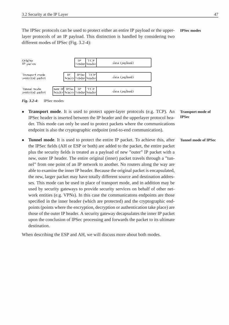
3.2 Security at the IP Layer 47
The IPSec protocols can be used to protect either an entire IPpayload or the upper- IPSec modes
layer protocols of an IP payload. This distinction is handled by considering twodifferent modes of IPSec (Fig. 3.2-4):
prote ted pa ketTunnel mode headernew IP headerIPSe headerIP headerTCP data (payload)prote ted pa ketTransport mode headerIP headerIPSe headerTCP data (payload)IP pa ketOriginal headerIP headerTCP data (payload)Fig. 3.2-4: IPSec modes
• Transport mode. It is used to protect upper-layer protocols (e.g. TCP). AnTransport mode ofIPSecIPSec header is inserted between the IP header and the upperlayer protocol hea-
der. This mode can only be used to protect packets where the communicationsendpoint is also the cryptographic endpoint (end-to-end communication).
• Tunnel mode. It is used to protect the entire IP packet. To achieve this, after Tunnel mode of IPSec
the IPSec fields (AH or ESP or both) are added to the packet, theentire packetplus the security fields is treated as a payload of new ”outer”IP packet with anew, outer IP header. The entire original (inner) packet travels through a ”tun-nel” from one point of an IP network to another. No routers along the way areable to examine the inner IP header. Because the original packet is encapsulated,the new, larger packet may have totally different source anddestination addres-ses. This mode can be used in place of transport mode, and in addition may beused by security gateways to provide security services on behalf of other net-work entities (e.g. VPNs). In this case the communicatons endpoints are thosespecified in the inner header (which are protected) and the cryptographic end-points (points where the encryption, decryption or authentication take place) arethose of the outer IP header. A security gateway decapsulates the inner IP packetupon the conclusion of IPSec processing and forwards the packet to its ultimatedestination.
When describing the ESP and AH, we will discuss more about both modes.

48 3 Internet Security Protocols
3.2.3 Encapsulating Security Payload (ESP)
The encapsulating Security payload (ESP) is an IPSec protocol which provides con-fidentiality, data origin authentication, anti-replay, and data integrity services to IP.It does so by inserting a new header - an ESP header - after the IP header and beforethe data to be protected, and appending an ESP trailer (Fig. 3.2-5). So, it encapsu-lates the data it protects. It encrypts the data contents of the reminder of the packet.The format of the ESP varies according to the type and mode of encryption beingused. An ESP packet is identified by the protocol field of an IP header. If its valueis 50, it is an ESP packet and immediately after the IP header is an ESP header.
headerIP headerESP prote teddata ESPtraileren rypted� -authenti ated� -An ESP-prote tedIP pa ket Authenti ation dataNext headerPad lengthPadProte ted data≈ ≈
Initialisation ve torSequen e numberSe urity Parameters Index (SPI)0 7 15 23 31 bit
ESP header and trailerFig. 3.2-5: ESP is both a header and a trailer - it encapsulates the data it protects
Since ESP provides both confidentiality and authentication, the specific algorithmused by both encryptor and authenticator is determined by the corressponding com-ponents in its Security Association (SA). By separating thebase ESP definition andformat from the actual algorithms which can be used, ESP is generic and extensiblesecurity mechanism, i.e many algorithms can be deployed to encrypt or authenti-cate. The ESP specification imposes requirements on transforms (encryption andESP as a generic
mechanism authentication algorithms) used with ESP but does not specify what those trans-forms are. This depends on the specification for implementation.
The current specification dictates that a compliant implementation must supportthe DES encryption algorithm in cipher block chaining mode (CBC). A numberEncryption algorithms
for ESP of other algorithms have been assigned identifiers in the DOIdocument and canbe therefore used for encryption. These include triple DES in CBC mode (3DES-CBC), Blowfish-CBC, RC5-CBC, IDEA-CBC, triple IDEA-CBC or CAST-CBC.All encryption algorithms used in ESP must operate in CBC mode. CBC requiresthat the amount of data to encrypt be a multiple of the block size of the cipher,and this is here met by padding the data block. When using CBC mode also aninitialization vector (IV) is required, which is here contained in the payload field,generally in the first bytes.

3.2 Security at the IP Layer 49
ESP supports the use of a message authentication codes (MAC)with a default Authenticationalgorithms for ESPlength of 96 bits. The current specification dictates that the compilant implemen-
tation of the authentication function of ESP, the truncatedoutput of HMAC-MD5and HMAC-SHA6 can be used.
ESP Format
The ESP specification defines the format of the ESP header. It immediately follows Format of the ESPheaderthe IP header, regardless of the mode that ESP is in. After theESP header follows
an upper layer protocol header (e.g. TCP header). The ESP header contains thefollowing fields:
• Security Parameter Index (SPI), 32 bits: This value combined with the desti-nation adress and protocol in the preceding IP header identifies the appropriateSecurity Association to use in the packet processing. It is an arbitrary numberand is selected by the destination during the key exchange. It is authenticatedbut not encrypted.
• Sequence number, 32 bits: This is a unique and monotonically increasing num-ber inserted into the header by the sender. It provides an anty-replay function andis authenticated but not encrypted.
The actual data being protected (encrypted) by ESP is contained in theplayloaddata field. Therefore, the length of this field depends on the length of the data. Itis a transport layer segment (transport mode) or IP packet (tunnel mode). This datais also used to contain any initialisation vector that the encryption algorithm mayrequire. TheESP trailer contains the following fields: Format of the ESP
trailer• Padding (if any, 0-255 bits): Certain modes of encryption algorithms require
that the input to the cipher be a multiple of its block size. Padding accomplishesthis.
• Pad length(8 bits): Defines how much pad has been added, so that the recepientcan restore the actual length of the payload data.
• Next header(8 bits): Indicates the type of data that is contained in the payloaddata field. If ESP is applied in tunnel mode, this will be valuefour, indicatingIP-in-IP. If ESP is applied in thansport mode, this value will indicate the type ofupper-level protocol that follows (e.g. TCP would be six).
6 HMAC is a special kind of keyed hash, with benifit that its generation is much faster than adigital signature. HMAC can be utilized with any existing hash function, so SHA becomesHMAC-SHA and MD5 becomes HMAC-MD5. The HMAC construction iscryptographicallystronger that the underlying hash function. HMAC uses two pad values (an inner pad ipad andan outher pad opad) to maintain state of the HMAC. The HMAC based on hash algorithm Hof message M using key K is defined as
HMAC(K, M) = H(KXORopad, H(KXORipad, M)).
All message authentication done in IPSec uses HMACs.

50 3 Internet Security Protocols
• Authentication data (variable length): Holds the result of the data integritycheck done on the ESP packet (keyed hash function computed over the ESPpacket minus the authentication data field). The size of thisfield depends onauthentication algorithm employed by the SA to process thispacket.
The ESP header is not encrypted, but a portion of the ESP trailer is. The data thatProtection of differentpacket fields the recepient needs to process the packet must be in clear text. Since the SPI is used,
along with the destination IP adress of the IP header of this packet, to identify an SAit must be in clear text. In addition, the sequence number andthe authentication dataare also in clear text. It is due to the specifiedorder of processingof IP packets:First verify the sequence number, then verify the integrityof the data, then decryptthe data. Since decryption is last, the sequence number and authentication data mustbe known.
Depending on what actually ESP is protecting, the ESP headeris applied to anIP packet in transport mode or in tunnel mode. Transport modeis used to encryptESP in transport mode
and optionally authenticate the data carried by IP (e.g. a TCP segment). This modeprovides confidentiality for any application that uses it, thus avoiding the need toimplement confidentiality in every individual application. It adds little overheadto the total length of the IP packet (advantage), but in this mode it is possible todo traffic analysis on the transmitted packets. In transportmode an ESP header isinserted between the IP header and the upper-layer protocolheader of an IP packet,and an ESP trailer is placed after the IP packet. If authentication is selected, theESP Authentication data field is added after the ESP trailer.The entire transportlevel segment plus the ESP trailer are encrypted (see Fig. 3.2-6 b).
IPv6 headernew IP headersext hdrESP headerorig. IP headersextended TCP data trlrESP authESPEn rypted� -Authenti ated� -
IPv4 newIP hdr. ESPhdr IP hdr.original TCP data trlrESP authESPEn rypted� -Authenti ated� -( ) Tunnel modeIPv6 headerorig. IP hop-by-hop, dest,routing, fragment, ESPhdr dest TCP data trlrESP authESPEn rypted� -Authenti ated� -
IPv4 orig.IP hdr. ESPhdr TCP data trlrESP authESPEn rypted� -Authenti ated� -(b) Transport modeIPv6 headerorig. IP extension he-aders (if any) TCP dataIPv4 orig.IP hdr. TCP data(a) Before applying ESP
Fig. 3.2-6: Scope of ESP encryption and authentication

3.2 Security at the IP Layer 51
In tunnel mode the entire protected IP packet is encapsulated in the ESP headerand a new IP header is added to that. For this mode, the ESP header is prefixed tothe packet and then the packet plus the ESP trailer are encrypted. Because the IPheader contains the destination address and possibly source routing directives, it isnot possible simply to transmit the encrypted IP packet prefixed by the ESP hea-der. Intermediate routers would be unable to process such a packet. Therefore, it isnecessary to encapsulate the entire block (ESP header plus ciphertext plus authenti-cation data, if present) with a new IP header that will contain sufficient informationfor routing, but not for traffic analysis (see Fig. 3.2-6 c.).So, this method can beused to counter traffic analysis.
3.2.4 Authentication Header (AH)
The AH protocol, which provides support for data integrity and authentication ofIP packets, is defined in RFC 2402. It defines the method of protection, the pla-cement of the header, the authentication coverage, the input and output processingrules, but it does not define the authentication algorithm touse (i.e. it is generic andextensible).
Just like ESP, AH can be used to protect the upper-layer protocol (transport mode) Features of AH
or an entire IP datagram (tunnel mode). In either case the AH header immediatelyfollows an IP header. AH is an IP protocol and an AH-protectedIP packet is justanother IP packet. Therefore, AH can be used alone or in conjunction with ESP. Thedata integrity that AH provides is subtly different from that provided by ESP;AHauthenticates portions of the outer IP header.
When AH and ESP are protecting the same data, the AH header is always insertedafter the ESP header. The AH header is much simpler than the ESP header, becauseAH header format
it does not provide confidentiality (there is no initialisation vector and no trailer asthere is no need for padding and pad length indicator). As shown in Fig. 3.2-7, theAH header has the following fields:
Authenti ation dataSequen e numberSe urity Parameters Index (SPI)headerNext lengthPayload Reserved0 7 15 23 31Fig. 3.2-7: The AH header
• Next header(8 bits): It indicates what follows the AH header. In transport modeit will be the value of the upper-layer protocol being protected (TCP or UDP)and in tunnel mode it will be the value 4 (for IPv4 IP-in-IP encapsulation) or thevalue 41 (for IPv6 encapsulation).
52 3 Internet Security Protocols
• Payload length (8 bits): This field indicates the length of the header itselfin32-bit words minus 2.
• Reserved field: It is not used and must be set to zero.
• Security Parameters Index (SPI), 32 bits: Identifies a security association usedto authenticate the packet (together with the destination adress of the outer IPheader).
• Sequence number(32 bits): It is used to provide the anti-replay function andismonotonically increasing counter identical to that used inESP.
• Authentication data (variable): This field contains the result of the integritychecking function. AH does not define authenticator, but HMACSHA- 96 andHMAC-MD5-96 are mandatory to implement.
Since authentication is based on the use of HMACs, the two parties must sharea key, which is established with the Internet Key Exchange Protocol (IKE). TheHMAC is calculated over the following:
• IP header fields that either do not change in transit (immutable) or that are pre-dictable. Fields that may change in transit are set to zero for purposes of HMACCalculating the
authentication data(HMAC)
calculation at both source and destination.
• The AH header except the authentication data field (this is set to zero for purpo-ses of calculation at both source and destination).
• The entire upper-level protocol data, which is assumed to beimmutable in transit(e.g a TCP segment or an inner IP packet in tunnel mode).
For IPv4, examples of immutable fields are Internet Header Length and SourceAdress. An example of an muttable but predictable field is theDestination Address.Examples of mutable fields that are zeroed prior to the HMAC calculation are theTime to Live and Header Checksum Fields. Note that both source and destinationadress fields are protected, so that adress spoofing7 is protected. For IPv6, examp-les in the base header are Version (immutable), DestinationAdress (mutable butpredictable), and Flow Label (mutable and zeroed for the HMAC calculation).
7 In IP Spoofing an intruder creates packets with false IP adresses

3.2 Security at the IP Layer 53
IPv6 headernew IP headersext AH headerorig. IP headersextended TCP datanew IP header and its extension headersAuthenti ated ex ept for mutable �elds in� -
IPv4 newIP hdr. AH IP hdr.original TCP data�elds in the new IP headerAuthenti ated ex ept for mutable� -( ) Tunnel modeIPv6 headerorig. IP hop-by-hop, dest,routing, fragment, AH dest TCP dataAuthenti ated ex ept for mutable �elds� -
IPv4 orig.IP hdr. AH TCP dataAuthenti ated ex ept for mutable �elds� -(b) Transport modeIPv6 headerorig. IP extension he-aders (if any) TCP dataIPv4 orig.IP hdr. TCP data(a) Before applying AH
Fig. 3.2-8: Scope of IPSec authentication
The IPSec authenticatein can be used in two ways.End-to-end authentication is Ways of using IPSecauthenticationwhen authentication is provided directly between a server and a client workstation
(which can be either on the same network as the server or on an external network),and this case uses transport mode SA.End-to-intermediate authentication is thecase when a remote workstation authentificates itself to thecorporate firewall, eitherfor the access to the entire internal network or because the requested server does notsupport the authentication feature. This case uses tunnel mode SA.
We now look at the scope of authentication provided by AH and the AH location Scope of authenticationprovided by AHfor the two modes. Fortransport mode AH using IPv4, the AH is inserted after
the original IP header and before the IP payload, e.g. a TCP segment (see Fig. 3.2-8b). In the context of IPv6, AH is viewed as an end-toend payload; that is, it is notexamined or processed by intermediate routers. Therefore,the AH appears after theIPv6 base header and the hop-by-hop, routing, and fragment extension headers.
For tunnel mode AH, the entire original IP packet is authenticated, and the AH isinserted between the original IP header and a new outer IP header (see Fig. 3.2-8 c).The inner IP header carries the ultimate source and destination adresses, while anouter IP header may contain different IP adresses (e.g. adresses of firewalls or othersecurity gateways). With tunnel mode, the entire IP packet,including the entireinner IP header (and, in the case of IPv6, the outer IP extension headers) is protectedexcept for mutable and unpredictable fields.
3.2.5 Security Association (SA)
A key concept that appears in both the authentication and confidentiality mecha-nisms of IP is the Security Association (SA). An associationis a one-way relati- Definition of SA
onship between a sender and a receiver that offers security services to the traffic

54 3 Internet Security Protocols
carried on it. If a peer relation for two-way secure exchangeis needed, then twoSAs are requird. A SA is uniquelly defined with three parameters: Security Para-meters Index (SPI, a bit string which is carried in AH and ESP headers to enablethe receiving system to select the SA under which a received packet will be proces-sed),IP destination address(address of the destination endpoint od the SA, whichmay be an end user system or a network system such as firewall orrouter), andSecurity Protocol Identifyer (which indicates whether the association is an AH orESP security association. Hence, in any IP packet the SA is uniquely identified bythe destination adress in the IPv4 or IPv6 header and the SPI in the enclosed exten-sion header (AH or ESP). Actually, SA is an abstraction of a security policy and akey.
In each IPSec implementation, there is a nominal (depends onthe implementor)Security Association Database (SADB)that defines the parameters associatedSADB
with each SA. An entry in this database (i.e. each SA) is defined with severalparameters and here we will only breafly mention some of them:sequence numbercounter, sequence counter overflow, anti-replay window, AHinformation (authenti-cation algorithm, keys, key lifetimes), ESP information (encryption and authentica-tion algorithm, keys, initialisation values, key lifetimes), lifetime of this SA (intervalafter which an SA must be replacer with a new SA or terminated), IPSec protocolmode (tunnel or transport), and others.
An individual SA can implement either the AH or ESP protocol,but not both.Sometimes, the particular traffic flow will call for the services provided by bothSA bundle
ESP and AH. Further, a particular traffic flow may require IPSec services betweenhosts and, for the same flow, separate services between security gateways, such asfirewalls. In all of these cases, multiple SAs must be employed for the same trafficflow to achieve the desired IPSec services. The termsecurity association bundlerefers to a sequence of SAs through which traffic must be processed to provide adesired set of IP services. The SAs in the bundle may terminate at different end-points or at the same endpoints. SAs may be combined into bundles in two ways:Combining of SAs
• Transport adjacency: Reffers to applying more than one security protocol to thesame IP packet, without invoking tunelling.
• Iterated tunelling: Reffers to the application of multiplelayers of security pro-tocols affected through IP tunelling. This approach allowsfor multiple levelsof nesting, since each tunnel can originate or terminate at adifferent IPSec sitealong the path.
The two approaches can be combined in a number of ways to yieldthe desired userconfiguration. The basic combinations of SAs are given in Fig. 3.2-9.
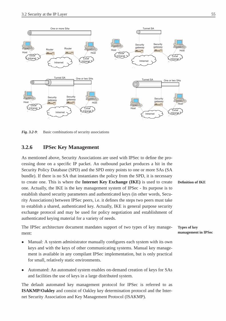
3.2 Security at the IP Layer 55
Fig. 3.2-9: Basic combinations of security associations
3.2.6 IPSec Key Management
As mentioned above, Security Associations are used with IPSec to define the pro-cessing done on a specific IP packet. An outbound packet produces a hit in theSecurity Policy Database (SPD) and the SPD entry points to one or more SAs (SAbundle). If there is no SA that instantiates the policy from the SPD, it is necessaryto create one. This is where theInternet Key Exchange (IKE) is used to create Definition of IKE
one. Actually, the IKE is the key management system of IPSec -Its purpose is toestablish shared security parameters and authenticated keys (in other words, Secu-rity Associations) between IPSec peers, i.e. it defines the steps two peers must taketo establish a shared, authenticated key. Actually, IKE is general purpose securityexchange protocol and may be used for policy negotiation andestablishment ofauthenticated keying material for a variety of needs.
The IPSec architecture document mandates support of two types of key manage- Types of keymanagement in IPSecment:
• Manual: A system administrator manually configures each system with its ownkeys and with the keys of other communicating systems. Manual key manage-ment is available in any compilant IPSec implementation, but is only practicalfor small, relatively static environments.
• Automated: An automated system enables on-demand creationof keys for SAsand facilities the use of keys in a large distributed system.
The default automated key management protocol for IPSec is referred to asISAKMP/Oakley and consist of Oakley key determination protocol and the Inter-net Security Association and Key Management Protocol (ISAKMP).

56 3 Internet Security Protocols
Oakley is a key exchange protocol based on the Diffie-Hellman algorithm whichprovides added security on it. It is a generic protocol in that it does not dictateFeatures of Oakley
specific formats. Oakley is designed to retain the advantages of Diffie- Hellman(secret keys are designed only when needed and there is no need to store secretkeys for a long period of time, exposing them to increased vulnerability and thekey exchange does not require any preexisting infrastructure) while countering itsweaknesses (does not provide any information about the identities of the parties,is subject to man-in-the-middle attack, and is computationally intensive). Oakleysupports the use of different groups for the Diffie-Hellman key exchange. The cur-rent specification includes the following groups: Modular exponentiation with 768-bit modulus and fixed parameters, modular exponentiation with 1024-bit modulusand fixed parameters, modular exponentiation with 1024-bitmodulus and variableparameters (to be determined), elliptic curve group over2155 with fixed parame-ters, and elliptic curve group over2185 with fixed parameters8. Oakly also employsmechanism which protects against replay-attacks and enables use of three differenttypes of authentication methods: digital signatures (the key exchange is authen-ticated with signing a mutually obtainable hash), public-key encryption (the keyexchange is authenticated by encrypting parameters), and symmetric-key encryp-tion. The Oakley specification includes a number of key exchanges that are allowa-ble under the protocol.
The Internet Security Association and Key Management Protocol(ISAKMP) defines procedures and packet formats to establish, negotiate, modify,Features of ISAKMP
and delete Security Associations. As a part of SA establishment, ISAKMP definespayload formats for exchanging key generation and authentication data. Thesepayload formats provide a consistent framework independent of the specific keyexchange protocol, encryption algorithm and authentication mechanism.
An ISAKMP message consists of an ISAKMPheader followed by one or moreISAKMP payloads. The ISAKMP header contains information about the type andthe length of the payload that follows. For ISAKMP, the following payload typesPayload types in an
ISAKMP message are defined:
• SA payload: Used to negotiate security attributes,
• Proposal payload: Indicates protocol to be used (ESP or AH) in this SA andnumber of transforms,
• Transform payload: Defines a security transform to be used tosecure the com-munication channel for the designed protocol (e.g 3DES, HMACSHA),
• Key exchange payload: Supports a variety of key exchange techniques,
• Identification payload: Used to exchange identification information,
• Certificate payload: Used to transport public-key certificates,
8 For more information see [KCL+00], chapter 4.

3.2 Security at the IP Layer 57
• Certificate request payload: Used from sender to request certificate of the othercommunicating entity,
• Hash payload: Contains data generated by a hash function over some part of themessage,
• Signature payload: Contains data generated by a digital signature function oversome part of the message,
• Nonce payload: Contains random data used to protect againstreplayattack,
• Notification payload: Used to transmit notification data, such as an error or statusinformation, and
• Delete payload: Indicates SAs that the sender has deleted fom its database andwhich are therefore no longer valid.
So, ISAKMP provides a framework for message exchange, with the payload typesmentioned aboved serving as building blocks. To resume, ISAKMP defines how twopeers communicate, how the messages they use to communicateare constructed,and also defines the state transitions they go through to secure their communication.
The IKE (which is actually a hybrid protocol of Oakley and ISAKMP) is envoked The IKE at work
by the kernel or by the policy management application or by another IKE peer toestablish keys. The IKE protocols are performed by each party that will be perfor-ming IPSec; the IKE peer is also IPSec peer. The protocol is ofrequest-responsetype with an initiator and a responder9. The initiator is the party that is instructedby IPSec to establish some SAs as a result of an outbound packet matching an SPDentry. It initiates the protocol to the responder.
Implementation of compliant IKE requires adherence to three documents: the baseISAKMP (specification (RFC 2408), the Domain of Interpretation for IPSec (RFC2407), and the IKE specification itself (RFC 2409).
Note that the key management mechanism is coupled to the authentication and pri-vacy mechanisms only by the way of Security Parameter Index.Hence, authentica-tion and privacy have been specified independent of any specific key managementsystem.
3.2.7 IPSec Policy
The IPSec policy determines the security services offered to a packet and the treat-Definition of policy
ment of the packet in the network. It is the security interface between the humanand the computer and therefore extremely important. The transition from humanto computer involves policy definition, policy representation, policy managementand the interactions between the policy and the various components of an IPSec
9 Since the protocol is pretty complicated, we are not going to discuss it here in detail. Formore information see [DH99].
58 3 Internet Security Protocols
system (IKE, SADB, SPD and IPSec process itself). Policy is not a standard. IETFdoes not mandate any particular representation of policy nor does it enforce anyparticular implementation - the policy issues are left to implementations.
IPSec allows very complex policy definitions. Because of itsnotions of selectors,the policy rules applied to inbound and outbound packets is very rich. Selectors canbe gross - an entire subnet - or fine - a specific port and protocol to a specific host.
There are several requirements imposed on any policy system. It must be possible toRequirements on apolicy system specify security policy for each individual host. The policy may reside on the host
or it may reside on the router or firewall in the network. The policy may specifyend-to-end security (policy between two hosts) or it may specify policy for this hostto another network. It also must be possible to specify security policy for an entirenetwork. The network policy may take the form of a network andsubnet, or the formof a range of adresses. Important is that a uniform security policy can be assignedto all entities of the network. It must also be possible to specify security policy tothe granularity of port, protocol and application. For example, it must be possible toprotect all telnet (tcp port 23) trafic destined for a particular subnet. Moreover, theremust be an ability to specify multiple protocols per flow. A flow is always identifiedby the tuple <src, dst, src port, dst port, protocol>. For each flow it must be possibleto specify the desired action:drop (reject the packets),protect (encrypt and/orauthenticate the packets), orpass(transmit the packets without any security action).It must be also possible to configure tunnels of more than one level deep (nestedtunnels). This is usually a result of combining various distinct policy requirementsinto a single unified network policy. Different IKE identities (IP adresses or domainnames) for access and authentication must also be supported. For example, a nodecan be configured to accept/reject connections by a particular user or by a set ofusers belonging to a particular domain. It must also be possible to define a policysuch that manually-keyed SAs are used instead of IKE in orderto protect certaintraffic (i.e. to disable the automated key management). Multiple security optionsmust be supported too. IKE provides the ability to offer multiple choices duringnegotiation so that the two peers can agree on something thatboth support. Forexample, host A may want to use ESP and 3DES with nodes that implement 3DES,but with nodes that do not support 3DES it may choose to communicate using DESinstead of dropping the connection.
Thepolicy representation is a database problem and involves two aspects:Policy representation
• The physical representation: It defines the format in which the policy is repre-sented, where it is stored, and how it is updated and modified.
• The interface: It defines how the various IPSec components acquire and managea policy.

3.2 Security at the IP Layer 59
The physical representation of a policy depends of the distribution mechanism.Because of its flexibility and generic design LDAP10 (Lightweight Directory AccessProtocol) has received the most attention as a mechanism to distribute policy. Thepolicy is stored centrally in a policy server, which is responsible for maintaining thepolicy for all nodes in the domain. The policy is either downloaded into the variousnodes of the network or is fetched dynamically by the nodes.
3.2.8 IPSec Implementation
IPSec may be implemented in end systems or in security gateways such as routersand firewalls. Typically this is done by directly modifying the IP stack. When accessto the IP stack of the machine is not possible, IPSec may be implemented as a shim Ways of
implementationthat extracts and inserts packets from the IP stack, called”Bump in the Stack”(BITS). IPSec can also be implemented as external, dedicated crypto device, gene-rally called”Bump in the Wire” (BITW) that may be independently addressable.
TableSADB&SPD EnginePoli y IPSe Manage-ment& SAPoli y databasePoli y IKE
Fig. 3.2-10: IPSec implementation architecture
Fig. 3.2-10 indicates the various components of IPSec and the interaction amongthem. We now briefly summarize the above discussed IPSec components: Interaction among the
IPSec components• IPSec base protocols: This componentt implement ESP and AH,which interact
closely with the network and the transport layer. In fact, IPSec base protocolis part of the network (IP) layer. ESP and AH process the headers, interact withSPD and SADB to determine the security that is offered to the packet, and hand-les network layer issues such as fragmentation.
• SPD: It is consulted for both outbound and inbound processing of the packet,because it determines the security afforded to the packet.
• SADB: Maintains the list of active SAs for outbound and inbound processing.The SADB is populated with SA either manually or via an authomatic key mana-gement system such as IKE. The choice of the data structure tostore SPD andSADB is very crucial to the performance of IPSec processing.This depends onthe performance requirements and the number of entries in SADB and SPD.
10 LDAP is an advantageous mechanism which provides a simplemethod of depositing andretrieving policy from a central repository. Describing LDAP in detail is out of the scope ofthis course.

60 3 Internet Security Protocols
• IKE: The Internet Key Exchange is envoked by the policy engine when thepolicy mandates an SA, or when SA(s) is to be established. IKEis also invo-ked by its peer when the node needs to communicate securely. It is responsiblefor dynamically populating the SADB and is in a quiescent state until its servicesare needed. It also provides an interface to the SPD to informit about establis-hing new SAs. It is normally a user-level process in the operating system.
• Policy and SA management: These are applications that manage the policy andSA. This module is implemented at the user level. The user interacts with thismodule for all policy-related processing. This module is responsible for adding,looking up and deleting policies and for manually adding, creating and deletingSAs.
3.2.9 IPSec Protocol Processing: An Example
The IPSec processing is broadly classified into outbound versus inbound proces-Classification of theIPSec processing sing, and AH versus ESP (and their variants) processing. Theinput (inbound) and
outgoing (outbound) packets of a node are differently processed. Moreover, thetransform and header processing is different between AH andESP. In the outboundprocessing a IPSec header is constructed and some operations (e.g. encryption) areperformed. Since in the inbound processing only the existing header is checked, it issimpler than the outbound processing. Before we sketch the inbound and outboundprcessing of packets on an exapmle, we summarize the functionalities of IPSec intransport and tunnel mode in Fig. 3.2-11.
Authenti ates IP payload but not IP header.headers following the ESP header.En rypts IP payload and any IPv6 extension En rypts inner IP pa ket.Authenti ates inner IP pa ket.ESP withauthenti ation headers following the ESP header.En rypts IP payload and any IPv6 extension.En rypts inner IP pa ket.ESP Authenti ates entire inner IP pa ket(inner header plus IP payload) plus sele tedportions of outer IP header and outer IPv6extension headers.Authenti ates IP payload and sele tedportions of IP header and IPv6 extensionheaders.AH Transport mode SA Tunnel mode SAFig. 3.2-11: Transport mode and tunnel mode functionality

3.2 Security at the IP Layer 61
Outbound Processing
To explain the outbound processing, we now consider the example shown inFig. 3.2-12. Suppose, we have an HTTP packet (TCP, port 80) generated by hostA and destined to hostB (a Web server) traversing routersRAandRB. The policyon A for packets destined to hostB mandates using AH in transport mode withHMAC-MD5. The policy on routerRA mandates that all packets destined to thenetwork 2.2.2/24 be encrypted with ESP using 3DES and tunneled toRB.
Fig. 3.2-12: Example of IPSec processing
In most TCP/IP implementations, the transport layer invokes the IP layer to senda packet by calling the function ip output. At the entry pointto the ip output, the Steps in the outbound
processingpolicy engine is consulted to determine the security services offered to a packet, soSPD processingis done at first. The input to the policy engine in our example willbe the touple <1.1.1.1, 2.2.2.2, TCP, 80>. The policy enginedetermines the securityservices and:
• Drops the packet, if the policy indicates that the packet hasto be dropped. Inthis case the ip output function is expected to discard the packet.
• Transmits the packet in clear text, if the policy indicates that this packet can betransmitted without any extra security processing.
• If the policy indicates that the packet needs security, the policy engine checks ifthe SAs are already established. If SAs are not already established, the securitypolicy notifies IKE to establish the required SA(s). The packet is queued untilthe SAs are established.

62 3 Internet Security Protocols
In our example the policy engine determines that the packet needs to be securedusing transport mode AH HMAC-MD5. It also determines that the SA is alreadyestablished, and hence does not invoke IKE to establish a newSA.
If SA is not established, thenIKE processing must be done to establish SAs.IKE requires special processing: It is a requirement that all implementations reco-gnize IKE packets and process them without securing them. This is possible as IKEalways uses a well-known port (500) and a well-known protocol (UDP).
The next step in the outbound packet processing is theSA processing. The particu-lar SA is fetched from the SA Database (SADB). In our example,the HMAC-MD5key for authentication is read from A’s outbound SADB. Afterthe SA processing,the protocol specific component is invoked : transport mode (for both AH and ESP)or tunnel mode (for both AH and ESP). So, at this place we have four possibilities:transport mode ESP processing, transport mode AH processing, tunnel mode ESPprocessing, and tunnel mode AH processing.
In our example, transport mode AH processing has to be done: The AH is construc-ted and appended to the packet, the HMAC-MD5 is computed and placed in the AHauthentication data field. Thetransport mode AH processingexpects part of theTransport mode AH
processing in host A IP header to be constructed before it calculates the hash (the AH header has to beinserted in the middle of a packet). The ideal place to perform AH processing isjust before the fragmentation check is performed. The rulesfor calculating the AHheader were described in Section 3.2.4.
The transport mode ESP involves encrypting the transport payload and calculatingthe hash. The transport mode ESP header is constructed before the IP header isadded to the payload. After the ESP transform is applied to the transport payloadand the ESP header is added, the ESP packet is forwarded to theIP layer for the IPprocessing.
The tunnel mode processinginvolves construction of an extra IP header. Tunnelscan be nested and can be of any depth as long as they are nested properly. If multipletunnels have to be constructed from the same node, multiple headers have to beprocessed. In our example, when router RA receives the packet, the output of thepolicy lookup in its SPD is a pointer to the Security proAssociation betweenRAandRB(SARA−>RB). TheSARA−>RB indicates that the packet should be protected bya tunnel mode ESP with 3DES. The source and destination fieldsin the SA recordTunnel mode ESP
processing in therouter RA
are the source and destination values in the outer IP header.The routerRAencryptsthe data payload, constructs a tunnel mode ESP header and forwards the packet tothe IP layer for IP processing. Tunnel mode processing on thehosts is different fromthat of the router because the host needs to add two IP headersand not one.
After IPSec processing, the packet is passed back to the IP layer. After the IP layeradds the IP header, the packet is forwarded to the data link layer (i.e. network accesslayer).

3.2 Security at the IP Layer 63
Inbound Processing
Because header checking is less complicated than header construction, the inboundprocessing is simpler than the outbound processing. Duringinbound processingthere is also no interaction with the key management system.The IP layer is invokedby layer 2 (see Fig. 3.2-1) to process the packet that was received over an interface.Most implementations have a function for each protocol thatthe IP layer can call toprocess the packet. The IP Layer strips the IP header and invokes the IPSec layerwith either an AH or ESP header at the beginning of the packet.
Let us consider the network from Fig. 3.2-12 again, this timefrom the perspectiveof inbound processing. In this figure, the SPD and SADB for thereceivers (routerRBand hostB) are also shown (note that the SPD entries are symmetric).
In our example,RB receives a tunneled packet fromRA. In the case of tunneling, Tunnel mode ESPprocessing in therouter RB
the IPSec layer has to perform an extra check to determine if the SA that was usedto process the packet was in fact established to process the packet from the actualsource. This is achieved by using the inner-header destination address for SPD loo-kup. Then IPSec invokes the upper layer to process the packet. In the case of tunne-led packets, the upper layer is the IP layer itself.RB receives a packet from source5.5.5.5 with tunneled ESP using 3DES using an SPI of value 11.The lookup inthe SADB yields an SA pointer. However, when the policy engine is envoked, thesource and the destination address will be that of the inner IP header. The values inthis case are 1.1.1.1 and 2.2.2.2. The lookup in the SPD matches the entry whose”from” and ”to” fields are network prefixes 2.2.2/24 and 1.1.1/24. They also indi-cate that the packet was tunneled by 5.5.5.5. As the securityservices afforded to thepacket match to that in the SPD, the tunnel is removed (the tunnel header is removedthe data is decrypted) and the packet is forwarded to the actual destination (hostB).
As the packet comes to hostB, the IPSec layer extracts the SPI from the AH orTransport mode AHprocessing in host BESP header (here 10), and the source and destination address(1.1.1.1 and 2.2.2.2)
and protocol from the IP header. The IPSec component then fetches the SA fromthe SADB using the destination (2.2.2.2), protocol (AH), and SPI (10), and thepacket is processed according to the rules defined in ESP and AH sections (if theSADB does not find the SA, an error is logged and the packet is dropped). Thepolicy corresponding to the packet is checked to determine if the IPSec processingis applied appropriately. In the example, the SPD has an entry that specifies that anypackets from 1.1.1.1 should have AH in transport mode using HMAC-MD5. Thepolicy engine checks if this is true. In this case, this is true, and hence the packet isaccepted. Then, the packet is authenticated and/or encrypted (in our example, it isonly authenticated, i.e.B computes HMAC-MD5 and compares it with the value inthe AH of the packet).
For non IPSec packets, the processing is limited to looking up into the SPD andconfirming that the packet can be admitted without any security.
Note that the throughputs of IPSec implementations usuallydecrease with the num-ber of SAs that are established and maintained simultaneously.
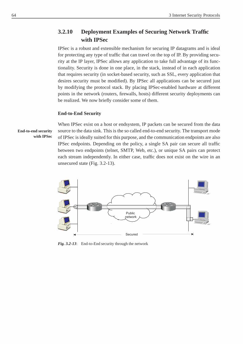
64 3 Internet Security Protocols
3.2.10 Deployment Examples of Securing Network Trafficwith IPSec
IPSec is a robust and extensible mechanism for securing IP datagrams and is idealfor protecting any type of traffic that can travel on the top ofIP. By providing secu-rity at the IP layer, IPSec allows any application to take full advantage of its func-tionality. Security is done in one place, in the stack, instead of in each applicationthat requires security (in socket-based security, such as SSL, every application thatdesires security must be modified). By IPSec all applications can be secured justby modifying the protocol stack. By placing IPSec-enabled hardware at differentpoints in the network (routers, firewalls, hosts) differentsecurity deployments canbe realized. We now briefly consider some of them.
End-to-End Security
When IPSec exist on a host or endsystem, IP packets can be secured from the datasource to the data sink. This is the so called end-to-end security. The transport modeEnd-to-end security
with IPSec of IPSec is ideally suited for this purpose, and the communication endpoints are alsoIPSec endpoints. Depending on the policy, a single SA pair can secure all trafficbetween two endpoints (telnet, SMTP, Web, etc.), or unique SA pairs can protecteach stream independently. In either case, traffic does not exist on the wire in anunsecured state (Fig. 3.2-13).
Fig. 3.2-13: End-to-End security through the network

3.2 Security at the IP Layer 65
Virtual Private Networks (VPNs)
A VPN can give a company the security it needs at a great savings in cost. It is VPNs with IPSec
not a physically distinct network (that’s why it is ”virtual”), and tunnels are usedto establish connectivity between disparate physical networks. A VPN is ”private”because tunnels are encrypted to provide confidentiality ina public network. InFig. 3.2-14, the local networks LAN1 and LAN 2 are securely connected over theInternet. VPNs are constructed by deploying IPSec on routers that provide the phy-sical network connection to a protected network. All trafficdestined for the VPNis through SAs on the router and to a snooper in the network it looks the same -it is just encrypted packets sourced by one router and destined to another router.Since VPN are protecting transient traffic (traffic sourced or destined for hosts on aprotected network), they must use IPSec in tunnel mode.
Fig. 3.2-14: A VPN across the Internet
Road Warriors
In end-to-end security, packets are encrypted and decrypted by the hosts that pro- Road warriors withIPSecduces and/or consumes the traffic. In a VPN, a router on the network encrypts and
decrypts packets on behalf of a host on a protected network. Acombination of thetwo is generally refered to as ”road warrior” configuration (Fig. 3.2-15). A road war-rior is typically an individual who requires access to a protected network but doesnot reside at a fixed location (e.g. a treveling employee who must securely accesscorporate resources from a hotel, airport dial-up or from any Internet POP availa-ble). In this scenario, the road warrior’s computer supports IPSec either natively,or by a bump-in-the-stack shim. He is able to secure outboundpackets before theyreach the wire and able to verify the security on inbound packets before they reachIP processing. The road warrior’s IPSec peer is a router thatprotects the network hewishes to access.

66 3 Internet Security Protocols
Fig. 3.2-15: Road warrior scenario
Nested Tunnels
Look at the following example: A corporation has a security gateway to protect itsNested tunnels withIPSec network from competitors and hackers, but inside the network, some sensitive infor-
mation (management information, acquisitions, personal data) has to be protectedfrom its own employees. In this case multiple levels of network security need to besupported and nested tunnels are necessary (Fig. 3.2-16). In this case, the packetsare secured two (or more times): once within the corporation, and then the outgoingtraffic from the corporation is secured at the exit router once more. The packets areencapsulated at each point that requires additional security, and each encapsulationis atomic.
Fig. 3.2-16: Nested tunnels
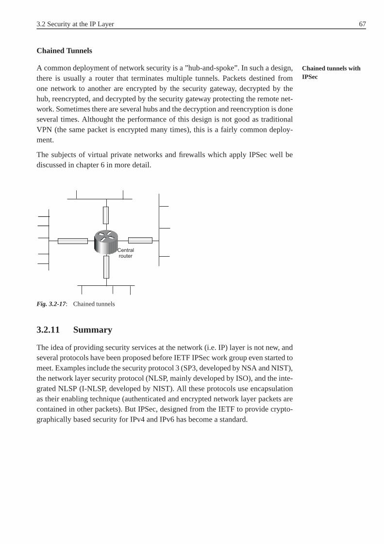
3.2 Security at the IP Layer 67
Chained Tunnels
A common deployment of network security is a ”hub-and-spoke”. In such a design, Chained tunnels withIPSecthere is usually a router that terminates multiple tunnels.Packets destined from
one network to another are encrypted by the security gateway, decrypted by thehub, reencrypted, and decrypted by the security gateway protecting the remote net-work. Sometimes there are several hubs and the decryption and reencryption is doneseveral times. Althought the performance of this design is not good as traditionalVPN (the same packet is encrypted many times), this is a fairly common deploy-ment.
The subjects of virtual private networks and firewalls whichapply IPSec well bediscussed in chapter 6 in more detail.
Fig. 3.2-17: Chained tunnels
3.2.11 Summary
The idea of providing security services at the network (i.e.IP) layer is not new, andseveral protocols have been proposed before IETF IPSec workgroup even started tomeet. Examples include the security protocol 3 (SP3, developed by NSA and NIST),the network layer security protocol (NLSP, mainly developed by ISO), and the inte-grated NLSP (I-NLSP, developed by NIST). All these protocols use encapsulationas their enabling technique (authenticated and encrypted network layer packets arecontained in other packets). But IPSec, designed from the IETF to provide crypto-graphically based security for IPv4 and IPv6 has become a standard.

68 3 Internet Security Protocols
The IP security architecture as described in this section isnot an overall securityarchitecture for the Internet. The topics of network address translation (NAT), sup-port for IP multicast, and issues related to interoperability must be included in fur-ther studies. At present, most IPSec implementations are either Bump in the Stack(BITS) or Bump in the Wire (BITW). This is expected to change in future, sincemore and more vendors of networking software are integrating the suite of IPSecprotocols into their products (including Cisco and Microsoft). Implementing theIPSec protocols is mandatory to IPv6 and therefore likely tobecome widespreadduring the next couple of years.
Exercise 3.2-1:
In discussing AH processing, it was mentioned that not all ofthe fields in an IPheader are included in the HMAC calculation. For each of the fields in IPv4 header,indicate whether the field is immutable, mutable but predictable, or mutable (zeroedprior to HMAC calculation). Justify your answer for each field!
Exercise 3.2-2:
1. Where may IPSec be implemented?
2. How can IPSec be implemented?
3.3 Security at the Transport Layer
In this section we focus on the security protocols that have been proposed andimplemented for the transport layer. The transport layer isresponsible for provi-ding services to the application layer. In the TCP/IP protocol suite the transportlayer provides the following services:
• Connection-oriented or connectionless transport,
• Reliable or unreliable transport,
• Security (this service is new in comparison with the other services offered bythe transport layer).
The TCP/IP protocol suite implements two protocols at the transport layer: TCPand UDP. The choice of using TCP or UDP is entirely up to the application - it hasto choose the services it requires from the transport layer.
3.3 Security at the Transport Layer 69
The idea of having a standardisedtransport layer security protocols is not new, Transport layersecurity protocolsand several protocols have been proposed before the IETF Transport Layer Security
Working Group (IETF TLS WG) started to meet. The NSA11 and NIST12 developedthe SP4 (Security Protocol 4) transport layer security protocol. The InternationalOrganisation for Standardisation (ISO) developed and standardised the TransportLayer Security Protocol (TLSP). In AT&T Bell Laboratories the Encrypted SessionManager (ESM) has been developed. We concentrate here on themost importantprotocols: Secure Shell (SSH, provides effective way to encrypt and authenticatenetwork log sessions), the Secure Socket Layer (SSL) and thefollow-on Internetstandard of SSL known as Transport Layer Security (TLS). Since SSL is widelyused and has become de-facto standard for protecting application’s data in transiton the Internet, it will be described here in more detail.
3.3.1 Secure Shell (SSH)
The Secure Shell (SSH) is a protocol and a software package that was originallydeveloped by Tatu Ylönen at the Helsinki University of Technology (the later foun- Development
der of SSH Communications Security). SSH was originally designed to replace theBerkeley r-tools such asrlogin (remote login),rsh (remote shell),rcp (remote filecopy), andrdist (remote file distribution). Applying SSL they are reffered to asslogin, ssh, scp, andsdist. It can also replace Telnet in many cases. As such, SSHprovides support for
• host and user authentication,
• data compression and
• data confidentiality and integrity protection.
There are currently two versions of SSH: a public and a commercial version. The Versions
public version13 has been freely available for various UNIX systems since 1995.The commercial version is called F-Secure SSH, is availablefor many operatingsystems and equipped with a number of additional features and utilities. F-SecureSSH is used and widely deployed on the Internet today.
SSH and F-Secure SSH both utilize a generic transport layer security protocol.When used over TCP/IP, the server normally listens for TCP/IP connections on port22, which has been registered for IANA14 and is oficially assigned for SSH. More
11 National Security Agency (in USA)
12 National Institute of Standards and Technology (in USA)
13 Source and documentation are publicly available and can be downloaded from the SSH home-page on the WWW: http://www.cs.hut.fi/ssh
14 The IANA (Internet Assigned Name Authority) is the overall authority for day-to-day admi-nistration of the Internet Domain Name System (DNS). IANA staff carry out administrativeresponsibilities for the assignment of IP Addresses, Autonomous System Numbers, Top LevelDomains (TLDs), ports, and other unique parameters of the DNS and its protocols.

70 3 Internet Security Protocols
recently, IETF has chartered Secure ShellWorking Group (secsh WG) to standardizeversion 2 of th SSH protocol15.
The SSH protocol consists of three major components: The SSLTransport LayerSubprotocols of SSH
Protocol provides server authentication, confidentiality, and integrity with perfectforward secrecy. The SSL User Authentication Protocol authenticates the clientto the server. The SSL Connection Protocol multiplexes the encrypted tunnel intoseveral logical channels. Each protocol is specified in an Internet Draft. Here, weonly consider the most important parts of this protocols.
SSH Transport Layer Protocol
The SSH Transport Layer Protocol provides cryptographic host authentication, dataconfidentiality and data integrity. The protocol does not provide user authentication(which is, as mentioned, provided by the SSH AuthenticationProtocol). The SSHTransport Layer Protocol supports various key exchange, encryption, and MACalgorithms that are negotiated during the connection establishement. Some algo-rithms are mandatory to implement (all implementations arerequired to supportthem), other algorithms are defined in the protocol specification but are optional.
When the SSH protocol is used to establish a TCP/IP connection between a clientand a server, the two parties first exchange identification strings that contain the SSLProtocol start
protocol and software version numbers in use. When a protocol execution starts, noencryption and message authentication are in use, but afteralgorithms negotiationand key exchange, compression, encryption and authentication are applied to allsubsequent messages.
Themessage flows on the SSH transport layer protocol executed between a client CMessage flow
and a server S is shown in Fig. 3.3-1 (simplified) and can be summarized as follows:
15 http://www.ietf.org/html.charters/secsh-charter.html

3.3 Security at the Transport Layer 71
Fig. 3.3-1: Simplified message flow in SSH transport protocol
The first phase after the protocol start is algorithm negotiation. The client sendsa Key Exchange Initialisation (SSH_msg_kexinit ) message to the server. Thismessage includes a list of supported data compression, encryption, MAC, and keyexchange algorithms. The first algorithm in each list is the prefered algorithm. Foreach algorithm type, the server selects the first algorithm of the client’s list, which it Algorithms negotiation
also supports. The list of its own algorithm preferences, the server sends to the clientwith the server Key Exchange Initialisation (SSH_msg_kexinit ) message. So,in this step, the client and the server agreed upon the algorithms they will use in thefollowing session. Currently, the following algorithms are defined in SSH:
• Data encryption algorithms: Triple DES in CPC mode (mandatory), IDEA inCBC mode, ARCFOUR stream cipher, Blowfish in CBC mode.
• Message authentication algorithms: HMAC-MD5, HMAC-SHA, SHA ofkey+data+key (mandatory), MD5-8 (first 8 bytes of MD5 of key+data+key),and SHA-8 (first 8 bytes of SHA5 of key+data+key).
After the kexinit packet exchange, thekey exchangealgorithm is run. The Key exchange
key exchange produces two values: a shared secretK and the exchange hashH.Encryption and authentication keys are derived from these.The server starts thekey exchange by sending anSSH_msg_kexrsa_hostkey message to the cli-ent, which include its public key. When the client receives this message, it firstverifies whether the server key belongs to the intended server. Then it genera-tes a 256-bit random secretK. In order to be sure that no one has manipula-ted the key exchange so far, the client computes a hash valueH from the con-

72 3 Internet Security Protocols
catenated payloads of the client and serverSSH_msg_kexinit messages, theserverSSH_msg_kexrsa_hostkey message, and the session key. This valueis called session identifier (session id ) and is used to to authenticate thekey exchange as a whole. Then the client concatenates six 0 bytes, the first10 bytes of the session identifier and the 32 bytes of the shared secretK, andencrypts the resulting 48 bytes with the server’s public key. The correspondingSSH_msg_kexrsa_sessionkey message is sent to the server. After receivingthis message, the server uses its private key to decrypt the secretK. As a result ofthe key exchange, the client and server share a 256 bit secretK that can now be usedto compute session keys16. The key exchange ends by each side by sending an SSHmsg newkeys message. All messages sent after this message must use the new keysand algorithms.
Either side may request akey reexchangeat any time after the initial key exchangeKey reexchange
by sending a newSSH_msg_kexinit message to the other. All keys and initiali-sation vectors are recomputed after the reexchange. The SSHprotocol specificationrecommends performing a key reexchange after each gigabyteof transfered data orafter one hour of connection time.
After the key exchange, the client requests a service (e.g. executing aService request
command on the server, file transfer). It does it by sending the messageSSH_service_request to the server. If the server supports the service and per-mits the client to use it, it responds with a correspondingSSH_service_accept
message. Each service is identified by a unique service name.The client must waitfor response to its service request message before sending any further data.
Once a particular service has been selected, data are transmitted withData transmission
SSH_stream_data messages. The data fields of the message are encryptedwith the selected algorithm and key. The message also contains the MAC of thedata computed with the selected MAC algorithm and key. The encryption stepsin each direction (client->server or server->client) run independently and theytypically use different keys. Different encryption algorithms may also be usedin each direction. Note that Triple DES is the only encryption algorithm that ismandatory for SSH 2.0. The MAC is computed over the actual content of themessage and a 32-bit sequence number (The sequence number ofthe first messageis set to zero; then it is incremented by one for each packet sent.). The MAC is
16 The session keys are computed as follows:
• - encryption key client to server:Hash(K||H ||′′C′′||session_id)
• - encryption key server to client:Hash(K||H ||′′D′′||session_id)
• - MAC key client to server:Hash(K||H ||′′E′′||session_id)
• - MAC key server to client:Hash(K||H ||′′F ′′||session_id)
The letters "A", "B", "C" and "D" are encoded as ASCII characters. Key data must be takenfrom the beginning of the hash output.

3.3 Security at the Transport Layer 73
transmitted without encryption as the last part of the SSH message. The appliedMAC algorithms and keys can also be different for each direction.
When the server or client application closes its output, aSSH_stream_eof mes- Closing the connection
sage is sent to the other side. When either side wants to terminate the communica-tion, it sends aSSH_stream_close message. The session ends by sending backa SSH_stream_close message from the other side.
Either party may send disconnect, ignore, debug or other reserved messages at anytime.
SSH Authentication Protocol
The purpose of SSH authentication protocol is to perform client user authentica- Purpose
tion. It runs on top of the SSH transport layer protocol, which has already authen-ticated the server machine, established an encrypted communication channel, andcomputed a unique session identifier for this session. The SSH authentication pro-tocol provides a single authenticated tunnel for the SSH connection protocol.
When a client declares its user name and the service name it wants to use, userauthentication is required. The server drives the authentication by telling the cli- Protocol
ent which authentication methods can be used. The client hasthe freedom to trythe methods listed by the server in any order. The server should have a timeout forauthentication, and disconnect if the authentication has not been accepted withinthis period. Additionaly, the implementation should limitthe number of failedauthentication attempts. The dialogue continues untill access has been granted ordenied.
Several user authentication methods are predefined in the SSH protocol specifi-cation. This include password authentication, SecurID authentication, S/Key and Supported user
authenticationmethods
OPIE one-time password authentication, authentication with public key, host-basedor Kerberos authentication. Additional authentication methods can also be defined.
In the case of the password method, the authenticating informtion is basically a userpassword. The password is sent in clear text, but the entire SSH message (includingthe password) is encrypted by the SSH transport layer protocol. Most one-time pass-word methods use a challenge-response authentication: a server sends a challenge tothe client and the client returns an appropriate response17. The public key and hostbased authentication methods work by having the client senda signature with a pri-vate key. In the several possible variants of Kerberos authentication, the messagestypically include some sort of user credentials or tickets.
SSH Connection Protocol
All terminal sessions, forwarded connections, etc. are channels. Either side may Channel mechanism
17 For more information see [KCL+00].

74 3 Internet Security Protocols
open a channel. Multiple channels are multiplexed into a single connection. Chan-nels are identified by numbers at each end. The number referring to a channel maybe different on each side. Requests to open a channel containthe sender’s channelnumber. Any other channel-related messages contain the recipient’s channel num-ber for the channel.
The SSH Connection Protocol provides interactive login sessions, remote execu-Purpose
tion of commands, forwarded TCP/IP connections, and forwarded X11 connecti-ons. All of thesechannels are multiplexed into a single encrypted tunnel. TheSSH Connection Protocol has been designed to run on top of theSSH transportlayer and user authentication protocols. Here we will not address the SSL Connec-tion Protocol in detail. The interested reader can find more information in the SSHspecification.
Summary
The Secure Shell protocol is the de-facto standard for encrypted and authenticatedremote terminal connectionsand secure file transfers on the Internet. It is a fullreplacement for telnet, rlogin, rsh, rcp, and ftp.
This protocol ia designed to be used over a reliable transport. If transmission errorsor message manipulations occur, the connection is closed. Disadvantge of SSH isthat it uses manually distributed and preconfigured public keys instead of certificate-based key management. This is notably the major disadvantage of SSH comparedto SSL and TLS protocols.
Exercise 3.3-1:
Answerbriefly the following questions:
1. What is F-Secure SSH?
2. On which port listen server applications using SSH?
3. Which are the main components (subprotocols) of the SSH protocol?
4. What is the goal of the SSH transport layer protocol?
5. Which data encryption algorithms can be used in SSH?
6. The SSH protocol specification recommends performing a key reexchangeafter each gigabyte transfered data or after one hour of connection time. Whydoes this key reexchange make sense?
7. Can the SSH protected data in a connection be differently encrypted and/orauthenticated in each direction?

3.3 Security at the Transport Layer 75
3.3.2 Secure Socket Layer (SSL)
The application layer defines the interface to the transportlayer, which is operatingsystem dependent. The most popular interface is thesocket interface. The socketinterface is provided in all flavours of the UNIX operating system and on the Micro-soft platforms. The SSL protocol is based on the concept of socket.
Netscape Communications introduced the SSL method and a corresponding pro- Development
tocol with the first version of Netscape Navigator. NetscapeCommunications didnot charge its customers for the implementation of its security protocol and con-sequently, SSL became after 1994 the predominant protocol to provide securityservices on the transport layer. There have been three versions of SSL: The firstversion, SSL 1.0, contained some serious flaws and was never released to public.The second version, SSL 2.0, was incorporated into NetscapeNavigator versions 1.0through 2.x. and it had some security weaknesses, to which Netscape answered withthe version SS v3.0, which also added some new features. The latest specification ofSSL 3.0 was oficially released in March 1996. It is implemented in both NetscapeNavigator 3.0 (and higher) and Microsoft Internet Explorer18 3.0 and higher. SSLhas become a de facto standard for cryptographic protectionof HTTP traffic.
The primary goal of the SSL Protocol is to provide cryptographic security betweentwo communicating applications. A second goal of SSL is extensibility: It provides Goals of SSL
the framework into which new public key and bulk encryption methods can be incor-porated as necessary. SSL also tends to achieve interoperability between differentindependent applications which use SSL and relative efficiency of the cryptographicoperation. It providesconnection securitywith the following properties:
• The connection is private. In the initial handshake protocol secret keys are defi-ned, then symmetric cryptography is used for data encryption.
• The peer’s identity can be authenticated using asymmetric cryptography.
• The connection is reliable. Message transport includes a message integrity checkusing a keyed MAC.
In order to make use of SSL, the client and server must both know that the otherside is using SSL. One (and the common) possibility to do thisis to use dedicatedport numbers reserved by the IANA. In this case, a separate port number must beassigned for every application protocol with SSL support. For example, https (httpover SSL/TLS) uses port 443, ftps (ftp over SSL/TLS) uses port 990, telnets (telnetover SSL/TLS) uses port 992, smtps19 (smtp over SSL/TLS) uses port 465, and so
18 Microsoft has attempted to leverage public uncertainityabout SSL’s security and introdu-ced the competingPrivate Communicating Technology (PCT) protocol in its firstrelease of Internet Explorer 1996. But after the release of SSL 3.0 Microsoft backed downand agreed to support SSL in all versions of its TCP/IP-basedsoftware.
19 The ”s” on the end of the protocol name indicates that the SSL is consistentely used forsecuring the protocol.

76 3 Internet Security Protocols
on. Another possibility is to use the normal port number for every application andto negotiate security options as part of the modified application protocol.
The following description of SSL is based on the latest protocol specification ofSSL 3.0.
SSL Architecture
SSL is designed to make use of TCP to provide a reliable end-to-end secure service.It operates on the top of the transport layer, i.e. between the transport and the appli-SSL in the TCP/IP
stack cation layer, as shown in Fig. 3.3-2. Thus, it can protect theapplication data and theheader from the application layer, but the control data fromthe lower layers (trans-port layer header, IP layer header and network access layer header) are transmittedunprotected (Fig. 3.3-3). The SSL protocol provides security services to varioushigher layer protocols. For example, the hypertext transfer protocol (HTTP), whichprovides the transfer service for Web client-server interaction, can operate on top ofSSL.
Fig. 3.3-2: SSL in TCP/IP stack
Fig. 3.3-3: SSL packet format
It is important to note that the SSL protocol does not protectagainst traffic analysisattacks. For example, by examinning the unencrypted IP source and destinationadresses and the TCP port numbers, or examining the volume ofnetwork trafficflow, a traffic analyst can eventually determine what partiesare interacting, whattypes of services are being used, or sometimes recover information about businessor personal relationships.

3.3 Security at the Transport Layer 77
SSL is not a single protocol but rather two layers of protocols, as illustrated inFig. 3.3-4. In the higher layer of SSL operate three protocols: the Handshake Proto-Layers of SSL
col, the Change Cipher Spec Protocol, and the Alert Protocol. These SSL-specificprotocols deal with the SSL management and will be explainedlater. In the lowerlayer of SSL operates the SSL Record Protocol which in fact provides the securityservices (encryption and authentication of data).
Fig. 3.3-4: SSL architecture
Two important SSL concepts are theSSL connection and SSL session. A connec- SSL connection andSSL sessiontion is a transport that provides a suitable type of service. For SSL such connections
are peer-to-peer relationships, they are transient and every connection is associatedwith one session. AnSSL sessionis an association between a client and a server.Sessions are created by the Handshake Protocol and they define a set of cryptogra-phic security parameters (algorithms, keys) which can be shared among multipleconnections. Sessions are used to avoid the expensive negotiation of new securityparameters for each connection. There are a number ofstatesassociated with eachsession. Logically the state is represented twice, once as the currentoperating state,and (during the handshake protocol) again as thepending state. Once a session isestablished, there is a current operating state for both read and write (i.e. receive andsend). Actually, during the Handshake Protocol pending read and write states arecreated which become current states after the successful conclusion of the Hands-hake Protocol.
A session stateis defined with the following parameters: session identifier, peer Session state
certificate, compression method, cipher spec, master secret, and the "is resumable"field. The significance of these parameters is explained in Fig. 3.3-5.
Fig. 3.3-5: SSL session state
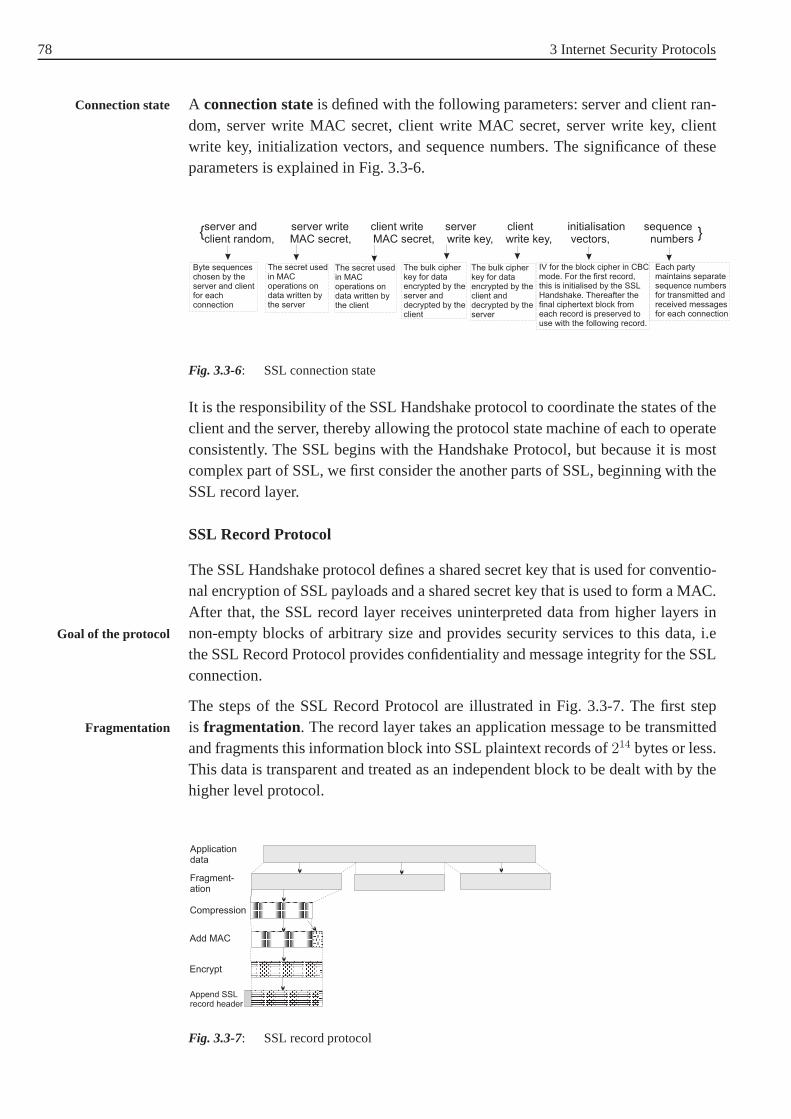
78 3 Internet Security Protocols
A connection stateis defined with the following parameters: server and client ran-Connection state
dom, server write MAC secret, client write MAC secret, server write key, clientwrite key, initialization vectors, and sequence numbers. The significance of theseparameters is explained in Fig. 3.3-6.
Fig. 3.3-6: SSL connection state
It is the responsibility of the SSL Handshake protocol to coordinate the states of theclient and the server, thereby allowing the protocol state machine of each to operateconsistently. The SSL begins with the Handshake Protocol, but because it is mostcomplex part of SSL, we first consider the another parts of SSL, beginning with theSSL record layer.
SSL Record Protocol
The SSL Handshake protocol defines a shared secret key that isused for conventio-nal encryption of SSL payloads and a shared secret key that isused to form a MAC.After that, the SSL record layer receives uninterpreted data from higher layers innon-empty blocks of arbitrary size and provides security services to this data, i.eGoal of the protocol
the SSL Record Protocol provides confidentiality and message integrity for the SSLconnection.
The steps of the SSL Record Protocol are illustrated in Fig. 3.3-7. The first stepis fragmentation. The record layer takes an application message to be transmittedFragmentation
and fragments this information block into SSL plaintext records of214 bytes or less.This data is transparent and treated as an independent blockto be dealt with by thehigher level protocol.
Fig. 3.3-7: SSL record protocol

3.3 Security at the Transport Layer 79
Next,compressionis optionally applied. All records are compressed using thecom- Compression
pression algorithm defined in the current session state. Thecompression algorithmtranslates an SSL Plaintext structure into an SSL compressed structure. The nextstep in processing is to compute aMessage Authentication Code(MAC) over the Message
Authenticationcompressed data. The MAC algorithm to be used is defined in thecurrent Cipher-Spec (keyed MD5 or keyed SHA-1) and the shared secret key has been assigned inthe Handshake Protocol.
After the MAC computation, the compressed message plus the MAC areencryptedusing symmetriciptables. Just as in the case of MAC, the encryption algorithm toEncryption
be used is defined in the current CipherSpec and the shared secret key has to beagreed in the Handshake Protocol. The following block encryption algorithms arepermitted: IDEA (128 bit key), RC2-40 (40 bit key), DES-40 (40 bit key), DES(56 bit key), 3DES (168 bit key), and Fortezza (80 bit key). Moreover, the streamciphers RC4-40 (40 bit key) and RC4-128 (128 bit key) can be used. For the CBCmode, the initialisation vector (IV) for the first record is provided by the handshakeprotocol. The IV for subsequent records is the last ciphertext block from the pre-vious record. Note that the MAC is computed before encryption. The encryptionand MAC functions translate an SSL Compressed structure into an SSL Ciphertext.
The final step of SSL Record Protocol processing is toprepend a header. It SSL record header
consist of four fields: Content Type (8 bits), Major Version (8 bits), Minor Ver-sion (8 bits) and Compressed Length (16 bits). The Content Type field indica-tes the higher-layer protocol used to process the enclosed fragment, i.e. it canbechange_cipher_spec , alert , handshake , andapplication_data
(see Fig. 3.3-8). Note that no distinction is made among various applications thatmight use SSL (e.g. HTTP or FTP). The fields Major Version and Minor Versionindicate the major resp. the minor version of SSL used. For example, for SSLv3, theMajor Version value is 3 and the Minor is 0. The field Compressed Length contentsthe length in bytes of the plaintext fragment, or compressedfragment (if compres-sion is used).
Fig. 3.3-8: SSL record format

80 3 Internet Security Protocols
At the receiving site, the operations in the SSL Record Layerare performed viceversa: first the SSL record layer header is removed, then the record is decrypted, theMAC is verified and the data is decompressed.
Change Cipher Spec Protocol
The Change Cipher Spec Protocol is one of the three SSL specific protocols that usethe SSL Record Protocol (see Fig. 3.3-4), and it is the simplest. It signals transitionsin ciphering strategies. The protocol consists of a single message, which consistsof a single byte with value 1 (see Fig. 3.3-8). This message issent by both clientand server to notify the receiving party that subsequent records will be protectedGoal of the protocol
under the just-negotiated CipherSpec and keys. Reception of this message causesthe receiver to copy the read pending state into the read current state, i.e. the purposeof this message is to cause the pending state to be copied intothe current state, whichupdates the cipher suite to be used in the connection. ChangeCipher Spec Messagesare sent during the Handshake Protocol following the handshake key exchange andcertificate verify messages (see Fig. 3.3-9 and Fig. 3.3-10).
Alert Protocol
One of the four content types supported by the SSL record layer is the alert type.The Alert Protocol is used to convey SSL-related alerts to the peer entity. Alert mes-Goal of the protocol
sages convey the severity of the message and a description ofthe termination of thecommunication. In this case, other connections corresponding to the session maycontinue, but the session identifier must be invalidated, preventing the failed sessionfrom being used to establish new connections. Like other messages, alert messagesare encrypted and compressed, as specified by the current connection state.
Two important types of alerts are closure and error alerts. The client and the serverClosure and erroralerts must share knowledge that the connection is ending and either party may initiate
the exchange of closing messages, i.e. closure alerts. The error alerts signalise theoccurance of an error. Error handling is in the SSL handshakeprotocol very simple.When an error is detected, the detecting party sends a message to the other party.Upon transmission or receipt of a fatal alert message, both parties immediately closethe connection. Servers and clients are required to forget any session-identifiers,keys, and secrets associated with the failed connection.
Each message in the alert protocol consists of two bytes (Fig. 3.3-8). TheAlert protocol message
first byte takes the value warning (1) or fatal (2). The secondbyte con-tains a code that indicates the specific alert. Examples of defined error alertsin SSL are: unexpected_message (an inappropriate mesage was recei-ved), bad_record_mac (a record is received with an incorrect MAC),decompression_failure (unable to decompress),handshake_failure
(the sender was unable to negotiate an acceptable set of security parameters),no_certificate , bad_certificate , unsupported_certificate ,certificate_revoked , certificate_expired , certificate_un -known andillegal_parameter .

3.3 Security at the Transport Layer 81
Handshake Protocol
The cryptographic parameters of the session state are negotiated by the SSL Hands- Goal of the protocol
hake Protocol, which operates on top of the SSL record layer.The handshake isperformed before any application data is transmitted. Whenan SSL client and ser-ver first start communicating, they agree on a protocol version, select cryptographicalgorithms, optionally authenticate each other, and use public-key encryption tech-niques to generate shared secrets. These processes are performed in the HandshakeProtocol, which we explain in the following.
The Handshake Protocol consists of a series of messages exchanged by clientand server. Each message consist of three fields: Type, Length, and Content (see Handshake Protocol
messageFig. 3.3-8). The fieldType is one byte and indicates one of 10 message types in theprotocol. They arehello_request , client_hello , server_hello ,certificate , server_key_exchange , certificate_request ,server_done , certificate_verify , client_key_exchange andfinished . The field Length (3 bytes) indicates the length of the message inbytes. The fieldContent (≥ 1 byte) comprises the parameters associated with thismessage.
The handshake protocol can be viewed as having four phases. In thefirst phase First phase of thehandshakesecurity capabilities are established. The phase is initiated by the client and is
used to initiate a logical connection by exchanging aHello messages between theclient and the server.
When a client first connects to a server it is required to send theClient Hello
as its first message (see Fig. 3.3-9). The client can also senda Client Hello inresponse to aHello Request message that comes from the server or on its owninitiative in order to renegotiate the security parametersin an existing connection.The Client Hello message is sent with the following parameter:Version
(the highest SSL version understood by the client,Session ID (session iden-tifier defined by the server and used to identify a session between client and ser-ver),Random Structure (28 random bytes generated by a secure random num-ber generator and used later in the protocol),Cipher Suite 20 (list which con-tains the combinations of cryptographic algorithms supported by the client), andCompression Method (a list of compression algorithms supported by the cli-ent; if the server supports none of those specified by the client, the session mustfail).
20 Each Cipher Suite defines both a key exchange algorithm anda CipherSpec. The first elementof the Cipher Suite is the key exchange method and the second is CipherSpec. The followingkey exchange methods are supported: RSA, authenticated Diffie-Hellman, anonymous Diffie-Hellman, and Fortezza. The CipherSpec includes the following fields: cipher algorithm (RC4,RC2, DES, 3DES, DES40, IDEA, Fortezza), MAC algorithm (MD5 or SHA-1), cipher type(stream or block), hash size (0, 16 or 20 bytes), key material(a sequence of bytes that containdata used in generating the keys), and IV size (size of the initialisation vector for CBC mode).

82 3 Internet Security Protocols
Fig. 3.3-9: SSL handshake protocol
The server processes theClient Hello message and responds with either aHandshake Failure (fatal error will occur and the connection will fail) ora Server Hello message. TheServer Hello message contains the sameparameters as theClient Hello message:Version , Random, Session ID ,Cipher Suite , and Compression Method . The Version field containsthe lowest of the version suggested by the client and the highest supported by theserver, and theRandomfield is generated by the server. If the server is willing toestablish the new connection using the specified session state, it will respond withthe same value of session identifier supplied by the client. The Cipher Suite
parameter contains a single cipher suite selected by the server from the list ofcipher suites proposed by the client (if no acceptable choices are presented, theserver returns aHandshake Failure alert and closes the connection). TheCompression Method is selected by the server from the list of compressionalgorithms in theClient Hello message.
So, theClient Hello and Server Hello messages are used to establishsecurity enhancement capabilities between client and server, i.e. the protocol ver-sion, session ID, cipher suite, and compression method are established.
The second phaseof the handshake protocol is theAuthentication and KeySecond phase of thehandshake Exchange. If the server is to be authenticated (which is generally thecase), it sends
its certificate in aCertificate message immediately following theServer
Hello message. The certificate type must be appropriate for the selected ciphersuite’s key exchange algorithm, and is generally an X.509.v3 certificate.

3.3 Security at the Transport Layer 83
If the server has no certificate, or has certificate only used for signing (e.g. DSScertificates, signing only RSA certificates), or Fortezza/DMS key exchange is used,the server sends theServer Key Exchange message. With this message, theserver informs the client about its public key parameters i.e. the message containsthe parameters used for RSA key exchange (RSA modulus and thepublic exponentof the server’s temporary RSA key), the parameters used for Diffie-Hellman keyexchange (prime modulusp, generatorg, and the server’s public valuegx mod p),or the parameters for the Fortezza key exchange algorithm.
When the server is authenticated, it may request a certificate from the client if thatis appropriate to the cipher suite selected, and send theCertificate Request
message. This message contains the types of certificates requested and a list ofnames of acceptable certificate authorities. It is a fatal handshake failure alert foranonymous server to request client identification.
The final message in phase 2, and the one that is always required, is theServer
Hello Done message sent by the server. This indicates that theServer Hello
and associated messages phase of the handshake is complete.The server will thenwait for a client response - the client should verify that theserver provided a validcertificate (if required) and that theServer Hello parameters are acceptable.
Thethird phase of the Handshake is theclient authentication and key exchange. Third phase of thehandshakeUpon receipt ofServer Hello Done message, the client should verify that the
server provided a valid certificate if required and check that theServer Hello
parameters are acceptable. If all is satisfactory, the client sends one or more mes-sages back to the server. If the server has sent aCertificate Request mes-sage, the first message the client sends is itsCertificate message (or aNo
Certificate alert, if no suitable certificate is available). This message is thesame type as the server’sCertificate message.
Next is theClient Key Exchange message, and the content of this messagedepends on the type of key exchange selected between theClient Hello and theServer Hello 21. Finally, in this phase, the client may send aCertificate
Verify message to provide explicit verification of the client certificate (if the cli-ent has sent a certificate). This message signs a hash code based on the preceedingmessages in the handshake.
21 If RSA is being used for key agreement and authentication,the client generates a 48-byte pre-master secret, encrypts it under the public key from the server’s certificate or temporary RSAkey from the Server Key Exchange message, and sends the result in an Encrypted PremasterSecret message. This random value (pre-master-secret) is generated by the client and is usedto generate the master secret. If Fortezza key exchange is being used, the client derives aToken Encryption Key (TEK) using the Fortezza algorithm. This calculation uses the publickey in the servers certificate along with private parametersin the clients token. The clientsends public parameters needed for the server to generate the TEK and generates sessionkeys, wraps them using the TEK and sends the result to the server. If the Diffie-Hellman keyexchange algorithm is being used, the Client Key Exchange message conveys the client’sDiffie-Hellman public value, if it was not already included in the client’s certificate.

84 3 Internet Security Protocols
Thefourth phase, i.e. thefinish phasecompletes the setting up of a secure connec-Fourth phase of thehandshake tion. The client sends aChange Cipher Spec message and copies the pen-
ding Cipher Spec into the currentCipher Spec . Note that this message isnot considered part of the Handshake Protocol but is sent using the Change CipherSpec Protocol. The client then immediately sends theFinished message to verifythat the key exchange and authentication process were successful. This is the firstmessage protected with the negotiated algorithms and keys.This message inclu-des hash values of all handshake messages starting atClient Hello up to theFinished message.
In response of these two messages, the server sends its ownChange Cipher
Spec message, transfers the pending to the currentCipher Spec , and then sendsits ownFinished message under the new Cipher Spec. Recipients ofFinished
message must verify that the contents are correct. No acknowledgement of theFinished message is required.
At this point, the handshake is complete and the client and server may begin toEnd of the handshake
exchange application layer data. The application data messages are carried by therecord layer and are fragmented, compressed and encrypted based on the currentconnection state. The handshake protocol messages are presented in the order theymust be sent; sending handshake messages in an unexpected order results in a fatalerror.
Fig. 3.3-10: SSL handshake protocol when resuming or duplicating the previous session
When the client and server decide toresume a previous session or duplicate anResuming a privious ordublicating an existing
sessionexisting session(instead of negotiating new security parameters) the message flowis as follows (Fig. 3.3-10). The client sends aClient Hello message using thesession ID of the session to be resumed. The server then checks its session cache fora match. If a match is found, and the server is willing to reestablish the connectionunder the specified session state, it will send aServer Hello with the same Ses-sion ID value. At this point, both client and server must sendChange Cipher
Spec messages and proceed directly to finished messages. Once thereestablish-ment is complete, the client and server may begin to exchangeapplication layer

3.3 Security at the Transport Layer 85
data. If a Session ID match is not found, the server generatesa new session ID andthe SSL client and server perform a full handshake.
SSL Implementation
With version 3.0, SSL has become a fairly sophisticated protocol. It provides itssecurity services without requiring users to manipulate cryptographic keys perso-nally. For example, if a hypertext link in a page specifies ”https”, then the browserwould automatically try to use SSL without requiring extra work by the user. Inthe recent past, many Web servers and browsers have been modified to make useof SSL. There are several commercial Web servers available that support SSL (andTLS). On the client side, most browsers (e.g. Netscape Navigator, Internet Explorer)provide support for SSL. The three major implementations ofSSL (SSLref, SSLeay,and SSL Plus) will be briefly discussed below. In addition, there is an increasinglylarge number of SSL implementations based on the Java programming language.
Netscape has developed an SSL reference implementation of the Version 3.0 specifi-cation calledSSLref. The implementation was written in C programming languageSSLref
and published in 1995. The SSLref source code is distributedfreely for noncom-mercial use. Parties interested in using SSLref in a commercial product require alicence from Netscape Communications. Some of algorithms used by SSL (RC2,RC4, RSA) must be licenced.SSLeayis an independent implementation of SSL,SSLeay
developed by Eric Young in Australia. SSLeay implements both SSL 2.0 and SSL3.0 and TLS 1.0. The software is publicly and freely available around the worldon a number of anonymous FTP sites. Since SSLeay was entirelydeveloped out-side the USA, its distribution is not restricted by U.S. export controls. TheSSL Plus SSL Plus
Security Toolkit developed by Consensus Development Corporation is currently theleading commercial implementation of SSL 3.0. It is licenced and used by severalleading companies to deploy security using public key cryptography and digital cer-tificates for their applications.
For obvious reasons, the use of SSL slows down the speed of a browser interac-ting with an HTTPS server. To minimize the performance degradation and impactof SSL, some organisations transmit the bulk of their data inclear text, and useSSL only for encrypting sensitive data. Unfortunately, this leaves the user open tospecific attacks.
Exercise 3.3-2:
Answerbriefly the following questions:
1. On which port listen server applications using SSL?
2. Which are the main components (subprotocols) of the SSL protocol?

86 3 Internet Security Protocols
3.3.3 Transport Layer Security (TLS)
TLS is an IETF standardisation initiative whose goal is to produce an Internet stan-dard version of SSL. The IETF Transport Layer Security Work Group (TLS WG)IETF TLS WG
was founded in April 1996 with the goal to write Internet standard track RFCs fora TLS protocol using the currently available specificationsof SSL (2.0 and 3.0),PCT (1.0) and SSH (2.0) as basis. In December 1996, a first TLS 1.0 documentwas released as an Internet Draft (RFC 2246) and this specification of TLS 1.0 isconceptually similar to SSL 3.0.
The goals of TLS Protocol, in order of their priority, are:Goals of TLS protocol
1. Cryptographic security: TLS should be used to establish a secure connec-tion between two parties.
2. Interoperability : Independent programmers should be able to develop appli-cations utilizing TLS that will then be able to successfullyexchange crypto-graphic parameters without knowledge of one another’s code.
3. Extensibility : TLS seeks to provide a framework into which new public keyand bulk encryption methods can be incorporated as it is necessary. This willalso accomplish two sub-goals: to prevent the need to createa new protocol(and risking the introduction of possible new weaknesses) and to avoid theneed to implement an entire new security library.
4. Relative efficiency: Cryptographic operations tend to be highly CPU inten-sive, particularly public key operations. For this reason,the TLS protocol hasincorporated an optional session caching scheme to reduce the number ofconnections that need to be established from scratch. Additionally, care hasbeen taken to reduce network activity.
Similar to SSL, the TLS protocol is a layered protocol. On thelower layer, theTLSTLS record protocol
record protocol takes messages to be transmitted, fragments the data into mana-geable blocks, optionally compresses them, computes and appends a MAC to eachblock, encrypts the result and transmits it. On the receiverside, a received TLSciphertext record is decrypted, verified, decompressed, and reassembled, before itis delivered to a higher level client. A TLS connection stateis the operating envi-ronment of the TLS record protocol. It specifies compression, encryption, and MACalgorithms, and determines parameters for these algorithms (encryption and MACkeys, initialisation vectors). The TLS record format is thesame as that of SSL recordformat (Fig. 3.3-8), and the fields in the header have the samemeanings. The onlydifferences are in the version values.
On the higher layer, several TLS subprotocols operate: TLS Handshake Protocol,TLS Change Cipher Spec Protocol, and TLS Alert Protocol. These protocols aresimilar to the corresponding SSL protocols. TheTLS Handshake Protocolis usedTLS Handshake
Protocol to negotiate a session state that consists of a session identifier, a peer certificate,a compression method, a cipher spec, a master key and a flag whether the sessionis resumable and can be used to initiate new connections. These items are used

3.3 Security at the Transport Layer 87
to create security parameters for use by the TLS record protocol when protectingapplication data. The corresponding message flow in the TLS Handshake Protocolis essentially the same as the message of the SSL handshake protocol discussedpreviously.
TheTLS Change Cipher Spec Protocolconsists of a single Change Cipher SpecTLS Change CipherSpec Protocolmessage that is sent by the client and server during the handshake. TheTLS alertTLS alert protocolprotocol is used to send alert messages that convey the severity of a message
and description of the alert. Like other messages, alert messages are compressed,authenticated, and encrypted as specified by the current connection state.
The differences between TLS 1.0 and SSL 3.0 are not huge,but they are significant Differences betweenTLS and SSLenough that TLS 1.0 and SSL 3.0 do not easily interoperate. Nevetheless, TLS 1.0
does incorporate a mechanism by which a TLS implementation can back down toSSL 3.0.
The three major modifications suggested to SSL 3.0 to be incorporated into TLS 1.0are:
• The HMAC construction developed in the IETF IPSec WG should be adoptedand used in TLS 1.0.
• The Fortezza key exchange algorithm should be removed from TLS 1.0 since itrefers to a proprietary and unpublishad technology.
• In comparison to SSL, TLS introduced more separation and a formal interfacebetween the handshaking process and the record layer. The idea is to make theseto related but separate standards.
There are two differences between SSL 3.0 and TLS MAC schemes: the actualalgorithm and the scope of the MAC calculation. TLS makes useof the HMACalgorithm. Recall that HMAC of messageM, based on hash algorithmH and usingkey K is defined as:
HMAC(K, M) = H(KXORopad, H(KXORipad, M)),
whereipad = 00110110 repeated 64 times (512 bit) andopad = 01011100 repea-ted 64 times (512 bit). SSL 3.0 uses the same algorithm, except that the paddingbytes are concatenated with the secret key rather than beingXORed with the secretkey padded to the block length. The MAC calculation in TLS covers all the fieldscovered by the SSL 3.0 calculation, plus the version of the protocol being employed.
TLS supports all of the alert codes defined in SSL 3.0 with the exception ofno_certificate . Moreover, a number of additional codes are defined in TLS.There are also several small differences between the ciphersuites available underTLS and SSL 3.0. As mentioned, TLS supports all of the key exchange techniquesof SSL 3.0 with the exception of Fortezza. TLS also includes all of the symmetricencryption algorithms found in SSL 3.0 with the exception ofFortezza. We do notadress here other slight differences in the certificate types, padding and cryptogra-phic computations.

88 3 Internet Security Protocols
For historical reasons and in order to avoid a profligate consumption of reserved portnumbers, application protocols which are secured by SSL 3.0and SSL 2.0 all fre-quently share the same connection port: for example, the https protocol (HTTP secu-Used ports
red by SSL or TLS) uses port 443 regardless of which security protocol it is using.Thus, some mechanism must be determined to distinguish and negotiate among thevarious protocols.
TLS 1.0 has been submitted to the IESG22 for consideration as proposed standard. InDevelopment andimprovements addition, there are proposals to improve and further enhance the TLS protocol. One
proposal, for example, is to use Kerberos as an additional authentication method.Another proposal is to fit password-based authentication into the TLS protocol (thereasoning is that passwords are still in widespread use today, as opposed to publickey certificates). Current working items of IETF TLS WG also address elliptic curvecryptosystems cipher suites, the use of HTTP over TLS, and other refinements.
Unfortunately, the protocols have some problems, which we address here. First,neither SSL nor TLS provide a viable solution for the security related problemsSecurity problems of
UDP-basedapplications
of UDP-based applications. They only support security services for connection-oriented transport, such as those provided by TCP over IP. The SSL and TLS proto-cols both require a TCP connection before the handshake may be performed. Con-sequently, if no TCP connection is established at all (as in the case of UDP-basedapplications), neither the SSL nor the TLS protocol can be used. In the long term,this may pose some problems, since an increasingly large number of applications(realtime communications, multicast applications) make use of UDP as a transportlayer protocol. Until the UDPsecurity is addressed, one cansecure it at the Internetlayer (with IPSec) or at the application layer using an application-specific securityenhancement.
It is paramount to comprehend that TSL (or SSL) do not automatically offer secu-rity. For TSL (or SSL) to be able to provide a secure connection, more is neededthan just flawless protocol. The server and client side systems have to be secureor the whole system is compromised. The same applies to everything else (keys,application programs). The greatest challenge lies not in the TSL (SSL) protocolitself, but rather in bug free implementation of it and in thedevelopment of secure,well-behaving applications on top of it.
Exercise 3.3-3:
Answerbriefly the following questions:
1. What is TLS?
2. On which port listen server applications using TLS?
3. Which are the main components (subprotocols) of the TLS protocol?
22 Internet Engineering Steering Group

3.4 Security at the Application Layer 89
3.3.4 Summary
Both SSL and TLS transport layer security protocols are wellsuited to providecommunicaton security services for TCP-based applications. In fact, the user com-munity of the SSL and TLS protocols is growing very rapidly. There are two imple- Implementation
possibilitiesmentation choices. For full generality, SSL or TLS could be provided as part of theunderlying protocol suite and therefore be transparent to applications. Alternatively,SSL can be embedded in specific packages. For example, Netscape and MicrosoftExplorer browsers come equipped with SSL, and most Web servers have implemen-ted the protocol.
3.4 Security at the Application Layer
The application layer provides the services for an application to send and receivedata over the network. It also provides services such as nameresolution (refer toDNS). Applications such as World Wide Web (WWW) browers or email clientsuse the services provided by the application layer to communicate with its peers,WWW servers and e-mail servers respectively. The application layer also definesthe interface to the transport layer.
Application-level security has to be implemented in end hosts. Providing security Advantages anddisatvantagesat the application layer is often the most intrusive option.It is also the most fle-
xible, because the scope and the strength of the protection can be tailored to meetthe specific needs of the application and the user has complete access to the datahe wants to protect and to credentials such as private keys. An application can beextended without having to depend on the operating system toprovide these services(normally, applications have no control over what is implemented in the operatingsystem). The downside of application layer security is thatthe security mechanismshave to be designed independently for each application. This implies existing app-lications have to be enhanced to provide security. As each application has to defineits own security mechanisms, there is a greater probabilityof making mistakes andhence opening up security holes for attacks.
In general, there are twoapproachesto provide security services at the applicationApproaches
layer: either the services are integrated into each application protocol individually(security-enhanced application protocols), or a generic security system is built thatcan be used to incorporate security services into arbitraryapplications (authentica-tion and key distribution systems).
Several application protocols have been enhanced to provide integrated securityservices. There are security enhencements for Telnet (STEL), for electronic mail(PEM, PGP, S/MIME), for WWW transactions (Secure-HTTP, SET) and some otherapplications. Also, considerable amount of work has been spent in the past few yearsto develope authentication and key distribution systems that can be used by arbitraryapplications to incorporate security services. Examples are Kerberos, NetSP (Net-work Security Program), and others. Since later Chapters ofthis course are devotedto application layer security, we will not further discuss this mechanisms here.

90 3 Internet Security Protocols
3.5 Summary
As it has been presented above, in today’s Internet, there are a lot of protocols desi-gned to secure traffic at various levels in the network. In general, it is difficult to saywhat layer is best suited to address the security requirements of specific applicati-ons and application protocols. The answer to this question heavily depends on theapplication. The advantage of placing security lower in theprotocol stack is that atthis layers security can be implemented transparently to users and application pro-grams. Puting the security on the higher layers has its own advantage, because onlyprotocols that work on the application layer can meet application-specific securityrequirements.
Irrespective of where in the stack security is implemented,the basic services ofconfidentiality, integrity, authentication, authorisation, key management and non-repudiation have to be provided. Depending on where in the stack the security isimplemented, it is possible to provide some or all of these services. In some cases,it does make sense to provide some capabilities at one layer and other capabilitiesat a different layer.
Exercise 3.5-1:
Answerbriefly the following questions:
1. Does the employing of some transport layer security protocol (SSH, SSL, orTLS) protect against traffic analysis attacks?
2. What is the main disadvantage of the SSL and TLS protocols?
3. What are the advantages and disadvantages of providing security mechanismson the application layer?

91
4 World Wide Web Security
4.1 Introduction
The World Wide Web was originally developed as a publishing medium for publicdocuments and therefore provided few controls for restricting access to information.As a wider range of documents and services appeared on the web, improved securityfacilities to satisfy the new requirements were needed.
There are basically three overlapping types of security risks regarding the WorldWide Web ( [Ste98]):
1. Bugs or misconfiguration problems in the Web server that allow unauthorizedremote users to:
• Steal confidential documents.
• Upload files on the server.
• Execute commands on the server host machine, allowing them to modifythe system.
• Gain information about the Web server’s host machine that will allowthem to break into the system.
• Launch denial-of-service attacks, rendering the machine temporarily unu-sable.
2. Browser-side risks, including:
• Active content that crashes the browser, damages the user’ssystem, brea-ches the user’s privacy, or merely creates an annoyance.
• The misuse of personal information knowingly or unknowingly providedby the end-user.
3. Interception of network data sent from browser to server or vice versa vianetwork eavesdropping.
From the point of view of the network administrator, a Web server represents yetanother potential hole in a local network’s security. The general goal of networksecurity is to keep strangers out, as a Web site provides the world with controlledaccess to a network. A poorly configured Web server can punch ahole in the mostcarefully designed firewall system, a poorly configured firewall can make a Web siteimpossible to use. Things get particularly complicated in an intranet environment,where the Web server must typically be configured to recognize and authenticatevarious groups of users, each with distinct access privileges.
To the end-user, Web surfing feels both safe and anonymous. It’s not. Active con-tent, such as ActiveX controls and Java applets, introducesthe possibility that Webbrowsing will introduce viruses or other malicious software into the user’s system.

92 4 World Wide Web Security
Active content also has implications for the network administrator, insofar as Webbrowsers provide a pathway for malicious software to bypassthe firewall system andenter the local area network. Even without active content, the very act of browsingleaves an electronic record of the user’s surfing history, from which unscrupulousindividuals can reconstruct a very accurate profile of the user’s tastes and habits.
Finally, both end-users and Web administrators need to worry about the confidentia-lity of the data transmitted across the Web. The TCP/IP protocol was not designedwith security in mind (for details see Chapter 3); hence it isvulnerable to networkeavesdropping. When confidential documents are transmitted from the Web serverto the browser, or when the end-user sends private information back to the serverinside a fill-out form, someone may be listening in.
It is important to realize that ”secure” browsers and servers are only designed toprotect confidential information against network eavesdropping. Without systemsecurity on both browser and server sides, confidential documents are vulnerableto interception.
Aspects regarding server-side security are the subject of Section 4.3, client-sidesecurity is covered in Section 4.4. We now consider authentication on the the Web
4.2 Authentication and the Web
In short, the process of verifying the identity of a requesting user is called userauthentication, whereas the process of granting the privileges to access particularresources is called user authorization. In the simplest case the user is given a user-name and a password. The username identifies the person who wishes to access theHTTP server, and the password authenticates the person. To increase security, moresophisticated user authentication schemes may be used.
When using an FTP or telnet service, the user is authenticated during the login pro-cess, sends one or more commands to the service, and then logsout. The initialauthentication remains in effect for all of the operations performed until the userlogs out; the many interactions between user and server during this period are the-refore regarded as a single session. The HTTP protocol has noconcept of a session.Each connection which a user makes to a server carries only a single request andresponse and is independent of all other connections, even those between the sametwo parties. The protocol was designed in this way so that servers did not have toretain any information from one connection to the other; in particular this meansthat authentication information, if required, will not be retained by the server andmust be included with every request. So long as the same authentication can be usedfor all documents on that server (or a known subset of those documents) this is nota problem as the necessary credentials can be stored by the browser program andreissued for each request. Any system which reuses the same credentials is vulnera-ble to replay attacks but the alternative of using a one-timepassword token requiresthat the user enter a new password for every request. Since each displayed page may

4.3 Server-side security 93
involve several requests (every graphic on the page requires a separate request) thiswould soon become intolerable.
In Section 4.3.1 we address two user authentication schemesthat have been propo-sed for HTTP: basic authentication and digest authentication. They both implementa password-based protection scheme for HTTP.
4.3 Server-side security
Web servers are usually run to make resources publicly available and accessible tousers. Therefore, the Web servers are typically configured to accept requests fromanonymous users, and there is no need for user authentication and authorisation. Iforganisations run Web servers whose resources may be restricted to employees ofthe organisation or to customers who have paid a subscription fee, proper accesscontrol is needed (Section 4.3.1).
CGI scripts also introduce serious security concerns, since one way to break into aWeb server is to exploit a weakness in the CGI programs that are accessible throughthe Web server itself. CGI scripts are subject of Section 4.3.2.
Finally, the Internet carries an increasing amount of private traffic and all requestsfor documents are logged by the Web server. Server logs and privacy are subject ofSection 4.3.3.
4.3.1 Authentication and access restriction
In general, there are several techniques that may be employed to control access toresources on Web servers ( [Ste98]):
1. Restriction by IP address, subnet, or domain:Individual documents or whole directories are protected insuch a way thatonly browsers connecting from certain IP (Internet) addresses, IP subnets, ordomains can access them.
2. Restriction by user name and password:Documents or directories are protected so that the remote user has to providea name and a password in order to get access.

94 4 World Wide Web Security
IP address or domain name
Most Web servers allow their administrators to restrict access to a particular groupof computers based on the computers’ IP address or DNS hostname.
Restriction by IP address is secure against curiousness butnot against a determi-ned hacker. There are several ways around IP address restrictions. With the properequipment and software, a hacker can ”spoof” the IP address,making it seem as ifhe is connecting from a location different from his real one.Moreover, there is noguarantee that the person contacting your server from an authorized host is in factthe person you think he is. The remote host may have been broken into and is beingused as a front. To be safe, IP address restriction must be combined with somethingthat checks the identity of the user, such as a check for user name and password.
IP address restriction can be made much safer by running yourserver behind afirewall machine (see Chapter 6) that is capable of detectingand rejecting attemptsat spoofing IP addresses. Such detection works best for intercepting packets fromthe outside world that claim to be from trusted machines on your internal network.
One thing to be aware of is that if a browser is set to use a proxyserver (see Sec-tion 6.3) to fetch documents, then your server will only knowabout the IP addressof the proxy, not the real user’s. This means that if the proxyis in a trusted domain,anyone can use that proxy to access your site. Unless you knowthat you can trust aparticular proxy to impose its own restriction, do not add the IP address of a proxy(or a domain containing a proxy server) to the list of authorized addresses.
Restriction by host or domain name has the same risks as restriction by IP address,but also suffers from the risk of ”DNS spoofing”, an attack in which your serveris temporarily fooled into thinking that a trusted host namebelongs to an alien IPaddress. To reduce that risk, some servers can be configured to do an extra DNSlookup for each client. After translating the IP address of the incoming request to ahost name, the server uses the DNS to translate from the host name back to the IPaddress. If the two addresses don’t match, the access is denied.
The details of how to restrict access to documents by the IP address or domain nameof the remote browser are different for each server. For Apache HTTP servers, youwill need to add a directory control section to the file access.conf (or to the file.htaccess) that looks something like this:
<Directory /full/path/to/directory>
<Limit GET POST>order mutual-failure
deny from allallow from 134.147. .fernuni-hagen.de
allow from 130.12.14.15 host35.siemens.de
</Limit></Directory>
This will deny access to everybody but the indicated hosts (130.12.14.15
andhost35.siemens.de ), subnets (134.147. ) and domains (.fernuni-
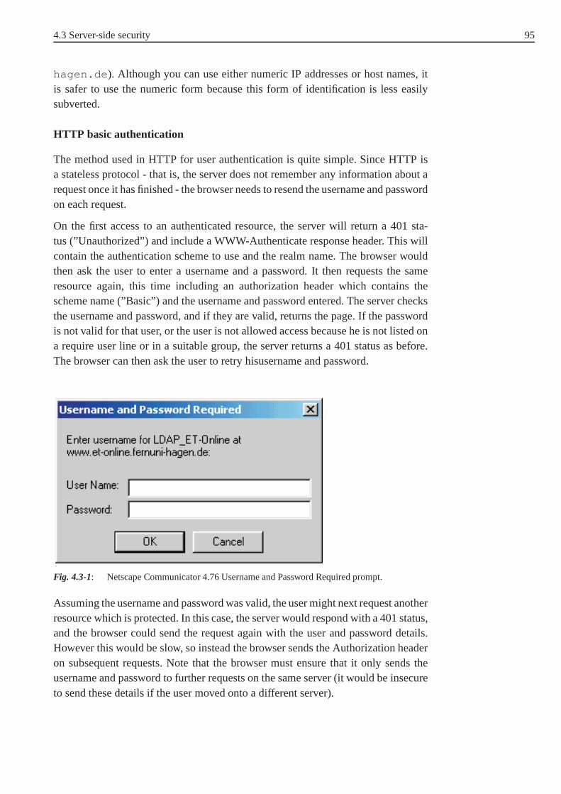
4.3 Server-side security 95
hagen.de ). Although you can use either numeric IP addresses or host names, itis safer to use the numeric form because this form of identification is less easilysubverted.
HTTP basic authentication
The method used in HTTP for user authentication is quite simple. Since HTTP isa stateless protocol - that is, the server does not remember any information about arequest once it has finished - the browser needs to resend the username and passwordon each request.
On the first access to an authenticated resource, the server will return a 401 sta-tus (”Unauthorized”) and include a WWW-Authenticate response header. This willcontain the authentication scheme to use and the realm name.The browser wouldthen ask the user to enter a username and a password. It then requests the sameresource again, this time including an authorization header which contains thescheme name (”Basic”) and the username and password entered. The server checksthe username and password, and if they are valid, returns thepage. If the passwordis not valid for that user, or the user is not allowed access because he is not listed ona require user line or in a suitable group, the server returnsa 401 status as before.The browser can then ask the user to retry hisusername and password.
Fig. 4.3-1: Netscape Communicator 4.76 Username and Password Required prompt.
Assuming the username and password was valid, the user mightnext request anotherresource which is protected. In this case, the server would respond with a 401 status,and the browser could send the request again with the user andpassword details.However this would be slow, so instead the browser sends the Authorization headeron subsequent requests. Note that the browser must ensure that it only sends theusername and password to further requests on the same server(it would be insecureto send these details if the user moved onto a different server).

96 4 World Wide Web Security
The browser needs to remember the username and password entered, so it can sendthese with future requests from the same server. Note that this can cause problemswhen testing authentication, since the browser remembers the first username andpassword that works. It might be difficult to force the browser to ask for a newusername and password.
HTTP digest authentication
The HTTP basic authentication is not considered to be a secure method of userauthentication, as the user name and password are passed over the network in anunencrypted form.
Version 1.1 of HTTP (published in July 1996) introduced an improved method cal-led digest authentication. This uses the same exchange of packets as basic authenti-cation, but the ”Unauthenticated” reply now includes a value, known as the nonce,which acts as a challenge. Instead of replying with the username and password, theclient calculates a message digest (using the MD5 algorithm) from the username,password and nonce and returns this along with the username as authenticationinformation. The server then repeats the MD5 calculation, using the user’s correctpassword, and returns the document if the two digests match.To do this the servermust hold each user’s password in a form suitable for calculating the MD5 digest.It is imperative that these passwords be stored as securely as possible, since anyonepossessing them would immediately be able to masquerade as any valid user of theserver. The need for security is even greater than for a Unix password file, whosecontents must be de-crypted by brute force methods before they can be misused.
The HTTP server is stateless so it cannot ”remember” the nonce value betweeneach challenge and its response; the nonce must therefore bederived from somecombination of information from the request packet along with values held centrallyon the server. This still leaves the process vulnerable to replay attacks as the serverdoes not ensure that nonces are unique to a single request. However by carefulchoice of the nonce this risk and the resulting damage can be substantially reduced.A good nonce calculation will usually include the URL of the document requestedso that a successful replay attack can only retrieve a singledocument, rather than thewhole realm as with basic authentication. The IP address of the client making therequest should also be part of the calculation: a replay attack from a different clientmachine will then fail unless the intruder has changed his IPaddress and managed topersuade the routing systems to return responses to the new location. The server mayalso maintain a single ’magic number’ which changes periodically. Including this inthe nonce will limit the time period during which a replay attack can be successful.However the rate of change must be sufficient to allow a legitimate user to enter ausername and password as otherwise the nonce will have expired by the time theauthenticated request is sent. To assist the user, it is suggested that servers shouldrecognise digests which are correct except for using an ’old’ nonce and requestthat the browser program re-calculate the digest with the latest value. This secondcalculation can be done without consulting the user (since the browser will have
4.3 Server-side security 97
cached the username and password) and as such should have a shorter round-triptime.
Only the server needs to know how the nonce is calculated, as such different serverscan choose methods appropriate to the sensitivity of the information they hold. Eachimprovement in security requires more processing in the calculation of the nonceand the message digest; for a busy server this may represent aconsiderable load. Anonce with a short lifetime is also likely to require many re-authentications, increa-sing the network traffic. The only way to prevent replay attacks is to keep a recordof all digest values received by the server, and ensure that each one is only usedonce. However this involves the server holding a great deal of information whichmust be checked at every request. There is still no protection against other typesof attacks, for example through a compromised or hostile proxy between the cli-ent and the server. These can only be prevented by cryptographic encryption of therequest and response so that even if transactions fall into wrong hands, they are ofno use. The standard concludes: ”Digest Authentication does not provide a strongauthentication mechanism. That is not its intent. It is intended solely to replace amuch weaker and even more dangerous authentication mechanism: Basic Authenti-cation. An important design constraint is that the new authentication scheme be freeof patent and other export restrictions. Most needs for secure HTTP transactionscannot be met by Digest Authentication. For those needs SSL or SHTTP are moreappropriate protocols.”
SSL can be used both for server-side and for client-side authentication. For detailedinformation on SSL see Section 3.3.2.
Certificate-based authentication
As presented in Section 3.3.2 and Section 3.3.3, SSL and TLS can be used to securecommunications between browsers and HTTP servers. Using HTTP on top of SSLor TLS makes user authentication and authorisation simple and straightforward. Inshort, Web servers authenticate themselves using site certificates, whereas indivi-dual users authenticate themselves using personal certificates.
In addition to superior security, there is another advantage related to the use of siteand personal certificates. A certificate generally binds a public key to an identity.This identity can, in turn, be used to control access to system resources.
.htaccess password protection
If the users who are allowed to access restricted resources are widely dispersed, orthe server administrator needs to be able to control access on an individual basis, itis possible to require a username and a password before beinggranted access to adocument.
Setting up user authentication takes two steps (in the following described for Apa-che HTTP servers):
1. Create a file containing the usernames and passwords.

98 4 World Wide Web Security
2. Tell the server what resources are to be protected and which users are allowed(after entering a valid password) to access them.
Creating a user database
A list of users and passwords needs to be created in a file. For security reasons,this file should not be under the document root. The examples here will assume youwant to use a file called users in your server root at/usr/local/etc/httpd .
The file will consist of a list of usernames and a password for each. The format issimilar to the standard Unix password file, with the usernameand password beingseparated by a colon. However you cannot just type in the usernames and passwordsbecause the passwords are stored in an encrypted format. Theprogramhtpasswd
is used to create a user file and to add or modify users.
htpasswd is a C program that is supplied in the support directory of theApachedistribution. If it is not already compiled, you will have tocompile it first. Runmake htpasswd in the support directory to compile it (you might need to modifythe makefile first, since any configuration you did when compiling the serveritself is not available to thismakefile ). After compilation, you can either leavethe htpasswd binary where it is, or move it to a directory on your path (e.g./usr/local/bin ). In the former case, you will need to remember to give the fullpathname to run it. The examples here will assume that it is installed somewhere onyour path.
Using htpasswd
To create a new user file and add the username bob with the password crypto01
to the file/usr/local/etc/httpd/users :
htpasswd -c /usr/local/etc/httpd/users bob
The -c argument tellshtpasswd to create a new users file. When you run thiscommand, you will be prompted to enter a password for bob, andconfirm it byentering it again. Other users can be added to the existing file in the same way,except that the -c argument is not needed. The same command can also be used tomodify the password of an existing user.
After adding a few users, the/usr/local/etc/httpd/users file mightlook like this:
bob_wRu808bHQAi48
jane:IabCqFQS59e8m
alice:FADHn3w774Ssu
The first field is the username, and the second field is the encrypted password.

4.3 Server-side security 99
Configuring the server
To get the server to use the usernames and passwords in this file, you need to con-figure a realm. This is a section of your site that is to be restricted to some or allof the users listed in this file. This is typically done on a per-directory basis, with adirectory (and all its subdirectories) being protected (Apache 1.2 and later also letyou protect individual files). The directives to create the protected area can be pla-ced in a.htaccess file in the relevant directory, or in a<Directory> sectionin theaccess.conf file.
To allow a directory to be restricted within a.htaccess file, you first needto ensure that theaccess.conf file allows user authentication to be set upin a .htaccess file. This is controlled by theAuthConfig override. Theaccess.conf file should includeAllowOverride AuthConfig to allowthe authentication directives to be used in a.htaccess file.
To restrict a directory to any user listed in the users file just created, you shouldcreate a.htaccess file containing:
AuthName "restricted stuff"
AuthType BasicAuthUserFile /usr/local/etc/httpd/users
require valid-user
The first directive,AuthName, specifies a realm name for this protection. Oncea user has entered a valid username and password, any other resources within thesame realm name can be accessed with the same username and password. This canbe used to create two areas which share the same username and password.
TheAuthType directive tells the server what protocol is to be used for authenti-cation. At the moment, HTTP basic is the only method available. However a newmethod, HTTP digest, is about to be standardised, and once browsers start to imple-ment it, HTTP digest authentication will provide more security than the HTTP basicauthentication.
AuthUserFile tells the server the location of the user file created byhtpasswd .A similar directive,AuthGroupFile , can be used to tell the server the locationof a group file (see below).
These four directives tell the server where to find the usernames and passwordsand what authentication protocol to use. The server now knows that this resourceis restricted to valid users. The final stage is to tell the server which usernamesfrom the file are valid for particular access methods. This isdone with the requiredirective. In this example, the argument valid-user tells the server that any usernamein the users file can be used. But it could be configured to allowonly certain usersin:
require user bob jane

100 4 World Wide Web Security
would only allow users bob and jane access (after they entered a correct password).If user alice (or any other user) tried to access this directory - even with the correctpassword - they would be denied. This is useful to restrict different areas of yourserver to different people with the same users file. If a user is allowed to accessdifferent areas, he only has to remember a single password. Note that if the realmname differs in the different areas, the user will have to re-enter his password.
Using groups
If you want to allow only selected users from the users file in to a particular area, youcan list all the allowed usernames on therequire line. However this means youare building username information into your.htaccess files, and this might notbe convenient if there are a lot of users. Fortunately there is a way round this, usingagroup file. This operates in a similar way to standard Unix groups: any particularuser can be a member of any number of groups. You can then use the require
line to restrict users to one or more particular groups. For example, you could createa group calledstaff containing users who are allowed to access internal pages.To restrict access to just users in thestaff group, you would use
require group staff
Multiple groups can be listed, andrequire user can also be given, in whichcase any user in any of the listed groups, or any user listed explicitly, can access theresource. For example
require group staff adminrequire user adminuser
which would allow any user in groupstaff or group admin , or the useradminuser , to access this resource after entering a valid password.
A group file consists of lines giving a group name followed by aspaceseparated listof users in that group. For example:
staff:bob jane
admin:alice adminuser
TheAuthGroupFile directive is used to tell the server the location of the groupfile. Note that the maximum line length within the group file inabout 8000 charac-ters. If you have more users in a group than will fit within thatline length, you canhave more than one line with the same group name within the file.

4.3 Server-side security 101
Other ways of storing user details
While Apache by default can only access user details in plaintext files, variousadd-on modules are available to allow user details to be stored in databases. BesidesDBM format, user and group lists can be stored in DB format files. Or full databasescan be used, such asmSQL, Postgres95 or any DBI-compatible database.
It is also possible to have an arbitrary external program check whether the givenusername and password is valid (this could be used to write aninterface to checkagainst any other database or authentication service). Modules are also available tocheck against the system password file, or to use a Kerberos system (see Chapter 6).
Limiting methods differently
In the example.htaccess file above, the require directory is not given inside a<Limit> section. This is valid in Apache, and means that it applies toall requestmethods. In other servers and most example.htaccess files, the require
directive is given inside a<Limit> section, such as this:
<Limit GET POST PUT>
require valid-user</Limit>
In Apache it is better to omit the<Limit> and</Limit> lines, to ensure thatthe protection applies to all methods. However, this formatcan be used to limitparticular methods. For example, to limit just thePOSTmethod, use
AuthName "restrict posting"
AuthType Basic
AuthUserFile /usr/local/etc/httpd/users
<Limit POST>require group staff
</Limit>
Now only members of the group staff will be allowed toPOST. Other users(unauthenticated) can use other methods, such asGET. This could be used to allowa CGI program to be accessed by anyone, but only authorised uses canPOST
information to it.
102 4 World Wide Web Security
4.3.2 CGI scripts
CGI is short for Common Gateway Interface. In common usage CGI means botha kind of programming interface and the idea of enabling a given URL to returnsomething dynamic rather than something static. CGI is a sort of meta-language,or middleware, as the term is generally used. Its syntax is loosely de facto standardhanded down from the NCSA server, but CGI has had a number of proprietary”enhancements” here and there. Nonetheless, the core idea is sound and proven -a programming language for scripts that are likely to run unmodified on a goodvariety of similar platformas, all UNIX platforms, for example.
But CGI is not a full programming language itself in the way that C is a program-ming language; it is just a fairly platform-independent wayto reach a runnableprogram from a URL. ”Runnable programs reachable via CGI” can be in just aboutany language that the local platform can understand, but some are standard acrossall platforms. The only requirements on a CGI language are that it be able to getat the same environment variables as thehttpd and that it be able to read fromstdin andstdout (e.g.Perl , Tcl , andJava ).
Because CGI talks to programs, naturally it has arguments tosend and return-valuesto receive. Both these are carried either in the URL or in HTMLforms.
This conversation by way of URL can take one of two forms; it iseither a keywordlist or a named parameter list. For a keyword list, the parameters are text set off fromeach other by the plus sign (+) and from the body of the URL by the question mark(?). For a named parameter list, the parameters are a concatenated set of attribute-value pairs set off from each other by the ampersand (&) and from the URL bodyby the question mark (?). Examples might look like this:
... naturally it has a set of
<A HREF="/rub2/chapter4/attribute+value">attribute-value pairs
</A> set off from each other ...
and this:
Examples might look like
<A HREF="/chapter4/index/figures?entry=examples&chap ter=6>
this</A>
You either configure your server so that a particular directory contains all yourCGI programs and only your CGI programs or you globally declare that a certainfilename extension always identifies a runnable script, or both. The typical installedApache server will be looking for the subdirectory./cgi-bin in the server rootor for filenames ending in.cgi .

4.3 Server-side security 103
CGI scripts are a major source of security holes. Although the CGI protocol is notinherently insecure, CGI scripts must be written with just as much care as the serveritself. Unfortunately some scripts fall short of this standard.
CGI scripts can present security holes in two ways:
1. They may intentionally or unintentionally leak information about the hostsystem that will help hackers break in.
2. Scripts that process remote user input, such as the contents of a form ora ”searchable index” command, may be vulnerable to attacks in which theremote user tricks them into executing commands.
Although there is nothing intrinsically dangerous about scattering CGI scriptsaround the document tree, it is better to store them in thecgi-bin directory.Because CGI scripts are such potentially large security holes, it is much easier tokeep track of which scripts are installed on your system if they are kept in a cen-tral location rather than being scattered around among multiple directories. This isparticularly true in an environment with multiple Web authors. It is just too easyfor an author to inadverently create a buggy CGI script and install it somewherein the document tree. By restricting CGI scripts to thecgi-bin directory and bysetting up permissions, so that only the Web administrator can install these scripts,you avoid this chaotic situation.
There is also a risk of a hacker managing to create a.cgi file somewhere in yourdocument tree and then executing it remotely by requesting its URL. A cgi-bin
directory with tightly-controlled access lessens the possibility of this happening.
4.3.3 Server logs and privacy
Most servers log every access. The log usually includes the IP address and/or hostname, the time of the download, the user’s name (if known by user authentication orobtained by the idented protocol), the URL requested (including the values of anyvariables from a form submitted using the GET method), the status of the request,and the size of the data transmitted. Some browsers also provide the client the readeris using, the URL that the client came from, and the user’s e-mail address. Serverscan log this information as well, or make it available to CGI scripts. Most WWWclients are probably run from single-user machines, thus a download can be attribu-ted to an individual. Revealing any of these datums could be potentially damagingto a reader.
Another way Web usage can be revealed locally is via browser history, hotlists, andcache. If someone has access to the reader’s machine, he can check the contents ofthese databases. An obvious example is shared machines in anopen lab or publiclibrary.
Proxy servers used for access to Web services outside an organization’s firewall arein a particularly sensitive position. A proxy server will log every access to the out-side Web made by every member of the organization and track both the IP number

104 4 World Wide Web Security
of the host making the request and the requested URL. A carelessly managed proxyserver can therefore represent a significant invasion of privacy.
All requests for documents are logged by the Web server. Although your name is notusually logged, your IP address and computer’s host name usually is. In addition,some servers also log the URL you were viewing (such as your home page) at thetime you requested the new URL. If the site is well administered, the record of youraccesses will be used for statistics generation and debugging only. However, somesites may leave the logs open for casual viewing by local users at the site or evenuse them to create mailing lists.
The contents of queries in forms submitted using the GET request appear in theserver log files because the query is submitted as part of the URL. However, whena query is submitted as a POST request (which is often the casewhen submittinga fill-out form), the data you submit does not get logged. If you are concernedabout the contents of a keyword search appearing in a public log somewhere, checkwhether the search script uses the GET or the POST method. Theeasiest techniqueis to try an innocuous query first. If the contents of the queryappear in the URL ofthe retrieved document, then they probably appear in the remote server’s logs too.
Server/browser combinations that use data encryption, such as Netsite/ Netscape,encrypt the URL request. Furthermore the encrypted request, because it is submittedas a POST request, does not appear in the server logs.
4.4 Client-side security
One of the most useful and powerful feature of browsers is their ability to downloadexecutable content from remote sites. Java, JavaScript, and ActiveX are examplesof executable content that can be downloaded to a machine running a browser. Java,in particular, can be used to run platform-independent applications that can be pro-totyped quickly. One of the features of the Java interpreterin Netscape’s Navigatorand Microsoft’s Internet Explorer is that applets cannot leave the controlled envi-ronment. This is equal to claiming that Java is secure which is far from true (seeSection 4.4.3).
ActiveX is different from the Java model: It assumes that content is digitally signedby trusted distributors. The client blindly trusts the signed code and no further secu-rity measures are taken. One problem with this model is that there is no globalpublic key infrastructure to scale the solution to the Web.
In this chapter, we describe the security of SSL (Section 4.4.1), the security pro-blems of JavaScript (Section 4.4.2), and ActiveX (Section 4.4.4). Next, we exploreJava and the Java environment (Section 4.4.3). Finally, we discuss cookies (Sec-tion 4.4.5).

4.4 Client-side security 105
4.4.1 SSL
SSL uses public-key encryption to exchange a session key between the client andthe server; this session key is used to encrypt the http transactions (both request andresponse). Each transaction uses a different session key sothat if someone managesto decrypt a transaction, it does not mean that he has found the server’s secret key;if he wants to decrypt another transaction, he will need to spend as much time andeffort on the second transaction as he did on the first.
Netscape servers and browsers do encryption using either a 40-bit secret key or a128-bit secret key. Many people feel that using a 40-bit key is insecure because itis vulnerable to a ”brute force” attack (trying each of the240 possible keys untilyou find the one that decrypts the message). This was in fact demonstrated in 1995when a French researcher used a network of workstations to crack a 40-bit encryptedmessage in a little over a week. It is thought that with specialised hardware, 40-bitmessages can be cracked in minutes to hours. Using a 128-bit key eliminates thisproblem because there are2128 instead of240 possible keys. To crack a messageencrypted with such a key by brute force would take significantly longer than theage of the universe using conventional technology.
In Netscape versions 3.X and earlier you can tell what kind ofencryption is inuse for a particular document by looking at the ”document information” screenaccessible from the file menu. The little key in the lower left-hand corner of theNetscape window also indicates this information. A solid key with three teeth means128-bit encryption, a solid key with two teeth means 40-bit encryption, and a brokenkey means no encryption. Even if your browser supports 128-bit encryption, it mayuse 40-bit encryption when talking to older servers.
In Netscape versions 4.X and higher, click on the ”Security”button to determinewhether the current page is encrypted, and, if so, what levelof encryption is in use.In Microsoft Internet Explorer, a solid padlock will appearon the bottom right of thescreen when encryption is in use. To determine whether 40-bit or 128-bit encryptionis in effect, open the document information page usingFile->Properties .This will indicate whether ”weak” or ”strong” encryption isin use.
4.4.2 JavaScript
JavaScript is a scripting language developed by Netscape23. Although it sharesmany of the features and structures of the full Java language, it was developedindependently and is endorsed by a number of software companies. JavaScript isan open language that anyone can use without purchasing a license. It is supported
23 There are several books describing the JavaScript language in detail (e.g. [Fla96]).
106 4 World Wide Web Security
by recent browsers from Netscape and Microsoft, though Internet Explorer supportsonly a subset, which Microsoft calls Jscript24.
JavaScript enables Web authors to allow code to be containedwithin HTML docu-ments themselves. This code could dynamically change the HTML that the browserinterprets based on many conditions. For example, a JavaScript code segment couldchange the users display in his browser based on the values ofthe cookies set onthe machine. JavaScript is especially well suited for popping up dilogue boxes andreceiving input from the users.
One of JavaScript’s most useful features is its ability to define userspecified eventhandlers. These can cause certain pieces of code to execute in response to eventssuch as mouse positioning or keystroke entries. In addition, as JavaScript is a com-plete programming language, mathematical calculations and all sorts or algorithmscan be implemented.
Security model
Java scripts, because they execute on the browser’s side of the connection insteadof on the server’s, move the security risk from the server to the client. Many ofJavaScript’s security problems cannot be exploited directly, since they require userinteraction. However, fooling users into providing the assistance necessary to mountthe attacks is easy. For example, many attacks require that auser clicks on a buttonto activate the malicious code. A simple trick ist to use JavaScript to display a pop-up dialogue box and get the user to click on a button. One way todo this is to displaya dialogue box with one button labeled OK. The unknowing userclicks the button,and the attack is activated.
JavaScript has a troubling history of security holes. Here are a few examples:
• Ability to read arbitrary files on user’s machine (November 1998):A bug in the JavaScript implementation in Netscape Communicator 4.5 and4.04-4.05 allows a Web page to read arbitrary files from the user’s machineand transmit them across the Internet. Any file that can be read with the user’spermission is vulnerable, including the system password file. The bug affectsboth Windows and Unix versions of Communicator. Any HTML page can carrythis exploit, including ones that are transmitted as an e-mail enclosure. InternetExplorer has not been reported to be vulnerable.
• The ”Cuartango” and ”Son of Cuartango” holes (November 1998):Microsoft Internet Explorer is also vulnerable to file theftvia Java- Script. Inter-net Explorer versions 4.0-4.01 and prerelease versions of IE 5.0 allow JavaScript
24 JScript is Microsoft’s extended implementation of ECMAScript (ECMA262), an internatio-nal standard based on the Netscape’s JavaScript and Microsoft’s JScript languages. JScriptis implemented as a Windows Script engine. This means that itcan be ”plugged in” to anyapplication that supports Windows Script, such as InternetExplorer, Active Server Pages, andWindows Script Host. It also means that any application supporting Windows Script can usemultiple languages - JScript, VBScript, Perl, and others.

4.4 Client-side security 107
programmes to cut and paste text into file upload fields, thereby allowing a boo-bytrapped Web page or e-mail message to steal any file on the user’s disk.
• Ability to intercept the user’s e-mail address and other preferences (February1998):Versions of Netscape Navigator 4.0 through 4.04 contain a security hole invol-ving access of JavaScript programmes to the browsers preferences settings. Thesettings, which are stored in a file namedpreferences.js (or prefs.js )in the Netscape directory, include a variety of private information such as youremail address, the names of mailbox files, and the identity ofyour e-mail andnews servers. In addition, in many cases the preferences filealso stores your e-mail (POP) and FTP (publish) passwords. To see what else is inthis file, open itin a text editor and take a look. The implications of this holeis that a JavaScriptenabled page can open the preferences file and upload all information containedwithin it to a remote server. This can be exploited to capturevisitors’ e-mailaddresses and to gather information about the user’s network configuration. Theworst risk is that the user’s e-mail password will be disclosed. Since the e-mailpassword is, in many cases, the same as the user’s LAN login password, thisexposes organizations to a potential route of attack.
People who worry about the disclosure of personal information are encouragedto turn off JavaScript completely. In Netscape Navigator 4.0 or higher, you cando this by deactivating a checkbox located inEdit->Preferences->Advanced.In Microsoft Internet Explorer versions 3.X, you can do thisby uncheckinga misleadingly-named checkbox labeledRun ActiveX scripts in View->Options->Security. In Microsoft Internet Explorer 4.0, the newSecurity
Zones feature, which was designed to make the Internet safer, actually makes itdifficult to turn off JavaScript, since it is active even whenHigh Security isselected. To do this, go toView->Internet Options->Internet Security, and selecttheInternet Zone . Now select the radio button labeledCustom and press theadjacentSettings... button. Scroll down to the bottom of the option list, anddisable the option labeledActive Scripting .

108 4 World Wide Web Security
Fig. 4.4-1: How to disable JavaScript in Netscape Navigator 4.0 or higher.
4.4.3 Java
Java is a high-level programming language developed by Sun Microsystems25. Javawas originally called OAK, and was designed for handheld devices and set-topboxes. Oak was unsuccessful so in 1995 Sun changed the name toJava and modifiedthe language to take advantage of the growing World Wide Web.
Java is an object-oriented language similar to C++, but simplified to eliminate lan-guage features that cause common programming errors. Java source code files (fileswith a .java extension) are compiled into a format called bytecode (fileswith a.class extension), which can then be executed by a Java interpreter. CompiledJava code can run on most computers because Java interpreters and runtime envi-ronments, known as Java Virtual Machines (VMs), exist for most operating systems,including UNIX, the Macintosh OS, and Windows. Bytecode canalso be converteddirectly into machine language instructions by a just-in-time compiler (JIT).
Small Java applications are called Java applets. Applets run from inside a web brow-ser and HTML pages therefore contain an<APPLET>tag, which tells the browserwhere to find the Java.class files. For example,26
25 There are several books describing the Java language in detail (e.g. [Fla99]).
26 Elliptic Curves

4.4 Client-side security 109
<APPLET CODE=EllipticCurveCryptosystem.EllipticCurve s.class
WIDTH=570 HEIGHT=400></APPLET>
Because applets are small in files size, cross-platform compatible, and highly secure(can’t be used to access users’ hard drives), they are ideal for small Internet appli-cations accessible from a browser.
Security model
Since Java bytecodes can be generated without a compiler, restrictions on the Javacompiler cannot be used for security. When we talk about Javasecurity, we referto access control on Java bytecodes that are received from anunknown source andexecuted. We would like these bytecode streams - called applets - to execute ina controlled environment from which they cannot escape. Such an environment isoften termed assandbox .
The idea behind the sandbox or virtual machine is that when running as applets, Javascripts are restricted with respect to what they are allowedto do by asecurity
manager object. Things, that applets are prevented from doing:
• The security manager does not ordinarily allow applets to execute arbitrary sys-tem commands, to load system libraries, or to open up system device driverssuch as disk drives. In addition, scripts are generally limited to reading and wri-ting to files in a user-designated directory only.
• Applets are also limited in the network connections they canmake: An appletis only allowed to make a network connection back to the server from which itwas downloaded.
• Finally, the security manager allows Java applets to read and write to the net-work, read and write to the local disk, but not both. This limitation was createdto reduce the risk of an applet spying on the user’s private documents and trans-mitting the information back to the server.
Unfortunately in the short time since its release, a number of security holes havebeen found in Java caused by bugs in the implementation. A variety of bugs havebeen identified and fixed.
Below are some of the older security holes present in the Javaimplementationsdistributed with various versions of Netscape and InternetExplorer.
• Vulnerability to denial-of-service attacks:Applets can hog system resources such as memory and CPU time.This mayhappen as the result of a programmer error, or maliciously inorder to slowdown the computer system to the point of unusability. Applets running underthe same browser are not protected from one another. One applet can easily dis-cover another’s existence and interfere with it, raising the interesting spectre ofone vendor’s applet deliberately making a competitor’s applet appear to behaveerroneously.

110 4 World Wide Web Security
• Ability to make network connections with arbitrary hosts:Once downloaded to a user’s machine, the applet can attempt to make a connec-tion to any machine on the user’s local area network, even if the LAN is pro-tected by a firewall. Many LANs are set up so that local machines are trustedto access services that distant machines are not. As a trivial example, an App-let could open up a connection to the organization’s privatenews server, fetchrecent postings to an internal newsgroup, and transmit themback to a foreignhost.
If you are security conscious, you might wish to take the safest course and deactivateJava completely. In Netscape Navigator 2.0-3.02, you can dothis by uncheckingthe ”Java” option inEdit->Preferences->Advanced. In Internet Explorer 3.02,uncheckEnable Java Programs in theView->- Options->Security->ActiveContent window.
Deactivating Java is harder in the 4.0 versions of both Navigator and Internet Explo-rer. In Netscape Navigator 4.0, selectEdit->Preferencesfrom the menu bar, thenselect the ”Advanced” category. Locate the ”Enable Java” checkbox and deselect it.
In IE 4.0, selectView->Internet Options->Security, select the Internet Zone, andselectCustom settings. Now press theSettings... button and scroll down tothe Java settings. ChooseDisable Java .
Fig. 4.4-2: How to disable Java in Netscape Navigator 4.0 or higher.

4.4 Client-side security 111
4.4.4 ActiveX
ActiveX is a technology developed by the Microsoft Corporation for distributingsoftware over the Internet. It is an outgrowth of two other Microsoft technolo-gies called OLE (Object Linking and Embedding) and COM (Component ObjectModel). Like Java Applets, an ActiveXcontrol can be embedded in a Web page,where it typically appears as a smart interactive graphic. Anumber of ActiveX con-trols are available for the Microsoft Internet Explorer (the only browser to supportthem so far), including a control that executes Java applets. Unlike Java, which isa platform-independent programming language, ActiveX controls are distributed asexecutable binaries, and must be separately compiled for each target machine andoperating system.
Security model
The ActiveX security model is considerably different from Java applets. Java achie-ves security by restricting the behavior of applets to a set of safe actions. ActiveX,on the other hand, places no restrictions on what a control can do. Instead, each Acti-veX control can be digitally signed by its author in such a waythat the signature can-not be altered or repudiated using a system calledauthenticode (a special kindof certificate). The digital signatures are then certified bya trustedcertifying
authority , such as VeriSign, to create the equivalent of a shrink-wrapped soft-ware package. When a digital certificate is granted, the software developer pledgesthat the software is free from viruses and other malicious components.
This security model places the responsibility for the computer system’s securitysquarely on the user’s side. Before the browser downloads anActiveX control thathasn’t been signed at all, or that has been signed but certified by an unknown cer-tifying authority, the browser presents a dialog box warning the user that this actionmay not be safe. The user can select to abort the transfer, or may continue the trans-fer and take his chances.
The ActiveX certification process ensures that ActiveX controls cannot be distribu-ted anonymously and that a control cannot be tampered with bythird parties afterits publication. However, the certification process does not ensure that a control willbe well-behaved. Although it is unlikely that signed and certified ActiveX controlswill behave in a malicious fashion, this is not impossible.
The main problem with the ActiveX security model is that it isdifficult to trackdown a control that has taken some subtle action, such as silently transmittingconfidential configuration information from the user’s computer to a server on theInternet, seeding the LAN with a virus, or even patching Internet Explorer so thatthe code authentication engine no longer functions correctly. This type of actionmay escape detection completely, or at least for a long period of time. Even if thedamage is detected immediately, Internet Explorer offers no secure audit trail thatrecords which ActiveX controls were downloaded. This makesidentifying the con-trol responsible for damaging your system a non-trivial task.

112 4 World Wide Web Security
ActiveX can be turned off completely from theInternet Options->Security pagesof Microsoft Internet Explorer. The default setting is on. This means that users whoare unaware of security considerations will automaticallyrun any ActiveX scriptsthat their browser downloads. In addition, there is an option to set the safety level.Choose theHigh Security setting to disable ActiveX completely, orMedium
Security to prompt you before downloading and executing ActiveX controls.TheLow Security option allows any ActiveX control to run, signed or not, andis not recommended.
4.4.5 Cookies
We will take a look at the basic technology behind cookies, aswell as some of thefeatures they enable. A cookie is a piece of text that a web server can store on auser’s hard disk. Cookies allow a web site to store information on a user’s machineand later retrieve it. The pieces of information are stored as name-value pairs. Forexample, a web site might generate a unique ID number for eachvisitor and storethe ID number on each user’s machine using a cookie file.
If you use Microsoft’s Internet Explorer to browse the web, you can see all of thecookies that are stored on your machine. The most common place for them to resideis in a directory called
c:\windows\cookies
You can see in the directory that each of these files is a simple, normal text file. Youcan see which web site placed the file on your machine by looking at the file name(the information is also stored inside the file). You can openeach file up by clickingon it.
For example, a cookie file created byamazon.com may contain the followinginformation:
session-id 104-1889894-2550358 amazon.com/
session-id-time 992851200 amazon.com/ubid-main 077-0190749-3709979 amazon.com/
x-main hQFiIxHUFj8mCscT@Yb5Z7xsVsOFQjBf amazon.com/
It appears that Amazon stores a main user ID, an ID for each session, and the timethe session started on the user’s computer (as well as anx-main value , whichcould be anything).
The vast majority of sites store just one piece of information - a user ID - on yourcomputer. But there really is no limit - a site can store as many name-value pairs asit likes. A name-value pair is simply a named piece of data. Itis not a programme,and it cannot ”do” anything. A web site can retrieve only the information that it hasplaced on your machine. It cannot retrieve information fromother cookie files, norany other information from your machine.

4.4 Client-side security 113
How does cookie data move?
As shown in the previous section, cookie data is simply a name-value pair storedon your hard disk by a web site. That is all that cookie data is.The web site canstore the data, and later it receives it back. A web site can only receive the data ithas stored on your computer. It cannot look at any other cookie, nor can it look atanything else on your computer. The data moves in the following manner:
• If you type the URL of a web site into your browser, your browser sendsa request to the web site for the page. For example, if you typethe URLhttp://www.amazon.com into your browser, your browser will contact Amazon’sserver and request its home page.
• When the browser does this, it will look on your machine for a cookie file thatAmazon has set. If it finds an Amazon cookie file, your browser will send allof the name-value pairs in the file to Amazon’s server along with the URL. If itfinds no cookie file, it will send no cookie data.
• Amazon’s web server receives the cookie data and the requestfor a page. Ifname-value pairs are received, Amazon can use them.
• If no name-value pairs are received, Amazon knows that you have not visitedtheir site before. The server creates a new ID for you in Amazon’s database andthen sends name-value pairs to your machine in the header forthe web page itsends. Your machine stores the namevalue pairs on your hard disk.
• The web server can change name-value pairs or add new pairs whenever youvisit the site and request a page.
There are other pieces of information that the server can send with the name-valuepair. One of these is an expiration date. Another is a path (sothat the site can asso-ciate different cookie values with different parts of the site). You have control overthis process. You can set an option in your browser so that thebrowser informs youevery time a site sends name-value pairs to you. You can then accept or deny thevalues.
How do web sites use cookies?
Cookies evolved because they solve a big problem for people who implement websites. In the broadest sense, a cookie allows a site to store state information on yourmachine. This information lets a web site remember what state your browser is in.An ID is one simple piece of state information - if an ID existson your machine, thesite knows that you have visited it before. The state is, ”Your browser has visitedthe site at least one time”, and the site knows your ID from that visit. Web sites usecookies in many different ways. Here are some of the most common examples:
• Sites can accurately determine how many readers actually visit the site. It turnsout that because of proxy servers, caching, concentrators and so on, the only

114 4 World Wide Web Security
way for a site to accurately count visitors is to set a cookie with a unique ID foreach visitor. Using cookies, a site can:
– Determine how many visitors arrive
– Determine how many are new vs. repeat visitors
– Determine how often a visitor has visited.
The way the site does this is by using a database. The first timea visitor arrives,the site creates a new ID in the database and sends the ID as a cookie. The nexttime the user comes back, the site can increment a counter associated with thatID in the database and know how many times that visitor returns.
• Sites can store user preferences so that the site can look different for each visitor(often referred to as customisation). For example, if you visit msn.com, it offersyou the ability to changecontent/layout/color . It also allows you toenter your zip code and get customized weather information.Most sites seem tostore preferences like this in the site’s database and storenothing but an ID as acookie, but storing the actual values in name-value pairs isanother way to do it(we’ll discuss why this approach has lost flavour below).
• eCommerce Sites can implement things like shopping carts and ”quick check-out” options. The cookie contains an ID and lets the site keeptrack of you asyou add different things to your cart. Each item you add to your shopping cart isstored in the site’s database along with your ID value. When you check out, thesite knows what is in your cart by retrieving all of your selections from the data-base. It would be impossible to implement a convenient shopping mechanismwithout cookies or something like it.
In all of these examples, note that what the database is able to store is things youhave selected from the site, pages you have viewed from the site, information yougive to the site in online forms, etc. All of the information is stored in the site’s data-base, and a cookie containing your unique ID is all that is stored on your computerin most cases.
Privacy
On a web site, the site can track not only your purchases, but also the pages thatyou read, the ads that you click on, etc. If you then purchase something and enteryour name and address, the site potentially knows much more about you than atraditional mail order company does. This makes targeting much more precise, andthat makes a lot of people uncomfortable.
The second fact is new. There are certain infrastructure providers that can actuallycreate cookies that are visible on multiple sites. DoubleClick is the most well knownexample of this. Many companies use DoubleClick to serve ad banners on theirsites. DoubleClick can place small (1x1 pixels) GIF files on the site that allowDoubleClick to load cookies on your machine. DoubleClick can then track your
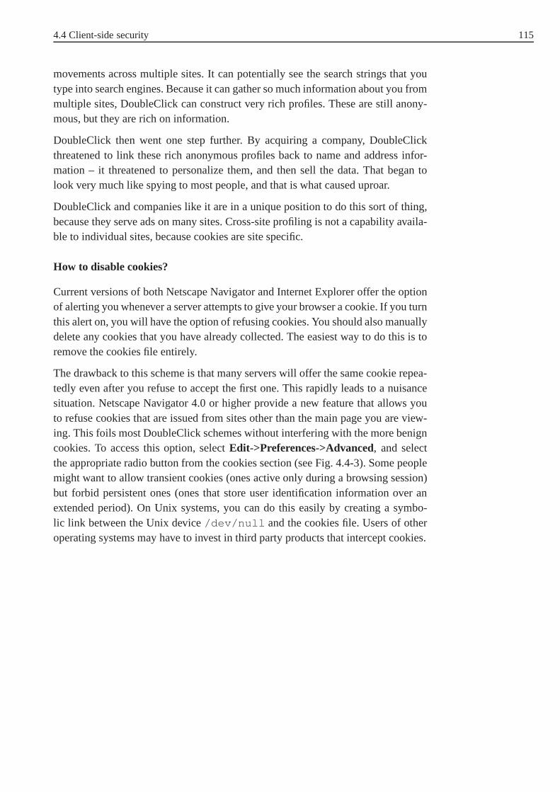
4.4 Client-side security 115
movements across multiple sites. It can potentially see thesearch strings that youtype into search engines. Because it can gather so much information about you frommultiple sites, DoubleClick can construct very rich profiles. These are still anony-mous, but they are rich on information.
DoubleClick then went one step further. By acquiring a company, DoubleClickthreatened to link these rich anonymous profiles back to nameand address infor-mation – it threatened to personalize them, and then sell thedata. That began tolook very much like spying to most people, and that is what caused uproar.
DoubleClick and companies like it are in a unique position todo this sort of thing,because they serve ads on many sites. Cross-site profiling isnot a capability availa-ble to individual sites, because cookies are site specific.
How to disable cookies?
Current versions of both Netscape Navigator and Internet Explorer offer the optionof alerting you whenever a server attempts to give your browser a cookie. If you turnthis alert on, you will have the option of refusing cookies. You should also manuallydelete any cookies that you have already collected. The easiest way to do this is toremove the cookies file entirely.
The drawback to this scheme is that many servers will offer the same cookie repea-tedly even after you refuse to accept the first one. This rapidly leads to a nuisancesituation. Netscape Navigator 4.0 or higher provide a new feature that allows youto refuse cookies that are issued from sites other than the main page you are view-ing. This foils most DoubleClick schemes without interfering with the more benigncookies. To access this option, selectEdit->Preferences->Advanced, and selectthe appropriate radio button from the cookies section (see Fig. 4.4-3). Some peoplemight want to allow transient cookies (ones active only during a browsing session)but forbid persistent ones (ones that store user identification information over anextended period). On Unix systems, you can do this easily by creating a symbo-lic link between the Unix device/dev/null and the cookies file. Users of otheroperating systems may have to invest in third party productsthat intercept cookies.

116 4 World Wide Web Security
Fig. 4.4-3: How to disable cookies in Netscape Navigator 4.0 or higher.
Exercise 4.4-1:
Specify the types of security risks regarding the WWW.
Exercise 4.4-2:
Shortly describe the two methods used in HTTP for user authentication.

117
5 Anonymity Techniques
5.1 Introduction
It is desirable in some communication sessions to conceal the identity of an entityinvolved in this communication. That is, a participant wants anonymously to usecommunication services without compromising his identity. For example, one wantsto send, and/or receive messages in an electronic mail system without being obser-ved. In this approach Chaum discussed the"traffic analysis problem" Traffic analysis
problem
"The problem of keeping confidential who communicates with whom; and whenthey communicate"
One important concept in anonymity techniques is theMix-concept. Its basic idea Mix-concept
was published by Chaum in 1981 ([Chaum81]). Thereafter, it was adjusted in orderto guarantee anonymity in some communication networks suchas mobile commu-nication networks or telephony communication networks. Anonymity can also beoffered by another concept: theDC-conceptor DC network. DC-concept
This chapter deals with some basic ideas of anonymity used inthe Mix- and theDC-concept and introduces the following types of anonymity:
Sender anonymity The sender of a message stays anonym for the recipient as wellSender anonymity
as for an observing attacker.
Recipient anonymity In a communication relationship between two partnersA Recipient anonymity
andB recipient anonymity allows e.g.A to send a message toB withoutbreaking the anonymity ofB. For this purposeA becomes a special addresswhich refers toB but does not revealB′s identity toA.
Mutual anonymity Combines sender and recipient anonymity and extends theMutual anonymity
concepts to provide anonymity for both, sender and recipient.
Unobservability The communication between two partnersA andB can not be Unobservability
observed, not even the existence of a communikation link betweenA andB
can be revealed by a third party.
For client-server-applications like the internet serviceWWW, we introduce thenotion offered by the JANUS system:
Client anonymity Client anonymity is reached, when all information about theClient anonymity
client is concealed.
Server anonymity Server anonymityis reached, when the identity of a server inServer anonymity
a communication session is hidden.
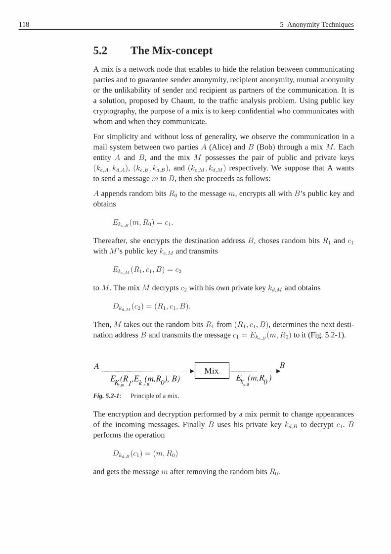
118 5 Anonymity Techniques
5.2 The Mix-concept
A mix is a network node that enables to hide the relation between communicatingparties and to guarantee sender anonymity, recipient anonymity, mutual anonymityor the unlikability of sender and recipient as partners of the communication. It isa solution, proposed by Chaum, to the traffic analysis problem. Using public keycryptography, the purpose of a mix is to keep confidential whocommunicates withwhom and when they communicate.
For simplicity and without loss of generality, we observe the communication in amail system between two partiesA (Alice) andB (Bob) through a mixM . Eachentity A and B, and the mixM possesses the pair of public and private keys(ke,A, kd,A), (ke,B, kd,B), and(ke,M , kd,M) respectively. We suppose that A wantsto send a messagem to B, then she proceeds as follows:
A appends random bitsR0 to the messagem, encrypts all withB’s public key andobtains
Eke,B(m, R0) = c1.
Thereafter, she encrypts the destination addressB, choses random bitsR1 andc1
with M ’s public keyke,M and transmits
Eke,M(R1, c1, B) = c2
to M . The mixM decryptsc2 with his own private keykd,M and obtains
Dkd,M(c2) = (R1, c1, B).
Then,M takes out the random bitsR1 from (R1, c1, B), determines the next desti-nation addressB and transmits the messagec1 = Eke,B
(m, R0) to it (Fig. 5.2-1).
MixA B
E (R ,E (m,R ), B) E (m,R )e,m e,B e,BK kk1 00
Fig. 5.2-1: Principle of a mix.
The encryption and decryption performed by a mix permit to change appearancesof the incoming messages. FinallyB uses his private keykd,B to decryptc1. B
performs the operation
Dkd,B(c1) = (m, R0)
and gets the messagem after removing the random bitsR0.

5.2 The Mix-concept 119
Of course, if only one message has been sent through the mixM , then the relati-onship between the sole incoming and outcoming message would be obvious. Thisrequireds that a number of messagesm1, m2, m3, . . . called abatch must be first Batch
collected and then treated (de/- encrypted) at one time. An attacker can thus not finda time correlation between incoming and outcoming messages. In order to avoid aTime correlation
replay-attack, each message must be treated by the mix no more than once. Repea- Replay-attack
ted messages in a batch must also be discard before being processed by the mix. Inother words, if copies of a message exist in a batch, then the message can be tracedby observing thefrequency of occurrencebetween the incoming and the outco-Frequency of
occurrenceming messages. A mix must also be able to remove all repeated messages whenthey appear in multiple batches.
Which role do the random bitsR0 andR1 play? Supposing that a messagem isencrypted by a mix without attachment of any random bits, then an attacker cansimply re-encrypt the outcoming messageDkd,M
(Eke,M(m)) with the mix’s public
key and obtain
Eke,M(Dkd,M
(Eke,M(m))) = Eke,M
(m).
Now he transmits anew the encrypted messageEke,M(m) to the mix M which
decrypts it with his private key and outputs the messagem. Hence a correspon-dence between the incoming and the outcoming message is found and the relationbetween sender and recipient of a message is not hidden anymore.
Another operation performed by the mix is thereordering of all messages in a Reordering
batch. All incoming messages of a batch are reordered in a lexicographical orderand then outputted. This prevents an attacker to detect the correspondences betweensequential inputs and their sequential outputs.
Despite all operations described until now which can be performed by the mix inorder to hide any relation between the incoming and the outcoming messages, anattacker can possibly find out which outgoing message corresponds to which inco-ming one only by observing the length of each message. Therefore all incoming andoutgoing messages must be of equal length. For this purpose,the messages shouldbe padded if necessary .
Fig. 5.2-2 resumes some basic functions of a mix. In practice, other supplementaryfunctions of a mix can be needed in order –for example– to handle latency, timedelay of information in a network etc or to avoid some known attacks against a mix(see [Franz97] and [Franz98]).
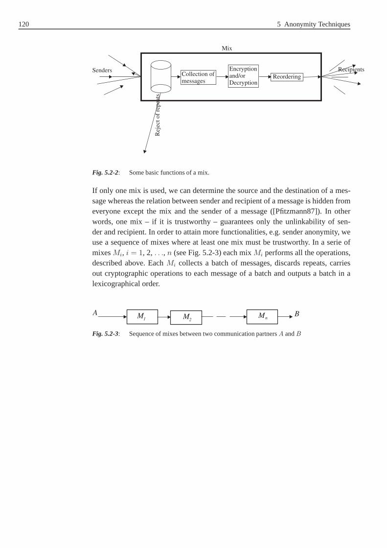
120 5 Anonymity Techniques
Senders
Rej
ect
of
repea
ts
Collection ofmessages
Encryptionand/orDecryption
Reordering
Recipients
Mix
Fig. 5.2-2: Some basic functions of a mix.
If only one mix is used, we can determine the source and the destination of a mes-sage whereas the relation between sender and recipient of a message is hidden fromeveryone except the mix and the sender of a message ([Pfitzmann87]). In otherwords, one mix – if it is trustworthy – guarantees only the unlinkability of sen-der and recipient. In order to attain more functionalities,e.g. sender anonymity, weuse a sequence of mixes where at least one mix must be trustworthy. In a serie ofmixesMi, i = 1, 2, . . ., n (see Fig. 5.2-3) each mixMi performs all the operations,described above. EachMi collects a batch of messages, discards repeats, carriesout cryptographic operations to each message of a batch and outputs a batch in alexicographical order.
A BM M M1 2 n
Fig. 5.2-3: Sequence of mixes between two communication partnersA andB

5.2 The Mix-concept 121
5.2.1 Sender anonymity
A wants to send a messagem to B in such a way thatB receivesm but withoutknowing who sends the message. SoA determines a sequence of mixesMi, i = 1,2, . . ., n. Each mixMi possesses a pair of public and a private key(ke,Mi
, kd,Mi).
Then she prepares the message by encrypting it in the following manner
m1 = Eke,B(R0, m, B)
mi = Eke,Mi−1(Ri−1, mi−1, Ai−2) for i = 2, . . . , n + 1.
A sends the message
mn+1 = Eke,Mn(Rn, mn, An−1)
to the mix Mn which decrypts it with his private keykd,Mnand obtains
(Rn, mn, An−1). Thereafter,Mn removes the random bitsRn and determines thenext destination addressAn−1 of the mixMn−1 to which it sends the messagemn.The mixMn−1 proceeds in the same manner asMn. In this way all mixes will besuccessively traversed (see Fig. 5.2-4). The mixM1 finaly gets the messagem2 andsends the messagem1 to the destination addressB. HenceB receives the messagem without knowing the identity of the sender.
A BM M Mn n-1 1mm m
nn+1 1
Fig. 5.2-4: Sender anonymity in a mix network.
Sender anonymity can be seen as packing the messagem in n nested envelopes.Beginning with the outmost envelopen and proceeding in descending order, theaddressAi of the mixMi is written down on each envelopei. So the outmost enve-lope can only be removed by the mixMn, the next envelope by the mixMn−1, etc.This is the same as the decryption with the mixes’ private keys. The last mixM1
forwards the intended messagem to the recipientB in an extra envelope that canonly be opened byB .

122 5 Anonymity Techniques
5.2.2 Return address and recipient anonymity
B wants to receive a messagem anonymously fromA. Therefore he must preparean address calledanonymous return address(RA) which referes to be but doesAnonymous return
address not reveal his identity.
Again we consider a sequence of mixesM1, M2, . . .Mn which is choosen byBto assign the way messagem should take through the Mix network. Each mixMi
possesses a pair of public and private keys(ke,Mi, kd,Mi
) and has the addressAi.B generatesRA by passing the sequence of mixes in descending order of the mixindices. For eachMi in the sequence a partRi of the return address will be formedas
Ri = Eke,Mi(ki, Ai+1, Ri+1), for i = n, . . . 1
whereki is a symmetric key, associated with the mixMi, that acts as random string([Chaum81]). In particular,An+1 denotes the address ofB andRn+1 = r is a stampfor B. We notice here that each mix must not treat repeats of returnaddress parts.Otherwise an attacker will be able to trace the message passing through such a mix.
With the notation introduced above, the return addressRA should be equal to(k0, A1, R1), wherek0 is a symmetric key associated with the sender. After prepa-ring the addressRA, B sends it anonymously toA (see Fig. 5.2-5) using a senderanonymity scheme.
Bemerkung: B can choose differnt ways form and RA through the Mix network.
A BM M M n1 2RA=(k ,A ,R )0 1 1
Fig. 5.2-5: Recipient anonymity in a mix network: Return address preparation.
A BM M M n1 2
E (m),Rk 10
E (E ...(E (E (m)))...),rk k k kn n-1 1 0
Fig. 5.2-6: Recipient anonymity in a mix network: Anonymous sending ofm.
Now A uses the prepared return address to send the messagem. So she encrypts themessage with the keyk0 and sendsR1, Ek0
(m) to the mixM1. Since
R1 = Eke,M1(k1, A2, R2),
the mixM1 can decryptR1 with his private keykd,M1and obtaink1, A2, R2. Then
he encryptsEk0(m) with k1 as
Ek1(Ek0
(m))

5.2 The Mix-concept 123
and sends the messageR2, Ek1(Ek0
(m)) to the mixM2. Proceeding in this manner,B gets the message
(Rn+1 = r), Ekn(Ekn−1
. . . (Ek1(Ek0
(m)))).
B can also decryptEkn(Ekn−1
. . . (Ek1(Ek0
(m)))), since the order of the usedencryptions is known to him (Fig. 5.2-6).
5.2.3 Mutual anonymity
By combining both sender and recipient anonymity, we get mutual anonymity. Forthis purpose, one mixMR plays the role of theturning pointfor sender and recipi-ent. So the recipient generates his return address asMR to which the sender sendsanonymously a message.
The recipient can trace the message only up to the mixMR, whereas the recipientcannot control the message after passing throughMR.
5.2.4 Anonymity services
The Internet is the global association of computers carrying data and making theexchange of information possible. The World Wide Web (WWW) is a service of theNet. It is a collection of interlinked documents that work together using a specificInternet protocol called HTTP (HyperText Transfer Protocol). This protocol is alsoused to transmit and receive all data over the World Wide Web.When we type aURL27 into our browser, we are actually sending an HTTP request to aWeb serverfor a page of information. Simultaneously, we send unintentionaly lot of adminis-trative data such as the E-mail address of our browser, the version of our operatingsystem ...etc. On the other side, the server gets the HTTP request and reacts witha HTTP response, i.e. it sends the desired page of information to the client andsome additional administrative data. The underlying communication utilized hereis accorded to the client/server model. The anonymity of thecommunication basedon our previous model can be specified in terms of client anonymity and/or senderanonymity ([Demuth01]).
Client anonymity
In a communication based on the client/server model, clientanonymity is reachedwhen all information about the client is concealed, i.e. theclient is kept anony-mous during a communication session ([Demuth01]). There exist some approachesthat guarantee client anonymity. For example, in theproxy28 approach, the proxy Proxy approach
27 The URL (Uniform Resource Locator) is the Internet equivalent of an address. An exampleof a URL is http://www.fernuni-hagen.de.

124 5 Anonymity Techniques
receives an HTTP request and removes or modifies all sensitive information of theclient before forwarding the HTTP request to the corresponding web server. In thiscase, the proxy can be considered as an intermediary party preventing unauthorizedparties29 from gathering personal information about the client’s usage. There arealready several services on the web which enable client anonymity. The Anonymi-zer is one of such services, offered in the Internet, that provides client anonymityusing the proxy approach.
Server anonymity
The server anonymity enables to hide the identity of a serverin a communicationsession. In fact, services that provide server anonymity, are rare in comparison tothat which offer client anonymity. The JANUS (justly anonymising numerous URLssystematically) system is a service which supports both client and server anonymityin the WWW. It represents a network of stations working with the mix method.In the JANUS system, the communication between client and server can occurover one JANUS instance or more instances in order to increase the security. InFig. 5.2-7, we see that a communication between client 3 and server 2 occurs overone JANUS instance (JANUS 3).
Client 1
Client 2
Server 1
Server 2
JANUS 1
Client 3
JANUS 2
JANUS 3
JANUS 4
JANUS 5
Fig. 5.2-7: JANUS network.
Each JANUS instance has a pair of public and private keys. When a provider wis-hes to publish an information on a web site without revealinghis identity (serveranonymity), he has to encrypt the URL with the public key of a JANUS instance oroptionally with more than one public key of many JANUS instances. The encryptionoccurs using public keys published by the operators of the JANUS server or simplyby accessing a special web page provided by a JANUS-web-server. The encryptedURL is used as a return address as in the mix concept. By using the JANUS system,the URL ([Demuth98])
28 Here, proxy means the proxy server which is a programm acting as an intermediary betweena web browser and a web server. A proxy server is mostly used tostore frequently demandedpages. Thus it gives users rapid access to popular web destinations without overloading thenetwork with uncessary communications traffic.
29 for example, the provider of the web server.

5.3 DC-network 125
http://ks.fernuni-hagen.de/
is encrypted into
http://www.rewebber.de/surf\_encrypted/MTBLKVGnZFbdGsfN2AaN8CRp7JFT$djND1CktOFNdNq8ow$eFW5Hq+J4ubGlxK+ob4ocVDScx$3YCf$N6cVxd9bK18h4iG93cPuvb3q5quijGz$SeCYq+OkqIVESlTsccQo=
Thereafter, the encrypted URL can be published in such a way that the anonymityof the provider remains guaranteed. In this manner, an observer of the encryptedURL can not gain any information about the provider of the website. Of course,the content of the provided web site should not contain any indications regardingthe provider such as his explicit address. Otherwise the anonymity will be clearlyviolated.
Now each user that types the encrypted URL in his browser sends an HTTP requestto the corresponding JANUS instance30. The last instance decrypts the encryptedURL with his private key and removes or modifies all sensitiveinformations relatedto the client. In other words, the JANUS system guarantees also client anonymity.Thereafter an HTTP request is forwarded by the JANUS instance to the correspon-ding web server which delivers the desired web site. The JANUS instance analysesagain the received page (from the web server) for URLs to be encrypted and for sen-sitive information (of the web server) to be modified or removed, before forwardingthis page to the client.
5.3 DC-network
The concept of a DC-network was introduced by Chaum in his publication titled"the Dining Cryptographers problem: Unconditional sender and recipient untra-ceability"([Chaum88]):
"Three cryptographers are sitting down to dinner at their favorite three-starrestaurant. Their waiter informs them that arrangements have been made withthe maitre d’ hotel for the bill to be paid anonymously. One ofthe cryptogra-phers might be paying for the dinner, or it might have been NSA(U.S. NationalSecurity Agency). The three cryptographers respect each other’s right to makean anonymous payment, but they wonder if NSA is paying."
To resolve this problem, Chaum proposes that each cryptographer flip a coin31 insecrecy between him and his right neighbour. Each of the three cryptographers mustalso state whether the faces seen at his right and his left arethe same or not. If onecryptographer has arranged to pay, he says the opposite of what he sees. Hencean odd number of cryptographers saying "different" impliesthat one of them paid,
30 We assume here that the URL was encrypted from only one JANUS instance, the other casecan be treated in the same manner.
31 each face of the coin (P/F) is required to appear with the probability ½.

126 5 Anonymity Techniques
an even number indicates that NSA is paying. The proposed protocol is performedunder the assumption that the dinner is to be paid by one person only.
Example: 5.1LetA, B, andC32 be three cryptographers. Without loss of generality, supposingthat A says "different" andA does not tell the opposite of what she sees. Forexample,A sees the faceP with B and the faceF with C (the other case, whereA sees the faceF with B and the faceP with C can be treated in the samemanner as in this example). CanA determine whetherB or C has paid? Twosubcases could occurre: either the face, seen betweenB andC, is P or F (seeFig. 5.3-1).
B BC C
A A
P PF F
P FCase one Case two
Fig. 5.3-1: Cases that can occur if the face seen betweenA andB resp.C is P resp.F
1. The face, seen betweenB andC, isP : In this caseA obtains the followingtable33
Tab. 5.3-1: Case one in the three cryptographers example.
A B C Numberof d
who does tellthe opposite
The payer
d s d 2 - NSA
d d d 3 B B
d s s 1 C C
d d s 2 B, C Not possible
d resp. s means that the corresponding cryptographer says "different" resp."same".
2. The face seen betweenB andC is F : In this caseA obtains the followingtable
Tab. 5.3-2: Case two in the three cryptographers example.
A B C Numberof d
who does tellthe opposite
The payer
d s d 2 B, C Not possible
d d d 3 C C
d s s 1 B B
d d s 2 - NSA
From the two tables we conclude: If the number of differencesis even(=2), thenA know immediately that NSA has paid. Under the assumption

5.3 DC-network 127
that the dinner can be paid for only once, two (three) cryptographers can-not simultaneously tell the opposite of what they see. For this reason thelast (the first) row in Table 5.3-1 (Table 5.3-2) is not possible. The casesone and two can occur with equal probability. That is, if an odd numberof cryptographers say "different", thenA knows that the dinner is paid butshe has no information who is the payer.
If we proceed as in the above Example and analyze all cases that can occur betweenthree cryptographers, we conclude that the anonymity of each cryptographer is gua-ranteed. If one cryptographer who is not the payer tries to find out the payer (if thedinner is not paid by NSA), he gets no information. Hence the protocol proposed byChaum in order to resolve the "dining cryptographers problem" is unconditionally Unconditionally secure
secure(information-theoretically secure).
The idea of Chaum can be mpdified in order to provide an anonym sending ofmessages in a network. Supposing that each user station can send a message of onlyone bit. So each user generates a one bit key and sends it to oneother user over asecure channel. Subsequently each user has 2 key bits: one hegenerates and onehe receives. If a user wants to send a one message bit, then he inverts the two keybits he possesses, adds up the inverses modulo 2 and the one message bit he wishesto send. The user, which has no message to send, adds up modulo2 his two keys(one he generates and one he receives). The sum delivers the one message bit thatwill be distributed over all users. Note that the inverse of an element in GF(2) is theelement itself.
Example: 5.2Let A, B andC three users of a network.A, B andC resp. generate a key bitka, kb, kc and send it toB, C andA resp. ThenA, B andC receive the key bitkc, ka andkb. A wants to send a message bitm, then she proceeds as follows:
Each usersA, B andC resp. forms the sumsa = m + ka + kc, sb = kb + ka andsc = kc + kb resp. The superposition of all sums delivers
sa + sb + sc = m + ka + kc + kb + ka + kc + kb
= m + ka + ka︸ ︷︷ ︸
=0
+ kb + kb︸ ︷︷ ︸
=0
+ + kc + kc︸ ︷︷ ︸
=0
.
= m.
This result will be distributed over all users. Each user receives the message bitbut cannot find out the sender.
32 Carolin.
33 Under the assumption that the dinner can be paid for only once.

128 5 Anonymity Techniques
Generally, the protocol of Chaum can be applied in a network of many user stationsand for sending messages of many bits. So each user, that wants to send a message,must proceed for each message bit as shown above. This will beillustrated in thefollowing example.
Example: 5.3We use the same notation as in Example. Letj be an integer≥ 1 andm =
(m1, m2, . . . , mj). Let
ka = (ka,1, ka,2, . . . , ka,j)
kb = (kb,1, kb,2, . . . , kb,j)
kc = (kc,1, kc,2, . . . , kc,j)
kn,m ∈ {0, 1}.
A wishes to send the messagem. Then she forms the sumsa =
(sa,1, sa,2, . . . , sa,j) such that for1 ≤ i ≤ j,
sa,i = mi + ka,i + kc,i mod 2.
B does not want to send, he forms the sumsb such that for1 ≤ i ≤ j,
sb,i = kb,i + ka,i mod 2.
C has no message to send, she forms the sumsc such that for1 ≤ i ≤ j,
sc,i = kc,i + kb,i mod 2.
The superposition of all sums delivers
Si = sa,i + sb,i + sc,i mod 2.
= mi + ka,i + kc,i + kb,i + ka,i + kc,i + kb,i mod 2.
= mi + ka,i + ka,i︸ ︷︷ ︸
=0
+ kb,i + kb,i︸ ︷︷ ︸
=0
+ kc,i + kc,i︸ ︷︷ ︸
=0
mod 2.
= mi, for 1 ≤ i ≤ j.
The result is the messagem = (m1, m2, . . . , mj) that will be distributed overall users. Fig. 5.3-2 illustrates this example with a key length of four bits.

5.3 DC-network 129
m 1101ka 0111
k
b
1111+
A’s user station
B’s user station
ka 0111
kb
1111
+
C
0011
k
k +
C’s user station
C
+
0011
0101
0100
1100
1101= m
Fig. 5.3-2: Sender anonymity in a DC-network.
In fact, it is usually the case that more than one user stationtries to send simul-taneously. In this case, the users will notice that the overall outcome does notcoincide with the message each one desired to send (in Example(S1, S2, . . . Sj) 6=(m1, m2, . . .mj). This phenomenon is called acollision and is typical in a network. Collision
If the users detect a collision, then they must stop to send and wait a random num-ber of rounds before retransmitting again. There exist somemulti-access methodswhich regulate the message traffic in a network. An adequately handling of thesemethods is beyond the scope of this course.
One network topology which can be adapted in order to carry out the protocol ofChaum is thering topology. It is in wide use for local area networks. In the ringRing topology
network, the users are connected on a cycle.
"Consider a single-bit message like the "I paid" message originally sent at thedinner table. Each participant exclusive-or’s the bit he receives with his ownoutput before forwarding it to the next participant. When the bit has traveleda full circle, it is the exclusive-or sum of all the participants’ outputs, whichis the desired result of the protocol. To provide these messages to all partici-pants, each bit is sent around a second time by the participant at the end of theloop"([Chaum88]).
As mentioned in this section, all sent messages in a DC-network will be delivered toeach participant in the network. An attacker can thus not trace the intended recipientof a message. Therefore an unconditionally reliable broadcasting of a message in aDC-network ensures anunconditional recipient untraceability . Unconditional
recipientuntraceability

130 5 Anonymity Techniques
If the sender of a message in DC-network will keep it secret from all participants butthe intended recipient, then he encrypts it with the intended recipient’s public key.Thereafter, he appends it with random bits and broadcasts itover all participants. Anobserver of the message traffic can once again not find out the intended recipient.The intended recipient receives the message decrypts it with his private key and cansee it. He is the only one able to do this
As mentioned before it is suggested that each any of two participants of a DC-network must share a key. The question now is how can these participants establishthe necessary keys? Akey establishment– based on common key establishmentKey establishment
protocols – would be well costly, since a large portion of keys, having the samelength as the messages, must be permanently exchanged. Alternatively, each twoparticipants can share a short key and then utilize a cryptographicpseudorandom-Pseudorandom-
sequencegenerator
sequence generatorto expand it for each use. In this case, the protocol would notbe secure in an information-theoretical sense any more but rather in a complexity-theoretical sense. Another possibility to establish keys between participants is thateach two of them agree an a common file of random bits (key bits)and store themon two optical disks34. Each one is also associated to one participants who hastherewith enough keys for sending messages.
Exercise 5.3-1:
Explain the notionsSender anonymity, Server anonymity, Recipient anonymityandClient anonymity.
34 On CD ROM for example.
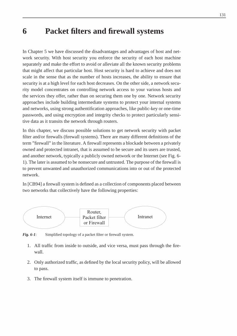
131
6 Packet filters and firewall systems
In Chapter 5 we have discussed the disadvantages and advantages of host and net-work security. With host security you enforce the security of each host machineseparately and make the effort to avoid or alleviate all the known security problemsthat might affect that particular host. Host security is hard to achieve and does notscale in the sense that as the number of hosts increases, the ability to ensure thatsecurity is at a high level for each host decreases. On the other side, a network secu-rity model concentrates on controlling network access to your various hosts andthe services they offer, rather than on securing them one by one. Network securityapproaches include building intermediate systems to protect your internal systemsand networks, using strong authentification approaches, like public-key or one-timepasswords, and using encryption and integrity checks to protect particularly sensi-tive data as it transits the network through routers.
In this chapter, we discuss possible solutions to get network security with packetfilter and/or firewalls (firewall systems). There are many different definitions of theterm ”firewall” in the literature. A firewall represents a blockade between a privatelyowned and protected intranet, that is assumed to be secure and its users are trusted,and another network, typically a publicly owned network or the Internet (see Fig. 6-1). The later is assumed to be nonsecure and untrusted. The purpose of the firewall isto prevent unwanted and unauthorized communications into or out of the protectednetwork.
In [CB94] a firewall system is defined as a collection of components placed betweentwo networks that collectively have the following properties:
Fig. 6-1: Simplified topology of a packet filter or firewall system.
1. All traffic from inside to outside, and vice versa, must pass through the fire-wall.
2. Only authorized traffic, as defined by the local security policy, will be allowedto pass.
3. The firewall system itself is immune to penetration.

132 6 Packet filters and firewall systems
These properties are design goals. A failure in one aspect does not necessarilymeans that the collection is not a firewall, but simply that itis not a good one.Consequently, there are different grades of security that afirewall can achieve. Notethat there must be a local security policy when the rules of the firewall systems areestablished. Other definitions of firewall systems include connections and data stre-ams from inside to outside and vice versa and must be stronglyauthenticated byusers. In this case, the firewall system has to operate at higher layers in a commu-nication protocol stack where information about users is available. These systemsrequire the use of application gateways. Systems which onlyoperate at lower layerswithout authentification information about the end users orconnections are calledpacket filters. For the sake of clarity, in this chapter we make a clear distinctionbetween packet filters (operating at the network layer, Internet layer or transportlayer in the Internet protocol stack) and firewalls operating at some higher layer.The definitions can also be applied to none Internet based protocol stacks. The fire-wall implements parts of a network security policy by forcing all traffic from insideto outside, and vice versa, to be directed or routed to the firewall, where it can beexamined and evaluated accordingly. A firewall also requires its users to stronglyauthenticate themselves before any further action is deployed.
Often there is also made a difference between the terms ”firewall technology” and”firewall system” ( [Sch97]): A firewall technology refers toa set of mechanismsthat can enforce a network security policy on communicationtraffic entering orleaving a domain, whereas a firewall system is an instantiation of the firewall tech-nology.
In the literature the termsinbound andoutbound are used in conjunction with theinbound, outbound
words connection, packet and interface. We will define the use of these in the fol-lowing way: An outbound connection is a connection initiated from a client on aninternal machine to a server running on an external network.An outbound connec-tion includes outbound packets, travelling from the clientto the external server, andinbound packets from the server to the internal client. The inbound interface for apacket refers to the physical network interface on a router that the packet actuallyappeared, while the outbound interface refers to the physical network interface thepacket will go out on if it isn’t denied by the application of aspecific packet filterrule.
Firewall systems also have disadvantages. Probably the main disadvantage is that afirewall can not protect an intranet against inside attacks.For that matter, internalfirewalls may be used to control access between different administration and secu-rity domains, or to protect sensitive parts of a corporate intranet. Internal firewallsare sometimes called intranet firewalls. From a purely technical point of view, thereis nothing that distinguishes an intranet firewall from an Internet firewall exceptfor the policy it enforces. Consequently, we are not going todifferentiate betweenintranet and Internet firewalls in the rest of this chapter.
Packet filters and stateful inspection of connections are addressed in Section 6.1.Packet filters work usually at the Internet layer and transport layer in the Internet

6.1 Packet filtering 133
protocol model (see Fig. 6.1-2). In Section 6.2 circuit-level gateways are described,which are fundamentally different from packet filtering. Application-level gatewaysand proxy servers are discussed in Section 6.3 and possibilities for network topolo-gies and architectures in Section 6.4.
6.1 Packet filtering
A router is an internetworking device that runs an operating system to transfer router
packets between two or more physically separated network segments. It operatesat the network layer in the OSI reference model, or the Internet layer in the Inter-net protocol model. Most routers today are able to route multiple protocols, like IPpackets, IPX packets, etc, but we focus on IP routing. A router transports IP packetsby consulting routing tables that indicate the best path thepacket should take toreach its final destination. More precisely, a router receives an IP packet on one net-work interface (inbound) and forwards it to another networkinterface (outbound).If the router is not able to transport the packet, maybe because of an invalid destina-tion IP address or an errorneous IP header, it sends anInternet Control M essage Internet Control
Message Protokoll,ICMP
Protokoll (ICMP) message to the source IP address.
A packet filter is an internetworking (multihomed) device that applies a set of rules packet filter
to each incoming or on that device generated packet in order to decide whether andhow it will be forwarded or dropped. Specially IP packets arefiltered based oninformation usually found in packet headers, such as
1. inbound network interface or locally generated packet,
2. source and destination IP address,
3. the transported service (UDP, TCP, ICMP),
4. values of IP, TCP or UDP flags and options.
Routers that support packet filtering are sometimes referred to as screening routers.Many commercial router products provide the capability to screen IP packets and tofilter them in accordance with a set of packet filter rules.
Packet filterswork stateless. This means, that any packet is examined isolated fromstateless packet filter
what happened in the past, forcing the packet filter to make decisions to permit ordeny each packet based upon the packet filter rules. This behaviour is sometimesalso referred to as static packet filtering, meaning that thepacket filter rules arestatic and context insensitive.

134 6 Packet filters and firewall systems
6.1.1 Packet filters and the IP protocol family
There exist some special problems that have do be consideredwhen you want toprotect your internal IP network with a packet filter or a firewall ( [ZCC00]):
1. Source Routing option in the IP headerstateless source routing
The most common IP option a firewall would be confronted with is the IPsource route option. Source routing lets the source specifythe route the packetis supposed to take to its destination, rather than letting each router along theway use its routing table to decide where to send the packet next. In practice,source routing is commonly used only by attackers attempting to circumventsecurity measures by causing packets to follow unexpected paths. This is infact a circular problem. Some packet filtering systems take the approach ofdropping any packet that has any IP option set.
2. Fragmentation of IP packetspacket fragmentation
From a packet filtering point of view, the problem with fragmentation is thatonly the first fragment will contain the header information from higher layerprotocols, like TCP, that the packet filtering system needs in order to decidewhether or not to allow the full packet to be transmitted. Originally, the com-mon packet filtering approach to deal with fragmentation wasto allow anynon-first fragments through and to do only packet filtering inthe first frag-ment of a packet. This was considered safe because if the packet filteringdecides to drop the first fragment, the destination system will not be able toreassemble the rest of the fragments into the original packet, regardless ofhow many of the rest of the fragments it receives. If it can notreconstruct theoriginal packet, the partial packet will not be accepted.
However, there still remain problems with fragmented packets. If you pass allnon-first fragments, the destination host will hold the fragments in memoryfor a while, waiting to see if it gets the missing piece. This makes it possiblefor attackers to use fragmented packets in a denial of service attack. When thedestination host gives up on reassembling the packet, it will send an ICMPmessage (”of type ”packet reassembly time expired”) back tothe source host,which will tell an attacker that the host exists and why the connection did notsucceed.
In addition, attackers can use specially fragmented packets to conceal data.Each fragment contains information about where the data it contains startsand ends. Normally, each one starts after the last one ended.However, anattacker can construct packets where fragments actually overlap, and containthe same data addresses. This does not happen in normal operation. It canonly happen when bugs or attackers are involved.
Because of these many and varied problems with fragmentation, you shouldlook for a packet filter that does reassembly. Rather than either permittingor denying fragments, the packet filter should reassemble the packet locally,

6.1 Packet filtering 135
and if necessary, refragment it before sending it further. This will increase theload on the packet filter and/or firewall somewhat, but it protects against allfragmentation-based risks and attacks, except those the packet filter itself isvulnerable to.
If the packet filter can not do fragment reassembly, the safest option is toreject all non-first fragments. This may destroy connections that otherwisewould have succeeded, but it is the lesser of two evils. Denying fragments willcause some connections to fail mysteriously, which is extremely unpleasantto debug. On the other hand, allowing them will open a varietyof attacksthat are widely exploited on the Internet. Fortunately, fragmented packets arebecoming rarer as the use of path MTU discovery increases.
3. TCP connections TCP connections
TCP is connection oriented and bidirectional in that once a connection isestablished, a server can reply to a client over the same connection. If TCPconnections should be blocked, it is sufficient to simply block the first packet(setup) of the connection. Without that first packet, any further packets in thatconnection can not be reassembled into a data stream by the receiver, and theconnection will never be made. That first packet is recognizable because theACK bit in its TCP header is not set and the SYN bit is set. All other packetsin the connection, regardless of which direction they are going in, will havethe ACK bit set.
Recognizing these ”start-of-connection” TCP packets letsyou enforce apolicy that allows internal clients to external servers butwould not allowexternal clients to internal servers. Attackers cannot subvert this approachsimply by turning on the ACK bit in their start-of-connection packets, becausethe absence of the ACK bit is what identifies these packets as start-of-connection packets.
Packet filtering implementations vary in how they treat and let you handlethe ACK bit. Some packet filtering implementations give direct access to theACK bit. Some other implementations give indirect access tothe ACK bit.Finally, some implementations do not let you examine the ACKbit at all.
6.1.2 Packet filtering for FTP sessions
There are some practical problems related to the use of static packet filtering, forexample with the FTP protocol. Consider an FTP session initiated by a client run-ning on an internal machine, which is inside the intranet. The FTP server resides onthe Internet. The FTP session basically consists of two TCP connections:
1. An outbound control connection initiated by the client.
2. An inbound data connection initiated by the server.

136 6 Packet filters and firewall systems
The outbound connection is initiated by the client from a random TCP port to theFTP server control port 21. The inbound connection for data transfer is initiatedby the FTP server data port 20 to a specific port on the client side. More precisely,the client informs the server about the destination port number it should use toconnect to for the inbound connection by using an FTP PORT command. To openthe data connection, the server establishes a TCP connection to that particular port.Consequently, the packet filtering device will see an inbound TCP segment trying toestablish an inbound connection. Most packet filters are configured to discard thesekinds of TCP segments and drop the corresponding IP packets accordingly.
From the packet filter’s point of view, the problem of FTP exists because the dataconnection is inbound, meaning that it is established from an external server to aninternal client. The problem is trivially solvable if both connections (the FTP controlconnection and the FTP data connection) are established outbound, meaning thatthey are initiated by the client.
Following this line of argumentation,passive mode FTPhas been proposed aspassive mode FTP
a preliminary solution in RFC 1579 ( [Bel94]). In passive mode FTP, instead ofsending out an FTP PORT command, the client waits for the server to specify aparticular port number and establishes an outbound TCP connection to that port. Asa result, any packet filter sitting between the client and theserver experiences twooutbound TCP connections (instead of one outbound and one inbound connection,as in the case of normal mode FTP). In general, the network security policy thatdrives the packet filtering device allows outbound connections to be established andtolerates passive mode FTP accordingly.
In summary, passive mode FTP represents a viable solution for intelligently filteringFTP traffic. It is however, not a general solution and other application protocols maycome up with different problems that can not be addressed with passive mode.
6.1.3 Stateful inspection
A more general solution to filter connection oriented services is called statefulinspection. It was suggested to introduce some state into the packet filtering process.Consequently, the resulting packet filter rules are dynamicand context-sensitive, thefirst attribute also being reflected in the termdynamic packet filtering that is some-dynamic packet
filtering times used as a synonym for stateful inspection.
Stateful inspection(or dynamic packet filtering) looks at the same header informa-stateful inspection
tion as static packet filtering does, but can also peek into the payload data wherethe transport and application layer data usually appears. More importantly, statefulinspection maintains state information about passed IP packets. It compares the firstpacket in a TCP connection to the packet filter rules, and if the packet is permitted,state information is added to an internal database. Think ofthis state informationrepresenting an internal virtual circuit in the firewall on top of the transport layerassociation. This information permits subsequent packetsin that association to passquickly through the firewall. If the rules for a specific type of service require exami-ning application data, the part of each packet must still be examined.

6.1 Packet filtering 137
For example, a dynamic packet filtering device can react on seeing an FTP PORTcommand by creating a dynamic rule permitting a TCP connection back from theFTP server to that particular port number of the client side.Logging, or authentica-tion as required by the rules, generally occurs at the application layer. Although theopportunity for better logging is present, stateful inspection firewalls typically onlylog the source and destination IP addresses and port numbers, similar to loggingwith a packet filter or screening router.
In spite of the fact that you can introduce state informationto improve the capabi-lities of a packet filtering device, the problem remains thatthere is no such thing asan association between a data stream and a previously authenticated and authorizeduser. To make things worse, there is no such thing as a user on the Internet layerwhere packet filtering occurs. Consequently, true firewallsmust operate above theInternet layer, typically at the transport layer.
There are also further problems with stateful packet filtering:
1. State tracking of a packet filter provides the ability to dothings that you can-not do therewise, but it also adds complications. First, thepacket filter has tokeep track of the state. This increases the load on the packetfilter, opens itto a number of denial of service attacks, and means that if therouter reboots,packets may be denied when they should have been accepted. Ifa packetmay go through redundant packet filters, they all need to havethe same stateinformation. There are protocols for exchanging this information, but it isstill a tricky business. If you have redundant routers simultaneously, the stateinformation needs to be transferred between them almost continously, or theresponse packet may come through before the state is updated.
2. Second, the packet filter has to keep track of state withoutany guarantee thatthere is ever going to be a response packet. Not all UDP packets have respon-ses. At some point, the packet filter needs to give up and to getrid of the rulethat will allow the response. If the packet filter gives up tooearly, it will denypackets that should have been accepted, causing delays and unneeded net-work traffic. If the router keeps the rule too long, the load onthe router willbe unnecessarily high, and there is an increased chance thatpackets will beaccepted when they should have been denied. Some protocol specificationsprovide guidelines, but these are not necessarily useful. For instance, DNS(Domain Name Service) replies are supposed to arrive within5 seconds, butreply times for name service queries across the Internet canbe as high as 15seconds. An implementation of the protocol specification will almost surelydeny a response that you wanted to be accepted.
6.1.4 Network Address Translation (NAT)
Network Address Translation (NAT) allows a network (intranet) to use one setNetwork AddressTranslation, NATof network addresses internally and a different set when dealing with external net-
works. NAT does not, by itself, provide security, but it helps to conceal the internal

138 6 Packet filters and firewall systems
network layout and to force connections (from inside to outside, and vice versa) togo through a choke point. NAT, routing, and packet filtering can be done by onehost, between the intranet and the Internet. Only the NAT host has an official andvalid Internet address. The addresses of the other hosts of the intranet (private net-work) have IP addresses that are not public to the Internet. An address allocationscheme for intranets is described in RFC 1918 ( [RM+96]).
NAT is standardized in RFC 2766 [TS00] by the IETF. For further information wealso refer to [SH99] and [SE01].
Like packet filtering, NAT works by having a router to do extrawork. In this case,the router not only sends packets, but also modifies them. When an internal hostsends a packet to the outside, the network address translation system modifies theIP source address of the IP packet to make the packet look as ifit is coming froma valid Internet address. When an external host sends a packet to the inside, thenetwork address translation system modifies the destination address into the correctinternal address. The network address translation system can also modify the sourceand destination port numbers. This is also called asPort and Address TranslationPort and Address
Translation, PAT (PAT).
Network address translation systems can use different schemes for the translationbetween internal and external addresses:
1. Allocation of one external host address for each internalhost and alwaysapply the same translation: This technique provides no savings in addressspace, and it slows down connections. It is normally a temporary measureused by sites that have been using illegal address space but are in the processof moving to using valid addresses.
2. Dynamic allocation of an external host address each time an internal hostinitiates a connection, without modifying port numbers: This limits the num-ber of internal hosts that can simultaneously access the Internet to the numberof available external addresses.
3. Creation of a fixed mapping from internal IP addresses to externally visibleaddresses, but with the use of port mapping so that multiple internal hosts usethe same external IP addresses but with a different port number.
4. Dynamically allocation of an external host address and port pair each time aninternal host initiates a connection. This makes the most efficient possible useof the external host addresses.
There exist also some security advantages in the use of NAT:
1. NAT helps to enforce the packet filter and firewall control over outboundconnections.
2. NAT can help to restrict incoming traffic, if dynamic allocation schemes areused.
3. NAT helps to conceal the internal network configuration.

6.1 Packet filtering 139
While NAT is a very useful way of conserving network address space, it presentssome problems:
1. Dynamic allocation requires state information that is not always available forthe NAT system.
2. Embedded IP addresses in the packet payload are a problem for NAT.
3. NAT interferes with some encryption and authentication protocols includingIPsec (see Chapter 3), which protects the entire IP packet including the IPheader.
4. Dynamic allocation of addresses interferes with logging.
5. Dynamic allocation of ports may interfere with packet filtering.
The NAT protocol is an extension module in the packet filter program iptables (seeSection 6.1.5).
We will now discussmasqueradingwhich is a form or system of network addressmasquerading
translation. Because it is capable of working at higher protocol levels, and doingmore intricate modifications than simple address changes, it is also called atransparent proxying system. What it does could be considered either proxyingtransparent proxying
systemor packet filtering: it is somewhere in between the two.
The IP address of the packet filter or firewall system is used tocommunicate withremote services. For simple protocols, masquerading alters only IP header informa-tion, including IP addresses, port numbers, and TCP sequence and acknowledge-ment numbers. Masquerading uses the IP address of the host (packet filter or fire-wall) doing the masquerading as the externally visible address, and maps the portnumber into one from a fixed pool of ports. Masquerading worksby interceptingpackets that are being forwarded by the packet filter. Masquerading for simple pro-tocols works much like simple network address translation.IP addresses and portnumbers are modified on outgoing packets. For TCP connections, a new sequencenumber is generated. The process is reversed for incoming packets.
Example 6.1-1: Masquerading of an internal serviceSuppose we have an internal network141.161.1.0 with a subnet mask255.255.255.0 . In this internal network there is a host (IP number141.161.1.3 ) with a Telnet serverS running on TCP port22 . The inter-nal network is protected with a packet filter with routing andmasqueradingfunctionality. This packet filterP has two network interfaces, one connectedwith the internal network and one connected with the Internet (IP number172.16.3.5 ). The internal network is not visible from the Internet. Themas-querading system is so configured, that incoming TCP packetswith destinationIP number172.16.3.5 and destination port22 are modified and forwardedin the internal network with the destination IP address141.161.1.3 and thedestination port number23 . If a Telnet clientCon the Internet (for example withIP number123.67.5.4 ) sends a TCP connection request to172.16.3.5

140 6 Packet filters and firewall systems
and destination port23 , this request is forwarded to141.161.1.3 and port23 .
The first two steps of the connection (request and response) are as follows, whereX is an arbitrary port number≥ 1024:
1. C → P :(source IP=132.67.5.4 , source port=X, dest. IP=172.16.3.5 , dest.port=23)
2. P → S:(source IP=132.67.5.4 , source port=X, dest. IP=141.161.1.3 ,dest. port=23)
3. S → P :(source IP=141.161.1.3 , source port=23 , dest. IP=132.67.5.4 ,dest. port=X)
4. P → C:(source IP=172.16.3.5 , source port=23 , dest. IP=132.67.5.4 ,dest. port=X)
6.1.5 Packet filters for the Linux operating system
In this section we describe how to configure the most well known, free available,and recent packet filter for the Linux operating system, namely iptables .
If you want to build a firewall system for the Internet protocols on a Linux platform,it depends on the version of the kernel of your Linux system. If the kernel version isprior to 2.2, you should use theipfwadm utility. Kernels with version 2.2.x supportipfwadm
the third generation program of packet filters, calledipchains. Linux kernels 2.3.15ipchains
and later support the fourth generation of Linux packet filters callediptables. Alliptables
three tools can be used to build a packet filter by defining rules which are appliedto IP packets. The Linux kernel must be configured to support IP packet filtering.This could be done by selecting the appropriate options whenperforming themake
menuconfig command in the process of compiling the Linux kernel.
The use and configuration of the toolsipfwadm andipchains are described in[KD00] (chapter 9) and in [ZCC00]. We will focus on the newestdevelopments ofIP packet filters for the Linux operating system:iptables .
While developingipchains , Paul Russel decided that IP packet filtering shouldbe less difficult on the Linux operating system. He soon set about the task of sim-plifying aspects of packet processing in the Linux kernel packet filtering code andproduced a filtering framework that was transparent and muchmore flexible. Hecalled this new frameworknetfilter . This concept was implemented and a new andnetfilter

6.1 Packet filtering 141
extensible configuration and management tooliptables was created35.
Iptables is used to set up, maintain and inspect the tables of IP packetfilter rulesin the Linux kernel. There are several different tables (filter , nat , mangle anduser-defined), and each table contains a number of built-in chains, and may containuser-defined chains. Each chain is a list of rules which can match a set of packets:each rule specifies what to do with a packet which matches. This is called thetarget targets
of a packet, which may be an action like accepting, dropping,modifying a packetor to jump to a user-defined chain in the same table or a return to the calling chain:
1. ACCEPTmeans to let the packet through.
2. DROPmeans to drop the packet.
3. QUEUEmeans that the packet is passed to a user-defined chain.
4. RETURNmeans stop traversing this chain, and resume at the next rulein theprevious calling chain.
If the packet does not match a rule, the next rule in the chain is examined. If the endof a user-defined chain is reached, or a rule in a built-in chain with targetRETURN
is matched, the target specified by the chain policy determines the fate of the packet.
Fig. 6.1-1 shows the different ways of packets through the system of a host and thepointsPi, 1 ≤ i ≤ 5, where iptables can interact with the packets. The packets canbe generated by a local process or are arriving at a network interface of the host(at the left side of Fig. 6.1-1). The packets are leaving the host system through anetwork interface (at the right side of Fig. 6.1-1) or end at alocal process, if theyare not dropped by a rule ofiptables .
There are currently three independent tables, which are present depending on thekernel configuration options and the dynamically loaded modules. Thetablesand tables and chains
chains are as follows (see Fig. 6.1-2):
1. filter : This is the default table, and contains the built-in chainsINPUT at P4
for packets to a local process,FORWARDat P2 for packets being through anetwork interface, andOUTPUTatP5 for locally generated packets.
2. nat: This table can be used to do network address translation. Itconsists ofthree built-in chains:PREROUTINGatP1 for altering packets as soon as theycome in the host,OUTPUTatP5 for altering locally-generated packets beforerouting, andPOSTROUTINGat P3 for altering packets as they are about togo out.
35 The official homepage ofnetfilter is http://www.netfilter.org/. There you can find codesources, documentation, FAQs, tutorials and presentations concerningnetfilter andiptables

142 6 Packet filters and firewall systems
3. mangle: This packet is used for specialized packet alteration. It has two built-in chains:PREROUTINGat P1 for altering incoming packets before routingandOUTPUTatP5 for altering locally-generated packets before routing.
Fig. 6.1-1: This figure shows the different ways of a packet through the system of a host and thepointsPi, 1 ≤ i ≤ 5, whereiptables can interact with the packets.
Fig. 6.1-2: Tables and chains ofiptables .
With the commandiptables the chains can be defined, extended and managed.A call has the following structure:
iptables -t table command chain parameters options
wheretable is fromfilter (default),nat or mangle, andcommandis a commandto modify thechain in the selected table. For the long versions of the command,parameter and option names one only need to use enough letters to ensure thatiptables can differentiate it from all other options.
The following commands exist in iptables:
• -A, --append: Append one or more rules to the end of the selected chain. Therules in a chain are numbered upwards from one.
• -C, --check: Check the datagram described by the rule specification against thespecific chain. This command will return a message describing how the chainprocessed the datagram.
• -D, --delete: Delete one or more rules from the selected chain.
• -R, --replace: Replace a rule in the selected chain.
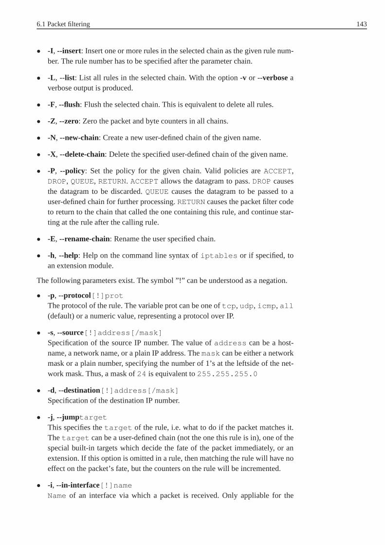
6.1 Packet filtering 143
• -I , --insert: Insert one or more rules in the selected chain as the given rule num-ber. The rule number has to be specified after the parameter chain.
• -L , --list: List all rules in the selected chain. With the option-v or --verboseaverbose output is produced.
• -F, --flush: Flush the selected chain. This is equivalent to delete all rules.
• -Z, --zero: Zero the packet and byte counters in all chains.
• -N, --new-chain: Create a new user-defined chain of the given name.
• -X, --delete-chain: Delete the specified user-defined chain of the given name.
• -P, --policy: Set the policy for the given chain. Valid policies areACCEPT,DROP, QUEUE, RETURN. ACCEPTallows the datagram to pass.DROPcausesthe datagram to be discarded.QUEUEcauses the datagram to be passed to auser-defined chain for further processing.RETURNcauses the packet filter codeto return to the chain that called the one containing this rule, and continue star-ting at the rule after the calling rule.
• -E, --rename-chain: Rename the user specified chain.
• -h, --help: Help on the command line syntax ofiptables or if specified, toan extension module.
The following parameters exist. The symbol ”!” can be understood as a negation.
• -p, --protocol[!]prot
The protocol of the rule. The variable prot can be one oftcp , udp , icmp , all
(default) or a numeric value, representing a protocol over IP.
• -s, --source[!]address[/mask]
Specification of the source IP number. The value ofaddress can be a host-name, a network name, or a plain IP address. Themask can be either a networkmask or a plain number, specifying the number of 1’s at the leftside of the net-work mask. Thus, a mask of24 is equivalent to255.255.255.0
• -d, --destination[!]address[/mask]
Specification of the destination IP number.
• -j , --jump target
This specifies thetarget of the rule, i.e. what to do if the packet matches it.Thetarget can be a user-defined chain (not the one this rule is in), one ofthespecial built-in targets which decide the fate of the packetimmediately, or anextension. If this option is omitted in a rule, then matchingthe rule will have noeffect on the packet’s fate, but the counters on the rule willbe incremented.
• -i, --in-interface[!]name
Nameof an interface via which a packet is received. Only appliable for the

144 6 Packet filters and firewall systems
INPUT, FORWARDandPREROUTINGchains. If the interface name ends witha ”+”, then any interface which begins with this name will match.
• -o, --out-interface[!]name
Nameof an interface via which a packet is going to be sent. Only appliable fortheFORWARD, OUTPUTandPOSTROUTINGchains. If the interface name endswith a ”+”, then any interface which begins with this name will match.
• [!] -f, --fragmentThis means that the rule only refers to second and further fragments of fragmen-ted IP packets. When the ”!” argument preceeds the ”-f” flag, the rule will onlymatch head fragments, or unfragmented packets.
Iptables can use extended packet matching modules. These modules canbe loa-ded in two ways, when-p or --protocol is specified, or explicitly with the-m or--match options, followed by the matching module name. After these,various extracommand line options become available, depending on the specific module. Besidesother, the following module names and protocols are possible:
1. tcp for TCP packets,
2. udp for UDP packets,
3. icmp for ICMP packets and
4. max for specifications for packets on the network layer.
For TCP packets (--protocoltcp ), the following options are possible:
• --source-port[!][port[:port]]
TCP source port specification. This can be a service name or a port number. Aninclusion range can also be specified, using the formatport:port . If the firstport is omitted, ”0” is assumed. The flag--sport is an alias for this option.
• --destination-port[!][port[:port]]
TCP destination port specification. The flag--dport is an alias for this option.
• --tcp-flags[!]mask comp
Match when the TCP flags are as specified. The first argument (mask) is theflags which should examine, written as comma-separated list, and the secondargument (comp) is a comma-separated list of flags which must be set. Flagsare:SYN, ACK, FIN , RST, URG, PSH, ALL, NONE.
• [!] --synOnly match TCP packets with theSYNbit set and theACKandFIN bits clea-red. Such packets are used to request TCP connection initiation. For exam-ple, blocking such packets coming in an interface will prevent incoming TCPconnections, but outgoing TCP connections will be unaffected. This option isequivalent to--tcp-flagsSYN,RST,ACK,SYN. If the ”!” preceeds the ”--syn”, thesense of the option is inverted.

6.1 Packet filtering 145
• --tcp-option[!]number
Match the packet, if the TCP optionnumber is set.
For UDP packets (--protocoludp ), the following options are possible:
• --source-port[!][port[:port]]
UDP source port specification. The flag--sport is an alias for this option.
• --destination-port[!][port[:port]]
UDP destination port specification. The flag--dport is an alias for this option.
For ICMP packets (--protocolicmp ), the following option is possible:
• --icmp-type[!]typename
This allows the specification of theICMP type , which can be a numeric ICMPtype, or one of the ICMP type names shown by the commandiptables -p
icmp -h .
The following option is possible for protocols in the network layer:
• --mac-source[!]address
MAC address specification. It must be of the formXX:XX:XX:XX:XX:XX .Note that this only makes sense for packets entering thePREROUTING,FORWARD, INPUT chains for packets coming from an ethernet device.
There exist a lot of extension modules for logging of packetsand actions, multiportdefinitions, to attempt to match various characteristic of the packet creator, statetracking and network address translation
Example 6.1-2: Iptables rules for a small networkNow we want to discuss a small network scenario. Suppose our intranet has thesubnet IP number172.16.1.0 with subnet mask255.255.255.0 , whichis equal to24 ones from the left side. The users in the subnet are allowed toaccess WWW servers on the Internet with their WWW browsers, but no othertraffic is allowed. Remember, WWW servers listen usually on port 80 of theTCP protocol for connection requests.
A screening router with Linux operating system (kernel≥ 2.4) and installediptables is physically between the Internet and the local intranet. The scree-ning router has two network interfaces, one is connected with the Internet andthe other with the intranet.
Thenetfilter kernel module has to be configured to fulfill the above policyfor the intranet.
At first the kernel module that provides support fornetfilter has to be loa-ded in the kernel:
$ modprobe ip tables

146 6 Packet filters and firewall systems
Now the commands to build the chains for thefilter table, that fulfill theabove policy:
$ iptables -F OUTPUT$ iptables -P OUTPUT DROP
$ iptables -F INPUT
$ iptables -P INPUT DROP$ iptables -F FORWARD
$ iptables -P FORWRAD DROP$ iptables -A FORWARD -m tcp -p tcp -s 0/0 --sport 80
-d 172.16.1.0/24 --syn -j DROP
$ iptables -A FORWARD -m tcp -p tcp -s 172.16.1.0/24-d 0/0 --dport 80 -j ACCEPT
$ iptables -A FORWARD -m tcp -p tcp -s 0/0--sport 80 -d 172.16.1.0/24 -j ACCEPT
The tablefilter has not to be specified, becausefilter is the default table.With the first six commands all three chains in thefilter table are cleanedand the default policy of the chains is set toDROP.
Exercise 6.1-1:
1. Is a packet filter in our definition a firewall system? Give reasons!
2. What is a security policy and what should it include?
3. How do we call routers that support packet filtering?
4. What problems arise with the fragmentation process of IP packets, if you wantto protect your IP network with a packet filter?
6.2 Circuit-level gateways
In general networking terminology, an application gatewayor gateway refers to aninternetworking device that connects one network to another for a specific appli-cation. Therefore, the gateway must understand and implement the correspondingapplication protocol. In the client-server model, a gateway refers to an intermediateprocess running between the client that requests a particular service and the serverthat provides the service. In this model, the gateway functions as a server from theclient’s point of view, and as a client from the server’s point of view. In general, agateway either works at the application layer or at the transport layer ( [Opp00]):
1. If a gateway works at the application layer, it is usually called an application-level gateway, or proxy server in short (see Section 6.3).

6.2 Circuit-level gateways 147
2. If a gateway works at the transport layer, it is usually called a circuit-levelgateway.
Most gateways used in firewall configurations work at the application layer andactually represent application-level gateways or proxy servers. In either case, theapplication gateway runs on a firewall host and performs a specific function as aproxy on the user’s behalf.
The idea of a circuit-level gateway is fundamentally different from packer filtering(either static or dynamic). In essence, a circuit-level gateway takes a TCP connec-tion request form a client, authenticates and authorizes the client, and establishesa second TCP connection to the origin server on the client’s behalf. After havingsuccessfully established this second TCP connection, the circuit-level gateway sim-ply relays data forth and back between the two connections. In particular, it doesnot interfere with the data stream. This differentiates a circuit-level gateway froman application-level gateway or proxy server that is able toactually understand theapplication protocol employed by the two endpoints of the connection.
The single circuit-level gateway that is actually in widespread use isSOCKS. SOCKS
SOCKS36 follows a customized client approach, meaning that it requires custo-mizations and modifications to client software, but no change is usually required touser procedures. More precisely, SOCKS requires modifications either to the clientsoftware or to the TCP/IP stack to accommodates the interception at the firewallbetween the client and the server:
1. A client that has been modified to handle SOCKS interactions is commonlyreferred to a socksified client. Following this terminology, Netscape Naviga-tor is a socksified HTTP client, as it accommodates interactions with SOCKSserver. A socksified client issues SOCKS calls that are transparent to theusers.
2. Socksified TCP/IP stacks are also available, which may obviate the need forclient software modifications.
In either case, the SOCKS server resides at the firewall host and interacts with thesocksified clients or TCP/IP stacks. There are no further changes required for theservers.
SOCKS and the SOCKS protocol for communications between a socksified clientand a SOCKS server were originally developed by David and Michelle Koblas ([KK92]). There are several software packages publicy and freely available on theInternet. A package consist of two components:
1. A SOCKS server, calledsocksd , and
2. a SOCKS library that can be used to replace regular TCP/IP function calls inthe client software.
36 The homepage of SOCKS is http://www.socks.permeo.com/

148 6 Packet filters and firewall systems
The design goal of SOCKS was to provide a general framework for TCP/IP applica-tions to securely use the services of a firewall. Complying with these design goals,SOCKS is independent of any supported TCP/IP application protocol. When a sock-sified client requires access to an Internet server, it must first open a TCP connectionto the appropriate port on the SOCKS server residing on the firewall system. TheSOCKS server is conventionally located on TCP port 1080. If the TCP connectionis established, the client sends a connection relay requestto the SOCKS server. Therequest includes the following information: desired (IP) destination address, desireddestination port and authentication information.
The SOCKS server evaluates the information from the client in the connection relayrequest. During this evaluation, it may perform various functions, such as authen-tication, authorization, message security-level negotiation, and so on. The SOCKSserver either accepts the request and establishes a corresponding connection to theInternet application server, or rejects the request. The evaluation depends on theconfiguration data of the SOCKS server. Once the requested connection is establis-hed, the SOCKS server simply relays data between the client and the server.
There are currently two versions of SOCKS available: SOCKS version 4 andSOCKS version 5. SOCKS V4 has been widely used in firewall systems, but itdoes not use real user authentication. It bases its decisions on whether to allow ordeny connections on the same sort of information that packetfilters use. SOCKSV5 provides support for several different ways of authenticating users, which givesyou more precise control and logging. The SOCKS V5 protocol is standardized bythe IETF in RFC 1928 ( [LGL+96]). Two authentification methods are specified:
1. Password-based authentification in [Lee96] and
2. Kerberos V5 GSS-API authentification in [McM96].
Further differences of Version 4 and 5 are described in [ZCC00] and [Opp00].
Finally, note that the only difference between a circuit-level gateway and a simpleport forwarding mechanism is that with circuit-level, the client is aware of the inter-mediate system, whereas in the case of a port forwarding mechanism, the client maybe completely oblivious of the existence of the intermediate. Also, a circuit-level isgeneric, and any TCP connection can be handled by the same gateway. Contrary tothat, a port forwarding mechanism is usually specific to a specific service, meaningthat all qualifying TCP segments are forwarded to a specific port of the destinationserver.
6.3 Application-level gateways and proxy servers
An application-level gateway or proxy-server is similar toa circuit-level gatewayas explained in the previous section. The main difference isthat the former under-stands the application protocol being relayed, whereas thesecond is generic and notapplication-specific. Consequently, a specific application-level gateway or proxyserver is implemented for each application protocol a firewall must support. In the

6.3 Application-level gateways and proxy servers 149
rest of this chapter, we use the terms application-level gateway and proxy serversynonymously and interchangeably.
Typically, when a client contacts an application-level gateway using one of theTCP/IP application protocols, such as Telnet, FTP, or HTTP,the gateway asksfor some valid user authentification and authorization information. In the easiestcase, this information simply consists of a username and a corresponding password.However, if the proxy server is accessible from the Internet, it is strongly recom-mended to use some strong authentication mechanisms, such as provided by one-time passwords or challenge-response systems. If the proxyserver accepts the userauthentication and authorization information, it either connects to a preconfiguredremote system to be accessed on the user’s behalf, such as an FTP or WWW server.In the second case, it is up to the user to respond accordinglyand to provide thename of a remote system. The proxy server, in turn, contacts the remote system andestablishes a secondary TCP connection to that system. After having established thesecondary TCP connection, the proxy server fully controls the data stream that isbeing relayed between the two connections. In particular, the proxy server can scanthe data stream for specific protocol commands or data contents, as well as enforcespecific restrictions on inbound and outbound traffic.
In order to properly authenticate a user, an application-level gateway or proxy servermust have access to some identification and authentication information. In principle,this information can be either locally stored or remotely archived and made availablethrough a security server.
The details on how proxying works differ from service to service. Some servicesprovide proxying easily or automatically. For these services, you set up proxyingby making configuration changes to normal servers. For most services, however,proxying requires appropriate proxy server software on theserver side. On the clientside it needs one of the following ( [ZCC00]):
1. Proxy-aware application softwareWith this approach, the software must know how to contact theproxy serverinstead of the real server when a user makes a request, and howto tell theproxy server what real servers to connect to.
2. Proxy-aware operating system softwareWith this approach, the operating system that the client is running on is modi-fied so that IP connections are checked to see if they should besent to theproxy server. This mechanism usually depends on dynamic runtime linking.This mechanism does now always work and can fail in ways that are notobvious to users.
3. Proxy-aware user proceduresWith this approach, the user client software that does not understand proxyingto talk to the proxy server tells the proxy server to connect to the real server,instead of telling the client software to talk to the real server directly.

150 6 Packet filters and firewall systems
4. Proxy-aware routerWith this approach, nothing on the client’s end is modified, but a router inter-cepts the connection and redirects it to the proxy server or proxies the request.This requires an intelligent router in addition to the proxyserver software.
Thefree firewall toolkit 37 (TIS FWTK ), from Trustd Information Systems, inclu-TIS FWTK
des a number of proxy servers of various types. TIS FWTK also provides a numberof other tools for authentication and other purposes. Whereas SOCKS attempts toprovide a single, general gateway, TIS FWTK provides individual proxies for themost common Internet services. The idea is that by using small separate programswith a common configuration file, it can provide intelligent proxies that are safe,while still allowing central control. The result is an extremely flexible toolkit and arather large configuration file. TIS FWTK includes:
• An authentication server that provides several mechanismsfor supporting non-reusable passwords
• An access control program
• Proxy servers for a variety of protocols
• A generic proxy server for simple TCP-based protocols usingone-to-one ormany-to-one connections
• A wrapper for SMTP servers such as Sendmail to protect them form SMTP-based attacks
• A wrapper for inetd started servers to control where they canbe contacted from.
6.4 Architectures and network topologies
In this section we discuss how to set up network topologies for packet filters orfirewall systems to make an intranet secure.
In general, a firewall system consists of packet filters and application gateways(circuit-level or application-level). There are many possibilities to combine thesecomponents in firewall configurations. These are described in the next sections([ZCC00], [Opp00]).
37 The homepage of TIS FWTK is http://freshmeat.net/projects/tisfirewalltoolkit/

6.4 Architectures and network topologies 151
6.4.1 Screening router
A simple topology (see Fig. 6.4-1) consists of a screening router, which connectsthe hosts on the intranet with the Internet. The screening router forwards or blockspackets, as determined by the site’s security policy. This is a low-cost system, sinceyou almost always need a router to connect to the Internet anyway, and you can sim-ply configure packet filtering in that router. If the screening router is compromisedor wrongly configured, you have no further security.
Fig. 6.4-1: Screening router.
A screening router is an appropriate firewall in situations where:
• The network being protected already has a high level of host security.
• The number of protocols being used is limited, and the protocols themselves arestraightforward.
• You require maximum performance and redundancy.
6.4.2 Dual-homed host
A dual-homed host architecture (see Fig. 6.4-2) is built around a dualhomed hostcomputer. Adual-homed hostis a computer that has at least two network inter-dual-homed host
faces. Such a host could act as a router between the networks these interfaces areattached to. It is capable of routing IP packets from one network to another. Howe-ver, to use a dual-homed host as a firewall, all routing functions are disabled. Thus,IP packets from one network are not directly routed to the other network. Systemsinside (on the intranet) can communicate with the dual-homed host, and systemsoutside the firewall (on the Internet) can communicate with the dual-homed host,but these systems can not communicate directly with each other.

152 6 Packet filters and firewall systems
Fig. 6.4-2: Dual-homed host.
Dual-homed hosts can provide a very high level of control. Ifyou aren’t allowingpackets to go between external and internal networks at all,you can be sure that anypacket on the internal network has an external source is evidence of some kind of asecurity problem.
On the other hand, dual-homed hosts are not high performancedevices. A dual-homed host has more work to do for each connection than a packet filter (screeningrouter) does, and correspondigly needs more resources.
Since a dual-homed host is a single point of failure, it is important to make certainthat its host security is absolutely impeccable. An attacker who can compromisethe dual-homed host has full access to your site. An attackerwho crashes the dual-homed host can cut you off from the Internet. Hosts with a highlevel of host securityand firewall functions are calledbastion host.bastion host
The Internet community uses the term bastion host to refer toa bastion host com-puter system that is part of a firewall configuration and hostsfor one or several app-lication gateways. The term ”bastion” comes from the heavily fortified projectionson the exteriors of castles in medieval times. A bastion hostshould be configuredto be particularly secure, since it is exposed to direct attacks form the Internet (hostsecurity). Typically, a bastion host is located in a secure environment by residingon a secure operating system. In this case, the secure operating system must protectthe firewall code and files from outside attacks.
6.4.3 Screened host
A better topology for a bastion host is shown in Fig. 6.4-3. Inthis architecture,the primary security is provided by packet filtering. The bastion host sits on theinternal network. The screening router is configured to accept only traffic from thebastion host to the Internet and vice versa. The other hosts on the intranet can onlycommunicate over the bastion host to the Internet. Any external system trying toaccess internal systems or services will have to connect to this host. The bastionhost thus needs to maintain a high level of host security.

6.4 Architectures and network topologies 153
Fig. 6.4-3: Screened host.
For most purposes, the screened host architecture providesboth better security andbetter usability than the dual-homed host architecture. Compared to other architec-tures, however, such as the screened subnet architecture (Section 6.4.4), there aresome disadvantages of the screened host architecture. The major one is that if anattacker manages to break in to the bastion host, nothing is left in the way of networksecurity between the bastion host and the rest of the internal hosts. The screeningrouter also presents a single point of failure. If the screening router is compromised,the entire network is available to an attacker. For this reason, the screened subnetarchitecture, discussed next, has become increasingly popular.
A screened host architecture is appropriate when:
• Few connections are coming from the Internet. In particular, it is not an appro-priate architecture if the screened host is a public WWW server.
• The network being protected has a relatively high level of host security.
6.4.4 Screened subnet
Fig. 6.4-4 illustrates the architecture of a screened subnet firewall38. In short, itconsists of two screening routers used to create an outer andinner network segment.The outer network segment is also called a screened subnet ordemilitarized zone(DMZ 39). The DMZ may contain host application gateways running on one or more DMZ
bastion hosts, as well as some additional servers that require carefully controlledInternet access, i.e. public WWW or FTP servers. Internal servers and hosts may beconnected to the inner network segment.
38 You can also find topologies in the literature, that are a little bit different from Section 6.4.4and are named also as screened subnet.
39 The DMZ is named after the strip of no-man’s-land between North and South Korea.
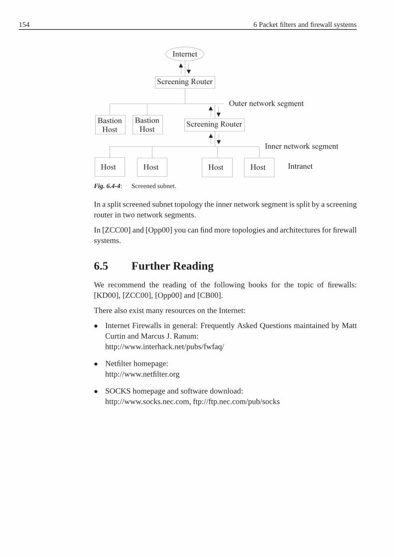
154 6 Packet filters and firewall systems
Fig. 6.4-4: Screened subnet.
In a split screened subnet topology the inner network segment is split by a screeningrouter in two network segments.
In [ZCC00] and [Opp00] you can find more topologies and architectures for firewallsystems.
6.5 Further Reading
We recommend the reading of the following books for the topicof firewalls:[KD00], [ZCC00], [Opp00] and [CB00].
There also exist many resources on the Internet:
• Internet Firewalls in general: Frequently Asked Questionsmaintained by MattCurtin and Marcus J. Ranum:http://www.interhack.net/pubs/fwfaq/
• Netfilter homepage:http://www.netfilter.org
• SOCKS homepage and software download:http://www.socks.nec.com, ftp://ftp.nec.com/pub/socks

155
7 Application Layer Security
7.1 Introduction
Users interact at the application layer of the OSI referencemodel for communica-tion. The application layer must be protected as vigorouslyas the other layers of theOSI model.
This chapter’s focus is on security issues intrinsic to the application layer.
We will next overview all proposals concerning the securityof Internet services andapplications with the hope to find which layer is well suited to provide the securityrequired (see Fig. 7.1-1):
Fig. 7.1-1: Securing Internet services in different layers [FRU00].
1. Security protocols and mechanisms operating at the Internet layer:The IP protocol is the protocol operating at the Internet layer40. So, if secu- IP protocol
rity services are provided at the network layer, the basic IPsoftware must bereplaced by or enhanced with modules to add security mechanisms. There-fore, existing applications can make use ofIPSec41 to provide security at the IPSec
IP layer in a transparent way. This means that we do not need todevelop newsecure applications. But Internet layer security has some disadvantages. Oneof them is, that it requires the use and deployement of newTCP/IP modules. TCP/IP modules
This requirement can not be met by less widely operating systems, since itleads to a very costly process.
40 See chapter 2.
41 See chapter 3.

156 7 Application Layer Security
2. The use of transport layer security:As mentioned in Chapter 3,SSL was originally conceived to protect theSSL
HTTP protocol. Thereafter, it was adapted to be able to provide security ser-vices for arbitrary TCP/IP based application protocols such as HTTP, FTPetc. One advantage of SSL is that transport layer security operates on an end-to-end basis. Since SSL is located between the transport andthe applicationlayer (see Fig. 7.1-1) each service of the application layercan directly useSSL-based connections and specify the required security mechanisms. Thisflexibility is desired in case of HTTP sessions, because not all Web sitesFlexibility
contain confidential information which require secure connections over theInternet.
Nevertheless, it is important to note that SSL does not protect againsttrafficTraffic analysis
analysis. For example, by examining the unencrypted source and destina-tion IP addresses and TCP port numbers, or examining the volume of trans-mitted data, a traffic analyst can still determine what parties are interacting,what type of services are being used, and sometimes even recover informationabout business or personal relationships [Opp00].
Like SSL, theSSH protocol operates at the transport layer. But it is moreSSH
conceived to secure the remote terminal access and the file transfer appli-cation42. TheTLS protocol is another example of this approach, it providesTLS protocol
communication security services for TCP based application. In fact, TLS pro-vides more security than SSL43. But TLS has some disadvantages, it can beactually applied only over TCP.
3. Integration of security mechanisms into the applicationlayer:Providing security at the application layer is also the mostflexible, becausethe scope and strength of the protection can be tailored to meet the specificneeds of the application [Opp00]. With this approach, application protocolsmust be modified to provide security services as well as programs writtenfor these protocols. Another disadvantage is that these newapplications mustbe available to both communication parties. For example, S-HTTP (SecureHypertext Transfer Protocol) is a security-enhanced HTTP protocol. A S-HTTP session requires the availability of an S-HTTP-capable client and anS-HTTP-capable server.
4. Security services above the application layer:Finally, it is also possible to provide security services above the applicaionlayer. In this way, application data is prepared in such a waythat it can both betransmitted transparently with existing application protocol implementations,and provide the security services required. For example, the programPGPPGP
enables a secure sending of e-mails by means of encryption and/or signaturemechanisms in a common email-program.
42 For further details, see chapter 3.
43 See chapter 3.3
7.2 Remote Terminal Access 157
Which of the above listed possibilities is convenient to provide security servicesfor TCP/IP based connections? Generally, we can not claim that one possibility isbetter than another one to provide security services. But the best choice depends onthe services required and the application environment in which the services must bedeployed [Opp00]. It is often the case that the security mechanisms are used not onlyin one layer but rather in multiple layers. This enables to combine all advantages ofthe possibilities to secure connections listed above.
There are many application protocols and services layered on top of TCP and UDP(User Datagram Protocol). The most important of them will beoutlined next. Foreach application protocol, we will focus on its security weaknesses and give alter-natives, or security-enhancements proposed to provide thesecurity required. So, wewill deal with:
1. Remote terminal access, implemented by the Telnet remotelogin protocol.
2. File transfer, implemented by the file transfer protocol (FTP).
3. The network file system (NFS) which uses RPC (Remote Procedure Call) toprovide transparent file access over a network.
The topics S/MIME and executable content which are subject to network security,will be introduced in this chapter, too.
7.2 Remote Terminal Access
Telnet is the standard for remote terminal access on the Internet [ZCC00]. In a Telnet
Telnet session, the user initiates a connection to a remote host and client and servernegotiate the connection. The user enters his user ID and password. If these stepshave been completed successfully, the terminal session starts. From now on, theTelnet session looks like any other terminal session with a remote host. At the endof the session, usually the user has to exit the Telnet clientmanually. Dependingon the configuration and implementation the client may also close the connectionautomatically.
Telnet was considered a fairly secure service because it is based on authentica-tion. Unfortunately, Telnet sends all of its information unencrypted, which makes itextremely vulnerable tosniffing andhijacking attacks. With a sniffing attack, an Sniffing attack
Hijacking attackattacker can read every network datagram sent over the network during the session.In a hijacking attack, an attacker is able to steal the Telnetsession for his purpo-ses. For example, if the authenticated user has logged to a remote host as root, anattacker mounting the hijacking attack can change the superuser password. For thisreason, Telnet is now considered as one of the most unsecure services when used toaccess remote systems.
In fact, the basic Telnet mechanism is subject to all security considerations, namelyauthentication, access control, confidentiality and integrity [Hug95]:
158 7 Application Layer Security
1. Telnet lacks a secureuser-to-host authentication44. Note that Telnet usersUser-to-hostauthentication must supply login passwords.
2. Without the existence of external filtering tools, a Telnet server initiatesconnections to both trusted and untrusted networks.
3. Telnet sessions are subject to network eavesdropping, giving their users noconfidentiality.
4. An untrusted router can alter the keystrokes sent by a userto a host, as wellas the host’s response back to the user.
Telnet would only be safe if the remote machine and all networks in between wouldbe secured. This means that Telnet should not be used across the Internet.
To realize authenticated remote access, we make use of SSH45. SSH enables tosecurely log into a remote machine, to execute commands on that machine, and totransfer files from one machine to another. Another possibility to provide secureremote access is to create an encrypted network connection (a virtual private net-VPN
work VPN ) and run normal Telnet across it.
Other security-enhanced Telnet software packages have been developed [Opp00]such as:
1. Thesecure Telnet software replacement for 4.4 BSD UNIX developedat AT&T Bell Laboratories.
2. Thesecure RPC authentication (SRA) software package was deve-loped at Texas AT&T Bell Laboratories. However, the parameter of the secureRPC were successfully cryptoanalyzed. After this the authors of SRA havedesigned and implemented the NATAS protocol. NATAS-based software wasthen developed for Telnet and FTP.
3. Secure Telnet (STEL) is another secure Telnet software package forUNIX systems that was developed at the University of Milan incooperationwith the Italian CERT.
7.3 File Transfer
File Transfer Protocol (FTP) [PR85] is a simple client-server protocol FTP whichFTP
provides a general-purpose mechanism for client manipulation of a server’s filesystem. Using an FTP application, clients are capable to transfer files to and fromthe server, to obtain directory listings, to create directories, and to delete or renamefiles.
44 User-to-host authentication schemes identify users to computer systems. The purpose of thistype of authentication is to provide users with services forwhich they are authorized, and todeny access to services for which they are not.
45 See chapter 3.3.

7.4 Network File Systems 159
Web browsers support FTP as well as HTTP and will automatically use FTP toaccess URLs which start with ”ftp” such as ”ftp.fernuni-hagen. de”.
An FTP site can be public, private, or both. With a private account, a user can begiven access to the entire network’s directory structure, or just specific areas. TheInternet is also home to thousands of public access servers that allow anyone toconnect and transfer files to and from specific directories regardless of whether theyhave an account on the host. This is calledanonymous FTP. In order to access an Anonymous FTP
anonymous FTP site, a user usually log in with ”anonymous” asthe user name and”guest” or the email address as password [KDS+00].
FTP still has its own security weaknesses:
1. FTP lacks a secure user-to-host identification. Authenticated (non-anonymous) FTP users provide login passwords in cleartext.
2. Unless external filters are applied, an FTP server can connect to both trustedand untrusted networks.
3. FTP sessions are subject to network eavesdropping and therewith no confi-dentiality can be provided.
4. An untrusted host can alter data sent between the client and the server.
Another security risk which affects anonymous FTP servers is that unauthorizedusers can get access to private areas or files, and can use FTP to get shell-level Shell-level access
accessto the system itself.
Secure file transfer can be offered with the use of SSH. Note that thesecurity- Security-enhancedFTPenhanced FTPis yet not of great importance in practice.
Exercise 7.3-1:
Explain why remote terminal access with Telnet and file transfer with FTP are notsecure? How can we secure these two applications?
7.4 Network File Systems
Protocols forfile sharing allow computers to use files that are physically located onFile sharing
disks of other computers (see Fig. 7.4-1). File sharing protocols can be used as filetransfer protocol. Therefore, the file must be shared first and then copied locally.File sharing protocols are much more complicated to implement than file transferprotocols. File sharing protocols providetransparency andrich access. Transpa- Transparency
Rich accessrency means that the file appears to be local and the user does not see the file sha-ring occurring. With rich access, the user can read and/or write and/or execute theremote file. On the other hand, transparency provided from the file sharing protocolputs limits to the sort of security to be implemented, and theneed to provide richaccess makes file sharing protocols more complex to implement [ZCC00].

160 7 Application Layer Security
Fig. 7.4-1: File sharing between NFS client and server [FRU00].
The most commonly used file sharing protocols are theNetwork File System
(NFS) based on UNIX, the Common Internet File System (CIFS) underMicrosoftNFS
Windows and Appleshare on Apple Macintosh computers.
Network File system (NFS)
NFS is implemented on different machine types, operating systems, and networkarchitectures. This platform independence is made possible by the use of theRemote Procedure Calls (RPC) [SM88].RPC
RPCs allow the client process to direct the server process toexecute procedure callsas if the client process had executed the calls in its own address space [N98]. Note,that the client and the server are two separate processes. Therewith, they do notneed to exist on the same physical system (although they can). Since it is possiblethat the two systems do not represent data in the same manner,RPC uses data typesdefined by theeXternal Data Representation (XDR) protocol [SM87]XDR
to hide all details of architecture-dependent data representation46.
46 XDR is the specification for a standard representation of various data types. By using a stan-dard data type representation, a program can be confident that it is interpreting data correctly,even if the source of the data is a machine with a completely different architecture. In practice,most programs use the data type representation specific to the architecture of the computeron which they are running. When the program needs to communicate with another program(which runs on another computer), it converts its data into XDR format before sending thedata. Conversely, when it receives data, it converts the data from XDR format into its ownspecific data type representation [N98].

7.4 Network File Systems 161
Fig. 7.4-2: NFS abstraction with RPC and XDR [Hug95].
From the security perspective, the NFS47 works in an unsecure manner. The requestfrom a client to a server as well as the content data will be transmitted using the TCPor UDP protocol. In other words, the confidentiality will be compromised withoutthe implementation ofencoding mechanismsin the used (unsecure) transport pro-Encoding mechanisms
tocol. On the other hand, an access control to files and directories must be assignedin both local and distributed file systems. Therewith, only authorized users will beable to read or manipulate files. Unfortunately, the last requirement is not adequa-tely met in NFS.
As mentioned above, NFS uses RPC to provide transparent file access over a net-work. The RPC possesses a mechanism for authenticating clients and servers. Infact, there are several mechanism for authenticating clients that apply to NFS, twoof them areAUTH_UNIX andAUTH_DES. TheAUTH_UNIXauthentication is AUTH_UNIX
AUTH_DESused by standard NFS implementations and provides no real form of authentica-tion. In fact, this authentication is employed in environments where very minimalsecurity is acceptable and a high level of distributed file system performance isrequired.
In the AUTH_UNIX authentication, only the client credentials including a hostname, UID, GID and adjunct GIDs are sent across the network. These credenti-als act as means for authentication. NFS also has a very weakclient authentica- Client authentication
tion. Using this security weakness, an attacker can convince theNFS server that arequest is coming from a client that is permitted in the exports file. Note, that in theexport file (/etc/export ) of the server, if it is properly configured, there will beExport file
specified which file systems can be mounted and which machinescan mount them.
If the NFS uses theAUTH_DESauthentication, a higher level of security (in compa-rison to theAUTH_UNIXauthentication) can be reached. In theAUTH_DESauthen-
47 We consider NFS version 2, see [SM89].

162 7 Application Layer Security
tication, the RPC client and server use theDiffie-Hellman algorithm 48 to derive aDiffie-Hellmanalgorithm DES session key, which is used to encrypt communications forthe duration of the
client’s login session. Even if the system provides theAUTH_DESauthentication,it can not provide the security desired, since [Hug95]:
1. The one-pass DES is already decrypted.
2. The modulo in the Diffie-Hellman algorithm must be adequately chosen.Otherwise, the communication for the duration of the clientuser’s login ses-sion could be easily decrypted.
Andrew File System AFS
AFS is a security-enhanced distributed file system. It was originally developed atAFS
Carnegie Mellon University and is marketed since 1997. Comparable to NFS, AFSprovides a considerably higher level of security. It uses the Kerberos49 system,Kerberos
an authentication and distribution key management system developed by the rese-archers at MIT (Massachuserts Institute of Technology) [FRU00]. Kerberos offersadditional layers of protection beyond what is available with simple private or publickey based services. Kerberos introduces the notion of a ticket which is a credentialcontaining expanded information about the user, and an encrypted DES key assi-gned by a trusted host called the Key Distribution Center (KDC). The DES key issafely distributed to both client and server, ensuring mutual authentication in muchthe same way as the scheme using Diffie-Hellman.
We will now make a comparison betweenauthorization serviceprovided by NFSAuthorization service
and AFS. The purpose of an authorization service is to ensurethat users have thepermission to do what they are attempting to do once they havebeen successfullyauthenticated. The NFS employ theUNIX style authorization in which both cli-ent and server must either share the same ID list, or there must be a mappingbetween the two [Hug95]. Once the mapping is established, users are authorizedto manipulate files. In addition to UNIX Modes authorization, AFS uses specialAccess Control Lists (ACL ) in order to determine whether and how a userACL
may access files [FRU00].
Since Kerberos and AFS require significant technical expertise to set up and main-tain, AFS is not widely used outside of a relatively small number of sites.
Cryptographic File System (CFS)
The Cryptographic File System (CFS) is another secure distributed file systemCFS
[FRU00]. The CFS pushes encryption services into the UNIX file system. The taskof CFS is to encrypt files when
1. they are stored on a local harddisk,
48 See [KCL+00].
49 Kerberos Version 4.
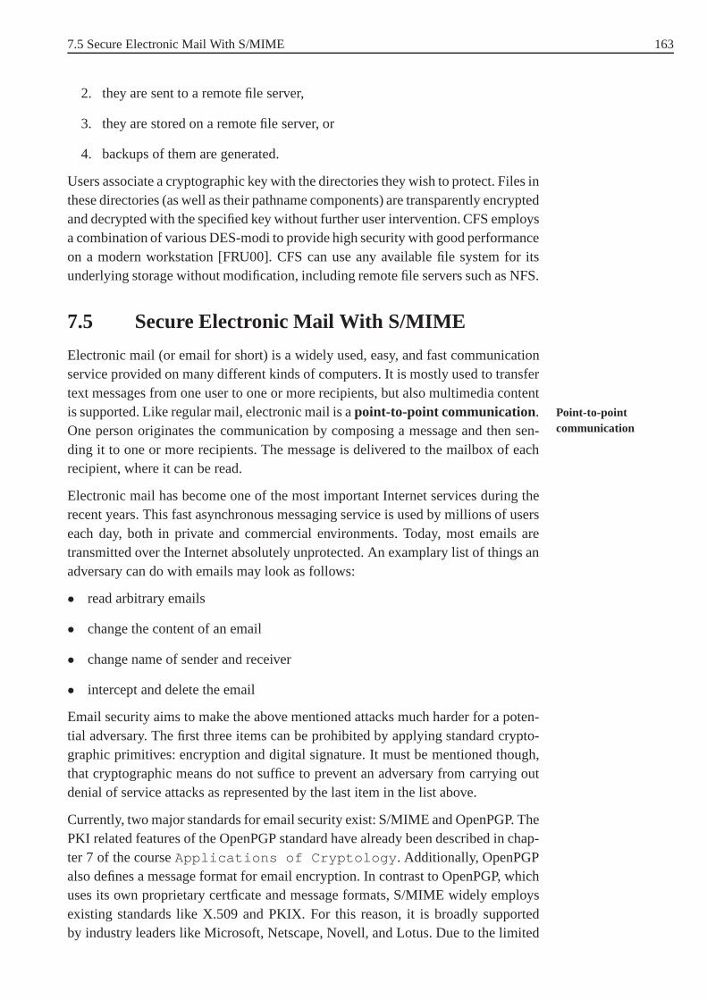
7.5 Secure Electronic Mail With S/MIME 163
2. they are sent to a remote file server,
3. they are stored on a remote file server, or
4. backups of them are generated.
Users associate a cryptographic key with the directories they wish to protect. Files inthese directories (as well as their pathname components) are transparently encryptedand decrypted with the specified key without further user intervention. CFS employsa combination of various DES-modi to provide high security with good performanceon a modern workstation [FRU00]. CFS can use any available file system for itsunderlying storage without modification, including remotefile servers such as NFS.
7.5 Secure Electronic Mail With S/MIME
Electronic mail (or email for short) is a widely used, easy, and fast communicationservice provided on many different kinds of computers. It ismostly used to transfertext messages from one user to one or more recipients, but also multimedia contentis supported. Like regular mail, electronic mail is apoint-to-point communication. Point-to-point
communicationOne person originates the communication by composing a message and then sen-ding it to one or more recipients. The message is delivered tothe mailbox of eachrecipient, where it can be read.
Electronic mail has become one of the most important Internet services during therecent years. This fast asynchronous messaging service is used by millions of userseach day, both in private and commercial environments. Today, most emails aretransmitted over the Internet absolutely unprotected. An examplary list of things anadversary can do with emails may look as follows:
• read arbitrary emails
• change the content of an email
• change name of sender and receiver
• intercept and delete the email
Email security aims to make the above mentioned attacks muchharder for a poten-tial adversary. The first three items can be prohibited by applying standard crypto-graphic primitives: encryption and digital signature. It must be mentioned though,that cryptographic means do not suffice to prevent an adversary from carrying outdenial of service attacks as represented by the last item in the list above.
Currently, two major standards for email security exist: S/MIME and OpenPGP. ThePKI related features of the OpenPGP standard have already been described in chap-ter 7 of the courseApplications of Cryptology . Additionally, OpenPGPalso defines a message format for email encryption. In contrast to OpenPGP, whichuses its own proprietary certficate and message formats, S/MIME widely employsexisting standards like X.509 and PKIX. For this reason, it is broadly supportedby industry leaders like Microsoft, Netscape, Novell, and Lotus. Due to the limited
164 7 Application Layer Security
scope, only S/MIME will be described in detail in this chapter. For information onthe message format of OpenPGP, please refer to RFC 2440 [ea98].
In the following section, first a thorough introduction to the structure of email mes-sages is given. The basics will be essential to understand the security related featuresthat are provided by S/MIME.
7.5.1 Structure Of Email Messages
Basically, electronic mail involves transferring a computer file from one useraccount to another user account. In the following we will usethe paradigm of papermail to explain the way electronic mail works. In Fig. 7.5-1 the two kinds of mailcan be seen side by side.
Fig. 7.5-1: Traditional mail vs. email.
The equivalence between the combination of the labeled envelope and the head ofthe letter on one side and the header of the email on the other side can clearly beseen. It is analogous to the matching of postal and email body.
The structure of email messages was defined some years ago. The RFC 822 [Cro82],the de facto Internet standard) shows the definition in detail and is used as basicliterature for this section.
The email message has three basic parts: Themessage envelope, theheader andMessage envelope
Header the message body . The message header lists information about the sender, therecipient, the posting date, the subject of the message, etc. Themessage bodycon-Message body
tains the actual message being sent. The message header consists of several fields.Take a look at the following example of an email message (all data of the email isshown; an email client will suppress some of these while displaying, some morefields can be displayed in other situations)

7.5 Secure Electronic Mail With S/MIME 165
Example 7.5-1:
Received: from SpoolDir by LGKS1 (Mercury 1.31);
10 Jul 100 16:22:48 METReturn-path: <[email protected]>
Received: from elm.fernuni-hagen.de by lgks1.fernuni-ha gen.de(Mercury 1.31) with ESM11 Jul 100 01:41:00 MET
Received: from slinky.cs.nyu.edu by elm.fernuni-hagen.d e via
Internetwith ESMTP; Tue, 11 Jul 2000 01:37:50 +0200
Received: from localhost (anne.nonymous@localhost)by slinky.cs.nyu.edu (8.9.1/8.9.1) with ESMTP id TAA27290
for <[email protected]>;
Mon, 10 Jul 2000 19:37:48 -0400 (EDT)From: Anne Nonymous <[email protected]>
To: [email protected]: Mon, 10 Jul 2000 16:21:33 +0200
MIME-Version: 1.0
Content-type: text/plain; charset=ISO-8859-1Content-transfer-encoding: Quoted-printable
Subject: ThanksPriority: normal
X-mailer: Pegasus Mail for Win32 (v3.12a)X-PMFLAGS: 34078848 0 1 Y0FC54.CNM
Dear Mr. Demuth,thank you for sending the research report.
Regards,Anne Nonymous
The header of this message consists of the fields from the first”Received” to ”X-PMFLAGS”, the body starts with ”Dear Mr. Demuth,”. Header and body must beseparated by a single line. Headers also pick up informationas a message is sentto its recipient. The email software adds hidden text that itemizes the messagessize, origination location, and other miscellaneous information. By the time themessage arrives at its destination, it will have a whole paragraph of additional textthat recounts the routers the message passed through.
7.5.2 The Email Header
The header consists of ”fields”. Each field has a name (and therefore a meaning), avalue, and is terminated by a newline/line feed. The field name must be composedof printableASCII characters, the body may be composed of printable ASCIIASCII characters
characters including newline/line feed. The header fields The most important andoften used header fields are explained in the following. Details can be found in RFC822. The minimum required fields are ”Date”, ”From”, and ”Bcc” or ”To”; all othersare optional.

166 7 Application Layer Security
To: This field contains the mailing addresses to which the message is to be sent.If more than one address is listed, they must be separated by commas.
Subject: The contents of the ”Subject” field should be a piece of text that says whatthe message is about. The reason ”Subject” fields are useful is that most mail-reading programs can provide a summary of messages, listingthe subject ofeach message but not its text.
Cc: This field (”Carbon Copy”) contains additional mailing addresses to send themessage to. This works like ”To”’ except that these readers should not regardthe message as directed to them.
Bcc: This field (”Blind Carbon Copy”) contains additional mailing addresses tosend the message to, which should not appear in the header of the messageactually sent. Copies sent this way are called blind carbon copies.
From: This field is used to specify the sender, when the account he isusing to sendthe mail is not his own. The contents of the ”From” field shouldbe a validmailing address, since replies will normally go there.
Received: The names of the sending and receiving hosts and time-of-receipt maybe specified in this field. The ”via” parameter may be used to indicate whatphysical mechanism the message was sent over and the ”with” parametermay be used to indicate the mail- or connection-level protocol that was used,such as the SMTP mail protocol, or X.25 transport protocol. Some trans-port services queue mail; the internal message identifier that is assigned tothe message may be noted, using the ”id” parameter. When the sending hostuses a destination address specification that the receivinghost reinterprets, byexpansion or transformation, the receiving host may wish torecord the origi-nal specification, using the ”for” parameter. For example, when a copy of amail is sent to a member of a distribution list, this parameter may be used torecord the original address that was used to specify the list.
Reply-to: This field directs replies to a different address. Most mail clients auto-matically send replies to the ”Reply-to” address in preference to the ”From”address.
In-reply-to: This field contains a piece of text describing a message for replyingto. Some mail systems can use this information to correlate related pieces ofmail.
References (Message Threading):This field is usually maintained and addedautomatically. ”References” describes the thread (chain,series) of messagesthat ”came before” the actual one. Each message on the Internet has a uniqueidentification number that is kept in the ”Message-ID” field.”References” isa list of the message-ids from previous messages in this thread. When a newmessage is composed and sent, the mail server adds the ”Message-ID” field.

7.5 Secure Electronic Mail With S/MIME 167
When someone replies to that message, the user’s email program will createa ”References” field and copy the original message-id into it. If someone elsereplies to that reply, this ”References” field gets the previous references, plusthe previous message-id. And so on. An example should make this easier tosee. Let’s look at a thread with three messages. user-A sendsa message touser-B. This original message header might have:
From: user-A
To: user-BSubject: Something very important
Message-ID: <[email protected]>
Now user-B replies to user-A. The reply header looks like:
From: user-B
To: user-ASubject: Re: Something very important
References: <[email protected]>
Message-ID: <[email protected]>
The third message in this thread is from user-A to user-B, with a copy touser-C. user-A also decides to change the subject:
From: user-A
To: user-B
Cc: user-CSubject: Another thing (was: Re: Something very important)
References: <[email protected]> <246@fernuni-hagen .de>Message-ID: <[email protected]>
The ”References” field will keep getting longer as this thread goes on. It letsone find all the messages in the thread by searching for the message-ids.
X- (Own Header Fields ): The RFC 822 transport standard carefully specifieswhat header fields are legal in mail messages. Any field name starting withthe characters X- (the letter X followed by a dash) will not beadopted bya new message header standard. According to RFC 822, ”any field whichis defined in a document published as a formal extension to this specifica-tion [will not] will have names beginning with the string ‘X-’.” That meansthe standard cannot anticipate every useful header, it allows for user-definedfields as extensions to the standard. The convention is to begin a user-definedfield with ”X-”, because the standard guarantees that no official extensionwill use a header with those names. So the X-headers can be seen as a free”playground” for anyone’s use (see Example 7.5-2).

168 7 Application Layer Security
Example 7.5-2:The web-based email service Hotmail includes anX-Originating-IP hea-der which holds the IP address of the sending computer. This can serve as ameans to identify the sending computer although the Hotmailemail account isanonymous.
Structure of an email address
Email messages employ a two-part addressing scheme. A validInternet emailaddress is:[email protected]
Email has its own adressing system, called domain name addressing (correspondingto the domain name system of the Internet as the electronic equivalent of postaladdresses. Like these postal addressses, email addresses go from specific to gene-ral, in order to route the message to the right computer and mailbox (or person).Generally, email addresses have a username, one or more location identifiers, anda domain. An ”@” (”at sign”) symbol separates the user name from locations anddomain.
The email body and MIME
The mail body is completely free of format, one can compose anemail in any desi-red way. Corresponding to the standard, the body is separated by a blank line fromthe header. In the early days of computers email was not ”8 bit” clean; users wereable only to write emails in straight (7 bit) ASCII text. Thatmeans that only tex-tual email is supported by RFC 822 email; nontextual byte content can therefore beclipped to seven bits.
To solve this problem, in 1992 the MIME standard was developed. MIME stands for”Multipurpose Internet Mail Extensions” and enables emailto transport multimediadata, still being conform to RFC 822.
Before MIME, users converted their binary files like spreadsheets or other officedocuments with the (UNIX) commands ”uuencode” and ”uudecode”. These com-mands are used to transmit binary files over transmission mediums that do not sup-port other than simple ASCII data. Uuencode reads the input and writes an encodedversion. The encoding uses only printable ASCII charactersand includes the modeof the file and the operand name for use by uudecode.
But, since the introduction of MIME no user has to care about this any more whilewriting emails (As a consequence of this, one can attach any binary file to an email.).
The following RFCs define Multipurpose Internet Mail Extensions, replacing theRFC 1521 which is not valid anymore:
• RFC 2045 [ea96c]: MIME Part One: Format of Internet Message Bodies
• RFC 2046 [ea96d]: MIME Part Two: Media Types
7.5 Secure Electronic Mail With S/MIME 169
• RFC 2047 [Moo96]: MIME Part Three: Message Header Extensions for Non-ASCII Text
• RFC 2048 [ea96b]: MIME Part Four: Registration Procedures
• RFC 2049 [ea96a]: MIME Part Five: Conformance Criteria and Examples
These standards (or definitions) redefine the simple structure of messages in RFC822 format to allow for textual message bodies in character sets other than US-ASCII, an extensible set of different formats for nontextual message bodies, multi-part message bodies, and textual header information in character sets other than US-ASCII. It is important to understand, that MIME does not change the structure of anemail. In fact it encodes the arbitrary data in ASCII to be transmitted in a standardemail message. Therefore, older email programs (email clients) can handle MIMEmessages, too.
To accomodate arbitrary data types and representations, each MIME message inclu-des information that tells the recipient the type of the dataand the encoding used.MIME information resides in the RFC 822 mail header - the MIMEheader filesspecify the version of MIME used, the type of the data being sent, and the encodingused to convert the data to ASCII.
Above, the possible encoding of binary messages or attachments with uuen-code/base64 has been mentioned. The advantage of MIME is a quite more comfor-table handling for the user. In addition to the defintion of encoding and formatting,MIME does also determine the methods modern email clients can detect and handlesuch messages autonomously, i.e. starting the appropriateapplication. For this rea-son, MIME messages contain meta information, defining the player for a sound fileor a program to work with graphics.
MIME is a flexible way to embedd multimedia attachments in Internet messages.Data can be nested and instructions to a front end program canbe embedded tooutput the information in dependence of available resources. In this way, a memocan be read out or displayed alternatively as text, if no sound device is available.Furthermore, links to external data can be integrated in MIME messages.
Example 7.5-3 illustrates a MIME message that contains a picture in standard GIFrepresenation. The GIF image has been converted to a 7-bit ASCII representationusing the base64 encoding (for explanation of base64, see below).
Example 7.5-3:
From: Anne Nonymous <[email protected]>To: [email protected]
Subject: Congratulations
Date: Mon, 10 Jul 2000 16:21:33 +0200MIME-Version: 1.0
Priority: normalX-mailer: Pegasus Mail for Win32 (v3.12a)

170 7 Application Layer Security
X-PMFLAGS: 34078848 0 1 Y0FC54.CNM
Content-type: Image/GIF; name="medal_of_honour.gif"Content-disposition: attachment; filename="medal_of_h onour.gif"
Content-transfer-encoding: BASE64
R0lGODdhWAK+AKIAAP///9vb27a2tpKSkm1tbUlJSSQkJAAAACw AAAAAWAK+AEAD
/wi63P4wykmrvTjrzbv/YCiOZGmeaKo6B7G+8BkchtI2Rh3vfJf 3wGCpoBMaj47BweaSDBiHaOO2MDxthqj2SVgClBMaoLssLGcDwSHAPghsEbVCPZgFFnIW6VBodB9/
ClkAWmsLXohSfHheDHk2V1MGbF1qdwp2iG8/bmFvbUuGhGIEOmAaREiqqxOpDqlmUUUABn1TWm+ljo0HaY0zOLYRVg9KwoRvCgNZTW7AhwNmcDaNh8kXp1RO1Vm9h7OH
AcZfoZd/1QAzVOiCxwynDWpS4YQPP9MjzH7s8Ay6tE1o1RC1QFq EagTfgZsTytaz
BWjSeckTy8VDfCQCsYLirv8ToQIzatV4dqfLMVGXNkb418AVAyv eIElwM4jWvDUGAk4rYCtmAQKxttSDxqKWGR2i7o0iojPdiEA1ZUhgI4ANnpTGCFw bRaOW
.
.
.
The MIME field MIME-Version 1.0 declares that the message was composedusing version 1.0 of the MIME protocol. MIME is downwards compatible, thatmeans, that every MIME capable email client can likewise handle ASCII messages.
Two more fields (not used in the example email) areContent-Id , acting asa non-ambiguous identifier (and functionally identical to the standard headerMessage-ID (see above)) andContent-Description , a text describing thecontent, understandable for a human reader to inform him before the content isdecoded. Thus the receiver of the message can decide if it is reasonable for him todecode the message.
The Content-Transfer-Encoding header declares in the example, thatbase64 encoding was used to convert the image to ASCII. Thereare five differentencoding schemes available (and another one for further extensions):
7bit: ASCII text, using 7 bit characters, to directly transfer thecontent withoutfurther encoding. This format is limited to 1.000 characters per line.
8bit: ASCII text, using 8 bit per character (values from 0 to 255) and thus viola-ting the encoding scheme of RFC 822. Nevertheless it is used,causing theexpected consequences.
binary: Like ”7bit” without the limitation to 1.000 characters per line, but with theconsequences of the ”7bit” mode.
base64: This encoding is also called ”ASCII armor”. Groups of 24 bitsare encodedin four units of six bit. Each of these units is then encoded asregular ASCIIcharacter (”A” for 0, ”B” for 1, and so on). Carriage returns and line feeds areignored.
quoted-printable: This encoding only affects bytes exceeding the limit of theseven-bit-ASCII-code. They are transformed into an equal sign, followed bythe hex code of the character (for example: ”=E9” for an ”¨a”). This type
7.5 Secure Electronic Mail With S/MIME 171
of encoding is useful, if special, national characters are used, or if it is notknown, if the receiver of a message can handle base64-encoded attachments.
TheContent-Type declaration specifies the type of information. Seven types aredefined, each with one or more subtypes; types and subtypes are separated with aslash (”/”). The purpose of theContent-Type field is to describe the data con-tained in the body in such a manner that the receiving user agent can pick an appro-priate agent or mechanism to present the data to the user, or otherwise deal with thedata in an appropriate manner. The value in this field is called ”media type”.
Table 7.5-1 shows the most often used MIME types and subtypes.
Tab. 7.5-1: MIME types and Subtypes.
Type Subtype Description
text plain unformatted ASCII text
richtext basically formatted ASCII text
image gif GIF picture
jpeg JPEG/JPG picture
audio basic sound data
video mpeg MPEG movie
application octet-stream non interpretable byte sequence
postscript printable postscript document
rfc822 MIME message in RFC 822 format
message partial message has been split before transfer
external-body link to external ressource
multipart alternative same message in different formats
parallel the parts of the message have to be displayed atonce
digest each part is a RFC 822 compliant message
mixed several parts of independent encoding
The understanding of MIME is not only important to realise the structure and inter-pretation of email messages. The Hypertext Transport Protocol (HTTP), used totransfer Web pages, does also use MIME for the transport of the pages.
It is the task of the sender’s email client to interprete the data to send and to selectthe right content and sub types. In some cases the sender has to interfere and selectthe types manually.
In Example 7.5-3 theContent-Type declaration specifies that the data is a GIFimage, image is the content type, and gif is the subtype. To view the image, a recei-vers email client must first convert from base64 encoding back to binary, and thenrun an application that displays a GIF image on the users screen.
In Example 7.5-3 an additional MIME header field can be seen:Content-disposition . This field gives more information about the fol-lowing MIME element. Like in the case of theContent-type field further

172 7 Application Layer Security
parameters can be added to the line. In the example one can seethe name of theimage and that it is an attached element.
Multipart MIME messages
One very important type mentioned above ismultipart . This type allows mes-sages consisting of several parts; these parts are clearly separated from each other.With the multipart content type, email gets considerable flexibility. The subtypemixed allows a single message to contain multiple, independent submessages, eachone having its own content type and encoding. Mixed messagesmake it possible toinclude different multimedia data in one message. The subtype alternative
allows a single message to include multiple representations of the same data. Thisapproach is usefull for sending the same message in different formats (audio, video,or text). The email client of the receiver should be able to decide the part of messagewhich will be used, with respect to the hardware capabilities of the computer. Sub-typeparallel permits a single message to include subparts that should be usedtogether (like separate audio and video data that must be played synchronously).Subtypedigest allows a single message to contain a set of other messages thatare RFC 822 compliant. This feature is very useful for receiving the daily or wee-kly email of a mailing list at once. The following example shows a multipart mixedMIME message
Example 7.5-4:
Date: Fri, 21 Jul 2000 14:02:28 +0200From: Anne Nonymous <[email protected]>
Organization: MAD Dept.- Department for Mathematics and
DepressionsX-Mailer: Mozilla 4.7 [en] (Win98; U)
MIME-Version: 1.0To: [email protected]
Subject: BetreffContent-Type: multipart/mixed;
boundary="------------675454AB4619496261BDECC9"
--------------675454AB4619496261BDECC9
Content-Type: text/plain; charset=us-asciiContent-Transfer-Encoding: 7bit
This is plain text (see Content-Type)--------------675454AB4619496261BDECC9
Content-Type: image/jpeg;name="et-online.jpg"Content-Transfer-Encoding: base64
Content-Disposition: inline;filename="et-online.jpg"
/9j/4AAQSkZJRgABAQAAAQABAAD/2wBDAAsICAoIBwsKCQoNDAsNERwSEQ8PE
SIZGhQcKSQr.
.
7.5 Secure Electronic Mail With S/MIME 173
Y9FFFbCCiiigAooooAKKKKACiiigAooooAKKKKACiiigAooooAK KKKACiiigA
ooooAKKKKACiiigAooooAKKKKAHdqQ8dDRRSA//2Q==--------------675454AB4619496261BDECC9
Content-Type: application/x-unknown-content-type-Win amp.File;
name="Elvis Presley - Jailhouse Rock.mp3"Content-Transfer-Encoding: base64
Content-Disposition: inline;filename="Elvis Presley - J ailhouseRock.mp3"
//uQRAAAAAAASwAAAAAAAAlgAAAAAAABLAAAAAAAACWAAAAA//////////////
//////////
.
.
AAAAAAAAAAAAAAAAAAAAAAAAAAAAAAAAAAAAAAAAAAAAAAAAAAAAAAAAAAAAAAAAAAAAAAAAAAAAAAAAAAAAAAAAAAAAAAAAAAAAAAER
--------------675454AB4619496261BDECC9--
7.5.3 Securing MIME-based Emails With S/MIME
In the following, we will describe the procedure that Alice and Bob have to gothrough if Alice wants to send an encrypted an signed email toBob:
1. Alice generates acontent-encryption key (session key).
2. Alice encrypts the message with thecontent-encryption key .
3. Alice encrypts thecontent-encryption key with Bob’s public key(encryption key). Alice may receive Bob’s public key in formof a certificate.
4. Alice concatenates the encrypted message with the encrypted content-
encryption key . Alice may append further information like the utili-zed algorithms to the message. The construct consisting of the message,the content-encryption key , and further information is also cal-led token or digital envelope . If Alice only seeks privacy, she candirectly send theenvelope to Bob.
5. If Alice also wants data integrity and message origin authentication she has todigitally sign theenvelope . The signature is carried out with Alice’s secretsigning key.
This basic procedure can be found in every email encryption product, both Open-PGP or S/MIME based. Nevertheless, this protocol only applies to simple mailswhich do not consist of several parts. In a multipart MIME email, all parts have tobe signed and encrypted separately.
It is obvious, that to allow interoperation between diverseemail clients the rathervaguely described operations and message format in the procedure above have tobe exactly specified. The two most important issues which must be agreed on are:
1. the certificate handling, that is the utilized PKI, and

174 7 Application Layer Security
2. theenvelope or message format.
In the case of S/MIME Version 3 this is done in two RFC documents:
• RFC 2632 : ”S/MIME Version 3 Certificate Handling” [Ram99a].
• RFC 2633 : ”S/MIME Version 3 Message Specification” [Ram99b].
The RFC 2632 specifies that a hierarchical X.509 PKI as definedby thePKIX working group must be utilized (see the courseApplications of
Cryptology ). The ”Message Specification” is based on another IETF standard,namely theCryptographic Message Syntax(CMS), which is specified in RFC 2630Cryptographic
Message Syntax [Hou99]. CMS defines how an arbitrary message can be cryptographically signedand encrypted. RFC 2633 specifies how the CMS can be applied toMIME messa-ges.
CMS is derived from the RSA de-facto standard PKCS #7 (RFC 2315) and specifiesthe following:
• Content type for signed data.
• Content type for digital envelopes (as described above).
• Digested-data content type. This normally serves as input for the enveloped-datacontent type. This data type holds the message digest of any type of content andthus provides content integrity.
• Encrypted-data content type. This differs from the envelope type in that no ses-sion keys and further information is regarded.
• Authenticated-data content type. This type consists of arbitrary content, a mes-sage authentication code (MAC), and encrypted authentication keys for one ormore recipients. The authentication key is randomly generated by the orignatorof the message and encrypted with the public key of the recipient. The MAC isconstructed by encrypting the message with the authentication key.
• Supported algorithms. The cryptographic algorithms that must and should besupported, e.g. CMS implementations must include DSA and may include RSA.
S/MIME Version 3 defines how to create a cryptographically enhanced MIME bodypart by employing CMS. S/MIME can be regarded as an CMS application and pro-vides the following cryptographic security services for electronic messaging app-lications: authentication, message integrity and non-repudiation of origin50 (usingdigital signatures) and privacy and data security (using encryption).
S/MIME messages are a combination of MIME bodies and CMS objects. Toimprove interoperability, S/MIME rigidly defines which options of CMS must besupported. Each MIME entity must be prepared for signing and/or enveloping. To
50 Non repudiation of origin prevent the originator of a message denying that he has originatedthe message.

7.5 Secure Electronic Mail With S/MIME 175
do this, the MIME entity is canonicalized and encoded for transfer. The task ofcanonicalizationof a MIME entity is to render it into a standard form that is inva- Canonicalization
riant as it goes through various email components. In fact, the exact details of cano-nicalization depend on the actual MIME type and subtype of anentity. For exam-ple, canonicalization of typetext/plain is different from canonicalization ofaudio/basic . The canonical MIME entity is fed into a CMS processing facilitywhich produces a CMS object. The CMS object is then finally wrapped in MIME.It must be noted, that the RFC 822 [Cro82] headers of an email are not included inS/MIME.
S/MIME defines theapplication/pkcs7-mime type. It also defines an optio-nal ”smime-type” parameter which conveys information about the security applied(signed or enveloped).
Enveloped messages
An enveloped-only message is created as follows:
1. The MIME entity is canonicalized.
2. TheMIME entity is processed into a CMS object of typeenvelopedData .The envelope holds the encrypted message, the session key encrypted for thereceivers, and the session key encrypted for the originatorof the message.
3. The CMS object is inserted into aapplication/pkcs7-mime entity.
The file extension.p7m is given for this type of message.
Example 7.5-5: Enveloped-only dataIn this example, ”enveloped-data” denotes the smime-type parameter for mes-sages that are enveloped but not signed.
Content-Type: application/pkcs7-mime; smime-type=enve loped-data;
name=smime.p7mContent-Transfer-Encoding: base64
Content-Disposition: attachment; filename=smime.p7m
rfvbnj756tbBghyHhHUujhJhjH77n8HHGT9HG4VQpfyF467GhIG fHfYT6
7n8HHGghyHhHUujhJh4VQpfyF467GhIGfHfYGTrfvbnjT6jH775 6tbB9Hf8HHGTrfvhJhjH776tbB9HG4VQbnj7567GhIGfHfYT6ghyHhHUu jpfyF4
0GhIGfHfQbnj756YT64V

176 7 Application Layer Security
Signed messages
There are two formats for signed messages defined by S/MIME:application/pkcs7-mime with signedData as parameter, andmultipart/signed .
A signed message using theapplication/pkcs7-mime type is created as fol-lows:
1. The MIME entity is canonicalized.
2. The MIME entity is processed into a CMS object.
3. The CMS object is inserted into aapplication/pkcs7-mime entity.
The file extension for this type of message is also.p7m . A receiver who wants toread the signed message, has to be capable of processing S/MIME entities.
Example 7.5-6: Signed-only data
Content-Type: application/pkcs7-mime; smime-type=sign ed-data;
name=smime.p7mContent-Transfer-Encoding: base64
Content-Disposition: attachment; filename=smime.p7m
567GhIGfHfYT6ghyHhHUujpfyF4f8HHGTrfvhJhjH776tbB9HG4 VQbnj7
77n8HHGT9HG4VQpfyF467GhIGfHfYT6rfvbnj756tbBghyHhHUu jhJhjHHUujhJh4VQpfyF467GhIGfHfYGTrfvbnjT6jH7756tbB9H7n8HH GghyHh
6YT64V0GhIGfHfQbnj75
The advantage of themultipart/signed message type is, that a receiver mustnot necessarily be S/MIME capable to read the message. In this case the receivercannot verify the signature but can at least read the message. This method is alsoreferred to as clear-signing. Themultipart/signed MIME type is specified inRFC 1847 [ea95]
. A multipart/signed message contains two parts: The first part is the bodypart over which the signature is created (including its MIMEheaders), the secondpart carries the control information which is necessary to verify the signature. Thefile extension for this type of message is.p7s .
Example 7.5-7: multipart/signed data
Content-Type: multipart/signed;protocol="application/pkcs7-signature";
micalg=sha1; boundary=boundary42
--boundary42Content-Type: text/plain

7.6 Executable Content 177
This is a clear-signed message.
--boundary42
Content-Type: application/pkcs7-signature; name=smime .p7sContent-Transfer-Encoding: base64
Content-Disposition: attachment; filename=smime.p7s
ghyHhHUujhJhjH77n8HHGTrfvbnj756tbB9HG4VQpfyF467GhIG fHfYT64VQpfyF467GhIGfHfYT6jH77n8HHGghyHhHUujhJh756tbB9HGT rfvbnj
n8HHGTrfvhJhjH776tbB9HG4VQbnj7567GhIGfHfYT6ghyHhHUu jpfyF4
7GhIGfHfYT64VQbnj756
--boundary42--
Enveloped and signed messages
Finally, we have to know how to both sign and encrypt a message. This is achievedby nesting the signed only and eneveloped-only formats. Themessage can either besigned first and then encrypted, or enveloped first and then signed. This is possiblebecause all the formats are MIME entities. When the message is first signed andthen enveloped, the signatories are hidden. When the message is first enveloped andthen signed the signatories are exposed, but the signaturescan be verified withoutremoving the enveloping.
A list of all documents relevant for S/MIME can be found on theWWW page ofthe respective IETF working group: http://www.imc.org/ietf-smime/
7.6 Executable Content
This section deals with potential risks related toexecutable content. A user of a Executable content
computer connected to the Internet has the possibility to download programs andexecute them. This can be dangerous, since such programs canhavebugs that may Bugs
cause a computer to crash, other can be malicious and do damaging things, such aserasing a harddisk or transmitting confidential data to secret locations somewhereon the Internet. On the other side, an attacker aims to be ableto execute maliciousprograms on a desired computer system without the knowledgeof the correspon-ding victim. To do this in an easy way, the attacker can provide the victim with aprogram to execute. Note that the victim cannot determine what a program will dowithout running it. Moreover, it is impossible to determinewhat a program is doingwhile or after it is running, since some programs have the ability to hide their actualoperations. Even operating systems with good security features do not offer suffi-cient protection against malicious programs that they download and execute locally.This is due to the fact that once the program is running, it inherits all theprivileges Privileges
andaccess rightsfrom the user who invoked it. Access rights

178 7 Application Layer Security
In fact, executable content is not always malicious.Well written executable con-Well writtenexecutable content tent makes Web pages more interesting and attractive. It enablesWeb pages to
provide animations, interactive games, and other multimdia objects. The questionnow is how can we decide whether executable content is well written or not. Theanswer to this question is not evident.
From a theoretical point of view, the security problem related to executable contentarises because there is no fundamental difference between aprogram (representingan active component) and data (representing a passive component) with regard to itsinternal representation within a computer system [Opp00].Both data and programsare treated in the same manner and stored in the same memory. Consequently, aprogram is able to modify data, programs and eventually itself. This fact is used incomputer virusesthat are computer programs having the ability to manipulateandComputer viruses
directly modify other program codes.
In the following, we treat some executable content and theirsecurity risks. As anexample of executable content, we focus on binary mail attachments, helper appli-cations and plug-ins, scripting languages, Java applets, and ActiveX.
7.6.1 Binary Mail Attachments
A binary mail attachment is an attachement to an email message that can encodeBinary mailattachment an excutable program. The sender of a mail message attaches the desired binary
data file(s) to the message. The receiver can automatically or manually execute thefile(s) upon reception.
The following example demonstrates the dangerousness of a binary mail attach-ments if it is used for malicious tasks.
Example 7.6-1: ”I LOVE YOU VIRUS” 51
”I LOVE YOU” is a macro virus detected in May 2000. A user will receive anemail with ”I LOVE YOU” as the subject, and the email will havean attachment(a file) that contains the macro virus. ”I LOVE YOU” is a VisualBasic scriptmacro. The virus is infectious when a user has a program (Microsoft Office orMicrosoft Outlook) that can run it. If the user opens the attachment or saves itand then runs it, it will infect the user’s system. This virusis very destructive (ifthe user has Microsoft Office products installed). It does the following:
1. Searches the user’s computer for music, picture and html related files(.MP3, .JPG, .JS, .CSS, .VBS, ...) and erases and overwritesthem withthe macro virus code.
2. Downloads another virus and runs it (this virus, calledWIN-BUGSFIX.EXE, is a password stealing program that sendsany passwords it finds in the computer to an email account –[email protected]).

7.6 Executable Content 179
3. Sends out virus-infected emails to everyone in the user’saddress book.
4. Sends the virus over the Internet Relay Chat (IRC) networkif the user hasmIRC installed.
7.6.2 Helper Applications And Plug-ins
The Netscape browser can only display a few types of files: HTML files (.html),pictures (.gif and .jpg), and plain text. When the browser encounters a sound, image,or video file, it hands off the data to other programs, calledhelper applications, to Helper applications
run or display the file. A helper application is then a specialprogram that is runautomatically by the browser when a specific data type is downloaded. We meanwith specific data type all data types other than ASCII, HTML,GIF, or JPEG.
Netscape Communications developed a system similar to the helper applicationssystem calledplug-ins. A plug-in is a module that is loaded directly into the address Plug-ins
space of the corresponding browser and is automatically executed when documentsof a particular data type (such as a sound) are downloaded. Most popular helperapplications have been rewritten as plug-ins, including the Adobe Acrobat readerto display PDF files, the RealAudio player to play sound files,and the MacromediaShockwave player to play animated video sequences.
From the security point of view, helper applications and plug-ins can be dangerous.Helper applications and plug-ins run on the user’s computersystem taking theirinput from arbitrary (trusted and untrusted) remote computer systems that can bemalicious. A user that will download a helper application orplug-in is generallynot sure that he/she is downloading an authentic copy. In this case, the user candownload a modified version (of the helper application or plug-in) that can be usedto abuse his/her computer system.
An interpreter for a general purpose programming language is a powerful helperapplication. Given the appropriate input, it can open, read, modify, or delete anyfile on a computer system. Note that many programming languages such as Javaallow programs to open network connections and look for security weakness onother computers. For this reason, interpreters for a general purpose programminglanguage are not to be used or configured as helper applications. Other programsshould not be used or configured as helper applications [Opp00]:
1. Any programs that includes Microsoft’s Visual Basic scripting languages(such as Microsoft World and Excel unless the macros featureis turned off);
2. The scripting languages Perl, Python, and Tcl/Tk;
3. UNIX shells, such sh, csh, tcsh, or any other UNIX shell;
4. The DOS command shellCOMMAND.COM;
51 See http://www.unifiedchaos.com/.

180 7 Application Layer Security
5. Any Postscript interpreter other than GhostView.
7.6.3 Scripting Languages
In the context of the Web,scripting languagesare an intermediate stage betweenScripting languages
HTML and programming languages such as Java, C++, and VisualBasic. HTMLis generally used for formatting and linking text. Programming languages are gene-rally used for giving a series of complex instructions to computers. The scriptinglanguages fall somewhere there between. They are easy to learn, easy to use andallow users to automate some aspects of system operation. Inthis section, we dealwith two popular scripting languages: JavaScript and VBscript.
JavaScript
JavaScript is a scripting language that Netscape developedto make animation andother forms of interaction more convenient. JavaScript codes are contained withinthe HTML code of the Web page and are interpreted by the browser as it reads themin contrast to Java programs that are downloaded separatelyfrom the HTML page.JavaScript code is usually inserted between tags:<SCRIPT> and</SCRIPT> (sothat they will be recognized by JavaScript-enabled browsers). The language withinthe<SCRIPT> tag can be specified as<SCRIPT language=JavaScript> .
JavaScript allows HTML files to command the browser. So JavaScript code cancreate new windows, fill out fields in forms, jump to a new URL, process imagemaps locally, change the content of an HTML file, compute mathematical results,and/or perform other functions.
From the security perspective, JavaScript code is more secure than code written inJava or in any other programming language. That is because JavaScript does notcontain methods that enable either the direct access to the client’s computer filesystem, or the direct opening of connections in other computers on the network.
JavaScript security problems can be resumed in two main areas: denial of serviceDenial of service attack
attacks andprivacy violation .Privacy violation
1. Denial of service attacksJavaScript can be used to mount denial of service attacks against the usersof Web browsers. These attacks can be resident on Web pages orthey can besent to users with JavaScript-enabled email readers. For example, an attackercan write a JavaScript code that can easily overwhelm a computer by simplyrequiring too much of the CPU or memory resources. This can occur, if thewritten JavaScript code tries to solve a computationally expensive problem.Another kind of denial of service attacks is to write a JavaScript code that canopen a large number of windows on the victim’s screen.
2. Privacy violationSince JavaScript code runs inside the browser itself, it potentially has accessto any information that the browser has. This fact can be usedto mount several
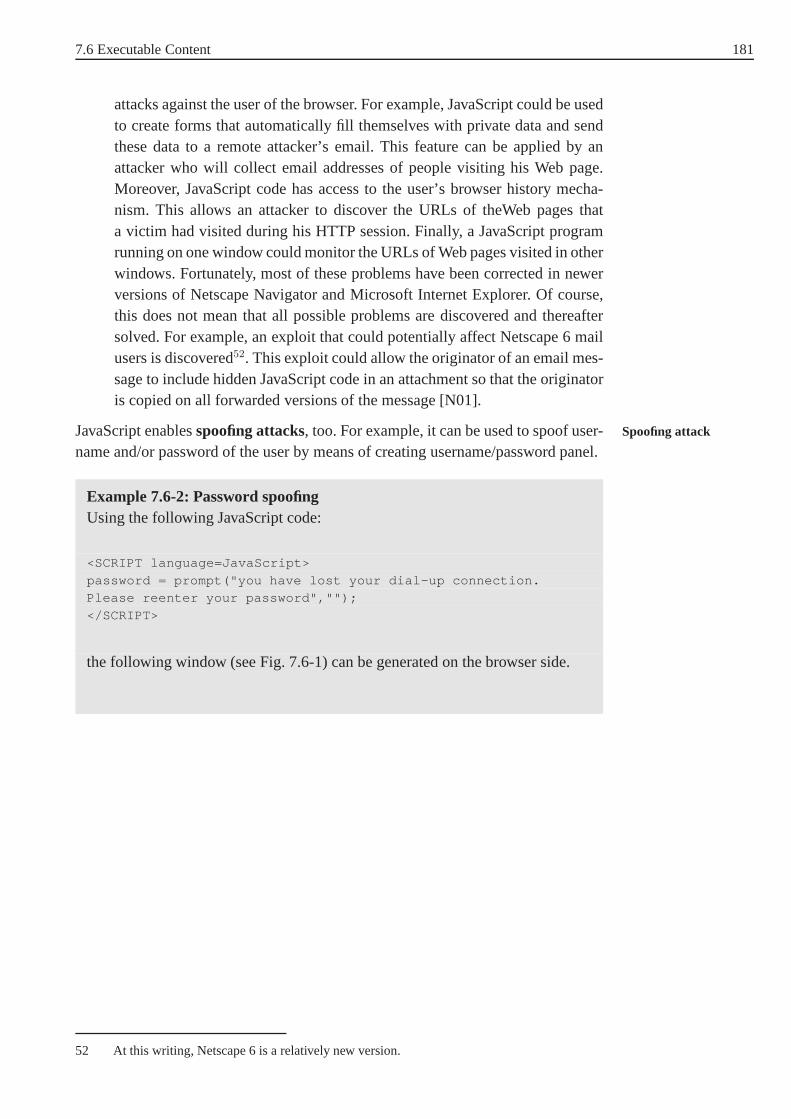
7.6 Executable Content 181
attacks against the user of the browser. For example, JavaScript could be usedto create forms that automatically fill themselves with private data and sendthese data to a remote attacker’s email. This feature can be applied by anattacker who will collect email addresses of people visiting his Web page.Moreover, JavaScript code has access to the user’s browser history mecha-nism. This allows an attacker to discover the URLs of theWeb pages thata victim had visited during his HTTP session. Finally, a JavaScript programrunning on one window could monitor the URLs of Web pages visited in otherwindows. Fortunately, most of these problems have been corrected in newerversions of Netscape Navigator and Microsoft Internet Explorer. Of course,this does not mean that all possible problems are discoveredand thereaftersolved. For example, an exploit that could potentially affect Netscape 6 mailusers is discovered52. This exploit could allow the originator of an email mes-sage to include hidden JavaScript code in an attachment so that the originatoris copied on all forwarded versions of the message [N01].
JavaScript enablesspoofing attacks, too. For example, it can be used to spoof user-Spoofing attack
name and/or password of the user by means of creating username/password panel.
Example 7.6-2: Password spoofingUsing the following JavaScript code:
<SCRIPT language=JavaScript>
password = prompt("you have lost your dial-up connection.Please reenter your password","");
</SCRIPT>
the following window (see Fig. 7.6-1) can be generated on thebrowser side.
52 At this writing, Netscape 6 is a relatively new version.
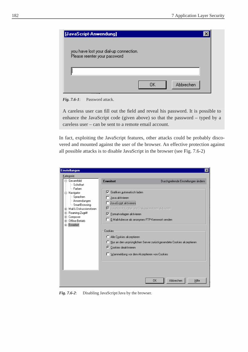
182 7 Application Layer Security
Fig. 7.6-1: Password attack.
A careless user can fill out the field and reveal his password. It is possible toenhance the JavaScript code (given above) so that the password – typed by acareless user – can be sent to a remote email account.
In fact, exploiting the JavaScript features, other attackscould be probably disco-vered and mounted against the user of the browser. An effective protection againstall possible attacks is to disable JavaScript in the browser(see Fig. 7.6-2)
Fig. 7.6-2: Disabling JavaScript/Java by the browser.

7.6 Executable Content 183
VBscript
Unlike the JavaScript language which is available for both Netscape Navigator andMicrosoft Internet Explorer, VBscript runs only on Microsoft Internet Explorer.Similar to JavaScript, VBscript can be used in denial of service and privacy violationattacks as well as in other attacks.
7.6.4 Java Applets
Java is an object-oriented, general-purpose programming language that has syntaxsimilar to C++. Although Java was thought of as a language forthe World WideWeb, Java is in fact a general-purpose computer language that can be used for wri-ting any code from simple programs to complicated applications.
What initially distinguished the typical Java implementation from other computerlanguages is the run-time environment. Instead of being compiled for a particu-lar microprocessor, Java programs are compiled into a processor-independent byte-code. Thisbytecodeis loaded into a computer’s memory by theJava Class Loader. Bytecode
Java Class LoaderFinally, the bytecode is executed on aJava Virtual Machine (JVM).JVM
The Java Virtual Machine can run Java programs directly on anoperating systemsuch as Windows or MacOS; alternatively, the JVM can be embedded inside a Webbrowser, allowing programs to be executed as they are downloaded from the WorldWide Web. Alternatively, it can use a ”just-in-time” compiler to convert the byte-code into the native machine code of the particular computeron which it is running.
Java can also be compiled directly into machine code and run on a target system.Used this way, Java loses its run-time advantage of being able to run on any com-puter and any operating system that has a JVM, but it retains its advantage of gene-rating code that has automatic memory management [GS95].
Java was not designed to be a secure programming language. But when Java wasdeployed in the Web, security immediately became a concern.Note that Java hasmany features making it a safe programming language. For example, the Java lan-guage does not possess pointers as in other computers languages. But safety isnot security. In fact, Java uses some techniques to limit what a downloaded Javaapplet can do. The main ones areJava Sandbox, theSecurityManager class, the Java Sandbox
SecurityManagerBytecode Verifier, and the Java Class Loader as briefly discussed in the following.Bytecode Verifier
Sandbox
Java programs run on a virtual computer (JVM) inside a restricted virtual space(runtime environment). They are not allowed to directly manipulate a computer’shardware or to make direct calls to the computer’s operatingsystem. Sun Microsys-tems termed this approach (to security) ”the sandbox”.

184 7 Application Layer Security
SecurityManager class
A series of special Java classes allow programs running inside the sand-box to communicate with the outside world. For example, the Java classFileOutputstream allows a Java program to open a file for writing to theuser’s harddisk. To limit danger which can be made by these classes, the devel-opers of Java created a special class, calledSecurityManager , which is madeto be called before any unsafe operation is executed. TheSecurityManager
class determines whether the operation should be allowed ornot.
Class Loader
One dangerous attack is to have a malicious program disable the standardSecurityManager class or replace it with a more permissive version. Such anattack could be realized by downloading a piece of machine code or a Java app-let that exploits a bug in the Java runtime system. To preventthis attack, the ClassLoader examines classes to make sure that they do not violatethe runtime system.
Bytecode Verifier
The Bytecode Verifier assures that the bytecode that is downloaded could only havebeen created by compiling a valid Java program.
Generally, the Java sandbox, SecurityManager class, ClassLoader, and BytecodeVerifier collectively implement a Java security policy. ButJava’s security policyisJava’s security policy
complicated by the fact that the Java language was designed for two fundamentallydifferent purposes. On one hand, Java is a general purpose language for creatingapplication software. On the other hand, Java is a programming language for crea-ting applets that perform animations, create interactive chat systems, etc.
These different purposes require different security policies. Thedual nature of theDual nature of the Javalanguage Java languageleads to a much more complicated security model, which in turn
leads to more difficulty in enforcement. Java’s original implementors envisionedthree different security policies that could be enforced byWeb browsers that imple-mented the Java programming language [GS95]:
1. Do not run Java programs.
2. Run Java programs with different privileges depending onthe source ofthe program. Programs downloaded from Web pages would run with severerestrictions. Programs loaded off the user’s harddrive would have no restric-tions.
3. No restrictions on Java programs. In this case, Java programs can do anythingwith the computer harddisk, network connectivity, and anything else.
These Java policies are only examples. Other Java policies can be defined and imple-mented. For example, we give next some policies that could beset for networkconnectivity [GS95]:

7.6 Executable Content 185
1. No network connectivity: A Java applet can not access the network.
2. Limited network connectivity: A Java applet can only opennetwork connec-tions to the host from which it was downloaded.
3. Limited network connectivity: A Java applet can only opennetwork connec-tions to a host whose name appears in a set of preapproved hosts.
4. Limited network connectivity: A Java applet can only opennetwork connec-tions on a specified port or ports.
5. No restrictions for applets downloaded from particular machines: A corpora-tion might want applets to be downloaded only from the company’s internal”intranet” server.
6. No restrictions for ”signed” applets: Java applets that are digitally signed byapproved secret key have full access to the computer’s resources, unsignedapplets are restricted.
7. Unlimited connectivity.
The two Web browsers Microsoft Internet Explorer and Netscape Navigator can beconfigured in such a manner that Java applets can be controlled and monitored bythe user. This can be done, for example, through the use of digitally signed Javaclasses. The higher level of security is reached by disabledthe execution of Javaprograms by the browser (see Fig. 7.6-2).
7.6.5 ActiveX Controls
ActiveX is a collection of technologies, protocols, and APIs developed by Microsoftthat are used for downloading executable code over the Internet. The code is bundledinto a single file called ActiveX control.
ActiveX controls are plug-ins that are automatically downloaded and installed,when they are needed. Once these plug-ins are not required, they are automaticallydeleted.
Fundamentally, two kinds of ActiveX controls are to be distinguished [GS95]:
1. ActiveX controls that contain native machine code. Thesecontrols are writtenin languages such as C, C++. The control’s source code is compiled into anexecutable code that is downloaded by the Web browser and executed on theclient machine.
2. ActiveX controls that contain Java bytecode. These controls are written inJava or another language that can be compiled into Java bytecode. These con-trols are downloaded by the Web browser and executed on a virtual machine.
Microsoft’s Authenticode technologyis a technology that is used to discover theAuthenticodetechnologyauthor of a particular piece of code and determine that the program has not been
altered before a download takes place. Authenticode is based ondigital signatures Digital signature
186 7 Application Layer Security
and apublic key infrastructure . Depending on the two kinds of ActiveX controls,Public keyinfrastructure Authenticode can be used for different purposes:
1. For ActiveX controls that contain native machine code:Authenticode can be used to enforce a simple decision: either download thecontrol or do not download the control. These Authenticode signatures areonly verified when a control is downloaded from the Internet.
2. For ActiveX controls that contain Java bytecode:Authenticode can be used to enforce a simple decision: either download thecontrol or do not download the control. Authenticode signatures can also beused to determine what access permissions are given to the Java bytecodewhen it is running.
If an ActiveX control contain machine code and Java bytecode, or if both machinecode and Java bytecode controls reside on the same Web site, the capabilities-controlled access provided by the Java system become irrelevant. Unfortunately,security through code-signing has many problems53. For example, buggy code, evenwhen it is properly signed, can damage the user’s computer.
Exercise 7.6-1:
1. Give examples of executable content which can affect the network security!
2. How can JavaScript be used to launch a denial of service attack against ahost?
3. Describe shortly how can the risk related with download ofJava applets belimited!
53 For more details, see [GS95].

187
8 Security in Wireless and MobileNetworks
Mobile networks have become a very attractive channel for the provision of elec-tronic services: They are available almost anytime and anywhere. Furthermore, theuser acceptance of mobile devices is high. As a result there is a strongly incre-asing amount of services offered through mobile networks, ranging from simplespeech and information services to sensitive applicationslike banking or electro-nic commerce. But not only for this reason the security of thedata and signallinginformation is very important. Due to the very sensitive radio path of the data, thecommunication traffic can be eavesdropped by everyone with very simple devices.After a short introduction to the development of mobile networks, we focus on secu-rity in GSM networks. After this, an overwiev of the securitymechanisms in UMTSnetworks, in the WAP protocol, and in the Bluetooth standardis given.
8.1 Development of Mobile Networks
The underlying vision for the emerging mobile and personal communication ser-vices and systems is to enable communication with any personat any time, anyplace, and in any form. Beside providing unlimited reachability and accessability,this vision for personal communications also underlines the increasing need forusers of communication services to be able to manage their individual calls andservices according to their real-time needs.
Radio communicationcan trace back its origin to the discovery of electromagne-The beginning of theradio communicationtic waves by Hertz in 1888 and the subsequent demonstration of transatlantic radio
telegraphy by Marconi in 1901. Mobile radio systems using simplex channels wereintroduced in the 1920s for police and emergency services. The first public mobilesystem in the USA was introduced in 1946 and can be consideredto be the begin-ning of the era of public mobile communication services. As illustrated in Fig. 8.1-1,the evolution of public mobile and personal communication services may be divi-ded into three broad periods. The development of thecellular concept in the1970s was a defining event which has played a significant part in the evolution ofmobile communication systems and networks around the world.

188 8 Security in Wireless and Mobile Networks
Fig. 8.1-1: Evolution of mobile communication services
At the beginning, mobile radio systems were based on thetrunkingThe past
principle . That means that the available frequency spectrum (in the 150 or450 MHz band) was divided into a suitable number of frequencychannnels and acentralized, high power antenna was used to transmit signals to mobile receivers.Large mobile receivers were installed in automobiles, and the telephone sets werealso very large. A call originating or terminating on a mobile terminal had tocompete for one of the limited number of channels.
Since the initial commercial introduction ofAdvanced Mobile PhoneThe present
system (AMPS) service in 1983, mobile communications has seen an explo-sive growth worldwide. Beside the frequency reuse capabilities provided by thecellular operation, advances in technologies for wirelessaccess, digital signalprocessing, integrated circuits, and increased battery life have contributed toexponential growth in mobile and personal communication services. Systems areevolving to address a range of applications and markets, which include digitalcellular, cordless telephony, satellite mobile, paging, and specialized mobile radiosystems. Data capabilities of these systems are also comming into focus with theincreasing user requirements for mobile data communication, driven by the need ofmobile Internet access. Whereas analog cellular mobile systems fall in the categoryof first generation mobile systems, digital cellular, low power wireless and perso-First generation
nal communication systems are perceived assecond generationmobile systems.Second generation

8.1 Development of Mobile Networks 189
•
•
•
•
•
•
•
•
•
•
•
•
•
•
••
••
•
••
••
••
••
••
••
•
••
••
• Cells using the same set of RF channels
•
Fig. 8.1-2: The principe of cellular systems
Thecellular conceptwas developed and introduced by the Bell Laboratories in theCellular concept
early 1970s. The principle is to devide a large geographic service area into cells withdiameters ranging from from 2 to 50 km/s; for each of them a number of Radio
Frequency (RF) channels is allocated. Transmitters in each adjacent celloperateat different frequencies to avoid interference. Since transmission power and antennaheights in each cell are relatively low, cells that are sufficiently far apart can reusethe same set of frequencies without causing co-channel interference. The theoreti-cal coverage range and capacity of a cellular system are therefore unlimited. As thedemand for cellular mobile services grows, additional cells can be added, and astraffic demand grows in a given area, cells can be split to accomodate the additionaltraffic. Fig. 8.1-2 illustrates an idealized view of a cellular mobile system, wherecells are depicted as perfect hexagons. A cellular system should provide the capabi-lity to hand over calls in progress, when a mobile user moves between cells. As faras possible the hand over should be transparent to the user interms of interuptionand/or call failure. Hand over between channels in the same cell may also be requi-red for other reasons, such as load balancing, emergency call handling or meetingrequirements of transmission quality.
The first digital cellular system specification was releasedin 1990 by theEuropean Telecommunications Standards Institute (ETSI ) forthe Global System for Mobile Communication (GSM). The GSM,DCS 1800 (Digital Cellular System , 1800 MHz version of GSM) andDECT (Digital Enhanced Cordless Telecommunications) systems developed byETSI form the basis for mobile and personal communication services not onlyin Europe but in many other parts of the world including NorthAmerica.The number of GSM subscribers worldwide exceeds 550 millionand is stillgrowing rapidly. In the United States, digital cellular standards developed bythe Telecommunications Industry Association (TIA ) have beenimplemented. A third digital cellular system called thePersonal Digital
Cellular (PDC) was developed in Japan and is in full commercial operation inthat country. The specification for these cellular systems were developed to meetthe business and regulatory requirements in specific countries and regions and thusleading to incompatible systems unable to provide global mobility.

190 8 Security in Wireless and Mobile Networks
While the initial focus of the current generation of mobile and personal communi-The future
cation systems has been circuit switched voice and low bit rate data services, thedemand for wide-area as well as local-area wireless data services is rapidly incre-asing. The emerging industry view is that the main drivers for the next-generationwireless networks will be Internet and multimedia services. Evolution towards highbit rate packet mode capabilities is therefore a key requirement for present andfuture mobile and personal communication systems. Future mobile systems willrepresent evolution and enhancements of the present systems in many directionsand on many fronts. These directions include increased capacity and coverage, glo-bal roaming and service delivery, interoperability between different radio environ-ments, support of high bit rate data, the Internet, multimedia services, global cover-age using satellite constellations, and others.
To complement the cellular and personal communication networks, whose radiocoverage is confined to populated areas of the world (less than 15% of theearth surface), a number of global mobilesatellite systemsare in advancedSatellite systems
stages of planning and implementation. These systems are generally referredto as Global Mobile Personal Communications by Satellites
(GMPCS). GMPCS systems like Iridium, Globstar and ICO use constellations oflow earth orbit (LEO) or medium earth orbit (MEO) satellites andoperate as overlay networks for existing cellular and PCS networks. They extendthe coverage of cellular and PCS networks to any and all locations on the earth’ssurface.
IMT-2000 (International Mobile Telecommunications - 2000) is the standard beingdeveloped by the ITU54 to set the stage for thethird generation of mobile com-Third generation
munication systems. The standard consolidates different wireless environments(cellular mobile, cordless telephony and satellite mobileservices). It also ensu-res global mobility in terms of global seamless roaming and delivery of services.TheUniversal Mobile Telecommunication System (UMTS), develo-ped by ETSI, also belongs to the IMT-2000 system.
8.2 Security Mechanisms in GSM Networks
Global System for Mobile Communications (GSM) is a standard fordigital mobile telephony, defined by theEuropean Telecommunications
Standards Institute (ETSI ). The first GSM services were started around1992. Today, this standard is used globally in more than 400 networks operating inmore than 170 countries worldwide55. The number of GSM subscribers currentlyexceeds 550 million56.
54 International Telecommunication Union
55 End of June 2001
56 For more statistical and up to date information about GSM networks seehttp://www.gsmworld.com/about/membership/mem_stats.shtml.

8.2 Security Mechanisms in GSM Networks 191
The original aims of the Groupe Special Mobile which was an initiative Aims of the GroupeSpecial Mobileof theEuropean Conference of Posts and Telecommunications
Administrations (CEPT) were to provide a harmonized mobile service acrossEurope, opening up large markets and thus reducing infrastructure and handsetcosts. In the 1980s the markets within Europe were fragmented between the UKTotal Access Communication System (TACS), the FrenchRadiocom
2000 System , the GermanC-Netz System , and the Nordic Mobile
Telephone (NMT) system. What everyone wanted was a new system which couldbe universally adopted making a single large market for handsets, base sites andswitches. The work on the standard was started in 1982, and the first full setof specifications became available in 1990. The responsibility for GSM standar- GSM standardisation
disation now resides with theGroupe Special Mobile (GSM) under theEuropean Telecommunication Standards Institute (ETSI ). An1800 MHz version of GSM, known as DCS 1800, has also been standardised inEurope.
In Germany the following GSM networks are on air: GSM networks inGermany• Since July 1992: D1 (DeTeMobil, Deutsche Telekom Mobile Network GmbH)
operating at 900/1800 MHz.
• Since June 1992: D2 (Mannesman Mobilfunk GmbH, now Vodafone) operatingat 900/1800 MHz.
• Since May 1994: E-Plus (E-Plus Mobilfunk) operating at 1800MHz.
• Since October 1998:O2 (formerly known as VIAG Interkom) operating at 1800MHz.
Before we discuss the security mechanisms in GSM networks, we first overviewtheir features and describe briefly how they work57.
8.2.1 Brief Overview of GSM Networks
The most important service supported by GSM is telephony. Other services deri- Services in GSM
ved from telephony included in the GSM specification are emergency calling andvoice messaging. Bearer services supported in GSM include various asynchronousand synchronous data services for information transfer between GSM and other net-works at rates from 300 to 9600 bit/s. This also includes fax andShort Message
Service (SMS). GSM also supports ISDN58-like supplementary services: call for-warding, call barring, call waiting, call hold, tele-conferencing, closed user groupservice and others. Summarized, themain features of the initial GSM standard Main features of GSM
include the following:
• Fully digital system utilizing the 900 MHz frequency band,
57 Basic knowledge about the principles of mobile networks is expected from the reader. In thebrief description below we do not claim completeness.
58 ISDN: Integrated Services Digital Network

192 8 Security in Wireless and Mobile Networks
• TDMA 59 over radio carriers (200 kHz carrier spacing),
• 8 full-rate or 16 half-rate TDMA channels per carrier,
• User and terminal authentication for fraud control,
• Encryption of speech/data transmission and control data over the radio path,
• Full international roaming capability,
• Low speed data services (up to 9,6 kbit/s),
• Compatibility with ISDN for supplementary services,
• Support ofShort Message Service (SMS).
Reference Architecture and Function Partitioning
As shown in Fig. 8.2-1, theGSM systemcomprises ofBase TranscieverGSM system
Stations (BTS), Base Station Controllers (BSC), Mobile
Switching Centers (MSC), and a set of registers (databases) to assist themobility management and security functions. All signalling between the MSC andthe various registers (databases) as well as between the MSCs takes place using theSignalling System No. 7 (SS7) network, with the application level mes-sages using theMobile Application Protocol (MAP) designed speciallyfor GSM. The signalling between the MSC and the national PSTN60/ISDN networkis based on the national options for SS7,Telephone User Part (TUP) orISDN User Part (ISUP). In order to understand how a GSM network works,we now briefly discuss its most important constituents.
Mobile Station (MS)Mobile Station
The GSM mobile stations (also called handsets or mobile phones) are portableradiotelephony units that can be used on any GSM system. Power levels supportedby the GSM mobile stations currently range from 0.8W to 8.0W,and power savingtechniques are used on the air interface to extend battery life. At the time of manu-facturing, an International Mobile Equipment Identity (IMEI), which is not easilyalterable or removable, is programmed into the terminal. Toactivate and operate aGSM terminal, a Subscriber Identity Module (SIM) is required. The SIM may beSIM card
contained within the MS, or it may be a removable unit that canbe inserted into theMS by the user. TheInternational Mobile Subscriber IdentityIMSI number
(IMSI ) number, which identifies the subscriber uniquely, is programmed into theSIM at the time of service provisioning, along with the appropriate security para-meters and algorithms.
59 Time Division Multiple Access
60 PSTN: Public Switching Telephone Network, i.e. the ”classical” analogue telephone network
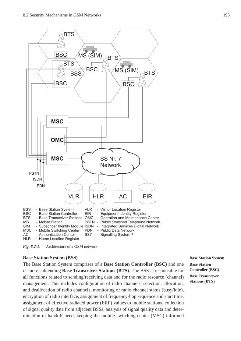
8.2 Security Mechanisms in GSM Networks 193
BSC
BSC
BTS
BSSBSC
MS (SIM) BTSBTS
BSC
MS (SIM) BTS
MSC
OMC
MSC
PSTN
ISDN
PDN
VLR HLR EIRAC
SS Nr. 7Network
BSSBSCBTSMSSIMMSCACHLR
--------
Base Station SystemBase Station ControllerBase Transceiver StationsMobile StationSubscriber Identity ModuleMobile Switching CenterAuthentication CenterHome Location Register
VLREIROMCPSTNISDNPDNSS7
-------
Visitor Location RegisterEquipment Identity RegisterOperation and Maintenance CenterPublic Switched Telephone NetworkIntegrated Services Digital NetworkPublic Data NetworkSignalling System 7
Fig. 8.2-1: Architecture of a GSM network
Base Station System (BSS) Base Station System
The Base Station System comprises of aBase Station Controller (BSC)and one Base StationController (BSC)or more subtendingBase Transceiver Stations (BTS). The BSS is responsible forBase TransceiverStations (BTS)
all functions related to sending/receiving data and for theradio resource (channel)management. This includes configuration of radio channels,selection, allocation,and deallocation of radio channels, monitoring of radio channel status (busy/idle),encryption of radio interface, assignment of frequency-hop sequence and start time,assignment of effective radiated power (ERP) values to mobile stations, collectionof signal quality data from adjacent BSSs, analysis of signal quality data and deter-mination of handoff need, keeping the mobile switching center (MSC) informed

194 8 Security in Wireless and Mobile Networks
regarding hand over activity, and it also includes digital signal processing (transco-ding and rate adaption, channel coding and decoding).
Mobile Switching Center (MSC)Mobile SwitchingCenter The Mobile Switching Center for GSM can be viewed as a local ISDN switch
with additional capabilities to support mobility management functions like termi-nal registration, location updating, and hand over. Unlikea local switch in a fixednetwork, the MSC does not administer the mobile subscriber parameters wich aredynamic and are held in theVisitor Location Register (VLR) associa-ted with the MSC. The MSC performs the following major functions: call setup,supervision and release, call routing, billing information collection, mobility mana-gement (registration, location updating, inter-BSS and inter-MSC call hand overs)management of radio resources during a call, echo cancelation, allocate resourcesto BSS, other MSCs, PSTN/ISDN, and other functions.
Home Location Register (HLR)Home LocationRegister The HLR represents a centralized database that has the permanent datafile about
the mobile subscribers in a large service area (generally one per GSM networkoperator). It is referenced using the SS7 signalling for every incoming call to theGSM network for determining the current location of the subscriber. The HLRis kept updated with the current locations of all its mobile subscribers, includingthose who may have roamed to another network operator withinor outside thecountry. The routing information is obtained from the serving VLR on a call-by-call basis (for each incoming call the HLR queries the serving VLR). Beside theup-to-date location information for each subscriber (which is dynamic), the HLRmaintains the following subscriber data on a permanent basis: International
Mobile Subscriber Identity (IMSI ), service subscription information,service restrictions, mobile terminal characteristics, and billing and accountinginformation (see Fig. 8.2-2).
User n
User n+1
.....
HLR
Calling Number
User Code
IMSIRAND, SRES,
TMSI, LAI, , CKSN
Location,Incoming calls,Outgoing calls, ...
User n
User n+1
.....
VLR
Calling Number
User Code
IMSIRAND, SRES,
TMSI, LAI, , CKSN
Location,Incoming calls,Outgoing calls, ...
cK
cK
cK
cK
Fig. 8.2-2: Data fields in HLR and VLR

8.2 Security Mechanisms in GSM Networks 195
Visitor Location Register (VLR) Visitor LocationRegisterThe Visitor Location Register (see Fig. 8.2-2) represents atemporary data store
and generally there is one VLR per MSC. This register contains information aboutthe mobile subscribers which are currently in the service area covered by theMSC/VLR. The temporary subscriber information resident ina VLR includes thecurrently activated features, theTemporary Mobile Station Identity
(TMSI), and the current location information about the MS (e.g., location area andcell identities).
Authentication Center (AC) Authentication Center
The Authentication Center contains authentication parameters that are used oninitial location registration, subsequent location updates and on each call setuprequest from the MS. The AC maintains the authentication keys and algorithmsand provides the security triplets (RAND, SRES, andKc) to the VLR so thatthe user authentication and radio channel encryption procedures may be carried outwithin the visited network. It contains the security modules for the authenticationkeys and the authentication and cipher key generation algorithms A3 and A8. In thefollowing sections we will discuss the functions of the AC inmore detail.
Equipment Identity Register (EIR) Equipment IdentityRegisterThe Equipment Identity Register maintains information to authenticate terminal
equipment to identify and deny service to fraudulent, stolen or non-type appro-ved terminals. The information is in form of white, gray and black lists that may beconsulted by the network when it wishes to confirm the authenticity of the terminalrequesting service.
Radio Characteristics
In GSM the uplink (mobile to base) frequency band is 890 - 915 MHz andthe corresponding downlink (base to mobile) band is 935 - 960MHz. TheGSM usesTime Division Multiple Access (TDMA) and Frequency
Division Multiple Access (FDMA), where the available 25 MHz spectrumis partitioned into 124 carriers (carrier spacing is 200 KHz). Each carrier in turn isdevided into 8 time slots. Each user periodically transmitsin every eighth time slotin an uplink radio carrier and receives in a corresponding time slot on the downlinkcarrier. Thus several conversations can take place simultaneously in the same pairof transmit/receive radio frequencies.

196 8 Security in Wireless and Mobile Networks
Fig. 8.2-3: Speech encoding and modulation in GSM
Digitalized speech is passed at 64 kbit/s through a speech coder (transcoder), whichGSM speech encodingand modulation compresses it to 13 kbit/s. The most important steps of the process of informa-
tion transfer for speech signals in the uplink direction across the radio interface areillustrated in Fig. 8.2-3 and will not be discussed here in detail. A similar process isapplicable for the downlink.
Full rate (22.8 kb/s)
Half-rate (11.4 kb/s)
9.6 kb/s4.8 kb/s2.4 kb/s
FCCH (frequency correction)
SCH (sychronization)
PCH (paging)ACCH (access grant)RACH (random access)
FACCH (fast associated)SACCH (slow associated)SDCCH (stand-alone)
Speech
Data
BCCH(broadcast)
CCCH(common)
TCH(traffic channel)
Bandwidth
CCH(control channel)
DCCH(dedicated)
Fig. 8.2-4: Logical channel structure in GSM
There are two distinct categories oflogical channels in GSM: TrafficLogical channels inGSM Channels (TCH) andControl Channels (CCH). In the initial GSM speci-
fication only the full-rate speech and data channels were defined as traffic channels.The three types of control cannels areBroadcast (BCCH), Common(CCCH), andDedicated (DCCH) channels, each of them is further subdivided. Each type oftraffic channel is always associated with a control channel.
8.2 Security Mechanisms in GSM Networks 197
To reduce the effects of multipath fading when a mobile station is stationary ormoving slowly, GSM providesfrequency hopping capabilities on the radio inter- Frequency hopping
face. Frequency hopping also provides added security against unauthorized eaves-dropping on a call in progress. It is achieved in such a way that the MS sends andreceives on different frequencies, according to the calculated sequence on both sidesof the air interface.
8.2.2 Specific Security Threats
A basic design requirement of GSM was the security of communication. Threatanalysis and security services are similar in nature for most mobile communicationsystems. The most obvious of them are:
1. Illegitimate use of a service,
2. building of profiles,
3. loss of confidentiality (eavesdropping the connection),and
4. loss of data integrity on the air interface.
The illegitimate use of serviceis probably the main security threat in a GSM net-Illegitimate use ofservicework. It is clearly important that billing should always be possible and only the sub-
scriber, who has caused the charge, is billed for it. The purpose of a masqueradingattack may, however, not just be to defraud the network by having the charges trans-ferred toany subscriber but to impersonate aspecific subscriber. This couldthen be used to ”show” that the subscriber made a call from a particular place at aparticular point in time. Authentication of the subscriberby cryptographic means isneeded. Additionally the use of a security device for storing data and algorithms forthe authentication process are essential requirements.
At the set up of a session the identity of the subscriber has tobe sent to the network Confidentiality of theuser identityby the MS. Furthermore, due to the constant update of the location of a MS, which
is necessary for a proper and timely delivery of mobile calls, the network has toknow the location of the subscriber card down to the cell in which the MS is active.Measures need thus be taken to protect the confidentiality ofthe identity of thesubscriber.
The security procedures should also prevent unauthorized parties frombuilding Building profiles
profiles, i.e. tracing the identity and location of the subscribers as they roamwithin or outside the home network. To protect the identity and the location ofthe subscriber, the appropriate radio signalling (control) channels are encipheredandtemporary identities (TMSI) instead of the actual identity (IMSI) areused over the radio path.
The security of the global Signalling System No. 7 (SS7) network as a transport Compromising the SS7messagessystem for sensitive signalling messages between different telecommunication net-
work elements is open to major compromise. Messages can be eavesdropped, alte-red, injected or deleted in an uncontrolled manner. This messages are exchanged

198 8 Security in Wireless and Mobile Networks
between network elements which sometimes belong to different network operators.Examples in GSM are particulary sensitive authentication data of mobile subscri-bers which have to be transported from the Authentication Center (AC) to the VisitorLocation Register (VLR) in order to authenticate the subscriber. The authenticationdata can be compromised either during its transport betweenthe home environmentand the serving network, or by unauthorized access to databases. This can lead toserious attacks, such as forcing to use a compromised cipherkey61 or impersonatingthe user62.
Listening to the communication on the air interface betweena Mobile Station andLoss of confidentiality
a Base Station can hardly be prevented. Generally, users of wireless networks aremore at risk than users of classical ”wired” networks, because the radio channels canbe eavesdropped with very simple devices (digital receivers with features similar tothose of base stations or deivces for network testing). The interception of user dataor user related signalling information may result in a loss of confidentiality of thisdata or of the user’s identity with respect to the outside world. Both traffic andsignallig channels (for example, the information which twouser communicate) canbe eavesdropped. One of the novel features of GSM is the enciphering of the radiolink (both traffic and signal channels) to protect user and signalling data againsteavesdropping. Special ciphers have been developed for this purpose.
The loss of data integrity on the air interface is also simpler than in a ”wired” net-Loss of data integrity
work. Adequate equipped persons can huddle on the role of thereceiver. So, thesender can not be sure, that his data reaches the right receiver and that the data hereceives has the appropriate source (sender). Moreover, the digital representation ofdata enables lots of manipulation possibilities of the data(deleting part of the data,inserting new data, changing data), which can not be noticedon the receiver sidewithout adequate mechanisms for protecting the data integrity.
To summarize, we can say that for protection of the network operators and usersagainst attacks, the following security features have to bemandatorily imple-mented:
• User identity authentication,
• signalling information confidentiality,
• user data confidentiality, and
• user data integrity.
Note that the privacy mechanisms in GSM (encryption and use of temporary iden-tities) are used only over the radio path and not within the fixed network infrastruc-
61 The intruder obtains a sample of authentication data and uses it to convince the user that heis connected to a proper serving network, and forces the use of a compromised cipher key.The intruder may force the repeated use of the same authentication data to ensure the sameencryption key will be used for many calls. This leads to continous eavesdropping.
62 The intruder obtains a sample of authentication data and uses it to impersonate a user towardsthe serving network.

8.2 Security Mechanisms in GSM Networks 199
ture, where the communication is carried out in clear mode (ie. unencrypted), as itis in PSTN63 and ISDN.
8.2.3 The Subscriber Identity Module (SIM)
TheSubscriber Identity Module (SIM) is a security deviceintegrated in the users SIM as security device
mobile station (MS) which contains all necessary information and algorithms toauthentificate the subscriber to the network. It also adds a new dimension of mobi-lity to the subscriber as it is a removable module and may be used in any mobileequipment.
The SIM as a smart card which comes in two formats. The ID-1 SIMhas a format ofa credit card. The Plug-in SIM, which is used mainly with mobile devices too smallto support an ID-1 SIM, has a size of 25 by 15 mm. The electricaland mechanicalinterfaces are in line with the relevant International Standards for Integrated Circuit(IC) cards.
To achieve its main task of authenticating the subscriber tothe network, theSIM Microprocessor in theSIMcontains a microprocessor, which consists of a CPU and three types of memory.
The Read Only Memory (ROM) usually contains the operating system of the card,the code for the GSM application and the security algorithmsA3 andA864. TheRandom Access Memory (RAM) is used for the execution of the algorithms and asa buffer for the transmission of data. Subscription specificdata, such as the keyKi
or IMSI, network related information, such as TMSI and LAI, which are needed tobe updated by the network, and subscriber related information such as dialing num-bers, are stored in non-volatile erasable memory (EEPROM, Electrically ErasableProgrammable Read Only Memory).
The card’s operating system controls access by the outside world to all datastored in the card. Useraccess to the SIM is controlled by aPersonal Access to the SIM
Identification Number (PIN ). The PIN can be freely chosen in the rangeof 4 to 8 digits and is stored in the EEPROM of the chip. The PIN does not leave thechip because the verification of the PIN presented by the useris carried out by themicroprocessor of the SIM. To protect the user against trialand error attacks, themicroprocessor controls the number of consecutive false PIN entries. After threefalse entries the card is blocked and will refuse to work. A blocked SIM does noteven send its identity in form of IMSI or TMSI as these data fields are protec-ted against reading by the security level PIN. The user can only ”unblock” a SIMby presenting the so-calledPIN Unblocking Key (PUK, another identificationnumber consisting of eight digits) to the card together witha new PIN. The PUKcan be stored in the home network and given to the user if the necessity arises. Theaccess of a SIM to a mobile service can easily be suspended by blacklisting thesubscription in the HLR/AC.
63 Public Switched Telephone Network
64 The AlgorithmsA3, A5, andA8 are explained later.

200 8 Security in Wireless and Mobile Networks
8.2.4 Security Services
The specification of the security related network functionsand the parameters forthe cryptographic algorithms needed to provide thesecurity servicesare specifiedSecurity services
in GSM 03.20 ([GSM0320]) which form the basis for the implementation of thesefeatures. From the user’s point of view it is not relevant whether the user-related datato be protected is contained in a traffic or a signalling channel. We may thereforesay that GSM provides three security services:
• Authentication for the corroboration of the identity of theuser,
• enciphering for the confidentiality of user-related data, and
• temporary identities (pseudonymes) for the confidentiality of the user identity.
Authentication of the Subscriber
Authentication is the corroboration that an entity is the one claimed or, in thisPurpose ofauthentication context, the verification of the identity of the SIM card. Theuser authenticates
itself to the SIM card with its PIN, and the SIM card authenticates to the networkwith a cryptographic strong authentication algorithm. Subscriber authentication isof major interest to each operator (protect the network against unauthorized use,correct billing, preventing masquerading attacks). The authentication algorithm inGSM is denoted asA3 and is implemented in the Authentication Center (AC) ofthe home network, i. e. the Home Public Lands Mobile Network (HPLMN), andin the SIM. The method employed between HLR/AC and a SIM is a challenge-Response mechanism65 using cryptographic secure random numbers. Thereby, a128-bit authentication keyKi is used, which is kept in the SIM card (subscriberside) and in the AC (network side).
65 More about challenge-and-Response algorithms can be found in [Kaderali00b]

8.2 Security Mechanisms in GSM Networks 201
Mobile Station(SIM)
Radio path VLR
Network(HLR / AC)
IMSI or TMSI
RAND (128 bit)RAND
128 bit
128 bit
SRES ’ (32 bit)SRES ’ SRES
A3 A3
Randomgenerator
Retrievefrom IMSI
SRES = SRES ?´
iK
iKiK
Fig. 8.2-5: Authentication protocol
Fig. 8.2-5 shows the basic procedure for the authenticationof the SIM by the net- Authenticationprotocolwork. After validating the identity of the SIM, the VLR sendsan authentication
request to the network. This request contains the IMSI (or TMSI) which is neededto retrive the secret on the network side (which is an individual subscriber authenti-cation keyKi). The network then generates a non-predictable 128-bit random num-ber RANDwhich is sent to the MS as a challenge (via the VLR). This challengechanges each time the protocol is run. To compute the Signed ResponseSREStothe challengeRAND, the SIM uses the algorithmA3 with RANDand the keyKi
(stored in the SIM) as input data. The algorithmA3 is actually a one-way functionwith a 32-bit outputSRES. SRES’ computed by the the SIM is then transmitted tothe VLR (which may be in a foreign network). There it is compared with the valueSREScomputed by the home network. The AC uses the sameRANDand the keyKi
which is associated with the identity claimed by the subscriber. The MS is grantedaccess to the network by the VLR only if the value ofSRES’ received from the MSequals the value forSRESfrom the HLR/AC. Only in this case it can be assumedthat the SIM is in possession of the right subscriber keyKi and that its identity isthe one claimed.
The authentication process takes less then 500 ms. When a user moves to a newVLR, the new VLR will normally establish the subscriber’s identity by requestingthe IMSI from the old VLR (see section Section 8.2.5).
Note that the individual subscriber keys are not transmitted over the network – theyare only used in the challenge-response protocol for authentication and key agree-ment.
Authentication of the Network
GSM does not provide the means for the SIM (i.e. the mobile station) to authenticate The MS can notauthenticate thenetwork

202 8 Security in Wireless and Mobile Networks
the network. When specifying the security features of GSM this functionality wasconsidered to be of limited use and the idea of administrating data in the SIM overthe air interface had not been of widespread interest. This has changed considera-bly in the last few years, because the availability of the so-called SIM ApplicationToolkit leads to new posibilities and security problems.
TheSIM Application Toolkit offers a platform for new operator specific servicesSecurity problems ofSIM Application
Toolkitsuch as loading of data into the SIM by use of the short messageservice. A typicalexample would be the update of service numbers or the creation of new data fieldsin the SIM. The SIM executes the command internally, and is dependent on the datato be updated and the commands to be executed; the SIM thus hasto be sure thatthe sender of the short message as well as its contents are genuine and have notbeen altered in an unauthorized manner. Work has begun on providing a securitystandard for the short message service as part of the SIM Application Toolkit.
Enciphering
The purpose of this security service is to ensure the privacyof the user informationcarried in both traffic and signalling channels and of user-related signalling elementson the radio path. The activation of this service is controlled by the network. It isstarted by the base station by sending astart_cipher command to the MS.
Algorithm A8
Parameter: 128 bitRAND 128 bit
Output: 64 bit
Algorithm A5
Parameter: 64 bitTDMA Nr. 22 bitOutput per frame: 114 bit
Frame duration: 4,615 ms
Mobile Station(SIM)
Radio pathNetwork(HLR / AC)
AuthenticationRAND RAND
TDMA framenumber
TDMA framenumber
Key stream… 001010111.... … 001010111....
… 101110001.... … 101110001....
… 100100110.... … 100100110....Plaintext Plaintext
CiphertextKey stream
A5 A5
A8 A8iK
iKiK
cK
cK
cKcK
Fig. 8.2-6: Cipher key generation and enciphering
A standard cipher algorithm calledA5 is contained as dedicated hardware in mobileequipment and base stations.A5 is a stream cipher66, and because of its high encryp-tion rate is suitable for real time applications such as telephony.

8.2 Security Mechanisms in GSM Networks 203
The plain text is organised into blocks of 114 bits as this is the amount of data which Key generation andencipheringis transmitted during a time slot. The key stream, which is a sequence of bits to be
XORed (modulo 2 addition) with the data block, is produced bythe algorithmA5 asan output block of 114 bits. The generation of the key stream from theA5 algorithmis controlled by the keyKc (input parameter). This key is derived in the SIM as partof the authentication process using the network operator specific key generationalgorithmA8 and the sameRANDandKi as in the authentication algorithmA3.The process of cipher key generation and enciphering is shown in Fig. 8.2-6.
LFSR
LFSR
LFSR
1
2
3
clockcontrol
stop / go
stop / go
stop / go
+
)(1,1 tS
t
)(2,2 tS
t
)(3,3 tS
t
)(1,1 tS
)1(1 +tc
)1(2 +tc
)1(3 +tc
c
c
c
)(1,2 tS
)(1,3 tS
)(ty
Fig. 8.2-7: A5 keystream generator
A common type of keystream generators for additive stream cipher applications The A5 cipher
consists of a number of possibly irregularly clockedlinear feedback shift
registers (LFSRs) that are combined by a function with or without memory.The binary stream cipherA5 consists of three short LFSRs (see Fig. 8.2-7) of totallength 64, which are mutually clocked in a stop/go manner. The LFSR lengths are19, 22, and 23 respectively, and the total length is 64. All feedback polynomialsare sparse. Middle taps in each of the LFSRs are used to define the clock-controlsequence. The clocking rule is such that at least two LFSRs are effectively clockedper each output bit, and the keystream sequence is formed as the bitwise sum ofthe three stop/go clocked LFSR sequences. The 64-bit secretkey is nonlinearlycombined with a 22-bit public key (frame number, which is different for every newmessage) to form the LFSR initial states. The first 100 outputbits are discarded andthe message length is only 114 bits (frequent resynchronisation). The source codeof the software realisation ofA5 is given in [Schneier96].
66 Stream ciphers have been extensively treated in [Kaderali00b]

204 8 Security in Wireless and Mobile Networks
Standard cryptographic criteria such as a large period, a high linear complexity,Weakness of the A5cipher and good statistical properties are fulfilled by theA5 key stream generator. Howe-
ver, such a generator may in principle be vulnerable to various divide-and-conquerattacks in the known plaintext scenario, where the objective is to reconstruct thesecret key controlled initial states from the known keystream sequence. Otherattacks on theA5 algorithm have also been published: the time-memory trade-offattack based on the birthday paradox, the internal state revision attack via bran-ching([Golic97]), or the attack on the tap-structure [Shamir99]. The weakness ofA5 is that its registers are short enough to make this attacks possible in realistictime.
But this weakness was politically intended. Originally, itwas thought that GSM’scryptography would prohibit export of the phones to specificcountries. Now someofficials are discussing whetherA5 might harm export sales, implying that it is soweak as to be an embarrassment. Rumor has it that the various NATO intelligenceagencies had a catfight in the mid 1980s over wheather GSM encryption shouldbe strong or weak. The Germans wanted strong cryptography, as protection againstthe Soviet Union [Schneier96] but were overruled by some other countries.A5 is afrench design.
However, the biggest security hole in the GSM system is that links between the basestations are not encrypted at all. This not only means that all telephone conversationscan be easily eavesdropped by the telephone company, but also that the equipmentin the fixed part of the GSM network is vulnerable to attacks from outside.
Temporary Identities
Profile building in GSM, i.e. tracing the identity and the location of the subscribersby unauthorized parties, is prevented by employing the techniques ofpseudonymesPseudonymes
or temporary identities. Over the radio path, even in the process of authentication,Temporary identities
temporary identities (TMSI) are used instead of the actual identities (IMSI).
When a user (subscriber) logs into a network, his identity has to be disclosed to thenetwork. Rather than sending theInternational Mobile Subscriber
Identity (IMSI ) number, which uniquely identifies the subscriber world-wide, aTemporary Mobile Subscriber Identity (TMSI) is transmitted by themobile station in the most instances. The purpose of this temporary identity is toundermine the possibility of an intruder to gain the resources used by a subscri-ber. Furthermore it prevents the tracing of a subscribers location and the matchingbetween the users and the transmitted data.
Clearly, the IMSI has to be used for the set up of a session if there are no other meansFirst authentication
to identify a mobile subscriber. This happens for instance,when the subscriber usesthe SIM for the first time or when data is lost in the VLR, where the subscriber istemporarily registered. When the SIM is used for the first time, the MS will read thedefault Temporary Mobile Subscriber Identity (TMSI) stored in the SIM and sendthis value to the VLR. As this is a default value, the VLR will request the IMSI fromthe MS. It then assigns a TMSI to the subscriber and transmitsit (after successful

8.2 Security Mechanisms in GSM Networks 205
authentication and activation of the cipher, see Fig. 8.2-8a.) in an enciphered formto the MS. The MS deciphers the data and stores the TMSI and information aboutthe present location (LAI , Location Area Identity ) in the SIM.
The mobile station will use this TMSI in the authentication procedure for the nextaccess to the network. So, even if the intruder knows the IMSIof the subscriber, itis not enough to trace his sessions.
At the next log-in the TMSI will be sent in clear mode (ie. unencrypted) to the Next authentication
network, and after the authentication procedure a new TMSI will be assigned by theVLR, and sent to the mobile station as enciphered data (the TMSI, which is sent inclear mode to the network, was sent encrypted to the MS in the last session).
Then a new TMSI will be assigned by the VLR and sent to the MS as enciphereddata (Fig. 8.2-8 b.). The mobile station saves the new TMSI and LAI and acknow-ledges this to the network. The TMSI must be updated wheneverthe MS enters anew location area and will be changed several times during a session.
Fig. 8.2-8: Pseudonymes technique with temporary identities
Although the TMSI consists of only five digits, the subscriber is uniquely identi-fiable. The TMSI is unique within the location area where the MS moves, and thelocation area identity (LAI) is always used in conjunction with the TMSI. As TMSI,IMSI, and LAI are stored in the VLR, the identity of a subscriber moving to a dif-ferent VLR can easily be validated by the new VLR. It knows the”old” VLR fromthe LAI which the MS had sent together with the TMSI at log-in and it then obtainsthe subscribers IMSI from the old VLR. Apart from the initialsession or a malfunc-tioning of the system, the IMSI will not be used over the radiopath for call set up.The GSM 3.20 standard specifies eight procedures for the allocation of a new TMSIdepending on the structure of the network and possible data losses.

206 8 Security in Wireless and Mobile Networks
8.2.5 Realisation of Security Services
Authentication Center (AC)
The central points of the security services in GSM networks are the Authentica-Role of the AC
tion Centers (AC), which are assigned to each Mobile Switching Center (MSC).They generate and store the IMSI and the authentication keyKi for each subscriber,which are also stored in the subscriber’s SIM.
Using the algorithmsA3 and A8, a triplet of random bit streamsRAND, signedresponsesSRESand session keysKc are generated in the AC in advance, and storedin the associated HLR, in conjunction with the appropriate identifier (see Fig. 8.2-9).
SIM
HLR
IMSIRAND, SRES,
TMSI, LAI, ,CKSN
IMSI
RandomNumber
RandomNumber
A3 A8
RAND SRES
AC
cK
cK
cK
iKiK
iK
Fig. 8.2-9: Authentication center
The specific security and administrative requirements for an authentication centerare not standardised but left to each network operator. The GSM 3.20 standard onlystates that the individual subscriber authentication keysKi are stored in an ACand that an AC also contains the authentication algorithmA3 and the cipher keygenerating algorithmA8.
A malfunction or a temporary loss of the information stored in an AC would havesevere consequences for the security as it affects the generation of the authentica-tion triplets. Since other information about the subscriptions, including the possibleblack lists of barred subscriptions, is contained in HLR, itis logical to ”integrate”the AC into the HLR. In networks with more than one HLR, the backup and over-load facilities can be distributed over several HLR /ACs.
Key managementis a major issue when designing an AC. The method used forKey management
generating and storing potentially several million individual subscriber authentica-tion keys and the handling of the authentication requests are of importance for boththe secure and the smooth running of the network.

8.2 Security Mechanisms in GSM Networks 207
There are two standard methods to generate keys. They may be generated by usinga random number generator or by deriving them from user related data with the helpof an algorithm under the control of aMaster Key (MK). Both methods have theiradvantages and disadvantages.
The main advantage of deriving a key from non-secret (subscription) data under a Deriving a key fromsubscription data andMK
master key is that such derivable keys do not need to be storedand that the back-up of the subscriber keys is reduced to the back-up of the master key. No databasecontaining secret information is thus required in the AC. When an authenticationrequest comes from the VLR, the AC would just load the relevant data, say theIMSI, into the algorithm and derive the individual subscriber authentication keyKi
from this data using the top secret master keyMK. This method has a few undesirableeffects if it is not managed with extreme care from both an administrative as well asa security point of view. The main problem is of course to keepthe very secret keyMKsecret. Anyone coming into possession of this key could (if he knows the methodof derivingKi and the algorithmsA3 andA8) compromise every SIM card issuedunderMK. The method can also lead to the production of ”identical” SIMs. If thesame IMSI has been used by mistake to generate the keys for twoSIMs, these SIMswill be identical from a security point of view, i.e. they contain the same IMSI andKi. One can avoid the risk of producing identical SIMs by combining subscriptiondata with random data.
Using a random number generator to produce the subscriber authentication keys Getting authenticationkeys from randomgenerator
ensures that all strings consisting of 128 bits are equally likely. This advantagecannot be achieved by an algorithm using IMSIs as an input. Asthere is no ”link”between the subscription and the authentication key, all keys have to be stored in adatabase of the AC and have to be backed-up at a physically different location. Toprotect the keys against unauthorized reading in the AC theyhave to be stored in anencrypted form. The key (or keys) used for decrypting the subscriber authenticationkeys is clearly very sensitive.
Example for Signalling in GSM
We will now exemplarily discuss the protocol for the allocation of a new TemporaryMobile Subscriber Identity (TMSI). It presents a typical signalling sequence overthe radio interface. All transmitted messages and commandscorrespond to those ofthe SS7 (Signalling System Nr.7), thus to those in the fixed network. If necessery,they are adequately modified in the network and passed to the relevant interfaces.

208 8 Security in Wireless and Mobile Networks
Fig. 8.2-10: Example for signalling in GSM (protocol for allocation of new TMSI)
When a subscriber (user) wants to change his temporary pseudonym TMSI, heProtocol for allocationof new TMSI announces his wish to the network, specifying thereby its current TMSI and LAI
(see Fig. 8.2-10). The network requests his authenticationand sends him the chal-lengeRAND. If the user is legitimate, he can sign the challenge with theauthenti-cation keyKi and then send the responseSRESwith the ”authentication responsemessage” to the network. He can also generate his session keyKc. The network veri-fies the signed responseSRESand if this was successful, it asks the subscriber withthe command ”Ciphering mode” to change into the mode, in which all messages andcommands are encrypted. The subscriber changes the mode andacknowledges thechange with the ”Ciphering Mode Complete” message. The network can decryptthis message, and allocate a new TMSI, which it sends together with the ”Loca-tion updating accepted” message. The subscriber acknowledges the reallocation ofthe TMSI. After that, the network releases the channel. Herewith the procedure ofTMSI reallocation is completed. Note that all messages after the ”ciphering modecommand message” are sent encrypted.
Distributed Databases
In the typical signalling protocol between a user and the network presented above,we assume that all information required for the authentication and encryption pro-cesses resided in one place in the network. But in reality, the data is distributedphysically over several databases. Messages, informationand parameters betweenthe distributed databases are transfered with strictly defined protocol sequences.

8.2 Security Mechanisms in GSM Networks 209
Fig. 8.2-11: Distributed databases in GSM
To illustrate the principle of distributed databases, we now describe the processAccessing a ”foreign”networkwhen a user wants to access a network other than his home network (see Fig. 8.2-
11). A user can access the network from anywhere with his IMSI. The VLR ofthe visited radio network part requests the necessary data from the Home LocationRegister (HLR) and receives sets of random bit streamsRAND, associated respon-sesSRESand session keysKc, which it stores for the time of the visit. The VLRassignes a temporary identity TMSI1 to the user, which is transmitted to him encryp-ted. In Fig. 8.2-11 the message sequence is displayed in a very simplified manner.This also applies for the message sequences between the databases (HLR-VLR andVLR-VLR), which belong to the SS7 protocol.

210 8 Security in Wireless and Mobile Networks
When the user moves to another network location area, also belonging to the ”for-eign” network, he can authenticate himself with his pseudonym TMSI1 and the LAIof the last network location area. The responsible VLR of thenew network locationarea requests the required data (RAND, SRES, Kc) from the issuer of the pseud-onym TMSI1, the VLR1. The VLR2 generates a new pseudonym TMSI2 for theuser, and sends it encrypted together withKc to him.
Note, if the user is outside of his home network, the visited network requests a setof (RAND, SRES, Kc) from the home network, and thus allows the visited networkto communicate with the mobile station without gaining access to the algorithmsA3 andA8.
As the SIMs and their contents (includingA3 andA8) are controlled by the respec-tive network operators, this structure leaves room for national and business policyenforcement. The algorithmA5, on the other hand, has to be supported by all net-works and end devices in order to interoperate properly.
Trust relations
GSM offers confidentiality, subscriber authentication, and subscriber identity confi-dentiality. The security mechanisms are applied to all traffic, including short messa-ges and control information. Note, that the security mechanisms are only defined forFixed part of the GSM
behind the BSs the air interface (mobile device to base station), i.e.,security of transport throughfixed networks behind the base stations is left to the networkproviders.
Although the algorithms are not published officially, one widely employed imple-mentation ofA3/A8 called COMP128 and an algorithm compatible toA5 have beenpublished. Attacks to the algorithm have also been published. This has lead to someuncertainty with regard to the actual strength of encryption and authentication ofproductive GSM networks.
Users and service providers relying on the GSM security haveto trust the networkTrust relations
providers regarding following aspects:
• Privacy of information and keying material, and
• Proper choice of the algorithmsA3 andA8.
Given the security infrastructure described above, ”pure”GSM should only be usedfor telephony services and application with low sensitivity, like public informa-tion services. Examples for such services include general information (e.g. weatherforecasts, sport results, nearest restaurant) and non-sensitive personalized financialinformation (e.g. stock information). Sensitive applications like account statementsor financial transactions should employ additional security mechanisms as descri-bed in the following section.

8.2 Security Mechanisms in GSM Networks 211
8.2.6 SIM Application Toolkit
A SIM application toolkit is a GSM specification which defines an interface bet-Purpose of SIMApplication Toolkitween GSM handsets and Subscriber Identity Modules (SIMs). The SIM Application
Toolkit allows applications stored on the SIM to communicate through the handsetwith the user and the network. In other words, applications on the SIM can usethe handset as an I/O device with the help of the SIM Application Toolkit, which,among others, includes the following functionalities: display of text and menus,receiving input from the keypad, sending and receiving short messages, set up ofcalls, and communication with a secondary smart card (for dual-slot handsets). Alt-hough a SIM Toolkit application can be any kind of application running on a givenSIM, there arestandardisation effortsunderway within ETSI to define an applica-Standardisation efforts
for SIM APIston programming interface for higher-level languages (SIMAPI).
In contrast to basic GSM security, SIM Application Toolkit allows asecure end-to- End-to-end security
end connectionbetween the subscriber and a service or content provider, such thatmessages can be encrypted, e.g., between a SIM and a banking server. This makessecurity independent of limitations of the GSM algorithms.
If a dual-slot handset is used, the SIM Application Toolkit can make use of a secon-dary cryptographic smart card. This is a useful feature if, for example, users alreadyhave a standardised signature card. The SIM application canthen coordinate thedisplay of data to be signed, the PIN generation and the actual signature generationon the secondary card.
Although SIM Application Toolkit allows an end-to-end security, the GSM provideris still involved in thetrust relations because he usually owns the SIM. All dataTrust relations
put on the SIM, including application and keys, is actually under the control of thenetwork provider. The communication parties have to trust the network provider andthe card manufacturer to the effect that they do not misuse orleak the (potential)knowledge of information stored on the SIM. There is no trustnecessary concerningintermediate networks, as in the case of ”pure” GSM security.
The SIM Application Toolkit is most suitable for sensitive,personalized services,such as banking and brockerage. Security mechanisms can be agreed upon indivi-dually per application. One basic application which is useful as building block formany solutions is a signature application. In such an application, the SIM containsthe private signing key and some application logic which controls the signature pro-cess. It receives short messages which contain the documentto be signed, displaysthe content to the user, and generates the signature on user demand. The signaturescan then be sent back to the source of the document, or to a different recipient. Inthis way the handset becomes a general-purpose and higly secure signature device.The signature process can be triggered by any kind of external application (e.g. webapplication).

212 8 Security in Wireless and Mobile Networks
8.3 Security in UMTS
The abbreviation UMTS stands for Universal Mobile Telecommunications System.It is a third generation mobile radio system developed within the EU programmesDevelopement of
UMTS RACE67 (1989-1994) and ACTS68 (1995-1998), in cooperation with ETSI69. In themeantime, the standardization process for UMTS has moved from ETSI to3GPP(Third Generation Partnership Project). 3GPP is a standardization organization for-med by various regional organizations and other related bodies from different coun-tries70.
The UMTS technology integrates the different mobile communications systemsavailable worldwide today, such as mobile phones and satellite radio systems, intoone system. It offers a common air interface covering all fields of applications. The-refore, users can transmit voice, text, data and images overone UMTS connectionwith a relatively high transmission capacity of up to 2 Mbit/s.
8.3.1 Architecture of UMTS
From the physical point of view, UMTS is divided into different domains. Fig. 8.3-Domains in UMTS
1 shows the architecture of UMTS. A basic architectural split is between the userequipment domain and the infrastructure domain, which is further divided into theaccess network domain and core network domain.
MobileEquipmentDomain
USIMDomain
AccessNetworkDomain
Serving NetworkDomain
TransitNetworkDomain
HomeNetworkDomain
User Equipment Domain Infrastructure Domain
USIM - User Services Identity Module
Core Network Domain
Fig. 8.3-1: UMTS domains and interfaces.
67 Research and Development in Advanced Communications Technologies in Europe.
68 Advanced Communications Technologies and Services.
69 European Telecommunications Standards Institute.
70 ETSI from Europe, ARIB (Association of Industries and Businesses) and TIA (Telecommuni-cation Industry Association) from Japan, TTA (Telecommunication Technology Association)from Korea, CWTS (China Wireless Telecommunication Standard) from China, and T1 fromNorth America.

8.3 Security in UMTS 213
User Equipment Domain
This domain is split into theUser Services Identity Module(USIM ) domain and User equipmentdomainMobile Equipment Domain. The Mobile Equipment Domain performs radio trans-
mission and contains applications. The USIM domain contains all information andprocedures used for encryption of the communication and forauthentication of aterminal to the network. The USIM is an application implemented in theUMTSIC card (UICC ). As in the GSM network, the user identifies himself to the UICC(for using the USIM application) by providing hisPersonal Identification Number(PIN)
Access Network Domain
This domain provides the user with a mechanism to access the UMTS core network. Access networkdomainThe access to the core network can be realized by using theUTRAN (UMTS Ter-
restrial Radio Access Network) technique, the GSM-BSS technique as used in theGSM network, or satellite communications.
Core Network Domain
This domain is an integral platform that can consist of different transport networks Core network domain
such as Internet, GSM networks, etc. which are linked together via network gate-ways. The core network domain is further divided into three domains:
• Serving network domain: This domain is the part of the core network domainServing networkdomainto which the access network domain is connected. It is responsible for routing
calls and transport of user data from source to destination,according to the pre-sent user access point.
• Home network domain: It works like the HLR71 and provides core network Home network domain
functions that relate to a fixed location (the location wherethe user is registered).The USIM is related by subscription to the home network domain. The latteris, therefore, responsible for management of subscriptioninformation and forhandling home specific services, potentially not offered bythe serving network.
• Transit network domain : This domain is the core network part located on theTransit networkdomaincommunication path between the serving network domain and the remote party.
It intervenes only if the remote (called) party is not in the same network as thecalling party.
Fig. 8.3-2 shows the UMTS architecture when UTRAN is used as access net-work. The UTRAN consists ofRadio Network Subsystems(RNS), each of which is UTRAN as access
networkconnected to thecore network(CN). An RNS consists of anRadio Network Con-troller (RNC) and one or moreNode B. In a UMTS environment, the base stationsare called Node B. A Node B is a logical unit responsible for the radio transmissionin one or more cells. It communicates with the RNC using the Iub interface. Thetask of the RNC is to controll the use and the integrity of the radio resources (e.g.
71 See Section 8.2 "Security Mechanisms in GSM Networks".

214 8 Security in Wireless and Mobile Networks
frequencies). The RNC is also responsible for the handover decisions that requiresignalling to the user equipment.
No
de B
RNCMEU
SIM
SIM
Nod
e B
Nod
e B
UE
ME
US
IM
SIM
UE
ME
US
IM
SIM
UE
RNC
MSC
GMSC
AuCHLRVLR
SGSN
GGSN
EIR
RNS
RNS
CN
PacketSwitchedConnections
Circuit SwitchedConnections
User Equipment Domain
Access Network Domain
Core Network Domain
AuC - Authentication CenterCN - Core NetworkEIR - Equipment Identity RegisterGGSN - Gateway GPRS Support NodeGMSC - Gateway Mobile-Services Switching CenterGPRS - General Packet Radio ServiceHLR - Home Location RegisterME - Mobile EquipmentMSC - Mobile Switching Center
Node B - In UMTS the base stations are called Node BRNC - Radio Network ControllerRNS - Radio Network SubsystemSGSN - Serving GPRS Support NodeSIM - Subscriber Identity ModuleUE - User EquipmentUSIM - User Services Identity ModuleVLR - Visitor Location Register
Fig. 8.3-2: UMTS architecture with UTRAN (UMTS Terrestrical Radio Access Network) asaccess network.
The core network is logically divided into aCircuit Switched Domain(CSD) forchannel-switched communication and aPacket Switched Domain(PSD) for packetswitched communication (Fig. 8.3-2)72. In the CSD, resources are reserved duringconnection setup and not released until termination, whereas in the PSD packets canbe sent independently of one another without the need to reserve resources in thenetwork.
72 For more information see [Kaderali00b].

8.3 Security in UMTS 215
The MSC, theGMSC (Gateway Mobile-services Switching Centre) and the VLRare part of the CSD. The EIR and the HLR (resp. AuC) are used jointly from bothdomains. Note that the functionalities of the entities MSC,VLR, EIR, HLR andAuc have already been discussed in Section 8.2. TheServing GPRS Support Node(SGSN) represents theGeneral Packet Radio Service(GPRS) switching centre inanalogy to the MSC. GPRS is a technology developed for the evolution of the GSMsystem towards third generation mobile communication systems. This technologyrepresents the first implementation of packet switching within GSM, which is essen-tially a circuit-switched technology. TheGateway GPRS Support Node(GGSN)serves as the interface towards external public data networks or other public landmobile networks.
8.3.2 Security Principles of UMTS
The security principles of UMTS are based on three aspects [DU99]:
1. Security elements within GSM and other second generationsystems that haveproved to be useful and robust, shall be adopted for UMTS. Thus, the fol-lowing security elements of second generation have to be – asa matter ofprinciple – retained for UMTS:
• Subscriber to network authentication.
• Use of a SIM card as a terminal independent security module, consistingof removable hardware.
• Authentication of subscriber to the SIM.
• Subscriber identity confidentiality.
• Radio interface encryption.
• The operation of security features (for example, encryption of communi-cation transferred over the air interface) is independent of user assistance,that means the user does not need to do anything for the security featuresto be in operation.
• SIM application toolkit security features provide a secureapplicationlayer (end-to-end security) between the SIM and the network.
• The authentication procedure is performed by the serving network.Nevertheless, the Home Environment (HLR in which the subscriber isregistered) has minimal trust in the serving network, henceno permanentuser-individual keys are transferred from the user’s Home Environment tothe serving network.
2. The UMTS security will improve the security of the second generation sys-tems. That is, the UMTS security will address and correct thesecurity weak-nesses in second generation systems. Some addressed weaknesses are:

216 8 Security in Wireless and Mobile Networks
• Cipher keys and authentication data (RAND, SRAND, Kc) are transmittedin clear mode (e.g. unencrypted) between and inside networks, e.g. bet-ween HLR and VLRs.
• False BTS attack: This attack can be performed by an attackerwho is inpossession of an ”IMSI catcher” ([Stepping02], [Fox02a]).So, he can playthe role of a (falsified) base station and prevent the user from establishinga connection to the appropriate (true) base station. This happens becausethe user of the MS receives the highest reception level from the IMSIcatcher when he attempts to connect to the network. Fig. 8.3-3 shows thefalse BTS attack, where the false base station is an IMSI catcher. On theother hand, the IMSI catcher acts as a usual mobile user to thenetworkand forwards the outgoing calls generated by the victim.
Basestation
MS
(True) Basestation
(False) Basestation
MS
Fig. 8.3-3: False base station attack (right) and usual communication(left).
• In GSM, user and signalling data are not encrypted between the BTS andthe BSC. The encryption over the air is terminated – earlier as necessary– at the BTS.
• In some cases, where user authentication usingRAND, SRES, andA3/A8
cannot be provided, user authentication can be done with theuse of a pre-viously generated cipher key. That is, the encryption leadsto an implicituser authentication. Some networks, however, do not support encryption.Subsequently, these networks cannot provide implicit userauthentication,too. This makes some attacks, such as channel hijacking, possible.
• Data integrity is not provided. Data integrity is one means to prevent falsebase station attacks if encryption is not supported by the network.
• The home environment has no knowledge or control of how a servingnetwork uses authentication parameters (RAND, SRES, ...) for home envi-ronment subscribers roaming within that serving network.

8.3 Security in UMTS 217
3. New services offered by the UMTS technology will be protected by using newsecurity features. For example, the UMTS terminal can be used as a platformfor e-commerce and other applications. So, the terminal maysupport personalauthentication using biometric methods.
Regarding the security weaknesses in GSM listed above, we now introduce the newsecurity features added to the UMTS system.
8.3.3 Authentication and Key Agreement (AKA)
The UMTS authentication and key agreement protocol has beendesigned in such amanner that the compatibility with GSM is maximized and a migration from GSMto UMTS is easily possible. Analog to GSM, UMTS uses a challenge-response pro-tocol for authentication. However, there are significant enhancements to this proto-col in order to achieve additional protocol goals [Puetz01a]:
• Authentication of the home environment to the user
• Agreement of an integrity key (IK ) between the user and the serving network.That implies that the integrity of data and signalling information is supported.
• Mutual assurance of freshness of the agreed cipher key (Kc) and integrity key(IK ) between the serving network and the user. Replay attacks are not possible.
An overview of the AKA protocol is shown in Fig. 8.3-4. On receipt of an authen-tication request from the VLR/SGSN, the HE/HLR (resp. AuC) sends an array ofnauthentication vectors73 to the VLR/SGSN. Each authentication vector consists ofa random numberRAND, an expected responseSRES, a cipher keyKC , an integritykey IK , and an authentication tokenAUTN. How these authentication vectors aregenerated, will be explained later.
In an authentication exchange, the VLR/SGSN selects the next (thei-th,1 ≤ i ≤ n)authentication vector from the ordered array and sends the parametersRAND(i)
and AUTN(i) to the user. The USIM (i.e. the user) checks whetherAUTN(i)
can be accepted, and if so, produces a responseRES(i) which is sent back to theVLR/SGSN. The latter compares it with itsSRES(i) value. The communication isset forth only if both are equal. The USIM now computes the keysKc andIK whichare used for encryption and integrity of data transferred over the air interface.
73 The equivalent of the GSM tripletRAND, SRES, andKC .

218 8 Security in Wireless and Mobile Networks
AUTN - Authentication TokenAV - Authentication VectorGPRS - General Packet Radio ServiceHE - Home EquipmentHLR - Home Location RegisterIK - Integrity KeyKc - Cipher Key
MS HE/HLRVLR/SGSN
Dis
trib
utio
n o
f aut
hent
ica
tion
vect
ors
from
HE
to
SN Authentication data request
Generate authenticationvectors AV(1..n)
Authentication data responseAV(1..n)
store authentication vectors
User authentication requestRAND(i) || AUTN(i)
Verify AUTN(i)Compute RES(i)
RES(i)
Compare RES(i) and SRES(i)
Select Kc(i) and IK(i)Compute Kc(i) and IK(i)
Authenication and key establishment
MS - Mobile StationRAND - Random NumberRES - ResponseSGSN - Serving GPRS Support NodeSN - Serving NetworkSRES - Expected ResponseVLR - Visitor Location Register
User authentication response
Fig. 8.3-4: Authentication and key agreement protocol
Generation of Authentication Vectors
It is assumed that the authentication centre AuC of the user’s home environmentand the user’s USIM share a user specific secret keyKi with 128 bit length, certainmessage authentication functionsf1, f2, and certain key generating functionsf3, f4,f5.
Upon receipt of an authentication data request, the HE/HLR (resp. AuC) starts withgenerating a fresh sequence numberSQNand an unpredictable random numberRAND. For each user the HE/HLR keeps track of a counterSQNHE. Thereafter,the HE/HLR computes the following values by using the secretkeyKi and an ope-rator specificAuthentication Management Field(AMF 74):
74 AMFdefines the operator-specific options used in the authentication processes, e.g the lifetimerestriction of cipher and integrity keys.
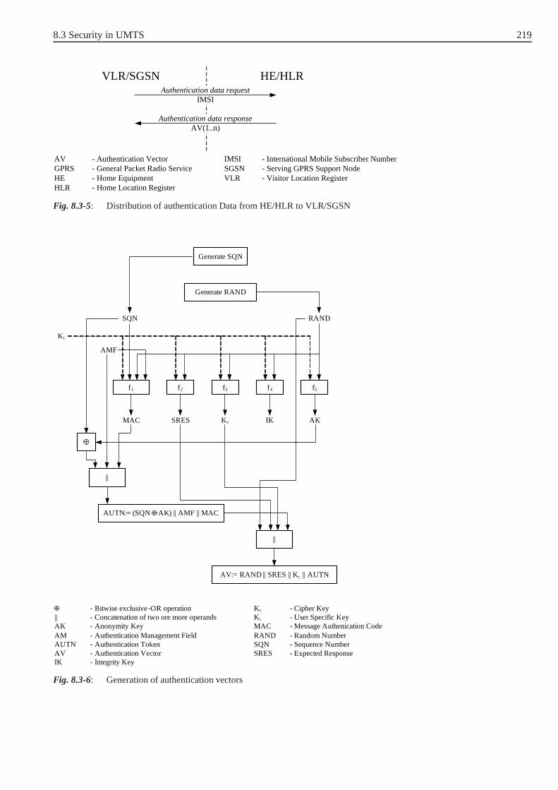
8.3 Security in UMTS 219
HE/HLRVLR/SGSNAuthentication data request
Authentication data responseAV(1..n)
IMSI
AV - Authentication VectorGPRS - General Packet Radio ServiceHE - Home EquipmentHLR - Home Location Register
IMSI - International Mobile Subscriber NumberSGSN - Serving GPRS Support NodeVLR - Visitor Location Register
Fig. 8.3-5: Distribution of authentication Data from HE/HLR to VLR/SGSN
Generate SQN
Generate RAND
K i
f1 f2 f3 f4 f5
MAC SRES Kc IK AK
||
AV:= RAND || SRES || Kc || AUTN
Kc - Cipher KeyK i - User Specific KeyMAC - Message Authenication CodeRAND - Random NumberSQN - Sequence NumberSRES - Expected Response
||
RANDSQN
AMF
AUTN:= (SQN AK) || AMF || MAC
- Bitwise exclusive -OR operation|| - Concatenation of two ore more operandsAK - Anonymity KeyAM - Authentication Management FieldAUTN - Authentication TokenAV - Authentication VectorIK - Integrity Key
Fig. 8.3-6: Generation of authentication vectors

220 8 Security in Wireless and Mobile Networks
• A message authentication codeMAC = f1Ki(SQN ||RAND||AMF )75.
• An expected responseSRES = f2Ki(RAND).
• A cipher keyKc = f3Ki(RAND).
• An integrity keyIK = f4Ki(RAND).
• An anonymity keyAK = f5Ki(RAND).
The authentication token can be constructed as:
AUTN = (SQN ⊕ AK)||AMF ||MAC.
TheAnonymity Key(AK ) is used to hide the sequence number which may exposethe identity and location of the user.
As described in the AKA protocol, the VLR/SGSN sends the values AUTN(i)
andRAND(i) in the user authentication request (see Fig. 8.3-4). Upon receipt ofAUTN(i) andRAND(i) , the USIM proceed as shown in Fig. 8.3-7. Note that inthe figure the indexi is ignored.
The USIM computes the anonymity keyAK = f5Ki(RAND) and retrieves the
sequence number
SQN = (SQN ⊕ AK) ⊕ AK.
Next, the USIM computes
XMAC = f1Ki(SQN ||RAND||AMF )
and compares it with the MAC included in the tokenAUTN. If they are diffe-rent, the user sends auser authentication rejectmessage back to the VLR/SGSNwith an indication of the cause and then abandons the procedure. Otherwise, theUSIM verifies that the received sequence number SQN is in the correct range. Ifthe USIM considers that the sequence number is not in the correct range. It sendsa synchronization failuremessage back to the VLR/SGSN, an integrity-protectedinformation about an acceptable sequence number, and abandons the procedure.The VLR/SGSN requests fresh authentication vectors by forwarding thesynchroni-zation failuremessage to the HE.
75 || indicates that the next term is appended (concatenated) to the one before. ThusSQN ||RAND means thatRANDis appended toSQN

8.3 Security in UMTS 221
VLR/SGSNUSIM
AUTN
SQN AK AMF MAC
f5
RAND
AK
SQN
f1 f2 f3 f4
XMAC RES Kc IK
K i
Verify MAC = XMAC
Verify that SQN is in the correct range
- Bitwise exclusive -OR operationAK - Anonymity KeyAMF - Authentication Management FieldAUTN - Authentication TokenIK - Integrity KeyKc - Cipher KeyKi - User Specific KeyMAC - Message Authenication Code
RAND - Random NumberRES - ResponseSGSN - Serving GPRS Support NodeSQN - Sequence NumberUSIM - User Services Identity ModuleVLR - Visitor Location RegisterXMAC - Expected MAC
User authentication response
RES
User authentication reject
CAUSE
Authentication data request
AUTN || RAND
Fig. 8.3-7: User authentification in the USIM
In the case where the USIM verifies that the sequence number lies in the cor-rect range, it computesRES = f2Ki
(RAND) and includes this parameter ina user authentication response back to the VLR/SGSN (see Fig. 8.3-4). Finally,the USIM computes the cipher keyKc = f3Ki
(RAND) and the integrity keyIK = f4Ki
(RAND). The fact thatMAC = XMACensures that the random chal-lengeRANDsent by VLR/SGSN is really generated by the user’s HE, and that theactual VLR/SGSN is trusted by the HE to deal correctly with authentication vec-tors. Thus, the authentication of the network is reached. Furthermore, checking thatSQNlies in the correct range implies the freshness of the keysKc andIK , because

222 8 Security in Wireless and Mobile Networks
SQNandRAND(from which the keysKc andIK are generated) are jointly integrityprotected by the MAC. In other words, any attempt by the VLR/SGSN to reuse aquintet more than once will be rejected by the MS.
Once the VLR/SGSN receives the value ofRES, it compares it with the expectedvalueSRES. If they are equivalent, the user is authenticated by the network.
If the AKA protocol is carried out properly, the VLR/SGSN is in possession ofa cipher keyKc and an integrity keyIK . These keys are then transferred to theRNC when needed. Note that there are special cipher/integrity keys for circuit-switched domains (CSD), and other cipher/integrity keys for packet-switcheddomains (PSD). For simplicity, we use the same notation for the cipher keyKc andthe integrity keyIK , independently from the used domain. Now, user data and somesignalling information can be confidentiality protected with the use of the standardalgorithmf8.
8.3.4 Encryption of the Communication
The f8 algorithm is a stream cipher used to encrypt the plaintext byapplying akeystream to it. Therefor a bit per bit binary addition of theplaintext and thekeystream is used (see Fig. 8.3-8). The decryption of the plaintext is obtained byan XOR addition of the ciphertext and the same keystream. Theencryption occursbetween theRadio Network Center(RNC) and theUser Equipment(UE)76. Recallthat in GSM, the encryption takes place only between the mobile unit and the BTS(and not BSC).
f8
COUNT-C
BEARER
DIRECTION
LENGTH
Kc
KEYSTREAMBLOCK
PLAINTEXTBLOCK
CIPHERTEXTBLOCK
f8
COUNT-C
BEARER
DIRECTION
LENGTH
KEYSTREAMBLOCK
PLAINTEXTBLOCK
UE or RNC UE or RNC
Kc
Fig. 8.3-8: Encryption/Decryption of the communication
The input parameters to thef8 algorithm are:
76 More precisely, between RNC and the mobile equipment ME which is a part of the UE.

8.3 Security in UMTS 223
– The cipher keyKc (128 bit),
– COUNT-C(32 bits), which represents the hyper-frame number as a time-variantparameter [Stepping02],
– BEARER(5 bits), which identifies the physical channel (”radio bearer”) used totransmit the data,
– DIRECTION(1 bit), which takes the value 0 for messages sent from UE to RNCand 1 for messages sent from RNC to UE. It is given as input tof8 in order toavoid that the keystreams for the uplink and downlink would use the same inputparameter values.
– LENGTH(16 bits), which determines the length of the required keystream block,and
Thef8 algorithm is based on the KASUMI cipher [3GP02c]. KASUMI is ablockcipher that produces a 64-bit output from a 64-bit input under the control of a 128-bit key Ki [3GP02d].f8 is a stream cipher that encrypts/decrypts blocks of databetween 1 and 20000 bits in length. It uses the block cipher KASUMI in OFBmode (see Fig. 8.3-9).
COUNT-C || BEARER || DIRECTION || 0...0
KASUMIKM
A
KASUMI KASUMI KASUMI KASUMI
BLCNT=1BLCNT=0 BLCNT=2BLCNT=BLOCKS-1
KS[0]...KS[63] KS[64]...KS[127] KS[128]...KS[191]
KcKc
Kc Kc
Kc
Fig. 8.3-9: KASUMI cipher used in OFB mode.
Before generating the keystream bits, thef8 algorithm must be initialized as follows(see Fig. 8.3-9):
– The 64-bit registerA is set toCOUNT ||BEARER||DIRECTION ||0 . . .0,with the right most 26 bits set to 0,
– BLKCNTis set to zero. Note thatBLKCNTis specified as a 64-bit counter,
– The 128-bit key modifierKMis set to55555555555555555555555555555555 ,

224 8 Security in Wireless and Mobile Networks
– KSB0 is set to zero. Note thatKSBi is theith block of keystream produced bythe keystream generator, where each block of keystream comprises 64 bits,
– One operation of KASUMI is then applied to the register A, using a modifiedversion of the confidentiality key:A = KASUMI[A]Kc⊕KM .
The f8 algorithm is now initialized and ready to generate the keystream bits.The plaintext/ciphertext to be encrypted/decrypted consists ofLENGTHbits (1 ≤LENGTH ≤ 20000). Between 0 and 63, the least significant bits are then dis-carded from the last block of the keystream depending on the total number of bitsrequired byLENGTH.
So letBLOCKSbe equal to (LENGTH/64) rounded up to the nearest integer. Forinstance, ifLENGTH = 128 thenBLOCKS = 2, if LENGTH = 129 thenBLOCKS = 3. To generate each keystream blockKSB, the following operation isperformed:
KSBn = KASUMI[A ⊕ BLKCNT ⊕ KSBn−1]Kc,
for each integern with 1 ≤ n ≤ BLOCKS, andBLKCNT = n − 1.
8.3.5 Integrity Protection
To protect the integrity of sensitive signalling information which is sent betweenthe MS and the network, an algorithm calledf9 is used. Like thef8 algorithm,f9 isapplied between theMobile Equipment(ME) and theRadio Network Center(RNC).Fig. 8.3-10 illustrates the use of the integrity algorithmf9.
COUNT-I
FRESH
MESSAGE
DIRECTION
f9IK
MAC-I
UE or RNC
COUNT-I
FRESH
MESSAGE
DIRECTION
f9IK
MAC-I
RNC or UE
Fig. 8.3-10: Using thef9 algorithm on a signalling message.
The input parameters to thef9 algorithm are:
– The integrity keyIK (128 bit),
– COUNT-I (32 bits): A sequence number to add a temporal dependency [Step-ping02],

8.3 Security in UMTS 225
– FRESH(32 bits), a random value generated by the network. There is oneFRESH
parameter value per user and this value is used to protect thenetwork againstreplay of signalling messages by the user,
– MESSAGE: The message to be protected,
– DIRECTION (1 bit), defined like in the previous section.
All these input parameters are used byf9 to compute a message authenticationcodeMAC-I . The MAC-I is appended to the message before sending it over theradio access link. The receiver computesX-MACon the message – in the same wayasMAC-I is computed – and compares it withMAC-I . If they are the same, themessage is considered to be integrity protected.
COUNT || FRESH || MESSAGE || DIRECTION || 1 || 0...0
PS0
KASUMI KASUMI
PS2
KASUMI
PSBLOCKS-1
KASUMIIK IK IK IK
KASUMIIK KM
MAC-I (left 32-bits)
PS1
Fig. 8.3-11: Integrity algorithmf9
The integrity algorithmf9 is also based on the block cipherKASUMIwhich is usedin the CBC mode to generate a 64-bit digest of the message input. Finally, theleftmost 32-bits of the digest are taken as the output valueMAC-I (see Fig. 8.3-11). The input parametersCOUNT-I, FRESH, MESSAGE, DIRECTION, a singlebit 1 and between 0 and 63 ’0’ bits are concatenated so that thetotal length of theresulting stringPS (Padded String) is an integral multiple of 64 bits. The PaddedString PS is then split into 64-bit blocksPSi, where0 ≤ i ≤ BLOCKS − 1
andBLOCKS = (bitlength ofPS)/64. ThePSi are then processed according toFig. 8.3-11 withKMset toAAAAAAAAAAAAAAAAAAAAAAAAAAAAAAAA.

226 8 Security in Wireless and Mobile Networks
8.3.6 Securing the Core Network Domain
The core network domain of mobile radio systems is the part ofthe network whichis independent of the radio interface technology. It is usedfor transporting user dataas well as signalling commands [Puetz01a]. In 2G mobile systems like GSM thecore network is not secured for two reasons:
• The initial design goal of 2G mobile systems was to make them as secure asfixed network connections. This means that the security of 2Gmobile systemsdepends only on the security provided at the radio interface.
• The core network is considered to be closed and hence not vulnerable to externalattacks.
As mentioned in Course Unit 9, GSM uses the SS7 (Signaling System No. 7) pro-tocol stack withMobile Application Part(MAP ) as an application on top for itssignalling messages. According to the 2G security viewpoint, the security of SS7network as transport system remains open to major compromises. Messages can beeavesdropped, altered, injected or deleted in an uncontrolled manner.
In 3G systems like UMTS, the security of the core network is taken more seriouslyinto consideration. This means that security solutions must be found for both SS7and IP based protocols. For this purposes, work has be done within the 3GPP inorder to specify security mechanisms and procedures necessary to protect the MAPprotocol. The complete set of enhancements and extensions to facilitate securityprotection for the MAP protocol is termed asMAPsec (see [3GP02a]). With net-MAPsec
works using SS7-based transport, the MAP protocol is protected at the applicationlayer. However, The MAP protocol can be protected at the network layer when theunderlying transport network is IP-based. Fig. 8.3-12 shows the architecture usedfor MAPsec.

8.3 Security in UMTS 227
KACA KACB
MAPNEA1
MAPNEA2
MAPNEB
PLMN A PLMN B
IKE connection
Secure tunnel providing confidentiality and integrity protection
Secure MAP operations
IKE - Internet Key ExchangeKAC - Key Administration CentersMAP NE - MAP Network ElementsPLMN - Public Land Mobile Network
Fig. 8.3-12: The architecture used for MAPsec
In order to protect the communication over the core network,Security Associati-ons77 (SA) need to be established between the respective Mobile Application Part(MAP) network elements. Security Associations define, among other things, whichkeys and algorithms are to be useed to protect the MAP signalling. The necessarySAs for the use of MAPsec between networks are negotiated between the respectiveKey Administration Centers(KACs) of the networks. The KACs are newly definednetwork entities to support the MAPsec protocol. EachPublic Land Mobile Net-work (PLMN ) can have one or more KACs. The negotiated Security Associationshold PLMN-wide and is distributed to all network elements which implement MAPapplication layer security within the PLMN. These elementsare denoted by MAPNEX with respect to the PLMN X (see Fig. 8.3-12).
When a MAP Network Element (MAP NE) needs to establish a secure connectiontowards another MAP NE, it will request a MAPsec Security Association (MAPsecSA) from the Key Administration Centers (KAC) if it cannot find any appropriateMAPsec SA in its localSecurity Association Database(SADB). Note that beforedoing so, the MAP Network Element must consult its security policy database tocheck if MAP security mechanisms shall be applied towards the other MAP NE.The Key Administration Centers (KAC) then either provides an existing MAPsecSecurity Association or negotiate a new one, before returning it to the MAP NE.The negotiation of MAPsec Security Associations between the Key AdministrationCenters (KAC) is performed using the Internet Key Exchange (IKE) protocol (seeFig. 8.3-12) and with respect to the security policy defined in the KAC securitypolicy database.
77 See chapter Internet Security Protocols in the course Network Security I.

228 8 Security in Wireless and Mobile Networks
A MAPsec Security Association (MAPsec SA) is valid for all MAP communicati-ons between the two PLMNs for which it was negotiated. That is, the same MAPsecSA shall be provided to all MAP Network Elements (MAP NE) in PLMN A forcommunication with MAP NEs in PLMN B.
The MAPsec protocol defines three different protection modes for securing the com-munication over the core network:
• Protection mode 0: No protection.
• Protection mode 1: Integrity and authenticity.
• Protection mode 2: Confidentiality, integrity and authenticity.
The secured MAP messages have the following structure:
Security Header Protected Payload
Fig. 8.3-13: Secured MAP message format.
In all three protection modes, the security header is transmitted in cleartext. ForProtection Mode 0, the security header constitutes of the following data elements:
Security header = SPI||Original component Id.
For protection modes 1 and 2, the security header is a sequence of the followingelements:
Security header = SPI||Original component Id||TV P ||NE − Id||Prop.
The Security Parameters Index(SPI, 32 bit) identifies the used MAPsec SA. TheOriginal component Ididentifies the type of message to be transmitted. TheTimeVariant Parameter(TVP) is a 32 bit time-stamp used for replay protection of secu-red MAP operations. The receiving network entity will accept an operation only ifthe time-stamp is within a certain time-window, theTVP period.NE-Id (6 octets)is used to create differentInitialization Vector78 (IV ) values for different NetworkElements within the same TVP period. The data elementProp (4 octets) is used tocreate different Initialization Vector (IV) values for different protected MAP mes-sages within the same TVP period for one Network Element.
The protected payload has the following format depending onthe protection modein operation:
• Protection Mode 0: The protected payload of secured MAP messages in protec-tion mode 0 is identical to the original MAP message payload in cleartext.
78 The Initialisation Vector is used for the initialisationof the encryption functions. For detailssee [3GP02b].

8.3 Security in UMTS 229
• Protection Mode 1: The protected payload of secured MAP messages in protec-tion mode 1 is
cleartext||f7(Security header||cleartext),
wheref7 denotes a MAP integrity algorithm and cleartext is the payload ofthe original MAP message in cleartext. More precisely,f7 is a 32-bit messageauthentication code applied to the concatenation of security header and cleartextwith the use of the integrity key defined by the security association. This enablesthem to achieve authentication of origin and message integrity.
• Protection Mode 2: The protected payload of secured MAP messages in protec-tion mode 2 is
f6(cleartext)||f7(Security header||f6(cleartext)),
wheref6 is a MAP encryption algorithm and cleartext is the payload oftheoriginal MAP message in cleartext. Confidentiality is achieved by encryptingcleartext using the encryption functionf6 with the confidentiality key defined bythe Security Association (SA) and the Initialization Vector (IV). Authenticationof origin and integrity are achieved by applying the messageauthentication codefunctionf7 with the Integrity Key (IK) defined by the Security Association tothe concatenation of security header and ciphertext. The length of the ciphertextis the same as the length of the cleartext.
In the evolution process of 2G mobile systems towards 3G mobile systems, theInternet Protocol (IP) was introduced as network layer in the GPRS backbone net-work and then later in the UMTS network domain. Furthermore,IP-based com-munication is used for both signalling and user traffic. So, in order to secure theUMTS core network domain, it is necessary to secure the IP-based communicationin addition to the SS7-based one.
The IPsec protocol is used to protect the data of all IP-basedprotocols used in theUMTS core network domain. Using IPsec, the protection is provided at the net-work layer. To support the use of IPsec, the core network domain is divided logi-cally and physically into security domains which are separated by means ofSecurityGatewaysdenoted bySEG(s). SEGs are entities on the borders of the IP securitydomains, so that all IP traffic shall pass through them beforeentering or leavingthe security domain. The SEGs useInternet Key Exchange(IKE )to negotiate, esta-blish and maintain a secureEncapsulation Security(ESP) tunnel between them.The tunnel is subsequently used for forwarding IP traffic between security domainA and security domain B (see Fig. 8.3-14). For all communication within the samesecurity domain the use ESP+IKE connections can be optionally implementet (see[3GP02a]).

230 8 Security in Wireless and Mobile Networks
NEA1
NEA2
SEGA
NEB1
NEB2
SEGB
Security Domain A Securtiy Domain B
IKE connection
ESP security association
ESP - Encapsulation Security PayloadIKE - Internet Key ExchangeNE - Network ElementsSEG - Security Gateways
Fig. 8.3-14: Network domain security for IP-based protocols
8.4 Security in WAP
In mid 1997 Ericsson, Motorola, Nokia and Phone.com decidedto define a newprotocol for mobile devices in order to offer wireless data communication servicesto end users, both in the form of Telecommunications-related and Internet-orientedapplications. In December 1997, the four partners formed a company, WAP ForumLtd., to control and manage the development of WAP. WAP stands forWireless App-lication Protocolrepresenting a protocol that uses three important network techno-logies: wireless data, telephony, and the Internet.
Because the WAP programming model is based on the WWW model, we first givean overview of the WWW architecture. In the WWW architecture, applicationsand content are presented in standard data formats, and are browsed by applica-tions known as web browsers. A web browser is a network application, i.e. it sendsrequests for named data objects to a network server and the server responds withthe data encoded using the standard formats [Wap01a] (Fig. 8.4-1).
Application Server
Response (Content)
HTTPServer
Request (URL)
Conte
nt
Client
WebBrowser
Fig. 8.4-1: WWW architecture

8.4 Security in WAP 231
8.4.1 Introduction to WAP
The WAP programming model is the same as the WWW programming model witha few enhancements. Adopting the WWW programming model provides the WAPprogramming model with several benefits including a familiar programming model,a proven architecture, and the ability to use existing tools(e.g., web servers, XMLtools, etc.). Fig. 8.4-2 shows the most significant enhancements that WAP has added.It can be seen that the WAP programming model supports the so calledPushand thewireless telephony application (WTA ) technologies. WTA provides the WAP clientwith telephony functionality such as call control, phone book and messaging. ThePush technology is a new technology in transmitting information between client andserver. In the normal client/server model, a client requests a service or informationfrom a server, which then responds in transmitting information to the client. Thisis known asPull technology. An example of this technology is browsing the WorldWide Web, where a user enters an URL (the request) that is sentto a server, and theserver answers by sending a Web page (the response) to the user.
The push technology is in fact based on the client/server model, but does not requirean explicit request from the client before the server transmits its content. That is, inthe WAP Push, informations can be transmitted to a device without an explicit userrequest.
WAPMicroBrowser
WAP Device Application Server
Response (Content)
HTTPServer
PushInitiator
Request (URL)
Push (Content)
Conte
nt
(WTA)
Fig. 8.4-2: WAP programming model
In order to optimize and enhance the connection between the wireless domain andthe WWW, WAP utilizes the proxy technology (Fig. 8.4-3). TheWAP proxy mayprovide a variety of functions, including [Wap01a]:
• Protocol gateway: The protocol gateway translates requests from a wireless pro-tocol stack to the WWW protocols (HTTP and TCP/IP). The gateway also per-forms DNS lookups of the servers named by the client in the requested URLs.
• Content encoders and decoders: The content encoders can be used to translateWAP content into a compact format that allows better utilization of the underly-ing (over the air) link due to its reduced bandwidth.

232 8 Security in Wireless and Mobile Networks
• User agent profile management: User agent profiles describing client capabilities(input and output capabilities, display size, etc.) and personal preferences thatare content presentation preferences.
• Caching proxy: A caching proxy can improve the performance of network utili-zation by maintaining a cache of frequently accessed resources (URLs).
• In addition, for a WAP proxy it is necessary to offer Push functionality.
Encoded Request (URL)
WAPMicroBrowser
HTTPProxy
FeatureEnhancements
Encoded Content
Client Proxy Application Server
HTTPServer
Conte
nt
Request (URL)
Content
Fig. 8.4-3: WAP programming model enhanced with the proxy technology
8.4.2 The WAP Protocol Stack
The design of the WAP protocol stack takes into consideration the nature of thewireless environment and the network. Applications developed for the Internet –as the main wired network – are designed for desktop computers and medium tohigh bandwidth. Wireless devices present, however, a more constrained compu-ting environment compared to desktop computers. Wireless devices tend to haveless powerful CPUs, less memory (ROM and RAM), restricted power consumption,smaller displays, and different input devices (e.g. a phonekeypad). Similarly, wire-less data networks present a more constrained communication environment compa-red to wired networks. Wireless data networks tend to have less bandwidth, morelatency, less connection stability, and less predictable availability.
The WAP protocol stack has a layered design (Fig. 8.4-4). Each of the layers ofthe architecture is accessible by the layers above, as well as by other services andapplications.

8.4 Security in WAP 233
Bearers
GSM CDMAIS-136 PHS CDPD PDC-P IDEN FLEX Etc...
Application Layer (WAE)
Session Layer (WSP)
Transaction Layer (WTP)
Security Layer (WTLS)
Transport Layer (WDP)
OtherServices
andApplications
Fig. 8.4-4: The WAP protocol stack
It can be seen from Fig. 8.4-4 that the WAP protocol can operate over different bea-rer services. The bearer is a data transport mechanism used to carry theWirelessDatagram Protocol(WDP) between two devices. Examples of underlying bearersare GSM SMS (Short Message Service), GSM USSD (UnstructuredSupplementaryService Data), GSM CSD (Circuit Switched Data), etc. WDP offers a consistent ser-vice to the upper protocols (Security, Transaction and Session) of WAP and commu-nicates transparently over one of the available bearer services. The WDP servicesinclude application addressing by port numbers, optional segmentation and reas-sembly and optional error detection. TheWireless Transaction Protocol(WTP) isdefined to provide the services necessary for interactive browsing (request/response)applications. The request/response cycle is referred to asa transaction. The objec-tive of the protocol is to reliably deliver the transaction while balancing the amountof reliability required for the application with the cost ofdelivering the reliability[Wap01d]. The benefits of using WTP in the WAP protocol include:
• Improved reliability over datagram services. WTP relievesthe upper layer fromretransmissions and acknowledgements which are necessaryif datagram ser-vices are used.
• Improved efficiency over connection oriented services. WTPhas no explicitconnection setup or termination (teardown) phases and hence no excessive over-head on the communication link.
• WTP is designed for services oriented towards transactions(request/responseapplications), such as browsing.
TheWireless Session Protocol(WSP) provides the upper-level application layer ofWAP with a consistent interface for two session services. The first is a connection-mode service that operates above the transaction layer protocol WTP, and the secondis a connectionless service that operates above a secure or non-secure datagramtransport service (WDP). The Wireless session protocol currently offers services

234 8 Security in Wireless and Mobile Networks
most suited for browsing applications (connection-mode service). Especially, WSPprovides HTTP 1.1 functionality and incorporates new features such as long-livedsessions, capability negotiation and session suspend/resume [Wap01c].
The part of WAP used by developers to develop their wireless applications and ser-vices is theWireless Application Environment(WAE ). The WAE consists of threemain parts: thewireless markup language(WML ), thewireless markup languagescript (WMLScript ), and thewireless telephony application interface(WTAI )79.
WML is a markup language based on XML but optimized for devices with limitedgraphical capabilities and a small amount of screen area. WML80 can be encodedby replacing parts of the WML (tags, attribute names and attribute values) by sin-gle byte tokens. This tokenisation improves the efficiency of transmission. WML-Script is a scripting language (like JavaScript) based on a subset of the ECMAS-cript (European Computer Manufacturer Association) WWW scripting language.WMLScript can be used together with WML to provide intelligence to the cli-ents. For example, WMLScript provides access to the WAP device and its peri-pherals. One important feature of WMLScript is that it can becompiled to a com-pressed bytecode and hence directly interpreted by a virtual machine81. Transmit-ting these compiled bytecode results in a reduction in size and also in the amountof parsing/processing required on the WAP enabled device. Note that the enco-ding/decoding of WML/WMLScript instructions into instructions understood bythe Internet is done in the WAP gateway as mentioned in previous sections.
8.4.3 Wireless Transport Layer Security (WTLS)
Security in WAP is defined by theWireless Transport Layer Security(WTLS ) pro-tocol. In the WAP stack, the WTLS protocol operates above thetransport layer pro-tocol. The WTLS protocol is a derivate of the TLS/SSL82 protocol but is optimizedfor low-bandwidth bearer networks with relatively high latency. The use of WTLSis not mandatory for each application, but only for those requiring a certain level ofsecurity. The cryptographic goals reached by using WTLS areconfidentiality, dataintegrity, and authentication between two communicating applications. WTLS doesnot, however, provide non repudiation services.
The WTLS protocol is based on a client-server architecture.In order to establish asecure session between client (WAP device) and server (Web server), the two com-municating parties first have to negotiate security parameters which will be used tosecure the session. This is done by performing thehandshake protocolwhich is a
79 See [Heijden00] for more details.
80 WML (Version 1).
81 This is not the case with WML which is only a compact representation of the content.
82 A detailed description of the TLS/SSL protocols is given in the course Network Security inchapter 3.

8.4 Security in WAP 235
subprotocol of the WTLS protocol. During the handshake protocol, the communica-ting parties agree on a protocol version, select cryptographic algorithms, optionallyauthenticate each other, and use public key encryption techniques to generate a sha-red secret. The message flow of the handshake protocol is illustrated in Fig. 8.4-5.
WAP Client
ClientHello
CertificateRequest *
ServerKeyExchange *
ServerHelloDone
ClientKeyExchange
Certificate *
Certificate *
CertificateVerify *
ChangeCipherSpec
ChangeCipherSpec
Application Data Application Data
Finished
Finished
ServerHello
ServerP
hase
1P
hase
2P
hase
3P
hase
4
Fig. 8.4-5: Message flow of the handshake protocol
The Handshake Protocol consists of a series of messages exchanged by client andserver and can be viewed as having four phases. In thefirst phase security capa-bilities are established. The phase is initiated by the client and is used to initiate alogical connection by exchanging hello messages between the client and the server.
When a client first connects to a server it is required to send the ClientHello
as its first message (see Fig. 8.4-5). The client can also senda ClientHello inresponse to aHelloRequest message that comes from the server or on its owninitiative in order to renegotiate the security parametersin an existing connection.The ClientHello message contains, among other things, the following para-meters:Version (the latest WTLS version understood by the client),Session
ID (session identifier used to identify a secure session between client and server),Random Structure (12 random bytes,HelloClient.random , generatedby a secure random number generator and used later in the protocol), Cipher
Suite (The Cipher Suite defines a bulk encryption algorithm (includingsecret key length) and a MAC algorithm. Examples of a bulk encryption algorithmand a MAC algorithm are DES algorithm operating in CBC mode with 40 bits keylength and MD5 MAC-algorithm with 128 bits key length, respectively.), andKey

236 8 Security in Wireless and Mobile Networks
Exchange Suite (a list of key exchange algorithms supported by the client,such as RSA or anonymous Diffie-Hellman key exchange algorithm).
The server processes theClientHello message and responds with either ahandshake failure (fatal error will occur and the connection will fail) orServerHello message. Generally, theServerHello message contains thesame parameters as theClientHello message, such asVersion , Random,Session ID , andCipher Suite . TheVersion field contains the lower ofthe WTLS version suggested by the client and the highest supported by the server.TheRandomfield, denotedHelloserver.random , is generated by the server.If the server is willing to establish the new connection using the specified securesession83, it will respond with the same value of session identifier supplied by theclient. TheCipher Suite parameter contains a single cipher suite selected bythe server from the list of cipher suites proposed by the client (if no acceptablechoices are presented, the server returns ahandshake failure alert and clo-ses the connection). TheServerHello message also includes a field containingthe number of the key exchange suite selected by the server from the list in theClientHello message.
Now after the end of hello messages, security enhancement capabilities are establis-hed between client and server, i.e. the protocol version, session ID, cipher suite, keyexchange suite, etc.
The second phaseof the handshake protocol is theAuthentication and KeyExchange. If the server is to be authenticated (which is generally thecase), itsends its certificate with theCertificate message immediately following theServerHello message. The certificate type must be appropriate for the selectedkey exchange suite’s algorithm. It can be a X.509.v3 certificate, a WTLS certificatewhich is optimized for size, or some other. If the server has no certificate, or itscertificate is used for signing only, the server sends theServerKeyExchange
message. With this message, the server informs the client about cryptographicparameters which enable the client to exchange a premaster secret , i.e., the mes-sage contains the parameters used for RSA key exchange (RSA modulus and thepublic exponent of the server’s temporary RSA key), the parameters used for Diffie-Hellman key exchange (prime modulop, generatorg, and the server’s public valuegx mod p).
When the server is authenticated, it may request a certificate from the client if thatis appropriate to the cipher suite selected, and send theCertificateRequest
message. This message consists of a list of the types and names of acceptable certifi-cation authorities. The final message in phase 2, and the one that is always required,is theServerHelloDone message sent by the server. It indicates that the hello-message phase of the handshake is complete. The server will then wait for a clientresponse.
83 Which is a secure session established previously betweenthe same client and server.
8.4 Security in WAP 237
The third phase of the handshake is theclient authentication and key exchange.Upon receipt ofServerHelloDone message, the client should verify that theserver provided a valid certificate if required and check that the ServerHello
parameters are acceptable. If all is satisfactory, the client sends one or more messa-ges back to the server. If the server has sent aCertificateRequest message,the first message the client sends is its certificate in theCertificate message(or a no certificate message, if no suitable certificate is available).
Next, theClient Key Exchange message is sent. The content of this mes-sage depends on the type of key exchange selected during the exchange of theClientHello and theServerHello messages. With sending this message, apremaster secret is set. For example, if RSA is used for key agreement and authen-tication, the client generates a 20-byte premaster secret,encrypts it with the publickey from the server’s certificate, and sends the result in anencrypted secret
message. This random value (premaster-secret) is generated by the client and isused to generate the master secret. Finally, in this phase, the client may send aCertificateVerify message to provide explicit verification of the client cer-tificate (if the client has sent a certificate). This message signs a hash code basedon some messages of the handshake. Note that the hash algorithm being used is theone agreed during the handshake.
The fourth phase, called thefinish phasecompletes the setting up of a secureconnection. The client sends aChangeCipherSpec message and copies the pen-ding CipherSpec into the current CipherSpec. Note that thismessage is not consi-dered part of the Handshake Protocol but is sent using the ChangeCipherSpec Pro-tocol, which is a subprotocol of the WTLS protocol and which notifies the othercommunicating party that subsequent messages (called records in the context ofthe WTLS protocol) will be protected under the newly negotiated CipherSpec andkeys. The client then immediately sends theFinished message to verify that thekey exchange and authentication process were successful. This is the first messageprotected with the just-negotiated algorithms and keys. This message includes hashvalues of all handshake messages starting atClientHello up to, but not inclu-ding, theFinished message.
In response to these two messages, the server sends its ownChangeCipherSpec
message, transfers the pending to the current CipherSpec, and then sends its ownFinished message under the new CipherSpec. Recipients of theFinished
message must verify that the contents are correct. No acknowledgement of theFinished message is required.
At this point, the handshake is complete and the client and server may begin toexchange application layer data using the secure connection.
When the client and server decide toresume a previous sessioninstead of negotia-ting new security parameters, the abbreviated handshake, which is a variant of the(full) handshake protocol, is to be used (Fig. 8.4-6).
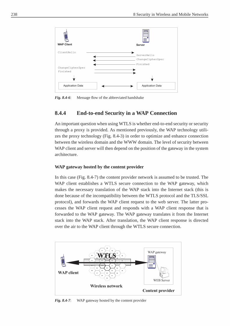
238 8 Security in Wireless and Mobile Networks
WAP Client
ClientHello
ChangeCipherSpec
ChangeCipherSpec
Application Data Application Data
Finished
Finished
ServerHello
Server
Fig. 8.4-6: Message flow of the abbreviated handshake
8.4.4 End-to-end Security in a WAP Connection
An important question when using WTLS is whether end-to-endsecurity or securitythrough a proxy is provided. As mentioned previously, the WAP technology utili-zes the proxy technology (Fig. 8.4-3) in order to optimize and enhance connectionbetween the wireless domain and the WWW domain. The level of security betweenWAP client and server will then depend on the position of the gateway in the systemarchitecture.
WAP gateway hosted by the content provider
In this case (Fig. 8.4-7) the content provider network is assumed to be trusted. TheWAP client establishes a WTLS secure connection to the WAP gateway, whichmakes the necessary translation of the WAP stack into the Internet stack (this isdone because of the incompatibility between the WTLS protocol and the TLS/SSLprotocol), and forwards the WAP client request to the web server. The latter pro-cesses the WAP client request and responds with a WAP client response that isforwarded to the WAP gateway. The WAP gateway translates it from the Internetstack into the WAP stack. After translation, the WAP client response is directedover the air to the WAP client through the WTLS secure connection.
•
•
•
•
•
•
•
•
•
•
•
•
•
•
••
•• •
•
••
••
•
••
••
•
••
••
•
WAP gateway
WEB Server
WTLS
Content providerWireless network
WAP client
•
•
•
•
•
•
•
•
•
•
•
•
•
•
••
•• •
•
••
••
•
••
••
•
••
••
•
WTLS
Fig. 8.4-7: WAP gateway hosted by the content provider
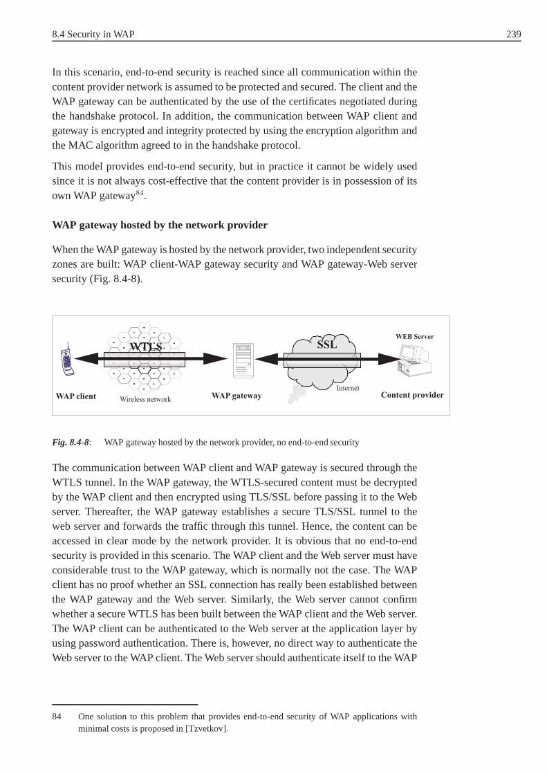
8.4 Security in WAP 239
In this scenario, end-to-end security is reached since all communication within thecontent provider network is assumed to be protected and secured. The client and theWAP gateway can be authenticated by the use of the certificates negotiated duringthe handshake protocol. In addition, the communication between WAP client andgateway is encrypted and integrity protected by using the encryption algorithm andthe MAC algorithm agreed to in the handshake protocol.
This model provides end-to-end security, but in practice itcannot be widely usedsince it is not always cost-effective that the content provider is in possession of itsown WAP gateway84.
WAP gateway hosted by the network provider
When the WAP gateway is hosted by the network provider, two independent securityzones are built: WAP client-WAP gateway security and WAP gateway-Web serversecurity (Fig. 8.4-8).
WAP gateway
WEB Server
Content providerWAP client
•
•
•
•
•
•
•
•
•
•
•
•
•
•
••
•• •
•
••
••
•
••
••
•
••
••
••
•
•
•
•
•
•
•
•
•
•
•
•
•
••
•• •
•
••
••
•
••
••
•
••
••
•
WTLS
Wireless network
SSL
Internet
Fig. 8.4-8: WAP gateway hosted by the network provider, no end-to-end security
The communication between WAP client and WAP gateway is secured through theWTLS tunnel. In the WAP gateway, the WTLS-secured content must be decryptedby the WAP client and then encrypted using TLS/SSL before passing it to the Webserver. Thereafter, the WAP gateway establishes a secure TLS/SSL tunnel to theweb server and forwards the traffic through this tunnel. Hence, the content can beaccessed in clear mode by the network provider. It is obviousthat no end-to-endsecurity is provided in this scenario. The WAP client and theWeb server must haveconsiderable trust to the WAP gateway, which is normally notthe case. The WAPclient has no proof whether an SSL connection has really beenestablished betweenthe WAP gateway and the Web server. Similarly, the Web servercannot confirmwhether a secure WTLS has been built between the WAP client and the Web server.The WAP client can be authenticated to the Web server at the application layer byusing password authentication. There is, however, no direct way to authenticate theWeb server to the WAP client. The Web server should authenticate itself to the WAP
84 One solution to this problem that provides end-to-end security of WAP applications withminimal costs is proposed in [Tzvetkov].

240 8 Security in Wireless and Mobile Networks
gateway using its certificate and the user of the WAP client should trust the WAPgateway that the authentication is correct.
8.4.5 Other Security Components of WAP
Other security components of WAP are theWMLScript Crypto Library[Wap01e]and theWireless Identity Module(WIM) [Wap01b]. The WMLScript Crypto Librarydefines a mechanism to see a text string and to sign it digitally. This complementsthe security goals of the WAP technology to the non repudiation issue in addition toprivacy, data integrity, and authentication issues.
Many kinds of applications, e.g. electronic commerce, require the ability to pro-vide persistent proof that someone has authorized a transaction. Although WTLSprovides transient client authentication for the durationof a WTLS connection, itdoes not provide persistent authentication for transactions that may occur duringthat connection. One way to provide such authentication is to associate a digitalsignature with data generated as the result of a transaction, such as a purchase orderor other financial document [Wap01e].
The Crypto.signText is a WMLScript function that supports persistentauthentication for application. A call to thesignText method first displays theexact text to be signed. The user is allowed to confirm this text or not. After confir-mation, the data will be signed and both the signature and thedata will be sent acrossthe network to the appropriate server. The latter can extract the digital signature andvalidate it.
The signature key is stored in the WIM. The WIM is a tamper-resistant device withcomputation capability having an interface to the WAP client. In fact, the properdigital signature computation is performed in the WIM (using signature key) beforebeing displayed by the WAP client. The WIM has other functionalities in additionto storing private keys and digital signature computation.It can be used for WTLSoperations, like performing cryptographic operations during the handshake, espe-cially those that are used for client authentication. For example, during an RSAhandshake, the WIM performs the signature operation proving the client’s identitywith the use of the client public key or certificate stored in it. The WIM may alsostore needed certificates: CA and user certificates85.
8.5 Security in Bluetooth
Bluetooth86 is an open industry standard for short range, wireless connectivity bet-ween common devices, e.g. connection of wireless PC keyboard, wireless mouse,
85 See [Wap01b] for more details about the WIM functionalityand capability.
86 The standard is named after Harald Blaatand "Bluetooth" II, king of Denmark 940-981A.D.A runic stone has been erected in his capitol city Jelling (Jutland) that depicts the chivalry ofHarald and the "runes" say: Harald christenized the Danes; Harald controlled Denmark andNorway; Harald thinks notebooks and cellular phones shouldseamlessly communicate.

8.5 Security in Bluetooth 241
and wireless mobile telephone to a PC. It is intended as a replacement of cableconnections in a range of up to 100 m. Bluetooth devices are categorized into threedifferent classes dependent on their transmission power. Class 3 devices use 1 mWpower and have a transmission range of 0.1 to 10 meters. Class2 devices use 1 to2.5 mW power and have a range of 10 meters. Class 1 device use upto 100 mWpower and have a range up to 100 meters. The Bluetooth system operates in the 2.4GHz ISM (Industrial Scientific Medicine) band.
8.5.1 Introduction to the Bluetooth Technology
A Bluetooth system provides a point-to-point connection between two Bluetoothdevices, or a point-to-multipoint connection. In a point-to-multipoint connection,the channel is shared among several Bluetooth devices. Apiconet87 consists of twoor more Bluetooth devices sharing the same channel, where one component acts asthe master of the piconet and the other component(s) (up to seven) act(s) as slave(s).All communication is between the master and the slave. Slaves cannot address eachother directly. It is, however, possible for devices to dynamically switch roles: for aslave to become a master and vice-versa [Dent]. Multiple piconets (up to ten) withoverlapping coverage areas form a scatternet. Each piconetcan only have one singlemaster. However, slaves can participate in different piconets. In addition, a masterin one piconet can be a slave in another piconet.
Fig. 8.5-1: Piconet and scatternet.
Between master and slave(s), different types of links can beestablished. Two linktypes have been defined:
87 It is ”pico” because of the short range of the Bluetooth wireless communications.

242 8 Security in Wireless and Mobile Networks
• Synchronous Connection Oriented (SCO) link: The SCO link isa point-to-pointlink between a master and a single slave in a piconet. It can beconsidered asa circuit-switched connection. The master can support up tothree SCO linksto the same slave or to different slaves. A slave can establish up to three SCOlinks to the same master, or two SCO links if the links originate from differentmasters.
• Asynchronous ConnectionLess (ACL) link: The ACL link provides a packet-switched connection between the master and all active slaves participating inthe piconet. Between a master and a slave only a single ACL link can exist.
How is the channel of a piconet established and how can Bluetooth devices be addedto and released from the piconet? Several states of operation of the Bluetooth deviceare defined to support these functions. Theinquiry state allows a device to discoverother Bluetooth devices which are in its range. Theinquiry scan state allows adevice to be discovered. A device that allows itself to be discovered is ininquiryscanand is ready to respond to inquiry messages. Once the devicesare discoveredby each other, a connection can be established using the paging procedure. Thepage scanstate enables a connection to be established. Thepagestate is used by themaster88 (source) to activate and connect to a slave (destination) which periodically”wakes up” in the page scan state. To ensure that connected devices do not remainactive all the time, power saving modes have been defined:
• HOLD mode: In this mode, a slave temporarily stops transmission.The HOLDmode is used to let the master establish a link to another device. With the holdmode, capacity can be made available to the slave to do other things like scan-ning, paging, inquiring, or attending another piconet.
• SNIFF mode: In this mode, the duty cycle of the slave’s listen activity can bereduced but the slave remains an active device of the piconet. The master canonly transmit after the "SNIFF" time.
• PARK mode: When a slave does not need to participate in the piconetchannelbut wants to remain synchronized to the channel, it can enterthe PARK mode.The PARK mode is a low power mode with very little activity in the slave. ThePARK mode is used to connect more than seven slaves to a singlemaster, wheremaximal seven of them are allowed to be active.
8.5.2 Bluetooth Protocol Stack
A Bluetooth protocol stack (see Fig. 8.5-2) has been specified89, so that electronicequipment can be connected to a Bluetooth device.
88 The Bluetooth device that initiates the connection playsthe role of a master.
89 The Bluetooth specification is developed by the BluetoothSpecial Interest Group SIG, whichis an association of telecommunication, computing, and network companies.

8.5 Security in Bluetooth 243
Fig. 8.5-2: The Bluetooth stack
The RF (Radio Frequency) layer is responsible for modulation/demodulation ofsignals to be transmitted/received over the air by the Bluetooth device.FrequencyHopping is used to minimize the effect of interference and fading. The link con-troller carries out the baseband protocols. The function ofthe baseband protocolincludes the handling of SCO and ACL packets and controllingthe physical linksvia the radio (error correction). The LMP protocol provideslink set up (SCO/ACLlinks), link configuration, and security function. The linkconfiguration tasks includequality of service, power control, and handling the mode of operation of the device(HOLD mode, SNIFF mode, etc). The security function deals with the authentica-tion of the Bluetooth devices to be linked, with the encryption of the traffic in apiconet, and with the management of the cryptographic keys.The Host ControllerInterface is used to isolate the Bluetooth baseband and linkmanager from a trans-port protocol such as USB or RS-232. This allows a standard host processor toconnect to Bluetooth hardware90. An HCI driver on the host is needed to interfaceBluetooth applications with the transport protocol.
The L2CAP protocol supports multiplexing, segmentation and reassembly of ACLpackets, and the conveying of quality of service information. With multiplexing,the L2CAP protocol allows multiple applications to use a link between two devi-ces simultaneously. In the segmentation process, packets received by applicationsare reduced in a size accepted by the baseband. On the reverseway, basebandpackets are reassembled before being forwarded to the application. The L2CAPprotocol allows Bluetooth devices to exchange informations about the quality ofservice expected in the connection in use. In addition, it supports group manage-ment mapping upper protocol groups to Bluetooth piconets. Several Bluetooth pro-tocols interface to the L2CAP link layer. SDP provides service discovery specificto the Bluetooth environment (example of services are printing, paging, FAXing,and information access services such as teleconferencing,and eCommerce facili-
90 The Bluetooth hardware integrates the RF, the baseband, and the link manager.
244 8 Security in Wireless and Mobile Networks
ties) and determines the characteristics of the service discovered. The RFCOMMprotocol allows applications developed for serial ports torun (to be emulated) onBluetooth platforms without modification. The Telephony Control protocol Speci-fication (TCS) is responsible for:
• Call Control (CC): Signalling for the establishment and release of speech anddata calls between Bluetooth devices.
• Group Management: Signalling to ease the handling of groupsof Bluetoothdevices.
• ConnectionLess TCS (CL): TCS CL is used to exchange signalling informationwithout establishing a TCS call. For example, when a home base station needsto alert all phones in range for an incoming call.
Fig. 8.5-2 illustrates a relatively abstract form of the Bluetooth stack. In addition,the SIG has specified profile stack specifications for application protocols like FTP,and LAN access protocol.
8.5.3 Security Features and Keys
The security provided by Bluetooth is based on authentication of the devices willingto establish a connection and the encryption of data passingthrough this connection.In fact, the security features are specified at the link level. During the connectionestablishment, Bluetooth devices can negotiate the security level of the communi-cation depending on which security mode the Bluetooth device is in. Three securitymodes have been specified:
• Security mode 1 (non-secure): They shall never initiate anysecurity procedure.
• Security mode 2 (service level enforced security): The channel or service usingL2CAP connection decides whether or not security is required. So until anL2CAP channel has been established, a device will not initiate any securityprocedures. A Bluetooth device in security mode 2 should classify the securityrequirements of its services using at least the following attributes: Authorizationrequired, authentication required, encryption required [Loehlein02].
• Security mode 3 (link level enforced security): In this mode, the authenticationof the devices is part of the connection establishment procedure. Encryption ofthe communication is optional.
The key used for authentication is named link key. Moreover,it is used as one ofthe parameters for generating the encryption key. In fact, the exchange of the keystakes place during an initialization phase which consists of:
• Generation of an initialization key,
• Generation of a link key,
• Link key exchange,
• Authentication, and

8.5 Security in Bluetooth 245
• Generation of an encryption key in each Bluetooth device (optional).
Four types of link keys are specified:
• The initialization keyKinit: It is used as link key during the initialization processwhen no combination or unit keys (which are explained later)have been definedand exchanged yet or when a link key has been lost.Kinit is derived by theE22 algorithm from a PIN code, the length of the PIN (in octets), and a randomnumberIN_RAND (128 bit) (Fig. 8.5-3). TheE22 algorithm is based on theblock cipher SAFER+91. The PIN code can be entered manually by the user orcan be generated automatically by a specific application. The PIN code can varyfrom 8 to 128 bits. Oncekinit has been derived, the PIN code will be augmentedwith BD_ADDR. BD_ADDR is the 48-bit public address of the Bluetoothdevice.
E22
L’
PIN’
RAND
KeyKey
8L’
128
128 128
E21
RAND
BD_ADDR
48
128
(1) (2)
Fig. 8.5-3: Key generation forkmaster andKinit in (1) and for the unit key and combination keyin (2)
• The unit keykA: This key is generated in a single deviceA. It is generated oncethe Bluetooth device is in operation for the first time. The unit key is used forauthentication by Bluetooth devices with less memory to store keys. The unitkey is computed by theE21 algorithm (based on the block cipher SAFER+, too)from a 128-bit random number and theBD_ADDR address (see Fig. 8.5-3).The unit key is exchanged by XORing it with the initialization keyKinit.
The combination keykAB: This key is generated by the use of information inboth devicesA and B, which are 128 bits random numbersLK_RANDA andLK_RANDB generated in the devicesA and B, respectively. It is suitable forapplications which require a higher level of security. However, these applicati-ons must run in an environment with more memory since for every connectionwith a new device a new combination key has to be stored. The combination keykAB is computed by using the algorithmE21, the random numbers (LK_RANDA,LK_RANDB) and the own address (BD_ADDRA, BD_ADDRA) as input. First,the numbersLK_KA, LK_KB are created in the corresponding device as follows:
91 SAFER+ is one of the fifteen block cipher finalists that wereselected as AES candidates.
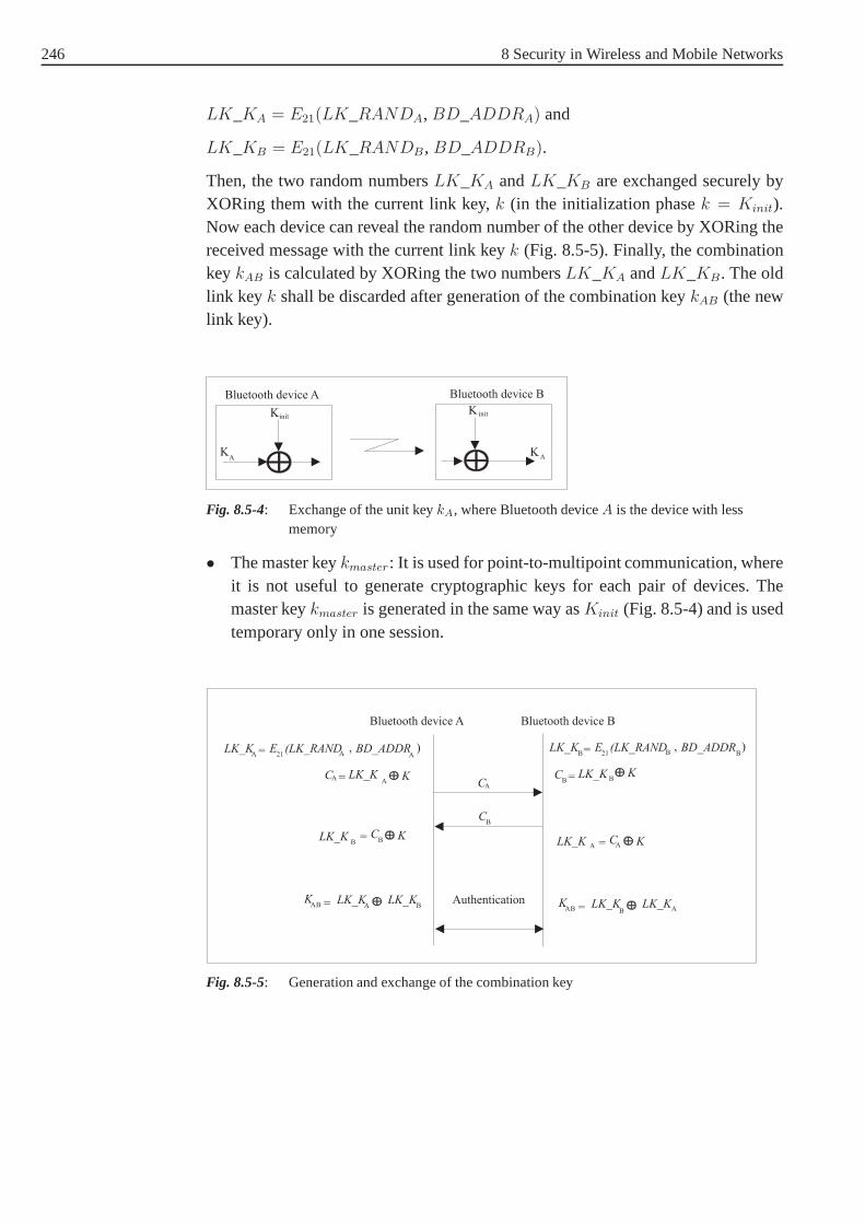
246 8 Security in Wireless and Mobile Networks
LK_KA = E21(LK_RANDA, BD_ADDRA) and
LK_KB = E21(LK_RANDB , BD_ADDRB).
Then, the two random numbersLK_KA andLK_KB are exchanged securely byXORing them with the current link key,k (in the initialization phasek = Kinit).Now each device can reveal the random number of the other device by XORing thereceived message with the current link keyk (Fig. 8.5-5). Finally, the combinationkeykAB is calculated by XORing the two numbersLK_KA andLK_KB. The oldlink key k shall be discarded after generation of the combination keykAB (the newlink key).
Bluetooth device A
Kinit
AK
K init
AK
Bluetooth device B
Fig. 8.5-4: Exchange of the unit keykA, where Bluetooth deviceA is the device with lessmemory
• The master keykmaster: It is used for point-to-multipoint communication, whereit is not useful to generate cryptographic keys for each pairof devices. Themaster keykmaster is generated in the same way asKinit (Fig. 8.5-4) and is usedtemporary only in one session.
Bluetooth device A Bluetooth device B
LK K_A 21= E (LK_RAND
A, BD_ADDR
A) LK K_
21= E (LK_RAND , BD_ADDR )B B B
C = LK_K KCA = LK_KA
KCA
B B
CB
LK_KB
= CB K
LK_K = C KA A
KAB = LK K_
ALK K_
B KAB = LK K_
ALK K_
B
Authentication
Fig. 8.5-5: Generation and exchange of the combination key

8.5 Security in Bluetooth 247
8.5.4 Authentication
The authentication of Bluetooth devices is based on a challenge-response scheme.Fig. 8.5-6 shows how a Bluetooth deviceA can authenticate the deviceB. For thispurpose, the claimant (device B) must prove its knowledge ofa shared secret, deno-ted here asAU_RANDA. First, the verifier computes an expected responseSRES ′
from the inputsAU_RANDA, BD_ADDRB, and the link key.AU_RANDA is a128 bit random number generated byA. BD_ADDRB is the device address of theclaimant which can be obtained by an inquiry procedure.E1 is a MAC algorithmbased on SAFER+. The output ofE1 is a 128 bit hash value, where the first 32bits constitute the responseSRES ′ and the rest 96 bits form a number called ACO(Authenticated Ciphering Offset). ACO is used in the generation of the encryptionkey. Thereafter, the verifier sends the challengeAU_RANDA to the claimant. Afterreceiving the challenge, the claimant computes the responseSRES. SRES are thefirst 32 bits taken from the hash value generated by theE1 algorithm and the inputsAU_RANDA, BD_ADDRB, and the link key.SRES is then sent to the verifierwhich checks whetherSRES andSRES ′ are equal. If they are equal,deviceB isauthenticated by deviceA.
E1E
1
AU_RANDA
AU_RANDA
BD_ADDRBBD_ADDRB
Link keyLink key
SRES’ SRES ACOACO
=?
SRES
AU_RAND
SRES
Verifier Claimant
Bluetooth device A Bluetooth device B
A
Fig. 8.5-6: Authentication in Bluetooth
Note that the verifier must not necessarily be a master. On theother hand, if mutualauthentication is to be used, deviceB can challenge deviceA in the same way, usinga challenge-response scheme with another 128 bit random numberAU_RANDB
generated by him.

248 8 Security in Wireless and Mobile Networks
8.5.5 Encryption
The encryption in Bluetooth protects the payload of the packets transmitted betweenBluetooth devices against eavesdropping. The key used for encryption is denoted asKc and is generated by the MAC algorithmE3
92 with the inputsEN_RAND, COF(Ciphering Offset), and the link key (Fig. 8.5-7).EN_RAND is a public 128-bitrandom number issued by the master. COF is a 96-bit number defined as follows:
COF =
{
BD_ADDR||BD_ADDR if link key is a master key
ACO otherwise.
E3
EN_RAND
COF
Link key
128
128
128
96
KC
Fig. 8.5-7: Encryption key generation
The encryption of the payload is performed with the stream cipher calledE0 that isresynchronized for every payload. It consists of bitwise XORing of data stream andkeystream bits generated byE0. The cipher algorithmE0 uses the Bluetooth masteraddress, 26 bits of the master real-time clock (CLK26−1) and the encryption key asinputKc, (see Fig. 8.5-8, where the Bluetooth deviceA is the master).
92 E3 is based on SAFER+, too.

8.5 Security in Bluetooth 249
E
BD_ADDR
Bluetooth device A
0
A
Cipher stream
DataA-B
DataB-A
clockA
KC
E
BD_ADDR
0
A
Cipher stream
clockA
KC
Data
EN_RANDA
Master
Bluetooth device B
Fig. 8.5-8: The Bluetooth encryption procedure.
Within the algorithmE0, the encryption keyKc (128 bit) is set to another keyk′
c,which is the same asKc but with modified bitlengthL, (8 ≤ L ≤ 128). The sizeof k′
c is negotiated between the communicating devices before theencryption takesplace. The realtime clock is incremented for each slot. The algorithmE0 is reinitia-lized at the start of each new packet (i.e. for master-to-slave as well as for slave-to-master transmission). By usingCLK26−1 at least one bit is changed between twotransmissions. Thus, a new keystream is generated after each reinitialization. Forpackets covering more than a single slot, the Bluetooth clock as found in the firstslot is used for the entire packet [Http].
8.5.6 Security Weaknesses
The Bluetooth security is not optimal and some security weaknesses were addres-sed in recent research publications (e.g. [Loehlein02], [Fox02a]). All authenticationprocedures and key generations depend on the secret PIN. If the PIN is not changedfor a long time and if it is not of considerable length (at least 80 bit), then it will bevulnerable to discovery. In this case the whole security system will fail.
As already mentioned, the unit key, that is an entity identifying the device, can beused as a link key. In other words, it can be in the hand of otherdevices. Once inpossession of a link key, an attacker can launch impersonation attacks. It is prefe-rable to change the link key for every session or to use a combination key as linkkey.
The Bluetooth device addressBD_ADDR is publicly known, thus it can be easilyspoofed and thereafter misused. OnceBD_ADDR is associated with a person,
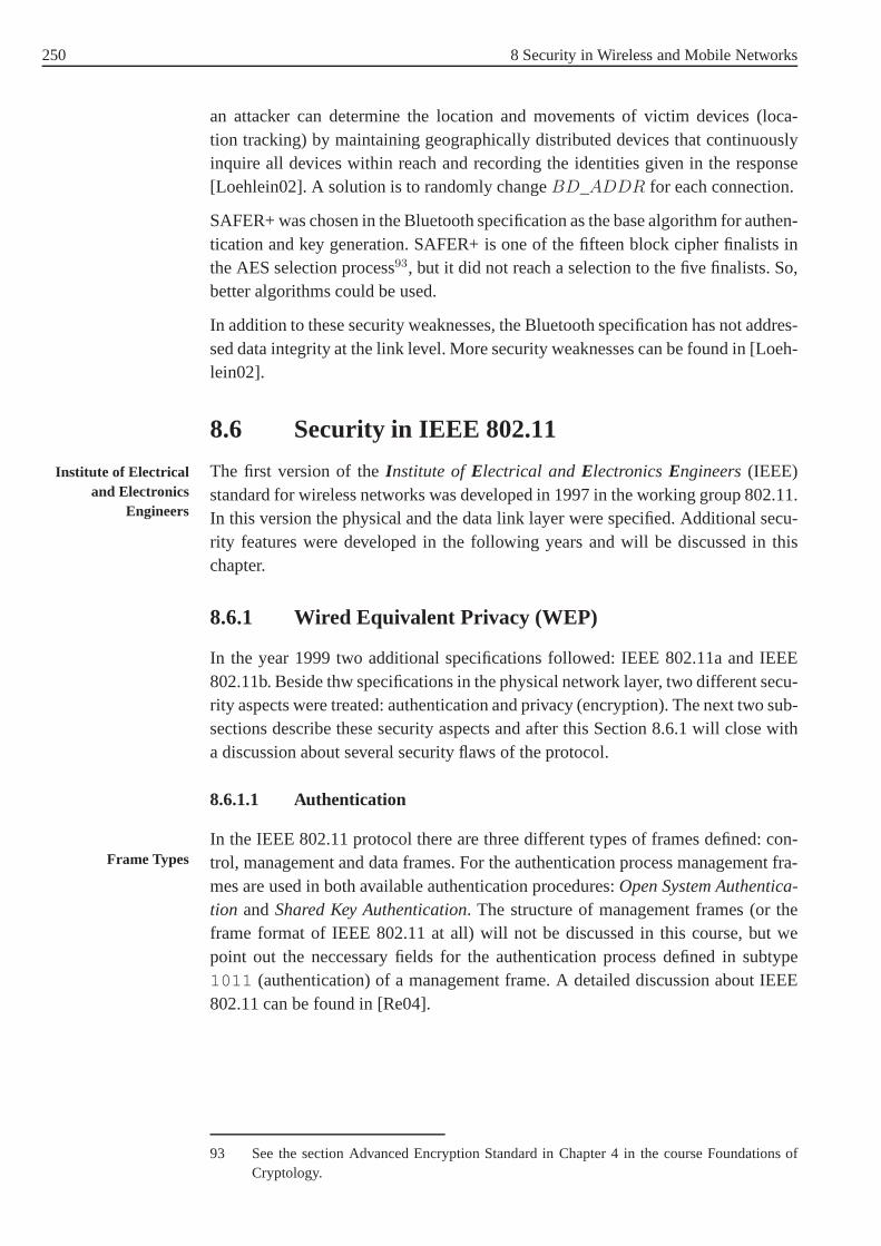
250 8 Security in Wireless and Mobile Networks
an attacker can determine the location and movements of victim devices (loca-tion tracking) by maintaining geographically distributeddevices that continuouslyinquire all devices within reach and recording the identities given in the response[Loehlein02]. A solution is to randomly changeBD_ADDR for each connection.
SAFER+ was chosen in the Bluetooth specification as the base algorithm for authen-tication and key generation. SAFER+ is one of the fifteen block cipher finalists inthe AES selection process93, but it did not reach a selection to the five finalists. So,better algorithms could be used.
In addition to these security weaknesses, the Bluetooth specification has not addres-sed data integrity at the link level. More security weaknesses can be found in [Loeh-lein02].
8.6 Security in IEEE 802.11
The first version of theInstitute ofElectrical andElectronicsEngineers(IEEE)Institute of Electricaland Electronics
Engineersstandard for wireless networks was developed in 1997 in the working group 802.11.In this version the physical and the data link layer were specified. Additional secu-rity features were developed in the following years and willbe discussed in thischapter.
8.6.1 Wired Equivalent Privacy (WEP)
In the year 1999 two additional specifications followed: IEEE 802.11a and IEEE802.11b. Beside thw specifications in the physical network layer, two different secu-rity aspects were treated: authentication and privacy (encryption). The next two sub-sections describe these security aspects and after this Section 8.6.1 will close witha discussion about several security flaws of the protocol.
8.6.1.1 Authentication
In the IEEE 802.11 protocol there are three different types of frames defined: con-Frame Types trol, management and data frames. For the authentication process management fra-
mes are used in both available authentication procedures:Open System Authentica-tion andShared Key Authentication. The structure of management frames (or theframe format of IEEE 802.11 at all) will not be discussed in this course, but wepoint out the neccessary fields for the authentication process defined in subtype1011 (authentication) of a management frame. A detailed discussion about IEEE802.11 can be found in [Re04].
93 See the section Advanced Encryption Standard in Chapter 4in the course Foundations ofCryptology.

8.6 Security in IEEE 802.11 251
AuthenticationAlgorithm Number
Authentication TransactionSequence Number
Status Code Challenge Text
Fig. 8.6-1: Management frame: Authentication message format
Authentication Algorithm Number defines the authentication algorithm in a 16bit field. The value of0 indicates theOpen System Authentication, 1 showsShared Key Authentication.
Authentication Transaction Sequence Numberdefines the actual status of anauthentication in progress. The 16 bit counter starts in thefirst message with1 and is incremented in each following step.
Status Code notifies the success or failure of a previos operation. In the16 bit fieldthere are different status codes defined, e.g.success(0), authentication failurebecause of errors in the challenge-text(15) or not supported authenticationalgorithm(13).
Challenge Text is a subtype of the fieldinformation elementwith a flexible lengthfrom 3 to 255 bytes. The information element has a simple frame structurewith three subelements. The first one is theinformation element idwhichindicates the information type in a 1 byte field. A challenge text has theinfor-mation element idof 16 and is followed by a 1 byte field that indicates thelengthof the challenge textitself. The last element in the frame will be thechallenge textwith a length from 1 to 253 bytes.
TheOpen System Authenticationis the only scheme which is required by the IEEEOpen SystemAuthentication802.11 specification. A mobile station is authenticated if it simply requests authen-
tication with it’s MAC address. Obviously this scheme does not provide any kind ofauthentication.
Access PointMobile Station
Authentication Request
Confirm success
Fig. 8.6-2: Open System Authentication
Shared Key Authenticationis a challenge-response scheme and is based on theShared KeyAuthenticationknowledge of a shared secret. As shown in Fig. 8.6-3 the access point generates
a random number as a challenge and then waits for the response, the encrypted

252 8 Security in Wireless and Mobile Networks
random number. Now the access point decrypts the response and only if this num-ber equals the formerly generated random number the access point grants networkaccess to the mobile station.
Access PointMobile Station
Authentication Request
Challenge
Response
Allow/Deny
Generate random number
Encrypt Challenge with RC4
Decrypt response and verify with
challenge
Fig. 8.6-3: Shared Key Authentication
Both cryptographic operations, the encryption at the mobile station and the decryp-tion at the access point, use the RC4 algorithm and need the actual WEP key as aninput for the algorithm.
Knowing these details we see thatOpen System Authenticationin fact means nosecurity at all andShared Key Authenticationonly means that both communicationpartners know the same shared key. A real authentication process is executed neitherfor the mobile station nor for the access point.

8.6 Security in IEEE 802.11 253
Example 8.6-1: Shared Key AuthenticationA mobile station wants to authenticate itself with theShared Key Authenticationprotocol to an access point. Fig. 8.6-4 shows the message flowfor this authenti-cation.
Access PointMobile Station
Generate random number
Encrypt Challenge with RC4
Decrypt response and verify with
challenge
AuthenticationAlgorithm Number
Authentication TransactionSequence Number
Status Code
Challenge Text
1 1
1 2 0 1234
1 3 0 9724
1 4 0
Fig. 8.6-4: Shared Key Authentication
The access point generates the challenge1234 and receives the response9724 .After checking the response with RC4, the access point sendsa authenticationsuccessmessage to the mobile station.
In the specification there are two types of keys defined:Default Keys94 andKey Default Keys
Key Mapping KeysMapping Keys95. Both types of keys are used for encryption and have the samecharacteristics, they
• have afixed lengthof 40 or 104 bits,
• arestatic and only will be changed after reconfiguration,
• areshared, a mobile station and an access point own the same key,
• aresymmetric, the same key is used for encryption and decryption.
94 Manufactures also use the termsshared key, group key, multicast key, broadcast keyor justkey.
95 also:individual key, per-station keyor unique key.

254 8 Security in Wireless and Mobile Networks
Default Keys are used system wide, all access points and mobile stations have thesame key. It is possible to define up to four different defaultkeys at the same time– each one with a different key index which is submitted in each frame in clear text(i.e. unencrypted). This is a help for network administrators to change the defaultkeys.
Key Mapping Keys are unique keys for each mobile station. With the knowledge ofthe MAC address of a mobile station the access point looks up an internal databaseto choose the unique key for the mobile station. This featureis optional for an IEEE802.11 compliant access point and only some vendors have implemented this in afew devices.
Unfortunately, the IEEE 802.11 specification does not address out the problem ofkey management. How are keys made available to all users and access points?Beside non-standard attempts of vendors, like Cisco with LEAP96, there are no keymanagement techniques provided. The standard answers the question only with thisstatement:
The required secret is presumed to have been delivered to participating stationsvia a secure channel that is independent of IEEE 802.11.
8.6.1.2 Privacy and Integrity Mechanisms of WEP
There are two security mechanisms defined in the protocol: ACyclic RedundancyCyclic RedundancyCheck Check (CRC) for data integrity andRC4 (Ron’s Cipher97 4) for encryption.
RC4The central cryptographic technique in the IEEE 802.11 standard to support privacyon the wireless interface is the stream cipher RC4. A shared (symmetric) secret keyis used to encrypt data at the link layer. The symmetric key (Kdefault) is concaten-ated with a 24 bitInitialisation Vector (IV) to generate a pseudo-random numberInitialisation Vector
stream with the stream cipher algorithm RC4. This key streamis added modulo2 (exclusiveOR) with the plaintext packet, which consists of the payload and aXOR
CRC-checksum. Fig. 8.6-5 shows a block diagram of the encryption progress forthe sender.
96 LightweightExtensibleAuthenticationProtocol, (see Section 8.6.2.2)
97 RC4 was developed in 1987 by Ronald L. Rivest for RSA Data Security Inc.
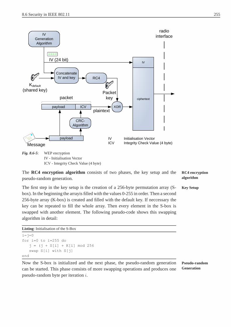
8.6 Security in IEEE 802.11 255
RC4
Kdefault
(shared key)
ciphertext
IV
Message
IV (24 bit)
CRC-Algorithm
Concatenate IV and key
IVGeneration Algorithm
ICV
payload
payload
packet
XOR
Packetkey
plaintext
radio interface
IV Initialisation VectorICV Integrity Check Value (4 byte)
Fig. 8.6-5: WEP encryptionIV - Initialisation VectorICV - Integrity Check Value (4 byte)
The RC4 encryption algorithm consists of two phases, the key setup and theRC4 encryptionalgorithmpseudo-random generation.
The first step in the key setup is the creation of a 256-byte permutation array (S- Key Setup
box). In the beginning the arrayis filled with the values 0-255 in order. Then a second256-byte array (K-box) is created and filled with the defaultkey. If neccessary thekey can be repeated to fill the whole array. Then every elementin the S-box isswapped with another element. The following pseudo-code shows this swappingalgorithm in detail:
Listing : Initialisation of the S-Box
i=j=0
for i=0 to i=255 doj = (j + S[i] + K[i] mod 256
swap S[i] with S[j]
end
Now the S-box is initialized and the next phase, the pseudo-random generation Pseudo-randomGenerationcan be started. This phase consists of more swapping operations and produces one
pseudo-random byte per iterationi.

256 8 Security in Wireless and Mobile Networks
Listing : Key Stream Generation
i = ( i + 1 ) mod 256
j = ( j + S[i] ) mod 256
swap S[i] and S[j]k = (S[i] + S[j]) mod 256
R = S[k]
The 802.11 standard was ratified in 1999. At this time export restrictions from theUS government for cryptographic technology limited the keysize of WEP to 40bits. The protocol was called 64-bit WEP (40 bit key + 24 bit IV). After abolition ofthe export restrictions all manufactures implemented an extended version, the 128-bit WEP. The key size was – like in the orginial version – much smaller, because themanufactures added the 24 bit IV (which is always sent in cleartext) to the sharedkey. The effective key size for 128-bit WEP thus is 104 bit.
8.6.1.3 Weaknesses of WEP
There are several possible attacks against a WEP encrypted wireless LAN. In gene-ral these attacks can be divided into active and passive attacks. Passive attacks donot modify the content of network traffic and can be either eavesdropping or trafficflow analysis.
Weak Initialisation Vectors This attack is based on some weaknesses in the keyscheduling algorithm of RC4 found by Fluhrer, Mantin and Shamir in 2001[FMS01] and is also called FMS attack. The attacker has always the IV incleartext and can analyse the IVs for some special conditions. The found IVsare called "weak", because these IVs result into a relative high correlationbetween the output and the key. Normally about five to ten million collectedencrypted packets are needed to find enough "weak" IVs to reconstruct thekey. Newer implementations of WEP avoid these IVs, thus it isharder tocollect enough packets.
Dictionary Attack Many access points – and nearly every available operating sys-tem – provide a functionality to the user to generate a WEP key(40 bit or 104bit) from a given password. The used algorithm is normally anMD5-Hash.For a dictionary based attack normally only one packet is needed. Every word(or permutation of word fragments, if additional password hacking tools areused) is translated to a WEP key. With this key and the known IVthe packetcan be tried to be decrypted. It is not neccessary to decrypt the whole packet,because every WLAN packet has a SNAP-Header (Sub Network AccessProtocol) which is the same for every IP or ARP packet. If the first bytesof the decrypted packet do not match this header, the rest of the packet alsodoes not.
Korek Attack This attack is named after a programmer with the pseudonym"KoreK" who published a code fragment in 2004. This attack does not need

8.6 Security in IEEE 802.11 257
weak IVs anymore, every packet with a unique IV is used in a statistical cryp-toanalysis to determine the key. There is a good chance to compute the keywith hundreds of thousands rather than millions of packets like in the FMSattack.
Even if the Korek attack does not need so much data input than the attack fromFMS, in low traffic networks this could take too long. Active attacks include mas-querading, replay, message modification andDenial of Service (DoS). There are Denial of Service
several known WEP related active attacks like replay attacks or packet injection.
Replay Attacks If there is not enough traffic in the destination wireless LANtocollect enough packets in an adequate time, the invader can use an activeattack against the wireless network to force response messages. WEP doesnot care about replay attacks where every time the same packet (with thesame IV) is received. With no knowlegede of the payload the attacker has tofind a packet which forces a response. The easiest way to find such a packetis to guess an ARP98-Request. ARP-Request are relativly small and can beidentified by the broadcast adressFF:FF:FF:FF:FF:FF .
Single Packet Decryption This attack is based on a proof of concept of "KoreK",which he called "chopchop". Because of the XOR operator in the WEP algo-rithm, each byte in the ciphertext exactly depends on one byte in the clear-text (see Fig. 8.6-5). During the attack the last byte of the ciphered payloadbcipher(n) is cut off. Then it is assumed, thatbclear(n) is 0, 1, 2, ..., 255 andfor each value the ICV is recomputed and the packet is sent to the accesspoint. If the AP does not drop the packet with the modified bytebclear(n),the packet has the right value and the algorithm continues with bclear(n − 1).After thousands of packets (but only a few seconds) the wholecleartextanda valid keystream of the RC4 algorithm with a known IV is available.
Packet Injection With a known RC4 keystream and the corresponding IV an atta-cker is able to inject every possible packet without knowingthe actual WEPkey.
8.6.2 Wi-Fi Protected Access (WPA)
Because of several security flaws found in WEP, a new and better security stan-dard for 802.11 based wireless networks became neccessary.The development waspushed by the industry groupWi-Fi Alliance. This group was founded in 1999 asWi-Fi Alliance
Wireless Ethernet Compatibility Alliance(WECA) and then renamed itself in 2003to Wi-Fi Alliance. The original objective of this alliance was to guarantee the inte-roperability of different wireless local area network equipment. The missing inter-operability was the main lack of the first generation devices, even though the speci-fications were defined in IEEE 802.11.
98 AddressResolutionProtocol

258 8 Security in Wireless and Mobile Networks
After a delay in the ratification of the standard 802.11i theWi-Fi AllianceannouncedWi-Fi ProtectedAccess(WPA) as a subset of IEEE 802.11i. This pseudo standardWi-Fi Protected Access
was a change-over from WEP to WPA2 (Section 8.6.3) which implements the fullstandard IEEE 802.11i. WPA is based on WEP security mechanism but improvesit with dynamic keys (Section 8.6.2.1) and better authentification schemes (Sec-tion 8.6.2.2).
8.6.2.1 Temporal Key Integrity Protocol (TKIP)
One of the objectives of theWi-Fi Alliance and IEEE 802.11i was to establishimprovements in a short time with the constraint, they have to run on legacy (the oldWEP) devices. The Initialization Vector is identified as thecenter of several securityproblems in WEP, four fundamental weaknesses are listed in Table 8.6-1.
Tab. 8.6-1: Weaknesses in WEP and their improvements
Weakness in WEP Improvement in TKIP
IV is too short, so the same values arereused regularly in a busy network.
The size is increased from 24 bit to 48 bit.
An IV is not related to a station, the sameIV can be used with the same key ondifferent stations.
To avoid replay attacks, the IV has asecondary role as a sequence counter.
Some IVs are "weak" (see FMS-attack). Weak IVs are avoided.
Message Integrity only with CRC-32. Message integrity is computed by amessage integrity protocol.
While designing theTemporalKeyIntegrityProtocol (TKIP) it was obvios that theTemporal KeyIntegrity Protocol size of the Initialization Vector must be increased. The working group IEEE 802.11i
decided to add 32 bits to the original 24 bits. The total length of 56 bits is reducedin practice to 48 bits to avoid weak keys. Remember, the legacy hardware requireda 24 bit IV followed by a 104 bit key to initialize the RC4 encryption engine. Theresulting "new" initialization string had a length of 150 bits, but even with firm-ware upgrades most of the hardware was unable to handle this.This problem wasaddressed in TKIP as shown in Fig. 8.6-6: the IV is split into two parts. The lowerpart is padded with 1 byte to avoid known weak keys and the resulting 24 bits areused in the same way as in WEP. The higher part of the IV is merged with the MACaddress, the session key and the lower-part IV and results intwo key mixing phasesinto a 104 bits per-packet key.

8.6 Security in IEEE 802.11 259
KDataEncryption
MACAddress
16bit (low)32bit (high)IV
IV Per-Packet KeyP IV
24 bit 104 bit
Phase IKey
Mixing
Phase IIKey
Mixing
RC4 Encryption
Key
Padding to avoid known weak keys
Fig. 8.6-6: Generation of the RC4 encryption key
To protect against replay attacks a mechanism calledTKIP SequenceCounter TKIP SequenceCounter(TSC) is used. The TSC is incremented for each packet and it isnot possible, that a
TSC will be repeated for a given key. A simple way to prevent replay attacks is toignore all packets with a TSC smaller than the last received message, but actuallyTKIP uses an advanced solution calledReplay Window. Normally every packet Replay Window
received is acknowledged separatly. Future standards of IEEE 802.11 aim to allowBurst-Acknowledgementwhere up to 16 packets can be acknowledged with oneBurst-
Acknowledgementpacket. With this constraint, a packeti only will be accepted if the condition
(TSCmax − 16) > TSCi
is true, whereTSCmax is the largest received TSC.
The message integrity in WEP is only checked by a CRC-32 checksum. Thischecksum is fast to compute, but the linear algorithm is far from a cryptographicsecure function. Keeping in mind the limited capacities of the microprocessorsinside most of the Wi-Fi devices and the contraint, that improvements have to workwith firmware upgrades, it is not possible to use a cryptographic secure hash func-tion like SHA-199 or RIPEMD-160100 for the MessageIntegrity Code (MIC101). Message Integrity
CodeNiels Ferguson proposed a method he calledMichaelwhich uses only fast shift oradd operations and no slow multiplications. This simplicity makesMichaelvulnera-ble to brute force attacks, but there are countermeasures defined in the protocol. If aninvalid MIC is detected the keys for the link get immediatelyinvalid and new keys
99 This algorithm is part of some standardizedSecureHashAlgorithms(SHA).
100 RACE Integrity Primitives EvaluationMessageDigestwas developed by Hans Dobbertin,Antoon Bosselaers and Bart Preneel in 1996 and produces a 160bit output.
101 Note that cryptographers use the term MAC (MessageAuthenticationCode), but this term isused in this context forMediaAccessControl. So MIC is used to avoid confusion.

260 8 Security in Wireless and Mobile Networks
must be negotiated. This negotiation is delayed 60 seconds,so only every minutean attack can be launched.
To understand the role ofMichael in the WPA encryption scheme it is necessary toexplain the protocol stack in wireless networks in a few words. The ready to sendmessages generated by operation system functions are called MessageProtocolMessage Protocol Data
Unit DataUnits (MPDU) and are forwarded to the MAC layer. If needed, the message isfragmented in this layer and is forwarded to the radio interface. A frame arriving atthis interface is calledMACServiceDataUnit (MSDU).MAC Service Data
UnitThe MIC is computed only once for the MSDU and not for every MPDU. This is incontrast to the RC4 encryption where every MPDU is encryptedwith a different per-packet key. This results in two advantages. At first the overhead is reduced becausethe MIC must not to be computed for every fragment. Secondly the computationis done prior to the forwarding to the wireless network adapter, so the computationcan be done in the device driver.
The WPA encryption architecture is shown in Fig. 8.6-7 and can be divided intofour blocks:
Michael computes a MIC on two 6 byte addresses (source and destination) and theuser data (payload). A 64 bit keyKDataIntegrity is used for the computation.
Key Derivation Two different keys are needed:KDataIntegrity for the algorithmMichael and KDataEncryption for the RC4 key generation. ThePairwisePairwise Master Key
Master Key (PMK) KPairwiseMaster with a length of 256 bit is generatedduring the authentication process (see Section 8.6.2.2). Two random num-bers and MAC addresses from both the access point and the mobile stationare needed to derive the data integrity key and data encryption key.
RC4 Key Generation The RC4 key generation is done in the key mixing phases Iand II (see Fig. 8.6-6).
WEP Encryption Each fragment is encrypted in the same way as described inSection 8.6.1.2.

8.6 Security in IEEE 802.11 261
KPairwiseMaster
Compute MIC
message
MSDU MIC
Fragmentation
FragmentFragment
Fragment
MIC Key
IV Generator
Key MixingCRC
RC4
Ciphertext
Michael
Key Derivation
ICVFragmentXOR
IV
(MSDU)
(MPDU)
WEPEncryption
RC4 Key Generation
Key Derivation
KDataIntegrity
KDataEncryption
Nonce APNonce Station
MAC AP
MAC Station
Fig. 8.6-7: WPA encryption
After 216 packets the keysKDataIntegrity andKDataEncryption are changed, this iscalled rekeying. The key derivation block also generates the Pairwise Transient Rekeying
Pairwise TransientKeys
Keys(PTK) for the authentication process described in Section 8.6.2.2:
• Key for data encryptionKDataEncryption
• Key for data integrityKDataIntegrity
• Key for EAPOW (ExtensibleAuthenticationProtocol)encryption. ExtensibleAuthenticationProtocol
• Key for EAPOW integrity.
8.6.2.2 Authentication in WPA
WPA (Wi-Fi ProtectedAccess) provides different authentication schemes. A simpleWi-Fi Protected Access
authentication with shared keys or a solution with key management is defined inIEEE 802.1x.
Pre-SharedKeys(PSK) are mostly used in wireless networks in the SOHO (smallPre-Shared Keys
office/home office) domain. In this domain additional infrastructure like authentica-tion servers cannot be assumed and a shared secret is a sufficient solution for just afew users.
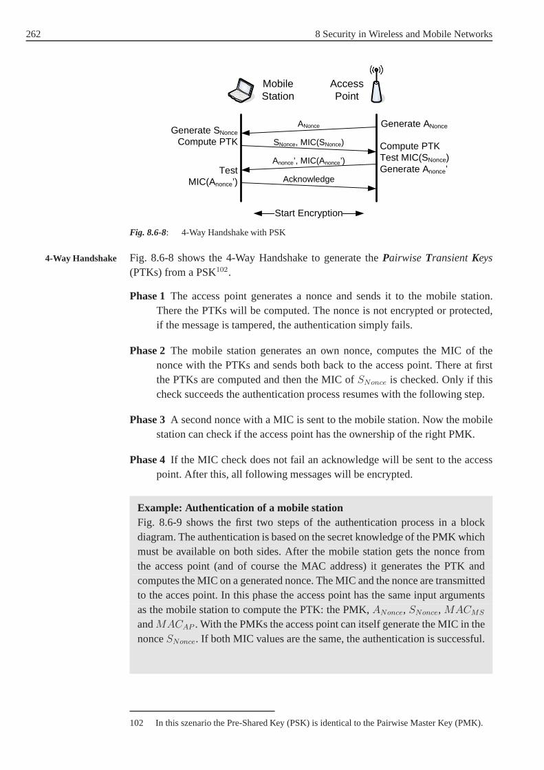
262 8 Security in Wireless and Mobile Networks
AccessPoint
MobileStation
SNonce, MIC(SNonce)
Anonce’, MIC(Anonce’)
ANonce Generate ANonceGenerate SNonce
Compute PTK Compute PTKTest MIC(SNonce)Generate Anonce’Test
MIC(Anonce’) Acknowledge
Start Encryption
Fig. 8.6-8: 4-Way Handshake with PSK
Fig. 8.6-8 shows the 4-Way Handshake to generate thePairwise TransientKeys4-Way Handshake
(PTKs) from a PSK102.
Phase 1The access point generates a nonce and sends it to the mobile station.There the PTKs will be computed. The nonce is not encrypted orprotected,if the message is tampered, the authentication simply fails.
Phase 2The mobile station generates an own nonce, computes the MIC of thenonce with the PTKs and sends both back to the access point. There at firstthe PTKs are computed and then the MIC ofSNonce is checked. Only if thischeck succeeds the authentication process resumes with thefollowing step.
Phase 3A second nonce with a MIC is sent to the mobile station. Now themobilestation can check if the access point has the ownership of theright PMK.
Phase 4 If the MIC check does not fail an acknowledge will be sent to the accesspoint. After this, all following messages will be encrypted.
Example: Authentication of a mobile stationFig. 8.6-9 shows the first two steps of the authentication process in a blockdiagram. The authentication is based on the secret knowledge of the PMK whichmust be available on both sides. After the mobile station gets the nonce fromthe access point (and of course the MAC address) it generatesthe PTK andcomputes the MIC on a generated nonce. The MIC and the nonce are transmittedto the acces point. In this phase the access point has the sameinput argumentsas the mobile station to compute the PTK: the PMK,ANonce, SNonce, MACMS
andMACAP . With the PMKs the access point can itself generate the MIC inthenonceSNonce. If both MIC values are the same, the authentication is successful.
102 In this szenario the Pre-Shared Key (PSK) is identical tothe Pairwise Master Key (PMK).

8.6 Security in IEEE 802.11 263
Access PointMobile Station
RNG
SNonce
RNGPMK
Generate PTK
ANonce
MACAP
MACMS
MIC
Generate PTK
PMK
MACAP
ANonce
SNonce
MACMS
PTK
PTK
MICMICok?
MIC(SNonce)
Fig. 8.6-9: 4-Way Handshake with PSK
The standard IEEE 802.1x is a protocol which defines network access control. It isbased on theExtensibleAuthenticationProtocol (EAP) and is able to authenticateExtensible
AuthenticationProtocol
devices attached to a network. If the authentication of a device failed, no access tothe network is possible. The described scheme is very similar to a dial-up situationwhere a user wants to access a remote network. In these cases the authenticationis often done by aRemoteAuthenticationDial-In UserService(RADIUS) server, Remote Authentication
Dial-In User Servicewhich is optional in WPA.
In an EAP based authentication scheme there are three entities acting: Thesup-plicant who wants to gain access, theauthenticatorwho controls the access andtheauthorizerwho decides if access will be admitted. Fig. 8.6-10 shows theEAPfor wireless networks, now calledExtensibleAuthenticationProtocol over WLAN(EAPOW).

264 8 Security in Wireless and Mobile Networks
AccessPoint
MobileStation
EAPOW – Start
RADIUSServer
EAP – Request Identity
EAP – Response IdentityAuthentication Request
Challenge Request (TLS)EAP – Request (TLS)
EAP – Response (TLS)Challenge Response (TLS)
Authentication Accepted/RejectedEAP – Success / Failure
EAPOW – Key
Supplicant Authenticator Authentication Server
Fig. 8.6-10: EAP over WLAN
There are several authentication schemes available:
• Message-Digest 5(MD5): A supplicant is authenticated with the hash value ofhis password.
• Transport Layer Security (TLS): Supplicant and authentication server performa mutual authentication in this certificate based solution.The same protocol asin the TLS connection phase is used.
• Tunneled Transport Layer Security (TTLS) establishes a TLS connection, butthe supplicant does not provide a certificate. Other protocols can be used withinthe TLS tunnel.
• Protected EAP(PEAP) is standardized by theInternetEngineeringTaskForceInternet EngineeringTask Force (IETF) and is similar to TTLS.
• Lightweight EAP (LEAP) is a proprietary solution from Cisco Systems.
8.6.3 Robust Security Network (RSN)
In IEEE 802.11i a new type of wireless network is defined: ARobustSecurityRobust SecurityNetwork Network(RSN). WPA and RSN implement the standard IEEE 802.11i in different
depths. Where as WPA only implements a subset, RSN implements the whole stan-dard and is more flexible. Not only TKIP can be used, even an encryption schemebased on theAdvancedEncryptionStandard(AES) is available. The Wi-Fi AllianceAdvanced Encryption
Standard called this WPA2 and makes it mandatory in march 2006 for all Wi-Fi certified pro-ducts.
AES can be used in different modes of operation. With the objective to use anauthenticated encryption scheme, theOffsetCodebookMode(OCM) is possible andOffset Codebook Mode

8.6 Security in IEEE 802.11 265
was discussed in the early stages of the IEEE 802.11i workinggroup. Because of(possible) arising licence fees in the future, the choice for this mode was discarded.
Hence a new mode was invented by the working group:Counter Mode withCBC Counter Mode CBCMAC ProtocolMessage Authentication CodeProtocol (CCMP). AES in Counter Mode is also
noted as AES/CM103.
AES is based on the Rijndael algorithm where different blockand key sizes of 128,192 or 256 bit are possible. IEEE 802.11i restricts both values to 128 bit.
A CCMP Header (see Fig. 8.6-11) is added between the MAC header and the pay-load. A 48 bitPacketNumber(PN) is submitted to protect against replay attacksPacket Number
and as a nonce used in the encryption. TheKeyID will only be used in multicasttraffic or transmissions in mixed groups with TKIP and CCMP.
PN0 PN1 Reserved PN2 PN3 PN4 PN5
Reserved 1 Key ID
5
1 11 1111
1 2
1 byte
bit
Fig. 8.6-11: Counter Mode withCBC Message Authentication CodeProtocol (CCMP) Header
The first block (Fig. 8.6-12) for the computation of the MIC isconstructed in aspecial way. A nonce is formed by the fieldsPriotity , Source Address andPacket Number . TheFlag has a fixed value of01011001 and theLength
inidicates the length of the plaintext data.
Flag Priority Source Address Packet Number Counter
Flag Priority Source Address Packet Number Length
0 152 87 13 141
First Block (CBC-MAC)
Counter (AES/CM)
Nonce
Fig. 8.6-12: First Block (CBC-MAC) and Counter (AES/CM)
The counter for AES/CM is almost identical to the first block of CBC-MAC. Toavoid an exactly identical counter theFlag is different and a 2 byte internalCounter is added. This counter is incremented for each MPDU.
103 Note that we are back in the cryptographers terminology and use in conjunction with CBCthe abbreviation MAC forMessageAuthenticationCode.

266 8 Security in Wireless and Mobile Networks
The whole encryption process is shown in Fig. 8.6-13. The MICis computed overthe MAC header104, the CCMP header and the plaintext data in the blockCBC-MAC and needs the key, the prior block (or the first block respectively) as inputarguments. In the next step the plaintext and the MIC are encrypted with AES/CM.
Key
AESCounter Mode
CBC-MAC
MAC Header
CCMP Header
Plaintext
First Block
MIC
MAC Header
CCMP Header
Plaintext
MAC Header
CCMP Header
Ciphertext
Packet Number
KeyID
CounterSrc Addr
Block i-1
Fig. 8.6-13: CCMP authenticated encryption
8.6.4 Summary
In Table 8.6-2 different security related properties of WEP, WPA (subset of IEEE802.11i) and WPA2 (whole specification of IEEE 802.11i and also known as RSN)are summarized.
104 Only the immutable fields are included.

8.6 Security in IEEE 802.11 267
Tab. 8.6-2: Comparison of WEP, WPA and 802.11i
WEP WPA 802.11i (WAP2)
Encryption RC4 RC4 AES/CM
Key length 56/102 bit 128 bit 128 bit
Data integrity CRC-32 Michael CBC-MAC
Header integrity – Michael CBC-MAC
Authentication Shared Key 802.1x 802.1x
Key management – 802.1x 802.1x
IV length 24 bit 48 bit 48 bit
Replay attack protection – TSC TSC
None of the original security protocols implemented in IEEE802.11 are robust.Attackers can easily bypass the authentication process andserious security flawsallow the recovery of the secret encryption key in a short time and the modificationand replay of WEP protected packets.
Fortunatly the improvements developed in WPA and RSN protect against the attacksknown from WEP. All known attacks against WPA and RSN focus onPre-Shared Pre Shared Keys
Keys(PSK). The derivation functionKDF2105 computes from a passphrase and theSSID (ServiceSet Identification) in 4096 iterations a 256 bit hash value, the PSK.Service Set
IdentificationThere are two possible attacks in a PSK domain:
Internal Attacks Everyone in the same wireless network uses the same PSK. Ifone captures the data in the WPA 4-Way-Handshake (see Section 8.6.2.2), onehas all data to compute thePairwise TransientKeys(PTK) and reconstruct Pairwise Transient
Keysthe transmitted data between the access point and the mobilestation.
External Attacks This is a passive attack, where external attackers capture afew(encrypted) packets and try a dictionary attack (see Section 8.6.1.3) againstthe password hash of the PTK.
The security enhancements between WPA and RSN are fairly small, judged bytodays knowledge about security flaws. In both protocols thecenter of the secu-rity level is the authentication type (Section 8.6.2.2). With the right choice, wirelessnetworks with high security requirements can be established. RSN has the benefit ofabsence of any legacy techniques or compromises. The well known and from manygroups checked algorithm AES is used in validated operationmodes. In contrast tothis the MIC algorithmMichael in WPA is relative new and not dicussed in such adetail.
105 KDF2 is part of thePKCS#5: Password Based Cryptography(see [RFC2898])
268 9 Electronic Payment Systems
9 Electronic Payment Systems
9.1 Motivation
With the rapid growth of the Internet, and particularly the World Wide Web(WWW), numerous consumers and organizations participate in a global on-linemarketplace. Electronic Commerce is now a large new industry all over the world.
Electronic payment is not a new concept. Actually most of us are familiar with elec-tronic payment: we check our account’s balance and tenants transfer rent charge, thefee for pipeline gas, water and electricity is paid to landlord’s account via on-lineinternet services, etc. When setting up an on-line store, one of the most importantconsiderations is the method of payment one intends to use. It is not practical toonly accept payment by checks and money orders by mail. This increases the admi-nistrative labors to an inacceptable extent, as well as potentially inconveniencingthe customers. In today’s business arena, flexibility and convenience pay off, andthat is why electronic payment systems have become more popular than ever.
Various secure network payment schemes have been developedin universities anddifferent research institutes as well as in commercial organizations. Some of themhave undergone small scale testing and some of them have beenproven to failfor some reasons (for example, some unconditional privacy protecting systemssometimes could be misused by criminals for blackmailing ormoney laundering[Solms92]). New technologies, including new security tools, new cryptographicalgorithms, new protocols are needed to be developed to protect the privacy duringtransaction and to make the systems more secure, more efficient and more accepta-ble by organizations and individuals.
This chapter attempts to introduce the main technologies involved in most paymentsystems currently available to network users. The cryptological techniques behindmost of the schemes supporting their security can be referred from our course mate-rials "Foundations of cryptology".
The characteristics of electronic payment systems are described in Section 9.2. Weclassify electronic payment systems in Section 9.3 and explain some systems fromeach category in Section 9.4 and end our chapter by having a bird’s eye view on thefuture of electronic payment systems.
9.2 Characteristics
There are several attempts to describe the characteristicsof electronic payment sys-tems [Asokan97], [Medvinsky93]. Most of them from a technology point of view.In this section, we try to describe the main characteristicsof general electronic pay-ment systems.
• Applicability. Whether a payment system can be applied to real life and play animportant role in paying over open networks is a very important characteristic ofan electronic payment system. Whether a payment system is applicable depends

9.3 Classification of Payment Mechanisms: State of the Art 269
on the extent to which customers and merchants accept it. Applicability of apayment system may vary from country to country.
• Usability. Paying with an electronic payment system shouldnot be a complextask.
• Security. Since Internet services are provided today on open networks, the infra-structure supporting electronic commerce, and payment systems in particular,must be resistant to attacks in the Internet environment.
• Reliability. Electronic payment systems should be stable and run smoothly.Otherwise no one would trust and deploy the payment systems.
• Anonymity. Privacy is always an important issue in electronic payment systems.Consumer’s identity and personal information should be kept secret. It shouldnot be possible to discover customer’s identity or to trace an individual’s purcha-sing activities. For electronic payment systems, anonymity is a necessity to pro-tect consumer’s privacy. Some cryptography tools, such as group signature andblind signature, are utilized to keep payment systems anonymous.
• Revokable Anonymity. As we pointed out above, anonymity is avery importantissue in electronic payment systems. But under some cases, this characteristiccould be misused by economic criminals for blackmailing or money laundering[Solms92]. So, it is strongly recommended to develop anonymity revocable sys-tems. In other words, under some suspicious circumstances,with a trusted thirdparty involved, the anonymity can be removed to discover theidentity of theowner. These systems now are called fair electronic paymentsystems.
• Undeniablility. For electronic payment systems, any transaction which is carriedout should not be deniable. This is very natural.
• Scalability. As the commercial use of the Internet grows, the demands placedon payment infrastructure will increases. The payment infrastructure as a wholeshould be scalable, to be able to handle the additional needsof users and mer-chants, so that systems will perform normally without performance degradation.
• Interoperability. A payment system is interoperable if it is not dependent on oneorganization, and is open and allows as many as necessary interested parties tojoin. This can be achieved by means of open standards for the technology that isused. Examples of interoperable initiatives are the CAFE project [Boly94], andSEMPER project [Semper].
9.3 Classification of Payment Mechanisms: Stateof the Art
Before we go further into the details of different systems, we present a classificationof electronic payment systems. This will be helpful to understand various electronicpayment systems.

270 9 Electronic Payment Systems
There are several ways to distinguish electronic payment systems. Based on theway in which money transfer is organized or based on the type of information thatis exchanged [Medvinsky93], [Wayner97], existing electronic payment systems canbe divided into four groups: Credit Card-based, electroniccheck, electronic cashand micro-payment systems. Furthermore, electronic cash systems may be distin-guished as on-line or off-line systems according to whetherbanks are involved intotransactions during the payment process.
Electronic cash resembles conventional cash, where parties exchange ElectronicTokens that represent values, just as normal banknotes do. While in Credit Card-based systems, bank accounts of customers are transferred over open networks andmoney is represented by numbers in the accounts. Micropayment system is a specialgroup in which the value of money per transaction is small andfixed with lowersecurity requirements.
We illustrate the classification of electronic payment systems as in Fig. 9.3-1.
Electronic Payment Systems
Electronic Check(Credit/debit systems)
Electronic cashpayment systems
Micropaymentsystems
Credit Card basedpayment systems
SEPP
iKP
SET
CyberCash
NetBill
NetCheck
PayPal
FSTC
Millicent
PayWord
MicroMint
SubScrip
on-line off-line
Ecash
Netcash
Mondex
CAFÉ
Fig. 9.3-1: Classification of electronic payment systems.
9.4 Overview of Some Typical Systems ofCategories
As we mentioned above, electronic payment systems fall intofour main groups:Credit Card-based payment systems, electronic check, electronic cash and micro-payment systems.
In this section, we will briefly introduce some important examples from each kindof electronic payment system.

9.4 Overview of Some Typical Systems of Categories 271
9.4.1 Credit Card-based Payment Systems–SET
To make it more secure, Credit Card-based payment systems always deploy com-plicated protocols and sophisticated network and cryptographic technologies whichmake the systems complex and impractical.
Because of combining different cryptographical tools including digital signatures,symmetric and asymmetric encryption techniques, hash functions as well as digitalcertificates and Public Key Infrastructure(PKI), Credit Card-based payment sys-tems have the advantage of high system security. Credit Card-based payment sys-tems utilize the existing credit card payment method which has been accepted andin use since the early 1960s. On the other hand, because of theuse of a mass ofcomputation consuming mathematical calculations, most systems are complicatedand inefficient. On-line credit card number checking seems still to be the system’sbottleneck. Credit card numbers being openly transmitted over networks is anothervulnerability of these kinds of legacy systems.
Various Credit Card-based systems have been introduced. CyberCash [Eastlake96],iKP(the Internet Keyed Payments) [Bellare95], Secure Electronic Transaction(SET)[MC96a], [MC96b], [MC96c] are the most well known systems.
In the CyberCash system, a server acting as a gateway links between the existingfinancial infrastructure and open networks. CyberCash onceplanned to improvetheir system to be SET-compatible.
The iKP has three levels of security with three individual protocols: 1KP, 2KP, 3KP.They differ from each other in the number of involved parties, who hold their ownpublic key pairs. The more the number of parties with own key pairs, the strongerthe security the protocol can provide.
In the rest of this section, SET will be described in detail toshow as an examplehow this kind of protocol works. Generally, CyberCash, iKP and SEPP have laidthe foundations for the SET protocol.
Background
Working with major credit card providers, a team of IBM researchers in Zurichand Watson Research Center developed a nonproprietary family of secure Internetpayment protocols iKP which were mentioned above. They claimed, "We didn’twant to develop a competing proprietary protocol, rather, we wanted to create anopen, standard protocol that everyone could use".
Based on the framework of iKP, IBM-MasterCard developed a modified protocolcalled Secure Electronic Payment Protocol(SEPP) by the middle of 1995. Beforethat, in 1994, Microsoft-VISA jointly designed a protocol,called Secure Transac-tion Technology(STT), which could safely transfer money across the Internet. Bothof these protocols are based on public key cryptography. To be standardized, VISA,MasterCard, supported by IBM and other partners, announcedthat they had agreedon a convergence of STT and SEPP and developed a new standard for secure paying

272 9 Electronic Payment Systems
over the Internet with credit cards in 1996, known as Secure Electronic Transacti-ons(SET).
SET is now an open standard for protecting the privacy and enabling secure creditcard transactions over open networks. SET allows all identities to be authenticatedvia digital certificates and it protects consumer’s credit card number from beingeavesdropped by combining two complex cryptographical mechanisms - symmetricor private key cryptography and asymmetric or public key cryptography.
Related cryptological techniques
Before turning to the details of SET, some special cryptological techniques are intro-duced here for better understanding.
• Dual signature:Fig. 9.4-1 shows how a dual signature is constructed.
Private Key
DualSignatureSignHash
Hash
Hash
Message1
Message2
Digest1
Digest1
Digest1
Fig. 9.4-1: Dual signature.
The two messages, message1 and message2, are hashed separately using the samehash function (Md5 or SHA1 etc.). Then the two digests, digest1 and digest2 areconcatenated and a new hash value is generated, which is thansigned with the sen-der’s private key.
Dual signature can be used to link two related messages without the need to knowthe message contents. The normal way to generate a dual signature can be describedas follows:
– Take two messagesM1, M2. The signer knows both contents.
– Create a normal dual signature:HH = H(H(M1), H(M2)). Then getthe signature{HH}Signer_private_key by signing HH with the private keyof signer. {HH}Signer_private_key, H(M2) is sent to the holder ofM1;{HH}Signer_private_key, H(M1) is sent to the holder ofM2.
– Now, both the holders ofM1 andM2 can verify the signature by regeneratingtheHH because they knowM1 andM2 respectively. But the holder ofM1 willnot know the message contents ofM2 and the holder ofM2 will not learn themessage contents ofM1.
The use of dual signature in SET can be seen later.

9.4 Overview of Some Typical Systems of Categories 273
• Digital envelope: If public key systems are used only for message authentica-tion, then a simple digital signature using the signer’s private key with a hashfunction can do that. However, if public key systems are usedas an encryptingtool to achieve confidentiality, then a technique called digital envelope can beapplied to achieve that goal.
Fig. 9.4-2 shows the process of digital envelope.
Alice
Symmetricencryption
Asymmetricencryption
Message Bob’s public key
S-Key S-Key
Internet
Encryptedmessage
EncryptedS-Key
Bob
Receivedmessage
SymmetricDecryption
Encryptedmessage
EncryptedS-Key
Decryption(w Bob’s private key)
Alice’smessage
S-Key
Fig. 9.4-2: Construction of a digital envelope.
The digital envelope consists of a message which will be encrypted using privatekey cryptography and a secret key which will be encrypted using public key cryp-tography. The following describes the process of creating adigital envelope:
As in the diagram, to generate a digital envelope, Alice chooses a secret key andencrypts the message with it, then encrypts the secret key using Bob’s public key.She sends Bob the encrypted message concatenated with the encrypted secret key.When Bob wants to read the message, he decrypts the secret key, using his privatekey, and then decrypts the message, using the secret key.
The reason for using a digital envelope is that public key cryptography systems havestronger security but lower encrypting speed (from a software point of view, publickey systems are about 1000 times slower than private key systems).
Most of the messages in SET are transmitted using the digitalenvelope technique.
• Extra strong encryptionIn SET, instead of encrypting using the digital envelopetechnique in some special cases, data is directly encryptedwith RSA public keyalgorithm to enhance the security. This process is called extra strong encryption.

274 9 Electronic Payment Systems
Framework
The framework of SET is shown in Fig. 9.4-3.
Non-SET Non-SET
Financial Network
Card IssuerPaymentGateway
Cardholder Merchant
SET
SET
Fig. 9.4-3: Framework of SET.
It can be seen from the diagram that SET is used between cardholder, merchant andpayment gateway. The payment gateway acts as a front end to the existing financialnetwork. SET was designed only with regard to the payment process instead ofbeing a general purpose E-commerce protocol. In other words, some processes, forexample, price negotiation and delivery protocol, have notbeen considered in SET.
Authentication model
Each of the parties involved in SET will be required to authenticate themselves atsome points in the payment process. The private key of a public-key pair is usedas the proof to authenticate the owner’s identity and the public key part must becertified by a trusted third party.
Digital certificate(X.509 version 3 format [ITU97]) is the tool used in SET to bindidentities with their corresponding public keys. The identity given by thesubjectfield in a certificate is bound to the public key held insubjectPublicKeyInfofieldand this binding is certified by theissuerby generating a digital signature on thecertificate using the private key of theissuer.

9.4 Overview of Some Typical Systems of Categories 275
BCA1_1 ... BCA1_n BCA2_1 ... BCA2_n
Cross verification
ROOT1 CA ROOT2 CA
CCA1 MCA1 GCA1 CCA1 MCA1 GCA1 CCA2 MCA2 GCA2 CCA2 MCA2 GCA2
Entities (Cardholder, Merchant, Gateway)Certificates
Entities (Cardholder, Merchant, Gateway)Certificates
BCA: Brand CA; CCA: Cardholder CAMCA: Merchant CA; GCA: Gateway CA
Fig. 9.4-4: Certification authority hierarchy in SET.
A certificate authority(CA) maintained by a trusted third party is responsible forcertificate issuing and management. Fig. 9.4-4 shows the certification architectureused in SET.
Two kinds of certificates exist in SET payment processes: oneof them is the signa-ture certificate where the corresponding private key is usedto sign messages; ano-ther is the data encipherment certificate where the public key is used to encryptmessages or to exchange keys. All parties must obtain certificates from a certifica-tion authority (CA) before starting using SET to make transfers over networks.
Message structure
A typical SET transaction is shown in Fig. 9.4-5. The messages needed to performa complete purchase transaction usually include:
• Initialization(PInitReq/PInitRes)
• Purchase order(PReq/PRes)
• Authorization(AuthReq/AuthRes)
• Capture of payment(CapReq/CapRes)
• Cardholder inquiry(InqReq/InqRes)[only optional]
Cardholder MerchantPaymentGateway
PInitReq
PInitRes
PReq
PRes
AuthReq
AuthRes
CapReq
CapRes
Fig. 9.4-5: Main messages exchanged in a SET transaction.

276 9 Electronic Payment Systems
All the messages are defined in a hardware-independent format in SET specificati-ons to enhance interoperability. Some parts of the messages, such as the financialdata about a credit card and purchase order are encrypted so that the card numberwill not be revealed to the merchant and the order information will not be learnedby the payment gateway.
In this section, we explain an example to show how to perform aSET transaction.More details can be found in the SET specifications [MC96a], [MC96b], [MC96c].
As shown in Fig. 9.4-6, there are three parties in a SET system: a wallet softwareinstalled on the user’s machine; a merchant server running at the merchant’s Website; and a payment gateway usually running at a financial organization (the mer-chant’s bank).
$
Web Server
Payment ServerWallet
Web Browser
CA
Card IssuerFinancial Network
Clearing
Payment Gateway
Certificate
Certificate
Certificate 8 5 6 7
1
2
3
4
Customer Merchant
Fig. 9.4-6: A typical SET transaction.
To perform a SET purchase, a user selects products from the merchant’s Web siteand then the merchant sends back a response to wake up the user’s wallet program.The user selects which credit card she wishes to use to pay with and then the walletautomatically performs a SET payment protocol by exchanging messages with themerchant and payment gateway to proceed the payment as follows:
• The user sends a PInitReq message to the merchant as shown in Fig. 9.4-7. InPInitReq message, BrandID is the brand of card that will be used in the pay-ment(VISA or MasterCard); LID_C is a local transaction ID; Chall_C is usedto guarantee the freshness of the communication; Thumbs is alist of certificatesalready stored by the user to verify the user’s certificate chain which links backto the root certificate.

9.4 Overview of Some Typical Systems of Categories 277
Cardholder Merchant
PInitReq: {BrandID,[Thumbs],LID_C,Chall_C}
PInitRes: {TransID, Date, Chall_C, Chall_M}Sig ,C ,CM PG M
Fig. 9.4-7: Initialization messages.
• On receiving the PInitReq message from the user, the merchant will generatePInitRes. In the merchant’s response message, TransID is a globally unique IDcombined with the LID_C. A new challenge, Chall_M, generated by the mer-chant is included along with the challenge Chall_C from the user. In addition,the needed certificates and the current date are also included in the PInitResmessage.
• Upon receiving of the PInitRes from the merchant, the user will generatepurchase request(PReq) message as shown in Fig. 9.4-8. PReqis the most com-plex message in the payment protocol. It consists of two parts: the order infor-mation(OI) and payment instructions(PI).
Cardholder Merchant
PReq: {OI, PI}
PRes: {TransID, CompletionCode[results], Chall_C}SigM
Fig. 9.4-8: Purchase request and response messages.
Each part is encrypted separately. The OI holds data that identifies the order des-cription and can be seen only by the merchant. The PI which contains credit cardnumber, purchase amount, etc., is encrypted with the payment gateway’s publickey and the merchant has no access to this part. Later, The PI will be forwardedto the payment gateway as part of the authorization. The constructions of OI andPI are shown in Fig. 9.4-9.
CardDataCard numberExpiryPANNoncePINNonce
OrderDescriptionAmountODsalt(nonce)
PIDataTransIDAmountCardDataH(Order)
OIDataTransIDBrandIDDateChall_CChall_MODsalt()nonce
OIOIDataDualSig
PIPIDataDualSig
Extra-strong encryption
H(OIData)
H(PIData)
Hash
Hash HH {HH}SigC
Encrypt: PKA
Fig. 9.4-9: Constructions of OI and PI.
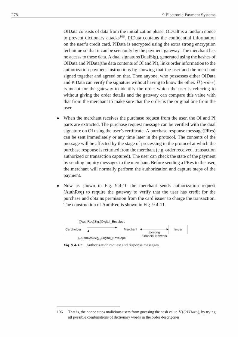
278 9 Electronic Payment Systems
OIData consists of data from the initialization phase. ODsalt is a random nonceto prevent dictionary attacks106. PIData contains the confidential informationon the user’s credit card. PIData is encrypted using the extra strong encryptiontechnique so that it can be seen only by the payment gateway. The merchant hasno access to these data. A dual signature(DualSig), generated using the hashes ofOIData and PIData(the data contents of OI and PI), links order information to theauthorization payment instructions by showing that the user and the merchantsigned together and agreed on that. Then anyone, who possesses either OIDataand PIData can verify the signature without having to know the other.H(order)
is meant for the gateway to identify the order which the user is referring towithout giving the order details and the gateway can comparethis value withthat from the merchant to make sure that the order is the original one from theuser.
• When the merchant receives the purchase request from the user, the OI and PIparts are extracted. The purchase request message can be verified with the dualsignature on OI using the user’s certificate. A purchase response message(PRes)can be sent immediately or any time later in the protocol. Thecontents of themessage will be affected by the stage of processing in the protocol at which thepurchase response is returned from the merchant (e.g. orderreceived, transactionauthorized or transaction captured). The user can check thestate of the paymentby sending inquiry messages to the merchant. Before sendinga PRes to the user,the merchant will normally perform the authorization and capture steps of thepayment.
• Now as shown in Fig. 9.4-10 the merchant sends authorizationrequest(AuthReq) to require the gateway to verify that the user has credit for thepurchase and obtains permission from the card issuer to charge the transaction.The construction of AuthReq is shown in Fig. 9.4-11.
Cardholder Merchant Issuer
{{AuthReq}Sig }Digital_EnvelopeM
{{AuthRes}Sig }Digital_EnvelopePG
ExistingFinancial Network
Fig. 9.4-10: Authorization request and response messages.
106 That is, the nonce stops malicious users from guessing the hash valueH(OIData), by tryingall possible combinations of dictionary words in the order description

9.4 Overview of Some Typical Systems of Categories 279
OrderDescriptionAmountODsalt
AuthReqTransIDDateAuthReqAmtH(Order)H(OIData)[Thumbs]SalesIndMerchant detailsCardholderbilling addressPI
From PReq
Fig. 9.4-11: Construction of AuthReq.
AuthReq message is signed and encrypted using the digital envelope techniqueby the merchant. Similar work can be done on the authorization response mes-sage (AuthRes).
• After receiving AuthReq from the merchant, the payment gateway decrypts andverifies the message. If the hashH(order) contained in AuthReq matches withthe one present in the PI from the PReq message, the gateway confirms thatboth the merchant and the user agreed on the order. TheH(OIData) and thedual signature in the PI prove that the order is originally from the user withoutrevealing any order details. Then the gateway tries to obtain the authorizationthrough the existing financial network. Having received an authorization fromthe card issuer, an authorization response (AuthRes, as shown in Fig. 9.4-12)containing a capture token, which is used later by the merchant to capture thepayment, is returned to the merchant. Upon receiving the authorization response,the merchant makes sure that the card issuer has confirmed thecard details andcan ship purchased goods to the user.
AuthResTransIDDateAuthAmtAuthCodeCapture Token
Capture TokenAuthAmtCapture DataToken Nonce
Fig. 9.4-12: Construction of AuthRes.
• Having processed the order from the user, now the merchant sends a capturerequest (CapReq) message to the payment gateway to move the transaction to thecapture state and request the previously authorized payment to be transferred toher account. A single request can contain several authorized payments as shownin Fig. 9.4-13.

280 9 Electronic Payment Systems
Cardholder Merchant Issuer
{{CapReq, CapToken1, CapToken2,...}Sig }Digital_EnvelopeM
{{CapRes}Sig }Digital_EnvelopePG
ExistingFinancial Network
clearing
Fig. 9.4-13: Capture request and response messages.
The construction of the CapReq is shown in Fig. 9.4-14. In each token, thecorresponding authorized amount and transaction ID (TransID) are included. Atthis point, the merchant will be credited and transaction fees may be deductedat this stage.
CapReqCapIDDateAuthAmtTransIDCapture Token
CapResCapIDTransIDCapCodeCapAmt
Random globallyunique ID
FromAuthRes Success/Failure
Fig. 9.4-14: Construction of capture request and response messages.
• After verifying the capture request, the capture response (CapRes as shown inFig. 9.4-14) containing a success indication, the settled amount, and a capturecode from the financial network will be returned to the merchant. Both CapReqand CapRes messages are signed and encrypted using the digital envelope tech-nique.
After a success capture, now a typical SET transaction is complete. More detailsand descriptions can be found in SET specifications [MC96a],[MC96b], [MC96c].
SET or SSL
Backed by MasterCard, Visa and IBM, SET is a completely secure card paymentprotocol using strong encryption and authentication schemes. Merchants do nothave access to the consumer’s credit card.
Unfortunately, SET is too complicated to be adopted by people all over the world.SET takes only credit cards as payment tools and needs to install the wallet softwareon the user’s machine. Furthermore, a trusted third party CAmust be maintained toauthenticate all parties involved in the transactions. A trusted CA issuing certificatesto users around the world is very difficult. In contrast to SET, another protocol,called Secure Sockets Layer (SSL) [Kocker97] developed by Netscape is currentlythe most widely used tool for performing secure transactions over the Internet andis supported by most Web servers and clients including Netscape Navigator andMicrosoft Internet Explorer. Although SSL is a secure protocol for more generalpurposes, when it is deployed in electronic payment systems, SSL is more simpleand flexible with higher efficiency. However the merchant does have access to theconfidential details of the consumer’s credit card in the SSLprotocol.

9.4 Overview of Some Typical Systems of Categories 281
SET or SSL? Which will be the winner is still not quite clear. It seems currently thatSSL takes a lead when competing with SET in the electronic payment field.
9.4.2 Electronic Check–NetBill
In the electronic check-like payment model (which can also be called debit-basedpayment), such as NetBill [Sirbu95] and NetCheque [Neuman95], etc., the systemswork much like the check approach in our real life. The biggest difference to CreditCard-based payment systems is that, in Credit Card-based payment systems, allthat is needed is a credit card number. The most important aspect in Credit Card-based payment systems is how to protect the consumer’s credit card number. Inelectronic check systems, electronic check works much likea conventional papercheck containing a consumer’s signature. Unlike a paper check however, it has tobe endorsed by the merchant before it is paid.
In this section, NetBill will be introduced as an example to show how this kind ofelectronic payment systems work.
Architecture of NetBill
NetBill [Sirbu95], [Cox95] is an electronic check-like system developed at the Car-negie Mellon University. The developers designed NetBill similar to a check in thatimmediate transfers from one personal account to another takes place at the time ofthe purchase.
The architecture of NetBill is shown in Fig. 9.4-15.
$
Internet
NetBill Server Bank
MerchantCustomer
Fig. 9.4-15: Architecture of NetBill.
NetBill system consists of three participants: customer, merchant and a NetBill ser-ver which maintains accounts for the merchant and the customer. These accountsare linked to existing financial institutions. After a purchase (of digital goods), thecustomer’s account is debited and the merchant’s account iscredited. Later, theNetBill server will clear the purchase with the conventional financial institution by

282 9 Electronic Payment Systems
transferring funds from the customer’s account in her bank to the merchant’s bankaccount.
NetBill provides transaction support through libraries integrated with differentclient-server pairs. The client library is called thecheckbookand the server library iscalled thetill . These libraries use a single transaction protocol to communicate bet-ween client and NetBill server. All communication between two parties is encryptedto protect it against attackers.
Public Key Kerberos
With regard to the Netbill payment system the secure distribution of the symmetri-cal encryption keys in order to encrypt and decrypt messagesduring the transactionsis an important issue. NetBill uses a modified version of pureKerberos [Steiner88]scheme called Public Key Kerberos [Sirbu95], [Sirbu96]. The modifications retainthe efficient symmetric encryption scheme but decrease the Kerberos server depen-dency by using the public key system during the protocol exchanges.
In the traditional Kerberos system, there is a Key Distribution Center (KDC), whichis responsible for issuing tickets for communication parties. All parties have a sha-red secret key with the KDC so that all transactions between any party and the serverare protected by encryption using the shared key. If A wishesto send a message toB, she will first get a ticket (TAB) from the KDC containing the session key (KAB)which will be used to encrypt and decrypt messages exchangedbetween A and B.KAB is encrypted using the shared key between B and the KDC. Also,A’s identityis included inTAB. TAB will be encrypted using the shared key between B and theKDC so that only B can encrypt the ticket and get the session key KAB. Now, A cansend messages to B as follows:
TAB, {Message}KAB
When B receives this, she can extract the session keyKAB from the ticket using theshared key with the KDC and can decrypt the ciphertext to get the original messagefrom A. In this way, A’s identity is also authenticated.
The NetBill system differs to this in that KDC does not exist.Instead, before anycommunication takes place, A gets ticketTAB directly from B using the public keycryptographic technique. First, A creates a symmetric encryption key,KChallenge,and sends the following message to B:
[A, B, T imeStamp, KChallenge]KOneTime, [KOneT ime]PKB
, SigA
It is assumed that both A and B have got each other’s public keys previously. Onreceiving the message, B can verify the signature generatedby A using the publickey of A. B can also use her private key to revealKOneT ime so that she can decryptthe contents which containKChallenge . Now B can construct a normal Kerberosticket, TAB, and the session keyKAB and send[TAB, KAB]KChallenge
back to A byencrypting it withKChallenge which can only be shared with B, the holder of theprivate keySKB. A unwraps the message usingKChallenge and makes sure thatTAB andKAB are generated by B.

9.4 Overview of Some Typical Systems of Categories 283
All communication parties have to obtain a ticket from the other before messagesare exchanged. In NetBill,TCM is the ticket established between the customer andthe merchant. Similarly,TMN is the ticket between the merchant and the NetBillserver.TCN is the ticket between the customer and the NetBill server.
NetBill transaction protocol
As shown in Fig. 9.4-16, there are at least eight steps in the NetBill transactionprotocol as follows:
• The customer accesses the merchant’s web server and choosesitems. Thencustomer’s client application indicates to thecheckbooklibrary that it would likea price quote from a particular merchant for a chosen product. Thecheckbookthen sends a request as follows for a quotation to the merchant’s till library.
TCM , [Credentials, PRD, Bid, RequestF lags, T ID]KCM
Thecredentialselement specifies any group memberships that may merit a dis-count. The product request data(PRD) describes the goods required and theBidis the price being offered by the customer.TID is a unique transaction ID.
Browser Web Server
Checkbook Till
NetBill Server
Customer Merchant
HTTP Dialogues
(1) Request for Quotation
(2) Quotation
(3) Purchase Req
(4) Encrypted Goods
(5) Signed EPO
(8) Key to Unwrap Goods
(6) Endorsed EPO (7) PurchaseAuthorization
Fig. 9.4-16: Transaction protocol.
• The merchant, on receiving the request, invokes an algorithm to determine aprice for the customer and returns a message as follows to thecustomer:
[ProductID, Price, RequestF lags, T ID]KCM
The merchant stores thePRD for later use in delivering the goods, generates anew set ofRequestFlagsbased on its response to the customer’sRequestFlags,and generates aprice quote. Also the transaction Id (TID) is included to linkthe quotation back to the original request made by the customer. The Produc-tID returned by the merchant is a human-readable product description that willappear on the customer’s NetBill statement.

284 9 Electronic Payment Systems
• If the customer accepts the price quoted, she invokes thecheckbookto send adigital signed purchase request to the merchant’still . Alternatively, the custo-mer can specify that her client application accepts any price below a specifiedamount and send a purchase request automatically.
Once the customer and merchant have negotiated a price for the goods in ques-tion, the customer directs the merchant to deliver the goodsby supplying theTID that was used in the price request phase:
TCM , [TID]KCM
• After receiving the purchase request, The merchant generates a unique symme-tric cipher keyKgoods, encrypts the goods using this key and sends the encryptedgoods to the customer, along with a cryptographic checksum computed on theencrypted goods. The customer can verify the integrity of the goods by applyingthe secure hash algorithm to the encrypted goods and check whether it matcheswith the one computed by the merchant to detect any discrepancy before pro-ceeding further. The merchant also sends an Electronic Payment OrderID, orEPOID, with the goods.
[Goods]Kgoods, [SHA([Goods]Kgoods)]KCM , EPOID
The EPOID is a globally unique identifier which will be used in the NetBillserver’s database to uniquely identify the transaction. Itconsists of three fields:a field identifying the merchant, a timestamp marking the time at the end of thegoods delivery, and a serial number to guarantee uniqueness.
• Upon receipt of the encrypted result, the customer verifies the checksum. Untilnow, she can not decrypt the result and neither has she been charged. Then thecustomer sends back a signed electronic payment order (EPO) back to the mer-chant’still .
TCM , [EPO, SigC]KCM
Before the EPO is submitted, the customer may cancel the purchase at any time.
An EPOconsists of two sections, a clear part containing transaction informationwhich is readable by the merchant and the NetBill server, andan encrypted partcontaining payment instructions which is readable only by the NetBill server.The clear part of theEPO includes:
– The customer’s identity
– The Product ID and price specified in the merchant’s quotation
– The merchant’s identity
– The cryptographic checksum of the encrypted goods
– The globally-unique EPOID

9.4 Overview of Some Typical Systems of Categories 285
The encrypted part of the EPO includes:
– A ticket proving the customer’s true identity
– The customer’s NetBill account number
– A customer memo field
• After the customer presents the signedEPO to the merchant, the merchantverifies the customer’s signature, checks that the product ID, price, and goodschecksum are in order and then the merchant endorses it and forwards the endor-sedEPO to the NetBill server. The endorsedEPOadds the merchant’s accountnumberMAcct, the merchant’s memo fieldMMemo, and the goods decryptionkeyKgoods, as well as the merchant’s signatureSigM :
TMN , [(EPO, SigC), MAcct, MMemo, Kgoods, SigM ]KMN
• The NetBill server makes its decision based on verification of the signatures,the privileges of the users involved, the customer’s account balance, and theuniqueness and freshness of the EPOID. It then issues aReceiptcontaining theresult code, the identities of the parties, the price and description of the goods,the EPOID, and the keyKgoods needed to decrypt the goods. TheReceiptisdigitally signed by the NetBill server. TheReceiptis denoted:
Receipt = [ResultCode, C, Price, P roductID,
M, Kgoods, EPOID]SigN
The NetBill server also will include some account status information withReceiptand sends the following to the merchant:
[Receipt]KMN , [EPOID, CAcct, Balance, F lags]KCN
• The merchant unwraps theReceipt, keeps a copy and re-encrypts it usingKCM
and then forwards the message to the customer:
[Receipt]KCM , [EPOID, CAcct, Balance, F lags]KCN
• Finally, the customer extractsKgoods from theReceiptand decrypts the goodsthat were delivered earlier. The payment now has been made.
NetBill provides a total electronic payment system from price negotiation to goodsdelivery with strong security. But the NetBill server has tobe involved in all tran-sactions. This can lead to a bottleneck of the whole network system.
NetCheque [Neuman95] is a another check-like electronic payment system develo-ped at the Information Sciences Institute of the Universityof Southern California.
286 9 Electronic Payment Systems
NetCheque is a distributed accounting service supporting the credit-debit model ofpayment. Unlike NetBill, NetCheque is completely based on the use of Kerberosinstead of using the Public Key Kerberos. Because of the efficiency of the sym-metric key encryption algorithm, NetCheque is more computationally efficient thanother systems based on public key cryptography.
The Financial Service Technology Consortium (FSTC), comprising of financialinstitutions, hardware and software companies, government agencies and industryassociations, have an electronic check project in the area of electronic payments[FST]. FSTC electronic check system is a much more general-purpose system. Itworks muck like a paper check system in real life. But becauseof the necessity ofusing some kind of hardware devices, the usefulness of this system is limited.
So far, none of these existing electronic check systems has found acceptance byconsumers or financial organizations. How to make the check-like systems moreefficient and more practical, is a problem that all researchers, whether from uni-versities or banking industry, are facing. The problem can be approached from twoaspects: using more efficient cryptgraphic technologies toenhance the security andimprove the efficiency; constructing more efficient communication tunnels betweenthe electronic check systems and the existing financial organizations.
9.4.3 Electronic Cash Systems–Ecash
Normally, there are three or four parties involved in an electronic cash system: cli-ents, merchants, banks and sometimes a trusted third party.The following mainprotocols are included in an electronic cash system: withdrawal protocol to with-draw money from banks; payment protocol to make a purchases;deposit protocolto get merchants credited. In some systems, there are also registration protocol andtracing protocol to realize some specific features.
According to whether the bank is involved in the payment protocol or not, whencustomers and merchants make the purchase, electronic cashsystems can be furtherdivided into two models: on-line and off-line.
Electronic cash systems are similar to the currencies used in the real world and thismakes electronic cash systems more easy to be accepted by users. But unlike thecurrencies in our real life, electronic coins have a danger that they could be doublespent, which means that a malicious user can make more than one purchase withthe same electronic coin. Double spending resistance is a necessary requirement inelectronic cash systems.
Many electronic cash systems have been proposed. The first off-line and doublespending resistant electronic cash system was introduced in [Chaum90], and moreefficient variants were designed in [Franklin93], [Brands93], [Brands94], [Fergu-son94]. Systems in [Chaum90],[Brands93], [Brands94], [Chaum93] use walletswith guardians to prevent the systems from a double spendingattack.
Among these systems, NetCash [Medvinsky93], Mondex [Mondex], CAFE[Boly94] and Ecash (DigiCash) [Chaum92] are the most well known. NetCash
9.4 Overview of Some Typical Systems of Categories 287
uses on-line checking to make the system double spending resistant. Mondex isan off-line electronic cash application built for MULTOS card operating systemchip cards. A proprietary Chip-to-Chip protocol is used in Mondex to make securetransactions. The problem with Mondex is that all users should have a device toread chip cards attached to their machines. CAFE (Conditional Access For Europe)project was an European Community’s program ESPRIT (project 7023). CAFEwas designed to be a prepaid off-line electronic payment, where the original ideacame from [Brands93], [Brands94].
Ecash was developed by DigiCash, a company specializing in electronic paymentsystems founded by David Chaum in 1990. It is a fully anonymous electronic cashsystem using the blind signature technique. RSA public-keycryptography techni-que is the basis of the system security. Anonymous electronic cash system wasintroduced by David Chaum [Chaum85], [Chaum90], [Chaum92]. David Chaum isa pioneer in the electronic payment area and sometimes has been called the fatherof digital cash. Unfortunately, his company, DigiCash wentbankrupt in September1998.
The goal of Ecash was to provide an anonymous, on-line digital cash system whichwas easy to implement and to use while being secure enough to make transfers overinsecure networks. We will present Ecash in detail in the rest of this section.
Blind signature with RSA
Blind signature, first introduced by David Chaum ([Chaum83]), allows a person toget a message signed by another entity without revealing anyinformation about themessage to the signer. Blind signature is the most common cryptographic tool usedin electronic cash systems to achieve system anonymity.
Blind signature with RSA works as follows: Suppose entityA has a messagemwhich she wishes to be signed by entityB, and she does not wantB to learn any-thing aboutm. Let (n, e) beB’s public key and(d) be her private key.A generatesa random valuer such thatgcd(r, n) = 1 and sends
m′ = re m mod n
to B. The valuem′ is "blinded" by the random valuer, and henceB can derive nouseful information from it.B returns the signed value,
s′ = (m′)d = (rem)d mod n
to A. Sinces′ = rmd modn, A can obtain the true signatures onm by computing
s = s′r−1 = md mod n
Now A’s message has a signature which she could not obtain on her own. Thissignature scheme is secure provided that factoring and rootextraction remain dif-ficult. However, regardless of the status of these problems the signature scheme isunconditionally "blind" sincer is random. The randomr does not allow the signerto learn anything about the message even if the signer can solve the underlying hardproblems.

288 9 Electronic Payment Systems
Ecash architecture
There are three parties: bank, client and merchant, involved in
$
Internet
Consumer Merchant
Purchase
Issuing Coins Deposit
Ecash Bank
Fig. 9.4-17: Ecash architecture.
the system. Special client and merchant software are neededin Ecash as shown inFig. 9.4-17.
Both client and merchant must have accounts at the same Ecashbank so that theycan process a purchase. There is a client wallet, known ascyberwallet, to be instal-led in the client’s machine to withdraw and store coins from the Ecash bank, andto process a purchase with merchants. The wallet keeps all transaction records andfulfills most of the tasks on behalf of the client. For some specific merchants orspecific amounts, it can be configured to finish a purchase automatically.
Ecash coins
A coin in Ecash system is a unique serial number generated by aclient’s wallet andsigned blindly by the Ecash bank. The serial numbers in Ecashsystems should belarge enough so that the chance that two different clients generate the same serialnumber is neglectable.
RSA-based blind signature, developed by David Chaum [Chaum85] was used as theblind signature in Ecash system so that the Ecash bank can notget any informationon the serial numbers, making the system fully unlinkable and anonymous.
It should be pointed out that, in Ecash system, there are different signing keys(Key_Deno) for each coin denomination to assign various values to a coin. This isbecause the bank is unable to see any information on the coin including the value.The client has to inform the bank of the value it wants the blinded coin to be worthand then the bank can blindly sign the coin using the private key corresponding tothat denomination.
An Ecash coin looks like in Fig. 9.4-18.
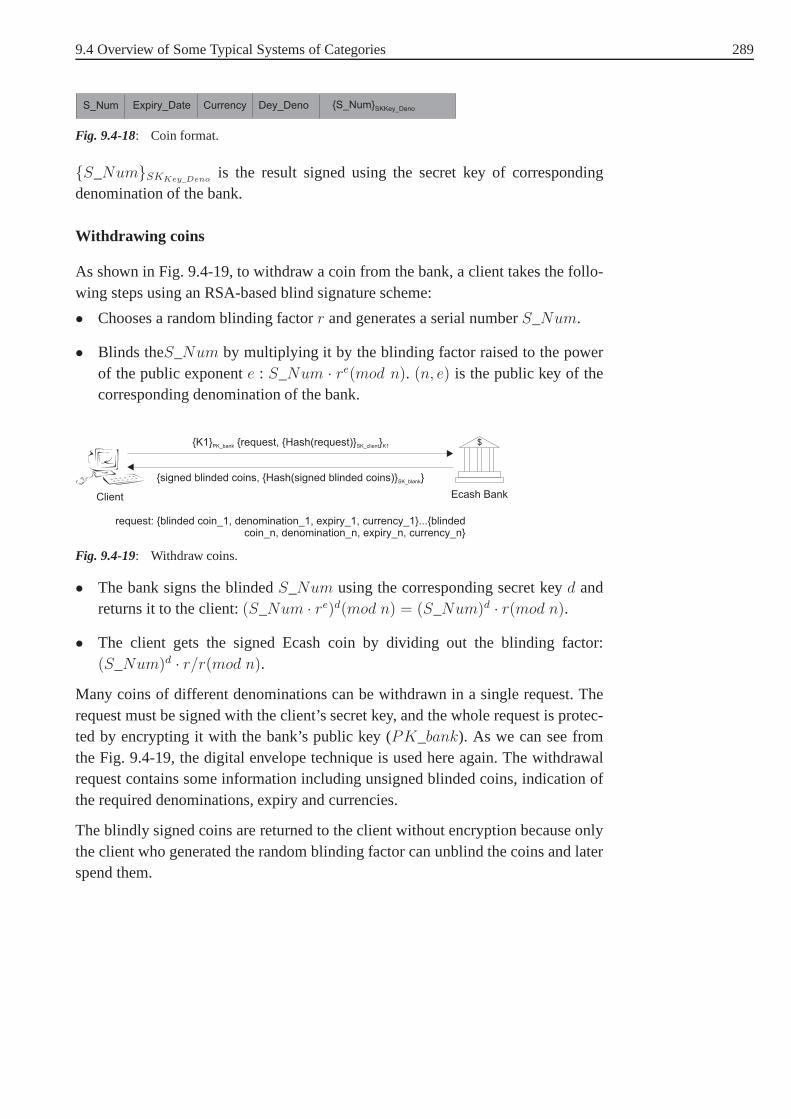
9.4 Overview of Some Typical Systems of Categories 289
S_Num Expiry_Date Currency Dey_Deno {S_Num}SKKey_Deno
Fig. 9.4-18: Coin format.
{S_Num}SKKey_Denois the result signed using the secret key of corresponding
denomination of the bank.
Withdrawing coins
As shown in Fig. 9.4-19, to withdraw a coin from the bank, a client takes the follo-wing steps using an RSA-based blind signature scheme:
• Chooses a random blinding factorr and generates a serial numberS_Num.
• Blinds theS_Num by multiplying it by the blinding factor raised to the powerof the public exponente : S_Num · re(mod n). (n, e) is the public key of thecorresponding denomination of the bank.
$
Client Ecash Bank
{K1} {request, {Hash(request)} }PK_bank SK_client K1
{signed blinded coins, {Hash(signed blinded coins)} }SK_blank
request: {blinded coin_1, denomination_1, expiry_1, currency_1}...{blindedcoin_n, denomination_n, expiry_n, currency_n}
Fig. 9.4-19: Withdraw coins.
• The bank signs the blindedS_Num using the corresponding secret keyd andreturns it to the client:(S_Num · re)d(mod n) = (S_Num)d · r(mod n).
• The client gets the signed Ecash coin by dividing out the blinding factor:(S_Num)d · r/r(mod n).
Many coins of different denominations can be withdrawn in a single request. Therequest must be signed with the client’s secret key, and the whole request is protec-ted by encrypting it with the bank’s public key (PK_bank). As we can see fromthe Fig. 9.4-19, the digital envelope technique is used hereagain. The withdrawalrequest contains some information including unsigned blinded coins, indication ofthe required denominations, expiry and currencies.
The blindly signed coins are returned to the client without encryption because onlythe client who generated the random blinding factor can unblind the coins and laterspend them.

290 9 Electronic Payment Systems
Payment : spending coins
Once a client has withdrawn coins from the bank and stored them in her wallet,she can spend these signed coins at a merchants site. As shownin Fig. 9.4-20, acomplete purchase can be as follows:
• Client selects items from a merchant’s Web site and sends anorder to the mer-chant. This could be done by submitting a form to the merchant’s web site.
• After receiving the order, the merchant sends apayment requestback to the cli-ent to invoke the client’s wallet. The request contains details about the purchaseinformation: the amount, the currency, the time, the merchant’s bank, the mer-chant’s accountID and a description of the items selected. The request is sentto the client without encryption.
ECash Bank
Cyber Wallet
Web Client
Merchantapplication
Web Server
3. payment request
4. send coins
7.receipt
8. goods
1. select items
5. deposit coins
6. accepted
2. invoke merchantapplication
Fig. 9.4-20: Payment in Ecash.
• The client then decides (or the wallet was configured to decide automatically)whether to make the payment. Once the client decides to pay, apaymentwill besent to the merchant to process the purchase. A payment instruction consists ofthe payment information and encrypted coins:
payment = {payment_Info, {coins, H(payment_Info)}PK_bank}payment_Info = {BankID, amount, currency, time, expiry, merchant_ID,
numberofcoins, H(description), H(payer_code)}.
A hash of the order description,H(description), is included within the pay-ment information. Because the merchant knows the order, themerchant cancompute a new hash using the order copy from her side and compare it withtheH(description). If these two hashes are the same then the merchant can besure that the client agrees on this order.Payment_codeis a secret generated bythe client to prove to the bank, after the merchant has deposited the coins, thatshe made the payment. A hash value of the secret,H(payer_code) is includedin the payment information so that the bank can make sure thatit was generatedby the client when she reveals the originalpayer_code value.
The coins used in the payment are protected by being encrypted using the publickey of the bank(PK_bank) so that nobody else except the bank can read thecoins. Also a hash ofpayment_Info, H(payment_Info), is encrypted to protectall messages from being altered.

9.4 Overview of Some Typical Systems of Categories 291
Deposit coins
The merchant can get credited through the deposit process. At this point, a normalpurchase with Ecash coins will be completed.
• Upon receiving the payment message, the merchant compares hashes to makecertain that the client agreed on the order and then sends adeposit requestto thebank including the payment message as part of the content. This message canbe optionally signed or encrypted before being sent to the bank.
• The bank verifies the signature and checks the coins contained in the paymentmessage to make sure they have not been spent, credits the merchant’s accountand returns a receipt to the merchant.
• After receiving the receipt, the merchant delivers the items to the client with thereceipt from the bank. In case the merchant rejects to deliver the items to theclient, the client can send the valuepayer_codeto the bank to prove that she hasmade the payment.
Double spending
Double spending means to spend a coin more than once. This is fatal to electro-nic cash systems and must be prevented. Ecash system is designed to be doublespending resistant.
Since the bank in Ecash system can not know the serial numberson the coins itissues, the bank can not record these serial numbers to prevent double spending. Soit is difficult to prevent double spending in the electronic cash systems providing fullanonymity. In Ecash, the bank will store all coins depositedback to the bank andcheck on-line to make sure a coin is not spent twice. A valid unspent coin shouldsatisfy the following conditions:
• Have a valid signature from the bank;
• Not appear in the deposited coins database;
• Be still not expired.
Although the bank can delete those coins which have been spent after the expirydate, a large database has to be maintained by the minting coins bank. Furthermore,Ecash can not prevent such misuses as blackmailing [Solms92] from happening.
Remarks
Ecash is an on-line electronic cash system providing secure, fully anonymous coinsover insecure open networks. It is suitable for small payments without the need forapplying a credit card. On the other hand, a wallet software must be installed at theclient’s machine to withdraw, store and spend coins from thebank. Furthermore, thecomputationally intensive cryptography, maintaining andsearching a large database

292 9 Electronic Payment Systems
of all spent serial numbers in order to be double spending resistant, prevent theEcash system from being used widely in the electronic payment area.
Several systems have been presented in [Traoré99], [Qiu02]providing revokableanonymity integrating a cryptological technique called group signature [Chaum91].Under special circumstance, the anonymity of an electroniccoin can be removedto reveal the identity of the coin. There is a trusted thirty party involved in thesesystems. Some other systems without any trustees are also introduced in [Sander99],[Kügler01], [Pfitzmann00].
9.4.4 Micropayment Systems–Millicent
With the rising necessity of intangible goods (e.g. information, CDs, games) inworldwide economies over the Internet and their instantaneous delivery at negli-gible cost, micropayment systems play an important role in billing for products andservices for small amounts of money. The goal of micropayment systems is to keepthe cost of transactions with small amounts of money low.
Unlike previous systems(e.g. iKP, SET, NetBill, Mondex) using public key crypto-graphy, micropayment systems use efficient one-way, collision resistant hash functi-ons or only private key cryptography which minimize the computational and storagecosts.
Micropayment systems are apparently not as secure as the previous electronic pay-ment systems. However, if a micropayment system is designedso that a customeris only at the risk of losing a few cents, and the cost of counterfeiting a coin iscomputationally higher than the value of the coin, then the security of the micro-payment system is considered to be adequate. This is the basic security assumptionof micropayment systems.
Millicent [Glassman95] is a micropayment system developedby DIGITAL Equip-ment Corporation. The goal of Millicent is to allow transactions of small amountswhile keeping the system secure.
Millicent uses an electronic currency calledscrip to make the system unforgeable,unusable if copied and inexpensive to create and validate. Ascrip is related to aspecific vendor in that it is valid or has a value only at one particular vendor.
MilliCent Model
Fig. 9.4-21 show that there are three entities in the Millicent system:brokers, ven-dors, customers. Brokers are assumed to be the most trustworthy.
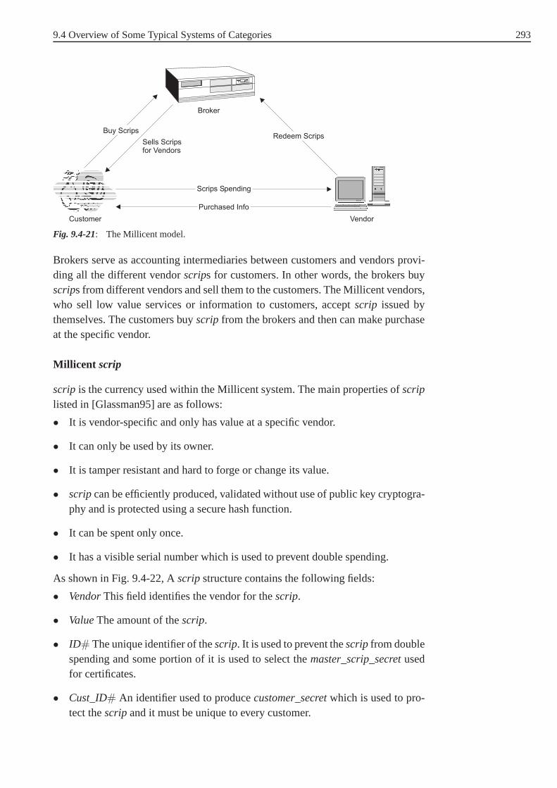
9.4 Overview of Some Typical Systems of Categories 293
Customer Vendor
Broker
Purchased Info
Scrips Spending
Buy ScripsRedeem Scrips
Sells Scripsfor Vendors
Fig. 9.4-21: The Millicent model.
Brokers serve as accounting intermediaries between customers and vendors provi-ding all the different vendorscrips for customers. In other words, the brokers buyscrips from different vendors and sell them to the customers. The Millicent vendors,who sell low value services or information to customers, accept scrip issued bythemselves. The customers buyscrip from the brokers and then can make purchaseat the specific vendor.
Millicent scrip
scrip is the currency used within the Millicent system. The main properties ofscriplisted in [Glassman95] are as follows:
• It is vendor-specific and only has value at a specific vendor.
• It can only be used by its owner.
• It is tamper resistant and hard to forge or change its value.
• scripcan be efficiently produced, validated without use of publickey cryptogra-phy and is protected using a secure hash function.
• It can be spent only once.
• It has a visible serial number which is used to prevent doublespending.
As shown in Fig. 9.4-22, Ascripstructure contains the following fields:
• VendorThis field identifies the vendor for thescrip.
• ValueThe amount of thescrip.
• ID# The unique identifier of thescrip. It is used to prevent thescripfrom doublespending and some portion of it is used to select themaster_scrip_secretusedfor certificates.
• Cust_ID# An identifier used to producecustomer_secretwhich is used to pro-tect thescripand it must be unique to every customer.

294 9 Electronic Payment Systems
• Expiry. The expiration time for thescript. Used to reduce the system’s memorysize.
• Extra info. The info is extra data describing the customer tothe vendor andmight be age, country of residence, etc. It is helpful to the vendor to make asales decision.
• Certificate. It is a kind of signature providing authentication. It is not based onpublic key algorithms. Instead, a hash function is used.
There are three secrets,customer_secret, master_customer_secretand mas-ter_scrip_secret, existing in the Millicent system. Under the secure networkconnection case, thecustomer_secretis used as the sharing key to encrypt thenetwork connection using a symmetric or private key encryption algorithm.Mas-ter_customer_secretis used to producecustomer_secretandmaster_scrip_secretis used to create the signature of thescrip, calledcertificate. The secrets are allused in a way that shows knowing the secret but does not revealany contents of thesecret.

9.4 Overview of Some Typical Systems of Categories 295
Certificate Hash
Scrip to the customer
Vendor Value ID# Cust ID# Expiry Extra Info master_scrip_secret 5
...Master_scrip_secret 3Master_scrip_secret 4Master_scrip_secret 5Master_scrip_secret 6
...
Certificate generation
Certificate validation
Customer_secret generation
Certificate HashScrip fromcustomer
Vendor Value ID# Cust ID# Expiry Extra Info master_scrip_secret 5
...Master_scrip_secret 3Master_scrip_secret 4Master_scrip_secret 5Master_scrip_secret 6
...
Certificate
Compare
Customer secret Hash
Vendor Value ID# Cust ID# Expiry Extra Info
master_customer_secret 4
...Master_scrip_secret 3Master_scrip_secret 4Master_scrip_secret 5Master_scrip_secret 6
...
Cust_ID#
Fig. 9.4-22: The generation and validation of the certificate and generation of customer secret.
Generation and validation ofscrip certificate
The certificate generation and validation of ascripare shown in Fig. 9.4-22.
The vendor maintains a list ofmaster_scrip_secrets, numbered from 1 toN whichwill be used to preventscripfrom being forged. Only the vendor who mints thescripknows these secrets. When minting ascrip, the vendor selects amaster_scrip_secretaccording to some parts ofID#, for example the highest three bits in theID#, andthen a secure one-way hash function (e.g. MD5, SHA1) is used to generate thecertificate so that the certificate can preventscrip from being altered.
When validation is going on, the vendor chooses the samemaster_scrip_secretusing the same part of theID#, generates again the certificate and compares itwith the certificate contained in thescrip to authenticate thescrip. Also during vali-dation, the vendor checks the list ofscrip ID# to make sure it is not a doublespendingscrip.

296 9 Electronic Payment Systems
The Millicent protocols
Scripis the basis of a Millicent protocol. There are three different protocols to sendscrip over the network:
• Scrip in clear.It is the simplest protocol in which the customer sends theScripunprotected in plaintext over the network. Also the purchased contents andScripchange information returned from the vendor is in cleartext.
• Private and Secure.In this case, Millicent can set up a secure tunnel betweenthe vendor and her customers using acustomer_secretas a sharing key with anysymmetrical encryption algorithm (e.g. DES, IDEA etc.).
Fig. 9.4-22 shows how to generate thecustomer_secretwhen the scrip is crea-ted. Some portion of theCust_ID# is used as an index to select amas-ter_customer_secret. Themaster_customer_secretlist is maintained by the ven-dor and only known to the vendor. Then thecustomer_secretcan be generatedby hashing theCust_ID# with the selectedmaster_customer_secret. On recei-ving thescrip, the merchant can recalculate thecustomer_secret. The customermust obtain thecustomer_secretfrom a broker.
• Secure without encryption.A fully encrypted network connection may be tooexpensive or an overkill for a micropayment system. This third variant proto-col uses thecustomer_secretas one part of the message with theScrip andpurchase request to generate a digital signature using a secure hash function,just as the generation of the certificate in the scrip. It provides secure authenti-cation without any encryption.
Millicent is an efficient, flexible and simple micropayment system, in which nopublic key encryption is used and verification is decentralized. However,scripbuy-ers can be spoofed since only the issuer of scrip can verifyscrip.
PayWord [Rivest96] and MicroMint [Rivest96] are both typical micropayment sys-tems. The PayWord protocol is a credit-based protocol proposed by Ron Rivest andAdi Shamir in 1996. It is based on a chain of hash values calledpayword. A paywordchain is vendor-specific and the user authenticates a completepaywordchain to thevendor with only a single public key signature. Eachpaywordrepresents a particu-lar unit of value. Until so far, there are still many researchers concerned about thesecurity and the practicality of PayWord [Adachi03], [Yang03]. MicroMint is thesecond micropayment scheme proposed by Ron Rivest and Adi Shamir who alsodesigned PayWord in the same paper. MicroMint gives up completely using publickey cryptography. It is debit-based to customers and brokers, while it is credit-basedto a vendor. MicroMint adapted brokers to mint electronic coins which can be usedat any vendor without an on-line verification.
An important feature of micropayment systems is that they use simple secure tech-niques to reduce the communication and speed up the transaction process. Althoughthere is still no large scale use of these systems, micropayment systems still providean ideal way to meet the demand for efficient and secure small-value payment sys-

9.4 Overview of Some Typical Systems of Categories 297
tems over insecure networks. As more and more new techniquesare being deployedand more schemes coming up, micropayment systems will bringmuch more com-mercial chances and profit to the whole open network community.
298 10 Security Aspects in Mobile Agent Systems
10 Security Aspects in Mobile AgentSystems
10.1 An Overview of Agent Technology and theMobile Agent Paradigm
This chapter gives an overview of the agent technology and the mobile agent para-digm. An evolution path of mobile agent paradigm is illustrated. A short descriptionof advantages and disadvantages of the mobile agent paradigm, a survey of mobileagent systems and research areas in mobile agent have been provided. In the nextsection, the security aspects in a mobile agent system will be discussed in detailed.
10.1.1 Overview of agent technology
At present, the computing environment migrates from individual standalone sys-tems to open systems. Due to the properties of open and complex system, systemcomponents must be able to response towards changes dynamically. In other words,there is a need for some degree of autonomy. Agent-based computing has emergedto deal with the above scenario. Before we present a set of agent-based applicati-ons, we have to describe what we mean by such terms as ‘agent’ and ‘agent-basedsystems’. Indeed, there are different labels of agents ranging from the genericauto-nomous agent, software agents, and intelligent agentsto the more specificinterfaceagents, mobile agents, and so on. The usage of the agent metaphor that leads to suchdifferent uses of the term is both strength and weakness. Itsstrength is that it can beapplied in many applications. The weakness is that the term agent is used so oftenthat there is no commonly accepted notion of what it is that constitutes an agent.We conclude that there is no agreement on what is the standarddefinition of anagent, therefore, for many researchers their only feasiblesolution is to provide theirown definition. According to [Luck03], agents can be defined to be autonomous,problem-solving computational entities capable of effective operation in dynamicand open environments. From [Jennings98], an autonomous agent is an agent, whichcan act without the direct intervention of humans and shouldhave control over itsown action and internal states. Agents are often deployed inenvironments in whichthey interact, and may cooperate, with other agents that have possibly conflictingaims. These environments are known as multi-agent system. From [Luck00], wehave the definition of a multi-agent system as a distributed system in which severaldistinct components, each of which is an independent problem-solving agent cometogether to form some coherent whole. There are several applications to which agenttechnology can be adapted.

10.1 An Overview of Agent Technology and the Mobile Agent Paradigm 299
Agent-based applications
Classified according to the application domain (more details in [Jennings98]) agenttechnology can be utilised in industrial applications (e.g. process control, manu-facturing and air traffic control), commercial applications (e.g. information mana-gement, e-commerce and business process management), and medical applications(e.g. patient monitoring). All of the application domains use software agents as a keydesign. From [Nwana96], Nwana presents a topology of software agents. They pro-pose that agents exist in a truly multi-dimensional space. However, for the sake ofclarity of understanding, they identify seven types of agents according to mobility,autonomy, learning (i.e. it reacts and/or interacts with its external environment; suchthat its performance increases) and cooperation (i.e. it cooperates with other agents)namely; Collaborative agents, Interface agents, Mobile agents, Information/Internetagents, Reactive agents, Hybrid agents and Smart agents.
10.1.2 The Mobile Agent Paradigm
The mobile agent paradigm is the overlapping concept between code mobility (i.e.mobile code) and the agent technology. In [Carzaniga97], Carzaniga et.al. explaincode mobility as the capability to dynamically change the bindings between codefragments and the location where they are executed. Code mobility is not a comple-tely new concept. It was first introduced in the period where asingle high perfor-mance mainframe was utilized as the central computation entity, e.g. remote batchjob submission and the use of postscript to control printers. Code mobility can beviewed as one of the variance of process migration implementation. In [Miloji-cic99a], Milojicic et. al. define process migration as the act of transferring a pro-cess (i.e. a process is an operating system abstraction representing an instance of arunning computer program) between two machines during its execution. The pur-poses of process migration are relatively tied with the typeof applications that usemigration. For instance, when applied to load distribution, its goals are to accessmore processing power or, when utilized in mobile computing, to migrate runningapplications from a host to their mobile computer as they connect to a network attheir current location or back again when they disconnect. From [Fuggetta98], Fug-getta et. al. illustrate a basic foundation of code mobilitydeployment and the setof code mobility design paradigms (i.e. remote evaluation,code on demand andmobile agent). The following figure, found in [Karnik98], presents an evolutionarypath from the client/server paradigm to the mobile agent paradigm. To discuss thedifferences in design paradigm, initially, we define some common terms as follows:a host is an execution platform, a code is a program to be executed, and resourcescan be generally interpreted as memory, CPU, or data contained in a host.
• Client-Server Paradigm: This paradigm is well known and broadly used. In it,hostB offers a set of services. Resources and codes are hosted by hostB. HostArequests the execution of a service at hostB. HostB performs the requested ser-vice by executing the corresponding code and accessing the involved resourcesco-located atB. At the end, hostB returns the result of code execution to hostA.

300 10 Security Aspects in Mobile Agent Systems
Host A
Host B
1. Send the request
2. Result return
R
C
Fig. 10.1-1: Client Server
• Remote Evaluation: Host A has the code but lacks the necessary resourceslocated at hostB. HostA sends the code to hostB. Subsequently, hostB executesthe code using the resources available there and sends the result of computationback to hostA.
Host A
Host B
1. Send the Code
2. Result return
R
C
C
Fig. 10.1-2: Remote Evaluation
• Code on Demand:HostA has the resources; however, it does not have a requi-red code for manipulating resources. It requests hostB for the code. After recei-ving the code, hostA executes the code.
Host A
Host B
1. Request for the Code
2. Code Transmission
R
C
R
Fig. 10.1-3: Code on Demand

10.1 An Overview of Agent Technology and the Mobile Agent Paradigm 301
• Mobile Agent: HostA has the code in hand, instead of forwarding/requestingservices offered by hostB. This time however, the code itself is able to migrateto the new host and interact locally with resources to perform its tasks. Thismethod is quite different to the previous three examples, inthis instance an entirecomponent is migrating, along with its associated data and code.
Host A
Host B
1. Send the MAR
MA
Fig. 10.1-4: Mobile Agent
10.1.3 Advantages and Disadvantages of the Mobile AgentParadigm
With the unique ability to transmit itself from one host in a network to anotherhost and autonomous capability in performing tasks on behalf of its owner, themobile agent paradigm grants some benefits over the traditional distributed com-puting approaches. According to [Lange99], the mobile agent paradigm offers thefollowing benefits:
• Network load reduction: Traditional communication protocols (e.g. challengeresponses, client-server) involve multiple interactionsto complete a target task.Applications dealing with massive information transfer (e.g. information retrie-val and filtering) in a low/high bandwidth connection (i.e. in case of a low band-width connection induces significant network load, the effect of massive datatransfer can obviously be noticed). As In [Das03], mobile agents have the poten-tial to substantially improve the speed and efficiency with which distributed andheterogeneous data is retrieved. By moving the computationto the data, retrievaltimes can be reduced by the elimination of unnecessary data transfer.

302 10 Security Aspects in Mobile Agent Systems
• Network latency minimization: A real time system (e.g. network monitoring,remote controlling, and network management) requires a fast response towardsdynamic changes of system environment. Communication delay in a real timesystem causes slow response (e.g. when remote procedure call is used for aremote countermeasure activation) towards reported problems that leads to, ina worst case, a system breakdown. Conventional network management is basedon SNMP (i.e. Simple Network Management Protocol) and oftenrun in a cen-tralized manner. Although the centralized management approach gives networkadministrators a flexibility of managing the whole network from a single place,it is prone to information bottleneck and excessive processing load at the mana-ger and heavy usage of network bandwidth. The mobile agent paradigm offers abetter solution by dispatching a mobile agent to operate locally on remote sys-tems. A mobile agent can monitor and execute autonomously when problemsoccur.
• Providing asynchronous, dynamic and autonomous computation: Mobileagents are capable of reacting autonomously to changes in the system. They cancooperate with other agents in the system to achieve their goals.
• Robustness and fault tolerance:Mobile agents’ ability to react dynamicallyto unfavorable situations and events makes it easier to build robust and fault-tolerant distributed systems. If a host is to be shut down, all agents executing onthat machine are warned and given time to dispatch and continue their operationon another host in the network.
From the list above, the mobile agent paradigm provides appealing and intuitivebenefits. Unfortunately there are many difficult problems that must be solved inorder to make mobile agent-based applications work properly. From [Vigna04] and[Milojicic99b], we gather the reasons of failure when utilizing the mobile agentparadigm as follows:
• Difficulties in a mobile agent system design:A mobile agent system designincluding testing and developing is rather complex due to system componentsinteroperation and the distribution of the heterogeneous host platforms in a net-work.
• Difficulties in security aspects realization:As its major vulnerability, securityaspects in the mobile agent paradigm can be broadly grouped into two groupsnamely: protecting host from malicious mobile agents and protecting mobileagent from malicious hosts. Further details will be presented in Section 10.2.
• Difficulties in communication infrastructure design: A communication infra-structure must be used when a mobile agent communicates withother agents(which reside on the same or different platforms) or platforms. To make com-munication possible the following must be achieved. Each interaction requiresthat the format used to exchange data and the meaning that is associated with thedata is understood and agreed upon by both the agent and the partner of the inter-action. When a mobile agent wants to communicate by message passing with

10.1 An Overview of Agent Technology and the Mobile Agent Paradigm 303
another agent on a different host, name and location of the target agent must beknown. Every host, which can possibly be the recipient of mobile agents, musthave a common communication infrastructure.
• No killer application: The mobile agent paradigm can be used to implementapplications in several cases, but these applications can also be implemented bytraditional techniques.
• Similar to worms: A mobile agent autonomously activates the transfer of itscode and data to another visited host where it resumes its execution. This featurecan be ambiguously interpreted as worm-like attacks.
10.1.4 Survey of Mobile Agent Systems
The mobile agent systems can be grouped according to their development pur-pose into two groups namely: commercial and non-commercial. Some examplesof commercial mobile agent systems are Telescript/Odyssey, Voyager, Concordia,Javaspaces, Crystaliz, Kyma Jumping Bean. On the other hand, some samplesof non-commercial mobile agent systems are D’Agents, ARA, Mole, Tracy, andNOMADS. There are also open source agent systems written in java available suchas Aglet, Bee-gent, BOND, Cougaar, JADE and Tucson. The state of the art in fra-meworks for mobile agent programming is almost exclusivelyjava. However, thereare some exception such as D’Agent (developed in TCL),Ara (that supports TCLand C/C++). According to [Mahmoud04], Mahmoud explains that mobile agentprogramming can be written in any language (e.g. Perl, TCL, Python, etc.) and maybe executed in either machine or interpreted language. Nevertheless, in order tosupport heterogeneity it is preferable and beneficial to program mobile agents in aninterpreted language. The Java language has a number of advantages that make itparticularly appropriate for Mobile Agent technology. While Java is by no meansthe only language being employed the Mobile Agents, it is arguably the best choice.The reasons for this are:
• Portability . Its use of bytecodes and its interpreted execution environment meanthat any system with sufficient resources can host Java programs. There are evenmachines being built today that execute Java natively. For Mobile Agents this isa tremendous opportunity. The more platforms capable of executing the agents’code, the better.
• A second advantage comes fromthe ubiquitous nature of Java on the Inter-net. Because it is embedded in many Web browsers, as well as applicationservers, there are many platforms deployed already. Application ProgrammingInterfaces such as AWT, the Advanced Windowing Toolkit, JFC, the Java Foun-dation Classes, and JDBC, Java Data Base Connectivity, are leading toward evenmore deployment of Java. Additionally, this deployment exactly targets the sortof services that agents can best use.

304 10 Security Aspects in Mobile Agent Systems
• Another major advantage isthe proliferation of tools that support Java pro-grammers. Many programmers are already familiar with C++, which Javaresembles in many ways. Added to that is the migration of existing tools to Javaand the creation of many more. The net result is an abundance of high quality,easy to use tools for both development and debugging.
• Finally, there isthe movement of major segments of the software industry toJava. Not only will Java be here for many years to come, it will be employed inever increasing applications.
10.1.5 Research in the Area of Mobile Agent
In the last decade, research and development of mobile agents are growing very fast.However, many research problems are still not solved completely. Many projectsconducted so far had the goal to prove the possibility to implement mobile agents indifferent programming languages and showed that it is worthusing mobile agentsfor particular application domains. In [Milojicic99c], Milojicic et. al. conclude thatthere are four research directions for the mobile agent paradigm namely: applica-tion, infrastructure, security and standard.
• Application: According to [Lange99], there are a lot of conceivable applicationsfor mobile agent or mobile code namely:
– Electronic commerce: E-Commerce is increasingly assuminga pivotal rolein many organisations. It offers opportunities to significantly improve (makefaster, cheaper, more personalised and/or more agile) the way that busines-ses interact with both their customers and their suppliers.E-Commerce, asnew opportunities for business making, can use the mobile agent paradigmin order to efficiently utilize its potential. For example, integrating a mobileagent paradigm to e-Commerce in a trading scenario can be viewed as vendoragents displaying goods and services and buying agents (i.e. represent buy-ers) making negotiations, and finally purchasing on behalf of buyers [Gutt-man98].
– Personal assistance: In case of roaming devices such as Personal Data Assi-stants (PDAs) or laptops, they are often disconnected from apermanent net-work for the sakes of cost of network connection and power consumption inmessage communication. This gives an opportunity to use mobile agents bya device dispatching its mobile agents to perform tasks on its behalf.
– Information retrieval: Within the traditional client-server paradigm, one islikely to involve massive data transferring across the networks which indu-ces high bandwidth consumption and time delay. Utilizing a mobile agentparadigm can reduce network load and provide data searchinglocally.
– Real time monitoring: Mobile agents can work locally on remote sites. Anagent can monitor a given information source without being dependent onthe system from which it originates.

10.1 An Overview of Agent Technology and the Mobile Agent Paradigm 305
– Parallel processing: More than one mobile agent can be dispatched to diffe-rent sites to perform tasks in parallel.
– Web services: These have been proposed as an important paradigm for sup-porting heterogeneous distributed computing by focusing on a core groupof Internet standards such as XML, SOAP and WSDL, in the develop-ment of web-centric applications, particularly for B2B transactions. Webservices define a technique for describing software components to be acces-sed, methods for accessing these components and methods that enable theidentification of relevant services provided
– Intrusion detection: In [Kruegel01], Kruegel et. al. discuss advantages anddisadvantages when applying the mobile agent paradigm to a distributedintrusion detection scheme. They conclude that only a few systems adoptmobile agents to perform security related tasks, even though its advantagesseem to be impressive. This stems from the fact that the benefits are notintroduced automatically and often the disadvantages outweigh the intendedimprovements.
The list is not exhaustive, but it names some applications where mobile agentscan be utilized.
• Infrastructure: This can be viewed as naming, locating, controlling and com-municating.
• Security: This can be categorized mainly into two important classes namely:protecting a host from malicious mobile agents and protecting a mobile agentfrom malicious hosts.
• Standards: The systems, from Section 10.1.4 differ widely in architecture andimplementation, thereby impeding interoperability and rapid deployment ofmobile agent technology in the marketplace. To promote interoperability, someaspects of mobile agent technology need to be standardized.Currently there aretwo standards for mobile agent technology: The Object Management Group’sMobile Agent System Interoperability Facility (MASIF) [Breugst98] and thespecifications promulgated by the Foundation for Intelligent Physical Agents(FIPA). MASIF is based on agent platforms and it enables agents to migratefrom one platform to another. FIPA spec is based on remote communication ser-vices. The former is primarily based on mobile agents travelling amongst agentsystems via CORBA interfaces and does not address inter-agent communication.The latter focuses on intelligent agent communication via content languages anddoes not say much about mobility. FIPA adopts an agent communication para-digm, which can better express the nature of cooperation andis more suitablefor integration with other AI technologies. MASIF adopts a mobile agent para-digm, which is more appropriate in situations where dynamicand autonomousswapping, replacement, modification, and updating of application componentsare required. FIPA 2002 provides the possibility of MASIF/FIPA integration.

306 10 Security Aspects in Mobile Agent Systems
10.2 Security in a Mobile Agent System
The objective of this section is to demonstrate the securitythreats and existent coun-termeasures found in mobile agent systems. Section 10.2.2 presents the classifica-tion of security threats in a mobile agent system. Section 10.2.3 discusses some hostprotection techniques. Section 10.2.4 gives a brief surveyof methods of protectinga mobile agent from malicious hosts’ attacks.
10.2.1 Introduction
As one of the active research areas of the mobile agent paradigm, security aspectshave received a lot of attentions from both research communities and academia.In [Montanari01], fully-scale adoption of mobile agent paradigm in untrustworthynetwork environments, such as Internet, had been delayed byseveral security com-plexities. Before proceeding further, some definitions aregiven as follows. A hostplatform is referred to as a computation environment that provides mobile agents toexecute their tasks, to access system resources and to guarantee integrity and protec-tion of mobile agents and its environment. We use ‘host (agent)´ and ‘host platform(mobile agent)´ interchangeably. A host also accommodatesmigration, naming andcommunication services. A mobile agent is a program (containing variables andcode) that autonomously migrates from host to host to act on behalf of its owner ina heterogeneous network.
10.2.2 Classification of Security Threats
From [Janzen00], there are four classes of security threats(where the classifyingcriteria are based on the source of attacks and the victim).
Mobile agent against host (Host security)
This type of threat can be viewed as a mobile agent commencingmalicious actionson the host’s resources which it has gained access to. The host’s resources canbe conventionally illustrated as its computation resource(e.g. memory and CPU),stored data, and communication devices. Malicious actionscan be categorized intotwo situations when the first is a mobile agent with an authorized access and thesecond is a mobile agent without an authorized access (see Fig. 10.2-1).

10.2 Security in a Mobile Agent System 307
Host Security
Agentwith
Authorization
Agentwithout
Authorization
• Denial of Service• Sensitive Data Extraction• Data Tampering• Annoyance Attack
• Masquerading
Fig. 10.2-1: Attacks against Host security
Malicious actions related to the first situation are shown tobe:
• Denial of Service:A malicious mobile agent may attempt to consume the host’sresources, which leads to a high processing time. In the worst case, a mobileagent can shut down the host.
• Sensitive data extraction:A malicious mobile agent uses its authorized accessto extract some private data.
• Data tampering: A malicious mobile agent attempts to modify host data bydeletions addition or alteration.
• Annoyance attack: A malicious host repeats some useless action, e.g. popupmany new windows.
In the second situation, a mobile agent performs the following action to obtain anauthorized access and then executes the same sort of attacksperceived in the firstsituation.
• Masquerading: A mobile agent masks itself as an authorized mobile agent toperform some attacks shown in the first situation. This type of attack is equiva-lent to a virus or a worm’s invasion.
The above represent only a partial list of possible attacks.These vulnerabilities arestemmed from lacking of an efficient control protocol. An efficient control protocolshould comprise of four steps namely an authentication scheme, a mobile agent’scode investigation, a resource provision, and a mobile agent’s activity monitoring.Please note that step 2 and step 3 can be rearranged (i.e. may be step 3 can beexecuted before step 2) or combined together. The definitionof each step and anumber of host protection methods will be further discussedin section 1.2.3.
Host against mobile agent (Mobile agent security)
This category has obtained a lot of attention from many research communities. Hereit is usually the case that a host, which has full control overthe environment, laun-

308 10 Security Aspects in Mobile Agent Systems
ches different types of attacks on a mobile agent currently residing on its site. Thereare many researchers who attempt to distinguish different types of attacks impo-sed on a mobile agent by a malicious host. For instance, [Janzen00] Janzen et.al. categorize attacks into four classes namely disclosureof information, denial ofservice, corruption of information and interference. Beirman et. al. [Beirman02],categorize their classification of malicious host securityattacks into four classesnamely integrity attack, availability attack, confidentiality attack, and authentica-tion attack. Concluding from literature relating to classification of malicious hosts’attacks, generally, a malicious host can attack in two aspects namely; on mobileagent’s components (agent’s components comprise of its data (e.g. collected data orresult of computation ), variables (i.e. state variable andinput variable), and code)and services provided to a mobile agent (see Fig. 10.2-2).
Mobile Agent Security
Data Service
• Data Modification• Data Snatching
• Service Refusal• Masquerading
Fig. 10.2-2: Attacks against Mobile Agent Security
The first are mobile agent’s components tampering and snatching. Tampering casecan be explained as follows:
• Modification: We provide two general cases: namely code modification anddata modification. In case of code modification, a malicious host might deletesome part of the agent’s code so that a mobile agent cannot work accordingto how it was implemented. In the worst case of code modification, a malicioushost simply deletes a mobile agent out of his platform. Generally, a mobile agentmust migrate to certain host platforms to collect some data.In case no precau-tions are taken, a malicious host is able to see the collecteddata. It can alsomodify (i.e. delete, alter) the collected data according toits goal.
In snatching case, a malicious host can perform as follows:
• Eavesdropping:In this attack [Alfalayleh04], a malicious host extracts the sen-sitive data of a mobile agent or intercepts intercommunication between mobileagents. Even though, there is no alterations this extractedinformation might bebeneficial to a malicious host.
In respect to services, a malicious host can do the following.

10.2 Security in a Mobile Agent System 309
• Service refusal: It is an action, which attempts to obstruct a mobile agent toaccomplish its tasks. A well-known premeditative action isthe denial of ser-vice. Denial of service can be accomplished in different ways. For example, amalicious host does not provide its communication device when a mobile agentneeds to transfer a message to its interaction partner or postpone the requestedservice so that a mobile agent must reside in its environmentfor a long periodof time.
• Masquerading: A malicious host hides its real identity and claims identityofanother host in order to gain access to a mobile agent’s data.
The above represent only a fraction of possible attacks. To resolve these vulnerabi-lities of a mobile agent emanated by malicious hosts, a set ofcounteractions mustbe available in each mobile agent system. A brief survey of existent counteractionswill be further discussed in Section 10.2.4.
Mobile agent against other agents
This category represents a set of attacks in which a malicious mobile agent exploitssecurity weaknesses of a target agent and a host to launch attacks against the targetagent. A set of attacks can be implied as data tampering and denial of service.One form of data tampering is when a malicious agent overwrites or alters a targetagent’s code. A possible denial of service attack is for example when a maliciousagent performs repeated activities with a target agent so that the target agent cannotcontinue its task. To handle this situation, a host must provide an efficient accesscontrol and an activity observation (i.e. monitor the behavior of a mobile agenttowards other agents).
Other external entities against mobile agent system
This category represents a set of attacks in which external entities (this refers to allentities which are not included in a particular mobile agentsystem), threaten thesecurity of a mobile agent platform (i.e. all mobile agents and all hosts constitu-ting a particular mobile agent system). This set of attacks is roughly designated asmasquerading (i.e. an external entity attempts to masquerade to be a mobile agentor a host which is legitimated), and communication attack (i.e. an external entityeavesdrops, intercepts or tampers messages sent between legitimate entities).
10.2.3 A Survey of Host Protection Methods
Now that we have looked at what threats a mobile agent imposeson a hosts. Aswe summarize that each host in a system must utilize an efficient control proto-col. There are numerous existent protocols developed to achieve one or more com-ponents of an efficient access control procedure. With each method presented below,we also demonstrate what its main achieved purpose is. Before proceeding further,a description of each component of an efficient control protocol is described as fol-lows:
310 10 Security Aspects in Mobile Agent Systems
• An authentication scheme:The main purpose of an authentication scheme isto prove a mobile agent ownership or a mobile agent’s sender (i.e. the host whodispatched the mobile agent) by utilizing cryptography functions (e.g. digitalsignature, hash function, message authentication code).
• A mobile agent code’s investigation:According to [Gelbart04], code investiga-tion is a method to verify a mobile agent’s code according to safety regulationscreated by the host. To be more explicit, code verification isto ensure that thecode does what it is supposed to do and nothing more.
• Resource provision:This can be described as a resource access allowance. Tobe more specific, it is a method by which a host grants each mobile agent anaccess to its resources according to the degree of authorization containing ina credential (for example, a credential of a mobile agent canbe considered asits owner signature on its code. Other types of credential can also be applied)carried by each mobile agent. For example, a host restricts access to its filedatabase only mobile agents coming from a particular group of hosts.
• A mobile agent’s activity monitoring: After having received permission toaccess some particular resources, a mobile agent can pursueits tasks on the host.The host must monitor the mobile agent’s activity so that it does not endangerany part of the host system (i.e. host itself or other agents).
Signed Code
Code signing is a fundamental technique of confirming the authenticity of objects(e.g. mobile agents) and its integrity, using digital signatures. The authenticity ofa mobile agent can be proved when checking the digital signature on a particularmobile agent’s code. The examiner will explicitly know (we assume that the exami-ner knows the signer’s public key) either the creator’s identity (i.e. owner of themobile agent) or some entities’ identities (i.e. hosts thathave reviewed or dispat-ched the mobile agent). Its integrity serves as an assurancethat the code has notbeen altered. Code signing involves public key cryptography. To make code signingmethods be applicable, a public key infrastructure must be available. From [Micro-soft03], we learn that this method cannot ensure that the code is safe to execute.For example [Janzen00b], introduces Microsoft’s Authenticode, a common formof code signing, that enables Java applets or Active X controls to be signed forensuring users that this software has not been tampered withor modified and thatthe identity of the author is identified. We conclude that themain purpose of thismethod is to serve as an authentication scheme, however it does not guarantee thatthe consequence of the execution of the mobile agent code is harmless or not haras-sing.

10.2 Security in a Mobile Agent System 311
Path Histories
This method was introduced by [Chess95]. The idea of path history is to maintainan authenticable record of previously visited hosts duringa mobile agent’s lifetime.A host uses the path history to decide whether it should grantits services under therestraint of where a mobile agent has been migrating before it arrives at its site. Tobuild a path history, it requires each host in a mobile agent’s itinerary to append asigned entry to the path indicating its identity and the identity of the next host tobe visited and to provide the complete path history to the next host. Obviously, themain drawbacks are, that the cost of path verification becomes higher as the pathhistory increases and that some malicious hosts in the itinerary might modify or notappend their signed entries to the received path history. Weconclude that the mainpurpose of this method is to provide a combination of an authentication scheme andresource provision.
Proof-Carrying Code (PCC)
This approach was introduced by [Necula98]. It requires thecode producer (i.e. themobile agent’s owner) to officially provide a formal proof that the code adheres toa security policy defined by the code consumer (i.e. the host). Upon receiving thecode and its formal proof sent by the code producer, the code consumer validatesthe code. The result of validation leads to the claim that thecode is safe to exe-cute or not. The PCC ensures the safety of code execution. To prove the code, nocryptographic techniques or external assistance is required. In addition, the PCC issecure against code or proof’s tampering. In other words, any tampering on eitherthe code or the formal proof results in either a verification error or, if the verifi-cation succeeds, a safe code transformation. Before becoming widely used, thereare two main limitations found in this approach namely proofgeneration and timeconsumption of proof validation process, which must be resolved. We conclude thatthe main purpose of this method is to provide the assurance, that the code is safe toexecute.
Software-Based Fault Isolation
The sandbox model [FM96] aims at limiting a mobile code in such a way, thatit cannot damage the local execution environment. To achieve this, the interpreterdefines the security policies for the local as well as the remotely originated code.Whereas local code is usually granted access to all resources (I/O, File system,etc.) the remotely originated code runs in the sandbox and isthus subject to higherrestrictions with respect to resource access. It may, for instance, not be allowedto access system commands. This approach limits the useful functionality remotecode can implement for example to display graphics and thus is not attractive forreal-world applications.

312 10 Security Aspects in Mobile Agent Systems
State appraisal
The idea of this approach (see [Farmer96]) is that a host derives a mobile agent’sdegree of authorization from its state information using a state appraisal functioncreated by the agent’s owner. A state appraisal function computes a set of privilegesto request as a function of the mobile agent’s state. After the state appraisal hasdetermined which permissions to request, a host uses a resource provision methodto determine which of the requested permissions will be granted. This approach isdeveloped to cope with illegitimate mobile agent’s state information alterations. Forexample, while a mobile agent is migrating among hosts, it brings code, static data,collected data and state information. State information ofa mobile agent refers tothe dynamic data created during the execution of a mobile agent and used as an inputto the computations conducted on the next host. After receiving a mobile agent, ahost checks the mobile agent´s state information to be sure that the state informationwas not tampered with before granting an access to its resource. This method servesas an authentication scheme for resource provision.
10.2.4 A Survey of Mobile Agent Protection Methods
The approaches to protecting a mobile agent can be broadly classified into twomain mechanisms [Karnik98]. Detection mechanisms attemptto detect attacks ona mobile agent. Prevention mechanisms try to make it impossible (or at least verycostly) to attack a mobile agent. Protection methods can be categorized into twotypes, according to their purpose as follows:
• Type 1:Aims to reduce the chance of migrating to a malicious host or restrictsmigrating to only trusted hosts. Normally, a protection method of this type uti-lizes the notion of trust. The notion of trust has been long recognized as beingof paramount important for secure systems. We call a method of this type atrust-based computing method. Some methods are discussed below.
• Type 2:This can be classified into two aspects, namely a protecting mobileagent’s components and protecting the mobile agent’s execution. The first aspectrefers to the protection of data, variables and code. The second aspect can becategorized into two issues namely; handling of infrastructure failures and ensu-ring the correctness of a mobile agent’s execution. In [Pleish04], Pleish et. al.explain infrastructure failures as follows. Infrastructure failures imply the pre-mature halting of processes (i.e. hosts, communication links). For example, afailing host causes all agents running on it to fail and a linkfailure causes theloss of all messages or mobile agents currently in transmission on this link.Without infrastructure failures, the correctness of a mobile agent’s executionimplies that a visited host must faithfully execute a mobileagent according tothe mobile agent’s code. Generally, most of the approaches in type 2 are stron-gly designed by using cryptography techniques (i.e. encryption/decryption algo-rithms, private and public keys, digital signatures, digital time stamps, and hashfunctions). Some methods are presented below.

10.2 Security in a Mobile Agent System 313
Trust-based Computing Methods
A method, which falls into this category, involves either creating a trusted environ-ment or equipping a mobile agent system with a trust model. A trusted environmentis a domain in which a mobile agent can roam without being threatened by anyentities in the same domain. A trusted environment can be implemented by using asecurity policy, tamper resistant hardware or external trusted hosts. A trust modelcan be explained as an efficient method for assessing each interaction partner’s trust-worthiness (e.g. trust value).
• Tamper-resistant hardware [prevention], [Wilhelm99]: The idea is to executea mobile agent in a tamper-resistant hardware added to conventional computingsystems (i.e. untrusted hosts), which can defend potentialphysical attacks. Onemajor drawback is that a mobile agent can migrate only in a closed environmentwhere every host must be equipped with tamper-resistant hardware.
• Trust model [prevention]: Today this is one of the most popular research topicsin the area of e-Commerce and Peer to Peer applications. The goal of a trustmodel is to calculate a trust value of the entity to be used as aquantity of mea-surement in a decision making process. In other word, we wantto assess howtrustworthy in a certain aspect the entity is, given some information (e.g. theentity’s reputation, direct experiences with the entity, ... etc.). After calculatingan entity’s trust value, we use it as one of the components (ineBay, such aquantity might be the price or the delivery time, and in a mobile agent system,it might be the service quality) to decide whether we will conduct an interac-tion (in case of e-commerce, an interaction means trading and in case of mobileagent systems, an interaction means migration to the host) with the entity or not.In [Derbas04], Derbas et.al. present TRUMMAR a trust model for mobile agentsystems based on reputation. In TRUMMAR, a hostA which wants to send amobile agentC to another hostB in order for the agent to accomplish its taskdoes this, only if hostB is trustworthy in providing a computational environ-ment which will not attack (i.e. delete, corrupt, manipulate or misinterpret theagent’s code, data or variable) the mobile agentC. In order to assessB’s trust-worthiness, hostA combines hostB’s reputation from many resources (e.g. itsneighbors, friends) withB’s reputation from its own perception derived fromits direct experiences withB, to came to a summarized reputation value of hostB. Host A will compare this summarized reputation value with the predefinedthreshold value to decide whether hostB is trustworthy or not.
Cryptographic-based Methods
For this category, there are numerous methods that have beenproposed so far. Firstwe present some methods aiming to protect mobile agent’s components as follows:
• Data protection methods: Many methods, for example, sliding encryption[Young97], partial result authentication code (PRAC) [Yee99], Chained signa-ture [Karjoth98], have been developed to ensure a mobile agent’s data integrity.

314 10 Security Aspects in Mobile Agent Systems
Data integrity, in this context, means the integrity of partial accumulated resultsperformed by a mobile agent on each of the visited hosts. Normally a data pro-tection method is utilized in a shopping scenario, i.e. in which a mobile agentroams in a fixed/undetermined itinerary of vendor platformsin search of somespecific item on behalf of its owner. The offers provided by each visited ven-dor can be viewed as a partial accumulated result. Without protecting partialaccumulated results, a malicious vendor can perform many types of attack.
– Sliding encryption [prevention]: In [Young97], Young et. al. propose a newmode of RSA public key encryption (the sliding encryption) to ensure theintegrity of collected data under a limited storage situation.
– Partial Result Authentication Code [detection]: Yee [Yee99] proposes thePartial Result Authentication Code (PRAC) to ensure the integrity of thecollected result. This method provides the agent with a set of secret keys usedto calculate a MAC (Message Authentication Code) on the result of eachhost, using a one-way function to produce the key associatedwith the currenthost from an initial secret key given by the originator. PRACcomprises ofthe result and its MAC. The agent erases the secret key associated with thecurrent host before migration. Yee defines forward integrity, which impliesthat the first visited malicious host cannot modify or forge any PRACs ofalready visited hosts.
– Chained Signature [detection]: In [Karjoth98], Karjoth etal. publish a familyof protocols that aims to protect the integrity and confidentiality of data col-lected by a free roaming agent. In their paper, they extendedYee’s protocolsand defined a set of security properties that has a higher degree of secu-rity. They extend public verifiable forward integrity from [Yee99] in the fol-lowing manner “Anyone can verify the offeroi by checking whether thechain is valid at encapsulated offerOi”. In other words, every visited hostis able to verify the integrity of the encapsulated offer by using a one timepublic/private key pair generated by the previous host. This property is veryuseful since not only the originator but also the visited host on the agent’sitinerary can detect the tampering.
– Route Protection [prevention]: Assume that each mobile agent visits a setof hosts according to a predefined itinerary given by its owner. A predefi-ned itinerary can be viewed as a restriction for each mobile agent to visitonly trusted hosts. Thus it becomes necessary to protect thegiven route. In[Westhoff99], nested encryptions and signatures are used to provide increa-sed security to the agent´s route. The basic idea is to sign and encrypt hostaddresses iteratively to attain a high level of security. A flexible itinerary,which allows dynamic adaptation and expansion during the execution of theagent, is preferable. A shortcoming of this flexible itinerary is that it is vul-nerable to corruption of hosts specified in the itinerary; a corrupted host canmodify the itinerary or attack other hosts in the itinerary to cause denial

10.2 Security in a Mobile Agent System 315
of service to the agent. There are some proposals [Westhoff00], [Ferrer01]which attempt to prevent this vulnerability.
– Environmental key generation [prevention]: This method protects the inte-grity of a mobile agent´s code. In [Schneier98], a mobile agent carries anencrypted code. In order to obtain the particular decrypting key, the hostenvironment must contain a predefined condition. The idea isthat construc-ting agents in such a way that upon encountering an environmental con-dition (i.e. via a matched search string), a key, which is used to decryptsome encrypted executable code, is generated. The environmental conditionis concealed through a one-way hash or public key encryptionof the envi-ronment trigger.
– Computing with an encrypted function [prevention]: This isproposed in[Sander98]. It offers a similar protection, as can be achieved by using atamper resistant hardware. The idea is to encrypt a functionf to obtainsome other functionE(f), which hides the content of functionf . Thisencrypted functionE(f) can then be implemented as a programP (E(f)),which is interpreted as a mobile agent and sent to the host. The hostthen executesP (E(f)) on an input x which leads to the encrypted resultP (E(f))(x). Since the host does not know what function it actually calcu-lated, it cannot meaningfully tamper with the code or its execution and isrestricted to random modifications. The encrypted result isreturned to theowner who can decrypt and obtain the desired result of the function f (i.e.E−1 P (E(f))(x) = f(x)). The idea is restricted solely to polynomials andrational functions. In addition it does not allow continuous interactions bet-ween an agent and a place (at the host). This approach is thus not well suitedfor general use.
In [Collberg02], Colleberg et. al. identify three methods that are adopted as alter-native defences against attacks on intellectual property contained in softwarenamely; Code obfuscation, Watermarking, and Tamper-Proofing. Undoubtedly,all of them can also be adapted to protect mobile agents.
– Code Obfuscation [prevention]: This is a process that renders software unin-telligible but still functional. In other words, it is a method of transforming anoriginal agent’s code into another code, which is functionally identical butvery hard to read and understand. It ensures security through obscurity. In[Hohl98], Hohl proposes a blackbox security using code obfuscation. Sinceobfuscation cannot accommodate perfect protection, a timelimited varia-tion of blackbox is introduced. After the interval elapses,the agent becomesinvalid. This method is suitable for an application, which does not conveyinformation. A main drawback is the lack of methods to calculate a reasona-ble time period for the mobile agent execution.
– Watermarking and Fingerprinting [detection]: Watermarking is a process,which embeds a copyright notice in the software code to allowthe owner ofthe software to assert his intellectual property rights. The fingerprinting is a

316 10 Security Aspects in Mobile Agent Systems
similar technique that embeds a unique customer identification number intoeach distributed copy of an application in order to facilitate the tracking andprosecution of copyright violators. In [Esparza03], Esparza et. al. proposemobile agent watermarking and mobile agent fingerprinting which first aimsat the assurance of the integrity of the execution and not at property rightprotection but later not only provides detection of attacksperformed duringthe mobile agent’s execution but also detects collusion attacks launched bya group of hosts. Mobile agent water marking can for example be achievedas follows; a mark is transferred to the agent’s results during the execution.However, the mark is disguised as part of the real results to the executinghosts. After migrating back to the owner, each result is verified. When themarks are differ from the owner’s expectation, this means that the host hasmodified the agent. In mobile agent fingerprinting, the embedded marks aredifferent for each host. During the verification process of each result, if analtered mark is detected, the host generating this mark is malicious. The aut-hors claim that by assigning different marks to each host makes the possibi-lity of collusion harder. In both methods, after a malicioushost is identified,an external authority must punish it. Drawbacks of both methods are increasein code and data size and the need of an external entity.
– Tamper-proofing method [prevention]: This causes a programto malfunctionwhen it detects that it has been modified. Thus it may be self-protected.
• Execution Protection and Infrastructure failure handling : There are someapproaches in protecting the mobile agent’s execution, namely a host is obligedto generate a log of the operation performed by the mobile agent while residingthere (e.g. execution tracing)
– Execution tracing [detection]: [Vigna98], introduces such a method fordetecting unauthorized modifications of an agent through the faithful reco-ding of the agent’s behavior during its execution on each visited host. Thistechnique requires each visited host involved to create andretain a non-repudiable log or trace of the operations performed by the agent residingthere, and to submit a hash of trace upon conclusion as a tracesummary.A trace comprises of a sequence of identifiers correspondingto the execu-ted statements in the agents code and affixed with the digitalsignature ofthe executing host. A secure protocol is also developed to convey agentsand associated security related information among the various parties invol-ved, which may include a trusted third party to retain the sequence of tracesummaries for the agent’s entire itinerary. If a suspiciousresult occurs, theappropriated traces and trace summaries can be obtained andverified, a mali-cious host thus is identified. This method can only detect a manipulationafter a mobile agent returns to its owner. Only when the ownerbecomessuspicious of a result, then the verification process is activated. Executiontracing has a number of drawbacks, e.g. the size and number oflogs to beretained, the verification process is triggered sporadically (i.e. based on the

10.2 Security in a Mobile Agent System 317
owner’s suspicion). As further reading on extended execution tracing werecommend[Tan02], [Tan04].
– Server and Mobile agent Replication [detection]: Infrastructure failures canonly be minimized by introducing redundancy. In [Minsky96], a set of inde-pendent replica hosts is used to provide parallel computation. After the exe-cution, the hosts vote on the result. A well-known problem when utilizingserver and mobile agent replication is multiple executionsof the mobileagent. This problem plays a crucial role in applications e.g. money transacti-ons, shopping. In [Rothermel98], an agent execution is defined to be “exactlyonce” if the entire sequence of its stages is eventually performed, and all ope-rations of each stage are executed exactly once. Whilst thisis not a problemof applications, e.g. reading data. As an example, Rothermel et.al. propose aprotocol for a scenario where a user launches a mobile agent to make a flightand hotel reservation for a forthcoming business trip. The agent is expectedto make both reservations if possible, and in any case returna status messageback to the user. This protocol applies ‘observer nodes’ formonitoring thestate of the currently executing node, which take over the execution whenthis node is not available. A voting procedure integrated inthe processingensures the “exactly-once” semantics.

318 11 Copyright Protection
11 Copyright Protection
Not everything that is on the Internet is public domain and may be used withoutpermission from the creator/owner. For our discourse copyright is a protection thatcovers published work over the Internet. There are a number of technologies thatcan be used to protect and enforce copyright. Two of these technologies we havealready encountered in the last chapter are watermarking and fingerprinting.
Copyright protection becomes more difficult in the digital world than in the analogworld, since a copy of digital data can be easily, inexpensively and quickly marketedand distributed over the Internet. Moreover, each copy is not distinguishable fromthe original107.
In general, there are two approaches which enables copyright protection:
1. Usage control: In this approach, each usage of the protected material, suchas viewing, playing or printing, is controlled by some authorized renderinghardware or software [Opp00]. Pay-TV and video-on-demand are two appli-cations that are protected according to the usage control approach.
2. Digital copyright labeling techniques:Digital copyright labeling techniquesembeddigital marks into protected material. These digital marks hold as aDigital marks
distinctive symbol for the copyright related information such as origin, owner,content, or recipient. The idea behind digital copyright labeling techniques isto allow unlimited copying and usage of the protected material, but to provideevidence for copyright violation. In this approach, in turn, two types of digitalcopyright labeling techniques can be distinguished:
a. Ownership labeling: Ownership labeling is referred to as watermar-Ownership labeling
king. A multimedia document is marked with a label that uniquely iden-tifies the copyright holder. A misuse of the protected document can bedetected by the determination of the legitimate owner of theprotectedmaterial and the corresponding copyright.
b. Recipient labeling: Recipient labeling is referred to as fingerprint. ARecipient labeling
multimedia document is marked in a manner that allows its distributionto be uniquely traced [Opp00]. In other words, an illegitimately redis-tributed copy of the protected material can be traced back toits originalrecipient.
11.1 Watermarking
Digital watermarking is a technology for embedding various types of informationWatermarking
(digital marks) in digital content. It is an adaptation of the commonly used and
107 In the analog world, as the number of copies increases thequality of these copies decreases.On the other hand digital original and copies are not distinguishable!

11.1 Watermarking 319
well known paper watermarks. For example, paper bank notes or stock certificatescontain watermarks. Otherwise, they could be easily copiedand (mis)used. As aconsequence thereof, the trust in the authenticity of thesepaper bank notes or stockcertificates would greatly be reduced, resulting in a big loss.
More precisely, digital watermarking is a digital signal added to digital data, such asa multimedia document, that can be detected or extracted later to make an assertionabout the data. It can serve several purposes, such as ownership assertion, authen-tication and integrity verification, content labeling, usage control, and control pro-tection [Opp00].
A watermark can be categorized to be visible or invisible108:
1. A visible watermark is – as the words say – visible to the eye. Example ofVisible watermark
this category is a company logo (see Fig. 11.1-1).
2. An invisible watermark is imperceptible by the user but can be read by aInvisible watermark
computer with the proper decoding software. This is analog to seals or markson paper currencies that are only visible when held up against light.
Fig. 11.1-1: An example of a visible watermark: The logo of the University of Hagen.
Furthermore, watermarks can be robust or fragile, depending on the application.
1. Fragility means that the watermark does not survive tampering by any image- Fragile watermarks
processing transformation. A fragile watermarking is convenient to imageintegrity checks where each modification on the image content must be detec-table.
2. Robustnessrefers to the capability of the watermark to survive any manipu- Robust watermarks
lations of the media, such as lossy compression, scaling, filtering, and requan-tisization, etc. A robust watermarking is required for ownership assertion.
Digital watermarks can be classified in public or private watermarks, too:
108 All our next discussion will be referred to watermarkingfor images, but is valid to watermar-king for other multimedia documents such as audio or video. In this regard, we will speakabout audible and inaudible watermark in the case of audio material.

320 11 Copyright Protection
1. A public watermark can be detected and read by anyone using an appro-Public watermark
priate detector software without the need of any secret information. For exam-ple, a detection of copyright violation in images publishedon the Web can beaccomplished with public watermarking techniques. Therefore, we can usemobile agents (detector software) to perform identity checks for images atlocations of the Web.
2. A private watermark , however, cannot be detected and read without acces-Private watermark
sing some secret information. Of course, this is also accomplished by using anappropriate detector software. Private watermarking provides a higher level ofsecurity but is less practicable in comparison to a public watermarking. It isclear that the secret information must be communicated and distributed to auser or third party in a secure manner, in case of the watermark detectionis not carried out by the image owner. So the private watermarking schemeis also suitable to demonstrate ownership of content in caseof misuse. Fur-ther, private watermarking can be subdivided intosecret key watermarkingSecret key
watermarking andpublic key watermarking according to the keys used forinsertion, andPublic key
watermarking
Insertion
extraction or detection(see Fig. 11.1-2).
ExtractionDetection
a. Secret key watermarking: The same (one) key is used for watermarkinsertion and extraction or detection. This secret key mustalso transpor-ted via a secure channel.
b. Public key watermarking: A private key of the image owner is usedfor watermark insertion, whereas its public key is used for watermarkextraction or detection.
Fig. 11.1-2: The watermarking process including watermark insertion,extraction and detection[Opp00].
Watermarking techniques must be carefully analyzed and developed in order to pre-vent all possible attacks against them. In general, four classes of attacks are possible:
1. Robustness attacks:Robustness attacks aim to diminish or remove the pre-Robustness attack
sence of a mark in a watermarked image without harming the image [Opp00].Such attacks can be made by means of operations such as data compression,filtering, resizing, etc.
2. Presentation attacks:In presentation attacks, the mark is not removed butPresentation attack
the image is manipulated in such a manner that the mark cannotbe detectableanymore.

11.2 Fingerprinting 321
3. Interpretation attacks: In interpretation attacks, the watermark is so mani-Interpretation attack
pulated that it will have an invalid or multiple interpretation from watermarkevidence point of view. If this occurs, the watermark ownership cannot beprovided anymore.
4. Legal attacks: In legal attacks, an attacker does not use technical meansLegal attack
against watermarking techniques. He just uses judicial means109 to despairevidence of ownership presented.
11.2 Fingerprinting
Fingerprinting enables to make each sold or distributed copy of the protected mate-rial unique. This uniqueness can be guaranteed through the introduction of indivi-dual marks in each copy. In this manner, the provider of the protected material candetect from the fingerprint, the illegally redistributed copies.
Essentially, the techniques and attacks which are introduced for watermarking arethe same as for fingerprinting. Most fingerprinting techniques are symmetric, i.e. theprovider of the protected material and the buyer know the fingerprinted copy. Con-sequently, if another copy with the same fingerprint is made,responsibility of illegalcopy cannot be assigned to one of them. In other words,non repudiation cannot Non repudiation
be provided by symmetric fingerprinting techniques. To solve this problem, asym-metric fingerprinting schemes have been proposed. They enable only the buyer toknow the document with the fingerprint. However, if the provider discovers a copyof the protected document, she/he can identify its buyer, and prove that such buyeris responsible for the illegal copy. For example, in the technique used in pay-TV, avideo stream is transmitted over a broadcast channel in encrypted form, (asymme-tric) traitor tracing schemes as application of asymmetricfingerprinting enable totrace people who abuse the broadcast encryption scheme by allowing illegitimateusers to decrypt the data stream.
109 For example, through different interpretations of copyright laws.

322 12 Intrusion Detection
12 Intrusion Detection
12.1 Introduction
Basically there are three possibilities for an intruder to get into somebody elsescomputer system. Ones can get in physically (physical intrusion), provoke a DenialPhysical intrusion
of Service (DoS) by disconnecting important network elements such as routers,servers, discs, etc. or install a sniffer to record the wholenetwork traffic looking forpasswords.
A user who already has an account on a system may be interestedin extending hisprivileges. In most cases users with low level privileges try to extend their privile-ges (system intrusion) and in the ideal case want to become root (Unix) or gainSystem intrusion
administrator privileges under Windows.
Remotely attacking a system can be done in diverse ways. One possibility is toRemote intrusion
exploit software bugs in running services at the target system and generate a bufferoverflow (see Section 12.2.2.2) to gain access to the system.Another way is tomake running services unavailable by, for example, floodingthe target system withrequests which are not processed (Denial of Service). In this course unit we willonly deal with system and remote intrusions, but before attacking a system, a cleverintruder will first collect as much information as possible about the target system.How this can be done is shown using a brief scenario (Footprinting ).Footprinting
If an attacker wants to access a system, the first thing he/shehas to do, is to deter-mine the topology or structure of the system, by checking which computers arealive. To do this, he/she generates an Echo request, generally known as PING(Packet Internet Groper). Let us assume that the target hosthas the IP address192.168.1.2 . The opponent then generates aping 192.168.1.2 . If the tar-get host is alive then he/she will generate an Echo reply message. The attacker nowknows that the host is alive. The next step is to determine which services are offeredby the target host by generating a so-calledport scanning. The result of a port scan-Port scanning
ning is the number of each port where a service is running. Nowthe attacker identi-fies those services which are reported to have bugs. Many known vulnerabilities insoftware are published in the internet (see CERT http://www.cert.org and MicosoftSecurity Bulletin Search http://www.microsoft.com/technet/security/current.aspx).Very often, when a bug has been found in software, patches arepublished in orderto solve the problem and close the hole. But there is only a small amount of admi-nistrators that install patches. According to a recent study carried out by the gartnergroup (www.gartner.com) 90% of all attacks can be avoided if all patch-levels arekept up-to-date and another 90% of future cyberattacks will exploit known securityflaws, for which a patch is available or a solution known.
After identifying active hosts and running services, sincemany security holes areplatform dependent or related to a specific operating system, the next step in theattacker roadmap is to determine the running operating system, commonly knownasFingerprinting .Fingerprinting

12.2 Intrusions 323
The implementation of the IP protocol stack depends on the type of operating sys-tem, especially when it comes to a reaction to crafted packets e.g. a packet wherethe SYN and FIN flag have both been set. If a database of the reactions from eachoperating system is set up, crafted packets can be construed, sent to the serverand based on the reaction of the server, it is possible to determine which ope-rating system is in use. The automated scanning tool NetworkMapper (NMAP)(www.insecure.org/nmap/) provides options to find out whatthe underlying opera-ting system is.
Currently, diverse tools are available for the automatic scanning of vulnerabilities innetworks. Nessus (www.nessus.org/) and the Security Administrator Tool for Ana-lyzing Networks (SATAN www.porcupine.org/satan/) are some of these tools. Thetools can be of great importance for the network administration in looking for secu-rity threats, but they can be used by intruders as well to randomly scan the internetlooking for exploitable vulnerabilities. However, after the attacker has sufficientlyexplored the system, brought together all the information needed and eventuallyfound security holes in the system, he/she initiates the next step by trying to exploitthe known vulnerabilities and start an attack. But before dealing with these attacks,it will be interesting to investigate what enables them.
12.2 Intrusions
Basically there are a multiplicity of reasons which allow anintrusion to happen.The following are worth mentioning:
• Configuration errors
• System or protocol related errors
• Programming errors
• Carelessness towards attackers.
A bad configuration of a component can have a great impact on the whole system Configuration errors
or network. If we take a web server as an example a misconfiguration of the con-figuration filehttpd.confcould allow clients to access files they are normally notallowed to. Many software applications are configured with default passwords. Insome cases these passwords are not changed and since they areknown to attackers,they can be used to gain access into the system.
Protocols related errors result from the fact that by the design of the IP protocolProtocol related errors
stack version 4 (IPv4), security related aspects had to takea back seat. Howeverthe situation is different now. The internet has become a tool of great importancefor private and business purposes and therefore attractiveto intruders. The imple-mentation of IPv6 (see Kurseinheit 13, Kommunikationsnetze- und Protokolle) wassupposed to solve some of the security related problems. However the proliferationof IPv6 has not been that good yet mainly because of the complexity related to it‘sdeployment. In this course unit, protocol related attacks are explained under theassumption that IPv4 is in use [RFC 791].

324 12 Intrusion Detection
Programming errors are often buffer overflows. A buffer overflow is a non defi-Programming errors
nable system state which can be used by attackers to get into the system by forexample crashing higher privileged programs (see Section 12.2.2.2 ).
The last point deals with the careless handling of passwords: whether they are writ-ten down and left beside the computer or it is easy for an attacker to guess themusingsocial engineering. Social Engineering occurs when someone tries to abuseSocial engineering
the trust relationship by for example claiming to be the administrator to gain accessto the password. As a result of the above and other reasons; attackers can get intosystems and cause serious damage.
Since there are diverse attacks which can append, only some of the types will bedealt with namely protocol related attacks, remote access attacks and malware inmore detail.
12.2.1 Protocol related Attacks
These attacks are enabled by week protocols and related security mechanisms. Wecategorize the attacks according to the seven layers OSI model and try to analysethe reasons enabling them, starting with (Address Resolution Protocol-ARP) relatedattacks.
12.2.1.1 ARP Attacks
The internet protocol was developed, in order to make different network technolo-gies compatible with each other. The IP address used to routepackets from sender toreceiver is a logical address, which means that it is not bound to a physical mediumand is an abstraction of the underlying physical network. This capability enablesnetworks, which are different from each other from a technological point of viewto be connected with each other and extended to a global (world-wide) network.Here, a difference has to be made on the one hand between services e.g. e-mail, filetransfer, domain name service running above the TCP/IP layers, which use the IPaddress and the physical transport medium on the other hand.Inevitably the data hasto be fed into the physical medium. The (Medium Access Control-MAC) addressMAC address
- a world-wide unique address which is recorded in the network interface card - isused for the communication on an Ethernet network. But sincehigher layer servicesoperate with IP addresses, a resolution mechanism is neededto map the IP addressinto a physical unique address. This function is performed by the ARP protocol[RFC 826], which runs beyond the IP protocol in the OSI model.To send a mes-sage to a receiver, the sender needs his/her physical address. Since the sender doesnot know the address of the receiver a priori, he looks at his ARP cache (addressresolution table) to check whether the address of the receiver is available or not. Ifnot, the sender then generates a broadcast request to all hosts which are connectedin the local network.

12.2 Intrusions 325
The broadcast request consists of: the IP address of the sender, the MAC address ofthe sender and the IP address of the receiver. All hosts in theLocal Area Network(LAN) can see the request, those who are not concerned ignorethe request and onlythe host whose MAC address corresponds to the generated IP address responds tothe request and sends a reply to the sender per unicast. The relation (association)between MAC and related IP addresses is stored in the ARP cache so that multi-ple requests and the related waste of bandwidth can be avoided. Since at the ARPlevel, no authentication mechanisms have been implemented, an attacker can use theabsentee authentication mechanism to reply to a request andgenerate a resolutionwhich is not correct (see Example 12.2-1 ).
ARP spoofingExample 12.2-1:In this example Host A want to establish a connection to receiver D (seeFig. 12.2-1). He generates a request as follows:Who has IPD? tell IPA
(1). On receiving the request, the opponent C generates a reply by sending itMAC addressMACC to sender A (2). The sender A has no possibility of verify-ing whether the generated MAC addressMACC in fact corresponds to the IPaddress of D. Attacker C has sucessfully spoofed the addressof Host D. Host Aand attacker C update their ARP tables (3).
ARP Table
IP MACD C
Host A Host B
Host C Host D
2
1
3
3
ARP Table
IP MACD C
LAN
Fig. 12.2-1: ARP spoofing
This attack works best if the host whose IP address has been spoofed, is disab-led. Since the records in the cache are cleansed cyclically,the attacker will
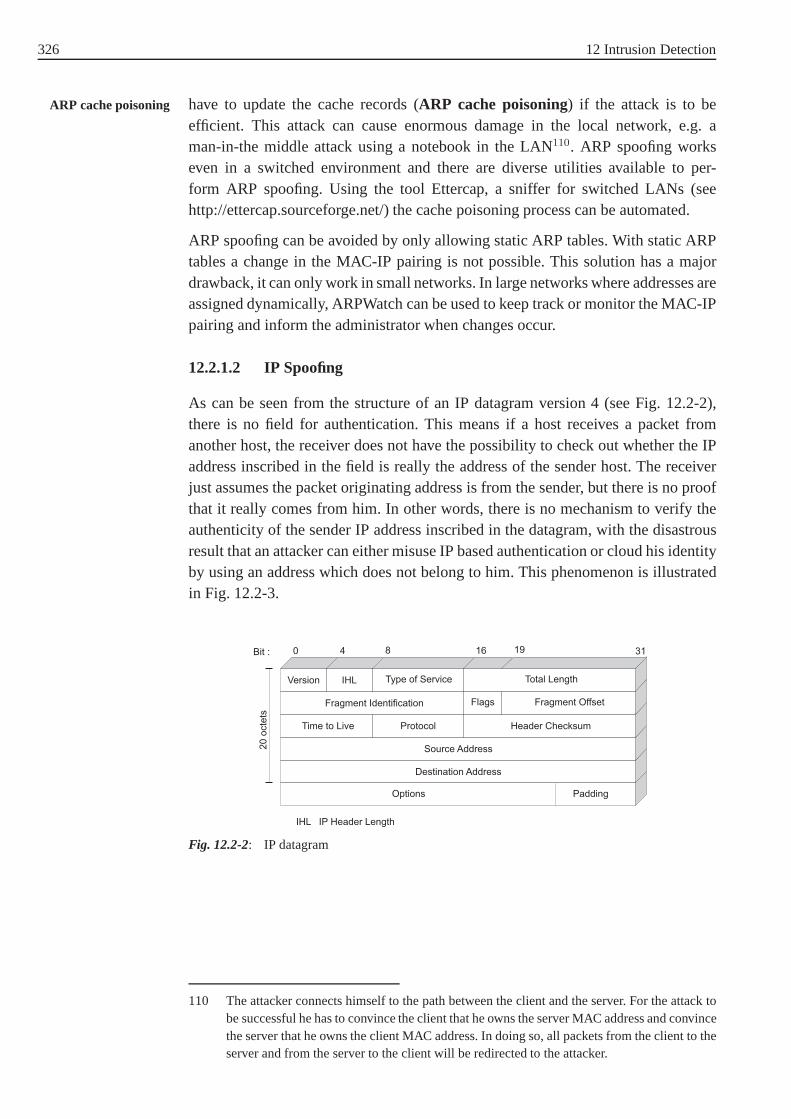
326 12 Intrusion Detection
have to update the cache records (ARP cache poisoning) if the attack is to beARP cache poisoning
efficient. This attack can cause enormous damage in the localnetwork, e.g. aman-in-the middle attack using a notebook in the LAN110. ARP spoofing workseven in a switched environment and there are diverse utilities available to per-form ARP spoofing. Using the tool Ettercap, a sniffer for switched LANs (seehttp://ettercap.sourceforge.net/) the cache poisoning process can be automated.
ARP spoofing can be avoided by only allowing static ARP tables. With static ARPtables a change in the MAC-IP pairing is not possible. This solution has a majordrawback, it can only work in small networks. In large networks where addresses areassigned dynamically, ARPWatch can be used to keep track or monitor the MAC-IPpairing and inform the administrator when changes occur.
12.2.1.2 IP Spoofing
As can be seen from the structure of an IP datagram version 4 (see Fig. 12.2-2),there is no field for authentication. This means if a host receives a packet fromanother host, the receiver does not have the possibility to check out whether the IPaddress inscribed in the field is really the address of the sender host. The receiverjust assumes the packet originating address is from the sender, but there is no proofthat it really comes from him. In other words, there is no mechanism to verify theauthenticity of the sender IP address inscribed in the datagram, with the disastrousresult that an attacker can either misuse IP based authentication or cloud his identityby using an address which does not belong to him. This phenomenon is illustratedin Fig. 12.2-3.
Options
Destination Address
Source Address
Time to Live Protocol Header Checksum
Fragment Identification Flags Fragment Offset
Version IHL Type of Service Total Length
Bit : 0 4 8 16 19 31
20
octe
ts
Padding
IHL IP Header Length
Fig. 12.2-2: IP datagram
110 The attacker connects himself to the path between the client and the server. For the attack tobe successful he has to convince the client that he owns the server MAC address and convincethe server that he owns the client MAC address. In doing so, all packets from the client to theserver and from the server to the client will be redirected tothe attacker.

12.2 Intrusions 327
Attacker Bob
Target
DoS attack
IP=172.12.29.0
IP=165.12.9.0
Victim
IP=183.17.13.0
IP source IP destination
183.17.13.0 165.12.9.0
Counterfeit acknowledgement
IP source IP destination
165.12.9.0 183.17.13.0
3
1
4
2
Fig. 12.2-3: IP spoofing
We have three participants: an attacker (Bob), a trusted host (Victim) and a server IP spoofing
(Target). First of all Bob disables the victim by issuing a DoS to the trusted host,so that it can not respond to any request otherwise it might see packets from thetarget and will send an RST packet to tear down the connection. Bob then generatesa packet with the IP address of the trusted host183.17.13.0 , pretending to bethe trusted host. Since the victim is trusted by the server the server checks the IPaddress and believes it really comes from the victim. But in reality it comes fromthe attacker. The packet from the server is sent to the victim, but since the victimhas been taken off, it can not respond. The attacker does not see the packet from theserver, but he can further process and perform some operations on the server.
IP based authentication can be bypassed through the misuse of trust relationship . Trust relationship
This trust relationship was implemented in the Berkeley Unix operating system forclient/server protocols belonging to the so-calledr family (e.g. rlogin, rcp, rsh) toalleviate jobs for users and administrators. The trust relationship can be carriedout either host wide, using the file /etc/host.equiv, which contains the name of thehosts considered to be trusted or user wide, in which case thefile .rhosts is usedand trusted users will not be prompted for passwords. IP spoofing is a blind attackmeaning that the attacker generally does not receive the response of the server.In order to receive server´s generated packets the attackermust be able to accessa router along the path between him and a server or carry out asource routingattack.111 Source routing attack
IP spoofing can be averted by using IPv6 [RFC 2460] where authentication fieldshave been implemented. IP spoofing is a dangerous attack, which is often used asa starting point in order to perform further attacks for example DoS attacks or TCPconnection hijacking. The latest will be dealt with in the following section.
111 The attacker defines the path along which the packets are sent to him. Currently most routersdo not allow Source Routing.
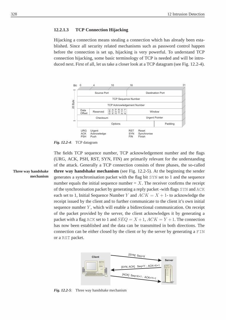
328 12 Intrusion Detection
12.2.1.3 TCP Connection Hijacking
Hijacking a connection means stealing a connection which has already been esta-blished. Since all security related mechanisms such as password control happenbefore the connection is set up, hijacking is very powerful.To understand TCPconnection hijacking, some basic terminology of TCP is needed and will be intro-duced next. First of all, let us take a closer look at a TCP datagram (see Fig. 12.2-4).
Options
Checksum Urgent Pointer
DataOffset
Reserved Window
TCP Acknowledgement Number
TCP Sequence Number
Source Port Destination Port
0 4 10 16 31Bit:
20
Byte
URG
ACK
PSH
RST
SYN
FIN
Padding
URGACKPSH
UrgentAcknowledgePush
RSTSYNFIN
ResetSynchroniseFinish
Fig. 12.2-4: TCP datagram
The fields TCP sequence number, TCP acknowledgement number and the flags(URG, ACK, PSH, RST, SYN, FIN) are primarily relevant for theunderstandingof the attack. Generally a TCP connection consists of three phases, the so-calledthree way handshake mechanism(see Fig. 12.2-5). At the beginning the senderThree way handshake
mechanism generates a synchronisation packet with the flag bitSYNset to 1 and the sequencenumber equals the initial sequence number =X. The receiver confirms the receiptof the synchronisation packet by generating a reply packet -with flagsSYNandACK
each set to 1, Initial Sequence NumberY andACK = X + 1- to acknowledge thereceipt issued by the client and to further communicate to the client it’s own initialsequence numberY , which will enable a bidirectional communication. On receiptof the packet provided by the server, the client acknowledges it by generating apacket with a flagACKset to 1 andSEQ = X +1, ACK = Y +1. The connectionhas now been established and the data can be transmitted in both directions. Theconnection can be either closed by the client or by the serverby generating aFIN
or aRSTpacket.
Server
Client[SYN] Seq=X
[SYN, ACK] Seq=Y ; ACK=X+1
[ACK] Seq=X+1 ; ACK=Y+1
Fig. 12.2-5: Three way handshake mechanism

12.2 Intrusions 329
A closer look at the three way handshake mechanism reveals that hijacking aconnection turns to determination of the sequence number ofthe server112. Thereare many possibilities to gather the sequence number of the server. Firstly if we canaccess the local network or a router along the path to the server, performing a man-in-the-middle attack, all packets between server and client can be sniffed and thesequence number as well. The second and probably more elegant possibility is topredict the TCP sequence number. The sequence number prediction works becauseof implementation flaws in relation to sequence number generators which allowattackers to predict TCP numbers using primitive statistical approaches [Zav01].113
In Fig. 12.2-6 it is shown how the attack works. We have three actors: the opponent(Attacker), the client (Victim) and the server (Target). Atfirst the attacker waits untila connection has been established between client and server(Step 1 to 3). Then theattacker issues a DoS to take off the client (4). Now the attacker has to predict thenext sequence number which will be used by the server. To do this the attackerinitiates a connection to a harmless port (5) by generating aSYN packet. The serveracknowledges the receipt of the packet (6), the attacker hasthe current sequencenumber and generates a RST (7). The attacker, using the current sequence number,can now predict the next sequence number as described in [Zav01]. The attackerthen initiates a new connection to the server by generating aSYN packet spoofedwith the address of the victim (8). The reply of the server is sent to the client (9),it can not respond since it has been disconnected using a DoS attack. The oppo-nent can not see the answer of the server, but acknowledges itwith the predictedsequence number (10).
Target
Attacker
Victim
SYN
SYN/ACKRST
SYN with IP_Victim
SYNSYN/ACK
ACKSYN/ACK
ACK
1
2
3
9
8
10
7
6
5
4 DoS
Fig. 12.2-6: TCP connection hijacking
TCP connection hijacking can be prevented if secure sequence number generatorsare implemented (see [RFC1750] and [RFC1948]).
112 Second step in the three way handshake.
113 For further discussion about random processes especially with regard to security see (RFC1750 and RFC 1948).

330 12 Intrusion Detection
12.2.2 Remote Access Attacks
There are diverse options to remotely access a system, some of which will be discus-sed in this course unit, namely by gaining a legitimate user password or by carryingout a buffer overflow. Firstly let us take a closer look at password attacks.
12.2.2.1 Password Attacks
In most computer systems, authentication is still carried out using a user namein combination with a password. This basically means that ifan attacker is ableto come into possession of the password he/she can access thesystem. There arediverse strategies to gain possession of passwords, some ofwhich will be discussedin the following
• Simple password guessing
• Password sniffing
• Password cracking
• Social engineering.
Simple password guessing is systematically trying to guessthe password by ente-Password guessing
ring passwords which are frequently used. Diverse lists with passwords often usedare available in the internet. The attacker uses these liststo insert typical login com-binations. There is no need to mention that this method can only work in a fewcases because most systems will refuse further access following a certain numberof access failures.
Sniffers are network utilities used by network administrators to record all packetsPassword sniffing
which traverse a network. Since there are many applicationswhere the passwordis transmitted non encrypted e.g. Telnet (Teletype Network) or FTP (File TransferProtocol), the attacker just reads the whole network trafficand gathers passwords.
Password cracking uses more sophisticated methods, to find out the password e.g.Password cracking
brute force, systematical passwords search or dictionary attacks. In the following acloser look will be taken at brute force and dictionary attacks on passwords.
Bruce Force Attack
A brute force attack consists of trying all possibilities available to find the pass-Brute force attack
word. Under the assumption that the attacker has infinite resources and time, eachpassword can be found using the brute force method. In reality, the attacker onlyhas a certain amount of time and resources. Therefore brute forcing a system is notvery efficient. Before dealing with the brute force method indetail, let us first takea closer look at how password authentication works.At the beginning a user is prompted by a login process to provide a combination ofuser name and password. The login process then compares the provided informa-tion with the information stored in the password file. If there is a match, the user isallowed to access the system otherwise the login request is rejected.

12.2 Intrusions 331
If X is the number of printable characters on a keyboard andα the number ofmaximum characters a password can take, then the password search space is oflength:Xα + Xα−1 + Xα−2 + . . . + X1. If we know the number of operations aprocessor can process in a given amount of time (MIPS) and we know how manyinstructions are needed to perform one password search, then we can derive themaximum searching time.
Example 12.2-2:In many operating systems the password is8 bits in length. Since the numberof printable characters in most keyboards is95, the password search space caneasily be derived and equals958 = 6, 63×1015 = 6634204312890625. If we fur-ther assume that the opponent has a modern standard PC with anIntel Pentiumprocessor of the fourth generation (Pentium 4) which can perform approxima-tely 8.000.000 guesses in a second, then it will take26, 296 years to brute forcethe system.
Unfortunately searching for passwords is easier than presented in the exampleabove. In reality things look completely different. When a user is given an accounton a system, he/she chooses her own password. To avoid havingto write the pass-word down on a piece of paper, users tend to choose easy to remember passwordssuch as names of children, name of pet, etc. Generally user passwords are not cho-sen according to security principles or password guidelines [Yan01][Yan04] withthe predictable result that they are easy to guess.
Example 12.2-3:The number of printable characters in most keyboards is95. These characterscan be grouped in four dimensions Numeric (10), Alphabetic (26), Upper/Lowercase (52) and Keyboard Extended (33). The password search space and the pass-word search time on a pentium IV for 8 character passwords chosen from diffe-rent search spaces has been summarized in Table 12.2-1 for the following cases:
1. All eight characters are alphabetic
2. All eight characters are numeric
3. Six are alphabetic and two are numeric.
Tab. 12.2-1: Search space and search time
Search space Search time
1. Alphabetic 268 = 208827064576 7, 25 h
2. Numeric 108 = 100.000000 12, 5 s
3. Combination 114C28 · 102 · 266 =
86496417280030, 033 h

332 12 Intrusion Detection
The disadvantage of the systematic password search method from the opponentpoint of view is the fact that many systems would only give youa couple of attemptsto access which means that brute forcing or systematically guessing passwords isnearly impossible. This along with the evidence that well chosen passwords arevery difficult to guess led to a more pragmatic solution called dictionary attackbeing used, and this will be discussed next.
Dictionary Attack
To carry out a dictionary attack an opponent needs a dictionary, the encryption algo-rithm, a powerful processor and the password file. The first three things are quiteeasy to acquire. Currently there are large amounts of electronic dictionaries availa-ble with the most common passwords in use. The main obstacle an attacker has tosurmount is to get the password file. In the case of Linux, thispassword file was pre-viously located in/etc/passwd . After several attacks, the file was shadowed andstored in/etc/shadow with the difference that, now, only the superuser root canaccess the password file. An abstract of a password file/etc/passwd is shownbelow. At first the user name is stored in clear (root ), then comesx which standsfor the encrypted password. After the password comes the user ID, in this case userroot has the number0, the group ID0, and then comes the Geco field (generalinformation about the user), the home folder of the user withthe shell that will beinvoked.
/etc/passwd
root:x:0:0:root:/root:/bin/bash
daemon:x:2:2:Daemon:/sbin:/bin/bashlp:x:4:7:Printing daemon:/var/spool/lpd:/bin/bash
bob:x:505:100::/home/bob:/bin/bashjames:x:507:100:/home/james:/bin/bash
peter:x:506:100:/home/peter:/bin/bash
edward:x:510:102:/home/eduard:/bin/bash
As can be seen from the shadow password file, users names are stored in cleartext and the password is encrypted. The superuser root e.g. has the passwordrjABCv9A8PLKu , and the user bobaoCFDr2E7IJKs .
/etc/shadow
root:rjABCv9A8PLKu:12235:0:10000daemon: * :3902:0:10000
lp: * :8902:0:10000
bob:aoCFDr2E7IJKs:12001:0:55555:3:james:pdLIDr7F3LGBt:12001:0:55555:3
peter:uiFDSi4H9RTWw:12001:0:55555:3edward:tzLFKz6R79KPs:12001:0:55555:3
114 C2
8≡ possibilities of choosing2 out of8 = 8·7
1·2.

12.2 Intrusions 333
Shadowing the password file has led to an increase of system security, since nobodyelse except the superuser root is allowed to access the shadow password file butin the past it was reported that there are bugs on running processes which allowattackers to read the shadowed file [Sch01]. However, if the attacker can come intothe possession of the password file, he can encipher the dictionary and then comparethe ciphered list of common passwords with the shadow password file. If there isa match, then a password has been found. To augment the probability of findinga valid password the attacker uses each word in different variations. This methodstrongly reduces the password search space as can be asserted from diverse studieswhich have been conducted in the past in order to increase password security. Thework of Robert Morris and Ken Thompson in 1979 is a milestone in testing thepower of user passwords [Ken79]. The test was carried out on aPDP-11/70. 3289passwords were examined and 30% of the passwords could be found and the searchonly lasted 5 minutes.
In another case study of over 14,000 Unix passwords, almost25% of the passwordswere found by searching for words from a carefully formed dictionary consisting ofonly 3 · 106 words [Mon99].
There are many approaches to strengthen password security.One is to select pass-Password guidelines
words randomly. The idea behind this approach is that the random selection ofpasswords will lead to a better use of the password space. A disadvantage of thisapproach is that randomly selected passwords are often not pronounceable and thusnot easy to remember. Another approach is to use computer generated passwordswhich are pronounceable. A further method, called proactive password checker sug-gests checking passwords before taking them into use [Bis95][Blu04]. This meansthe password chosen is subject to a dictionary attack and if it is broken the user willhave to provide another one. Password aging is another approach which consists offorcing the user to change their password after a certain period of time. The benefitof this method is not evident.
12.2.2.2 Buffer Overflows
A closer look shows that this attack leads the current list ofthe CERT statistics.Below a short list of reported bugs of the CERT statistic:
2. June, 2006, Mozilla contains a buffer overflow vulnerabi lity in
crypto.signText()
20. May, 2006, Microsoft Word buffer Overflow25 April 2006: Multiple vulnerabilities in DNS implementat ions
14 March 2006 Microsoft Office routing slip buffer overflow .
Before we deal with the attack in greater detail, some information on the functio-ning of modern operating systems is necessary, especially memory managementand related terms such as programs, processes, functions, procedures are of greatimportance.

334 12 Intrusion Detection
Parameter values of functions
Return address
Local variables
Stack
Heap
Text (code)
Higher memory address
Lower memory address
Fig. 12.2-7: Process in memory
Generally a process consists of three different parts: the heap, the stack and thedata part (Fig. 12.2-7). The data part is the part where the program code is stored.Since the program code does not change at execution, this part is static and mostimportantly read only. In the heap, all data which is used program wide for exampleconstants and global variables is stored. The heap is dynamic, but does not grow sofast. The third part of the process is called the stack. The stack grows from the top(higher addresses) to the bottom (lower addresses) and contains all dynamic datawhich is needed during the execution of procedures or functions, e.g. parametervalues of functions, local variables, register values and most importantly the returnaddress is stored here. The storage order is shown in Fig. 12.2-7 as well: at thetop parameter values of functions, then the return address (Program Counter) andafterwards local variables. Since many values are stored and among them the returnaddress, overflowing or manipulating the buffer to change the return address canlead to a serious security threat which will be addressed next using a conceptualexample.
Example:As can be seen from (Fig. 12.2-8 left side)Program bufferoverflowis the mainprogram and consists of several instructions and a subroutinebuffer. The addres-ses of the instructions are shown as well. The subroutine hasthe addressn andthe instruction where the program continues after the subroutine has been exe-cuted has the addressn + 1. As can be seen from the stack 4 bytes are reservedeach for the local variables x, y and z and another 4 bytes for the return address.When the subroutinebuffer is invoked (Instructionn), the return address (thenext instruction to be executed), in this casen+1 is stored in the stack, then thelocal variable x, y and z respectively. Since the buffer grows from bottom to top,if we put more than the foreseen 4 bytes into the buffer reserved for z, the localvariable y, the local variable x and most inportantly the return address (n + 1)can be overwritten and replaced by a new return address.

12.2 Intrusions 335
Programm bufferoverflowbegin
Address
Instruction 1;
Instruction 2;
Instruction 3;
0
1
2
...
n
Subroutine bufferbegin
char x[4]char y[4]char z[4]
end
n+1 next instruction;
end
Return address (n+1)
local variable x
local variable y
local variable z
Subroutine bufferin the stack beforethe call
NOP
Malicious Code
Stackgrowth
local variable x
local variable y
Malicious input(local variable z)
Subroutine bufferat execution
Buffergrowth
Return address (n+1)
.
.
.
.
.
.
Fig. 12.2-8: Buffer overflow
If the content of the return address is overwritten, the program crashes if there isno reasonable code at the given new return address (segmentation violation underUnix), but if a useful code e.g. /bin/bash is available at thenew return addresstheprocess will continue at the new return address and provide the attacker with a rootshell if the crashed process was running with root privileges. Now that it has beenshown how a buffer overflow is generated, the next question tobe answered is howto get a useful code at the new return address. This can be doneeither by using codewhich is already available in the memory or by planting useful code (malicious inputsee Fig. 12.2-8) at the return address [Cri00]. Since the address of the executablecode can not be exactly determinedNo Operation(NOP) are inserted. At theexecution theNOPpart will be ignored and the attack code executed.
Buffer overflow is a serious security threat, but can be prevented if diverse securitymeasures are taken into account. The prevention can be carried out by for examplechecking the bounds of the inputs variables before they are processed, by writingbetter code (hand inspection), by analyzing the source codeand by rendering thestack not executable ([Ist01]). In the next section we will deal with one of the mostimportant and dangerous attacks (malware).
12.2.3 Malware
Malware related attacks are reported approximately every day. Nearly each compu-ter user has to deal with this type of attack consciously or not. The costs related tomalware are enormous: alone the damages caused by theLove Letter wormwere
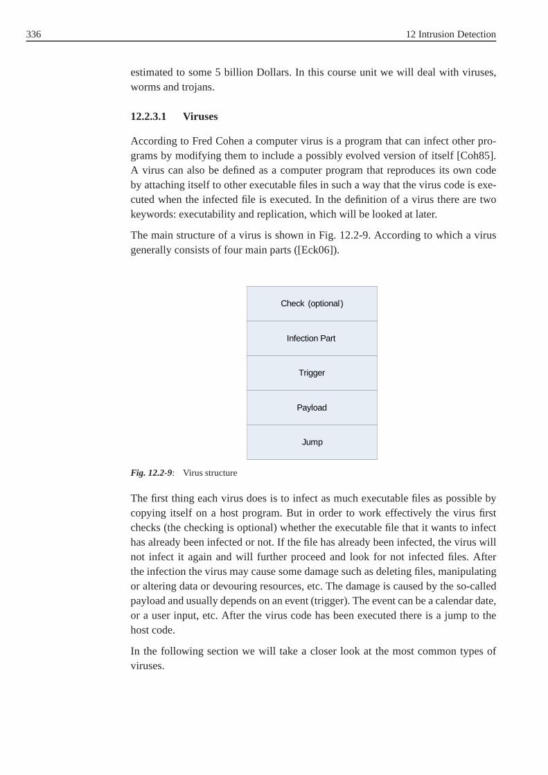
336 12 Intrusion Detection
estimated to some 5 billion Dollars. In this course unit we will deal with viruses,worms and trojans.
12.2.3.1 Viruses
According to Fred Cohen a computer virus is a program that caninfect other pro-grams by modifying them to include a possibly evolved version of itself [Coh85].A virus can also be defined as a computer program that reproduces its own codeby attaching itself to other executable files in such a way that the virus code is exe-cuted when the infected file is executed. In the definition of avirus there are twokeywords: executability and replication, which will be looked at later.
The main structure of a virus is shown in Fig. 12.2-9. According to which a virusgenerally consists of four main parts ([Eck06]).
Check (optional)
Infection Part
Trigger
Payload
Jump
Fig. 12.2-9: Virus structure
The first thing each virus does is to infect as much executablefiles as possible bycopying itself on a host program. But in order to work effectively the virus firstchecks (the checking is optional) whether the executable file that it wants to infecthas already been infected or not. If the file has already been infected, the virus willnot infect it again and will further proceed and look for not infected files. Afterthe infection the virus may cause some damage such as deleting files, manipulatingor altering data or devouring resources, etc. The damage is caused by the so-calledpayload and usually depends on an event (trigger). The eventcan be a calendar date,or a user input, etc. After the virus code has been executed there is a jump to thehost code.
In the following section we will take a closer look at the mostcommon types ofviruses.

12.2 Intrusions 337
File Viruses
File viruses modify the content of COM- and EXE (and further files, which can beexecuted such as DLLs). They append the virus code either to the beginning or tothe end of a file. The original file stays as it was. When the file is run, the virus codeis executed first and there is a jump to the program code, the program code proceedsas if nothing has happened, the same as before the infection (see Fig. 12.2-10).
Program Virus
Virus Program
Program
Fig. 12.2-10: File viruses
Terminate Stay Resident (TSR viruses)
Once executed TSR viruses stay resident in the memory (RAM) and manipulate theoperating system so that, each time a program is started it isinfected. If the PC isshut down, the virus is deleted from the RAM but the executionof a file which hasbeen infected is enough to restore the previous state.
Stealth Viruses
Stealth viruses are a specific group of TSR viruses. Antivirus programs generaterequests to look at system files which have been altered or manipulated. Stealthviruses intercept the result and send it back to the antivirus program. The resultclaims to the antivirus program that the state of the file is still the same as beforethe infection. Stealth viruses can intercept system calls and then generate their ownanswer.
Encrypted viruses
Encrypted viruses consist of an encrypted payload and an encryption routine. One ofthe most important characteristics is that for each encryption a different encryptionkey is used to make the virus look different. Therefore no signature can be found inthe virus payload, but in the encryption routine, which always looks the same.

338 12 Intrusion Detection
Polymorphic Viruses
Polymorphic viruses work as encrypted viruses, but they have a further compo-nent, the so-calledmutation engine, which changes the encryption routine afterMutation engine
each infection and cleares the drawback of encrypted viruses. A polymorphic virusworks as follows: when a file which has been infected by a polymorphic virus isexecuted, the encryption routine is run first and gains control of the further programexecution. The virus payload and the mutation engine are decrypted, at this stagethe decrypted virus takes control over program execution. The virus creates a copyof itself and of the mutation engine in the memory. The mutation engine genera-tes a new encryption routine, which has the same functionality as the previous, butlooks different. Afterwards the encryption routine encrypts the virus payload andthe mutation engine and infects new files.
12.2.3.1.1 Macro viruses
Many applications (MS Word, MS Excel) have a very powerful macro library inorder to support the user and ease the use of applications. But since macros areexecutable, all applications which have integrated macro functions can be infectedby viruses. Through the use of an Auto-Open function the virus is executed when anExcel or a Word document is opened. Macro viruses are generally spread throughe-mail with file attachments. A double click on the attachment suffices and the virusis run.
12.2.3.2 Worms
At first glance, viruses and worms have quite a few things in common, but if we takea closer look we will see that the differences are quite important. As has previouslybeen said, generally a virus first checks if the program it wants to infect has alreadybeen infected to avoid double infection. Unlike viruses, worms are self replicatingprograms and do not infect any programs. Both, worms and viruses replicate, butthe manner of replication is quite different. Viruses replicate by infection (modify-ing existing code) and by waiting for the host code to be run. Worms replicate bygenerating a copy of the worm program and proliferate by spreading over networks.To proliferate, the worm can either inject the worm code in the stack or overflowthe buffer and run the worm application locally in the system. Another way used bymany worms, to assure proliferation, is by sending itself asan e-mail attachment.
As the following examples show, worms are a great security threat and damagescaused by them can range from simple jokes like displaying messages on the usersscreen to more serious things such as stealing passwords, deleting files or disruptinghosts from the internet by causing a DoS. There are also combinations of virusesand worms.

12.2 Intrusions 339
W32.MiMail.j@mmExample 12.2-4:W32.MiMail.j@mm is a worm, first published in 17.11.2003, which is sent asan attachment. The e-mail which is sent, gives the impression that it comes froma trustworthy person. When the attachment is opened, a form is shown, whichrequests credit card information. This information is thenstored and sent toprecise e-mail addresses. One of these attachments isInfoUpdate.exe . Ifthe attachment is executed, the worm creates an entry in the registry. So thateach time the computer is started, the worm is started as well.
Code Red wormExample 12.2-5:The "Code Red" worm was first published in july 2001. The worm provoked abuffer overflow on Internet Information Server II (version 4.0 and 5.0) runningunder the operating sytems Windows NT 4.0 or Windows 2000. Toprovokethe buffer overflow the worm generates an HTTP request on port80, overflowsthe buffer and injects the worm code into memory as seen in Section 12.2.2.2.After overflowing the buffer the worm is run locally on the server and dis-plays the message"HELLO! Welcome to http://www.worm.com!
Hacked By Chinese!" which is why it is known as the Code Red worm.There were two versions of the Code Red worm. In order to proliferate the firstversion of the Code Red worm has an IP random number generatorwhich gene-rates IP addresses of hosts to be infected. But because of thestatic seed of thisIP random number generator, only the same hosts were infectable. The secondversion implements a dynamic IP random number generator with the result thatmore than 359.000 machines were infected in just 14 hours. The damage causedby the worm depends on the date (trigger): from 1-19 of each month, the worminfects and proliferates; from the 20-27 of each month a Distributed Denial ofService (DDoS)115 attack is performed on a fixed IP, from the 28-end of eachmonth the worm sleeps.
12.2.3.3 Trojans
A trojan is a secret implementation of a set of instructions in a program (insertionof program chuncks without changing the documented task) orthe secret installa-tion of a program on a system. Characteristic for trojans is,therefore, that they dosomething else other than that what they are supposed to do.
Trojans can be active in many layers: implemented in an integrated developmentenvironment (IDE) they can copy themselves into all programs which are created
115 The idea behind DDoS is to make the attack more powerful byincreasing the number ofcomputers performing the attack, in the Code Red worm case a great number of infectedcomputers participated in an attack on the White House IP address.

340 12 Intrusion Detection
and operate in the firmware, operating system, service routines, database systems,etc.
The implementation of a trojan generally presupposes intensified insider knowledgeover the system, otherwise the execution of the trojan will lead to an unexpectedbehaviour of the program and thus, to the recognition of the trojan. In programswhich are very modular, the implementation of a trojan is easier.
Since the real processes which are carried out by the trojan are unknown to theuser, the damages caused by trojans can be serious. A trojan code may be stealthas a game or a slightly harmful animation on the screen but thereal process whichis carried out without the users knowledge can be for examplestealing passwords,spying, etc.
12.3 Intrusion Detection
In the following section we will deal with intrusion detection in greater detail. In thisregard many questions have to be answered, e.g. what is an intrusion? What does thebasic architecture for an intrusion detection system look like? What is the overallgoal of an IDS? Which intrusions can be detected and most importantly what typesof intrusion detection categories are available and what are their limitations. Wewill start by investigating which intrusion detection types are available and whichapproaches can be used to detect intrusions.
12.3.1 Intrusion Detection: Basic Principles and Concepts
According to Anderson 1980, who laid the cornerstone in the area of detecting intru-sions, an intrusion can be viewed as a set of actions that attempt to compromise theintegrity, confidentiality, or availability of computing resources via DoS, creating aback door (trojan horses), planting viruses and exploitingsoftware vulnerabilities[An80]. Seven years later Denning 1987 defined an IDS as a software with the func-tions of detecting, identifying and responding to unauthorized or abnormal activitiesin a target system [Den87]. When dealing with intrusion detection, the overall goalto achieve is to make sure that the security policy is respected. A violation of thesecurity policy can and will be seen as an intrusion [Kum95].In line with this, intru-sion detection can be viewed as detecting all activities which violate a predefinedsecurity policy. In Fig. 12.3-1 a general concept of an IDS isshown [Amo99]. Asensor monitors the target system and each time an activity happens which can beinterpreted by the sensor as an intrusion, a report is generated to alarm the securityofficer responsible for the system. There is evidence which shows that traditionalsecurity methods such as firewalls (packet filters, proxies)and access control cannot solve the problem we are facing today [Esc98].
As the name already suggests, packet filters are used to filterpackets based on theFirewalls and ACLs
information contained in the header, they therefore operate at OSI layer 3 and 4and do not have access to the content of packets. This means that all application

12.3 Intrusion Detection 341
related attacks can neither be prevented nor detected. Application gateways, com-monly known as proxies operate at the application level (ISOlayer 5 to 7), they canindeed access the data stream and filter it, but they have somedrawbacks. Firstly,since the applications generally differ from each other, one needs a proxy for eachapplication. Further, proxies are only available for the applications mostly in use(e.g. HTTP, SMTP, FTP, Telnet), this means that many other applications can notbe protected through the use of proxies. Furthermore, they cannot always find out,whether the data which is transmitted is intrusive or not. A good example for thelimitation of a proxy is the so-calleddirectory traversal attack(see Example 12.3-1)on the Microsoft Internet Information Sever (IIS 3.0, 4.0 and 5.0), where throughthe use of unicode, directories could be accessed which are normally not accessible[Spe03].
Another major drawback of firewalls is that they can neither prevent attacks onprotected areas nor new attacks.
IntrusionDetection System
Report
Intrusion Detection System Infrastructure
Monitor
Target System
Respond
Fig. 12.3-1: Intrusion detection system
In environments where authentication and Access Control Lists (ACLs) are used toprotect the system, user impersonalisation116 as an example can not be detected. Thelimit of traditional security mechanisms has been reached here, more modern secu-rity methods are needed to address this issue and this is where intrusion detectionstarts to play a role.
116 E.g. the opponent Bob has sucessfully guessed the password of user Alice, and he registersas Alice.

342 12 Intrusion Detection
12.3.2 Intrusion Detection Types and Approaches
In Fig. 12.3-2 the basic architecture of an IDS is illustrated and generally consistsof four units. Depending on the way the data to be analysed is collected, we speakof Host-based Intrusion Systems (HIDSs) or of Network-based Intrusion Detec-tion Systems (NIDSs). After the data has been collected it has to be processed togenerate a format which is suitable for analysis. Diverse techniques can be usedto analyse the data, some of which will be explored in more detail in this courseunit. In case an intrusion is discovered an alarm is sent to the security officer whothen takes appropriate measures. At the beginning of this section it was mentionedthat sensors can either be installed on a single host to collect data (HIDS) or net-work wide (NIDS) to monitor whole network segments. In the following we willtake a closer look at both, analyse the differences, and highlight the advantages anddisadvantages of each philosophy, starting with HIDS.
Data source
Data preprocessing
User Interface
Data Analysis- Anomaly Detection- Misuse Detection
Database
Fig. 12.3-2: IDS: basic architecture
12.3.2.1 Host-based Intrusion Detection
In case of a host-based IDS, the software is installed on eachhost. Diverse methodscan be used to detect intrusions on a host, some of which (Log File Analysis, andSystem Integrity Verification) will be dealt with in greaterdetail.

12.3 Intrusion Detection 343
12.3.2.1.1 Analysis of Log Files
Generally, on each computer system diverse events (file access, access to systemresources, unusual behaviour, etc.) are recorded and stored in the so-calledlog files.Carefully analysed, these log files can be used to detect intruders. On Windows,three types of events are recorded (application related events, system related eventsand most importantly security related events). In Solaris the so-calledBasic SecurityModule (BSM) records all security relevant events, nearly 250 security relevant BSM
events are available. In the past the BSM has been used in manystudies to detectintrusions [Kor93][Por92]. In Unix, diverse log files are used to record the activitieson the system e.g. syslog117, lastlog118, faillog119. In the following we will providesome examples of how log files can be used to detect intruders.
Directory traversalattack
Example 12.3-1:Assume we have a web server running on a host, how can we use logfile analysisto detect attacks on the web server? In the case of a web server, two log files areavailable, access log and error log. An abstract of access log is shown below:
132.176.12.173 [06/Jun/2006:10:30:16 +0100]GET /middle.html HTTP/1.1 200 478
132.176.12.173 [06/Jun/2006:10:35:14 +0100]GET /alice.gif HTTP/1.1 304
132.176.12.173 [06/Jun/2006:10:37:14 +0100]
GET /home/user/down.html HTTP/1.1 200 367
132.176.12.173 [06/Jun/2006:10:39:14 +0100]
GET /print.gif HTTP/1.1 304
132.176.12.173 [06/Jun/2006:10:42:14 +0100]
GET /logo.jpg HTTP/1.1 404 297
62.104.86.112 [06/Jun/2006:10:47:19 +0100]GET /scripts/.\%252e/.\%252e\/winnt/system32/cmd.exe ?/
c+dir+c: HTTP/1.1\ 404 325
151.198.253.35 [06/Jun/2006:13:01:46 +0100]
GET /scripts/ .\%\%..\%255c\%255c../winnt/system32/cm d.exe?/c+dir 404 -
211.81.24.3 [06/Jun/2006:15:20:34 +0100]
CONNECT 1.3.3.7:1337 HTTP/1.0 404 273
117 Syslog records all system calls.
118 Lastlog records last logins.
119 Here all failed logins are stored.

344 12 Intrusion Detection
As can be seen from the log file each log entry consists of the IPaddress ofthe client who accesses the server, the date and time the file has been acces-sed, followed by the method used to invoke the resource, the resource theclient has requested, the current version of the HTTP protocol, and finally acode to indicate what happens. The common one are 200 (OK) and 404 (Not
Found ). In the first row of this log file, the code number200 tells us thatthe client with the IP number132.176.12.173 has sucessfully accessed theresourcemiddle.html . A closer look at other rows, e.g. those starting withthe IP addresses62.104.86.112 and 151.198.253.35 , clearly showsus that there has been an attempt to perform a directory traversal on the ser-ver. Normally a web server only allows users access to web folders and rela-ted subfolders. But if the web server has a bug, further folders (even thoseabove the root directory) can be accessed and applications could be invoked.As seen in this example the users with the IP addresses62.104.86.112
and151.198.253.35 try to execute the commandcmd.exe?/c+dir+c
to display a list of files in theC:\ directory.
Every page which can not be accessed whatever the reason has aprotocol of this inits error log as the following example shows.
Example 12.3-2:
217.238.141.213 [12/Jun/2006:09:04:13 +0100]
GET /main.php HTTP/1.0 404 281
217.238.141.213 [12/Jun/2006:09:06:13 +0100]GET /phpinfo.php HTTP/1.0 404 284
217.238.141.213 [12/Jun/2006:09:08:13 +0100]GET /test.php HTTP/1.0 404 281
217.238.141.213 [12/Jun/2006:09:14:14 +0100]
GET /index.php3 HTTP/1.0 404 283
128.206.132.141 [12/Jun/2004:10:12:16 +0100]
GET /scripts/..\%255c\%255c../winnt/system32/cmd.exe ?/c+dir" 404
218.61.34.188 [14/Jun/2006:14:41:42 +0100]
GET /d/winnt/system32/cmd.exe?/c+dir 404
In the first row, the code 404 tell us that there was an attempt to retrievethe web sitemain.php , but unfortunately an error has occurred sincethe web site is no longer available, most web users will be familiar withcode 404. The two last entries of the error log table show thatthere was,as in the case of access log, one more attempt to perform a directorytraversal (GET /scripts/..\%255c\%255c../winnt/system32/
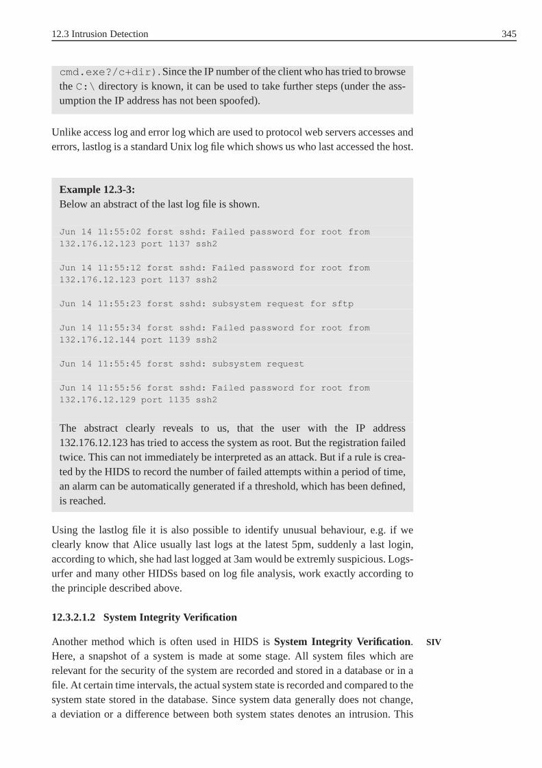
12.3 Intrusion Detection 345
cmd.exe?/c+dir) . Since the IP number of the client who has tried to browsetheC:\ directory is known, it can be used to take further steps (under the ass-umption the IP address has not been spoofed).
Unlike access log and error log which are used to protocol webservers accesses anderrors, lastlog is a standard Unix log file which shows us who last accessed the host.
Example 12.3-3:Below an abstract of the last log file is shown.
Jun 14 11:55:02 forst sshd: Failed password for root from
132.176.12.123 port 1137 ssh2
Jun 14 11:55:12 forst sshd: Failed password for root from132.176.12.123 port 1137 ssh2
Jun 14 11:55:23 forst sshd: subsystem request for sftp
Jun 14 11:55:34 forst sshd: Failed password for root from132.176.12.144 port 1139 ssh2
Jun 14 11:55:45 forst sshd: subsystem request
Jun 14 11:55:56 forst sshd: Failed password for root from132.176.12.129 port 1135 ssh2
The abstract clearly reveals to us, that the user with the IP address132.176.12.123 has tried to access the system as root. But the registration failedtwice. This can not immediately be interpreted as an attack.But if a rule is crea-ted by the HIDS to record the number of failed attempts withina period of time,an alarm can be automatically generated if a threshold, which has been defined,is reached.
Using the lastlog file it is also possible to identify unusualbehaviour, e.g. if weclearly know that Alice usually last logs at the latest 5pm, suddenly a last login,according to which, she had last logged at 3am would be extremly suspicious. Logs-urfer and many other HIDSs based on log file analysis, work exactly according tothe principle described above.
12.3.2.1.2 System Integrity Verification
Another method which is often used in HIDS isSystem Integrity Verification. SIV
Here, a snapshot of a system is made at some stage. All system files which arerelevant for the security of the system are recorded and stored in a database or in afile. At certain time intervals, the actual system state is recorded and compared to thesystem state stored in the database. Since system data generally does not change,a deviation or a difference between both system states denotes an intrusion. This

346 12 Intrusion Detection
method is straightforward but it has to be ensured, that at the moment the snapshotof the system was taken, the system was not compromised and that the database filewhere the system state is stored is write protected or protected against intruders.
Tripwire Example 12.3-4:One of the most often used system integrity verifier is Tripwire. Tripwire usescryptographic check sums to test the integrity of systems files. The fingerprintof each file is made and stored in the database. If a file is modified by a hacker,it will provide a different fingerprint. Here there is no possibility to hide themodification by modifying a file but making sure that the file attributes whichare controlled such as date, file length etc. remain the same.Tripwire can detectsuch modifications, since the fingerprint will differ from that of the snapshot.
Host-based IDSs have many advantages: log files are available which clearly pro-vide us with a lot of different information e.g. files that have been accessed, accessfailure, user logins, or resource usage. In short, very precise information is availa-ble about what happens on the host. Further, since the software is installed on ahost, it is independent of the network speed. HIDSs have their drawbacks as well.Since the software has to be installed on several hosts, morework can be involvedthan is required for the installation of NIDSs. Further HIDSs are dependent on theoperating system they are installed on.
HIDSs can detect all host intrusions such as file modification, user impersonalisa-tion, password guessing, attacks with encrypted traffic, etc.
12.3.2.2 Network-based Intrusion Detection
As previously mentioned, the data source is the starting point of an IDS. In net-works, network packets are analysed to detect intrusions. Hereby the header andpayload of each packet traversing the network are recorded and statistical methodsare used to detect unusual behaviour (Anomaly Detection) orrules are definedaccording to which the analyser has to deal with the packets.Some of the import-ant questions which arise at this stage are where to place thesensor to collect thepackets and how to deal with fragmented packets.
Depending on the topology of the network the NIDS can either be placed at theNIDS placement
front of or behind the firewall. Placing the NIDS in front of the firewall has someadvantages. All external traffic traversing the network canbe monitored and theo-retically all intrusions which can be seen, and most importantly, attacks, also thoseagainst the firewall can be detected. But placing the sensor in front of the firewallhas one enormous drawback, internal intruders, who according to various statisticsare a great problem, can not be detected at all. On the other hand by placing thesensor behind the firewall, internal intruders who are misusing the system can bedetected but since undesired traffic is blocked by the firewall, it is not possible tosee all attempted intrusions. Further, attacks against thefirewall as such can not

12.4 Major Intrusion Detection Modelling Techniques 347
be detected. Therefore it is recommended to use both, an internal and an externalintrusion detection system (Fig. 12.3-3).
Firewall
LAN
INTERNET
NIDSNIDS
Fig. 12.3-3: NIDS placement
As we have seen at the beginning a NIDS analyses each packet which enters thenetwork segment it is installed on. But, a NIDS which only looks for known patternsin single packets, a so-calledpacket analyser[Spe03] will not be able to detectattacks which are spawn over multiple packets. Therefore a good intrusion detectionsystem should be able to deal with the fragmentation and reassembly of packets.
Compared to HIDSs, the great advantage of NIDSs is that they are independent of Fragmentation andreassemblythe underlying operating system and therefore portable. Since the software opera-
tes network wide, there can be less work involved in managingthem than HIDSs.NIDS have some drawbacks as well, current NIDSs can barely handle Gbps trafficand because many companies are now installing lines with Gbps, NIDSs may haveproblems to follow. Further, they are blind to encrypted traffic and have a relativelyhigh rate of false positives120 compared to HIDSs. Intrusions which can be detectedby NIDSs are: spoofing, DoS attacks, buffer overflows, port scanning etc.
12.4 Major Intrusion Detection ModellingTechniques
As previously mentioned detecting anomalies means constructing a subject profile.To construct these profiles diverse techniques can be used, e.g. statistical models[Mar01], data mining models [Wen98], neural networks [Rya98], decision trees,etc. To detect misuse, models such as state transition analysis [Nstat][Por92][Kor93]and rule based misuse detection are used. We will start by taking a closer look atanomaly detection.
120 False positive are alarms generated although there was no intrusion.

348 12 Intrusion Detection
12.4.1 Anomaly Detection: Statistical Approaches
By the anomaly detection a typical system behaviour has to bebuilt first. This meansthat in the preliminary stage of building the system a lot of measures have to betaken to determine the normal or typical behaviour of the system or users of thesystem, the so-called reference value of the user behaviouror system. This is avery difficult task: firstly because it is difficult to determine what is normal andsecondly because users who know that their profile is being made can consciouslybehave differently to normal in order to falsify their profile. To build up the normalbehaviour, often attributes relating to event counter (number of false logins within aperiod), resource usage (CPU usage), session duration, user last logins, etc. are used.If we assume a time discrete model, generally we haven observationsx1. . .xn andthe goal is to check whether the next observationxn+1 is abnormal or not [Den87].In the following section we will see how statistical models,e.g. mean and standarddeviation model and the Hotelling´s test [Ye01][Ye02][Ye01a][Sac93] can be usedto detect intruders.
12.4.1.1 Univariate Analysis: Mean and Standard DeviationModel
Assumex1. . .xn is an observation, then the mean of this observation can be deter-mined and equals
X̄ =∑
i
xi
n, 12.4-1
with xi the value of the the variableX at timei. The standard deviationσ can bedefined as well
s2 =
∑i=ni=1 (xi − X̄)2
n − 1with σ =
√s2. 12.4-2
A new observation is classified as an intrusion if it does not fit into predefined boun-daries or into a tolerance interval. Using the mean and standard deviation model, theprocedure to detect intrusions is summarized below:
1. The activity profile of a user, e.g. the CPU usage is recorded and sampled, weobtainx1. . .xn with xi the value of the profile at timei.
2. The mean and the variance of the activity is determined according toEq. 12.4-1 and Eq. 12.4-2.
3. Now, when the system records the next samplexn+1 it has to decide whetheran anomaly has occurred or not. Here the boundaries within which the valuexn+1 has to be in order to be seen as normal can be determined by using theChebyshev´s Inequality.
(P (|X − E(X)|) ≤ ǫ) ≥ 1 − σ2
ǫ212.4-3

12.4 Major Intrusion Detection Modelling Techniques 349
TheChebyshev´s Inequalitycan be used independently of the form of the curve.Chebyshev´sInequalityIn the special case of a normal distribution for the probability density of the subject
profiles, the next sample can be classified as being normal or abnormal using the Theoretical sampledistribution of themean
theoretical sample distribution of the mean (Fig. 12.4-1).It is already known that,approximately
• 68, 27% of the samples fall betweenµ ± ·σ;
• 95,45% betweenµ ± 2 · σ;
• and 99, 73% betweenµ ± 3 · σ [Sac93][Spi90].
If we want to detect intruders using the normal distributionwe will first have todetermine the level of accuracy. By choosing a confidence level of 0, 9973, we want99, 73% of all our samples to be betweenµ± 3 · σ. In this case, each time a samplexn+1 is observed,xn+1 has to lie in the intervallµ± 3 · σ (three standard deviationsaway from the mean), otherwise there is an intrusion.
This model has a major drawback, only one variable is taken into consideration.But it is known that intrusion activities are generally correlated. In other words,when an intrusion happens, the probability that more that one variable is involved islarge. This has led to methods which take this into account, called theMultivariateAnalysis.
−3 −2 −1 0 1 2 30
0.05
0.1
0.15
0.2
0.25
0.3
0.35
0.4
x
µ = 0 σ = 1.0
68,27%
95,45%
99,73%
Fig. 12.4-1: Theoretical sample distribution of the mean.

350 12 Intrusion Detection
12.4.1.2 Multivariate Analysis
In the multivariate analysis more than one variable is analysed and correlationsbetween variables are included in the model. In this case instead of monitoring andanalysing only the CPU usage, the number of file accesses and the number of loginscan be taken into consideration as well. There are diverse methods (Hotelling’s test,Chi-square test see Appendix A.2) which can be used to analyse multiple variables,in this course unit we will focus on the Hotelling´s test.
In the case of univariate analysis, we have proceeded as follows: at first we have cal-culated the mean and the variance of a variable. Using the Chebyshev´s Inequalityor the theoretical sample distribution of the mean we were able to fix the boundaryand make a statement about intrusion or not. In the case of multivariate analysis wewill proceed in the same way. Firstly we determine the mean ofthe multivariable.Let us denoteX this variable, thenX̄ = [X̄1, X̄2, X̄3, X̄4, . . . X̄p] whereX̄i is themean of the variableXi. Further, as in the univariate case we will determine thevariance of the multivariableX, which is the variance of each variable taken on itsown and since there can be correlations between variables, the covariance betweeneach pair of variables. The result is the so-calledvariance-covariance matrix.Variance-covariance
matrixBeM a matrix of observations withp being the number of variables to be analysedandn the number of observations for each variable. M can be written as follows
M =
x11 x12 x13 . . . x1p
x21 x22 x23 . . . x2p
x31 x32 x33 . . . x3p
. . .
xn1 xn2 xn3 . . . xnp
12.4-4
The variance-covariance matrixS can be calculated as follows [Ye01]
S =1
(n − 1)·
i=n∑
i=1
(Xi − X̄)(Xi − X̄)t, 12.4-5
HerebyXi is a row vector of the matrixM .
The Hotelling´s test for a new observationXe is
T 2 = (Xe − X̄)t · S−1(Xe − X̄) 12.4-6
As we can guess, Eq. 12.4-5 has the same structure as in the univariate case. Nowthat it has been shown how the mean and the variance-covariance matrix are cal-culated, we will proceed further and determine the condition under which a nextobservationXn+1 = xn+11, xn+12, . . . xn+1p can be classified as normal or abnor-mal. To determine whether a new observationXn+1 is normal or abnormal, we applythe Hotelling´s test as follows:Hotelling´s test

12.4 Major Intrusion Detection Modelling Techniques 351
1. Determine the mean̄X of the variableX
2. Determine the variance-covariance matrix S according toEq. 12.4-5
3. Compute the Hotelling´s testT 2 for the eventXn+1 according to Eq. 12.4-6.
A new observation is abnormal if the computed value ofT 2 depasses an upper limit.To determine this upper limit the Hotelling´sT 2 statistic has to be transformed intoan F-distribution (Appendix A.3) withp and(n − p) degrees of freedom [Ye01a].This is achieved by multiplyingT 2 with a constant n·(n−p)
p·(n+1)·(n−1). The obtained value
T 2 · n·(n−p)p·(n+1)·(n−1)
is then compared to the tabulated F value for a given level of signi- Level of significanceα
ficanceα. If the calculated value is greater than the tabulated value(critical value)it will then be assumed that an intrusion has occurred.
Example 12.4-1:The result of an experiment involving three variables(X1, X2, X3) is shownbelow
X1 = (1, 2 1, 4 1, 3 1, 5 1, 2), X2 = (3, 1 3, 4 3, 3 3, 6 3, 4),X3 = (5, 4 5, 2 5, 3 5, 0 5, 5). We have 5 observations for each varia-ble, and it has to be checked whether the next observation(1, 3 3, 37 5, 23)
is an intrusion or not. In order to do this, we will first have towrite down theobservations as a matrix
M =
1, 2 3, 1 5, 4
1, 4 3, 4 5, 2
1, 3 3, 3 5, 3
1, 5 3, 6 5, 0
1, 2 3, 4 5, 5
Now we have to determine the mean vector, by calculating the mean valueof each variableX̄ = (1, 32 3, 36 5, 28). We can determine the variance-covariance matrix S according to equation Eq. 12.4-5. HereXi is a row vectorof the matrixM . We will determine the first factor in the equation Eq. 12.4-5.X1 = (1, 2 3, 1 5, 4) and(X1 − X̄)·(X1 − X̄)t =
−0, 12
−0, 26
0.12
·(−0, 12 −0, 26 0, 12) =
0, 0144 0, 0312 −0, 0144
0, 0312 0, 0676 −0, 0312
−0, 0144 −0, 0312 0, 0144

352 12 Intrusion Detection
The same is done for all other factors and put in Eq. 12.4-5. Wewill not carryout the operation here in detail, the result is shown in the matrix
S =
0, 017 0, 0185 −0, 0245
0, 0185 0, 033 −0, 0235
−0, 0245 −0, 0235 0, 037
The interpretation of the results clearly shows that Cov (X1, X3) = -0,0245 thismeans that the variablesX1 and theX3 are not dependent on each other, butsince Cov (X1, X2) is positiveX1 andX2 are correlated. After determining theS matrix we can now calculate the Hotelling´s testT 2 for the new observation(1, 3 3, 37 5, 23). In this caseT 2 equals
(−0, 02 0, 01 −0, 05)·
0, 017 0, 0185 −0, 0245
0, 0185 0, 033 −0, 0235
−0, 0245 −0, 0235 0, 037
−1
·
−0, 02
0, 01
−0, 05
T 2 = 8, 31
This value is then transformed to an F value by multiplying itwitha constant n·(n−p)
p·(n+1)·(n−1)and then compared to the tabulated value
(seehttp://www.socr.ucla.edu/Applets.dir/F_Table.html ). p = 3 (3variables) andn = 5 (5 observations for each variable). ThereforeT 2· n·(n−p)
p·(n+1)·(n−1)= 1, 154.
The tabulated value forp = 3 andn−p = 2 for a level of significanceα = 0.05
is 19.1643. Since the calculated value is smaller than the tabulated one, there isno intrusion.
The Hotelling´s test has a big drawback, then to determine the variance-covariancematrix and its inverse is very time consuming and since in modern networks, attackshave to be detected in real time, a faster method is needed, this has led to anotherproposition for detection of outliers using the Chi-squaretest [Ye01a]. With the Chi-square test the matrix inversion is not necessary, only the distance from the meanvector is taken into account.
12.4.2 Misuse Detection
In misuse detection, another approach is pursued. It is assumed that whenever anintrusion happens, an intrusion specific signature is left.If this signature is analysedcarefully, then suspicious attacks can be detected.

12.4 Major Intrusion Detection Modelling Techniques 353
User InterfaceCom-parsion
Intrusion
Signature Database
Alarm
User Input
Database Update
Data Stream
Fig. 12.4-2: Misuse detection
In Fig. 12.4-2 the principle is shown. A signature database of all known attacks isavailable. The data stream is then analysed and searched forknown attacks stored inthe database. If there is a match, an alarm is generated to inform the security officer.Whenever new attack signatures are available, the databasehas to be updated. Someof the approaches often used to detect misuse are state transition analysis and rulebased misuse detection.
In state transition analysis, a computer intrusion is seen as a sequence of actionsState transitionanalysisleading from an initial limited acces, generally less powerful state (normal user) to
a final compromised state, generally a more powerful state (root) ([Por92][Kor93]).As the pattern matching technique, state transition analysis is based on a predefinedattack signature. The technique works as follows: firstly known attacks are modelledas state transition diagrams and stored in a database. Each time an event starts, e.g.a user logs in, the activities are recorded and a transition diagram relating to theactivities is generated and compared to that of known attacks. If both diagramsmatch, there is an intrusion. If we take a closer look at the approach of modellingintrusions using state transition analysis, then we realise that since a state diagramconsists of states and transitions between states, we firstly have to define what thestates of our system are and most importantly we have to determine those events orkey actions which lead to a transition from one state to another state.
12.4.2.1 Rule based Misuse Detection (Pattern Matching)
The general idea using this method is to build a signature database of known attacksand use rules to fire if known attacks are seen in packets. A normal three way hands-hake mechanism to initiate a TCP connection between sender and recipient has thefollowing flags: SYN, SYN/ACK and ACK. A TCP half open scan in contrast onlyhas one flag set and a series of SYN without acknowledgement, which can be usedto perform a DoS on a server. Since this type of attacks are already known, rulescan be generated to avoid them and alert the administrator incase packets with suchpatterns are seen. There are many NIDSs which work based on rules, a famous oneis Snort.

354 12 Intrusion Detection
Snort
Snort is an open source tool which has been designed to protect small networks inthe range of 100 Mbps. Using Snort three operational modis are available:
• sniffer
• packet logger
• and IDS.
If Snort has been configured as a sniffer, all packets traversing the network canbe seen. In the packet logging mode, the packets are recordedon the disc. In theintrusion detection mode, Snort uses rules, which are defined in the configurationfile snort.conf to detect intrusions.
The general anatomy of a snort rule is shown in Fig. 12.4-3 andconsists of twoparts:
• the rule header and
• the rule options.
alert tcp any any -> any 80 (msg:"PHF Probe!"; cont ent:"cgi-bin/phf"; offset:6; depth:30;)
Rule header Rule options
Fig. 12.4-3: Anatomy of a Snort rule
Snort analyses each packet traversing the network in two steps. At first the headerof the Snort rule is applied to the packet. If there is no match, the packet is ignored,otherwise the rule options are applied, in case rule header and rule options match,actions are taken. In the following we will take a closer lookat the anatomy of aSnort rule starting with the rule header.

12.4 Major Intrusion Detection Modelling Techniques 355
Rule header
As can be seen from Table 12.4-1 the rule header describes theendpoints of thecommunication. Each rule header starts with the action to betaken in case the rulefires.
Tab. 12.4-1: Rule header
Action Protocol Source IP SourcePort
Direction DestinationIP
DestinationPort
alert tcp any any → any 80
• Action
Currently 5 rule actions are available:
alert: in this case the packet is recorded and an alarm is generated.In thecurrent version of Snort seven alert modes are available. Inthe default modethe packet header is printed together with the alert message. Snort can beconfigured as well to send an alert message to the screen.
log: the packet is recorded, no alert message is generated.
pass: tells Snort to ignore the packet.
activate an alert message is generated and further so-calleddynamicrules are activated.
dynamic they are actived by previous rules.
• Protocol
Here the protocols to be analysed for suspicious behaviour are specified.Currently Snort analyses 4 protocols (ICMP, IP, TCP and UDP). Further proto-cols such as ARP, IPX (Internet Packet eXchange), RIP (Routing InformationProtocol), etc. will be supported in the near future.
• Sender/Receiver IP address
The sender/receiver IP address in the CDIR (Classless Interdomain Routing,see RFC 1517) notation is used to identify the sender/receiver of the message.Snort allows the use of variables to define a range of addresses as well. A dollarin front shows that it is a variable and indicates the IP rangeto be observed(see Example 12.4-3). The variable must be defined in the configuration filesnort.conf .
• Sender/Receiver Port
Ports can be specified either as numbers or ranges. The numberrange is from 1to 65535. Since port numbers are irrelevant in an IP packet, rule will be appliedto all packets. Variables can be used to define port range as well.
• Direction

356 12 Intrusion Detection
Indicates the direction of the traffic the rule should apply to (unidirectional orbidirectional).
If there is a match for the rule header, options are applied tothe rest of the packetto further analyse it. Currently diverse options are available. Some of which will beintroduced next.
Rule Options
As can be seen from Fig. 12.4-3 options are the second part of the Snort rule andare in parentheses. They tell Snort which attributes of the packet are to be checkedfurther. The options start with a keyword followed by the option argument (the valueof the option to be checked). Options and their arguments areseparated with a colonand options are separated from each other by a semicolon.
Keyword Separator Argument Separator Further options
msg : "PHFProbe!"
; content:"cgi-bin/phf";
offset:6;
depth:30;)
1. IP Protocol options
• sameip: checks whether the sender and the receiver IP is the same (seeExample 12.4-2) for the use of this option.
• TTL: checks the Time-to-Live, it is useful for the detection of tracerouteattempts.
• fragbits: checks the fragment bits in the IP header. Three bits can bechecked:
R-bit (reserved bit) is reserved for future use.
D-bit (do not fragment) in case this bit is set, the router isnot allowed to fragment the packet.
M-bit indicates that more fragments are coming. All packets exceptthe last one have theM-bit set to 1.
2. TCP protocol options
Attributes of the TCP header which are often analysed by Snort to look forattacks are flags. Since many attacks rely on crafted packets(misconfigurationof the flags to generate bad traffic) .
• Flags : F, S, R, P, A andUbits or a combination of them is checked. Thesequence number and acknowledment number can be checked as well.
3. content
Content is one of the most powerful options, then in many cases such as bufferoverflow or malware the content of the packet (payload) has tobe analysed

12.4 Major Intrusion Detection Modelling Techniques 357
in order to be able to detect the attack. Some of the attributes used in relationwith the content are described next.
• content: searches for specific patterns. Binary patterns can be searchedfor as well, they are enclosed in pipe ( ||).
• uricontent: tells Snort to only check the URI (Unified ResourceIdentifier) part of the packet.
• offset: normally the Snort engine searches for specific pattern in thewhole payload, but with the offset option it can be specified where to beginto search.
• depth: the maximal depth to search for.
• nocase: not case sensitive.
4. Meta-data rule options
• msg: message to be logged together with the packet to quickly identifythe attack.
• reference: to find further information related to the attack.
Currently Snort has a database with nearly 2200 predefined rules some of which areshown next.
Example 12.4-2:A land attackconsists of sending a crafted IP packet where the source addressequals the destination address. On Computers running unpatched versions ofWindows NT, the computer crashes if the sender address is thesame as thereceiver address. The rule to prevent such attacks is shown below:
alert ip any any -> any any (msg:"DOS Land
attack";sameip;)
Let us break down the rule:
• alert: indicates it is a highly sensible message (alert message)
• ip the IP protocol header is checked
• any from any IP address
• any from any port
• ⇒ indicates the direction that has to be checked.
• any to any IP address
• any on any receiving port
• msg indicates which kind of attacks are dealt with, in this case aDOS landattack, the message is enclosed in brackets
• sameip this rules looks for spoofed packets with source IP = destination IP.

358 12 Intrusion Detection
Example 12.4-3:
alert ip $EXTERNAL_NET $SHELLCODE_PORTS -> $HOME_NET any
(msg: SHELLCODE x86 NOOP;content: |90 90 90 90 90 90 90 90 9090 90 90 90 90|; depth: 128;).
This rule looks for attempts to overflow a buffer as seen in Section 12.2.2.2and execute arbitrary code in the stack. Snort generates an alert whenever an IPpacket is observed coming fromEXTERNAL_NETheaded toHOME_NETcon-taining the binary string "|90 90 90 90 90 90 90 90 90 90 90
90 90 90 90 90|" . The pipes are there to indicate that this string is abinary one. The optiondepth : 128 specifies that only the first 128 bytes shouldbe searched for.
With the open source tool Snort a great range of attacks can bedetected (exploits,bad traffic, malware, etc.). Compared to the anomaly based method, the rule basedapproach has a relatively low amount of false positives. Thegreatest disadvantageof this method is that unknown attacks can not be detected. Further, the signaturedatabase has to be updated on a regular basis.

359
A Distributions
A.1 Normal Distribution
As can be seen from Eq. 1 the normal distribution can be fully characterized by twoterms: the heightµ (the mean of the variablex) and the widthσ (the standard devia-tion). Assume we would like to detect intruders on a host based on CPU utilisation.Firstly we will have to determine the mean of the CPU usage, which will clearlyshow us the average CPU usage and then we will have to determine the CPU usagedeviation from the mean. When we have these two values, we canspecify our con-fidence interval, which is the interval we want our normal CPUusage to be within.
−3 −2 −1 0 1 2 30
0.1
0.2
0.3
0.4
0.5
0.6
0.7
0.8
x
f(x)
µ = 0.0 σ = 0.5µ = 0.0 σ = 1.0µ = 0.5 σ = 0.5
Fig. 1: Normal distribution
f(x) =1
σ√
2πe−1
2
(x − µ
σ
)2
1
For many applications the probability of a variableX being between an intervala
andb under the curve of the nornal distribution is of great interest, then, if we candefine a confidence interval (where allgood valueslie) all values not belonging tothis interval can be seen as anomalies.
The probability of a value X, being betweena andb can be calculated and equals:
P (a ≤ X ≤ b) =
∫ b
a
f(x)dx 2

360 A Distributions
and the probability of a value being under the curve of the probability density func-tion is:
P (−∞ ≤ X ≤ ∞) =
∫∞
−∞
f(x)dx = 1 3
In practice the probabilities of the variableX being betweenµ±σ ; µ±2σ ; µ±3σ
is of great importance and has already been calculated (see Fig. 12.4-1):∫ µ+σ
µ−σ
f(x)dx = 0, 6827;
∫ µ+2σ
µ−2σ
f(x)dx = 0, 9545;
∫ µ+3σ
µ−3σ
f(x)dx = 0, 9973 4
A.2 The Chi-Square Distribution
Before we introduce the Chi-square distribution we would first like to introduce theChi-square test. Normally when we carry out an experiment, we expect the result ofthe experiment to differ from the empirical result. But if wewant to know to whatextent the result of the experiment differs from the empirical result we can use theChi-square test to find out.
The starting point of each Chi-square test is the so calledZero Hypothesiswhichrelies on empirical results. When we toss a coin10 times, we expect to get heads5 times and tails5 times. We therefore asssume that the coin is perfect (the coin isfair): this is our Zero Hypothesis. Depending on the result of the experiment we caneither confirm the Zero Hypothesis or reject it. The formula used to calculate theChi-square test is
χ2 =(O1 − E1)
2
E1+
(O2 − E2)2
E2+ . . . +
(On − En)2
En
=∑
i
(Oi − Ei)2
Ei
5
whereEi is the expected value based on empirical experiences andOi is the obervedvalue.
As can be seen from Eq. 6 the probability density function (PDF) of the Chi-squarevariable only depends on one parameter, the so calleddegree of freedom1 (ν = n − 1) .
f(x) =e(−x
2) · x ν
2−1
2ν2 · Γ(ν
2)
, with x ≥ 0 6
HereΓ(ν2) is the Gamma Function
Γ(α) =
∫∞
0
tα−1 · e−xdx, with α ≥ 0
1 The degree of freedom is the number of classes minus 1.

A.2 The Chi-Square Distribution 361
0 5 10 15 20 25 30 35 40 45 500
0.02
0.04
0.06
0.08
0.1
0.12
0.14
0.16
x
f(x)
ν = 5ν = 10ν = 15ν = 20
Fig. 2: Chi-square distribution
In the following we will introduce an example to illustrate the Chi-square test.
Example 1:We toss a coin150 times and we observe heads80 times (O1 = 80) and tails70
times (O2 = 70). The expected value for head and tails according to empiricalresults is75. Theχ2 test for the experiment isχ2 = (80−75)2
75+ (70−75)2
75= 0, 66.
Now we want to see whether we can confirm the Zero Hypothesis (the coinis perfect) or not, we assume a level of significanceα = 0.01. The degree offreedom is1 since two classes of events are available (head, tails). With thesignificance levelα = 0, 01 together with the degree of freedomν = 1 wecan read the critical value of the Chi-square test in question. In this case thetabulated critical value forχ2
0.01 is 6, 63. Since0.66 < 6.63 we can confirm theZero Hypothesis.
How the Chi-square test is carried out is summarized in the following steps:
• Carry out the Chi-square test for observation to be tested according to Eq. 5 .
• Determine the degree of freedom.
• Determine the tabulated value (critical value), this critical value depends on twoparameters: the degree of freedomν and the level of significanceα.
• Compare the calculated value of the Chi-square test with thecritical tabulatedvalue for a given level of significanceα. According to the result of the compari-son we can either approve or reject the Zero Hypothesis.

362 A Distributions
A.3 Fisher´s Distribution
The F-distribution was introduced by Sir Ronald A. Fisher and can be used to com-pare twoχ2 random variables. To do this a third variable being the quotient of thetwo random variables to be compared with is introduced. IfU1 andU2 are inde-pendent random variables, each having a probability function χ2 with m andn thedegrees of freedom, the random variable
D =U1
mU2
n
7
has an F-distribution. The probability density function ofthe F-distribution is givenbelow
f(x) = mm2 n
n2 · Γ(m
2+ n
2)
Γ(m2)Γ(n
2)· x
m2−1
(mx + n)m+n
2
8
0 0.5 1 1.5 2 2.5 30
0.1
0.2
0.3
0.4
0.5
0.6
0.7
0.8
0.9
1
x
f(x)
m = 2 n = 2m = 5 n = 10m = 10 n = 10
Fig. 3: Fisher´s distribution
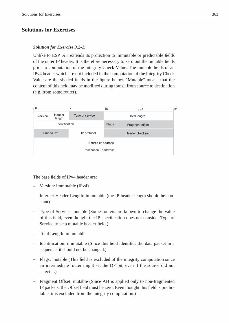
Solutions for Exercises 363
Solutions for Exercises
Solution for Exercise 3.2-1:
Unlike to ESP, AH extends its protection to immutable or predictable fieldsof the outer IP header. It is therefore necessary to zero out the mutable fieldsprior to computation of the Integrity Check Value. The mutable fields of anIPv4 header which are not included in the computation of the Integrity CheckValue are the shaded fields in the figure below. "Mutable" means that thecontent of this field may be modified during transit from source to destination(e.g. from some router).
The base fields of IPv4 header are:
– Version: immutable (IPv4)
– Internet Header Length: immutable (the IP header length should be con-stant)
– Type of Service: mutable (Some routers are known to change the valueof this field, even thought the IP specification does not consider Type ofService to be a mutable header field.)
– Total Length: immutable
– Identification: immutable (Since this field identifies the data packet in asequence, it should not be changed.)
– Flags: mutable (This field is excluded of the integrity computation sincean intermediate router might set the DF bit, even if the source did notselect it.)
– Fragment Offset: mutable (Since AH is applied only to non-fragmentedIP packets, the Offset field must be zero. Even thought this field is predic-table, it is excluded from the integrity computation.)

364 Solutions for Exercises
– Time to Live: mutable (This field is change on the route as a normal courseof processing by routers, and thus its value at the receiver is not predictableby the sender.)
– Protocol: immutable (This should be the value for AH)
– Header Checksum: mutable (This will change if any of these other fieldschanges, and thus its value upon reception cannot be predicted by thesender.)
– Source Address: immutable
– Destination Adress: Mutable but predictable
Solution for Exercise 3.2-2:
1. IPSec may be implemented in end systems (hosts) or in security gate-ways such as routers and firewalls.
2. The implementation of IPSec is typically done by directlymodifying theIP stack (the communication software). When access to the IPstack ofthe machine is not possible, IPSec may be implemented as a shim thatmodifies (protects), and inserts packets to the IP stack. This is called"Bump in the stack" (BITS). IPSec can also be implemented as external,dedicated crypto-device called "Bump in the wire" (BITW).
Solution for Exercise 3.3-1:
1. F-Secure SSH is a commercial version of SSH (Secure Shell)which iswidely deployed on the Internet today.
2. Port 22 has been IANA-registered and officialy assigned for SSH.
3. The major components of the SSH (Secure Shell) protocol are the SSHTransport Layer Protocol, the SSH User Authentication Protocol, andthe SSH Connection Protocol.
4. The SSH Transport Layer Protocol provides cryptographichost authen-tication, data confidentiality (encryption) and data integrity. It also sup-ports secure key exchange algorithms.
5. Several data encryption algorithms can be used in SSH (in the SSHTransport Layer Protocol). Mandatory to implement is Triple DES inCBC mode. IDEA in CBC mode, the stream cipher ARCFOUR, andBlowfish in CBC mode are also defined. The algorithm to be used isnegotiated during the connection establishment.

Solutions for Exercises 365
6. This prevents attacks. If an attacker eavesdropes the connection andrecords the traffic, the more data encrypted with one key he has, themore material for crypto-analysis is available to him (the probability forsuccessful crypto-analysis rises).
7. Yes. Different encryption algorithms and keys may be usedin eachdirection of the communication (e.g. algorithmA1 with key K1 for thetraffic from the server to the client and algorithmA2 with keyK2 for thetraffic from the client to the server). The applied authentication algo-rithms and keys can also be different for each direction.
Solution for Exercise 3.3-2:
1. A separate port number must be assigned for every application withSSL support. Following dedicated ports have been reserved by IANA:- port 443 for HTTP with SSL- port 465 for SMTP with SSL- port 585 for IMAP with SSL- port 636 for LDAP with SSL- port 990 for FTP with SSL- port 992 for TELNET with SSL- port 994 for IRC with SSL- port 995 for POP3 with SSLand others.For more information see http://www.iana.org/assignments/port-numbers
2. SSL consists of four major subprotocols, which operate intwo layers.On the higher layer of SSL operate the protocols dealing withSSLmanagement: The SSL Handshake Protocol, the SSL Change CipherSpec Protocol, and the SSL Alert Protocol. On the lower layeroperatesthe SSL Record Protocol, which in fact provides the securityservices(encryption and authentication of data).
Solution for Exercise 3.3-3:
1. TLS (Transport Layer Security) is the follow-on Internetstandard ofSSL, initiated by IETF. It operates in the transport layer and providescryptographic security, interoperability, extensibility and efficiency.
2. Application protocols secured with TLS use the same portsas if theapplication was secured with SSL. So, the port numbers are same asthose cited in the Solution for Exercise 3.3-2.1.

366 Solutions for Exercises
3. Similar to SSL, TLS is a layerd protocol consisting of fourmajor sub-protocols. On the higher layer of TLS operate the protocols dealingwith TLS management: The TLS Handshake Protocol, the TLS ChangeCipher Spec Protocol, and the TLS Alert Protocol. On the lower layeroperates the TLS Record Protocol.
Solution for Exercise 3.5-1:
1. No. The transport layer security protocols (SSH, SSL, TLS) operate onthe top of the transport layer, i.e. between the transport and the appli-cation layer. This means that all information (headers) of the underly-ing protocols (e.g. IP) are unprotected. This enables traffic analysis. Forexapmple, by examing an unencrypted IP source and destination addres-ses and the TCP port numbers, or examining the volume of network traf-fic flow, a traffic analyst can determine which parties are interacting andwhat types of services are being used. Since IP headers are transmittedunprotected, IP address spoofing attacks are also possible.
2. SSL and TLS offer security services only for connection-oriented trans-port, such as those provided by the TCP protocol. Conectionless trans-port, such as those provided by the UDP protocol, can not be securedwith SSL or TLS.
3. Advantage: Providing security at the application layer is very flexible,because the scope and the strength of the protection can be tailoredto meet the specific needs of the aplication and the user has completeaccess to the data he wants to protect and to the private keys.To providethe security services, the application can be extended without having todepend on the operating system.
Disadvantage: The security mechanisms have to be designed indepen-dently for each application, i.e. applications have to be enhanced. Aseach application has to define its own security mechanisms, the probabi-lity of making mistakes or not using security at all is greater. (Generally,users prefere convinience and each extra click they have to do leads themvery often to refuse using security functions!)
Solution for Exercise 4.4-1:
There are basically three overlapping types of security risks regarding theWorld Wide Web:
1. Bugs or misconfiguration problems in the Web server that allow unaut-horised remote users to:
• Steal confidential documents.

Solutions for Exercises 367
• Upload files on the server.
• Execute commands on the server host machine, allowing them tomodify the system.
• Gain information about the Web server’s host machine that willallow them to break into the system.
• Launch denial-of-service attacks, rendering the machine temporarilyunusable.
2. Browser-side risks, including:
• Active content that crashes the browser, damages the user’ssystem,breaches the user’s privacy, or merely creates an annoyance.
• The misuse of personal information knowingly or unknowingly pro-vided by the end-user.
3. Interception of network data sent from browser to server or vice versavia network eavesdropping.
Solution for Exercise 4.4-2:
1. HTTP basic authentication:On the first access to an authenticated resource, the server will return a401 status ("Unauthorized") and include a WWW-Authenticate responseheader. This will contain the authentication scheme to use and the realmname. The browser would then ask the user to enter a username and apassword. It then requests the same resource again, this time includingan authorisation header which contains the scheme name ("Basic") andthe username and password entered.The server checks the username and password, and if they are valid,returns the page. If the password is not valid for that user, or the user isnot allowed access because he is not listed on a require user line or ina suitable group, the server returns a 401 status as before. The browsercan then ask the user to retry his username and password.Assuming the username and password was valid, the user mightnextrequest another resource which is protected. In this case, the serverwould respond with a 401 status, and the browser could send the requestagain with the user and password details. However this wouldbe slow,so instead the browser sends the Authorization header on subsequentrequests. Note that the browser must ensure that it only sends the user-name and password to further requests on the same server.The browser needs to remember the username and password entered, soit can send them with future requests from the same server.
368 Solutions for Exercises
2. HTTP digest authentication:Version 1.1 of HTTP (published in July 1996) introduced an improvedmethod called digest authentication. This uses the same exchange ofpackets as basic authentication, but the "Unauthen- ticated" reply nowincludes a value, known as the nonce, which acts as a challenge. Insteadof replying with the username and password, the client calculates a mes-sage digest (using the MD5 algorithm) from the username, password andnonce and returns this along with the username as authentication infor-mation. The server then repeats the MD5 calculation, using the user’scorrect password, and returns the document if the two digests match.To do this the server must hold each user’s password in a form suita-ble for calculating the MD5 digest. It is imperative that these passwordsbe stored as securely as possible, since anyone possessing them wouldimmediately be able to masquerade as any valid user of the server.
Solution for Exercise 5.3-1:
The notionSender anonymityis provided in the Mix- an in the DC-concept.Sender anonymitymeans that senderA of messagem stays anonym for therecipientB as well as for an observing attacker.
The notionServer anonymity is provided in the JANUS network.Serveranonymity enables to hide the identity of a server in a communication ses-sion.
The notionRecipient anonymity is provided in the Mix- an in the DC-concept. In a communication relationship between two partnersA andB reci-pient anonymity allows e.g.A to send a message toB without breaking theanonymity ofB. For this purposeA becomes a special address which refersto B but does not revealB′s identity toA.
The notionClient anonymity is provided in the JANUS network.Clientanonymity is reached, when all information about the client is concealed.
Solution for Exercise 6.1-1:
1. Packet filters are not firewall systems in the strong sense,because theydo not authorize traffic from inside to outside, and vice versa. Firewallsystems should only allow authorized traffic to pass, as defined by thelocal security policy.
2. A security policy is a document or a statement about security objectiveswhich should be fulfilled in an organization.
a. A security policy should be explicit and understandable by non-technical persons.

Solutions for Exercises 369
b. A security policy sets explicit expectations and responsibilitiesamong the staff, the management, users and customers.
c. A security policy should include consequences that are activatedwhen the policy is not followed.
d. A security policy needs to describe what you are trying to protectand why. It does not necessarily need to describe technical detailsof how.
3. A router with packet filter support is called ascreening router .
4. The following problems arise with IP fragmentation and packet filtering:
a. Only the first fragment will contain the IP header information, sothe packet filter can inspect only the first fragment and can let non-first fragments through.
b. Another approach is to reassemble the IP packet by the packet filter.In this case denial of service attacks are possible against the packetfilter.
c. An attacker can construct overlapping packets.
Solution for Exercise 7.3-1:
Telnet and FTP do not provide user-to-host authentication.Both Telnet andFTP users must supply login passwords. The passwords are transmitted incleartext and are therewith subject to eavesdropping. Without the existenceof external filtering tools, a Telnet or FTP server initiatesconnections to bothtrusted and untrusted networks. Telnet and FTP provide no confidentiality andno data integrity, since the traffic between server and client is not encryptedand can be altered by an intermediate host. If an anonymous FTP server isnot properly configured, an unauthorized user can get shell-level access tothe server’s host. We can avoid all these security risks by the use of the SSHsoftware which provides among other things secure remote terminal accessand secure file transfer. Running Telnet over an encrypted network connectionsuch as a VPN connection provides the desired security, too.
Solution for Exercise 7.6-1:
1. Examples of executable content which can affect the network securityare binary mail attachments, helper applications and plug-ins, scriptinglanguages, Java applets, and ActiveX.
2. A denial of service attack can be mounted against a host, when a JavaS-cript code is written in a malicious manner. For example, theJavaScript

370 Solutions for Exercises
code can require too much of the CPU or memory resources, or itcantry to open a large number of windows on the victim’s screen.
3. Java uses some techniques to limit the risk related to a downloading ofJava applets. These techniques are the Java Sandbox, the SecurityMana-ger class, the Bytecode Verifier, and the Java Class Loader.
• Java Sandbox: enables Java programs to run only on a JVM inside arestricted runtime environment.
• SecurityManager class: will be called before any unsafe operation isexecuted.
• Java Class Loader: examines classes to ascertain that they do notviolate the runtime system.
• Bytecode Verifier: assures whether a downloaded bytecode stemsfrom a valid Java program.

371
Assignments
Assignments for Chapter "Introduction"
Assignment 1: As mentioned in the course, the significance of security in infor- 3 P.mation technology increases constantly. Find some actual examples from the newsabout fraudulent activities or abuse in the Internet.
Assignment 2: In the following exercises security goals along with current attack 8 P.trends are dealt with.
a) Important security goals in open networks are: 4 P.
• Confidentiality
• Integrity
• Authentication
Can you briefly explain the meaning of these words and give twomore goals?
b) Complete the following table by entering which security goals have been vio- 4 P.lated in the following scenarios.
a. Alice sends an E-mail to Bob. The E-mail is captured on the way fromAlice to Bob by Eve. Eve changes the content of the E-mail and sends itto Bob.
b. Alice is talking to Bob on the telephone, the line is eavedroped.
c. Eve gets into Alice´s work place and steals her disc.
d. Alice has a file containing a list of people on her computer that she trusts.They are Bob, Jane, Brad und Paul. Eve intiates a connection to Alice’scomputer and pretends she is Bob. She then changes the list inscribing hername on it and she then crashes the system.
e. Alice surfs on the internet, her data is forwarded throughEve’s Computer(Router). Eve has installed software on her computer that gives her theposssibility to track Alice’s surfing behaviour
f. Eve orders a product but claims she did not.
Scenario Security goals violated
a)
b)
c)
d)
e)
f)

372 Assignments
Assignment 3: Every year the Computer Security Institute (CSI) publishes a sur-4 P.vey on attacks and their consequences. Briefly comment page 13 (Figure 14) andpage 15 (figure 16) of the survey 2005. The survey can be downloaded fromhttp://www.usdoj.gov/criminal/cybercrime/FBI2005.pdf
Assignments for Chapter "Basics"
Assignment 4:4+3+2=9 P.1. What are the main differences between packet switching and circuit swit-
ching?
2. In which processes can circuit switching be subdivided?
3. Which packet switching modes are used for the following protocols:
a. IP
b. ICMP
c. UDP
d. TCP
Assignment 5: We consider the network in Example 2.3-1. HostA has IP address3+3+3=9 P.123.76.12.211 and hostB has IP address123.76.15.70 .
1. A wants to send an IP packet to hostB. Which source and destination IPaddresses have to be specified in the IP packet? Which host’s destination MACaddress must be used in the packet of the network access layertransportingthis IP packet? What is the name of the routing technique usedon the networkaccess layer?
2. A server is running on hostB (port 499) over the TCP protocol. HostA wantsto open a TCP connection to the server on hostB. Describe the contents ofthe TCP packets (port numbers, sequence numbers, TCP flags (SYN, ACK,FIN)) which have to be sent between the two hosts in order to establish theTCP connection. The sequence numbers are starting at 456 (host A) and 789(hostB), respectively.
3. The connection betweenA andB is now established.A sends a message with20 bytes payload toB and B sends a message with 30 bytes payload toA
over this connection. Describe the contents of the TCP packets (port numbers,sequence numbers, TCP flags (SYN, ACK, FIN)). No errors occurand allmessages have to be acknowledged.

373
Assignment 6: Consider again the network in Example 2.3-1 and Assignment5. 2+3+1+3+3=12 P.HostA has IP address123.76.12.211 , hostB has IP address123.76.15.70
and a TCP service listens on hostB on port 499.
1. How can hostA perform a denial of service attack against hostB?
2. Describe three ways how this attack can be staffed off!
3. How can hostA run an IP spoofing attack against hostB?
4. Recite three Internet services which authenticate the clients with unencryptedpasswords!
5. What are the standard port numbers of the following Internet services:
a. SMTP
b. RAP
c. FTP
Assignments for Chapter "Internet Security Protocols (Part I)"
Assignment 7: Answerbriefly the following questions: 12 P.
1. Which security services does IPSec provide?
2. Where in the TCP/IP protocol stack is the IPSec protectionapplied?
3. Do the IP packet format change after applying some IPSec security features?
4. Can different traffic flows have different protection level with IPSec?
5. Which encryption algorithms can be used in ESP of IPSec?
6. Which authentication algorithms can be used in ESP of IPSec?
7. Is the SPI field of the ESP header encrypted? Why?
8. Why is the lack of encryption of the Sequence Number field inthe ESP headernot a security risk?
9. In which mode of ESP it is possible to do traffic analysis of the transmittedpackets?
10. What is the difference between the data integrity provided by ESP and AH?
11. Why, from your point of view, no public key authentication algorithms (likeRSA or DSS) have been defined for use with AH?
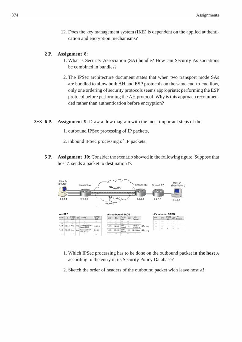
374 Assignments
12. Does the key management system (IKE) is dependent on the applied authenti-cation and encryption mechanisms?
Assignment 8:2 P.1. What is Security Association (SA) bundle? How can Security As sociations
be combined in bundles?
2. The IPSec architecture document states that when two transport mode SAsare bundled to allow both AH and ESP protocols on the same end-to-end flow,only one ordering of security protocols seems appropriate:performing the ESPprotocol before performing the AH protocol. Why is this approach recommen-ded rather than authentication before encryption?
Assignment 9: Draw a flow diagram with the most important steps of the3+3=6 P.
1. outbound IPSec processing of IP packets,
2. inbound IPSec processing of IP packets.
Assignment 10: Consider the scenario showed in the following figure. Suppose that5 P.hostA sends a packet to destinationD.
1. Which IPSec processing has to be done on the outbound packet in the hostAaccording to the entry in its Security Policy Database?
2. Sketch the order of headers of the outbound packet wich leave hostA!

375
Assignments for Chapter "Internet Security Protocols (Part II)"
Assignment 11: Describebriefly how SSH authentication protocol runs! 2 P.
Assignment 12: 2 P.1. Where in the TCP/IP protocol stack does the SSL protocol run?
2. Which control data (headers) are protected with SSL, beside the applicationdata?
Assignment 13: 3 P.1. Explainbriefly the steps of the SSL record protocol!
2. What kind of message can be the encrypted message of the SSLrecord?
Assignment 14: Explainbriefly the four phases of the SSL Handshake Protocol!8 P.
Assignment 15: Additional exercise 0 P.
There are many sites in Internet where personal and sensitive user data is requi-red. Examples are online-shops or insurance companies ("give me your data andI’ll find the best offer for you"). Examples are www.amazon.de, www.lob.de,www.versicherungsvergleich.de, and others. Some of them use the SSL protocolfor protecting the data in transit (e.g. www.amazon.de) butthe majority does not dothis yet. Find some examples where the SSL protocol is used toprotect the data andsome examples where the data is not protected at all! Be awarewhen sending yourpersonal data and do this only if data protection is guaranteed!
Assignments for Chapter "World Wide Web Security"
Assignment 16: Using the programhtpasswd we have created a file containing5+5=10 P.the following usernames and passwords (/etc/apache/passwd ):
alice:cXU3jeeggMprU
bob:tX1WkwIxq.efgcharly:dYZQ3GIFAaQfA
cryptoad:B0ENPe.o4SLdg
Furthermore, there exists a group file (/etc/apache/htgroup ) containing thethree groupsall , students1 , andstudents2 :

376 Assignments
all: alice bob charly cryptoad
students1: alice bob charlystudents2: alice bob
The directory structure looks like this:
What are the contents of the.htaccess files and where to put them to restrictuser access in the following cases?
1. Case 1
• The administratorcryptoad has access to all directories.
• No one but the administratorcryptoad has access to the directoryassignement and all subjacent directories.
• alice andbob have access to the directoriescourse , cu2 , ua3 , andua4 .
• charly has access to the directoriescourse andcu1 .
• The directorynetsec is not access restricted.
2. Case 2
• The administratorcryptoad has access to all directories.
• alice , bob , andcharly have access to the directoriesassignment ,ea2 , ua1 , andua2 .
• The following directories are not access restricted:netsec , course , andall directories belowcourse .
Assignment 17: How does cookie data move?4 P.

377
Assignment 18: How do web sites use cookies? 5 P.
Assignments for Chapter "Anonymity Techniques"
Assignment 19: We assume that one message can be sent anonymously using the4 P.mix concept. We want to send anonymously a messagem = 124 using a sequenceof 2 mixes as illustrated below:
A BM M1 2
Our mix concept is based on RSA public key cryptography. The public key ke,A,ke,B, ke,M1
, andke,M2respectively is the pairke,A = (eA, nA) = (5, 62894113),
ke,B = (eB, nB) = (5, 28829), ke,M1= (eM1
, nM1) = (5, 55465219), andke,M2
=
(eM2, nM2
) = (3674911, 6012707) respectively. The private keys arekd,A, kd,B,kd,M1
, andkd,M2are respectivelykd,A = dA = 37726937, kd,B = dB = 22781,
kd,M1= dM1
= 44360237, andkd,M2= dM2
= 422191 respectively.
a) Which condition must the two mixes satisfy in order to reach an anonymous 1 P.sending of a messagem.
b) Suppose that at each encryption the message to be sent neednot to be atta- 3 P.ched with any random bits and that the addresses are encrypted independentlyof the message. Compute the incoming and the outcoming message (withoutaddress) of the mixM1.
Assignment 20: Which problems can occur when the basic idea of the DC concept 2 P.is implemented in a network?

378 Assignments
Assignments for Chapter "Packet filters and firewall systems"
Assignment 21:1+3+3=7 P.1. What is stateful packet filtering?
2. What problems remain and arise with stateful packet filtering?
3. What are the security related advantages of NAT (Network Address Transla-tion)?
Assignment 22: Recall Example 6.1-2. Suppose our intranet has the subnet IP14 P.number172.16.1.0 with subnet mask255.255.255.0 . The users in the localsubnet are not allowed to access any services on the Internet. The users on the Inter-net are allowed to access the local WWW server on the machine with IP number172.16.1.10 .
Write down the commands to build a packet filter withiptables on a router or adual-homed host between the Internet and the local subnet!
Assignments for Chapter "Application Layer Security (Chapter 7.1 - 7.6)"
Assignment 23: Which layer of the Internet model is well suited for providing2 P.the security of the Internet services and applications? Justify briefly your answerthrough some examples!
Assignment 24:2+2+2=6 P.1. How does a distributed file system with NFS work?
2. Give some security weaknesses of NFS Version2!
3. Give two secure distributed file systems and explain how they work!
Assignment 25:1+1+2=4 P.1. What are the cryptographic security services provided byS/MIME for elec-
tronic messaging applications?
2. What is the first step to do before signing or enveloping a MIME entity?
3. S/MIME defines two formats for signing messages. What is the main diffe-rence between these two formats?
379
Assignment 26: 1+1+2=4 P.1. Give examples of executable content which can affect the network security!
2. How can JavaScript be used to launch a denial of service attack against a host?
3. Describe shortly how can the risk related with download ofJava applets belimited!
Assignments for Chapters "Application Layer Security and Security in Wire-less and Mobile Networks (Chapter 7.7 - 8.2)"
Assignment 27: Which security services are provided by GSM? Give a brief des- 3 P.cription how these services are realized in GSM.
Assignment 28: Answer the following questions concerning GSM authentication: 15 P.
1. Which entities are involved in GSM authentication?
2. Give an overview of the authentication protocol that is used in GSM.
3. Which parties are authenticated and how?
Assignment 29: Make an online search for attacks on GSM Systems. Give a brief 12 P.description for at least three of these attacks and associate them with one ore moreof the following security goals:
• Integrity
• Confidentiality
• Authenticity
• Authorisation
• Nonrepudiation
• Availability
• Anonymity
Example:The tap-structure attacks [Shamir99] mentioned in the course can be briefly des-cribed as real time cryptoanalysis attacks on the strong version of theA5 algo-rithm, theA5/1 variant. These two attacks are based on subtle flaws in the tapstructure of the linear feedback shift registers. In the first variant the key canbe computed from two minutes of captured conversation in about one secondon a single PC. The second variant needs the captured data of two seconds ofconversation and computes the key within several minutes. In both variants the

380 Assignments
computation has to be carried out only once. Thenceforward the communicationcan be eavesdropped in real time.
This attack compromises the security goal of confidentiality.
Remember to mention the references for your examples.
Assignments for Chapter "Security in Wireless and Mobile Networks (Chapter8.3 - 8.4)"
Assignment 30: What are the fundamental improvements in security features of6 P.UMTS compared to GSM?
Assignment 31: UMTS provides mutual authentication between the USIM and the6 P.network. Give a brief answer to the following questions concerning authenticationin UMTS:
a) Which attacks (known from GSM) does the introduction of mutual authenti-2 P.cation prevent?
b) Have you an idea why this kind of attacks are still possibleduring the transition4 P.phase from 2G (GSM) to 3G (UMTS) technology? Make an online search.
Assignment 32: Make an online search for attacks on WAP Systems. Give a brief8 P.description of at least two of these attacks and associate them with the followingsecurity goals of WAP:
• Data Integrity
• Confidentiality
• Authenticity
• Nonrepudiation
Assignments for Chapter "Security in Wireless and Mobile Networks (Chapter8.5 - 8.6)"
Assignment 33: A common attack against a cipher suite is a known plaintext2 P.attack. What is in general a known plaintext attack? Is it possible to find a plaintextassociated with it’s ciphertext in a wireless network secured with WEP?

381
Assignment 34: Outline the structure of the decryption engine of WEP. 4 P.
Assignment 35: Make an online search for attacks on WAP Systems. Give a brief 8 P.description of at least two of these attacks and associate them with the followingsecurity goals of WAP:
• Data Integrity
• Confidentiality
• Authenticity
• Nonrepudiation
Assignments for Chapter "Electronic Payment Systems"
Assignment 36: What is an electronic payment system? List the main categories of 10 P.electronic payment systems and explain why Credit Card-based systems need muchstronger security than other electronic payment systems.
Assignment 37: 4*5=20 P.1. What is the function of theODsaltcontained inOIData in theSETprotocol?
2. What is the main feature of electronic check systems? Is the NetBill server abottleneck of the hole system and why?
3. List the main parties and main protocols in an electronic cash payment system.What is the function of thePayer_codein Ecash systems?
4. What is the main idea behind electronic micropayment systems? How do theelectronic micropayment systems differ from macropaymentsystems introdu-ced earlier in this chapter? What is the data fieldID# in the Millicent scriptused for?
Assignments for Chapters "Security Aspects in Mobile Agents Systems andCopyright Protection"
Assignment 38: What is a mobile agent? 2 P.
Assignment 39: Explain how a malicious host can attack a mobile agent? 3 P.

382 Assignments
Assignment 40: What are the research areas of the mobile agent paradigm?2 P.
Assignment 41: What kind of communication paradigm can be applied to a mobile3 P.agent system when one wants to communicate with a mobile agent and how shouldthe proposed communication paradigm be implemented (i.e. Please explain onlysome main requirements of your solution)?
Assignments for Chapter "Intrusion Detection"
Assignment 42: The purpose of this exercise is to make you familiar with tools10 P.used to detect intrusions.
a) Download Nmap from http://www.insecure.org/nmap/download.html and per-3 P.form a scan on the machinebitburger.fernuni-hagen.de .
1. Summarize the scan result.
2. Which ports does Nmap reports open? Which of them is useless in youropinion.
3. Which operating system is in use?
b) Ethereal is one of the most powerful tools used to sniff packets traversing a7 P.network for maintenance and troubleshooting purposes. Download Etherealfrom http://www.ethereal.com.
Start Ethereal, open the filetest.cap and analyse the trace of the captureby answering the following questions.
1. Which protocols can you identitfy in the trace?
2. We consider packet30. What are the hexadecimal values of the sourceand destination address (Ethernet address)?
3. Determine the fields of the 30th packet according to Fig. 12.2-2 andFig. 12.2-4. Has this packet been fragmented?
4. The packet30 has a captured length of810 bytes, how do we get this?
5. Filter the packets by enteringhttp . Which methods can you identify inthe trace? Analyse the packets93 and95, what is the Unified ResourceIdentifier (URI)?
6. Determine the HTTP version the server is running, which status code wasreturned from the server to your browser.
7. Determine the following statistics: average packet size, average byte/s,total amount of TCP and UDP packets captured.

383
Assignment 43: In anomaly detection the normal behaviour of a variable is mode- 15 P.led. Generally to do this, many attributes which characterise the variable are takeninto consideration. Possible attributes for network basedanomaly detection areinterarrival time of packets, sender address, receiver address, number of bytes, num-ber of packets, etc. For reasons of simplicity we will only consider two attributes inthis exercise.
A web server has been observed for a while and the following values have beenrecorded for different time intervals of equal lengthδti (see Table 1). Answer thefollowing questions.
Tab. 1: Profile of the web server
Zeit Number of packetsreceived
Number of bytesreceived (Bytes)
δt0 13 10498
δt1 12 10478
δt2 11 10480
δt3 13 10476
δt4 12 10454
δt5 12 10472
δt6 12 10486
δt7 13 10483
δt8 11 10492
δt9 12 10467
δt10 13 10484
δt11 13 10475
δt12 13 10476
δt13 13 10465
δt14 12 10460
δt15 11 10469
δt16 12 10473
δt17 11 10472
δt18 10 10472
δt19 13 10471
a) Complete the frequency tables for both the received number of packets as well 2 P.as received number of bytes.

384 Assignments
Tab. 2: Frequency table for numberof bytes received
Frequency Percentage
10454 1 5,0
10460 1 5,0
Tab. 3: Frequency table for number of packetsreceived
Frequency Percent
10 1 5,0
b) Draw a histogram for the attribute number of bytes received.3 P.
c) Approximate the histogram through a normal distributionand determine the3 P.confidence interval for a level of significanceα = 0.05. Can this normal dis-tribution be used for anomaly detection?
Solution hints: The histogram and the normal distribution can be drawn usingtheStatistical Software Packet SPSS (Statistical Product andService Solution) whichis freely available for students of the FernUniversity in Hagen (http://www.fernuni-hagen.de/urz/service/Liste.html).
d) In the following a Multivariate Analysis using the Hotelling’s test is taken1 P.into consideration. Give the Matrix of observations M according to equationEq. 12.4-4 based on the samples in Table 1 .

385
e) Calculate the first factor in equation Eq. 12.4-5 2 P.
(X1 − X̄)(X1 − X̄)t
f) The variance-covariance matrix equals 4 P.
S =
[0, 83 1, 09
1.09 106.98
]
Apply the Hotelling’s test to the observationsx20 at time interval∆t20 andx21
at time interval∆t21 in Table 4 for a level of significanceα = 0.05. Are theseobservations anomalies?
Tab. 4: Obervations to be tested
Number of packets received Number of bytes received
∆t20 13 10498
∆t21 12 10478
Assignment 44: Visit the Snort homepage http://www.snort.org/, installSnort and 5 P.try to be familiar with it. Download the Snort user manual andread it carefully.
a) Interpret the following Snort rules taken from thesnort.conf file and 5 P.determine the priority class for each time.
1. alert tcp $EXTERNAL_NET any -> $HTTP_SERVERS $HTTP_PORTS
(msg:"WEB-ATTACKS /usr/bin/id command attempt";flow:to_server,established;
content:"/usr/bin/id"; nocase;classtype:web-application-attack; sid:1332; rev:5;)
2. alert tcp $EXTERNAL_NET any -> $HOME_NET 22(msg:"EXPLOIT ssh CRC32 overflow NOOP";
flow:to_server,established;
content:"|90 90 90 90 90 90 90 90 90 90 90 90 90 90 90 90|";reference:bugtraq,2347; reference:cve,2001-0144;
reference:cve,2001-0572; classtype:shellcode-detect;sid:1326; rev:6;)
3. alert tcp $SQL_SERVERS 3306 -> $EXTERNAL_NET any(msg:"MYSQL server greeting"; flow:from_server,establi shed;
content:"|00|"; depth:1; offset:3;flowbits:set,mysql.server_greeting; flowbits:noalert ;
reference:bugtraq,10655;
reference:url,www.nextgenss.com/advisories/mysql-au thbypass.txt;classtype:attempted-user; sid:3665; rev:1;)

386 Assignments
4. alert ip $EXTERNAL_NET any -> $HOME_NET any
(msg:"BAD-TRAFFIC Unassigned/Reserved IP protocol";ip_proto:>134;
reference:url,www.iana.org/assignments/protocol-num bers;
classtype:non-standard-protocol; sid:1627; rev:3;)
5. alert tcp $EXTERNAL_NET any -> $HOME_NET 79(msg:"BACKDOOR CDK"; flow:to_server,established;
content:"ypi0ca"; depth:15; nocase; reference:arachnid s,263;
classtype:misc-activity; sid:185; rev:5;)
Assignment 45: Write a Snort rule to detect the following attacks.4 P.
a)3 P. 1. A packet sent to port 80 with the content „cmd.exe“ is in principle a goodsign for an attack on a windows based web server e.g. InternetInfor-mation Server (IIS). With „cmd.exe“ a Windows-Shell can be invoked.Write a rule to identify a directory traversal as seen in Example 12.3-1and Example 12.3-2.
2. The Code Red worm has been dealt with in Example 12.2-5. Thewormhas the following signature. Write down a rule to indentify the Code Redworm.
default.ida?NNNNNNNNNNNNNNNNNNNNNNNNNNNNNNNNNNNNNNNNNNNNNNNNNNNNNNNNNNNNNNNNNNNNNNNNNNNNNNNNNNNN
NNNNNNNNNNNNNNNNNNNNNNNNNNNNNNNNNNNNNNNNNNNNNNNNNNNNNNNNNNN
NNNNNNNNNNNNNNNNNNNNNNNNNNNNNNNNNNNNNNNNNNNNNNNNNNNNNNNNNNNNNNNNNNNNNNNNNNNNNNNNN
%u9090%u6858%ucbd3%u7801%u9090%u6858%ucbd3% u7801%u9090%u6858%ucbd3%u7801%u9090%u9090%u8190%u00c3%u0003%u8b00%u531
b%u53ff%u0078%u0000%u00=a
3. Somebody is scanning your network, write a rule to identify a SYN/FINscan.
4. As we have seen in Section 12.2.2.1 if an attacker came intopossession ofthe shadow password file/etc/shadow , he/she can carry out a dictio-nary attack to find valid passwords. Write a Snort rule to detect attemptsto access the/etc/shadow file.

387
Solutions for Assignments
Solution for Assignment 1:
Look at:
• http://www.heise.de/security/
• http://www.securityfocus.com/
• http://www.microsoft.com/germany/technet/sicherheit/bulletins/default.mspx
Solution for Assignment 2:
a) Explanations for the security goals are:
• Confidentiality: The only person allowed to see the information is the person forwhom the information is determined.
• Integrity: modifications can be recognised.
• Authentication: identity check.
Further security goals are: availability, anonymity and nonrepudiation.
• Availability: The availability of resources or services isof great importancenowadays e.g. with regard to web presence.
• Anonymity: Keep the identity of the user secret.
• Nonrepudiation: The sender cannot deny having sent the message and the reci-pient cannot deny having received it.
b) Security goals violated in the scenario above are outlined in the table below:
Scenario Security goals violated
a) Integrity
b) Confidentiality
c) Availability
d) Authentication, Integrity, availability
e) Anonymity
f) Nonrepudiation
Solution for Assignment 3:
As can be seen from figure 14 (page 13) the frequency of reported attacks has stea-dily decreased from 1999 to 2005 apart from the misuse of the Wireless Network.The trend with regard to website defacement is also alarming. Although the fre-quency of reported Malware (viruses, worms, trojans) has decreased as well, thelevel is still very high and the costs related to Malware are approximately 33% ofall costs. Moreover Malware, unauthorized access and theftof proprietary informa-tion makes up nearly 90% of all costs.

388 Solutions for Assignments
Solution for Assignment 4:
1. The main differences between packet switching and circuit switching are:
a. Circuit switching:In circuit switching, the communication processesA andB exclusivelyuse a communication link or channel across the network for the wholecommunication process. No other process can use this link orchannel atthe same time.
b. Packet switching:In packet switching, the message which is to be transmitted from A toB is divided into packets. Each packet is provided with destination andcontrol information and is separately transmitted via the network. Packetswitching can be realized in two different operational modes: connection-less and connection-oriented.
2. Circuit switching can be subdivided into the following three processes:
a. Setup phase:A indicates to the concerned switching unit that he wants tocommunicate withB. The switching unit informsB aboutA’s request. IfB negotiates, the link betweenA andB is exclusively reserved.
b. Connection phase:A andB exchange information over the channel.
c. Termination phase: Both communication partners can inform the swit-ching unit that the communication is finished.
3. Packet switching modes:
a. IP: connectionless
b. ICMP: connectionless
c. UDP: connectionless
d. TCP: connection-oriented
Solution for Assignment 5:
We consider the network in Example 2.3-1.
1. HostsA and B are on different subnetworks. Nevertheless, the source IPaddress of the IP packet is123.76.12.211 and the destination IP addressis 123.76.15.70 . The destination MAC address is the MAC address ofthe interface (binded with IP address123.76.12.254 ) of the router. Therouting technique is known asindirect routing .
2. The following TCP packets are sent between A and B:
a.A to B: (source port=1250, destination port=499, sequence number=456,acknowledgement number=random, SYN=1, ACK=0, FIN=0)The source port is a random number between 1024 and 5000.

Solutions for Assignments 389
b. B to A: (source port=499, destination port=1250, sequence number=789,acknowledgement number=457, SYN=1, ACK=1, FIN=0)
c. A to B: (source port=1250, destination port=499, sequence number=457,acknowledgement number=790, SYN=0, ACK=1, FIN=0)
3. The following TCP packets are sent between A and B:
a.A to B: (source port=1250, destination port=499, sequence number=457,acknowledgement number=790, SYN=0, ACK=1, FIN=0)
b. B to A: (source port=499, destination port=1250, sequence number=790,acknowledgement number=477, SYN=0, ACK=1, FIN=0)
c. A to B: (source port=1250, destination port=499, sequence number=477,acknowledgement number=820, SYN=0, ACK=1, FIN=0)
Solution for Assignment 6:
Consider again the network in Example 2.3-1 and Assignment 5. Host A has IPaddress123.76.12.211 , hostB has IP address123.76.15.70 and a TCPservice listens on hostB on port 499.
1. A denial of service attack byA againstB: Host A continuously sends TCPpackets with destination IP address123.76.15.70 and destination port499.
2. Possibilities to stave the attack:
a. Disconnect hostB from the network.
b. Disable the TCP service on port 499 on hostB.
c. Allowing a maximum number of connections on port 499.
d. Disconnected the subnetwork123.176.15 is from the router.
e. May be the best choice: Configure the router with a firewall (packet filter),so that only certain IP, TCP or UDP packets can get into the subnetwork132.176.15 .
3. HostA sends TCP packets to hostB with a source IP address which is notequal to its own IP address123.76.12.211 and destination port 499. HostA selects an destionation IP address in the packets which is not blocked by therouter.
4. Examples of Internet services which authenticate the clients with unencryptedpasswords:
a. Remote Login: Telnet, rlogin, . . .
b. File Transfer: FTP (File Transfer Protocol)

390 Solutions for Assignments
c. Mail Message Download: POP (Post Office Protocol)
5. In [RP94] the port numbers of the different Internet services are standardizedas follows:
a. SMTP (Simple Mail Transfer Protcol): port 25 for TCP and UDP.
b. RAP (Route Access Protocol): port 38 for TCP and UDP.
c. FTP (File Transfer Protocol) has two ports (channels): a control and datatransfer channel:
i. FTP (File Transfer for Control): port 21 for TCP and UDP.
ii. FTP-DATA (File Transfer for Data): port 20 for TCP and UDP.
Solution for Assignment 7:
1. IPSec provides the following security services:
• Data source authentication,
• Data integrity,
• Confidentiality (encryption),
• Protection against replay attacks, and
• Secure exchange of keys.
2. IPSec protection takes place at layer 2 (IP layer). More exactly it is applied inthe TCP/IP stack below the transport layer processing (and with it below theapplication data) and above the IP routing processing.
3. Yes. The security features of IPSec are implemented as extension headers (AHor ESP) that follow the main IP header.
4. Yes. The granularity in the IPSec policy, maintained by the Security PolicyDatabase (SPD), allows different traffic flows to have different protectionlevels.
5. Different encryption algorithms can be used. Examples are DES, triple DES,Blowfish, RC5, IDEA, triple IDEA, CAST and others (all in CBC mode).Mandatory to implement is DES in CBC mode.
6. Different authentication algorithms can be used. Mandatory to implement areHMAC-MD5 and HMAC-SHA.
7. The SPI field of ESP header is authenticated but not encrypted. This is a neces-sity because the SPI is used to identify the state (encryption algorithm and key)used on the other (recepient) side to decrypt the packet.
Solutions for Assignments 391
8. The sequence number provides anti-reply services to ESP,i.e. we want todetermine whether a packet is a duplicate. The sequence number does notreally require confidentiality because it does not expose any secrets in clear-text form. A sefety check can be accomplished by doing the anti-reply checkprior to decryption. Hence, the packet will be droped (if necessary) from thedestination without expending resources to decrypt it.
9. When ESP is applied in transport mode it is possible to do trafffic analysison the transmitted (and encrypted) packets. This is becausein this mode theIP header, which contents all traffic information (source address, destinationaddress, protocol), is not encrypted.
10. The AH authenticates portions of the outer IP header, which are not authenti-cated when using ESP (Compare to Fig. 3.3-6 and Fig. 3.3-8)
11. This is due to the cost: Public-key algorithms are too slow for bulk data authen-tication.
12. No. The authentication and encryption algorithms to be employed have beenspecified independent of any specific key management system.The key mana-gement mechanism is coupled to the authentication and encryption algorithmsonly through the SPI field in the ESP or AH header.
Solution for Assignment 8:
1. Sometimes, several Security Associations (SA) must be employed to the sametraffic flow in order to achieve the desired IPSec services. This set of SecurityAssociations (the several steps of IPSec processing) is called Security Associa-tions bundle. SAs can be combined in bundles in two ways: to achieve trans-port adjacency (applying of more than one security protocolto the same IPpacket, without tunelling) or to achieve iterated (multiple) tunelling(applyingmore than one security protocol to the same IP packet with tunneling).
2. The AH header always protects ESP header, not the other wayaround. Theauthentication (AH protocol) is a computationaly "cheaper" operation thanencryption (ESP protocol). So, first the authentication check is done, and if itfails, the packet will be dropped and no decryption will be performed.
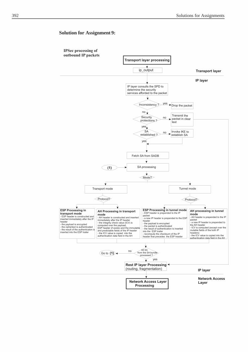
392 Solutions for Assignments
Solution for Assignment 9:

Solutions for Assignments 393
Solution for Assignment 10:
1. In this scenario, the policy indicates that for the hostA to send packet to thehostD, it has to first authenticate to the routerRCand send the packet encryp-ted to firewallRB. First, the IPSec layer builds a tunneled AH packet to therouterRC. After constructing the AH header, the IP layer is invoked toadd

394 Solutions for Assignments
the tunnel header. It uses the routerRCaddress (2.2.3.3 ) as the destina-tion address in the selector field. The policy indicates thatthe packet has to beencrypted and tunneled toRB(6.6.6.6 ). IPSec processes the packet desti-ned to2.2.3.3 , adding the ESP header, ESP trailer and encryting the pay-load. It then invokes the IP layer to add an additional header. It uses the routerRBaddress as the destination. This packet with multiple tunnels is then dispat-ched.
2.
Solution for Assignment 11:
The SSH authentication protocol runs on the top of the SSH transport layer proto-col, which has already authenticated the server machine, established an encryptedcommunication channel, and computed a unique session identifier for this session.When a client declares its user name and the service it wants to use, the serverrequires user authentication. The server drives the authentication by telling the cli-ent which authentication methods can be used (password authentication, SecurIDauthentication, S/Key and OPIE one-time password authentication, authenticationwith public key, host-based or Kerberos authentication). The client has the free-dom to try the methods listed by the server in any order. The server should have atimeout for authentication, and disconnect if the authentication can not be acceptedwithin this period. Additionaly, the implementation should limit the number of fai-led authentication attempts. The dialogue continues untill access has been grantedor denied.
Solution for Assignment 12:
1. The SSL protocol operates on top of the transport layer, i.e. between the trans-port and the application layer.
2. The SSL protocol protects the application data and the control data (header)from the application layer. The control data of all protocolls operating on thelower layers (transport layer, IP layer, network access layer) can not be pro-tected with SSL.

Solutions for Assignments 395
Solution for Assignment 13:
1. After the SSL handshake protocol has been run and the both sides share secretkeys for encryption and authentication, theSSL record protocol starts. Itreceives data from the higher layers in blocks of arbitrary size. The first pur-pose of the Record Protocol isto fragment this data into SSL plaintext recordsof 214 bytes or less. Then all records are compressed using the compressionalgorithm defined in the current session state. Then aMAC is computed overthe compressed data. After the MAC computation, the compressed messageplus the MAC areencryptedusing symmetric encryption. Just as in the case ofMAC, the encryption algorithm to be used is defined in the current CipherSpecand the shared secret key has been agreed in the Handshake Protocol. The finalstep of SSL Record Protocol processing is toprepend an SSL record hea-der, which contains important control information about the protocol. Thisstructure of authenticated and encrypted fragment with SSLheader is knownasSSL record. This record is now proceeded to the lower layer protocol.
At the receiving site, the operations in the SSL Record Layerare performedvice versa: When the SSL record is received, first the SSL record layer headeris removed, then the record is decrypted, the MAC is verified and the data isdecompressed. The data is proceeded to the higher layer protocol.
2. The encrypted message of the SSL record can be either a message of the SSLHandshake Protocol, or a message of the SSL Change Cipher Spec Protocol,or a message of the SSL Alert Protocol, or a message with application data.This depends on the protocol which is above the SSL record protocol in theprocessing stack. The type of message is indicated in the Content Type fieldof the SSL record header.
Solution for Assignment 14:
In the SSL Handshake Protocol the cryptographic parameters(algorithms, keys)used to secure a connection between a client and a server are negotiated. The proto-col can be viewed as having four phases.
In thefirst phase security capabilities are established. The phase is initiated bythe client and is used to initiate a logical connection by exchanging aHello mes-sages between the client and the server. When a client first connects to a server itis required to send theClient Hello as its first message. The client can alsosend aClient Hello in response to aHello Request message that comesfrom the server or on its own initiative in order to renegotiate the security parame-ters in an existing connection. The server processes theClient Hello messageand responds with either aHandshake Failure (fatal error will occur and theconnection will fail) orServer Hello message. With theClient Hello andServer Hello messages the security enhancement capabilities (protocolver-sion, session ID, cipher suite, and compression method) between client and serverare established.

396 Solutions for Assignments
The second phaseof the handshake protocol is theAuthentication and KeyExchange. If the server is to be authenticated (which is generally thecase), itsends its certificate inCertificate message immediately following the Ser-ver Hello message. If the server has no certificate, or has certificate only usedfor signing, or Fortezza/DMS key exchange is used, the server sends theServer
Key Exchange message. With this message, the server informs the client aboutits public key parameters (for RSA, for Diffie-Hellman or forthe Fortezza keyexchange algorithm).When the server is authenticated, it may request a certificate from the client if thatis appropriate to the cipher suite selected, and send theCertificate Request
message. The final message in phase 2, and the one that is always required, isthe Server Hello Done message sent by the server. This indicates that theServer Hello and associated messages phase of the handshake is complete.The server will then wait for a client response.
Thethird phase of the Handshake is theclient authentication and key exchange.Upon receipt ofServer Hello Done message, the client should verify that theserver provided a valid certificate if required and check that theserver hello
parameters are acceptable. If all is satisfactory, the client sends one or more mes-sages back to the server. If the server has sent aCertificare Request mes-sage, the first message the client sends is itsCertificate message (or aNo
Certificate alert, if no suitable certificate is available). Next is theClient
Key Exchange message, and the content of this message depends on the typeof key exchange selected before. Then the client may send aCertificate
Verify message to provide explicit verification of the client certificate (if the cli-ent has sent a certificate).
Thefourth phasecompletes the setting up of a secure connection. The client sendsaChange Cipher Spec message and copies the pendingCipher Spec intothe currentCipher Spec . The client then immediately sends theFinished
message to verify that the key exchange and authentication process were successful.This message includes hash values of all handshake messagesstarting atClient
Hello up to theFinished message and is the first message protected withthe negotiated algorithms and keys. In response of these twomessages, the serversends its ownChange Cipher Spec message, transfers the pending to the cur-rent Cipher Spec , and then sends its ownFinished message under the newCipher Spec . Recipients ofFinished message must verify that the contentsare correct. No acknowledgement of the Finished message is required.
At this point, the handshake is complete and the client and server may begin toexchange application layer data, which are carried by the SSL record layer.
Solution for Assignment 15:
Examples for sites where the SSL protocol is used to protect the data:
• www.amazon.de
• www.sparkasse-hagen.de

Solutions for Assignments 397
• www.quelle.de
Examples for Sites without SSL protection:
• www.lob.de
• www.versicherungsvergleich.de
Solution for Assignment 16:
Contents and locations of the.htaccess files:
1. Case 1
• Location:assignment , content:
AuthName "assignment"
AuthUserFile /etc/apache/passwdAuthGroupFile /etc/apache/htgroup
AuthType Basic
<LIMIT GET PUT>require user cryptoad
</LIMIT>
• Location:course , content:
AuthName "course"AuthUserFile /etc/apache/passwd
AuthGroupFile /etc/apache/htgroup
AuthType Basic<LIMIT GET PUT>
require group all</LIMIT>
• Location:cu1 , content:
AuthName "cu1"
AuthUserFile /etc/apache/passwd
AuthGroupFile /etc/apache/htgroupAuthType Basic
<LIMIT GET PUT>require user cryptoad charly
</LIMIT>
• Location:cu2 , content:
AuthName "cu2"AuthUserFile /etc/apache/passwd
AuthGroupFile /etc/apache/htgroup
AuthType Basic<LIMIT GET PUT>
require group students2require user cryptoad
</LIMIT>
2. Case 2
• Location:assignment , content:

398 Solutions for Assignments
AuthName "assignment"
AuthUserFile /etc/apache/passwdAuthGroupFile /etc/apache/htgroup
AuthType Basic
<LIMIT GET PUT>require group all
</LIMIT>
• Location:ea1 , content:
AuthName "ea1"AuthUserFile /etc/apache/passwd
AuthGroupFile /etc/apache/htgroupAuthType Basic
<LIMIT GET PUT>
require user cryptoad</LIMIT>
• Location:ea3 , content:
AuthName "ea3"
AuthUserFile /etc/apache/passwdAuthGroupFile /etc/apache/htgroup
AuthType Basic
<LIMIT GET PUT>require user cryptoad
</LIMIT>
Solution for Assignment 17:
The data moves in the following manner:
• If you type the URL of a web site into your browser, your browser sendsa request to the web site for the page. For example, if you typethe URLhttp://www.amazon.com into your browser, your browser will contact Amazon’sserver and request its home page.
• When the browser does this, it will look on your machine for a cookie file thatAmazon has set. If it finds an Amazon cookie file, your browser will send allof the name-value pairs in the file to Amazon’s server along with the URL. If itfinds no cookie file, it will send no cookie data.
• Amazon’s web server receives the cookie data and the requestfor a page. Ifname-value pairs are received, Amazon can use them.
• If no name-value pairs are received, Amazon knows that you have not visitedtheir site before. The server creates a new ID for you in Amazon’s database andthen sends name-value pairs to your machine in the header forthe web page itsends. Your machine stores the name- value pairs on your harddisk.
• The web server can change name-value pairs or add new pairs whenever youvisit the site and request a page.

Solutions for Assignments 399
There are other pieces of information that the server can send with the name-valuepair. One of these is an expiration date. Another is a path (sothat the site can asso-ciate different cookie values with different parts of the site).
Solution for Assignment 18:
Web sites use cookies in many different ways. Here are some ofthe most commonexamples:
• Sites can accurately determine how many readers actually visit the site. It turnsout that because of proxy servers, caching, concentrators and so on, the onlyway for a site to accurately count visitors is to set a cookie with a unique ID foreach visitor. Using cookies, a site can:
– Determine how many visitors arrive
– Determine how many are new vs. repeat visitors
– Determine how often a visitor has visited.
The way the site does this is by using a database. The first timea visitor arrives,the site creates a new ID in the database and sends the ID as a cookie. The nexttime the user comes back, the site can increment a counter associated with thatID in the database and know how many times that visitor returns.
• Sites can store user preferences so that the site can look different for each visitor(often referred to as customisation). For example, if you visit msn.com, it offersyou the ability to change content/layout/color. It also allows you to enter yourzip code and get customized weather information. Most sitesseem to store pre-ferences like this in the site’s database and store nothing but an ID as a cookie,but storing the actual values in name-value pairs is anotherway to do it (we’lldiscuss why this approach has lost flavour below).
• Ecommerce Sites can implement things like shopping carts and "quick check-out" options. The cookie contains an ID and lets the site keeptrack of you asyou add different things to your cart. Each item you add to your shopping cart isstored in the site’s database along with your ID value. When you check out, thesite knows what is in your cart by retrieving all of your selections from the data-base. It would be impossible to implement a convenient shopping mechanismwithout cookies or something like it.
Solution for Assignment 19:
a) At least one of the two mixesM1, M2 must be trustworthy.
400 Solutions for Assignments
b) Without consideration of the addresses’s encryption, the incoming message tothe mixM1 is
c1 = Eke,M1(Eke,M2
(Eke,B(m))) = Eke,M1
(Eke,M2(meB mod nB)
= Eke,M1(Eke,M2
(1245 mod 28829)
= Eke,M1(Eke,M2
(11695))
= Eke,M1(116953674911 mod 6012707)
= Eke,M1(625690)
= 6256905 mod 55465219
= 7226241.
The outcoming message fromM1 is
Dkd,M1(c1) = Dkd,M1
(7226241)
= 7226241dM1 mod nM1
= 722624144360237 mod 55465219
= 625690.
Solution for Assignment 20:
If more than one message is sent over the DC network, then thiscauses a collo-sion of messages. That is, the messages would not be correctely sent. A commonkey establishment is not practicable in a DC network (in its basic version) since alarge portion of keys, having the same length as the messages, must be permanentlyexchanged. In this case, the time delay of the network’s traffic will be increased aswell as the required bandwith.
Solution for Assignment 21:
1. Stateful packet filtering maintains state information about passed IP packets.Stateful inspection peeks into the payload date where transport and applicationlayer data usually appears, to identify connections or virtual circuits.
2. The following problems exist with stateful packet filtering:
a. In stateful packet filtering the problem remains, that there is no associa-tion between a data stream and a preciously authenticated and authorizeduser.
b. The packet filter has to keep track of the state. This increases the load onthe packet filter and opens it to denial of servive attacks.
c. Packets may be denied when they should have been accepted.
3. There exist some security related advantages in the use ofNAT:
a. NAT helps to enforce the packet filter and firewall control over outboundconnections.
Solutions for Assignments 401
b. NAT can help to restrict incoming traffic, if dynamic allocation schemesare used.
c. NAT helps to conceal the internal networks’ configuration.
Solution for Assignment 22:
Recall Example 6.1-2. Suppose our intranet has the subnet IPnumber172.16.1.0 with subnet mask255.255.255.0 . The users in the localsubnet are not allowed to access any services on the Internet. The users on theInternet are allowed to access the local WWW server on the machine with IPnumber172.16.1.10 .
The commands to build a packet filter withiptables on a router or dual-homedhost between the Internet and the local subnet are as follows:
At first the kernel module that provides support fornetfilter has to be loadedinto the kernel:
$ modprobe iptables
The commands to build the chains for thefilter table, that fulfill the above policyare:
$ iptables -F OUTPUT
$ iptables -P OUTPUT DROP$ iptables -F INPUT
$ iptables -P INPUT DROP$ iptables -F FORWARD
$ iptables -P FORWRAD DROP
$ iptables -A FORWARD -m tcp -p tcp -s 172.16.1.10/32--sport 80 -d 0/0 --syn -j DROP
$ iptables -A FORWARD -m tcp -p tcp -s 0/0-d 172.16.1.10/0 --dport 80 -j ACCEPT
$ iptables -A FORWARD -m tcp -p tcp -s 172.16.1.10/32
--sport 80 -d 0/0 -j ACCEPT
Solution for Assignment 23:
There is no general recommendation which layer of the Internet model is best suitedto provide the security for Internet services and applications. The best layer (to bechosen for providing security of an application) depends onthe security servicesrequired and the application environment in which the services must be deployed.Note that a higher level of security of some services can be reached by the useof multiple layers rather than only one. The transport layeris more appropriateto provide security for applications of the electronic commerce field (using TLSor SSL). Email service which provides a point-to-point communication is richlysecured above the application layer (with S/MIME specifications or PGP programs).Bulk data cryptographic transformations, such as message authentication, integritychecking, and data encryption are well performed at the network layer.

402 Solutions for Assignments
Solution for Assignment 24:
1. A distributed file system with NFS works following the client-server model.A client’s user can access the server’s file system in a transparent way onthe basis of the Remote Procedure Calls (RPCs). RPC guarantees platformindependence, i.e. the client and the server do not need to exist on the samephysical system. In turn, RPC uses data types defined by the eXternal DataRepresentation (XDR) to hide all details of architecture-dependent data repre-sentation.
2. The NFS-request from a client to a server as well as the datacontent will betransmitted using the TCP or UDP protocol, i.e. the confidentiality is not gua-ranteed. The requirement that only authorized users are able to read or mani-pulate files, is not adequately met by NFS. AUTH UNIX and AUTH DESare two of many mechanisms for authenticating clients and servers that applyto NFS. The AUTH UNIX follows the UNIX style for authentication. Thus, itprovides no real authentication. The AUTH DES authentication which uses theDeffie-Hellman algorithm to derive a DES key for encrypting the communi-cation between client and server, has some security weaknesses. On one hand,the DES is already decrypted. On the other hand, the choice ofsmall modulusin the Deffie-Hellman algorithm leads to the decryption the NFS packets.
3. The use of AFS (Andrew File System) and CFS (CryptographicFile System)enables a secured distributed file system. AFS uses Kerberosfor the mutualauthentication of client and server. To provide authorization service, AFS usesspecial Access Control Lists (ACL).
CFS pushes encryption services into the UNIX file system suchas NFS. CFSenables to encrypt files when
• they are stored on a local harddisk,
• they are sent to a remote file server,
• they are stored on a remote file server, or
• backups of them are generated.
Solution for Assignment 25:
1. S/MIME provides the following cryptographic security services for electronicmessaging applications: authentication, message integrity and non-repudiationof origin (using digital signatures) and privacy and data security (using encryp-tion).
2. A MIME entity must be prepared for signing or enveloping, i.e. it must becanonicalized and encoded for transfer.
3. Two formats for signed messages are defined by S/MIME:

Solutions for Assignments 403
application/pkcs7-mime with signedData as parameter, andmultipart/signed .
By the multipart/signed format, a recipient without any S/MIME orCMS processing facilities is able to read the message. A recipient of a messagesigned usingsignedData format, cannot read the message if he possess noS/MIME facilities.
Solution for Assignment 26:
1. Examples of executable content which can affect the network security arebinary mail attachments, helper applications and plug-ins, scripting langua-ges, Java applets, and ActiveX.
2. A denial of service attack can be mounted against a host, when a JavaScriptcode is written in a malicious manner. For example, the JavaScript code canrequire too much of the CPU or memory resources, or it can try to open a largenumber of windows on the victim’s screen.
3. Java uses some techniques to limit the risk related to a downloading of Javaapplets. These techniques are the Java Sandbox, the SecurityManager class,the Bytecode Verifier, and the Java Class Loader.
• Java Sandbox: enables Java programs to run only on a JVM inside a restric-ted runtime environment.
• SecurityManager class: will be called before any unsafe operation is exe-cuted.
• Java Class Loader: examines classes to ascertain that they do not violatethe runtime system.
• Bytecode Verifier: assures whether a downloaded bytecode stems from avalid Java program.
Solution for Assignment 27:
The following three security Services are provided by GSM:
• Authenticity is realized by a permanent secret keyKi for each subscriber.
• Confidentiality of user-related data is realized by enciphering with theA5
algorithm.
• Confidentiality of the user identity is realized by the use ofTemporary MobileSubscriber Identities (TMSI).
Solution for Assignment 28:
In Section 8.2.4 the basic procedure for GSM authenticationis presented. For thissolution, especially for the second answer, we consider a procedure in some moredetaile.

404 Solutions for Assignments
1. Entities involved in GSM authentication are:
SIM: Subscriber Identity Module
BTS:Base Transceiver Station
VLR / MSC: Visitor Location Register / Mobile Switching Centre (for circuitservices)
HLR / AC: Home Location Register / Authentication Centre
2. The method for authentication employed between HLR/AC and SIM is achallenge-response mechanism using cryptographic secure128-bit randomnumbers (RAND) and a 128-bit authentication key (Ki), which is kept bothin the SIM card and theAuthentication Centre.
1. TheMobile Stationsigns into the network.
2. TheMobile Switching Centrerequests five triplets from theHome Loca-tion Register.
3. TheHome Location Registercreates the five requested triplets. Each ofthese triplets consists of the following three values:
• A non-predictable 128-bit random number (RAND).
• A 32-bit Singed Response (SRES), calculated formRANDandKi byutilizing the authentication algorithmA3.
• A 64-bit Session Key (Kc), calculated formRANDandKi by utilizingthe key generation algorithmA8. After a successful authentication theSession Key is used to encrypt the subsequent communicationwiththeA5 algorithm.
4. The five triplets are sent from theHome Location Registerto theMobileSwitching Centre.
5. TheMobile Switching Centrerelays the random number (RAND) from thefirst triplet to theBase Transceiver Station.
6. TheBase Transceiver Stationrelays this random number to theMobileStation.
7. The Mobile Stationutilizes theA3 algorithm to calculate the SignedResponse (SRES’) from the received random numberRANDand the sto-red Authentication KeyKi.
8. TheMobile Stationsends the Signed Response (SRES’) to theBase Tran-sceiver Station.
9. TheBase Transceiver Stationrelays the Signed Response (SRES’) to theMobile Switching Centre.

Solutions for Assignments 405
10. TheMobile Switching CentrecomparesSRESfrom the first triplet withSRES’.
11. Only if SRESis equal toSRES’ access to the network is granted to theMobile Station.
3. The network authenticates the SIM. Therefore the SIM has to demonstrateits knowledge ofKi. The authentication of the network by the SIM is notprovided by GSM.
Solution for Assignment 29:
Examples for GSM attacks are:
SMS spoofing attack:SMS spoofing is a very simple attack. With an apropriateapplication the originating address of an SMS can be freely set to any desiredset of alphanumeric characters.
This attack compromises the security goals of authenticityand nonrepudiation.
False base station attack:Base stations in GSM do not authenticate themselves tomobile stations. Therefore an attacker can set up a false base station and thenforce a mobile station to turn off encryption in order to eavesdrop the connec-tion. See [Mitchell01].
The false base station attack compromises the security goalof confidentiality.
IBM side channel partitioning attacks:These attacks developed by IBM [Rao02]do not attack the cryptographic algorithms directly, but exploit the large quan-tities of sensitive information emanating from the side-channels such as powerconsumption and electromagnetic radiations. Therefore itis possible to findout the subscriber authentication keyKi and clone the SIM card in a relativelyshort period of time.
The IBM side channel partitioning attacks compromise the security goals ofauthenticity and authorisation.
Solution for Assignment 30:
• Authentication of theHome Location Register(HLR ) to theUser Services Iden-tity Module(USIM ).
• Integrity on the air interface both for data and for signalling information.
• Key freshness.
• New algorithms.
• Key length of 128 Bit.
• Core network signalling security.
• Encryption ends in theRadio Network Controllers(RNC).
• Anonymity
406 Solutions for Assignments
Solution for Assignment 31:
a) Man-in-the-middle attacks (e.g. false base station attacks as described in thesolutions for exercises in course unit 9) are prevented by the mutual authenticationprovided in the UMTS standard.
b) In order to facilitate the evolution from GSM to UMTS, mobile devices allowa UMTS subscriber to roam between GSM and UMTS networks. Thismeans thata UMTS subscriber can connect to a serving network with UMTS backbone com-ponents via a GSM base station subsystem. In this case an attacker can performa man-in-the-middle attack since GSM base stations do not support integrity pro-tection, which is necessary for the network authenticationdefined in the UMTSstandard (see [Meyer04]).
Solution for Assignment 32:
Examples for WAP attacks are:
Truncation attack: Some of the alert messages used in the WAP protocol are sentin cleartext and are not properly authenticated. It is possible for an attackerto replace an encrypted datagram with a plaintext alert message with thesame sequence number. Thus arbitrary packets can be truncated from the datastream.
This attack compromises the security goals of authenticityand integrity.
XOR MAC and stream ciphers:The WTLS protocol supports a 40-bit XOR MACto provide message integrity. But in combination with stream ciphers as usedin WAP an XOR MAC does not provide any message integrity because if a bitat positionn in the ciphertext is invertet the MAC can be made to match easilyby inverting the bit (n mod40) in the MAC.
This attack compromises the security goal of integrity.
Solution for Assignment 33:
In a plaintext attack the attacker knows the plaintext and the corresponding cipher-text. In the challenge-response phase of theShared Key Authentication, the chal-lenge (plaintext) and the response (ciphertext) are both transmitted with no encryp-tion.
Solution for Assignment 34:
The decryption engine looks similar to the encryption part:

Solutions for Assignments 407
RC4
Kdefault
(shared key)
ciphertext
IVConcatenate IV and key
XOR
radio interface
KV ok?
ICVpayload
packet
CRC-Algorithm
Message
Solution for Assignment 35:
Examples for WAP attacks are:
Truncation attack: Some of the alert messages used in the WAP protocol are sentin cleartext and are not properly authenticated. It is possible for an attackerto replace an encrypted datagram with a plaintext alert message with thesame sequence number. Thus arbitrary packets can be truncated from the datastream.
This attack compromises the security goals of authenticityand integrity.
XOR MAC and stream ciphers:The WTLS protocol supports a 40-bit XOR MACto provide message integrity. But in combination with stream ciphers as usedin WAP an XOR MAC does not provide any message integrity because if a bitat positionn in the ciphertext is invertet the MAC can be made to match easilyby inverting the bit (n mod40) in the MAC.
This attack compromises the security goal of integrity.
Solution for Assignment 36:
An electronic payment system is a system providing servicesfor paying goods andinformation electronically over insecure open networks. Usually, diverse cryptogra-phic technologies and network security tools are used to ensure that network userscan make payments fast and safely.
The main categories of electronic payment systems are the following:
• Credit Card-based payment systems

408 Solutions for Assignments
• Electronic check systems
• Electronic cash systems
• Micropayment systems
Credit Card-based systems have to transmit customers credit card numbers overinsecure networks. That is the reason, why Credit Card-based systems need muchstronger security than other electronic payment systems.
Solution for Assignment 37:
1. OIsalt is a nonce which is used when creating a hash of the order descriptionto prevent dictionary attacks. This nonce can prevent an attack from guessingthe hash value,H(OIData), by trying all possible combinations of dictionarywords in the order description.
2. The main feature of electronic check payment systems is the immediate trans-fer from the payers account to the payee´s account at the timeof purchase. TheNetBill server is the bottleneck of the system because the NetBill server hasto be involved into all transactions.
3. The main parties involved in an electronic cash system are:
• Consumer
• Merchant
• Issuing bank
• The trusted third party (optional)
The following protocols are the main protocols contained inan electronic cashsystem:
• Registration protocol (set up account with the bank)
• Withdrawal protocol
• Payment protocol
• Deposit protocol
• Tracing protocol
Payer_codeis generated secretly by the user. A hash of it,H(payer_code), isincluded in the payment information which enables the user to prove the banklater, after the coin has been deposited, that he made the payment.
4. Electronic micropayment systems are systems that can provide the transferof very small amounts of money in a single transaction while minimizing thecommunication traffic. The main point of an electronic micropayment systemsis that, when the cost of commiting a fraud exceeds the value of the purchase,

Solutions for Assignments 409
then the system is thought to be secure. The computation consuming crypto-graphy primitives will not used in electronic micropaymentsystems.
ID# is a unique identifier of the scrip in the Millicent systemas a serial num-ber. It is used to prevent double spending of the scrip. Furthermore, someparts of it are used to select the secret which is called master_scrip_secret.The master_scrip_secrets are known to the vendor only.
Solution for Assignment 38:
It is a program that can autonomously migrate to visited hosts in the heterogeneousnetwork for performing tasks on behalf of its owner.
Solution for Assignment 39:
A malicious host can attack a mobile agent on data and service. In case of data, it canmodify data by deletion, alteration, and modification. However, in case of service, itperforms denial of service (i.e. does not let the mobile agent migrate to other visitedhosts, does not provide its resources, repeatedly executesmobile agent).
Solution for Assignment 40:
There are four main researches for the mobile agent paradigmnamely application,infrastructure, security, and standard.
Solution for Assignment 41:
There are two possibilities namely: dialogue and message passing. The proposedparadigm should be equipped with a mobile agent locating function, a standard mes-sage format and a reliable message delivery protocol. In order to develop a mobileagent locating function, the proposed solution must equip each mobile agent a uni-que name and location update scheme. About a reliable message delivery protocol,the proposed paradigm should be able to guarantee correct message delivery to thetarget agent. For a standard message format, it ensures the format of an exchangingmessage and how a message should be interpreted.
Solution for Assignment 42:
a) 1. The result of the scan is shown below:
Starting Nmap 3.9999 ( http://www.insecure.org/nmap ) at 2 006-05-16 15:51Westeuropäische Normalzeit
Interesting ports on Bitburger.fernuni-hagen.de (132.17 6.12.10):
(The 1664 ports scanned but not shown below are in state: clos ed)
PORT STATE SERVICE VERSION22/tcp open ssh OpenSSH 3.9p1 (protocol 2.0)
25/tcp open smtp Postfix smtpd80/tcp open http Apache httpd 1.3.33 ((Unix) PHP/4.3.9)
111/tcp open rpcbind 2 (rpc #100000)
139/tcp open netbios-ssn Samba smbd (workgroup: LGKS)443/tcp open ssl OpenSSL

410 Solutions for Assignments
3306/tcp open mysql MySQL (unauthorized)
5432/tcp open postgresql PostgreSQL DB
MAC Address: 00:02:B3:95:4C:FB (Intel)
Device type: general purposeRunning: Linux 2.4.X
OS details: Linux 2.4.19 - 2.4.20Uptime 27.059 days (since Wed Apr 19 14:27:12 2006)
Service Info: Host: bitburger.fernuni-hagen.deNmap finished: 1 IP address (1 host up) scanned in 14.109 seco nds
2. As can be seen from the result the following ports are open:
• 22 (SSH)
• 25 (SMTP)
• 80 (HTTP)
• 111 (RPCbind)
• 139 (NetBios)
• 443 (SSL)
• 3306 (Mysql database server)
• 5432 (postgresSql database server)
None of them is useless.
3. The bitbuger server runs a Linux 2.4 version.
b) 1. The following protocols can be identified from the trace
• Ethernet II
• ARP (Address Resolution Protocol)
• IPX (Internet Packet eXchange)
• PIM (Protocol Independent Multicast)
• IP (Internet Protocol)
• TCP (Transport Control Protocol)
• UDP (User Datagram Protocol)
• HTTP (HyperText Transport Protocol)
• NTP (Network Time Protocol).
2. The hexadecimal values of the source address is 00 07 ec 13 f7 fc and thehexadecimal value of the destination address is 00 e0 18 e9 fd93 for packet30.
3. The fields of the IP and TCP header can be determined from thecapture andare:
1. IP header
IP Version = 4

Solutions for Assignments 411
IP header length = 20
Differentiated Services Code Point-DSCP = 0
ECN (Explicit Congestion Notification) = 0
Total length = 796 bytes
Identification = 22121
Flags• reserved bit: not set
• don´t fragment (DF): set, since the DF-bit is set the packet can notbe fragmented
• more fragment (MF): not set
Fragment offset = 0
TTL = 63
Protocol = tcp
Header checksum = 59dc (the packet has been transmitted withouterror)
Source IP address = 132.176.114.181
Destination IP address =132.176.12.129
2. TCP header
Source port 80 (standard HTTP port)
Destination port (1529)
Sequence number = 10950 (relative sequence number)
Acknowledment number = 722 (relative acknowlegment number)
Flags: PSH and ACK are set, the rest is not set
Window size = 49640
Checksum = 5467 (hexadeximal)
4. The packet consists of 756 bytes of payload + 20 bytes (TCP header) + 20 bytes(IP header) + 14 Bytes (Ethernet Header) = 810 Bytes.
5. The method used to request the information isGET. As can be seen fromthe URI a Graphic Interchange Format (GIF) image has been requested fromthe client with the IP number 132.176.12.129 (packet93). The response camefrom the server with the IP address 132.176.114.181 (packet95). The URI is/info/images/pfeil_rot.gif .
6. An Apache 1.3.33, PHP 5.0.5 server is used and it runs HTTP/1.1, status code:200, which means the information requested has been retrieved without pro-blems.
7. Average packet size = 662 bytes, average byte/s = 9813,676bytes/s, totalamount of TCP packets = 86 and UDP packets = 10.

412 Solutions for Assignments
Solution for Assignment 43:
a) The frequency table for the number of bytes received is illustrated below:
Frequency Percent Cumulative Percent
10454 1 5 5
10460 1 5 10
10465 1 5 15
10467 1 5 20
10469 1 5 25
10471 1 5 30
10472 3 15 45
10473 1 5 50
10475 1 5 55
10476 2 10 65
10478 1 5 70
10480 1 5 75
10483 1 5 80
10484 1 5 85
10486 1 5 90
10492 1 5 95
10498 1 5 100
Total 20 100
The frequency table for the number of packets received, is shown below:
Frequency Percent Cumulative Percent
10 1 5 5
11 4 20 25
12 7 35 60
13 8 40 100
Total 20 100
b) The histogram of the number of bytes received is shown below:

Solutions for Assignments 413
105001049010480104701046010450
Number of bytes
5
4
3
2
1
0
Fre
qu
en
cy
c) The parameters of the normal distribution areµ = 10475, 15 andσ = 10, 343.The approximation is shown below. As can be seen from the picture, this nor-mal distribution does not approximate the histogram well and therefore can notbe used to detect anomalies. A transformation function has to be applied to thedata set in Table 1 to generate a data set which will better fit anormal distribu-tion. The confidence interval for a level of significanceα = 0.05 is $µ ± 2σ =
[10454, 46 10495, 836].

414 Solutions for Assignments
105001049010480104701046010450
Number of bytes
5
4
3
2
1
0
Fre
qu
en
cy
histoMean10475,
15histoStdDev10,
343histoN20

Solutions for Assignments 415
d) The Matrix of observations M is :
M =
13 10498
12 10478
11 10480
13 10476
12 10454
12 10472
12 10486
13 10483
11 10492
12 10467
13 10484
13 10475
13 10476
13 10465
12 10460
11 10469
12 10473
11 10472
10 10472
13 10471
e) The mean vector̄X equals
X̄ =
(12, 1
10475, 15
)
X1 =
(13
10498
)
(X1 − X̄)(X1 − X̄)t =
[0, 81 20, 56
20, 56 522, 12
]
f) The Hotelling’s test can be calculated for both events (observations).
The Hotelling´s test forx20
T 2x20
= (0, 9 22, 85 )
[0, 83 1, 09
1, 09 106, 98
]−1
·(
0, 9
22, 85
)
= 5, 42
This value is then multiplied with n·(n−p)p·(n+1)·(n−1)
herebyn = 20 andp = 2. The resultis 2, 445. The tabulated value forp = 2 andn − p = 18 for a level of significanceα = 0.05 is 3, 55. Since the calculated value is smaller than the tabulated value,x20
is not an anomaly.

416 Solutions for Assignments
The same is done forx21
T 2x21
= (−0, 1 2, 85 )
[0, 83 1, 09
1, 09 106, 98
]−1
·(
−0, 1
2, 85
)
= 0, 096
The value is then multiplied by0.451. The result is0.043 smaller than the tabulatedvalue. Thereforex21 is not an anomaly.
Solution for Assignment 44:
a) 1.alert tcp $EXTERNAL_NET any -> $HTTP_SERVERS $HTTP_PORTS
(msg:"WEB-ATTACKS /usr/bin/id command attempt";flow:to_server,established;
content:"/usr/bin/id"; nocase;
classtype:web-application-attack; sid:1332; rev:5;)
This rule tells Snort to generate an alert message whenever an attacker tries toexecute the Unix command "id" to gather information about users or groupon the host. Snort generates an alert whenever a TCP packet carrying web traf-fic is observed coming from$EXTERNAL_NETheaded to$HTTP_SERVER
containing the command string"/usr/bin/id" . Hereby the content is notcase sensitive. The variables$EXTERNAL_NETand$HTTP_SERVERare tobe defined in the configuration filesnort.conf . Snort attacks are categori-zed along classes and are assigned priorities. This attack belongs to the webapplication attacks class and the priority is high. It is therefore an attack whichshould be taken very seriously. Further information related to the attack can befound underreference and with thesid , each Snort rule can be uniquelyidentified. Therev is used for rules update.
2. alert tcp $EXTERNAL_NET any -> $HOME_NET 22
(msg:"EXPLOIT ssh CRC32 overflow NOOP";flow:to_server,established;
content:"|90 90 90 90 90 90 90 90 90 90 90 90 90 90 90 90|";
reference:bugtraq,2347; reference:cve,2001-0144;reference:cve,2001-0572; classtype:shellcode-detect;
sid:1326; rev:6;)
In this rule Snort generates an alert message whenever an attacker tries to per-form a buffer overflow on a SSH server and execute arbitrary code with theprivilege of the user running the daemon (root). Snort generates an alert whe-never a TCP packet is observed coming from$EXTERNAL_NETheaded to$HOME_NETcontaining the binary string "|90 90 90 90 90 90 90
90 90 90 90 90 90 90 90 90|" . The pipe indicates that this string isa binary one. This attack belongs to the shell-code detect class and the priorityis high.flow : indicates that rules are only applied to clients or servers, in thiscase on established server connections.

Solutions for Assignments 417
3. alert tcp $SQL_SERVERS 3306 -> $EXTERNAL_NET any
(msg:"MYSQL server greeting"; flow:from_server,establi shed;content:"|00|"; depth:1; offset:3;
flowbits:set,mysql.server_greeting; flowbits:noalert ;
reference:bugtraq,10655;reference:url,www.nextgenss.com/advisories/mysql-au thbypass.txt;
classtype:attempted-user; sid:3665; rev:1;)
This rule generates an alert message when an attacker tries to bypass passwordauthentication in MySQL 4.1. The offset specifies the numberof bytes to beskipped and the depth tells Snort how far it should look in thepacket. In thisrule the first 3 bytes are skipped and the the binary content"|00|" is searchedfor in the first byte of the payload.
4. alert ip $EXTERNAL_NET any -> $HOME_NET any
(msg:"BAD-TRAFFIC Unassigned/Reserved IP protocol"; ip_ proto:>134;
reference:url,www.iana.org/assignments/protocol-num bers;classtype:non-standard-protocol; sid:1627; rev:3;)
This rule generates an alert message when an attacker tries to use unassigned orreserved fields in the IP packet header to send crafted packets. In IPv4 the fieldprotocol is 8 bit in length, that means that 256 values can be used. The valuesof the field are specified in RFC 1700. In this rule, Snort testsall values whichare greater than 134. The attack belongs to the class non-standard-protocol andthe priority is medium.
5. alert tcp $EXTERNAL_NET any -> $HOME_NET 79
(msg:"BACKDOOR CDK"; flow:to_server,established;content:"ypi0ca"; depth:15; nocase; reference:arachnid s,263;
classtype:misc-activity; sid:185; rev:5;)
This rule generates an alert message when an attacker tries to connect to avictim server, where a backdoor has been installed by issuing the password"ypi0ca" . The attack can be detected by searching for the string"ypi0ca"
in the first 15 bytes of the packet. The attack belongs to the class misc-activityand priority is low.
Solution for Assignment 45:
a) 1. A rule to identify this attack is given below:
alert tcp $EXTERNAL_NET any → $HTTP_SERVERS $HTTP_PORTS(msg:"WEB-IIS cmd32.exe access"; content:"cmd32.exe"; n ocase;)
2. alert tcp any any → any 80
(msg "Code Red Worm", content: "default.ida?"; nocase;)
3. alert tcp $EXTERNAL_NET any -> $HOME_NET any
(flags: SF;msg:"SYN-FIN Scan";)
4. alert tcp $EXTERNAL_NET any -> $HTTP_SERVERS $HTTP_PORTS
(msg:"WEB-ATTACKS /etc/shadow access";flow:to_server,established; content:"/etc/shadow"; no case;)

418 Solutions for Assignments

References 419
References
References for Chapter "Introduction"
[Buc99] Johannes Buchmann.Einführung in die Kryptographie.Springer Verlag,1999.
[CB94] William R. Cheswick and Steven M. Bellovin.Firewalls and InternetSecurity: Repelling the Wily Hacker.Addison-Wesley, 1994.
[Com00] Douglas E. Comer.The Internet Book.Prentice Hall International, 2000.
[Den87] Dorothy E. Denning. IEEE Transactions on software engineering, Vol.Se-13, No. 2, FEBRUARY 1987, 222-232.
[DH76] W. Diffie and Martin E. Hellman.New directions in cryptography.IEEETransactions on Information Theory, 22(6):644– 654, November 1976.
[DH99] Naganand Doraswamy and Dan Harkins.IPSec.Prentice Hall Internatio-nal, 1999.
[Eck06] Claudia Eckert.IT-Sicherheit: Konzepte, Verfahren, Protokolle 4. über-arbeitete und erweiterte Auflage.R. Oldenbourg Verlag, 2006
[Fei99] Sidnie Feit.TCP/IP - Architecture, Protocols and Implementation withIPv6 and IP security.Mc Graw Hill, 1999.
[FRU00] Stephan Fischer, Christoph Rensing, and Rödig Utz.Open InternetSecurity.Springer Verlag, 2000.
[Fuh98] Kai Fuhrberg.Internet-Sicherheit: Browser, Firewalls und Verschlsse-lung.Hanser Verlag, 1998.
[Kad91] Firoz Kaderali.Digitale Kommunikationstechnik (Band 1).Vieweg Ver-lag, 1991.
[Kad95] Firoz Kaderali.Digitale Kommunikationstechnik (Band 2).Vieweg Ver-lag, 1995.
[Kad00] Firoz Kaderali.Anonymität im InternetBerichte aus der Kommunikati-onstechnik Band5, Shaker Verlag, Aachen, 2000.
[Kah67] David Kahn.The Codeberakers.Macmillan Publishing Company, NewYork, 1967.
[KCL+00] Firoz Kaderali, Biljana Cubaleska, Bernhard Löhlein, Sonja Schaup,and Oliver Stutzke.Course - Foundations of Cryptology.Department ofCommunication Systems, University of Hagen, 2000.
420 References
[KDS+00] Firoz Kaderali, Thomas Demuth, Dagmar Sommer, Gerd Steinkamp,and Michael Stepping.Course 20018 - Internet Techniques.Departmentof Communication Systems, University of Hagen, 2000.
[Los99] Pete Loshin.TCP/IP clearly explained.Morgan Kaufmann, 1999. 3rdEdition.
[MOV96] Alfred J. Menezes, Paul C. van Oorschot, and Scott A.Vanstone.Hand-book of Applied Cryptography.CRC Press, 1996.
[Opp00] Ralf Oppliger.Security Technologies for the Internet.Artech HousePublishers, 2000.
[Sch96] Bruce Schneier.Applied Cryptography: protocols, algorithms, andsource code in C.John Wiley and Sons, 1996.
[Sch97] C. L. Schuba.On the Modeling, Design, and Implementation of FirewallTechnology.PhD thesis, Pudue University, December 1997.
[Sha49] Claude Shannon.Communication theory of secrecy systems.Bell SystemTechnical Journal, 28:656–715, 1949.
[Smi97] Richard E. Smith.Internet cryptography.Addison Wesley Longman Inc.,1997.
[Spu00] Charles E. Spurgeon.Ethernet: The Definitive Guide.O’Reilly and Asso-ciates, 2000.
[Ste98] Lincoln D. Stein.Web Security: A Step-by-Step Reference Guide.AddisonWesley, 1998.
[Sti95] Douglas R. Stinson.Cryptography: Theory and Practice.CRC Press,1995.
[Tan00] Andrew S. Tanenbaum.Computernetzwerke.Pearson Studium, 2000.
References for Chapter "Basics"
[Buc99] Johannes Buchmann.Einführung in die Kryptographie.Springer Verlag,1999.
[Cha92] Lyman Chapin.The internet standards process.Technical report, RFC(Request for Comments) 1310, Status: Informational, IETF (InternetEngineering Task Force), 1992. http://www.ietf.org/rfc/rfc1310.txt.
[DH98] S. Deering, and R. Hinden.Internet protocol, version 6 (ipv6) speci-fication. Technical report, RFC (Request for Comments) 2460, Sta-tus: Draft Standard, IETF (Internet Engineering Task Force), 1998.http://www.ietf.org/rfc/rfc2460.txt.

421
[ISO84] ISO 7498-1.Information processing systems – open systems interconnec-tion – basic reference model - part 1:The basic model. Technicalreport, International Organization for Standardization,Geneva, Switzer-land, 1984. ISO 7498-1, first edition 1984, second edition 1994.
[ISO89] ISO 7498-2.Information processing systems – open systems interconnec-tion – basic reference model - part 2:Security architecture. Technicalreport, International Organization for Standardization,Geneva, Switzer-land, 1989. ISO 7498-2, first edition 1989.
[KDS+00] Firoz Kaderali, Thomas Demuth, Dagmar Sommer, Gerd Steinkamp,and Michael Stepping.Course 20018 - Internet Techniques.Departmentof Communication Systems, University of Hagen, 2000.
[MF00] David A. McGrew and Scott R. Fluhrer.Attacks on additive encyrptionof redundant plaintext and implications on internet security. In SeventhWorkshop on Selected Areas in Cryptography (SAC’00), Lecture Notes inComputer Science.Springer-Verlag, 2000.
[Pos80] J. Postel.User datagram protocol.Technical report, RFC (Requestfor Comments) 768, Status: Standard, IETF (Internet Engineering TaskForce), 1980. http://www.ietf.org/rfc/rfc0768.txt.
[Pos81a] J. Postel.Internet control message protocol.Technical report, RFC(Request for Comments) 792, Status: Standard, IETF (Internet Enginee-ring Task Force), 1981. http://www.ietf.org/rfc/rfc0792.txt.
[Pos81b] J. Postel.Internet protocol.Technical report, RFC (Request for Com-ments) 791, Status: Standard, IETF (Internet Engineering Task Force),1981. http://www.ietf.org/rfc/rfc0791.txt.
[Pos81c] J. Postel.Transmission control protocol.Technical report, RFC (Requestfor Comments) 793, Status: Standard, IETF (Internet Engineering TaskForce), 1981. http://www.ietf.org/rfc/rfc0793.txt.
[RP94] J. Reynolds and J. Postel.Assigned numbers.Technical report, RFC(Request for Comments) 1700, Status: Standard, IETF (Internet Enginee-ring Task Force), 1994. http://www.ietf.org/rfc/rfc1700.txt.
[Sch96] Bruce Schneier.Applied Cryptography: protocols, algorithms, andsource code in C.John Wiley and Sons, 1996.
[ZCC00] Elisabeth D. Zwicky, Simon Cooper, and D. Brent Chapman.BuildingInternet Firewalls.O’Reilly and Associates, 2000. Second Edition.
422 References
References for Chapter "Internet Security Protocols"
[DA99] T. Dierks and C. Allen. The tls protocol, version 1.0.Technical report,RFC (Request for Comments) 2246, Status: Informational, IETF (InternetEngineering Task Force), 1999. http://www.ietf.org/rfc/rfc2246.txt.
[DH99] Naganand Doraswamy and Dan Harkins.IPSec. Prentice Hall Internatio-nal, 1999.
[Eck04] Claudia Eckert.IT-Sicherheit.R. Oldenbourg Verlag, 2004
[Fei99] Sidnie Feit.TCP/IP - Architecture, Protocols and Implementation withIPv6 and IP security.Mc Graw Hill, 1999.
[FRU00] Stephan Fischer, Christoph Rensing, and Rödig Utz.Open InternetSecurity.Springer Verlag, 2000.
[KCL+00] Firoz Kaderali, Biljana Cubaleska, Bernhard Löhlein, SonjaSchaup, and Oliver Stutzke.Course - Foundations of Cryptology.2000. Department of Communication Systems, University of Hagen,http://etonline.fernuni-hagen.de/lehre/rub/rub1.
[KDS+00] Firoz Kaderali, Thomas Demuth, Dagmar Sommer, Gerd Steinkamp,and Michael Stepping.Course 20018 - Internet Techniques. 2000.Depart-ment of Communication Systems, University of Hagen, http://www.ice-bachelor.fernuni-hagen.de.
[KPS95] Charlie Kaufman, Radia Perlman, and Mike Speciner.Network Security:Private Communication in a Public World.Prentice Hall, 1995.
[Opp00] Ralf Oppliger.Security Technologies for the Internet.Artech HousePublishers, 2000.
[RUB97] Aviel Rubin.Web Security Sourcebook.John Wiley and Sons, 1997.
[Smi97] Richard E. Smith.Internet cryptography.AddisonWesley Longman Inc.,1997.
[Sta96] William Stallings.Practical Cryptography for Data Internetworks.IEEEComputer Society Press, 1996.
[Sta99] William Stallings.Cryptography and Network Security.Prentice Hall,1999. Second Edition.
[Ste98] Lincoln D. Stein.Web Security: A Step-by-Step Reference Guide.AddisonWesley, 1998.

423
References for Chapter "World Wide Web Security"
[ABH97] Derek Atkins, Paul Buis, and Chris Hare.Internet Security, ProfessionalReference Guide, 2nd Edition.New Riders Publishing, 1997.
[Fla96] David Flanagan. Javascript:The Definitive Guide.O’Reilly & Associates,1996.
[Fla99] David Flanagan.JAVA in a Nutshell, 3rd Edition.O’Reilly & Associates,1999.
[Opp00] Ralf Oppliger.Security Technologies for the Internet.Artech HousePublishers, 2000.
[Rub97] Aviel Rubin.Web Security Sourcebook.John Wiley and Sons, 1997.
[Ste98] Lincoln D. Stein.Web Security: A Step-by-Step Reference Guide.AddisonWesley, 1998.
References for Chapter "Anonymity Techniques"
[Chaum81] David L. Chaum. Untraceable electronic mail, return adress, and digi-tal pseudonyms.Communication of the ACM, 24(2):84–88, 1981.
[Chaum88] David Chaum. The dining cryptographers problem:Unconditionelsender and recipient untraceability.Journal of Cryptology, 1(1):65–75,1988.
[Demuth98] Thomas Demuth and Andreas Rieke. Anonym im WorldWide Web?JANUS-Schutz von Inhalteanbietern im WWW.DuD Datenschutz undDatensicherheit, 22(11):623–627, 1998.
[Demuth01] Thomas Demuth and Andreas Rieke. Janus: Server anonymity in theworld wide web.10th Annual EICAR Conference, 2nd European Anti-Malware Conference, 2001.
[Franz97] Elke Franz, Anja Jerichow, and Andreas Pfitzmann.Systemisierungund Modellierung von Mixen.Verlliche ITSysteme, GI-Fachtagung VIS’97, DuD Fachbeiträge, pages 172–190, 1997.
[Franz98] Elke Franz, A. Graubner, A. Jerichow, and A. Pfitzmann. Model-ling mix-mediated anonymous communication and preventingpool-modeattacks.Global IT Security, Proc. of IFIP/SEC’98, 14th Intern. Informa-tion Security Conference, Schriftenreihe der Österreichischen ComputerGesellschaft, Band 116, pages 554–560, 1998.
[Pfitzmann87] Andreas Pfitzmann and Michael Waidner. Networks without userobservability.Computer and Security, 6(2):158–66, 1987.

424 References
References for Chapter "Packet filters and firewallsystems"
[Bel94] Steven M. Bellovin. Firewall-friendly FTP. Technical report,RFC (Request for Comments) 1579, Status: Informatio-nal, IETF (Internet Engineering Task Force), February 1994.http://www.ietf.org/rfc/rfc1579.txt.
[CB94] William R. Cheswick and Steven M. Bellovin.Firewalls and InternetSecurity: Repelling the Wily Hacker.Addison- Wesley, 1994.
[CB00] William R. Cheswick and Steven M. Bellovin.Internet security: Firewallsand gateways.Addison-Wesley, 2000.
[KD00] Olaf Kirch and Terry Dawson.Linux Network Administrator’s Guide.O’Reilly and Associates, 2000. Second Edition.
[KK92] D. Koblas and M.R. Koblas. Socks. In N. [N.92], pages 77–82.
[Lee96] M. Leech. Username/Password Authentication for SOCKS V5. Tech-nical report, RFC (Request for Comments) 1929, Status: Propo-sed Standard, IETF (Internet Engineering Task Force), March 1996.http://www.ietf.org/rfc/rfc1929.txt.
[LGL+96] M. Leech, M. Ganis, Y. Lee, R. Kuris, D. Koblas, and L. Jones.SOCKS Protocol Version 5. Technical report, RFC (Request for Com-ments) 1928, Status: Proposed Standard, IETF (Internet Engineering TaskForce), March 1996. http://www.ietf.org/rfc/rfc1928.txt.
[McM96] P. McMahon. GSS-API Authentication Method for SOCKS Ver-sion 5. Technical report, RFC (Request for Comments) 1961, Sta-tus: Proposed Standard, IETF (Internet Engineering Task Force), 1996.http://www.ietf.org/rfc/rfc1961.txt.
[N.92] N. N., editor.Proceedings of the Third Annual USENIX Security Sympo-sium.IEEE Press, September 1992.
[Opp00] Ralf Oppliger.Security Technologies for the Internet.Artech HousePublishers, 2000.
[RM+96] Y. Rekhter, , B. Moskowitz, D. Karrenberg, G. J. de Groot, and E. Lear.Address Allocation for Private Internets. Technical report, RFC (Requestfor Comments) 1918, Status: Best Current Praxis, IETF (Internet Engi-neering Task Force), February 1996. http://www.ietf.org/rfc/rfc1918.txt.
[Sch97] C. L. Schuba.On the Modeling, Design, and Implementation of FirewallTechnology.PhD thesis, Pudue University, December 1997.
[SE01] P. Srisuresh and K. Egevang. Traditional IP Network Address Translator(Traditional NAT). Technical report, RFC (Request for Comments) 3022,
425
Status: Informational, IETF (Internet Engineering Task Force), January2001. http://www.ietf.org/rfc/rfc3022.txt.
[SH99] P. Srisuresh and M. Holdrege. IP Network Address Translator (NAT)Terminology and Considerations. Technical report, RFC (Request forComments) 2663, Status: Informational, IETF (Internet Engineering TaskForce), August 1999. http://www.ietf.org/rfc/rfc2663.txt.
[TS00] G. Tsirtsis and P. Srisuresh. Network Address Translation - ProtocolTranslation (NAT-PT). Technical report, RFC (Request for Comments)2766, Status: Proposed Standard, IETF (Internet Engineering Task Force),February 2000. http://www.ietf.org/rfc/rfc2766.txt.
[ZCC00] Elisabeth D. Zwicky, Simon Cooper, and D. Brent Chapman.BuildingInternet Firewalls.O’Reilly and Associates, 2000. Second Edition.
References for Chapter "Application Layer Security(Chapter 7.1 - 7.6)"
[Cro82] David H. Crocker. STANDARD FOR THE FORMAT OF ARPA INTER-NET TEXT MESSAGES. RFC (Request for Comments) 822, Sta-tus: Proposed Standard, IETF (Internet Engineering Task Force), 1982.http://www.ietf.org/rfc/rfc822.txt.
[ea95] J. Galvin et al. Security Multiparts for MIME: Multipart/Signed andMultipart/Encrypted. RFC (Request for Comments) 1847, Status:Proposed Standard, IETF (Internet Engineering Task Force), 1995.http://www.ietf.org/rfc/rfc1847.txt.
[ea96a] N. Freed et al. Multipurpose Internet Mail Extensions (MIME) Part Five:Conformance Criteria and Examples . RFC (Request for Comments)2049, Status: Proposed Standard, IETF (Internet Engineering Task Force),1996. http://www.ietf.org/rfc/rfc2049.txt.
[ea96b] N. Freed et al. Multipurpose Internet Mail Exten- sions (MIME) PartFour: Registration Procedures. RFC (Request for Comments)2048, Sta-tus: Proposed Standard, IETF (Internet Engineering Task Force), 1996.http://www.ietf.org/rfc/rfc2048.txt.
[ea96c] N. Freed et al. Multipurpose Internet Mail Extensions (MIME) Part One:Format of Internet Message Bodies. RFC (Request for Comments) 2045,Status: Proposed Standard, IETF (Internet Engineering Task Force), 1996.http://www.ietf.org/rfc/rfc2045.txt.
[ea96d] N. Freed et al. Multipurpose Internet Mail Exten- sions (MIME)Part Two: Media Types. RFC (Request for Comments) 2046, Sta-tus: Proposed Standard, IETF (Internet Engineering Task Force), 1996.http://www.ietf.org/rfc/rfc2046.txt.
426 References
[ea98] J. Callas et al. OpenPGP Message Format. RFC (Requestfor Comments)2440, Status: Proposed Standard, IETF (Internet Engineering Task Force),November 1998. http://www.ietf.org/rfc/rfc2440.txt.
[FRU00] Stephan Fischer, Christoph Rensing, and Rödig Utz.Open InternetSecurity.Springer Verlag, 2000.
[GS95] Simson Garfinkel and Gene Spafford.Web security & Commerce.O’Reilly & Associates, Inc., 1995. First Edition.
[Hug95] Larry J. Hughes and Jr.Actually Useful Internet Security Techniques.New Riders Publishing, 1995.
[Hou99] B. Kaliski. PKCS #7: Cryptographic Message Syntax Version 1.5. RFC(Request for Comments) 2315, Status: Proposed Standard, IETF (InternetEngineering Task Force), 1998. http://www.ietf.org/rfc/rfc2315.txt.
[KCL+00] Firoz Kaderali, Biljana Cubaleska, Bernhard LÄohlein, SonjaSchaup, and Oliver Stutzke.Course - Foundations of Cryptology.2000. Department of Communication Systems, University of Hagen,http://etonline.fernuni-hagen.de/lehre/rub/rub1.
[KDS+00] Firoz Kaderali, Thomas Demuth, Dagmar Sommer, Gerd Steinkamp,and Michael Stepping.Course 20018 - Internet Techniques.2000. Depart-ment of Communication Systems, University of Hagen, http://www.ice-bachelor.fernuni-hagen.de.
[Moo96] K. Moore. MIME (Multipurpose Internet Mail Extensions) Part Three:Message Header Extensions for Non-ASCII Text. RFC (RequestforComments) 2047, Status: Proposed Standard, IETF (InternetEngineeringTask Force), 1996. http://www.ietf.org/rfc/rfc2047.txt.
[N98] N. N. System Management Guide: Communications and Networks. 1998.http://www.rs6000.ibm.com/doc_link/en_US/a_doc_lib/aixbman/commadmn/toc.htm.
[N01] N. N. eMail Wiretapping Exploit. 2001.http://home.de.netscape.com/de/info/security-doc.html.
[Opp97] Ralf Oppliger.Internet and Intranet Security.Artech House Publishers,1997.
[Opp00] Ralf Oppliger.Security Technologies for the Internet.Artech HousePublishers, 2000.
[PR85] J. Postel and J. Reynolds. FILE TRANSFER PROTOCOL (FTP). RFC(Request for Comments) 595, Status: Proposed Standard, IETF (InternetEngineering Task Force), 1985. http://www.ietf.org/rfc/rfc595.txt.
[Ram99a] B. Ramsdell. S/MIME Version 3 Certificate Handling. RFC (Requestfor Comments) 2632, Status: Proposed Standard, IETF (Internet Enginee-ring Task Force), 1999. http://www.ietf.org/rfc/rfc2632.txt.
427
[Ram99b] B. Ramsdell. S/MIME Version 3 Message Speci¯cation. RFC (Requestfor Comments) 2633, Status: Proposed Standard, IETF (Internet Enginee-ring Task Force), 1999. http://www.ietf.org/rfc/rfc2633.txt.
[SM87] Inc. Sun Microsystems. XDR: External Data RepresentationStandard. RFC (Request for Comments) 1014, Status: Propo-sed Standard, IETF (Internet Engineering Task Force), 1987.http://www.ietf.org/rfc/rfc1014.txt.
[SM88] Inc. Sun Microsystems. RPC: Remote Procedure Call Protocol Spe-cification Version 2. RFC (Request for Comments) 1057, Status:Proposed Standard, IETF (Internet Engineering Task Force), 1988.http://www.ietf.org/rfc/rfc1057.txt.
[SM89] Inc. Sun Microsystems. NFS: Network File System ProtocolSpecification. RFC (Request for Comments) 1094, Status: Pro-posed Standard, IETF (Internet Engineering Task Force), 1989.http://www.ietf.org/rfc/rfc1094.txt.
[ZCC00] Elisabeth D. Zwicky, Simon Cooper, and D. Brent Chapman.BuildingInternet Firewalls.O’Reilly and Associates, 2000. Second Edition
References for Chapters "Application Layer Securityand Security in Wireless and Mobile Networks (Chap-ter 7.7 - 8.2)"
[Borcherding] Malte Borcherding. Mobile security - an overview of GSM, SATand WAP. pages 133–141.
[GSM0320] GSM 03.20 (ETS 300 534).Digital cellular telecommunications sys-tem (phase 2); Security related functions.Technical report.
[GSM1203] GSM 12.03 (ETS 300 614).Digital cellular telecommunications sys-tem (phase 2); Security management.Technical report.
[Golic97] Jovan Dj. Golic.Cryptanalysis of alleged A5 stream cipher.pages 239–255.
[Kaderali00b] Firoz Kaderali, Biljana Cubaleska, Bernhard Löhlein, SonjaSchaup, and Oliver Stutzke.Course - Foundations of Cryptology.2000.Department of Communication Systems, University of Hagen
[Schneier96] Bruce Schneier.Applied Cryptography: protocols, algorithms, andsource code in C.John Wiley and Sons, 1996.
[Shamir99] Adi Shamir.Real time cryptanalysis of A5/1 on a PC.Technicalreport, Weizmann Institute of Technology, Israel, 1999.

428 References
[Mitchell01] C. Mitchell. The security of the GSM air interface protocol.Tech-nical Report RHUL-MA-2001-3, Royal Holloway, University of London,2001.
[Rao02] J. Rao, P. Rohatgi, H. Scherzer and S. Tinguely.Partitioning Attacks:Or How to Rapidly Clone Some GSM Cards.Proceedings of the IEEESymposium on Security and Privacy, Oakland, 2002
References for Chapter "Security in Wireless andMobile Networks (Chapter 8.3 - 8.4)"
[3GP02a] 3GPP. 3g security; network domain security; ip network layer security.Technical report, 3rd Generation Partnership Project, June 2002. 3G TS33210 V5.1.0.
[3GP02b] 3GPP. 3g security; network domain security; map application layersecurity. Technical report, 3rd Generation Partnership Project, 3 2002. 3GTS 33200 V5.0.0.
[3GP02c] 3GPP. Specification of the 3gpp confidentiality andintegrity algo-rithms; document 1: f8 and f9 specification. Technical report, 3rd Gene-ration Partnership Project, June 2002. 3GPP TS 35201 V5.0.0.
[3GP02d] 3GPP. Specification of the 3gpp confidentiality andintegrity algo-rithms; document 2: Kasumi specification. Technical report, 3rd Gene-ration Partnership Project, June 2002. 3GPP TS 35202 V5.0.0.
[DU99] DTS/TSGS-033120U.3g security; security principles and objectives.Technical report, 3rd Generation Partnership Project, 1999. 3G TS 33120V3.0.0.
[Fox02a] Dirk Fox.Bluetooth security.DuD, Datenschutz und Datensicherheit.October 2002.
[Heijden00] Marcel Van der Heijden and Marcus Taylor.Understanding WAPWirless; Applications, Devices, and Services.Artech House, 2000.
[Kaderali00b] Firoz Kaderali, Biljana Cubaleska, Bernhard Löhlein, SonjaSchaup, and Oliver Stutzke.Course - Foundations of Cryptology.2000.Department of Communication Systems, University of Hagen
[Loehlein02] Bernhard Loehlein.Bluetooth - technology, security and weaknes-ses.Proceedings of SCI 2002.
[Meyer04] Ulrike Meyer, Susanne Wetzel.A Man-in-the-Middle Attack on UMTS.Proceedings of WiSe 2004
[Puetz01a] Stephan Pütz, Roland Schmitz, and Tobias Martin. Security mecha-nisms in umts.Datenschutz und Datensicherheit (DuD), pages 323–332,June 2001.

429
[Stepping02] Christoph Stepping.Integration of security aspects in umts andbran. Institute for data communication systems, university of siegen.2002.
[Tzvetkov] Vesselin Tzvetkov and Biljana Cubaleska. Wap protocol security solu-tions for mobile commerce. Proceedings of Sci2002, Volume IV.
[Wap01a] Wap architecture. July 2001. WAP-210-WAPArch-20010712.http://www.wapforum.org/.
[Wap01b] Wireless identity module.July 2001. Version 12-July-2001.http://www.wapforum.org/.
[Wap01c] Wireless session protocol specification.July 2001. Approved Version5-July-2001. http://www.wapforum.org/.
[Wap01d] Wireless transaction protocol.July 2001. Version 10-Jul-2001.http://www.wapforum.org/.
[Wap01e] Wmlscript crypto library. June 2001. Version 20-Jun-2001.http://www.wapforum.org/.
References for Chapter "Security in Wireless andMobile Networks (Chapter 8.5 - 8.6)"
[Dent] Donald J. Dent. The bluetooth wireless revolution. Proceedings ofSci2002, Volume IV.
[EA05] Jon Edney and William A. Arbaugh:Real 802.11 Security: Wi-Fi Protec-ted Access and 802.11i, Addison Wesley, 2005
[FMS01] Scott Fluhrer, Itsik Martin and Adi Shamir:Weaknesses in the Key Sche-duling Algorithm of RC4, August 2001
[Fox02a] Dirk Fox.Bluetooth security.DuD, Datenschutz und Datensicherheit.October 2002.
[Http] http://www.bluetooth.com.
[Loehlein02] Bernhard Loehlein.Bluetooth - technology, security and weaknes-ses.Proceedings of SCI 2002.
[Re04] Jörg Rech:Wireless LANs, Heise Zeitschriften Verlag, 2004
[RFC2898] PKCS #5: Password Based Cryptography, Version 2,http://www.ietf.org/rfc/rfc2898.txt

430 References
References for Chapter "Electronic Payment Sys-tems"
[Adachi03] N.Adachi, S.Aoki, Y.Komano, and K.Ohta. The security problems ofrivest and shamir’s payword scheme. InCEC’2003, pages 20–24. IEEEComputer society Press, 2003.
[Asokan97] N. Asokan, Phillipe A. Janson, Michael Steiner,and Michael Waid-ner.The state of the art in electronic payment systems.IEEE Computer,30(9):28–35, 1997.
[Bellare95] Mihir Bellare, Juan Garay, Ralf Hauser, Amir Herzberg, Hugo Kra-wczyk, Michael Steiner, Gene Tsudik, and Michael Waidner. iKP – Afamily of secure electronic payment protocols. InProceedings of the 1stUSENIX Workshop on Electronic Commerce, pages 89–106, 1995.
[Boly94] J-p. Boly and et al. The esprit project cafe. InESORICS’94, volume 875of Lecture Notes in Computer Science, pages 217– 230. Springer Verlag,1994.
[Brands93] Stefan Brands.An efficient off-line electronic cash system based onthe representation problem.Technical Report CSR9323, Centrum voorWiskunde en Informatica, Computer Science Department of Algorithmicsand Architecture, 1993.
[Brands94] Stefan Brands. Untraceable off-line cash in wallets with observers. InCRYPTO’93, volume 773 ofLecture Notes in Computer Science, pages302–318, Berlin, 1994. Springer Verlag.
[Chaum83] David Chaum. Blind signatures for untraceable payments. InAdvan-ces in Cryptology: CRYPTO ’82, pages 199–203, 1983.
[Chaum85] David Chaum. Security without identification: Transaction systemsto make big brother obsolete.Communications of the ACM, 28(10):1030,1985.
[Chaum90] D. Chaum and M. Naor A. Fiat. Untraceable electronic cash. InCRYPTO ’88, volume 403 ofLecture Notes in Computer Science, pages319–327. Springer Verlag, 1990.
[Chaum91] D. Chaum and E. van Heyst.Group signatures.volume 547, pages257–265, 1991.
[Chaum92] David Chaum.Achieving electronic privacy.Scientific American,267(2):96, 1992.
[Chaum93] David Chaum and Torben Pryds Pedersen. Wallet databases withobservers. InCRYPTO ’92, volume 740 ofLecture Notes in ComputerScience, pages 89–105. Springer Verlag, 1993.

431
[Cox95] Tygar D. Cox, B. and M. Sirbu.Netbill security and transaction protocol.Technical report, Carnegie Mellon University, 1995.
[Eastlake96] D. Eastlake 3rd, B. Boesch, S. Crocker, and M. Yesil. Cybercash cre-dit card protocol version 0.8. InInternet Network Working Group, Requestfor Comments: RFC 1898, 1996.
[Ferguson94] Neils Ferguson. Extensions of single-term coins. In CRYPTO’93,volume 773 ofLecture Notes in Computer Science, pages 292–301, Ber-lin, 1994. Springer Verlag.
[Franklin93] M.Franklin and M.Yung. Secure and efficient off-line electronicdigital money. In20th Int. Colloquium on Automata, Languages and pro-gramming (ICALP), volume 700 of Lecture Notes in Computer Science,pages 265–276. Springer Verlag, 1993.
[FST] http://echeck.commerce.net/overview/consortium/fstc.html.
[Glassman95] S. Glassman, M. S. Manasse, M. Abadi, P. Gauthier, and P. Sobal-varro. The millicent protocol for inexpensive electronic commerce. InProceedings of Fourth International World Wide Web Conference, Dec1995.
[ITU97] ITU-T X.509 V3 (formerly CCITT X.509).The Directory: Authentica-tion Framework.June 1997.
[Kocker97] P. Kocker, A. Freier, and P. Karlton.The SSL Protocol Version 3.0.Netscape Communications Corp., March 1997.
[Kügler01] D.Kügler and H.Vogt. Fair tracing without trustees. InFinancial Cryp-tography 2001, volume 2339 ofLecture Notes in Computer Science,pages 136–148. Springer Verlag, 2001.
[MC96a] MasterCard and VISA Corporations.Secure Electronic Transac-tion(SET) Specification - Book 1: Business Description. June 1996.
[MC96b] MasterCard and VISA Corporations.Secure Electronic Transac-tion(SET) Specification - Book 2: Programmer’s Guide. June 1996.
[MC96c] MasterCard and VISA Corporations.Secure Electronic Transac-tion(SET) Specification - Book 3: Formal Protocol Definition. June1996.
[Medvinsky93] Gennady Medvinsky and B. Clifford Neuman. Netcash: A designfor practical electronic currency on the internet. In Proceedings of theFirst ACM Conference on Computer and Communications Security,pages 102–106, 1993.
[Mondex] http://www.mondex.com
[Neuman95] B. Clifford Neuman and Gennady Medvinsky. Requirements fornetwork payment: The netcheque perspective.In Proceedings of IEEECOMPCON’95, pages 32–36, 1995.

432 References
[Pfitzmann00] B. Pfitzmann and A. Sadeghi.Self-escrowed cash against userblackmailing. volume 1962, pages 42–45, 2000.
[Qiu02] Weidong Qiu, Kefei Chen, and Dawu Gu. A new off-line privacy protec-ting e-cash system with revokable anonymity. InInternational SecurityConference, ISC’98, Sao Paulo, Brazil, volume 2433 of Lecture Notes inComputer Science, pages 177–190. Springer Verlag, 2002.
[Rivest96] Ronald L. Rivest and Adi Shamir. Payword and micromint: Two sim-ple micropayment schemes. InSecurity Protocols Workshop, pages 69–87, 1996.
[Sander99] T. Sander and A. Ta-Shma.Auditable, anonymous electronic cash.volume 1666, pages 555–572, 1999.
[Semper] http://www.semper.org.
[Sirbu95] M. Sirbu and J.D. Tygar. Netbill: An electronic commerce system opti-mized for network delivered services. InProceedings of IEEE COMP-CON’95, pages 20–25, 1995.
[Sirbu96] M. Sirbu and J. Chuang Public-key based ticket granting service in ker-beros8. InInternet Network Working Group, Request for Comments: RFC1510, May 1996.
[Solms92] S.von Solms and D.Naccache. On blind signatures and perfect crime.Computer and Security, 11(6):581, 1992.
[Steiner88] J. G. Steiner, B. C. Neuman, and J. I. Schiller. Kerberos: An authen-tication service for open network systems. InProceedings of USENIXwinter, pages 191–202, 1988.
[Traoré99] J. Traoré. Group signature and their relevance to privacyprotecting off-line electronic cash systems. InACISP99, volume 1587, pages 228–243,1999.
[Wayner97] Peter Wayner.Digital cash: Commerce on the net. Morgan Kauf-mann; 2nd edition, London, 1997.
[Yang03] C-N.Yang and H.-T.Teng. An efficient method for finding minimumhash chain of multi-payword chains in micropayment. InCEC’2003,pages 45–49. IEEE Computer society Press, 2003.
References for Chapters "Security Aspects in MobileAgents Systems and Copyright Protection"
[Alfalayleh04] M. Alfalay, L. Brankovic.An Overview of Security Issues andTechnique in Mobile Agents.CMS Conference on Communications andMultimedia Security 2004.
433
[Beirman02] E. Beirman, E. Cloete.Classification of Malicious Host Threats inMobile Agent Computing.SAICSIT 2002.
[Breugst98] D. Milojicic, M. Breugst, I. Busse, J. Campbell, S. Covaci, B. Fried-man, K. Kosaka, D. Lange, K. Ono, M. Oshima, C. Tham, S. Virdhagris-waran and J. White.MASIF The OMG Mobile Agent System Interoperabi-lity Facility. Proceedings of the International Workshop on Mobile Agents(MA ’98), Stuttgart, September 1998.
[Carzaniga97] A. Carzaniga, G. P. Picco, G. Vigna.Designing Distributed Appli-cations with Mobile code paradigm.Proceedings of the 19th InternationalConference on Software Engineering,1997.
[Chess95] D. Chess, B.Grosof, C. Harrison, D. Levine, C. Parris, G. Tsudik.Iti-nerant Agents for Mobile Computing.IEEE Personal Communications.1995.
[Collberg02] C. Collberg, C. Thomborson.Watermarking, Tamper-Proofing, andObfusication - Tools for Software Protection.IEEE Transactions on Soft-ware Engineering,Volume 28, Issue 8, Aug. 2002 Page(s):735-746.
[Das03] S. Das, K. Shuster, C. Wu.Dynamic Information Retrieval OptimizationUsing Mobile Agents.AAMAS 2003.
[Derbas04] G. Derbas, A. Kayssi, H. Artail. A. Chehab.TRUMMAR - A TrustModel for Mobile Agent Systems Based on Reputation.IEEE/ACS inter-national conference on pervasive services, 2004.
[Esparza03] O. Esparza, M. Fernandez, M. Soriano. J. L. Munoz, and J. Forne.Mobile Agent Watermarking and Fingerprinting: Tracing Malicious host.DXEA 2003, LNCS 2736.
[Farmer96] W. M. Farmer, J. D. Guttman, V. Swarup.Security for Mobile Agents:Authentication and State Apprisal.EROSIC 1996.
[Ferrer01] J. D. Ferrer.Mobile Agent Route Protection through Hash-BasedMechanism.INDOCRYPT 2001, LNCS 2247.
[FIPA02] http://www.fipa.org.
[FM96] J.S. Fritzinger and M. Mueller.Java Security.Sun Microsystems, Inc.,1996.
[Fuggetta98] A. Fuggetta, G. P. Picco, G. Vigna.Understanding Code Mobi-lity.IEEE Transactions on Software Engineering, 1998.
[Gelbart04] O. Gelbart.Mobile Agent Security: Protecting The Host Platformform Malicious Mobile Agents.2004.
[Guttman98] R. H. Guttman, A.G. Moukas, P. Maes.Agent-mediated ElectronicCommerce: A Survey.1998.

434 References
[Hohl98] F. Hohl. Time Limited BlackBox Security: Protecting Mobile AgentsFrom Malicious Hosts.LNCS 1419, 1998.
[Janzen00] W. Jansen, T. Karygiannis.NIST Special Publication 800-19 MobileAgent Security.National Institute of Standard and Technology, 2000.
[Janzen00b] W. Jansen.Countermeasure for mobile agent security.National Insti-tute of Standard and Technology, 2000.
[Jennings98] . R. Jennings, M. J. Wooldridge.Agent Technology.
[Karnik98] N. M. Karnik, A. R. Tripathi.Design Issues in Mobile Agent Pro-gramming System.Department of Computer Science, Univ. of Minnesota,1998.
[Karjoth98] G. Karjoth, N. Asokan, C. Gülcü.Protecting the Computation Resultsof Free-Roaming Agents.Proceedings of the 2nd International Workshopon Mobile Agents. LNCS, Vol. 1477. Springer-Verlag, BerlinHeidelbergNew York (1998), 195–207.
[Kruegel01] C. Kruegel, T. Toth.Applying Mobile agent Technology to Intru-sion detection.ICSE Workshop on Software Engineering and Mobility,Canada, May 2001.
[Lange99] D. B. Lange, M. Oshima.Seven Good Reasons for Mobile Agents.Communications of the ACM, 1999.
[Luck03] M. Luck, P. McBurney, C. Preist.Agent Technology: Enabling NextGeneration Computing.
[Luck00] M. Luck, M. D´Inverno.Understanding Agent System.
[Mahmoud04] D. Mahmoud.Mobile Agent and Java.
[Microsoft03] Retrieved November 2003 from Microsoft Cooperation.http://msdn.microsoft.com/workshop/security/authcode/intro_authenticode.asp.
[Milojicic99a] D. S. Milojicic, F. Douglis, Y. Paindaveine,R. Wheeler,S. Zhou.Process migration.1999.
[Milojicic99b] D. S. Milojicic. Mobile Agent Applications.IEEE concurrency,1999.
[Milojicic99c] D. S. Milojicic, F. Douglis, R. Wheeler.Mobility, processed, com-puters and agents.1999.
[Minsky96] Y. Minsky, R. van Renesse, F. B. Schneider.Cryptodraphic Supportfor Fault-Tolerant Distributed Computing.ACM SIGOPS, pp 109-144,1996.
[Montanari01] R. Montanari, N. Dulay, C. Stefanelli,Flexible Security Policiesfor Mobile Agent Systems.Microprocessors and Microsystems, ElsevierScience, Vol. 25, No. 2, Apr. 2001.

435
[Nwana96] H.S. Nwana, D.Software Agent Overview.Knowledge engineeringoverview, 1996.
[Necula98] G. C. Lee, P. Lee.Safe, Untrusted Agent using Proof-carrying Code.LNCS 1998.
[Opp00] Ralf Oppliger.Security Technologies for the Internet.Artech HousePublishers, 2000.
[Pleish04] S. Pleisch, A. Schiper.Approaches to fault-Tolerant and TransactionalMobile Agent Execution- An Algorithm View.ACM Computing Survey,Vol. 36. 3 September 2004, pp 219-262.
[Rothermel98] K. Rothermel, M. Strasser.A fault-tolerant protocol for providingthe exactly-once property of mobile agents.In Proc. Of the 17th IEEEsymposium on reliable distributed system (SRDS’98),pp 100-108.
[Sander98] T. Sander, C. F. Tschudin.Protecting Mobile Agents Against Mali-cious Hosts.LNCS 1998.
[Schneier98] B. Schneier, J. Riordan.Environmental Key Generation TowardsClueless Agent.LNCS 1419, 1998.
[Tan02] H. K. Tan, L. Moreau.Extending execution tracing for mobile code secu-rity. SEMAS 2002.
[Tan04] H. K. Tan.Interaction Tracing for Mobile Agent Security.PhD Thesis,March 2004.
[Testfatson05] L. Testfatsion.Rough definition of complex system.
[Vigna98] G. Vigna. “ Cryptographic Traces for Mobile Agents”. LNCS 1419,1999.
[Vigna04] G. Vigna.Mobile Agents: Ten Reasons for Failure.In the proceedingof MDM 2004,pp. 298-299, Berkeley, CA,2004.
[Westhoff99] D. Westhoff, M. Schneider, C. Unger, F. Kaderali. Methods for pro-tecting a mobile agent’s route.ISW 1999, LNCS 1729, 1999.
[Wilhelm99] U. G. Wilhelm, S. Staaman, L, Buttyan.Introducing trusted Thirdparties to the mobile agent paradigm.LNCS 1999.
[Yee99] B. Yee.A Sanctuary for Mobile Agent.Security Issues for Mobile andDistributed Object. LNCS 1999.
[Young97] A. Young, M. Yung.Sliding Encryption: A Cryptographic tool forMobile Agent.Proceedings of the 4 th International Workshop on FastSoftware Encryption, 1997

436 References
Refences for Chapter "Intrusion Detection"
[Amo99] E. G. Amoroso: Intrusion Detection: An Introduction to Internet Sur-veillance, Correlation, Trace Back, Traps, and Response. Intrusion.NetBooks, 1999.
[An80] J. P. Anderson: Computer security threat monitoringand surveillance.Technical report, J. P. Anderson Co., Ft. Washington, Pennsylvania(1980).
[Bis95] M. Bishop, D. V. Klein: Improving system security via proactive pass-word checking. Computers & Security, 14(3):233–249, 1995.
[Blu04] C. Blundo, P. D’Arco, A. De Santis, and C. G. Hyppocrates: A NewProactive Password Checker. The Journal of Systems and Software, N.71, pp. 163-175, 2004.
[Can98] J. Cannady: Artificial neural networks for misuse detection, Procee-dings of the 1998 National Information Systems Security Conference(NISSC’98), pp. 443-456, 1998.http://citeseer.ist.psu.edu/cannady98artificial.html
[Coh85] F. Cohen: Computer Viruses, PhD thesis, Universityof Southern Califor-nia, 1985.
[Cri00] P. Cowan, C. Wagle, Pu, S. Beattie and J. Walpole: Buffer overflows -Attacks and defenses for the vulnerability of the decade. InProceedingsDARPA Information Survivability Conference and Exposition, pages119–129, Hilton Head, SC, Jan. 2000.
[Den87] D. E. Denning: An intrusion-detection model. IEEE Transactions onSoftware Engineering, 13 (2): 222-232, February, 1987.
[Eck06] C. Eckert: IT Sicherheit - Konzepte - Verfahren - Protokolle, 4 überarbei-tete Auflage, Oldenbourg, 2006.
[Ist01] S. Istvan: A comparative analysis of methods of defense against bufferoverflow attacks, January 2001.http://www.mcs.csuhayward.edu/~simon/security/boflo.html
[Ken79] R. Morris, K. Thompson: Password security: A case history, ACM,22(11):594–597, 1979.
[Kor93] K. Ilgun: USTAT - A Real-time Intrusion Detection System for UNIX,"Technical Report TRCS93-26, Computer Science Department,Universityof California, Santa Barbara, CA, 1993.
[Kum95] S. Kumar: Classification and Detection of Computer Intrusions, PhDThesis, Purdue University, 1995.
[Mar01] D. J. Marchette: Computer Intrusion Detection and Network Monitoring:A statistical Viewpoint, Springer, 2001.

437
[Mon99] F. N. Monrose, M. K. Reiter, S. Wetzel: Password hardening based onkeystroke dynamics. pages 73-82. ACM, 1999.
[Nstat] G. Vigna, R. A. Kemmerer: NetSTAT - A Network based Intrusion Detec-tion System. Journal of Computer Security, 7(1):37–71, 1999.http://citeseer.ifi.unizh.ch/vigna99netstat.html
[Por92] P. Porras: STAT: A state Transition Analysis Tool for Intrusion Detection,Master Thesis, University of California, Santa Barbara, 1992.
[Rya98] J. Ryan, M-J. Lin, R. Miikkulainen: Intrusion Detection with Neural Net-works, Advances in Neural Information Processing Systems,volume =10, MIT Press, 1998,http://citeseer.ist.psu.edu/ryan98intrusion.html
[RFC 791] J. Postel: Internet Protocol. RFC 791, Sept. 1981.
[RFC1750] D. Eastlake, S. Crocker, J. Schiller: RandomnessRecommendationsfor Security, MIT December 1994.
[RFC1948] S. Bellovin: Defending Against Sequence Number Attacks, AT&TResearch, May 1996.
[RFC 826] D. C. Plummer: Ethernet Address Resolution Protocol: Or convertingnetwork protocol addresses to 48 bit Ethernet address for transmission onEthernet hardware, November 1982.
[RFC 1519] V. Fuller, T. Li, J. Yu, K. Varadhan: Classless Inter-Domain Routing(CIDR): an Address Assignment and Aggregation Strategy, September1993.
[RFC 2460] S. Deering, R. Hinden: Internet Protocol, Version 6 (IPv6) Specifica-tion, December 1998.
[Sac93] L. Sachs: Statistische Methoden, Planung und Auswertung, Springer Ver-lag, 1993.
[Sch01] J. Schneiderer: Trainingsbuch SuSE Linux-Sicherheit, mitp, 2001.
[Spe03] R. Spenneberg: Intrusion Detection für Linux-Server - Mit Open Source-Tools Angriffe erkennen und analysieren.
[Spi90] R. M. Spiegel: Statistik, 2. bearbeitete Auflage, McGraw-Hill Book Com-pany Europe, 1990.
[Wen98] W. Lee, S. Stolfo: Data mining approaches for intrusion detection, Pro-ceedings of the 7th USENIX Security Symposium, 1998http://citeseer.ist.psu.edu/article/lee98data.html
[Yaj00] Yan J., Y. Alan, B. Ross, A. Alasdair: The Memorability and Security ofPasswords – Some Empirical Results, Technical Report No. 500, Compu-ter Laboratory, University of Cambridge, 2000http://citeseer.ist.psu.edu/yan00memorability.html

438 References
[Yan01] Yan, J.J: A Note on Proactive Password Checking, In Proceedings of theNew Security Paradigms Workshop 2001, September 10th-13th, Cloud-croft, NM, USA pp. 127-135 ACM 2001.
[Yan04] J. Yan, Alan, Ross, Alasdair: Password Memorability and Security:Empirical Results, IEEE Security and Privacy, vol. 02, no. 5, pp. 25-31,2004.
[Ye01] N. Ye et all: Probabilistic techniques for intrusiondetection based on com-puter audit data. IEEE Transactions on Systems, MAN, and Cybernetics- Part A: Systems and Humans, 31 (4): 226-274, 2001.
[Ye01a] N. Ye, Q. Chen: An anomaly detection technique basedon a chi-squarestatistic for detecting intrusions into information systems. Quality andReability Engineering International, 17, 2001.
[Ye02] N. Ye et all.: Multivariate statistical analysis of audit trails for host-basedintrusion detection. IEEE Transactions on Computers, 51 (7): 810-820,2002.
[Zav01] M. Zalewski: Strange Attractors and TCP/IP Sequence Number Analysis,BindView Corporation, 2001.http://razor.bindview.com/publish/papers/tcpseq/print. html
Further Readings
[And01] R. Andernson: Security Engineering - A Guide to Building DependableDistributed Systems, Wiley, 2001.
[Bej04] R. Bejtlich: The Tao of Network Security Monitoring: Beyond IntrusionDetection, 2004.
[Bis04] M. Bishop: Computer Security: Art and Science, Addison Wesley, 2004.
[Bis05] M. Bishop: Introduction to Computer Security, Addison Wesley, 2005.
[Esc98] T. Escamilla: Intrusion Detection - Network Security beyond the Firewall,Wiley 1998.
[Fei98] S. Feit: TCP/IP - Architecture, Protocols, and Implementation with IPv6and IP Security, McGraw-Hill, 1998.
[Nor02] S. Northcutt, J. Novak: Network Intrusion Detection: An Analyst’s Hand-book (3rd Edition), 2002.
[Nor04] S. Northcutt, J. Novak: Network Intrusion Detection, Übersetzung derdritten Auflage des US-Standardwerkes, 2004.
[Tan02] Andrew S. Tanenbaum: Moderne Betriebssysteme, 2. bearbeitete Auf-lage, Pearson Studium, 2002.
Index 439
Index
/etc/passwd 332
/etc/shadow 332
4-Way Handshake 262
access log 343
ACL 341
Advanced Encryption Standard 264
Anderson 340
ARP 324, 355
ARP cache 325
ARP cache poisoning 326
ARP spoofing 326
brute force attack 330
BSM 343
CDIR 355
CERT 322
Chebyshev´s Inequality 349
Code Red worm 339
Counter Mode CBC MAC Protocol265
Default Keys 253
Denial of Service 257
Denning 340
directory traversal attack 341
DoS 322
Encrypted viruses 337
error log 343
Extensible Authentication Protocol261, 263
faillog 343
Fingerprinting 322
flags 328
Footprinting 322
Fred Cohen 336
FTP 330, 341
HIDS 342
Hotelling´s test 348
HTTP 341
httpd.conf 323
ICMP 355
IDE 339
IIS 3.0 341
Internet Engineering Task Force 264
IP 355
IP spoofing 327
IPv6 327
IPX 355
Key Mapping Keys 253
LAN 325
lastlog 343
Log File Analysis 342
MAC 324
MAC-IP pairing 326
mean and standard deviation model348
Multivariate Analysis 349
mutation engine 338
NIDS 342
NMAP 323
Offset Codebook Mode 264
Open System Authentication 251
OSI model 324

440 Index
packet analyser 347
Packet Number 265
Pairwise Master Key 260
Pairwise Transient Keys 261, 262, 267
pattern matching technique 353
physical intrusion 322
Polymorphic viruses 338
port scanning 322
Pre-Shared Keys 261
Pre-Shared Keys 267
r family 327
RADIUS 263
remote intrusion 322
Replay Window 259
RIP 355
Robust Security Network 264
SATAN 323
Service Set Identification 267
Shared Key Authentication 251
SMTP 341
Snort 354
Social engineering 324
State transition analysis 353
syslog 343
System Integrity Verification 342
system intrusion 322
TCP 355
TCP acknowledgement number 328
TCP connection hijacking 328
TCP sequence number 328
Telnet 330, 341
Temporal Key Integrity Protocol 258
three way handshake 353
TKIP Sequence Counter 259
trojan 339
TSR viruses 337
UDP 355
variance-covariance matrix 350
W32.MiMail.j@mm 339
Wi-Fi Alliance 257
Wi-Fi Protected Access 258