
NetApp Element Software User Guide Version 11.0
166
-
Upload
khangminh22 -
Category
Documents
-
view
2 -
download
0
Transcript of NetApp Element Software User Guide Version 11.0


Contents
About this guide ............................................................................................ 8SolidFire storage system .............................................................................. 9
Clusters ........................................................................................................................ 9
Nodes ........................................................................................................................... 9
Storage nodes .................................................................................................. 9
Fibre Channel nodes ...................................................................................... 10
Drives ............................................................................................................ 10
Networking ................................................................................................................ 11
Switch configuration for clusters running Element software ........................ 11
Network port requirements ............................................................................ 11
System setup ................................................................................................ 15Installing a management node ................................................................................... 15
Setting up the connection.json file for Active IQ ...................................................... 16
Help options for the manage-collector.py utility ........................................... 17
Configuring a storage node ....................................................................................... 18
Configuring the node using the node UI ....................................................... 19
Configuring the node using the TUI .............................................................. 20
Configuring iDRAC on each new node ......................................................... 20
Configuring a Fibre Channel node ............................................................................ 20
Creating a new cluster ............................................................................................... 21
Adding drives to a cluster .......................................................................................... 22
Changing the Element software default SSL certificate ........................................... 23
Using the Element software web UI .......................................................... 24Using filters ............................................................................................................... 24
Sorting lists ................................................................................................................ 25
Using the API log ...................................................................................................... 25
Element UI and cluster load .......................................................................... 26
Icons in the Element UI ............................................................................................. 26
Providing feedback .................................................................................................... 27
System management ................................................................................... 28Managing cluster administrator users ....................................................................... 28
Storage cluster user types .............................................................................. 28
Cluster Admins details .................................................................................. 29
Creating a cluster administrator account ....................................................... 29
Editing cluster administrator permissions ..................................................... 30
Deleting a cluster administrator account ....................................................... 31
Changing passwords for cluster administrator accounts ............................... 31
Managing LDAP ........................................................................................... 31
Configuring cluster settings ...................................................................................... 33
Setting cluster full threshold ......................................................................... 33
Enabling and disabling support access .......................................................... 34
Table of Contents | 3

Encryption at rest .......................................................................................... 34
Enabling and disabling encryption for a cluster ............................................ 34
Managing Terms of Use ................................................................................ 35
Network time protocol .................................................................................. 36
Enabling a broadcast client ........................................................................... 36
Managing SNMP ........................................................................................... 36
Managing drives ............................................................................................ 39
Managing nodes ............................................................................................ 40
Viewing Fibre Channel ports details ............................................................. 43
Fibre Channel ports details ............................................................................ 43
Managing virtual networks ............................................................................ 44
Upgrading storage nodes ........................................................................................... 47
Installing management node software ........................................................... 47
Using HealthTools for software upgrades ..................................................... 48
Upgrading Element software ......................................................................... 52
Upgrading Element software on dark sites ................................................... 55
Data management ....................................................................................... 57Working with accounts .............................................................................................. 57
Creating an account ....................................................................................... 57
Account details .............................................................................................. 58
Viewing individual account details ............................................................... 58
Editing an account ......................................................................................... 58
Deleting an account ....................................................................................... 59
Working with volumes .............................................................................................. 59
Quality of Service .......................................................................................... 60
QoS policies .................................................................................................. 62
Creating a volume ......................................................................................... 64
Volume details ............................................................................................... 64
Viewing individual volume performance details ........................................... 65
Editing active volumes .................................................................................. 66
Deleting a volume ......................................................................................... 67
Restoring a deleted volume ........................................................................... 68
Purging a volume ........................................................................................... 68
Cloning a volume .......................................................................................... 68
Assigning LUNs to Fibre Channel volumes ................................................. 70
Applying a QoS policy to volumes ............................................................... 70
Removing the QoS policy association of a volume ....................................... 70
Working with virtual volumes ................................................................................... 71
Enabling virtual volumes .............................................................................. 71
Viewing virtual volume details ...................................................................... 73
Virtual volume details ................................................................................... 73
Individual virtual volume details ................................................................... 74
Deleting a virtual volume .............................................................................. 75
Storage containers ......................................................................................... 76
Protocol endpoints ......................................................................................... 78
4 | NetApp Element Software User Guide
Bindings ........................................................................................................ 79
Host details .................................................................................................... 79
Working with access groups and initiators ................................................................ 80
Creating an access group ............................................................................... 80
Volume access group details ......................................................................... 81
Viewing individual access group details ....................................................... 82
Adding volumes to an access group .............................................................. 82
Removing volumes from an access group ..................................................... 82
Creating an initiator ....................................................................................... 83
Editing an initiator ......................................................................................... 84
Adding a single initiator to an access group ................................................. 84
Adding multiple initiators to an access group ............................................... 85
Removing initiators from an access group .................................................... 85
Deleting an access group ............................................................................... 86
Deleting an initiator ....................................................................................... 86
Data protection ........................................................................................... 87Using individual volume snapshots ........................................................................... 87
Creating a volume snapshot .......................................................................... 87
Editing snapshot retention ............................................................................. 88
Deleting a snapshot ....................................................................................... 89
Cloning a volume from a snapshot ................................................................ 89
Rolling back a volume to a snapshot ............................................................. 90
Volume snapshot backup operations ............................................................. 90
Using group snapshots .............................................................................................. 92
Group snapshot details .................................................................................. 92
Creating a group snapshot ............................................................................. 93
Editing group snapshots ................................................................................ 94
Deleting a group snapshot ............................................................................. 94
Rolling back volumes to a group snapshot .................................................... 95
Editing members of group snapshot .............................................................. 95
Cloning multiple volumes ............................................................................. 96
Cloning multiple volumes from a group snapshot ........................................ 96
Using snapshot schedules .......................................................................................... 97
Snapshot schedule details .............................................................................. 97
Creating a snapshot schedule ........................................................................ 98
Editing a snapshot schedule .......................................................................... 98
Copying a snapshot schedule ........................................................................ 99
Deleting a snapshot schedule ........................................................................ 99
Using replication between clusters running Element software ............................... 100
Configuring cluster and volume pairing for real-time replication .............. 100
Cluster pairs ................................................................................................. 101
Pairing clusters ............................................................................................ 101
Cluster pair details ....................................................................................... 103
Deleting a cluster pair ................................................................................. 103
Volume pairs ................................................................................................ 104
Table of Contents | 5

Volume pair details ...................................................................................... 108
Editing volume pairs ................................................................................... 110
Deleting volume pairs ................................................................................. 111
Using SnapMirror replication between Element and ONTAP clusters ................... 111
SnapMirror overview ................................................................................... 111
Enabling SnapMirror on the cluster ............................................................ 111
Enabling SnapMirror on the volume ........................................................... 112
SnapMirror endpoints .................................................................................. 113
SnapMirror labels ........................................................................................ 115
SnapMirror relationships ............................................................................. 116
Disaster recovery using SnapMirror ............................................................ 119
Backing up and restoring volumes .......................................................................... 124
Backing up a volume to an Amazon S3 object store ................................... 124
Backing up a volume to an OpenStack Swift object store .......................... 124
Backing up a volume to a SolidFire storage cluster .................................... 125
Restoring a volume from backup on an Amazon S3 object store ............... 126
Restoring a volume from backup on an OpenStack Swift object store ....... 127
Restoring a volume from backup on a SolidFire storage cluster ................ 127
System monitoring and troubleshooting ................................................ 129Viewing information about system events .............................................................. 129
Event types .................................................................................................. 130
Viewing status of running tasks ............................................................................... 132
Viewing system alerts .............................................................................................. 132
Cluster fault codes ....................................................................................... 133
Viewing node performance activity ......................................................................... 138
Viewing volume performance ................................................................................. 139
Volume performance details ........................................................................ 139
Viewing iSCSI sessions ........................................................................................... 140
iSCSI session details ................................................................................... 141
Viewing Fibre Channel sessions .............................................................................. 141
Fibre Channel session details ...................................................................... 142
Troubleshooting drives ............................................................................................ 142
Removing failed drives from the cluster ..................................................... 143
Basic MDSS drive troubleshooting ............................................................. 143
Adding MDSS drives .................................................................................. 144
Removing MDSS drives .............................................................................. 145
Troubleshooting nodes ............................................................................................ 145
Powering down a cluster ............................................................................. 146
Working with per-node utilities ............................................................................... 146
Per-node network settings details ................................................................ 146
Per-node cluster settings details .................................................................. 147
Running system tests ................................................................................... 148
Running system utilities from the per-node UI ........................................... 149
Working with the management node ....................................................................... 149
Accessing a management node ................................................................... 150
6 | NetApp Element Software User Guide

NetApp HCI alert monitoring ..................................................................... 150
Management node network settings ............................................................ 150
Management node cluster settings .............................................................. 151
Testing the management node settings ........................................................ 152
Running system utilities from the management node ................................. 152
Configuring a proxy server for the management node ................................ 152
Enabling remote NetApp Support connections ........................................... 153
Understanding cluster fullness levels ...................................................................... 154
Accessing per-node settings ........................................................................ 155
Enabling FIPS 140-2 on your cluster ...................................................................... 155
SSL ciphers ................................................................................................. 156
Where to find additional information ..................................................... 158Copyright information ............................................................................. 159Trademark information ........................................................................... 160How to send comments about documentation and receive update
notifications .......................................................................................... 161Index ........................................................................................................... 162
Table of Contents | 7

About this guide
The NetApp Element Software User Guide provides information about how to configure, manage,and use storage systems running Element data management software. This guide is intended for ITprofessionals, software developers, and others who install, administer, or troubleshoot NetAppSolidFire storage solutions.
This guide makes the following assumptions:
• You have a background as a Linux system administrator.
• You are familiar with server networking and networked storage, including IP addresses, netmasks,and gateways.
8

SolidFire storage system
The SolidFire storage system contains hardware and software designed for complete systemautomation and management.
Using the NetApp Element user interface (Element UI), you can set up and monitor SolidFire clusterstorage capacity and performance, and manage storage activity across a multi-tenant infrastructure.The Element UI is built on the NetApp Element software API, which enables you to see systemadjustments almost immediately.
ClustersA cluster is the hub of a SolidFire storage system and is made up of a collection of nodes. You musthave at least four nodes in a cluster for SolidFire storage efficiencies to be realized. A cluster appearson the network as a single logical group and can then be accessed as block storage.
Creating a new cluster initializes a node as communications owner for a cluster and establishesnetwork communications for each node in the cluster. This process is performed only once for eachnew cluster. You can create a cluster by using the Element UI or the API.
You can scale out a cluster by adding additional nodes. When you add a new node, there is nointerruption of service and the cluster automatically uses the performance and capacity of the newnode.
Administrators and hosts can access the cluster using virtual IP addresses. Any node in the clustercan host the virtual IP addresses. The management virtual IP (MVIP) enables cluster managementthrough a 1GbE connection, while the storage virtual IP (SVIP) enables host access to storagethrough a 10GbE connection. These virtual IP addresses enable consistent connections regardless ofthe size or makeup of a SolidFire cluster. If a node hosting a virtual IP address fails, another node inthe cluster begins hosting the virtual IP address.
Note: Beginning in Element version 11.0, nodes can be configured with IPv4, IPv6, or bothaddresses for their management network. This applies to both storage nodes and managementnodes. When creating a cluster, only a single IPv4 or IPv6 address can be used for the MVIP andthe corresponding address type must be configured on all nodes.
NodesNodes are the individual hardware components that are grouped into a cluster to be accessed as blockstorage. There are two types of nodes in a SolidFire storage system: storage nodes and Fibre Channelnodes.
Related concepts
Storage nodes on page 9
Fibre Channel nodes on page 10
Drives on page 10
Storage nodes
A SolidFire storage node is a server containing a collection of drives that communicate with eachother through the Bond10G network interface. Drives in the node contain block and metadata spacefor data storage and data management.
Storage nodes have the following characteristics:
9

• Each node has a unique name. If a node name is not specified by an administrator, it defaults toSF-XXXX, where XXXX is four random characters generated by the system.
• Each node has its own high-performance non-volatile random access memory (NVRAM) writecache to improve overall system performance and reduce write latency.
• Each node is connected to two networks, storage and management, each with two independentlinks for redundancy and performance. Each node requires an IP address on each network.
• You can create a cluster with new storage nodes, or add storage nodes to an existing cluster toincrease storage capacity and performance.
• You can add or remove nodes from the cluster at any time without interrupting service.
Fibre Channel nodes
SolidFire Fibre Channel nodes provide connectivity to a Fibre Channel switch, which you canconnect to Fibre Channel clients. Fibre Channel nodes act as a protocol converter between the FibreChannel and iSCSI protocols; this enables you to add Fibre Channel connectivity to any new orexisting SolidFire cluster.
Fibre Channel nodes have the following characteristics:
• Fibre Channel switches manage the state of the fabric, providing optimized interconnections.
• The traffic between two ports flows through the switches only; it is not transmitted to any otherport.
• Failure of a port is isolated and does not affect operation of other ports.
• Multiple pairs of ports can communicate simultaneously in a fabric.
Drives
A storage node contains one or more physical drives that are used to store a portion of the data for thecluster. The cluster utilizes the capacity and performance of the drive after the drive has beensuccessfully added to a cluster.
A storage node contains two types of drives:
Volume metadata drives
These drives store compressed information that defines each volume, clone, or snapshotwithin a cluster. The total metadata drive capacity in the system determines the maximumamount of storage that can be provisioned as volumes. The maximum amount of storagethat can be provisioned is independent from how much data is actually stored on the blockdrives of the cluster. Volume metadata drives store data redundantly across a cluster usingDouble Helix data protection.
Note: Some system event log and error messages refer to volume metadata drives asslice drives.
Block drives
These drives store the compressed, de-duplicated data blocks for server applicationvolumes. Block drives make up a majority of the storage capacity of the system. Themajority of read requests for data already stored on the SolidFire cluster, as well asrequests to write data, occur on the block drives. The total block drive capacity in thesystem determines the maximum amount of data that can be stored, taking into accountthe effects of compression, thin provisioning, and de-duplication.
10 | NetApp Element Software User Guide

NetworkingThe network setup for a SolidFire system consists of switch and port requirements. Theimplementation of these depends on your system.
Related concepts
Switch configuration for clusters running Element software on page 11
Related references
Network port requirements on page 11
Switch configuration for clusters running Element software
The NetApp Element software system has certain switch requirements and best practices for optimalstorage performance.
Storage nodes require 10 or 25GbE Ethernet switches, depending on specific node hardware, foriSCSI storage services and node intra-cluster services communication. 1GbE switches can be usedfor these types of traffic:
• Management of the cluster and the nodes
• Intra-cluster management traffic between the nodes
• Traffic between the cluster nodes and the management node virtual machine
You should implement the following best practices when configuring Ethernet switches for clustertraffic:
• Deploy a pair of 1GbE switches to provide high availability and load sharing for non-storagetraffic in the cluster.
• Configure and utilize jumbo frames (an MTU size of 9216 bytes) on the storage networkswitches. This ensures a successful installation and eliminates storage network errors due tofragmented packets.
Network port requirements
You might need to allow the following TCP ports through your datacenter's edge firewall so that youcan manage the system remotely and allow clients outside of your datacenter to connect to resources.Some of these ports might not be required, depending on how you use the system.
All ports are TCP unless stated otherwise, and should permit bi-directional communications betweenthe NetApp Support Server, management node, and nodes running Element software.
Tip:
Enable ICMP between the management node, nodes running Element software, and cluster MVIP.
The following abbreviations are used in the table:
• MIP: Management IP address
• SIP: Storage IP address
• MVIP: Management virtual IP address
• SVIP: Storage virtual IP address
SolidFire storage system | 11

Source Destination Port Description
iSCSI clients Storage cluster MVIP 443 (Optional) UI and API access
iSCSI clients Storage cluster SVIP 3260 Client iSCSI communications
iSCSI clients Storage node SIP 3260 Client iSCSI communications
Management node sfsupport.solidfire.com 22 Reverse SSH tunnel for supportaccess
Management node Storage node MIP 22 SSH access for support
Management node DNS servers 53TCP/UDP
DNS lookup
Management node Storage node MIP 442 UI and API access to storagenode and Element softwareupgrades
Management node monitoring.solidfire.com 443 Storage cluster reporting toActive IQ
Management node Storage cluster MVIP 443 UI and API access to storagenode and Element softwareupgrades
SNMP server Storage cluster MVIP 161 UDP SNMP polling
SNMP server Storage node MIP 161 UDP SNMP polling
Storage SIP Compute node SIP 8888 (NetApp HCI only) Computenode API; configuration andvalidation; access to softwareinventory
Storage node MIP DNS servers 53TCP/UDP
DNS lookup
Storage node MIP Management node 80 Element software upgrades
Storage node MIP S3/Swift endpoint 80 (Optional) HTTPcommunication to S3/Swiftendpoint for backup andrecovery
Storage node MIP NTP server 123TCP/UDP
NTP
Storage node MIP Management node 162 UDP SNMP traps
Storage node MIP SNMP server 162 UDP SNMP traps
Storage node MIP LDAP server 389TCP/UDP
LDAP lookup
Storage node MIP Remote storage clusterMVIP
443 Remote replication clusterpairing communication
Storage node MIP Remote storage nodeMIP
443 Remote replication clusterpairing communication
Storage node MIP S3/Swift endpoint 443 (Optional) HTTPScommunication to S3/Swiftendpoint for backup andrecovery
12 | NetApp Element Software User Guide

Source Destination Port Description
Storage node MIP Management node 10514TCP/UDP
514TCP/UDP
Syslog forwarding
Storage node MIP Syslog server 10514TCP/UDP
514TCP/UDP
Syslog forwarding
Storage node MIP LDAPS server 636TCP/UDP
LDAPS lookup
Storage node MIP Remote storage nodeMIP
2181 Intercluster communication forremote replication
Storage node SIP S3/Swift endpoint 80 (Optional) HTTPcommunication to S3/Swiftendpoint for backup andrecovery
Storage node SIP S3/Swift endpoint 443 (Optional) HTTPScommunication to S3/Swiftendpoint for backup andrecovery
Storage node SIP Remote storage node SIP 2181 Intercluster communication forremote replication
Storage node SIP Storage node SIP 3260 Internode iSCSI
Storage node SIP Remote storage node SIP 4000through4020
Remote replication node-to-node data transfer
System administratorPC
Storage node MIP 80 (NetApp HCI only) Landingpage of NetApp HCIDeployment Engine
System administratorPC
Management node 442 HTTPS UI access tomanagement node
System administratorPC
Storage node MIP 442 HTTPS UI and API access tostorage node
(NetApp HCI only)Configuration and deploymentmonitoring in NetApp HCIDeployment Engine
System administratorPC
Management node 443 HTTPS UI and API access tomanagement node
System administratorPC
Storage cluster MVIP 443 HTTPS UI and API access tostorage cluster
System administratorPC
Storage node MIP 443 HTTPS storage cluster creation,post-deployment UI access tostorage cluster
vCenter Server Storage cluster MVIP 443 vCenter Plug-in API access
SolidFire storage system | 13

Source Destination Port Description
vCenter Server Management node 8080/8443 (Optional) vCenter Plug-inQoSSIOC service. 8080redirects to 8443.
vCenter Server Storage cluster MVIP 8444 vCenter VASA provider access(VVols only)
vCenter Server Management node 9443 vCenter Plug-in registration.The port can be closed afterregistration is complete.
Related information
VMware documentation
14 | NetApp Element Software User Guide

System setup
Before you can use your SolidFire storage system, you must install and configure the managementnode, configure the individual nodes, create a cluster, and add drives to the cluster.
The SolidFire storage system provisions storage using volumes. Volumes are block devices accessedover the network by iSCSI or Fibre Channel clients. Accounts enable clients to connect to volumeson a node. You must create accounts to be able to access the volumes on a node.
Your hardware must be racked, cabled, and powered on before you perform the system setup tasks.Instructions for setting up the hardware are included in the hardware shipment. When setting up theSolidFire storage system, you must follow a specific order of operations to ensure that your nodesand clusters are configured correctly.
Steps
1. Installing a management node on page 15
2. Setting up the connection.json file for Active IQ on page 16
3. Configuring a storage node on page 18
4. Configuring a Fibre Channel node on page 20
5. Creating a new cluster on page 21
6. Adding drives to a cluster on page 22
7. Changing the Element software default SSL certificate on page 23
Related concepts
Using the Element software web UI on page 24
Working with accounts on page 57
Working with volumes on page 59
Installing a management nodeYou can install the management node using the appropriate image for your configuration. Amanagement node is a virtual machine-based node used to upgrade the system software, connect toActive IQ for system monitoring, and allow NetApp Support to access your nodes if you need helptroubleshooting a problem.
Before you begin
You have identified the management node image type that is correct for your platform. See thefollowing table for guidance:
Platform Installation image type
Microsoft Hyper-V .iso
KVM .iso
VMware vSphere .iso, .ova
Citrix XenServer .iso
OpenStack .iso
15

About this task
You must use a minimum screen resolution of 1024 x 768 at 16-bit color.
Steps
1. Create a new 64-bit virtual machine with the following configuration:
• Two virtual CPUs
• 8GB RAM
• 400GB virtual disk, thin provisioned
• One virtual network interface with internet access
• (Optional) One virtual network interface with management network access to the storagecluster
2. Attach the solidfire-fdva-xxxx-xxxx.iso to the virtual machine, and boot to the .isoinstall image.
Note:
• Access the NetApp Support Site for the latest version of the management node .iso image.
• Installing a management node removes all data from the virtual machine (VM).
3. Power on the management node after the installation completes.
4. Create a management node admin user using the terminal user interface (TUI).
Tip: To enter text, press Enter on the keyboard to open edit mode. After you enter text, pressEnter again to close the edit mode. To navigate between fields, use the arrow keys.
5. Configure the management node network using the TUI.
Related concepts
Working with the management node on page 149
Related tasks
Accessing a management node on page 150
Configuring the node using the TUI on page 20
Setting up the connection.json file for Active IQYou must configure the connection.json file when connecting to SolidFire Active IQ from behinda proxy server.
About this task
You might choose to leave out the proxy and certificates steps of this procedure if they are notrequired in your environment. The proxyUsername and proxyPassword are optional even if youspecify a proxy server. If you specify a proxyIP, you must also specify a proxyPort.
Note: The certificates option might be required if the collector is installed on something other thana management node. By default, the certificates option looks for the /etc/ssl/certs/ca-certificates.crt file to get the set of trusted root certificates to validate the remote supportserver SSL certification. If that file does not exist, you can use the certificates file that is
16 | NetApp Element Software User Guide

maintained by the cURL project. The certificates file is located at: http://curl.haxx.se/ca/cacert.pem. Save the cacert.pem file in a desired location, and point the certificates option tothat file.
Steps
1. Open a terminal window and use Secure Shell (SSH) to connect to your management node.
2. Become root with the following command:
sudo su
3. Change to the following directory: cd / solidfire/collector
4. Change the permissions for the collector.py file to 775 with the following command:
sudo chmod 775 collector.py
5. View the help to see the options that you can use to configure the connection.json file.
sudo ./manage-collector.py --help
6. Set the user name and MVIP for the collection configuration in the connection.json file.
See the following sample input command:
./manage-collector.py --set-username <username> --set-mvip <mvip>
The script automatically saves the connection.json file.
7. Set the password using the set-password command.
See the following sample input command:
./manage-collector.py --set-password <password>
Note: When you enter a password using the set-password command, you are prompted to enterthe password and reenter it to confirm the password.
8. Restart the collector service with the following command:
sudo restart sfcollector
9. Verify the connection is working with the following command:
tail -f /var/log/sf-collector.log
Related references
Help options for the manage-collector.py utility on page 17
Help options for the manage-collector.py utility
You can view the full list of help options that can be used to configure the connection.json file.
-h --help
Show help message and exit.
System setup | 17

--config CONFIG
Collector configuration file to manage (default: ./connection.json).
--save-config
Save the configuration to the collector configuration file. This option is not necessarywhen calling any of the set commands; the configuration is saved automatically whenusing those commands.
--set-username USERNAME
Set the cluster user name in the collector configuration file.
--set-password
Set the cluster password in the collector configuration file.
Note: The new password will be captured at the prompt.
--set-mvip MVIP
Set the cluster management virtual IP (MVIP) address in the collector configuration file.
--set-remoteHost REMOTEHOST
Set the remote host in the collector configuration file.
--get-all
Get all the parameters from the collector configuration file.
--get-username
Get the cluster user name from the collector configuration file.
--get-password
Get the cluster password from the collector configuration file.
--get-mvip
Get the cluster MVIP from the collector configuration file.
--get-remoteHost
Get the remote host from the collector configuration file.
--debug
Enable debug messages.
Related tasks
Setting up the connection.json file for Active IQ on page 16
Configuring a storage nodeYou must configure individual nodes before you can add them to a cluster. When you install andcable a node in a rack unit and power it on, the terminal user interface (TUI) displays the fieldsnecessary to configure the node. Ensure that you have the necessary configuration information for thenode before proceeding.
Alternatively, you can configure these settings by accessing the node via the Element UI using theDynamic Host Configuration Protocol (DHCP) 1G management IP address displayed in the TUI. TheDHCP address is located in the menu bar at the top of the TUI.
You cannot add a node with DHCP assigned IP addresses to a cluster. You can use the DHCP IPaddress to initially configure the node in the Element UI, TUI, or API. During this initialconfiguration, you can add the static IP address information so that you can add the node to a cluster.
18 | NetApp Element Software User Guide

After initial configuration, you can access the node using the node's management IP address. You canthen change the node settings, add it to a cluster, or use the node to create a cluster. You can alsoconfigure a new node using Element software API methods.
Note: Beginning in Element version 11.0, nodes can be configured with IPv4, IPv6, or bothaddresses for their management network. This applies to both storage nodes and managementnodes. When creating a cluster, only a single IPv4 or IPv6 address can be used for the MVIP andthe corresponding address type must be configured on all nodes.
Related concepts
Configuring iDRAC on each new node on page 20
Related tasks
Configuring the node using the node UI on page 19
Configuring the node using the TUI on page 20
Creating a new cluster on page 21
Related references
Node states on page 41
Related information
NetApp SolidFire Installation
Configuring the node using the node UI
You can configure nodes using the Node Configuration user interface.
About this task
• You can configure the node using IPv4 or IPv6 addressing.
• You need the DHCP address displayed in the TUI to access a node. You cannot use DHCPaddresses to add a node to a cluster.
Attention: You should configure the Bond1G and Bond10G interfaces for separate subnets.Bond1G and Bond10G interfaces configured for the same subnet causes routing problemswhen storage traffic is sent via the Bond1G interface. If you must use the same subnet formanagement and storage traffic, manually configure management traffic to use the Bond10Ginterface. You can do this for each node using the Cluster Settings page of the Element UI.
Steps
1. In a browser window, enter the DHCP IP address of a node.
You must add the extension :442 to access the node; for example, https://172.25.103.6:442.
The Network Settings tab opens with the Network Settings – Bond1G section.
2. Enter the 1G network settings.
3. Click Save Changes.
4. Click Bond10G to display the settings for the 10G network settings.
5. Enter the 10G network settings.
6. Click Save Changes.
System setup | 19

7. Click Cluster Settings.
8. Enter the hostname for the 10G network.
9. Click Save Changes.
Configuring the node using the TUI
You can use the terminal user interface (TUI) to perform initial configuration for new nodes.
About this task
Attention: You should configure the Bond1G and Bond10G interfaces for separate subnets.Bond1G and Bond10G interfaces configured for the same subnet causes routing problems whenstorage traffic is sent via the Bond1G interface. If you must use the same subnet for managementand storage traffic, manually configure management traffic to use the Bond10G interface. You cando this for each node using the Cluster Settings page of the Element UI.
Steps
1. Attach a keyboard and monitor to the node and then power on the node.
The TUI appears on the tty1 terminal with the Network Settings tab. If a DHCP server is runningon the network with available IP addresses, the 1GbE address appears in the Address field.
Note: If the node cannot reach your configuration server, the TUI displays an error message.Check your configuration server connection or the networking connection to resolve the error.
2. Use the on-screen navigation to configure the 1G and 10G network settings for the node.
Tip: To enter text, press Enter on the keyboard to open edit mode. After you enter text, pressEnter again to close the edit mode. To navigate between fields, use the arrow keys.
3. Enter s to save the settings, and then enter y to accept the changes.
4. Enter c to navigate to the Cluster tab.
5. Use the on-screen navigation to configure the cluster settings for the node.
All the nodes in a cluster must have identical cluster names. Cluster names are case-sensitive.
6. Enter s to save the settings, and then enter y to accept the changes.
The node is put in a pending state and can be added to an existing cluster or a new cluster.
Configuring iDRAC on each new node
NetApp installs Dell iDRAC Enterprise on each node. iDRAC enables you to remotely manage andmonitor the underlying hardware of each node in the cluster.
Related information
How to configure iDRAC on a SolidFire storage node
Configuring a Fibre Channel nodeFibre Channel nodes enable you to connect the cluster to a Fibre Channel network fabric. FibreChannel nodes are added in pairs, and operate in active-active mode (all nodes actively process trafficfor the cluster). Clusters running Element software version 9.0 and later support up to four nodes;clusters running previous versions support a maximum of two nodes.
You must ensure that the following conditions are met before you configure a Fibre Channel node:
20 | NetApp Element Software User Guide

• At least two Fibre Channel nodes are connected to Fibre Channel switches.
• All SolidFire Fibre Channel ports should be connected to your Fibre Channel fabric. The fourSolidFire Bond10G network connections should be connected in one LACP bond group at theswitch level. This will allow for the best overall performance from the Fibre Channel systems.
Network and cluster configuration steps are the same for Fibre Channel nodes and storage nodes.
When you create a new cluster with Fibre Channel nodes and SolidFire storage nodes, the worldwideport name (WWPN) addresses for the nodes are available in the Element UI. You can use the WWPNaddresses to zone the Fibre Channel switch.
WWPNs are registered in the system when you create a new cluster with nodes. In the Element UI,you can find the WWPN addresses from the WWPN column of the FC Ports tab, which you accessfrom the Cluster tab.
Related concepts
Configuring iDRAC on each new node on page 20
Related tasks
Configuring the node using the node UI on page 19
Configuring the node using the TUI on page 20
Creating a new cluster on page 21
Related information
SolidFire Fibre Channel Configuration Guide
Creating a new clusterYou can create a new cluster after you have configured individual nodes. When you create a cluster, acluster administrator user account is automatically created for you. The cluster administrator haspermission to manage all cluster attributes and can create other cluster administrator accounts.
Before you begin
• You have installed the management node.
• You have configured individual nodes.
About this task
During new node configuration, 1G or 10G Management IP (MIP) addresses are assigned to eachnode. You must use one of the node IP addresses created during configuration to open the Create aNew Cluster page. The IP address you use depends on the network you have chosen for clustermanagement.
Note: When creating a new cluster, if you are using storage nodes that reside in a shared chassis,you might want to consider designing for chassis-level failure protection using the protectiondomains feature.
Steps
1. In a browser window, enter a node MIP address.
2. In Create a New Cluster, enter the following information:
System setup | 21

• Management VIP: Routable virtual IP on the 1GbE or 10GbE network for networkmanagement tasks.
Note: You can create a new cluster using IPv4 or IPv6 addressing.
• iSCSI (storage) VIP: Virtual IP on the 10GbE network for storage and iSCSI discovery.
Note: You cannot change the SVIP after you create the cluster.
• User name: The primary cluster administrator user name for authenticated access to thecluster. You must save the user name for future reference.
Note: You can use uppercase and lowercase letters, special characters, and numbers for theuser name.
• Password: Password for authenticated access to the cluster. You must save the user name forfuture reference.
Two-way data protection is enabled by default. You cannot change this setting.
3. Read the End User License Agreement, and click I Agree, if you approve.
4. Optional: In the Nodes list, ensure that the check boxes for nodes that should not be included inthe cluster are not selected.
5. Click Create Cluster.
The system might take several minutes to create the cluster depending on the number of nodes inthe cluster. On a properly configured network, a small cluster of five nodes should take less thanone minute. After the cluster is created, the Create a New Cluster window is redirected to theMVIP URL address for the cluster and displays the Element UI.
Adding drives to a clusterWhen you add a node to the cluster or install new drives in an existing node, the drives automaticallyregister as available. You must add the drives to the cluster using either the Element UI or API beforeit can participate in the cluster.
About this task
Drives are not displayed in the Available Drives list when the following conditions exist:
• Drives are in Active, Removing, Erasing, or Failed state.
• The node of which the drive is a part of is in Pending state.
Steps
1. Select Cluster > Drives.
2. Click Available to view the list of available drives.
3. Choose one of the following options to add drives:
Option Steps
To add individual drivesa. Click the Actions button for the drive you want to add.
b. Click Add.
22 | NetApp Element Software User Guide

Option Steps
To add multiple drivesa. Select the check boxes of the drives to add, and click Bulk Actions.
b. Click Add.
Related information
How to calculate max provisioned space in a SolidFire cluster
Changing the Element software default SSL certificateYou can change the default SSL certificate and private key of the storage node in the cluster using theNetApp Element API.
When a NetApp Element software cluster is created, the cluster creates a unique self-signed SecureSockets Layer (SSL) certificate and private key that is used for all HTTPS communication via theElement UI, per-node UI, or APIs. Element software supports self-signed certificates as well ascertificates that are issued and verified by a trusted Certificate Authority (CA).
You can use the following API methods to get more information about the default SSL certificate andmake changes. For information about each method, see the NetApp Element Software API ReferenceGuide in the Element product library.
GetSSLCertificate
You can use this method to retrieve information about the currently installed SSLcertificate including all certificate details.
SetSSLCertificate
You can use this method to set the cluster and per-node SSL certificates to the certificateand private key you supply. The system validates the certificate and private key to preventan invalid certificate from being applied.
RemoveSSLCertificate
This method removes the currently installed SSL certificate and private key. The clusterthen generates a new self-signed certificate and private key.
Note: The cluster SSL certificate is automatically applied to all new nodes added to the cluster.Any node removed from the cluster reverts to a self-signed certificate and all user-definedcertificate and key information is removed from the node.
Related information
NetApp Element Product Library
System setup | 23

Using the Element software web UI
You can use the NetApp Element software web user interface (Element UI) to monitor and performcommon tasks on your SolidFire system. You can access the UI by using the management virtual IP(MVIP) address of the primary cluster node.
Before you access the UI, you must ensure that popup blockers and NoScript settings are disabled inyour browser.
You can access the UI using IPv4 or IPv6 addressing.
IPv4
Enter https://<IPv4 MVIP address>. For example, https://10.123.456.789/
IPv6
Enter https://[IPv6 MVIP address]. For example, https://[fd20:8b1e:b256:45a::1234]/
For DNS
Enter the host name.
You should click through any authentication certificate messages.
Related tasks
Using filters on page 24
Using the API log on page 25
Sorting lists on page 25
Providing feedback on page 27
Related references
Icons in the Element UI on page 26
Using filtersYou can sort and filter list information on pages in the Element UI. When viewing lists (such asvolumes, snapshots, and so on), you can use filter functionality to focus the information and make itmore easily fit on the screen.
Steps
1. When viewing list information, click Filter.
2. Expand the Filter By field.
3. Choose a column to filter by from the leftmost element in the field.
4. Choose a constraint for the column.
5. Enter text to filter by.
6. Click Add.
The system runs the new filter on the information in the list, and temporarily stores the new filterin the Filter By field.
7. Optional: To add another filter, perform the following steps:
24

a. Click Add.
b. Follow Steps 3 through 6 to add another filter.
8. Optional: Click Clear All to remove the list of filters and display the unfiltered list information.
Sorting listsYou can sort list information by one or more criteria on certain pages in the Element UI. This helpsyou arrange the information you need on the screen.
Steps
1. To sort on a single column, click the column heading until the information is sorted in the desiredorder.
2. To sort using multiple columns, click the column heading for each column you want to sort byuntil the information in each column is sorted in the desired order.
The Sort button appears when you sort using multiple columns.
3. To reorder the sort criteria, perform the following steps:
a. Click Sort.
The system populates the Sort By field with your column selections.
b. Arrange the columns in the Sort By field in the order you want the list to be sorted.
The system sorts the list information.
4. To remove a single sort criterion, click the Remove icon next to the name of a sort criteria.
5. Optional: To remove all sort criteria, click Clear All.
Using the API logThe Element system uses the NetApp Element API as the foundation for its features andfunctionality. The Element UI enables you to view various types of real-time API activity on thesystem as you use the interface. With the API log, you can view user-initiated and backgroundsystem API activity, as well as API calls made on the page you are currently viewing.
About this task
You can use the API log to identify what API methods are used for certain tasks, and see how to usethe API methods and objects to build custom applications. For information about each method, seethe NetApp Element Software API Reference Guide in the Element product library
Steps
1. From the Element UI navigation bar, click API Log.
2. To modify the type of API activity displayed in the API Log window, perform the followingsteps:
a. Select Requests to display API request traffic.
b. Select Responses to display API response traffic.
c. Filter the types of API traffic by selecting one of the following:
Using the Element software web UI | 25

• User Initiated: API traffic by your activities during this web UI session.
• Background Polling: API traffic generated by background system activity.
• Current Page: API traffic generated by tasks on the page you are currently viewing.
Related information
NetApp Element Product Library
Element UI and cluster load
Depending on API response times, the cluster might automatically adjust the data refresh interval forcertain portions of the page you are viewing.
The refresh interval is reset to the default when you reload the page in your browser. You can see thecurrent refresh interval by clicking the cluster name in the upper-right of the page. Note that theinterval controls how often API requests are made, not how quickly the data comes back from theserver.
When a cluster is under heavy load, it might queue API requests from the Element UI. In rarecircumstances, when system response is significantly delayed, such as a slow network connectioncombined with a busy cluster, you might be logged out of the Element UI if the system does notrespond to queued API requests quickly enough. If you are redirected to the logout screen, you canlog in again after dismissing any initial browser authentication prompt. Upon returning to theoverview page, you might be prompted for cluster credentials if they are not saved by your browser.
Icons in the Element UIYou can find information about the icons in the Element UI.
The following table provides a quick reference:
Icon Description
Actions
Backup to
Clone or copy
Delete or purge
Edit
Filter
Pair
Refresh
Restore
Restore from
Rollback
26 | NetApp Element Software User Guide

Icon Description
Snapshot
Providing feedbackYou can help improve the Element software web user interface and address any UI issues by usingthe feedback form that is accessible throughout the UI.
Steps
1. From any page in the Element UI, click the Feedback button.
2. Enter relevant information in the Summary and Description fields.
3. Attach any helpful screenshots.
4. Enter a name and email address.
5. Select the check box to include data about your current environment.
6. Click Submit.
Using the Element software web UI | 27

System management
You can manage your system in the Element UI. This includes creating and managing clusteradministrators, managing cluster settings, and upgrading software.
Related concepts
Managing cluster administrator users on page 28
Configuring cluster settings on page 33
Upgrading storage nodes on page 47
Managing cluster administrator usersYou can manage cluster administrators for a SolidFire storage system. Available cluster administratormanagement functions include creating, deleting, and editing cluster administrator accounts,changing the cluster administrator password, and configuring LDAP settings to manage systemaccess for users.
Related concepts
Storage cluster user types on page 28
Related tasks
Creating a cluster administrator account on page 29
Editing cluster administrator permissions on page 30
Deleting a cluster administrator account on page 31
Changing passwords for cluster administrator accounts on page 31
Configuring LDAP on page 32
Disabling LDAP on page 33
Related references
Cluster Admins details on page 29
Storage cluster user types
There are two types of administrators that can exist in a storage cluster running Element software: theprimary cluster administrator account and a cluster admin role.
The following types of administrators can exist in a cluster:
Primary cluster administrator account
This administrator account is created when the cluster is created. This account is theprimary administrative account with the highest level of access to the cluster. This accountis analogous to a root user in a Linux system. Two (or more) cluster administrators withadministrator access permissions must exist before you can delete the primary clusteradministrator account. You can change the password for this administrator account.
Cluster admin account
You can give a cluster admin account a limited range of administrative access to performspecific tasks within a cluster. The credentials assigned to each cluster admin account areused to authenticate API and Element UI requests within the storage system.
28

Note: A local (non-LDAP) cluster admin account is required to access active nodes in a cluster viathe per-node UI. Account credentials are not required to access a node that is not yet part of acluster.
Cluster Admins details
On the Cluster Admins page of the Users tab, you can view the following information.
ID
Sequential number assigned to the cluster admin account.
Username
The name given to the cluster admin account when it was created.
Access
Shows the user permissions assigned to the user account. Possible values:
• read
• reporting
• nodes
• drives
• volumes
• accounts
• clusterAdmins
• administrator
Note: All permissions are available to the administrator access type.
Type
Shows the type of cluster administrator. Possible values:
• Cluster
• Ldap
Attributes
If the cluster admin user was created using the Element API, this column shows anyname-value pairs that were set using that method. See the NetApp Element Software APIReference Guide in the Element product library.
Related information
NetApp Element Product Library
Creating a cluster administrator account
You can create new cluster administrator accounts with permissions to allow or restrict access tospecific areas of the storage system. When you set cluster administrator account permissions, thesystem grants read-only rights for any permissions you do not assign to the cluster administrator.
Before you begin
If you want to create an LDAP cluster administrator account, ensure that LDAP is configured on thecluster before you begin.
System management | 29

Steps
1. Click Users > Cluster Admins.
2. Click Create Cluster Admin.
3. To create a cluster-wide (non-LDAP) cluster administrator account, perform the followingactions:
a. Select the Cluster user type.
b. Enter a user name.
c. Enter a password for the account.
d. Confirm the password.
e. Select user permissions to apply to the account.
f. Select the check box to agree to the End User License Agreement.
g. Click Create Cluster Admin.
4. To create a cluster administrator account in the LDAP directory, perform the following actions:
a. Select the LDAP user type.
b. Follow the example in the text box to enter a full distinguished name for the user.
c. Select user permissions to apply to the account.
d. Select the check box to agree to the End User License Agreement.
e. Click Create Cluster Admin.
Related tasks
Configuring LDAP on page 32
Editing cluster administrator permissions
You can change cluster administrator account privileges for reporting, nodes, drives, volumes,accounts, and cluster-level access. When you enable a permission, the system assigns write access forthat level. The system grants the administrator user read-only access for the levels that you do notselect.
Steps
1. Click Users > Cluster Admins.
2. Click the Actions icon for the cluster administrator you want to edit.
3. Click Edit.
4. Select user permissions to apply to the account.
5. Click Save Changes.
30 | NetApp Element Software User Guide

Deleting a cluster administrator account
You can remove any cluster administrator user account created by a system administrator. You cannotremove the primary cluster administrator account that was created when the cluster was created.
Steps
1. Click Users > Cluster Admins.
2. Click the Actions icon for the cluster administrator you want to delete.
3. In the resulting menu, select Delete.
4. Confirm the action.
Changing passwords for cluster administrator accounts
You can use the Element UI to change cluster administrator passwords.
Steps
1. Click Users > Cluster Admins.
2. Click the Actions icon for the cluster administrator you want to edit.
3. Click Edit.
4. In the Change Password field, enter a new password.
5. Confirm the password.
6. Click Save Changes.
Related concepts
Storage cluster user types on page 28
Managing LDAP
You can set up the Lightweight Directory Access Protocol (LDAP) to enable secure directory-basedlogin functionality to SolidFire storage. You can configure LDAP at the cluster level and authorizeLDAP users and groups.
You can configure LDAP at the cluster level and authorize LDAP users and groups.
Note: You can use both IPv4 and IPv6 addresses.
LDAP details
The LDAP page on the Cluster tab provides information about the following settings.
Note: You must enable LDAP to view these LDAP configuration settings.
LDAP Authentication Enabled
To configure LDAP, you must enable authentication.
LDAP Servers
Address of an LDAP or LDAPS directory server.
Auth Type
Identifies which user authentication method is used. Possible values:
System management | 31

• DirectBind
• SearchAndBind
Search Bind DN
A fully qualified DN to log in with to perform an LDAP search for the user (needs bind-level access to the LDAP directory).
Search Bind Password
Password used to authenticate access to the LDAP server.
User Search Base DN
The base DN of the tree used to start the user search. The system searches the subtreefrom the specified location.
Group Search Type
Controls the default group search filter used. Possible values:
• ActiveDirectory: Nested membership of all of a user’s LDAP groups.
• NoGroups: No group support.
• MemberDN: MemberDN-style groups (single-level).
Group Search Base DN
The base DN of the tree used to start the group search. The system searches the subtreefrom the specified location.
Test User Authentication
After LDAP is configured, use this to test the user name and password authentication forthe LDAP server.
Configuring LDAP
You can configure storage system integration with an existing LDAP server. This enables LDAPadministrators to centrally manage storage system access for users.
Steps
1. Click Cluster > LDAP.
2. Click Yes to enable LDAP authentication.
3. Click Add a Server.
4. Enter the Host Name/IP Address.
5. Optional: Select Use LDAPS Protocol.
6. Enter the required information in General Settings.
7. Click Enable LDAP.
8. Click Test User Authentication if you want to test the server access for a user
9. Optional: Click Save Changes to save any new settings.
Related tasks
Creating a cluster administrator account on page 29
32 | NetApp Element Software User Guide

Related references
LDAP details on page 31
Disabling LDAP
You can disable LDAP integration using the Element UI.
Before you begin
You have made a note of all the configuration settings, because disabling LDAP erases all settings.
Steps
1. Click Cluster > LDAP.
2. Click No.
3. Click Disable LDAP.
Configuring cluster settingsYou can view and change cluster-wide settings and perform cluster-specific tasks from the Cluster tabof the Element UI.
You can configure settings such as cluster fullness threshold, support access, encryption at rest,virtual volumes, SnapMirror, and NTP broadcast client.
Related concepts
Using SnapMirror replication between Element and ONTAP clusters on page 111
Working with virtual volumes on page 71
Managing Terms of Use on page 35
Managing SNMP on page 36
Managing drives on page 39
Managing nodes on page 40
Managing virtual networks on page 44
Related tasks
Setting cluster full threshold on page 33
Enabling and disabling support access on page 34
Enabling and disabling encryption for a cluster on page 34
Enabling a broadcast client on page 36
Viewing Fibre Channel ports details on page 43
Related information
How to calculate SolidFire system error alert percentage
Setting cluster full threshold
You can change the level at which the system generates a cluster fullness warning.
Before you begin
You have cluster administrator privileges.
System management | 33

Steps
1. Click Cluster > Settings.
2. In the Cluster Full Settings section, enter a percentage in Raise a warning alert when _%capacity remains before Helix could not recover from a node failure.
3. Click Save Changes.
Related information
How to calculate SolidFire system error alert percentage
Enabling and disabling support access
You can enable support access to temporarily allow NetApp support personnel access to storagenodes via SSH for troubleshooting.
Before you begin
You must have cluster admin privileges to change support access.
Steps
1. Click Cluster > Settings.
2. In the Enable / Disable Support Access section, enter the duration (in hours) that you want toallow support to have access.
3. Click Enable Support Access.
4. Optional: To disable support access, click Disable Support Access.
Encryption at rest
SolidFire clusters enable you to encrypt all data stored on the cluster.
All drives in storage nodes capable of encryption leverage AES 256-bit encryption at the drive level.Each drive has its own encryption key, which is created when the drive is first initialized. When youenable the encryption feature, a cluster-wide password is created, and chunks of the password arethen distributed to all nodes in the cluster. No single node stores the entire password. The password isthen used to password-protect all access to the drives and must then be supplied for every read andwrite operation to the drive.
Enabling the encryption at rest feature does not affect performance or efficiency on the cluster.Additionally, if an encryption-enabled drive or node is removed from the cluster with the ElementAPI or Element UI, encryption at rest will be disabled on the drives. After the drive is removed, thedrive can be secure erased by using the SecureEraseDrives API method. If a drive or node isforcibly removed from the cluster, the data remains protected by the cluster-wide password and thedrive’s individual encryption keys.
Enabling and disabling encryption for a cluster
You can enable and disable cluster-wide encryption at rest. This feature is not enabled by default.
Before you begin
• You must have cluster administrator privileges to change encryption settings.
• Ensure that the cluster is in a healthy state before changing encryption settings.
34 | NetApp Element Software User Guide
Tip: Configure NTP on the cluster to point to a local NTP server. You should use the IP addressand not the DNS host name. The default NTP server at cluster creation time is set tous.pool.ntp.org; however, a connection to this site cannot always be made depending on thephysical location of the SolidFire cluster.
Steps
1. Click Cluster > Settings.
2. Click Enable Encryption at Rest.
3. Optional: To disable encryption at rest, click Disable Encryption at Rest.
Managing Terms of Use
You can use the Element UI to configure a banner that appears containing a message for the user.
Enabling Terms of Use
You can enable a Terms of Use banner that appears when a user logs in to the Element UI. When theuser clicks on the banner, a text dialog box appears containing the message you have configured forthe cluster. The banner can be dismissed at any time.
Before you begin
You must have cluster administrator privileges to enable Terms of Use functionality.
Steps
1. Click Users > Terms of Use.
2. In the Terms of Use form, enter the text to be displayed for the Terms of Use dialog box.
Note: Do not exceed 4096 characters.
3. Click Enable.
Editing Terms of Use
You can edit the text that a user sees when they select the Terms of Use login banner.
Before you begin
• You must have cluster administrator privileges to configure Terms of Use.
• Ensure that the Terms of Use feature is enabled.
Steps
1. Click Users > Terms of Use.
2. In the Terms of Use dialog box, edit the text that you want to appear.
Note: Do not exceed 4096 characters.
3. Click Save Changes.
System management | 35

Disabling Terms of Use
You can disable the Terms of Use banner. With the banner disabled, the user is no longer requested toaccept the terms of use when using the Element UI.
Before you begin
• You must have cluster administrator privileges to configure Terms of Use.
• Ensure that Terms of Use is enabled.
Steps
1. Click Users > Terms of Use.
2. Click Disable.
Network time protocol
The NTP is used to synchronize clocks over a network. Connection to an internal or external NTPserver should be part of the initial cluster setup
You can use the Element UI to enter up to five different NTP servers.
Note: You can use both IPv4 and IPv6 addresses.
Enabling a broadcast client
You can use the broadcast client setting to instruct each node in a cluster to listen for NTP broadcastsinstead of querying an NTP server for updates.
Before you begin
• You must have cluster administrator privileges to configure this setting.
• You must configure an NTP server on your network as a broadcast server.
Steps
1. Click Cluster > Settings.
2. Under Network Time Protocol Settings, select Yes to use as a broadcast client.
3. In the Server field, enter the NTP server you configured in broadcast mode.
4. Click Save Changes.
Managing SNMP
You can use the Element UI to configure Simple Network Management Protocol (SNMP) in yourcluster.
You can select which version of SNMP to use and configure traps to monitor the SolidFire cluster.You can also view and access management information base files.
Note: You can use both IPv4 and IPv6 addresses.
36 | NetApp Element Software User Guide

SNMP details
On the SNMP page of the Cluster tab, you can view the following information.
SNMP MIBs
You can see which MIB files are available for you to view or download.
General SNMP Settings
You can enable or disable SNMP. After you enable SNMP, you can choose which versionto use. If using version 2, you can add requestors, and if using version 3, you can set upUSM users.
SNMP Trap Settings
You can identify which traps you want to capture. You can set the host, port, andcommunity string for each trap recipient.
Configuring an SNMP requestor
When SNMP version 2 is enabled, you can enable or disable a requestor, and configure requestors toreceive authorized SNMP requests.
Steps
1. Click Cluster > SNMP.
2. Under General SNMP Settings, click Yes to enable SNMP.
3. From the Version list, select Version 2.
4. In the Requestors section, enter the Community String and Network information.
5. Optional: To add another requestor, follow these steps:
a. Click Add a Requestor.
b. Enter the Community String and Network information.
Note: By default, the community string is public, and the network is localhost. You can changethese default settings.
6. Click Save Changes.
Related tasks
Configuring SNMP traps on page 38
Viewing management information base files on page 38
Configuring an SNMP USM user
When you enable SNMP version 3, you need to configure a USM user to receive authorized SNMPrequests.
Steps
1. Click Cluster > SNMP.
2. Under General SNMP Settings, click Yes to enable SNMP.
3. From the Version list, select Version 3.
4. In the USM Users section, enter the name, password, and passphrase.
System management | 37

5. Optional: To add another USM user, follow these steps:
a. Click Add a USM User.
b. Enter a name, password, and passphrase.
6. Click Save Changes.
Configuring SNMP traps
System administrators can use SNMP traps, also referred to as notifications, to monitor the health ofthe SolidFire cluster.
About this task
When SNMP traps are enabled, the SolidFire cluster generates traps associated with event log entriesand system alerts. To receive SNMP notifications, you need to choose the traps that should begenerated and identify the recipients of the trap information. By default, no traps are generated.
Steps
1. Click Cluster > SNMP.
2. Select one or more types of traps in the SNMP Trap Settings section that the system shouldgenerate:
• Cluster Fault Traps
• Cluster Resolved Fault Traps
• Cluster Event Traps
3. In the Trap Recipients section, enter the host, port, and community string information for arecipient.
4. Optional: To add another trap recipient, follow these steps:
a. Click Add a Trap Recipient.
b. Enter the host, port, and community string for the recipient.
5. Click Save Changes.
Viewing management information base files
You can view and download the management information base (MIB) files used to define each of themanaged objects. The SNMP feature supports read-only access to those objects defined in theSolidFire-StorageCluster-MIB.
About this task
The statistical data provided in the MIB shows system activity for the following:
• Cluster statistics
• Volume statistics
• Volumes by account statistics
• Node statistics
• Other data such as reports, errors, and system events
38 | NetApp Element Software User Guide

The system also supports access to the MIB file containing the upper level access points (OIDS) toSF-Series products.
Steps
1. Click Cluster > SNMP.
2. Under SNMP MIBs, click the MIB file you want to download.
3. In the resulting download window, open or save the MIB file.
Managing drives
Each node contains one or more physical drives that are used to store a portion of the data for thecluster. The cluster utilizes the capacity and performance of the drive after the drive has beensuccessfully added to a cluster. You can use the Element UI to manage drives.
Related tasks
Adding drives to a cluster on page 22
Drives details
The Drives page on the Cluster tab provides a list of the active drives in the cluster. You can filter thepage by selecting from the Active, Available, Removing, Erasing, and Failed tabs.
When you first initialize a cluster, the active drives list is empty. You can add drives that areunassigned to a cluster and listed in the Available tab after a new SolidFire cluster is created. Thefollowing table describes the elements shown in the list of active drives.
Drive ID
The sequential number assigned to the drive.
Node ID
The node number assigned when the node is added to the cluster.
Node Name
The name of the node that houses the drive.
Slot
The slot number where the drive is physically located.
Capacity
The size of the drive, in GB.
Serial
The serial number of the drive.
Wear Remaining
The wear level indicator.
Type
The type of drive. The type can be either block or metadata.
Wear remaining on drives
The storage system reports the approximate amount of wear available on each solid-state drive (SSD)for writing and erasing data. A drive that has consumed 5 percent of its designed write and erase
System management | 39

cycles reports 95 percent wear remaining. The system does not refresh drive wear informationautomatically; you can refresh or close and reload the page to refresh the information.
Managing nodes
You can manage SolidFire storage and Fibre Channel nodes from the Nodes page of the Cluster tab.
Related tasks
Adding a node to a cluster on page 40
Related references
Node states on page 41
Adding a node to a cluster
You can add nodes to a cluster when more storage is needed or during cluster creation. Nodes requireinitial configuration when they are first powered on. After the node is configured, it appears in the listof pending nodes and you can add it to a cluster.
About this task
The software version on each node in a cluster must be compatible. When you add a node to acluster, the cluster installs the cluster version of Element software on the new node as needed.
You can add nodes of smaller or larger capacities to an existing cluster. You can add larger nodecapacities to a cluster to allow for capacity growth. Larger nodes added to a cluster with smallernodes must be added in pairs. This allows for sufficient space for Double Helix to move the datashould one of the larger nodes fail. You can add smaller node capacities to a larger node cluster toimprove performance.
Steps
1. Select Cluster > Nodes.
2. Click Pending to view the list of pending nodes.
3. Do one of the following:
• To add individual nodes, click the Actions icon for the node you want to add.
• To add multiple nodes, select the check box of the nodes to add, and then Bulk Actions.
Note:
If the node you are adding has a different version of Element software than the version runningon the cluster, the cluster asynchronously updates the node to the version of Element softwarerunning on the cluster master. After the node is updated, it automatically adds itself to thecluster. During this asynchronous process, the node will be in a pendingActive state.
4. Click Add.
The node appears in the list of active nodes.
Related concepts
Node versioning and compatibility on page 41
Configuring a Fibre Channel node on page 20
40 | NetApp Element Software User Guide
Node versioning and compatibility
Node compatibility is based on the Element software version installed on a node. Element software-based storage clusters automatically image a node to the Element software version on the cluster ifthe node and cluster are not at compatible versions.
The following list describes the software release significance levels that make up the Elementsoftware version number:
Major
The first number designates a software release. A node with one major component numbercannot be added to a cluster containing nodes of a different major-patch number, nor can acluster be created with nodes of mixed major versions.
Minor
The second number designates smaller software features or enhancements to existingsoftware features that have been added to a major release. This component is incrementedwithin a major version component to indicate that this incremental release is notcompatible with any other Element software incremental releases with a different minorcomponent. For example, 10.0 is not compatible with 10.1, and 10.1 is not compatiblewith 10.2.
Micro
The third number designates a compatible patch (incremental release) to the Elementsoftware version represented by the major.minor components. For example, 10.0.1 iscompatible with 10.0.2, and 10.0.2 is compatible with 10.0.3.
Major and minor version numbers must match for compatibility. Micro numbers do not have tomatch for compatibility.
Cluster capacity in a mixed node environment
You can mix different types of nodes in a cluster. The SF-Series 2405, 3010, 4805, 6010, 9605, 9010,19210, 38410 and the H610S-x family of nodes can coexist in a cluster.
The H610S-x family of nodes consists of H610S-1, H610S-2, and H610S-4 nodes. These nodes areboth 10GbE and 25GbE capable.
It is best to not intermix non-encrypted and encrypted nodes. In a mixed node cluster, no node can belarger than 33 percent of the total cluster capacity. For instance, in a cluster with four SF-Series 4805nodes, the largest node that can be added alone is an SF-Series 9605. The cluster capacity thresholdis calculated based on the potential loss of the largest node in this situation.
Node states
A node can be in one of several states depending on the level of configuration.
• Available: The node has no associated cluster name and is not yet part of a cluster.
• Pending: The node is configured and can be added to a designated cluster.
Authentication is not required to access the node.
• PendingActive: The system is in the process of installing compatible Element software on thenode.
When complete, the node will move to the Active state.
• Active: The node is participating in a cluster.
Authentication is required to modify the node.
In each of these states, some fields are read only.
System management | 41

Node details
On the Nodes page of the Cluster tab, you can view information about nodes such as ID, name,configured IOPs, and role type.
Node ID
The system-generated ID for the node.
Node Name
The system-generated node name.
Available 4k IOPS
Displays the IOPS configured for the node.
Node Role
Identifies what role the node has in the cluster. This can be Cluster Master, EnsembleNode, or Fibre Channel node.
Node Type
Displays the model type of the node.
Active Drives
The number of active drives in the node.
Management IP
The management IP (MIP) address assigned to node for 1GbE or 10GbE network admintasks.
Cluster IP
The cluster IP (CIP) address assigned to the node used for the communication betweennodes in the same cluster.
Storage IP
The storage IP (SIP) address assigned to the node used for iSCSI network discovery andall data network traffic.
Management VLAN ID
The virtual ID for the management local area network.
Storage VLAN ID
The virtual ID for the storage local area network.
Version
The version of software running on each node.
Replication Port
The port used on nodes for remote replication.
Service Tag
The unique service tag number assigned to the node.
Viewing individual node details
You can view details for individual nodes such as service tags, drive details, and graphics forutilization and drive statistics. The Nodes page of the Cluster tab provides the Version column whereyou can view the software version of each node.
Steps
1. Click Cluster > Nodes.
2. Click the Actions icon for a node.
42 | NetApp Element Software User Guide

3. Click View Details.
Viewing Fibre Channel ports details
You can view details of Fibre Channel ports such as its status, name, and port address from the FCPorts page.
Steps
1. Click Cluster > FC Ports.
2. To filter information on this page, click Filter.
Related references
Fibre Channel ports details on page 43
Fibre Channel ports details
The FC Ports page on the Cluster tab provides information about the Fibre Channel ports that areconnected to the cluster.
The following list describes information about the Fibre Channel ports that are connected to thecluster:
Node ID
The node hosting the session for the connection.
Node Name
System-generated node name.
Slot
Slot number where the Fibre Channel port is located.
HBA Port
Physical port on the Fibre Channel host bus adapter (HBA).
WWNN
The world wide node name.
WWPN
The target world wide port name.
Switch WWN
World wide name of the Fibre Channel switch.
Port State
Current state of the port.
nPort ID
The node port ID on the Fibre Channel fabric.
Speed
The negotiated Fibre Channel speed. Possible values are as follows:
• 4Gbps
• 8Gbps
• 16Gbps
System management | 43

Managing virtual networks
Virtual networking in SolidFire storage enables traffic between multiple clients that are on separatelogical networks to be connected to one cluster. Connections to the cluster are segregated in thenetworking stack through the use of VLAN tagging.
Related tasks
Adding a virtual network on page 44
Enabling virtual routing and forwarding on page 45
Editing a virtual network on page 46
Editing VRF VLANs on page 46
Deleting a virtual network on page 46
Virtual networks details
On the Network page of the Cluster tab, you can view information about virtual networks, such asID, VLAN Tag, SVIP, and Netmask.
ID
Unique ID of the VLAN network, which is assigned by the system.
Name
Unique user-assigned name for the VLAN network.
VLAN Tag
VLAN tag assigned when the virtual network was created.
SVIP
Storage virtual IP address assigned to the virtual network.
Netmask
Netmask for this virtual network.
Gateway
Unique IP address of a virtual network gateway. VRF must be enabled.
VRF Enabled
Shows if virtual routing and forwarding is enabled or not.
IPs Used
The range of virtual network IP addresses used for the virtual network.
Adding a virtual network
You can add a new virtual network to a cluster configuration to enable a multi-tenant environmentconnection to a cluster running Element software.
Before you begin
• Identify the block of IP addresses that will be assigned to the virtual networks on the clusternodes.
• Identify a storage network IP (SVIP) address that will be used as an endpoint for all NetAppElement storage traffic.
Attention: You must consider the following criteria for this configuration:
• VLANs that are not VRF-enabled require initiators to be in the same subnet as the SVIP.
44 | NetApp Element Software User Guide

• VLANs that are VRF-enabled do not require initiators to be in the same subnet as the SVIP,and routing is supported.
• The default SVIP does not require initiators to be in the same subnet as the SVIP, and routing issupported.
About this task
When a virtual network is added, an interface for each node is created and each requires a virtualnetwork IP address. The number of IP addresses you specify when creating a new virtual networkmust be equal to or greater than the number of nodes in the cluster. Virtual network addresses arebulk provisioned by and assigned to individual nodes automatically. You do not need to manuallyassign virtual network addresses to the nodes in the cluster.
Steps
1. Click Cluster > Network.
2. Click Create VLAN.
3. In the Create a New VLAN dialog box, enter values in the following fields:
• VLAN Name
• VLAN Tag
• SVIP
• Netmask
• (Optional) Description
4. Enter the Starting IP address for the range of IP addresses in IP Address Blocks.
5. Enter the Size of the IP range as the number of IP addresses to include in the block.
6. Click Add a Block to add a non-continuous block of IP addresses for this VLAN.
7. Click Create VLAN.
Enabling virtual routing and forwarding
You can enable virtual routing and forwarding (VRF), which allows multiple instances of a routingtable to exist in a router and work simultaneously. This functionality is available for storage networksonly.
About this task
You can enable VRF only at the time of creating a VLAN. If you want to switch back to non-VRF,you must delete and re-create the VLAN.
Steps
1. Click Cluster > Network.
2. To enable VRF on a new VLAN, select Create VLAN.
a. Enter relevant information for the new VRF/VLAN. See Adding a virtual network.
b. Select the Enable VRF check box.
c. Optional: Enter a gateway.
System management | 45
3. Click Create VLAN.
Related tasks
Adding a virtual network on page 44
Editing a virtual network
You can change VLAN attributes, such as VLAN name, netmask, and size of the IP address blocks.The VLAN tag and SVIP cannot be modified for a VLAN. The gateway attribute is not a validparameter for non-VRF VLANs.
About this task
If any iSCSI, remote replication, or other network sessions exist, the modification might fail.
Steps
1. Click Cluster > Network.
2. Click the Actions icon for the VLAN you want to edit.
3. Click Edit.
4. In the Edit VLAN dialog box, enter the new attributes for the VLAN.
5. Click Add a Block to add a non-continuous block of IP addresses for the virtual network.
6. Click Save Changes.
Editing VRF VLANs
You can change VRF VLAN attributes, such as VLAN name, netmask, gateway, and IP addressblocks.
Steps
1. Click Cluster > Network.
2. Click the Actions icon for the VLAN you want to edit.
3. Click Edit.
4. Enter the new attributes for the VRF VLAN in the Edit VLAN dialog box.
5. Click Save Changes.
Deleting a virtual network
You can remove a virtual network object. You must add the address blocks to another virtual networkbefore you remove a virtual network.
Steps
1. Click Cluster > Network.
2. Click the Actions icon for the VLAN you want to delete.
3. Click Delete.
4. Confirm the message.
46 | NetApp Element Software User Guide
Related tasks
Editing a virtual network on page 46
Upgrading storage nodesYou must use the HealthTools suite of tools to upgrade storage node software. This suite is madeavailable by installing the latest version of the management node. The management node contains thesoftware needed to perform the upgrade process.
The software upgrade process includes the following tasks:
• Install the latest management node.
• Download and install the latest HealthTools.
• Download and install the latest software package.
Note: Certain operations are suppressed during upgrade such as adding and removing nodes,adding and removing drives, and commands associated with initiators, volume access groups, andvirtual networks, to name a few.
Related concepts
Using HealthTools for software upgrades on page 48
Related tasks
Installing management node software on page 47
Upgrading Element software on page 52
Upgrading Element software on dark sites on page 55
Installing management node software
Before you upgrade the Element software on your cluster, you must ensure that you have the latestversion of the management node software. To check the version of software running on yourmanagement node, look at the file /solidfire/version on your management node.
About this task
You need the management node 11.0 to upgrade software from 10.3 + through 11.x.
For upgrading from older Element software versions to 10.3 or 10.4, use Element management node10.x (10.3 or 10.4; both are supported).
Note: The Element Software User Guide Version 10.3 is valid for 10.3 and 10.4. See the NetAppElement product library.
Attention: If you have an existing management node that has been updated to 10.3 using update-fdva, it may need a patch from NetApp Support before it can be used to run HealthTools and/orupgrade the storage cluster.
Steps
1. Log in to the NetApp Support Site at https://mysupport.netapp.com/NOW/cgi-bin/software/ todownload the latest software package.
2. Follow the steps in Installing a management node.
System management | 47
Related tasks
Installing a management node on page 15
Related information
NetApp Element Product Library
Using HealthTools for software upgrades
The HealthTools suite includes the components required for the software upgrade process: sfupdate-healthtools, sfupgradecheck, and sfinstall.
Note: The commands noted here require escalated privileges to run. Either preface commands withsudo or escalate your user to root privileges.
Related tasks
Checking the installed version of HealthTools on page 48
Checking the installed version of HealthTools on dark sites on page 48
Updating HealthTools on page 49
Checking the installed version of HealthTools
You can run the sfupdate-healthtools command to check the version of HealthTools installedon the management node. This will compare the currently installed version with the newest availableversion.
Before you begin
You are using the latest management node.
Steps
1. To view the installed version, in the command line enter the following command:
sfupdate-healthtools -v
A sample of the output is as follows:
Currently installed version of HealthTools: 2018.09.01.130
2. To view the latest available version, in the command line enter the following command:
sfupdate-healthtools -l
A sample of the output is as follows:
Latest available version of HealthTools: 2018.09.01.130The latest version of HealthTools can be downloaded from:https://mysupport.netapp.com/NOW/cgi-bin/software/
Checking the installed version of HealthTools on dark sites
For management nodes isolated from external Internet access, the verification check for the latestversion of the HealthTools always fails. You must manually verify if the latest version available is thesame as the installed version.
Before you begin
• You have a management node on a dark site.
48 | NetApp Element Software User Guide

• When you run sfupdate-healthtools -l, you are unable to verify the latest available versionof HealthTools.
Steps
1. Run the following command to check which version of HealthTools is installed on themanagement node:
sfupdate-healthtools -v
2. Go to https://library.netapp.com/ecm/ecm_get_file/ECMLP2840740 and check the latest_versionfield.
If your installed version of HealthTools is not the same as what is in the latest_version field, youmust manually copy the newest HealthTools software to the management node using USB.
3. Log in to the NetApp Support Site at https://mysupport.netapp.com/NOW/cgi-bin/software/ todownload the latest HealthTools software.
Related tasks
Updating HealthTools on page 49
Updating HealthTools
You can use the sfupdate-healthtools command to update the version of HealthTools that isinstalled on the management node.
Steps
1. Log in to the NetApp Support Site at https://mysupport.netapp.com/NOW/cgi-bin/software/.
2. Download the latest version of HealthTools to a computer that is not the management node.
3. Copy the installation file to the management node.
You can do this using, for example, SCP.
4. Run the sfupdate-healthtools <path to install file> command to install the newsoftware.
Example
See the following sample input command:
sfupdate-healthtools /tmp/solidfire-healthtools-2018.09.01.130.tgz
A sample of the output is as follows:
Checking key signature for file /tmp/solidfire-healthtools-2018.09.01.130/components.tgzinstalling command sfupdate-healthtoolsRestarting on version 2018.09.01.130sfupdate-healthtools /sf/bin/sfupdate-healthtools -r 2018.09.01.130installing command sfupgradecheckinstalling command sfinstallinstalling command sfresetupgrade
5. Run the sfupdate-healthtools -v command to check the installed version.
System management | 49

Example
A sample of the output is as follows:
Currently installed version of HealthTools:2018.09.01.130
Upgrade readiness checks
You can use the sfupgradecheck command to verify that the cluster is ready to be upgraded. Thiscommand verifies information such as pending nodes, disk space, and cluster faults.
Scenarios
• If your cluster is upgrade ready, running the sfupgradecheck -u <cluster-user-name> -p <cluster-password> MVIP command does not give an error.
See the following sample input command:
sfupgradecheck -u admin -p admin 10.117.78.244
A sample output is as follows:
check_pending_nodes:Test Description: Verify no pending nodes in clusterMore information: https://kb.netapp.com/support/s/article/ka11A0000008ltOQAQ/pending-nodescheck_cluster_faults:Test Description: Report any cluster faultscheck_root_disk_space:Test Description: Verify node root directory has at least 12 GBs of available disk spacePassed node IDs: 1, 2, 3More information: https://kb.netapp.com/support/s/article/ka11A0000008ltTQAQ/SolidFire-Disk-space-errorcheck_mnode_connectivity:Test Description: Verify storage nodes can communicate with management nodePassed node IDs: 1, 2, 3More information: https://kb.netapp.com/support/s/article/ka11A0000008ltYQAQ/mNode-connectivitycheck_files:Test Description: Verify options file existsPassed node IDs: 1, 2, 3check_cores:Test Description: Verify no core or dump files existsPassed node IDs: 1, 2, 3check_upload_speed:Test Description: Measure the upload speed between the storage node and the management nodeNode ID: 1 Upload speed: 90063.90 KBs/secNode ID: 3 Upload speed: 106511.44 KBs/secNode ID: 2 Upload speed: 85038.75 KBs/sec
• If your cluster is not upgrade ready, checks within the sfupgradecheck tool will fail with errormessage details about the issue.
A sample output is as follows:
The following tests failed:check_root_disk_space:Test Description: Verify node root directory has at least 12 GBs of available disk spaceSeverity: ERRORFailed node IDs: 2Remedy: Remove unneeded files from root drive
50 | NetApp Element Software User Guide

More information: https://kb.netapp.com/support/s/article/ka11A0000008ltTQAQ/SolidFire-Disk-space-errorcheck_pending_nodes:Test Description: Verify no pending nodes in clusterMore information: https://kb.netapp.com/support/s/article/ka11A0000008ltOQAQ/pending-nodescheck_cluster_faults:Test Description: Report any cluster faultscheck_root_disk_space:Test Description: Verify node root directory has at least 12 GBs of available disk spacePassed node IDs: 1, 3More information: https://kb.netapp.com/support/s/article/ka11A0000008ltTQAQ/SolidFire-Disk-space-errorcheck_mnode_connectivity:Test Description: Verify storage nodes can communicate with management nodePassed node IDs: 1, 2, 3More information: https://kb.netapp.com/support/s/article/ka11A0000008ltYQAQ/mNode-connectivitycheck_files:Test Description: Verify options file existsPassed node IDs: 1, 2, 3check_cores:Test Description: Verify no core or dump files existsPassed node IDs: 1, 2, 3check_upload_speed:Test Description: Measure the upload speed between the storage node and the management nodeNode ID: 1 Upload speed: 86518.82 KBs/secNode ID: 3 Upload speed: 84112.79 KBs/secNode ID: 2 Upload speed: 93498.94 KBs/sec
In this example, node 1 is low on disk space. You can find more information in the knowledgebase article listed in the error message.
• If HealthTools is out-of-date, the upgrade check fails with an error message.
Sample output is as follows:
sfupgradecheck failed: HealthTools is out of date: installed version: 2018.02.01.200 latest version: 2018.03.05.901.The latest version of the HealthTools can be downloaded from: https://mysupport.netapp.com/NOW/cgi-bin/software/ Or rerun with the -n option
When this happens, you must either follow the steps described in this procedure or rerunsfupgradecheck -n -u <cluster-user-name> -p <cluster-password> MVIP to skipthe version checking.
• If your management node is on a dark site, the upgrade check fails.
A sample output is as follows:
sfupgradecheck failed: Unable to verify latest available version of healthtools.Manually verify latest version by checking 'latest_version' field in https://library.netapp.com/ecm/ecm_get_file/ECMLP2840740 (this version: 2018.02.01.200)Re-run the command with '-n, --skip-version-check' parameter. Please run 'sfupgradecheck --help' for full list of parameters.
When this happens, you must verify that the HealthTools are up-to-date and then run thefollowing command:
sfupgradecheck -n -u <cluster-user-name> -p <cluster-password> MVIP
or
System management | 51

sfupgradecheck --skip-version-check -u <cluster-user-name> -p <cluster-
password> MVIP
Upgrading Element software
You must use the sfinstall file included in the HealthTools suite of tools to update the Elementsoftware.
Before you begin
Attention: Before you upgrade Element software, see the NetApp Element Software ReleaseNotes for the Element version you are upgrading to and verify that the upgrade path is valid.
• You have the latest version of the management node software.
• You have the latest version of HealthTools.
• You verified that the cluster is ready to be upgraded with the command sfupgradecheck.
Note: For upgrades from older Element software versions to 10.3 or 10.4, use Elementmanagement node 10.x (10.3 or 10.4; both are supported).
Steps
1. Go to the NetApp Support Site.
2. Download the newest NetApp Element software package to a computer that is not themanagement node.
3. Copy the ISO file to the management node in an accessible location like /tmp.
You can do this using, for example, SCP.
Note: When you upload the ISO file, make sure that the name of the file does not change,otherwise later steps will fail.
4. Run the sfinstall command with the following parameters to give the path to the ISO file:
sfinstall -u <cluster_username> -p <cluster_password> <MVIP> <path-to-install-file-ISO>
Example
See the following sample input command:
sfinstall 10.117.78.244 -u admin -p admin /tmp/solidfire-rtfi-sodium-11.0.0.345.iso
The output for the sample shows that sfinstall attempts to verify if a newer version ofsfinstall is available:
sfinstall 10.117.78.244 -u admin -p admin /tmp/solidfire-rtfi-sodium-11.0.0.345.iso2018-10-01 16:52:15: Newer version of sfinstall available. This version: 2018.09.01.130, latest version: 2018.06.05.901. The latest version of the HealthTools can be downloaded from: https://mysupport.netapp.com/NOW/cgi-bin/software/ or rerun with --skip-version-check
52 | NetApp Element Software User Guide
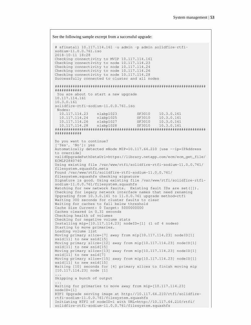
See the following sample excerpt from a successful upgrade:
# sfinstall 10.117.114.161 -u admin -p admin solidfire-rtfi-sodium-11.0.0.761.iso2018-10-11 18:28Checking connectivity to MVIP 10.117.114.161Checking connectivity to node 10.117.114.23Checking connectivity to node 10.117.114.24Checking connectivity to node 10.117.114.26Checking connectivity to node 10.117.114.28Successfully connected to cluster and all nodes
################################################################################ You are about to start a new upgrade10.117.114.16110.3.0.161solidfire-rtfi-sodium-11.0.0.761.iso Nodes: 10.117.114.23 nlabp1023 SF3010 10.3.0.161 10.117.114.24 nlabp1025 SF3010 10.3.0.161 10.117.114.26 nlabp1027 SF3010 10.3.0.161 10.117.114.28 nlabp1028 SF3010 10.3.0.161################################################################################
Do you want to continue?['Yes', 'No']: yes Automatically detected mNode MIP=10.117.64.210 [use --ip=IPAddress to override]validUpgradePathDataUrl=https://library.netapp.com/ecm/ecm_get_file/ECMLP2840740Using existing file /var/www/rtfi/solidfire-rtfi-sodium-11.0.0.761/filesystem.squashfs.metaFound /var/www/rtfi/solidfire-rtfi-sodium-11.0.0.761/filesystem.squashfs checking signatureSignature is good. Using existing file /var/www/rtfi/solidfire-rtfi-sodium-11.0.0.761/filesystem.squashfsWatching for new network faults. Existing fault IDs are set([]).Checking for legacy network interface names that need renamingUpgrading from 10.3.0.161 to 11.0.0.761 upgrade method=rtfiWaiting 300 seconds for cluster faults to clearWaiting for caches to fall below thresholdCache Size Current: 0 Target: 5000000000Caches cleared in 0.31 secondsChecking health of volumesChecking for negative volume statsInstalling mip=[10.117.114.23] nodeID=[1] (1 of 4 nodes)Starting to move primaries.Loading volume listMoving primary slice=[7] away from mip[10.117.114.23] nodeID[1] ssid[11] to new ssid[15]Moving primary slice=[12] away from mip[10.117.114.23] nodeID[1] ssid[11] to new ssid[15]Moving primary slice=[13] away from mip[10.117.114.23] nodeID[1] ssid[11] to new ssid[7]Moving primary slice=[15] away from mip[10.117.114.23] nodeID[1] ssid[11] to new ssid[15]Waiting [10] seconds for [4] primary slices to finish moving mip [10.117.114.23] node [1] ...Skipping a bunch of output...Waiting for primaries to move away from mip=[10.117.114.23] nodeID=[1]RTFI Upgrade serving image at http://10.117.64.210/rtfi/solidfire-rtfi-sodium-11.0.0.761/filesystem.squashfsInitiating RTFI of nodeID=1 with URL=http://10.117.64.210/rtfi/solidfire-rtfi-sodium-11.0.0.761/filesystem.squashfs
System management | 53
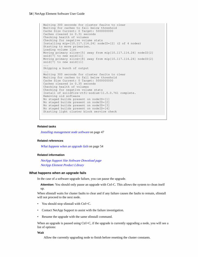
Waiting 300 seconds for cluster faults to clearWaiting for caches to fall below thresholdCache Size Current: 0 Target: 5000000000Caches cleared in 0.31 secondsChecking health of volumesChecking for negative volume statsInstalling mip=[10.117.114.24] nodeID=[2] (2 of 4 nodes)Starting to move primaries.Loading volume listMoving primary slice=[5] away from mip[10.117.114.24] nodeID[2] ssid[7] to new ssid[11]Moving primary slice=[8] away from mip[10.117.114.24] nodeID[2] ssid[7] to new ssid[11]...Skipping a bunch of output...Waiting 300 seconds for cluster faults to clearWaiting for caches to fall below thresholdCache Size Current: 0 Target: 5000000000Caches cleared in 0.35 secondsChecking health of volumesChecking for negative volume statsInstall of solidfire-rtfi-sodium-11.0.0.761 complete.Removing old softwareNo staged builds present on nodeID=[1]No staged builds present on nodeID=[2]No staged builds present on nodeID=[3]No staged builds present on nodeID=[4]Starting light cluster block service check
Related tasks
Installing management node software on page 47
Related references
What happens when an upgrade fails on page 54
Related information
NetApp Support Site Software Download page
NetApp Element Product Library
What happens when an upgrade fails
In the case of a software upgrade failure, you can pause the upgrade.
Attention: You should only pause an upgrade with Ctrl-C. This allows the system to clean itselfup.
When sfinstall waits for cluster faults to clear and if any failure causes the faults to remain, sfinstallwill not proceed to the next node.
• You should stop sfinstall with Ctrl+C.
• Contact NetApp Support to assist with the failure investigation.
• Resume the upgrade with the same sfinstall command.
When an upgrade is paused using Ctrl+C, if the upgrade is currently upgrading a node, you will see alist of options:
Wait
Allow the currently upgrading node to finish before resetting the cluster constants.
54 | NetApp Element Software User Guide

Continue
Continue the upgrade, which cancels the pause.
Abort
Reset the cluster constants and abort the upgrade immediately.
Note: Aborting the cluster upgrade while a node is being updated might result in thedrives being ungracefully removed from the node. If the drives are ungracefullyremoved, adding the drives back during an upgrade will require manual intervention byNetApp Support. The node might be taking longer to do firmware updates or post-update syncing activities. If the upgrade progress seems stalled, please contact NetAppSupport for assistance.
Related tasks
Upgrading Element software on page 52
Upgrading Element software on dark sites
You must use the sfinstall file included in the HealthTools suite of tools to update NetApp Elementsoftware.
Before you begin
Attention: Before you upgrade Element software, see the NetApp Element Software ReleaseNotes for the Element version you are upgrading to and verify that the upgrade path is valid.
• You have the latest version of the management node software.
• Your management node is not connected to the Internet.
Steps
1. Go to the NetApp Support Site.
2. Download the newest NetApp Element software package to a computer that is not themanagement node.
3. Copy the ISO file to the management node in an accessible location like /tmp.
You can do this using, for example, SCP.
Note: When you upload the ISO file, make sure that the name of the file does not change,otherwise later steps will fail.
4. Run the sfinstall command with the following parameters to give the path to the ISO file:
sfinstall -u <cluster_username> --skip-version-check -p<cluster_password> <MVIP> <path-to-install-file-ISO>
When this is run on a dark site, there is no access to the NetApp Support Site, therefore it cannotvalidate the latest version. The command fails unless you run the command with the --skip-version-check option:
See the following sample input command:
sfinstall 10.117.78.244 -u admin -p admin /tmp/solidfire-rtfi-sodium-11.0.0.345.iso.
System management | 55

The output for the sample is as follows:
sfinstall failed: Unable to verify latest available version of healthtools.Manually verify latest version by checking 'latest_version' field in https://library.netapp.com/ecm/ecm_get_file/ECMLP2840740 (this version: 2018.09.01.130)Re-run the command with '-n, --skip-version-check' parameter.
Related tasks
Checking the installed version of HealthTools on dark sites on page 48
Installing management node software on page 47
56 | NetApp Element Software User Guide
Data management
You can manage the data in a cluster running Element software from the Management tab in theElement UI. Available cluster management functions include creating and managing data volumes,user accounts, volume access groups, initiators, and Quality of Service (QoS) policies.
Related concepts
Working with accounts on page 57
Working with volumes on page 59
Working with virtual volumes on page 71
Working with access groups and initiators on page 80
Working with accountsIn SolidFire storage systems, accounts enable clients to connect to volumes on a node. When youcreate a volume, it is assigned to a specific user account.
An account contains the CHAP authentication required to access the volumes assigned to it. Anaccount can have up to two-thousand volumes assigned to it, but a volume can belong to only oneaccount.
Related tasks
Creating an account on page 57
Viewing individual account details on page 58
Editing an account on page 58
Deleting an account on page 59
Creating an account
You can create an account to allow access to volumes.
About this task
Each account name in the system must be unique.
Steps
1. Select Management > Accounts.
2. Click Create Account.
3. Enter a Username.
4. In the CHAP Settings section, enter the following information:
• Initiator Secret for CHAP node session authentication.
• Target Secret for CHAP node session authentication.
Note: Leave the credential fields blank to auto-generate either password.
5. Click Create Account.
57

Account details
The Accounts page on the Management tab provides information about each account in the system,such as ID, user name, and efficiency details for the volumes assigned to each account.
ID
The system-generated ID for the account.
Username
The name given to the account when it was created.
Status
The status of the account. Possible values:
• active: An active account.
• locked: A locked account.
• removed: An account that has been deleted and purged.
Active Volumes
The number of active volumes assigned to the account.
Compression
The compression efficiency score for the volumes assigned to the account.
Deduplication
The deduplication efficiency score for the volumes assigned to the account.
Thin Provisioning
The thin provisioning efficiency score for the volumes assigned to the account.
Overall Efficiency
The overall efficiency score for the volumes assigned to the account.
Viewing individual account details
You can view performance activity for individual accounts in a graphical format.
About this task
The graph information provides I/O and throughput information for the account. The Average andPeak activity levels are shown in increments of 10-second reporting periods. These statistics includeactivity for all volumes assigned to the account.
Steps
1. Select Management > Accounts.
2. Click the Actions icon for an account.
3. Click View Details.
Editing an account
You can edit an account to change the status, change the CHAP secrets, or modify the account name.
About this task
Modifying CHAP settings in an account or removing initiators or volumes from an access group cancause initiators to lose access to volumes unexpectedly. To verify that volume access will not be lost
58 | NetApp Element Software User Guide

unexpectedly, always log out iSCSI sessions that will be affected by an account or access groupchange, and verify that initiators can reconnect to volumes after any changes to initiator settings andcluster settings have been completed.
Steps
1. Select Management > Accounts.
2. Click the Actions icon for an account.
3. In the resulting menu, select Edit.
4. Optional: Edit the Username.
5. Optional: Click the Status drop-down list and select a different status.
Attention: Changing the status to locked terminates all iSCSI connections to the account, andthe account is no longer accessible. Volumes associated with the account are maintained;however, the volumes are not iSCSI discoverable.
6. Optional: Under CHAP Settings, edit the Initiator Secret and Target Secret credentials used fornode session authentication.
Note: If you do not change the CHAP Settings credentials, they remain the same. If you makethe credentials fields blank, the system generates new passwords.
7. Click Save Changes.
Deleting an account
You can delete an account when it is no longer needed.
Before you begin
Delete and purge any volumes associated with the account before you delete the account.
Steps
1. Select Management > Accounts.
2. Click the Actions icon for the account you want to delete.
3. In the resulting menu, select Delete.
4. Confirm the action.
Working with volumesThe SolidFire system provisions storage using volumes. Volumes are block devices accessed over thenetwork by iSCSI or Fibre Channel clients. From the Volumes page on the Management tab, you cancreate, modify, clone, and delete volumes on a node. You can also view statistics about volumebandwidth and I/O usage.
Related concepts
Quality of Service on page 60
Related tasks
Creating a QoS policy on page 62
Data management | 59

Editing a QoS policy on page 63
Deleting a QoS policy on page 63
Creating a volume on page 64
Viewing individual volume performance details on page 65
Editing active volumes on page 66
Deleting a volume on page 67
Restoring a deleted volume on page 68
Purging a volume on page 68
Cloning a volume on page 68
Assigning LUNs to Fibre Channel volumes on page 70
Applying a QoS policy to volumes on page 70
Removing the QoS policy association of a volume on page 70
Quality of Service
A SolidFire storage cluster has the ability to provide Quality of Service (QoS) parameters on a per-volume basis. You can guarantee cluster performance measured in inputs and outputs per second(IOPS) using three configurable parameters that define QoS: Min IOPS, Max IOPS, and Burst IOPS.
IOPS parameters are defined in the following ways:
Minimum IOPS
The minimum number of sustained inputs and outputs per second (IOPS) that the storagecluster provides to a volume. The Min IOPS configured for a volume is the guaranteedlevel of performance for a volume. Performance does not drop below this level.
Maximum IOPS
The maximum number of sustained IOPS that the storage cluster provides to a volume.When cluster IOPS levels are critically high, this level of IOPS performance is notexceeded.
Burst IOPS
The maximum number of IOPS allowed in a short burst scenario. If a volume has beenrunning below the Max IOPS, burst credits are accumulated. When performance levelsbecome very high and are pushed to maximum levels, short bursts of IOPS are allowed onthe volume.
Element software uses Burst IOPS when a cluster is running in a state of low cluster IOPSutilization.
A single volume can accrue Burst IOPS and use the credits to burst above their Max IOPSup to their Burst IOPS level for a set "burst period". A volume can burst for up to 60seconds if the cluster has the capacity to accommodate the burst.
A volume accrues one second of burst credit (up to a maximum of 60 seconds) for everysecond that the volume runs below its Max IOPS limit.
Burst IOPS are limited in two ways:
• A volume can burst above its Max IOPS for a number of seconds equal to the numberof burst credits that the volume has accrued.
• When a volume bursts above its Max IOPS setting, it is limited by its Burst IOPSsetting. Therefore, the burst IOPS never exceeds the burst IOPS setting for the volume.
Effective Max Bandwidth
The maximum bandwidth is calculated by multiplying the number of IOPS (based on theQoS curve) by the IO size.
Example:
60 | NetApp Element Software User Guide

QoS parameter settings of 100 Min IOPS, 1000 Max IOPS, and 1500 Burst IOPs have thefollowing effects on quality of performance:
• Workloads are able to reach and sustain a maximum of 1000 IOPS until the conditionof workload contention for IOPS becomes apparent on the cluster. IOPS are thenreduced incrementally until IOPS on all volumes are within the designated QoS rangesand contention for performance is relieved.
• Performance on all volumes is pushed toward the Min IOPS of 100. Levels do not dropbelow the Min IOPS setting but could remain higher than 100 IOPS when workloadcontention is relieved.
• Performance is never greater than 1000 IOPS, or less than 100 IOPS for a sustainedperiod. Performance of 1500 IOPS (Burst IOPS) is allowed, but only for thosevolumes that have accrued burst credits by running below Max IOPS and only allowedfor a short periods of time. Burst levels are never sustained.
QoS value limits
You can find information about the possible minimum and maximum values for Quality of Service(QoS).
I/O size maximum value
Parameters
Minimumvalue
Default 4KB 8KB 16KB 262KB
MinIOPS
50 50 15,000 9,375* 5556* 385*
MaxIOPS
100 15,000 200,000** 125,000 74,074 5128
BurstIOPS
100 15,000 200,000** 125,000 74,074 5128
*These estimations are approximate.
**Max IOPS and Burst IOPS can be set as high as 200,000; however, this setting is allowed onlyto effectively uncap the performance of a volume. Real-world maximum performance of a volumeis limited by cluster usage and per-node performance.
QoS performance curve
The Quality of Service (QoS) performance curve shows the relationship between block size and thepercentage of IOPS.
Block size and bandwidth have a direct impact on the number of IOPS that an application can obtain.Element software takes into account the block sizes it receives by normalizing block sizes to 4k.Based on workload, the system might increase block sizes. As block sizes increase, the systemincreases bandwidth to a level necessary to process the larger block sizes. As bandwidth increases thenumber of IOPS the system is able to attain decreases.
The QoS performance curve shows the relationship between increasing block sizes and thedecreasing percentage of IOPS:
Data management | 61

As an example, if block sizes are 4k, and bandwidth is 4000 KBps, the IOPS are 1000. If block sizesincrease to 8k, bandwidth increases to 5000 KBps, and IOPS decrease to 625. By taking block sizeinto account, the system ensures that lower priority workloads that use higher block sizes, such asbackups and hypervisor activities, do not take too much of the performance needed by higher prioritytraffic using smaller block sizes.
QoS policies
A Quality of Service (QoS) policy enables you to create and save a standardized quality of servicesetting that can be applied to many volumes. You can create, edit, and delete QoS policies from theQoS Policies page on the Management tab.
Related tasks
Creating a QoS policy on page 62
Editing a QoS policy on page 63
Deleting a QoS policy on page 63
Creating a QoS policy
You can create QoS policies and apply them when creating volumes.
Steps
1. Select Management > QoS Policies.
2. Click Create QoS Policy.
3. Enter the Policy Name.
4. Enter the Min IOPS, Max IOPS, and Burst IOPS values.
5. Click Create QoS Policy.
62 | NetApp Element Software User Guide

QoS policies details
You can view details of QoS policies from the Management tab.
ID
The system-generated ID for the QoS policy.
Name
The user-defined name for the QoS policy.
Min IOPS
The minimum number of IOPS guaranteed for the volume.
Max IOPS
The maximum number of IOPS allowed for the volume.
Burst IOPS
The maximum number of IOPS allowed over a short period of time for the volume.Default = 15,000.
Volumes
Shows the number of volumes using the policy. This number links to a table of volumesthat have the policy applied.
Editing a QoS policy
You can change the name of an existing QoS policy or edit the values associated with the policy.Changing a QoS policy affects all volumes associated with the policy.
Steps
1. Select Management > QoS Policies.
2. Click the Actions icon for the QoS policy you want to edit.
3. In the resulting menu, select Edit.
4. In the Edit QoS Policy dialog box, modify the following properties as required:
• Policy Name
• Min IOPS
• Max IOPS
• Burst IOPS
5. Click Save Changes.
Deleting a QoS policy
You can delete a QoS policy if it is no longer needed. When you delete a QoS policy, all volumesassociated with the policy maintain the QoS settings but become unassociated with a policy.
Steps
1. Select Management > QoS Policies.
2. Click the Actions icon for the QoS policy you want to delete.
3. In the resulting menu, select Delete.
4. Confirm the action.
Data management | 63

Creating a volume
You can create a volume and associate the volume with a given account. Every volume must beassociated with an account. This association gives the account access to the volume through theiSCSI initiators using the CHAP credentials.
About this task
You can specify QoS settings for a volume during creation.
Steps
1. Select Management > Volumes.
2. Click Create Volume.
3. In the Create a New Volume dialog box, enter the Volume Name.
4. Enter the total size of the volume.
Note: The default volume size selection is in GB. You can create volumes using sizes measuredin GB or GiB:
• 1GB = 1 000 000 000 bytes
• 1GiB = 1 073 741 824 bytes
5. Select a Block Size for the volume.
6. Click the Account drop-down list and select the account that should have access to the volume.
If an account does not exist, click the Create Account link, enter a new account name, and clickCreate. The account is created and associated with the new volume.
Note: If there are more than 50 accounts, the list does not appear. Begin typing and the auto-complete function displays possible values for you to choose.
7. To set the Quality of Service, do one of the following:
a. Under Policy, you can select an existing QoS policy, if available.
b. Under Custom Settings, set customized minimum, maximum, and burst values for IOPS oruse the default QoS values.
Volumes that have a Max or Burst IOPS value greater than 20,000 IOPS might require highqueue depth or multiple sessions to achieve this level of IOPS on a single volume.
8. Click Create Volume.
Volume details
The Volumes page on the Management tab provides information about the active volumes such asname, account, access groups associated with the volume, and size of the volume.
ID
The system-generated ID for the volume.
Name
The name given to the volume when it was created. Names can be up to 223 characters inlength and contain a-z, 0-9, and dash (-) characters.
64 | NetApp Element Software User Guide
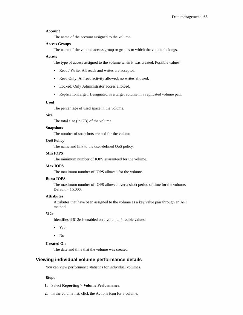
Account
The name of the account assigned to the volume.
Access Groups
The name of the volume access group or groups to which the volume belongs.
Access
The type of access assigned to the volume when it was created. Possible values:
• Read / Write: All reads and writes are accepted.
• Read Only: All read activity allowed; no writes allowed.
• Locked: Only Administrator access allowed.
• ReplicationTarget: Designated as a target volume in a replicated volume pair.
Used
The percentage of used space in the volume.
Size
The total size (in GB) of the volume.
Snapshots
The number of snapshots created for the volume.
QoS Policy
The name and link to the user-defined QoS policy.
Min IOPS
The minimum number of IOPS guaranteed for the volume.
Max IOPS
The maximum number of IOPS allowed for the volume.
Burst IOPS
The maximum number of IOPS allowed over a short period of time for the volume.Default = 15,000.
Attributes
Attributes that have been assigned to the volume as a key/value pair through an APImethod.
512e
Identifies if 512e is enabled on a volume. Possible values:
• Yes
• No
Created On
The date and time that the volume was created.
Viewing individual volume performance details
You can view performance statistics for individual volumes.
Steps
1. Select Reporting > Volume Performance.
2. In the volume list, click the Actions icon for a volume.
Data management | 65

3. Click View Details.
A tray appears at the bottom of the page containing general information about the volume.
4. To see more detailed information about the volume, click See More Details.
The system displays detailed information as well as performance graphs for the volume.
Editing active volumes
You can modify volume attributes such as QoS values, volume size, and the unit of measurement inwhich byte values are calculated. You can also modify account access for replication usage or torestrict access to the volume.
About this task
You can resize a volume when there is sufficient space on the cluster under the following conditions:
• Normal operating conditions.
• Volume errors or failures are being reported.
• The volume is being cloned.
• The volume is being resynced.
Steps
1. Select Management > Volumes.
2. In the Active window, click the Actions icon for the volume you want to edit.
3. Click Edit.
4. Optional: Change the total size of the volume.
Note:
• You can increase, but not decrease, the size of the volume. You can only resize one volumein a single resizing operation. Garbage collection operations and software upgrades do notinterrupt the resizing operation.
• If you are adjusting volume size for replication, you should first increase the size of thevolume assigned as the replication target. Then you can resize the source volume. Thetarget volume can be greater or equal in size to the source volume, but it cannot be smaller.
Note: The default volume size selection is in GB. You can create volumes using sizes measuredin GB or GiB:
• 1GB = 1 000 000 000 bytes
• 1GiB = 1 073 741 824 bytes
5. Optional: Select a different account access level of one of the following:
• Read Only
• Read/Write
• Locked
• Replication Target
66 | NetApp Element Software User Guide

6. Optional: Select the account that should have access to the volume.
If the account does not exist, click the Create Account link, enter a new account name, and clickCreate. The account is created and associated with the volume.
Note: If there are more than 50 accounts, the list does not appear. Begin typing and the auto-complete function displays possible values for you to choose.
7. Optional: To change the selection in Quality of Service, do one of the following:
a. Under Policy, you can select an existing QoS policy, if available.
b. Under Custom Settings, set customized minimum, maximum, and burst values for IOPS oruse the default QoS values.
Note: When you change IOPS values, you should increment in tens or hundreds. Inputvalues require valid whole numbers.
Tip: Configure volumes with an extremely high burst value. This allows the system toprocess occasional large block sequential workloads more quickly, while still constrainingthe sustained IOPS for a volume.
8. Click Save Changes.
Deleting a volume
You can delete one or more volumes from a SolidFire cluster.
About this task
The system does not immediately purge a deleted volume; the volume remains available forapproximately eight hours. If you restore a volume before the system purges it, the volume comesback online and iSCSI connections are restored.
If a volume used to create a snapshot is deleted, its associated snapshots become inactive. When thedeleted source volumes are purged, the associated inactive snapshots are also removed from thesystem.
Steps
1. Select Management > Volumes.
2. To delete a single volume, perform the following steps:
a. Click the Actions icon for the volume you want to delete.
b. In the resulting menu, click Delete.
c. Confirm the action.
The system moves the volume to the Deleted area on the Volumes page.
3. To delete multiple volumes, perform the following steps:
a. In the list of volumes, check the box next to any volumes you want to delete.
b. Click Bulk Actions.
c. In the resulting menu, click Delete.
d. Confirm the action.
The system moves the volumes to the Deleted area on the Volumes page.
Data management | 67

Restoring a deleted volume
You can restore a volume in the system if it has been deleted but not yet purged. The systemautomatically purges a volume approximately eight hours after it has been deleted. If the system haspurged the volume, you cannot restore it.
Steps
1. Select Management > Volumes.
2. Click the Deleted tab to view the list of deleted volumes.
3. Click the Actions icon for the volume you want to restore.
4. In the resulting menu, click Restore.
5. Confirm the action.
The volume is placed in the Active volumes list and iSCSI connections to the volume arerestored.
Purging a volume
When a volume is purged, it is permanently removed from the system. All data in the volume is lost.
About this task
The system automatically purges deleted volumes eight hours after deletion. However, if you want topurge a volume before the scheduled time, you can do so.
Steps
1. Select Management > Volumes.
2. Click the Deleted button.
3. Perform the steps to purge a single volume or multiple volumes.
Option Steps
Purge a single volumea. Click the Actions icon for the volume you want to purge.
b. Click Purge.
c. Confirm the action.
Purge multiple volumesa. Select the volumes you want to purge.
b. Click Bulk Actions.
c. In the resulting menu, select Purge.
d. Confirm the action.
Cloning a volume
You can create a clone of a single volume or multiple volumes to make a point-in-time copy of thedata. When you clone a volume, the system creates a snapshot of the volume and then creates a copy
68 | NetApp Element Software User Guide
of the data referenced by the snapshot. This is an asynchronous process, and the amount of time theprocess requires depends on the size of the volume you are cloning and the current cluster load.
About this task
The cluster supports up to two running clone requests per volume at a time and up to eight activevolume clone operations at a time. Requests beyond these limits are queued for later processing.
Attention: Before you truncate a cloned volume by cloning to a smaller size, ensure that youprepare the partitions so that they fit into the smaller volume.
Steps
1. Select Management > Volumes.
2. To clone a single volume, perform the following steps:
a. In the list of volumes on the Active page, click the Actions icon for the volume you want toclone.
b. In the resulting menu, click Clone.
c. In the Clone Volume window, enter a volume name for the newly cloned volume.
d. Select a size and measurement for the volume using the Volume Size spin box and list.
Note: The default volume size selection is in GB. You can create volumes using sizesmeasured in GB or GiB:
• 1GB = 1 000 000 000 bytes
• 1GiB = 1 073 741 824 bytes
e. Select the type of access for the newly cloned volume.
f. Select an account to associate with the newly cloned volume from the Account list.
Note: You can create an account during this step if you click the Create Account link,enter an account name, and click Create. The system automatically adds the account to theAccount list after you create it.
3. To clone multiple volumes, perform the following steps:
a. In the list of volumes on the Active page, check the box next to any volumes you want toclone.
b. Click Bulk Actions.
c. In the resulting menu, select Clone.
d. In the Clone Multiple Volumes dialog box, enter a prefix for the cloned volumes in the NewVolume Name Prefix field.
e. Select an account to associate with the cloned volumes from the Account list.
f. Select the type of access for the cloned volumes.
4. Click Start Cloning.
Note: Increasing the volume size of a clone results in a new volume with additional free spaceat the end of the volume. Depending on how you use the volume, you might need to extendpartitions or create new partitions in the free space to make use of it.
Data management | 69

Assigning LUNs to Fibre Channel volumes
You can change the LUN assignment for a Fibre Channel volume in a volume access group. You canalso make Fibre Channel volume LUN assignments when you create a volume access group.
About this task
Assigning new Fibre Channel LUNs is an advanced function and could have unknown consequenceson the connecting host. For example, the new LUN ID might not be automatically discovered on thehost, and the host might require a rescan to discover the new LUN ID.
Steps
1. Select Management > Access Groups.
2. Click the Actions icon for the access group you want to edit.
3. In the resulting menu, select Edit.
4. Under Assign LUN IDs in the Edit Volume Access Group dialog box, click the arrow on theLUN Assignments list.
5. For each volume in the list that you want to assign a LUN to, enter a new value in thecorresponding LUN field.
6. Click Save Changes.
Applying a QoS policy to volumes
You can bulk apply an existing QoS policy to one or more volumes.
Before you begin
The QoS policy you want to bulk apply exists.
Steps
1. Select Management > Volumes.
2. In the list of volumes, check the box next to any volumes you want to apply the QoS policy to.
3. Click Bulk Actions.
4. In the resulting menu, click Apply QoS Policy.
5. Select the QoS policy from the drop-down list.
6. Click Apply.
Related concepts
QoS policies on page 62
Removing the QoS policy association of a volume
You can remove a QoS policy association from a volume by selecting custom QoS settings.
Before you begin
The volume you want to modify is associated with a QoS policy.
70 | NetApp Element Software User Guide

Steps
1. Select Management > Volumes.
2. Click the Actions icon for a volume that contains a QoS policy you want to modify.
3. Click Edit.
4. In the resulting menu under Quality of Service, click Custom Settings.
5. Modify Min IOPS, Max IOPS, and Burst IOPS, or keep the default settings.
6. Click Save Changes.
Working with virtual volumesYou can view information and perform tasks for virtual volumes and their associated storagecontainers, protocol endpoints, bindings, and hosts using the Element UI.
The NetApp Element software storage system ships with the Virtual Volumes (VVols) featuredisabled. You must perform a one-time task of manually enabling vSphere VVol functionalitythrough the Element UI.
After you enable the VVol functionality, a VVols tab appears in the user interface that offers VVols-related monitoring and limited management options. Additionally, a storage-side software componentknown as the VASA Provider acts as a storage awareness service for vSphere. Most VVolscommands, such as VVol creation, cloning, and editing, are initiated by a vCenter Server or ESXihost and translated by the VASA Provider to Element APIs for the Element software storage system.Commands to create, delete, and manage storage containers and delete virtual volumes can beinitiated using the Element UI.
The majority of configurations necessary for using Virtual Volumes functionality with Elementsoftware storage systems are made in vSphere. See the VMware vSphere Virtual Volumes forSolidFire Storage Configuration Guide to register the VASA Provider in vCenter, create and manageVVol datastores, and manage storage based on policies.
Note: The VVol functionality has a cluster limit of 8000 virtual volumes.
Related concepts
Protocol endpoints on page 78
Bindings on page 79
Related tasks
Enabling virtual volumes on page 71
Deleting a virtual volume on page 75
Creating a storage container on page 76
Editing a storage container on page 77
Deleting a storage container on page 78
Related references
Host details on page 79
Enabling virtual volumes
You must manually enable vSphere Virtual Volumes (VVols) functionality through the Element UI.The Element software system comes with VVols functionality disabled by default, and it is not
Data management | 71

automatically enabled as part of a new installation or upgrade. Enabling the VVols feature is a one-time configuration task.
Before you begin
• The cluster must be running Element 9.0 or later.
• The cluster must be connected to an ESXi 6.0 and later environment that is compatible withVVols.
• For systems running Element software 11.x, enabling virtual volumes before or after settingprotection domain monitoring causes the cluster protection domains feature to function only atnode level.
About this task
Attention: Enabling vSphere Virtual Volumes functionality permanently changes the Elementsoftware configuration. You should only enable VVols functionality if your cluster is connected toa VMware ESXi VVols-compatible environment. You can disable the VVols feature and restore thedefault settings only by returning the cluster to the factory image.
Steps
1. Select Clusters > Settings.
2. Find the cluster-specific settings for Virtual Volumes.
3. Click Enable Virtual Volumes.
4. Click Yes to confirm the Virtual Volumes configuration change.
The VVols tab appears in the Element UI.
Note: When VVols functionality is enabled, the SolidFire cluster starts the VASA Provider,opens port 8444 for VASA traffic, and creates protocol endpoints that can be discovered byvCenter and all ESXi hosts.
5. Copy the VASA Provider URL from the Virtual Volumes (VVols) settings in Clusters > Settings.You will use this URL to register the VASA Provider in vCenter.
6. Create a storage container in VVols > Storage Containers.
Note: You must create at least one storage container so that VMs can be provisioned to a VVoldatastore.
7. Select VVols > Protocol Endpoints.
8. Verify that a protocol endpoint has been created for each node in the cluster.
Note: Additional configuration tasks are required in vSphere. See the VMware vSphere VirtualVolumes for SolidFire Storage Configuration Guide to register the VASA Provider in vCenter,create and manage VVol datastores, and manage storage based on policies.
Related information
VMware vSphere Virtual Volumes for SolidFire Storage Configuration Guide
72 | NetApp Element Software User Guide

Viewing virtual volume details
You can review virtual volume information for all active virtual volumes on the cluster in the ElementUI. You can also view performance activity for each virtual volume, including input, output,throughput, latency, queue depth, and volume information.
Before you begin
• You have enabled VVols functionality in the Element UI for the cluster.
• You have created an associated storage container.
• You have configured your vSphere cluster to use Element software VVols functionality.
• You have created at least one VM in vSphere.
Steps
1. Click VVols > Virtual Volumes.
The information for all active virtual volumes is displayed.
2. Click the Actions icon for the virtual volume you want to review.
3. In the resulting menu, select View Details.
Virtual volume details
The Virtual Volumes page of the VVols tab provides information about each active virtual volume onthe cluster, such as volume ID, snapshot ID, parent virtual volume ID, and virtual volume ID.
Volume ID
The ID of the underlying volume.
Snapshot ID
The ID of the underlying volume snapshot. The value is 0 if the virtual volume does notrepresent a SolidFire snapshot.
Parent Virtual Volume ID
The virtual volume ID of the parent virtual volume. If the ID is all zeros, the virtualvolume is independent with no link to a parent.
Virtual Volume ID
The UUID of the virtual volume.
Name
The name assigned to the virtual volume.
Storage Container
The storage container that owns the virtual volume.
Guest OS Type
Operating system associated with the virtual volume.
Virtual Volume Type
The virtual volume type: Config, Data, Memory, Swap, or Other.
Access
The read-write permissions assigned to the virtual volume.
Size
The size of the virtual volume in GB or GiB.
Data management | 73

Snapshots
The number of associated snapshots. Click the number to link to snapshot details.
Min IOPS
The minimum IOPS QoS setting of the virtual volume.
Max IOPS
The maximum IOPS QoS setting of the virtual volume.
Burst IOPS
The maximum burst QoS setting of the virtual volume.
VMW_VmID
Information in fields prefaced with "VMW_" are defined by VMware.
Create Time
The time the virtual volume creation task was completed.
Individual virtual volume details
The Virtual Volumes page on the VVols tab provides the following virtual volume information whenyou select an individual virtual volume and view its details.
VMW_XXX
Information in fields prefaced with "VMW_" are defined by VMware.
Parent Virtual Volume ID
The virtual volume ID of the parent virtual volume. If the ID is all zeros, the virtualvolume is independent with no link to a parent.
Virtual Volume ID
The UUID of the virtual volume.
Virtual Volume Type
The virtual volume type: Config, Data, Memory, Swap, or Other.
Volume ID
The ID of the underlying volume.
Access
The read-write permissions assigned to the virtual volume.
Account Name
Name of the account containing the volume.
Access Groups
Associated volume access groups.
Total Volume Size
Total provisioned capacity in bytes.
Non-Zero Blocks
Total number of 4KiB blocks with data after the last garbage collection operation hascompleted.
Zero Blocks
Total number of 4KiB blocks without data after the last round of garbage collectionoperation has completed.
Snapshots
The number of associated snapshots. Click the number to link to snapshot details.
74 | NetApp Element Software User Guide

Min IOPS
The minimum IOPS QoS setting of the virtual volume.
Max IOPS
The maximum IOPS QoS setting of the virtual volume.
Burst IOPS
The maximum burst QoS setting of the virtual volume.
Enable 512
Because virtual volumes always use 512-byte block size emulation, the value is alwaysyes.
Volumes Paired
Indicates if a volume is paired.
Create Time
The time the virtual volume creation task was completed.
Blocks Size
Size of the blocks on the volume.
Unaligned Writes
For 512e volumes, the number of write operations that were not on a 4k sector boundary.High numbers of unaligned writes might indicate improper partition alignment.
Unaligned Reads
For 512e volumes, the number of read operations that were not on a 4k sector boundary.High numbers of unaligned reads might indicate improper partition alignment.
scsiEUIDeviceID
Globally unique SCSI device identifier for the volume in EUI-64 based 16-byte format.
scsiNAADeviceID
Globally unique SCSI device identifier for the volume in NAA IEEE Registered Extendedformat.
Attributes
List of name-value pairs in JSON object format.
Deleting a virtual volume
Although virtual volumes should always be deleted from the VMware Management Layer, thefunctionality for you to delete virtual volumes is enabled from the Element UI. You should onlydelete a virtual volume from the Element UI when absolutely necessary, such as when vSphere failsto clean up virtual volumes on SolidFire storage.
Steps
1. Select VVols > Virtual Volumes.
2. Click the Actions icon for the virtual volume you want to delete.
3. In the resulting menu, select Delete.
Attention: You should delete a virtual volume from the VMware Management Layer to ensurethat the virtual volume is properly unbound before deletion. You should only delete a virtualvolume from the Element UI when absolutely necessary, such as when vSphere fails to cleanup virtual volumes on SolidFire storage. If you delete a virtual volume from the Element UI,the volume will be purged immediately.
4. Confirm the action.
Data management | 75
5. Refresh the list of virtual volumes to confirm that the virtual volume has been removed.
6. Optional: Select Reporting > Event Log to confirm that the purge has been successful.
Storage containers
A storage container is a vSphere datastore representation created on a cluster running Elementsoftware.
Storage containers are created and tied to NetApp Element accounts. A storage container created onElement storage appears as a vSphere datastore in vCenter and ESXi. Storage containers do notallocate any space on Element storage. They are simply used to logically associate virtual volumes.
A maximum of four storage containers per cluster is supported. A minimum of one storage containeris required to enable VVols functionality.
Creating a storage container
You can create storage containers in the Element UI and discover them in vCenter. You must create atleast one storage container to begin provisioning VVol-backed virtual machines.
Before you begin
You have enabled VVols functionality in the Element UI for the cluster.
Steps
1. Select VVols > Storage Containers.
2. Click the Create Storage Containers button.
3. Enter storage container information in the Create a New Storage Container dialog box:
a. Enter a name for the storage container.
b. Configure initiator and target secrets for CHAP.
Tip: Leave the CHAP Settings fields blank to automatically generate secrets.
c. Click the Create Storage Container button.
4. Verify that the new storage container appears in the list in the Storage Containers sub-tab.
Note: Because a NetApp Element account ID is created automatically and assigned to thestorage container, it is not necessary to manually create an account.
Storage container details
On the Storage Containers page of the VVols tab, you can view information for all active storagecontainers on the cluster.
Account ID
The ID of the NetApp Element account associated with the storage container.
Name
The name of the storage container.
Status
The status of the storage container. Possible values:
• Active: The storage container is in use.
• Locked: The storage container is locked.
76 | NetApp Element Software User Guide

PE Type
Indicates the protocol endpoint type (SCSI is the only available protocol for Elementsoftware).
Storage Container ID
The UUID of the virtual volume storage container.
Active Virtual Volumes
The number of active virtual volumes associated with the storage container.
Individual storage container details
You can view the storage container information for an individual storage container by selecting itfrom the Storage Containers page on the VVols tab.
Account ID
The ID of the NetApp Element account associated with the storage container.
Name
The name of the storage container.
Status
The status of the storage container. Possible values:
• Active: The storage container is in use.
• Locked: The storage container is locked.
Chap Initiator Secret
The unique CHAP secret for the initiator.
Chap Target Secret
The unique CHAP secret for the target.
Storage Container ID
The UUID of the virtual volume storage container.
Protocol Endpoint Type
Indicates the protocol endpoint type (SCSI is the only available protocol).
Editing a storage container
You can modify storage container CHAP authentication in the Element UI.
Steps
1. Select VVols > Storage Containers.
2. Click the Actions icon for the storage container you want to edit.
3. In the resulting menu, select Edit.
4. Under CHAP Settings, edit the Initiator Secret and Target Secret credentials used forauthentication.
Tip: If you do not change the CHAP Settings credentials, they remain the same. If you makethe credentials fields blank, the system automatically generates new secrets.
5. Click Save Changes.
Data management | 77
Deleting a storage container
You can delete storage containers from the Element UI.
Before you begin
All virtual machines have been removed from the VVol datastore.
Steps
1. Select VVols > Storage Containers.
2. Click the Actions icon for the storage container you want to delete.
3. In the resulting menu, select Delete.
4. Confirm the action.
5. Refresh the list of storage containers in the Storage Containers sub-tab to confirm that thestorage container has been removed.
Protocol endpoints
Protocol endpoints are access points used by a host to address storage on a cluster running NetAppElement software. Protocol endpoints cannot be deleted or modified by a user, are not associated withan account, and cannot be added to a volume access group.
A cluster running Element software automatically creates one protocol endpoint per storage node inthe cluster. For example, a six-node storage cluster has six protocol endpoints that are mapped toeach ESXi host. Protocol endpoints are dynamically managed by Element software and are created,moved, or removed as needed without any intervention. Protocol endpoints are the target for multi-pathing and act as an I/O proxy for subsidiary LUNs. Each protocol endpoint consumes an availableSCSI address, just like a standard iSCSI target. Protocol endpoints appear as a single-block (512-byte) storage device in the vSphere client, but this storage device is not available to be formatted orused as storage.
iSCSI is the only supported protocol. Fibre C
hannel protocol is not supported.
Protocol endpoints details
The Protocol Endpoints page on the VVols tab provides protocol endpoint information.
Primary Provider ID
The ID of the primary protocol endpoint provider.
Secondary Provider ID
The ID of the secondary protocol endpoint provider.
Protocol Endpoint ID
The UUID of the protocol endpoint.
Protocol Endpoint State
The status of the protocol endpoint. Possible values are as follows:
• Active: The protocol endpoint is in use.
• Start: The protocol endpoint is starting.
• Failover: The protocol endpoint has failed over.
• Reserved: The protocol endpoint is reserved.
78 | NetApp Element Software User Guide

Provider Type
The type of the protocol endpoint's provider. Possible values are as follows:
• Primary
• Secondary
SCSI NAA Device ID
The globally unique SCSI device identifier for the protocol endpoint in NAA IEEERegistered Extended Format.
Bindings
To perform I/O operations with a virtual volume, an ESXi host must first bind the virtual volume.
The SolidFire cluster chooses an optimal protocol endpoint, creates a binding that associates theESXi host and virtual volume with the protocol endpoint, and returns the binding to the ESXi host.After it is bound, the ESXi host can perform I/O operations with the bound virtual volume.
Bindings details
The Bindings page on the VVols tab provides binding information about each virtual volume.
The following information displayed:
Host ID
The UUID for the ESXi host that hosts virtual volumes and is known to the cluster.
Protocol Endpoint ID
Protocol endpoint IDs that correspond to each node in the SolidFire cluster.
Protocol Endpoint in Band ID
The SCSI NAA device ID of the protocol endpoint.
Protocol Endpoint Type
Indicates the protocol endpoint type.
VVol Binding ID
The binding UUID of the virtual volume.
VVol ID
The universally unique identifier (UUID) of the virtual volume.
VVol Secondary ID
The secondary ID of the virtual volume that is a SCSI second level LUN ID.
Host details
The Hosts page on the VVols tab provides information about VMware ESXi hosts that host virtualvolumes.
The following information is displayed:
Host ID
The UUID for the ESXi host that hosts virtual volumes and is known to the cluster.
Host Address
The IP address or DNS name for the ESXi host.
Bindings
Binding IDs for all virtual volumes bound by the ESXi host.
Data management | 79

ESX Cluster ID
The vSphere host cluster ID or vCenter GUID.
Initiator IQNs
Initiator IQNs for the virtual volume host.
SolidFire Protocol Endpoint IDs
The protocol endpoints that are currently visible to the ESXi host.
Working with access groups and initiatorsYou can use iSCSI initiators or Fibre Channel initiators to access volume access groups.
You can create access groups by mapping iSCSI initiator IQNs or Fibre Channel WWPNs in acollection of volumes. Each IQN that you add to an access group can access each volume in thegroup without requiring CHAP authentication. Each WWPN that you add to an access group enablesFibre Channel network access to the volumes in the access group.
Note: Volume access groups have the following limits:
• A maximum of 64 IQNs or WWPNs are allowed in an access group.
• An access group can be made up of a maximum of 2000 volumes.
• An IQN or WWPN can belong to only one access group.
• A single volume can belong to a maximum of four access groups.
Related tasks
Creating an access group on page 80
Adding volumes to an access group on page 82
Removing volumes from an access group on page 82
Creating an initiator on page 83
Editing an initiator on page 84
Adding a single initiator to an access group on page 84
Adding multiple initiators to an access group on page 85
Removing initiators from an access group on page 85
Deleting an access group on page 86
Deleting an initiator on page 86
Creating an access group
You can create volume access groups by mapping initiators to a collection of volumes for securedaccess. You can then grant access to the volumes in the group with an account CHAP initiator secretand target secret.
Steps
1. Click Management > Access Groups.
2. Click Create Access Group.
3. Enter a name for the volume access group in the Name field.
4. Add an initiator to the volume access group in one of the following ways:
80 | NetApp Element Software User Guide

Option Description
Adding a Fibre Channelinitiator
a. Under Add Initiators, select an existing Fibre Channel initiator fromthe Unbound Fibre Channel Initiators list.
b. Click Add FC Initiator.
Note:
You can create an initiator during this step if you click the CreateInitiator link, enter an initiator name, and click Create. Thesystem automatically adds the initiator to the Initiators list afteryou create it.
A sample of the format is as follows:
5f:47:ac:c0:5c:74:d4:02
Adding an iSCSI initiator Under Add Initiators, select an existing initiator from the Initiators list.
Note:
You can create an initiator during this step if you click the CreateInitiator link, enter an initiator name, and click Create. The systemautomatically adds the initiator to the Initiators list after you create it.
A sample of the format is as follows:
iqn.2010-01.com.solidfire:c2r9.fc0.2100000e1e09bb8b
Tip: You can find the initiator IQN for each volume by selecting ViewDetails in the Actions menu for the volume on the Management >Volumes > Active list.
5. Optional: Add more initiators as needed.
6. Under Add Volumes, select a volume from the Volumes list.
The volume appears in the Attached Volumes list.
7. Optional: Add more volumes as needed.
8. Click Create Access Group.
Related tasks
Adding volumes to an access group on page 82
Volume access group details
The Access Groups page on the Management tab provides information about volume access groups.
The following information is displayed:
ID
The system-generated ID for the access group.
Name
The name given to the access group when it was created.
Data management | 81

Active Volumes
The number of active volumes in the access group.
Compression
The compression efficiency score for the access group.
Deduplication
The deduplication efficiency score for the access group.
Thin Provisioning
The thin provisioning efficiency score for the access group.
Overall Efficiency
The overall efficiency score for the access group.
Initiators
The number of initiators connected to the access group.
Viewing individual access group details
You can view details for an individual access group, such as attached volumes and initiators, in agraphical format.
Steps
1. Click Management > Access Groups.
2. Click the Actions icon for an access group.
3. Click View Details.
Adding volumes to an access group
You can add volumes to a volume access group. Each volume can belong to more than one volumeaccess group; you can see the groups that each volume belongs to on the Active volumes page.
About this task
You can also use this procedure to add volumes to a Fibre Channel volume access group.
Steps
1. Click Management > Access Groups.
2. Click the Actions icon for the access group you want to add volumes to.
3. Click the Edit button.
4. Under Add Volumes, select a volume from the Volumes list.
You can add more volumes by repeating this step.
5. Click Save Changes.
Removing volumes from an access group
When you remove a volume from an access group, the group no longer has access to that volume.
About this task
Modifying CHAP settings in an account or removing initiators or volumes from an access group cancause initiators to lose access to volumes unexpectedly. To verify that volume access will not be lost
82 | NetApp Element Software User Guide

unexpectedly, always logout iSCSI sessions that will be affected by an account or access groupchange, and verify that initiators can reconnect to volumes after any changes to initiator settings andcluster settings have been completed.
Steps
1. Click Management > Access Groups.
2. Click the Actions icon for the access group you want to remove volumes from.
3. Click Edit.
4. Under Add Volumes in the Edit Volume Access Group dialog box, click the arrow on theAttached Volumes list.
5. Select the volume you want to remove from the list and click the x icon to remove the volumefrom the list.
You can remove more volumes by repeating this step.
6. Click Save Changes.
Creating an initiator
You can create iSCSI or Fibre Channel initiators and optionally assign them aliases.
Steps
1. Click Management > Initiators.
2. Click Create Initiator.
3. Perform the steps to create a single initiator or multiple initiators:
Option Steps
Create a single initiatora. Click Create a Single Initiator.
b. Enter the IQN or WWPN for the initiator in the IQN/WWPN field.
c. Enter a friendly name for the initiator in the Alias field.
d. Click Create Initiator.
Create multiple initiatorsa. Click Bulk Create Initiators.
b. Enter a list of IQNs or WWPNs in the text box.
c. Click Add Initiators.
d. Choose an initiator from the resulting list and click the correspondingAdd icon in the Alias column to add an alias for the initiator.
e. Click the check mark to confirm the new alias.
f. Click Create Initiators.
Data management | 83

Editing an initiator
You can change the alias of an existing initiator or add an alias if one does not already exist.
Steps
1. Click Management > Initiators.
2. Click the Actions icon for the initiator you want to edit.
3. Click Edit.
4. Enter a new alias for the initiator in the Alias field.
5. Click Save Changes.
Adding a single initiator to an access group
You can add an initiator to an existing access group.
About this task
When you add an initiator to a volume access group, the initiator has access to all volumes in thatvolume access group.
Tip: You can find the initiator for each volume by clicking the Actions icon and then selectingView Details for the volume in the active volumes list.
Steps
1. Click Management > Access Groups.
2. Click the Actions icon for the access group you want to edit.
3. Click the Edit button.
4. To add a Fibre Channel initiator to the volume access group, perform the following steps:
a. Under Add Initiators, select an existing Fibre Channel initiator from the Unbound FibreChannel Initiators list.
b. Click Add FC Initiator.
Note: You can create an initiator during this step if you click the Create Initiator link, enter aninitiator name, and click Create. The system automatically adds the initiator to the Initiatorslist after you create it.
A sample of the format is as follows:
5f:47:ac:c0:5c:74:d4:02
5. To add an iSCSI initiator to the volume access group, under Add Initiators, select an existinginitiator from the Initiators list.
Note: You can create an initiator during this step if you click the Create Initiator link, enter aninitiator name, and click Create. The system automatically adds the initiator to the Initiatorslist after you create it.
The accepted format of an initiator IQN is as follows: iqn.yyyy-mm, in which y and m are digits,followed by text which must only contain digits, lower-case alphabetic characters, a period (.),colon (:) or dash (-).
84 | NetApp Element Software User Guide

A sample of the format is as follows:
iqn.2010-01.com.solidfire:c2r9.fc0.2100000e1e09bb8b
Tip: You can find the initiator IQN for each volume from the Management > Volumes ActiveVolumes page by clicking the Actions icon and then selecting View Details for the volume.
6. Click Save Changes.
Adding multiple initiators to an access group
You can add multiple initiators to an existing volume access group to allow access to volumes in thevolume access group without requiring CHAP authentication..
About this task
When you add initiators to a volume access group, the initiators have access to all volumes in thatvolume access group.
Tip: You can find the initiator for each volume by clicking the Actions icon and then View Detailsfor the volume in the active volumes list.
Steps
1. Click Management > Initiators.
2. Select the initiators you want to add to an access group.
3. Click the Bulk Actions button.
4. Click Add to Volume Access Group.
5. In the Add to Volume Access Group dialog box, select an access group from the Volume AccessGroup list.
6. Click Add.
Removing initiators from an access group
When you remove an initiator from an access group, it can no longer access the volumes in thatvolume access group. Normal account access to the volume is not disrupted.
About this task
Modifying CHAP settings in an account or removing initiators or volumes from an access group cancause initiators to lose access to volumes unexpectedly. To verify that volume access will not be lostunexpectedly, always logout iSCSI sessions that will be affected by an account or access groupchange, and verify that initiators can reconnect to volumes after any changes to initiator settings andcluster settings have been completed.
Steps
1. Click Management > Access Groups.
2. Click the Actions icon for the access group you want to remove.
3. In the resulting menu, select Edit.
4. Under Add Initiators in the Edit Volume Access Group dialog box, click the arrow on theInitiators list.
Data management | 85

5. Select the x icon for each initiator you want to remove from the access group.
6. Click Save Changes.
Deleting an access group
You can delete an access group when it is no longer needed. You do not need to delete Initiator IDsand Volume IDs from the volume access group before deleting the group. After you delete the accessgroup, group access to the volumes is discontinued.
Steps
1. Click Management > Access Groups.
2. Click the Actions icon for the access group you want to delete.
3. In the resulting menu, click Delete.
4. To also delete the initiators associated with this access group, select the Delete initiators in thisaccess group check box.
5. Confirm the action.
Deleting an initiator
You can delete an initiator after it is no longer needed. When you delete an initiator, the systemremoves it from any associated volume access group. Any connections using the initiator remainvalid until the connection is reset.
Steps
1. Click Management > Initiators.
2. Perform the steps to delete a single initiator or multiple initiators:
Option Steps
Delete single initiatora. Click the Actions icon for the initiator you want to delete.
b. Click Delete.
c. Confirm the action.
Delete multiple initiatorsa. Select the check boxes next to the initiators you want to delete.
b. Click the Bulk Actions button.
c. In the resulting menu, select Delete.
d. Confirm the action.
86 | NetApp Element Software User Guide

Data protection
Element software enables you to protect your data in a variety of ways with capabilities such assnapshots for individual volumes or groups of volumes, snapshot scheduling capability, replicationbetween clusters and volumes, and replication to ONTAP systems.
Related concepts
Using individual volume snapshots on page 87
Using group snapshots on page 92
Using snapshot schedules on page 97
Using replication between clusters running Element software on page 100
Using SnapMirror replication between Element and ONTAP clusters on page 111
Backing up and restoring volumes on page 124
Using individual volume snapshotsA volume snapshot is a point-in-time copy of a volume. You can take a snapshot of a volume and usethe snapshot later if you need to roll a volume back to the state it was in at the time the snapshot wascreated.
Snapshots are similar to volume clones. However, snapshots are simply replicas of volume metadata,so you cannot mount or write to them. Creating a volume snapshot also takes only a small amount ofsystem resources and space, which makes snapshot creation faster than cloning.
You can replicate snapshots to a remote cluster and use them as a backup copy of the volume. Thisenables you to roll back a volume to a specific point in time by using the replicated snapshot; you canalso create a clone of a volume from a replicated snapshot.
Related tasks
Creating a volume snapshot on page 87
Editing snapshot retention on page 88
Deleting a snapshot on page 89
Cloning a volume from a snapshot on page 89
Rolling back a volume to a snapshot on page 90
Backing up a volume snapshot to an Amazon S3 object store on page 90
Backing up a volume snapshot to an OpenStack Swift object store on page 91
Backing up a volume snapshot to a SolidFire cluster on page 91
Creating a volume snapshot
You can create a snapshot of an active volume to preserve the volume image at any point in time. Youcan create up to 32 snapshots for a single volume.
Steps
1. Click Management > Volumes.
2. Click the Actions icon for the volume you want to use for the snapshot.
3. In the resulting menu, select Snapshot.
4. In the Create Snapshot of Volume dialog box, enter the new snapshot name.
87

5. Optional: Select the Include Snapshot in Replication When Paired check box to ensure that thesnapshot is captured in replication when the parent volume is paired.
6. To set the retention for the snapshot, select from one of the following options:
• Click Keep Forever to retain the snapshot on the system indefinitely.
• Click Set Retention Period and use the date spin boxes to choose a length of time for thesystem to retain the snapshot.
7. To take a single, immediate snapshot, perform the following steps:
a. Click Take Snapshot Now.
b. Click Create Snapshot.
8. To schedule the snapshot to run at a future time, perform the following steps:
a. Click Create Snapshot Schedule.
b. Enter a New Schedule Name.
c. Choose a Schedule Type from the list.
d. Optional: Select the Recurring Schedule check box to repeat the scheduled snapshotperiodically.
e. Click Create Schedule.
Related concepts
Using snapshot schedules on page 97
Editing snapshot retention
You can change the retention period for a snapshot to control when or if the system deletes snapshots.The retention period you specify begins when you enter the new interval. When you set a retentionperiod, you can select a period that begins at the current time (retention is not calculated from thesnapshot creation time). You can specify intervals in minutes, hours, and days.
Steps
1. Click Data Protection > Snapshots.
2. Click the Actions icon for the snapshot you want to edit.
3. In the resulting menu, click Edit.
4. Optional: Select the Include Snapshot in Replication When Paired check box to ensure that thesnapshot is captured in replication when the parent volume is paired.
5. Optional: Select a retention option for the snapshot:
• Click Keep Forever to retain the snapshot on the system indefinitely.
• Click Set Retention Period and use the date spin boxes to select a length of time for thesystem to retain the snapshot.
6. Click Save Changes.
88 | NetApp Element Software User Guide

Deleting a snapshot
You can delete a volume snapshot from a storage cluster running Element software. When you deletea snapshot, the system immediately removes it.
About this task
You can delete snapshots that are being replicated from the source cluster. If a snapshot is syncing tothe target cluster when you delete it, the sync replication completes and the snapshot is deleted fromthe source cluster. The snapshot is not deleted from the target cluster.
You can also delete snapshots that have been replicated to the target from the target cluster. Thedeleted snapshot is kept in a list of deleted snapshots on the target until the system detects that youhave deleted the snapshot on the source cluster. When the target detects that you have deleted thesource snapshot, the target stops replication of the snapshot.
When you delete a snapshot from the source cluster, the target cluster snapshot is not affected (thereverse is also true).
Steps
1. Click Data Protection > Snapshots.
2. Click the Actions icon for the snapshot you want to delete.
3. In the resulting menu, select Delete.
4. Confirm the action.
Cloning a volume from a snapshot
You can create a new volume from a snapshot of a volume. When you do this, the system uses thesnapshot information to clone a new volume using the data contained on the volume at the time thesnapshot was created. This process stores information about other snapshots of the volume in thenewly created volume.
Steps
1. Click Data Protection > Snapshots.
2. Click the Actions icon for the snapshot you want to use for the volume clone.
3. In the resulting menu, click Clone Volume From Snapshot.
4. Enter a Volume Name in the Clone Volume From Snapshot dialog box.
5. Select a Total Size and size units for the new volume.
6. Select an Access type for the volume.
7. Select an Account from the list to associate with the new volume.
8. Click Start Cloning.
Data protection | 89

Rolling back a volume to a snapshot
You can roll back a volume to a previous snapshot at any time. This reverts any changes made to thevolume since the snapshot was created.
Steps
1. Click Data Protection > Snapshots.
2. Click the Actions icon for the snapshot you want to use for the volume rollback.
3. In the resulting menu, select Rollback Volume To Snapshot.
4. Optional: To save the current state of the volume before rolling back to the snapshot:
a. In the Rollback To Snapshot dialog box, select Save volume's current state as a snapshot.
b. Enter a name for the new snapshot.
5. Click Rollback Snapshot.
Volume snapshot backup operations
You can use the integrated backup feature to back up a volume snapshot. You can back up snapshotsfrom a SolidFire cluster to an external object store, or to another SolidFire cluster. When you back upa snapshot to an external object store, you must have a connection to the object store that allows read/write operations.
Backing up a volume snapshot to an Amazon S3 object store
You can back up SolidFire snapshots to external object stores that are compatible with Amazon S3.
Steps
1. Click Data Protection > Snapshots.
2. Click the Actions icon for the snapshot you want to back up.
3. In the resulting menu, click Backup to.
4. In the Integrated Backup dialog box under Backup to, select S3.
5. Select an option under Data Format:
• Native: A compressed format readable only by SolidFire storage systems.
• Uncompressed: An uncompressed format compatible with other systems.
6. Enter a hostname to use to access the object store in the Hostname field.
7. Enter an access key ID for the account in the Access Key ID field.
8. Enter the secret access key for the account in the Secret Access Key field.
9. Enter the S3 bucket in which to store the backup in the S3 Bucket field.
10. Optional: Enter a nametag to append to the prefix in the Nametag field.
11. Click Start Read.
90 | NetApp Element Software User Guide

Backing up a volume snapshot to an OpenStack Swift object store
You can back up SolidFire snapshots to secondary object stores that are compatible with OpenStackSwift.
Steps
1. Click Data Protection > Snapshots.
2. Click the Actions icon for the snapshot you want to back up.
3. In the resulting menu, click Backup to.
4. In the Integrated Backup dialog box, under Backup to, select Swift.
5. Select an option under Data Format:
• Native: A compressed format readable only by SolidFire storage systems.
• Uncompressed: An uncompressed format compatible with other systems.
6. Enter a URL to use to access the object store.
7. Enter a Username for the account.
8. Enter the Authentication Key for the account.
9. Enter the Container in which to store the backup.
10. Optional: Enter a Nametag.
11. Click Start Read.
Backing up a volume snapshot to a SolidFire cluster
You can back up volume snapshots residing on a SolidFire cluster to a remote SolidFire cluster.
Before you begin
Ensure that the source and target clusters are paired.
About this task
When backing up or restoring from one cluster to another, the system generates a key to be used asauthentication between the clusters. This bulk volume write key allows the source cluster toauthenticate with the destination cluster, providing a level of security when writing to the destinationvolume. As part of the backup or restore process, you need to generate a bulk volume write key fromthe destination volume before starting the operation.
Steps
1. On the destination cluster, click Management > Volumes.
2. Click the Actions icon for the destination volume.
3. In the resulting menu, click Restore from.
4. In the Integrated Restore dialog box under Restore from, select SolidFire.
5. Select a data format under Data Format:
• Native: A compressed format readable only by SolidFire storage systems.
Data protection | 91

• Uncompressed: An uncompressed format compatible with other systems.
6. Click Generate Key.
7. Copy the key from the Bulk Volume Write Key box to your clipboard.
8. On the source cluster, click Data Protection > Snapshots.
9. Click the Actions icon for the snapshot you want to use for the backup.
10. In the resulting menu, click Backup to.
11. In the Integrated Backup dialog box under Backup to, select SolidFire.
12. Select the same data format you selected earlier in the Data Format field.
13. Enter the management virtual IP address of the destination volume's cluster in the RemoteCluster MVIP field.
14. Enter the remote cluster user name in the Remote Cluster Username field.
15. Enter the remote cluster password in the Remote Cluster Password field.
16. In the Bulk Volume Write Key field, paste the key you generated on the destination clusterearlier.
17. Click Start Read.
Using group snapshotsYou can create a group snapshot of a related set of volumes to preserve a point-in-time copy of themetadata for each volume. You can use the group snapshot in the future as a backup or rollback torestore the state of the group of volumes to a certain state.
Related tasks
Creating a group snapshot on page 93
Editing group snapshots on page 94
Editing members of group snapshot on page 95
Deleting a group snapshot on page 94
Rolling back volumes to a group snapshot on page 95
Cloning multiple volumes on page 96
Cloning multiple volumes from a group snapshot on page 96
Group snapshot details
The Group Snapshots page on the Data Protection tab provides information about the groupsnapshots.
ID
The system-generated ID for the group snapshot.
UUID
The unique ID of the group snapshot.
Name
User-defined name for the group snapshot.
Create Time
The time at which the group snapshot was created.
92 | NetApp Element Software User Guide

Status
The current status of the snapshot. Possible values:
• Preparing: The snapshot is being prepared for use and is not yet writable.
• Done: This snapshot has finished preparation and is now usable.
• Active: The snapshot is the active branch.
# Volumes
The number of volumes in the group.
Retain Until
The day and time the snapshot will be deleted.
Remote Replication
Identifies whether or not the snapshot is enabled for replication to a remote SolidFirecluster. Possible values:
• Enabled: The snapshot is enabled for remote replication.
• Disabled: The snapshot is not enabled for remote replication.
Creating a group snapshot
You can create a snapshot of a group of volumes, and you can also create a group snapshot scheduleto automate group snapshots. A single group snapshot can consistently snapshot up to 32 volumes atone time.
Steps
1. Click Management > Volumes.
2. Use the check boxes to select multiple volumes for a group of volumes.
3. Click Bulk Actions.
4. Click Group Snapshot.
5. Enter a new group snapshot name in the Create Group Snapshot of Volumes dialog box.
6. Optional: Select the Include Each Group Snapshot Member in Replication When Pairedcheck box to ensure that each snapshot is captured in replication when the parent volume ispaired.
7. Select a retention option for the group snapshot:
• Click Keep Forever to retain the snapshot on the system indefinitely.
• Click Set Retention Period and use the date spin boxes to choose a length of time for thesystem to retain the snapshot.
8. To take a single, immediate snapshot, perform the following steps:
a. Click Take Group Snapshot Now.
b. Click Create Group Snapshot.
9. To schedule the snapshot to run at a future time, perform the following steps:
a. Click Create Group Snapshot Schedule.
b. Enter a New Schedule Name.
Data protection | 93

c. Select a Schedule Type from the list.
d. Optional: Select the Recurring Schedule check box to repeat the scheduled snapshotperiodically.
e. Click Create Schedule.
Editing group snapshots
You can edit the replication and retention settings for existing group snapshots.
Steps
1. Click Data Protection > Group Snapshots.
2. Click the Actions icon for the group snapshot you want to edit.
3. In the resulting menu, select Edit.
4. Optional: To change the replication setting for the group snapshot:
a. Click Edit next to Current Replication.
b. Select the Include Each Group Snapshot Member in Replication When Paired check boxto ensure that each snapshot is captured in replication when the parent volume is paired.
5. Optional: To change the retention setting for the group snapshot, select from the followingoptions:
a. Click Edit next to Current Retention.
b. Select a retention option for the group snapshot:
• Click Keep Forever to retain the snapshot on the system indefinitely.
• Click Set Retention Period and use the date spin boxes to choose a length of time for thesystem to retain the snapshot.
6. Click Save Changes.
Deleting a group snapshot
You can delete a group snapshot from the system. When you delete the group snapshot, you canchoose whether all snapshots associated with the group are deleted or retained as individualsnapshots.
About this task
If you delete a volume or snapshot that is a member of a group snapshot, you can no longer roll backto the group snapshot. However, you can roll back each volume individually.
Steps
1. Click Data Protection > Group Snapshots.
2. Click the Actions icon for the snapshot you want to delete.
3. In the resulting menu, click Delete.
4. Select from one of the following options in the confirmation dialog box:
• Click Delete group snapshot AND all group snapshot members to delete the groupsnapshot and all member snapshots.
94 | NetApp Element Software User Guide

• Click Retain group snapshot members as individual snapshots to delete the group snapshotbut keep all member snapshots.
5. Confirm the action.
Rolling back volumes to a group snapshot
You can roll back a group of volumes at any time to a group snapshot.
About this task
When you roll back a group of volumes, all volumes in the group are restored to the state they werein at the time the group snapshot was created. Rolling back also restores volume sizes to the sizerecorded in the original snapshot. If the system has purged a volume, all snapshots of that volumewere also deleted at the time of the purge; the system does not restore any deleted volume snapshots.
Steps
1. Click Data Protection > Group Snapshots.
2. Click the Actions icon for the group snapshot you want to use for the volume rollback.
3. In the resulting menu, select Rollback Volumes To Group Snapshot.
4. Optional: To save the current state of the volumes before rolling back to the snapshot:
a. In the Rollback To Snapshot dialog box, select Save volumes' current state as a groupsnapshot.
b. Enter a name for the new snapshot.
5. Click Rollback Group Snapshot.
Editing members of group snapshot
You can edit the retention settings for members of an existing group snapshot.
Steps
1. Click Data Protection > Snapshots.
2. Click the Members tab.
3. Click the Actions icon for the group snapshot member you want to edit.
4. In the resulting menu, select Edit.
5. To change the replication setting for the snapshot, select from the following options:
• Click Keep Forever to retain the snapshot on the system indefinitely.
• Click Set Retention Period and use the date spin boxes to choose a length of time for thesystem to retain the snapshot.
6. Click Save Changes.
Data protection | 95
Cloning multiple volumes
You can create multiple volume clones in a single operation to create a point-in-time copy of the dataon a group of volumes.
About this task
When you clone a volume, the system creates a snapshot of the volume and then creates a newvolume from the data in the snapshot. You can mount and write to the new volume clone. Cloningmultiple volumes is an asynchronous process and takes a variable amount of time depending on thesize and number of the volumes being cloned.
Volume size and current cluster load affect the time needed to complete a cloning operation.
Steps
1. Click Management > Volumes.
2. Click the Active tab.
3. Use the check boxes to select multiple volumes, creating a group of volumes.
4. Click Bulk Actions.
5. Click Clone in the resulting menu.
6. Enter a New Volume Name Prefix in the Clone Multiple Volumes dialog box.
The prefix is applied to all volumes in the group.
7. Optional: Select a different account to which the clone will belong.
If you do not select an account, the system assigns the new volumes to the current volumeaccount.
8. Optional: Select a different access method for the volumes in the clone.
If you do not select an access method, the system uses the current volume access.
9. Click Start Cloning.
Cloning multiple volumes from a group snapshot
You can clone a group of volumes from a point-in-time group snapshot. This operation requires that agroup snapshot of the volumes already exist, because the group snapshot is used as the basis to createthe volumes. After you create the volumes, you can use them like any other volume in the system.
About this task
Volume size and current cluster load affect the time needed to complete a cloning operation.
Steps
1. Click Data Protection > Group Snapshots.
2. Click the Actions icon for the group snapshot you want to use for the volume clones.
3. In the resulting menu, select Clone Volumes From Group Snapshot.
4. Enter a New Volume Name Prefix in the Clone Volumes From Group Snapshot dialog box.
The prefix is applied to all volumes created from the group snapshot.
96 | NetApp Element Software User Guide

5. Optional: Select a different account to which the clone will belong.
If you do not select an account, the system assigns the new volumes to the current volumeaccount.
6. Optional: Select a different access method for the volumes in the clone.
If you do not select an access method, the system uses the current volume access.
7. Click Start Cloning.
Using snapshot schedulesYou can protect data on a volume or a group of volumes by scheduling volume snapshots to occur atspecified intervals. You can schedule either single volume snapshots or group snapshots to runautomatically.
When you configure a snapshot schedule, you can choose from time intervals based on days of theweek or days of the month. You can also specify the days, hours, and minutes before the nextsnapshot occurs. You can store the resulting snapshots on a remote storage system if the volume isbeing replicated.
Related tasks
Creating a snapshot schedule on page 98
Editing a snapshot schedule on page 98
Deleting a snapshot schedule on page 99
Copying a snapshot schedule on page 99
Snapshot schedule details
On the Data Protection > Schedules page, you can view the following information in the list ofsnapshot schedules.
ID
The system-generated ID for the snapshot.
Type
Indicates the type of schedule. Snapshot is currently the only type supported.
Name
The name given to the schedule when it was created. Snapshot schedule names can be upto 223 characters in length and contain a-z, 0-9, and dash (-) characters.
Frequency
The frequency at which the schedule is run. The frequency can be set in hours andminutes, weeks, or months.
Recurring
The frequency at which the schedule is run. The frequency can be set in hours andminutes, weeks, or months.
Manually Paused
Identifies whether or not the schedule has been manually paused.
Volume IDs
Displays the ID of the volume the schedule will use when the schedule is run.
Last Run
Displays the last time the schedule was run.
Data protection | 97

Last Run Status
Displays the outcome of the last schedule execution. Possible values:
• Success
• Failure
Creating a snapshot schedule
You can schedule a snapshot of a volume or volumes to automatically occur at specified intervals.
About this task
When you configure a snapshot schedule, you can choose from time intervals based on days of theweek or days of the month. You can also create a recurring schedule and specify the days, hours, andminutes before the next snapshot occurs.
If you schedule a snapshot to run at a time period that is not divisible by 5 minutes, the snapshot willrun at the next time period that is divisible by 5 minutes. For example, if you schedule a snapshot torun at 12:42:00 UTC, it will run at 12:45:00 UTC. You cannot schedule a snapshot to run at intervalsof less than 5 minutes.
Steps
1. Click Data Protection > Schedules.
2. Click Create Schedule.
3. In the Volume IDs CSV field, enter a single volume ID or a comma-separated list of volume IDsto include in the snapshot operation.
4. Enter a new schedule name.
5. Select a schedule type and set the schedule from the options provided.
6. Optional: Select Recurring Schedule to repeat the snapshot schedule indefinitely.
7. Optional: Enter a name for the new snapshot in the New Snapshot Name field.
If you leave the field blank, the system uses the time and date of the snapshot's creation as thename.
8. Optional: Select the Include Snapshots in Replication When Paired check box to ensure thatthe snapshots are captured in replication when the parent volume is paired.
9. To set the retention for the snapshot, select from the following options:
• Click Keep Forever to retain the snapshot on the system indefinitely.
• Click Set Retention Period and use the date spin boxes to choose a length of time for thesystem to retain the snapshot.
10. Click Create Schedule.
Editing a snapshot schedule
You can modify existing snapshot schedules. After modification, the next time the schedule runs ituses the updated attributes. Any snapshots created by the original schedule remain on the storagesystem.
Steps
1. Click Data Protection > Schedules.
98 | NetApp Element Software User Guide

2. Click the Actions icon for the schedule you want to change.
3. In the resulting menu, click Edit.
4. In the Volume IDs CSV field, modify the single volume ID or comma-separated list of volumeIDs currently included in the snapshot operation.
5. To pause or resume the schedule, select from the following options:
• To pause an active schedule, select Yes from the Manually Pause Schedule list.
• To resume a paused schedule, select No from the Manually Pause Schedule list.
6. Enter a different name for the schedule in the New Schedule Name field if desired.
7. To change the schedule to run on different days of the week or month, select Schedule Type andchange the schedule from the options provided.
8. Optional: Select Recurring Schedule to repeat the snapshot schedule indefinitely.
9. Optional: Enter or modify the name for the new snapshot in the New Snapshot Name field.
If you leave the field blank, the system uses the time and date of the snapshot's creation as thename.
10. Optional: Select the Include Snapshots in Replication When Paired check box to ensure thatthe snapshots are captured in replication when the parent volume is paired.
11. To change the retention setting, select from the following options:
• Click Keep Forever to retain the snapshot on the system indefinitely.
• Click Set Retention Period and use the date spin boxes to select a length of time for thesystem to retain the snapshot.
12. Click Save Changes.
Copying a snapshot schedule
You can copy a schedule and maintain its current attributes.
Steps
1. Click Data Protection > Schedules.
2. Click the Actions icon for the schedule you want to copy.
3. In the resulting menu, click Make a Copy.
The Create Schedule dialog box appears, populated with the current attributes of the schedule.
4. Optional: Enter a name and updated attributes for the new schedule.
5. Click Create Schedule.
Deleting a snapshot schedule
You can delete a snapshot schedule. After you delete the schedule, it does not run any futurescheduled snapshots. Any snapshots that were created by the schedule remain on the storage system.
Steps
1. Click Data Protection > Schedules.
Data protection | 99

2. Click the Actions icon for the schedule you want to delete.
3. In the resulting menu, click Delete.
4. Confirm the action.
Using replication between clusters running Elementsoftware
For clusters running Element software, real-time replication enables the quick creation of remotecopies of volume data. You can pair a storage cluster with up to four other storage clusters. You canreplicate volume data synchronously or asynchronously from either cluster in a cluster pair forfailover and failback scenarios.
Related tasks
Pairing clusters on page 101
Pairing volumes on page 104
Configuring cluster and volume pairing for real-time replication
You must first pair two storage clusters running Element software and then pair volumes on eachcluster to take advantage of real-time remote replication.
Before you begin
• You must have cluster administrator privileges to one or both clusters being paired.
• All node IP addresses on both management and storage networks for paired clusters are routed toeach other.
• MTU of all paired nodes must be the same and be supported end-to-end between clusters.
• The difference between Element software versions on the clusters is no greater than one majorversion. If the difference is greater, one of the clusters must be upgraded to perform datareplication.
Note: WAN Accelerator appliances have not been qualified by NetApp for use when replicatingdata. These appliances can interfere with compression and deduplication if deployed between twoclusters that are replicating data. Be sure to fully qualify the effects of any WAN Acceleratorappliance before you deploy it in a production environment.
Steps
1. Create a cluster pair.
2. Create a volume pair.
3. Assign a replication source and target to the paired volumes.
Related tasks
Pairing clusters on page 101
Pairing volumes on page 104
Assigning a replication source and target to paired volumes on page 107
100 | NetApp Element Software User Guide

Cluster pairs
You must pair two clusters as a first step to using real-tme replication functionality. After you pairand connect two clusters, you can configure active volumes on one cluster to be continuouslyreplicated to a second cluster, providing continuous data protection (CDP).
You can pair one cluster with up to four other clusters for replicating volumes. You can also pairclusters within the cluster group with each other.
Pairing clusters
You can pair a source and target cluster using the MVIP of the target cluster if there is clusteradministrator access to both clusters. If cluster administrator access is only available on one cluster ina cluster pair, a pairing key can be used on the target cluster to complete the cluster pairing.
Before you begin
• You must have cluster administrator privileges to one or both clusters being paired.
• All node MIPs and SIPs are routed to each other.
• Less than 2000 ms of round-trip latency between clusters.
• The difference between Element software versions on the clusters is no greater than one majorversion. If the difference is greater, one of the clusters must be upgraded to perform datareplication.
Note: Cluster pairing requires full connectivity between nodes on the management network.Replication requires connectivity between the individual nodes on the storage cluster network.
Step
1. Select one of the following methods to pair clusters:
• Pair clusters using MVIP: Use this method if there is cluster administrator access to bothclusters. This method uses the MVIP of the remote cluster to pair two clusters.
• Pair clusters using a pairing key: Use this method if there is cluster administrator access toonly one of the clusters. This method generates a pairing key that can be used on the targetcluster to complete the cluster pairing.
Related tasks
Pairing clusters using MVIP on page 101
Pairing clusters using a pairing key on page 102
Related references
Network port requirements on page 11
Pairing clusters using MVIP
You can pair two clusters for real-time replication by using the MVIP of one cluster to establish aconnection with the other cluster. Cluster administrator access on both of clusters is required to usethis method. The cluster administrator user name and password is used to authenticate cluster accessbefore the clusters can be paired.
Steps
1. On the local cluster, select Data Protection > Cluster Pairs.
Data protection | 101

2. Click Pair Cluster.
3. Click Start Pairing and click Yes to indicate that you have access to the remote cluster.
4. Enter the remote cluster MVIP address.
5. Click Complete pairing on remote cluster.
In the Authentication Required window, enter the cluster administrator user name and passwordof the remote cluster.
6. On the remote cluster, select Data Protection > Cluster Pairs.
7. Click Pair Cluster.
8. Click Complete Pairing.
9. Click the Complete Pairing button.
In the Cluster Pairs window, verify that the cluster pair is connected.
(Optional) Navigate back to the local cluster and the Cluster Pairs window and verify that thecluster pair is connected.
Related tasks
Pairing clusters using a pairing key on page 102
Related information
Pairing clusters using MVIP (video)
Pairing clusters using a pairing key
If you have cluster administrator access to a local cluster but not the remote cluster, you can pair theclusters using a pairing key. A pairing key is generated on a local cluster and then sent securely to acluster administrator at a remote site to establish a connection and complete the cluster pairing forreal-time replication.
Steps
1. On the local cluster, select Data Protection > Cluster Pairs.
2. Click Pair Cluster.
3. Click Start Pairing and click No to indicate that you do not have access to the remote cluster.
4. Click Generate Key.
Note: This action generates a text key for pairing and creates an unconfigured cluster pair onthe local cluster. If you do not complete the procedure, you will need to manually delete thecluster pair.
5. Copy the cluster pairing key to your clipboard.
6. Make the pairing key accessible to the cluster administrator at the remote cluster site.
Note: The cluster pairing key contains a version of the MVIP, user name, password, anddatabase information to permit volume connections for remote replication. This key should betreated in a secure manner and not stored in a way that would allow accidental or unsecuredaccess to the user name or password.
Attention: Do not modify any of the characters in the pairing key. The key becomes invalid if itis modified.
102 | NetApp Element Software User Guide

7. On the remote cluster, select Data Protection > Cluster Pairs.
8. Click Pair Cluster.
9. Click Complete Pairing and enter the pairing key in the Pairing Key field (paste is therecommended method).
10. Click Complete Pairing.
In the Cluster Pairs window, verify that the cluster pair is connected.
(Optional) Navigate back to the local cluster and the Cluster Pairs window and verify that thecluster pair is connected.
Related tasks
Pairing clusters using MVIP on page 101
Related information
Pairing clusters using a cluster pairing key (video)
Cluster pair details
The Cluster Pairs page on the Data Protection tab provides information about clusters that have beenpaired or are in the process of being paired. The system displays pairing and progress messages in theStatus column.
ID
A system-generated ID given to each cluster pair.
Remote Cluster Name
The name of the other cluster in the pair.
Remote MVIP
The management virtual IP address of the other cluster in the pair.
Status
Replication status of the remote cluster
Replicating Volumes
The number of volumes contained by the cluster that are paired for replication.
UUID
A unique ID given to each cluster in the pair.
Deleting a cluster pair
You can delete a cluster pair from the Element UI of either of the clusters in the pair.
Steps
1. Click Data Protection > Cluster Pairs.
2. Click the Actions icon for a cluster pair.
3. In the resulting menu, click Delete.
4. Confirm the action.
5. Perform the steps again from the second cluster in the cluster pairing.
Data protection | 103
Volume pairs
You can pair two volumes for real-time replication that are stored on different storage clusters in aconnected cluster pair. After you pair two clusters, you can configure active volumes on one clusterto be continuously replicated to a second cluster, providing continuous data protection (CDP). Youcan also assign either volume to be the source or target of the replication.
Volume pairings are always one-to-one. After a volume is part of a pairing with a volume on anothercluster, you cannot pair it again with any other volume.
Pairing volumes
After you have established a connection between clusters in a cluster pair, you can pair a volume onone cluster with a volume on the other cluster in the pair. When a volume pairing relationship isestablished, you must identify which volume is the replication target.
Before you begin
• You have established a connection between clusters in a cluster pair.
• You have cluster administrator privileges to one or both clusters being paired.
Steps
1. Pair volumes by selecting one of the following methods:
• Using a volume ID: Use this method if you have cluster administrator access to both clusterson which volumes are to be paired. This method uses the volume ID of the volume on theremote cluster to initiate a connection.
• Using a pairing Key: Use this method if you have cluster administrator access to only thesource cluster. This method generates a pairing key that can be used on the remote cluster tocomplete the volume pair.
Note: The volume pairing key contains an encrypted version of the volume information andmight contain sensitive information. Only share this key in a secure manner.
2. Assign a replication target and source to the paired volumes.
Note: A replication source volume has read/write account access. A replication target volumecan only be accessed by the replication source as read/write.
3. Optional: Verify that the cluster pairs have an active connection.
Related tasks
Pairing clusters using MVIP on page 101
Pairing clusters using a pairing key on page 102
Pairing volumes using a volume ID on page 105
Pairing volumes using a pairing key on page 106
Assigning a replication source and target to paired volumes on page 107
Related references
Network port requirements on page 11
104 | NetApp Element Software User Guide

Pairing volumes using a volume ID
You can pair a volume with another volume on a remote cluster if you have cluster administratorcredentials for the remote cluster.
Before you begin
• Ensure that the clusters containing the volumes are paired.
• Create a new volume on the remote cluster.
Note: You can assign a replication source and target after the pairing process. A replicationsource or target can be either volume in a volume pair. You should create a target volume thatcontains no data and has the exact characteristics of the source volume, such as size, 512esetting, and QoS configuration. If you assign an existing volume as the replication target, thedata on that volume will be overwritten. The target volume can be greater or equal in size to thesource volume, but it cannot be smaller.
• Know the target Volume ID.
Steps
1. Select Management > Volumes.
2. Click the Actions icon for the volume you want to pair.
3. Click Pair.
4. In the Pair Volume dialog box, select Start Pairing.
5. Select I Do to indicate that you have access to the remote cluster.
6. Select a Replication Mode from the list:
• Real-time (Asynchronous): Writes are acknowledged to the client after they are committedon the source cluster.
• Real-time (Synchronous): Writes are acknowledged to the client after they are committed onboth the source and target clusters.
• Snapshots Only: Only snapshots created on the source cluster are replicated. Active writesfrom the source volume are not replicated.
7. Select a remote cluster from the list.
8. Choose a remote volume ID.
9. Click Start Pairing.
The system opens a web browser tab that connects to the Element UI of the remote cluster. Youmight be required to log on to the remote cluster with cluster administrator credentials.
10. In the Element UI of the remote cluster, select Complete Pairing.
11. Confirm the details in Confirm Volume Pairing.
12. Click Complete Pairing.
After you confirm the pairing, the two clusters begin the process of connecting the volumes forpairing. During the pairing process, you can see messages in the Volume Status column of theVolume Pairs window. The volume pair displays the following message until the volume pairsource and target are assigned: PausedMisconfigured
Data protection | 105

Related tasks
Assigning a replication source and target to paired volumes on page 107
Related references
Volume pairing messages on page 109
Volume pairing warnings on page 109
Pairing volumes using a pairing key
If you do not have cluster admin credentials for a remote cluster, you can pair a volume with anothervolume on a remote cluster using a pairing key.
Before you begin
• Ensure that the clusters containing the volumes are paired.
• Ensure that there is a volume on the remote cluster to use for the pairing.
Note: You can assign a replication source and target after the pairing process. A replicationsource or target can be either volume in a volume pair. You should create a target volume thatcontains no data and has the exact characteristics of the source volume, such as size, 512esetting, and QoS configuration. If you assign an existing volume as the replication target, thedata on that volume will be overwritten. The target volume can be greater or equal in size to thesource volume, but it cannot be smaller.
Steps
1. Select Management > Volumes.
2. Click Actions icon for the volume you want to pair.
3. Click Pair.
4. In the Pair Volume dialog box, select Start Pairing.
5. Select I Do Not to indicate that you do not have access to the remote cluster.
6. Select a Replication Mode from the list:
• Real-time (Asynchronous): Writes are acknowledged to the client after they are committedon the source cluster.
• Real-time (Synchronous): Writes are acknowledged to the client after they are committed onboth the source and target clusters.
• Snapshots Only: Only snapshots created on the source cluster are replicated. Active writesfrom the source volume are not replicated.
7. Click Generate Key.
Note: This action generates a text key for pairing and creates an unconfigured volume pair onthe local cluster. If you do not complete the procedure, you will need to manually delete thevolume pair.
8. Copy the pairing key to your computer's clipboard.
9. Make the pairing key accessible to the cluster admin at the remote cluster site.
Note: The volume pairing key should be treated in a secure manner and not used in a way thatwould allow accidental or unsecured access.
106 | NetApp Element Software User Guide

Attention: Do not modify any of the characters in the pairing key. The key becomes invalid if itis modified.
10. In the remote cluster Element UI, select Management > Volumes.
11. Click the Actions icon for the volume you want to pair.
12. Click Pair.
13. In the Pair Volume dialog box, select Complete Pairing.
14. Paste the pairing key from the other cluster into the Pairing Key box.
15. Click Complete Pairing.
After you confirm the pairing, the two clusters begin the process of connecting the volumes forpairing. During the pairing process, you can see messages in the Volume Status column of theVolume Pairs window. The volume pair displays PausedMisconfigured until the volume pairsource and target are assigned.
Related tasks
Assigning a replication source and target to paired volumes on page 107
Related references
Volume pairing messages on page 109
Volume pairing warnings on page 109
Assigning a replication source and target to paired volumes
After volumes are paired, you must assign a source volume and its replication target volume. Areplication source or target can be either volume in a volume pair. You can also use this procedure toredirect data sent to a source volume to a remote target volume should the source volume becomeunavailable.
Before you begin
You have access to the clusters containing the source and target volumes.
Steps
1. From the cluster that contains the volume you want to assign as source, select Management >Volumes.
2. Click the Actions icon for the volume you want to assign as source.
3. Click Edit.
4. In the Access drop-down list, select Read/Write.
Attention: If you are reversing source and target assignment, this action will cause the volumepair to display the following message until a new replication target is assigned:PausedMisconfigured
Changing access pauses volume replication and causes the transmission of data to cease. Besure that you have coordinated these changes at both sites.
5. Click Save Changes.
6. From the cluster that contains the volume you want to assign as target, select Management >Volumes.
Data protection | 107

7. Click the Actions icon for the volume you want to assign as target.
8. Click Edit.
9. In the Access drop-down list, select Replication Target.
Attention: If you assign an existing volume as the replication target, the data on that volumewill be overwritten. You should use a new target volume that contains no data and has the exactcharacteristics of the source volume, such as size, 512e setting, and QoS configuration. Thetarget volume can be greater or equal in size to the source volume, but it cannot be smaller.
10. Click Save Changes.
11. Optional: From either cluster, select Data Protection > Volume Pairs.
12. Optional: Verify that the volume status is Active.
Related tasks
Pairing volumes using a volume ID on page 105
Pairing volumes using a pairing key on page 106
Volume pair details
The Volume Pairs page on the Data Protection tab provides information about volumes that have beenpaired or are in the process of being paired. The system displays pairing and progress messages in theVolume Status column.
ID
System-generated ID for the volume.
Name
The name given to the volume when it was created. Volume names can be up to 223characters and contain a-z, 0-9, and dash (-).
Account
Name of the account assigned to the volume.
Volume Status
Replication status of the volume
Snapshot Status
Status of the snapshot volume.
Mode
Indicates the client write replication method. Possible values are as follows:
• Async
• Snapshot-Only
• Sync
Direction
Indicates the direction of the volume data:
• Source volume icon ( ) indicates data is being written to a target outside the cluster.
• Target volume icon ( ) indicates data is being written to the local volume from anoutside source.
108 | NetApp Element Software User Guide

Async Delay
Length of time since the volume was last synced with the remote cluster. If the volume isnot paired, the value is null.
Remote Cluster
Name of the remote cluster on which the volume resides.
Remote Volume ID
Volume ID of the volume on the remote cluster.
Remote Volume Name
Name given to the remote volume when it was created.
Volume pairing messages
You can view volume pairing messages during the initial pairing process from the Volume Pairs pageunder the Data Protection tab. These messages can display on both source and target ends of the pairin the Replicating Volumes list view.
PausedDisconnected
Source replication or sync RPCs timed out. Connection to the remote cluster has been lost.Check network connections to the cluster.
ResumingConnected
The remote replication sync is now active. Beginning the sync process and waiting fordata.
ResumingRRSync
A single helix copy of the volume metadata is being made to the paired cluster.
ResumingLocalSync
A double helix copy of the volume metadata is being made to the paired cluster.
ResumingDataTransfer
Data transfer has resumed.
Active
Volumes are paired and data is being sent from the source to the target volume and thedata is in sync.
Idle
No replication activity is occurring.
Volume pairing warnings
The Volume Pairs page on the Data Protection tab provides these messages after you pair volumes.These messages can display on both source and target ends of the pair (unless otherwise indicated) inthe Replicating Volumes list view.
PausedClusterFull
Because the target cluster is full, source replication and bulk data transfer cannot proceed.The message displays on the source end of the pair only.
PausedExceededMaxSnapshotCount
The target volume already has the maximum number of snapshots and cannot replicateadditional snapshots.
PausedManual
Local volume has been manually paused. It must be unpaused before replication resumes.
Data protection | 109

PausedManualRemote
Remote volume is in manual paused mode. Manual intervention required to unpause theremote volume before replication resumes.
PausedMisconfigured
Waiting for an active source and target. Manual intervention required to resumereplication.
PausedQoS
Target QoS could not sustain incoming IO. Replication auto-resumes. The messagedisplays on the source end of the pair only.
PausedSlowLink
Slow link detected and stopped replication. Replication auto-resumes. The messagedisplays on the source end of the pair only.
PausedVolumeSizeMismatch
Target volume is smaller than the source volume.
PausedXCopy
A SCSI XCOPY command is being issued to a source volume. The command mustcomplete before replication can resume. The message displays on the source end of thepair only.
StoppedMisconfigured
A permanent configuration error has been detected. The remote volume has been purgedor unpaired. No corrective action is possible; a new pairing must be established.
Editing volume pairs
You can edit volume pair properties to make changes to the replication mode of the volume pairrelationship or manually pause replication.
Steps
1. Select Data Protection > Volume Pairs.
2. Click the Actions icon that corresponds to the volume pair you want to edit.
3. Click Edit.
4. In the Edit Volume Pair pane, do any of the following:
Attention: Pausing or resuming volume replication manually will cause the transmission ofdata to cease or resume. Changing the mode of replication will cause the mode to changeimmediately. Be sure that you have coordinated these changes at both sites.
• Manually pause or start the replication process.
• Select a new replication mode:
◦ Real-time (Asynchronous): Writes are acknowledged to the client after they arecommitted on the source cluster.
◦ Real-time (Synchronous): Writes are acknowledged to the client after they are committedon both the source and target clusters.
◦ Snapshots Only: Only snapshots created on the source cluster are replicated. Activewrites from the source volume are not replicated.
5. Click Save Changes.
110 | NetApp Element Software User Guide

Deleting volume pairs
You can delete a volume pair if want to remove a pair association between two volumes.
Steps
1. Select Data Protection > Volume Pairs.
2. Click the Actions icon that corresponds to the volume pair you want to delete.
3. Click Delete.
4. Confirm the message.
Using SnapMirror replication between Element and ONTAPclusters
You can create SnapMirror relationships from the Data Protection tab in the NetApp Element UI.SnapMirror functionality must be enabled to see this in the user interface.
Note: IPv6 is not supported for SnapMirror replication between NetApp Element software andONTAP clusters.
Related concepts
SnapMirror endpoints on page 113
SnapMirror labels on page 115
SnapMirror relationships on page 116
Disaster recovery using SnapMirror on page 119
Related tasks
Enabling SnapMirror on the cluster on page 111
Enabling SnapMirror on the volume on page 112
SnapMirror overview
NetApp Element 10.1 and above supports SnapMirror functionality to copy and restore snapshotswith NetApp ONTAP systems.
Systems running Element 10.1 and above include code that can communicate directly withSnapMirror on ONTAP systems running 9.3 or higher. The NetApp Element API provides methodsto enable SnapMirror functionality on clusters, volumes, and snapshots. Additionally, the Element UIincludes all necessary functionality to manage SnapMirror relationships between Element softwareand ONTAP based systems.
Starting with Element 10.3 and ONTAP 9.4 systems, you can replicate ONTAP originated volumes toElement volumes in specific use cases with limited functionality. For more information, see ONTAPdocumentation.
Related information
Replication between Element software and ONTAP
Enabling SnapMirror on the cluster
You must manually enable SnapMirror functionality at the cluster level through the NetApp ElementUI. The system comes with SnapMirror functionality disabled by default, and it is not automatically
Data protection | 111

enabled as part of a new installation or upgrade. Enabling the SnapMirror feature is a one-timeconfiguration task.
Before you begin
The storage cluster must be running NetApp Element software version 10.1 or later.
About this task
SnapMirror can only be enabled for clusters running Element software used in conjunction withvolumes on a NetApp ONTAP system. You should enable SnapMirror functionality only if yourcluster is connected for use with NetApp ONTAP volumes.
Steps
1. Click Clusters > Settings.
2. Find the cluster-specific settings for SnapMirror.
3. Click Enable SnapMirror.
Note: Enabling SnapMirror functionality permanently changes the Element softwareconfiguration. You can disable the SnapMirror feature and restore the default settings only byreturning the cluster to the factory image.
4. Click Yes to confirm the SnapMirror configuration change.
Enabling SnapMirror on the volume
You must enable SnapMirror on the volume in the Element UI. This allows replication of data tospecified ONTAP volumes. This is permission from the administrator of the cluster running NetAppElement software for SnapMirror to control a volume.
Before you begin
• You have enabled SnapMirror in the Element UI for the cluster.
• A SnapMirror endpoint is available.
• The volume must be 512e block size.
• The volume is not participating in remote replication.
• The volume access type is not Replication Target.
Note: You can also set this property when creating or cloning a volume.
Steps
1. Click Management > Volumes.
2. Click the Actions icon for the volume you want to enable SnapMirror for.
3. In the resulting menu, select Edit.
4. In the Edit Volume dialog box, select the check box Enable SnapMirror.
5. Click Save Changes.
112 | NetApp Element Software User Guide

SnapMirror endpoints
A SnapMirror endpoint is an ONTAP cluster that serves as a replication target for a cluster runningNetApp Element software. You must create a SnapMirror endpoint before you can create aSnapMirror relationship.
You can create and manage up to four SnapMirror endpoints on a storage cluster running Elementsoftware.
Note: If an existing endpoint was originally created using the API and credentials were not saved,you can see the endpoint in the Element UI and verify its existence, but it cannot be managed usingthe Element UI. This endpoint can then only be managed using the Element API. For informationabout the API methods, see the NetApp Element Software API Reference Guide in the Elementproduct library.
Related information
NetApp Element Product Library
Creating an endpoint
You must create a SnapMirror endpoint in the NetApp Element UI before you can create arelationship.
Before you begin
• You have enabled SnapMirror in the Element UI for the storage cluster.
• You know the ONTAP credentials for the endpoint.
Steps
1. Click Data Protection > SnapMirror Endpoints.
2. Click Create Endpoint.
3. In the Create a New Endpoint dialog box, enter the cluster management IP address of theONTAP system.
4. Enter the ONTAP administrator credentials associated with the endpoint.
5. Click Create Endpoint.
SnapMirror endpoint details
The SnapMirror Endpoints page on the Data Protection tab provides information about allSnapMirror endpoints on the cluster such as ID, cluster name, and cluster management IP.
ID
The ID of the endpoint.
Cluster Name
Name of the destination cluster.
Cluster Management IP
IP address of the destination cluster.
LIFs
This lists the ONTAP intercluster logical interfaces used to communicate with Element.
Data protection | 113

Relationships
Number of relationships associated with this endpoint.
Status
Current status of the SnapMirror endpoint. Possible values are as follows:
• connected
• disconnected
• unmanaged
Editing an endpoint
You must modify a SnapMirror endpoint in the NetApp Element UI.
Before you begin
• You have enabled SnapMirror in the Element UI for the cluster.
• An existing SnapMirror endpoint is available to modify.
Steps
1. Click Data Protection > SnapMirror Endpoints.
2. Click the Actions icon for the endpoint you want to edit.
3. In the resulting menu, select Edit.
4. Under Cluster Management IP, edit the IP address as needed.
5. Under ONTAP Credentials, edit the user name or password, if necessary.
6. Click Save Changes.
Deleting an endpoint
You must delete a SnapMirror endpoint from the NetApp Element UI.
Before you begin
• You have enabled SnapMirror in the Element UI for the cluster.
• An existing SnapMirror endpoint is available to delete.
Steps
1. Click Data Protection > SnapMirror Endpoints.
2. Click the Actions icon for the endpoint you want to delete.
3. In the resulting menu, select Delete.
4. Confirm the action.
5. Refresh the list of SnapMirror endpoints to confirm that the endpoint has been removed.
114 | NetApp Element Software User Guide

SnapMirror labels
A SnapMirror label serves as a marker for transferring a specified snapshot according to the retentionrules of the relationship.
Applying a label to a snapshot marks it as a target for SnapMirror replication. The role of therelationship is to enforce the rules upon data transfer by selecting the matching labeled snapshot,copying it to the destination volume, and ensuring the correct number of copies are kept. It refers tothe policy to determine the keep count and the retention period. The policy can have any number ofrules and each rule has a unique label. This label serves as the link between the snapshot and theretention rule.
It is the SnapMirror label that indicates which rule is applied for the selected snapshot, groupsnapshot, or schedule.
Adding SnapMirror labels to snapshots
SnapMirror labels specify the snapshot retention policy on the SnapMirror endpoint. You can addlabels to snapshots and group snapshots.
Before you begin
• SnapMirror is enabled on the cluster.
• The label you want to add already exists in ONTAP.
About this task
You can view available labels from an existing SnapMirror relationship dialog box or the NetAppOnCommand System Manager.
Attention: When adding a label to a group snapshot, any existing labels to individual snapshots areoverwritten.
Steps
1. Click Data Protection > Snapshots or Group Snapshots page.
2. Click the Actions icon for the snapshot or group snapshot you want to add a SnapMirror label to.
3. In the Edit Snapshot dialog box, enter text in the SnapMirror Label field. The label must matcha rule label in the policy applied to the SnapMirror relationship.
4. Click Save Changes.
Adding SnapMirror labels to snapshot schedules
You can add SnapMirror labels to snapshot schedules to ensure that a SnapMirror policy is applied.You can view available labels from an existing SnapMirror relationship dialog box or the NetAppOnCommand System Manager.
Before you begin
• SnapMirror is enabled at the cluster level.
• The label you want to add already exists in ONTAP.
Steps
1. Click Data Protection > Schedules.
Data protection | 115

2. Add a SnapMirror label to a schedule in one of the following ways:
Option Steps
Creating a new schedulea. Select Create Schedule.
b. Enter all other relevant details.
c. Select Create Schedule.
Modifying existing schedulea. Click the Actions icon for the schedule you want to add a label to and
select Edit.
b. In the resulting dialog box, enter text in the SnapMirror Label field.
c. Select Save Changes.
Related tasks
Creating a snapshot schedule on page 98
SnapMirror relationships
A SnapMirror relationship is the relationship between a source volume and a destination volume.Data is replicated to the destination volume by using NetApp snapshot copies. You can edit anddelete SnapMirror relationships using the NetApp Element UI.
Creating a SnapMirror relationship
You must create a SnapMirror relationship in the NetApp Element UI.
Before you begin
SnapMirror is enabled on the volume.
Note: When a volume is not yet enabled for SnapMirror and you select to create a relationshipfrom the Element UI, SnapMirror is automatically enabled on that volume.
Steps
1. Click Management > Volumes.
2. Click the Actions icon for the volume that is to be a part of the relationship.
3. Click Create a SnapMirror Relationship.
4. In the Create a SnapMirror Relationship dialog box, select an endpoint from the Endpoint list.
5. Select if the relationship will be created using a new ONTAP volume or an existing ONTAPvolume.
6. To create a new ONTAP volume in the Element UI, click Create new volume.
a. Select the Storage Virtual Machine for this relationship.
b. Select the Aggregate from the drop-down list.
c. In the Volume Name Suffix field, enter a suffix.
Note: The system detects the source volume name and copies it to the Volume Name field.The suffix you enter appends the name.
d. Click Create Destination Volume.
116 | NetApp Element Software User Guide

7. To use an existing ONTAP volume, click Use existing volume.
a. Select the Storage Virtual Machine for this relationship.
b. Select the volume that is the destination for this new relationship.
8. In the Relationship Details section, select a policy. If the selected policy has keep rules, theRules table displays the rules and associated labels.
9. Optional: Select a schedule.
This determines how often the relationship creates copies.
10. Optional: In the Limit Bandwidth to field, enter the maximum amount of bandwidth that can beconsumed by data transfers associated with this relationship.
11. To not initialize at this time, ensure that the Initialize check box is not selected.
Note: Initialization can be time-consuming. You might want to run this during off-peak hours.Initialization performs a baseline transfer; it makes a snapshot copy of the source volume, thentransfers that copy and all the data blocks it references to the destination volume. You caninitialize manually or use a schedule to start the initialization process (and subsequent updates)according to the schedule.
12. Click Create Relationship.
13. Click Data Protection > SnapMirror Relationships to view this new SnapMirror relationship.
SnapMirror relationship details
The SnapMirror Relationships page on the Data Protection tab provides information about allSnapMirror relationships on the cluster such as endpoint ID, name of destination cluster, and name ofdestination volume.
Endpoint ID
The ID of the endpoint.
Source Cluster
Name of the source cluster.
Source Volume
Name of the source volume.
Destination Cluster
Name of the destination ONTAP cluster.
Destination Volume
Name of the destination ONTAP volume.
State
Current relationship state of the destination volume. Possible values are as follows:
• uninitialized: The destination volume has not been initialized.
• snapmirrored: The destination volume has been initialized and is ready to receiveSnapMirror updates.
• broken-off: The destination volume is read/write and snapshots are present.
Status
Current status of the relationship. Possible values are idle, transferring, checking,quiescing, quiesced, queued, preparing, finalizing, aborting, and breaking.
Data protection | 117

Lag Time
The amount of time in seconds that the destination system lags behind the source system.The lag time must be no more than the transfer schedule interval.
Bandwidth Limit
The maximum amount of bandwidth that can be consumed by data transfers associatedwith this relationship.
Last Transferred
Timestamp of the last transferred snapshot. Click for further information.
Policy Name
The name of the ONTAP SnapMirror policy for the relationship.
Policy Type
Type of ONTAP SnapMirror policy selected for the relationship. Possible values are asfollows:
• async_mirror
• mirror_vault
Schedule Name
Name of the pre-existing schedule on the ONTAP system selected for this relationship.
Editing a SnapMirror relationship
You must edit a SnapMirror relationship in the NetApp Element UI.
Before you begin
• SnapMirror is enabled on the volume.
• An existing SnapMirror relationship is available to modify.
Steps
1. Click Data Protection > SnapMirror Relationships.
2. Click the Actions icon for the relationship that is to be edited.
3. Click Edit.
4. In the Edit SnapMirror Relationship dialog box, you can change the policy, schedule, orbandwidth limit settings.
5. Click Save Changes.
Deleting a SnapMirror relationship
You can delete a SnapMirror relationship from the NetApp Element UI.
Before you begin
• You have enabled SnapMirror in the Element UI for the cluster.
• An existing SnapMirror relationship is available to delete.
Steps
1. Click Data Protection > SnapMirror Relationships.
118 | NetApp Element Software User Guide
2. Click the Actions icon for the relationship you want to delete.
3. In the resulting menu, select Delete.
4. Confirm the action.
5. Refresh the list of SnapMirror relationships to confirm that the relationship has been removed.
SnapMirror relationship actions
You can configure a relationship from the SnapMirror Relationships page of the Data Protection tab.The options from the Actions icon are described here.
Edit
Edits the policy used or schedule for the relationship.
Delete
Deletes the SnapMirror relationship. This function does not delete the destination volume.
Initialize
Performs the first initial baseline transfer of data to establish a new relationship.
Update
Performs an on-demand update of the relationship, replicating any new data and Snapshotcopies included since the last update to the destination.
Quiesce
Prevents any further updates for a relationship.
Resume
Resumes a relationship that is quiesced.
Break
Makes the destination volume read-write and stops all current and future transfers.Determine that clients are not using the original source volume, because the reverse resyncoperation makes the original source volume read-only.
Resync
Reestablishes a broken relationship in the same direction before the break occurred.
Reverse Resync
Automates the necessary steps to create and initialize a new relationship in the oppositedirection. This can be done only if the existing relationship is in a broken state. Thisoperation will not delete the current relationship. The original source volume reverts to themost recent common Snapshot copy and resynchronizes with the destination. Any changesthat are made to the original source volume since the last successful SnapMirror updateare lost. Any changes that were made to, or new data written into the current destinationvolume is sent back to the original source volume.
Abort
Cancels a current transfer in progress. If a SnapMirror update is issued for an abortedrelationship, the relationship continues with the last transfer from the last restartcheckpoint that was created before the abort occurred.
Disaster recovery using SnapMirror
In the event of a problem with a volume or cluster running NetApp Element software, use theSnapMirror functionality to break the relationship and failover to the destination volume.
Note: If the original cluster has completely failed or is non-existent, contact NetApp Support forfurther assistance.
Data protection | 119

Performing a failover
You can perform a failover from the Element cluster to make the destination volume read/write andaccessible to hosts on the destination side.
Before you begin
• A SnapMirror relationship exists and has at least one valid snapshot on the destination volume.
• You have a need to failover to the destination volume due to unplanned outage or planned event atthe primary site.
About this task
Use the NetApp Element UI to perform the failover. If the Element UI is not available, you can alsouse OnCommand System Manager or ONTAP CLI to issue the break relationship command.
Steps
1. In the Element UI, click Data Protection > SnapMirror Relationships.
2. Find the relationship with the source volume that you want to failover.
3. Click the Actions icon of this relationship.
4. Click Break.
5. Confirm the action.
The volume on the destination cluster now has read-write access and can be mounted to theapplication hosts to resume production workloads. All SnapMirror replication is halted as a resultof this action. The relationship shows a state of broken-off.
SnapMirror failback to Element
When the issue on the primary side has been mitigated, you must resynchronize the original sourcevolume and fail back. The steps you perform vary depending on whether the original source volumestill exists or whether you need to failback to a newly created volume.
Related concepts
SnapMirror failback scenarios on page 122
Related tasks
Performing a failback when source volume still exists on page 120
Performing a failback when source volume no longer exists on page 121
Performing a failback when source volume still exists
You can resynchronize the original source volume and fail back using the NetApp Element UI. Thisprocedure applies to scenarios where the original source volume still exists.
Steps
1. In the Element UI, find the relationship that you broke to perform the failover.
2. Click the Actions icon and click Reverse Resync.
3. Confirm the action.
120 | NetApp Element Software User Guide

Note: The Reverse Resync operation creates a new relationship in which the roles of theoriginal source and destination volumes are reversed (this results in two relationships as theoriginal relationship persists). Any new data from the original destination volume is transferredto the original source volume as part of the reverse resync operation. You can continue toaccess and write data to the active volume on the destination side, but you will need todisconnect all hosts to the source volume and perform a SnapMirror update before redirectingback to the original primary.
4. Click the Actions icon of the inverse relationship that you just created and click Update.
Now that you have completed the reverse resync and ensured that there are no active sessionsconnected to the volume on the destination side and that the latest data is on the original primaryvolume, you can perform the following steps to complete the failback and reactivate the originalprimary volume:
5. Click the Actions icon of the inverse relationship and click Break.
6. Click the Actions icon of the original relationship and click Resync.
Note: The original primary volume can now be mounted to resume production workloads onthe original primary volume. The original SnapMirror replication resumes based on the policyand schedule configured for the relationship.
7. After you confirm that the original relationship status is “snapmirrored”, click the Actions icon ofthe inverse relationship and click Delete.
Related concepts
SnapMirror failback scenarios on page 122
Performing a failback when source volume no longer exists
You can resynchronize the original source volume and fail back using the NetApp Element UI. Thissection applies to scenarios in which the original source volume has been lost but the original clusteris still intact. For instructions about how to restore to a new cluster, see the documentation on theNetApp Support Site.
Before you begin
• You have a broken-off replication relationship between Element and ONTAP volumes.
• The Element volume is irretrievably lost.
• The original volume name shows as NOT FOUND.
Steps
1. In the Element UI, find the relationship that you broke to perform the failover.
Best Practices: Make note of the SnapMirror policy and schedule details of the originalbroken-off relationship. This information will be required when recreating the relationship.
2. Click the Actions icon and click Reverse Resync.
3. Confirm the action.
Note: The Reverse Resync operation creates a new relationship in which the roles of theoriginal source volume and the destination volume are reversed (this results in tworelationships as the original relationship persists). Because the original volume no longerexists, the system creates a new Element volume with the same volume name and volume sizeas the original source volume. The new volume is assigned a default QoS policy called sm-recovery and is associated with a default account called sm-recovery. You will want to
Data protection | 121

manually edit the account and QoS policy for all volumes that are created by SnapMirror toreplace the original source volumes that were destroyed.
Data from the latest snapshot is transferred to the new volume as part of the reverse resyncoperation. You can continue to access and write data to the active volume on the destination side,but you will need to disconnect all hosts to the active volume and perform a SnapMirror updatebefore reinstating the original primary relationship in a later step. After you complete the reverseresync and ensure that there are no active sessions connected to the volume on the destination sideand that the latest data is on the original primary volume, continue with the following steps tocomplete the failback and reactivate the original primary volume:
4. Click the Actions icon of the inverse relationship that was created during the Reverse Resyncoperation and click Break.
5. Click the Actions icon of the original relationship, in which the source volume does not exist, andclick Delete.
6. Click the Actions icon of the inverse relationship, which you broke in step 4, and click ReverseResync.
7. This reverses the source and destination and results in a relationship with the same volume sourceand volume destination as the original relationship.
8. Click the Actions icon and Edit to update this relationship with the original QoS policy andschedule settings you took note of.
9. Now it is safe to delete the inverse relationship that you reverse resynced in step 6.
Related concepts
SnapMirror failback scenarios on page 122
SnapMirror failback scenarios
The SnapMirror disaster recovery functionality is illustrated in two failback scenarios. These assumethe original relationship has been failed over (broken).
The steps from the corresponding procedures are added for reference.
Note: In the examples here, R1 = the original relationship in which the cluster running NetAppElement software is the original source volume (Element) and ONTAP is the original destinationvolume (ONTAP). R2 and R3 represent the inverse relationships created through the reverse resyncoperation.
The following image shows the failback scenario when the source volume still exists:
122 | NetApp Element Software User Guide

The following image shows the failback scenario when the source volume no longer exists:
Related tasks
Performing a failback when source volume still exists on page 120
Performing a failback when source volume no longer exists on page 121
Data protection | 123

Backing up and restoring volumesYou can back up and restore volumes to other SolidFire storage, as well as secondary object storesthat are compatible with Amazon S3 or OpenStack Swift.
When you restore volumes from OpenStack Swift or Amazon S3, you need manifest informationfrom the original backup process. If you are restoring a volume that was backed up on a SolidFirestorage system, no manifest information is required.
Related tasks
Backing up a volume to an Amazon S3 object store on page 124
Backing up a volume to an OpenStack Swift object store on page 124
Backing up a volume to a SolidFire storage cluster on page 125
Restoring a volume from backup on an Amazon S3 object store on page 126
Restoring a volume from backup on an OpenStack Swift object store on page 127
Restoring a volume from backup on a SolidFire storage cluster on page 127
Backing up a volume to an Amazon S3 object store
You can back up volumes to external object stores that are compatible with Amazon S3.
Steps
1. Click Management > Volumes.
2. Click the Actions icon for the volume you want to back up.
3. In the resulting menu, click Backup to.
4. In the Integrated Backup dialog box under Backup to, select S3.
5. Select an option under Data Format:
• Native: A compressed format readable only by SolidFire storage systems.
• Uncompressed: An uncompressed format compatible with other systems.
6. Enter a hostname to use to access the object store in the Hostname field.
7. Enter an access key ID for the account in the Access Key ID field.
8. Enter the secret access key for the account in the Secret Access Key field.
9. Enter the S3 bucket in which to store the backup in the S3 Bucket field.
10. Optional: Enter a nametag to append to the prefix in the Nametag field.
11. Click Start Read.
Backing up a volume to an OpenStack Swift object store
You can back up volumes to external object stores that are compatible with OpenStack Swift.
Steps
1. Click Management > Volumes.
2. Click the Actions icon for the volume to back up.
124 | NetApp Element Software User Guide
3. In the resulting menu, click Backup to.
4. In the Integrated Backup dialog box under Backup to, select Swift.
5. Select a data format under Data Format:
• Native: A compressed format readable only by SolidFire storage systems.
• Uncompressed: An uncompressed format compatible with other systems.
6. Enter a URL to use to access the object store in the URL field.
7. Enter a user name for the account in the Username field.
8. Enter the authentication key for the account in the Authentication Key field.
9. Enter the container in which to store the backup in the Container field.
10. Optional: Enter a name tag to append to the prefix in the Nametag field.
11. Click Start Read.
Backing up a volume to a SolidFire storage cluster
You can back up volumes residing on a cluster to a remote cluster for storage clusters runningElement software.
Before you begin
Ensure that the source and target clusters are paired. See Cluster Pairing for more information.
About this task
When backing up or restoring from one cluster to another, the system generates a key to be used asauthentication between the clusters. This bulk volume write key allows the source cluster toauthenticate with the destination cluster, providing a level of security when writing to the destinationvolume. As part of the backup or restore process, you need to generate a bulk volume write key fromthe destination volume before starting the operation.
Steps
1. On the destination cluster, Management > Volumes.
2. Click the Actions icon for the destination volume.
3. In the resulting menu, click Restore from.
4. In the Integrated Restore dialog box, under Restore from, select SolidFire.
5. Select an option under Data Format:
• Native: A compressed format readable only by SolidFire storage systems.
• Uncompressed: An uncompressed format compatible with other systems.
6. Click Generate Key.
7. Copy the key from the Bulk Volume Write Key box to your clipboard.
8. On the source cluster, go to Management > Volumes.
9. Click the Actions icon for the volume to back up.
10. In the resulting menu, click Backup to.
Data protection | 125
11. In the Integrated Backup dialog box under Backup to, select SolidFire.
12. Select the same option you selected earlier in the Data Format field.
13. Enter the management virtual IP address of the destination volume's cluster in the RemoteCluster MVIP field.
14. Enter the remote cluster user name in the Remote Cluster Username field.
15. Enter the remote cluster password in the Remote Cluster Password field.
16. In the Bulk Volume Write Key field, paste the key you generated on the destination clusterearlier.
17. Click Start Read.
Related concepts
Cluster pairs on page 101
Restoring a volume from backup on an Amazon S3 object store
You can restore a volume from a backup on an Amazon S3 object store.
Steps
1. Click Reporting > Event Log.
2. Locate the backup event that created the backup you need to restore.
3. In the Details column for the event, click Show Details.
4. Copy the manifest information to your clipboard.
5. Click Management > Volumes.
6. Click the Actions icon for the volume you want to restore.
7. In the resulting menu, click Restore from.
8. In the Integrated Restore dialog box under Restore from, select S3.
9. Select the option that matches the backup under Data Format:
• Native: A compressed format readable only by SolidFire storage systems.
• Uncompressed: An uncompressed format compatible with other systems.
10. Enter a hostname to use to access the object store in the Hostname field.
11. Enter an access key ID for the account in the Access Key ID field.
12. Enter the secret access key for the account in the Secret Access Key field.
13. Enter the S3 bucket in which to store the backup in the S3 Bucket field.
14. Paste the manifest information into the Manifest field.
15. Click Start Write.
126 | NetApp Element Software User Guide

Restoring a volume from backup on an OpenStack Swift object store
You can restore a volume from a backup on an OpenStack Swift object store.
Steps
1. Click Reporting > Event Log.
2. Locate the backup event that created the backup you need to restore.
3. In the Details column for the event, click Show Details.
4. Copy the manifest information to your clipboard.
5. Click Management > Volumes.
6. Click the Actions icon for the volume you want to restore.
7. In the resulting menu, click Restore from.
8. In the Integrated Restore dialog box under Restore from, select Swift.
9. Select the option that matches the backup under Data Format:
• Native: A compressed format readable only by SolidFire storage systems.
• Uncompressed: An uncompressed format compatible with other systems.
10. Enter a URL to use to access the object store in the URL field.
11. Enter a user name for the account in the Username field.
12. Enter the authentication key for the account in the Authentication Key field.
13. Enter the name of the container in which the backup is stored in the Container field.
14. Paste the manifest information into the Manifest field.
15. Click Start Write.
Restoring a volume from backup on a SolidFire storage cluster
You can restore a volume from a backup on a SolidFire storage cluster.
About this task
When backing up or restoring from one cluster to another, the system generates a key to be used asauthentication between the clusters. This bulk volume write key allows the source cluster toauthenticate with the destination cluster, providing a level of security when writing to the destinationvolume. As part of the backup or restore process, you need to generate a bulk volume write key fromthe destination volume before starting the operation.
Steps
1. On the destination cluster, click Management > Volumes.
2. Click the Actions icon for the volume you want to restore.
3. In the resulting menu, click Restore from.
4. In the Integrated Restore dialog box, under Restore from, select SolidFire.
5. Select the option that matches the backup under Data Format:
Data protection | 127

• Native: A compressed format readable only by SolidFire storage systems.
• Uncompressed: An uncompressed format compatible with other systems.
6. Click Generate Key.
7. Copy the Bulk Volume Write Key information to the clipboard.
8. On the source cluster, click Management > Volumes.
9. Click the Actions icon for the volume you want to use for the restore.
10. In the resulting menu, click Backup to.
11. In the Integrated Backup dialog box, select SolidFire under Backup to.
12. Select the option that matches the backup under Data Format.
13. Enter the management virtual IP address of the destination volume's cluster in the RemoteCluster MVIP field.
14. Enter the remote cluster user name in the Remote Cluster Username field.
15. Enter the remote cluster password in the Remote Cluster Password field.
16. Paste the key from your clipboard into the Bulk Volume Write Key field.
17. Click Start Read.
128 | NetApp Element Software User Guide

System monitoring and troubleshooting
You must monitor the system for diagnostic purposes and to get information about performancetrends and statuses of various system operations. You might need to replace nodes or SSDs formaintenance purposes.
Related concepts
Troubleshooting drives on page 142
Troubleshooting nodes on page 145
Working with per-node utilities on page 146
Working with the management node on page 149
Understanding cluster fullness levels on page 154
Related tasks
Viewing information about system events on page 129
Viewing system alerts on page 132
Viewing node performance activity on page 138
Viewing volume performance on page 139
Viewing iSCSI sessions on page 140
Viewing Fibre Channel sessions on page 141
Enabling FIPS 140-2 on your cluster on page 155
Related references
Viewing status of running tasks on page 132
Viewing information about system eventsYou can view information about various events detected in the system. The system refreshes the eventmessages every 30 seconds. The event log displays key events for the cluster.
Step
1. In the Element UI, select Reporting > Event Log.
For every event, you see the following information:
Item Description
ID Unique ID associated with each event.
Event Type The type of event being logged, for example,API events or clone events.
Message Message associated with the event.
Details Information that helps identify why the eventoccurred.
Service ID The service that reported the event (ifapplicable).
Node The node that reported the event (ifapplicable).
129

Item Description
Drive ID The drive that reported the event (ifapplicable).
Event Time The time the event occurred.
Related references
Event types on page 130
Related information
Product Documentation Library
Event types
The system reports multiple types of events; each event is an operation that the system hascompleted. Events can be routine, normal events or events that require administrator attention. TheEvent Types column on the Event Log page indicates in which part of the system the event occurred.
Note: The system does not log read-only API commands in the event log.
The following list describes the types of events that appear in the event log:
apiEvent
Events initiated by a user through an API or web UI that modify settings.
binAssignmentsEvent
Events related to the assignment of data bins. Bins are essentially containers that hold dataand are mapped across the cluster.
binSyncEvent
System events related to a reassignment of data among block services.
bsCheckEvent
System events related to block service checks.
bsKillEvent
System events related to block service terminations.
bulkOpEvent
Events related to operations performed on an entire volume, such as a backup, restore,snapshot, or clone.
cloneEvent
Events related to volume cloning.
clusterMasterEvent
Events appearing upon cluster initialization or upon configuration changes to the cluster,such as adding or removing nodes.
dataEvent
Events related to reading and writing data.
dbEvent
Events related to the global database maintained by ensemble nodes in the cluster.
driveEvent
Events related to drive operations.
encryptionAtRestEvent
Events related to the process of encryption on a cluster.
130 | NetApp Element Software User Guide

ensembleEvent
Events related to increasing or decreasing the number of nodes in an ensemble.
fibreChannelEvent
Events related to the configuration of and connections to the nodes.
gcEvent
Events related to processes run every 60 minutes to reclaim storage on block drives. Thisprocess is also known as garbage collection.
ieEvent
Internal system error.
installEvent
Automatic software installation events. Software is being automatically installed on apending node.
iSCSIEvent
Events related to iSCSI issues in the system.
limitEvent
Events related to the number of volumes or virtual volumes in an account or in the clusternearing the maximum allowed.
networkEvent
Events related to the status of virtual networking.
platformHardwareEvent
Events related to issues detected on hardware devices.
remoteClusterEvent
Events related to remote cluster pairing.
schedulerEvent
Events related to scheduled snapshots.
serviceEvent
Events related to system service status.
sliceEvent
Events related to the Slice Server, such as removing a metadata drive or volume.
snmpTrapEvent
Events related to SNMP traps.
statEvent
Events related to system statistics.
tsEvent
Events related to the system transport service.
unexpectedException
Events related to unexpected system exceptions.
vasaProviderEvent
Events related to a VASA (vSphere APIs for Storage Awareness) Provider.
System monitoring and troubleshooting | 131

Viewing status of running tasksYou can view the progress and completion status of running tasks in the web UI that are beingreported by the ListSyncJobs and ListBulkVolumeJobs API methods. You can access theRunning Tasks page from the Reporting tab of the Element UI.
If there are a large number of tasks, the system might queue them and run them in batches. TheRunning Tasks page displays the services currently being synchronized. When a task is complete, itis replaced by the next queued synchronizing task. Synchronizing tasks might continue to appear onthe Running Tasks page until there are no more tasks to complete.
Note: You can see replication synchronizations data for volumes undergoing replication on theRunning Tasks page of the cluster containing the target volume.
Viewing system alertsYou can view alerts for information about cluster faults or errors in the system. Alerts can beinformation, warnings, or errors and are a good indicator of how well the cluster is running. Mosterrors resolve themselves automatically.
About this task
You can use the ListClusterFaults API method to automate alert monitoring. This enables youto be notified about all alerts that occur.
Steps
1. In the Element UI, select Reporting > Alerts.
The system refreshes the alerts on the page every 30 seconds.
For every event, you see the following information:
Item Description
ID Unique ID associated with a cluster alert.
Severity The degree of importance of the alert. Possible values:
• warning: A minor issue that might soon require attention.System upgrades are still allowed.
• error: A failure that might cause performance degradationor loss of high availability (HA). Errors generally shouldnot affect service otherwise.
• critical: A serious failure that affects service. The system isunable to serve API or client I/O requests. Operating in thisstate could lead to potential loss of data.
• bestPractice: A recommended system configuration bestpractice is not being used.
Type The component that the fault affects. Can be node, drive,cluster, service, or volume.
Node Node ID for the node that this fault refers to. Included for nodeand drive faults, otherwise set to - (dash).
132 | NetApp Element Software User Guide

Item Description
Drive ID Drive ID for the drive that this fault refers to. Included for drivefaults, otherwise set to - (dash).
Error Code A descriptive code that indicates what caused the fault.
Details A description of the fault with additional details.
Date The date and time the fault was logged.
2. Click Show Details for an individual alert to view information about the alert.
3. To view the details of all alerts on the page, click the Details column.
After the system resolves an alert, all information about the alert including the date it wasresolved is moved to the Resolved area.
Related references
Cluster fault codes on page 133
Related information
https://mysupport.netapp.com/documentation/productlibrary/index.html?productID=62480
Cluster fault codes
The system reports an error or a state that might be of interest by generating a fault code, which islisted on the Alerts page. These codes help you determine what component of the system experiencedthe alert and why the alert was generated.
The following list outlines the different types of codes:
availableVirtualNetworkIPAddressesLow
The number of virtual network addresses in the block of IP addresses is low. To resolvethis fault, add more IP addresses to the block of virtual network addresses.
blockClusterFull
There is not enough free block storage space to support a single node loss. To resolve thisfault, add another storage node to the storage cluster.
blockServiceTooFull
A block service is using too much space. To resolve this fault, add more provisionedcapacity.
blockServiceUnhealthy
A block service has been detected as unhealthy. The system is automatically movingaffected data to other healthy drives.
clusterCannotSync
There is an out-of-space condition and data on the offline block storage drives cannot besynced to drives that are still active. To resolved this fault, add more storage.
clusterFull
There is no more free storage space in the storage cluster. To resolve this fault, add morestorage.
clusterIOPSAreOverProvisioned
Cluster IOPS are over provisioned. The sum of all minimum QoS IOPS is greater than theexpected IOPS of the cluster. Minimum QoS cannot be maintained for all volumessimultaneously.
System monitoring and troubleshooting | 133

disconnectedClusterPair
A cluster pair is disconnected or configured incorrectly.
disconnectedRemoteNode
A remote node is either disconnected or configured incorrectly.
disconnectedSnapMirrorEndpoint
A remote SnapMirror endpoint is disconnected or configured incorrectly.
driveAvailable
One or more drives are available in the cluster. In general, all clusters should have alldrives added and none in the available state. If this fault appears unexpectedly, contactNetApp Support. To resolve this fault, add any available drives to the storage cluster.
driveFailed
One or more drives have failed. Contact NetApp Support to have the drive replaced.
driveWearFault
A drive's remaining life has dropped below thresholds, but it is still functioning. Toresolve this fault, replace the drive soon.
duplicateClusterMasterCandidates
More than one storage cluster master candidate has been detected. Contact NetAppSupport for assistance.
ensembleDegraded
Network connectivity or power has been lost to one or more of the ensemble nodes. Toresolve this fault, restore network connectivity or power.
exception
A fault reported that is other than a routine fault. These faults are not automaticallycleared from the fault queue. Contact NetApp Support for assistance.
failedSpaceTooFull
A block service is not responding to data write requests. This causes the slice service torun out of space to store failed writes. To resolve this fault, restore block servicesfunctionality to allow writes to continue normally and failed space to be flushed from theslice service.
fanSensor
A fan sensor has failed or is missing. Contact NetApp Support for assistance.
fibreChannelAccessDegraded
A Fibre Channel node is not responding to other nodes in the storage cluster over itsstorage IP for a period of time. In this state, the node will then be considered unresponsiveand generate a cluster fault.
fibreChannelAccessUnavailable
All Fibre Channel nodes are unresponsive. The node IDs are displayed.
fibreChannelConfig
This cluster fault indicates one of the following conditions:
• There is an unexpected Fibre Channel port on a PCI slot.
• There is an unexpected Fibre Channel HBA model.
• There is a problem with the firmware of a Fibre Channel HBA.
• A Fibre Channel port is not online.
• There is a persistent issue configuring Fibre Channel passthrough.
134 | NetApp Element Software User Guide

Contact NetApp Support for assistance.
fileSystemCapacityLow
There is insufficient space on one of the filesystems.
To resolve this fault, add more capacity to the filesystem.
fipsSelfTestFailure
The FIPS subsystem has detected a failure during the self test.
Contact NetApp Support for assistance.
hardwareConfigMismatch
This cluster fault indicates one of the following conditions:
• The configuration does not match the node definition.
• There is an incorrect drive size for this type of node.
• An unsupported drive has been detected.
• There is a drive firmware mismatch.
• The drive encryption capable state does not match the node.
Contact NetApp Support for assistance.
inconsistentBondModes
The bond modes on the VLAN device are missing. This fault will display the expectedbond mode and the bond mode currently in use.
inconsistentInterfaceConfiguration
The interface configuration is inconsistent.
To resolve this fault, ensure the node interfaces in the storage cluster are consistentlyconfigured.
inconsistentMtus
This cluster fault indicates one of the following conditions:
• Bond1G mismatch: Inconsistent MTUs have been detected on Bond1G interfaces.
• Bond10G mismatch: Inconsistent MTUs have been detected on Bond10G interfaces.
This fault displays the node or nodes in question along with the associated MTU value.
inconsistentRoutingRules
The routing rules for this interface are inconsistent.
inconsistentSubnetMasks
The network mask on the VLAN device does not match the internally recorded networkmask for the VLAN. This fault displays the expected network mask and the network maskcurrently in use.
incorrectBondPortCount
The number of bond ports is incorrect.
invalidConfiguredFibreChannelNodeCount
One of the two expected Fibre Channel node connections is degraded. This fault appearswhen only one Fibre Channel node is connected.
irqBalanceFailed
An exception occurred while attempting to balance interrupts.
Contact NetApp Support for assistance.
System monitoring and troubleshooting | 135

memoryUsageThreshold
Memory usage is above normal.
Contact NetApp Support for assistance.
metadataClusterFull
There is not enough free metadata space to support a single node loss.
To resolve this fault, add another storage node to the storage cluster.
mtuCheckFailure
A network device is not configured for the proper MTU size.
To resolve this fault, ensure that all network interfaces and switch ports are configured forjumbo frames (MTUs up to 9000 bytes in size).
networkConfig
This cluster fault indicates one of the following conditions:
• An expected interface is not present.
• A duplicate interface is present.
• A configured interface is down.
• A network restart is required.
Contact NetApp Support for assistance.
networkErrorsExceedThreshold
This cluster fault indicates one of the following conditions:
• The number of frame errors is above normal.
• The number of CRC errors is above normal.
To resolve this fault, replace the network cable connected to the interface reporting theseerrors.
Contact NetApp Support for assistance.
noAvailableVirtualNetworkIPAddresses
There are no available virtual network addresses in the block of IP addresses. No morestorage nodes can be added to the cluster.
To resolve this fault, add more IP addresses to the block of virtual network addresses.
nodeOffline
Element software cannot communicate with the specified node.
notUsingLACPBondMode
LACP bonding mode is not configured.
To resolve this fault, use LACP bonding when deploying storage nodes; clients mightexperience performance issues if LACP is not enabled and properly configured.
ntpServerUnreachable
The storage cluster cannot communicate with the specified NTP server or servers.
To resolve this fault, check the configuration for the NTP server, network, and firewall.
ntpTimeNotInSync
The difference between storage cluster time and the specified NTP server time is too large.The storage cluster cannot correct the difference automatically. To resolve this fault, useNTP servers that are internal to your network, rather than the installation defaults. If you
136 | NetApp Element Software User Guide

are using internal NTP servers and the issue persists, contact NetApp Support forassistance.
nvramDeviceStatus
An NVRAM device has an error, is failing, or has failed.
Contact NetApp Support for assistance.
powerSupplyError
This cluster fault indicates one of the following conditions:
• A power supply is not present.
• A power supply has failed.
• A power supply input is missing or out of range.
To resolve this fault, verify that redundant power is supplied to all nodes. Contact NetAppSupport for assistance.
provisionedSpaceTooFull
The overall provisioned capacity of the cluster is too full.
To resolve this fault, add more provisioned space, or delete and purge volumes.
remoteRepAsyncDelayExceeded
The configured asynchronous delay for replication has been exceeded.
remoteRepClusterFull
The volumes have paused remote replication because the target storage cluster is too full.
remoteRepSnapshotClusterFull
The volumes have paused remote replication of snapshots because the target storagecluster is too full.
To resolve this fault, free up some space on the target storage cluster.
remoteRepSnapshotsExceededLimit
The volumes have paused remote replication of snapshots because the target storagecluster volume has exceeded its snapshot limit.
scheduleActionError
One or more of the scheduled activities ran, but failed.
The fault clears if the scheduled activity runs again and succeeds, if the scheduled activityis deleted, or if the activity is paused and resumed.
sensorReadingFailed
The Baseboard Management Controller (BMC) self-test failed or a sensor could notcommunicate with the BMC.
Contact NetApp Support for assistance.
serviceNotRunning
A required service is not running.
Contact NetApp Support for assistance.
sliceServiceTooFull
A slice service has too little provisioned capacity assigned to it.
To resolve this fault, add more provisioned capacity.
sliceServiceUnhealthy
The system has detected that a slice service is unhealthy and is automaticallydecommissioning it.
System monitoring and troubleshooting | 137

sshEnabled
The SSH service is enabled on one or more nodes in the storage cluster.
To resolve this fault, disable the SSH service on the appropriate node or nodes or contactNetApp Support for assistance.
sslCertificateExpiration
The SSL certificate associated with this node has expired.
To resolve this fault, renew the SSL certificate. If needed, contact NetApp Support forassistance.
tempSensor
A temperature sensor is reporting higher than normal temperatures. This fault can betriggered in conjunction with powerSupplyError or fanSensor faults.
To resolve this fault, check for airflow obstructions near the storage cluster. If needed,contact NetApp Support for assistance.
upgrade
An upgrade has been in progress for more than 24 hours.
to resolve this fault, resume the upgrade or contact NetApp Support for assistance.
unbalancedMixedNodes
A single node accounts for more than one-third of the storage cluster's capacity.
Contact NetApp Support for assistance.
unresponsiveService
A service has become unresponsive.
Contact NetApp Support for assistance.
virtualNetworkConfig
This cluster fault indicates one of the following conditions:
• An interface is not present.
• There is an incorrect namespace on an interface.
• There is an incorrect netmask.
• There is an incorrect IP address.
• An interface is not up and running.
• There is a superfluous interface on a node.
Contact NetApp Support for assistance.
volumeDegraded
Secondary volumes have not finished replicating and synchronizing. The message iscleared when the synchronizing is complete.
volumesOffline
One or more volumes in the storage cluster are offline.
Contact NetApp Support for assistance.
Viewing node performance activityYou can view performance activity for each node in a graphical format. This information providesreal-time statistics for CPU and read/write I/O operations per second (IOPS) for each drive the node.
138 | NetApp Element Software User Guide

The utilization graph is updated every five seconds, and the drive statistics graph updates every tenseconds.
Steps
1. Click Cluster > Nodes.
2. Click Actions for the node you want to view.
3. Click View Details.
Note: You can see specific points in time on the line and bar graphs by positioning your cursorover the line or bar.
Viewing volume performanceYou can view detailed performance information for all volumes in the cluster. You can sort theinformation by volume ID or by any of the performance columns. You can also use filter theinformation by certain criteria.
About this task
You can change how often the system refreshes performance information on the page by clicking theRefresh every list, and choosing a different value. The default refresh interval is 10 seconds if thecluster has less than 1000 volumes; otherwise, the default is 60 seconds. If you choose a value ofNever, automatic page refreshing is disabled.
You can reenable automatic refreshing by clicking Turn on auto-refresh.
Steps
1. In the Element UI, select Reporting > Volume Performance.
2. In the volume list, click the Actions icon for a volume.
3. Click View Details.
A tray is displayed at the bottom of the page containing general information about the volume.
4. To see more detailed information about the volume, click See More Details.
The system displays detailed information as well as performance graphs for the volume.
Related references
Volume performance details on page 139
Volume performance details
You can view performance statistics of volumes from the Volume Performance page of the Reportingtab in the Element UI.
The following list describes the details that are available to you:
ID
The system-generated ID for the volume.
Name
The name given to the volume when it was created.
Account
The name of the account assigned to the volume.
System monitoring and troubleshooting | 139

Access Groups
The name of the volume access group or groups to which the volume belongs.
Volume Utilization
A percentage value that describes how much the client is using the volume.
Possible values:
• 0 = Client is not using the volume
• 100 = Client is using their max
• >100 = Client is using their burst
Total IOPS
The total number of IOPS (read and write) currently being executed against the volume.
Read IOPS
The total number of read IOPS currently being executed against the volume.
Write IOPS
The total number of write IOPS currently being executed against the volume.
Total Throughput
The total amount of throughput (read and write) currently being executed against thevolume.
Read Throughput
The total amount of read throughput currently being executed against the volume.
Write Throughput
The total amount of write throughput currently being executed against the volume.
Total Latency
The average time, in microseconds, to complete read and write operations to a volume.
Read Latency
The average time, in microseconds, to complete read operations to the volume in the last500 milliseconds.
Write Latency
The average time, in microseconds, to complete write operations to a volume in the last500 milliseconds.
Queue Depth
The number of outstanding read and write operations to the volume.
Average IO Size
Average size in bytes of recent I/O to the volume in the last 500 milliseconds.
Viewing iSCSI sessionsYou can view the iSCSI sessions that are connected to the cluster. You can filter the information toinclude only the desired sessions.
Steps
1. In the Element UI, select Reporting > iSCSI Sessions.
2. To see the filter criteria fields, click Filter.
140 | NetApp Element Software User Guide

Related references
iSCSI session details on page 141
iSCSI session details
You can view information about the iSCSI sessions that are connected to the cluster.
The following list describes the information that you can find about the iSCSI sessions:
Node
The node hosting the primary metadata partition for the volume.
Account
The name of the account that owns the volume. If value is blank, a dash (-) is displayed.
Volume
The volume name identified on the node.
Volume ID
ID of the volume associated with the Target IQN.
Initiator ID
A system-generated ID for the initiator.
Initiator Alias
An optional name for the initiator that makes finding the initiator easier when in a longlist.
Initator IP
The IP address of the endpoint that initiates the session.
Initiator IQN
The IQN of the endpoint that initiates the session.
Target IP
The IP address of the node hosting the volume.
Target IQN
The IQN of the volume.
Created On
Date the session was established.
Viewing Fibre Channel sessionsYou can view the Fibre Channel (FC) sessions that are connected to the cluster. You can filterinformation to include only those connections you want displayed in the window.
Steps
1. In the Element UI, select Reporting > FC Sessions.
2. To see the filter criteria fields, click Filter.
Related references
Fibre Channel session details on page 142
System monitoring and troubleshooting | 141
Fibre Channel session details
You can find information about the active Fibre Channel (FC) sessions that are connected to thecluster.
The following list describes the information you can find about the FC sessions connected to thecluster:
Node ID
The node hosting the session for the connection.
Node Name
System-generated node name.
Initiator ID
A system-generated ID for the initiator.
Initiator WWPN
The initiating worldwide port name.
Initiator Alias
An optional name for the initiator that makes finding the initiator easier when in a longlist.
Target WWPN
The target worldwide port name.
Volume Access Group
Name of the volume access group that the session belongs to.
Volume Access Group ID
System-generated ID for the access group.
Troubleshooting drivesYou can replace a failed solid-state drive (SSD) with a replacement drive. SSDs for SolidFire storagenodes are hot-swappable. If you suspect an SSD has failed, contact NetApp Support to verify thefailure and walk you through the proper resolution procedure. NetApp Support also works with youto get a replacement drive according to your service-level agreement.
You should maintain on-site spares suggested by NetApp Support to allow for immediatereplacement of the drive if it fails.
Note: For testing purposes, if you are simulating a drive failure by pulling a drive from a node, youmust wait 30 seconds before inserting the drive back into the drive slot.
If a drive fails, Double Helix redistributes the data on the drive across the nodes remaining on thecluster. Multiple drive failures on the same node are not an issue since Element software protectsagainst two copies of data residing on the same node. A failed drive results in the following events:
• Data is migrated off of the drive.
• Overall cluster capacity is reduced by the capacity of the drive.
• Double Helix data protection ensures that there are two valid copies of the data.
Attention: SolidFire storage systems do not support removal of a drive if it results in aninsufficient amount of storage to migrate data.
142 | NetApp Element Software User Guide

Related concepts
Basic MDSS drive troubleshooting on page 143
Related tasks
Removing failed drives from the cluster on page 143
Removing MDSS drives on page 145
Related information
Replacing drives for SolidFire storage nodes
Replacing drives for H600S series storage nodes
Removing failed drives from the cluster
The SolidFire system puts a drive in a failed state if the drive's self-diagnostics tells the node it hasfailed or if communication with the drive stops for five and a half minutes or longer. The systemdisplays a list of the failed drives. You must remove a failed drive from the failed drive list in NetAppElement software.
About this task
Drives in the Alerts list show as blockServiceUnhealthy when a node is offline. When restarting thenode, if the node and its drives come back online within five and a half minutes, the drivesautomatically update and continue as active drives in the cluster.
Steps
1. In the Element UI, select Cluster > Drives.
2. Click Failed to view the list of failed drives.
3. Note the slot number of the failed drive.
You need this information to locate the failed drive in the chassis.
4. Remove the failed drives using one of the following methods:
Option Steps
To remove individual drivesa. Click Actions for the drive you want to remove.
b. Click Remove.
To remove multiple drivesa. Select all the drives you want to remove, and click Bulk Actions.
b. Click Remove.
Basic MDSS drive troubleshooting
You can recover metadata (or slice) drives by adding them back to the cluster in the event that one orboth metadata drives fail. You can perform the recovery operation in the NetApp Element UI if theMDSS feature is already enabled on the node.
If either or both of the metadata drives in a node experiences a failure, the slice service will shutdown and data from both drives will be backed up to different drives in the node.
The following scenarios outline possible failure scenarios, and provide basic recommendations tocorrect the issue:
System monitoring and troubleshooting | 143

System slice drive fails
• In this scenario, the slot 2 is verified and returned to an available state.
• The system slice drive must be repopulated before the slice service can be brought back online.
• You should replace the system slice drive, when the system slice drive becomes available, add thedrive and the slot 2 drive at the same time.
Note: You cannot add the drive in slot 2 by itself as a metadata drive. You must add both drivesback to the node at the same time.
Slot 2 fails
• In this scenario, the system slice drive is verified and returned to an available state.
• You should replace slot 2 with a spare, when slot 2 becomes available, add the system slice driveand the slot 2 drive at the same time.
System slice drive and slot 2 fails
• You should replace both system slice drive and slot 2 with a spare drive. When both drivesbecome available, add the system slice drive and the slot 2 drive at the same time.
Order of operations
• Replace the failed hardware drive with a spare drive (replace both drives if both have failed).
• Add drives back to the cluster when they have been repopulated and are in an available state.
Verify operations
• Verify that the drives in slot 0 (or internal) and slot 2 are identified as metadata drives in theActive Drives list.
• Verify that all slice balancing has completed (there are no further moving slices messages in theevent log for at least 30 minutes).
Related tasks
Adding MDSS drives on page 144
Adding MDSS drives
You can add a second metadata drive on a SolidFire node by converting the block drive in slot 2 to aslice drive. This is accomplished by enabling the multi-drive slice service (MDSS) feature. To enablethis feature, you must contact NetApp Support.
About this task
Getting a slice drive into an available state might require replacing a failed drive with a new or sparedrive. You must add the system slice drive at the same time you add the drive for slot 2. If you try toadd the slot 2 slice drive alone or before you add the system slice drive, the system will generate anerror.
Steps
1. Click Cluster > Drives.
2. Click Available to view the list of available drives.
144 | NetApp Element Software User Guide

3. Select the slice drives to add.
4. Click Bulk Actions.
5. Click Add.
6. Confirm from the Active Drives tab that the drives have been added.
Removing MDSS drives
You can remove the multi-drive slice service (MDSS) drives. This procedure applies only if the nodehas multiple slice drives.
About this task
Note: If the system slice drive and the slot 2 drive fail, the system will shutdown slice services andremove the drives. If there is no failure and you remove the drives, both drives must be removed atthe same time.
Steps
1. Click Cluster > Drives.
2. From the Available drives tab, click the check box for the slice drives being removed.
3. Click Bulk Actions.
4. Click Remove.
5. Confirm the action.
Troubleshooting nodesYou can remove nodes from a cluster for maintenance or replacement. You should use the NetAppElement UI or API to remove nodes before taking them offline.
An overview of the procedure to remove storage nodes is as follows:
• Ensure that there is sufficient capacity in the cluster to create a copy of the data on the node.
• Remove drives from the node.
This results in the system migrating data from the node's drives to other drives in the cluster. Thetime this process takes is dependent on how much data must be migrated.
• Remove the node from the cluster.
Keep the following considerations in mind before you power down or power up a node:
• Powering down nodes and clusters involves risks if not performed properly.
Powering down a node should be done under the direction of NetApp Support.
• If a node has been down longer than 5.5 minutes under any type of shutdown condition, DoubleHelix data protection begins the task of writing single replicated blocks to another node toreplicate the data. In this case, contact NetApp Support for help with analyzing the failed node.
• To safely reboot or power down a node, you can use the Shutdown API command.
• If a node is in a down, or in an off state, you must contact NetApp Support before bringing it backonline.
• After a node is brought back online, you must add the drives back to the cluster, depending onhow long it has been out of service.
System monitoring and troubleshooting | 145

Related information
Replacing a failed SolidFire chassis
Replacing a failed H600S series node
Powering down a cluster
You can power down an entire cluster after you have contacted NetApp Support and completedpreliminary steps..
Before you begin
Prepare the cluster for shutdown by doing the following:
• Stop all I/O.
• Disconnect all iSCSI sessions.
• Shut down all the nodes at the same time.
Steps
1. Navigate to the management virtual IP (MVIP) address on the cluster to open the Element UI.
2. Note the nodes listed in the Nodes list.
3. Run the Shutdown API method with the halt option specified on each Node ID in the cluster.
Working with per-node utilitiesYou can use the per-node utilities for troubleshooting network problems if the standard monitoringtools in the NetApp Element UI do not give you enough information for troubleshooting. Per-nodeutilities provide specific information that can help you troubleshoot network problems between nodesor with the management node.
Related tasks
Accessing per-node settings on page 155
Running system tests on page 148
Running system utilities from the per-node UI on page 149
Related references
Per-node network settings details on page 146
Per-node cluster settings details on page 147
Per-node network settings details
You can change the node network settings to give the node a new set of network attributes.
The network settings for a node appear in the Network Settings window. You can see the networksettings when you log in to the node. The following list describes the settings that you can modifywhen a node is in available, pending, and active states:
Method
The method used to configure the interface. This depends on other settings, such as theuse of a static IP address, which will change the method to static. Possible methods are:
• loopback: Used to define the IPv4 loopback interface.
146 | NetApp Element Software User Guide

• manual: Used to define interfaces for which no configuration is done by default.
• dhcp: Might be used to obtain an IP address via Dynamic Host Configuration Protocol(DHCP).
• static: Used to define Ethernet interfaces with statically allocated IPv4 addresses.
IP Address
IP address for the 10G or 1G network.
Subnet Mask
Address subdivisions of the IP network.
Gateway Address
Router network address to send packets out of the local network.
MTU
Largest packet size that a network protocol can transmit. Must be greater than or equal to1500 bytes.
DNS Servers
Network interface used for cluster communication.
Search Domains
Search for additional MAC addresses available to the system.
Bond Mode
Can be one of the following modes:
• ActivePassive (default)
• ALB
• LACP
Per-node cluster settings details
You can modify the cluster settings for a node. You can view the Cluster Settings tab after you log into the node.
The following list describes the cluster settings for a node that you can modify:
Role
Role the node has in the cluster; it can be one of the following values:
• Storage: Storage or Fibre Channel node.
• Management: Node is a management node.
Hostname
Name of the node.
Cluster
Name of the cluster.
Cluster Membership
State of the node; it can be one of the following values:
• Available: The node has no associated cluster name and is not yet part of a cluster.
• Pending: The node is configured and can be added to a designated cluster.Authentication is not required to access the node.
System monitoring and troubleshooting | 147

• PendingActive: The system is in the process of installing compatible software onthe node. When complete, the node will move to the Active state.
• Active: The node is participating in a cluster. Authentication is required to modifythe node.
Version
Version of the Element software running on the node.
Ensemble
Node that are part of the database ensemble.
Node ID
ID assigned when a node is added to the cluster.
Cluster Interface
Network interface used for cluster communication.
Management Interface
Management network interface. This defaults to Bond1G but can also use Bond10G.
Storage Interface
Storage network interface using Bond10G.
Running system tests
You can test changes to the network settings after you commit them to the network configuration.You can run the tests to ensure that the node is stable and can be brought online without any issues.
Before you begin
You have logged in to the per-node user interface (UI).
Steps
1. Click System Tests.
2. Click the button to run the type of test that you want.
• Run All Tests: Runs all test operations. This can be time consuming and should be done onlyat the direction of NetApp Support.
• Test Connected Ensemble: Tests and verifies the connectivity to a database ensemble.
• Test Connect Mvip: Pings the specified management virtual IP (MVIP) address and thenexecutes a simple API call to the MVIP to verify connectivity.
• Test Connect Svip: Pings the specified storage virtual IP (SVIP) address using InternetControl Message Protocol (ICMP) packets that match the Maximum Transmission Unit(MTU) size set on the network adapter. It then connects to the SVIP as an iSCSI initiator.
• Test Hardware Config: Tests that all hardware configurations are correct, validates firmwareversions are correct, and confirms all drives are installed and running properly. This is thesame as factory testing. This test is resource intensive and should only be run if requested bysupport.
• Test Local Connectivity: Tests the connectivity to all of the other nodes in the cluster bypinging the cluster IP (CIP) on each node. This test will only be displayed on a node if thenode is part of an active cluster.
• Test Locate Cluster: Locates the cluster on the network by its name.
148 | NetApp Element Software User Guide
• Test Network Config: Verifies that the configured network settings match the network settingsbeing used on the system. This test is not intended to detect hardware failures when a node isactively participating in a cluster.
• Test Ping: Pings a specified list of hosts or, if none specified, dynamically builds a list of allregistered nodes in the cluster and pings each for simple connectivity.
• Test Remote Connectivity: Tests the connectivity to all remotely paired clusters' nodes bypinging the cluster IP (CIP) on each node. This test will only be displayed on a node if thenode is part of an active cluster.
Running system utilities from the per-node UI
You can use the per-node user interface (UI) to create or delete support bundles, reset configurationsettings for drives, and restart network or cluster services.
Before you begin
You have logged in to a per-node user interface (UI).
Steps
1. Click System Utilities.
2. Click the button to run the type of utility that you want.
• Create Support Bundle: Creates a support bundle under the node's /tmp/bundlesdirectory.
• Delete All Support Bundles: Deletes any current support bundles residing on the node.
• Reset Drives: Initializes drives and removes all data currently residing on the drive. You canreuse the drive in an existing node or in an upgraded node.
• Restart Networking: Restarts all networking services on a node.
Attention: This operation can cause temporary loss of network connectivity.
• Restart Services: Restarts Element software services on a node.
Attention: This operation can cause temporary node service interruption. You shouldperform this operation only at the direction of NetApp Support.
Working with the management nodeYou can use the management node UI to enable remote access to your SolidFire cluster.
Related tasks
Accessing a management node on page 150
Testing the management node settings on page 152
Running system utilities from the management node on page 152
Configuring a proxy server for the management node on page 152
Enabling remote NetApp Support connections on page 153
Related references
Management node network settings on page 150
System monitoring and troubleshooting | 149

Accessing a management node
You can access network and cluster settings, and system tests and utilities in the management nodeuser interface after you enter the management node IP and authenticate.
About this task
You need only one management node for reporting to and managing upgrades for a cluster. However,you might need to have multiple management nodes to allow multiple vCenter plug-ins to connect toa single cluster.
Steps
1. In a browser window, enter the management node IP address followed by 442:
https://192.168.107.112:442
2. In the authentication dialog box, enter an admin user name and password, if required.
After you log in, you can configure the management node and modify management node settings.
Related references
Management node network settings on page 150
NetApp HCI alert monitoring
On the Alert Monitor tab in the web UI for the management node, you can configure settings for theNetApp Monitoring Agent.
The NetApp Monitoring Agent forwards NetApp HCI storage cluster system alerts to vCenter Server,enabling you to view all alerts for NetApp HCI from the vSphere Web Client interface. You need touse the NetApp HCI API to enable system alerts.
Attention: These tools are not configured or used for storage-only clusters, such as SolidFire all-flash array. Running the tools results in the following 405 error, which is expected given theconfiguration: webUIParseError : Invalid response from server. 405
Related information
NetApp HCI doc center
Management node network settings
On the Network Settings tab of the Node UI for management node, you can modify the managementnode network interface fields.
Method
The method used to configure the interface. Possible methods are:
• loopback: Used to define the IPv4 loopback interface.
• manual: Used to define interfaces for which no configuration is done by default.
• dhcp: Might be used to obtain an IP address via DHCP.
• static: Used to define Ethernet interfaces with statically allocated IPv4 addresses.
Link Speed
The speed negotiated by the virtual NIC.
150 | NetApp Element Software User Guide

IPv4 Address
The IPv4 address for the eth0 network.
IPv4 Subnet Mask
Address subdivisions of the IPv4 network.
IPv4 Gateway Address
Router network address to send packets out of the local network.
IPv6 Address
The IPv6 address for the eth0 network.
IPv6 Gateway Address
Router network address to send packets out of the local network.
MTU
Largest packet size that a network protocol can transmit. Must be greater than or equal to1500.
DNS Servers
Network interface used for cluster communication.
Search Domains
Search for additional MAC addresses available to the system.
Status
Possible values:
• UpAndRunning
• Down
• Up
Routes
Static routes to specific hosts or networks via the associated interface the routes areconfigured to use.
Management node cluster settings
On the Cluster Settings tab of the Node UI for the management node, you can modify clusterinterface fields when a node is in Available, Pending, PendingActive, and Active states.
Role
Role the management node has in the cluster. Possible value: Management.
Hostname
Name of the management node.
Version
Element software version running on the cluster.
Default Interface
Default network interface used for management node communication with the SolidFirecluster.
System monitoring and troubleshooting | 151

Testing the management node settings
After you change settings for the management node and commit the changes, you can run tests tovalidate the changes you made.
Steps
1. In the management node user interface, click System Tests.
2. To run all test operations, click Run All Tests.
3. To verify that the network settings you configured match the network settings being used on thesystem, click Test Network Config.
4. To check connectivity with host, click Test Ping, and specify the list of hosts to ping.
If you do not specify a host, the system pings each registered node in the cluster.
Related references
Management node network settings on page 150
Running system utilities from the management node
You can use the management node user interface (UI) to create or delete cluster support bundles,reset node configuration settings, or restart networking.
Before you begin
You are logged in to the management node using the management node admin credentials.
Steps
1. In the management node UI, click System Utilities.
2. Click the button to run the type of utility that you want.
• Create Cluster Support Bundle: Creates the cluster support bundle to assist NetApp Supportdiagnostic evaluations of one or more nodes in a cluster. Click show options to display thefields you must fill.
• Delete All Support Bundles: Deletes any current support bundles residing on the node.
• Reset Node: Resets the management node to a new install image. This changes all settings tothe default state, except the network configuration.
• Restart Networking: Restarts all networking services on the management node.
Attention: This operation causes temporary loss of networking connectivity.
Configuring a proxy server for the management node
If your SolidFire cluster is behind a proxy server, you must configure the proxy settings so you canreach a public network.
Steps
1. Run the sfsetproxy to configure proxy settings for the management node.
The sfsetproxy command modifies settings for the following:
• Reverse Secure Shell (SSH) tunnel
152 | NetApp Element Software User Guide

• apt-get and aptitude (via /etc/profile.d/sf_proxy_settings.sh)
• apt-mirror (via wget)
• collector (script)
2. To verify that the proxy settings are consistent, run sfsetproxy without any arguments.
Example
For example, run the following command:
admin@mnode:~$ sudo sfsetproxy
The above command gives the following output:
Proxy host: 192.168.140.136Proxy port: 3128
3. To set the host and port arguments when a user name and password are not required on the proxyserver, run the following command:
sfsetproxy [-P ssh_port]
Example
sfsetproxy 192.168.140.136 3128
4. To set the host and port arguments when a user name and password are required on the proxyserver, run the following command:
sfsetproxy [-P ssh_port] [-u username -p password]ProxyHostnameOrIPAddress ProxyPort (Initial setup of proxy)
Example
sfsetproxy –u testproxy –p solidfire 192.168.140.136 3128
Note: This command does not return output if it completes successfully. Run ./sfsetproxyto see if the proxy has been set.
Enabling remote NetApp Support connections
If you require technical support for your SolidFire storage system, NetApp Support can connectremotely with your system. To gain remote access, NetApp Support can open a reverse Secure Shell(SSH) connection to your environment.
About this task
You can open a Transmission Control Protocol (TCP) port for SSH reverse tunnel connection withNetApp Support. This connection allows Support to log in to your management node. If yourmanagement node is behind a proxy server, the following TCP ports are required in thesshd.config file:
TCP port Description Connection direction
443 API calls/HTTPS for reverseport forwarding via opensupport tunnel to the web UI
Management node to SolidFirenodes
System monitoring and troubleshooting | 153

TCP port Description Connection direction
22 SSH login access Management node to SolidFirenodes or from SolidFire nodesto management node
Steps
1. Log in to your management node and open a terminal session.
2. At a prompt, enter the following:
rst –r sfsupport.solidfire.com –u element –p <port number>
NetApp Support can provide the port number to access your management node with an SSHconnection.
3. To close a remote support tunnel, enter the following:
rst --killall
Related references
Network port requirements on page 11
Understanding cluster fullness levelsThe cluster running Element software generates cluster faults to warn the storage administrator whenthe cluster is running out of capacity. There are three levels of cluster fullness, all of which aredisplayed in the NetApp Element UI: warning, error, and critical.
The system uses the BlockClusterFull error code to warn about cluster block storage fullness. Youcan view the cluster fullness severity levels from the Alerts tab of the Element UI.
The following list includes information about the BlockClusterFull severity levels:
Warning
This is a customer-configurable warning that appears when the cluster's block capacity isapproaching the error severity level. By default, this level is set at three percent under theerror level and can be tuned via the Element UI and API. You must add more capacity, orfree up capacity as soon as possible.
Error
When the cluster is in this state, if a node is lost, there will not be enough capacity in thecluster to rebuild Double Helix data protection. New volume creation, clones, andsnapshots are all blocked while the cluster is in this state. This is not a safe orrecommended state for any cluster to be in. You must add more capacity, or free upcapacity immediately.
Critical
This critical error has occurred because the cluster is 100 percent consumed. It is in aread-only state and no new iSCSI connections can be made to the cluster. When this stageis reached, you must free up or add more capacity immediately.
The system uses the MetadataClusterFull error code to warn about cluster metadata storage fullness.You can view the cluster metadata storage fullness from the Cluster Capacity section on theOverview page of the Reporting tab in the Element UI.
The following list includes information about the MetadataClusterFull severity levels:
154 | NetApp Element Software User Guide

Warning
When the cluster is in this state, if two nodes are lost, there will not be enough capacity inthe cluster to rebuild Double Helix data protection.
Error
When the cluster is in this state, if a node is lost, there will not be enough capacity in thecluster to rebuild Double Helix data protection. New volume creation, clones, andsnapshots are all blocked while the cluster is in this state. This is not a safe orrecommended state for any cluster to be in. You must add more capacity, or free upcapacity immediately.
Critical
This critical error has occurred because the cluster is 100 percent consumed. It is in aread-only state and no new iSCSI connections can be made to the cluster. When this stageis reached, you must free up or add more capacity immediately.
Accessing per-node settings
You can access network and cluster settings, and system tests and utilities in the per-node userinterface after you enter the management node IP and authenticate.
About this task
If you want to modify settings of a node in an active state that is part of a cluster, you must log in as acluster administrator user.
Note: You should configure or modify one node at a time. You must ensure that the networksettings specified are having the expected effect, are stable, and are performing well before youmake modifications to another node.
Step
1. Open the per-node UI by using one of the following methods:
• Enter the management IP address followed by :442 in a browser window, and log in using anadmin user name and password.
• In the Element UI, select Cluster > Nodes, and click the management IP address link for thenode you want to configure or modify.
In the browser window that opens, you can edit the settings of the node.
Enabling FIPS 140-2 on your clusterYou can use the EnableFeature API method to enable the FIPS 140-2 operating mode for HTTPScommunications.
About this task
Starting with Element 10.3, you can choose to enable Federal Information Processing Standards(FIPS) 140-2 operating mode on your cluster. Enabling this mode activates the NetAppCryptographic Security Module (NCSM) and leverages FIPS 140-2 Level 1 certified encryption forall communication via HTTPS to the NetApp Element UI and API.
Attention: After you enable FIPS 140-2 mode, it cannot be disabled. When FIPS 140-2 mode isenabled, each node in the cluster reboots and runs through a self-test ensuring that the NCSM iscorrectly enabled and operating in the FIPS 140-2 certified mode. This causes an interruption toboth management and storage connections on the cluster. You should plan carefully and onlyenable this mode if your environment needs the encryption mechanism it offers.
System monitoring and troubleshooting | 155

For more information see the NetApp Element Software API Reference Guide in the Elementproduct library. If needed, contact NetApp Support for assistance.
The following is an example of the API request to enable FIPS:
{ "method": "EnableFeature", "params": { "feature" : "fips" }, "id": 1}
After this operating mode is enabled, all HTTPS communication uses the FIPS 140-2 approvedciphers.
Related references
SSL ciphers on page 156
Related information
NetApp Element Product Library
SSL ciphers
SSL ciphers are encryption algorithms used by hosts to establish a secure communication. There arestandard ciphers that Element software supports and non-standard ones when FIPS 140-2 mode isenabled.
The following lists provide the standard Secure Socket Layer (SSL) ciphers supported by Elementsoftware and the SSL ciphers supported when FIPS 140-2 mode is enabled:
FIPS 140-2 disabled
TLS_RSA_WITH_3DES_EDE_CBC_SHA (rsa 2048) - C
TLS_RSA_WITH_AES_128_CBC_SHA (rsa 2048) - A
TLS_RSA_WITH_AES_128_CBC_SHA256 (rsa 2048) - A
TLS_RSA_WITH_AES_128_GCM_SHA256 (rsa 2048) - A
TLS_RSA_WITH_AES_256_CBC_SHA (rsa 2048) - A
TLS_RSA_WITH_AES_256_CBC_SHA256 (rsa 2048) - A
TLS_RSA_WITH_AES_256_GCM_SHA384 (rsa 2048) - A
TLS_RSA_WITH_CAMELLIA_128_CBC_SHA (rsa 2048) - A
TLS_RSA_WITH_CAMELLIA_256_CBC_SHA (rsa 2048) - A
TLS_RSA_WITH_IDEA_CBC_SHA (rsa 2048) - A
TLS_RSA_WITH_RC4_128_MD5 (rsa 2048) - C
TLS_RSA_WITH_RC4_128_SHA (rsa 2048) - C
TLS_RSA_WITH_SEED_CBC_SHA (rsa 2048) - A
FIPS 140-2 enabled
TLS_DHE_RSA_WITH_AES_128_CBC_SHA256 (dh 2048) - A
TLS_DHE_RSA_WITH_AES_128_GCM_SHA256 (dh 2048) - A
TLS_DHE_RSA_WITH_AES_256_CBC_SHA256 (dh 2048) - A
TLS_DHE_RSA_WITH_AES_256_GCM_SHA384 (dh 2048) - A
156 | NetApp Element Software User Guide

TLS_ECDHE_RSA_WITH_AES_128_CBC_SHA256 (secp256r1) - A
TLS_ECDHE_RSA_WITH_AES_128_GCM_SHA256 (secp256r1) - A
TLS_ECDHE_RSA_WITH_AES_256_CBC_SHA384 (secp256r1) - A
TLS_ECDHE_RSA_WITH_AES_256_GCM_SHA384 (secp256r1) - A
TLS_RSA_WITH_3DES_EDE_CBC_SHA (rsa 2048) - C
TLS_RSA_WITH_AES_128_CBC_SHA (rsa 2048) - A
TLS_RSA_WITH_AES_128_CBC_SHA256 (rsa 2048) - A
TLS_RSA_WITH_AES_128_GCM_SHA256 (rsa 2048) - A
TLS_RSA_WITH_AES_256_CBC_SHA (rsa 2048) - A
TLS_RSA_WITH_AES_256_CBC_SHA256 (rsa 2048) - A
TLS_RSA_WITH_AES_256_GCM_SHA384 (rsa 2048) - A
Related tasks
Enabling FIPS 140-2 on your cluster on page 155
System monitoring and troubleshooting | 157

Where to find additional information
You can learn more about tasks related to the SolidFire storage system in NetApp's extensivedocumentation library.
How to calculate max provisioned space in a SolidFire cluster
Describes how to calculate the max provisioned space in a SolidFire storage cluster. Maxprovisioned space is the metadata drive capacity in a cluster.
How to calculate SolidFire system error alert percentage
Describes how to calculate the SolidFire storage cluster fullness percentage at which thesystem notifies you.
NetApp SolidFire Element OS Documentation Library
Includes documentation for various releases of Element software.
NetApp SolidFire Element OS Known Issues
Provides a list of known issues in the current and earlier versions of Element software.
NetApp SolidFire Element OS Resolved Issues
Provides a list of resolved issues in the current and earlier versions of Element software.
NetApp SolidFire Resources page
Provides resources about Element software, including links to video content and technicalreports.
NetApp Technical Report 4677: NetApp SolidFire Element OS Remote Replication
Describes different types of remote replication supported by NetApp SolidFire storageclusters.
158

Copyright information
Copyright © 2018 NetApp, Inc. All rights reserved. Printed in the U.S.
No part of this document covered by copyright may be reproduced in any form or by any means—graphic, electronic, or mechanical, including photocopying, recording, taping, or storage in anelectronic retrieval system—without prior written permission of the copyright owner.
Software derived from copyrighted NetApp material is subject to the following license anddisclaimer:
THIS SOFTWARE IS PROVIDED BY NETAPP "AS IS" AND WITHOUT ANY EXPRESS ORIMPLIED WARRANTIES, INCLUDING, BUT NOT LIMITED TO, THE IMPLIEDWARRANTIES OF MERCHANTABILITY AND FITNESS FOR A PARTICULAR PURPOSE,WHICH ARE HEREBY DISCLAIMED. IN NO EVENT SHALL NETAPP BE LIABLE FOR ANYDIRECT, INDIRECT, INCIDENTAL, SPECIAL, EXEMPLARY, OR CONSEQUENTIALDAMAGES (INCLUDING, BUT NOT LIMITED TO, PROCUREMENT OF SUBSTITUTEGOODS OR SERVICES; LOSS OF USE, DATA, OR PROFITS; OR BUSINESS INTERRUPTION)HOWEVER CAUSED AND ON ANY THEORY OF LIABILITY, WHETHER IN CONTRACT,STRICT LIABILITY, OR TORT (INCLUDING NEGLIGENCE OR OTHERWISE) ARISING INANY WAY OUT OF THE USE OF THIS SOFTWARE, EVEN IF ADVISED OF THEPOSSIBILITY OF SUCH DAMAGE.
NetApp reserves the right to change any products described herein at any time, and without notice.NetApp assumes no responsibility or liability arising from the use of products described herein,except as expressly agreed to in writing by NetApp. The use or purchase of this product does notconvey a license under any patent rights, trademark rights, or any other intellectual property rights ofNetApp.
The product described in this manual may be protected by one or more U.S. patents, foreign patents,or pending applications.
Data contained herein pertains to a commercial item (as defined in FAR 2.101) and is proprietary toNetApp, Inc. The U.S. Government has a non-exclusive, non-transferrable, non-sublicensable,worldwide, limited irrevocable license to use the Data only in connection with and in support of theU.S. Government contract under which the Data was delivered. Except as provided herein, the Datamay not be used, disclosed, reproduced, modified, performed, or displayed without the prior writtenapproval of NetApp, Inc. United States Government license rights for the Department of Defense arelimited to those rights identified in DFARS clause 252.227-7015(b).
159

Trademark information
NETAPP, the NETAPP logo, and the marks listed on the NetApp Trademarks page are trademarks ofNetApp, Inc. Other company and product names may be trademarks of their respective owners.
http://www.netapp.com/us/legal/netapptmlist.aspx
160

How to send comments about documentation andreceive update notifications
You can help us to improve the quality of our documentation by sending us your feedback. You canreceive automatic notification when production-level (GA/FCS) documentation is initially released orimportant changes are made to existing production-level documents.
If you have suggestions for improving this document, send us your comments by email.
To help us direct your comments to the correct division, include in the subject line the product name,version, and operating system.
If you want to be notified automatically when production-level documentation is released orimportant changes are made to existing production-level documents, follow Twitter account@NetAppDoc.
You can also contact us in the following ways:
• NetApp, Inc., 1395 Crossman Ave., Sunnyvale, CA 94089 U.S.
• Telephone: +1 (408) 822-6000
• Fax: +1 (408) 822-4501
• Support telephone: +1 (888) 463-8277
161

Index
A
access groupsadding a single initiator 84adding multiple initiators 85adding volumes 82creating 80deleting 86removing initiators 85removing volumes 82viewing details 82
access groups and initiatorsworking with 80
accountschanging CHAP 58creating 57deleting 59editing 58finding individual account data 58overview 57understanding system data 58
administrator user accounts 28alert error codes 133alerts
error codes 133viewing 132, 139
API logviewing API calls 25
B
blockServiceUnhealthy 143broadcast client
enabling 36
C
clustermixed nodes 41
cluster admin permissionsediting 30
cluster administrator accountschanging password 31creating 29deleting 31LDAP 29
cluster administrator userscluster admin 28creating 28deleting 28editing 28managing 28primary cluster admin 28
cluster admins 29cluster capacity 41cluster data management
overview of functions 57, 59cluster fault codes 133
cluster fullnesssetting 33
cluster pairsabout cluster pairs 101deleting 103pairing with multiple targets 101real-time replication in local and remote pair 101
cluster settingsconfiguring 33configuring cluster fullness threshold 33enabling support access 33encryption at rest 33NTP broadcast client 33SnapMirror 33virtual volumes 33
cluster upgradereadiness checks for 50
clustersabout 9adding drives to 22creating new 21data refresh interval 26powering down 146QoS performance curve 61switch configuration for 11
commentshow to send feedback about documentation 161
connection.jsonconfiguring 16setting up 16viewing help options 17
D
data collectormanaging 17
data protection 87Dell iDRAC Enterprise 20details 117disaster recovery
performing a failover 120SnapMirror 119
documentationhow to receive automatic notification of changes to161how to send feedback about 161
drivesmanaging 39removing 39removing failed 143resetting 149wear remaining 39
E
Element and ONTAPreplicating between clusters 111
Element software
162 | NetApp Element Software User Guide

updating 52upgrading 47upgrading on dark sites 55upgrading using management node 47
Element software servicesrestarting 149
Element UIaccessing 24accessing using MVIP 24data refresh interval 26filtering information 24icons 26providing feedback 27sorting information 24, 25sorting lists 25sorting on multiple columns 25sorting on single column 25understanding cluster fullness 154using sort criteria 25viewing the API log 25
enabling FIPS 155enabling SnapMirror on the volume 112encryption
disabling encryption at rest 34enabling encryption at rest 34
encryption at restdisabling 34enabling 34
endpoints 113ESXi host details 79event log
event types 130using 129viewing 129
event types 130
F
failback scenarios 122FC nodes
configuring 20FC sessions
information about 142viewing 141
feedbackhow to send comments about documentation 161
Fibre Channel nodesconfiguring 20
Fibre Channel portsviewing details 43
Fibre Channel sessionsinformation about 142viewing 141
G
group snapshotscreating 93deleting 94editing 94editing members of 95
H
HealthToolschecking installed version 48managing on dark sites 48performing software upgrades using 48updating 49
I
informationhow to send feedback about improvingdocumentation 161
initiatorsadding to a volume access group 84, 85changing the alias 84creating 83deleting 86editing 84removing from access groups 85
installing management node software 47iSCSI sessions
viewing 140
L
LDAPconfiguring 32configuring at the cluster level 31creating cluster administrator account 29disabling 33enabling authentication 32managing 31viewing settings 31
LDAP settingsconfiguring 28
LDAP users and groupsauthorizing 31
login banner 35
M
management information base filesdownloading 38MIB 38viewing 38
management nodeaccessing 150cluster interface settings 151configuring 150configuring proxy server 152creating cluster support bundle 152deleting cluster support bundle 152for upgrading Element software 47image types 15installing 15, 47resetting configuration settings 152restarting networking 152
management node settingstesting 152
managing cluster administrator users 28managing cluster settings 28
Index | 163

MDSS drivesadding 144removing 39, 145troubleshooting 143
MIB filesviewing 36
mixed nodescluster capacity 41
monitoringusing per-node utilities 146
monitoring system 129multi-drive slice service 144, 145multiple volumes
cloning 96cloning from a group snapshot 96rolling back to a group snapshot 95
N
NetApp HCI alert monitoringconfiguration settings in the management node UI150
NetApp Supportenabling remote connections 153
network port requirements 11network settings
testing changes 148network settings for eth0 150network time protocol 36networking
overview 11nodes
accessing settings using per-node UI 155adding to a cluster 40changing cluster settings 147changing network settings 146configuring 18configuring iDRAC 20configuring using Element software 18configuring using node UI 19configuring using TUI 18, 20Element software version 41Fibre Channel 10managing 40managing hardware 20monitoring hardware 20overview 9removing 145resetting 149resetting configuration settings 152running system tests 148running system utilities 149states 41storage 9troubleshooting 145upgrading Element software 47version numbers 41versioning 41viewing details for individual 42viewing performance activity 138
NTPnetwork time protocol 36
P
paired clustersdeleting 103
paired volumesdeleting 111editing 110
pairing clusterspairing using MVIP 101pairing using pairing key 102pairing without remote cluster access 102
passwordscluster administrator account 31
performing a failbackSnapMirror 120
protocol endpoints 78
Q
QoS policiesabout 62applying to volumes 70changing QoS policy settings 63creating 62deleting a QoS Policy 63disassociating a policy from a volume 70viewing details 63
Quality of Service (QoS)about burst IOPS 60about maximum IOPS 60about minimum IOPS 60maximum possible values 61minimum possible values 61performance curve 61
R
relationshipsactions 119
replicationassigning a replication source volume 107assigning a replication target 107cluster pair details 103cluster pairing 100, 101cluster pairs 101messages during volume pairing 109pairing volumes 104pairing volumes using a volume ID 105, 106real-time replication 100viewing cluster pair details 103viewing volume pair details 108volume pair 104volume pair details 108volume pairing 100, 104volume pairs 104warnings during volume pairing 109
running tasksviewing progress of 132viewing status of 132
164 | NetApp Element Software User Guide

S
SnapMirroradding labels to snaphots 115creating endpoints 113deleting endpoints 114editing an endpoint 114enabling on the cluster 111enabling on the volume 112endpoint details 113endpoints 113failback 122labels 115manually enabling 111performing a failback 120, 121performing a failover 120retention rules 115source volume still exists 120
SnapMirror failback 120SnapMirror labels
adding to snapshot schedules 115adding to snapshots 115specifying retention policies 115
SnapMirror relationshipscreating 116deleting 118editing 118managing 111modifying 118
snapshot schedulescopying 99creating 98deleting 99editing 98
snapshots 97SNMP
configuring 36configuring requestors 37configuring traps 38configuring USM users 37managing 36overview 37
solid-state drivestroubleshooting 142
SolidFire Active IQconnecting 16
SolidFire storage systemadditional documentation about 158overview 9setting up 15
source volumeresynchronizing 120, 121
source volume lostperforming a failback 121
source volume still existsperforming a failback 120
SSDstroubleshooting 142
SSL certificate 23SSL ciphers 156storage containers
deleting 78storage nodes
configuring 18configuring using Element software 18configuring using TUI 18
suggestionshow to send feedback about documentation 161
support accessdisabling 34enabling 34
support bundlecreating 149
systemmanagement 28
system tests 148
T
terminal user interface 20Terms of Use
configuring 35configuring banner 35disabling 36editing 35enabling 35managing 35
troubleshootingusing per-node utilities 146using the management node UI 149
troubleshooting system 129TUI 20Twitter
how to receive automatic notification ofdocumentation changes 161
U
upgrade failure 54upgrading software 28, 47user guide
overview 8user types 28
V
virtual networksadding 44deleting 46editing 46managing 44viewing details 44
virtual routing and forwardingenabling 45VLANs 46
virtual volumesabout bindings 79about storage containers 76, 78bindings information for each virtual volume 79changing CHAP authentication on a storagecontainer 77configuring VVols 71creating a storage container 76enabling functionality on the cluster 71individual storage container details 77
Index | 165

storage container details 76using the Element UI to delete a VVol 75using the UI to manage 71viewing high-level VVol performance activity 73viewing individual VVol performance activity 74viewing VVol performance activity 73
volume access groups 80, 81volume backups
restoring from a SolidFire storage cluster 127restoring from Amazon S3 126restoring from OpenStack Swift 127
volume pairsassigning a replication source 107assigning a replication target 107deleting 111editing 110messages during volume pairing 109warnings during volume pairing 109
volume performance 139volume snapshot backup operations 90volume snapshots
backing up to a SolidFire cluster 91backing up to an Amazon S3 object store 90backing up to an OpenStack Swift object store 91cloning volumes from 89creating 87deleting 89editing the retention period for 88rolling back individual volumes to 90
volumesadding to access groups 82
assigning a replication source 107assigning a replication target 107assigning LUNs to Fibre Channel volumes 70assigning QoS during volume creation 64backing up and restoring 124backing up to a SolidFire storage cluster 125backing up to Amazon S3 124backing up to OpenStack Swift 124changing associated account for a volume 66changing volume access 66changing volume access mode 66changing volume QoS 66changing volume size 66cloning 68creating a volume 64deleting 67deleting a volume with an associated snapshot 67details 64editing volume settings 66length of time before purge 67pairing using a pairing key 106pairing using a volume ID 105purging 68removing from access groups 82restoring a deleted volume 68viewing individual volume performance 65
VRF 45VRF VLANs
editing 46
166 | NetApp Element Software User Guide