MVH Amendment Application Packet_2018-02-09.pdf
106
MAINE VETERANS’ HOMES AUGUSTA CLC AUGUSTA, MAINE AMENDED APPLICATION CITY OF AUGUSTA MAJOR DEVELOPMENT REVIEW APPLICATION PREPARED FOR MAINE VETERANS’ HOMES 460 CIVIC CENTER DRIVE AUGUSTA, MAINE 04330 PREPARED BY STANTEC CONSULTING SERVICES, INC. 482 PAYNE ROAD SCARBOROUGH, MAINE 04074 (207) 883-3355 FEBRUARY 2018
-
Upload
khangminh22 -
Category
Documents
-
view
4 -
download
0
Transcript of MVH Amendment Application Packet_2018-02-09.pdf
MAINE VETERANS’ HOMES AUGUSTA CLC AUGUSTA, MAINE
AMENDED APPLICATION CITY OF AUGUSTA
MAJOR DEVELOPMENT REVIEW APPLICATION
PREPARED FOR
MAINE VETERANS’ HOMES 460 CIVIC CENTER DRIVE AUGUSTA, MAINE 04330
PREPARED BY
STANTEC CONSULTING SERVICES, INC. 482 PAYNE ROAD
SCARBOROUGH, MAINE 04074 (207) 883-3355
FEBRUARY 2018

Stantec Consulting Services Inc. 482 Payne Road Scarborough Court, Scarborough ME 04074-8929
February 9, 2018 Mr. Matthew Nazar Director of Development Services City of Augusta 16 Cony Street Augusta, ME 04330 Subject: Proposed Maine Veterans’ Home Augusta CLC Map 39; Lots 14 & 15 and Existing Paper Street Amended Major Development Review & Conditional Use Applications Applicant: Maine Veterans’ Homes Dear Mr. Nazar: On behalf of the Maine Veterans’ Homes, Stantec is pleased to submit an Amended Application submission for the Major Development Review Application and Conditional Use Applications previously approved by the Planning Board in April 2017. The amendment results from significant modifications to the Maine Veterans’ Home development proposed and a change in the development area occurring by the addition of Lot 1-A. The following submission materials have been updated as necessary to describe the current development proposed and are included in this submission: Major Development Review & Conditional Use Applications Written Project Narrative Site Figures Site Lighting Fixture Cut Sheet Project Sign and Architectural Renderings Supporting Plans including Site Plans, Lighting Plan, Preliminary Floor Plan, and Building
Elevations Some of the required application attachments are referenced as being on file as part of the original submission and are not included in this amended submission package since they did not change. We look forward to presenting this amendment to the Planning Board and we welcome any staff comments you may have prior to the meeting. Please be advised that a representative of the development team will drop off the application fee amount under separate cover.
Mr. Matt Nazar February 9, 2018 Page 2
If you have any questions with regards to the information submitted, please contact our office. Regards, STANTEC CONSULTING SERVICES INC. Stephen R. Bushey, P.E. Associate Phone: (207) 887-3478 Fax: (207) 883-3376 [email protected] Attachments – Listed Above c: Ron Herbert – Maine Veterans’ Homes Michael Schaefer – Plunkett Raysich Architects, LLP V:\1953\active\195350326\civil\admin\permitting\local\Amended Application Feb 2018\ltr_nazar_amend_dev_rev_20180209.docx

Page 3 of 5 Revision Date: 10-03-2016
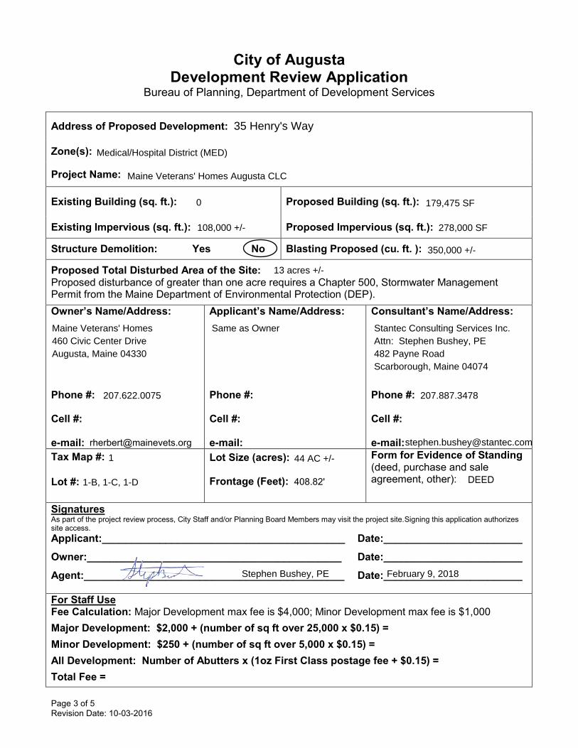
City of Augusta Development Review Application
Bureau of Planning, Department of Development Services
Address of Proposed Development:
Zone(s):
Project Name:
Existing Building (sq. ft.): Proposed Building (sq. ft.):
Existing Impervious (sq. ft.): Proposed Impervious (sq. ft.):
Structure Demolition: Yes No Blasting Proposed (cu. ft. ):
Proposed Total Disturbed Area of the Site: Proposed disturbance of greater than one acre requires a Chapter 500, Stormwater Management Permit from the Maine Department of Environmental Protection (DEP). Owner’s Name/Address:
Phone #:
Cell #:
e-mail:
Applicant’s Name/Address:
Phone #:
Cell #:
e-mail:
Consultant’s Name/Address:
Phone #:
Cell #:
e-mail:Tax Map #:
Lot #:
Lot Size (acres):
Frontage (Feet):
Form for Evidence of Standing (deed, purchase and sale agreement, other):
Signatures As part of the project review process, City Staff and/or Planning Board Members may visit the project site.Signing this application authorizes site access. Applicant:__________________________________________ Date:________________________
Owner:____________________________________________ Date:________________________
Agent:_____________________________________________ Date:________________________
For Staff Use Fee Calculation: Major Development max fee is $4,000; Minor Development max fee is $1,000 Major Development: $2,000 + (number of sq ft over 25,000 x $0.15) = Minor Development: $250 + (number of sq ft over 5,000 x $0.15) = All Development: Number of Abutters x (1oz First Class postage fee + $0.15) = Total Fee =
35 Henry's Way
Medical/Hospital District (MED)
Maine Veterans' Homes Augusta CLC
0
207.622.0075 207.887.3478
1 44 AC +/-
1-B, 1-C, 1-D
Stephen Bushey, PE February 9, 2018
Maine Veterans' Homes Same as Owner Stantec Consulting Services Inc. 460 Civic Center Drive Attn: Stephen Bushey, PE Augusta, Maine 04330 482 Payne Road Scarborough, Maine 04074
350,000 +/-
108,000 +/-
13 acres +/-
408.82' DEED
179,475 SF
278,000 SF
Page 4 of 5 Revision Date: 10-03-2016
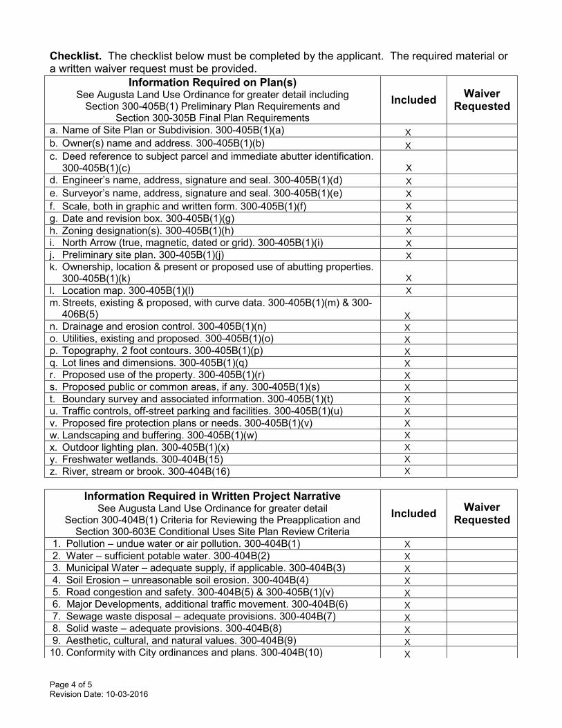
Checklist. The checklist below must be completed by the applicant. The required material or a written waiver request must be provided.
Information Required on Plan(s) See Augusta Land Use Ordinance for greater detail including
Section 300-405B(1) Preliminary Plan Requirements and Section 300-305B Final Plan Requirements
Included Waiver Requested
a. Name of Site Plan or Subdivision. 300-405B(1)(a) b. Owner(s) name and address. 300-405B(1)(b) c. Deed reference to subject parcel and immediate abutter identification.
300-405B(1)(c)
d. Engineer’s name, address, signature and seal. 300-405B(1)(d) e. Surveyor’s name, address, signature and seal. 300-405B(1)(e) f. Scale, both in graphic and written form. 300-405B(1)(f) g. Date and revision box. 300-405B(1)(g) h. Zoning designation(s). 300-405B(1)(h) i. North Arrow (true, magnetic, dated or grid). 300-405B(1)(i) j. Preliminary site plan. 300-405B(1)(j) k. Ownership, location & present or proposed use of abutting properties.
300-405B(1)(k)
l. Location map. 300-405B(1)(l) m. Streets, existing & proposed, with curve data. 300-405B(1)(m) & 300-
406B(5)
n. Drainage and erosion control. 300-405B(1)(n) o. Utilities, existing and proposed. 300-405B(1)(o) p. Topography, 2 foot contours. 300-405B(1)(p) q. Lot lines and dimensions. 300-405B(1)(q) r. Proposed use of the property. 300-405B(1)(r) s. Proposed public or common areas, if any. 300-405B(1)(s) t. Boundary survey and associated information. 300-405B(1)(t) u. Traffic controls, off-street parking and facilities. 300-405B(1)(u) v. Proposed fire protection plans or needs. 300-405B(1)(v) w. Landscaping and buffering. 300-405B(1)(w) x. Outdoor lighting plan. 300-405B(1)(x) y. Freshwater wetlands. 300-404B(15) z. River, stream or brook. 300-404B(16)
Information Required in Written Project Narrative See Augusta Land Use Ordinance for greater detail
Section 300-404B(1) Criteria for Reviewing the Preapplication and Section 300-603E Conditional Uses Site Plan Review Criteria
Included Waiver Requested
1. Pollution – undue water or air pollution. 300-404B(1) 2. Water – sufficient potable water. 300-404B(2) 3. Municipal Water – adequate supply, if applicable. 300-404B(3) 4. Soil Erosion – unreasonable soil erosion. 300-404B(4) 5. Road congestion and safety. 300-404B(5) & 300-405B(1)(v) 6. Major Developments, additional traffic movement. 300-404B(6) 7. Sewage waste disposal – adequate provisions. 300-404B(7) 8. Solid waste – adequate provisions. 300-404B(8) 9. Aesthetic, cultural, and natural values. 300-404B(9) 10. Conformity with City ordinances and plans. 300-404B(10)
X
X
X X X X X X X
X X
X X X X X X X X X X X X X X
X X X X X X X X X X
X
Page 5 of 5 Revision Date: 10-03-2016
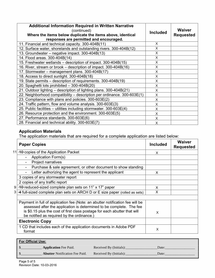
Application Materials The application materials that are required for a complete application are listed below:
For Official Use: $____________ Application Fee Paid. Received By (Initials):__________________Date:_________________
$____________ Abutter Notification Fee Paid. Received By (Initials):__________________Date:_________________
Additional Information Required in Written Narrative (continued)
Where the items below duplicate the items above, identical responses are permitted and encouraged.
Included Waiver Requested
11. Financial and technical capacity. 300-404B(11) 12. Surface water, shorelands and outstanding rivers. 300-404B(12) 13. Groundwater – negative impact. 300-404B(13) 14. Flood areas. 300-404B(14) 15. Freshwater wetlands – description of impact. 300-404B(15) 16. River, stream or brook – description of impact. 300-404B(16) 17. Stormwater – management plans. 300-404B(17) 18. Access to direct sunlight. 300-404B(18) 19. State permits – description of requirements. 300-404B(19) 20. Spaghetti lots prohibited – 300-404B(20) 21. Outdoor lighting – description of lighting plans. 300-404B(21) 22. Neighborhood compatibility – description per ordinance. 300-603E(1) 23. Compliance with plans and policies. 300-603E(2) 24. Traffic pattern, flow and volume analysis. 300-603E(3) 25. Public facilities – utilities including stormwater. 300-603E(4) 26. Resource protection and the environment. 300-603E(5) 27. Performance standards. 300-603E(6) 28. Financial and technical ability. 300-603E(7)
Paper Copies Included Waiver Requested
10 copies of the Application Packet - Application Form(s) - Project narratives - Purchase & sale agreement, or other document to show standing - Letter authorizing the agent to represent the applicant
3 copies of any stormwater report 2 copies of any traffic report 10 reduced-sized complete plan sets on 11” x 17” paper 4 full-sized complete plan sets on ARCH D or E size paper Payment in full of application fee (Note: an abutter notification fee will be
assessed after the application is determined to be complete. The fee is $0.15 plus the cost of first class postage for each abutter that will be notified as required by the ordinance.)
Electronic Copy 1 CD that includes each of the application documents in Adobe PDF
format
X X X X X X X X X X X X X X X X X X
X
X
X-----11
-----9---3 (rolled as sets)
X
X X
Page 1 of 6 Revision Date 01-25-2018
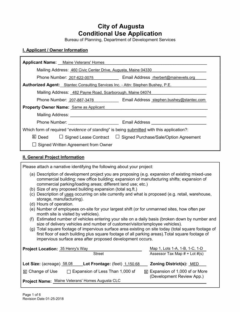
City of Augusta Conditional Use Application
Bureau of Planning, Department of Development Services
I. Applicant / Owner Information
Applicant Name: ______________________________________________________________
Mailing Address:
Phone Number: _____________________ Email Address
Authorized Agent:_____________________________________________________________
Mailing Address:
Phone Number: _____________________ Email Address
Property Owner Name: _________________________________________________________
Mailing Address:
Phone Number: _____________________ Email Address
Which form of required “evidence of standing” is being submitted with this application?:
Deed Signed Lease Contract Signed Purchase/Sale/Option Agreement
Signed Written Agreement from Owner
II. General Project Information Please attach a narrative identifying the following about your project:
(a) Description of development project you are proposing (e.g. expansion of existing mixed-use commercial building; new office building; expansion of manufacturing shifts; expansion of commercial parking/loading areas; different land use; etc.)
(b) Size of any proposed building expansion (total sq.ft.) (c) Description of uses occurring on site currently and what is proposed (e.g. retail, warehouse,
storage, manufacturing). (d) Hours of operation. (e) Number of employees on-site for your largest shift (or for unmanned sites, how often per
month site is visited by vehicles). (f) Estimated number of vehicles entering your site on a daily basis (broken down by number and
size of delivery vehicles and number of customer/visitor/employee vehicles). (g) Total square footage of impervious surface area existing on site today (total square footage of
first floor of each building plus square footage of all parking areas).Total square footage of impervious surface area after proposed development occurs.
Project Location:
Street Assessor Tax Map # + Lot #(s)
Lot Size: (acreage) Lot Frontage: (feet) Zoning District(s):
Change of Use Expansion of Less Than 1,000 sf Expansion of 1,000 sf or More (Development Review App.) Project Name:
Maine Veterans' Homes
460 Civic Center Drive, Augusta, Maine 04330
207-622-0075 [email protected]
Stantec Consulting Services Inc. - Attn: Stephen Bushey, P.E.
482 Payne Road, Scarborough, Maine 04074
207-887-3478 [email protected]
Same as Applicant
X
35 Henry's Way Map 1, Lots 1-A, 1-B, 1-C, 1-D
58.08 1,150.68 MED
X X
Maine Veterans' Homes Augusta CLC
Page 2 of 6 Revision Date 01-25-2018
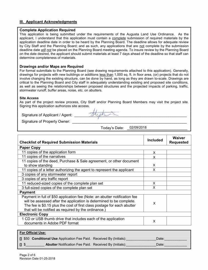
III. Applicant Acknowledgments
Complete Application Required This application is being submitted under the requirements of the Augusta Land Use Ordinance. As the applicant, I understand that this application must contain a complete submission of required materials by the application deadline date in order to be heard by the Planning Board. The deadline allows for adequate review by City Staff and the Planning Board; and as such, any applications that are not complete by the submission deadline date will not be placed on the Planning Board meeting agenda. To insure review by the Planning Board on the date desired, the applicant should submit materials at least 7 days ahead of the deadline so that staff can determine completeness of materials.
Drawings and/or Maps are Required For formal submittals to the Planning Board (see drawing requirements attached to this application). Generally, drawings for projects with new buildings or additions less than 1,000 sq. ft. in floor area, (or) projects that do not involve changing the existing structure, can be done by hand, as long as they are drawn to-scale. Drawings are critical to the Planning Board and City staff in adequately understanding existing and proposed site conditions, as well as seeing the relationships between proposed structures and the projected impacts of parking, traffic, stormwater runoff, buffer areas, noise, etc. on abutters.
Site Access As part of the project review process, City Staff and/or Planning Board Members may visit the project site. Signing this application authorizes site access.
Signature of Applicant / Agent: ______________________________________________________
Signature of Property Owner: _______________________________________________________
Today’s Date: _____________________________
For Official Use: [] $50 Conditional Use Application Fee Paid. Received By (Initials):________________Date:____________
[] $__________ Abutter Notification Fee Paid. Received By (Initials):________________Date:____________
Checklist of Required Submission Materials Included Waiver Requested
Paper Copy 11 copies of the application form 11 copies of the narratives 11 copies of the deed, Purchase & Sale agreement, or other document
to show standing 11 copies of a letter authorizing the agent to represent the applicant 3 copies of any stormwater report 3 copies of any traffic report 11 reduced-sized copies of the complete plan set 3 full-sized copies of the complete plan set Payment Payment in full of $50 application fee (Note: an abutter notification fee
will be assessed after the application is determined to be complete. The fee is $0.15 plus the cost of first class postage for each abutter that will be notified as required by the ordinance.)
Electronic Copy 1 CD or USB thumb drive that includes each of the application
documents in Adobe PDF format
X X
X X
X
X
X X
02/09/2018
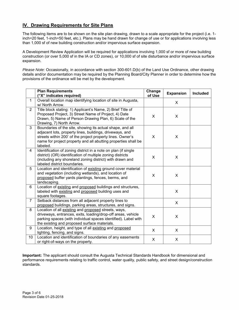
Page 3 of 6 Revision Date 01-25-2018
IV. Drawing Requirements for Site Plans The following items are to be shown on the site plan drawing, drawn to a scale appropriate for the project (i.e. 1-inch=20 feet, 1-inch=50 feet, etc.). Plans may be hand drawn for change of use or for applications involving less than 1,000 sf of new building construction and/or impervious surface expansion. A Development Review Application will be required for applications involving 1,000 sf or more of new building construction (or over 5,000 sf in the IA or CD zones), or 10,000 sf of site disturbance and/or impervious surface expansion. Please Note: Occasionally, in accordance with section 300-601.D(b) of the Land Use Ordinance, other drawing details and/or documentation may be required by the Planning Board/City Planner in order to determine how the provisions of the ordinance will be met by the development.
Important: The applicant should consult the Augusta Technical Standards Handbook for dimensional and performance requirements relating to traffic control, water quality, public safety, and street design/construction standards.
Plan Requirements (“X” indicates required)
Change of Use Expansion Included
1 Overall location map identifying location of site in Augusta, w/ North Arrow. X
2 Title block stating: 1) Applicant’s Name, 2) Brief Title of Proposed Project, 3) Street Name of Project, 4) Date Drawn, 5) Name of Person Drawing Plan, 6) Scale of the Drawing, 7) North Arrow.
X X
3 Boundaries of the site, showing its actual shape, and all adjacent lots, property lines, buildings, driveways, and streets within 200’ of the project property lines. Owner’s name for project property and all abutting properties shall be labeled.
X X
4 Identification of zoning district in a note on plan (if single district) (OR) identification of multiple zoning districts (including any shoreland zoning district) with drawn and labeled district boundaries.
X X
5 Location and identification of existing ground cover material and vegetation (including wetlands), and location of proposed buffer yards plantings, fences, berms, and landscaping.
X X
6 Location of existing and proposed buildings and structures, labeled with existing and proposed building uses and square footages.
X
7 Setback distances from all adjacent property lines to proposed buildings, parking areas, structures, and signs. X
8 Location of all existing and proposed streets, ways, driveways, entrances, exits, loading/drop-off areas, vehicle parking spaces (with individual spaces identified). Label with the existing and proposed surface materials.
X X
9 Location, height, and type of all existing and proposed lighting, fencing, and signs. X X
10 Location and identification of boundaries of any easements or right-of-ways on the property. X X
City of Augusta Major Development Review and Conditional Use Application MVH Augusta CLC
TABLE OF CONTENTS APPLICATION FORMS 1. DEVELOPMENT DESCRIPTION ................................................................................... 1-1
1.1 PROJECT DESCRIPTION .................................................................................. 1-1
1.2 PROJECT SCHEDULE ....................................................................................... 1-3
1.3 FIGURES AND DRAWINGS ............................................................................... 1-4
2. MAJOR DEVELOPMENT REVIEW CRITERIA .............................................................. 2-1 2.1 POLLUTION ....................................................................................................... 2-1
2.2 WATER............................................................................................................... 2-1
2.3 MUNICIPAL WATER SUPPLY ........................................................................... 2-1
2.4 SOIL EROSION .................................................................................................. 2-1
2.5 ROAD CONGESTION AND SAFETY ................................................................. 2-6
2.6 MAJOR DEVELOPMENTS, ADDITIONAL TRAFFIC MOVEMENT ..................... 2-6
2.7 SEWAGE WASTE DISPOSAL ............................................................................ 2-6
2.8 SOLID WASTE ................................................................................................... 2-6
2.9 AESTHETIC, CULTURAL AND NATURAL VALUES .......................................... 2-8
2.10 CONFORMITY WITH CITY ORDINANCES AND PLANS ................................... 2-9
2.11 FINANCIAL AND TECHNICAL CAPACITY ......................................................... 2-9
2.12 SURFACE WATER, SHORELANDS AND OUTSTANDING RIVERS ............... 2-11
2.13 GROUNDWATER ............................................................................................. 2-11
2.14 FLOOD AREAS ................................................................................................ 2-12
2.15 FRESHWATER WETLANDS ............................................................................ 2-12
2.16 RIVER, STREAM OR BROOK .......................................................................... 2-14
2.17 STORMWATER MANAGEMENT ...................................................................... 2-14
2.18 ACCESS TO DIRECT SUNLIGHT .................................................................... 2-19
2.19 STATE PERMITS ............................................................................................. 2-19
2.20 SPAGHETTI LOTS PROHIBITED..................................................................... 2-19
2.21 OUTDOOR LIGHTING ...................................................................................... 2-19
2.22 NEIGHBORHOOD COMPATIBILITY ................................................................ 2-19
2.23 COMPLIANCE WITH PLANS AND POLICIES .................................................. 2-21
2.24 TRAFFIC PATTERN, FLOW AND VOLUME ANALYSIS .................................. 2-21
2.25 PUBLIC FACILITIES ......................................................................................... 2-22
2.26 RESOURCE PROTECTION AND ENVIRONMENT .......................................... 2-22
City of Augusta Major Development Review and Conditional Use Application MVH Augusta CLC
2.27 PERFORMANCE STANDARDS ....................................................................... 2-24
2.28 FINANCIAL AND TECHNICAL ABILITY ........................................................... 2-25
3. SITE PLAN REVIEW CRITERIA FOR CONDITIONAL USES ....................................... 3-1 3.1 NEIGHBORHOOD COMPATIBILITY .................................................................. 3-1
3.2 COMPLIANCE WITH PLANS AND POLICIES .................................................... 3-1
3.3 TRAFFIC PATTERN, FLOW AND VOLUME ANALYSIS .................................... 3-1
3.4 PUBLIC FACILITIES ........................................................................................... 3-1
3.5 RESOURCE PROTECTION AND ENVIRONMENT ............................................ 3-1
3.6 PERFORMANCE STANDARDS ......................................................................... 3-1
3.7 FINANCIAL AND TECHNICAL ABILITY ............................................................. 3-1 FIGURES REFERENCES (Materials on file as part of the original submission)
Property Deeds Project Construction Cost Estimate Correspondence with Greater Augusta Utility District Correspondence with Natural Resource and Historic Preservation Agencies Traffic Impact Analysis – Abridged Wetland Delineation Report and Impact Figures
ATTACHMENTS
Attachment 1 – Site Lighting Cut Sheets Attachment 2 – Project Sign and Architectural Renderings
City of Augusta Major Development Review and Conditional Use Application MVH Augusta CLC Page 1-1
1. DEVELOPMENT DESCRIPTION
1.1 PROJECT DESCRIPTION
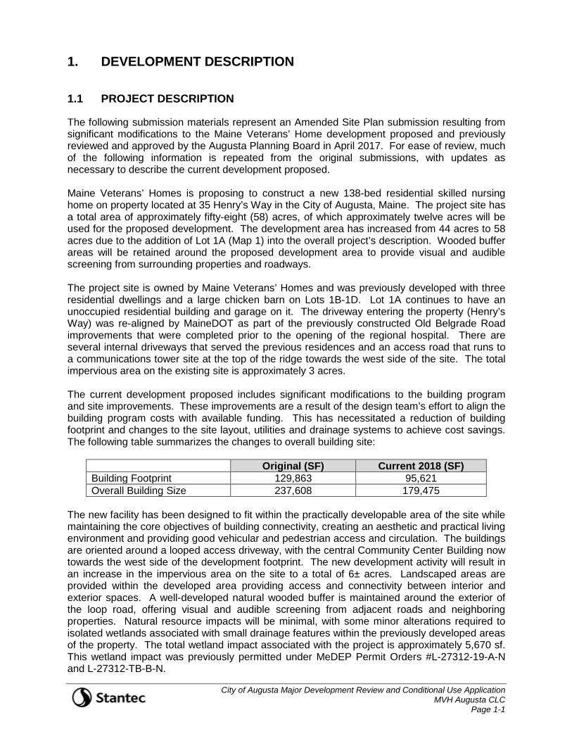
The following submission materials represent an Amended Site Plan submission resulting from significant modifications to the Maine Veterans’ Home development proposed and previously reviewed and approved by the Augusta Planning Board in April 2017. For ease of review, much of the following information is repeated from the original submissions, with updates as necessary to describe the current development proposed. Maine Veterans’ Homes is proposing to construct a new 138-bed residential skilled nursing home on property located at 35 Henry’s Way in the City of Augusta, Maine. The project site has a total area of approximately fifty-eight (58) acres, of which approximately twelve acres will be used for the proposed development. The development area has increased from 44 acres to 58 acres due to the addition of Lot 1A (Map 1) into the overall project’s description. Wooded buffer areas will be retained around the proposed development area to provide visual and audible screening from surrounding properties and roadways. The project site is owned by Maine Veterans’ Homes and was previously developed with three residential dwellings and a large chicken barn on Lots 1B-1D. Lot 1A continues to have an unoccupied residential building and garage on it. The driveway entering the property (Henry’s Way) was re-aligned by MaineDOT as part of the previously constructed Old Belgrade Road improvements that were completed prior to the opening of the regional hospital. There are several internal driveways that served the previous residences and an access road that runs to a communications tower site at the top of the ridge towards the west side of the site. The total impervious area on the existing site is approximately 3 acres. The current development proposed includes significant modifications to the building program and site improvements. These improvements are a result of the design team’s effort to align the building program costs with available funding. This has necessitated a reduction of building footprint and changes to the site layout, utilities and drainage systems to achieve cost savings. The following table summarizes the changes to overall building site:
Original (SF) Current 2018 (SF) Building Footprint 129,863 95,621 Overall Building Size 237,608 179,475
The new facility has been designed to fit within the practically developable area of the site while maintaining the core objectives of building connectivity, creating an aesthetic and practical living environment and providing good vehicular and pedestrian access and circulation. The buildings are oriented around a looped access driveway, with the central Community Center Building now towards the west side of the development footprint. The new development activity will result in an increase in the impervious area on the site to a total of 6± acres. Landscaped areas are provided within the developed area providing access and connectivity between interior and exterior spaces. A well-developed natural wooded buffer is maintained around the exterior of the loop road, offering visual and audible screening from adjacent roads and neighboring properties. Natural resource impacts will be minimal, with some minor alterations required to isolated wetlands associated with small drainage features within the previously developed areas of the property. The total wetland impact associated with the project is approximately 5,670 sf. This wetland impact was previously permitted under MeDEP Permit Orders #L-27312-19-A-N and L-27312-TB-B-N.

City of Augusta Major Development Review and Conditional Use Application MVH Augusta CLC Page 1-2
The main entrance to the facility is at the existing signalized intersection on Old Belgrade Road, directly opposite the recently constructed MaineGeneral Alfond Center for Health campus. Access around the facility is provided via a looped driveway, with parking for individual units spread throughout the site. A series of external walkways provide pedestrian access to outdoor amenities and landscaped areas around the units, and connectivity to other areas of the site and adjacent public facilities. A second access road is now contemplated to extend from the north side of the site through Lot 1A. A new access route to the Tower will also be constructed. Utility services will be extended to the site from Old Belgrade Road. Parking is provided at the front of the Community Center Building and at strategic locations throughout the site to facilitate ease of access to the neighborhoods for residents, visitors and staff. A loading and service area is provided at the northeast side of the Community Center Building. This includes a four-foot high loading bay to accommodate deliveries for tractor trailer trucks, and an area for a trash compactor, dumpsters and major utility entrances. Pedestrian walkways are provided throughout the site, connecting the buildings with on-site outdoor amenities and landscaped areas, and connectivity to Old Belgrade Road and adjacent facilities. The site will be graded to achieve the development program in the most efficient manner, given the topographical and geotechnical constraints and challenges presented by the existing conditions. These include:
• Steep rising slopes and shallow depth to bedrock at the west side of the development area; and
• A shallow crust of stiff to moderately stiff clay overlying very soft silty clay to considerable depth in the central and eastern portions of the development site.
The grading design has been developed to minimize rock cuts at the west side of the site, while also minimizing fills over the clay soils found under the eastern and central areas. It is estimated that approximately 5,000 to 15,000 CY of rock removal will be required to achieve design grades at the west side of the site. All blasting will be undertaken in strict accordance with City of Augusta Chapter 130 Blasting. There are no occupied structures within 500 feet of the area of proposed blasting (see Figure 8 at the end of this section). However, the applicant will correspond with and coordinate all blasting activities with abutting property owners. This specifically includes MaineGeneral as there may be equipment on their campus that is particularly sensitive to vibration. Runoff from the new development will be captured and treated in a series of stormwater Best Management Practices (BMP) spread throughout the site. This includes a large wet pond and various proprietary BMP products. Road drainage will be captured in an enclosed drainage system of catch basins and pipes and conveyed to the wet ponds or to several localized Focal Point® underdrained bioretention cells that will provide water quality treatment. The wet pond has been sized to provide water quality treatment and detention and attenuation of the channel protection volume (CPV). The stormwater management system is designed to meet current local, and State standards and ensure that there are no significant detrimental impacts to downstream properties or receiving waters. Site Location of Development Act and Natural Resource Protection Act permit applications for this project were filed with Maine Department of Environmental Protection and approved as evidenced in MeDEP Permit Orders #L-27312-19-A-N and L-27312-TB-B-N. Amendment applications will be filed with the MeDEP concurrent with this local application.
City of Augusta Major Development Review and Conditional Use Application MVH Augusta CLC Page 1-3
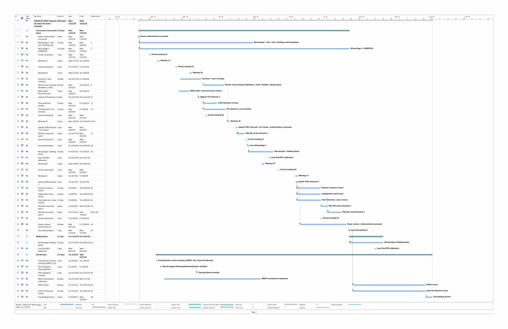
The aim of the project is to construct a state of the art residential care facility in an attractive and welcoming environment that will meet the needs of a growing Veteran population. 1.2 PROJECT SCHEDULE
Construction of the Maine Veterans’ Homes CLC is scheduled to begin in the summer of 2018. The schedule anticipates a construction period of approximately thirty months, with an anticipated completion date in the fall of 2020. An outline schedule for the construction work is given on the following page. The Construction Manager is VJS-Cianbro.
ID Task
Mode
Task Name Duration Start Finish Predecessors
0 150322-01 MVH Augusta
CD phase AE team
schedule
183 days? Mon
1/22/18
Wed
10/3/18
1 Construction Documents
phase
131 days Mon
1/22/18
Mon
7/23/18
2 Owner authorization
to proceed
0 days Mon
1/22/18
Mon
1/22/18
3 Bid package 1: site /
civil / footings and
foundations
71 days Mon
1/22/18
Mon
4/30/18
2
4 Bid package 2:
A/MEPS/ID
131 days Mon
1/22/18
Mon
7/23/18
2
5 Virtual meeting 24 1 day Wed
1/31/18
Wed
1/31/18
6 Meeting 27 2 days Wed 2/7/18 Thu 2/8/18
7 Virtual meeting 25 1 day Fri 2/23/18 Fri 2/23/18
8 Meeting 28 2 days Wed 3/7/18 Thu 3/8/18
9 Construct room
mockups
14 days Tue 2/27/18 Fri 3/16/18
10 Review room mockups
(Residents / staff /
families / design team)
14 days Mon
3/19/18
Thu 4/5/18 9
11 BIM model /
document peer
reviews
7 days Mon
2/26/18
Tue 3/6/18
12 Upload 75% bid pack 2 0 days Thu 3/15/18 Thu 3/15/18 11
13 Clash detection
reviews
10 days Mon
3/19/18
Fri 3/30/18 12
14 75% bid pack 2 cost
estimate
15 days Mon
3/19/18
Fri 4/6/18 12
15 Virtual meeting 26 1 day Wed
3/21/18
Wed
3/21/18
16 Meeting 29 2 days Mon 4/9/18 Tue 4/10/18 10,14
17 Upload 100% bid pack
1 for review /
authorization to
1 day Mon
4/16/18
Mon
4/16/18
18 PRA QA review bid
pack 1
5 days Tue 4/17/18 Mon
4/23/18
17
19 Virtual meeting 27 1 day Wed
4/25/18
Wed
4/25/18
20 Issue bid package 1 1 day Thu 4/26/18 Thu 4/26/18 18
21 Bid package 1 bidding
phase
16 days Fri 4/27/18 Fri 5/18/18 20
22 Issue final BP1
addendum
1 day Tue 5/15/18 Tue 5/15/18
23 Meeting 30 2 days Wed 5/9/18 Thu 5/10/18
24 Virtual meeting 28 1 day Wed
5/23/18
Wed
5/23/18
25 Meeting 31 2 days Thu 6/7/18 Fri 6/8/18
26 Upload 100% bid pack
2
1 day Thu 6/7/18 Thu 6/7/18
27 Exterior enclosure
review
15 days Fri 6/8/18 Thu 6/28/18 26
28 Independent code
review
15 days Fri 6/8/18 Thu 6/28/18 26
29 Clash detection / peer
reviews
15 days Fri 6/8/18 Thu 6/28/18 26
30 PRA PM review bid
pack 2
4 days Fri 6/29/18 Wed 7/4/18 29
31 PRA QA review bid
pack 2
8 days Thu 7/5/18 Mon
7/16/18
30,27,28
32 Virtual meeting 29 1 day Fri 6/29/18 Fri 6/29/18
33 Owner review /
authorization to
proceed
30 days Mon
6/11/18
Fri 7/20/18 26
34 Issue bid package 2 1 day Mon
7/23/18
Mon
7/23/18
33
35 Bidding phase 21 days Tue 7/24/18 Tue 8/21/18
36 Bid package 2 bidding
phase
21 days Tue 7/24/18 Tue 8/21/18 34
37 Issue final BP2
addendum
1 day Wed
8/15/18
Wed
8/15/18
38 AHJ Reviews 172 days Tue 2/6/18 Wed
10/3/18
39 Presubmission review
meetings (MDEP, City,
State Fire Marshal)
1 day Tue 2/6/18 Tue 2/6/18
40 City of Augusta
Planning Board
submission deadline
1 day Fri 2/9/18 Fri 2/9/18
41 Planning Board
meeting
1 day Tue 3/13/18 Tue 3/13/18 40
42 MDEP amendment
submission
60 days Tue 2/13/18 Mon 5/7/18
43 DHHS review 45 days Fri 7/27/18 Thu 9/27/18 34
44 State Fire Marshal
review
45 days Fri 7/27/18 Thu 9/27/18 34
45 City Building Permit 4 days Fri 9/28/18 Wed
10/3/18
44
Owner authorization to proceed
Bid package 1: site / civil / footings and foundations
Bid package 2: A/MEPS/ID
Virtual meeting 24
Meeting 27
Virtual meeting 25
Meeting 28
Construct room mockups
Review room mockups (Residents / staff / families / design team)
BIM model / document peer reviews
Upload 75% bid pack 2
Clash detection reviews
75% bid pack 2 cost estimate
Virtual meeting 26
Meeting 29
Upload 100% bid pack 1 for review / authorization to proceed
PRA QA review bid pack 1
Virtual meeting 27
Issue bid package 1
Bid package 1 bidding phase
Issue final BP1 addendum
Meeting 30
Virtual meeting 28
Meeting 31
Upload 100% bid pack 2
Exterior enclosure review
Independent code review
Clash detection / peer reviews
PRA PM review bid pack 2
PRA QA review bid pack 2
Virtual meeting 29
Owner review / authorization to proceed
Issue bid package 2
Bid package 2 bidding phase
Issue final BP2 addendum
Presubmission review meetings (MDEP, City, State Fire Marshal)
City of Augusta Planning Board submission deadline
Planning Board meeting
MDEP amendment submission
DHHS review
State Fire Marshal review
City Building Permit
24 31 7 14 21 28 4 11 18 25 4 11 18 25 1 8 15 22 29 6 13 20 27 3 10 17 24 1 8 15 22 29 5 12 19 26 2 9 16 23 30 7 14 21 28 4 11 18
Jan '18 Feb '18 Mar '18 Apr '18 May '18 Jun '18 Jul '18 Aug '18 Sep '18 Oct '18 Nov '18
Task
Split
Milestone
Summary
Project Summary
Inactive Task
Inactive Milestone
Inactive Summary
Manual Task
Duration-only
Manual Summary Rollup
Manual Summary
Start-only
Finish-only
External Tasks
External Milestone
Deadline
Progress
Manual Progress
Page 1
Project: 150322-01 MVH Augus
Date: Tue 1/23/18

City of Augusta Major Development Review and Conditional Use Application MVH Augusta CLC Page 1-4
1.3 FIGURES AND DRAWINGS
Figures showing the proposed project site are included at the end of this section as follows:
Figure # Title 1 USGS Topographic Map 2 Aerial Photograph 3 FEMA Flood Map 4 USDA SCS Soils Map 5 Abutter Map 5a Abutter Map Showing Uses 8 Blasting Setback Figure 9 Sand and Gravel Aquifer Map
Project drawings submitted with this application are as follows:
Sheet # Title C-1.0 Civil Cover Sheet C-1.1 General Notes and Legend C-2.0 Boundary and Topographic Survey Sheet 1 of 9 (Sebago Technics) C-2.1 Boundary and Topographic Survey Sheet 2 of 9 (Sebago Technics) C-2.2 Boundary and Topographic Survey Sheet 3 of 9 (Sebago Technics) C-2.3 Boundary and Topographic Survey Sheet 4 of 9 (Sebago Technics) C-2.4 Boundary and Topographic Survey Sheet 5 of 9 (Sebago Technics) C-2.5 Boundary and Topographic Survey Sheet 6 of 9 (Sebago Technics) C-2.6 Boundary and Topographic Survey Sheet 7 of 9 (Sebago Technics) C-2.7 Boundary and Topographic Survey Sheet 8 of 9 (Sebago Technics) C-2.8 Boundary and Topographic Survey Sheet 9 of 9 (Sebago Technics) C-2.9 Existing Conditions and Demolition Plan C-3.0 Overall Site Plan – Sheet 1 of 2 C-3.1 Overall Site Plan – Sheet 2 of 2 C-4.0 Overall Grading and Drainage Plan – Sheet 1 of 2 C-4.1 Overall Grading and Drainage Plan – Sheet 2 of 2 C-4.2* Stormdrain Appurtenance Tables C-5.0 Overall Utility Plan – Sheet 1 of 2 C-5.1 Overall Utility Plan – Sheet 2 of 2 C-6.0 Erosion Control Plan – Sheet 1 of 2 C-6.1 Erosion Control Plan – Sheet 2 of 2 C-6.2 Erosion Control Details C-6.3 Erosion Control Notes C-7.0* Road Cross Sections C-7.1* Wall Sections C-8.0 Road & Sidewalk Details
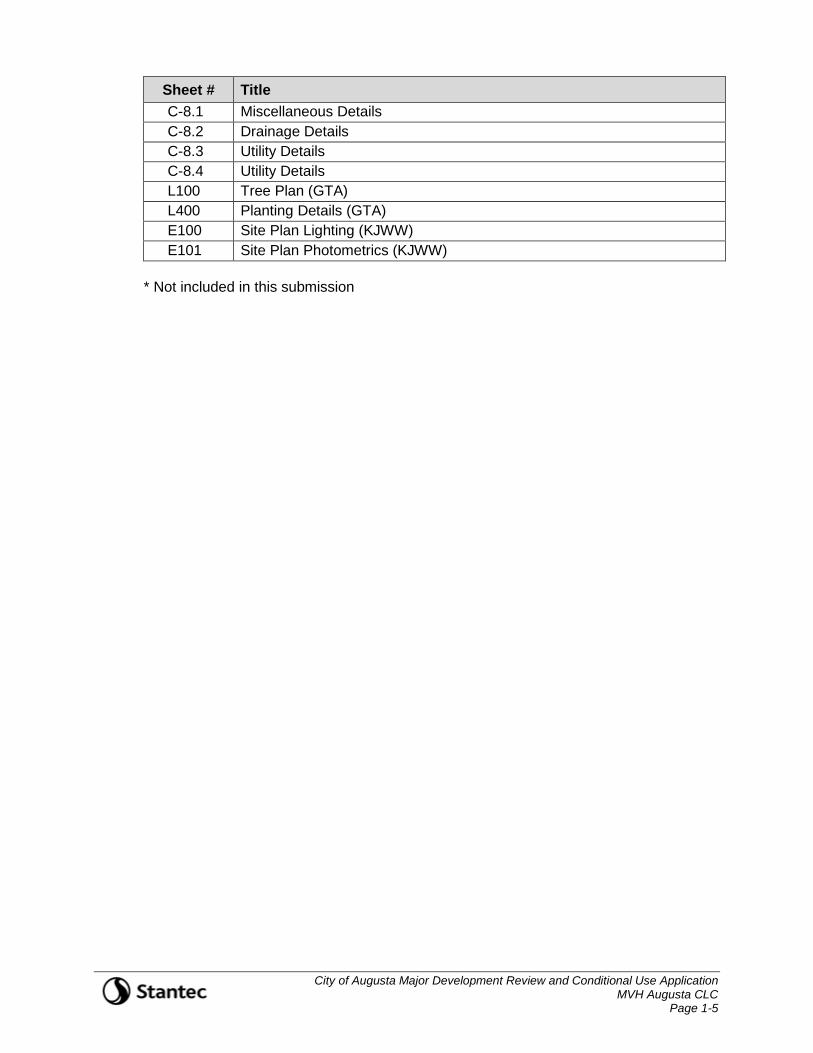
City of Augusta Major Development Review and Conditional Use Application MVH Augusta CLC Page 1-5
Sheet # Title C-8.1 Miscellaneous Details C-8.2 Drainage Details C-8.3 Utility Details C-8.4 Utility Details L100 Tree Plan (GTA) L400 Planting Details (GTA) E100 Site Plan Lighting (KJWW) E101 Site Plan Photometrics (KJWW)
* Not included in this submission
City of Augusta Major Development Review and Conditional Use Application MVH Augusta CLC Page 2-1
2. MAJOR DEVELOPMENT REVIEW CRITERIA (Per Augusta Land Use Ordinance Section 300-404B and 300-603E)
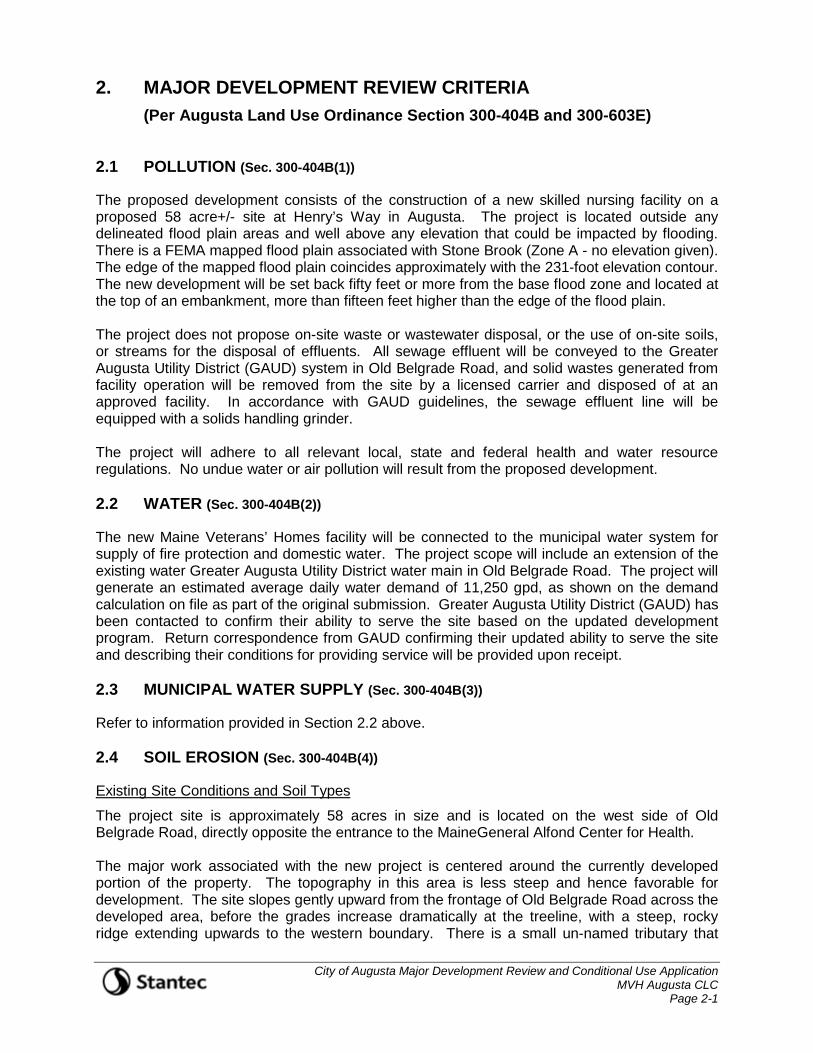
2.1 POLLUTION (Sec. 300-404B(1))
The proposed development consists of the construction of a new skilled nursing facility on a proposed 58 acre+/- site at Henry’s Way in Augusta. The project is located outside any delineated flood plain areas and well above any elevation that could be impacted by flooding. There is a FEMA mapped flood plain associated with Stone Brook (Zone A - no elevation given). The edge of the mapped flood plain coincides approximately with the 231-foot elevation contour. The new development will be set back fifty feet or more from the base flood zone and located at the top of an embankment, more than fifteen feet higher than the edge of the flood plain. The project does not propose on-site waste or wastewater disposal, or the use of on-site soils, or streams for the disposal of effluents. All sewage effluent will be conveyed to the Greater Augusta Utility District (GAUD) system in Old Belgrade Road, and solid wastes generated from facility operation will be removed from the site by a licensed carrier and disposed of at an approved facility. In accordance with GAUD guidelines, the sewage effluent line will be equipped with a solids handling grinder. The project will adhere to all relevant local, state and federal health and water resource regulations. No undue water or air pollution will result from the proposed development. 2.2 WATER (Sec. 300-404B(2))
The new Maine Veterans’ Homes facility will be connected to the municipal water system for supply of fire protection and domestic water. The project scope will include an extension of the existing water Greater Augusta Utility District water main in Old Belgrade Road. The project will generate an estimated average daily water demand of 11,250 gpd, as shown on the demand calculation on file as part of the original submission. Greater Augusta Utility District (GAUD) has been contacted to confirm their ability to serve the site based on the updated development program. Return correspondence from GAUD confirming their updated ability to serve the site and describing their conditions for providing service will be provided upon receipt. 2.3 MUNICIPAL WATER SUPPLY (Sec. 300-404B(3))
Refer to information provided in Section 2.2 above. 2.4 SOIL EROSION (Sec. 300-404B(4))
Existing Site Conditions and Soil Types
The project site is approximately 58 acres in size and is located on the west side of Old Belgrade Road, directly opposite the entrance to the MaineGeneral Alfond Center for Health. The major work associated with the new project is centered around the currently developed portion of the property. The topography in this area is less steep and hence favorable for development. The site slopes gently upward from the frontage of Old Belgrade Road across the developed area, before the grades increase dramatically at the treeline, with a steep, rocky ridge extending upwards to the western boundary. There is a small un-named tributary that
City of Augusta Major Development Review and Conditional Use Application MVH Augusta CLC Page 2-2
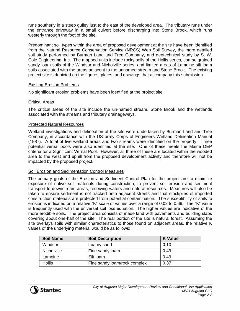
runs southerly in a steep gulley just to the east of the developed area. The tributary runs under the entrance driveway in a small culvert before discharging into Stone Brook, which runs westerly through the foot of the site. Predominant soil types within the area of proposed development at the site have been identified from the Natural Resource Conservation Service (NRCS) Web Soil Survey, the more detailed soil study performed by Burman Land and Tree Company, and geotechnical study by S. W. Cole Engineering, Inc. The mapped units include rocky soils of the Hollis series, coarse grained sandy loam soils of the Windsor and Nicholville series, and limited areas of Lamoine silt loam soils associated with the areas adjacent to the unnamed stream and Stone Brook. The existing project site is depicted on the figures, plates, and drawings that accompany this submission. Existing Erosion Problems
No significant erosion problems have been identified at the project site. Critical Areas
The critical areas of the site include the un-named stream, Stone Brook and the wetlands associated with the streams and tributary drainageways. Protected Natural Resources
Wetland investigations and delineation at the site were undertaken by Burman Land and Tree Company, in accordance with the US army Corps of Engineers Wetland Delineation Manual (1987). A total of five wetland areas and two streams were identified on the property. Three potential vernal pools were also identified at the site. One of these meets the Maine DEP criteria for a Significant Vernal Pool. However, all three of these are located within the wooded area to the west and uphill from the proposed development activity and therefore will not be impacted by the proposed project. Soil Erosion and Sedimentation Control Measures
The primary goals of the Erosion and Sediment Control Plan for the project are to minimize exposure of native soil materials during construction, to prevent soil erosion and sediment transport to downstream areas, receiving waters and natural resources. Measures will also be taken to ensure sediment is not tracked onto adjacent streets and that stockpiles of imported construction materials are protected from potential contamination. The susceptibility of soils to erosion is indicated on a relative “K” scale of values over a range of 0.02 to 0.69. The “K” value is frequently used with the universal soil loss equation. The higher values are indicative of the more erodible soils. The project area consists of made land with pavements and building slabs covering about one-half of the site. The rear portion of the site is natural forest. Assuming the site overlays soils with similar characteristics to those found on adjacent areas, the relative K values of the underlying material would be as follows:
Soil Name Soil Description K Value Windsor Loamy sand 0.10 Nicholville Fine sandy loam 0.49 Lamoine Silt loam 0.49 Hollis Fine sandy loam/rock complex 0.37
City of Augusta Major Development Review and Conditional Use Application MVH Augusta CLC Page 2-3
Based on a review of the K values, the onsite soils in the area are low to moderately susceptible to erosion after the cover material is stripped. The silt loam and fine sandy loam soils are of greatest concern from an erosion control perspective. The primary emphasis of the Erosion and Sedimentation Control Plan to be implemented for this project is as follows: Construction Schedule – Major earth moving activities at the site will be scheduled for
the summer and will be started when a suitable weather window has been identified. This will minimize the potential for exposure of bare soil to inclement weather.
Temporary Measures – Planning the project to have soil erosion Best Management Practices (BMPs) in place prior to construction to avoid and minimize soil erosion at the site. These include run-on diversion measures that will intercept and convey runoff from upstream areas around the work area, cover materials and temporary seeding to stabilize areas disturbed during construction.
Stabilization of areas denuded to underlying parent material to minimize the period of soil exposure.
Stabilization of drainage paths to avoid rill and gully erosion.
The use of on-site measures to capture sediment (hay bales/silt fence, etc.) before it is conveyed to sediment sumps.
Erosion/Sedimentation Control BMPs
Construction of this project requires authorization under the Maine Pollutant Discharge Elimination System (MPDES) General Permit for Construction Activity. As part of the site development, the Contractor will be obligated to implement the following erosion and sediment control best management practices. These devices shall be installed as indicated on the plans or as described within this report. For further reference on these devices, see the Maine Erosion and Sediment Control Best Management Practices (BMPs) Manual for Designers and Engineers, Maine DEP, October 2016. 1. Crushed stone-stabilized construction entrances will be placed at any construction access
points from adjacent streets. The locations of the construction entrances shown on the drawings should be considered illustrative and will need to be adjusted as appropriate and located at any area where there is the potential for tracking of mud and debris onto existing roads or streets. Stone stabilized construction entrances will require the stone to be removed and replaced, as it becomes covered or filled with mud and material tracked by vehicles exiting the site.
2. Siltation fence shall be installed down slope of any disturbed areas to trap runoff borne sediments. The silt fence shall be installed per the detail provided in the plan set and inspected immediately after each rainfall and at least daily during prolonged rainfall. The Contractor shall make repairs immediately if there are any signs of erosion or sedimentation below the fence line. If such erosion is observed, the Contractor shall take proactive action to identify the cause of the erosion and take action to avoid its re-occurrence. Typically, this requires that stabilization measures be undertaken. Proper placement of stakes and keying the bottom of the fabric into the ground is critical to the fence’s effectiveness. If there are signs of undercutting at the center or the edges, or impounding of large volumes of water behind the fence, the barrier shall be replaced with a stone check dam and measures taken to avoid the concentration of flows not intended to be directed to the silt fence.
City of Augusta Major Development Review and Conditional Use Application MVH Augusta CLC Page 2-4
3. Twin rows of siltation fence with hay bales shall be installed at the foot of steep slopes and adjacent to protected natural resources (wetland areas).
4. Silt fence shall be installed along the downgradient side of construction work areas, with locations being adjusted along with the construction phasing areas. The Contractor may use erosion mix in place of single silt fence barrier.
5. Silt fence will be installed along the upstream perimeter of the work area as shown on the plans, to divert run-on from upslope areas and prevent surface water from entering the construction area. If necessary, and at the direction of the Project Engineer, interception trenches shall be constructed to prevent shallow groundwater from flowing into construction areas.
6. Temporary sediment sumps will provide sedimentation control for stormwater runoff from disturbed areas during construction until stabilization has been achieved.
7. A construction entrance will be constructed at all access points onto the site to prevent tracking of soil onto adjacent local roads and streets and the existing parking lot.
8. Stone sediment traps or a premanufactured SiltSack™ and a sediment bag will be installed at catch basin inlets to prevent silt from entering the storm drain system. Installation details are provided in the plan set on the erosion control detail sheets.
9. Dirtbags™ will be required to be on site and available for construction dewatering. The Contractor will be required to provide four Dirtbags™ with one prepared for operation prior to commencing any trenching operations.
10. Silt logs are an option for stone check dams and may be substituted provided the devices are well anchored.
11. A silt curtain will be required in the new stormwater, around the outlet pipe while construction is continuing. This will prevent any sediment laden water that sinks to the foot of the water column from entering the pipe. Water near the surface of the basin will be allowed to flow over the silt curtain and hence reach the outlet pipe. This will allow discharge of clean water and settlement of any suspended solids from the retained water behind the curtain.
12. All slopes steeper than 4:1 shall receive erosion control blankets.
13. Areas of visible erosion and the temporary sediment sumps shall be stabilized with crushed stone. The size of the stone shall be determined by the contractor’s designated representative in consultation with the Owner.
Maintenance of the Erosion/Sedimentation Control Features
The project will be contracted by the Owner. The Contractor shall prepare a list and designate by name, address and telephone number all individuals who will be responsible for implementation, inspection, and maintenance of all erosion control measures identified within this section and as contained in the Erosion and Sedimentation Control Plan of the contract drawings. Assuring and certifying the Owner’s construction sequence is in conformance with the specified schedule of this section. A weekly certification stating compliance, any deviations, and corrective measures necessary to comply with the erosion control requirements of this section shall be prepared and signed by the inspector(s). In addition to the weekly certifications, the inspector(s) shall maintain written reports recording construction activities on site which include:

City of Augusta Major Development Review and Conditional Use Application MVH Augusta CLC Page 2-5
1. Dates when major grading activities occur in particular areas.
2. Dates when major construction activities cease in a particular area, either temporarily or permanently.
3. Dates when an area is stabilized.
4. Inspection of this project work site on a weekly basis and after each significant rainfall event (0.25 inch or more within any consecutive 24-hour period) during construction until permanent erosion control measures have been properly installed and the site has been stabilized.
5. Identification of proper erosion control measure installation in accordance with the erosion control detail sheet or as specified in this section.
6. Determine whether each erosion control measure is properly operating. If not, identify damage to the control device and determine remedial measures.
7. Identify areas which appear vulnerable to erosion and determine additional erosion control measures which should be used to improve conditions.
8. Inspect areas of recent seeding to determine percent catch of grass. A minimum catch of 90 percent is required prior to removal of erosion control measures.
9. All erosion controls shall be removed within 30 days of permanent stabilization except for mulch and netting not detrimental to the project. Removals shall include but not be limited to all silt fence, hay bales, inlet protection, and stone check dams.
10. Accumulated silt/sediment should be removed when the depth of sediment reaches 50 percent of the barrier height. Accumulated silt/sediment should be removed from behind silt fencing when the depth of the sediment reaches 6 inches.
11. Silt sacks should be removed and replaced at least every three months and at any time where the weekly inspection reveals that siltation has significantly retarded the rate of flow through the silt sack.
12. If inspection of the site indicates a change should be made to the erosion control plan, to either improve effectiveness or correct a site-specific deficiency, the inspector shall immediately implement the corrective measure and notify the Owner of the change.
All certifications, inspection forms, and written reports prepared by the inspector(s) shall be filed with the Owner, and the Permit File contained on the project site. All written certifications, inspection forms, and written reports must be filed within one (1) week of the inspection date. Preconstruction Conference
Prior to any construction at the site, representatives of the Contractor, the Architect, the Owner, and the site design engineer shall meet to discuss the scheduling of the site construction and the designation of the responsible parties for implementing the plan. The Contractor shall be responsible for scheduling the meeting. Prior to the meeting, the Contractor will prepare a detailed schedule and a marked-up site plan indicating areas and components of the work and key dates showing date of disturbance and completion of the work. The Contractor shall conduct a meeting with employees and sub-contractors to review the erosion control plan, the construction techniques which will be employed to implement the plan, and provide a list of attendees and items discussed at the meeting to the Owner. Three copies of the schedule, the Contractor’s meeting minutes, and marked-up site plan shall be provided to the Owner.
City of Augusta Major Development Review and Conditional Use Application MVH Augusta CLC Page 2-6
Further details of erosion control measures are shown on the Erosion Control Plans and Details sheets that accompany this submission. 2.5 ROAD CONGESTION AND SAFETY (Sec. 300-404B(5) & 300-405B(1)(v))
The project will not result in unreasonable highway or public road congestion, or unsafe conditions with respect to the use of existing highways or public roads. Significant infrastructure improvements were constructed in the area of the project site to support continued development in the area surrounding the new regional hospital. A Traffic Impact Analysis was previously conducted for the project by Traffic Solutions, Inc. An abridged version of the report, including the full text without appendices is on file as part of the original submission. The report summarizes traffic counts in the vicinity of the site and trip generation forecasts for the proposed development. The report concludes that “The Old Belgrade Road/Medical Center Parkway/Henry’s Way intersection is expected to operate at Level of Service B conditions under forecast 2020 pre-development traffic loadings. Each specific vehicle turning movement within the intersection is projected to operate at or above Level of Service B travel conditions. Post-development operations at the intersection were determined to be very similar; even with the added traffic signal phase added for the Henry’s Way approach. The intersection continues to operate at Level of Service B conditions under forecast post-development traffic conditions with an overall average vehicle delay of 17 seconds.” Minor adjustments to the signal operation at the intersection are recommended to serve the new facility. 2.6 MAJOR DEVELOPMENTS, ADDITIONAL TRAFFIC MOVEMENT
(Sec. 300-404B(6))
The development is not subject to a Traffic Movement Permit. 2.7 SEWAGE WASTE DISPOSAL (Sec. 300-404B(7))
The new Maine Veterans’ Homes facility will be connected to a municipal sewer system. Sewer flow generated at the site will discharge to the Greater Augusta Utility District system located in Old Belgrade Road. The project will generate an estimated average daily water demand of 11,250 gpd, as shown on the demand calculation on file as part of the original submission. Greater Augusta Utility District (GAUD) has been contacted to re-affirm their ability to serve the site based on the updated building program. Return correspondence from GAUD confirming their ability to serve the site and describing their conditions for providing service will be provided upon receipt. 2.8 SOLID WASTE (Sec. 300-404B(8))
The project will generate solid waste both during construction of the improvements and in the post- construction operation of the facility. All wastes will be disposed of in accordance with current local and State regulations as follows: Solid Wastes Generated During Construction of the Site Improvements and Buildings
This project will require about 3.0 acres of mixed woodland and scrub to be cleared to make room for the planned improvements at the site. The clearing of trees is expected to generate about 150 CY of stumps. The high-quality trees will be cut to saw logs with any other wood biomass chipped. Tree logs will be hauled to an appropriate sawmill. The biomass with either be retained on site for erosion control materials or processed and sent to a biomass facility.

City of Augusta Major Development Review and Conditional Use Application MVH Augusta CLC Page 2-7
The pine stumps are larger and bulky. The stumps will be excavated and or chipped onsite for use as erosion control mix or landscape mulch.
Other demolition and removal wastes include:
Pavement removal – approx. 32,500 sf @ 3.5” = 350 CY
Pavement removed from the site can be processed for re-use as base material, or granular fill. Other solid waste from site activity will be minor. Some cardboard or Kraft wrapping is anticipated for the light poles, and minor solid wastes may also be generated by the workers. Other waste could include various containers, short lengths of pipe, or conduit. The construction contract will require the Contractor to attempt a recycling level of 75%. Materials not recycled will be required to be disposed of at the locations specified in this section. The volume of solid waste generated by site construction, which will be hauled for disposal, is estimated to be approximately 50-60 CY. Hazardous & Special Wastes
There are no known areas of hazardous or special wastes at the project site. If any hazardous or special waste is identified during construction, MaineDEP will be notified immediately. A licensed waste hauler will be retained to dispose of the material at a licensed facility. Maine Veterans’ Homes will retain records of the collection, transport, and disposal of any such material. Disposal of Solid Waste Generated During the Construction of the Facility
This project will require about 3.0 acres of mixed woodland and scrub to be cleared to make room for the planned improvements at the site. The clearing of trees is expected to generate about 150 CY of stumps. Unless otherwise approved through a MaineDEP Permit Modification prepared by the Contractor for submission and approval from MaineDEP, the waste stream generated by construction will be transported and disposed of as follows:
• Separated clean wood salvaged for recycling can use Re-Energy in Lewiston, Maine; or taken to the Hatch Hill Solid Waste Disposal Facility in Augusta, Maine.
• Metals for recycling can be taken to Clarks Eastside Scrap in Chelsea, Maine.
• Mixed construction materials can be taken the Hatch Hill Solid Waste Disposal Facility in Augusta, Maine.
The collection, transfer, disposal, and payment of all fees for solid wastes shall be the responsibility of the Contractor, with all waste transferred by a licensed non-hazardous waste transporter. Solid Waste Generated from the Operation of the Facility
At a rate of 2 lbs./resident/day plus 1 lb./staff per day, the facility is anticipated to generate approximately 350 lbs. of waste per day, based upon 138 residents and 75 full-time equivalent staff personnel. The wastes from facility operations will be collected by Waste Management, or
City of Augusta Major Development Review and Conditional Use Application MVH Augusta CLC Page 2-8
a similar contracted provider and transported to the Hatch Hill Solid Waste Disposal Facility in Augusta, Maine.
Fluorescent Lights and Fixtures Maine Veterans’ Homes will segregate fluorescent bulbs for legal disposal by the solid waste service provider.
Hazardous and Special Wastes The Facility will not use hazardous materials or cleaning products in greater than household quantities.
Miscellaneous Solid Wastes Provisions for miscellaneous wastes will follow MaineDEP recommendations.
2.9 AESTHETIC, CULTURAL AND NATURAL VALUES (Sec. 300-404B(9))
The proposed project has been designed to fit largely within the existing cleared and developed area of the property thus minimizing the visual impact of the proposed development from neighboring properties and adjacent streets. Much of the mature woodland bounding the property to the west, and encompassing the area around the development will be retained. This will provide visual and audible screening from adjacent properties and roadways and create a peaceful and aesthetic setting for the residents. The existing trees will also screen the view of the property from Old Belgrade Road. The new entrance to the site connects to the existing signalized intersection on Old Belgrade Road and follows the line of the existing driveway, crossing the unnamed stream at the location of the current culvert crossing. The closest new building is setback approximately five hundred feet from the street line and although the new buildings will likely be visible from Old Belgrade Road, the visual impact will be softened both by the distance from the street and the trees and framing vegetation that will remain along the Stone Brook and unnamed stream corridors. Views towards the site from the south will be largely unaffected due to the significant vegetated buffer surrounding Stone Brook. To the west of the development a steep wooded ridge blocks any views towards from off-site areas towards the property. The buildings will not be visible from the top of the ridge due to the changes in elevation and the dense evergreen forest that extends upwards from the site. Similarly, the view of the project from the north will be screened by the large evergreen growth that runs along the unnamed stream corridor. It should also be noted that the property directly to the north of the development site is owned by the Applicant, but will not be developed as part of this project. The proposed project will not result in any significant impacts to historic resources. Maine Historic Preservation Commission has been contacted regarding potential historic sites in the vicinity of the project. Their response indicates that there are no known historical or archaeological sites near the project site. Correspondence with MHPC is on file as part of the original submission. The project will not result in impacts to unusual natural areas or rare or unique botanical features. No rare and exemplary botanical features have been identified in the vicinity of the project according to correspondence received for the Maine Natural Areas Program (Maine NAP). Correspondence with Maine NAP is on file as part of the original submission.

City of Augusta Major Development Review and Conditional Use Application MVH Augusta CLC Page 2-9
The proposed project will not result in any significant impacts to wildlife and fisheries. Correspondence from Maine Department of Inland Fisheries and Wildlife (Maine IF&W) and the United States Fisheries and Wildlife Service (US F&W) indicates that the site may include habitat for threatened or endangered species including four species of bats that are current listed as Special Concern. It is our understanding that the primary concern for these species is their possible presence at the site during the migration and/or breeding season. The project team will consult with US F&W staff and adhere to any issued guidelines and recommendations related to seasonal limitations on tree cutting or other activities that could potentially impact these species. Correspondence with State and Federal wildlife agencies is on file as part of the original submission. 2.10 CONFORMITY WITH CITY ORDINANCES AND PLANS (Sec. 300-404B(10))
The proposed development of the property is consistent with the goals stated in the 2007 City of Augusta Comprehensive Plan. This identified the area including and surrounding the project site as an Economic Growth region (p33). The Comprehensive plan also states that “The City should stimulate growth of the health care industry, recognizing it is one of the largest industries in Augusta and brings many people from surrounding towns into the city” (Augusta Comprehensive Plan Inventory 2007, Health and Welfare Key Issues: P 124). The project has been designed to meet the requirements of the City of Augusta Zoning Ordinance, The City of Augusta Shoreland Zoning Ordinance, and the City of Augusta Site Plan Review Ordinance. All blasting undertaken to remove rock at the site will be undertaken in accordance with the City of Augusta Blasting Ordinance. 2.11 FINANCIAL AND TECHNICAL CAPACITY (Sec. 300-404B(11))
Financial Capacity
The overall project costs and budget breakdown are summarized in the table below. As shown, the overall project cost is estimated at $76.8M. The latest Construction Cost Estimate is on file as part of the original submission.
Construction Cost (from VJS Estimate) $63,800,000 Soft Costs
Professional Fees $6,240,000 Permitting $ 700,000 Owner Purchased Equipment $5,160,000 Misc. Expenses (legal fees, re-location expenses, testing, inspections, utility and infrastructure fees
$ 900,000
Total Soft Costs $13,000,000 TOTAL PROJECT COSTS $76,800,000
City of Augusta Major Development Review and Conditional Use Application MVH Augusta CLC Page 2-10
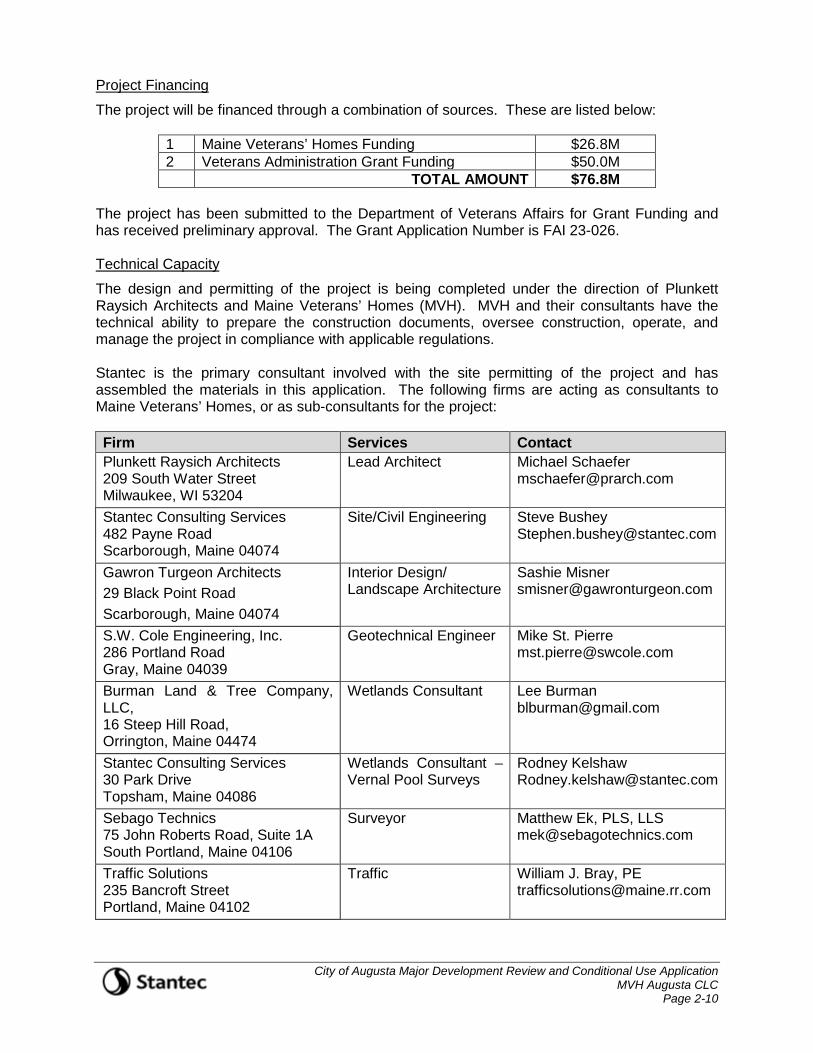
Project Financing
The project will be financed through a combination of sources. These are listed below:
1 Maine Veterans’ Homes Funding $26.8M 2 Veterans Administration Grant Funding $50.0M TOTAL AMOUNT $76.8M
The project has been submitted to the Department of Veterans Affairs for Grant Funding and has received preliminary approval. The Grant Application Number is FAI 23-026. Technical Capacity
The design and permitting of the project is being completed under the direction of Plunkett Raysich Architects and Maine Veterans’ Homes (MVH). MVH and their consultants have the technical ability to prepare the construction documents, oversee construction, operate, and manage the project in compliance with applicable regulations. Stantec is the primary consultant involved with the site permitting of the project and has assembled the materials in this application. The following firms are acting as consultants to Maine Veterans’ Homes, or as sub-consultants for the project: Firm Services Contact Plunkett Raysich Architects 209 South Water Street Milwaukee, WI 53204
Lead Architect Michael Schaefer [email protected]
Stantec Consulting Services 482 Payne Road Scarborough, Maine 04074
Site/Civil Engineering Steve Bushey [email protected]
Gawron Turgeon Architects 29 Black Point Road Scarborough, Maine 04074
Interior Design/ Landscape Architecture
Sashie Misner [email protected]
S.W. Cole Engineering, Inc. 286 Portland Road Gray, Maine 04039
Geotechnical Engineer Mike St. Pierre [email protected]
Burman Land & Tree Company, LLC, 16 Steep Hill Road, Orrington, Maine 04474
Wetlands Consultant Lee Burman [email protected]
Stantec Consulting Services 30 Park Drive Topsham, Maine 04086
Wetlands Consultant – Vernal Pool Surveys
Rodney Kelshaw [email protected]
Sebago Technics 75 John Roberts Road, Suite 1A South Portland, Maine 04106
Surveyor Matthew Ek, PLS, LLS [email protected]
Traffic Solutions 235 Bancroft Street Portland, Maine 04102
Traffic William J. Bray, PE [email protected]
City of Augusta Major Development Review and Conditional Use Application MVH Augusta CLC Page 2-11
Experience of Project Team
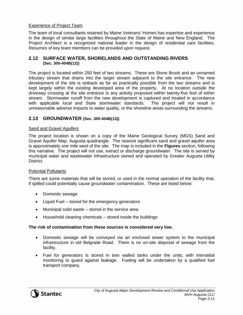
The team of local consultants retained by Maine Veterans’ Homes has expertise and experience in the design of similar large facilities throughout the State of Maine and New England. The Project Architect is a recognized national leader in the design of residential care facilities. Resumes of key team members can be provided upon request. 2.12 SURFACE WATER, SHORELANDS AND OUTSTANDING RIVERS
(Sec. 300-404B(12))
The project is located within 250 feet of two streams. These are Stone Brook and an unnamed tributary stream that drains into the larger stream adjacent to the site entrance. The new development of the site is setback as far as practically possible from the two streams and is kept largely within the existing developed area of the property. At no location outside the driveway crossing at the site entrance is any activity proposed within twenty-five feet of either stream. Stormwater runoff from the new development is captured and treated in accordance with applicable local and State stormwater standards. The project will not result in unreasonable adverse impacts to water quality, or the shoreline areas surrounding the streams. 2.13 GROUNDWATER (Sec. 300-404B(13))
Sand and Gravel Aquifers
The project location is shown on a copy of the Maine Geological Survey (MGS) Sand and Gravel Aquifer Map, Augusta quadrangle. The nearest significant sand and gravel aquifer area is approximately one mile west of the site. The map is included in the Figures section, following this narrative. The project will not use, extract or discharge groundwater. The site is served by municipal water and wastewater infrastructure owned and operated by Greater Augusta Utility District. Potential Pollutants
There are some materials that will be stored, or used in the normal operation of the facility that, if spilled could potentially cause groundwater contamination. These are listed below:
• Domestic sewage
• Liquid Fuel – stored for the emergency generators
• Municipal solid waste – stored in the service area
• Household cleaning chemicals – stored inside the buildings The risk of contamination from these sources is considered very low.
• Domestic sewage will be conveyed via an enclosed sewer system to the municipal infrastructure in old Belgrade Road. There is no on-site disposal of sewage from the facility.
• Fuel for generators is stored in twin walled tanks under the units, with interstitial monitoring to guard against leakage. Fueling will be undertaken by a qualified fuel transport company.
City of Augusta Major Development Review and Conditional Use Application MVH Augusta CLC Page 2-12
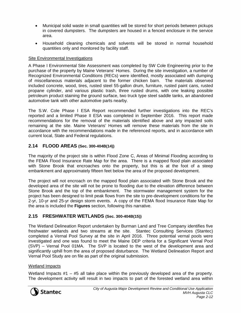
• Municipal solid waste in small quantities will be stored for short periods between pickups in covered dumpsters. The dumpsters are housed in a fenced enclosure in the service area.
• Household cleaning chemicals and solvents will be stored in normal household quantities only and monitored by facility staff.
Site Environmental Investigations
A Phase I Environmental Site Assessment was completed by SW Cole Engineering prior to the purchase of the property by Maine Veterans’ Homes. During the site investigation, a number of Recognized Environmental Conditions (RECs) were identified, mostly associated with dumping of miscellaneous materials adjacent to the former chicken barn. The materials observed included concrete, wood, tires, rusted steel 55-gallon drum, furniture, rusted paint cans, rusted propane cylinder, and various plastic trash, three rusted drums, with one leaking possible petroleum product staining the ground surface, two truck type steel saddle tanks, an abandoned automotive tank with other automotive parts nearby. The S.W. Cole Phase I ESA Report recommended further investigations into the REC’s reported and a limited Phase II ESA was completed in September 2016. This report made recommendations for the removal of the materials identified above and any impacted soils remaining at the site. Maine Veterans’ Homes will remove these materials from the site in accordance with the recommendations made in the referenced reports, and in accordance with current local, State and Federal regulations. 2.14 FLOOD AREAS (Sec. 300-404B(14))
The majority of the project site is within Flood Zone C, Areas of Minimal Flooding according to the FEMA Flood Insurance Rate Map for the area. There is a mapped flood plain associated with Stone Brook that encroaches onto the property, but this is at the foot of a steep embankment and approximately fifteen feet below the area of the proposed development. The project will not encroach on the mapped flood plain associated with Stone Brook and the developed area of the site will not be prone to flooding due to the elevation difference between Stone Brook and the top of the embankment. The stormwater management system for the project has been designed to limit peak flows from the site to pre-development conditions for the 2-yr, 10-yr and 25-yr design storm events. A copy of the FEMA flood Insurance Rate Map for the area is included the Figures section, following this narrative. 2.15 FRESHWATER WETLANDS (Sec. 300-404B(15))
The Wetland Delineation Report undertaken by Burman Land and Tree Company identifies five freshwater wetlands and two streams at the site. Stantec Consulting Services (Stantec) completed a Vernal Pool Survey at the site in April 2016. Three potential vernal pools were investigated and one was found to meet the Maine DEP criteria for a Significant Vernal Pool (SVP) – Vernal Pool 01MA. The SVP is located to the west of the development area and significantly uphill from the area of proposed disturbance. The Wetland Delineation Report and Vernal Pool Study are on file as part of the original submission. Wetland Impacts
Wetland Impacts #1 – #5 all take place within the previously developed area of the property. The development activity will result in two impacts to part of the forested wetland area within
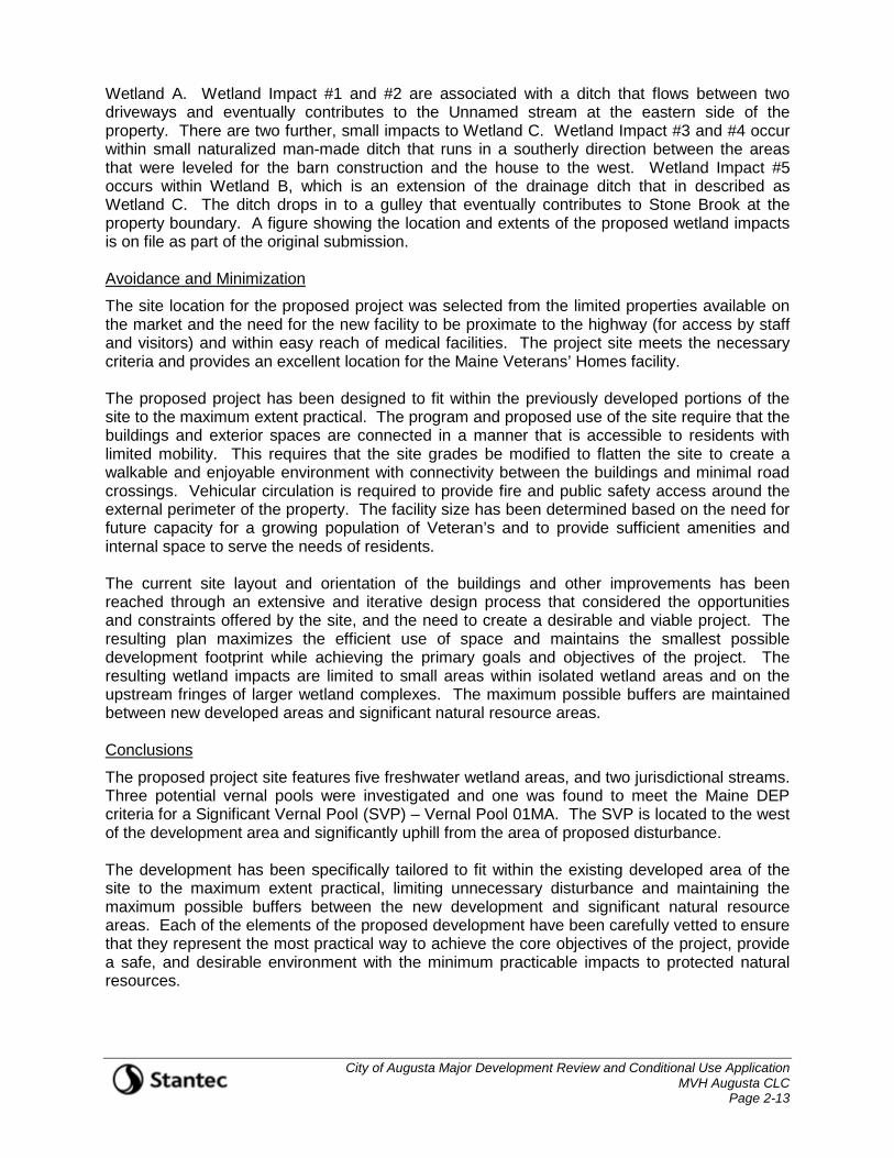
City of Augusta Major Development Review and Conditional Use Application MVH Augusta CLC Page 2-13
Wetland A. Wetland Impact #1 and #2 are associated with a ditch that flows between two driveways and eventually contributes to the Unnamed stream at the eastern side of the property. There are two further, small impacts to Wetland C. Wetland Impact #3 and #4 occur within small naturalized man-made ditch that runs in a southerly direction between the areas that were leveled for the barn construction and the house to the west. Wetland Impact #5 occurs within Wetland B, which is an extension of the drainage ditch that in described as Wetland C. The ditch drops in to a gulley that eventually contributes to Stone Brook at the property boundary. A figure showing the location and extents of the proposed wetland impacts is on file as part of the original submission. Avoidance and Minimization
The site location for the proposed project was selected from the limited properties available on the market and the need for the new facility to be proximate to the highway (for access by staff and visitors) and within easy reach of medical facilities. The project site meets the necessary criteria and provides an excellent location for the Maine Veterans’ Homes facility. The proposed project has been designed to fit within the previously developed portions of the site to the maximum extent practical. The program and proposed use of the site require that the buildings and exterior spaces are connected in a manner that is accessible to residents with limited mobility. This requires that the site grades be modified to flatten the site to create a walkable and enjoyable environment with connectivity between the buildings and minimal road crossings. Vehicular circulation is required to provide fire and public safety access around the external perimeter of the property. The facility size has been determined based on the need for future capacity for a growing population of Veteran’s and to provide sufficient amenities and internal space to serve the needs of residents. The current site layout and orientation of the buildings and other improvements has been reached through an extensive and iterative design process that considered the opportunities and constraints offered by the site, and the need to create a desirable and viable project. The resulting plan maximizes the efficient use of space and maintains the smallest possible development footprint while achieving the primary goals and objectives of the project. The resulting wetland impacts are limited to small areas within isolated wetland areas and on the upstream fringes of larger wetland complexes. The maximum possible buffers are maintained between new developed areas and significant natural resource areas. Conclusions
The proposed project site features five freshwater wetland areas, and two jurisdictional streams. Three potential vernal pools were investigated and one was found to meet the Maine DEP criteria for a Significant Vernal Pool (SVP) – Vernal Pool 01MA. The SVP is located to the west of the development area and significantly uphill from the area of proposed disturbance. The development has been specifically tailored to fit within the existing developed area of the site to the maximum extent practical, limiting unnecessary disturbance and maintaining the maximum possible buffers between the new development and significant natural resource areas. Each of the elements of the proposed development have been carefully vetted to ensure that they represent the most practical way to achieve the core objectives of the project, provide a safe, and desirable environment with the minimum practicable impacts to protected natural resources.

City of Augusta Major Development Review and Conditional Use Application MVH Augusta CLC Page 2-14
2.16 RIVER, STREAM OR BROOK (Sec. 300-404B(16))
Two streams have been identified on the project site. An unnamed tributary stream runs in a southerly direction along the eastern boundary of the site and crosses the existing driveway in a 15-inch diameter HDPE culvert. The unnamed stream drains into Stone Brook near the site entrance. Stone Brook runs under Old Belgrade Road just south of the existing entrance driveway and continues in a southwesterly direction towards Civic Center Drive, forming the southwestern boundary of the project site. The streams are shown on the drawings accompanying this submission. There is an SP100 Stream Protection Overlay District associated with Stone Brook. This District extends fifty feet either side of the stream according to the official Shoreland Zoning Map (5). 2.17 STORMWATER MANAGEMENT (Sec. 300-404B(17))
Stormwater Management for the project is provided through new collection and conveyance infrastructure that will direct flows from newly developed areas to a series of new stormwater Best Management Practices (BMPs). BMPs have been designed to capture, detain and provide water quality treatment in accordance with current local, State and Federal stormwater standards. A summary of the updated Stormwater Management Report is provided in the paragraphs below. A copy of the full document will be provided under a separate cover with the full MaineDEP Amended Site Law Submission. Stormwater Management
There are currently no provisions for stormwater management at the site. Runoff from developed areas of the property drains by sheet flow and in a series of un-maintained ditches directly into the main drainageways that convey surface water off the property. These include Stone Brook, an un-named tributary stream, and the associated wetlands. New stormwater management BMPs have been designed to capture and treat runoff from the improvements associated with this project. These include two FocalPoint® modular biofiltration systems and a large wet pond. These new BMPs will provide detention of the channel protection volume (CPV), and water quality treatment for runoff from new impervious and new developed areas of the site. The new system will maintain the existing drainage patterns at the site, while protecting water quality and ensuring that there is no increase in peak runoff rates from the property. This stormwater management analysis has been prepared in accordance with the Maine Department of Environmental Protection (MeDEP) Chapter 500 Regulations for Basic, General and Flooding Standards in order to ensure that the planned development will not result in a degradation of water quality or any other significant impacts to locations downstream of the development site as a result of stormwater runoff. Existing Conditions
The project site is described as Map 1, Lots 1-A, 1-B, 1-C, and 1-D on the City of Augusta Assessor’s database and comprises a total area of approximately fifty-eight (58) acres. The property is bounded by Old Belgrade Road to the east, Stone Brook to the south, residential property to the north, and a wooded ridge to the west. The lower portion of the property is previously developed with several buildings including three residences, storage buildings, and an old chicken barn, all of which have been removed from the site. The site slopes gently
City of Augusta Major Development Review and Conditional Use Application MVH Augusta CLC Page 2-15
upward from the frontage of Old Belgrade Road across the developed area, before the grades increase dramatically at the treeline, with a steep, rocky ridge extending upwards to the western boundary. There is a communications tower located on a lease parcel towards the high point at the northwest corner of the property. A gravel road winds through the property providing access to the tower. A full site boundary and topographic survey was undertaken by Sebago Technics in October 2015, and updated in September 2016 and is included with this submission. General surficial soil mapping for the site has been obtained through the Natural Resource Conservation Service (NRCS) Web Soil Survey. This indicates the presence of predominantly coarse grained rocky and sandy loam soils in the upper portions of the property, transitioning to finer grained silt loams in the low areas adjacent to the un-named stream and Stone Brook. The steep ridge that runs across the site is mapped as Hollis soil with limited depth to bedrock. Site observations indicate outcropping of bedrock within this map unit. Burman Land and Tree Company has undertaken on-site soil evaluations to provide more detailed definition of the map units present within the area of proposed development and at the locations of proposed stormwater BMPs. S.W. Cole Engineering has undertaken geotechnical investigations at the site and these largely confirm the surficial soils mapping indicating glaciomarine sand deposits at or near the surface. In the western portion of the property, the surficial soils are underlain by a shallow stiff clay layer followed by glacial till and bedrock at depths of between five and fifteen feet below surface. In the eastern portion of the property, the surficial soils are underlain by a softer silty clay which extends to depths up to 59 feet below grade. Natural resource mapping at the site has been undertaken by Burman Land and Tree Company, LLC. The investigation identified five freshwater wetland areas, three potential vernal pools, and two streams at the site. The freshwater wetlands are forested scrub-shrub and emergent wetlands some of which are associated with small ditches and drainage ways that run through the previously developed portions of the property. The two streams are Stone Brook, which has a FEMA delineated flood plain and a small unnamed tributary that flows in from the north. Receiving Waters
Runoff from the northern portion of project site drains to the east and south to a small unnamed stream that runs in a steep gulley along the eastern property line and crosses the entrance driveway in a small culvert near the site entrance. Downstream of the culvert the unnamed stream joins Stone Brook, which runs in a southwesterly direction along the site boundary. Runoff from the southern portion of the site drains directly to Stone Brook. Historical Flooding
There are no reports of historic flooding on the site, or on adjacent properties. Most of the site is within Flood Zone C, Areas of Minimal Flooding according to the FEMA Flood Insurance Rate Map for the area. There is a mapped flood plain associated with Stone Brook that encroaches onto the property, but this is at the foot of a steep embankment and approximately fifteen feet below the area of the proposed development. Alterations to Natural Drainageways
The project will not result in alteration of any natural drainageways. There will be some alterations to man-made and naturalized ditches that serve the existing developed areas of the site. The stormwater management system is designed to meet current local, and State standards and ensure that there are no significant detrimental impacts to downstream properties or receiving waters.
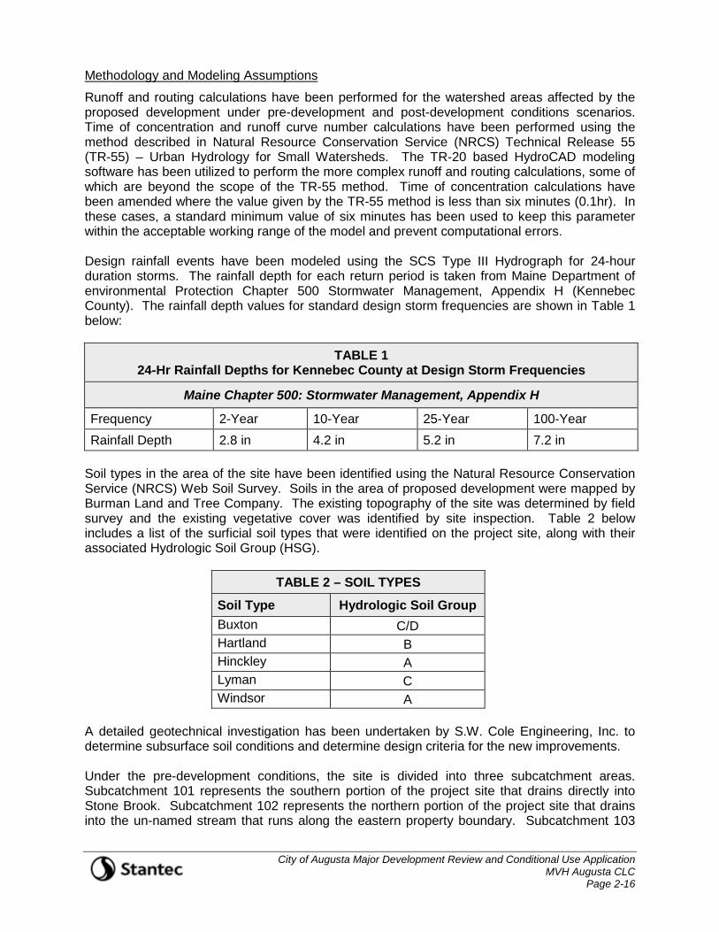
City of Augusta Major Development Review and Conditional Use Application MVH Augusta CLC Page 2-16
Methodology and Modeling Assumptions
Runoff and routing calculations have been performed for the watershed areas affected by the proposed development under pre-development and post-development conditions scenarios. Time of concentration and runoff curve number calculations have been performed using the method described in Natural Resource Conservation Service (NRCS) Technical Release 55 (TR-55) – Urban Hydrology for Small Watersheds. The TR-20 based HydroCAD modeling software has been utilized to perform the more complex runoff and routing calculations, some of which are beyond the scope of the TR-55 method. Time of concentration calculations have been amended where the value given by the TR-55 method is less than six minutes (0.1hr). In these cases, a standard minimum value of six minutes has been used to keep this parameter within the acceptable working range of the model and prevent computational errors. Design rainfall events have been modeled using the SCS Type III Hydrograph for 24-hour duration storms. The rainfall depth for each return period is taken from Maine Department of environmental Protection Chapter 500 Stormwater Management, Appendix H (Kennebec County). The rainfall depth values for standard design storm frequencies are shown in Table 1 below:
TABLE 1 24-Hr Rainfall Depths for Kennebec County at Design Storm Frequencies
Maine Chapter 500: Stormwater Management, Appendix H
Frequency 2-Year 10-Year 25-Year 100-Year Rainfall Depth 2.8 in 4.2 in 5.2 in 7.2 in
Soil types in the area of the site have been identified using the Natural Resource Conservation Service (NRCS) Web Soil Survey. Soils in the area of proposed development were mapped by Burman Land and Tree Company. The existing topography of the site was determined by field survey and the existing vegetative cover was identified by site inspection. Table 2 below includes a list of the surficial soil types that were identified on the project site, along with their associated Hydrologic Soil Group (HSG).
TABLE 2 – SOIL TYPES
Soil Type Hydrologic Soil Group Buxton C/D Hartland B Hinckley A Lyman C Windsor A
A detailed geotechnical investigation has been undertaken by S.W. Cole Engineering, Inc. to determine subsurface soil conditions and determine design criteria for the new improvements. Under the pre-development conditions, the site is divided into three subcatchment areas. Subcatchment 101 represents the southern portion of the project site that drains directly into Stone Brook. Subcatchment 102 represents the northern portion of the project site that drains into the un-named stream that runs along the eastern property boundary. Subcatchment 103
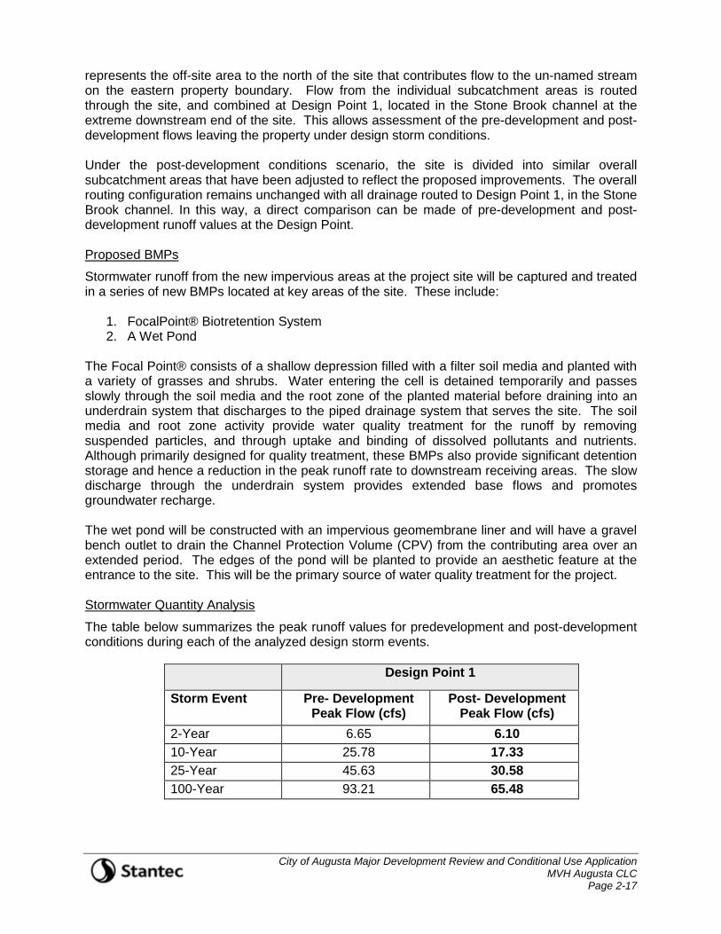
City of Augusta Major Development Review and Conditional Use Application MVH Augusta CLC Page 2-17
represents the off-site area to the north of the site that contributes flow to the un-named stream on the eastern property boundary. Flow from the individual subcatchment areas is routed through the site, and combined at Design Point 1, located in the Stone Brook channel at the extreme downstream end of the site. This allows assessment of the pre-development and post-development flows leaving the property under design storm conditions. Under the post-development conditions scenario, the site is divided into similar overall subcatchment areas that have been adjusted to reflect the proposed improvements. The overall routing configuration remains unchanged with all drainage routed to Design Point 1, in the Stone Brook channel. In this way, a direct comparison can be made of pre-development and post- development runoff values at the Design Point. Proposed BMPs
Stormwater runoff from the new impervious areas at the project site will be captured and treated in a series of new BMPs located at key areas of the site. These include:
1. FocalPoint® Biotretention System 2. A Wet Pond
The Focal Point® consists of a shallow depression filled with a filter soil media and planted with a variety of grasses and shrubs. Water entering the cell is detained temporarily and passes slowly through the soil media and the root zone of the planted material before draining into an underdrain system that discharges to the piped drainage system that serves the site. The soil media and root zone activity provide water quality treatment for the runoff by removing suspended particles, and through uptake and binding of dissolved pollutants and nutrients. Although primarily designed for quality treatment, these BMPs also provide significant detention storage and hence a reduction in the peak runoff rate to downstream receiving areas. The slow discharge through the underdrain system provides extended base flows and promotes groundwater recharge. The wet pond will be constructed with an impervious geomembrane liner and will have a gravel bench outlet to drain the Channel Protection Volume (CPV) from the contributing area over an extended period. The edges of the pond will be planted to provide an aesthetic feature at the entrance to the site. This will be the primary source of water quality treatment for the project. Stormwater Quantity Analysis
The table below summarizes the peak runoff values for predevelopment and post-development conditions during each of the analyzed design storm events.
Design Point 1
Storm Event Pre- Development Peak Flow (cfs)
Post- Development Peak Flow (cfs)
2-Year 6.65 6.10 10-Year 25.78 17.33 25-Year 45.63 30.58 100-Year 93.21 65.48
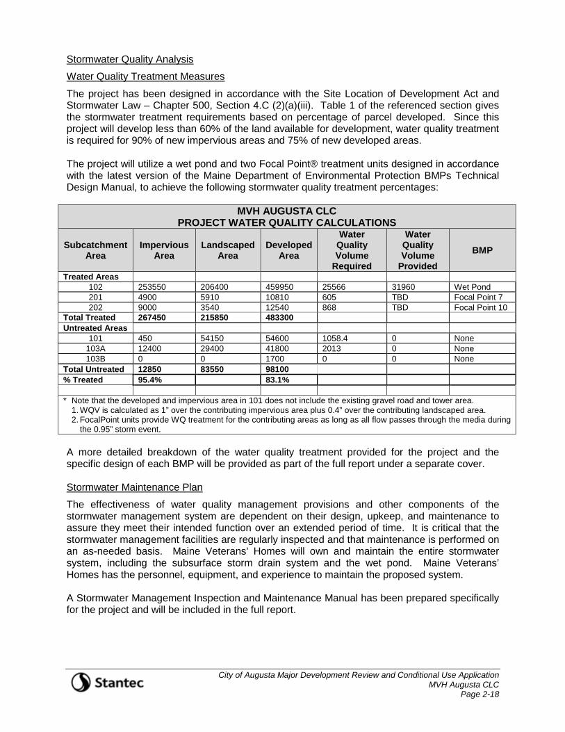
City of Augusta Major Development Review and Conditional Use Application MVH Augusta CLC Page 2-18
Stormwater Quality Analysis
Water Quality Treatment Measures
The project has been designed in accordance with the Site Location of Development Act and Stormwater Law – Chapter 500, Section 4.C (2)(a)(iii). Table 1 of the referenced section gives the stormwater treatment requirements based on percentage of parcel developed. Since this project will develop less than 60% of the land available for development, water quality treatment is required for 90% of new impervious areas and 75% of new developed areas. The project will utilize a wet pond and two Focal Point® treatment units designed in accordance with the latest version of the Maine Department of Environmental Protection BMPs Technical Design Manual, to achieve the following stormwater quality treatment percentages:
MVH AUGUSTA CLC PROJECT WATER QUALITY CALCULATIONS
Subcatchment Area
Impervious Area
Landscaped Area
Developed Area
Water Quality Volume
Required
Water Quality Volume
Provided BMP
Treated Areas 102 253550 206400 459950 25566 31960 Wet Pond 201 4900 5910 10810 605 TBD Focal Point 7 202 9000 3540 12540 868 TBD Focal Point 10
Total Treated 267450 215850 483300 Untreated Areas
101 450 54150 54600 1058.4 0 None 103A 12400 29400 41800 2013 0 None 103B 0 0 1700 0 0 None
Total Untreated 12850 83550 98100 % Treated 95.4% 83.1% * Note that the developed and impervious area in 101 does not include the existing gravel road and tower area.
1. WQV is calculated as 1” over the contributing impervious area plus 0.4” over the contributing landscaped area. 2. FocalPoint units provide WQ treatment for the contributing areas as long as all flow passes through the media during
the 0.95” storm event. A more detailed breakdown of the water quality treatment provided for the project and the specific design of each BMP will be provided as part of the full report under a separate cover. Stormwater Maintenance Plan
The effectiveness of water quality management provisions and other components of the stormwater management system are dependent on their design, upkeep, and maintenance to assure they meet their intended function over an extended period of time. It is critical that the stormwater management facilities are regularly inspected and that maintenance is performed on an as-needed basis. Maine Veterans’ Homes will own and maintain the entire stormwater system, including the subsurface storm drain system and the wet pond. Maine Veterans’ Homes has the personnel, equipment, and experience to maintain the proposed system. A Stormwater Management Inspection and Maintenance Manual has been prepared specifically for the project and will be included in the full report.

City of Augusta Major Development Review and Conditional Use Application MVH Augusta CLC Page 2-19
Conclusions
The stormwater management system designed for this project will mitigate impacts of development on stormwater runoff peak discharge rates and provide treatment of non-point source pollutants in the runoff in accordance with Maine’s Stormwater Management Act and Regulations. Based on the analysis described herein, it is expected that runoff from the proposed development will not cause adverse impacts to downstream properties. 2.18 ACCESS TO DIRECT SUNLIGHT (Sec. 300-404B(18))
The project will have no impact on access to direct sunlight for solar energy systems on adjacent properties. 2.19 STATE PERMITS (Sec. 300-404B(19))
The project was previously issued Site Location of Development Act and Natural Resource Protection Act (Tier 1 and Permit-By-Rule) permits from Maine Department of Environmental Protection (see attached). The project will also be covered by the State of Maine Pollution Discharge Elimination Program (MPDES) General Permit for Construction Activity. The project does not meet the trip generation threshold that would require a Traffic Movement Permit from Maine Department of Transportation. A State Fire Marshall permit will be required for the building (s). 2.20 SPAGHETTI LOTS PROHIBITED (Sec. 300-404B(20))
This section is not applicable. The project does not propose the creation of new lots. 2.21 OUTDOOR LIGHTING (Sec. 300-404B(21))
The outdoor lighting for the project has been designed to prevent light trespass onto adjacent properties. Site lighting and photometric plans are included in the accompanying plan set. Cut sheets for exterior lighting fixtures are included in Attachment 1. 2.22 NEIGHBORHOOD COMPATIBILITY (Sec. 300-603E(1))
A. Zoning The project is located within the Medical/Hospital District on the west side of Interstate 95 and directly opposite the MaineGeneral Alfond Center for Health campus. The zone was created to allow medical service providers and other associated users to locate in the vicinity of the new regional hospital facility, and take advantage of the proximity to the new facility. The proposed use is consistent with the intent of the zoning and will benefit from the proximity of the medical facilities on the adjacent land.
B. Land Use There are a variety of current land uses on the properties abutting the project site. These include: • Medical – MaineGeneral Alfond Center for Cancer Care and Alfond Center for Health
are located on the opposite side of Old Belgrade Road. The Center for Cancer Care is
City of Augusta Major Development Review and Conditional Use Application MVH Augusta CLC Page 2-20
approximately 800 feet from the project site, the regional hospital is approximately 1,600 feet from the site.
• Quarry – The Auburn Concrete facility is located on Civic Center Drive to the west of the project site. This is approximately 1,200 feet from the site and is shielded by a high ridge between the properties.
• Cemetery/Open Space – The State of Maine owns the property directly south of the project site that housed the Veterans Cemetery.
• Residential – There are three small residential lots on Charest Lane (off Old Belgrade Road), the closes of these is approximately five hundred feet from the site. There is also a residential property on Old Belgrade Road, approximately five hundred feet north of the site.
The proposed skilled nursing home use is consistent with the mix of residential and medical uses in the existing neighborhood. Furthermore, there is adequate space and buffering between the proposed new facility and the street to allow the scale of the new project to be integrated into the surrounding neighborhood.
C. Architectural Design The architecture of the new facility incorporates traditional New England materials and elements into the building design in a manner that reduces the scale and massing of the structures. This creates an attractive high quality residential aesthetic that compliments the site and surrounding landscape.
D. Scale, Bulk and Building Height As described in the section above, the architectural design of the new buildings incorporates a variety of features and elements that effectively reduce the scale of the individual buildings to provide a residential feel to project.
E. Identity and Historical Character, Disposition and Orientation of Buildings on the Lot The proposed new buildings reflect many aspects of historical New England architectural design, while providing a modern, state-of-the-art care facility. The buildings are arranged on the site to provide direct, covered connectivity between each residential building and the Community Center to allow free access to the central facilities for residents. This is a key element of the design. Each building has a dedicated front entrance off the loop road, creating a smaller scale “neighborhood” feel to the project and allowing each building to develop an individual character. Localized parking, external areas and landscaping around each building further develop the concept of individual residential units integrated into a larger neighborhood.
F. Visual Integrity, Privacy, and Healthful Conditions The project design integrates the new development within the natural surroundings of the site. The major architectural design elements are maintained throughout the project, creating seamless transitions between the buildings and producing an attractive and consistent visual aesthetic. The provision of courtyards and common areas around the entrance of each building allows for small scale and private gatherings, in addition to the larger function spaces provided at and around the Community Center. External access is
City of Augusta Major Development Review and Conditional Use Application MVH Augusta CLC Page 2-21
provided adjacent to each neighborhood and a connected system of walking paths, gardens and patio areas enable enjoyment of outdoor spaces for residents of all ages and abilities. The new facility will provide an attractive, healthy and tranquil setting for future residents.
G. Impacts on the Value of Adjacent Properties The project proposes the development of a high quality residential care facility on an attractive site set back from Old Belgrade Road, and surrounded by mature woods. The architectural design of the new buildings will create a high quality residential aesthetic that will be partially visible from old Belgrade Road. The project will enhance the surrounding neighborhood and create further momentum behind the continued development of an integrated medical and hospital zone. Under these circumstances the impact on the value of adjacent properties will likely be significantly beneficial.
2.23 COMPLIANCE WITH PLANS AND POLICIES (Sec. 300-603E(2))
A. The proposed development of the property is consistent with the goals stated in the 2007 City of Augusta Comprehensive Plan. This identified the area including and surrounding the project site as an Economic Growth region (p33). The Comprehensive Plan also states that “The City should stimulate growth of the health care industry, recognizing it is one of the largest industries in Augusta and brings many people from surrounding towns into the city” (Augusta Comprehensive Plan Inventory 2007, Health and Welfare Key Issues: P 124).
2.24 TRAFFIC PATTERN, FLOW AND VOLUME ANALYSIS (Sec. 300-603E(3))
A. The project will not result in unreasonable highway or public road congestion, or unsafe conditions with respect to the use of existing highways or public roads. Significant infrastructure improvements were constructed in the area of the project site to support continued development in the area surrounding the new regional hospital. A Traffic Impact Analysis has been conducted for the project by Traffic Solutions, Inc. and an abridged version of the report, including the full text without appendices is on file as part of the original submission.
B. The site entrance is located at a signalized intersection, directly opposite the entrance to the MaineGeneral Alfond Center for Health. This provides controlled access to the site from Old Belgrade Road, which was re-constructed by Maine DOT in 2013 to accommodate traffic to and from the new hospital.
C. Access is provided into and around the site via a new entrance and loop road that extends
around the perimeter of the facility. This provides access to all areas of the site for emergency vehicles, staff and visitors to the facility. The classification of the on-site roadways is governed by Section 3.2.4. of the City of Augusta Technical Manual. The classification depends on projected Average Daily Traffic, with a Lane serving up to 250 Average Daily Trips (ADT), and a Street between 250 and 900 ADT. The ITE Trip Generation Manual indicates that the facility as a whole could generate an ADT of around 378. This would classify the main entrance to the site (prior to the split in the loop road) as a Private Street. If the ADT is then split around the loop road, the remainder of the roadway would classify as a Private Lane. The City Technical Manual requires a minimum paved travel way of eighteen feet for a Private Lane and twenty-two feet for a Private Street. The design proposes a paved width of twenty-four feet at the entrance and up to the split in the loop road. The width is then narrowed to twenty-two feet for the remainder of the circulation.

City of Augusta Major Development Review and Conditional Use Application MVH Augusta CLC Page 2-22
Therefore, the proposed road dimensions conform to the requirements of the City Technical Manual.
D. Parking for staff, visitors and residents is provided in a series of areas located throughout
the facility. The provision of small, localized parking areas adds to the residential aesthetic of the project, allows for efficient access to each housing unit and efficient movement and circulation of traffic. In addition to the surface parking, underground parking is provided below the Assisted Living building. The total number of parking spaces provided at the site is 180 (including 18 ADA spaces and at least four van parking spaces). The City of Augusta Performance Standards (§300-513, Table 300-513A) gives the following requirements for parking at Nursing Home uses: Category Ordinance Requirement Count Spaces Required Beds 1 space per 4 138 35
Employee 2 spaces per 3 98* 66
Staff Doctor 1 space per 1 2 2
TOTAL SPACES REQUIRED BY ORDINANCE 103
* Day shift (largest) The number of spaces provided at the site reflects the facility need, based on experience at the current MVH facility on Cony Road, and exceeds the ordinance requirement for parking.
2.25 PUBLIC FACILITIES (Sec. 300-603E(4))
A. The new Maine Veterans’ Homes facility will be connected to the municipal water system for supply of fire protection and domestic water. The project scope will include an extension of the existing water Greater Augusta Utility District water main In Old Belgrade Road, to the site entrance.
B. Sewer flow generated at the site will discharge to the Greater Augusta Utility District system located in Old Belgrade Road. The project will generate an estimated average daily water demand of 11,250 gpd, as shown on the demand calculation previously described.
C. Electrical power will be provided to the site by Central Maine Power Company. Communications and cable service will be provided by Spectrum. These services will run underground into the site from the street. It is anticipated that natural gas will be provided to the site by Maine Natural Gas Company.
D. Storm drainage for the site will be provided by an internal private separate stormwater system that will capture, detain and treat runoff from developed areas of the site before allowing it to discharge to the streams and drainageways adjacent to the site. Overall drainage patterns will be maintained and peak runoff rates will be kept to pre-development levels for the 2-year, 10- year and 25-year design storm events.
2.26 RESOURCE PROTECTION AND ENVIRONMENT (Sec. 300-603E(5))
A. The development has been specifically tailored to fit within the existing developed area of the site to the maximum extent practical, limiting unnecessary disturbance and maintaining the maximum possible buffers between the new development and significant natural
City of Augusta Major Development Review and Conditional Use Application MVH Augusta CLC Page 2-23
resource areas. Each of the elements of the proposed development have been carefully vetted to ensure that they represent the most practical way to achieve the core objectives of the project, provide a safe, and desirable environment with the minimum practicable impacts to protected natural resources. The proposed development will not encroach on any aquifer recharge areas, or flood plains and has been designed to provide the maximum possible setbacks from the two streams identified on the property. The applicant has retained S.W. Cole Engineering to undertake a full geotechnical investigation of the site and provide recommendations that have been incorporated into the project design.
B. The proposed project does not propose any use that could compromise air quality standards. Provisions are made in the soil erosion and sediment control plan to control dust during construction.
C. The proposed project has been designed to meet all applicable local, State and Federal water quality regulations. A comprehensive stormwater management plan has been designed to control and treat runoff from newly developed area. Soil erosion and sediment control plans, details and notes have been produced to protect downstream areas and receiving waters during and after construction of the project. Solid waste materials generated both during construction and in the daily operation of the facility will be disposed of in accordance with local and State regulations.
D. Sewage effluent for the proposed facility will discharge to the Greater Augusta Utility District (GAUD) system in Old Belgrade Road. The project will not produce any industrial wastes.
E. Shoreland and Wetland Districts
1. The project maintains the maximum possible setbacks from the two streams identified at the site. Stormwater management systems will treat runoff for water quality and maintain pre-development discharge rates, thus maintain the health of the downstream receiving waters.
2. The proposed project has been designed to meet all applicable local, State and Federal water quality regulations. A comprehensive stormwater management plan has been designed to control and treat runoff from newly developed area. Soil erosion and sediment control plans, details and notes have been produced to protect downstream areas and receiving waters during and after construction of the project.
3. Sewage effluent for the proposed facility will discharge to the Greater Augusta Utility District (GAUD) system in Old Belgrade Road.
4. The project will not result in impacts to unusual natural areas or rare or unique botanical features. No rare and exemplary botanical features have been identified in the vicinity of the project according to correspondence received for the Maine Natural Areas Program (Maine NAP). The proposed project will not result in any significant impacts to wildlife and fisheries.
5. The project does not propose any significant impacts to shore cover, or any visual or actual points of access to inland or coastal waters.
City of Augusta Major Development Review and Conditional Use Application MVH Augusta CLC Page 2-24
6. The proposed project will not result in any significant impacts to historic resources. Maine Historic Preservation Commission has been contacted regarding potential historic sites in the vicinity of the project.
7. The project does not encroach on any floodplain areas and maintains the maximum practical setbacks from the two streams identified on the site.
8. The project conforms to the applicable sections of §300-528. The southern branch of the loop road is located within 75 feet of the wetland adjacent to Stone Brook, but is setback greater than 25 feet as allowed with Planning Board approval. The loop road is located at the edge of the existing developed area and is curbed to prevent any erosion towards the wetland. All runoff from the road is captured and treated in the project stormwater management system.
2.27 PERFORMANCE STANDARDS (Sec. 300-603E(6))
A. The project complies with the dimensional standards for the district. These are as follows: Ordinance Criteria Standard Provided Minimum Lot Size 20,000 sf >1,800,000 sf Minimum Frontage 150 feet 408.82 feet Minimum Depth 100 feet >1,500 feet Minimum Front Setback 20/35 feet >500 feet
B. The proposed project seeks to develop the property to construct a skilled nursing facility for
Maine Veterans’ Homes. The location was selected to provide a tranquil and peaceful setting for residents and noise generation will be kept to a minimum in order to provide an environment suited to the proposed use. The primary noise generator during the normal operation of the facility will be from traffic entering and leaving the facility. This will include staff and visitor passenger vehicles, and occasional delivery and service trucks. Routine grounds maintenance activities may require the use of power equipment such as mowers, leaf blowers, trimmers, snow blowers, etc. This activity will take place during regular daytime hours and will not exceed noise levels associated with equivalent residential uses. Mechanical equipment will be screened and baffled to prevent noise impacts to residents of the facility. There are two large emergency generators located at the facility to provide electrical power in the event of a mains power outage. The generators are located to the north of the loop road and will be housed in full enclosures. These will be run periodically on a routine test basis during daytime hours and during power outages. It is not anticipated that any activity at the site will generate noise levels in excess of 60dBA at the property lines.
C. Not applicable. The proposal does not involve intense glare, or heat, direct or reflected.
D. The site lighting is designed to meet the design requirements for the Medical/Hospital District and will feature full cutoff fixtures. The photometric analysis demonstrates that there will be no light trespass from the project onto abutting properties. Cut sheets for lighting fixtures are included in Attachment 1.
E. An extensive landscaping plan has been developed for the site. This includes landscaping around the buildings and outdoor spaces, and screening of service areas and equipment. The landscape plan is included with the project drawings.

City of Augusta Major Development Review and Conditional Use Application MVH Augusta CLC Page 2-25
F. The sign proposed for the project will be similar in design to the existing sign at the Maine Veterans’ Homes headquarters building on Civic Center Drive. A copy of the sign design for this location is included in Attachment 2.
2.28 FINANCIAL AND TECHNICAL ABILITY (Sec. 300-603E(7))
Refer to the information provided in Section 2.9 of this document.
City of Augusta Major Development Review and Conditional Use Application MVH Augusta CLC Page 3-1
3. SITE PLAN REVIEW CRITERIA FOR CONDITIONAL USES (Per Augusta Land Use Ordinance Section 300-603.E(1) through (7))
3.1 NEIGHBORHOOD COMPATIBILITY (Sec. 300-603E(1))
Refer to the information provided in Section 2.22 of this document. 3.2 COMPLIANCE WITH PLANS AND POLICIES (Sec. 300-603E(2))
Refer to the information provided in Section 2.23 of this document. 3.3 TRAFFIC PATTERN, FLOW AND VOLUME ANALYSIS (Sec. 300-603E(3))
Refer to the information provided in Section 2.24 of this document. 3.4 PUBLIC FACILITIES (Sec. 300-603E(4))
Refer to the information provided in Section 2.25 of this document. 3.5 RESOURCE PROTECTION AND ENVIRONMENT (Sec. 300-603E(5))
Refer to the information provided in Section 2.26 of this document. 3.6 PERFORMANCE STANDARDS (Sec. 300-603E(6))
Refer to the information provided in Section 2.27 of this document. 3.7 FINANCIAL AND TECHNICAL ABILITY (Sec. 300-603E(7))
Refer to the information provided in Section 2.11 of this document.

City of Augusta Major Development Review and Conditional Use Application MVH Augusta CLC Figures
FIGURES
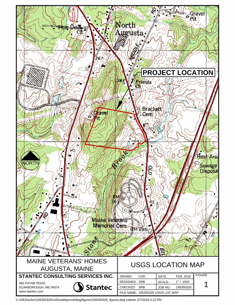
PROJECT LOCATION
1
FIGURE
USGS LOCATION MAP
MAINE VETERANS' HOMES
AUGUSTA, MAINE
SRB
SRB
195350326-USGS LOC MAP
SCALE:
JOB NO.
FILE NAME:
CHECKED:
DESIGNED:
DATE:CDDDRAWN:
1" = 1000'
195350326
FEB. 2018
V:\1953\active\195350326\civil\cadd\permit\dwg\figures\195350326_figures.dwg cddube 2/7/2018 3:12 PM
STANTEC CONSULTING SERVICES INC.
482 PAYNE ROAD
SCARBOROUGH, ME 04074
www.stantec.com

PROJECT
SITE
HENRYS WAY
O
L
D
B
E
L
G
R
A
D
E
R
O
A
D
R
O
U
T
E
3
R
O
U
T
E
8
2FIGURE
AERIAL PHOTOGRAPHMAINE VETERANS' HOMESAUGUSTA, MAINE
SRB
SRB
195350326_aerial_based_figures
SCALE:
JOB NO.FILE NAME:
CHECKED:
DESIGNED:DATE:CDDDRAWN:
1" = 600'
195350326
FEB. 2018
V:\1953\active\195350326\civil\cadd\permit\dwg\figures\195350326_aerial_based_figures.dwg cddube 2/8/2018 9:34 AM
STANTEC CONSULTING SERVICES INC.
482 PAYNE ROAD
SCARBOROUGH, ME 04074
www.stantec.com

3FIGURE
FEMA FLOOD MAPMAINE VETERANS' HOMESAUGUSTA, MAINE
SRB
SRB
195350326_aerial_based_figures
SCALE:
JOB NO.FILE NAME:
CHECKED:
DESIGNED:DATE:CDDDRAWN:
N.T.S.
195350326
FEB. 2018
V:\1953\active\195350326\civil\cadd\permit\dwg\figures\195350326_aerial_based_figures.dwg cddube 2/8/2018 9:33 AM
STANTEC CONSULTING SERVICES INC.
482 PAYNE ROAD
SCARBOROUGH, ME 04074
www.stantec.com

4FIGURE
NRCS SOILS MAPMAINE VETERANS' HOMESAUGUSTA, MAINE
SRB
SRB
195350326_aerial_based_figures
SCALE:
JOB NO.FILE NAME:
CHECKED:
DESIGNED:DATE:CDDDRAWN:
N.T.S.
195350326
FEB. 2018
V:\1953\active\195350326\civil\cadd\permit\dwg\figures\195350326_aerial_based_figures.dwg cddube 2/7/2018 3:33 PM
STANTEC CONSULTING SERVICES INC.
482 PAYNE ROAD
SCARBOROUGH, ME 04074
www.stantec.com
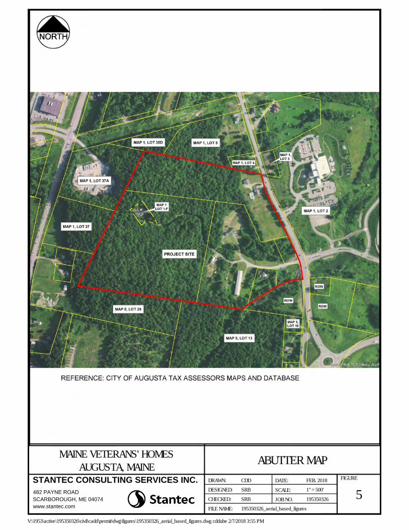
5FIGURE
ABUTTER MAPMAINE VETERANS' HOMESAUGUSTA, MAINE
SRB
SRB
195350326_aerial_based_figures
SCALE:
JOB NO.FILE NAME:
CHECKED:
DESIGNED:DATE:CDDDRAWN:
1" = 500'
195350326
FEB. 2018
V:\1953\active\195350326\civil\cadd\permit\dwg\figures\195350326_aerial_based_figures.dwg cddube 2/7/2018 3:55 PM
STANTEC CONSULTING SERVICES INC.
482 PAYNE ROAD
SCARBOROUGH, ME 04074
www.stantec.com
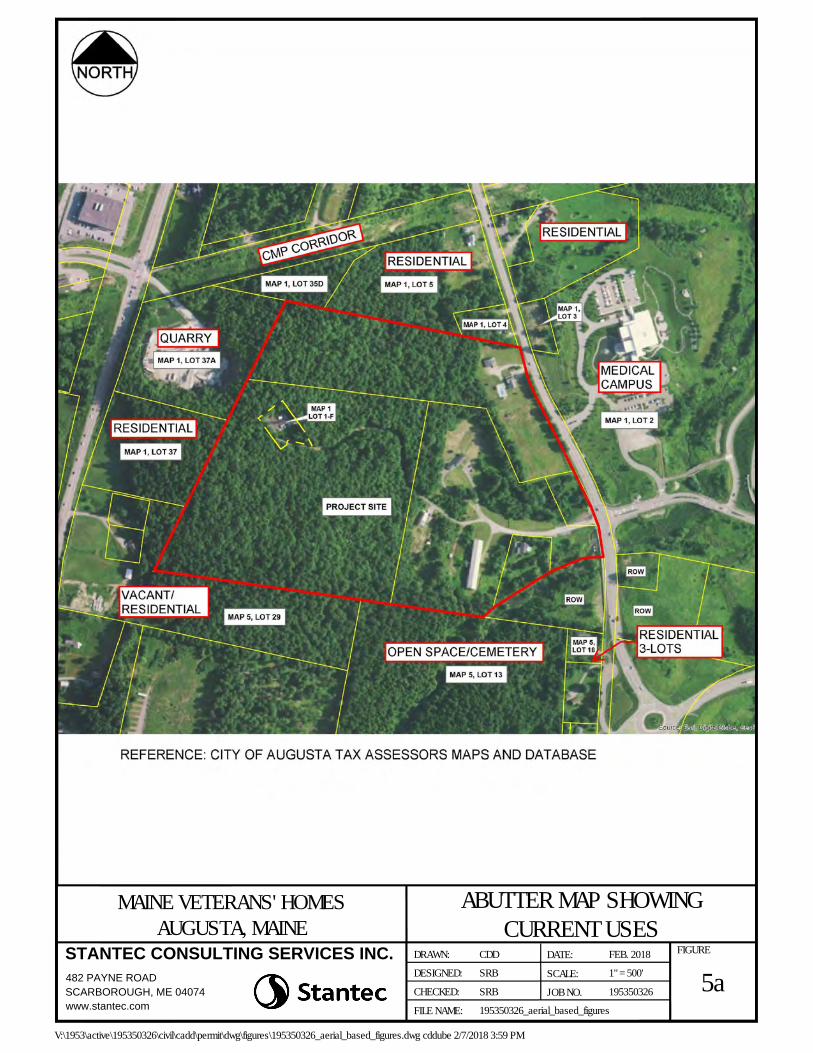
5aFIGURE
ABUTTER MAP SHOWINGCURRENT USES
MAINE VETERANS' HOMESAUGUSTA, MAINE
SRB
SRB
195350326_aerial_based_figures
SCALE:
JOB NO.FILE NAME:
CHECKED:
DESIGNED:DATE:CDDDRAWN:
1" = 500'
195350326
FEB. 2018
V:\1953\active\195350326\civil\cadd\permit\dwg\figures\195350326_aerial_based_figures.dwg cddube 2/7/2018 3:59 PM
STANTEC CONSULTING SERVICES INC.
482 PAYNE ROAD
SCARBOROUGH, ME 04074
www.stantec.com
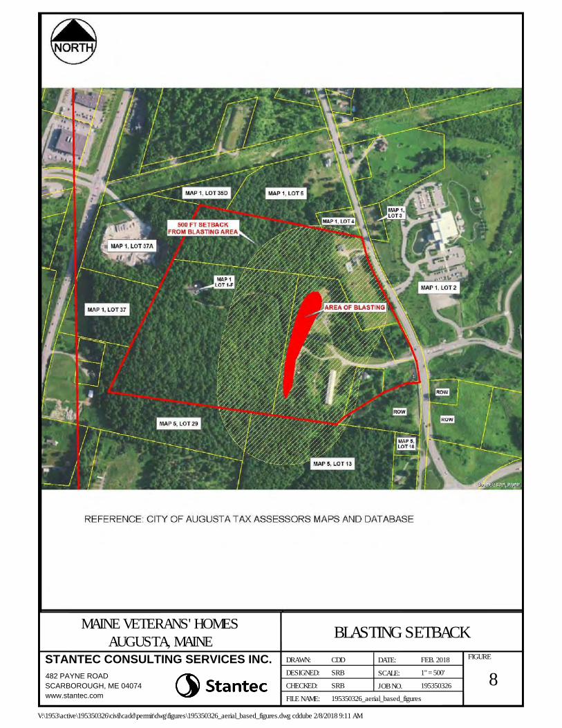
8FIGURE
BLASTING SETBACKMAINE VETERANS' HOMESAUGUSTA, MAINE
SRB
SRB
195350326_aerial_based_figures
SCALE:
JOB NO.FILE NAME:
CHECKED:
DESIGNED:DATE:CDDDRAWN:
1" = 500'
195350326
FEB. 2018
V:\1953\active\195350326\civil\cadd\permit\dwg\figures\195350326_aerial_based_figures.dwg cddube 2/8/2018 9:11 AM
STANTEC CONSULTING SERVICES INC.
482 PAYNE ROAD
SCARBOROUGH, ME 04074
www.stantec.com

9FIGURE
SAND & GRAVEL ACQUIFER MAPMAINE VETERANS' HOMESAUGUSTA, MAINE
SRB
SRB
195350326_aerial_based_figures
SCALE:
JOB NO.FILE NAME:
CHECKED:
DESIGNED:DATE:CDDDRAWN:
N.T.S.
195350326
FEB. 2018
V:\1953\active\195350326\civil\cadd\permit\dwg\figures\195350326_aerial_based_figures.dwg cddube 2/7/2018 4:11 PM
STANTEC CONSULTING SERVICES INC.
482 PAYNE ROAD
SCARBOROUGH, ME 04074
www.stantec.com
City of Augusta Major Development Review and Conditional Use Application MVH Augusta CLC Attachment 1
ATTACHMENT 1
SITE LIGHTING CUT SHEETS
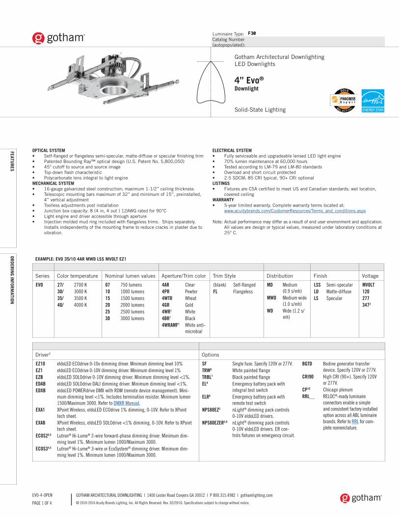
Luminaire Type:Catalog Number(autopopulated):
GOTHAM ARCHITECTURAL DOWNLIGHTING | 1400 Lester Road Conyers GA 30012 | P 800.315.4982 | gothamlighting.com
© 2010-2016 Acuity Brands Lighting, Inc. All Rights Reserved. Rev. 02/29/16. Specifications subject to change without notice.PAGE 1 OF 4
EVO-4-OPEN
Gotham Architectural DownlightingLED Downlights
4” Evo®
Downlight
Solid-State Lighting
OPTICAL SYSTEM• Self-flanged or flangeless semi-specular, matte-diffuse or specular finishing trim• Patented Bounding Ray™ optical design (U.S. Patent No. 5,800,050) • 45° cutoff to source and source image• Top-down flash characteristic• Polycarbonate lens integral to light engineMECHANICAL SYSTEM• 16-gauge galvanized steel construction; maximum 1-1/2” ceiling thickness• Telescopic mounting bars maximum of 32” and minimum of 15”, preinstalled,
4” vertical adjustment• Toolless adjustments post installation• Junction box capacity: 8 (4 in, 4 out ) 12AWG rated for 90°C• Light engine and driver accessible through aperture • Injection molded mud ring included with flangeless trims. Ships separately.
Installs independently of the mounting frame to reduce cracks in plaster due to vibration.
ELECTRICAL SYSTEM• Fully serviceable and upgradeable lensed LED light engine • 70% lumen maintenance at 60,000 hours• Tested according to LM-79 and LM-80 standards• Overload and short circuit protected• 2.5 SDCM; 85 CRI typical, 90+ CRI optionalLISTINGS• Fixtures are CSA certified to meet US and Canadian standards; wet location,
covered ceilingWARRANTY• 5-year limited warranty. Complete warranty terms located at:
www.acuitybrands.com/CustomerResources/Terms_and_conditions.aspx
Note: Actual performance may differ as a result of end user environment and application. All values are design or typical values, measured under laboratory conditions at
25° C.
EXAMPLE: EVO 35/10 4AR MWD LSS MVOLT EZ1
Series Color temperature Nominal lumen values Aperture/Trim color Trim Style Distribution Finish Voltage
EVO 27/ 2700 K30/ 3000 K35/ 3500 K40/ 4000 K
07 750 lumens10 1000 lumens15 1500 lumens20 2000 lumens25 2500 lumens30 3000 lumens
4AR Clear4PR Pewter4WTR Wheat4GR Gold4WR1 White4BR1 Black4WRAMF1 White anti-
microbial
(blank) Self-flangedFL Flangeless
MD Medium (0.9 s/mh)
MWD Medium wide (1.0 s/mh)
WD Wide (1.2 s/mh)
LSS Semi-specular LD Matte-diffuseLS Specular
MVOLT1202773472
Driver3 Options
EZ10 eldoLED ECOdrive 0-10v dimming driver. Minimum dimming level 10%EZ1 eldoLED ECOdrive 0-10V dimming driver. Minimum dimming level 1%EZB eldoLED SOLOdrive 0-10V dimming driver. Minimum dimming level <1%. EDAB eldoLED SOLOdrive DALI dimming driver. Minimum dimming level <1%. EDXB eldoLED POWERdrive DMX with RDM (remote device management). Mini-
mum dimming level <1%. Includes termination resistor. Minimum lumen 1500/Maximum 3000. Refer to DMXR Manual.
EXA1 XPoint Wireless, eldoLED ECOdrive 1% dimming, 0-10V. Refer to XPoint tech sheet.
EXAB XPoint Wireless, eldoLED SOLOdrive <1% dimming, 0-10V. Refer to XPoint tech sheet.
ECOS24,5 Lutron® Hi-Lume® 2-wire forward-phase dimming driver. Minimum dim-ming level 1%. Minimum lumen 1000/Maximum 3000.
ECOS34,5 Lutron® Hi-Lume® 3-wire or EcoSystem® dimming driver. Minimum dim-ming level 1%. Minimum lumen 1000/Maximum 3000.
SF Single fuse. Specify 120V or 277V.TRW6 White painted flangeTRBL7 Black painted flangeEL8 Emergency battery pack with
integral test switchELR8 Emergency battery pack with
remote test switchNPS80EZ5 nLight® dimming pack controls
0-10V eldoLED drivers.NPS80EZER5,9 nLight® dimming pack controls
0-10V eldoLED drivers. ER con-trols fixtures on emergency circuit.
BGTD Bodine generator transfer device. Specify 120V or 277V.
CRI90 High CRI (90+). Specify 120V or 277V.
CP10 Chicago plenumRRL__ RELOC®-ready luminaire
connectors enable a simple and consistent factory installed option across all ABL luminaire brands. Refer to RRL for com-plete nomenclature.
FEATURES
ORDERING IN
FORMATION
leeba
Highlight
leeba
Text Box
IMEG ENGINEERING | PROJ# 16.0011.00 MAINE VETERANS HOME / AUGUSTA F30
leeba
Rectangle
leeba
Rectangle
leeba
Rectangle
leeba
Rectangle
leeba
Rectangle
leeba
Rectangle
leeba
Rectangle
leeba
Highlight
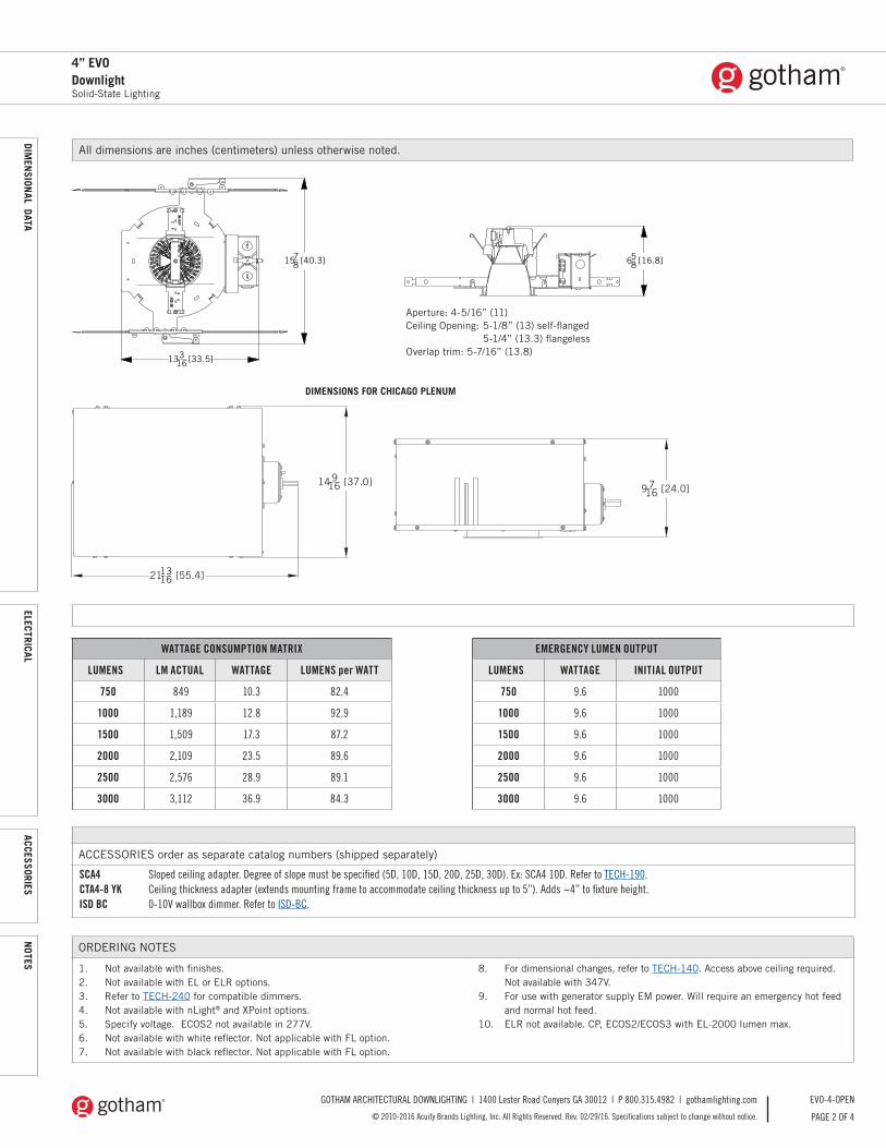
GOTHAM ARCHITECTURAL DOWNLIGHTING | 1400 Lester Road Conyers GA 30012 | P 800.315.4982 | gothamlighting.com
© 2010-2016 Acuity Brands Lighting, Inc. All Rights Reserved. Rev. 02/29/16. Specifications subject to change without notice. PAGE 2 OF 4
EVO-4-OPEN
4” EVODownlightSolid-State Lighting
PHOTOM
ETRY
All dimensions are inches (centimeters) unless otherwise noted.
ORDERING NOTES
1. Not available with finishes.2. Not available with EL or ELR options.3. Refer to TECH-240 for compatible dimmers.4. Not available with nLight® and XPoint options.5. Specify voltage. ECOS2 not available in 277V.6. Not available with white reflector. Not applicable with FL option.7. Not available with black reflector. Not applicable with FL option.
8. For dimensional changes, refer to TECH-140. Access above ceiling required.Not available with 347V.
9. For use with generator supply EM power. Will require an emergency hot feed and normal hot feed.
10. ELR not available. CP, ECOS2/ECOS3 with EL-2000 lumen max.
14916 [37.0]
211316 [55.4]
9716 [24.0]
DIMENSIONS FOR CHICAGO PLENUM
ACCESSORIES order as separate catalog numbers (shipped separately)
SCA4 Sloped ceiling adapter. Degree of slope must be specified (5D, 10D, 15D, 20D, 25D, 30D). Ex: SCA4 10D. Refer to TECH-190.CTA4-8 YK Ceiling thickness adapter (extends mounting frame to accommodate ceiling thickness up to 5”). Adds ~4” to fixture height.ISD BC 0-10V wallbox dimmer. Refer to ISD-BC.
WATTAGE CONSUMPTION MATRIX
LUMENS LM ACTUAL WATTAGE LUMENS per WATT
750 849 10.3 82.4
1000 1,189 12.8 92.9
1500 1,509 17.3 87.2
2000 2,109 23.5 89.6
2500 2,576 28.9 89.1
3000 3,112 36.9 84.3
EMERGENCY LUMEN OUTPUT
LUMENS WATTAGE INITIAL OUTPUT
750 9.6 1000
1000 9.6 1000
1500 9.6 1000
2000 9.6 1000
2500 9.6 1000
3000 9.6 1000
DIMEN
SIONAL DATA
ELECTRICALACCESSORIES
NOTES
13316 [33.5]
1578 [40.3] 658 [16.8]
Aperture: 4-5/16” (11)Ceiling Opening: 5-1/8” (13) self-flanged 5-1/4” (13.3) flangelessOverlap trim: 5-7/16” (13.8)
leeba
Rectangle

GOTHAM ARCHITECTURAL DOWNLIGHTING | 1400 Lester Road Conyers GA 30012 | P 800.315.4982 | gothamlighting.com
© 2010-2016 Acuity Brands Lighting, Inc. All Rights Reserved. Rev. 02/29/16. Specifications subject to change without notice.PAGE 3 OF 4
EVO-4-OPEN
PHOTOM
ETRY
4” EVODownlight
Solid-State Lighting
PHOTOMETRY NOTES
• Tested in accordance with IESNA LM-79-08.• Tested to current IES and NEMA standards under stabilized laboratory conditions.• CRI: 85 typical.
LUMEN OUTPUT MULTIPLIER - CRI
CRI FACTOR
80 CRI 1
90 CRI 0.79
LUMEN OUTPUT MULTIPLIER - CCT
CRI FACTOR
4000 K 1.035
3500 K 1
3000 K 0.973
2700 K 0.938
LUMEN OUTPUT MULTIPLIER - TRIM FINISH
FINISHCLEAR
(AR)PEWTER
(PR)WHEAT (WTR)
GOLD (GR)
WHITE (WR/WRAMF)
BLACK (BR)
Specular (LS) 1.00 0.88 0.83 0.95 N/A N/A
Semi-specular (LSS) 0.95 0.84 0.79 0.90 N/A N/A
Matte-diffuse (LD) 0.85 0.73 0.69 0.80 N/A N/A
Paint N/A N/A N/A N/A 0.87 0.73
Distribution Curve Distribution Data Output Data Coefficient of Utilization Illuminance: Single Luminaire 30” Above Floor
EVO 35/10 4AR LS INPUT WATTS: 12.8, DELIVERED LUMENS: 1189, LM/W=92.9, 1.08 S/MH, TEST NO. LTL27785
0° 20°
40°
60°
80°
400
800
Ave Lumens05152535455565758590
1012103511699104498022000
102325411276713100
Zone Lumens % Lamp0° - 30°0° - 40°0° - 60°0° - 90°
90° - 180°0° - 180°
838.31114.01188.41189.3
0.01189.3
70.593.799.9100.00.0
*100.0*Efficiency
%02fppc 80% 70% 50%pw 50% 30% 10% 50% 30% 10% 50% 30% 10%012345678910
1191111039690847874696561
119108999184787268635956
119106968780746863595552
1161091019588837873696561
116106989083777267635955
116104958679736863595552
111105989286817672686460
111103958882767167625955
111101928578736763595551
RC
R
50% beam -56.8°
10% beam -80.2°
MountingHeight
Inital FCCenterBeam Diameter FC Diameter FC
8.010.012.014.016.0
33.518.011.27.75.6
5.98.110.312.414.6
16.79.05.63.82.8
9.312.616.019.422.7
3.31.81.10.80.6
EVO 35/30 4AR LS INPUT WATTS: 36.9, DELIVERED LUMENS: 3112, LM/W=84.3 , 1.07 S/MH, TEST NO. LTL27791
EVO 35/15 4AR LS INPUT WATTS: 17.3, DELIVERED LUMENS: 1509, LM/W=87.2, 1.08 S/MH, TEST NO. LTL27786
0° 20°
40°
60°
80°
1200
2400
Ave Lumens05152535455565758590
2763282431332417111718662320
27886910906941688222
Zone Lumens % Lamp0° - 30°0° - 40°0° - 60°0° - 90°
90° - 120°90° - 130°90° - 150°90° - 180°0° - 180°
2236.62930.33106.13111.9
0.00.00.00.0
3111.9
71.994.299.8100.00.00.00.00.0
*100.0*Efficiency
%02fppc 80% 70% 50%pw 50% 30% 10% 50% 30% 10% 50% 30% 10%012345678910
1191111039690847974706662
119108999184787368646056
119106968780746964605652
1161091019589837873696562
116106989084787268636056
116104958780746864595652
111105989287817772686461
111103958882777267635956
111101938579736863595552
RC
R
50% beam -56.4°
10% beam -78.8°
MountingHeight
Inital FCCenterBeam Diameter FC Diameter FC
8.010.012.014.016.0
91.349.130.620.915.2
5.98.010.212.314.5
45.724.615.310.47.6
9.012.315.618.922.2
9.14.93.12.11.5
0° 20°
40°
60°
80°
600
1200
Ave Lumens05152535455565758590
12901338152111675469221000
132423527338854100
Zone Lumens % Lamp0° - 30°0° - 40°0° - 60°0° - 90°
90° - 180°0° - 180°
1081.01419.31507.81509.3
0.01509.3
71.694.099.9100.00.0
*100.0*Efficiency
%02fppc 80% 70% 50%pw 50% 30% 10% 50% 30% 10% 50% 30% 10%012345678910
1191111039690847974706662
119108999184787368646056
119106968780746964595652
1161091019589837873696561
116106989084787268635956
116104958780746864595652
111105989287817672686461
111103958882777267635956
111101938579736863595552
RC
R
50% beam -56.7°
10% beam -79.7°
MountingHeight
Inital FCCenterBeam Diameter FC Diameter FC
8.010.012.014.016.0
42.622.914.39.87.1
5.98.110.312.414.6
21.311.57.14.93.5
9.212.515.919.222.5
4.32.31.41.00.7
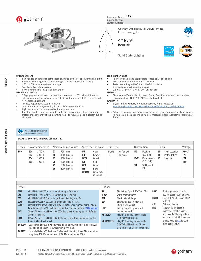
Luminaire Type:Catalog Number(autopopulated):
GOTHAM ARCHITECTURAL DOWNLIGHTING | P 800.315.4982 | gothamlighting.com
© 2010-2017 Acuity Brands Lighting, Inc. All Rights Reserved. Rev. 01/19/17. Specifications subject to change without notice.PAGE 1 OF 4
EVO-4-OPEN
Gotham Architectural DownlightingLED Downlights
4” Evo®
Downlight
Solid-State Lighting
OPTICAL SYSTEM• Self-flanged or flangeless semi-specular, matte-diffuse or specular finishing trim• Patented Bounding Ray™ optical design (U.S. Patent No. 5,800,050) • 45° cutoff to source and source image• Top-down flash characteristic• Polycarbonate lens integral to light engineMECHANICAL SYSTEM• 16-gauge galvanized steel construction; maximum 1-1/2” ceiling thickness• Telescopic mounting bars maximum of 32” and minimum of 15”, preinstalled,
4” vertical adjustment• Toolless adjustments post installation• Junction box capacity: 8 (4 in, 4 out ) 12AWG rated for 90°C• Light engine and driver accessible through aperture • Injection molded mud ring included with flangeless trims. Ships separately.
Installs independently of the mounting frame to reduce cracks in plaster due to vibration.
ELECTRICAL SYSTEM• Fully serviceable and upgradeable lensed LED light engine • 70% lumen maintenance at 60,000 hours• Tested according to LM-79 and LM-80 standards• Overload and short circuit protected• 2.5 SDCM; 85 CRI typical, 90+ CRI optionalLISTINGS• Fixtures are CSA certified to meet US and Canadian standards; wet location,
covered ceiling ENERGY STAR® certified product.WARRANTY• 5-year limited warranty. Complete warranty terms located at:
www.acuitybrands.com/CustomerResources/Terms_and_conditions.aspx
Note: Actual performance may differ as a result of end user environment and application. All values are design or typical values, measured under laboratory conditions at
25° C.
EXAMPLE: EVO 35/10 4AR MWD LSS MVOLT EZ1
Series Color temperature Nominal lumen values Aperture/Trim color Trim Style Distribution Finish Voltage
EVO 27/ 2700 K30/ 3000 K35/ 3500 K40/ 4000 K
07 750 lumens10 1000 lumens15 1500 lumens20 2000 lumens25 2500 lumens30 3000 lumens
4AR Clear4PR Pewter4WTR Wheat4GR Gold4WR1 White4BR1 Black4WRAMF1 White anti-
microbial
(blank) Self-flangedFL Flangeless
MD Medium (0.9 s/mh)
MWD Medium wide (1.0 s/mh)
WD Wide (1.2 s/mh)
LSS Semi-specular LD Matte-diffuseLS Specular
MVOLT1202773472
Driver3 Options
EZ10 eldoLED 0-10V ECOdrive. Linear dimming to 10% min.EZ1 eldoLED 0-10V ECOdrive. Linear dimming to 1% min.EZB eldoLED 0-10V SOLOdrive. Logarithmic dimming to <1%. EDAB eldoLED SOLOdrive DALI. Logarithmic dimming to <1%. EDXB eldoLED POWERdrive DMX with RDM (remote device management). Square
Law dimming to <1%. Includes termination resistor. Refer to DMXR Manual. EXA1 XPoint Wireless, eldoLED 0-10V ECOdrive. Linear dimming to 1%. Refer to
XPoint tech sheet. EXAB XPoint Wireless, eldoLED 0-10V SOLOdrive. Logarithmic dimming to <1%.
Refer to XPoint tech sheet.ECOS24,5 Lutron® Hi-Lume® 2-wire forward-phase driver. Minimum dimming level
1%. Minimum lumen 1000/Maximum lumen 3000.ECOS34,5 Lutron® Hi-Lume® 3-wire or EcoSystem® dimming driver. Minimum dim-
ming level 1%. Minimum lumen 1000/Maximum lumen 4500.
SF Single fuse. Specify 120V or 277V.TRW6 White painted flangeTRBL7 Black painted flangeEL8 Emergency battery pack with
integral test switchELR8 Emergency battery pack with
remote test switchNPS80EZ5 nLight® dimming pack controls
0-10V eldoLED drivers.NPS80EZER5,9 nLight® dimming pack controls
0-10V eldoLED drivers. ER con-trols fixtures on emergency circuit.
BGTD Bodine generator transfer device. Specify 120V or 277V.
CRI90 High CRI (90+). Specify 120V or 277V.
CP10 Chicago plenumRRL__ RELOC®-ready luminaire
connectors enable a simple and consistent factory installed option across all ABL luminaire brands. Refer to RRL for com-plete nomenclature.
FEATURES
ORDERING IN
FORMATION
A+ Capable options indicated by this color background.
leeba
Rectangle
leeba
Rectangle
leeba
Rectangle
leeba
Rectangle
leeba
Rectangle
leeba
Rectangle
leeba
Rectangle
leeba
Rectangle
leeba
Text Box
IMEG ENGINEERING | PROJ# 16.0011.00 MAINE VETERANS HOME / AUGUSTA F30A
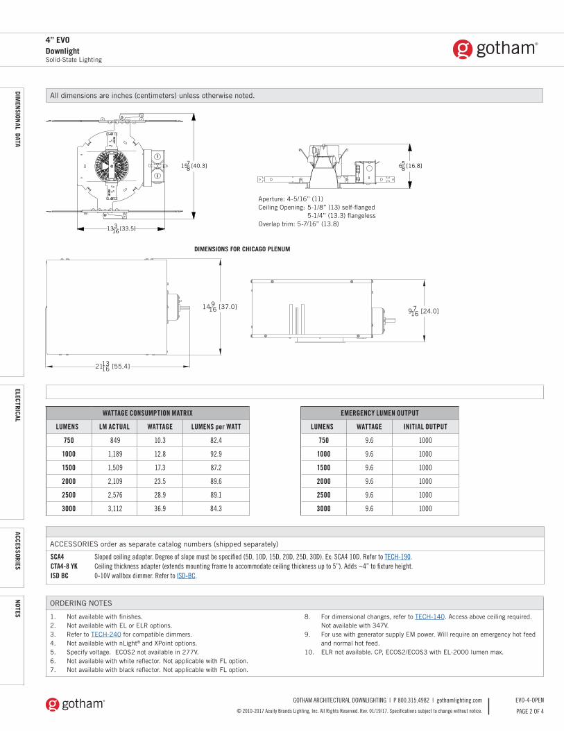
GOTHAM ARCHITECTURAL DOWNLIGHTING | P 800.315.4982 | gothamlighting.com
© 2010-2017 Acuity Brands Lighting, Inc. All Rights Reserved. Rev. 01/19/17. Specifications subject to change without notice. PAGE 2 OF 4
EVO-4-OPEN
4” EVODownlightSolid-State Lighting
PHOTOM
ETRY
All dimensions are inches (centimeters) unless otherwise noted.
ORDERING NOTES
1. Not available with finishes.2. Not available with EL or ELR options.3. Refer to TECH-240 for compatible dimmers.4. Not available with nLight® and XPoint options.5. Specify voltage. ECOS2 not available in 277V.6. Not available with white reflector. Not applicable with FL option.7. Not available with black reflector. Not applicable with FL option.
8. For dimensional changes, refer to TECH-140. Access above ceiling required. Not available with 347V.
9. For use with generator supply EM power. Will require an emergency hot feed and normal hot feed.
10. ELR not available. CP, ECOS2/ECOS3 with EL-2000 lumen max.
14916 [37.0]
211316 [55.4]
9716 [24.0]
DIMENSIONS FOR CHICAGO PLENUM
ACCESSORIES order as separate catalog numbers (shipped separately)
SCA4 Sloped ceiling adapter. Degree of slope must be specified (5D, 10D, 15D, 20D, 25D, 30D). Ex: SCA4 10D. Refer to TECH-190.CTA4-8 YK Ceiling thickness adapter (extends mounting frame to accommodate ceiling thickness up to 5”). Adds ~4” to fixture height.ISD BC 0-10V wallbox dimmer. Refer to ISD-BC.
WATTAGE CONSUMPTION MATRIX
LUMENS LM ACTUAL WATTAGE LUMENS per WATT
750 849 10.3 82.4
1000 1,189 12.8 92.9
1500 1,509 17.3 87.2
2000 2,109 23.5 89.6
2500 2,576 28.9 89.1
3000 3,112 36.9 84.3
EMERGENCY LUMEN OUTPUT
LUMENS WATTAGE INITIAL OUTPUT
750 9.6 1000
1000 9.6 1000
1500 9.6 1000
2000 9.6 1000
2500 9.6 1000
3000 9.6 1000
DIMEN
SIONAL DATA
ELECTRICALACCESSORIES
NOTES
13316 [33.5]
1578 [40.3] 658 [16.8]
Aperture: 4-5/16” (11)Ceiling Opening: 5-1/8” (13) self-flanged 5-1/4” (13.3) flangelessOverlap trim: 5-7/16” (13.8)
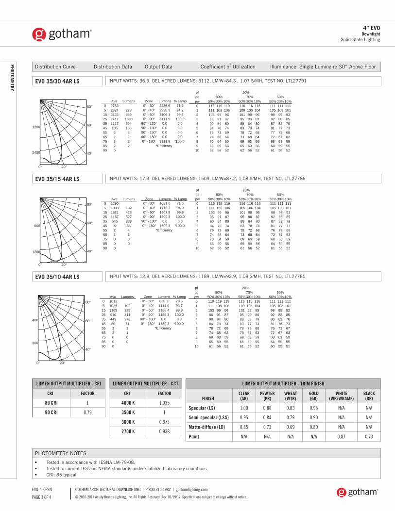
GOTHAM ARCHITECTURAL DOWNLIGHTING | P 800.315.4982 | gothamlighting.com
© 2010-2017 Acuity Brands Lighting, Inc. All Rights Reserved. Rev. 01/19/17. Specifications subject to change without notice.PAGE 3 OF 4
EVO-4-OPEN
PHOTOM
ETRY
4” EVODownlight
Solid-State Lighting
PHOTOMETRY NOTES
• Tested in accordance with IESNA LM-79-08.• Tested to current IES and NEMA standards under stabilized laboratory conditions.• CRI: 85 typical.
LUMEN OUTPUT MULTIPLIER - CRI
CRI FACTOR
80 CRI 1
90 CRI 0.79
LUMEN OUTPUT MULTIPLIER - CCT
CRI FACTOR
4000 K 1.035
3500 K 1
3000 K 0.973
2700 K 0.938
LUMEN OUTPUT MULTIPLIER - TRIM FINISH
FINISHCLEAR
(AR)PEWTER
(PR)WHEAT (WTR)
GOLD (GR)
WHITE (WR/WRAMF)
BLACK (BR)
Specular (LS) 1.00 0.88 0.83 0.95 N/A N/A
Semi-specular (LSS) 0.95 0.84 0.79 0.90 N/A N/A
Matte-diffuse (LD) 0.85 0.73 0.69 0.80 N/A N/A
Paint N/A N/A N/A N/A 0.87 0.73
Distribution Curve Distribution Data Output Data Coefficient of Utilization Illuminance: Single Luminaire 30” Above Floor
EVO 35/10 4AR LS INPUT WATTS: 12.8, DELIVERED LUMENS: 1189, LM/W=92.9, 1.08 S/MH, TEST NO. LTL27785
0° 20°
40°
60°
80°
400
800
Ave Lumens05152535455565758590
1012103511699104498022000
102325411276713100
Zone Lumens % Lamp0° - 30°0° - 40°0° - 60°0° - 90°
90° - 180°0° - 180°
838.31114.01188.41189.3
0.01189.3
70.593.799.9100.00.0
*100.0*Efficiency
%02fppc 80% 70% 50%pw 50% 30% 10% 50% 30% 10% 50% 30% 10%012345678910
1191111039690847874696561
119108999184787268635956
119106968780746863595552
1161091019588837873696561
116106989083777267635955
116104958679736863595552
111105989286817672686460
111103958882767167625955
111101928578736763595551
RC
R
50% beam -56.8°
10% beam -80.2°
MountingHeight
Inital FCCenterBeam Diameter FC Diameter FC
8.010.012.014.016.0
33.518.011.27.75.6
5.98.110.312.414.6
16.79.05.63.82.8
9.312.616.019.422.7
3.31.81.10.80.6
EVO 35/30 4AR LS INPUT WATTS: 36.9, DELIVERED LUMENS: 3112, LM/W=84.3 , 1.07 S/MH, TEST NO. LTL27791
EVO 35/15 4AR LS INPUT WATTS: 17.3, DELIVERED LUMENS: 1509, LM/W=87.2, 1.08 S/MH, TEST NO. LTL27786
0° 20°
40°
60°
80°
1200
2400
Ave Lumens05152535455565758590
2763282431332417111718662320
27886910906941688222
Zone Lumens % Lamp0° - 30°0° - 40°0° - 60°0° - 90°
90° - 120°90° - 130°90° - 150°90° - 180°0° - 180°
2236.62930.33106.13111.9
0.00.00.00.0
3111.9
71.994.299.8100.00.00.00.00.0
*100.0*Efficiency
%02fppc 80% 70% 50%pw 50% 30% 10% 50% 30% 10% 50% 30% 10%012345678910
1191111039690847974706662
119108999184787368646056
119106968780746964605652
1161091019589837873696562
116106989084787268636056
116104958780746864595652
111105989287817772686461
111103958882777267635956
111101938579736863595552
RC
R
50% beam -56.4°
10% beam -78.8°
MountingHeight
Inital FCCenterBeam Diameter FC Diameter FC
8.010.012.014.016.0
91.349.130.620.915.2
5.98.010.212.314.5
45.724.615.310.47.6
9.012.315.618.922.2
9.14.93.12.11.5
0° 20°
40°
60°
80°
600
1200
Ave Lumens05152535455565758590
12901338152111675469221000
132423527338854100
Zone Lumens % Lamp0° - 30°0° - 40°0° - 60°0° - 90°
90° - 180°0° - 180°
1081.01419.31507.81509.3
0.01509.3
71.694.099.9100.00.0
*100.0*Efficiency
%02fppc 80% 70% 50%pw 50% 30% 10% 50% 30% 10% 50% 30% 10%012345678910
1191111039690847974706662
119108999184787368646056
119106968780746964595652
1161091019589837873696561
116106989084787268635956
116104958780746864595652
111105989287817672686461
111103958882777267635956
111101938579736863595552
RC
R
50% beam -56.7°
10% beam -79.7°
MountingHeight
Inital FCCenterBeam Diameter FC Diameter FC
8.010.012.014.016.0
42.622.914.39.87.1
5.98.110.312.414.6
21.311.57.14.93.5
9.212.515.919.222.5
4.32.31.41.00.7
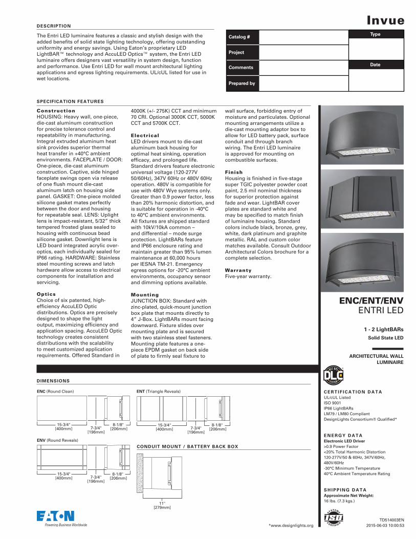
ENC/ENT/ENV ENTRI LED
1 - 2 LightBARs
Solid State LED
ARCHITECTURAL WALL
LUMINAIRE
InvueThe Entri LED luminaire features a classic and stylish design with the added benefits of solid state lighting technology, offering outstanding uniformity and energy savings. Using Eaton’s proprietary LED LightBAR™ technology and AccuLED Optics™ system, the Entri LED luminaire offers designers vast versatility in system design, function and performance. Use Entri LED for wall mount architectural lighting applications and egress lighting requirements. UL/cUL listed for use in wet locations.
DESCRIPTION
SPECIFICATION FEATURES
ConstructionHOUSING: Heavy wall, one-piece, die-cast aluminum construction for precise tolerance control and repeatability in manufacturing. Integral extruded aluminum heat sink provides superior thermal heat transfer in +40°C ambient environments. FACEPLATE / DOOR: One-piece, die-cast aluminum construction. Captive, side hinged faceplate swings open via release of one flush mount die-cast aluminum latch on housing side panel. GASKET: One-piece molded silicone gasket mates perfectly between the door and housing for repeatable seal. LENS: Uplight lens is impact-resistant, 5/32” thick tempered frosted glass sealed to housing with continuous bead silicone gasket. Downlight lens is LED board integrated acrylic over-optics, each individually sealed for IP66 rating. HARDWARE: Stainless steel mounting screws and latch hardware allow access to electrical components for installation and servicing. OpticsChoice of six patented, high-efficiency AccuLED Optic distributions. Optics are precisely designed to shape the light output, maximizing efficiency and application spacing. AccuLED Optic technology creates consistent distributions with the scalability to meet customized application requirements. Offered Standard in
4000K (+/- 275K) CCT and minimum 70 CRI. Optional 3000K CCT, 5000K CCT and 5700K CCT.
ElectricalLED drivers mount to die-cast aluminum back housing for optimal heat sinking, operation efficacy, and prolonged life. Standard drivers feature electronic universal voltage (120-277V 50/60Hz), 347V 60Hz or 480V 60Hz operation. 480V is compatible for use with 480V Wye systems only. Greater than 0.9 power factor, less than 20% harmonic distortion, and is suitable for operation in -40°C to 40°C ambient environments. All fixtures are shipped standard with 10kV/10kA common – and differential – mode surge protection. LightBARs feature and IP66 enclosure rating and maintain greater than 95% lumen maintenance at 60,000 hours per IESNA TM-21. Emergency egress options for -20°C ambient environments, occupancy sensor and dimming options available. MountingJUNCTION BOX: Standard with zinc-plated, quick-mount junction box plate that mounts directly to 4” J-Box. LightBARs mount facing downward. Fixture slides over mounting plate and is secured with two stainless steel fasteners. Mounting plate features a one-piece EPDM gasket on back side of plate to firmly seal fixture to
wall surface, forbidding entry of moisture and particulates. Optional mounting arrangements utilize a die-cast mounting adaptor box to allow for LED battery pack, surface conduit and through branch wiring. The Entri LED luminaire is approved for mounting on combustible surfaces.
FinishHousing is finished in five-stage super TGIC polyester powder coat paint, 2.5 mil nominal thickness for superior protection against fade and wear. LightBAR cover plates are standard white and may be specified to match finish of luminaire housing. Standard colors include black, bronze, grey, white, dark platinum and graphite metallic. RAL and custom color matches available. Consult Outdoor Architectural Colors brochure for a complete selection.
WarrantyFive-year warranty.
TD514003EN 2015-06-03 10:00:53
S
YSTEMS
C
E RT I F I E
D
C E R T I F I C A T I O N D A T AUL/cUL ListedISO 9001IP66 LightBARsLM79 / LM80 CompliantDesignLights Consortium® Qualified*
E N E R G Y D A T AElectronic LED Driver>0.9 Power Factor<20% Total Harmonic Distortion120-277V/50 & 60Hz, 347V/60Hz, 480V/60Hz-30°C Minimum Temperature40°C Ambient Temperature Rating
S H I P P I N G D A T AApproximate Net Weight: 16 lbs. (7.3 kgs.)
7-3/4"[196mm]
15-3/4"[400mm]
8-1/8" [206mm] 7-3/4"
[196mm]
15-3/4"[400mm]
8-1/8" [206mm]
7-3/4"[196mm]
15-3/4"[400mm]
8-1/8" [206mm]
ENT (Triangle Reveals)ENC (Round Clean)
ENV (Round Reveals)
DIMENSIONS
Catalog # Type
Date
Project
Comments
Prepared by
*www.designlights.org
11"[279mm]
CONDUIT MOUNT / BATTERY BACK BOX
leeba
Text Box
IMEG ENGINEERING | PROJ# 16.0011.00 MAINE VETERANS HOME / AUGUSTA F33
leeba
Rectangle
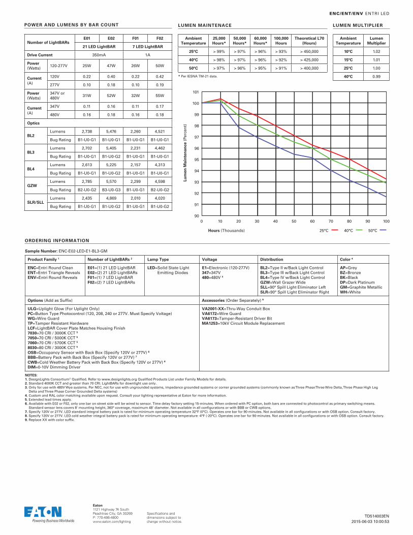
Specifications and dimensions subject to change without notice.
Eaton 1121 Highway 74 SouthPeachtree City, GA 30269P: 770-486-4800www.eaton.com/lighting
101
0 10 20 30 40 50 60 70 80 90 100
100
99
98
97
96
95
94
93
92
91
90
Hours (Thousands)
Lum
en M
ain
ten
ance
(Pe
rcen
t)
25°C 40°C 50°C
ENC/ENT/ENV ENTRI LED
TD514003EN 2015-06-03 10:00:53
AmbientTemperature
25,000 Hours*
50,000 Hours*
60,000 Hours*
100,000 Hours
Theoretical L70 (Hours)
25ºC > 99% > 97% > 96% > 93% > 450,000
40ºC > 98% > 97% > 96% > 92% > 425,000
50ºC > 97% > 96% > 95% > 91% > 400,000
* Per IESNA TM-21 data.
LUMEN MAINTENACE
AmbientTemperature
Lumen Multiplier
10ºC 1.02
15ºC 1.01
25ºC 1.00
40ºC 0.99
LUMEN MULTIPLIER
Number of LightBARsE01 E02 F01 F02
21 LED LightBAR 7 LED LightBAR
Drive Current 350mA 1A
Power (Watts)
120-277V 25W 47W 26W 50W
Current (A)
120V 0.22 0.40 0.22 0.42
277V 0.10 0.18 0.10 0.19
Power (Watts)
347V or 480V
31W 52W 32W 55W
Current (A)
347V 0.11 0.16 0.11 0.17
480V 0.16 0.18 0.16 0.18
Optics
BL2Lumens 2,738 5,476 2,260 4,521
Bug Rating B1-U0-G1 B1-U0-G1 B1-U0-G1 B1-U0-G1
BL3Lumens 2,702 5,405 2,231 4,462
Bug Rating B1-U0-G1 B1-U0-G2 B1-U0-G1 B1-U0-G1
BL4Lumens 2,613 5,225 2,157 4,313
Bug Rating B1-U0-G1 B1-U0-G2 B1-U0-G1 B1-U0-G1
GZWLumens 2,785 5,570 2,299 4,598
Bug Rating B2-U0-G2 B3-U0-G3 B1-U0-G1 B2-U0-G2
SLR/SLLLumens 2,435 4,869 2,010 4,020
Bug Rating B1-U0-G1 B1-U0-G2 B1-U0-G1 B1-U0-G2
POWER AND LUMENS BY BAR COUNT
Sample Number: ENC-E02-LED-E1-BL3-GM
Product Family 1 Number of LightBARs 2 Lamp Type Voltage Distribution Color 4
ENC= Entri Round CleanENT= Entri Triangle RevealsENV= Entri Round Reveals
E01=( 1) 21 LED LightBARE02= ( 2) 21 LED LightBARsF01=(1) 7 LED LightBARF02= (2) 7 LED LightBARs
LED= Solid State Light Emitting Diodes
E1= Electronic (120-277V)347=347V 480=480V 3
BL2=Type II w/Back Light ControlBL3=Type III w/Back Light ControlBL4=Type IV w/Back Light ControlGZW=Wall Grazer WideSLL=90° Spill Light Eliminator LeftSLR=90° Spill Light Eliminator Right
AP=GreyBZ=BronzeBK=BlackDP= Dark PlatinumGM= Graphite MetallicWH=White
Options (Add as Suffi x) Accessories (Order Separately) 9
ULG=Uplight Glow (For Uplight Only)PC=Button Type Photocontrol (120, 208, 240 or 277V. Must Specify Voltage)WG=Wire GuardTP=Tamper Resistant Hardware LCF= LightBAR Cover Plate Matches Housing Finish7030=70 CRI / 3000K CCT 5
7050=70 CRI / 5000K CCT 5
7060=70 CRI / 5700K CCT 5
8030=80 CRI / 3000K CCT 5
OSB=Occupancy Sensor with Back Box (Specify 120V or 277V) 6
BBB=Battery Pack with Back Box (Specify 120V or 277V) 7
CWB= Cold Weather Battery Pack with Back Box (Specify 120V or 277V) 8
DIM=0-10V Dimming Driver
VA2001-XX=Thru-Way Conduit BoxVA6172=Wire GuardVA6173=Tamper-Resistant Driver BitMA1253=10kV Circuit Module Replacement
NOTES: 1. DesignLights Consortium® Qualifi ed. Refer to www.designlights.org Qualifi ed Products List under Family Models for details.2. Standard 4000K CCT and greater than 70 CRI. LightBARs for downlight use only.3. Only for use with 480V Wye systems. Per NEC, not for use with ungrounded systems, impedance grounded systems or corner grounded systems (commonly known as Three Phase Three Wire Delta, Three Phase High Leg
Delta and Three Phase Corner Grounded Delta systems)4. Custom and RAL color matching available upon request. Consult your lighting representative at Eaton for more information.5. Extended lead times apply.6. Available with E02 or F02, only one bar on street side will be wired to sensor. Time delay factory setting 15-minutes. When ordered with PC option, both bars are connected to photocontrol as primary switching means.
Standard sensor lens covers 8' mounting height, 360° coverage, maximum 48' diameter. Not available in all confi gurations or with BBB or CWB options.7. Specify 120V or 277V. LED standard integral battery pack is rated for minimum operating temperature 32°F (0°C). Operates one bar for 90-minutes. Not available in all confi gurations or with OSB option. Consult factory.8. Specify 120V or 277V. LED cold weather integral battery pack is rated for minimum operating temperature -4°F (-20°C). Operates one bar for 90-minutes. Not available in all confi gurations or with OSB option. Consult factory.9. Replace XX with color suffi x.
ORDERING INFORMATION
leeba
Rectangle
leeba
Rectangle
leeba
Rectangle
leeba
Rectangle
leeba
Rectangle
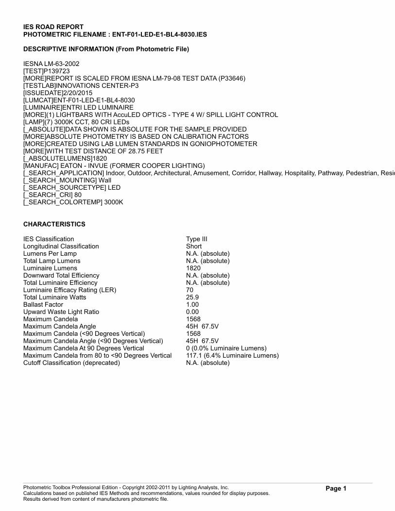
IES ROAD REPORTPHOTOMETRIC FILENAME : ENT-F01-LED-E1-BL4-8030.IES
DESCRIPTIVE INFORMATION (From Photometric File)
IESNA LM-63-2002[TEST]P139723[MORE]REPORT IS SCALED FROM IESNA LM-79-08 TEST DATA (P33646)[TESTLAB]INNOVATIONS CENTER-P3[ISSUEDATE]2/20/2015[LUMCAT]ENT-F01-LED-E1-BL4-8030[LUMINAIRE]ENTRI LED LUMINAIRE[MORE](1) LIGHTBARS WITH AccuLED OPTICS - TYPE 4 W/ SPILL LIGHT CONTROL[LAMP](7) 3000K CCT, 80 CRI LEDs[_ABSOLUTE]DATA SHOWN IS ABSOLUTE FOR THE SAMPLE PROVIDED[MORE]ABSOLUTE PHOTOMETRY IS BASED ON CALIBRATION FACTORS[MORE]CREATED USING LAB LUMEN STANDARDS IN GONIOPHOTOMETER[MORE]WITH TEST DISTANCE OF 28.75 FEET[_ABSOLUTELUMENS]1820[MANUFAC] EATON - INVUE (FORMER COOPER LIGHTING)[_SEARCH_APPLICATION] Indoor, Outdoor, Architectural, Amusement, Corridor, Hallway, Hospitality, Pathway, Pedestrian, Residential, Sidewalk, Stairway, Walkway, Ambient, Decorative, Downlight, Uplight[_SEARCH_MOUNTING] Wall[_SEARCH_SOURCETYPE] LED[_SEARCH_CRI] 80[_SEARCH_COLORTEMP] 3000K
CHARACTERISTICS
IES Classification Type IIILongitudinal Classification ShortLumens Per Lamp N.A. (absolute)Total Lamp Lumens N.A. (absolute)Luminaire Lumens 1820Downward Total Efficiency N.A. (absolute)Total Luminaire Efficiency N.A. (absolute)Luminaire Efficacy Rating (LER) 70Total Luminaire Watts 25.9Ballast Factor 1.00Upward Waste Light Ratio 0.00Maximum Candela 1568Maximum Candela Angle 45H 67.5VMaximum Candela (<90 Degrees Vertical) 1568Maximum Candela Angle (<90 Degrees Vertical) 45H 67.5VMaximum Candela At 90 Degrees Vertical 0 (0.0% Luminaire Lumens)Maximum Candela from 80 to <90 Degrees Vertical 117.1 (6.4% Luminaire Lumens)Cutoff Classification (deprecated) N.A. (absolute)
Photometric Toolbox Professional Edition - Copyright 2002-2011 by Lighting Analysts, Inc.Calculations based on published IES Methods and recommendations, values rounded for display purposes.Results derived from content of manufacturers photometric file.
Page 1
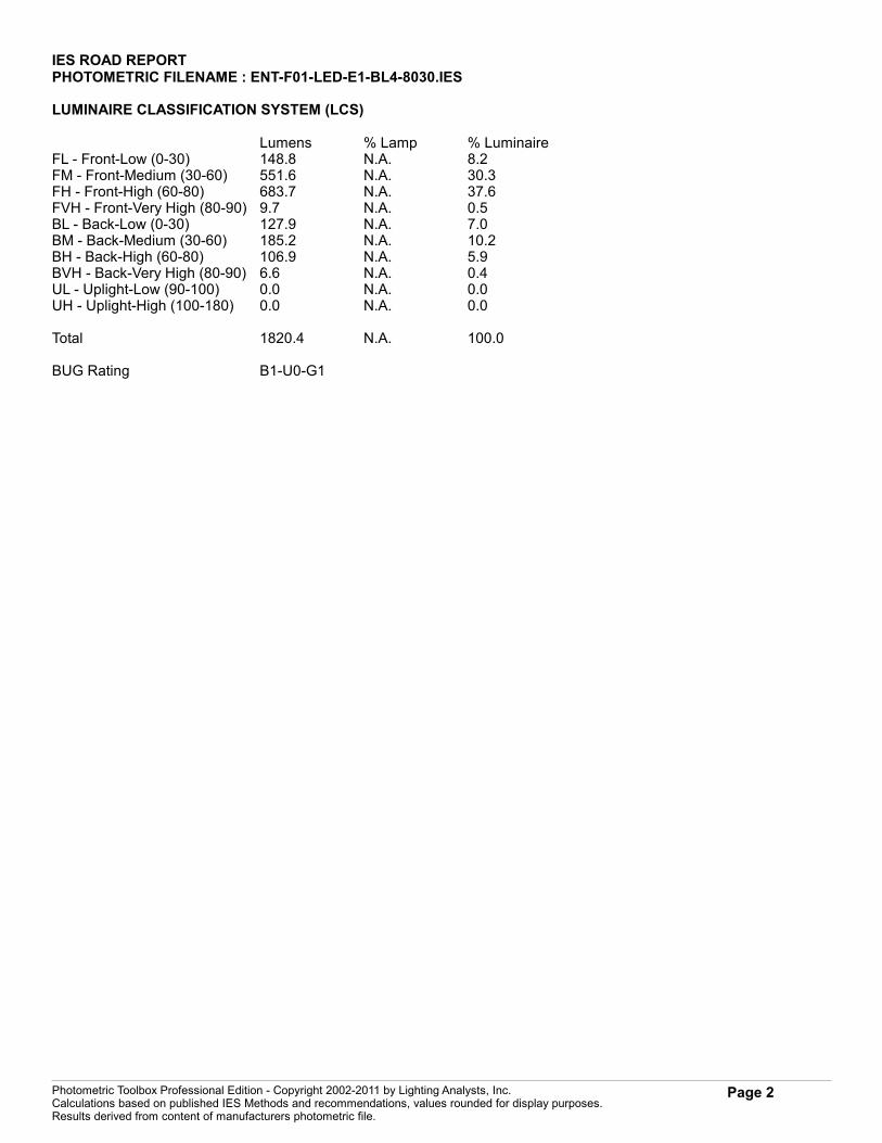
IES ROAD REPORTPHOTOMETRIC FILENAME : ENT-F01-LED-E1-BL4-8030.IES
LUMINAIRE CLASSIFICATION SYSTEM (LCS)
Lumens % Lamp % LuminaireFL - Front-Low (0-30) 148.8 N.A. 8.2FM - Front-Medium (30-60) 551.6 N.A. 30.3FH - Front-High (60-80) 683.7 N.A. 37.6FVH - Front-Very High (80-90) 9.7 N.A. 0.5BL - Back-Low (0-30) 127.9 N.A. 7.0BM - Back-Medium (30-60) 185.2 N.A. 10.2BH - Back-High (60-80) 106.9 N.A. 5.9BVH - Back-Very High (80-90) 6.6 N.A. 0.4UL - Uplight-Low (90-100) 0.0 N.A. 0.0UH - Uplight-High (100-180) 0.0 N.A. 0.0
Total 1820.4 N.A. 100.0
BUG Rating B1-U0-G1
Photometric Toolbox Professional Edition - Copyright 2002-2011 by Lighting Analysts, Inc.Calculations based on published IES Methods and recommendations, values rounded for display purposes.Results derived from content of manufacturers photometric file.
Page 2
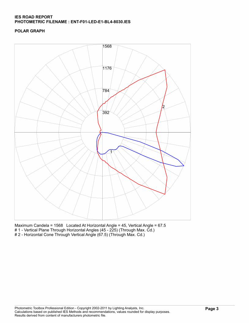
IES ROAD REPORTPHOTOMETRIC FILENAME : ENT-F01-LED-E1-BL4-8030.IES
POLAR GRAPH
392
784
1176
1568
1
2
Maximum Candela = 1568 Located At Horizontal Angle = 45, Vertical Angle = 67.5# 1 - Vertical Plane Through Horizontal Angles (45 - 225) (Through Max. Cd.)# 2 - Horizontal Cone Through Vertical Angle (67.5) (Through Max. Cd.)
Photometric Toolbox Professional Edition - Copyright 2002-2011 by Lighting Analysts, Inc.Calculations based on published IES Methods and recommendations, values rounded for display purposes.Results derived from content of manufacturers photometric file.
Page 3

IES ROAD REPORTPHOTOMETRIC FILENAME : ENT-F01-LED-E1-BL4-8030.IES
ISOFOOTCANDLE LINES OF HORIZONTAL ILLUMINANCE
0 1 2 2.25 3 3.75 4 5 6 75
4
32.75
21.75
1
0
1
2
3
House Side Street Side
Distance In Units Of Mounting HeightValues Based On 10 Foot Mounting Height
.1
.2
.51
2
1/2 Maximum Candela Trace Shown As Dashed Curve(+) = Maximum Candela Point
Photometric Toolbox Professional Edition - Copyright 2002-2011 by Lighting Analysts, Inc.Calculations based on published IES Methods and recommendations, values rounded for display purposes.Results derived from content of manufacturers photometric file.
Page 4
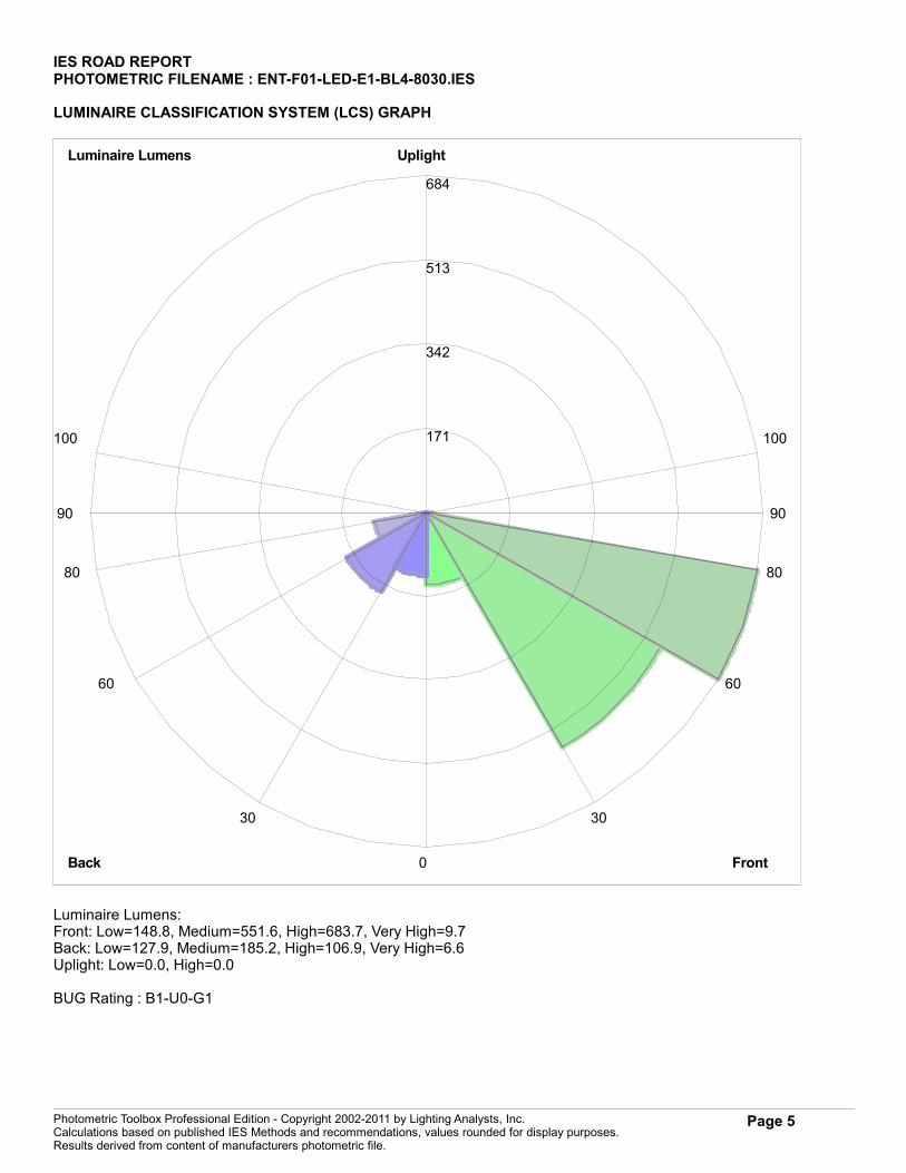
IES ROAD REPORTPHOTOMETRIC FILENAME : ENT-F01-LED-E1-BL4-8030.IES
LUMINAIRE CLASSIFICATION SYSTEM (LCS) GRAPH
171
342
513
684
Luminaire Lumens
FrontBack
Uplight
0
30
60
80
90
100
30
60
80
90
100
Luminaire Lumens:Front: Low=148.8, Medium=551.6, High=683.7, Very High=9.7Back: Low=127.9, Medium=185.2, High=106.9, Very High=6.6Uplight: Low=0.0, High=0.0
BUG Rating : B1-U0-G1
Photometric Toolbox Professional Edition - Copyright 2002-2011 by Lighting Analysts, Inc.Calculations based on published IES Methods and recommendations, values rounded for display purposes.Results derived from content of manufacturers photometric file.
Page 5
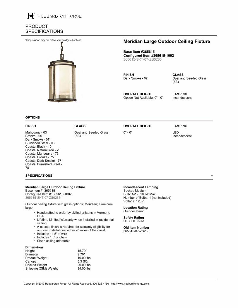
−
OPTIONS
SPECIFICATIONS
Copyright © 2017 Hubbardton Forge. All Rights Reserved. 800-826-4766 | http://www.hubbardtonforge.com
PRODUCT SPECIFICATIONS
Meridian Large Outdoor Ceiling Fixture
Base Item #365615 Configured Item #365615-1002 365615-SKT-07-ZS0283
FINISHDark Smoke - 07
GLASSOpal and Seeded Glass (ZS)
OVERALL HEIGHTOption Not Available: 0" - 0"
LAMPINGIncandescent
*Image shown may not reflect your configured options
FINISH
Mahogany - 03Bronze - 05Dark Smoke - 07Burnished Steel - 08Coastal Black - 10Coastal Natural Iron - 20Coastal Mahogany - 73Coastal Bronze - 75Coastal Dark Smoke - 77Coastal Burnished Steel - 78
GLASS
Opal and Seeded Glass (ZS)
OVERALL HEIGHT
0" - 0"
LAMPING
LEDIncandescent
Meridian Large Outdoor Ceiling FixtureBase Item #: 365615Configured Item #: 365615-1002365615-SKT-07-ZS0283
Outdoor ceiling fixture with glass options: Meridian; aluminum, large.
• Handcrafted to order by skilled artisans in Vermont, USA
• Lifetime Limited Warranty when installed in residential setting
• A coastal finish is required for warranty eligibility for outdoor installations within 20 miles of the coast.
• Includes 11.5′ of wire• Includes 1.0′ of chain• Slope ceiling adaptable
DimensionsHeight 15.70″Diameter 9.70″Product Weight 10.00 lbsCanopy 5.3 SQPacked Weight 20.00 lbsShipping (DIM) Weight 34.00 lbs
Incandescent Lamping Socket: MediumBulb: A-19, 100W MaxNumber of Bulbs: 1 (not included)Voltage: 120V
Location RatingOutdoor Damp
Safety RatingUL, CUL listed
Old Item Number365615-07-ZS283
leeba
Text Box
IMEG ENGINEERING | PROJ# 16.0011.00 MAINE VETERANS HOME / AUGUSTA F35, TYPICAL

leeba
Image
leeba
Image
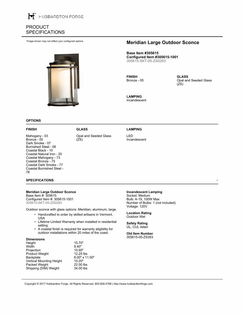
−
OPTIONS
SPECIFICATIONS
Copyright © 2017 Hubbardton Forge. All Rights Reserved. 800-826-4766 | http://www.hubbardtonforge.com
PRODUCT SPECIFICATIONS
Meridian Large Outdoor Sconce
Base Item #305615 Configured Item #305615-1001 305615-SKT-05-ZS0283
FINISHBronze - 05
GLASSOpal and Seeded Glass (ZS)
LAMPINGIncandescent
*Image shown may not reflect your configured options
FINISH
Mahogany - 03Bronze - 05Dark Smoke - 07Burnished Steel - 08Coastal Black - 10Coastal Natural Iron - 20Coastal Mahogany - 73Coastal Bronze - 75Coastal Dark Smoke - 77Coastal Burnished Steel - 78
GLASS
Opal and Seeded Glass (ZS)
LAMPING
LEDIncandescent
Meridian Large Outdoor SconceBase Item #: 305615Configured Item #: 305615-1001305615-SKT-05-ZS0283
Outdoor sconce with glass options: Meridian; aluminum, large.
• Handcrafted to order by skilled artisans in Vermont, USA
• Lifetime Limited Warranty when installed in residential setting
• A coastal finish is required for warranty eligibility for outdoor installations within 20 miles of the coast.
DimensionsHeight 15.70″Width 9.40″Projection 10.90″Product Weight 12.25 lbsBackplate 8.00″ x 11.00″Vertical Mounting Height 10.20″Packed Weight 22.00 lbsShipping (DIM) Weight 34.00 lbs
Incandescent Lamping Socket: MediumBulb: A-19, 100W MaxNumber of Bulbs: 1 (not included)Voltage: 120V
Location RatingOutdoor Wet
Safety RatingUL, CUL listed
Old Item Number305615-05-ZS283
leeba
Text Box
IMEG ENGINEERING | PROJ# 16.0011.00 MAINE VETERANS HOME / AUGUSTA F37, TYPICAL
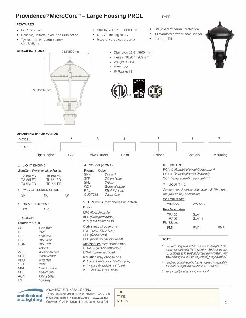
| 1 |
Providence® MicroCore™ – Large Housing PROL
ARCHITECTURAL AREA LIGHTING17760 Rowland Street | City of Industry | CA 91748P 626.968.5666 | F 626.369.2695 | www.aal.net Copyright © 2014 November 28, 2016 10:48 AM
TYPE
JOBTYPENOTES
18.7 in / 475 mm
31.5 in / 800 mm
Weight: 29lbs. EPA: 1.30
23.6"/599mm
38.95/989mm
• DLC Qualified• Reliable, uniform, glare free illumination• Types II, III, IV, V and custom
distributions
1. LIGHT ENGINE
MicroCore Precision aimed optics
T2-56LED T5-56LED T3-56LED TL-56LED T4-56LED TR-56LED 2. COLOR TEMPERATURE
3K 4K 5K
3. DRIVE CURRENT
700 450
Light Engine CCT Drive Current Color Options Controls Mounting
SPECIFICATIONS
• 3000K, 4000K, 5000K CCT• 0-10V dimming ready• Integral surge suppression
• LifeShield™ thermal protection• 13 standard powder coat finishes• Upgrade Kits
FEATURES
5. OPTIONS (may choose as noted)
Finish
SPK (Decorative spike) BPS (Struts painted brass) PFN (Finial painted brass)
Optics may choose oneLDL (Lightly diffused lens. )CLR (Clear flat lens)HSS (House Side shield for Type 4)Accessories may choose oneEPA-C (Egress-Contemporary) 3
EPA-T (Egress-Traditional) 3
Mounting may choose onePT4 (Post top fitter for a 4"/100mm pole)PT23 (Slips Over a 2 3/8" x 4" Tenon)PT3 (Slips Over a 3"x 4" Tenon)
6. CONTROLPCA-C (Rotatable photocell-Contemporary) PCA-T (Rotatable photocell-Traditional) SCP (Sensor Control Programmable) 1 2
7. MOUNTING
Standard configuration slips over a 5” DIA open top pole or may choose one.
Wall Mount Arm
WMA55 WMA56
Pole Mount Arm
TRA55 SLA1 TRA56 SLA1-2 Pier Mount
PM1 PM2 PM3
ORDERING INFORMATION
• Diameter: 23.6” / 599 mm• Height: 38.95” / 989 mm• Weight: 47 lbs• EPA: 1.33• IP Rating: 65
MODEL
PROL
1 2 3 4 5 6 7
4. COLOR
Standard Color
WH Arctic White BL Black BLT Matte Black DB Dark Bronze DGN Dark Green TT Titanium WDB Weathered Bronze MDB Bronze Metallic VBU Verde Blue CRT Corten MAL Matte Aluminum MG Medium Grey AGN Antique Green LG Light Grey
4. COLOR (CONT)
Premium Color SHK Shamrock SPP Salt and Pepper SFM Seafoam WCP Weathered Copper RAL RAL 4 digit Color CUSTOM Custom Color
NOTE:
¹ Pole accessory with motion sensor and daylight photo-control for California Title 24 section 130.2 compliance. For complete spec sheet and ordering information, visit www.aal.net/products/sensor_control_programmable/
² Handheld commissioning tool is required to separately configure or adjust any number of SCP sensors
³ Not compatible with PCA-C nor PCA-T
leeba
Text Box
IMEG ENGINEERING | PROJ# 16.0011.00 MAINE VETERANS HOME / AUGUSTA S2
leeba
Rectangle
leeba
Rectangle
leeba
Rectangle
leeba
Rectangle
leeba
Typewritten Text
20FT
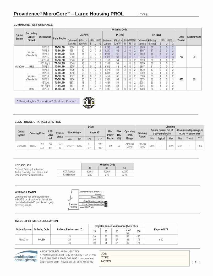
| 2 |
Providence® MicroCore™ – Large Housing PROL
ARCHITECTURAL AREA LIGHTING17760 Rowland Street | City of Industry | CA 91748P 626.968.5666 | F 626.369.2695 | www.aal.net Copyright © 2014 November 28, 2016 10:48 AM
TYPE
JOBTYPENOTES
LUMINAIRE PERFORMANCE
Optical System
Secondary Lens or Shield
Distribution
Ordering Code
System WattsLight Engine3K (WW) 4K (NW) 5K (BW)
Drive CurrentDelivered
LumensEfficacy (Lm/W)
BUG Rating Delivered Lumens
Efficafcy (Lm/W)
BUG Rating Delivered Lumens
Efficafcy (Lm/W)
BUG RatingB U G B U G B U G
MicroCore
No Lens (Standard)
TYPE 2 T2-56LED 6556 50 2 0 2 8283 63 2 0 2 8860 67 2 0 2
700 132
TYPE 3 T3-56LED 6591 50 2 0 2 8240 62 2 0 2 8907 67 2 0 2TYPE 4 T4-56LED 6370 48 1 0 2 8048 61 1 0 2 8603 65 1 0 2TYPE 5 T5-56LED 6620 50 3 0 1 8318 63 3 0 1 8945 63 3 0 G45° Left TL-56LED 6048 46 1 0 2 7163 54 1 0 2 7959 60 1 0 2
45° Right TR-56LED 6048 46 1 0 2 7163 54 1 0 2 7959 60 1 0 2HSS TYPE 4 T3-56LED 5275 40 0 0 2 6316 48 0 0 2 6687 51 0 0 2
No Lens (Standard)
TYPE 2 T2-56LED 4196 49 1 0 1 5273 62 2 0 2 5670 67 2 0 2
450 85
TYPE 3 T3-56LED 4218 50 1 0 1 5301 62 1 0 1 5700 67 1 0 2TYPE 4 T4-56LED 4077 48 0 0 1 5151 61 1 0 2 5506 65 1 0 2TYPE 5 T5-56LED 4236 50 2 0 1 5324 63 3 0 1 5275 62 3 0 145° Left TL-56LED 3871 46 1 0 1 4584 54 1 0 2 5094 60 1 0 2
45° Right TR-56LED 3871 46 1 0 1 4584 54 1 0 2 5094 60 1 0 2HSS TYPE 4 T4-56LED 3376 40 0 0 2 4042 48 0 0 2 4280 50 0 0 2
ELECTRICAL CHARACTERISTICS
Optical System
Ordering Code
Driver Dimming
LED Drive mA
System Watts
Line Voltage Amps AC Min. Power Factor
Max THD (%)
Operating Temp. Range
Dimming Range
Source current out of 0-10V purple wire
Absolute voltage range on 0-10V (+) purple wire
Min Typical Max Min Typical MaxVAC HZ 120 277
MicroCore 56LED700 700 132
120-277 50/601.1 0.5
≥.9 20-30°C TO
+40°C10% TO 100%
0 MA - 2 MA -2.0 V - +15 V450 450 85 0.7 0.3
Ordering Code3K 4K 5K
CCT Average 3000K 4000K 5000KCRI Minimum ≥ 80 ≥ 70 ≥ 70
LED COLORConsult factory for Amber, Turtle Friendly, Gulf Coast and Observatory applications.
WIRING LEADS
Luminaires not configured with wiHUBB or photo-control shall be provided with 0-10 purple and gray dimming leads.
TM-21 LIFETIME CALCULATION
* DesignLights Consortium® Qualified Product
Optical System Ordering Code Ambient Environment °CProjected Lumen Maintenance (% vs. Khrs)
Reported L7015 25 50 TM-21*
60 100
MicroCore 56LED15 95 93 88 86 80
≥ 6025 93 91 97 85 7940 93 91 87 85 78
leeba
Rectangle
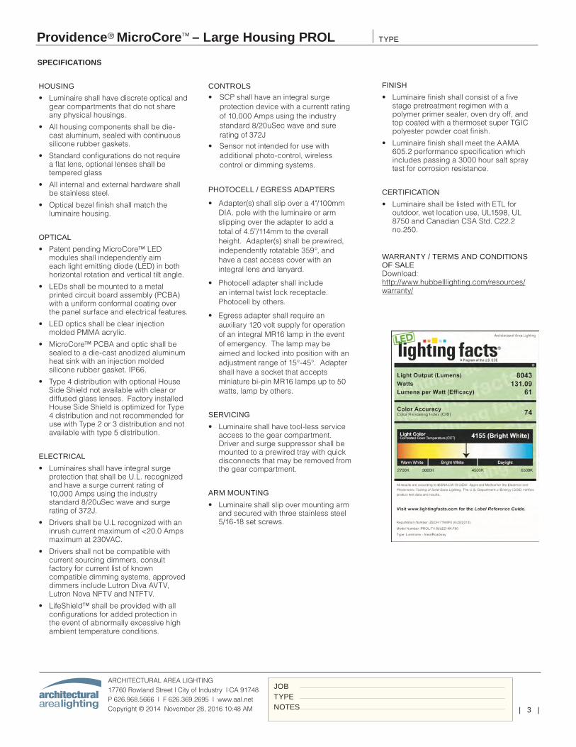
| 3 |
Providence® MicroCore™ – Large Housing PROL
ARCHITECTURAL AREA LIGHTING17760 Rowland Street | City of Industry | CA 91748P 626.968.5666 | F 626.369.2695 | www.aal.net Copyright © 2014 November 28, 2016 10:48 AM
TYPE
JOBTYPENOTES
HOUSING
• Luminaire shall have discrete optical and gear compartments that do not share any physical housings.
• All housing components shall be die-cast aluminum, sealed with continuous silicone rubber gaskets.
• Standard configurations do not require a flat lens, optional lenses shall be tempered glass
• All internal and external hardware shall be stainless steel.
• Optical bezel finish shall match the luminaire housing.
OPTICAL
• Patent pending MicroCore™ LED modules shall independently aim each light emitting diode (LED) in both horizontal rotation and vertical tilt angle.
• LEDs shall be mounted to a metal printed circuit board assembly (PCBA) with a uniform conformal coating over the panel surface and electrical features.
• LED optics shall be clear injection molded PMMA acrylic.
• MicroCore™ PCBA and optic shall be sealed to a die-cast anodized aluminum heat sink with an injection molded silicone rubber gasket. IP66.
• Type 4 distribution with optional House Side Shield not available with clear or diffused glass lenses. Factory installed House Side Shield is optimized for Type 4 distribution and not recommended for use with Type 2 or 3 distribution and not available with type 5 distribution.
ELECTRICAL
• Luminaires shall have integral surge protection that shall be U.L. recognized and have a surge current rating of 10,000 Amps using the industry standard 8/20uSec wave and surge rating of 372J.
• Drivers shall be U.L recognized with an inrush current maximum of <20.0 Amps maximum at 230VAC.
• Drivers shall not be compatible with current sourcing dimmers, consult factory for current list of known compatible dimming systems, approved dimmers include Lutron Diva AVTV, Lutron Nova NFTV and NTFTV.
• LifeShield™ shall be provided with all configurations for added protection in the event of abnormally excessive high ambient temperature conditions.
SPECIFICATIONS
CONTROLS
• SCP shall have an integral surge protection device with a currentt rating of 10,000 Amps using the industry standard 8/20uSec wave and sure rating of 372J
• Sensor not intended for use with additional photo-control, wireless control or dimming systems.
PHOTOCELL / EGRESS ADAPTERS
• Adapter(s) shall slip over a 4"/100mm DIA. pole with the luminaire or arm slipping over the adapter to add a total of 4.5”/114mm to the overall height. Adapter(s) shall be prewired, independently rotatable 359°, and have a cast access cover with an integral lens and lanyard.
• Photocell adapter shall include an internal twist lock receptacle. Photocell by others.
• Egress adapter shall require an auxiliary 120 volt supply for operation of an integral MR16 lamp in the event of emergency. The lamp may be aimed and locked into position with an adjustment range of 15°-45°. Adapter shall have a socket that accepts miniature bi-pin MR16 lamps up to 50 watts, lamp by others.
SERVICING
• Luminaire shall have tool-less service access to the gear compartment. Driver and surge suppressor shall be mounted to a prewired tray with quick disconnects that may be removed from the gear compartment.
ARM MOUNTING
• Luminaire shall slip over mounting arm and secured with three stainless steel 5/16-18 set screws.
FINISH
• Luminaire finish shall consist of a five stage pretreatment regimen with a polymer primer sealer, oven dry off, and top coated with a thermoset super TGIC polyester powder coat finish.
• Luminaire finish shall meet the AAMA 605.2 performance specification which includes passing a 3000 hour salt spray test for corrosion resistance.
CERTIFICATION
• Luminaire shall be listed with ETL for outdoor, wet location use, UL1598, UL 8750 and Canadian CSA Std. C22.2 no.250.
WARRANTY / TERMS AND CONDITIONS OF SALE Download: http://www.hubbelllighting.com/resources/warranty/
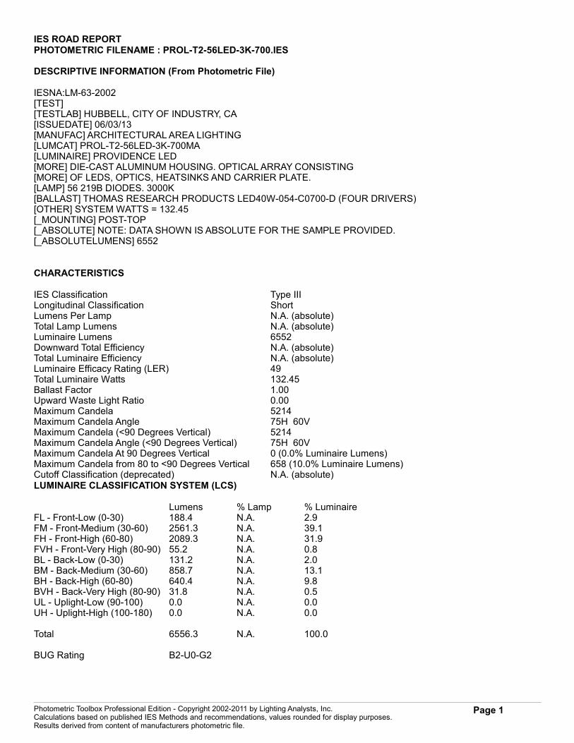
IES ROAD REPORTPHOTOMETRIC FILENAME : PROL-T2-56LED-3K-700.IES
DESCRIPTIVE INFORMATION (From Photometric File)
IESNA:LM-63-2002[TEST] [TESTLAB] HUBBELL, CITY OF INDUSTRY, CA[ISSUEDATE] 06/03/13[MANUFAC] ARCHITECTURAL AREA LIGHTING[LUMCAT] PROL-T2-56LED-3K-700MA[LUMINAIRE] PROVIDENCE LED[MORE] DIE-CAST ALUMINUM HOUSING. OPTICAL ARRAY CONSISTING[MORE] OF LEDS, OPTICS, HEATSINKS AND CARRIER PLATE.[LAMP] 56 219B DIODES. 3000K[BALLAST] THOMAS RESEARCH PRODUCTS LED40W-054-C0700-D (FOUR DRIVERS)[OTHER] SYSTEM WATTS = 132.45[_MOUNTING] POST-TOP[_ABSOLUTE] NOTE: DATA SHOWN IS ABSOLUTE FOR THE SAMPLE PROVIDED.[_ABSOLUTELUMENS] 6552
CHARACTERISTICS
IES Classification Type IIILongitudinal Classification ShortLumens Per Lamp N.A. (absolute)Total Lamp Lumens N.A. (absolute)Luminaire Lumens 6552Downward Total Efficiency N.A. (absolute)Total Luminaire Efficiency N.A. (absolute)Luminaire Efficacy Rating (LER) 49Total Luminaire Watts 132.45Ballast Factor 1.00Upward Waste Light Ratio 0.00Maximum Candela 5214Maximum Candela Angle 75H 60VMaximum Candela (<90 Degrees Vertical) 5214Maximum Candela Angle (<90 Degrees Vertical) 75H 60VMaximum Candela At 90 Degrees Vertical 0 (0.0% Luminaire Lumens)Maximum Candela from 80 to <90 Degrees Vertical 658 (10.0% Luminaire Lumens)Cutoff Classification (deprecated) N.A. (absolute)LUMINAIRE CLASSIFICATION SYSTEM (LCS)
Lumens % Lamp % LuminaireFL - Front-Low (0-30) 188.4 N.A. 2.9FM - Front-Medium (30-60) 2561.3 N.A. 39.1FH - Front-High (60-80) 2089.3 N.A. 31.9FVH - Front-Very High (80-90) 55.2 N.A. 0.8BL - Back-Low (0-30) 131.2 N.A. 2.0BM - Back-Medium (30-60) 858.7 N.A. 13.1BH - Back-High (60-80) 640.4 N.A. 9.8BVH - Back-Very High (80-90) 31.8 N.A. 0.5UL - Uplight-Low (90-100) 0.0 N.A. 0.0UH - Uplight-High (100-180) 0.0 N.A. 0.0
Total 6556.3 N.A. 100.0
BUG Rating B2-U0-G2
Photometric Toolbox Professional Edition - Copyright 2002-2011 by Lighting Analysts, Inc.Calculations based on published IES Methods and recommendations, values rounded for display purposes.Results derived from content of manufacturers photometric file.
Page 1
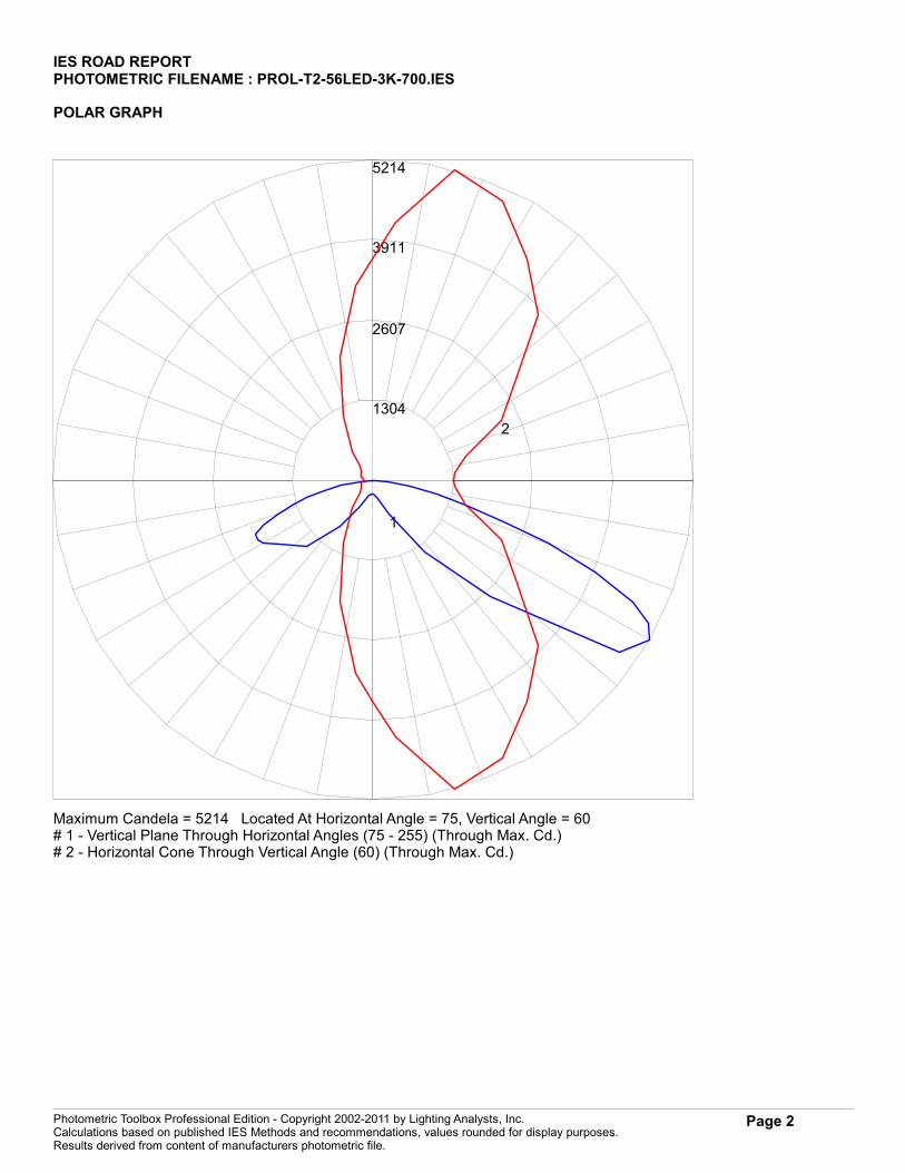
IES ROAD REPORTPHOTOMETRIC FILENAME : PROL-T2-56LED-3K-700.IES
POLAR GRAPH
1304
2607
3911
5214
1
2
Maximum Candela = 5214 Located At Horizontal Angle = 75, Vertical Angle = 60# 1 - Vertical Plane Through Horizontal Angles (75 - 255) (Through Max. Cd.)# 2 - Horizontal Cone Through Vertical Angle (60) (Through Max. Cd.)
Photometric Toolbox Professional Edition - Copyright 2002-2011 by Lighting Analysts, Inc.Calculations based on published IES Methods and recommendations, values rounded for display purposes.Results derived from content of manufacturers photometric file.
Page 2

IES ROAD REPORTPHOTOMETRIC FILENAME : PROL-T2-56LED-3K-700.IES
ISOFOOTCANDLE LINES OF HORIZONTAL ILLUMINANCE
0 1 2 2.25 3 3.75 4 5 6 75
4
32.75
21.75
1
0
1
2
3
House Side Street Side
Distance In Units Of Mounting HeightValues Based On 10 Foot Mounting Height
.1
.2
.5
1
2
510
1/2 Maximum Candela Trace Shown As Dashed Curve(+) = Maximum Candela Point
Photometric Toolbox Professional Edition - Copyright 2002-2011 by Lighting Analysts, Inc.Calculations based on published IES Methods and recommendations, values rounded for display purposes.Results derived from content of manufacturers photometric file.
Page 3
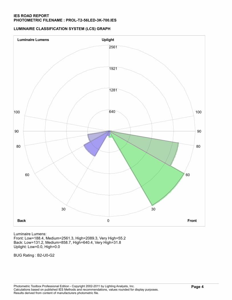
IES ROAD REPORTPHOTOMETRIC FILENAME : PROL-T2-56LED-3K-700.IES
LUMINAIRE CLASSIFICATION SYSTEM (LCS) GRAPH
640
1281
1921
2561
Luminaire Lumens
FrontBack
Uplight
0
30
60
80
90
100
30
60
80
90
100
Luminaire Lumens:Front: Low=188.4, Medium=2561.3, High=2089.3, Very High=55.2Back: Low=131.2, Medium=858.7, High=640.4, Very High=31.8Uplight: Low=0.0, High=0.0
BUG Rating : B2-U0-G2
Photometric Toolbox Professional Edition - Copyright 2002-2011 by Lighting Analysts, Inc.Calculations based on published IES Methods and recommendations, values rounded for display purposes.Results derived from content of manufacturers photometric file.
Page 4
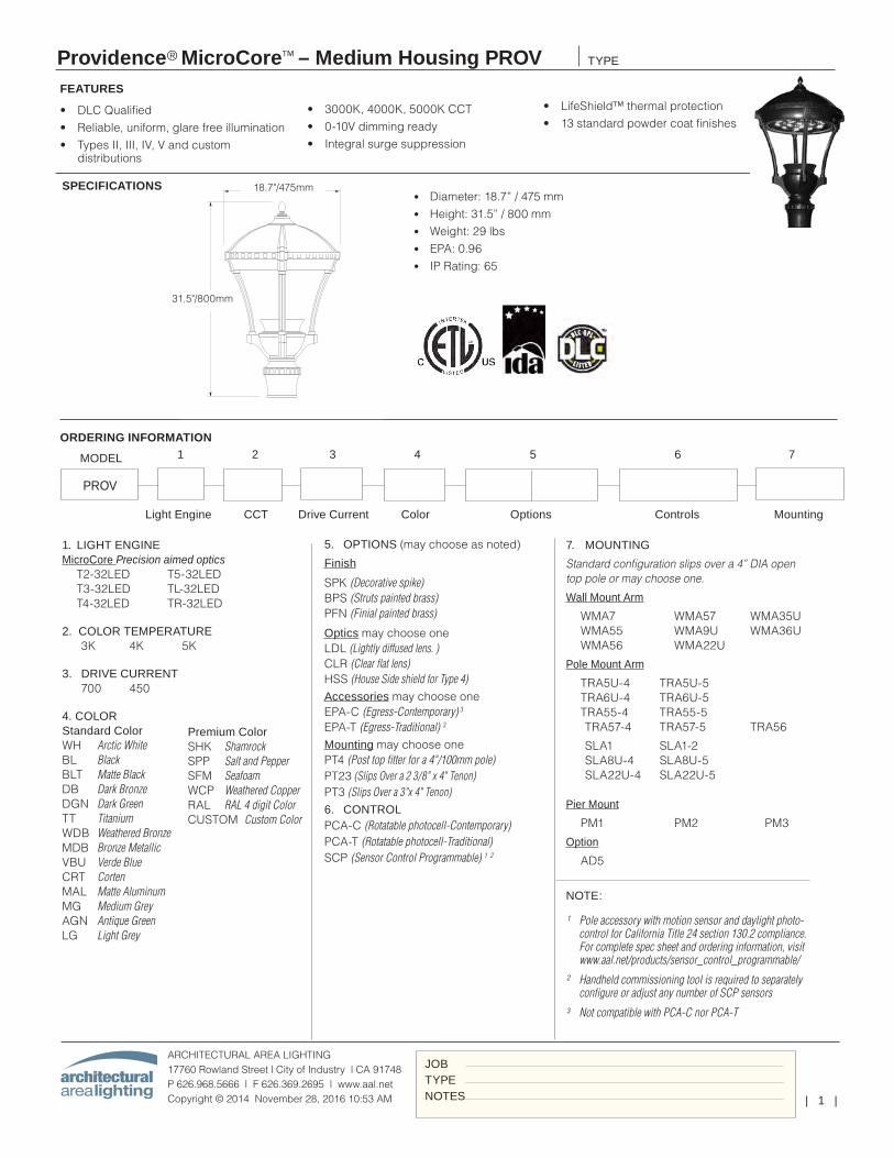
| 1 |
Providence® MicroCore™ – Medium Housing PROV
ARCHITECTURAL AREA LIGHTING17760 Rowland Street | City of Industry | CA 91748P 626.968.5666 | F 626.369.2695 | www.aal.net Copyright © 2014 November 28, 2016 10:53 AM
TYPE
JOBTYPENOTES
• DLC Qualified• Reliable, uniform, glare free illumination• Types II, III, IV, V and custom
distributions
Light Engine CCT Drive Current Color Options Controls Mounting
SPECIFICATIONS
• 3000K, 4000K, 5000K CCT• 0-10V dimming ready• Integral surge suppression
• LifeShield™ thermal protection• 13 standard powder coat finishes
FEATURES
7. MOUNTING
Standard configuration slips over a 4” DIA open top pole or may choose one.
Wall Mount Arm
WMA7 WMA57 WMA35U WMA55 WMA9U WMA36U WMA56 WMA22U
Pole Mount Arm
TRA5U-4 TRA5U-5 TRA6U-4 TRA6U-5 TRA55-4 TRA55-5 TRA57-4 TRA57-5 TRA56
SLA1 SLA1-2 SLA8U-4 SLA8U-5 SLA22U-4 SLA22U-5 Pier Mount
PM1 PM2 PM3
Option
AD5
ORDERING INFORMATION
• Diameter: 18.7” / 475 mm• Height: 31.5” / 800 mm• Weight: 29 lbs• EPA: 0.96• IP Rating: 65
MODEL
PROV
1 2 3 4 5 6 7
18.7 in / 475 mm
31.5 in / 800 mm
Weight: 29lbs. EPA: 1.30
18.7"/475mm
31.5"/800mm
1. LIGHT ENGINE MicroCore Precision aimed optics T2-32LED T5-32LED T3-32LED TL-32LED T4-32LED TR-32LED
2. COLOR TEMPERATURE 3K 4K 5K
3. DRIVE CURRENT 700 450
4. COLOR Standard Color WH Arctic White BL Black BLT Matte Black DB Dark Bronze DGN Dark Green TT Titanium WDB Weathered Bronze MDB Bronze Metallic VBU Verde Blue CRT Corten MAL Matte Aluminum MG Medium Grey AGN Antique Green LG Light Grey
Premium Color SHK Shamrock SPP Salt and Pepper SFM Seafoam WCP Weathered Copper RAL RAL 4 digit Color CUSTOM Custom Color
5. OPTIONS (may choose as noted)
Finish
SPK (Decorative spike) BPS (Struts painted brass) PFN (Finial painted brass)
Optics may choose oneLDL (Lightly diffused lens. )CLR (Clear flat lens)HSS (House Side shield for Type 4)Accessories may choose oneEPA-C (Egress-Contemporary) 3
EPA-T (Egress-Traditional) 3
Mounting may choose onePT4 (Post top fitter for a 4"/100mm pole)PT23 (Slips Over a 2 3/8" x 4" Tenon)PT3 (Slips Over a 3"x 4" Tenon)6. CONTROLPCA-C (Rotatable photocell-Contemporary) PCA-T (Rotatable photocell-Traditional) SCP (Sensor Control Programmable) 1 2
NOTE:
¹ Pole accessory with motion sensor and daylight photo-control for California Title 24 section 130.2 compliance. For complete spec sheet and ordering information, visit www.aal.net/products/sensor_control_programmable/
² Handheld commissioning tool is required to separately configure or adjust any number of SCP sensors
³ Not compatible with PCA-C nor PCA-T
leeba
Text Box
IMEG ENGINEERING | PROJ# 16.0011.00 MAINE VETERANS HOME / AUGUSTA S3, S4, S5
leeba
Typewritten Text
S3 S4
leeba
Typewritten Text
S5
leeba
Rectangle
leeba
Rectangle
leeba
Typewritten Text
S3,S5
leeba
Typewritten Text
S4
leeba
Rectangle
leeba
Typewritten Text
15FT
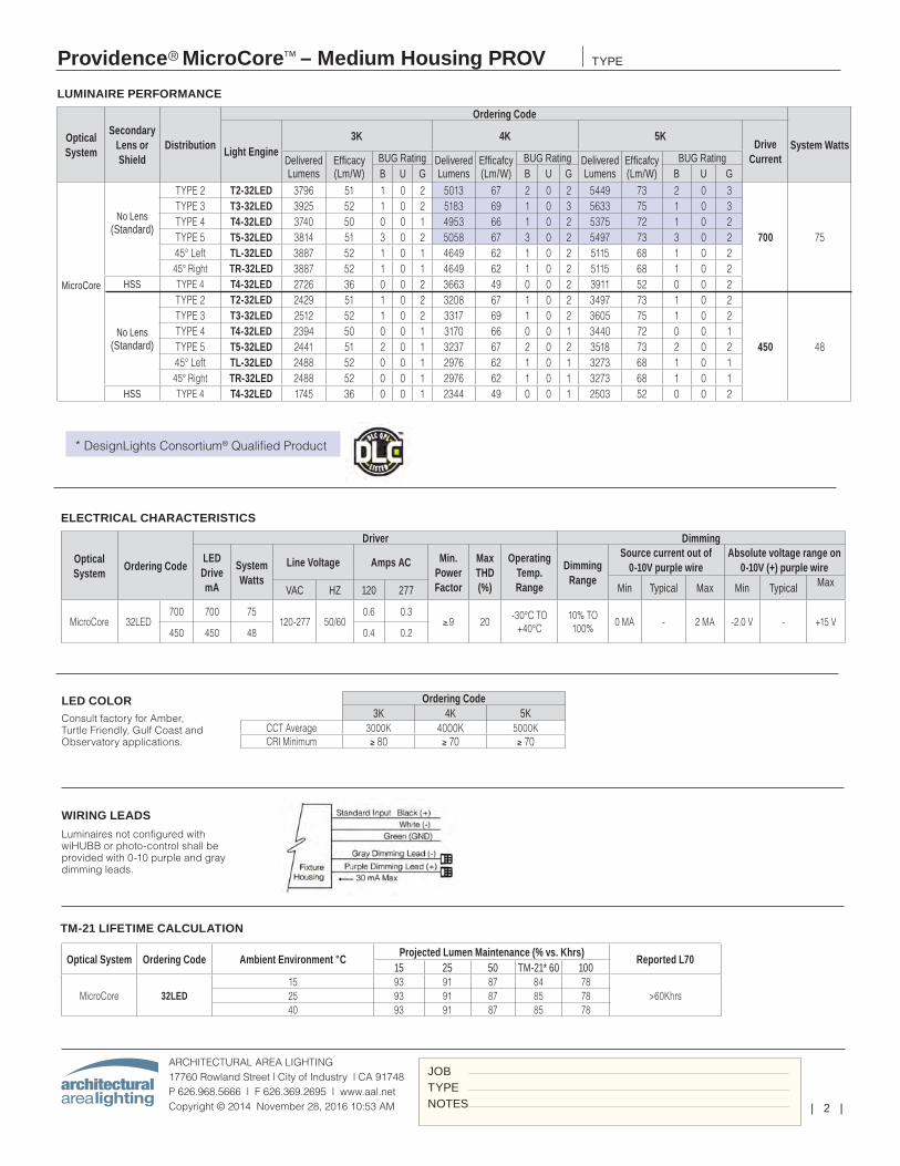
| 2 |
Providence® MicroCore™ – Medium Housing PROV
ARCHITECTURAL AREA LIGHTING17760 Rowland Street | City of Industry | CA 91748P 626.968.5666 | F 626.369.2695 | www.aal.net Copyright © 2014 November 28, 2016 10:53 AM
TYPE
JOBTYPENOTES
LUMINAIRE PERFORMANCE
Optical System
Secondary Lens or Shield
Distribution
Ordering Code
System WattsLight Engine3K 4K 5K
Drive CurrentDelivered
LumensEfficacy (Lm/W)
BUG Rating Delivered Lumens
Efficafcy (Lm/W)
BUG Rating Delivered Lumens
Efficafcy (Lm/W)
BUG RatingB U G B U G B U G
MicroCore
No Lens (Standard)
TYPE 2 T2-32LED 3796 51 1 0 2 5013 67 2 0 2 5449 73 2 0 3
700 75
TYPE 3 T3-32LED 3925 52 1 0 2 5183 69 1 0 3 5633 75 1 0 3TYPE 4 T4-32LED 3740 50 0 0 1 4953 66 1 0 2 5375 72 1 0 2TYPE 5 T5-32LED 3814 51 3 0 2 5058 67 3 0 2 5497 73 3 0 245° Left TL-32LED 3887 52 1 0 1 4649 62 1 0 2 5115 68 1 0 245° Right TR-32LED 3887 52 1 0 1 4649 62 1 0 2 5115 68 1 0 2
HSS TYPE 4 T4-32LED 2726 36 0 0 2 3663 49 0 0 2 3911 52 0 0 2
No Lens (Standard)
TYPE 2 T2-32LED 2429 51 1 0 2 3208 67 1 0 2 3497 73 1 0 2
450 48
TYPE 3 T3-32LED 2512 52 1 0 2 3317 69 1 0 2 3605 75 1 0 2TYPE 4 T4-32LED 2394 50 0 0 1 3170 66 0 0 1 3440 72 0 0 1TYPE 5 T5-32LED 2441 51 2 0 1 3237 67 2 0 2 3518 73 2 0 245° Left TL-32LED 2488 52 0 0 1 2976 62 1 0 1 3273 68 1 0 145° Right TR-32LED 2488 52 0 0 1 2976 62 1 0 1 3273 68 1 0 1
HSS TYPE 4 T4-32LED 1745 36 0 0 1 2344 49 0 0 1 2503 52 0 0 2
ELECTRICAL CHARACTERISTICS
Optical System
Ordering Code
Driver Dimming
LED Drive mA
System Watts
Line Voltage Amps AC Min. Power Factor
Max THD (%)
Operating Temp. Range
Dimming Range
Source current out of 0-10V purple wire
Absolute voltage range on 0-10V (+) purple wire
Min Typical Max Min Typical MaxVAC HZ 120 277
MicroCore 32LED700 700 75
120-277 50/600.6 0.3
≥.9 20-30°C TO
+40°C10% TO 100%
0 MA - 2 MA -2.0 V - +15 V450 450 48 0.4 0.2
Ordering Code3K 4K 5K
CCT Average 3000K 4000K 5000KCRI Minimum ≥ 80 ≥ 70 ≥ 70
LED COLORConsult factory for Amber, Turtle Friendly, Gulf Coast and Observatory applications.
WIRING LEADS
Luminaires not configured with wiHUBB or photo-control shall be provided with 0-10 purple and gray dimming leads.
TM-21 LIFETIME CALCULATION
* DesignLights Consortium® Qualified Product
Optical System Ordering Code Ambient Environment °CProjected Lumen Maintenance (% vs. Khrs)
Reported L7015 25 50 TM-21* 60 100
MicroCore 32LED15 93 91 87 84 78
>60Khrs25 93 91 87 85 7840 93 91 87 85 78
leeba
Rectangle
leeba
Rectangle
leeba
Rectangle
leeba
Typewritten Text
S4
leeba
Typewritten Text
S5
leeba
Typewritten Text
S3
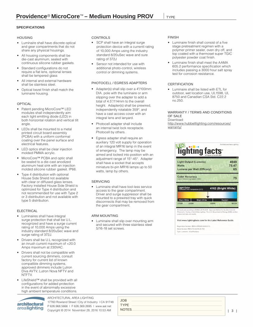
| 3 |
Providence® MicroCore™ – Medium Housing PROV
ARCHITECTURAL AREA LIGHTING17760 Rowland Street | City of Industry | CA 91748P 626.968.5666 | F 626.369.2695 | www.aal.net Copyright © 2014 November 28, 2016 10:53 AM
TYPE
JOBTYPENOTES
HOUSING
• Luminaire shall have discrete optical and gear compartments that do not share any physical housings.
• All housing components shall be die-cast aluminum, sealed with continuous silicone rubber gaskets.
• Standard configurations do not require a flat lens, optional lenses shall be tempered glass
• All internal and external hardware shall be stainless steel.
• Optical bezel finish shall match the luminaire housing.
OPTICAL
• Patent pending MicroCore™ LED modules shall independently aim each light emitting diode (LED) in both horizontal rotation and vertical tilt angle.
• LEDs shall be mounted to a metal printed circuit board assembly (PCBA) with a uniform conformal coating over the panel surface and electrical features.
• LED optics shall be clear injection molded PMMA acrylic.
• MicroCore™ PCBA and optic shall be sealed to a die-cast anodized aluminum heat sink with an injection molded silicone rubber gasket. IP66.
• Type 4 distribution with optional House Side Shield not available with clear or diffused glass lenses. Factory installed House Side Shield is optimized for Type 4 distribution and not recommended for use with Type 2 or 3 distribution and not available with type 5 distribution.
ELECTRICAL
• Luminaires shall have integral surge protection that shall be U.L. recognized and have a surge current rating of 10,000 Amps using the industry standard 8/20uSec wave and surge rating of 372J.
• Drivers shall be U.L recognized with an inrush current maximum of <20.0 Amps maximum at 230VAC.
• Drivers shall not be compatible with current sourcing dimmers, consult factory for current list of known compatible dimming systems, approved dimmers include Lutron Diva AVTV, Lutron Nova NFTV and NTFTV.
• LifeShield™ shall be provided with all configurations for added protection in the event of abnormally excessive high ambient temperature conditions.
SPECIFICATIONS
CONTROLS
• SCP shall have an integral surge protection device with a currentt rating of 10,000 Amps using the industry standard 8/20uSec wave and sure rating of 372J
• Sensor not intended for use with additional photo-control, wireless control or dimming systems.
PHOTOCELL / EGRESS ADAPTERS
• Adapter(s) shall slip over a 4"/100mm DIA. pole with the luminaire or arm slipping over the adapter to add a total of 4.5”/114mm to the overall height. Adapter(s) shall be prewired, independently rotatable 359°, and have a cast access cover with an integral lens and lanyard.
• Photocell adapter shall include an internal twist lock receptacle. Photocell by others.
• Egress adapter shall require an auxiliary 120 volt supply for operation of an integral MR16 lamp in the event of emergency. The lamp may be aimed and locked into position with an adjustment range of 15°-45°. Adapter shall have a socket that accepts miniature bi-pin MR16 lamps up to 50 watts, lamp by others.
SERVICING
• Luminaire shall have tool-less service access to the gear compartment. Driver and surge suppressor shall be mounted to a prewired tray with quick disconnects that may be removed from the gear compartment.
ARM MOUNTING
• Luminaire shall slip over mounting arm and secured with three stainless steel 5/16-18 set screws.
FINISH
• Luminaire finish shall consist of a five stage pretreatment regimen with a polymer primer sealer, oven dry off, and top coated with a thermoset super TGIC polyester powder coat finish.
• Luminaire finish shall meet the AAMA 605.2 performance specification which includes passing a 3000 hour salt spray test for corrosion resistance.
CERTIFICATION
• Luminaire shall be listed with ETL for outdoor, wet location use, UL1598, UL 8750 and Canadian CSA Std. C22.2 no.250.
WARRANTY / TERMS AND CONDITIONS OF SALE Download: http://www.hubbelllighting.com/resources/warranty/

leeba
Rectangle
leeba
Rectangle
leeba
Rectangle
leeba
Image
leeba
Image
leeba
Image
leeba
Typewritten Text
BUG Rating: B1-U0-G2
leeba
Typewritten Text
S3 Photometric Graphs
leeba
Typewritten Text
S4 Photometric Graphs
leeba
Typewritten Text
S5 Photometric Graphs
leeba
Image
leeba
Image
leeba
Image
leeba
Typewritten Text
BUG Rating: B0-U0-G1
leeba
Image
leeba
Image
leeba
Image
leeba
Typewritten Text
BUG Rating: B3-U0-G2
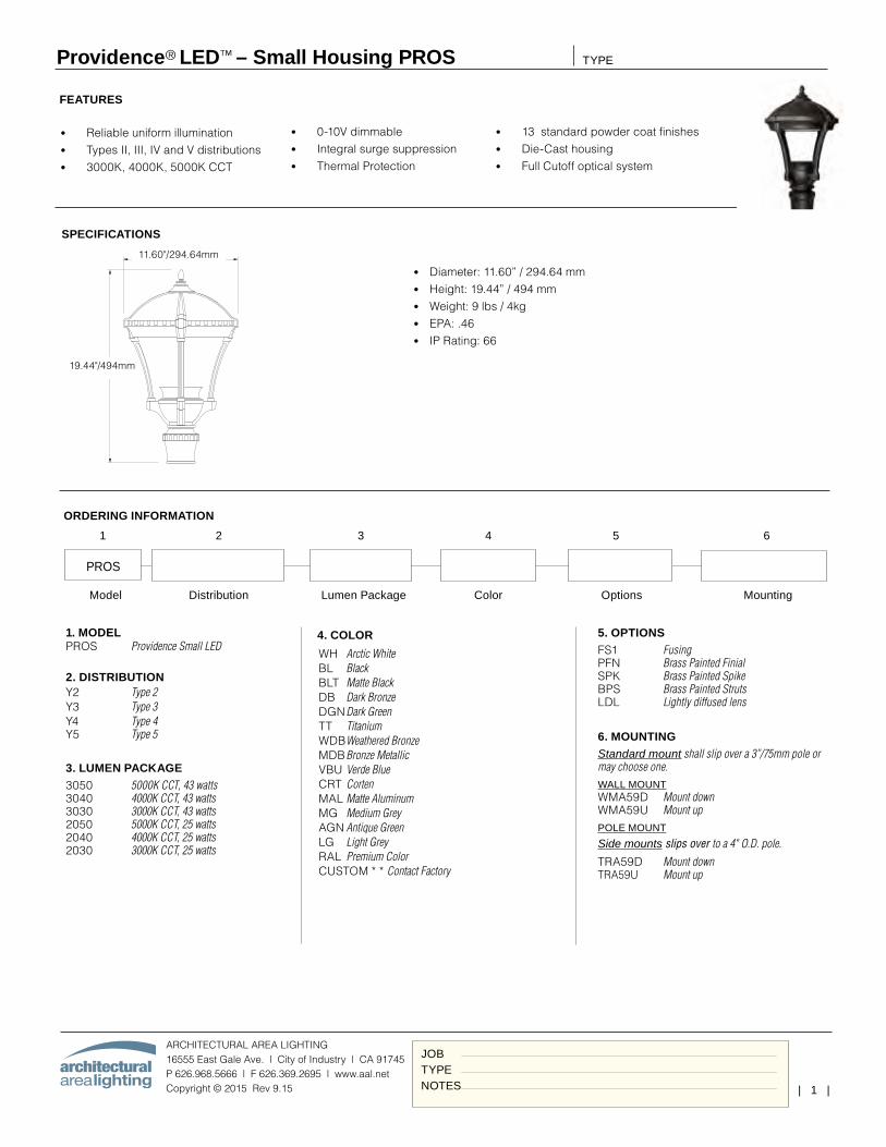
| 1 |
Providence® LED™ – Small Housing PROS
ARCHITECTURAL AREA LIGHTING16555 East Gale Ave. | City of Industry | CA 91745P 626.968.5666 | F 626.369.2695 | www.aal.net Copyright © 2015 Rev 9.15
TYPE
JOBTYPENOTES
SPECIFICATIONS
FEATURES
• Diameter: 11.60” / 294.64 mm• Height: 19.44” / 494 mm• Weight: 9 lbs / 4kg• EPA: .46• IP Rating: 66
18.7 in / 475 mm
31.5 in / 800 mm
Weight: 29lbs. EPA: 1.30
11.60"/294.64mm
19.44"/494mm
• Reliable uniform illumination• Types II, III, IV and V distributions• 3000K, 4000K, 5000K CCT
• 0-10V dimmable• Integral surge suppression• Thermal Protection
• 13 standard powder coat finishes• Die-Cast housing• Full Cutoff optical system
Model Distribution Lumen Package Color Options Mounting
4. COLOR
WH Arctic White BL Black BLT Matte Black DB Dark Bronze DGN Dark Green TT Titanium WDB Weathered Bronze MDB Bronze Metallic VBU Verde Blue CRT Corten MAL Matte Aluminum MG Medium Grey AGN Antique Green LG Light Grey RAL Premium Color CUSTOM * * Contact Factory
5. OPTIONSFS1 Fusing PFN Brass Painted Finial SPK Brass Painted Spike BPS Brass Painted Struts LDL Lightly diffused lens
6. MOUNTINGStandard mount shall slip over a 3”/75mm pole or may choose one.WALL MOUNT WMA59D Mount down WMA59U Mount up POLE MOUNT
Side mounts slips over to a 4" O.D. pole. TRA59D Mount down TRA59U Mount up
ORDERING INFORMATION
PROS
1 2 3 4 5 6
1. MODELPROS Providence Small LED
2. DISTRIBUTIONY2 Type 2 Y3 Type 3 Y4 Type 4 Y5 Type 5
3. LUMEN PACKAGE3050 5000K CCT, 43 watts 3040 4000K CCT, 43 watts 3030 3000K CCT, 43 watts 2050 5000K CCT, 25 watts 2040 4000K CCT, 25 watts 2030 3000K CCT, 25 watts
leeba
Text Box
IMEG ENGINEERING | PROJ# 16.0011.00 MAINE VETERANS HOME / AUGUSTA S6
leeba
Rectangle
leeba
Typewritten Text
12FT
leeba
Rectangle
leeba
Rectangle
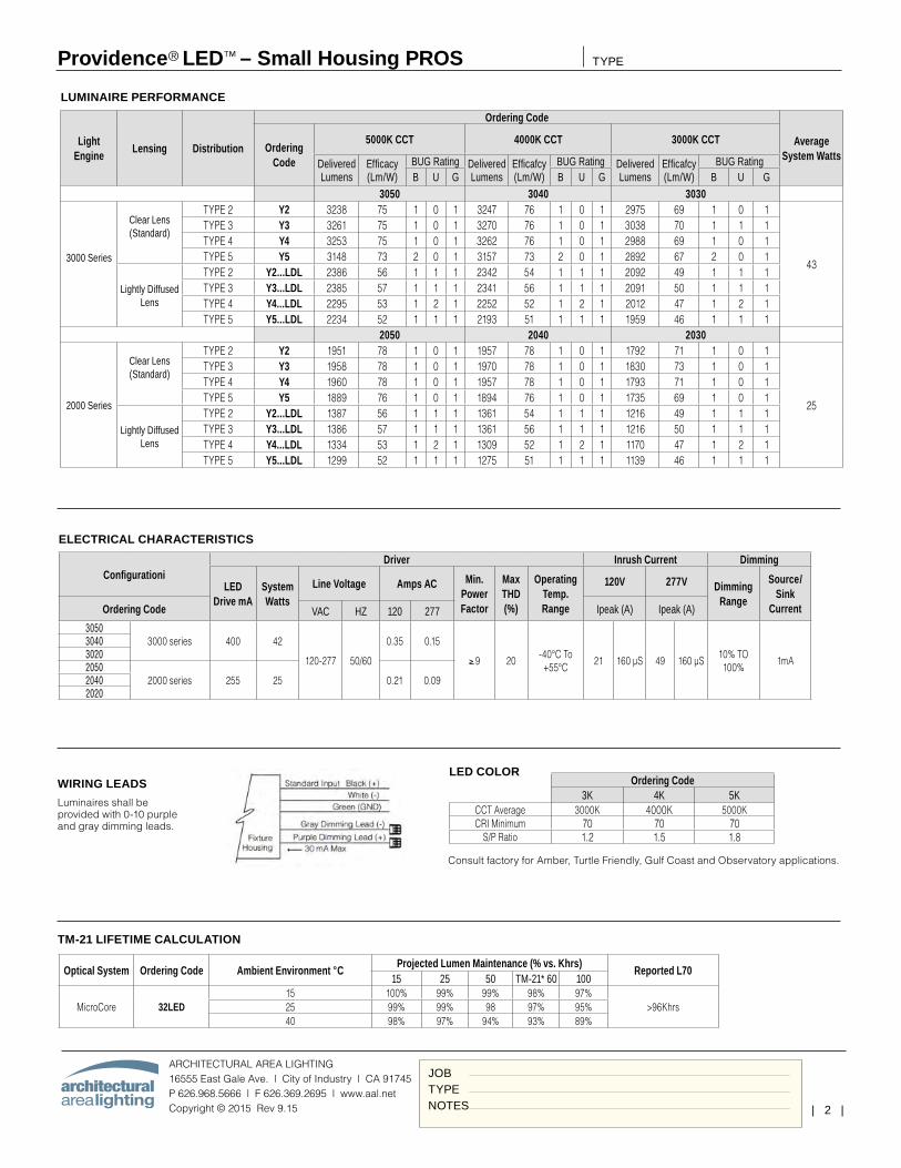
| 2 |
Providence® LED™ – Small Housing PROS
ARCHITECTURAL AREA LIGHTING16555 East Gale Ave. | City of Industry | CA 91745P 626.968.5666 | F 626.369.2695 | www.aal.net Copyright © 2015 Rev 9.15
TYPE
JOBTYPENOTES
LUMINAIRE PERFORMANCE
Light Engine
Lensing Distribution
Ordering Code
Average System Watts
Ordering Code
5000K CCT 4000K CCT 3000K CCT
Delivered Lumens
Efficacy (Lm/W)
BUG Rating Delivered Lumens
Efficafcy (Lm/W)
BUG Rating Delivered Lumens
Efficafcy (Lm/W)
BUG RatingB U G B U G B U G
3050 3040 3030
3000 Series
Clear Lens (Standard)
TYPE 2 Y2 3238 75 1 0 1 3247 76 1 0 1 2975 69 1 0 1
43
TYPE 3 Y3 3261 75 1 0 1 3270 76 1 0 1 3038 70 1 1 1TYPE 4 Y4 3253 75 1 0 1 3262 76 1 0 1 2988 69 1 0 1TYPE 5 Y5 3148 73 2 0 1 3157 73 2 0 1 2892 67 2 0 1
Lightly Diffused Lens
TYPE 2 Y2...LDL 2386 56 1 1 1 2342 54 1 1 1 2092 49 1 1 1TYPE 3 Y3...LDL 2385 57 1 1 1 2341 56 1 1 1 2091 50 1 1 1TYPE 4 Y4...LDL 2295 53 1 2 1 2252 52 1 2 1 2012 47 1 2 1TYPE 5 Y5...LDL 2234 52 1 1 1 2193 51 1 1 1 1959 46 1 1 1
2050 2040 2030
2000 Series
Clear Lens (Standard)
TYPE 2 Y2 1951 78 1 0 1 1957 78 1 0 1 1792 71 1 0 1
25
TYPE 3 Y3 1958 78 1 0 1 1970 78 1 0 1 1830 73 1 0 1TYPE 4 Y4 1960 78 1 0 1 1957 78 1 0 1 1793 71 1 0 1TYPE 5 Y5 1889 76 1 0 1 1894 76 1 0 1 1735 69 1 0 1
Lightly Diffused Lens
TYPE 2 Y2...LDL 1387 56 1 1 1 1361 54 1 1 1 1216 49 1 1 1TYPE 3 Y3...LDL 1386 57 1 1 1 1361 56 1 1 1 1216 50 1 1 1TYPE 4 Y4...LDL 1334 53 1 2 1 1309 52 1 2 1 1170 47 1 2 1TYPE 5 Y5...LDL 1299 52 1 1 1 1275 51 1 1 1 1139 46 1 1 1
ELECTRICAL CHARACTERISTICS
ConfigurationiDriver Inrush Current Dimming
LED Drive mA
System Watts
Line Voltage Amps AC Min. Power Factor
Max THD (%)
Operating Temp. Range
120V 277V Dimming Range
Source/Sink
CurrentOrdering Code Ipeak (A) Ipeak (A)VAC HZ 120 2773050
3000 series 400 42
120-277 50/60
0.35 0.15
≥.9 20-40°C To +55°C
21 160 µS 49 160 µS10% TO 100%
1mA
304030202050
2000 series 255 25 0.21 0.0920402020
WIRING LEADS
Luminaires shall be provided with 0-10 purple and gray dimming leads.
TM-21 LIFETIME CALCULATION
Optical System Ordering Code Ambient Environment °CProjected Lumen Maintenance (% vs. Khrs)
Reported L7015 25 50 TM-21* 60 100
MicroCore 32LED15 100% 99% 99% 98% 97%
>96Khrs25 99% 99% 98 97% 95%40 98% 97% 94% 93% 89%
LED COLOR
Consult factory for Amber, Turtle Friendly, Gulf Coast and Observatory applications.
Ordering Code3K 4K 5K
CCT Average 3000K 4000K 5000KCRI Minimum 70 70 70
S/P Ratio 1.2 1.5 1.8
leeba
Rectangle

| 3 |
Providence® LED™ – Small Housing PROS
ARCHITECTURAL AREA LIGHTING16555 East Gale Ave. | City of Industry | CA 91745P 626.968.5666 | F 626.369.2695 | www.aal.net Copyright © 2015 Rev 9.15
TYPE
JOBTYPENOTES
HOUSING
• Luminaire shall have discrete optical and gear compartments that do not share any physical housings.
• All housing components shall be die-cast aluminum, sealed with continuous silicone rubber gaskets.
• Standard configurations do not require a flat lens, optional lenses shall be tempered glass
• All internal and external hardware shall be stainless steel.
• Optical bezel finish shall match the luminaire housing.
OPTICAL
• LEDs shall be mounted to a metal printed circuit board assembly (MCPCB) with a uniform conformal coating over the panel surface and electrical features.
• LED optics shall be clear injection molded PMMA acrylic.
• MCPCB and optic shall be sealed to a die-cast anodized aluminum heat sink with an injection molded silicone rubber gasket. IP66.
SPECIFICATIONS
ELECTRICAL
• Luminaires shall have integral surge protection that shall be U.L. recognized and have a surge current rating of 10,000 Amps using the industry standard 8/20uSec wave and surge rating of 372J.
• Drivers shall be U.L recognized with an inrush current maximum of <20.0 Amps maximum at 230VAC.
• Drivers shall not be compatible with current sourcing dimmers, consult factory for current list of known compatible dimming systems, approved dimmers include Lutron Diva AVTV, Lutron Nova NFTV and NTFTV.
SERVICING
• Luminaire shall have tool-less service access to the gear compartment. Driver shall be mounted to a prewired tray with quick disconnects that may be removed from the gear compartment.
MOUNTING
• One-piece cast aluminum arms accept the standard 3" slip fitter on the Providence fixture.
• Arms are prewired with quick disconnects.
• Wall mounted arms do not include wall mounting hardware.
• Pole mounted arms use 3/8-16 hardware bolts for attaching to the pole.
FINISH
• Luminaire finish shall consist of a five stage pretreatment regimen with a polymer primer sealer, oven dry off, and top coated with a thermoset super TGIC polyester powder coat finish.
• Luminaire finish shall meet the AAMA 605.2 performance specification which includes passing a 3000 hour salt spray test for corrosion resistance.
CERTIFICATION
• Luminaire shall be listed with ETL for outdoor, wet location use, UL1598, UL 8750 and Canadian CSA Std. C22.2 no.250.
WARRANTY / TERMS AND CONDITIONS OF SALE Download: http://www.hubbelllighting.com/resources/warranty/
leeba
Rectangle
leeba
Typewritten Text
BUG Rating: B1-U0-G1
leeba
Typewritten Text
S6 Photometric Graphs
leeba
Image
leeba
Image
leeba
Image
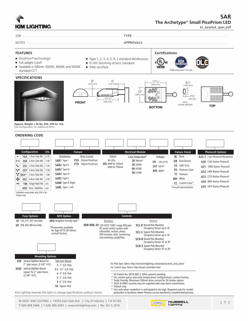
| 1 |
JOB
NOTES
TYPE
APPROVALS
SARThe Archetype® Small PicoPrism LED
kl_sarpled_spec.pdf
Kim Lighting reserves the right to change specifications without notice.
© 2016 KIM LIGHTING | 16555 East Gale Ave. | City of Industry | CA 91745
P 626.968.5666 | F 626.369.2695 | www.kimlighting.com | Rev. Oct. 5, 2016
SPECIFICATIONS
ORDERING CODE
FEATURES Certifications
�■ PicoPrism® technology1
�■ Full uplight cutoff�■ Available in 580nm 3000K, 4000K and 5000K
standard CCT
�■ Type 1, 2, 3, 4, 5, R, L standard distributions�■ 0-10V dimming drivers standard�■ IP66 certified
Configuration EPA1SA 1 Arm Side Mt. 0.70
2SB 2 Arm Side Mt. 1.40
2SL 2 Arm Side Mt. 1.20
3ST 3 Arm Side Mt. 1.90
3SY* 3 Arm Side Mt. 1.90
4SC 4 Arm Side Mt. 2.50
1W Single Wall Mt. n/a
HSF Horz. Slipfitter n/a
* Available round poles only. EPA is for Fixture only
Distribution
SAR1 Type I
SAR2 Type II
SAR3 Type III
SAR4 Type IV
SAR5 Type V
SARR Type R, Right
SARL Type L, Left
Drive Current
P35 350mA PicoPrismP70 700mA PicoPrism
Fixture
NFO Option
NFO Neighbor Friendly Optic*
Fuse Options
SF 120, 277, 347 Line Volts
DF 208, 240, 480 Line Volts
Fixture Finish
BL Black
DB Dark Bronze
LG Light Gray
PS Platinum Silver
TT Titanium
WH White
CC Custom Color*
*Consult representative
Electrical ModuleSource
40L40 LEDs46W for 350mA93W for 700mA
Color Temperature2
2K 580nm3
3K 3000K
4K 4200K
5K 5100K
1
2
3
4
5
6
US Patent No. D674,965 S. Other patents pending.For custom optics and color temperature configurations, contact factory. Turtle friendly. Maximum 500mA drive current for 2K Amber option.347V & 480V currents may be supplied with step-down transformer.350mA only. Use only when vandalism is anticipated to be high. Required only for vandal protection in locations where fixtures can be reached by unauthorized persons.
For Pole Spec Select: http://www.kimlighting.com/products/arms_and_poles/For Control Spec Select: http://trpssl.com/index.html
Controls
Photocell Options
A25-7 7-pin Photocell Receptacle
A30 120V Button Photocell
A31 208V Button Photocell
A32 240V Button Photocell
A33 277V Button Photocell
A34 480V Button Photocell
A35 347V Button Photocell
Approx. Weight = 30 lbs. EPA .070 for 1SA. See configuration for Additional EPAs.
Voltages
UV 120-277V
347 347V4
480 480V4
*Photometry available for Type III / IV. All others, consult factory.
5"(127 mm)
171/8"(435 mm)
6"(152 mm)
FRONT
12"(305.mm)
171/8"(435 mm)
BOTTOMArm
cross-section
13/4"(45 mm)
41/4"(108 mm)
TOP
Mounting Options
Side Arm Mount3 3" O.D. Pole
3.5 3.5" O.D. Pole4 4" O.D. Pole5 5" O.D. Pole6 6" O.D. Pole
SQ Square Pole
3000K and warmer CCTs only
VSF Vertical Slipfitter Mount for 2" pipe tenon, (2-3/8" O.D.)
SVSF Vertical Slipfitter Mount square for 2" pipe tenon, (2-3/8" O.D.)
MotionSCL-R Round Pole Mounted
Occupancy Sensor up to 16'
SCL-S Square Pole Mounted Occupancy Sensor up to 16'
SCH-R Round Pole Mounted Occupancy Sensor 16' to 30'
SCH-S Square Pole Mounted Occupancy Sensor 16' to 30'
WirelessWIR-RML-IO 120-347V, 1000' range, WiScape
RF mesh control system with off/on/dim, motion, photo, GPS location, alert, monitoring and metering capabilities.
leeba
Text Box
IMEG ENGINEERING | PROJ# 16.0011.00 MAINE VETERANS HOME / AUGUSTA S8,S8N,S9,S9N,S10
leeba
Rectangle
leeba
Rectangle
leeba
Rectangle
leeba
Rectangle
leeba
Rectangle
leeba
Rectangle
leeba
Line
leeba
Line
leeba
Typewritten Text
S8,S8N S9,S9N S10
leeba
Line
leeba
Line
leeba
Line
leeba
Typewritten Text
S8N,S9N
leeba
Typewritten Text
15FT POLE
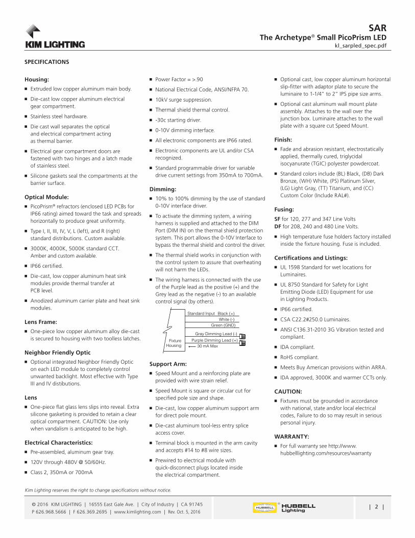
| 2 |
SARThe Archetype® Small PicoPrism LED
kl_sarpled_spec.pdf
Kim Lighting reserves the right to change specifications without notice.
© 2016 KIM LIGHTING | 16555 East Gale Ave. | City of Industry | CA 91745
P 626.968.5666 | F 626.369.2695 | www.kimlighting.com | Rev. Oct. 5, 2016
Housing:�■ Extruded low copper aluminum main body.
�■ �Die-cast low copper aluminum electrical gear compartment.
�■ Stainless steel hardware.
�■ Die cast wall separates the optical and electrical compartment acting as thermal barrier.
�■ �Electrical gear compartment doors are fastened with two hinges and a latch made of stainless steel.
�■ Silicone gaskets seal the compartments at the barrier surface.
Optical Module: �■ PicoPrism® refractors (enclosed LED PCBs for
IP66 rating) aimed toward the task and spreads horizontally to produce great uniformity.
�■ Type I, II, III, IV, V, L (left), and R (right) standard distributions. Custom available.
�■ 3000K, 4000K, 5000K standard CCT. Amber and custom available.
�■ IP66 certified.
�■ Die-cast, low copper aluminum heat sink modules provide thermal transfer at PCB level.
�■ Anodized aluminum carrier plate and heat sink modules.
Lens Frame:�■ �One-piece low copper aluminum alloy die-cast
is secured to housing with two toolless latches.
Neighbor Friendly Optic�■ Optional integrated Neighbor Friendly Optic
on each LED module to completely control unwanted backlight. Most effective with Type III and IV distibutions.
Lens�■ One-piece flat glass lens slips into reveal. Extra
silicone gasketing is provided to retain a clear optical compartment. CAUTION: Use only when vandalism is anticipated to be high.
Electrical Characteristics: �■ �Pre-assembled, aluminum gear tray.
�■ �120V through 480V @ 50/60Hz.
�■ Class 2, 350mA or 700mA
�■ �Power Factor = >.90
�■ �National Electrical Code, ANSI/NFPA 70.
�■ 10kV surge suppression.
�■ � Thermal shield thermal control.
�■ � -30c starting driver.
�■ 0-10V dimming interface.
�■ All electronic components are IP66 rated.
�■ �Electronic components are UL and/or CSA recognized.
�■ Standard programmable driver for variable drive current settings from 350mA to 700mA.
Dimming: �■ 10% to 100% dimming by the use of standard
0-10V interface driver.
�■ �To activate the dimming system, a wiring harness is supplied and attached to the DIM Port (DIM IN) on the thermal shield protection system. This port allows the 0-10V Interface to bypass the thermal shield and control the driver.
�■ The thermal shield works in conjunction with the control system to assure that overheating will not harm the LEDs.
�■ �The wiring harness is connected with the use of the Purple lead as the positive (+) and the Grey lead as the negative (-) to an available control signal (by others).
Support Arm: �■ Speed Mount and a reinforcing plate are
provided with wire strain relief.
�■ Speed Mount is square or circular cut for specified pole size and shape.
�■ �Die-cast, low copper aluminum support arm for direct pole mount.
�■ �Die-cast aluminum tool-less entry splice access cover.
�■ Terminal block is mounted in the arm cavity and accepts #14 to #8 wire sizes.
�■ Prewired to electrical module with quick-disconnect plugs located inside the electrical compartment.
�■ �Optional cast, low copper aluminum horizontal slip-fitter with adaptor plate to secure the luminaire to 1-1/4” to 2” IPS pipe size arms.
�■ Optional cast aluminum wall mount plate assembly. Attaches to the wall over the junction box. Luminaire attaches to the wall plate with a square cut Speed Mount.
Finish:�■ Fade and abrasion resistant, electrostatically
applied, thermally cured, triglycidal isocyanurate (TGIC) polyester powdercoat.
�■ �Standard colors include (BL) Black, (DB) Dark Bronze, (WH) White, (PS) Platinum Silver, (LG) Light Gray, (TT) Titanium, and (CC) Custom Color (Include RAL#).
Fusing:
SF for 120, 277 and 347 Line Volts DF for 208, 240 and 480 Line Volts.
�■ �High temperature fuse holders factory installed inside the fixture housing. Fuse is included.
Certifications and Listings:�■ UL 1598 Standard for wet locations for
Luminaires.
�■ UL 8750 Standard for Safety for Light Emitting Diode (LED) Equipment for use in Lighting Products.
�■ IP66 certified.
�■ CSA C22.2#250.0 Luminaires.
�■ ANSI C136.31-2010 3G Vibration tested and compliant.
�■ IDA compliant.
�■ RoHS compliant.
�■ Meets Buy American provisions within ARRA.
�■ IDA approved, 3000K and warmer CCTs only.
CAUTION: �■ Fixtures must be grounded in accordance
with national, state and/or local electrical codes, Failure to do so may result in serious personal injury.
WARRANTY: �■ For full warranty see http://www.
hubbelllighting.com/resources/warranty
SPECIFICATIONS
FixtureHousing 30 mA Max
Gray Dimming Lead (-)
Standard Input Black (+)White (-)
Green (GND)
Purple Dimming Lead (+)
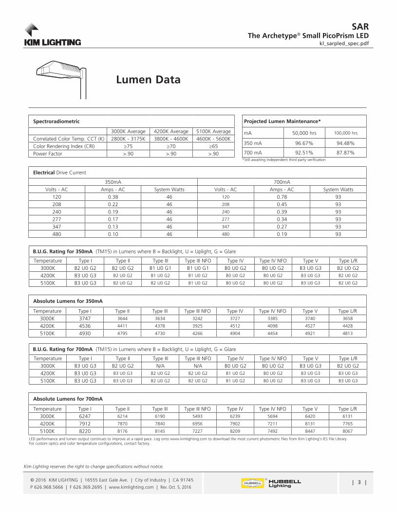
| 3 |
SARThe Archetype® Small PicoPrism LED
kl_sarpled_spec.pdf
Kim Lighting reserves the right to change specifications without notice.
© 2016 KIM LIGHTING | 16555 East Gale Ave. | City of Industry | CA 91745
P 626.968.5666 | F 626.369.2695 | www.kimlighting.com | Rev. Oct. 5, 2016
Lumen Data
Absolute Lumens for 350mA
Temperature Type I Type II Type III Type III NFO Type IV Type IV NFO Type V Type L/R3000K 3747 3644 3634 3242 3727 3385 3740 3658
4200K 4536 4411 4378 3925 4512 4098 4527 4428
5100K 4930 4795 4730 4266 4904 4454 4921 4813
Absolute Lumens for 700mA
Temperature Type I Type II Type III Type III NFO Type IV Type IV NFO Type V Type L/R3000K 6247 6214 6190 5493 6239 5694 6420 6131
4200K 7912 7870 7840 6956 7902 7211 8131 7765
5100K 8220 8176 8145 7227 8209 7492 8447 8067
B.U.G. Rating for 350mA (TM15) in Lumens where B = Backlight, U = Uplight, G = Glare
Temperature Type I Type II Type III Type III NFO Type IV Type IV NFO Type V Type L/R3000K B2 U0 G2 B2 U0 G2 B1 U0 G1 B1 U0 G1 B0 U0 G2 B0 U0 G2 B3 U0 G3 B2 U0 G24200K B3 U0 G3 B2 U0 G2 B1 U0 G2 B1 U0 G2 B0 U0 G2 B0 U0 G2 B3 U0 G3 B2 U0 G2
5100K B3 U0 G3 B2 U0 G2 B2 U0 G2 B1 U0 G2 B0 U0 G2 B0 U0 G2 B3 U0 G3 B2 U0 G2
B.U.G. Rating for 700mA (TM15) in Lumens where B = Backlight, U = Uplight, G = Glare Temperature Type I Type II Type III Type III NFO Type IV Type IV NFO Type V Type L/R
3000K B3 U0 G3 B2 U0 G2 N/A N/A B0 U0 G2 B0 U0 G2 B3 U0 G3 B2 U0 G24200K B3 U0 G3 B3 U0 G3 B2 U0 G2 B2 U0 G2 B1 U0 G2 B0 U0 G2 B3 U0 G3 B3 U0 G3
5100K B3 U0 G3 B3 U0 G3 B2 U0 G2 B2 U0 G2 B1 U0 G2 B0 U0 G2 B3 U0 G3 B3 U0 G3
Electrical Drive Current
350mA 700mAVolts - AC Amps - AC System Watts Volts - AC Amps - AC System Watts
120 0.38 46 120 0.78 93208 0.22 46 208 0.45 93240 0.19 46 240 0.39 93277 0.17 46 277 0.34 93347 0.13 46 347 0.27 93480 0.10 46 480 0.19 93
LED performance and lumen output continues to improve at a rapid pace. Log onto www.kimlighting.com to download the most current photometric files from Kim Lighting’s IES File Library. For custom optics and color temperature configurations, contact factory.
Spectroradiometric
3000K Average 4200K Average 5100K Average Correlated Color Temp. CCT (K) 2800K - 3175K 3800K - 4600K 4600K - 5600K Color Rendering Index (CRI) ≥75 ≥70 ≥65 Power Factor >.90 >.90 >.90
Projected Lumen Maintenance*
mA 50,000 hrs 100,000 hrs
350 mA 96.67% 94.48%
700 mA 92.51% 87.87%*Still awaiting independent third party verification
leeba
Typewritten Text
S7 S8 S8N S9 S9N S10
leeba
Rectangle
leeba
Rectangle
leeba
Typewritten Text
S7 S8 S8N S9 S9N S10
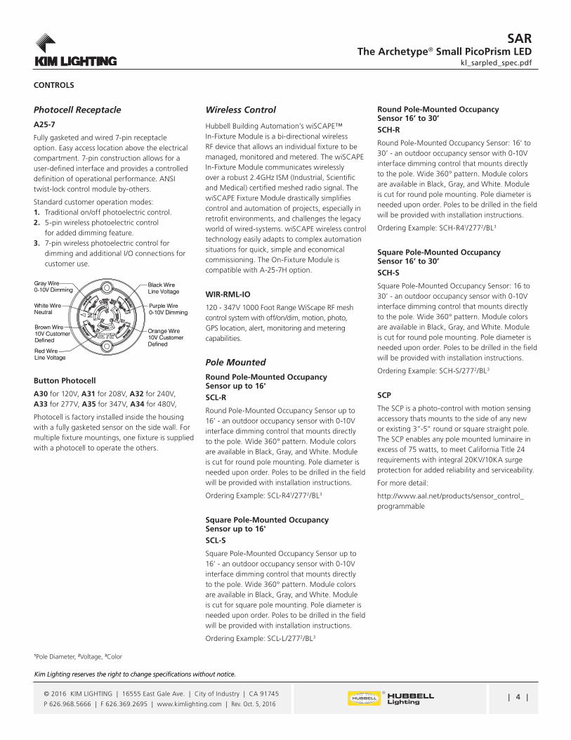
| 4 |
SARThe Archetype® Small PicoPrism LED
kl_sarpled_spec.pdf
Kim Lighting reserves the right to change specifications without notice.
© 2016 KIM LIGHTING | 16555 East Gale Ave. | City of Industry | CA 91745
P 626.968.5666 | F 626.369.2695 | www.kimlighting.com | Rev. Oct. 5, 2016
Kim Lighting reserves the right to change specifications without notice.
1Pole Diameter, 2Voltage, 3Color
Gray Wire0-10V Dimming
Purple Wire0-10V Dimming
Orange Wire10V CustomerDefined
Red WireLine Voltage
Brown Wire10V CustomerDefined
Black WireLine Voltage
White WireNeutral
CONTROLS
Photocell Receptacle
A25-7
Fully gasketed and wired 7-pin receptacle option. Easy access location above the electrical compartment. 7-pin construction allows for a user-defined interface and provides a controlled definition of operational performance. ANSI twist-lock control module by-others.
Standard customer operation modes: 1. Traditional on/off photoelectric control. 2. 5-pin wireless photoelectric control for added dimming feature. 3. 7-pin wireless photoelectric control for dimming and additional I/O connections for customer use.
Button Photocell
A30 for 120V, A31 for 208V, A32 for 240V, A33 for 277V, A35 for 347V, A34 for 480V,
Photocell is factory installed inside the housing with a fully gasketed sensor on the side wall. For multiple fixture mountings, one fixture is supplied with a photocell to operate the others.
Wireless Control
Hubbell Building Automation’s wiSCAPE™ In-Fixture Module is a bi-directional wireless RF device that allows an individual fixture to be managed, monitored and metered. The wiSCAPE In-Fixture Module communicates wirelessly over a robust 2.4GHz ISM (Industrial, Scientific and Medical) certified meshed radio signal. The wiSCAPE Fixture Module drastically simplifies control and automation of projects, especially in retrofit environments, and challenges the legacy world of wired-systems. wiSCAPE wireless control technology easily adapts to complex automation situations for quick, simple and economical commissioning. The On-Fixture Module is compatible with A-25-7H option.
WIR-RML-IO
120 - 347V 1000 Foot Range WiScape RF mesh control system with off/on/dim, motion, photo, GPS location, alert, monitoring and metering capabilities.
Pole Mounted
Round Pole-Mounted Occupancy Sensor up to 16'SCL-R
Round Pole-Mounted Occupancy Sensor up to 16’ - an outdoor occupancy sensor with 0-10V interface dimming control that mounts directly to the pole. Wide 360° pattern. Module colors are available in Black, Gray, and White. Module is cut for round pole mounting. Pole diameter is needed upon order. Poles to be drilled in the field will be provided with installation instructions.
Ordering Example: SCL-R41/2772/BL3
Square Pole-Mounted Occupancy Sensor up to 16'SCL-S
Square Pole-Mounted Occupancy Sensor up to 16’ - an outdoor occupancy sensor with 0-10V interface dimming control that mounts directly to the pole. Wide 360° pattern. Module colors are available in Black, Gray, and White. Module is cut for square pole mounting. Pole diameter is needed upon order. Poles to be drilled in the field will be provided with installation instructions.
Ordering Example: SCL-L/2772/BL3
Round Pole-Mounted Occupancy Sensor 16’ to 30’SCH-R
Round Pole-Mounted Occupancy Sensor: 16' to 30’ - an outdoor occupancy sensor with 0-10V interface dimming control that mounts directly to the pole. Wide 360° pattern. Module colors are available in Black, Gray, and White. Module is cut for round pole mounting. Pole diameter is needed upon order. Poles to be drilled in the field will be provided with installation instructions.
Ordering Example: SCH-R41/2772/BL3
Square Pole-Mounted Occupancy Sensor 16’ to 30’SCH-S
Square Pole-Mounted Occupancy Sensor: 16 to 30’ - an outdoor occupancy sensor with 0-10V interface dimming control that mounts directly to the pole. Wide 360° pattern. Module colors are available in Black, Gray, and White. Module is cut for round pole mounting. Pole diameter is needed upon order. Poles to be drilled in the field will be provided with installation instructions.
Ordering Example: SCH-S/2772/BL3
SCP
The SCP is a photo-control with motion sensing accessory thats mounts to the side of any new or existing 3”-5” round or square straight pole. The SCP enables any pole mounted luminaire in excess of 75 watts, to meet California Title 24 requirements with integral 20KV/10KA surge protection for added reliability and serviceability.
For more detail:
http://www.aal.net/products/sensor_control_programmable
Gray Wire0-10V Dimming
Purple Wire0-10V Dimming
Orange Wire10V CustomerDefined
Red WireLine Voltage
Brown Wire10V CustomerDefined
Black WireLine Voltage
White WireNeutral
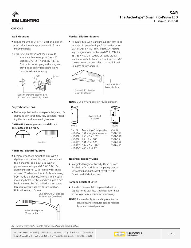
| 5 |
Kim Lighting reserves the right to change specifications without notice.
SARThe Archetype® Small PicoPrism LED
kl_sarpled_spec.pdf
© 2016 KIM LIGHTING | 16555 East Gale Ave. | City of Industry | CA 91745
P 626.968.5666 | F 626.369.2695 | www.kimlighting.com | Rev. Oct. 5, 2016
Wall Mounting:
�■ �Fixture mounts to 3" or 4" junction boxes by a cast aluminum adapter plate with fixture mounting bolts.
NOTE: Junction box in wall must provide adequate fixture support. See NEC sections 370-13, 17 and 410-14, 16. Quick-disconnect plug and wiring are provided to allow field connections prior to fixture mounting.
Polycarbonate Lens:
�■ Fixture supplied with a one-piece flat, clear, UV stabilized polycarbonate, fully gasketed, replac-ing the standard tempered glass lens.
CAUTION: Use only when vandalism is anticipated to be high.
Horizontal Slipfitter Mount:
�■ Replaces standard mounting arm with a slipfitter which allows fixture to be mounted to a horizontal pole davit-arm with 2" pipe-size mounting end (2 3/8" O.D.). Cast aluminum slipfitter with set screw for an up or down 5° adjustment lock. Bolts to housing from inside the electrical compartment using mounting holes for the standard support arm. Davit-arm must be field drilled at a set screw location to insure against fixture rotation. Finished to match fixture.
Vertical Slipfitter Mount:
�■ Allows fixture with standard support arm to be mounted to poles having a 2" pipe-size tenon (2 3/8" O.D. x 4 1/2" min. length). All mount-ing configurations can be used (1SA, 2SB, 2SL, 3ST, 3SY, 4SC). 4" square or round die-cast aluminum with flush cap, secured by four 3/8" stainless steel set point allen screws, finished to match fixture and arm.
NOTE: 3SY only available on round slipfitter.
Neighbor Friendly Optic
�■ Integrated Neighbor Friendly Optic on each PicoEmitter™ module to completely control unwanted backlight. Most effective with Type III and IV distibutions.
Tamper-Resistant Latch
�■ Standard die-cast latch is provided with a captive 10-32 stainless steel flat socket-head screw to prevent unauthorized opening.
NOTE: Required only for vandal protection in locationswhere fixtures can be reached by unauthorized persons.
OPTIONS
Flat Glass
Davit-arm with 2" pipe-size fixture mount (by others)
Horizontal Slipfitter Mount by Kim
Vertical Slipfitter Mount by Kim
Pole with 2" pipe-size tenon (by others)
stainless steel set screws
Round Square
Cat. No.VSF-1SAVSF-2SBVSF-2SLVSF-3ST VSF-3SYVSF-4SC
Cat. No.SVSF-1SASVSF-2SBSVSF-2SLSVSF-3STSVSF-4SC
Mounting Configuration1SA - single arm mount2SB - 2 at 180°2SL - 2 at 90°3ST - 2 at 90°3SY - 2 at 120°4SC - 2 at 90°
11/16"
43/4"
J-box
Wall mount using adapter plate 3" or 4" J-box in wall (by others)

leeba
Rectangle
leeba
Rectangle
leeba
Rectangle
leeba
Typewritten Text
BUG Rating: B2-U0-G2
leeba
Typewritten Text
S7 Photometric Graphs
leeba
Typewritten Text
S8 Photometric Graphs
leeba
Typewritten Text
S8N Photometric Graphs
leeba
Typewritten Text
BUG Rating: B1-U0-G1
leeba
Typewritten Text
BUG Rating: B1-U0-G1
leeba
Image
leeba
Image
leeba
Image
leeba
Image
leeba
Image
leeba
Image
leeba
Image
leeba
Image
leeba
Image

leeba
Rectangle
leeba
Rectangle
leeba
Rectangle
leeba
Typewritten Text
BUG Rating: B0-U0-G2
leeba
Typewritten Text
S9 Photometric Graphs
leeba
Typewritten Text
S9N Photometric Graphs
leeba
Typewritten Text
S10 Photometric Graphs
leeba
Typewritten Text
BUG Rating: B0-U0-G2
leeba
Typewritten Text
BUG Rating: B3-U0-G3
leeba
Image
leeba
Image
leeba
Image
leeba
Image
leeba
Image
leeba
Image
leeba
Image
leeba
Image
leeba
Image
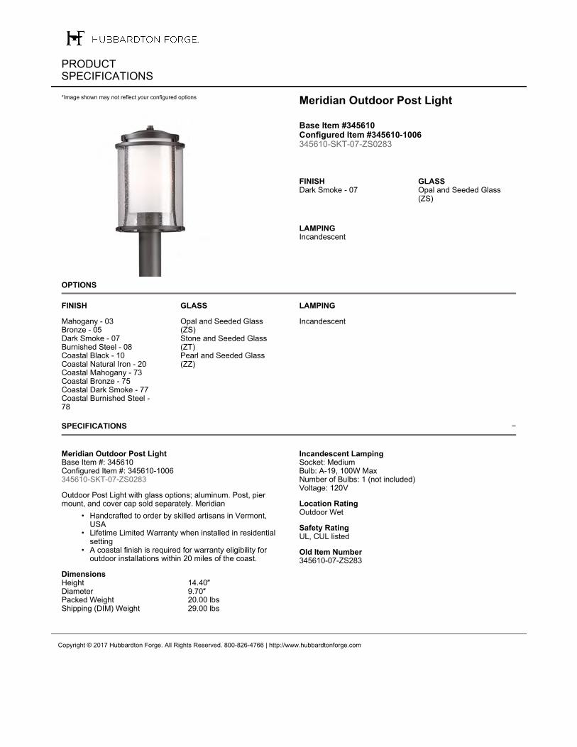
−
OPTIONS
SPECIFICATIONS
Copyright © 2017 Hubbardton Forge. All Rights Reserved. 800-826-4766 | http://www.hubbardtonforge.com
PRODUCT SPECIFICATIONS
Meridian Outdoor Post Light
Base Item #345610 Configured Item #345610-1006 345610-SKT-07-ZS0283
FINISHDark Smoke - 07
GLASSOpal and Seeded Glass (ZS)
LAMPINGIncandescent
*Image shown may not reflect your configured options
FINISH
Mahogany - 03Bronze - 05Dark Smoke - 07Burnished Steel - 08Coastal Black - 10Coastal Natural Iron - 20Coastal Mahogany - 73Coastal Bronze - 75Coastal Dark Smoke - 77Coastal Burnished Steel - 78
GLASS
Opal and Seeded Glass (ZS)Stone and Seeded Glass (ZT)Pearl and Seeded Glass (ZZ)
LAMPING
Incandescent
Meridian Outdoor Post LightBase Item #: 345610Configured Item #: 345610-1006345610-SKT-07-ZS0283
Outdoor Post Light with glass options; aluminum. Post, pier mount, and cover cap sold separately. Meridian
• Handcrafted to order by skilled artisans in Vermont, USA
• Lifetime Limited Warranty when installed in residential setting
• A coastal finish is required for warranty eligibility for outdoor installations within 20 miles of the coast.
DimensionsHeight 14.40″Diameter 9.70″Packed Weight 20.00 lbsShipping (DIM) Weight 29.00 lbs
Incandescent Lamping Socket: MediumBulb: A-19, 100W MaxNumber of Bulbs: 1 (not included)Voltage: 120V
Location RatingOutdoor Wet
Safety RatingUL, CUL listed
Old Item Number345610-07-ZS283
leeba
Text Box
IMEG ENGINEERING | PROJ# 16.0011.00 MAINE VETERANS HOME / AUGUSTA S11, TYPICAL
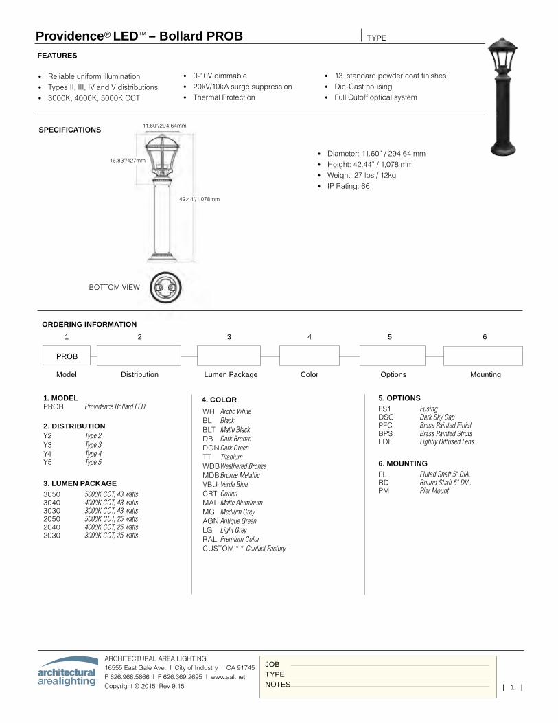
| 1 |
Providence® LED™ – Bollard PROB
ARCHITECTURAL AREA LIGHTING16555 East Gale Ave. | City of Industry | CA 91745P 626.968.5666 | F 626.369.2695 | www.aal.net Copyright © 2015 Rev 9.15
TYPE
JOBTYPENOTES
SPECIFICATIONS
FEATURES
• Diameter: 11.60” / 294.64 mm• Height: 42.44” / 1,078 mm• Weight: 27 lbs / 12kg• IP Rating: 66
• Reliable uniform illumination• Types II, III, IV and V distributions• 3000K, 4000K, 5000K CCT
• 0-10V dimmable• 20kV/10kA surge suppression• Thermal Protection
• 13 standard powder coat finishes• Die-Cast housing• Full Cutoff optical system
Bottom View
BOTTOM VIEW
16.83"/427mm
42.44"/1,078mm
11.60"/294.64mm
Model Distribution Lumen Package Color Options Mounting
4. COLOR
WH Arctic White BL Black BLT Matte Black DB Dark Bronze DGN Dark Green TT Titanium WDB Weathered Bronze MDB Bronze Metallic VBU Verde Blue CRT Corten MAL Matte Aluminum MG Medium Grey AGN Antique Green LG Light Grey RAL Premium Color CUSTOM * * Contact Factory
5. OPTIONSFS1 Fusing DSC Dark Sky Cap PFC Brass Painted Finial BPS Brass Painted Struts LDL Lightly Diffused Lens
6. MOUNTINGFL Fluted Shaft 5" DIA. RD Round Shaft 5" DIA. PM Pier Mount
ORDERING INFORMATION
PROB
1 2 3 4 5 6
1. MODELPROB Providence Bollard LED
2. DISTRIBUTIONY2 Type 2 Y3 Type 3 Y4 Type 4 Y5 Type 5
3. LUMEN PACKAGE3050 5000K CCT, 43 watts 3040 4000K CCT, 43 watts 3030 3000K CCT, 43 watts 2050 5000K CCT, 25 watts 2040 4000K CCT, 25 watts 2030 3000K CCT, 25 watts
leeba
Text Box
IMEG ENGINEERING | PROJ# 16.0011.00 MAINE VETERANS HOME / AUGUSTA S12,S13
leeba
Typewritten Text
S12 S13
leeba
Rectangle
leeba
Line
leeba
Rectangle

| 2 |
Providence® LED™ – Bollard PROB
ARCHITECTURAL AREA LIGHTING16555 East Gale Ave. | City of Industry | CA 91745P 626.968.5666 | F 626.369.2695 | www.aal.net Copyright © 2015 Rev 9.15
TYPE
JOBTYPENOTES
LUMINAIRE PERFORMANCE
ELECTRICAL CHARACTERISTICS
ConfigurationiDriver Inrush Current Dimming
LED Drive mA
System Watts
Line Voltage Amps AC Min. Power Factor
Max THD (%)
Operating Temp. Range
120V 277V Dimming Range
Source/Sink
CurrentOrdering Code Ipeak (A) Ipeak (A)VAC HZ 120 2773050
3000 series 400 42
120-277 50/60
0.35 0.15
≥.9 20-40°C To +55°C
21 160 µS 49 160 µS10% TO 100%
1mA
304030202050
2000 series 255 25 0.21 0.0920402020
WIRING LEADS
Luminaires shall be provided with 0-10 purple and gray dimming leads.
TM-21 LIFETIME CALCULATION
Optical System Ordering Code Ambient Environment °CProjected Lumen Maintenance (% vs. Khrs)
Reported L7015 25 50 TM-21* 60 100
MicroCore 32LED15 100% 99% 99% 98% 97%
>96Khrs25 99% 99% 98 97% 95%40 98% 97% 94% 93% 89%
LED COLOR
Consult factory for Amber, Turtle Friendly, Gulf Coast and Observatory applications.
Ordering Code3K 4K 5K
CCT Average 3000K 4000K 5000KCRI Minimum 70 70 70
S/P Ratio 1.2 1.5 1.8
Light Engine
Lensing Distribution
Ordering Code
Average System Watts
Ordering Code
5000K CCT 4000K CCT 3000K CCT
Delivered Lumens
Efficacy (Lm/W)
BUG Rating Delivered Lumens
Efficafcy (Lm/W)
BUG Rating Delivered Lumens
Efficafcy (Lm/W)
BUG RatingB U G B U G B U G
3050 3040 3030
3000 Series
Clear Lens (Standard)
TYPE 2 Y2 3238 75 1 0 1 3247 76 1 0 1 2975 69 1 0 1
43
TYPE 3 Y3 3261 75 1 0 1 3270 76 1 0 1 3038 70 1 1 1TYPE 4 Y4 3253 75 1 0 1 3262 76 1 0 1 2988 69 1 0 1TYPE 5 Y5 3148 73 2 0 1 3157 73 2 0 1 2892 67 2 0 1
Lightly Diffused Lens
TYPE 2 Y2...LDL 2386 56 1 1 1 2342 54 1 1 1 2092 49 1 1 1TYPE 3 Y3...LDL 2385 57 1 1 1 2341 56 1 1 1 2091 50 1 1 1TYPE 4 Y4...LDL 2295 53 1 2 1 2252 52 1 2 1 2012 47 1 2 1TYPE 5 Y5...LDL 2234 52 1 1 1 2193 51 1 1 1 1959 46 1 1 1
2050 2040 2030
2000 Series
Clear Lens (Standard)
TYPE 2 Y2 1951 78 1 0 1 1957 78 1 0 1 1792 71 1 0 1
25
TYPE 3 Y3 1958 78 1 0 1 1970 78 1 0 1 1830 73 1 0 1TYPE 4 Y4 1960 78 1 0 1 1957 78 1 0 1 1793 71 1 0 1TYPE 5 Y5 1889 76 1 0 1 1894 76 1 0 1 1735 69 1 0 1
Lightly Diffused Lens
TYPE 2 Y2...LDL 1387 56 1 1 1 1361 54 1 1 1 1216 49 1 1 1TYPE 3 Y3...LDL 1386 57 1 1 1 1361 56 1 1 1 1216 50 1 1 1TYPE 4 Y4...LDL 1334 53 1 2 1 1309 52 1 2 1 1170 47 1 2 1TYPE 5 Y5...LDL 1299 52 1 1 1 1275 51 1 1 1 1139 46 1 1 1
leeba
Rectangle
leeba
Line
leeba
Typewritten Text
S12 S13
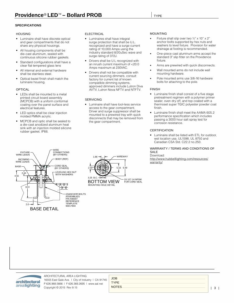
| 3 |
Providence® LED™ – Bollard PROB
ARCHITECTURAL AREA LIGHTING16555 East Gale Ave. | City of Industry | CA 91745P 626.968.5666 | F 626.369.2695 | www.aal.net Copyright © 2015 Rev 9.15
TYPE
JOBTYPENOTES
SPECIFICATIONS
HOUSING
• Luminaire shall have discrete optical and gear compartments that do not share any physical housings.
• All housing components shall be die-cast aluminum, sealed with continuous silicone rubber gaskets.
• Standard configurations shall have a clear flat tempered glass lens
• All internal and external hardware shall be stainless steel.
• Optical bezel finish shall match the luminaire housing.
OPTICAL
• LEDs shall be mounted to a metal printed circuit board assembly (MCPCB) with a uniform conformal coating over the panel surface and electrical features.
• LED optics shall be clear injection molded PMMA acrylic.
• MCPCB and optic shall be sealed to a die-cast anodized aluminum heat sink with an injection molded silicone rubber gasket. IP66.
ELECTRICAL
• Luminaires shall have integral surge protection that shall be U.L. recognized and have a surge current rating of 10,000 Amps using the industry standard 8/20uSec wave and surge rating of 372J.
• Drivers shall be U.L recognized with an inrush current maximum of <20.0 Amps maximum at 230VAC.
• Drivers shall not be compatible with current sourcing dimmers, consult factory for current list of known compatible dimming systems, approved dimmers include Lutron Diva AVTV, Lutron Nova NFTV and NTFTV.
SERVICING
• Luminaire shall have tool-less service access to the gear compartment. Driver and surge suppressor shall be mounted to a prewired tray with quick disconnects that may be removed from the gear compartment.
MOUNTING
• Fixture shall slip over two ½” x 10” x 2” anchor bolts supported by hex nuts and washers to level fixture. Provision for water drainage at footing is recommended.
• One-piece cast aluminum arms accept the standard 3" slip fitter on the Providence fixture.
• Arms are prewired with quick disconnects.
• Wall mounted arms do not include wall mounting hardware.
• Pole mounted arms use 3/8-16 hardware bolts for attaching to the pole.
FINISH
• Luminaire finish shall consist of a five stage pretreatment regimen with a polymer primer sealer, oven dry off, and top coated with a thermoset super TGIC polyester powder coat finish.
• Luminaire finish shall meet the AAMA 605.2 performance specification which includes passing a 3000 hour salt spray test for corrosion resistance.
CERTIFICATION
• Luminaire shall be listed with ETL for outdoor, wet location use, UL1598, UL 8750 and Canadian CSA Std. C22.2 no.250.
WARRANTY / TERMS AND CONDITIONS OF SALE Download: http://www.hubbelllighting.com/resources/warranty/
BASE DETAIL
BODY (REF)
LEVELING HEX NUTWITH WASHERS
FIXTUREWIRE LEADS
INCOMINGWIRE LEADS
WIRE CONNECTIONS(BY OTHERS)
WIREWAY
BASE
(2)ANCHOR BOLTSASSEMBLIESP/N A90007REFERENCETEMPLATE93017904
MOUNTING HOLE DETAIL
CORD SEAL(BY OTHERS)
BOTTOM VIEW
1.86
9.495.162.00
2X 1/2"-14 NPSMFOR CORD SEAL
3.25 B.C.4.92
2.44
10.0
2.0
leeba
Rectangle
leeba
Image
leeba
Image
leeba
Image
leeba
Typewritten Text
BUG Rating: B1-U0-G1
leeba
Image
leeba
Image
leeba
Image
leeba
Typewritten Text
S12 Photometric Graphs
leeba
Typewritten Text
S13 Photometric Graphs
leeba
Typewritten Text
BUG Rating: B1-U0-G1
City of Augusta Major Development Review and Conditional Use Application MVH Augusta CLC Attachment 2
ATTACHMENT 2
PROJECT SIGN AND ARCHITECTURAL RENDERINGS

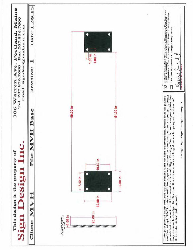
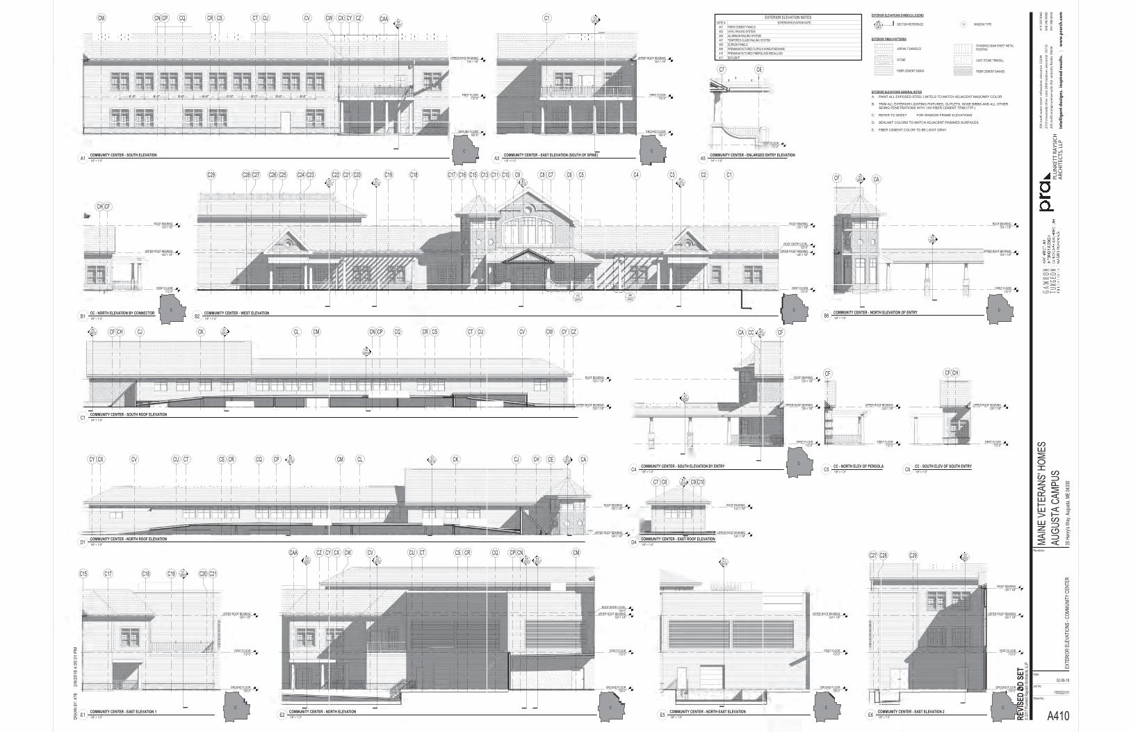
EXTERIOR FINISH PATTERNS
ASPHALT SHINGLES
STONE
FIBER CEMENT SIDING
STANDING SEAM SHEET METAL ROOFING
CAST STONE TRIM/SILL
FIBER CEMENT SHAKES
EXTERIOR ELEVATIONS GENERAL NOTES
EXTERIOR ELEVATIONS SYMBOLS LEGEND
SECTION REFERENCE WINDOW TYPE1iDTLSHT
PAINT ALL EXPOSED STEEL LINTELS TO MATCH ADJACENT MASONRY COLOR
TRIM ALL EXTERIOR LIGHTING FIXTURES, OUTLETS, HOSE BIBBS AND ALL OTHER SIDING PENETRATIONS WITH 1X4 FIBER CEMENT TRIM (TYP.)
REFER TO SHEET FOR WINDOW FRAME ELEVATIONS
SEALANT COLORS TO MATCH ADJACENT FINISHED SURFACES.
FIBER CEMENT COLOR TO BE LIGHT GRAY.
A.
B.
C.
D.
E.
FIRST FLOOR112'-0"
B1A510
ROOF BEARING133'-1 1/8"
C3A510
A1A511
C1C2C3C4C5C6C7C10C11C13C15C16C17C18C19C20C21C22C23C24C25C26C27C28C29 C8C9E1
A510
UPPER ROOF BEARING124'-1 1/8"
ROOF ENTRY LEVEL125'-0"
A410A5
A522B6
FIRST FLOOR112'-0"
GROUND FLOOR100'-0"
CM CN CP CQ CR CS CT CU CV CW CZ CAACX CYE6
A521
8'-0"8'-0"8'-0"8'-0"8'-0"8'-0"8'-0"8'-0"
UPPER ROOF BEARING124'-1 1/8"
FIRST FLOOR112'-0"
GROUND FLOOR100'-0"
C3A510
C1
UPPER ROOF BEARING124'-1 1/8"
FIRST FLOOR112'-0"
GROUND FLOOR100'-0"
ROOF BEARING133'-1 1/8"
C27 C28 C29 E5A521
UPPER ROOF BEARING124'-1 1/8"
FIRST FLOOR112'-0"
GROUND FLOOR100'-0"
E3A521
E4A521
CMCNCPCQCRCSCTCUCVCWCZCAA CXCYE6
A510
UPPER ROOF BEARING124'-1 1/8"
C2A510
ROOF ENTRY LEVEL125'-0"
FIRST FLOOR112'-0"
GROUND FLOOR100'-0"
C1A510
UPPER ROOF BEARING124'-1 1/8"
FIRST FLOOR112'-0"
GROUND FLOOR100'-0"
C15 C17 C18 C19 C20 C21E1A510
UPPER ROOF BEARING124'-1 1/8"
FIRST FLOOR112'-0"
ROOF BEARING133'-1 1/8"
CFCH
UPPER ROOF BEARING124'-1 1/8"
FIRST FLOOR112'-0"
ROOF BEARING133'-1 1/8"
CACF E5A510
UPPER ROOF BEARING124'-1 1/8"
A3A520
FIRST FLOOR112'-0"
ROOF BEARING133'-1 1/8"
CA CC CFE5A510
UPPER ROOF BEARING124'-1 1/8"
A3A520
FIRST FLOOR112'-0"
CF
UPPER ROOF BEARING124'-1 1/8"
FIRST FLOOR112'-0"
CF CH
UPPER ROOF BEARING124'-1 1/8"
A1A510
ROOF BEARING133'-1 1/8"
CF CH CJ CK CL CM CN CP CQ CR CS CT CU CV CW CZCYE5A510
E6A510
UPPER ROOF BEARING124'-1 1/8"
A1A510
ROOF BEARING133'-1 1/8"
CACECHCJCKCLCMCPCQCRCSCTCUCVCXCY E5A510
E6A510
UPPER ROOF BEARING124'-1 1/8"
B1A510
ROOF BEARING133'-1 1/8"
C7 C10C8 C9
UPPER ROOF BEARING124'-1 1/8"
FIRST FLOOR112'-0"
C6C7
Sheet No.:
Job No:
Date:
Revisions:
REVI
SED
DD S
ET
2/8/
2018
4:0
5:31
PM
150322-01
A410
AUGU
STA
CAMP
US35
Hen
ry's W
ay, A
ugus
ta, M
E 04
330
DRAW
N BY
: KTB
EXTE
RIOR
ELE
VATI
ONS
-COM
MUNI
TY C
ENTE
R
02-06-18
MAIN
E VE
TERA
NS' H
OMES
© 20
17 P
lunke
tt Ray
sich A
rchite
cts, L
LP
EXTERIOR ELEVATION NOTESNOTE # EXTERIOR ELEVATION NOTE
401 FIBER CEMENT PANELS402 VINYL RAILING SYSTEM406 ALUMINUM RAILING SYSTEM407 TEMPERED GLASS RAILING SYSTEM408 SCREEN PANELS409 PREMANUFACTURED CUPOLA W/WEATHERVANE410 PREMANUFACTURED FIBERGLASS MEDALLION411 SKYLIGHT
1/8" = 1'-0"B2COMMUNITY CENTER - WEST ELEVATION
1/8" = 1'-0"A1COMMUNITY CENTER - SOUTH ELEVATION
1/8" = 1'-0"A3COMMUNITY CENTER - EAST ELEVATION (SOUTH OF SPINE)
1/8" = 1'-0"E6COMMUNITY CENTER - EAST ELEVATION 2
1/8" = 1'-0"E2COMMUNITY CENTER - NORTH ELEVATION
1/8" = 1'-0"E5COMMUNITY CENTER - NORTH EAST ELEVATION
1/8" = 1'-0"E1COMMUNITY CENTER - EAST ELEVATION 1
1/8" = 1'-0"B1CC - NORTH ELEVATION BY CONNECTOR
1/8" = 1'-0"B6COMMUNITY CENTER - NORTH ELEVATION OF ENTRY
1/8" = 1'-0"C4COMMUNITY CENTER - SOUTH ELEVATION BY ENTRY
1/8" = 1'-0"C5CC - NORTH ELEV OF PERGOLA
1/8" = 1'-0"C6CC - SOUTH ELEV OF SOUTH ENTRY
1/8" = 1'-0"C1COMMUNITY CENTER - SOUTH ROOF ELEVATION
1/8" = 1'-0"D1COMMUNITY CENTER - NORTH ROOF ELEVATION
1/8" = 1'-0"D4COMMUNITY CENTER - EAST ROOF ELEVATION
C C C C
C C
C C C
C
1/4" = 1'-0"A5COMMUNITY CENTER - ENLARGED ENTRY ELEVATION
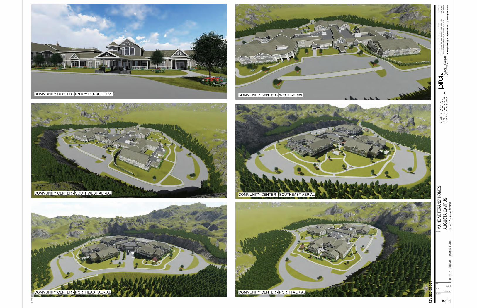
Sheet No.:
Job No:
Date:
Revisions:
REVI
SED
DD S
ET
2/8/
2018
1:3
3:41
PM
150322-01
A411
AUGU
STA
CAMP
US35
Hen
ry's W
ay, A
ugus
ta, M
E 04
330
DRAW
N BY
: KTB
EXTE
RIOR
PER
SPEC
TIVE
S -C
OMMU
NITY
CEN
TER
02-06-18
MAIN
E VE
TERA
NS' H
OMES
COMMUNITY CENTER - ENTRY PERSPECTIVE COMMUNITY CENTER - WEST AERIAL
COMMUNITY CENTER - SOUTHWEST AERIAL COMMUNITY CENTER - SOUTHEAST AERIAL
COMMUNITY CENTER - NORTH AERIALCOMMUNITY CENTER - NORTHEAST AERIAL

FIRST FLOOR112'-0"
SECOND FLOOR124'-0"
A1A510
ROOF BEARING133'-1 1/8"
409
401
FIRST FLOOR112'-0"
SECOND FLOOR124'-0"
ROOF BEARING133'-1 1/8"
401
402
402
FIRST FLOOR112'-0"
SECOND FLOOR124'-0"
ROOF BEARING133'-1 1/8"
402
FIRST FLOOR112'-0"
SECOND FLOOR124'-0"
ROOF BEARING133'-1 1/8"
402
402
410
410
FIRST FLOOR112'-0"
SECOND FLOOR124'-0"
ROOF BEARING133'-1 1/8"
D6A511
408 408 408
410
409
411411411
E6A522
FIRST FLOOR112'-0"
SECOND FLOOR124'-0"
ROOF BEARING133'-1 1/8"
408408 408
408
411
FIRST FLOOR112'-0"
SECOND FLOOR124'-0"
ROOF BEARING133'-1 1/8"
C27C28C29
ROOF ENTRY LEVEL125'-0"
402
EXTERIOR FINISH PATTERNS
ASPHALT SHINGLES
STONE
FIBER CEMENT SIDING
STANDING SEAM SHEET METAL ROOFING
CAST STONE TRIM/SILL
FIBER CEMENT SHAKES
EXTERIOR ELEVATIONS GENERAL NOTES
EXTERIOR ELEVATIONS SYMBOLS LEGEND
SECTION REFERENCE WINDOW TYPE1iDTLSHT
PAINT ALL EXPOSED STEEL LINTELS TO MATCH ADJACENT MASONRY COLOR
TRIM ALL EXTERIOR LIGHTING FIXTURES, OUTLETS, HOSE BIBBS AND ALL OTHER SIDING PENETRATIONS WITH 1X4 FIBER CEMENT TRIM (TYP.)
REFER TO SHEET FOR WINDOW FRAME ELEVATIONS
SEALANT COLORS TO MATCH ADJACENT FINISHED SURFACES.
FIBER CEMENT COLOR TO BE LIGHT GRAY.
A.
B.
C.
D.
E.
Sheet No.:
NOT F
OR C
ONST
RUCT
ION
Job No:
Date:
Revisions:
2/8/
2018
4:0
5:46
PM
150322-01
A420M
AUGU
STA
CAMP
US35
Hen
ry's W
ay, A
ugus
ta, M
E 04
330
DRAW
N BY
: Auth
or
EXTE
RIOR
ELE
VATI
ONS
-MEM
ORY
CARE
02-06-18
MAIN
E VE
TERA
NS' H
OMES
© 20
18 P
lunke
tt Ray
sich A
rchite
cts, L
LP
1/8" = 1'-0"A1MEMORY CARE - NORTH ELEVATION - COURTYARD
1/8" = 1'-0"A3MEMORY CARE - EAST ELEVATION - COURTYARD
1/8" = 1'-0"A4MEMORY CARE - SOUTH ELEVATION - COURTYARD
1/8" = 1'-0"C1MEMORY CARE - NORTH ELEVATION
1/8" = 1'-0"C3MEMORY CARE - WEST ELEVATION
1/8" = 1'-0"D1MEMORY CARE - SOUTH ELEVATION
1/8" = 1'-0"D3MEMORY CARE - CONNECTOR - WEST
EXTERIOR ELEVATION NOTESNOTE # EXTERIOR ELEVATION NOTE
401 FIBER CEMENT PANELS402 VINYL RAILING SYSTEM406 ALUMINUM RAILING SYSTEM407 TEMPERED GLASS RAILING SYSTEM408 SCREEN PANELS409 PREMANUFACTURED CUPOLA W/WEATHERVANE410 PREMANUFACTURED FIBERGLASS MEDALLION411 SKYLIGHT
M
MM
MM
M
M
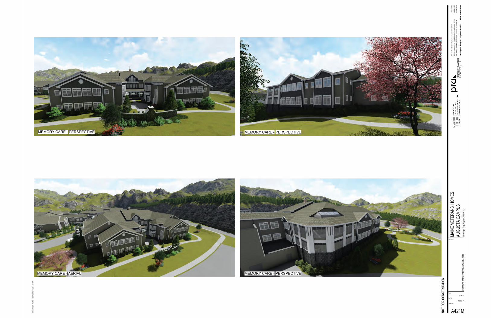
Sheet No.:
NOT F
OR C
ONST
RUCT
ION
Job No:
Date:
Revisions:
2/8/
2018
1:3
3:42
PM
150322-01
A421M
AUGU
STA
CAMP
US35
Hen
ry's W
ay, A
ugus
ta, M
E 04
330
DRAW
N BY
: Auth
or
EXTE
RIOR
PER
SPEC
TIVE
S -M
EMOR
Y CA
RE
02-06-18
MAIN
E VE
TERA
NS' H
OMES
MEMORY CARE - PERSPECTIVE MEMORY CARE - PERSPECTIVE
MEMORY CARE - PERSPECTIVEMEMORY CARE - AERIAL
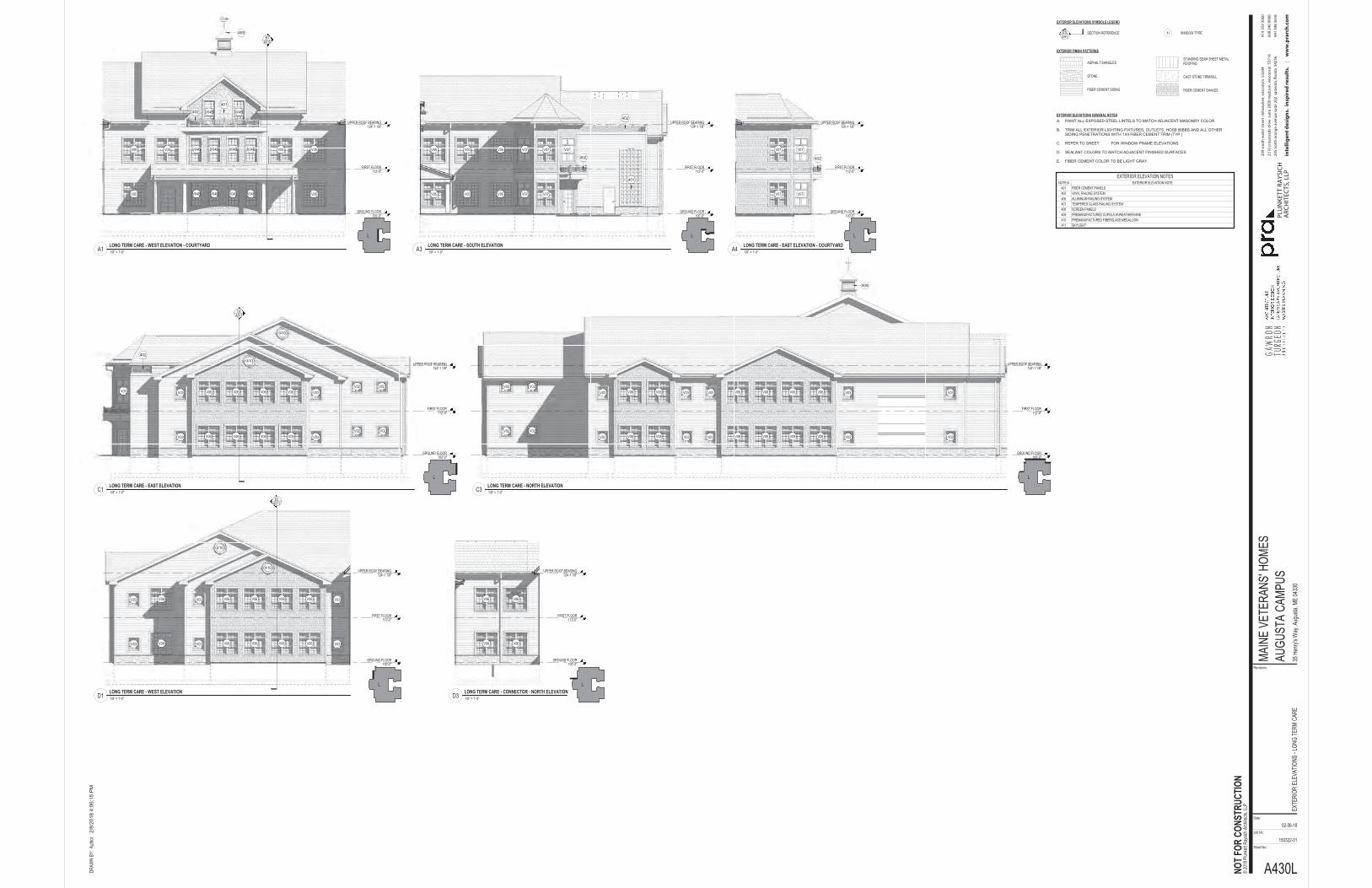
EXTERIOR FINISH PATTERNS
ASPHALT SHINGLES
STONE
FIBER CEMENT SIDING
STANDING SEAM SHEET METAL ROOFING
CAST STONE TRIM/SILL
FIBER CEMENT SHAKES
EXTERIOR ELEVATIONS GENERAL NOTES
EXTERIOR ELEVATIONS SYMBOLS LEGEND
SECTION REFERENCE WINDOW TYPE1iDTLSHT
PAINT ALL EXPOSED STEEL LINTELS TO MATCH ADJACENT MASONRY COLOR
TRIM ALL EXTERIOR LIGHTING FIXTURES, OUTLETS, HOSE BIBBS AND ALL OTHER SIDING PENETRATIONS WITH 1X4 FIBER CEMENT TRIM (TYP.)
REFER TO SHEET FOR WINDOW FRAME ELEVATIONS
SEALANT COLORS TO MATCH ADJACENT FINISHED SURFACES.
FIBER CEMENT COLOR TO BE LIGHT GRAY.
A.
B.
C.
D.
E.FIRST FLOOR
112'-0"
GROUND FLOOR100'-0"
B1A510
UPPER ROOF BEARING124'-1 1/8"
401
402
409
FIRST FLOOR112'-0"
GROUND FLOOR100'-0"
UPPER ROOF BEARING124'-1 1/8"
402
402
401
FIRST FLOOR112'-0"
GROUND FLOOR100'-0"
UPPER ROOF BEARING124'-1 1/8"
402
FIRST FLOOR112'-0"
GROUND FLOOR100'-0"
UPPER ROOF BEARING124'-1 1/8"
D2A511
402410
410
FIRST FLOOR112'-0"
GROUND FLOOR100'-0"
UPPER ROOF BEARING124'-1 1/8"
409
FIRST FLOOR112'-0"
GROUND FLOOR100'-0"
UPPER ROOF BEARING124'-1 1/8"
D2A511
410
410
FIRST FLOOR112'-0"
GROUND FLOOR100'-0"
UPPER ROOF BEARING124'-1 1/8"
Sheet No.:
NOT F
OR C
ONST
RUCT
ION
Job No:
Date:
Revisions:
2/8/
2018
4:0
6:15
PM
150322-01
A430L
AUGU
STA
CAMP
US35
Hen
ry's W
ay, A
ugus
ta, M
E 04
330
DRAW
N BY
: Auth
or
EXTE
RIOR
ELE
VATI
ONS
-LON
G TE
RM C
ARE
02-06-18
MAIN
E VE
TERA
NS' H
OMES
© 20
18 P
lunke
tt Ray
sich A
rchite
cts, L
LP
EXTERIOR ELEVATION NOTESNOTE # EXTERIOR ELEVATION NOTE
401 FIBER CEMENT PANELS402 VINYL RAILING SYSTEM406 ALUMINUM RAILING SYSTEM407 TEMPERED GLASS RAILING SYSTEM408 SCREEN PANELS409 PREMANUFACTURED CUPOLA W/WEATHERVANE410 PREMANUFACTURED FIBERGLASS MEDALLION411 SKYLIGHT
1/8" = 1'-0"A1LONG TERM CARE - WEST ELEVATION - COURTYARD
1/8" = 1'-0"A3LONG TERM CARE - SOUTH ELEVATION
1/8" = 1'-0"A4LONG TERM CARE - EAST ELEVATION - COURTYARD
1/8" = 1'-0"C1LONG TERM CARE - EAST ELEVATION
1/8" = 1'-0"C3LONG TERM CARE - NORTH ELEVATION
1/8" = 1'-0"D1LONG TERM CARE - WEST ELEVATION
1/8" = 1'-0"D3LONG TERM CARE - CONNECTOR - NORTH ELEVATION
L
L LL
L L
L

Sheet No.:
NOT F
OR C
ONST
RUCT
ION
Job No:
Date:
Revisions:
2/8/
2018
1:3
3:43
PM
150322-01
A431L
AUGU
STA
CAMP
US35
Hen
ry's W
ay, A
ugus
ta, M
E 04
330
DRAW
N BY
: Auth
or
EXTE
RIOR
PER
SPEC
TIVE
S -L
ONG
TERM
CAR
E
02-06-18
MAIN
E VE
TERA
NS' H
OMES
LONG TERM CARE - PERSPECTIVE LONG TERM CARE - PERSPECTIVE
LONG TERM CARE - PERSPECTIVELONG TERM CARE - AERIAL
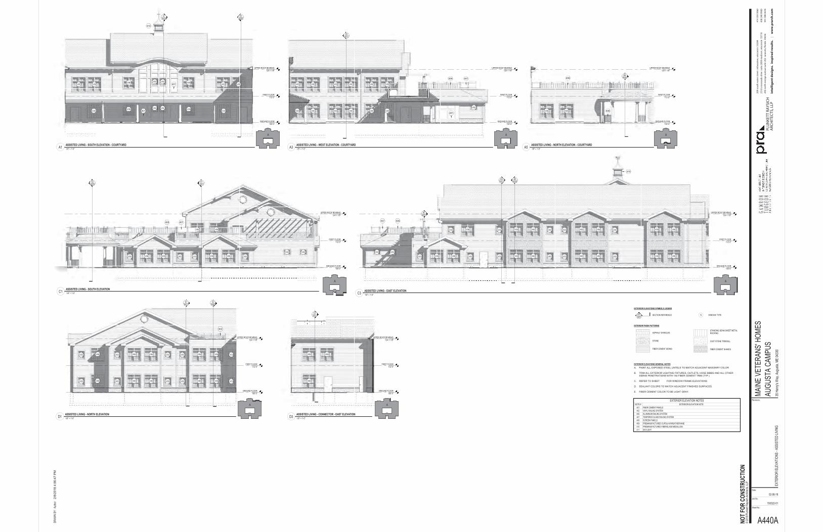
FIRST FLOOR112'-0"
GROUND FLOOR100'-0"
D1A511
UPPER ROOF BEARING124'-1 1/8"
FIRST FLOOR112'-0"
GROUND FLOOR100'-0"
UPPER ROOF BEARING124'-1 1/8"
E1A511
E3A520
402
FIRST FLOOR112'-0"
GROUND FLOOR100'-0"
E5A511
UPPER ROOF BEARING124'-1 1/8"
E5A520
406407
410
B1A521
FIRST FLOOR112'-0"
GROUND FLOOR100'-0"
UPPER ROOF BEARING124'-1 1/8"
E1A511
E2A520
406 407
FIRST FLOOR112'-0"
GROUND FLOOR100'-0"
E5A511
UPPER ROOF BEARING124'-1 1/8"
401
406 407
FIRST FLOOR112'-0"
GROUND FLOOR100'-0"
A1A510
UPPER ROOF BEARING124'-1 1/8"
E3A520
401
401
410
EXTERIOR FINISH PATTERNS
ASPHALT SHINGLES
STONE
FIBER CEMENT SIDING
STANDING SEAM SHEET METAL ROOFING
CAST STONE TRIM/SILL
FIBER CEMENT SHAKES
EXTERIOR ELEVATIONS GENERAL NOTES
EXTERIOR ELEVATIONS SYMBOLS LEGEND
SECTION REFERENCE WINDOW TYPE1iDTLSHT
PAINT ALL EXPOSED STEEL LINTELS TO MATCH ADJACENT MASONRY COLOR
TRIM ALL EXTERIOR LIGHTING FIXTURES, OUTLETS, HOSE BIBBS AND ALL OTHER SIDING PENETRATIONS WITH 1X4 FIBER CEMENT TRIM (TYP.)
REFER TO SHEET FOR WINDOW FRAME ELEVATIONS
SEALANT COLORS TO MATCH ADJACENT FINISHED SURFACES.
FIBER CEMENT COLOR TO BE LIGHT GRAY.
A.
B.
C.
D.
E.
FIRST FLOOR112'-0"
GROUND FLOOR100'-0"
UPPER ROOF BEARING124'-1 1/8"
E2A520406
406
Sheet No.:
NOT F
OR C
ONST
RUCT
ION
Job No:
Date:
Revisions:
2/8/
2018
4:0
6:47
PM
150322-01
A440A
AUGU
STA
CAMP
US35
Hen
ry's W
ay, A
ugus
ta, M
E 04
330
DRAW
N BY
: Auth
or
EXTE
RIOR
ELE
VATI
ONS
-ASS
ISTE
D LIV
ING
02-06-18
MAIN
E VE
TERA
NS' H
OMES
© 20
18 P
lunke
tt Ray
sich A
rchite
cts, L
LP
1/8" = 1'-0"D3ASSISTED LIVING - CONNECTOR - EAST ELEVATION
1/8" = 1'-0"D1ASSISTED LIVING - NORTH ELEVATION
1/8" = 1'-0"C3ASSISTED LIVING - EAST ELEVATION
1/8" = 1'-0"C1ASSISTED LIVING - SOUTH ELEVATION
1/8" = 1'-0"A3ASSISTED LIVING - WEST ELEVATION - COURTYARD
1/8" = 1'-0"A1ASSISTED LIVING - SOUTH ELEVATION - COURTYARD
EXTERIOR ELEVATION NOTESNOTE # EXTERIOR ELEVATION NOTE
401 FIBER CEMENT PANELS402 VINYL RAILING SYSTEM406 ALUMINUM RAILING SYSTEM407 TEMPERED GLASS RAILING SYSTEM408 SCREEN PANELS409 PREMANUFACTURED CUPOLA W/WEATHERVANE410 PREMANUFACTURED FIBERGLASS MEDALLION411 SKYLIGHT
AA
AA
AA
1/8" = 1'-0"A5ASSISTED LIVING - NORTH ELEVATION - COURTYARD
A
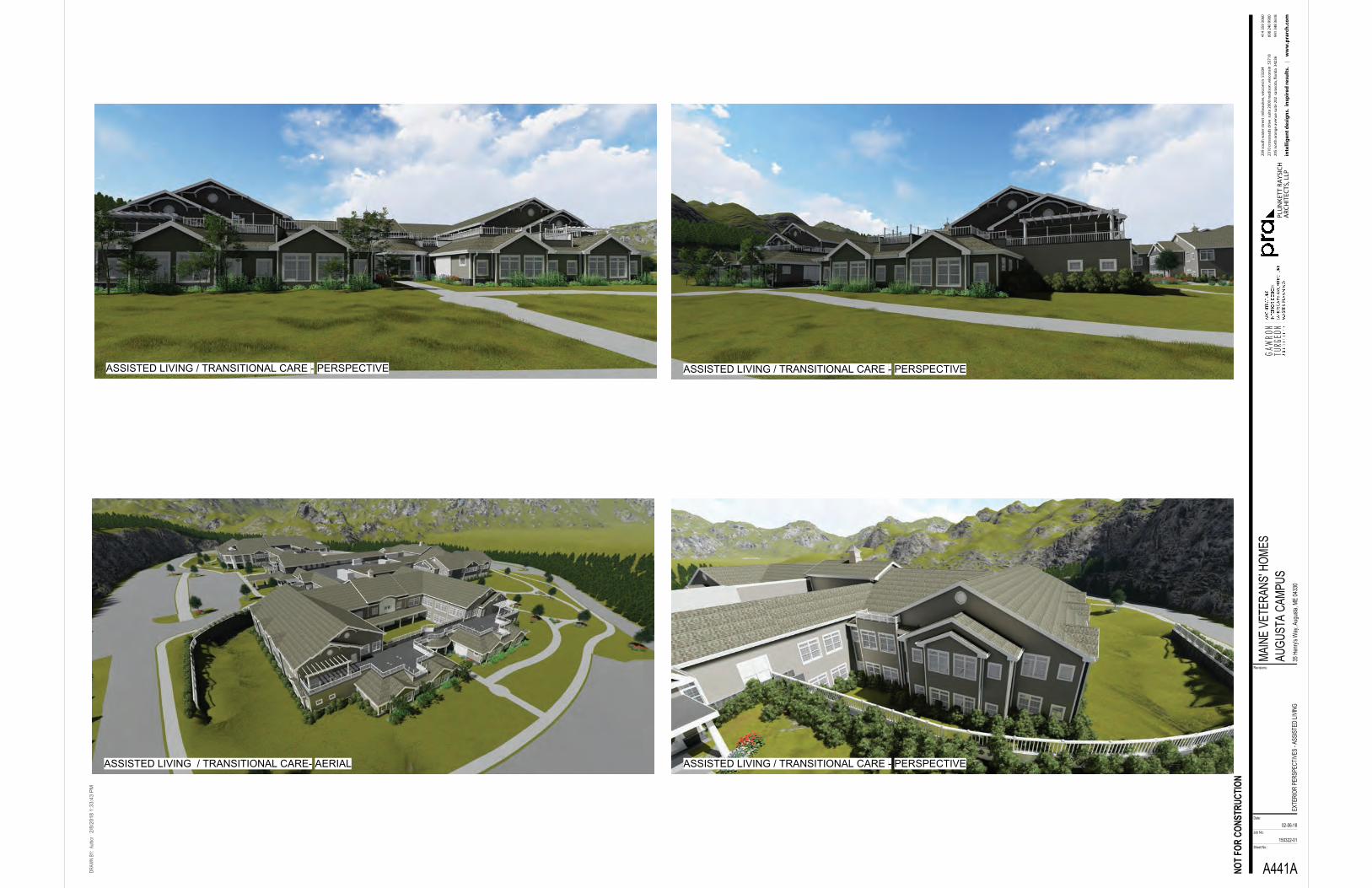
Sheet No.:
NOT F
OR C
ONST
RUCT
ION
Job No:
Date:
Revisions:
2/8/
2018
1:3
3:43
PM
150322-01
A441A
AUGU
STA
CAMP
US35
Hen
ry's W
ay, A
ugus
ta, M
E 04
330
DRAW
N BY
: Auth
or
EXTE
RIOR
PER
SPEC
TIVE
S -A
SSIS
TED
LIVIN
G
02-06-18
MAIN
E VE
TERA
NS' H
OMES
ASSISTED LIVING / TRANSITIONAL CARE - PERSPECTIVE
ASSISTED LIVING / TRANSITIONAL CARE- AERIAL
ASSISTED LIVING / TRANSITIONAL CARE - PERSPECTIVE
ASSISTED LIVING / TRANSITIONAL CARE - PERSPECTIVE