municipal corporation of greater mumbai
93
MUNICIPAL CORPORATION OF GREATER MUMBAI TENDER DOCUMENT Proposed Super-specialty Hospital at Bharat Ratna Dr. Babasaheb Ambedkar Municipal General Hospital (Centenary Hospital) Complex, Village Poisar at S. V. Road, Kandivali (West). TECHNICAL SPECIFICATION (CIVIL & PLUMBING WORKS) (VOLUME II-A) ___________________________________________ M/S. G. D. SAMBHARE & CO. Golden Bunglow, 7 th Floor Juhu Road, Santacruz (W) Mumbai 400 054 Email: [email protected] Tel: +91 22 26614321 Fax: +91 22 266131423
-
Upload
khangminh22 -
Category
Documents
-
view
1 -
download
0
Transcript of municipal corporation of greater mumbai

MUNICIPAL CORPORATION OF GREATER MUMBAI
TENDER DOCUMENT
Proposed Super-specialty Hospital at Bharat Ratna
Dr. Babasaheb Ambedkar Municipal General Hospital (Centenary Hospital) Complex,
Village Poisar at S. V. Road, Kandivali (West).
TECHNICAL SPECIFICATION (CIVIL & PLUMBING WORKS)
(VOLUME II-A)
___________________________________________ M/S. G. D. SAMBHARE & CO.
Golden Bunglow, 7th Floor Juhu Road, Santacruz (W)
Mumbai 400 054 Email: [email protected]
Tel: +91 22 26614321 Fax: +91 22 266131423

Technical Specifications for Civil & Plumbing Works
2
VOLUME-II
PART A: TECHNICAL SPECIFICATIONS FOR CIVIL WORKS. Page
1. PANIC BAR 5
2. VERMICULITE CONCRETE 5
3. Soil Nailing 5
4. Rock Anchoring 5
5. Artificial marble 6
6. S.S. False Ceiling 6
PART B: TECHNICAL SPECIFICATIONS FOR PLUMBING WORKS. Page
SECTION A. GENERAL REQUIREMENTS 9
SECTION B. SANITARY FIXTURES 15
SECTION C. SOIL, WASTE, VENT & RAINWATER PIPES & FITTINGS 19
SECTION D. WATER SUPPLY SYSTEM 30
SECTION E. DRAINAGE (SEWERS & STORM WATER DRAINS) 38
SECTION F. PIPE COLOUR CODE 50
SECTION G: I.S. CODES AND REFERENCE STANDARDS 51
PART C: TECHNICAL SPECIFICATIONS FOR STP-ETP. Page
SECTION A. PREAMBLE 59
SECTION B. GENERAL REQUIREMENTS 60
SECTION C. TECHNICAL SPECIFICATIONS – ETP 68
SECTION D. TECHNICAL SCHEDULE SYSTEM /UNIT DETAILS 72
SECTION E. ELECTRIC DRIVER LIST 78
SECTION F. TECHNICAL SPECIFICATIONS – STP 79
SECTION G. TECHNICAL SCHEDULE SYSTEM /UNIT DETAILS 82
SECTION H. ELECTRIC DRIVER LIST 88
SECTION I. TECHNICAL SCHEDULE – POWER, CHEMICAL & UTILITIES 89
SECTION J. PIPE LINE SCHEDULE 90

Technical Specifications for Civil & Plumbing Works
3
PART A:
TECHNICAL SPECIFICATIONS FOR
CIVIL WORKS

Technical Specifications for Civil & Plumbing Works
4
REFER DETAIL TECHNICAL SPECIFICATIONS AVAILABLE ON MCGM PORTAL AND
TECHNICAL SPECIFICATIONS FOR FAIR ITEMS ATTACHED BELOW.

Technical Specifications for Civil & Plumbing Works
5
VOLUME-II
PART A: TECHNICAL SPECIFICATIONS FOR CIVIL WORK:
1. Panic / Push Bar:-
Panic / push bar shall be of approved make with Single point locking, modular type for single leaf door with security anti-thrust latch and dogging device. It shall comprise of Panic Latch Set with steel latch, steel latch keeper with spacer plates complete set with screws & fixing accessories. It shall be finished with silver finish. Panic Bar must be approved for fire and smoke check doors. Mode of Measurement: Numbers Make:- Dorma / Enox / Godrej
2. Vermiculite Concrete:-
Vermiculite Concrete is low density non-structural construction material. It shall be light weight, mixed in proportion 1:4 (volume basis) I.e 1 part of ordinary Portland cement to be mixed with 4 parts of vermiculite aggregates by adding 1 1/2 parts of water including mixing, transporting, laying and curing and complete in all respect and as directed by The Engineer in charge. The Density of vermiculite concrete - 500 to 550 Kg/Cum Mode of Measurement: Cum. Make:- PerlTech / Welcome Chemicals / SV Ispat
3. Soil Nailing:-
Soil nailing is used for stabilization of soil in sloping profile, in the area where piles are not provided. It shall be carried out by providing and laying 8mm thk. Geotextile membrane followed by 75mm thk shortcreting with weld mesh and anchoring reinforcement 32mm dia. The contractor shall be responsible for maintenance of the soil nailing for required duration of time till construction work in this specific area. Providing soil anchors of required diameter of TMT bar and length as to be grouted in soil with neat cement grout (with Cebex 100 or equivalent). The Contractor unit rates including boring in soil for anchors, providing TMT bar of specified diameter and length, drilling, grouting, etc. complete. Mode of Measurement: Sqm. Make: Zed Geothechnics or equivalent
4. Rock Anchoring:-
Pre-stressed Rock Anchors are to be designed as per Geotechnical Consultant's Specifications, Methodology, Drawings and Site instructions. Inclined rock anchors are to be provided at c/c distance & of capacity including the fixed & free length as per the drawing. Scope includes

Technical Specifications for Civil & Plumbing Works
6
mobilization & demobilization of necessary plant & equipment for drilling inclined hole through the gap between the shore piles at specified locations. Preparation and binding of HTS cables, lowering it through PVC pipe, grouting of fixed length with cement grout, stressing fixed length of cable & locking the same, grouting of free length etc. complete as per specification and as directed by Consultants. Total length of rock anchor shall depend upon actual level of rock strata encountered. Mode of Measurement: Rmt. Make: Utracon / Zed Geothechnics
5. Artificial marble:-
Artificial Marble shall be of superior finish with snow white colour; 15 to 16 mm thk. of approved quality, pattern for dado. Marble shall have anti dust, stain proof, low water absorption properties with seamless joint.
It is ideal to cut a slab of 10ft X 4ft into 3 equal pieces. If not, use it in at least 2 pieces of size 5ft
x 4ft each, provided the thickness of the slab being used is 16mm or 18mm.
Laying Instructions:
i. Adhesives: For artificial marble products, it is recommended to use adhesives (Diamond
Star + Admix AD-1) from Ardex Endura (India) Pvt. Ltd. or any other polymer modified
adhesives meeting these specifications.
ii. Surface Preparation:
Remove all loose particles and mortar to reach a sound surface.
The surface should be free of dirt, dust and other contaminants.
New screeds and plastering should be cured for a minimum of 7 days and dried completely for at least 2 weeks, or as per manufacturer’s specifications.
The surface should be plain, plumb in line without undulations.
iii. Application of Adhesive and Installation:
Spread the adhesive on the wall surface at a thickness of 2-6mm, using a suitable steel notch trowel.
Press the slab firmly into position with a slight twisting action and use a suitable rubber mallet for gentle tamping.
Suitable support should be provided during the initial setting time to ensure proper adhesion to substrate.
iv. Grouting:
It is recommended to use epoxy resin based grouts. Grouting can be carried out after 4-5
days of installation. The company recommends grouts from Ardex Endura (India) Pvt. Ltd.
or any other equivalent epoxy resin based grouts.
Mode of Measurement: Sqm. Make:- Johnson / Nitco / Elegant Marble
6. S.S. False Ceiling:-

Technical Specifications for Civil & Plumbing Works
7
True horizontal level suspended ceiling comprising of Stainless Steel Clip-in with double pip self-
leveling feature and special tabs to allow removal of tile to enable plenum access. The tile shall
have plain visual in Brush Finish consisting of 600x600mm clip in tiles of stainless steel in 0.5
mm thickness with bevel edge of grade SS-304.
Installation:
To comprise 3000mm long ‘C’ channels spaced at 1200mm centers securely fixed to the
structural soffit using threaded rod of approved make connecting C- channel hanger at 1200mm
C/C and anchor fastener of approved make. The last hanger at the end of each C channel
should not be greater than 600mm from the adjacent wall. Use a C-channel connector for
splicing two pieces of C-channels. 4000mm DP-12 Main carriers (spring tee bars) shall be spaced
at 600mm centers in a direction perpendicular to the C-channels and shall be secured at every
intersection with C channel using a DP-12 hanger. Use DP-12 connector to splice two pieces of
DP-12 main carriers. Tiles should be clipped in between two DP-12 carriers (spring tee bars)
from below. This is a downward installation. Security clip to be installed to ensure the panels
are positively engaged with DP12 channel
Perimeter trims to be of wall angles of size 3000x19x32mm in white color secured to walls at
450mm maximum centers. Cut tiles to be secured to the wall angles using a spring clamp.
Mode of Measurement: Sqm. Make:- Armstrong or equivalent

Technical Specifications for Civil & Plumbing Works
8
PART B:
TECHNICAL SPECIFICATIONS
FOR PLUMBING WORKS

Technical Specifications for Civil & Plumbing Works
9
SECTION A: GENERAL REQUIREMENTS 1. Scope of work
1.1 The form of Contract shall be according to the "Conditions of Contract". The following clauses
shall be considered as an extension and not in limitation of the obligation of the Contractor.
1.2 Work under this Contract shall consist of furnishing all labour, materials, equipment and appliances necessary and required. The Contractor is required to completely furnish all the plumbing and other specialised services as described hereinafter and as specified in the schedule of quantities and/or shown on the plumbing drawings.
1.3 Without restricting to the generality of the foregoing, the sanitary installations shall include
the following:- Plumbing Works - Sanitary Fixtures - Soil, Waste, Vent, Rainwater Pipes & Fittings - Water Supply System
- Internal Sewerage & Storm Water Drainage 1.4 Services rendered under this section shall be done without any extra charge. 2. Specifications:
2.1 Work under this Contract shall be carried out strictly in accordance with specifications
attached with the tender.
2.2 Items not covered under these specifications or due to any ambiguity or misprints, or additional works, the work shall be carried out as per specifications of the latest Central Public Works Department with upto date amendments as applicable in the Contract.
2.3 Works not covered under para 2.1 and 2.2 shall be carried out as per relevant Codes &
Bureau of Indian Standards and in case of its absence as per British Standard Code of Practice.
3. Execution of work
3.1 The Contractor should visit and examine the site of work and satisfy himself as to the nature
of the existing roads and other means of communication and other details pertaining to the work and local conditions and facilities for obtaining his own information on all matters affecting the execution of work. No extra charge made in consequence of any misunderstanding, incorrect information on any of these points or on ground of insufficient description will be allowed.
3.2 The work shall be carried out in conformity with the Plumbing drawings and within the requirements of architectural, HVAC, electrical, structural and other specialised services drawings.
3.3 The Contractor shall cooperate with all trades and agencies working on the site. He shall make
provision for hangers, sleeves, structural openings and other requirements well in advance to

Technical Specifications for Civil & Plumbing Works
10
prevent hold up of progress of the construction schedule. All supports to the civil structure shall be provided with dash fasteners.
3.4 On award of the work, Contractor shall submit a schedule of construction in the form of a
PERT chart or BAR chart for approval of the Project Manager/Architect/ Consultant. All dates and time schedule agreed upon shall be strictly adhered to within the stipulated time of completion/ commissioning along with the specified phasing, if any.
4. Drawings:
4.1 Contract drawings are diagrammatic but shall be followed as closely as actual construction
permits. Any deviations made shall be in conformity with the architectural and other services drawings.
4.2 Architectural drawings shall take precedence over plumbing or other services drawings as to all dimensions.
4.3 Contractor shall verify all dimensions at site and bring to the notice of the Project Manager all
discrepancies or deviations noticed. Decision of the Project Manager shall be final. 4.4 Large size details and manufacturers dimensions for materials to be incorporated shall take
precedence over small scale drawings. 4.5 Any drawings issued by the Architects/Consultant for the work are the property of the
Architects/ Consultant and shall not be lent, reproduced or used on any works other than intended without the written permission of the Architects/Consultant.
5. Inspection and testing of materials:
5.1 Contractor shall be required, if requested, to produce manufacturers test certificate for the
particular batch of materials supplied to him. The tests carried out shall be as per the relevant Bureau of Indian Standards.
5.2 For examination and testing of materials and works at the site Contractor shall provide all testing and gauging equipment necessary but not limited to the following:
a) Steel tapes b) Weighing machine c) Plumb bobs, sprit levels, hammer d) Micrometres e) Hydraulic machine
5.3 All such equipment shall be tested for calibration at any approved laboratory, if required by
the Project Manager. All testing equipment shall be preferably located in special room meant for the purpose.
5.4 Samples of all materials shall be got approved before placing order and the approved samples shall be deposited with the Project Manager.
6. Metric conversion:

Technical Specifications for Civil & Plumbing Works
11
6.1 All dimensions and sizes of materials and equipment given in the tender document are commercial metric sizes.
6.2 Any weights, or sizes given in the tender having changed due to metric conversion, the nearest equivalent sizes accepted by Indian Standards shall be acceptable without any additional cost.
7. Reference points:
7.1 Contractor shall provide permanent bench marks, flag tops and other reference points and check that with other agencies to confirm the same reference point for all the proper execution of work and these shall be preserved till the end of the work.
7.2 All such reference points shall be in relation to the levels and locations, given in the architectural and plumbing drawings.
8. Reference drawings:
8.1 The Contractor shall maintain one set of all drawings issued to him as reference drawings.
These shall not be used on site. All important drawings shall be mounted on boards and placed in racks indexed. No drawings shall be rolled.
8.2 All corrections, deviations and changes made on the site shall be shown on these reference drawings for final incorporation in the completion drawings to be submitted by the contractor in fulfilment of the conditions of this contract.
8.3 On award of the work the contractor shall be issued four sets of consultant’s working drawings
stamped “good for construction” by the Project Manager. The consultant’s drawings shall be the basis of contractor’s shop drawings. In addition, the Project Manager shall also issue one copy of the Interior Designer’s; Electrical & HVAC approved shop drawings relevant to his work
8.4 Shop drawings are detailed working drawings which incorporate the contractor's details for
execution of the work and incorporate equipment manufacturer's details and dimensions to ensure that the same can be installed in the space provided.
8.5 All shop drawings should detailed pipe routing and levels, showing location of other services
at crossings etc., cable runs, route cable trays and all allied works and must be fully co-ordinated with other services and approved by the Project Manager before execution of the works. Project Manager shall arrange to issue two copies/prints of services drawings from the respective contracting agencies. Additional copies/prints may be provided on payment of actual cost of the copies/ prints. All drawings will valid only when stamped and issued by the Project Manager.
8.6 Shop drawings shall also be furnished for detailed layout of all equipment, foundation, bolting
and vibration elimination details along with information on dead and dynamic load, vibration etc.
8.7 Six sets of manufacturer's equipment drawings, roughing in and wiring diagrams shall be
submitted. 8.8 Contractor shall submit shop drawings furnishing all details of MCC panels, cable routes, wiring
diagrams and connection details as required.

Technical Specifications for Civil & Plumbing Works
12
8.9 Three copies of each set of shop drawings shall be submitted for initial scrutiny, discussion and approval.
8.10 Each submission shall be accompanied by contractor's certificate stating that the shop
drawings meet all the contract requirements and that the piping and equipment can be satisfactorily installed without any obstructions in the space available.
8.11 On approval of the above the contractor shall furnish six sets of the approved shop drawings for execution of the work.
9. Completion drawings:
9.1 On completion of work, Contractor shall submit one complete set of original tracings and two prints of "as built" drawings to the Project Manager. These drawings shall have the following information. a) Run of all piping, diameters on all floors, vertical stacks and location of external services.
b) Ground and invert levels of all drainage pipes together with location of all manholes and
connections upto outfall.
c) Run of all water supply lines with diameters, locations of control valves, access panels.
d) Location of all mechanical equipment with layout and piping connections and mechanical equipment.
e) All shop drawings shall be updated from time to time for the purpose of making
completion drawings.
f) No completion certificate shall be issued unless the above drawings are submitted.
9.2 Contractor shall provide four sets of catalogues, service manuals, manufacturer's drawings, performance data and list of spare parts together with the name and address of the manufacturer for all electrical and mechanical equipment provided by him.
9.3 All "warranty cards" given by the manufacturers shall be handed over to the Project Manager. 10. Contractor's rates:
10.1 Rates quoted in this tender shall be inclusive of cost of materials, labour, supervision, erection,
tools, plant, scaffolding, service connections, transport to site, taxes, octroi and levies, breakage, wastage and all such expenses as may be necessary and required to completely do all the items of work and put them in a working condition.
10.2 Rates quoted are for all heights and depths and in all positions as may be required for this work.
10.3 All rates quoted must be for complete items inclusive of all such accessories, fixtures and
fixing arrangements, nuts, bolts, hangers as are a standard part of the particular item except where specially mentioned otherwise.

Technical Specifications for Civil & Plumbing Works
13
10.4 All rates quoted are inclusive of cutting holes and chases in walls and floors and making good the same with cement mortar/concrete/water proofing of appropriate mix and strength as directed by the Project Manager. Contractor shall provide holes, sleeves, recesses in the concrete and masonry work as the work proceeds. All hot and cold water supply pipes crossing masonry walls shall be provided with G.I. pipe sleeves. The annular space between the pipe and sleeve shall be filled up with fire proof sealant after testing. Contractor shall give the pipe sleeves to the civil contractor well in time so that the same can be fixed along with civil works. Any co-ordination gap shall be of contractor’s responsibility.
10.5 The Contractor shall furnish the Project Manager with vouchers & test certificates, on request, to prove that the materials are as specified and to indicate that the rates at which the materials are purchased in order to work out the rate analysis of non-tendered items which he may be called upon to carryout.
11. Testing:
11.1 Piping and drainage works shall be tested as specified under the relevant clauses of the
specifications.
11.2 Tests shall be performed in presence of the Project Manager and test records for the tests shall be duly signed by Contractor and the Project Manager.
11.3 All materials and equipment found defective shall be replaced and whole work tested to meet
the requirements of the specifications. 11.4 Contractor shall perform all such tests as may be necessary and required by the local
authorities to meet municipal or other bye-laws in force. 11.5 Contractor shall provide all labour, equipment and materials for the performance of the tests. 12. Site clearance and clean-up:
12.1 The Contractor shall, from time to time, clear away all debris and excess materials
accumulated at the site.
12.2 After the fixtures, equipment and appliances have been installed and commissioned, Contractor shall clean-up the same and remove all plaster, paints, stains, stickers and other foreign matter or discolouration leaving the same in a ready to use condition.
12.3 On completion of all works, Contractor shall demolish all stores, remove all surplus materials
and leave the site in a broom clean condition, failing which the same shall be done by the Project Manager at the Contractor’s risk and cost. Cost of the cleanup shall be deducted from the contractor's bills on pro-rata basis in proportion to his contract value.
13. Licence permits and authorities:
13.1 Contractor must hold a valid plumbing or any other as required licence by the municipal
authority or other competent authority under whose jurisdiction the work falls.
13.2 Contractor must keep constant liaison with the local development, municipal/statutory authority and obtain approval of all drainage, water supply, fire suppression and other works carried out by him.

Technical Specifications for Civil & Plumbing Works
14
13.3 Contractor shall obtain, from the municipal and other authorities 'C' & 'D' & other forms as required for approval of drainage and water supply works during execution and the completion certificate with respect to his work as required for occupation of the building. Contractor shall obtain permanent water supply and drainage connections from authorities concerned. OWNER’S shall reimburse the fees paid to the authorities towards the connection charges on production of receipts for money paid.
13.4 Contractor shall get any materials tested from the appropriate authority if so required with no
cost to the OWNER’S. 14. Recovery of cost for materials issued to Contractors free of cost:
If any material issued free of cost by the OWNER’S to the contract for use on the work and the same is lost, stolen ,pilfered or broken while in contractor’ possession, the cost of the same shall be recovered from the Contractor on the basis of actual cost to OWNER’S. The cost shall include the cost paid, freight, transportation, excise duty, sales tax, octroi, import duty and other levies, plus 100% as penalty. The decision on the actual cost given by the OWNER’S shall be final and binding on the Contractor.
14.1 Contractor has to keep full records of material issued by the OWNER’S with reference and challans etc. Contractor has to give account of all such materials to the Project Manager.
15. Cutting of Water Proofing Membrane:
No walls terraces shall be cut for making and opening after water proofing has been done without written approval of project manager. Cutting of water proofing membrane shall be done very carefully so as other portion of water proofing is not damaged. On completion of work at such place the water proofing membrane shall be made good and ensured that the opening/cutting is made fully water proof as per specifications and details of water proofing approved by Project Managers.
16. Cutting of structural members: No structural member shall be chased or cut without the written permission of the Project
Manager. 17. Materials supplied by OWNER’S: The Contractor shall verify that all materials supplied by the OWNER’S conform to the
specifications of the relevant item in the tender. Any discrepancy found shall be brought to the notice of the Project Manager.
18. Materials:
18.1 Unless otherwise specified and expressly approved in writing by the Project Manager, only
materials of makes and specification as mentioned in the list of approved makes attached with the specifications shall be used.
18.2 If required, the Contractor shall submit samples of materials proposed to be used in the works. Approved samples shall be kept in the office of the Project Manager.
END OF SECTION A: GENERAL REQUIREME

Technical Specifications for Civil & Plumbing Works
15
SECTION B : SANITARY FIXTURES 1. Scope of work:
1.1 Work under this section shall consist of furnishing all materials & labour necessary and
required to completely install all sanitary fixtures, chromium plated fittings and accessories as required by the drawings specified hereinafter and given in the Schedule of Quantities.
1.2 Without restricting to the generality of the foregoing the sanitary fixtures shall include the following:-
a) Sanitary fixtures b) Chromium plated fittings c) Porcelain or stainless steel sinks d) Accessories e.g towel rods, toilet paper holders, soap dish, towel rails, coat hooks etc as
specified in the schedule of quantities. e) Connections to all kitchens, equipment, pump headers and other equipment requiring
water and drainage connections.
1.3 Whether specifically mentioned or not all fixtures and appliances shall be provided with all fixing devices, nuts, bolts, screws, hangers as required.
1.4 All exposed pipes within toilets and near fixtures shall be chromium plated brass or copper unless otherwise specified.
2. General requirements:
2.1 All fixtures and fittings shall be provided with all such accessories as are required to complete
the item in working condition whether specifically mentioned or not in the Schedule of Quantities, specifications, drawings. Accessories shall include proper fixing arrangement, brackets, nuts, bolts, screws and required connection pieces, WC flexible connectors etc.
2.2 Fixing screws shall be half round head chromium plated brass screws with C.P. washers where
necessary. 2.3 Contractor shall furnish without cost all such accessories and fixing devices that are necessary
and required but not supplied along with the Plumbing Fixtures & CP Fittings by the manufacturers as a part of the original and standard supply.
2.4 All fittings and fixtures shall be fixed in a neat workmanlike manner true to level and heights
shown on the drawings and in accordance with the manufacturer’s recommendations. Care shall be taken to fix all inlet and outlet pipes at correct positions. Faulty locations shall be made good and any damage to the finished floor, tiling or terrace shall be made good at Contractor's cost.
2.5 Contractor shall seal all fixtures fixed near wall, marble and edges with an approved type of
poly-sulphide sealant appropriate for its application. 3. European W.C: 3.1 European W.C. shall be wash down or symphonic type floor or wall mounted set flushed by
means of porcelain/ plastic flushing cistern or concealed type flush valves/cisterns, which will

Technical Specifications for Civil & Plumbing Works
16
be an integral part of the WC system. Framework, walling and finishing will not form a part of the contractor’s work. Where applicable flush pipe/ bend shall be connected to the W.C. by means of a suitable rubber adapter. Wall hung W.C. shall be supported by C.I. floor mounted chair or wall brackets with dash fasteners as per manufacturer’s recommendations. Connection between water closet and waste pipe shall be made using W.C. connector with rubber insertion.
3.2 Each W.C. set shall be provided with a plastic seat shall be with rubber buffers and chromium plated hinges.
3.3 Plastic seat shall be so fixed that it remains absolutely stationary in vertical position without
falling down on the W.C. Each W.C. shall be suitable for flushing in low volume of water 3-6 litres.
3.4 Flushing cistern when provided shall be provided with all internal flushing mechanism, 15 mm
dia. ball cock with unbreakable polythene float and overflow pipe. Any frame work required for fixing cistern has to be provided by the contractor.
4. Indian W.C.:
4.1 Indian WC shall be Orissa pattern of size 500 x 630 mm. Each WC shall be provided with a 100
mm dia. C.I. P or S trap with or without vent horn. The WC shall be flushed by means of an concealed / exposed type flush valve. Flush pipe/bend shall be connected to the WC by means of suitable rubber adapter.
4.2 The Indian WC shall be fixed in level in a neat workman like manner. The WC and trap shall be set in cement concrete 1:2:4 mix (1 cement: 2 coarse sand: 4 stone aggregate 20 mm nominal size).
5. Urinals:
5.1 Urinals shall be white glazed vitreous china of size, shape and type specified in the Schedule of
Quantities.
5.2 Bowl urinals shall be provided with 15 mm dia. C.P. spreader, 32 mm dia. stainless steel domical waste and C.P. cast brass bottle trap with pipe and wall flange, and shall be fixed to wall by C.I. brackets and C.I. wall clips as recommended by manufacturers complete as directed by Project Manager.
5.3 Urinals shall be fixed with C.P. brass screws and shall be provided with 32 mm dia. domical
waste leading to urinal's trap. 5.4 Flush pipes shall be uPVC pipes concealed in wall chase but with chromium plated bends at
inlet and outlet or as given in Schedule of Quantities. 5.5 Urinals shall be flushed by means of auto push (pressmatic) tap/ fully automatic no-touch
flush valve with solenoid valves as specified in the schedule of quantities. 5.6 Waste pipes for urinals shall be uPVC class III (6 kg/sqcm) or G.I pipes (Medium class) to IS:
1239 conforming to IS : 4985 as given in schedule of quantities.

Technical Specifications for Civil & Plumbing Works
17
5.7 Waste pipes may be concealed in chase or exposed on wall as directed by the Project Manager. Specifications for waste pipes shall be same as given in Section II.
6. Lavatory basin:
6.1 Lavatory basins shall be white glazed vitreous china of size, shape and type specified in
the Schedule of Quantities.
6.2 Each basin shall be provided with brackets and clips of approved and securely fixed. Placing of basins over the brackets without secure fixing shall not be accepted.
6.3 Each basin shall be provided with 32 mm dia. C.P. waste with overflow, pop-up waste or
rubber plug and chain as specified in the Schedule of Quantities, 32 mm dia. C.P. brass bottle trap with C.P pipe to wall and flange.
6.4 Each basin shall be provided with pillar tap or hot and cold mixer fitting as specified in the
Schedule of Quantities. 6.5 Basins shall be fixed at proper heights as shown on drawings. If height is not specified, the rim
level shall be 79 cms or as directed by Project Manager.
7. Sinks:
7.1 Sinks shall be stainless steel or any other material as specified in the Schedule of Quantities. 7.2 Each sink shall be provided with brackets of approved and securely fixed. Counter top sinks
shall be fixed with suitable brackets or clips as recommended by the manufacturer. Each sink shall be provided with 40 mm dia. C.P. waste with chain and plug as given in the Schedule of Quantities. Fixing shall be done as directed by Project Manager.
7.3 Supply fittings for sinks shall be mixing fittings or C.P. taps as specified in the Schedule of
Quantities. 8. Hand Drier (Where Specified):
8.1 The hand drier shall be no touch operating type with solid state time delay to allow user to
keep hand in any position.
8.2 The hand drier shall be fully hygienic, rated for continuous repeat use 8.3 The rating of hand drier shall be such that time required to dry a pair of hands upto wrists is
approximately 30 seconds. 8.4 The hand drier shall be wall mounting type suitable for 230 volts, single phase, 50 Hz, A.C.
power supply. 9. Toilets for Disabled (Where Specified):
9.1 Where specified in washroom facilities designed to accommodate physically handicapped,
accessories should be provided as directed by the Project Manager.
Technical Specifications for Civil & Plumbing Works
18
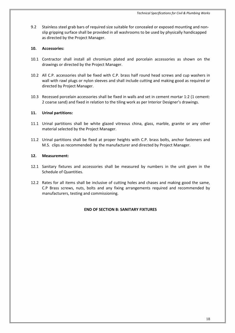
9.2 Stainless steel grab bars of required size suitable for concealed or exposed mounting and non-slip gripping surface shall be provided in all washrooms to be used by physically handicapped as directed by the Project Manager.
10. Accessories:
10.1 Contractor shall install all chromium plated and porcelain accessories as shown on the
drawings or directed by the Project Manager.
10.2 All C.P. accessories shall be fixed with C.P. brass half round head screws and cup washers in wall with rawl plugs or nylon sleeves and shall include cutting and making good as required or directed by Project Manager.
10.3 Recessed porcelain accessories shall be fixed in walls and set in cement mortar 1:2 (1 cement:
2 coarse sand) and fixed in relation to the tiling work as per Interior Designer’s drawings. 11. Urinal partitions: 11.1 Urinal partitions shall be white glazed vitreous china, glass, marble, granite or any other
material selected by the Project Manager.
11.2 Urinal partitions shall be fixed at proper heights with C.P. brass bolts, anchor fasteners and M.S. clips as recommended by the manufacturer and directed by Project Manager.
12. Measurement:
12.1 Sanitary fixtures and accessories shall be measured by numbers in the unit given in the
Schedule of Quantities.
12.2 Rates for all items shall be inclusive of cutting holes and chases and making good the same, C.P Brass screws, nuts, bolts and any fixing arrangements required and recommended by manufacturers, testing and commissioning.
END OF SECTION B: SANITARY FIXTURES

Technical Specifications for Civil & Plumbing Works
19
SECTION C : SOIL, WASTE, VENT & RAINWATER PIPES & FITTINGS 1. Scope of work:
1.1 Work under this section shall consist of furnishing all labour, materials, equipment and
appliances necessary and required to completely install all soil, waste, vent and rainwater pipes and fittings as required by the drawings, and given in the Schedule of Quantities.
1.2 Without restricting to the generality of the foregoing, the soil, waste, vent pipes system shall include the following:-
a) Vertical and horizontal soil, waste, vent pipes, and fittings, joints, clamps, connections to
fixtures. b) Connection of all pipes to sewer lines as shown on the drawings at ground floor levels. c) Drainage, channels, gratings & floor drains. d) Floor and urinal traps, cleanout plugs, inlet fittings and rainwater heads/ Khurras. e) Testing of all pipe lines.
2. General requirements:
2.1 All materials shall be new of the best quality conforming to specifications and subject to the
approval of Project Manager.
2.2 Pipes and fittings shall be fixed truly vertical, horizontal or in slopes as required in a neat workmanlike manner.
2.3 Pipes shall be fixed in a manner as to provide easy accessibility for repair and maintenance
and shall not cause obstruction in shafts, passages etc. 2.4 Pipes shall be securely fixed to walls and ceilings by suitable clamps intervals specified. 2.5 Access doors for fittings and clean outs shall be so located that they are easily accessible for
repair and maintenance. Any access panel required in the civil structure, false ceiling or marble cladding etc. shall be clearly reported to the OWNER’S in the form of shop drawing so that other agencies are instructed to provide the same.
3. Piping System:
3.1 Schedule of Pipes Use shall be as below or as specified in the schedule of quantities. 1 uPVC pipes 75,110 & 160 mm dia. Vt. stacks for Soil, Waste and Vent
(O rings joints SWR system Pipes and main headers at IS 13592 Type B) basement ceiling
2 uPVC pipes 40, 50 & 63 mm OD Waste lines for Wash basin, Urinal, (welded joints) 6 kg/sqcm class III Floor drain & Sink Or 1A. Centrifugally Cast spun iron S&S Pipes Vt. stacks for Soil, Waste. & Vent
Pipes As per I.S. 398

Technical Specifications for Civil & Plumbing Works
20
2A. G.I. pipes conforming to IS 1239 Waste lines for Wash basin, Urinal, (Heavy class) Floor drain & Sink. 3 uPVC pipes 75 mm to 200 mm OD Rain Water Pipes.
(O rings joints SWR system IS 13592 Type A) 4. CI (Class LA) pipes to IS 1536 or Pipes under building floor
D.I. class K-7
5. uPVC Class III (6 kg/sqcm) or Sump Rising Main G.I. pipes conforming to IS 1239 (Medium class) 3.2 Soil, Waste & Vent Pipes:
a) The Soil & Waste Pipe System above ground has been planned as a "Two Pipe System
with all soil appliances ventilated" as defined in IS : 5329 having common pipes for soil
and waste for W.C. W.B. kitchen sinks, showers, washbasins, AHU’s condensate drains
and floor drains with a ventilating pipe for all soil appliances.
b) Where applicable all waste water from AHU's plant and pump rooms, floor channels will
be provided with a deep seal trap before connecting to the main drain or vertical stack.
c) Vertical soil & waste stacks shall be connected to a separate horizontal drain at basement
ceiling generally where applicable and shown on the drawings.
d) Toilet layouts have been so arranged that the W.C. outlets shall be with “P” trap above
floor wherever possible.
e) All soil/waste from areas in basement (where applicable) will be collected in sumps and
after treatment in STP shall be recycled for flushing and gardening. Excess water shall be
pumped into sewer line.
f) Head (Starting point) of drains and sewage / Waste Water Sumps (as and where
applicable) having a length of greater than 4 m up to it connection to the main drain or
manhole shall be provided with a 50/75/100 mm vent pipe terminating above roof or
as directed by Project Manager.
3.3 Rainwater Pipes:
a) All open terraces shall be drained by rain water down takes. b) Rainwater down takes is separate and independent of the soil and waste system and will
discharge into the Storm water Drainage system of the Complex. c) Rain water in open courtyards shall be collected in catch basins and connected to the
storm water drainage system. d) Any dry weather flow from waste appliances e.g. AHU’s pump rooms, waste water sumps
shall connect to sewers after traps and not in the storm water drainage system

Technical Specifications for Civil & Plumbing Works
21
3.4 Balcony/Planter drainage: Wherever required, all balconies, terraces, planters and other formal landscape areas will be drained by vertical down takes or other type of drainage system shown on the drawings and directed by the Architect/Project Manager.
3.5 Soil Waste & vent Pipes & fittings above ground
3.5.1 uPVC Pipes & Fittings (for toilets and kitchen waste)
a) Soil, Waste, Vent and Anti-siphonage pipes shall be uPVC. All pipes 75 mm dia. and above shall be straight and smooth conforming to IS: 13592 SWR of class B. Pipes less than 75 mm OD shall be uPVC (6 kg/sq cm) confirming to I.S. 4985.
b) Pipes and fittings for main vertical stacks & branches 160mm, 110 mm & 75 mm dia. shall be Soil, Waste & Rainwater System known in the short form as SWR drainage system with injection moulded fittings with approved type of socket & 'O' rubber ring joints/ solvent cement joints conforming to relevant IS code.
c) Joints shall be done as per the manufacturer’s recommendations. The pipes and fittings
must have matching dimension for perfect joints in the system. ’O’ ring fittings must have sufficient gap (approx. 10 mm) for thermal expansion of pipes.
d) uPVC pipes shall be clamped to the wall with approved type uPVC saddle clamps / U clamps
and GI rod fixed to the angle iron support system within the shaft
e) Use proper uPVC pipe adapters for connections between cast iron pipes, traps & uPVC pipes where necessary. Such joints shall be made of an approved type of ‘Putty’.
3.5.2 Cast Iron Soil, Waste & Vent Pipes (when specified).
a) Soil, Waste & Vent Pipes used in toilets, kitchens, exposed locations, basement ceiling and under floors and such other locations which may expose them to internal or external high temperatures or to damage shall be centrifugally spun cast iron pipes (confirming to I.S. 3989) as specified below.
All pipes shall be straight and smooth from inside free from irregular bore, blow holes, cracks and other manufacturing defects. Standard weight dimensions and pig lead required for joints shall be as follows:-
3.5.3 Standard weight dimensions and pig lead required for joints shall be as follows:-
Sand Cast Iron Pipes & Matching Fitting shall be to I.S. 3989 (where specified)
Nominal Diameter Thickness Overall Thickmess Depth Weight Length of lead 1.80 m inches mm mm kg mm mm 2 50 3.5 8.4 3.5 25 3 75 3.5 12.50 3.5 25 4 100 4.0 18.80 4.0 25 6 150 5.0 34.90 5.0 38

Technical Specifications for Civil & Plumbing Works
22
Sand Cast Iron Pipes & Matching Fitting shall be to I.S. 1729
Nominal Diameter Thickness Overall Thickness Depth Weight Length of lead 1.80 m inches mm mm kg mm mm 2 50 3.5 11.41 5.0 25 3 75 3.5 16.42 5.0 25 4 100 4.0 21.67 5.0 25 6 150 5.0 31.92 5.0 38
3.5.4 Tolerance:
Acceptable tolerance for pipes to I.S. 3989 and I.S 1729 shall be as follows:-
a) Wall thickness -15% b) Length ± 20 mm c) Weight -10% 3.6 Fittings:
3.6.1 Fittings shall conform to the same Indian Standard as for pipes. Pipes and fittings must be of
matching I.S. Specification. Interchange of pipes of one standard with fittings on the other standard will not be permitted.
3.6.2 Fittings shall be of the required degree of curvature with or without access door. 3.6.3 Access door shall be made up with 3 mm thick insertion rubber washer and white lead. The
bolts shall be lubricated with grease or white lead for easy removal later. The fixing shall be air and water tight.
3.6.4 Connection from a vertical stack or position to a horizontal line shall be made only by a “Y”
junction. 3.7 Fixing:
3.7.1 All vertical pipes shall be fixed by galvanized clamps truly vertical. Branch pipes shall be
connected to the stack at the same angle as that of the fittings. No collars shall be used on
vertical stacks. Each stack shall be terminated at top with a cowl (terminal guard).
3.7.2 Horizontal pipes running along ceiling shall be fixed on galvanized structural adjustable
clamps (Clevis clamps) of special design shown on the drawings or as directed. Horizontal
pipes shall be laid to uniform slope and the clamps adjusted to the proper levels so that
the pipes fully rest on them.
3.7.3 Contractor shall provide all sleeves, openings, hangers, inserts during the construction. He
shall provide all necessary information to the PMC / Building Contractor for making such
provisions in the structure as necessary. All damages shall be made good to restore the
surfaces at no extra cost

Technical Specifications for Civil & Plumbing Works
23
4. Clamps: 4.1 Holder bat clamps shall be of standard design and fabricated from galvanized M.S. standard
flats 40x3 mm thick and 12 mm dia. M.S. Rod and 6 mm nuts and bolts. Holder bat clamps shall be fixed in cement concrete 1:2:4 mix blocks 10x10x10 cms deep.
4.2 Where holder bat clamps are to be fixed in RCC column or slotted angles, walls or beam they shall be fixed with galvanized 40x3 mm flat iron "U" type clamps with anchor fasteners of approved design or 6 mm nuts and bolts.
4.3 Structural clamps shall be fabricated by electro-welding from M.S. structural members e.g. rods, angles, channels flats as per detailed drawing. Contractor shall provide all nuts & bolts, welding material. All fabricated clamps, nuts, bolts and washers shall be not dipped galvanized.
4.4 Galvanized slotted angle/channel supports on walls shall be provided wherever shown on
drawings. Angles/channels shall be of sizes shown on drawings or specified in schedule of quantities. Angles/channels shall be fixed to brick walls with bolts embedded in cement concrete blocks and to RCC walls with suitable anchor fasteners. The spacing of support bolts horizontally shall not exceed 1 m.
4.5 Wherever M.S. clamps are required to be anchored directly to brick walls, concrete slabs,
beams or columns, nothing extra shall be payable for clamping arrangement and making good with cement concrete 1:2:4 mix (1 cement :2 coarse sand :4 mm stone aggregate 20 mm nominal size) as directed by the PMC.
4.6 For sleeves, anchor fasteners and clamp spacing chart shall be as follows:
CLAMP AND PIPE SUPPORT SPACING
<--------------- Commercial Pipe Dia.( Spacing in m ) ------------------>
S.No. Type of Pipes & Position 15/20 20/25 32/40 50 75/80 100/110 150/160 200
1 Vertical Pipes
1.1 GI /MS Pipes 2.4 2.4 3 3.6 4.5 5.4 5.4
1.2 Cast Iron Pipes
SWR Pipes x x <---------------------- 3 m --------------------------->
IS 1729/3989
Water Supply Pipes
IS 1536 /1538/7181/8329 x x <---------------------- 3.6 m --------------------------->
1.3 uPVC /cPVC Pipes
IS 4985 for Water Supply x x 0.5 0.7 0.9 0.9
IS 13585 for SWR x x 0.5 0.7 0.9 0.9
2 Horizontal Pipes
2.1 GI /MS Pipes <------2.0 m ------> 2.4 m 3 3.6 4 <--- 4.5 m--->
2.2 Cast Iron Pipes
SWR Pipes <---------------------- 3.0 m -------------------------------->
IS 1729/3989
Water Supply Pipes 3 3.6 3.6 4.5
IS 1536 /1538/7181/8329
5. Traps:
5.1 Floor traps:
Floor traps shall be siphon type full bore uPVC (SWR) ‘P’ / ‘S’ type having a minimum 50 mm deep seal. The trap and waste pipes shall be set in cement concrete blocks firmly supported

Technical Specifications for Civil & Plumbing Works
24
on the structural floor. The blocks shall be in 1:2:4 mix (1 cement :2 coarse sand :4 stone aggregate 20 mm nominal size) and extended to 40 mm below finished floor level. Contractor shall provide all necessary shuttering and centering for the blocks. Size of the block shall be 30x30 cms of the required depth.
5.2 Urinal traps:
Urinal traps shall be uPVC (SWR) ‘P’ / ‘S’ traps with or without vent and set in cement concrete block specified for floor traps.
5.3 Floor trap inlet:
Bath room traps and connections shall ensure free and silent flow of discharging water. Where specified, Contractor shall provide an uPVC height raiser with one, two or three inlet sockets welded on side to connect the waste pipe. Joint between waste and hopper inlet socket shall be rubber ring / cement solvent. Floor trap inlet hoppers and the traps shall be set in cement concrete blocks as specified in para above without extra charge.
5.4 Floor Gratings:
Floor and urinal traps shall be provided with 100-150 mm square or round C.P./Stainless steel grating, with rim of approved design and shape. Minimum thickness shall be 4 mm or as specified in the Schedule of Quantities.
5.5 Jointing:
Soil, waste vent, anti-syphonage and rainwater pipes shall be jointed with rubber ring / cement solvent.
6. Cleanout Plugs:
5.5 Clean out plug for Soil, Waste or Rainwater pipes laid under floors shall be provided near pipe
junctions bends, tees, “Ys” and on straight runs at such intervals as required as per site conditions. Cleanout plugs shall terminate flush with the floor levels. They shall be threaded and provided with key holes for opening. Cleanout plugs shall be uPVC suitable for the Pipe dia. screwed / flanged joint to a threaded PVC socket.
5.6 Cleanout on Drainage Pipes:
a) Cleanout plugs shall be provided on starting point of each drain and in between at locations indicated on plans or directed by the PMC. Cleanout plugs shall be of size matching the full bore of the pipe but not exceeding 150 mm dia. FCO Plugs on drains of greater diameters shall be 150 mm dia. Fixed with a suitable reducing adapter.
b) Cleanouts at ceiling level pipe shall be provided with a bend terminating at floor level above. The brass plug shall be screwed type flush with the floor.
7. Waste pipe from appliances:
7.1 General
a) Waste pipe from appliances e.g. washbasins, sinks and urinals shall be of uPVC class III, 6 kg/sq cm or galvanized steel, as given in the Schedule of Quantities or shown on the drawings.

Technical Specifications for Civil & Plumbing Works
25
b) All pipes shall be fixed in gradient towards the outfalls of drains. Pipes inside a toilet room shall be in chase unless otherwise shown on drawings. Where required pipes may be run at ceiling level in suitable gradient and supported on galvanized structural clamps. Spacing for clamps for such pipes shall be as per the pipe spacing chart given in section 1.
8. Cast iron pipes for drainage:
8.1 All drainage lines passing under building shall be CI (LA) pipes, in exposed position above
ground etc. or as specified in the schedule of quantities. Position of such pipes shall generally be shown on the drawings.
8.2 Cast iron pipes shall be spigot & socket (S&S) centrifugally spun iron pipes conforming to I.S. 1536 (Class LA) suitable for pre-molded rubber Tyton joints. Quality certificates shall be furnished.
8.3 Fittings:
a) Fittings used for C.I. drainage pipe shall conform to I.S.1538 (Heavy class). Connections from vertical branch pipes shall be made by a “Y” tee.
8.4 Joints:
a) Joints between pipes shall be made with pre-molded rubber joints (Tyton Joints) supplied by the manufacturer to ensure compatibility and water tightness.
b) Joints between pipes and fittings shall be made by caulked spun yarn dipped in tar and molten pig lead 45 mm deep by hammering with caulking tools.
9. Encasing pipe in Cement Concrete: uPVC (SWR) soil and waste pipes and drainage under floor in sunken slabs and in wall
chases (when cut specially for the pipe) shall be encased in cement concrete 1:2:4 mix (1
cement :2 coarse sand : 4 stone aggregate 12 mm size) 75 mm in bed and all-round. When
pipes are running well above the structural slab, the encased pipes shall be supported with
suitable cement concrete pillars of required height at intervals of 1.8 m. Rate for concrete
round pipes shall be inclusive of pillars, supports, shuttering and centering.
10. Painting:
10.1 All cast iron, soil, waste vent, anti-syphonage and rainwater pipes in exposed location in
shafts and pipe spaces shall be painted with two or more coats of synthetic enamel
paint to give an even shade.
10.2 Paint shall be of approved quality and shade. Where directed pipes shall be painted in
accordance with approved pipe colour code.
10.3 G.I. waste pipes in chase shall be painted with two coats of bitumen paint, covered with
polythene tape and a final coat of bitumen paint. Exposed pipes shall be painted with two or
more coats of synthetic enamel paint.

Technical Specifications for Civil & Plumbing Works
26
10.4 C.I. soil and waste pipes below ground shall be covered all-round with cement conc. and shall
not be painted.
11. Cutting and making good: Contractor shall provide all necessary holes cut outs and chases in structural members as building work proceeds. Wherever holes are cut or left originally, they shall be made good with cement concrete 1:2:4 (1 cement: 2 coarse sand: 4 stone aggregate 20 mm nominal size) or cement mortar 1:2 (1 cement: 2 coarse sand) and the surface restored as in original condition.
12. Testing:
12.1 Testing procedure specified below apply to all soil, waste and vent pipes above ground including C.I. LA pipes laid in basement ceiling.
12.2 Entire drainage system shall be tested for water tightness during and after completion of the installation. No portion of the system shall remain untested. Contractor must have adequate number of expandable rubber/bellow plugs, manometers, smoke testing machines, pipe and fitting work test benches and any other equipment necessary and required to conduct the tests. All testing shall be certified for its calibration by an approved laboratory.
12.3 All materials obtained and used on site must have manufacturer's hydraulic test certificate for
each batch of materials used on the site. 12.4 Testing soil, waste and rainwater pipes: 12.4.1 Testing Procedure for uPVC SWR drainage pipes for soil waste vent and / or Rain Water
Pipes.
a) Testing procedure specified below apply to all soil, waste and vent pipes above ground including pipes laid in basement ceiling. Horizontal lines with in bathrooms should be cement encased and tested before compacting of sunken floor to avoid any accidental damages. Smoke test should be avoided.
b) Entire drainage system shall be tested for water tightness during and after completion of the installation. No portion of the system shall remain untested. Contractor must have adequate number of expandable rubber bellow plugs / socket plugs or any other equipment necessary and required to conduct the tests.
c) All materials obtained and used on site must have manufacturers hydraulic test certificate for
each batch of materials used on the site.
d) After installation all connections from fixtures, vertical stacks and horizontal drains including pipes along ceiling shall be tested to a hydraulic pressure not exceeding 3 m. Such tests shall be conducted for each floor separately by suitable plugs. Seal hermetically all openings below the top of section to be tested. The water level shall then be raised to a height of not less than 3 meters above the highest point of the section being tested. Every Joint shall be carefully examined for leaks.

Technical Specifications for Civil & Plumbing Works
27
e) After the installation is fully complete, it should be also tested by flushing the toilets, running at least 20% of all taps simultaneously and ensuring that the entire system is self-draining, has no leakages, blockages etc. Rectify and replace where required.
f) Contractor shall maintain a test register identifying date and time of each area. All tests shall be conducted in presence of Project Manager and signed by both.
12.4.2 Testing Procedure for C.I. drainage pipes for soil waste vent and / or Rain Water Pipes. (Wherever required)
a) Apart from factory test all pipes and fittings shall be hydraulically tested for a head of 3 m
preferably on a specially set up work bench. After applying pressure, strike the pipe with a wooden pallet and inspect for blow holes and cracks. Pressure may be applied for about 2 minutes. Reject and remove all defective pipes.
b) After installation all connections from fixtures, vertical stacks and horizontal drains including C.I. LA pipes shall be tested to a hydraulic pressure not exceeding 3 m. Such tests shall be conducted for each floor separately by suitable plugs.
c) The entire installation shall be tested by smoke testing machine. The test can be conducted
after the plumbing fixtures are installed and all traps have water seal or by plugging all inlets by bellow plugs. Apply dense smoke keeping the top of stack open and observe for leakages. Rectify or replace defective sections.
d) After the installation is fully complete, it should be tested by flushing the toilets, running at
least 20% of all taps simultaneously and ensuring that the entire system is self-draining, has no leakages, blockages etc. Rectify and replace where required.
12.5 Contractor shall maintain a test register identifying date and time of each area. All tests shall
be conducted in presence of PMC and signed by both. 13. Measurements:
13.1 General
a) Rates for all items quoted shall be inclusive of all work and items given in the specifications and Schedule of Quantities.
b) Rates are applicable for the work in basements, under floors, in shafts at ceiling level area for all heights and depths.
c) Rates are inclusive of cutting holes and chase in RCC and masonry work and making good
the same.
d) Rates are inclusive of pre testing, on site testing, of the installations, materials and commissioning of the works.
e) Pipes (unit of measurement. Linear meter to the nearest centimeter).
13.2 All uPVC soil, waste, vent, anti-syphonage and rain water pipes shall be measured net when
fixed correct to a centimeter including all fittings along its length. No allowance shall be made for the portions of pipe lengths entering the sockets of the adjacent pipes or fittings. The

Technical Specifications for Civil & Plumbing Works
28
above will apply to both case i.e. whether pipes are fixed on wall face or pillars or embedded in masonry or pipes running at ceiling level.
13.3 Pipes shall measure per running meter correct to a centimeter for the finished work which shall include fittings e.g. bends, tees, elbows, reducers, crosses, sockets, nipples and nuts. The length shall be taken along center line of the pipes and fittings. All pipes and fittings shall be classified according to their diameter, method of jointing and fixing substance, quality, and finish. The diameters shall be nominal diameter of internal bore. The pipes shall be described as including all cutting and waste. In case of fittings of un-equal bore, the largest bore shall be measured.
13.4 Cement concrete around pipes shall be measured along the center of the pipe line
measured per linear meter and include any masonry supports, shuttering and centering cutting complete as described in the relevant specifications.
13.5 Slotted angles/channels shall be measured per linear meter of finished length and shall
include support bolts, nuts and clamps embedded in masonry walls with cement concrete blocks and nothing extra will be paid for making good the same.
13.6 Fittings:
Unit of measurement shall be the number of pieces. Pipe fittings are included in the rate for pipes. Urinal traps, trap gratings, hoppers, cleanout plugs shall be measured by number per piece and shall include all items described in the relevant specifications and Schedule of Quantities.
13.7 Painting: Painting of pipes shall be measured per running meter and shall be inclusive of all fittings and clamps. No deduction for fittings shall be made.
13.8 Excavation for soil pipes:
No payment shall be admissible with respect to excavation, refilling and disposal of surplus earth for cast iron soil and waste pipes laid below ground, in sunken slabs or over basement rafts.
13.9 PMC’s decision with respect to the correct interpretation regarding mode of measurement shall be final and binding on the contractor.
14.1 uPVC Pipes & Fittings as specified in the schedule of quantities.
a) Soil, Waste and Anti-siphonage pipes and fittings shall be uPVC. All pipes shall be straight
and smooth conforming to IS: 13592 or as specified in Schedule of Quantities.
b) Pipes and fittings for main vertical stacks & branches 110 mm, & 75 mm dia. shall be Soil, Waste & Rainwater System known in the short form as SWR drainage system with injection moulded fittings with approved type of socket & ‘O’ rubber ring joints.
c) Joints shall be done as per the manufacturer’s recommendations. The pipes and fittings
must have matching dimension for perfect joints in the system. ‘O’ ring fittings must have sufficient gap (approx. 10 mm) for thermal expansion of pipes.
d) uPVC pipes shall be clamped to the wall with approved type uPVC saddle clamps/U
clamps and G.I. rod fixed to the angle iron support system within the shaft.

Technical Specifications for Civil & Plumbing Works
29
e) Use proper uPVC pipe adapters for connections between cast iron pipes, traps & uPVC
pipes where necessary. Such joints shall be made of an approved type of ‘Putty’. 14.2 Clamps: 14.2.1 For UPVC pipes standard UPVC clamps shall be used. For other pipes M.S. clamps, supports
and hangers provided shall be galvanised. Factory made Pre-fabricated clamps shall be preferred. Contactor may fabricate the clamps of special nature and galvanise them after fabrication but before installation.(Clamps shall be fabricated from mild steel sections) All nuts, bolts, washers and other fasteners shall be factory galvanised.
14.2.2 Clamps shall be of approved designs and fabricated from M.S. flats and other sections of thickness and sizes as per drawings or contractor’s shop drawings. Clamps shall be fixed in accordance to manufacturer’s details/shop drawings to be submitted by the contractors.
14.2.3 When required to be fixed on RCC columns, walls or beam they shall be fixed with approved type of galvanised expansion anchor fasteners (Dash fasteners) of approved design and size according to load.
14.2.4 Structural clamps e.g. trapeze or cluster hangers shall be fabricated by electro-welding from
M.S. structural members e.g. rods, angles, channels flats as per Contractors shop drawing shall be galvanised after fabrication. All nuts, bolts and washers shall be galvanised.
14.2.5 Galvanised slotted angle/channel supports on walls shall be provided wherever shown on
drawings. Angles/channels shall be of sizes shown on drawings or specified in schedule of quantities. Angles/channels shall be fixed to brick walls with bolts embedded in cement concrete blocks and to RCC walls with anchor fasteners mentioned above. The spacing of support bolts on support members fixed horizontally shall not exceed 1 m
14.3 Traps: 14.3.1 Floor traps
a) Floor traps where specified shall be of multi inlet or 100 x 100 mm deep seal type uPVC traps (SWR) having a minimum 50 mm deep seal. The trap and waste pipes when buried below ground shall be set and encased in cement concrete blocks firmly supported on firm ground or when installed on a sunken RCC structural slab. The blocks shall be in 1:2:4 mix (1 cement: 2 coarse sand: 4 stone aggregate 20 mm nominal size).
b) Contractor shall provide all necessary shuttering and centring for the blocks. Size of the block shall be 30x30 cms of the required depth.
14.3.2 Urinal traps
Urinal traps/horn shall be uPVC deep seal 100 x 100 mm traps with or without vent and set in cement concrete block specified for floor traps.
14.3.3 Cleanout plugs
a) Floor Clean out Plug:
Clean out plug for Soil, Waste or Rainwater pipes laid under floors shall be provided near pipe junctions bends, tees, “Ys” and on straight runs at such intervals as required as per site conditions. Cleanout plugs shall terminate flush with the floor levels. They shall be

Technical Specifications for Civil & Plumbing Works
30
threaded and provided with key holes for opening. Cleanout plugs shall be Cast Brass fixed by means of screwed to a G.I. socket/ uPVC . The socket shall be cement solvent / lead caulked / drip seal joint to the drain pipes.
END OF SECTION C : SOIL, WASTE, VENT & RAINWATER PIPES & FITTINGS

Technical Specifications for Civil & Plumbing Works
31
SECTION D: WATER SUPPLY SYSTEM 1. Scope of work 1.1 Work under this section consists of furnishing all labour, materials equipment and appliances
necessary and required to completely install the water supply system as required by the drawings, specified hereinafter and given in the Schedule of Quantities.
1.2 Without restricting to the generality of the foregoing, the water supply system shall include
the following:-
a) Distribution system from main supply headers from pump to all fixtures and appliances for cold & hot water.
b) Cold water supply lines from tube wells and city water connections to Fire and Under Ground Water Tanks.
c) Excavation and refilling of pipes trenches. d) Insulation to hot water pipes e) Pipe protection and painting. f) Control valves, masonry chambers and other appurtenances. g) Connections to all plumbing fixtures, tanks, appliances and municipal mains hi) Inserts for R.C.C. tanks
2 General requirements 2.1 All materials shall be new of the best quality conforming to specifications. All works
executed shall be to the satisfaction of the Project Manager. 2.2 Pipes and fittings shall be fixed truly vertical, horizontal or in slopes as required in a neat
workmanlike manner. 2.3 Short or long bends shall be used on all main pipe lines as far as possible. Use of elbows shall
be restricted for short connections. 2.4 Pipes shall be fixed in a manner as to provide easy accessibility for repair and maintenance
and shall not cause obstruction in shafts, passages etc.
2.5 Pipes shall be securely fixed to walls and ceilings by suitable clamps at intervals specified. 2.6 Clamps, hangers and supports on RCC walls, columns & slabs shall be fixed only by means of
approved made of expandable metal fasteners inserted by use of power drills. 2.7. All pipe clamps, supports, nuts, bolts, washers shall be galvanised MS steel throughout the
building. Painted MS clamps & MS nuts, bolts & washers shall not be accepted. 2.8 Valves and other appurtenances shall be so located as to provide easy accessibility for
operations, maintenance and repairs. 3 Water Supply System 3.1 Contractor should study the site plan and the water supply systems separate for Domestic
and flushing water from O.H.T. near underground water tank and STP.

Technical Specifications for Civil & Plumbing Works
32
3.1.1 Source
Water supply will be acquired from local municipal and captive tube wells within the site and collected in water storage tanks located underground.
3.1.2 The system has been connected to a gravity feed system from overhead tanks to all parts of the building
3.1.3 It is proposed to provide flushing cistern / flush valves for all WCs and Infra-red NO-TOUCH
flush valves / auto push type shall be provided for Urinals. These will be fed from flushing overhead tank by gravity.
3.1.4 Domestic water supply shall be provided with cold and hot water system only. Hot water
provisions are limited to kitchen and toilets connected to a local electric hot water storage geyser.
4 CPVC / PPR / G.I. pipes, fittings & valves 4.1 CPVC Pipes for hot water application. 4.1.1 All pipes inside the toilets for domestic hot water supply shall be CPVC conforming to CTS
SDR-11 at a working pressure of 27.8 kg/sqcm PSI at 23 deg C & 100 PSI at 82 deg. C. 4.1.2 Solvent welded CPVC fittings etc. tees, elbows, couplers, unions, reducers, brushing etc.
including transition fittings (connection between CPVC and metal pipes/G.I. ie. Brass adopters conforming to ASTM D-2846) shall be provided.
4.1.3 All pipes shall be fixed in accordance with layout and alignment shown on the drawings. Care
shall be taken to avoid air pockets. CPVC /G.I. pipes inside toilets shall run above false ceiling with vertical drop in wall chases for all fixtures. No pipes to run inside sunken floor as far as possible. Pipes may run in wall chase, under the ceiling or floors and other areas as shown on drawings.
4.1.4 uPVC Pressure Pipes for cold water application. All pipes inside the toilets for domestic and flushing cold water supply shall be uPVC
unthreaded pressure class Sch 40 pipes as per ASTM–D standard 1785 pressure pipes suitable for jointing with cement solvent of approved grade. Fittings shall be solvent weld socketed and threaded with brass inserts for connection to threaded metal fixtures.
4.2 PP-R Pipes. (Alternate item when specified) 4.2.1 All Pipes up to 100 mm nominal size inside the buildings, and pipe shafts and where specified
shall be anti-bacterial UV stabilized (Green Colour), Polypropylene Random Copolymer (PP-R) rigid pipes of PN-16 grade confirming to DIN 8077 with matching fittings to DIN 16962 suitable for fusion joints. The pipe shall have fire retardant property.
4.2.1 Fittings shall be as per DIN 16962. Each fitting shall have manufacturer's trade mark stamped
on it.

Technical Specifications for Civil & Plumbing Works
33
4.2.2 Pipes and fittings shall be joined by Heat Fusion (no use of solvent ensuring leak proof joint) using welding machine and suitable die, by heating the outer surface of the pipe and inner surface of the fitting simultaneously and inserting the pipe in the fitting to achieve homogeneous joint. For making connection to metallic fittings PP-R fitting having threaded metal insert shall be used.
4.2.3 All pipes shall be fixed in accordance with layout and alignment shown on the drawings. Care
shall be taken to avoid air pockets. Pipes inside toilets shall be fixed in wall chases well above the floor. No pipes are run inside a sunken floor as far as possible. Pipes may be run under the ceiling or floors and other areas as shown on drawings.
4.3 Joining Pipes & Fittings
a) Cutting Pipes shall be cut either with a wheel type plastic pipe cutting or hacksaw blade and care shall be taken to make a square cut. All burrs should be removed for proper contact between pipe and fittings during jointing. b) Solvent Cement Application Only CPVC solvent cement conforming to ASTM-F-493 should be used for joining pipe with fittings. An even coat of solvent cement should be applied on the pipe end and a thin coat inside the fitting socket. Solvent cement for uPVC sch 40 pipes shall be pipe confirming to ASTM D 2563 medium bodied or as per manufacture’s recommendations. c) Assembly After applying the solvent cement on both pipe and fitting socket, pipe should be inserted into the fitting socket within 30 seconds, and rotating the pipe ¼ to ½ turn while inserting so as to ensure even distribution of solvent cement with the joint. The assembled system should be held for 10 seconds (approximately) in order to allow the joint to set up. d) Testing The system should be hydrostatically pressure tested at 150 psi (10 Bar) for one hour. During pressure testing, the system should be fitted with water and if a leak is found, the joint should be cut out the replaced with new one.
4.4 Transition of Flow guard cPVC in metals
When making a transition connection to metal threads, special brass/plastic transition fitting (Male and female adapters) should be used. Plastic threaded connections should not be over torqued.
4.5 Threaded sealants
Teflon tape shall be used to make threaded connections leak proof. 4.6 Solvent Cement

Technical Specifications for Civil & Plumbing Works
34
Only cPVC solvent cement conforming to ASTMF 493 should be used for joining pipe with fittings and valves. Solvent cement for uPVC 40 pipes shall be confirming to ASTM D 2563 medium bodied or as per manufacture’s recommendation.
4.7 Hangers and supports For Horizontal runs, support should be given at 3 feet (90 cms) intervals for diameters of one inch and below and at 4 feet (1.2 m) intervals for larger sizes. Supports should be as per the below mentioned table:
Size of pipe 20ºC 49ºC 71ºC 82ºC
Inch Ft. Ft. Ft. Ft.
½” 5.5 4.5 3.0 2.5
¾” 5.5 5.0 3.0 2.5
1” 6.0 5.5 3.5 3.0
1¼” 6.5 6.0 3.5 3.5
1¼” 7.0 6.0 3.5 3.5
2” 7.0 6.5 4.0 3.5
4.7. Anchor Fasteners
4.7.1 All pipe supports, hangers and clamps to be fixed on RCC walls, beams, columns, slabs and masonry walls 230mm thick and above by means of galvanised expandable anchor fasteners in drilled holes of correct size and model to carry the weight of pipes. Drilling shall be made only by approved type of power drill as recommend and approved by manufacturer of the anchor fasteners. Failure of any fastening devices shall be the entire responsibility and contractor shall redo or provide additional supports at his own cost. He shall also compensate the OWNER’S for any damage that may be caused by such failures.
4.8 Unions Contractor shall provide adequate number of unions on all pipes to enable easy dismantling
later when required. Unions shall be provided near each gunmetal valve, stop cock, or check valve and on straight runs as necessary at appropriate locations as required and/or directed by Project Manager.
4.9 Flanges Flanged connections shall be provided on pipes as required or where shown on the
drawings, all equipment connections as necessary and required or as directed by the Project Manager. Connections shall be made by correct number and size of GI nuts, bolts & washers with 3 mm thick gasket. Where hot water connections are made insertion gasket shall be of suitable high temperature grade and quality approved by the Project Manager. Bolt hole dia. for flanges shall conform to match the specification for C.I. sluice valve to I.S. 780. And C.I. butterfly valve to IS: 13095.
4.10 Painting (Painting for PP-R & CPVC pipes not required) Pipe protection (Protection for CPVC pipes not required) 4.11 G.I. Pipes and Fittings. (For risers and terrace when specified)

Technical Specifications for Civil & Plumbing Works
35
4.11.1 All pipes inside the buildings and where specified, outside the building shall be galvanized steel tubes conforming to I.S. 1239 of class specified in the schedule of quantities. When class is not specified they shall be heavy class.
4.11.2 Fittings shall be of malleable iron galvanized of approved make. Each fitting shall have
manufacturer's trade mark stamped on it. Fittings for G.I. pipes shall include couplings, bends, tees, reducers, nipples, unions, and bushes. Fittings shall conform to I.S.1879- (Part I to X).
4.11.3 Pipes and fittings shall be jointed with screwed joints. After cutting a pipe with a hacksaw or
a cutting machine care shall be taken to remove burr from the end of the pipe after reaming with a proper file.
4.11.4 Pipe threaded joints will be made by applying suitable grade of pipe sealing cord nontoxic
pipe sealant used for drinking water supply. (Use of red or white lead and sutli will not be permitted for screwed joints).
4.11.5 All pipes shall be fixed in accordance with layout and alignment shown on the drawings.
Care shall be taken to avoid air pockets. G.I. pipes inside toilets shall be fixed in wall chases well above the floor. No pipes shall be run inside a sunken floor as far as possible. Pipes may be run under the ceiling or floors and other areas as shown on drawings.
4.12 Clamps G.I. Pipes in shafts and other locations shall be supported by galvanized M.S. clamps of
design approved by Project Manager. Pipes in wall chases shall be anchored by G.I. hooks. Pipes at ceiling level shall be supported on structural clamps fabricated from M.S. structural. Pipes in typical shafts shall be supported on slotted angles/channels as per standard drawings.
4.12.1 For sleeves, anchor fasteners and clamp spacing chart (See 4.2 for clamp spacing chart
Section 3 above) . 4.13 Unions Contractor shall provide adequate number of unions on pipes 40 mm and below to enable
easy dismantling later when required. Unions shall be provided near each gunmetal valve, stop cock, or check valve and on straight runs as necessary at appropriate locations as required and/or directed by PMC.
5 Flanges 5.1 Flanged connections shall be provided on pipes 65 mm and above as required or where
shown on the drawings generally as follows:
a) On straight runs not exceeding 30 m, near bends and at connections to main branch lines.
b) On all valves ends c) On equipment /pump connections as necessary and required or as directed by
PMC.
5.2 Flanged connections shall be made by the correct number and size of the bolts and made with 3 mm thick insertion neoprene gaskets Bolt hole dia. for flanges shall conform
Technical Specifications for Civil & Plumbing Works
36
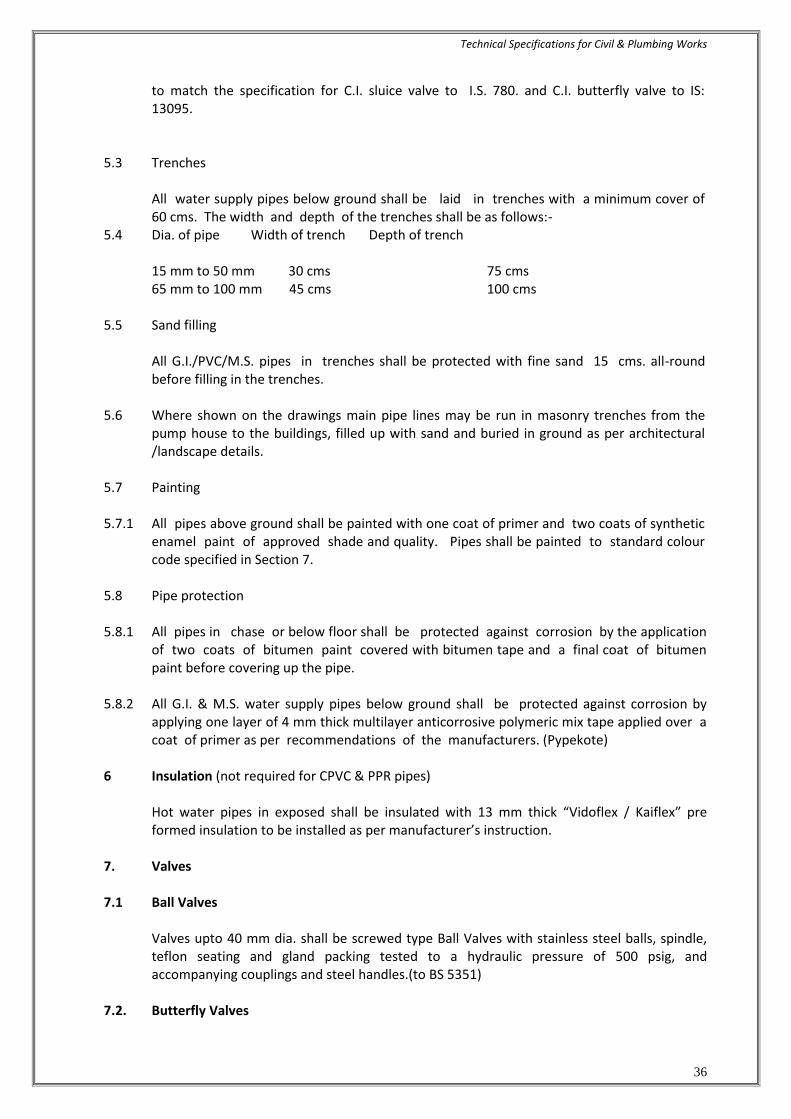
to match the specification for C.I. sluice valve to I.S. 780. and C.I. butterfly valve to IS: 13095.
5.3 Trenches All water supply pipes below ground shall be laid in trenches with a minimum cover of
60 cms. The width and depth of the trenches shall be as follows:- 5.4 Dia. of pipe Width of trench Depth of trench
15 mm to 50 mm 30 cms 75 cms 65 mm to 100 mm 45 cms 100 cms 5.5 Sand filling All G.I./PVC/M.S. pipes in trenches shall be protected with fine sand 15 cms. all-round
before filling in the trenches. 5.6 Where shown on the drawings main pipe lines may be run in masonry trenches from the
pump house to the buildings, filled up with sand and buried in ground as per architectural /landscape details.
5.7 Painting 5.7.1 All pipes above ground shall be painted with one coat of primer and two coats of synthetic
enamel paint of approved shade and quality. Pipes shall be painted to standard colour code specified in Section 7.
5.8 Pipe protection 5.8.1 All pipes in chase or below floor shall be protected against corrosion by the application
of two coats of bitumen paint covered with bitumen tape and a final coat of bitumen paint before covering up the pipe.
5.8.2 All G.I. & M.S. water supply pipes below ground shall be protected against corrosion by
applying one layer of 4 mm thick multilayer anticorrosive polymeric mix tape applied over a coat of primer as per recommendations of the manufacturers. (Pypekote)
6 Insulation (not required for CPVC & PPR pipes) Hot water pipes in exposed shall be insulated with 13 mm thick “Vidoflex / Kaiflex” pre
formed insulation to be installed as per manufacturer’s instruction. 7. Valves 7.1 Ball Valves Valves upto 40 mm dia. shall be screwed type Ball Valves with stainless steel balls, spindle,
teflon seating and gland packing tested to a hydraulic pressure of 500 psig, and accompanying couplings and steel handles.(to BS 5351)
7.2. Butterfly Valves

Technical Specifications for Civil & Plumbing Works
37
7.2.1 Valves 50 mm dia. and above shall be cast iron butterfly valve to be used for isolation. The
valves shall be bubble tight, resilient seated suitable for flow in either direction and seal in both direction with accompanying flanges and steel handle.
7.2.2 Butterfly valve shall be of best quality conforming to IS: 13095. 7.3 Non Return Valve (Slim Type) Where specified non return valve (dual plate slim type) shall be provided through which flow
can occur in one direction only. It shall be single door swing check type of best quality. 7.3.1 Each Butterfly and Slim Type Check (NRV) Valve shall be provided with a pair of flanges
screwed or welded to the main line and having the required number of galvanised nuts, bolts and washers of correct length.
7.3.2 Storage tanks Underground & Overhead Tank. (Accessories & Connections) 7.3.3 Storage tanks for water supply shall be in reinforced cement concrete built by the building
Contractor. 7.3.4 Each tank shall be provided with lockable type manhole cover fabricated from M.S. sheets.
Manhole covers shall be 450-500 mm dia. and fully galvanised after fabrication or as approved by the Project Manager.
7.4 Storage Tanks 7.4.1 Underground Underground storage tanks for water supply shall be reinforced cement concrete built by the
building contractor. Each tank shall be provided with lockable type manhole cover fabricated from M.S. sheet or
standard cost iron tank covers. Manhole covers shall be 450-500 mm dia. or as approved by local municipal authority.
7.5 Outlets and overflow All nozzles for puddle flanges in RCC tank for inlet, outlet, overflow and scour etc. shall be
provided by civil contractor or as given in the Schedule of Quantities. Further connections and accessories shall be provided under this contract.
7.5 Testing 7.5.1 All pipes, fittings and valves after fixing at site, shall be tested by hydrostatic pressure of 1.5
times the working pressure or 10 kg/cm2 whichever is more. Pressure shall be maintained for a period of at least thirty minutes without any drop. A test register shall be maintained and all entries shall be signed and dated by Contractor (s)
and Project Manager.

Technical Specifications for Civil & Plumbing Works
38
7.5.2 In addition to the sectional testing carried out during the construction, Contractor shall test the entire installation after connections to the overhead tanks or pumping system or mains. He shall rectify all leakages and shall replace all defective materials in the system. Any damage done due to carelessness, open or burst pipes or failure of fittings, to the building, furniture and fixtures shall be made good by the Contractor during the defects liability period without any cost.
7.5.3 After commissioning of the water supply system, Contractor shall test each valve by closing
and opening it a number of times to observe if it is working efficiently. Valves which do not effectively operate shall be replaced by new ones at no extra cost and the same shall be tested as above.
7.6 Measurement
a) PP-R / CPVC / uPVC or G.I. pipes above ground shall be measured per linear meter (to the nearest cm) and shall be inclusive of
i) all fittings e.g. coupling, tees, bends, elbows, unions, flanges and U clamps with nuts,
bolts & washers fixed to wall or other standard supports.
ii) Jointing with teflon tape, white lead and insertion gasket of appropriate temperature grade.
iii) Cutting holes, and chases in walls, floors, any pipe support required for pipes below ground & making good the same.
iv) Excavation, back filling, disposal of surplus earth and restoring the ground & floor in original condition.
7.7 Pipe Supports. a) Fabricated and galvanised supports shall be measured by weight. Weight for each type of
clamp shall be calculated on basis of the quantity of structural and MS used from the theoretical weight calculated on basis of the components theoretical weight of the sections.
7.7.1 Rate quoted for supports & hangers shall be inclusive of:- a) Expandable anchor fastens. b) Galvanising of all supports & hangers. c) Cutting holes in walls, ceilings on floors and making good where permitted. d) Nuts, bolts and washers for fixing and assembling. e) Wooden/PVC pipe saddles for vertical or horizontal runs. 7.7.2 Valves
Gunmetal, cast iron, butterfly and non-return valves and puddle flanges shall be measured by numbers and shall include wheels/caps, GI nuts, bolts, washers and insertion gasket.
7.7.3 Painting/pipe protection/insulation
Painting/pipe protection/insulation for pipes shall be measured per linear metre over finished surface and shall include all valves and fittings for which no deduction shall be made. No extra payment shall be made for fittings, valves or flanges.

Technical Specifications for Civil & Plumbing Works
39
SECTION E: DRAINAGE (SEWERS & STORM WATER DRAINS) 1 Scope of work 1.1 Work under this section shall consist of furnishing all labour, materials, equipment and
appliances necessary and required to completely install all the drainage system as required by the drawings and specified hereinafter or given in the Schedule of Quantities.
1.2 Without restricting to the generality of the foregoing, the drainage system shall include:-
a) Sewer lines including excavations, pipe lines, manholes, drop connections and connections to the Sewage Treatment Plant.
b) Storm water drainage, excavation, pipe lines, manholes, catch basins, drain channels,
recharging pits and overflows to external low areas 2 General requirements 2.1 All materials shall be new of the best quality conforming to specifications and subject to the
approval of Project Manager. 2.2 Drainage lines and open drains shall be laid to the required gradients and profiles. 2.3 All drainage work shall be done in accordance with the local municipal bye-laws. 2.4 Contractor shall obtain necessary approval and permission for the drainage system from the
municipal or any other competent authority. 2.5 Location of all manholes, etc. shall be as per site plan drawings. No drains or sewers shall be
laid in the middle of road unless otherwise specifically shown on the drawings or directed by the Project Manager.
3 Excavation 3.1 Alignment and grade The sewer pipes shall be laid to alignment and gradient shown on the drawings but subject
to such modifications as shall be ordered by the Project Manager. No deviations from the lines, depths of cutting or gradients of sewers shown on the plans and sections shall be permitted except by the express direction in writing of the Project Manager.
3.2 Excavation in tunnels The excavation for sewer works shall be open cutting unless the permission of the Project
Manager is obtained for laying pipes in tunnel where sewers have to be constructed along narrow passages or difficult ground.
3.3 Opening out trenches In excavating the trenches, etc. the solid road metalling, pavement, kerbing, etc. and turf is
to be placed on one side and preserved for reinstatement when the trenches or other excavation shall be filled up. Before any road metal is replaced, it shall be carefully sifted.

Technical Specifications for Civil & Plumbing Works
40
The surface of all trenches and holes shall be restored and maintained to the satisfaction of the Project Manager. The Contractor shall grub up and clear the surface over the trenches and other excavations of all trees, stumps roots and all other encumbrances affecting execution of the work and shall remove them from the site to the approval of the Project Manager.
3.4 Obstruction of roads The Contractor shall not occupy or obstruct by his operation more than one half of the
width of any road or street and sufficient space shall then be left for public and private transit, he shall remove the materials excavated and bring them back again when the trench is required to be refilled. The Contractor shall obtain the consent of the Project Manager.
3.5 Removal of filth All night soil, filth or any other offensive matter met with during the execution of the works,
immediately after it is taken out of any trench, sewer or cess pool, shall not be deposited on to the surface of any street or where it is likely to be a nuisance or passed into any sewer or drain but shall be at once put into the carts and removed to a suitable place to be provided by the Contractor.
3.6 Excavation to be taken to proper depths The trenches shall be excavated to such a depth that the sewer shall rest on concrete as
described in the several clauses relating thereto and so that the inverts may be at the levels given in the sections.
3.7 Refilling After the sewer or other work has been laid and proved to be water tight, the trench or
other excavations shall be refilled. Utmost care shall be taken in doing this, so that no damage shall be caused to the sewer and other permanent work. The filling in the haunches and upto 75 cms above the crown of the sewer shall consist of the finest selected materials placed carefully in 15 cms layers and flooded and consolidated. After this has been laid, the trench and other excavation shall be refilled carefully in 15 cms layers with materials taken from the excavation, each layer being watered to assist in the consolidation.
3.8 Contractor to restore settlement and damages The Contractor shall, at his own costs and charges, make good promptly during the whole
period the works are in hand, any settlement that may occur in the surfaces of roads, berms, footpaths, gardens, open spaces etc. whether public or private caused by his trenches or by his other excavations and he shall be liable for any accidents caused thereby. He shall also, at his own expense and charges, repair and make good any damage done to buildings and other property if in the opinion of the Project Manager the damage is due to his negligence.
3.9 Disposal of surplus soil

Technical Specifications for Civil & Plumbing Works
41
The Contractor shall at his own costs and charges provide places for disposal of all surplus materials not required to be used on the works. As each trench is refilled the surplus soil shall be immediately removed, the surface properly restored and roadways and sides left clear.
3.10 Timbering of sewer and trenches
a) The Contractor shall at all times support efficiently and effectively the sides of the sewer trenches and other excavations by suitable timbering, piling and sheeting and they shall be closed timbered in loose or sandy strata and below the surface of the sub soil water level.
b) All timbering, sheeting and piling with their walling and supports shall be of adequate
dimensions and strength and fully braced and strutted so that no risk of collapse or subsidence of the walls of the trench shall take place.
c) The Contractor shall be held responsible and will be accountable for the sufficiency of all timbering, bracings, sheeting and piling used as also for, all damage to persons and property resulting from improper quality, strength, placing, maintaining or removing of the same.
3.11 Shoring of buildings The Contractor shall shore up all buildings, walls and other structures, the stability of which
is liable to be endangered by the execution of the work and shall be fully responsible for all damages to persons or property resulting from any accident.
3.12 Removal of water from sewer, trench etc.
a) The Contractor shall at all times during the progress of the work keep the trenches and excavations free from water which shall be disposed of by him in a manner as will neither cause injury to the public health nor to the public or private property nor to the work completed or in progress nor to the surface of any roads or streets, nor cause any interference with the use of the same by the public.
b) If any excavation is carried out at any point or points to a greater width than the
specified cross section of the sewer with its envelope, the full width of the trench shall be filled with concrete by the Contractor at his own expenses and charges to the requirements of the Project Manager.
3.13 Width of trench 3.13.1 Recommended width of trenches at the bottom shall be as follows:- 100 mm dia. pipe 55 cms 150 mm dia. pipe 55 cms 225-250 mm dia. pipe 60 cms 300 mm dia. pipe 75 cms Maximum width of the bed concrete shall also be as above. No additional payment is
admissible for widths greater than specified.

Technical Specifications for Civil & Plumbing Works
42
4 Salt glazed stoneware pipes:
4.1 Stoneware pipes shall be of first class quality salt glazed and free from rough texture inside and outside and straight. All pipes shall have the manufacturers name marked on it and shall comply with I.S. 651 approved makes.
4.2 Laying and jointing of stoneware salt glazed pipes
a) Pipes are liable to be damaged in transit and notwithstanding tests that may have been made before despatch each pipe shall be examined carefully on arrival at site. Each pipe shall be rung with a wooden hammer or mallet and those that do not ring true and clear shall be rejected. Sound pipes shall be carefully stacked to prevent damage. All defective pipes should be segregated, marked in a conspicuous manner and their use in the works prevented.
b) The pipes shall be laid with sockets leading uphill and rest on solid and even
foundations for the full length of the barrel. Socket holes shall be formed in the foundation sufficiently deep to allow the pipe jointer room to work right round the pipe and as short as practicable to admit the socket and allow the joint to be made.
c) Where pipes are not bedded on concrete the trench bottom shall be left slightly high
and carefully bottomed up as pipe laying proceeds so that the pipe barrels rest on firm ground. If excavation has been carried too low it shall be made up with cement concrete at the Contractor's cost and Charges.
d) If the bottom of the trench consists of rock or very hard ground that cannot be easily
excavated to a smooth surface, the pipes shall be laid on cement concrete bed to ensure even bearing.
4.3 Jointing of pipes
a) Tarred gaskin shall first be wrapped round the spigot of each pipe and the spigot shall
then be placed into the socket of the pipe previously laid, the pipe shall then be adjusted and fixed in its correct position and the gaskin caulked tightly home so as to fill not more than one quarter of the total length of the socket.
b) The remainder of the socket shall be filled with stiff mix of cement mortar (1 cement : 1
clean sharp washed sand). When the socket is filled, a fillet should be formed round the joint with a trowel forming an angle of 450 with the barrel of the pipe. The mortar shall be mixed as needed for immediate use and no mortar shall be beaten up and used after it has begun to set.
c) After the joint has been made any extraneous materials shall be removed from inside of
the joint with a suitable scraper of "badger". The newly made joints shall be protected until set from the sun, drying winds, rain or dust. Sacking or other materials which can be kept damp shall be used. The joints shall be exposed and space left all-round the pipes for inspection by the Project Manager. The inside of the sewer must be left absolutely clear in bore and free from cement mortar or other obstructions throughout its entire length, and shall efficiently drain and discharge.

Technical Specifications for Civil & Plumbing Works
43
4.4 Testing
a) All lengths of the sewer and drain shall be fully tested for water tightness by means of water pressure maintained for not less than 30 minutes. Testing shall be carried out from manhole to manhole. All pipes shall be subjected to a test pressure of at least 1.5 metre head of water. The test pressure shall, however, not exceed 6 meter head at any point. The pipes shall be plugged preferably with standard design plugs with rubber plugs on both ends. The upper end shall, however, be connected to a pipe for filling with water and getting the required head.
b) Sewer lines shall be tested for straightness by:
(i) inserting a smooth ball 12 mm less than the internal diameter of the pipe. In the absence of obstructions such as yarn or mortar projecting at the joints the ball should roll down the invert of the pipe and emerge at the lower end, (ii) means of a mirror at one and a lamp at the other end. If the pipe line is straight the full circle of light will be seen otherwise obstruction of deviation will be apparent.
c) The Contractor shall give a smoke test to the drains and sewer at his own expense and
charges, if directed by the Project Manager. d) A test register shall be maintained which shall be signed and dated by Contractor,
5 Salt glazed stoneware pipes 5.1 Stoneware pipes shall be of first class quality salt glazed and free from rough texture inside
and outside and straight. All pipes shall have the manufacturers name marked on it and shall comply with I.S. 651.
5.2 Laying and jointing of stoneware salt glazed pipes a) Pipes are liable to be damaged in transit notwithstanding tests that may have been
made before despatch each pipe shall be examined carefully on arrival at site. Each pipe shall be rung with a wooden hammer or mallet and those that do not ring true and clear shall be rejected. Sound pipes shall be carefully stacked to prevent damage. All defective pipes should be segregated, marked with permanent marker in a conspicuous manner and their use in the works prevented.
All stoneware pipes should be fitted together on the surface of the ground to ensure proper fit before they are lowered. The barrels, spigots and sockets are properly cleaned and brushed.
b) The pipes shall be laid with sockets leading uphill and rest on solid and even foundations for
the full length of the barrel. Socket holes shall be formed in the foundation sufficiently deep to allow the pipe jointer room to work right round the pipe and as short as practicable to admit the socket and allow the joint to be made.
Pipes shall be laid carefully to the alignment, levels and gradient as per drawings,
specifications and as directed by PMC and care shall be taken to prevent any sand, earth or other matter from entering the pipes during laying. The pipes between manholes shall be laid truly in straight line. The alignment shall be done by suitable ranging rods and levels established by proper levelling instrument.

Technical Specifications for Civil & Plumbing Works
44
c) Where pipes are not bedded on concrete the trench bottom shall be left slightly high and carefully bottomed up as pipe laying proceeds so that the pipe barrels rest on firm ground. If excavation has been carried too low it shall be made up with cement concrete of the same mix as specified for pipe bedding at the Contractor's cost and Charges.
d) If the bottom of the trench consists of rock or very hard ground that cannot be easily
excavated to a smooth surface, the pipes shall be laid on cement concrete bed to ensure even bearing.
5.3 Jointing of pipes a) A gasket of Tarred yarn shall be wrapped round the spigot of each pipe and the spigot
shall then be placed into the socket of the pipe previously laid, the pipe shall then be adjusted and fixed in its correct position and the gasket caulked tightly home so as to fill not more than one quarter of the total length of the socket. The yarn will be moistened to avoid absorption of water from the mixed cement mortar.
b) The remainder of the socket shall be filled with stiff mix of cement mortar (1 cement: 1 clear sharp washed sand). When the socket is filled, a fillet should be formed round the joint with a trowel forming an angle of 45 degrees with the barrel of the pipe. The mortar shall be mixed as needed for immediate use and no mortar shall be beaten up and used after it has begun to set.
c) After the joint has been made any extraneous materials shall be removed from inside of
the joint with a suitable scraper of "badger". The newly made joints shall be protected until set from the sun, drying winds, rain or dust. Sacking or other materials which can be kept damp shall be used. The joints shall be exposed and space shall be left all-round the pipes for inspection by the PMC. Inside of the sewer must be left absolutely clear in bore and free from cement mortar or other obstructions throughout its entire length, and shall efficiently drain and discharge.
Depths of yarn and cement mortar paste for different sizes of pipe joints are given below:
Internal dia. of Depth of Depth of Depth of pipe (mm) socket (mm yarn mortar ---------------------------------------------------------------------------------------------------- 100 50 22 28 150 60 28 28 250 65 32 32 ---------------------------------------------------------------------------------------------------- 5.4 Testing a) All lengths of the sewer and drain shall be fully tested for water tightness by means of
water pressure maintained for not less than 30 minutes. Testing shall be carried out from manhole to manhole. All pipes shall be subjected to a test pressure of at least 1.5 metre head of water. The test pressure shall, however, not exceed 6 meter head at any point. The pipes shall be plugged preferably with standard design plugs with rubber plugs on both ends. The upper end shall, however, be connected to a pipe for filling with water and getting the required head.

Technical Specifications for Civil & Plumbing Works
45
b) Sewer lines shall be tested for straightness by:
inserting a smooth ball of dia. 12 mm less than the internal diameter of the pipe. In the absence of obstructions such as yarn or mortar projecting at the joints the ball should roll down the invert of the pipe and emerge at the lower end,
means of a mirror at one and a lamp at the other end. If the pipe line is straight the full circle of light will be seen otherwise obstruction of deviation will be apparent.
c) The Contractor shall give a smoke test to the drains and sewer at his own expense and
charges, as directed by the PMC. d) A test register shall be maintained by the contractor and jointly signed and dated by
Contractor and PMC. 5.5 Gully traps Gully traps shall be of the same quality as described for stoneware pipes in clause 4.1 above
and used where shown on drawings. Gully traps shall be fixed in cement concrete 1:5:10 mix and a brick masonry chamber 30x30
cms inside in cement mortar 1:5 with 15x15 cms grating inside and 30x30 cms C.I. sealed cover and frame weighing not less than 7.3 kg to be constructed as per standard drawing. Where necessary, sealed cover shall be replaced with C.I. grating of the same size (1 cement : 5 coarse sand : 10 stone aggregate 40 mm nominal size)
6 Reinforced cement concrete pipes 6.1 All underground storm water drainage pipes and sewer lines where specified (other than
those specified cast iron) shall be centrifugally spun S & S RCC pipes of specified class. Pipes shall be true and straight with uniform bore, throughout. Cracked, warped pipes shall not be used on the work. All pipes shall be tested by the manufacturer and the Contractor shall produce, when directed a certificate to that effect from the manufacturer.
6.2 Laying
R.C.C. spun pipes shall be laid on cement concrete bed or cradles as specified and shown on the detailed drawings. The cradles may be precast and sufficiently cured to prevent cracks and breakage in handling. The invert of the cradles shall be left 12 mm below the invert level of the pipe properly placed on the soil to prevent any disturbance. The pipe shall then be placed on the bed concrete or cradles and set for the line and gradient by means of sight rails and bonding rods etc. Cradles or concrete bed may be omitted, if directed by the Project Manager.
6.3 Jointing
After setting out the pipes the socket shall be centred over the spigot and filled in with tarred gaskin, so that sufficient space is left on either side of the collar to receive the mortar. The space shall then be filled with cement mortar 1:2 (1 cement: 2 fine sand) and caulked by means of proper tools. All joints shall be finished at an angle of 450 to the longitudinal axis of the pipe on both sides of the collars neatly.

Technical Specifications for Civil & Plumbing Works
46
6.4 Testing
All pipes shall be tested to a hydraulic test of 1.5 m head for at least 30 minutes at the highest point in the section under test. Test shall also be carried out similar to those for stoneware pipes given above the smoke test shall be carried out by the Contractor, if directed by the A test register shall be maintained which shall be signed and dated by Contractor,/ Project Manager.
7 Cement concrete and masonry works (for manholes and chambers etc.) 7.1 Materials a) Water
Water used for all the constructional purposes shall be clear and free from oil, acid, alkali, organic and other harmful matters, which shall deteriorate the strength and/or durability of the structure. In general, the water suitable for drinking purposes shall be considered good enough for constructional purpose.
b) Aggregate for concrete
The aggregate for concrete shall be in accordance with I.S.383 and I.S. 515. In general, these shall be free from all impurities that may cause corrosion of the reinforcement. Before actual use these shall be washed in water, if required as per the direction of Project Manager. The size of the coarse aggregate shall be done as per I.S.383.
c) Sand
Sand for various constructional purposes shall conform to IS : 2687 and its grading shall comply in all respects with I.S. 2116 and I.S. 1542. It shall be clean, coarse hard and stone, sharp, durable, uncoated, free from any mixture of clay, dust, vegetable matters, mica, iron impurities soft or flaky and elongated particles, alkali, organic matters, salt, loam and other impurities which may be considered by the Project Manager.
d) Cement
The cement used for all the constructional purposes shall be ordinary Portland cement or rapid hardening Portland cement conforming to I.S.269.
d) Mild steel reinforcement
The mild steel for the reinforcement bars shall be in the form of round bars conforming to all requirements of I.S. 432 Grade I.
f) Bricks
Brick shall have uniform colour, thoroughly burnt but not over burnt, shall have plain rectangular faces with parallel sides and sharp right angled edges. They should give ringing sound when struck. Brick shall not absorb more than 20% to 22% of water, when immersed in water for 24 hours. Bricks to be used shall be approved by the Project Manager. The bricks used for construction of sewer manholes shall conform to IS : 4885.
g) Other materials
Other materials not fully specified in these specifications and which may be required in the work shall conform to the latest I.S. All such materials shall be approved by the Project Manager.

Technical Specifications for Civil & Plumbing Works
47
7.2 Cement concrete (plain or reinforced)
a) Cement concrete for pipes bedding, cradles, foundations and R.C.C. slabs for all works shall be mixed by a mechanical mixer where quantities of the concrete poured at one time permit. Hand mixing on properly constructed platforms may be allowed for small quantities by the Project Manager. Rate for cement concrete shall be inclusive of all shuttering and centring at all depth and heights.
b) Concrete work shall be of such thickness and mix as given in the Schedule of Quantities. c) All concrete work shall be cured for a period of at least 7 days. Such work shall be kept moist
by means of gunny bags at all times. 7.3 Masonry work
Masonry work for manholes, chambers, septic tanks, and such other works as required shall be constructed with bricks as specified in the Schedule of quantities in cement mortar of mix as specified in schedule of quantities. All joints shall be properly raked to receive plaster.
7.4 Cement concrete for pipe support a) Wherever specified or shown on the drawings, all pipes shall be supported in bed all round
or haunches. The thickness and mix of the concrete shall be given in the Schedule of Quantities. Width of the bedding shall be the width of the trench as specified.
b) Unless otherwise directed by the Project Engineer, cement concrete for bed, alround or in
haunches shall be laid as follows :-
upto 1.5 m upto 3 m beyond 3 m depth depth depth ------------------------------------------------------------------------------------------ Mix of concrete (1:4.8 ) (1:4:8 ) (1:4:8 ) (no sub soil water)
Stone ware pipes All round upto Haunches All round
RCC Pipes All round upto Haunches upto Haunches) Under sub-soil water
Mix of concrete 1:3:6) (1:3:6) (1:3:6) R.C.C. Pipes or SW.pipes All round All round All round
Under the building (1:3:6) (1:3:6) (1:3:6) RCC Pipes or SW pipes All round All round All round
(Concrete mix refer to cement : coarse sand: stone aggregate 40 mm nominal size) c) R.C.C. pipes or C.I. pipes may be supported on brick masonry or precast R.C.C. or in situ
cradles. Cradles shall be as shown on the drawings. d) Pipes in loose soil or above ground shall be supported on brick or stone masonry
pillars as shown on the drawings.

Technical Specifications for Civil & Plumbing Works
48
8 Manholes and chambers 8.1 All manholes, chambers and other such works as specified shall be constructed in brick
masonry in cement mortar 1:5 (1 cement : 5 coarse sand) or as specified in the Schedule of Quantities.
8.2 All manholes and chambers etc. shall be supported on base of cement concrete of such
thickness and mix as given in the Schedule of Quantities or shown on the drawings. Where not specified manholes shall be constructed as follows:- (all dimensions internal clear in cms) Size of manhole 90x80 120x90 90 dia. at bottom 122 dia. at bottom type Rect. Rect. Conical Conical ---------------------------------------------------------------------------------------------------------- Maximum depth 150 240 167 239 Average thickness of R.C.C slab 15 15 - - Size of cover and 60x45 50 dia. 50 dia. 50 dia frame mm 116 or 116 or 116 or Weight of cover 38 kg 225 kg 225 kg 225 kg and frame --------------------------------------------------------------------------------------------------- 8.3 All manholes shall be provided with cement concrete benching in 1:2:4 mix (1 cement : 2
coarse sand : 4 stone aggregate 20 mm nom. Size) The benching shall have a slope of 10 cms towards the channel. The depth of the channel shall be full diameter of the pipe. Benching shall be finished with a floating coat of neat cement. as per standard details.
8.4 All manholes shall be plastered with 12/15 mm thick cement mortar 1:3 (1 cement : 3
coarse sand) and finished with a floating coat of neat cement inside. Manhole shall be plastered outside as above but with rough plaster mixed with water proofing compound.
8.5 All manholes with depths greater than 0.8m shall be provided with 20 mm square or 25 mm
round rods aoristic coated catch rings set in cement concrete blocks 25x10x10 cms in 1:2:4 mix 30 cms vertically and staggered. Foot rests shall be coated with coal tar before embedding.
8.6 All manholes shall be provided with cast iron/steel fibre reinforced plastic (SFRC) covers
and frames and embedded in reinforced cement concrete slab. Weight of cover, frame and thickness of slab shall be as specified in the Schedule of Quantities or given above.
8.7 Road gullies, ramp drains, gratings in basement shall be cast iron with M.S. frame or Steel
Fibre Reinforced Concrete (SFRC) with frame as specified in the Schedule of Quantities. 9 Making connections 9.1 Contractor shall connect the sewer line of the building to the main manhole by providing
making holes and channels etc. 10. Measurement

Technical Specifications for Civil & Plumbing Works
49
10.1 Excavation 10.1.1 Measurement for excavation of pipe trenches shall be made per linear metre correct upto 1
cm. Separately for a) all soil b) rocks 10.1.2 Trenches shall be measured between outside walls of manholes at top and the depth shall
be the average depth between the two ends to the nearest cm. The rate quoted shall be for a depth upto 1.5 m or as given in the Schedule of Quantities.
10.1.3 Payment for trenches more than 1.5 m in depth shall be made for extra depth as given in the
schedule of quantities and above the rate for depth upto 1.5 m. 10.1.4 Timbering and Shoring Timbering and shoring as described above shall be measured per m
2 and paid for as per the
type of timbering of shoring done at site and as per the relevant item in the Schedule of Quantities. Rate for timbering and shoring shall be for all depths and types of soil classifications including saturated soil.
10.1.5 Saturated Soil
No extra payment for pumping and bailing out water shall be made for excavation with an average depth of 1.5 m in saturated soil, surface water from rain falls or broken pipes lines, or sieves and other similar sources. An extra rate as quoted in the schedule of quantities shall be paid for excavation in saturated soil for pipe trenches above average depth of 1.5 m. No payment is admissible for water collected from surface sources and broken pipe lines or sewers.
10.1.6 Refilling, Consolidation and Disposal of Surplus Earth Rate quoted for excavation of trenches shall be inclusive of refilling, consolidation and
disposal of surplus earth within a lead of 200 m. 10.2 Stoneware Pipes/RCC/C.I. pipes Stoneware R.C.C./C.I. pipes shall be measured for the finished length of the pipeline in
running metres nearest to a centimetre. (a) Lengths between manholes shall be recorded from inside of one manhole to inside of other
manhole, (b) Length between gully trap and manhole shall be recorded between socket of pipe near gully
trap and inside of manhole. Rate shall include all items given in the schedule of quantities and specifications.
10.3 Gully Traps Gully traps shall be measured by the number and rate shall include all excavation,
foundation, concrete brick masonry, cement plaster inside and outside, C.I. grating and sealed cover and frame.

Technical Specifications for Civil & Plumbing Works
50
10.4 Cement Concrete for Pipes Cement concrete in bed and all round or in haunches shall be paid per running metre
between the outside wall of manholes at bottom of the trench. No additional payment is admissible in respect of concreting done for widths greater than specified, for shuttering or centering and concreting in sub soil water conditions.
10.5 Manholes, Catch basins & Ramp drains
a) All manholes and catch basins shall be measured by numbers and shall include all items specified above and necessary excavation, refilling & disposal of surplus earth.
b) Manholes with depths greater than specified under the main item shall be paid for under
"extra depth" and shall include all items as given for manholes. Measurement shall be done to the nearest cm. Depth of the manholes shall be measured from top of the manhole cover to bottom of channel.
c) Ramp drains shall be measured per metre length.
10.6 Making Connections Item for making connection to municipal sewer shall be paid for by number and shall include
all items given in the Schedule of Quantities and specifications.
END OF SECTION E: DRAINAGE (SEWER & STORM WATER DRAINS)

Technical Specifications for Civil & Plumbing Works
51
SECTION F : PIPE COLOUR CODE This Colour Code is as per I.S. 2379. Ground Colour 1st Colour Band 2nd Colour band Proportional width of band 4:1 Note:-Arrow indicating the direction of flow. Pipe lines Ground Colour 1st Colour 2nd Colour Band Band 1. Drinking water (all cold water Sea green French blue Signal red lines after filter) 2. Treated water Sea green Light orange (soft water) 3. Domestic hot Sea green Light grey water 4. Drainage Black Sewer /SWD 5. Fire Services Fire red This Colour Code is as per I.S. 2379.
Final design for colour coding will be of OWNER’S only
END OF SECTION F: PIPE COLOUR CODE

Technical Specifications for Civil & Plumbing Works
52
SECTION G : I.S. CODES AND REFERENCE STANDARDS. A. Codes and reference standards referred to in the contract shall be understood to form a part
of the contract. B. Alternative reference standards produced by different standards authorities may be
specified in a Section. Standards of any of the specified authorities may be acceptable, however, materials specified in the Section shall be incorporated in the works from only one of the specified standards authority to ensure compatibility in the performance of the materials.
C. The contractor shall be responsible for adherence to reference standard requirements by
subcontractors and suppliers. D. Where edition date is not specified, consider that reference to manufacturer's and
published codes, standards and specifications are made to the latest edition (revision or amendment) approved by the issuing organization current at issue date of the Tender.
E. The specified reference standards are INDIAN STANDARD CODES and are intended to
establish the quality of materials and workmanship required for the works. Reference standards published in other countries may, in the sole judgement of the owner's consultant, also be acceptable providing that the Contractor furnishes sufficient data for the Owner's Consultant to determine if the quality of materials and workmanship at least equals or exceeds all tests prescribed by the specified reference Indian Standards codes.
Such other reference standards published by the following will be considered; BSI : British Standards Institute AFNOR : Association Francoise de Normalization (French Standards Institute) DIN : Deutsche Industries Norman (German Standards) ANSI : American National Standards Institute ASTM : American Society for Testing and Materials F. Reference standards and specifications are quoted in the specification to establish minimum
standards. Works of quality or of performance characteristics that exceed these minimum standards will be considered to confirm.
Should regulatory requirements or the contract conflict with specified reference standards
or specifications, the more stringent in each case shall govern. G. Where reference is made to manufacturer's directions, instructions or specifications they
shall include full information on storing, handling, preparing, mixing, installing, erection, applying or other matters concerning the materials pertinent to their use in the works and their relationship to materials with which they are incorporated.
H. Obtain copies of codes applying to the Work, manufacturer’s directions and reference
standards referred to in the contract within 90 days of signing the contract. I. Submit a copy of each code, reference standard and specification, and manufacturer's
directions, instructions and specifications, to which reference is made in the specification to the Owner's Authorized Representative.

Technical Specifications for Civil & Plumbing Works
53
J. LIST OF CODES (INDIAN STANDARD CODES) Standards, specifications, associations, and regulatory bodies are generally referred to
throughout the specifications by their abbreviated designations. The materials workmanship shall be in accordance with the requirement of the appropriate CP, I.S code wherever applicable together with any building regulations or bye-laws governing the works.
The following list is included for guidance only and the omission of any CP, I.S. codes from
the list does not relieve the contractor from compliance therewith: The more important Codes, Standards and Publications applicable to this section are listed
hereinafter: 1. General IS 1200 Mode of Measurement.
IS 12183 Code of practice for plumbing in multi- storeyed buildings (Water Supply) (Part 1)
IS 12251 Code of practice for drainage of building basements.
IS 3844 Code of practice for installation and maintenance of internal fire hydrants and hose reel on premises
SP 7 National building code of India. (Part IX plumbing services) IS 27 Pig Lead IS 325 Three phase induction motors
IS 554 Dimensions for pipe threads where pressure light joints are required on the threads.
IS 694 PVC insulated cables for working voltages upto and including 1100 V. IS 779 Specification for water meters (domestic type) IS 1172 Code of Basic requirements for water supply drainage and sanitation IS 1367 Technical supply conditions for threaded steel fasteners: (Part 1) Part I Introduction and general information IS 1367 Technical supply conditions for threaded steel fasteners: (Part 2) Part 2 Product grades and tolerances. IS 1554 PVC insulated (heavy duty) electric cables: (Part 1) Part 1 For working voltages upto and including 1100 V. IS 1554 PVC insulated (heavy duty) electric cables: (Part 2) Part 2 For working voltages from 3.3 KV upto and including 11 kV.

Technical Specifications for Civil & Plumbing Works
54
IS 1726 Specification for cast iron manhole covers and frames IS 1979 High test line pipe IS 1742 Code of practice for building drainage
IS 2064 Selection, installation and maintenance of sanitary appliances- Code of practice
IS 2065 Code of practice for water supply in buildings IS 2643 Dimensions for pipe threads for fastening purposes: (Part 1) Part 1 Basic profile and dimensions IS 2643 Dimensions for pipe threads for fastening purposes: (Part 2) Part 2 Tolerances IS 2643 Dimensions for pipe threads for fastening purposes: (Part 3) Part 3 Limits of sizes IS 2104 Specification for water meter boxes (domestic type) IS 2373 Specification for water meters (bulk type) IS 2379 Colour code for the identification of pipe lines. IS 7558 Code of practice for domestic hot water installations IS 5329 Code of practice for sanitary pipe work above ground for buildings
IS 2527 Code of practice for fixing rainwater gutters and down pipes for roof drainage
IS 9668 Code of practice for provision and maintenance of water supplies and
firefighting. 2. Pipes and Fittings IS 1536 centrifugally cast (spun) iron pressure pipes for water, gas and sewage
IS 7181 Specification for horizontally cast iron double flanged pipes for water, gas and sewage?
IS 1729 Sand cast iron spigot and socket soil, waste and ventilating pipes, fittings and
accessories
IS 3989 Centrifugally cast (spun) iron spigot and socket soil, waste and ventilating pipes, fittings and accessories
IS 3486 Cast iron spigot & socket pipes IS 1879 Malleable cast iron pipe fittings (Parts 1 to 10)

Technical Specifications for Civil & Plumbing Works
55
IS 1538 Cast iron fittings for pressure pipes for water, gas and sewage (Parts 1 to 23)
IS 6418 Cast iron and malleable cast iron flanges for general engineering practice.
IS 3589 Seamless or electrically welded steel pipes for water, gas and sewage (168.3 mm to 2032 mm outside diameter)
IS 1239 Mild steel tubulars and other wrought steel pipe fittings. Part 1 Mild steel tubes Part 2 Mild steel tubulars and other wrought steel pipe fittings.
IS 458 Specification for pressure concrete pipes (with and without reinforcement) IS 2501 Copper tubes for general engineering purposes IS 651 Salt glazed stone-ware pipes and fittings 3. Valves IS 780 Specification for sluice valves for water works purposes (50 to 300 mm size)
IS 2906 Specification for sluice valves for water works purposes (350 to 1200 mm size)
IS 1703 Specification copper alloy float valves (horizontal plunger type) for water
supply
IS 778 Specification for copper alloy gate, globe and check valves for water works purposes
IS 3950 Specification for surface boxes for sluice valves IS 5312 Specification for swing check type reflux (Non-return) valves: (Part 1) Part 1 Single door pattern IS 5312 Specification for swing check type reflux (Non-return) valves: (Part 2) Part 2 Multi door pattern 4. Sanitary Fittings
IS 8931 Specification for cast copper alloy fancy bib taps and stop valves for water services
IS 8934 Specification for cast copper alloy fancy pillar taps and stop valves for water
services
IS 781 Specification for cast copper alloy screw down bib taps and stop valves for water services
IS 782 Specification for caulking lead

Technical Specifications for Civil & Plumbing Works
56
IS 2692 Specification for ferrule for water services IS 6249 Specification for flush valves and fittings for marine use IS 2326 Specification for automatic flushing cistern for urinals
IS 774 Specification for flushing cisterns for water closets and urinals (other than plastic cistern)
IS 775 Specification for cast iron brackets and supports for wash basins IS 6411 Specification for gel-coated glass fibre reinforced polyester resin bath tubs IS 771 Specification for glazed fire clay sanitary appliances (Part 1 to 6) IS 5961 Specification for cast iron gratings for drainage purposes. IS 7231 Specification for plastic flushing cisterns for water closets and urinals IS 2548 Specification for plastic seats and covers for water closets, Thermoset seats (Part 1) and covers
(Part 2) Specification for plastic seats and covers for water closets, Thermoplastic seats and covers
IS 2556 Specification for vitreous sanitary appliances (vitreous china) (Part 1) Part 1 : General requirements IS 2556 Specification for vitreous sanitary appliances (vitreous china)
(Part 2) Part 2 : Specific requirements of wash-down water closets IS 2556 Specification for vitreous sanitary appliances (vitreous china) (Part 3) Part 3 : Specific requirements of squatting pans IS 2556 Specification for vitreous sanitary (Part 4) appliances (vitreous china) Part 4 : Specific requirements of wash basins
IS 2556 Specification for vitreous sanitary (Part 6 Sec 2) appliances (vitreous china) Part 6 : Specific requirements of urinals, Section 2 Half stall urinals
IS 2556 Specification for vitreous sanitary (Part 6 Sec 4) appliances (vitreous china)
Part 6 : Specific requirements of urinals, Section 4 Partition slabs
IS 2556 Specification for vitreous sanitary (Part 6 Sec 5) appliances (vitreous china) Part 6 : Specific requirements of urinals, Section 5 waste fittings
IS 2556 Specification for vitreous sanitary (Part 6 Sec 6) appliances (vitreous china)
Part 6 : Specific requirements of urinals, Section 6 Water spreaders for half stall urinals

Technical Specifications for Civil & Plumbing Works
57
IS 2556 Specification for vitreous sanitary (Part 6 Sec 7) appliances (vitreous china) Part 7 : Specific requirements of half round channels
IS 2556 Specification for vitreous sanitary (Part 7 Sec 7) appliances (vitreous china)
Part 7 : Specific requirements of half round channels. IS 2556 Specification for vitreous sanitary (Part 8) appliances (vitreous china) Part 8 : Specific requirements of siphonic wash down water closets. IS 2556 Specification for vitreous sanitary (Part 11) appliances (vitreous china)
Part 11: Specific requirements for shower rose IS 2556 Specification for vitreous sanitary (Part 12) appliances (vitreous china)
Part 12: Specific requirements floor traps IS 2556 Specification for vitreous sanitary (Part 15) appliances (vitreous china)
Part 15: Specific requirements of universal water closets 5. Water Quality Tolerance IS 10500 Drinking water IS 4764 Tolerance limits for sewage effluents discharged into inland surface waters IS 1700 Specification for drinking fountains IS 1978 Line pipe
IS 2002 Steel plates for pressure vessels for intermediate & high temperature service including boilers
IS 2629 Recommended practice for hot dip galvanizing on iron and steel
IS 2717 Glossary of terms relating to vitreous enamelware and ceramic-metal systems
IS 2825 Code for unfired pressure vessels IS 2963 Specifications for copper alloy waste-fittings for wash basins and sinks
IS 3025 Method of sampling and test (physical and (Part 1 to 44) chemical) for water and waste water
IS 3114 Code of practice for laying of cast iron pipes IS 3311 Specification for waste plug and its accessories for sinks and wash basins. IS 3468 Pipe nuts IS 3589 Seamless or electrically welded pipes for water, gas and sewage

Technical Specifications for Civil & Plumbing Works
58
IS 4127 Code of practice for laying glazed stoneware pipes IS 4346 Specifications for washers for use with fittings for water services IS 4711 Methods of sampling steel pipes, tubes and fittings
IS 4853 Recommended practice for radiographic inspection of fusion welded butt joints in steel pipes
IS 6159 Recommended practice for design and fabrication of material prior to
galvanizing. IS 6411 Specification for gel-coated glass fibre reinforced polyester resin baths
IS 8090 Specification for coupling, branch pipe, nozzle, used in hose reel tubing for fire fighting
IS 8321 Glossary of terms applicable to plumbing work
IS 8419 Requirements for water filtration equipment (Part 1) Part 1 Filtration media-sand and gravel requirements for rapid sand gravity filtration equipment’s.
IS 8419 Requirements for water filtration equipment (Part 2)
Part 2 Under drainage system IS 6392 Steel pipe flanges IS 9758 Specification for flush valves and fitting for water closets and urinals IS 9842 Preformed fibrous pipe insulation
IS 9912 Coal tar based coating materials and suitable primers for protecting iron and steel pipe lines
IS 10221 Code of practice for coating and wrapping of underground mild steel
pipelines IS 10234 Recommendations for general pipeline welding IS 10446 Glossary of terms relating to water supply and Sanitation IS 11149 Rubber Gaskets
IS 11790 Code of practice for preparation of butt-welding ends for pipes, valves flanges and fittings
IS 12011 Code of safety practice for domestic LPG installation
END OF SECTION G: I.S. CODES AND REFERENCE STANDARDS.

Technical Specifications for Civil & Plumbing Works
59
PART C:
TECHNICAL SPECIFICATIONS FOR
STP/ETP

Technical Specifications for Civil & Plumbing Works
60
SECTION A: PREAMBLE 1. General Instructions:
1.1 The proposed plant is planned for the treatment of domestic sewage generated from the
various areas in the complex including domestic Kitchen / main Kitchen (after grease removal in local grease traps and effluent generated from the Laboratories, Laundry and Hot Toilets.
1.2 The plant shall be planned for an occupancy load variation of 15-20% of the projected maximum load due to initial low conditions encountered.
1.3 The plant offered must be located within the space and height available and allotted for the
purpose. 1.4 It may not be possible to provide a grease trap immediately after all kitchens and cooking
areas. The grease trap if required shall be provided as a part of this contract and shall be included in the scope of work.
1.5 The sewage treatment plant is proposed to be provided in single unit of total capacity. 2. Statutory approvals:
2.1 On award of the work, contractor shall submit and obtain approval and permission of State
Board for Control of Pollution and any other statutory authority whose approval may be required for the installation and operation of the sewage treatment plant for the proposed process and disposal arrangement. The contractor shall make presentation and all submittals required by the authority.
2.2 On completion of the works and commissioning of the plant, he shall operate it for two weeks with a minimum load of 30% BOD load conditions and then on full load to ensure that the plant provides the final effluent as specified in this tender. On satisfactory operations and getting desired effluent results he shall obtain the No Objection Certificate (NOC) from the competent authority mentioned above.

Technical Specifications for Civil & Plumbing Works
61
SECTION B: GENERAL REQUIREMENTS: 1. Special Conditions:
1.1 This is a performance based contract with the contractor’s guarantee for output of the
effluent at specified parameter for a continuous running plant for minimum period of one year.
1.2 Contractor must include all and required equipment accessories, piping, control and
monitoring equipment to ensures that the offer is for a fully operational plant. 1.3 The main elements of the plant, media tank sizes, pumps, piping and all allied equipments
and accessories must be of capacities to meet the performance requirement of the plant. 1.4 Any shortcoming or failure in the plant to provide the desired results will be considered as a
failure on part of the contractor to supply and install the system according to the contractor requirement. Contractor may replace or rectify any part of the system or equipment (before signing of contract agreement) so that the system operates to special performance criteria.
1.5 Owners reserves right to ask the contractor to replace specific equipment or order the recall
of the entire plant. It further reserves the right to recover any or all payment, in place a penalty equal to twice the contract amount.
1.6 Decision of Owners shall be final and binding
2. Scope of work:
2.1 The form of Contract shall be according to the "Conditions of Contract". The following
clauses shall be considered as an extension and not in limitation of the obligation of the Contractor.
2.2 Work under this Contract shall consist of furnishing all labour, materials, equipment and
appliances necessary and required. The Contractor is required to completely furnish all the plumbing and other specialized works as described hereinafter and as specified in the schedule of quantities and/or shown on the ETP/STP drawings issued by the consultants.
2.3 Services rendered under this section shall be done without any extra charge. 2.4 Without restricting to the generality of the foregoing the work shall include the
following:
a) Design, manufacture, supply, assembly, installation, testing and commissioning of a Effluent Treatment Plant 10 KLD with primary treatment and Sewage Treatment Plant capacity 225 KLD based on ‘Moving Bed Bio-media Reactor’(MBBR) complete with all mechanical, electrical system, piping and ancillary equipment pumps generally comprising of :- (Civil Works as optional item)
b) Inlet screens with rake.
c) PVC structured media in bundles for installation in Bio Reactor tanks & settling tanks

Technical Specifications for Civil & Plumbing Works
62
d) Twin lobe air blowers as specified.
e) Submerged fine bubble air diffusers for main reactor tanks, equalization tank and sludge
holding tank.
f) All connecting piping from air blowers to diffusers.
g) Pumping sets including stand for sludge recirculation, filter pumps and effluent disposal pumps
Sewage / Effluent lifting pumps
Sludge recirculation pumps
Effluent pumps to filters
Sludge disposal pumps
i) Pressure filters, U F System and pumps with all necessary piping and accessories and instruments
j) U.V. Treatment system.
k) Filter Presses for Sludge
l) All electrical works including wiring and MCC panel complete with connection to each
equipment including earthing of panel and individual equipment and area lighting within ETP / STP pump room.
m) Piping for sludge drying beds, if required.
n) All interconnecting piping, valves, instrumentation and allied work
3. Specifications:
3.1 Work under this Contract shall be carried out strictly in accordance with specifications attached with the tender.
3.2 Works not covered under para 2.1 - 2.4 shall be carried out as per relevant Indian Standards
and in case of its absence as per British Standard Code of Practice/ASTM codes where applicable.
4. Execution of work:
4.1 The Contractor should visit and examine the site of work and satisfy himself as to the nature
of the existing roads and other means of communication and other details pertaining to the work and local conditions and facilities for obtaining his own information on all matters affecting the execution of work. No extra charge made in consequence of any misunderstanding, incorrect information on any of these points or on ground of insufficient description will be allowed.
4.2 The work shall be carried out in conformity with the Plumbing drawings and within the
requirements of architectural, HVAC, electrical, structural and other specialized services drawings relevant for this work.

Technical Specifications for Civil & Plumbing Works
63
4.3 The Contractor shall cooperate with all trades and agencies working on the site. He shall
make provision for hangers, sleeves, structural openings and other requirements well in advance to prevent hold up of progress of the construction schedule.
4.4 On award of the work, Contractor shall submit a schedule of construction in the form of a PERT chart or BAR chart for approval of the Project Manager/Architect/Consultant. All dates and time schedule agreed upon shall be strictly adhered to, within the stipulated time of completion/ commissioning along with the specified phasing, if any.
5. Drawings:
5.1 Plumbing/Tender drawings are diagrammatic but shall be followed as closely as actual
construction permits. Any deviations made shall be in conformity with the architectural and other services drawings.
5.2 Architectural drawings shall take precedence over plumbing or other services drawings as to
all dimensions. 5.3 Contractor shall verify all dimensions at site and bring to the notice of the Project Manager
all discrepancies or deviations noticed. Decision of the Project Manager shall be final. 5.4 Large size details and manufacturers dimensions for materials to be incorporated shall take
precedence over small-scale drawings. 5.5 Any drawings issued by the Architects/Consultant for the work are the property of the
Architects/Consultant and shall not be lent, reproduced or used on any works other than intended without the written permission of the Architects/Consultant.
6. Inspection and testing of materials:
6.1 Contractor shall be required, if requested, to produce manufacturers test certificates for the
particular batch of materials supplied to him. The tests carried out shall be as per the relevant Indian Standards.
6.2 For examination and testing of materials and works at the site, Contractor shall provide all
testing and gauging equipment necessary and required for the work. 6.3 All such equipment shall be tested for calibration at any approved laboratory, if required, by
the Project Manager. 6.4 Samples of all materials shall be got approved before placing order and the approved
samples shall be deposited with the Architects. Any materials declared defective by Project Manager/ Architect/ Consultant shall be removed from the site within 48 hours.
7. Metric conversion:
7.1 All dimensions and sizes of materials and equipment given in the tender document are
commercial metric sizes. 7.2 Any weights, or sizes given in the tender having changed due to metric conversion, the
nearest equivalent sizes accepted by Indian Standards shall be acceptable without any additional cost.

Technical Specifications for Civil & Plumbing Works
64
8. Reference points:
8.1 Contractor shall provide permanent benchmarks, flag tops and other reference points for
the proper execution of work and these shall be preserved till the end of the work. 8.2 All such reference points shall be in relation to the levels and locations, given in the
architectural and plumbing drawings. 9. Reference drawings:
9.1 The Contractor shall maintain one set of all drawings issued to him as reference drawings.
These shall not be used on site. All important drawings shall be mounted on boards and placed in racks indexed. No drawings shall be rolled.
9.2 All corrections, deviations and changes made on the site shall be shown on these reference
drawings for final incorporations in the completion drawings. All changes to be made shall be initialed by the Project Manager or Architects.
10. Shop drawings:
The contractor shall submit shop drawings as follows: 10.1 On award of the work, he shall submit GA drawing, PIB diagrams, plant layout with basic
dimensions, flow diagram with levels of elements. 10.2 Detailed structural calculation and drawings for foundations, platform, RCC tanks and
other elements, masonry and structural supports drawings required for execution of the works at site.
10.3 Detailed designs for fabrication of MBBR (Moving bed bio-reactor) units and other
equipment, layout of piping, valves and all other information required for installation. 10.4 Electrical layouts, detail of all MCC, cable sizing and system diagrams and earthing
system. 10.5 Piping layout with pipe dia. slopes, fixing arrangements. 10.6 Three copies of the shop drawings shall be submitted for initial scrutiny. On approval of
the same contractor shall submit six copies of the same incorporating corrections etc. Two sets will be stamped "GOOD FOR CONSTRUCTION" by the Engineer-in-Charge and returned to the contractor.
11. Other Submittals:
11.1 Contractor shall furnish four sets of folders giving:
a) Catalogues and technical information sheets of equipment to be installed.
b) Performance curves, foundation details and fixing arrangements. 11.2 Contractors proposal for testing procedures for individual equipment and for overall
testing of the plant.
Technical Specifications for Civil & Plumbing Works
65
11.3 Submittals shall be separate for: a) Civil Works b) Mechanical and Piping works c) Electrical Works 11.4 All shop drawings and submittals mentioned above shall be approved by Engineer-in-
Charge and two sets duly stamped shall be returned to the contractor for execution of the works.
12. Completion drawings:
12.1 On completion of work, Contractor shall submit one complete set of original tracings and
two prints of "as built" drawings to the Project Manager. These drawings shall have the following information.
a) Final equipment layout with plans and section b) System diagram with pipe dia , valves c) Run of all pipe lines with diameters, locations of control valves, access panels. d) Working drawings as built and installed of the MCC, cabling and instrumentation
No completion certificate shall be issued unless the above drawings are submitted. 13. Contractor's rates:
13.1 Rates quoted in this tender shall be inclusive of cost of materials, labour, supervision,
erection, tools, plant, scaffolding, service connections, transport to site, taxes levies, breakage, wastage and all such expenses as may be necessary and required to completely do all the items of work and put them in a working condition. (Except when materials are supplied by owner).
13.2 Rates quoted are for all heights and depths and in all positions as may be required for this
work. 13.3 All rates quoted must be for complete items inclusive of all such accessories, and fixing
arrangements, nuts, bolts as are a standard part of the particular item except where specially mentioned otherwise.
13.4 All rates quoted are inclusive of cutting holes and chases if required in walls and floors and
making good the same with cement mortar/concrete/water proofing of appropriate mix and strength as directed by Project Manager. Contractor shall provide holes, sleeves, recesses in the concrete and masonry work as the work proceeds.
13.5 The Contractor shall furnish the Architects with vouchers & test certificates, on request, to
prove that the materials are as specified and to indicate that the rates at which the materials are purchased in order to work out the rate analysis of non-tendered items which he may be called upon to carryout.
14. Testing:

Technical Specifications for Civil & Plumbing Works
66
14.1 On award of the work contractor shall submit a test procedure for the entire system to enable the Project Engineer to monitor installation and testing of the plant as the work proceeds.
14.2 Tests shall be performed in presence of the Project Manager/Consultant. 14.3 All materials and equipment found defective shall be replaced and whole work tested to
meet the requirements of the specifications. 14.4 Contractor shall perform all such tests as may be necessary and required by the local
authorities to meet municipal or other bye-laws in force. 14.5 Contractor shall provide all labour, equipment and materials for the performance of the
tests. 15. Site clearance and cleanup: 15.1 The Contractor shall, from time to time, clear away all debris and excess materials
accumulated at the site. 15.2 After the fixtures, equipment and appliances have been installed and commissioned,
Contractor shall clean-up the same and remove all plaster, paints, stains, stickers and other foreign matter or discoloration leaving the same in a ready to use condition.
15.3 On completion of all works, Contractor shall demolish all stores, remove all surplus materials
and leave the site in a broom clean condition, failing which the same shall be done at Contractor's risk and cost.
16. License permits and authorities: 16.1 Contractor must hold a valid plumbing or any other as required license by the municipal
authority or other competent authority under whose jurisdiction the work falls. 16.2 Contractor must keep constant liaison with the municipal /statutory authority and obtain
approval of all drainage, water supply and other works carried out by him. 16.3 Contractor shall obtain, from the municipal and other authorities completion certificate with
respect to his work as required for occupation of the building. Employer shall reimburse the fees paid to the authorities towards the connection charges an production of receipts for money paid.
17. Recovery of cost for materials issued to Contractors free of cost: 17.1 If any materials issued to the Contractor, free of cost, are damaged or pilfered, the cost of
the same shall be recovered from the Contractor on the basis of actual cost to owner which shall include all freight and transportation, excise duty, sales tax, octroi, import duty etc, plus 100%. The decision on the actual cost given by the Employer shall be final and binding on the Contractor.
18. Cutting of Water Proofing Membrane: No walls basement slab shall be cut for making and opening after water proofing has been
done without written approval of Project Manager/Architects. Cutting of water proofing

Technical Specifications for Civil & Plumbing Works
67
membrane shall be done very carefully so as other portion of water proofing is not damaged. On completion of work at such place the water proofing membrane shall be made good and ensured that the opening/cutting is made fully water proof as per specifications and details of water proofing approved by Architects.
19. Cutting of structural members: No structural member shall be chased or cut without the written permission of the Project
Manager. 20. Materials supplied by employer: 20.1 The Contractor shall verify that all materials supplied by the employer conform to the
specifications of the relevant item in the tender. Any discrepancy found shall be brought to the notice of the Project Manager.
21. Materials: 21.1 Unless otherwise specified and expressly approved in writing by the Project Manager, only
materials of makes and specification as mentioned in the list of approved makes attached with the specifications shall be used.
21.2 If required, the Contractor shall submit samples of materials proposed to be used in the
works. Approved samples shall be kept in the office of the Project Manager and returned to the Contractor at the appropriate time.
22. Statutory Permissions: 22.1 Contractor shall submit a write-up of process of the plant, drawings, design parameters
flow and PIB diagrams as necessary and required for submission to the local pollution control authority.
22.2 Contractor shall assist the Engineer in Charge in filling up any forms, applications and
other documents related to his portion of the work for obtaining statutory approval of the STP from the Pollution Control Board.
22.3 Contractor shall furnish at his own cost, analysis of incoming kitchen influent at source
(for evaluation) as well as that of mixed influent at the holding tank of the STP and the effluents from the STP for submitting to the State Pollution Control Board and any other statutory authority whose approval is required.
22.4 Contractor shall perform all testing and operation of the plant in presence of the
Pollution Control Board if so stipulated by them. 23. Completion documents:
On successful completion of the entire work, the contractor shall submit 4 sets of
following documents to Engineer –in-Charge. 23.1 A brief write-up of process, day to day operating and maintenance instructions. 23.2 List of approved chemicals and procedure for storage and safety norms.

Technical Specifications for Civil & Plumbing Works
68
23.3 Completion drawing and data, catalogues, performance charts, technical data sheets of
equipments installed. 23.4 Manufacturer’s maintenance and operating instructions for mechanical and electrical
equipment. 23.5 Laminated and framed “As Built” drawings with plans, section, process flow diagrams,
pipe runs, levels and final disposal point schedule of equipment installed with all their model Nos. plate data and date of installation.
23.6 NOC (No Objection Certificate) from State Pollution Control Board and any other
statutory authority whose approval is required. 24. Performance Guarantee:
24.1 Equipment supplied and installed shall be guaranteed to yield the specified effluent
standards which must meet and accepted with the requirements of local authorities. 24.2 The guarantee implicitly includes replacement of the entire plant on failure to meet
desired effluent parameters, replacement of individual equipment or repairs as warranted. Decision on each and every aspect on this matter shall rest with the Engineer-in-Charge and shall be final and binding on the contractor.
End of General Requirements.

Technical Specifications for Civil & Plumbing Works
69
SECTION C: TECHNICAL SPECIFICATIONS: A) EFFLUENT TREATMENT PLANT CAPACITY 10 KLD: 1.1 Description of the Works:
The effluent generated, will contain soluble organic matter, which are easily bio-degradable. The Effluent Treatment Plant is to be constructed as per the treatment scheme mentioned in the documents, to suit the standards prescribed by State Pollution Control Board. The Scope of work shall comprise of but not limited to design, construction of necessary, Raw sewage sump / Equalization tank, Perforated Screen Chambers, High Speed Agitator in Flash Mixer, Dosing system for Alum, Lime and Poly, Flash Mixer and Flocculation tanks, Attached Growth Moving Bed Bio-Reactors, Settling Tank, Sludge Sump, Filter press, clear water and treated water tanks, filter feed and treated effluent disposal pump, Coliform Removal/Reduction Disinfection System, Supply of Mechanical, Electrical & Instrumentation Equipments, Cables, Electrical Panel. Administrative cum Panel Room, Other Interconnecting Piping Works, Painting, Erection and Commissioning of all equipment and various units of treatment plant and providing training of staff during Commissioning. This being Turnkey job, the Contractor shall be required to execute as apart of scope of work, any other item not specified above or indicated in the contract but essentially required for satisfactory and desired functioning of the plant, including its operation & maintenance for a period of minimum 2 months.
1.2. Raw Effluent Characteristics:
Parameter Units Values
Flow M3/d 10
Peak Factor 2.5 x Average
pH 6.5-8.0
BOD mg/l 700 -800
COD mg/l 900-1200
Total Suspended Solids mg/l 250-400
Oil and Grease Mg/l < 50
1.3 Treated Effluent Characteristics:
Parameter Units As Reqd. As Guaranteed by Bidder
pH 6.5 -8.5
BOD mg/1 < 10
COD mg/1 < 50
Total Suspended Solids mg/1 < 20
Oil and Grease Mg/l <5
2. A Basic scheme for Effluent Treatment is described in short in the subsequent section.
However bidder has to work out the detailed design for quoting. The bidder is requested to furnish the following along with Bid.
1. P &I Diagram. 2. Plant Layout.

Technical Specifications for Civil & Plumbing Works
70
3. Hydraulic Drawing. 4. Write up on the Treatment scheme being adopted with backup and confirmation of
meeting the outlet guarantees as per State Pollution Control Board norms. 5. Design and Unit Sizing Calculations. 6. Hydraulic Calculations.
3. Space Availability : As shown on dwg. and Bidder to confirm. 4. Facilities at Site: 4.1. Contractor will have to make his own arrangements for drawing water from the water
tapping point shown to him within the battery limits by the OWNER. 4.2 The contractor shall make his own arrangement for necessary electric power supply for
construction of the Treatment Plant required for completing the works within the time stipulate.
4.3 Bidder should make his own arrangements for all shifting and storage of tools/
tackles/equipments etc. in the space allotted to him by the Owner. The temporary sheds shall be dismantled at the time of bidders departure from site after completion of work.
5. Civil Design Data: 5.1 Bidder to submit the complete Civil design details for 10 KLD. 6.0 Specific Requirement of Treatment Process: 6.1 Screening: The raw effluent from various areas collected shall be passed through the screen chamber
with openings generally of uniform size to remove suspended or floating matters present in the sewage. The required velocity to be maintained so as to avoid settling of grit or organic matter. The screenings shall be removed manually.
6.2 Oil and Grease Removal: The raw sewage from various areas collected shall be passed through Oil and Grease
removal unit to remove oil and grease present in the influent. 6.3 Raw Effluent Receiving Sump: The sewage from oil and grease removal unit shall overflow to raw sewage receiving sump
(Equalisation tank 1No.). To avoid septic conditions aeration system shall be provided. The raw sewage is transferred to aerobic bioreactor using submersible sewage pumps.
A suitable size magnetic flow meter is to be provided at the inlet/outlet to measure the
sewage pumped into the plant. 6.4 Primary Treatment:
From equalization tank the effluent shall be pumped to flash mixer where lime, alum and poly electrolyte shall be dosed and mixed through high speed agitator. Then the effluent

Technical Specifications for Civil & Plumbing Works
71
shall be passed to flocculation tank followed by primary tube-settler for formation of flocks and further solid liquid separation in tube settler. The settled sludge shall be fed to Centrifuge through effluent feed pump for thickening. The overflow from primary tube settler shall be passed to bio-reactor tanks.
6.5 Floating / Moving Aerated Bio-media Reactor (MBBR): This is typically an attached growth process where the biomass is allowed to grow on plastic
type media. The process generally consists of two successive aeration tanks where the media is completely submerged in the waste water. The reactors shall be suitably sized to take the organic and suspended Solid load in the raw sewage and deliver consistently the outlet as per the treated wastewater quality mentioned.
The media shall be of such material of construction as to be non-degradable and UV
resistant. The media quantity shall be adequate to provided sufficient surface area for maintaining the microbial strength as required to achieve the quality.
The air quantity required shall be suitable to provide sufficient oxygen for aerobic
biodegradation of the inlet organic matter. The air will be supplied by positive displacement roots type Air Blower.
The material of construction should be suitable to avoid any corrosion and also shall be
designed to avoid any choking. 6.5 Settling:
The tank shall be provided with proper inlet distribution to achieve steady velocity throughout the cross section of the tank and avoid turbulence.
The sludge hopper will be designed to collect the sludge and allow to flow towards drain pit with mechanical scrappers. The solids separated shall be drained with established frequency for further disposal.
The clear treated sewage should be collected with proper collection launders designed with
suitable weir loading rate. 6.5 Sludge Digestion/Conditioning (If required): The sludge from the secondary Clarifier / settling tank if drawn out in undigested form from
the bottom of settling tank shall be taken into a Sludge Sump. From the Sludge Sump, the sludge be thickened and digested.
6.6 Dis –infection:
The Dis-infection shall be achieved by U.V treatment. The type and capacity of treatment unit shall be as specified or as per manufacturer’s recommendations.
6.7 Sludge Handling:

Technical Specifications for Civil & Plumbing Works
72
The Sludge from the Secondary Clarifier as is applicable will then be pumped to respective sludge holding tanks for digestion and thickening. The thickened sludge shall be disposed periodically. Provision shall be made for recycling of sludge to the Bio-reactor.
6.9 Tertiary System:
After disinfection the sewage is made to pass through the series of filters consisting of Pressure sand & Activated carbon filter with the help of filter feed pumps. It will help in removal of any colloidal particles, odour and any other slippages.
Note: -The above specifications are based on Floating / Moving Aerated Bio-media Reactor
Technology (MBBR). The bidder may quote for alternative technology with detailed design / specifications sheets as per their technology.
End of Technical Specifications

Technical Specifications for Civil & Plumbing Works
73
SECTION D: TECHNICAL SCHEDULE SYSTEM /UNIT DETAILS: 1. Design Basis and Plant Performance:
Parameter Units Values
Flow M3/d 10
Peak Factor 2.5 x Average
pH 6.5 – 8.0
BOD mg/l 700 - 850
COD mg/l 900-1200
Total Suspended Solids mg/l 250-400
Oil and Grease Mg/l < 50
2. Treated Waste Water Quality & Quantity (Guaranteed):
Parameter Units Before Tertiary Treatment
After Tertiary Treatment
pH 6.5 -8.5
BOD mg/1 < 30 < 10
COD mg/1 < 150 < 70
Total Suspended Solids mg/1 < 50 < 20
Oil and Grease mg/1 < 10 <5
3. Scum/Sludge Generation:
Parameter As kg/d Dry Solids
Concentration as percentage
Volume in m3/d
From Primary and Secondary Clarifier Due to Organic Matter Biodegradation from Settling Tank
4. Technical Data Sheets of Equipments/Units: The technical schedule sheets are to be filled in by the Tenderer / Bidder and Returned with Bid. Bids without filled up technical schedule shall not be considered for evaluation. 4.01 Raw Sewage Sump
To Be Filled By Bidder.
Number
Retention Time Min.
Effective Volume M3
Material of Construction R.C.C. M20
Size
Width x Length / Diameter Mtr
Liquid Depth Mtr
Free Board MM
Raw Sewage Feed Pumps
Number (1W +1S )
Type Submersible

Technical Specifications for Civil & Plumbing Works
74
Capacity Cum/hr
Head Mtr
Material of Construction
Make of Pump & Model No.
4.02 Bar Screen / Perforated Screen
Number
Average Flow Cum/hr
Peak factor
Velocity at peak flow Mtr /sec
Bar size MM
Type Fine, manual type
Clear Spacing MM
Width Mtr
Length Mtr
Liquid Depth Mtr
Free Board, mm MM
Material of Construction SS/ MS
4.03 Instrument – Pressure Indicator
Type
No. of Pressure Gauges Glycerin Filled Bourdon
Make of pressure Gauge
4.04 Flash Mixer
Design Flow KLD
Hours of Operation Hrs
Retention Period Minutes
Volume of Tank Cum
Free Board MM
4.05 Flocculation Tank
Design Flow KLD
Hours of Operation Hrs
Retention Period Minutes
Volume of Tank Cum
Free Board MM
4.06 Attached Growth Bioreactor
System Proposed Moving bed Bio reactor.
Design Flow KLD
Design BOD Mg/l
Bioreactor – Media
Width x Length / Diameter Mtr
Liquid Mtr
Liquid Depth Mtr

Technical Specifications for Civil & Plumbing Works
75
Free Board MM
Tank Material of Construction
Media Type
Media Make Offered
Material of Construction PP
Make
Air Grid
Type
Material of Construction SS 304 / HDPE
Make
Aeration System
Type Coarse/Fine Bubbling
Air Required (m3/hr) Cum / hr
No. of Air Blowers
Air Blower Drive KW /RPM
Make of Blower
Instrument for Air measurement
Type Glass Tube/Pilot Tube
Nos.
Make
Instrument – Pressure Indicator
Type Glycerin Filled Bourdon
No. of Pressure Gauges
Make of pressure Gauge
4.07 Secondary Clarifier
Type of Clarifier
Design Flow Cum/Day
Peak Factor
Hydraulic Loading, m3/m2/day Cum / Sqm / Day
Width x Length / Diameter Mtr
Liquid Depth Mtr.
Free Board MM
Tank Material of Construction MM
Sludge Removal
By Hydraulic pressure
Sludge Pipe Dia MM
Expected Sludge Quality In kg/day as dry solids
Sludge Concentration In kg/day as dry solids
Sludge Volume In kg/day as dry solids
4.08 Sludge Sump
Dry Sludge Quantity
Solid Consistency in Sludge %
Volume of Sludge Cum/Day
Retention Time, Hours Hours
Free Board MM
Tank Material of Construction RCC M-20

Technical Specifications for Civil & Plumbing Works
76
4.09 Sludge Feed Pumps to Sludge Holding Tank
Pump Numbers
Type
Capacity Cum/ Hr
Head M
Material of Construction
Make
4.10 Disinfection by U.V. Treatment (By Alfa UV)
Flow Rate Cum/ Hr
Power Watts
Number of Lamps
Make
4.11 Mixer (Chemical Dosing Tank)
Numbers
Type
Capacity Cum/ Hr
Material of Construction
Make of Mixer
4.12 Chemical Dosing Pumps
Pump Numbers
Type Metering/Plunger / Diaphragm
Capacity LPH
Head M
Material of Construction
Make
4.13 Filter Feed Pumps
Pump Numbers
Type
Capacity Cum/ Hr
Head M
Material of Construction
Make
4.14 Pressure Sand Filter
Design Flow Cum/ Hr
Type
Number
Diameter MM
Media Quantity
Material of Construction
Make

Technical Specifications for Civil & Plumbing Works
77
4.15 Activated Carbon Filter
Design Flow Cum/ Hr
Type
Number
Diameter MM
Media Quantity
Material of Construction
Make
4.16 Anoxic Tank recirculation Pumps
Number
Type
Capacity Cum/ Hr
Head Mtr
Material of Construction
Make of Pump & Model No.
4.17 Softener Feed Pumps
Number
Type
Capacity Cum/ Hr
Head Mtr
Material of Construction
Make of Pump & Model No.
4.18 Softener
Design Flow Cum/ Hr
Type
Number Cum/ Hr
Height on Straight Mtr
Make
4.19 Sludge Holding Tank.
Width Mtr
Length Mtr
Liquid Depth Mtr
Free Board MM
Volume Cum
Tank Material of Construction
4.20 Chemical Dosing (When Required)
Dose Point Chemical Proposed To Be Used
Free Chlorine Dose in mg/l
Purity, % Quantity in Kg/d
Chemical Solution Required per annum
At the inlet

Technical Specifications for Civil & Plumbing Works
78
of Chlorine Contact Tank
Note: The above specifications are based on Moving Bed Bio-Reactor Technology. The bidder may quote for alternative technology with detailed design / specifications sheets as per their technology.
End of Technical Schedule System

Technical Specifications for Civil & Plumbing Works
79
SECTION E: ELECTRIC DRIVES LIST:
Drive for Nos. Installed
Nos. Operating Phase Ratings in Kw
Raw Sewage Pumps
Plant Room Drainage Pump
Air Blowers for Bio Reactors
Chlorine Dosing Pumps if provided
Sludge Feed Pumps to Sludge Holding Tank.
Filter Feed Pumps
Excess Treated Sewage Disposal Pumps
Others(if any)
End of Electrical Driven List

Technical Specifications for Civil & Plumbing Works
80
SECTION F: TECHNICAL SPECIFICATIONS: B) SEWAGE TREATMENT PLANT SYSTEM: 1.1 Description of the Works.
The sewage generated, will contain soluble organic matter, which are easily bio-degradable. The Sewage Treatment Plant is to be constructed as per the treatment scheme mentioned in the documents, to suit the standards prescribed by State Pollution Control Board. The Scope of work shall comprise of but not limited to design, construction of necessary, Raw sewage sump / Equalization tank, Perforated Screen Chambers, Anoxic Tanks, Attached Growth Moving Bed Bio-Reactor, Settling Tank, Anoxic Tank, Sludge Sump, Filter press, clear water and treated water tanks, filter feed and water transfer pumps, Coliform Removal/Reduction Disinfection System, Supply of Mechanical, Electrical & Instrumentation Equipments, Cables, Electrical Panel. Administrative cum Panel Room, Other Interconnecting Piping Works, Painting, Erection and Commissioning of all equipment and various units of treatment plant and providing training of staff during Commissioning. This being Turnkey job, the Contractor shall be required to execute as apart of scope of work, any other item not specified above or indicated in the contract but essentially required for satisfactory and desired functioning of the plant, including its operation & maintenance for a period of minimum 2 months.
1.2. Raw Sewage Characteristics.
Parameter Units Values
Flow M3/d 225
Peak Factor 2.5 x Average
pH 6.5-8.0
BOD mg/l 250 - 350
COD mg/l 450-600
Total Suspended Solids mg/l 250-400
Oil and Grease Mg/l < 50
1.3 Treated Effluent Characteristics
Parameter Units As Reqd. As Guaranteed by Bidder
pH 6.5 -8.5
BOD mg/1 < 10
COD mg/1 < 50
Total Suspended Solids mg/1 < 10
Oil and Grease Mg/l <5
2. A Basic scheme for Sewage Treatment is described in short in the subsequent section.
However bidder has to work out the detailed design for quoting. The bidder is requested to furnish the following along with Bid.
7. P &I Diagram. 8. Plant Layout. 9. Hydraulic Drawing. 10. Write up on the Treatment scheme being adopted with backup and confirmation of
meeting the outlet guarantees as per State Pollution Control Board norms. 11. Design and Unit Sizing Calculations.

Technical Specifications for Civil & Plumbing Works
81
12. Hydraulic Calculations. 3. Space Availability : As shown on dwg. and Bidder to confirm. 4. Facilities at Site: 4.1. Contractor will have to make his own arrangements for drawing water from the water
tapping point shown to him within the battery limits by the OWNER. 4.2 The contractor shall make his own arrangement for necessary electric power supply for
construction of the Treatment Plant required for completing the works within the time stipulate.
4.3 Bidder should make his own arrangements for all shifting and storage of tools/
tackles/equipments etc. in the space allotted to him by the Owner. The temporary sheds shall be dismantled at the time of bidders departure from site after completion of work.
5. Civil Design Data: 5.1 Bidder to submit the complete Civil design details for 225 KLD. 6.0 Specific Requirement of Treatment Process: 6.1 Screening: The raw sewage from various areas collected shall be passed through the screen chamber
with openings generally of uniform size to remove suspended or floating matters present in the sewage. The required velocity to be maintained so as to avoid settling of grit or organic matter. The screenings shall be removed manually.
6.2 Oil and Grease Removal: The raw sewage from various areas collected shall be passed through Oil and Grease
removal unit to remove oil and grease present in the influent (kitchen waste). 6.3 Raw Sewage Receiving Sump: The sewage from oil and grease removal unit shall overflow to raw sewage receiving sump
(Equalisation tank 1No.). To avoid septic conditions aeration system shall be provided. The raw sewage is transferred to aerobic bioreactor using submersible sewage pumps.
A suitable size magnetic flow meter is to be provided at the inlet/outlet to measure the
sewage pumped into the plant 6.4 Floating / Moving Aerated Bio-media Reactor (MBBR): This is typically an attached growth process where the biomass is allowed to grow on plastic
type media. The process generally consists of two successive aeration tanks where the media is completely submerged in the waste water. The reactors shall be suitably sized to take the organic and suspended Solid load in the raw sewage and deliver consistently the outlet as per the treated wastewater quality mentioned.
Technical Specifications for Civil & Plumbing Works
82
The media shall be of such material of construction as to be non-degradable and UV resistant. The media quantity shall be adequate to provided sufficient surface area for maintaining the microbial strength as required to achieve the quality.
The air quantity required shall be suitable to provide sufficient oxygen for aerobic
biodegradation of the inlet organic matter. The air will be supplied by positive displacement roots type Air Blower.
The material of construction should be suitable to avoid any corrosion and also shall be designed to avoid any choking.
6.5 Settling:
The tank shall be provided with proper inlet distribution to achieve steady velocity throughout the cross section of the tank and avoid turbulence.
The sludge hopper will be designed to collect the sludge and allow to flow towards drain pit with mechanical scrappers. The solids separated shall be drained with established frequency for further disposal.
The clear treated sewage should be collected with proper collection launders designed with
suitable weir loading rate. 6.5 Sludge Digestion/Conditioning (If required): The sludge from the secondary Clarifier / settling tank if drawn out in undigested form from
the bottom of settling tank shall be taken into a Sludge Sump. From the Sludge Sump, the sludge be thickened and digested.
6.6 Dis –infection:
The Dis-infection shall be achieved by U.V treatment. The type and capacity of treatment unit shall be as per manufacturer’s recommendations.
6.7 Sludge Handling:
The Sludge from the Secondary Clarifier as is applicable will then be pumped to respective sludge holding tanks for digestion and thickening. The thickened sludge shall be disposed periodically. Provision shall be made for recycling of sludge to the Bio-reactor.
6.8 Nutrient Removal:
After the biological treatment in bioreactor the sewage is treated for removal of total phosphorous and ammoniac nitrogen removal using a chemical treatment. Adequate system consisting of preparation of chemical solutions, dosing of chemicals and dosing using dosing pumps shall be provided.
6.9 Tertiary System:
After disinfection the sewage is made to pass through the series of filters consisting of Pressure sand & Activated carbon filter with the help of filter feed pumps and Ultra Filtration System for flushing water. It will help in removal of any colloidal particles, odour and any other slippages.
Note: -The above specifications are based on Floating / Moving Aerated Bio-media Reactor Technology (MBBR). The bidder may quote for alternative technology with detailed design / specifications sheets as per their technology.
End of Technical Specifications

Technical Specifications for Civil & Plumbing Works
83
SECTION G: TECHNICAL SCHEDULE SYSTEM /UNIT DETAILS: 1. Design Basis and Plant Performance.
Parameter Units Values
Flow M3/d 2X225
Peak Factor 2.5 x Average
pH 6.5 – 8.0
BOD mg/l 250 - 350
COD mg/l 450-600
Total Suspended Solids mg/l 250-400
Oil and Grease Mg/l < 50
2. Treated Waste Water Quality & Quantity (Guaranteed)
Parameter Units Before Tertiary Treatment
After Tertiary Treatment
pH 6.5 -8.5
BOD mg/1 < 30 < 10
COD mg/1 < 150 < 50
Total Suspended Solids mg/1 < 50 < 20
Oil and Grease mg/1 < 10 <5
3. Scum/Sludge Generation
Parameter As kg/d Dry Solids
Concentration as percentage
Volume in m3/d
From Secondary Clarifier Due to Organic Matter Biodegradation from Settling Tank
4. Technical Data Sheets of Equipments/Units The technical schedule sheets are to be filled in by the Tenderer / Bidder and Returned with Bid. Bids without filled up technical schedule shall not be considered for evaluation. 4.01 RAW SEWAGE SUMP.
TO BE FILLED BY BIDDER.
Number
Retention Time Min.
Effective Volume M3
Material of Construction R.C.C. M20
Size
Width x Length / Diameter Mtr
Liquid Depth Mtr
Free Board MM

Technical Specifications for Civil & Plumbing Works
84
Raw Sewage Feed Pumps
Number (1W +1S )
Type Submersible
Capacity Cum/hr
Head Mtr
Material of Construction
Make of Pump & Model No.
4.02 Bar Screen / Perforated Screen
Number
Average Flow Cum/hr
Peak factor
Velocity at peak flow Mtr /sec
Bar size MM
Type Fine, manual type
Clear Spacing MM
Width Mtr
Length Mtr
Liquid Depth Mtr
Free Board, mm MM
Material of Construction SS/ MS
4.03 Instrument – Pressure Indicator
Type
No. of Pressure Gauges Glycerin Filled Bourdon
Make of pressure Gauge
4.04 Attached Growth Bioreactor
System Proposed Moving bed Bio reactor.
Design Flow KLD
Design BOD Mg/l
Bioreactor – Media
Width x Length / Diameter Mtr
Liquid Mtr
Liquid Depth Mtr
Free Board MM
Tank Material of Construction
Media Type
Media Make Offered
Material of Construction PP
Make
Air Grid
Type
Material of Construction SS 304 / HDPE
Make
Aeration System

Technical Specifications for Civil & Plumbing Works
85
Type Coarse/Fine Bubbling
Air Required (m3/hr) Cum / hr
No. of Air Blowers
Air Blower Drive KW /RPM
Make of Blower
Instrument for Air measurement
Type Glass Tube/Pilot Tube
Nos.
Make
Instrument – Pressure Indicator
Type Glycerin Filled Bourdon
No. of Pressure Gauges
Make of pressure Gauge
4.05 Secondary Clarifier
Type of Clarifier
Design Flow Cum/Day
Peak Factor
Hydraulic Loading, m3/m2/day Cum / Sqm / Day
Width x Length / Diameter Mtr
Liquid Depth Mtr.
Free Board MM
Tank Material of Construction MM
Sludge Removal
By Hydraulic pressure
Sludge Pipe Dia MM
Expected Sludge Quality In kg/day as dry solids
Sludge Concentration In kg/day as dry solids
Sludge Volume In kg/day as dry solids
4.06 Sludge Sump
Dry Sludge Quantity
Solid Consistency in Sludge %
Volume of Sludge Cum/Day
Retention Time, Hours Hours
Free Board MM
Tank Material of Construction RCC M-20
4.09 Sludge Feed Pumps to Sludge Holding Tank
Pump Numbers
Type
Capacity Cum/ Hr
Head M
Material of Construction
Make

Technical Specifications for Civil & Plumbing Works
86
4.07 Disinfection by U.V. Treatment (By Alfa UV)
Flow Rate Cum/ Hr
Power Watts
Number of Lamps
Make
4.08 Mixer (Chemical Dosing Tank)
Numbers
Type
Capacity Cum/ Hr
Material of Construction
Make of Mixer
4.09 Chemical Dosing Pumps
Pump Numbers
Type Metering/Plunger / Diaphragm
Capacity LPH
Head M
Material of Construction
Make
4.10 Filter Feed Pumps
Pump Numbers
Type
Capacity Cum/ Hr
Head M
Material of Construction
Make
4.11 Pressure Sand Filter
Design Flow Cum/ Hr
Type
Number
Diameter MM
Media Quantity
Material of Construction
Make
4.12 Activated Carbon Filter
Design Flow Cum/ Hr
Type
Number
Diameter MM
Media Quantity

Technical Specifications for Civil & Plumbing Works
87
Material of Construction
Make
4.13 Anoxic Tank recirculation Pumps
Number
Type
Capacity Cum/ Hr
Head Mtr
Material of Construction
Make of Pump & Model No.
4.14 Softener Feed Pumps
Number
Type
Capacity Cum/ Hr
Head Mtr
Material of Construction
Make of Pump & Model No.
4.15 Softener
Design Flow Cum/ Hr
Type
Number Cum/ Hr
Height on Straight Mtr
Make
4.16 Sludge Holding Tank.
Width Mtr
Length Mtr
Liquid Depth Mtr
Free Board MM
Volume Cum
Tank Material of Construction
4.17 Ultra Filtration Feed Pumps
Number
Type
Capacity Cum/ Hr
Head Mtr
Material of Construction
Make of Pump & Model No.
4.18 Ultra Filtration Back Wash Pumps
Number

Technical Specifications for Civil & Plumbing Works
88
Type
Capacity Cum/ Hr
Head Mtr
Material of Construction
Make of Pump & Model No.
4.19 Ultra Filtration CIP Pumps
Number
Type
Capacity Cum/ Hr
Head Mtr
Material of Construction
Make of Pump & Model No.
4.20 Chemical Dosing (When Required)
Dose Point Chemical Proposed To Be Used
Free Chlorine Dose in mg/l
Purity, % Quantity in Kg/d
Chemical Solution Required per annum
At the inlet of Chlorine Contact Tank
End of Technical Schedule System /Unit Details

Technical Specifications for Civil & Plumbing Works
89
SECTION H: ELECTRIC DRIVES LIST:
Drive for Nos. Installed
Nos. Operating Phase Ratings in Kw
Raw Sewage Pumps
Plant Room Drainage Pump
Air Blowers for Bio Reactors
Chlorine Dosing Pumps if provided
Sludge Feed Pumps to Sludge Holding Tank.
Filter Feed Pumps
Anoxic Tank Feed Pumps
Ultra Filtration System
Ultra Filtration Feed Pump
Ultra Filtration Backwash Pump
Ultra Filtration Chemical Cleaning System
Water Transfer Pumps Garden Irrigation
Hydropneumatic System for Flushing Water.
Excess Treated Sewage Disposal Pumps
Others(if any)
End of Electrical Driven List

Technical Specifications for Civil & Plumbing Works
90
SECTION I: TECHNICAL SCHEDULE – POWER, CHEMICAL & UTILITIES Project: Effluent and Sewage Treatment Plant Cap. 225 KLD The technical schedule sheets are to be filled in by the Tendered / Bidder and returned with Bid. Bids without filled up technical schedule shall not be considered for evaluation 1 – Chemicals
The bidder should list the chemical consumption and the approximate (1/-10%) delivered rate of the chemical at the project site to be used by them for the STP.
This information is to b e used for evaluating of the Offer.
Chemical /Utilities Units Delivered Rate in Rs. /Unit
Daily Consumption
Kg/day
For waste water treatment Total installed Power; Kw ----------------------------------------- consumed Power KW h/day ----------------------------------------- 3- Service water Service water quantity in m3/d ----------------------------------------- 4- Sludge Generated Excess sludge quantity in (m3/d) and (tons/day) Note: The electric drive list, pipe line schedule, instrumentation schedule technical Schedule
(Power Chemical &Utilities) and Electric load list etc mentioned are as per Attached Growth Fixed Film Bio-Reactor Technology. The bidder will mention above items as per this mention technology. All interconnecting and sludge pipe shall be MS ‘B’ class
End of Technical Schedule

Technical Specifications for Civil & Plumbing Works
91
SECTION J: PIPE LINES SCHEDULE
From To Flow Pipe Dia MOC Remarks
End of Pipe Line Schedule

MCGM Make List -
Civil - PlumbingSuperspecialty Hospital, Kandivali
Note:
Sr. No. Item Description Suggested Makes
1 Panic / Push Bar Dorma / Enox / Godrej
2 Vermiculite Concrete PerlTech / Welcome Chemicals / SV Ispat
3 Soil Nailing Zed Geothechnics or equivalent
4 Rock Anchoring Utracon / Zed Geothechnics
5 Artificial marble Johnson / Nitco / Elegant Marble
6 S.S. False Ceiling Armstrong or equivalent
Sr. No. Item Description Suggested Makes
1 uPVC Pipes & Fittings Supreme / Finolex / Prince Pipes/ JainPipes/ Astral/ AKG
2 Spout Jaquar/Parryware/Hindware/Cera/Kohler
3 P-trap Supreme / Finolex / Prince Pipes/ JainPipes/ A.K.G.
4 Multi trap Supreme / Finolex / Prince Pipes/ JainPipes/ A.K.G./ Astral
5 Floor drain Supreme / Finolex / Prince Pipes/ JainPipes
6 SS Gratings Chilly/Neer/Jayna
7 Floor clean out Neer/GMGR
8 G.I. Pipes Tata / Jindal / Zenith/ Surya Roshni
9 G.I. Fittings UNIK/ “R” brand
10 Check Valves (slim type) Zoloto / Advance
11 Butterfly valve Audco/ Advance/SKS
12 Ball Valves Zoloto/ Leader/ Leader/ CIM
13 Globe valve Zoloto/Sant/DRP
14 Motorised valve Honeywell/Sant/AIP
15 Gyser Jaquar/Venus/ A.O.Smith/ Wave/Recold
16 Pressure reducing valve Zoloto/Sant/AIP
17 NP-3 PipeJain Spun Pipe/ Pranali/ Ameya Concretech/ Pawan Concrete/
Dayaspun
18 Anti corrosive bitumistic paint Asian/Burger/J&N
CIVIL WORKS
PLUMBING WORKS
MUNCIPAL CORPORATION OF GREATER MUMBAI
PROPOSED SUPER SPECIALTY HOSPITAL AT KANDIVALI
LIST OF SUGGESTED MAKES - CIVIL - PLUMBING WORKS
1. For any item not covered in the list below/ the contractor shall get the samples approved from the
authorised representative of MCGM/PMC before the supply is made.
2. The vendor to highlight the make of material considered while quoting makes have been listed in order
of preference.
3. The make list shall be read along with make list mentioned in MCGM USOR 2018.
1

MCGM Make List -
Civil - PlumbingSuperspecialty Hospital, Kandivali
LIST OF SUGGESTED MAKES - CIVIL - PLUMBING WORKS
Sr. No. Item Description Suggested Makes
1 Submersible Pumps KSB / Grundfoss / ABB
2 Centrifugal PumpsKirloskar/Grundfos/Xylem / Wilow/ Kriloskar / Lubi / CNP/
Mather Platt
3 Air blowers Beta / Everst/Usha/Kay
4 Filter feed pumpsKirloskar/Grundfos/Xylem / Wilow/ Kriloskar / Lubi / CNP/
Mather Platt
5 U.V.Treatment Alfaa UV /Hanovea (UK)
6 Submersible Mixer ABS / Aqua Italy/Toshio (CNP).
7 Sludge feed Pumps Roto / Alfa Helica / Johnson / Kirloskar
8 Chemical Dosing Pumps LMI/Toshcon/Grundfos
9 Fixed film PVC MM Aqua Technologies/Cool Deck
10 Fine bubble DiffusersAirmax /MM Aqua Technologies/ Grindwell Norton/ Beta
Machine Fabric Ltd/ ABS /OTT/SSI
11 Ultra Filtration Unit Membrane Hydranautics/Uniqflux/Qua / GE
12 Pressure Filters/AC Filter Ion Exchange / Thermax
13 Filter Press Pharmatech
14 Digital type energy meter L&T / ABB
STP-ETP WORKS
2