Multiuser and Multirelay Cognitive Radio Networks Under Spectrum-Sharing Constraints
7
IEEE TRANSACTIONS ON VEHICULAR TECHNOLOGY, VOL. 63, NO. 1, JANUARY 2014 433 Multiuser and Multirelay Cognitive Radio Networks Under Spectrum-Sharing Constraints F. Rafael V. Guimarães, Daniel B.da Costa, Senior Member, IEEE, Theodoros A. Tsiftsis, Senior Member, IEEE, Charles C. Cavalcante, Senior Member, IEEE, and George K. Karagiannidis, Senior Member, IEEE Abstract—In this paper, the outage behavior of dual-hop multiuser multirelay cognitive radio networks under spectrum-sharing constraints is investigated. In the proposed cognitive radio network, the secondary network is composed of one secondary-user (SU) source that communi- cates with one out of L destinations through a direct link and also via the help of one out of N relays by using an efficient relay–destination selection scheme. Additionally, a selection combining (SC) scheme to select the best link (direct or dual-hop link) from the SU source is employed at the selected SU destination. Adopting an underlay approach, the SU communication is performed accounting for an interference constraint, where the overall transmit power is governed by the interference at the primary-user (PU) receiver, as well as by the maximum transmission power available at the respective nodes. Closed-form expressions for the outage probability are derived, from which an asymptotic analysis reveals that the diversity order of the considered system is not affected by the interference and is equal to N + L for both decode-and-forward (DF) and amplify-and-forward (AF) relaying protocols. The analytical results are corroborated by Monte Carlo simulations, and insightful discussions are provided. Index Terms—Cooperative diversity (CD), multiuser diversity, outage analysis, selection schemes, underlay approach. I. I NTRODUCTION During the last decade, cooperative diversity (CD) [1], [2] has received considerable attention from the wireless community due to the enormous performance gains obtained with its use and without the need for multiple antennas implemented at the terminals. The key idea behind CD is to allow single-antenna devices to share their antenna to mimic a physical multiple-antenna array. From this concept, the same gains obtained in multiple-antenna systems can be also attained in single-antenna CD systems. Basically, there are two main relaying protocols in CD systems, namely, decode-and-forward (DF) and amplify-and-forward (AF), which have been extensively studied in the technical literature. Another concern that is currently being studied by the wireless community is the need for more efficient use of spectrum resources. In this sense, cognitive radio has arisen as a promising technique [3] to alleviate the underutilization spectrum problem [4]. Motivated by the promising gains acquired with the use of CD and cognitive spectrum-sharing concepts, several works Manuscript received December 28, 2012; revised May 9, 2013 and July 20, 2013; accepted July 25, 2013. Date of publication July 30, 2013; date of current version January 13, 2014. This work was supported by the Conselho Nacional de Desenvolvimento Científico e Tecnológico (CNPq) under Proc. 302106/2011-1. The review of this paper was coordinated by Dr. C. Ibars. F. R. V. Guimarães, D. B. da Costa, and C. C. Cavalcante are with the Wireless Telecommunications Research Group, Federal University of Ceará, Fortaleza-CE 60455-760, Brazil (e-mail: [email protected]; danielbcosta@ ieee.org; [email protected]). T. A. Tsiftsis is with the Department of Electrical Engineering, Technolog- ical Educational Institute of Lamia, Lamia 351 00, Greece (e-mail: tsiftsis@ teilam.gr). G. K. Karagiannidis is with the Department of Electrical and Computer Engineering, Aristotle University of Thessaloniki, Thessaloniki 541 24, Greece (e-mail: [email protected]). Color versions of one or more of the figures in this paper are available online at http://ieeexplore.ieee.org. Digital Object Identifier 10.1109/TVT.2013.2275201 have investigated the joint use of these two promising aforementioned technologies, and such papers are briefly described as follows. In [5], the outage analysis of simple dual-hop cooperative spectrum-sharing systems (CSSSs) with an interference constraint in Nakagami-m fading channels was analyzed. In [6], a CSSS consisting of one secondary-user (SU) source, multiple SU relays, one SU desti- nation, and one primary-user PU receiver was considered. Neglecting the presence of the direct link, the authors of [6] studied the outage performance of the secondary network in which an appropriate relay selection criterion was employed. Following a different approach, the authors of [7] assumed the presence of the direct link between the SU source and SU destination and employed a selection combining (SC) technique to choose the best link (direct or dual-hop link) from the SU source. Considering a Nakagami-m fading scenario, in [8], the outage performance of CSSSs was investigated. This work has been recently extended in [9] assuming the presence of the direct link. In [10], the outage performance of CSSSs with multiple SU relays and in the pres- ence of the direct link was analyzed, adopting that the overall trans- mit power is governed solely by the interference at the PU receiver. In this paper, different from all previous works and with the aim of analyzing a more general CSSS, we study the outage performance of multirelay cognitive networks in multiuser spectrum-sharing sys- tems, composed of one SU source, N SU relays, L available SU destinations, and one PU receiver. In our analysis, both DF and AF relaying protocols are considered. Focusing on the SU communication, an efficient relay–destination selection scheme is employed. Briefly speaking, the SU source selects the best SU destination node based on the channel quality of the direct links and then selects the best SU relay that yields the best path from the SU source to the selected SU destination. Adopting an underlay approach due to the spectrum- sharing environment, the transmit power values of the SU nodes are governed by both the interference at the PU receiver and their maximum respective transmission power values. After the communi- cation process is performed, the selected SU destination employs an SC technique to choose the best link (direct or dual-hop link) from the SU source. Closed-form expressions for the outage probability are derived, and asymptotic analysis is carried out, revealing that the diversity order of the considered system is not affected by the interference and is equal to N + L for both DF and AF relaying protocols. The proposed formulations are validated by means of Monte Carlo simulations, and insightful discussions are provided. Throughout this paper, f Z (·) and F Z (·) denote the probability density function and cumulative distribution function of an arbitrary random variable (RV) Z, respectively, and E[·] stands for expectation. II. SYSTEM MODEL Consider a dual-hop CSSS composed of one SU source S, N SU relays R n (n = 1,...,N ), L SU destinations D l (l = 1,...,L), and one PU receiver P , as shown in Fig. 1. All nodes have a single antenna and operate in a half-duplex mode. The PU transmitter is assumed to be far away from the SU nodes so that it does not interfere with the selection process of the relay and destination nodes. It is also assumed that the SU source has a line-of-sight with all the SU destinations. The channel coefficients h MT experience Rayleigh quasi-static fading, with M and T denoting two arbitrary nodes, and all noise terms are additive white Gaussian noise signals with mean power N 0 . Due the presence of the PU receiver, maximum tolerable interference I generated by the SU transmitters at the PU receiver is established such that the primary communication will not be affected by the secondary transmission. Let P S and P Rn be the maximum transmit power values 0018-9545 © 2013 IEEE. Personal use is permitted, but republication/redistribution requires IEEE permission. See http://www.ieee.org/publications_standards/publications/rights/index.html for more information.
Transcript of Multiuser and Multirelay Cognitive Radio Networks Under Spectrum-Sharing Constraints
IEEE TRANSACTIONS ON VEHICULAR TECHNOLOGY, VOL. 63, NO. 1, JANUARY 2014 433
Multiuser and Multirelay Cognitive Radio NetworksUnder Spectrum-Sharing Constraints
F. Rafael V. Guimarães, Daniel B. da Costa, Senior Member, IEEE,Theodoros A. Tsiftsis, Senior Member, IEEE,
Charles C. Cavalcante, Senior Member, IEEE, andGeorge K. Karagiannidis, Senior Member, IEEE
Abstract—In this paper, the outage behavior of dual-hop multiusermultirelay cognitive radio networks under spectrum-sharing constraintsis investigated. In the proposed cognitive radio network, the secondarynetwork is composed of one secondary-user (SU) source that communi-cates with one out of L destinations through a direct link and also via thehelp of one out of N relays by using an efficient relay–destination selectionscheme. Additionally, a selection combining (SC) scheme to select the bestlink (direct or dual-hop link) from the SU source is employed at the selectedSU destination. Adopting an underlay approach, the SU communicationis performed accounting for an interference constraint, where the overalltransmit power is governed by the interference at the primary-user (PU)receiver, as well as by the maximum transmission power available at therespective nodes. Closed-form expressions for the outage probability arederived, from which an asymptotic analysis reveals that the diversity orderof the considered system is not affected by the interference and is equal toN + L for both decode-and-forward (DF) and amplify-and-forward (AF)relaying protocols. The analytical results are corroborated by Monte Carlosimulations, and insightful discussions are provided.
Index Terms—Cooperative diversity (CD), multiuser diversity, outageanalysis, selection schemes, underlay approach.
I. INTRODUCTION
During the last decade, cooperative diversity (CD) [1], [2] hasreceived considerable attention from the wireless community due tothe enormous performance gains obtained with its use and withoutthe need for multiple antennas implemented at the terminals. Thekey idea behind CD is to allow single-antenna devices to share theirantenna to mimic a physical multiple-antenna array. From this concept,the same gains obtained in multiple-antenna systems can be alsoattained in single-antenna CD systems. Basically, there are two mainrelaying protocols in CD systems, namely, decode-and-forward (DF)and amplify-and-forward (AF), which have been extensively studiedin the technical literature. Another concern that is currently beingstudied by the wireless community is the need for more efficient useof spectrum resources. In this sense, cognitive radio has arisen asa promising technique [3] to alleviate the underutilization spectrumproblem [4]. Motivated by the promising gains acquired with theuse of CD and cognitive spectrum-sharing concepts, several works
Manuscript received December 28, 2012; revised May 9, 2013 and July 20,2013; accepted July 25, 2013. Date of publication July 30, 2013; date ofcurrent version January 13, 2014. This work was supported by the ConselhoNacional de Desenvolvimento Científico e Tecnológico (CNPq) under Proc.302106/2011-1. The review of this paper was coordinated by Dr. C. Ibars.
F. R. V. Guimarães, D. B. da Costa, and C. C. Cavalcante are with theWireless Telecommunications Research Group, Federal University of Ceará,Fortaleza-CE 60455-760, Brazil (e-mail: [email protected]; [email protected]; [email protected]).
T. A. Tsiftsis is with the Department of Electrical Engineering, Technolog-ical Educational Institute of Lamia, Lamia 351 00, Greece (e-mail: [email protected]).
G. K. Karagiannidis is with the Department of Electrical and ComputerEngineering, Aristotle University of Thessaloniki, Thessaloniki 541 24, Greece(e-mail: [email protected]).
Color versions of one or more of the figures in this paper are available onlineat http://ieeexplore.ieee.org.
Digital Object Identifier 10.1109/TVT.2013.2275201
have investigated the joint use of these two promising aforementionedtechnologies, and such papers are briefly described as follows.
In [5], the outage analysis of simple dual-hop cooperativespectrum-sharing systems (CSSSs) with an interference constraint inNakagami-m fading channels was analyzed. In [6], a CSSS consistingof one secondary-user (SU) source, multiple SU relays, one SU desti-nation, and one primary-user PU receiver was considered. Neglectingthe presence of the direct link, the authors of [6] studied the outageperformance of the secondary network in which an appropriate relayselection criterion was employed. Following a different approach, theauthors of [7] assumed the presence of the direct link between the SUsource and SU destination and employed a selection combining (SC)technique to choose the best link (direct or dual-hop link) from the SUsource. Considering a Nakagami-m fading scenario, in [8], the outageperformance of CSSSs was investigated. This work has been recentlyextended in [9] assuming the presence of the direct link. In [10], theoutage performance of CSSSs with multiple SU relays and in the pres-ence of the direct link was analyzed, adopting that the overall trans-mit power is governed solely by the interference at the PU receiver.
In this paper, different from all previous works and with the aimof analyzing a more general CSSS, we study the outage performanceof multirelay cognitive networks in multiuser spectrum-sharing sys-tems, composed of one SU source, N SU relays, L available SUdestinations, and one PU receiver. In our analysis, both DF and AFrelaying protocols are considered. Focusing on the SU communication,an efficient relay–destination selection scheme is employed. Brieflyspeaking, the SU source selects the best SU destination node basedon the channel quality of the direct links and then selects the bestSU relay that yields the best path from the SU source to the selectedSU destination. Adopting an underlay approach due to the spectrum-sharing environment, the transmit power values of the SU nodesare governed by both the interference at the PU receiver and theirmaximum respective transmission power values. After the communi-cation process is performed, the selected SU destination employs anSC technique to choose the best link (direct or dual-hop link) fromthe SU source. Closed-form expressions for the outage probabilityare derived, and asymptotic analysis is carried out, revealing thatthe diversity order of the considered system is not affected by theinterference and is equal to N + L for both DF and AF relayingprotocols. The proposed formulations are validated by means of MonteCarlo simulations, and insightful discussions are provided. Throughoutthis paper, fZ(·) and FZ(·) denote the probability density function andcumulative distribution function of an arbitrary random variable (RV)Z, respectively, and E[·] stands for expectation.
II. SYSTEM MODEL
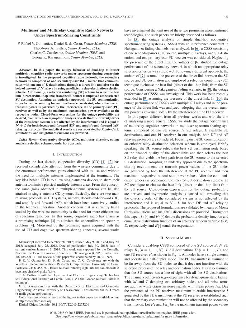
Consider a dual-hop CSSS composed of one SU source S, N SUrelays Rn(n = 1, . . . , N), L SU destinations Dl(l = 1, . . . , L), andone PU receiver P , as shown in Fig. 1. All nodes have a single antennaand operate in a half-duplex mode. The PU transmitter is assumed tobe far away from the SU nodes so that it does not interfere with theselection process of the relay and destination nodes. It is also assumedthat the SU source has a line-of-sight with all the SU destinations.The channel coefficients hMT experience Rayleigh quasi-static fading,with M and T denoting two arbitrary nodes, and all noise termsare additive white Gaussian noise signals with mean power N0. Duethe presence of the PU receiver, maximum tolerable interference Igenerated by the SU transmitters at the PU receiver is established suchthat the primary communication will not be affected by the secondarytransmission. Let PS and PRn be the maximum transmit power values
0018-9545 © 2013 IEEE. Personal use is permitted, but republication/redistribution requires IEEE permission.See http://www.ieee.org/publications_standards/publications/rights/index.html for more information.
434 IEEE TRANSACTIONS ON VEHICULAR TECHNOLOGY, VOL. 63, NO. 1, JANUARY 2014
Fig. 1. System model.
at the SU source and nth SU relay, respectively. Thus, making use ofan underlay approach,1 the transmit power values at S and Rn canbe written, respectively, as PS = min((I/|hSP |2), PS) and PRn =min((I/|hRnP |2), PRn). Focusing on the SU communication, a time-division multiple-access strategy is employed, which is performedin two phases. However, before the communication process starts,an efficient relay–destination selection scheme is carried out. Morespecifically, the best SU destination D∗ is first selected based onthe channel quality of the direct links, i.e., D∗ = argmaxl[γSDl
],where γSDl
= min((I/|hSP |2), PS)(d−ρSDl
|hSDl|2/N0), dMT is the
distance between two arbitrary nodes M and T , and ρ represents thepath loss coefficient.2 After the SU destination is selected, the relayselection process is performed in such a way that the chosen relay R∗
will maximize the end-to-end SNR from the SU source to the selectedSU destination.3 In what follows, the relay selection process and theend-to-end SNR will be formulated for both DF and AF relayingprotocols.
A. DF Relaying Protocol
As stated previously, the communication process comprises twophases. In phase I, the SU source broadcasts its information to bothR∗ and D∗ with transmission power PS . In particular, for DF relays,R∗ is given by
R∗ = argmaxn
[min [γSRn , γRnD∗ ]] (1)
1In practice, the channel state information (CSI) of the links between thesecondary and primary nodes can be obtained through a direct feedback fromthe PU or through an indirect feedback by a band manager that mediates theexchange of information between the primary and secondary networks.
2Note that, if we consider the path loss for the link between the SU andPU, it would be hard for the former to determine the distance from the PUto calculate its respective transmit power. For instance, the transmit power ofthe SU source would be PS = min((I/d−ρ
SP |hSP |2), PS) instead of PS =
min((I/|hSP |2), PS). Thus, due to practical implementation issues, we optedto not include the path loss for the link between the SU and PU nodes.
3Although the scheduling policy is suboptimal from the outage performancepoint of view, it will be shown that this strategy achieves the same diversityorder of the optimal node selection strategy, i.e., L+N . Furthermore, theamount of CSI required in the proposed scheme is L+ 2N + 2, whereasit would be LN + L+N + 2 if an optimal joint relay-destination schemewere employed. In addition, our proposed scheme only needs to compareL+N potential links in each transmission process, whereas for a joint relay-destination selection scheme it would require L(N + 1) potential links. Thus,one can notice that, for large-scale multirelay multidestination cooperativespectrum-sharing systems, the proposed scheme can significantly reduce theamount of overhead when compared with the optimal strategy, in addition toachieving the same diversity order.
where γSRn=min((I/|hSP |2), PS)(d−ρSRn
|hSRn |2/N0), and γRnD∗=
min((I/|hRnP |2), PRn)(d−ρRnD∗ |hRnD∗ |2/N0). In phase II, assum-
ing that the selected SU relay is always able to fully decode thereceived signal, R∗ forwards it to D∗ with transmission power PRn .At the end of this two-phase transmission, an SC strategy is performedby the selected SU destination. In this case, the path with the highestinstantaneous SNR is chosen between the direct and the selected dual-hop link so that the end-to-end SNR can be written as
γDFend = max
[max
l[γSDl
],maxn
[min [γSRn , γRnD∗ ]]]. (2)
B. AF Relaying Protocol
For the AF case, the first phase occurs similarly to the DF case, withthe SU source broadcasting its information to D∗ and R∗, where thelatter is now given by
R∗ = argmaxn
[γSRnγRnD∗
1 + γSRn + γRnD∗
]. (3)
In the second phase, the selected SU relay amplifies4 the received sig-nal from the SU source and forwards it to the selected SU destination.After the second phase, an SC strategy is employed at the selected SUdestination so that the end-to-end SNR can be written as
γAFend = max
[max
l[γSDl
],maxn
[γSRnγRnD∗
1 + γSRn + γRnD∗
]]. (4)
In (2) and (4), note that the two terms inside the max[., .] operator arenot statistically independent due to the presence of the common RV|hSP |2. Next, we will use the similar approach, as presented in [7], tostudy the system’s outage performance.
III. OUTAGE PROBABILITY ANALYSIS
A. DF
The outage probability is defined as the probability that the in-stantaneous end-to-end SNR, i.e., γDF
end, falls below a given thresholdγth. Due to the common term |hSP |2, as previously mentioned, theconditional outage probability can be written as
Pr(γDFend < γth|hSP
)=
θ︷ ︸︸ ︷Pr
(max
l[γSDl
] < γth|hSP
)×Pr
(max
n[min [γSRn , γRnD∗ ]] < γth|hSP
)︸ ︷︷ ︸
Ψ
. (5)
Since all the links from S to Dl are statistically independent, θ can beexpressed as
θ =
L∏l=1
Pr(γSDl< γth|hSP ) =
L∏l=1
FγSDl(γth|hSP )
=
L∏l=1
(1 − e−γth βSDl ) (6)
4In this paper, we consider only variable-gain relays in which the amplifica-tion factor is determined by the instantaneous channel statistics of the source-relay links.
IEEE TRANSACTIONS ON VEHICULAR TECHNOLOGY, VOL. 63, NO. 1, JANUARY 2014 435
where βSDl
Δ= 1/E[γSDl
]. According to the total probability theorem[11], Ψ in (5) can be written as
Ψ = Pr(max
n[min [γSRn , γRnD∗ ]] < γth|hSP
)
=
L∑l=1
Pr(D∗ = Dl) Pr(max
n
[min
[γSRn , γRnDl
]]< γth|hSP
)︸ ︷︷ ︸
Φ
.
(7)
By its turn, knowing that Pr(min[W,V ] < γth) = FW (γth) +FV (γth)− FW (γth)× FV (γth) [11], Φ can be reexpressed as
Φ =
N∏n=1
[(1 − e−γth βSRn ) + (1 − e−γth βRnDl )
− (1 − e−γth βSRn )(1 − e−γth βRnDl )]
(8)
where βSRn
Δ= 1/E[γSRn ], and βRnDl
Δ= 1/E[γRnDl
]. To determi-nate the value of Pr(D∗ = Dl), we make use of the results presentedin [12], yielding
Pr(D∗ = Dl) = 1 +
L−1∑k=1
∑Ak⊆{1,2,...,l−1,l+1,...,L}
|Ak|=k
×(−1)kβSDl
βSDl+∑
j∈Ak, βSDj
. (9)
Now, let X = |hSP |2, Y = |hRnP |2, γSD∗ = maxl[γSDl], and
γSR∗D∗ = maxn[min[γSRn , γRnD∗ ]]. Thus, a general expression forthe outage probability can be found by solving the following integral[11]:
Pout =
∞∫0
∞∫0
FγSD∗ (γth|X)FγSR∗D∗ (γth|X,Y )
× fX(x) fY (y) dx dy (10)
where FγSD∗ (γth|X) =∏L
l=1(1 − e−γth βSDl ), and FγSR∗D∗ (γth|
X,Y ) =∑L
l=1Pr(D∗ = Dl)× Φ. To determine the integral in (10),
it is important to see that
min(I
X,PS
)=
{PS , when X ≤ I/PS
I/X, when X > I/PS
min(I
Y, PRn
)=
{PRn , when Y ≤ I/PRn
I/Y, when Y > I/PRn .(11)
Thus, the outage probability can be rewritten as a sum of four terms,i.e., PDF
out = ξ1 + ξ2 + ξ3 + ξ4, where
ξ1 =
I/Q∫0
I/Q∫0
FγSD∗ (γth|X)FγSR∗D∗ (γth|X,Y )
× fX(x) fY (y)dx dy (12)
ξ2 =
I/Q∫0
∞∫I/Q
FγSD∗ (γth|X)FγSR∗D∗ (γth|X,Y )
× fX(x) fY (y)dx dy (13)
ξ3 =
∞∫I/Q
I/Q∫0
FγSD∗ (γth|X)FγSR∗D∗ (γth|X,Y )
× fX(x) fY (y)dx dy (14)
ξ4 =
∞∫I/Q
∞∫I/Q
FγSD∗ (γth|X)FγSR∗D∗ (γth|X,Y )
× fX(x) fY (y)dx dy. (15)
Without any loss of generality, let PRn = PS = Q. Thus, performingthe appropriate substitutions in (12), it follows that
ξ1 =
I/Q∫0
I/Q∫0
L∏l=1
(1 − e
−γthβQSDl
) L∑l=1
Pr(D∗ = Dl)
×N∏
n=1
(1 − e
−γth
(βQSRn
+βQRnDl
))× βSP e
−xβSP βRnP e−yβRnP dx dy (16)
where βSPΔ= 1/E[X], βRnP
Δ= 1/E[Y ], and βQ
MT
Δ= 1/(E[Qd−α
MT
|hMT |2/N0]), with M ∈ {S,Rn} and T ∈ {Rn,Dl}. By integratingthe previous equation, (16) results in
ξ1 =
L∏l=1
(1 − e
−γthβQSDl
) L∑l=1
Pr(D∗ = Dl)
×N∏
n=1
(1 − e
−γth
(βQSRn
+βQRnDl
))(1 − e
− IQ
βSP )
× (1 − e− I
QβRnP ). (17)
In a similar manner, by performing the appropriate substitutions in(13), we have
ξ2 =
I/Q∫0
∞∫I/Q
L∏l=1
(1 − e
−γth βQSDl
) L∑l=1
Pr(D∗ = Dl)
×N∏
n=1
(1 − e
−γth
(βQSRn
+yβIRnDl
))× βSP e
−xβSP βRnP e−yβRnP dx dy (18)
where yβIRnDl
Δ= 1/E[(I/y)(d−α
RnDl|hRnDl
|2/N0)]. Now, usingidentity
∏K
k=1(1 − xk) =
∑K
k=0(−1)k/k!
∑K
n1,...,nk
∏k
t=1xnt , it
follows that
ξ2 =
L∏l=1
(1 − e
−γthβQSDl
) L∑l=1
Pr(D∗ = Dl)(1 − e− I
QβSP )
×∞∫
I/Q
βRnP e−yβRnP
K∑k=0
(−1)k
k!
K∑n1,...,nk
×k∏
t=1
e−γth
(βQSRnt
+yβIRntDl
)dy. (19)
In the sequel, we assume that the links from S to Rn undergo indepen-dent identically distributed (i.i.d.) Rayleigh fading, which implies the

436 IEEE TRANSACTIONS ON VEHICULAR TECHNOLOGY, VOL. 63, NO. 1, JANUARY 2014
same average SNR (i.e., βSRn = βSR, ∀n).5 The same assumptioncan be made for the SU destinations, where the links from S andRn to Dl are also i.i.d. However, it is worth noting that the channelspertaining to different hops experience distinct fading conditions fromeach other. Thus, (19) can be rewritten as
ξ2 =
L∏l=1
(1 − e
−γthβQSDl
) L∑l=1
Pr(D∗ = Dl)(1 − e− I
QβSP )
× βRnP
N∑n=0
(N
n
)(−1)n
× exp
(−γthn
(βQSRn
+I
QβIRnDl
))e− I
QβRnP
γthnβIRnDl
+ βRnP
.
(20)
Applying the same procedure, (14) and (15) can be derived in closedform, respectively, as
ξ3 =
L∑m=0
(L
m
)(−1)m
L∑l=1
Pr(D∗ = Dl)
×N∑
n=0
(N
n
)(−1)nβSP
(1 − e− I
QβRnP ) e
(− IQ
βSP )
× exp
(−γth
(m
I
QβISDm
+ n
(I
QβISRn
+ βQRnDm
)))× 1
γth(mβI
SDm+ nβI
SRn
)+ βSP
(21)
ξ4 =
L∑m=0
(L
m
)(−1)m
L∑l=1
Pr(D∗ = Dl)
×N∑
n=0
(N
n
)(−1)nβSPβRnP
× exp
(−γth
I
Q
(mβI
SDm+ nβI
SRn+ nβI
RnDm
))
× e
(− I
Q(βSP+βRnP )
)[γth(mβI
SDm+ nβI
SRn) + βSP
] [γthnβI
RnDm+ βRnP
](22)
where βISRn
Δ= 1/E[I d−α
SRn|hSRn |2/N0], and βI
SDl
Δ= 1/E[I d−α
SDl
|hSDl|2/N0]. Finally, by substituting (17), (20)–(22) into PDF
out =ξ1 + ξ2 + ξ3 + ξ4, a closed-form expression for the outage probabilityof a DF relaying scenario is derived.
B. AF
For AF relays, because the two terms inside (4) are not statisticallyindependent, we adopt a similar approach previously used for DFrelays. In this case, the conditional outage probability can be writ-ten as
Pr(γAFend < γth|hSP
)= Pr
(max
l[γSDl
] < γth|hSP
)×Pr
(max
n
[γSRnγRnD∗
1 + γSRn + γRnD∗
]< γth|hSP
)︸ ︷︷ ︸
Ω
. (23)
5Such an assumption relies on the fact that the SU relays are clusteredrelatively close together and are selected by a long-term routing process (see[13] and references therein).
The term Pr(maxl[γSDl] < γth|hSP ) is given by (6). In addition, Ω
can be calculated as
Ω = Pr
(max
n
[γSRnγRnDl
1 + γSRn + γRnDl
]< γth|hSP
)
=
L∑l=1
Pr(D∗ = Dl)
×N∏
n=1
Pr
([γSRnγRnDl
1 + γSRn + γRnDl
]< γth|hSP
)︸ ︷︷ ︸
Θ
(24)
where∑L
l=1Pr(D∗ = Dl) is given by (9), and Θ can be determined
as [12]
Θ =
∞∫0
Pr
(max
n
[γSRnγRnDl
1 + γSRn + γRnDl
]< γth|hSP
)× fγSRn
(γSRn)dγSRn
= 1 − βSRne−γth(βSRn+βRnDl
)2
√z
βSRn
K1
(2√
zβSRn
)(25)
where z = γth(γth + 1)βRnDl, and K1(·) denotes the first-order
modified Bessel function of the second kind [14, Eq. (8.432.6)].By replacing (25) and (9) into (24) and plugging this latter and(6) into (23), a closed-form expression for the conditional outageprobability is obtained. Then, unconditioning such expression withrespect to hSP , the outage probability can be determined as in (10) bymaking the appropriate substitutions of the required statistics. In thiscase, for AF relays, FγSD∗ (γth|X) =
∏L
l=1(1 − e−γth βSDl ) and
FγSR∗D∗ (γth|X,Y ) =∑L
l=1Pr(D∗ = Dl)×
∏N
n=1Θ. Finally, us-
ing the same rationale employed to DF relays, the outage probabilitycan be written as PAF
out = ϑ1 + ϑ2 + ϑ3 + ϑ4, where ϑi is determinedin the same way as ξi, i = 1, 2, 3, 4, by substituting the appropriatestatistics for the AF relaying case. In particular, it can be shown that
ϑ1 =
I/Q∫0
I/Q∫0
L∏l=1
(1 − e
−γthβQSDl
) L∑l=1
Pr(D∗ = Dl)
×N∏
n=1
(1 − βQ
SRne−γth(β
QSRn
+βQRnDl
)
× 2
√z
βSRn
K1
(2√
zβSRn
))× βSP e
−xβSP βRnP e−yβRnP dx dy (26)
which results in
ϑ1 =
L∏l=1
(1 − e−γthβ
QSDl )
×L∑
l=1
Pr(D∗ = Dl)(1 − e− I
QβSP )(1 − e
− IQ
βRnP )
×N∏
n=1
(1 − βQ
SRne−γth
(βQSRn
+βQRnDl
)2
√γth(γth + 1)βQ
RnDl
βQSRn
×K1
(2√
γth(γth + 1)βQRnDl
βQSRn
)). (27)

IEEE TRANSACTIONS ON VEHICULAR TECHNOLOGY, VOL. 63, NO. 1, JANUARY 2014 437
By its turn, ϑ2 is expressed as
ϑ2 =
I/Q∫0
∞∫I/Q
L∏l=1
(1 − e−γthβ
QSDl )
L∑l=1
Pr(D∗ = Dl)
×N∏
n=1
(1 − βQ
SRne−γth
(βQSRn
+yβIRnDl
)
× 2√
zI
βQSRn
K1
(2√
zIβQSRn
))× βSP e
−xβSP βRnP e−yβRnP dx dy (28)
where zI = yγth(γth + 1)βIRnDl
. To evaluate (28) in closed form, wemake use of the following approximation6 K1(ζ) ≈ 1/ζ[14, Eq. (9.6.9)]. Thus
ϑ2 ≈I/Q∫0
∞∫I/Q
L∏l=1
(1 − e−γthβ
QSDl )
L∑l=1
Pr(D∗ = Dl)
×N∏
n=1
(1 − e
−γth(βQSRn
+yβIRnDl
))
× βSP e−xβSP βRnP e
−yβRnP dx dy (29)
which results in (20). In the same way, ϑ3 and ϑ4 can be wellapproximated by (21) and (22), respectively. Finally, by substituting(27), (20)–(22) into PAF
out = ϑ1 + ϑ2 + ϑ3 + ϑ4, an accurate closed-form approximation for the system outage probability with AF relaysis attained.
IV. ASYMPTOTIC ANALYSIS
To provide further insights from the attained expressions, an asymp-totic analysis (high-SNR regime) is now carried out for both DF and
AF relaying protocols. Without loss of generality, let γΔ= 1/N0 be
the system SNR and assume that I/Q = μ, where μ is a positiveconstant. As γ → ∞, note that βSP � γth/γ and βRnP � γth/γ.Thus, using the Maclaurin series of exponential functions, we havee−γx 1 − γx. Based on this approximation, making use of K1(ζ) 1/ζ for the AF case and performing the appropriate substitutions inaddition to some algebraic manipulations, we arrive at the followingasymptotic expressions:
1) DF
P ξ1out
L∏m=1
(γthβ
QSDm
)×
L∑l=1
Pr(D∗ = Dl)(1 − e(−μβSP ))(1 − e(−μβRnP ))
×N∏
n=1
[γth
(βQSRn
+ βQRnDm
)]∝(
1γ
)L+N
(30)
P ξ2out
L∏m=1
(γthβ
QSDm
)×
L∑l=1
Pr(D∗ = Dl)(1 − eμβSP )e−μβRnP
6Interestingly, such approximation will exhibit good tightness with thesimulated results for all ranges of system SNRs.
×N∏
n=1
[γth
(βQSRn
+ μβIRnDm
)]∝(
1γ
)L+N
(31)
P ξ3out
L∏m=1
(μγthβ
ISDm
)×
L∑l=1
Pr(D∗ = Dl)(1 − e−μβRnP )e−μβSP
×N∏
n=1
[γth
(μβI
SRn+ βQ
RnDm
)]∝(
1γ
)L+N
(32)
P ξ4out
L∏l=1
(μγthβ
ISDl
)Pr(D∗ = Dl)(1 − μβSP − μβRnP )
×N∏
n=1
[μγth
(βISRn
+ βIRnDl
)]∝(
1γ
)L+N
(33)
2) AF
Pϑ1out
L∏m=1
(γthβ
QSDm
)×
L∑l=1
Pr(D∗ = Dl)(1 − e(−μβSP ))(1 − e(−μβRnP ))
×N∏
n=1
[γth
(βQSRn
+ βQRnDm
)]∝(
1γ
)L+N
(34)
Pϑ2out =P ξ2
out Pϑ3out = P ξ3
out Pϑ4out = P ξ4
out. (35)
From the previous equation, it is easy to see that the system underconsideration achieves full diversity, with the diversity order beingequal to L+N for both DF and AF relaying protocols. In addition,note that this gain is not affected by the interference constraint, and itis only determined by the number of SU relays and destinations.
V. NUMERICAL PLOTS AND DISCUSSIONS
To evaluate the outage performance of the considered dual-hopcognitive multirelay network, representative numerical examples arenow presented. As will be observed, all the cases investigated revealedexcellent agreement between analytical (exact → DF relays; approxi-mate → AF relays) and simulation results. For the plots, without lossof generality, the statistical average of the channel gains is determinedby the distance among the nodes, the threshold γth is set to 3 dB, andthe path loss coefficient ρ is set to 4. The network is generated in a2-D plane, where the SU source is located at (0, 0), the SU destinationsare clustered together and collocated at (1, 0), the SU relays are alsoclustered together and collocated at (0.5, 0), and the PU receiver islocated at (0, 1).
Figs. 2 and 3 show the outage probability against the system SNRfor four different combinations of SU relays and destinations, as wellas adopting DF and AF relays, respectively. Note that the asymptoticcurves are shown to be very tight with the analytical curves at high-SNR regions, which confirms the correctness of our analysis. It isshown that the diversity order is given by L+N for both DF and AFrelays, as expected. In addition, in both figures, considering a diversityorder equal to 3, the case with {N = 2, L = 1} outperforms the casewith {N = 1, L = 2}. In other words, for the same diversity order, theoutage performance is higher when the number of SU relays surpassesthe number of SU destinations. This shows that the use of CD is muchmore beneficial for the system performance than the use of multiuserdiversity, which motivates the use of the former.

438 IEEE TRANSACTIONS ON VEHICULAR TECHNOLOGY, VOL. 63, NO. 1, JANUARY 2014
Fig. 2. Outage probability and asymptotic behavior versus system SNRusing DF strategy for different numbers of SU relays and destinations (Q =I = 0.5).
Fig. 3. Outage probability and asymptotic behavior versus system SNRusing AF strategy for different numbers of SU relays and destinations (Q =I = 0.5).
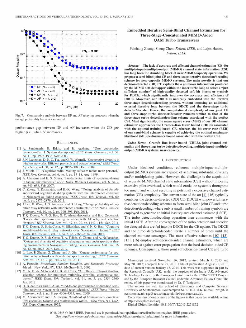
Figs. 4 and 5 show the impact of interference temperature con-straints on the outage probability for DF relays and AF relays, respec-tively, and assuming N = L = 2. Note that, due to the interferenceconstraint, the outage probability of the system becomes saturatedbecause the maximum allowed power for transmission is reached,as similarly observed in [5]. Moreover, as I gets larger, the outageperformance improves, approaching the no-interference case.
In Fig. 6, a comparative outage analysis between the two relayingstrategies is performed assuming the same diversity order (i.e., 6).To make the figures clearer, simulation data have been omitted. Asexpected, the outage performance for the DF relaying case is betterthan that for the AF relaying case. Note also that, when the numberof SU relays increases, the gap between DF and AF becomes higherat low SNRs. This means that, when the CD gets higher, choosingthe DF relaying strategy is even more preferable. Finally, in Fig. 7,a comparative analysis between DF and AF relaying protocols iscarried out assuming that the outage probability becomes saturated.As expected, the outage performance increases for higher values ofdiversity order. In addition, as shown in Fig. 6, in this figure, the
Fig. 4. Impact of interference constraints on the outage performance assumingDF relays (N = L = 2).
Fig. 5. Impact of interference constraints on the outage performance assumingAF relays (N = L = 2).
Fig. 6. Comparative outage analysis between DF and AF relaying protocolswhen Q = I = 0.5.
IEEE TRANSACTIONS ON VEHICULAR TECHNOLOGY, VOL. 63, NO. 1, JANUARY 2014 439
Fig. 7. Comparative analysis between DF and AF relaying protocols when theoutage probability becomes saturated.
performance gap between DF and AF increases when the CD getshigher (i.e., when N increases).
REFERENCES
[1] A. Sendonaris, E. Erkip, and B. Aazhang, “User cooperationdiversity—Part I: System description,” IEEE Trans. Commun., vol. 51,no. 11, pp. 1927–1938, Nov. 2003.
[2] J. N. Laneman, D. N. C. Tse, and G. W. Wornell, “Cooperative diversity inwireless networks: Efficient protocols and outage behavior,” IEEE Trans.Inf. Theory, vol. 50, no. 12, pp. 3062–3080, Dec. 2004.
[3] J. Mitola, III, “Cognitive radio: Making software radios more personal,”IEEE Pers. Commun, vol. 6, no. 4, pp. 13–18, Aug. 1999.
[4] A. Ghasemi and E. S. Sousa, “Fundamental limits of spectrum-sharingin fading environments,” IEEE Trans. Wireless Commun., vol. 6, no. 2,pp. 649–658, Feb. 2007.
[5] C. Zhong, T. Ratnarajah, and K.-K. Wong, “Outage analysis of decode-and-forward cognitive dual-hop systems with the interference constraintin Nakagami-m fading channels,” IEEE Trans. Veh. Technol., vol. 60,no. 6, pp. 2875–2879, Jul. 2011.
[6] J. Lee, H. Wang, J. G. Andrews, and D. Hong, “Outage probability of cog-nitive relay networks with interference constraints,” IEEE Trans. WirelessCommun., vol. 10, no. 2, pp. 390–395, Feb. 2011.
[7] T. Q. Duong, V. N. Q. Bao, G. C. Alexandropoulos, and H.-J. Zepernick,“Cooperative spectrum sharing networks with AF relay and selectiondiversity,” IET Electron. Lett., vol. 47, no. 20, pp. 1149–1151, Sep. 2011.
[8] T. Q. Doung, D. B. da Costa, M. Elkashlan, and V. N. Q. Bao, “Cognitiveamplify-and-forward relay networks over Nakagami-m fading,” IEEETrans. Veh. Technol., vol. 61, no. 5, pp. 2368–2374, Jun. 2012.
[9] T. Q. Duong, D. B. da Costa, T. A. Tsifsis, C. Zhong, and A. Nallanathan,“Outage and diversity of cognitive relaying systems under spectrum shar-ing environments in Nakagami-m fading,” IEEE Commun. Lett., vol. 16,no. 12, pp. 2075–2078, Dec. 2012.
[10] L. Luo, P. Zhang, G. Zhang, and J. Qin, “Outage performance for cog-nitive relay networks with underlay spectrum sharing,” IEEE Commun.Lett., vol. 15, no. 7, pp. 710–712, Jul. 2011.
[11] A. Papoulis, Probability, Random Variables, and Stochastic Processes,4th ed. New York, NY, USA: McGraw-Hill, 2002.
[12] M. A. B. de Melo and D. B. da Costa, “An efficient relay–destinationselection scheme for multiuser multirelay downlink cooperative net-works,” IEEE Trans. Veh. Technol., vol. 61, no. 5, pp. 2354–2360,Jun. 2012.
[13] D. B. da Costa and S. Aissa, “End-to-end performance of dual-hop semi-blind relaying systems with partial relay selection,” IEEE Trans. WirelessCommun., vol. 8, no. 8, pp. 4306–4315, Aug. 2009.
[14] M. Abramowitz and I. A. Stegun, Handbook of Mathematical Functionswith Formulas, Graphs, and Mathematical Tables. New York, NY, USA:U.S. Dept. Commerce, 1972.
Embedded Iterative Semi-Blind Channel Estimation forThree-Stage-Concatenated MIMO-Aided
QAM Turbo Transceivers
Peichang Zhang, Sheng Chen, Fellow, IEEE, and Lajos Hanzo,Fellow, IEEE
Abstract—The lack of accurate and efficient channel estimation (CE) formultiple-input–multiple-output (MIMO) channel state information (CSI)has long been the stumbling block of near-MIMO-capacity operation. Wepropose a semi-blind joint CE and three-stage iterative detection/decodingscheme for near-capacity MIMO systems. The main novelty is that ourdecision-directed (DD) CE exploits the a posteriori information producedby the MIMO soft demapper within the inner turbo loop to select a “justsufficient number” of high-quality detected soft bit blocks or symbolsfor DDCE, which significantly improves the accuracy and efficiency ofDDCE. Moreover, our DDCE is naturally embedded into the iterativethree-stage detection/decoding process, without imposing an additionalexternal iterative loop between the DDCE and the three-stage turbodetector/decoder. Hence, the computational complexity of our joint CEand three-stage turbo detector/decoder remains similar to that of thethree-stage turbo detection/decoding scheme associated with the perfectCSI. Most significantly, the mean square error (MSE) of our DD channelestimator approaches the Cramér–Rao lower bound (CRLB) associatedwith the optimal-training-based CE, whereas the bit error rate (BER)of our semi-blind scheme is capable of achieving the optimal maximum-likelihood (ML) performance bound associated with the perfect CSI.
Index Terms—Cramér–Rao lower bound (CRLB), joint channel esti-mation and three-stage turbo detection/decoding, multiple-input–multiple-output (MIMO) systems, near-capacity.
I. INTRODUCTION
Under idealized conditions, coherent multiple-input–multiple-output (MIMO) systems are capable of achieving substantial diversityand/or multiplexing gains. However, the challenge is the acquisitionof accurate MIMO channel state information (CSI) without imposingexcessive pilot overhead, which would erode the system’s throughputtoo much, and without resulting in potentially excessive channel esti-mation (CE) complexity. The current state of the art [1]–[16] typicallycombines the decision-directed (DD) CE (DDCE) with powerful itera-tive detection/decoding schemes to form semi-blind joint CE and turbodetection/decoding, where only a small number of training symbols areemployed to generate an initial least squares channel estimate (LSCE).The turbo detection/decoding operation then commences with theinitial LSCE. After the convergence of the turbo detector and decoder,the detected data are fed into the DDCE for the CE update. The DDCEand the turbo detector/decoder iterate a number of times until thechannel estimate converges. The most effective schemes [10]–[13],[15], [16] employ soft-decision-aided channel estimators, which aremore robust against error propagation than the hard-decision-aided CEschemes. Consequently, these joint soft-decision-based CE and turbo
Manuscript received November 16, 2012; revised March 4, 2013 andMay 20, 2013; accepted June 25, 2013. Date of publication August 21, 2013;date of current version January 13, 2014. This work was supported in part bythe Research Councils U.K. under the auspices of the India–U.K. AdvancedTechnology Center, by the European Union under the CONCERTO Project,and by the European Research Council under the Advanced Fellow Grant. Thereview of this paper was coordinated by Dr. T. Taniguchi.
The authors are with the School of Electronics and Computer Science,University of Southampton, Southampton SO17 1BJ, U.K. (e-mail: [email protected]; [email protected]; [email protected]).
Color versions of one or more of the figures in this paper are available onlineat http://ieeexplore.ieee.org.
Digital Object Identifier 10.1109/TVT.2013.2271872
0018-9545 © 2013 IEEE. Personal use is permitted, but republication/redistribution requires IEEE permission.See http://www.ieee.org/publications_standards/publications/rights/index.html for more information.