
MULTI - CHANNEL ALLOCATION AND FAIR-PRIORITY MAC DESIGN FOR WIRELESS SENSOR NETWORKS
16
K. Ranjith Singh et al, International Journal of Computer Science and Mobile Computing Vol.2 Issue. 11, November- 2013, pg. 30-45 © 2013, IJCSMC All Rights Reserved 30 Available Online at www.ijcsmc.com International Journal of Computer Science and Mobile Computing A Monthly Journal of Computer Science and Information Technology ISSN 2320–088X IJCSMC, Vol. 2, Issue. 11, November 2013, pg.30 – 45 RESEARCH ARTICLE MULTI - CHANNEL ALLOCATION AND FAIR-PRIORITY MAC DESIGN FOR WIRELESS SENSOR NETWORKS 1 K. Ranjith Singh, 2 S. Ranjani 1,2 Department of Computer Science, Periyar University, TamilNadu, India 1 kranjithsingh@yahoo,com, 2 [email protected] Abstract- A wireless sensor network (WSN) consists of a number of Autonomous and inexpensive sensor nodes. Each of them is composed of sensors, a low-power radio transceiver, small amount of memory and processing capability as well as limited battery power supply. The WSN should consist of hundreds or thousands of such tiny devices deployed in adhoc manner, which are able to sense the environment, compute simple task and communicate with each other in order to achieve common objective, like environmental monitoring, target tracking, detecting hazardous chemicals and forest fires, monitoring seismic activity, military surveillance. 1. INTRODUCTION The primary objective in WSN design is maximizing node/network lifetime, leaving the other performance metrics as secondary objectives. Since the communication of sensor nodes is more energy consuming than their computation, it is a primary concern to minimize communication while achieving the desired network operation. Media Access Control (MAC) is a key component to ensure the successful operation of WSNs and it has obtained intensive research attention. A MAC protocol
Transcript of MULTI - CHANNEL ALLOCATION AND FAIR-PRIORITY MAC DESIGN FOR WIRELESS SENSOR NETWORKS

K. Ranjith Singh et al, International Journal of Computer Science and Mobile Computing Vol.2 Issue. 11, November- 2013, pg. 30-45
© 2013, IJCSMC All Rights Reserved 30
Available Online at www.ijcsmc.com
International Journal of Computer Science and Mobile Computing
A Monthly Journal of Computer Science and Information Technology
ISSN 2320–088X
IJCSMC, Vol. 2, Issue. 11, November 2013, pg.30 – 45
RESEARCH ARTICLE
MULTI - CHANNEL ALLOCATION
AND FAIR-PRIORITY MAC DESIGN
FOR WIRELESS SENSOR NETWORKS 1 K. Ranjith Singh, 2 S. Ranjani
1,2Department of Computer Science, Periyar University, TamilNadu, India
1 kranjithsingh@yahoo,com, 2 [email protected]
Abstract- A wireless sensor network (WSN) consists of a number of Autonomous and inexpensive sensor nodes. Each of
them is composed of sensors, a low-power radio transceiver, small amount of memory and processing capability as well as
limited battery power supply. The WSN should consist of hundreds or thousands of such tiny devices deployed in adhoc
manner, which are able to sense the environment, compute simple task and communicate with each other in order to achieve
common objective, like environmental monitoring, target tracking, detecting hazardous chemicals and forest fires,
monitoring seismic activity, military surveillance.
1. INTRODUCTION The primary objective in WSN design is maximizing node/network lifetime, leaving the other performance metrics as
secondary objectives. Since the communication of sensor nodes is more energy consuming than their computation, it is a
primary concern to minimize communication while achieving the desired network operation. Media Access Control (MAC) is a
key component to ensure the successful operation of WSNs and it has obtained intensive research attention. A MAC protocol

K. Ranjith Singh et al, International Journal of Computer Science and Mobile Computing Vol.2 Issue. 11, November- 2013, pg. 30-45
© 2013, IJCSMC All Rights Reserved 31
decides when competing nodes could access the shared medium to transmit their data and tries to ensure that no collisions
occur. MAC protocol controls the activity of nodes’ radio transceiver directly, and therefore makes a strong impact to the
overall network performance and energy efficiency.
Popularity of WSNs is the result of technological advancements in Micro-Electro Mechanical Systems (MEMS) for
sensing, microelectronics for computation and communication, and wireless networking techniques for efficient transmission.
Sensor nodes usually are equipped with a single transceiver utilizing a single channel. Therefore, WSNs cannot provide reliable
and timely communication with high data rate requirements due to radio collisions and limited bandwidth. Here, the term
“channel” is used upon a logical level, where it can be implemented as a frequency band under FDMA or an orthogonal code
under CDMA.
Recent developments in sensor technology WINS nodes and the IEEE 802.15.4 Zigbee, have enabled support for
single-transceiver, multi-channel communication. The task of channel assignment with minimum interference, also named as
the 2-hop coloring problem, allows repetition of colors occurs only if the nodes are separated by more than 2 hops. Being NP
complete, development of efficient heuristics for this coloring problem is an open research area and proposes the Dynamic
Channel Allocation (DCA) algorithm as a novel solution.
Once channels are assigned, a Medium Access Control protocol must be devised so that channel selection, arbitration
and scheduling occur with maximum energy savings and reduced message overhead, both critical considerations for sensor
networks.
2. RELATED WORK
The problem of channel allocation is similar to the code assignment problem in Code Division Multiple Access
(CDMA) networks that eliminates collisions through spread spectrum techniques and orthogonal codes. Earlier works on
CDMA code allocation have approached this as a graph coloring problem, where colors can be repeated only at 3 hops or more,
unlike traditional graph coloring as surveyed. We shall henceforth refer to coloring under this constraint as the NP complete 2-
hop coloring problem.
Centralized code assignment schemes are unsuitable when directly applied to sensor networks as it may be infeasible to
establish direct communication between the base station (BS) and the individual sensor nodes. Past work has also involved
presenting optimal 2-hop coloring algorithms for special topologies, such as the ring, bus, chain, tree and hexagonal grids.
In the analysis of our proposed Distributed Coloring Algorithm (DCA), we consider the more general case of random
deployment of the sensor nodes. Recent work, including the algorithm proposed reduces, under assumptions of ordering, to the
Hidden Primary Collision Avoidance (HP-CA) suggested and modified , when a node chooses a color, it is propagated to its 2-
hop neighbors having an ID lower than itself.

K. Ranjith Singh et al, International Journal of Computer Science and Mobile Computing Vol.2 Issue. 11, November- 2013, pg. 30-45
© 2013, IJCSMC All Rights Reserved 32
The simple modification of making a node wait till it hears from all nodes having a higher ID and within its 2-hop
range before announcing its own non-conflicting color provides an elegant solution. We call this HP-CAM with ‘M’ for
modified. A node chooses a unique ID and broadcasts it amongst its 2-hop neighbors.
In case of a conflict, the information is conveyed back to the transmitting node and new ID is chosen thus repeating the
process. Though simple, this process involves large message passing as n-1re-tries may be required for each node in the worst
case. In HP-CAM, each node is aware of its 2- hop information and generates an ordering based on node weight.
This results in reduced number of messages as there is no color conflict once an assignment has been done. There has
recently been much interest in developing suitable MAC protocols for wireless sensor networks. Existing work in this area can
be classified into the following categories: time-division multiple accesses (TDMA), contention-based and multiple-channel
MAC protocols. TDMA based protocols, though not scalable, enable collision free communication and are simple to set up and
maintain.
Local synchronization is required and they alternate between listen and sleep cycles. TDMAW requires non-repetition
of the time slots over a 2- hop range, similar to the task of channel allocation in our case. The activity between a node and its
neighbors is monitored at the end of every frame and this helps to further tune the wakeup period.
The authors propose a scheme in which centralized allocation of schedules in undertaken by a cluster head like node
(gateway). This is however, typical of standard TDMA schemes and requires global synchronization. Concentrate on assigning
non-overlapping 2-hop slots but allow nodes to join and leave the network.
They do not address issues of energy conservation, latency amongst others and need synchronization of the start and
end of slot times. Sift is a randomized contention-based CSMA protocol which has a small, fixed size contention window (CW)
with a non-uniform probability of transmission in each slot of the CW.
This scheme, however, does not accommodate sleep cycles and needs accurate time synchronization during the CW as
slot times are small. S-MAC and protocols inspired by it, follow the listen and sleep cycles as described earlier, but contend for
the channel during the listen cycles. Pair wise synchronization is usually sufficient and they trade fairness and latency for
energy savings. By choosing to send a burst of data during the listen cycle, T-MAC shows performance improvement over
SMAC, but at the cost of monopolizing a bottleneck node, the authors present AC-MAC which has an adaptive duty cycle based
on the number of packets queued at the MAC layer as an indication of the traffic load.
While the above work assume a single radio, the idea of using an additional wakeup radio for sensor networks is not
novel and is discussed in According to the authors in, this low power radio may only use 1 lW of energy compared to the high
dissipation of the MR (order of mW), and hence is the ideal choice for channel monitoring when the MR is switched off.
In this work, however, the authors focus more on the channel allocation problem and the MAC protocol is left for
future research. STEM and RATE-EST are similar in principle in which the authors assume the presence of two channels:
primary channel for sending data and a wakeup channel used for the wakeup signals. Both these approaches use a busy tone
K. Ranjith Singh et al, International Journal of Computer Science and Mobile Computing Vol.2 Issue. 11, November- 2013, pg. 30-45
© 2013, IJCSMC All Rights Reserved 33
instead of encoded data for the wakeup signal. Energy savings are obtained by allowing the radio for data communication to
enter the low power sleep mode until communication is desired.
The additional wakeup radio periodically listens to the channel using a low duty cycle. A node with data to send,
begins transmitting continuously on the wakeup channel long enough to guarantee that all neighbors receive the wakeup signal.
The authors evaluate analytically the duty cycle for the wakeup radio and suggest a scheme that prevents a large
number of nodes from being triggered into an active state at the same time. While similar to STEM, RATE-EST achieves
greater energy savings by periodically listening on the primary channel and buffering packets. Our work differs from all these
approaches in the respect that we assume a multi-channel scenario and in-band signaling. Here, each node is assigned a unique
channel in 2-hop range with a single transceiver present for data communication.
In our work, we describe a scheme for the wakeup process and channel information exchange without any special
control channel, thus saving bandwidth for the purpose of communication only.
Furthermore, our protocol allows for listening and replying to control messages even when a reception of a data packet
is in progress at a sensor node, thus taking the first step towards solving the deafness problem in wireless networks.
Throughputs and expected delays
Since, we assume that packet arrivals follow Poisson process performance evaluation of random access schemes can
be carried out by exploiting the busy period analysis, where the average busy time B ̄ and average idle time Ī are used for
determining the characteristics of various schemes. In the appendices, we derive the following probabilities for different multi-
channel protocols using the busy period analysis: Ps is the probability of successful transmission, Pc is the probability of
collision and Pb is the probability that the channel is sensed busy. In this section, we derive closed-form solutions for average
access delays and throughputs of various multi-channel MAC schemes individually by exploiting derived probabilities.
Theoretical results are confirmed by simulations. Examined protocols are G-McMAC, MMAC and SYN-MAC. In the case of
G-McMAC and SYN-MAC, we derive the theoretical results rigorously. On the other hand, since MMAC uses finite contention
windows, only approximations can be found in case of MMAC which are then justified by simulation results.
We specify throughput S as follows
S=gTPs,(2)
where T is the packet size in discrete time slots τ. Next, we define average access delay. Average access delay is the
sum of the initial access delay and the delay because of i unsuccessful transmissions. We denote the initial access delay with D0
and the delay of ith retransmission with Di. In general form, the total access delay in case of R retransmissions is
D=∑Ri=0Di.(3)
K. Ranjith Singh et al, International Journal of Computer Science and Mobile Computing Vol.2 Issue. 11, November- 2013, pg. 30-45
© 2013, IJCSMC All Rights Reserved 34
Added to this, different retransmission policies induce different delays. By denoting the ith backoff delay as uniformly
distributed random variable Wi ~ U(1, 2i-1ω), where ω is the original backoff window in slots, we get the following expected
delay for the ith backoff in case of Binary Exponential Backoff (BEB)
E[Wbebi]=1+2i−1ω2.(4)
and, respectively, in case of Uniform Backoff (UB) we have Wi ~ U(1, ω) and
E[Wub]=1+ω2.(5)
A. Generic multi-channel MAC (G-McMAC)
First, we derive equations for the throughput and average access delay of G-McMAC. We exclude the beacon period from this analysis since beaconing may be used by other protocols as well, such as MMAC, or periodic beaconing may be required for time synchronization, routing, etc. For example, many routing protocols use broadcast messages to distribute routing information and hence, require a beacon period in practice to avoid transmission of a routing packet many times. Moreover, it is presumed that beacon periods are carried out rarely such that the impact of the period is negligible to the packet arrival process.
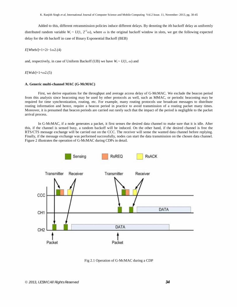
In G-McMAC, if a node generates a packet, it first senses the desired data channel to make sure that it is idle. After this, if the channel is sensed busy, a random backoff will be induced. On the other hand, if the desired channel is free the RTS/CTS message exchange will be carried out on the CCC. The receiver will sense the wanted data channel before replying. Finally, if the message exchange was performed successfully, nodes can start the data transmission on the chosen data channel. Figure 2 illustrates the operation of G-McMAC during CDPs in detail.
Fig 2.1 Operation of G-McMAC during a CDP
K. Ranjith Singh et al, International Journal of Computer Science and Mobile Computing Vol.2 Issue. 11, November- 2013, pg. 30-45
© 2013, IJCSMC All Rights Reserved 35
Average access delay of G-McMAC depends on two issues. First, the contention process on the CCC and possible
collisions induce some delay. Second, if all data channels are occupied an extra delay will be added as well. We deduce the
delay of the contention process first and the impact of occupied channels will be taken into account while deriving the
probability of successful transmission in Appendix A.
Now, if the CCC is sensed busy, the latency time for the first unsuccessful transmission is
D1=(W1+1)⋅τ.(6)
Respectively, if the channel is sensed idle, the transmitter waits for 4τ to conclude whether there was a collision or not.
In case of a collision, the delay time for the second unsuccessful transmission is
D2=(W2+4)⋅τ.(7)
Consequently, by denoting the number of retransmission because of the channel is sensed busy by K, the total delay
time can be calculated as follows
D=D0+∑Ki=1(W1+1)⋅τ+∑Rj=K+1(W2+4)⋅τ=D0+τ∑Ri=1Wi+Kτ+4(R−K)⋅τ,(1)(2)(3)(8)
where D0 ~ U (5τ, 6τ) is the initial transmission delay in case of successful transmission and 0 ≤ K ≤ R. Hence, R - K is
the amount of retransmission due to packet collisions during contention. The joint distribution of R and K is
P{R=r,K=k}=⎛⎝rk⎞⎠PkbPr−kcPs,0≤k≤r,(9)
and the used probabilities for G-McMAC are derived in Appendix A. Now, the expected delay conditioned on R = r
and K = k for G-McMAC can be formulated as
E[D|R=r,K=k]=E[D0]+τ∑ri=1E[Wi]+kτ+4(r−k)⋅τ=τ2(ω2r+9r−6k+11−ω).(1)(2)(3)(4)(10)
Moreover, to derive the average access delay we need to remove the conditioning on R and K. Therefore, the average
access delay is given by
D ̄ =∑∞r=0∑rk=0E[D—R=r,K=k]⋅P{R=r,K=k}=τ2(ωPs1−2(1−Ps)+9Ps−6PbPs+2−ω),Ps>0.5,(1)(2)(3)(4)(11)
Where Ps > 0.5 is required to have a finite average delay. In addition, availability of channels causes additional delay as
well. We model the impact of multi-channel communications using a Markov model and thus, the probability that all the data
channels are occupied (Pocc) can be calculated using the Erlang B formula. As a result, the throughput of G-McMAC is
S=gT⋅e−gτ4−3e−gτ⋅(1−Pocc),(12)

K. Ranjith Singh et al, International Journal of Computer Science and Mobile Computing Vol.2 Issue. 11, November- 2013, pg. 30-45
© 2013, IJCSMC All Rights Reserved 36
where
Pocc=GN−1(N−1)!∑N−1i=0Gii!,(13)
and G = gT. Since the control channel is not used for data transmissions, only N - 1 channels are available for data
transmissions. Figure 3 shows that the theoretical and simulated results match up well for different number of channels with
respect to delay.
Fig 3 Theoretical and simulated results for average access delay of G-McMAC (T = 100, ω = 32)
B. Multi-channel MAC (MMAC)
Next, we study split phase approaches using MMAC as an example. Operation of MMAC is divided into two parts
which form a cycle. MMAC is designed for IEEE 802.11 networks and it exploits Ad hoc Traffic Indication Message (ATIM)
windows of IEEE 802.11 Power Saving Mechanism (PSM) which are originally used only for power management. In MMAC
ATIM windows are extended and channel reservations conducted during ATIM windows on the CCC. Data transmissions take
place on all available channels afterwards. We denote the length of the ATIM window by Tatim and the length of the data interval
by T, both in time slots. Thus, the total length of one cycle is Tc = Tatim + T. Lengths of these intervals are predetermined and
fixed and hence, the intervals determine the average access delay as well. We set Tatim = 0.2 · Tc and T = 0.8 · Tc since these
values were used in the initial simulation model in. Furthermore, it is assumed that packets fit perfectly to the chosen cycle
structure.
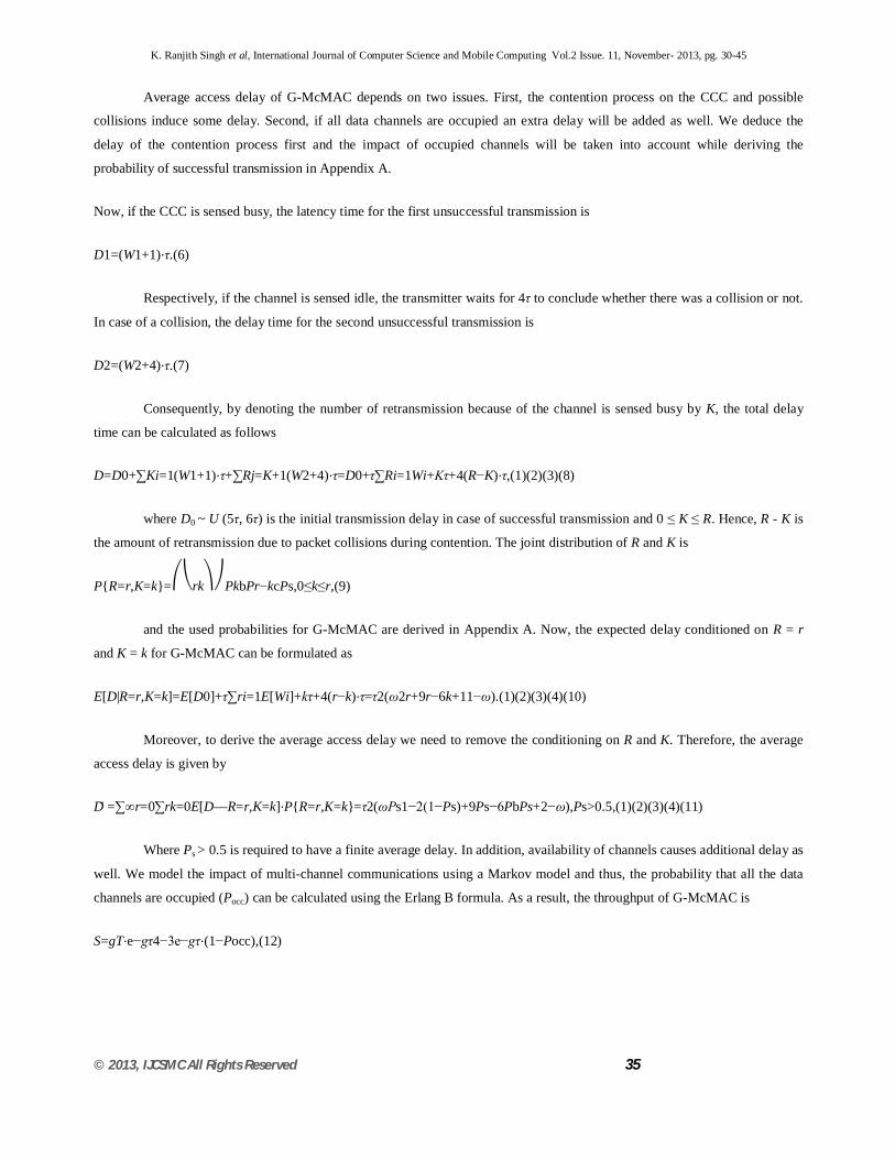
Figure 4 depicts the operation of MMAC during ATIM windows.
K. Ranjith Singh et al, International Journal of Computer Science and Mobile Computing Vol.2 Issue. 11, November- 2013, pg. 30-45
© 2013, IJCSMC All Rights Reserved 37
Fig 4: Negotiation during an ATIM window
In the case of MMAC, a node has to wait until the end of an ATIM window even though the initial transmission would be
successful before transmitting data. Consequently, on average the initial transmission delay is
E[D0]=Tatim2⋅TatimTc+(TD2+Tatim)⋅TDTc.(14)
Moreover, if a node has not been able to reserve resources before the end of an ATIM window, it has to wait for the
next data interval and an additional delay of Tc is added. Hence, the overall delay is
D=D0+M⋅Tc,(15)
where M denotes the number of additional cycles. If the delay due to CSMA operations during an ATIM window is
larger than the length of the ATIM window or all of the channels are occupied before a node can reserve resources, a packet will
be delayed. By denoting the latency of a packet during an ATIM window with L, this blocking probability can be represented as
Pblock=P{L>Tatim}+P{L≤Tatim}⋅P{Occupied}.(16)
Since all resource reservations will be made during ATIM windows, the packet arrival rate has to be scaled such that
all packets are generated during an ATIM window in one cycle for theoretical analysis. Hence, in theory we have the following
packet arrival rate for the contention phase
ga=g⋅TcTatim.(17)
First, we find out the probability that a node can not reserve resources during an ATIM window due to the shortage of
data channels. We approximate this by comparing the number of channel reservations to the number of channels. This is done
by scaling the difference between the amount of successful negotiations and the number of channels with the amount of
successful negotiations. All of the used probabilities are derived in Appendix B. The amount of successful data negotiations
during an ATIM window is on average

K. Ranjith Singh et al, International Journal of Computer Science and Mobile Computing Vol.2 Issue. 11, November- 2013, pg. 30-45
© 2013, IJCSMC All Rights Reserved 38
E[packets]=PsgaTatim.(18)
In the beginning of each ATIM window all the channels are free and hence, the previously used Markov model can not
be exploited. In consequence, we approximate the probability that a packet is blocked because of channel shortage as follows
Pcb1ock≈max{0,PsgaTatim−NPsgaTatim}.(19)
Second, in the case of small ATIM windows, the performance will be bounded by the fact that only a certain amount of
data channels can be reserved in time before the end of an ATIM window. Now, if a node senses that the control channel is busy
during contention, it will backoff according to BEB. Same happens in case of collisions as well. During an ATIM window the
latency of a successful RTS/CTS message exchange is 3τ. Since ω = 32, the performance is dominated by P{R = 0} and P{R =
1} while the total delay is L ≤ 35. Furthermore, while 35 < Tatim ≤ 2ω, P{R ≤ 2} dominates. Finally, if Tatim > 2ω the effect of
Pdb1ock becomes negligible since multiple retransmissions may take place and it is very unlikely that a packet is delayed due to
the end of an ATIM window.
Figure 5 depicts theoretical and simulated results for different packet sizes. When the packet size is 100, the blocking
probability is determined by Pdb1ock and with the packet size of 1,000, the blocking probability is determined by Pcb1ock.
With moderate packet sizes, the blocking probability is determined by both probabilities and hence, the simulated and
theoretical results do not match perfectly. Nevertheless, according to our results these approximations do not significantly
under- or overestimate the performance of MMAC in case and hence, the use of these approximates is justifiable for adequate
analysis.
Fig 5 : Theoretical and simulated results for the probability of block as a function of arrival rate

K. Ranjith Singh et al, International Journal of Computer Science and Mobile Computing Vol.2 Issue. 11, November- 2013, pg. 30-45
© 2013, IJCSMC All Rights Reserved 39
3. DCA ALGORITHM
In this section we describe the DCA, which colors the network graph within the constraints of 2-hop coloring. We list our
assumptions and provide a discussion on each of them:
(i) A 1-hop clustering structure is in place: the non-linear relationship between energy and distance makes a single bit
transmission more energy efficient using several short, intermediate hops instead of one longer hop . Clustering allows sensors
to communicate data over smaller distances, which then gets forwarded to the sink. We have adapted the generalized weight
based clustering scheme presented in with the weight being decided by connectivity and ties resolved with node ID. Each
cluster head (CH) knows the weights of the CHs of all nodes that are within 2-hop range of the nodes in its own cluster.
(ii) The sensor network is assumed to be static during the coloring process. No new nodes are added and nodes do not die out
while coloring is in progress.
(iii) A CSMA/CA mechanism is in place during algorithm operation. At the point of termination of the algorithm, the channel is
partitioned into disjoint sets and is essentially collision free, assuming no adjacent channel interference. We define the term
neighbor set of a cluster i, NSi, as the set of all those nodes, n, such that n is at most 2 hops away considering cluster 2, NS2 =
{x,a,b, s, t,c,CH3,CH4}.
The problem of color allocation is essentially coloring of a node such that there is no conflict with the already assigned
colors of the nodes in the neighbor set.
In particular, consider two nodes, x and y linked through a and each belonging to a different cluster. This configuration
poses a difficult task in assignment of non-conflicting color and we define it as the hidden cluster problem. This necessitates the
longest chain of color information propagation across cluster boundaries.
The DCA begins at a point where each CH is aware of its own weight, w(CH), as well that of the other CHs that serve its
neighbor set, i.e., CH2 knows w(CH1), w(CH3) and w(CH4). A CH proceeds to color its own cluster only when color
assignment by the larger weight CHs of the neighbor nodes is complete.
If w (CH2) > w(CH3) > w(CH4) > w(CH1), CH2 starts coloring first, followed by CH3. On their completion, the color
assignment is propagated and thus CH1, CH4 begin coloring simultaneously (x,CH1 R NS4). It should be noted that there is no
possible color conflict in clusters 1 and 4, as the neighbor set of one has no common node from the other cluster. Each node in
cluster i maintains a color table (CT) containing a list of its neighbor nodes belonging to a CH having an ID higher than its own
CH, e.g., CTy = U while CTa = {- v, y, CH2}. As a node receives color information about these nodes, this list is updated and
all these colors are forbidden for the node itself. In addition, the CH has a table, which we call as the cluster color table (CCT).
The CCT has an entry for each node in its cluster and the colors forbidden for it are continuously updated, as in the case of
CT. A CH starts coloring only when this CCT is full, i.e., all the forbidden colors for each node in its cluster are available.

K. Ranjith Singh et al, International Journal of Computer Science and Mobile Computing Vol.2 Issue. 11, November- 2013, pg. 30-45
© 2013, IJCSMC All Rights Reserved 40
Each CH performs this check at the receipt of a message, in order to check whether the information contained in the CCT is
sufficient to start the coloring process.
The DCA is entirely message driven, i.e. an action taken by a node is a function of the type and information contained in
the incoming packet.
We define three types of messages:
The channel assignment message that is sent by the CH letting a node know of its assigned color, the update message
aimed at 1-hop neighbors to make them aware of a forbidden color, and the information message which alleviates the hidden
cluster problem while notifying the CH of a forbidden color for a node in its cluster. We now describe, through an example (Fig.
2), the actions taken by nodes for different control messages.
3.1. Message types
3.1.1. Channel assignment (CA) message
The CA message consists of an ordered pair of the type (node ID, assigned color) for each cluster member. A node first
identifies whether
the message was sent by its CH. It then extracts its own color and that of nodes 1 hop away from it and member of the same
cluster. Thus node y identifies the color assigned to it and that of CH2, v. y then broadcasts an UP packet containing this
information. Similarly, if a node c is in 1-hop distance of a neighboring CH, i.e. CH4, it will receive a CA message not intended
for its own cluster. It then extracts the colors of the 1-hop nodes appearing in its CTc i.e. (CH4) and 2-hop nodes (s and t). In
such a case, an INF message is generated by c and the change made in its CT is included in the message.
The INF message has a 1-hop list and a 2-hop list as payload containing ordered pairs of the type (node, color) which
are updated with (CH4) and (s and t), respectively.
3.1.2. Update (UP) message
The UP message is targeted at nodes within transmission range of a recently colored node, notifying the former of the
colors assigned to their 1- and 2-hop neighbors. When such a node, a, receives the UP message from y, CTa is updated with the
colors assigned to y, v and CH2. An INF message is broadcast that contains the colors and IDs of the 1-hop (y) and 2-hop (v and
CH2) neighbors of a, that were updated due to the received UP message. As 1-hop clusters are formed, the INF message
broadcast by any node lets its CH know that its CT is updated. CH3 is thus made aware through a’s INF broadcast that the
colors assigned to v, y, and CH2 are now forbidden for a. Nodes belonging to the same cluster as the originator of the UP
message, e.g. v, ignore it. As before, if a CH, say CH3, receives an UP message from non-cluster node, say y, it implies that the
node y is in 2-hop range of every member of its cluster. It adds the color of node y as a forbidden color for every node in the
cluster, including a, if this information is not already present. Also, CH3 adds the colors of all 1-hop cluster members of node y,
i.e. v and CH2, as forbidden colors for itself.
K. Ranjith Singh et al, International Journal of Computer Science and Mobile Computing Vol.2 Issue. 11, November- 2013, pg. 30-45
© 2013, IJCSMC All Rights Reserved 41
3.1.3. Information (INF) message
It is generated on two separate occasions.
(1) The INF broadcast (IB) message is generated by a node as a result of an UP message is useful for its own CH and all other
neighbor nodes.
(2) An INF unicast message (IU), directed at the CH, is generated when a node receives an IB from a sender not belonging to
the same cluster. For example, The IB message sent by a is used by CH3 to update its CCT. An adjacent cluster node x,
overhears the IB, extracts Message dependencies: the receipt of one type of message generates another. CTx. An IU message is
then sent by x to CH1 having a single node-color pair (y, color).
We reason this as follows:
The IB message sent by a node a contains, in the 1-hop color table, the color assigned to node y, otherwise hidden from
x. For node x, y is a 2-hop neighbor and hence must appear in the 1-hop list of the incoming IB message. Consequently, only
this information is included in the IU message sent by x. This two stage INF propagation allows CH1 to assign a color to x such
that it does not conflict with the color given to y, 2 hops away from x. If a node, b, receives an INF message from its own
cluster member, a, it is ignored unless the receiving node is also the CH for that cluster.
We note that the INF is the most commonly generated message:
(1) The result of hearing a CA directly from another cluster,
(2) On receiving an UP message and
(3) Another INF broadcast message. Successive INF/UP messages received at the node from different source nodes may include
color information that the node has already propagated earlier.
In our implementation, we adopt the following enhancement geared to reduce the number of messages in the network:
the color information forwarded by a node in an INF or UP message is not sent again through another INF or UP, respectively.
3.2. Analysis of number of messages
In this section we derive expressions for the expected number of channel assignment, update and inform broadcast
messages for the DCA. While the analysis presented in the following propositions is approximate owing to the restricting
assumptions of multi-hop modeling, all equations derived are verified in Section 5 and found to be in good agreement. Consider
N nodes to be distributed independently and uniformly in large area R # R2 where R2 signifies the 2- dimensional Euclidian
space. If R is large, the placement of the nodes essentially represents a Poisson process.
We assume:
1. All nodes have the same transmission radius r.

K. Ranjith Singh et al, International Journal of Computer Science and Mobile Computing Vol.2 Issue. 11, November- 2013, pg. 30-45
© 2013, IJCSMC All Rights Reserved 42
2. The average degree of a node is given by davg. Proposition 1. The total number of channel assignment messages transmitted
is approximately Proof.
For a single node A, the coverage area is pr2. The probability that there are m nodes within its transmission range is
given by: pm (A) = ((qpr2) m/m!) exp (_qpr2). The expected number of nodes within its 1-hop communication range, also the
average degree davg, can be calculated as
E½x_ ¼X
N
m¼1
mpmðAÞ ¼X
N
m¼1
ðqpr2Þm
m!
expð_qpr2_ Þ_
The weight based clustering algorithm forms 1-hop clusters by associating nodes with their 1-hop neighbors that have a
higher weight, with ties being broken by node ID. If all the neighbors of a node A link with other higher weight CHs, A may be
forced to announce itself CH of the ingle node cluster.
We now calculate the expected number of such single node clusters. We list the nodes in the 1-hop neighborhood of A,
along with A itself, in the following rank table. The rank of a node in this table is decided by the highest weight of its 1-hop
neighbor set. From Fig. 4, each neighbor of A is connected to another node having a weight higher than that of A, i.e. W1 > W
(A), W2 >W (A) and W3 > W (A) and hence A forms a 1-hop cluster. A is at position 1 on the table with the increasing index
indicative of increasing rank. Out of davg + 1 nodes, the probability of only A occurring in slot 1 of the rank table is given by
P½position1¼A_¼P½A¼slot1__P½1;2;...;davg–slot1_ P½position1¼A_¼
1
davg þ1
1_
1
_ davgþ1_davg

K. Ranjith Singh et al, International Journal of Computer Science and Mobile Computing Vol.2 Issue. 11, November- 2013, pg. 30-45
© 2013, IJCSMC All Rights Reserved 43
¼
1
davgþ1
davg
_davgþ1_davg
This is also the probability of a node forming a single node cluster as all its neighbors have been drawn away by other
higher weight 2-hop neighbors. The expected number of such single node clusters is
CH0 ¼
N
davg þ 1
davg
_davg þ 1_davg
The approximation to the average number of clusters having davg nodes is improved by subtracting single node
clusters, i.e., (N _ CH0)/davg and it follows that the total clusters formed is approximately, E[Clusters] = (N _ CH0) / davg +
CH0. The CA message is broadcast by the CH only and each cluster has a single CH. Hence n (CA) = E [Clusters] giving the
required result. H Proposition 2. The total number of update messages transmitted is approximately given by, n (UP) = N _ n
(CA). Proof. Every node (other than the CH itself) is assigned a color by the CH of its cluster. This color assignment occurs
through the CA message sent by the CH (or an announcement done by the node itself if it is a single node cluster).
Each node of the cluster generates one UP message, on reception of the CA message. As colors are assigned only once,
every non-CH node will transmit a single UP message during the coloring process. We note that the number of CH nodes = n
(CA). It follows that the total number of UP messages equals the total number of non-CH nodes and hence, n (UP) = N _ n
(CA). h 1 2 3 4 5 6 … δ avg+1 A 1 Hop Neighbors of A Fig. 4. Ranked table of adjacent nodes on the basis of 1 hop neighbor
weights.
The total number of inform messages are given by: n(INF) = {(2q/3)pr2 _ 1}n(UP) approximately. Proof. We prove the
proposition in two parts. First we show that the average number of IB messages is given by (davg/3) n (UP). We begin with the
simplifying assumption that clusters formed are approximately of the same size (each having a radius equal to the transmission
range of a node). From geometric considerations, such a cluster can have at most six neighboring clusters. Consider one such
cluster, 4, The CA broadcast by the CH is received by node A, which then sends an UP message.
All nodes that receive the UP message and send an IB in response have their locus shown by sector o–a–b that
subtends an angle of 120_ to the center o of cluster 1. Thus the average number of nodes in this sector gives the average number
K. Ranjith Singh et al, International Journal of Computer Science and Mobile Computing Vol.2 Issue. 11, November- 2013, pg. 30-45
© 2013, IJCSMC All Rights Reserved 44
of IB messages generated in response to a single UP message. For n(UP) messages, n(IB) = q(120/360)pr2n(UP) =
(q/3)pr2n(UP). The IB messages sent by the nodes in sector o–a–b are received by nodes lying in sectors o00–d– c and o0–e–f
in the adjacent clusters 2 and 3. These are the nodes that are eligible to generate IU for their CHs. The number of such nodes is
given by: 2 _ q (120/ 360) pr2n (UP) = (2q/3) pr2n (UP). But the above set of nodes generating IU also includes nodes that have
already heard an UP by the member nodes of
Cluster 4 that originated the CA message. Similarly, a single node can hear more than one IB, and we suppress the
generation of IU for multiple IB messages containing the same information. Thus, we subtract the number of nodes that have
already received UP and IB messages to get the actual number of nodes that transmit the IU message, given by n(IU) = (2q/
3)pr2n(UP) _ [n(UP) + n(IB)]. Hence, the average number of INF messages (both IU and IB) is: n(INF) = n(IU) + n(IB) =
(2q/3)pr2n(UP)-n(UP) = {(2q/3)p r2 _ 1}n(UP). H Propositions 1–3 are verified through simulations in Section 5. Having
established the channel allocation algorithm, we now describe our proposed MAC protocol, CMAC, which leverages this
channel assignment.
4. CONCLUSIONS
We presented a distributed channel assignment algorithm, DCA, which efficiently allocates channels to randomly
deployed sensor nodes. Our proposed solution can be used as a base algorithm for several different schemes like allocating
channels, assigning non overlapping TDMA slots and nodes addresses to sensor networks. Our de-synchronized multi-channel
MAC protocol for sensor networks, CMAC, addresses the critical issue of energy conservation without trade-offs in latency and
throughput.
Through a wakeup radio in addition to the main transceiver, multi-channel communication is accomplished resulting in
a virtually collision-free protocol. CMAC enables maximum possible sleep-time, prevents overhearing and has minimal control
overhead. In addition to the above, our protocol supports high data rates making it application independent. CMAC however
needs an adequate number of available channels to satisfy the 2-hop coloring constraint.
The channel is accessed by sensors according to their priorities. For sensors with the same priority, they send frames in
a round manner. In addition the fairness between different priorities is guaranteed. Simulation and experiment results indicate
that FP-MAC protocol provides high channel utilization and bounded delays for real-time communication and can be well
adapted in dynamic wireless sensor networks.
5. REFERENCES
[1] D. Agrawal, Q.-A. Zeng, Introduction to Wireless and Mobile Systems, Brooks/Cole Publishing, 2003, ISBN 0534-40851-6.
436pP.
[2] J.R. Agre, L.P. Clare, G.J. Pottie, N.P. Romanov, Development platform for self-organizing wireless sensor networks, In:
Proceedings of SPIEAerosense, Unattended Ground Sensor Technologies and Applications, vol. 3713, pp. 257–268.
K. Ranjith Singh et al, International Journal of Computer Science and Mobile Computing Vol.2 Issue. 11, November- 2013, pg. 30-45
© 2013, IJCSMC All Rights Reserved 45
[3] Ed Callaway, P. Gorday, L. Hester, J.A. Gutierrez, M. Neave, B. Heile, V. Bahl, Home networking with IEEE 802.15.4: a
developing standard for low-rate wireless personal area networks, IEEE Communication Magazine 40 (8) 70–77.
[4] A. Dunkels, L.M. Feeney, B. Grönvall, T. Voigt, An integrated approach to developing sensor network solutions, in:
Proceedings of the Second International Workshop on Sensor and Actor Network Protocols and Applications, Boston,
Massachusetts.