
Multi-Agent Systems in the Industry Three Notable Cases in Italy
173
Multi-Agent Systems in the Industry Three Notable Cases in Italy Federico Bergenti Dipartimento di Matematica Univesit` a degli Studi di Parma Parma, Italy Email: [email protected] Eloisa Vargiu Dipartimento di Ingegneria Elettrica ed Elettronica Universit` a degli Studi di Cagliari Cagliari, Italy Email: [email protected] Abstract—This paper reports on three notable examples of the use of multi-agent systems in the Italian Industry. First, we introduce the topic and we outline some examples of real-world agent-based software application. Then, we describe in details the use of multi-agent systems in three software packages for (i) personalized press reviews, (ii) monitoring boats in marine reserves, and (iii) advanced contact centers. Finally, we draw some conclusions and summarize the lesson learnt from described experiences. The discussion focuses on the benefits and problems that the choice of agent technology brought. I. I NTRODUCTION From the ’80s the term “agent” has been adopted by a variety of sub-disciplines of artificial intelligence and com- puter science [1]. In particular, from the ’90s we can talk of “Multi-Agent Systems” (MAS) in software engineering, data communications and concurrent systems research, as well as robotics, artificial intelligence and distributed artificial intelligence [2]. In 1996, FIPA 1 was established to produce software stan- dards for heterogeneous, interacting agents and agent-based systems. Since its conception, FIPA has played a crucial role in the development of agents standards and has promoted a number of initiatives and events that contributed to the development and uptake of agent technology. According to FIPA reports many MAS and relative platforms have been developed; among others, let us recall here FIPA-OS [3], JACK [4], ZEUS [5] and JADE [6]. Nowadays, only few MAS solutions have been devised, deployed, and adopted in industrial applications [7]. As noted in [8], agent technologies have been concentrated in a small number of business sectors: • Simulation and training applications in defense domains, e.g., the system developed by Agent Oriented Software to aid the Ministry of Defence in military training 2 and the NASA’s OCA Mirroring System [9]; • Network management, e.g., IRIS, a tool for strategic security allocation in transport networks [10] and the sys- tem developed by Magenta to help a shipping company improve oil distribution shipping networks [11]; 1 http://www.fipa.org 2 http://ats.business.gov.au/Company/CompanyProfile.aspx?ID=22 • User interface and local interaction management in telecommunication networks, e.g., the systems developed by Telecom Italia on WADE to implement a mediation layer between network elements and OSS and to provide step-by-step guidance to technicians performing mainte- nance operations in the fields [12]; • Schedule planning and optimization in logistics and supply-chain management, e.g., Living Systems Adaptive Transportation Networks, a system for logistics manage- ment developed by Whitestein Technologies [13] and the system for heat and sequence optimization in the supply chain of steel production proposed in [14]; • Control system management in industrial plants, e.g., the MAS solution applied in mass-production planning of car engines for Skoda Auto [15]; • Simulation modeling to guide decision-makers in public policy domains, e.g., the one developed by Eurobios to improve production schedules for a cardboard box manufacturer [16]. According to [17], the main bottlenecks that prevent a fast and massive adoption of agent-based solutions in real world applications are: (i) limited awareness about the potentials of agent technology; (ii) limited publicity of successful in- dustrial projects carried out with the agent technology; (iii) misunderstandings about the effectiveness of agent-based solu- tions, characterized by over-expectations of the early industrial adopters and subsequent frustration; (iv) risks for adopting a technology that has not been already proven in large scale industrial applications; as well as (v) lack of mature enough design and development tools for industrial deployment. More than ten years after the first FIPA specifications [18], we state that time is ripe to adopt MAS in the industry [19]. In fact, the MAS technology is already effective for deploying real applications from both a software engineering [20] and a technological perspective [21]. To this end, in this paper, we present and discuss our experience in using MAS for developing industrial applications. In particular, we describe in details the use of MAS in three software packages for (i) personalized press reviews, (ii) monitoring boats in marine reserves, and (iii) advanced contact centers. The rest of the paper is organized as follows: in Section II, Section III, and Section IV we describe and discuss the system
-
Upload
khangminh22 -
Category
Documents
-
view
1 -
download
0
Transcript of Multi-Agent Systems in the Industry Three Notable Cases in Italy

Multi-Agent Systems in the IndustryThree Notable Cases in Italy
Federico BergentiDipartimento di Matematica
Univesita degli Studi di ParmaParma, Italy
Email: [email protected]
Eloisa VargiuDipartimento di Ingegneria Elettrica ed Elettronica
Universita degli Studi di CagliariCagliari, Italy
Email: [email protected]
Abstract—This paper reports on three notable examples ofthe use of multi-agent systems in the Italian Industry. First, weintroduce the topic and we outline some examples of real-worldagent-based software application. Then, we describe in detailsthe use of multi-agent systems in three software packages for(i) personalized press reviews, (ii) monitoring boats in marinereserves, and (iii) advanced contact centers. Finally, we drawsome conclusions and summarize the lesson learnt from describedexperiences. The discussion focuses on the benefits and problemsthat the choice of agent technology brought.
I. INTRODUCTION
From the ’80s the term “agent” has been adopted by avariety of sub-disciplines of artificial intelligence and com-puter science [1]. In particular, from the ’90s we can talkof “Multi-Agent Systems” (MAS) in software engineering,data communications and concurrent systems research, aswell as robotics, artificial intelligence and distributed artificialintelligence [2].
In 1996, FIPA1 was established to produce software stan-dards for heterogeneous, interacting agents and agent-basedsystems. Since its conception, FIPA has played a crucial rolein the development of agents standards and has promoteda number of initiatives and events that contributed to thedevelopment and uptake of agent technology. According toFIPA reports many MAS and relative platforms have beendeveloped; among others, let us recall here FIPA-OS [3],JACK [4], ZEUS [5] and JADE [6].
Nowadays, only few MAS solutions have been devised,deployed, and adopted in industrial applications [7]. As notedin [8], agent technologies have been concentrated in a smallnumber of business sectors:
• Simulation and training applications in defense domains,e.g., the system developed by Agent Oriented Softwareto aid the Ministry of Defence in military training2 andthe NASA’s OCA Mirroring System [9];
• Network management, e.g., IRIS, a tool for strategicsecurity allocation in transport networks [10] and the sys-tem developed by Magenta to help a shipping companyimprove oil distribution shipping networks [11];
1http://www.fipa.org2http://ats.business.gov.au/Company/CompanyProfile.aspx?ID=22
• User interface and local interaction management intelecommunication networks, e.g., the systems developedby Telecom Italia on WADE to implement a mediationlayer between network elements and OSS and to providestep-by-step guidance to technicians performing mainte-nance operations in the fields [12];
• Schedule planning and optimization in logistics andsupply-chain management, e.g., Living Systems AdaptiveTransportation Networks, a system for logistics manage-ment developed by Whitestein Technologies [13] and thesystem for heat and sequence optimization in the supplychain of steel production proposed in [14];
• Control system management in industrial plants, e.g., theMAS solution applied in mass-production planning of carengines for Skoda Auto [15];
• Simulation modeling to guide decision-makers in publicpolicy domains, e.g., the one developed by Eurobiosto improve production schedules for a cardboard boxmanufacturer [16].
According to [17], the main bottlenecks that prevent a fastand massive adoption of agent-based solutions in real worldapplications are: (i) limited awareness about the potentialsof agent technology; (ii) limited publicity of successful in-dustrial projects carried out with the agent technology; (iii)misunderstandings about the effectiveness of agent-based solu-tions, characterized by over-expectations of the early industrialadopters and subsequent frustration; (iv) risks for adopting atechnology that has not been already proven in large scaleindustrial applications; as well as (v) lack of mature enoughdesign and development tools for industrial deployment.
More than ten years after the first FIPA specifications [18],we state that time is ripe to adopt MAS in the industry [19].In fact, the MAS technology is already effective for deployingreal applications from both a software engineering [20] anda technological perspective [21]. To this end, in this paper,we present and discuss our experience in using MAS fordeveloping industrial applications. In particular, we describein details the use of MAS in three software packages for (i)personalized press reviews, (ii) monitoring boats in marinereserves, and (iii) advanced contact centers.
The rest of the paper is organized as follows: in Section II,Section III, and Section IV we describe and discuss the system

for creating personalized press reviews, for monitoring boats inmarine reserves, and for managing advanced contact centers,respectively. In particular, for each system we first illustratethe corresponding scenario, then, we present the proposedsolution, and, finally, we discuss the underlying motivationsin adopting a MAS-based approach. Section V ends the paperwith some conclusions and a summary of the lesson learntfrom described experiences.
II. PERSONALIZED PRESS REVIEWS
In this section, we present a MAS explicitly devoted to gen-erate press reviews by (i) extracting articles from Italian onlinenewspapers, (ii) classifying them using text categorizationaccording to user’s preferences, and (iii) providing suitablefeedback mechanisms [22]. The system has been developedand deployed together with Arcadia Design3 under the projectDMC (Digital Media Center) ordered by Cosmic Blue Team4.
A. The ScenarioThe World Wide Web offers a growing amount of infor-
mation and data coming from different and heterogeneoussources. As a consequence, it becomes more and more difficultfor Web users to select contents according to their interests,especially if contents are frequently updated (e.g., news, news-paper articles, reuters, RSS feeds, and blogs). Supporting usersin handling the enormous and widespread amount of Webinformation is becoming a primary issue. To this end, severalonline services have been proposed (e.g., Google News5 andPRESSToday6). Unfortunately, they allow users to choose theirinterests among macro-areas (e.g. economics, politics, andsport), which is often inadequate to express what the useris really interested in. Moreover, existing systems typicallydo not provide a feedback mechanism able to allow the userto specify non-relevant items—with the goal of progressivelyadapting the system to her/his actual interests.
Fig. 1. An example of results provided by the personalized press reviewsystem.
3http://www.arcadiadesign.it4http://www.cbt.it5http://news.google.com6http://www.presstoday.com
B. The Implemented MASTo generate press reviews, the system is organized in
three layers, each aimed at performing a specific information-retrieval step:
• Information Extraction. To perform information extrac-tion, we use several wrapper agents, each associated witha specific information source: the Reuters portal7, TheTimes8, The New York Times9, the Reuters documentcollection, and the taxonomy adopted during the clas-sification phase. Once extracted, all the information issuitably encoded to facilitate the text categorization task.To this end, all non-informative words, e.g., preposi-tions, conjunctions, pronouns and very common verbsare removed using a stop-word list. After that, a stan-dard stemming algorithm removes the most commonmorphological and inflectional suffixes. Then, for eachcategory of the taxonomy, feature selection, based on theinformation-gain heuristics, has been adopted to reducethe dimensionality of the feature space.
• Hierarchical Text Categorization. To perform hierarchicaltext categorization, we adopt the Progressive Filtering ap-proach proposed in [23]. Each node of a given taxonomyis a classifier entrusted with recognizing all correspondingrelevant inputs. Any given input traverses the taxonomyas a token, starting from the root. If the current classifierrecognizes the token as relevant, it passes it on to all itschildren (if any). The typical result consists of activatingone or more pipelines of classifiers within the taxonomy.
• User’s Feedback. When an irrelevant article is evidencedby the user, it is immediately embedded in the trainingset of a k-NN classifier that implements the user feed-back. A suitable check performed on this training setafter inserting the negative example allows to trigger aprocedure entrusted with keeping the number of negativeand positive examples balanced. In particular, when theratio between negative and positive examples exceeds agiven threshold (by default set to 1.1), some examplesare randomly extracted from the set of truely positiveexamples and embedded in the above training set.
The prototype of the system has been devised throughX.MAS [24]—a generic multi-agent architecture, built uponJADE [6], devised to make it easier the implementation ofinformation retrieval and information filtering applications.Through the user interface, the user can set (i) the sourcefrom which news will be extracted, and (ii) the topics s/heis interested in. As for the newspaper headlines, the user canchoose among the Reuters portal, The Times, and The NewYork Times. As for the topics of interest, the user can selectone or more categories in accordance with the given RCV1taxonomy. First, information agents able to handle the selectednewspaper headlines extract the news. Then, all agents thatembody a classifiers trained on the selected topics are involved
7http://www.reuters.com8http://www.the-times.co.uk/9http://www.nytimes.com/

to perform text categorization. Finally, the system supplies theuser with the selected news through suitable interface agents(see Figure 1). The user can provide a feedback to the systemby selecting all non-relevant news (i.e., false positives). Thisfeedback is important to let the system adapting to the actualinterests of the corresponding user.
C. The Role of AgentsThe motivation for adopting a MAS lies in the fact that
a centralized classification system might be quickly over-whelmed by a large and dynamic document stream, suchas daily-updated online news [25]. Furthermore, the Web isintrinsically a distributed system and offers the opportunityto take advantage of distributed computing paradigms anddistributed knowledge resources.
Let us also note that an information retrieval system musttake into account several issues, such as: (i) how to deal withdifferent information sources and to integrate new informationsources without re-writing significant parts of it, (ii) howto suitably encode data in order to put into evidence theinformative content useful to discriminate among categories,(iii) how to control the imbalance between relevant andirrelevant articles, (iv) how to allow the user to specify her/hispreferences, and (v) how to exploit the user’s feedback toimprove the overall performance of the system. The aboveproblems are typically strongly interdependent in state-of-the-art systems. To better concentrate on these aspects separately,we adopted a layered multiagent architecture, able to promotethe decoupling among all aspects deemed relevant.
III. MONITORING BOATS IN MARINE RESERVES
Under the project “A Multiagent System for MonitoringIntrusions in Marine Reserves” (POR Sardegna 2000/2006,Asse 3 - Misura 3.13) supported by Regione Autonoma dellaSardegna, we experimented a MAS-based solution with thegoal of monitoring and signaling intrusion in marine reserves.In the corresponding system, developed and deployed togetherwith the companies SETI S.N.C.10 and ICHNOWARE S.A.S.,authorized boats are equipped with suitable devices able totransmit (through GSM technology) their position (throughGPS technology). In this way, the corresponding scenarioencompasses two kinds of boats: authorized, recognizable bythe GPS+GSM devices, and unauthorized. Both kinds of boatsare expected to be identified by a digital radar able to detecttheir position in the protected area. Comparing the positionssent by boats with those detected by the radar allows toidentify unauthorized boats.
A. The ScenarioIn the summertime, in Sardinia and in its small archipelago,
tourists sometimes sail in protected or forbidden areas closeto the coast. Monitoring such areas with the goal of discrim-inating between authorized and unauthorized boats is quitecomplicated. In fact, along Sardinian coasts, there are two-hundred tourist harbors with about thirteen thousand places
10http://www.setiweb.it
Fig. 2. A snapshot of SEA.MAS user interface
available for boats and several services for boat owners.Monitoring large areas without suitable resources (such asradars) can be highly uneconomic, since staff operators wouldbe (and typically are) compelled to directly patrol them overtime. A typical solution consists of using a radar systemcontrolled by a central unit located ashore in a strategicalposition. Radar signals allow to detect the positions of theboats that sail in the controlled area.
B. The Implemented MAS
The MAS aimed at monitoring boats in marine reserves hasbeen called SEA.MAS [26] to highlight the fact that it stemsfrom X.MAS. The adoption of X.MAS comes from the factthat the problem of monitoring and signaling intrusions in ma-rine reserves can be seen as a particular information retrievaltask: radar and GPS+GSM devices are information sources,while authorized and unauthorized boats are categories to bediscriminated.
The first step for customizing X.MAS to a specific applica-tion consists of extending each abstract class with the goal ofproviding the required features and capabilities:
• Information level. Information sources are the digitalradar and GPS+GSM devices. For each informationsource, a suitable information agent has been devisedto embody the information provided therein. GPS- andradar-signals are retrieved by suitable information agents,devised to extract the actual position according to GPSand NMEA standards.
• Filter level. Filter agents are aimed at encoding the infor-mation extracted by the information agents. The encodingactivity consists of creating events containing the positionof the detected boats and their identification code, whenavailable. Moreover, filter agents are devoted to avoidtwo kinds of redundancy: information detected morethan once from the same device (caching) or throughoutdifferent devices (information overloading).

• Task level. A task agent is created for each boat, theunderlying motivation being the need to centralize theknowledge regarding the position of a boat and its state.As for the position, events are classified as belongingeither to anonymous sources or to known sources. Forknown sources the state reports their identification codeand—when available—further information, i.e., a descrip-tion of the boat and/or owner’s data. The main tasksof the agents belonging to this level are: (i) to followa boat position during its navigation, also dealing withany temporary lack of signal; (ii) to promptly alertingthe interface agents in the event that unauthorized boatsare identified; and (iii) to handle messages coming fromthe interface level, e.g. false alarm notification.
• Interface level. Suitable interface agents allow the systemadministrator and staff operators to interact with thesystem. In both cases, the corresponding interface agentis aimed at getting a feedback from the user, for instanceto inform relevant agents about changes occurred in theenvironment or about faults that might occur in deviceslocated on the authorized boats. User feedback can alsobe used to improve the overall ability of discriminatingamong authorized and unauthorized boats. This kind ofuser feedback is performed through a simple solutionbased on the k-NN technology. When either a falsepositive or a false negative is evidenced by the user, itis immediately embedded in the training set of the k-NNclassifier that implements the feedback.
SEA.MAS has been experimented in a marine reservelocated in the North of Sardinia. The interface agent (seeFigure 2) represents in different colors different states: autho-rized, unauthorized, not-detected, under verification. In caseof intrusion, a sound is generated together with the positionof unauthorized boats; such a signal can be forwarded tothe security patrol, whose primary goal is to catch intruders.SEA.MAS involves a number of agents that in practice isproportional to the number of boats being monitored. Infact, whereas the number of middle-, information-, filter-, andinterface-level agents is fixed (i.e., one agent for each middle-span level, two agents at the information level, one agent atthe filter level, and typically one agent at the interface level),a task agent is instantiated for each boat. This fact does notgenerate any scalability problem for two main reasons: thenumber of boats sealing in marine reserves is typically lessthan a hundred at a time and, if needed, agents could bedistributed on several nodes. In practice, the maximum numberof boats in the selected marine reserve was 20.
C. The Role of AgentsSince monitoring boats requires to involve entities able to
cooperate each other, move in the environment, and adapt tochanges that may occur, an agent solution could help in thedevelopment of such a system.
As for cooperation, SEA.MAS agents can horizontally andvertically cooperate. The former kind of cooperation occursamong agents belonging to a specific level in accordance
with the following schemes: pipeline, centralized composition,and distributed composition. The latter is performed—acrosslevels—throughout middle agents, which support communi-cation among requesters and providers belonging to adjacentlevels of the architecture.
As for mobility, all involved agents can be mobile, if needed.In fact, in case of a large number of agents (i.e., boats)this requirement becomes mandatory in order to handle thecomputational complexity. Thus, mobility permits the run-timedeployment of agents in a distributed architecture.
As for adaptivity, task agents are able to adapt their behaviorin order to avoid losing boats in case of signal absence (i.e.,areas devoid of GSM signal).
IV. ADVANCED CONTACT CENTERS
Back in 2002 FRAMeTech S.R.L.11 developed the Mer-cury Contact Center Suite (Mercury for short) to provideits customers with a full-featured, cost-effective solution forinbound/outbound contact centers and automatic telephonyservices. The product has been successfully adopted in thelast 8 years from a large number of customers rangingfrom SMEs to Large Enterprises to implement automatic andsemi-automatic services up to 60 concurrent users and 1,000calls/hour. We can say now that Mercury is a mature productwith a solid architecture and no foreseen limitations in thescalability of functionality and performances.
From the functional point of view, Mercury is a point ofconvergence for common communication media: telephone(analog, digital and IP-based), faxes and e-mails. From atechnological point of view, Mercury is completely Web-basedand implemented taking advantage of innovative, open-sourcetechnologies like Java.
A. The Scenario
Mercury is an open platform that is verticalized to meetthe needs of single customers. Just to give an example ofthe service scenarios that Mercury addresses, we can mentionthe common case of inbound contact centers. The basicfunctionality of an inbound contact center are: (i) to answertelephone calls from multiple lines, (ii) to provide the callerwith an interactive menu, (iii) to hold on music the call if nouser is available, (iv) to dispatch queued calls to the best uservia, e.g., skill based routing, and, (v) to provide the chosenuser with all available details on the caller in order to meether/his requests.
Mercury advocates a similar approach also for outboundcontact centers, which are services that provide, at least,the functionality (i) to allow interfacing a (possibly external)database to collect a list of names and numbers to call, (ii) toplace calls to the selected numbers ensuring that, at answer-time, a good user with the right skills and capabilities wouldbe eventually available, (iii) to provide the chosen user withall available details on the called party in order to value thecall.
11http://www.frametech.it

Fig. 3. Mercury Contact Center Suite workflow editor
Mentioned examples are very simple cases of semi-automatic scenarios, because a user is always involved inthe so-called workflow of the service. It is worth mentioningthat Mercury supports also fully automatic services, e.g., forautomatic calls to personnel on duty in quality processes, andfor self-serve banking services.
B. The Implemented MAS
Even if the analysis and specification of requirements ofMercury were done using a use-case driven approach, thedesign of the whole system was centered around agent-oriented concepts. Unfortunately, the concrete implementationof the product could not exploit the available agent-orientedtechnologies, e.g., JADE [6], because of the initial tight non-functional requirements. Actually, the product still ships em-bedded onboard of a low-end PBX (Private Branch Exchange).
In order to discuss the role of agents in the design ofMercury, we first need to outline the architecture of theproduct. The main modules of the architecture are:
1) Contact Manager module, in charge of providing a con-verged interface for sending commands to and process-ing events from available communication channels12.
2) User Manager module, that manages the lifecycle ofusers in the system and that provides access to userprofiles.
3) ACD (Automatic Contact Dispatcher) module, that man-ages the allocation and dynamic rerouting of contacts toavailable users via customizable skill-based policies.
4) Workflow Manager module, in charge of coordinatingthe execution of scripts that control the behavior ofservices.
Agents are used to implement all such modules, as follows.The Contact Manager module is made of a group of agents,
one for each inbound/outbound communication channel, thatare in charge of the supervision of the physical state of
12Mercury adheres to the common nomenclature that names “contact” theactual event of communication, e.g., a telephone call, and not the personinvolved in the communication.
channels and of their relative expected behaviors. Such agentsrealize (i) functionality that are common to all channels, e.g.,activation/deactivation and notification of state change, and(ii) channel-specific functionality, e.g., agents in charge ofmanaging a telephone line can send commands to dial anumber or to answer a call, and they can also inform interestedparties of changes in the state of the line, e.g., when the lineis ringing or when line is put on hold.
The User Manager module associates an agent to eachand every active user in the system and such agents are incharge of (i) managing negotiations on behalf of users, and(ii) maintaining users’ skill and capability profiles. Moreover,User Manager agents are also meant to implement groups ofusers with similar skills and capabilities in order to provide ameans for dynamic allocation of inbound/outbound contacts.
The ACD module is a standard component of contact centersystems that manages a set of queues and that is in chargeof the dynamic allocation of contacts to users. Mercury usessuch a standard approach and it provides an agent for eachACD queue. Dynamic dispatching of, e.g., incoming calls, istherefore a matter of negotiation between the relative ContactManager line agent and available ACD agent in order tomaximize the overall quality of the service. Mercury hassophisticated dynamic policies meant to maximize the Qualityof Service (QoS) in terms of, e.g., the amount of time spentin queue, the length of the queue, the workload of personneland the skills and capabilities of personnel.
The Workflow Manager module provides an agent for eachactive service to ensure that service activities are properlyorchestrated. Mercury provides a graphical editor (see Fig-ure 3) in the style of the popular WADE editor [12], tomodel the workflow of a service in terms of a flowchart withasynchronous exceptions. Once a service gets activated, e.g.,because of an incoming call on a tall free number, a specificagent for the service is created to ensure that the call wouldfollow the nominal steps as sketched in the relative flowchart.Unfortunately, asynchronous events may break the nominalflow of event, e.g., the caller drops before choosing an entryin the interactive menu, and the service agent is in charge ofmanaging the event and performing needed actions to ensurea proper termination of the contact.
C. The Role of AgentsCommon agent-oriented abstractions, e.g., dynamic
capability-based coordination, dynamic contracting andgoal-directed workflows, are ubiquitous in the design ofMercury, as described previously in this section.
Basically, we see agents used in the design of Mercurywith two peculiar roles. The first is to provide a set ofuniform abstractions that can effectively model all aspectsof the product with no loss of specific details. This is thecase, e.g., of the unifying view that agents provide to differenttypes of communication channels in the scope of the ContactManager: all media are modeled in terms of agents and thediverse causes of faults and unexpected behavior, that are veryspecific of single types of channels, are all uniformly modeled.

Then, agents are also used in the design of Mercury toembed value-added functionality into the coherent frameworkof agents abstracting away from low-level details, that areleft unspecified in order to support future enhancements. Thisis the case, e.g., of the specific contracting mechanism thatACD agents and Contact Manager agents use: the high-leveldesign of the product leaves it unspecified in order to ensure aproper place for future enhancement, e.g., to support predictivedialing of outbound calls using Markov Decision Processes.
V. CONCLUSION
In this paper we reported on three Italian industrial use casesdeveloped by resorting to MAS technology.
The lesson learnt in adopting MAS technology in the indus-try is that agent technology is applicable to a wide range of in-dustry problems. Moreover, an important added value in usingMAS-based solutions is that they highly reduce complexity.Let us also note that, in principle, designing with agents iseasier for business analysts than using any other mainstreamtechnologies and that information-technology practitionerscan easily make the transition from, e.g., everyday object-orientation to agent-orientation [27].
Summarizing, from our experience we can state that MAStechnology is definitely effective in the design and concreterealization of industrial-strength software applications.
ACKNOWLEDGMENT
The authors would like to thank all researchers and prac-titioners that were involved in realization of the three casestudies for their precious contributions.
REFERENCES
[1] S. Russell and P. Norvig, Artificial Intelligence: A Modern Approach,2nd ed. Prentice-Hall, Englewood Cliffs, NJ, 2003.
[2] M. J. Wooldridge, “The logical modelling of computational multi-agentsystems,” Ph.D. dissertation, 1992.
[3] P. Buckle, T. Moore, S. Robertshaw, A. Treadway, S. Tarkoma, andS. Poslad, “Scalability in multi-agent systems: The fipa-os perspective,”in Selected papers from the UKMAS Workshop on Foundations andApplications of Multi-Agent Systems. London, UK: Springer-Verlag,2002, pp. 110–130.
[4] P. Busetta, R. Ronnquist, A. Hodgson, and A. Lucas, “Jack intelligentagents - components for intelligent agents in java,” AgentLink News,vol. 2, 1999.
[5] H. S. Nwana, D. T. Ndumu, L. C. Lee, and J. C. Collis, “Zeus: Atoolkit for building distributed multiagent systems,” Applied ArtificialIntelligence: An International Journal, vol. 13, pp. 129–185, 1999.
[6] F. Bellifemine, F. Bergenti, G. Caire, and A. Poggi, “JADE - a javaagent development framework,” in Multi-Agent Programming, 2005, pp.125–147.
[7] J. McKean, H. Shorter, M. Luck, P. McBurney, and S. Willmott,“Technology diffusion: analysing the diffusion of agent technologies,”Journal Autonomous Agents and Multi-Agent Systems, vol. 17, no. 3,pp. 372–396, 2008.
[8] R. A. Belecheanu, S. Munroe, M. Luck, T. Payne, T. Miller, P. McBur-ney, and M. Pechoucek, “Commercial applications of agents: lessons,experiences and challenges,” in AAMAS ’06: Proceedings of the fifthinternational joint conference on Autonomous agents and multiagentsystems. New York, NY, USA: ACM, 2006, pp. 1549–1555.
[9] M. Sierhuis and W. J. Clancey, “Nasas oca mirroring system anapplication of multiagent systems in mission control,” in AAMAS ’09:Proceedings of the 8th international joint conference on Autonomousagents and multiagent systems. Richland, SC: International Foundationfor Autonomous Agents and Multiagent Systems, 2009, pp. 85–92.
[10] J. Tsai, S. Rathi, C. Kiekintveld, O. Ordez, and M. Tambe, “Iris-atoolforstrategic security allocation in transportation networks,” in AA-MAS ’09: Proceedings of the 8th international joint conference onAutonomous agents and multiagent systems. Richland, SC: InternationalFoundation for Autonomous Agents and Multiagent Systems, 2009, pp.85–92.
[11] J. Himoff, P. Skobelev, and M. Wooldridge, “Magenta technology: multi-agent systems for industrial logistics,” in AAMAS ’05: Proceedings ofthe fourth international joint conference on Autonomous agents andmultiagent systems. New York, NY, USA: ACM, 2005, pp. 60–66.
[12] G. Caire, D. Gotta, and M. Banzi, “Wade: a software platform todevelop mission critical applications exploiting agents and workflows,”in AAMAS ’08: Proceedings of the 7th international joint conference onAutonomous agents and multiagent systems. Richland, SC: InternationalFoundation for Autonomous Agents and Multiagent Systems, 2008, pp.29–36.
[13] K. Dorer and M. Calisti, “An adaptive solution to dynamic transportoptimization,” in AAMAS ’05: Proceedings of the fourth internationaljoint conference on Autonomous agents and multiagent systems. NewYork, NY, USA: ACM, 2005, pp. 45–51.
[14] S. Jacobi, D. Raber, and K. Fischer, “Masdispoxt: heat and sequenceoptimisation based on simulated trading inside the supply chain of steelproduction,” in AAMAS ’08: Proceedings of the 7th international jointconference on Autonomous agents and multiagent systems. Richland,SC: International Foundation for Autonomous Agents and MultiagentSystems, 2008, pp. 23–26.
[15] M. Pechoucek, M. Rehak, P. Charvat, T. Vlcek, and M. Kolar, “Multi-agent planning in mass-oriented production,” IEEE Transactions System,Man and Cybernetics, vol. Part C, 37, no. 3, pp. 386–395, 2007.
[16] V. Darley, P. V. Tessin, and D. Sanders, “An agent-based model of acorrugated box factory: The tradeoff between finished-goods- stock andon-time-in-full delivery,” in Proceedings of the Fifth Workshop on Agent-Based Simulation. H. Coelho and B. Espinasse, 2004.
[17] M. Pechoucek and V. Marik, “Industrial deployment of multi-agenttechnologies: review and selected case studies,” Journal AutonomousAgents and Multi-Agent Systems, vol. 17, no. 3, pp. 397–431, 2008.
[18] “Foundation for intelligent physical agents. specifications,” 1997.[19] D. Weyns, A. Helleboogh, and T. Holvoet, “How to get multi-agent
systems accepted in industry?” Journal Autonomous Agents and Multi-Agent Systems, vol. 3, no. 4, pp. 383–390, 2009.
[20] F. Zambonelli and A. Omicini, “Challenges and research directions inagent-oriented software engineering,” Journal of Autonomous Agentsand Multiagent Systems, vol. 9, pp. 253–283, 2004.
[21] F. Bergenti, G. Rimassa, A. Poggi, and P. Turci, “Middleware andprogramming support for agent systems,” in Proceedings of the 2ndInternational Symposium from Agent Theory to Agent Implementation,2002, pp. 617–622.
[22] A. Addis, G. Cherhi, A. Manconi, and E. Vargiu, “A multiagent systemfor personalized press reviews,” in Distributed Agent-Based RetrievalTools, A. Soro, G. Armano, and G. Paddeu, Eds. Polimetrica, 2006,pp. 67–86.
[23] A. Addis, G. Armano, and E. Vargiu, “Using progressive filtering to dealwith information overload,” in 7th International Workshop on Text-basedInformation Retrieval, 2010.
[24] A. Addis, G. Armano, and E. Vargiu, “From a generic multiagent archi-tecture to multiagent information retrieval systems,” in AT2AI-6, SixthInternational Workshop, From Agent Theory to Agent Implementation,2008, pp. 3–9.
[25] Y. Fu, W. Ke, and J. Mostafa, “Automated text classification us-ing a multi-agent framework,” in JCDL ’05: Proceedings of the 5thACM/IEEE-CS joint conference on Digital libraries. New York, NY,USA: ACM Press, 2005, pp. 157–158.
[26] G. Armano and E. Vargiu, Post-proceedings of PROMAS 2009. SpringerVerlag, 2010, ch. A MultiAgent System for Monitoring Boats in MarineReserves, p. in press.
[27] S. S. Benfield, J. Hendrickson, and D. Galanti, “Making a strongbusiness case for multiagent technology,” in AAMAS ’06: Proceedingsof the fifth international joint conference on Autonomous agents andmultiagent systems. New York, NY, USA: ACM, 2006, pp. 10–15.

Towards an Agent-Based Proxemic Modelfor Pedestrian and Group Dynamic
Lorenza Manenti, Sara Manzoni, Giuseppe VizzariComplex Systems and Artificial Intelligence research center
University of Milano–Bicoccaviale Sarca 336/14, 20126 Milano
{lorenza.manenti,sara.manzoni,giuseppe.vizzari}@disco.unimib.it
Kazumichi Ohtsuka, Kenichiro ShimuraResearch Center for Advanced Science & Technology
University of TokyoKomaba 4-6-1, Meguro-ku, Tokyo, 153-8904, JAPAN
[email protected]@tokai.t.u-tokyo.ac.jp
Abstract—Models for the simulation of pedestrian dynamicsand crowds of pedestrians have already been successfully appliedto several scenarios and case studies, off-the-shelf simulators canbe found on the market and they are commonly employed byend-user and consultancy companies. However, these models arethe result of a first generation of research efforts consideringindividuals, their interactions with the environment and amongthemselves, but generally neglecting aspects like (a) the impactof cultural heterogeneity among individuals and (b) the effectsof the presence of groups and particular relationships amongpedestrians. This work is aimed, on one hand, at clarifyingsome fundamental anthropological considerations on which mostpedestrian models are based, and in particular Edward T. Hall’swork on proxemics. On the other hand, the paper will brieflydescribe the first steps towards the definition of an agent-based model encapsulating in the pedestrian’s behavioural modeleffects capturing both proxemics and influences due to potentialpresence of groups in the crowd.
I. INTRODUCTION
Crowds of pedestrians are complex entities from differentpoints of view, starting from the difficulty in providing asatisfactory definition of the term crowd. The variety ofindividual and collective behaviours that take place in a crowd,the composite mix of competition for the shared space but alsocollaboration due to, not necessarily explicit but often shared(at least in a given scenario), social norms, the possibility todetect self-organization and emergent phenomena they are allindicators of the intrinsic complexity of a crowd. Nonetheless,the relevance of human behaviour, and especially of themovements of pedestrians, in built environment in normal andextraordinary situations (e.g. evacuation), and its implicationsfor the activities of architects, designers and urban plannersare apparent (see, e.g., [1] and [2]), especially given recentdramatic episodes such as terrorist attacks, riots and fires,but also due to the growing issues in facing the organiza-tion and management of public events (ceremonies, races,carnivals, concerts, parties/social gatherings, and so on) andin designing naturally crowded places (e.g. stations, arenas,airports). Computational models of crowds and simulators arethus growingly investigated in the scientific context, but alsoadopted by firms1 and decision makers. In fact, even if research
1see, e.g., Legion Ltd. (http://www.legion.com), Crowd Dynamics Ltd.(http://www.crowddynamics.com/), Savannah Simulations AG (http://www.savannah-simulations.ch).
on this topic is still quite lively and far from a completeunderstanding of the complex phenomena related to crowdsof pedestrians in the environment, models and simulators haveshown their usefulness in supporting architectural designersand urban planners in their decisions by creating the possibilityto envision the behaviour/movement of crowds of pedestriansin specific designs/environments, to elaborate what-if scenariosand evaluate their decisions with reference to specific metricsand criteria.
The Multi-Agent Systems (MAS) approach to the modelingand simulation of complex systems has been applied in verydifferent contexts, ranging from the study of social systems [3],to biological systems (see, e.g., [4]), and it is consideredas one of the most successful perspectives of agent–basedcomputing [5], even if this approach is still relatively young,compared, for instance, to analytical equation-based modeling.The MAS approach has also been adopted in the pedestrianand crowd modeling context, especially due to the adequacy ofthe approach to the definition of models and software systemsin which autonomous and possibly heterogeneous agents canbe defined, situated in an environment, provided with thepossibility to perceive it and their local context, decide andtry to carry out the most appropriate line of action, possiblyinteracting with other agents as well as the environment itself.The approach can moreover lead to the definition of modelsthat are richer and more expressive than other approaches thatwere adopted in the modeling of pedestrians (that respectivelyconsider pedestrians as particles subject to forces, in physicalapproaches, or particular states of cells in which the environ-ment is subdivided, in CA approaches).
The main aim of this work is to present the motivations,fundamental research questions and directions, and some pre-liminary results of an agent–based modeling and simulationapproach to the multidisciplinary investigation of the complexdynamics that characterize aggregations of pedestrians andcrowds. This work is set in the context of the Crystals project,a joint research effort between the Complex Systems andArtificial Intelligence research center of the University ofMilano–Bicocca, the Centre of Research Excellence in Hajjand Omrah and the Research Center for Advanced Scienceand Technology of the University of Tokyo. In particular, themain focus of the project is on the adoption of an agent-based

pedestrian and crowd modeling approach to investigate mean-ingful relationships between the contributions of anthropology,cultural characteristics and existing results on the researchon crowd dynamics, and how the presence of heterogeneousgroups influence emergent dynamics in the context of the Hajjand Omrah. The last point is in fact an open topic in thecontext of pedestrian modeling and simulation approaches:the implications of particular relationships among pedestriansin a crowd are generally not considered or treated in a verysimplistic way by current approaches. In the specific contextof the Hajj, the yearly pilgrimage to Mecca that involves over2 millions of people coming from over 150 countries, thepresence of groups (possibly characterized by an internal struc-ture) and the cultural differences among pedestrians representtwo fundamental features of the reference scenario. Studyingimplications of these basic features is the main aim of theCrystal project.
The paper breaks down as follows: the following sectiondescribes some basic anthropological and sociological theoriesthat were selected to describe the phenomenologies that willbe considered in the agent-based model definition. Section IIIwill present the current state of the art on pedestrian andcrowd models, with particular reference to recent develop-ments aimed at the modeling of groups or improving themodeling of anthropological aspects of pedestrians. Section IVbriefly describes the first steps towards the definition andexperimentation of a model encompassing basic anthropolog-ical rules for the interpretation of mutual distances by agentsand basic rules for the cohesion of groups of pedestrians.Conclusions and future developments will end the paper.
II. INTERDISCIPLINARY RESEARCH FRAMEWORK
The context of research regards very large events where alarge number of people may be gathered in a limited spatialarea, this can bring to serious safety and security issues forthe participants and the organizers. The understanding of thedynamics of large groups of people is very important in the de-sign and management of any type of public events. The contextis also related to crowd dynamics study in collective publicenvironments towards comfort services to event participants.Large people gatherings in public spaces (like pop-rock con-certs or religious rites participation) represents scenarios wherethe dynamics can be quite complex due to different factors (thelarge number and heterogeneity of participant people, theirinteractions, their relationship with the performing artists andalso exogenous factors like dangerous situations and any kindof different stimuli present in the environment [6], [7]). Thetraditional and current trend in social sciences studying crowdsis still characterized by a non-dominant behavioral theory onindividuals and crowds dynamics. Several open issues are stillunder study, according multiple methodological approachesand final aims. However, in order to develop both empiricaland theoretical works on crowd studies, we claim that thetheoretical reference framework has to be clarified. This is themain aim of this section.
A. Perceived Distance and Proxemic Behavior
Proxemic behavior includes different aspects which could itbe useful and interesting to integrate in crowd and pedestriandynamics simulation. In particular, the most significant ofthese aspects being the existence of two kinds of distance:physical distance and perceived distance. While the first de-pends on physical position associated to each person, the latterdepends on proxemic behavior based on culture and socialrules. The term proxemics was first introduced by Hall withrespect to the study of set of measurable distances betweenpeople as they interact [8]. In his studies, Hall carried outanalysis of different situations in order to recognize behavioralpatterns. These patterns are based on people’s culture as theyappear at different levels of awareness.
In [9] Hall proposed a system for the notation of proxemicbehavior in order to collect data and information on peoplesharing a common space. Hall defined proxemic behaviorand four types of perceived distances: intimate distance forembracing, touching or whispering; personal distance forinteractions among good friends or family members; socialdistance for interactions among acquaintances; public distanceused for public speaking. Perceived distances depend on someadditional elements which characterize relationships and inter-actions between people: posture and sex identifiers, sociofugal-sociopetal (SFP) axis, kinesthetic factor, touching code, visualcode, thermal code, olfactory code and voice loudness.
It must be noted that some recent research effort was aimedat evaluating the impact of proxemics and cultural differenceson the fundamental diagram [10], a typical way of evaluatingboth real crowding situations and simulation results.
B. Crowds: Canetti’s Theory
Elias Canetti work [11] proposes a classification and anontological description of the crowd; it represents the resultof 40 years of empirical observations and studies from psy-chological and anthropological viewpoints. Elias Canetti canbe considered as belonging to the tradition of social studiesthat refer to the crowd as an entity dominated by uniformmoods and feelings. We preferred this work among othersdealing with crowds due to its clear semantics and explicit ref-erence to concepts of loss of individuality, crowd uniformity,spatio-temporal dynamics and discharge as a triggering entitygenerating the crowd, that could be fruitfully represented bycomputationally modeling approaches like.
The normal pedestrian behaviour, according to Canetti, isbased upon what can be called the fear to be touched principle:
“There is nothing man fears more than the touchof the unknown. He wants to see what is reachingtowards him, and to be able to recognize or at leastclassify it.”“All the distance which men place around them-selves are dictated by this fear.”
A discharge is a particular event, a situation, a specificcontext in which this principle is not valid anymore, sincepedestrians are willing to accept being very close (within

Fig. 1. A diagram exemplifying an analytical model for pedestrian movement:the gray pedestrian, in the intersection, has an overall velocity v that is theresult of an aggregation of the contributions related to the effects of attractionby its own reference point (a), and the repulsion by other pedestrians (b andc).
touch distance). Canetti provided an extensive categorizationof the conditions, situations in which this happens and healso described the features of these situations and of theresulting types of crowds. Finally, Canetti also provides theconcept of crowd crystal, a particular set of pedestrians whichare part of a group willing to preserve its unity, despitecrowd dynamics. Canetti’s theory (and precisely the fear to betouched principle) is apparently compatible with Hall’s prox-emics, but it also provides additional concepts that are usefulto describe phenomena that take place in several relevantcrowding phenomena, especially from the Hajj perspective.
Recent developments aimed at formalizing, embedding andemploying Canetti’s crowd theory into computer systems (forinstance supporting crowd profiling and modeling) can befound in the literature [12], [13] and they represent a usefulcontribution to the present work.
III. RELATED WORKS
It is not a simple task to provide a compact yet compre-hensive overview of the different approaches and models forthe representation and simulation of crowd dynamics. In fact,entire scientific interdisciplinary workshops and conferencesare focused on this topic (see, e.g., the proceedings of thefirst edition of the International Conference on Pedestrian andEvacuation Dynamics [14] and consider that this event hasreached the fifth edition in 2010). However, most approachescan be classified according to the way pedestrians are repre-sented and managed, and in particular:
• pedestrians as particles subject to forces of attrac-tion/repulsion;
• pedestrians as particular states of cells in a CA;• pedestrians as autonomous agents, situated in an environ-
ment.
!"# !"$ !"%
Fig. 2. A diagram showing a sample effect of movement generated throughthe coordinated change of state of adjacent cells in a CA. The black cell isoccupied by a pedestrian that moves to the right in turn 0 and down in turn1, but these effects are obtained through the contemporary change of stateamong adjacent cells (previously occupied becoming vacant and vice versa).
A. Pedestrians as particles
Several models for pedestrian dynamics are based on ananalytical approach, representing pedestrian as particles sub-ject to forces, modeling the interaction between pedestrianand the environment (and also among pedestrians themselves,in the case of active walker models [15]). Forces of attrac-tion lead the pedestrians/particles towards their destinations(modeling thus their goals), while forces of repulsion areused to represent the tendency to stay at a distance fromother points of the environment. Figure 1 shows a diagramexemplifying the application of this approach to the repre-sentation of an intersection that is being crossed by threepedestrians. In particular, the velocity of the gray pedestrianis determined as an aggregation of the influences it is subjectto, that are the attraction to its reference point (the top exit)and the repulsion from the other pedestrians. This kind ofeffect was introduced by a relevant and successful exampleof this modeling approach, the social force model [16]; thisapproach introduces the notion of social force, representing thetendency of pedestrians to stay at a certain distance one fromanother; other relevant approaches take inspiration from fluid-dynamic [17] and magnetic forces [18] for the representationof mechanisms governing flows of pedestrians.
While this approach is based on a precise methodology andhas provided relevant results, it represents pedestrian as mereparticles, whose goals, characteristics and interactions mustbe represented through equations, and it is not simple thus toincorporate heterogeneity and complex pedestrian behavioursin this kind of model. It is worth mentioning, however, thatan attempt to represent the influence of groups of pedestriansin this kind of model has been recently proposed [19].
B. Pedestrians as states of CA
A different approach to crowd modeling is characterized bythe adoption of Cellular Automata (CA), with a discrete spatialrepresentation and discrete time-steps, to represent the simu-lated environment and the entities it comprises. The cellularspace includes thus both a representation of the environmentand an indication of its state, in terms of occupancy of thesites it is divided into, by static obstacles as well as humanbeings. Transition rules must be defined in order to specify theevolution of every cell’s state; they are based on the concept ofneighborhood of a cell, a specific set of cells whose state will

be considered in the computation of its transition rule. Thetransition rule, in this kind of model, generates the illusionof movement, that is mapped to a coordinated change ofcells state. To make a simple example, an atomic step of apedestrian is realized through the change of state of two cells,the first characterized by an “occupied” state that becomes“vacant”, and an adjacent one that was previously “vacant”and that becomes “occupied”. Figure 2 shows a sample effectof movement generated by the subsequent application of atransition rule in the cellular space. This kind of applicationof CA-based models is essentially based on previous worksadopting the same approach for traffic simulation [20].
Local cell interactions are thus the uniform (and only) wayto represent the motion of an individual in the space (andthe choice of the destination of every movement step). Thesequential application of this rule to the whole cell spacemay bring to emergent effects and collective behaviours.Relevant examples of crowd collective behaviours that weremodeled through CAs are the formation of lanes in bidi-rectional pedestrian flows [21], the resolution of conflicts inmultidirectional crossing pedestrian flows [22]. In this kindof example, different states of the cells represent pedestriansmoving towards different exits; this particular state activates aparticular branch of the transition rule causing the transitionof the related pedestrian to the direction associated to thatparticular state. Additional branches of the transition rulemanage conflicts in the movement of pedestrians, for instancethrough changes of lanes in case of pedestrians that wouldoccupy the same cell coming from opposite directions.
It must be noted, however, that the potential need torepresent goal driven behaviours (i.e. the desire to reach acertain position in space) has often led to extend the basicCA model to include features and mechanisms breaking thestrictly locality principle. A relevant example of this kindof development is represented by a CA based approach topedestrian dynamics in evacuation configurations [23]. Inthis case, the cellular structure of the environment is alsocharacterized by a predefined desirability level, associated toeach cell, that, combined with more dynamic effects generatedby the passage of other pedestrians, guide the transitionof states associated to pedestrians. Recent developments ofthis approach introduce even more sophisticated behaviouralelements for pedestrians, considering the anticipation of themovements of other pedestrians, especially in counter flowsscenarios [24].
Another relevant recent research effort that must be men-tioned here is represented by a first attempt to explicitlyinclude proxemic considerations not only as a backgroundelement in the motivations a behavioural model is based upon,but rather as a concrete element of the model itself [25].
C. Pedestrians as autonomous agentsRecent developments in this line of research (e.g. [26], [27]),
introduce modifications to the basic CA approach that areso deep that the resulting models can be considered muchmore similar to agent–based and Multi Agent Systems (MAS)
models exploiting a cellular space representing spatial aspectsof agents’ environment. A MAS is a system made up of aset of autonomous components which interact, for instanceaccording to collaboration or competition schemes, in orderto contribute in realizing an overall behaviour that could notbe generated by single entities by themselves. As previouslyintroduced, MAS models have been successfully applied to themodeling and simulation of several situations characterizedby the presence of autonomous entities whose action andinteraction determines the evolution of the system, and theyare growingly adopted also to model crowds of pedestrians [1],[28], [29], [30]. All these approaches are characterized bythe fact that the agents encapsulate some form of behaviourinspired by the above described approaches, that is, formsof attractions/repulsion generated by points of interest orreference in the environment but also by other pedestrians.
Some of the agent based approaches to the modeling ofpedestrians and crowds were developed with the primary goalof providing an effective 3D visualization of the simulateddynamics: in this case, the notion of realism includes ele-ments that are considered irrelevant by some of the previousapproaches, and it does not necessarily require the modelsto be validated against data observed in real or experimentalsituations. The approach described in [31] and in [32] is char-acterized by a very composite model of pedestrian behaviour,including basic reactive behaviours as well as a cognitivecontrol layer; moreover, actions available to agents are notstrictly related to their movement, but they also allow formsof direct interaction among pedestrians and interaction withobjects situated in the environment. Other approaches in thisarea (see, e.g., [33]) also define layered architectures includingcognitive models for the coordination of composite actionsfor the manipulation of objects present in the environment.Another relevant approach, described in [34], is less focusedon visual effectiveness of the simulation dynamics, and itsupports a flexible definition of the simulation scenario alsowithout requiring the intervention of a computer programmer.However, these virtual reality focused approaches to pedestrianand crowd simulation were not tested in paradigmatic casestudies, modeled adopting analytical approaches or cellularautomata and validated against real data.
IV. A SIMPLE AGENT-BASED PROXEMIC MODEL
This section will describe a first step towards an agent–basedmodel encompassing abstractions and mechanisms accountingbased on fundamental considerations about proxemics andbasic group behaviour in pedestrians. We first defined a verygeneral and simple model for agents, their environment andinteraction, then we realized a proof–of–concept prototype tohave an immediate idea of the implications of our modelingchoices. In parallel to this effort, a set of experiments wereconducted (in June 2010) to back-up with observed data someintuitions on the implications of the presence of groups inspecific scenarios; two photos of one of the experimentsare shown in Figure 4. In particular, this experiments ischaracterized by two sets of pedestrians moving in opposite

p g
(a) (b)
r
Fig. 3. Basic behavioural rules: a basic proxemic rule drives an agent to move away from other agents that entered/are present in his/her own personal space
(delimited by the proxemic distance p) (a), whereas a member of a group will pursue members of his/her group that have moved/are located beyond a certain
distance (g) but within his/her perception radius (r) (b).
directions in a constrained portion of space. In the set of
pedestrians, in some of the experiments, some individuals were
instructed to behave as friends or relatives, tying to stay close
to each other in the movement towards their goal. It must
be noted that this kind of situation is simple yet relevant
for the understanding of some general principle on pedestrian
movement and on the implications of the presence of groups
in a crowd. In the context of the project a set of observations
will be carried out in order to extend and improve the available
data for model calibration and validation.
The simulated environment represents a simplified real built
environment, a corridor with two exits (North and South);
later different experiments will be described with corridors of
different size (10m wide and 20 m long as well as 5m wide
and 10 m long). We represented this environment as a simple
euclidean bi-dimensional space, that is discrete (meaning that
coordinates are integer numbers) but not “discretized” (as
in a CA). Pedestrians, in other words, are characterized by
a position that is a pair �x, y� that does not not denote a
cell but rather admissible coordinates in an euclidean space.
Movement, the fundamental agent’s action, is represented as
a displacement in this space, i.e. a vector. The approach is
essentially based on the Boids model [35], in which however
rules have been modified to represent the phenomenologies
described by the basic theories and contributions on pedes-
trian movement instead of flocks. Boundaries can also be
defined: in the example Eastern and Western borders cannot
be crossed and the movement of pedestrians is limited by the
pedestrian position update function, which is an environmental
responsibility. Every agent a ∈ A (where A is the set
of agents representing pedestrians of the modeled scenario)
is characterized by a position posa represent by a pair of
coordinates �xa, yx�. Agent’s action is thus represented by
a vector ma = �δxa , δya� where |ma| =�
δ2xa
+ δ2ya
< M
where M is a parameter depending on the specific scenario
representing the maximum displacement per time unit.
More complex environments could be modeled, for instance
by means of a set of relevant objects in the scene, like points of
interest but also obstacles. These objects could be perceived by
agents according to their position and perceptual capabilities,
and they could thus have implications on their movement.
Objects can (but they do not necessarily must be) in fact be
considered as attractive or repulsive by them. The effect of the
perception of objects and other pedestrians, however, is part
of agents’ behavioural specifications. For this specific applica-
tion, however, the perceptive capability of an agent a are sim-
ply defined as the set of other pedestrians that are present at the
time of the perception in a circular portion of space or radius
rp centered at the current coordinates of agent a. In particular,
each agent a ∈ A is provided with a perception distance pera;
the set of perceived agents is defined as Pa = p1, . . . , pi where
d(a, i) =�
(xa − xi)2 + (ya − yi)2 ≤ pera.
Pedestrians are modeled as agents situated in an envi-
ronment, each occupying about 40 cm2, characterized by a
state representing individual properties. Their behaviour has a
goal driven component, a preferred direction; in this specific
example it does not change over time and according to agent’s
position in space (agents want to get out of the corridor from
one of the exits, wither North or South), but it generally
changes according to the position of the agent, generating a
path of movement from its starting point to its own destination.
The preferred direction is thus generally the result of a stochas-
tic function possibly depending on time and current position of
the agent. The goal driven component of the agent behavioural
specification, however, is just one the different elements of
the agent architectures that must include elements properly
capturing elements related to general proxemic tendencies
and group influence (at least), and we also added a small
random contribution to the overall movement of pedestrians,
as suggested by [36]. The actual layering of the modules
contributing to the overall is object of current and future work.
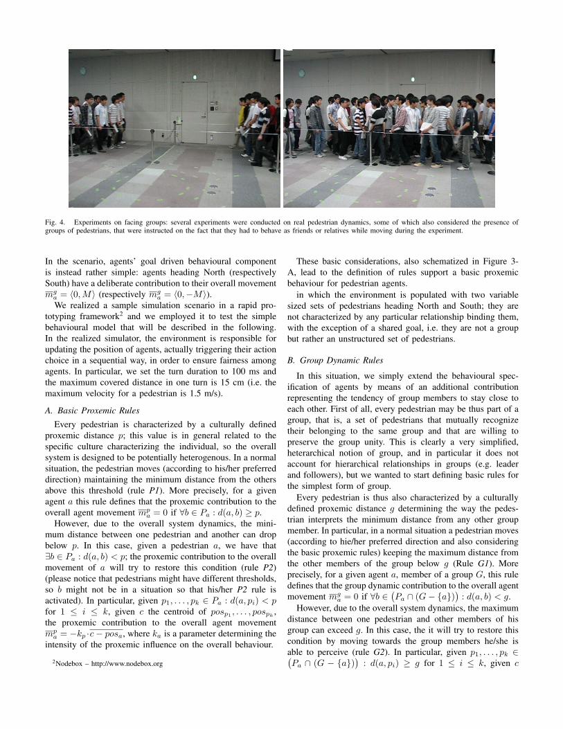
Fig. 4. Experiments on facing groups: several experiments were conducted on real pedestrian dynamics, some of which also considered the presence of
groups of pedestrians, that were instructed on the fact that they had to behave as friends or relatives while moving during the experiment.
In the scenario, agents’ goal driven behavioural component
is instead rather simple: agents heading North (respectively
South) have a deliberate contribution to their overall movement
mga = �0, M� (respectively mg
a = �0,−M�).We realized a sample simulation scenario in a rapid pro-
totyping framework2
and we employed it to test the simple
behavioural model that will be described in the following.
In the realized simulator, the environment is responsible for
updating the position of agents, actually triggering their action
choice in a sequential way, in order to ensure fairness among
agents. In particular, we set the turn duration to 100 ms and
the maximum covered distance in one turn is 15 cm (i.e. the
maximum velocity for a pedestrian is 1.5 m/s).
A. Basic Proxemic RulesEvery pedestrian is characterized by a culturally defined
proxemic distance p; this value is in general related to the
specific culture characterizing the individual, so the overall
system is designed to be potentially heterogenous. In a normal
situation, the pedestrian moves (according to his/her preferred
direction) maintaining the minimum distance from the others
above this threshold (rule P1). More precisely, for a given
agent a this rule defines that the proxemic contribution to the
overall agent movement mpa = 0 if ∀b ∈ Pa : d(a, b) ≥ p.
However, due to the overall system dynamics, the mini-
mum distance between one pedestrian and another can drop
below p. In this case, given a pedestrian a, we have that
∃b ∈ Pa : d(a, b) < p; the proxemic contribution to the overall
movement of a will try to restore this condition (rule P2)
(please notice that pedestrians might have different thresholds,
so b might not be in a situation so that his/her P2 rule is
activated). In particular, given p1, . . . , pk ∈ Pa : d(a, pi) < pfor 1 ≤ i ≤ k, given c the centroid of posp1 , . . . , pospk ,
the proxemic contribution to the overall agent movement
mpa = −kp ·c− posa, where ka is a parameter determining the
intensity of the proxemic influence on the overall behaviour.
2Nodebox – http://www.nodebox.org
These basic considerations, also schematized in Figure 3-
A, lead to the definition of rules support a basic proxemic
behaviour for pedestrian agents.
in which the environment is populated with two variable
sized sets of pedestrians heading North and South; they are
not characterized by any particular relationship binding them,
with the exception of a shared goal, i.e. they are not a group
but rather an unstructured set of pedestrians.
B. Group Dynamic Rules
In this situation, we simply extend the behavioural spec-
ification of agents by means of an additional contribution
representing the tendency of group members to stay close to
each other. First of all, every pedestrian may be thus part of a
group, that is, a set of pedestrians that mutually recognize
their belonging to the same group and that are willing to
preserve the group unity. This is clearly a very simplified,
heterarchical notion of group, and in particular it does not
account for hierarchical relationships in groups (e.g. leader
and followers), but we wanted to start defining basic rules for
the simplest form of group.
Every pedestrian is thus also characterized by a culturally
defined proxemic distance g determining the way the pedes-
trian interprets the minimum distance from any other group
member. In particular, in a normal situation a pedestrian moves
(according to hie/her preferred direction and also considering
the basic proxemic rules) keeping the maximum distance from
the other members of the group below g (Rule G1). More
precisely, for a given agent a, member of a group G, this rule
defines that the group dynamic contribution to the overall agent
movement mga = 0 if ∀b ∈
�Pa ∩ (G− {a})
�: d(a, b) < g.
However, due to the overall system dynamics, the maximum
distance between one pedestrian and other members of his
group can exceed g. In this case, the it will try to restore this
condition by moving towards the group members he/she is
able to perceive (rule G2). In particular, given p1, . . . , pk ∈�Pa ∩ (G − {a})
�: d(a, pi) ≥ g for 1 ≤ i ≤ k, given c
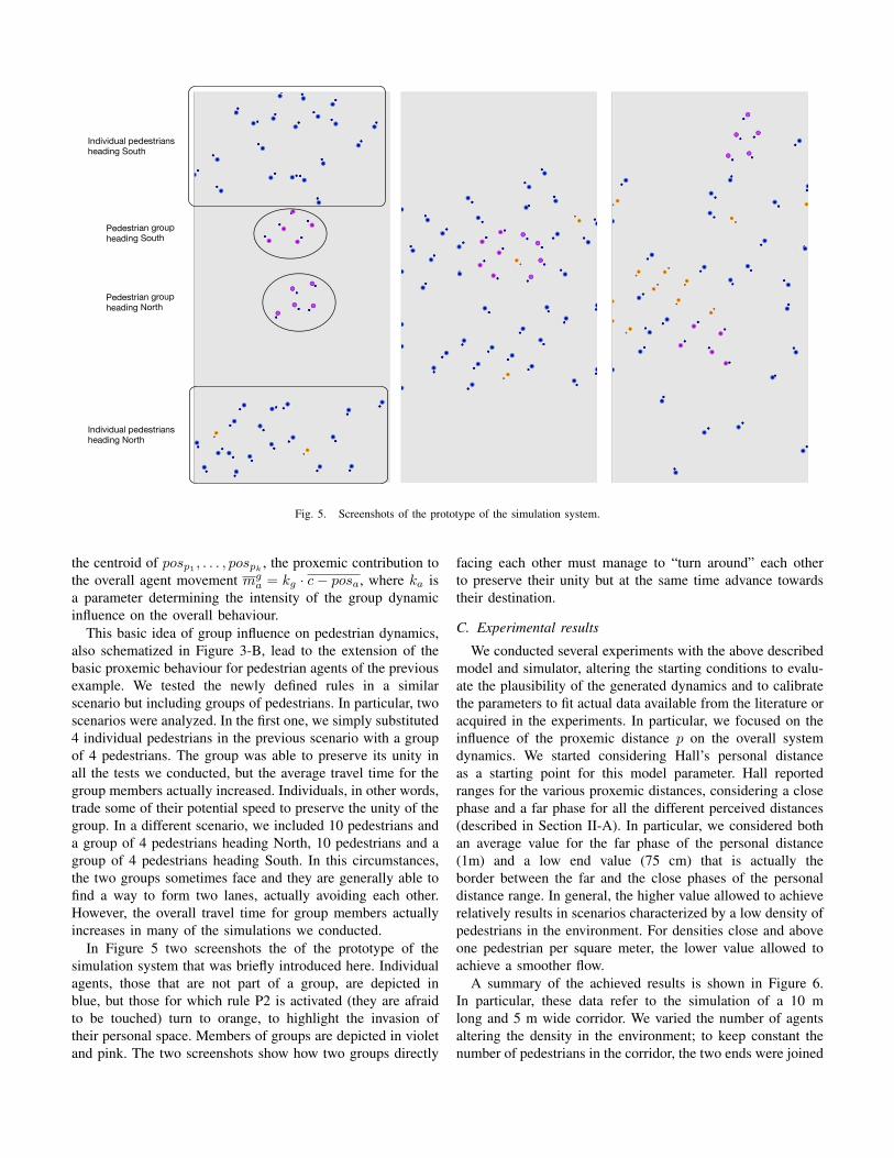
Individual pedestriansheading South
Pedestrian groupheading South
Pedestrian groupheading North
Individual pedestriansheading North
Fig. 5. Screenshots of the prototype of the simulation system.
the centroid of posp1 , . . . , pospk , the proxemic contribution to
the overall agent movement mga = kg · c− posa, where ka is
a parameter determining the intensity of the group dynamic
influence on the overall behaviour.
This basic idea of group influence on pedestrian dynamics,
also schematized in Figure 3-B, lead to the extension of the
basic proxemic behaviour for pedestrian agents of the previous
example. We tested the newly defined rules in a similar
scenario but including groups of pedestrians. In particular, two
scenarios were analyzed. In the first one, we simply substituted
4 individual pedestrians in the previous scenario with a group
of 4 pedestrians. The group was able to preserve its unity in
all the tests we conducted, but the average travel time for the
group members actually increased. Individuals, in other words,
trade some of their potential speed to preserve the unity of the
group. In a different scenario, we included 10 pedestrians and
a group of 4 pedestrians heading North, 10 pedestrians and a
group of 4 pedestrians heading South. In this circumstances,
the two groups sometimes face and they are generally able to
find a way to form two lanes, actually avoiding each other.
However, the overall travel time for group members actually
increases in many of the simulations we conducted.
In Figure 5 two screenshots the of the prototype of the
simulation system that was briefly introduced here. Individual
agents, those that are not part of a group, are depicted in
blue, but those for which rule P2 is activated (they are afraid
to be touched) turn to orange, to highlight the invasion of
their personal space. Members of groups are depicted in violet
and pink. The two screenshots show how two groups directly
facing each other must manage to “turn around” each other
to preserve their unity but at the same time advance towards
their destination.
C. Experimental results
We conducted several experiments with the above described
model and simulator, altering the starting conditions to evalu-
ate the plausibility of the generated dynamics and to calibrate
the parameters to fit actual data available from the literature or
acquired in the experiments. In particular, we focused on the
influence of the proxemic distance p on the overall system
dynamics. We started considering Hall’s personal distance
as a starting point for this model parameter. Hall reported
ranges for the various proxemic distances, considering a close
phase and a far phase for all the different perceived distances
(described in Section II-A). In particular, we considered both
an average value for the far phase of the personal distance
(1m) and a low end value (75 cm) that is actually the
border between the far and the close phases of the personal
distance range. In general, the higher value allowed to achieve
relatively results in scenarios characterized by a low density of
pedestrians in the environment. For densities close and above
one pedestrian per square meter, the lower value allowed to
achieve a smoother flow.
A summary of the achieved results is shown in Figure 6.
In particular, these data refer to the simulation of a 10 m
long and 5 m wide corridor. We varied the number of agents
altering the density in the environment; to keep constant the
number of pedestrians in the corridor, the two ends were joined

!"!!#
!"$!#
!"%!#
!"&!#
!"'!#
!"(!#
!")!#
!"*!#
!"+!#
!",!#
$"!!#
!"!# !"(# $"!# $"(# %"!# %"(# &"!# &"(#
!"#$%&'()
*"+,&'()
-.+/01"+'0#)/&02301)4)5"#$%&'()
-./#0123.456#783954:1# ;8<=#0123.456#783954:1#
!"!!#
!"$!#
!"%!#
!"&!#
!"'!#
("!!#
("$!#
("%!#
!"!# !")# ("!# (")# $"!# $")# *"!# *")#
!"#$
%
&'()*+,%
!-(./0'(+/"%.*/12/0%3%4#$%
+,-#./01,234#5617328/# 96:;#./01,234#5617328/#
Fig. 6. Fundamental diagrams for the 10m long and 5m wide corridorscenario. The two data series respectively refer to different values for theproxemic distance, respectively the low end (75cm) and the average value(1m) of personal distance.
(i.e. pedestrians exiting from one end were actually re-enteringthe corridor from the other). For each run only completepedestrian trips were considered (i.e. the first pedestrian exitevent was discarded because related to a partial crossing of thecorridor) and in some occasions several starting turns were alsodiscarded to avoid transient starting conditions. The resultsof the simulations employing the low personal distance areconsistent with empirical observations discussed in [7].
We are currently analyzing the implications of the presenceof groups in the environment. The generated data, as wellas the empirical observations, still do not lead to conclusiveresults: in most cases, especially in low density scenarios,group members are generally slower than single individualsbut in high density scenarios they are sometimes able tooutperform the average individual. This is probably due tothe fact that the presence of the group has a greater influenceon the possibility of other individuals to move, generating forinstance a higher possibility of members on the back of thegroup to follow the “leaders”.
V. CONCLUSIONS AND FUTURE WORKS
The paper has presented the research setting in which aninnovative agent–based pedestrian an crowd modeling andsimulation effort is set. Preliminary results of the first stage ofthe modeling phase were described. Future works are aimed,on one hand, at consolidating the preliminary results of thisfirst scenarios (performing a calibration of the model andvalidation of the results, that is currently under way), butalso extending the range of simulated scenarios characterizedby relatively simple spatial structures for the environment(e.g. bends, junctions). On the other hand, we want to betterformalize the agent behavioural model and its overall archi-tecture, but also extending the notion of group, in order tocapture phenomenologies that are particularly relevant in thecontext of Hajj (e.g. hierarchical groups, but also hierarchiesof groups). Finally, we are also working at the integration ofthese models into an existing open source framework for 3Dcomputing (Blender3, also to be able to embed these modelsand simulations in real portions of the built environmentdefined with traditional CAD tools.
ACKNOWLEDGMENTS
This work has been partly funded by the Crystal Project.The authors would like to thank Dr. Nabeel Koshak forhis expertise on the Hajj pilgrimage description and on therequirements for second generation modeling and simulationsystems; the authors would also thank Prof. Ugo Fabietti forhis suggestions about the anthropological literature that wasconsidered in this work.
REFERENCES
[1] M. Batty, “Agent based pedestrian modeling (editorial),” Environment
and Planning B: Planning and Design, vol. 28, pp. 321–326, 2001.[2] A. Willis, N. Gjersoe, C. Havard, J. Kerridge, and R. Kukla, “Human
movement behaviour in urban spaces: Implications for the designand modelling of effective pedestrian environments,” Environment and
Planning B, vol. 31, no. 6, pp. 805–828, 2004.[3] R. Axtell, “Why Agents? On the Varied Motivations for Agent Comput-
ing in the Social Sciences,” Center on Social and Economic Dynamics
Working Paper, vol. 17, 2000.[4] S. Christley, X. Zhu, S. A. Newman, and M. S. Alber, “Multiscale
agent-based simulation for chondrogenic pattern formation n vitro,”Cybernetics and Systems, vol. 38, no. 7, pp. 707–727, 2007.
[5] M. Luck, P. McBurney, O. Sheory, and S. Willmott, Eds., Agent
Technology: Computing as Interaction. University of Southampton,2005.
[6] E. D. Kuligowski and S. M. V. Gwynne, Pedestrian and Evacuation
Dynamics 2008. Springer, 2010, ch. The Need for Behavioral Theoryin Evacuation Modeling, pp. 721–732.
[7] A. Schadschneider, W. Klingsch, H. Klupfel, T. Kretz, C. Rogsch, andA. Seyfried, “Evacuation dynamics: Empirical results, modeling andapplications,” in Encyclopedia of Complexity and Systems Science, R. A.Meyers, Ed. Springer, 2009, pp. 3142–3176.
[8] E. T. Hall, The Hidden Dimension. Anchor Books, 1966.[9] ——, “A system for the notation of proxemic behavior,” American
Anthropologist, vol. 65, no. 5, pp. 1003–1026, 1963. [Online].Available: http://www.jstor.org/stable/668580
[10] U. Chattaraj, A. Seyfried, and P. Chakroborty, “Comparison of pedestrianfundamental diagram across cultures,” Advances in Complex Systems,vol. 12, no. 3, pp. 393–405, 2009.
[11] E. Canetti and C. Stewart, Crowds and power. Farrar, Straus andGiroux, 1984.
3http://www.blender.org/

[12] S. Bandini, S. Manzoni, and S. Redaelli, “Towards an ontology forcrowds description: A proposal based on description logic,” in ACRI,ser. Lecture Notes in Computer Science, H. Umeo, S. Morishita,K. Nishinari, T. Komatsuzaki, and S. Bandini, Eds., vol. 5191. Springer,2008, pp. 538–541.
[13] S. Bandini, L. Manenti, S. Manzoni, and F. Sartori, “A knowledge-based approach to crowd classification,” in Proceedings of the The5th International Conference on Pedestrian and Evacuation Dynamics,March 8-10, 2010,, 2010.
[14] M. Schreckenberg and S. D. Sharma, Eds., Pedestrian and EvacuationDynamics. Springer–Verlag, 2001.
[15] D. Helbing, F. Schweitzer, J. Keltsch, and P. Molnar, “Active walkermodel for the formation of human and animal trail systems,” PhysicalReview E, vol. 56, no. 3, pp. 2527–2539, January 1997.
[16] D. Helbing and P. Molnar, “Social force model for pedestrian dynamics,”Phys. Rev. E, vol. 51, no. 5, pp. 4282–4286, May 1995.
[17] D. Helbing, “A fluid–dynamic model for the movement of pedestrians,”Complex Systems, vol. 6, no. 5, pp. 391–415, 1992.
[18] S. Okazaki, “A study of pedestrian movement in architectural space,part 1: Pedestrian movement by the application of magnetic models,”Transactions of A.I.J., no. 283, pp. 111–119, 1979.
[19] M. Moussaıd, N. Perozo, S. Garnier, D. Helbing, and G. Theraulaz,“The walking behaviour of pedestrian social groups and its impacton crowd dynamics,” PLoS ONE, vol. 5, no. 4, p. e10047, 04 2010.[Online]. Available: http://dx.doi.org/10.1371%2Fjournal.pone.0010047
[20] K. Nagel and M. Schreckenberg, “A cellular automaton model forfreeway traffic,” Journal de Physique I France, vol. 2, no. 2221, pp.222–235, 1992.
[21] V. J. Blue and J. L. Adler, “Cellular automata microsimulation ofbi-directional pedestrian flows,” Transportation Research Record, vol.1678, pp. 135–141, 2000.
[22] ——, “Modeling four-directional pedestrian flows,” Transportation Re-search Record, vol. 1710, pp. 20–27, 2000.
[23] A. Schadschneider, A. Kirchner, and K. Nishinari, “Ca approach tocollective phenomena in pedestrian dynamics.” in Cellular Automata,5th International Conference on Cellular Automata for Research andIndustry, ACRI 2002, ser. Lecture Notes in Computer Science, S. Ban-dini, B. Chopard, and M. Tomassini, Eds., vol. 2493. Springer, 2002,pp. 239–248.
[24] K. Nishinari, Y. Suma, D. Yanagisawa, A. Tomoeda, A. Kimura, andR. Nishi, Pedestrian and Evacuation Dynamics 2008. Springer BerlinHeidelberg, 2008, ch. Toward Smooth Movement of Crowds, pp. 293–308.
[25] J. Was, “Crowd dynamics modeling in the light of proxemic theories,”in ICAISC (2), ser. Lecture Notes in Computer Science, L. Rutkowski,R. Scherer, R. Tadeusiewicz, L. A. Zadeh, and J. M. Zurada, Eds., vol.6114. Springer, 2010, pp. 683–688.
[26] C. M. Henein and T. White, “Agent-based modelling of forces incrowds.” in Multi-Agent and Multi-Agent-Based Simulation, Joint Work-shop MABS 2004, New York, NY, USA, July 19, 2004, Revised SelectedPapers, ser. Lecture Notes in Computer Science, P. Davidsson, B. Logan,and K. Takadama, Eds., vol. 3415. Springer–Verlag, 2005, pp. 173–184.
[27] J. Dijkstra, J. Jessurun, B. de Vries, and H. J. P. Timmermans, “Agentarchitecture for simulating pedestrians in the built environment,” inInternational Workshop on Agents in Traffic and Transportation, 2006,pp. 8–15.
[28] C. Gloor, P. Stucki, and K. Nagel, “Hybrid techniques for pedestriansimulations,” in Cellular Automata, 6th International Conference onCellular Automata for Research and Industry, ACRI 2004, ser. LectureNotes in Computer Science, P. M. A. Sloot, B. Chopard, and A. G.Hoekstra, Eds., vol. 3305. Springer–Verlag, 2004, pp. 581–590.
[29] M. C. Toyama, A. L. C. Bazzan, and R. da Silva, “An agent-basedsimulation of pedestrian dynamics: from lane formation to auditoriumevacuation,” in 5th International Joint Conference on AutonomousAgents and Multiagent Systems (AAMAS 2006), H. Nakashima, M. P.Wellman, G. Weiss, and P. Stone, Eds. ACM press, 2006, pp. 108–110.
[30] S. Bandini, M. L. Federici, and G. Vizzari, “Situated cellular agentsapproach to crowd modeling and simulation,” Cybernetics and Systems,vol. 38, no. 7, pp. 729–753, 2007.
[31] S. R. Musse and D. Thalmann, “Hierarchical model for real timesimulation of virtual human crowds,” IEEE Trans. Vis. Comput. Graph.,vol. 7, no. 2, pp. 152–164, 2001.
[32] W. Shao and D. Terzopoulos, “Autonomous pedestrians,” GraphicalModels, vol. 69, no. 5-6, pp. 246–274, 2007.
[33] S. Paris and S. Donikian, “Activity-driven populace: A cognitive ap-proach to crowd simulation,” IEEE Computer Graphics and Applica-tions, vol. 29, no. 4, pp. 34–43, 2009.
[34] Y. Murakami, T. Ishida, T. Kawasoe, and R. Hishiyama, “Scenariodescription for multi-agent simulation,” in AAMAS. ACM, 2003, pp.369–376.
[35] C. W. Reynolds, “Flocks, herds and schools: A distributed behavioralmodel,” in SIGGRAPH ’87: Proceedings of the 14th annual conferenceon Computer graphics and interactive techniques. New York, NY,USA: ACM, 1987, pp. 25–34.
[36] M. Batty, Advanced Spatial Analysis: The CASA Book of GIS. EsriPress, 2003, ch. Agent-based pedestrian modelling, pp. 81–106.
Towards an Application of Graph Structure Analysis
to a MAS-based model of Proxemic Distances
in Pedestrian Systems
Lorenza Manenti, Luca Manzoni, Sara Manzoni
CSAI - Complex Systems Artificial & Intelligence Research Center
Dipartimento di Informatica, Sistemistica e Comunicazione
Universita degli Studi di Milano - Bicocca
viale Sarca 336, 20126, Milano, Italy
Email {lorenza.manenti, luca.manzoni, sara.manzoni}@disco.unimib.it
Abstract—This paper proposes the use of methods for networkanalysis in order to study the properties of a dynamic graphthat model the interaction among agents in an agent-basedmodel. This model is based on Multi Agent System definitionand simulates a multicultural crowd in which proxemics theoryand distance perception are taking into account.
After a discussion about complex network analysis and crowdresearch context, an agent-based model based on SCA*PED(Situated Cellular Agents for PEdestrian Dynamics) approachis presented, based on two separated yet interconnected layersrepresenting different aspects of the overall system dynamics.Then, an analysis of network derived from agent interactionsin the Proxemic layer is proposed, identifying characteristicstructures and their meaning in the crowd analysis. At the endan analysis related to the identification of those characteristicstructures in some real examples is proposed.
I. INTRODUCTION
The analysis of networks can be traced back to the first
half of the XX century [1], with some works dating back to
the end of the XIX century [2]. Network analysis has been
proved useful in the study of social phenomena and their
applications, like rumor spreading [3], opinion formation [4],
[5] and the structure of social relation [6]. Outside the social
sciences, network analysis has been applied to study and model
the epidemic spreading process [7], the interaction between
proteins [8] and the link structure in the World Wide Web [9].
The analysis of social networks is an emerging topic also
in the Multi Agent System (MAS) area [10]. Some prominent
examples of this analysis can be found in reputation and trust
systems [11] with the aim of identifying how the propagation
of trust and reputation can influence system dynamics.
In this paper we propose an analysis of the graph structures
of a social network derived from the interaction among agents
in a MAS with the aim to support the simulation of crowd and
pedestrian dynamics. This system is based on a model that is
an extension of an agent-based approach previously presented
in the pedestrian dynamics area: in particular, we refer to
SCA*PED approach (Situated Cellular Agents for PEdestrianDynamics [12]).
In this approach, according to agent-based modeling and
simulation, crowds are studied as complex systems: other
approaches consider pedestrians as moving particles subjected
to forces (i.e., Social Force models [13]) or as cells in a
cellular automata (i.e., Cellular Automata models [14]). In
the first approach the dynamic of spatial features is studied
through spatial occupancy of individuals and each pedestrian
is attracted by its goal and repelled by obstacles modeled
as forces; in the second, the environment is represented as
a regular grid where each cell has a state that indicates the
presence/absence of pedestrians and environmental obstacles.
These traditional modeling approaches focus on pedestrian
dynamics with the aim of supporting decision-makers and
managers of crowded spaces and events. Differently, in the
agent-based approach, pedestrians are instead explicitly rep-
resented as autonomous entities, where the dynamics of the
system results from local behavior among agents and their
interactions with the environment. With respect to the particle
approach, the agent-based model can deal with individual
aspects of the crowd and differences between single agents
(or groups of agents) [15]. Since those aspect can influence
the behavior of the crowd, we consider this approach more
promising even if it is computationally intensive.
In this way some multidisciplinary proposals have recently
been suggested to tackle the complexity of crowd dynamics by
taking into account emotional, cultural and social interaction
concepts [16]–[18].
In this paper we focus on interactions among different
kinds of agents and we study how the presence of hetero-
geneities in the crowd influence its dynamics. In particular,
the model we present explicitly represents the concept of
perceived distance: despite spatial distance, perceived distance
quantifies the different perception of the same distance by
pedestrians with different cultural attitudes. In the model we
assume that pedestrians keep a certain distance between each
other following the theory proposed by Elias Canetti [19].
This distance evolves according to the situation in which the
pedestrian is: free walking, inside a crowd, inside a group in
a crowd (i.e., crowd crystal).
The concept of perceived distance is strictly related to
the concept of proxemic distance: the term proxemics was

first introduced by Hall with respect to the study of set ofmeasurable distances between people as they interact [20],[21]. Perceived distances depend on some elements whichcharacterize relationships and interactions between people:posture and sex identifiers, sociofugal-sociopetal1 (SFP) axis,kinesthetic factor, touching code, visual code, thermal code,olfactory code and voice loudness.
In order to represents spatial and perceived distances, theproposed model represents pedestrians behaving according tolocal information and knowledge on two separated yet inter-connected layers where the first (i.e., Spatial layer) describesthe environment in which pedestrian simulation is performedand the second (i.e., Proxemic layer) represents heterogeneitiesin system members on the basis of cultural differences.
The methods and algorithms related to social networkanalysis can be applied on the network created from interactionamong agents in the Proxemic layer. This study allows theevaluation of dynamic comfort properties (for each pedestrianand for the crowd) given a multicultural crowd sharing astructured environment.
The paper is organized as follow: after a description ofgeneral SCA*PED approach, we will describe deeply eachlayer of the structure. Starting from the analysis of the socialnetwork created at Proxemic layer, we will identify relevantstructures and properties of the corresponding graph. In theend, we will propose some examples of those structures inreal world situations.
II. TWO LAYERED MODEL
In this section, the proposed multi-layered model is pre-sented: after an introduction on SCA*PED general approach,we will describe the Spatial and Proxemic layer focusing onthe interaction between layers and among agents.
In order to model spatial and perceived distances, wedefined a constellation of interacting MAS situated on a two-layered structure (i.e., Spatial and Proxemic layers). Followingthe SCA*PED approach definition the agents are definedas reactive agents that can change their internal state ortheir position on the environment according to perception ofenvironmental signals and local interactions with neighboringagents. Each MAS layer is defined by a triple
�Space, F,A�
where Space models the environment in which the set A ofagents is situated, acts autonomously and interacts throughthe propagation/perception of the set F of fields. IN particularSpace is modeled as an undirected graph of nodes p ∈ P .
A network, or graph, is a pair G = (V,E) where V is aset of nodes and E ⊆ V × V is a set of edges. A graph G iscalled undirected if and only if for all u, v ∈ V , (u, v) ∈E ⇔ (v, u) ∈ E. Otherwise the graph is called directed.A graph can be also represented as an adjacency matrix A,where the elements au,v of the matrix are 1 if (u, v) ∈ E and
1These terms were first introduced in 1957 by H. Osmond in [22] and referto the different degree of tolerance of crowding.
Fig. 1. Two-layered MAS model is shown. Spatial layer describes theenvironment in which pedestrian simulation is performed and Proxemic layerrefers to the dynamic perception of neighboring pedestrians. For instance, thetwo agents ax and ay are adjacent in the Spatial layer and, consequently,they are connected by an edge in the Proxemic layer due to the perception ofthe fields exported.
0 otherwise. Two nodes u, v ∈ V such that (u, v) ∈ E arecalled adjacent nodes. The edge of a graph could be weighedif it is defined a weight function w : E �→ R. In this case thegraph is a weighted graph.
The set of nodes P of Space is defined by a set of triples�ap, Fp, Pp� (i.e., every p ∈ P is a triple) where ap ∈ A∪{⊥}is the agent situated in p, Fp ⊂ F is the set of fields activein p and Pp ⊂ P is the set of nodes adjacent to p. Fields canbe propagated and perceived in the same or different layers.In order to allow this interaction, the model introduces thepossibility to export (import) fields from (into) each layer.
In each layer, pedestrians and relevant elements of theenvironment are represented by different kinds of agents. Anagent type τ = �Στ , P erceptionτ , Actionτ � is defined by:
• Στ , the set of states that agents of type τ can assume;• Perceptionτ , a function that describes how an agent is
influenced by fields defining a receptiveness coefficientand a sensibility threshold for each field f ∈ F ;
• Actionτ , a function that allows the agent movementbetween spatial positions, the change of agent state andthe emission of fields.
Each agent is defined as a triple �s, p, τ� where τ is the agenttype, s ∈
�τ is the agent state and p ∈ P is the site in which
the agent is situated.Spatial and Proxemic layers will be described in the fol-
lowing sections. The first describing the environment in whichpedestrian simulation is performed while the second referringto the dynamic perception of neighboring pedestrians accord-ing to proxemic distances.
A. The Spatial LayerIn the Spatial layer, each spatial agent aspa ∈ Aspa emits
and exports to Proxemic layer a field to signal changes on

physical distance with respect to other agents. This meansthat when an agent ay ∈ Aspa enters the neighborhood of anagent ax ∈ Aspa (considering nodes adjacent to pax ), bothagents emits a field fpro with an intensity id proportionalto the spatial distance between ax and ay . In particular, axstarts to emit a field fpro(ay) with information related toay and intensity idxy , and ay starts to emit a field fpro(ax)with information related to ax and intensity idyx. Obviously,idxy = idyx due to the symmetry property of distance and thedefinition of id.
When physical condition changes and one of the agents exitsthe neighborhood, the emitting of the fields ends.
Fields are exported into Proxemic layer and influences therelationships and interactions between proxemic agents. InFigure 1, a representation of the interaction between Spatialand Proxemic layers is shown. How this field is perceived andinfluences the agent interactions in the Proxemic layer, will bedescribed in the next section.
B. The Proxemic Layer
As previously anticipated, Proxemic layer describes theagents behavior taking into account the dynamic perception ofneighboring pedestrians according to Proxemics theory. Prox-emic layer hosts a heterogeneous system of agents Apro whereseveral kinds of agents τ1, .., τn represent different attitudesof a multicultural crowd. Each type τi is characterized by aperception function perci and a value of social attitude sai.This value takes into account proxemic categories introducedbefore and indicates the attitude to sociality for that type ofagent.
In this layer, space is described as a set of nodes whereeach node is occupied by a proxemic agent apro ∈ Apro andconnected to the corresponding node at Spatial layer. Proxemicagents are influenced by fields imported from Spatial layer bymeans of their perception function. The latter interprets thefield fpro perceived, amplifying or reducing the value of itsintensity id on the basis of sa value.
When in the Spatial layer ax ∈ Aspa emits a field withinformation on ay , in the Proxemic layer a�x ∈ τi perceivesthe field fpro(ay):
perci(fpro(ay)) = sai × idxy = ipxy (1)
and a�y ∈ τj perceives the field fpro(ax):
percj(fpro(ax)) = saj × idyx = ipyx (2)
Values ipxy and ipyx quantify the different way to perceivethe physical distance between ax and ay from the point ofview of ax and ay respectively.
Each apro ∈ Apro is also characterized by a state s ∈ Σwhich dynamically evolves on the basis of the perceptions ofdifferent fpro imported from the Spatial layer. The transitionof state represents the local change of comfort value foreach agent. State change may imply also a change in theperception: this aspect may be introduced into the model byspecifying it into the perception function (i.e., perci(fpro, s) =
perci(fpro)). In this paper we do not consider this aspect:future works will consider this issue.
In general, the state evolves according to the composition ofthe different ip calculated on the basis of interactions whichtake place in the Spatial layer.
Fig. 2. A system of four agents where the state of agent a�z ∈ Apro resultsfrom the composition of its perceived neighbors (i.e., a�1, a
�2, a
�3 ∈ Apro).
Figure 2 shows an heterogeneous system composed of fourneighboring agents where the state of each agent results fromthe composition of all perceived neighbors:
∀a�z ∈ Apro, sz = compose(ipz1, ipz2, .., ipzn)
where a�1, .., a�n ∈ Apro are the corresponding proxemic
agents of a1, ..an ∈ Aspa which belong to the neighborhoodof az ∈ Aspa.
After the perception and modulation of fields perceived, itis possible to consider the relationship between i and j in (1)and (2).
If i = j the two agents belong to the same type (i.e., τi =τj) and the values ipxy and ipyx resultant from the perceptionare equal (i.e., sai = saj and idxy = idyx for definition).Otherwise, if i �= j the two agents belong to different kinds(i.e., τi �= τj) and the values ipxy and ipyx resultant fromthe perception are different (the agents perceive their commonphysical distance in different way).
Proxemic relationships among agents are represented as anundirected graph PG = (A,E) where A is the set of nodes(i.e., agents) and E is the set of edges. The edges of PG aredynamically modified as effect of spatial interactions occurringat Spatial layer and social attitude sa. In particular, when afield fpro(ay) is perceived from agent a�x with information onay , an edge between a�x and a�y is created. When field emissionends due to the exit of the neighborhood by one agent, theedge previously created is eliminated. The edge (x, y) betweennodes x and y is characterized by a weight wxy:
wxy = |ipxy − ipyx|
and represents the proxemic relationships between agents axand ay in the Spatial layer. Obviously, only if ipxy �= ipyx thewxy is non null.
In the next section we will introduce the basic notions onnetworks and the analysis of their properties.

III. BASICS NETWORK ANALYSIS
In this section we introduce the basic properties and kindsof graph used in the analysis of networks.
Starting with the previous definition of graph, we canintroduce the notion of node degree. The in-degree of anode is the number of incoming edges in the node: forv ∈ V , in(v) = |{(u, v) ∈ E}|. The out-degree of a nodeis the number of outgoing edges in a node: for v ∈ V ,out(v) = |{(v, u) ∈ E}|. The degree deg(v) of a node v ∈ V
is the sum of its in-degree and out-degree. A first simplecharacterization of graphs can be done using their degreedistribution. The degree distribution P (k) of a graph G is theratio of nodes in the graph that have degree equal to k. Fordirected graph it is useful to distinguish between the in-degreedistribution Pin(k) and the out-degree distribution Pout(k).
A first property of interest in a graph is the diameter,indicated by Diam(G). Let d(v, u) be the shortest path fromthe node u to the node v. The diameter is the maximum valueassumed by d(u, v). If the graph G is not connected then thevalue of the diameter is infinite. Related to the diameter is theaverage shortest path length, defined as:
L =1
|V |(|V |− 1)
�
u,v∈V,v �=u
d(u, v)
As with the diameter, the average shortest path length isinfinite when the graph is not connected.
Another measure used in the analysis of networks is theclustering coefficient introduced by Watts and Strogatz [23].The clustering coefficent for the node v ∈ V is defined as:
c(v) =
�u1,u2
av,u1au1,u2au2,v
deg(v)(deg(v)− 1)
The clustering coefficient of the graph G as a whole is themeans of the clustering coefficient of the single nodes:
C =1
|V |�
v∈V
c(v)
Many variations of the clustering coefficient has been pro-posed, for example to remove biases [24].
A structure of particular interest is the community struc-ture. The concept of community has been defined in socialsciences [6]. Since a community on a graph has to correspondto a social community, it does not have a single definition.Intuitively a community is a subgraph whose nodes are tightlyconnected. The strongest definition is that a community isa cliche (i.e., a maximal subgraph where all the nodes areadjacent) or a k-cliche (i.e., a maximal subgraph where allthe nodes are at a distance bounded by k). Another definitionimplies that the sum of the degree of the nodes towardsother community members is greater than the sum of thedegree of the nodes towards nodes outside the community.Other definitions have been proposed to fit particular modelingrequirements.
In the study of complex networks many kinds of networkstructure have been proposed:
1) RANDOM GRAPH. This is the simplest type of graph,where pairs of nodes where connected with a certainprobability p. Unfortunately it is not able of representingmany real world phenomena;
2) “SMALL WORLD” GRAPH. In many real world net-works there exists “shortcuts” in the communicationbetween nodes (i.e., edges connecting otherwise distantparts of the graph). This property is called small worldproperty and is present when the average shortest pathof a graph is at most logarithmic in the number of nodesin the graph. This property is usually associated with ahigh clustering factor [23];
3) FREE SCALE NETWORKS. A more in-depth study ofreal networks shows that the distribution of degreesis not a Gaussian one. The distribution emerging inbiological [25] and technological [26] contests is thepower law distribution.The majority of the nodes in scale-free networks have alow degree, while a small number of nodes have a veryhigh degree. Those nodes are called hubs.Since this kind of networks is ubiquitous, there are manystudies on their properties, the possible formation pro-cesses and their resistance to attacks and damages [27].
This short introduction to network analysis is certainly notcomplete. To a more in-depth introduction it is possible torefer to one of the many survey articles [27], [28].
In the next section we will apply those properties definitionsto the graph of the Proxemic layer of the previously definedagent-based model.
IV. STRUCTURES IDENTIFICATION
In this section we identify the structures of interests that weexpect to find in the Proxemic layer of the previously definedMAS model.
A. BordersA first interesting study is related to the identification of
“friction zones”, where a homogeneous group of agents oftype τi is encircled by agents of different type τj �= τi. Weare interested in the study of the border between a group andother agents. This structure can be interesting since we canidentify the presence of homogeneous zones in a MAS andhow those structures evolve in time and interact with otherhomogeneous groups or single agents (that can belong to thesame type or a different one).
Let G = (V,E) and H = (U,F ) be two undirected graph,{τ1, . . . , τn} a partition of V and f : V �→ U an injectivefunction. Let A ,B ⊆ V such that B = V \A and that existA ⊆ A and B ⊆ B with the following properties:
i. For all v ∈ A , v ∈ τi for some i ∈ {1, . . . , n};ii. For all v ∈ B, v /∈ τi;
iii. For all v ∈ A there exists u ∈ B such that (v, u) ∈ E
and for all u� ∈ B exists v� ∈ A such that (u�
, v�) ∈ E;
iv. For all v ∈ A \ A, deg(v) = 0;v. For all u, v ∈ A there exist a sequence f(u) =
f(u0), f(u1), . . . , f(un) = f(v) in H such that

Fig. 3. A schematic example of the border structure
u1, . . . , un ∈ A and (f(ui), f(ui+1)) ∈ F for all
i ∈ {0, . . . , n− 1}.
vi. For all C ⊃ A, C does not respect at least one between
i,iii,iv and v. For all D ⊃ B, D does not respect at least
one between ii and iii.
A subgraph GA,B = (VA,B = A ∪ B, EA,B) with EA,B ={(u, v) ∈ E | u ∈ A, v ∈ B or u ∈ B, v ∈ A} that respects
all the previous properties will be called border for the group
A . We will also call A the inner border and B the outer
border. An example of a border structure is shown in Fig. 3.
Every property of the definition has an associated semantical
motivation. The first property states that a group must be
composed of agents of the same kind. The second property
declares that the agents directly outside the group must be of
a different kind (otherwise they must be part of the group).
The third property states that for each agent inside the inner
(resp. outer) border must exist at least one agent inside the
outer (resp. inner) border that is aware of its presence. The
fourth property declares that the agents of the group that are
not in the border must be isolated from the outside social
interactions. The fifth property uses a mapping function (that
can be used to map agents in the Proxemic layer to loci in the
Spatial layer) to assure that all the elements of the group are
in the same spatial location. The last property assures that we
are taking the entire group and not one subset of it.
Given a border GA,B = (VA,B, EA,B) and a weight function
w, we can be interested in computing the average weight of
the border:
WA,B =1
|EA,B|�
(u,v)∈EA,B
wu,v
We are also interested in the average comfort of the inner
border:
Cinner =1
|A|�
v∈Asv
We can define Couter in the same way. We assume that the
concept of comfort previously introduced can be translated
into a set of real values, where to higher values correspond to
an higher level of comfort.
We can fix two values r ∈ R (a discriminating value
between low and high weights) and c ∈ R (a discriminating
value between comfortable and uncomfortable states) and
obtain 4 possible situations in which a border GA,B can stand:
1) WA,B ≤ r and Cinner � Couter ≤ c.In this case the group A is uncomfortable with the
agents outside it. The outside agents are also uncom-
fortable with the presence of A . The expected reaction
of the group is to close itself and to move farther from
the other agents. The agents in the outer border will also
move away from the group;
2) WA,B ≤ r and Cinner � Couter > c.In this case the group A is comfortable with the outer
agents and the outer agents are comfortable with A .
This is a situation in which it is possible for the group
to be open with respect to the rest of the agents;
3) WA,B > r and Cinner > Couter.
In this case the group A is comfortable with the outer
agents but the converse is false. In this situation the outer
agents are going to increase their distance from A ;
4) WA,B > r and Cinner ≤ Couter.
In this case the outer agents are comfortable with the
group A but the converse is false. In this situation Awill probably increase the distance from the outer agents
and close itself.
Note that the concept of border it is also useful to identify a
group inside the MAS graph PG. Since the set A is composed
by agents of the same type that occupy a certain space, we
can use A as our definition of group.
B. Homogeneous Spatially Located Groups
Another interesting study is the individuation of homoge-
neous groups of agents that are in the same spatial location.
This homogeneous spatially located group (HSL-group) of
agents is expected to behave as a unique entity, so its individ-
uation allows us to understand better the complex dynamics of
the whole system (due to an abstraction process on the system
components).
In order to identify the structure we use a subgraph of the
inverse graph of the perception representation in the Proxemic
layer. We are doing this transformation because two agents
of the same type τi cannot be connected by an edge in the
Proxemic Layer. This means that in the inverse graph they will
be connected. It is necessary to note that we must take care
of agents that are not connected but only as a consequence of
the spatial distance. Those agents must remain unconnected.
In this way we generate a graph where an edge between an
agent u and an agent v has the following semantic: “u and vare of the same type and their spatial distance is low”.
Note that this definition of HSL-group is similar to the
definition of group given previously. In fact, the former is
a generalization of the latter since it is composed by spatially
adjacent groups (under the assumption that when two agents

Fig. 4. A schematic example of some HSL-group
u and v are spatially adjacent, u perceives v and v perceives
u).
We will now proceed with a formal definition of HSL-group.
Let G = (V,E) be an undirected graph and g : V × V �→{0, 1}. We call the inverted graph with respect to g the graph
G� = (V,E�) where E� = {(u, v) ∈ (V × V ) \ E | g(u, v) =1}.
The graph G�is a subgraph of the inverse of G since
we have added an auxiliary condition g. This condition
can be defined in the following way: gip(u, v) = 1 ⇔max{ipu,v, ipv,u} > 0 (i.e., if at least one of the agents
perceives the other one).
Given G and a function g, a HSL-group is a connected
component of G�. Note that in our MAS model the graph G
is the representation of perceptions in the Proxemic layer PGand the function g is gip. An example of HSL-group is shown
in Fig. 4.
Some interesting properties that can be studied inside a
single HSL-group are:
1) the small world property, since we are interested in
how the information can be propagated inside a single
HSL-group and the influence of information propagation
in the HSL-group dynamics. Recall that small world
property implies small diameter and high clustering
coefficient. For this reason, we expect that the presence
of this property can generate a cohesion mechanism
between the components of the HSL-group, otherwise
we expect the group to be uncoordinated and to have a
short lifespan as a single entity when the movement in
the spatial layer are consistent;
2) the power law degree distribution, since it implies a
scale-free structure of the HSL-group. Recall that a
scale-free structure is characterized by hubs (i.e., nodes
with high degree). Because of this, we expect the hubs
of the HSL-group to be hypothetical leaders. In fact,
Fig. 5. Pilgrimage towards Mecca.
The image is from http://www.trafficforum.org/crowdturbulence
when this condition appears, we expect to be able to
understand the group dynamics using only the leader
behaviour;
In the next section we will show some real examples where
those structures can be identified.
V. REAL WORLD EXAMPLES OF GROUPS
In this section we are going to analyze some photographic
examples to manually extract the presence of some of the
structures previously defined.
In the first part we will identify a border structure inside a
photo from the Hajj (i.e., the pilgrimage towards Mecca).
In the second part we will identify small HSL-groups at the
entrance of the 1912 Democratic National Convention.
A. Borders
In Fig. 5 a particular situation during the pilgrimage towards
Mecca is shown. During the Hajj, people of a lot of different
cultures attend to the different phases of the rite. For this
reason, a partitioning in cultural groups is expected. In the
lower right part of the image there is a group of women dressed
in dark, encircled by a cordon of men dressed in white. This
cordon represents an inner border while people near the inner
border compose the outer border. The group is composed of
the cordon of men and the women. Note that since every HSL-
group is also a group, this structure is a simple example of
HSL-group.
B. Small HSL-groups
In Fig. 6 the entrance to the 1912 Democratic National
Convention is shown. In this picture we can identify some
HSL-groups: in particular, the most evident ones are the
following:
• A AND D. They are composed of four and three people
respectively. In the first case the people are organized on
two pair disposed on parallel lines while in the second
case the people are aligned;
• B AND C. They are composed of only one person. This is
a degenerate version of a group but, nevertheless, it still

Fig. 6. Entrance to the 1912 Democratic National Convention
is an interesting case due to the effects of the interactionbetween a single person and a full-fledged group.
In this picture it is difficult to see large groups, but we expectthose groups to be identifiable in simulations and in monitoredevents with a large number of people.
VI. CONCLUSIONS AND FUTURE WORKS
In this paper we have introduced a new agent-based modelfor the modeling of pedestrian dynamics that includes notonly spatial structures and distances but also perceived andproxemic distances. We have also introduced and formalizedtwo structures of interest that can arise from the analysis ofthe network of perceived distances.
We plan to implement the proposed model and the algo-rithms to find the introduced structures in order to experimen-tally verify the consistence of the model and the hypothesison the behavior of the structure introduced.
This work is part of an ongoing research project withthe aim to study interaction between people in multiculturalcrowds.
ACKNOWLEDGEMENT
This work is partially funded by CRYSTALS project, acollaboration between the Center of Research Excellence inHajj and Omrah headed by Dr. Nabeel Koshak and theCSAI - Complex Systems & Artificial Intelligence ResearchCenter headed by Prof. Stefania Bandini. The aim of thestudy is to investigate how the presence of heterogeneousgroups influences emergent dynamics in the Hajj pilgrimage.Other financial supports for this paper have been done bythe University of Milano-Bicocca within the project “Fondod’Ateneo per la Ricerca - anno 2009”.
REFERENCES
[1] B. Wellman, “The school child’s choice of companions,” Journal ofEducational Research, vol. 14, pp. 126–132, 1926.
[2] J. J. Sylvester, “Chemistry and algebra,” Nature, vol. 17, p. 284, 1878.[3] W. Vogels, R. van Renesse, and K. Birman, “The power of epidemics:
robust communication for large-scale distributed systems,” SIGCOMMComput. Commun. Rev., vol. 33, no. 1, pp. 131–135, 2003.
[4] E. Majorana, “Il valore delle leggi statistiche nella fisica e nelle scienzesociali,” Scientia, vol. 36, no. 58, pp. 58–66, 1942.
[5] K. Sznajd-Weron and J. Sznajd, “Opinion evolution in closed commu-nity,” Internation Journal of Modern Physics C, vol. 11, pp. 1157–1165,2000.
[6] S. Wasserman and K. Faust, Social Network Analysis: methods andapplications. Cambridge Unoiversity Press, 1994.
[7] N. T. J. Bailey, The Mathematical Theory of Infectious Diseases, 2nd ed.New York: Hafner, 1975.
[8] B. Vogelstein, D. Lane, and A. J. Levine, “Surfing the p53 network,”Nature, vol. 408, pp. 307–310, 2000.
[9] R. Albert, H. Jeong, and A.-L. Barabasi, “The diameter of the www,”Nature, vol. 401, pp. 130–131, 1999.
[10] P. Iravani, “Multi-level network analysis of multi-agent systems,” inRoboCup 2008: Robot Soccer World Cup XII, ser. Lecture Notes inComputer Science. Berlin: Springer, 2009, pp. 495–506.
[11] J. Sabater and C. Sierra, “Reputation and social network analysis inmulti-agent systems,” in AAMAS ’02: Proceedings of the first interna-tional joint conference on Autonomous agents and multiagent systems.New York, NY, USA: ACM, 2002, pp. 475–482.
[12] S. Bandini, S. Manzoni, and G. Vizzari, “Situated cellular agents a modelto simulate crowding dynamics,” Special Issue on Cellular Automata,vol. E87-D, pp. 669–676, 2004.
[13] D. Helbing and P. Molnar, “Social force model for pedestrian dynamics,”Phisical Review E, vol. 51(5), pp. 4282–4286, 1995.
[14] A. Schadschneider, Pedestrian and Evacuation Dynamics. Springer-Verlag, 2002, ch. Cellular Automaton Approach to Pedestrian Dynamics-Theory, pp. 75–85.
[15] F. Klugl and G. Rindsfuser, “Large-scale agent-based pedestrian simu-lation,” in MATES ’07: Proceedings of the 5th German conference onMultiagent System Technologies. Berlin, Heidelberg: Springer-Verlag,2007, pp. 145–156.
[16] A. Adamatzky, Dynamics of Crowds Minds. World Scientific, 2005.[17] J. Was, “Multi-agent frame of social distances model,” in ACRI ’08:
Proceedings of the 8th international conference on Cellular Automatafor Reseach and Industry. Berlin, Heidelberg: Springer-Verlag, 2008,pp. 567–570.
[18] M. Moussaıd, S. Garnier, G. Theraulaz, and D. Helbing, “Collectiveinformation processing and pattern formation in swarms, flocks, andcrowds,” Topics in Cognitive Science, vol. 1, no. 3, pp. 1–29, 2009.[Online]. Available: http://dx.doi.org/10.1111/j.1756-8765.2009.01028.x
[19] E. Canetti, Crowds and Power. New York: Paperback, 1984.[20] E. T. Hall, The Hidden Dimension. Doubleday, 1966.[21] ——, “A system for the notation of proxemic behavior,” American
Antropologist, New Series, vol. 65(5), pp. 75–85, 1963.[22] H. Osmond, “Function as the basis of psychiatric ward design,” Mental
Hospitals, vol. 8, pp. 23–29, 1957.[23] D. J. Watts and S. H. Strogatz, “Collective dynamics of “small-world”
networks,” Nature, vol. 393, pp. 409–410, 1998.[24] S. N. Soffer and A. Vazquez, “Network clustering coefficient without
degree-correlation biases,” Phys. Rev. E, vol. 71, no. 5, p. 057101, May2005.
[25] H. Jeong, S. P. Mason, A. L. Barabasi, and Z. N. Oltvai, “Lethality nadcentrality in protein networks,” Nature, vol. 411, pp. 41–42, 2001.
[26] R. Pastor-Satorras and A. Vespignani, Evolution and Structure of theInternet: A Statistical Physics Approach. Cambridge: CambridgeUniversity Press, 2004.
[27] S. Boccaletti, V. Latora, Y. Moreno, M. Chavez, and D.-U. Hwang,“Complex networks: Structure and dynamics,” Physics Reports, vol. 424,no. 4-5, pp. 175 – 308, 2006.
[28] M. E. J. Newman, “The structure and function of complex networks,”SIAM Review, vol. 45, pp. 167–256, 2003.
[29] S. Bandini, S. Manzoni, and G. Vizzari, Encyclopedia of Complexityand Systems Science. Springer, 2009, ch. Agent Based Modeling andSimulation, pp. 184–197.
[30] A. Demers, D. Greene, C. Hauser, W. Irish, J. Larson, S. Shenker,H. Sturgis, D. Swinehart, and D. Terry, “Epidemic algorithms forreplicated database maintenance,” in PODC ’87: Proceedings of the sixthannual ACM Symposium on Principles of distributed computing. NewYork, NY, USA: ACM, 1987, pp. 1–12.

A Multiscale Agent-based Model of Morphogenesisin Biological Systems
Sara MontagnaDEIS–Universita di Bologna
via Venezia 52, 47023 Cesena, ItalyEmail: [email protected]
Andrea OmiciniDEIS–Universita di Bologna
via Venezia 52, 47023 Cesena, ItalyEmail: [email protected]
Alessandro RicciDEIS–Universita di Bologna
via Venezia 52, 47023 Cesena, ItalyEmail: [email protected]
Abstract—Studying the complex phenomenon of pattern for-mation created by the gene expression is a big challenge inthe field of developmental biology. This spatial self-organisationautonomously emerges from the morphogenetic processes andthe hierarchical organisation of biological systems seems to playa crucial role. Being able to reproduce the systems dynamicsat different levels of such a hierarchy might be very useful. Inthis paper we propose the adoption of the agent-based model asan approach capable of capture multi-level dynamics. Each cellis modelled as an agent that absorbs and releases substances,divides, moves and autonomously regulates its gene expression.As a case study we present an agent-based model of Drosophilamelanogaster morphogenesis. We then propose a formalisationof the model which clearly describe its main components. Wefinally show simulation results demonstrating the capability ofthe model of reproducing the expression pattern of the embryo.
I. INTRODUCTION
Developmental biology is an interesting branch of lifescience that studies the process by which organisms develop,focussing on the genetic control of cell growth, differentiationand movement. A main problem in developmental biology isunderstanding the mechanisms that make the process of ver-tebrates’ embryo regionalisation so robust, making it possiblethat from one cell (the zygote) the organism evolves acquiringthe same morphologies each time. This phenomenon involvesat the same time the dynamics of – at least – two levels,including both cell-to-cell communication and intracellularphenomena: they work together, and influence each other in theformation of complex and elaborate patterns that are peculiarto the individual phenotype. This happens according to theprinciples of downward and upward causation, where thebehaviour of the parts (down) is determined by the behaviourof the whole (up), and the emergent behaviour of the wholeis determined by the behaviour of the parts [19].
Modelling embryo- and morphogenesis presents big chal-lenges: (i) there is a lack of biological understanding ofhow intracellular networks affect multicellular developmentand of rigourous methods for simplifying the correspondentbiological complexity: this makes the definition of the modela very hard task; (ii) there is a significant lack of multi-level models of vertebrate development that capture spatialand temporal cell differentiation and the consequent hetero-geneity in these four dimensions; (iii) on the computationalframework side, there is the need of tools able to integrate and
simulate dynamics at different hierarchical levels and spatialand temporal scales.
A central challenge in the field of developmental biologyis to understand how mechanisms at intracellular and cellularlevel of the biological hierarchy interact to produce higherlevel phenomena, such as precise and robust patterns ofgene expressions which clearly appear in the first stages ofmorphogenesis and develop later into different organs. Howdoes local interaction among cells and inside cells give rise tothe emergent self-organised patterns that are observable at thesystem level?
The above issues have already been addressed with differentapproaches, including mathematical and computational ones.Mathematical models, on the one side, are continuous, and usedifferential equations—in particular, partial differential equa-tions describing how the concentration of molecules variesin time and space. A main example is the reaction-diffusionmodel developed by [18] and applied to the Drosophilamelanogaster (Drosophila in short) development by [15]. Themain drawback of mathematical models is the inability ofbuilding multi-level models that could reproduce dynamics atdifferent levels.
Computational models, on the other side, are discrete, andmodel individual entities of the system—cells, proteins, genes.The agent-based approach is an example of such a kind ofmodels. Agent-based modelling (ABM) is a computationalapproach that can be used to explicitly model a set of entitieswith a complex internal behaviour and which interact withthe others and with the environment generating an emergentbehaviour representing the system dynamics. Some work hasalready been done which applies ABM in morphogenesis-like scenarios: a good review is proposed in [17]. Most ofthese models generate artificial pattern – French and Japaneseflags [2] – realising bio-inspired models of multicellular de-velopment in order to obtain predefined spatial structures. Atthe best of our knowledge, however, few results have beenobtained till now in the application of ABM for analysingreal phenomena of morphogenesis.
In order to get the benefits of both approaches, hybridframeworks has been developed. For instance, COMPU-CELL 3D [3] combines discrete methods based on cellular-automata to model cell interactions and continuous modelbased on reaction-diffusion equation to model chemical dif-

fusion. COMPUCELL 3D looks like a very promising frame-work whose main limitation is represented by the lack of asuitable model for cell internal behaviour—gene regulatorynetwork in particular.
In this paper we present an agent-based model of theDrosophila embryo development, reproducing the gene regula-tory network that causes the early (stripes-like) regionalisationof gene expression in the anteroposterior axis [21], [15]. Theembryo is modelled as a set of agents, where each agent is acell. Our approach allows the gene-regulatory network to bedirectly modelled as the internal behaviour of an agent, whosestate reproduces the gene expression level and dynamicallychanges according to functions that implement the interactionsamong genes. It also allows the cell interacting capabilitymediated by morphogens to be modelled as the exchange ofmessages among agents that absorb and secrete – from andtowards the environment – the molecules that are then able todiffuse over the environment.
The remainder of this paper is organised as follows: Therole of hierarchy in the spatial self-organisation of geneexpression during morphogenesis is first highlighted alongwith the main biochemical mechanisms taking place in thisphenomenon. The agent-based approach is then presented withthe modelling abstractions it provides. The third part describesthe biological principles of Drosophila embryo development,while the fourth part reports the ABM we have developed,formalised and implemented. Simulation results are then dis-cussed, followed by concluding remarks.
II. THE ROLE OF HIERARCHY IN MORPHOGENESIS
Complex systems in general exhibit a hierarchical organi-sation that divide the system into levels composed by manyinteracting elements whose behaviour is not rigid, and isinstead self-organised according to a continuous feedbackbetween levels. Hierarchy has therefore a crucial role in thestatic and dynamic characteristics of the systems themselves.An example is given by biological systems: an outstandingproperty of all life is the tendency to form multi-levelledstructures of systems within systems. Each of these forms awhole with respect to its parts, while at the same time being apart of a larger whole. Biological systems have different levelof hierarchical organisation – (1) sequences; (2) molecules;(3) pathways (such as metabolic or signalling); (4) networks,collections of cross-interacting pathways; (5) cells; (6) tissues;(7) organs – and the constant interplay among these levelsgives rise to their observed behaviour and structure. Thisinterplay extends from the events that happen very slowly ona global scale right down to the most rapid events observedon a microscopic scale. A unique molecular event, like amutation occurring in particularly fortuitous circumstances,can be amplified to the extent that it changes the course ofevolution. In addition, all processes at the lower level of thishierarchy are restrained by and act in conformity to the lawsof the higher level.
In this contest, an emblematic process is morphogenesis,which takes place at the beginning of the animal life and is
responsible for the formation of the animal structure. Morpho-genesis phenomena includes both cell-to-cell communicationand intracellular dynamics: they work together, and influenceeach other in the formation of complex and elaborate patternsthat are peculiar to the individual phenotype.
A. The biology of development
Animal life begins with the fertilisation of one egg. Duringthe development, this cell undergoes mitotic division andcellular differentiation to produce many different cells. Eachcell of an organism normally owns an identical genome; thedifferentiation among cells is then not due to different geneticinformation, but to a diverse gene expression in each cell.The set of genes expressed in a cell controls cell prolifera-tion, specialisation, interactions and movement, and it hencecorresponds to a specific cell behaviour and role in the entireembryo development.
One possible way for creating cells diversity during em-bryogenesis is to expose them to different environmentalconditions, normally generated by signals from other cells,either by cell-to-cell contact, or mediated by cues that travelin the environment.
On the side of intracellular dynamics, signalling pathwaysand gene regulatory networks are the means to achieve cellsdiversity. Signalling pathways are the ways through whichan external signal is converted into an information travellinginside the cell and, in most of the cases, affecting the expres-sion of one or more target genes. The signalling pathways areactivated as a consequence of the binding between (i) a cuein the environment and a receptor in the cell membrane, or(ii) two membrane proteins belonging to different cells. Thebinding causes the activation of the downstream proteins untila transcription factor that activates or inhibits the expressionof target genes.
During morphogenesis few pathways are active. They workeither as mutual inhibitors, or as mutual enhancers. The ideais that there are regions where the mutual enhancers are activeand interact giving rise to positive feedbacks. Pathways activein different regions work probably as mutual inhibitors. Thereare then boundary regions where we can observe a gradient ofactivity of the different sets of pathways, due to the inhibitoryeffect of the pathways belonging to neighbour regions.
III. THE AGENT-BASED APPROACH
In literature, agent-based systems – in particular Multi-Agent Systems (MAS) – are considered as an effectiveparadigm for modelling, understanding, and engineering com-plex systems, providing a basic set of high level abstractionsthat makes it possible to directly capture and represent themain aspects of such complex systems, such as interaction,multiplicity and decentralisation of control, openness and dy-namism [13], [12], [11]. A MAS can be characterised by threekey abstractions: agents, societies and environment. Agentsare the basic active components of the systems, executingpro-actively and autonomously. Societies are formed by set

of agents that interact and communicate with each other, ex-ploiting and affecting the environment where they are situated.Such an environment plays a fundamental role, as a contextenabling, mediating and constraining agent activities [20].
By adopting an agent-based approach, biological systemscan be modelled as a set of interacting autonomous com-ponents – i.e., as a set of agents –, whereas their chemicalenvironment can be modelled by suitable agent environmentabstractions, enabling and mediating agent interactions. Inparticular, MAS provide a direct way to model: (i) the in-dividual structures and behaviours of different entities of thebiological system as different agents (heterogeneity); (ii) theheterogeneous – in space and time – environment structureand its dynamics; (ii) the local interactions between biologicalentities/agents (locality) and their environment. An agent-based simulation means executing the MAS and studying itsevolution through time, in particular: (i) observing individ-ual and environment evolution; (ii) observing global systemproperties as emergent properties from agent-environment andinter-agent local interaction; (iii) performing in-silico experi-ments. The approach is ideal then for studying the systemicand emergent properties that characterise a biological system,which are meant to be reproduced in virtuo. In the context ofbiological system, agent-based models can therefore accountfor individual cell biochemical mechanisms – gene regulatorynetwork, protein synthesis, secretion and absorption, mitosisand so on – as well as the extracellular matrix dynamic –diffusion of morphogens, degradation and so on – and theirdynamic influences on cell behaviour.
IV. THE DROSOPHILA EMBRYO DEVELOPMENT
One of the best example of pattern formation during mor-phogenesis is given by the patterning along the anteroposterioraxis of the fruit fly Drosophila melanogaster.
A. Biological backgroundThe egg of Drosophila is about 0.5 mm long and 0.15 mm
in diameter. It is already polarised by differently localisedmRNA molecules which are called maternal effects The earlynuclear divisions are synchronous and fast (about every 8minutes): the first nine divisions generate a set of nuclei, mostof which move from the middle of the egg towards the surface,where they form a monolayer called syncytial blastoderm.After other four nuclear divisions, plasma membranes growto enclose each nucleus, converting the syncytial blastoderminto a cellular blastoderm consisting of about 6000 separatecells.
Up to the cellular blastoderm stage, development dependslargely – although not exclusively – on maternal mRNAs andproteins that are deposited in the egg before fertilisation. Aftercellularisation, cell division continues asynchronously and at aslower rate, and the transcription increases dramatically. Oncecellularisation is completed the gene expression regionalisationis already observable.
The building blocks of anterior-posterior axis patterning arelaid out during egg formation thanks to the maternal effects.
Bicoid and caudal are the maternal effect genes that are mostimportant for patterning of anterior parts of the embryo inthis early stage. They are transcription factors that drive theexpression of gap genes such as hunchback (Hb), Kruppel(Kr), knirps (Kni) and giant (Gt), as shown in the diagram ofFig. 1; there, tailless (Tll) also appears as gap genes whoseregulation we do not represent here. Gap genes together withmaternal factors then regulate the expression of downstreamtargets, such as the pair-rule and segment polarity genes. Thesegmentation genes specify 14 parasegments that are closelyrelated to the final anatomical segments [1], [6].
Fig. 1. Gene regulatory network as in [15], [8]
V. METHODS
Our model consists of a set of agents that represent the cells,as well as of a grid-like environment representing the extra-cellular matrix. Agent internal behaviour reproduces the generegulatory network of the cell, while agent interaction with theenvironment models the process of cell-to-cell communicationmediated by the signalling molecules secreted in and absorbedby the extra-cellular matrix. Our model aims at reproducingthe expression pattern of the gap genes, before the pair-rulegenes are activated.
A. Model of the cell
We model different cell processes: secretion-absorptiondiffusion of chemicals from and towards the environment,cell growth, cell movement and cell internal dynamics—generegulatory network in particular.
1) Chemical diffusion: We model the process of moleculesecretion and absorption as facilitated diffusion—the literaturelacks of information about the transport mechanisms of suchtranscription factors and about the rate of diffusion.
2) Gene regulatory network: Gene transcription beginswith the binding at the gene promoter of one or more transcrip-tion factors. Gene transcription might also be repressed oncetranscription factors bind to other control regions called si-lencers. This activation/inhibition is stochastic [10] and highlydepends on the concentration of transcription factors. For thosegenes whose transcription is regulated by a set of other geneproducts we define a probability of transcription as a sumof positive and negative contributions from the concentrationof enhancers and silencers, respectively. For instance, the

probability of transcription of hunckback, according to thegraph of Fig. 1, is then calculated as:
Ph = f([Bicoid ]) + f([Hunchback ]) + f([Tailless])−f([Knirps])− f([Kruppel ])
where f is a linear function with the proportionality constantrepresenting the strength of interaction. Then if Ph > 0 theprotein is synthesised, otherwise the gene remains silent.
No distinction has been done in the model between anterior(a) and posterior (p) hunckback and giant, whose differentexpression only deals with the spatial distribution of maternalproducts.
3) Movement: The model of cell movement considers thechemotaxis phenomenon which is known to be responsible forcell sorting during morphogenesis [4]. This model componentis inspired at a previous work that considers chemotaxis as animportant actor for the creation of self-organised structures [5].We here assume that cells move towards the direction createdby the gradient of the protein which is more expressed in eachof them.
4) Mitosis: According to Fig. 2 where we show how thenumber of cells varies in the first four hours of embryodevelopment – until the cleavage cycle 14, temporal class 8 –we computed the rate of division as a function of time: celldivision is fast and synchronous until cleavage cycle 9, thenslows down and becomes asynchronous. The rate of divisionis constant in the first hours of development (9.05 min−1),then decreases until a low value (0.2 min−1), as it appears inFigure 3.
0 8 16 24 32 40 48 56 64 72 80 88 96 104 112 120 128 136 144 152 160 168 176 184 192 200 208 216 224 232 2401
50
100
500
1000
2000
40006000
Time [min]
Nu
mb
er
of
ce
lls
!"#$%&'
"! !&
!'(!&
!'(!"
!'(!! !'(!)
!'(!#!'(!$!'(!'
!'(!%
*) !+ !!
Fig. 2. Number of cells varying from one to 6000 in the first 14 cleavagecycles
B. Model of the environmentThe 3D-tapered structure of the embryo, as in Figure 4,
is modelled as a 2D-section of the embryo along the antero-posterior axis (c) under the assumption that the dynamics alongthe other two axis, a and b, does not influence what happensalong the c axis. The space scale is 1:3.33 according to thereal dimension of the embryo where the antero-posterior axisis almost three times the dorso-ventral one a. Space is notcontinuous but grid like, and each location might be occupiedboth by a set of morphogenes and by a cell.
The environment has its own dynamics, which mainly con-sists in the diffusion of morphogenes from region with bigger
0 20 40 60 80 100 120 140 160 180 200 220 2400
1
2
3
4
5
6
7
8
9
10
Time [min]
Div
isio
n R
ate
Fig. 3. Rate of division in the first 14 cleavage cycles
Fig. 4. 3D-structure of real embryo
concentration to region with lower concentration, according tothe Fick’s low that the diffusive flux is proportional to the localconcentration gradient [16]. This law is used in its discretisedform.
C. Model formalisationFigure 5 shows some of the statecharts [9] used to formally
describe the cell behaviour, in term of a hierarchical structureof states and event-triggered transitions. The main macro stateAlive contains two states, Placing and Life Cycle. As soonas a cell is created (Alive macro state), first it moves to findits place inside the embryo (Placing sub-state) and then –when the moving is completed – it starts a life-cycle (LifeCycle sub-state) until its death. Such a life cycle is modelledwith two parallel processes that concern proteins’ expulsionand absorbing – composed by Rest A (idle), Expelling andAbsorbing sub-states – and cell protein synthesis and cell mi-tosis – composed by sub-states Rest B (idle), Synthesizing andMitosis Cycle sub-states. The cell expels or absorbs moleculesfrom its environment depending on the concentration of suchsubstances inside the cell and the one perceived in its localenvironment. The protein synthesis process is triggered bythe perception of a specific activating protein (evActiveProteinevent in the statechart), while mitosis is triggered by a specificsituation which includes timing and other cell state conditions(evMitosis).
D. Model implementation and simulation procedureThe model is implemented on top of Repast Simphony1,
an open-source, agent-based modelling and simulation toolkit.
1http://repast.sourceforge.net/index.html

Fig. 5. Some of the main statecharts representing cell behaviour
It provides all the abstraction for directly modelling the agentbehaviour and the environment. It implements a multithreadeddiscrete event scheduler.
Simulations are executed from the cleavage cycle 11, whenthe zygotic expression begins. We used the experimental dataavailable online in the FlyEx database2. The data containsquantitative wild-type concentration profiles for the proteinproducts of the seven genes – Bcd, Cad, Hb, Kr, Kni, Gt,
Tll – during cleavage cycles 11 up to 14A, which constitutesthe blastoderm stage of Drosophila development. These dataare used to validate the model dynamic. Expression data fromcleavage cycle 11 are used as initial condition—see Fig. 7.The concentration of proteins are unitless, ranging from 0 to255, at space point x, ranging from 0 to 100 % of embryolength.
Model parameters are: (i) diffusion constants of morpho-genes motion; (ii) rates of gene interactions; (iii) rates of pro-tein synthesis. Few data are available in literature for inferringthe diffusion constants. We took inspiration from the work of[7] that calculates the diffusion rate for Bicoid and we imposedthe value for all the morphogenes at 0.3 µm2/sec. The ratesof gene interactions and of protein synthesis are determinedthrough a process of automatic parameter tuning. The task isdefined as an optimisation problem over the parameter space.The optimisation makes use of metaheuristics – particle swarmoptimisation – to find a parameter configuration such thatthe simulated system has a behaviour comparable with thereal one [14]. We supported the automatic parameter tuningwith a process of model refinement which slightly changed
2http://flyex.ams.sunysb.edu/flyex/index.jsp
the topology of gene regulatory network, adding some edgesthat we found necessary for obtaining the real behaviour.An argumentation about the final model is provided in theDiscussion.
Fig. 6. Qualitative results
E. Simulation results
Qualitative results charted in the 2D-grid are shown in Fig. 6(top) for expression of hb, kni, gt, Kr at the eighth time stepof cleavage cycle 14A. The image shows for each cell of theembryo the genes with higher expression. It clearly displaysthe formation of a precise spatial pattern along the A-P axis butit does not give any information about gene expression level.Experimental data are also provided in Fig. 6 (bottom) with2D-Atlas reconstructing the expression level of the four genesin A-P sections of the embryo. More precise information aboutsimulation behaviour are given with the quantitative results
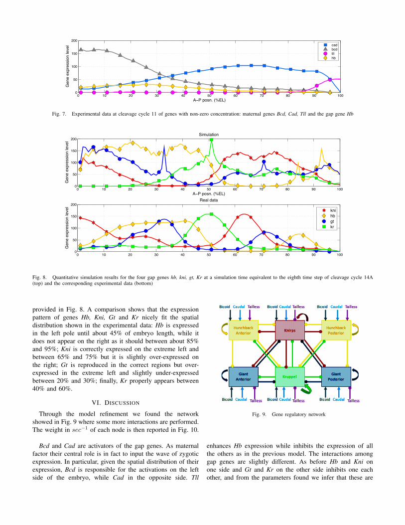
! "! #! $! %! &! '! (! )! *! "!!!
&!
"!!
"&!
#!!
+!,-./012-34567
8919-9:.;900</1-=9>9=
-
-
?@A
B?A
C==
DB
Fig. 7. Experimental data at cleavage cycle 11 of genes with non-zero concentration: maternal genes Bcd, Cad, Tll and the gap gene Hb
! "! #! $! %! &! '! (! )! *! "!!!
&!
"!!
"&!
#!!
+,-./01,23
4!56728396:;<=>
?@3@6@A7B@88,236/@C@/
! "! #! $! %! &! '! (! )! *! "!!!
&!
"!!
"&!
#!!
D@0/6E010
?@3@6@A7B@88,236/@C@/
6
6
F3,
GH
I1
FB
Fig. 8. Quantitative simulation results for the four gap genes hb, kni, gt, Kr at a simulation time equivalent to the eighth time step of cleavage cycle 14A
(top) and the corresponding experimental data (bottom)
provided in Fig. 8. A comparison shows that the expression
pattern of genes Hb, Kni, Gt and Kr nicely fit the spatial
distribution shown in the experimental data: Hb is expressed
in the left pole until about 45% of embryo length, while it
does not appear on the right as it should between about 85%
and 95%; Kni is correctly expressed on the extreme left and
between 65% and 75% but it is slightly over-expressed on
the right; Gt is reproduced in the correct regions but over-
expressed in the extreme left and slightly under-expressed
between 20% and 30%; finally, Kr properly appears between
40% and 60%.
VI. DISCUSSION
Through the model refinement we found the network
showed in Fig. 9 where some more interactions are performed.
The weight in sec−1of each node is then reported in Fig. 10.
Bcd and Cad are activators of the gap genes. As maternal
factor their central role is in fact to input the wave of zygotic
expression. In particular, given the spatial distribution of their
expression, Bcd is responsible for the activations on the left
side of the embryo, while Cad in the opposite side. Tll
Fig. 9. Gene regulatory network
enhances Hb expression while inhibits the expression of all
the others as in the previous model. The interactions among
gap genes are slightly different. As before Hb and Kni on
one side and Gt and Kr on the other side inhibits one each
other, and from the parameters found we infer that these are

Fig. 10. Rate of gene interactions
the strongest inhibitions among gap genes; Hb then weaklyinhibits Kr and vice-versa, as well as Gt versus Kni. Newweak edges have been found between Kni versus Gt, and Kr
versus Kni.As far as we know, there are no evidences in biological
literature that already support the above results. It might be astarting point for new laboratory experiments.
VII. CONCLUSION
The process of spatial organisation resulting from the mor-phogenesis process is demonstrated to be highly-dependentby the interplay between the dynamics at different levels ofthe biological systems hierarchical organisation. In modellingand simulating the phenomena of morphogenesis it might beappropriate to reproduce such a hierarchy. In this work wehave described the application of ABM as an approach capableof supporting multi-level dynamics.
We studied the phenomenon of pattern formation duringDrosophila embryo development, modelling the interactionsbetween maternal factors and gap genes that originate the earlyregionalisation of the embryo. The possibility to model boththe reactions taking place inside the cells that regulate the geneexpressions, and the molecules diffusion that mediates the cell-to-cell communication, makes it possible the reproduction ofthe interplay between the two levels in order to verify itsfundamental role in the spatial self-organisation characteristicof such a phenomenon.
The model is formally described using the statecharts thatmake it possible to clearly show the model components andhow they behave.
The simulation results presented show the formation of aprecise spatial pattern which have been successfully comparedwith observations acquired from the real embryo gene expres-sions.
Future work will be firstly devoted to extending the modelwith the introduction of new phenomena on the side ofboth intracellular dynamics and cell-to-cell interaction. Generegulatory network will be enlarged with other sets of geneswhich are downstream to gap genes such as the pair rulegenes, even-skipped as first, whose expression gives riseat the characteristic segments of Drosophila embryo. Othermechanism regulating cell movements will then be added –for instance cell adhesion and mechanic forces – as soon asthey are known to play a crucial role in cell sorting duringmorphogenesis.
Finally. we are planning to exploit the predictive powerof the model analysing embryos that are not wild type, forinstance performing in-silico Knock-Out experiments.
REFERENCES
[1] B. Alberts, A. Johnson, J. Lewis, M. Raff, K. Roberts, and P. Walter.Molecular Biology of the Cell. Garland Science Textbooks. GarlandScience, 4th edition, June 2002.
[2] G. Beurier, F. Michel, and J. Ferber. A morphogenesis model formultiagent embryogeny. In L. M. Rocha, L. S. Yaeger, M. A. Bedau,D. Floreano, R. L. Goldstone, and A. Vespignani, editors, Artificial Life
X: Proceedings of the Tenth International Conference on the Simulation
and Synthesis of Living Systems, pages 84–90. MIT Press, Cambridge,MA, 2006.
[3] T. M. Cickovski, C. Huang, R. Chaturvedi, T. Glimm, H. G. E.Hentschel, M. S. Alber, J. A. Glazier, S. A. Newman, and J. A. Iza-guirre. A framework for three-dimensional simulation of morphogenesis.IEEE/ACM Transactions on Computational Biology and Bioinformatics,2:273–288, 2005.
[4] J. Davies. Mechanisms of Morphogenesis. Academic Press, Oct. 2005.[5] M. Eyiyurekli, L. Bai, P. I. Lelkes, and D. E. Breen. Chemotaxis-based
sorting of self-organizing heterotypic agents. In SAC ’10: Proceedings
of the 2010 ACM Symposium on Applied Computing, pages 1315–1322,New York, NY, USA, 2010. ACM.
[6] S. F. Gilbert. Developmental Biology, Eighth Edition. Sinauer AssociatesInc., Eighth edition, Mar. 2006.
[7] T. Gregor, E. Wieschaus, A. McGregor, W. Bialek, and D. Tank.Stability and nuclear dynamics of the bicoid morphogen gradient. Cell,130(1):141–152, July 2007.
[8] V. V. Gursky, J. Jaeger, K. N. Kozlov, J. Reinitz, and A. M. Samsonov.Pattern formation and nuclear divisions are uncoupled in drosophilasegmentation: comparison of spatially discrete and continuous models.Physica D: Nonlinear Phenomena, 197(3-4):286–302, October 2004.
[9] D. Harel. Statecharts: A visual formalism for complex systems. Sci.
Comput. Program., 8(3):231–274, 1987.[10] M. Kaern, T. C. Elston, W. J. Blake, and J. J. Collins. Stochasticity in
gene expression: from theories to phenotypes. Nature reviews. Genetics,6(6):451–464, June 2005.
[11] F. Klugl, C. Oechslein, F. Puppe, and A. Dornhaus. Multi-agentmodelling in comparison to standard modelling. In F. J. Barros andN. Giambiasi, editors, Artificial Intelligence, Simulation and Planning in
High Autonomy Systems, pages 105–110. SCS Publishing House, 2002.[12] E. Merelli, G. Armano, N. Cannata, F. Corradini, M. d’Inverno,
A. Doms, P. W. Lord, A. Martin, L. Milanesi, S. Moller, M. Schroeder,and M. Luck. Agents in bioinformatics, computational and systemsbiology. Briefings in Bioinformatics, 8(1):45–59, 2007.
[13] F. Michel, J. Ferber, and A. Drogoul. Multi-Agent Systems andSimulation: a Survey From the Agents Community’s Perspective. InA. U. Danny Weyns, editor, Multi-Agent Systems: Simulation and Ap-
plications, Computational Analysis, Synthesis, and Design of DynamicSystems, pages 3–51. CRC Press - Taylor & Francis, 05 2009.
[14] S. Montagna and A. Roli. Parameter tuning of a stochastic biologicalsimulator by metaheuristics. In AI*IA, volume 5883 of Lecture Notes
in Computer Science, pages 466–475. Springer, 2009.[15] T. J. Perkins, J. Jaeger, J. Reinitz, and L. Glass. Reverse engineering
the gap gene network of Drosophila Melanogaster. PLoS Comput Biol,2(5):e51, 05 2006.
[16] W. Smith and J. Hashemi. Foundations of Materials Science and
Engineering. McGraw-Hill, 4th edition, July 2005.[17] B. Thorne, A. Bailey, D. Desimone, and S. Peirce. Agent-based
modeling of multicell morphogenic processes during development. Birth
Defects Res C Embryo Today, 81(4):344–353, 2008.[18] A. M. Turing. The chemical basis of morphogenesis. Philosophical
Transactions of the Royal Society (B), 237:37–72, 1952.[19] A. M. Uhrmacher, D. Degenring, and B. Zeigler. Discrete event multi-
level models for systems biology. In C. Priami, editor, Transactions
on Computational Systems Biology I, volume 3380 of Lecture Notes in
Computer Science, pages 66–89. Springer, 2005.[20] D. Weyns, A. Omicini, and J. Odell. Environment as a first-class
abstraction in multi-agent systems. Autonomous Agents and Multi-Agent
Systems, 14(1):5–30, Feb. 2007. Special Issue on Environments forMulti-agent Systems.
[21] D. Yamins and R. Nagpal. Automated global-to-local programming in1-d spatial multi-agent systems. In 7th International Joint Conference on
Agents and Multi-Agent Systems (AAMAS-08), pages 615–622, Estoril,Portugal, 12–16May 2008. IFAAMAS.

A Methodology to Extend Imperative Languageswith AgentSpeak Declarative Constructs
Loris FicheraUniversity of Catania – Engineering Faculty
Viale Andrea Doria, 6 — 95125 - Catania, ITALYEMail: [email protected]
Daniele MarlettaScuola Superiore di Catania
Via S. Nullo 5/i — 95123 – Catania, ITALYEMail: [email protected]
Vincenzo NicosiaScuola Superiore di Catania – Laboratorio sui Sistemi Complessi
Via S. Nullo 5/i — 95123 – Catania, ITALYEMail: [email protected]
Corrado SantoroUniversity of Catania – Dept. of Mathematics and Computer Science
Viale Andrea Doria, 6 — 95125 - Catania, ITALYEMail: [email protected]
Abstract—This paper presents a novel technique for thesupport of declarative constructs of AgentSpeak in a imperativelanguage. Starting from an analysis of the characteristics andsemantics of AgentSpeak, as well as the requirements of anAgentSpeak implementation, the paper proposes a frameworkwhich, by exploiting object-orientation and operator overload-ing, is able to enrich an imperative language with declarativeconstructs suitable to represent and write AgentSpeak programs.A concrete implementation of the proposed framework is thengiven by presenting PROFETA (Python RObotic Framework fordEsigning sTrAtegies), a tool written in Python which adds tothis language the capability to write and execute AgentSpeakplans. A case-study shows how PROFETA can be used to easilywrite strategies for an autonomous mobile robot, designed by theauthors for the “Eurobot 2010” international robotic competition.
I. INTRODUCTION
Software agents are an abstraction for autonomous entitieswhich have a certain amount of knowledge, interact withan environment and play a given role in order to achieve agoal. They have been used in the last decade as a referencemodel for the solution of a variety of problems in differentfields, from automatic reasoning to data mining, from searchin semantic web to simulation of social behaviours. Theadaptability of agent–oriented modelling and the possibilityto represent different problems as agent–based systems haveproduced a proliferation of agent models, such as reflex–based agents, goal–based agents, utility–based agents, learn-ing agents [3], [20], [14], [16], each of them with peculiarcharacteristics which make it useful for the solution of a
specific class of problems. At the same time many agent–oriented programming languages (Soar [21], NetLogo [17],3APL [6], GOAL [7]) and agent–based platforms (JADE [1],MASON [10], Repast [18], Swarm [19]) have been developedin the last decade, in order to give programmers powerful andeasy–to–use tools to model, develop and maintain agent–basedsoftware.An increasing interest has been recently devoted to ex-
ploit goal–based agent models for the realization of intelli-gent autonomous systems [11], [15]. One of the proposedparadigms for goal–oriented agents is the Belief–Desire–Intention (BDI) [13], which models the knowledge as a set ofbeliefs about environment and internal state of the agent, thenrepresents as desires the goals to be achieved, which expandinto a set of intentions, i.e. atomic actions to be performedin order to achieve a desire. There exists a reference abstractlanguage for BDI agents, which is called AgentSpeak(L) [12],and defines a declarative syntax to express desires and in-tentions in a way which is much similar to rule-based logicprogramming: beliefs are treated as facts while desires andintentions respectively correspond to conditions and bodyof rules. The only existing implementation of AgentSpeaksemantic is Jason [9], which is an interpreter, written in Java,for an extended AgentSpeak syntax written. Jason lets theprogrammer write its AgentSpeak statements in a separate fileand requires actions and event handlers to be implementedby Java classes. Unfortunately, all the AgentSpeak programis completely separated from action implementation, while it

ag ::= bs psbs ::= at1, . . . , atn. (n ! 0)at ::= P(t1, . . . , tn) (n ! 0)ps ::= p1, . . . , pn. (n ! 1)p ::= te : cd < " h.te ::= +at | " at | + g | " gcd ::= true | l1 & . . . & ln (n ! 1)h ::= true | f1 ; . . . ; fn (n ! 1)l ::= at | not atf ::= A(t1, . . . , tn) | g | u (n ! 0)g ::= !at | ?atu ::= +at | " at
Fig. 1. Basic AgentSpeak Syntax
would be very useful to preserve a declarative AgentSpeakmodel into the same programming environment.This paper shows that it is possible to embed an AgentS-
peak semantic into any imperative language which allowoperator overloading, and proposes an example of such em-bedding in Python. The developed tool is called PROFETA(for Python RObotic Framework for dEsigning sTrAtegies),and has been successfully used to implement agent–basedintelligent autonomous systems to drive robots in dynamicenvironments [5].The paper is organised as follows. Section II provides an
overview of AgentSpeak(L) syntax and semantics. Section IIIexplains the methodology used to embed AgentSpeak(L) se-mantic into imperative languages through operator overload-ing. Section IV describes the implementation of PROFETA.Section V illustrates a case-study of PROFETA in a realapplication. Section VI reports conclusions and future works.
II. AGENTSPEAK: REQUIREMENTS FOR ITSIMPLEMENTATION
A. Overview of AgentSpeakAgentSpeak(L) [13], [12] (or simply AgentSpeak) is an
abstract declarative language designed many years ago toprogram BDI agents. According to its basic syntax, firstintroduced in [13], [12] and then extended in [2], which isreported in Figure 1, an agent program is made of a set ofbeliefs and a set of plans.Beliefs represent the knowledge of the agent and are ex-
pressed using atomic formulae made of a predicate symbolP and a set of zero or more ground terms. The same syntax(predicate with ground terms) is also used to represent goals,which are the AgentSpeak abstractions for desires. Two typesof goals are provided: (i) achievement goal, expressed as!at, meaning that the agent wants to make true formula at(i.e., ensure that at is a known belief); and (ii) test goal,expressed as ?at, intended to verify whether formula at istrue (i.e., check if at is a known belief).Plans are the tasks that the agent has to execute and are
expressed by means of rules in the form te : cd < " h;here:
• te is the event triggering the rule; it can be the additionor removal of a belief (+at or "at), or the request toachieve (or no more achieve) a goal (+!at or "!at);
• cd is the condition1, that is made of a set of beliefsthat must be all true in order to trigger the plan. Thespecified beliefs may contain ground terms or variables,and express the knowledge the agent must have when theevent te fires in order to trigger the plan.
• h is a set of atomic actions which are executed, insequence, following plan triggering. They include, onceagain, addition or removal of a belief (+at or "at),request to achieve or no more achieve a (sub-)goal (+!ator "!at), or the execution of a user-defined action. Withthe exception of the last case (user-defined action), all theother actions, when executed, generate the relevant triggerevent causing the possible selection of another plan.
As the reader can understand, an AgentSpeak program is aset of rules in the form event-condition-action(s); events maycome from the perception of the agent’s environment (in thiscase they are called external events) or be generated by anaction (internal events), such as the achievement of a sub-goal.On the basis of event type, the way in which it is processeddiffers, according to the specific semantics of the languagewhich is described in [12], [9], [4].An example of an AgentSpeak program running in a mobile
robot is given in Figure 2. Let us consider that the robotaims at grabbing two types of objects, balls and cylinders, andthat, to accomplish this task, it has two different mechanicalarms, one for each type of object. A camera, with a properartificial vision software, is used to detect the presence ofan object to be picked. Two predicates are used for beliefs:object_seen, which is asserted by the artificial visionsoftware when an object of a certain type is detected ina given (x, y) position, and arm_deployed, representingwhich one of the two arms is currently in the deployedconfiguration (and thus able to pick the object of the samekind). According to the program in Figure 2, when the cameradetects an object, the proper belief is asserted causing thefirst plan to be triggered and executed; this plan contains theachievement of three goals: first the proper arm has to bedeployed, then the position of the detected object has to bereached so that finally the object can be picked. In achievingthe first goal (prepare_arm), we check if an arm not ableto pick the recognised object is currently deployed and, ifthis is the case, we retract the current arm and deploy theother one. We suppose that such retract/deploy actions, duringtheir execution, change the belief set by properly updating thearm_deploy belief2. The second goal aims at reaching thetarget position and, as the source code reports, triggers theactions needed to orientate the robot towards the target pointand then to go to it. The last goal performs object picking byactivating the corresponding mechanical arm.
1AgentSpeak uses the term “context”, but we prefer “condition” because itis more appropriate for the real meaning of the cd part of the plan.2This is in accordance with AgentSpeak model.

+object_seen(Type, X, Y) : true <-+!prepare_arm(Type);+!reach_object(X, Y);+!pick_object(Type).
+!prepare_arm(ball) :arm_deployed(cylinder) <-
retract_arm(cylinder);deploy_arm(ball).
+!prepare_arm(cylinder) :arm_deployed(ball) <-
retract_arm(ball);deploy_arm(cylinder).
+!prepare_arm(X) :arm_deployed(X) <-
true.
+!reach_object(X,Y) : true <-orientate_towards(X,Y),go_to(X,Y).
+!pick_object(X) : true <-activate_arm(X).
Fig. 2. An object picking robot
B. From Theory to Practice: Architecture of an AgentSpeakInterpreter
AgentSpeak represents a very flexible language to expressthe behaviour of agents using a goal-oriented approach; inorder to allow the development of such agents, a properinterpreter needs to be designed and implemented. To thisaim, we could imagine three different design approaches:totally declarative, a mix of declarative and imperative, totallyimperative.The first approach, totally declarative, requires the exten-
sion of AgentSpeak with additional statements in order toderive a complete programming language. These statementsinclude constructs to modify variables and to apply themmathematical/logical operators, as well as proper general-purpose library functions to interact with the environment(i.e., sensors and actuators). Obviously, all the additionalstatements and constructs must obey to the declarative/goal-oriented paradigm which is the basis of AgentSpeak; whilethis aim can be easily achieved for variable assignment andmathematical/logical operators (which could be, for instance,borrowed from Prolog), the same is not straightforward tobe achieved for functions. After all, what is a “function”in AgentSpeak? Given that in imperative programming a“function” is the evolution of the concept of “subroutine”, ina goal-oriented language like AgentSpeak the execution of afunction can be viewed as the achievement of a “sub-goal”.
Indeed, AgentSpeak semantics specifies that the presence of agoal achievement statement +!at in a plan implies to suspendthe execution of the plan, perform sub-goal achievement andthen resume the plan; such a behaviour is therefore quitesimilar to that of subroutine execution. Starting from theseconsiderations, a totally declarative approach seems a viablesolution, even if its validity, effectiveness and efficiency hasto be verified. Nevertheless, extending AgentSpeak to make ita complete declarative language is beyond the scope of thispaper.The second approach, a mix of declarative and imperative
paradigms, is the easiest solution and implies the use of animperative language to build the interpreter of the AgentSpeakprogram and then write, using the imperative language itself,all the parts which cannot be implemented in AgentSpeak,i.e. specific agent actions and event catching and signalling.This is the approach exploited by Jason [9], the most widelyknown AgentSpeak implementation which is written in Java3.In Jason, agent’s behaviour has to be written using AgentSpeaksyntax (in a separate source file), while a set of specific classes,to be developed in Java, are required to implement all theatomic actions specified in the AgentSpeak file as well asthe computations needed to poll and generate external events.While this approach is valid and effective, even if a bit naıve, ithas some drawbacks. Indeed, there are two different “worlds”,the declarative one with its syntax, semantics, objects andidentifiers, and the imperative one, with a different syntax andsemantics, somewhat “glued” to the declarative part in order toallow the access to and manipulation of the knowledge-base(beliefs). This is unfavourable for both program design andexecution: the former aspect forces a programmer to handledifferent source files with different semantics while the latterrequires proper transformations to pass data between the twodomains which undoubtedly affect performances. Moreover,the AgentSpeak file cannot be compiled, thus impeding todeploy only binary files in a live system.The third approach, totally imperative, at first sight sounds
quite weird: how can we provide declarative semantics onlyusing imperative constructs? Indeed, to execute an AgentSpeakprogram, a proper processing engine needs to be written, andthis can be done in an imperative language4; the same enginecould provide an API with proper function calls able to definebeliefs, goals and plans by using the imperative languageitself. Surely, a skilled software engineer can easily verify thatsuch an approach is even worse than mixing imperative anddeclarative paradigms: the resulting source file could easilybecome unreadable and hard to maintain since the declarativesemantics would be somewhat “hidden” in the API functioncalls. But if the language is object-oriented and supportsoperator overloading, such features can be exploited to solvethe problems above and provide an “all-in-one” environment.This is described, in details, in the following Sections.
3and probably, the sole AgentSpeak implementation at the time this paperhas been written.4After all, the Jason engine is written in Java!

III. EMBEDDING DECLARATIVE CONSTRUCTS INTO ANIMPERATIVE LANGUAGE
Let us suppose we have an imperative language, let us callit host language, and let us consider that we want to havethe possibility of writing AgentSpeak statements in the hostlanguage, without changing the compiler and the (standard)runtime library, and without introducing something like a pre-processor able to suitably perform a syntactic transformationof the declarative code5. The question to answer is: could wewrite (and execute), for example in C, something like this?
+!reach_object(X,Y) : true <-orientate_towards(X,Y);go_to(X,Y).
The answer is obviously “No!”, since syntax and semanticsare not in accordance with C rules. However, we couldreformulate the question as follows: could we try to modifysomething, in the code above, in order to make it writable (andexecutable), in an imperative language such as C? Let’s dealwith such a problem by taking into account syntax first, andthen semantics.From the syntactical point of view, the construct above
has three main problems, due to the presence of thesymbols “:”, “<-” and “.”. Indeed, “+” and “!”are valid operators, and reach_object(X,Y), true,orientate_towards(X,Y) and go_to(X,Y) are validconstructs (functions calls and symbol/variable evaluation).Therefore, let us reasonably replace non-recognisable symbolswith other symbols which conform to C syntax. To this aim,since symbol “:” can be interpreted as “such that”, a candidatereplacement is “|”; in a similar way, symbol “<-”, whosemeaning is a sort of implication, can be replaced with “<<”.The last symbol, the dot “.”, is employed to signal the endingof the sequence of actions to be performed following planactivation; in this case, its replacement entails to find a properway to represent a sequence or block of actions: the C block,i.e. { ... }, is worth to be used in this case.According to such modifications, the AgentSpeak plan
above can be rewritten as:
+!reach_object(X,Y) | true <<{
orientate_towards(X,Y);go_to(X,Y);
}
While this “syntactical replacement” has been quite straight-forward, dealing with semantics surely implies more problems.The first remark is related to the symbol << which, fromsemantic point of view, is an operator and thus needs twovalid expression at both left-hand and right-hand side; whilefor the LHS this is true, it is not the same for the RHS, since itis a block of code, not an expression. But even if we could beable to overcome the problem above, and thus find a suitableconstruct to transform a block of code into an expression, the
5For instance, we do not want something like “SQL embedded in C”.
Plan ::= “(” Head “)” “<<” “(” ActionList “)”
Head ::= “(” Event “)” “|” “(” Condition “)”| “(” Event “)” “|” “(” Belief “)”
Condition ::= Belief “&” Belief| Condition “&” Belief
Event ::= GoalEvent| BeliefEvent
GoalEvent ::= “+” “!” Belief| “-” “!” Belief
BeliefEvent ::= “+” Belief| “-” Belief
ActionList ::= ActionList “,” Event| ActionList “,” AtomicAction
Fig. 3. Example of Operator Grammar for the Host Language
question remains the meaning of operators: “+” is the unary-plus in C, but it should behave as “transform the belief orgoal into the related event”; similarly, “!” is the not operator,while, in the AgentSpeak view, it should be interpreted as“achieve the goal represented by the belief”. This “change ofmeaning” for operators is completely not allowed in C, butif we think to C++ or, more generally, to an object-orientedlanguage, the operator overloading feature6 can surely helpus.Starting from these considerations, all the actors of a plan,
namely beliefs, goals and actions, should become expressionsevaluating to proper objects, whose class declarations includethe proper operator redefinition, suitably allowing the desired“change of meaning”. Some operators and a grammar areneeded, in order to guide a designer to properly write thecode for operator overloading, which must obviously be inaccordance with AgentSpeak syntax. A reference grammar isshown in Figure 3; it can be also used to derive the operatorsneeded to be redefined in the host language, together with theirmeaning which are summarized in Figure 4.On the basis of the grammar and operators described, an
AgentSpeak plan such as:
+object_seen_at(300,400) | true <<{orientate_towards(300,400);go_to(300,400);
}
would be rewritten as:
class Belief {// provide operator overloading here
};
6if supported by the language

Operator Type Symbol used Meaningin Figure 3
Add event unary + Transform a belief or an achievement goal into an addition eventDelete event unary - Transform a belief or an achievement goal into a deleting eventAchieve unary ! Transform a belief into an achievement goal
Logical and binary & Concatenate beliefs to represent the conditionSuch that binary | Relate the event with the conditionImplication binary << Relate the head of the plan (event + condition) with the list of actionsList construct binary , Concatenate actions to represent the body of the plan
Fig. 4. Operators Needed an Their Meaning
class Condition {// provide operator overloading here
} ;
class Action {// provide operator overloading here
} ;
class object_seen_at : public Belief {// provide belief-specific methods// and attributes
} ;
class true : public Condition {// this is be the TRUE condition
} ;
class orientate_towards :public Action {
void execute(void) {// the code for the action
} ;} ;
class go_to : public Action {void execute(void) {
// the code for the action} ;
} ;
...
(+object_seen_at(300,400) | true()) <<(orientate_towards(300,400),go_to(300,400) );
According to the code snippet above, when the expressiondefining the plan is evaluated, first the object_seen_atobject is created and the operator unary-“+”, redefined in theBelief class, is applied to it; the result (which will surely beanother proper object) is then passed, together with the trueobject, to the code for operator “|”; finally, the result of thelast expression will be the first operand for operator “<<”,
whose RHS is an object of the Action class.This expression evaluation, which is performed when the
corresponding instruction of host language code contain-ing the plan is executed, from the declarative model pointof view does not correspond to plan execution, but toplan definition: indeed, the real actions corresponding toorientate_towards and go_to must be executed whenthe belief object_seen_at(300,400) is “somewhat as-serted”.This separation between definition and execution of plans
has two major consequences. The first one is the need ofa proper processing engine as a part of the overall runtimesystem; this engine has to embed structures to represent theknowledge base and the plan library, also providing an APIfor their manipulation: the code present in operator redefinitionmethods will add the objects representing the plan, returnedby the plan expression evaluation, into the plan library;subsequently, the generation of an external event, such asassertion of a new belief, triggered by means of a suitableAPI function/method call, will instruct the engine to find theassociated plan in the plan library and then really execute theaction: this is the reason for the presence of the executemethod—for late execution—in the Action class.The second important consequence is the role of variables
in a plan. If we would like to make the piece of code moregeneral, we should replace constants with variables, that is,something like:
(+object_seen_at(X,Y) | true()) <<(orientate_towards(X,Y),go_to(X,Y) );
However, variables X and Y are interpreted by the hostlanguage during plan definition, and thus they not only needto be defined but also bound to specific values. This isquite undesirable since, according to the declarative paradigm,variable binding must be done during plan execution: likeactions need late execution, a late binding feature shouldbe provided for variables. To this aim, we cannot use thevariables provided by the host languages, which do not permitlate binding, and, also in this case, we have to replace themwith proper “variable objects”. Therefore, by supposing the
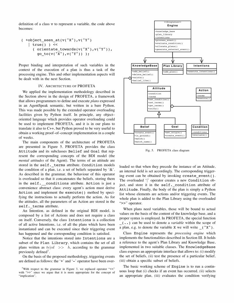
definition of a class v to represent a variable, the code abovebecomes:
( +object_seen_at(v("X"),v("Y")| true() ) <<( orientate_towards(v("X"),v("Y")),go_to(v("X"),v("Y")) );
Proper binding and interpretation of such variables in thecontext of the execution of a plan is thus a task of theprocessing engine. This and other implementation aspects willbe dealt with in the next Section.
IV. ARCHITECTURE OF PROFETAWe applied the implementation methodology described in
the Section above in the design of PROFETA, a frameworkthat allows programmers to define and execute plans expressedin an AgentSpeak semantic, but written in a bare Python.This was made possible by the extended operator overloadingfacilities given by Python itself. In principle, any object–oriented language which provides operator overloading couldbe used to implement PROFETA, and it is in our plans totranslate it also to C++, but Python proved to be very useful toobtain a working proof–of–concept implementation in a coupleof weeks.The main components of the architecture of PROFETA
are presented in Figure 5. PROFETA provides the classAttitude and its subclasses Belief and Goal that rep-resent the corresponding concepts of the BDI model (themental attitudes of the Agent). The terms of an attitude arestored in the self._terms attribute. Condition modelsthe condition of a plan, i.e. a set of beliefs separated by ‘&’.As described in the grammar, the behaviour of this operatoris overloaded so that it concatenates the beliefs, storing themin the self.__conditions attribute. Action is just aconvenience abstract class: every agent’s action must deriveAction and implement the execute() method by speci-fying the instructions to actually perform the action. As forthe attitudes, all the parameters of an Action are stored in theself._terms attribute.An Intention, as defined in the original BDI model, is
composed by a list of Actions and does not require a classon itself. Conversely, the class Intentions is a collectionof all active Intentions, i.e. of all the plans which have beeninstantiated and can be executed since their triggering eventhas happened and the corresponding condition is satisfied.Notice that the intentions stored into Intentions are a
subset of the Plan Library, which contains the set of allplans written as te|cd >> h, according to the grammarpreviously defined7.On the basis of the proposed methodology, triggering events
are defined as follows: the ‘+’ and ‘-’ operator have been over-
7With respect to the grammar in Figure 3, we replaced operator “<<”with “>>” since we argue that it is more appropriate for the concept of“implication”.
<<Singleton>>
Engine
-knowledge_base-plan_library-intentions+process_event()+evaluate_condition()+allocate_plans()+generate_external_event()
Condit ion
-conditions+evaluate()
At t i tude
-condition-terms+set_condition()+set_terms()+get_terms()+unify()
Belief
+create_event()+is_ground()+match()+match_name()
Goal
+set_origin()+create_event()
KnowledgeBase
+add_belief()+delete_belief()+exists()+belief_like()
Plan Library
+add_plan()
In tent ions
+execute_intentions()
Action
-terms+execute()
Fig. 5. PROFETA class diagram
loaded so that when they precede the instance of an Attitude,an internal field is set accordingly. The corresponding trigger-ing event can be obtained by invoking create_event().The overloaded ‘|’ operator creates a new Condition ob-ject, and store it in the self._condition attribute ofAttitude. Finally, the body of the plan is simply a Pythonlist whose elements are actions and/or triggering events. Thewhole plan is added to the Plan Library using the overloaded“>>” operator.When plans need variables, those will be bound to actual
values on the basis of the content of the knowledge base, and aproper syntax is employed. In PROFETA, the special function_(..) can be used to denote a variable within the scope ofa plan, e.g. to denote the variable X we will write _("X").Class Engine represents the processing engine which
implements the functionalities described in Section III. It holdsa reference to the agent’s Plan Library and Knowledge Base,implemented in two suitable classes. The KnowledgeBaseclass exposes an appropriate interface that allows to: (i) modifythe set of beliefs, (ii) test the presence of a particular belief,(iii) obtain a specific subset of beliefs.The basic working scheme of Engine is to run a contin-
uous loop that (i) checks if an event has occurred, (ii) selectsan appropriate plan, (iii) evaluates the condition verifying

whether it is true, (iv) executes the plan8. While internal events(i.e. events specified in the Body of a plan) are directly handledby Engine, external events that are bound, for example, toperception made by sensors must be notified to the Engine,so that it can reason about them and determine the appropriateplan(s)—if any. In this case, to let the Engine know that anevent has occurred, the generate_external_event()method has to be used.
V. CASE STUDYThis Section shows how PROFETA has been actually used
to define strategies for an autonomous mobile robot takingpart in the Eurobot robotic contest [5].Robots taking part to Eurobot are required to imple-
ment a strategy which usually consists in repetitively (i)approach/recognise an object, (ii) pick the object and store it,(iii) put the object in an appropriate place. Objects are usuallyof different type and colour, and thus need to be sorted, putin different containers or in specific sequences to gain morepoints, etc. For instance, in the 2010 edition, robots had to col-lect and store orange and red balls (representing, respectively,oranges and tomatoes) and white cylinders (representing earsof corn). Game matches are played by two robots at the sametime, on a shared game table: in order not to get penalties,robots have to avoid each other. Moreover, matches have a 90seconds time limit. A winning game strategy should take intoaccount all the issues stated above and also foresee and handleall the different unexpected situations that could happen duringthe match.Figure 6 reports a fragment of an actual game strategy
written using PROFETA: during the first part of the match, wewanted our robot to collect ears of corn. According to Eurobot2010 rules, objects can be found on the game table in fixed,a priori known, positions. We have hardcoded such positionsin a global accessible table and enumerated game elements—e.g. all ears of corn have been given a code like “c0”, “c1”,and so on—so that such codes can be used as keys to retrievethe position of the specified object. There exists two kinds ofears of corn: good and fake ones, the formers are painted inwhite, the latter are painted in black. We wanted—of course—the robot to collect good ones and to discard the others. Onthis basis, the employed strategy aims at (i) detecting colourconfiguration, (ii) picking the first three ears near the startingarea (called “c0”, “c3” and “c6”), (iii) depositing them intothe basket, (iv) picking other three ears near the basket, (v)depositing the objects picked. In picking the ears, we have topay attention to their colour, and skip it if it is fake (black).As reported in Figure 6, we defined the beliefs
white_corn and black_corn, to represent a ear ofcorn of the given colour; corns_in_robot, to countthe number of ears that the robot has already picked; andno_more_corns to signal that, according to the strat-egy, we are not interested in picking more ears. Three
8Indeed, the real working scheme of a BDI engine is quite more complexthat described; due to space restrictions, we reported only a simplified version;interested readers may refer to [12], [8].
goals are defined: go, which is the goal triggering thestarting of the overall game strategy; grab_corn, aim-ing at reaching and picking a specified ear of corn; anddeposit_corns, which instructs the robot to release thepicked ears in the proper basket. Finally, required actions are:detect_configuration, which instructs the vision sys-tem to recognise the colour of the various ears and assert theproper white_corn/black_corn beliefs; reach_corn,triggering the robot to move in order to reach the position ofa specified ear; pick_corn, driving the mechanical arms topick the ear from the table (thus properly updating the numberof objects inside the robot); reach_deposit_zone, mak-ing the robot to reach the basket; and open_tank, whichdrives the actuators to open the tank and release the objects(this action also resets the number of ears of corn in robot).As for the strategy, defined in function setup_strategy,
the first goal (go) implies to detect the corn colours, grab thefirst three ears and then go to deposit them. The grab_corngoal is subject to the condition related to ear colour: if it iswhite, it can be picked, otherwise no action is needed. Goaldeposit_corns is instead subject to a condition on thenumber of ears the robot has picked: if it is less than two9, itcould be worth to try to pick other ears (and thus save time)before going to the basket. If we have instead an adequatenumber of ears of corn, we can reach the basket, deposit them,and then go to pick the other ears.Notice that the strategy example reported in Figure 6 is
written in bare Python. Operator overloading does all themagic, making it possible to express all the strategy with apure declarative syntax. This approach allows to put strategiesin a separate Python module or in the same module whereActions are defined, according to programmer’s preferences.Moreover, the preferred strategy can be easily selected beforeeach match just by calling the corresponding function, whichloads all the rules and initial beliefs into the engine, withoutthe need to recompile of parse again any source file.
VI. CONCLUSIONS AND FUTURE WORK
This paper has described an approach to seamless embeddeclarative constructs able to write AgentSpeak programsinto an imperative object-oriented language. By exploitingoperator overloading, a feature proper of many object-orientedlanguages, and a suitable software architecture, the proposedapproach allows a programmer to design, deploy and run acomplete agent system, based on a goal-oriented paradigm, us-ing a single programming language and runtime environment.As a proof of concepts, the paper has presented an imple-mentation of the proposed approach in a Python framework,called PROFETA (Python RObotic Framework for dEsigningsTrAtegies). As it has been described in the case-study, the tooldeveloped has proved its effectiveness in a typical real case,which is the design and implementation of an autonomousmobile robot.
9because at least two ears among “c0”, “c3” and “c6” are black

class white_corn(Belief):pass
class black_corn(Belief):pass
class corns_in_robot(Belief):pass
class no_more_corns(Belief):pass
class go(Goal):pass
class grab_corn(Goal):pass
class deposit_corn(Goal):pass
class detect_configuration(Action):def execute(self):
## ...
class reach_corn(Action):def execute(self):
## ...
class pick_corn(Action):def execute(self):
## ...
class reach_deposit_zone(Action):def execute(self):
## ...
class open_tank(Action):def execute(self):
## ...
def setup_strategy():(+!go()) >> [ detect_configuration(), +!grab_corn("c0"), +!grab_corn("c3"),
+!grab_corn("c6"), +!deposit_corns()]
(+!grab_corn(_("X")) | ( white_corn(_("X")) )) >> [ reach_corn(_("X")), pick_corn() ](+!grab_corn(_("X")) | ( black_corn(_("X")) )) >> [ ]
(+!deposit_corns() | ( corns_in_robot(_("X")) & (lambda : X > 1)) ) >>[ reach_deposit_zone(), open_tank(), +!deposit_corns() ]
(+!deposit_corns() | ( corns_in_robot(_("X")) & (lambda : X <= 1) & no_more_corns() )) >>[ # second part of the game ... ]
(+!deposit_corns() | ( corns_in_robot(_("X")) & (lambda : X <= 1)) ) >>[ +!grab_corn("c11"), +!grab_corn("c12"),
+!grab_corn("c13"), +no_more_corns(), +!deposit_corns() ]
def start():setup_strategy()Engine.instance().generate_external_event( +!go() )
Fig. 6. An actual game strategy for Eurobot written in Python using PROFETA

Future work will aim at further improving the tool by intro-ducing missing features, such as test goal and goal deletion, aswell as at studying appropriate optimisations to speed up planselection and execution. Once all the features of PROFETAwill be implemented, next step will be the implementation ofPROFETA in another object–oriented language, such as C++.
REFERENCES[1] F. Bellifemine, A. Poggi, and G. Rimassa, “Jade - a fipa-compliant agent
framework,” in Proceedings of the Practical Applications of IntelligentAgents, 1999.
[2] R. Bordini, A. Bazzan, R. Jannone, D. Basso, R. Vicari, and V. Lesser,“Agent-speak (xl): efficient intention selection in bdi agents via decision-theoretic task scheduling,” in Proceedings of the 1st International JointConference on autonomous agents and multiagent systems. ACM NewYork, NY, USA, 2002, pp. 1294–1302.
[3] J. M. Bradshaw, Ed., Software Agents. AAAI Press/The MIT Press,1997.
[4] M. d’Inverno and M. Luck, “Engineering agentspeak(l): Aformal computational model,” Journal of Logic and Computation,vol. 8, no. 3, pp. 233–260, 1998. [Online]. Available:http://eprints.ecs.soton.ac.uk/3846/
[5] L. Fichera, D. Marletta, V. Nicosia, and C. Santoro, “Flexible robotstrategy design using belief–desire–intention model,” in Proceedings ofEurobot Conference 2010, 2010.
[6] K. Hinddriks, F. de Boer, W. van der Hoek, and J. C. Meyer, “Agentprogramming in 3apl,” Int. J. of Autonomous Agents and Multi-agentSystems, vol. 2, pp. 357–401, 1999.
[7] ——, “Agent programming with declarative goals,” in Intelligent AgentsVII. Agent Theories, Architectures and Languages, ser. LNCS, vol. 1986.Springer–Verlag, 2000.
[8] J. Hubner, R. Bordini, and M. Wooldridge, “Programming declarativegoals using plan patterns,” Lecture Notes in Computer Science, vol.4327, p. 123, 2006.
[9] Jason Home Page, “http://www.jason.sourceforge.net/,” 2004.[10] S. Luke, C. Cioffi-Revilla, L. Panait, K. Sullivan, and G. Balan, “Mason:
a multi–agent simulation environment,” Simulation, vol. 81, no. 7, pp.517–527, July 2005.
[11] V. Nicosia, C. Spampinato, and C. Santoro, “Software agents forautonomous robots: The eurobot 2006 experience,” in Proceedings ofthe WOA 2006 Workshop, 2006.
[12] A. Rao, “AgentSpeak (L): BDI agents speak out in a logical computablelanguage,” Lecture Notes in Computer Science, vol. 1038, pp. 42–55,1996.
[13] A. Rao and M. Georgeff, “BDI agents: From theory to practice,” inProceedings of the first international conference on multi-agent systems(ICMAS-95). San Francisco, CA, 1995, pp. 312–319.
[14] S. Russell and P. Norvig, Artificial Intelligence: A Modern Ap-proach/Second Edition. Prentice Hall, 2003.
[15] C. Santoro, “An erlang framework for autonomous mobile robots,” inProcedings of the 2007 ACM SIGPLAN Workshop on Erlang. ACM,2007, pp. 85–92.
[16] R. Siegwart and I. Nourbakhsh, Introduction to Autonomous MobileRobots. MIT Press, 2004.
[17] E. Sklar, “Software review: Netlogo, a multi–agent simulation environ-ment,” Artificial Life, vol. 13, pp. 303–311, 2007.
[18] E. Tatara, M. North, T. Howe, N. T. Collier, and J. Vos, “An intro-duction to repast modelling using a simple predator–prey example,” inProceedings of Agents 2006 Conference on Social Agents: Results andProspects, 2006.
[19] P. Terna, “Simulation tools for social scientists: Building agent basedmodels with swarm,” Journal of Artificial Societies and Social Simula-tion, vol. 1, no. 2, 1998.
[20] G. Weiss, Ed., Multiagent Systems. The MIT Press, April 1999.[21] R. Wray and R. Jones, “An introduction to soar as an agent architecture,”
in Cognition and Multi-Agent interaction: from Cognitive Modelling toSocial Simulation, R. Sun, Ed. Cambridge University Press, 2005, pp.53–78.

Programming Open Systems withAgents, Environments and Organizations
Michele Piunti,Alessandro Ricci
Universita di BolognaSede di Cesena
{michele.piunti,a.ricci}@unibo.it
Olivier BoissierEcole Nationale Superieure des Mines
St-Etienne, [email protected]
Jomi F. HubnerUniversidade Regional de Blumenau
Blumenau, SC - [email protected]
Abstract—MAS research pushes the notion of openness re-lated to systems combining heterogeneous computational enti-ties. Typically, those entities answer to different purposes andfunctions and their integration is a crucial issue. Starting froma comprehensive approach in developing agents, organizationsand environments, this paper devises an integrated approach anddescribes a unifying programming model. It introduces the notionof embodied organization, which is described first focusing on themain entities as separate concerns; and, second, establishing dif-ferent interaction styles aimed to seamlessly integrate the variousentities in a coherent system. An integration framework, built ontop of Jason, CArtAgO andMoise (as programming platformsfor agents, environments and organizations resp.) is described asa suitable technology to build embodied organizations in practice.
I. INTRODUCTION
Agent based approaches consider agents as autonomous en-tities encapsulating their control, characterized (and specified)by epistemic states (beliefs) and motivational states (goals)which result in a goal oriented behavior. Recently, organiza-tion oriented computing in Multi Agent Systems (MAS) hasbeen advocated as a suitable computation model coping withthe complex requirements of socio-technical applications. Asindicated by many authors [8], [2], [6], organizations are apowerful tool to build complex systems where computationalagents can autonomously pursue their activities exhibitingsocial attitudes. The organizational dimension is conceivedin terms of functionalities to be exploited by agents, whileit is assumed to control social activities by monitoring andchanging those functionalities at runtime. Being conceived interms of human organizations, i.e., being structured in termsof norms, roles and global objectives, this perspective assumesan organizational layer aimed at promoting desired coordina-tion, improving control and equilibrium of social dynamics.Besides, the need for openness and interoperability requiresto cope with computational environments populated by severalentities, not modellable as agents or organizations, which aresupposed to be concurrently exploited by providing function-alities supporting agents objectives. These aspects are evenmore recognized in current ICT, characterized by a massiveinterplay of self-interested entities (humans therein) developedaccording to different models, technologies and programmingstyles. Not surprisingly, recent approaches introduced environ-ment as pivotal dimension in MAS development [22], [14].
Such a multifaceted perspective risks to turn systems into ascattered aggregation of heterogenous elements, while theirinterplay, as well as their interaction, is reduced to a problemof technological interoperability. To prevent this, besides thedifferent mechanisms and abstractions that must be considered,there is a strong need of binding these elements together in aflexible and clear way.
Providing a seamless integration of the above aspects placesthe challenge to conceive the proper integration pattern be-tween several entities and constructs. A main concern is agentawareness, namely the need for agents to exhibit specialabilities and knowledge in order to bring about organizationaland environmental notions—which typically are not nativeconstructs of their architectures [21], [15]. Once the environ-ment dimension is introduced as an additional dimension, asecond concern is how to connect in a meaningful way theorganizational entities and the environmental ones, thereby(i) how the organization can ground normative measures asregimentation and obligations in environments, and (ii) howcertain events occurring in environments may affect the globalorganizational configuration. These aspects enlighten a seriesof drawbacks on existing approaches, either on the conceptualmodel and on the programming constructs to be adopted tobuild systems in practice.
Taking a programming perspective, this work describes aninfrastructural support allowing to seamlessly integrate variousaspects characterizing an open MAS. In doing so, the notionof Embodied Organization is detailed, aimed at introducingeach element in the MAS as an integral part of a structuredinfrastructure. In order to reconcile organizations, agents andenvironments, Embodied organization allows developers tofocus on the main entities as separate concerns, and thento establish different interaction styles aimed to seamlesslyintegrate the various entities in a coherent system. In particular,the proposed approach defines a series of basic mechanismsrelated to the interaction model:
• How the agents could profitably interact with both or-ganizational and other environmental entities in order toattain their design objectives;
• How the organizational entities could control agent ac-tivities and regiment environmental resources in order topromote desired equilibrium;

• How environmental changes could affect both organiza-tional dynamics and agents activities;
The rest of the paper is organized as follows: Section IIprovides a survey of situated organization as proposed by ex-isting works. Starting from the description of the basic entitiescharacterizing an integrated perspective, Section III presentsa unified programming model including agents, organizationsand environments. The notion of Embodied Organization isdetailed in Section IV, while Section V discusses a concreteprogramming model to implement it in practice. Finally, Sec-tion VI concludes the paper discussing the proposed approachand future directions.
II. ORGANIZATIONS SITUATED IN MAS ENVIRONMENTS
Although early approaches in organization programminghave not been addressed at modeling environments explic-itly, recent trends are investigating the challenge to situateorganizations in concrete computational environments. In whatfollows, a survey on related works is discussed, enlighteningstrengths and drawbacks of existing proposals.
A. Current ApproachesSeveral agent based approaches allow to implement situ-
ated organizations instrumenting computational environmentswhere social interactions are of concern. A remarkable exam-ple of situated organization is due to Okuyama et al. [12], whoproposed the use of “normative objects” as reactive entitiesinspectable by agents working in “normative places”. Nor-mative objects can be exploited by the organization to makeavailable information about norms that regulate the behaviorof agents within the place where such objects can be perceivedby agents. Indeed, they are supposed to indicate obligations,prohibitions, rights and are readable pieces of information thatagents can get and exploit in computational environments.The approach envisages a distributed normative infrastructurewhich is assumed to control emergent dynamics and to allowagents to implicitly interact with a normative institution. Themechanism is based on the intuition that the reification ofa particular state in a normative place may constitute therealization of a particular institutional fact (e.g., “being ona car driver seat makes an agent to play the role driver”). Thisbasic idea is borrowed from John Searle’s work on speech actsand social reality [16], [17] Searle envisaged an institutionaldimension rising out of collective agreements through specialkind of rules, that he refers as constitutive rules. Those rulesconstitute (and also regulate) an activity the existence of whichis logically dependent on the rules themselves, thus forming akind of tautology for what a constitutive rule also defines thenotion that it regulates. In this view, “being on a car driverseat makes an agent to play the role driver” strongly situatethe institutional dimension on the environmental one, bothregulating the concept of role adoption and, at the same time,defining it.
Constitutive rules in the form X counts as Y in C arealso at the basis of the formal work proposed by Dastani etal. [5]. Here a normative infrastructure (which is referred as
“normative artifact”) is conceived as a centralized environmentthat is explicitly conceived as a container of institutional facts,i.e., facts related to the normative/institutional states, and brutefacts, i.e. related to the concrete/ “physical” workplace whereagents work. To shift facts from the brute dimension to thenormative one the system is assumed to handle constitutiverules defined on the basis of “count-as” and “sanctioning”constructs, which allows the infrastructure to recast brutefacts to institutional ones. The mechanism regulating theapplication of “count-as” and “sanctioning” rules is thenbased on a monitoring process which is established as aninfrastructural functionality embedded inside the normativesystem. Thanks to this mechanism, agents behavior can beautomatically regulated through enforcing mechanisms, i.e.without the intervention of organizational agents.
A similar approach is proposed in the work by Tinnemeieret al. [20], where a normative programming language based onconditional obligations and prohibitions is proposed. Thanksto the inclusion of the environment dimension in the normativesystem, this work explicitly grounds norms either on institu-tional states either on specific environmental states. In this caseindeed the normative system is also in charge of monitoringthe outcomes of agent activities as performed in the workenvironment, in so doing providing a twofold support to theorganizational dimension and to the environmental one.
With the aim to reconcile physical reality with institutionaldimensions, an integral approach has been proposed with theMASQ approach, which introduces a meta-model promotingan analysis and design of a global systems along severalconceptual dimensions [19]. The MASQ approach relies onthe less recent AGR model, extended with an explicit supportto environment as envisaged by the AGRE and AGREEN
[1]. Four dimensions are introduced, ranging from endogenousaspects (related to agent’s mental attitudes) to exogenousaspects (related to environments, society and cultures whereagents are immersed). In this case, the same infrastructureused to deploy organizational entities is also regulated byprecise rules for interactions between agents and environmententities. The resulting interaction model relies on the theoryof influences and reactions [9], in the context of which severalinteraction styles can be established among the heterogenousentities dwelling the system.
Besides conceptual and formal integration, few approacheshave accounted a programming approach for situated organi-zations. By relating situated activities in the workplace, theBrahms platform endows human work practices and allowsto represent the relations of people, locations, agent systems,communication and information content [18]. Based on exist-ing theories of situated action, activity theory and distributedcognition, the Brahms language promotes the interplay ofintelligent software agents with humans their organizations.A similar idea is provided by Situated Electronic Institutions(SEI) [4], recently proposed as an extension of ElectronicInstitutions (EI) [7]. Besides providing a runtime managementof the normative specification of dialogic interactions betweenagents, the notion of observability of environment states is

at the basis of SEI. They are aimed at interceding betweenreal environments and EI. In this case, special governors,namely modelers, allow to bridge environmental structures tothe institution by instrumenting environments with “embod-ied” devices controlled by the institutional apparatus. Partic-ipating agents can, in this case, perform individual actionsand interactions (either non message based) while operatingupon concrete devices inside the environment. Besides, SEIintroduces the notion of staff agents, namely organizationaware agents which role is to monitor ongoing activitiesperformed by agents which are not under the direct controlof the institution. Staff agents are then assumed to bridgethe gap between participating agents and the institutionaldimensions: they typically react to norm violations, possiblyascribing sanctioning and enforcements to disobeying agents.Institutional control is also introduced by the mean of feedbackmechanisms aimed at comparing observed properties withcertain expected values. On the basis of possible not standardproperties detected, an autonomic mechanism specifies howreconfigure the institution in order to re-establish equilibrium.
The ORA4MAS approach [11] proposed a programmingmodel for concretely building systems integrating organiza-tional functionalities in instrumented work environment. InORA4MAS organizational entities are viewed as artifact basedinfrastructures. Specialized organizational artifacts (OAs) areassumed to encapsulate organizational functions, which canbe exploited by agents to fulfill their organizational purposes.Using artifacts as basic building blocks of organizations,allows agents to natively interact with the organizational entityat a proper abstraction level, namely without being constrainedto shape external actions as mechanism-level primitives neededto work with middleware objects. The consequence is that theinfrastructure does not rely on a sort of hidden components,but the organizational layer is placed beside the agents as asuitable set of services and functionalities to be dynamicallyexploited (and created) as an integral part of the MAS workenvironment. On the other side, ORA4MAS does not providean explicit support to environmental resources which arenot included in the organizational specification. Two typesof agents are assumed to evolve in ORA4MAS systems:(i) participating agents, assumed to join the organization inorder to exploit its functions (i.e., adopting roles, committingmissions etc.), while (ii) organization aware agents, assumed tomanage the organization by making changes to its functionaland structural aspects (i.e., creating and updating functionalschemes or groups) or to make decisions about the deonticevents (i.e. norm violations).
B. Open Issues and ChallengesDespite the richness of the models proposed for organiza-
tions of agents situated in computational environments, manyaspects are still under discussion and have still to convergein a shared perspective between the different research lines.This variety of approaches have been dealt with separatelyin current programming approaches, each forming a differentpiece of a global view, with few consideration for how they
could fit all together.
Typically interactions are based on a sub-agentive level, andare founded on protocols and mechanisms, instead on beingbased on the effective capabilities and functionalities exhib-ited by the entities involved in the whole system. Differentapproaches are provided for the interaction model betweenenvironment, agents and their organizations. Besides, thereis not a clear vision on how environment and organizationalentities should support agents in their native capabilities, asfor instance the ones related to action and perception.
The computational treatments of goals clashes differentapproaches once they are referred to agents and their subjectivegoals, and when they are related to organizations and theirglobal goals. For instance, approaches as MASQ, ORA4MAS
describe in a rather abstract terms (i) how the subjectiveand global goals should be fulfilled in practice; (ii) whichbrute state has to be reached in order to consider a goal asachieved. By considering environments explicitly, either agentsand organizations should be able to ground goals to actualenvironment configurations, thus recognizing the fulfillment oftheir objectives once the pursued goals have been reached inpractice (this approach is adopted, for instance, in [5]). Otherapproaches, as for instance ORA4MAS [11], do not assumeorganizations able to automatically detect the fulfillment ofglobal goals in terms of environment configurations.
As for goals, a weak support is provided for groundingnorms in concrete application domains, thus allowing to es-tablish how and when a norm has been fulfilled or violated.Furthermore few approachess manage norm lifecycle withrespect to distributed and (highly) dynamic environments. Noagreement is then established on which kind of monitoring andsanctioning mechanisms must be adopted. Some approachesenvisage the role of organizational/staff agents [4], otherapproaches propose the sole automatic regulation provided bya programmable infrastructure [5], [20].
Different solutions are provided for defining agent capabil-ities, namely which grade of awareness is required for agentsto exploit the functionalities provided by the organizationaland environmental resources. Related to organizations, someapproaches propose agents able to automatically internalize or-ganizational specifications (i.e. MASQ, “normative objects”),other approaches, as (ORA4MAS and SEI) assume agents’awareness to be encoded at a programming level.
Finally, few approaches account technological integration,for instance with respect to varying agent architectures, proto-cols and data types. Besides, the described proposals typicallyfocus on a restricted set of interaction styles (i.e. dialogicalinteractions supported by an institutional infrastructure in SEI,environment mediated interactions in normative objects, anhybrid approach in ORA4MAS).
With the aim to respond the above mentioned challenges,the next sections describe an integrated approach aimed atdevising a unified programming model seamlessly integratingagents, organizations and environments.

StaffGroup
Doctor
Staff
1..1
0..1
VisitGroup
Escort Patient
0..1 1..1
inheritance
composition
ROLE
GROUP
acquaintance
communication
authority
compatibility
LINKS INTRA-GROUP EXTRA-GROUPLEGEND
min..max
Surgery RoomGroup
1..10..NVMAX
Visitor
ABS
ROLE
(a) Structural Specification (b) Deontic Specification
Fig. 1. Structural (a) and Normative (b) specifications for the hospital scenario, represented using theMoise graphical notation.
III. UNIFYING AGENTS, ORGANIZATIONS ANDENVIRONMENTS PROGRAMMING
This section figures out the main elements characterizingan Embodied Organization. It envisages an integrated MAS interms of societies of agents, environmental and organizationalentities. In doing this, we refer to the consistent body ofwork already addressed at specifying existing computationalmodels, while only the aspects which are relevant for thepurposes of this work will be detailed. In particular, we referto Jason [3] as agent development framework, CArtAgO [14]for environments andMoise [10] for organizations.
In order to ease the description, the approach will besketched in the context of an hospital scenario. It summarizesthe dynamics of an ambulatory room, and can be seen as anopen system, where heterogenous agents can enter and leave inorder to fulfill their purposes. In particular, two types of agentsare modeled as organization participants. Staff agents (namelyphysicians and medical nurses) are assumed to cooperate witheach other in order to provide medical assistance to visitors.Accordingly, visitor agents (namely patients and escorts) areassumed to interact themselves in order to book and exploitthe medical examinations provided by the staff.
A. OrganizationsThe first considered dimension concerns the organization.
We do adopt the Moise model, which allows to specify anorganization based on three different dimensions referred as (i)structural, (ii) functional, and (iii) normative1. The StructuralSpecification (SS) provides the organizational structure interms of groups of agents, roles and functional relationsbetween roles (links). A role defines the behavioral scope ofagents actually playing it, thus providing a standardized patternof behavior for the autonomous part of the system. An inher-itance relation can be specified, indicating roles that extendand inherit properties from parent roles. As showed in Fig. 1(left), visitor agents can adopt two roles, patient and escort,both inheriting from a visitor abstract role. The doctor role is
1We here provide a synthesis of theMoise approach showing the speci-fication of the hospital scenario. For a more detailed description, see [10].
assumed to be played by a physician. It extends the propertiesof a more generic staff role, which is assigned in support andadministration activities inside the group. Relationships can bespecified between roles to define authorities, communicationchannels and acquaintance links. Groups consist in a set ofroles and related properties and links. In the hospital scenarioescorts and patients form visit groups, while staff and doctorfrom staff groups. The specification allows taxonomies ofgroups (i.e., escorts and patients forming visit group), andintra-group links, stating that an agent playing the source roleis linked to all agents playing the target role. Notice that thecardinalities for roles inside a group are specified, indicatingthe maximum amount of agents allowed to play that role.The constraints imposed by the SS allow to establish globalproperties on groups, e.g. the well-formedness property meansto complain role cardinality, compatibility, and so on.
The Functional Specification (FS) gives a set of functionalschemes specifying how, according with the SS, variousgroups of agents are expected to achieve their global (orga-nizational) goals. The related schemes can be seen as goaldecomposition trees, where the root is a goal to be achievedby the overall group and the leafs are goals that can beachieved by the single agents. A mission defines all the goalsan agent commits to when participating in the execution ofa scheme and, accordingly, groups together coherent goalswhich are assigned to a role in a group. The FS for thehospital scenario (Fig. 2) presents three rehearsed schemes.The visitor scheme (visitorSch) describes the goal tree relatedto the visitor group. It specifies three missions, namely mVisitas the mission to which each agent joining the visit group hasto commit, mPatient as the mission to be committed by thepatient who has to undergo the medical visit, and mPay asthe mission to be committed by at least one agent in the visitgroup. Notice that the goals “do the visit” (which is relatedto the mission mPatient) and “pay visit” (which is related tothe mission mPay) can be fulfilled in parallel. The monitorSchdescribes the activities performed by a staff agent. These plansare aimed at verifying if the activities performed by the visitorsfollow an expected outcome, namely if the visitors fulfill the

joinWorkspaceHospital
useDesk
bookVisit
useBillingMachine
pay
quitWorkspaceHospital
useTerminalsendBill
enterthe room
book the visit
visit
visitor scheme
observe
send fee
monitorscheme
mSanpayvisit
enforcement
sendbill
mRewdo thevisit
mVisit mVisit
mPaymPatient
exitmVisit mStaff
useTerminalsendFee
useSurgeryTablet
signPat
focusDesk,
BillingMachine
Doctorscheme
visit patient
mDoc
useSurgeryTablet
signDoc
BillingMachine
pay
payments
ENVIRONMENTMANAGEMENTINFRASTRUCTURE( EMI ) SurgeryTablet
signDocsignPat
visitsHospital
Workspace
visitorSch monitorSch docSch
Desk
bookVisit
reservations
Terminal
sendBill
sendFee
Fig. 2. (Above)Moise Functional Specification (FS) for the hospital scenario. Schemes are used to coordinate the behavior of autonomous agents. (Below)FS is used to find a set of environmental artifacts, and to map their functionalities in the EMI.
payment committing the mPay mission (which includes the“pay visit” goal). Finally, the docSch specifies the activities towhich a doctor has to commit, namely to perform the visit toevery patient. Notice that each mission has a further propertyspecifying the maximum amount of time than an agent has tocommit to the mission (“time to fulfill”, or ttf value). The FSalso defines the expected cardinality for every mission in thescheme, namely the number of agents inside the group whomay commit a given mission without violating the schemeconstraints.
The Normative Specification (NS) relates roles (as they arespecified in the SS) to missions (as they are specified in the FS)by specifying a set of norms.Moise norms result in terms ofpermissions or obligations to commit to a mission. This allowsgoals to be indirectly related to roles and groups, i.e. throughthe policies specified for mission commitment. Fig. 1 (right)shows the declarative specification of the norms regulatingthe hospital scenario, and refers to the missions described inFig. 2. “Time to fulfill” (ttf ) values refer to the maximumamount of time the organization expects for the agent to fulfilla norm. For instance, norms n1 and n2 define an obligationfor agents playing either patient and escort roles to commit tothe mVisit mission. A patient is further obliged to commit tomPatient mission (n3). The norm n10 is activated only whenthe norm n6 is not fulfilled: It specifies an obligation for adoctor to commit the mStaff mission, if no other staff agentis committing to it inside the group. Based on the constraintsspecified within the SS and FS, the NS is assumed to includean additional set of norms which are automatically generatedin order to control role cardinality, goal compliance, deadlineof commitments, etc.
The concrete computational entities based on the abovedetailed specification have been developed based on an ex-tended version of ORA4MAS [11]. This programming ap-
proach envisages organizational artifacts (OA) are those non-autonomous computational entities adopted to reify organiza-tions at runtime, thereby implementing the institutional dimen-sion within the MAS. In particular, ORA4MAS adopts twotypes of artifacts, referred as scheme and group artifacts, whichmanage the organizational aspects as specified in Moise’sfunctional, structural and normative dimensions. The result-ing system has been referred as Organizational ManagementInfrastructure (OMI), where the term infrastructure can beunderstood from an agent perspective: it embeds those organi-zational functionalities exploitable by agents to participate theorganizational activities and to access organization resourcespossibly exploiting, creating and modifying OAs on the need.Of course, in order to suitably exploit the OMI functionalities,agents need to be equipped with special capabilities andknowledge about the organizational structures, that is whatin Subsection II-B we refer as agent awareness.
B. Environments
As said in Subsection II-A, the ORA4MAS approachdoes not support environments besides organizational func-tionalities. To this end, dually to the OMI, an EnvironmentManagement Infrastructure (EMI) is introduced to embed theset of environmental entities aimed at supporting pragmaticfunctionalities. While artifacts are adopted as basic buildingblocks to implement the EMI, environments also make useof workspaces (e.g., an Hospital workspace is assumedto contain the hospital infrastructures). Artifacts are adoptedin this case to provide a concrete (brute) dimension – atthe environment level – to the global system. Workspace areadopted in order to model a notion of locality in terms of anapplication domain.
As Fig. 2 shows, it is quite straightforward to find a basicset of Environment Artifacts (EA) building the EMI. Taking an

agent perspective, the developer here simply imagines whichkind of service may be required for the fulfillment of thevarious missions/goals, thus mapping artifact functionalitiesto the functional specification given by theMoise FS.
Designing an EMI is thus not dissimilar to instrumenting areal workplace in the human case: (i) to model the hospitalroom it will be used a specialized hospital workspace, (ii) toautomate bookings it will be provided a Desk artifact, (iii) tofinalize visits it will be provided a (program running on an)Surgery Tablet artifact, (iv) to automate payments it will beprovided a Billing Machine artifact, and (v) to send fees andbills it will be provided a Terminal artifact.
C. Agents
Besides the abstract indication of the different artifactsexploitable at the environment level, the Fig. 2 also shows theactions to be performed by agents for achieving their goals.Thanks to the CArtAgO integration technology, several agentplatforms are actually enabled to play in environments: seam-less interoperability is provided by implementing a basic set ofactions, and related perception mechanisms, allowing agentsto interact with artifacts and workspaces [14], [15]. Thoseactions are directly mapped into artifact operations (functions),or addressed to the workspace: in the case of the EMI, a Jason
agent has to perform a joinWorkspace("Hospital")action to enter the room (which is related to the mVisitmission); to book the visit (related to the mVisit mission) theaction bookvisit()[artifact_name("Desk")] hasto be performed on the desk artifact, and so on (see Fig. 2,below).
The same semantic mapping agents’ actions into artifactoperations is adopted to describe interactions between agentsand OMI: e.g., commitMission is an operation that canbe used by agents upon the scheme artifact to notify missioncommitments; adoptRole (or leaveRole) can be used byan agent upon the group artifact in order to adopt (leave) agiven role inside the group, etc.
Fig. 3 (left) shows a global picture of the resulting system.As showed, agents fulfill their goals and coordinate them-selves by interacting with EMI artifacts, while staff agents,which we assume as special agents aware of organizationalfunctionalities, can directly interact with the OMI. Both thesedimensions are an integral part of the global infrastructureand, most important, can be dynamically exploited by agentsto serve their purposes. From an agent perspective, the wholesystem can be understood as a set of facts and functions,which are exploited, from time to time, to the organizationaland environmental dimensions. Through artifacts, the globalinfrastructure provides observable states, namely informationreadable by agents for improving their knowledge. Artifactsalso provide operations, namely process based functionalities,aimed at being exploited by agents for externalizing activitiesin terms of external actions. Thus, the epistemic nature ofobservable properties can be addressed to the informationaldimension of the whole infrastructure, while the pragmatic
nature of artifact operations is assumed to cover the functionaldimension.
IV. EMBODIED ORGANIZATIONS
As far as the global system is conceived, EMI and OMI aresituated side by side inside the same work environment, butthey are conceived as separated systems. They are assumedto face distinct application domains, the former being relatedto concrete environment functionalities and the latter dealingspecifically with organizational ones. The notion of EmbodiedOrganization provides a more strict integration: it furtheridentifies and implements additional mechanisms and con-ceives a unified infrastructure enabling functional relationshipsbetween EMI and OMI. As some of the approaches discussedin Section II, we theoretically found this relationship onSearle’s notion of constitutive rules. Differently from otherapproaches, we ground the notion of Embodied Organizationon a concrete programming model, as the one who lead us tothe implementation of EMI and OMI. As explained below, Em-bodied Organizations rely on a revised management of eventsin CArtAgO, and can be specified by special programmingconstructs referred as Emb-Org-Rules.
A. EventsA crucial element characterizing Embodied Organizations
is given by the renewed workspace kernel based on events.Events are records of significant changes in the applicationdomain, handled at a platform level inside CArtAgO. They arereferred to both state and processes to represent the transitionsof configurations inside workspaces. Each event is representedby a type,value pair (�evt, evv�): Event type indicates thetype of the event (i.e., join_req indicating agents joiningworkspace, op_completed indicating the completion of anartifact operation, signal indicating events signalled withinartifact operation execution, and so on); Event value givesadditional information about the event (i.e., the source ofthe event, its informational content, and so on). Due to thelack of space, the complete list of events, together with thedescription of the mechanism underlying event processing,can not be described here. The interested reader can find thecomplete model, including the formal transition system, in[13]. We here emphasize the relevance of events, which havethe twofold role (i) to be perceived or triggered by agents (i.e.focusing/using artifacts) and (ii) to be collected and rankedwithin the workspace in order to trace the global dynamic ofthe system.
B. Embodied Organization RulesWhile the former role played by events refers to the interac-
tion between agents and artifacts, the second role is exploitedto identify, and possibly govern, intra-workspace dynamics.On such a basis, the notion of Embodied Organization refersto the particular class of situated organization structured interms of artifact based infrastructures and governed by consti-tutive rules based on workspace events. Events are originatedwithin the infrastructure, being produced by environmental

Hospital
Workspace
Agent
Platforms
EMIENVIRONMENT
ARTIFACTS
OMI ORGANISATIONALARTIFACTS
Desk
BillingMachine
SurgeryTablet
Terminal
STAFF
STAFF
VISITOR
VISITOR
SchemeBoards
GroupBoards
Constitutive Rule
(Emb-Org-Rule)
Count-as
Rule
Enact
Rule
Embodied
Organization
Environment
Event
Organization
Event
Event
Ev Type
Ev Value
Produces
Triggers
1..n
Fig. 3. (Left) Global view of the system presents an open set of agents at work with infrastructures managing Environment and Organization. Functionalrelationships between EMI and OMI are established by count-as and enact rules. (Right) Meta-model for Organizational Embodied Rules, used to implementcount-as and enact rules.
and organizational entities. Computing constitutive rules isrealized by Emb-Org-Rule, which consist of a programmableconstructs “gluing” together organizational and environmentaldimensions. An abstract model of this process is shown bythe dotted arrows between EMI and OMI in Fig. 3 (right).Structures defining Emb-Org-Rule refer to count-as and enactrelations.Count-as rules state which are the consequences, at theorganizational level, for an event generated inside the overallinfrastructure. They indicate how, since the actions performedby the agents, the system automatically detects relevant events,thus transforming them to the application of a set of operatorsaimed at changing the configuration of the Embodied Orga-nization. In so doing, either relevant events occurring insidethe EMI (possibly triggered by agents actions), either eventsoccurring in the context of the organization itself (OMI) canbe vehicled to the institutional dimension: these events can befurther translated in the opportune institutional changes insidethe OMI, that is assumed to update accordingly.Enact rules state, for each institutional event, which is thecontrol feedback at the environmental level. Hence, enactrules express how the organizational entities automaticallycontrol the environmental ones. The use of enact rules allowsto exploit organizational events (i.e. role adoption, missioncommitment) in order to elicit changes in the environment.
V. PROGRAMMING EMBODIED ORGANIZATIONS
Embodied Organizations enable a unified perspective onagents, organizations and environments by conceiving an in-teraction space based on a twofold infrastructure governed byevents and constitutive rules (Emb-Org-Rules). In this sectionexamples of programming such rules are discussed.Programming Count-as Rules According to theMoise FSpreviously defined, the organization expects that an agent vaid
joining the hospital workspace is assumed to play the role
visitor, which purpose is to book a medical visit and possiblyachieve it. Thus, an event join req, �vaid, t�, dispatched oncean agent vaid tries to enter the workspace, from the pointof view of the organization “count-as” creating a new positionrelated to the visit group. Making the event join req to “countas” vaid adopting the role visitor, is specified by the firstrule in TABLE I (left): it states that since an event signallingthat an agent Ag is joining the workspace, an Emb-Org-
Rule must be applied to the system. The body of the rulespecifies that two new instances of organizational artifactsrelated to the visit group will be created using the make
operator. In this case the new artifacts will be identifiedby visitorGroupBoard and visitorSchBoard. Thefollowing operator constitutes the new role inside the group:apply acts on the visitorGroupBoard artifact just createdby automatically making the agent Ag to adopt the role patient.Finally, once the adopt role operator succeeds, the last operatorincludes the agent Ag in the workspace.
In the above described scenario, the effect of theapplication of the rule provides an institutional out-come to the joinWorkspace actions. Besides joining theworkspace, a sequence of operators is applied establish-ing what this event means in organizational terms. Whenthe effects of the role-adoption are committed, as previ-ously described, a new event is generated by the groupboard: �op completed, �"visitorGroupBoard", vaid,adoptRole, patient ��. For the organization, such anevent may “count-as” committing to mission mPat on thevisitorSchBoard. This relation is specified by the secondrule in TABLE I, where a commitMission is applied tothe visitorSchBoard for the mission mPat. Similarly,an event �ws leaved, �vaid, t��, signalling that the visitoragent has left the workspace, from an organizational per-spective “count-as” leaving the role patient. This relationis specified by the first rule in TABLE I (right), where

+join_req(Ag)-> make("visitorGroupBoard","OMI.GroupBoard",["moise/hospital.xml","visitGroup"]);
make("visitorSchBoard","OMI.SchemeBoard",["moise/hospital.xml","visitorSch"]);
apply("visitorGroupBoard",adoptRole(Ag, "patient"));
include(Ag).
+op_completed("visitorGroupBoard", _,adoptRole(Ag, "patient"))
-> apply("visitorSchBoard",commitMission(Ag, "mPat")).
+ws_leaved(Ag)-> apply("visitorGroupBoard",
leaveRole(Ag, "patient")).
+op_completed("BillingMachine",Ag, pay)
-> apply("visitorSchBoard",setGoalAchieved(Ag, pay_visit)).
+op_completed("Terminal",Ag, sendFee)
-> apply("monitorSchBoard",setGoalAchieved(Ag, send_fee)).
TABLE IEXAMPLE OF EMB-ORG-RULE (COUNT-AS) IN THE HOSPITAL SCENARIO.
+signal("visitorGroupBoard",role_cardinality, visitor)
-> disable("Desk", bookVisit).
+signal("monitorSchBoard",goal_non_compliance,obligation(Ag,ngoa(monitorSch,mRew,send_bill),achieved(monitorSch,send_bill,Ag), TTF)
-> exclude(Ag).
TABLE IIEXAMPLE OF EMB-ORG-RULE (ENACT) IN THE HOSPITAL SCENARIO.
a leaveRole is applied to the visitorGroupBoardfor the role patient. At the same time, an event like�op completed, �BillingMachine, vaid,pay, t�� signalsthat a visitor agent has successfully finalized the pay operationupon the billing machine. Such an event “count-as” havingachieved the goal pay visit on the visitorSchBoard (sec-ond rule in TABLE I, right). Finally, an event �op completed,�Terminal, said,sendFee , t��, signalling that a staff agenthas successfully used the terminal to send the fee to a givenpatient, “count-as” having achieved the goal send fee (thirdrule in TABLE I, right).Programming Enact Rules Enact effects are defined to indi-cate how, from the events occurring at the institutional level,some control feedback can be applied to the environmentalinfrastructure. As far as the execution of the operations isconceived in CArtAgO, the OMI automatically dispatchesevents signalling ongoing violations. Violations are thus or-ganizational events which may suddenly elicit the applicationof some enact rule used to regiment the environment.
In TABLE II, a regimentation is installed by theorganization thanks to the enact rule stating that an event�signal, �visitorGroupBoard, role_cardinality,∅, t�� signalled by the visitorGroupBoard indicatesthe violation for the norm role_ cardinality. Therelated enact rule is given in TABLE II (left), where thereaction to this event is specified in order to disable thebook operation on the desk artifact, for all the agentsinside the workspace. The absence of any parameterrelated to agent identifier in the disable("Desk",bookVisit) operator makes the disabling to affectthe overall set of agents inside the workspace. Similarly,violating the obligation imposed to the staff agent tofulfill sanctioning and rewarding missions elicits the
scheme board assigned to the monitorSch to signal the event�signal, �monitorSchBoard,goal_non_compliance,obligation(Ag,ngoa(monitorSch,mRew,send_bill),achieved(monitorSch,send_bill,Ag),TTF), t��.This event is generated thanks to a special norm (calledgoal_non_compliance) which is automatically generatedsince the Moise specification and stored inside the OMI.Due to the enact rule specified in TABLE II (right), thiscauses the exclusion for the Ag agent from the hospitalworkspace.
VI. CONCLUSION AND PERSPECTIVES
The notion of Embodied Organization has been introducedas a unified programming model for a seamless integration ofenvironmental and organizational dimensions of MAS.
In Embodied Organizations, either environmental and or-ganizational entities are implemented in concrete infrastruc-tures instrumenting workspaces, decentralized in specializedartifacts which serve informational and operational functions.The approach establishes a coherent semantic for agent - in-frastructure interactions, Embodied Organizations define func-tional relationships between the heterogenous entities at thebasis of organizations and environments. These are placed interms of programmable constructs (Emb-Org-Rules), gov-erned by workspace events and inspired by Searle’s notionof constitutive rules. Implementing organizations in concreteenvironments allows to deal explicitly with goals and norms,which fulfillment can be structurally monitored and promotedat the organizational level through the use of artifacts. Em-bodied Organizations are aimed to fit the work of agents andaccordingly to allow them to externalize pragmatic and organi-zational activities. The use of Emb-Org-Rule automates andpromotes specific organizational patterns, to which agents may

effortlessly participate simply by exploiting environmentalresources. Artifacts can be used in goal oriented activities, and,most important, without the need to be aware of organizationalnotions like roles, norms, etc. Technological interoperability isensured at a system level, by providing mechanisms for agent-artifact interactions which are based on a coherent semanticdefined in CArtAgO. Besides, several interaction styles can beestablished at an application level, being agents mediated byinfrastructures which can be modified, replaced and createdon the need.
Future work will be addressed at covering missing aspects,such as the dialogical dimension of interactions, and theinclusion of real embodied entities in the system (i.e., humans,robots, etc.). An important objective is the definition of ageneral purpose approach, towards the full adoption of theproposed model in the context of concrete application domainsand mainstream agent oriented programming.
REFERENCES
[1] Jose-Antonio Baez-Barranco, Tiberiu Stratulat, and Jacques Ferber. Aunified model for physical and social environments. In Environments forMulti-Agent Systems III, Third International Workshop (E4MAS 2006),volume 4389 of Lecture Notes in Computer Science, pages 41–50.Springer, 2006.
[2] Olivier Boissier, Jomi Fred Hubner, and Jaime Simao Sichman. Orga-nization Oriented Programming: From Closed to Open Organizations.In Engineering Societies for Agent Worlds (ESAW-2006). Extended andRevised version in Lecture Notes in Computer Science LNCS series,Springer, pages 86–105, 2006.
[3] Rafael H. Bordini, Jomi Fred Hubner, and Michael Wooldrige. Program-ming Multi-Agent Systems in AgentSpeak using Jason. Wiley Series inAgent Technology. John Wiley & Sons, 2007.
[4] Jordi Campos, Maite Loopez-Sanchez, Juan A. Rodrıguez-Aguilar, andMarc Esteva. Formalising Situatedness and Adaptation in ElectronicInstitutions. In COIN-08, Proc., 2008.
[5] Mehdi Dastani, Nick Tinnemeier, and John-Jules CH. Meyer. Aprogramming language for normative multi-agent systems. In Multi-Agent Systems: Semantics and Dynamics of Organizational Models. IGI-Global, 2009.
[6] Virginia Dignum, editor. Handbook of Research on Multi-Agent Systems:Semantics and Dynamics of Organizational Models. IGI-Global, 2009.
[7] Marc Esteva, Juan A. Rodrıguez-Aguilar, Bruno Rosell, and Josep L.AMELI: An agent-based middleware for electronic institutions. InProceedings of International conference on Autonomous Agents andMulti Agent Systems (AAMAS’04), pages 236–243, New York, 2004.ACM.
[8] Jacques Ferber, Olivier Gutknecht, and Fabien Michel. From Agentsto Organizations: An Organizational View of Multi-agent Systems. InProceedings of (AOSE-03), volume 2935 of Lecture Notes ComputerScience (LNCS). Springer, 2003.
[9] Jacques Ferber and Jean-Pierre Muller. Influences and Reaction: a Modelof Situated Multi-Agent Systems. In Proc. of the 2nd Int. Conf. onMulti-Agent Systems (ICMAS’96). AAAI, 1996.
[10] Jomi F. Hubner, , Jaime S. Sichman, and Olivier Boissier. Developingorganised multi-agent systems using the MOISE+ model: Programmingissues at the system and agent levels. International Journal of Agent-Oriented Software Engineering, 1(3/4):370–395, 2007.
[11] Jomi F. Hubner, Olivier Boissier, Rosine Kitio, and Alessandro Ricci.Instrumenting Multi-Agent Organisations with Organisational Artifactsand Agents. Journal of Autonomous Agents and Multi-Agent Systems,April 2009.
[12] Fabio Y. Okuyama, Rafael H. Bordini, and Antonio Carlosda Rocha Costa. A Distributed Normative Infrastructure for SituatedMulti-Agent Organisations. In Decl. Agent Lang. & Techn. (DALT-VI),volume 5397 of LNCS. Springer, 2009.
[13] Michele Piunti. Designing and Programming Organizational Infrastruc-tures for Agents situated in Artifact-based Environments. PhD thesis,ALMA MATER STUDIORUM Universita di Bologna, April 2010.
[14] Alessandro Ricci, Michele Piunti, and Mirko Viroli. Environmentprogramming in multi-agent systems: An artifact-based perspective.Autonomous Agents and Multi-Agent Systems, 2010. Springer, ISSN1387-2532 (Print) 1573-7454 (Online).
[15] Alessandro Ricci, Andrea Santi, and Michele Piunti. Action andPerception in Multi-Agent Programming Languages: From Exogenousto Endogenous Environments. In Proceedings Programming MultiagentSystems (PROMAS-10), 2010.
[16] John R. Searle. Speech Acts, chapter What is a Speech Act? CambridgeUniversity Press, 1964.
[17] John R. Searle. The Construction of Social Reality. Free Press, 1997.[18] M. Sierhuis. Modeling and Simulating Work Practice; Brahms: A
multiagent modeling and simulation language for work system analysisand design. PhD thesis, University of Amsterdam, SIKS DissertationSeries, 2001.
[19] Tiberiu Stratulat, Jacques Ferber, and John Tranier. MASQ: Towards anIntegral Approach of Agent-Based Interaction. In Proc. of 8th Conf. onAgents and Multi Agent Systems (AAMAS-09), 2009.
[20] Nick Tinnemeier, Mehdi Dastani, J.-J.Ch. Meyer, and L. van derTorre. Programming normative artifacts with declarative obligations andprohibitions. In IEEE/WIC/ACM International Joint Conference on WebIntelligence and Intelligent Agent Technology (WI-IAT 2009), 2009.
[21] M. Birna van Riemsdijk, Koen Hindriks, and Catholijin Jonker. Pro-gramming organisation-aware agents: a research agenda. In In 10thEngineering Societies for Agents Worlds (ESAW 09), 2009.
[22] Danny Weyns, Andrea Omicini, and James J. Odell. Environment asa first-class abstraction in multi-agent systems. Autonomous Agentsand Multi-Agent Systems, 14(1):5–30, February 2007. Special Issue onEnvironments for Multi-agent Systems.

Exploiting Agent-Oriented Programming forDeveloping Android Applications
Andrea SantiUniversity of Bologna
Cesena, ItalyEmail: [email protected]
Marco GuidiUniversity of Bologna
Cesena, ItalyEmail: [email protected]
Alessandro RicciDEIS, University of Bologna
Cesena, ItalyEmail: [email protected]
Abstract—Agent-Oriented Programming (AOP) provides an
effective level of abstraction for tackling the programming
of mainstream software applications, in particular those that
involve complexities related to concurrency, asynchronous events
management and context-sensitive behaviour. In this paper we
support this claim in practice by discussing the application of
AOP technologies – Jason and CArtAgO in particular – for the
development of smart nomadic applications based on the Google
Android platform.
I. INTRODUCTION
The value of Agent-Oriented Programming (AOP) [20] isoften remarked and evaluated in the context of ArtificialIntelligence (AI) and Distributed AI problems. This is evi-dent, for instance, by considering existing agent programminglanguages (see [4], [6] for comprehensive surveys) – whosefeatures are typically demonstrated by considering toy prob-lems such as block worlds and alike.
Besides this view, we argue that the level of abstraction in-troduced by AOP is effective for organizing and programmingsoftware applications in general, starting from those programsthat involve aspects related to reactivity, asynchronous inter-actions, concurrency, up to those involving different degreesof autonomy and intelligence. Following this view, one ofour current research lines investigates the adoption and theevaluation of existing agent-based programming languages andtechnologies for the development of applications in some ofthe most modern and relevant application domains. In thiscontext, a relevant one is represented by next generationnomadic applications. Applications of this kind are getting astrong momentum given the diffusion of mobile devices whichare more and more powerful, in terms of computing power,memory, connectivity, sensors and so on. Main examples aresmart-phones such as the iPhone and Android-based devices.
On the one side, nomadic applications share more and morefeatures with desktop applications, and eventually extendingsuch features with capabilities related to context-awareness,reactivity, usability, and so on, all aspects that are importantin the context for Internet of Things and Ubiquitous Com-puting scenarios. All this increases – on the other side –the complexity required for their design and programming,introducing aspects that – we argue – are not suitably tackledby mainstream programming languages such as the object-oriented ones.
So, in this paper we discuss the application of an agent-oriented programming platform called JaCa to the develop-ment of smart nomadic applications. Actually JaCa is nota new platform, but the integration of two existing agentprogramming technologies: Jason [5] agent programminglanguage and platform, and CArtAgO [17] framework, forprogramming and running the environments where agentswork. JaCa is meant to be a general-purpose programmingplatform, so useful for developing software applications ingeneral. In order to apply JaCa to nomadic computing, wedeveloped a porting of the platform on top of Google Android,which we refer as JaCa-Android. Google Android is an open-source software stack for mobile devices provided by Googlethat includes an operating system (Linux-based), middleware,SDK and key applications.
Other works in literature discuss the use of agent-basedtechnology on mobile devices—examples include AgentFac-tory [13], 3APL [10], JADE [3]. Differently from these works,here we do not consider the issue of porting agent technologieson limited capability devices, but we focus on the advantagesbrought by the agent-oriented programming level of abstrac-tion for the development of complex nomadic applications.
The remainder of the paper is organised as follows: inSection II we provide a brief overview of the JaCa platform– which we consider part of the background of this paper;then, in Section III we introduce and discuss the applicationof JaCa for the development of smart nomadic applicationson top of Android, and in Section IV we describe two practicalapplication samples useful to evaluate the approach. Finally,in Section V we briefly discuss some open issues related toJaCa and, more generally, to the use of current agent-orientedprogramming technologies for developing applications andrelated future works.
II. AGENT-ORIENTED PROGRAMMING FOR MAINSTREAMAPPLICATION DEVELOPMENT – THE JACA APPROACH
An application in JaCa is designed and programmed asa set of agents which work and cooperate inside a com-mon environment. Programming the application means thenprogramming the agents on the one side, encapsulating thelogic of control of the tasks that must be executed, andthe environment on the other side, as first-class abstractionproviding the actions and functionalities exploited by the

agents to do their tasks. It is worth remarking that this is anendogenous notion of environment, i.e. the environment hereis part of the software system to be developed [18].
More specifically, in JaCa Jason [5] is adopted as pro-gramming language to implement and execute the agents andCArtAgO [17] as the framework to program and execute theenvironments.
Being a concrete implementation of an extended versionof AgentSpeak(L) [15], Jason adopts a BDI (Belief-Desire-Intention)-based computational model and architecture to de-fine the structure and behaviour of individual agents. In that,agents are implemented as reactive planning systems: they runcontinuously, reacting to events (e.g., perceived changes in theenvironment) by executing plans given by the programmer.Plans are courses of actions that agents commit to executeso as to achieve their goals. The pro-active behaviour ofagents is possible through the notion of goals (desired statesof the world) that are also part of the language in which plansare written. Besides interacting with the environment, Jasonagents can communicate by means of speech acts.
On the environment side, CArtAgO – following the A&A
meta-model [14], [19] – adopts the notion of artifact as first-class abstraction to define the structure and behaviour ofenvironments and the notion of workspace as a logical con-tainer of agents and artifacts. Artifacts explicitly represent theenvironment resources and tools that agents may dynamicallyinstantiate, share and use, encapsulating functionalities de-signed by the environment programmer. In order to be used bythe agents, each artifact provides a usage interface composedby a set of operations and observable properties. Operationscorrespond to the actions that the artifact makes it availableto agents to interact with such a piece of the environment;observable properties define the observable state of the artifact,which is represented by a set of information items whose value(and value change) can be perceived by agents as percepts.Besides observable properties, the execution of operationscan generate signals perceivable by agents as percepts, too.As a principle of composability, artifacts can be assembledtogether by a link mechanism, which allows for an artifact toexecute operations over another artifact. CArtAgO provides aJava-based API to program the types of artifacts that can beinstantiated and used by agents at runtime, and then an object-oriented data-model for defining the data structures used inactions, observable properties and events.
The notion of workspace is used to define the topologyof complex environments, that can be organised as multiplesub-environments, possibly distributed over the network. Bydefault, each workspace contains a predefined set of artifactcreated at boot time, providing basic actions to manage theoverall set of artifacts (for instance, to create, lookup, link to-gether artifacts), to join multiple workspaces, to print messageon the console, and so on.
JaCa integrates Jason and CArtAgO so as to make theuse of artifact-based environments by Jason agents seamless.To this purpose, first, the overall set of external actions that aJason agent can perform is determined by the overall set of
artifacts that are actually available in the workspaces wherethe agent is working. So, the action repertoire is dynamic andcan be changed by agents themselves by creating, disposingartifacts. Then, the overall set of percepts that a Jasonagent can observe is given by the observable properties andobservable events of the artifacts available in the workspace atruntime. Actually an agent can explicitly select which artifactsto observe, by means of a specific action called focus. By ob-serving an artifact, artifacts’ observable properties are directlymapped into beliefs in the belief-base, updated automaticallyeach time the observable properties change their value. So aJason agent can specify plans reacting to changes to beliefsthat concern observable properties or can select plan accordingto the value of beliefs which refer to observable properties.Artifacts’ signals instead are not mapped into the belief base,but processed as non persistent percepts possibly triggeringplans—like in the case of message receipt events. Finally, theJason data-model – essentially based on Prolog terms – isextended to manage also (Java) objects, so as to work with dataexchanged by performing actions and processing percepts.
A full description of Jason language/platform andCArtAgO framework – and their integration – is out of thescope of this paper: the interested reader can find details inliterature [17], [16] and on Jason and CArtAgO open-sourceweb sites12.
III. PROGRAMMING ANDROID APPLICATIONS WITH JACA
In this section we describe how JaCa’s features can beeffectively exploited to program smart nomadic applicationson top of Android, providing benefits over existing non-agentapproaches. First, we briefly sketch some of the complexitiesrelated to the design and programming of such a kind ofapplications; then, we describe how these are addressed inJaCa-Android—which is the porting of JaCa on Android,extended with a predefined set of artifacts specifically designedfor exploiting Android functionalities.
A. Programming Nomadic Applications: Complexities
Mobile systems and nomadic applications have gained a lotof importance and magnitude both in research and industryover the last years. This is mainly due to the introductionof mobile devices such as the iPhone3 and the most modernAndroid4-based devices that changed radically the concept ofsmartphone thanks to: (i) hardware specifications that allowto compare these devices to miniaturised computers, situated– thanks to the use of practically every kind of knownconnectivity (GPS, WiFi, bluetooth, etc.) – in a computationalnetwork which is becoming more and more similar to thevision presented by both the Internet of Things and ubiquitouscomputing, and (ii) the evolution of both the smartphone O.S.(Apple iOS, Android, Meego5) and their related SDK.
1http://jason.sourceforge.net2http://cartago.sourceforge.net3http://www.apple.com/it/iphone/4http://www.android.com/5http://meego.com

These innovations produce a twofold effect: on the oneside, they open new perspectives, opportunities and applicationscenarios for these new mobile devices; on the other side,they introduce new challenges related to the developmentof the nomadic applications, that are continuously increasingtheir complexity [1], [11]. These applications – due to theintroduction of new usage scenarios – must be able to addressissues such as concurrency, asynchronous interactions with dif-ferent kinds of services (Web sites/Services, social-networks,messaging/mail clients, etc.) and must also expose a user-centric behaviour governed by specific context information(geographical position of the device, presence/absence ofdifferent kinds of connectivity, events notification such as thereception of an e-mail, etc.).
To cope with these new requirements, Google has developedthe Android SDK6, which is an object-oriented Java-basedframework meant to provide a set of useful abstractions forengineering nomadic applications on top of Android-enablemobile devices. Among the main coarse-grain componentsintroduced by the framework to ease the application devel-opment we mention here:
• Activities: an activity provides a GUI for one focusedendeavor the user can undertake. For example, an activitymight present a list of menu items users can choose, listof contacts to send messages to, etc.
• Services: a service does not have a GUI and runs in thebackground for an indefinite period of time. For example,a service might play background music as the user attendsto other matters.
• Broadcast Receiver: a broadcast receiver is a componentthat does nothing but receive and react to broadcastannouncements. Many broadcasts originate in systemcode - for example, announcements that the timezone haschanged, that the battery is low, etc.
• Content providers: a content provider makes a specific setof the application’s data available to other applications.The data can be stored in the file system, in an SQLitedatabase, etc.
In Android, interactions among components are managedusing a messaging facility based on the concepts of Intent
and IntentFilter. An application can request the execution ofa particular operation – that could be offered by anotherapplication or component – simply providing to the O.S. anIntent properly characterised with the information related tothat operation. So, for example, if an application needs todisplay a particular Web page, it expresses this need creatinga proper Intent instance, and then sending this instance to theAndroid operating system. The O.S. will handle this requestlocating a proper component – e.g. a browser – able to managethat particular Intent. The set of Intents manageable by acomponent are defined by specifying, for that component, aproper set of IntentFilters.
Generally speaking, these components and the Intent-basedinteraction model are useful – indeed – to organise and
6http://developer.android.com/sdk/index.html
structure applications; however – being the framework fullybased on an object-oriented virtual machine and language suchas Java – they do not shield programmers from using callbacks,threads, and low-level synchronisation mechanisms as soon asapplications with complex reactive behaviour are considered.For instance, in classic Android applications asynchronousinteractions with external resources are still managed usingpolling loops or some sort of mailbox; context-dependentbehaviour must be realised staining the source code witha multitude of if statements; concurrency issues must beaddressed using Java low-level synchronisation mechanisms.So, more generally, we run into the problems that typicallyarise in mainstream programming languages when integratingone or multiple threads of control with the management ofasynchronous events, typically done by callbacks.
In next section we discuss how agent-oriented programmingand, in particular, the JaCa programming model, are effectiveto tackle these issues at a higher-level of abstraction, makingit possible to create more clear, terse and extensible programs.
B. An Agent-oriented Approach based on JaCaBy adopting the JaCa programming model, a mobile An-
droid application can be realised as a workspace in whichJason agents are used to encapsulate the logic and the controlof tasks involved by the mobile application, and artifacts areused as tools for agents to seamlessly exploit available Androiddevice/platform components and services.
From a conceptual viewpoint, this approach makes it pos-sible to keep the same level of abstraction – based on agent-oriented concepts – both when designing the application andwhen concretely implementing it using Jason and CArtAgO.In this way we are able to provide developers a uniformguideline – without conceptual gaps between the abstractionsused in the analysis and implementation phases – that drivesthe whole engineering process of a mobile application.
From a programming point of view, the agent paradigmmakes it possible to tackle quite straightforwardly some ofthe main challenges mentioned in previous sections, in partic-ular: (i) task and activity oriented behaviours can be directlymapped onto agents, possibly choosing different kinds ofconcurrent architectures according to the need—either usingmultiple agents to concurrently execute tasks, or using a singleagent to manage the interleaved execution of multiple tasks;(ii) agents’ capability of adapting the behaviour on the basis ofthe current context information can be effectively exploited torealise context-sensitive and context-dependent applications;(iii) asynchronous interactions can be managed by properlyspecifying the agents’ reactive behaviour in relation to thereception of particular percepts (e.g. the reception of a newe-mail).
To see this in practice, we developed a porting of JaCa
on top of Android – referred as JaCa-Android – available asopen-source project7. Fig. 1 shows an abstract representationof the levels characterising the JaCa-Android platform andof a generic applications running on top of it.
7http://jaca-android.sourceforge.net

JaCa (Jason+CArtAgO)
Android Framework(Dalvik Virtual Machine + Libraries)
Linux kernel
JaCa Android artifacts
JaCa-services shared workspace
JaCa-Android app
SMSManager
CalendarGPSArtifact
ActivityGUIMyArtifact
Fig. 1. Abstract representation of the JaCa-Android platform – with inevidence the different agent technologies on which the platform is based –and of generic applications running on top of it.
The platform includes a set of predefined types of artifacts(BroadcastReceiverArtifact, ActivityArtifact,ContentProviderArtifact, ServiceArtifact)specifically designed to build compliant Android components.So, standard Android components become fully-fledgedartifacts that agents and agent developers can exploit withoutworrying and knowing about infrastructural issues related tothe Android SDK. This makes it possible for developers toconceive and realise nomadic applications that are seamlesslyintegrated with the Android SDK, possibly interacting/re-using every component and application developed using thestandard SDK. This integration is fundamental in order toguarantee to developers the re-use of existing legacy – i.e.the standard Android components and applications – and foravoiding the development of the entire set of functionalitiesrequired by an application from scratch.
Besides, the platform also provides a set of artifacts thatencapsulate some of the most common functionalities usedin the context of smart nomadic applications. In detail theseartifacts are:
• SMSManager/MailManager, managing sms/mail-related functionalities (send and receive sms/mail,retrieve stored sms/mail, etc.).
• GPSManager, managing gps-related functionalities (e.g.geolocalisation of the device).
• CallManager, providing functionalities for handling –answer/reject – phone calls.
• ConnectivityManager, managing the access to thedifferent kinds of connectivity supported by the mobiledevice.
• CalendarArtifact, providing functionalities for man-aging the built-in Google calendar.
These artifacts, being general purpose, are situated in aworkspace called jaca-services (see Fig. 1) which is sharedby all the JaCa-Android applications—being stored andexecuted into a proper Android service installed with theJaCa-Android platform. More generally, any JaCa-Android
workspace can be shared among different applications—promoting, then, the modularisation and the reuse of thefunctionalities provided by JaCa-Android applications.
In the next section we discuss more in detail the benefitsof the JaCa programming model for implementing smartnomadic applications by considering two samples that havebeen developed on top of JaCa-Android. These applicationsare quite simple and their aim is to show how it is possibleto address some – e.g concurrency issues are not addressed –of the relevant aspects of smart nomadic applications devel-opment with JaCa-Android.
IV. EVALUATION THROUGH PRACTICAL EXAMPLES
The first example aims at showing how the approach allowsfor easily realising context-sensitive nomadic applications.For this purpose, we consider a JaCa-Android applicationinspired to Locale8, one of the most famous Android ap-plications and also one of the winners of the first AndroidDeveloper Contest9. This application (JaCa-Locale) can beconsidered as a sort of intelligent smartphone manager re-alised using a simple Jason agent. The agent during itsexecution use some of the built-in JaCa-Android artifactsdescribed in Section III and two application-specific artifacts:a PhoneSettingsManager artifact used for managing thedevice ringtone/vibration and the ContactManager used formanaging the list of contacts stored into the smartphone (thislist is an observable property of the artifact, so directly mappedinto agents beliefs). The agent manages the smartphone be-haviour discriminating the execution of its plans on the basisofa comparison among its actual context information and aset of user preferences that are specified into the agent’s planscontexts. TABLE I reports a snipped of the Jason agent usedin JaCa-Locale, in particular the plans shown in TABLE I arethe ones responsible of the context-dependent management ofthe incoming phone calls.
The behaviour of the agent, once completed the initialisationphase (lines 00-07), is governed by a set of reactive plans.The first two plans (lines 9-15) are used for regulating theringtone level and the vibration for the incoming calls on thebasis ofthe notifications provided by the CalandarArtifact
about the start or the end of an event stored into the usercalendar. Instead, the behaviour related to the handling ofthe incoming calls is managed by the two reactive plansincoming_call (lines 17-28). The first one (lines 17-19)is applicable when a new incoming call arrives and thephone owner is not busy, or when the incoming call isconsidered critical. In this case the agent normally handlesthe incoming call – the ringtone/vibration settings have al-ready been regulated by the plans at lines 9-15 – usingthe handle_call operation provided by the CallManager
artifact. The second plan instead (lines 21-28) is applicablewhen the user is busy and the call does not come from arelevant contact. In this case the phone call is automatically
8http://www.twofortyfouram.com/9http://code.google.com/intl/it-IT/android/adc/

00 !init.
01
02 +!init
03 <- focus("SMSManager"); focus("MailManager");
04 focus("CallManager"); focus("ContactManager");
05 focus("CalendarArtifact");
06 focus("PhoneSettingsManager");
07 focus("ConnectivityManager").
08
09 +cal_event_start(EventInfo) : true
10 <- set_ringtone_volume(0);
11 set_vibration(on).
12
13 +cal_event_end(EventInfo) : true
14 <- set_ringtone_volume(100);
15 set_vibration(off).
16
17 +incoming_call(Contact, TimeStamp)
18 : not busy(TimeStamp) | is_call_critical(Contact)
19 <- handle_call.
20
21 +incoming_call(Contact, TimeStamp)
22 : busy(TimeStamp) & not is_call_critical(Contact)
23 <- get_event_description(TimeStamp,EventDescription);
24 drop_call;
25 .concat("Sorry, I’m busy due
26 to", EventDescription, "I will call you back
27 as soon as possible.", OutStr);
28 !handle_auto_reply(OutStr).
29
30 +!handle_auto_reply(Reason) : wifi_status(on)
31 <- send_mail("Auto-reply", Reason).
32
33 +!handle_auto_reply(Reason): wifi_status(off)
34 <- send_sms(Reason).
TABLE ISOURCE CODE SNIPPET OF THE JACA-LOCALE JASON AGENT
rejected using the drop_call operation of the CallManagerartifact (line 24), and an auto-reply message containing themotivation of the user unavailability is send back to thecontact that performed the call. This notification is sent –using one of the handle_auto_reply plans (lines 30-34)– via sms or via mail (using respectively the SMSManager
or the MailManager) depending on the current availabilityof the WiFi connection on the mobile device (availabilitychecked using the wifi_status observable property of theConnectivityManager). It is worth remarking that busy
and is_call_critical refer to rules – not reported in thesource code – used for checking respectively: (i) if the phoneowner is busy – by checking the belief related to one of theCalendarArtifact observable properties (current_app) –or (ii) if the call is critical – by checking if the call comes fromone of the contact in the ContactManager list consideredcritical: e.g. the user boss/wife.
Generalising the example, context-sensitive applications canbe designed and programmed in terms of one or more agentswith proper plans that are executed only when the specificcontext conditions hold.
The example is useful also for highlighting the benefitsintroduced by artifact-based endogenous environments: (i) itmakes it possible to represent and exploit platform/devicefunctionalities at an agent level of abstractions – so in termsof actions and perceptions, modularised into artifacts; (ii) itprovides a strong separation of concerns, in that developerscan fully separate the code that defines the control logic ofthe application (into agents) from the reusable functionalities
Fig. 2. Screenshot of the SmartNavigator application that integrate in itsGUI some of the Google Maps components for showing: (i) the user currentposition, (ii) the road directions, and (iii) the route to the designed destination.
(embedded into artifact) that are need by the application,making agents’ source code more dry.
The second application sample – called SmartNavigator
(see Fig. 2 for a screenshot) – aims at showing the effective-ness of the approach in managing asynchronous interactionswith external resources, such as – for example – Web services.This application is a sort of smart navigator able to assistthe user during its trips in an intelligent way, taking into theaccount the current traffic conditions.
The application is realised using a single Jason agentand four different artifacts: (i) the GPSManager used for thesmartphone geolocalisation, (ii) the GoogleMapsArtifact,an artifact specifically developed for this application, used forencapsulating the functionalities provided by Google Maps(e.g. calculate a route, show points of interest on a map, etc.),(iii) the SmartNavigatorGUI, an artifact developed on thebasis ofthe ActivityArtifact and some other Google Mapscomponents, used for realizing the GUI of the applicationand (iv) an artifact, TrafficConditionsNotifier, used formanaging the interactions with a Web site10 that provides real-time traffic information.
TABLE II shows a snippet of the agent source code.
10http://www.stradeanas.it/traffico/

The agent main goal assist_user_trips is managed bya set of reactive plans that are structured in a hierarchyof sub-goals – handled by a set of proper sub-plans. Theagent has a set of initial beliefs (lines 00-01) and an initialplan (lines 5-9) that manages the initialisation of the arti-facts that will be used by the agent during its execution.The first plan, reported at lines 11-12, is executed afterthe reception of an event related to the modification ofthe SmartNavigatorGUI route observable property – aproperty that contains both the starting and arriving locationsprovided in input by the user. The handling of this event ismanaged by the handle_navigation plan that: (i) retrieve(line 15) and updates the appropriate agent beliefs (line 16and 19), (ii) computes the route using an operation providedby the GoogleMapsArtifact (calculate_route lines 17-18), (iii) makes the subscription – for the route of interest– to the Web site that provides the traffic information usingthe TrafficConditionsNotifier (lines 20-21), and finally(iv) updates the map showed by the application (using theSmartNavigatorGUI operations set_current_position
and update_map, lines 22-23) with both the current positionof the mobile device (provided by the observable propertycurrent_position of the GPSManager) and the new route.
In the case that no meaningful changes occur in the traf-fic conditions and the user strictly follows the indicationsprovided by the SmartNavigator, the map displayed inthe application GUI will be updated, until arriving to thedesigned destination, simply moving the current position ofthe mobile device using the plan reported at lines 34-38.This plan, activated by a change of the observable propertycurrent_position, simply considers (using the sub-plancheck_position_consistency instantiated at line 36, notreported for simplicity) if the new device position is consistentwith the current route (retrieved from the agent beliefs atline 35) before updating the map with the new geolocationinformation (line 37-38). In the case in which the new positionis not consistent – i.e. the user chose the wrong direction – thesub-plan check_position_consistency fails. This fail ishandled by a proper Jason failure handling plan (lines 40-42)that simply re-instantiate the handle_navigation plan forcomputing a new route able to bring the user to the desireddestination from his current position (that was not consideredin the previous route).
Finally, the new_traffic_info plan (lines 25-32) is worthof particular attention. This is the reactive plan that managesthe reception of the updates related to the traffic conditions.If the new information are considered relevant with respectto the user preferences (sub-plan check_info_relevance
instantiated at line 28 and not shown) then, on the basisofthis information, the current route (sub-plan update_route
instantiated at lines 29-30), the Web site subscription (sub-planupdate_subscription instantiated at line 31), and finallythe map displayed on the GUI (line 32) are updated.
So, this example shows how it is possible to integrate thereactive behaviour of a JaCa-Android application – in thisexample the asynchronous reception of information from a
00 preferences([...]).
01 relevance_range(10).
02
03 !assist_user_trips.
04
05 +!assist_user_trips
06 <- focus("GPSManager");
07 focus("GoogleMapsArtifact");
08 focus("SmartNavigatorGUI");
09 focus("TrafficConditionsNotifier").
10
11 +route(StartLocation, EndLocation)
12 <- !handle_navigation(StartLocation, EndLocation).
13
14 +!handle_navigation(StartLocation, EndLocation)
15 <- ?relevance_range(Range); ?current_position(Pos);
16 -+leaving(StartLocation);-+arriving(EndLocation);
17 calculate_route(StartLocation,
18 EndLocation, OutputRoute);
19 -+route(OutputRoute);
20 subscribe_for_traffic_condition(OutputRoute,
21 Range);
22 set_current_position(Pos);
23 update_map.
24
25 +new_traffic_info(TrafficInfo)
26 <- ?preferences(Preferences);
27 ?leaving(StartLocation); ?arriving(EndLocation);
28 !check_info_relevance(TraffincInfo,Preferences);
29 !update_route(StartLocation, EndLocation,
30 TrafficInfo, NewRoute);
31 !update_subscription(NewRoute);
32 update_map.
33
34 +current_position(Pos)
35 <- ?route(Route);
36 !check_position_consistency(Pos, Route);
37 set_current_position(Pos);
38 update_map.
39
40 -!check_position_consistency(Pos, Route)
41 : arriving(EndLocation)
42 <- !handle_navigation(Pos, EndLocation).
TABLE IISOURCE CODE SNIPPET OF THE SMARTNAVIGATOR JASON AGENT
certain source – with its pro-active behaviour — assisting theuser during his trips. This integration allows to easily modifyand adapt the pro-active behaviour of an application after thereception of new events that can be handled by proper reactiveplans: in this example, the reception of the traffic updates canlead the SmartNavigator to consider a new route for thetrip on the basis ofthe new information.
V. OPEN ISSUES AND FUTURE WORK
Besides the advantages described in previous section, theapplication of current agent programming technologies to thedevelopment of concrete software systems such as nomadicapplications have been useful to focus some main weaknessesthat these technologies currently have to this end. Here wehave identified three general issues that will be subject offuture work:
(i) Devising of a notion of type for agents and artifacts
— current agent programming languages and technologieslack of a notion of type as the one found in mainstreamprogramming languages and this makes the development oflarge system hard and error-prone. This would make it possibleto detect many errors at compile time, allowing for stronglyreducing the development time and enhancing the safety ofthe developed system. In JaCa we have a notion of type justfor artifacts: however it is based on the lower OO layer and

so not expressive enough to characterise at a proper level ofabstraction the features of environment programming.
(ii) Improving modularity in agent definition — this is amain issue already recognised in the literature [7], [8], [9],where constructs such as capabilities have been proposedto this end. Jason still lacks of a construct to properlymodularise and structure the set of plans defining an agent’sbehaviour —a recent proposal is described here [12].
(iii) Improving the integration with the OO layer — Torepresent data structures, Jason – as well as the majority ofagent programming languages – adopts Prolog terms, whichare very effective to support mechanisms such as unification,but quite weak – from an abstraction and expressivenesspoint of view – to deal with complex data structures. Mainagent frameworks (not languages) in Agent-Oriented SoftwareEngineering contexts – such as Jade [2] or JACK11 – adoptobject-oriented data models, typically exploiting the one ofexisting OO languages (such as Java). By integrating Jasonwith CArtAgO, we introduced a first support to work with anobject-oriented data model, in particular to access and createobjects that are exchanged as parameters in actions/percepts.However, it is just a first integration level and some importantaspects – such as the use of unification with object-orienteddata structures – are still not tackled.
Finally, concerning the specific mobile application context,JaCa-Android is just a prototype and indeed needs furtherdevelopment for stressing more in depth the benefits providedby agent-oriented programming compared to mainstream non-agent platforms. Therefore, in future works we aim at improv-ing JaCa-Android in order to tackle some other important fea-tures of modern nomadic applications such as the smart use ofthe battery and the efficient management of the computationalworkload of the device.
VI. CONCLUSION
To conclude, we believe that agent-oriented programmingwould provide a suitable level of abstraction for tackling thedevelopment of complex software applications, extending tra-ditional programming paradigms such as the Object-Orientedto deal with aspects such as concurrency, reactiveness, asyn-chronous interaction managements, dynamism and so on. Inthis paper, in particular, we showed the advantages of applyingsuch an approach to the development of smart nomadic appli-cations on the Google Android platform, exploiting the JaCa
integrated platform. However, we argue that in order to stressand investigate the full value of the agent-oriented approach tothis end, further work is need to extend current agent languagesand technologies – or to devise new ones – tackling mainaspects that have not been considered so far, being not relatedto AI but to the principles of software development. This isthe core of our current and future work.
REFERENCES
[1] A. Battestini, C. Del Rosso, A. Flanagan, and M. Miettinen. Creatingnext generation applications and services for mobile devices: Challenges
11http://www.agent-software.com
and opportunities. In EEE 18th Int. Symposium on Personal, Indoor and
Mobile Radio Communications (PIMRC), 2007, pages 1 –4, 3-7 2007.[2] F. L. Bellifemine, G. Caire, and D. Greenwood. Developing Multi-Agent
Systems with JADE. Wiley, 2007.[3] M. Berger, S. Rusitschka, D. Toropov, M. Watzke, and M. Schlichte.
Porting distributed agent-middleware to small mobile devices. InAAMAS Workshop on Ubiquitous Agents on Embedded, Wearable and
Mobile Devices.[4] R. Bordini, M. Dastani, J. Dix, and A. E. F. Seghrouchni, editors. Multi-
Agent Programming: Languages, Platforms and Applications (vol. 1).Springer, 2005.
[5] R. Bordini, J. Hubner, and M. Wooldridge. Programming Multi-Agent
Systems in AgentSpeak Using Jason. John Wiley & Sons, Ltd, 2007.[6] R. H. Bordini, M. Dastani, J. Dix, and A. El Fallah Seghrouchni, editors.
Multi-Agent Programming: Languages, Platforms and Applications (vol.
2). Springer Berlin / Heidelberg, 2009.[7] L. Braubach, A. Pokahr, and W. Lamersdorf. Extending the capability
concept for flexible BDI agent modularization. In Programming Multi-
Agent Systems, volume 3862 of LNAI, pages 139–155. Springer, 2005.[8] M. Dastani, C. Mol, and B. Steunebrink. Modularity in agent program-
ming languages: An illustration in extended 2APL. In Proceedings of
the 11th Pacific Rim Int. Conference on Multi-Agent Systems (PRIMA
2008), volume 5357 of LNCS, pages 139–152. Springer, 2008.[9] K. Hindriks. Modules as policy-based intentions: Modular agent
programming in GOAL. In Programming Multi-Agent Systems, volume5357 of LNCS, pages 156–171. Springer, 2008.
[10] F. Koch, J.-J. C. Meyer, F. Dignum, and I. Rahwan. Programmingdeliberative agents for mobile services: The 3apl-m platform. InPROMAS, pages 222–235, 2005.
[11] B. Konig-Ries. Challenges in mobile application development. it -
Information Technology, 51(2):69–71, 2009.[12] N. Madden and B. Logan. Modularity and compositionality in Jason.
In Proceedings of Int. Workshop Programming Multi-Agent Systems
(ProMAS 2009). 2009.[13] C. Muldoon, G. M. P. O’Hare, R. W. Collier, and M. J. O’Grady. Agent
factory micro edition: A framework for ambient applications. In Int.
Conference on Computational Science (3), pages 727–734, 2006.[14] A. Omicini, A. Ricci, and M. Viroli. Artifacts in the A&A meta-model
for multi-agent systems. Autonomous Agents and Multi-Agent Systems,17 (3), Dec. 2008.
[15] A. S. Rao. Agentspeak(l): Bdi agents speak out in a logical computablelanguage. In MAAMAW ’96: Proceedings of the 7th European workshop
on Modelling autonomous agents in a multi-agent world : agents
breaking away, pages 42–55, Secaucus, NJ, USA, 1996. Springer-VerlagNew York, Inc.
[16] A. Ricci, M. Piunti, L. D. Acay, R. Bordini, J. Hubner, and M. Das-tani. Integrating artifact-based environments with heterogeneous agent-programming platforms. In Proceedings of 7th International Conference
on Agents and Multi Agents Systems (AAMAS08), 2008.[17] A. Ricci, M. Piunti, M. Viroli, and A. Omicini. Environment pro-
gramming in CArtAgO. In R. H. Bordini, M. Dastani, J. Dix, andA. El Fallah-Seghrouchni, editors, Multi-Agent Programming: Lan-
guages, Platforms and Applications, Vol. 2, pages 259–288. Springer,2009.
[18] A. Ricci, A. Santi, and M. Piunti. Action and perception in multi-agentprogramming languages: From exogenous to endogenous environments.In Proceedings of the Int. Workshop on Programming Multi-Agent
Systems (ProMAS’10), Toronto, Canada, 2010.[19] A. Ricci, M. Viroli, and A. Omicini. The A&A programming model &
technology for developing agent environments in MAS. In M. Das-tani, A. El Fallah Seghrouchni, A. Ricci, and M. Winikoff, editors,Programming Multi-Agent Systems, volume 4908 of LNAI, pages 91–109. Springer Berlin / Heidelberg, 2007.
[20] Y. Shoham. Agent-oriented programming. Artificial Intelligence,60(1):51–92, 1993.

Towards a Flexible Development Framework for Multi-Agent Systems
Agostino Poggi Dipartimento di Ingegneria dell'Informazione
University of Parma Parma, Italy
Abstract—In this paper, we present a software framework, called HDS (Heterogeneous Distributed System), that tries to simplify the realization of distributed applications and, in particular, of multi-agent systems, by: i) abstracting the use of different technologies for the realization of distributed applications on networks of heterogeneous devices connected through a set of different communication transport protocols, ii) merging the client-server and the peer-to-peer paradigms, and iii) implementing all the interactions among the processes of a system through the exchange of typed messages that allow the implementation of a large set of communication protocols and languages.
Keywords - software framework; layered framework; typed message, composition filter.
I. INTRODUCTION In the early 1990s, Multi-Agent Systems (MAS) were put
forward as a promising paradigm for the realization of complex distributed systems. Over the years, MAS researchers have developed a wide body of models, techniques and methodologies for developing complex distributed systems, have realized several effective software development tools, and have contributed to the realization of several successful applications. However, even if today�’s software systems are more and more characterized by a distributed and multi-actor nature, that lends itself to be modeled and realized taking advantage of MAS techniques and technologies, very few space in software development is given to the use of such techniques and technologies.
It is due to several reasons [1][2][3][4][5]. One of the most important reasons is that the large part of software developers have few knowledge about MAS technologies and solutions: it is mainly because of the lack of references to the results of MAS research outside the MAS community. Moreover, even when there is a good knowledge about MAS, software developers do not evaluate the possibility of their use because: i) they believe that multi-agent approaches are not technically superior to traditional approaches (i.e., there are not problems where a MAS approach cannot be replaced by a non-agent approach), and ii) they consider MAS approaches too sophisticated and hard to understand and to be used outside the research community.
Therefore, it is possible to state that the MAS community has yet to demonstrate the significant benefits of using agent-oriented approaches to solve complex problems, but also that some efforts should be done for facilitating the use and the integration of MAS technologies and solutions in mainstream software development technologies and solutions.
In particular, MAS developers should avoid to consider MAS solutions a �“panacea�” for all the kinds of system. Therefore, a MAS should be realized only when the components of a system must express the typical features (i.e., proactiveness, sociality and goal) that distinguish a software agent from another software component.
The case when a new MAS is realized and must be embedded and integrated with an existing software environment, where other software systems are running and interact with each other, deserves particular attention. In this case, MAS developers usually try to propose, as most effective integration solution, the �“agentification�” of the other software systems even if this kind of integration, besides requiring the burden of encapsulating the interface of a non-agent based system with a code that generates and processes messages of the agent communication language (ACL) used by the MAS, often might not guarantee the level of performance, security and transactionality required in such a software environment. It is because the majority of the MAS community has still the belief that agents are the best means for supporting software interoperability. This belief comes from the first important works on MAS [6][7] and was partially supported by the specifications for agent interoperability defined by FIPA [8]; however, in the last ten years the advent and the success of Web services and service-oriented architecture have shown that what software customers and developers want is a solution that simply renew the traditional ways of integrating systems, avoiding any solution that might be considered too complex or that might reduce the quality of the system.
In this paper, we present a software framework, called HDS (Heterogeneous Distributed System), whose goal is to simplify the realization of distributed applications taking advantage of multi-agent model and techniques and providing an easy way for the integration between MAS and non-agent based systems. The next section describes the main features of the HDS software framework. Section three discusses about the experimentation of such a framework for the realization of both

MAS and non-agent based systems. Finally section four concludes the paper sketching some future research directions.
II. HDS HDS (Heterogeneous Distributed System), is a software
framework that has the goal of simplifying the realization of distributed applications by merging the client-server and the peer-to-peer paradigms and by implementing all the interactions among the processes of a system through the exchange of typed messages. In particular, HDS provides both proactive and reactive processes (respectively called actors and servers) and an application can be distributed on a (heterogeneous) network of computational nodes (from now on called runtime nodes).
The HDS software framework model is based on two layers called, respectively; concurrency and runtime layers. While the first layer defines the elements that an application developer must directly use for realizing applications, the second layers, besides providing the services that enable the creation of the elements of the concurrency layer and their interaction, abstracts the use of different technologies for realizing distributed applications on nets of heterogeneous devices connected through a set of different communication transport protocols.
A. Concurrency Layer The concurrency layer is based on six main elements:
process, description, selector, message, content and filter.
A process is a computational unit able to performs one or more tasks taking, if necessary, advantage of the tasks provided by other processes. To facilitate the cooperation among processes, a process can advertize itself making available to the other processes its description. Usually a description contains the process identifier, the process type and the data that have been used for its initialization; however, a process may introduce some additional information in its description.
A process can be either an actor or a server. An actor is a process that can have a proactive behavior and so can start the execution of some tasks without the request of other processes. A server is a reactive process that is only able to perform tasks in response of the request of other processes.
A process can interact with the other processes through the exchange of messages based on one of the following three types of communication: i) synchronous communication, the process sends a message to another process and waits for its answer; ii) asynchronous communication, the process sends a message to another process, performs some actions and then waits for its answer and iii) one-way communication, the process sends a message to another process, but it does not wait for an answer. In particular, while an actor can start all the three previous types of communication with all the other processes, a server can either respond to the requests of the other processes or can delegate the execution of such requests to some other processes.
Taking advantage of the registry service provided by the runtime layer, a process has also the ability of discovering the
other processes of the application. In particular, a process can: i) check if an identifier is bound to a process of the application, ii) get the identifiers of the other processes of its runtime node, and iii) get the identifiers of the processes of the application whose description satisfies some constraints. The last capability is possible, because, a process can create a special type of object, called selector, that define some constraints on the information maintained by the process descriptions (e.g., the process must be of a specific type, the process identifier must have a specific prefix or suffix), then the process sends such a selector to the registry service provided by the runtime layer, and the registry service applies the constraints defined by the selector on the information of the registered process descriptions and sends to the processes the identifiers of the processes that satisfy the constraints defined by the selector.
As we wrote above, processes interact with each other through the exchange of messages. A message contains the typical information used for exchanging data on the net, i.e., some fields representing the header information, and a special object, called content, that contains the data to be exchanged. In particular, the content object is used for defining the semantics of messages (e.g., if the content is an instance of the Ping class, then the message represents a ping request and if the content is an instance of the Result class, then the message contains the result of a previous request). In particular, the message model defined by the concurrency layer allows the implementation of a large set of communication protocols and languages. In fact, the traditional client-server protocol can be realizing associating the request and response data to the message content element and the most known agent communion language, i.e., KQML and FIPA ACL [9], can be realized by using the content element for the representation of ACL messages.
Normally, a process can interact with all the other processes of the application and the sending of messages does not involve any operation that is not related to the delivery of messages to the destination; however, the presence of message filters can modify the normal delivery of messages. A message filter is a composition filter [10] whose primary scope is to define the constraints on the reception/sending of messages; however, it can also be used for manipulating messages (e.g., their encryption and decryption) and for the implementation of replication and logging services.
The runtime layer associates two lists of message filters with each process: the ones of the first list, called input message filters, are applied to the input messages and the others, called output message filters, are applied to the output messages. When a new message arrives or must be sent, the relative message filters are applied to it in sequence until a message filter fails; therefore, such a message is stored in the input queue or is sent only if all the message filters have success.
B. Runtime Layer The main goal of the runtime layer is to allow the use of
different technologies for realizing distributed applications on nets of heterogeneous devices connected through a set of different communication transport protocols, but abstracting

such technologies through a tiny API towards the concurrency layer. In particular, the runtime layer defines a set of services that can be used by the concurrency layer and a set of interfaces that must be implemented for integrating a new technology and using it for providing the services provided by the runtime layer.
The main element of the runtime layer is the reference. A reference is a proxy of the process that makes transparent the communication respect to the location of the process and the technologies connecting the reference with its process. The duty of a reference is to allow the insertion of messages in the queue of its process. Therefore, when a process wants to send a message to another process, it must obtain the reference to such a process and then use it for putting the message in the input queue of the other process.
The access to the reference of a process is possible through the use of the registry service. This service is provided by the runtime layer to the processes of an application and allows: the binding and unbinding of the processes with their identifiers, description, and references, the retrieval of a reference on the basis of the process identifier and the listing of sets of identifiers of the processes of an application by using, if necessary, some selectors..
The runtime layer has also the duty of creating processes and their related references. In fact, it provides a factory service that allows a process of an application to create other processes by proving to the runtime layer the qualified name of the class implementing the process and its initialization list.
Finally, the runtime layer provides a filtering service that allow the management of the list of message filters associated with the processes of an application. In fact a process cannot modify any list of message filters. Therefore, taking advantage of the filterer service, a process can modify the lists of its message filters, but can also drive the behavior of some other processes by modifying their message filter lists.
C. Implementation The HDS software framework has been realized taking
advantage of the Java programming language. While the runtime layer has been implemented for providing the remote delivery of messages through both Java RMI [11] and JMS [12] communication technologies, the concurrency layer provides: i) a message implementation, ii) four abstract classes that implement the application independent parts of actors, servers, selectors and filters, and iii) a set of abstract and concrete content classes useful for realizing the typical communication protocols used in distributed applications. In particular, HDS provides a client-server implementation of all the protocols used by processes for accessing to the services of the runtime layer and a complete implementation of the FIPA ACL coupled with an abstract implementation of the "roles" involved in the FIPA interaction protocols. Moreover, for simplified the deployment of application, current HDS implementation provides a software tool that allows the deployment of applications through the use of a set of configuration files.
III. EXPERIMENTATION A first experimentation of the HDS software framework
has been and is still now done and is oriented to demonstrate that i) such a software framework is suitable to realize complex applications and MAS, and ii) makes easy the reuse of the typical models and techniques, that are exhibited in MAS (i.e., the interaction protocols), in other kinds of software systems.
The experimentation of the software framework as means for realizing complex system consists in the development of an environment for the provision of collaborative services for social networks and, in particular, for supporting the sharing of information among users. The current release of such an environment allows the interaction among users that are connected through heterogeneous networks (e.g., traditional wired and wireless computer networks and GSM and UMTS phone networks), devices (e.g., personal computers and smart phones), software (e.g., users can interact either through a Web portal or through specialized application, and users can have at their disposal applications that are able to either visualize and modify or only visualize documents) and rights (e.g., some users have not the right of performing a subset of the actions that are possible in the environment). The experimentation is still in the first phase, but has been already sufficient to realize that the integration between actors, servers and message filters is a profitable solution for the realization of adaptive and pervasive applications.
The experimentation of the use of multi-agent typical models and techniques and of the use of such a software framework for realizing MAS started with the development of an abstract implementation of the BDI agent architecture [13], and then continued on the parallel development of two prototypes of a market place application: both the prototypes are based on the HDS implementation of FIPA interaction protocols, but only the first realize the prototype as a MAS by taking advantage of realized BDI agent abstract architecture. The abstract BDI agent architecture was realized in few time by simply extending the abstract actor class with: i) a working memory, where maintaining the beliefs, desires and intentions of the agent, ii) a plan library, where maintaining the set of predefined plans and iii) an interpreter able to select the plan that must be used to achieve the current goal, and then able to execute it. Therefore, starting from this abstract implementation, a concrete BDI agent can be obtained by providing the code for initializing and updating the working memory and for filling the plan library.
After the realization of such abstract agent architecture, we start the parallel development of the prototypes of a market place where agents can buy and sell goods through the use of English and Dutch auctions.
This experimentation was done by two groups of master students: the students of the first group had a good knowledge about artificial intelligence and agent-based systems, because they followed two courses on those topics, and the students of the second group had few knowledge about such topics, because they did not follow any related course. In few words, the results of the experimentation were that: all the students had not difficulties to obtain a good implementation of the version of the application without the use of the BDI agents

that, however, take advantages of the typical multi-agent interaction protocols, but while the students without any knowledge about artificial intelligence and agent-based system had great difficulties for realizing the version of the application based on the use of BDI agents and realized some prototypes that do not completely exploit the characteristic of BDI agents, the other students did it obtaining more flexible prototypes than the ones without BDI agents, but spending a lot of time in their implementation.
IV. CONCLUSIONS This paper presented a software framework, called HDS,
that has the goal of simplifying the realization of distributed applications by merging the client-server and the peer-to-peer paradigms and by implementing the interactions among all the processes of a system through the exchange of typed messages.
HDS is implemented by using the Java language and its use simplify the realization of systems in heterogeneous environments where computers, mobile and sensor devices must cooperate for the execution of tasks. Moreover, the possibility of using different communication protocols for the exchange of messages between the processes of different computational nodes of an application opens the way for a multi-language implementation of the HDS framework allowing the integration of hardware and software platforms that do not provide a Java support.
HDS can be considered a software framework for the realization of any kind of distributed system. Some of its functionalities derive from the one offered by JADE [14][15][16], a software framework that can be considered one of the most known and used software framework for the developing of MAS. This derivation does not depend only on the fact that some of the people involved in the development of the HDS software framework were involved in the development of JADE too, but because HDS tries to propose a new view of MAS where the respect of the FIPA specifications are not considered mandatory and ACL messages can be expressed in a way that is more usable by software developers outside the MAS community. This work may be important not only for enriching other theories and technologies with some aspects of MAS theories and technologies, but also for providing new opportunities for the diffusion of both the knowledge and use of MAS theory and technologies.
HDS is a suitable software framework for the realization of pervasive applications. Some of its features introduced above (i.e., the Java implementation, the possibility of using different communication protocols and the possibility a multi-language implementation) are fit for such kinds of application. However, the combination of multi-agent and aspect-oriented techniques might be one of the best solutions for providing an appropriate adaptation level in a pervasive application. In fact, this solution allows to couple the power of multi-agent based solutions with the simplicity of compositional filters solutions guaranteeing both a good adaptation to the evolution of the environment and a limited overhead to the performances of the applications.
Current and future research activities are dedicated, besides to continue the experimentation and validation of the HDS software framework in the realization of collaborative services for social network, to the improvement of the HDS software framework. In particular, current activities are dedicated to: i) the implementation of more sophisticated adaptation services based on message filters taking advantages of the solutions presented by PICO [17] and by PCOM [18], ii) the automatic creation of the Java classes representing the typed messages from OWL ontologies taking advantage of the O3L software library [19], and iii) the extension of the software framework with a high-performance software library to support the communication between remote processes, i.e., MINA [20].
REFERENCES [1] V. Ma íka and J. La�žanský. Industrial applications of agent technologies.
Control Engineering Practice, 15(11):1364-1380, 2007. [2] L. Braubach, A. Pokahr and W. Lamersdorf. A Universal Criteria
Catalog for Evaluation of Heterogeneous Agent Development Artifacts. In Proc. of the Sixth Int.Workshop "From Agent Theory to Agent Im-plementation" (AT2AI-6), pp. 19-28, Estoril, Portugal, 2008.
[3] J. McKean, H. Shortery, M. Luckz, P. McBurneyx and S. Willmott. Technology diffusion: analysing the diffusion of agent technologies, Autonomous Agents and Multi-Agent Systems, 17(2):372-396, 2008.
[4] S. A. DeLoach. Moving multi-agent systems from research to practice. Agent-Oriented Software Engineering, 3(4):378-382, 2009.
[5] D. Weyns, A. Helleboogh and T. Holvoet. How to get multi-agent systems accepted in industry? Agent-Oriented Software Engineering, 3(4):383-390, 2009.
[6] M. R. Genesereth and S. P. Ketchpel. Software Agenta, Communications of ACM, 37(7):48-63, 1994.
[7] J. M. Bradshaw. An introduction to software agents. in, Jeffrey M. Bradshaw, Ed, Software Agents, pp. 3-46, MIT Press, Cambridge, MA, 1997.
[8] FIPA Specifications. Available from http://www.fipa.org. [9] Y. Labrou, T. Finin, and Y. Peng. Agent Communication Languages:
The Current Landscape. IEEE Intelligent Systems, 14(2):45-52. 1999. [10] L. Bergmans and M. Aksit. Composing crosscutting concerns using
composition filters. Communications of ACM, 44(10):51-57, 2001. [11] E. Pitt and K. McNiff. Java.rmi: the Remote Method Invocation Guide.
Addison-Wesley, 2001. [12] R. Monson-Haefel and D. Chappell. Java Message Service. O'Reilly &
Associates, 2000. [13] A. S. Rao and M. P. Georgeff: BDI Agents: From Theory to Practice. In
Proc. of the First International Conference on Multiagent Systems, pp. 312-319, San Francisco, CA, 1995.
[14] F. Bellifemine, A. Poggi and G. Rimassa. Developing multi agent systems with a FIPA-compliant agent framework. Software Practice & Experience, 31:103-128, 2001.
[15] F. Bellifemine, G. Caire, A. Poggi and G. Rimassa. JADE: a Software Framework for Developing Multi-Agent Applications. Lessons Learned. Information and Software Technology Journal, 50:10-21, 2008.
[16] JADE. Available from http://jade.tilab.com. [17] M. Kumar, B. A. Shirazi, S. L. Das, B. Y. Sung, D. Levine, and M.
Singhal. PICO: A Middleware Framework for Pervasive Computing. IEEE Pervasive Computing, 2(3):72-79, 2003.
[18] C. Becker, M. Hante, G. Schiele and K. Rotheemel. PCOM - a component system for pervasive computing. In Proc. of the 2nd IEEE Conf. on Pervasive Computing and Communications (PerCom 2004), Orlando, FL, 67-76, 2004.
[19] A. Poggi. Developing Ontology Based Applications with O3L. WSEAS Trans. on Computers 8(8):1286-1295, 2009.
[20] MINA. Available from: http://mina.apache.org.

A Multi-Agent Implementation of Social Networks
Enrico Franchi Dipartimento di Ingegneria dell’Informazione
Università degli Studi di Parma Parma, Italy
Abstract—In this paper, we present a multi-agent system implementing a fully distributed Social Network System supporting user profiles as FOAF profiles. This system is built around the idea that users should be the sole owners of the information they provide (either consciously or unconsciously) and addresses privacy issues by design, also minimizing the amount of information users have to disclose in order to make new friends. Users are represented by agents that both mediate access to private data and proactively negotiate with other agents in order to extend their user’s social network. We also present the distributed connection discovery algorithm used by the agents and detail the representation of data in the users’ profiles used to support the algorithm. The design is rather agnostic about the layer responsible for the communication technology; here we present a possible implementation on the top of the HDS software framework.
Keywords; Middleware for distributed social systems, social networks, multi-agent systems
I. INTRODUCTION In social sciences, a social network is a structure of
individuals connected with some kind of relationship; the focus is placed almost entirely on relations and individuals themselves are often just represented as tiny dots in a graph [1]. However, from our point of view, these tiny dots are rich of important information; information at least as important as relations since it can be used to discover the relations themselves. Therefore, we define a Social Network (SN) as a connected graph of public and/or semi-public profiles. A profile represents a user in the network and connections between users are represented as labeled edges in the graph. A profile is public if all the information therein contained is accessible to all users in the system or to all users that have a connection with the profile owner. A profile is semi-public if there are restrictions on the pieces of information that are available to other users. Fully private profiles are of no interest: if no information were accessible at all, we would not even know that the user is registered.
A Social Network System (SNS) is a software system that supports the persistent storage of SNs and that provides means to update, to add and to query information. This definition is roughly equivalent to the one used in [2], which describes a SNS as a site allowing users to: i) construct a public or semi-public profile within a bounded system; ii) articulate a list of other users with whom they share a connection; iii) view and traverse their list of connections and those made by users within the system. We also expect a SNS to suggest proactively possible acquaintanceships among users, using the information
in user profiles (or other user provided data) according to user specified policies. This is indeed the main service a SNS offers: it gathers information on users’ social contacts, construct a large interconnected social network and reveal to users how they are connected to others in the network.
In traditional SNSs most profile entries are related to hobbies and interests, such as music and sports [3]. Other features commonly found in traditional SN profiles provide information about education and past jobs; some well-known SNSs (e.g., LinkedIn [4]) are entirely centered on the latter kind of data.
In order to discover the connections, traditional SNSs store every possible piece of information. The huge amount of recorded data can raise privacy concerns and, even though most SNSs have rather acceptable privacy policies (e.g., [5]), visibility rules on contents is more geared towards protecting content from other users than from the system itself (or its advertising partners). For example, in Orkut [6] it is possible to define which parts of the user profile are visible to: i) the user himself; ii) his friends; iii) friends of friends; iv) everyone. Another serious problem regards the ownership of inserted data. Some communities make it clear that the sole owner remains the original user [7], while in other systems the issue is foggy. On the other hand, in a completely distributed system, the user is the sole owner and, by design, has full control of his data.
In this paper, we present a multi-agent system implementing a fully distributed SNS. This system is built around the idea that users should be the sole owners of the information they provide (either consciously or unconsciously) and addresses privacy issues by design, also minimizing the amount of information users have to disclose in order to make new friends.
In Section II we briefly review the results in the field of social networks; in Section III the abstract design of our system is detailed, especially detailing: i) the connection discovery algorithm we devised in order to discover acquaintanceships between users, without resorting to any centralized omniscient entity; ii) the semantic structure of user profiles. In Section IV the HDS framework is introduced and in Section V we present how the system described in Section III can be built on top of HDS. Eventually, in Section VI we draw some conclusions and we propose some future research directions based on the current work.

II. SOCIAL NETWORKS AND MULTI-AGENT SYSTEMS Social networks have been studied for at least 50 years; one
of the earliest and more important results is Milgram’s small world phenomenon [8] [9]; the small world phenomenon is a basic statement about the abundance of short paths in a graph whose nodes are people, with links joining pairs who know one another. The chains of acquaintance are also known as “six degrees of separation”, since six is their average length. The results of Milgram’s original experiment have been reproduced in recent years using emails [10].
Social network structure has been thoroughly studied [11] and mathematical models have been devised in order to explain the small world phenomenon and the “searchability” of social networks [12] [13] [14], i.e., the fact that people with mostly local information are able to route messages to people they don’t know. Essentially, the social networks feature some individuals that have a number of contacts above average and these individuals work as “hubs” connecting different groups of people. Moreover, there are some “non local” links, which allow connections between otherwise distant groups.
While early web communities were centered around shared hobbies and interests, the recent advent of modern social network sites changed entirely the focus: people preferred to be linked with people they know in real life [2].
Among the early works on software agents supporting social networks the papers on Yenta [15] and on ReferralWeb [16] are particularly relevant. These early systems mined various public and private (such as email archives) resources to build social networks, but were intended primarily as an “expert-finding tool” and secondarily to form interest-based communities. Yenta also had the idea of “sending a message to a group”, which can be regarded as a key feature of modern SNSs. However, the focus was still on common interests rather than real life acquaintance.
More recently a social network navigation and analysis tool called Flink [17] has been developed. Flink uses FOAF profiles and other public data to present and analyze the social network of the semantic web community. Polyphonet [18] is another social network mining system tailored to facilitate communication and mutual understanding for an academic community. Differently from Yenta [15] and ReferralWeb [17], these are centralized systems.
None of these systems is a SNS, even though each solved issues similar to ours, such as: i) the extraction of relations from profiles and ii) the idea of building social networks from sparse data.
III. SYSTEM DESIGN This section briefly explains the challenges of designing a
completely distributed social network system (DSNS) along with the adopted solutions. The design is rather agnostic about the layer responsible for the communication technology. We essentially assume that agents have a unique identifier and can receive and send synchronous and asynchronous messages. A proactive software agent represents every user and his tasks
are: i) it mediates access to user’s data; ii) it actively negotiates with agents in its social network to enrich with new connections the social network itself. The negotiation is performed using data stored in the user’s profile, according to user specified rules.
In the following subsections, we detail the connection discovery algorithm used to negotiate new friendships and the representation of profiles containing user information.
A. The connection discovery algorithm The main problem is that as soon as we break the system
unity into multiple autonomous agents, things get more complicated: each agent accesses only its users data and there is no “omniscient” third party which draws the connections among users. A distributed algorithm to discover connection in a way that privacy is not violated is a mandatory requirement of such a system: even if the same amount of data is present in the system, it is up to the agents to discover the acquaintance information implied by the data in user profiles. We say that a link is latent if a pair of users would like to be connected provided they were aware of the other user’s existence in the system. A connection is active if the user’s respective agents are actually connected.
Here we present a distributed algorithm that aims at activating most latent connections. In order to simplify the presentation, we say that two connected agents are friends, even though the system supports fine-grained semantic connections, which express the true kind of relationship between users. In fact, every pair of users may be linked through multiple connections (and probably should).
We assume that some agents are already connected, for example because their user manually connected when they have been invited to the system. The problem is that the active connections are a minimal part of the latent connections, while our goal is that all latent connections become active. In order to reach our goal, the connection discovery algorithm let each agent provide some personal information to the agents it is already linked to and allows them to broker new links with their respective friends.
In Fig. 1, the connection discovery algorithm is presented, assuming that agent A is linked to agent B with a connection of type L and wants to make friends with agents connected to B through a connection of type L. A sends a FindConnection(L, ex) to B, where ex is a list of agents A does not want to connect with (for example, because it is already connected with) and where A is sure that each agent in ex is known to B. B chooses a subset of its friends connected with a link of type L disjoint with ex and sends each of them a RequestConnection(A, L) message, meaning that A may want their friendship. At this point, C decides whether a connection with A is desirable or not. If so, A answers B with an AcceptConnection(A, L) message and consequently B sends A an AcceptedConnection(C, L) message to A. Eventually, A finalizes the link with C with an AcceptedConnection(A, L) message. If C prefers not to connect with A, it issues a RefuseConnection(A, L) to B. In the latter case, A will not be aware of C existence. Moreover, B could record C answer and

consequently exclude C from successive connection requests from A.
The algorithm is designed to propagate the least possible amount of information needed to establish new connections. The FindConnection(L, ex) message in fact propagates no new information at all: A simply allows to share some information (on A) that B already has. A can create the ex list with the identifiers of agents suggested by B through a previous AcceptedConnection message (both in case A did accept the connection or it did not).
The RequestConnection(A, L) message does propagate information: before that message, C could not even know about A existence (not that A had something to do with L or it knew B). However, this cannot be avoided. Some information must be shared in order to create a connection. With our algorithm the ones who want to make new friends are the only ones that start sharing information and are perfectly in control of what kind and amount of information they are willing to share. Of course, the more information they share, the more likely they connect with new agents.
AcceptConnection/RefuseConnection messages do not share new information: once again, they simply allow B to propagate information it already has and that is strictly needed to establish the connection. The information propagation is due to the AcceptedConnection messages, but they are strictly necessary.
In order to prove that the information provided is minimal, suppose we would like to provide less information. The only messages that increase the amount of information shared with someone are the RequestConnection and the AcceptedConnection. Firstly, without RequestConnection, C could not approve a friendship with someone he does not even know (and is guaranteed that if he refuses, A will not know anything); secondly, without AcceptedConnection, B could not inform A that a new friend is found.
B. The representation of profiles In social network systems users enter data in a variety of
ways. The most structured part is their user profile: this is
essentially filled through some web form with fields for relevant entries; the exact nature of the data users put in their profiles is related with the kind of social network, e.g., whether oriented towards career [4] or hobbies [6] [3]. Users provide data in many other ways: for example users may add pictures, posts, comments, video, and audio-clips. Even more data can be gathered saving the search queries the user more frequently uses, his browsing habits (in the social network system) and similar statistical data. In principle, this huge amount of data is gathered in order to offer better suggestion to the user, meaning both “more” contacts and “better” advertising.
In fact, since all this information is available to the software agents, we expect they can use it as effectively as a centralized system, although with less privacy concerns. Semantic structure can be obtained from textual comments and articles like in [19] through systems such as Lucene [20]. Semantic processing of images is an active research subject (e.g., [21]); however, satisfactory results can be obtained by means of manual “tagging”, which is a standard practice in existing social networks.
However, from an abstract point of view, we prefer to use the non restrictive assumption that all the relevant information is in a profile written using the Resource Description Framework (RDF) [22] [23]. The assumption is non restrictive because we could simply add every datum gathered with other means to such RDF profile.
Friend Of A Friend (FOAF) [24] is a widespread machine-readable ontology describing persons, their activities and their relations to other people and objects; moreover, FOAF is extensible. We use the popular extensions Description Of A Career (DOAC) [25] and Description Of A Project (DOAP) [26]. In essence, FOAF is a descriptive vocabulary expressed using RDF and the Web Ontology Language (OWL) [27].
The idea behind FOAF is that there should not be any centralized database. However, a minor problem in the model FOAF proposes is that every profile is meant to be entirely public, while we prefer to let the agent decide which portions are accessible to whom. This issue has already been addressed
Figure 1. The sequence diagram presenting the connection discovery algorithm.
alt
A : Agent B : Agent C : Agent
1: FindConnection(L, ex)1.1: RequestConnection(A, L)
2: AcceptConnection(A, L)
2.1: AcceptedConnection(C, L)
2.2: AcceptedConnection(A, L)
3: RefuseConnection(A, L)
[if C "likes" A]
[else]

in some systems [28] [29], although their main focus appears to be distributed authentication.
In a FOAF profile, the owner is put in relation with other entities, such as the Schools and Universities where he studied, the companies he worked for, sport societies or clubs he frequents. The idea behind the connection discovery algorithm is to use this data to find similarities and possible acquaintances among users. For example, if a user attended a given university, he is likely to know other people who attended the same school of university. The connection essentially uses a third entity, which differentiates different connections between the same users; with a small abuse of language we say that the connection is “typed”. For example, two persons may be connected through an “attended University of Parma” link. In Fig. 2 users P1 and P2 both hold a degree in Computer Engineering at the University of Parma and this is the type of their connection. This way it is possible to derive relationships among users from elements in their profile.
This is the principal way to form new connections in our distributed social network system. However, the standard way people can be related to other people directly in FOAF is through the “knows” term [30]; the FOAF specification requires that the term should be used only if some kind of reciprocity exists (especially mentioning stalking as a limit case of not knowing). However, since each user owns and controls his FOAF profile, our system cannot enforce the requirement. In other words, we cannot automatically remove knows-entries from user profiles if the user claiming the acquaintance is not connected to the other user. We believe that users are the sole owners and responsible party of their profile; consequently, we do not edit them against their will, even if they are doing wrong.
If a white-pages service mapping foaf:Person’s to Agent IDs exists, it is possible to use foaf:knows terms to establish new connection in a more direct way than using the connection discovery algorithm. This step can also be used in order to create some more connections to bootstrap the connection discovery algorithm itself. In this case the white-pages service can be used as a broker.
Suppose that A has a knows-entry in its profile for Person B. Then A can ask the white-pages service for the id of the
agent corresponding to Person B. The service sends a message RequestConnection(A, knows) to Agent B and then the negotiation can proceed as in the usual case.
More precise kinds of relationships have been part of the FOAF ontology, but they were removed because “they were somewhat awkward to actually use, bringing an inappropriate air of precision to an intrinsically vague concept” [30]. However, extensions [31] have been proposed.
IV. HDS HDS (Heterogeneous Distributed System) [32] [33] is a
software framework merging the client-server and the peer-to-peer paradigms, whose goal is to simplify the realization of distributed applications. HDS implements all the interactions among the system processes through the exchange of typed messages. In particular, HDS provides both active and passive processes (respectively called actors and servers) and an application can be distributed on a (heterogeneous) network of computational nodes (from now on called runtime nodes).
The software architecture of a HDS application can be described through the three different models:
• the concurrency model, which describes how the processes of a runtime node can interact and share resources.
• the runtime model, which describes the services available for managing the processes of an application.
• the distribution model, which describes how the processes of different runtime nodes can communicate.
A. Concurrency Model A process can interact with the other processes through the
exchange of messages based on one of the following three types of communication: i) synchronous communication, the process sends a message to another process and waits for its answer; ii) asynchronous communication, the process sends a message to another process, performs some actions and then waits for its answer; iii) one-way communication, the process sends a message to another process, but it does not wait for an answer.
Actors can start communication of all the three types with
Figure 2. A link between users based on information in their FOAF profile.
<doac:Degree><doac:title>Computer Engeneer<doac:title><doac:organization>University of Parma</doac:org…></doac:Degree>
<foaf:Person><foaf:name>P1</foaf:name><doac:education><doac:Degree><doac:title>Computer Engineer</doac:title></doac:organization>University of Parma<doac:organization></doac:Degree></doac:education></foaf:Person>
<foaf:Person><foaf:name>P2</foaf:name><doac:education><doac:Degree><doac:title>Computer Engineer</doac:title></doac:organization>University of Parma<doac:organization></doac:Degree></doac:education></foaf:Person>

every other process, while servers can only answer to requests and compose services provided by other servers through synchronous communication.
Processes delegate the task of exchanging messages with the other processes to a mailer. Mirroring the distinction between actors and servers, there are actor mailers and server mailers. Mailers both send the messages and keep a queue of received messages. These messages are rich objects, with header fields and a special content object holding the actual payload of the message. The content also determines the “type” of the message (much in an object oriented sense).
HDS features message filters that can: i) modify the normal delivery of messages; ii) manipulate the messages themselves (e.g., encrypt and decrypt); iii) provide additional capabilities, such as replication or logging services. Message filters are essentially composition filters [34]. Each agent has two lists of message filters: the ones of the first list, called input message filters, are applied to the input messages and the others, called output message filters, are applied to the output messages. When a new message arrives or is sent, the message filters of the appropriate list are applied to it in sequence until a message filter fails; therefore, such a message is stored in the input queue or is sent only if all the message filters have success.
B. Runtime Model The runtime model defines the basic services provided by
the middleware to the processes of an application. This model is based on four main elements: registry, processer, filterer and porter.
The registry is the runtime service responsible for the discovery of the processes of the application: i) it binds and unbinds the processes with their identifiers; ii) it provides a list of process identifiers; iii) it returns a reference on the basis of the process identifier. References are essentially proxies of the process; they make transparent the communication with respect to the process location. In order to send a message to another process, it is mandatory to obtain that process reference.
The processer is the runtime service responsible for the creation of new processes (and the related mailer) in the local runtime node. The creation is performed on the basis of the qualified name of the class implementing the process and a list of initialization parameters.
Since processes cannot directly modify the lists of message filters, the services of a filterer are needed. A filterer allows the creation and modification of the lists of message filters associated with the processes of the local runtime node.
Finally, a porter is a runtime service responsible for the creation of ports, which are special objects allowing an external application to use the services implemented by a server of the local runtime node. In essence, a port wraps a server and can: i) limit access to the process functionalities; ii) hide the use of some its services; iii) add some constraints on the use of some of its services.
C. Distribution Model The distribution model defines the software infrastructure
that allows the communication of a runtime node with the other
nodes of an application, possibly through different types of communication supports, thus guaranteeing a transparent communication among their processes. This model is based on three kinds of element: distributor, connector and connection.
A distributor manages the connections with the other runtime nodes of the application. Each distributor manages connections that can be realized with different kinds of communication technology through the use of different connectors. Moreover, a pair of runtime nodes can be connected through different connections. A connector is a connection handler that manages the connections of a runtime node using a specific communication technology and allows the exchange of messages between the processes of the accessible runtime nodes that support such a communication technology.
A connection is a mono-directional communication channel that provides the communication between the processes of two runtime nodes through the use of remote references. In particular, a connection provides a remote lookup service offering the listing of the remote processes and the access to their remote references.
V. SYSTEM IMPLEMENTATION Given the extremely modest platform requirements of the
system described in Section III, nearly any middleware framework could be used. We chose HDS because of its simplicity.
Each agent in our system has two main tasks: a) it uses information in the profile in order to discover new friendships and acquaintances on his owner's behalf and b) it mediates access to the profile information, allowing or refusing queries from other agents. While task b) does not need a full-fledged software agent, since a simple rule-based strategy suffices, task a) exhibits a typical proactive behavior, as agents actively pursue their owner's goal, without direct human intervention.
Task a) is accomplished using the connection discovery algorithm and has been implemented with three HDS processes: process i) searches new connections and friendships according to the data available; process ii) brokers connections between possibly mutual friends; process iii) accepts/refuses connections proposed by the first two processes. Processes i) and ii) are proactive, since they have to actively contact other agents, thus i) and ii) are HDS actors. Process iii), as well as the process implementing task b), are server processes.
In Section III, communication among agents is already described using typed messages. Those abstract messages can be mapped upon HDS typed messages, defining an appropriate Java class for each message.
In HDS every agent can query the registry to obtain a resource in order to send messages to it, but we require that only connected agents could communicate. The solution is to provide each agent with a pair of public/private keys. Every valid message is encrypted with the receiver’s public key and signed with the sender’s private key. Public keys are sent along with AcceptedConnection messages; consequently, only connected agents are able to communicate.

VI. CONCLUSION In this paper we have presented a fully distributed social
networking site, supporting user profiles stored as FOAF profiles. We presented an algorithm that suggests connections to the users, essentially constructing a social network through the information stored in their FOAF profile. Privacy is respected since: i) users can easily specify which data shall be used to construct their social network; ii) no central unit needs to access data in the user profile; iii) the amount of information that is propagated to users not directly connected is minimal; iv) the users receiving new information are friends of a friend and not total strangers. Moreover, we proposed the design of an implementation based on the HDS framework [33].
An experimental study will be carried out: i) to verify the effective construction of a user’s social network, possibly using also foaf:knows terms and ii) to gather data for a more formal mathematical study. If the results would show that the information in the FOAF profile were not sufficient to activate a reasonable quantity of latent links, we propose to adapt the algorithms described in [35] to multi-agent systems, considering how the user can control both the quantity and the quality of information he actually shares (and with whom).
Eventually, we want to study algorithms to send messages to distant users using the social network constructed using the above techniques and examine the feasibility of a P2P file sharing application internal to the social network system, using the social network itself to route messages and files.
ACKNOWLEGMENTS Stimulating discussions with Profs. A. Poggi and F.
Bergenti are gratefully acknowledged.
REFERENCES [1] B. Wellman and S. D. Berkowitz, Social structures: a network approach,
Jan 1997, JAI Press, p. 508. [2] D. M. Boyd and N. B. Ellison, “Social Network Sites: Definition,
History, and Scholarship,” Journal of Computer-Mediated Communication, 13(1), article 11.
[3] Facebook. http://www.facebook.com/. [4] LinkedIn. http://www.linkedin.com/. [5] Facebook Policy. http://www.facebook.com/policy.php. [6] Orkut. http://www.orkut.com. [7] Orkut Content Ownership Policy.
http://www.google.com/support/orkut/bin/answer.py?answer=57439. [8] S. Milgram, “The Small-World Problem,” Psychology Today, vol 1.,
May 1967, pp 61-67. [9] J. Travers and S. Milgram," An experimental study of the small world
problem," Sociometry, vol 3, Dec 1969, pp 425-443. [10] P. Dodds, R. Muhamad, and D. Watts, “An Experimental Study of
Search in Global Social Networks,” Science, vol. 301, no. 5634, Aug 2003, p. 827.
[11] S. Wasserman and K. Faust, Social network analysis: Methods and applications, Cambridge University Press, 1994.
[12] D. Watts, P. Dodds, and M. Newman, “Identity and search in social networks,” Science, vol. 296, May 2002, pp 1302-1305.
[13] D. Watts and S. Strogatz, “Collective dynamics of ‘small-world’ networks,” Nature, vol. 393, June 1998, pp. 440-442.
[14] J. Kleinberg, “The small-world phenomenon: an algorithm perspective,” Proceedings of the 32nd annual ACM on Theory of computing, 2000, pp 163-170.
[15] L. N. Foner, “Yenta: a multi-agent, referral-based matchmaking system,” Proceedings of the First international Conference on Autonomous Agents, 1997, pp 301-307.
[16] H. Kautz, B. Selman, and M. Shah. “Referral Web: combining social networks and collaborative filtering,” Communication of the ACM, vol. 40, Mar 1997, pp. 63-65
[17] P. Mika, “Flink: Semantic Web technology for the extraction and analysis of social networks,” Web Semantics, vol. 3, 2005, pp. 211-223.
[18] Y. Matsuo, J. Mori, M. Hamasaki, T. Nishimura, H. Takeda, K. Hasida, and M. Ishizuka, “POLYPHONET: An advanced social network extraction system from the Web.” Web Semantics. vol 5 (4), Dec. 2007, pp. 262-278.
[19] D. Shoujian and X. Youming, “Design and Implementation of Semantic Retrieval Model Based on Ontology and Lucene,” Modern Electronics Technique, 2009.
[20] M. McCandless, E. Hatcher, and O. Gospodnetic, Lucene in action, 2nd ed., Manning Publications, 2008.
[21] M. Lux and S. Chatzichristofis, “Lire: lucene image retrieval: an extensible java CBIR library,” Proceeding of the 16th ACM on Multimedia, 2008, pp.1085-1088.
[22] D. Beckett and B. McBride, “RDF/XML syntax specification (revised),” W3C recommendation, 2004.
[23] F. Manola, E. Miller, and B. McBride, “RDF primer,” W3C recommendation, 2004.
[24] D. Brickley and L. Miller, Friend Of a Friend (FOAF), http://xmlns.com/foaf/spec/.
[25] R. Antonio, Description of a Career, http://ramonantonio.net/doac. [26] E. Dumbhill, Description of a Project, http://trac.usefulinc.com/doap. [27] G. Antoniou and F. Harmelen, “Web ontology language: Owl”,
Handbook on ontologies, Springer, 2009, pp 91-110. [28] S. Kruk, A. Gzella, and S. Grzonkowski, “D-FOAF-Distributed Identity
Management based on Social Networks,” Proceedings of the 3rd European Semantic Web Conference (ESWC2006), 2006.
[29] H. Story, B. Harbulot, I. Jacobi, and M. Jones, “FOAF+SSL: RESTful Authentication for the Social Web,” in European Semantic Web Conference, Workshop: SPOT2009, Heraklion, Greece, 2009.
[30] D. Brickley and L. Miller, “FOAF ‘knows’ specification,” http://xmlns.com/foaf/spec/#term_knows.
[31] E. Vitiello, “A module for defining relationships in FOAF, http://www.perceive.net/schemas/20021119/relationship/.
[32] F. Bergenti, E. Franchi and A. Poggi, “Using HDS for realizing Multiagent Applications,” Proceeding of the Third International Workshop on Languages, Methodologies and Development Tools for Multi-Agent Systems (LADS'010), Lyon, France, In press.
[33] A. Poggi and M. Tomaiuolo, “Use and Reuse of Multi-Agent Models and Techniques in a Distributed Systems Development Framework,” in Seventh International Symposium “From Agent Theory to Agent Implementation,” pp. 477-482, Vienna, Austria, 2010.
[34] L. Bergmans and M. Aksit, “Composing crosscutting concerns using composition filters,” Communications of the ACM, vol. 44, Oct 2001, pp 51-57.
[35] M. Makrehchi and M. Kamel, “Learning social networks using multiple resampling method,” International Conference on Systems, Man and Cybernetics, Oct 2007, pp. 406-411.

Peer-to-Peer Delegation for Accessing Web Services
Michele Tomaiuolo, Paola Turci Dipartimento di Ingegneria dell’Informazione Università degli Studi di Parma, Parma, Italy {michele.tomaiuolo, paola.turci}@unipr.it
Abstract — Hierarchical collaborations between cooperative, rational agents are quite naturally achieved through goal delegation. In the context of a service-oriented architecture, agents responsible for workflow management can subdivide their goals in sub-goals, generate a utility function from each sub-goal and set up a negotiation process with the agents associated to one or more Web services and responsible for the interaction with them. However, such delegations cannot come into effect unless they are associated with a corresponding delegation of privileges, which are needed to access some resources and achieve desired goals. In this paper we present a security mechanism for SOAP-style and REST-style Web services that allows the distribution of the delegation of access rights among different services and clients.
Security; delegation; authorization; Web services.
I. INTRODUCTION A number of architectures and systems are being proposed
as a ground for improved interoperability among diverse systems, mainly exploiting the idea of a service-oriented architecture. There are two preferred ways of realizing a service-oriented architecture based on Web services, i.e. SOAP-style and REST-style. REST Web Services have been enjoying increasing popularity in the last years. The rationale, upon which REST is based, is quite simple, i.e. the use of long-established Web technologies instead of new standard specifications. In particular, REST-style Web services are a design paradigm in which web services are viewed as resources and can be identified by their URLs. On the other hand, SOAP-style Web services may be more appropriate when a formal contract must be established to describe the interface offered by web services or when developers must address complex nonfunctional requirements. Therefore, depending on the particular application scenario, one has to decide the best approach to use.
The adoption of a service-oriented paradigm based on Web services has definitely many benefits, but security is still a great concern. A lot of efforts, by various standards groups such as W3C, WS-I, OASIS, etc. have been devoted to web service security standards in recent years. A basic way of achieving security is relying on a secure transport layer, typically HTTPS and TLS. However, a message-level security is required in the case of architectures in which intermediaries can manipulate messages on their way. This was the rationale for the definition of new specifications, such as WS-Security [23]. WS-Security, by using the XML-signature and XML-
encryption specifications, defines a standard way to secure SOAP messages, independent from the underlying transport protocol. As far as the REST-style is concerned, the security model is not as highly-developed as the security model for SOAP. Nevertheless, in both cases the focus is on individual Web services and the access issues in composed services or in the case of the presence of intermediaries between the requester and the resources have not been taken into consideration. The problem becomes more complex when the use of workflows involves many layers of services.
Let us consider, for instance, a heterogeneous society of agents, where different members have different internal complexity. In such a heterogeneous society, hierarchical collaboration between reasoning capable agents is achieved mainly through goal delegation. From the perspective of this example, the most interesting types of agents composing the society could be: the WS-manager agent and the workflow manager agent. Each WS-manager agent is associated to one or more Web services and is responsible for the interaction with them. Workflow managers have the goal of supporting users in the process of building workflows, composing external Web services and monitoring their execution. The workflow manager agent assumes the role of the delegate agent in a goal delegation protocol, subdivides its goal in sub-goals, generates a utility function from each sub-goal and sets up a negotiation process with the WS- manager agents. In such a scenario, these delegations cannot come into effect unless they are associated with a corresponding delegation of privileges, which are needed to access some resources and complete delegated tasks, or achieve desired goals.
In this paper we present a security mechanism for SOAP-style and REST-style Web services that allows the distribution of the delegation of access rights among different services and clients. This paper is organized as follows. In Section 2 we give background information on WS-* and RESTful Web services with particular attention to security issues. The third section briefly discusses the related work. Then, in Section 4, the basics of peer-to-peer delegation are introduced and in the following section a generic library and some services implementing those basic mechanisms are presented. Finally, in the last section, some conclusions are drawn about this work.
II. SERVICES ON THE WEB: SECURITY ISSUES REST-style and SOAP-style Web services are not mutually
exclusive nor is one better than the other. Both are valid approaches to solving real problems, each with its strengths

and weaknesses. The choice of which approach to use should be based on the characteristics of the application being developed.
At a fundamental level the difference between REST-style and SOAP-style Web service is ascribable to the difference between resource-oriented and activity-oriented services. Resource-oriented services focus on a collection of resources upon which a set of basic operations can be performed. The operations that can be performed are defined by the HTTP specification, i.e. retrieving, creating, modifying and deleting resources. In other words, this means working directly with the HTTP interface down at the transport layer, rather than addressing system-specific interfaces and using messages for sending the invocation details of Web services. On the other hand, an activity-oriented service focuses on actions that one can perform. Actions are the center of the attention, as opposed to resource-oriented services where operations that can be performed remain basically constant regardless of the type of resources. After all, in the REST perspective the Web is seen as the means for publishing globally accessible resources and for delivering services to clients, whereas in the SOAP context the HTTP protocol is only exploited as a binding transport protocol and the selection of the operation to be performed is specifyed in the SOAP message. Such differences have obvious consequences on the way security is implemented in the two approaches
The Web service specifications (WS-*), taking advantage the SOAP header as an extensible container for message metadata, provides developers with a set of optional specifications including those which cover the security issues. The WS-* specifications are designed in order to be composed with each other. WS-Security provides a level of abstraction which allows different systems, using different security technologies, to communicate securely using SOAP in a way which is independent from the underlying transport protocol. This level of abstraction allows developers to use existing security infrastructure but also to incorporate new security technologies. It provides a set of security features, built on established industry standards for authentication and XML encryption and signing, which supports the definition of security tokens inside SOAP messages, the use of XML Security specifications to encrypt and sign these tokens and to sign and encrypt other parts of a SOAP message. Recent specifications provide further SOAP-level security mechanisms. WS-SecureConversation defines security contexts, which can be used to secure sessions between two parties. WS-Trust specifies how security contexts are issued and obtained. It includes methods to issue, validate, renew and forwarding security tokens, to exchange policies and trust relationships between different parties. Finally, WS-Policy allows organizations, exposing Web Services, to specify the security requirements of their services. This specification provides a general purpose model and the corresponding syntax to describe the requirements and constraints of a Web service as policies, using policy assertions.
No framework for advanced security, equivalent to that provided by WS-*, has been proposed for REST. The simplicity of REST if compared with SOAP and WS-* stack is real until it is carried out an ad hoc integration over the Web,
but if advanced functionalities, as those delivered by WS-*, are needed, it is not so simple to extend REST-style Web services in order to support them in an interoperable manner. For less demanding scenarios, both REST and SOAP styles take advantage of the basic guarantees provided by protocols such as HTTPS and TLS.
III. RELATED WORK The Web Services access control is already becoming an
important topic of many recent researches. The various security standards proposed and most of the studies carried out in the context of Web services focus mainly on the access control policies for single web services [4][5][6]. In particular, in [5] the authors address the problem of securing sequences of SOAP messages exchanged between web services and their clients. By constructing formal models they investigate the security guarantees offered by the specifications WS-Trust and WS-SecureConversation, which provide mechanisms allowing communicating parties to establish shared security contexts and to use them to secure SOAP-based sessions.
A few research works have dealt with security issues related to composed services.
She et al. [29] propose a delegation-based security model to address problems such as how much privilege to delegate, how to confirm cross-domain delegation, how to delegate additional privilege. The proposed model extends the basic security models and supports flexible delegation and evaluation-based access control. But all web services participating in this composition have to agree on a single token-based authorization mechanism, i.e. a hierarchical access control framework is provided.
In [9] a delegation framework which allows delegation of access rights in multi-domain service compositions is presented. The approach is based on an abstraction layer, called abstract delegation, which harmonises the management of heterogeneous access control mechanisms and offers a unified user experience hiding the details of different access control mechanisms. Our approach differs from this because we consider each service or resource as a trust domain based on a certificate chain access control mechanism.
IV. DELEGATION The traditional approach for inter-domain security is based
on centralized or hierarchical certification authorities and public directories of names [13][14][16]. In contrast with this hierarchical approach, other solutions are possible, where the owner of local resources is considered as the ultimate source of trust about them, and he is provided with means to carefully administer the flow of delegated permissions [7][8][18]. Trust management principles argue that no a-priori trusted parties should be supposed to exist in the system, as this would imply some “obligated choice” of trust for the user, and without choice, there is no real trust. Moreover, the presence of some third party as a globally trusted entity implies that all systems participating in the global environment have to equally trust it.
Nowadays, new technologies, in the form of protocols and certificate representations, are gaining momentum. They allow

a different approach towards security in global environments, an approach which is paradoxically founded on the concept of “locality”. Federation of already deployed security systems is considered the key to building global security infrastructures. In this way, users are not obliged to adopt some out of the box solution for their particular security issues, to rebuild the whole system or to make it dependent upon some global authority, in order to gain interoperability with others.
Instead they are provided with means to manage the trust relations they build with other entities operating in the same, global environment. In the same manner as people collaborate in the real world, systems are being made interoperable in the virtual world. Cooperation and agreements among companies and institutions are making virtual organizations both a reality and a necessity. But they will never be very successful if existing technologies will not match their needs.
The Simple Digital Security Infrastructure (SDSI) [1][15][28], which eventually became part of the SPKI proposal [10], showed that local names could not only be used on a local scale, but also in a global, Internet-wide, environment. In fact local names, defined by a principal, can be guaranteed to be unique and valid in its namespace, only. However, local names can be made global, if they are prefixed with the public key (i.e. the principal) defining them. There's no limitation to the number of subjects (keys or other names) which can be made valid meanings for a name. So in the end, a name certificate defines a named group of principals. Some authors interpret these named groups of principals as distributed roles [19][20][21]. The case where a group contains other groups is interpreted as a role-subroles relation. While the SPKI proposal was based on s-expressions for representing certificates, the theory on which the proposal is based doesn't force a particular representation.
Recently, the SAML language emerged as the standard for representing security assertions [24]. Since the specifications allow a quite wide range of assertion types to be issued, it is also possible to use SAML to represent delegation certificates based on trust management principles and on the SPKI theory.
The generic structure of a SAML assertion makes evident it is very similar to what is usually called a “digital certificate”. Like in every other certificate, an issuer attests some properties about a subject, digitally signing the document to prove its authenticity and to avoid tampering. Conditions can be added to limit the validity of the certificate. As usual, a time window can be defined. Moreover, it can be limited to a particular audience or to a one-time use. Conditions can also be put on the use of the certificate by proxies who want to sign more assertions on its basis.
Being designed to allow interoperability among very different security systems, SAML offers a variety of schemes to format security assertions. One interesting possibility is to use a SubjectConfirmation object to represent a subject directly by its public key, which resembles the basic concepts of SPKI, where, at the end, principals “are” always public keys.
The possibility to link local namespaces in a global scale, paves the way for a new paradigm for distributed security. This paradigm is sometimes named dRBAC, distributed Role-based
Access Control. In particular, some authors [12] argue that dRBAC should add some new features to previous approaches:
• Third-Party delegations allow some entities to delegate roles in different namespaces. This mechanism, related to the “speaks for” relationship in the Taos system, does not add any new functionality, as the same results can be obtained using anonymous intermediate roles, but improves the expressiveness and manageability of the system.
• Valued attributes allow to add attributes and corresponding numeric values to roles. This way, access rights for sensible resources can be modulated according to some attributes. The same result could be obtained by defining different roles for different levels of access rights, but this would multiply the number of needed roles.
• Continuous monitoring allows to verify the actuality of trust relationships. Typically, this feature is based on a publish/subscribe protocol to advertise the status updates of relevant credentials, which can be either revocable or short-lived.
V. IMPLEMENTATION AND DISCUSSION In the following the implementation of security
mechanisms for web services, based on peer-to-peer delegation, will be presented. In particular, a generic library has been developed, which allows issuing and verifying chains of delegation certificates and thus allows associating a particular request with some roles and permissions. Furthermore, a SOAP based security service has been developed, responsible for allowing the creation of a security session on a platform, so that a client can send his chain of delegation certificates just once, and then possibly access the services provided on that platform. A quite similar service has also been developed according to the RESTful paradigm. Finally, an extension of our delegation framework is proposed, with the aim of taking into account the OpenID protocol.
A. Delegation library The first step to develop a security infrastructure for web
services consisted in the realization of a software library implementing core functionalities, i.e. allowing the creation and validation of delegation certificates and certificate chains. This software library can be used to manipulate SAML and XACML structures. Unfortunately, probably due to the relative novelty of relevant standards (especially for their latest versions), the software park is not particularly vast.
With regards to SAML, the choice falls on the OpenSAML library. In fact, while still being in a development phase, it is the only one supporting all functionalities of SAML 2.0 and, above all, allowing the definition of new classes with relative simplicity. Extensibility is in fact particularly important, in our case, to realize a “glue” level between SAML and XACML [25], embodied by the XACMLPolicyStatement element.
About XACML, instead, the choice of Sun's XACML Implementation was obliged, in practice, as it is the only valid open source tool to deal with the language.

Then, it was decided to give a standard structure to our library, realizing its API like a Java security provider. The Java Cryptographic Architecture (JCA) foresees in fact the possibility to realize packages, called security provider, which provide JDK with a concrete implementation of a subset of Java cryptograohic functionalities. For developers wanting to use the library, the main advantage of this choice is the availability of a set of API with a well known and collaudated structure. Moreover, this will allow the use of certificates and paths which will be realized with normal Java API, without duplicating their functionalities. In fact, in principle any component (also external ones), operating on a Java certificate, will be able to operate on a certificate of the new library, too.
To realize an extension of the Cryptographic Architecture, first of all it was necessary to extend Java basic data types, which in our case are represented by certificates and paths; then engine classes had to be realized, which specify algorithms to be implemented. Finally, a master class for the provider had to be implemented, which is necessary to register new classes and allow them to be used by Java.
To represent certificates, Java cryptographic APIs define an abstact class: Certificate. Within it, all basic methods to manage public key certificates can be found. Extending this class, an abstract class has been realized, containing the common methods of its derived classes, representing name certificates and authorization certificates.
An algorithm to evaluate the correctness of a certificate chain is described in the original SPKI proposal. To this aim, a subclass of CertPathValidator had to be developed, implementing this validation algorithm (see Fig.1). Parameters of the validation process are represented as ValidatorParameters objects, containing the list of keys trusted by the principal operating the verification, and possibly additional parameters.
A further operation to be offered by the library is that of validating a request to access a local resource. The request itself is represented by an instance of the AuthorizationRequest interface. Users of the library can provide different implementations of the interface, according to their needs.
Apart from the request, the algorithm with the list of authorization certificates to use and the list of trusted keys needed during the certificate verification process must be provided. Finally, in the case some additional conditions exist, it could be necessary to specify additional parameters for the verification process.
The validation happens through the creation of a Policy Decision Point (PDP). The Sun's XACML library provide the methods for creating such a decision block. However, to be
able to obtain all needed policies, to validate the request, the PDP class of XACML uses various finder modules allowing to retrieve information. It was thus necessary to develop a finder module, called AuthzPolicyFinderModule, which is in charge of retrieving policies from authorization certificates provided as parameters.
During the process of creation of a PDP it is possible to insert additional finder modules. Such modules can be specified in the phase of construction of the AuthorizationEvaluator object and allow to extend the object's capabilities to search for information. Moreover, this way it is possible to provide the validation module with a series of local policies which are not stored within SPKI authorization certificates.
The final result of the operation is a list of AuthorizationResponse objects, one for each resource which was asked to be accessed. Each instance contains in its structure an identifier of the resource which it refers to, a decision value and a status code.
B. SOAP services The objective of this first sub-project was to create a
security mechanism for web services based on the SOAP protocol. The mechanism had to allow the distributed delegation of access rights among different services and clients. Instead of attaching a certificate chain to each service request, a generic security service was designed. This service had to accept and verify a certificated chain attached to a signed authentication request. After a successful authentication, the client had to be associated with a security session, which it could then mention when trying to access services on a particular platform. The session id had to be obtained according to the WS-Trust specifications and it had to be used as a meaningful security token to be associated with WS-Security enriched messages.
The sub-project has been implemented using the Axis framework, and resulted in a generic authentication service, a dummy service which needs proper authorization to be accessed, and a prototype client (see Fig.2).
All three parties are associated with their own couple of private and public keys, and can manage chains of delegation certificates encoded as SAML assertions. Moreover all parties leverage Rampart to generate signed SOAP messages conforming to WS-Security specifications.
Thus, the project effectively uses a number of technologies which have already been tested, and can work together to realize more complex scenarios than the ones foreseen in their specifications.
Figure 1. Delegation chain

The realized security Web Service can effectively handle authentication requests, i.e. verify the message signature, verify the chain of delegation certificates, and eventually generate a security session and return a session identifier to the client. It is not yet associated with an explicit security policy, as defined by the WS-Policy specifications. Instead, the client has to possess a-priori knowledge of security requirements.
The client is built as an example and illustrates all the steps that a user application has to complete, to use the delegation mechanism.
The dummy service, finally, has an associated Axis Handler to manage the session abstraction and verify the proper authorization before granting access to the service. Under the hood, the handler contacts the security service to receive a list of distributed roles associated with the public key and session id of the client, and then it uses an XACML policy to verify the association of the roles with the required permissions.
C. RESTful services This sub-project replies in large part the previous one, but
in a RESTful environment. The main actors are still a client, a security service, to handle authentication requests and sessions, and a dummy service, which exploits the security service to implement its access control mechanisms (see Fig.2).
Some differences, though, derive directly from the different stack of involved protocols. The RESTful approach is much simplified with respect to the SOAP approach. Messages are plain HTTP messages, and security is limited to TLS and HTTPS. In our scenario, we also introduced some variations, to exploit the specific features of the REST environment. First of all, the client was reduced to a plain web browser, which generates all requests and takes care of the cryptography. For this purpose, we installed a private/public key pair (encoded into self-signed PKCS#12 certificates) in Firefox and enabled the not very popular policy of mutual authentication, allowed by HTTPS. Another difference we introduced was to send the
chain of certificates not directly in the request body, but as urls of signed SAML documents available as resources on the web. This way, the composition of the request is simplified for the user, and moreover this opens up the possibility of renewing the delegation certificates automatically, and making the most recent issue available in a well known location.
The framework used, for the development of the RESTful web services themselves, is Jersey. The internal functioning of the services remains the same as in the previous sub-project, but the APIs change for adhering to the chosen paradigm. For implementing the dummy service, a Filter was created, which takes care of contacting the security service and matching the acknowledged roles with the required permissions.
D. Integration with OpenID Installing certificates in a browser is not always possible or
desirable. It may be practical for accessing services from a personal device, but this would limit the integration of the application in the web at large.
OpenID [26] is a decentralized digital identity system, in which any user’s online identity is given by URL (such as for a blog or a home page) and can be verified by any server running the protocol.
The main motivation for OpenID is to avoid Internet users, in particular users of blogs, wikis and forums, to create and manage a new account for every site they intend to contribute in. Instead, on OpenID enabled sites, users only need to provide their home url, so that the authentication process can be completed with their own identity provider.
A limitation which has been often highlighted, is that OpenID does not allow to describe the authentication and login mechanism explicitly. When the knowledge of used mechanism is needed by a relying party, before accepting a remote authentication notification, it must be obtained by other means. This is the case of access to sensitive data, for example in the context of e-banking applications, which require the use of strong authentication mechanisms. To solve this issue, the
Figure 2. Using delegation certificates for accessing Web services

integration of OpenID with SAML has been proposed. In this case, SAML can be used to provide explicit information about the authentication context.
Another limitation is associated with the very idea of completely “open” authentication, as in fact a malicious user or software agent can provide its own authentication server. Thus the whole mechanism does not improve security in any way. As a consequence, “open” authentication soon turned into federation among authentication domains, using white or black lists of known OpenID providers.
Yet, the main problem is that, even if integrated this way with SAML or used into a federation of security domains, OpenID still remains focused on authentication, thus its usefulness and applicability is confined to very simple applications, where trust relationships are not built among users, with delegation of access rights, but instead based on federation of identity providers. However, in the generic context of service composition, above all in open peer to peer networks, identity information alone (especially if it is provided by some remote host) is not sufficient to take decisions whether to grant access to a local resource or a service, or not.
The next sub-project, which we are working on, in the context of this research deals with the integration of OpenID into a trust management environment. The goal is to substitute, in the last ring of a delegation chain, the public key with an OpenID url to authenticate the final user of the service. In this way, on the one hand, the remote identity is associated with distributed roles and thus to local access rights. On the other hand, an identity provider is trusted when it is included into a chain of delegation, thus eventually allowing to avoid the global white and black lists of identity providers.
This sub-project will have to overcome some problems related to the secure communication of the credentials, but above all it will have to deal with (and probably live with) important differences between the paradigms: one completely decentralized, the other one based on a unique hierarchy of names (urls) and on globally trusted third parties to assure the secure communication among all peers.
VI. CONCLUSION While the traditional approach for inter-domain security is
based on centralized or hierarchical certification authorities and public directories of names, new solutions are appearing. Trust management systems do not assume, a-priori, the existence of some globally trusted parties. A number of emerging technologies, including SAML and XACML, can enable this kind of solutions in the context of web services. This work analyzed the use of peer-to-peer delegation mechanisms in the context of SOAP services and RESTful services, using the relevant standards defined for the two different approaches. The results of this work include a generic library for issuing and verifying delegations chains, a security service with a SOAP interface, a security service with a RESTful interface, plus prototype components representing clients and final services to be deployed in an open environment.
REFERENCES [1] Abadi, M. (1998). On SDSI’s Linkd Local Name Spaces. Journal of
Computer Security, 6 (1-2), 3-21. [2] Anderson, A., Lockhart, H. (2004). SAML 2.0 profile of XACML.
Retrieved April 20, 2009, from http://docs.oasis-open.org/xacml/access_control-xacml-2.0-saml_profile-spec-cd-02.pdf
[3] Aura, T. (1998). On the structure of delegation networks. In Proc. 11th IEEE Computer Security Foundations Workshop (pp. 14-26). IEEE Computer Society Press.
[4] Bertino E., Squicciarini A. C., Paloscia I., and Martino L. (2006). Ws-AC: a fine grained access control system for web services. World Wide Web. Vol. 9. No. 2. pp. 143-171.
[5] Bhargavan, K., C. Fournet, C., Gordon, A.D., Corin, R. (2007). Secure sessions for web services. ACM Transactions on Information and System Security. Vol. 10. Issue 12. 2007.
[6] Bhatti R., Joshi J. B. D., Bertino E., Ghafoor A., (2003). Access Control in Dynamic XML-based Web-Services with XRBAC, In proceedings of The First International Conference on Web Services, Las Vegas.
[7] Blaze, M. , Feigenbaum, J., Lacy, J. (1996). Decentralized trust management. In Proc. of the 17th Symposium on Security and Privacy (pp. 164-173). IEEE Computer Society Press.
[8] Blaze, M., Feigenbaum, J., Ioannidis, J., Keromytis, A. (1999). The KeyNote Trust-Management System Version 2. IETF RFC 2704, September 1999. Retrieved April 20, 2009, from http://www.ietf.org/rfc/rfc2704.txt
[9] Bussard, L., Nano, A., Pinsdorf, U. (2009). Delegation of access rights in multi-domain service compositions. IDIS Journal (Identity in the Information Society), volume 2, n. 2, p. 137-154. Springer Netherlands.
[10] Ellison, C., Frantz, B., Lampson, B., Rivest, R., Thomas, B., Ylonen, T. (1999). SPKI certificate theory. IETF RFC 2693, September 1999. Retrieved April 20, 2009, from http://www.ietf.org/rfc/rfc2693.txt
[11] Foster, I., Kesselman, C., and Tuecke, S. (2001). The anatomy of the grid-enabling scalable virtual organizations. International Journal of High Performance Computing Applications, 15(3), 200-222.
[12] Freudenthal, E., Pesin, T., Port, L., Keenan, E., Karamcheti, V. (2002). dRBAC: Distributed Role-based Access Control for Dynamic Coalition Environments. icdcs, pp.411, 22nd IEEE International Conference on Distributed Computing Systems (ICDCS'02), 2002.
[13] Gutmann, P. (2004). How to build a PKI that works. 3rd Annual PKI R&D Workshop. NIST, Gaithersburg MD. April 12-14, 2004.
[14] Gutmann, P. (2000). X.509 Style Guide. Retrieved April 20, 2009, from http://www.cs.auckland.ac.nz/~pgut001/pubs/x509guide.txt
[15] Halpern, J. van der Meyden, R. (1999). A Logic for SDSI’s Linked Local Name Spaces. In Proc. 12th IEEE Computer Security Foundations Workshop (pp.111-122).
[16] Housley, R., Polk, W., Ford, W., Solo, D. (2002). Internet X.509 Public Key Infrastructure Certificate and CRL Profile. IETF RFC 3280, April 2002. Retrieved April 20, 2009, from http://www.ietf.org/rfc/rfc3280.txt
[17] Khare, R., Rifkin, A. (1997). Weaving a web of trust. World Wide Web Journal, 2 (3), 77-112.
[18] Lewis, J. Reinventing PKI: Federated Identity and the Path to Practical Public Key Security. 1 March 2003. Retrieved April 20, 2009, from http://www.burtongroup.com/
[19] Li, N., Grosof, B. N., Feigenbaum, J. (2003). Delegation logic: a logic-based approach to distributed authorization. ACM Transactions on Information and System Security. Vol. 6. No. 1. pp. 128-171. 2003.
[20] Li, N. (2000). Local names in SPKI/SDSI. In Proc. 13th IEEE Computer Security Foundations Workshop (pp. 2-15). IEEE Computer Society Press.
[21] Li, N., Grosof, B. (2000). A practically implementable and tractable delegation logic. Proc. 2000 IEEE Symposium on Security and Privacy (pp. 29-44). IEEE Computer Society Press.
[22] Moses, T. (2005). eXtensible Access Control Markup Language (XACML) Version 2.0. Retrieved April 20, 2009, from http://docs.oasis-open.org/xacml/2.0/access_control-xacml-2.0-core-spec-os.pdf

[23] OASIS. Web Services Security: SOAP Message Security 1.1. http://www.oasis-open.org/committees/download.php/16790/wssv1.1-spec-os-SOAPMessageSecurity.pdf. Feb., 2006.
[24] OASIS Security Services (SAML) TC. http:// www.oasis-open.org/committees/security/.
[25] OASIS eXtensible Access Control Markup Language (XACML) TC. http://www.oasis-open.org/committees/xacml/.
[26] OpenID (2007). OpenID Authentication 2.0, December 5, 2007. Retrieved April 20, 2009, from http://openid.net/specs/openid-authentication-2_0.html
[27] Ragouzis, N., Hughes, J., Philpott, R., Maler, E., Madsen, P., Scavo, T. (2008). Security Assertion Markup Language (SAML) V2.0 Technical Overview. Retrieved April 20, 2009, from http://www.oasis-
open.org/committees/download.php/27819/sstc-saml-tech-overview-2.0-cd-02.pdf
[28] Rivest, R.L., Lampson, B. (1996). SDSI - A Simple Distributed Security Infrastructure. September 15, 1996. Retrieved April 20, 2009, from http://people.csail.mit.edu/rivest/sdsi11.html
[29] She, W, Thuraisingham, B, Yen, I-L. (2007). Delegation-based security model for web services. In: Proceedings of 10th IEEE High Assurance Systems Engineering Symposium (HASE ’07). IEEE Computer Society. p. 82–91. ISBN:978-0-7695-3043-7.
[30] Welch, V., Foster, I., Kesselman, C., Mulmo, O., Pearlman, L., Tuecke, S., Gawor, J., Meder, S., Siebenlist, F. (2004): X.509 Proxy Certificates for Dynamic Delegation. Proceedings of the 3rd Annual PKI R&D Workshop. Gaithersburg MD, USA, NIST Technical Publications.

Developing Web Client Applications withJaCa-Web
Mattia MinottiUniversity of Bologna
Cesena, ItalyEmail: [email protected]
Andrea SantiDEIS, University of Bologna
Cesena, ItalyEmail: [email protected]
Alessandro RicciDEIS, University of Bologna
Cesena, ItalyEmail: [email protected]
Abstract—We believe that agent-oriented programming lan-guages and multi-agent programming technologies provide aneffective level of abstraction for tackling the design and pro-gramming of mainstream software applications, in particularthose that involve the management of asynchronous events andconcurrency. In this paper we support this claim in practiceby discussing the use of a platform integrating two main agentprogramming technologies – Jason agent programming languageand CArtAgO environment programming framework – to thedevelopment of Web Client applications. Following the cloudcomputing perspective, these kinds of applications will moreand more replace desktop applications, exploiting the Webinfrastructure as a common distributed operating system, raisinghowever challenges that are not effectively tackled – we argue– by mainstream programming paradigms, such as the object-oriented one.
I. INTRODUCTION
The value of Agent-Oriented Programming (AOP) [24] – in-cluding Multi-Agent Programming (MAP) – is often remarkedand evaluated in the context of Artificial Intelligence (AI)and Distributed AI problems. This is evident, for instance, byconsidering existing agent programming languages (see [5],[7] for comprehensive surveys) – whose features are typicallydemonstrated by considering AI toy problems such as blockworlds and alike. Besides this view, we argue that the levelof abstraction introduced by AOP is effective for organizingand programming software applications in general, startingfrom those programs that involve aspects related to reactivity,asynchronous interactions, concurrency, up to those involvingdifferent degrees of autonomy and intelligence. In that context,an important example is given by Web Client applications,which share more and more features with desktop applications,combining their better user experience with all the benefitsprovided by the Web, such as distribution, openness andaccessibility. This kind of applications are at the core of thecloud computing vision.
In this paper we show this idea in practice by describing aplatform for developing Web Client applications using agentprogramming technologies, in particular Jason for program-ming agents and CArtAgO for programming the environmentswhere agents work. We refer to the integrated use of Jasonand CArtAgO as JaCa and its application for building WebClient application as JaCa-Web. Besides describing the plat-form, our aim here is to discuss the key points that make
JaCa and – more generally – agent-oriented programming asuitable paradigm for tackling main complexities of softwareapplications, advanced Web applications in this case, that– we argue – are not properly addressed by mainstreamprogramming languages, such as object-oriented ones. In that,this work extends a previous one [14] where we adopted aJava-based framework called simpA [23] to this end, replacedin this paper Jason so as to exploit the features providedby strong agency, in particular by the Belief-Desire-Intention(BDI) architecture.
The remainder of the paper is organised as follows. First,we provide a brief overview of JaCa (Section II) program-ming model and platform. Then, we discuss the use ofJaCa for developing Web Client applications (Section III),remarking the advantages compared to existing state-of-the artapproaches. To evaluate the approach we describe the designand implementation of a case study (Section IV), discussing,finally, related work (Section V) and open issues (Section VI).
II. AGENT-ORIENTED PROGRAMMING FOR MAINSTREAMAPPLICATION DEVELOPMENT – THE JaCa APPROACH
An application in JaCa is designed and programmed asa set of agents which work and cooperate inside a com-mon environment. Programming the application means thenprogramming the agents on the one side, encapsulating thelogic of control of the tasks that must be executed, andthe environment on the other side, as first-class abstractionproviding the actions and functionalities exploited by theagents to do their tasks. It is worth remarking that this is anendogenous notion of environment, i.e. the environment hereis part of the software system to be developed [21].
More specifically, in JaCa Jason [6] is adopted as pro-gramming language to implement and execute the agents andCArtAgO [20] as the framework to program and executeenvironments.
Being a concrete implementation of an extended versionof AgentSpeak(L) [18], Jason adopts a BDI (Belief-Desire-Intention)-based computational model and architecture to de-fine the structure and behaviour of individual agents. In that,agents are implemented as reactive planning systems: they runcontinuously, reacting to events (e.g., perceived changes in theenvironment) by executing plans given by the programmer.Plans are courses of actions that agents commit to execute

so as to achieve their goals. The pro-active behaviour ofagents is possible through the notion of goals (desired statesof the world) that are also part of the language in which plansare written. Besides interacting with the environment, Jasonagents can communicate by means of speech acts.
On the environment side, CArtAgO – following the A&A
meta-model [15], [22] – adopts the notion of artifact asfirst-class abstraction to define the structure and behaviourof environments and the notion of workspace as a logicalcontainer of agents and artifacts. Artifacts explicitly representthe environment resources and tools that agents may dynam-ically instantiate, share and use, encapsulating functionalitiesdesigned by the environment programmer. In order to be usedby the agents, each artifact provides of a usage interfacecomposed by a set of operations and observable properties.Operations correspond to the actions that the artifact makes itavailable to agents to interact with such a piece of the environ-ment. Operations are executed by the artifact transactionally,and only one operation can be in execution at a time, like inthe case of monitors in concurrent programming. Observableproperties define the observable state of the artifact, which isrepresented by a set of information items whose value (andvalue change) can be perceived by agents as percepts. Besidesobservable properties, the execution of operations can generatesignals perceivable by agents as percepts, too. As a principleof composability, artifacts can be assembled together by a linkmechanism, which allows for an artifact to execute operationsover another artifact. CArtAgO provides a Java-based APIto program the types of artifacts that can be instantiated andused by agents at runtime, and then an object-oriented data-model for defining the data structures in actions, observableproperties and events.
Finally, the notion of workspace is used to define thetopology of complex environments, that can be organisedas multiple sub-environments, possibly distributed over thenetwork. By default, each workspace contains a predefinedset of artifact created at boot time, providing basic actionsto manage the set of artifacts in a workspace – for instance,to create, lookup, link together artifacts – to join multipleworkspaces, to print message on the console, and so on.
JaCa integrates Jason and CArtAgO so as to make itseamless the use of artifact-based environments by Jasonagents. To this purpose, first, the overall set of external actionsthat a Jason agent can perform is determined by the overall setof artifacts that are actually available in the workspaces wherethe agent is working. So, the action repertoire is dynamic andcan be changed by agents themselves by creating, disposingartifacts. Then, the overall set of percepts that a Jasonagent can observe is given by the observable properties andobservable events of the artifacts available in the workspace atruntime. Actually an agent can explicitly select which artifactsto observe, by means of a specific action called focus. By ob-serving an artifact, artifacts’ observable properties are directlymapped into beliefs in the belief-base, updated automaticallyeach time the observable property changes its value. So aJason agent can specify plans reacting to changes to beliefs
that concern observable properties or can select plan accordingto the value of beliefs which refer to observable properties.Artifacts’ signals instead are not mapped into the belief base,but processed as non persistent percepts possibly triggeringplans—like in the case of message receipt events. Finally, theJason data-model – essentially based on Prolog terms – isextended to manage also (Java) objects, so as to work with dataexchanged by performing actions and processing percepts.
A full description of Jason language/platform andCArtAgO framework – and their integration – is out of thescope of this paper: the interested reader can find details inliterature [20], [19] and on Jason and CArtAgO open-sourceweb sites12.
III. PROGRAMMING WEB CLIENT APPLICATIONS WITHJaCa
In this section, we describe how the features of JaCa canbe exploited to program complex Web Client applications,providing benefits over existing approaches. First, we sketchthe main complexities related to the design and programmingof modern and future web applications; then we describe howthese are addressed by JaCa-Web, which is a framework ontop of JaCa to develop such a kind of applications.
A. Programming Future Web Applications: Complexities
Due to network speed problems overcoming and machinecomputational power increasing, the client-side of so-calledrich web applications is constantly evolving in terms of com-plexity. Web Client applications share more and more featureswith desktop applications in order to combine their betteruser experience with all Web benefits, such as distribution,openness and accessibility. One of the most important featuresof Web Client is a new interaction model between the clientuser interface of a Web browser and the server-side of theapplication. Such rich Web applications allow the client tosend multiple concurrent requests in an asynchronous way,avoiding complete page reload and keeping the user interfacelive and responding. Periodic activities within the client-sideof the applications can be performed in the same fashion, withclear advantages in terms of perceived performance, efficiencyand interactivity.
So the more complex web apps are considered, the morethe application logic put on the client side becomes richer,eventually including asynchronous interactions – with the user,with remote services – and possibly also concurrency – due tothe concurrent interaction with multiple remote services. Thissituation is exemplified by cloud computing applications, suchas Google doc3.
The direction of decentralizing responsibilities to the client,and eventually improving the capability of working offline,is evident also by considering the new HTML standard 5.0,which enriches the set of API and features that can be used
1http://jason.sourceforge.net2http://cartago.sourceforge.net3http://docs.google.com

nextNum
8
checkPrime
100maxnum4nprimes
incPrimes
currentmyPage
PrimeSearcher
PrimeSearcher
primeService1
primeService2
checkPrime
User
HTTP
RemotePrimeServicenumGen
Jason CArtAgO
Java Virtual Machine
Browser
Web tech(JavaScript,
LiveConnect, ...)
JaCa-Web Artifacts
prime-app-workspace
checkPrime
Fig. 1. An abstract overview of a JaCa-Web application, referring in particular to the toy example described in the paper. In evidence: (Top) the workspacewith the agents (circles) and artifacts (rounded square); among the artifacts, myPage and primeService1 enable and rule the interaction with the externalenvironment sources, namely the human user and the remote HTTP service; (Bottom) the layers composing the JaCa-Web platform, which includes – ontop of the Java Virtual Machine and browser/web infrastructure – Jason and CArtAgO sub-system and then a pre-defined library of artifacts (JaCa-Web
artifacts) specifically designed for the Web context.
by the web application on the client side4. Among the others,some can have a strong impact on the way an application isdesigned: it is the case of the Web Worker mechanism5, whichmakes it possible to spawn background workers running scriptsin parallel to their main page, allowing for thread-like oper-ation with message-passing as the coordination mechanism.Another one is cross-document messaging6, which definesmechanisms for communicating between browsing contexts inHTML documents.
Besides devising enabling mechanisms, a main issue is thenhow to design and program applications of this kind.
A basic and standard way to realise the client side of webapp is to embed in the page scripts written in some scriptinglanguage – such as JavaScript. Originally such scripts weremeant just to perform check on the inputs and to createvisual effects. The problem is that scripting languages – likeJavaScript – have not been designed for programming in thelarge, so using them to organize, design, implements complexprograms is hard and error-prone.
To address the problems related to scripting languages,higher-level approaches have been proposed, based on frame-works that exploit mainstream object-oriented programminglanguages. A main example is Google Web Toolkit (GWT)7,which allows for developing client-side apps with Java. Thischoice makes it possible to reuse and exploit all the strengthof mainstream programming-in-the-large languages that are
4http://dev.w3.org/html5/spec/5http://www.whatwg.org/specs/web-workers/current-work/6http://dev.w3.org/html5/postmsg/7http://code.google.com/webtoolkit/
typically not provided by scripting languages—an exampleis strong typing. However it does not provide significantimprovement for those aspects that are still an issue for OOprogramming languages, such as concurrency, asynchronousevents and interactions, and so on.
We argue then that these aspects can be effectively cap-tured by adopting an agent-oriented level of abstraction andprogrammed by exploiting agent-oriented technologies such asJaCa: in next section we discuss this point in detail.
B. An Agent-Oriented Programming Approach based on JaCa
By exploiting JaCa, we directly program the Web Clientapplication as a normal JaCa agent program, composed bya workspace with one or multiple agents working within anartifact-based environment including a set of pre-defined typeof artifacts specifically designed for the Web context domain(see Fig. 1). Generally speaking, agents are used to encapsulatethe logic of control and execution of the tasks that characterisethe Web Client app, while artifacts are used to implement theenvironment needed for executing the tasks, including thosecoordination artifacts that can ease the coordination of theagents’ work. As soon as the page is downloaded by thebrowser, the application is launched – creating the workspace,the initial set of agents and artifacts.
Among the pre-defined types of artifact available in theworkspace, two main ones are the Page artifact and theHTTPService artifact. Page provides a twofold functionality toagents: (i) to access and change the web page, internally ex-ploiting specific low-level technology to work with the DOM(Document Object Model) object, allowing for dynamicallyupdating its content, structure, and visualisation style; (ii) to

make events related to user’s actions on the page observable toagents as percepts. An application may either exploit directlyPage or define its own extension with specific operations andobservable properties linked to the specific content of thepage. HTTPService provides basic functionalities to interactwith a remote HTTP service, exploiting and hiding the use ofsockets and low-level mechanisms. Analogously to Page, thiskind of artifact can be used as it is – providing actions to doHTTP requests – or can be extended providing an higher-levelapplication specific usage interface hiding the HTTP level.
To exemplify the description of these elements and of JaCa-
Web programming in the overall, in the following we considera toy example of Web Client app, in which two agents are usedto search for prime numbers up to a maximum value whichcan specified and dynamically changed by the user through theweb page. As soon as an agent finds a new prime number, afield on the the web page reporting the total number of valuesis updated.
The environment (shown in Fig. 1) includes – besides theartifact representing the page, called here myPage – an artifactcalled numGen, functioning as a number generator, sharedand used by agents to get the numbers to verify, and two ar-tifacts, primeService1 and primeService2, providingthe (same) functionality that is verifying if a number is prime.myPage is an instance of MyPage extending the basic Pageartifact so as to be application specific, by: (i) defining anobservable property maxnum whose value is directly linked tothe related input field on the web page; (ii) generating startand stop signals as soon as the page button controls startand stop are pressed; (ii) defining an operation incPrimesthat updates the output field of the page reporting the actualnumber of prime numbers found. numGen is an instance ofthe NumGen artifact (see Fig. 2), which provides an actiongetNextNum to generate a new number – retrieved asoutput (i.e. action feedback) parameter. The two prime numberservice artifacts provide the same usage interface, composedby a checkPrime(num: integer) action, which gen-erates an observable event is_prime(num: integer)if the number is found to be prime. One artifact does thecomputation locally (LocalPrimeService); the other one,instead – which is an instance of RemotePrimeService,extending the pre-defined HTTPService artifact – provides thefunctionality by interacting with a remote HTTP service.
Fig. 3 shows the source code of one of the two agents.After having set up the tools needed to work, the agent waitsto perceive a start event generated by the page. Then, itstarts working, repeatedly getting a new number to check –by executing a getNextNum – until the maximum number isachieved. The agent knows such a maximum value by meansof the maxnum page observable property—which is mappedonto the related agent belief. The agent checks the numberby performing the action checkPrime and then reactingto is_prime(Num: integer) event, updating the pageby performing incPrimes. If a stop event is perceived –which means that the user pressed the stop button on the Webpage – the agent promptly reacts and stops working, dropping
public class MyPage extends PageArtifact {
protected void setup() {defineObsProperty("maxnum",getMaxValue());//Operation for event propagationlinkEventToOp("start","click","startClicked");linkEventToOp("stop","click","stopClicked");linkEventToOp("maxnum","change","maxnumChange");
}@OPERATION void incPrimes(){Elem el = getElementById("primes_found");el.setValue(el.intValue()+1);
}@INTERNAL_OPERATION private void startClicked(){signal("start");
}@INTERNAL_OPERATION private void stopClicked(){signal("stop");
}@INTERNAL_OPERATION private void maxnumChange(){updateObsProperty("maxnum",getMaxValue());
}private int getMaxValue(){return getElementById("maxnum").intValue();
}}
public class RemotePrimeService extends HTTPService {
@OPERATION void checkPrime(double n){HTTPResponse res =
doHTTPRequest(serverAddr,"isPrime",n);if (res.getElem("is_prime").equals("true")){
signal("is_prime",n);}
}}
public class NumGen extends Artifact {
void init(){defineObsProperty("current",0);
}@OPERATION void nextNum(OpFeedbackParam<Integer> res){int v = getObsProperty("current").intValue();updateObsProperty("current",++v);res.set(v);
}}
Fig. 2. Artifacts’ definition in CArtAgO: MyPage andRemotePrimeService extending respectively PageArtifactand HTTPService artifact types which are available by default inJaCa-Web workspaces, and NumGen to coordinate number generation andsharing.
its main intention.
C. Key pointsWe have identified three key points that, in our opinion,
represent main benefits is adopting agent-oriented program-ming and, in particular, the JaCa-Web programming model,for developing applications of this kind.
First, agents are first-class abstractions for mapping possiblyconcurrent tasks identified at the design level, so reducingthe gap from design to implementation. The approach allowsfor choosing the more appropriate concurrent architecture,allocating more tasks to the same kind of agent or definingmultiple kind of agents working concurrently. This allows foreasily programming Web Client concurrent applications, thatare able to exploit parallel hardware on the client side (suchas multi-core architectures). In the example, two agents areused to fairly divide the overall job and work concurrently,

!setup.
+!setup<- lookupArtifact("MyPage",Page);
focus(Page);makeArtifact("primeService1","RemotePrimeService");makeArtifact("numGen","NumGen").
+start<- lookupArtifact("primeService1",Serv);
focus(Serv);lookupArtifact("numGen",NunGen);focus(NumGen);!!checkPrimes.
+!checkPrimes<- nextNum(Num);
!checkNum(Num).
+!checkNum(Num): maxnum(Max) & Num <= Max<- checkPrime(Num);
!checkPrimes.
+!checkNum(Num) <- maxnum(Max) & Num > Max.
+is_prime(Num) <- incPrimes.
+stop <- .drop_intention(checkPrimes).
Fig. 3. Jason source code of a prime searcher agent.
exploiting the number generator artifact as a coordination toolto share the sequence of numbers. Actually, changing thesolution by using a single agent or more than two agents wouldnot require any substantial change in the code.
A second key point provided by the agent control architec-ture is the capability of defining task-oriented computationalbehaviours that straightforwardly integrate the management ofasynchronous events generated by the environment – such asthe input of the user or the responses retrieved from remoteservices – and the management of workflows of possiblyarticulated activities, which can be organized and structuredin plans and sub-plans. This makes it possible to avoid thetypical problems produced by the use of callbacks to manageevents within programs that need – at the same time – to haveone or multiple threads of control.
In the prime searcher agent shown in the example, forinstance, on the one hand we use a plan handling thecheckPrimes goal to pro-actively search for prime num-bers. The plan is structured then into a subgoal checkNum toprocess the number retrieved by interacting with the numbergenerator. Then, the plan executed to handle this subgoaldepends on the dynamic condition of the system: if the numberto process is greater than the current value of the maxnumpage observable property (i.e. of its related agent belief), thenno checks are done and the goal is achieved; otherwise, thenumber is checked by exploiting a prime service availablein the environment and the a new checkPrimes goal isissued to go on exploring the rest of the numbers. The usercan dynamically change the value of the maximum number toexplore, and this is promptly perceived by the agents whichcan change then their course of actions accordingly. On theother hand, reactive plans are used to process asynchronousevents from the environment, in particular to process incoming
results from prime services (plan +is_prime(Num) <-...) and user input to stop the research (plan +stop <-...).
Finally, the third aspect concerns the strong separation ofconcerns which is obtained by exploiting the environment asfirst class abstraction. Jason agents, on the one side, encap-sulates solely the logic and control of tasks execution; on theother side, basic low-level mechanisms to interact and exploitthe Web infrastructure are wrapped inside artifacts, whosefunctionalities are seamlessly exploited by agents in terms ofactions (operations) and percepts (observable properties andevents). Also, application specific artifacts – such as NumGen– can be designed to both encapsulate shared data structuresuseful for agents’ work and regulate their access by agents,functioning as a coordination mechanism.
IV. A CASE STUDY
To stress the features of agent-oriented programming andtest-drive the capabilities of the JaCa-Web framework, wedeveloped a real-world Web application – with features thatgo beyond the ones that are typically found in current WebClient app. The application is about searching products andcomparing prices from multiple services, a “classic” problemon the Web.
We imagine the existence of N services that offer productlists with features and prices, codified in some standardmachine-readable format. The client-side in the Web applica-tion needs to search all services for a product that satisfies a setof user-defined parameters and has a price inferior to a certainuser-defined threshold. The client also needs to periodicallymonitor services so as to search for new offerings of thesame product. A new offering satisfying the constraints shouldbe visualised only when its price is more convenient thanthe currently best price. The client may finish its search andmonitoring activities when some user-defined conditions aremet—a certain amount of time is elapsed, a product witha price less than a specified threshold is find, or the userinterrupts the search with a click on a proper button in thepage displayed by the browser. Finally, if such an interruptiontook place, by pressing another button it must be possible tolet the search continue from the point where it was blocked.
The characteristics of concurrency and periodicity of theactivities that the client-side needs to perform make thiscase study a significant prototype of the typical Web Clientapplication. Typically applications of this kind are realised byimplementing all the features on the server side, without –however – any support for long-term searching and monitoringcapabilities. In the following, we describe a solution based onJaCa-Web, in which responsibilities related to the long-termsearch and comparison are decentralised into the client side ofthe application, improving then the scalability of the solution –compared to the server-side solution – and the user experience,providing a reactive user interface and a desktop-like look-and-feel.

Fig. 4. The architecture of the client-side Web application sample in terms of agent, artifacts, and their interactions. UA is the UserAgent, PFs are theProductFinder agents, PD is the ProductDirectory artifact and finally Services are the ProductService artifacts
A. Application Design
The solution includes two kinds of agents (see Fig. 4): aUserAssistant agent – which is responsible of setting up theapplication environment and manage interaction with the user– and multiple ProductFinder agents, which are responsible toperiodically interact with remote product services to find theproducts satisfying the user-defined parameters. To aggregatedata retrieved from services and coordinate the activities ofthe UserAssistant and ProductFinder we introduce a Product-Directory artifact, while a MyPage page artifact and multipleinstances of ProductService artifacts are used respectively bythe UserAssistant and ProductFinder to interact with the userand with remote product services.
More in detail, the UserAssistant agent is the first agentbooted on the client side, and it setups the application environ-ment by creating the ProductDirectory artifact and spawninga number of ProductFinder agents, one for each service tomonitor. Then, by observing the MyPage artifact, the agentmonitors user’s actions and inputs. In particular, the webpage provides controls to start, stop the searching process andto specify and change dynamically the keywords related tothe product to search, along with the conditions to possiblyterminate the process. Page events are mapped onto startand stop observable events generated by MyPage, whilespecific observable properties – keywords and terminationconditions – are used to make it observable the input infor-mation specified by the user.
The UserAssistant reacts to these observable events andto changes to observable properties, and interacts with Pro-ductFinder agents to coordinate the searching process. Theinteraction is mediated by the ProductDirectory artifact,which is used and observed by both the UserAssistantand ProductFinders. In particular, this artifact provides ausage interface with operations to: (i) dynamically update
the state and modality of the searching process – in par-ticular startSearch and stopSearch to change thevalue of a searchState observable property – usefulto coordinate agents’ work – and changeBasePrice,changeKeywords to change the value of the base priceand the keywords describing the product, which are stored in akeyword observable property; (ii) aggregate product informa-tion found by ProductFinders – in particular addProducts,removeProducts, clearAllProducts to respectivelyadd and remove a product, and remove all products found sofar. Besides searchState and keywords, the artifact hasfurther observable properties, bestProduct, to store andmake it observable the best product found so far.
Finally, each ProductFinders periodically interact with aremote product service by means of a private ProductServiceartifact, which extends a HTTPService artifact providing anoperation (requestProducts) to directly perform high-level product-oriented requests, hiding the HTTP level.
B. Implementation
The source code of the application can be consulted onthe JaCa-Web web site8, where the interested reader canfind also the address of a running instance that can be usedfor tests. Here we just report a snippet of the ProductFinderagents’ source code (Fig. 5), with in evidence (i) the plansused by the agent to react to changes to the search stateproperty perceived from the ProductDirectory artifact - addingand removing a new search goal, and (ii) the plan usedto achieve that goal, first getting the product list by meansof the requestProducts operation and then updating theProductDirectory accordingly by adding new products andremoving products no more available. It is worth noting theuse of the keywords belief – related to the keywords
8http://jaca-web.sourceforge.net

// ProductFinder agent
...
+searchState("start")<- lookupArtifact("service1",Service);
focus(Service);!!search.
+!search: keywords(Keywords)<- requestProducts(Keywords,ProductList);
!processProducts(ProductList,ProductsToAdd,ProductsToRemove);
addProducts(ProductsToAdd);removeProducts(ProductsToRemove);.wait({+keywords(_)},5000,_);!search.
+searchState("stop")<- .drop_intention(search).
Fig. 5. A snippet of ProductFinder agent’s plans.
observable property of the ProductDirectory artifact – in thecontext condition of the plan to automatically retrieve andexploit updated information about the product to search.
V. RELATED WORK
Several frameworks and bridges have been developed toexploit agent technologies for the development of Web appli-cations. Main examples are the Jadex Webbridge [16], JACKWebBot [2] and the JADE Gateway Agent [1]. The WebbridgeFramework enables a seamless integration of the Jadex BDIagent framework [17] with JSP technology, combining thestrength of agent-based computing with Web interactions. Inparticular, the framework extends the the Model 2 architecture– which brings the Model-View-Controller (MVC) pattern inthe context of Web application development – to include alsoagents, replacing the controller with a bridge to an agentapplication, where agents react to user requests. JACK WebBotis a framework on top of the JACK BDI agent platformwhich supports the mapping of HTTP requests to JACK eventhandlers, and the generation of responses in the form of HTMLpages. Using WebBot, you can implement a web applicationwhich makes use of JACK agents to dynamically generate webpages in response to user input. Finally, the JADE GatewayAgent is a simple interface to connect any Java non-agentapplication – including Web Applications based on Servletsand JSP – to an agent application running on the JADEplatform [3].
All these approaches explore the use of agent technologieson the server side of Web Applications, while in our workwe focus on the client side, which is what characterises Web2.0 applications. So – roughly speaking – our agents arerunning not on a Web server, but inside the Web browser,so in a fully decentralized fashion. Indeed, these two viewscan be combined together so as to frame an agent-based wayto conceive next generation Web applications, with agentsrunning on both the client and server side.
VI. OPEN ISSUES AND FUTURE WORK
Besides the advantages described in previous sections, theapplication of current agent programming technologies to thedevelopment of concrete software systems such as Web Clientapplications have been useful to focus some main weaknessesthat these technologies currently have to this end. Here wehave identified three general issues that will be subject offuture work:
(i) Devising of a notion of type for agents and artifacts— current agent programming languages and technologieslack of a notion of type as the one found in mainstreamprogramming languages and this makes the development oflarge system hard and error-prone. This would make it possibleto detect many errors at compile time, allowing for stronglyreducing the development time and enhancing the safety ofthe developed system. In JaCa we have a notion of type justfor artifacts: however it is based on the lower OO layer andso not expressive enough to characterise at a proper level ofabstraction the features of environment programming.
(ii) Improving modularity in agent definition — this is amain issue already recognised in the literature [8], [9], [11],where constructs such as capabilities have been proposedto this end. Jason still lacks of a construct to properlymodularise and structure the set of plans defining an agent’sbehaviour—a recent proposal is described here [13].
(iii) Improving the integration with the OO layer — Torepresent data structures, Jason – as well as the majority ofagent programming languages – adopts Prolog terms, whichare very effective to support mechanisms such as unification,but quite weak – from an abstraction and expressivenesspoint of view – to deal with complex data structures. Mainagent frameworks (not languages) in Agent-Oriented SoftwareEngineering contexts – such as Jade 9 or JACK10 – adoptobject-oriented data models, typically exploiting the one ofexisting OO languages (such as Java). By integrating Jasonwith CArtAgO, we introduced a first support to work with anobject-oriented data model, in particular to access and createobjects that are exchanged as parameters in actions/percepts.However, it is just a first integration level and some importantaspects – such as the use of unification with object-orienteddata structures – are still not tackled.
Finally, the use of agents to represent concurrent andinteroperable computational entities already sets the stage fora possible evolution of Web Client applications into SemanticWeb applications [4]. From the very beginning [10], researchactivity on the Semantic Web has always dealt with intelligentagents capable of reasoning on machine-readable descriptionsof Web resources, adapting their plans to the open Internetenvironment in order to reach a user-defined goal, and nego-tiating, collaborating, and interacting with each other duringtheir activities. So, a main future work accounts for extendingthe JaCa-Web platform with Semantic Web technologies: to
9http://jade.tilab.com10http://www.agent-software.com

this purpose, existing works such as JASDL [12], will be mainreferences.
REFERENCES
[1] JADE gateway agent (JADE 4.0 api) – http://jade.tilab.com/doc/api/jade/wrapper/gateway/jadegateway.html.
[2] Agent Oriented Software Pty. JACK intelligent agents webbot man-ual – http://www.aosgrp.com/documentation/jack/webbot manual web/index.html#thejackwebbotarchitecture.
[3] F. L. Bellifemine, G. Caire, and D. Greenwood. Developing Multi-AgentSystems with JADE. Wiley, 2007.
[4] T. Berners-Lee, J. Hendler, and O. Lassila. The Semantic Web. ScientificAmerican, 2001.
[5] R. Bordini, M. Dastani, J. Dix, and A. E. F. Seghrouchni, editors. Multi-Agent Programming: Languages, Platforms and Applications (vol. 1).Springer, 2005.
[6] R. Bordini, J. Hubner, and M. Wooldridge. Programming Multi-AgentSystems in AgentSpeak Using Jason. John Wiley & Sons, Ltd, 2007.
[7] R. H. Bordini, M. Dastani, J. Dix, and A. El Fallah Seghrouchni, editors.Multi-Agent Programming: Languages, Platforms and Applications (vol.2). Springer Berlin / Heidelberg, 2009.
[8] L. Braubach, A. Pokahr, and W. Lamersdorf. Extending the capabilityconcept for flexible BDI agent modularization. In Programming Multi-Agent Systems, volume 3862 of LNAI, pages 139–155. Springer, 2005.
[9] M. Dastani, C. Mol, and B. Steunebrink. Modularity in agent program-ming languages: An illustration in extended 2APL. In Proceedings ofthe 11th Pacific Rim Int. Conference on Multi-Agent Systems (PRIMA2008), volume 5357 of LNCS, pages 139–152. Springer, 2008.
[10] J. Hendler. Agents and the Semantic Web. IEEE Intelligent Systems,16(2):30–37, 2001.
[11] K. Hindriks. Modules as policy-based intentions: Modular agentprogramming in GOAL. In Programming Multi-Agent Systems, volume5357 of LNCS, pages 156–171. Springer, 2008.
[12] T. Klapiscak and R. H. Bordini. JASDL: A practical programming ap-proach combining agent and semantic web technologies. In DeclarativeAgent Languages and Technologies VI, volume 5397/2009 of LNCS,2009.
[13] N. Madden and B. Logan. Modularity and compositionality in Jason.In Proceedings of Int. Workshop Programming Multi-Agent Systems(ProMAS 2009). 2009.
[14] M. Minotti, G. Piancastelli, and A. Ricci. An agent-based program-ming model for developing client-side concurrent web 2.0 applications.In J. Filipe and J. Cordeiro, editors, Web Information Systems andTechnologies, volume 45 of Lecture Notes in Business InformationProcessing. Springer Berlin Heidelberg, 2010.
[15] A. Omicini, A. Ricci, and M. Viroli. Artifacts in the A&A meta-modelfor multi-agent systems. Autonomous Agents and Multi-Agent Systems,17 (3), Dec. 2008.
[16] A. Pokahr and L. Braubach. The webbridge framework for buildingweb-based agent applications. pages 173–190, 2008.
[17] A. Pokahr, L. Braubach, and W. Lamersdorf. Jadex: A BDI reasoningengine. In R. Bordini, M. Dastani, J. Dix, and A. E. F. Seghrouchni,editors, Multi-Agent Programming. Kluwer, 2005.
[18] A. S. Rao. Agentspeak(l): Bdi agents speak out in a logical computablelanguage. In MAAMAW ’96: Proceedings of the 7th European workshopon Modelling autonomous agents in a multi-agent world : agentsbreaking away, pages 42–55, Secaucus, NJ, USA, 1996. Springer-VerlagNew York, Inc.
[19] A. Ricci, M. Piunti, L. D. Acay, R. Bordini, J. Hubner, and M. Das-tani. Integrating artifact-based environments with heterogeneous agent-programming platforms. In Proceedings of 7th International Conferenceon Agents and Multi Agents Systems (AAMAS08), 2008.
[20] A. Ricci, M. Piunti, M. Viroli, and A. Omicini. Environment pro-gramming in CArtAgO. In R. H. Bordini, M. Dastani, J. Dix, andA. El Fallah-Seghrouchni, editors, Multi-Agent Programming: Lan-guages, Platforms and Applications, Vol. 2, pages 259–288. Springer,2009.
[21] A. Ricci, A. Santi, and M. Piunti. Action and perception in multi-agentprogramming languages: From exogenous to endogenous environments.In Proceedings of the International Workshop on Programming Multi-Agent Systems (ProMAS’10), Toronto, Canada, 2010.
[22] A. Ricci, M. Viroli, and A. Omicini. The A&A programming model &technology for developing agent environments in MAS. In M. Das-tani, A. El Fallah Seghrouchni, A. Ricci, and M. Winikoff, editors,Programming Multi-Agent Systems, volume 4908 of LNAI, pages 91–109. Springer Berlin / Heidelberg, 2007.
[23] A. Ricci, M. Viroli, and G. Piancastelli. simpA: A simple agent-orientedJava extension for developing concurrent applications. In M. Dastani,A. E. F. Seghrouchni, J. Leite, and P. Torroni, editors, Languages,Methodologies and Development Tools for Multi-Agent Systems, volume5118 of LNAI, pages 176–191, Durham, UK, 2007. Springer-Verlag.
[24] Y. Shoham. Agent-oriented programming. Artificial Intelligence,60(1):51–92, 1993.

DomoBuilder: A MultiAgent Architecture for HomeAutomation
Andrea AddisDept. of Electrical and Electronical Engineering
University of CagliariEmail: [email protected]
Giuliano ArmanoDept. of Electrical and Electronical Engineering
University of CagliariEmail: [email protected]
Abstract—Current technologies permit people to make use of
various systems able to fulfill most of their needs while being
at home. However, their use is often not intuitive and they are
also difficult to integrate. In this paper we propose a solution
to these issues, together with a pragmatical demonstration of
its effectiveness. The architectural solution we devised, called
DomoBuilder, is aimed at abstracting hardware (i.e., electronic
devices) and software (i.e., applications, systems), with specific
emphasis on the ability of simplifying human interaction while
combining heterogeneous devices within the same application.
In so doing, system integration is promoted, making it easier
to devise complex devices that implement new behaviors while
preserving ease of use. A case study has also been devised
and implemented, which highlights the great potential of the
DomoBuilder architecture.
I. INTRODUCTION
The new technological era has given birth to more and morepowerful automatic devices for home automation, providinga huge amount of innovative devices and services. However,such systems are often not intuitive, or impossible to use,without a training phase (e.g., using a TV set typicallyrequires to access decoders, recorders, remote controls, andconfiguration panels). Even a simple MP3 reader typicallyrequires reading a short manual before beign able to use it.
Human beings feel more comfortable with describing anobject throughout its properties; in fact, problems that occurwith new devices and their use are often due to an imperfector missing description of the corresponding properties.
In principle a property can be read, set, or modified.However, properties can be different in their meaning andusage. For instance, some are required to describe the internalstate of a device without the need of exporting them to the user(e.g., different parameters can be checked by a car for securitypurposes, but the driver does not need to know them), someare made available to the user in “read-only” mode (e.g., thetemperature shown by a thermostat), and others are directlychangeable by the user (e.g., the state of a lamp).
In the Object Oriented paradigm, the scope of a propertycan be controlled with access modifiers. The visual develop-ment approach, in which complex components export just thefeatures required for their usage, uses the so-called Properties,Methods, Events (PME) model[9]. In PME, properties describea component, methods allow to use it (modifying propertiesand/or its state), and events allow the system to be informed
about occurring changes. Properties can be made read-only toprotect them by accidental access, while methods can be usedto change them, or a collection of them, including the state ofthe component in hand.
The simplest way to describe a device consists of exportingand clearly depicting the set of properties deemed useful forthe final user [7]. Encapsulating and combining those proper-ties allows to build new interfaces and components, so that thesystem can be enriched with more powerful functionalities.
From a software engineering point of view, the Agent-Oriented Software Engineering (AOSE) paradigm [13] allowsto embed heterogeneous devices in the same architecture,also providing useful supports for communication, persistence,pro-activeness, and mobility. In particular, there are manyevidences of the advantages in using MultiAgent Systems(MAS) for Home Automation (aka Domotics) and AmbientIntelligence (AmI).
Sanchez et al. [11] point out that AmI investigates ubiq-uitous computer-based services, based on a variety of objectsand devices, so that their intelligent and intuitive interfaces actas mediators through which people can interact with the am-bient environment. The authors also highlight that research incontext-aware systems has been moving towards reusable andadaptable architectures for managing more advanced human-computer interfaces.
Acampora and Loia [1] highlight the capability of AmI todeal with a new world, where computing devices are spreadeverywhere to improve the quality of the interaction betweenhuman beings and information technology and to put togethera dynamic computational ecosystem capable of satisfying theuser requirements. They show how the design of AmI systemsdepends upon psychological- and social-science aspects, ableto describe and analyze the status of a human being duringthe process of decision making performed by a system.
Also device coordination during the execution of servicesin AmI systems is of paramount importance, as focused in [6],where planning capabilities for MAS in the AmI context areanalyzed.
According to Bergenti and Poggi [3], a real load of workspresents the usefulness of the AmI in the health care context.These applications can take outstanding advantage of theintrinsic characteristics of MAS thanks to notable features thatmost healthcare applications share: (i) they are composed of

loosely coupled (complex) systems; (ii) they are realized interms of heterogeneous components and legacy systems; (iii)they dynamically manage distributed data and resources; and(iv) they are often accessed by remote users in (synchronous)collaboration.
Further approaches for service-oriented architectures [12],independent from a specific environment [5], or aggregatorsof technologies, for domestic health purposes [8], are alsoproposed in the literature.
This work presents DomoBuilder, a multiagent architecturefor home automation, together with a case study aimed atshowing how a complex system for AmI purposes can beeasily built with it.
A major issue with this work is to provide really simple hu-man interfaces. In fact, in the 21th century, human beings areexpected to communicate with devices and systems mimickingthe way they communicate with each other, e.g., throughoutnatural speech and/or gestures. People that are clueless whenit comes to computer technology should be taken as target,our goal being to make the system usable also to peoplethat are not familiar even to simple operations like selecting,dragging and clicking items with a mouse. For this reason,DomoBuilder represents every single component of the systemby its properties and shows in natural language a descriptionof the operations it can perform.
The rest of the paper is organized as follows: SectionII illustrates the DomoBuilder architecture and Section IIIdescribes its “internals”. The case study is then presented inSection IV. Conclusions and future work (Section V) end thepaper.
II. DOMOBUILDER BUILDING BLOCKS
DomoBuilder is a multiagent architecture for home au-tomation, which promotes the abstraction of any software orhardware device. Furthermore, it allows to centralize theircontrol and to make uniform their interface, so that interactingwith them becomes very easy, also thanks to the integrationof special devices explicitly devised for handling humaninterfaces. According to [10], in DomoBuilder each device isintended as the building block of a system –i.e., a resource ortool that has describable properties and can encapsulate somekind of functions. Moreover, thanks to a centralized control, itis possible to connect devices for building complex systems.
A. Devices
Let us take as examples of device a light bulb and an mp3player. The former has one property that describes its state(i.e., on/off), and a method that allows to turn on and off (i.e.,toggle) the light, whereas the latter can: (i) store the trackloaded, (ii) store its state (i.e., it is playing/stopped/paused),(iii) play a particular track, (iv) search for a track, and (v)trigger an event –e.g., when a track or a playlist is finished.Other examples of common devices used in Home Automationare a thermostat, a sensor, a microwave, and a washing-machine.
The ability of mashing up heterogeneous devices and ofcombining their functionalities permits to give rise to complexsystems. Let us consider some trivial –though clarifying–examples that highlight this concept: (1) “when the roomtemperature is low and the sensor detects a movement, turnon the heat pump” and (2) “when the current mp3 playlisthas been played, turn lights on”. To this end, DomoBuilderprovides a support for defining devices, for combining events,and for triggering method calls from a device to another. Asa result, devices can be connected together to implement newbehaviors.
B. Interfaces
Interfaces can be seen as a particular kind of device, aimedat permitting the user to interact with the system. Due to areflective behavior performed on top of devices, interfacesin DomoBuilder can dynamically retrieve information aboutfeatures of other devices. Furthermore, each device can storevisual information about its appearance and its position in theenvironment, thus permitting to build a 3D-like visualizationof the structure of a system in terms of its embedded devices.
This approach makes it also easier to ask a device how itcan be useful for our purposes. 1
C. Agents
Since every device hosted by DomoBuilder must be au-tonomous and must natively integrate social abilities to interactwith the other devices, the AOSE paradigm has been adopted,as Domobuilder has been built upon the agent frameworkJADE [2].
In particular, DomoBuilder devices are in fact Jade agents.To define a specific kind of device one should extend theDevice class of DomoBuilder, setting name, description andproperties. This is the only information required to allow theuser and (instances of) other devices to communicate with it(i.e., with an instance of the device being defined).
A special agent called Kernel (see section III-C) has beendefined –aimed at controlling the life cycle of devices and athandling system events. In fact, according to[4], it is reallyuseful to delegate a particular kind of agent to centralizethe knowledge about the network of components embeddedby a system. A GUI called Panel is also available whena DomoBuilder system starts, together with a Clock deviceuseful to temporize actions. In DomoBuilder, devices can beadded and activated at run-time. The Kernel handles the lifeon the system and its persistence.
D. Containers
In general, a device wraps and controls the correspondinghardware or software device. It can communicate within the
1 See for example http://www.alice.org/. Alice is an innovative 3D pro-gramming environment that makes it easy to create an animation for telling astory, playing an interactive game, or a video to share on the web. Alice is ateaching tool for introductory computing. It uses 3D graphics and a drag-and-drop interface to facilitate a more engaging, less frustrating first programmingexperience.

system and move across JADE containers. The containers be-longing to the main platform are two: (i) the “Core” container,which hosts the Kernel, and (ii) the “Devices” container, whichhosts the Panel and other devices. When additional machineswant to connect to the system, they must connect their ownJADE container to the main platform2 (see Figure 1).
Fig. 1. The system at a glance
E. General-Purpose TransducersAs DomoBuilder is expected to deal with heterogeneous
hardware devices, a general-purpose transducer, called Moret-tillo, has been devised and implemented (see Figure 2).Morettillo is a small plug-and-play hardware device equippedwith radio switches, which allows to interact with up to 5output (wired or wireless) and 7 input channels. It is endowedwith a transmission channel compatible with switches workingon radio frequencies 433.92MHz x 1000W max, which arecommonly used and not expensive (about 7 Euros x plug).Connected via USB and auto-powered, Morettillo is automat-ically recognized by MS Windows.
III. DOMOBUILDER INTERNALS
At the first start, a default configuration is created, whichincludes a Panel and a Clock device. The former is a GUI thatallows to interact with the system, whereas the latter is usefulto create temporized rules (e.g., alarms or time events).
A. CommunicationSince devices are JADE agents, it is possible to communi-
cate with them using ACL performatives according to a givenontology.
2 A batch file is provided to quickly and easily start a new platform.
Fig. 2. Morettillo, a panel for controlling electronic devices
Fig. 3. The Panel Device
The Panel device (see Figure 3) is a very simple graphicaluser interface, which allow to easily communicate with theother devices, hiding the technical details concerning commu-nication.
B. EventsEvents are handled by the Kernel throughout an instance of
the class EventHandler, which is contained in UltraUnits, ageneral purpose library that has been implemented to providea suite of tools for handling common data structures, operatingsystem components, data sources, and multimedia. An instanceof the EventHandler class is generated according to the single-ton pattern, yielding the eventHandler object, which is used todispatch asynchronous events if given conditions are reached.A condition represents the achieved state of one or morevariables. When a condition is reached a corresponding actionis undertaken. It is also possible to define time constraints, andthe number of times an action can be executed.
As an example let us assume that one wants to create thefollowing rule: “when the thermostat measures less than 18
degrees, the Panel must show the new temperature providedthat the light is on. Activate this rule from December 20th,2010, at 8pm and only on Monday” we must write:<id>Thermostat/Light Rule Example</id><conditions>Thermostat.Temperature<<18<&& /> Lamp.light==ON</conditions><action>PANEL SHOW The new temperature is %value%.</action><dateconstraint>START 2010-12-20,DAY_OF_WEEK 2</dateconstraint><times>-1</times>
C. Kernel
The Kernel is aimed at managing (i) the life cycle of thedevices populating the system and (ii) the occurring events. Inorder to do this, the Kernel uses the following commands:
1) Commands to Manage Devices:• KERNEL_DEVICE_ADD: adds a device to the sys-
tem defining its name (e.g., Thermostat), accordingto the given class (e.g., domo.devs.Thermostat), andthe name of an existing container (e.g., Devices). Onfailure (e.g., when the container does not exist) aKERNEL_DEVICE_ERROR command is issued.
• KERNEL_DEVICE_REMOVE: removes a device identi-fied by its name.
• KERNEL_DEVICE_ADDED: informs the Kernelthat a device has been correctly created. Thenthe KERNEL_EVENT_TRIGGERED command isissued (e.g., KERNEL.KERNEL_DEVICE_ADDED ==Thermostat).
• KERNEL_DEVICE_ERROR: informs the Kernel that anerror has been triggered by a device.
2) Commands to Handle Events:• KERNEL_EVENT_ADD: adds an event defining its prop-
erties;• KERNEL_EVENT_REMOVE: removes an event identified
by its id;• KERNEL_EVENT_TRIGGERED: informs the Kernel that
an event has been triggered (i.e., a device changed itsstate).
D. Devices
As already pointed out, devices are agents wrappinghardware devices into DomoBuilder. Their description is setduring their development by calling the methods:
putDeviceDescription(String deviceDescription)
putDeviceDescription(String deviceDescription,
boolean deviceVisible,
BufferedImage deviceImage,
Point3D devicePosition)
where:• deviceDescription: a string describing the device;• deviceVisible (optional): a boolean value indicating
whether the device is visible in the control panel. Infact, a device can be removed from the Panel if not usedby a user (e.g., a user may not need to interact with a
speech engine, whereas it can be used by other devicesto communicate with the user);
• devicePosition (optional): the physical position of a de-vice in the environment;
• deviceImage (optional): the image used to represent thedevice.
The properties of a device are identified by their name andcan store a string value, optionally with the type of the value.They can be set calling the method:
putDeviceProperty (String name, String description,
String type, String format,
String initialValue)
where:• name: the name of the property.• description: a string that describes the property, in natural
language;• type: the type of the property (it must be a Java class
name);• format : the property in an EBNF-like format;• initialValue: a string representing the initial value (it can
be empty).The methods applicable to a device are identified by their
name, the parameters of a method (if any) being embedded intoa single string (multiple parameters can also be representedin XML format). A method can be attached to a device asfollows:
putDeviceMethod (String name, String description,
String type, String format)
where:• name: the name of the method;• description: the description of the method in natural
language;• type: the type of the property, i.e., the name of a Java
class;• format : the property in an EBNF-like format.
A device can handle the following commands:• DEVICE_METHOD: executes a method with its parame-
ter;• DEVICE_MOVE: moves the device to another container;• DEVICE_DIE: turns off and remove a device from the
list of devices.
E. Requesting InformationRequests on different topics can be made to the Ker-
nel or to a device by sending the message “INFORMA-TION REQUEST”. The corresponding reply will be giventhroughout the message “INFORMATION INFORM”.
The list of topics, with the corresponding parameters andanswers, follows:
• TOPIC_DESCRIPTION: requests the description to adevice (parameters = none, answer = the descriptionof the device in text format);
• TOPIC_PROPERTY: requests a specific property to a de-vice (parameters = the name of the property, answer= the name of the property and its value);

• TOPIC_EVENTS: requests the list of the events to theKernel (parameters = none, answer = the systemevents in text format).
• TOPIC_DEVICELIST: requests the list of the devicenames to the Kernel (parameters = none, answer= the name of the devices in text format, one for eachline).
To give the reader the flavor of how an information requestis issued, let us consider the following examples:
> Kernel INFORMATION REQUEST TOPIC EVENTS
> Thermostat INFORMATION REQUESTTOPIC PROPERTY Temperature
The answer is issued by the device to which the request hasbeen addressed throughout the overridden method:
onAnswer(String senderLocalName, String topic, String an-
swer).
IV. CASE STUDY
The case study (called DomoPro) developed in the field ofhome automation consists of:
• Panel: A GUI for the system• HiFi: An mp3 Reader• Clock: A system clock with alarm• Pyrotz: A device that can understand commands in nat-
ural language• Movimentio: A movement sensor that exploit a computer
webcam• Nabaztag: A device to control the Nabaztag Tag3, a Wi-
Fi enabled ambient electronic device in the shape of arabbit
• Skype: A device that interfaces the system with the Skypemessenger
• Talker: A text to speech synthesizer• MailReader: A device able to read e-mails• Morettillo: A device that controls the homonym general-
purpose hardware device• Piantana: A device that controls a lamp• Scaldabagno: A device that controls a house water heaterThanks to the portability of DomoBuilder and to the plug-
and-play capability of Morettillo, a new installation of theabove set of useful home automation functionalities can beperformed in less than 10 minutes.
A. Starting DomoProWhen DomoBuilder starts for the first time, a new con-
figuration file (i.e., domo.xml) is created; then the Kernel,the Panel, and the Clock start running. The properties andmethods of these devices can be easily inspected throughoutthe graphical interface of the Panel (see Figure 4). In order todo this, the user must click the button with the name of the
3 See Nabaztag on Wikipedia.
device to inspect. Upon clicking, the properties of the device,together with the corresponding values, will be listed on theleft, whereas the method buttons will appear on the right sideof the Panel.
B. Building a New Device
To create a device, one must extend the domo.Device
DomoBuilder class. To describe the device, together with itsproperties and methods, the putDeviceDescription, putDevi-
ceProperty, putDeviceMethod must be called as described insection III-D.
For the sake of simplicity, let us take a look at the Clockdevice, which is actually already available in DomoBuilder. Aswe can see from Figure 4, the final device ought to have threeproperties and three methods. An example of code follows:
Fig. 4. The Panel shows the Clock properties
public Clock() {putDeviceDescription("A timer with alarm");[...]putDeviceProperty("Time", "The Actual Time", ...[...]putDeviceMethod("setAlarmTime", "Set the Alarm Time"’, ...[...]
timer.start(999);}
Note that the device timer has been instantiated to run anaction each second; i.e., every second the overridden methodonTimer() will be called. In this particular case, the onTimer()method will (i) update the time of the clock and (ii) checkwhether the alarm sound has to be played.
At this point, the system knows the description of thisdevice, its readable properties, and its callable methods. Tobetter illustrate what happens when a user or a device in thesystem calls a method, let us report the following Java code,which overrides the default onMethod() method:
@Overridepublic void onMethod(String name, String value) {
if (name.equals("setAlarmTime")) {// Example of changing a propertyset("AlarmTime", value);
}if (name.equals("playAlarm")) {
// Example of calling an inner methodsoundAlarm();
}[...]
}

In so doing, our Clock device is ready.
C. Adding Further Devices to DomoPro
The Kernel can be asked at any time to add further devices.For the sake of brevity, let us describe how to add theMorettillo device.
The following command must be sent to the Kernel throughthe Panel command box4:KERNEL KERNEL_DEVICE_ADD<name>Morettillo</name><class>domo.ultra_devices.Morettillo</class><container>Devices</container>
After that, the Morettillo button will appear on the panel,close to the buttons of other devices. Please note that thisoperation could be made completely automatic, being thedevice recognized and activated as soon as its class (e.g., jarfile) is added to the program folder.
D. Analysing Some Relevant Devices of DomoPro
1) Pyrotz: We prototyped Pyrotz, a device which permitsto communicate with the system using natural language.We can communicate with Pyrotz by sending the com-mand message DEVICE_METHOD device.user HearHello my friend!5 as well as writing Hello my Friend!in the big yellow text field on the Panel. It will write theanswer in the small yellow panel below (see Figure 5).
Fig. 5. Saying hello to Pyrotz
Pyrotz can understand natural language, so, it is able totranslate sentences like: “turn on the light”, “please couldyou turn the lights on?”, “it is too dark, make light”, with,Piantana DEVICE_COMMAND Switch ON.
Thanks to the event-triggering mechamism, when Pyrotzsays something the Talker will speech it.
2) Skype: The system can be interfaced with the Web bywrapping any kind of Internet application. For instance, thanksto the Skype device, we can (i) directly send commands toDomoPro or (ii) chat with Pyrotz. Using an external voicerecognition software it is also possible to talk to DomoPro.
In principle, everybody can talk and receive answers fromPyrotz, even if for obvious security reasons, only selectedSkype users are allowed to send command to the house inwhich the system has been installed.
4 Opening the command box, a list of command templates is given.5 The parameter device.user identifies the sender, e.g., domo.Panel. This
prevents other devices to communicate with it; “Hear” is the method name,and the rest is the parameter of the command, or the sentence in this case
E. Adding Events to DomoPro
All DomoPro devices can be used in isolation. For instance,the talker could be asked to say “Hello”, the house lightscan be turned on and off (even from an Internet computerconnected with Skype). More interesting is when DomoProautomatically undertakes decisions and executes complex be-haviors (i.e., behaviors that involve different devices). Someexamples of complex behaviors follows:
1) When Pyrotz utters or answers something, should Talkersynthesize it.
2) When somebody wakes up in the morning, turn on themp3 reader
3) When somebody gets back home in the afternoon, readthe emails
4) When somebody leaves the room, turn off the lights5) If somebody touches the ears of the Nabaztag, ask him
to stop doing it
V. CONCLUSIONS AND FUTURE WORK
In this paper we proposed and illustrated DomoBuilder,an architectural solution aimed at abstracting hardware andsoftware, with specific emphasis on the ability of simplifyinghuman interaction while combining heterogeneous deviceswithin the same application. A case study has also beenillustrated, which highlights the great potential of the Do-moBuilder architecture. With DomoBuilder, it is very easyto devise, implement, and install easy-to-use and low-costsystems for Home Automation, also thanks to the uderlyingmultiagent architecture that facilitates the integration of, andthe interaction among, heterogenous devices.
ACKNOWLEDGMENTS
We would like to thank Marco Lai (aka Moretti) for his helpin developing the Morettillo hardware device and Eloisa Vargiufor her useful suggestions about the DomoBuilder architecture.
REFERENCES
[1] G. Acampora and V. Loia. A dynamical cognitive multi-agent systemfor enhancing ambient intelligence scenarios. In FUZZ-IEEE’09: Pro-ceedings of the 18th international conference on Fuzzy Systems, pages770–777, Piscataway, NJ, USA, 2009. IEEE Press.
[2] F. Bellifemine, A. Poggi, and G. Rimassa. Developing multi-agentsystems with JADE. In ATAL ’00: Proceedings of the 7th InternationalWorkshop on Intelligent Agents VII. Agent Theories Architectures andLanguages, pages 89–103, London, UK, 2001. Springer-Verlag.
[3] F. Bergenti and A. Poggi. Multi-agent systems for e-health: Recentprojects and initiatives. In 10th Workshop dagli Oggetti agli Agenti(WOA 2009), 2009.
[4] W.-H. Chen and W.-S. Tseng. A novel multi-agent framework for thedesign of home automation. Information Technology: New Generations,Third International Conference on, 0:277–281, 2007.
[5] G. Fiol, D. Arellano, F. J. Perales, P. Bassa, and M. Zanlongo. Theintelligent butler: a virtual agent for disabled and elderly people assis-tance. International Symposium on Distributed Computing and ArtificialIntelligence 2008 (DCAI 2008), 2009.
[6] N. Gatti, F. Amigoni, and M. Rolando. Multiagent technology solutionsfor planning in ambient intelligence. In WI-IAT ’08: Proceedings of the2008 IEEE/WIC/ACM International Conference on Web Intelligence andIntelligent Agent Technology, pages 286–289, Washington, DC, USA,2008. IEEE Computer Society.
[7] G. G. Marquez. Cien anos de soledad. 1967.

[8] C. Munoz, D. Arellano, F. J. Perales, and G. Fontanet. Perceptual andintelligent domotics system for disabled people. In Proceedings of theSixth IASTED International Conference, 2006.
[9] K. Reisdorph and H. Ken. Borland C++ Builder. Apogeo, 1997.[10] A. Ricci, M. Viroli, and A. Omicini. Give agents their artifacts: the
A&A approach for engineering working environments in MAS. In E. H.Durfee, M. Yokoo, M. N. Huhns, and O. Shehory, editors, AAMAS, 6thInternational Joint Conference on Autonomous Agents and MultiagentSystems (AAMAS 2007), Honolulu, Hawaii, USA, May 14-18, 2007, page150. IFAAMAS, 2007.
[11] N. Sanchez, E. Mangina, J. Carbs, and J. M. Molina. Multi-agent system(mas) applications in ambient intelligence (ami) environments. Trendsin Practical Applications of Agents and Multiagent Systems, 2010.
[12] N. I. Spanoudakis and P. Moraitis. An ambient intelligence applicationintegrating agent and service-oriented technologies. In SGAI Conf.,pages 393–398, 2007.
[13] F. Zambonelli and A. Omicini. Challenges and research directions inagent-oriented software engineering. Journal of Autonomous Agents andMultiagent Systems, 9:253–283, 2004.

MERCURIO: An Interaction-oriented Frameworkfor Designing, Verifying and Programming
Multi-Agent Systems (Position paper)Matteo Baldoni!, Cristina Baroglio!, Federico Bergenti§, Antonio Boccalatte‡,
Elisa Marengo!, Maurizio Martelli‡, Viviana Mascardi‡, Luca Padovani!,Viviana Patti!, Alessandro Ricci†, Gianfranco Rossi§, and Andrea Santi†
!Universita degli Studi di Torino{baldoni,baroglio,emarengo,padovani,patti}@di.unito.it
†Universita degli Studi di Bologna{a.ricci,a.santi}@unibo.it
‡Universita degli Studi di Genova{martelli,mascardi}@disi.unige.it, [email protected]
§Universita degli Studi di Parma{federico.bergenti,gianfranco.rossi}@unipr.it
Abstract—This is a position paper reporting the motivations,the starting point and the guidelines that characterise theMERCURIO1 project proposal, submitted to MIUR PRIN 20092.The aim is to develop formal models of interactions and ofthe related support infrastructures, that overcome the limits ofthe current approaches by explicitly representing not only theagents but also the computational environment in terms of rules,conventions, resources, tools, and services that are functional tothe coordination and cooperation of the agents. The models willenable the verification of interaction properties of MAS from theglobal point of view of the system as well as from the point ofview of the single agents, due to the introduction of a novel socialsemantic of interaction based on commitments and on an explicitaccount of the regulative rules.
I. MOTIVATION
The growing pervasiveness of computer networks and ofInternet is an important catalyst pushing towards the real-ization of business-to-business and cross-business solutions.Interaction and coordination, central issues to any distributedsystem, acquire in this context a special relevance sincethey allow the involved groups to integrate by interactingaccording to the agreed contracts, to share best practices andagreements, to cooperatively exploit resources and to facilitatethe identification and the development of new products.
The issues of interaction, coordination and communicationhave been receiving great attention in the area of Multi-AgentSystems (MAS). MAS are, therefore, the tools that couldbetter meet these needs by offering the proper abstractions.Particularly relevant in the outlined application context are ashared and inspectable specification of the rules of the MASand the verification of global properties of the interaction, likethe interoperability of the given roles, as well as properties
1Italian name of Hermes, the messenger of the gods in Greek mythology.2Despite the label “2009”, it is the just closed call for Italian National
Projects, http://prin.miur.it/index.php?pag=2009.
like the conformance of an agent specification (or of its run-time behavior) to a protocol. In open environments, in fact, itis important to have guaranties on how interaction will takeplace, coping with notions like responsibility and commitment.Unfortunately, current proposals of platforms and languagesfor the development of MAS do not supply high level toolsfor directly implementing this kind of specifications. As aconsequence, they do not support the necessary forms ofverification, with a negative impact on the applicability ofMAS to the realization of business-to-business and cross-business systems.
Let us consider, for instance, JADE [4], [18], [16], [17],which is one of the best known infrastructures, sticking outfor its wide adoption also in business contexts. JADE agentscommunicate by exchanging messages that conform to FIPAACL [3]. According to FIPA ACL mentalistic approach, thesemantics of messages is given in terms of preconditions andeffects on the mental states of the involved agents, which areassumed to share a common ontology. Agent platforms basedon FIPA exclusively provide syntactic checks of messagestructures, entrusting the semantics issues to agent developers.This hinders the applicability to open contexts, where it isnecessary to coordinate autonomous and heterogeneous agentsand it is not possible to assume mutual trust among them.In these contexts it is necessary to have an unambiguoussemantics allowing the verification of interaction propertiesbefore the interaction takes place [53] or during the interaction[9], preserving at the same time the privacy of the implementedpolicies.
The mentalistic approach does not allow to satisfy allthese needs [41]; it is suitable for reasoning from the localpoint of view of a single agent, but it does not allow theverification of interaction properties of a MAS from a globalpoint of view. One of the reasons is that the reference model
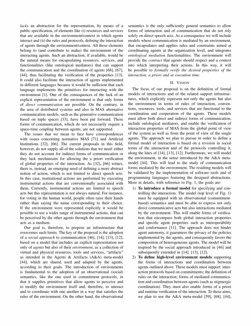
lacks an abstraction for the representation, by means of apublic specification, of elements like (i) resources and servicesthat are available in the environment/context in which agentsinteract and (ii) the rules and protocols, defining the interactionof agents through the environment/context. All these elementsbelong to (and contribute to make) the environment of theinteracting agents. Such an abstraction, if available, would bethe natural means for encapsulating resources, services, andfunctionalities (like ontological mediators) that can supportthe communication and the coordination of agents [68], [67],[44], thus facilitating the verification of the properties [13].It could also facilitate the interaction of agents implementedin different languages because it would be sufficient that eachlanguage implements the primitives for interacting with theenvironment [1]. One of the consequences of the lack of anexplicit representation of the environment is that only formsof direct communication are possible. On the contrary, inthe area of distributed systems and also in MAS alternativecommunication models, such as the generative communicationbased on tuple spaces [33], have been put forward. Theseforms of communication, which do not necessarily require aspace-time coupling between agents, are not supported.
The issues that we mean to face have correspondenceswith issues concerning normative MAS [71] and ArtificialInstitutions [32], [66]. The current proposals in this field,however, do not supply all of the solutions that we need: eitherthey do not account for indirect forms of communication orthey lack mechanisms for allowing the a priori verificationof global properties of the interaction. As [32], [66] witnes,there is, instead, an emerging need of defining a more abstractnotion of action, which is not limited to direct speech acts.In this case, institutional actions are performed by executinginstrumental actions that are conventionally associated withthem. Currently, instrumental actions are limited to speechacts but this representation is not always natural. For instance,for voting in the human world, people often raise their handsrather than saying the name corresponding to their choice.If the environment were represented explicitly it would bepossible to use a wider range of instrumental actions, that canbe perceived by the other agents through the environment thatacts as a medium.
Our goal is, therefore, to propose an infrastructure thatovercomes such limits. The key of the proposal is the adoptionof a social approach to communication [46], [14], [13], [12],based on a model that includes an explicit representation notonly of agents but also of their environment, as a collection ofvirtual and physical resources, tools and services, “artifacts”as intended in the Agents & Artifacts (A&A) meta-model[44], which are shared, used and adapted by the agents,according to their goals. The introduction of environmentsis fundamental to the adoption of an observational (social)semantics, like the one used in commitment protocols, inthat it supplies primitives that allow agents to perceive andto modify the environment itself and, therefore, to interactand to coordinate with one another in a way that satisfies therules of the environment. On the other hand, the observational
semantics is the only sufficiently general semantics to allowforms of interaction and of communication that do not relysolely on direct speech acts. As a consequence we will includemodels where communication is mediated by an environment,that encapsulates and applies rules and constraints aimed atcoordinating agents at the organization level, and integratesontological mediation functionalities. The environment willprovide the contract that agents should respect and a contextinto which interpreting their actions. In this way, it willbe possible to formally verify the desired properties of theinteraction, a priori and at execution time.
II. VISION
The focus of our proposal is on the definition of formalmodels of interactions and of the related support infrastruc-tures, which explicitly represent not only the agents but alsothe environment in terms of rules of interaction, conven-tions, resources, tools, and services that are functional to thecoordination and cooperation of the agents. These modelsmust allow both direct and indirect forms of communication,include ontological mediators, and enable the verification ofinteraction properties of MAS from the global point of viewof the system as well as from the point of view of the singleagents. The approach we plan to pursue in order to define aformal model of interaction is based on a revision in socialterms of the interaction and of the protocols controlling it,along the lines of [14], [13], [12]. Furthermore, we will modelthe environment, in the sense introduced by the A&A meta-model [44]. This will lead to the study of communicationforms mediated by the environment. The resulting models willbe validated by the implementation of software tools and ofprogramming languages featuring the designed abstractions.More in details, with reference to Fig. 1, the goals are:
1) To introduce a formal model for specifying and con-trolling the interaction. The model (top level of Fig. 1)must be equipped with an observational (commitment-based) semantics and must be able to express not onlydirect communicative acts but also interactions mediatedby the environment. This will enable forms of verifica-tion that encompass both global interaction propertiesand specific agent properties such as interoperabilityand conformance [11]. The approach does not hinderagent autonomy, it guarantees the privacy of the policiesimplemented by the agents, and consequently favors thecomposition of heterogeneous agents. The model will beinspired by the social approach introduced in [46] andsubsequently extended in [14], [13], [12].
2) To define high-level environment models supportingthe forms of interactions and coordination betweenagents outlined above. These models must support: inter-action protocols based on commitments; the definition ofrules on the interaction; forms of mediated communica-tion and coordination between agents (such as stigmergiccoordination). They must also enable forms of a prioriand runtime verification of the interaction. To these aims,we plan to use the A&A meta-model [59], [68], [44],

Fig. 1. The MERCURIO architecture.
[57] and the corresponding notion of programmableenvironment [58] (programming abstractions level ofFig. 1).
3) To integrate ontologies and ontological mediators inthe definition of the models so as to guarantee opennessand heterogeneity of MAS. Mediation will occur attwo distinct levels: the one related to the vocabularyand domain of discourse and the one that characterizesthe social approach where it is required to bind thesemantics of the agent actions with their meaning insocial terms. Ontological mediators will be realized asartifacts.
4) To integrate the abstractions defined in the abovemodels within programming languages and frameworks.In particular, we plan to integrate the notions of agents,of environment, of direct and mediated communication,and of ontological mediators. Possible starting pointsare the aforementioned FIPA ACL standard and theworks that focus on the integration of agent-orientedprogramming languages with environments [56]. TheJaCa platform [58], integrating Jason and CArtAgO,will be taken as reference. This will form the executionplatform of Fig. 1 and will supply the primitives forinteracting with the environments.
5) To develop an open-source prototype of softwareinfrastructure for the experimentation of the definedmodels. The prototype will integrate and extend existingtechnologies such as JADE [18], [16], [17] (as a FIPA-compliant framework), CArtAgO [1] (for the program-ming and the execution of environments), Jason (as aprogramming language for BDI agents), MOISE [36](as organizational infrastructure).
6) To identify applicative scenarios for the evaluation ofthe developed models and prototypes. In this respect weregard the domain of Web services as particularly rele-vant because of the need to deploy complex interactionshaving those characteristics of flexibility that agents
are able to guarantee. Another interesting applicationregards the verification of adherence of bureaucraticprocedures of public administration with respect to thecurrent normative. Specific case studies will be definedin collaboration with those companies that have statedinterest towards the project.
III. STATE OF ART
These novel elements, related to the formation of andthe interaction within decentralized structures, find an initialsupport in proposals from the literature in the area of MAS.Current proposals, however, are still incomplete in that theysupply solutions to single aspects. For instance, electronicinstitutions [29], [10], [36], [35] regulate interaction, tackleopen environments and their semantics allows the verificationof properties but they only tackle direct communication pro-tocols, based on speech acts, and do not include an explicitnotion of environment. Commitment protocols [46], [70],effective in open systems and allowing more general formsof communication, do not supply behavioral patterns, and forthis reason it is impossible to verify properties of the inter-action. Eventually, most of the models and architectures forenvironments prefigure simple/reactive agent models withoutdefining semantics, that are comparable to the ones for ACL,and without explaining how such proposals could be integratedwith direct communication models based on speech acts. Weclassify the relevant contributions in the literature accordingto the objectives and the methodological aspects that will beexamined in-depth along the project.
A. Formal Models for Regulating the Interaction in MASThis topic has principally been tackled by modeling in-
teraction protocols. Most of protocol representations referto classic models, such as Petri nets, finite state machines,process algebras, and aim at capturing the expected interactionflow. An advantage of this approach is that it supports theverification of interaction properties [53], [21], [11], suchas: verifying the interoperability of the system and verifying

if certain modifications of a system preserve some desiredproperties (a crucial issue in open domains where agents canenter/leave the system at any time). Singh and colleagues criti-cize the use of procedural specifications because too rigid [61],[25], [70]: agents cannot take advantage of opportunities thatemerge along the interaction and that are not foreseen by theirprocedure. Another issue is that communication languages usea BDI semantics (FIPA ACL is an example), where each agenthas goals and beliefs of its own. At the system level, however,it is impossible to perform introspection of agents, which are,for this reason, black boxes. For what concerns the verificationof properties this approach allows agents to draw conclusionsabout their own behavior but not to verify global properties ofthe system [41], [65].
Both problems are solved by commitment protocols [46],[61], which rely on an observational semantics of the interac-tion and offer adequate flexibility to agents. Moreover, they donot require the spatio-temporal coupling of agents (as insteaddirect communication does). Another advantage is that, thoughremaining black boxes, agents agree on the meaning of thesocial actions of the protocol. Since interactions are observableand their semantics is shared, each agent should be able todraw conclusions concerning the system as a whole. Unfortu-nately, besides some preliminary studies [62], the state of artdoes not contain proposals on how performing the verificationsin a MAS, ruled by this kind of protocols. A relevant featureseems to be the introduction, within commitment protocols,of behavioral rules which constrain the possible evolutions ofthe social state [13], [12].
B. Environment ModelsThe notion of environment has always played a key role in
the context of MAS; recently, it started to be considered as afirst-class abstraction useful for the design and the engineeringof MAS [68]. A&A [44] follows this perspective, beinga meta-model rooted upon Activity Theory and ComputerSupport Cooperative Work that defines the main abstractionsfor modeling a MAS, and in particular for modeling theenvironment in which a MAS is situated. A&A promotesa vision of an endogenous environment, that is a sort ofsoftware/computational environment, part of the MAS, thatencapsulates the set of tools and resources useful/required byagents during the execution of their activities. A&A introducesthe notion of artifact as the fundamental abstraction used formodeling the resources and the tools that populates the MASenvironment. The introduction of the environment as a newfirst-class abstraction requires new engineering approaches forprogramming the MAS environment. The CArtAgO frame-work [58] has been devised precisely for copying this newnecessity. It provides the basis for the engineering of MASenvironments on the base of: (i) a proper computationalmodel and (ii) a programming model for the design andthe development of the environments on the base of theA&A meta-model. In particular, it provides those featuresthat are important from a software engineering point of view:abstraction, it preserves the agent abstraction level, since the
main concepts used to define application environments, i.e.artifacts and workspaces, are first-class entities in the agentsworld, and the interaction with agents is built around the agent-based concepts of action and perception (use and observation);modularity and encapsulation, it provides an explicit way tomodularize the environment, where artifacts are componentsrepresenting units of functionality, encapsulating a partially-observable state and operations; extensibility and adaptation,it provides a direct support for environment extensibility andadaptation, since artifacts can be dynamically constructed(instantiated), disposed, replaced, and adapted by agents;reusability, it promotes the definition of types of artifact thatcan be reused as tools in different application contexts, suchas in the case of coordination artifacts empowering agentinteraction and coordination, such as blackboards and synchro-nizers. These features will be advantageous in the realizationof the second goal of the project, w.r.t. approaches like [26],where commitment stores, communication constraints andthe interaction mechanisms reside in the middleware, whichshields them from the agents. This has two disadvantages: thefirst is that even though all these elements are accounted forin the high level specification, the lack of a correspondingprogramming abstraction makes it difficult to verify whetherthe system corresponds to the specification; the second is alack of flexibility, in that it is not possible for the agents todynamically change the rules of interaction or to adopt kindsof communication that are not already implemented in themiddleware.
In the state of the art numerous applications of the endoge-nous environments, i.e. environments used as a computationalsupport for the agents’ activities, have been explored, in-cluding coordination artifacts [45], artifacts used for realizingargumentation by means of proper coordination mechanisms[43], artifacts used for realizing stigmergic coordination mech-anisms [55], [49], organizational artifacts [35], [50], [51].Even if CArtAgO can be considered a framework sufficientlymature for the concrete developing of software/computationalMAS environments it can not be considered “complete” yet.Indeed at this moment the state of the art and in particularthe CArtAgO framework are still lacking: (i) a referencestandard on the environment side comparable to the existingstandards in the context of the agents direct communications(FIPA ACL), (ii) the definition of a rigorous and formalsemantics, in particular related to the artifact abstraction, (iii)an integration with the current communication approaches(FIPA ACL, KQML, etc.), and finally (iv) the support ofsemantic models and ontologies.
C. Multi-agent Organizations and InstitutionsThe possibility of controlling and specifying interactions
is relevant also for areas like the organizational theory [40],[71], [15], [36] and electronic institutions [29], [10] areas.Tendentiously, the focus is orthogonal to the one posed oninteraction protocols, in that it concerns the modeling of thestructure rather than of the interaction.
The abstract architecture of e-Institutions (e.g. Ameli [29]),

places a middleware composed of governors and staff agentsbetween participating agents and an agent communicationinfrastructure (e.g. JADE [18], [16], [17]). The notion ofenvironment is dialogical: it is not something agents can senseand act upon but a conceptual one that agents, playing withinthe institution, can interact with by means of norms and laws,based on specific ontologies, social structures, and languageconventions. Agents communicate with each other by meansof speech acts and, behind the scene, the middleware mediatessuch communication. The extension proposed for situated e-Institutions [10] introduces the notion of “World of Interest”to model the environment, that is external to the MAS butwhich is relevant to the MAS application. The infrastructureof the e-Institution, in this case, mediates also the interactionof the agents in the MAS with the view of the environmentthat it supplies. Further along this line, but in the context oforganizations, ORA4MAS [35] proposes the use of artifacts toenable the access of the agents in the MAS to the organization,providing a working environment that agents can perceive,act upon and adapt. Following the A&A perspective, they areconcrete bricks used to structure the agents’ world: part of thisworld is represented by the organizational infrastructure, partby artifacts introduced by specific MAS applications, includingentities/services belonging to the external environment.
According to [10] there are, however, two significant differ-ences among artifacts and e-Institutions: (i) e-Institutions aretailored to a particular, though large, family of applicationswhile artifacts are more generic; (ii) e-Institutions are a wellestablished and proven technology that includes a formal foun-dation, and advanced engineering and tool support, while forartifacts, these features are still in a preliminary phase. One ofthe aims of MERCURIO is to give to artifacts both the formalfoundation (in terms of commitments and interaction patterns)and the engineering tools that they are still missing. The in-troduction of interaction patterns with an observational nature,allowing the verification of global properties, that we aim atstudying, will allow the realization of e-Institutions by meansof artifacts. The artifact will contain all the features necessaryfor monitoring the on-going interactions and for detectingviolations. A second step will be to consider organizationsand realize them again by means of artifacts. To this aim, itis possible to exploit open source systems like CArtAgO [1],for the programming and the execution of environments, andMOISE [36], as organizational infrastructure.
D. Semantic Mediation in MASThe problem of semantic mediation at the vocabulary and
domain of discourse levels was faced for the first time bythe “Ontology Service Specification” [8] issued by FIPA in2001. According to that specification, an “Ontology Agent”(OA, for short) should be integrated in the MAS in orderto provide services such as translating expressions betweendifferent ontologies and/or different content languages andanswering queries about relationships between terms or be-tween ontologies. Although the FIPA Ontology Service Spec-ification represents the first and only attempt to analyze in a
systematic way the services that an OA should provide forensuring semantic interoperability in an open MAS, it hasmany limitations. The main one is the assumption that eachontology integrated in the MAS adheres to the OKBC model[6]. Currently, in fact, the most widely accepted ontologylanguage is OWL [7] which is quite different from OKBC andcannot be converted to it in an easy and automatic way. Also,agents are allowed to specify only one ontology as referencevocabulary for a given message, which is a strong limitationsince an agent might use terms from different ontologies inthe same message, and hence it might want to refer to morethan one ontology at the same time.
Maybe due to these limitations, there have been reallyfew attempts to design and implement OAs. The first datesback to 2001 [63] and realizes an OA for the COMTECplatform that implements a subset of the services of a genericFIPA-compliant OA. In 2007 [47] integrated an OA intoAgentService, a FIPA compliant framework based on .NET[64]. Ontologies in AgentService are represented in OKBC,and hence the implementation of their OA is fully compliantwith the FIPA specification, although the offered servicesare a subset of the possible ones. The only two attempts ofintegrating a FIPA-compliant OA into JADE, we are awareof, are [42], and [24]. Both follow the FIPA specification butadapt it to ontologies represented in OWL. The first proposalis aimed at storing and modifying OWL ontologies: the OAagent exploits the Jena library [37] to this aim. The secondproposal, instead, faces the problem of “answering queriesabout relationships between terms or between ontologies”. Thesolution proposed by the authors exploits ontology matchingtechniques [30]. Apart from [24], no other existing proposalfaces that problem. Among non FIPA-compliant solutions, wemention [38], which focuses on the process of mapping andintegrating ontologies in a MAS thanks to a set of agentswhich collaborate together, and the proposal in [48], whichimplements the OA as a web service, in order to offer itsservices also over the Internet.
As far as semantic mediation at the social approach levelis concerned, we are aware of no proposals in the literature.In order to take the context of count-as rules into account, weplan to face this research issue by exploiting context awaresemantic matching techniques, that extend and improve thosedescribed in [39].
E. Software Infrastructures for AgentsThe tools currently available to agent developers fail in
supporting both semantic interoperability and goal-directedreasoning. Nowadays, the development of agents and multi-agent systems is based on two kinds of tools: agent platformsand BDI (or variations) development environments. Agentplatforms, such as JADE [18], [16], [17] and FIPA-OS [2] pro-vide only a transport layer and some basic services, but they donot provide any support for goal-directed behavior. Moreover,they lack support for semantic interoperability because theydo not take into account the semantics of the ACL they adopt.The available BDI development environments, such as Jadex

[23] and 2APL [28], support only syntactic interoperabilitybecause they do not exploit their reasoning engines to integratethe semantics of the adopted ACL.
The research on Agent Communication Languages (ACL)is constantly headed towards semantic interoperability [34]because the most common ACLs, e.g., KQML [31] and FIPAACL [3], provide each message with a declarative semanticsthat was explicitly designed to support goal-directed reasoning.Unfortunately, the research on ACLs only marginally inves-tigated the decoupling properties of this kind of languages(see, e.g., [19], [20]). To support the practical developmentof software agents, several programming languages have thusbeen introduced to incorporate some of the concepts fromagent logics. Some languages use actions as their starting pointto define commitments (Agent-0, [60]), intentions (AgentS-peak(L), [54]) and goals (3APL, [27]).
IV. EXPECTED RESULTS
The achievements expected from this research are of dif-ferent natures: scientific result that will advance the state ofthe art, software products deriving from the development ofimplementations, and upshots in applicative settings.
The formal model developed in MERCURIO will extendcommitment protocols by introducing behavioral rules. Thestarting point will be the work done in [14], [13], [12]. Thiswill advance the current state of the art with respect to thespecification of commitment protocols and also with respectto the verification of interaction properties (like interoperabil-ity and conformance), for which there currently exist onlypreliminary proposals [62]. Another advancement concernsthe declarative specification of protocols and their usage bydesigners and software engineers. The proposals coming fromMERCURIO conjugate the flexibility and openness featuresthat are typical of MAS with the needs of modularity andcompositionality that are typical of design and developmentmethodologies. The adoption of commitment protocols makesit easier and more natural to represent (inter)actions that arenot limited to communicative acts but that include interactionsmediated by the environment, namely actions upon the envi-ronment and the detection of variations of the environmentruled by “contracts”.
For what concerns the coordination infrastructure, a firstresult will be the definition of environments based on the A&Ameta-model and on the CArtAgO computational framework,that implement the formal models and the interaction proto-cols mentioned above. A large number of the environments,described in the literature supporting communication and coor-dination, have been stated considering purely reactive architec-tures. In MERCURIO we will formulate environment modelsthat allow goal/task-oriented agents (those that integrate pro-activities and re-activities) the participation to MAS. Amongthe specific results related to this, we foresee an advancementof the state of the art with respect to the definition and theexploitation of forms of stigmergic coordination [55] in thecontext of intelligent agent systems. A further contributionregards the flexible use of artifact-based environments by
intelligent agents, and consequently the reasoning techniquesthat such agents may adopt to take advantage of these envi-ronments. First steps in this direction, with respect to agentswith BDI architectures, have been described in [52], [49].
The MERCURIO project aims at putting forward an ex-tension proposal for the FIPA ACL standard, where the FIPAACL-based communication is integrated with forms of interac-tions, that are enabled and mediated by the environment. Thiswill lead to an explicit representation of environments as first-class entities (in particular endogenous environments basedon artifacts) and of the related model of actions/perceptions.Furthermore we will formulate an improved version of theMAS programming language/framework JaCa, where we planto integrate the agent-oriented programming language Jason,which is based on a BDI architecture, with the CArtAgOcomputational framework. This result will extend the workdone so far in this direction [56], [58].
In MERCURIO we will implement a prototype of thereference infrastructural model defined by the project. Theprototype will be based on the development and integrationof existing open-source technologies including JADE [4], thereference FIPA platform, CArtAgO [1], the reference platformand technology for the programming and execution of envi-ronments, and agent-oriented programming languages such asJason [5] and 2APL [28]. The software platform will includeimplementations of the “context sensitive” ontology alignmentalgorithms developed in MERCURIO. The algorithms will beevaluated against standard benchmarks and also against thecase studies devised in MERCURIO.
Aside from the effects on research contexts, we think thatthe project may give significant contributions also to industrialapplicative contexts, in particular to those companies workingon software development in large, distributed systems andin service-oriented architectures. Among the most interest-ing examples are the integration and the cooperation of e-Government applications (services) spread over the nation. Forthis reason, MERCURIO will involve some companies in theproject, and in particular in the definition of realistic case stud-ies against which the project’s products will be validated. Asregards (Web) services, some fundamental aspects promotedby the SOA model, such as autonomy and decoupling, areaddressed in a natural way by the agent-oriented paradigm.Development and analysis of service-oriented systems canbenefit from the increased level of abstraction offered byagents, by reducing the gap between the modeling, design,development, and implementation phases.
REFERENCES
[1] CARTAGO. http://cartago.sourceforge.net.[2] FIPA OS. http://fipa-os.sourceforge.net.[3] FIPA specifications. http://www.fipa.org.[4] JADE. http://jade.tilab.com/.[5] JASON. http://jason.sourceforge.net.[6] OKBC. http://www.ai.sri.com/ okbc/.[7] OWL. http://www.w3.org/TR/owl-features/.[8] Fipa architecture board, fipa ontology service specification, 2001.
http://www.fipa.org/specs/fipa00086/.

[9] M. Alberti, F. Chesani, M. Gavanelli, E. Lamma, P. Mello, and P. Tor-roni. Verifiable agent interaction in abductive logic programming: Thesciff framework. ACM Trans. Comput. Log., 9(4), 2008.
[10] J. L. Arcos, P. Noriega, J. A. Rodrıguez-Aguilar, and C. Sierra. E4MASThrough Electronic Institutions. In Weyns et al. [69], pages 184–202.
[11] M. Baldoni, C. Baroglio, A. K. Chopra, N. Desai, V. Patti, and M. P.Singh. Choice, interoperability, and conformance in interaction protocolsand service choreographies. In Proc. of the 8th Int. Conf. on AutonomousAgents and Multiagent Systems, AAMAS 2009, pages 843–850.
[12] M. Baldoni, C. Baroglio, and E. Marengo. Behavior-orientedCommitment-based Protocols. In Proc. of 19th European Conferenceon Artificial Intelligence, ECAI 2010, 2010. To appear.
[13] M. Baldoni, C. Baroglio, and E. Marengo. Commitment-based Protocolswith Behavioral Rules and Correctness Properties of MAS. In Proc. ofInt. Workshop on Declarative Agent Languages and Technologies, DALT2010, held in conjuction with AAMAS 2010, pages 66–83, 2010.
[14] M. Baldoni, C. Baroglio, and E. Marengo. Constraints among Com-mitments: Regulative Specification of Interaction Protocols. In Proc.of International Workshop on Agent Communication, AC 2010, held inconjuction with AAMAS 2010, pages 2–18, 2010.
[15] M. Baldoni, G. Boella, and L. van der Torre. Bridging Agent Theoryand Object Orientation: Agent-like Communication among Objects. InPost-Proc. of the Int. Workshop on Programming Multi-Agent Systems,ProMAS 2006, LNAI 4411, pages 149–164. Springer, 2007.
[16] F. Bellifemine, F. Bergenti, G. Caire, and A. Poggi. JADE - A Java AgentDevelopment Framework. In Multi-Agent Programming: Languages,Platforms and Applications, volume 15 of Multiagent Systems, ArtificialSocieties, and Simulated Organizations, pages 125–147. Springer, 2005.
[17] F. Bellifemine, G. Caire, A. Poggi, and G. Rimassa. JADE: A softwareframework for developing multi-agent applications. Lessons learned.Information & Software Technology, 50(1-2):10–21, 2008.
[18] F. Bellifemine, A. Poggi, and G. Rimassa. Developing multi-agentsystems with a FIPA-compliant agent framework. Softw., Pract. Exper.,31(2):103–128, 2001.
[19] F. Bergenti and F. Ricci. Three Approaches to the Coordination ofMultiagent Systems. In Proc. of the ACM Symposium on AppliedComputing (SAC), pages 367–372, 2002.
[20] F. Bergenti, G. Rimassa, M. Somacher, and L. M. Botelho. A FIPACompliant Goal Delegation Protocol. In Communication in MultiagentSystems, Agent Communication Languages and Conversation Polocies,LNCS 2650, pages 223–238. Springer, 2003.
[21] L. Bordeaux, G. Salaun, D. Berardi, and M. Mecella. When are TwoWeb Services Compatible? In Proc. of Technologies for E-Services, 5thInt. Workshop, LNCS 3324, pages 15–28, 2004.
[22] R. H. Bordini, J. F. Hubner, and R. Vieira. Jason and the GoldenFleece of Agent-Oriented Programming. In Multi-Agent Programming:Languages, Platforms and Applications, vol. 15 of Multiagent Systems,Artificial Societies, and Simulated Organizations, pp 3–37. Springer,2005.
[23] L. Braubach, A. Pokahr, and W. Lamersdorf. Jadex: A bdi agentsystem combining middleware and reasoning. In Software Agent-BasedApplications, Platforms and Development Kits. Birkhauser Book, 2005.
[24] D. Briola, A. Locoro, and V. Mascardi. Ontology Agents in FIPA-compliant Platforms: a Survey and a New Proposal. In Proc. of WOA2008: Dagli oggetti agli agenti, Evoluzione dell’agent development:metodologie, tool, piattaforme e linguaggi. Seneca Edizioni, 2008.
[25] A. K. Chopra and M. P. Singh. Nonmonotonic Commitment Machines.In Advances in Agent Communication, Int. Workshop on Agent Commu-nication Languages, LNCS 2922, pages 183–200, 2003.
[26] A. K. Chopra and M. P. Singh. An Architecture for Multiagent Systems:An Approach Based on Commitments. In Proc. of the AAMAS Workshopon Programming Multiagent Systems (ProMAS), 2009.
[27] M. Dastani, B. M. van Riemsdijk, F. Dignum, and J.-J. Ch. Meyer. AProgramming Language for Cognitive Agents Goal Directed 3APL. InProc. of PROMAS 2003, LNCS 3067, pages 111–130, 2003.
[28] Mehdi Dastani. 2apl: a practical agent programming language. Au-tonomous Agents and Multi-Agent Systems, 16(3):214–248, 2008.
[29] M. Esteva, B. Rosell, J. A. Rodrıguez-Aguilar, and J. L. Arcos. AMELI:An Agent-Based Middleware for Electronic Institutions. In AAMAS,pages 236–243. IEEE Computer Society, 2004.
[30] J. Euzenat and P. Shvaiko. Ontology Matching. Springer, 2007.[31] T. Finin, Y. Labrou, and J. Mayfield. Kqml as an agent communication
language. InSoftware Agents. MIT Press, Cambridge, 1997.
[32] N. Fornara, F. Vigano, and M. Colombetti. Agent communication andartificial institutions. Autonomous Agents and Multi-Agent Systems,14(2):121–142, 2007.
[33] David Gelernter. Generative communication in linda. ACM Trans.Program. Lang. Syst., 7(1):80–112, 1985.
[34] S. Heiler. Sematic Interoperability. ACM Computing Surveys, 27(2):271–273, 1995.
[35] J. F. Hubner, O. Boissier, R. Kitio, and A. Ricci. Instrumenting multi-agent organisations with organisational artifacts and agents: “Giving theorganisational power back to the agents”. Autonomous Agents and Multi-Agent Systems, 20, 2009.
[36] Jomi Fred Hubner, Jaime Simao Sichman, and Olivier Boissier. Develop-ing organised multiagent systems using the moise. IJAOSE, 1(3/4):370–395, 2007.
[37] Jena – A Semantic Web Framework for Java. Online, accessed on June,14th, 2010. http://jena.sourceforge.net/.
[38] L. Li, B. Wu, and Y. Yang. Agent-based ontology integration forontology-based application. In Proc. of Australasian Ontology Work-shop, pages 53–59, 2005.
[39] V. Mascardi, A. Locoro, and F. Larosa. Exploiting Prolog and NLPtechniques for matching ontologies and for repairing correspondences.In Proc. of 24th Convegno Italiano di Logica Computazionale, 2009.
[40] C. Masolo, L. Vieu, E. Bottazzi, C. Catenacci, R. Ferrario, A. Gangemi,and N. Guarino. Social Roles and their Descriptions. In Principles ofKnowledge Representation and Reasoning: Proc. of the Ninth Interna-tional Conference (KR2004), pages 267–277, 2004.
[41] P. McBurney and S. Parsons. Games That Agents Play: A FormalFramework for Dialogues between Autonomous Agents. Journal ofLogic, Language and Information, 11(3):315–334, 2002.
[42] M. Obitko and V. Snael. Ontology repository in multi-agent system. InProc. of Conf. on Artificial Intelligence and Applications, 2004.
[43] E. Oliva, P. McBurney, and A. Omicini. Co-argumentation Artifactfor Agent Societies. In Argumentation in Multi-Agent Systems, 4thInternational Workshop, ArgMAS 2007, LNCS 4946, pages 31–46, 2007.
[44] A. Omicini, A. Ricci, and M. Viroli. Artifacts in the A&A meta-modelfor multi-agent systems. Autonomous Agents and Multi-Agent Systems,17(3):432–456, 2008.
[45] A. Omicini, A. Ricci, M. Viroli, C. Castelfranchi, and L. Tummolini.Coordination Artifacts: Environment-Based Coordination for IntelligentAgents. In 3rd Int. Joint Conference on Autonomous Agents andMultiagent Systems (AAMAS 2004), pages 286–293, 2004.
[46] Singh M. P. An Ontology for Commitments in Multiagent Systems.Artif. Intell. Law, 7(1):97–113, 1999.
[47] A. Passadore, C. Vecchiola, A. Grosso, and A. Boccalatte. Designingagent interactions with Pericles. In Proc. of 2nd Int. Workshop onOntology, Conceptualization and Epistemology for Software and SystemEngineering, 2007.
[48] A. Pena, H. Sossa, and F. Gutierrez. Web-services based ontologyagent. In Proc. of 2nd Int. Conference on Distributed Frameworks forMultimedia Applications, DFMA 2006, pages 1–8, 2006.
[49] M. Piunti and A. Ricci. Cognitive Use of Artifacts: Exploiting RelevantInformation Residing in MAS Environments. In Proc. of KnowledgeRepresentation for Agents and Multi-Agent Systems, KRAMAS 2008,LNCS 5605, pages 114–129, 2008.
[50] M. Piunti, A. Ricci, O. Boissier, and J. F. Hubner. Embodied Organisa-tions in MAS Environments. In Proc. of Multiagent System Technologies,7th German Conf., LNCS 5774, pages 115–127, 2009.
[51] M. Piunti, A. Ricci, O. Boissier, and J. F Hubner. EmbodyingOrganisations in Multi-agent Work Environments. In Proc. of the 2009IEEE/WIC/ACM Int. Conf. on Intelligent Agent Technology, IAT, pages511–518. IEEE, 2009.
[52] M. Piunti, A. Ricci, L. Braubach, and A. Pokahr. Goal-Directed In-teractions in Artifact-Based MAS: Jadex Agents Playing in CARTAGOEnvironments. In IAT, pages 207–213. IEEE, 2008.
[53] S. K. Rajamani and J. Rehof. Conformance Checking for Models ofAsynchronous Message Passing Software. In Proc. of Computer AidedVerification CAV’02, LNCS 2404, pages 166–179. Springer, 2002.
[54] A. S. Rao. AgentSpeak(L): BDI Agents Speak Out in a LogicalComputable Language. In MAAMAW, LNCS 1038, pages 42–55. 1996.
[55] A. Ricci, A. Omicini, M. Viroli, L. Gardelli, and E. Oliva. Cognitivestigmergy: Towards a framework based on agents and artifacts. In Weynset al. [69], pages 124–140.
[56] A. Ricci, M. Piunti, D. L. Acay, R. H. Bordini, J. F. Hubner, andM. Dastani. Integrating heterogeneous agent programming platforms

within artifact-based environments. In AAMAS (1), pages 225–232.IFAAMAS, 2008.
[57] A. Ricci, M. Piunti, and M. Viroli. Environment Programming in MAS– An Artifact-Based Perspective. Autonomous Agents and Multi-AgentSystems. To appear.
[58] A. Ricci, M. Piunti, M. Viroli, and A. Omicini. Environment Pro-gramming in CArtAgO. In Multi-Agent Programming II: Languages,Platforms and Applications, Multiagent Systems, Artificial Societies, andSimulated Organizations. 2009.
[59] A. Ricci, M. Viroli, and A. Omicini. The A&A programming modeland technology for developing agent environments in mas. In PROMAS,volume 4908 of LNCS, pages 89–106. Springer, 2007.
[60] Y. Shoham. Agent-Oriented Programming. Artificial Intelligence,60(1):51–92, 1993.
[61] M. P. Singh. A social semantics for agent communication languages. InIssues in Agent Communication, volume 1916 of LNCS, pages 31–45.Springer, 2000.
[62] M. S. Singh and A. K. Chopra. Correctness Properties for MultiagentSystems. In Proc. of DALT, LNCS 5948, pages 192–207. Springer, 2009.
[63] H. Suguri, E. Kodama, M. Miyazaki, H. Nunokawa, and S. Noguchi.Implementation of FIPA Ontology Service. In Proc. of Workshop onOntologies in Agent Systems , 2001.
[64] C. Vecchiola, A. Grosso, and A. Boccalatte. AgentService: a frameworkto develop distributed multi-agent systems. Int. J. Agent-OrientedSoftware Engineering, 2(3):290 – 323, 2008.
[65] M. Venkatraman and M. P. Singh. Verifying compliance with com-mitment protocols. Autonomous Agents and Multi-Agent Systems, 2(3),1999.
[66] M. Verdicchio and M. Colombetti. Communication Languages forMultiagent Systems. Computational Intelligence, 25(2):136–159, 2009.
[67] M. Viroli, T. Holvoet, A. Ricci, K. Schelfthout, and F. Zambonelli.Infrastructures for the environment of multiagent systems. AutonomousAgents and Multi-Agent Systems, 14(1):49–60, 2007.
[68] D. Weyns, A. Omicini, and J. Odell. Environment as a first classabstraction in multiagent systems. Autonomous Agents and Multi-AgentSystems, 14(1):5–30, 2007.
[69] D. Weyns, H. Van Dyke Parunak, and F. Michel, editors. Environmentsfor Multi-Agent Systems III, 3rd Int. Workshop, Selected Revised andInvited Papers, LNCS 4389. Springer, 2007.
[70] P. Yolum and M. P. Singh. Commitment machines. In Proc. of ATAL,pages 235–247, 2001.
[71] F. Zambonelli, N. R. Jennings, and M. Wooldridge. Developingmultiagent systems: The Gaia methodology. ACM Trans. Softw. Eng.Methodol., 12(3):317–370, 2003.

Documenting SODA: An Evaluationof the Process Documentation Template
Ambra MolesiniALMA MATER STUDIORUM – Universita di Bologna
Viale Risorgimento 2, 40136 Bologna, ItalyEmail: [email protected]
Andrea OmiciniALMA MATER STUDIORUM – Universita di Bologna a Cesena
Via Venezia 52, 47521 Cesena, ItalyEmail: [email protected]
Abstract—This paper presents an experimental evaluation ofthe methodology documentation template proposed by the IEEEFIPA Design Process Documentation and Fragmentation workinggroup [1]. Generally aimed at agent-oriented methodologies, thetemplate is here put to the test by documenting the SODA
methodology, so as to obtain a partial but significant evaluationof the template’s strengths and weaknesses.
I. INTRODUCTION
While artificial systems grow in complexity, the role ofmodels, methodologies and development processes in theirengineering becomes increasingly relevant. In the field ofcomputational systems, AOSE (Agent-Oriented Software En-gineering) methodologies and processes are research subjectsof foremost interest since agent-based models and technologiesare nowadays recognised as providing one of the most suitableapproaches to the engineering of complex software systemssuch as self-organising and pervasive systems.
There is common agreement both in the traditional softwareengineering and in the AOSE fields that there is not a uniquemethodology or process that fits all the application domains[2]. This means that the methodology or process must beadapted to the particular characteristics of the domain forwhich the software is developed.
A variety of (special-purpose) AOSE methodologies havebeen defined in the past years [3], [4], [5], [6], [7] to disciplineand support the development of multi-agent systems (MAS).However, the increasing number of AOSE methodologies andthe key role in the construction of new ad-hoc methodologiesor processes played by the Situational Method Engineer-ing [8], [9], [10] have hindered the applicability of AOSEmethodologies. In fact, each methodology has its own specificmeta-model, notation, and process. All of these features arefundamental for a correct understanding of a methodology,and should then be described in a manual or book that theproject manager and his/her team of developers closely follow[11]. However, such manuals typically do not represent in aproper way the methodologies since they do not suitably for-malise those three crucial aspects. Instead, methodologies aretypically explained through an ambiguous textual descriptionfocussing more on the notation language and on the workproducts rather than on other essential aspects such as theprocess, the concepts meta-model and the application domain.
Although it is possible to describe a methodology / pro-cess without an explicit documentation, formalising its un-derpinning ideas is valuable for checking consistency, orwhen planning extensions or modifications: there, a formaldocumentation can be exploited to check both the softwaredevelopment process and the completeness and expressivenessof methodologies. More generally, the relevance of documen-tation becomes clear when studying the completeness andthe expressiveness of a methodology / process, and whencomparing / integrating different methodologies / processestogether.
In this context, the IEEE FIPA Design Process Docu-mentation and Fragmentation (DPDF) working group [1]has recently proposed a template for documenting AOSEmethodologies. So, the objective of this paper is to presentan experimental evaluation of the FIPA DPDF template bymeans of the application of such a template to the SODA
methodology [12], [13].Accordingly, the paper is structured as follows. Section II
briefly presents the IEEE FIPA DPDF template, while Sec-tion III presents some excerpts from the SODA documen-tation. Then, Section IV discusses the template’s strengthsand weaknesses identified during the creation of the SODA
documentation. Conclusions are reported in Section V.
II. PROCESS DOCUMENTATION TEMPLATE IN A NUTSHELL
The IEEE FIPA DPDF working group has recently proposeda template for documenting AO methodologies and processes.This template takes into account the three aforementionedmethodology features—meta-model, notation, and process. Inthe first place, the template has been conceived with no refer-ence to any particular methodology—which should guaranteethat all methodologies can be documented using the proposedtemplate. Moreover, the template is also neutral regardingthe meta-model and/or the modelling notation adopted in thedescription of the the methodology.
Secondly, the template has a simple structure resemblinga tree—see above for further details. This implies that thedocumentation can be built up in a natural and progressiveway, addressing in first place the general description andmeta-model definition – which constitute the root elementsof the methodology –, subsequently detailing the branches

1.Introduction1.1.The (process name) Process lifecycle1.2.The (process name) Metamodel1.2.1. Definition of MAS metamodel elements
2.Phases of the (process name) Process2.1.(First) Phase2.1.1.Process roles2.1.2.Activity Details2.1.3.Work Products
2.2 (Second) Phase2.2.1.Process roles2.2.2.Activity Details2.2.3.Work Products. . . (further phases) . . .
3.Work Product Dependencies
TABLE ITHE IEEE FIPA DPDF PROCESS TEMPLATE
representing the phases. Next, thinner branches like activitiesor sub-activities have to be described. As a result, the templatecan in principle support complex methodologies and differentsituations.
In the third place, the use of the template is easy for asoftware engineer as it relies on few assumptions. Moreover,the notation suggested is the OMG’s standard Software Pro-cess Engineering Metamodel (SPEM) [14] along with fewextensions [15].
So, in the remainder of this section, we only report a briefpresentation of the template—interested readers can refer to[1] for the details. The template is based on the definition ofprocess and process model as proposed by [16]. A processmodel is supposed to have three basic components: the stake-
holders (i.e., roles and workers), the consumed and generatedproducts (i.e., work products), and the activities and tasksundertaken during the process, these being particular instances(i.e., work definitions) of the work to be done. Anotherimportant component of the template is the MAS metamodel,as suggested in [15]—given that the MAS metamodel mightconstrain the way in which fragments can be defined andreused.
The template schema reported in Table I introduces thefundamental components of the process model definition. Thetemplate has a structure that provides a natural decompositionof the process elements in a tree-like structure, whose rootis the Introduction section, which includes a description ofthe process lifecycle and the MAS metamodel. Introductiontries to provide a general overview of the process detailing theoriginal objectives of the methodology, its intended domain ofapplication, its scope, limits and constraints (if any), etc. TheMetamodel part provides a complete description of the MASmetamodel adopted in the process, along with the definitionsof its composing elements. Thus, the different conceptualelements considered when modelling the system should beidentified and described. The attention to the MAS metamodelis not new in the agent-oriented community, and it is also co-herent with the emerging model-driven approaches, which arealways based on the system metamodel. The methodology’s
process is supposed to be composed (from the work-to-be-done point of view) by phases. Each phase is composed ofactivities that, in turn, may be composed of other activities ortasks. Such a structure is compliant to the SPEM specificationthat is explicitly adopted as a part of this template, althoughwith some (minor) extensions—see [15]. The next part of thetemplate is represented by a number of Phase sections, onefor each phase composing the whole process. The main aimof each Phase section is to define the phase mainly from aprocess-oriented point of view; that is, workflow, work prod-ucts and process roles are the centre of the discussion. Initially,the phase workflow is introduced by using a SPEM activitydiagram, which reports the activities composing the phase, andby doing a quick description of work products and roles. ASPEM diagram follows reporting the structural decompositionof each activity in terms of the involved elements: tasks, rolesand work products.
In the last section, the template discusses work productswith a twofold goal: the first part aims at detailing the infor-mation content of each work product by representing whichMAS model elements are reported in it (and which operationsare performed on them). The second part focusses on themodeling notation adopted by the methodology in the specificwork product. The work products are described by usinga SPEM work product structured document. This diagramis a structural diagram reporting the main work product(s)delivered by each phase, and the diagrams are completed bya table that describes the scope of each work product. Finally,work product dependencies are reported in a specific diagram.
III. SODA DOCUMENTATION
This section presents only the main excerpts from theSODA documentation—interested readers can find the fulldocumentation at [17]. In particular next subsections describeSODA according to the template structure (TABLE I): Subsec-tion III-A presents the introduction of the documentation, Sub-section III-B details the SODA phases, finally Subsection III-Cshows the SODA work product dependencies.
A. Documentation Introduction
SODA (Societies in Open and Distributed Agent spaces)[17] is an agent-oriented methodology for the analysis anddesign of agent-based systems, which adopts the Agents& Artifacts (A&A) building blocks [18], and introduces alayering principle as an effective tool for scaling with thesystem complexity, applied throughout the analysis and designprocess. Since its first version [12], SODA is not concernedwith intra-agent issues: designing a multi-agent system withSODA leads to defining agents in terms of their requiredobservable behaviour and their roles in the multi-agent system.Then, whichever methodology one may choose to define theagent structure and inner functionality, it could be easily usedin conjunction with SODA. SODA focusses on inter-agent
issues, like the engineering of societies and environment forMAS.

Requirements Analysis
Analysis Architectural Design
Detailed Design
Layering
Layering
Fig. 1. SODA process lifecycle
The abstractions belonging to the SODA meta-model –called MAS Meta-model Elements (MMMElements) – [17]are logically divided into three categories: i) abstractionsfor modelling / designing the system active part (task, role,agent, etc.); ii) abstractions for the reactive part (function,resource, artifact, etc.); and iii) abstractions for interaction andorganisational rules (relation, dependency, interaction, rule,etc.). In its turn, the SODA process (Fig. 1) is organised intwo phases, each structured in two sub-phases: the Analysis
phase, which includes the Requirements Analysis and theAnalysis steps, and the Design phase, including the Archi-tectural Design and the Detailed Design steps. Due to thetransformational nature of SODA, each sub-phase models(designs) the system exploiting a specific and different subsetof the SODA MMMElements: each subset always includes atleast one abstraction for each of the above categories—that is,at least one abstraction for the system active part, one for thereactive part, and another for interaction and organisationalrules.
In-zoom Out-zoom
Projection
Select Layer
increases detail increases abstraction
new layer?
no
yes
Fig. 2. The layering capability pattern
In addition, since the SODA process (Fig. 1) is iterative,each step can be repeated several times, by suitably exploitingthe SODA layering mechanism (Fig. 2). The layering inFig. 1 is represented as a simple Activity of the process:
actually, it is a capability pattern [19], i.e., a reusable portionof the process—see Fig. 2. In particular, layering exhibitstwo different functionalities: (i) the selection of a specificlayer for refining / completing the abstractions models in themethodology process, and (ii) the creation of a new layer inthe system by in-zooming (i.e., increasing the system detail) orout-zooming (i.e., increasing the system abstraction) activities.In the latter case, the layering process terminates with theprojection activity needed to project the abstractions from onelayer to another “as they are”, so as to maintain the consistencyin each layer. The layering pattern is also used within sub-phases—except in the Detailed Design, where the layeringprinciple is, by definition, not applicable.
B. Phases of the SODA Process
1) Requirements Analysis: The goal of Requirements Anal-ysis is to characterise of both the customers’ requirements andthe legacy systems with which the system should interact, aswell as to highlight the relationships among requirements andlegacy systems. The diagram in Fig. 3 presents the Require-ments Analysis activities, each related to its correspondingtask(s) use [19]. The diagram also reports the roles involvedin this step and the work products that should be produced—i.e., the SODA tables describing the abstract entities of theRequirements Analysis. The Requirements Modelling activityis composed by the Actors Description and RequirementsDescription tasks both performed by the Requirement Analystrole supported by the Domain Expert (Fig. 3). In this activity,Requirement and Actor are used for modelling the customers’requirements and the requirement sources, respectively, whilethe ExternalEnvironment notion is used as a container ofthe LegacySystems that represent the legacy resources ofthe environment in the Environment Modelling activity. Therelationships between requirements and legacy systems aremodelled in the Relation Modelling activity in terms of asuitable Relation.
As one could see in Fig. 3, other three activities appear inthe diagram – Requirement Layering, Environment Layering,and Relation Layering – and are strictly related – through thepredecessor relationship – to the previously described activi-ties. These activities represent the Layering capability patternsince during each activity of this step it is possible to create anew (or, to select a specific) layer for detailing (or abstracting)the specific model under investigation. It is important to note

Requirements Modelling
Relations Modelling
Environment Modelling
Relation Descriptions
Actors Description Requirements
Description
<<input>>
<<performs,
primary>>
Requirement Analyst
LegacySystem Description
Requirements specification
<<pr
edec
esso
r>>
<<pe
rform
s,
prim
ary>
>
<<output>>
<<output>>
<<performs, primary>>
<<output>>
<<output>>
Environment Analyst
RequirementAnalyst
<<pe
rform
s,
prim
ary>
>
Domain Expert
<<performs, assist>>
Domain Expert
<<performs, assist>>
Requirement table
Actor-Requirement table
<<performs, assist>>
<<output>>Actor table
<<input>>
<<performs, assist>>
Domain Expert
LegacySystem table
<<input>>
<<pr
edec
esso
r>>
Environment Analyst
<<performs, assist>>
Relation table<<output>>
Requirement-Relation table
<<output>>
LegacySystem-Relation table
<<input>>
<<in
put>
>
Requirements specification
Requirements specification
<<input>>
<<input>>
Environment Layering
<<predecessor>>
<<predecessor>> <<output>>
Zooming table
<<input>>
Requirement Layering
<<predecessor>> <<predecessor>>
<<output>><<input>>
<<input>>
Relation Layering
<<predecessor>>
<<predecessor>>
<<output>><<input>>
Layering
<<predecessor>>
<<predecessor>>
<<output>>
<<output>>
ExternalEnvironment-LegacySystem table
Zooming table
Zooming table
Fig. 3. Requirements Analysis flow of activities, work products and roles
that layerings do not represent an iteration of the step: instead,they refine the model over which they are applied—and area peculiarity of SODA. The Requirements Analysis iterationis done through the Layering activity located between theRelation Modelling and the Requirements Modelling activities(Fig. 3). The same consideration also applies to the Analysisand Architectural Design steps.
2) Analysis: The first activity in the Analysis step is Mov-
ing from Requirements, where the MMMElements identifiedin the previous step are mapped onto the MMMElementsadopted in this stage to generate the initial version of theAnalysis models. The work product of this activity is rep-resented by a set of relational table called Reference Tablesdepicted in Fig. 4, where the relation between Analysis work-products and Analysis MMMElements are showed (D meansdefine/instantiate, R means relate, Q means quote/cite, Fmeans refine). In particular, Reference Tables defines (labelD in Fig. 4) the Analysis MMMElements and puts them inrelation (label R in Fig. 4) with the Requirements AnalysisMMMElements.
The Analysis step expresses the requirement representationin terms of more concrete MMMElements such as tasks
and functions. Tasks are activities requiring one or morecompetences and are analysed in the Task analysis activity,while functions are reactive activities aimed at supporting tasksanalysed in the Function analysis activity. The structure ofthe environment, analysed in the Topology analysis activity,is also modelled in terms of topologies—i.e., topologicalconstraints over the environment. The relations highlighted inthe previous step are here the starting point for the definition ofdependencies among such abstract entities in the Dependency
analysis activity.3) Architectural Design: This stage (Fig. 5) is one of
the more complex sub-phases in SODA. The first activityis Transition (Fig. 5), where the MMMElements identifiedin the previous step are mapped onto the MMMElementsadopted in this stage so as to generate the initial version of
Fig. 4. Analysis work products
the Architectural Design models. The main goal is to assignresponsibilities for achieving tasks to roles – Role Design ac-tivity composed by the Action Design task – and for providingfunctions to resources—Resource Design activity composedby Operation Design task. In order to attain one or moretasks, a role should be able to perform actions – Role Design
activity –; analogously, the resource should be able to executeoperations providing one or more functions—Resource Design
activity. The topology constraints lead to the definition ofspaces, i.e., conceptual places structuring the environment inthe Space Design activity. Finally, the dependencies identifiedin the previous phase become here interactions and rules.Interactions represent the acts of the interaction among roles,among resources and between roles and resources, and aredesigned in the Interaction Design activity; rules, instead,enable and bound the entities’ behaviour and are designed inthe Constraint Design activity.
4) Detailed Design: The Detailed Design step (Fig. 6) isthe only stage where the layering principle is not applicable,since its goal is to choose the most adequate representationlevel for each architectural entity, thus leading to depictone (detailed) design from the several potential alternativesarchitectures outlined in the previous step. So, as shown inFig. 6, the first activity of this sub-process is Carving, whichrepresents a sort of boundary between the Architectural Designand the Detailed Design, where the chosen system architectureis “carved out” from all the possible architectures.
The next activity is Mapping (Fig. 6), where the carvedMMMElements are mapped onto the MMMElements adoptedin this stage, thus generating the initial version of the DetailedDesign models. Then, the Detailed Design presents threedifferent activities. The Agent Design activity design the active

Zooming table
Architectural Designer
Transition
<<performs,
primary>
>
<<input>>
<<input>>
<<input>>
<<input>>
Layering
<<output>>
<<predecessor>>
<<predecessor>>
Map Analysis-ArchDes
<<output>>
Role Design
Resource Design
Space Design
Role Layering
<<predecessor>>
<<predecessor>>
<<pr
edec
ess
or>>
Action Design
<<input>><<output>>
Zooming table
<<ou
tput
>>
<<input>>
<<predecessor>><<
pred
eces
sor>
>
Resource Layering
<<pr
edec
esso
r>><<predecessor>>
Operation Design<<output>>
Zooming table
<<ou
tput
>>
<<input>>
<<pe
rform
s,
prim
ary>
>
<<pe
rform
s, pr
imar
y>>
Space Layering<<predecessor>>
<<predecessor>>
Space Design
Zooming table
<<input>>
Constraint Design
Constraint Layering
<<predecessor>> <<pr
edec
esso
r>>
Zooming table<<output>
>
Layering
<<predecessor>>
<<predecessor>>
Rule Design
<<input>>
<<performs, prim
ary>><<output
>>
<<output>>
Architectural Designer
Architectural Designer
Architectural Designer
c
Responsibilities Tablesc
Dependencies Table
c
Topologies Tables
Interaction Design
Interaction Layering Interaction Design
<<predecessor>>
<<predecessor>>
<<predecessor>>
<<predecessor>>
Zooming table <<input>>
<<input>>
Architectural Designer
<<pe
rform
s,
prim
ary>
>
<<ou
tput
>>
<<predecessor>>
<<pr
edec
ess
or>>
<<output>>
<<input>>
<<in
put>
>
c
Topological Tables
c
Constraints Tables
c
Interactions Tables
c
Entities Tables
c
Transition Tables
<<performs,
primary>>
<<input>>
<<input>>
<<input>>
<<output>><<input>>
c
Entities Tables
<<input>>
Fig. 5. Architectural Design flow of activities, work products and roles
Zooming table
Detailed Designer
Carving
<<pe
rform
s,
primary
>>
<<input>>
<<input>><<input>>
<<input>>Carving
<<output>>
Agent Design
Environment Design
Workspace Design
<<pr
edec
ess
or>>
Agent/Society Design
<<output>>
Mapping
<<predecessor>>
Environment Design
<<output>>
<<performs, primary>>
<<pe
rform
s,
prim
ary>
>
Workspace Design
Detailed Designer
Interaction Detailed Design
Interaction Detailed Design
<<predecessor>>
<<predecessor>>
<<output>>
<<output>>
<<in
put>
>
c
Topological Design Tables
c
Interaction Design Tables
c
Mapping Tables
<<performs, primary>>
<<inp
ut>>
c
Environment Design Tables
<<input>>
c
Entities Tables
c
Interactions Tables
c
Constraints Tables
c
Topological Tables
<<input>> Carving Diagram
a
Map ArchDes-DetDes
<<input>>
c
Entities Tables
c
Interactions Tables
c
Constraints Tables
c
Topological Tables
<<input>>
<<input>>
<<input>>
<<input>>
<<output>>
c
Agent/Society Design Tables
<<input>>
c
Environment Design Tables
<<input>>
c
Agent/Society Design Tables
<<input>>
<<pe
rform
s,
prim
ary>
>
Detailed Designer
Detailed Designer
<<input>>
<<predecessor>>
c
Agent/Society Design Tables
c
Environment Design Tables
<<in
put>
>
<<pr
edec
esso
r>
>
<<predecessor>>
Fig. 6. Detailed Design flow of activities, work products and roles
part of the system in terms of Agent and agent Society. Moreprecisely, agents are intended here as autonomous entities ableto play several roles, while a society can be seen as a groupof interacting agents and artifacts whose overall behaviouris essentially autonomous and proactive: they are designedduring the Agent Design activity.
In the Environment Design activity, the resources identifiedin the previous step are here mapped onto suitable Artifact,while Aggregate is defined as a group of interacting agentsand artifacts whose overall behaviour is essentially functionaland reactive.
The Workspace Design activity defines the topology of theenvironment in terms of Workspaces that take the form ofan open set of artifacts and agents: artifacts can be dynami-cally added to or removed from workspaces, and agents can
dynamically enter (join) or exit workspaces. Finally, duringthe Interactions Design activity, the interaction are designedin terms of Use – interaction between agents and artifacts –,Manifest – interaction between artifacts and agents –, SpeakTo
– interaction among agents – and LinkedTo – interactionamong artifacts – MMMElements.
C. Work Product Dependencies
The diagram in Fig. 7 describes the high-level dependenciesamong the different sets of SODA work products—calledcomposite work products. In fact, due to the huge numberof SODA work products – each table represent a workproduct – it is not possible to create a comprehensive andreadable diagram depicting all the work products and theirdependencies.
IV. DISCUSSION
This paper evaluates a template for process documentationthat seems to provide a good framework in the documentationof processes for agent-oriented development. However, thecurrent version of the template presents several limitations—some of which related more to the notational language thanto the template structure.
The main weakness of the current template structure isrelated to the absence of a clear indication of where to describethe tools and guidance [19] applied both in the overall processand in the specific part of the process. In particular, whentrying to document SODA we had some problems in thedocumentation of the layering. This is quite a peculiar aspectof SODA, which adopts the layering principle as a tool formanaging the system complexity spread all over the process—excluding the Detailed Design step.
The first issue was about the place where to place thelayering description. From our experience in developing andexplaining SODA, we understood that the layering should bepresented before detailing the different SODA’s steps. Thisbecause the layering is not a simple mechanism for creatingthe iteration in the SODA process, but it is also a way forrefining single SODA model, so it is largely adopted in thefirst three steps. Looking at Fig. 3 and Fig. 5, it is possibleto see both the layering activity (Layering) that inducting –if necessary – a new iteration of the step and the differentlayering activities (such as Requirement Layering, RelationLayering, etc.) devoted to the models refinement. The aboveconsiderations led us to the definition of a new sub-section inthe documentation introduction (TABLE I) where the layeringis documented. After our requests for explanations, the rightplace where the process guidance and mechanisms shouldbe positioned is now under discussion inside the IEEE FIPADPDF working group.
The second issue coming from the layering documentationis related to the structure of the newly created sub-section.We decided to structure the new sub-section in a very similarway to the structure of the single phases, since the layeringhas its portion of process, its specific activities and tasks, andobviously its work product. We also created a specific diagram

c
Requirements Tables
c
Domain Tables
c
Relation Tables
Zooming table
c
References Tables
c
Responsibilities Tables
c
Dependencies Table
c
Topologies Tables
c
Transitions Tables
c
Entities Tables
c
Interactions Tables
c
Constraints Tables
c
Topological Tables
c
Mappings Tables
c
Agent / Society Design Tables
c
Environment Design Tables
c
Interaction Design Tables
c
Topological Design Tables
Zooming table
Zooming table
Carving Diagram
a
Fig. 7. SODA work products dependencies
– like the diagram in Fig. 4 – that puts the Zooming table –i.e., the layering work product – in relation with the SODA’sMMMElements, in order to explain how the layering is closelyrelated to the SODA meta-model [17].
The last layering issue is related to the SPEM notation.In fact, the diagrams in Fig. 3 and Fig. 5 are very difficult tounderstand due to the huge number of strictly-related activities.In particular, in Fig. 5 there are six different layering activities– one for the step iteration and five for the models refinement– and the only predecessor relation is not powerful enoughfor explaining the right flow of activities in the Architec-tural Design step—so this diagram alone is not sufficientlyexpressive. For instance, the Role Design activity in Fig. 5is the predecessor of two different and alternative activities,on the one hand the Role Layering and on the other handthe Interaction Design. In this diagram, at the best of ourknowledge, there is no way for expressing this alternative.Even though such an alternative is documented in anotheractivity diagram (see the SODA documentation at [17]), inour view the alternative paths should be highlighted also inthe diagram in Fig. 5.
This consideration about the SPEM limitation leads to an-other SPEM issue tied to the work product documentation. Indifferent diagrams such as those presented in Fig. 5 and Fig. 7we are able to document only the SODA composite workproducts in order to have readable diagrams. The diagramsproposed by SPEM seems not so suitable for documentingthose methodologies which a great number of work productslike SODA.
Apart from the weaknesses highlighted above, the templateseems very valuable, since it forced us to re-think the wayof presenting our methodology. Usually, when discussing amethodology, authors are more worried about identifying the
models to construct, the concepts to define, etc. than indetailing the phases and the activities to do, or in definingthe order of these activities. Thanks to this template now theauthors should pay more attention to process-related aspects.
In addition, a major task of the documentation templateshould be to offer a good support for process evaluation andcomparison. When comparing SODA to the other methodolo-gies documented in [1], we can notice for instance that PASSI[20] and SODA meta-models are different in the content(different elements, concepts and models); however, using thesame approach in describing them easily enables the study ofsimilarities and differences between them. Furthermore, fromthe comparison of the SODA documentation and the docu-mentations (see [1]) of PASSI and INGENIAS [21], we haveeasily deduced that INGENIAS has a limited set of models,which are however quite complex since each of them includemany concepts. On the other hand, PASSI and SODA haverespectively more diagrams and tables, but each of them intro-duces few concepts. In addition, the documentation highlightsthe different attention paid to the environment modelling. Thisis a primary activity in SODA, a task in INGENIAS, whilePASSI demands the study of the environment in the next phase.Another difference concerns the identification of role and agentconcepts that in PASSI and INGENIAS is done in the firstphase of the process, whereas SODA defines such abstractionsonly in the design phase. So, the use of the template easilysupports the identification of such differences.
V. CONCLUSIONS AND FUTURE WORK
In this paper, we used IEEE FIPA DPDF template fordocumenting the SODA design process, and represents anexperimental evaluation of the template. SODA proved tobe a good test for the template since the creation of theSODA documentation highlighted a weakness in the template

structure. The SODA documentation showed the power of thetemplate in process documentation, and sketched some of itsbenefits briefly comparing SODA to PASSI and INGENIAS.
In addition, the creation of the SODA documentation helpedus formalising the SODA process and organising in a properway the huge number of SODA work products. In particular,diagrams such as those depicted in Fig. 4 proved to bevery valuable in relating the SODA work products to theSODA MMMElements. This improved the general SODA
understanding—including ours. Finally, the SODA documen-tation could be considered as the starting point for the SODA
fragmentation, since in the future the models produced for thedocumentation will be used for identifying and documentingfragments. Such fragments will be reused and integrated so asto provide new ways of developing agent-oriented systems.
REFERENCES
[1] IEEE FIPA Design Process Documentation and Fragmentation, “IEEEFIPA Design Process Documentation and Fragmentation Homepage,”http://www.pa.icar.cnr.it/cossentino/fipa-dpdf-wg/, 2009.
[2] I. Sommerville, Software Engineering 8th Edition. Addison-Wesley,2007.
[3] P. Cuesta, A. Gomez, J. Gonzalez, and F. J. Rodrıguez, “The MESMAmethodology for agent-oriented software engineering,” in Proceedings
of First International Workshop on Practical Applications of Agents and
Multiagent Systems (IWPAAMS’2002), 2002, pp. 87–98.[4] S. A. O’Malley and S. A. DeLoach, “Determining when to use an agent-
oriented software engineering pradigm,” in Agent-Oriented Software
Engineering. Second Int. Workshop, AOSE 2001, ser. Lecture Notes inComputer Science, M. Wooldridge, G. Weiss, and P. Ciancarini, Eds.Springer-Verlag, 2002, vol. 2222.
[5] C. Bernon, M. Cossentino, and J. Pavon, “Agent-oriented softwareengineering,” Knowl. Eng. Rev., vol. 20, no. 2, pp. 99–116, 2005.
[6] J. Pavon and J. Gomez-Sanz, “Agent Oriented Software Engineeringwith INGENIAS,” Multi-Agent Systems and Applications III, vol. 2691,pp. 394–403, 2003.
[7] A. Mas, Agentes Software y Sistemas Multi-Agentes. Pearson PrenticeHall, 2004.
[8] S. Brinkkemper, K. Lyytinen, and R. Welke, Method engineering:
Principles of method construction and tool support. Kluwer AcademicPublishers, 1996.
[9] J. Ralyte and C. Rolland, “An approach for method reengineering,”in Conceptual Modeling. London, UK: Springer-Verlag, 2001, pp.471–484, 20th International Conference (ER 2001), Yokohama,Japan, 27-30 Nov. 2001. Proceedings. [Online]. Available:http://www.springerlink.com/content/pbtbr52cwya7qyd4/
[10] V. Seidita, M. Cossentino, V. Hilaire, N. Gaud, S. Galland, A. Koukam,and S. Gaglio, “The Metamodel: a Starting Point for Design Pro-cesses Construction,” International Journal of Software Engineering and
Knowledge Engineering, 2009, in-press.[11] B. Henderson-Sellers and C. Gonzalez-Perez, “A comparison of four
process metamodels and the creation of a new generic standard,”Information & Software Technology, vol. 47, no. 1, pp. 49–65, 2005.
[12] A. Omicini, “SODA: Societies and infrastructures in the analysis anddesign of agent-based systems,” in Agent-Oriented Software Engineer-
ing, ser. LNCS, P. Ciancarini and M. J. Wooldridge, Eds. Springer,2001, vol. 1957, pp. 185–193, 1st International Workshop (AOSE 2000),Limerick, Ireland, 10 Jun. 2000. Revised Papers.
[13] A. Molesini, E. Nardini, E. Denti, and A. Omicini, “Situatedprocess engineering for integrating processes from methodologiesto infrastructures,” in 24th Annual ACM Symposium on Applied
Computing (SAC 2009), S. Y. Shin, S. Ossowski, R. Menezes,and M. Viroli, Eds., vol. II. Honolulu, Hawai’i, USA:ACM, 8–12 Mar. 2009, pp. 699–706. [Online]. Available:http://portal.acm.org/citation.cfm?id=1529282.1529429
[14] O. M. G. OMG, “Software Process Engineering Metamodel Specifica-tion. Version 1.1, formal/05-01-06,” http://www.omg.org/ (accessed onSeptember 5, 2008), 2005.
[15] V. Seidita, M. Cossentino, and S. Gaglio, “Using and extending the spemspecifications to represent agent oriented methodologies,” in AOSE,ser. Lecture Notes in Computer Science, M. Luck and J. J. Gomez-Sanz, Eds., vol. 5386. Springer, 2009, pp. 46–59, 9th InternationalWorkshop, AOSE 2008, Estoril, Portugal, May 12-13, 2008, RevisedSelected Papers.
[16] L. Cernuzzi, M. Cossentino, and F. Zambonelli, “Process models foragent-based development,” Engineering Applications of Artificial Intel-
ligence, vol. 18, no. 2, pp. 205–222, 2005.[17] SODA, “Home page,” http://soda.apice.unibo.it. [Online].
Available: http://soda.apice.unibo.it[18] A. Omicini, A. Ricci, and M. Viroli, “Artifacts in the
A&A meta-model for multi-agent systems,” Autonomous Agents
and Multi-Agent Systems, vol. 17, no. 3, pp. 432–456, Dec.2008, special Issue on Foundations, Advanced Topics andIndustrial Perspectives of Multi-Agent Systems. [Online]. Available:http://www.springerlink.com/content/l2051h377k2plk07/
[19] Object Management Group, “Software & SystemsProcess Engineering Meta-Model Specification 2.0,”http://www.omg.org/spec/SPEM/2.0/PDF, Apr. 2008.
[20] M. Cossentino, “From requirements to code with the PASSImethodology,” in Agent Oriented Methodologies, B. Henderson-Sellersand P. Giorgini, Eds. Hershey, PA, USA: Idea Group Publishing,Jun. 2005, ch. IV, pp. 79–106. [Online]. Available: http://www.idea-group.com/books/details.asp?id=4931
[21] J. Pavon, J. J. Gomez-Sanz, and R. Fuentes, “The INGENIASmethodology and tools,” in Agent Oriented Methodologies,B. Henderson-Sellers and P. Giorgini, Eds. Hershey, PA, USA:Idea Group Publishing, Jun. 2005, ch. IX, pp. 236–276. [Online].Available: http://www.idea-group.com/books/details.asp?id=4931
[22] B. Henderson-Sellers and P. Giorgini, Eds., Agent Oriented Methodolo-
gies. Hershey, PA, USA: Idea Group Publishing, Jun. 2005. [Online].Available: http://www.idea-group.com/books/details.asp?id=4931
From Service-Oriented Architectures toNature-Inspired Pervasive Service Ecosystems
Franco ZambonelliDipartimento di Scienze e Metodi dell’Ingegneria
Universita di Modena e Reggio Emilia, ItalyEmail: [email protected]
Mirko ViroliDipartimento di Elettronica Informatica e SistemisticaAlma Mater Studiorum – Universita di Bologna, Italy
Email: [email protected]
Abstract—Emerging pervasive computing scenarios requireopen service frameworks promoting situated adaptive behaviorsand supporting diversity in services and long-term evolvability.We argue that this naturally calls for a nature-inspired ap-proach, in which pervasive services are modeled and deployedas autonomous individuals in an ecosystem of other services,data sources, and pervasive devices. As an evolution of standardservice-oriented architectures, we present a general frameworkframing the concepts expressed, and discuss a number of naturalmetaphors that we can adopt to concretely incarnate the proposedframework and implement pervasive service ecosystems.
I. INTRODUCTION
The ICT landscape, yet notably changed by the advent ofubiquitous wireless connectivity, is further re-shaping due tothe increasing deployment of pervasive computing technolo-gies. Via RFID tags and alike, objects will carry on digitalinformation of any sort. Wireless sensor networks and cameranetworks will be spread in our cities and buildings to monitorphysical phenomena. Smart phones and alike will increasinglysense and store notable amounts of data related to our personal,social and professional activities, other than feeding (and beingfed by) the Web with spatial and social real-time information[1].
This evolution is contributing to building integrated anddense infrastructures for the pervasive provisioning of general-purpose digital services. If all their components will be able toopportunistically connect with each other, such infrastructurescan be used to enrich existing services with the capabilityof autonomously adapting their behavior to the physical andsocial context in which they are invoked, and will alsosupport innovative services for enhanced interactions with thesurrounding physical and social worlds [2]. Users will play anactive role, by contributing data and services and by makingavailable their own sensing and actuating devices. This willmake pervasive computing infrastructures as participatory andcapable of value co-creation as the Web [3], eventually actingas globally shared substrates to externalize and enhance ourphysical and social intelligence, and make it become collectiveand more valuable.
We are already facing the commercial release of a varietyof early pervasive services trying to exploit the possibili-ties opened by these new scenarios: GPS navigator systemsproviding real-time traffic information and updating routesaccordingly, cooperative smart phones that inform us about
the current positions of our friends, and augmented realityservices to enrich what we see around with dynamicallyretrieved digital information [4]. However, the road towardsthe effective and systematic exploitation of these emergingscenarios calls for a radical rethinking of current servicemodels and frameworks.
II. CASE STUDY AND REQUIREMENTS
A simple case study – representative of a larger classof emerging pervasive scenarios – can help grounding ourarguments and sketching the requirements of future pervasiveservices.
It is a matter of fact that we are increasingly surrounded bydigital displays: from those of wearable devices to wide wall-mounted displays pervading urban and working environments.Currently, the latter are simply conceived as static informationservers to show information in a manually-configured manner– e.g., cycling some pre-defined commercials or general inter-est news – independently of the context in which they operateand of the users nearby. However, such displays infrastructurescan be made more effective and advantageous for both usersand information/service providers by becoming general, open,and adaptable information service infrastructures.
First, information should be displayed based on the currentstate of the surrounding physical and social environment. Forinstance, by exploiting information from surrounding temper-ature sensors and from user profiles, an advertiser could haveice tea commercials – instead of liquor ones – being displayedin a warm day and in a location populated by teenagers. Also,actions could be coordinated among neighboring displays, e.g.,to avoid irritating users with the same ads as they pass by, or touse adjacent displays as a single wide one to show complexmultifaceted information. These examples express a generalrequirement for pervasive services:
• Situatedness — Pervasive services deal with spatially-and socially-situated activities of users, and should thusbe able to interact with the surrounding physical andsocial world and adapt their behavior accordingly. Theinfrastructure itself, deeply embedded in the physicalspace, should effectively deal with spatial concepts anddata.
Second, and complementary to the above, the display infras-tructure and the services within should automatically adapt to

their own modifications and contingencies in an automatic waywithout experiencing malfunctionings, and possibly takingadvantage of such modifications. Namely, when new devicesare deployed or when new information is injected, a sponta-neous re-distribution and re-shaping of the overall displayedinformation should take place. For instance: the deployment ofa big advertising display in a room may suggest re-directingthere all the ads previously forwarded to the personal displaysof users; the injection of a new information service couldinduce aggregating it with the existing ones to provide amore complete yet uniform service. In terms of a generalrequirement for decentralized and dynamic scenarios:
• Adaptivity — Pervasive services and infrastructuresshould inherently exhibit properties of autonomous adap-tation and management, to survive contingencies withouthuman intervention and at limited costs.
Third, the display infrastructure should enable users – otherthan display owners – to upload information and services toenrich the offer or adapt it to their own needs. For instance,users may continuously upload personal content (e.g., picturesand annotations related to the local environment) from theirown devices to the infrastructure, both for better visualiza-tion and for increasing the overall local information offer.Similarly, a group of friends can exploit a public displayto upload software letting it host a shared real-time map tovisualize what’s happening around (which would also requireopportunistic access to the existing environmental sensors andto any available user-provided sensors, to make the map aliveand rich in real-time information). In general, one shouldenable users to act as “prosumers” – i.e., as both consumersand producers – of devices, data, and services. Not onlythis will make environments meet the specific needs of anyspecific user (and capture the long tail of the market), butwill also induce a process of value co-creation increasingthe overall intrinsic value of the system and of its services[5]. If the mentioned real-time map accesses some sensors inunconventional ways to better detect situations around, thisadds value both to such sensors and to all existing and futureservices requiring situation recognition. In terms of a generalrequirement:
• Prosumption and Diversity — The infrastructure shouldtolerate open models of service production and usagewithout limiting the number and classes of servicesprovided, and rather taking advantage of the injection ofnew services by exploiting them to improve and integrateexisting services whenever possible, and add further valueto them.
Finally, beside short-term adaptation, in the longer-termany pervasive infrastructure will experience dramatic changesrelated to the technology being adopted, as well as in thekinds of services being deployed and in their patterns of usage.For instance, a display infrastructure will somewhen integratemore sophisticated sensing means than we have today andwill possibly integrate enriched actuators via which to attractuser attention and interact with them. This can be the case
Fig. 1. Architecting pervasive service environments. Up: solution with acentralized middleware server. Bottom: solution relying on a distributed setof local middleware services.
of personal projection systems to make any physical objectbecome a display, or of eyeglass displays for immersive per-ception and action. While this can open up the way for brandnew classes and generation of services to be conceived anddeployed, it also requires that such evolution can be graduallyaccommodated without harming the existing infrastructure andservices. As a general requirement:
• Eternity — The infrastructure should tolerate long-termevolutions of structure, components, and usage patterns,to accommodate the changing needs of users and techno-logical evolution without forcing significant and expen-sive re-engineering efforts to incorporate innovations andchanges.
III. FROM SERVICE-ORIENTED ARCHITECTURES TONATURE-INSPIRED PERVASIVE SERVICE ECOSYSTEMS
Could the above requirements be met by architecting per-vasive service environments around standard service-orientedarchitectures (SOA) [6]? Yes, to some extents, but the finalresult would be such a scramble of SOA to rather suggestre-thinking from scratch the architecture and its foundingprinciples.
A. Centralized SOA Solution
In general, SOA consider the inter-related activities ofservice components to be managed by various infrastructural

(middleware) services such as: discovery services to helpcomponents get to know each other; context services to helpcomponents situate their activities; orchestration services tocoordinate interactions according to specific application logics;and shared dataspace services to support data-mediated inter-actions. To architect a pervasive display environment in suchterms (Figure 1-up), one has to set up up a middleware serverin which to host all the necessary infrastructural services tosupport the various components of the scenario, i.e., displays,information and advertising services, user-provided services,sensing devices and personal devices.
Such components access the discovery service to get awareof each other. However, in dynamic scenarios (users anddevices coming and going), components are forced to con-tinuously access (or being notified by) the discovery serviceto preserve up-to-date information—a computational and com-munication wasting activity. Also, since discovery and inter-actions among components have to rely on spatial information(i.e., a display is interested only in the users and sensors in itsproximity), this requires either sophisticated context-servicesto extract the necessary spatial information about components,or to embed spatial descriptions for each component into itsdiscovery entry, again inducing frequent and costly updates tokeep up with mobility.
To adapt to situations and contingencies, components shouldbe able to recognize relevant changes in their current environ-ment and plan corrective actions in response to them, whichagain require notable communication and computational costsfor all the components involved. Alternatively, or complemen-tary, one could think at embedding adaptation logics into somespecific server inside the middleware (e.g., in the form ofautonomic control managers [7]). However, such logics wouldhave to be very complex and heavyweight to ensure capabilityof adapting to any foreseeable situation, and especially hardfor long-term adaptivity.
B. Decentralized SOA Solution
To reduce the identified complexities and costs and bettermatch the characteristics of the scenario, one could think at amore distributed solution, with a variety of middleware serversdeployed in the infrastructure to serve, on a strictly local basis,only a limited portion of the overall infrastructure. For instance(Figure 1-bottom), one could install one middleware server foreach of the available public displays. It will manage the localdisplay and all local service components, thus simplifyinglocal discovery and naturally enforcing spatial interactions.Adaptation to situations is made easier, thanks to the possi-bility of recognizing in a more confined way (and at reducedcosts) local contingencies and events, and of acting locallyupon them.
With the adoption of a distributed solution enforcing local-ity, the distinction between the logics and duties of the differ-ent infrastructural services fades: discovering local servicesand devices implies discovering something about the localcontext; the dynamics of the local scenarios, as reflecting in thelocal discovery tables, makes it possible to have components
indirectly influence each other (being their actions possiblydependent of such tables), as in a sort of shared dataspacemodel. This also induces specific orchestration patterns forcomponents, based on the local logics upon which the mid-dleware relies to distribute information and events amongcomponents and to put components in touch with each other.
A problem of this distributed architecture is to requiresolutions both to tune it to the spatial characteristics of thescenario and to adaptively handle contingencies. The logics ofallocation of middleware servers (i.e., one server per display)derives naturally only in a static scenario, but the arrival anddismissing of displays requires the middleware servers to reactby re-shaping the spatial regions and the service componentsof pertinence of each of them, also correspondingly notifyingcomponents. To tackle this problem, the actual distributionof middleware servers should become transparent to servicecomponents—they should not worry about where servers are,but will simply act in their local space confident that thereare servers to access. Moreover, the network of servers shouldbe able to spontaneously re-organize its shape in autonomy,without directly affecting service components but simply adap-tively inducing in them a re-organization of their interactionpatterns.
C. Nature-inspired Ecosystems
Pushed towards a very dense and mobile network of nodesand pervasive devices, the architecture will end up beingperceivable as a dense distributed environment above whicha very dynamic set of spatially-situated components discover,interact, and orchestrate with each other. This is done interms of a much simplified logics, embedded into the uniqueinfrastructural service, subsuming the roles of discovery, con-text, dataspace, and orchestration services, and taking theform of a limited set of local rules embedded in the spatialsubstrate itself. That is, we would end up with something thatnotably resembles the architecture of natural ecosystems: aset of spatially situated entities interacting according to well-defined set of natural laws enforced by the spatial environmentin which they situate, and adaptively self-organizing theirinteraction dynamics according to its the shape and structure.
Going further than architectural similarity, the naturalmetaphor can be adopted as the ground upon which to rely toinherently accommodate the requirements of pervasive servicescenarios. Situatedness and spatiality are there by construction.Adaptivity can be achieved because of the basic rules of thegame: the dynamics of the ecosystem, as determined by theenactment of laws and by the shape of the environment, canspontaneously induce forms of adaptive self-organization be-side the characteristics of the individual components. Accom-modating new and diverse component species, even towards along-term evolution, is obtained by making components partto the game in respect of its rules, and by letting the ecosystemdynamics evolve and re-shape in response to the appearanceof such new species. This way, we can take advantage ofthe new interactional possibility of such new services andof the additional value they bring in, without requiring the
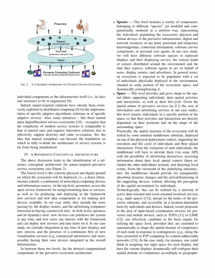
Fig. 2. A Conceptual Architecture for Pervasive Service Ecosystems
individual components or the infrastructure itself (i.e., its lawsand structure) to be re-engineered [8].
Indeed, nature-inspired solutions have already been exten-sively exploited in distributed computing [9] for the implemen-tation of specific adaptive algorithmic solutions or of specificadaptive services. Also, many initiatives – like those namedupon digital/business service ecosystems [10] – recognize thatthe complexity of modern service systems is comparable tothat of natural ones and requires innovative solutions also toeffectively support diversity and value co-creation. Yet, theidea that natural metaphors can become the foundation onwhich to fully re-think the architecture of service systems isfar from being metabolized.
IV. A REFERENCE CONCEPTUAL ARCHITECTURE
The above discussion leads to the identification of a ref-erence conceptual architecture for nature-inspired pervasiveservice ecosystems (see Figure 2).
The lowest level is the concrete physical and digital groundon which the ecosystem will be deployed, i.e., a dense infras-tructure (ideally a continuum) of networked computing devicesand information sources. At the top level, prosumers access theopen service framework for using/consuming data or services,as well as for producing and deploying in the frameworknew services and new data components or for making newdevices available. In our case study, they include the userspassing by, the display owners, and the advertising companiesinterested in buying commercial slots. At both levels opennessand its dynamics arise: new devices can join/leave the systemat any time, and new users can interact with the frameworkand can deploy new services and data items on it. In our casestudy, we consider integration at any time of new displays andnew sensors, and the presence of a continuous flow of newvisualization services (e.g. commercial advertisers) and users,possibly having their own devices integrated in the overallinfrastructure.
In between these two levels, lay the abstract computationalcomponents of the pervasive ecosystem architecture.
• Species — This level includes a variety of components,belonging to different “species” yet modeled and com-putationally rendered in a uniform way, representingthe individuals populating the ecosystem: physical andvirtual devices of the pervasive infrastructure, digital andnetwork resources of any kind, persistent and temporaryknowledge/data, contextual information, software servicecomponents, or personal user agents. In our case study,we will have different software species to representdisplays and their displaying service, the various kindsof sensors distributed around the environment and thedata they express, software agents to act on behalf ofusers, display owners, and advertisers. In general terms,an ecosystem is expected to be populated with a setof individuals physically deployed in the environment,situated in some portion of the ecosystem space, anddynamically joining/leaving it.
• Space — This level provides and gives shape to the spa-tial fabric supporting individuals, their spatial activitiesand interactions, as well as their life-cycle. Given thespatial nature of pervasive services (as it is the case ofinformation and advertising services in our case study),this level situates individuals in a specific portion of thespace, so that their activities and interactions are directlydependent on their positions and on the shape of thesurrounding space.Practically, the spatial structure of the ecosystem will bereified by some minimal middleware substrate, deployedon top of the physical deployment context, supporting theexecution and life cycle of individuals and their spatialinteractions. From the viewpoint of such individuals, themiddleware will have to provide them (via some API)with the possibility of advertising themselves, accessinginformation about their local spatial context (there in-cluded the other individuals around), and detecting localevents. From the viewpoint of the underlying infrastruc-ture, the middleware should provide for transparentlyabsorbing dynamic changes and the arrival/dismissing ofthe supporting devices, without affecting the perceptionof the spatial environment by individuals.Technologically, this can be realized by a network ofactive data-oriented and event-oriented localized services(e.g., tuple spaces [11]), spread on the nodes of the per-vasive substrate, and accessible on a location-dependentbasis by individuals and devices. Indeed, recent proposalsin the area of tuple-based coordination services for per-vasive and mobile devices, such as TOTA [11] or LIME[12], can effectively candidate as the basic engine forreifying the space level, provided they are extended toautomatically re-shape the spatial domain of competenceof each node in response to contingencies (e.g., along thelines promoted in P2P computing by content-addressablenetworks [13]). In the case study, for instance, one couldthink at assigning one tuple space for each display, andhave the various displays dynamically self-configure theirspatial domain of competence accordingly to geographi-

cal and “line of sight” factors.• Eco-Laws — The way in which individuals (whether
services components, devices, or generic resources) liveand interact is determined by the set of fundamental “eco-laws” regulating the ecosystem model. Enactment of eco-laws on individuals will typically affect and be affectedby the local space around and by the other individualsaround. In our case study, eco-laws might provide atautomatically and dynamically determining to display aspecific information on a screen as a sort of automaticreaction to specific environmental conditions, or at havingtwo displays spontaneously aggregate and synchronizewith each other in showing specific advertisements.Although the set of eco-laws is expected to be alwaysthe same for a specific implementation, they will possi-bly have different effects on different species. Accord-ingly, their enactment may require the presence of somemeaningful description (within the uniform modeling ofindividuals) of the information/service/structure/goals ofeach species and of their current context and state. Thesedescriptions, together with proper “matching” criteria,define how the eco-laws apply to specific species inspecific conditions of the space. We emphasize that, in theproposed architecture, the concept of “semantic descrip-tion” of traditional SOA to facilitate discovery turns intoa concept of “alive semantic description” (dynamicallychanging as the context and state of components change),to properly rule the dynamic enactment of eco-laws.Practically, to be able to code eco-laws and enact them,the middleware substrate should proactively mediateinter-component interactions, and act as an active spacein which to store their continuously updating semanticdescriptions, so as to adaptively support the matchingprocess triggering eco-laws in dependence of the currentconditions of the overall ecosystem. Technologically,since most tuple-based middleware systems are currentlyenriched with the capability of reacting to events and ofconfiguring the matching process, they could well act asthe interaction media in which to embed and enact eco-laws.
The proposed architecture represents a radically new perspec-tive on modeling service systems and their infrastructures.The typically heavyweight and multifaceted layers of SOAare subsumed by an unlayered universe of components, all ofwhich underlying the same model, living and interacting in thesame spatial substrate, and obeying the same eco-laws—beingthe latter the only concept hardwired into the system.
This rethinking is very important to ensure adaptivity,diversity, and long-term evolution: no component, service ordevice is there to stay, everything can change and evolve,self-adapting over space and time, without undermining theoverall structure and assumptions of the ecosystem. That is,by conceiving the middleware in terms of a simple spatialsubstrate in charge of enforcing only basic interaction rules,we have moved away from the infrastructure itself the need
of adapting, and fully translated this as a property of theapplication level and of its dynamics.
The dynamics of the ecosystem will be determined byindividuals acting based on their own goals/attitudes, yet beingsubject to the eco-laws for their interactions with others.Typical patterns that can be driven by such laws may includeforms of adaptive self-organization (e.g., spontaneous serviceaggregation or service orchestration, where the eco-laws playsan active role in facilitating individuals to spontaneouslyinteract and orchestrate with each other, also in dependenceof current conditions), adaptive evolution (changing conditionsreflect in changes in the way individuals in a locality areaffected by the eco-laws) and of decentralized control (to affectthe ecosystem behavior by injecting new components in it).
V. METAPHORS
Beside the above architectural guidelines, what actual shapecan species, space, and eco-laws take in an actual implemen-tation? Identifying and validating specific solutions in thisdirection will be a key challenge of pervasive computing inthe next years. Yet, we argue that whatever solution will mostlikely get inspiration from one of the key natural metaphorsalready explored in the literature, or possibly extract specificdesirable aspects from many of them towards a new syn-thesis. Key metaphors include physical [11], chemical [14]and biological ones [9], along with metaphors focussing onhigher-level social models (e.g., trophic networks [15])—thekey difference between them being in the way the species, thespace, and the eco-laws are modeled and implemented (seeFigure 3).
All the metaphors, by adhering to the proposed architec-ture, are by construction spatially situated, adaptive by self-organization, and open to host diverse and evolving species.However, when it comes to modeling and implementing,different metaphors may tolerate with variable efficiency andcomplexity the enforcement of adaptive self-organization pat-terns and the support of diversity and evolution. In addition,since the service ecosystem is here to ultimately serve us,it is necessary to analyze how and to which extent themetaphors facilitate exerting forms of decentralized controlover the ecosystem behavior, in order to direct its self-organizing activities and behavior and not to lose controlover it. Ideally, a metaphor should be able to support thesefeatures while limiting the number and complexity of eco-laws, the complexity of individuals and their environment,while keeping the infrastructure lightweight and the overallexecution efficient.
A. Physical metaphors
These consider species as sort of computational particles,living in a world of other particles and virtual computationalforce fields, the latter acting as the basic interaction means.Activities of particles (to be practically modeled and imple-mented as reactive agents) are driven by laws that determinehow particles spread fields, how fields propagate and reshapeupon changing conditions, and how they influence particles

Fig. 3. Metaphors for Pervasive Service Ecosystems
(those whose semantic description “matches” some criterion).Particles change their status based on the perceived fields,and move or exchange data by navigating them (i.e., particlesspread sort of data particles to be routed according to the shapeof fields). The world in which such particles live and fieldsspread and diffuse can be either a simple (euclidean) metricworld mapped in the physical space, or a virtual/social spacemapped on the technological network. From the infrastructuralviewpoint, a network of local tuple spaces will have to proac-tively support the storing of local field values, the propagationand continuous update of fields across the network, and thenotifications about these changes to individuals. For instance,the TOTA middleware [11] can be adopted for the implemen-tation and management of physically-inspired distributed fielddata structures.
In the case study, we can imagine display services as massesemitting gravitational-like fields (in the form of broadcastevents or spanning trees over the network). Such fields havedifferent “flavors” (i.e., different semantic descriptions, reflect-ing the characteristics of users around and the environmentconditions) and an intensity proportional to either their dimen-sion or the available display slots. Information and advertiseragents can behave as masses attracted by fields with specificflavor, eventually getting in touch with suitable displays fortheir information and ads. Upon changing conditions, thestructure and flavors of diffused fields will change, providing
for dynamically re-assigning information and ads to differentdisplays.
Physical metaphors have been extensively studied for theirspatial self-organization features, and for their effectivenessin facilitating the achievement of coherent behaviors evenin large scale systems—for load balancing, data distribution,clustering, aggregation, and differentiation of behaviors. Theconceptual tools available for controlling the spatial behaviorand the dynamics of such systems are well-developed, mostof them related to acting on how fields propagate and dy-namically change—by which it is actually possible to exertcontrol over the overall system behavior. On the other hand,such metaphors hardly tolerate high diversity and evolution.In fact, to support very diverse species and behaviors (at atime and over time), eco-laws must become complex enoughto tolerate a wide range of different fields and propagationrules, with an increase in the complexity of the model andin burden on the infrastructure [11], that has to proactivelysupport the propagation and continuous update of many fieldstructures.
B. Chemical metaphors
These consider species as sorts of computationalatoms/molecules (again modeled and implemented asreactive agents), enriched with semantic descriptions actingas the computational counterpart of the bonding properties

of physical atoms/molecules (yet made dynamic to reflectthe current state and context of individuals). Accordingly,the laws that drive the overall ecosystem behavior resemblechemical reactions, that dictate how chemical bondingbetween components take place (relying on some forms ofpattern matching between semantic descriptions), and leadto aggregated, composite, and new components, and also togrowth/decay of species. The world where individuals liveis typically formed by a set of spatially confining localities,intended as the “solutions” in which chemical interactionsoccur and across which chemicals can eventually diffuse.The declarative tuple space model of TuCSoN coordinationinfrastructure can support an effective implementation forchemically-inspired interactions [14].
In the case study, we can think of display services, ofinformation services (concerning ads and news), as well as ofuser and environmental data as molecules. Displays representdifferent localities (i.e., tuple spaces) in which componentsreact. Chemical rules dictate that when the preferences ofa user entering the locality of a display match an informa-tion/advertisement service, then a new composite componentis created which is in charge of actually displaying that servicein that display. Concurrently, in each locality, catalytic com-ponents can be in charge of re-enforcing the concentration ofspecific information or of specific information/advertisements,reflecting the current situation of users. Also, localities can beopen to enforce chemical bonds across displays, so that high-activity of advertisement reactions on a display can eventuallypropagate to neighbors.
Chemical metaphors can effectively lead to self-organizingstructures like local composite services and local aggregates.As in real chemistry, chemical computational metaphors canaccommodate an incredible amount of different componentsand composites with a single set of basic laws. In practice,this means that it can tolerate an increasingly diverse andevolving set of semantic descriptions for components withoutaffecting basic eco-laws and without increasing the burden tothe infrastructure. As far as control is concerned, one can thinkat using sort of catalyst or reagent components to engineerand control (in a fully decentralized way) the dynamics andthe behavior of the ecosystem. A limitation of the chemicalapproach is that it typically relies on activities taking placewithin a locality or at least across neighboring ones via localdiffusion [14], making it hard to naturally and easily enforcedistributed self-organized behaviors, like creating a complexand distributed aggregation of components.
C. Biological metaphors
These focus on biological systems at the scale of individualorganisms, or of colonies of organisms like ants. The speciesare therefore either simple cells or animals acting on the basisof simple goals like finding food and reproducing (to be mod-eled and implemented in terms of simple goal-oriented agents).As in physical systems, interactions take place by means ofsignals of various flavors (i.e., chemical pheromones) spreadby individuals in the environment, and slowly diffusing and
evaporating. The spatial environment is again a computationallandscape either mapped on the network topology or on thephysical space. Unlike physical systems, individuals here arenot necessarily passively subject to the sensed pheromones, butthey can react to them depending on their current “mood” (e.g.,their state towards the achievement of a goal). Consequently,eco-laws are only aimed at determining how such pheromones,depending on their specific flavors, should propagate and dif-fuse in the environment. From the implementation viewpoint,any infrastructure that can support physical metaphors can alsobe adapted to support biological metaphors, by turning fieldsinto persistent and slowly diffusing/evaporating data structures.
In the case study, users will be represented by simpleagents roaming around and spreading chemical signals with aflavor reflecting their personal interests. Displays can locallyperceive such pheromones, and react by emitting some dif-ferent pheromones to express the availability of commercialsand information. Advertising and information agents, by theirside, sense the concentration of such pheromones and areattracted towards the displays where the concentration of userswith specific interests is maximized. Displays, advertising andinformation agents by their side, and depending on what theyhave displayed so far, can also emit additional flavors ofpheromones, to store memory of past events. The persistenceof pheromones can also be exploited by additional componentsthat, by moving from display to display, create pheromonestrails as a basis for more global strategies—like identifyingrouting paths that advertiser agents use to globally find thebest displays to exploit.
Biological metaphors appear very flexible in efficientlyenabling the spatial formation of both localized and distributedactivity patterns, and have a variety of applications [9]. Theproblems of accommodating diversity and evolution that affectphysical metaphors are here notably smoothed. In fact, anincrease in the variety of pheromone flavors (to supportdiversity and evolution) can be handled with less overheadby the infrastructure, since pheromones (unlike fields) relyon local diffusion and slow evaporation dynamics. On thenegative side, since the mechanisms of morphogenesis andself-organization in actual biological systems are not fullyunderstood yet, it can be consequently hard to understand howto enforce control in their computational counterparts too.
D. Social metaphors
These focus on biological systems at the level of animalspecies and of their interactions [15]. Individuals are sortsof goal-oriented animals (i.e., agents) belonging to a specificspecies, that are in search of “food” resources to survive andprosper, and that can represent in their turn food to others(both aspects reflecting in some proper semantic descriptions).Pure data items and resources can be abstracted as sorts ofpassive life-forms (i.e., vegetables). The eco-laws determinehow the resulting “web of food” should be realized, namely,how animals search food, eat, and possibly produce andreproduce, thus influencing and ruling the overall dynamicsof the ecosystem and the interaction among individuals of

different species. Similarly to chemical systems, the shapeof the world is typically organized around a set of localities,i.e., ecological niches, yet enabling interactions and diffusionof species across niches. From the implementation viewpoint,reactive tuple space models [12] can be effectively adoptedtowards the realization of a supporting infrastructure, wherethe possibility for the tuple space to enforce control over allinteractions can be used as a mean to rule the food-web-basedeco-laws.
In the case study, and assuming that each display is associ-ated to an ecological niche, we can imagine users as speciesof herbivor agents roaming from niche to niche, possibly toeat those vegetable-like individuals representing information.Advertisers can be sorts of carnivors (i.e., eating other activelife-forms) in need to find proper users to survive (users withmatching interests). For both cases, the primary effect of aneating action is the feeding of displays with information orcommercials to show. A possible secondary effect of eatingis the reproduction and diffusion in the environment of thebest-fit species, e.g., of most successful commercials. Thosespecies that do not succeed in eating at a niche can eitherdie or move to other niches to find food. Concurrently withthe activities of the above species, background agents actingas sorts of bacteria can digest the activity logs at the variousniches to enforce specific forms of distributed control overthe whole system (e.g., by affecting the way information ispropagated across niches).
Social metaphors, such as the one here described but withoutforgetting the large body of work in the area of socialmulti-agent systems, appear suitable for local forms of self-organization like chemical metaphors—think at self-organizedequilibria of web food patterns in ecological niches. Unlikechemical metaphors, and more similarly to biological one,social metaphors can be effectively exploited also to enforcedistributed forms of self-organization, by exploiting the ca-pability of individuals of moving around (e.g., to find foodand/or reproduce). In addition, social metaphors are suitablefor tolerating diversity and evolution at no additional burdenfor the infrastructure—think at how biodiversity has increasedover the course of evolution without requiring any changeto the underlying infrastructure (i.e., the earth). However,understanding how to control the behavior and dynamics ofsocial computational ecosystems can be as difficult as it is inreal social systems.
VI. CONCLUSIONS
Nature-inspired models and architectures appear verypromising for re-thinking the foundation of modern andemerging pervasive service systems. Yet, the general lessonthat we can extract from our analysis is that:
• None of the natural metaphors being proposed so far issuited, as is, to act as a way to fully realize the eternallyadaptive service ecosystem vision.
• Thus, along the lines of the proposed reference architec-ture and being guided by it, some new synthesis should be
identified to incorporate the key features of the existingmetaphors into a unifying general-purpose one.
In addition to the key problem of identifying suitablemetaphors, the widespread deployment of nature-inspired per-vasive service ecosystems requires methodologies and toolsfor their engineering, proper security mechanisms and policies,and means to integrate the approach with the legacy of currentSOA systems. Lastly, the road towards pervasive serviceecosystems will have to ground on the emerging science ofservice systems [3], and will possibly be able to contribute toit.
REFERENCES
[1] A. T. Campbell, S. B. Eisenman, N. D. Lane, E. Miluzzo, R. A. Peterson,H. Lu, X. Zheng, M. Musolesi, K. Fodor, and G.-S. Ahn, “The rise ofpeople-centric sensing,” IEEE Internet Computing, vol. 12, no. 4, 2008.
[2] B. Coleman, “Using sensor inputs to affect virtual and real environ-ments,” IEEE Pervasive Computing, vol. 8, no. 3, pp. 16–23, 2009.
[3] J. C. Spohrer, P. P. Maglio, J. H. Bailey, and D. Gruhl, “Steps toward ascience of service systems,” IEEE Computer, vol. 40, no. 1, pp. 71–77,2007.
[4] A. Ferscha and S. Vogl, “Wearable displays – for everyone!” IEEE
Pervasive Computing, vol. 9, no. 1, pp. 7–10, 2010.[5] S. L. Vargo, P. P. Maglio, and M. A. Akaka, “On value and value co-
creation: a service systems and service logic perspective,” European
Management Journal, vol. 26, no. 3, pp. 145–152, 2008.[6] M. N. Huhns and M. P. Singh, “Service-oriented computing: Key
concepts and principles,” IEEE Internet Computing, vol. 9, no. 1, pp.75–81, 2005.
[7] J. O. Kephart and D. M. Chess, “The vision of autonomic computing,”IEEE Computer, vol. 36, no. 1, pp. 41–50, 2003.
[8] M. Jazayeri, “Species evolve, individuals age,” in 8th IEEE International
Workshop on Principles of Software Evolution, Washington, DC, 2005,pp. 3–12.
[9] O. Babaoglu, G. Canright, A. Deutsch, G. A. D. Caro, F. Ducatelle, L. M.Gambardella, N. Ganguly, M. Jelasity, R. Montemanni, A. Montresor,and T. Urnes, “Design patterns from biology for distributed computing,”ACM Trans. Auton. Adapt. Syst., vol. 1, no. 1, pp. 26–66, 2006.
[10] M. Ulieru and S. Grobbelaar, “Engineering industrial ecosystems in anetworked world,” in 5th IEEE International Conference on Industrial
Informatics. IEEE Press, June 2007, pp. 1–7.[11] M. Mamei and F. Zambonelli, “Programming pervasive and mobile
computing applications: the tota approach,” ACM Trans. Software Engi-
neering and Methodology, vol. 18, no. 4, 2009.[12] A. L. Murphy, G. P. Picco, and G.-C. Roman, “Lime: A coordination
model and middleware supporting mobility of hosts and agents,” ACM
Trans. on Software Engineering and Methodology, vol. 15, no. 3, pp.279–328, 2006.
[13] S. Androutsellis-Theotokis and D. Spinellis, “A survey of peer-to-peercontent distribution technologies.” ACM Computing Surveys, vol. 36,no. 4, pp. 335–371, 2004.
[14] M. Viroli and M. Casadei, “Biochemical tuple spaces for self-organizingcoordination,” in Coordination Languages and Models, ser. LNCS, vol.5521. Springer-Verlag, June 2009, pp. 143–162.
[15] G. Agha, “Computing in pervasive cyberspace,” Commun. ACM, vol. 51,no. 1, pp. 68–70, 2008.
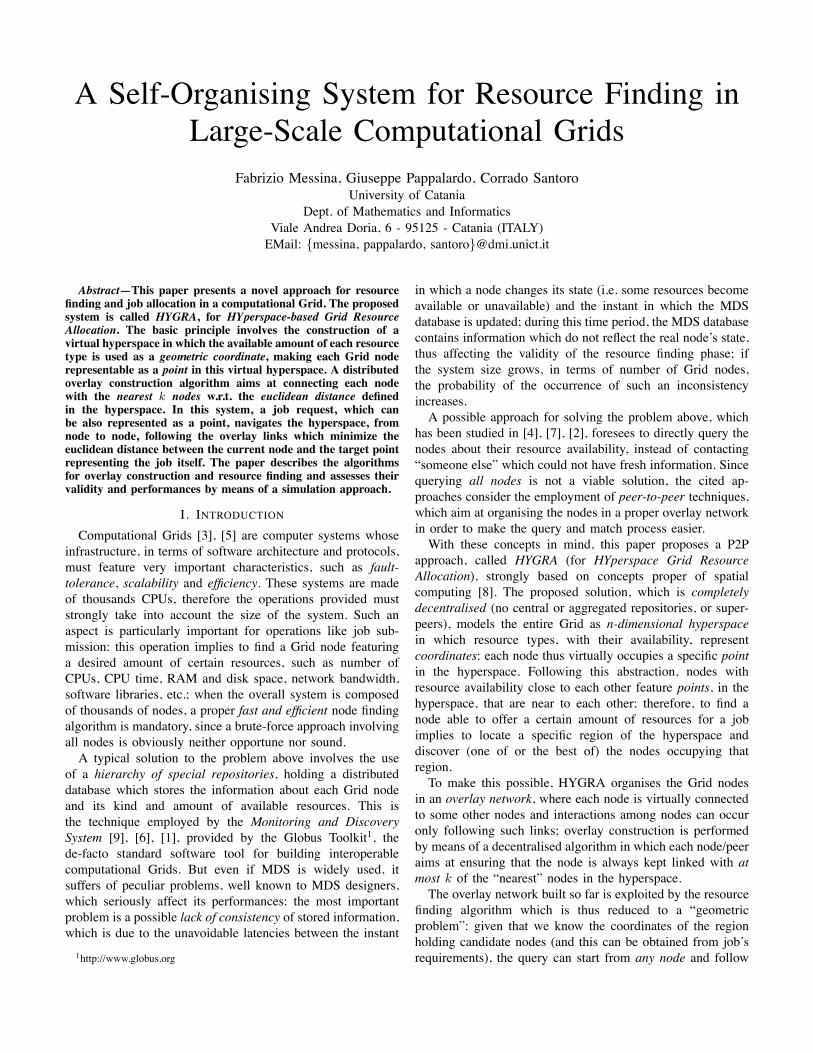
A Self-Organising System for Resource Finding inLarge-Scale Computational Grids
Fabrizio Messina, Giuseppe Pappalardo, Corrado SantoroUniversity of Catania
Dept. of Mathematics and InformaticsViale Andrea Doria, 6 - 95125 - Catania (ITALY)EMail: {messina, pappalardo, santoro}@dmi.unict.it
Abstract—This paper presents a novel approach for resourcefinding and job allocation in a computational Grid. The proposedsystem is called HYGRA, for HYperspace-based Grid ResourceAllocation. The basic principle involves the construction of avirtual hyperspace in which the available amount of each resourcetype is used as a geometric coordinate, making each Grid noderepresentable as a point in this virtual hyperspace. A distributedoverlay construction algorithm aims at connecting each nodewith the nearest k nodes w.r.t. the euclidean distance definedin the hyperspace. In this system, a job request, which canbe also represented as a point, navigates the hyperspace, fromnode to node, following the overlay links which minimize theeuclidean distance between the current node and the target pointrepresenting the job itself. The paper describes the algorithmsfor overlay construction and resource finding and assesses theirvalidity and performances by means of a simulation approach.
I. INTRODUCTIONComputational Grids [3], [5] are computer systems whose
infrastructure, in terms of software architecture and protocols,must feature very important characteristics, such as fault-tolerance, scalability and efficiency. These systems are madeof thousands CPUs, therefore the operations provided muststrongly take into account the size of the system. Such anaspect is particularly important for operations like job sub-mission: this operation implies to find a Grid node featuringa desired amount of certain resources, such as number ofCPUs, CPU time, RAM and disk space, network bandwidth,software libraries, etc.; when the overall system is composedof thousands of nodes, a proper fast and efficient node findingalgorithm is mandatory, since a brute-force approach involvingall nodes is obviously neither opportune nor sound.A typical solution to the problem above involves the use
of a hierarchy of special repositories, holding a distributeddatabase which stores the information about each Grid nodeand its kind and amount of available resources. This isthe technique employed by the Monitoring and DiscoverySystem [9], [6], [1], provided by the Globus Toolkit1, thede-facto standard software tool for building interoperablecomputational Grids. But even if MDS is widely used, itsuffers of peculiar problems, well known to MDS designers,which seriously affect its performances: the most importantproblem is a possible lack of consistency of stored information,which is due to the unavoidable latencies between the instant1http://www.globus.org
in which a node changes its state (i.e. some resources becomeavailable or unavailable) and the instant in which the MDSdatabase is updated; during this time period, the MDS databasecontains information which do not reflect the real node’s state,thus affecting the validity of the resource finding phase; ifthe system size grows, in terms of number of Grid nodes,the probability of the occurrence of such an inconsistencyincreases.A possible approach for solving the problem above, which
has been studied in [4], [7], [2], foresees to directly query thenodes about their resource availability, instead of contacting“someone else” which could not have fresh information. Sincequerying all nodes is not a viable solution, the cited ap-proaches consider the employment of peer-to-peer techniques,which aim at organising the nodes in a proper overlay networkin order to make the query and match process easier.With these concepts in mind, this paper proposes a P2P
approach, called HYGRA (for HYperspace Grid ResourceAllocation), strongly based on concepts proper of spatialcomputing [8]. The proposed solution, which is completelydecentralised (no central or aggregated repositories, or super-peers), models the entire Grid as n-dimensional hyperspacein which resource types, with their availability, representcoordinates: each node thus virtually occupies a specific pointin the hyperspace. Following this abstraction, nodes withresource availability close to each other feature points, in thehyperspace, that are near to each other; therefore, to find anode able to offer a certain amount of resources for a jobimplies to locate a specific region of the hyperspace anddiscover (one of or the best of) the nodes occupying thatregion.To make this possible, HYGRA organises the Grid nodes
in an overlay network, where each node is virtually connectedto some other nodes and interactions among nodes can occuronly following such links; overlay construction is performedby means of a decentralised algorithm in which each node/peeraims at ensuring that the node is always kept linked with atmost k of the “nearest” nodes in the hyperspace.The overlay network built so far is exploited by the resource
finding algorithm which is thus reduced to a “geometricproblem”: given that we know the coordinates of the regionholding candidate nodes (and this can be obtained from job’srequirements), the query can start from any node and follow

the links leading to nodes with minimum distance from thetarget region. Also in this case, the approach is completelydecentralised, since the peer receives the query, checks it and,if necessary, forwards it to a linked node until the target canbe found.The paper is structured as follows. Section II introduces the
basic concepts and symbols used later on in the descriptionof the HYGRA. Section III describes the system architecture.Section IV details the working scheme of HYGRA, reportingand explaining the overlay construction and resource findingalgorithms. Section V discusses the result of a simulation studyabout the performances of HYGRA. Section VI concludes thepaper.
II. BASIC HYGRA MODEL
To better explain the technique proposed in this paper,we first introduce a mathematical formulation with a setof symbols and relations that are used to model the Gridenvironment and the hyperspace, and helps the understandingof the HYGRA algorithms.
A. Model of Resource and Job RequestWe consider a Grid composed of n nodes; for each node i,
let si denote its state, meant to describe resource availabilityon i, at a certain time instant; assuming that, in the overallGrid, all nodes offers m different types of resources (say,CPU, memory, disk space, network, OS type, etc.), the statesi of a node will be a vector (ri,1, ri,2, . . . , ri,m); here eachcomponent ri,j represents the amount of resource j availableat node i.Let us define resource domains D1,D2, . . . ,Dm, mean-
ing that ri,j!Dj for i=1 . . . n, j=1 . . . m. If a resource ismeasured by a quantity, such as RAM, disk space, networkbandwidth or CPU time,Dj will be a numeric interval, rangingfrom a minimum to the maximum admissible resource amountover all nodes. If the resource is of a different kind, such asthe presence of a certain library or the availability of a certainlibrary version, Dj will be a set of values each describing apotential resource instance.In this system model, a job submission request, which
carries job’s requirements, is represented as the tuple q =((f1, q1), (f2, q2), . . . , (fm, qm)), where qj is the amount ofthe resource of type j requested by the job, and fj is apredicate used to match the requirement with the availability:we say that node n! can host a job carrying request q ifffj(rn!,j , qj) = true, "j ! 1, . . . ,m. We assume, without lossof generality, that predicate fj can be either the = or the #relation: the former means that the request and availabilitymust exactly match, while, in the latter case, the predicatesucceeds if the resource availability is greater than the resourcerequested2.Let us introduce an example to better explain the practical
usage of the symbols provided. We consider a Grid whosenodes possess the following resources: amount of RAM,
2These two predicates cover most cases of job allocation requests in a Grid.
number of CPU cores and GCC library version; let us sup-pose that there cannot be more than 8 GBytes RAM and8 cores per node, and that some nodes offer glibc version2.10.2 while others offer version 2.9.1. For this Grid, resourcedomains will be D1 = 0 . . . 8192 (assuming RAM is specifiedin Megabytes), D2 = 0 . . . 8 and D3 = {2.9.1, 2.10.2}.In this system, a request for a job that needs 3 cores, atleast 25 MBytes of RAM and glibc version 2.10.2 can berepresented as {(#, 25), (=, 3), (=, 2.10.2)}.
B. Model of the HyperspaceThe hyperspace model used by HYGRA starts from the
formulation introduced above, provided that a transformationis applied to domains not featured by a numeric value: for eachdomain Dj which is a finite set of known values, we associatea (natural) number to each of such values; as instance, domainD3 = {2.9.1, 2.10.2} of the example above can be remappedto D3 = {1, 2} = [1, 2] $ N.After this transformation, each domain is indeed a subset
of N or R, therefore we can construct a metric space (S, d),where S = D1 %D2 % . . .%Dm, elements are vectors v ! S,and the metric d is the euclidean distance. Each Grid node ifeatures a state si which (provided again the proper domaintransformation) becomes a vector of the metric space si ! S:in other words, we can say that a node i of the Grid, accordingto its state, represents a point in the hyperspace S.Following the same abstraction, in a job request q =
((f1, q1), (f2, q2), . . . , (fm, qm)), vector q = (q1, q2 . . . , qm)is also an element of S, and q, due to the presence ofthe predicates, determines a partition of S (or a semispace),S(q) $ S, made of all elements in S that satisfy predicatesfj :
S(q) = {v ! S : fj(vj , qj) = true "j ! 1, . . . ,m}
We call S(q) the admissible region for job q since any Gridnode i such that si ! S(q) is able to host the job. The aim ofHYGRA is to provide a decentralised approach to allow thediscovery of the nodes belonging to the admissible region ofa given job that needs to be allocated and executed.
III. HYGRA ARCHITECTUREFrom the software architecture point of view, HYGRA is
made by means of a multi-agent system. Since the overallstructure is based an overlay network, each Grid node runsa NODEAGENT holding three kind of information: (i) thestate si of the node; (ii) the set of references of otherNODEAGENTs, which belong to directly linked nodes of theoverlay3; and (iii) the state sj of each node j relevant todirectly linked NODEAGENTs.Each NODEAGENT can communicate with other
NODEAGENTs by exchanging the following types ofmessages:
3Of course such a reference may be an IP address, a couple IP/port, a FIPAagent name, etc. This is a matter of the implementation and its choice doesnot affect the architecture or the validity of the approach.

1) Job Allocation Request q. This message is sent from aNODEAGENT, which is not able to allocate the job, toa linked NODEAGENT selected according to a properforwarding policy detailed in Section IV.
2) State Change Notification. It is sent from theNODEAGENT of a node i to all the linkedNODEAGENTs when node’s state si changes to s!i(due to a new job arrival or the termination of theexecution of a running job); the message obviouslycarries information about the new state s!i.
3) 2-hop Status Query. This is a query message sentfrom the NODEAGENT of a node i to all its linkedNODEAGENTs and aims at obtaining the state sk of eachnode linked to all the nodes directly linked with i. Aproper 2-hop Status Reply message is expected followingthe transmission of this query.
4) Link Creation Notification. It is sent from aNODEAGENT i to a NODEAGENT j to informthe latter that i wants to be connected with j. After thereception of this message, NODEAGENT j updates itsset of directly linked agents by including also i.
5) Link Cut Notification. It is sent from a NODEAGENT ito a (connected) NODEAGENT j to inform the latter thatthe link i/j has to be destroyed. After the reception ofthis message, NODEAGENT j updates its set of directlylinked agents by removing i.
These messages are exchanged during the two main activ-ities of the NODEAGENTs, (i) overlay construction, whichaims at (self-)organising the overlay network in order toensure certain neighborhood properties; and (ii) job allocation,in which a job request has to be fulfilled by checking theavailability of resources of a node and, if this is not the case,properly forwarding the request to a linked NODEAGENT. Thedetails and algorithms of such activities are described in thefollowing Section.
IV. HYGRA WORKING SCHEMEAs reported above, the working scheme of HYGRA is based
on organising the Grid nodes in an overlay network featuring,in the metric space (S, d), a neighbourhood property based onthe euclidean distance. In particular, for each node i, giventhe set L(i) of the nodes directly connected with i, thesenodes are those which feature the minimal euclidean distanced(si, sk),!k " L(i). In other words, for each node i thefollowing property holds:
!k " L(i), # $sh " S, h #= k, h #" L(i) : d(si, sh) < d(si, sk)(1)
If the property above holds, the resulting overlay networkis a topological graph that can be traversed by means of e.g.a minimal path algorithm in order to find nodes belonging tothe admissible region.
A. Construction of the Overlay NetworkThe overlay construction technique is based on an
algorithm run by the NODEAGENTs which is regulated
by two parameters, degmin and degmax, respectivelythe minimum and maximum degree of each node4;therefore degmin, degmax " N, degmin < degmax anddegmin % |L(i)| % degmax,!i. The basic algorithm run bythe NODEAGENT of a generic node i can be summarised inthe following steps:
Algorithm 1 Overlay Construction
1) by sending 2-hop Status Messages to each node of L(i),build the set L!(i) = (L(i)&(&"j#L(i)L(j)))'{i}, thatis the set of directly linked and 2-hop linked nodes of i;
2) since the NODEAGENT now knows all the states ofnodes in L!(i) (i.e. their coordinates in the hyperspace),order nodes in L!(i) according to the distance to i (inascendant order), i.e. d(si, sk),!k " L!(i);
3) build the set L!!
(i) by taking at most the degmax firstnodes from L!(i); these will be the nodes in L!(i) whichare the nearest to i;
4) if L(i) = L!!
(i), i is still connected to the nearestpossible nodes, thus property (1) holds and the algorithmstops here.
5) connect node i with all nodes in L!!
(i); to this aim,disconnect, from i, nodes in L(i) ' L
!!
(i), by sendingthem a Link Cut Notification message and connect i withnodes in L
!!
(i)'L(i), by sending them a Link CreationNotification message; then update L(i) = L!!(i).
6) restart from step 1.
The basic principle of the overlay construction algorithmshould be quite clear: given any configuration of the overlaynetwork, at each step of the algorithm each node tends to beconnected to nodes that are nearer; this should be enough toensure that, sooner or later, property (1) will be met. In sucha case, condition in step 4 of algorithm 1 holds, meaning thatthe node has reached a stability; no more runs of the algorithmare needed unless the state si of the node changes due to thearrival of a new job or the termination of a running job: inthis case, since the node has changed its coordinates in thehyperspace, property (1) could no more hold and the rightlinks need to be re-created.Bootstrapping the overlay network is also a simple opera-
tion: a new node x which wants to join must know only oneexisting node of the network, k: it has to link itself with kand nodes in L(k), thus L(x) = k & L(k), and immediatelyrun Algorithm 1; at the first run, property (1) could not hold,but as soon as some steps of the construction algorithm areexecuted, a stable condition can be reached.In order to understand the behaviour of the overlay con-
struction technique, we built a software simulator, which isthen described in Section V. Figure 1 shows some screenshotstaken during the construction of the overlay following thealgorithm described and using a Grid featuring two typesof resources (in order to allow the representation of the4According the literature on graphs, the degree of a node (or vertex) is the
number of its links (edges) or its connected nodes.

(a) Initial condition (random) (b) After one step (c) Stable condition (after five steps)Fig. 1. Overlay network construction from a random initial condition
network in two dimensions). The degree coefficients, degmin
and degmax, are respectively set to 6 and 15. The initialcondition of the network, in which all links are randomly set,is shown in Figure 1a, while Figure 1b and Figure 1c showsthe network condition after respectively 1 and 5 iterations ofAlgorithm 1: the ability of the system to self-organise and tomeet property (1) is quite evident.Step 4 of Algorithm 1 reports a condition which, if met, en-
sures that the network, for what the single node is concerned,has reached a stability. The question is: can we ensure thatsooner or later this condition will hold? Or, in other words,does the algorithm terminate? While, by looking the individualbehaviour of the single node, at first sight the answer could bepositive, the situation is much more complex when the mutualinfluence between linked nodes is considered. Indeed, since thesame link connects two nodes, say i1 and i2, operations madeby the algorithm in i1 affect the behaviour of i2 and vice-versa. If we take into account such a mutual influence, on thebasis of the topological configuration of the nodes, during step5 of Algorithm 1 the following situations may happen:1) i2 ! L
!!
(i1) " deg(i2) = degmax; according to the firstcondition, the algorithm in i1 should connect i1 to i2,however, since the degree of i2 is already degmax, a newconnection would cause an overcome of the maximumdegree limit;
2) i2 ! L(i1) # L!!
(i1) " deg(i2) = degmin; the linkbetween i1 and i2 should be removed, but this operationwould cause the degree of i2 to go below degmin;
3) i2 ! L(i1) # L!!
(i1) " i1 ! L!!
(i2); in this case,the same link is considered completely different by eachnode since it needs to be removed for i1 but added for i2;the result is a sort of “local oscillation” of the algorithm.
A simple check on the degree of each node in L!!
(i)—resp.L(i)#L
!!
(i)—is able to easily solve situations 1 and 2: if theresulting degree is not between degmin and degmax, the nodeis not connected—resp. disconnected.The third situation is more hard to tackle: indeed both nodes
are in accordance with the algorithm and there is no way tochoose if the link must be removed or preserved. It should benoted that such a local oscillation does not provoke a loss ofconsistency of the overlay network: indeed property (1) is notviolated but the problem is only with a lack of efficiency due
to a wasting of computational power since Algorithm 1 runscontinuously without converging to a stable condition.The solution we employed to avoid this problem is based
on running a cycle of Algorithm 1 according to a certainprobability; exploiting a model similar to that of simulatedannealing, we associate to each node a virtual temperature ti,which is initially set to a maximum value Tmax and decreasesat each cycle (till reaching 0) unless the node changes itsstate: in this case, ti is reset again to Tmax. Therefore, acycle of Algorithm 1 runs with a probability Pi = ti
Tmax, thus
ensuring that, even if the algorithm starts locally oscillating,sooner or later (if the node does not changes its state) thisoscillation terminates and a stability is reached. According tothis optimisation, the final behaviour of each NODEAGENT isdescribed by the Algorithm 2 below:
Algorithm 2 Overlay Construction with Optimisation
1) Set ti = Tmax;2) Compute Pi = ti
Tmax;
3) Run one cycle of Algorithm 1 with probability Pi;4) if node i has changed its state si (due to job arrival orjob termination), set ti = Tmax;
5) otherwise set ti = ti # 1, unless ti is still 0;6) go to step 2;
B. Resource Finding and Job Allocation AlgorithmThe overlay construction algorithm described so far aims at
organising the network in order to ease the resource findingphase. Indeed, the resource finding algorithm is quite simpleand is based on check-and-forward policy: roughly speaking,once a node receives a job submission request, it checks if itcan fulfill it (i.e. the node belongs to the admissible region),otherwise the node forwards the request to the linked nodewhich is the nearest, according to its state, to the admissibleregion. The real algorithm is based on the principle above andapplies some peculiar strategies for the choice of the next node(when more than one of it are candidates) and for the recoverywhen a path leading to a “dead end” (i.e. a wrong path whichcannot lead to the admissible region) is followed.A request, which is carried by a Job Allocation Request
is represented by the tuple (q, P ), where P is the orderedsequence of nodes visited till now. The request is submitted to

any NODEAGENT of the Grid with P initially set to empty;when a NODEAGENT receives such a message, the followingalgorithm is executed:
Algorithm 3 Resource Finding
1) on the arrival of a job request (q, P ), check if the nodecan host the job, that is if fj(ri,j , qj) = true, !j "1, . . . ,m;
2) if the condition is met, allocate the job in node i andterminate the algorithm with success;
3) if the previous condition is not met, build the set L(i)#Pand check if the set N = (L(i)#P )$S(q) is not empty,i.e. determine the set of nodes in L(i)#P which belongto the admissible region;
4) if such a set is empty, select a node i! in L(i)#P whichminimises the distance d(si! , q);
5) if set N is not empty, select a node i! in N on the basisof an heuristic H(N) which is detailed below;
6) if one of the previous two steps is successful, and thusnode i! exists, we are approaching the admissible region,therefore update P ! = P % {i!} by concatenating i! tosequence P , and forward the request (q, P !) to node i!;
7) if L(i) # P = & there is no node that can allow therequest to approach the admissible region since all linkednodes have been already visited and the algorithm wouldend in a infinite circular loop; in this case there are twopossible causes: (i) the admissible region contains nonodes, or (ii) the path followed led to “local minimum”.Indeed, with the current knowledge, the NODEAGENThas no way to understand the real cause and it can onlysuppose that the path is wrong: maybe making a differentchoice could help in finding the target, therefore wefind, in the sequence P , the position of i and select theprevious node i!!. If such a node exists, the NODEAGENTforwards the request to i!!, otherwise (that is, i is the firstnode in P ) the algorithm terminates with a “node notfound” message, meaning that the job request cannot befulfilled.
If step 2 succeeds, the job has to be allocated on node i andthe amount of resources needed by the job must be grantedto it; in this case, the state of node i changes from si to s!i,the node occupies another point in the hyperspace, it becomes“hot” and overlay construction algorithm restarts in order to letthe network to re-organise itself. In a similar way, when a jobterminates its execution on a node, it releases all the resourcesneeded: also in this case the state of the node changes and arestart of the overlay construction algorithm is triggered.Step 5 of Algorithm 3 entails to select the next node
according to an heuristic; it is employed when, in proximityof the admissible region, the set L(i)#P contains more thanone node belonging to S(q), so the question is which one ofsuch nodes we have to select. To this aim, we have proposedand tested two different strategies:1) MaxFree, it selects the node that has the highest amount
of free resources; in order words, the further node, withrespect to q, is chosen;
2) BestFit, it selects the node that best fits the allocation,leaving the amount free resources nearer to zero; in otherwords, we choose the nearest node, with respect to q.
Admissible region for the request
Request submission
Local minimum
Fig. 2. A local minimum during resource finding
A final remark is needed to explain step 7. As it has beendetailed in Algorithm 3, since there is no global knowledgeor view of the network, there is no way, for a NODEAGENT,to understand if the admissible region is empty; the only factwhich can be deducted is that the NODEAGENT is no moreable to proceed further. However, as it is depicted in Figure 2,experimental results proved that such a condition occurs alsoin some extreme cases in which nodes are placed in pointssuch that a path, for a certain job request, seems to leadto the admissible region, but indeed reaches a “dead end”or, in other words, what we call a local minimum. To solvesuch conditions, a second choice is given to the algorithmby backtracing to a previous node of the path followed: adifferent branch of the graph is selected thus increasing theprobability to exit from the local minimum and reach theadmissible region. Obviously, if the admissible region is reallyempty, all the alternative branches selected would end in nodesstill visited and, sooner or later, the first node of the pathwill be reached again: after this, no choices will be left andtherefore the algorithm will end with a failure indication (byhigh probability).
V. PERFORMANCE EVALUATIONA. The SimulatorIn order to study the performance of HYGRA, we imple-
mented a software simulator. It is a time-driven simulationtool which is able to represent the behaviour of Grid nodes,modeling both the overlay construction and the resourcefinding algorithm, also simulating job allocation and execution.The tool is capable to simulate the flow of time by means ofdiscrete “ticks”. For each timer tick a) a step of the overlayconstruction algorithm is executed on all nodes; b) a step ofthe resource finding algorithm is executed for all the requestscirculating in the network; c) a bunch of new job requests isgenerated, on the basis of a frequency parameter specified inthe configuration file (see below); d) a check on the execution
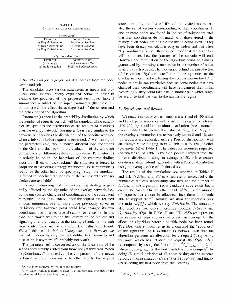
TABLE ICRITICAL SIMULATION PARAMETERS
System Load-Parameter- -Admitted values-
(a) Req.N.distribution Poisson or Random(b) Res.X.distribution Poisson or Random(c) Req.X.distribution Poisson or Random
Algorithm Behaviour-Parameter- -Admitted values-(d) strategy Backtracking or Stop
(e) node-selection ByID or ByCoordinates
of the allocated job is performed, deallocating from the nodeterminated jobs.The simulator takes various parameters as inputs and pro-
duces some indexes, briefly explained below, in order toevaluate the goodness of the proposed technique. Table Isummarises a subset of the input parameters (the most im-portant ones) that affect the average load of the system andthe behaviour of the algorithm.Parameter (a) specifies the probability distribution by which
the number of requests per tick will be sampled, while param-eter (b) specifies the distribution of the amount of resourcesover the overlay network5. Parameter (c) is very similar to theprevious but specifies the distribution of the specific resourcewhen a job submission request is generated. A well-tuning ofthe parameters (a-c) would induce different load conditionsin the Grid and thus permits the evaluation of the approachon the basis of different system configurations. Parameter (d)is strictly bound to the behaviour of the resource findingalgorithm. If set to “backtracking” the simulator is forced toadopt the backtracking strategy whenever a local minimum isfound; on the other hand, by specifying “Stop” the simulatoris forced to conclude the journey of the request whenever nochoices are available6.It’s worth observing that the backtracking strategy is gen-
erally affected by the dynamics of the overlay network, i.e.,by the unexpected changing of coordinates and the subsequentreorganization of links. Indeed, once the request has reacheda local minimum, one or more node previously saved inits history (the traversed path) could have changed its owncoordinates due to a resource allocation or releasing. In thiscase, our choice was to end the journey of the request andsignaling a failure, exactly as the totality of nodes in the pathwere visited back and no any alternative paths were found.We call this case the hole-in-history exception. However, weverified it occurs by very low probability, thus measuring anddiscussing it anymore it’s probably not worth.The parameter (e) is concerned about the discerning of the
set of nodes already visited from those not yet traversed. When“ByCoordinates” is specified, the comparison of the nodesis based on their coordinates. In other words, the request
5X has to be replaced by the id of the resource6The “Stop” variant is useful to assess the improvement provided by the
introduction of the backtracking strategy.
stores not only the list of IDs of the visited nodes, butalso the set of vectors corresponding to their coordinates. Ifone or more nodes are found in the set of neighbours suchthat their coordinates do not match with those stored in thehistory, such nodes are eligible for the selection even if theyhave been already visited. It is easy to understand that when“ByCoordinates” is set, there is no proof that the algorithmwill terminate, i.e., the journey of the capsule will end.However, the termination of the algorithm could be triviallyguaranteed by imposing a max value in the number of nodesvisited by each request. The motivation behind the introductionof the variant “ByCoordinates” is still the dynamics of theoverlay network. In fact, basing the comparison on the ID ofnodes might be too restrictive because some nodes that havechanged their coordinates, will have reorganised their links.Accordingly, they could take part in another path which mightbe useful to find the way to the admissible region.
B. Experiments and Results
We made a series of experiments on a test-bed of 100 nodesand two type of resources with a value ranging in the interval[100, 200] by a uniform random distribution (see parameter(b) of Table I). Moreover, the value of degm and degM forthe overlay construction are respectively set to 8 and 15, andjob requests are generated using a Poisson distribution, withan average value ranging from 20 jobs/tick to 150 jobs/tick(parameter (a) of Table I). The values for resources requested(parameter (c) of Table I) by each job are sampled from thePoisson distribution using an average of 50. Job executionduration is also randomly generated with a Poisson distributionusing an average value of 40 time ticks.The results of the simulations are reported in Tables II
and III. NAlloc and NFails represent, respectively, thenumber of requests successfully allocated, and the number offailures of the algorithm, i.e. a candidate node exists but itcannot be found. On the other hand, NRej is the numberof requests that cannot be allocated since there is no nodeable to support them7. Anyway we show for shortness onlythe ratio NFails
NAlloc, which we say FailRatio. The simulator
also produces two other interesting indexes, NSteps andOptimality (Opt. in Tables II and III). NSteps representsthe number of hops (nodes) performed, in average, by theallocation algorithm before a suitable node has been found.The Optimality index let us to understand the “goodness”of the algorithm and is evaluated as follows. Each time thealgorithm performs an allocation for a request q, say nalloc
the node which has satisfied the request, the Optimalityis computed by using the formula 1 ! d(nalloc,nbestSelection)
max(dist(ni,nj)),
where nbestSelection is the best candidate node computed bydoing (i) a total ordering of all nodes basing on the selectedresource finding strategy (BestF it or MaxFree), and finally(ii) selecting the best node from that ordering.
7Clearly, NAlloc + NRej = NReq.

C. Evaluation of Results
Table II and III show the results of the simulation study; herewe reported only the results of strategyMaxFree because, forall the indexes evaluated, it behaves quite better than BestF it.The first and most important remark to highlight is that the
number of failures in Table II is lower than that reported inTable III, showing the advantages of applying the backtrackingstrategy. Furthermore, the overall trend of fail-ratio in Table IIIcan even be considered low enough if compared to the totalnumber of requests (see “FailsRatio” in Table III).The second interesting parameter is the average number of
steps performed by the allocation algorithm, which reasonablyincreases with the increment of the job generation rate. Wehave to remark also that the performances of the “Backtrack-ing” strategy is comparable to that exploited by the “Stop”strategy in term of number of steps, in average, necessary toallocate a request.The last performance parameter to take into account is the
Optimality, that in our experiments appears to be independentof the job generation load8.Finally we have to report that even simulations were per-
formed also for the “ByCoordinates” variants, we do notinclude the related results here, because the improvement interm of performance is not so significant.
TABLE IISTRATEGY: BACKTRACKING / NODE-SELECTION: BYID
Jobs/Tick NFails Fails NSteps Opt. N.Req.(avg) Ratio (avg) (avg)20 0 0.0 6.26 0.61 497230 7 0.0014 35 0.66 504340 8 0.0016 67.52 0.66 495150 6 0.0012 57.32 0.63 498260 8 0.0017 94 0.63 473270 8 0.0016 86 0.61 504380 19 0.0040 99 0.59 4721100 24 0.0048 113 0.66 4996120 32 0.0064 102 0.61 5023150 34 0.0068 112 0.65 5012
TABLE IIISTRATEGY: STOP / NODE-SELECTION: BYID
Jobs/Tick Fails Fails NSteps Opt. N.Req.(avg) Ratio (avg) (avg)20 0 0.0 5 0.68 497830 12 0.002 38 0.67 507940 32 0.006 59 0.62 495150 30 0.009 65 0.64 498260 43 0.008 86 0.63 473270 54 0.0016 78 0.61 504380 72 0.0040 72 0.59 4721100 112 0.022 88 0.61 4996120 124 0.025 82 0.58 5023150 145 0.029 95 0.63 5012
8Therefore the algorithm, as for optimality, does not suffer of a performancedegradation due to increasing load conditions.
VI. CONCLUSIONSThis paper has described a novel technique, based on a self-
organising approach, for solving the problem of job alloca-tion/resource finding in large scale computational Grids. Theproposed system, called HYGRA, exploits spatial computingconcepts and maps the entire Grid system into an hyperspacewhere each node, according to the availability of its resources,virtually occupies a point in the hyperspace. A completelydecentralised algorithm, which exploits the euclidean distanceamong nodes, is able to self-organise an overlay networkwhere each node is virtually linked with some other nodes fea-ture a specific neighbourhood property. A check-and-forwardalgorithm is then employed during job submission to search,by surfing the overlay network, the node able to host at bestthe job, given its requirements. The proposed technique hasbeen evaluated by means of software tool, able to simulate notonly the behaviour of the algorithms but also the dynamics ofjob generation, submission and termination. Simulation results,provided in terms of computational cost, effectiveness andsensitivity with respect to Grid load conditions, have shownthe validity of the HYGRA system.
REFERENCES[1] K. Czajkowski, S. Fitzgerald, I. Foster, and C. Kesselman, “Grid In-
formation Services for Distributed Resource Sharing,” in 10thIEEEInternational Symposium on High-Performance Distributed Computing(HPDC 2001), San Francisco, August 6-9 2001.
[2] A. Di Stefano and C. Santoro, “A Peer-to-Peer Decentralized Strategyfor Resource Management in Computational Grids,” Concurrency &Computation: Practice & Experience, 2006.
[3] I. Foster and C. Kesselman, Eds., The Grid (2nd Edition): Blueprint fora New Computing Infrastructure. Morgan Kaufmann, 2004.
[4] A. Iamnitchi and I. Foster, “On Fully Decentralized Resource Discoveryin Grid Environments,” in International Workshop on Grid Computing2001, Denver, CO, Nov. 2001.
[5] D. Minoli, A Networking Approach to Grid Computing. Wiley Inter-Science, 2005.
[6] X. Z. J. Schopf, “Performance Analysis of the Globus Toolkit Monitoringand Discovery Service, MDS2,” in International Workshop on MiddlewarePerformance (MP 2004) at IPCCC 2004, April 2004.
[7] D. Talia and P. Trunfio, “Toward a Synergy Between P2P and Grids,”IEEE Internet Computing, vol. 7, no. 4, pp. 94–96, 2003.
[8] F. Zambonelli and M. Mamei, “Spatial Computing: an EmergingParadigm for Autonomic Computing and Communication,” in 1st In-ternational Workshop on Autonomic Communication, Berlin (Germany),October 2004.
[9] X. Zhang, J. Freschl, and J. Schopf, “A Performance Study of Monitoringand Information Services for Distributed Systems,” in 12thIEEE Interna-tional Symposium on High-Performance Distributed Computing (HPDC2003), Seattle, Washington, June 22-24 2003.

A Self-Organising Infrastructure forChemical-Semantic Coordination:
Experiments in TuCSoNElena Nardini Mirko Viroli Matteo Casadei Andrea Omicini
ALMA MATER STUDIORUM – Universita di Bologna(elena.nardini, mirko.viroli, m.casadei, andrea.omicini)@unibo.it
Abstract—Recent works proposed the adoption of a nature-
inspired approach of chemistry for implementing service archi-
tectures suitable for pervasive applications [34]. In particular,
[31] proposes a chemical-semantic tuple-space model where
coordination of data, devices and software agents – representing
the services of the pervasive computing application – are reified
into proper tuples managed by the coordination infrastructure.
Service coordination is enacted by chemical-like reactions that
semantically match those tuples accordingly enacting the desired
interaction patterns (composition, aggregation, competition, con-
textualisation, diffusion and decay).
After showing and motivating the proposed coordination
approach for situated, adaptive, and diversity-accomodating
pervasive computing systems, in this paper we outline how it is
possible to concretise the approach on the TuCSoN coordination
infrastructure, which can been suitably enhanced with modules
supporting fuzzy semantic-coordination and execution engine for
chemical-inspired coordination laws.
I. INTRODUCTION
The advent of ubiquitous wireless connectivity and comput-ing technologies like pervasive services and social networkswill re-shape the Information and Communication Technology(ICT) landscape. In particular, new devices with increasinginteraction capabilities will be exploited to create servicesable to inject and retrieve data from any location of the verydynamic and dense network that will pervade our everydayenvironments. Such a scenario calls for infrastructures promot-ing a concept of pervasive “eternality”: changes in topology,device technology, and continuous injection of new serviceshave to be dynamically incorporated with no significant re-engineering costs at the middleware level [35], [34]. In thiscontext, self-organisation – supporting situatedness, adaptivityand long-term accommodation of diversity – will increas-ingly be required as a key system-property for the system-component coordination.
Among the available metaphors – e.g. physical, chemical,biological, social [34] – used as a source of inspiration forself-organising computational mechanisms, here we focus onchemistry. In particular, we adopt the concept of chemical-semantic tuple-spaces introduced in [31] as a coordinationmodel, extending the standard tuple space model that is fre-quently adopted in middleware for situated and adaptive per-vasive computing [28], [12], [19], [20]. In chemical-semantictuple-spaces, tuples are seen as sort of species in a population,
and coordination laws taking the form of chemical reactionssemantically apply to such tuples and evolve them over time.Such an evolution behaviour promotes the exploitation of(natural or idealised) chemical reactions that are known tomake interesting self-organisation properties emerge [31].
This paper focusses on how a distributed architecture forchemical-semantic tuple-spaces can be implemented, namely,in terms of a coordination infrastructure providing the fabricof chemical tuples along with the stochastic and semantic ap-plication of chemical-like laws. As a basis for this implemen-tation we start from the TuCSoN coordination infrastructure[24] supporting the notion of semantic tuple-centre [21], i.e.programmable semantic tuple-space. In particular, TuCSoNpromotes a view of the tuple space as a set of facts in a logictheory, and its program as a set of rules dictating how thetuple set should evolve as time passes and as new interactionevents occur. TuCSoN appears a suitable means to enact thetwo basic ingredients necessary to implement chemical tuple-spaces in TuCSoN: (i) chemical-inspired stochastic evolutionof tuples, which is achieved by implementing the well-knownGillespie’s exact simulation algorithm [16] as a tuple spaceprogram, and (ii) fuzzy semantic-matching of chemical lawsagainst tuples in the space obtained seeing a tuple as anindividual of an ontology, and a reactant in the chemicalreaction as a concept of the ontology [17].
The remainder of this paper is organised as follows. SectionII motivates the proposed approach. Section III introduces thechemical-semantic coordination model and provides abstractexamples of coordination laws. Section IV describes how theTuCSoN coordination infrastructure can be tailored to supportthe proposed model. Finally, Section V outlines related worksin coordination and middleware for self-adaptive and self-organising systems, and Section VI concludes discussing aroadmap towards completing the development of the infras-tructure.
II. CHEMICAL-SEMANTIC TUPLE-SPACES FOR PERVASIVESERVICES
In order to better explain the motivation behind the modelpresented in this paper, we rely on a case study, which webelieve well represents a large class of pervasive computingapplications in the near future. We consider a pervasive display

infrastructure, used to surround our environments with digitaldisplays, from those in our wearable devices and domestichardware, to wide wall-mounted screens that already pervadeurban and working environments [13]. In particular, as areference domain, we consider an airport terminal filled withwide screens mounted in the terminal area, i.e in the shops, inthe corridors and in the gates, down to tiny screens installedin each seat of the gate areas or directly on passengers’ PDAs.
Situatedness. Information should be generally displayedbased on the current state of the surrounding physical andsocial environment like surrounding temperature sensors orpassenger profiles/preferences. Hence, services should be ableto interact with the surrounding physical and social world,accordingly adapting their behaviour.
Adaptivity. Complementary to the above, the displayinfrastructure, and the services within it, should be ableto automatically adapt to changes and contingencies in anautomatic way. For instance, when a great deal of newinformation to be possibly displayed emerges, the displayedinformation should overall spontaneously re-distribute andre-shape across the set of existing local displays.
Diversity. The service infrastructure should not limit thenumber and classes of services potentially provided, butrather taking advantage of the injection of new services byexploiting them to improve and integrate existing serviceswhenever possible. For example, the display infrastructurealso should be able to allow users – other than display owners– to upload information, like user private-content uploadedfrom her/his PDA, to displays so as to enrich the informationoffer or adapt it to their own needs.
As it is shown in many proposals for pervasive computingenvironments and middleware infrastructures, situatedness andadaptiveness are promoted by the adoption of shared virtualspaces for services and component interaction [28], [12], [19],[20], [31]. Among the various shared-virtual-space modelsproposed in literature, we adopt the chemical tuple-spacemodel [31], in which tuples – containing semantic informationabout the “entities” to be coordinated (services, devices, data)– evolve in a stochastic and spatial way through coordinationlaws resembling chemical reactions. We observe that thismodel can properly tackle the requirements sought for adaptivepervasive services.
Concerning situatedness, the current situation in a systemlocality is represented by the tuples existing in the tuplespace. Some of them can act as catalysts for specific chemicalreactions, thus making system evolution intrinsically context-dependent. Concerning adaptivity, it is known from biologythat some complex chemical systems are auto-catalytic (i.e.they produce their own catalyst), providing positive-negativefeedbacks that induce self-organisation [11] and lead to thespontaneous toleration of environment perturbations. Such sys-tems can be modelled by simple idealised chemical reactions
– e.g. prey-predator systems, Brussellator, and Oregonator[16] – regarded as a set of coordination laws for pervasiveservices. Finally, considering diversity, we note that chemicalreactions follow a simple pattern: they have some reactants(typically 1 or 2) which combine, resulting in a set of products,through a propensity (or rate) dictating the likelihood forthis combination to actually happen. Similarly to the naturalchemistry, in our framework this generates chemical reactionsthat can be instantiated for the specific and unforeseen servicesthat will be injected in the system over time, using semanticmatching.
Though key requirements seem to be supported in principle,designing the proper set of chemical reactions to regulatesystem behaviour is crucial. Without excluding the appropri-ateness of other solutions, in this paper we mostly rely onchemical reactions resembling laws of population dynamics as,e.g. the prey-predator system [16], [7]. This kind of idealisedchemical reactions has been successfully used to model auto-catalytic systems manifesting self-organisation properties: butmoreover, they can also nicely fit the “ecological” metaphorthat is often envisioned for pervasive computing systems [5],[30], [1], [34], [35]—namely, seeing pervasive services asspatially situated entities living in an ecosystem of otherservices and devices.
III. THE COORDINATION MODEL OFCHEMICAL-SEMANTIC TUPLE-SPACES
In this section, first we informally introduce the coordinationmodel of chemical-semantic tuple-spaces (Section III-A), thendescribe some example applications in the context of compet-itive pervasive services (Section III-B).
A. Coordination ModelThe chemical-semantic tuple-space model is an extension
of standard LINDA settings with multiple tuple spaces [15].A LINDA tuple space is simply described as a repositoryof tuples (structured data chunks like records) for thecoordination of external “agents”, providing primitives usedrespectively to insert, read, and remove a tuple. Tuplesare retrieved by specifying a tuple template—a tuple withwildcards in place of some of its arguments. The proposedmodel enhances this basic schema with the followingingredients.
Tuple concentration and chemical reactions. We attach aninteger value called “concentration” to each tuple, measuringthe pertinence/activity value of the tuple in the given tuplespace: the higher such a concentration, the more likelyand frequently the tuple will be retrieved and selectedby the coordination laws to influence system behaviour.Tuple concentration ‘spontaneously” evolves, as typicallythe pertinence of system activities is. This is achieved bycoordination rules in the form of chemical reactions—theonly difference with respect to standard chemical reactions isthat they now specify tuple templates instead of molecules.For example, a reaction “X + Y
0.1−−→ X +X” would mean

that tuples x and y matching X and Y are to be selected, getcombined, and as a result one concentration item of y turnsinto x—concentration of y decreases by one, concentrationof x increases by one. According to [16], this transition ismodelled as a Poisson event with average rate (i.e. frequency)0.1 × #x × #y (#x is the concentration of x). This modelmakes a tuple space running as a sort of exact chemicalsimulator, picking reactions probabilistically: external agentsobserving the evolution of tuples would perceive somethingequivalent to the corresponding natural/artificial chemicalsystem described by those reactions.
Semantic matching. It is easy to observe that standardsyntactic matching for tuple spaces can hardly deal with theopenness requirement of pervasive services, in the same way assyntactic match-making has been criticised for Web services[25]. This is because we want to express general reactionsthat apply to specific tuples independently of their syntacticstructure, which cannot be clearly foreseen at design time.Accordingly, semantic matching can be considered as a propermatching criterion for our coordination infrastructure [25], [4],[9].
It should be noted that matching details are orthogonalto our model, since the application at hand may require aspecific implementation of them—e.g. it strongly depends onthe description of application domain. As far as the model isconcerned, we only assume that matching is fuzzy [9], i.e.matching a tuple with a template returns a “vagueness” valuebetween 0 and 1, called match degree. Vagueness affects theactual application rate of chemical reactions: given a chemicalreaction with rate r, and assume reactants match some tupleswith degree 0.5, then the reaction can be applied to thosetuples with an actual rate of 0.5 ∗ r, implying a lower matchlikelyhood—since match is not perfect. Namely, the role ofsemantic matching in our framework is to allow for codinggeneral chemical laws that can uniformly apply to specificcases—appropriateness influences probability of selection.
Tuple transfer. We add a mechanism by which a (unit of con-centration of a) tuple can be allowed to move towards the tuplespace of a neighbouring node, thus generating a computationalfield, namely, a data structure distributed through the wholenetwork of tuple spaces. Accordingly, we introduce the notionof “firing” tuple (denoted t�), which is a tuple (producedby a reaction) scheduled for being sent to a neighbouringtuple space—any will be selected non-deterministically. Forinstance, the simple reaction “X 0.1−−→ X�” is used to transferitems of concentration of any tuple matching X out from thecurrent tuple space.
B. Examples
We now discuss some examples of chemical reactionsenacting general coordination patterns of interest for pervasiveservice systems.
Local competition. We initially consider a scenario in which asingle tuple space mediates the interactions between pervasiveservices and their users in an open and dynamic system. Weaim at enacting the following behaviour: (i) services that donot attract users fade until eventually disappearing from thesystem, (ii) successful services attract new users more andmore, and accordingly, (iii) overlapping services compete oneanother for survival, so that some/most of them eventuallycome to extinction.
An example protocol for service providers can be as follows.A tuple service is first inserted in the space to model pub-lication, specifying service identifier and semantic descriptionof the service content. Dually, a client inserts a specific requestas a tuple request—insertion is the (possibly implicit) actof publishing user preferences. The tuple space is charged withthe role of matching a request with a reply, creating a tupletoserve(service,request), combining a request anda reply semantically matching. Such tuples are read by theservice provider, which collects information about the request,serves it, and eventually produces a result emitted in the spacewith a tuple reply, which will be retrieved by the client. Theabstract rules we use to enact the described behaviour are asfollows:
(USE) SERV+ REQu�−→ SERV+ SERV+
toserve(SERV,REQ)
(DECAY) SERVd�−→ 0
On the left side (reactants), SERV is a template meant tomatch any service tuple, REQ a template matching any requesttuple; on the right side (products), toserve(SERV,REQ)will create a tuple having in the two arguments the serviceand request tuples selected, while 0 means there will beno product. Rule (USE) has a twofold role: (i) it firstselects a service and a request, it semantically matches themand accordingly creates a toserve tuple, and dynamicallyremoves the request; and (ii) it increases service concentration,so as to provide a positive feedback—resembling the prey-predator system described by Lotka-Volterra equations[7], [16]. We refer to use rate of a couple service/requestas u multiplied by the match degree of those reactantswhen applying (USE) law, as described in the previoussection: as a result, it can be noted that the higher thematch degree, the more likely a service and a requestare combined. On the other hand, rule (DECAY) makesany concentration item of the service tuple disappear atrate d, contrasting the positive feedback of (USE): here,the overall decay rate of a service is d multiplied by thematch degree—with no match, we would have no decay at all.
Spatial competition. This example can be extended to anetwork of tuple spaces, so as to emphasise the spatial andcontext-dependent character of competing services. Supposeeach space is programmed with (USE,DECAY) reactions plusa simple diffusion law for service tuples:
(DIFFUSE) SERVm�−→ SERV
�

The resulting system can be used to coordinate a pervasiveservice scenario in which a service is injected into a nodeof the network (e.g. the node where service is more urgentlyneeded, or where the producer resides), and accordingly startsdiffusing around on a step-by-step basis until possibly coveringthe whole network—hence becoming a global service. Thissituation is typical in the pervasive display infrastructure, sincea frequent policy for visualisation services would be to showthem on any display of the network—although more specificpolicies might be enacted to make certain services only locallydiffuse.
In this system, we can observe the dynamics by whichthe injection of a new and improved service may eventu-ally result in a complete replacement of previous versions—spatially speaking, the region where the new service is active isexpected to enlarge until covering the whole system, while theold service diminishes. In the context of visualisation services,for instance, this would amount to the situation where anexisting advertisement service is established, but a new onetargeted to the same users is injected that happens to havegreater use rate, namely, it is more appropriate for the averageprofile of users: we might expect this new service to overcomethe old one, which accordingly extinguishes.
IV. AN ARCHITECTURE BASED ON THE TuCSoNINFRASTRUCTURE
In this section we show that an infrastructure for the chemi-cal tuple space model can be implemented on top of an existingtuple space middleware, such as TuCSoN. In particular, after ageneral overview of TuCSoN (Section IV-A), we describe howthe two basic additional ingredients of the proposed model canbe supported on top of TuCSoN: semantic matching (SectionIV-B) and chemical engine (Section IV-C).
A. Overview of TuCSoNTuCSoN (Tuple Centres Spread over the Network) [24]
is a coordination infrastructure that manages the interactionspace of an agent-based system by means of ReSpecT [23]tuple centres, which are Linda tuple spaces [15] empoweredwith the ability to define their behaviour in response / re-action to communication events. Other than supporting thenotion of tuple centre, TuCSoN also extends Linda modelfrom the topology viewpoint. Differently from the [15] tuplespace model, TuCSoN has been conceived for providinga suitable infrastructural support for engineering distributedapplication scenarios [24]. In particular, tuple centres aredistributed through the network, hosted in the nodes of theinfrastructure, and organised into articulated domains, eachcharacterised by a gateway node and a set of nodes calledplaces. A place is meant to host tuple centres for the specificapplications/systems, while the gateway node is meant tohost tuple centres used for domain administration, keepinginformation on the places.
As discussed in [33], TuCSoN supports features thatare key for implementing self-organising systems, some ofwhich are here recapped that are useful for implementing the
chemical tuple space model:
Topology and locality. Tuple centres can be created locallyto a specific node, and the gateway tuple centre can beprogrammed to keep track of which tuple centres reside inthe neighbourhood—accessible either by agents or by tuplecentres in current node.
On-line character and time. TuCSoN supports the so called“on-line coordination services”, executed by reactions that arefired in the background of normal agent interactions, throughtimed reactions.
Probability. Probability is a key feature of self-organisation,which is necessary to abstractly deal with the unpredictabilityof contingencies in pervasive computing. In TuCSoN this issupported by drawing random numbers and using them to drivethe reaction firing process, that is, making tuple transformationbe intrinsically probabilistic.
B. Semantic Matching
We now describe the extension of the tuple centre modelthat allows us to perform semantic reasoning over tuples,namely, the ability of matching a tuple with respect to atemplate not only syntactically as usual, but also semantically.In spite some approaches have been proposed to add semanticreasoning to tuple spaces [22], we here introduce a differentmodel, which is aimed at smoothly extending the standardsettings of tuple spaces [21].
Abstract model. From an abstract viewpoint, a tuple centrecan be seen as a knowledge repository structured as a setof tuples. According to a semantic view, such knowledgerepresents a set of objects occurring in the application domain,whose meaning is described by an ontology, that is, in termsof concepts and relations among them.
In order to formally define the notions of domain ontol-ogy and objects, the literature makes available a family ofknowledge representation formalisms called Description Log-ics (DL) [2]—we rely on SHOIN(D) Description Logic, whichrepresents the theoretical counterpart of W3C’s standard OWLDL [17]. In DL, an ontology component called TBox is firstintroduced that includes the so-called terminological axioms:concept descriptions (denoting meaningful sets of individualsof the domain), and role descriptions (denoting relationshipsamong individuals). Concepts can be of the following kinds:� is the set of all objects, ⊥ the void set, C �D is union ofconcepts, C �D intersection, ¬D negation, {i1, . . . , in} is aset of individuals, ∀R.C is the set of objects that are in relation(through role R) with only objects belonging to concept C,∃R.C is the set of objects that are in relation (through role R)with at least one object belonging to concept C, and ≤ nRis the set of objects that are in relation (through role R) withno more than n objects (and similarly for concepts ≥ nR and= nR). Given these constructs, the TBox provides axioms

for expressing inclusion of concepts (C � D). For instance, aTBox for a car domain [9] can provide the following assertions
MaxSpeed � {90km/h,180km/h,220km/h,280km/h}
Car � (= 1hasMaxSpeed)(= 1hasMaxSpeed) � Car
� � ∃ hasMaxSpeed .MaxSpeedSlowCar � Car � (∃ hasMaxSpeed .{90km/h})CityCar � SlowCar
which respectly: (i) defines the concept MaxSpeed as including4 individuals, (ii) defines the concept Car and states that allits objects have precisely one maximum speed value, (iii)conversely states that any object with one maximum speedvalue is a car, (iv) states that maximum speed value is anobject of MaxSpeed, (v) defines SlowCar as a new concept(sub-concept of Car) such that its individuals have 90km/h
as maximum speed, and finally (vi) defines a CityCar as a kindof slow car—possibly to be completed with other features, e.g.being slow, compact and possibly featuring electric battery.By these kinds of inclusion, which are typical of the OWLstandard approach, one can flexibly provide suitable definitionsfor concepts of sport cars, city cars, and so on.
Another component of DL is the so-called ABox, definingaxioms to assert specify domain objects and their properties:they can be of kind C(a), declaring individual a and theconcept C it belongs to, and of kind R(a, b), declaringthat role R relates individual a with b. Considering the cardomain example, the ABox could include axioms Car(f40),Car(fiat500), hasMaxSpeed(f40,280km/h), andhasMaxSpeed(fiat500,90km/h).
Semantic reasoning of DL basically amounts – among theothers – to check whether an individual belongs to a concept,namely, the so-called semantic matching. As a simple example,a DL checker could verify that fiat500 is an instance ofCityCar. This contrasts syntactic matching, which would havefailed since Car and CityCar are two “types” that do notsyntactically match—they rather semantically match due tothe definitions in the TBox.
Given the above concepts of DL, we design the semanticextension of tuple centres by the following ingredients, whichwill be described in more detail in turn: (ontologies) anontology has to be attached to a tuple centre, so as to groundthe definition of concepts required to perform semanticreasoning; (semantic tuples) a semantic tuple represents anindividual, and a language is hence to be introduced tospecify individual’s name, the concept it belongs to, andthe individuals it is related to by roles; (tuple templates)templates are to be used to flexibly retrieve tuples, hence welink the semantic tuple template notion with that of concept inthe ontology, and accordingly introduce a template language;(matching mechanism) matching simply amounts to checkwhether the tuple is an instance of the concept describedby the template, providing a match factor in between 0 and1. In order to give a “fuzzy” notion of matching we take
inspiration from the work shown in [9] – describing a fuzzyextension of DL – introducing the notion of degree (a numberin between 0 and 1) into the language of tuples and templates.
Ontology language. In our implementation we adopt theOWL [17] ontology language in order to define domainontologies in TuCSoN. OWL is an XML-based ontologylanguage introduced by W3C for the Semantic Web: relyingon a standard language for ontologies is key for the opennessaims of the application domains considered in this paper,and moreover, standard automated reasoning techniques canbe exploited relying on existing open source tools—like e.g.Pellet reasoner [29]. Accordingly, each tuple centre carriesan OWL ontology describing the TBox, and that internalmachinery can be easily implemented so as to query andsemantically reason about it.
Semantic tuple language. Instead of completely depart-ing from the syntactic setting of TuCSoN, where tu-ples are expressed as first-order terms, we design asmooth extension of it, so as to capture a ratherlarge set of situations. The car domain example de-scribed above would be expressed by the semantic tuplefiat500:’Car’(hasMaxSpeed:’90km/h’). Namely,the tuple describes individual name, concept name, and listof role fillers—extending the case of first-order tuples, whereeach tuple is basically the specification of a “type” (functorname) followed by an ordered list of parameters. By exploitingthe definition of degree introduced in [9], we can also write:
f40:’SportCar’->0.8(
hasMaker : ferrari->0.8,
hasMaxSpeed : ’285km/h’,
hasColour in {red->0.3,
black->0.7})
where “->N” represents the degree of belonging of anindividual to a concept or to a relationship with otherindividuals. Where a “->N” is not defined, the degree is 1.Note that semantic tuples are basically first-order terms withthe introduction of few infix binary functors (“:”, “in” and“->”).
Semantic templates language. Another aspect to be facedconcerns the representation of semantic tuple templates asspecifications of sets of domain individuals (concepts) amongwhich a matching tuple is to be retrieved. The grammar oftuple templates we adopt basically turns DL concepts into aterm-like syntax (as in Prolog), extended with the possibilityto associate to each concept a degree representing how muchindividuals belong to a particular concept and to describe a
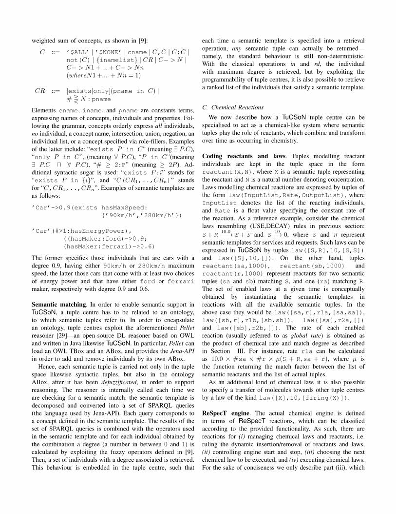
weighted sum of concepts, as shown in [9]:
C ::= ’$ALL’ | ’$NONE’ | cname | C,C | C;C |not(C) | {inamelist} | CR | C− > N |C− > N1 + ...+ C− > Nn(whereN1 + ...+Nn = 1)
CR ::= [exists|only](pname in C) |# � N : pname
Elements cname, iname, and pname are constants terms,expressing names of concepts, individuals and properties. Fol-lowing the grammar, concepts orderly express all individuals,no individual, a concept name, intersection, union, negation, anindividual list, or a concept specified via role-fillers. Examplesof the latter include: “exists P in C” (meaning ∃ P.C),“only P in C”, (meaning ∀ P.C), “P in C”(meaning∃ P.C � ∀ P.C), “# ≥ 2:P” (meaning ≥ 2P ). Ad-ditional syntactic sugar is used: “exists P:i” stands for“exists P in {i}”, and “C(CR1,..,CRn)” standsfor “C,CR1,..,CRn”. Examples of semantic templates areas follows:
’Car’->0.9(exists hasMaxSpeed:
{’90km/h’,’280km/h’})
’Car’(#>1:hasEnergyPower),
((hasMaker:ford)->0.9;
(hasMaker:ferrari)->0.6)
The former specifies those individuals that are cars with adegree 0.9, having either 90km/h or 280km/h maximumspeed, the latter those cars that come with at least two choicesof energy power and that have either ford or ferrari
maker, respectively with degree 0.9 and 0.6.
Semantic matching. In order to enable semantic support inTuCSoN, a tuple centre has to be related to an ontology,to which semantic tuples refer to. In order to encapsulatean ontology, tuple centres exploit the aforementioned Pelletreasoner [29]—an open-source DL reasoner based on OWLand written in Java likewise TuCSoN. In particular, Pellet canload an OWL TBox and an ABox, and provides the Jena-APIin order to add and remove individuals by its own ABox.
Hence, each semantic tuple is carried not only in the tuplespace likewise syntactic tuples, but also in the ontologyABox, after it has been defuzzificated, in order to supportreasoning. The reasoner is internally called each time weare checking for a semantic match: the semantic template isdecomposed and converted into a set of SPARQL queries(the language used by Jena-API). Each query corresponds toa concept defined in the semantic template. The results of theset of SPARQL queries is combined with the operators usedin the semantic template and for each individual obtained bythe combination a degree (a number in between 0 and 1) iscalculated by exploiting the fuzzy operators defined in [9].Then, a set of individuals with a degree associated is retrieved.This behaviour is embedded in the tuple centre, such that
each time a semantic template is specified into a retrievaloperation, any semantic tuple can actually be returned—namely, the standard behaviour is still non-deterministic.With the classical operations in and rd, the individualwith maximum degree is retrieved, but by exploiting theprogrammability of tuple centres, it is also possible to retrievea ranked list of the individuals that satisfy a semantic template.
C. Chemical ReactionsWe now describe how a TuCSoN tuple centre can be
specialised to act as a chemical-like system where semantictuples play the role of reactants, which combine and transformover time as occurring in chemistry.
Coding reactants and laws. Tuples modelling reactantindividuals are kept in the tuple space in the formreactant(X,N), where X is a semantic tuple representingthe reactant and N is a natural number denoting concentration.Laws modelling chemical reactions are expressed by tuples ofthe form law(InputList,Rate,OutputList), whereInputList denotes the list of the reacting individuals,and Rate is a float value specifying the constant rate ofthe reaction. As a reference example, consider the chemicallaws resembling (USE,DECAY) rules in previous section:S+ R
10.0−−→ S+ S and S10−→ 0, where S and R represent
semantic templates for services and requests. Such laws can beexpressed in TuCSoN by tuples law([S,R],10,[S,S])and law([S],10,[]). On the other hand, tuplesreactant(sa,1000), reactant(sb,1000) andreactant(r,1000) represent reactants for two semantictuples (sa and sb) matching S, and one (ra) matching R.The set of enabled laws at a given time is conceptuallyobtained by instantiating the semantic templates inreactions with all the available semantic tuples. In theabove case they would be law([sa,r],r1a,[sa,sa]),law([sb,r],r1b,[sb,sb]), law([sa],r2a,[])
and law([sb],r2b,[]). The rate of each enabledreaction (usually referred to as global rate) is obtained asthe product of chemical rate and match degree as describedin Section III. For instance, rate r1a can be calculatedas 10.0 × #sa × #r × µ(S + R,sa + r), where µ isthe function returning the match factor between the list ofsemantic reactants and the list of actual tuples.
As an additional kind of chemical law, it is also possibleto specify a transfer of molecules towards other tuple centresby a law of the kind law([X],10,[firing(X)]).
ReSpecT engine. The actual chemical engine is definedin terms of ReSpecT reactions, which can be classifiedaccording to the provided functionality. As such, there arereactions for (i) managing chemical laws and reactants, i.e.ruling the dynamic insertion/removal of reactants and laws,(ii) controlling engine start and stop, (iii) choosing the nextchemical law to be executed, and (iv) executing chemical laws.For the sake of conciseness we only describe part (iii), which
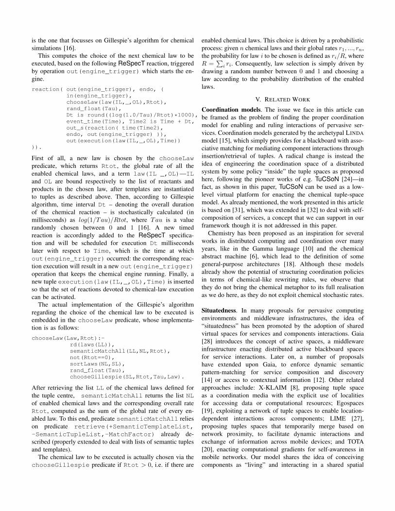
is the one that focusses on Gillespie’s algorithm for chemicalsimulations [16].
This computes the choice of the next chemical law to beexecuted, based on the following ReSpecT reaction, triggeredby operation out(engine_trigger) which starts the en-gine.reaction( out(engine_trigger), endo, (
in(engine_trigger),
chooseLaw(law(IL,_,OL),Rtot),
rand_float(Tau),
Dt is round((log(1.0/Tau)/Rtot)*1000),
event_time(Time), Time2 is Time + Dt,
out_s(reaction( time(Time2),
endo, out(engine_trigger) )),
out(execution(law(IL,_,OL),Time))
)).
First of all, a new law is chosen by the chooseLaw
predicate, which returns Rtot, the global rate of all theenabled chemical laws, and a term law(IL _,OL)—IL
and OL are bound respectively to the list of reactants andproducts in the chosen law, after templates are instantiatedto tuples as described above. Then, according to Gillespiealgorithm, time interval Dt – denoting the overall durationof the chemical reaction – is stochastically calculated (inmilliseconds) as log(1/Tau)/Rtot, where Tau is a valuerandomly chosen between 0 and 1 [16]. A new timedreaction is accordingly added to the ReSpecT specifica-tion and will be scheduled for execution Dt millisecondslater with respect to Time, which is the time at whichout(engine_trigger) occurred: the corresponding reac-tion execution will result in a new out(engine_trigger)
operation that keeps the chemical engine running. Finally, anew tuple execution(law(IL,_,OL),Time) is insertedso that the set of reactions devoted to chemical-law executioncan be activated.
The actual implementation of the Gillespie’s algorithmregarding the choice of the chemical law to be executed isembedded in the chooseLaw predicate, whose implementa-tion is as follows:chooseLaw(Law,Rtot):-
rd(laws(LL)),
semanticMatchAll(LL,NL,Rtot),
not(Rtot==0),
sortLaws(NL,SL),
rand_float(Tau),
chooseGillespie(SL,Rtot,Tau,Law).
After retrieving the list LL of the chemical laws defined forthe tuple centre, semanticMatchAll returns the list NLof enabled chemical laws and the corresponding overall rateRtot, computed as the sum of the global rate of every en-abled law. To this end, predicate semanticMatchAll relieson predicate retrieve(+SemanticTemplateList,
-SemanticTupleList,-MatchFactor) already de-scribed (properly extended to deal with lists of semantic tuplesand templates).
The chemical law to be executed is actually chosen via thechooseGillespie predicate if Rtot > 0, i.e. if there are
enabled chemical laws. This choice is driven by a probabilisticprocess: given n chemical laws and their global rates r1, ..., rn,the probability for law i to be chosen is defined as ri/R, whereR =
�i ri. Consequently, law selection is simply driven by
drawing a random number between 0 and 1 and choosing alaw according to the probability distribution of the enabledlaws.
V. RELATED WORK
Coordination models. The issue we face in this article canbe framed as the problem of finding the proper coordinationmodel for enabling and ruling interactions of pervasive ser-vices. Coordination models generated by the archetypal LINDAmodel [15], which simply provides for a blackboard with asso-ciative matching for mediating component interactions throughinsertion/retrieval of tuples. A radical change is instead theidea of engineering the coordination space of a distributedsystem by some policy “inside” the tuple spaces as proposedhere, following the pioneer works of e.g. TuCSoN [24]—infact, as shown in this paper, TuCSoN can be used as a low-level virtual platform for enacting the chemical tuple-spacemodel. As already mentioned, the work presented in this articleis based on [31], which was extended in [32] to deal with self-composition of services, a concept that we can support in ourframework though it is not addressed in this paper.
Chemistry has been proposed as an inspiration for severalworks in distributed computing and coordination over manyyears, like in the Gamma language [10] and the chemicalabstract machine [6], which lead to the definition of somegeneral-purpose architectures [18]. Although these modelsalready show the potential of structuring coordination policiesin terms of chemical-like rewriting rules, we observe thatthey do not bring the chemical metaphor to its full realisationas we do here, as they do not exploit chemical stochastic rates.
Situatedness. In many proposals for pervasive computingenvironments and middleware infrastructures, the idea of“situatedness” has been promoted by the adoption of sharedvirtual spaces for services and components interactions. Gaia[28] introduces the concept of active spaces, a middlewareinfrastructure enacting distributed active blackboard spacesfor service interactions. Later on, a number of proposalshave extended upon Gaia, to enforce dynamic semanticpattern-matching for service composition and discovery[14] or access to contextual information [12]. Other relatedapproaches include: X-KLAIM [8], proposing tuple spaceas a coordination media with the explicit use of localitiesfor accessing data or computational resources; Egospaces[19], exploiting a network of tuple spaces to enable location-dependent interactions across components; LIME [27],proposing tuples spaces that temporarily merge based onnetwork proximity, to facilitate dynamic interactions andexchange of information across mobile devices; and TOTA[20], enacting computational gradients for self-awareness inmobile networks. Our model shares the idea of conceivingcomponents as “living” and interacting in a shared spatial

substrate (of tuple spaces) where they can automaticallydiscover and interact with one another. Yet, our aim isbroader, namely, to dynamically and systemically enforcesituatedness, service interaction, and data management with asimple language of chemical reactions, and most importantly,enacting an ecological behaviour thanks to the support ofdiversity in the long term.
Self-organisation. Several recent works exploit the lessons ofadaptive self-organising natural and social systems to enforceself-awareness, self-adaptivity, and self-management featuresin distributed and pervasive computing systems. At the level ofinteraction models, these proposals typically take the form ofspecific nature- and socially inspired interaction mechanisms[3] (e.g. pheromones [26] or virtual fields [20]), enforcedeither at the level of component modelling or via specificmiddleware-level mechanisms. We believe our framework in-tegrates and improves these works in two main directions: (i)it tries to identify an interaction model that is able to representand subsume the diverse nature-inspired mechanisms via aunifying self-adaptive abstraction (i.e. the semantics chemicalreactions); (ii) the “ecological” approach we undertake goesbeyond most of the current studies that limit to ensemblesof homogeneous components, supporting the vision of novelpervasive and Internet scenarios as a sort of cyber-organisms[1].
VI. ROADMAP AND CONCLUSION
In this paper we described research and development chal-lenges in the implementation of the chemical tuple spacemodel in TuCSoN. These are routed in two basic dimensions,which are mostly – but not entirely – orthogonal.
On the one hand, the basic tuple centre model is to beextended to handle semantic matching, which we supportby the following ingredients: (i) an OWL ontology (a setof definitions of concepts) stored into a tuple centre whichgrounds semantic matching; (ii) tuples (other than syntacticas usual) can be semantic, describing an individual of theapplication domain (along with the concept it belongs toand the individuals it is linked to through roles); and (iii)a matching function implemented so as to check whether atuple is the instance of a concept, returning the correspondingmatch factor.
On the other hand, the coordination specification for the tu-ple centre should act as a sort of “online chemical simulator”,evolving the concentration of tuples over time using the samestochastic model of chemistry [16], so as to reuse existingnatural and artificial chemical systems (like prey-predatorequations); at each step of the process: (i) the reaction rates ofall the chemical laws are computed, (ii) one is probabilisticallyselected and then executed, (iii) the next step of the processis triggered after an exponentially distributed time interval,according to the Markov property.
The path towards a fully featured and working infrastructurehas been paved, but further research and development is
required to tune several aspects:
Match factor. Studying suitable fuzzy matching techniquesis currently a rather hot research topic, e.g. in the SemanticWeb context. Our current support trades off simplicity forexpressive power, but we plan to extend it using some morecomplete approach and in light of the application to selectedcases—e.g. fully relying on [9].
Performance. The problem of performance was notconsidered yet, but will be subject of our future investigation.Possible bottlenecks include the chemical model and itsimplementation as a ReSpecT program, but also semanticretrieval, which is seemingly slower than standard syntacticone. We still observe that in many scenarios of pervasivecomputing this is not a key issue.
Chemical language. Developing a suitable language forsemantic chemical laws is a rather challenging issue. Thedesign described in this paper supports limited forms ofservice interactions that will likely be extended in the future.For instance, a general law X + Y → Z is meant to combinetwo individuals into a new one, hence the chemical languageshould be able to express into Z how the semantic templatesX and Y should combine—aggregation, contextualisation,and other related patterns of self-organising pervasive systemsare to be handled at this level.
Application cases. The model, and correspondingly the im-plementation of the infrastructure, are necessarily to be tunedafter evaluation of selected use cases can be performed.Accordingly, the current version of the infrastructure is meantto be a prototype over which initial sperimentation can beperformed. A main application scenario we will considered foractual implementation is a general purpose pervasive displayinfrastructure.
REFERENCES
[1] G. Agha. Computing in pervasive cyberspace. Commun. ACM, 51(1):68–70, 2008.
[2] F. Baader, D. Calvanese, D. L. McGuinness, D. Nardi, and P. F.Patel-Schneider, editors. The Description Logic Handbook: Theory,Implementation, and Applications. Cambridge University Press, 2003.
[3] O. Babaoglu, G. Canright, A. Deutsch, G. A. D. Caro, F. Ducatelle, L. M.Gambardella, N. Ganguly, M. Jelasity, R. Montemanni, A. Montresor,and T. Urnes. Design patterns from biology for distributed computing.ACM Trans. Auton. Adapt. Syst., 1(1):26–66, 2006.
[4] A. Bandara, T. R. Payne, D. D. Roure, N. Gibbins, and T. Lewis.A pragmatic approach for the semantic description and matching ofpervasive resources. In Advances in Grid and Pervasive Computing,volume 5036 of LNCS, pages 434–446. Springer, 2008.
[5] A. P. Barros and M. Dumas. The rise of web service ecosystems. ITProfessional, 8(5):31–37, 2006.
[6] G. Berry and G. Boudol. The chemical abstract machine. TheoreticalComputer Science, 96(1):217–248, apr 1992.
[7] A. A. Berryman. The origins and evolution of predator-prey theory.Ecology, 73(5):1530–1535, October 1992.
[8] L. Bettini, R. De Nicola, and M. Loreti. Implementing Mobile andDistributed Applications in X-Klaim. Scalable Computing: Practice andExperience, Special Issue: Software Agent Mobility, 7(4):13–35, 2006.

[9] F. Bobillo and U. Straccia. fuzzyDL: An expressive fuzzy descriptionlogic reasoner. In 2008 International Conference on Fuzzy Systems(FUZZ-08), pages 923–930. IEEE Computer Society, 2008.
[10] J.-P. Bonatre and D. Le Metayer. Gamma and the chemical reactionmodel: Ten years after. In Coordination Programming, pages 3–41.Imperial College Press London, UK, 1996.
[11] S. Camazine, J.-L. Deneubourg, N. R. Franks, J. Sneyd, G. Theraulaz,and E. Bonabeau. Self-Organization in Biological Systems. PrincetonStudies in Complexity. Princeton University Press, Princeton, NJ, USA,2001.
[12] P. D. Costa, G. Guizzardi, J. P. A. Almeida, L. F. Pires, and M. van Sin-deren. Situations in conceptual modeling of context. In Tenth IEEE Inter-national Enterprise Distributed Object Computing Conference (EDOC2006), 16-20 October 2006, Hong Kong, China, Workshops, page 6.IEEE Computer Society, 2006.
[13] A. Ferscha, A. Riener, M. Hechinger, and H. Schmitzberger. Buildingpervasive display landscapes with stick-on interfaces. In CHI Workshopon Information Visualization and Interaction Techniques, April 2006.
[14] C.-L. Fok, G.-C. Roman, and C. Lu. Enhanced coordination in sensornetworks through flexible service provisioning. In J. Field and V. T.Vasconcelos, editors, Coordination Languages and Models, volume 5521of LNCS, pages 66–85. Springer-Verlag, June 2009. 11th InternationalConference (COORDINATION 2009), Lisbon, Portugal, June 2009.Proceedings.
[15] D. Gelernter. Generative communication in linda. ACM Trans. Program.Lang. Syst., 7(1):80–112, 1985.
[16] D. T. Gillespie. Exact stochastic simulation of coupled chemicalreactions. The Journal of Physical Chemistry, 81(25):2340–2361, 1977.
[17] I. Horrocks, P. F. Patel-Schneider, and F. V. Harmelen. From shiq andrdf to owl: The making of a web ontology language. Journal of WebSemantics, 1:2003, 2003.
[18] P. Inverardi and A. L. Wolf. Formal specification and analysis ofsoftware architectures using the chemical abstract machine model. IEEETrans. Software Eng., 21(4):373–386, 1995.
[19] C. Julien and G.-C. Roman. Egospaces: Facilitating rapid developmentof context-aware mobile applications. IEEE Trans. Software Eng.,32(5):281–298, 2006.
[20] M. Mamei and F. Zambonelli. Programming pervasive and mobilecomputing applications: the TOTA approach. ACM Trans. SoftwareEngineering and Methodology, 18(4), 2009.
[21] E. Nardini, M. Viroli, and E. Panzavolta. Coordination in open anddynamic environments with TuCSoN semantic tuple centres. In S. Y.Shin, S. Ossowski, M. Schumacher, M. Palakal, C.-C. Hung, andD. Shin, editors, 25th Annual ACM Symposium on Applied Computing(SAC 2010), volume III, pages 2037–2044, Sierre, Switzerland, 22–26 Mar. 2010. ACM. Awarded as Best Paper.
[22] L. j. b. Nixon, E. Simperl, R. Krummenacher, and F. Martin-recuerda.Tuplespace-based computing for the semantic web: A survey of the state-of-the-art. Knowl. Eng. Rev., 23(2):181–212, 2008.
[23] A. Omicini. Formal ReSpecT in the A&A perspective. ElectronicNotes in Theoretical Computer Sciences, 175(2):97–117, June 2007.
[24] A. Omicini and F. Zambonelli. Coordination for Internet applicationdevelopment. Autonomous Agents and Multi-Agent Systems, 2(3):251–269, Sept. 1999.
[25] M. Paolucci, T. Kawamura, T. R. Payne, and K. P. Sycara. Semanticmatching of web services capabilities. In International Semantic WebConference, volume 2342 of LNCS, pages 333–347. Springer, 2002.
[26] H. V. D. Parunak, S. Brueckner, and J. Sauter. Digital pheromonemechanisms for coordination of unmanned vehicles. In AutonomousAgents and Multiagent Systems (AAMAS 2002), volume 1, pages 449–450. ACM, 15–19 July 2002.
[27] G. P. Picco, A. L. Murphy, and G.-C. Roman. LIME: Linda meetsmobility. In The 1999 International Conference on Software Engineering(ICSE’99), pages 368–377. ACM, 1999. May 16-22, Los Angeles (CA),USA.
[28] M. Roman, C. K. Hess, R. Cerqueira, A. Ranganathan, R. H. Campbell,and K. Nahrstedt. Gaia: a middleware platform for active spaces. MobileComputing and Communications Review, 6(4):65–67, 2002.
[29] E. Sirin, B. Parsia, B. C. Grau, A. Kalyanpur, and Y. Katz. Pellet: Apractical OWL-DL reasoner. J. Web Sem., 5(2):51–53, 2007.
[30] M. Ulieru and S. Grobbelaar. Engineering industrial ecosystems in anetworked world. In 5th IEEE International Conference on IndustrialInformatics, pages 1–7. IEEE Press, June 2007.
[31] M. Viroli and M. Casadei. Biochemical tuple spaces for self-organisingcoordination. In J. Field and V. T. Vasconcelos, editors, Coordina-tion Languages and Models, volume 5521 of LNCS, pages 143–162.Springer-Verlag, June 2009. 11th International Conference (COORDI-NATION 2009), Lisbon, Portugal, June 2009. Proceedings.
[32] M. Viroli and M. Casadei. Chemical-inspired self-composition ofcompeting services. In S. Y. Shin, S. Ossowski, M. Schumacher,M. Palakal, C.-C. Hung, and D. Shin, editors, 25th Annual ACMSymposium on Applied Computing (SAC 2010), volume III, pages 2029–2036, Sierre, Switzerland, 22–26 Mar. 2010. ACM.
[33] M. Viroli, M. Casadei, and A. Omicini. A framework for modellingand implementing self-organising coordination. In 24th Annual ACMSymposium on Applied Computing (SAC 2009), volume III, pages 1353–1360. ACM, 8–12 Mar. 2009.
[34] M. Viroli and F. Zambonelli. A biochemical approach to adaptive serviceecosystems. Information Sciences, 180(10):1876–1892, 2010.
[35] F. Zambonelli and M. Viroli. Architecture and metaphors for eternallyadaptive service ecosystems. In IDC’08, volume 162/2008 of Studies inComputational Intelligence, pages 23–32. Springer Berlin / Heidelberg,September 2008.
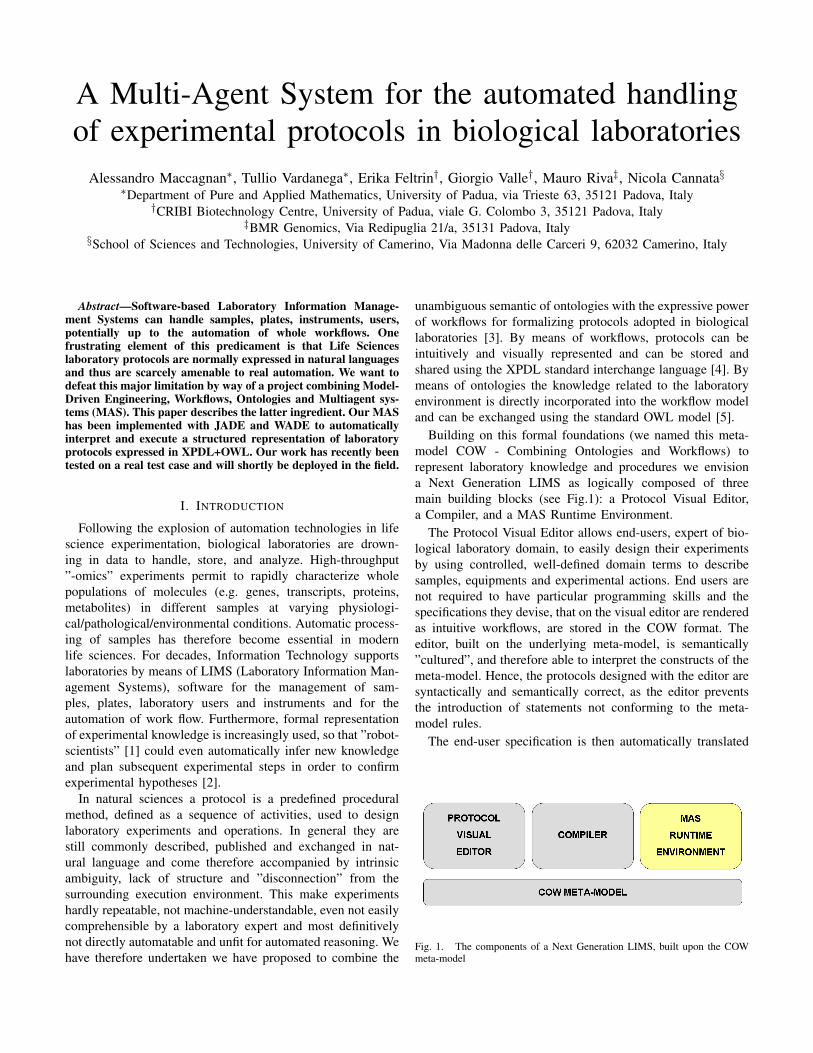
A Multi-Agent System for the automated handlingof experimental protocols in biological laboratories
Alessandro Maccagnan∗, Tullio Vardanega∗, Erika Feltrin†, Giorgio Valle†, Mauro Riva‡, Nicola Cannata§∗Department of Pure and Applied Mathematics, University of Padua, via Trieste 63, 35121 Padova, Italy
†CRIBI Biotechnology Centre, University of Padua, viale G. Colombo 3, 35121 Padova, Italy‡BMR Genomics, Via Redipuglia 21/a, 35131 Padova, Italy
§School of Sciences and Technologies, University of Camerino, Via Madonna delle Carceri 9, 62032 Camerino, Italy
Abstract—Software-based Laboratory Information Manage-
ment Systems can handle samples, plates, instruments, users,
potentially up to the automation of whole workflows. One
frustrating element of this predicament is that Life Sciences
laboratory protocols are normally expressed in natural languages
and thus are scarcely amenable to real automation. We want to
defeat this major limitation by way of a project combining Model-
Driven Engineering, Workflows, Ontologies and Multiagent sys-
tems (MAS). This paper describes the latter ingredient. Our MAS
has been implemented with JADE and WADE to automatically
interpret and execute a structured representation of laboratory
protocols expressed in XPDL+OWL. Our work has recently been
tested on a real test case and will shortly be deployed in the field.
I. INTRODUCTION
Following the explosion of automation technologies in lifescience experimentation, biological laboratories are drown-ing in data to handle, store, and analyze. High-throughput”-omics” experiments permit to rapidly characterize wholepopulations of molecules (e.g. genes, transcripts, proteins,metabolites) in different samples at varying physiologi-cal/pathological/environmental conditions. Automatic process-ing of samples has therefore become essential in modernlife sciences. For decades, Information Technology supportslaboratories by means of LIMS (Laboratory Information Man-agement Systems), software for the management of sam-ples, plates, laboratory users and instruments and for theautomation of work flow. Furthermore, formal representationof experimental knowledge is increasingly used, so that ”robot-scientists” [1] could even automatically infer new knowledgeand plan subsequent experimental steps in order to confirmexperimental hypotheses [2].
In natural sciences a protocol is a predefined proceduralmethod, defined as a sequence of activities, used to designlaboratory experiments and operations. In general they arestill commonly described, published and exchanged in nat-ural language and come therefore accompanied by intrinsicambiguity, lack of structure and ”disconnection” from thesurrounding execution environment. This make experimentshardly repeatable, not machine-understandable, even not easilycomprehensible by a laboratory expert and most definitivelynot directly automatable and unfit for automated reasoning. Wehave therefore undertaken we have proposed to combine the
unambiguous semantic of ontologies with the expressive powerof workflows for formalizing protocols adopted in biologicallaboratories [3]. By means of workflows, protocols can beintuitively and visually represented and can be stored andshared using the XPDL standard interchange language [4]. Bymeans of ontologies the knowledge related to the laboratoryenvironment is directly incorporated into the workflow modeland can be exchanged using the standard OWL model [5].
Building on this formal foundations (we named this meta-model COW - Combining Ontologies and Workflows) torepresent laboratory knowledge and procedures we envisiona Next Generation LIMS as logically composed of threemain building blocks (see Fig.1): a Protocol Visual Editor,a Compiler, and a MAS Runtime Environment.
The Protocol Visual Editor allows end-users, expert of bio-logical laboratory domain, to easily design their experimentsby using controlled, well-defined domain terms to describesamples, equipments and experimental actions. End users arenot required to have particular programming skills and thespecifications they devise, that on the visual editor are renderedas intuitive workflows, are stored in the COW format. Theeditor, built on the underlying meta-model, is semantically”cultured”, and therefore able to interpret the constructs of themeta-model. Hence, the protocols designed with the editor aresyntactically and semantically correct, as the editor preventsthe introduction of statements not conforming to the meta-model rules.
The end-user specification is then automatically translated
Fig. 1. The components of a Next Generation LIMS, built upon the COWmeta-model
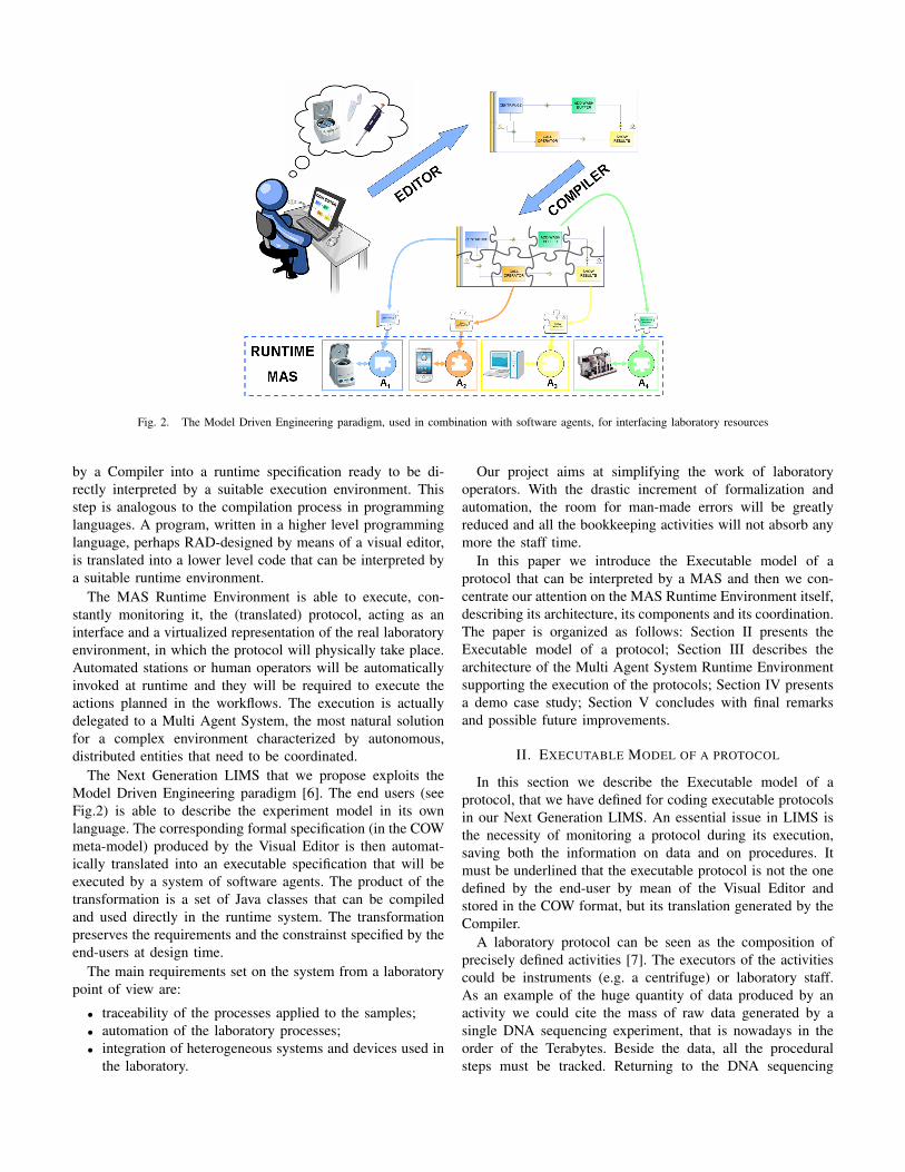
Fig. 2. The Model Driven Engineering paradigm, used in combination with software agents, for interfacing laboratory resources
by a Compiler into a runtime specification ready to be di-rectly interpreted by a suitable execution environment. Thisstep is analogous to the compilation process in programminglanguages. A program, written in a higher level programminglanguage, perhaps RAD-designed by means of a visual editor,is translated into a lower level code that can be interpreted bya suitable runtime environment.
The MAS Runtime Environment is able to execute, con-stantly monitoring it, the (translated) protocol, acting as aninterface and a virtualized representation of the real laboratoryenvironment, in which the protocol will physically take place.Automated stations or human operators will be automaticallyinvoked at runtime and they will be required to execute theactions planned in the workflows. The execution is actuallydelegated to a Multi Agent System, the most natural solutionfor a complex environment characterized by autonomous,distributed entities that need to be coordinated.
The Next Generation LIMS that we propose exploits theModel Driven Engineering paradigm [6]. The end users (seeFig.2) is able to describe the experiment model in its ownlanguage. The corresponding formal specification (in the COWmeta-model) produced by the Visual Editor is then automat-ically translated into an executable specification that will beexecuted by a system of software agents. The product of thetransformation is a set of Java classes that can be compiledand used directly in the runtime system. The transformationpreserves the requirements and the constrainst specified by theend-users at design time.
The main requirements set on the system from a laboratorypoint of view are:
• traceability of the processes applied to the samples;• automation of the laboratory processes;• integration of heterogeneous systems and devices used in
the laboratory.
Our project aims at simplifying the work of laboratoryoperators. With the drastic increment of formalization andautomation, the room for man-made errors will be greatlyreduced and all the bookkeeping activities will not absorb anymore the staff time.
In this paper we introduce the Executable model of aprotocol that can be interpreted by a MAS and then we con-centrate our attention on the MAS Runtime Environment itself,describing its architecture, its components and its coordination.The paper is organized as follows: Section II presents theExecutable model of a protocol; Section III describes thearchitecture of the Multi Agent System Runtime Environmentsupporting the execution of the protocols; Section IV presentsa demo case study; Section V concludes with final remarksand possible future improvements.
II. EXECUTABLE MODEL OF A PROTOCOL
In this section we describe the Executable model of aprotocol, that we have defined for coding executable protocolsin our Next Generation LIMS. An essential issue in LIMS isthe necessity of monitoring a protocol during its execution,saving both the information on data and on procedures. Itmust be underlined that the executable protocol is not the onedefined by the end-user by mean of the Visual Editor andstored in the COW format, but its translation generated by theCompiler.
A laboratory protocol can be seen as the composition ofprecisely defined activities [7]. The executors of the activitiescould be instruments (e.g. a centrifuge) or laboratory staff.As an example of the huge quantity of data produced by anactivity we could cite the mass of raw data generated by asingle DNA sequencing experiment, that is nowadays in theorder of the Terabytes. Beside the data, all the proceduralsteps must be tracked. Returning to the DNA sequencing

Fig. 3. XML schema for an Action
laboratory example, the protocol would probably require toexecute also ”virtual” operations like converting the raw datainto DNA sequences and subsequently assemble them bymeans of alignment algorithms.
In the typical protocol we can found three kind of activities,depending on their performer:
• those performed by a physical device, like a liquidhandler workstation (e.g. Biomek FX);
• those performed by a virtual device, like an assemblingsoftware;
• those performed by a human operator, like shaking a plateor taking a sample of DNA through a swab.
Starting from these considerations we have defined a generalnotion of activity, called Action. An Action is defined by aname and a list of parameters. Each parameter is characterizedby a name, a type and by the mode in which it is passed (read-only, read/write, write-only) (Fig.3). An Action is an atomicstep in our execution model and could be seen as the simplestinstruction that our MAS is able to interpret and execute
Referring again to the programming language metaphor wecan assimilate an Action in the Executable model of a protocolto a single machine instruction in a machine code program. Asingle machine instruction can be directly executed by the pro-cessor. The definition of Action is general enough to includethe three cases above mentioned. Given the heterogeneity andthe complexity of the laboratory environment, this solutionrepresents a good trade-off between the need of describing aprotocol with enough granularity and the need of having acommon interface for every activity involved.
Fig.4 shows the XML document describing a ”centrifugate”Action. A centrifugate Action is defined by three parameters.The parameter named ”performed”, is of boolean type and itsmode is OUT, so that it is actually an output parameter of theaction, representing whether the action has been successfullyperformed. The second and the third parameters are inputs ofinteger type representing respectively the g-force to be appliedin the centrifugation and the centrifugation time.
It must be recalled that an Executable Action has a semanticcounterpart in the Action concept, formally defined in the lab-oratory domain ontology of the COW meta-model supportingthe Next Generation LIMS [3].
In the Executable model, a Protocol is an articulated flowof Actions. A Valid Protocol is a protocol that our runtimeenvironment is able to interpret and to execute. A Protocolin the model could be composed using different Actionsavailable in the runtime environment or loaded from external
Fig. 4. XML document for a centrifugate action
libraries. We use the XPDL [4] meta-model to describe theexecution and the orchestration of different actions. In XPDLa process is a structured composition of piece of works, calledActivities, that could be of various type [8]. In our system aValid Protocol is a XPDL compliant model with some minorlimitations and differences.
In order to guarantee the correct interpretation of a COWprotocol we do require that every piece of work must bedescribed by means of an Action concept. In this mannerthe COW meta-model is semantically enriched and we wantto preserve at runtime the ontological constraints definedat design-time. In XPDL the notion of ”piece of work” isdescribed by the concept of Activity. Hence we impose thatevery Activity is allowed to invoke only Actions. In order tosatisfy this condition in the Executable model, we imposedtwo restrictions to the XPDL meta-model.
The first one is to limit the types of Activity only to Routeand SubFlow. The Route activity performs no work and simplysupports routing decisions among the incoming transitionsand/or among the outgoing transitions. The SubFlow activityenables the reuse of processes and could be usefully used toencapsulate parts of protocols in self-contained modules.
Second, we provide a specific SubFlow (ExecuteActionW)around an invocation of an Action. The ExecuteActionWSubFlow (Fig.5) simply invokes the execution of the Actionand checks if it is performed with or without errors. Actionscan be executed only encapsulated within such construct.
Using only Route and SubFlow activities and using theExecuteActionW SubFlow we can therefore ensure that everypiece of work is backed by an Action concept. In the nextsection we will describe how we have built a MAS runtimesystem able to execute a Valid Protocol.
III. MAS RUNTIME ENVIRONMENT
The enactment of workflows using multiagent systems hasalready been proposed in the literature [9], [10], including

Fig. 5. The ExecuteActionW SubFlow that encapsulate the execution ofactions
the development [11], [12] of workflow management systemsbased on the popular open source MAS platform JADE [13].
Recently, a new software platform has been proposed asan extension to JADE by the JADE development group itself.WADE (Workflow and Agent Development Environment) hasbeen developed on top of JADE, with the implementationof new features for supporting the use of workflows in thedeployment of multi-agent applications [14]. WADE includesa micro-engine embedded in a set of dedicated agents whichare specifically developed for the execution of workflowsdefined in an extended version of XPDL. Doing this, the newengine permits to directly execute the Java code associated toa specific workflow activity. Moreover, this new tool allowsto choose and assign secondary agents for the execution ofsubflows. Additional components have been also defined inWADE in order to manage administration and fault toleranceissues.
The main challenge in WADE consists in bringing theworkflow approach from the business process level to the levelof system internal logics [15]. In other words, the objectiveis not to support an orchestration of services provided bydifferent systems at high level, but to implement the internalbehavior of the single systems.
The new functionality offered by WADE is of specialimportance for us. The capabilities to run a slightly differentmodel of XPDL workflows fits with our requirements. Wehence decided to build our MAS on top of the JADE/WADEframework.
The architecture of the MAS Runtime Environment isdesigned to closely resemble the laboratory environment, withthe additional capability of being able to interpret and executeActions as described in Section II. The Executable Model of aprotocol involves one main kind of entities. These entities areheterogeneous and distributed resources that actually exposeand, on request, performs Actions. We therefore dedicatedone class of agent to these entities, the Device Agent (DA).Another distinctive characteristic of the Runtime Environmentis an entity that does read an executable protocol and handlesits execution. A Protocol Manager agent (PM) is appointed tocontrol this aspect. A user interface agent (APE) is designedfor loading new protocols in the MAS. A Reporter Agent(RA) is built specifically as a User Interface for mobile
devices.
• DA: controls a resource (physical or virtual)• PM: executes a protocol in the MAS• APE: allows the loading of new protocols• RA: user interface for mobile devicesThe RA agent is created at the boot of the system. For
each resource in the laboratory environment that should beautomatically managed from the LIMS, it is then created aDA Agent counterpart. One APE is also created in the bootphase, however two (or more) instances can co-exist withoutany problem. The same apply for the RA. A PM agent insteadis created dynamically on user demand, being responsiblefor the execution of a particular protocol. Once completedthe protocol, the PM agents automatically disappear from thesystem.
A. Device Agent
In the past years the literature recognized the need to explic-itly embody the notion of resource in a MAS [16], [17]. A wellknown approach is to use the notion of “artifact”. Artifactscan be considered as complementary abstractions to agentspopulating a MAS. While agents are goal-oriented pro-activeentities, artifacts are a general abstraction to model function-oriented passive entities. MAS designers employs artifacts toencapsulate some kind of functionality, by representing (orwrapping) existing resources or instruments mediating agentactivities [18]. The purpose is to encapsulate functionalitiesand services in suitable first class abstractions at the agent level[16]. Artifacts could be used for wrapping existing resourcesand therefore are a suitable model for our purpose. Particularlyfitting is the Agent and Artifact model [16], in which anArtifact is structured as a set of operations.
We therefore propose a combination of a Driver and anAgent in order to make available in the MAS a service thatcan be executed by a physical or virtual resource. A Driver inour model actually performs the communication with a legacyresource as a centrifuge or a robotized station. Since our modelis inspired from the A&A model, our Driver is structured interms of Actions. The similarity with the model lies on the factthat a Driver represents a resource in the MAS environment(Artifact in the A&A model). The main difference is that westrictly bind an instance of a Driver with exactly one instanceof a DA. As a consequence every request of Actions must beposed to a specific DA that acts as a proxy to the driver andtherefore to the resource.
A Resource exposes a set of Actions, one for every function-ality. In the Centrifuge example the Centrifuge is the resourceitself, and it is described by means of the functionalities itexposes and hence by a set of different Actions i.e. the actionsit can actually perform (e.g. ”centrifugate” or ”open lid”). ADA is responsible for executing the single actions, thereforeit needs to knows how to physically communicate with therelated resource. It needs also to communicate with otheragents in order to satisfy any request for its functionalities. Wetherefore structured a DA in two layers as depicted in Fig.6.
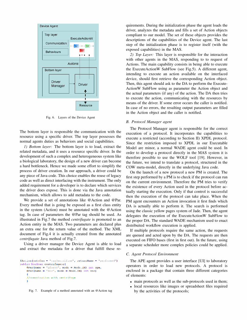
Fig. 6. Layers of the Device Agent
The bottom layer is responsible the communication with theresource using a specific driver. The top layer possesses thenormal agents duties as behaviors and social capabilities.
1) Bottom layer: The bottom layer is to load, extract therelated metadata, and it uses a resource specific driver. In thedevelopment of such a complex and heterogeneous system likea biological laboratory, the design of a new driver can becomea hard bottleneck. Hence we made some effort to simplify theprocess of driver creation. In our approach, a driver could beany piece of Java code. This choice enables the reuse of legacycode as well as direct interfacing with the instrument. The onlyadded requirement for a developer is to declare which servicesthe driver does expose. This is done via the Java annotationmechanism, which allows to add metadata to the code.
We provide a set of annotations like @Action and @Par.Every method that is going be exposed as a first class entityin the system (Action) must be annotated with the @Actiontag. In case of parameters the @Par tag should be used. Asillustrated in Fig.7 the method centrifugate is promoted to anAction entity in the MAS. Two parameters are declared plusan extra one for the return value of the method. The XMLdocument of Fig.4 it is actually created from the annotatedcentrifugate Java method of Fig.7.
Using a driver manager the Device Agent is able to loadand extract the metadata for a driver that fulfill these re-
Fig. 7. Example of a method annotated with an @Action tag
quirements. During the initialization phase the agent loads thedriver, analyzes the metadata and fills a set of Action objectscompliant to our model. The set of these objects provides thedescriptions of the capabilities of the Device agent. The laststep of the initialization phase is to register itself (with theexposed capabilities) in the MAS.
2) Top Layer: This layer is responsible for the interactionwith other agents in the MAS, responding to to request ofActions. The main capability consists in being able to executethe ExecuteActionW SubFlow (see Fig.5). A different agent,intending to execute an action available on the interfaceddevice, should first retrieve the corresponding Action object.Then, this agent should ask to the DA to perform the Execute-ActionW SubFlow using as parameter the Action object andthe actual parameters (if any) of the action. The DA then triesto execute the action, communicating with the resources bymeans of the driver. If some error occurs the caller is notified.In case of no errors, the resulting output parameters are filledin the Action object and the caller is notified.
B. Protocol Manager agent
The Protocol Manager agent is responsible for the correctexecution of a protocol. It incorporates the capabilities toexecute a restricted (according to Section II) XPDL protocol.Since the restriction imposed to XPDL in our ExecutableModel are minor, a normal WADE agent could be used. Inorder to develop a protocol directly in the MAS system it istherefore possible to use the WOLF tool [19]. However, inthe future, we intend to translate a protocol, structured in theCOW meta-model, directly in the underlying Java code.
On the launch of a new protocol a new PM is created. Thefirst step performed by a PM is to check if the protocol can runon the current environment. Therefore the PM tries to verifythe existence of every Action used in the protocol before ac-tually starting the execution. Only if that control is successfulthen the execution of the protocol can take place. When thePM agent encounters an Action invocation it first finds whichDA is actually able to perform it. The search is performedusing the classic yellow pages system of Jade. Then, the agentdelegates the execution of the ExecuteActionW SubFlow tothe proper DA. The standard WADE mechanism used to enactdistribuited workflow execution is applied.
If multiple protocols require the same action, the requestsare queued and acted upon by the DA. The requests are thenexecuted on FIFO bases (first in first out). In the future, usinga separate scheduler more complex policies could be applied.
C. Agent Protocol Environment
The APE agent provides a user interface [UI] to laboratoryoperators in order to load new protocols. A protocol isenclosed in a package that contain three different categoriesof elements:
• main protocols as well as the sub-protocols used in them;• local resources like images or spreadsheet files required
by the activities of the protocols;
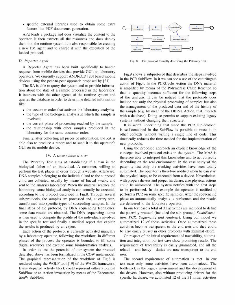
• specific external libraries used to obtain some extrafeature like PDF documents generation.
APE loads a package and does visualize the content to theoperator. It then extracts all the resources and does deploythem into the runtime system. It is also responsible for creatinga new PM agent and to charge it with the execution of theloaded protocol.
D. Reporter Agent
A Reporter Agent has been built specifically to handlerequests from mobile devices that provide GUIs to laboratoryoperators. We currently support ANDROID [20] based mobiledevices using the peer-to-peer approach proposed by [21].
The RA is able to query the system and to provide informa-tion about the state of a sample processed in the laboratory.It interacts with the other agents of the runtime system andqueries the database in order to determine detailed informationlike:
• the customer order that activate the laboratory analysis;• the type of the biological analysis in which the sample is
involved;• the current phase of processing reached by the sample;• the relationship with other samples produced in the
laboratory for the same customer order.Finally, after collecting all pieces of information, the RA is
able also to produce a report and to send it to the operator’sGUI on its mobile device.
IV. A DEMO CASE STUDY
The Paternity Test aims at establishing if a man is thebiological father of an individual. A customer, willing toperform the test, places an order through a website. Afterward,DNA samples belonging to the individual and to the supposedchild are collected, usually by means of buccal swabs, andsent to the analysis laboratory. When the material reaches thelaboratory, some biological analysis can actually be executed,according to the protocol described in Fig.8. Through severalsub-protocols, the samples are processed and, at every step,transformed into specific types of succeeding samples. In thefinal steps of the protocol, by DNA sequencing techniques,some data results are obtained. The DNA sequencing outputis then used to compute the profile of the individuals involvedin the specific test and finally a medical report that explainthe results is produced by an expert.
Each action of the protocol is currently activated manuallyby a laboratory operator, following the workflow. In differentphases of the process the operator is bounded to fill somedigital resources and execute some bioinformatics analysis.
In order to test the potential of our system the protocoldescribed above has been formalized in the COW meta-model.The graphical representation of the workflow of Fig.8 isrendered using the WOLF tool [19] of the WADE framework.Every depicted activity block could represent either a normalSubFlow or an Action invocation by means of the ExecuteAc-tionW SubFlow.
Fig. 8. The protocol formally describing the Paternity Test
Fig.9 shows a subprotocol that describes the steps involvedin the PCR SubFlow. In it we can see a use of the centrifugateaction of Fig.4. In the PCRCycle Action the DNA materialis amplified by means of the Polymerase Chain Reaction sothat its quantity becomes sufficient for the following stepsof the analysis. It can be noticed that the protocols doesinclude not only the physical processing of samples but alsothe management of the produced data and of the history ofthe sample (e.g. by mean of the DBReg Action, that interactswith a database). Doing so permits to support existing legacysystems without changing their structure.
It is worth underlining that since the PCR sub-protocolis self-contained in the SubFlow is possible to reuse it inother contexts without writing a single line of code. Thisdrastically reduces the time needed for the implementation ofnew protocols.
Using the proposed approach an explicit knowledge of theconcepts involved protocol exists in the system. The MAS istherefore able to interpret this knowledge and to act correctlydepending on the real environment. In the case study of thepaternity test only the tracking activities have been totallyautomated. The operator is therefore notified when he can startthe physical steps, to be executed from a device. Nevertheless,with propers drivers and proper hardware, also physical actionscould be automated. The system notifies with the next stepsto be performed. In the example the operator is notified toperform a PCR on some specific samples. After the sequencingphase an automatically analysis is performed and the resultsare delivered to the laboratory operator.
In our test case a total of 31 activities are included to definethe paternity protocol (included the sub-protocol SwabExtrac-
tion, PCR, Sequencing and Analysis). Using our model weautomatized 12 of those activities. Once automatized theseactivities become transparent to the end user and they couldbe also easily reused in other protocols with minimal effort.
On respect of the initial requirement of traceability, automa-tion and integration our test case show promising results. Therequirement of traceability is easily guaranteed, and all therelated - and heavy - duties are now transparent to the enduser.
The second requirement of automation is met. In ourtest case only some activities have been automatized. Thebottleneck is the legacy environment and the development ofthe drivers. However, also without producing drivers for thespecific hardware, we automated 12 of the 31 initial activities

Fig. 9. The PCR subprotocol of the paternity protocol
(38%).The last requirement is met under the constraint to produce
specific drivers for the specific devices used in the laboratory.
V. CONCLUSION
In our vision a Next Generation LIMS will ease the man-agement of a biological laboratory. The laboratory knowledge,including the procedural one, would be formalized and wouldbecome easy, for automatic systems, to exchange, control,analyze and exploit. On the other hand, laboratory protocolswould become easy to specify, read and maintain also bydomain experts.
Protocols could be statically validated in a given executionenvironment (i.e. “MAS interfaced” laboratory) according tospecifications to be met. In this way it will be possibleto know if the environment is able to execute the protocolensuring the expected quality of service respecting all thecritical constraints.
A Scheduler agent could also perform a dynamic validationand optimization of a protocol at runtime. In this way it willbe possible to effectively and efficiently answer to possiblesudden changes in the environment, like e.g. the breakdownof a resource. The actions to be taken in order to recoverfrom abnormal situations could be based on a set of rules.The agents should perform some reasoning upon that rules inorder to react in a proper and fast way to the changes of theenvironment.
It could also dynamically schedule groups of samples actingon the current state of the resources, in order to optimize theresource consumption.
The system will permit an easier tracking of all the transfor-mations applied to the analyzed samples, including the virtual(i.e. digital) ones. Automation will be naturally enhanced:physical devices will undergo a direct control performed bysoftware agents, in turn controlled by protocol “instructions”.The integration of heterogeneous systems and instruments,including the communications with laboratory operators, alsovia mobile platforms, will thus become possible.
REFERENCES
[1] R. King, K. Whelan, F. Jones, P. Reiser, C. Bryant, S. Muggleton,D. Kell, and S. Oliver, “Functional genomic hypothesis generation andexperimentation by a robot scientist,” Nature, vol. 427, pp. 247–252,2004.
[2] R. D. King, J. Rowland, S. G. Oliver, M. Young, W. Aubrey,E. Byrne, M. Liakata, M. Markham, P. Pir, L. N. Soldatova,A. Sparkes, K. E. Whelan, and A. Clare, “The Automation of Science,”Science, vol. 324, no. 5923, pp. 85–89, 2009. [Online]. Available:http://www.sciencemag.org/cgi/content/abstract/324/5923/85
[3] A. Maccagnan, M. Riva, E. Feltrin, B. Simionati, T. Vardanega,G. Valle, and N. Cannata, “Combining ontologies and workflowsto design formal protocols for biological laboratories,” Automated
Experimentation, vol. 2, no. 1, p. 3, 2010. [Online]. Available:http://www.aejournal.net/content/2/1/3
[4] Xml process definition language. [Online]. Available:http://www.wfmc.org/xpdl.html
[5] Ontology web language. [Online]. Available:http://www.w3.org/TR/owl-ref/
[6] R. France and B. Rumpe, “Model-driven development of complexsoftware: A research roadmap,” FOSE ’07: 2007 Future of Software
Engineering, pp. 37–54, 2007.[7] M. Courtot, W. Bug, F. Gibson, A. Lister, J. Malone, D. Schober,
R. Brinkman, and A. Ruttenberg, “The owl of biomedical investigations,”in Proceedings of the Fifth OWLED Workshop on OWL: Experiences,
2008, xx 2008.[8] R. Shapiro and M. Marin, Workflow Management Coalition Workflow
StandardProcess Definition Interface– XML Process Definition Lan-
guage, The Workflow Management Coalition, 99 Derby Street, Suite200 Hingham, MA 02043 USA, October 2008.
[9] P. A. Buhler and J. M. Vidal, “Towards adaptive workflow enactmentusing multiagent systems,” Inf. Technol. and Management, vol. 6, no. 1,pp. 61–87, 2005.
[10] E. Bartocci, F. Corradini, and E. Merelli, “Enacting proactive workflowsengine in e-science,” in International Conference on Computational
Science (3), 2006, pp. 1012–1015.[11] C. V. Trappey, A. J. Trappey, C.-J. Huang, and C. Ku, “The
design of a jade-based autonomous workflow management systemfor collaborative soc design,” Expert Systems with Applications,vol. 36, no. 2, Part 2, pp. 2659 – 2669, 2009. [On-line]. Available: http://www.sciencedirect.com/science/article/B6V03-4RV7Y9W-2/2/f933cced0e8af5448692818153bb1648
[12] G. Fortino, A. Garro, and W. Russo, “Distributed workflow enactment:an agent-based framework,” in Atti del 7 Workshop dagli Oggetti agli
Agenti (WOA) Sistemi GRID, Peer-to-peer e Self-*, Catania (Italia).[13] F. L. Bellifemine, G. Caire, and D. Greenwood, Developing Multi-Agent
Systems with JADE (Wiley Series in Agent Technology). Wiley, April2007.
[14] G. Caire, D. Gotta, and M. Banzi, “Wade: a software platform todevelop mission critical applications exploiting agents and workflows,”in AAMAS ’08: Proceedings of the 7th international joint conference on
Autonomous agents and multiagent systems. Richland, SC: InternationalFoundation for Autonomous Agents and Multiagent Systems, 2008, pp.29–36.
[15] A. Poggi and P. Turci, “An agent-based bridge between business processand business rules,” in Decimo Workshop Nazionale Dagli Oggetti agli
Agenti, 2009.[16] A. Ricci, M. Viroli, and A. Omicini, “The a&a programming model and
technology for developing agent environments in mas,” in ProMAS’07:
Proceedings of the 5th international conference on Programming multi-
agent systems. Berlin, Heidelberg: Springer-Verlag, 2008, pp. 89–106.[17] A. Omicini, A. Ricci, and M. Viroli, “Artifacts in the a&a meta-model
for multi-agent systems,” Autonomous Agents and Multi-Agent Systems,vol. 17, no. 3, pp. 432–456, 2008.
[18] R. Kitio, O. Boissier, J. F. Hbner, and R. Ricci, “Organisational artifactsand agents for open multi-agent organisations: giving the power back tothe agents.”
[19] G. Caire, M. Porta, E. Quarantotto, and G. Sacchi, “Wolf - an eclipseplug-in for wade,” in WETICE ’08: Proceedings of the 2008 IEEE 17th
Workshop on Enabling Technologies: Infrastructure for Collaborative
Enterprises. Washington, DC, USA: IEEE Computer Society, 2008,pp. 26–32.
[20] Android platform. [Online]. Available: http://code.google.com/android[21] M. Ughetti, T. Trucco, and D. Gotta, “Development of agent-based, peer-
to-peer mobile applications on android with jade,” Mobile Ubiquitous
Computing, Systems, Services and Technologies, International Confer-
ence on, vol. 0, pp. 287–294, 2008.

Using mobile agents for secure biometricauthentication
Marco TranquillinDepartment of Information
EngineeringThe University of Padova
Padova, Italy
Carlo FerrariDepartment of Information
EngineeringThe University of Padova
Padova, ItalyEmail: [email protected]
Michele MoroDepartment of Information
EngineeringThe University of Padova
Padova, ItalyEmail: [email protected]
Abstract—This paper deals with the definition of a strongauthentication model, coupling usual password/PIN based meth-ods with a biometric matching, over a Multi Agent distributedinfrastructure. When the user authentication procedure involvespersonal devices, the Multi Agent System model helps in the dis-tribution of data and algorithms thanks to a better partitioning ofroles and responsibilities, enhancing robustness to eavesdroppingand tampering by properly moving agents around the systemitself. The system architecture is based on specialized agents tiedto the different devices, which safely communicate using bothsymmetric encryption for messages and asymmetric encryption tocheck principals’ roles. Moreover, agents can carry on biometricparameters matching algorithms, bringing computation on thosenodes with enough computing power. A complete authenticationprotocol has been developed and two different demos have beendevised and tested. They differ for the tasks assigned to themobile devices in use. Experiments show that agent capabilities,together with their power of migration, help in maintaining ahigher level of security when mobile devices are involved.
I. INTRODUCTIONIdentity recognition is still an open problem and its solution
can help for user authentication, tracking, secure access torestricted areas and, more generally, anytime it is necessaryto automatically acquire the identity of a human operator.It is worth to point out that the application of an identityrecognition system can go beyond security issues, being thebasic for a more sophisticated human machine interface ina pervasive context. A person can be identified through theanalysis of her physical peculiar features: automated methodsand algorithms for feature acquisition, analysis and recognitionstand at the core of Biometrics, that it is focused on the correctrepresentation and measurements of those personal physicalinvariants, like fingerprints, iris, hand geometry and so on,that are strictly linked to each person and cannot be easilytampered with. In the recognition process acquired raw dataare preprocessed to extract relevant geometric arrangementsof features that are then compared and matched to those thatform the user template stored in a backend database.A biometric recognition process involves different compu-
tational activities distributed among biometric sensors, hostcomputer, personal mobile devices. Modern computationalsystems can involve heterogeneous machines and devices thatgreatly differ with respect to their computational power. Some
of them can move freely in the working space thanks to wire-less connections while remaining strongly tied to their (human)owner. The interaction with the fixed part of the system ismanaged by proper protocols in order to guarantee securityand performances. The design of applications can benefit fromnovel paradigms and methodologies that explicitly deal withmobility and that support delegation mechanisms in order tomove the heavier part of computation on those nodes that cancope with the required service levels.The mobile agents paradigm is focused on the mobility
concept of computation and code [1]. That means the abilityto organize programs that can be sent without changes toa number of different computers and that can be executedwith the same semantics on each of them. This paradigm isa remarkable option in the context of Multi-Agent Systems(MAS) that in [2] are defined as “a loosely coupled networkof problem-solver entities that work together to find answersto problems that are beyond the individual capabilities orknowledge of each entity“. One of the most interesting andinnovative feature of this model is about its integration withmodern mobile devices, like smart phone or handhelds, thatallows a greater relocation of computing resources linking soft-ware with users in a more safe effective and reflective manner.For sure security is a major issue in distributed systems anddevice mobility requires new more robust solutions [3], [4],[5].The main goal of this paper is to present how biometric
matching methods can be combined with usual password/PINbased methods in those scenarios where mobile devices areinvolved. The paper is focused on the use of the mobile agentparadigm suitably exploited to integrate a mobile device in thesystem.The authentication model that we present is a strong au-
thentication model [6]. In fact it involves more than onefactor, something that the user knows (personal data like name,surname, date of birth etc. and one PIN generally), somethingthat the user has (a mobile device with its memory card) andsomething tied to the user (a biometric parameter).A model using three contextual authentication criteria is
more robust and is able to fully take advantage of the mobileagents approach. Unlike previous works that are based on

smart card [7], [8], [9], the innovative issue of this model isthe introduction of a mobile device that can be used both like adata repository and an active element inside the authenticationprotocol, executing matching of biometric templates.Mobile agents can transfer entire object code in order
to manipulate data in a more robust manner (there is noneed to copy and paste data from one location to another)and to react immediately either to errors or to exceptions(for example an agent that must install particular softwarethat needs some libraries can autonomously download themfrom Internet without any user intervention). Thus a MASsupports effective forms of adaptable computations in accor-dance with the requested level of security and the availabilityof computational power, and it shows a relevant degree ofscalability and maintainability. The framework that we chosefor implementing the proposed authentication system is theopen-source project Jade. It’s a worldwide project associatedwith a great community that has realized a lot of adds-on,like Jade-S and Jade-Leap. The first one is a plug-in thatincreases the native security level of the platform through theverification of credentials that belong to agents. The secondone allows to execute a light version of the Jade frameworkinto a device that has limited hardware resources like mobilephones or handhelds.The authentication system that we propose is based on bio-
metric parameters (in the first release we use only fingerprintanalysis). It addresses the following questions:
how can we surely transport user private data?how can we extract the template from a fingerprint froma trusted source?how can we be sure of subjects that are exchanging data?
In the next paragraph the architecture of the system isdescribed while, in the third paragraph, the details of theauthentication protocol are given. The fourth paragraph isdevoted to a brief final discussion and conclusions.
II. SYSTEM ARCHITECTURE
Authentication is carried on by different agents that performspecific tasks and with at least the robustness reachablewith elaborated protocols like Kerberos [10]. The involvedphysical entities of the system are a mobile device, typicallya smartphone, a client machine mainly devoted to biometricdata acquisition, and a server machine to access the centraluser database. Within these machines both static and mobileagents run on an agent platform. The overall architecture isbuilt on the following basic elements:
server agent: it must execute the operations at the serverside, e.g. generating mobile agents, checking data, query-ing a database and so on;user phone agent: running on the mobile device, itprovides the GUI for the owner to be authenticated. Thenecessary communications with the server are performedvia messages piggybacked on another (mobile) agent;mobile agent: it moves between a client and the servercarrying all the necessary information for the authenti-
cation process; when at client it is delegated for all thecommunications with the phone agent.
Instances of the previous components can be combined to formthe final system, as shown in figure 1.It is worth to point out that the role of the mobile agent
is to load programs “on the fly”. Then it is not necessary topreinstall all the software at the client side, reducing the riskof hacking and tampering of those critical components thatare devoted to the authentication. Moreover executing soft-ware within a remote agency benefits of those encapsulationcapabilities of agents providing a stronger degree of security.The abovementioned issues are even more significant whenthe mobile device can host an agency.Every client machine is responsible for controlling one
biometric sensor from which it gets raw data when requested.The match of the live template, extracted by the client, can becentralized in the server. The use of a mobile device, coupledwith one client machine, enables a stronger level of securitybecause also PINs must be provided by the user and, withsuitable computational power, the match can be carried directlyon the mobile device. In order to reach a useful flexibility andthe adaptation of the client to the characteristics of the userphone, all the main functions of the client are carried by amobile agent coming from the server. For example, a specificmobile agent could be created by the server in accordance withthe capability of the mobile device currently shown.Every communication from one agent to another is protected
by symmetric encryption to obscure contents of messages andby asymmetric encryption to apply digital signature to everymessage in order to let the agent automatically verifying theidentity of message sender. Since we use an agent platform,it is possible to identify a specific agent (each agent that isrunning on a platform has its unique name) and to find itslocation on the network in order to be sure to talk to a non-tampered agent.
III. THE AUTHENTICATION PROTOCOL
The biometric based authentication system, as mentionedearlier, leverages the power of the platform agents to executeall the operations that are mandatory to authenticate a user.The protocol is organized into a sequence of four phases:1) Initialization.2) Authentication of the mobile device.3) Authentication of the shared secret.4) Authentication of the biometric parameter.
These steps refer to the case we called ’Template on phone’that contemplates the presence of an encrypted fingerprint inthe mobile device memory and the match of the biometricparameter on the server.
Phase 1: the initiative is taken by the user who runs anapplication on her mobile device. After she has provided aPIN, the mobile device application asks the Jade platformserver to start an agent called “User Phone Agent“ (UPA).This also activates the client to start the authentication:it requests the server for establishing an SSL session.

Fig. 1. Internal Model
Finally an other agent resident on the server (simply’server agent’, SA) is activated.Phase 2: this phase is dedicated to authenticate themobile device (something that the user has). In orderto authenticate the UPA, the SA creates a mobile agent(MA) that brings a challenge (i.e. a prompt to receive aprivate information as its response [11]), encrypted (withthe server AES key) and signed by the SA, to the clientby migrating to this latter. The UPA verifies the serversignature, extracts the challenge and it sends a responsechallenge (updated, encrypted and signed), together withthe user asymmetric public key, back to the server throughthe MA. The authentication of the UPA completes whenthe MA goes back to the server that verifies the encryptedreply using the enveloped public key.Phase 3: now it is the turn to get the user personaldata (something that the user knows). The MA carriesa new challenge to the UPA requiring a hashed versionof the user personal data and PIN. When it comes backto the server, the SA can search the user data in the localdatabase, through their hashed value. Any time a positivematch occurs, the user AES key is extracted from thedatabase record and it is used as the basis of a personalsecure communication channel for the next steps. At thispoint the UPA receives an acknowledgement affirmingthat the server has correctly recognized the user andconsequently the authentication can continue.Phase 4: this phase includes the biometric match (some-thing tied to the user). The UPA provides the userfingerprint template that is stored in the mobile device
memory whereas the client is in charge to provide the livetemplate. The MA goes back-and-forth two times, the firstto bring the encrypted stored template, the second one tomake the client to get the user live fingerprint. The livetemplate is encrypted with the asymmetric public key ofthe server so that the client is not requested to maintainany secret key. The two templates are now comparedusing the established matching algorithm. The last travelof the MA is used to notify the match response to theUPA.
When a ’Match on phone’ is possible, i.e. the mobile devicecan implement the matching algorithm, the live template mustbe sent to the UPA and the stored template is not moved fromits original position in the phone device. Obviously in this casethe UPA is responsible for performing such a match and forgiving back to the server the final response.
IV. DISCUSSION AND CONCLUSION
In our experimentation we developed the two differentscenarios through the following demonstrative applications:
Demo 1 “MIDP-TOP“ (Template On Phone): the bio-metric match is on server, whereas the mobile device isused as the user personal data repository;Demo 2 “MIDP-MOP“ (Match On Phone): the biometricmatch is performed on the mobile device. In this casethe reference template can be stored exclusively on themobile device.
To complete our prototype we developed a tool named En-rollment Tool that allows the system administrator to manageuser personal data and keys and, more important, to extract a

template from a fingerprint (that can be loaded from a file orlive captured) and to support the initialization of the mobiledevice repository.A distributed system with mobile devices requires proper
policies to combine different security mechanisms in order tomeet a high level of dependability. Biometric-based identityrecognition benefits from the association with other (nonbiometric) personal data, allowing a faster search on a commondatabase, thanks to the use of well established and efficientstring search algorithms.A MAS explicitly supports the partition of responsibilities
and roles: in fact it is a model that is distributed ’per se’ andthat assigns different responsibilities to the various actors. Theconcurrent use of both biometric and non-biometric parametersasks for such kind of partitioning. When multi-biometricsis concerned, this is even more evident because more clientmachines equipped with specific devices and tools could beinvolved. Agents are entities that can be precisely identifiedwithin a platform together with their specific responsibilities,acting in favour of their own or on behalf of other entities,particularly in the case of mobile agents.As previously described, we propose a sequence of three
steps recognizing first a mobile device as member of a setof authorized devices, second a user through her personalcredentials and finally we perform the biometric match. Inthis scenario the client should be simply responsible for thereading of the raw biometric parameter. Notwithstanding, theuse of a mobile agent permits any client to execute crucialactions on delegation of the server to cope with the limitationof the mobile device. So that also the user mobility is implicitlyguaranteed not being restricted to a specific client (e.g. a usercould authenticate herself to enter a restricted area throughone of several different entrances).An appropriate combination of secret keys related both
to the machines and to the single users provides a goodbalance between performances and the level of security. Itis worth to point out that the Jade security extension (Jade-S) unfortunately presents some hard limitations that make itunusable when mobile devices are involved.Basic security is provided by the SSL tunnel. Freshness
and liveness properties are guaranteed by the challenge-and-response approach, like in the Needham-Schroeder protocol[11]. Every one of the three recognition steps in sequence iscorrect because it realizes standard security procedures, andit provides its specific level of security, related to the entityunder authentication (device, user ID data and biometric data).
Whenever a step fails the whole authentication process fails.If a step is fraudulently passed, no effect of further weaknessis propagated at subsequent levels that use new and differentcritical data. The last step, that uses biometric data, is thehardest to be misleaded.Our experimentation, necessarily carried out on a small
group of a dozen people, has proved the correctness and ef-fectiveness of the model. In perspective the MAS architectureshows a sufficient degree of scalability to adapt our modelto significantly more complex situations like those requiringseveral client locations and a great number of potential users.The future availability of more powerful smartphones will alsobring the conditions for introducing the agent mobility at thephone level.
ACKNOWLEDGEMENTThis work has been partially supported by the University of
Padova Research Project CPDA073251/07, ”Algorithms andmethods for secure authentication using biometrics data”.
REFERENCES[1] S. J. Russel, P. Norvig, Artificial Intelligence: A Modern Approach,
Prentice Hall International, 2003.[2] J. F. Dray, M. E. Smid and R. Warnar, A Token Based Access Control
System for Computer Networks, Proceedings of the 12th NationalComputer Security Conference, NIST/NCSC, Baltimore, MD, (USA),October 1989.
[3] T. Y. C. Woo and S.S. Lam, Authentication for Distributed Systems,IEEE Computer, vol. 25, no. 1, pp. 39–52, January 1992.
[4] Guideline on User Authentication Techniques for Computer NetworkAccess Control, National Institute of Standards and Technology, FederalInformation Processing Standards Publication 83, National TechnicalInformation Service, Springfi eld, VA, September 1980.
[5] H. Aouadi and PR M. Ben Hamed Security Enhancements for MobileAgents Platforms, IJCSNS, vol. 6, no. 7, pp. 216–221, 2005
[6] R. E. Smith Authentication: From Passwords to Public Keys, Addison-Wesley. 2001.
[7] S. Bistarelli, S. Frassi, A. Vaccarelli, MOC via TOC Using a MobileAgent Framework, Proceedings of the 5th Int. Conf. on Audio and Video-Based Biometric Person Authentication, Hilton Rye Town, NY, USA,2005, pp. 464–473.
[8] S. Bistarelli, F. Santini and A. Vaccarelli An Asymmetric FingerprintMatching Algorithm for JavaCard, Proceedings of the 5th Int. Conf. onAudio and Video-Based Biometric Person Authentication, Hilton RyeTown, NY, USA, 2005, pp. 279–288.
[9] Z. Pozgaj, I. Duretek, Smart Card in Biometric Authentication, Pro-ceedings of the 18th Int. Conf. on Information and Intelligent Systems,Varazdin, Croatia, 2007, pp. 319-325.
[10] J. G. Steiner, C. Neuman, J. I. Schiller Kerberos: An AuthenticationService for Open Network Systems in Usenix Winter Conference Pro-ceedings, Dallas, Texas (USA), 1988, pp. 191-202.
[11] A. S. Tanenbaum, M. van Steen, Distributed Systems: Principles andParadigms, Prentice Hall, 2002.
Programming Wireless Body Sensor Network Applications through Agents
Giancarlo Fortino, Stefano Galzarano Department of Electronics, Informatics and Systems (DEIS)
University of Calabria (UNICAL) Rende (CS), ITALY
[email protected], [email protected]
Abstract—Wireless Sensor Networks (WSNs) are currently emerging as one of the most disruptive technologies enabling and supporting next generation ubiquitous and pervasive computing scenarios. In particular, Wireless Body Sensor Networks (WBSNs) are conveying notable attention as their real-world applications aim at improving the quality of human beings life by enabling continuous and real-time non-invasive assistance at low cost. This paper proposes a high-level programming approach based on the agent-oriented model to flexibly design and efficiently implement WBSNs applications. The approach is exemplified through a case study concerning a real-time human activity monitoring system which is developed through two different agent-based frameworks: MAPS (Mobile Agent Platform for Sun SPOT) and AFME (Agent Factory Micro Edition). The programming effectiveness of MAPS and AFME with respect to the developed systems is finally discussed.
Keywords - Mobile agent platforms; wireless body sensor networks; Java Sun SPOT; finite state machines; human activity monitoring
I. INTRODUCTION Wireless Sensor Networks (WSNs) [1] are collection of
tiny, low-cost devices with sensing, computing, storing, communication and possibly actuating capabilities. Every sensor node is programmed to interact with the other ones and with its environment, constituting a unique distributed and cooperative system aiming at reaching a global behavior and result. WSNs are a powerful technology for supporting a lot of different real-world applications, and for a demonstration it is worth noting that in the last decade this new technology has emerged in a wide range of different domains including health-care, environment and infrastructures monitoring, smart home automation, emergence management, and military support, showing a great potential for numerous other applications.
When a WSN is specifically used for being applied to the human body we deal with Wireless Body Sensor Network (WBSN) [2] which involves wireless wearable physiological sensors for strictly medical or non medical purposes. For example, they can be very effective for providing continuous monitoring and analysis of physiological or physics parameters very useful, among the others, in medical assistance, in motion and gestures detection, in emotional recognition, etc.
Unfortunately, designing such networks is not an easy work because it implies knowledge from many different areas, ranging from low-level aspects of the sensor nodes hardware
and radio communication to high-level concepts concerning final user applications. Overcoming these difficulties by providing a powerful yet simple software development tool is a fundamental step for better exploiting current sensor platforms. It is quite evident that middleware supporting high-level abstraction model can be adopted for addressing these programming problems and assisting users in a fast and effective development of applications. For this reason, programming abstractions definition is one of the most fermenting research areas in the context of sensor networks, demonstrated by the several high-level programming paradigms proposed during the last years.
The main focus of this paper is to show how the agent-based programming model is an effective, easy and fast approach for developing WBSN applications, with particular emphasis on two Java-based agent platforms running on Sun SPOT sensors: MAPS (Mobile Agent Platform for Sun SPOTs) [12, 13] and AFME (Agent Factory Micro Edition) [14, 15].
The rest of this paper is structured as follows. In Section II, we first briefly review several programming paradigms for WSNs, most of which can be easily applicable in the context of WBSNs. Section III is devoted to a description of the main characteristics of a WBSN. Agent-oriented application design and implementation using MAPS and AFME are described in Section IV whereas a WBSN real-time human activity monitoring system, developed through the two aforementioned agent platforms, is described in Section V. Finally, concluding remarks are drawn.
II. PROGRAMMING PARADIGMS FOR WSN The basic functions required by high-level programming
tools are (1) to provide standard system services to easily deploy current and future applications and (2) to offer mechanisms for an adaptive and efficient utilization of system resources. Such tools embrace a wide range of software systems that can be categorized in different classes, each of which characterized by specific features so that, although most WSN applications have common requirements, many different solutions [3] have been proposed in the last years, differing on the basis of the model assumed for providing the high-level programming abstractions. On the basis of the literature so far, it emerges that none of the proposed application development methodologies can be considered the predominant one. Part of them has peculiar features specifically conceived for particular application domains but lacks in other contexts. However,

among the different programming methodologies, we believe that the exploitation of the agent-oriented programming paradigm to develop WBSN applications could provide the required effectiveness, flexibility and development easiness as demonstrated by the application of agent technology in several other key application domains [24]. In the following, several programming paradigms along with their brief descriptions are provided.
A. Database model The database model lets users view the whole sensor
network as a virtual relational distributed database system allowing a simple and easy communication scheme between network and users. Through the adoption of easy-to-use languages the latter have the ability to make intuitive queries for extracting the data of interest from the sensors. The most common way for querying networks is making use of a SQL-like language, a simple declarative-style language. This model is mainly designed to collect data streams, with the problem that it provides only approximate results and also, it is not able to support real-time applications because it lacks of time-space relations between events. TinyDB [4], Cougar [5] and SINA [6] are examples of middleware adopting this approach.
B. Macroprogramming model This model considers the global behavior for wireless
sensor network, rather than single actions related to individual nodes. The need for this approach arises when developers have to deal with WSNs constituted by a quite large number of nodes, such that the complexity resulting from the task to coordinate their actions makes applications impossible to be designed in an effective way. Macroprogramming generally have some language constructs for abstracting embedded systems’ details, communication protocols, nodes collaboration, and resource allocation. Moreover, it provides mechanisms through which sensors can be divided into logical groups on the basis of their locations, functionalities, or roles. Then, programming task decreases in complexity because programmers have only to specify what kind of collaborations exist between groups, whereas the underlaying execution environment is in charge of translating these high-level conceptual descriptions into actual node-level actions. ATaG [7], Kairos [8] and Regiment [9] are based on the macroprogramming model.
C. Agent-based model The agent-based programming model is associated with
the notion of multiples, desirable lightweight, agents migrating from node to node performing part of a given task, and collaborating each other to implement a global distributed application. Mobile agents are software processes able to migrate among computing nodes by retaining their execution state. An agent could read sensor values, actuate devices, and send radio packets. The users do not have to define any per-node behaviors, but only an arbitrary number of agents with their logics, specifying how they have to collaborate for accomplishing the tasks needed to form the global application on the network. Middleware according to this model provides users with high-level constructs of a formal language for defining agents’ characteristics, hiding how collaboration and
mobility are actually implemented. The reasons in adopting such a model is mainly due to the need for building applications that can be reconfigured and relocated. Moreover, the key of this approach is that applications are as modular as possible to facilitate their distribution trough the network using mobile code. Agilla [10], ActorNet [11], MAPS [12, 13] and AFME [14, 15] are the main agent-based solutions for WSN.
D. Virtual machine model Virtual machines (VM) have been generally adopted for
software emulating a guest system running on top of a host real one. In the WSN context, VMs are used for allowing a vastly range of applications to run on different platforms without worrying of the actual architecture characteristics. User applications are coded with a simple set of instructions that are interpreted by the VM execution environment. Unfortunately, this approach suffers from the overhead that the instructions interpretation introduces. Maté [16] is an example of VM-based middleware.
E. Event-based model In the context of wireless sensor networks where nodes
mobility and failures are very common, the event-based middleware solutions are the effective way to support reactive and instantaneous responses to network changes. In a context where continuing data collecting and monitoring take place among a large number of nodes, a traditional request/response communication paradigm is not suitable at all, as it could be happen that some nodes (e.g. a data source node or a sink node) are not available. As a consequence, a client that continuously needs information updates could make requests without receiving any response, and this is not acceptable because energy is a scarce resource and also, this could bring to network congestion. Rather, the asynchronous event-driven communication with support for a publish/subscribe mechanism, allows a strong decoupling between sender and receiver, resulting in a more suitable approach. A client subscribes particular events so that it receives a message only when one of them occurs and also, data processing execution takes place only when necessary. Mires [17] and DSWare [18] are two examples of event-based middleware.
F. Application-driven model Middlewares belonging to this model aim to provide
services to applications according to their needs and requirements, especially for QoS and reliability of the collected data. They allow programmers to directly access the communication protocol stack for adjusting network functions to support and satisfy requested requirements. MiLAN [19] is an example of middleware based on this approach.
III. WIRELESS BODY SENSOR NETWORKS WSNs applied to the human body are usually called
Wireless Body Sensor Networks (WBSNs) [2] involving wireless wearable physiological sensors for strictly medical or non medical purposes. WBSNs are conveying notable attention as their real-world applications aim at improving the quality of human beings life by enabling continuous and real-time non-invasive assistance at low cost. Applications where WBSNs could be greatly useful include early detection or
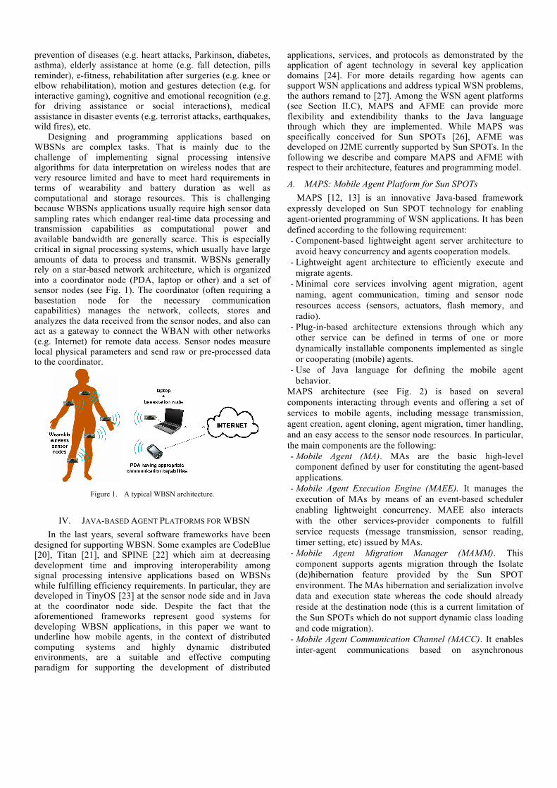
prevention of diseases (e.g. heart attacks, Parkinson, diabetes, asthma), elderly assistance at home (e.g. fall detection, pills reminder), e-fitness, rehabilitation after surgeries (e.g. knee or elbow rehabilitation), motion and gestures detection (e.g. for interactive gaming), cognitive and emotional recognition (e.g. for driving assistance or social interactions), medical assistance in disaster events (e.g. terrorist attacks, earthquakes, wild fires), etc.
Designing and programming applications based on WBSNs are complex tasks. That is mainly due to the challenge of implementing signal processing intensive algorithms for data interpretation on wireless nodes that are very resource limited and have to meet hard requirements in terms of wearability and battery duration as well as computational and storage resources. This is challenging because WBSNs applications usually require high sensor data sampling rates which endanger real-time data processing and transmission capabilities as computational power and available bandwidth are generally scarce. This is especially critical in signal processing systems, which usually have large amounts of data to process and transmit. WBSNs generally rely on a star-based network architecture, which is organized into a coordinator node (PDA, laptop or other) and a set of sensor nodes (see Fig. 1). The coordinator (often requiring a basestation node for the necessary communication capabilities) manages the network, collects, stores and analyzes the data received from the sensor nodes, and also can act as a gateway to connect the WBAN with other networks (e.g. Internet) for remote data access. Sensor nodes measure local physical parameters and send raw or pre-processed data to the coordinator.
Figure 1. A typical WBSN architecture.
IV. JAVA-BASED AGENT PLATFORMS FOR WBSN In the last years, several software frameworks have been
designed for supporting WBSN. Some examples are CodeBlue [20], Titan [21], and SPINE [22] which aim at decreasing development time and improving interoperability among signal processing intensive applications based on WBSNs while fulfilling efficiency requirements. In particular, they are developed in TinyOS [23] at the sensor node side and in Java at the coordinator node side. Despite the fact that the aforementioned frameworks represent good systems for developing WBSN applications, in this paper we want to underline how mobile agents, in the context of distributed computing systems and highly dynamic distributed environments, are a suitable and effective computing paradigm for supporting the development of distributed
applications, services, and protocols as demonstrated by the application of agent technology in several key application domains [24]. For more details regarding how agents can support WSN applications and address typical WSN problems, the authors remand to [27]. Among the WSN agent platforms (see Section II.C), MAPS and AFME can provide more flexibility and extendibility thanks to the Java language through which they are implemented. While MAPS was specifically conceived for Sun SPOTs [26], AFME was developed on J2ME currently supported by Sun SPOTs. In the following we describe and compare MAPS and AFME with respect to their architecture, features and programming model.
A. MAPS: Mobile Agent Platform for Sun SPOTs MAPS [12, 13] is an innovative Java-based framework
expressly developed on Sun SPOT technology for enabling agent-oriented programming of WSN applications. It has been defined according to the following requirement: - Component-based lightweight agent server architecture to
avoid heavy concurrency and agents cooperation models. - Lightweight agent architecture to efficiently execute and
migrate agents. - Minimal core services involving agent migration, agent
naming, agent communication, timing and sensor node resources access (sensors, actuators, flash memory, and radio).
- Plug-in-based architecture extensions through which any other service can be defined in terms of one or more dynamically installable components implemented as single or cooperating (mobile) agents.
- Use of Java language for defining the mobile agent behavior.
MAPS architecture (see Fig. 2) is based on several components interacting through events and offering a set of services to mobile agents, including message transmission, agent creation, agent cloning, agent migration, timer handling, and an easy access to the sensor node resources. In particular, the main components are the following: - Mobile Agent (MA). MAs are the basic high-level
component defined by user for constituting the agent-based applications.
- Mobile Agent Execution Engine (MAEE). It manages the execution of MAs by means of an event-based scheduler enabling lightweight concurrency. MAEE also interacts with the other services-provider components to fulfill service requests (message transmission, sensor reading, timer setting, etc) issued by MAs.
- Mobile Agent Migration Manager (MAMM). This component supports agents migration through the Isolate (de)hibernation feature provided by the Sun SPOT environment. The MAs hibernation and serialization involve data and execution state whereas the code should already reside at the destination node (this is a current limitation of the Sun SPOTs which do not support dynamic class loading and code migration).
- Mobile Agent Communication Channel (MACC). It enables inter-agent communications based on asynchronous

messages (unicast or broadcast) supported by the Radiogram protocol.
- Mobile Agent Naming (MAN). MAN provides agent naming based on proxies for supporting MAMM and MACC in their operations. It also manages the (dynamic) list of the neighbor sensor nodes which is updated through a beaconing mechanism based on broadcast messages.
- Timer Manager (TM). It manages the timer service for supporting timing of MA operations.
- Resource Manager (RM). RM allows access to the resources of the Sun SPOT node: sensors (3-axial accelerometer, temperature, light), switches, leds, battery, and flash memory.
Figure 2. MAPS software architecture.
The dynamic behavior of a mobile agent (MA) is modeled through a multi-plane state machine (MPSM). Each plane may represent the behavior of the MA in a specific role so enabling role-based programming. In particular, a plane is composed of local variables, local functions, and an automaton whose transitions are labeled by Event-Condition-Action (ECA) rules E[C]/A, where E is the event name, [C] is a boolean expression evaluated on global and local variables, and A is the atomic action. Thus, agents interact through events, which are asynchronously delivered and managed by the MAEE component.
It is worth noting that the MPSM-based agent behavior programming allows exploiting the benefits deriving from three main paradigms for WSN programming: event-driven programming, state-based programming and mobile agent-based programming.
B. AFME: Agent Factory Micro Edition AFME [14, 15] is an open-source lightweight J2ME MIDP
compliant agent platform based upon the preexisting Agent Factory framework and intended for wireless pervasive systems. Thus, AFME has not been specifically designed for sensor networks but, thanks to a recent support of J2ME onto the Sun SPOT sensor platform, it can be adopted for developing agent-based WSN applications.
AFME is strongly based on the Believe-Desire-Intention (BDI) paradigm, in which agents follow a sense-deliberate-act cycle. To facilitate the creation of BDI agents the framework supports a number of system components which developers have to extend when building their applications: perceptors, actuators, modules, and services. Perceptors and actuators enable agents to sense and to act upon their environment respectively. Modules represent a shared information space
between actuators and perceptors of the same agent, and are used, for example, when a perceptor may perceive the resultant effect of an actuator affecting the state of an object instance internal to the agent. Services are shared information space between agents used for data agent exchange.
The agents are periodically executed using a scheduler, and in particular four functions are performed during agent execution. First, the perceptors are fired and their sensing operations generate beliefs, which are added to the agent’s belief set. A belief is a symbolic representation of information related to the agent’s state or to the environment. Second, the agent’s desires are identified using resolution-based reasoning, a goal-based querying mechanism commonly employed within Prolog interpreters. Third, the agent’s commitments (a subset of desires) are identified using a knapsack procedure. Fourth, depending on the nature of the commitments adopted, various actuators are fired.
In AFME agents are defined through a mixed declarative/imperative programming model. The declarative Agent Factory Agent Programming Language (AFAPL), based on a logical formalism of belief and commitment, is used to encode an agent’s behavior by specifying rules defining the conditions under which commitments are adopted. The imperative Java code is instead used to encode perceptors and actuators. A declarative rule is expressed in the following form:
b1, b2, …, bn > doX; where b1… bn represent beliefs, whereas doX is an action. The rule is evaluated during the agent execution, and if all the specified beliefs are currently included into the agent’s beliefs set, the imperative code enclosed into the actuator associated to the symbolic string doX is executed.
The AFME platform architecture is shown in Fig. 3. It comprises a scheduler, a group of agents, and several platform services needed for supporting, among the others, agents communication and migration.
Figure 3. AFME software architecture.
To improve reuse and modularity within AFME, actuators, perceptors, and services are prevented from containing direct object references to each other. Actuators and perceptors developed for interacting with a platform service in one application can be used, without any changes to their imperative code, to interact with a different service in a different application. In the other way round, the implementation of platform services can be completely modified without having to change the actuators and the perceptors. Additionally, a same platform service may be used within two different applications to interact with a different set of actuators and perceptors. So, all system components of the AFME platform are interchangeable because they interact without directly referencing one another.

V. AN AGENT-BASED REAL-TIME HUMAN ACTIVITY MONITORING SYSTEM
The main aims of this section are (1) to demonstrate the effectiveness of agent-based platforms to support programming of WBSN applications and (2) to show how differently the two Java-based platforms, MAPS and AFME, allow defining the agent behavior in a real context. For these purposes a signal processing in-node system specialized for real-time human activity monitoring has been designed and implemented. In particular, the application is able to recognize postures (e.g. lying down, sitting and standing still) and movements (e.g. walking) of assisted livings. The architecture of the system, shown in Fig. 4, is constituted of one coordinator and two sensor nodes.
Figure 4. Architecture of the Real-time Activity Monitoring System.
The coordinator is an enhancement of the Java-based coordinator developed in the context of the SPINE project [22]. Differently from it, the new one has been re-designed around an agent developed through the JADE platform [25], which encapsulates the already implemented SPINE Manager and SPINE Listener. In particular, the SPINE Manager is used by end-user applications (e.g. the Real-time Activity Monitoring Application) for sending commands to the sensor nodes and for being notified with higher-level events and message content coming from the nodes. Then, the SPINE Manager communicates with the nodes by relying on the SPINE Listener, which integrates several sensor platform-specific SPINE communication modules. A SPINE communication module is composed of a send/receive interface and some components that implement such interface according to the specific sensor platform and that encapsulate the high-level SPINE messages into sensor platform-specific messages. In addition to the already implemented TinyOS and Z-Stack modules, not illustrated in Fig. 4, the MAPS and AFME modules have been integrated into the listener. The JADE agent coordinator also incorporates the logic for managing the synchronization of the two sensor agents.
The sensor nodes are two Sun SPOT respectively positioned on the waist and the thigh of the monitored person. In particular, MAPS or AFME runtime systems are resident on the sensor nodes and support the execution of the WaistSensorAgent and the ThighSensorAgent. The two agents have the following similar step-wise cyclic behavior:
1. Sensing on the 3-axial accelerometer sensor according to a given sampling time (ST);
2. Computation of specific features (Mean, Max and Min functions) on the acquired raw data according to the window (W) and shift (S) parameters. In particular, W is the sample size on which features are computed whereas S is the number of new acquired sample data for calculating a new feature. Usually S is set to 50% of W;
3. Features aggregation and transmission to the coordinator; Goto 1.
The agents differ in the specific computed features even though the W and S parameters are equally set. In particular, while the WaistSensorAgent computes the mean values for data sensed on the XYZ axes, the min and max values for data sensed on the X axis, the ThighSensorAgent calculates the min value for data sensed on the X axis. The interaction diagram depicted in Fig. 5 shows the interaction among the three agents constituting the real-time system: CoordinatorAgent, WaistSensorAgent and ThighSensorAgent.
Figure 5. Agents interaction of the Real-time Activity Monitoring System.
In particular, the CoordinatorAgent first sends an AGN_START event to each sensor agent for configuring them with the sensing parameters (W, S and ST); then, it broadcasts the START event to start the sensing activity of the sensor agents. Sensor agents send the DATA event to the CoordinatorAgent as soon as features are computed. If the CoordinatorAgent detect that the agents are not synchronized anymore (i.e. agent data are received with significant time difference due to different processing tasks), it sends the RESYNCH event to resynchronize them, for not affecting the real-time monitoring (see [28] for more details).
After having described the general architecture of the system, in the following subsections we describe the implementation of the WaistSensorAgent carried out with MAPS and AFME and, then, we compare the implemented solutions.
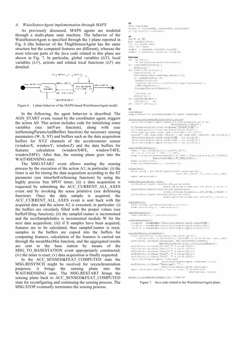
A. WaistSensorAgent implementation through MAPS As previously discussed, MAPS agents are modeled
through a multi-plane state machine. The behavior of the WaistSensorAgent is specified through the 1-plane reported in Fig. 6 (the behavior of the ThighSensorAgent has the same structure but the computed features are different), whereas the most relevant parts of the Java code related to this plane are shown in Fig. 7. In particular, global variables (GV), local variables (LV), actions and related local functions (LF) are detailed.
Figure 6. 1-plane behavior of the MAPS-based WaistSensorAgent model.
In the following, the agent behavior is described. The AGN_START event, issued by the coordinator agent, triggers the action A0. This action includes code for initializing some variables (see initVars function), along with (see initSensingParamsAndBuffers function) the necessary sensing parameters (W, S, ST) and buffers such as the data acquisition buffers for XYZ channels of the accelerometer sensor (windowX, windowY, windowZ) and the data buffers for features calculation (windowX4FE, windowY4FE, windowZ4FE). After that, the sensing plane goes into the WAIT4SENSING state.
The MSG.START event allows starting the sensing process by the execution of the action A1; in particular: (i) the timer is set for timing the data acquisition according to the ST parameter (see timerSetForSensing function) by using the highly precise Sun SPOT timer; (ii) a data acquisition is requested by submitting the ACC_CURRENT_ALL_AXES event and by invoking the sense primitive (see doSensing function). Once the data sample is acquired, the ACC_CURRENT_ALL_AXES event is sent back with the acquired data and the action A2 is executed; in particular: (i) the buffers are circularly filled with the proper values (see bufferFilling function); (ii) the sampleCounter is incremented and the nextSampleIndex is incremented module W for the next data acquisition; (iii) if S samples have been acquired, features are to be calculated, thus sampleCounter is reset, samples in the buffers are copied into the buffers for computing features, calculation of the features is carried out through the meanMaxMin function, and the aggregated results are sent to the base station by means of the MSG_TO_BASESTATION event appropriately constructed; (iv) the timer is reset; (v) data acquisition is finally requested.
In the ACC_SENSED&FEAT_COMPUTED state the MSG.RESYNCH might be received for resynchronization purposes; it brings the sensing plane into the WAIT4SENSING state. The MSG.RESTART brings the sensing plane back to ACC_SENSED&FEAT_COMPUTED state for reconfiguring and continuing the sensing process. The MSG.STOP eventually terminates the sensing process.
Figure 7. Java code related to the WaistSensorAgent plane.

B. WaistSensorAgent implementation through AFME The WaistSensorAgent specified trough the AFME design
model is depicted in Fig. 8 whereas a code excerpt, related to the model implementation, is provide in Fig. 9. In particular, the perceive method of the SensingPerceptor, the act method of the ActivateSensorActuator and part of the SharedDataModule are detailed. The AFME agent design is constituted by the components described in the following: • 2 Perceptors. MTSPerceptor checks for the arrival of a new
message coming from the coordinator whereas SensingPerceptor checks that the necessary features computation results are available, so that they can be sent to the coordinator.
• 3 Actuators. ActivateSensorActuator allows activating the sensing operation, ResetActuator resets the data buffer after the reception of the resynch message, and RequestActuator is used to send a request message to the coordinator carrying the computed features.
• Rules. TerImplication contains the auto-generated Java description of the agent behavior rules defined into a script file (see below).
• 1 Module. SharedDataModule contains buffers storing the data sensed from the three accelerometer channels, the feature extraction buffers and parameters, and an activation flag variable for enabling the sensing process.
• 1 Service. RadiogramMTS represents the message transport service for data transmission to the coordinator.
Figure 8. AFME-based WaistSensorAgent model.
The rules defining the agent behavior are the following: 1. message(inform, sender(BaseStation,
addresses(BSAddress)), begin) > activateSensors(1); 2. sense(?val), !message(inform, sender(BaseStation,
addresses(BSAddress)), resynch) > request(agentID(BaseStation, addresses("radiogram://"+BSAddress)), ?val);
3. message(inform, sender(BaseStation, addresses(BSAddress)), resynch) > reset;
The rule (1) enables the sensor reading operation on the sensor node. In particular, this rules states that the belief generated upon the reception of an inform message, having the “begin” content and sent by the coordinator with address BSAddress, triggers the action activateSensors(1), which fires the ActivateSensorActuator. This actuator simply sets the activation flag on: at first, the argument of the activateSensors in the rule is provided to the actuator through the action.next
method, then the call to the aMan.actOn (see act method in Fig. 9) causes the execution of the processAction in the SharedDatamodule (the actual flag is represented by the activated variable).
SensingPerceptor:
.... private PerceptionManager pMan; .... public void perceive(){
FOS fos = pMan.perManage("shareddata", 1); int activated= integer.parseInt(fos.toString()); if(activated == 1) { FOS fos2= pMan.perManage("shareddata",0); if(fos2!=null) { String fos2S= fos2.toString();
adoptBelief("sense("+fos2S+")"); } }
} ....
ActivateSensorActuator: .... private AffectManager aMan; .... public boolean act(FOS arg0) {
FOS arg= action.next(); aMan.actOn("shareddata", 1, null); return true;
} ....
SharedDataModule: .... // variables and data structures declaration .... // Perceptor processing public FOS processPer(int id)throws MalformedLogicExcep{ .... if(id==0) {
IAccelerometer3D acceleratorSensor= EDemoBoard.getInstance().getAccelerometer(); try {
windowX[this.windowCounter]= acceleratorSensor.getAccelX();
windowY[this.windowCounter]= acceleratorSensor.getAccelY();
windowZ[this.windowCounter]= acceleratorSensor.getAccelZ();
this.windowCounter= ((this.windowCounter +1)%this.WINDOW_SIZE);
this.shiftCounter++; }catch(IOException e){e.printStackTrace();} if (shiftCounter == SHIFT_SIZE){
double meanX = meanMaxMin(this.windowX)[0]; double meanY = meanMaxMin(this.windowY)[0]; double meanZ = meanMaxMin(this.windowZ)[0]; double maxY = meanMaxMin(this.windowY)[1]; double minY = meanMaxMin(this.windowY)[2]; String returnValues = this.timestamp+"|"+meanX+"|"+
meanY+"|"+meanZ+"|"+maxY+"|"+minY; this.timestamp=
((this.timestamp +1)%this.MAX_TIMESTAMP); this.shiftCounter= 0; return FOS.createFOS(returnValues);
}else return null; }else if(id==1){
String s= String.valueOf(activated); return FOS.createFOS(s);
} .... } // Actuator processing public FOS processAction(int id, FOS data)
throws MalformedLogicExcep{ ....
if(id==1){ String s= data.toString();
activated= Integer.parseInt(s); }
.... } ....
Figure 9. Java code from the AFME-based WaistSensorAgent.
The rule (2) regulates the agent behaviour during the sensing phase. If a new sense-belief is generated (i.e. features computation has been carried out on sensed data) and a message-belief, generated upon reception of the resynch message sent by the coordinator, does not exist, the request action is carried out so that a new message containing the computed features is sent to the coordinator. In particular, the sensing operation and the features computation are driven by the SensingPerceptor (see perceive method in Fig. 9) which, if the flag is on (activated==1), calls the pMan.perManage method with parameter “0” that in turns causes the execution of the processPer in the SharedDataModule (more precicely the code related to the condition id==0). This code performs the data reading from the accelerometer and the features computation, returning the results in the form of a belief (see sense(?val) in rule 2). Finally, the rule (3) allows resynchronizing the sensor agent. In particular, it states that if the belief message is generated upon reception of the resynch

message, the reset action, which re-initializes all the data structures in SharedDataModule, is executed.
C. MAPS and AFME: programming model differences The development of MAPS and AFME agents is based on
different approaches. MAPS uses state machines to model the agent behavior and directly the Java language to program conditions and actions. AFME uses a more complex model centered on perceptors, actuators, rules, modules, and services for defining the mobile agents. They are both effective in modeling agent behavior even though MAPS is more straightforward as it relies on a programming style based on state machines widely known by programmers of embedded systems. Moreover, differently from AFME, MAPS is specifically designed for WSNs and fully exploits the release 5.0 red of the Sun SPOT library to provide advanced functionality of communication, migration, sensing/actuation, timing, and flash memory storage. Finally, MAPS allows developers to program agent-based applications in Java according to its rules so no translator and/or interpreter need to be developed and no new language has to be learnt. See [28] for experimental results comparing the two agent platforms.
VI. CONCLUSION In this paper we have presented the agent-oriented
approach for high-level programming of WBAN applications. The agent approach is not only effective during the design of a WBAN application but also during the implementation phase. In particular, we have described two Java-based agent platforms, MAPS and AFME, allowing for a more rapid prototyping of sensor node code than low-level APIs which can be effectively used only by sensor node skilled programmers having knowledge of sensor drivers, communication and energy mechanisms. The higher level software abstractions provided by MAPS and AFME are suitable for a fast and easy real WBSN applications development as demonstrated by the proposed case study concerning a real-time human activity monitoring system.
ACKNOWLEDGMENT Authors wish to thank the members of the Plasma Group at
University of Calabria and in particular, Francesco Aiello, Alessio Carbone, Raffaele Gravina, and Antonio Guerrieri, for their excellent support and valuable contributions in terms of ideas, discussions and implementation efforts.
REFERENCES [1] J. Yick, B. Mukherjee, and D. Ghosal, “Wireless sensor network
survey,” Comput. Netw., vol. 52, pp. 2292-2330, August 2008. [2] G.-Z. Yang, Body Sensor Networks, Springer 2006. [3] Salem Hadim and Nader Mohamed, “Middleware: Middleware
challenges and approaches for wireless sensor networks,” IEEE Distributed Systems Online, vol. 7, March 2006.
[4] S. R. Madden, M. J. Franklin, J. M. Hellerstein, and W. Hong, “Tinydb: an acquisitional query processing system for sensor networks,” ACM Trans. Database Syst., vol. 30, pp.122-173, 2005.
[5] P. Bonnet, J. Gehrke, and P. Seshadri, “Towards sensor database systems,” in MDM '01: in Proc. of the 2nd Int. Conference on Mobile Data Management, pp. 3-14, London, UK, 2001. Springer-Verlag.
[6] Chavalit Srisathapornphat, Chaiporn Jaikaeo, and Chien-Chung Shen., “Sensor information networking architecture,” in Proc. of the International Workshop on Parallel Processing (ICPP), pp. 23, 2000.
[7] A. Bakshi, V. K. Prasanna, J.Reich, and D. Larner, “The abstract task graph: a methodology for architecture-independent programming of networked sensor systems,” in EESR '05: Proceedings of the 2005 workshop on End-to-end, sense-and-respond systems, applications and services, pp. 19-24, Berkeley, CA, USA, 2005. USENIX Association.
[8] R. Gummadi, O. Gnawali, and R. Govindan, “Macro-programming wireless sensor networks using kairos,” in International Conference on Distributed Computing in Sensor Systems (DCOSS), 2005.
[9] R. Newton, G. Morrisett, and M. Welsh, “The regiment macroprogramming system,” in Proc. of the 6th international Conference on Information Processing in Sensor Networks (IPSN '07, Cambridge, Massachusetts, USA, April 2007), pp. 489-498.
[10] C.-L. Fok, G.-C. Roman, and C. Lu, “Agilla: A mobile agent middleware for self-adaptive wireless sensor networks,” ACM Trans. Auton. Adapt. Syst., vol. 4, pp 1-26, 2009.
[11] Y Kwon, S. Sundresh, K. Mechitov, and G. Agha, "ActorNet: An Actor Platform for Wireless Sensor Networks," in Proc. of the 5th Int’l Joint Conference on Autonomous Agents and Multiagent Systems (AAMAS), pp. 1297-1300, 2006.
[12] F. Aiello, G. Fortino, R. Gravina, A. Guerrieri, “A Java-based Agent Platform for Programming Wireless Sensor Networks,” The Computer Journal, pp. 1-28, 2010. doi: 10.1093/comjnl/bxq019.
[13] Mobile Agent Platform for Sun SPOT (MAPS), documentation and software at: http://maps.deis.unical.it/ (2010).
[14] C. Muldoon, G. M. P. O Hare, R.W. Collier, and M. J. O’Grady, “Agent Factory Micro Edition: A Framework for Ambient Applications,” in Proc. of Intelligent Agents in Computing Systems, Lecture Notes in Computer Science, vol. 3993, pp. 727-734, Reading, UK, Springer 2006.
[15] Agent Factory Micro Edition (AFME), documentation and software at http://sourceforge.net/projects/agentfactory/files/ ( 2010).
[16] P. Levis and D. Culler, “Maté: a tiny virtual machine for sensor networks,” SIGARCH Comput. Archit. News, vol. 30, pp. 85-95, 2002.
[17] E. Souto, G. Guimaraes, G. Vasconcelos, M. Vieira, N. Rosa, and C. Ferraz, “A message-oriented middleware for sensor networks,” in Proceedings of the 2nd workshop on Middleware for pervasive and ad-hoc computing (MPAC '04), pp. 127-134, New York, NY, USA, 2004.
[18] S. Li, S. Son, and J. Stankovic, “Event detection services using data service middleware in distributed sensor networks,” Telecommunication Systems, vol. 26, pp. 351-368, 2004.
[19] W.B. Heinzelman, A.L. Murphy, H.S. Carvalho, and M.A. Perillo, “Middleware to support sensor network applications,” IEEE Network Magazine Special Issue, vol. 18, pp. 6-14, January 2004.
[20] D. Malan, T. Fulford-Jones, M. Welsh, and S. Moulton, “CodeBlue: An Ad Hoc Sensor Network Infrastructure for Emergency Medical Care,” in Proc. of MobiSys 2004 Workshop on Applications of Mobile Embedded Systems (WAMES 2004), June 2004.
[21] C. Lombriser, D. Roggen, M. Stager, and G. Troster, “Titan: A Tiny Task Network for Dynamically Reconfigurable Heterogeneous Sensor Networks,” in Verteilten Systemen (KiVS 2007), Bern, Switzerland..
[22] Signal Processing In-Node Environment (SPINE), documentation and software at http://spine.tilab.com (2010).
[23] TinyOS website, www.tinyos.net (2010). [24] M. Luck, P. McBurney, and C. Preist, “A manifesto for agent
technology: towards next generation computing,” Autonomous Agents and Multi-Agent Systems, vol. 9, pp. 203–252, November 2004.
[25] JADE, documentation and software at http://jade.tilab.com/ (2010). [26] Sun™ Small Programmable Object Technology (Sun SPOT),
http://www.sunspotworld.com/ (2010). [27] F. Aiello, G. Fortino, A. Guerrieri, “Using mobile agents as an effective
technology for wireless sensor networks,” in Proc. of the Second IEEE/IARIA International Conference on Sensor Technologies and Applications (SENSORCOMM 2008), Aug 25-31, Cap Esterel, France, 2008.
[28] F. Aiello, G. Fortino, S. Galzarano, R. Gravina, A. Guerrieri, “Signal processing in-node frameworks for Wireless Body Sensor Networks: from low-level to high-level approaches", Wireless Body Area Networks: Technology, Implementation and Applications. Pan Stanford publishing, 2010. To appear.
An agent-based system for maritime search andrescue operations
Salvatore Aronica1, Francesco Benvegna2,3, Massimo Cossentino2, Salvatore Gaglio2,4, Alessio Langiu2,3,5,Carmelo Lodato2, Salvatore Lopes2, Umberto Maniscalco2, Pierluca Sangiorgi2
(1) IAMC-CNR, Consiglio Nazionale delle Ricerche - Mazara del Vallo (TP), Italy(2) ICAR-CNR, Consiglio Nazionale delle Ricerche - Palermo, Italy
(3) Dipartimento di Matematica e Informatica, Universita degli Studi di Palermo - Palermo, Italy(4) Dipartimento di Ingegneria Informatica, Universita degli Studi di Palermo - Palermo, Italy
(5) Laboratoire d’Informatique Gaspard-Monge, Universite Paris-EST - Marne La Vallee, France
[email protected], [email protected], [email protected], [email protected], [email protected],[email protected], [email protected], [email protected], [email protected]
Abstract—Maritime search and rescue operations are criticalmissions involving personnel, boats, helicopter, aircrafts in astruggle against time often worsened by adversary sea andweather conditions. In such a context, telecommunication and in-formation systems may play a crucial role sometimes concurringto successfully accomplish the mission. In this paper we presentan application able to localize the vessel who has launched arescue request and to plan the most effective path for rescueassets. The application has been realised as a distributed andopen multi-agent system deployed on rescue vehicles as well as ona land maritime stations of the Italian Coast Guard. The systemis going to be tested in real scenarios by the Coast Guard.
I. INTRODUCTION
Coast Guards of all around the world are responsible formonitoring safety at sea and operate all the search and rescue(SAR) operations when someone is in danger. Search andrescue operations usually originates from an explicit requestfor rescue. Then a preliminary localization of the calling shipis conducted with results that strongly depend on the safetyequipment available on-board. A search plan is built basedupon this position to cover an area that has to take into accountthe position changes due to natural derive of objects in thesea and the type and number of the units involved in searchoperations. After the first eye contact, a physical approach tothe ship signs the starting point of the final rescue phase. Timeplays a primary role all along the previous phases. Every sailorknows the “golden day” rule stating that only within the first24 hours from the rescue request there are good chances ofsuccessfully accomplish the rescue. This is mainly based onthree factors: 1. Injured man condition may require urgentmedical assistance. 2. Damaged ship stays a short time atthe sea surface level before getting completely underwater.3. Men in water are difficult to sight and they have a shortsurvival time because of the need for drinking water or due toprohibitive temperature conditions.
Passenger ships and big cargo ships are equipped withdigital localization and transmission systems like the GlobalMaritime Distress and Safety System (GMDSS, see [11]),the satellite Emergency Position Indicating Radio Beacons(EPIRBs), the Search And Rescue Transponders (SARTs) anda radio station for long distance radio communications, thatallow route monitoring by Coast Guard and instantaneouslocalization in case of rescue request. The International Con-vention for the Safety of Life at Sea (SOLAS, see [10]), inforce in almost every worldwide sea since 1974, requires suchkind of devices aboard on big ships. These are called ”compul-sory ships” because they are required or compelled by treatyor statute to be equipped with specified telecommunicationsequipment.
What about smaller ships? Smaller ships used for recreation(e.g., sailing, diving, sport fishing, fishing, water skiing) arenot always required to have radio stations installed but theymay be so equipped by a choice. These ships are knownas “voluntary ships” because they are not required by lawto carry a radio but voluntarily fit some of the equipmentsused by compulsory ships. Ship stations may communicatewith other ship stations or coast stations primarily for safety,and secondarily for navigation and operational efficiency. Theymay or may not have a radio-positioning system, like theLong Range Navigation (LORAN) or the Global PositioningSystem (GPS), depending on the distance from the coast theyare authorized to navigate. Some ships or vessels have aradio station including a radio transmitter working on theVHF marine band, a Digital Selective Calling (DSC, see[12]) device, usually embedded in the radio transmitter, anda GPS attached to the DSC. When this system is correctlyset, it is able to easily send a semi automatic distress digitalcommunication with the vessel position if data is available.
Many other ships, probably the major part of the recreationships that sail between 6 and 50 marine miles far away from

the coast, have just a voice marine VHF radio transmitter.In this case a rescue request has to be done via voice onthe emergency channel by a human operator that has to com-municate his own position at the best of her/his knowledge.This process is prone to a lot of errors, like: an erroneousknowledge of the position itself, a misunderstanding of themessage over the voice channel because of a low quality ofthe radio communication, etc. Clearly, it takes much more timewith respect to an automatic system, in the order of minutesat least, and requires the presence of an operator at the on-board radio station. Obviously, while the operator is using theradio (s)he cannot give her/his help to other people or, worst,(s)he may not have enough time to communicate his positionbecause (s)he has to leave the ship, for instance in case of fireor sinking.
Once that Coast Guard has received a rescue request andknows the source position, it usually follows the InternationalAeronautical and Maritime Search and Rescue (IAMSAR, see[1]) guide lines to plan the search activity and to coordinateall the sea and air search units until the rescue is achieved.In the planning phase it has to determine an area where tolimit the search operation and it has to determine the searchpath of each single unit involved in the activity. Based onmany parameters, like elapsed time, weather conditions, kindof search unit (helicopter, ship) and other, it is needed tocalculate the shortest way to scour all the search area. Thispreparation work usually requires precious minutes.
The coordination work then has to assure the search oper-ation is performed as defined in the search plan. How muchtime the search will require and its final outcome are uncertainvariables.
In this scenario, what is possible to do is acting on thetimeliness and the accuracy of the overall system to better takeadvantage of the first moments, when rescue expectation isstill high. This paper proposes a system based on sophisticatedradio-communication devices and an agent-based software tocope with all of these problems. The solution includes anautomatic localization system of the radio signals on theemergency channel, an aiding system for the search area andsearch paths calculation and a coordination console that assiststhe Coast Guard operator during SAR phases by visualizingsearch paths and the last known position of the vessel indistress.
This system is the results of a joint effort of two institutesof the National Research Council (IAMC and ICAR) and ofthe Italian Coast Guard who participated in the project withpersonnel from the Mazara del Vallo station. The project itselfhas been funded by the Sicily Region Government.
The paper is organised as follows: the next section presentssome details about the problem of localising the vessel who isin danger and about the search and rescue planning issues.Section three discusses the proposed solution (in both itshardware and software aspects), section four discusses theobtained results and finally some conclusions are drawn inthe last section.
II. THE PROBLEM
This section discusses some details about the problemfaced in this project that mainly may be divided in twosub-problems: localization of the vessel who sent a distresssignal and the search and rescue operations planning andcoordination.
A. LocalizationLocalization is a very important activity in marine search
and rescue operations. The time spent to localize a vesselplays a fundamental role in life saving. The less the timeto discovery a vessel position, the more is the probabilityof saving human beings. Traditional techniques are based onradio communications between the boat in distress and therescue service. When an accident occurs, many factors suchas environment conditions, distance, stress could make hardthe communication and delay the rescue operation startup. Sofar, it’s clear that a fast and reliable communication betweenactors can be the difference in life saving.
While human beings need some time to communicate thevessel position by using the radio, an intelligent system coulddetect and localize the vessel in the sea by monitoring the radiochannel activity. Radio communications often occur duringrescue requests so that an intelligent observer which looksfrom different locations could localize the vessel by signaldirection detection.
To this aim a radio direction finder (RDF), that is a devicefor finding the direction of an incoming radio signal, maybe an useful tool. The Radio Direction Finder checks thesignal strength of a directional antenna pointing in differentdirections. While old devices used a simple rotating antennalinked to a degree indicator, new devices use a dipole antennato detect the signal. In the past the RDF was used during thewar to detect and identify secret transmitters in large region.The same idea can be applied to the different scenario ofmarine search and rescue. A group of RDFs controlled byan intelligent system can detect a distress signal and localizethe source before that a communication between human beingseven starts.
The system we developed, is also able to track vesselmovements after its first identification (tracking feature). Thisfeature can be very useful during long rescue operations toupdate the vessel position. The automatic localization has theadvantage of scalability: human communication requires manyradio listening points across the coast with many employeesbut a network of intelligent detectors can be installed over along coast (like the Italian one) and it requires a minimalnumber of human operators. The detection range can beincreased by the installation of new units along the coast.
The intelligent system is composed by a society of intelli-gent agents which collaborate in monitoring radio frequencies,in matching the detections, in notifying every rescue requestto the rescue service operator. The system normally listens tothe maritime radio emergency channels and whenever a signalis detected, a search of possible matches is looked for. Whena match is found, the agents notify the discovery to other

agents responsible for other system behaviors (for instancerescue plan definition) and to the Coast Guard personnel. Ofcourse, the rescue operator is free to verify the alarm by usingother communications or to monitor the radio signal as longas (s)he wants.
The localization is possible due to at least two radio signaldetections by two of the several stations deployed alongthe sea coast. When the source of the signal (the vessel)and the two detection stations are not aligned, a geometrictriangulation gives the vessel position. The triangulation iscomputed between the direction vectors detected by the twostations. Of course, two vectors are necessary and sufficientbut other ones may be used to improve the precision of thelocalization. Precision is in fact limited by the small error onthe identification of the observed signal direction. The degreeerror becomes an estimated position error that is proportionalto the distance between the source and the detection stations.
In Figure 1 we show the most simple search and rescuescenario where a vessel in troubles sends a distress signal thatis in turn detected by a couple of coast stations. After thedetections, the intelligent agents share that information andlocalize the source of the signal. In figure 1 we show the twovectors and the two angles used for triangulation.
In the system there are two different kinds of stations:detection stations are unmanned and the only host hard-ware and software devoted to receive the distress signal andidentify its direction. Control stations are manned and theyhost a complete hardware-software system thus including thecapability of receiving information from detection stations,performing triangulation and supporting SAR operations asdescribed in the next subsection. Usually there is one controlstation responsible for each sea area according to Coast Guardprocedures.
Each detection station sends the following data to thecontrol station:
• the radio channel of the signals obtained from detectionfinder
• the direction of the signal• the position of the station• the time of detection
The position and the time of detections are very usefulto match detections from several stations. Of course, twodetections of the same signal have a very similar detectiontime.
The detections should be stored in an archive to solveproblems about communication delays. In order to match asignal, the system searches a very similar detection from an-other station occurred in a fixed time window; the match withhighest score is selected and used to compute the triangulation.The use of an archive is very important to trace each eventcollected by the system.
So far, the computed localizations are sent to a GUI-GISplatform which shows a map to support the rescue operatorsin organizing the rescue operation and in managing it. Theoperator can update the data about any vessel shown by
Fig. 1. A simple scenario with two stations detecting an emergency call
the GUI and could start tracking or could cancel an alarmdetection.
B. Search and Rescue
Search and rescue Operations (SAROPs) in maritime en-vironment are regulated by a series of procedures definedand approved at the worldwide level. These procedures arereported in the IAMSAR (International Aeronautical and Mar-itime Search and Rescue) Manual Volume II. In Italy, SAROPsin maritime environment are entrusted to the Corpo delleCapitanerie di Porto Guardia Costiera (Coast Guard), whichuses an articulated organizational network sometimes involv-ing other national forces to accomplish these operations. Ourscope is to provide this organization with a computer aidedsystem that covers all the procedures involved in maritimeSAROPs and that is compliant to the guidelines provided bythe IAMSAR manual extended and optimized with the naturalbenefits a computer system can give. The procedures involvedin SAROPs can be grouped in two principal phases:
• Determining datum• Define search action plan
Datum in SAR is defined as a geographic point, line, or areaused as a reference in search planning. Scope of the first phaseis to determinate the datum starting from information like lastknown position, time of distress, a series of environmentalinformation like wind, water current, leeway and other inputsthat combined are able to give the effect of the drift on thesearch objects. In this phase the use of a computer systemenables the remote acquisition and management of a largeamount of data and a fast computation on it, with a veryimportant time-saving that is a critical point in SAROPs.

Fig. 2. Probability density for point, line and area datum (from IAMSARmanual, vol. II)
Once the datum has been determined, the second phase is todefine the optimal search area where the available search effortshould be deployed. The search planner involved in this phasemust define the optimal search area starting from the previ-ously calculated datum and from some statistical considera-tions based on probability distributions. The IAMSAR manualonly considers two types of probability distributions: standardnormal distribution and uniform distribution, respectively usedfor datum points and lines or for areas datum. The first consistsin a Gaussian distribution with the highest probability densitynear the datum and a decreasing probability density as thedistance from the datum increases.The second consists in anarea assumed to be evenly distributed unless there is specificinformation which favourishes some parts over others. Figure2 is taken from IAMSAR Manual and it shows respectivelythe probability density for point, line and area datum.
Based on these distributions, the manual provides a set ofprobability maps of grid type where every cell has a prefixedvalue of probability of containment of the search object. Thesearch planner must chooses one of these maps and overlay itover the chart centered in the estimated datum position. In thisway (s)he obtains the area which contains the search object andthe probability of containment distribution in that area. Afterthat, the search planner evaluates the environmental searchconditions, (s)he splits the search area in sub-areas and assignsthem to search facilities chosen for the operations between allavailable ones. Such search rescue units (SRUs) will coverthe assigned area with a prefixed navigational path chosen bythe search planner from a set defined in the manual. Figures3(a) and 3(b) are taken from IAMSAR Manual and show twoexamples of possible search paths.
The step illustrated in 3(b) may seem simple for the searchplanner, but it requires a relevant experience because of the
(a) Parallel sweep search (PS).
(b) Creeping line searh, co-ordinated (CSC).
Fig. 3. Two examples of possible search paths (from IAMSAR manual, vol.II)
presence of a limited set of very generic choices for coveringevery specific scenario. We think that, thanks to the use ofa computer system, there is a lot of optimization marginin this phase and our system has been designed to supportenhanced statistical elaboration techniques like the MonteCarlo Simulation (see [6]) to determine the search area insteadof the prefixed probability maps suggested by the IAMSAR.Moreover optimization of search paths for the navigation ofthe SRUs is supported by a similar analysis. The RequirementAnalysis phase of the project was done with the supportof a domain specialist working with the Coast Guard andconsidering the list of “Functional Characteristics to Considerwith the Computer-based Search Planning Aids” provided bythe IAMSAR Manual.
III. THE PROPOSED SOLUTION
In order of improve the time response of SAR operationsfollowing a distress request, we propose an integrated aidingsystem that is able to localize and visualize the requestingvessel position, it is able to estimate and visualize the searchplan for the search operators and the operation coordinatorand to allow to visually follow all the SAR operations. Theproposed solution uses multiple detection stations equippedwith a RDF to simultaneously acquire the direction of thedistress radio request and then to estimate the source signalposition by triangulation. The solution also includes somevisualization features by which operators are provided witha Geographic(al) Information System (GIS) interface thatgraphically shows the searched vessel estimated position, theposition of the search units and the search plan information.

Fig. 4. Architecture of the system.
The same interface allows to interact with the system forconfiguration and control purpose.
In the next subsections the details of the developed solutionwill be presented starting by the analysis of the hardwarecomponents and then considering the software part.
A. System Devices and Technologies
The engineering of a distributed system as a solution to theabove problem involves the design of hardware and softwarearchitectures. The hardware architecture will comprise all theneeded devices to work in marine radio environment both fordetection and communication. The hardware architecture ofthe system is shown in figure 4. The main components are:
• Detection Finder: listens to a fixed radio frequency toidentify a source of a radio signal in any directions
• Global Positioning System: reads from satellites the po-sition of itself and the current time
• Computer: hosts a component of the intelligent systemwhich manages the devices used to localize the source ofa radio signal
• Network Device: is used fro communication betweenstations. For mobile station a marine radio-modem isused while a router or switch is used to connect severalnetwork segments in the coast.
While the communication among coast stations is alwayswired, the communications among mobile units and coaststations are based on a wireless connection. The radio-modemused in the last cases operates on the radio marine frequencyto send data at the fastest possible speed. Of course, theconnection speed is affected by other communications butmore significantly by the distance between communicationpoints. The location of the stations is needed to compute thetriangulation of detected signals. Therefore a Global Position-ing System (GPS) is installed in every detection station. TheGPS is connected to the computer which hosts the intelligentagents so that they can read the station coordinates and sendthem data about the radio signal.
Communications in this project are affected by the limitsderiving from the use of marine radio systems famong coaststations and rescue boats. We decided to adopt a classicalTCP/IP connection by Point-To-Point-Protocol (PPP) overradio-modems. The TCP protocol permits an easy communi-cation among the agent platforms due to digital bridge createdby PPP over a radio communication. Indeed, the stations onthe coast are connected by an Intranet or Internet connectionso that no communication problems should occur.
The used direction finders are the RT-300 made by Rho-Theta. They can receive radio signals on the marine VHF

Fig. 5. Agent Identification Diagram of the designed system
band and they export the signal detections using the NationalMarine Electronics Association (NMEA) 0183 [2] compliantcommunications. Also the selected GPS receivers are NMEAcompliant. They are marine GPS devices with 12 parallelreceiving channels. The used radio modems are the Taitradio modems. They have a transmission power of 5W onthe marine VHF band that allow communication boat-coastup to about 15 miles (radio horizon distance). For the on-board stations we used Panel PCs because of their water andsolicitation resistance and the easy to use their touch-screenbased interface. Other devices are standard office equipmentsas PCs and network devices.
To the software design and implementation we devoted thenext two subsections.
B. The Multi Agent System
The software solution has been designed by using the PASSIdesign process (see [3]) and its evolution PASSI2 (see [4]). Themulti-agent system has been implemented by using the JADEagent framework (see [8] and [9]) in Java language (see [7]).
Figure 5 shows the PASSI Agent Identification Diagram ofthe designed system. This diagram depicts agents in form ofpackages and their functionalities are reported as use cases.
The most important agents identified in the design processare:
• Read HW: the agent collects data from a detection finderand GPS device connected to the station. The data readfrom devices is NMEA coded and each uses a differentsubset of the protocol. The devices are connected througha serial link to the computer that hosts the agent platformnode. The serial line is used to query the device and toread the response. The agent collects the data and sendsthem to the agent ’Send Data’ (see below).
• Send Data: this agent is designed to solve a project risk:the radio communication channel in some cases is notas fast as a wired one so a communication point whichserialize data in very efficient way must be defined. Thisagent is needed because the slow communication channelshould be used as little as possible. A message must besent only to the agent that will use it. These problems arevery important when the number of installed detectionstations is high.
• Receive Data: this agent is the receiving agent which iscoupled with the agent ’Send Data’ described above.
• Estimate V Position: this agent collects the detected sig-nals, stores them and finds any match inside to estimatethe source of the radio signal. Of course the source ofthe signal is the position of the boat distress. The datais stored in a relational database system with logs ofany event of the system.The search of the matches isimplemented by a JADE cyclic behaviour which verifiesany detection not marked and searches a compatiblesignal in different detection stations. Two signals arecompatible if the radio channel is the same and thedetection time is quite ’near’. When a match is foundthe agent searches another compatible match to verify ifthe estimated position is about a movement of the distressboat. The latter feature is the boat tracking one. So theagent understands if the estimated position is about a newdetection or about a movement of a known boat.
• Show V Position: this agent is the nearest to the humanuser. The agent has a GUI with a GIS support to showthe state of the system to the operator and to interact withher/him. The GUI shows a sea and coast map with theestimated position of the active boat distress. The agentcollects the estimated position produced by the above

Fig. 6. A deployment of the agents in the system: each node is a JADE container connected to the Main Container - Control Station CT0
mentioned agent ’Estimate V Position’ and permits tousers to execute some operations as alarm validation andtracking.
• Datum Agent: This agent is responsible for determiningthe datum for the search targets. It receives the estimatedincident position (or last known position) from the agentSend Data and starting from this information and otherinputs about the scenario coming from Search Plannerand Information Provider actors, it computes the driftforces by which the searched objects are affected. Inthis way the agent can provide to the Search Planner anestimated datum of the search objects after the amountof time from time of distress to the commence searchpoint. Main abilities of this agent are the acquisition ofexternal information, management of points in WGS84coordinates and vector calculus.
• Planner Agent: This agent is responsible for providing asearch action plan for the search objects starting fromthe datum estimated by the Datum Agent. Once thedatum is received, it defines the search area based on thefacilities employed, environmental search conditions andprobability calculation based on Monte Carlo Simulation.After that, it considers the area with the maximumprobability of containment of the search objects that canbe covered by the employed facilities and splits it in sub-areas to assign each of them to a SRU (Search and RescueUnit). The agent is also responsible for determining thebest coverage path for every SRU so to maximize theprobability of success with the maximum search effort
available. Another functionality provided by this agent isthe management of the list of facilities available for theCost Guard, with insert, update and remove functions ofthe facility. Main abilities of this agent are statistical andoperational research computation, respectively for MonteCarlo Simulation and best coverage path algorithm.
• Plotter Agent: This agent is responsible to plot the in-formation relative to the datum and search action planpreviously calculated by the relative agents. It makes useof an open source GIS library (OpenMap) ?? to overlaythe relevant operation results on nautical charts in WGS84coordinates.
• Report Agent: This agent is responsible for producingthe official papery worksheets defined in the IAMSARmanual. After a SAR mission is completed, and all datarelative to the mission is known, it produces several PDFfiles that represent the previously cited documents.
The participating actors of the system are:
• Rescue Operator: he is the actor that interacts with thelocalization subsystem. Any position about source of sig-nal on emergency channels is notified to this actor whichtries to communicate with that source for understandingwhat is going on.
• Search Planner: Actor that represents the SAR missioncoordinator (SMC) of the Coast Guard. (S)He interactswith the system typing the scenario information of thesystem and receiving the output results.
• Information Provider: Actor that represents any externalinformation provider useful for the scenario definition

and elaboration, like Web Services for weather condition,time-zone calculation, daylight/sunrise calculation, and soon.
The system is fully implemented in Jade. Some little partsare native libraries used to read and write through the serialports. The object-oriented persistence is implemented by use ofthe framework Hibernate. The persistence framework permitsto be independent from databases: the first implementationuses an installation of Apache Derby but future developmentis possible on more performant databases as MySQL orPostgreSQL.
The deployment of the agents is shown in figure 6. We cansee that a mobile station has only agents useful to receive andshow the active detections and to send requests about valida-tion and tracking to nodes that perform the estimate of vesselposition. A detection station in the coast may have or notthe GIS platform that shows a map with detections. In everyway an agent ’Show V Position’ can be deployed in the nodeto add visualization features. This feature is an advantage ofthe agent-platform over service-oriented architectures becausean agent can be created and can easily migrate to any nodeconnected to the main container.
The mobile station receives the updated state of detectionsso that rescue operation will be more efficient. The operatoron the rescue boat doesn’t need to retrieve information aboutboat distress from main rescue station because the system doesit for him.
C. User interfaces
The system is provided with a graphical user interfacedeveloped using Java Swing library. The main interface screenreports GIS data visualization. This is based on the opensource GIS platform “OpenMap” that allows to easily visualizegeographical coordinates for points, shapes or lines on ageographic map.
An example of such interface is reported in Figure 7. Herea “Sinking Boat” is shown by a red blinking point and a boatname. This name is initialized by the system with the MaritimeMobile Service Identity (MMSI) when the distress request issent by a DSC/VHF or it is assigned by the system in caseof voice communication, but the operator can modify it fora more friendly mnemonic name. Blue icons refer to searchunits. The shadowed area is referring to the boat datum, i.e. thesearch area. Other boats are represented by white icons. Moreinformation could be recalled on this page by the operator.
System SAR functionalities are grouped in three differenttab-forms respectively for the estimate datum, search actionplan and plot activities. This GUI was designed according tothe guidelines of the domain specialist working with the CoastGuard. This collaboration reflects the choice to produce largeforms with great vertical grow that contain the greatest infor-mation as possible, so to reduce input typing of informationand different screen navigation, with consequently time-savingfor the SMC. Figure 8 shows a fragment of the Estimate Datumtab where the user can input information about wind and water
Fig. 7. A screenshot of the GIS interface.
current and obtain the results both in textual and graphicalrepresentation.
Fig. 8. A screenshot of the Estimate Datum form.
IV. DISCUSSION
The problem we are studying is in our opinion a goodexample of ideal application context for multi-agent systems.This is due to the some specific requirements it has tofulfill: autonomy of components, scalability, distribution andopenness.
• In the faced scenario specific problems may occur asan obvious consequence of the complexity descendingfrom the distribution of a very large system. Each stationshould be autonomous and independent from other sta-tions so that a failure in one station does not seriouslyaffect the system functionalities. This fault tolerance isvery important in a rescue system because a block of the

system may cause an injury for people or things. Eachsystem component should be able to resume its activityafter a (system or communication) failure so that thecollected data can be analyzed when the fault is resolved.This behavior is a feature that in a service-orientedarchitecture may create some problems. A service isalways called by someone else: a service is a procedurethat is executed when it is requested. A service is notautonomous: if it is not called then it doesn’t start anyaction.
• Scalability permits a wide installation to cover largeregions as well as a small initial deploy (what we arerealizing within this project). The adoption of a MASeasily permits to scale the number of installed stationswithout any significant change to the system architecture.
• The easiness of agents distribution (together with theirautonomous behavior) permits the installation in some ofthe stations of only a part of the system that is duplicatedin some others. Upgrade of existing software components(necessary because of a bug fixing or a new releasedeploy) may be rapidly thanks to agents’ mobility.
• Openess in another issue to be faced. The system issupposed to be in operation for a long period and it shouldbe able to accept new functionalities by dynamicallyintroducing new agents in the society. This is not onlysupposed to be done by the central authority but any localstation should be able to start a local project deliveringnew agents that should smoothly enter the system. Inorder to fully support that, we rigorously applied someof the most advanced features of the PASSI process.Agents may depend on other agents for information orservices. Such a dependency is never hard coded but it isdynamically realized on the basis of ontological specifi-cations. Each agent registers on the system yellow pagesthe services and information it is able to provide. Agentsin need of such services/information always look for theirproviders in the yellow pages and then directly contactthem. PASSI fully supports that thanks to the specificationof service/information exchange in the Domain OntologyDescription and the Communication Ontology Diagram.When a new agent enters the community, it can offer newservices or depend on existing ones. The system automat-ically accepts the change and the agents will considerthe new service at the same level of the older ones. Thiswill obviously imply an autonomous reorganization ofthe society behavior towards the achievement of the newgoals.
In other words, the nature of the project and the environmentwhere it is executed are good reasons to have a solutionbased on agent- oriented software. A primary advantage ofthis solution is the autonomy of the agents and their capacityto work in large cooperating environments. Agents’ autonomyalso contributes to solve the problem of fault tolerance: ev-erywhen a fault happens the agents which are not involvedor damaged continue to collect, send and compute data. Each
agent executes a unit of work and, because of its autonomy, itdecides any action to be executed on the occurrence of severalevents. The scalability is another intrinsic aspect obtained bythe use of agent technology. The proposed system can growto meet new requirements about land cover: to cover a newmarine area it is just sufficient to install a new detection stationmanages by a new set of agents which collaborate with theexisting agent-society.
V. CONCLUSIONS
Maritime search and rescue operations are critical missionsinvolving personnel, boats, helicopters, aircrafts in a struggleagainst time often worsened by adversary sea and weatherconditions. In such a context, telecommunication and informa-tion systems may play a crucial role sometimes concurring tosuccessfully accomplish the mission. In this paper we presenta complex system designed and developed to cope with theseproblems in a real application scenario. The hardware partof the system includes radio communication devices, GPSreceivers and Radio Direction Finders (RDF). The softwarepart is composed by a multi-agent system with demandingfeatures like high distribution, scalability, openness, fault tol-erance and high reliability. The system is to be deployed onrescue vehicles as well as on a land maritime stations of theItalian Coast Guard. The system is going to be tested in realSAR scenarios.
ACKNOWLEDGEMENTS
The authors would like to thank personnel of the Mazaradel Vallo Coast Guard Station, specifically C.F. Manganiellofor its invaluable help and stimulating suggestions. This workhas been partially funded by the ICT-E3 (ICT Excellenceprogramme of the Western Sicily) project of the Sicily Region.
REFERENCES
[1] IAMSAR Manual Volume II :Mission Co-Ordination 2007 ConsolidatedEdition, 2007.
[2] NMEA 0183 Standard. National Marine Electronics Association, 7 RiggsAve., Severna Park, MD 21146.http://www.nmea.org
[3] M.Cossentino, From Requirements to Code with the PASSI Methodology.In Agent-Oriented Methodologies, B. Henderson-Sellers and P. Giorgini(Editors). Idea Group Inc., Hershey, PA, USA. 2005. 2008.
[4] M. Cossentino, V. Seidita. PASSI 2 - Going Towards Maturity of the PASSIProcess. ICAR-CNR Technical Report 09-02. December 2009, 2008.
[5] BBN Technologies, OpenMap: Open System Mapping Technology(http://www.openmap.org), 2005.
[6] Metropolis, N.; Ulam, S., The Monte Carlo Method, 1949 - Journal ofthe American Statistical Association (American Statistical Association)44 (247): 335341. doi:10.2307/2280232. PMID 18139350.
[7] James Gosling, Bill Joy, Guy Steele and Gilad Bracha. Java TM LanguageSpecification, The 3rd Edition. Addison-Wesley Professional. 2005. ISBN0321246780.
[8] F. Bellifemine, A. Poggi and G. Rimassa., Developing multi-agent sys-tems with JADE, Seventh International Workshop on Agent Theories,Architectures, and Languages (ATAL-2000), Boston, MA, 2000.
[9] Fabio Bellifemine, Agostino Poggi, Giovanni Rimassa, JADE - A FIPA-compliant agent framework, Telecom Italia internal technical report. Partof this report has been also published in Proceedings of PAAM’99,London, April 1999, pp.97-108.
[10] International Conference on Safety of Life at Sea, 1974. Inter-governmental Maritime Consultative Organization. ISBN 9280110365,1974.

[11] Global Maritime Distress and Safety System (GMDSS) - InternationalMaritime Organization (IMO).http://www.imo.org/About/mainframe.asp?topic_id=389
[12] Digital selective-calling system for use in the maritime mobileservice. Recommendation International TelecommunicationUnion ITU-R M.493-13, techinical specification. 10-2009.http://www.gmdss.com.au/DSC%20tech%20spec.pdf.

Transitivity in Trust A discussed property
Rino Falcone Institute of Cognitive Sciences and Technologies
National Research Council of Italy Rome, Italy
Cristiano Castelfranchi Institute of Cognitive Sciences and Technologies
National Research Council of Italy Rome, Italy
Abstract—Transitivity in trust is very often considered as a quite simple property, trivially inferable from the classical transitivity defined in mathematics, logic, or grammar. In fact the complexity of the trust notion suggests evaluating the relationships with the transitivity in a more adequate way. In this paper, starting from a socio-cognitive model of trust, we analyze the different aspects and conceptual frameworks involved in this relation and show how different interpretations of these concepts produce different solutions and definitions of trust transitivity.
Keywords-component; Trust, Transitivity, Degree of Trust, Task definition
I. INTRODUCTION Trust is becoming a research topic of major interest not only in Artificial Intelligence (AI) and in Multi-Agent Systems (MAS), but also more in general in Information and Communication Technologies (ICT). The main reason of this fact is that the more recent developments of the “interaction” paradigm of computation, are driving more and more towards the development of computational entities with a strong and well defined autonomy. These entities have to cooperate/conflict among them in conditions of open world for achieving their own goals. In perspective, we are going towards an interaction scenario in which artificial entities and humans are indistinguishable from each other. In this view, the probability that we have to interact or cooperate with entities we do not have any personal experience with, will be growing, and the need of attributing trustworthiness to the potential partners becomes a fundamental prerequisite. And to model trust in the way in which humans have always done it, being them in the interaction loop, is particularly relevant. Many different approaches and models of trust were developed in the last 15 years [1, 2, 3, 4, 5, 6, 7, 8, 9, 10]: they contributed to clarify many aspects and problems about trust and trustworthiness, although many issues remain to be addressed and some elementary but not so trivial trust properties are left in a contradictory form. One of them is the problem of trust transitivity. If X trusts Y, and Y trusts Z: What about the trust relationship between X and Z? Different and sometimes diverging answers were given to this problem. The question is not only theoretically
relevant; it is very relevant from the practical point of view, for the reason we have just mentioned: acting in an open world, interacting with new people/agents.
In this paper we will present an analysis of the trust transitivity in the case in which a socio-cognitive model of trust is taken in consideration. Through this kind of model we are able to evaluate and partially cope with the complexity that the concept of transitivity introduces when applied to the trust relationship.
II. A SOCIO-COGNITIVE MODEL OF TRUST In our socio-cognitive model of trust [11, 12, 13, 14] we consider trust as a layered notion, where the various more or less complex meanings are embedded one into the other. We analyzed the relevant relationships among these different layers and studied the possible transitions among them. We developed the analysis of the mental attitude and disposition towards the trustee (considering beliefs like evaluations and expectations); the intention and decision based on the previous dispositions; the act of relying upon the trustee’s expected behaviour; finally the social interaction and relation between trustor and trustee.
In particular we consider trust as a relational construct between the trustor (X), the trustee (Y), about a defined (more or less specialized) task (!):
where are also explicitly present both the X’s goal (gX, respect to which trust is activated) and the role of the context (C) in which the relationship is going to happens. In fact, the successful performance of the task ! will satisfy the goal gX. So the X’s mental ingredients of trust are: the goal gX, and a set of main beliefs:
!
Bel(X CanY ("))
!
Bel(X WillY ("))
!
Bel(X ExtFactY (")) where: CanY (!) means that Y is potentially able to do ! (in the sense that, under the given conditions, is competent, has the internal powers, skills, know-how, etc) (and this is believed by X);
!
Trust (X Y C " gX )

WillY (!) means that, under the given conditions, Y potentially has the attributions for being willing, persistent, available, etc., on the task ! (and this is believed by X); ExtFactY (!) means that potentially there are a set of external conditions either favoring or hindering Y realizing the task ! (and this is believed by X).
In our model we also consider that trust can be graded: X can have a strong trust that Y will realize the task (maybe 0.95 in the range (0,1)); or even just a sufficient trust that Y will achieve it (maybe 0.6 with a threshold of 0.55; and so on with other possible values). For this we have introduced a quantification of the degree of trust (DoTXY!) and, in general,
a threshold (") to be overcome from this DoTXY!. Given the previous analysis of the main components of the trust attitude (gX, Bel (X CanY (!)), Bel (X WillY (!)), Bel (X ExtFactY (!))), we can say that this degree is, on its turn, resultant from the several quantifications of these components:
!
DoTXY" = f (DoCX (OppY (")),DoCX (AbilY (")),DoCX (WillY (")))where: f is in general a function that preserves monotonicity;
DoCX (OppY(!)) is the X’s degree of credibility about the external opportunities (positively or negatively) interfering with Y’s action in realizing the task ! ; DoCX (AbilityY(!)) is the X’s degree of credibility about the Y’s ability/competence to perform !; DoCX (WillingnessY(!)) is the X’s degree of credibility about the Y’s willingness to perform !.
We are ignoring the subjective certainty of the pertinent beliefs (how much sure is X of its evalutative beliefs about that specific Y’s quality, that is a meta-belief; in fact we can say that this factor is integrated with the other). At the same time we are ignoring for now the value of the goal (gX). So trivially X will trust Y about the task ! if
!
DoTXY" ># that means that a set of analogous conditions must be realized about the other quantitative elements (DoCX (OppY(!)), DoCX (AbilityY(!)), DoCX (WillingnessY(!))). We do not consider in this paper the detailed analysis of how the degree of trust is resulting by the more elementary components and we also omit of considering the potential positive and negative interferences among the components themselves.
Introducing also the concept of Y’s trustworthiness degree (TrustworthinessYX(!)) with respect to X about the task ! , we can say that from:
!
DoTXY" ># it derives that
!
Bel(X TrustworthinessYX (") > #) In general "=# .
III. TRANSITIVITY IN TRUST Many authors have questioned whether the transitive property can be applied to trust. In more specific words many of them have presented this problem in this way: If X trusts Y, and Y trusts Z: What about the trust relationship between X and Z? Their answers are different and very briefly we will analyze some of them in §IV. We are now interested to translate this problem in our terms of trust. First of all, we do not consider the unspecified case “X trusts Y” because in our model an agent has to trust another agent with respect a task (either very well defined or less defined and abstract); this task directly derives from the goal the trustor has to reach with the trust attribution. So we have to transform “X trusts Y” in “X trusts Y about !”. And given the graded qualification of trust we have that:
!
DoTXY" ># this means in particular that X believes that Y is potentially able and willing to do ! and that the external conditions in which Y will perform its task are at least not so opposite to the task realization (may be also they are neutral or favorable). So this Y’s trustworthiness with respect to X (perceived/believed by X) is based on these specific beliefs. At the same way “Y trusts Z” becomes “Y trusts Z about !1” (about the difference between ! and !1, see later) with the same particular Y’s beliefs about Z and the external conditions. Also in this case we can say that there is a threshold to be overcome and the condition:
!
DoTYZ"1 >#1 successfully satisfied in case of trust attribution. If we have to consider the trust relationship between “X and Z” as a consequence of the previous trust relationships between “X and Y” and between “Y and Z” we have to define the task on which this relationship should be based (question of assimilation between ! and !1) and the degree of trust that must be overcome even from X:
!
DoTXZ" >#2
with the consideration of the threshold "2. The role of the trust threshold is quite complex and can have an overlapping with the ingredients of trust. We strongly simplify in this case considering " as dependent just from the specific intrinsic characteristics of the trustor (those that define an agent intrinsically: prudent, reckless, and so on) independently from the external circumstances (on the contrary, these factors affect the degree of trust, by affecting the more elementary beliefs above showed). So, we can say that in this approximation (for the same agent the trust threshold is always the same):
" = "2
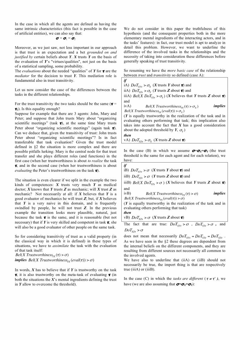
In the case in which all the agents are defined as having the same intrinsic characteristics (this fact is possible in the case of artificial entities), we can also say that:
" = "1 = "2 Moreover, as we just saw, not less important in our approach is that trust is an expectation and a bet grounded on and justified by certain beliefs about Y. X trusts Y on the basis of the evaluation of Y’s "virtues/qualities", not just on the basis of a statistical sampling, some probability. The evaluations about the needed “qualities” of Y for ! are the mediator for the decision to trust Y. This mediation role is fundamental also in trust transitivity. Let us now consider the case of the differences between the tasks in the different relationships. For the trust transitivity the two tasks should be the same (! = !1). Is this equality enough? Suppose for example that there are 3 agents: John, Mary and Peter; and suppose that John trusts Mary about “organizing scientific meetings” (task !), at the same time Mary trusts Peter about “organizing scientific meetings” (again task !). Can we deduce that, given the transitivity of trust: John trusts Peter about “organizing scientific meetings”? Is in fact transferable that task evaluation? Given the trust model defined in §2 the situation is more complex and there are possible pitfalls lurking: Mary is the central node for that trust transfer and she plays different roles (and functions) in the first case (when her trustworthiness is about to realize the task !, and in the second case (when her trustworthiness is about evaluating the Peter’s trustworthiness on the task !). The situation is even clearer if we split in the example the two kinds of competences: X trusts very much Y as medical doctor; X knows that Y trusts Z as mechanic; will X trust Z as mechanic? Not necessarily at all: if X believes that Y is a good evaluator of mechanics he will trust Z; but, if X believes that Y is a very naive in this domain, and is frequently swindled by people, he will not trust Z. In the previous example the transition looks more plausible, natural, just because the task ! is the same, and it is reasonable (but not necessary) that if Y is very skilled and competent in task ! , she will also be a good evaluator of other people on the same task. So for considering transitivity of trust as a valid property (in the classical way in which it is defined) in these types of situations, we have to assimilate the task with the evaluation of that task itself:
!
Bel(X TrustworthinessYX (") ># ) implies
!
Bel(X TrustworthinessYX (eval(")) ># ) In words, X has to believe that if Y is trustworthy on the task !, it is also trustworthy on the meta-task of evaluating ! (in both the situations the X’s mental ingredients defining the trust in Y allow to overcome the threshold).
We do not consider in this paper the truthfulness of this hypothesis (and the consequent properties both in the more elementary mental ingredients of the interacting actors, and in the tasks’ features): in fact, our trust model is apt to analyze in detail this problem. However, we want to underline the difference of the involved tasks in the relationships and the necessity of taking into consideration these differences before generally speaking of trust transitivity.
So resuming we have the more basic case of the relationship between trust and transitivity so defined (case A): if iA)
!
DoTXY" >#X (X trusts Y about !) and iiA)
!
DoTYZ" >#Y (Y trusts Z about !) and iiiA)
!
Bel(X DoTYZ" >#Y ) (X believes that Y trusts Z about !) and ivA)
!
Bel(X TrustworthinessYX (") >#X ) implies
!
Bel(X TrustworthinessYX (eval(")) >#X ) (Y is equally trustworthy in the realization of the task and in evaluating others performing that task; this implication also takes into account the fact that X has a good consideration about the adopted threshold by Y,
!
"Y ) then vA)
!
DoTXZ" >#X (X trusts Z about !)
In the case (B) in which we assume "="X="Y (the trust threshold is the same for each agent and for each relation), we have: if iB)
!
DoTXY" ># (X trusts Y about !) and iiB)
!
DoTYZ" ># (Y trusts Z about !) and iiiB)
!
Bel(X DoTYZ" ># ) (X believes that Y trusts Z about !) and ivB)
!
Bel(X TrustworthinessYX (") ># ) implies
!
Bel(X TrustworthinessYX (eval(")) ># ) (Y is equally trustworthy in the realization of the task and in evaluating others performing that task) then vB)
!
DoTXZ" ># (X trusts Z about !)
The fact that are true:
!
DoTXY" ># ,
!
DoTYZ" ># , and
!
DoTXZ" >#
does not mean that necessarily
!
DoTXY" = DoTYZ" = DoTXZ" . As we have seen in the §2 these degrees are dependent from the internal beliefs on the different components, and they are resulting from different sources not necessarily all common to the involved agents. We have also to underline that (iiA) or (iiB) should not necessarily be true, the import thing is that are respectively true (iiiA) or (iiiB). In the case (C) in which the tasks are different (
!
" # " ' ), we have (we are also assuming that "="X="Y):

if iC)
!
DoTXY" ># (X trusts Y about !) and iiC)
!
DoTYZ"' ># (Y trusts Z about !) and iiiC)
!
Bel(X DoTYZ"' ># ) (X believes that Y trusts Z about !) and ivC)
!
Bel(X TrustworthinessYX (") ># ) implies
!
Bel(X TrustworthinessYX (eval("')) ># ) (Y is equally trustworthy in the realization of the task and in evaluating others performing that specific different task) then vC)
!
DoTXZ"' ># (X trusts Z about !’) In this last case C, the transitivity essentially depends from
the implication reported in the formula (iiiC); are there elements in the reasons (believed by X) for trusting Y on the task ! that (in X’s view) are sufficient also for trusting Y on the different task !’ ?
A. Trust and Transitivity in the delegated subtasks Another interesting case of the relationship between trust and transitivity is when we have the following situation: “X trusts Y about !” and, in realizing the task (!), Y delegates parts of the task itself to other agents Z, W (for example the delegated subtasks are respectively !1 and !2). Then if we suppose that X is aware of this delegation; what we can say (on the basis of the trust relationship between X and Y) about the trust between X and Z with respect to !1? And between X and W with respect !2? Suppose, for example, that John trusts Mary about “organizing a scientific meeting” and that Mary delegates Peter to “organize the registration process”, and delegates Alice to “organize the sponsoring of the event”. What about the John’s direct trust on Peter (as organizing the registration process) and the John’s direct trust on Alice (as organizing the sponsoring of the event)? Are these trust relationships the same of the Mary’s ones? How are they mediated by the John’s trust on Mary? We have that:
!
DoTJohn Mary" ># and
!
DoTMary Peter"1 ># and
!
DoTMary Alice"2 ># But from these assumptions does not necessarily follow that:
!
DoTJohn Peter"1 ># and/or
!
DoTJohn Alice"2 ># In fact, John should know how exactly the delegation of the subtasks is realized and on what basis is founded. In a trust relationship, as we have seen in §2, are involved not only qualities about abilities and skills but also qualities about willingness, availability, and so on. So these others qualities could be elicited by the specific relation with the trustor (delegating agent) and in some cases are strictly related with the interaction history among the agents (see §3.2 for a more detailed analysis of this). In these cases is more difficult for
John to evaluate which could be the Peter’s and Alice’s performances (and then their trustworthiness). In addition may be there is a particular interaction among the subtasks and the main task in which Mary plays a specific role of integration and substitution (in presence of shortcomings of the other agents (Peter and Alice)) that is essential for the success of the complete task. Also in this case John trusting Peter and Alice, at the same way of Mary, should be aware to be able of playing (in case of necessity) the same role of integration and substitution. So we can say that for applying the trust transitivity to the cases of subtasks delegation, we have to analyze in deep detail: on the one hand the set relationships among task and its subtasks (and how they are distributed among the agents in play), and, on the other hand, how the executing agents are motivated and activated in the task realization by the relationship with the trustor. Resuming in the case (D) of delegated subtasks we can say that: if iD)
!
DoTXY" ># and iiD)
!
DoTYZ"1 ># where !1 is a subtask of ! (realizing !1 are achieved parts of the result of !) and iiiD)
!
Bel(X DoTYZ"1 >#) and ivD)
!
DoTYW"2 ># where !2 is a subtask of ! (realizing !2 are achieved parts of the result of !) and vD)
!
Bel(X DoTYW"2 >#) and viD)
!
Bel(X TrustworthinessZX ("1) #TrustworthinessZY ("1)) and viiD)
!
Bel(X TrustworthinessWX ("2) #TrustworthinessWY ("2)) then viiiD)
!
DoTXZ"1 ># and
!
DoTXW"2 ># .
B. Competence and Willingness in Transitivity The need for a careful qualitative consideration of the nature of the link between the trustor and the trustee, is even more serious. Not only it is fundamental (as we have argued) to make explicit and do not forget the specific “task” (activity, and thus “qualities”) X is trusting Y or Z about, but it is even necessary to consider the different dimensions/components of the trust disposition (evaluation), decision, and relation. In our model (a part from the basic thought and feeling that I have not to worry about Y, that there is no danger from Y's side, that I do not need diffidence and a defensive attitude), trust has two basic nucleuses: (i) Y’s competence, ability, for correctly performing the delegated task; (ii) Y’s willingness to do it, to act as expected.

The two dimensions (and ‘virtues’ of Y) are quite independent on each other: Y might be very well disposed and willing to do, but not very competent or unable; Y might be very expert and skilled, but not very reliable: unstable, unpredictable, not well disposed, insincere, dishonest, etc. Now, this (at least) double dimensions affect transitivity. In fact, even assuming that the competence is rather stable (see below) (and that Y is a good evaluator of Z’s competence) not necessarily Z’s willingness is equally stable and transferable from Y to X. This is a more relation-based dimension. Y was evaluating Z’s willingness to do as expected on the basis of their specific relation. Is Z a friend of Y? Is there a specific benevolence, or values sharing, or gratitude and reciprocity, or obligation and hierarchical relation, etc.? Not necessarily the reasons that Z would have for satisfying Y’s expectation and delegation would be present (or equally important) towards X. X’s relation with Z might be very different. Are the reasons/motives motivating Z towards Y, and making him reliable, transferable or equally present towards X? Only in this case it would be reasonable for X to adopt Y’s trustful attitude and decision towards Z. Only certain kinds of relations will be generalized from Y to X; for example, if Y trusts Z only because it is an economic exchange, only for Z’s interest in money, reasonably X can become a new client of Z; or if Y relies on Z because Z is a charitable person, generously helping (without any prejudice and discrimination) poor suffering people, and X is in the same condition of Y, than also X can trust in Z. In sum,
• Y’s expectation about Z’s reliable behavior, in particular about Z’s “adoption” of Y’s goal (help, etc.) depends on the relationship between Y and Z, and in particular on Z’s attitude towards Y (and reasons for goal-adoption); if the relation between X and Z, and in particular Z’s attitude towards X (and reasons for goal-adoption), would be analogous, then the trust “transfer” would be reasonable.
In the previous analysis and examples we have partially solved this problem considering the concept of Y’s trustworthiness towards X about the task !, in which the trustworthiness of the trustee (Y) also depends from the trustor (X) and the task (!).
C. Trust Dynamics affects Transitivity Moreover, we have shown ([13], [14]) that Z’s willingness,
and even ability, can be affected, increased, by Y’s trust and reliance (this can affect Z’s commitment, pride, effort,... attention, study,...). Z’s trustworthiness is improved by Y’s trust and delegation. And Y might predict and calculate this in her decision to rely on Z.
However, not necessarily the effect of Y on Z’s trustworthiness will be produced also by another trustor. Thus, also this will affect “transitivity”: suppose that Y’s trust and delegation to Z makes him more trustworthy, improves Z’s willingness or ability (and Y trusts and relies on Z on the basis of such expectation); not necessarily X’s reliance on Z would
have the same effect. Thus even if X knows that Y reasonably trusts Z (for something) and that he is a good evaluator and decision-maker, not necessarily X can have the same trust in Z, since perhaps Z’s trustworthiness would not be equally improved by X’s reliance.
Trust 'dynamics' between Y and Z, is not automatically identical to trust “dynamics” between X and Z.
IV. TRANSITIVITY AND TRUST: RELATED WORK The necessity of modeling trust in the social networks is becoming more and more important, and a set of new definitions are emerging in different domains of computing: computational trust, trust propagation, trust metrics, trust in web-based social networks, and so on. Most of these concepts are strictly linked with the goal of inferring trust relationships between individuals that are not directly connected in the networks. For this reason the concept of trust transitivity is very often considered and used in these approaches. A relevant example is given from the Josang’s approach; he introduces the subjective logics (an attempt of overcoming the limits of the classical logics) for taking in consideration the uncertainty, the ignorance and the subjective characteristics of the beliefs [15]. Using this approach Josang addressed the problem of trust transitivity in different works [16], till the last developments, see [17], where it is recognized the intrinsic cognitive nature of this phenomenon. However, the main limits of this approach are that trust is in fact the trust in the information sources; and the transitivity regards two different tasks (referred to our formalism: ! ! !1: X has to trust the evaluation of Y (task !) with respect Z as realizing another task (task !1, for example as mechanic). As we showed before, this difference is really relevant for the transitivity phenomenon. In addition, also the first task (Y as evaluator) is just analyzed with respect to the property of sincerity (and this is a confirmation of the constrained view of trust phenomenon; they write: “A’s disbelief in the recommending agent B means that A thinks that B consistently recommends the opposite of his real opinion about the truth value of x”; where A, B, and x are, in our terms, respectively X, Y and !1). But in trusting someone as evaluator of another agent (with respect to a specific task), I have also to consider his competence as evaluator, not just his sincerity. Trust is based on ascribed qualities. Y could be completely sincere but at the same time completely inappropriate to evaluate that task. So the limits of this approach of an adequate treatment of the trust transitivity are quite clear.
Many other authors [18, 19], developed algorithms for inferring trust among agents not directly connected. These algorithms differ from each other in the way they compute trust values and propagate those values in the networks. In any case when trust transitivity is introduced, this phenomenon is not analyzed with respect the complexity it contains and that we tried to explain in the previous paragraphs.

CONCLUSIONS The relationships between Transitivity and Trust (like transitivity in partial order and equivalence relations) represent an important element to well-understand the intimate nature of the trust concept. Since trust is considered the glue of social interactions, its complex nature has to be deeply investigated if we want realize a careful and precise model to be transfered in the artificial societies. The analysis of the trust properties is, in this sense, a very useful tool. And transitivity (among the other properties) is one of the more interesting one. In this paper we analyzed the relationships between trust and transitivity, showing in particular, how this analysis implicates the evaluation of the tasks involved in the different relationships, of the qualities of the agents in play in those specific tasks and of the particular relationships among the agents (and of their interaction histories and contexts).
We tried to show how a too trivial simplification of the transitive property when applied to the trust concept leads to wrong conclusions about the model of the phenomenon we are studying.
REFERENCES [1] Marsh, S.P., (1994), Formalising Trust as a computational concept. PhD
thesis, University of Stirling. Available at: http://www.nr.no/abie/papers/TR133.pdf.
[2] Jonker, C., and Treur, J., (1999), Formal Analysis of Models for the Dynamics of Trust based on Experiences, Autonomous Agents '99 Workshop on "Deception, Fraud and Trust in Agent Societies", Seattle, USA, May 1, pp.81-94.
[3] Barber, S., and Kim, J., (2000), Belief Revision Process based on trust: agents evaluating reputation of information sources, Autonomous Agents 2000 Workshop on "Deception, Fraud and Trust in Agent Societies", Barcelona, Spain, June 4, pp.15-26.
[4] Jones, A.J.I., Firozabadi, B.S., (2001), On the characterization of a trusting agent: Aspects of a formal approach. In Castelfranchi, C., Tan, Y.H., (Eds.), Trust and Deception in Virtual Societies. Pp. 55-90. Kluwer, Dordrecht.
[5] Resnick P., Zeckhauser, R., (2002), Trust among strangers in internet transactions: Empirical analysis of eBay’s reputation systems. In Baye, R. (Editor), The economico of the internet and e-commerce. Vol. 11 of Advances in Applied Microneconomics. Elsevier Science.
[6] Yu, B., Singh, M.P., (2003), Searching social networks. In Proceedings of the second international joint conference on autonomous agents and multi-agent systems (AAMAS). Pp. 65-72. ACM Press.
[7] Singh, M.P., (2003), Trustworthy Service Composition: challenger and Research Questions. in Falcone, R., Barber, S., Korba, L., Singh, M., (Eds.), Trust Reputation, and Security: Theories and Practice. Lecture Notes on Artificial Intelligence, n°2631, Springer.
[8] Sabater, J. (2003), Trust and Reputation for Agent Societies, PhD thesis, Universitat Autonoma de Barcelona.
[9] Hang, C.W., Wang, Y., Singh, M.P., (2009), Operators for Propagating Trust and their Evaluation in Socila Networks. In Proceedings of the eight international joint conference on autonomous agents and multi-agent systems (AAMAS).
[10] Ziegler, C.N., (2009), On Propagation Interpersonal Trust in Social Network. In Golbeck, J., (Ed.), Computing with Social Trust. Human Computer Interaction Series, Springer.
[11] Castelfranchi C., Falcone R., (1998) Principles of trust for MAS: cognitive anatomy, social importance, and quantification, Proceedings of the International Conference of Multi-Agent Systems (ICMAS'98), pp. 72-79, Paris, July.
[12] Falcone R., Castelfranchi C., (2001). Social Trust: A Cognitive Approach, in Trust and Deception in Virtual Societies by Castelfranchi C. and Yao-Hua Tan (eds), Kluwer Academic Publishers, pp. 55-90.
[13] Falcone R., Castelfranchi C. (2001), The socio-cognitive dynamics of trust: does trust create trust? In Trust in Cyber-societies: Integrating the Human and Artificial Perspectives R. Falcone, M. Singh, and Y. Tan (Eds.), LNAI 2246 Springer. pp. 55-72.
[14] Castelfranchi C., Falcone R., (2010), Trust Theory: A Socio-Cognitive and Computational Model, John Wiley and Sons, 2010.
[15] Josang A., A logic for uncertain probabilities, International journal of Uncertain, Fuzziness and Knowledge-based Systems, 9(3):279-311, June, 2001.
[16] Josang A., Gray E., and Kinateder M., Simplification and Analysis of Transitive Trust Networks, Web Intelligence and Agent Systems, 4(2): 139-161, 2006.
[17] Bhuiyan T., Josang A., Xu Y., An analysis of trust transitività taking base rate into account, In: proceeding of the Sixth International Conference on Ubiquitous Intelligence and Computing, 7-9 July 2009, University of Queensland, Brisbane, 2009.
[18] Li, X., Han, Z., Shen, C., Transitive trust to executables generated during runtime, second International Conference on Innovative Computing, Information and Control, 2007.
[19] Golbeck J., Hendler J., Inferring binary trust relationships in web-based social networks, ACM Transactions on Internet Technology, 6(4), 497-529, 2006.

Classification of Whereabouts Patterns From Large-scale Mobility Data
Laura FerrariDISMI, Universita di Modena e Reggio EmiliaVia Amendola 2, 42122 Reggio Emilia, Italy
Marco MameiDISMI, Universita di Modena e Reggio EmiliaVia Amendola 2, 42122 Reggio Emilia, Italy
Abstract
Classification of users’ whereabouts patterns is impor-
tant for many emerging ubiquitous computing applications.
Latent Dirichlet Allocation (LDA) is a powerful mecha-
nism to extract recurrent behaviors and high-level patterns
(called topics) from mobility data in an unsupervised man-
ner. One drawback of LDA is that it is difficult to give
meaningful and usable labels to the extracted topics. We
present a methodology to automatically classify the topics
with meaningful labels so as to support their use in appli-
cations. This mechanism is tested and evaluated using the
Reality Mining dataset consisting of about 350000 hours of
continuous data on human behavior.
1 Introduction
The recent diffusion of smart phones equipped with lo-calization capabilities allows to collect data about mobilityand whereabouts in an economically feasible and unobtru-sive way from a large user population [17, 15]. Several in-stitutions, both in academia and industry, are exploiting thistechnology to create applications to collect logs of people’swhereabouts. This information opens new scenarios andpossibilities in the development of context-aware servicesand applications, but several challenges need to be tack-led to extract practically useful information from such largemobility datasets. Accordingly, one of the key research is todevelop and apply pattern analysis algorithms to such data.However, this kind of research has been impeded until re-cently by the sheer availability of mobility data from a largeuser population.
The Reality Mining dataset is a seminal dataset in thisarea. It collects data about the daily life of 97 users over10 months. Some pioneering researches started to applypattern-analysis and data mining algorithm to such mobilitydataset in order to extract high-level information and routinebehaviors.
A number of these researches focus on two “similar”
techniques: Principal Component Analysis (PCA) [2] andLatent Dirichlet Allocation (LDA) [3]. The goal of boththese techniques is to discover significant patterns and fea-tures from the input data. More precisely, from a maximum-likelihood perspective, both these techniques aim at identi-fying a set of latent variables z and conditional probabilitydistributions p(x|z) for the observed variable x represent-ing users’ whereabouts. The latent variables z are typicallyof a much lower dimensionality than x. Thus they encodepatterns in a more understandable way with reduced noise.These techniques have been applied to a variety of peoplemobility datasets [7, 8, 4] with similar modalities.
In the context of the Reality Mining dataset (that isalso the target of our work), the approach consists of ex-tracting for each user and for each day a 24-slots ar-ray indicating where the user was at a given time of theday (24 hours). User’s locations are expressed as either:‘Home’,‘Work’,‘Elsewhere’ or ‘No Signal’, the latter indi-cating lack of data (in the remainder of this paper we referto these locations respectively as ‘H’, ‘W’,‘E’,‘N’). For ex-ample, a typical day of a user could be ‘HHHHHHHHH-WWWWWWWWWEEEHHH’ expressing the user was athome at night and early morning, then went to work untillate afternoon, then went to somewhere else for three hours,and finally went back home (see next Section for furtherdetails on the dataset).
Applying PCA or LDA to a set of these arrays allows toextract some low-dimensions latent variables (eigenvectorsand LDA-topics respectively) representing underlying pat-terns in the data, and offering conditional probability dis-tributions for the observed arrays (i.e., days). Figure 1 il-lustrates some eigenvectors and LDA-topics extracted fromthe Reality Mining dataset.
Eigenvectors, leftmost part of Figure 1, encode the prob-ability of the user being at a given location: ‘H’, ‘W’,‘E’. Inthe picture the lighter the color, the higher the probability.
Similarly, LDA-topics encode the probability of the userbeing at a given location (in a different representation for-mat – see next Section for details). The rightmost part ofFigure 1 shows the most probable days according to the con-
1

Figure 1. (left) The top two eigenbehaviors forSubject 4 of the Reality Mining dataset. (right)
Exemplary LDA-topics – images respectivelytaken from [7] and [8]
ditional probability distribution of a given topic. These daysare thus a representation of the topic itself.
Assigning a meaning to the extracted latent variables isa difficult task, that has been typically performed by vi-sually inspecting the latent variable itself or the days thatstrongly correlate to the variable (i.e., most probable daysgiven the latent variable) [7, 8, 4]. For example in [7],by visually inspecting the first eigenbehavior representedin Figure 1, authors conclude that it relates to the typicalweekday behavior consisting of being at work from 10:00to 20:00 and being at home in the remaining part of the day.The second eigenbehavior corresponds to typical weekendbehavior where the subject remains at home past 10:00 inthe morning and is out in the town (elsewhere) later thatevening. Similarly, the rightmost part of Figure 1 reportssome LDA-topics obtained in [8]. By visually inspectingthe days strongly correlated to the extracted topics, authorsconclude that topic 20 means “at home in the morning”while topic 46 means “at work in the afternoon until latein the evening”. Looking at these examples, it is clear howdifficult it is to give a meaning to the extracted patterns andhow difficult it is to evaluate the quality of the given mean-ing (i.e., label).
The need to associate meaningful labels to topics havebeen also considered in text-mining applications. The workpresented in [16] tries to classify latent topics extractedfrom text corpora. Although this work applies to a com-pletely different scenario, the fact that topic understandingis an important research challenge also in other communi-ties further motivates our work.
The contribution of this paper is to present a method-ology to automatically classify the extracted topics without
UserID Begin End CellID
22 2004-08-27 14:00 2004-08-27 16:00 10222 2004-08-27 16:30 2004-08-27 17:00 122... ... ... ...
UserID CellID Label
22 102 Home22 121 Work... ... ...
Figure 2. Tables used in the Reality Miningdataset.
any visual inspection or user involvement. Once meaning-ful labels are given to the topics, the extracted pattern be-comes readily understandable and usable in applications.For example, life-log applications [10] could readily usethe extracted label to automatically create an entry in theuser blog. Similarly, analyzing city-wide mobility patterns,applications could identify routine behaviors affecting city-life and communicate such information to local governmentand city planners. These tasks are simplified once a properlabel is assigned to the discovered patterns, while they arevery difficult starting from the extracted eigenbehaviors andtopics in Figure 1.
The proposed classification methodology is a powerfultool in that it allows to express what is going to happen tothe user (i.e., which topic is going to be expressed) withhigh-level meaningful labels.
Despite the fact that the presented approach is generaliz-able both to PCA and LDA, in the following of this paperwe focus only on the LDA application. The probabilisticmodel realized by LDA is better suited at extracting differ-ent patterns from complex datasets [3, 8].
2 Data Preprocessing and LDA
In this section we present the data and algorithms repre-senting the starting point of our work.
2.1 Data Preprocessing
The work presented in this paper is based on the GSM-localization part of the Reality Mining dataset. This datasetbasically consists of two big tables (see Figure 2). For eachuser are recorded several time-frames and the GSM tow-ers where the user was connected. Tables have missingdata (time-frames in which no information has been logged)due to data corruption and powered-off devices. On aver-age logs account for approximatively 85% of the time thatthe data collection lasted. Another table records the labels
2

given by the users to the different GSM towers. Not all thetowers are labeled. The dataset comprises 32628 GSM tow-ers and only 825 are labeled (2.5%). Fortunately labeledcells are those in which users spend most of the time sooverall 75% of the dataset happens to be in labeled cells.Still, identifying where the users have been in the remain-ing 25% of the time is an important issue to improve thedata.
Although some works [8] try to extract patterns directlyfrom such data (considering as “Elsewhere” all the unla-beled towers), we opted to run some preprocessing to com-plete missing values. In particular, we train a SVM to inferthe labels of all the GSM towers. SVM computations havebeen performed with the LIBSVM library [5], on the basisof the following procedure:
1. We create training and testing set as:
Day of Week Weekend Hour CellID Label
Tuesday no 14 150 WorkSaturday yes 17 950 Home
Wednesday no 15 155 ?
The table associates the label to be identified to a fea-ture vector consisting of the day of the week when thetower is visited, whether it is a weekend or not, thehour of the visit, and the cell ID.
2. We conduct a simple scaling on the data, converting allthe values to a [0,1] scale. This is to avoid attributes ingreater numeric ranges dominating the others.
3. Following other examples in the SVM literature [5],we consider Radial Basis Function (RBF) kernel sinceit well-applies to a vast range of classification prob-lems. In addition, we use cross-validation to find thebest parameters C and γ of SVM and RBF respec-tively. Basically we try all the combinations of theparameters with an exponentially-growing grid search.Parameters producing best cross-validation accuracyare selected for the final model.
4. We use the best parameters to train the SVM model onthe whole training set and to classify the testing set.
SVM classification produces results with an overall 86%accuracy in cross validation (accuracy being defined as theproportion of correct results in the population). After SVM-classification, the dataset is much more representative ofthe plausible whereabouts of the users (missing groundtruthinformation, we can not make assertions on their actual
whereabouts). For example, without SVM, a lot of days ofthe users are described by being always “Elsewhere” (i.e.,not at home nor work). This is rather unrealistic and in factSVM corrects this unbalance by restoring, for example, thebeing-at-home-at-night behavior.
H H H H H H H H H W W W W W W W W W E E E H H H
1HHH 3HWW 8HHH
... ... ... ...sliding window
bag of words1HHH
Figure 3. Sliding windows approach.
Following [7, 8], we organize the dataset into a sequenceof days each consisting of 24 time-slots lasting 1 hour. Eachtime slot is labeled after the cell where the user spends mostof his time. If no information are present for that time slot,the cell is marked as ‘No-Signal’.
To apply the LDA algorithm described in the followingsection, the dataset has been further processed. Each dayis divided into a sequence of words each representing a 3hours time-slot. A 3-hours sliding window runs across theday, each word is composed of an integer value in (1,8) (werefer to this value as time-period) and the 3 (‘H’,‘W’,‘E’ or‘N’) labels in the sliding window. The time-period abstractsthe time of the day, it is 1 if the sliding window starts in0:00am - 3:00am, 2 in 3:00am - 6:00am, and so on (seeFigure 3).
The fact of using time-periods of 3 hours each (in con-trast with some previous work [8] in which different time-
periods are skewed) improves the resulting dataset in thatthe number of words for each time slot is not biased by itslength, but better reflects the actual user behavior.
The resulting bag of words summarizes the originaldataset and is the input data structure for the LDA algorithmdescribed in the next subsection.
2.2 LDA Algorithm
LDA is a probabilistic generative model [3] used to clus-ter documents according to the topics (i.e., word patterns)they contain. The work in [8] proposes using this model toextract mobility patterns from a mobility dataset.
LDA is based on the Bayesian network depicted in Fig-ure 4. A word w is the basic unit of data, representing userlocation at a given time-period (see bag of words in Fig-ure 3). A set of N words defines a day of the user. Eachuser has a dataset consisting of M documents. Each dayis viewed as a mixture of topics z, where topics are dis-tributions over words (i.e., each topic can be representedby the list of words associated to the probability p(w|z)).For each day i, the probability of a word wij is given byp(wij) =
�Tt=1 p(wij |zit)p(zit), where T is the number
of topics. p(wij |zit) and p(zit) are assumed to have Multi-nomial distributions with hyperparameters α and β respec-tively. LDA uses the EM-algorithms [2] to learn the model
3
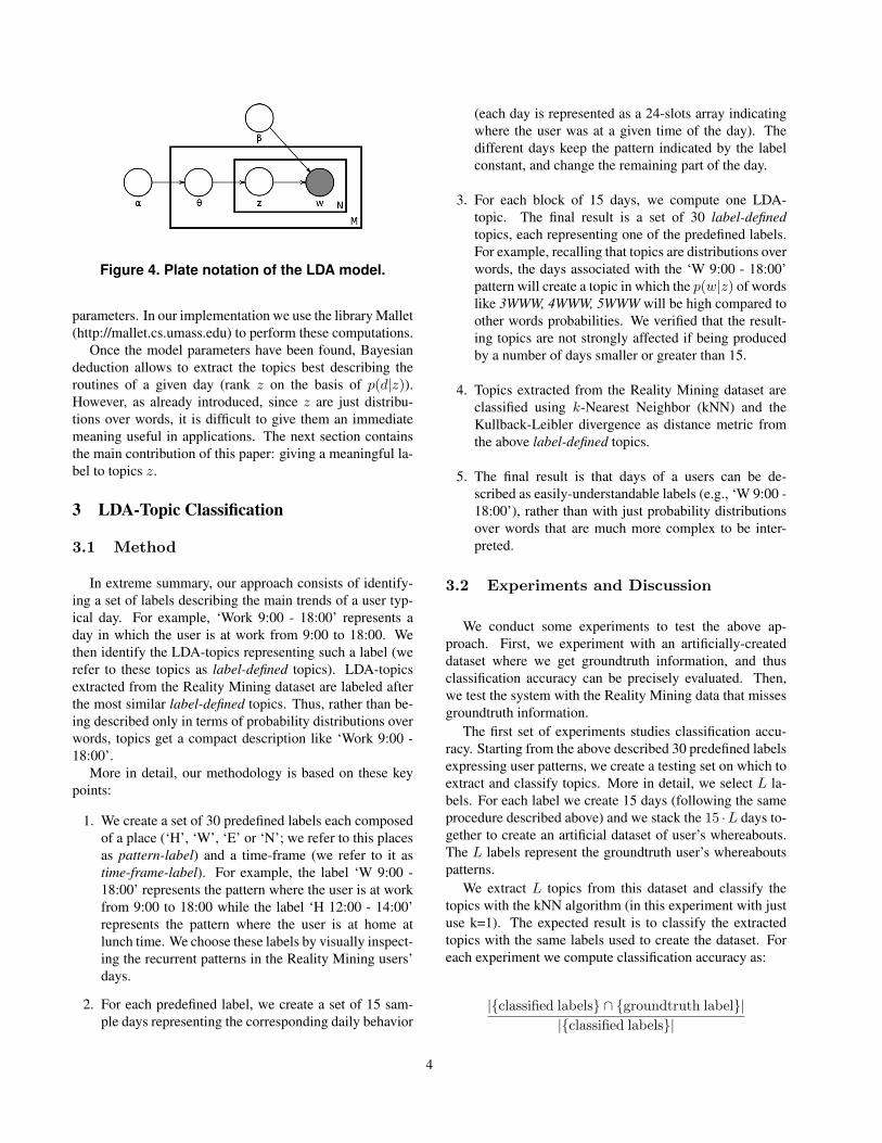
Figure 4. Plate notation of the LDA model.
parameters. In our implementation we use the library Mallet(http://mallet.cs.umass.edu) to perform these computations.
Once the model parameters have been found, Bayesiandeduction allows to extract the topics best describing theroutines of a given day (rank z on the basis of p(d|z)).However, as already introduced, since z are just distribu-tions over words, it is difficult to give them an immediatemeaning useful in applications. The next section containsthe main contribution of this paper: giving a meaningful la-bel to topics z.
3 LDA-Topic Classification
3.1 Method
In extreme summary, our approach consists of identify-ing a set of labels describing the main trends of a user typ-ical day. For example, ‘Work 9:00 - 18:00’ represents aday in which the user is at work from 9:00 to 18:00. Wethen identify the LDA-topics representing such a label (werefer to these topics as label-defined topics). LDA-topicsextracted from the Reality Mining dataset are labeled afterthe most similar label-defined topics. Thus, rather than be-ing described only in terms of probability distributions overwords, topics get a compact description like ‘Work 9:00 -18:00’.
More in detail, our methodology is based on these keypoints:
1. We create a set of 30 predefined labels each composedof a place (‘H’, ‘W’, ‘E’ or ‘N’; we refer to this placesas pattern-label) and a time-frame (we refer to it astime-frame-label). For example, the label ‘W 9:00 -18:00’ represents the pattern where the user is at workfrom 9:00 to 18:00 while the label ‘H 12:00 - 14:00’represents the pattern where the user is at home atlunch time. We choose these labels by visually inspect-ing the recurrent patterns in the Reality Mining users’days.
2. For each predefined label, we create a set of 15 sam-ple days representing the corresponding daily behavior
(each day is represented as a 24-slots array indicatingwhere the user was at a given time of the day). Thedifferent days keep the pattern indicated by the labelconstant, and change the remaining part of the day.
3. For each block of 15 days, we compute one LDA-topic. The final result is a set of 30 label-defined
topics, each representing one of the predefined labels.For example, recalling that topics are distributions overwords, the days associated with the ‘W 9:00 - 18:00’pattern will create a topic in which the p(w|z) of wordslike 3WWW, 4WWW, 5WWW will be high compared toother words probabilities. We verified that the result-ing topics are not strongly affected if being producedby a number of days smaller or greater than 15.
4. Topics extracted from the Reality Mining dataset areclassified using k-Nearest Neighbor (kNN) and theKullback-Leibler divergence as distance metric fromthe above label-defined topics.
5. The final result is that days of a users can be de-scribed as easily-understandable labels (e.g., ‘W 9:00 -18:00’), rather than with just probability distributionsover words that are much more complex to be inter-preted.
3.2 Experiments and Discussion
We conduct some experiments to test the above ap-proach. First, we experiment with an artificially-createddataset where we get groundtruth information, and thusclassification accuracy can be precisely evaluated. Then,we test the system with the Reality Mining data that missesgroundtruth information.
The first set of experiments studies classification accu-racy. Starting from the above described 30 predefined labelsexpressing user patterns, we create a testing set on which toextract and classify topics. More in detail, we select L la-bels. For each label we create 15 days (following the sameprocedure described above) and we stack the 15 ·L days to-gether to create an artificial dataset of user’s whereabouts.The L labels represent the groundtruth user’s whereaboutspatterns.
We extract L topics from this dataset and classify thetopics with the kNN algorithm (in this experiment with justuse k=1). The expected result is to classify the extractedtopics with the same labels used to create the dataset. Foreach experiment we compute classification accuracy as:
|{classified labels} ∩ {groundtruth label}||{classified labels}|
4

0
10
20
30
40
50
60
70
80
90
100
5 10 20 30
% accuracy
number of patterns
max
min
Figure 5. Classification accuracy and num-ber of patterns used to create the testingdatasets. Minimum and maximum accuraciesgive a fair measure of the variance in our re-sults.
All the results are averaged over 100 runs of the experi-ment in which we generate random groundtruth topics andrandom days containing that topics.
Figure 5 shows the average classification accuracy as afunction of the number of patterns used to create the test-ing dataset. The loss in the accuracy classification ob-tained with a little number of patterns is due to the factthat our algorithm tends to misclassify labels representingshort time-frame-label. For example, if the predefined labelis ‘H 12:00 - 14:00’, a testing day could be ‘EEEHHHH-HWWWHHHWWWWWHHHHH’ which is better repre-sented by a topic described by the label ‘W 9:00 - 18:00’or ‘H 20:00 - 24:00’.This fact is also reflected by the highervariation between the minimum and maximum classifica-tion accuracy obtained with a little number of patterns.
To further test the approach in this experimental setting,we add artificial noise to the testing dataset. The idea isto corrupt the underlying pattern to see that what extentthe LDA algorithm and our classification mechanism areable to generalize the pattern. In particular, once a day hasbeen created, we change noise% of the labels in the pat-tern time-slots with random other labels. For example, ifthe label expressing the testing set days is ‘E 18:00 - 24:00’a sample day for this experiment could be ‘HHHHHHHH-WWWWWWWWWEEEEHHH’ expressing the user wassomewhere else only until 22:00 and then went back home(noise = 3/7 = 42%).
Figure 6 shows the classification accuracy obtained atdifferent noise levels in the case of datasets composed of 5and 30 patterns respectively. As above mentioned, the vari-ation between minimum and maximum classification accu-racy is higher with a little number of patterns than with a lotof them. In addition, a higher number of pattern results lessaffected by the introduction of artificial noise in the testing
30
40
50
60
70
80
90
100
10% 20% 30% 40% 50%
% accuracy
% noise
5 pattern
70
75
80
85
90
95
100
10% 20% 30% 40% 50%
% accuracy
% noise
30 pattern
Figure 6. Average classification accuracy asa function of the noise introduced. The x-axis represents the hours’ percentage (withrespect to the time slot length indicated bythe label) that has been randomly changed.
dataset.In a second group of experiments, we test our classifica-
tion method on the Reality Mining dataset.We experiment with 36 individuals and 121 consecutive
days (from 26-08-2004 to 21-12-2004). We chose this sub-set of days with the goal of analyzing people and days forwhich the data is reasonably complete and with the goalof comparing our results with those presented in [8] takinginto consideration the same subset of days. We also com-plete missing values with the SVM mechanism described inthe previous section.
Since groundtruth information regarding user topics arenot available, our experiments on the Reality Mining datasetfocus on two main aspects:
1. We first evaluate whether the predefined labels associ-ated to the user’s topics are a good representation ofher days. In other words we verify whether the labelsare informative enough to reconstruct the day of theuser.
2. We evaluate if there are other labels describing userdays better then the ones selected by our approach.
With regard to the former aspect, we extract 100 LDA-topics from all the days of each user taken into consider-ation. For each day d we rank the topic z according top(d|z). Starting from he topic z with higher p(d|z), wereconstruct the day d according to the pattern-label and thetime-frame-label associated to z. If a part of the day has
5

0
5
10
15
20
25
30
0-‐10 10-‐20 20-‐30 30-‐40 40-‐50 50-‐60 60-‐70 70-‐80 80-‐90 90-‐100
% days
% accuracy
Figure 7. Average day reconstruction accu-racy computed over all users and days.
been already reconstructed by a previous (more probable)topic, the mechanisms just left it unchanged. Parts of theday that do not appear in the considered topics labels arenot reconstructed.
We then compare the real and the reconstructed day. Foreach time-slot (hour) we assign an error equals to 1 if thereconstructed label is wrong. While an error equals to 0.5 ifthat hours is not reconstructed. The idea is that it is betterfor the algorithm not to reconstruct a part of the day ratherthan reconstructing it wrong. Figure 7 shows the distribu-tion of days reconstruction accuracy: an average of 80% isobtained.
Figure 8 shows days reconstruction accuracy as a func-tion of the number of LDA-topics extracted from users’days. The low number of LDA-topics necessary to obtainhigh accuracy level can be explained by the limited numberof users’ days available and by their repetitiveness.
With regard to the latter aspect of the Reality Miningexperiments, we extract 100 LDA-topics from all the daysof each user taken into consideration. For each day d, wewant to find the topic that best describes that day. We ranktopics z according to both p(d|z) and the length of the time-
frame-label assigned to the topic. The idea is that topicsexplaining a bigger part of the user day are to be preferred.
The most probable topic ztop is selected for describingthe day. We then evaluate how good the label assigned toztop describes the day. In particular, for each time-slot inthe time-frame-label we assign an error equals to 1 if thereconstructed label is wrong. For each time-slot that is notin the time-frame-label we give an error of 0.5. The idea isto lower the performance of topics associated to short time-
frame-label, thus describing only a fraction of the day. Fi-nally, we evaluate with the same error measure if there ex-ists another label, better describing the day. We obtain thatthe labels associated to the selected topics are better than
0
10
20
30
40
50
60
70
80
1 10 20 30 40 50 60 70 80 90 100
% accuracy
number of topics
Figure 8. Average day reconstruction accu-racy as a function of the number of topics ex-tracted from the user’s dataset.
any other label in the 80% of the cases.All these results support the use of our classification
mechanism. Our classification can notably simplify thecomparison of users’ routines characteristic, in that it allowsdirect comparison between topics meaningful labels.
4 Related Work
The availability of affordable localization mechanismsand the recognition of location as a primary source of con-text information has stimulated a wealth of work. In particu-lar, the core problem addressed in this paper: understandingusers’ whereabouts.
4.1 Identifying Places
Several researches tackle the problem of understandingpeople whereabouts by trying to extract and identify thoseplaces that matter to the user. Mainstream approaches areeither based on segmenting and clustering GPS-traces to in-fer what are the places relevant to the user [1, 18], or ondetecting places and mobility on the basis of nearby RF-beacons such as WiFi and GSM towers [13, 7]. These ap-proaches require the user to run a special software on herdevice to collect and analyze the log of GPS or RF-beaconsavailable. Thus experiments with these mechanisms areusually conducted with a relatively small user population(the Reality Mining dataset used also in this paper is by farone of largest datasets in this category).
Starting from these results, another important area of re-search concerns the problem of converting from places de-scribed in terms of geographical coordinates or abstract IDs(e.g., GSM tower ID) to semantically-rich places such as:“home” or “favorite pub”. The work described in [1, 14]
6

adopt a probabilistic model to automatically attach seman-tic labels to visited places. These works rely on the factthat semantic information can be added by exploiting thestructure of a person’s daily routine. For example, the placewhere the user usually spends the night can be tagged se-mantically as “home”, while the place where the user usu-ally goes from 8:00 to 18:00 can be tagged as “work”. In[1] further information are extracted by geocoding the placeand mining the Web in search for relevant information.
In summary, these approaches allow to represent and un-derstand users’ mobility patterns as a sequence of placesbeing visited at different times of the day. This representa-tion resembles the “Home, Work, Elsewhere, No Signal”-representation used in the Reality Mining dataset.
Accordingly, while this paper focuses on higher-level ab-stractions (the sequence of places being visited is our start-ing point), the above approaches are the fundamental ele-ments to apply our algorithms to other mobility datasets.
4.2 Identifying Routes
A number of related work deals with the problem ofidentifying the routes the user takes to move from one placeto another. These approaches run data mining algorithmsto identify recurrent patterns in the GPS tracks from mul-tiple users. Works in this area can be divided in 2 broadcategories: “geometric-based” approaches [9] apply patternmatching to the sequence of geographical coordinates com-posing the tracks. We call it geometric in that they usethe physical “shape” of the path to compute the matchingamong routes. “String-based” approaches, instead, createa symbolic representation of the path (e.g., by consideringonly the names of the areas crosses by the path) and applypattern-matching on that list of symbols [11]. In both cases,the extracted routes can be used to classify the user currentand past whereabouts.
The work presented in this paper is similar to ‘string-based” approaches, in that the geographic informationabout the places visited by the users are lost in favor ofthe more compact “Home, Work, Elsewhere, No Signal”-representation. However, there are two important differ-ences. On the one hand, our representation is even moreabstract that the one discussed in [11] and similar works.Labels in our dataset (e.g., Home) are completely detachedfrom their physical location and, in fact, different userswill label as “Home” completely different places. On theother hand our classification algorithm could extend alsothe above related work to obtained a more descriptive labelfor the extracted routes.
4.3 Identifying Routines
Even more high-level than extracting places and routes,is the problem of identifying routine whereabouts behav-iors.
The CitySense project (http://www.citysense.com) isbased on GPS and WiFi localization and has the goal ofmonitoring and describing the city’s nightlife. In particular,the application identifies hot-spots in the city (e.g., popularbars and clubs) and compares the number of people locatedin a given area in real time with past measures, to determinethe “activity-level” of a given night. In a similar work basedon extremely large anonymized mobility data coming fromTelecom operators authors were able to extract the spatio-temporal dynamics of the city, highlighting where peopleusually go during the day. Authors were able also to iden-tify the most visited areas by tourists during the day and thetypical time of the visit [4, 12].
In this context the works that most directly compare toour proposal are [7, 8]. They use PCA and LDA algorithmsto extract routine behavior from the Reality Mining dataset.Our work provides a further classification step to give mean-ingful labels to the extracted routines.
5 Conclusion and Future Work
In this paper we presented a methodology to automati-cally classify the routine whereabouts extracted from a largemobility dataset with meaningful labels.
Our future work in this area will target 3 main directions:
1. We will apply the presented approaches to “live”datasets such as those that can be acquired fromGoogle Latitude (http://www.google.com/latitude) andFlickr [12].
2. We will develop mechanisms to add/modify topic la-bels at run time, so as to enable the use of the systemin a wide range of scenarios.
3. We will develop Web-based visualization mechanismsto inspect and communicate whereabouts behaviors inan effective way [6].
The ultimate goal will be to create a real live Web appli-cation allowing different classes of users to see, understandand predict their own and other users’ whereabouts.
6 Acknowledgements
We thank Katayoun Farrahi for clarifications on their useof the LDA algorithm on the Reality Mining dataset.
7

References
[1] N. Bicocchi, G. Castelli, M. Mamei, A. Rosi, andF. Zambonelli. Supporting location-aware services formobile users with the whereabouts diary. In Interna-
tional Conference on MOBILe Wireless MiddleWARE,
Operating Systems, and Applications, Innsbruck, Aus-tria, 2008.
[2] C. Bishop. Pattern Recognition and Machine Learn-
ing. Springer Verlag, 2006.
[3] D. Blei, A. Ng, and M. Jordan. Latent dirichlet al-location. Journal of Machine Learning Research,3(1):993–1022, 2003.
[4] F. Calabrese, J. Reades, and C. Ratti. Eigenplaces:analysing cities using the space-time structure of themobile phone network. IEEE Pervasive Computing,9(1):78–84, 2010.
[5] C.-C. Chang and C.-J. Lin. LIBSVM: a library for
support vector machines, 2001. Software available athttp://www.csie.ntu.edu.tw/ cjlin/libsvm.
[6] A. Clear, R. Shannon, T. Holland, A. Quigley, S. Dob-son, and P. Nixon. Situvis: A visual tool for modelinga user’s behaviour patterns in a pervasive environment.In International Conference on Pervasive Computing,Nara, Japan, 2009.
[7] N. Eagle and A. Pentland. Eigenbehaviors: Identify-ing structure in routine. Behavioral Ecology and So-
ciobiology, 63(7):1057–1066, 2009.
[8] K. Farrahi and D. Gatica-Perez. Learning and predict-ing multimodal daily life patterns from cell phones.In International Conference on Multimodal Interfaces
(ICMI-MLMI), Cambridge (MA), USA, 2009.
[9] J. Froehlich and J. Krumm. Route prediction from tripobservations. In Intelligent Vehicle Initiative, Technol-
ogy Advanced Controls and Navigation Systems, SAE
World Congress and Exhibition, Detriot (MI), USA,2008.
[10] J. Gemmell, G. Bell, and R. Lueder. Mylifebits: apersonal database for everything. Communications of
the ACM, 49(1):88–95, 2006.
[11] F. Giannotti, M. Nanni, D. Pedreschi, and F. Pinelli.Trajectory pattern mining. In ACM SIGKDD Interna-
tional Conference on Knowledge Discovery and Data
Mining, San Jose (CA), USA, 2007.
[12] F. Girardin, J. Blat, F. Calabrese, F. D. Fiore, andC. Ratti. Digital footprinting: Uncovering touristswith user-generated content. IEEE Pervasive Comput-
ing, 7(4):36–43, 2008.
[13] D. Kim, J. Hightower, R. Govindan, and D. Estrin.Discovering semantically meaningful places from per-vasive rf-beacons. In International Conference on
Ubiquitous Computing, Orlando (FL) ,USA, 2009.
[14] L. Liao, D. Fox, and H. Kautz. Extracting placesand activities from gps traces using hierarchical con-ditional random fields. International Journal of
Robotics Research, 26(1):119–134, 2007.
[15] M. Massimi, K. Truong, D. Dearman, and G. Hayes.Understanding recording technologies in everydaylife. IEEE Pervasive Computing, pre-print, 2010.
[16] Q. Mei, X. Shen, and C. Zhai. Automatic labelingof multinomial topic models. In ACM International
Conference on Knowledge Discovery and Data Min-
ing, San Jose (CA), USA, 2007.
[17] S. Patel, J. Kientz, G. Hayes, S. Bhat, and G. Abowd.Farther than you may think: An empirical investiga-tion of the proximity of users to their mobile phones.In International Conference on Ubiquitous Comput-
ing, Orange County (CA), USA, 2006.
[18] Y. Zheng, L. Zhang, X. Xie, and W.-Y. Ma. Mining in-teresting locations and travel sequences from gps tra-jectories for mobile users. In International World Wide
Web Conference, Madrid, Spain, 2009.
8


![CIVIL CASES] [FRESH (FOR ADMISSION) - CRIMINAL CASES]](https://static.fdokumen.com/doc/165x107/633739bdd63e7c790105b19d/civil-cases-fresh-for-admission-criminal-cases-1682892728.jpg)


