MSP430BT5190 Device Erratasheet (Rev. AE)
43
1 SLAZ071AE – October 2012 – Revised March 2019 Submit Documentation Feedback Copyright © 2012–2019, Texas Instruments Incorporated MSP430BT5190 Device Erratasheet Errata SLAZ071AE – October 2012 – Revised March 2019 MSP430BT5190 Device Erratasheet The revision of the device can be identified by the revision letter on the Package Markings or by the HW_ID located inside the TLV structure of the device 1 Functional Errata Revision History Errata impacting device's operation, function or parametrics. ✓ The check mark indicates that the issue is present in the specified revision. Errata Number Rev H Rev G Rev F Rev E Rev D ADC25 ✓ ✓ ✓ ✓ ✓ ADC27 ✓ ✓ ✓ ADC42 ✓ ✓ ✓ ✓ ✓ ADC69 ✓ ✓ ✓ ✓ ✓ CPU37 ✓ ✓ ✓ ✓ ✓ CPU47 ✓ ✓ ✓ ✓ ✓ DMA4 ✓ ✓ ✓ ✓ ✓ DMA7 ✓ ✓ ✓ ✓ ✓ DMA8 ✓ ✓ ✓ ✓ ✓ DMA10 ✓ ✓ ✓ ✓ ✓ FLASH33 ✓ ✓ ✓ ✓ ✓ FLASH34 ✓ ✓ ✓ ✓ ✓ FLASH35 ✓ FLASH37 ✓ ✓ ✓ MPY1 ✓ ✓ ✓ ✓ ✓ PMM9 ✓ ✓ ✓ ✓ ✓ PMM10 ✓ ✓ ✓ PMM11 ✓ ✓ ✓ ✓ ✓ PMM12 ✓ ✓ ✓ ✓ ✓ PMM14 ✓ ✓ ✓ ✓ ✓ PMM15 ✓ ✓ ✓ ✓ ✓ PMM17 ✓ ✓ ✓ PMM18 ✓ ✓ ✓ ✓ ✓ PMM20 ✓ ✓ ✓ ✓ ✓ PORT16 ✓ ✓ ✓ ✓ ✓ PORT19 ✓ ✓ ✓ ✓ ✓ RTC3 ✓ ✓ ✓ ✓ ✓ RTC6 ✓ ✓ ✓ ✓ ✓ SYS10 ✓ ✓ ✓ SYS12 ✓ ✓ ✓ SYS16 ✓ ✓ ✓ ✓ ✓ TA20 ✓ ✓ ✓ ✓ ✓
-
Upload
khangminh22 -
Category
Documents
-
view
1 -
download
0
Transcript of MSP430BT5190 Device Erratasheet (Rev. AE)

1SLAZ071AE–October 2012–Revised March 2019Submit Documentation Feedback
Copyright © 2012–2019, Texas Instruments Incorporated
MSP430BT5190 Device Erratasheet
ErrataSLAZ071AE–October 2012–Revised March 2019
MSP430BT5190 Device Erratasheet
The revision of the device can be identified by the revision letter on the Package Markings or by theHW_ID located inside the TLV structure of the device
1 Functional Errata Revision HistoryErrata impacting device's operation, function or parametrics.
✓ The check mark indicates that the issue is present in the specified revision.
Errata Number Rev
H
Rev
G
Rev
F
Rev
E
Rev
D
ADC25 ✓ ✓ ✓ ✓ ✓ADC27 ✓ ✓ ✓ADC42 ✓ ✓ ✓ ✓ ✓ADC69 ✓ ✓ ✓ ✓ ✓CPU37 ✓ ✓ ✓ ✓ ✓CPU47 ✓ ✓ ✓ ✓ ✓DMA4 ✓ ✓ ✓ ✓ ✓DMA7 ✓ ✓ ✓ ✓ ✓DMA8 ✓ ✓ ✓ ✓ ✓DMA10 ✓ ✓ ✓ ✓ ✓FLASH33 ✓ ✓ ✓ ✓ ✓FLASH34 ✓ ✓ ✓ ✓ ✓FLASH35 ✓FLASH37 ✓ ✓ ✓MPY1 ✓ ✓ ✓ ✓ ✓PMM9 ✓ ✓ ✓ ✓ ✓PMM10 ✓ ✓ ✓PMM11 ✓ ✓ ✓ ✓ ✓PMM12 ✓ ✓ ✓ ✓ ✓PMM14 ✓ ✓ ✓ ✓ ✓PMM15 ✓ ✓ ✓ ✓ ✓PMM17 ✓ ✓ ✓PMM18 ✓ ✓ ✓ ✓ ✓PMM20 ✓ ✓ ✓ ✓ ✓PORT16 ✓ ✓ ✓ ✓ ✓PORT19 ✓ ✓ ✓ ✓ ✓RTC3 ✓ ✓ ✓ ✓ ✓RTC6 ✓ ✓ ✓ ✓ ✓SYS10 ✓ ✓ ✓SYS12 ✓ ✓ ✓SYS16 ✓ ✓ ✓ ✓ ✓TA20 ✓ ✓ ✓ ✓ ✓

Preprogrammed Software Errata Revision History www.ti.com
2 SLAZ071AE–October 2012–Revised March 2019Submit Documentation Feedback
Copyright © 2012–2019, Texas Instruments Incorporated
MSP430BT5190 Device Erratasheet
Errata Number Rev
H
Rev
G
Rev
F
Rev
E
Rev
D
TAB23 ✓ ✓ ✓UCS6 ✓ ✓ ✓UCS7 ✓ ✓ ✓ ✓ ✓UCS9 ✓ ✓ ✓UCS10 ✓ ✓ ✓UCS11 ✓ ✓ ✓ ✓ ✓USCI26 ✓ ✓ ✓ ✓ ✓USCI30 ✓ ✓ ✓USCI31 ✓ ✓ ✓ ✓ ✓USCI34 ✓ ✓ ✓ ✓ ✓USCI35 ✓ ✓ ✓ ✓ ✓USCI39 ✓ ✓ ✓ ✓ ✓USCI40 ✓ ✓ ✓ ✓ ✓WDG4 ✓ ✓ ✓ ✓ ✓
2 Preprogrammed Software Errata Revision HistoryErrata impacting pre-programmed software into the silicon by Texas Instruments.
✓ The check mark indicates that the issue is present in the specified revision.
Errata Number Rev
H
Rev
G
Rev
F
Rev
E
Rev
D
JTAG20 ✓ ✓ ✓ ✓ ✓
3 Debug only Errata Revision HistoryErrata only impacting debug operation.
✓ The check mark indicates that the issue is present in the specified revision.
Errata Number Rev
H
Rev
G
Rev
F
Rev
E
Rev
D
EEM8 ✓EEM9 ✓ ✓ ✓ ✓ ✓EEM11 ✓ ✓ ✓ ✓ ✓EEM13 ✓ ✓ ✓ ✓ ✓EEM14 ✓ ✓ ✓ ✓ ✓EEM16 ✓ ✓ ✓ ✓ ✓EEM17 ✓ ✓ ✓ ✓ ✓EEM19 ✓ ✓ ✓ ✓ ✓EEM21 ✓ ✓ ✓ ✓ ✓EEM23 ✓ ✓ ✓ ✓ ✓JTAG26 ✓ ✓ ✓ ✓ ✓JTAG27 ✓ ✓ ✓ ✓ ✓

www.ti.com Fixed by Compiler Errata Revision History
3SLAZ071AE–October 2012–Revised March 2019Submit Documentation Feedback
Copyright © 2012–2019, Texas Instruments Incorporated
MSP430BT5190 Device Erratasheet
4 Fixed by Compiler Errata Revision HistoryErrata completely resolved by compiler workaround. Refer to specific erratum for IDE and compilerversions with workaround.
✓ The check mark indicates that the issue is present in the specified revision.
Errata Number Rev
H
Rev
G
Rev
F
Rev
E
Rev
D
CPU21 ✓ ✓ ✓ ✓ ✓CPU22 ✓ ✓ ✓ ✓ ✓CPU23 ✓ ✓ ✓ ✓ ✓CPU26 ✓ ✓ ✓ ✓ ✓CPU27 ✓ ✓ ✓ ✓ ✓CPU28 ✓ ✓ ✓ ✓ ✓CPU29 ✓ ✓ ✓ ✓ ✓CPU30 ✓ ✓ ✓ ✓ ✓CPU31 ✓ ✓ ✓ ✓ ✓CPU32 ✓ ✓ ✓ ✓ ✓CPU33 ✓ ✓ ✓ ✓ ✓CPU34 ✓ ✓ ✓ ✓ ✓CPU35 ✓ ✓ ✓ ✓ ✓CPU39 ✓ ✓ ✓ ✓ ✓CPU40 ✓ ✓ ✓ ✓ ✓
Refer to the following MSP430 compiler documentation for more details about the CPU bugsworkarounds.
TI MSP430 Compiler Tools (Code Composer Studio IDE)• MSP430 Optimizing C/C++ Compiler: Check the --silicon_errata option• MSP430 Assembly Language Tools
MSP430 GNU Compiler (MSP430-GCC)• MSP430 GCC Options: Check -msilicon-errata= and -msilicon-errata-warn= options• MSP430 GCC User's Guide
IAR Embedded Workbench• IAR workarounds for msp430 hardware issues

Package Markings www.ti.com
4 SLAZ071AE–October 2012–Revised March 2019Submit Documentation Feedback
Copyright © 2012–2019, Texas Instruments Incorporated
MSP430BT5190 Device Erratasheet
5 Package Markings
PZ100 LQFP (PZ) 100 Pin
ZQW113 BGA (ZQW), 113 Pin
6 Memory-Mapped Hardware Revision (TLV Structure)
Die Revision TLV Hardware RevisionRev H 17hRev G 16hRev F 15hRev E 14hRev D 13h
Further guidance on how to locate the TLV structure and read out the HW_ID can be found in the deviceUser's Guide.

www.ti.com Detailed Bug Description
5SLAZ071AE–October 2012–Revised March 2019Submit Documentation Feedback
Copyright © 2012–2019, Texas Instruments Incorporated
MSP430BT5190 Device Erratasheet
7 Detailed Bug Description
ADC25 ADC12_A Module
Category Functional
Function Write to ADC12CTL0 triggers ADC12 when CONSEQ = 00
Description If ADC conversions are triggered by the Timer_B module and the ADC12 is in single-channel single-conversion mode (CONSEQ = 00), ADC sampling is enabled by writeaccess to any bit(s) in the ADC12CTL0 register. This is contrary to the expectedbehavior that only the ADC12 enable conversion bit (ADC12ENC) triggers a new ADC12sample.
Workaround When operating the ADC12 in CONSEQ=00 and a Timer_B output is selected as thesample and hold source, temporarily clear the ADC12ENC bit before writing to other bitsin the ADC12CTL0 register. The following capture trigger can then be re-enabled bysetting ADC12ENC = 1.
ADC27 ADC12_A Module
Category Functional
Function Integral and differential non-linearity exceed specifications
Description The ADC12_A integral and differential non-linearity may exceed the limits specified inthe data sheet under the following conditions:
- If the internal voltage reference generator is used
and
- If the reference voltage is not buffered off-chip
and
- If fADC12CLK > 2.7 MHz
The non-linearity can be up to tens of LSBs. This is due to the internal reference bufferproviding insufficient drive for the switched capacitor array of the ADC12_A.
Workaround (1) Turn on the output of the internal voltage reference to increase the drive strength ofthe reference to the ADC_12 core:
- If REFMSTR bit in REFCTL0 is 0 (allowing Shared REF to be controlled by ADC_Areference control bits)
Set ADC12REFON bit in ADC12CTL0 = 1
and
Set ADC12REFOUT bit in ADC12CTL2 = 1
- If REFMSTR bit in REFCTL0 is 1
Set REFON and REFOUT bits in REFCTL0 = 1
(2) Ensure fADC12CLK < 2.7 MHz. Depending on the frequency of the source offADC12CLK (ACLK, MCLK, SMCLK, or MODOSC), select the divider bits accordingly.
- If fADC12CLK = MODOSC
(ADC12OSC) ADC12CTL1 |= ADC12DIV_1; // Divide clock by 2
- If fADC12CLK = ACLK/SMCLK/MCLK > 2.7 MHz.

Detailed Bug Description www.ti.com
6 SLAZ071AE–October 2012–Revised March 2019Submit Documentation Feedback
Copyright © 2012–2019, Texas Instruments Incorporated
MSP430BT5190 Device Erratasheet
Use ADC12DIVx and/or ADC12PDIVx bits to reduce the selected clock frequency tobetween 0.45 MHz and 2.7 MHz.
ADC42 ADC12_A Module
Category Functional
Function ADC stops converting when successive ADC is triggered before the previous conversionends
Description Subsequent ADC conversions are halted if a new ADC conversion is triggered whileADC is busy. ADC conversions are triggered manually or by a timer. The affected ADCmodes are:
- sequence-of-channels
- repeat-single-channel
- repeat-sequence-of-channels (ADC12CTL1.ADC12CONSEQx)
In addition, the timer overflow flag cannot be used to detect an overflow(ADC12IFGR2.ADC12TOVIFG).
Workaround 1. For manual trigger mode (ADC12CTL0.ADC12SC), ensure each ADC conversion iscompleted by first checking ADC12CTL1.ADC12BUSY bit before starting a newconversion.
2. For timer trigger mode (ADC12CTL1.ADC12SHP), ensure the timer period is greaterthan the ADC sample and conversion time.
To recover the conversion halt:
1. Disable ADC module (ADC12CTL0.ADC12ENC = 0 and ADC12CTL0.ADC12ON = 0)
2. Re-enable ADC module (ADC12CTL0.ADC12ON = 1 and ADC12CTL0.ADC12ENC =1)
3. Re-enable conversion
ADC69 ADC12_A Module
Category Functional
Function ADC stops operating if ADC clock source is changed from SMCLK to another sourcewhile SMCLKOFF = 1.
Description When SMCLK is used as the clock source for the ADC (ADC12CTL1.ADC12SSELx =11) and CSCTL4.SMCLKOFF = 1, the ADC will stop operating if the ADC clock source ischanged by user software (e.g. in the ISR) from SMCLK to a different clock source. Thisissue appears only for the ADC12CTL1.ADC12DIVx settings /3/5/7. The hang state canbe recovered by PUC/POR/BOR/Power cycle.
Workaround 1. Set CSCTL4.SMCLKOFF = 0 before switch ADC clock source.
OR
2. Only use ADC12CTL1.ADC12DIVx as /1, /2, /4, /6, /8
CPU21 CPUXv2 Module
Category Compiler-Fixed
Function Using POPM instruction on Status register may result in device hang up

www.ti.com Detailed Bug Description
7SLAZ071AE–October 2012–Revised March 2019Submit Documentation Feedback
Copyright © 2012–2019, Texas Instruments Incorporated
MSP430BT5190 Device Erratasheet
Description When an active interrupt service request is pending and the POPM instruction is used toset the Status Register (SR) and initiate entry into a low power mode , the device mayhang up.
Workaround None. It is recommended not to use POPM instruction on the Status Register.
Refer to the table below for compiler-specific fix implementation information.
IDE/Compiler Version Number NotesIAR Embedded Workbench Not affected
TI MSP430 Compiler Tools (CodeComposer Studio) v4.0.x or later
User is required to add the compiler orassembler flag option below.--silicon_errata=CPU21
MSP430 GNU Compiler (MSP430-GCC) MSP430-GCC 4.9 build 167 or later
CPU22 CPUXv2 Module
Category Compiler-Fixed
Function Indirect addressing mode with the Program Counter as the source register may produceunexpected results
Description When using the indirect addressing mode in an instruction with the Program Counter(PC) as the source operand, the instruction that follows immediately does not getexecuted.
For example in the code below, the ADD instruction does not get executed.
mov @PC, R7add #1h, R4
Workaround Refer to the table below for compiler-specific fix implementation information.
IDE/Compiler Version Number NotesIAR Embedded Workbench Not affected
TI MSP430 Compiler Tools (CodeComposer Studio) v4.0.x or later
User is required to add the compiler orassembler flag option below.--silicon_errata=CPU22
MSP430 GNU Compiler (MSP430-GCC) MSP430-GCC 4.9 build 167 or later
CPU23 CPUXv2 Module
Category Compiler-Fixed
Function Rotate instruction does not function as expected
Description When repeated rotate instructions (rrcm, rram, rrum and rlam) are applied on theProgram Counter(PC), unexpected instruction execution may occur.
Workaround Insert a NOP instruction between sequential rotate instructions performed on the PCregister.
Refer to the table below for compiler-specific fix implementation information.

Detailed Bug Description www.ti.com
8 SLAZ071AE–October 2012–Revised March 2019Submit Documentation Feedback
Copyright © 2012–2019, Texas Instruments Incorporated
MSP430BT5190 Device Erratasheet
IDE/Compiler Version Number NotesIAR Embedded Workbench Not affected
TI MSP430 Compiler Tools (CodeComposer Studio) v4.0.x or later
User is required to add the compiler orassembler flag option below.--silicon_errata=CPU23
MSP430 GNU Compiler (MSP430-GCC) MSP430-GCC 4.9 build 167 or later
CPU26 CPUXv2 Module
Category Compiler-Fixed
Function CALL SP instruction does not behave as expected
Description The intention of the CALL SP instruction is to execute code from the stack, instead itskips the first piece of data (instruction) on the stack. The second piece of data at SP+2is used as the first executable instruction.
Workaround Write the op code for a NOP as the first instruction on the stack. Begin the intendedsubroutine at address SP + 2.
Refer to the table below for compiler-specific fix implementation information.
IDE/Compiler Version NumberIAR Embedded Workbench Not affectedTI MSP430 Compiler Tools (Code Composer Studio) v4.1.3 or laterMSP430 GNU Compiler (MSP430-GCC) Not affected
CPU27 CPUXv2 Module
Category Compiler-Fixed
Function Program Counter (PC) is corrupted during the context save of a nested interrupt
Description When a low power mode is entered within an interrupt service routine that has enablednested interrupts (by setting the GIE bit), and the instruction that sets the low powermode is directly followed by a RETI instruction, an incorrect value of PC + 2 is pushed tothe stack during the context save. Hence, the RETI instruction is not executed on returnfrom the nested interrupt and the PC becomes corrupted.
Workaround Insert a NOP or __no_operation() intrinsic function between the instruction that sets thelower power mode and the RETI instruction.
Refer to the table below for compiler-specific fix implementation information.
IDE/Compiler Version Number Notes
IAR Embedded Workbench IAR EW430 v6.20 until v6.40User is required to add the compiler orassembler flag option below.--hw_workaround=nop_after_lpm
IAR Embedded Workbench IAR EW430 v6.40 or later Workaround is automatically enabled
TI MSP430 Compiler Tools (CodeComposer Studio) v4.1.3 or later
MSP430 GNU Compiler (MSP430-GCC) MSP430-GCC 4.9 build 167

www.ti.com Detailed Bug Description
9SLAZ071AE–October 2012–Revised March 2019Submit Documentation Feedback
Copyright © 2012–2019, Texas Instruments Incorporated
MSP430BT5190 Device Erratasheet
CPU28 CPUXv2 Module
Category Compiler-Fixed
Function PC is corrupted when using certain extended addressing mode combinations
Description An extended memory instruction that modifies the program counter executes incorrectlywhen preceded by an extended memory write-back instruction under the followingconditions:
First instruction:
2-operand instruction, extended mode using (register,index), (register,absolute), OR(register,symbolic) addressing modes
Second instruction:
2-operand instruction, extended mode using the (indirect,PC), (indirect auto-increment,PC), OR (indexed [with ind 0], PC) addressing modes
Example:
BISX.A R6,&AABCD
ANDX.A @R4+,PC
Workaround 1. Insert a NOP or a __no_operation() intrinsic function between the two instructions
Or
2. Do not use an extended memory instruction to modify the PC
Refer to the table below for compiler-specific fix implementation information.
IDE/Compiler Version NumberIAR Embedded Workbench Not affectedTI MSP430 Compiler Tools (Code Composer Studio) v4.1.3 or laterMSP430 GNU Compiler (MSP430-GCC) Not affected
CPU29 CPUXv2 Module
Category Compiler-Fixed
Function Using a certain instruction sequence to enter low power mode(s) affects the instructionwidth of the first instruction in an NMI ISR
Description If there is a pending NMI request when the CPU enters a low power mode (LPMx) usingan instruction of Indexed source addressing mode, and that instruction is followed by a20-bit wide instruction of Register source and destination addressing modes, the firstinstruction of the ISR is executed as a 20-bit wide instruction.
Example:
main:
...
MOV.W [indexed],SR ; Enter LPMx
MOVX.A [register],[register] ; 20-bit wide instruction
...
ISR_start:
MOV.B [indexed],[register] ; ERROR - Executed as a 20-bit instruction!

Detailed Bug Description www.ti.com
10 SLAZ071AE–October 2012–Revised March 2019Submit Documentation Feedback
Copyright © 2012–2019, Texas Instruments Incorporated
MSP430BT5190 Device Erratasheet
Note: [] indicates addressing mode
Workaround 1. Insert a NOP or a __no_operation() intrinsic function following the instruction thatenters the LPMx using indexed addressing mode
OR
2. Use a NOP or a __no_operation() intrinsic function as first instruction in the ISR
OR
3. Do not use the indexed mode to enter LPMx
Refer to the table below for compiler-specific fix implementation information.
IDE/Compiler Version Number Notes
IAR Embedded Workbench IAR EW430 v6.20 until v6.40User is required to add the compiler orassembler flag option below.--hw_workaround=nop_after_lpm
IAR Embedded Workbench IAR EW430 v6.40 or later Workaround is automatically enabled
TI MSP430 Compiler Tools (CodeComposer Studio) v4.1.3 or later
MSP430 GNU Compiler (MSP430-GCC) MSP430-GCC 4.9 build 167
CPU30 CPUXv2 Module
Category Compiler-Fixed
Function ADDA, SUBA, CMPA [immediate],PC behave as if immediate value were offset by -2
Description The extended address instructions ADDA, SUBA, CMPA in immediate addressing modeare represented by 4-bytes of opcode (see the MSP430F5xx Family User's GuideMSP430F5xx Family User's Guide for more details). In cases where the program counter(PC) is used as the destination register only 2 bytes of the current instruction's 4-byteopcode are accounted for in the PC value. The resulting operation executes as if theimmediate value were offset by a value of -2.
Ideal: ADDA #Immediate-4, PC
...is equivalent to...
Actual: ADDA #Immediate-2, PC
** NOTE: The MOV instruction is not affected **
Workaround 1) Modify immediate value in software to account for the offset of 2.
OR
2) Use extended 20-bit instructions (addx.a, subx.a, cmpx.a).
Refer to the table below for compiler-specific fix implementation information.
IDE/Compiler Version Number Notes
IAR Embedded Workbench IAR EW430 v5.30 or later
IDE-based usage enables the workaroundautomatically.When using the command line, user isrequired to add the option below:Linker: -D?CPU30_OFFSET=2
TI MSP430 Compiler Tools (CodeComposer Studio) v4.0 or later
www.ti.com Detailed Bug Description
11SLAZ071AE–October 2012–Revised March 2019Submit Documentation Feedback
Copyright © 2012–2019, Texas Instruments Incorporated
MSP430BT5190 Device Erratasheet
IDE/Compiler Version Number NotesMSP430 GNU Compiler (MSP430-GCC) Not affected
CPU31 CPUXv2 Module
Category Compiler-Fixed
Function SP corruption
Description When the instruction PUSHX.A is executed using the indirect auto-increment mode withthe stack pointer (SP) as the source register [PUSHX.A @SP+] the SP is consequentlycorrupted. Instead of decrementing the value of the SP by four, the value of the SP isreplaced with the data pointed to by the SP previous to the PUSHX.A instructionexecution.
Workaround None. Note that compilers will not generate a PUSHX.A instruction that involves the SP.
Refer to the table below for compiler-specific information.
IDE/Compiler Version NumberIAR Embedded Workbench Not affectedTI MSP430 Compiler Tools (Code Composer Studio) Not affectedMSP430 GNU Compiler (MSP430-GCC) Not affected
CPU32 CPUXv2 Module
Category Compiler-Fixed
Function CALLA PC executes incorrectly
Description When the instruction CALLA PC is executed, the program counter (PC) that is pushedonto the stack during the context save is incorrectly offset by a value of -2.
Workaround None. Note that compilers will not generate a CALLA PC instruction.
Refer to the table below for compiler-specific information.
IDE/Compiler Version NumberIAR Embedded Workbench Not affectedTI MSP430 Compiler Tools (Code Composer Studio) Not affectedMSP430 GNU Compiler (MSP430-GCC) Not affected
CPU33 CPUXv2 Module
Category Compiler-Fixed
Function CALLA [indexed] may corrupt the program counter
Description When the Stack Pointer (SP) is used as the destination register in the CALLAindex(Rdst) instruction and is preceded by a PUSH or PUSHX instruction in any of thefollowing addressing modes: Absolute, Symbolic, Indexed, Indirect register or Indirectauto increment, the "index" of the CALLA instruction is not sign extended to 20-bits andis always treated as a positive value. This causes the Program Counter to be set to awrong address location when the index of the CALLA instruction represents a negativeoffset.

Detailed Bug Description www.ti.com
12 SLAZ071AE–October 2012–Revised March 2019Submit Documentation Feedback
Copyright © 2012–2019, Texas Instruments Incorporated
MSP430BT5190 Device Erratasheet
NOTE:
1. This erratum only applies when the instruction sequence is: PUSH or PUSHX followedby CALLA index(SP)
2. This erratum does not apply if the PUSH or PUSHX instruction is used in the Registeror Immediate addressing mode
3. This erratum only applies when SP is used as the destination register in the CALLAindex(Rdst) instruction
Workaround Place a "NOP" instruction in between the PUSH or PUSHX and the CALLA index(SP)instructions.
NOTE: This bug has no compiler impact as the compiler will not generate a CALLAinstruction that uses indexed addressing mode with the SP.
Refer to the table below for compiler-specific information.
IDE/Compiler Version NumberIAR Embedded Workbench Not affectedTI MSP430 Compiler Tools (Code Composer Studio) Not affectedMSP430 GNU Compiler (MSP430-GCC) Not affected
CPU34 CPUXv2 Module
Category Compiler-Fixed
Function CPU may be halted if a conditional jump is followed by a rotate PC instruction
Description If a conditional jump instruction (JZ, JNZ, JC, JNC, JN, JGE, JL) is followed by anAddress Rotate instruction on the PC (RRCM, RRAM, RLAM, RRUM) and the jump isnot performed, the CPU is halted.
Workaround Insert a NOP between the conditional jump and the rotate PC instructions.
Refer to the table below for compiler-specific information.
IDE/Compiler Version NumberIAR Embedded Workbench Not affectedTI MSP430 Compiler Tools (Code Composer Studio) Not affectedMSP430 GNU Compiler (MSP430-GCC) Not affected
CPU35 CPUXv2 Module
Category Compiler-Fixed
Function Instruction BIT.B @Rx,PC uses the wrong PC value
Description The BIT(.B/.W) instruction in indirect register addressing mode uses the wrong PC value.This instruction is represented by 2 bytes of opcode. If the Program Counter (PC) isused as the destination register, the 2 opcode bytes of the current BIT instruction are notaccounted for. The resulting operation executes the instruction using the wrong PC valueand this affects the results in the Status Register (SR).
Workaround None. Note that compilers will not generate a BIT instruction that uses the PC as anoperand.

www.ti.com Detailed Bug Description
13SLAZ071AE–October 2012–Revised March 2019Submit Documentation Feedback
Copyright © 2012–2019, Texas Instruments Incorporated
MSP430BT5190 Device Erratasheet
Refer to the table below for compiler-specific information.
IDE/Compiler Version NumberIAR Embedded Workbench Not affectedTI MSP430 Compiler Tools (Code Composer Studio) Not affectedMSP430 GNU Compiler (MSP430-GCC) Not affected
CPU37 CPUXv2 Module
Category Functional
Function Wrong program trace display in the debugger while using conditional jump instructions
Description The state storage window displays an incorrect sequence of instructions when:
1. Conditional jump instructions are used to form a software loop
AND
2. A false condition on the jump breaks out of the loop
In such cases the trace buffer incorrectly displays the first instruction of the loop as theinstruction that is executed immediately after exiting the loop.
Example:
Actual Code:
mov #4,R4
LABEL mov #1,R5
dec R4
jnz LABEL
mov #2,R6
nop
State Storage Window Displays:
LABEL mov #1,R5
dec R4
jnz LABEL
mov #1,R5
nop
Workaround None
Note: This erratum affects the trace buffer display only. It does not affect code executionin debugger or free run mode
CPU39 CPUXv2 Module
Category Compiler-Fixed
Function PC is corrupted when single-stepping through an instruction that clears the GIE bit
Description Single-stepping over an instruction that clears the General Interrupt Enable bit (forexample DINT or BIC #GIE,SR) when the GIE bit was previously set may corrupt the

Detailed Bug Description www.ti.com
14 SLAZ071AE–October 2012–Revised March 2019Submit Documentation Feedback
Copyright © 2012–2019, Texas Instruments Incorporated
MSP430BT5190 Device Erratasheet
PC. For example, the DINT or BIC #GIE,SR is a 2-byte instruction. Single steppingthrough this instruction increments the PC by a value of 4 instead of 2 thus corruptingthe next PC value.
Note: This erratum applies to debug mode only.
Workaround Insert a NOP or __no_operation() intrinsic immediately after the line of code that clearsthe GIE bit.
OR
Refer to the table below for compiler-specific fix implementation information.
Note that compilers implementing the fix may lead to double stack usage whenRET/RETA follows the compiler-inserted NOP.
IDE/Compiler Version Number Notes
IAR Embedded Workbench IAR EW430 v5.60 until v6.20
User is required to add the compiler flagoption below.--hw_workaround=CPU39For the command line version add thefollowing informationCompiler: --core=430Assembler:-v1
IAR Embedded Workbench IAR EW430 v6.20 or later Workaround is automatically enabled
TI MSP430 Compiler Tools (CodeComposer Studio) v4.1.3 or later
MSP430 GNU Compiler (MSP430-GCC) MSP430-GCC 4.9 build 167 or later
CPU40 CPUXv2 Module
Category Compiler-Fixed
Function PC is corrupted when executing jump/conditional jump instruction that is followed byinstruction with PC as destination register or a data section
Description If the value at the memory location immediately following a jump/conditional jumpinstruction is 0X40h or 0X50h (where X = don't care), which could either be aninstruction opcode (for instructions like RRCM, RRAM, RLAM, RRUM) with PC asdestination register or a data section (const data in flash memory or data variable in
RAM), then the PC value is auto-incremented by 2 after the jump instruction is executed;therefore, branching to a wrong address location in code and leading to wrong programexecution.
For example, a conditional jump instruction followed by data section (0140h).
@0x8012 Loop DEC.W R6
@0x8014 DEC.W R7
@0x8016 JNZ Loop
@0x8018 Value1 DW 0140h
Workaround In assembly, insert a NOP between the jump/conditional jump instruction and programcode with instruction that contains PC as destination register or the data section.
Refer to the table below for compiler-specific fix implementation information.

www.ti.com Detailed Bug Description
15SLAZ071AE–October 2012–Revised March 2019Submit Documentation Feedback
Copyright © 2012–2019, Texas Instruments Incorporated
MSP430BT5190 Device Erratasheet
IDE/Compiler Version Number Notes
IAR Embedded Workbench IAR EW430 v5.51 or later
For the command line version add thefollowing informationCompiler: --hw_workaround=CPU40Assembler:-v1
TI MSP430 Compiler Tools (CodeComposer Studio) v4.0.x or later
User is required to add the compiler orassembler flag option below.--silicon_errata=CPU40
MSP430 GNU Compiler (MSP430-GCC) Not affected
CPU47 CPUXv2 Module
Category Functional
Function An unexpected Vacant Memory Access Flag (VMAIFG) can be triggered
Description An unexpected Vacant Memory Access Flag (VMAIFG) can be triggered, if a PC-modifying instruction (e.g. - ret, push, call, pop, jmp, br) is fetched from the lastaddresses (last 4 or 8 byte) of a memory (e.g.- FLASH, RAM, FRAM) that is notcontiguous to a higher, valid section on the memory map.
In debug mode using breakpoints the last 8 bytes are affected.
In free running mode the last 4 bytes are affected.
Workaround Edit the linker command file to make the last 4 or 8 bytes of affected memory sectionsunavailable, to avoid PC-modifying instructions on these locations.
Remaining instructions or data can still be stored on these locations.
DMA4 DMA Module
Category Functional
Function Corrupted write access to 20-bit DMA registers
Description When a 20-bit wide write to a DMA address register (DMAxSA or DMAxDA) isinterrupted by a DMA transfer, the register contents may be unpredictable.
Workaround 1. Design the application to guarantee that no DMA access interrupts 20-bit wideaccesses to the DMA address registers.
OR
2. When accessing the DMA address registers, enable the Read Modify Write disable bit(DMARMWDIS = 1) or temporarily disable all active DMA channels (DMAEN = 0).
OR
3. Use word access for accessing the DMA address registers. Note that this limits thevalues that can be written to the address registers to 16-bit values (lower 64K of Flash).
DMA7 DMA Module
Category Functional
Function DMA request may cause the loss of interrupts
Description If a DMA request starts executing during the time when a module register containing an

Detailed Bug Description www.ti.com
16 SLAZ071AE–October 2012–Revised March 2019Submit Documentation Feedback
Copyright © 2012–2019, Texas Instruments Incorporated
MSP430BT5190 Device Erratasheet
interrupt flags is accessed with a read-modify-write instruction, a newly arriving interruptfrom the same module can get lost. An interrupt flag set prior to DMA execution wouldnot be affected and remain set.
Workaround 1. Use a read of Interrupt Vector registers to clear interrupt flags and do not use read-modify-write instruction.
OR
2. Disable all DMA channels during read-modify-write instruction of specific moduleregisters containing interrupts flags while these interrupts are activated.
DMA8 DMA Module
Category Functional
Function DMA can corrupt values on write-access to program stack
Description If the DMA controller makes a write access to the stack while executing one of thefollowing instructions, the data that is written may be corrupted.
CALLA [REG | IDX | SYM | ABS | IND | INA | IMM]
PUSHX.A [IDX | SYM | ABS | IND | IMM | INA]
PUSHX.A [REG]
PUSHM.A [REG]
POPM.A [REG]
Note: [ ... ] denotes an addressing mode
Workaround Do not declare function-scope variables. Declare all variables that are intended to bemodified by the DMA as global- or file-scope such that they are allocated in the datasection of RAM and not on the program stack.
DMA10 DMA Module
Category Functional
Function DMA access may cause invalid module operation
Description The peripheral modules MPY, CRC, USB, RF1A and FRAM controller in manual modecan stall the CPU by issuing wait states while in operation. If a DMA access to themodule occurs while that module is issuing a wait state, the module may exhibitundefined behavior.
Workaround Ensure that DMA accesses to the affected modules occur only when the modules arenot in operation. For example with the MPY module, ensure that the MPY operation iscompleted before triggering a DMA access to the MPY module.
EEM8 EEM Module
Category Debug
Function Debugger stops responding when using the DMA
Description In repeated transfer mode, the DMA automatically reloads the size counter (DMAxSZ)once a transfer is complete and immediately continues to execute the next transferunless the DMA Enable bit (DMAEN) has been previously cleared. In burst-block transfermode, DMA block transfers are interleaved with CPU activity 80/20% - of ten CPU

www.ti.com Detailed Bug Description
17SLAZ071AE–October 2012–Revised March 2019Submit Documentation Feedback
Copyright © 2012–2019, Texas Instruments Incorporated
MSP430BT5190 Device Erratasheet
cycles, eight are allocated to a block transfer and two are allocated for the CPU.
Because the JTAG system must wait for the CPU bus to be clear to halt the device, itcan only do so when two conditions are met:
- Three clock cycles after any DMA transfer, the DMA is no longer requesting the bus.
and
- The CPU is not requesting the bus.
Therefore, if the DMA is configured to operate in the repeat burst-block transfer mode,and a breakpoint is set between the line of code that triggers the DMA transfers and theline that clears the DMAEN bit, the DMA always requests the bus and the JTAG systemnever gains control of the device.
Workaround When operating the DMA in repeat burst-block transfer mode, set breakpoint(s) onlywhen the DMA transfers are not active (before the start or after the end of the DMAtransfers).
EEM9 EEM Module
Category Debug
Function Combined triggers on the PUSH instruction may be missed
Description When the PUSH instruction is used in any addressing mode except register orimmediate modes, a combined trigger may be missed when its conditions are defined bya PUSH instruction fetch and a successful match of the value being pushed onto stack.
Workaround None
EEM11 EEM Module
Category Debug
Function Conditional register write trigger fails while executing rotate instructions
Description A conditional register write trigger will fail to generate the expected breakpoint if thetrigger condition is a result of executing one of the following rotate instructions:RRUM,RRCM, RRAM and RLAM.
Workaround None
NOTE: This erratum applies to debug mode only.
EEM13 EEM Module
Category Debug
Function Halting the debugger does not return correct PC value when in LPM
Description When debugging, if the device is in any low power mode and the debugger is halted, theprogram counter update by the debugger is corrupted. The debugger is unable to halt atthe correct location.
Workaround None.

Detailed Bug Description www.ti.com
18 SLAZ071AE–October 2012–Revised March 2019Submit Documentation Feedback
Copyright © 2012–2019, Texas Instruments Incorporated
MSP430BT5190 Device Erratasheet
NOTE: This erratum applies to debug mode only.
EEM14 EEM Module
Category Debug
Function Single-step or breakpoint on module registers with WAIT capability may not work
Description In debug mode, the CPU clock is driven independently from the wait inputs of devicemodules (i.e., MULT, USB, RF1A, CRC). As a result, an EEM halt on an access to themodule data registers (breakpoint or single-step) may show incorrect results due toincomplete execution.
Workaround Do not single-step through a data register access that holds the CPU to provide a validresult. Place breakpoints after the affected register is accessed and sufficient clockcycles have been provided.
NOTE: This erratum applies to debug mode only.
EEM16 EEM Module
Category Debug
Function The state storage display does not work reliably when used on instructions with CPUWait cycles.
Description When executing instructions that require wait states; the state storage window updatesincorrectly. For example a flash erase instruction causes the CPU to be held until theerase is completed i.e. the flash puts the CPU in a wait state. During this time if the statestorage window is enabled it may incorrectly display any previously executed instructionmultiple times.
Workaround Do not enable the state storage display when executing instructions that require waitstates. Instead set a breakpoint after the instruction is completed to view the statestorage display.
NOTE: This erratum affects debug mode only.
EEM17 EEM Module
Category Debug
Function Wrong Breakpoint halt after executing Flash Erase/Write instructions
Description Hardware breakpoints or Conditional Address triggered breakpoints on instructions thatfollow Flash Erase/Write instructions, stops the debugger at the actual Flash Erase/Writeinstruction even though the flash erase/write operation has already been executed. Thehardware/conditional address triggered breakpoints that are placed on either the nexttwo single opcode instructions OR the next double opcode instruction that follows theFlash Erase/Write instruction are affected by this erratum.

www.ti.com Detailed Bug Description
19SLAZ071AE–October 2012–Revised March 2019Submit Documentation Feedback
Copyright © 2012–2019, Texas Instruments Incorporated
MSP430BT5190 Device Erratasheet
Workaround None. Use other conditional/advanced triggered breakpoints to halt the debugger rightafter Flash erase/write instructions.
NOTE: This erratum affects debug mode only.
EEM19 EEM Module
Category Debug
Function DMA may corrupt data in debug mode
Description When the DMA is enabled and the device is in debug mode, the data written by the DMAmay be corrupted when a breakpoint is hit or when the debug session is halted.
Workaround This erratum has been addressed in MSPDebugStack version 3.5.0.1. It is also availablein released IDE EW430 IAR version 6.30.3 and CCS version 6.1.1 or newer.
If using an earlier version of either IDE or MSPDebugStack, do not halt or usebreakpoints during a DMA transfer.
NOTE: This erratum applies to debug mode only.
EEM21 EEM Module
Category Debug
Function LPMx.5 debug limitations
Description Debugging the device in LPMx.5 mode might wake the device up from LPMx.5 modeinadvertently, and it is possible that the device enters a lock-up condition; that is, thedevice cannot be accessed by the debugger any more.
Workaround Follow the debugging steps in Debugging MSP430 LPM4.5 SLAA424 .
EEM23 EEM Module
Category Debug
Function EEM triggers incorrectly when modules using wait states are enabled
Description When modules using wait states (USB, MPY, CRC and FRAM controller in manualmode) are enabled, the EEM may trigger incorrectly. This can lead to an incorrect profilecounter value or cause issues with the EEMs data watch point, state storage, andbreakpoint functionality.
Workaround None.
NOTE: This erratum affects debug mode only.
FLASH33 FLASH Module
Category Functional

Detailed Bug Description www.ti.com
20 SLAZ071AE–October 2012–Revised March 2019Submit Documentation Feedback
Copyright © 2012–2019, Texas Instruments Incorporated
MSP430BT5190 Device Erratasheet
Function Flash erase/program with fsystem <160kHz causes code execution to fail
Description A flash erase or flash program operation with the system frequency (fsystem) <160kHzcauses the program execution (executing out of main or info memory) that follows to fail.
Workaround Make sure the fsystem >160kHz before doing a flash erase or program operation.
FLASH34 FLASH Module
Category Functional
Function Concurrent flash read during bank erase fails
Description Code residing in flash cannot be executed during a bank erase.
Workaround Place the code to be executed during bank erase in RAM.
FLASH35 FLASH Module
Category Functional
Function Flash read error may cause invalid memory access
Description Flash memory accesses are always 32-bit wide and performed on 32-bit boundaries. Aread error when accessing flash may corrupt the most significant bit (MSB) in a 32-bitaccess when programmed as a logic 0.
When affected flash is idle, the read disturb may occur on the first flash access thatfollows any of the listed events:
- On reset issued at RST input pin
- On wakeup from low-power modes when accessing interrupt vector addresses
located at addresses <0x8000
- When moving program execution from unaffected to affected areas of flash
- When accessing affected flash after execution from RAM
Workaround See Flash Read Error and Susceptibility for MSP430F54xxA (SLAA470) for detailed
background information and possible workaround(s).
FLASH37 FLASH Module
Category Functional
Function Corrupted flash read when SVM low-side flag is triggered
Description If the SVM low side is enabled, a change in the VCORE voltage level (an increase in theVCORE level) may cause the currently executed read operation from flash to beincorrect and may lead to unexpected code execution or incorrect data. This can happenunder any one of the following conditions:
- When the VCORE is changed in application, the SVM low side is used to indicate if thecore voltage has settled by using the SVMDLYIFG flag. The failure occurs only when aflash access is concurrent to the expiration of the settling time delay.
- Unexpected changes in the VCORE voltage level

www.ti.com Detailed Bug Description
21SLAZ071AE–October 2012–Revised March 2019Submit Documentation Feedback
Copyright © 2012–2019, Texas Instruments Incorporated
MSP430BT5190 Device Erratasheet
For code examples and detailed guidance on the PMM operation and software APIs forPMM configuration see the driverlib APIs from 430Ware (MSP430Ware).
Workaround - Execute the procedure to change the VCORE level from RAM.
or
- If executing from flash, follow the procedure below when increasing the VCORE level.Note: To apply this workaround, the SVM low-side comparator must operate in normalmode (SVMLFP = 0 in SVMLCTL).
// Set SVM highside to new level and check if a VCore increase is possible
SVSMHCTL = SVMHE | SVSHE | (SVSMHRRL0 * level);
// Wait until SVM highside is settled
while ((PMMIFG & SVSMHDLYIFG) == 0);
// Clear flag
PMMIFG &= ~SVSMHDLYIFG;
// Set also SVS highside to new level
// Vcc is high enough for a Vcore increase
SVSMHCTL |= (SVSHRVL0 * level);
// Wait until SVM highside is settled
while ((PMMIFG & SVSMHDLYIFG) == 0);
// Clear flag
PMMIFG &= ~SVSMHDLYIFG;
//**************flow change for errata workaround ************
// Set VCore to new level
PMMCTL0_L = PMMCOREV0 * level;
// Set SVM, SVS low side to new level
SVSMLCTL = SVMLE | (SVSMLRRL0 * level)| SVSLE | (SVSLRVL0 * level);
// Wait until SVM, SVS low side is settled
while ((PMMIFG & SVSMLDLYIFG) == 0);
// Clear flag
PMMIFG &= ~SVSMLDLYIFG;
//**************flow change for errata workaround ************
JTAG20 JTAG Module
Category Software in ROM
Function BSL does not exit to application code
Description The methods used to exit the BSL per MSP430 Programming Via the Bootstrap Loader(SLAU319) are invalid.
Workaround To exit the BSL one of the following methods must be used.
- A Power cycle

Detailed Bug Description www.ti.com
22 SLAZ071AE–October 2012–Revised March 2019Submit Documentation Feedback
Copyright © 2012–2019, Texas Instruments Incorporated
MSP430BT5190 Device Erratasheet
or
- Toggle the TEST pin twice when nRST is high and after 50us pull nRST low.
Note: This toggling of TEST pins is not subject to timing constraints. The appropriatelevel transitions on TEST pin, followed by a RST pulse after 50us, are sufficient to triggeran exit from BSL mode.
JTAG26 JTAG Module
Category Debug
Function LPMx.5 Debug Support Limitations
Description The JTAG connection to the device might fail at device-dependent low or high supplyvoltage levels if the LPMx.5 debug support feature is enabled. To avoid a potentiallyunreliable debug session or general issues with JTAG device connectivity and theresulting bad customer experience Texas Instruments has chosen to remove the LPMx.5debug support feature from common MSP430 IDEs including TIs Code Composer Studio6.1.0 with msp430.emu updated to version 6.1.0.7 and IARs Embedded Workbench6.30.2, which are based on the MSP430 debug stack MSP430.DLL 3.5.0.1http://www.ti.com/tool/MSPDS
TI plans to re-introduce this feature in limited capacity in a future release of the debugstack by providing an IDE override option for customers to selectively re-activate LPMx.5debug support if needed. Note that the limitations and supply voltage dependenciesoutlined in this erratum will continue to apply.
For additional information on how the LPMx.5 debug support is handled within theMSP430 IDEs including possible workarounds on how to debug applications usingLPMx.5 without toolchain support refer to Code Composer Studio User's Guide forMSP430 chapter F.4 and IAR Embedded Workbench User's Guide for MSP430 chapter2.2.5.
Workaround 1. If LPMx.5 debug support is deemed functional and required in a given scenario:
a) Do not update the IDE to continue using a previous version of the debug stack suchas MSP430.DLL v3.4.3.4.
OR
b) Roll back the debug stack by either performing a clean re-installation of a previousversion of the IDE or by manually replacing the debug stack with a prior version such asMSP430.DLL v3.4.3.4 that can be obtained from http://www.ti.com/tool/MSPDS.
2. In case JTAG connectivity fails during the LPMx.5 debug mode, the device supplyvoltage level needs to be raised or lowered until the connection is working.
Do not enable the LPMx.5 debug support feature during production programming.
JTAG27 JTAG Module
Category Debug

www.ti.com Detailed Bug Description
23SLAZ071AE–October 2012–Revised March 2019Submit Documentation Feedback
Copyright © 2012–2019, Texas Instruments Incorporated
MSP430BT5190 Device Erratasheet
Function Unintentional code execution after programming via JTAG/SBW
Description The device can unintentionally start executing code from uninitialized RAM addresses0x0006 or 0x0008 after being programming via the JTAG or SBW interface. This canresult in unpredictable behavior depending on the contents of the address location.
Workaround 1. If using programming tools purchased from TI (MSP-FET, LaunchPad), update toCCS version 6.1.3 later or IAR version 6.30 or later to resolve the issue.
2. If using the MSP-GANG Production Programmer, use v1.2.3.0 or later.
3. For custom programming solutions refer to the specification on MSP430 ProgrammingVia the JTAG Interface User's Guide (SLAU320) revision V or newer and useMSPDebugStack v3.7.0.12 or later.
For MSPDebugStack (MSP430.DLL) in CCS or IAR, download the latest version of thedevelopment environment or the latest version of the MSPDebugStack
NOTE: This only affects debug mode.
MPY1 MPY Module
Category Functional
Function Save and Restore feature on MPY32 not functional
Description The MPY32 module uses the Save and Restore method which involves saving themultiplier state by pushing the MPY configuration/operand values to the stack beforeusing the multiplier inside an Interrupt Service Routine (ISR) and then restoring the stateby popping the configuration/operand values back to the MPY registers at the end of theISR. However due to the erratum the Save and Restore operation fails causing the writeoperation to the OP2H register right after the restore operation to be ignored as it is notpreceded by a write to OP2L register resulting in an invalid multiply operation.
Workaround None. Disable interrupts when writing to OP2L and OP2H registers.
Note: When using the C-compiler, the interrupts are automatically disabled while usingthe MPY32
PMM9 PMM Module
Category Functional
Function False SVSxIFG events
Description The comparators of the SVS require a certain amount of time to stabilize and output acorrect result once re-enabled; this time is different for the Full Performance versus theNormal mode. The time to stabilize the SVS comparators is intended to be accounted forby a built-in event-masking delay of 2 us when Full Performance mode is enabled.
However, the comparators of the SVS in Full Performance mode take longer than 2 us tostabilize so the possibility exists that a false positive will be triggered on the SVSH orSVSL. This results in the SVSxIFG flags being set and depending on the configuration ofSVSxPE bit a POR can also be triggered.
Additionally when the SVSxIFGs are set, all GPIOs are tri-stated i.e. floating until theSVSx comparators are settled.
The SVS IFG's are falsely set under the following conditions:
1. Wakeup from LPM2/3/4 when SVSxMD = 0 (default setting) && SVSxFP=1. TheSVSx comparators are disabled automatically in LPM2/3/4 and are then re-enabled on

Detailed Bug Description www.ti.com
24 SLAZ071AE–October 2012–Revised March 2019Submit Documentation Feedback
Copyright © 2012–2019, Texas Instruments Incorporated
MSP430BT5190 Device Erratasheet
return to active mode.
2. SVSx is turned on in full performance mode (SVSxFP=1).
3. A PUC/POR occurs after SVSx is disabled. After a PUC or POR the SVSx areenabled automatically but the settling delay does not get triggered. Based on SVSxPEbit this may lead to POR events until the SVS comparator is fully settled.
Workaround For each of the above listed conditions the following workarounds apply:
1. If the Full Performance mode is to be enabled for either the high- or low-side SVScomparators, the respective SVSxMD bits must be set (SVSxMD = 1) such that the SVScomparators are not temporarily shut off in LPM2/3/4. Note that this is equivalent to a 2uA (typical) adder to the low power mode current, per the device-specific datasheet, foreach SVSx that remains enabled.
2. The SVSx must be turned on in normal mode (SVSxFP=0). It can be reconfigured touse full performance mode once the SVSx/SVMx delay has expired.
3. Ensure that SVSH and SVSL are always enabled.
PMM10 PMM Module
Category Functional
Function SVS/SVM flags disabled after Power Up Clear reset
Description SVS/SVM interrupt flag functionality is disabled after a Power Up Clear (PUC) Reset ifthe SVS was disabled before the PUC reset was applied.
Workaround A write access to the intended SVSx register after PUC re-enables the SVS & SVMinterrupt flags.
PMM11 PMM Module
Category Functional
Function MCLK comes up fast on exit from LPM3 and LPM4
Description The DCO exceeds the programmed frequency of operation on exit from LPM3 and LPM4for up to 6 us. This behavior is masked from affecting code execution by default: SVSLand SVML run in normal-performance mode and mask CPU execution for 150 us onwakeup from LPM3 and LPM4. However, when the low-side SVS and the SVM aredisabled or are operating in full-performance mode (SVMLE = 0 and SVSLE = 0, orSVMLFP = 1 and SVSLFP = 1) AND MCLK is sourced from the internal DCO runningover 4 MHz, 7 MHz, 11 MHz, or 14 MHz at core voltage levels 0, 1, 2, and 3,respectively, the mask lasts only 2 us. MCLK is, therefore, susceptible to run out of specfor 4 us.
Workaround Set the MCLK divide bits in the Unified Clock System Control 5 Register (UCSCTL5) todivide MCLK by two prior to entering LPM3 or LPM4 (set DIVMx = 001). This preventsMCLK from running out of spec when the CPU wakes from the low-power mode.Following the wakeup from the low-power mode, wait 32, 48, 80, or 100 cycles for corevoltage levels 0, 1, 2, and 3, respectively, before resetting DIVMx to zero and runningMCLK at full speed [for example, __delay_cycles(100)].
PMM12 PMM Module
Category Functional

www.ti.com Detailed Bug Description
25SLAZ071AE–October 2012–Revised March 2019Submit Documentation Feedback
Copyright © 2012–2019, Texas Instruments Incorporated
MSP430BT5190 Device Erratasheet
Function SMCLK comes up fast on exit from LPM3 and LPM4
Description The DCO exceeds the programmed frequency of operation on exit from LPM3 and LPM4for up to 6 us. When SMCLK is sourced by the DCO, it is not masked on exit from LPM3or LPM4. Therefore, SMCLK exceeds the programmed frequency of operation on exitfrom LPM3 and LPM4 for up to 6 us. The increased frequency has the potential tochange the expected timing behavior of peripherals that select SMCLK as the clocksource.
Workaround - Use XT2 as the SMCLK oscillator source instead of the DCO.
or
- Do not disable the clock request bit for SMCLKREQEN in the Unified Clock SystemControl 8 Register (UCSCTL8). This means that all modules that depend on SMCLK tooperate successfully should be halted or disabled before entering LPM3 or LPM4. If theincreased frequency prevents the proper function of an affected module, wait 32, 48, 80,or 100 cycles for core voltage levels 0, 1, 2, or 3, respectively, before re-enabling themodule [for example, __delay_cycles(100)].
PMM14 PMM Module
Category Functional
Function Increasing the core level when SVS/SVM low side is configured in full-performancemode causes device reset
Description When the SVS/SVM low side is configured in full performance mode(SVSMLCTL.SVSLFP = 1), the setting time delay for the SVS comparators is ~2us.When increasing the core level in full-performance mode; the core voltage does notsettle to the new level before the settling time delay of the SVS/SVM comparatorexpires. This results in a device reset.
Workaround When increasing the core level; enable the SVS/SVM low side in normal mode(SVSMLCTL.SVSLFP=0). This provides a settling time delay of approximately 150usallowing the core sufficient time to increase to the expected voltage before the delayexpires.
PMM15 PMM Module
Category Functional
Function Device may not wake up from LPM2, LPM3, or LPM4
Description Device may not wake up from LPM2, LPM3 or LMP4 if an interrupt occurs within 1 usafter the entry to the specified LPMx; entry can be caused either by user code orautomatically (for example, after a previous ISR is completed). Device can be recoveredwith an external reset or a power cycle. Additionally, a PUC can also be used to resetthe failing condition and bring the device back to normal operation (for example, a PUCcaused by the WDT).
This effect is seen when:
- A write to the SVSMHCTL and SVSMLCTL registers is immediately followed by anLPM2, LPM3, LPM4 entry without waiting the requisite settling time((PMMIFG.SVSMLDLYIFG = 0 and PMMIFG.SVSMHDLYIFG = 0)).
or
The following two conditions are met:
- The SVSL module is configured for a fast wake-up or when the SVSL/SVML module is

Detailed Bug Description www.ti.com
26 SLAZ071AE–October 2012–Revised March 2019Submit Documentation Feedback
Copyright © 2012–2019, Texas Instruments Incorporated
MSP430BT5190 Device Erratasheet
turned off. The affected SVSMLCTL register settings are shaded in the following table.
and
-The SVSH/SVMH module is configured to transition from Normal mode to an OFF statewhen moving from Active/LPM0/LPM1 into LPM2/LPM3/LPM4 modes. The affectedSVSMHCTL register settings are shaded in the following table.
Workaround Any write to the SVSMxCTL register must be followed by a settling delay(PMMIFG.SVSMLDLYIFG = 0 and PMMIFG.SVSMHDLYIFG = 0) before entering LPM2,LPM3, LPM4.
and
1. Ensure the SVSx, SVMx are configured to prevent the issue from occurring by thefollowing:
- Configure the SVSL module for slow wake up (SVSLFP = 0). Note that this willincrease the wakeup time from LPM2/3/4 to twakeupslow (~150 us).
or
- Do not configure the SVSH/SVMH such that the modules transition from Normal modeto an OFF state on LPM entry and ensure SVSH/SVMH is in manual mode. Insteadforce the modules to remain ON even in LPMx. Note that this will cause increased power

www.ti.com Detailed Bug Description
27SLAZ071AE–October 2012–Revised March 2019Submit Documentation Feedback
Copyright © 2012–2019, Texas Instruments Incorporated
MSP430BT5190 Device Erratasheet
consumption when in LPMx.
Refer to the MSP430 Driver Library(MSPDRIVERLIB) for proper PMM configurationfunctions.
Use the following function, PMM15Check (void), to determine whether or not the existingPMM configuration is affected by the erratum. The return value of the function is 1 if theconfiguration is affected, and 0 if the configuration is not affected.
unsigned char PMM15Check (void)
{
// First check if SVSL/SVML is configured for fast wake-up
if ( (!(SVSMLCTL & SVSLE)) || ((SVSMLCTL & SVSLE) && (SVSMLCTL & SVSLFP)) ||
(!(SVSMLCTL & SVMLE)) || ((SVSMLCTL & SVMLE) && (SVSMLCTL & SVMLFP)) )
{ // Next Check SVSH/SVMH settings to see if settings are affected by PMM15
if ((SVSMHCTL & SVSHE) && (!(SVSMHCTL & SVSHFP)))
{
if ( (!(SVSMHCTL & SVSHMD)) || ((SVSMHCTL & SVSHMD) &&
(SVSMHCTL & SVSMHACE)) )
return 1; // SVSH affected configurations
}
if ((SVSMHCTL & SVMHE) && (!(SVSMHCTL & SVMHFP)) && (SVSMHCTL &SVSMHACE))
return 1; // SVMH affected configurations
}
return 0; // SVS/M settings not affected by PMM15
}
}
2. If fast servicing of interrupts is required, add a 150us delay either in the interruptservice routine or before entry into LPM3/LPM4.
PMM17 PMM Module
Category Functional
Function Vcore exceed maximum limit of 2.0V.
Description If the device is switching between active mode and LPM2/3/4 with very high frequency,the core voltage of the device, VCORE, may rise incrementally until it is beyond 2.0 V,which is the maximum allowable limit for digital circuitry internal to the MSP430. Thisincrease may remain undetected in an application with no functional impact but couldpotentially result in decreased endurance and increased wear over the lifetime of thedevice, because the digital circuitry is continually subjected to overvoltage.
The accumulation of Vcore affects only older lot trace codes of mentioned revisions.
Workaround The VCORE accumulation is fixed by enabling the prolongation mechanism in software.The following lines of code need to be implemented before periodic execution of LPM-to-AM-LPM. It is recommended to execute the code at program start:
ASM code:

Detailed Bug Description www.ti.com
28 SLAZ071AE–October 2012–Revised March 2019Submit Documentation Feedback
Copyright © 2012–2019, Texas Instruments Incorporated
MSP430BT5190 Device Erratasheet
mov.w #0x9602, &0110h;
bis.w #0x0800, &0112h;
C code:
*(unsigned int*)(0x0110)=0x9602;
*(unsigned int*)(0x0112)|=0x0800;
The automatic prolongation mechanism is disabled with a BOR and must be enabledafter each boot code execution.
For detailed background information, affected LTCs and possible workaround(s) seeVcore Accumulation documentation in SLAA505.
PMM18 PMM Module
Category Functional
Function PMM supply overvoltage protection falsely triggers POR
Description The PMM Supply Voltage Monitor (SVM) high side can be configured as overvoltageprotection (OVP) using the SVMHOVPE bit of SVSMHCTL register. In this mode a PORshould typically be triggered when DVCC reaches ~3.75V.
If the OVP feature of SVM high side is enabled going into LPM234, the SVM mighttrigger at DVCC voltages below 3.6V (~3.5V) within a few ns after wake-up. This canfalsely cause an OVP-triggered POR. The OVP level is temperature sensitive during failscenario and decreases with higher temperature (85 degC ~3.2V).
Workaround Use automatic control mode for high-side SVS & SVM (SVSMHCTL.SVSMHACE=1).The SVM high side is inactive in LPM2, LPM3, and LPM4.
PMM20 PMM Module
Category Functional
Function Unexpected SVSL/SVML event during wakeup from LPM2/3/4 in fast wakeup mode
Description If PMM low side is configured to operate in fast wakeup mode, during wakeup fromLPM2/3/4 the internal VCORE voltage can experience voltage drop below thecorresponding SVSL and SVML threshold (recommendation according to User's Guide)leading to an unexpected SVSL/SVML event. Depending on PMM configuration, thisevent triggers a POR or an interrupt.
NOTE: As soon the SVSL or the SVML is enabled in Normal performance modethe device is in slow wakeup mode and this erratum does not apply.
In addition, this erratum has sporadic characteristic due to an internalasynchronous circuit. The drop of Vcore does not have an impact onspecified device performance.
Workaround If SVSL or SVML is required for application (to observe external disruptive events atVcore pin) the slow wakeup mode has to be used to avoid unexpected SVSL/SVMLevents. This is achieved if the SVSL or the SVML is configured in "Normal" performancemode (not disabled and not in "Full" Performance Mode).

www.ti.com Detailed Bug Description
29SLAZ071AE–October 2012–Revised March 2019Submit Documentation Feedback
Copyright © 2012–2019, Texas Instruments Incorporated
MSP430BT5190 Device Erratasheet
PORT16 PORT Module
Category Functional
Function GPIO pins are driven low during device start-up
Description During device start-up, all of the GPIO pins are expected to be in the floating input state.Due to this erratum, some of the GPIO pins are driven low for the duration of boot codeexecution during device start-up, if an external reset event (via the RST pin) interruptedthe previous boot code execution. Boot code is always executed after a BOR, and theduration of this boot code execution is approximately 500us.
For a given device family, this erratum affects only the GPIO pins that are not availablein the smallest package device family member, but that are present on its larger packagevariants.
NOTE: This erratum does not affect the smallest package device variants in aparticular device family.
Workaround Ensure that no external reset is applied via the RST pin during boot code execution ofthe device, which occurs 1us after device start-up.
NOTE: System application needs to account for this erratum in to ensure thereis no increased current draw by the external components or damage tothe external components in the system during device start-up.
PORT19 PORT Module
Category Functional
Function Port interrupt may be missed on entry to LPMx.5
Description If a port interrupt occurs within a small timing window (~1MCLK cycle) of the device entryinto LPM3.5 or LPM4.5, it is possible that the interrupt is lost. Hence this interrupt will nottrigger a wakeup from LPMx.5.
Workaround None
RTC3 RTC Module
Category Functional
Function Unreliable write to RTC register
Description A write access to the RTC registers (SEC, MIN, HOUR, DATE, MON, YEAR, DOW) mayresult in unexpected results. As a consequence the addressed register might not containthe written data, or some data can be accidentally written to other RTC registers.
Workaround Use the RTC library routines, available as F541x/F543x code examples on the MSP430Code Examples page (www.ti.com/msp430 > Software > Code Examples), which usecarefully aligned MOV instructions. Library is listed as RTC_Workaround.zip andincludes both CCE and IAR example projects that show proper usage. Using this library,full access to RTC registers is possible.

Detailed Bug Description www.ti.com
30 SLAZ071AE–October 2012–Revised March 2019Submit Documentation Feedback
Copyright © 2012–2019, Texas Instruments Incorporated
MSP430BT5190 Device Erratasheet
RTC6 RTC Module
Category Functional
Function the step size of the RTC frequency adjustment is twice the specified size.
Description In BCD mode of operation, the step size of the RTC frequency adjustment is =+8ppm/-4ppm. This is twice the size specified in the User's Guide.
In BCD mode, for up calibration this results in a step size per step of 8ppm (1024 cycles)instead of 4ppm (512 cycles). For down calibration this results in a step size per step of4ppm (512 cycles) instead of 2ppm (256 cycles).
In Binary mode, the step size = +4ppm/-2ppm as per the spec.
Workaround In BCD mode of operation, half the calibration value could be written into RTCCALregister to compensate the doubled step size.
SYS10 SYS Module
Category Functional
Function BSL entry sequence is subject to specific timing requirements
Description The BSL entry sequence requires that the low phase of the TEST/SBWTCK pin does notexceed 15us. This timing requirement is faster than most PC serial ports can provide, asshown in the following picture. If this requirement is not met, the entry sequence failsand the SYSBSLIND is not set.
Workaround An external hardware solution is recommended to provide the appropriate BSL entrysequence. See http://processors.wiki.ti.com/index.php/BSL_(MSP430) forrecommendations on available BSL hardware.
SYS12 SYS Module
Category Functional
Function Invalid ACCVIFG when DVcc in the range of 2.4 to 2.6V
Description A Flash Access Violation Interrupt Flag (ACCVIFG) may be triggered by the VoltageChanged During Program Error bit (VPE) when DVcc is in the range of 2.4 to 2.6V.However the VPE does not signify an invalid flash operation has occurred.
If the ACCVIE bit is set and a flash operation is executed in the affected voltage range,an unnecessary interrupt is requested. The bootstrap loader also cannot be used toexecute write/erase flash operations in this voltage range, because it exits the flashoperation and returns an error on an ACCVIFG event.

www.ti.com Detailed Bug Description
31SLAZ071AE–October 2012–Revised March 2019Submit Documentation Feedback
Copyright © 2012–2019, Texas Instruments Incorporated
MSP430BT5190 Device Erratasheet
Workaround None
SYS16 SYS Module
Category Functional
Function Fast Vcc ramp after device power up may cause a reset
Description At initial power-up, after Vcc crosses the brownout threshold and reaches a constantlevel, an abrupt ramp of Vcc at a rate dV/dT > 1V/100us can cause a brownout conditionto be incorrectly detected even though Vcc does not fall below the brownout threshold.This causes the device to undergo a reset.
Workaround Use a controlled Vcc ramp to power up the device.
TA20 TIMER_A Module
Category Functional
Function TA0 output connection to ADC12 is incompatible with previous device families
Description The Timer_A output signal, TA0, is connected to the ADC12. To be compatible withprevious device families, should be connected to TA1.
Workaround Modify any existing code to use TA0 as opposed to TA1. In addition, Timer_B7 nowsupports TB0 or TB1 for usage with the ADC12.
TAB23 TIMER_A/TIMER_B Module
Category Functional
Function TAxR/TBxR read can be corrupted when TAxR/TBxR = TAxCCR0/TBxCCR0
Description When a timer in Up mode is stopped and the counter register (TAxR/TBxR) is equal tothe TAxCCR0/TBxCCR0 value, a read of the TAR/TBR register may return anunexpected result.
Workaround 1. Use 'Up/Down' mode instead of 'Up' mode
OR
2. In 'Up' mode, use the timer interrupt instead of halting the counter and reading out thevalue in TAxR/TBxR
OR
3. When halting the timer counter in 'Up' mode, reinitialize the timer before starting to runagain.
UCS6 UCS Module
Category Functional
Function USCI source clock does not turn off in LPM3/4 when UART is idle
Description The USCI clock source (ACLK/SMCLK) remains enabled in LPM3 and LPM4 when theUSCI is configured in UART mode and the communication is idle (UCSWRST = 0 but noTX or RX currently executing). This is contrary to the expected automatic clock activation

Detailed Bug Description www.ti.com
32 SLAZ071AE–October 2012–Revised March 2019Submit Documentation Feedback
Copyright © 2012–2019, Texas Instruments Incorporated
MSP430BT5190 Device Erratasheet
described in the User's Guide and can lead to higher current consumption in low powermodes, depending on the oscillator that feeds ACLK / SMCLK.
Workaround Use the oscillator that is already active in LPM3 (ACLK) to source the USCI and utilizethe low-power baud rate generator (UCOS16 = 0). For UART baud rates where a fastSMCLK sourced by the internal DCO is required use LPM0 instead of LPM3.
UCS7 UCS Module
Category Functional
Function DCO drifts when servicing short ISRs when in LPM0 or exiting active from ISRs for shortperiods of time
Description The FLL uses two rising edges of the reference clock to compare against the DCOfrequency and decide on the required modifications to the DCOx and MODx bits. If thedevice is in a low power mode with FLL disabled (LPM0 with DCO not sourcingACLK/SMCLK or LPM2, LPM3, LPM4 where SCG1 bit is set) and enters a state whichenables FLL (enter ISR from LPM0/LPM2 or exit active from ISRs) for a period less than3x reference clock cycles, then the FLL will cause the DCO to drift.
This occurs because the FLL immediately begins comparing an active DCO with itsreference clock and making the respective modifications to the DCOx and MODx bits. Ifthe FLL is not given sufficient time to capture a full reference clock cycle (2 x referenceclock periods) and adjust accordingly (1 x reference clock period), then the DCO willkeep drifting each time the FLL is enabled.
Workaround (1) If DCO is not sourcing ACLK or SMCLK in the application, use LPM1 instead ofLPM0 to make sure FLL is disabled when interrupt service routine is serviced.
(2) When exiting active from ISRs, insert a delay of at least 3 x reference clock periods.To save on power budget, the 3 x reference clock periods could also be spent in LPM0with TimerA or TimerB using ACLK/SMCLK sourced from DCO. This way, the FLL andDCO are still active in LPM0.
UCS9 UCS Module
Category Functional
Function Digital Bypass mode prevents entry into LPM4
Description When entering LPM4, if an external digital input applied to XT1 in HF mode or XT2 is notturned off, the PMM does not switch to low-current mode causing higher than expectedpower consumption.
Workaround Before entering LPM4:
(1) Switch to a clock source other than external bypass digital input.
OR
(2) Turn off external bypass mode (UCSCTL6.XT1BYPASS = 0).
UCS10 UCS Module
Category Functional
Function Modulation causes shift in DCO frequency

www.ti.com Detailed Bug Description
33SLAZ071AE–October 2012–Revised March 2019Submit Documentation Feedback
Copyright © 2012–2019, Texas Instruments Incorporated
MSP430BT5190 Device Erratasheet
Description When the FLL is enabled, the DCO frequency can be tracked automatically by modifyingthe DCOx and MODx bits. The MODx bits switch between the frequency selected by theDCO bits and the next-higher frequency set by (DCO + 1). The erroneous behavior isseen when the FLL is tracking close to a DCO step boundary and the MOD counter isexpected to rollover, but instead the DCO bits increment and the MOD bits decrement.This causes the DCO to shift by up to 12% and remain at an increased frequency untilapproximately 15 REFCLK cycles have elapsed. The frequency reverts to the expectedvalue immediately afterward.
For example, the modulator moves from DCOx = n and MODx = 31 to DCOx = n + 1
and MODx = 30, causing a large increase in the DCO frequency.
Applications could be impacted as follows:
When using the DCO frequency for asynchronous serial communication and timeroperation, the effect can be seen as corrupted data or incorrect timing events.
Workaround (1) Turn off the FLL.
Or
(2) Implement a Software FLL, comparing the DCO frequency to a known reference suchas REFO or LFXT1 using a timer capture and tuning the value of the DCO and MOD bitsperiodically.
Or
(3) Execute the following sequence in periodic intervals.
1. Disable peripherals sourced by the DCO such as UART and Timer.
2. Turn on the FLL.
3. Wait the worst case settling time of 32 X 32 X fFLLREFCLK to allow it to lock to thetarget frequency.
4. Turn off the FLL.
5. Compare the DCO frequency to a known reference such as REFO or LFXT1 using atimer capture.
- If the DCO frequency is higher than expected, repeat from step (2) until the
frequency reaches to the expected range.
- Else proceed with code execution.
See the application report UCS10 Guidance SLAA489 for more detailed informationregarding working with this erratum. This erratum does not affect proper operation of theCPU when MCLK = DCO/FLL and is set to the maximum clock frequency specified inthe device datasheet.
UCS11 UCS Module
Category Functional
Function Modifying UCSCTL4 clock control register triggers an additional erroneous clock request
Description Changing the SELM/SELS/SELA bits in the UCSCTL4 register will correctly configurethe respective clock to use the intended clock source but might also erroneously setXT1/XT2 fault flag if the crystals are not present at XT1/XT2 or not configured in theapplication firmware. If the NMI interrupt for the OFIFG is enabled, an unintentional NMIinterrupt will be triggered and needs to be handled.

Detailed Bug Description www.ti.com
34 SLAZ071AE–October 2012–Revised March 2019Submit Documentation Feedback
Copyright © 2012–2019, Texas Instruments Incorporated
MSP430BT5190 Device Erratasheet
NOTE: The XT1/XT2 fault flag can be set regardless of whichSELM/SELS/SELA bit combinations are being changed.
Workaround Clear all the fault flags in UCSCTL7 register once after changing any of theSELM/SELS/SELA bits in the UCSCTL4 register.
If OFIFG-NMI is enabled during clock switching, disable OFIFG-NMI interrupt duringchanging the SELM/SELS/SELA bits in the UCSCTL4 register to prevent unintendedNMI.
Alternatively it can be handled accordingly (clear falsely set fault flags) in the InterruptService Routine to ensure proper OFIFG clearing.
USCI26 USCI Module
Category Functional
Function Tbuf parameter violation in I2C multi-master mode
Description In multi-master I2C systems the timing parameter Tbuf (bus free time between a stopcondition and the following start) is not guaranteed to match the I2C specification of4.7us in standard mode and 1.3us in fast mode. If the UCTXSTT bit is set during arunning I2C transaction, the USCI module waits and issues the start condition on busrelease causing the violation to occur.
Note: It is recommended to check if UCBBUSY bit is cleared before settingUCTXSTT=1.
Workaround None
USCI30 USCI Module
Category Functional
Function I2C mode master receiver / slave receiver
Description When the USCI I2C module is configured as a receiver (master or slave), it performs adouble-buffered receive operation. In a transaction of two bytes, once the first byte ismoved from the receive shift register to the receive buffer the byte is acknowledged andthe state machine allows the reception of the next byte.
If the receive buffer has not been cleared of its contents by reading the UCBxRXBUFregister while the 7th bit of the following data byte is being received, an error conditionmay occur on the I2C bus. Depending on the USCI configuration the following mayoccur:
1) If the USCI is configured as an I2C master receiver, an unintentional repeated startcondition can be triggered or the master switches into an idle state (I2C communicationaborted). The reception of the current data byte is not successful in this case.
2) If the USCI is configured as I2C slave receiver, the slave can switch to an idle statestalling I2C communication. The reception of the current data byte is not successful inthis case. The USCI I2C state machine will notify the master of the aborted receptionwith a NACK.
Note that the error condition described above occurs only within a limited window of the7th bit of the current byte being received. If the receive buffer is read outside of thiswindow (before or after), then the error condition will not occur.

www.ti.com Detailed Bug Description
35SLAZ071AE–October 2012–Revised March 2019Submit Documentation Feedback
Copyright © 2012–2019, Texas Instruments Incorporated
MSP430BT5190 Device Erratasheet
Workaround a) The error condition can be avoided altogether by servicing the UCBxRXIFG in atimely manner. This can be done by (a) servicing the interrupt and ensuringUCBxRXBUF is read promptly or (b) Using the DMA to automatically read bytes fromreceive buffer upon UCBxRXIFG being set.
OR
b) In case the receive buffer cannot be read out in time, test the I2C clock line before theUCBxRXBUF is read out to ensure that the critical window has elapsed. This is done bychecking if the clock line low status indicator bit UCSCLLOW is set for atleast threeUSCI bit clock cycles i.e. 3 X t(BitClock).
Note that the last byte of the transaction must be read directly from UCBxRXBUF. For allother bytes follow the workaround:
Code flow for workaround
(1) Enter RX ISR for reading receiving bytes
(2) Check if UCSCLLOW.UCBxSTAT == 1
(3) If no, repeat step 2 until set
(4) If yes, repeat step 2 for a time period > 3 x t (BitClock) where t (BitClock) = 1/ f(BitClock)
(5) If window of 3 x t(BitClock) cycles has elapsed, it is safe to read UCBxRXBUF
USCI31 USCI Module
Category Functional
Function Framing Error after USCI SW Reset (UCSWRST)
Description While receiving a byte over USCI-UART (with UCBUSY bit set), if the application resetsthe USCI module (software reset via UCSWRST), then a framing error is reported for thenext receiving byte.
Workaround 1. If possible, do not reset USCI-UART during an ongoing receive operation; that is,when UCBUSY bit is set.
2. If the application software resets the USCI module (via the UCSWRST bit) during anongoing receive operation, then set and reset the UCSYNC bit before releasing thesoftware USCI reset.
Workaround code sequence:
bis #UCSWRST, &UCAxCTL1 ; USCI SW reset
;Workaround begins
bis #UCSYNC, &UCAxCTL0 ; set synchronous mode
bic #UCSYNC, &UCAxCTL0 ; reset synchronous mode
;Workaround ends
bic #UCSWRST, &UCAxCTL1 ; release USCI reset
USCI34 USCI Module
Category Functional
Function I2C multi-master transmit may lose first few bytes.
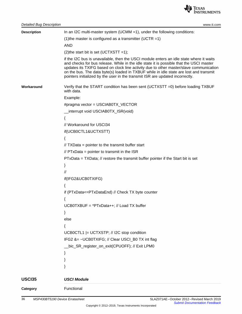
Detailed Bug Description www.ti.com
36 SLAZ071AE–October 2012–Revised March 2019Submit Documentation Feedback
Copyright © 2012–2019, Texas Instruments Incorporated
MSP430BT5190 Device Erratasheet
Description In an I2C multi-master system (UCMM =1), under the following conditions:
(1)the master is configured as a transmitter (UCTR =1)
AND
(2)the start bit is set (UCTXSTT =1);
if the I2C bus is unavailable, then the USCI module enters an idle state where it waitsand checks for bus release. While in the idle state it is possible that the USCI masterupdates its TXIFG based on clock line activity due to other master/slave communicationon the bus. The data byte(s) loaded in TXBUF while in idle state are lost and transmitpointers initialized by the user in the transmit ISR are updated incorrectly.
Workaround Verify that the START condition has been sent (UCTXSTT =0) before loading TXBUFwith data.
Example:
#pragma vector = USCIAB0TX_VECTOR
__interrupt void USCIAB0TX_ISR(void)
{
// Workaround for USCI34
if(UCB0CTL1&UCTXSTT)
{
// TXData = pointer to the transmit buffer start
// PTxData = pointer to transmit in the ISR
PTxData = TXData; // restore the transmit buffer pointer if the Start bit is set
}
//
if(IFG2&UCB0TXIFG)
{
if (PTxData<=PTxDataEnd) // Check TX byte counter
{
UCB0TXBUF = *PTxData++; // Load TX buffer
}
else
{
UCB0CTL1 |= UCTXSTP; // I2C stop condition
IFG2 &= ~UCB0TXIFG; // Clear USCI_B0 TX int flag
__bic_SR_register_on_exit(CPUOFF); // Exit LPM0
}
}
}
USCI35 USCI Module
Category Functional

www.ti.com Detailed Bug Description
37SLAZ071AE–October 2012–Revised March 2019Submit Documentation Feedback
Copyright © 2012–2019, Texas Instruments Incorporated
MSP430BT5190 Device Erratasheet
Function Violation of setup and hold times for (repeated) start in I2C master mode
Description In I2C master mode, the setup and hold times for a (repeated) START, tSU,STA and tHD,STArespectively, can be violated if SCL clock frequency is greater than 50kHz in standardmode (100kbps). As a result, a slave can receive incorrect data or the I2C bus can bestalled due to clock stretching by the slave.
Workaround If using repeated start, ensure SCL clock frequencies is < 50kHz in I2C standard mode(100 kbps).
USCI39 USCI Module
Category Functional
Function USCI I2C IFGs UCSTTIFG, UCSTPIFG, UCNACKIFG
Description Unpredictable code execution can occur if one of the hardware-clear-able IFGsUCSTTIFG, UCSTPIFG or UCNACKIFG is set while the global interrupt enable is set bysoftware (GIE=1). This erratum is triggered if ALL of the following events occur infollowing order:
1. Pending Interrupt: One of the UCxIFG=1 AND UCxIE=1 while GIE=0
2. The GIE is set by software (e.g. EINT)
3. The pending interrupt is cleared by hardware (external I2C event) in a time window of1 MCLK clock cycle after the "EINT" instruction is executed.
Workaround Disable the UCSTTIE, UCSTPIE and UCNACKIE before the GIE is set. After GIE is set,the local interrupt enable flags can be set again.
Assembly example:
bic #UCNACKIE+UCSTPIE+UCSTTIE, UCBxIE ; disable all self-clearing interrupts
NOP
EINT
bis #UCNACKIE+UCSTPIE+UCSTTIE, UCBxIE ; enable all self-clearing interrupts
USCI40 USCI Module
Category Functional
Function SPI Slave Transmit with clock phase select = 1
Description In SPI slave mode with clock phase select set to 1 (UCAxCTLW0.UCCKPH=1), after thefirst TX byte, all following bytes are shifted by one bit with shift direction dependent onUCMSB. This is due to the internal shift register getting pre-loaded asynchronously whenwriting to the USCIA TXBUF register. TX data in the internal buffer is shifted by one bitafter the RX data is received.
Workaround Reinitialize TXBUF before using SPI and after each transmission.
If transmit data needs to be repeated with the next transmission, then write backpreviously read value:
UCAxTXBUF = UCAxTXBUF;
WDG4 WDT Module

Detailed Bug Description www.ti.com
38 SLAZ071AE–October 2012–Revised March 2019Submit Documentation Feedback
Copyright © 2012–2019, Texas Instruments Incorporated
MSP430BT5190 Device Erratasheet
Category Functional
Function The WDT failsafe can be disabled
Description The UCS is capable of masking clock requests (ACLK, SMCLK, MCLK) from peripheralmodules; see request enable (REQEN) bits in the UCS control register, UCSCTL8.
The clock request logic of the UCS is used by the WDT module to ensure a fail-safeclock source in all low-power modes. Therefore, de-asserting the request enable bit ofthe watchdog clock source (xCLKREQEN = 0) allows the respective clock to be disabledupon entry into a low-power mode. Without an active clock source, the WDT timer stopsincrementing and a watchdog event will not occur.
Workaround None

www.ti.com Document Revision History
39SLAZ071AE–October 2012–Revised March 2019Submit Documentation Feedback
Copyright © 2012–2019, Texas Instruments Incorporated
MSP430BT5190 Device Erratasheet
8 Document Revision HistoryChanges from device specific erratasheet to document Revision A.1. Corrected silicon revision A to revision D2. Added silicon revision E
Changes from document Revision A to Revision B.1. Added PMM15
Changes from document Revision B to Revision C.1. Corrected EEM11 description
Changes from document Revision C to Revision D.1. Errata RTC4 was removed2. Errata EEM19 was added3. Errata EEM21 was added4. Errata FLASH37 was added5. Errata PMM14 was added6. Errata PMM17 was added7. Errata PORT16 was added8. Errata SYS16 was added9. Errata UCS10 was added10. Errata USCI30 was added11. Errata USCI31 was added12. Revision F was added13. Revision G was added14. Revision H was added15. Errata TA23 was renamed to TAB2316. PZ100 package markings have been updated17. PZ100 package markings have been updated
Changes from document Revision D to Revision E.1. Errata DMA10 was added to the errata documentation.2. Errata PORT19 was added to the errata documentation.3. Errata PMM18 was added to the errata documentation.4. Errata RTC6 was added to the errata documentation.
Changes from document Revision E to Revision F.1. DMA10 Workaround was updated.2. DMA10 Description was updated.
Changes from document Revision F to Revision G.1. Errata RTC3 was added to the errata documentation.2. DMA10 Description was updated.
Changes from document Revision G to Revision H.1. DMA10 Description was updated.2. DMA10 Function was updated.
Changes from document Revision H to Revision I.1. DMA10 Description was updated.2. MPY1 Description was updated.3. Errata EEM23 was added to the errata documentation.

Document Revision History www.ti.com
40 SLAZ071AE–October 2012–Revised March 2019Submit Documentation Feedback
Copyright © 2012–2019, Texas Instruments Incorporated
MSP430BT5190 Device Erratasheet
4. Errata CPU43 was added to the errata documentation.
Changes from document Revision I to Revision J.1. SYS16 Description was updated.2. CPU43 Description was updated.3. Device TLV Hardware Revision information added to erratasheet.
Changes from document Revision J to Revision K.1. Errata PMM20 was added to the errata documentation.2. Errata USCI35 was added to the errata documentation.
Changes from document Revision K to Revision L.1. Errata UCS11 was added to the errata documentation.
Changes from document Revision L to Revision M.1. EEM19 Workaround was updated.2. EEM13 Workaround was updated.3. EEM23 Workaround was updated.4. EEM17 Description was updated.5. EEM23 Description was updated.6. EEM17 Workaround was updated.7. PORT16 Workaround was updated.8. CPU43 Description was updated.9. EEM11 Workaround was updated.10. EEM14 Workaround was updated.11. EEM16 Description was updated.12. PORT16 Description was updated.13. EEM16 Workaround was updated.14. EEM19 Description was updated.
Changes from document Revision M to Revision N.1. DMA10 Workaround was updated.2. DMA10 Description was updated.3. DMA10 Function was updated.
Changes from document Revision N to Revision O.1. CPU40 Workaround was updated.2. EEM19 Workaround was updated.3. Errata USCI39 was added to the errata documentation.4. Package Markings section was updated.5. EEM23 Workaround was updated.6. EEM23 Description was updated.7. Errata ADC42 was added to the errata documentation.8. EEM23 Function was updated.9. EEM19 Description was updated.
Changes from document Revision O to Revision P.1. Errata USCI40 was added to the errata documentation.2. Errata CPU43 was removed from the errata documentation.3. PMM18 Workaround was updated.
Changes from document Revision P to Revision Q.

www.ti.com Document Revision History
41SLAZ071AE–October 2012–Revised March 2019Submit Documentation Feedback
Copyright © 2012–2019, Texas Instruments Incorporated
MSP430BT5190 Device Erratasheet
1. DMA7 Workaround was updated.2. EEM23 Description was updated.3. DMA7 Description was updated.
Changes from document Revision Q to Revision R.1. USCI39 Description was updated.
Changes from document Revision R to Revision S.1. Errata JTAG26 was added to the errata documentation.
Changes from document Revision S to Revision T.1. EEM19 Workaround was updated.
Changes from document Revision T to Revision U.1. RTC6 Description was updated.2. UCS11 Workaround was updated.3. UCS11 Description was updated.4. UCS11 Function was updated.
Changes from document Revision U to Revision V.1. Errata JTAG27 was added to the errata documentation.
Changes from document Revision V to Revision W.1. JTAG20 Workaround was updated.2. USCI39 Workaround was updated.3. SYS12 Description was updated.
Changes from document Revision W to Revision X.1. CPU21 was added to the errata documentation.2. CPU23 was added to the errata documentation.3. CPU22 was added to the errata documentation.4. Workaround for CPU27 was updated.5. Function for CPU26 was updated.6. Description for CPU26 was updated.7. Workaround for CPU26 was updated.8. Workaround for CPU29 was updated.9. Workaround for CPU28 was updated.10. Workaround for PMM15 was updated.11. Workaround for CPU30 was updated.12. Workaround for CPU32 was updated.13. Workaround for CPU31 was updated.14. Workaround for CPU39 was updated.15. Workaround for CPU34 was updated.16. Workaround for CPU33 was updated.17. Workaround for CPU35 was updated.18. Workaround for CPU40 was updated.
Changes from document Revision X to Revision Y.1. TLV hardware revision ID for Rev D was updated.
Changes from document Revision Y to Revision Z.1. Workaround for PMM15 was updated.
Changes from document Revision Z to Revision AA.

Document Revision History www.ti.com
42 SLAZ071AE–October 2012–Revised March 2019Submit Documentation Feedback
Copyright © 2012–2019, Texas Instruments Incorporated
MSP430BT5190 Device Erratasheet
1. Description for RTC6 was updated.2. Workaround for RTC6 was updated.
Changes from document Revision AA to Revision AB.1. Erratasheet format update.2. Added errata category field to "Detailed bug description" section
Changes from document Revision AB to Revision AC.1. Workaround for CPU40 was updated.
Changes from document Revision AC to Revision AD.1. CPU47 was added to the errata documentation.2. ADC69 was added to the errata documentation.
Changes from document Revision AD to Revision AE.1. USCI34 was added to the errata documentation.

IMPORTANT NOTICE AND DISCLAIMERTI PROVIDES TECHNICAL AND RELIABILITY DATA (INCLUDING DATA SHEETS), DESIGN RESOURCES (INCLUDING REFERENCE DESIGNS), APPLICATION OR OTHER DESIGN ADVICE, WEB TOOLS, SAFETY INFORMATION, AND OTHER RESOURCES “AS IS” AND WITH ALL FAULTS, AND DISCLAIMS ALL WARRANTIES, EXPRESS AND IMPLIED, INCLUDING WITHOUT LIMITATION ANY IMPLIED WARRANTIES OF MERCHANTABILITY, FITNESS FOR A PARTICULAR PURPOSE OR NON-INFRINGEMENT OF THIRD PARTY INTELLECTUAL PROPERTY RIGHTS.These resources are intended for skilled developers designing with TI products. You are solely responsible for (1) selecting the appropriate TI products for your application, (2) designing, validating and testing your application, and (3) ensuring your application meets applicable standards, and any other safety, security, regulatory or other requirements.These resources are subject to change without notice. TI grants you permission to use these resources only for development of an application that uses the TI products described in the resource. Other reproduction and display of these resources is prohibited. No license is granted to any other TI intellectual property right or to any third party intellectual property right. TI disclaims responsibility for, and you will fully indemnify TI and its representatives against, any claims, damages, costs, losses, and liabilities arising out of your use of these resources.TI’s products are provided subject to TI’s Terms of Sale or other applicable terms available either on ti.com or provided in conjunction with such TI products. TI’s provision of these resources does not expand or otherwise alter TI’s applicable warranties or warranty disclaimers for TI products.TI objects to and rejects any additional or different terms you may have proposed. IMPORTANT NOTICE
Mailing Address: Texas Instruments, Post Office Box 655303, Dallas, Texas 75265Copyright © 2022, Texas Instruments Incorporated