MP Reconstruction System - Link Sweden
40
Surgical Technique MP Reconstruction System Cementless & Cemented
-
Upload
khangminh22 -
Category
Documents
-
view
1 -
download
0
Transcript of MP Reconstruction System - Link Sweden

Surgical Technique
MP Reconstruction SystemCementless & Cemented

Explanation of Pictograms
Manufacturer Item number
Material (number) Product meets the applicable requirements, which are regulated in the EU harmonization legislation for the affixing of the CE marking.

01
Contents
MP Reconstruction SystemCementless & Cemented
System Description 02 System Overview
Surgical Technique 03 Preoperative Planning
Surgical Technique, cementless 05 Reaming of the Medullary Canal 06 Insertion of the Prosthesis Stem 08 Preparation of the proximal femur 09 Trial Reduction 10 Leg Length and Lateralization, Anteversion, Trial Fixation Screws, Use of a Longer Trial Neck Segment 13 Final Assembly 14 Stem Extraction
Surgical Technique, cemented 15 Procedure
Implants 18 Prosthesis Stems, cementless 19 Modular Revision Prosthesis Stems, cemented 20 Neck Segments 21 Proximal Spacers and Expansion Bolts
Instruments 22 Complete Instrument Set 23 Instrument Trays 1-10
Accessories 30 Additional Instruments, X-ray Templates, Cleaning and Care Instructions
Literature 31 Reprints 32 Additional Information
33 Indications / Contraindications
Important Information
02
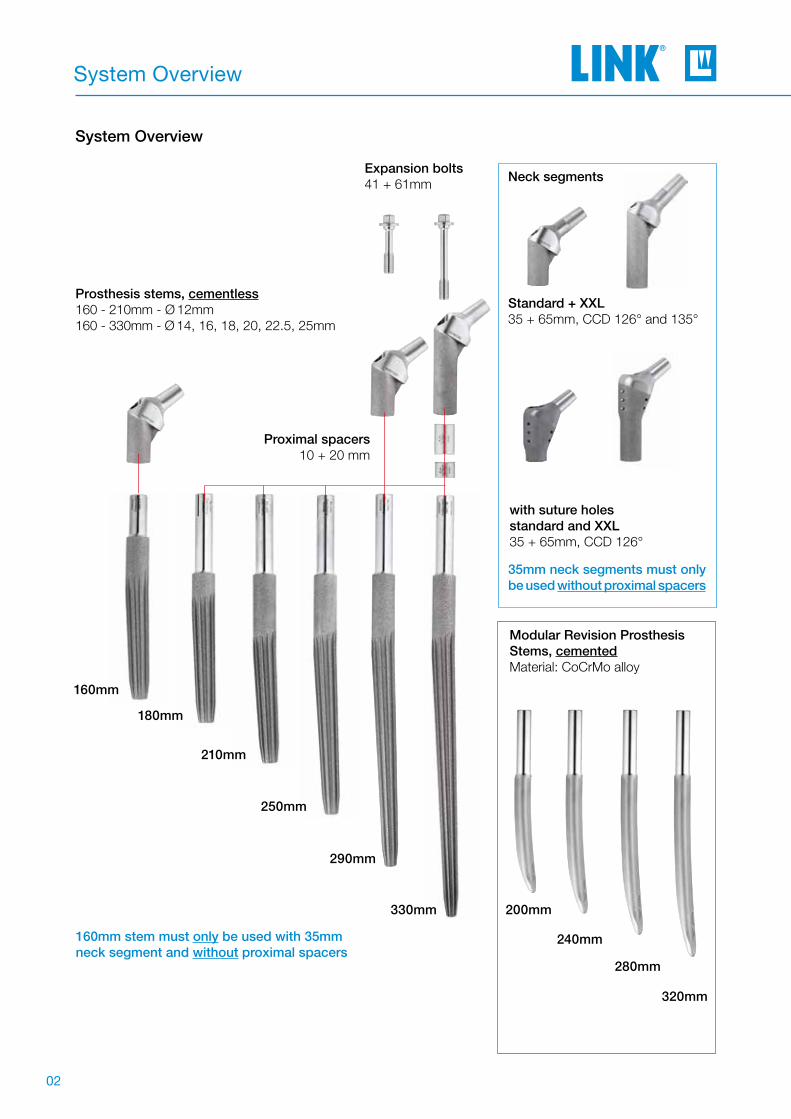
System Overview
Standard + XXL35 + 65mm, CCD 126° and 135°
Neck segments
with suture holesstandard and XXL35 + 65mm, CCD 126°
Modular Revision Prosthesis Stems, cementedMaterial: CoCrMo alloy
Prosthesis stems, cementless160 - 210mm - Ø 12mm160 - 330mm - Ø 14, 16, 18, 20, 22.5, 25mm
160mm stem must only be used with 35mm neck segment and without proximal spacers
Expansion bolts41 + 61mm
210mm
180mm
160mm
250mm
290mm
330mm
35mm neck segments must only be used without proximal spacers
Proximal spacers10 + 20 mm
System Overview
320mm
280mm
240mm
200mm

03
Surgical Technique
It is important to plan the intervention preoperatively in order to select the correct implant type and size and its final intraosseous position based on the pati-ents individual anatomy. The surgeon shouldperform a careful evaluation of the patient´s clinical condition and consider the level of physical activity before performing a hip replacement. For optimal results, the surgery should be planned in advance using the appropriate templates. The magnification factor of the X-rays must be compatible with the factor on the templates. Special MP Reconstruction Sys-tem X-ray templates are available in standard 1.1:1. The implant size must be chosen from adequate AP and ML X-rays with sufficient quality. Each X-ray should be large enough for application of the whole template. A second X-ray of the unaffected joint is often helpful. Inadequate pre-operative planning can lead to improper selection of the implants and/or incorrect implant positioning.
CautionPreoperative planning provides an initial estima-tion of the final situation but cannot conclusively determine the most adequate size to be used. The ultimate decision can only be taken intra-operatively.
Preoperative Planning
As general rule, the prosthesis stem should be mea-sured in such a way that a positive-fit fixation of the prosthesis is created over a sufficient length in vital bone. To this end, it is necessary to make allowance for reaming the femoral canal. Achieving anatomi-cally appropriate head-neck length is of paramount importance. The MP Reconstruction System offers different offsets with changing CCD angles. This combined with femoral heads with up to four head-neck lengths allows the surgeon great flexibility.
The surgical instructions below for reconstructing a damaged hip joint with the MP Reconstruction System describe an idealized surgical situation. However, every procedure has individual particula-rities, and the surgeon decides during the surgery which method can be expected to achieve the best outcome in the each case.
In-situ implants and the bone cement must be com-pletely removed before implanting an MP Reconst-ruction System.
Tip Preoperative planning may be time-consuming, but the time spent results in better intraoperative support and enhanced quality assurance.

04
Surgical Technique
Preoperative planning supports optimal surgical outcomes by ensuring the most appropriate implant selections for the patient. The key objectives invol-ved are the correct positioning of the central rota-tional point of the hip, correct leg length and finally preservation or restoration of sufficient soft tissue tension by avoiding medialisation of the femur.
Planning should ideally be based on two X-rays: an AP film of the pelvis and a mediolateral X-ray of the hip to be revised. When performing the pelvic X-ray it is important to ensure that:
1. Both femurs are shown adequate length, to show the preoperative geometry.
2. The femurs are straight and parallel and, if possible, internally rotated approximately 5° in that position.
3. Key landmarks needed for planning are visible: the inferior margins of the obturator foramen and of the acetabular teardrop.
When evaluating the X-rays, it is important calculate the magnification factor. Two factors are decisive (Fig. 1):
1) Focal distance Focal spot X-ray tube x Film cassette A focal distance of 100cm gives magnification of about 10%.
2) Object film distance Femoral axis x Film cassette
Fig. 1
Focal spot X-ray tube
Ob
ject
film
dis
tanc
e
Film level
(Cassette)
Fo
cal d
ista
nce

05
Surgical Technique, cementless
Reaming of Medullary CanalThe reaming of the femoral canal begins with atapered reamer corresponding to the planned pros-thesis stem length (A), but with a diameter 1-2 sizes smaller than the planned stem diameter; this does not apply when using the smallest diameter (Ø12mm 160-250mm).
The reaming depth is determined by the position of the ring markings on the shaft of the tapered reamer. The marking should be in relation to an anatomical landmark on the bone, determined during the pre-operative planning.
If no proximal spacers are used, the position of the lower marking ring should be at the medial level of the original femoral neck resection (Fig. 6). This land-mark can be easily identifi ed on the X-ray, enabling a reference marking to be determined for the surgery.
TipThe fourth ring is approximately at the level of thetip of the greater trochanter, and the lower ring a thumb’s breadth above the lesser trochanter – always without the use of proximal spacers.
The tapered reamers should only ever be screwed into the femoral canal as far as indicated by the po-sition of the marking ring to the specifi ed landmark.
The reaming must be performed carefully. The tape-red reamer must not become hot to the touch. For this reason, we urgently recommend performing the reaming by hand.
The surgical instructions below for reconstruc-ting a damage hip joint using the MP Reconst-ruction System depict an idealized surgical situ-ation. However, every procedure has individual particularities, and the surgeon decides during the surgery which method can be expected to achieve the most success in the current case.
Con
tact
with
cor
tical
bon
e
Reaming depth without proximal spacer(s)
The last tapered reamer is used to prepare the me-dullary canal until contact is made with the endosteal cortical bone until adequate endosteal engagement is achieved (Fig. 6).
In addition, the surgeon can check whether contact surface is suffi ciently large when the last tapered reamer is carefully removed clockwise. Bone partic-les on the tapered reamer shaft can provide informa-tion on the reaming distance.The last reaming step must always be performed with a diameter identical to that of the implant stem.For example, if an implant with Ø 18mm is used, the last reaming step must be performed with a Ø 18mm tapered reamer.
A
Fig. 6

06
Surgical Technique, cementless
Use of proximal spacers:
Leg length: ± 0mm ± 0mm ± 0mm + 10mm
Insertion of the Prosthesis StemThe selected MP stem (B), which corresponds to the size of the last tapered reamer used, is screwed tightly to the inserter for stems (C) (Fig. 8).
The line marking on the stem identifi es the side of the stem which indicates the 3° angle (Fig. 8, center). The orientation of the marking is used for a better overview when inserting the stem. The arrow on the striking surface now indicates where the angle of the stem is. This makes it possible to insert the MP stem into the femoral canal precisely aligned to the natural curvature of the femur (Fig. 8/with curvature).
The stem is then carefully driven in to the fi nal depth using a mallet. The fi nal position must be verifi ed by means of radioscopic control (Figs. 9 and 10).
The MP stem must not be driven in deeper than intended in the preoperative planning. Should it prove impossible to achieve stable fi xation of the stem at the intended depth due to poor bone quality, any shortening of the leg that results from driving the stem in deeper can be compensated by using proximal spacers of up to 30mm (10mm, 20mm, or 20+10mm). Intentional lengthening of the leg is also possible with a proximal spacer (see Fig. 7).
Secure fi xation of the MP prosthesis stem in the medullary canal is always given utmost priority.
Fig. 7

07
Surgical Technique, cementless
B
C
Fig. 8
Fig. 9 Fig. 10

08
Surgical Technique, cementless
Preparation of the proximal femurIf required, the Tubular Reamer is used to prepare the implant bed for the neck segment (Fig. 11).
There are two reamer guides available for positi-oning the reamer on the in-situ stem. Their length must be selected according to the neck segment being used (Fig. 12).
Short reamer guide --> long neck segment (x)Long reamer guide --> short neck segment (y)
The reamer guide can be screwed into the stem by hand or using the hex screwdriver.
The reamer guide also serves as a stop to avoid the teeth of the tubular reamer from coming into contact with the edge of the lower portion of the stem.
Irrigation is recommended to avoid overheating of the bone.
x
y
x
Fig. 11 Fig. 12
09
Surgical Technique, cementless
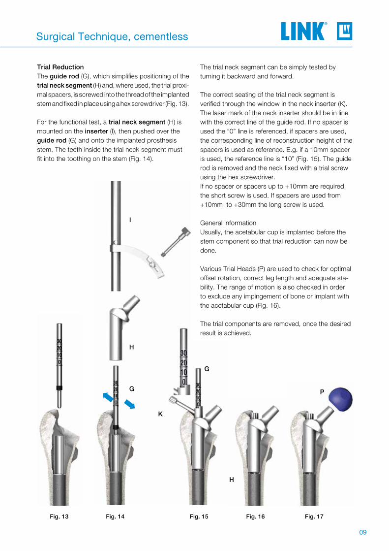
Trial Reduction The guide rod (G), which simplifies positioning of the trial neck segment (H) and, where used, the trial proxi-mal spacers, is screwed into the thread of the implanted stem and fixed in place using a hex screwdriver (Fig. 13).
For the functional test, a trial neck segment (H) is mounted on the inserter (I), then pushed over the guide rod (G) and onto the implanted prosthesis stem. The teeth inside the trial neck segment must fit into the toothing on the stem (Fig. 14).
The trial neck segment can be simply tested by turning it backward and forward.
The correct seating of the trial neck segment is verified through the window in the neck inserter (K). The laser mark of the neck inserter should be in line with the correct line of the guide rod. If no spacer is used the “0” line is referenced, if spacers are used, the corresponding line of reconstruction height of the spacers is used as reference. E.g. if a 10mm spacer is used, the reference line is “10” (Fig. 15). The guide rod is removed and the neck fixed with a trial screw using the hex screwdriver. If no spacer or spacers up to +10mm are required, the short screw is used. If spacers are used from +10mm to +30mm the long screw is used.
General informationUsually, the acetabular cup is implanted before the stem component so that trial reduction can now be done.
Various Trial Heads (P) are used to check for optimal offset rotation, correct leg length and adequate sta-bility. The range of motion is also checked in order to exclude any impingement of bone or implant with the acetabular cup (Fig. 16).
The trial components are removed, once the desired result is achieved.
H
I
G
G
K
➡➡
H
P
Fig. 15 Fig. 16 Fig. 17Fig. 14Fig. 13
G

10
Surgical Technique, cementless
Leg Length and LateralizationLeg length can be corrected by 10mm, 20mm, or 30mm (combination of 10mm and 20mm proximal spacers) by using trial proximal spacers (Fig. 18, 19).
Fine tuning of the leg length and different laterali-zation of the prosthesis stem can be achieved by selecting:
• Neck segment with 126° or 135° CCD angle (Fig. 19) in standard neck length or XXL neck length (Fig. 20) or
• Trial head with suitable head-neck length (Fig. 21)
TipA long trial neck segment is obligatory when trial proximal spacers are used.
Short trial neck segments must not be used with trial proximal spacers (Fig. 19).
RotationThe rotation angle can be corrected by turning the trial neck segment after loosening the fixation screw. The desired position should then be marked on the bone so that the final neck segment can be positioned correctly.
TipA short trial fixation screw is required if no trial proximal spacer or a 10mm trial proximal spacer is used. If a 20mm trial proximal spacer, or a combination of a 20mm and a 10mm proximal spacer, is used, then only the long trial fixation screw may be used (Fig. 18).
Use of a Longer Trial Neck SegmentReplacing an originally used 35 mm trial neck seg-ment with a 65mm trial neck segment can require the use of the tubular reamer due to the longer tubular neck of the 65mm segment.
Once the leg length, anteversion and joint stability have been checked, the trial prostheses can be removed.
Fig. 18

11
Surgical Technique, cementless
Trial
20mm
30mm
10mm
Expansion BoltsProximal spacers (trial + implant)
Trial
20mm
30mm
10mm
10mmlong
Neck segments (trial + implant)Proximal spacers (trial + implant)
Fig. 19
Fig. 20
short
long short

12
Surgical Technique, cementless
Final AssemblyImplantation of neck segmentInsert the guide rod (G) into the stem using the hex screwdriver (Fig. 21). The trial neck segment (I) is then slid over the guide rod (G) onto the stem either by hand or by using the inserter forceps (M). The neck can be driven into its final position with subtle hammer strokes, using the neck inserter (K) (Fig. 22). If spacers are used, trial spacers are slid over the guide rod before inserting the neck segment.
The correct seating of the neck segment is verified through the window in the neck inserter. The laser mark of the neck inserter should be in line with the correct line of the guide rod. If no spacer is used the “0” line is referenced, if a spacers are used, the corresponding line of reconstruction height of the spacers is used as reference. E.g. if a 10mm spacer is used, the reference line is “10” (Fig. 22). This assures a safe seating of the teeth connection.The guide rod is removed and the neck fixed with the Expansion Bolt, using the neck inserter (I) (Fig. 23).If no spacer or spacers up to +10mm are used, the short Expansion Bolt is used. If spacers are used from +20mm to +30mm the long Expansion Bolt is used.
A final trial reduction can be conducted using a plastic trial head. If necessary, the rotation can now be corrected by loosening the Expansion Bolt again. The guide rod is then reinserted into the stem and the neck segment can be rotated by slighly lifting it up before rotating. Then the steps of inserting and cheking are repeated as described above.
G
K
I
G
Fig. 21 Fig. 22 Fig. 23

13
Surgical Technique, cementless
M
N
Fig. 24
Final assembly of the implantAfter the Expansion Bolt is hand tighened with the neck inserter (K), the Expansion Bolt is tighened with the torque wrench (N). When tightening the Expansion Bolt with the torque wrench, the Inser-ting Foreceps (M) is used as a counter torque by gripping the neck segment over the trunion. Once the necessary torque is reached, the torque wrench emits a loud snap (Fig. 24).
TipThe taper caps must be checked for damage before use.
CautionLINK implants and Expansion Bolt can only be used once. It is not possible to reuse them because no expansion occurs when the bolt is tightened a second time. The torque wrench (N) is supplied with a calibration certificate and separate instructions for use, and must be sub-jected to a functional test after 250 uses.To this end, the instrument should be sent toWaldemar Link GmbH & Co. KG.
Attaching the prosthesis headThe taper of the stem is carefully cleaned and dried. This is particularly important with ceramic heads. Then the head is attached by hand with a rotational movement, applying axial pressure. To finish, the Head Impactor is used to tap the prosthesis head into position (Fig. 25).
Final reduction of the jointAfter cleaning the joint surfaces, the joint is reduced. The wound is closed in layers.
Fig. 25

14
Surgical Technique, cementless
C
O
C
Rod with slap hammer
Inserter for stems
MP stem
Stem ExtractionShould it prove necessary to remove the MP stem during the surgery or later revision, the inserter (C) is mounted on the in-situ stem and screwed to the rod with slap hammer (O).
The MP stem can be driven out of the medullary ca-nal safely by applying measured blows to the upper stop with the slap hammer.
Fig. 26

15
Surgical Technique, cemented
The short guide is screwed onto the trial stem as described on page 08, and then the proximal bone reamed for the cemented preparation with the tubu-lar reamer (134-211/00).
The guide is then unscrewed again and the trial stem is removed from the femur with the aid of the inserter. This can be done using the slide hammer.
Fig. 28
Procedure
If use of a cemented stem is planned, the 180mm long MP trial stems (134-070/00), the additional instrument set for the cemented surgical technique (134-110/00), and an insertion sleeve, UHMWPE (134-212/00) are required in addition to the basic instrument set.
The medullary canal is prepared with medullary space drills or ball reamers to accept the prosthesis stem. It is recommended to start with the smallest dia-meter and open up the medullary canal millimeter by millimeter until contact with the cortical bone is identified distally around the circumference.
To achieve an even cement coating of 1mm all the way around, the medullary space must be excavated to a diameter at least 2mm larger than the stem used.
It might be necessary to clear the pro-ximal femur to allow for the use of the plastic sleeve. If this can‘t be achieved using the start reamer please proceed with the following steps.
Once the medullary space has been
prepared to the required diameter, a trial stem measuring 180mm in length is in-serted, corresponding to the diameter of the last medullary space reamer used.
The trial stem is secured on the inserter (C) as described on page 06, and then inserted up to the planned proximal marking.
Caution Do not exert too much pressure,
as the trial stem is not intended to achieve a press fit, and can thus be driven further into the femur than planned.
C
Fig. 27

16
Surgical Technique, cemented
The plastic sleeves must be checked for damage before use.
The plastic sleeve is screwed to the insertion slee-ve, pushed onto the proximal section of the implant stem, and then screwed to the inserter (Fig. 28).
The medullary space is then sealed with a bone dowel or a medullary plug a little below the intended position of the stem tip. Following application of the cement, the prosthesis stem is introduced into the medullary space. The markings on the plastic sleeve correspond to the markings on the inserter used in the cementless surgical technique. As such, the lowest line marks the proximal end of the stem.
Fig. 30
Caution When applying the cement, it is essential to en-sure secure fi xation of the distal end of the stem. Proximal oozing of the cement should be avoi-ded and any escaping cement removed before it sets.
The stem is held in the required position with the inserter until the cement sets. The plastic sleeve prevents excess cement from coming into contact with the proximal portion of the stem (Fig. 29).Once the cement has completely set, the inserter is disconnected from the implant and removed along with the plastic sleeve.
To remove the plastic sleeve, the ext-ractor is inserted in the sleeve and the bayonet mount is locked. The plastic sleeve can now be twisted free from the cement and removed (Fig. 30).
Fig. 9

17
Surgical Technique, cemented
The guide is screwed onto the prosthesis stem again and the further preparation of the proximal femur can continue as shown on page 09.
Any excess cement is then removed from the area of the proximal femur at the next reaming stage and with the tubular reamer (134-200/00).
Tip We recommend checking the cement application and the associated prosthesis positioning with radioscopic control.
Fig. 31

18
Implants
160mm long stems must only be used with short neck segments and without proximal spacers.
Prosthesis stems, cementless Tilastan-S
Prosthesis Stems, cementless
microporousSize
Prox. stem-Ø mm
Dist. stem-Ø mm
Lengthmm
172-916/12 X S-0 12.0 10.0 160
172-916/14 X S-1 14.0 12.0 160
172-916/16 X S-2 16.0 14.0 160
172-916/18 X S-3 18.0 16.0 160
172-916/20 X S-4 20.0 18.0 160
172-916/22 X S-5 22.5 21.0 160
172-916/25 X S-6 25.0 23.0 160
172-918/12 S-0 12.0 10.0 180
172-918/14 S-1 14.0 12.0 180
172-918/16 S-2 16.0 14.0 180
172-918/18 S-3 18.0 16.0 180
172-918/20 S-4 20.0 18.0 180
172-918/22 S-5 22.5 21.0 180
172-918/25 S-6 25.0 23.0 180
172-921/12 00 12.0 10.0 210
172-921/14 001 14.0 12.0 210
172-921/16 002 16.0 14.0 210
172-921/18 003 18.0 16.0 210
172-921/20 004 20.0 18.0 210
172-921/22 005 22.5 21.0 210
172-921/25 006 25.0 23.0 210
172-925/14* 01 14.0 11.0 250
172-925/16 02 16.0 13.0 250
172-925/18 03 18.0 15.0 250
172-925/20 04 20.0 17.0 250
172-925/22 05 22.5 19.0 250
172-925/25 06 25.0 22.0 250
172-929/14* 1 14.0 9.0 290
172-929/16 2 16.0 11.0 290
172-929/18 3 18.0 13.0 290
172-929/20 4 20.0 15.0 290
172-929/22 5 22.5 18.0 290
172-929/25 6 25.0 20.0 290
172-930/14* 7 14.0 8.0 330
172-930/16 8 16.0 10.0 330
172-930/18 9 18.0 12.0 330
172-930/20 10 20.0 14.0 330
172-930/22 11 22.5 16.0 330
172-930/25 12 25.0 19.0 330
* Stems combined with a neck/head combination creating an offset higher than 48.5mm could not be prooven to fulfil the mechanical normative requirements.

19
Implants
Stems combined with a neck/head combination creating an offset higher than 43.2mm could not be prooven to fulfil the mechanical normative requirements.
Modular Revision Prosthesis Stems, cemented, anatomically curved EndoDur (CoCrMo alloy)
Prosthesis Stems, cemented
for stem length (C)mm
Stem Ø (D)mm
172-900/12 200 12
172-900/14 200 14
172-900/16 200 16
172-901/12 240 12
172-901/14 240 14
172-901/16 240 16
172-902/12 280 12
172-902/14 280 14
172-902/16 280 16
172-903/12 320 12
172-903/14 320 14
172-903/16 320 16
C

20
Implants
Standard Neck Segments , taper 12/14mm
XXL Standard Neck Segments (with 40mm femoral axis offset)
, taper 12/14mm
Neck Segments with Suture Holes , taper 12/14mm
XXL Neck Segments with Suture Holes , taper 12/14mm
Neck Segments
microporousLength
mmCCD angle
Offsetmm
172-964/26 65 126° 31
172-964/35 65 135° 29
172-965/26 35 126° 31
172-965/35 35 135° 29
microporousLength
mmCCD angle
Offsetmm
172-984/26 65 126° 40
172-984/35 65 135° 40
172-985/26 35 126° 40
172-985/35 35 135° 40
microporousLength
mmCCD angle
Offsetmm
99-0984/30 65 126° 31
99-0984/32 35 126° 31
microporousLength
mmCCD angle
Offsetmm
99-0984/26 65 126° 40
99-0984/28 35 126° 40

21
Implants
1) Combination with proximal spacer(s) not possible.
Length (mm)
172-950/10 10
172-950/20 20
Length (mm)
172-947/38 41
172-947/58 61
Neck Segments Proximal Spacers Expansion Expansion bolt
Length (mm) 10mm 20mm mm Length (mm)
65 - - 0 41
65 10 - 10 41
65 - 20 20 61
65 10 20 30 61
351) - - - 41
Possible Combinations:
Proximal Spacers CoCrMo alloy
Expansion Bolts CoCrMo alloy
Proximal Spacers and Expansion Bolts

22
Instruments
Additional Instrument Set
Complete instrument set (incl. trays 1, 2, 3 and 4)
Set in 4 instrument trays, comprising:
134-010/00 Instrument tray 1, basic instrument set
134-020/00 Instrument tray 2, trial implants
134-030/00 Instrument tray 3, tapered reamers 160 - 250mm
134-040/00 Instrument tray 4, tapered reamers 290 - 330mm
Additional instruments, trays 5, 6, 7, 8, 9 and 10
134-050/00 Instrument tray 5, tapered reamers, uneven, 160 - 250mm
134-060/00 Instrument tray 6, tapered reamers, uneven, 290 - 330mm
134-070/00 Instrument tray 7, trial stems 160 - 180 mm
134-080/00 Instrument tray 8, trial stems 210 - 250 mm
134-090/00 Instrument tray 9, trial stems 290 - 330 mm
134-110/00 Instrument tray 10, cemented technique

23
Instruments
1 2 3 5 6 7
121314
10
1517
9
11
Item no. Description
1 134-011/00 Instrument tray 1, empty, 485 x 253 x 80 mm
2 15-6053/00 T-handle, Hudson
3 134-105/00 Screwdriver, size 3.5, Hudson
4 Adapter, optional
16-3283/00 Adapter, Hudson female / triangular male
16-3284/00 Adapter, Hudson female / AO male
16-3286/00 Adapter, Hudson female / Harris male
5 15-6037/00 Start drill
6 134-204/35 Reamer guide, for standard neck segment
7 134-204/65 Reamer guide, for short neck segment
8 134-210/00 Inserter for stems
9 134-200/00 Hollow reamer, Hudson
10 131-379/00 Inserter for neck segments, plus box
11 134-140/00 Torque wrench, size 8 mm, 380 mm
12 131-385/01 Screwdriver, size 8 mm, 185 mm
13 130-600 Driver for prosthesis heads
14 64-8008/02 Screwdriver, size 3.5 mm
15 134-141/00 Insertion forceps for MP® neck segments
16 134-202/00 Caliper
17 134-201/00 Guide rod
18 131-830/04 Taper cap
134-010/00 Instrument tray 1, basic instrument set
18
4
16
8

24
Instruments
1 14 1615 17 18 19
22242527 23
134-020/00 Instrument Tray 2, trial implants
Description
1 134-021/00 Instrument tray 1, empty
2 175-928/11 Trial head, 28mm, S
3 175-928/12 Trial head, 28mm, M
4 175-928/13 Trial head, 28mm, L5 175-928/14 Trial head, 28mm, XL
6 175-932/11 Trial head, 32mm, S
7 175-932/12 Trial head, 32mm, M
8 175-932/13 Trial head, 32mm, L9 175-932/14 Trial head, 32mm, XL
10 175-936/11 Trial head, 36mm, S
11 175-936/12 Trial head, 36mm, M
12 175-936/13 Trial head, 36mm, L13 175-936/14 Trial head, 36mm, XL
14 99-0984/33 Trial neck segment, 35mm, 126° with suture hole15 99-0984/31 Trial neck segment, 65mm, 126° with suture hole
16 131-395/35 Trial neck segment, 35mm, 135°
17 131-393/35 Trial XXL neck segment, 35mm, 135°
18 131-396/35 Trial neck segment, 65mm, 135°19 131-394/35 Trial XXL neck segment, 65mm, 135°
20 131-394/26 Trial XXL neck segment, 65mm, 126°
21 134-100/61 Trial fixation screw, long22 134-100/41 Trial fixation screw, short
23 131-396/26 Trial neck segment, 65mm, 126°
24 131-393/26 Trial XXL neck segment, 35mm, 126°25 131-395/26 Trial neck segment, 35mm, 126°
26 99-0984/27 Trial XXL neck segment, 65mm, 126° with suture hole27 99-0984/29 Trial XXL neck segment, 35mm, 126° with suture hole
28 131-398/10 Trial proximal spacer, 10mm29 131-398/20 Trial proximal spacer, 20mm
30 317-661 Threaded rod with slap hammer
2-5 6-9 10-13
28-2930 2126 20

25
Instruments
134-030/00 Instrument Tray 3, tapered reamers 160-250mm109 11 12 13 14 15
Description
1 134-031/00 Instrument tray 3, empty2 134-600/00 Tapered reamer, Ø 12mm, for stem size 250mm3 134-600/01 Tapered reamer, Ø 14mm, for stem size 250mm4 134-600/02 Tapered reamer, Ø 16mm, for stem size 250mm5 134-600/03 Tapered reamer, Ø 18mm, for stem size 250mm6 134-600/04 Tapered reamer, Ø 20mm, for stem size 250mm7 134-600/05 Tapered reamer, Ø 22.5mm, for stem size 250mm8 134-600/06 Tapered reamer, Ø 25mm, for stem size 250mm9 134-500/00 Tapered reamer, Ø 12mm, for stem size 160-210mm
10 134-500/01 Tapered reamer, Ø 14mm, for stem size 160-210mm11 134-500/02 Tapered reamer, Ø 16mm, for stem size 160-210mm12 134-500/03 Tapered reamer, Ø 18mm, for stem size 160-210mm13 134-500/04 Tapered reamer, Ø 20mm, for stem size 160-210mm14 134-500/05 Tapered reamer, Ø 22.5mm, for stem size 160-210mm15 134-500/06 Tapered reamer, Ø 25mm, for stem size 160-210mm
321 4 5 6 7 8

26
Instruments
134-040/00 Instrument Tray 4, tapered reamers 290-330mm
Description
1 134-041/00 Instrument tray 4, empty
2 134-800/00 Tapered reamer, Ø 12mm, for stem size 330mm
3 134-800/01 Tapered reamer, Ø 14mm, for stem size 330mm
4 134-800/02 Tapered reamer, Ø 16mm, for stem size 330mm
5 134-800/03 Tapered reamer, Ø 18mm, for stem size 330mm
6 134-800/04 Tapered reamer, Ø 20mm, for stem size 330mm
7 134-800/05 Tapered reamer, Ø 22.5mm, for stem size 330mm
8 134-800/06 Tapered reamer, Ø 25mm, for stem size 330mm
9 134-700/00 Tapered reamer, Ø 12mm, for stem size 290mm
10 134-700/01 Tapered reamer, Ø 14mm, for stem size 290mm
11 134-700/02 Tapered reamer, Ø 16mm, for stem size 290mm
12 134-700/03 Tapered reamer, Ø 18mm, for stem size 290mm
13 134-700/04 Tapered reamer, Ø 20mm, for stem size 290mm
14 134-700/05 Tapered reamer, Ø 22.5mm, for stem size 290mm
15 134-700/06 Tapered reamer, Ø 25mm, for stem size 290mm
109 11 12 13 14 15321 4 5 6 7 8

27
Instruments
134-050/00 Instrument tray 5 Tapered reamers, uneven 160-250mm
32 4 5 6 7 8
Description1 134-051/00 Instrument tray 5, empty2 134-500/07 Tapered reamer, Ø 13mm
for stem size 160mm-210mm
3 134-500/08 Tapered reamer, Ø 15mm for stem size 160mm-210mm
5 134-500/09 Tapered reamer, Ø 17mm for stem size 160mm-210mm
7 134-500/10 Tapered reamer, Ø 19mm for stem size 160mm-210mm
9 134-500/11 Tapered reamer, Ø 21mm for stem size 160mm-210mm
11 134-500/12 Tapered reamer, Ø 24mm for stem size 160mm-210mm
4 134-600/09 Tapered reamer, Ø 17mm for stem size 250mm
6 134-600/10 Tapered reamer, Ø 19mm for stem size 250mm
8 134-600/11 Tapered reamer, Ø 21mm for stem size 250mm
10 134-600/12 Tapered reamer, Ø 24mm for stem size 250mm
321 4 5 6 7 89 10 11 9
134-060/00 Instrument tray 6 Tapered reamers, uneven 290-330mm
Description1 134-061/00 Instrument tray 6, empty2 134-700/09 Tapered reamer, Ø 17mm
for stem size 290mm 4 134-700/10 Tapered reamer, Ø 19mm
for stem size 290mm6 134-700/11 Tapered reamer, Ø 21mm
for stem size 290mm8 134-700/12 Tapered reamer, Ø 24mm
for stem size 290mm3 134-800/09 Tapered reamer, Ø 17mm
for stem size 330mm5 134-800/10 Tapered reamer, Ø 19mm
for stem size 330mm7 134-800/11 Tapered reamer, Ø 21mm
for stem size 330mm9 134-800/12 Tapered reamer, Ø 24mm
for stem size 330mm
1
Additional Instrument Set, tapered reamers 5 and 6, uneven

28
Instruments
134-070/00 Instrument Tray 7, trial stems 160-180mm
134-080/00 Instrument Tray 8, trial stems 210-250mm
32 4
56
78
910
11
Description
1 134-071/00 Instrument tray 7, empty
2 134-900/12 Trial stem, Ø 12mm, 160mm
3 134-900/14 Trial stem, Ø 14mm, 160mm
4 134-900/16 Trial stem, Ø 16mm, 160mm
5 134-900/18 Trial stem, Ø 18mm, 160mm
6 134-900/20 Trial stem, Ø 20mm, 160mm
7 134-900/22 Trial stem, Ø 22.5mm, 160mm
8 134-900/25 Trial stem, Ø 25mm, 160mm
9 99-0155/12 Trial stem, Ø 12mm, 180mm
10 99-0155/14 Trial stem, Ø 14mm, 180mm
11 99-0155/16 Trial stem, Ø 16mm, 180mm
12 99-0155/18 Trial stem, Ø 18mm, 180mm
13 99-0155/20 Trial stem, Ø 20mm, 180mm
14 99-0155/22 Trial stem, Ø 22.5mm, 180mm
15 99-0155/25 Trial stem, Ø 25mm, 180mm
Description
1 134-081/00 Instrument tray 8, empty
2 99-0142/12 Trial stem, Ø 12mm, 210mm
3 99-0142/14 Trial stem, Ø 14mm, 210mm
4 99-0142/16 Trial stem, Ø 16mm, 210mm
5 99-0142/18 Trial stem, Ø 18mm, 210mm
6 99-0142/20 Trial stem, Ø 20mm, 210mm
7 99-0142/22 Trial stem, Ø 22.5mm, 210mm
8 99-0142/25 Trial stem, Ø 25mm, 210mm
9 99-0143/12 Trial stem, Ø 12mm, 250mm
10 99-0143/14 Trial stem, Ø 14mm, 250mm
11 99-0143/16 Trial stem, Ø 16mm, 250mm
12 99-0143/18 Trial stem, Ø 18mm, 250mm
13 99-0143/20 Trial stem, Ø 20mm, 250mm
14 99-0143/22 Trial stem, Ø 22.5mm, 250mm
15 99-0143/25 Trial stem, Ø 25mm, 250mm
1213
1415 3
21
45
67
89
1011
1213
14151
Additional Instrument Sets

29
Instruments
134-090/00 Instrument Tray 9, trial stems 290-330mm
Description
1 134-091/00 Instrument tray 9, empty
2 99-0144/14 Trial stem, Ø 14mm, 290mm
3 99-0144/16 Trial stem, Ø 16mm, 290mm
4 99-0144/18 Trial stem, Ø 18mm, 290mm
5 99-0144/20 Trial stem, Ø 20mm, 290mm
6 99-0144/22 Trial stem, Ø 22.5mm, 290mm
7 99-0144/25 Trial stem, Ø 25mm, 290mm
8 99-0145/14 Trial stem, Ø 14mm, 330mm
9 99-0145/16 Trial stem, Ø 16mm, 330mm
10 99-0145/18 Trial stem, Ø 18mm, 330mm
11 99-0145/20 Trial stem, Ø 20mm, 330mm
12 99-0145/22 Trial stem, Ø 22.5mm, 330mm
13 99-0145/25 Trial stem, Ø 25mm, 330mm
32
14
56
78
910
1112
13
134-110/00 Instrument Tray 10
Description
1 134-111/00 Instrument tray 10, empty
2 134-211/00 Tubular reamer, Ø 19mm
3 134-213/00 Insertion sleeve
4 134-214/00 Extractor
321 4
134-212/00 Insertion sleeve, UHMWPE
Additional Instrument Set, cemented

30
Accessories
(X-ray templates 120% natural size available on request)
Widthmm
Working lengthmm
65-1700/20 20 6565-1700/25 25 65
Blade Chisel with Sheath, 250 mm
X-ray Templates for MP reconstruction prosthesis 110% natural size, taper 12/14 mm, set of 7 plates
CCD angleHead-Ø
mmNeck length
for stem lengthmm
Set
175-870/02 126° 32 Short (S) 160 7 plates175-870/05 135° 32 Short (S) 160 7 plates175-870/08 126° 32 Medium (M) 180 7 plates175-870/11 135° 32 Medium (M) 180 7 plates175-870/14 126° 32 Long (L) 210-330 7 plates175-870/17 135° 32 Long (L) 210-330 7 plates
Additional Instruments(not included in instrument set)
Corresponding instructions for the instrument sets are available from [email protected] on request.
Accessories
X-ray Templates
Cleaning and Care Instructions

31
Literature
Ph. Lubinus, W. KlauserThe Revision Femur: A Potpourri of Options, A Modular Option for Proximal Bone Loss, Orthopaedics, Vol. 23 No. 9, Sept. 2000 (H112)
A. Seth Greenwald, Paul D. PostakThe Influence of Modularity on the Endurance Performance of the LINK MP Hip Stem,Orthopaedic Research Laboratories, Cleveland, Ohio, Feb. 2001 (H114)
F. Bellomo, L. Bertignone, L. Morino, P. Milano, E. Schiavone, M. BaraleLINK MP cementless distal fixation modular prosthesis for revision total hip arthroplasty,J Orthopaed Traumatol (2002) 2:121-124 ©Springer Verlag 2002 (H118)
Daniel J. Berry, MDFemoral Revision, Distal Fixation With Fluted, Tapered Grit-Blasted StemsThe Journal of Arthroplasty, Vol. 17 No. 4 Suppl 1, June 2002 (H121)
Louis M. Kwong, MD, A. John Miller, MD, and Philipp Lubinus, MDA Modular Distal Fixation Option for Proximal Bone Loss in Revision Total Hip Arthroplasty, A 2- to 6- Year Follow-up Study, The Journal of Arthroplasty Vol.18 No. 3 Suppl.1 March 2003 (H122)
Daniel J. Berry, MDTreatment of Vancouver B3 Periprosthetic Femur Fractures With a Fluted Tapered Stem,Clinical Orthopaedics, No. 417, December 2003, pp. 224-231 (H128)
W. Klauser, P. LubinusMP-Rekonstruktionsprothese (LINK), Modulare Revisionsendoprothetik des Hüftgelenks,Sonderdruck aus P. Thümler, R. Forst /Hrsg), Seiten 264-270, Springer-Verlag Berlin Heidelberg, 2004 (H130)
Stephen B. Murphy, MD, and Jose Rodriguez, MDRevision Total Hip Arthroplasty With Proximal Bone Loss, The Journal of Arthroplasty Vol.19; No. 4; Suppl 1; June 2004 (H133)
Scott M. Sporer, MD, MS; Wayne G. Paprovsky, MD, FACSFemoral Fixation in the Face of Considerable Bone Loss, Clinical Orthopaedics, No. 429, pp 227-231, 2004
Clinical Cases with the LINK MP Hip SystemOrder No.: 664So/4.99L
G.S. Tamvakopoulos, C.T.J. Servant, G. Clark, J.P. IvoryMedium-term follow-up series using a modular distal fixation prosthesis to address proximal femoral bone deficiency in revision total hip arthroplasty. A 5- to 9-years follow-up study, Hip International Vol.17 no. 3; 2007 - pp. 143-149 (H152)
J.A. Rodriguez MD, R. Fada MD, S.B. Murphy MD, V.J. Rasquinha MD, C.S. Ranawat MDTwo-Year to Five-Year Follow-Up of Femoral Defects in Femoral Revision Treated with the Link MP Modular Stem, The Journal of Arthroplasty Vol.24 no. 5; August 2009 (H156)
R.J. Weiss, F. Strömwall, M.O. Beckmann, K.A. Hansson, A. StarkDistal femoral stem-bone anchorage of a cementless revision total hip arthroplasty Acta Orthopaedica 80 (3): 298-302; 2009 (H160)
M.D. Schofer, T. Efe, T.J. Heyse, N. Timmesfeld, R. Velte, F. Hinrichs, J. SchmittZementfreier Femurschaftwechsel mit einem modularen Hüftendoprothesenrekonstruktionsschaft Der Orthopäde, Bd 39, Heft 2: Februar 2010 (H162)
R.J. Weiss MD PhD, M.O. Beckmann MD, † A. Enocson MD, ‡ A. Schmalholz MD PhD, ‡ A. Starck MD PhDMinimum 5-Year Follow-Up of a Cementless, Modular, Tapered Stem in Hip Revision Arthroplasty The Journal of Arthroplasty, Vol. 26, No. 1; 2011 (H169)
R.R. Thakur MD, A.J. Deshmukh MD, A.Goyal MD, A.S. Ranawat MD, V.J. Rasquinha MD, J.A. Rodriguez MDManagement of Failed Trochanteric Fracture Fixation With Cementless Modular Hip Arthroplasty Using a Distally Fixing Stem, The Journal of Arthroplasty, Vol. 26, No. 3; 2011 (H170)
W. Klauser MD, Y. Bangert MD, P. Lubinus MD, † D. Kendoff MDMedium-Term Follow-Up of a Modular Tapered Noncemented Titanium Stem in Revision Total Hip Arthroplasty: A Single-Surgeon Experience The Journal of Arthroplasty, In Press, Corr. Proof, Av. online 19 Oct 2012 (H174)
32
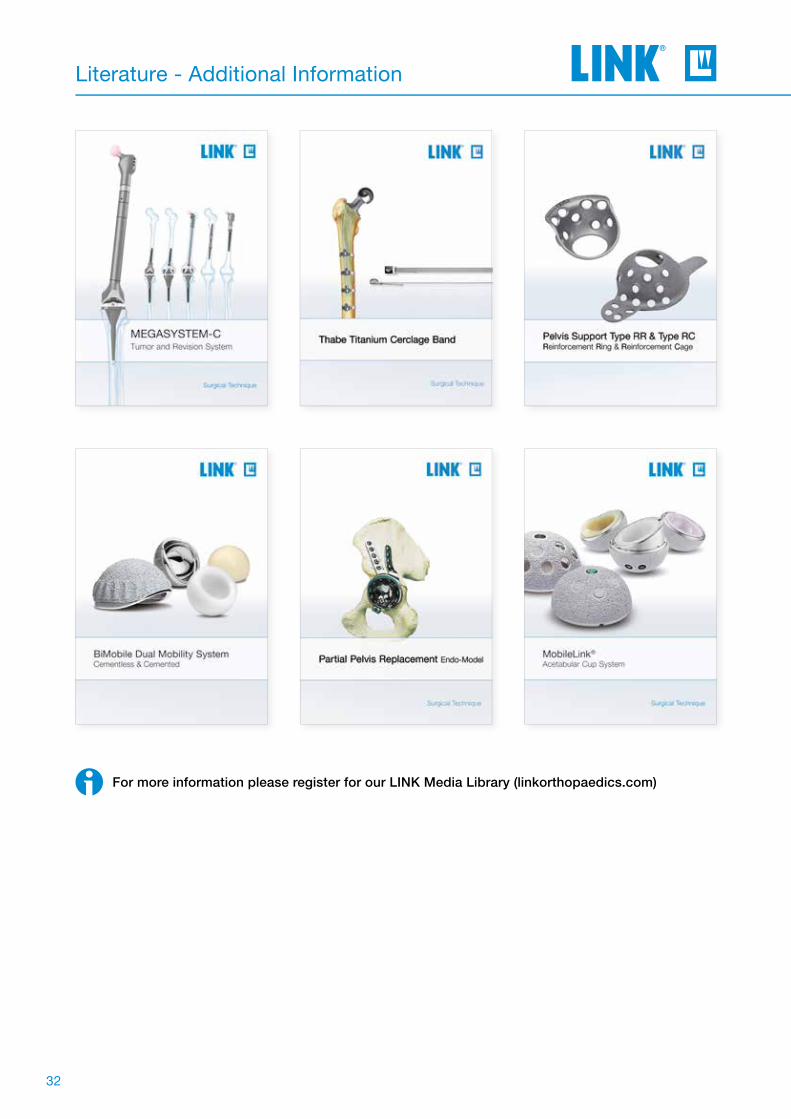
Literature - Additional Information
For more information please register for our LINK Media Library (linkorthopaedics.com)

33
Indications / Contraindications
Specified Indications and Contraindications:MP Reconstruction Prosthesis
General indication
Mobility-limiting diseases, fractures or defects of the hip joint or proximal femur which cannot be treated by conservative or osteosynthetic procedures
Indications
The prosthesis is used when fixation is required below the level of the femoral metaphysis in hip arthroplasty
Contraindications
Insufficient / inadequate bone mass- or quality which prevents a stable anchorage of the prosthesis.
Poor general state of health
Acute and chronic infections, local and systemic, insofar as they may compromise the successful implantation
Allergies to (implant) materials
The above indications and contraindications are based on standard cases. The final decision regarding an implant must be made by the surgeon for each patient on the basis of the surgeon's individual analysis and experience.

34
Notes

Notes

36
Notes

Important Information
Please note the following regarding the use of our implants:
1. Choosing the right implant is very important. The size and shape of the human bone determines the size and shape of the implant and also limits the load capacity. Implants are not designed to withstand unlimited physical stress. Demands should not exceed normal functional loads.
2. Correct handling of the implant is very important. Under no circumstances should the shape of a finished implant be altered, as this shortens its life span. Our implants must not be combined with implants from other manufacturers. The instruments indicated in the Surgical Technique must be used to ensure safe implantation of the components.
3. Implants must not be reused. Implants are supplied sterile and are intended for single use only. Used implants must not be used again.
4. After-treatment is also very important. The patient must be informed of the limitations of the implant. The load capacity of an implant cannot compare with that of healthy bone!
5. Unless otherwise indicated, implants are supplied in sterile packaging. Note the following conditions for storage of packaged implants:
• Avoid extreme or sudden changes in temperature.• Sterile implants in their original, intact protective packaging may be stored in permanent buildings up until the
“Use by” date indicated on the packaging. • They must not be exposed to frost, dampness or direct sunlight, or mechanical damage.• Implants may be stored in their original packaging for up to 5 years after the date of manufacture. The “Use by” date
is indicated on the product label.• Do not use an implant if the packaging is damaged.
6. Traceability is important. Please use the documentation stickers provided to ensure traceability.
7. Further information on the material composition is available on request from the manufacturer.
Follow the instructions for use!
Waldemar Link GmbH & Co. KG, Hamburg
All content in this catalog, including text, pictures and data, is protected by law. Every instance of use, whether in part or in whole and which is not permitted by law, is subject to our prior consent. In particular, this applies to the reproduction, editing, translation, publishing, saving, processing, or passing on of content stored in databases or other electronic media and systems, in any manner or form. The information in the catalogs is solely intended to describe the products and does not constitute a guarantee.
The Surgical Technique described has been written to the best of our knowledge and belief, but it does not relieve the surgeon of his/her responsibility to duly consider the particularities of each individual case.
Products shown in this document may not be available in your country. The product availability is subject to the approval and/or registra-tion regulations of the respective country. Please contact Waldemar Link GmbH & Co. KG if you have questions about the availability of LINK products in your country.
Waldemar Link GmbH & Co. KG and/or other corporate affiliated entities own, use or have applied for the following trademarks in many jurisdictions: LINK, BiMobile, SP II, Modell Lubinus, E-Dur, EndoDur, T.O.P. II, BetaCup, CombiCup PF, CombiCup SC, CombiCup R, MobileLink, C.F.P., LCU, SP-CL, LCP, MIT-H, Endo-Model, Endo-Model SL, MP, MEGASYSTEM-C, GEMINI SL, SPAR-K, LCK, Link OptiStem, HX, TiCaP, X-LINKed, PorAg, LINK PorEx, BiPorEx, PorEx-Z, TrabecuLink, Tilastan, customLINK, RescueSleeve, Stactip, VACUCAST.
Other trademarks and trade names may be used in this document to refer to either the entities claiming the marks and/or names or their products and are the property of their respective owners.

© L
INK
667
4_M
P_O
P-I
mp
l-In
str_
en_2
020-
04_0
01 M
AR
-026
86 1
.0
Waldemar Link GmbH & Co. KGBarkhausenweg 10 · 22339 Hamburg · GermanyPhone +49 40 53995-0 · [email protected]


![III. THEORETICAL STRUCTURES Mp[QMS]](https://static.fdokumen.com/doc/165x107/631eca3256cbbb475005bb31/iii-theoretical-structures-mpqms.jpg)