Motorcycle Service Manual
703
ZZR 1400 ZZR1400 ABS Ninja ZX-14 Motorcycle Service Manual
-
Upload
khangminh22 -
Category
Documents
-
view
0 -
download
0
Transcript of Motorcycle Service Manual

ZZR 1400ZZR1400 ABSNinja ZX-14
MotorcycleService Manual


This quick reference guide will assistyou in locating a desired topic or pro-cedure.•Bend the pages back to match theblack tab of the desired chapter num-ber with the black tab on the edge ateach table of contents page.•Refer to the sectional table of contentsfor the exact pages to locate the spe-cific topic required.
Quick Reference Guide
General Information 1 jPeriodic Maintenance 2 jFuel System (DFI) 3 jCooling System 4 jEngine Top End 5 jClutch 6 jEngine Lubrication System 7 jEngine Removal/Installation 8 jCrankshaft/Transmission 9 jWheels/Tires 10 jFinal Drive 11 jBrakes 12 jSuspension 13 jSteering 14 jFrame 15 jElectrical System 16 jAppendix 17 j


ZZR 1400ZZR1400 ABSNinja ZX-14
MotorcycleService Manual
All rights reserved. No parts of this publication may be reproduced, stored in a retrieval system, ortransmitted in any form or by any means, electronic mechanical photocopying, recording or otherwise,without the prior written permission of Quality Division/Consumer Products & Machinery Company/KawasakiHeavy Industries, Ltd., Japan.No liability can be accepted for any inaccuracies or omissions in this publication, although every possible
care has been taken to make it as complete and accurate as possible.The right is reserved to make changes at any time without prior notice and without incurring an obligation
to make such changes to products manufactured previously. See your Motorcycle dealer for the latestinformation on product improvements incorporated after this publication.All information contained in this publication is based on the latest product information available at the time
of publication. Illustrations and photographs in this publication are intended for reference use only and maynot depict actual model component parts.
© 2006 Kawasaki Heavy Industries, Ltd. First Edition (1): Mar. 3, 2006 (M)

LIST OF ABBREVIATIONSA ampere(s) lb pound(s)ABDC after bottom dead center m meter(s)AC alternating current min minute(s)ATDC after top dead center N newton(s)BBDC before bottom dead center Pa pascal(s)BDC bottom dead center PS horsepowerBTDC before top dead center psi pound(s) per square inch°C degree(s) Celsius r revolutionDC direct current rpm revolution(s) per minuteF farad(s) TDC top dead center°F degree(s) Fahrenheit TIR total indicator readingft foot, feet V volt(s)g gram(s) W watt(s)h hour(s) Ω ohm(s)L liter(s)
COUNTRY AND AREA CODESAT Austria FR FranceAU Australia GB United KingdomCA Canada MY MalaysiaCAL California US United StatesCH Switzerland WVTA Whole Vehicle Type ApprovalDE Germany

EMISSION CONTROL INFORMATION
To protect the environment in which we all live, Kawasaki has incorporated crankcase emis-sion (1) and exhaust emission (2) control systems in compliance with applicable regulations ofthe United States Environmental Protection Agency and California Air Resources Board. Addi-tionally, Kawasaki has incorporated an evaporative emission control system (3) in compliancewith applicable regulations of the California Air Resources Board on vehicles sold in Californiaonly.1. Crankcase Emission Control SystemThis system eliminates the release of crankcase vapors into the atmosphere. Instead, the vapors
are routed through an oil separator to the inlet side of the engine. While the engine is operating,the vapors are drawn into combustion chamber, where they are burned along with the fuel and airsupplied by the fuel injection system.2. Exhaust Emission Control SystemThis system reduces the amount of pollutants discharged into the atmosphere by the exhaust
of this motorcycle. The fuel, ignition, and exhaust systems of this motorcycle have been carefullydesigned and constructed to ensure an efficient engine with low exhaust pollutant levels.The exhaust system of this model motorcycle manufactured primarily for sale in California in-
cludes a catalytic converter system.3. Evaporative Emission Control SystemVapors caused by fuel evaporation in the fuel system are not vented into the atmosphere. In-
stead, fuel vapors are routed into the running engine to be burned, or stored in a canister whenthe engine is stopped. Liquid fuel is caught by a vapor separator and returned to the fuel tank.
The Clean Air Act, which is the Federal law covering motor vehicle pollution, contains what iscommonly referred to as the Act’s “tampering provisions”.“Sec. 203(a) The following acts and the causing thereof are prohibited...
(3)(A) for any person to remove or render inoperative any device or element of design installedon or in a motor vehicle or motor vehicle engine in compliance with regulations under thistitle prior to its sale and delivery to the ultimate purchaser, or for any manufacturer or dealerknowingly to remove or render inoperative any such device or element of design after suchsale and delivery to the ultimate purchaser.
(3)(B) for any person engaged in the business of repairing, servicing, selling, leasing, or tradingmotor vehicles or motor vehicle engines, or who operates a fleet of motor vehicles know-ingly to remove or render inoperative any device or element of design installed on or in amotor vehicle or motor vehicle engine in compliance with regulations under this title follow-ing its sale and delivery to the ultimate purchaser...”
NOTEThe phrase “remove or render inoperative any device or element of design” has been generallyinterpreted as follows.
1. Tampering does not include the temporary removal or rendering inoperative of de-vices or elements of design in order to perform maintenance.
2. Tampering could include.a.Maladjustment of vehicle components such that the emission standards are ex-ceeded.
b.Use of replacement parts or accessories which adversely affect the performanceor durability of the motorcycle.
c.Addition of components or accessories that result in the vehicle exceeding the stan-dards.
d.Permanently removing, disconnecting, or rendering inoperative any component orelement of design of the emission control systems.
WE RECOMMEND THAT ALL DEALERS OBSERVE THESE PROVISIONS OF FEDERAL LAW,THE VIOLATION OF WHICH IS PUNISHABLE BY CIVIL PENALTIES NOT EXCEEDING $10000 PER VIOLATION.

TAMPERING WITH NOISE CONTROL SYSTEM PROHIBITED
Federal law prohibits the following acts or the causing thereof. (1) The removal or renderinginoperative by any person other than for purposes of maintenance, repair, or replacement, of anydevice or element of design incorporated into any new vehicle for the purpose of noise controlprior to its sale or delivery to the ultimate purchaser or while it is in use, or (2) the use of thevehicle after such device or element of design has been removed or rendered inoperative byany person.Among those acts presumed to constitute tampering are the acts listed below.•Replacement of the original exhaust system or muffler with a component not in compliancewith Federal regulations.•Removal of the muffler(s) or any internal portion of the muffler(s).• Removal of the air box or air box cover.•Modifications to the muffler(s) or air inlet system by cutting, drilling, or other means if suchmodifications result in increased noise levels.

Foreword
This manual is designed primarily for use bytrained mechanics in a properly equipped shop.However, it contains enough detail and basic in-formation to make it useful to the owner who de-sires to perform his own basic maintenance andrepair work. A basic knowledge of mechanics,the proper use of tools, and workshop proce-dures must be understood in order to carry outmaintenance and repair satisfactorily. When-ever the owner has insufficient experience ordoubts his ability to do the work, all adjust-ments, maintenance, and repair should be car-ried out only by qualified mechanics.In order to perform the work efficiently and
to avoid costly mistakes, read the text, thor-oughly familiarize yourself with the proceduresbefore starting work, and then do the work care-fully in a clean area. Whenever special tools orequipment are specified, do not use makeshifttools or equipment. Precision measurementscan only be made if the proper instruments areused, and the use of substitute tools may ad-versely affect safe operation.For the duration of the warranty period,
we recommend that all repairs and scheduledmaintenance be performed in accordance withthis service manual. Any owner maintenance orrepair procedure not performed in accordancewith this manual may void the warranty.To get the longest life out of your vehicle.• Follow the Periodic Maintenance Chart in theService Manual.• Be alert for problems and non-scheduledmaintenance.• Use proper tools and genuine Kawasaki Mo-torcycle parts. Special tools, gauges, andtesters that are necessary when servicingKawasaki motorcycles are introduced by theService Manual. Genuine parts provided asspare parts are listed in the Parts Catalog.• Follow the procedures in this manual care-fully. Don’t take shortcuts.• Remember to keep complete records of main-tenance and repair with dates and any newparts installed.
How to Use This ManualIn this manual, the product is divided into
its major systems and these systems make upthe manual’s chapters. The Quick Reference
Guide shows you all of the product’s systemand assists in locating their chapters. Eachchapter in turn has its own comprehensive Ta-ble of Contents.For example, if you want ignition coil informa-
tion, use the Quick Reference Guide to locatethe Electrical System chapter. Then, use theTable of Contents on the first page of the chap-ter to find the Ignition Coil section.Whenever you see these WARNING and
CAUTION symbols, heed their instructions!Always follow safe operating and maintenancepractices.
WARNINGThis warning symbol identifies specialinstructions or procedures which, if notcorrectly followed, could result in per-sonal injury, or loss of life.
CAUTIONThis caution symbol identifies specialinstructions or procedures which, if notstrictly observed, could result in dam-age to or destruction of equipment.
This manual contains four more symbols (inaddition toWARNING andCAUTION) which willhelp you distinguish different types of informa-tion.
NOTEThis note symbol indicates points of par-ticular interest for more efficient and con-venient operation.
• Indicates a procedural step or work to bedone.Indicates a procedural sub-step or how to dothe work of the procedural step it follows. Italso precedes the text of a NOTE.Indicates a conditional step or what action totake based on the results of the test or inspec-tion in the procedural step or sub-step it fol-lows.In most chapters an exploded view illustration
of the system components follows the Table ofContents. In these illustrations you will find theinstructions indicating which parts require spec-ified tightening torque, oil, grease or a lockingagent during assembly.


GENERAL INFORMATION 1-1
1
General InformationTable of Contents
Before Servicing ..................................................................................................................... 1-2Model Identification................................................................................................................. 1-7General Specifications............................................................................................................ 1-12Technical Information-CAN (Controller Area Network) Communication System.................... 1-15Unit Conversion Table ............................................................................................................ 1-18
1-2 GENERAL INFORMATIONBefore Servicing
Before starting to perform an inspection service or carry out a disassembly and reassembly opera-tion on a motorcycle, read the precautions given below. To facilitate actual operations, notes, illustra-tions, photographs, cautions, and detailed descriptions have been included in each chapter wherevernecessary. This section explains the items that require particular attention during the removal andreinstallation or disassembly and reassembly of general parts.Especially note the following.
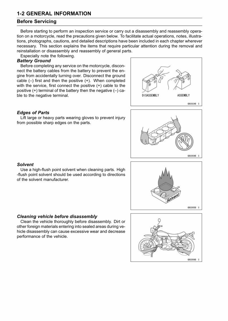
Battery GroundBefore completing any service on the motorcycle, discon-
nect the battery cables from the battery to prevent the en-gine from accidentally turning over. Disconnect the groundcable (–) first and then the positive (+). When completedwith the service, first connect the positive (+) cable to thepositive (+) terminal of the battery then the negative (–) ca-ble to the negative terminal.
Edges of PartsLift large or heavy parts wearing gloves to prevent injury
from possible sharp edges on the parts.
SolventUse a high-flush point solvent when cleaning parts. High
-flush point solvent should be used according to directionsof the solvent manufacturer.
Cleaning vehicle before disassemblyClean the vehicle thoroughly before disassembly. Dirt or
other foreign materials entering into sealed areas during ve-hicle disassembly can cause excessive wear and decreaseperformance of the vehicle.

GENERAL INFORMATION 1-3Before Servicing
Arrangement and Cleaning of Removed PartsDisassembled parts are easy to confuse. Arrange the
parts according to the order the parts were disassembledand clean the parts in order prior to assembly.
Storage of Removed PartsAfter all the parts including subassembly parts have been
cleaned, store the parts in a clean area. Put a clean clothor plastic sheet over the parts to protect from any foreignmaterials that may collect before re-assembly.
InspectionReuse of worn or damaged parts may lead to serious ac-
cident. Visually inspect removed parts for corrosion, discol-oration, or other damage. Refer to the appropriate sectionsof this manual for service limits on individual parts. Replacethe parts if any damage has been found or if the part is be-yond its service limit.
Replacement PartsReplacement Parts must be KAWASAKI genuine or
recommended by KAWASAKI. Gaskets, O-rings, oil seals,grease seals, circlips or cotter pins must be replaced withnew ones whenever disassembled.
Assembly OrderIn most cases assembly order is the reverse of disassem-
bly, however, if assembly order is provided in this ServiceManual, follow the procedures given.

1-4 GENERAL INFORMATIONBefore Servicing
Tightening SequenceGenerally, when installing a part with several bolts, nuts,
or screws, start them all in their holes and tighten them toa snug fit. Then tighten them according to the specified se-quence to prevent case warpage or deformation which canlead to malfunction. Conversely when loosening the bolts,nuts, or screws, first loosen all of them by about a quar-ter turn and then remove them. If the specified tighteningsequence is not indicated, tighten the fasteners alternatingdiagonally.
Tightening TorqueIncorrect torque applied to a bolt, nut, or screw may
lead to serious damage. Tighten fasteners to the specifiedtorque using a good quality torque wrench.
ForceUse common sense during disassembly and assembly,
excessive force can cause expensive or hard to repair dam-age. When necessary, remove screws that have a non-permanent locking agent applied using an impact driver.Use a plastic-faced mallet whenever tapping is necessary.
Gasket, O-ringHardening, shrinkage, or damage of both gaskets and
O-rings after disassembly can reduce sealing performance.Remove the old gaskets and clean the sealing surfacesthoroughly so that no gasket material or other material re-mains. Install the new gaskets and replace the usedO-ringswhen re-assembling
Liquid Gasket, Non-permanent Locking AgentFor applications that require Liquid Gasket or a
Non-permanent Locking Agent, clean the surfaces sothat no oil residue remains before applying liquid gasket ornon-permanent locking agent. Do not apply them exces-sively. Excessive application can clog oil passages andcause serious damage.

GENERAL INFORMATION 1-5Before Servicing
PressFor items such as bearings or oil seals that must be
pressed into place, apply small amount of oil to the con-tact area. Be sure to maintain proper alignment and usesmooth movements when installing.
Ball Bearing and Needle BearingDo not remove pressed ball or needle unless removal is
absolutely necessary. Replace with new ones wheneverremoved. Press bearings with the manufacturer and sizemarks facing out. Press the bearing into place by puttingpressure on the correct bearing race as shown.Pressing the incorrect race can cause pressure between
the inner and outer race and result in bearing damage.
Oil Seal, Grease SealDo not remove pressed oil or grease seals unless removal
is necessary. Replace with new ones whenever removed.Press new oil seals with manufacture and size marks facingout. Make sure the seal is aligned properly when installing.
Apply specified grease to the lip of seal before installingthe seal.
Circlips, Cotter PinsReplace the circlips or cotter pins that were removed with
new ones. Take care not to open the clip excessively wheninstalling to prevent deformation.

1-6 GENERAL INFORMATIONBefore Servicing
LubricationIt is important to lubricate rotating or sliding parts during
assembly to minimize wear during initial operation. Lubri-cation points are called out throughout this manual, applythe specific oil or grease as specified.
Direction of Engine RotationWhen rotating the crankshaft by hand, the free play
amount of rotating direction will affect the adjustment. Ro-tate the crankshaft to positive direction (clockwise viewedfrom output side).
Electrical WiresA two-color wire is identified first by the primary color and
then the stripe color. Unless instructed otherwise, electricalwires must be connected to those of the same color.
InstrumentUse a meter that has enough accuracy for an accurate
measurement. Read the manufacture’s instructions thor-oughly before using the meter. Incorrect values may leadto improper adjustments.

GENERAL INFORMATION 1-7Model Identification
ZX1400A6F (Europe) Left Side View
ZX1400A6F (Europe) Right Side View
Frame Number Engine Number

1-8 GENERAL INFORMATIONModel Identification
ZX1400A6F (United States and Canada) Left Side View
ZX1400A6F (United States and Canada) Right Side View

GENERAL INFORMATION 1-9Model Identification
ZX1400A6F (Malaysia) Left Side View
ZX1400A6F (Malaysia) Right Side View

1-10 GENERAL INFORMATIONModel Identification
ZX1400B6F (Europe) Left Side View
ZX1400B6F (Europe) Right Side View

GENERAL INFORMATION 1-11Model Identification
ZX1400B6F (Malaysia) Left Side View
ZX1400B6F (Malaysia) Right Side View

1-12 GENERAL INFORMATIONGeneral Specifications
Items ZX1400A6F, ZX1400B6FDimensionsOverall Length 2 170 mm (85.4 in.)Overall Width 760 mm (29.9 in.)Overall Height 1 170 mm (46.1 in.)Wheelbase 1 460 mm (57.4 in.)Road Clearance 125 mm (4.9 in.)Seat Height 800 mm (31.5 in.)Dry Mass:ZX1400A6F 215 kg (474 lb)ZX1400B6F 218 kg (481 lb)
Curb Mass:FrontZX1400A6F 125 kg (276 lb)ZX1400B6F 126 kg (278 lb)RearZX1400A6F 127 kg (280 lb)ZX1400B6F 129 kg (284 lb)
Fuel Tank Capacity 22 L (5.8 US gal)PerformanceMinimum Turning Radius 3.1 m (10.2 ft)
EngineType 4-stroke, DOHC, 4-cylinderCooling System Liquid-cooledBore and Stroke 84.0 × 61.0 mm (3.3 × 2.4 in.)Displacement 1 352 cm³ (82.5 cu in.)Compression Ratio 12.0 : 1Maximum Horsepower 140.0 kW (190 PS) @9 500 r/min (rpm),
(FR) 78.2 kW (106 PS) @8 500 r/min (rpm),(MY) 132.6 kW (180 PS) @9 000 r/min (rpm),(CA, CAL, US) – – –
Maximum Torque 154 N·m (15.7 kgf·m, 114 ft·lb) @7 500 r/min (rpm),(FR) 114 N·m (11.6 kgf·m, 84 ft·lb) @4 500 r/min (rpm),(MY) 147.4 N·m (15.0 kgf·m, 109 ft·lb) @7 500 r/min (rpm),(CA), (CAL), (US) – – –
Carburetion System FI (Fuel injection), MIKUNI 44EIDW × 4Starting System Electric starterIgnition System Battery and coil (transistorized)Timing Advance Electronically advanced (digital igniter in ECU)Ignition Timing From 10° BTDC @1 100 r/min (rpm)Spark Plug NGK CR9EIA-9Cylinder Numbering Method Left to right, 1-2-3-4Firing Order 1-2-4-3

GENERAL INFORMATION 1-13General Specifications
Items ZX1400A6F, ZX1400B6FValve Timing:Inlet:Open 41° (BTDC)Close 71° (ABDC)Duration 292°
Exhaust:Open 64° (BBDC)Close 34° (ATDC)Duration 278°
Lubrication System Forced lubrication (wet sump with cooler)Engine Oil:Type API SE, SF or SG
API SH, SJ or SL with JASO MAViscosity SAE10W-40Capacity 4.5 L (4.8 US qt)
Drive TrainPrimary Reduction System:Type GearReduction Ratio 1.541 (94/61)
Clutch Type Wet multi discTransmission:Type 6-speed, constant mesh, return shiftGear Ratios:1st 2.625 (42/16)2nd 1.947 (37/19)3rd 1.545 (34/22)4th 1.333 (32/24)5th 1.154 (30/26)6th 1.036 (29/28)
Final Drive System:Type Chain driveReduction Ratio 2.412 (41/17)Overall Drive Ratio 3.849 @Top gear
FrameType Press, backboneCaster (Rake Angle) 23°Trail 94 mm (3.7 in.)Front Tire:Type TubelessSize 120/70 ZR17 M/C (58 W)
Rear Tire:Type TubelessSize 190/50 ZR17 M/C (73 W)

1-14 GENERAL INFORMATIONGeneral Specifications
Items ZX1400A6F, ZX1400B6FRim Size:Front 17 × 3.50Rear 17 × 6.00
Front Suspension:Type Telescopic fork (upside-down)Wheel Travel 117 mm (4.6 in.)
Rear Suspension:Type Swingarm (uni-trak)Wheel Travel 122 mm (4.8 in.)
Brake Type:Front Dual discsRear Single disc
Electrical EquipmentBattery 12 V 14 AhHeadlight:Type Semi-sealed beamBulb:High 12 V 55 W + 65 W (quartz-halogen) × 2Low 12 V 55 W (quartz-halogen) × 2
Tail/Brake Light 12 V 0.5/4.9 W (LED)Alternator:Type Three-phase ACRated Output 35 A/14 V @5 000 r/min (rpm)
Specifications subject to change without notice, and may not apply to every country.

GENERAL INFORMATION 1-15Technical Information-CAN (Controller Area Network) Communication System
OverviewThe CAN communication system is used for transmitting and receiving data that is sent to the meter
unit and ECU. A LCD (liquid crystal display) display in the meter unit displays information such as bat-tery voltage, fuel consumption, and service codes in addition to the conventional indicator functions.
1. Meter Display
1. Fuel Mileage Range2. Fuel Consumption (Current)3. Fuel Consumption (Average)4. Battery Voltage
5. Gear Position6. Service Code7. Immobilizer Registration8. Clutch Engagement Timing
2. CAN is a multi-cast serial bus standard (ISO protocol). Data is transmitted by changing the voltagesignal of the two bus leads which are composed of high and low voltage wires twisted together.Since the high-speed ISO standard is used (transmission speeds of up to 500 kbps*), large quan-tities of data can be transmitted and received in a short period of time.*bps: bit/sec→ the number of signals (0 or 1) transmittable/receivable per second

1-16 GENERAL INFORMATIONTechnical Information-CAN (Controller Area Network) Communication System
Structure and Function1. In the CAN communication system, anti-noise twisted pair leads are used (two leads).
Twisted Pair Leads [A] (In the main harness)
2. Data is transmitted from the two nodes-the ECU and meter unit-on the CAN bus and does notcontain specific bus addresses of either node.
Instead, the content of a data stream, such as engine rpm, is labeled with an identifier that is uniquethroughout the network. All nodes on the network receive the data and each performs an acceptancetest on the identifier to determine if the message (and its data) is relevant to that particular node.
If a message is relevant to a particular node (meter unit), it will be processed and displayed other-wise it is ignored. The unique data identifier also determines the priority of the message. In situationswhere the two nodes attempt to transmit at the same time, a non-destructive arbitration techniqueguarantees that the messages are sent in order of importance.
3. The CAN data that is transmitted from the ECU to the meter unit are engine rpm, water temper-ature, gear position, starter lockout switch, self-diagnosis information and *fuel injected volume.And the data transmitted from the meter to the ECU is vehicle speed.*Fuel injected volume is converted into the fuel consumption by the meter unit.

GENERAL INFORMATION 1-17Technical Information-CAN (Controller Area Network) Communication System
System failure and maintenance1. Detection of a system failureWhen the DFI or immobilizer system fails, the information will be shown on the LCD under the "ig-
nition switch ON" condition.
2. System maintenance1. Do not add a by-pass lead to the twisted pair lead. This can damage components.
2. Do not modify the twisted pair lead or loosen/tighten the number of twists. Such modifications ofthe leads can cause the deterioration of the anti-noise characteristics resulting in communicationerrors.

1-18 GENERAL INFORMATIONUnit Conversion Table
Prefixes for Units
Prefix Symbol Powermega M × 1 000 000kilo k × 1 000centi c × 0.01milli m × 0.001micro µ × 0.000001
Units of Masskg × 2.205 = lbg × 0.03527 = oz
Units of VolumeL × 0.2642 = gal (US)L × 0.2200 = gal (imp)L × 1.057 = qt (US)L × 0.8799 = qt (imp)L × 2.113 = pint (US)L × 1.816 = pint (imp)mL × 0.03381 = oz (US)mL × 0.02816 = oz (imp)mL × 0.06102 = cu in
Units of ForceN × 0.1020 = kgN × 0.2248 = lbkg × 9.807 = Nkg × 2.205 = lb
Units of Lengthkm × 0.6214 = milem × 3.281 = ftmm × 0.03937 = in
Units of TorqueN·m × 0.1020 = kgf·mN·m × 0.7376 = ft·lbN·m × 8.851 = in·lbkgf·m × 9.807 = N·mkgf·m × 7.233 = ft·lbkgf·m × 86.80 = in·lb
Units of PressurekPa × 0.01020 = kgf/cm²kPa × 0.1450 = psikPa × 0.7501 = cmHgkgf/cm² × 98.07 = kPakgf/cm² × 14.22 = psicmHg × 1.333 = kPa
Units of Speedkm/h × 0.6214 = mph
Units of PowerkW × 1.360 = PSkW × 1.341 = HPPS × 0.7355 = kWPS × 0.9863 = HP
Units of Temperature

PERIODIC MAINTENANCE 2-1
2
Periodic MaintenanceTable of Contents
Periodic Maintenance Chart ................................................................................................... 2-3Torque and Locking Agent...................................................................................................... 2-6Specifications ......................................................................................................................... 2-12Special Tools .......................................................................................................................... 2-14Maintenance Procedure ......................................................................................................... 2-15Fuel System (DFI)................................................................................................................ 2-15Throttle Control System Inspection................................................................................... 2-15Engine Vacuum Synchronization Inspection..................................................................... 2-15Idle Speed Inspection ....................................................................................................... 2-19Idle Speed Adjustment...................................................................................................... 2-19Fuel Hose Inspection (fuel leak, damage, installation condition) ...................................... 2-19
Cooling System.................................................................................................................... 2-20Coolant Level Inspection................................................................................................... 2-20Radiator Hose and Pipe Inspection .................................................................................. 2-20
Evaporative Emission Control System (California Model) ................................................... 2-21Evaporative Emission Control System Inspection ............................................................ 2-21
Air Suction System .............................................................................................................. 2-21Air Suction System Damage Inspection............................................................................ 2-21
Engine Top End ................................................................................................................... 2-22Valve Clearance Inspection .............................................................................................. 2-22
Clutch and Drive Train ......................................................................................................... 2-27Clutch Operation Inspection ............................................................................................. 2-27Clutch Fluid Level Inspection ............................................................................................ 2-27Clutch Fluid Leak Inspection............................................................................................. 2-28Clutch Hose and Pipe Damage and Installation Condition Inspection.............................. 2-28
Wheels/Tires........................................................................................................................ 2-29Air Pressure Inspection..................................................................................................... 2-29Wheel/Tire Damage Inspection......................................................................................... 2-29Tire Tread Wear Inspection .............................................................................................. 2-29Wheel Bearing Damage Inspection .................................................................................. 2-30
Drive Train ........................................................................................................................... 2-30Drive Chain Lubrication Condition Inspection ................................................................... 2-30Drive Chain Slack Inspection ............................................................................................ 2-31Drive Chain Slack Adjustment .......................................................................................... 2-31Wheel Alignment Inspection ............................................................................................. 2-32Drive Chain Wear Inspection ............................................................................................ 2-32Chain Guide Wear Inspection ........................................................................................... 2-33
Brake System ...................................................................................................................... 2-34Brake Fluid Leak (Brake Hose and Pipe) Inspection ........................................................ 2-34Brake Hose and Pipe Damage and Installation Condition Inspection............................... 2-35Brake Operation Inspection .............................................................................................. 2-35Brake Fluid Level Inspection............................................................................................. 2-35Brake Pad Wear Inspection .............................................................................................. 2-36Brake Light Switch Operation Inspection .......................................................................... 2-37
Suspensions ........................................................................................................................ 2-37Front Forks/Rear Shock Absorber Operation Inspection .................................................. 2-37Front Fork Oil Leak Inspection.......................................................................................... 2-38Rear Shock Absorber Oil Leak Inspection ........................................................................ 2-38Rocker Arm Operation Inspection..................................................................................... 2-38Tie-Rod Operation Inspection ........................................................................................... 2-38

2-2 PERIODIC MAINTENANCE
Steering System .................................................................................................................. 2-39Steering Play Inspection ................................................................................................... 2-39Steering Play Adjustment.................................................................................................. 2-39Steering Stem Bearing Lubrication ................................................................................... 2-40
Electrical System ................................................................................................................. 2-41Lights and Switches Operation Inspection........................................................................ 2-41Headlight Aiming Inspection ............................................................................................. 2-44Sidestand Switch Operation Inspection ............................................................................ 2-45Engine Stop Switch Operation Inspection......................................................................... 2-46
Others .................................................................................................................................. 2-46Chassis Parts Lubrication ................................................................................................ 2-46Bolts, Nuts and Fasteners Tightness Inspection............................................................... 2-47
Replacement Parts .............................................................................................................. 2-48Air Cleaner Element Replacement.................................................................................... 2-48Fuel Hose Replacement ................................................................................................... 2-49Coolant Change................................................................................................................ 2-51Radiator Hose and O-ring Replacement........................................................................... 2-53Engine Oil Change............................................................................................................ 2-53Oil Filter Replacement ...................................................................................................... 2-54Brake Hose and Pipe Replacement.................................................................................. 2-55Brake Fluid Change .......................................................................................................... 2-57Master Cylinder Rubber Parts Replacement .................................................................... 2-58Caliper Rubber Parts Replacement .................................................................................. 2-59Rear Caliper Assembly ..................................................................................................... 2-62Clutch Hose and Pipe Replacement ................................................................................. 2-63Rubber Parts of Clutch Master Cylinder/Slave Cylinder Replacement ............................. 2-64Clutch Fluid Change ......................................................................................................... 2-66Spark Plug Replacement .................................................................................................. 2-66

PERIODIC MAINTENANCE 2-3Periodic Maintenance Chart
The scheduled maintenance must be done in accordance with this chart to keep the motorcycle ingood running condition.The initial maintenance is vitally important and must not be neglected.
FREQUENCY Whichevercomesfirst
* ODOMETERREADING× 1000 km
(× 1000 mile)1 6 12 18 24 30 36
INSPECTION Every (0.6) (4) (7.5) (12) (15) (20) (24)
SeePage
Fuel SystemThrottle control system (play, smooth return,no drag) - inspect year • • • • 2-15
Engine vacuum synchronization-inspect • • • 2-15Idle speed-inspect • • • • 2-19Fuel leak (fuel hose and pipe) - inspect year • • • • 2-19Fuel hose and pipe damage-inspect year • • • • 2-19Fuel hose and pipe installationcondition-inspect year • • • • 2-19
Cooling SystemCoolant level - inspect • • • • 2-20Coolant leak (radiator hose and pipe) - inspect year • • • • 2-20Radiator hose damage - inspect year • • • • 2-20Radiator hose installation condition - inspect year • • • • 2-20Evaporative Emission Control System(CAL)Evaporative emission control system function- inspect • • • • • • • 2-21
Air Suction SystemAir suction system damage - inspect • • • 2-21Engine Top End
US, CA, AU Model •Valve clearance - inspectOther than US,CA, AU Model Every 42 000 km (26 000 mile)
2-22
Clutch and Drive TrainClutch operation (play, disengagement,engagement) - inspect • • • • 2-27
Clutch fluid level - inspect 6 months • • • • • • • 2-27Clutch fluid leak (clutch hose and pipe) -inspect year • • • • • • • 2-28
Clutch hose and pipe damage - inspect year • • • • • • • 2-28Clutch hose installation condition - inspect year • • • • • • • 2-28Wheels and TiresTire air pressure - inspect year • • • 2-29Wheels/tires damage - inspect • • • 2-29Tire tread wear abnormal wear - inspect • • • 2-29Wheel bearing damage - inspect year • • • 2-30

2-4 PERIODIC MAINTENANCEPeriodic Maintenance Chart
FREQUENCY Whichevercomesfirst
* ODOMETERREADING× 1000 km
(× 1000 mile)1 6 12 18 24 30 36
INSPECTION Every (0.6) (4) (7.5) (12) (15) (20) (24)
SeePage
Final DriveDrive chain lubrication condition - inspect # Every 600 km (400 mile) after driving in rain 2-30Drive chain slack - inspect # Every 1 000 km (600 mile) 2-31Drive chain wear - inspect # • • • 2-32Drive chain guide wear - inspect • • • 2-33Brake SystemBrake fluid leak (brake hose and pipe) -inspect year • • • • • • • 2-34
Brake hose and pipe damage - inspect year • • • • • • • 2-35Brake hose installation condition - inspect year • • • • • • • 2-35Brake operation (effectiveness, play, no drag)- inspect year • • • • • • • 2-35
Brake fluid level - inspect 6 months • • • • • • • 2-35Brake pad wear - inspect # • • • • • • 2-36Brake light switch operation - inspect • • • • • • • 2-37SuspensionsFront forks/rear shock absorber operation(damping and smooth stroke) - inspect • • • 2-37
Front forks/rear shock absorber oil leak -inspect year • • • 2-38
Rocker arm operation - inspect • • • 2-38Tie-rods operation - inspect • • • 2-38Steering SystemSteering play - inspect year • • • • 2-39Steering stem bearings-lubricate 2 years • 2-39Electrical SystemLights and switches operation - inspect year • • • 2-41Headlight aiming - inspect year • • • 2-44Sidestand switch operation - inspect year • • • 2-45Engine stop switch operation - inspect year • • • 2-46OthersChassis parts-lubricate year • • • 2-46Bolts, nuts and fasteners tightness - inspect • • • • 2-47#: Service more frequently when operating in severe conditions; dusty, wet, muddy, high speed orfrequent starting/stopping.
*: For higher odometer readings, repeat at the frequency interval established here.

PERIODIC MAINTENANCE 2-5Periodic Maintenance Chart
Periodic Replacement PartsFREQUENCY Whichever
comefirst
* ODOMETER READING× 1000 km
(× 1000 mile)1 12 18 24 36 48
CHANGE/REPLACEMENT Every (0.6) (7.5) (12) (15) (24) (30)
SeePage
Air cleaner element # Every 18 000 km (12 000 mile) 2-48Fuel hose 4 years • 2-49Coolant 3 years • 2-51Radiator hoses and O-rings 3 years • 2-53Engine oil # year • • • • • 2-53Oil filter year • • • • • 2-54Brake hose and pipe 4 years • 2-55Brake fluid 2 years • • 2-57Rubber parts of brake master cylinder/caliper 4 years • 2-58Clutch hose and pipe 4 years • 2-63Rubber parts of clutch master cylinder/slavecylinder 4 years • 2-64
Clutch fluid 2 years • • 2-66Spark plugs • • • • 2-66#: Service more frequently when operating in severe conditions; dusty, wet, muddy, high speed orfrequent starting/stopping.
*: For higher odometer readings, repeat at the frequency interval established here.

2-6 PERIODIC MAINTENANCETorque and Locking Agent
The following tables list the tightening torque for the major fasteners requiring use of anon-permanent locking agent or silicone sealant etc.
Letters used in the “Remarks” column mean:AL: Tighten the two clamp bolts alternately two times to ensure even tightening torque.G: Apply grease to the threads.L: Apply a non-permanent locking agent to the threads.M: Apply molybdenum disulfied grease.
MO: Apply molybdenum disulfide grease oil(mixture of engine oil and molybdenum disulfide grease in a weight ration is 10 : 1).
R: Replacement PartsS: Tighten the fasteners following the specified sequence.Si: Apply silicone grease (ex. PBC grease).SS: Apply silicone sealant.
TorqueFastener
N·m kgf·m ft·lbRemarks
Fuel SystemAir Cleaner Element Cover Bolts 6.9 0.70 61 in·lbAir Cleaner Element Holder Screws 6.9 0.70 61 in·lbBypass Screws 0.2 0.02 1.8 in·lbCamshaft Position Sensor Bolt 9.8 1.0 87 in·lbCrankshaft Sensor Bolts 5.9 0.60 52 in·lb LDelivery Pipe Mounting Screws 5.0 0.51 44 in·lbDuct Clamp Bolts 2.0 0.20 18 in·lbFront Air Inlet Duct Mounting Bolts 9.8 1.0 87 in·lbFuel Pump Bolts 9.8 1.0 87 in·lb L, SGear Position Switch Lead Clamp Bolts 9.8 1.0 87 in·lbGear Position Switch Screws 2.9 0.30 26 in·lb LInlet Air Pressure Sensor Bracket Screws 3.5 0.36 31 in·lbMiddle Air Inlet Duct Clamp Bolts 2.9 0.30 26 in·lbMiddle Air Inlet Duct Mounting Bolts 9.8 1.0 87 in·lbRear Air Inlet Duct Mounting Bolts 9.8 1.0 87 in·lbSpeed Sensor Bolt 3.9 0.40 35 in·lb LThrottle Body Assy Holder Bolts 9.8 1.0 87 in·lb SThrottle Body Assy Holder Clamp Bolts 2.0 0.20 18 in·lbVehicle-down Sensor Bolts 5.9 0.60 52 in·lbWater Temperature Sensor 25 2.5 18
Cooling SystemCoolant Drain Plug 12 1.2 106 in·lbCoolant Fitting Bolts 8.8 0.90 78 in·lb LOil Cooler Mounting Bolts 12 1.2 106 in·lb SRadiator Hose Clamp Screws 2.0 0.20 18 in·lbThermostat Housing Cover Bolts 5.9 0.60 52 in·lbThermostat Housing Mounting Bolts 9.8 1.0 87 in·lbWater Pump Cover Bolts 9.8 1.0 87 in·lbWater Temperature Sensor 25 2.5 18

PERIODIC MAINTENANCE 2-7Torque and Locking Agent
TorqueFastener
N·m kgf·m ft·lbRemarks
Engine Top EndAir Suction Valve Cover Bolts 9.8 1.0 87 in·lb LCamshaft Cap Bolts 12 1.2 106 in·lb SCamshaft Chain Guide Bolts 12 1.2 106 in·lb SCamshaft Chain Tensioner Mounting Bolts 9.8 1.0 87 in·lbCamshaft Position Sensor Bolt 9.8 1.0 87 in·lbCam Sprocket Mounting Bolts 15 1.5 11 LCrankshaft Sensor Cover Bolts 9.8 1.0 87 in·lb L (1)Cylinder Head Bolts (M6) 12 1.2 106 in·lb SCylinder Head Cover Bolts 9.8 1.0 87 in·lb SCylinder Head Bolts (M11, First) 39 4.0 29 MO, SCylinder Head Bolts (M11, Final) 71 7.2 52 MO, SEngine Bracket Bolts (M8) 25 2.5 18 R, SFront Camshaft Chain Guide Bolt (Upper) 25 2.5 18Front Camshaft Chain Guide Bolt (Lower) 12 1.2 106 in·lbFront Engine Mounting Bolts (M10) 59 6.0 44 R, SMuffler Body Mounting Bolts 34 3.5 25Spark Plugs 13 1.3 115 in·lbThrottle Body Holder Bolts 9.8 1.0 87 in·lb SThrottle Body Assy Holder Clamp Bolts 2.0 0.20 18 in·lbWater Passage Plugs 20 2.0 15 L
ClutchClutch Cover Bolts 9.8 1.0 87 in·lb L (1)Clutch Hose Banjo Bolt 25 2.5 18Clutch Hub Nut 135 14 100 RClutch Lever Pivot Bolt 1.0 0.10 8.9 in·lbClutch Lever Pivot Bolt Locknut 5.9 0.60 52 in·lbClutch Master Cylinder Bleed Valve 7.8 0.80 69 in·lbClutch Master Cylinder Clamp Bolts 8.8 0.90 78 in·lb SClutch Slave Cylinder Bleed Valve 7.8 0.80 69 in·lbClutch Slave Cylinder Bolts – – – LClutch Spring Bolts 8.8 0.90 78 in·lb
Oil Filler Cap – – – Hand-tighten
Engine Lubrication SystemEngine Oil Drain Bolt 30 3.0 22Holder Mounting Bolt 35 3.6 26 LOil Cooler Mounting Bolts 12 1.2 106 in·lb SOil Filter 31 3.2 23 G, ROil Pan Bolts 9.8 1.0 87 in·lbOil Pan Plate Bolts 9.8 1.0 87 in·lb LOil Passage Plug 20 2.0 15 LOil Pressure Relief Valve 15 1.5 11 L
2-8 PERIODIC MAINTENANCETorque and Locking Agent
TorqueFastener
N·m kgf·m ft·lbRemarks
Oil Pressure Switch 15 1.5 11 SSOil Pressure Switch Terminal Bolt 1.5 0.15 13 in·lb GOil Pump Cover Bolts 9.8 1.0 87 in·lb
Engine Removal/InstallationAdjusting Collars 25 2.5 18 MEngine Bracket Bolts (M8) 25 2.5 18 S, REngine Mounting Nuts (M12) 59 6.0 44 SFront Engine Mounting Bolts (M10) 59 6.0 44 S, RSubframe Bolts 23 2.3 17 R
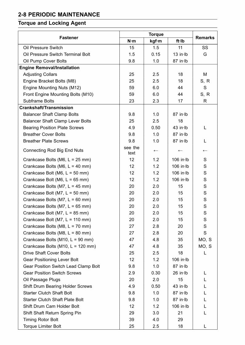
Crankshaft/TransmissionBalancer Shaft Clamp Bolts 9.8 1.0 87 in·lbBalancer Shaft Clamp Lever Bolts 25 2.5 18Bearing Position Plate Screws 4.9 0.50 43 in·lb LBreather Cover Bolts 9.8 1.0 87 in·lbBreather Plate Screws 9.8 1.0 87 in·lb L
Connecting Rod Big End Nuts see thetext ← ← ←
Crankcase Bolts (M6, L = 25 mm) 12 1.2 106 in·lb SCrankcase Bolts (M6, L = 40 mm) 12 1.2 106 in·lb SCrankcase Bolt (M6, L = 50 mm) 12 1.2 106 in·lb SCrankcase Bolt (M6, L = 65 mm) 12 1.2 106 in·lb SCrankcase Bolts (M7, L = 45 mm) 20 2.0 15 SCrankcase Bolt (M7, L = 50 mm) 20 2.0 15 SCrankcase Bolts (M7, L = 60 mm) 20 2.0 15 SCrankcase Bolts (M7, L = 65 mm) 20 2.0 15 SCrankcase Bolt (M7, L = 85 mm) 20 2.0 15 SCrankcase Bolt (M7, L = 110 mm) 20 2.0 15 SCrankcase Bolts (M8, L = 70 mm) 27 2.8 20 SCrankcase Bolts (M8, L = 80 mm) 27 2.8 20 SCrankcase Bolts (M10, L = 90 mm) 47 4.8 35 MO, SCrankcase Bolts (M10, L = 120 mm) 47 4.8 35 MO, SDrive Shaft Cover Bolts 25 2.5 18 LGear Positioning Lever Bolt 12 1.2 106 in·lbGear Position Switch Lead Clamp Bolt 9.8 1.0 87 in·lbGear Position Switch Screws 2.9 0.30 26 in·lb LOil Passage Plugs 20 2.0 15 LShift Drum Bearing Holder Screws 4.9 0.50 43 in·lb LStarter Clutch Shaft Bolt 9.8 1.0 87 in·lb LStarter Clutch Shaft Plate Bolt 9.8 1.0 87 in·lb LShift Drum Cam Holder Bolt 12 1.2 106 in·lb LShift Shaft Return Spring Pin 29 3.0 21 LTiming Rotor Bolt 39 4.0 29Torque Limiter Bolt 25 2.5 18 L

PERIODIC MAINTENANCE 2-9Torque and Locking Agent
TorqueFastener
N·m kgf·m ft·lbRemarks
Wheels/TiresFront Axle Clamp Bolts 20 2.0 15 ALFront Axle Nut 127 13.0 94Rear Axle Nut 127 13.0 94
Final DriveChain Guide Bolt 12 1.2 106 in·lb LChain Guide Bolts 9.8 1.0 87 in·lb LEngine Sprocket Cover Bolts 9.8 1.0 87 in·lbEngine Sprocket Nut 125 13.0 92 MORear Axle Nut 127 13.0 94Rear Sprocket Nuts 69 7.0 51Speed Sensor Bolt 3.9 0.40 35 in·lb LStud Bolts 14.7 1.5 11 L
BrakesBleed Valves 7.8 0.80 69 in·lbBrake Hose Banjo Bolts 25 2.5 18Brake Lever Pivot Bolt 1.0 0.10 9 in·lb SiBrake Lever Pivot Bolt Locknut 5.9 0.60 52 in·lbBrake Pedal Bolt 8.8 0.90 78 in·lbBrake Pipe Joint Nuts (ZX1400B Models) 18 1.8 13Front Brake Disc Mounting Bolts 27 2.8 20 LFront Brake Light Switch Screw 1.2 0.12 11 in·lbFront Brake Pad Pins 17.2 1.8 13Front Brake Reservoir Cap Stopper Screw 1.2 0.12 11 in·lbFront Caliper Assembly Bolts 27 2.8 20 LFront Caliper Mounting Bolts 34 3.5 25Front Master Cylinder Bleed Valve 7.8 0.80 69 in·lbFront Master Cylinder Clamp Bolts 8.8 0.90 78 in·lb SRear Brake Disc Mounting Bolts 27 2.5 18 LRear Brake Pad Pin 17.2 1.8 13Rear Caliper Assembly Bolts 37 3.8 27 LRear Caliper Mounting Bolts 25 2.5 18Rear Master Cylinder Mounting Bolts 25 2.5 18Rear Master Cylinder Push Rod Locknut 17.2 1.8 13
SuspensionFront Axle Clamp Bolts 20 2.0 15 ALFront Fork Bottom Allen Bolts 23 2.3 17 LFront Fork Clamp Bolts (Upper) 20 2.0 15Front Fork Clamp Bolts (Lower) 30 3.1 22 ALFront Fork Top Plugs 22 2.2 16Piston Rod Nuts 28 2.9 21Rear Shock Absorber Nut (Upper) 34 3.5 25Rear Shock Absorber Nut (Lower) 34 3.5 25

2-10 PERIODIC MAINTENANCETorque and Locking Agent
TorqueFastener
N·m kgf·m ft·lbRemarks
Swingarm Pivot Adjusting Collar 20 2.0 15Swingarm Pivot Adjusting Collar Locknut 98 10.0 72Swingarm Pivot Shaft Nut 108 11.0 80Tie-Rod Nuts 59 6.0 44Uni-Trak Rocker Arm Nut 34 3.5 25
SteeringFront Fork Clamp Bolts (Upper) 20 2.0 15Front Fork Clamp Bolts (Lower) 30 3.1 22 ALHandlebar Bolts 34 3.5 25 LHandlebar Holder Bolts 25 2.5 18 ALSteering Stem Head Nut 78 8.0 58Steering Stem Nut 23 2.3 17Switch Housing Screws 3.5 0.36 31 in·lb
FrameCenter Stand Bolts 44 4.5 32Front Footpeg Bracket Bolts 25 2.5 18Grab Rail Mounting Bolts 25 2.5 18Rear Fender Mounting Screws 1.2 0.12 11 in·lbRear Footpeg Bracket Bolts 25 2.5 18Rear Frame Bolts 44 4.5 32 LRear Frame Pipe Bolts 44 4.5 32Rear Frame Pipe Nuts 44 4.5 32Seat Lock Bracket Screws 1.2 0.12 11 in·lbSidestand Bolt 44 4.5 32Sidestand Bracket Bolts 49 5.0 36 LSidestand Switch Bolt 8.8 0.90 78 in·lb LWindshield Mounting Bolts 0.42 0.043 3.7 in·lb
Electrical SystemAlternator Cover Bolts 9.8 1.0 87 in·lbAlternator Lead Holding Plate Bolts 8.3 0.85 73 in·lb LAlternator Rotor Bolt (First) 69 7.0 51 SAlternator Rotor Bolt (Final) 110 11.2 81 SCamshaft Position Sensor Bolt 9.8 1.0 87 in·lbCrankshaft Sensor Bolts 5.9 0.60 52 in·lb LCrankshaft Sensor Cover Bolts 9.8 1.0 87 in·lb L (1)Engine Ground Terminal Bolt 9.8 1.0 87 in·lbFront Brake Light Switch Screw 1.2 0.12 11 in·lbFront Turn Signal Light Mounting Screws 1.2 0.12 11 in·lbFuel Level Sensor Bolts 6.9 0.70 61 in·lb LGear Position Switch Lead Clamp Bolts 9.8 1.0 87 in·lbGear Position Switch Screws 2.9 0.30 26 in·lb LHeadlight Mounting Screws 1.2 0.12 11 in·lbLeft Switch Housing Screws 3.5 0.36 31 in·lb

PERIODIC MAINTENANCE 2-11Torque and Locking Agent
TorqueFastener
N·m kgf·m ft·lbRemarks
Licence Plate Light Cover Mounting Screws 0.9 0.09 8 in·lbLicence Plate Light Mounting Screws 1.2 0.12 11 in·lbRear Turn Signal Light Mounting Screws 1.2 0.12 11 in·lbRegulatorRectifier Bolts 9.8 1.0 87 in·lbRight Switch Housing Screws 3.5 0.36 31 in·lbSidestand Switch Bolt 8.8 0.90 78 in·lb LSpark Plugs 13 1.3 115 in·lbSpeed Sensor Bolt 3.9 0.40 34 in·lb LStarter Lockout Switch Screw 0.7 0.07 6 in·lbStarter Motor Cable Mounting Bolt 3.9 0.40 34 in·lbStarter Motor Cable Terminal Nut 5.9 0.60 52 in·lbStarter Motor Mounting Bolts 9.8 1.0 87 in·lbStarter Motor Terminal Locknut 6.9 0.70 61 in·lbStarter Motor Through Bolts 3.4 0.35 30 in·lbStator Coil Bolts 12 1.2 106 in·lbTail/Brake Light Mounting Screws 1.2 0.12 11 in·lbWater Temperature Sensor 25 2.5 18The table below, relating tightening torque to thread diameter, lists the basic torque for the bolts and
nuts. Use this table for only the bolts and nuts which do not require a specific torque value. All of thevalues are for use with dry solvent-cleaned threads.
Basic Torque for General FastenersThreads Torque
diameter (mm) N·m kgf·m ft·lb5 3.4 ∼ 4.9 0.35 ∼ 0.50 30 ∼ 43 in·lb6 5.9 ∼ 7.8 0.60 ∼ 0.80 52 ∼ 69 in·lb8 14 ∼ 19 1.4 ∼ 1.9 10.0 ∼ 13.510 25 ∼ 34 2.6 ∼ 3.5 19.0 ∼ 2512 44 ∼ 61 4.5 ∼ 6.2 33 ∼ 4514 73 ∼ 98 7.4 ∼ 10.0 54 ∼ 7216 115 ∼ 155 11.5 ∼ 16.0 83 ∼ 11518 165 ∼ 225 17.0 ∼ 23.0 125 ∼ 16520 225 ∼ 325 23 ∼ 33 165 ∼ 240

2-12 PERIODIC MAINTENANCESpecifications
Item Standard Service LimitFuel SystemThrottle Grip Free Play 2 ∼ 3 mm (0.08 ∼ 0.12 in.) – – –Idle Speed 1 100 ±50 r/min (rpm) – – –Throttle Body Vacuum 39 ±1.33 kPa (293 ±10 mmHg) at idle speed – – –Air Cleaner Element Viscous paper element – – –
Cooling SystemCoolant:Type (Recommended) Permanent type antifreeze – – –Color Green – – –Mixed Ratio Soft water 50%, coolant 50% – – –Freezing Point –35°C (–31°F) – – –Total Amount 3.4 L (3.6 US qt) – – –
Engine Top EndValve Clearance:Exhaust 0.22 ∼ 0.27 mm (0.0087 ∼ 0.0106 in.) – – –Inlet 0.15 ∼ 0.20 mm (0.0059 ∼ 0.0079 in.) – – –
ClutchClutch Fluid:Grade DOT4 – – –
Clutch Lever Free Play Non-adjustable – – –Engine Lubrication SystemEngine Oil:Type API SE, SF or SG – – –
API SH, SJ or SL with JASO MAViscosity SAE 10W-40 – – –Capacity 3.7 L (3.9 US qt) (when filter is not removed) – – –
4.1 L (4.3 US qt) (when filter is removed) – – –4.5 L (4.8 US qt) (when engine is completelydry)
– – –
Level Between upper and lower level lines (Wait 2 ∼3 minutes after idling or running)
– – –
Wheels/TiresTread Depth:Front 3.8 mm (0.15 in.) 1 mm (0.04 in.),
(AT, CH, DE) 1.6mm (0.06 in.)
Rear 4.8 mm (0.19 in.) Up to 130 km/h (80mph): 2 mm (0.08in.), Over 130 km/h(80 mph): 3 mm(0.12 in.)
Air Pressure (when Cold):Front Up to 180 kg (397 lb) load:
290 kPa (2.9 kgf/cm², 42 psi)– – –
Rear Up to 180 kg (397 lb) load:290 kPa (2.9 kgf/cm², 42 psi)
– – –

PERIODIC MAINTENANCE 2-13Specifications
Item Standard Service LimitFinal DriveDrive Chain Slack 32 ∼ 38 mm (1.3 ∼ 1.5 in.) – – –Drive Chain Wear (20-linkLength)
317.5 ∼ 318.2 mm (12.50 ∼ 12.53 in.) 323 mm (12.7 in.)
Standard Chain:Make DAIDO – – –Type DID50ZVM4 GC&B – – –Link 116 links – – –
BrakesBrake Fluid:Grade DOT4 – – –
Brake Pad Lining Thickness:Front 4.0 mm (0.16 in.) 1 mm (0.04 in.)Rear 5.0 mm (0.20 in.) 1 mm (0.04 in.)
Brake Light Timing:Front Pulled ON – – –Rear On after about 10 mm (0.39 in.) of pedal travel – – –
Electrical SystemSpark Plug:Type NGK CR9EIA-9 – – –

2-14 PERIODIC MAINTENANCESpecial Tools
Inside Circlip Pliers:57001-143
Steering Stem Nut Wrench:57001-1100
Jack:57001-1238
Oil Filter Wrench:57001-1249
Pilot Screw Adjuster, C:57001-1292
Vacuum Gauge:57001-1369
Pilot Screw Adjuster Adapter, 5:57001-1372
Jack Attachment:57001-1608

PERIODIC MAINTENANCE 2-15Maintenance Procedure
Fuel System (DFI)Throttle Control System Inspection•Check the throttle grip free play [A].If the free play is incorrect, adjust the throttle cables.
Throttle Grip Free PlayStandard: 2 ∼ 3 mm (0.08 ∼ 0.12 in.)
•Check that the throttle grip [B] moves smoothly from fullopen to close, and the throttle closes quickly and com-pletely by the return spring in all steering positions.If the throttle grip does not return properly, check the throt-tle cables routing, grip free play, and cable damage. Thenlubricate the throttle cable.• Run the engine at the idle speed, and turn the handlebarall the way to the right and left to ensure that the idle speeddoes not change.If the idle speed increases, check the throttle cable freeplay and the cable routing.
If necessary, adjust the throttle cable as follows.• Loosen the locknuts [A] [B].• Screw both throttle cable adjusters [C] [D] to give thethrottle grip plenty of play.• Turn the decelerator cable adjuster [C] until 2 ∼ 3 mm(0.08 ∼ 0.12 in.) of throttle grip play is obtained.• Tighten the locknut [A].• Turn the accelerator cable adjuster [D] until 2 ∼ 3 mm(0.08 ∼ 0.12 in.) of throttle grip play is obtained.• Tighten the locknut [B].If the free play cannot be adjusted with the adjusters, re-place the cable.
Engine Vacuum Synchronization InspectionNOTE
These procedures are explained on the assumption thatthe inlet and exhaust systems of the engine are in goodcondition.
•Situate the motorcycle so that it is vertical.• Remove:Fuel Tank Cover (see Fuel Tank Removal in the FuelSystem (DFI) chapter)Left and Right Middle Fairings (see Middle Fairing Re-moval in the Frame chapter)• Pull off the rubber caps [A] from the fittings of each throttlebody.Front [B]

2-16 PERIODIC MAINTENANCEMaintenance Procedure
•For the California Model, pull off the vacuum hoses [A].
• Pull off the air switching valve hose [A] from the air cleanerhousing.• Plug the air switching valve hose end and air cleanerhousing hole.
• Connect a vacuum gauge (special tool) and hoses [A] tothe fittings on the throttle body.Special Tool - Vacuum Gauge: 57001-1369
•Connect a highly accurate tachometer [B] to one of thestick coil primary leads.
• Start the engine and warm it up thoroughly.• Check the idle speed, using a highly accurate tachometer[A].If the idle speed is out of the specified range, adjust it withthe adjust screw.
CAUTIONDo not measure the idle speed by the tachometer ofthe meter unit.
•While idling the engine, inspect the throttle body vacuum,using the vacuum gauge [B].
Throttle Body VacuumStandard: 39 ±1.33 kPa (293 ±10 mmHg) at Idle Speed
1 100 ±50 r/min (rpm)

PERIODIC MAINTENANCE 2-17Maintenance Procedure
If any vacuum is not within specifications, first synchro-nize the balance of the left (#1, #2 throttle valves) andright (#3, #4 throttle valves) assemblies.
Example:#1: 260 mmHg#2: 290 mmHg#3: 250 mmHg#4: 270 mmHg•With the engine at the correct idle speed, equalize highervacuum of #1 or #2 (for example 290 mmHg) to highervacuum of #3 or #4 (for example 270 mmHg) by turningthe center adjusting screw [A].Right Side View [B]
In this photo [C], the throttle body has been removed forclarity.Special Tool - Pilot Screw Adjuster, C: 57001-1292
Pilot Screw Adjuster Adapter, 5: 57001-1372
NOTEAfter adjustment, the final vacuum measurement be-tween the highest throttle valves may not be 290 mmHg(for example). The goal is to have the highest two vac-uums between the left (#1 and #2) and right (#3 and #4)banks be the same and be within the service limits.
•Open and close the throttle after each measurement, andadjust the idle speed as necessary.•Once the throttle valves have been synchronized, inspectoutput voltage of themain throttle sensor to ensure properoperation (procedure is explained at the end of this sec-tion).
If a value of measured vacuum pressure is out of thespecified range after synchronization, adjust the bypassscrews [A].Special Tool - Pilot Screw Adjuster, C: 57001-1292
Pilot Screw Adjuster Adapter, 5: 57001-1372
Rear View [B]• Adjust lower vacuum between #1 and #2 to higher vac-uum of #1 and #2.• Adjust the lower vacuum between #3 and #4 to highervacuum of #3 and #4.•Open and close the throttle valves after each measure-ment, and adjust the idle speed as necessary.• Check the vacuums as before.If all vacuums are within the specification range, finish theengine vacuum synchronization.If any vacuum cannot be adjusted within the specification,remove the bypass screws #1 ∼ #4 and clean them.

2-18 PERIODIC MAINTENANCEMaintenance Procedure
•Turn in the bypass screw [A] with counting the number ofturns until it seals fully but not tightly. Record the numberof turns.Torque - Bypass Screw: 0.2 N·m (0.02 kgf·m, 1.8 in·lb)
CAUTIONDo not over tighten them. They could be damaged,requiring replacement.
•Remove:Bypass ScrewSpring [B]Washer [C]O-ring [D]• Check the bypass screw and its hole for carbon deposits.If any carbons accumulate, wipe the carbons off from thebypass screw and the hole, using a cotton pad penetratedwith a high-flash point solvent.• Replace the O-ring with a new one.• Check the tapered portion [E] of the bypass screw forwear or damage.If the bypass screw is worn or damaged, replace it.• Turn in the bypass screw until it seats fully but not tightly.Torque - Bypass Screw: 0.2 N·m (0.02 kgf·m, 1.8 in·lb)
•Back out the same number of turns counted when firstturned in. This is to set the screw to its original position.
NOTEA throttle body has different “turns out” of the bypassscrew for each individual unit. On setting the bypassscrew, use the “turns out” determined during disassem-bly.
•Repeat the same procedure for other bypass screws.• Repeat the synchronization.If the vacuums are correct, check the output voltage ofthe main throttle sensor (see Output Voltage Inspection ofMain Throttle Sensor in the Fuel System (DFI) chapter).
Main Throttle Sensor Output VoltageConnections to ECUMeter (+) → Y/W lead (terminal 26)Meter (–) → BR/BK lead (terminal 34)
Standard: DC 0.63 ∼ 0.65 V (at idle throttle opening)
If the output voltage is out of the range, check the throttleinput voltage of the main throttle sensor (see Input Volt-age Inspection in the Main Throttle Sensor section in theFuel System (DFI) chapter).
• Remove the vacuum gauge hoses and install the rubbercaps on the original position.• For the California Model, install the vacuum hoses.Route the vacuum hoses according to Cable, Wire, andHose Routing section in the Appendix chapter. Refer tothe diagram of the evaporative emission control systemin the Fuel System (DFI) chapter too.

PERIODIC MAINTENANCE 2-19Maintenance Procedure
Idle Speed Inspection•Start the engine and warm it up thoroughly.•With the engine idling, turn the handlebar to both sides[A].If handlebar movement changes the idle speed, thethrottle cables may be improperly adjusted or incorrectlyrouted, or damaged. Be sure to correct any of theseconditions before riding (see Cable, Wire, and HoseRouting section in the Appendix chapter).
WARNINGOperation with improperly adjusted, incorrectlyrouted, or damaged cables could result in an un-safe riding condition.
•Check the idle speed.If the idle speed is out of specified range, adjust it.
Idle SpeedStandard: 1 100 ±50 r/min (rpm)
Idle Speed Adjustment•Start the engine and warm it up thoroughly.• Turn the adjusting screw [A] until the idle speed is correct.Open and close the throttle a few times to make sure thatthe idle speed is within the specified range. Readjust ifnecessary.
Fuel Hose Inspection (fuel leak, damage,installation condition)If the motorcycle is not properly handled, the high pres-sure inside the fuel line can cause fuel to leak [A] or thehose to burst. Remove the fuel tank (see Fuel Tank Re-moval in the Fuel System (DFI) chapter) and left middlefairing (see Middle Fairing Removal in the Frame chap-ter), and check the fuel hose.Replace the fuel hose if any fraying, cracks [B] or bulges[C] are noticed.
• Check that the hoses are routed according to Cable, Wire,and Hose Routing section in the Appendix chapter.Replace the hose if it has been sharply bent or kinked.Hose Joints [A]Fuel Hose [B]

2-20 PERIODIC MAINTENANCEMaintenance Procedure
•Check that the hose joints are securely connected.Push and pull [A] the hose joint [B] back and forth morethan two times, and make sure it is locked.If it does not locked, reinstall the hose joint.
WARNINGMake sure the hose joint is installed correctly on thedelivery pipe by sliding the joint, or the fuel couldleak.
Cooling SystemCoolant Level Inspection
NOTECheck the level when the engine is cold (room or ambi-ent temperature).
•Check the coolant level in the reserve tank [A] with themotorcycle held perpendicular (Do not use the sidestand).If the coolant level is lower than the “L” level line [B], un-screw the reserve tank cap and add coolant to the “F”level line [C].“L”: low“F”: full
CAUTIONFor refilling, add the specified mixture of coolantand soft water. Adding water alone dilutes thecoolant and degrades its anticorrosion properties.The diluted coolant can attack the aluminum en-gine parts. In an emergency, soft water alone canbe added. But the diluted coolant must be returnedto the correct mixture ratio within a few days.If coolant must be added often or the reservoir tankhas run completely dry, there is probably leakage inthe cooling system. Check the system for leaks.Coolant ruins painted surfaces. Immediately washaway any coolant that spills on the frame, engine,wheels or other painted parts.
Radiator Hose and Pipe Inspection(Coolant leak, damage, Installation Condition)The high pressure inside the radiator hose can causecoolant to leak [A] or the hose to burst if the line is notproperly maintained.• Visually inspect the hoses for signs of deterioration.Squeeze the hoses. A hose should not be hard andbrittle, nor should it be soft or swollen.Replace the hose if any fraying, cracks [B] or bulges [C]are noticed.• Check that the hoses are securely connected and clampsare tightened correctly.Torque - Radiator Hose ClampScrews: 2.0 N·m (0.20 kgf·m,
18 in·lb)

PERIODIC MAINTENANCE 2-21Maintenance Procedure
Evaporative Emission Control System (California Model)Evaporative Emission Control System Inspection• Inspect the canister as follows.Remove the seat (see Seat Removal in the Frame chap-ter).Remove the canister [A], and disconnect the hoses fromthe canister.Visually inspect the canister for cracks or other damage.If the canister has any cracks or bad damage, replace itwith a new one.
NOTEThe canister is designed to work well through the motor-cycle’s life without any maintenance if it is used undernormal conditions.
•Check the liquid/vapor separator as follows.Remove the fuel tank (see Fuel Tank Removal in the FuelSystem (DFI) chapter).Disconnect the hoses from the separator, and remove theseparator [A] from the motorcycle right side.Visually inspect the separator for cracks and other dam-age.If the separator has any cracks or damage, replace it witha new one.To prevent the gasoline from flowing into or out of thecanister, hold the separator perpendicular to the ground.• Check the hoses of the evaporative emission control sys-tem as follows.Check that the hoses are securely connected and clipsare in position.Replace any kinked, deteriorated or damaged hoses.Route the hoses according to Cable, Wire, and HoseRouting section in the Appendix chapter. Refer to the di-agram of the evaporative emission control system in theFuel System (DFI) chapter too.When installing the hoses, avoid sharp bending, kinking,flattening or twisting, and route the hoses with a minimumof bending so that the emission flow will not be obstructed.
Air Suction SystemAir Suction System Damage Inspection•Remove the right middle fairing (see Middle Fairing Re-moval in the Frame chapter).• Pull the air switching vale hose [A] out of the air cleanerhousing.• Start the engine and run it at idle speed.• Plug [B] the air switching valve hose end with your fingerand feel vaccum pulsing in the hose.If there is no vaccum pulsation, check the hose line forleak. If there is no leak, check the air switching valve(see Air Switching Valve Unit Test in the Electrical Sys-tem chapter) or air suction valve (see Air Suction ValveInspection in the Engine Top End chapter).

2-22 PERIODIC MAINTENANCEMaintenance Procedure
Engine Top EndValve Clearance InspectionValve Clearance Inspection
NOTEValve clearance must be checked and adjusted whenthe engine is cold (at room temperature).
•Remove:Lower Fairings (see Lower Fairing Removal in the Framechapter)Middle Fairings (see Middle Fairing Removal in theFrame chapter)Crankshaft Sensor CoverCylinder Head Cover (see Cylinder Head Cover Re-moval in the Engine Top End chapter)
• Position the crankshaft at 1, 4 piston TDC.TDC Mark [A] for #1, 4 PistonsTiming Mark [B] (crankcase halves mating surface)
• Using a thickness gauge [A], measure the valve clearancebetween the cam and the valve lifter.
Valve ClearanceStandard:Exhaust 0.22 ∼ 0.27 mm (0.0087 ∼ 0.0106 in.)Inlet 0.15 ∼ 0.20 mm (0.0059 ∼ 0.0079 in.)
NOTEThickness gauge is horizontally inserted on the valvelifter.
Appropriateness [A]Inadequacy [B]Thickness Gauge [C]Horizontally Inserts [D]Cam [E]Valve Lifter [F]Hits the Valve Lifter Ahead [G]

PERIODIC MAINTENANCE 2-23Maintenance Procedure
When positioning #1 piston TDC at the end of thecompression stroke:Inlet Valve Clearance of #1 and #3 CylindersExhaust Valve Clearance of #1 and #2 CylindersMeasuring Valve [A]
When positioning #4 piston TDC at the end of thecompression stroke:Inlet Valve Clearance of #2 and #4 CylindersExhaust Valve Clearance of #3 and #4 CylindersMeasuring Valve [A]
If the valve clearance is not within the specified range,first record the clearance, and then adjust it.
Valve Clearance Adjustment•To change the valve clearance, remove the camshaftchain tensioner, camshafts and valve lifters. Replace theshim with one of a different thickness.
NOTEMark and record the locations of the valve lifters andshims so that they can be reinstalled in their originalpositions.

2-24 PERIODIC MAINTENANCEMaintenance Procedure
Bisides the standard shims in the valve clearance adjust-ment charts, the following additional shims maybe used.
Adjustment ShimsPart Number Thickness92025-1982 2.425 mm92025-1983 2.475 mm92025-1984 2.525 mm92025-1985 2.575 mm92180-1058 2.375 mm92180-1059 2.625 mm92180-1194 2.675 mm92180-1195 2.725 mm92180-1196 2.775 mm92180-0209 2.025 mm92180-0210 2.075 mm92180-0211 2.125 mm92180-0212 2.175 mm92180-0213 2.225 mm92180-0214 2.275 mm92180-0215 2.325 mm92180-0216 2.825 mm92180-0217 2.875 mm92180-0218 2.925 mm92180-0219 2.975 mm
•Clean the shim to remove any dust or oil.•Measure the thickness of the removed shim [A].

PERIODIC MAINTENANCE 2-25Maintenance Procedure
EXHAUST- VALVE CLEARANCE ADJUSTMENT CHART
1. Measure the clearance (with engine cold).2. Check present shim size.3. Match clearance in vertical column with present shimsize in horizontal column.
4. Install the shim specified where the lines intersect. Thisshim will give the proper clearance.Example: Present shim is 2.60 mm.
Measured clearance is 0.33 mm.Replace 2.60 mm shim with 2.70 mm shim.

2-26 PERIODIC MAINTENANCEMaintenance Procedure
INLET- VALVE CLEARANCE ADJUSTMENT CHART
1. Measure the clearance (with engine cold).2. Check present shim size.3. Match clearance in vertical column with present shimsize in horizontal column.
4. Install the shim specified where the lines intersect. Thisshim will give the proper clearance.Example: Present shim is 2.55 mm.
Measured clearance is 0.36 mm.Replace 2.55 mm shim with 2.75 mm shim.

PERIODIC MAINTENANCE 2-27Maintenance Procedure
CAUTIONBe sure to remeasure the clearance after selectinga shim according to the table. If the clearance is outof the specified rage, use the additional shim.
If there is no valve clearance, use a shim that is a fewsizes smaller, and remeaasure the valve clearance.•When installing the shim, face the marked side toward thevalve lifter. At this time, apply engine oil to the shim orthe valve lifter to keep the shim in place during camshaftinstallation.
CAUTIONDo not put shim stock under the shim. This maycause the shim to pop out at high rpm, causing ex-tensive engine damage.Do not grind the shim. This may cause it to fracture,causing extensive engine damage.
•Apply engine oil to the valve lifter surface and install thelifter.• Install the camshaft (see Camshaft Installation in the En-gine Top End chapter).• Recheck the valve clearance and readjust if necessary.• Install the removed parts (see appropriate chapters).Clutch and Drive TrainClutch Operation Inspection•Start the engine and check that the clutch does not slipand that it releases properly.If the clutch operation is insufficiency, inspect the clutchsystem.
WARNINGWhen inspecting by running the vehicle, note asurrounding traffic situation enough in the place ofsafety.
Clutch Fluid Level Inspection•Hold the clutch fluid reservoir [A] horizontal.• Check that the clutch fluid level of the clutch reservoir isbetween the lower [B] and the upper [C] level lines.If the fluid level is lower than the lower level line, fill thereservoir to the upper level line in the reservoir.Since the clutch fluid is the same as the brake fluid, referto Brake Fluid Section in the Brake chapter for furtherdetails.
2-28 PERIODIC MAINTENANCEMaintenance Procedure
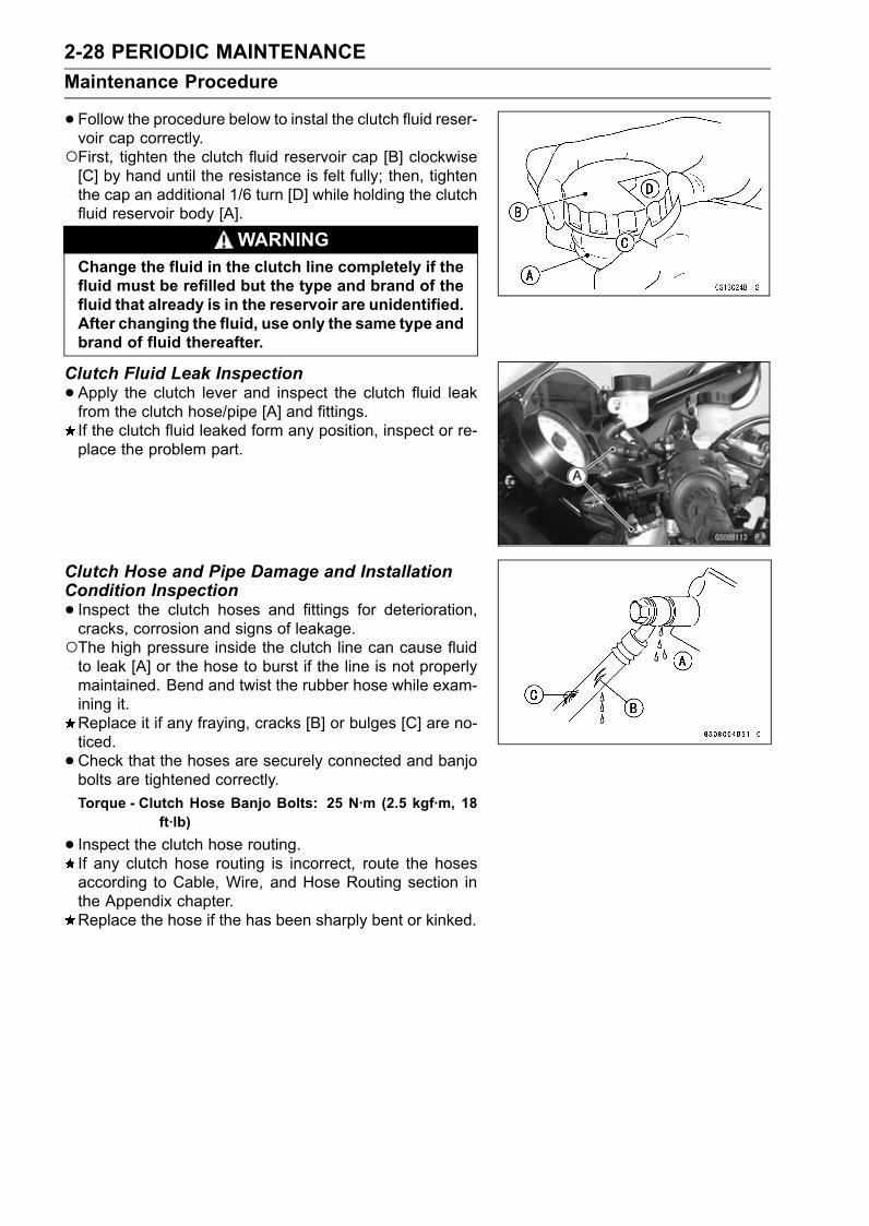
•Follow the procedure below to instal the clutch fluid reser-voir cap correctly.First, tighten the clutch fluid reservoir cap [B] clockwise[C] by hand until the resistance is felt fully; then, tightenthe cap an additional 1/6 turn [D] while holding the clutchfluid reservoir body [A].
WARNINGChange the fluid in the clutch line completely if thefluid must be refilled but the type and brand of thefluid that already is in the reservoir are unidentified.After changing the fluid, use only the same type andbrand of fluid thereafter.
Clutch Fluid Leak Inspection•Apply the clutch lever and inspect the clutch fluid leakfrom the clutch hose/pipe [A] and fittings.If the clutch fluid leaked form any position, inspect or re-place the problem part.
Clutch Hose and Pipe Damage and InstallationCondition Inspection• Inspect the clutch hoses and fittings for deterioration,cracks, corrosion and signs of leakage.The high pressure inside the clutch line can cause fluidto leak [A] or the hose to burst if the line is not properlymaintained. Bend and twist the rubber hose while exam-ining it.Replace it if any fraying, cracks [B] or bulges [C] are no-ticed.• Check that the hoses are securely connected and banjobolts are tightened correctly.Torque - Clutch Hose Banjo Bolts: 25 N·m (2.5 kgf·m, 18
ft·lb)
• Inspect the clutch hose routing.If any clutch hose routing is incorrect, route the hosesaccording to Cable, Wire, and Hose Routing section inthe Appendix chapter.Replace the hose if the has been sharply bent or kinked.

PERIODIC MAINTENANCE 2-29Maintenance Procedure
Wheels/TiresAir Pressure Inspection•Remove the air valve cap.•Measure the tire air pressure with an air pressure gauge[A] when the tires are cold (that is, when the motorcyclehas not been ridden more than a mile during the past 3hours).• Install the air valve cap.Adjust the tire air pressure according to the specificationsif necessary.
Air Pressure (when Cold)Front: Up to 180 kg (397 lb)
290 kPa (2.9 kgf/cm², 42 psi)Rear: Up to 180 kg (397 lb)
290 kPa (2.9 kgf/cm², 42 psi)
Wheel/Tire Damage Inspection•Remove any imbedded stones [A] or other foreign parti-cles [B] from tread.• Visually inspect the tire for cracks and cuts, and replacethe tire if necessary. Swelling or high spots indicate inter-nal damage, requiring tire replacement.• Visually inspect the wheel for cracks, cuts and dents dam-age.If any damage is found, replace the wheel if necessary.
Tire Tread Wear InspectionAs the tire tread wears down, the tire becomes more sus-
ceptible to puncture and failure. An accepted estimate isthat 90% of all tire failures occur during the last 10% of treadlife (90% worn). So it is false economy and unsafe to usethe tires until they are bald.•Measure the tread depth at the center of the tread with adepth gauge [A]. Since the tire may wear unevenly, takemeasurement at several places.If any measurement is less than the service limit, replacethe tire (see Tire Removal/Installation in the Wheels/Tireschapter).
Tread DepthStandard:Front 3.8 mm (0.15 in.)Rear 4.8 mm (0.19 in.)
Service Limit:Front 1 mm (0.04 in.)
(AT, CH, DE) 1.6 mm (0.06 in.)Rear 2 mm (0.08 in.)
(Up to 130 km/h (80 mph))3 mm (0.12 in.)(Over 130 km/h (80 mph))

2-30 PERIODIC MAINTENANCEMaintenance Procedure
WARNINGTo ensure safe handling and stability, use only therecommended standard tires for replacement, in-flated to the standard pressure.
NOTEMost countries may have their own regulations a mini-mum tire tread depth: be sure to follow them.Check and balance the wheel when a tire is replacedwith a new one.
Wheel Bearing Damage Inspection•Raise the front wheel off the ground with the jack (seeFront Wheel Removal in the Wheels/Tires chapter).• Turn the handlebar all the way to the right or left.• Inspect the roughness of the front wheel bearing by push-ing and pulling [A] the wheel.• Spin [B] the front wheel lightly, and check for smoothlyturn, roughness, binding or noise.If roughness, binding or noise is found, remove the frontwheel and inspect the wheel bearing (see Front WheelRemoval, Hub Bearing Inspection in the Wheels/Tireschapter).
• Raise the rear wheel off the ground with the stand (seeRear Wheel Removal in the Wheels/Tires chapter).• Inspect the roughness of the rear wheel bearing by push-ing and pulling [A] the wheel.• Spin [B] the rear wheel lightly, and check for smoothlyturn, roughness, binding or noise.If roughness, binding or noise is found, remove the rearwheel and inspect the wheel bearing (seeRearWheel Re-moval, Hub Bearing Inspection in the Wheels/Tires chap-ter) and coupling (see Coupling Bearing Inspection in theFinal Drive chapter).
Drive TrainDrive Chain Lubrication Condition Inspection• If a special lubricant is not available, a heavy oil such asSAE 90 is preferred to a lighter oil because it will stay onthe chain longer and provide better lubrication.• If the chain appears especially dirty, clean it before lubri-cation.
CAUTIONThe O-rings between the side plates seal in the lu-bricant between the pin and the bushing. To avoiddamaging the O-rings and resultant loss of lubri-cant, observe the following rules.Use only kerosene or diesel oil for cleaning of the O-ring of the drive chain. Any other cleaning solutionsuch as gasoline or trichloroethylene will cause de-terioration and swelling of the O-ring. Immediatelyblow the chain dry with compressed air after clean-ing. Complete cleaning and drying the chain within10 minutes.

PERIODIC MAINTENANCE 2-31Maintenance Procedure
•Apply oil to the sides of the rollers so that oil will penetrateto the rollers and bushings. Apply the oil to the O-rings sothat the O-rings will be coated with oil.•Wipe off any excess oil.Oil Applied Areas [A]O-ring [B]
Drive Chain Slack InspectionNOTE
Check the slack with the motorcycle setting on its sidestand.Check the slack with the motorcycle setting on its centerstand (center stand equipped models).Clean the chain if it is dirty, and lubricate it if it appearsdry.
•Check the wheel alignment (seeWheel Alignment Inspec-tion).• Rotate the rear wheel to find the position where the chainis tightest.•Measure the vertical movement (chain slack) [A] midwaybetween the sprockets.If the chain slack exceeds the standard, adjust it.
Chain SlackStandard: 32 ∼ 38 mm (1.3 ∼ 1.5 in.)
Drive Chain Slack Adjustment•Remove the cotter pin [A], and loosen the axle nut [B].• Loosen the both chain adjuster locknuts [C].If the chain is too loose, turn out the right and left chainadjusters [D] evenly.If the chain is too tight, turn in the right and left chainadjusters evenly, and kick the wheel forward.• Turn both chain adjusters evenly until the drive chain hasthe correct amount of slack. To keep the chain and wheelproperly aligned, the notch [E] on the right wheel align-ment indicator [F] should align with the same swingarmmark or position [G] that the left indicator notch alignswith.
WARNINGMisalignment of the wheel will result in abnormalwear and may result in an unsafe riding condition.
•Tighten both chain adjuster locknuts securely.• Tighten the axle nut.Torque - Rear Axle Nut: 127 N·m (13.0 kgf·m, 94 ft·lb)
•Turn the wheel, measure the chain slack again at the tight-est position, and readjust if necessary.

2-32 PERIODIC MAINTENANCEMaintenance Procedure
• Insert a new cotter pin [A].NOTE
When inserting the cotter pin, if the slots in the nut donot align with the cotter pin hole in the axle, tighten thenut clockwise [B] up to next alignment.It should be within 30°.Loosen once and tighten again when the slot goes pastthe nearest hole.
•Bend the cotter pin [A] over the nut.WARNING
If the rear axle nut is not securely tightened or thecotter pin is not installed, an unsafe riding condi-tion may result.
Wheel Alignment Inspection•Check that the notch [A] on the right alignment indicator[B] aligns with the same swingarm mark or position [C]that the left alignment indicator notch aligns with.If they do not, adjust the chain slack and align the wheelalignment (see Drive Chain Slack Adjustment).
NOTEWheel alignment can be also checked using thestraightedge or string method.
WARNINGMisalignment of the wheel will result in abnormalwear, and may result in an unsafe riding condition.
Drive Chain Wear Inspection•Remove the chain cover (see Drive Chain Removal in theFinal Drive chapter).• Rotate the rear wheel to inspect the drive chain for dam-aged rollers, and loose pins and links.If there is any irregularity, replace the drive chain.Lubricate the drive chain if it appears dry.• Stretch the chain taut by hanging a 98 N (10 kg, 20 lb)weight [A] on the chain.•Measure the length of 20 links [B] on the straight part [C] ofthe chain from the pin center of the 1st pin to the pin centerof the 21st pin. Since the chain may wear unevenly, takemeasurements at several places.If any measurements exceed the service limit, replace thechain. Also, replace the front and rear sprockets when thedrive chain is replaced.
Drive Chain 20-link LengthStandard: 317.5 ∼ 318.2 mm (12.50 ∼ 12.53 in.)Service Limit: 323 mm (12.7 in.)

PERIODIC MAINTENANCE 2-33Maintenance Procedure
WARNINGIf the drive chain wear exceeds the service limit, re-place the chain or an unsafe riding condition mayresult. A chain that breaks or jumps off the sprock-ets could snag on the engine sprocket or lock therear wheel, severely damaging the motorcycle andcausing it to go out of control.For safety, use only the standard chain. It is an end-less type and should not be cut for installation.
Standard ChainMake: DAIDOType: DID50ZVM4 GC&BLink: 116 links
Chain Guide Wear Inspection•Remove the swingarm (see Swingarm Removal in theSuspension chapter).• Visually inspect the chain guide [A].Replace the chain guide if it shows any signs of abnormalwear or damage.

2-34 PERIODIC MAINTENANCEMaintenance Procedure
Brake SystemBrake Fluid Leak (Brake Hose and Pipe) Inspection•For ABS equipped models; note the following.• Remove:Fuel Tank (see Fuel Tank Removal in the Fuel System(DFI) chapter)Battery (see Battery Removal in the Electrical Systemchapter)• Apply the brake lever or pedal and inspect the brake fluidleak from the brake hoses [A], pipes (ABS equipped mod-els) [B] and fittings [C].If the brake fluid leaked from any position, inspect or re-place the problem part.

PERIODIC MAINTENANCE 2-35Maintenance Procedure
Brake Hose and Pipe Damage and InstallationCondition Inspection•For ABS equipped models; note the following.• Remove:Fuel Tank (see Fuel Tank Removal in the Fuel System(DFI) chapter)Battery (see Battery Removal in the Electrical Systemchapter)• Inspect the brake hoses and fittings for deterioration,cracks and signs of leakage.The high pressure inside the brake line can cause fluidto leak [A] or the hose, pipes (ABS equipped models) toburst if the line is not properly maintained. Bend and twistthe rubber hose while examining it.Replace the hose and pipe (ABS equipped models) if anycrack [B], bulge [C] or leakage is noticed.Tighten any brake hose banjo bolts.Torque - Brake Hose Banjo Bolts: 25 N·m (2.5 kgf·m, 18
ft·lb)
• Inspect the brake hose routing.If any brake hose and pipe (ABS equipped models) rout-ing is incorrect, route the brake hose and pipe accordingto Cable, Wire, and Hose Routing section in the Appendixchapter.
Brake Operation Inspection• Inspect the operation of the front and rear brake by run-ning the vehicle on the dry road.If the brake operation is insufficiency, inspect the brakesystem.
WARNINGWhen inspecting by running the vehicle, note asurrounding traffic situation enough in the place ofsafety.
Brake Fluid Level Inspection•Check that the brake fluid level in the front brake reservoir[A] is above the lower level line [B].
NOTEHold the reservoir horizontal by turning the handlebarwhen checking brake fluid level.
If the fluid level is lower than the lower level line, fill thereservoir to the upper level line [C].

2-36 PERIODIC MAINTENANCEMaintenance Procedure
•Follow the procedure below to install the front brake fluidreservoir cap correctly.First, tighten the front brake fluid reservoir cap [B] clock-wise [C] by hand until slight resistance is felt indicatingthat the cap is seated on the reservoir body, then tightenthe cap an additional 1/6 turn [D] while holding the brakefluid reservoir body [A].
• Remove the seat (see Seat Removal in the Frame chap-ter).• Check that the brake fluid level in the rear brake reservoir[A] is above the lower level line [B].If the fluid level is lower than the lower level line, fill thereservoir to the upper level line [C].
WARNINGChange the brake fluid in the brake line completelyif the brake fluid must be refilled but the type andbrand of the brake fluid that is already in the reser-voir are unidentified. After changing the fluid, useonly the same type and brand of fluid thereafter.
Recommended Disc Brake FluidGrade: DOT4
•Follow the procedure below to install the rear brake fluidreservoir cap correctly.First, tighten the rear brake fluid reservoir cap [B] clock-wise [C] by hand until slight resistance is felt indicatingthat the cap is seated on the reservoir body, then tightenthe cap an additional 1/6 turn [D] while holding the brakefluid reservoir body [A].
Brake Pad Wear Inspection•Remove the brake pads (see Front/Rear Brake Pad Re-moval in the Brakes chapter).• Check the lining thickness [A] of the pads in each caliper.If the lining thickness of either pad is less than the servicelimit [B], replace both pads in the caliper as a set.
Pad Lining ThicknessStandard:Front 4.0 mm (0.16 in.)Rear 5.0 mm (0.20 in.)
Service Limit: 1 mm (0.04 in.)

PERIODIC MAINTENANCE 2-37Maintenance Procedure
Brake Light Switch Operation Inspection•Turn on the ignition switch.• The brake light [A] should go on when the brake lever isapplied or after the brake pedal is depressed about 10mm (0.39 in.).
If it does not, adjust the brake light switch.•While holding the switch body, turn the adjusting nut toadjust the switch.Switch Body [A]Adjusting Nut [B]Light sooner as the body rises [C]Light later as the body lowers [D]
CAUTIONTo avoid damaging the electrical connections in-side the switch, be sure that the switch body doesnot turn during adjustment.
If it does not go on, inspect or replace the following items.Battery (see Charging Condition Inspection in the Elec-trical System chapter)Brake Light (see Tail/Brake Light Removal in the Electri-cal System chapter)Main Fuse 30 A and Taillight Fuse 10 A (see Fuse In-spection in the Electrical System chapter)Front Brake Light Switch [A] (see Switch Inspection inthe Electrical System chapter)Rear Brake Light Switch (see Switch Inspection in theElectrical System chapter)Harness (see Wiring Inspection in the Electrical Systemchapter)
SuspensionsFront Forks/Rear Shock Absorber OperationInspection•Pump the forks down and up [A] 4 or 5 times, and inspectthe smooth stroke.If the forks do not smoothly or noise is found, inspect thefork oil level or fork clamps (see Front Fork Oil Change inthe Suspension chapter).

2-38 PERIODIC MAINTENANCEMaintenance Procedure
•Pump the seat down and up [A] 4 or 5 times, and inspectthe smooth stroke.If the shock absorber does not smoothly stroke or noiseis found, inspect the oil leak (see Rear Shock AbsorberOil Leak Inspection).
Front Fork Oil Leak Inspection•Visually inspect the front forks [A] for oil leakage.Replace or repair any defective parts, if necessary.
Rear Shock Absorber Oil Leak Inspection•Visually inspect the shock absorber [A] for oil leakage.If the oil leakage is found on it, replace the shock absorberwith a new one.
Rocker Arm Operation Inspection•Remove the rear fairing (see Rear Fairing Removal in theFrame chapter).• Pump the seat down and up 4 or 5 times, and inspect thesmooth stroke.If the rocker arm [A] does not smoothly stroke or noiseis found, inspect the fasteners and bearings (see RockerArm/Tie-Rod Bearing, Sleeve Inspection in the Suspen-sion chapter).
Tie-Rod Operation Inspection•Remove the rear fairing (see Rear Fairing Removal in theFrame chapter).• Pump the seat down and up 4 or 5 times, and inspect thesmooth stroke.If the tie-rods [A] do not smoothly stroke or noise is found,inspect the fasteners and tie-rod bearings (see RockerArm/Tie-Rod Bearing, Sleeve Inspection in the Suspen-sion chapter).

PERIODIC MAINTENANCE 2-39Maintenance Procedure
Steering SystemSteering Play Inspection•Remove the lower fairings (see Lower Fairing Removal inthe Frame chapter).• Raise the front wheel off the ground with the jack.Special Tools - Jack: 57001-1238
Jack Attachment: 57001-1608
•With the front wheel pointing straight ahead, alternatelytap each end of the handlebar. The front wheel shouldswing fully left and right from the force of gravity until thefork hits the stop.If the wheel binds or catches before the stop, the steeringis too tight.• Feel for steering looseness by pushing and pulling theforks.If you feel looseness, the steering is too loose.
NOTEThe cables and wiring will have some effect on the mo-tion of the fork which must be taken into account.Be sure the leads and cables are properly routed.The bearings must be in good condition and properlylubricated in order for any test to be valid.
Steering Play Adjustment•Remove:Handlebars (see Handlebar Removal in the Steeringchapter)Stem Head Nut [A] and Washer [B]Upper Fork Clamp Bolts [C] (Loosen)Stem Head [D]
• Bend the claws [A] of the claw washer straighten.• Remove the steering stem locknut [B] and claw washer[C].

2-40 PERIODIC MAINTENANCEMaintenance Procedure
•Adjust the steering.Special Tool - Steering Stem Nut Wrench [A]: 57001-1100If the steering is too tight, loosen the stem nut a fractionof a turn.If the steering is too loose, tighten the stem nut a fractionof a turn.
NOTETurn the stem nut 1/8 turn at time maximum.
• Install the claw washer [A] so that its bent side [B] facesupward, and engage the bent claws with the grooves ofstem locknut [C].• Hand tighten the stem locknut until it touches the clawwasher.• Tighten the stem locknut clockwise until the claws arealigned with the grooves (ranging from 2nd to 4th) of stemnut [D], and bend the 2 claws downward [E].• Install the stem head.• Install the washer, and tighten the stem head nut.• Tighten:Torque - Upper Front Fork Clamp Bolts: 20 N·m (2.0 kgf·m,
15 ft·lb)Steering Stem Head Nut: 78 N·m (8.0 kgf·m, 58ft·lb)
•Check the steering again.If the steering is still too tight or too loose, repeat the ad-justment.• Install the handlebars (see Handlebar Installation in theSteering chapter).
Steering Stem Bearing Lubrication•Remove the steering stem (see Stem, Stem Bearing Re-moval in the Steering chapter).• Using a high-flash point solvent, wash the upper andlower ball bearings in the cages, and wipe the upper andlower outer races, which are press-fitted into the framehead pipe, clean off grease and dirt.• Visually check the outer races and the ball bearings.Replace the bearing assemblies if they show wear ordamage.• Pack the upper and lower ball bearings [A] in the cageswith grease, and apply a light coat of grease to the upperand lower outer races.• Install the steering stem (see Stem, Stem Bearing Instal-lation in the Steering chapter).• Adjust the steering (see Steering Play Adjustment).

PERIODIC MAINTENANCE 2-41Maintenance Procedure
Electrical SystemLights and Switches Operation InspectionFirst Step•Turn on the ignition switch.• The following lights should go on according to below table.City Light [A] goes onTaillight [B] goes onLicense Plate Light [C] goes onMeter Panel Illumination Light (LED) [D] goes onMeter Panel LCD [E] goes onNeutral Indicator Light (LED) [F] goes onOil Pressure Warning Indicator Light (LED) [G] goes onABS Indicator Light (LED) [H] (EquippedModels) goes on
If the light does not go on, inspect or replace the followingitem.Battery (see Charging Condition Inspection in the Elec-trical System chapter)Applicable Bulb (see Wiring Diagram in the ElectricalSystem chapter)Meter Unit for Meter Panel LCD (see Meter Unit Inspec-tion in the Electrical System chapter)Meter Unit for Neutral Indicator Light (LED) (see MeterUnit Inspection in the Electrical System chapter)Meter Unit for Warning Indicator Light (LED) (see MeterUnit Inspection in the Electrical System chapter)Meter Unit for Oil Pressure Warning Indicator Light(LED) (see Meter Unit Inspection in the Electrical Sys-tem chapter)Meter Unit for Illumination Light (LED) (see Meter UnitInspection in the Electrical System chapter)ECU (see ECUPower Supply Inspection in the Fuel Sys-tem (DFI) chapter)Main Fuse 30 A and Taillight Fuse 10 A (see Fuse In-spection in the Electrical System chapter)Ignition Switch (see Switch Inspection in the ElectricalSystem chapter)Gear Position Switch (see Gear Position Switch Inspec-tion in the Electrical System chapter)Harness (see Wiring Inspection in the Electrical Systemchapter)ABS Indicator Light (LED) (Equipped Models) (see ABSIndicator Light (LED) Inspection in the Brakes chapter)• Turn off the ignition switch.• The all lights should go off.• For the immobilizer model, Warning Indicator Light (LED)will blinks (see Immobilizer System (Equipped Models)section in the Electrical System chapter).If the light does not go off, replace the ignition switch.

2-42 PERIODIC MAINTENANCEMaintenance Procedure
Second Step•Turn the ignition switch to P (Park) position.• The city light, taillight and license plate light should go on.If the light does not go on, inspect or replace the followingitem.Ignition Switch (see Switch Inspection in the ElectricalSystem chapter)
Third Step•Turn on the ignition switch.• Turn on the turn signal switch [A] (left or right position).• The left or right turn signal lights [B] (front and rear) ac-cording to the switch position should flash.• The either of turn signal indicator lights (LED) [C] in themeter unit should flash.If the each light does not flash, inspect or replace thefollowing item.Turn Signal Light Bulb (see Turn Signal Light Bulb Re-placement in the Electrical System chapter)Meter Unit for Turn Signal Indicator Light (LED) (see Me-ter Unit Inspection in the Electrical System chapter)Turn Signal Relay Fuse 10 A (see Fuse Inspection in theElectrical System chapter)Turn Signal Switch (see Switch Inspection in the Electri-cal System chapter)Turn Signal Relay (see Turn Signal Relay Inspection inthe Electrical System chapter)Harness (see Wiring Inspection in the Electrical Systemchapter)• Push the turn signal switch.• The turn signal lights and indicator light (LED) should gooff.If the light does not go off, inspect or replace the followingitem.Turn Signal Switch (see Switch Inspection in the Electri-cal System chapter)Turn Signal Relay (see Turn Signal Relay Inspection inthe Electrical System chapter)

PERIODIC MAINTENANCE 2-43Maintenance Procedure
Fourth Step•Set the dimmer switch [A] to low beam position.• Start the engine.• The low beam headlights [B] should go on.If the low beam headlight does not go on, inspect or re-place the following item.Headlight Low Beam Bulb (see Headlight Bulb Replace-ment in the Electrical System chapter)Headlight Fuse (Low) 15 A (see Fuse Inspection in theElectrical System chapter)Headlight Relay Fuse 10 A (see Fuse Inspection in theElectrical System chapter)Headlight Circuit Relay in Relay Box (see Relay CircuitInspection in the Electrical System chapter)Headlight Relay (Low) (see Headlight Relay Inspectionin the Electrical System chapter)Harness (see Wiring Inspection in the Electrical Systemchapter)
• Push the passing button (equipped models) or set thedimmer switch to high beam position.• The low beam [A] and high beam [B] headlights shouldgo on.• The high beam indicator light (LED) [C] should go on.If the high beam headlight and/or high beam indicator light(LED) does not go on, inspect or replace the followingitem.Headlight High Beam Bulb (see Headlight Bulb Replace-ment in the Electrical System chapter)Headlight Fuse (High) 15 A (see Fuse Inspection in theElectrical System chapter)Headlight Relay Fuse 10 A (see Fuse Inspection in theElectrical System chapter)Passing Button (Equipped Models) (see Switch Inspec-tion in the Electrical system chapter)Dimmer Switch (see Switch Inspection in the ElectricalSystem chapter)Headlight Circuit Relay in Relay Box (see Relay CircuitInspection in the Electrical System chapter)Headlight Relay (High) (see Headlight Relay Inspectionin the Electrical System chapter)Harness (see Wiring Inspection in the Electrical Systemchapter)• Turn off the engine stop switch.• The low beam and high beam headlights should stay go-ing on.If the headlights and high beam indicator light (LED) doesgo off, inspect or replace the following item.Headlight Circuit Relay in Relay Box (see Relay CircuitInspection in the Electrical System chapter)• Turn off the ignition switch.• The headlights and high beam indicator light (LED) shouldgo off.

2-44 PERIODIC MAINTENANCEMaintenance Procedure
Headlight Aiming Inspection• Inspect the headlight beam for aiming.If the headlight beam points to one side rather thanstraight ahead, adjust the horizontal beam.
Headlight Beam Horizontal Adjustment•Turn the horizontal adjuster [A] in both headlights in or outuntil the beam points straight ahead.If the headlight beam points too low or high, adjust thevertical beam.
Headlight Beam Vertical Adjustment•Turn the vertical adjuster [A] in both headlights in or outto adjust the headlight vertically.
NOTEON high beam, the brightest points should be slightlybelow horizontal with the motorcycle on its wheels andthe rider seated. Adjust the headlight to the proper an-gle according to local regulations.For US model, the proper angle is 0.4 degrees belowhorizontal. This is 50 mm (2 in.) drop at 7.6 m (25ft) measured from the center of the headlight with themotorcycle on its wheels and the rider seated.
50 mm (2 in.) [A]Center of Brightest Spot [B]7.6 m (25 ft) [C]Low Beam [D]Height of Headlight Center [E]High Beam [F]

PERIODIC MAINTENANCE 2-45Maintenance Procedure
Sidestand Switch Operation Inspection• Inspect the sidestand switch [A] operation accordance totable the below.
Sidestand Switch Operation
Sidestand GearPosition
ClutchLever
EngineStart
EngineRun
Up Neutral Released Starts Continuerunning
Up Neutral Pulled in Starts Continuerunning
Up In Gear Released Doesn’tstart
Continuerunning
Up In Gear Pulled in Starts Continuerunning
Down Neutral Released Starts Continuerunning
Down Neutral Pulled in Starts Continuerunning
Down In Gear Released Doesn’tstart Stops
Down In Gear Pulled in Doesn’tstart Stops
If the sidestand switch operation does not work, inspector replace the following item.Battery (see Charging Condition Inspection in the Elec-trical System chapter)Main Fuse 30 A (see Fuse Inspection in the ElectricalSystem chapter)ECU Fuse 30 A (see Fuse Inspection in the ElectricalSystem chapter)Ignition Fuse 10 A (see Fuse Inspection in the ElectricalSystem chapter)Ignition Switch (see Switch Inspection in the ElectricalSystem chapter)Sidestand Switch (see Switch Inspection in the ElectricalSystem chapter)Starter Lockout Switch (see Switch Inspection in theElectrical System chapter)Engine Stop Switch (see Switch Inspection in the Elec-trical System chapter)Starter Button (see Switch Inspection in the ElectricalSystem chapter)Gear Position Switch (see Gear Position Switch Inspec-tion in the Electrical System chapter)Starter Relay (see Starter Relay Inspection in the Elec-trical System chapter)Relay Box (see Relay Circuit Inspection in the ElectricalSystem chapter)Starter Circuit Relay (see Relay Circuit Inspection in theElectrical System chapter)Harness (see Wiring Inspection in the Electrical Systemchapter)If the all parts are in good condition, replace the ECU.

2-46 PERIODIC MAINTENANCEMaintenance Procedure
Engine Stop Switch Operation InspectionFirst Step•Turn on the ignition switch.• Set the neutral position.• Turn the engine stop switch to stop position [A].• Push the starter button.• The engine does not start.If the engine starts, inspect or replace the following item.Engine Stop Switch (see Switch Inspection in the Elec-trical System chapter)
Second Step•Turn on the ignition switch.• Set the neutral position.• Turn the engine stop switch to run position [A].• Push the starter button and run the engine.• Turn the engine stop switch to stop position.• Immediately the engine should be stop.If the engine does not stop, inspect or replace the follow-ing item.Engine Stop Switch (see Switch Inspection in the Elec-trical System chapter)
OthersChassis Parts Lubrication•Before lubricating each part, clean off any rusty spots withrust remover and wipe off any grease, oil, dirt, or grime.• Lubricate the points listed below with indicated lubricant.
NOTEWhenever the vehicle has been operated underwet or rainy conditions, or especially after using ahigh-pressure water spray, perform the general lubri-cation.
Pivots: Lubricate with Grease.Brake LeverBrake PedalClutch LeverCenter Stand (Equipped Models)Rear Brake Joint PinSidestand
Points: Lubricate with Grease.Throttle Inner Cable Upper and Lower Ends [A]

PERIODIC MAINTENANCE 2-47Maintenance Procedure
Cables: Lubricate with Rust Inhibitor.Throttle Cables• Lubricate the cables by seeping the oil between the cableand housing.The cable may be lubricated by using a commerciallyavailable pressure cable lubricator with an aerosol cablelubricant.
•With the cable disconnected at both ends, the inner cableshould move freely [A] within the cable housing.If cable movement is not free after lubricating, if the cableis frayed [B], or if the cable housing is kinked [C], replacethe cable.
Bolts, Nuts and Fasteners Tightness Inspection•Check the tightness of the bolts and nuts listed here. Also,check to see that each cotter pin is in place and in goodcondition.
NOTEFor the engine fasteners, check the tightness of themwhen the engine is cold (at room temperature).
If there are loose fasteners, retorque them to the spec-ified torque following the specified tightening sequence.Refer to the appropriate chapter for torque specifications.If torque specifications are not in the appropriate chapter,see the Standard Torque Table. For each fastener, firstloosen it by 1/2 turn, then tighten it.If cotter pins are damaged, replace them with new ones.

2-48 PERIODIC MAINTENANCEMaintenance Procedure
Bolt, Nut and Fastener to be checkedEngine:Clutch Lever Pivot Bolt LocknutEngine Mounting BoltsMuffler Clamp BoltsExhaust Pipe Manifold Holder NutsMuffler Body Mounting Bolts
Wheels:Front Axle Clamp BoltsFront Axle NutRear Axle NutRear Axle Nut Cotter Pin
Brakes:Brake Lever Pivot NutBrake Pedal BoltBrake Rod Joint Cotter PinCaliper Mounting BoltsFront Master Cylinder Clamp BoltsRear Master Cylinder Mounting Bolts
Suspension:Front Fork Clamp BoltsRear Shock Absorber Mounting NutsSwingarm Pivot Shaft NutUni-Trak Link Nuts
Steering:Handlebar Holder BoltsSteering Stem Head Nut
Others:Center Stand (Equipped Models)Footpeg Bracket BoltsSidestand Bolt
Replacement PartsAir Cleaner Element Replacement
NOTEIn dusty areas, the element should be replaced morefrequently than the recommended interval.After riding through rain or on muddy roads, the elementshould be replaced immediately.
WARNINGIf dirt or dust is allowed to pass through into thethrottle assembly, the throttle may become stuck,possibly causing an accident.
CAUTIONIf dirt gets through into the engine, excessive en-gine wear and possibly engine damage will occur.

PERIODIC MAINTENANCE 2-49Maintenance Procedure
•Remove:Fuel Tank Cover (see Fuel Tank Removal in the FuelSystem (DFI) chapter)Air Cleaner Element Cover Bolts [A]Air Cleaner Element Cover [B]
• Discard the air cleaner element [A].
• Install a new element [A] so that screen side [B] facesupward.
CAUTIONUse only the recommended air cleaner element(Kawasaki part number 11013-0014). Using anotherair cleaner element will wear the engine prema-turely or lower the engine performance.
• Install the air cleaner element cover [A] so that arrowmark[B] faces foward.• Tighten:Torque - Air Cleaner Element Cover Bolts: 6.9 N·m (0.70
kgf·m, 61 in·lb)
Fuel Hose Replacement•Pull out the throttle body assy [A] from the holder (seeThrottle Body Assy Removal in the Fuel System (DFI)chapter).• Be sure to place a piece of cloth [B] around the fuel hosejoint.• Push the joint lock claws [C].

2-50 PERIODIC MAINTENANCEMaintenance Procedure
•Pull the joint lock [A] as shown.• Pull the fuel hose joint [B] out of the delivery pipe.• Remove the throttle body assy (see Throttle Body AssyRemoval in the Fuel System (DFI) chapter).• Pull out the fuel hose to foward [C].
WARNINGBe prepared for fuel spillage; any spilled fuel mustbe completely wiped up immediately.When the fuel hose is disconnected, fuel spills outfrom the hose and the pipe. Cover the hose connec-tion with a clean shop towel to prevent fuel spillage.
• Install the new fuel hose so that the white mark [A] sidefaces throttle body assy.• Run the fuel hose correctly (see Cable, Wire, and HoseRouting section in the Appendix chapter).• Pull [B] the joint lock [C] fully as shown.
• Insert the fuel hose joint [A] straight onto the delivery pipeuntil the hose joint clicks.• Push [B] the joint lock [C] until the hose joint clicks.
• Push and pull the fuel hose joint [A] back and forth morethan two times and make sure it is locked and doesn’tcome off.
WARNINGMake sure the fuel hose joint is installed correctlyon the delivery pipe or the fuel could leak.
If it comes off, reinstall the hose joint.• Install the throttle body assy (see Throttle Body Assy In-stallation in the Fuel System (DFI) chapter).• Start the engine and check the fuel hose for leaks.

PERIODIC MAINTENANCE 2-51Maintenance Procedure
Coolant ChangeWARNING
To avoid burns, do not remove the radiator cap ortry to change the coolant when the engine is stillhot. Wait until it cools down. Coolant on tires willmake them slippery and can cause an accidentand injury. Immediately wipe up or wash away anycoolant that spills on the frame, engine, or otherpainted parts.Since coolant is harmful to the human body, do notuse for drinking.
•Remove:Right Middle Fairing (see Middle Fairing Removal in theFrame chapter)Radiator Cap [A]
Remove the radiator cap in two steps. First turn the capcounterclockwise to the first stop. Then push and turn itfurther in the same direction and remove the cap.
• Remove:Left Lower Fairing (see Lower Fairing Removal in theFrame chapter)Left Middle Fairing (see Frame chapter)• Place a containers under the drain plug [A] at the bottomof the water pump cover.• Drain the coolant from the radiator and engine by remov-ing the drain plug.
• Remove:Hoses [A]Mounting Bolts [B]Coolant Reserve Tank [C]• Remove the cap [D] and pour the coolant into a container.
• Install the reserve tank, and reconnect the reserve tankhose and overflow hose correctly (see Cable, Wire, andHose Routing in the Appendix chapter).• Tighten the drain plug with the washer.Replace the drain plug gasket with a new one.Torque - Coolant Drain Plug: 12 N·m (1.2 kgf·m, 106 in·lb)

2-52 PERIODIC MAINTENANCEMaintenance Procedure
•Fill the radiator up to the radiator filler neck [A] withcoolant, and install the radiator cap.
NOTEPour in the coolant slowly so that it can expel the airfrom the engine and radiator.
•Fill the reserve tank up to the full level line with coolant,and install the cap.
CAUTIONSoft or distilled water must be used with the an-tifreeze (see below for antifreeze) in the cooling sys-tem.If hard water is used in the system, it causes scalesaccumulation in the water passages, and consider-ably reduces the efficiency of the cooling system.
Water and Coolant Mixture Ratio (Recommended)Soft Water: 50%Coolant: 50%Freezing Point: –35°C (–31°F)Total Amount: 3.4 L (3.6 US qt)
NOTEChoose a suitable mixture ratio by referring to thecoolant manufacturer’s directions.
•Bleed the air from the cooling system as follows.Start the engine with the radiator cap removed and run ituntil no more air bubbles [A] can be seen in the coolant.Tap the radiator hoses to force any air bubbles caughtinside.Stop the engine and add coolant up to the radiator fillerneck.• Install the radiator cap.• Start the engine, warm it up thoroughly until the radiatorfan turns on and then stop the engine.• Check the coolant level in the reserve tank after the en-gine cools down.If the coolant level is lower than the low level line, addcoolant to the full level line.
CAUTIONDo not add more coolant above the full level line.

PERIODIC MAINTENANCE 2-53Maintenance Procedure
Radiator Hose and O-ring Replacement•Drain the coolant (see Coolant Change).• Remove:Lower Fairings (see Lower Fairing Removal in the Framechapter)Middle Fairings (see Middle Fairing Removal in theFrame chapter)Throttle Body Assy (see Throttle Body Assy Removal inthe Fuel System (DFI) chapter)Thermostat Housing [A]Fitting [B]Hoses [C]O-rings [D]• Apply grease to the new O-rings and install them.• Instal the new hoses and tighten the clamps securely.• Fill the coolant (see Coolant Change in the Periodic Main-tenance chapter).• Check the cooling system for leaks.
Engine Oil Change•Situate the motorcycle so that it is vertical after warmingup the engine.• Remove the engine oil drain bolt [A] to drain the oil.The oil in the oil filter can be drained by removing the filter(see Oil Filter Replacement).Replace the drain bolt gasket [B] with a new one.• Tighten the drain bolt.Torque - Engine Oil Drain Bolt: 30 N·m (3.0 kgf·m, 22 ft·lb)
•Pour in the specified type and amount of oil.

2-54 PERIODIC MAINTENANCEMaintenance Procedure
Recommended Engine OilType: API SE, SF or SG
API SH, SJ or SL with JASO MAViscosity: SAE 10W-40Capacity: 3.7 L (3.9 US qt) (when filter is not
removed)4.1 L (4.3 US qt) (when filter is removed)4.5 L (4.8 US qt) (when engine iscompletely dry)
NOTEAlthough 10W-40 engine oil is the recommended oilfor most conditions, the oil viscosity may need to bechanged to accommodate atmospheric conditions inyour riding area.
Oil Filter Replacement•Drain the engine oil (see Engine Oil Change).• Remove:Lower Fairing (see Frame chapter)• Remove the oil filter [A] with the oil filter wrench [B].Special Tool - Oil Filter Wrench: 57001-1249
•Replace the filter with a new one.• Apply engine oil to the gasket [A] before installation.• Tighten the filter with the oil filter wrench.Torque - Oil Filter: 31 N·m (3.2 kgf·m, 23 ft·lb)
NOTEHand tightening of the oil filter can not be allowed sinceit does not reach to this tightening torque.
•Pour in the specified type and amount of oil (see EngineOil Change).

PERIODIC MAINTENANCE 2-55Maintenance Procedure
Brake Hose and Pipe ReplacementCAUTION
Brake fluid quickly ruins painted plastic surfaces;any spilled fluid should be completely washed awayimmediately.
•Remove the brake hose banjo bolts [A].•When removing the brake hose, take care not to spill thebrake fluid on the painted or plastic parts.•When removing the brake hoses [B], temporarily securethe end of the brake hose to some high place to keep fluidloss to a minimum.• Immediately wash away any brake fluid that spills.

2-56 PERIODIC MAINTENANCEMaintenance Procedure
•For ABS equipped models; note the following.• Remove:Fuel Tank (see Fuel Tank Removal in the Fuel System(DFI) chapter)Battery (see Battery Removal in the Electrical Systemchapter)Upper Fairing (see Upper Fairing Removal in the Framechapter)Brake Pipe Joint Nuts [A]Bolts [B]Bracket [C]• There are washers on each side of the brake hose fitting.Replace them with new ones when installing.• Tighten:Torque - Brake Hose Banjo Bolts: 25 N·m (2.5 kgf·m, 18
ft·lb)Brake Pipe Joint Nuts: 18 N·m (1.8 kgf·m, 13 ft·lb)(ZX1400B Models)
•When installing the hoses, avoid sharp bending, kink-ing, flatting or twisting, and route the hoses according toCable, Wire, and Hose Routing section in the Appendixchapter.• Fill the brake line after installing the brake hose (seeBrake Fluid Change).

PERIODIC MAINTENANCE 2-57Maintenance Procedure
Brake Fluid ChangeNOTE
The procedure to change the front brake fluid is as fol-lows. Changing the rear brake fluid is the same as forthe front brake.
• Level the brake fluid reservoir.• Remove the reservoir cap and diaphragm.•Remove the rubber cap from the bleed valve [A] on thecaliper.• Attach a clear plastic hose [B] to the bleed valve, and runthe other end of the hose into a container.• Fill the reservoir with fresh specified brake fluid.
• Change the brake fluid.Repeat this operation until fresh brake fluid comes outfrom the plastic hose or the color of the fluid changes.
1. Open the bleed valve [A].2. Apply the brake and hold it [B].3. Close the bleed valve [C].4. Release the brake [D].
NOTEThe fluid level must be checked often during the chang-ing operation and replenished with fresh brake fluid. Ifthe fluid in the reservoir runs out any time during thechanging operation, the brakes will need to be bledsince air will have entered the brake line.Front Brake: Repeat the above steps for the othercaliper.
•Remove the clear plastic hose.• Install the diaphragm and reservoir cap.
• Follow the procedure below to install the front brake fluidreservoir cap correctly.First, tighten the front brake fluid reservoir cap [B] clock-wise [C] by hand until slight resistance is felt indicatingthat the cap is seated on the reservoir body, then tightenthe cap an additional 1/6 turn [D] while holding the brakefluid reservoir body [A].

2-58 PERIODIC MAINTENANCEMaintenance Procedure
•Tighten:Torque - Front Brake Reservoir Cap Stopper Screw: 1.2
N·m (0.12 kgf·m, 11 in·lb)
•Tighten the bleed valve, and install the rubber cap.Torque - Bleed Valve: 7.8 N·m (0.80 kgf·m, 69 in·lb)
•After changing the fluid, check the brake for good brakingpower, no brake drag, and no fluid leakage.If necessary, bleed the air from the lines.
Master Cylinder Rubber Parts ReplacementFront Master Cylinder Disassembly•Remove the front master cylinder (see Front Master Cylin-der Removal in the Brakes chapter).• Remove the seal cover [A], circlip [B], connector [C] andO-ring [D].Special Tool - Inside Circlip Pliers: 57001-143
•Unscrew the locknut [E] and pivot bolt [F], and remove thebrake lever.• Remove the circlip [G].• Pull out the piston assy [H].• Replace:Seal Cover [A]Circlip [B]O-ring [D]Circlip [G]Piston Assy [H]Diaphragm [I]
Rear Master Cylinder Disassembly•Remove the rear master cylinder (see Rear Master Cylin-der Removal in the Brakes chapter).• Remove the circlip [A], connector [B] and O-ring [C].Special Tool - Inside Circlip Pliers: 57001-143
•Slide the dust cover [D] out of place, and remove the cir-clip [E].• Pull out the push rod assy [F].• Take off the piston assy [G] and return spring [H].
CAUTIONDo not remove the secondary cup from the pistonsince removal will damage it.
•Replace:Circlip [A]O-ring [C]Circlip [E]Push Rod Assy [F]Piston Assy [G]Diaphragm [I]

PERIODIC MAINTENANCE 2-59Maintenance Procedure
Master Cylinder Assembly•Before assembly, clean all parts including the mastercylinder with brake fluid or alcohol.
CAUTIONExcept for the disc pads and disc, use only discbrake fluid, isopropyl alcohol, or ethyl alcohol forcleaning brake parts. Do not use any other fluid forcleaning these parts. Gasoline, engine oil, or anyother petroleum distillate will cause deterioration ofthe rubber parts. Oil spilled on any part will be diffi-cult to wash off completely, and will eventually de-teriorate the rubber used in the disc brake.
•Apply brake fluid to the new parts and to the inner wall ofthe cylinder.• Take care not to scratch the piston or the inner wall of thecylinder.• Apply silicone grease to the brake lever pivot bolt.• Tighten the brake lever pivot bolt and the locknut.Torque - Brake Lever Pivot Bolt: 1.0 N·m (0.10 kgf·m, 9
in·lb)Brake Lever Pivot Bolt Locknut: 5.9 N·m (0.60kgf·m, 52 in·lb)
Caliper Rubber Parts ReplacementFront Caliper Disassembly• Loosen the front caliper pad pins [A] and banjo bolt [B]and tighten them loosely.• Remove:Front Caliper [C] (see Front Caliper Removal in theBrakes chapter)Brake Pads (see Front Brake Pad Removal in the brakeschapter)Front Caliper Assembly BoltsO-ring
•Using compressed air, remove the pistons. One way toremove the pistons is as follows.Install a rubber gasket [A] and a wooden board [B] morethan 10 mm (0.4 in.) thick on the caliper half, and fas-ten them together with a suitable bolt and nut as shown.Leave one of the oil passages [C] open.Lightly apply compressed air [D] to the oil passage untilthe pistons hit the rubber gasket. Block the hose jointopening [E] during this operation if the caliper half hasthe opening.Bolt [F] and NutPush down [G].

2-60 PERIODIC MAINTENANCEMaintenance Procedure
WARNINGTo avoid serious injury, never place your fingers orpalm in front of the piston. If you apply compressedair into the caliper, the piston may crush your handor fingers.
Pull out the pistons by hand.• Remove the dust seals [A] and fluid seals [B].• Remove the bleed valve [C] and rubber cap [D].• Repeat the previous step to remove the pistons from theother side of the caliper body.
NOTEIf compressed air is not available, do as follows for bothcalipers coincidentally, with the brake hose connectedto the caliper.Prepare a container for brake fluid, and perform thework above it.Remove the pad springs and pads (see Front BrakePad Removal in the Brakes chapter).Pump the brake lever until the pistons come out of thecylinders, and then disassemble the caliper.
Front Caliper Assembly•Clean the caliper parts except for the pads.
CAUTIONFor cleaning the parts, use only disc brake fluid,isopropyl alcohol, or ethyl alcohol.
• Install the bleed valve and rubber cap.Torque - Bleed Valve: 7.8 N·m (0.80 kgf·m, 69 in·lb)
•Replace the fluid seals [A] with new ones.Apply silicone grease to the fluid seals, and install theminto the cylinders by hand.• Replace the dust seals [B] with new ones if they are dam-aged.Apply silicone grease to the dust seals, and install theminto the cylinders by hand.
• Replace the O-ring [A].• Apply brake fluid to the outside of the pistons, and pushthem into each cylinder by hand.• Be sure to install the O-ring.• Apply a non-permanent locking agent to the threads ofthe front caliper assembly bolts, and tighten them.Torque - Front Caliper Assembly Bolts: 27 N·m (2.8 kgf·m,
20 ft·lb)

PERIODIC MAINTENANCE 2-61Maintenance Procedure
• Install the pads (see Front Brake Pad Installation in theBrakes chapter).•Wipe up any spilled brake fluid on the caliper with wetcloth.
Rear Caliper Disassembly• Loosen the rear caliper pad pin [A] and banjo bolt [B], andtighten them loosely.• Remove:Rear Caliper [C] (see Rear Caliper Removal in theBrakes chapter)Brake Pads (see Rear Brake Pad Removal in the Brakeschapter)Rear Caliper Assembly BoltsO-ring
•Remove the left side piston as follows.• Removal of the left side piston is the same as for the frontcaliper.Left Side Caliper [A]Rubber Gasket [B]Wooden Board [C]Bolt [D] and NutApply compressed air [E]
WARNINGTo avoid serious injury, never place your fingers orpalm in rear of the piston. If you apply compressedair into the caliper, the piston may crush your handor fingers.
•Remove the right side piston as follows.• Using the rear caliper assembly bolt [A], remove the pis-ton [B] as shown in the figure.

2-62 PERIODIC MAINTENANCEMaintenance Procedure
•Remove the dust seals [A] and fluid seals [B].• Remove the bleed valves [C] and rubber caps [D].
NOTEIf compressed air is not available, do as follows with thebrake hose connected to the caliper.Prepare a container for brake fluid, and perform thework above it.Remove the pads and pad spring (see Rear Brake PadRemoval in the Brakes chapter).Pump the brake pedal to remove the caliper piston.
Rear Caliper Assembly•Clean the caliper parts except for the pads.
CAUTIONFor cleaning the parts, use only disc brake fluid,isopropyl alcohol, or ethyl alcohol.
• Install the bleed valves and rubber caps.Torque - Bleed Valves: 7.8 N·m (0.80 kgf·m, 69 in·lb)
•Apply brake fluid to the cylinder bores.• Replace the fluid seals [A] with new ones.Apply silicone grease to the fluid seals, and install theminto each cylinder by hand.• Replace the dust seals [B] with new ones.

PERIODIC MAINTENANCE 2-63Maintenance Procedure
•Replace the O-ring [A].• Apply brake fluid to the outside of the pistons, and pushthem into each cylinder by hand.• Be sure to install the O-ring.• Apply a non-permanent locking agent to the threads ofthe rear caliper assembly bolts, and tighten them.Torque - Rear Caliper Assembly Bolts: 37 N·m (3.8 kgf·m,
27 ft·lb)
• Install the pads (see Rear Brake Pad Installation in theBrakes chapter).•Wipe up any spilled brake fluid on the caliper with wetcloth.
Clutch Hose and Pipe ReplacementCAUTION
Clutch fluid quickly ruins painted plastic surfaces;any spilled fluid should be completely washed awayimmediately.
•When removing the clutch hose, take care not to spill theclutch fluid on the painted or plastic parts.•When removing the clutch hose [A], temporarily securethe end of the clutch hose to some high place to keepfluid loss to a minimum.• Immediately wash away any clutch fluid that spills.• There are washers on each side of the clutch hose fittings.Replace them with new ones when installing.• Tighten:Torque - Clutch Hose Banjo Bolts: 25 N·m (2.5 kgf·m, 18
ft·lb)
•When installing the hoses [A], avoid sharp bending, kink-ing, flatting or twisting, and route the hoses according toCable, Wire, and Hose Routing section in Appendix chap-ter.• Fill the clutch line after installing the clutch hose (seeClutch Fluid Change).

2-64 PERIODIC MAINTENANCEMaintenance Procedure
Rubber Parts of Clutch Master Cylinder/SlaveCylinder ReplacementClutchMaster Cylinder Cup andDust Seal Replacement•Remove the clutch master cylinder (see Clutch MasterCylinder Removal in the Clutch chapter).• Remove the seal cover [A], circlip [B], connector [C] andO-ring [D].Special Tool - Inside Circlip Pliers: 57001-143
•Unscrew the locknut [E] and pivot bolt [F], and remove theclutch lever.• Pull the circlip [G].• Pull out the piston assy [H].• Replace:Seal Cover [A]Circlip [B]O-ring [D]Circlip [G]Piston Assy [H]Diaphragm [I]
• Before assembly, clean all parts including the mastercylinder with clutch fluid or alcohol.
CAUTIONUse only disc brake fluid, isopropyl alcohol or ethylalcohol for cleaning parts. Do not use any otherfluid for cleaning these parts. Gasoline, motor oilor any other petroleum distillate will cause deterio-ration of the rubber parts. Oil spilled on any part willbe difficult to wash off completely, and will eventu-ally deteriorate the rubber used in the cylinder.
•Apply clutch fluid to the parts removed and to the innerwall of the cylinder.• Take care not to scratch the piston or the inner wall of thecylinder.Torque - Clutch Lever Pivot Bolt: 1.0 N·m (0.10 kgf·m, 8.9
in·lb)Clutch Lever Pivot Bolt Locknut: 5.9 N·m (0.60kgf·m, 52 in·lb)
• Install the clutchmaster cylinder (seeClutchMaster Cylin-der Removal in the Clutch chapter).

PERIODIC MAINTENANCE 2-65Maintenance Procedure
Clutch Slave Cylinder Piston Seal Replacement•Remove the left lower fairing (see Lower Fairing Removalin the Frame chapter).• Remove the coolant reserve tank.• Loosen the banjo bolt [A] at the clutch pipe lower end, andtighten it loosely.• Unscrew the slave cylinder bolts [B] and detach the slavecylinder with the pipe installed from the engine.• Pump the clutch lever until the piston comes out of thecylinder.• Unscrew the banjo bolt and remove the slave cylinder [C].
CAUTIONImmediately wash away any clutch fluid that spills.It may damage painted surfaces.
NOTEIf the clutch slave cylinder is removed and left alone, thepiston will be pushed out by spring force.
•Remove the spring and piston seal.CAUTION
Replace the piston seal with a new one if it was re-moved from the piston.
•Before assembly, apply clutch fluid to the outside of thepiston and the piston seal.• Install the piston seal as shown.Cylinder [A]Piston [B]Piston Seal [C]Spring [D]
WARNINGMotorcycle operation with insufficient, deterioratedor contaminated engine oil will cause acceleratedwear and may result in engine or transmissionseizure, accident, and injury.

2-66 PERIODIC MAINTENANCEMaintenance Procedure
Clutch Fluid Change• Level the clutch fluid reservoir and remove the reservoircap.• Remove the left lower fairing (see Frame chapter).• Remove the rubber cap from the bleed valve on the clutchslave cylinder.• Attach a clear plastic hose [A] to the bleed valve and runthe other end of the hose into a container.• Fill the reservoir with fresh fluid.• Change the clutch fluid as follows.Open [B] the bleed valve, using a wrench.Pump the clutch lever and hold [C] it.Close [D] the bleed valve.Release [E] the clutch lever.
Repeat this operation until fresh fluid comes out from theplastic hose or the color of the fluid changes.Check the fluid level in the reservoir often, replenishing itas necessary.
NOTEIf the fluid in the reservoir runs completely out any timeduring fluid changing, the bleeding operation must bedone over again from the beginning since air will haveentered the line.
WARNINGDo not mix two brands of fluid.
•After changing the fluid, check the clutch for good clutchpower and no fluid leakage.If necessary, bleed the air from the lines (see Clutch LineBleeding in the Clutch chapter).• Remove the clear plastic hose.• Install the reservoir cap.• Tighten the bleed valve, and install the rubber cap.Torque - Clutch Slave Cylinder Bleed Valve: 7.8 N·m (0.80
kgf·m, 69 in·lb)
Spark Plug Replacement•Remove:Stick Coils (see Stick Coil Removal in the Electrical Sys-tem chapter)• Remove the spark plug using the 16 mm (0.63 in.) plugwrench [A] vertically.

PERIODIC MAINTENANCE 2-67Maintenance Procedure
•Replace the spark plug with a new one.Standard Spark PlugType: NGK CR9EIA-9
• Insert new spark plug in the plug hole, and finger-tightenit first.• Using the plug wrench [A] vertically, tighten the plug.
CAUTIONThe insulator of the spark plug may break if whenthe wrench is inclined during tightening.
Torque - Spark Plugs: 13 N·m (1.3 kgf·m, 115 in·lb)
• Install the stick coils securely.Be sure the stick coils are installed by pulling up it lightly.


FUEL SYSTEM (DFI) 3-1
3
Fuel System (DFI)Table of Contents
Exploded View........................................................................................................................ 3-4DFI System............................................................................................................................. 3-10DFI Parts Location.................................................................................................................. 3-16Specifications ......................................................................................................................... 3-18Special Tools and Sealant ...................................................................................................... 3-20DFI Servicing Precautions ...................................................................................................... 3-22
DFI Servicing Precautions ................................................................................................ 3-22Troubleshooting the DFI System ............................................................................................ 3-24Outline ................................................................................................................................. 3-24Inquiries to Rider.................................................................................................................. 3-29
DFI System Troubleshooting Guide ....................................................................................... 3-32Self-Diagnosis ........................................................................................................................ 3-37Self-diagnosis Outline.......................................................................................................... 3-37Self-diagnosis Procedures................................................................................................... 3-38Service Code Reading ...................................................................................................... 3-41Service Code Erasing ....................................................................................................... 3-41
Backups............................................................................................................................... 3-43Main Throttle Sensor (Service Code 11) ................................................................................ 3-45
Main Throttle Sensor Removal/Adjustment ...................................................................... 3-45Input Voltage Inspection.................................................................................................... 3-45Output Voltage Inspection................................................................................................. 3-47Resistance Inspection....................................................................................................... 3-50
Inlet Air Pressure Sensor (Service Code 12).......................................................................... 3-51Removal............................................................................................................................ 3-51Installation......................................................................................................................... 3-51Input Voltage Inspection.................................................................................................... 3-52Output Voltage Inspection................................................................................................. 3-53
Inlet Air Temperature Sensor (Service Code 13).................................................................... 3-57Removal/Installation.......................................................................................................... 3-57Output Voltage Inspection................................................................................................. 3-57Sensor Resistance Inspection .......................................................................................... 3-58
Water Temperature Sensor (Service Code 14) ...................................................................... 3-60Removal/Installation.......................................................................................................... 3-60Output Voltage Inspection................................................................................................. 3-60Sensor Resistance Inspection .......................................................................................... 3-61
Atmospheric Pressure Sensor (Service Code 15).................................................................. 3-62Removal............................................................................................................................ 3-62Installation......................................................................................................................... 3-62Input Voltage Inspection.................................................................................................... 3-62Output Voltage Inspection................................................................................................. 3-63
Crankshaft Sensor (Service Code 21).................................................................................... 3-66Crankshaft Sensor Removal/Installation........................................................................... 3-66Crankshaft Sensor Inspection........................................................................................... 3-66
Camshaft Position Sensor (Service Code 23) ........................................................................ 3-67Camshaft Position Sensor Removal/Installation ............................................................... 3-67Camshaft Position Sensor Inspection ............................................................................... 3-67
Speed Sensor (Service Code 24)........................................................................................... 3-68Speed Sensor Removal/Installation.................................................................................. 3-68Speed Sensor Inspection.................................................................................................. 3-68Input Voltage Inspection.................................................................................................... 3-68

3-2 FUEL SYSTEM (DFI)
Output Voltage Inspection................................................................................................. 3-69Gear Position Switch (Service Code 25) ................................................................................ 3-71
Gear Position Switch Removal/Installation ....................................................................... 3-71Gear Position Switch Inspection ....................................................................................... 3-71Input Voltage Inspection.................................................................................................... 3-71
Vehicle-down Sensor (Service Code 31)................................................................................ 3-73Removal............................................................................................................................ 3-73Installation......................................................................................................................... 3-73Inspection.......................................................................................................................... 3-74
Subthrottle Sensor (Service Code 32).................................................................................... 3-76Subthrottle Sensor Removal/Adjustment .......................................................................... 3-76Input Voltage Inspection.................................................................................................... 3-76Output Voltage Inspection................................................................................................. 3-78Resistance Inspection....................................................................................................... 3-80
Immobilizer Amplifier (Service Code 35) ................................................................................ 3-81Antenna Resistance Inspection ........................................................................................ 3-81Amplifier Input Voltage Inspection..................................................................................... 3-81
Blank Key Detection (Service Code 36) ................................................................................. 3-82User Key Inspection.......................................................................................................... 3-82
Fuel Pump Relay (Service Code 46) ...................................................................................... 3-83Fuel Pump Relay Removal ............................................................................................... 3-83Fuel Pump Relay Inspection ............................................................................................. 3-83
Stick Coils #1, #2, #3, #4: (Service Code 51, 52, 53, 54) ...................................................... 3-85Removal/Installation.......................................................................................................... 3-85Input Voltage Inspection.................................................................................................... 3-85
Subthrottle Valve Actuator (Service Code 62) ........................................................................ 3-87Subthrottle Valve Actuator Removal ................................................................................. 3-87Subthrottle Valve Actuator Inspection ............................................................................... 3-87Resistance Inspection....................................................................................................... 3-87Input Voltage Inspection.................................................................................................... 3-88
ECU Main Relay (Service Code 75) ....................................................................................... 3-90ECU Main Relay Inspection .............................................................................................. 3-90
ECU........................................................................................................................................ 3-91ECU Identification ............................................................................................................. 3-91ECU Removal ................................................................................................................... 3-91ECU Installation ................................................................................................................ 3-92ECU Power Supply Inspection.......................................................................................... 3-93CAN Communication Line Resistance Inspection ............................................................ 3-95
DFI Power Source .................................................................................................................. 3-97ECU Fuse Removal .......................................................................................................... 3-97ECU Fuse Installation ....................................................................................................... 3-97ECU Fuse Inspection ........................................................................................................ 3-97
Warning Indicator Light (LED) ................................................................................................ 3-98Light (LED) Inspection ...................................................................................................... 3-98
Fuel Line................................................................................................................................. 3-99Fuel Pressure Inspection .................................................................................................. 3-99Fuel Flow Rate Inspection ................................................................................................ 3-100
Fuel Pump .............................................................................................................................. 3-103Fuel Pump Removal ......................................................................................................... 3-103Fuel Pump Installation ...................................................................................................... 3-103Operation Inspection......................................................................................................... 3-104Operating Voltage Inspection............................................................................................ 3-104
Fuel Injectors .......................................................................................................................... 3-106Removal/Installation.......................................................................................................... 3-106Power Source Voltage Inspection ..................................................................................... 3-106Output Voltage Inspection................................................................................................. 3-107Audible Inspection............................................................................................................. 3-108

FUEL SYSTEM (DFI) 3-3
Injector Signal Test............................................................................................................ 3-109Injector Resistance Inspection .......................................................................................... 3-109Injector Unit Test ............................................................................................................... 3-110Injector Fuel Line Inspection ............................................................................................. 3-110
Throttle Grip and Cables ........................................................................................................ 3-112Free Play Inspection ......................................................................................................... 3-112Free Play Adjustment........................................................................................................ 3-112Cable Installation .............................................................................................................. 3-112Cable Lubrication .............................................................................................................. 3-112
Throttle Body Assy ................................................................................................................. 3-113Idle Speed Inspection ....................................................................................................... 3-113Throttle Bore Cleaning ...................................................................................................... 3-113Synchronization Inspection ............................................................................................... 3-113Synchronization Adjustment ............................................................................................. 3-113Throttle Body Assy Removal............................................................................................. 3-113Throttle Body Assy Installation.......................................................................................... 3-116Throttle Body Assy Disassembly ...................................................................................... 3-118Throttle Body Assy Assembly ........................................................................................... 3-119
Air Line ................................................................................................................................... 3-121Element Removal.............................................................................................................. 3-121Element Installation........................................................................................................... 3-121Air Cleaner Element Inspection ........................................................................................ 3-121Air Cleaner Element Holder Removal ............................................................................... 3-121Air Cleaner Element Holder Installation ............................................................................ 3-121Oil Draining ....................................................................................................................... 3-122Rear Air Inlet Duct Removal ............................................................................................. 3-122Rear Air Inlet Duct Installation .......................................................................................... 3-122Front and Middle Air Inlet Duct Removal .......................................................................... 3-123Front and Middle Air Inlet Duct Installation ....................................................................... 3-123
Fuel Tank................................................................................................................................ 3-125Fuel Tank Removal ........................................................................................................... 3-125Fuel Tank Installation ........................................................................................................ 3-127Fuel Tank and Cap Inspection .......................................................................................... 3-129Fuel Tank Cleaning ........................................................................................................... 3-129
Evaporative Emission Control System ................................................................................... 3-130Parts Removal/Installation ................................................................................................ 3-130Hose Inspection ................................................................................................................ 3-130Separator Inspection......................................................................................................... 3-130Separator Operation Test.................................................................................................. 3-131Canister Inspection ........................................................................................................... 3-131

3-4 FUEL SYSTEM (DFI)Exploded View

FUEL SYSTEM (DFI) 3-5Exploded View
TorqueNo. Fastener
N·m kgf·m ft·lbRemarks
1 Front Air Inlet Duct Mounting Bolts 9.8 1.0 87 in·lb2 Middle Air Inlet Duct Mounting Bolts 9.8 1.0 87 in·lb3 Middle Air Inlet Duct Clamp Bolts 2.9 0.30 26 in·lb4 Rear Air Inlet Duct Mounting Bolts 9.8 1.0 87 in·lb5 Air Cleaner Element Holder Screws 6.9 0.70 61 in·lb6 Air Cleaner Element Cover Bolts 6.9 0.70 61 in·lb7 Duct Clamp Bolts 2.0 0.20 18 in·lb8. Air Cleaner Element9. Air Switching Valve10. Air Inlet Temperature SensorL: Apply a non-permanent locking agent.
WL: Apply a soap and water solution or rubber lubricant.

3-6 FUEL SYSTEM (DFI)Exploded View

FUEL SYSTEM (DFI) 3-7Exploded View
TorqueNo. Fastener
N·m kgf·m ft·lbRemarks
1 Speed Sensor Bolt 3.9 0.40 35 in·lb L2 Crankshaft Sensor Bolts 5.9 0.60 52 in·lb L3 Gear Position Switch Screws 2.9 0.30 26 in·lb L4 Gear Position Switch Lead Clamp Bolts 9.8 1.0 87 in·lb5 Vehicle-down Sensor Bolts 5.9 0.60 52 in·lb6 Camshaft Position Sensor Bolt 9.8 1.0 87 in·lb7 Water Temperature Sensor 25 2.5 188 Throttle Body Assy Holder Clamp Bolts 2.0 0.20 18 in·lb9 Throttle Body Assy Holder Bolts 9.8 1.0 87 in·lb S10 Inlet Air Pressure Sensor Bracket Screws 3.5 0.36 31 in·lb11 Delivery Pipe Mounting Screws 5.0 0.51 44 in·lb12 Bypass Screws 0.2 0.02 1.8 in·lb13. Atmospheric Pressure Sensor14. Inlet Air Pressure Sensor15. Main Throttle Sensor16. Fuel Injectors17. Subthrottle Valve Actuator18. Subthrottle Sensor19. Throttle Cable (Accelerator)20. Throttle Cable (Decelerator)21. Relay Box22. ECU23. Stick CoilsCL: Apply cable lubricant.EO: Apply engine oil.G: Apply grease.L: Apply a non-permanent locking agent.R: Replacement PartsS: Follow the specified tightening sequence.

3-8 FUEL SYSTEM (DFI)Exploded View

FUEL SYSTEM (DFI) 3-9Exploded View
TorqueNo. Fastener
N·m kgf·m ft·lbRemarks
1 Fuel Pump Bolts 9.8 1.0 87 in·lb L, S2. Canister3. Separator4. Fitting5. Red Hose6. Blue Hose7. Green Hose8. White Hose9. Damper (ZX1400B Models)L: Apply a non-permanent locking agent.R: Replacement PartsS: Follow the specified tightening sequence.

3-10 FUEL SYSTEM (DFI)DFI System
DFI System

FUEL SYSTEM (DFI) 3-11DFI System
1. ECU2. Crankshaft Sensor3. Camshaft Position Sensor4. Main Throttle Sensor5. Subthrottle Sensor6. Subthrottle Valve Actuator7. Inlet Air Pressure Sensor8. Atmospheric Pressure Sensor9. Water Temperature Sensor10. Inlet Air Temperature Sensor11. Gear Position Switch12. Vehicle-down Sensor13. Fuel Injectors14. Delivery Pipe15. Pressure Regulator16. Fuel Pump17. Fuel Filter18. Speed Sensor19. Battery 12 V 14 Ah20. Air Flow21. Fuel Flow

3-12 FUEL SYSTEM (DFI)DFI System

FUEL SYSTEM (DFI) 3-13DFI System
Part Name1. Ignition Switch2. Joint Connector 13. Engine Stop Switch4. Starter Button5. Camshaft Position Sensor6. Stick Coil #1, #2, #3, #47. Speed Sensor8. Water Temperature Sensor9. Inlet Air Temperature Sensor10. Water-proof Joint 211. Injector #112. Injector #213. Injector #314. Injector #415. Atmospheric Pressure Sensor16. Crankshaft Sensor17. Subthrottle Valve Actuator18. Subthrottle Sensor19. Main Throttle Sensor20. Inlet Air Pressure Sensor21. Warning Indicator Light (LED)22. Water Temperature Gauge23. Speedmeter24. Water-proof Joint 125. ECU26. ECU Fuse15 A27. Ignition Fuse 10 A28. Fuse Box 229. Main Relay30. Fuel Pump Relay31. Relay Box32. Joint Connector 233. Main Fuse 30 A34. Starter Relay35. Battery 12 V 14 Ah36. Frame Ground 137. Frame Ground 238. Engine Ground39. Vehicle-down Sensor40. Fuel Pump41. Joint Connector 3

3-14 FUEL SYSTEM (DFI)DFI System
Terminal Numbers of ECU Connectors
Terminal Names1. CAN Communication Line (High)2. Subthrottle Valve Actuator3. Subthrottle Valve Actuator4. Gear Position Switch5. Crankshaft Sensor (–)6. Speed Sensor7. Power Supply to Sensors8. Inlet Air Temperature Sensor9. Vehicle-down Sensor10. Unused11. Atmospheric Pressure Sensor12. Unused13. Fuel Pump Relay14. Battery Monitor15. Power Supply to ECU (from Battery)16. Unused17. Ground for Control System18. CAN Communication Line (Low)19. Subthrottle Valve Actuator20. Subthrottle Valve Actuator21. External Communication Line (Immobilizer/*KDS)22. Crankshaft Sensor (+)23. Unused24. Camshaft Position Sensor25. Water Temperature Sensor26. Main Throttle Sensor27. Subthrottle Sensor28. Inlet Air Pressure Sensor29. Unused30. Radiator Fan Relay31. Unused32. Power Supply to ECU (from Battery)33. Ignition Switch34. Ground for Sensors

FUEL SYSTEM (DFI) 3-15DFI System
35. External Communication Line (Immobilizer/*KDS)36. Immobilizer Amplifier37. Unused38. Air Switching Valve39. Engine Ground40. Starter Lockout Switch41. Unused42. Starter Button43. Unused44. Injector #345. Stick Coil #346. Injector #147. Stick Coil #148. Unused49. Immobilizer Amplifier50. Immobilizer Amplifier51. Unused52. Engine Ground53. Sidestand Switch54. Unused55. Ground56. Unused57. Injector #458. Ignition Coil #459. Injector #260. Ignition Coil #2
* KDS (Kawasaki Diagnostic System)KDS that runs on Windows personal computer (PC) diagnostic tool for motorcycle with Kawasaki
DFI system.

3-16 FUEL SYSTEM (DFI)DFI Parts Location
Main Throttle Sensor [A]Subthrottle Sensor [B]Subthrottle Valve Actuator [C]Water Temperature Sensor [D]Battery [E]
Fuel Injectors #1, #2, #3, #4 [A]
Relay Box (Fuel Pump Relay) [A]Immobilizer/Kawasaki Diagnostic System Connector [B]Atmospheric Pressure Sensor [C]ECU [D]Fuse Box (ECU Fuse 15 A) [E]
Stick Coils #1, #2, #3, #4 [A]
Inlet Air Temperature Sensor [A]

FUEL SYSTEM (DFI) 3-17DFI Parts Location
Camshaft Position Sensor [A]Crankshaft Sensor [B]
Speed Sensor [A]Gear Position Switch [B]
Ignition Key [A] (Transponder, Immobilizer Models)Ignition Switch [B]Immobilizer Antenna [C] (Immobilizer Models)Immobilizer Amplifier [D] (Immobilizer Models)Vehicle-down [E]
Inlet Air Pressure Sensor [A]
Fuel Pump [A]

3-18 FUEL SYSTEM (DFI)Specifications
Item StandardDigital Fuel Injection SystemIdle Speed 1 100 ±50 r/min (rpm)Throttle Assy:Type Four barrel typeBore 44 mm (1.7 in.)Throttle Body Vacuum 39 ±1.33 kPa (293 ±10 mmHg)Bypass Screws – – –
ECU:Make Mitsubishi ElectricType Digital memory type, with built in IC igniter, sealed with
resinUsable Engine Speed 100 ∼ 12 000 r/min (rpm)
Fuel Pressure (high pressure line):304 kPa (3.1 kgf/cm², 44 psi) with fuel pump running280 kPa (2.9 kgf/cm², 41 psi) with fuel pump stopped
Right after Ignition Switch ON, withfuel pump running for 3 secondswith engine idling 304 kPa (3.1 kgf/cm², 44 psi) with fuel pump running
Fuel Pump:Type In-tank pump (in fuel tank), or Wesco pump (friction pump)Discharge 67 mL (2.26 US oz.) or more for 3 seconds
Fuel Injectors:Type INP-286Nozzle Type One spray type with 10 holesResistance About 11.7 ∼ 12.3 Ω at 20°C (68°F)
Main Throttle Sensor: Non-adjustable and non-removableInput Voltage DC 4.75 ∼ 5.25 V between BL and BR/BK leadsOutput Voltage DC 0.63 ∼ 3.91 V between Y/W and BR/BK leads (at idle
throttle opening to full throttle opening)Resistance 4 ∼ 6 kΩ
Inlet Air Pressure Sensor/Atmo-spheric Pressure Sensor:Input Voltage DC 4.75 ∼ 5.25 V between BL and BR/BK leadsOutput Voltage DC 3.80 ∼ 4.20 V at standard atmospheric pressure (see
this text for details)Inlet Air Temperature Sensor:Resistance 2.09 ∼ 2.81 kΩ at 20°C (68°F)
About 0.322 kΩ at 80°C (176°F) (reference value)Output Voltage at ECU About 2.25 ∼ 2.50 V at 20°C (68°F)
Water Temperature Sensor:Resistance see Electrical System chapterOutput Voltage at ECU About 2.80 ∼ 2.97 V at 20°C (68°F)
Speed Sensor:Input Voltage at Sensor About DC 9 ∼ 11 V at Ignition Switch ONOutput Voltage at Sensor About DC 0.05 ∼ 0.09 V or DC 4.5 ∼ 4.9 at Ignition Switch
ON and 0 km/h

FUEL SYSTEM (DFI) 3-19Specifications
Item StandardVehicle-down sensor:Detection Method Magnetic flux detection methodDetection Angle More than 60 ∼ 70° for each bankOutput Voltage with sensor arrow mark pointed up: 3.55 ∼ 4.45 V
with sensor tilted 60 ∼ 70° or more: 0.65 ∼ 1.35 VSubthrottle Sensor: Non-adjustable and non-removalInput Voltage DC 4.75 ∼ 5.25 V between BL and BR/BK leadsOutput Voltage DC 0.62 ∼ 4.14 V between BL/W and BR/BK leads (at idle
throttle opening to full throttle opening)Resistance 4 ∼ 6 kΩ
Immobilizer Antenna:Resistance About 0.6 ∼ 0.9 Ω
Subthrottle Valve Actuator:Resistance About 5 ∼ 7 ΩInput Voltage About DC 10.5 ∼ 12.5 V
CAN Communication Line:Resistance 114 ∼ 126 Ω at ECU Connector
Throttle Grip and CablesThrottle Grip Free Play 2 ∼ 3 mm (0.08 ∼ 0.12 in.)

3-20 FUEL SYSTEM (DFI)Special Tools and Sealant
Oil Pressure Gauge, 5 kgf/cm²:57001-125
Fork Oil Level Gauge:57001-1290
Vacuum Gauge:57001-1369
Hand Tester:57001-1394
Throttle Sensor Setting Adapter #1:57001-1400
Peak Voltage Adapter:57001-1415
Needle Adapter Set:57001-1457
Throttle Sensor Setting Adapter:57001-1538
Sensor Harness Adapter:57001-1561
Fuel Pressure Gauge Adapter:57001-1593

FUEL SYSTEM (DFI) 3-21Special Tools and Sealant
Fuel Hose:57001-1607
Kawasaki Bond (Silicone Sealant):56019-120

3-22 FUEL SYSTEM (DFI)DFI Servicing Precautions
DFI Servicing PrecautionsThere are a number of important precautions that should
be followed servicing the DFI system.
This DFI system is designed to be used with a 12 V sealedbattery as its power source. Do not use any other batteryexcept for a 12 V sealed battery as a power source.Do not reverse the battery cable connections. This willdamage the ECU.To prevent damage to the DFI parts, do not disconnect thebattery cables or any other electrical connections whenthe ignition switch is on, or while the engine is running.Take care not to short the leads that are directly con-nected to the battery positive (+) terminal to the chassisground.When charging, remove the battery from the motorcycle.This is to prevent ECU damage by excessive voltage.
Whenever the DFI electrical connections are to be dis-connected, first turn off the ignition switch, and disconnectthe battery (–) terminal. Do not pull the lead, only the con-nector. Conversely, make sure that all the DFI electricalconnections are firmly reconnected before starting the en-gine.Connect these connectors until they click [A]
Do not turn the ignition switch ON while any of the DFIelectrical connectors are disconnected. The ECU memo-rizes service codes.Do not spray water on the electrical parts, DFI parts, con-nectors, leads, and wiring.If a transceiver is installed on the motorcycle, make surethat the operation of the DFI system is not influenced byelectric wave radiated from the antenna. Check operationof the system with the engine at idle. Locate the antennaas far as possible away from the ECU.When any fuel hose is disconnected, do not turn on theignition switch. Otherwise, the fuel pump will operate andfuel will spout from the fuel hose.Do not operate the fuel pump if the pump is completelydry. This is to prevent pump seizure.

FUEL SYSTEM (DFI) 3-23DFI Servicing Precautions
Before removing the fuel system parts, blow the outer sur-faces of these parts clean with compressed air.When any fuel hose is disconnected, fuel may spout outby residual pressure in the fuel line. Cover the hose jointwith a piece of clean cloth to prevent fuel spillage.When installing the fuel hoses, avoid sharp bending, kink-ing, flattening or twisting, and route the fuel hoses with aminimum of bending so that the fuel flow will not be ob-structed.Route the hoses according to Cable, Wire, and HoseRouting section in the Appendix chapter.To prevent corrosion and deposits in the fuel system, donot add to fuel any fuel antifreeze chemicals.Replace the fuel hose if it has been sharply bent or kinked.If the motorcycle is not properly handled, the high pres-sure inside the fuel line can cause fuel to leak or the hose[A] to burst. Bend and twist the fuel hose while examiningit.Replace the hose if any cracks or bulges are noticed.
To maintain the correct fuel/air mixture (F/A), there mustbe no inlet air leaks in the DFI system. Be sure to installthe oil filler plug [A] after filling the engine oil.Clutch Cover [B]Torque - Oil Filler Plug: Hand-tighten

3-24 FUEL SYSTEM (DFI)Troubleshooting the DFI System
OutlineWhen a problem occurs with DFI system, the warning in-
dicator (LED) [A] goes on and FI warning message [B] andFI warning symbol [C] are displayed alternately on the LCD(Liquid Crystal Display) to alert the rider.
For models equipped with an immobilizer system, thewarning indicator light [A] blinks and immobilizer warningmessage [B] and immobilizer warning symbol [C] arealternately displayed on the LCD, when a problem occursin the system.

FUEL SYSTEM (DFI) 3-25Troubleshooting the DFI System
With the engine stopped and turned in the self-diagnosismode, the service code (error code) [A] is displayed on theLCD by the number of two digits.
When the service code [A] is displayed, for first ask therider about the conditions [B] of trouble, and then start todetermine the cause [C] of problem.As a pre-diagnosis inspection, check the ECU for ground
and power supply, the fuel line for no fuel leaks, and forcorrect pressure. The pre-diagnosis items are not indicatedby the warning indicator light (LED), FI warning messageand FI warning symbol.Don’t rely solely on the DFI self-diagnosis function, use
common sense.

3-26 FUEL SYSTEM (DFI)Troubleshooting the DFI System
Even when the DFI system is operating normally, thewarning indicator light (LED) goes on and FI warningmessage and FI warning symbol may be displayed understrong electrical interference. Additional measures are notrequired. Turn the ignition switch OFF to stop the indicatorlight, message and symbol.If the warning indicator light (LED) of the motorcycle
brought in for repair still goes on, check the service code.When the repair has been done, the warning indicator
light (LED) goes off and FI warning message and FI warningsymbol are not displayed on the LCD. But the service codesstored in memory of the ECU are not erased to preservethe problem history. The problem history can be referredusing the KDS (Kawasaki Diagnostic System) when solvingunstable problems
Much of the DFI system troubleshooting work consistsof confirming continuity of the wiring. The DFI parts areassembled and adjusted with precision, and it is impossibleto disassemble or repair them.
•When checking the DFI parts, use a digital meter whichcan be read two decimal place voltage or resistance.The DFI part connectors have seals, including the ECU.When measuring the input or output voltage with theconnector joined, use the needle adapter set. Insert theneedle adapter inside the seal until the needle adapterreaches the terminal.Special Tool - Needle Adapter Set: 57001-1457
CAUTIONInsert the needle adapter straight along the terminalin the connector to prevent short-circuit betweenterminals.
After measurement, remove the needle adapters and ap-ply silicone sealant to the seals [A] of the connector [B]for waterproofing.Sealant - Kawasaki Bond (Silicone Sealant): 56019-120
-Seals of Connector

FUEL SYSTEM (DFI) 3-27Troubleshooting the DFI System
•Always check battery condition before replacing the DFIparts. A fully charged battery is a must for conductingaccurate tests of the DFI system.• Trouble may involve one or in some cases all items.Never replace a defective part without determining whatCAUSED the problem. If the problem was caused bysome other item or items, they too must be repaired orreplaced, or the new replacement part will soon fail again•Measure coil winding resistance when the DFI part is cold(at room temperature)• Do not adjust or remove the throttle sensor.• Do not directly connect a 12 V battery to a fuel injector.Insert a resistor (5 ∼ 7 Ω ) or a bulb (12 V × 3 ∼ 3.4 W) inseries between the battery and the injector.• The DFI parts have been adjusted and set with precision.Therefore, they should be handled carefully, never strikesharply, as with a hammer, or allowed to drop on a hardsurface. Such a shock to the parts can damage them.•Check wiring and connections from the ECU connectorto the suspected faulty DFI parts, using the hand tester(special tool, analog tester) rather than a digital tester.Special Tool - Hand Tester: 57001-1394
•Make sure all connectors in the circuit are clean and tight,and examine wires for signs of burning, fraying, etc. Dete-riorated leads and bad connections can cause reappear-ance of problems and unstable operation of the DFI sys-tem.If any wiring is deteriorated, replace the wiring.
• Pull each connector [A] apart and inspect it for corrosion,dirt, and damage.If the connector is corroded or dirty, clean it carefully. If itis damaged, replace it. Connect the connectors securely.• Check the wiring for continuity.Use the wiring diagram to find the ends of the lead whichis suspected of being a problem.Connect the hand tester between the ends of the leads.Set the tester to the × 1 Ω range, and read the tester.If the tester does not read 0 Ω, the lead is defective. Re-place the lead or the main harness or the sub harness.

3-28 FUEL SYSTEM (DFI)Troubleshooting the DFI System
If both ends of a harness [A] are far apart, ground [B] theone end [C], using a jumper lead [D] and check the con-tinuity between the end [E] and the ground [F]. This en-ables to check a long harness for continuity. If the harnessis open, repair or replace the harness.
When checking a harness [A] for short circuit, open oneend [B] and check the continuity between the other end[C] and ground [D]. If there is continuity, the harness hasa short circuit to ground, and it must be repaired or re-placed.
• Narrow down suspicious locations by repeating the con-tinuity tests from the ECU connectors.If no abnormality is found in the wiring or connectors, theDFI parts are the next likely suspects. Check the part,starting with input and output voltages. However, there isno way to check the ECU itself.If an abnormality is found, replace the affected DFI part.If no abnormality is found in the wiring, connectors, andDFI parts, replace the ECU.The diagnosis flow chart illustrates the above procedures.After inspection, be sure to connect all the DFI electricalconnectors. Do not turn the ignition switch ON while theDFI electrical connectors and ignition system connectorsare disconnected. Otherwise, the ECU memorizes ser-vice codes as open circuit.
Lead Color Codes:BK: Black G: Green P: PinkBL: Blue GY: Gray PU: PurpleBR: Brown LB: Light Blue R: RedCH: Chocolate LG: Light Green W: WhiteDG: Dark Green O: Orange Y: Yellow

FUEL SYSTEM (DFI) 3-29Troubleshooting the DFI System
DFI Diagnosis Flow Chart
Inquiries to RiderEach rider reacts to problems in different ways, so it is important to confirm what kind of symptomsthe rider has encountered.Try to find out exactly what problem occurred under exactly what conditions by asking the rider;knowing this information may help you reproduce the problem.The diagnosis sheet will help prevent you from overlooking any areas, and will help you decide if itis a DFI system problem, or a general engine problem.

3-30 FUEL SYSTEM (DFI)Troubleshooting the DFI System
Sample Diagnosis SheetRider name: Registration No. (license plate No.): Year of initial registration:Model: Engine No.: Frame No.:Date problem occurred: Mileage:
Environment when problem occurred.Weather fine, cloudy, rain, snow, always, other:Temperature hot, warm, cold, very cold, always, other:Problemfrequency
chronic, often, once
Road street, highway, mountain road ( uphill, downhill), bumpy, pebbleAltitude normal, high (about 1000 m or more)
Motorcycle conditions when problem occurred.Warningindicator light(LED)
Goes on about 3 seconds after from ignition switch ON, and FI warning messageand FI warning symbol are displayed alternately on the LCD (DFI systemproblem).
Starts blinking about 3 seconds after from ignition switch ON, and immobilizerwarning message and immobilizer warning symbol are displayed alternately onthe LCD (Immobilizer system problem).
Does not go on or blink about 3 seconds after ignition switch ON. starter motor not rotating.Starting
difficulty starter motor rotating but engine doesn’t turn over. starter motor and engine don’t turn over. no fuel flow ( no fuel in tank, no fuel pump sound). engine flooded (do not crank engine with throttle opened, which promotes engineflooding).
no spark. other:
Engine stalls right after starting.when opening throttle grip.when closing throttle grip.when moving off.when stopping the motorcycle.when cruising. other:

FUEL SYSTEM (DFI) 3-31Troubleshooting the DFI System
very low idle speed, very high idle speed, rough idle speed.Poor running at lowspeed battery voltage is low (charge the battery).
spark plug loose (tighten it). spark plug dirty, broken, or gap maladjusted (remedy it). backfiring. afterfiring. hesitation when acceleration. engine oil viscosity too high. brake dragging. engine overheating. clutch slipping. other: spark plug loose (tighten it).Poor running or no
power at high speed spark plug dirty, broken, or gap maladjusted (remedy it). spark plug incorrect (replace it). knocking (fuel poor quality or incorrect,→ use high-octane gasoline). brake dragging. clutch slipping. engine overheating. engine oil level too high. engine oil viscosity too high. other:

3-32 FUEL SYSTEM (DFI)DFI System Troubleshooting Guide
NOTEThis is not an exhaustive list, giving every possible cause for each problem listed. It is meantsimply as a rough guide to assist the troubleshooting for some of the more common difficulties inDFI system.The ECU may be involved in the DFI electrical and ignition system troubles. If these parts andcircuits are checked out good, be sure to check the ECU for ground and power supply. If theground and power supply are checked good, replace the ECU.
Engine Won’t Turn OverSymptoms or possible Causes Actions (chapter)
Gear position, starter lockout or sidestand switchtrouble
Inspect each switch (see chapter 16).
Immobilizer system trouble Inspect (see chapter 3).Vehicle-down sensor coming off Reinstall (see chapter 3).Vehicle-down sensor trouble Inspect (see chapter 3).Crankshaft sensor trouble Inspect (see chapter 16).Stick coil shorted or not in good contact Inspect or Reinstall (see chapter 16).Stick coil trouble Inspect (see chapter 16).Spark plug dirty, broken or gap maladjusted Inspect and replace (see chapter 16).Spark plug incorrect Replace it with the correct plug (see chapter 2).ECU ground and power supply trouble Inspect (see chapter 3).ECU trouble Inspect (see chapter 3).No or little fuel in tank Supply fuel (see Owner’s Manual).Fuel Injector trouble Inspect and replace (see chapter 3).Fuel pump not operating Inspect (see chapter 3).Fuel pump relay trouble Inspect and replace (see chapter 3).Fuel filter or pump screen clogged Inspect and replace fuel pump (see chapter 3).Fuel pressure regulator trouble Inspect fuel pressure and replace fuel pump (see
chapter 16).Fuel line clogged Inspect and repair (see chapter 3).
Poor Running at Low SpeedSymptoms or Possible Causes Actions (chapter)
Spark weak:Stick coil shorted or not in good contact Inspect or Reinstall (see chapter 16).Stick coil trouble Inspect (see chapter 16).Spark plug dirty, broken or gap maladjusted Inspect and replace (see chapter 16).Spark plug incorrect Replace it with the correct plug (see chapter 2).ECU trouble Inspect (see chapter 3).Fuel/air mixture incorrect:Little fuel in tank Supply fuel (see Owner’s Manual).Air cleaner clogged, poorly sealed, or missing Clean element or inspect sealing (see chapter 3).Air duct holder loose Reinstall (see chapter 3).Throttle body assy holder loose Reinstall (see chapter 3).Throttle body assy dust seal damage Replace (see chapter 3).Fuel Injector O-ring damage Replace (see chapter 3).Fuel filter or pump screen clogged Inspect and replace fuel pump (see chapter 3).

FUEL SYSTEM (DFI) 3-33DFI System Troubleshooting Guide
Symptoms or Possible Causes Actions (chapter)Fuel pressure regulator trouble Inspect fuel pressure and replace fuel pump (see
chapter 16).Fuel line clogged Inspect and repair (see chapter 3).Inlet air pressure sensor trouble Inspect (see chapter 3).Atmospheric pressure sensor trouble Inspect (see chapter 3).Water temperature sensor trouble Inspect (see chapter 3).Inlet air temperature sensor trouble Inspect (see chapter 3).Main throttle sensor trouble Inspect (see chapter 3).Subthrottle sensor trouble Inspect (see chapter 3).Subthrottle valve actuator trouble Inspect (see chapter 3).Unstable (rough) idling:Fuel pressure too low or too high Inspect (see chapter 3).Fuel Injector trouble Inspect (see chapter 3).Main throttle sensor trouble Inspect (see chapter 3).Subthrottle sensor trouble Inspect (see chapter 3).Subthrottle valve actuator trouble Inspect (see chapter 3).Engine vacuum not synchronizing Inspect and adjust (see chapter 2).Inlet air pressure sensor trouble Inspect (see chapter 3).Atmospheric pressure sensor trouble Inspect (see chapter 3).Water temperature sensor trouble Inspect (see chapter 3).Inlet air temperature sensor trouble Inspect (see chapter 3).Engine stalls easily:Spark plug dirty, broken or gap maladjusted Inspect and replace (see chapter 16).Stick coil trouble Inspect (see chapter 16).Camshaft position sensor trouble Inspect (see chapter 16).Main throttle sensor trouble Inspect (see chapter 3).Subthrottle sensor trouble Inspect (see chapter 3).Subthrottle valve actuator trouble Inspect (see chapter 3).Inlet air pressure sensor trouble Inspect (see chapter 3).Atmospheric pressure sensor trouble Inspect (see chapter 3).Water temperature sensor trouble Inspect (see chapter 3).Inlet air temperature sensor trouble Inspect (see chapter 3).Fuel pump trouble Inspect (see chapter 3).Fuel Injector trouble Inspect (see chapter 3).Fuel pressure too low or too high Inspect (see chapter 3).Fuel pressure regulator trouble Inspect fuel pressure and replace fuel pump (see
chapter 16).Fuel line clogged Inspect and repair (see chapter 3).Poor accelerationFuel pressure too low Inspect (see chapter 3).Water or foreign matter in fuel Change fuel. Inspect and clean fuel system (see
chapter 3).Fuel filter or pump screen clogged Inspect and replace fuel pump (see chapter 3).Fuel pump trouble Inspect (see chapter 3).Fuel Injector trouble Inspect (see chapter 3).

3-34 FUEL SYSTEM (DFI)DFI System Troubleshooting Guide
Symptoms or Possible Causes Actions (chapter)Main throttle sensor trouble Inspect (see chapter 3).Subthrottle sensor trouble Inspect (see chapter 3).Subthrottle valve actuator trouble Inspect (see chapter 3).Inlet air pressure sensor trouble Inspect (see chapter 3).Atmospheric pressure sensor trouble Inspect (see chapter 3).Water temperature sensor trouble Inspect (see chapter 3).Inlet air temperature sensor trouble Inspect (see chapter 3).Spark plug dirty, broken or gap maladjusted Inspect and replace (see chapter 16).Stick coil trouble Inspect (see chapter 16).Stumble:Fuel pressure too low Inspect (see chapter 3).Fuel Injector trouble Inspect (see chapter 3).Main throttle sensor trouble Inspect (see chapter 3).Subthrottle sensor trouble Inspect (see chapter 3).Subthrottle valve actuator trouble Inspect (see chapter 3).Inlet air pressure sensor trouble Inspect (see chapter 3).Atmospheric pressure sensor trouble Inspect (see chapter 3).Water temperature sensor trouble Inspect (see chapter 3).Inlet air temperature sensor trouble Inspect (see chapter 3).Surge:Unstable fuel pressure Fuel pressure regulator trouble (Inspect and
replace fuel pump) or kinked fuel line Inspect(Inspect and replace fuel pump) (see chapter 3).
Fuel Injector trouble Inspect (see chapter 3).Water temperature sensor trouble Inspect (see chapter 3).Backfiring when deceleration:Spark plug dirty, broken or gap maladjusted Inspect and replace (see chapter 16).Fuel pressure too low Inspect (see chapter 3).Fuel pump trouble Inspect (see chapter 3).Main throttle sensor trouble Inspect (see chapter 3).Subthrottle sensor trouble Inspect (see chapter 3).Subthrottle valve actuator trouble Inspect (see chapter 3).Inlet air pressure sensor trouble Inspect (see chapter 3).Atmospheric pressure sensor trouble Inspect (see chapter 3).Water temperature sensor trouble Inspect (see chapter 3).Inlet air temperature sensor trouble Inspect (see chapter 3).Air switching valve trouble Inspect and replace (see chapter 16).Air suction valve trouble Inspect and replace (see chapter 5).After fire:Spark plug burned or gap maladjusted Replace (see chapter 16).Fuel Injector trouble Inspect (see chapter 3).Inlet air pressure sensor trouble Inspect (see chapter 3).Atmospheric pressure sensor trouble Inspect (see chapter 3).Water temperature sensor trouble Inspect (see chapter 3).

FUEL SYSTEM (DFI) 3-35DFI System Troubleshooting Guide
Symptoms or Possible Causes Actions (chapter)Inlet air temperature sensor trouble Inspect (see chapter 3).Other:Intermittent any DFI fault and its recovery Check that DFI connectors are clean and tight,
and examine leads for signs of burning or fraying(see chapter 3).
Poor Running or No Power at High Speed:Symptoms or Possible Causes Actions (chapter)
Firing incorrect:Stick coil shorted or not in good contact Inspect or Reinstall (see chapter 16).Stick coil trouble Inspect (see chapter 16).Spark plug dirty, broken or gap maladjusted Inspect and replace (see chapter 16).Spark plug incorrect Replace it with the correct plug (see chapter 2).ECU trouble Inspect (see chapter 3).Fuel/air mixture incorrect:Air cleaner clogged, poorly sealed, or missing Clean element or inspect sealing (see chapter 3).Air duct holder loose Reinstall (see chapter 3).Throttle body assy holder loose Reinstall (see chapter 3).Throttle body assy dust seal damage Replace (see chapter 3).Water or foreign matter in fuel Change fuel. Inspect and clean fuel system (see
chapter 3).Fuel Injector O-ring damage Visually inspect and replace (see chapter 3).Fuel Injector clogged Inspect and repair (see chapter 3).Fuel line clogged Inspect and repair (see chapter 3).Fuel pump operates intermittently and often DFIfuse blows.
Fuel Pump bearings may wear. Replace the fuelpump (see chapter 3).
Fuel pump trouble Inspect (see chapter 3).Inlet air pressure sensor trouble Inspect (see chapter 3).Cracked or obstructed inlet air pressure sensorhose
Inspect and repair or replace (see chapter 3).
Atmospheric pressure sensor trouble Inspect (see chapter 3).Water temperature sensor trouble Inspect (see chapter 3).Inlet air temperature sensor trouble Inspect (see chapter 3).Main throttle sensor trouble Inspect (see chapter 3).Subthrottle sensor trouble Inspect (see chapter 3).Subthrottle valve actuator trouble Inspect (see chapter 3).Knocking:Fuel poor quality or incorrect Fuel chage (Use the gasoline recommended in
the Owner’s Manual).Spark plug incorrect Replace it with the correct plug (see chapter 2).Stick coil trouble Inspect (see chapter 16).ECU trouble Inspect (see chapter 3).Engine vacumm not synchronizing Inspect and adjust (see chapter 2).Inlet air pressure sensor trouble Inspect (see chapter 3).Atmospheric pressure sensor trouble Inspect (see chapter 3).

3-36 FUEL SYSTEM (DFI)DFI System Troubleshooting Guide
Symptoms or Possible Causes Actions (chapter)Water temperature sensor trouble Inspect (see chapter 3).Inlet air temperature sensor trouble Inspect (see chapter 3).Miscellaneous:Subthrottle sensor trouble Inspect (see chapter 3).Subthrottle valve actuator trouble Inspect (see chapter 3).Speed sensor trouble Inspect (see chapter 3).Throttle valves will not fully open Inspect throttle cables and lever linkage (see
chapter 3).Engine overheating - Water temperature sensor ,crankshaft sensor or speed sensor trouble
(see Overheating of Troubleshooting Guide inchapter 17).
Air switching valve trouble Inspect and replace (see chapter 16).Air suction valve trouble Inspect and replace (see chapter 5).Exhaust Smokes Excessively:(White smokes)Air cleaner clogged Clean element (see chapter 3).Fuel pressure too high Inspect (see chapter 3).Fuel Injector trouble Inspect (see chapter 3).Water temperature sensor trouble Inspect (see chapter 3).Inlet air temperature sensor trouble Inspect (see chapter 3).(Brown smoke)Air duct holder loose Reinstall (see chapter 3).Fuel pressure too low Inspect (see chapter 3).Water temperature sensor trouble Inspect (see chapter 3).Inlet air temperature sensor trouble Inspect (see chapter 3).

FUEL SYSTEM (DFI) 3-37Self-Diagnosis
Self-diagnosis OutlineThe self-diagnosis system has two modes and can be
switched to another mode by operating the meter unit.
User ModeThe ECU notifies the rider of troubles in DFI system , igni-
tion system and immobilizer system by lighting up or blink-ing the warning indicator light (LED) [A] and displaying thewarning message [B] and warning symbol [C] alternatelyon the LCD (Liquid Crystal Display) when DFI, ignition andimmobilizer system parts are faulty, and initiates fail-safefunction. In case of serious troubles ECU stops the injec-tion/ignition/starter motor operation.
Dealer ModeThe LCD (Liquid Crystal Display) display the service
code(s) [A] to show the problem(s) which the DFI system,ignition system and immobilizer system has at the momentof diagnosis.

3-38 FUEL SYSTEM (DFI)Self-Diagnosis
Self-diagnosis ProceduresWhen a problem occurs with DFI system and ignition sys-tem, the warning indicator (LED) [A] goes on and FI warn-ing message [B] and FI warning symbol [C] are displayedalternately on the LCD (Liquid Crystal Display) to alert therider.
For models equipped with an immobilizer system, thewarning indicator light (LED) [A] blinks and immobilizerwarning message [B] and immobilizer warning symbol[C] are alternately displayed on the LCD, when a problemoccurs in the system.

FUEL SYSTEM (DFI) 3-39Self-Diagnosis
•Turn the ignition switch ON.• Push theMODE button [A] andRESET button [B] for morethan two seconds.• The service code [C] is displayed on the LCD by the num-ber of two digits.When pushing and holding the MODE button while thewarning massage and warning symbol are displayed al-ternately on the LCD, the display on the LCD is shifted tothe previous display with the warning indicator light (LED)goes on.After switching to the previous display, the service codecan not be displayed even if pushing the MODE buttonand RESET button for more than two seconds.
• Any of the following procedures ends self-diagnosis.When the service code is displayed on the LCD, pushthe MODE button and RESET button for more than twoseconds.When the ignition switch is turned OFF.

3-40 FUEL SYSTEM (DFI)Self-Diagnosis
Self-Diagnosis Flow Chart

FUEL SYSTEM (DFI) 3-41Self-Diagnosis
Service Code ReadingThe service code(s) is displayed on the LCD by the number of two digits.When there are a number of problems, all the service codes can be stored and the display will beginstarting from the lowest number service code in the numerical order.Then after completing all codes, the display is repeated until the ignition switch is turned OFF orMODE button and RESET button are pushed for more than two seconds.For example, if three problems occurred in the order of 46, 15, 35, the service codes aredisplayed (each two seconds) from the lowest number in the order listed as shown below.(15→35→46)→(15→35→46)→· · ·(repeated)
In the case more than two service codes are available, you may push the MODE button to shift intothe other code too.If the no problem or when the repair has done, warning indicator light (LED) goes off and warningmessage and warning symbol are not displayed, and no service code is displayed.If the problem is with the following parts, the ECU can not memorize these problem, he warningindicator light (LED) do not lights up or blinks and warning message and warning symbol are notdisplayed, and no service codes can be displayed.Warning Indicator Light (LED)Meter Panel LCDStick Coil Secondary Wiring and Ground Wiring (see Stick Coil (Ignition Coil together with SparkPlug Cap) Inspection in the Electrical System chapter)ECU Power Source Wiring and Ground Wiring (see ECU power Supply Inspection)
Service Code ErasingWhen repair has been done, warning indicator light (LED) goes off and warning message and warn-ing symbol are not displayed, and no service code is displayed.But the service codes stored in memory of the ECU are not erased to preserve the problem history.In this model, the problem history can not be erased.

3-42 FUEL SYSTEM (DFI)Self-Diagnosis
Service Code TableService Code Problems
11 Main throttle sensor malfunction, wiring open or short12 Inlet air pressure sensor malfunction, wiring open or short13 Inlet air temperature sensor malfunction, wiring open or short14 Water temperature sensor malfunction, wiring open or short15 Atmospheric pressure sensor malfunction, wiring open or short21 Crankshaft sensor malfunction, wiring open or short23 Camshaft position sensor malfunction, wiring open or short24 Speed sensor malfunction25 Gear position switch malfunction, wiring open or short31 Vehicle-down sensor malfunction, wiring open or short32 Subthrottle sensor malfunction, wiring open or short35 Immobilizer amplifier malfunction36 Blank key detection46 Fuel pump relay malfunction, relay is stuck51 Stick (Ignition) coil #1 malfunction, wiring open or short52 Stick (Ignition) coil #2 malfunction, wiring open or short53 Stick (Ignition) coil #3 malfunction, wiring open or short54 Stick (Ignition) coil #4 malfunction, wiring open or short62 Subthrottle valve actuator malfunction, wiring open or short75 ECU main relay malfunction, relay is stuck
Notes:The ECU may be involved in these problems. If all the parts and circuits checked out good, be sureto check the ECU for ground and power supply. If the ground and power supply are checked good,replace the ECU.When no service code is displayed, the electrical parts of the DFI system has no fault, and themechanical parts of the DFI system and the engine are suspect.

FUEL SYSTEM (DFI) 3-43Self-Diagnosis
BackupsThe ECU takes the following measures to prevent engine damage when the DFI, ignition or immo-bilizer system parts have troubles.ServiceCodes Parts Output Signal Usable
Range or Criteria Backups by ECU
11 Main ThrottleSensor
Main Throttle SensorOutput Voltage0.2 ∼ 4.8 V
If the main throttle sensor system fails (thesignal is out of the usable range, wiring shortor open), the ECU locks ignition timing into theignition timing at closed throttle position andsets the DFI in the D-J method.
12Inlet AirPressureSensor
Inlet Air Pressure(absolute)Pv = 100 mmHg ∼ 900mmHg
If the inlet air pressure sensor system fails (thesignal Pv is out of the usable range, wiringshort or open), the ECU sets the DFI in theα-N method (1).
13Inlet Air
TemperatureSensor
Inlet Air TemperatureTa = – 30°C ∼ + 100°C
If the inlet air temperature sensor fails (thesignal is out of the usable range, wiring shortor open), the ECU sets Ta at 30°C.
14Water
TemperatureSensor
Water TemperatureTw = – 30°C° ∼ + 120°C
If the water temperature sensor system fails(the signal is out of the usable range, wiringshort or open), the ECU sets Tw at 80°C.
15AtmosphericPressureSensor
Absolute AtmosphericPressurePa = 100 mmHg ∼ 900mmHg
If the atmospheric pressure sensor systemfails (the signal is out of the usable range,wiring short or open), the ECU sets Pa at 760mmHg (the standard atmospheric pressure).
21 CrankshaftSensor
Crankshaft sensor cannotsend the signal to the ECUduring 8 crankings.
If crankshaft sensor fails, the engine stops byitself.
23CamshaftPositionSensor
Camshaft position sensorcannot send the signalto the ECU during 24crankings.
If the camshaft position sensor system fails(the signal is missing, wiring short or open),the ECU continues to ignite cylinders in thesame sequence following the last good signal.
24 SpeedSensor
Speed sensor must send4 signals (output signal) tothe ECU at the one rotationof the drive shaft.
If the speed sensor system fails (no signal,wiring short or open), the speedometer shows0.
25GearPositionSwitch
Gear Position SwitchOutput Voltage (signal)Vg = 0.2 ∼ 4.8 V
If the speed sensor system fails (no signal,wiring short or open), the ECU set the top (6)gear position.
31Vehicle-downSensor
Vehicle-down SensorOutput Voltage (signal)Vd = 0.2 ∼ 4.8 V
If the vehicle-down sensor system has failures(the output voltage Vd is more than usablerange, wiring open), the ECU shuts off thefuel pump, the fuel injectors and the ignitionsystem.
32 SubthrottleSensor
Subthrottle Sensor OutputVoltage0.2 ∼ 4.8 V
If the subthrottle sensor system fails (thesignal is out of the usable range, wiring shortor open), the actuator locks subthrottle valveat full open position.
35 ImmobilizerAmplifier – If the immobilizer system fails (no signal, wiring
short or open), the vehicle is no start and run.
36 Master orUser Key
The user or master keymust use register key.
If the blank key or broken key is used, thevehicle is no start and run.

3-44 FUEL SYSTEM (DFI)Self-Diagnosis
ServiceCodes Parts Output Signal Usable
Range or Criteria Backups by ECU
46 Fuel PumpRelay
When the relay ONcondition, battery monitorvoltage 5 V or more
If the relay fails, battery monitor voltage 12 V.
51Stick Coil#1 (IgnitionCoil)*
The ignition coil primarywinding must send signals(output voltage) 32 or moretimes continuously to theECU.
If the ignition primary winding #1 has failures(no signal, wiring short or open), the ECUshuts off the injector #1 to stop fuel to thecylinder #1, though the engine keeps running.
52Stick Coil#2 (IgnitionCoil)*
The ignition coil primarywinding must send signals(output voltage) 32 or moretimes continuously to theECU.
If the ignition primary winding #2 has failures(no signal, wiring short or open), the ECUshuts off the injector #2 to stop fuel to thecylinder #2, though the engine keeps running.
53Stick Coil#3 (IgnitionCoil)*
The ignition coil primarywinding must send signals(output voltage) 32 or moretimes continuously to theECU.
If the ignition primary winding #3 has failures(no signal, wiring short or open), the ECUshuts off the injector #3 to stop fuel to thecylinder #3, though the engine keeps running.
54Stick Coil#4 (IgnitionCoil)*
The ignition coil primarywinding must send signals(output voltage) 32 or moretimes continuously to theECU.
If the ignition primary winding #4 has failures(no signal, wiring short or open), the ECUshuts off the injector #4 to stop fuel to thecylinder #4, though the engine keeps running.
62SubthrottleValveActuator
The actuator operatesopen and close of thesubthrottle valve by thepulse signal from the ECU.
If the subthrottle valve actuator fails (thesignal is out to the usable range, wiring shortor open), the ECU stops the current to theactuator.
75 ECU MainRelay
When the relay OFFcondition, the main relay isopen.
–
Note:(1) α-N Method: the DFI control method from medium to heavy engine load. When the engine load
is light like at idling or low speed, the ECU determines the injection quantity by calculating from thethrottle vacuum (vacuum sensor output voltage) and engine speed (crankshaft sensor output voltage).This method is called D-J method. As the engine speed increases, and the engine load turns middleto heavy, the ECU determines the injection quantity by calculating from the throttle opening (throttlesensor output voltage) and the engine speed. This method is called α-N method.* This depends on the number of stopped cylinders.

FUEL SYSTEM (DFI) 3-45Main Throttle Sensor (Service Code 11)
The main throttle sensor is a rotating variable resistor thatchange output voltage according to throttle operating. TheECU senses this voltage change and determines fuel injec-tion quantity, and ignition timing according to engine rpm,and throttle opening.Input Terminal [A]Output Terminal [B]Ground Terminal [C]
Main Throttle Sensor Removal/AdjustmentCAUTION
Do not remove or adjust themain throttle sensor [A]since it has been adjusted and set with precision atthe factory.Never drop the throttle body assy, especially on ahard surface. Such a shock to the sensor can dam-age it.
Input Voltage InspectionNOTE
Be sure the battery is fully charged.•Turn the ignition switch OFF.•Remove the ECU (see ECU Removal).Do not disconnect the ECU connectors.• Connect a digital meter [A] to the connectors [B], usingthe needle adapter set.Special Tool - Needle Adapter Set: 57001-1457
Main Throttle Sensor Input VoltageConnections to ECU ConnectorMeter (+) → BL lead (terminal 7)Meter (–) → BR/BK lead (terminal 34)
•Measure the input voltage with the engine stopped, andwith the connectors joined.• Turn the ignition switch ON.Input Voltage at ECU ConnectorStandard: DC 4.75 ∼ 5.25 V
•Turn the ignition switch OFF.If the reading of input voltage is less than the standard,check the ECU for its ground, and power supply (see ECUPower Supply Inspection) and wiring shorted.If the input voltage is within the standard range, check theinput voltage at the main throttle sensor connector.

3-46 FUEL SYSTEM (DFI)Main Throttle Sensor (Service Code 11)
•Remove the right fairing cover (see Fairing Cover Re-moval in the Frame chapter).• Disconnect the main throttle sensor connector [A].
• Connect the harness adapter [A] between the harnessconnector and main throttle sensor connector.Special Tool - Throttle Sensor Setting Adapter: 57001
-1538
•Connect a digital meter to the harness adapter leads.Main Throttle Sensor Input VoltageConnections to AdapterMeter (+)→ W (sensor BL) leadMeter (–)→ BK (sensor BR/BK) lead
•Measure the input voltage with the engine stopped, andwith the connector joined.• Turn the ignition switch ON.Input Voltage at SensorStandard: DC 4.75 ∼ 5.25 V
•Turn the ignition switch OFF.If the reading is out of the range, check the wiring (seewiring diagram in this section).If the reading is good, check the output voltage of thesensor.

FUEL SYSTEM (DFI) 3-47Main Throttle Sensor (Service Code 11)
Output Voltage Inspection•Measure the output voltage at the ECU in the same wayas input voltage inspection. Note the following.Digital Meter [A]Connector [B]Special Tool - Needle Adapter Set: 57001-1457
Main Throttle Sensor Output VoltageConnections to ECU ConnectorMeter (+) → Y/W lead (terminal 26)Meter (–) → BR/BK lead (terminal 34)
•Start the engine and warm it up thoroughly.• Check idle speed to ensure throttle opening is correct.Idle SpeedStandard: 1 100 r/min (rpm)
If the idle speed is out of the specified range, adjust theidle speed (see Idle Speed Inspection in Periodic Mainte-nance chapter).• Turn the ignition switch OFF.•Measure the output voltage with the engine stopped, andwith the connector joined.• Turn the ignition switch ON.•Measure the output voltage when the throttle is fullyopened or completely closed.
Output Voltage at ECUStandard: DC 0.63 ∼ 3.91 V (at idle throttle opening to
full throttle opening)
NOTEThe throttle sensor is operating correctly if the followingvoltages are obtained:• DC 0.63 V (or slightly higher) with the throttle at theidle position.• DC 3.91 V (or slightly lower) with the throttle at the fullyopen position.
CAUTIONDo not remove or adjust the main throttle sensor.It has been adjusted and set with precision at thefactory.Never drop the sensor can especially on a hard sur-face. A shock to the sensor can damage it.

3-48 FUEL SYSTEM (DFI)Main Throttle Sensor (Service Code 11)
NOTEThe standard voltage refers to the value when the volt-age reading at the Input Voltage Inspection shows 5Vexactly.When the input voltage reading shows other than 5V,derive a voltage range as follows.Example:In the case of a input voltage of 4.75 V.0.63 × 4.75 ÷ 5.00 = 0.60 V3.91 × 4.75 ÷ 5.00 = 3.71 VThus, the valid range is 0.60 ∼ 3.71 V
If the output voltage is within the standard range, checkthe ECU for its ground, and power supply (see ECUPower Supply Inspection).If the ground and power supply are good, replace the ECU(see ECU section).If the output voltage is far out of the standard range (e.g.when the wiring is open, the reading is 0 V), check theoutput voltage again at the sensor connector.

FUEL SYSTEM (DFI) 3-49Main Throttle Sensor (Service Code 11)
•Disconnect the main throttle sensor connector and con-nect the harness adapter [A] between the harness con-nector and main throttle sensor connector.Special Tool - Throttle Sensor Setting Adapter: 57001
-1538
•Connect a digital meter to the harness adapter leads.Throttle Sensor Output VoltageConnections to AdapterMeter (+) → R (sensor Y/W) leadMeter (–) → BK (sensor BR/BK) lead
•Measure the sensor output voltage with the enginestopped, and with the connector joined.• Turn the ignition switch ON.•Measure the output voltage when the throttle is fullyopened or completely closed.
Output Voltage at SensorStandard: DC 0.63 ∼ 3.91 V (at idle throttle opening to
full throttle opening)
NOTEThe throttle sensor is operating correctly if the followingvoltages are obtained:• DC 0.63 V (or slightly higher) with the throttle at theidle position.• DC 3.91 V (or slightly lower) with the throttle at the fullyopen position.
CAUTIONDo not remove or adjust the main throttle sensor.It has been adjusted and set with precision at thefactory.Never drop the sensor, especially on a hard surface.A shock to the sensor can damage it.
NOTEThe standard voltage refers to the value when the volt-age reading at the Input Voltage Inspection shows 5Vexactly.When the input voltage reading shows other than 5V,derive a voltage range as follows.Example:In the case of a input voltage of 4.75 V.0.63 × 4.75 ÷ 5.00 = 0.60 V3.91 × 4.75 ÷ 5.00 = 3.71 VThus, the valid range is 0.60 ∼ 3.71 V
•Turn the ignition switch OFF.If the reading is out of the standard range, inspect themain throttle sensor resistance.If the output voltage is normal, check the wiring for conti-nuity (see wiring diagram in this section).

3-50 FUEL SYSTEM (DFI)Main Throttle Sensor (Service Code 11)
Resistance Inspection•Turn the ignition switch OFF.•Disconnect the main throttle sensor connector.• Connect a digital meter [A] to the main throttle sensorconnector [B].•Measure the main throttle sensor resistance.Main Throttle Sensor ResistanceConnections: BL lead [C]←→BR/BK lead [D]Standard: 4 ∼ 6 kΩ
If the reading is out of the range, replace the throttle bodyassy (see Throttle Body Assy section).If the reading is within the range, but the problem stillexists, replace the ECU (see ECU section).
Main Throttle Sensor Circuit
1. ECU2. Subthrottle Valve Actuator3. Subthrottle Sensor4. Main Throttle Sensor5. Water-proof Joint 2

FUEL SYSTEM (DFI) 3-51Inlet Air Pressure Sensor (Service Code 12)
CAUTIONNever drop the sensor, especially on a hard surface.Such a shock to the part can damage it.
Removal•Remove:Fuel Tank Cover (see Fuel Tank Removal)Bolt [A]Bracket [B]
• Remove:Inlet Air Pressure Sensor Connector [A]Inlet Air Pressure Sensor [B]Vacuum Hose [C]
InstallationNOTE
The inlet air pressure sensor is the same part as the at-mospheric sensor except that the sensor has a vacuumhose and different wiring.
• Install the vacuum hose.• Put the inlet air pressure sensor in the stay plate [A] ofthrottle body assy.

3-52 FUEL SYSTEM (DFI)Inlet Air Pressure Sensor (Service Code 12)
Input Voltage InspectionNOTE
Be sure the battery is fully charged.The inspection is the same as “Input Voltage Inspection”of the throttle sensor and the atmospheric pressure sen-sor.
•Turn the ignition switch OFF.•Remove the ECU (see ECU Removal).Do not disconnect the ECU connectors.• Connect a digital meter [A] to the connector [B], with theneedle adapter set.Special Tool - Needle Adapter Set: 57001-1457
Inlet Air Pressure Sensor Input VoltageConnections to ECU ConnectorMeter (+) → BL lead (terminal 7)Meter (–) → BR/BK lead (terminal 34)
•Measure the input voltage with the engine stopped, andwith the connectors joined.• Turn the ignition switch ON.Input Voltage at ECUStandard: DC 4.75 ∼ 5.25 V
If the reading is less than the standard range, check theECU for its ground, and power supply (see ECU PowerSupply Inspection).If the ground and power supply are good, replace the ECU(see ECU section).
If the reading is within the standard range, and check theinput voltage again at the sensor connector.• Disconnect the inlet air pressure sensor connector andconnect the harness adapter [A] between the harnessconnector and inlet air pressure sensor connector.Special Tool - Sensor Harness Adapter: 57001-1561
•Connect a digital meter to the harness adapter leads.Inlet Air Pressure Sensor [B]
Inlet Air Pressure Sensor Input VoltageConnections to AdapterMeter (+) → G (sensor BL) lead [C]Meter (–)→ BK (sensor BR/BK) lead [D]
•Measure the input voltage with the engine stopped, andwith the connector joined.• Turn the ignition switch ON.Input Voltage at Sensor ConnectorStandard: DC 4.75 ∼ 5.25 V
•Turn the ignition switch OFF.If the reading is out of the standard range, check thewiring (see wiring diagram in this section).If the reading is good, the input voltage is normal. Checkthe output voltage.

FUEL SYSTEM (DFI) 3-53Inlet Air Pressure Sensor (Service Code 12)
Output Voltage Inspection•Measure the output voltage at the ECU in the same wayas input voltage inspection. Note the following.Digital Meter [A]Connector [B]Special Tool - Needle Adapter Set: 57001-1457
Inlet Air Pressure Sensor Output VoltageConnections to ECUMeter (+) → Y/BL lead (terminal 28)Meter (–) → BR/BK lead (terminal 34)
Output Voltage at ECUUsable Range: DC 3.80 ∼ 4.20 V at the standard
atmospheric pressure (101.32 kPa, 76cmHg abs.)
NOTEThe output voltage changes according to the local at-mospheric pressure.The vacuum sensor output voltage is based on a nearlyperfect vacuum in the small chamber of the sensor. So,the sensor indicates absolute vacuum pressure.
If the output voltage is within the usable range, check theECU for its ground, and power supply (see ECU PowerSupply Inspection).If the ground and power supply are good, replace the ECU(see ECU section).
If the output voltage is far out of the usable range, checkthe output voltage again at the sensor connector [A](when the lead is open, the output voltage is about 1.8V).• Connect a digital meter to the harness adapter leads.Inlet Air Pressure Sensor [B]Special Tool - Sensor Harness Adapter: 57001-1561
Inlet Air Pressure Sensor Output VoltageConnections to AdapterMeter (+)→ G/W (sensor Y/BL) lead [C]Meter (–)→ BK (sensor BR/BK) lead [D]
Measure the input voltage with the engine stopped, andwith the connector joined.Turn the ignition switch ON.
Output Voltage at Sensor ConnectorUsable Range: DC 3.80 ∼ 4.20 V at the standard
atmospheric pressure (101.32 kPa or76 cmHg abs.)
•Turn the ignition switch OFF.If the output voltage is normal, check the wiring for conti-nuity (see wiring diagram in this section).If the output voltage is out of the usable range, replacethe sensor.

3-54 FUEL SYSTEM (DFI)Inlet Air Pressure Sensor (Service Code 12)
Inlet Air Pressure Sensor Circuit
1. ECU2. Inlet Air Pressure Sensor3. Water-proof Joint 2
If you need to check the inlet air pressure sensor for vac-uum other than 76 cmHg (abs.), check the output voltageas follows.

FUEL SYSTEM (DFI) 3-55Inlet Air Pressure Sensor (Service Code 12)
•Remove the inlet air pressure sensor [A] and disconnectthe vacuum hose from the sensor.• Connect an auxiliary hose [B] to the inlet air pressure sen-sor.• Temporarily install the inlet air pressure sensor.Connect a digital meter [C], vacuum gauge [D], and thefork oil level gauge [E] to the inlet air pressure sensor.Special Tools - Fork Oil Level Gauge: 57001-1290
Vacuum Gauge: 57001-1369Sensor Harness Adapter: 57001-1561
Inlet Air Pressure Sensor Output Voltage Connection toAdapterMeter (+) → G/W (sensor Y/BL) leadMeter (–) → BK (sensor BR/BK) lead
Turn the ignition switch ON.Measure the inlet air pressure sensor output voltage fromvarious vacuum readings, while pulling the handle of thefork oil level gauge.Check the inlet air pressure sensor output voltage, usingthe following formula and chart.
Suppose:Pg : Vacuum Pressure (gauge) of Throttle AssyPl : Local Atmospheric Pressure (abs.) measured by a
barometerPv : Vacuum Pressure (abs.) of Throttle AssyVv : Sensor Output Voltage (v)
thenPv = Pl – Pg
For example, suppose the following data is obtained:Pg = 8 cmHg (vacuum gauge reading)Pl = 70 cmHg (barometer reading)Vv = 3.2 V (digital volt meter reading)
thenPv = 70 – 8 = 62 cmHg (abs.)
Plot this Pv (62 cmHg) at a point [1] on the chart and draw avertical line through the point. Then, you can get the usablerange [2] of the sensor output voltage.Usable range = 3.08 ∼ 3.48 V
Plot Vv (3.2 V) on the vertical line. → Point [3].Results: In the chart, Vv is within the usable range andthe sensor is normal.
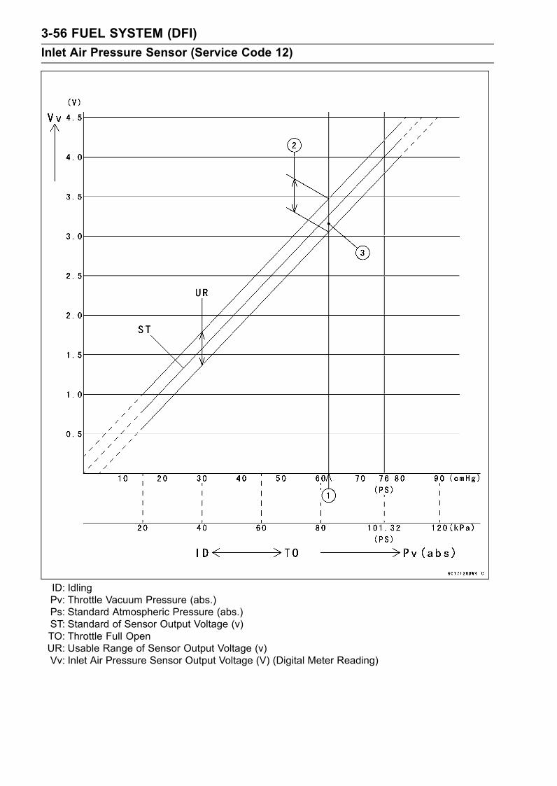
3-56 FUEL SYSTEM (DFI)Inlet Air Pressure Sensor (Service Code 12)
ID: IdlingPv: Throttle Vacuum Pressure (abs.)Ps: Standard Atmospheric Pressure (abs.)ST: Standard of Sensor Output Voltage (v)TO: Throttle Full OpenUR: Usable Range of Sensor Output Voltage (v)Vv: Inlet Air Pressure Sensor Output Voltage (V) (Digital Meter Reading)

FUEL SYSTEM (DFI) 3-57Inlet Air Temperature Sensor (Service Code 13)
Removal/InstallationCAUTION
Never drop the sensor, especially on a hard surface.Such a shock to the sensor can damage it.
•Remove the fuel tank (see Fuel Tank Removal).•Open the clamp [A]• Disconnect the connector [B] from the inlet air tempera-ture sensor.• Pull out the inlet air temperature sensor [C].• Install the inlet air temperature sensor [A] in the grommet[B].
Output Voltage InspectionNOTE
Be sure the battery is fully charged.•Remove the ECU (see ECU Removal).Do not disconnect the ECU connectors.• Connect a digital meter to the ECU connector, using nee-dle adapter set.Special Tool - Needle Adapter Set: 57001-1457
Inlet Air Temperature Sensor Output VoltageConnections to ECU ConnectorMeter (+) → Y lead (terminal 8)Meter (–) → BR/BK lead (terminal 34)
•Measure the sensor output voltage with the enginestopped and the connector joined.• Turn the ignition switch ON.Output Voltage at ECUStandard: About 2.25 ∼ 2.50 V at inlet air temperature
20°C (68°F)
NOTEThe output voltage changes according to the inlet airtemperature.
•Turn the ignition switch OFF.

3-58 FUEL SYSTEM (DFI)Inlet Air Temperature Sensor (Service Code 13)
If the output voltage is out of the specified, check the ECUfor its ground, and power supply (see ECU Power SupplyInspection).If the ground and power supply are good, replace the ECU(see ECU section).If the output voltage is far out of the specified (e.g. whenthe wiring is open, the voltage is about 4.6 V), check thewiring (see wiring diagram in this section).If the wiring is good, check the sensor resistance.
Sensor Resistance Inspection•Remove the inlet air temperature sensor (see Re-moval/Installation).• Suspend the sensor [A] in a container of machine oil sothat the heat-sensitive portion is submerged.• Suspend a thermometer [B] with the heat-sensitive por-tion [C] located in almost the same depth with the sensor.
NOTEThe sensor and thermometer must not touch the con-tainer side or bottom.
•Place the container over a source of heat and graduallyraise the temperature of the oil while stirring the oil gentlyfor even temperature.• Using a digital meter, measure the internal resistanceof the sensor across the terminals at the temperaturesshown in the table.
Inlet Air Temperature Sensor ResistanceStandard: 2.09 ∼ 2.81 kΩ at 20°C (68°F)
About 0.322 kΩ at 80°C (176°F) (referencevalue)
If themeasurement is out of the range, replace the sensor.If the measurement is within the specified, replace theECU (see ECU section).

FUEL SYSTEM (DFI) 3-59Inlet Air Temperature Sensor (Service Code 13)
Inlet Air Temperature Sensor Circuit
1. ECU2. Inlet Air Temperature Sensor3. Water-proof Joint 2

3-60 FUEL SYSTEM (DFI)Water Temperature Sensor (Service Code 14)
Removal/InstallationCAUTION
Never drop the sensor, especially on a hard surface.Such a shock to the sensor can damage it.
•Drain the coolant (see Coolant Change in the PeriodicMaintenance chapter).• Remove:Throttle Body Assy (see Throttle Body Assy Removal)Connector [A]Water Temperature Sensor [B]• Replace the gasket with a new one, and tighten the watertemperature sensor.Torque - Water Temperature Sensor: 25 N·m (2.5 kgf·m, 18
ft·lb)
•Fill the engine with coolant and bleed the air from the cool-ing system (see Coolant Change in the Periodic Mainte-nance chapter).
Output Voltage InspectionNOTE
Be sure the battery is fully charged.•Remove the ECU (see ECU Removal).Do not disconnect the ECU connectors.• Connect a digital meter [A] to the ECU connectors [B],with the needle adapter set.Special Tool - Needle Adapter Set: 57001-1457
Water Temperature Sensor Output VoltageConnections to ECUMeter (+) → O lead (terminal 25)Meter (–) → BR/BK lead (terminal 34)
•Measure the sensor output voltage with the enginestopped and the connector joined.• Turn the ignition switch ON.Output Voltage at ECUStandard: About 2.80 ∼ 2.97 V at 20°C (68°F)
NOTEThe output voltage changes according to the coolanttemperature in the engine.
•Turn the ignition switch OFF.If the output voltage is out of the specified, check the ECUfor its ground, and power supply (see ECU Power SupplyInspection).If the ground and power supply are good, replace the ECU(see ECU section).If the output voltage is far out of the specified (e.g. whenthe wiring is open, the voltage is about 5V), check thewiring (see wiring diagram in this section).If the wiring is good, check the water temperature sensorresistance.

FUEL SYSTEM (DFI) 3-61Water Temperature Sensor (Service Code 14)
Sensor Resistance Inspection•Refer to the Water Temperature Sensor Inspection in theElectrical System chapter (see Water Temperature Sen-sor Inspection in the Electrical System chapter).
Water Temperature Sensor Circuit
1. ECU2. Meter Unit3. Water Temperature Sensor4. Water-proof Joint 2

3-62 FUEL SYSTEM (DFI)Atmospheric Pressure Sensor (Service Code 15)
CAUTIONNever drop the sensor, especially on a hard surface.Such a shock to the sensor can damage it.
Removal•Remove:Seat (see Seat Removal in the Frame chapter)Atmospheric Pressure Sensor Connector [A]Damper [B]Atmospheric Pressure Sensor [C]
InstallationNOTE
The atmospheric pressure sensor is the same part asthe inlet air pressure sensor except that the inlet airpressure sensor has a inlet air pressure hose and dif-ferent wiring.
• Installation is reverse of removal.Input Voltage Inspection
NOTEBe sure the battery is fully charged.The inspection is the same as “Input Voltage Inspection”of the throttle sensor and the inlet air pressure sensor.
•Turn the ignition switch OFF.•Remove the ECU (see ECU Removal).Do not disconnect the ECU connectors.• Connect a digital meter [A] to the connector [B], with theneedle adapter set.Special Tool - Needle Adapter Set: 57001-1457
Atmospheric Pressure Sensor Input VoltageConnections to ECU ConnectorMeter (+) → BL lead (terminal 7)Meter (–) → BR/BK lead (terminal 34)
•Measure the input voltage with the engine stopped, andwith the connectors joined.• Turn the ignition switch ON.Input Voltage at ECUStandard: DC 4.75 ∼ 5.25 V
If the reading of input voltage is less than the standardrange, check the ECU for its ground, and power supply(see ECU Power Supply Inspection).If the ground and power supply are good, replace the ECU(see ECU section).

FUEL SYSTEM (DFI) 3-63Atmospheric Pressure Sensor (Service Code 15)
If the reading is within the standard range, remove theseat, and check the input voltage again at the sensor con-nector.• Disconnect the atmospheric pressure sensor connectorand connect the harness adapter [A] between the harnessconnector and atmospheric pressure sensor connector.Special Tool - Sensor Harness Adapter: 57001-1561
•Connect a digital meter to the harness adapter leads.Atmospheric Pressure Sensor [B]
Atmospheric Pressure Sensor Input VoltageConnections to AdapterMeter (+) → G (sensor BL) lead [C]Meter (–)→ BK (sensor BR/BK) lead [D]
•Measure the input voltage with the engine stopped, andwith the connector joined.• Turn the ignition switch ON.Input Voltage at Sensor ConnectorStandard: DC 4.75 ∼ 5.25 V
•Turn the ignition switch OFF.If the reading is out of the standard range, check thewiring (see wiring diagram in this section).If the reading is good, the input voltage is normal. Checkthe output voltage.
Output Voltage Inspection•Measure the output voltage at the ECU in the same wayas input voltage inspection. Note the following.Digital Meter [A]ECU Connector [B]Special Tool - Needle Adapter Set: 57001-1457
Atmospheric Pressure Sensor Output VoltageConnections to ECU ConnectorMeter (+) → G/W lead (terminal 11)Meter (–) → BR/BK lead (terminal 34)
Output VoltageUsable Range: DC 3.80 ∼ 4.20 V at the standard
atmospheric pressure (101.32 kPa, 76cmHg abs.)
NOTEThe output voltage changes according to the local at-mospheric pressure.The atmospheric sensor output voltage is based ona nearly perfect vacuum in the small chamber of thesensor. So, the sensor indicates absolute atmosphericpressure.
If the output voltage is within the usable range, check theECU for its ground, and power supply (see ECU PowerSupply Inspection).If the ground and power supply are good, replace the ECU(see ECU section).

3-64 FUEL SYSTEM (DFI)Atmospheric Pressure Sensor (Service Code 15)
If the output voltage is far out of the usable range, checkthe output voltage at the sensor connector [A] (when thewiring is open, the output voltage is about 1.8 V).• Connect a digital meter [A] to the harness adapter leads.Atmospheric Pressure Sensor [B]Special Tool - Sensor Harness Adapter: 57001-1561
Atmospheric Pressure Sensor Output VoltageConnections to AdapterMeter (+)→ G/W (sensor G/W) lead [C]Meter (–)→ BK (sensor BR/BK) lead [D]
Output Voltage at SensorUsable Range: DC 3.80 ∼ 4.20 V at the standard
atmospheric pressure (101.32 kPa, 76cmHg abs.)
•Turn the ignition switch OFF.If the output voltage is normal, check the wiring for conti-nuity (see wiring diagram in this section).If the output voltage is out of the usable range, replacethe sensor.
Atmospheric Pressure Sensor Circuit
1. ECU2. Atmospheric Pressure Sensor3. Water-proof Joint 2
If you need to check the atmospheric pressure sensor forvarious altitudes other than sea level, check the outputvoltage as follows.Determine the local altitude (Elevation).

FUEL SYSTEM (DFI) 3-65Atmospheric Pressure Sensor (Service Code 15)
If you know the local atmospheric pressure using abarometer, substitute the atmospheric pressure for throt-tle vacuum pressure in the inlet air pressure sensor chart(see Inlet Air Pressure Sensor section). And get theusable range of the atmospheric pressure sensor outputvoltage and check if output voltage is within the standardor not in the same way as Output Voltage Inspection ofthe inlet air pressure sensor.If you know the local altitude, use the following chart.
Atmospheric Pressure/Altitude Relationship

3-66 FUEL SYSTEM (DFI)Crankshaft Sensor (Service Code 21)
Crankshaft Sensor Removal/Installation•Refer to the Crankshaft Sensor Removal/Installation inthe Electrical System chapter (see Crankshaft Sensor Re-moval/Installation in the Electrical System chapter).
Crankshaft Sensor InspectionThe crankshaft have no power source, and when the en-gine stops, the crankshaft generates no signals.• Crank the engine and measure the peak voltage of thecrankshaft sensor (see Crankshaft Sensor Peak VoltageInspection in the Electrical System chapter) in order tocheck the sensor.• Check the wiring for continuity (see wiring diagram in thissection).
Crankshaft Sensor Circuit
1. ECU2. Crankshaft Sensor

FUEL SYSTEM (DFI) 3-67Camshaft Position Sensor (Service Code 23)
Camshaft Position Sensor Removal/InstallationThe camshaft position sensor detects the position of the
camshaft, and distinguishes the cylinder.• Refer to the Camshaft Position Sensor Removal/Installa-tion in the Electrical System chapter (see Camshaft Posi-tion Sensor Removal/Installation in the Electrical Systemchapter).
Camshaft Position Sensor InspectionThe camshaft position sensor have no power source, andwhen the engine stops, the camshaft position sensor gen-erates no signal.• Crank the engine and measure the peak voltage of thecamshaft position sensor (see Camshaft Position SensorPeak Voltage Inspection in the Electrical System chapter)in order to check the sensor.• Check the wiring for continuity (see wiring diagram in thissection).
Camshaft Position Sensor Circuit
1. ECU2. Camshaft Position Sensor3. Frame Ground 1

3-68 FUEL SYSTEM (DFI)Speed Sensor (Service Code 24)
Speed Sensor Removal/Installation•Refer to the Speed Sensor Removal/Installation inthe Electrical System chapter (see Speed Sensor Re-moval/Installation in the Electrical System chapter).
Speed Sensor Inspection•Refer to the Speed Sensor Inspection in the ElectricalSystem chapter (see Speed Sensor Inspection in theElectrical System chapter).
Input Voltage InspectionNOTE
Be sure the battery is fully charged.•Turn the ignition switch OFF.•Disconnect the speed sensor connector [A].
• Connect the harness adapter [A] between the harnessconnector and speed sensor connector.Special Tool - Throttle Sensor Setting Adapter #1: 57001
-1400
•Connect a digital meter to the harness adapter leads.Speed Sensor Input VoltageConnections to AdapterMeter (+) → BL (sensor P) lead [B]Meter (−) → BK/BL (sensor BK) lead [C]
•Measure the input voltage with the engine stopped, andwith the connector joined.• Turn the ignition switch ON.Input VoltageStandard: About DC 9 ∼ 11 V
•Turn the ignition switch OFF.If the reading is out of the range, check the wiring (seewiring diagram in this section), and meter unit (see Elec-tronic Combination Meter Unit Inspection in the ElectricalSystem chapter).If the reading is good, check the output voltage.

FUEL SYSTEM (DFI) 3-69Speed Sensor (Service Code 24)
Output Voltage Inspection•Before this inspection, inspect the input voltage (see InputVoltage Inspection in this section).
NOTEBe sure the battery is fully charged.•Turn the ignition switch OFF.•Using the stand, raise the rear wheel off the ground.• Disconnect the speed sensor connector [A] and connectthe harness adapter [B] between the harness connectorand speed sensor connector.• Connect a digital meter to the harness adapter leads.Special Tool - Throttle Sensor Setting Adapter #1: 57001
-1400
Speed Sensor Output VoltageConnections to AdapterMeter (+) → BY (sensor BL/Y) lead [C]Meter (–)→ BK/BL (sensor BK) lead [D]
•Measure the output voltage with the engine stopped, andwith the connector joined.• Turn the ignition switch ON.Output Voltage at SensorStandard: About DC 0.05 ∼ 0.09 V or DC 4.5 ∼ 4.9
•Rotate the rear wheel by hand, confirm the output voltagewill be raise or lower.• Turn teh ignition switch OFF.If the reading is out of the range, check the speed sensor(see Speed Sensor Inspection in the Electrical Systemchapter) and the wiring to ECU (see wiring diagram in thissection).If the reading, speed sensor and wiring are good, replacethe ECU (see ECU section).

3-70 FUEL SYSTEM (DFI)Speed Sensor (Service Code 24)
1. ECU2. Meter Unit3. Speed Sensor4. Frame Ground 1

FUEL SYSTEM (DFI) 3-71Gear Position Switch (Service Code 25)
Gear Position Switch Removal/Installation•Refer to the Gear Position Switch Removal/Installation inthe Electrical System chapter (see Gear Position SwitchRemoval/Installation in the Electrical System chapter).
Gear Position Switch Inspection•Refer to the Gear Position Switch Inspection in the Electri-cal System chapter (see Gear Position Switch Inspectionin the Electrical System chapter).
Input Voltage InspectionNOTE
Be sure the battery is fully charged.•Turn the ignition switch OFF.•Remove the ECU (see ECU Removal).Do not disconnect the ECU connectors.• Connect a digital meter [A] to the connector, with the nee-dle adapter set.Special Tool - Needle Adapter Set: 57001-1457
Gear Position Switch Input Voltage at 1 ∼ 6 Gear PositionsConnections to ECU ConnectorMeter (+) → G/R lead (terminal 4)Meter (–) → Engine Ground
•Measure the switch input voltage with the engine stopped,and with the connector joined.• Turn the ignition switch ON.Input Voltage at 1 ∼ 6 Gear PositionsStandard:1st About 3.0 V2nd About 2.5 V3rd About 2.0 V4th About 1.5 V5th About 1.1 V6th About 0.7 V
•Turn the ignition switch OFF.If the reading is out of the range, check the gear positionswitch (see Gear Position Switch Inspection in the Elec-trical System chapter).If the switch is good, check the ECU for its ground andpower supply (see ECU Power Supply Inspection).If the ground and power supply are good, replace the ECU(see ECU section).

3-72 FUEL SYSTEM (DFI)Gear Position Switch (Service Code 25)
Gear Position Switch Circuit
1. ECU2. Gear Position Switch3. Joint Connector 14. Joint Connector 25. Frame Ground 1

FUEL SYSTEM (DFI) 3-73Vehicle-down Sensor (Service Code 31)
This sensor has a weight [A] with two magnets inside, andsends a signal to the ECU. But when the motorcycle banks60 ∼ 70° or more to either side (in fact falls down), the weightturns and shuts off the signal. The ECU senses this change,and stops the fuel pump, the fuel injectors, and the ignitionsystem.Hall IC [B]When the motorcycle is down, the ignition switch is left
ON. If the starter button is pushed, the electric starter turnsbut the engine doesn’t start. To start the engine again, raisethe motorcycle, turn the ignition switch OFF, and then ON.When the ignition switch is turned ON, current flows throughthe latch-up circuit and the transistor in the circuit is turnedON to unlock the latch-up circuit.Vehicle-down Sensor [A]Ground Terminal BR/BK [B]Output Terminal Y/G [C]Power Source Terminal BL [D]
RemovalCAUTION
Never drop the vehicle-down sensor, especially ona hard surface. Such a shock to the sensor candamage it.
•Remove:Windshield (see Windshield Removal in the Framechapter)Bolts [A]
• Remove:Connector [A]Bolts [B]Vehicle-down Sensor [C]
Installation•The UP mark [A] of the sensor should face upward.
WARNINGIncorrect installation of the vehicle-down sensorcould cause sudden loss of engine power. Therider could lose balance during certain riding situ-ations, like leaning over in a turn, with the potentialfor an accident resulting in injury or death. Ensurethat the vehicle-down sensor is held in place by thesensor brackets.
•Tighten:Torque - Vehicle-down Sensor Bolts: 5.9 N·m (0.60 kgf·m,
53 in·lb)

3-74 FUEL SYSTEM (DFI)Vehicle-down Sensor (Service Code 31)
InspectionNOTE
Be sure the battery is fully charged.•Remove the Windshield (see Windshield Removal in theFrame chapter).• Connect a digital meter [A] to the connector of the vehicle-down sensor [B], with the needle adapter set [C].Special Tool - Needle Adapter Set: 57001-1457
Vehicle-down sensor Power Source VoltageConnections to SensorMeter (+) → BL lead [D]Meter (–) → BR/BK lead [E]
•Turn the ignition switch ON, and measure the powersource voltage with the connector joined.
Power Source Voltage at SensorStandard: DC 4.75 ∼ 5.25 V
•Turn the ignition switch OFF.If there is no voltage, check the following.Battery (see Charging Condition Inspection in the Elec-trical System chapter)ECU Fuse 15 A (see Fuse Inspection in the ElectricalSystem chapter)If the power source is normal, check the output voltage.

FUEL SYSTEM (DFI) 3-75Vehicle-down Sensor (Service Code 31)
•Turn the ignition switch OFF.•Remove the vehicle-down sensor.Do not disconnect the sensor connector.• Connect a digital meter [A] to the connector, with needleadapter set [B].Special Tool - Needle Adapter Set: 57001-1457
Vehicle-down sensor Output VoltageConnections to SensorMeter (+) → Y/G lead [C]Meter (–) → BR/BK lead [D]
•Hold the sensor vertically.• Turn the ignition switch ON, and measure the output volt-age with the connector joined.Tilt the sensor 60 ∼ 70° or more [E] right or left, then holdthe sensor almost vertical with the arrow mark pointed up,and measure the output voltage.
Output Voltage at SensorStandard: with sensor arrow mark pointed up: 3.55 ∼
4.45 Vwith sensor tilted 60 ∼ 70° or more right orleft: 0.65 ∼ 1.35 V
NOTEIf you need to test again, turn the ignition switch OFF,and then ON.
•Turn the ignition switch OFF.If the output voltage is out of the specified, replace thevehicle-down sensor.
Vehicle-down Sensor Circuit
1. ECU2. Vehicle-down Sensor
3. Water-proof Joint 2

3-76 FUEL SYSTEM (DFI)Subthrottle Sensor (Service Code 32)
The subthrottle sensor is a rotating variable resistor thatchange output voltage according to throttle operating. TheECU senses this voltage change and determines fuel injec-tion quantity, and ignition timing according to engine rpm,and throttle opening.Input Terminal [A]Output Terminal [B]Ground Terminal [C]
Subthrottle Sensor Removal/AdjustmentCAUTION
Do not remove or adjust the subthrottle sensor [A]since it has been adjusted and set with precision atthe factory.Never drop the throttle body assy, especially on ahard surface. Such a shock to the sensor can dam-age it.
Input Voltage InspectionNOTE
Be sure the battery is fully charged.•Turn the ignition switch OFF.•Remove the ECU (see ECU Removal).Do not disconnect the ECU connectors.• Connect a digital meter [A] to the connector [B], using theneedle adapter set.Special Tool - Needle Adapter Set: 57001-1457
Subthrottle Sensor Input VoltageConnections to ECU ConnectorMeter (+) → BL lead (terminal 7)Meter (–) → BR/BK lead (terminal 34)
•Measure the input voltage with the engine stopped, andwith the connectors joined.• Turn the ignition switch ON.Input Voltage at ECU ConnectorStandard: DC 4.75 ∼ 5.25 V
•Turn the ignition switch OFF.If the reading of input voltage is less than the standard,check the ECU for its ground, power supply and wiringshorted.If the ground and power supply are good, replace the ECU(see ECU section).If the input voltage is within the standard range, check theinput voltage at the subthrottle sensor connector.

FUEL SYSTEM (DFI) 3-77Subthrottle Sensor (Service Code 32)
•Remove the right fairing cover (see Fairing Cover Re-moval in the Frame chapter).• Disconnect the subthrottle sensor connector [A].
• Connect the harness adapter [A] between the harnessconnector and subthrottle sensor connector.Special Tool - Throttle Sensor Setting Adapter: 57001
-1538
•Connect a digital meter to the harness adapter leads.Subthrottle Sensor Input VoltageConnections to AdapterMeter (+) → BK (sensor BL) leadMeter (–) → W (sensor BR/BK) lead
•Measure the sensor input voltage with the enginestopped, and with the connector joined.• Turn the ignition switch ON.Input Voltage at SensorStandard: DC 4.75 ∼ 5.25 V
•Turn the ignition switch OFF.If the reading is out of the range, check the wiring (seewiring diagram in this section).If the reading is good, check the output voltage of thesensor.

3-78 FUEL SYSTEM (DFI)Subthrottle Sensor (Service Code 32)
Output Voltage Inspection•Measure the output voltage at the ECU in the same wayas input voltage inspection. Note the following.Digital Meter [A]Connector [B]Special Tool - Needle Adapter Set: 57001-1457
Subthrottle Sensor Output VoltageConnections to ECU ConnectorMeter (+) → BL/W lead (terminal 27)Meter (–) → BR/BK lead (terminal 34)
•Remove the air cleaner caps (see Throttle Body Assy Re-moval).• Turn the ignition switch ON.•Measure the output voltage when the subthrottle valve isfully opened or completely closed by hand.
Output Voltage at ECUStandard: DC 0.62 ∼ 4.14 V (at subthrottle valve full
opening to closing)
NOTEThe throttle sensor is operating correctly if the followingvoltages are obtained:• DC 0.62 V (or slightly higher) with the subthrottle valveat the closed position.• DC 4.14 V (or slightly lower) with the subthrottle valveat the fully open position.
CAUTIONDo not remove or adjust the subthrottle sensor. Ithas been adjusted and set with precision at the fac-tory.Never drop the throttle body assy, especially on ahard surface. Such a shock to the sensor can dam-age it.
If the output voltage is within the standard range, checkthe ECU for its ground, and power supply (see ECUPower Supply Inspection).If the ground and power supply are good, replace the ECU(see ECU Removal).If the output voltage is far out of the standard range (e.g.when the wiring is open, the reading is 0 V), check theoutput voltage again at the sensor connector.

FUEL SYSTEM (DFI) 3-79Subthrottle Sensor (Service Code 32)
•Disconnect the subthrottle sensor connector [A] and con-nect the harness adapter [B] between the harness con-nector and subthrottle sensor connector.Special Tool - Throttle Sensor Harness Adapter: 57001
-1538
•Connect a digital meter to the harness adapter leads.Subthrottle Sensor Output VoltageConnections to AdapterMeter (+) → R (sensor BL/W) leadMeter (–) → W (sensor BR/BK) lead
•Measure the output voltage with the engine stopped, andwith the connector joined.• Turn the ignition switch ON.•Measure the output voltage when the subthrottle valve isfully opened or completely closed by hand.
Output Voltage at SensorStandard: DC 0.62 ∼ 4.14 V (at subthrottle valve full
opening to closing)
NOTEThe throttle sensor is operating correctly if the followingvoltages are obtained:• DC 0.62 V (or slightly higher) with the subthrottle valveat the closed position.• DC 4.14 V (or slightly lower) with the subthrottle valveat the fully open position.
CAUTIONDo not remove or adjust the subthrottle sensor. Ithas been adjusted and set with precision at the fac-tory.Never drop the throttle body assy, especially on ahard surface. Such a shock to the sensor can dam-age it.
NOTEThe standard voltage refers to the value when the volt-age reading at the Input Voltage Inspection shows 5Vexactly.When the input voltage reading shows other than 5V,derive a voltage range as follows.Example:In the case of a input voltage of 4.75 V.0.62 × 4.75 ÷ 5.00 = 0.59 V4.14 × 4.75 ÷ 5.00 = 3.93 VThus, the valid range is 0.59 ∼ 3.93 V
•Turn the ignition switch OFF.If the reading is out of the standard range, inspect thesubthrottle sensor resistance.If the output voltage is normal, check the wiring for conti-nuity (see wiring diagram in this section).

3-80 FUEL SYSTEM (DFI)Subthrottle Sensor (Service Code 32)
Resistance Inspection•Turn the ignition switch OFF.•Disconnect the subthrottle sensor connector.• Connect a digital meter [A] to the subthrottle sensor con-nector [B].•Measure the subthrottle sensor resistance.Subthrottle Sensor ResistanceConnections: BL lead [C]←→ BR/BK lead [D]Standard: 4 ∼ 6 kΩ
If the reading is out of the range, replace the throttle bodyassy (see Throttle Body Assy section).If the reading is within the range, but the problem stillexists, replace the ECU (see ECU section).
Subthrottle Sensor Circuit
1. ECU2. Subthrottle Valve Actuator3. Subthrottle Sensor4. Main Throttle Sensor5. Water-proof Joint 2

FUEL SYSTEM (DFI) 3-81Immobilizer Amplifier (Service Code 35)
Antenna Resistance Inspection•Remove the left inner cover (see Inner Cover Removal inthe Frame chapter).• Disconnect the antenna lead connector [A].•Measure the resistance of the antenna coil in the ignitionswitch as follows.
Antenna ResistanceConnections to AntennaMeter → BK leadMeter → BK lead
Standard: About 0.6 ∼ 0.9 Ω
If the resistance is out of the standard range, replace theignition switch.
Amplifier Input Voltage InspectionNOTE
Be sure the battery is fully charged.•Turn the ignition switch OFF.•Remove the windshield (see Windshield Removal in theFrame chapter).
• Connect a digital meter to the amplifier connector [A], us-ing the needle adapter set.Special Tool - Needle Adapter Set: 57001-1457
Amplifier Input VoltageConnections to ConnectorMeter (+) → BR/W leadMeter (–) → BK/Y lead
•Measure the input voltage with the engine stopped, andwith the connector joined.• Turn the ignition switch ON.Input VoltageStandard: Battery Voltage
•Turn the ignition switch OFF.If the reading is out of the range, check the wiring (seewiring diagram in next section).If the reading and antenna resistance are good, replacethe amplifier (see Immobilizer System Parts Replacementin the Electrical System chapter).

3-82 FUEL SYSTEM (DFI)Blank Key Detection (Service Code 36)
•This code appears in the following conditions.The transponder [A] in the master and/or user key is mal-function.When the spare key of unregistration is used.When the master key is registered in the registered ECU.• Therefore, the service code 36 will disappear when theabove issue is solved.
User Key Inspection•Register the user key correctly (see Key Registration inthe Electrical System chapter).If the service code 36 appears again, the transponder inthe key is malfunction, replace it.
Immobilizer System Circuit
1. Ignition Switch2. Immobilizer Antenna3. Meter Unit4. Immobilizer Amplifier5. Joint Connector 16. Fuse Box × 27. ECU Fuse 15 A8. Ignition Fuse 10 A9. Main Relay
10. Relay Box11. Joint Connector 212. Main Fuse 30 A13. Starter Relay14. Battery 12 V 14 Ah15. Frame Ground 116. Frame Ground 217. Immobilizer/Kawasaki Diagnostic System
Connector18. Water-proof Joint 119. ECU

FUEL SYSTEM (DFI) 3-83Fuel Pump Relay (Service Code 46)
Fuel Pump Relay RemovalCAUTION
Never drop the relay, especially on a hard surface.Such a shock to the relay can damage it.
The fuel pump relay is included in the relay box.• Remove the seat (see Seat Removal in the Frame chap-ter).• Remove the relay box [A] from the bracket and disconnectthe connectors.
Fuel Pump Relay Inspection•Remove the relay box (see Fuel Pump Relay Removal).• Connect the hand tester [A] and one 12 V battery to therelay connector as shown.Special Tool - Hand Tester: 57001-1394Relay Coil Terminals [1] and [2]Relay Switch Terminals [3] and [4]
Testing RelayTester range: 1 Ω rangeCriteria: When battery is connected→ 0 Ω
When battery is disconnected→ ∞ Ω
If the relay does not work as specified, replace the relaybox.

3-84 FUEL SYSTEM (DFI)Fuel Pump Relay (Service Code 46)
Fuel Pump Relay Circuit
1. Ignition Switch2. Joint Connector 13. Engine Stop Switch4. Water-proof Joint 15. ECU6. ECU Fuse 15 A7. Ignition Fuse 10 A8. Fuse Box 29. Main Relay
10. Fuel Pump Relay11. Relay Box12. Joint Connector 213. Main Fuse 30 A14. Starter Relay15. Battery 12 V 14 Ah16. Frame Ground 217. Fuel Pump18. Joint Connector 3

FUEL SYSTEM (DFI) 3-85Stick Coils #1, #2, #3, #4: (Service Code 51, 52, 53, 54)
Stick Coil #1: Service Code 51Stick Coil #2: Service Code 52Stick Coil #3: Service Code 53Stick Coil #4: Service Code 54
Removal/InstallationCAUTION
Never drop the stick coils, especially on a hard sur-face. Such a shock to the stick coil can damage it.
•Refer to the Stick Coil (Ignition Coil together with SparkPlug Cap) Removal/Installation in the Electrical Systemchapter (see Stick Coil (Ignition Coil together with SparkPlug Cap) Removal/Installation in the Electrical Systemchapter).
Input Voltage InspectionNOTE
Be sure the battery is fully charged.•Turn the ignition switch OFF.•Remove the ECU (see ECU Removal).Do not disconnect the ECU connectors.• Connect a digital meter [A] as shown, with the needleadapter set.Special Tool - Needle Adapter Set: 57001-1457
Stick Coil Input Voltage at ECUConnections for Stick Coil #1Meter (+) → W/R lead (terminal 47)Meter (–) → BK/Y lead (terminal 52)
Connections for Stick Coil #2Meter (+) → W/BL lead (terminal 60)Meter (–) → BK/Y lead (terminal 52)
Connections for Stick Coil #3Meter (+) → W/G lead (terminal 45)Meter (–) → BK/Y lead (terminal 52)
Connections for Stick Coil #4Meter (+) → W/Y lead (terminal 58)Meter (–) → BK/Y lead (terminal 52)
•Measure the input voltage to each primary winding of thestick coils with the engine stopped, and with the connec-tors joined.• Turn the ignition switch ON.Input Voltage at ECUStandard: Battery Voltage
If the reading is out of the standard, check the wiring (seewiring diagram in this section).If the reading is good, the input voltage is normal. Crankthe engine, and check the peak voltage of the stick coils(see Stick Coil Primary Peak Voltage Inspection in theElectrical System chapter) in order to check the primarycoils.

3-86 FUEL SYSTEM (DFI)Stick Coils #1, #2, #3, #4: (Service Code 51, 52, 53, 54)
Stick Coil Circuit
1. ECU2. Stick Coil #43. Stick Coil #34. Stick Coil #25. Stick Coil #16. Engine Stop Switch7. Ignition Switch8. Fuse Box 2
9. Ignition Fuse 10 A10. Starter Relay11. Main Fuse 30 A12. Battery 12 V 14 Ah13. Frame Ground 214. Engine Ground15. Joint Connector 3

FUEL SYSTEM (DFI) 3-87Subthrottle Valve Actuator (Service Code 62)
Subthrottle Valve Actuator RemovalCAUTION
Do not remove the subthrottle valve actuator [A]since it has been adjusted and set with precisionat the factory.Never drop the actuator , especially on a hard sur-face. Such a shock to the actuator can damage it.
Subthrottle Valve Actuator Inspection•Remove:Fuel Tank (see Fuel Tank Removal)Left and Right Air Cleaner Caps (see Throttle Body AssyRemoval)• Turn the ignition switch ON.•Check to see that all subthrottle valves [A] open and closesmoothly.If the subthrottle valves do not operate, check the actuatorinternal resistance (see Resistance Inspection).
Resistance Inspection•Turn the ignition switch OFF.•Disconnect the subthrottle valve actuator connector [A].
• Connect a digital meter to the connector [A].•Measure the subthrottle valve actuator resistance.Subthrottle Valve Actuator ResistanceConnections: Y lead [1] ←→ P lead [2]
BK lead [3] ←→ G lead [4]Standard: About 5 ∼ 7 Ω
If the reading is out of the range, replace the throttle bodyassy (see Throttle Body Assy section).If the reading is within the range, check the input voltage(see Input Voltage Inspection in this section).

3-88 FUEL SYSTEM (DFI)Subthrottle Valve Actuator (Service Code 62)
Input Voltage InspectionNOTE
Be sure the battery is fully charged.•Turn the ignition switch OFF.•Connect the peak voltage adapter [A] and a digital meter[B] to the connector [C], using the needle adapter set [D].Special Tools - Peak Voltage Adapter: 57001-1415
Type: KEK-54-9-BNeedle Adapter Set: 57001-1457
Subthrottle Valve Actuator Input VoltageConnections to Harness Connector(I) Meter (+) → BK/BL lead [1]
Meter (–) → Frame Ground 2 [E](II) Meter (+) → G lead [2]
Meter (–) → Frame Ground 2 [E](III) Meter (+) → Y/BK lead [3]
Meter (–) → Frame Ground 2 [E](IV) Meter (+) → P lead [4]
Meter (–) → Frame Ground 2 [E]
•Measure the input voltage with the engine stopped, andwith the connector joined.• Turn the ignition switch ON.Input VoltageStandard: About DC 10.5 ∼ 12.5 V
If the reading is out of the range, check the wiring to ECU(see wiring diagram in this section).If the wiring is good, replace the ECU (see ECU section).

FUEL SYSTEM (DFI) 3-89Subthrottle Valve Actuator (Service Code 62)
Subthrottle Valve Actuator Circuit
1. ECU2. Subthrottle Valve Actuator3. Subthrottle Sensor4. Main Throttle Sensor5. Water-proof Joint 2

3-90 FUEL SYSTEM (DFI)ECU Main Relay (Service Code 75)
ECU Main Relay InspectionThe ECU main relay function is included in the ECU [A].So, the ECU main relay function cannot be inspected.•When the service code 75 is displayed on the LCD, re-place the ECU (see ECU section).

FUEL SYSTEM (DFI) 3-91ECU
CAUTIONNever drop the ECU, especially on a hard surface.Such a shock to the ECU can damage it.
ECU IdentificationMost countries have their own regulations, so each ECUhas different characteristic. So, do not confuse ECU witheach other and use only the ECU for your model. Other-wise, the motorcycle cannot clear the regulation.
ECU IdentificationPart Number
[A] Specification
Europe, WVTA, Full, H, with Immobilizer21175-0076
U.K., WVTA, Full, H, with ImmobilizerU.S.A (except California), without Immobilizer
21175-0084Canada, without Immobilizer
21175-0089 U.S.A (California), without Immobilizer21175-0101 Malaysia, with Immobilizer21175-0090 Australia, with Immobilizer21175-0102 France, WVTA, 78.2, H, with Immobilizer
Full: Full PowerH: Honeycomb Type Catalyst78.2: Maximum Horsepower 78.2 kW (106.3 PS)
ECU Removal•Remove the seat (see Seat Removal in the Frame chap-ter).• Pull the hook [A] to lift up the lid [B] of the tool kit case.
• Remove the tool kit [A].

3-92 FUEL SYSTEM (DFI)ECU
•Remove:Fuse Box [A]Bolts [B]Tool Kit Case [C]
• Remove the relay box [A].• Lift up the ECU [B] with rubber protector [C].
• Remove:ECU Connectors [A]ECU [B]• Refer to the Immobilizer SystemParts Replacement in theElectrical System chapter for the immobilizer models (seeImmobilizer System Parts Replacement in the ElectricalSystem chapter).
ECU Installation• Install:ECU [A] (In rubber protector [B])ECU Connectors [C]
• Insert the slits of the rubber protector to the projections[A] of the rear fender front.

FUEL SYSTEM (DFI) 3-93ECU
• Install:Connector Holder [A]Relay Box [B]
• Install the plate [A] to the tool kit case [B] and tighten thebolts [C].• Insert the stopper [D] of the fuse box [E] into the grooveof the tool case.
ECU Power Supply Inspection•Remove the ECU (see ECU Removal).• Visually inspect the terminals [A] of the ECU connectors.If the connector is clogged with mud or dust, blow it offwith compressed air.Replace the main harness if the terminals of the mainharness connectors are cracked, bent, or otherwise dam-aged.Replace the ECU if the terminals of the ECU connectorsare cracked, bent, or otherwise damaged.
•With the ECU connectors [B] connected, check the fol-lowing ground lead for continuity with the ignition switchOFF, using a digital meter [A] and needle adapter set.Special Tool - Needle Adapter Set: 57001-1457
ECU Grounding Inspection17, 39, or 52 Terminal ←→ Frame Ground 2 [C]: 0 ΩEngine Ground ←→ Frame Ground 2 [C]: 0 Ω
If no continuity, check the connector, the engine groundlead, or main harness, and repair or replace them if nec-essary.

3-94 FUEL SYSTEM (DFI)ECU
•Check the ECU power source voltage with a digital meter[A].Position the terminal in accordance with terminal numbersof ECU connectors [B] in the figure.
ECU Power Source InspectionTesterConnections: between 33 (BR) Terminal and
Frame Ground 2 [C]between 15 (W/BK) Terminal andFrame Ground 2 [C]between 32 (W/BK) and FrameGround 2 [C]
Ignition Switch OFF: 33 (BR) Terminal, 0 V15 (W/BK) Terminal, BatteryVoltage32 (W/BK) Terminal, BatteryVoltage
Ignition Switch ON: 33 (BR) Terminal, Battery Voltage15 (W/BK) Terminal, BatteryVoltage32 (W/BK) Terminal, BatteryVoltage
If the tester does not read as specified, check the follow-ing.Power SourceWiring (see wiring diagram in this section)Main Fuse 30 A (see Fuse Inspection in the ElectricalSystem chapter)ECU Fuse 15 A (see ECU Fuse Inspection)If the wiring and fuse are good, replace the ECU (see ECUsection).

FUEL SYSTEM (DFI) 3-95ECU
ECU Power Source Circuit
1. ECU2. Water-proof Joint 13. Ignition Switch4. ECU Fuse 15 A5. Fuse Box 26. Starter Relay7. Main Fuse 30 A8. Battery 12 V 14 Ah9. Frame Ground 210. Joint Connector 3
CAN Communication Line Resistance InspectionIn this model, resistors for CAN communication line arebuilt in the ECU and meter unit.• Turn the ignition switch OFF.•Disconnect the ECU connector [A] (see ECU Removal).

3-96 FUEL SYSTEM (DFI)ECU
•Connect a digital meter [A] to the ECU connector [B].•Measure the resistance of the CAN communication lineresistor.CAN Communication Line Resistance (at ECUConnector)Connections: Terminal 1←→Terminal 18Standard: 114 ∼ 126 Ω
If the reading is out of the range, replace the ECU (seeECU section).If the reading is within the range, resistor of the ECU forCAN communication line is normal.• Check the wiring for continuity of the CAN communicationline (see wiring diagram in this section).If the wiring is open, replace the main harness.• Refer to the Meter Unit Inspection in the Electrical Systemchapter for the resistor in the meter unit (see Meter UnitInspection in the Electrical System chapter).
CAN Communication Line Circuit
1. Meter Unit2. ECU3. Resistor (In the Meter Unit)4. Resistor (In the ECU)

FUEL SYSTEM (DFI) 3-97DFI Power Source
ECU Fuse Removal•Refer to the ECUFuse 15 ARemoval in the Electrical Sys-tem chapter (see 15 A ECU Fuse Removal in the Electri-cal System chapter).
ECU Fuse InstallationIf a fuse fails during operation, inspect the DFI system todetermine the cause, and then replace it with a new fuseof proper amperage.• Refer to the Fuse installation in the Electrical Systemchapter (see Fuse Installation in the Electrical Systemchapter).
ECU Fuse Inspection•Refer to the Fuse Inspection in the Electrical Systemchapter (see Fuse Inspection in the Electrical Systemchapter).

3-98 FUEL SYSTEM (DFI)Warning Indicator Light (LED)
Light (LED) InspectionThe warning indicator light (LED) [A] is used for the FIindicator and immobilizer indicator (immobilizer models).In this model, the warning indicator light (LED) goes on orblinks by the special signal sent from the ECU.•Refer to the fuel level warning inspection procedure (seeMeter Unit Inspection in the Electrical System chapter) forthe warning indicator light (LED) inspection.
Warning Indicator Light (LED) Circuit
1. Meter Unit2. Warning Indicator Light (LED)3. Frame Ground 14. ECU

FUEL SYSTEM (DFI) 3-99Fuel Line
Fuel Pressure InspectionNOTE
Be sure the battery is fully charged.•Remove the fuel tank (see Fuel Tank Removal).• Be sure to place a piece of cloth around the fuel supplypipe of the throttle body assy.• Remove the fuel hose from the fuel supply pipes of thethrottle body assy (see Fuel Hose Replacement in thePeriodic Maintenance chapter).
WARNINGBe prepared for fuel spillage; any spilled fuel mustbe completely wiped up immediately.When the fuel hose is disconnected, fuel spills outfrom the hose and the pipe because of residualpressure. Cover the hose connection with a pieceof clean cloth to prevent fuel spillage.
•Connect the following parts temporary.Fuel Pump Lead ConnectorFuel Level Sensor Lead Connector• Install the fuel pressure gauge adapter [A] and fuel hoses(Special Tool: 57001-1607) [B] between the fuel supplypipes of the fuel pump and throttle body assy.• Connect the pressure gauge [C] to the fuel pressuregauge adapter.Special Tools - Oil Pressure Gauge, 5 kgf/cm²: 57001-125
Fuel Pressure Gauge Adapter: 57001-1593Fuel Hose: 57001-1607
WARNINGDo not try to start the engine with the fuel hosesdisconnected.
•Turn the ignition switch ON. The fuel pump will turn for 3seconds, and then stop.
CAUTIONDo not drive the fuel pump 3 seconds or more with-out the fuel in the fuel tank. If the fuel pump is drivenwithout the fuel, it may be damaged.
•Measure the fuel pressure with the engine stopped.Fuel Pressureright after Ignition Switch ON, with pump running:Standard: 304 kPa (3.1 kgf/cm², 44 psi)
after 3 seconds from Ignition Switch ON, with pumpstopped:Standard: 280 kPa (2.9 kgf/cm², 41 psi) , residual fuel
pressureThe system should hold the residualpressure about 30 seconds.

3-100 FUEL SYSTEM (DFI)Fuel Line
•Start the engine, and let it idle.•Measure the fuel pressure with the engine idling.Fuel Pressure (idling)Standard: 304 kPa (3.1 kgf/cm², 44 psi)
NOTEThe gauge hand will fluctuate. Read the pressure at theaverage of the maximum and minimum indications.
If the fuel pressure is much higher than the specified, re-place the fuel pump (see Fuel Pump section).If the fuel pressure is much lower than specified, checkthe following.Fuel Line LeakageAmount of Fuel Flow (see Fuel Flow Rate Inspection)If the fuel pressure is much lower than specified, and ifinspection above checks out good, replace the throttlebody assy, or the fuel pump and measure the fuel pres-sure again (see appropriate sections).• Remove the fuel pressure gauge, hoses and adapter.• Install:Fuel Hose (see Fuel Hose Replacement in the PeriodicMaintenance chapter)Fuel Tank (see Fuel Tank Installation)
Fuel Flow Rate InspectionNOTE
Be sure the battery is fully charged.WARNING
Gasoline is extremely flammable and can be explo-sive under certain conditions. Make sure the areais well-ventilated and free from any source of flameor sparks; this includes any appliance with a pilotlight. Do not smoke. Turn the ignition switch OFF.Be prepared for fuel spillage; any spilled fuel mustbe completely wiped up immediately.
•Turn the ignition switch and engine stop switch OFF.•Wait until the engine cools down.• Prepare a fuel hose (Special Tool: 57001-1607) and ameasuring cylinder.Special Tool - Fuel Hose: 57001-1607
•Remove:Seat (see Seat Removal in the Frame chapter)Fuel Tank Cover (see Fuel Tank Removal)Fuel Tank Bolts [A]

FUEL SYSTEM (DFI) 3-101Fuel Line
•Remove the fuel tank bolts [A].
•Open the fuel tank cap [A] to lower the pressure in thetank.• Be sure to place a piece of cloth around the fuel supplypipe of the fuel pump.•Remove the fuel hose from the fuel pump (see Fuel TankRemoval).
WARNINGBe prepared for fuel spillage; any spilled fuel mustbe completely wiped up immediately.When the fuel hose is disconnected, fuel spills outfrom the hose and the pipe because of residualpressure. Cover the hose connection with a pieceof clean cloth to prevent fuel spillage.
•Connect the prepared fuel hose [A] to the fuel supply pipeof the fuel pump.• Secure the fuel hose with a clamp.• Insert the fuel hose into the measuring cylinder [B].

3-102 FUEL SYSTEM (DFI)Fuel Line
WARNINGWipe off spilled out fuel immediately.Be sure to hold the measuring cylinder vertical.
•Close the fuel tank cap.•With the engine stopped, turn the ignition switch ON. Thefuel pump should operate for 3 seconds, and then shouldstop.
CAUTIONDo not drive the fuel pump 3 seconds or more with-out the fuel in the fuel tank. If the fuel pump is drivenwithout the fuel, it may be damaged.
•Measure the discharge for 3 seconds.Repeat this operation several times.Amount of Fuel FlowStandard: 67 mL (2.26 US oz.) or more for 3 seconds
If the fuel flow is much less than the specified, check thefollowing.Battery Condition (see Charging Condition Inspection inthe Electrical System chapter)• After inspection, connect the fuel hose (see Fuel TankInstallation).• Start the engine and check for fuel leakage.

FUEL SYSTEM (DFI) 3-103Fuel Pump
Fuel Pump RemovalCAUTION
Never drop the fuel pump, especially on a hard sur-face. Such a shock to the pump can damage it.
WARNINGGasoline is extremely flammable and can be explo-sive under certain conditions. Make sure the areais well-ventilated and free from any source of flameor sparks; this includes any appliance with a pilotlight. Do not smoke. Turn the ignition switch OFF.Disconnect the battery (–) terminal.To make fuel spillage minimum, draw the fuel outfrom the fuel tank when the engine is cold. Beprepared for fuel spillage; any spilled fuel must becompletely wiped up immediately.
•Draw the fuel out from the fuel tank with a commerciallyavailable electric pump.•Remove the fuel tank (see Fuel Tank Removal).Be careful of fuel spillage from the fuel tank since fuel stillremains in the fuel tank and fuel pump. Plug the fuel pipeof the fuel tank.
• Turn the fuel tank upside down.•Unscrew the fuel pump bolts [A], and take out the fuelpump assembly [B] and gasket.• Discard the fuel pump gasket.
CAUTIONDo not pull the leads [C] of the fuel pump and fuelreserve switch. If they are pulled, the lead terminalsmay be damaged.
Fuel Pump Installation•Remove dirt or dust from the fuel pump [A] by lightly ap-plying compressed air.• Replace the fuel pump gasket with a new one.

3-104 FUEL SYSTEM (DFI)Fuel Pump
•Check that the fuel pump terminals [A], fuel reserve switchterminal [B] and band [C] are in place.Front [D]• Apply a non-permanent locking agent to the threads ofthe fuel pump bolts.• Tighten the fuel pump bolts to a snug fit following the tight-ening sequence shown.• Following the tightening sequence, tighten the pump boltsto the specified torque.Torque - Fuel Pump Bolts: 9.8 N·m (1.0 kgf·m, 89 in·lb)
•Tighten the pump bolts again to check the tightness in theorder shown.
Operation InspectionNOTE
Be sure the battery is fully charged.•Turn the ignition switch ON and make sure that the fuelpump operates (make light sounds) for 3 seconds, andthen stops.• Turn the ignition switch OFF.If the pump does not work as described above, inspectthe operating voltage.
Operating Voltage InspectionNOTE
Be sure the battery is fully charged.•Turn the ignition switch OFF.•Remove the seat (see Seat Removal in the Frame chap-ter).
• Connect the hand tester (× 25 V DC) to the 4 pins con-nector [A], with needle adapter set.Special Tools - Hand Tester: 57001-1394
Needle Adapter Set: 57001-1457
Pump Operating Voltage at PumpConnections to Pump ConnectorTester (+) → BK/Y LeadTester (–) → BK/W Lead
•Measure the operating voltage with the engine stopped,and with the connector joined.• Turn the ignition switch ON.The tester needle should indicate battery voltage for 3seconds, and then 0 V.
Operating Voltage at Pump ConnectorStandard: Battery Voltage for 3 seconds, and then 0 V
If the reading stays on battery voltage, and never shows0 V. Check the ECU and fuel pump relay.If the voltage is in specification, but the pump doesn’twork, replace the pump.If there is still no battery voltage, check the pump relay(see Fuel Pump Relay Inspection).

FUEL SYSTEM (DFI) 3-105Fuel Pump
Fuel Pump Circuit
1. Ignition Switch2. Joint Connector 13. Engine Stop Switch4. Water-proof Joint 15. ECU6. ECU Fuse 15 A7. Ignition Fuse 10 A8. Fuse Box 29. Main Relay
10. Fuel Pump Relay11. Relay Box12. Joint Connector 213. Main Fuse 30 A14. Starter Relay15. Battery 12 V 14 Ah16. Frame Ground 217. Fuel Pump18. Joint Connector 3

3-106 FUEL SYSTEM (DFI)Fuel Injectors
Removal/Installation•Refer to the Throttle Body Assy Disassembly/Assembly(see Throttle Body Assy Disassembly/Assembly).
CAUTIONNever drop the injector, especially on a hard sur-face. Such a shock to the injector can damage it.
Power Source Voltage InspectionNOTE
Be sure the battery is fully charged.•Turn the ignition switch OFF.•Remove the ECU (see ECU Removal).Do not disconnect the ECU connectors.• Connect a digital meter [A] to the connector [B], with theneedle adapter set.Special Tool - Needle Adapter Set: 57001-1457
Injector Power Source Voltage at ECU ConnectorConnections to ECU ConnectorMeter (+) → W/R lead (terminal 14)Meter (–) → Frame Ground 2 [C]
•Measure the power source voltage with the enginestopped, and with the connectors joined.• Turn the ignition switch ON.Power Source Voltage at ECUStandard: Battery Voltage for 3 seconds, and then 0 V
If the power source voltage is less than the standard,check the fuel pump relay (see Fuel Pump Relay Inspec-tion), wiring (see wiring diagram in this section), and theECU for its ground, and power supply (see ECU PowerSupply Inspection chapter).
If the reading is normal, check the power source voltageat the injector connector.• Remove:Left Middle Fairing (see Middle Fairing Removal in theFrame chapter)Bolts [A]

FUEL SYSTEM (DFI) 3-107Fuel Injectors
•Connect a digital meter [A] to the throttle body subharnessconnector [B], using the needle adapter set [C].Special Tool - Needle Adapter Set: 57001-1457
Injector Power Source Voltage at InjectorConnections to Injector #1, #2, #3, #4Meter (+) → W/R lead [E]Meter (–) → Ground [D]
•Measure the power source voltage with the enginestopped, and with the connector joined.• Turn the ignition switch ON.Power Source Voltage at Injector ConnectorStandard: Battery Voltage for 3 seconds, and then 0 V
•Turn the ignition switch OFF.If the reading is out of the standard, check the wiring (seewiring diagram in this section).If the reading is good, and the power source voltage isnormal, check the output voltage.
Output Voltage Inspection•Measure the output voltage at the ECU connector in thesame way as power source voltage inspection. Note thefollowing.Digital Meter [A]Connector [B]Special Tool - Needle Adapter Set: 57001-1457
Injector Output Voltage at ECUConnections for Injector #1Meter (+) → BL/R lead (terminal 46)Meter (–) → Frame Ground 2 [C]
Connections for Injector #2Meter (+) → BL/G lead (terminal 59)Meter (–) → Frame Ground 2 [C]
Connections for Injector #3Meter (+) → BL/BK lead (terminal 44)Meter (–) → Frame Ground 2 [C]
Connections for Injector #4Meter (+) → BL/Y lead (terminal 57)Meter (–) → Frame Ground 2 [C]
•Turn the ignition switch ON.Output Voltage at ECUStandard: Battery Voltage for 3 seconds, and then 0 V
If the output voltage is normal, check the ECU for itsground, and power supply (see ECU Power Supply In-spection).If the ground and power supply are good, replace the ECU(see ECU section).

3-108 FUEL SYSTEM (DFI)Fuel Injectors
If the output voltage is out of the standard, check the out-put voltage at the throttle body subharness connector [B]using a digital meter [A] and needle adapter set [C] (whenthe lead is open, the output voltage is 0 V).Special Tool - Needle Adapter Set: 57001-1457
Injector Output Voltage at InjectorConnections to Injector #1Meter (+) → BL/R lead [E]Meter (–) → Ground [D]
Connections to Injector #2Meter (+) → BL/G lead [F]Meter (–) → Ground [D]
Connections to Injector #3Meter (+) → BL/BK lead [G]Meter (–) → Ground [D]
Connections to Injector #4Meter (+) → BL/Y lead [H]Meter (–) → Ground [D]
•Turn the ignition switch ON.Output Voltage at Injector ConnectorStandard: Battery Voltage for 3 seconds, and then 0 V
If the output voltage is normal, check the wiring for conti-nuity (see wiring diagram in this section).If the wiring is good, perform “Audible Inspection” for con-firmation.If the output voltage is out of the standard, perform “Au-dible Inspection” for confirmation.
Audible Inspection•Remove the left and right fairing cover (see Fairing CoverRemoval in the Frame chapter).• Start the engine.• Apply the tip of a screwdriver [A] to the injector [B]. Putthe grip end onto your ear, and listen whether the injectoris clicking or not.• A sound scope can also be used.• Do the same for the other injector.If all the injectors click at a regular intervals, the injectorsare good.The click interval becomes shorter as the engine speedrises.If either injector doesn’t click, perform the “Injector SignalTest” for injector operation.
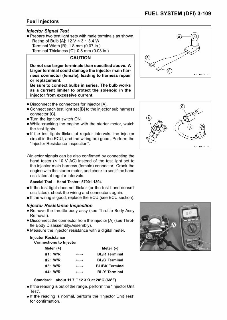
FUEL SYSTEM (DFI) 3-109Fuel Injectors
Injector Signal Test•Prepare two test light sets with male terminals as shown.Rating of Bulb [A]: 12 V × 3 ~ 3.4 WTerminal Width [B]: 1.8 mm (0.07 in.)Terminal Thickness [C]: 0.8 mm (0.03 in.)
CAUTIONDo not use larger terminals than specified above. Alarger terminal could damage the injector main har-ness connector (female), leading to harness repairor replacement.Be sure to connect bulbs in series. The bulb worksas a current limiter to protect the solenoid in theinjector from excessive current.
•Disconnect the connectors for injector [A].• Connect each test light set [B] to the injector sub harnessconnector [C].• Turn the ignition switch ON.•While cranking the engine with the starter motor, watchthe test lights.If the test lights flicker at regular intervals, the injectorcircuit in the ECU, and the wiring are good. Perform the“Injector Resistance Inspection”.
Injector signals can be also confirmed by connecting thehand tester (× 10 V AC) instead of the test light set tothe injector main harness (female) connector. Crank theengine with the starter motor, and check to see if the handoscillates at regular intervals.Special Tool - Hand Tester: 57001-1394If the test light does not flicker (or the test hand doesn’toscillates), check the wiring and connectors again.If the wiring is good, replace the ECU (see ECU section).
Injector Resistance Inspection•Remove the throttle body assy (see Throttle Body AssyRemoval).• Disconnect the connector from the injector [A] (see Throt-tle Body Disassembly/Assembly).•Measure the injector resistance with a digital meter.Injector ResistanceConnections to Injector
Meter (+) Meter (–)#1: W/R ←→ BL/R Terminal#2: W/R ←→ BL/G Terminal#3: W/R ←→ BL/BK Terminal#4: W/R ←→ BL/Y Terminal
Standard: about 11.7 ∼ 12.3 Ω at 20°C (68°F)
If the reading is out of the range, perform the “Injector UnitTest”.If the reading is normal, perform the “Injector Unit Test”for confirmation.

3-110 FUEL SYSTEM (DFI)Fuel Injectors
Injector Unit Test•Use two leads [A] and the same test light set [B] as in“Injector Signal Test”.Rating of Bulb [C]: 12 V × (3 ∼ 3.4) W12 V MF Battery [D]
CAUTIONBe sure to connect the bulb in series. The bulbworks as a current limiter to protect the solenoidin the injector from excessive current.
•Connect the test light set to the injector [E] as shown.•Open and connect [F] the end of the lead to the battery(–) terminal repeatedly. The injector should click.If the injector does not click, replace the injector.
Injector Fuel Line Inspection•Remove the throttle body assy (see Throttle Body AssyRemoval).• Check the injector fuel line for leakage as follows.Connect a commercially available vacuum/pressurepump [A] to the nipple of the delivery pipe [B] with thefuel hose [C] (both ends connected with the clamps [D])as shown.Apply soap and water solution to the areas [E] as shown.Watching the pressure gauge, squeeze the pump lever[F], and build up the pressure until the pressure reachesthe maximum pressure.
Fuel Line Maximum PressureStandard: 300 kPa (3.06 kgf/cm², 43 psi)
CAUTIONDuring pressure testing, do not exceed the maxi-mum pressure for which the system is designed.
•Watch the gauge for at least 6 seconds.If the pressure holds steady, the system is good.If the pressure drops at once, or if bubbles are found inthe area, the line is leaking. Replace the delivery pipe,injectors and related parts.Repeat the leak test, and check the fuel line for no leak-age.• Install the throttle body assy (see Throttle Body Assy In-stallation).• Run the hoses correctly (seeCable, Wire, and HoseRout-ing section in the Appendix chapter).

FUEL SYSTEM (DFI) 3-111Fuel Injectors
Fuel Injector Circuit
1. Ignition Switch2. Joint Connector 13. Engine Stop Switch4. Fuel Injector #45. Fuel Injector #36. Fuel Injector #27. Fuel Injector #18. Water-proof Joint 19. ECU10. ECU Fuse 15 A11. Ignition Fuse 10 A
12. Fuse Box 213. Main Relay14. Fuel Pump Relay15. Relay Box16. Joint Connector 217. Main Fuse 30 A18. Starter Relay19. Battery 12 V 14 Ah20. Frame Ground 221. Fuel Pump22. Joint Connector 3

3-112 FUEL SYSTEM (DFI)Throttle Grip and Cables
Free Play Inspection•Refer to the Throttle Control System Inspection in the Pe-riodic Maintenance chapter (see Throttle Control SystemInspection in the Periodic Maintenance chapter).
Free Play Adjustment•Refer to the Throttle Control System Inspection in the Pe-riodic Maintenance chapter (see Throttle Control SystemInspection in the Periodic Maintenance chapter).
Cable Installation• Install the throttle cables in accordance with the Cable ,Wire, and Hose Routing section in the Appendix chapter.• Install the lower ends of the throttle cables in the cablebracket on the throttle assy after installing the upper endsof the throttle cables in the grip.• After installation, adjust each cable properly (see ThrottleControl System Inspection in the Periodic Maintenancechapter).
WARNINGOperation with incorrectly routed or improperly ad-justed cables could result in an unsafe riding con-dition.
Cable Lubrication•Refer to the Chassis Parts Lubrication Perform in the Peri-odic Maintenance chapter (see Chassis Parts LubricationPerform in the Periodic Maintenance chapter).

FUEL SYSTEM (DFI) 3-113Throttle Body Assy
Idle Speed Inspection•Refer to the Idle Speed Inspection in the Periodic Mainte-nance chapter (see Idle Speed Inspection in the PeriodicMaintenance chapter).
Throttle Bore Cleaning•Check the throttle bore for cleanliness as follows.Remove the throttle body assy (see Throttle Body AssyRemoval).Check the main throttle valves and throttle bores [A] forcarbon deposits by opening the main throttle valves.If any carbon accumulates, wipe the carbon off the throt-tle bores around the throttle bores and the throttle valves,using a cotton pad penetrated with a high-flash point sol-vent.
Synchronization Inspection•Refer to the Engine Vacuum Synchronization Inspectionin the Periodic Maintenance chapter (see Engine VacuumSynchronization Inspection in the Periodic Maintenancechapter).
Synchronization Adjustment•Refer to the Engine Vacuum Synchronization Inspectionin the Periodic Maintenance chapter (see Engine VacuumSynchronization Inspection in the Periodic Maintenancechapter).
Throttle Body Assy RemovalWARNING
Gasoline is extremely flammable and can be ex-plosive under certain conditions. Turn the ignitionswitch OFF. Disconnect the battery (–) cable ter-minal. Do not smoke. Make sure the area iswell-ventilated and free from any source of flameor sparks; this includes any appliance with a pilotlight.Be prepared for fuel spillage: any spilled fuel mustbe completely wiped up immediately.
•Remove:Fuel Tank Cover (see Fuel Tank Removal)Left and Right Middle Fairings (see Middle Fairing Re-moval in the Frame chapter)Bolts [A]Subframe Bolts [B] and Washers
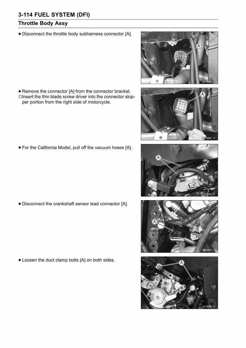
3-114 FUEL SYSTEM (DFI)Throttle Body Assy
•Disconnect the throttle body subharness connector [A].
• Remove the connector [A] from the connector bracket.Insert the thin blade screw driver into the connector stop-per portion from the right side of motorcycle.
• For the California Model, pull off the vacuum hoses [A].
• Disconnect the crankshaft sensor lead connector [A].
• Loosen the duct clamp bolts [A] on both sides.

FUEL SYSTEM (DFI) 3-115Throttle Body Assy
•Remove:Fuel Tank (see Fuel Tank Removal)Inlet Air Temperature Sensor [A]Bolts [B]Left and Right Air Cleaner Caps [C]
Do not disconnect the inlet air temperature sensor leadconnector.
• Remove the duct clamps from the ducts [A], and pull outthe ducts upward.
Remove the grommets [A] as necessary.
• Remove the throttle case [A] to make a throttle cableslack.
• Remove:Clamp [A]Throttle Cable Lower Ends [B]
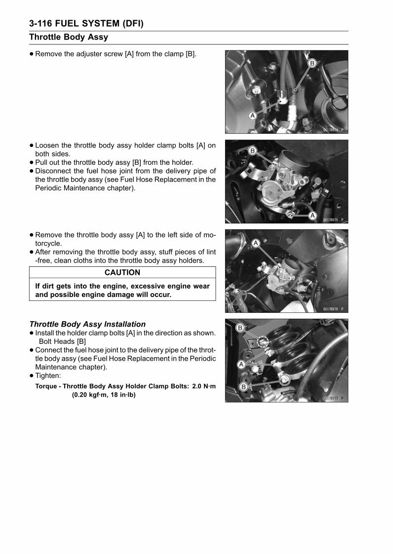
3-116 FUEL SYSTEM (DFI)Throttle Body Assy
•Remove the adjuster screw [A] from the clamp [B].
• Loosen the throttle body assy holder clamp bolts [A] onboth sides.• Pull out the throttle body assy [B] from the holder.• Disconnect the fuel hose joint from the delivery pipe ofthe throttle body assy (see Fuel Hose Replacement in thePeriodic Maintenance chapter).
• Remove the throttle body assy [A] to the left side of mo-torcycle.• After removing the throttle body assy, stuff pieces of lint-free, clean cloths into the throttle body assy holders.
CAUTIONIf dirt gets into the engine, excessive engine wearand possible engine damage will occur.
Throttle Body Assy Installation• Install the holder clamp bolts [A] in the direction as shown.Bolt Heads [B]• Connect the fuel hose joint to the delivery pipe of the throt-tle body assy (see Fuel Hose Replacement in the PeriodicMaintenance chapter).• Tighten:Torque - Throttle Body Assy Holder Clamp Bolts: 2.0 N·m
(0.20 kgf·m, 18 in·lb)

FUEL SYSTEM (DFI) 3-117Throttle Body Assy
If the grommet [A] was removed, install it.Install the grommet from the inside of the frame.• Insert the duct [B] to the grommet.Apply a soap and water solution or rubber lubricant to theoblique portion [C] on the duct for easy installation.• Fit the projections [D] of the duct into the holes [E] in theclamp.
• Install the duct clamp bolts [A] in the direction as shown.Front [B]Upside View [C]• Tighten:Torque - Duct Clamp Bolts: 2.0 N·m (0.20 kgf·m, 18 in·lb)
• Install the air cleaner caps.The right air cleaner cap [A] has a R mark [B].
• Replace the subframe bolts with new ones, and tighten it.Torque - Subframe Bolts: 23 N·m (2.3 kgf·m, 17 ft·lb)
•Run the leads and hoses as shown in the Cable, Wire,and Hose Routing section of the Appendix chapter.• Adjust:Throttle Grip Free Play (see Throttle Control System In-spection in the Periodic Maintenance chapter)Idle Speed (see Idle Speed Adjustment in the PeriodicMaintenance chapter)

3-118 FUEL SYSTEM (DFI)Throttle Body Assy
Throttle Body Assy Disassembly
1. Subthrottle Valve Actuator2. Subthrottle Sensor3. Main Throttle Sensor4. Throttle Body Assy5. Injector6. Delivery Pipe7. Throttle Body Subharness
CAUTIONDo not remove, disassemble or adjust the mainthrottle sensor, subthrottle sensor, subthrottlevalve actuator, throttle link mechanism and throttlebody assy, because they are adjust or set surely atthe manufacturer. Adjustment of these parts couldresult in poor performance, requiring replacementof the throttle body assy.
•Remove the throttle body assy (see Throttle Body AssyRemoval).• Disconnect the injector connectors [A].

FUEL SYSTEM (DFI) 3-119Throttle Body Assy
•Disconnect the main throttle sensor [A] and subthrottlesensor [B] connector.
• Disconnect:Subthrottle Valve Actuator Lead Connector [A]Inlet Air Pressure Sensor Connector [B]
• Separete the hoses [A] from the throttle body fittings andinlet air pressure sensor.• Remove the screws [B] to pull out the injector assies fromthe throttle body assy together with the delivery pipe [C].
NOTEDo not damage the insertion portions of the injectorswhen they are pulled out from the throttle body.
•Pull out the injectors [A] from the delivery pipe [B].NOTE
Do not damage the insertion portions of the injectorswhen they are pulled out from the delivery pipe.
Throttle Body Assy Assembly•Before assembling, blow away dirt or dust from the throttlebody and delivery pipe by applying compressed air.• Apply daphne oil or engine oil to the new O-rings [A] ofeach injector, insert them to the delivery pipe [B] and con-firm whether the injectors turn smoothly or not.
NOTEReplace the O-rings of injectors to new ones.

3-120 FUEL SYSTEM (DFI)Throttle Body Assy
•Apply daphne oil or engine oil to the new dust seals [A],and insert the injectors into the throttle body, which in-stalled to the delivery pipe.
NOTEReplace the dust seals of the throttle body to new ones.• Install the delivery pipe to the throttle body.Torque - Delivery Pipe Mounting Screws: 5.0 N·m (0.50
kgf·m, 44 in·lb)
•Connect the injector connectors.• Insert the each hoses to the throttle body fittings and inletair pressure sensor.• Install the throttle body assy (see Throttle Body Assy In-stallation).

FUEL SYSTEM (DFI) 3-121Air Line
Element Removal•Refer to the Air Cleaner Element Replacement in the Pe-riodic Maintenance chapter (see Air Cleaner Element Re-placement in the Periodic Maintenance chapter).
Element Installation•Refer to the Air Cleaner Element Replacement in the Pe-riodic Maintenance chapter (see Air Cleaner Element Re-placement in the Periodic Maintenance chapter).
Air Cleaner Element Inspection•Remove the air cleaner element (see Air Cleaner ElementReplacement in the Periodic Maintenance chapter).• Visually check the element [A] for tears or breaks.If the element has any tears or breaks, replace the ele-ment.
Air Cleaner Element Holder Removal•Remove:Air Cleaner Element (see Air Cleaner Element Replace-ment in the Periodic Maintenance chapter)Screws [A]
• Pull out the air cleaner element holder [A] from the hous-ing.
Air Cleaner Element Holder Installation• Install the air cleaner element holder [A] so that the holderends [B] insert along the rib [C] in the housing.• Tighten:Torque - Air Cleaner Element Holder Screws: 6.9 N·m (0.70
kgf·m, 61 in·lb)

3-122 FUEL SYSTEM (DFI)Air Line
Oil DrainingA drain hose is connected to the bottom of the air cleaner
part to drain water or oil accumulated in the cleaner part.• Visually check the catch tank of the drain hose [A], if thewater or oil accumulates in the tank.If any water or oil accumulates in the tank, remove theplug [B] from the tank and drain it.
WARNINGBe sure reinstall the plug in the tank after draining.Oil on tires will make them slippery and can causean accident and injury.
Rear Air Inlet Duct Removal•Remove:Left and Right Inner Covers (see Inner Cover Removalin the Frame chapter)Fuel Tank Cover (see Fuel Tank Cover Removal)• Loosen the clamp bolt [A] on both sides.• Remove the mounting bolts [B] and, pull off the right rearair inlet ducts [C] to backward.• Remove the left rear air inlet duct in the sameway as right.Rear Air Inlet Duct Installation• Insert the projections [A] of the holder [B] in the holes [C]of rear air inlet duct [D].
• Insert the rear air inlet duct [A] until the duct end [B] alignthe line [C] of middle air inlet duct [D].• TightenTorque - Rear Air inlet Duct Mounting Bolts: 9.8 N·m (1.0
kgf·m, 87 in·lb)

FUEL SYSTEM (DFI) 3-123Air Line
• Install the clamp bolts [A] so that bolt heads [B] facesdirection as shown.Left Clamp [C]Right Clamp [D]About 30° [E]Rear View [F]• Tighten:Torque - Middle Air inlet Duct Clamp Bolts: 2.9 N·m (0.30
kgf·m, 26 in·lb)
Front and Middle Air Inlet Duct Removal•Remove the upper fairing (see Upper Fairing Removal inthe Frame chapter).•Open the clamps [A].
•Open the clamps [A].
• Remove:Bolts [A]Front Air inlet Duct [B]Rubber Seal [C]• Loosen the clamp bolts [D] on both sides.• Remove the bolts [E] on both sides.• Pull off the left and right middle air inlet ducts [F] to for-ward.
Front and Middle Air Inlet Duct InstallationNOTE
The left middle air inlet duct has a L mark [A] and theright middle air inlet duct has a R mark.

3-124 FUEL SYSTEM (DFI)Air Line
• Insert the middle air inlet duct [A] until the line [B] alignthe duct end [C] of rear air inlet duct [D].• Tighten:Torque - Middle Air Inlet Duct Mounting Bolts: 9.8 N·m (1.0
kgf·m, 87 in·lb)
• Install the clamp bolt [A] so that bolt heads [B] faces di-rection as shown.Left Clamp [C]Right Clamp [D]About 30° [E]Rear View [F]• Tighten:Torque - Middle Air Inlet Duct Clamp Bolts: 2.9 N·m (0.30
kgf·m, 26 in·lb)
• Install the rubber seal [A] so that the hollow side [B] facesforward.• Insert the front air inlet duct to the rubber seal, and tightenthe bolts.Torque - Front Air Inlet Duct Mounting Bolts: 9.8 N·m (1.0
kgf·m, 87 in·lb)
•Run the leads correctly (see Cable, Wire, and Hose Rout-ing section in the Appendix chapter).

FUEL SYSTEM (DFI) 3-125Fuel Tank
Fuel Tank RemovalWARNING
Gasoline is extremely flammable and can be explo-sive under certain conditions. Make sure the areais well-ventilated and free from any source of flameor sparks; this includes any appliance with a pilotlight. Do not smoke. Turn the ignition switch OFF.Be prepared for fuel spillage; any spilled fuel mustbe completely wiped up immediately.
•Turn the ignition switch OFF.•Remove the left and right fairing covers (see FairingCover Removal in the Frame chapter).• Disconnect the battery (–) terminal (see Battery Removalin the Electrical System chapter).• Remove:Left and Right Inner Covers (see Inner Cover Removalin the Frame chapter)Bolt [A]
• Pull the fuel tank cover [A] evenly outward to clear theprojections [B] on both sides.• Remove the fuel tank cover to forward [C].
• Remove the bolts [A].
• Remove:Bolts [A]Drain Hose [B]• For the California model, remove the following.Fuel Return Hose [C] (right side, red)Fuel Tank Breather Hose [D] (left side, blue)

3-126 FUEL SYSTEM (DFI)Fuel Tank
•Disconnect:Fuel Pump Lead Connector [A]Fuel Level Sensor Lead Connector [B]
•Open the fuel tank cap [A] to lower the pressure in thetank.During tank removal, keep the tank cap open to releasepressure in the tank. This makes fuel spillage less.
• Draw the fuel out from the fuel tank with a commerciallyavailable pump [A].Use a soft plastic hose [B] as a pump inlet hose in orderto insert the hose smoothly.Put the hose through the fill opening [C] into the tank anddraw the fuel out.Front [D]
WARNINGThe fuel could not be removed completely from thefuel tank. Be careful for remained fuel spillage.
•Be sure to place a piece of cloth [A] around the fuel hosejoint [B].• Push the joint lock claws [C].
• Pull the joint lock [A] as shown.• Pull [B] the fuel hose joint [C] out of the delivery pipe.WARNING
Be prepared for fuel spillage; any spilled fuel mustbe completely wiped up immediately.When the fuel hose is disconnected, fuel spills outfrom the hose and the pipe because of residualpressure. Cover the hose connection with a pieceof clean cloth to prevent fuel spillage.
•Close the fuel tank cap.• Remove the fuel tank, and place a it on a flat surface.Do not apply the load to the delivery pipe of the fuel pump.

FUEL SYSTEM (DFI) 3-127Fuel Tank
•For the California Model, note the following.CAUTION
For the California model, if gasoline, solvent, wateror any other liquid enters the canister, the canister’svapor absorbing capacity is greatly reduced. If thecanister does become contaminated, replace it witha new one.
Be sure to plug the evaporative fuel return hose to preventfuel spilling before fuel tank removal.
WARNINGFor the California model, be careful not to spill thegasoline through the return hose. Spilled fuel ishazardous.If liquid or gasoline flows into the breather hose, removethe hose and blow it clean with compressed air (Californiamodel).Be careful of fuel spillage from the fuel tank since fuel stillremains in the fuel tank and fuel pump.
WARNINGStore the fuel tank in an area which is well-ventilated and free from any source of flameor sparks. Do not smoke in this area. Place thefuel tank on a flat surface and plug the fuel pipesto prevent fuel leakage.
Fuel Tank Installation•Note the above WARNING (see Fuel Tank Removal).• Route the hoses correctly (see Cable, Wire, and HoseRouting section in the Appendix chapter).• Check that the dampers [A] and pad [B] are in place onthe fuel tank as well.If the dampers are damaged or deteriorated, replacethem.• For the California Model, note the following.To prevent the gasoline from flowing into or out of thecanister, hold the separator perpendicular to the ground.Connect the hoses according to the diagram of the sys-tem (see Cable, Wire, and Hose Routing section in theAppendix chapter). Make sure they do not get pinched orkinked.Route hoses with a minimum of bending so that the air orvapor will not be obstructed.

3-128 FUEL SYSTEM (DFI)Fuel Tank
•Pull the joint lock [A] as shown.
• Insert the fuel hose joint [A] straight onto the delivery pipeuntil the hose joint clicks.• Push the joint lock [B] until the hose joint clicks.
• Push and pull [A] the hose joint [B] back and forth morethan two times and make sure it is locked and doesn’tcome off. When the hose joint is correctly installed, itshould slide on the delivery pipe about 5 mm (0.2 in.).
WARNINGMake sure the hose joint is installed correctly on thedelivery pipe by sliding the joint, or the fuel couldleak.If it does not slide, reinstall the hose joint.• Connect the fuel pump, fuel level sensor lead connectorsand the battery (–) terminal (see Battery Installation in theElectrical System chapter).
• For models equipped with an ABS, fit the grooves of thedamper [A] on the brake pipes [B].

FUEL SYSTEM (DFI) 3-129Fuel Tank
•Fit the dampers [A] of the fuel tank into the slots [B] of thefuel tank cover [C].
Fuel Tank and Cap Inspection•Visually inspect the gasket [A] on the tank cap for anydamage.Replace the gasket if it is damaged.• Check to see if the water drain pipe [B] and fuel breatherpipe [C] (California Model) in the tank are not clogged.Check the tank cap breather also.If they are clogged, remove the tank and drain it, and thenblow the breather free with compressed air.
CAUTIONDo not apply compressed air to the air vent holes[D] in the tank cap. This could cause damage andclogging of the labyrinth in the cap.
Fuel Tank CleaningWARNING
Clean the tank in a well-ventilated area, and takecare that there are no sparks or flame anywherenear the working area. Because of the danger orhighly flammable liquids, do not use gasoline orlow-flash point solvents to clean the tank.
•Remove:Fuel Tank (see Fuel Tank Removal)Fuel Pump (see Fuel Pump Removal)• Pour some high-flash point solvent into the fuel tank andshake the tank to remove dirt and fuel deposits.• Draw the solvent out of the fuel tank.• Dry the tank with compressed air.• Install:Fuel Pump (see Fuel Pump Installation)Fuel Tank (see Fuel Tank Installation)

3-130 FUEL SYSTEM (DFI)Evaporative Emission Control System
The Evaporative Emission Control System routes fuel va-pors from the fuel system into the running engine or storesthe vapors in a canister when the engine is stopped. Al-though no adjustments are required, a thorough visual in-spection must be made at the intervals specified by the Pe-riodic Maintenance Chart.
Parts Removal/InstallationWARNING
Gasoline is extremely flammable and can be ex-plosive under certain conditions. Turn the ignitionswitch OFF. Do not smoke. Make sure the area iswell-ventilated and free from any source of flameor sparks; this includes any appliance with a pilotlight.
CAUTIONIf gasoline, solvent, water or any other liquid entersthe canister, the canister’s vapor absorbing capac-ity is greatly reduced. If the canister does becomecontaminated, replace it with a new one.
•To prevent the gasoline from flowing into or out of thecanister, hold the separator perpendicular to the ground.• Connect the hoses according to the diagram of the sys-tem. Make sure they do not get pinched or kinked.
Hose Inspection•Refer to the Evaporative Emission Control System In-spection in the Periodic Maintenance chapter (see Evapo-rative Emission Control System Inspection in the PeriodicMaintenance chapter).
Separator Inspection•Refer to the Evaporative Emission Control System In-spection in the Periodic Maintenance chapter (see Evapo-rative Emission Control System Inspection in the PeriodicMaintenance chapter).Separator [A]

FUEL SYSTEM (DFI) 3-131Evaporative Emission Control System
Separator Operation TestWARNING
Gasoline is extremely flammable and can be ex-plosive under certain conditions. Turn the ignitionswitch OFF. Do not smoke. Make sure the area iswell-ventilated and free from any source of flameor sparks; this includes any appliance with a pilotlight.
•Connect the hoses to the separator, and install the sepa-rator on the motorcycle.• Disconnect the breather hose from the separator, and in-ject about 20 mL (0.68 US oz.) of gasoline [A] into theseparator [B] through the hose fitting.• Disconnect the fuel return hose [C] from the fuel tank [D].• Run the open end of the return hose into the containerand hold it level with the tank top [E].• Start the engine, and let it idle.If the gasoline in the separator comes out of the hose, theseparator works well. If it does not, replace the separatorwith a new one.
Canister Inspection•Refer to the Evaporative Emission Control System In-spection in the PeriodicMaintenance chapter (see Evapo-rative Emission Control System Inspection in the PeriodicMaintenance chapter).
NOTEThe canister [A] is designed to work well through themotorcycle’s life without any maintenance if it is usedunder normal conditions.

3-132 FUEL SYSTEM (DFI)Evaporative Emission Control System
1. Fuel Tank2. White Hose (Vacuum)3. Throttle Body Assy4. Green Hose (Purge)5. Canister6. Band (for Canister)7. Red Hose (Right, Return)8. Fitting9. Bracket (for Separator)10. Separator11. Blue Hose (Breather)12. Blue Hose (Left, Breather)

COOLING SYSTEM 4-1
4
Cooling SystemTable of Contents
Exploded View........................................................................................................................ 4-2Coolant Flow Chart................................................................................................................. 4-4Specifications ......................................................................................................................... 4-6Coolant ................................................................................................................................... 4-7
Coolant Deterioration Inspection....................................................................................... 4-7Coolant Level Inspection................................................................................................... 4-7Coolant Draining ............................................................................................................... 4-7Coolant Filling ................................................................................................................... 4-7Pressure Testing ............................................................................................................... 4-7Cooling System Flushing .................................................................................................. 4-8Coolant Reserve Tank Removal/Installation ..................................................................... 4-8
Water Pump............................................................................................................................ 4-9Water Pump Removal ....................................................................................................... 4-9Water Pump Installation.................................................................................................... 4-9Water Pump Impeller Inspection....................................................................................... 4-10
Radiator .................................................................................................................................. 4-11Radiator and Radiator Fan Removal ................................................................................ 4-11Radiator and Radiator Fan Installation ............................................................................. 4-12Radiator Inspection ........................................................................................................... 4-12Radiator Cap Inspection ................................................................................................... 4-13Radiator Filler Neck Inspection ......................................................................................... 4-13
Thermostat ............................................................................................................................. 4-14Thermostat Removal......................................................................................................... 4-14Thermostat Installation...................................................................................................... 4-14Thermostat Inspection ...................................................................................................... 4-14
Hoses and Pipes .................................................................................................................... 4-16Hose Installation ............................................................................................................... 4-16Hose Inspection ................................................................................................................ 4-16
Water Temperature Sensor .................................................................................................... 4-17Water Temperature Sensor Removal................................................................................ 4-17Water Temperature Sensor Inspection ............................................................................. 4-17

4-2 COOLING SYSTEMExploded View

COOLING SYSTEM 4-3Exploded View
TorqueNo. Fastener
N·m kgf·m ft·lbRemarks
1 Radiator Hose Clamp Screws 2.0 0.20 18 in·lb2 Coolant Drain Plug 12 1.2 106 in·lb3 Water Pump Cover Bolts 9.8 1.0 87 in·lb4 Oil Cooler Mounting Bolts 12 1.2 106 in·lb S5 Thermostat Housing Cover Bolts 5.9 0.60 52 in·lb6 Thermostat Housing Mounting Bolts 9.8 1.0 87 in·lb7 Coolant Fitting Bolt 8.8 0.90 78 in·lb L8 Water Temperature Sensor 25 2.5 189. ThermostatG: Apply grease.L: Apply a non-permanent locking agent.R: Replacement PartsS: Follow the specified tightening sequence.

4-4 COOLING SYSTEMCoolant Flow Chart

COOLING SYSTEM 4-5Coolant Flow Chart
Permanent type antifreeze is used as a coolant to protect the cooling system from rust and corrosion.When the engine starts, the water pump turns and the coolant circulates.The thermostat is a wax pellet type which opens or closes with coolant temperature changes. The
thermostat continuously changes its valve opening to keep the coolant temperature at the proper level.When coolant temperature is less than 55°C (131°F), the thermostat closes so that the coolant flowis restricted through the air bleeder hole, causing the engine to warm up more quickly. When coolanttemperature is more than 58 ∼ 62°C (136 ∼ 144°F), the thermostat opens and the coolant flows.When the coolant temperature goes up beyond 95°C (203°F), the radiator fan relay conducts to op-
erate the radiator fan. The radiator fan draws air through the radiator core when there is not sufficientair flow such as at low speeds. This increases up the cooling action of the radiator. When the coolanttemperature is below 90°C (194°F), the fan relay opens and the radiator fan stops.In this way, this system controls the engine temperature within narrow limits where the engine op-
erates most efficiently even if the engine load varies.The system is pressurized by the radiator cap to suppress boiling and the resultant air bubbles
which can cause engine overheating. As the engine warms up, the coolant in the radiator and thewater jacket expands. The excess coolant flows through the radiator cap and hose to the reserve tankto be stored there temporarily. Conversely, as the engine cools down, the coolant in the radiator andthe water jacket contracts, and the stored coolant flows back to the radiator from the reserve tank.The radiator cap has two valves. One is a pressure valve which holds the pressure in the system
when the engine is running. When the pressure exceeds 93 ∼ 123 kPa (0.95 ∼ 1.25 kgf/cm², 13 ∼ 18psi), the pressure valve opens and releases the pressure to the reserve tank. As soon as pressureescapes, the valve closes, and keeps the pressure at 93 ∼ 123 kPa (0.95 ∼ 1.25 kgf/cm², 13 ∼ 18 psi).When the engine cools down, another small valve (vacuum valve) in the cap opens. As the coolantcools, the coolant contracts to form a vacuum in the system. The vacuum valve opens and allows thecoolant from the reserve tank to enter the radiator.

4-6 COOLING SYSTEMSpecifications
Item StandardCoolant Provided when ShippingType (Recommended) Permanent type of antifreeze (soft water and ethylene glycol
plus corrosion and rust inhibitor chemicals for aluminumengines and radiators)
Color GreenMixed Ratio Soft water 50%, coolant 50%Freezing Point –35°C (–31°F)Total Amount 3.4 L (3.6 US qt)
(Reserve tank full level, including radiator and engine)Radiator CapRelief Pressure 93 ∼ 123 kPa (0.95 ∼ 1.25 kgf/cm², 13 ∼ 18 psi)
ThermostatValve Opening Temperature 58 ∼ 62°C (136 ∼ 144°F)Valve Full Opening Lift 8 mm (0.31 in.) or more @75°C (167°F)

COOLING SYSTEM 4-7Coolant
Coolant Deterioration Inspection•Visually inspect the coolant in the reserve tank.If whitish cotton-like wafts are observed, aluminum partsin the cooling system are corroded. If the coolant isbrown, iron or steel parts are rusting. In either case, flushthe cooling system.If the coolant gives off an abnormal smell, check for acooling system leak. It may be caused by exhaust gasleaking into the cooling system.
Coolant Level Inspection•Refer to the Coolant Level Inspection in the PeriodicMain-tenance chapter.
Coolant Draining•Refer to the Coolant Change in the Periodic Maintenancechapter.
Coolant Filling•Refer to the Coolant Change in the Periodic Maintenancechapter.
Pressure Testing•Remove the right middle fairing (see Middle Fairing Re-moval in the Frame chapter).• Remove the radiator cap, and install the cooling systempressure tester [A] on the filler neck.
NOTEWet the cap sealing surfaces with water or coolant toprevent pressure leaks.
•Build up pressure in the system carefully until the pres-sure reaches 142 kPa (1.45 kgf/cm², 21 psi).
CAUTIONDuring pressure testing, do not exceed the pres-sure for which the system is designed. The maxi-mum pressure is 142 kPa (1.45 kgf/cm², 21 psi).
•Watch the gauge for at least 6 seconds.If the pressure holds steady, the system is all right.If the pressure drops and no external source is found,check for internal leaks. Droplets in the engine oil indicateinternal leakage. Check the cylinder head gasket and thewater pump.•Remove the pressure tester, replenish the coolant, andinstall the radiator cap.

4-8 COOLING SYSTEMCoolant
Cooling System FlushingOver a period of time, the cooling system accumulates
rust, scale, and lime in the water jacket and radiator. Whenthis accumulation is suspected or observed, flush the cool-ing system. If this accumulation is not removed, it will clogup the water passage and considerable reduce the effi-ciency of the cooling system.•Drain the cooling system (see Coolant Change in the Pe-riodic Maintenance chapter).• Fill the cooling system with fresh water mixed with a flush-ing compound.
CAUTIONDo not use a flushing compoundwhich is harmful tothe aluminum engine and radiator. Carefully followthe instructions supplied by themanufacturer of thecleaning product.
•Warm up the engine, and run it at normal operating tem-perature for about ten minutes.• Stop the engine, and drain the cooling system.• Fill the system with fresh water.•Warm up the engine and drain the system.•Repeat the previous two steps once more.• Fill the system with a permanent type coolant and bleedthe air from the system (see Coolant Change in the Peri-odic Maintenance chapter).
Coolant Reserve Tank Removal/Installation•The coolant reserve tank is removed and installed dur-ing coolant change (see Coolant Change in the PeriodicMaintenance chapter).

COOLING SYSTEM 4-9Water Pump
Water Pump Removal•Drain:Coolant (see Coolant Change in the Periodic Mainte-nance chapter)Engine Oil (see Engine Oil Change in the Periodic Main-tenance chapter)• Remove:Clutch Slave Cylinder (see Clutch Slave Cylinder Re-moval in the Clutch chapter)Engine Sprocket Cover (see Engine Sprocket Removalin the Final Drive chapter)
• Remove:Radiator Hose [A]Water Pump Cover Bolts [B]Water Pump Cover [C]
• Remove the radiator hose [A] and the air bleeder hose [B]for the water pump body.• Remove the water pump body [C] with impeller [D].
Water Pump Installation•Turn the pump drive gear shaft so that the slot [A] in itsshaft fits onto the projection [B] of the impeller shaft.
• Install the radiator hose [A] and the air bleeder hose [B]for the water pump body as shown.

4-10 COOLING SYSTEMWater Pump
• Install the water pump cover [A].• Tighten:Torque - Water Pump Cover Bolts: 9.8 N·m (1.0 kgf·m, 87
in·lb)
• Install the water hose [B] as shown.
Water Pump Impeller Inspection•Visually inspect the water pump impeller [A].If the surface is corroded or if the blades are damaged,replace the water pump assy.

COOLING SYSTEM 4-11Radiator
Radiator and Radiator Fan Removal•Remove:Middle Fairings (see Middle Fairing Removal in theFrame chapter)Coolant (Drain, see Coolant Change in the PeriodicMaintenance chapter)Reservoir Tank Hose [A]Air Bleeder Hose [B] for Thermostat HousingRadiator Hose [C]Oil Cooler Outlet Hose [D]Radiator Upper Bolt [E]
• Remove:Radiator Fan Lead Connector [A]Radiator Hose [B]Radiator Lower Bolt [C]Radiator Upper Bolt [D]• Remove the radiator [E].
CAUTIONDo not touch the radiator core. This could damagethe radiator fins, resulting in loss of cooling effi-ciency.
•Remove:Radiator Fan Mounting Bolts [A]Radiator Fan [B]

4-12 COOLING SYSTEMRadiator
Radiator and Radiator Fan Installation•Be sure that the trim seals [A] are in position on the radi-ator as shown.• Install the dampers [B], radiator bracket collars [C] andbolts as shown.
Radiator Inspection•Check the radiator core.If there are obstructions to air flow, remove them.If the corrugated fins [A] are deformed, carefullystraighten them.If the air passages of the radiator core are blocked morethan 20% by unremovable obstructions or irreparably de-formed fins, replace the radiator with a new one.
CAUTIONWhen cleaning the radiator with steam cleaner, becareful of the following to prevent radiator damage:Keep the steam gun [A] away more than 0.5 m (1.6ft) [B] from the radiator core.Hold the steam gun perpendicular [C] (not oblique[D]) to the core surface.Run the steam gun, following the core fin direction.

COOLING SYSTEM 4-13Radiator
Radiator Cap Inspection•Remove:Right Middle Fairing (see Middle Fairing Removal in theFrame chapter)Radiator Cap•Check the condition of the bottom [A] and top [B] valveseals and valve spring [C].If any one of them shows visible damage, replace the capwith a new one.
• Install the cap [A] on a cooling system pressure tester [B].NOTE
Wet the cap sealing surfaces with water or coolant toprevent pressure leaks.
•Watching the pressure gauge, pump the pressure testerto build up the pressure until the relief valve opens: thegauge needle flicks downward. Stop pumping and mea-sure leak time at once. The relief valve must open withinthe specified range in the table below and the gauge handmust remain within the same range at least 6 seconds.
Radiator Cap Relief PressureStandard: 93 ∼ 123 kPa (0.95 ∼ 1.25 kgf/cm², 13 ∼ 18
psi)
If the cap can not hold the specified pressure or if it holdstoo much pressure, replace it with a new one.
Radiator Filler Neck Inspection•Remove the right middle fairing (see Middle Fairing Re-moval in the Frame chapter).• Remove the radiator cap.• Check the radiator filler neck for signs of damage.• Check the condition of the top and bottom sealing seats[A] in the filler neck. They must be smooth and clean forthe radiator cap to function properly.

4-14 COOLING SYSTEMThermostat
Thermostat Removal•Drain the coolant (see Coolant Change in the PeriodicMaintenance chapter).• Remove:Fuel Tank (see Fuel Tank Removal in the Fuel System(DFI) chapter)Throttle Body Assy (see Throttle Body Assy Removal inthe Fuel System (DFI) chapter)Thermostat Housing Mounting Bolts [A]Radiator Hose [B]Air Bleeder Hoses [C]Thermostat Housing [D]
• Remove:Thermostat Housing Cover Bolts [A]Thermostat Housing Cover [B]Thermostat
Thermostat Installation• Install the thermostat [A] in the housing so that the airbleeder hole [B] is on top.• Install a new O-ring into the housing.• Tighten the thermostat housing cover bolts and the ther-mostat housing mounting bolts.Torque - Thermostat Housing Cover Bolts: 5.9 N·m (0.60
kgf·m, 52 in·lb)Thermostat Housing Mounting Bolts: 9.8 N·m (1.0kgf·m, 87 in·lb)
•Fill the radiator with coolant (see Coolant Change in thePeriodic Maintenance chapter).
Thermostat Inspection•Remove the thermostat, and inspect the thermostat valve[A] at room temperature.If the valve is open, replace the thermostat with a newone.

COOLING SYSTEM 4-15Thermostat
•To check valve opening temperature, suspend the ther-mostat [A] in a container of water and raise the tempera-ture of the water.The thermostat must be completely submerged and mustnot touch the container sides or bottom. Suspend an ac-curate thermometer [B] in the water so that the heat sen-sitive portions [C] are located in almost the same depth.It must not touch the container, either.If the measurement is out of the specified range, replacethe thermostat with a new one.
Thermostat Valve Opening Temperature58 ∼ 62°C (136 ∼ 144°F)

4-16 COOLING SYSTEMHoses and Pipes
Hose Installation• Install the hoses and pipes, being careful to follow bend-ing direction. Avoid sharp bending, kinking, flattening ortwisting.• Run the hoses (see Cable, Wire, and Hose Routing sec-tion in the Appendix chapter).• Install the clamp [A] as near as possible to the hose endto clear the raised rib of the fitting. This will prevent thehoses from working loose.The clamp screws should be positioned correctly to pre-vent the clamps from contacting the other parts.Torque - Radiator Hose ClampScrews: 2.0 N·m (0.20 kgf·m,
18 in·lb)
Hose Inspection•Refer to the Radiator Hose and Connection Inspection inthe Periodic Maintenance chapter.

COOLING SYSTEM 4-17Water Temperature Sensor
CAUTIONThe water temperature sensor should never be al-lowed to fall on a hard surface. Such a shock totheir parts can damage them.
Water Temperature Sensor Removal•Refer to the Water Temperature Sensor Removal in theFuel System (DFI) chapter.Water Temperature Sensor [A]
Water Temperature Sensor Inspection•Refer to the Water Temperature Sensor Inspection in theElectrical System chapter.


ENGINE TOP END 5-1
5
Engine Top EndTable of Contents
Exploded View........................................................................................................................ 5-2Exhaust System...................................................................................................................... 5-6Specifications ......................................................................................................................... 5-8Special Tools and Sealant ...................................................................................................... 5-9Clean Air System.................................................................................................................... 5-11
Air Suction Valve Removal................................................................................................ 5-11Air Suction Valve Installation............................................................................................. 5-11Air Suction Valve Inspection ............................................................................................. 5-12Air Switching Valve Removal ............................................................................................ 5-12Air Switching Valve Installation ......................................................................................... 5-12Air Switching Valve Operation Test ................................................................................... 5-12Air Switching Valve Unit Test ............................................................................................ 5-12Clean Air System Hose Inspection ................................................................................... 5-12
Cylinder Head Cover .............................................................................................................. 5-13Cylinder Head Cover Removal ......................................................................................... 5-13Cylinder Head Cover Installation ...................................................................................... 5-13
Camshaft Chain Tensioner ..................................................................................................... 5-15Camshaft Chain Tensioner Removal ................................................................................ 5-15Camshaft Chain Tensioner Installation ............................................................................. 5-15
Camshaft, Camshaft Chain .................................................................................................... 5-17Camshaft Removal ........................................................................................................... 5-17Camshaft Installation ........................................................................................................ 5-17Camshaft, Camshaft Cap Wear ........................................................................................ 5-20Camshaft Runout .............................................................................................................. 5-21Cam Wear......................................................................................................................... 5-21Camshaft Chain Removal ................................................................................................. 5-21Camshaft Chain Installation .............................................................................................. 5-22
Cylinder Head......................................................................................................................... 5-23Cylinder Compression Measurement................................................................................ 5-23Cylinder Head Removal .................................................................................................... 5-24Cylinder Head Installation ................................................................................................. 5-24Cylinder Head Warp.......................................................................................................... 5-25
Valves ..................................................................................................................................... 5-26Valve Clearance Inspection .............................................................................................. 5-26Valve Removal .................................................................................................................. 5-26Valve Installation ............................................................................................................... 5-26Valve Guide Removal ....................................................................................................... 5-26Valve Guide Installation .................................................................................................... 5-27Valve-to-Guide Clearance Measurement (Wobble Method) ............................................. 5-28Valve Seat Inspection ....................................................................................................... 5-29Valve Seat Repair ............................................................................................................. 5-29
Throttle Body Holder............................................................................................................... 5-34Throttle Body Holder Installation....................................................................................... 5-34
Muffler..................................................................................................................................... 5-35Muffler Body Removal/Installation .................................................................................... 5-35Exhaust Pipe Removal...................................................................................................... 5-36Exhaust Pipe Installation................................................................................................... 5-36
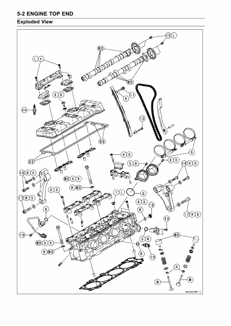
5-2 ENGINE TOP ENDExploded View

ENGINE TOP END 5-3Exploded View
TorqueNo. Fastener
N·m kgf·m ft·lbRemarks
1 Air Suction Valve Cover Bolts 9.8 1.0 87 in·lb L2 Cylinder Head Cover Bolts 9.8 1.0 87 in·lb S3 Camshaft Cap Bolts 12 1.2 106 in·lb S4 Camshaft Chain Guide Bolts 12 1.2 106 in·lb S
Cylinder Head Bolts (M11, First) 39 4.0 29 MO, S5
Cylinder Head Bolts (M11, Final) 71 7.2 52 MO, S6 Cylinder Head Bolts (M6) 12 1.2 106 in·lb S7 Water Passage Plugs 20 2.0 15 L8 Throttle Body Holder Bolts 9.8 1.0 87 in·lb S9 Throttle Body Assy Holder Clamp Bolts 2.0 0.20 18 in·lb10 Camshaft Position Sensor Bolt 9.8 1.0 87 in·lb11 Front Camshaft Chain Guide Bolt (Upper) 25 2.5 1812 Front Camshaft Chain Guide Bolt (Lower) 12 1.2 106 in·lb13 Camshaft Chain Tensioner Mounting Bolts 9.8 1.0 87 in·lb14 Spark Plugs 13 1.3 115 in·lb15 Cam Sprocket Mounting Bolts 15 1.5 11 L16 Engine Bracket Bolts 25 2.5 18 R, S17 Front Engine Mounting Bolts 59 6.0 44 R, S18 Plug – – – Hand-tighten19 Water Temperature Sensor 25 2.5 18G: Apply grease.L: Apply a non-permanent locking agent.M: Apply molybdenum disulfide grease.
MO: Apply molybdenum disulfide oil.(mixture of the engine oil and molybdenum disulfide grease in a weight ratio 10 : 1)
R: Replacement PartsS: Follow the specific tightening sequence.SS: Apply silicone sealant (Kawasaki Bond: 92104-0004).

5-4 ENGINE TOP ENDExploded View

ENGINE TOP END 5-5Exploded View
TorqueNo. Fastener
N·m kgf·m ft·lbRemarks
1 Muffler Body Mounting Bolts 34 3.5 252 Crankshaft Sensor Cover Bolts 9.8 1.0 87 in·lb L (1)3. Muffler Body Clamp Bolts4. Exhaust Pipe Manifold Holder NutsL: Apply a non-permanent locking agent.R: Replacement Parts

5-6 ENGINE TOP ENDExhaust System
Full: Full PowerH: Honeycomb Type Catalyst
78.2: Hosepower 78.2 kW (106.3 ps)
Manifold Mark Position [A]

ENGINE TOP END 5-7Exhaust System
Silencer Mark Position [A]
Honeycomb Type Catalyst [A]

5-8 ENGINE TOP ENDSpecifications
Item Standard Service LimitCamshaftsCam Height:Exhaust 34.442 ∼ 34.556 mm (1.3560 ∼ 1.3605 in.) 34.34 mm (1.352 in.)Inlet 34.943 ∼ 35.057 mm (1.3757 ∼ 1.3802 in.) 34.84 mm (1.372 in.)
Camshaft Journal, CamshaftCap Clearance
0.038 ∼ 0.081 mm (0.0015 ∼ 0.0032 in.) 0.17 mm (0.0067 in.)
Camshaft Journal Diameter 23.940 ∼ 23.962 mm (0.9425 ∼ 0.9434 in.) 23.91 mm (0.941 in.)Camshaft Bearing InsideDiameter
24.000 ∼ 24.021 mm (0.9449 ∼ 0.9457 in.) 24.08 mm (0.948 in.)
Camshaft Runout TIR 0.02 mm (0.0008 in.) or less TIR 0.1 mm (0.004 in.)Cylinder HeadCylinder Compression (Usable Range)
1 030 ∼ 1 569 kPa (10.5 ∼ 16.0 kgf/cm²,149 ∼ 228 psi) @300 r/min (rpm)
– – –
Cylinder Head Warp – – – 0.05 mm (0.002 in.)ValvesValve Clearance:Exhaust 0.22 ∼ 0.27 mm (0.0087 ∼ 0.0106 in.) – – –Inlet 0.15 ∼ 0.20 mm (0.0059 ∼ 0.0079 in.) – – –
Valve Head Thickness:Exhaust 0.8 mm (0.031 in.) 0.7 mm (0.0276 in.)Inlet 0.5 mm (0.020 in.) 0.25 mm (0.001 in.)
Valve Stem Bend TIR 0.01 mm (0.0004 in.) or less TIR 0.05 mm (0.002 in.)Valve Stem Diameter:Exhaust 4.955 ∼ 4.970 mm (0.1951 ∼ 0.1957 in.) 4.94 mm (0.194 in.)Inlet 4.975 ∼ 4.990 mm (0.1959 ∼ 0.1965 in.) 4.96 mm (0.195 in.)
Valve Guide Inside Diameter:Exhaust 5.000 ∼ 5.012 mm (0.1969 ∼ 0.1973 in.) 5.077 mm (0.200 in.)Inlet 5.000 ∼ 5.012 mm (0.1969 ∼ 0.1973 in.) 5.077 mm (0.200 in.)
Valve/valve Guide Clearance(Wobble Method):Exhaust 0.10 ∼ 0.18 mm (0.0039 ∼ 0.0071 in.) 0.39 mm (0.015 in.)Inlet 0.03 ∼ 0.12 mm (0.0012 ∼ 0.0047 in.) 0.33 mm (0.013 in.)
Valve Seat Cutting Angle 45°, 32°, 60° – – –Valve Seating Surface:Width:Exhaust 0.8 ∼ 1.2 mm (0.031 ∼ 0.047 in.) – – –Inlet 0.5 ∼ 1.0 mm (0.020 ∼ 0.039 in.) – – –
Outside Diameter:Exhaust 27.6 ∼ 27.8 mm (1.087 ∼ 1.094 in.) – – –Inlet 32.6 ∼ 32.8 mm (1.283 ∼ 1.291 in.) – – –
Valve Spring Free Length:Exhaust 39.10 mm (1.539 in.) 37.4 mm (1.472 in.)Inlet 38.72 mm (1.524 in.) 37.1 mm (1.461 in.)

ENGINE TOP END 5-9Special Tools and Sealant
Compression Gauge, 20 kgf/cm²:57001-221
Valve Spring Compressor Assembly:57001-241
Valve Seat Cutter, 45° - 35:57001-1116
Valve Seat Cutter, 32° - 30:57001-1120
Valve Seat Cutter, 32° - 35:57001-1121
Valve Seat Cutter, 60° - 30:57001-1123
Valve Seat Cutter Holder Bar:57001-1128
Valve Seat Cutter, 45° - 30:57001-1187
Valve Guide Arbor, 5:57001-1203
Valve Guide Reamer, 5:57001-1204

5-10 ENGINE TOP ENDSpecial Tools and Sealant
Valve Seat Cutter Holder, 5:57001-1208
Valve Seat Cutter, 60° - 33:57001-1334
Valve Guide Driver:57001-1564
Valve Spring Compressor Adapter, 24:57001-1586
Compression Gauge Adapter, M10 × 1.0:57001-1601
L-Shape Hose:57001-1606
Valve Guide Driver Attachment, E:57001-1677
Kawasaki Bond (Silicone Sealant):92104-0004

ENGINE TOP END 5-11Clean Air System
Air Suction Valve Removal•Remove:Middle Fairings (see Middle Fairing Removal in theFrame chapter)• Pull out the hoses [A].• Disconnect the connector [B].• Remove the air switching valve [C] with the hoses.
• Remove the following from the bracket [A].Rivets [B]Bolts [C]
• Remove:Air Suction Valve Cover Bolts [A]Air Suction Valve Cover [B]Air Suction Valve [C]
Air Suction Valve Installation• Install the air suction valve so that opening [A] of the reedfaces the rear and downward.• Apply a non-permanent locking agent to the threads ofthe air suction valve cover bolts, and tighten them withthe specified torque.Torque - Air Suction Valve Cover Bolts: 9.8 N·m (1.0 kgf·m,
87 in·lb)

5-12 ENGINE TOP ENDClean Air System
Air Suction Valve Inspection•Remove the air suction valve (see Air Suction Valve Re-moval).• Visually inspect the reeds [A] for cracks, folds, warps,heat damage, or other damage.If there is any doubt as to the condition of the reed, replacethe air suction valve as an assembly.• Check the reed contact areas [B] of the valve holder forgrooves, scratches, any sings of separation from theholder, or heat damage.If there is any doubt as to the condition of the reed contactareas, replace the air suction valve as an assembly.• If any carbon or other foreign particles have accumulatedbetween the reed and the reed contact area, wash thevalve assembly with a high flash-point solvent.
CAUTIONDo not scrape off the deposits with a scraper as thiscould damage the rubber, requiring replacement ofthe suction valve assembly.
Air Switching Valve Removal•Remove:Middle Fairings (see Middle Fairing Removal in theFrame chapter)Connector [A]Air Switching Valve [B]
CAUTIONNever drop the switch especially on a hard surface.Such a shock to the switch can damage it.
Air Switching Valve Installation• Install the air switching valve so that the air duct [A] facesleft side.• Route the hoses correctly (see Cable, Wire, and HoseRouting section in the Appendix chapter).
Air Switching Valve Operation Test•Refer to the Air Switching Valve Operation Test in theElectrical System chapter.
Air Switching Valve Unit Test•Refer to the Air Switching Valve Unit Test in the ElectricalSystem chapter.
Clean Air System Hose Inspection•Be certain that all the hoses are routed without being flat-tened or kinked, and are connected correctly to the aircleaner housing, air switching valve and air suction valvecovers.If they are not, correct them. Replace them if they aredamaged.

ENGINE TOP END 5-13Cylinder Head Cover
Cylinder Head Cover Removal•Remove:Middle Fairings (see Middle Fairing Removal in theFrame chapter)Throttle Body Assy (see Throttle Body Assy Removal inthe Fuel System (DFI) chapter)Air Switching Valve (see Air Switching Valve Removal)• Free the heat insulation rubber plate.• Remove:Stick Coils (see Stick Coil (Ignition Coil together withSpark Plug Cap) Removal in the Electrical System chap-ter)Air Suction Valve Covers (see Air Suction Valve Re-moval)
• Remove the cylinder head cover bolts [A].• Remove the cylinder head cover to backward floating it alittle up.
Cylinder Head Cover Installation•Replace the head cover gasket with a new one.• Apply silicone sealant [A] to the cylinder head as shown.Sealant - Kawasaki Bond (Silicone Sealant): 92104-0004
• Install:Dowel Pins [A]Plug Hole Gaskets [B]

5-14 ENGINE TOP ENDCylinder Head Cover
• Install the washer [A] with the metal side faces upward.• Tighten the cover bolts, following the sequence numberson the cover.Torque - Cylinder Head Cover Bolts [B]: 9.8 N·m (1.0 kgf·m,
87 in·lb)
• Install the removed parts (see appropriate chapters).

ENGINE TOP END 5-15Camshaft Chain Tensioner
Camshaft Chain Tensioner RemovalCAUTION
Do not turn over the crankshaft while the tensioneris removed. This could upset the camshaft chaintiming, and damage the valves.
•Remove the right middle fairing (see Middle Fairing Re-moval in the Frame chapter).• Remove the mounting bolts [A] and take off the camshaftchain tensioner [B].
Camshaft Chain Tensioner Installation•Remove the cylinder head cover (see Cylinder HeadCover Removal).• Pinching [A] the stopper [B], release it and push [C] thepush rod [D] into the interior of tensioner body [E].
• Pushing [A] the push rod, slide the snap ring [B] into thegroove [C] of smaller diameter from the groove [D] oflarger diameter.
• Install the tensioner body so that the stopper [A] facesupward.• Tighten the tensioner mounting bolts.Torque - Camshaft Chain Tensioner Mounting Bolts: 9.8
N·m (1.0 kgf·m, 87 in·lb)

5-16 ENGINE TOP ENDCamshaft Chain Tensioner
• Lightly hit the push rod head [A] with a minus screw driver[B] to move out the push rod.
NOTEYou hear of the sound from which the push rod movesout.
•Turn the crankshaft 2 turns clockwise to allow the ten-sioner to expand and recheck the camshaft chain timing.

ENGINE TOP END 5-17Camshaft, Camshaft Chain
Camshaft Removal•Remove:Cylinder Head Cover (see Cylinder Head Cover Re-moval)Crankshaft Sensor Cover• Position the crankshaft at #1, 4 piston TDC.TDC mark [A] for #1, 4 PistonsTiming Mark (crankcase halves mating surface) [B]
• Remove:Camshaft Chain Tensioner (see Camshaft Chain Ten-sioner Removal)Camshaft Cap Bolts [A]Chain GuideCamshaft Caps [B]Camshafts [C]• Stuff a clean cloth into the chain tunnel to keep any partsfrom dropping into the crankcase.
• Remove the cam sprocket mounting bolts [A].• Remove the cam sprocket.
CAUTIONThe crankshaft may be turned while the camshaftsare removed. Always pull the chain taut while turn-ing the crankshaft. This avoids kinking the chainon the lower (crankshaft) sprocket. A kinked chaincould damage both the chain and the sprocket.
Camshaft Installation•Be sure to install the following parts.Plug Hole Gaskets [A]Dowel Pins [B]
• Install the cam sprockets as shown in figure.#4 Cam Positions [A]Inlet Cam Sprocket [B]Exhaust Cam Sprocket [C]• Apply a non-permanent locking agent to the threads andtighten the bolts.Torque - Cam Sprocket Mounting Bolts: 15 N·m (1.5 kgf·m,
11 ft·lb)

5-18 ENGINE TOP ENDCamshaft, Camshaft Chain
•Apply engine oil to all cam parts and journals.• If a new camshaft is to be used, apply a thin coat of molyb-denum disulfide grease to the cam surfaces.
NOTEThe exhaust camshaft has a 1090 EX mark [A] and theinlet camshaft has a 1090 IN mark [B]. Be careful not tomix up these shafts.
NOTEThe exhaust camshaft has the projection [A] forcamshaft position sensor.
•Position the crankshaft at #1, 4 piston TDC.• Pull the tension side (exhaust side) [A] of the chain tautto install the chain.• Engage the camshaft chain with the camshaft sprocketsso that the timing marks on the sprockets are positionedas shown.The timing marks of #1, 4T must be aligned with the lowersurface of crankcase of rear side [B].

ENGINE TOP END 5-19Camshaft, Camshaft Chain
The timing marks must be aligned with the cylinder headupper surface [A].EX mark [B]IN mark [C]

5-20 ENGINE TOP ENDCamshaft, Camshaft Chain
• Install the camshaft cap, following the identification No.[A] and chain guide [B].First tighten the camshaft cap and all chain guide boltsevenly to seat the camshaft in place, then tighten all boltsfollowing the specified tightening sequence.Torque - Camshaft Cap Bolts (1 ∼ 16, 17, 18): 12 N·m (1.2
kgf·m, 106 in·lb)Camshaft Chain Guide Bolts (19, 20): 12 N·m (1.2kgf·m, 106 in·lb)
• Install the camshaft chain tensioner (see Camshaft ChainTensioner Installation).
Camshaft, Camshaft Cap Wear•Remove:Camshaft Chain GuideCamshaft Cap (see Camshaft Removal)• Cut strips of plastigage to journal width. Place a stripon each journal parallel to the camshaft installed in thecorrect position.•Measure each clearance between the camshaft journaland the camshaft cap using plastigage (press gauge) [A].
• Tighten:Torque - Camshaft Cap Bolts: 12 N·m (1.2 kgf·m, 106 in·lb)
Camshaft Chain Guide Bolts: 12 N·m (1.2 kgf·m,106 in·lb) (see Camshaft Installation)
NOTEDo not turn the camshaft when the plastigage is be-tween the journal and camshaft cap.
Camshaft Journal, Camshaft Cap ClearanceStandard: 0.038 ∼ 0.081 mm (0.0015 ∼ 0.0032 in.)Service Limit: 0.17 mm (0.0067 in.)

ENGINE TOP END 5-21Camshaft, Camshaft Chain
If any clearance exceeds the service limit, measure thediameter of each camshaft journal with a micrometer.
Camshaft Journal DiameterStandard: 23.940 ∼ 23.962 mm (0.9425 ∼ 0.9434 in.)Service Limit: 23.91 mm (0.941 in.)
If the camshaft journal diameter is less than the servicelimit, replace the camshaft with a new one and measurethe clearance again.If the clearance still remains out of the limit, replace thecylinder head unit.
Camshaft Runout•Remove the camshaft (see Camshaft Removal).• Set the camshaft in a camshaft alignment jig or on Vblocks.•Measure runout with a dial gauge at the specified placeas shown.If the runout exceeds the service limit, replace the shaft.
Camshaft RunoutStandard: TIR 0.02 mm (0.0008 in.) or lessService Limit: TIR 0.1 mm (0.004 in.)
Cam Wear•Remove the camshaft (see Camshaft Removal).•Measure the height [A] of each cam with a micrometer.If the cams are worn down past the service limit, replacethe camshaft.
Cam HeightStandard:Exhaust 34.442 ∼ 34.556 mm (1.3560 ∼ 1.3605 in.)Inlet 34.943 ∼ 35.057 mm (1.3757 ∼ 1.3802 in.)
Service Limit:Exhaust 34.34 mm (1.352 in.)Inlet 34.84 mm (1.372 in.)
Camshaft Chain Removal•Remove:Camshafts (see Camshaft Removal)Timing Rotor [A] (see Timing Rotor Removal in the Elec-trical System chapter)Front Camshaft Chain Guide Bolts [B]Front Camshaft Chain Guide [C]Dowel Pin [D]Rear Camshaft Chain Guide [E]

5-22 ENGINE TOP ENDCamshaft, Camshaft Chain
•Remove the crankshaft sprocket [A].• Pull out the camshaft chain [B] from downward.
Camshaft Chain Installation• Install the camshaft chain from head side.• Install the crankshaft sprocket [A] on the crankshaft [B]with their teeth [C] aligned.• Install the front camshaft chain guide, and tighten thebolts.Torque - Front Camshaft Chain Guide Bolt (Upper): 25 N·m
(2.5 kgf·m, 18 ft·lb)Front Camshaft Chain Guide Bolt (Lower): 12 N·m(1.2 kgf·m, 106 in·lb)
• Install the removed parts (see appropriate chapters).

ENGINE TOP END 5-23Cylinder Head
Cylinder Compression MeasurementNOTE
Use the battery which is fully charged.•Warm up the engine thoroughly.• Stop the engine.• Remove:Stick Coils (see Stick Coil (Ignition Coil together withSpark Plug Cap) Removal in the Electrical System chap-ter)Spark Plugs (see Spark Plug Replacement in the Peri-odic Maintenance chapter)Owner’s Tool - Spark Plug Wrench: 92110-1132
•Attach the compression gauge [A] and adapter [B] firmlyinto the spark plug hole.Using the starter motor, turn the engine over with the throt-tle fully open until the compression gauge stops rising; thecompression is the highest reading obtainable.Special Tools - Compression Gauge, 20 kgf/cm²: 57001-221
Compression Gauge Adapter, M10 × 1.0:57001-1601
L-Shape Hose: 57001-1606 [C]
Cylinder CompressionUsable Range: 1 030 ∼ 1 569 kPa (10.5 ∼ 16.0 kgf/cm²,
149 ∼ 228 psi) @300 r/min (rpm)
•Repeat the measurement for the other cylinders.• Install the spark plugs.Torque - Spark Plugs: 13 N·m (1.3 kgf·m, 115 in·lb)
The following table should be consulted if the obtainable compression reading is not within the us-able range.Problem Diagnosis Remedy (Action)
Carbon accumulation on piston and incombustion chamber possibly due todamaged valve stem oil seal and/ordamaged piston oil rings (This may beindicated by white exhaust smoke).
Remove the carbon deposits andreplace damaged parts if necessary.
Cylindercompressionis higher thanusable range
Incorrect cylinder head gasket thickness Replace the gasket with a standard part.Gas leakage around cylinder head Replace damaged check gasket and
cylinder head warp.Bad condition of valve seating Repair if necessary.Incorrect valve clearance Adjust the valve clearance.Incorrect piston/cylinder clearance Replace the piston and/or cylinder.Piston seizure Inspect the cylinder and replace/repair
the cylinder and/or piston as necessary.
Cylindercompressionis lower thanusable range
Bad condition of piston ring and/or pistonring grooves
Replace the piston and/or the pistonrings.
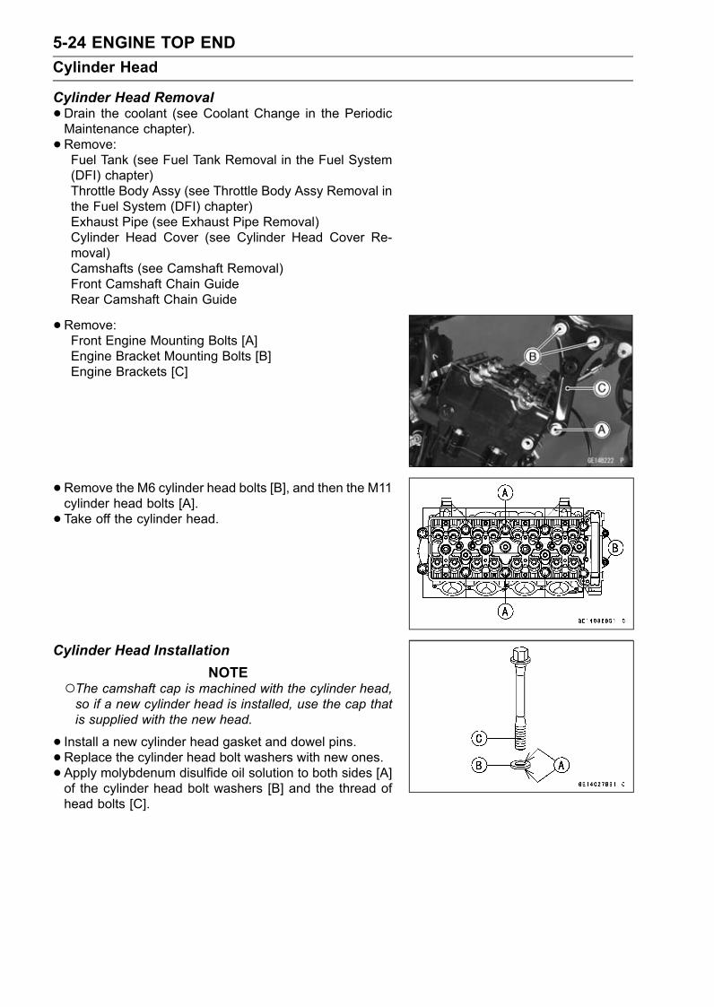
5-24 ENGINE TOP ENDCylinder Head
Cylinder Head Removal•Drain the coolant (see Coolant Change in the PeriodicMaintenance chapter).• Remove:Fuel Tank (see Fuel Tank Removal in the Fuel System(DFI) chapter)Throttle Body Assy (see Throttle Body Assy Removal inthe Fuel System (DFI) chapter)Exhaust Pipe (see Exhaust Pipe Removal)Cylinder Head Cover (see Cylinder Head Cover Re-moval)Camshafts (see Camshaft Removal)Front Camshaft Chain GuideRear Camshaft Chain Guide
•Remove:Front Engine Mounting Bolts [A]Engine Bracket Mounting Bolts [B]Engine Brackets [C]
• Remove the M6 cylinder head bolts [B], and then the M11cylinder head bolts [A].• Take off the cylinder head.
Cylinder Head InstallationNOTE
The camshaft cap is machined with the cylinder head,so if a new cylinder head is installed, use the cap thatis supplied with the new head.
• Install a new cylinder head gasket and dowel pins.• Replace the cylinder head bolt washers with new ones.• Apply molybdenum disulfide oil solution to both sides [A]of the cylinder head bolt washers [B] and the thread ofhead bolts [C].

ENGINE TOP END 5-25Cylinder Head
•Tighten the M11 cylinder head bolts following the tighten-ing sequence [1 ∼ 10].Torque - Cylinder Head Bolts (M11):
First: 39 N·m (4.0 kgf·m, 29 ft·lb)Final: 71 N·m (7.2 kgf·m, 52 ft·lb)
•Tighten the M6 cylinder head bolts [11 ∼ 12].Torque - Cylinder Head Bolts (M6): 12 N·m (1.2 kgf·m, 106
in·lb)
• Install:Dowel Pin [A]Rear Camshaft Chain Guide [B]Front Camshaft Chain Guide [C]O-ring [D]Collar [E]• Tighten:Torque - Front Camshaft Chain Guide Bolt (Upper) [F]: 25
N·m (2.5 kgf·m, 18 ft·lb)Front Camshaft Chain Guide Bolt (Lower) [G]: 12N·m (1.2 kgf·m, 106 in·lb)
•Replace the following bolts with new bolts pre-coated withlocking agent and torque them.Engine Bracket BoltsFront Engine Mounting BoltsSubframe BoltsTorque - Front Bracket Bolts: 25 N·m (2.5 kgf·m, 18 ft·lb)
Front Engine Mounting Bolts: 59 N·m (6.0 kgf·m,44 ft·lb)
Subframe Bolts: 23 N·m (2.3 kgf·m, 17 ft·lb)
• Install the removed parts (see appropriate chapters).Cylinder Head Warp•Clean the cylinder head.• Lay a straightedge across the lower surface of the cylinderhead at several positions.• Use a thickness gauge [A] to measure the space betweenthe straightedge [B] and the head.
Cylinder Head WarpStandard: – – –Service Limit: 0.05 mm (0.002 in.)
If the cylinder head is warped more than the service limit,replace it.If the cylinder head is warped less than the service limit,repair the head by rubbing the lower surface on emerypaper secured to a surface plate (first No. 200, then No.400).

5-26 ENGINE TOP ENDValves
Valve Clearance Inspection•Refer to the Valve Clearance Inspection in the PeriodicMaintenance chapter.
Valve Removal•Remove the cylinder head (see Cylinder Head Removal).• Remove the valve lifter and shim.Mark and record the valve lifter and shim locations so theycan be installed in their original positions.• Using the valve spring compressor assembly, remove thevalve.Special Tools - Valve Spring Compressor Assembly: 57001
-241 [A]Adapter, 24: 57001-1586 [B]
Valve InstallationCAUTION
Do not lap the exhaust valve to the exhaust valveseat, using the grinding compound. It will come offoxide film treated surface of the valve.
•Replace the oil seal with a new one.• Apply a thin coat of molybdenum disulfide grease to thevalve stem before valve installation.• Install the springs so that the closed coil end faces down-wards.Valve Stem [A]Oil Seal [B]Spring Seat [C]Closed Coil End [D]Valve Spring [E]:EX-White PaintIN-Red Paint
Retainer [F]Split Keepers [G]
Valve Guide Removal•Remove:Valve (see Valve Removal)Oil SealSpring Seat• Heat the area around the valve guide to 120 ∼ 150°C (248
∼ 302°F), and hammer lightly on the valve guide arbor [A]to remove the guide from the top of the head.
CAUTIONDo not heat the cylinder head with a torch. This willwarp the cylinder head. Soak the cylinder head inoil and heat the oil.
Special Tool - Valve Guide Arbor, 5: 57001-1203

ENGINE TOP END 5-27Valves
Valve Guide Installation•Apply oil to the valve guide outer surface before installa-tion.• Heat the area around the valve guide hole to about 120 ∼150°C (248 ∼ 302°F).
CAUTIONDo not heat the cylinder head with a torch. This Willwarp the cylinder head. Soak the cylinder head andheat the oil.
•Assembly the valve guide driver parts (Holder and attach-ment E).• Insert the rod of the driver into the valve guide bore andhammer the end of the driver until it bottoms.Valve Guide Driver Attachment E [A]Valve Guide Driver (Holder) [B]Valve Guide [C]Cylinder Head [D]Valve Guide Installed Height = 13 mm [E]Special Tools - Valve Guide Driver: 57001-1564
Valve Guide Driver Attachment, E: 57001-1677
•Ream the valve guide with valve guide reamer [A], evenif the old guide is reused.Special Tool - Valve Guide Reamer, 5: 57001-1204

5-28 ENGINE TOP ENDValves
Valve-to-Guide Clearance Measurement (WobbleMethod)If a small bore gauge is not available, inspect the valve
guide wear by measuring the valve to valve guide clearancewith the wobble method as indicated below.• Insert a new valve [A] into the guide [B] and set a dialgauge against the stem perpendicular to it as close aspossible to the cylinder head mating surface.•Move the stem back and forth [C] to measure valve/valveguide clearance.• Repeat the measurement in a direction at a right angle tothe first.If the reading exceeds the service limit, replace the guide.
NOTEThe reading is not actual valve/valve guide clearancebecause the measuring point is above the guide.
Valve/Valve Guide Clearance (Wobble Method)Standard:Exhaust 0.10 ∼ 0.18 mm (0.0039 ∼ 0.0071 in.)Inlet 0.03 ∼ 0.12 mm (0.0012 ∼ 0.0047 in.)
Service Limit:Exhaust 0.39 mm (0.015 in.)Inlet 0.33 mm (0.013 in.)

ENGINE TOP END 5-29Valves
Valve Seat Inspection•Remove the valve (see Valve Removal).• Check the valve seating surface [A] between the valve [B]and valve seat [C].Measure the outside diameter [D] of the seating patternon the valve seat.If the outside diameter is too large or too small, repair theseat (see Seat Repair).
Valve Seating Surface Outside DiameterStandard:Exhaust 27.6 ∼ 27.8 mm (1.087 ∼ 1.094 in.)Inlet 32.6 ∼ 32.8 mm (1.283 ∼ 1.291 in.)
Measure the seat width [E] of the portion where there isno build-up carbon (white portion) of the valve seat with avernier caliper.Good [F]If the width is too wide [G], too narrow [H] or uneven [J],repair the seat (see Valve Seat Repair).
Valve Seating Surface WidthStandard:Exhaust 0.8 ∼ 1.2 mm (0.031 ∼ 0.047 in.)Inlet 0.5 ∼ 1.0 mm (0.020 ∼ 0.039 in.)
Valve Seat Repair•Repair the valve seat with the valve seat cutters [A].Special Tools - Valve Seat Cutter Holder, 5: 57001-1208
[B]Valve Seat Cutter Holder Bar: 57001-1128[C]
For Exhaust Valve SeatValve Seat Cutter, 45° - 30: 57001-1187Valve Seat Cutter, 32° - 30: 57001-1120Valve Seat Cutter, 60° - 30: 57001-1123
For Inlet Valve SeatValve Seat Cutter, 45° - 35: 57001-1116Valve Seat Cutter, 32° - 35: 57001-1121Valve Seat Cutter, 60° - 33: 57001-1334
If the manufacturer’s instructions are not available, usethe following procedure.

5-30 ENGINE TOP ENDValves
Seat Cutter Operation Care1. This valve seat cutter is developed to grind the valve forrepair. Therefore the cutter must not be used for otherpurposes than seat repair.
2. Do not drop or shock the valve seat cutter, or the dia-mond particles may fall off.
3. Do not fail to apply engine oil to the valve seat cutterbefore grinding the seat surface. Also wash off groundparticles sticking to the cutter with washing oil.
NOTEDo not use a wire brush to remove the metal particlesfrom the cutter. It will take off the diamond particles.
4. Setting the valve seat cutter holder in position, operatethe cutter in one hand. Do not apply too much force tothe diamond portion.
NOTEPrior to grinding, apply engine oil to the cutter and dur-ing the operation, wash off any ground particles stickingto the cutter with washing oil.
5. After use, wash it with washing oil and apply thin layerof engine oil before storing.
Marks Stamped on the CutterThemarks stamped on the back of the cutter [A] represent
the following.60° ........................... Cutter angle [B]37.5 ....................... Outer diameter of cutter [C]
Operating Procedures•Clean the seat area carefully.• Coat the seat with machinist’s dye.• Fit a 45° cutter into the holder and slide it into the valveguide.• Press down lightly on the handle and turn it right or left.Grind the seating surface only until it is smooth.
CAUTIONDo not grind the seat too much. Overgrinding willreduce valve clearance by sinking the valve into thehead. If the valve sinks too far into the head, it willbe impossible to adjust the clearance, and the cylin-der head must be replaced.

ENGINE TOP END 5-31Valves
•Measure the outside diameter of the seating surface witha vernier caliper.If the outside diameter of the seating surface is too small,repeat the 45° grind until the diameter is within the spec-ified range.Widened Width [A] of engagement by machining with45° cutterGround Volume [B] by 32° cutter32° [C]Correct Width [D]Ground Volume [E] by 60° cutter60° [F]
•Measure the outside diameter of the seating surface witha vernier caliper.If the outside diameter of the seating surface is too small,repeat the 45° grind [A] until the diameter is within thespecified range.Original Seating Surface [B]
NOTERemove all pittings of flaws from 45° ground surface.After grinding with 45° cutter, apply thin coat of machin-ist’s dye to seating surface. This makes seating surfacedistinct and 32° and 60° grinding operation easier.When the valve guide is replaced, be sure to grind with45° cutter for centering and good contact.
If the outside diameter [A] of the seating surface is toolarge, make the 32° grind described below.If the outside diameter of the seating surface is within thespecified range, measure the seat width as described be-low.•Grind the seat at a 32° angle [B] until the seat O.D. iswithin the specified range.To make the 32° grind, fit a 32° cutter into the holder, andslide it into the valve guide.Turn the holder one turn at a time while pressing downvery lightly. Check the seat after each turn.
CAUTIONThe 32° cutter removes material very quickly.Check the seat outside diameter frequently to pre-vent overgrinding.
After making the 32° grind, return to the seat O.D. mea-surement step above.• To measure the seat width, use a vernier caliper to mea-sure the width of the 45° angle portion of the seat at sev-eral places around the seat.If the seat width is too narrow, repeat the 45° grind untilthe seat is slightly too wide, and then return to the seatO.D. measurement step above.

5-32 ENGINE TOP ENDValves
If the seat width is too wide, make the 60° [A] grind de-scribed below.If the seat width is within the specified range, lap the valveto the seat as described below.•Grind the seat at a 60° angle until the seat width is withinthe specified range.To make the 60° grind, fit 60° cutter into the holder, andslide it into the valve guide.Turn the holder, while pressing down lightly.After making the 60° grind, return to the seat width mea-surement step above.Correct Width [B]
CAUTIONDo not lap the exhaust valve to the exhaust valveseat, using the grinding compound. It will come offoxide film treated surface of the valve.
• Lap the inlet valve to the inlet valve seat, once the seatwidth and O.D. are within the ranges specified above.Put a little coarse grinding compound on the face of thevalve in a number of places around the valve head.Spin the valve against the seat until the grinding com-pound produces a smooth, matched surface on both theseat and the valve.Repeat the process with a fine grinding compound.Lapper [A]Valve Seat [B]Valve [C]• The seating area should be marked about in the middleof the valve face.If the seat area is not in the right place on the valve, checkto be sure the valve is the correct part. If it is, it may havebeen refaced too much; replace it.• Be sure to remove all grinding compound before assem-bly.•When the engine is assembled, be sure to adjust the valveclearance (see Valve Clearance Inspection in the PeriodicMaintenance chapter).

ENGINE TOP END 5-33Valves

5-34 ENGINE TOP ENDThrottle Body Holder
Throttle Body Holder Installation•Be sure to install the O-rings [A].• Install the clamps [B] as shown.• Tighten the holder bolts following the tightening sequence[1 ∼ 3].Torque - Throttle Body Holder Bolts [C]: 9.8 N·m (1.0 kgf·m,
87 in·lb)Throttle Body Assy Holder Clamp Bolts [D]: 2.0N·m (0.20 kgf·m, 18 in·lb)

ENGINE TOP END 5-35Muffler
WARNINGTo avoid a serious burn, do not remove the mufflerwhen the engine is still hot. Wait until the mufflercool down.
Muffler Body Removal/Installation•Remove:Lower Fairings (see Lower Fairing Removal in the Framechapter)Rear Fairing (see Rear Fairing Removal in the Framechapter)Muffler Clamp Bolts [A]Muffler Mounting Bolts and Nuts [B]• Pull the muffler body [C] backward.
• Replace the muffler gaskets [A] with new ones.Install the gaskets until they are bottomed [B].Install the gaskets so that their chamfer sides [C] face thefront.

5-36 ENGINE TOP ENDMuffler
•Align [A] the projections on the muffler bodies with thehoses on the muffler clamps.
• Tighten:Torque - Muffler Body Mounting Bolts: 34 N·m (3.5 kgf·m,
25 ft·lb)
Exhaust Pipe Removal•Remove:Radiator (see Radiator Removal in the Cooling Systemchapter)Right and Left Muffler Body (see Muffler Body Re-moval/Installation)• Remove the exhaust pipe manifold holder nuts [A].• Remove the exhaust pipe manifold [B].
Exhaust Pipe Installation•Replace the exhaust pipe gaskets [A], muffler gasket withnew ones and install them.Install the muffler gasket until it is bottomed so that thechamfer side faces front (see Muffler Body Removal/In-stallation).• Tighten:Torque - Muffler Body Mounting Bolts: 34 N·m (3.5 kgf·m,
25 ft·lb)

CLUTCH 6-1
6
ClutchTable of Contents
Exploded View........................................................................................................................ 6-2Specifications ......................................................................................................................... 6-4Special Tools and Sealant ...................................................................................................... 6-5Clutch Master Cylinder ........................................................................................................... 6-6
Clutch Lever Adjustment................................................................................................... 6-6Clutch Master Cylinder Removal ...................................................................................... 6-6Clutch Master Cylinder Installation .................................................................................. 6-6Clutch Master Cylinder Disassembly ............................................................................... 6-7Clutch Master Cylinder Assembly ..................................................................................... 6-7Clutch Master Cylinder Inspection .................................................................................... 6-7
Clutch Slave Cylinder ............................................................................................................. 6-8Clutch Slave Cylinder Removal ........................................................................................ 6-8Clutch Slave Cylinder Installation ..................................................................................... 6-9Clutch Slave Cylinder Disassembly ................................................................................. 6-9Clutch Slave Cylinder Assembly ....................................................................................... 6-9
Clutch Fluid............................................................................................................................. 6-10Clutch Fluid Level Inspection ............................................................................................ 6-10Clutch Fluid Change ......................................................................................................... 6-10Bleeding the Clutch Line ................................................................................................... 6-10Clutch Hose Removal/Installation ..................................................................................... 6-11Clutch Hose and Connection Inspection........................................................................... 6-11
Clutch Cover........................................................................................................................... 6-12Clutch Cover Removal ...................................................................................................... 6-12Clutch Cover Installation ................................................................................................... 6-12
Clutch ..................................................................................................................................... 6-13Clutch Removal................................................................................................................. 6-13Clutch Installation.............................................................................................................. 6-14Clutch Plate Assembly Inspection..................................................................................... 6-16Clutch Plate Assembly Adjustment ................................................................................... 6-16Clutch Plate, Wear, Damage Inspection ........................................................................... 6-17Clutch Plate Warp Inspection............................................................................................ 6-17Clutch Spring Free Length Measurement ......................................................................... 6-17

6-2 CLUTCHExploded View

CLUTCH 6-3Exploded View
TorqueNo. Fastener
N·m kgf·m ft·lbRemarks
1 Clutch Lever Pivot Bolt 1.0 0.10 8.9 in·lb2 Clutch Lever Pivot Bolt Locknut 5.9 0.60 52 in·lb3 Clutch Master Cylinder Bleed Valve 7.8 0.80 69 in·lb4 Clutch Slave Cylinder Bleed Valve 7.8 0.80 69 in·lb5 Clutch Slave Cylinder Bolts – – – L6 Clutch Hose Banjo Bolt 25 2.5 187 Clutch Master Cylinder Clamp Bolts 8.8 0.90 78 in·lb S8 Clutch Cover Bolts 9.8 1.0 87 in·lb L (1)9 Clutch Spring Bolts 8.8 0.9 78 in·lb10 Clutch Hub Nut 135 14 100 R11 Oil Filler Cap – – – Hand-tightenC: Apply clutch fluid.EO: Apply engine oil.L: Apply a non-permanent locking agent.M: Apply molybdenum disulfide grease.R: Replacement PartsS: Follow the specific tightening sequence.Si: Apply silicone grease.

6-4 CLUTCHSpecifications
Item Standard Service LimitClutch Fluid:Grade DOT4 – – –
Clutch Lever: – – –Clutch Lever Position 5-way adjustable (to suit rider) – – –Clutch Lever Free Play Non-adjustable – – –
Clutch:Friction Plate Thickness(13088-0030, 13088-0031)
2.92 ∼ 3.08 mm (0.115 ∼ 0.121 in.) 2.7 mm (0.106 in.)
Friction Plate Thickness(13088-0032)
3.72 ∼ 3.88 mm (0.146 ∼ 0.153 in.) 3.5 mm (0.138 in.)
Friction and Steel Plate Warp 0.15 mm (0.0059 in.) or less 0.3 mm (0.012 in.)Friction Plate Warp(only 13088-0030)
0.2 mm (0.008 in.) or less 0.3 mm (0.012 in.)
Clutch Spring Free Length 65.0 mm (2.56 in.) 62.0 mm (2.44 in.)

CLUTCH 6-5Special Tools and Sealant
Inside Circlip Pliers:57001-143
Clutch Holder:57001-1243
Clutch Gear Setting Screw:57001-1671
Kawasaki Bond (Silicone Sealant):92104-0004

6-6 CLUTCHClutch Master Cylinder
Clutch Lever AdjustmentThe adjuster has 5 positions so that the clutch lever posi-tion can be adjusted to suit the operator’s hand.• Push the lever forward and turn the adjuster [A] to alignthe number with the triangular mark [B] on the lever holder(front view).The distance from the grip to the lever is minimumat Num-ber 5 and maximum at Number 1.
Clutch Master Cylinder Removal•Disconnect the starter lockout switch connector [A] (rearview).• Drain the clutch fluid from the reservoir (see Clutch FluidChange in the Periodic Maintenance chapter).
• Remove:Bracket Bolt [A]Clutch Reservoir Bolt [B]• Remove the banjo bolt [C] to disconnect the clutch hosefrom the master cylinder (rear view).• Unscrew the clamp bolts [D], and take off themaster cylin-der as an assembly with the clutch reservoir, clutch lever,and starter lockout switch installed.
CAUTIONClutch fluid quickly ruins painted surface; anyspilled fluid should be completely washed awayimmediately.
Clutch Master Cylinder Installation•Align the punch mark [A] on the handlebar with the matingsurface [B] of the master cylinder clamp (left view).Front [C]

CLUTCH 6-7Clutch Master Cylinder
• Install the master cylinder clamp with the triangular mark[A] up.• Tighten the upper clamp bolt [B] first, and then the lowerclamp bolt [C]. There will be a gap at the lower part of theclamp after tightening.Torque - ClutchMaster Cylinder Clamp Bolts: 8.8 N·m (0.90
kgf·m, 78 in·lb)
•Use a new flat washer on each side of the clutch hosefitting.Torque - Clutch Hose Banjo Bolt: 25 N·m (2.5 kgf·m, 18
ft·lb)
•Replenish the clutch fluid into the reservoir and bleed theclutch line (See Bleeding the Clutch Line in this chapter).• Check that the clutch line has proper fluid pressure andno fluid leakage.
Clutch Master Cylinder Disassembly•Refer to the Clutch Master Cylinder Cap and Dust SealReplacement in the Periodic Maintenance chapter.
Clutch Master Cylinder Assembly•Refer to the Clutch Master Cylinder Cap and Dust SealReplacement in the Periodic Maintenance chapter.
Clutch Master Cylinder Inspection•Disassemble the clutch master cylinder (see Clutch Mas-ter Cylinder Cap and Dust Seal Replacement in the Peri-odic Maintenance chapter).Special Tool - Inside Circlip Pliers: 57001-143
•Check that there are no scratches, rust or pitting on theinside of the master cylinder [A] and on the outside of thepiston [B].If the master cylinder or piston shows any damage, re-place them.• Inspect the primary cup [C] and secondary cup [D].If a cup is worn, damaged, softened (rotted), or swollen,the piston assembly should be replaced to renew the cup.• If fluid leakage is noted at the clutch lever, the piston as-sembly should be replaced to renew the cup.• Check the dust cover [E] for damage.• If it is damaged, replace the piston assembly.• Check that the relief [F] and supply [G] ports are notplugged.If the small relief port becomes plugged, the clutch willdrag. Blow the ports clean with compressed air.• Check the piston return spring [H] for any damage.If the spring is damaged, replace it.

6-8 CLUTCHClutch Slave Cylinder
Clutch Slave Cylinder Removal•Remove:Left Lower Fairing (see Lower Fairing Removal Framechapter)Left Middle Fairing (see Middle Fairing Removal in theFrame chapter)Banjo Bolt [A]Clutch Slave Cylinder Bolts [B]Slave Cylinder [C]
CAUTIONImmediately wash away any clutch fluid that spills.It may damage painted surfaces.
•Pull off the clutch pipe [A] by prying the dampers [B] outof the grooves of the frame. This prevents the pipe fromdistorting.
• Perform the following if the clutch slave cylinder is to beremoved but not disassembled.
CAUTIONIf the clutch slave cylinder is removed and leftalone, the piston will be pushed out by spring forceand the clutch fluid will drain out.
Remove the clutch slave cylinder from the engine with thepipe installed. Push [A] the piston into the cylinder as faras it will go.
Apply the clutch lever [A] slowly and hold it with a band[B].
NOTEHolding the clutch lever keeps the piston from comingout.

CLUTCH 6-9Clutch Slave Cylinder
Clutch Slave Cylinder Installation•Apply molybdenum disulfide grease to either end [A] ofthe push rod, and install the push rod so that the greasedend faces in.• Replace the spacer [B] of the clutch slave cylinder with anew one.• Install the spacer so that the stepped side [C] faces out-ward.
• Apply a non-permanent locking agent to the threads ofthe slave cylinder bolts [A].• Finger tighten all the clutch slave cylinder bolts.• Remove the band from the clutch lever and release theclutch lever.• Tighten the slave cylinder bolts.• Replace the washer on each side of the clutch hose fittingwith new one.• Tighten the banjo bolt [B] to the specified torque.Torque - Clutch Pipe Banjo Bolt: 25 N·m (2.5 kgf·m, 18 ft·lb)
•Check the fluid level in the master cylinder reservoir, andbleed the air in the clutch line.• Check the clutch operation.• Install the removed parts.Coolant Reserve TankLeft Lower Fairing (see Lower Fairing Installation in theFrame chapter)
Clutch Slave Cylinder Disassembly•Refer to Rubber Parts of Clutch Master Cylinder/SlaveCylinder Replacement in the Periodic Maintenance chap-ter.
Clutch Slave Cylinder Assembly•Refer to Rubber Parts of Clutch Master Cylinder/SlaveCylinder Replacement in the Periodic Maintenance chap-ter.

6-10 CLUTCHClutch Fluid
Clutch Fluid Level Inspection•Refer to the Clutch Fluid Level Inspection in the PeriodicMaintenance chapter.
Clutch Fluid Change•Refer to the Clutch Fluid Change in the Periodic Mainte-nance chapter.
Bleeding the Clutch LineWARNING
Be sure to bleed the air from the clutch line when-ever clutch lever action feels soft or spongy afterthe clutch fluid is changed, or whenever a clutchline fitting has been loosened for any reason.
CAUTIONClutch fluid quickly ruins painted or plastic sur-faces; any spilled fluid should be completely wipedup immediately with wet cloth.
•Remove:Screw [A]Clamp [B]Clutch Reservoir Cap [C]Diaphragm PlateDiaphragm•Fill the reservoir with fresh clutch fluid to the upper levelline in the reservoir.
NOTETap the clutch hose lightly going from the lower end toupper end and bleed the air off the reservoir.
•With the reservoir cap off, slowly pump the clutch leverseveral times until no air bubbles can be seen rising upthrough the fluid from the holes at the bottom of the reser-voir.Bleed the air completely from the master cylinder by thisoperation.
• Remove the rubber cap from the bleed valve on the mas-ter cylinder.• Attach a clear plastic hose [A] to the bleed valve, and runthe other end of the hose into a container.

CLUTCH 6-11Clutch Fluid
•Bleed the clutch line and the master cylinder.Repeat this operation until no more air can be seen com-ing out into the plastic hose.1. Pump the clutch lever until it becomes hard, and applythe clutch lever and hold it [C].
2. Quickly open and close [B] the bleed valve while hold-ing the clutch lever applied.
3. Release the clutch lever [A].
NOTEThe fluid level must be checked often during the bleed-ing operation and replenished with fresh clutch fluid asnecessary. If the fluid in the reservoir runs completelyout any time during bleeding, the bleeding operationmust be done over again from the beginning since airwill have entered the line.
•Remove the clear plastic hose.• Tighten the bleed valve, and install the rubber cap.Torque - Clutch Master Cylinder Bleed Valve: 7.8 N·m (0.80
kgf·m, 69 in·lb)
•Remove the left lower fairing (see Lower Fairing Removalin the Frame chapter).• Remove the rubber cap from the bleed valve.• Attach a clear plastic hose [A] to the bleed valve on theclutch slave cylinder, and run the other end of the hoseinto a container.• Bleed the clutch line as follows:Repeat this operation until no more air can be seen com-ing out into the plastic hose.
1. Pump the clutch lever a few times until it becomes hardand then hold it applied [D].
2. Quickly open and close [C] the bleed valve.3. Release the clutch lever [B].
NOTECheck the fluid level in the reservoir often, replenishingit as necessary.If the fluid in the reservoir runs completely out any timeduring bleeding, the bleeding operation must be doneover again from the beginning since air will have en-tered the line.
WARNINGDo not mix different grades and brands of fluid.
•Remove the clear plastic hose.Torque - Clutch Slave Cylinder Bleed Valve: 7.8 N·m (0.80
kgf·m, 69 in·lb)
Clutch Hose Removal/Installation•Refer to the Clutch Hose and Pipe Replacement in thePeriodic Maintenance chapter.
Clutch Hose and Connection Inspection•Refer to the Clutch Hose Damage and Installation Con-nection Inspection in the Periodic Maintenance chapter.

6-12 CLUTCHClutch Cover
Clutch Cover Removal•Remove:Engine Oil (Drain, see Engine Oil Change in the PeriodicMaintenance chapter)Right Lower Fairing (see Lower Fairing Removal in theFrame chapter)Clutch Cover Bolts [A]Clutch Cover [B]
Clutch Cover Installation•Apply silicone sealant to the area [A] where the matingsurface of the crankcase touches the clutch cover gasket.Sealant - Kawasaki Bond (Silicone Sealant): 92104-0004
•Replace the clutch cover gasket with a new one.• Tighten the clutch cover mounting bolts.Apply a non-permanent locking agent to only one clutchcover mounting bolt [A] shown in figure.Torque - Clutch Cover Mounting Bolts: 9.8 N·m (1.0 kgf·m,
87 in·lb)
• If the oil gauge [A] is removed, press the gauge so that itsprojection [B] faces the inside, using lubricant.

CLUTCH 6-13Clutch
Clutch Removal•Remove:Right Lower Fairing (see Lower Fairing Removal in theFrame chapter)Clutch Cover (see Clutch Cover Removal)Clutch Spring Bolts [A]Clutch SpringsClutch Spring Plate [B] (with thrust bearing, pusher [C]and washer)
• Remove:Friction Plates [A]Steel PlatesSpringSpring Seat
Holding the clutch hub [A], remove the nut [B] and wash-ers [C]Special Tool - Clutch Holder: 57001-1243 [D]
•Remove:Clutch HubWasher
• Insert the clutch gear setting screw to the hole of theclutch housing (see Clutch Installation).Position the hole of the clutch housing at the front side ofthe engine so that the tip of the gear setting does not hitthe crankcase wall.Align the teeth of the clutch housing gears by the gearsetting.Special Tool - Clutch Gear Setting Screw: 57001-1671
•Pull out the sleeve [B] from the clutch housing [D], andremove the housing.If the sleeve does not pull out easily, insert M4 bolts [A]into the threaded hole of the sleeve, and pull out thesleeve and needle bearing [C].• Remove the thrust washer.

6-14 CLUTCHClutch
Clutch Installation• Install the thrust washer [A] by facing its chamfered side[B] towards the crankcase.
• Align the teeth of the clutch housing gears by the gearsetting screw [A].Install the clutch housing so that the hole position forwardof the engine.Special Tool - Clutch Gear Setting Screw: 57001-1671
• Install:Clutch HousingNeedle BearingSleeveWasher [A]
Apply engine oil to the needle bearing and the sleeve be-fore installation.
• Install the clutch hub and two washers [A].The outside washer has the OUT SIDE mark [B].
• Replace the clutch hub nut with a new one.• Holding the clutch hub, tighten the clutch hub nut with thetorque wrench.Special Tool - Clutch Holder: 57001-1243
Torque - Clutch Hub Nut: 135 N·m (14 kgf·m, 100 ft·lb)

CLUTCH 6-15Clutch
• Install the spring seat [A], spring [B], friction plates [C] [D][E] and steel plates [F] as shown.
NOTEThe inside diameter of first friction plates are largerthan the others because the spring seat and spring areequipped to decrease the judder noise as shown.
Clutch Hub [G]
CAUTIONIf new dry friction plates and steel plates are in-stalled, apply engine oil to the surfaces of eachplate to avoid clutch plate seizure.
Install outer-end friction plate, that has the large liningblocks [A] among others.
Install the last friction plate [A] fitting the tangs in thegrooves in the housing as shown.
• Applymolybdenum disulfide grease [M] to the outside sur-face of the pusher [A], then install the pusher into the driveshaft.
• Install the spring, and tighten the clutch spring boltsevenly.Torque - Clutch Spring Bolts: 8.8 N·m (0.90 kgf·m, 78 in·lb)
• Install the clutch cover (see Clutch Cover Installation).

6-16 CLUTCHClutch
Clutch Plate Assembly Inspection• Inspect the friction plate thickness (see Clutch Plate,Wear, Damage Inspection).•Measure the length [A] of the clutch plate assembly asshown.Assemble:Clutch Hub [B]Spring Seat [C]Spring [D]Friction Plates [E] [F] [G]Steel Plates [H]Spring Plate [J]Springs [K]Spring Bolts [L]Torque - Clutch Spring Bolts: 8.8 N·m (0.90 kgf·m, 78 in·lb)
Clutch Plate Assembly LengthStandard: 53.52 ∼ 54.52 mm (2.11 ∼ 2.15 in.)
If the length is not within the specified range, adjust thelength (see Clutch Plate Assembly Adjustment).
Clutch Plate Assembly Adjustment• Inspect the clutch plate assembly length, and then re-place the steel plate(s) which brings the length within thespecified range.Remove:Spring BoltsSpringsSpring PlateClutch Plates
Replace the following steel plate(s).Part No. Thickness13089-0019 2.3 mm (0.091 in.)13089-0018 2.6 mm (0.102 in.) (STD)13089-0020 2.9 mm (0.114 in.)
NOTEDo not use the steel plate of 2.9 mm (0.114 in.) and 2.3mm (0.091 in.) thickness at the same time.
• Install the removed parts, and inspect the clutch plate as-sembly length.Torque - Clutch Spring Bolts: 8.8 N·m (0.90 kgf·m, 78 in·lb)

CLUTCH 6-17Clutch
Clutch Plate, Wear, Damage Inspection•Visually inspect the friction and steel plates for signs ofseizure, overheating (discoloration), or uneven wear.•Measure the thickness of each friction plate [A] at severalpoints.If any plates show signs of damage, or if they have wornpast the service limit, replace them with new ones.
Friction Plate Thickness (13088-0030, 13088-0031)Standard: 2.92 ∼ 3.08 mm (0.115 ∼ 0.121 in.)Service Limit: 2.7 mm (0.106 in.)
Friction Plate Thickness (13088-0032)Standard: 3.72 ∼ 3.88 mm (0.146 ∼ 0.153 in.)Service Limit: 3.5 mm (0.138 in.)
Clutch Plate Warp Inspection•Place each friction plate or steel plate on a surface plateand measure the gap between the surface plate [A] andeach friction plate or steel plate [B] with a thickness gauge[C]. The gap is the amount of friction or steel plate warp.If any plate is warped over the service limit, replace it witha new one.
Friction and Steel Plate WarpStandard: 0.15 mm (0.0059 in.) or lessService Limit: 0.3 mm (0.012 in.)
Friction Plate Warp (only 13088-0030)Standard: 0.2 mm (0.008 in.) or lessService Limit: 0.3 mm (0.012 in.)
Clutch Spring Free Length Measurement•Measure the free length of the clutch springs [A].If any spring is shorter than the service limit, it must bereplaced.
Clutch Spring Free LengthStandard: 65.0 mm (2.56 in.)Service Limit: 62.0 mm (2.44 in.)


ENGINE LUBRICATION SYSTEM 7-1
7
Engine Lubrication SystemTable of Contents
Exploded View........................................................................................................................ 7-2Engine Oil Flow Chart............................................................................................................. 7-4Specifications ......................................................................................................................... 7-6Special Tools and Sealant ...................................................................................................... 7-7Engine Oil and Oil Filter.......................................................................................................... 7-8
Oil Level Inspection........................................................................................................... 7-8Engine Oil Change............................................................................................................ 7-8Oil Filter Replacement ...................................................................................................... 7-8
Oil Pan.................................................................................................................................... 7-9Oil Pan Removal ............................................................................................................... 7-9Oil Pan Installation ............................................................................................................ 7-9
Oil Pressure Relief Valve........................................................................................................ 7-11Oil Pressure Relief Valve Removal ................................................................................... 7-11Oil Pressure Relief Valve Installation ................................................................................ 7-11Oil Pressure Relief Valve Inspection................................................................................. 7-11
Oil Pump................................................................................................................................. 7-12Oil Pump Removal ............................................................................................................ 7-12Oil Pump Installation ......................................................................................................... 7-12
Oil Cooler................................................................................................................................ 7-14Oil Cooler Removal........................................................................................................... 7-14Oil Cooler Installation........................................................................................................ 7-14
Oil Pressure Measurement..................................................................................................... 7-15Oil Pressure Measurement ............................................................................................... 7-15
Oil Pressure Switch ................................................................................................................ 7-16Oil Pressure Switch Removal ........................................................................................... 7-16Oil Pressure Switch Installation ........................................................................................ 7-16
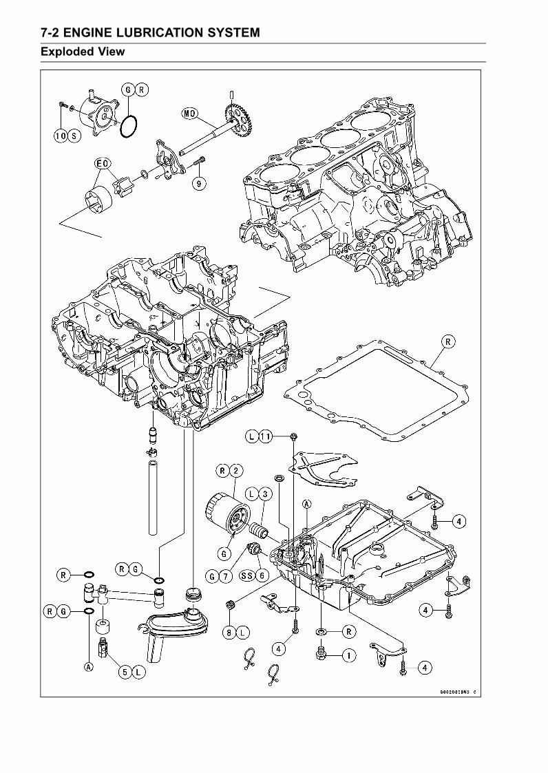
7-2 ENGINE LUBRICATION SYSTEMExploded View

ENGINE LUBRICATION SYSTEM 7-3Exploded View
TorqueNo. Fastener
N·m kgf·m ft·lbRemarks
1 Engine Oil Drain Bolt 30 3.0 222 Oil Filter 31 3.2 23 G, R3 Holder Mounting Bolt 35 3.6 26 L4 Oil Pan Bolts 9.8 1.0 87 in·lb5 Oil Pressure Relief Valve 15 1.5 11 L6 Oil Pressure Switch 15 1.5 11 SS7 Oil Pressure Switch Terminal Bolt 1.5 0.15 13 in·lb G8 Oil Passage Plug 20 2.0 15 L9 Oil Pump Cover Bolts 9.8 1.0 87 in·lb10 Oil Cooler Mounting Bolts 12 1.2 106 in·lb S11 Oil Pan Plate Bolts 9.8 1.0 87 in·lb LEO: Apply engine oil.G: Apply grease.L: Apply a non-permanent locking agent.
MO: Apply molybdenum disulfide oil.(mixture of the engine oil and molybdenum disulfide grease in a weight ratio 10 : 1)
R: Replacement PartsSS: Apply silicone sealant (Kawasaki Bond: 56019-120).

7-4 ENGINE LUBRICATION SYSTEMEngine Oil Flow Chart

ENGINE LUBRICATION SYSTEM 7-5Engine Oil Flow Chart

7-6 ENGINE LUBRICATION SYSTEMSpecifications
Item StandardEngine OilType API SE, SF or SG
API SH, SJ or SL with JASO MAViscosity SAE 10W-40Capacity 3.7 L (3.9 US gt) (when filter is not removed)
4.1 L (4.3 US gt) (when filter is removed)4.5 L (4.8 US gt) (when engine is completely dry)
Level Between upper and lower level linesOil Pressure MeasurementOil Pressure @4 000 r/min (rpm),Oil Temperature 90°C (194°F)
245 ∼ 343 kPa (2.5 ∼ 3.5 kgf/cm², 36 ∼ 50 psi)

ENGINE LUBRICATION SYSTEM 7-7Special Tools and Sealant
Oil Pressure Gauge, 10 kgf/cm²:57001-164
Oil Pressure Gauge Adapter, PT3/8 × 19/in.:57001-1233
Oil Filter Wrench:57001-1249
Kawasaki Bond (Silicone Sealant):56019-120

7-8 ENGINE LUBRICATION SYSTEMEngine Oil and Oil Filter
WARNINGMotorcycle operation with insufficient, deteri-orated, or contaminated engine oil will causeaccelerated wear and may result in engine or trans-mission seizure, accident, and injury.
Oil Level Inspection•Check that the engine oil level is between the upper [A]and lower [B] levels in the gauge.
NOTESituate the motorcycle so that it is perpendicular to theground.If the motorcycle has just been used, wait several min-utes for all the oil to drain down.If the oil has just been changed, start the engine andrun it for several minutes at idle speed. This fills the oilfilter with oil. Stop the engine, then wait several minutesuntil the oil settles.
CAUTIONRacing the engine before the oil reaches every partcan cause engine seizure.If the engine oil gets extremely low or if the oil pumpor oil passages clog up or otherwise do not functionproperly, the oil pressure warning light will light. Ifthis light stays onwhen the engine is running aboveidle speed, stop the engine immediately and find thecause.
Engine Oil Change•Refer to the Engine Oil Change in the Periodic Mainte-nance chapter.
Oil Filter Replacement•Refer to the Oil Filter Replacement in the Periodic Main-tenance chapter.

ENGINE LUBRICATION SYSTEM 7-9Oil Pan
Oil Pan Removal•Remove:Engine Oil (Drain, see Engine Oil Change in the PeriodicMaintenance chapter)Muffler Bodies (see Muffler Body Removal/Installation inthe Engine Top End chapter)Exhaust Pipe (see Exhaust Pipe Removal in the EngineTop End chapter)• Disconnect the oil pressure switch terminal [A].• Remove the oil filter [B] (see Oil Filter Replacement in thePeriodic Maintenance chapter).
• Remove:Oil Pan Bolts [A]Oil Pan [B]
• Remove:Oil Screen [A]Oil Pipe [B]Oil Pressure Relief Valve [C] (if necessary)
CAUTIONDo not remove the relief valve with the oil pipe in-stalled on the lower crankcase half. The oil pipe willbe damaged.
Oil Pan Installation•Clean the oil screen [A].• Install the oil screen so that the crankcase rib [B] fits thenotch [C] of oil screen.• Apply grease the oil pipe O-rings and install the oil pipe.If the oil pressure relief valve was removed, install it.Apply a non-permanent locking agent to the threads ofthe oil pressure relief valve, and tighten it.
CAUTIONDo not apply too much non-permanent lockingagent to the threads. This may block the oil pas-sage.
Torque - Oil Pressure Relief Valve: 15 N·m (1.5 kgf·m, 11ft·lb)

7-10 ENGINE LUBRICATION SYSTEMOil Pan
•Put new O-ring [A] on the lower crankcase [B] as shown.Oil Pipe [C]
• Install the brackets [A] as shown.•Replace the oil pan gasket [B] with a new one.• Tighten:Torque - Oil Pan Bolts: 9.8 N·m (1.0 kgf·m, 87 in·lb)
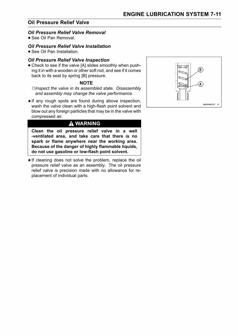
ENGINE LUBRICATION SYSTEM 7-11Oil Pressure Relief Valve
Oil Pressure Relief Valve Removal•See Oil Pan Removal.Oil Pressure Relief Valve Installation•See Oil Pan Installation.Oil Pressure Relief Valve Inspection•Check to see if the valve [A] slides smoothly when push-ing it in with a wooden or other soft rod, and see if it comesback to its seat by spring [B] pressure.
NOTEInspect the valve in its assembled state. Disassemblyand assembly may change the valve performance.
If any rough spots are found during above inspection,wash the valve clean with a high-flash point solvent andblow out any foreign particles that may be in the valve withcompressed air.
WARNINGClean the oil pressure relief valve in a well-ventilated area, and take care that there is nospark or flame anywhere near the working area.Because of the danger of highly flammable liquids,do not use gasoline or low-flash point solvent.
If cleaning does not solve the problem, replace the oilpressure relief valve as an assembly. The oil pressurerelief valve is precision made with no allowance for re-placement of individual parts.

7-12 ENGINE LUBRICATION SYSTEMOil Pump
Oil Pump Removal•Drain:Coolant (see Coolant Change in the Periodic Mainte-nance chapter)Engine Oil (see Engine Oil Change in the Periodic Main-tenance chapter)• Remove:Clutch (see Clutch Removal in the Clutch chapter)
• Remove the oil pump cover bolts [A].• Remove the oil pump cover [B] with oil pump shaft.• Remove the outer rotor and inner rotor.
Oil Pump Installation•Apply molybdenum disulfide oil solution to the journal por-tions [A] on the oil pump drive gear shaft [B].
• Insert the outer rotor [A] the dowel pin [B] into thecrankcase.
• Insert the pump cover [A], washer [B], pin [C] and innerrotor [D] to the oil pump shaft [E].

ENGINE LUBRICATION SYSTEM 7-13Oil Pump
• Install the oil pump shaft with inner rotor.Turn the pump shaft [A] so that the projection [B] in itsshaft fits onto the slot [C] of the water pump shaft [D].Fit the pin of the oil pump cover into the hole in thecrankcase. (in the photo, the oil pan have been removedfor clarity)
• Tighten:Torque - Oil Pump Cover Bolts [A]: 9.8 N·m (1.0 kgf·m, 87
in·lb)

7-14 ENGINE LUBRICATION SYSTEMOil Cooler
Oil Cooler Removal•Remove:Lower Fairings (see Lower Fairing Removal in the Framechapter)• Drain:Coolant (see Coolant Change in the Periodic Mainte-nance chapter)Engine Oil (see Engine Oil Change in the Periodic Main-tenance chapter)• Remove the water hoses from the oil cooler.• Unscrew the oil cooler mounting bolts [A], and remove theoil cooler [B].
Oil Cooler Installation•Apply grease to new O-ring [A] before installation.• Install the oil cooler to the oil cooler case, and tighten thebolts, following the specified tightening sequence [1 ∼ 4].Torque - Oil Cooler Mounting Bolts [B]: 12 N·m (1.2 kgf·m,
106 in·lb)
• Install the water hoses as shown.White Mark [A]• Tighten:Torque - Water Hose Clamp Screws: 2.0 N·m (0.20 kgf·m,
18 in·lb)
•Pour:Engine Oil (see Engine Oil Change in the Periodic Main-tenance chapter)Coolant (see Coolant Change in the Periodic Mainte-nance chapter)

ENGINE LUBRICATION SYSTEM 7-15Oil Pressure Measurement
Oil Pressure Measurement•Remove the left lower fairing (see Lower Fairing Removalin the Frame chapter).• Remove the oil passage plug, and attach the adapter [A]and gauge [B] to the plug hole.Special Tools - Oil Pressure Gauge, 10 kgf/cm²: 57001-164
Oil Pressure Gauge Adapter, PT3/8 × 19/in.:57001-1233
•Start the engine and warm up the engine.• Run the engine at the specified speed, and read the oilpressure gauge.If the oil pressure is much lower than the standard, checkthe oil pump, relief valve, and/or crankshaft bearing insertwear immediately.If the reading is much higher than the standard, check theoil passages for clogging.
Oil PressureStandard: 245 ∼ 343 kPa (2.5 ∼ 3.5 kgf/cm², 36 ∼ 50
psi) @ 4 000 r/min (rpm), oil temperature90°C (194°F)
•Stop the engine.• Remove the oil pressure gauge and adapter.WARNING
Take care against burns form hot engine oil thatwill drain through the oil passage when the gaugeadapter is removed.
•Apply a non-permanent locking agent to the oil passageplug, and install it.Torque - Oil Passage Plug: 20 N·m (2.0 kgf·m, 15 ft·lb)

7-16 ENGINE LUBRICATION SYSTEMOil Pressure Switch
Oil Pressure Switch Removal•Remove:Engine Oil (Drain, see Engine Oil Change in the PeriodicMaintenance chapter)Left Lower Fairing (see Lower Fairing Removal in theFrame chapter)Switch Cover [A]Switch Terminal [B]Oil Pressure Switch [C]
Oil Pressure Switch Installation•Apply silicone sealant to the threads of the oil pressureswitch and tighten it.Sealant - Kawasaki Bond (Silicone Sealant): 56019-120
Torque - Oil Pressure Switch: 15 N·m (1.5 kgf·m, 11 ft·lb)
• Install the switch lead direction [A] upward.• Apply grease [B] to the terminal.• Tighten the terminal bolt.Torque - Oil Pressure Switch Terminal Bolt: 1.5 N·m (0.15
kgf·m, 13 in·lb)
NOTEApply a small amount grease to the terminal so thatgrease should not close two breather holes [A] forswitch diaphragm.

ENGINE REMOVAL/INSTALLATION 8-1
8
Engine Removal/InstallationTable of Contents
Exploded View........................................................................................................................ 8-2Engine Removal/Installation ................................................................................................... 8-4
Engine Removal................................................................................................................ 8-4Engine Installation............................................................................................................. 8-6

8-2 ENGINE REMOVAL/INSTALLATIONExploded View

ENGINE REMOVAL/INSTALLATION 8-3Exploded View
TorqueNo. Fastener
N·m kgf·m ft·lbRemarks
1 Engine Mounting Nuts (M12) 59 6.0 44 S2 Adjusting Collars 25 2.5 18 M3 Front Engine Mounting Bolts (M10) 59 6.0 44 S, R4 Engine Bracket Bolts (M8) 25 2.5 18 S, R5 Subframe Bolts 23 2.3 17 RM: Apply molybdenum sulfide grease.R: Replacement PartsS: Follow the specified tightening sequence.

8-4 ENGINE REMOVAL/INSTALLATIONEngine Removal/Installation
Engine Removal•Support the rear part of the swingarm with a stand.• Squeeze the brake lever slowly and hold it with a band[A].
WARNINGBe sure to hold the front brake when removing theengine, or the motorcycle may fall over. It couldcause an accident and injury.
CAUTIONBe sure to hold the front brake when removing theengine, or the motorcycle may fall over. The engineor the motorcycle could be damaged.
•Drain:Engine Oil (see Engine Oil Change in the Periodic Main-tenance chapter)Coolant (see Coolant Change in the Periodic Mainte-nance chapter)• Remove:Lower Fairings (see Lower Fairing Removal in the Framechapter)Middle Fairings (see Middle Fairing Removal in theFrame chapter)Fuel Tank (see Fuel Tank Removal in the Fuel System(DFI) chapter)Coolant Reserve TankClutch Slave Cylinder (see Clutch Slave Cylinder Re-moval in the Clutch chapter)Radiator (see Radiator and Radiator Fan Removal in theCooling System chapter)Muffler Bodies (see Muffler Body Removal/Installation inthe Frame chapter)Exhaust Pipe (see Exhaust Pipe Removal in the EngineTop End chapter)Shift Pedal (see Shift Pedal Removal in the Crank-shaft/Transmission chapter)
• Disconnect:Sidestand Switch Lead Connector [A]Oil Pressure Switch/Gear Position Switch Leads Con-nector [B]

ENGINE REMOVAL/INSTALLATION 8-5Engine Removal/Installation
•Disconnect the alternator lead conductor [A].
• Remove:Connector [A] of Subharness for Sensor and Valve (dis-connect)Subframe Bolts [B]Subframe Bracket Bolt [C]• Remove the subframe [D] with the clutch pipe [E].
• Disconnect:Throttle Body Subharness Connector [A]Breather Hose [B]Fuel Hose [C] on the Delivery PipeThrottle Cable Lower Ends [D]
• Remove the bracket Bolt [A].• Disconnect:Air Switching Valve Connector [B]Stick Coil Subharness Connector [C]
• Remove the air switching valve [A] with hoses.• Remove the air suction cover (see Air Suction Valve Re-moval in the Engine Top End chapter).

8-6 ENGINE REMOVAL/INSTALLATIONEngine Removal/Installation
•Remove the engine sprocket [A] (see Engine SprocketRemoval in the Final Drive chapter).• Support the engine with a suitable stand [B].Put a plank [C] onto the suitable stand for engine balance.
• Remove:Engine Bracket Bolts [A]Front Engine Mounting Bolts [B]Engine Bracket [C]
• Remove:Engine Mounting Nuts [A]
• Disconnect the engine ground terminal [A].• Using a hexagon wrench, turn the engine mounting bolts[B] clockwise to make the gap between the engine andframe.
•Remove the drive chain from the output shaft.• Remove the starter motor cable terminal nut [A].• Using the stand, take out the engine.
Engine Installation•Support the engine with a suitable stand.Put a plank onto the suitable stand for engine balance.• Install the heat insulation rubber plate.

ENGINE REMOVAL/INSTALLATION 8-7Engine Removal/Installation
A: After installation, set the projection in the hole.B: To Water Temperature SensorC: To Breather HoseD: To Throttle Body Subharness BracketE: To throttle Body HolderF: To Throttle PulleyG: To Air Suction Valve and Stick CoilsH: Only put the heat insulation rubber plate on the cylinder head cover.J: Bracket on Air Suction Valve Cover

8-8 ENGINE REMOVAL/INSTALLATIONEngine Removal/Installation
•Before installing the engine. Confirm the routing of thewater temperature sensor lead [A].Run [B] the water temperature sensor lead between the#3 and #4 cylinder and connect the water temperaturesensor body.
• Install the engine mounting bolts and nuts, following thespecified installing sequence.Apply molybdenum disulfide grease [A] to the thread ofadjusting collars.First, tighten the adjusting collars fully by hand.Upper Adjusting Collar [B]Upper Crankcase [C]Lower Adjusting Collar [D]Lower Crankcase [E]

ENGINE REMOVAL/INSTALLATION 8-9Engine Removal/Installation
Secondly, insert the mounting bolts [A] until they fit [B] inthe adjusting collars [C].Be sure that the collar [D] is in position.
NOTEReplace the following bolts with new bolts pre-coatedwith locking agent.
Engine Bracket Bolts (P/No. 92153-1724)Front Engine Mounting Bolts (P/No. 92153-1723)Subframe Bolts (P/No. 92153-1722)
Thirdly, install the left engine bracket [A] and temporallytighten the left engine bracket bolts [B].Fourthly, tighten the left front engine mounting bolt [C].Fourthly, turn the mounting bolts [A] counterclockwisewith specified torque until the clearance [B] between thecrankcase [C] and swingarm [D] comes to zero mm [E].Adjusting Collars [F]Torque - Adjusting Collars: 25 N·m (2.5 kgf·m, 18 ft·lb)Do not exceed the specified torque of adjusting collars.

8-10 ENGINE REMOVAL/INSTALLATIONEngine Removal/Installation
Fifthly, tighten the left engine bracket bolts [A].Sixthly, tighten the upper engine mounting nut [B] andthen the lower engine mounting nut [C].Seventhly, install the right engine bracket and tighten theright engine bracket bolts [D] and the right front enginemounting bolt [E].Torque:Torque - Engine Mounting Nut (M12): 59 N·m (6.0 kgf·m, 44
ft·lb)
NOTEHold the upper and lower engine mounting bolts with anAllen wrench, and torque them.
Torque:Torque - Engine Bracket Bolts (M8): 25 N·m (2.5 kgf·m, 18
ft·lb)Front Engine Mounting Bolts (M10): 59 N·m (6.0kgf·m, 44 ft·lb)

ENGINE REMOVAL/INSTALLATION 8-11Engine Removal/Installation
•Run the leads, cable and hoses correctly (see Cable,Wire, and Hose Routing section in the Appendix chap-ter).• Install the removed parts (see appropriate chapters).• Adjust:Throttle Cables (see Throttle Control System Inspectionin the Periodic Maintenance chapter)Drive Chain (see Drive Chain Slack Inspection in thePeriodic Maintenance chapter)• Fill the engine with engine oil (see Engine Oil Change inthe Periodic Maintenance chapter).• Fill the engine with coolant and bleed the air from the cool-ing system (see Coolant Change in the Periodic Mainte-nance chapter).


CRANKSHAFT/TRANSMISSION 9-1
9
Crankshaft/TransmissionTable of Contents
Exploded View................................... 9-2Specifications .................................... 9-6Special Tools and Sealants ............... 9-9Crankcase Splitting............................ 9-10
Crankcase Splitting ...................... 9-10Crankcase Assembly ................... 9-11
Crankshaft and Connecting Rods...... 9-15Crankshaft Removal .................... 9-15Crankshaft Installation ................. 9-15Connecting Rod Removal ............ 9-16Connecting Rod Installation ......... 9-16Crankshaft/Connecting RodCleaning .................................... 9-19
Connecting Rod Bend.................. 9-19Connecting Rod Twist .................. 9-20Connecting Rod Big End SideClearance.................................. 9-20
Connecting Rod Big End BearingInsert/Crankpin Wear ................ 9-20
Crankshaft Side Clearance.......... 9-22Crankshaft Runout ....................... 9-23Crankshaft Main BearingInsert/Journal Wear................... 9-23
Pistons............................................... 9-26Piston Removal............................ 9-26Piston Installation......................... 9-27Cylinder Wear (UpperCrankcase)................................ 9-28
Piston Wear ................................. 9-28Piston Ring, Piston Ring GrooveWear.......................................... 9-28
Piston Ring Groove Width............ 9-29Piston Ring Thickness ................. 9-29Piston Ring End Gap ................... 9-29
Balancer ............................................ 9-30Front Balancer Removal .............. 9-30Front Balancer Installation ........... 9-30
Rear Balancer Removal............... 9-31Rear Balancer Installation............ 9-32Balancer Adjustment.................... 9-34Balancer Damper Inspection........ 9-34
Starter Motor Clutch and TorqueLimiter ............................................. 9-35Starter Motor Clutch Removal...... 9-35Starter Motor Clutch Installation... 9-35Starter Motor Clutch Disassembly 9-35Starter Motor Clutch Assembly .... 9-36Starter Clutch Inspection.............. 9-36Torque Limiter Removal ............... 9-36Torque Limiter Installation ............ 9-37
Transmission ..................................... 9-38Shift Pedal Removal .................... 9-38Shift Pedal Installation ................. 9-38External Shift MechanismRemoval .................................... 9-38
External Shift MechanismInstallation ................................. 9-39
External Shift MechanismInspection.................................. 9-39
Transmission Shaft Removal ....... 9-39Transmission Shaft Installation .... 9-40Transmission Shaft Disassembly. 9-40Transmission Shaft Assembly...... 9-41Shift Drum and Fork Removal...... 9-44Shift Drum and Fork Installation... 9-44Shift Drum Disassembly............... 9-44Shift Drum Assembly ................... 9-44Shift Fork Bending ....................... 9-45Shift Fork/Gear Groove Wear ...... 9-45Shift Fork Guide Pin/DrumGroove Wear............................. 9-45
Gear Dog and Gear Dog HoleDamage..................................... 9-45

9-2 CRANKSHAFT/TRANSMISSIONExploded View

CRANKSHAFT/TRANSMISSION 9-3Exploded View
TorqueNo. Fastener
N·m kgf·m ft·lbRemarks
1 Breather Cover Bolts 9.8 1.0 87 in·lb2 Breather Plate Screws 9.8 1.0 87 in·lb L3 Crankcase Bolts (M10, L = 90 mm) 47 4.8 35 MO, S4 Crankcase Bolts (M10, L = 120 mm) 47 4.8 35 MO, S5 Crankcase Bolt (M7, L = 110 mm) 20 2.0 15 S6 Crankcase Bolt (M7, L = 85 mm) 20 2.0 15 S7 Crankcase Bolts (M7, L = 60 mm) 20 2.0 15 S8 Crankcase Bolt (M7, L = 50 mm) 20 2.0 15 S9 Crankcase Bolts (M7, L = 45 mm) 20 2.0 15 S10 Crankcase Bolts (M8, L = 80 mm) 27 2.8 20 S11 Crankcase Bolts (M8, L = 70 mm) 27 2.8 20 S12 Crankcase Bolts (M7, L = 65 mm) 20 2.0 15 S13 Crankcase Bolt (M6, L = 65 mm) 12 1.2 106 in·lb S14 Crankcase Bolt (M6, L = 50 mm) 12 1.2 106 in·lb S15 Crankcase Bolts (M6, L = 40 mm) 12 1.2 106 in·lb S16 Crankcase Bolts (M6, L = 25 mm) 12 1.2 106 in·lb S17 Shift Drum Bearing Holder Screws 4.9 0.50 43 in·lb L18 Bearing Position Plate Screws 4.9 0.50 43 in·lb L19 Oil Passage Plug 20 2.0 15 L20 Connecting Rod Big End Nuts see the text ← ← ←21 Timing Rotor Bolt 39 4.0 2922 Gear Position Switch Lead Clamp Bolt 9.8 1.0 87 in·lb23 Drive Shaft Cover Bolts 25 2.5 18 L24. "R" marked side faces up.25. "RN" marked side faces up.26. Hollow mark faces forward.27. Do not apply any grease or oil.G: Apply grease.L: Apply a non-permanent locking agent.
LG: Apply liquid gasket (Kawasaki Bond: 92104-1064).M: Apply molybdenum disulfide grease.
MO: Apply molybdenum disulfide oil.(mixture of engine oil and molybdenum disulfide grease in a weight ratio is 10 : 1)
R: Replacement PartsS: Follow the specified tightening sequence.

9-4 CRANKSHAFT/TRANSMISSIONExploded View

CRANKSHAFT/TRANSMISSION 9-5Exploded View
TorqueNo. Fastener
N·m kgf·m ft·lbRemarks
1 Balancer Shaft Clamp Bolts 9.8 1.0 87 in·lb2 Balancer Shaft Clamp Lever Bolts 25 2.5 183 Starter Clutch Shaft Bolt 9.8 1.0 87 in·lb L4 Starter Clutch Shaft Plate Bolt 9.8 1.0 87 in·lb L5 Torque Limiter Bolt 25 2.5 18 L6 Shift Drum Cam Holder Bolt 12 1.2 106 in·lb L7 Gear Position Switch Screws 2.9 0.30 26 in·lb L8 Gear Positioning Lever Bolt 12 1.2 106 in·lb9 Shift Shaft Return Spring Pin 29 3.0 21 L10. Front Balancer11. Rear Balancer12. Install the bearing into the drive shaft cover so that the shield side faces in.EO: Apply engine oil.M: Apply molybdenum disulfide grease.
MO: Apply molybdenum disulfide oil.(mixture of engine oil and molybdenum disulfide grease in a weight ratio is 10 : 1)
G: Apply grease.L: Apply a non-permanent locking agent.R: Replacement Parts

9-6 CRANKSHAFT/TRANSMISSIONSpecifications
Item Standard Service LimitCrankcase, Crankshaft, ConnectingRodsConnecting Rod Bend – – – TIR 0.2/100 mm
(0.008/3.94 in.)Connecting Rod Twist – – – TIR 0.2/100 mm
(0.008/3.94 in.)Connecting Rod Big End SideClearance
0.13 ∼ 0.38 mm(0.0051 ∼ 0.0150 in.)
0.58 mm(0.023 in.)
Connecting Rod Big End BearingInsert/crankpin Clearance
0.048 ∼ 0.086 mm(0.0019 ∼ 0.0034 in.)
0.12 mm(0.0047 in.)
Crankpin Diameter: 37.984 ∼ 38.000 mm(1.4954 ∼ 1.4961 in.)
37.97 mm(1.4949 in.)
Marking None 37.984 ∼ 37.992 mm(1.4954 ∼ 1.4957 in.)
– – –
37.993 ∼ 38.000 mm(1.4958 ∼ 1.4961 in.)
– – –
Connecting Rod Big End InsideDiameter:
41.000 ∼ 41.016 mm(1.6142 ∼ 1.6148 in.)
– – –
Marking None 41.000 ∼ 41.008 mm(1.6142 ∼ 1.6145 in.)
– – –
41.009 ∼ 41.016 mm(1.6145 ∼ 1.6148 in.)
– – –
Connecting Rod Big End BearingInsert Thickness:Brown 1.475 ∼ 1.480 mm
(0.05807 ∼ 0.05827 in.)– – –
Black 1.480 ∼ 1.485 mm(0.05827 ∼ 0.05846 in.)
– – –
Blue 1.485 ∼ 1.490 mm(0.05846 ∼ 0.05866 in.)
– – –
Connecting Rod Bolt Stretch: (Usable Range)New Connecting Rod 0.25 ∼ 0.34 mm
(0.0098 ∼ 0.0134 in.)– – –
Used Connecting Rod 0.25 ∼ 0.34 mm(0.0098 ∼ 0.0134 in.)
– – –
Crankshaft Side Clearance 0.05 ∼ 0.24 mm(0.0020 ∼ 0.0094 in.)
0.30 mm(0.0118 in.)
Crankshaft Runout TIR 0.03 mm (0.0012 in.) or less TIR 0.08 mm(0.0031 in.)
Crankshaft Main Bearing Insert/journalClearance
0.031 ∼ 0.063 mm(0.0012 ∼ 0.0025 in.)
0.09 mm(0.0035 in.)
Crankshaft Main Journal Diameter: 37.984 ∼ 38.000 mm(1.4954 ∼ 1.4961 in.)
37.96 mm(1.4945 in.)
Marking None 37.984 ∼ 37.992 mm(1.4954 ∼ 1.4957 in.)
– – –
1 37.993 ∼ 38.000 mm(1.4958 ∼ 1.4961 in.)
– – –
Crankcase Main Bearing InsideDiameter:
41.000 ∼ 41.016 mm(1.6142 ∼ 1.6148 in.)
– – –

CRANKSHAFT/TRANSMISSION 9-7Specifications
Item Standard Service LimitMarking 41.000 ∼ 41.008 mm
(1.6142 ∼ 1.6145 in.)– – –
None 41.009 ∼ 41.016 mm(1.6145 ∼ 1.6148 in.)
– – –
Crankshaft Main Bearing InsertThickness:Brown 1.490 ∼ 1.494 mm
(0.0587 ∼ 0.0588 in.)– – –
Black 1.494 ∼ 1.498 mm(0.0588 ∼ 0.0590 in.)
– – –
Blue 1.498 ∼ 1.502 mm(0.0590 ∼ 0.0591 in.)
– – –
PistonsCylinder (Upper Crankcase) InsideDiameter
83.994 ∼ 84.006 mm(3.3068 ∼ 3.3073 in.)
84.10 mm(3.3110 in.)
Piston Diameter 83.959 ∼ 83.974 mm(3.3055 ∼ 3.3061 in.)
83.81 mm(3.2996 in.)
Piston/Cylinder Clearance 0.020 ∼ 0.047 mm(0.0008 ∼ 0.0019 in.)
– – –
Piston Ring/Groove Clearance:Top 0.03 ∼ 0.07 mm
(0.0012 ∼ 0.0028 in.)0.17 mm(0.0067 in.)
Second 0.02 ∼ 0.06 mm(0.0008 ∼ 0.0024 in.)
0.16 mm(0.0063 in.)
Piston Ring Groove Width:Top 0.92 ∼ 0.94 mm
(0.0362 ∼ 0.0370 in.)1.02 mm(0.040 in.)
Second 1.01 ∼ 1.03 mm(0.0398 ∼ 0.0406 in.)
1.11 mm(0.044 in.)
Piston Ring Thickness:Top 0.87 ∼ 0.89 mm
(0.0343 ∼ 0.0350 in.)0.80 mm(0.032 in.)
Second 0.97 ∼ 0.99 mm(0.0382 ∼ 0.0390 in.)
0.90 mm(0.035 in.)
Piston Ring End Gap:Top 0.20 ∼ 0.30 mm
(0.0079 ∼ 0.0118 in.)0.6 mm(0.024 in.)
Second 0.40 ∼ 0.55 mm(0.0157 ∼ 0.0217 in.)
0.8 mm(0.031 in.)
TransmissionShift Fork Ear Thickness 5.74 ∼ 6.00 mm
(0.2260 ∼ 0.2362 in.)5.6 mm(0.220 in.)
Gear Groove Width 6.05 ∼ 6.15 mm(0.238 ∼ 0.242 in.)
6.25 mm(0.246 in.)
Shift Fork Guide Pin Diameter 6.9 ∼ 7.0 mm(0.272 ∼ 0.276 in.)
6.8 mm(0.268 in.)
Shift Drum Groove Width 7.05 ∼ 7.20 mm(0.278 ∼ 0.283 in.)
7.3 mm(0.287 in.)

9-8 CRANKSHAFT/TRANSMISSIONSpecifications
Connecting Rod Big End Bearing Insert SelectionBearing InsertCon-rod Big End Bore
Diameter MarkingCrankpin Diameter
Marking Size Color Part NumberNone Brown 92139-0131None None Black 92139-0130
None Blue 92139-0129
Crankshaft Main Bearing Insert SelectionBearing InsertCrankcase Main
Bearing InsideDiameter Marking
Crankshaft MainJournal Diameter
Marking Size Color Part Number Journal Nos.
92139-0134 1, 3, 5 1 Brown92139-0137 2, 4
None 1 92139-0133 1, 3, 5 None
Black92139-0136 2, 492139-0132 1, 3, 5
None None Blue92139-0135 2, 4

CRANKSHAFT/TRANSMISSION 9-9Special Tools and Sealants
Bearing Puller:57001-135
Bearing Puller Adapter:57001-317
Piston Pin Puller Assembly:57001-910
Piston Ring Compressor Grip:57001-1095
Piston Ring Compressor Belt, 80 ∼ 91:57001-1320
Kawasaki Bond (Silicone Sealant):56019-120
Kawasaki Bond:92104-1064

9-10 CRANKSHAFT/TRANSMISSIONCrankcase Splitting
Crankcase Splitting•Remove the engine (see Engine Removal/Installation inthe Engine Removal/Installation chapter).• Set the engine on a clean surface and hold the enginesteady while parts are being removed.• Remove:Clutch (see Clutch Removal in the Clutch chapter)Starter Motor (see Starter Motor Removal in the Electri-cal System chapter)Oil Pump (see Oil Pump Removal in the Engine Lubri-cation System chapter)Alternator Rotor (see Alternator Rotor Removal in theElectrical System chapter)Oil Cooler (see Oil Cooler Removal in the Engine Lubri-cation System chapter)Oil Pan (see Oil Pan Removal in the Engine LubricationSystem chapter)External Shift Mechanism (see External Shift Mecha-nism Removal)
• Remove the upper crankcase bolts.First loosen the M6 bolts.M6 Bolts [A]M7 Bolt [B]M7 Bolt with Clamp [C]M8 Bolts with Washers [D]
• Remove the lower crankcase bolts.First loosen the M7 bolts [A].

CRANKSHAFT/TRANSMISSION 9-11Crankcase Splitting
Next, loosen the M10 Bolts [1∼ 10] (sequence numbers).If the crankshaft is to be removed, remove the pistons(see Piston Removal).• Tap lightly around the crankcase mating surface with aplastic mallet, and split the crankcase. Take care not todamage the crankcase.
• Remove the front balancer [A] on the lower crankcase half[B] (see Front Balancer Removal).
Crankcase AssemblyCAUTION
The upper and lower crankcase halves are ma-chined at the factory in the assembled state, so thecrankcase halves must be replaced as a set.
NOTEWhen replacing the crankcase halves, install thethrust washers (t = 2.5 mm, 0.0984 in.) on the uppercrankcase half.
•With a high-flash point solvent, clean off the mating sur-faces of the crankcase halves and wipe dry.• Using compressed air, blow out the oil passages in thecrankcase halves.
• Install the new drive shaft bearing [A] so that its steppedside [B] faces as shown using a press.• Install the bearing plate [C] with the screws [D].Apply a non-permanent locking agent to the bearing platescrew and tighten them.Torque - Bearing Position Plate Screws: 4.9 N·m (0.50
kgf·m, 43 in·lb)

9-12 CRANKSHAFT/TRANSMISSIONCrankcase Splitting
• Install the new needle bearing [A] for the shift shaft so thatits marked side [B] faces as shown, using a press.• Install the new oil seal [C] so that its surface [D] is flushwith the surface of the crankcase [E].
• Install:Crankshaft, Pistons and Connecting RodsTransmission Shaft and GearsDowel Pins [A]
• Install the front balancer [A] on the upper crankcase half[B] (see Balancer Installation).• Before fitting the lower case on the upper case, check thefollowing.Check to see that the shift drum and transmission gearsare in the neutral position.
• Apply liquid gasket [A] to the mating surface of the lowercrankcase half.Sealant - Kawasaki Bond: 92104-1064
NOTEAster tightening the crankcase bolts, wipe up the liquidgasket seeping out the output shaft bearing hole [D].Make the application finish within 20 minutes whenthe liquid gasket to the mating surface of the lowercrankcase half is applied.
CAUTIONDo not apply liquid gasket to the grooves [B] insidefrom the crankshaft main bearing inserts, and bal-ancer bearing.
CAUTIONDo not plug the inside of breather hole [C] with liq-uid gasket.

CRANKSHAFT/TRANSMISSION 9-13Crankcase Splitting
•Fit the lower crankcase half to the upper crankcase half.• Be sure that the breather hole [A] on the upper crankcase[B] is not plugged with liquid gasket.
• The M10 bolts have washers, replace them with newones.• Applymolybdenum disulfide oil solution to the seating sur-faces [A] of the washers and the threads [B] of the M10bolts.
• Tighten the lower crankcase bolts using the followingsteps.Following the sequence numbers on the lower crankcasehalf, tighten the M10 bolts [1 ∼ 10] with washers.Torque - Crankcase Bolts (M10): 47 N·m (4.8 kgf·m, 35 ft·lb)
Tighten the M7 bolts [A].Torque - Crankcase Bolts (M7): 20 N·m (2.0 kgf·m, 15 ft·lb)

9-14 CRANKSHAFT/TRANSMISSIONCrankcase Splitting
•Tighten the upper crankcase bolts in the order listed.The M8 bolts have washers, replace them with new ones.Tighten:M8 Bolts with Washers [A]M7 Bolt with the clamp [B]M7 Bolt [C]M6 Bolts [D]Torque - Crankcase Bolts (M8): 27 N·m (2.8 kgf·m, 20 ft·lb)
Crankcase Bolts (M7): 20 N·m (2.0 kgf·m, 15 ft·lb)Crankcase Bolts (M6): 12 N·m (1.2 kgf·m, 106 in·lb)
•After tightening all crankcase bolts, check the followingitems.Crankshaft and transmission shafts turn freely.While spinning the output shaft, gears shift smoothly fromthe 1st to neutral, and neutral to 1st.

CRANKSHAFT/TRANSMISSION 9-15Crankshaft and Connecting Rods
Crankshaft Removal•Split the crankcase (see Crankcase Splitting).• Remove the crankshaft (see Connecting Rod Removal).Crankshaft Installation
CAUTIONIf the crankshaft, bearing inserts, or crankcasehalves are replaced with new ones, select the bear-ing inserts and check clearance with a plastigage(press gauge) before assembling engine to be surethe correct bearing inserts are installed.
NOTEWhen replacing the crankcase halves, install thethrust washers (t = 2.5 mm, 0.0984 in.) on the uppercrankcase half.
•Apply molybdenum disulfide oil solution to the crankshaftmain bearing inserts.• Follow the next procedure to insert the thrust washers onthe upper crankcase half, after installing connecting rodon the crankshaft (see Connecting Rod Installation).• Apply molybdenum disulfide grease to the outside sur-faces [A] of both thrust washers [B].• Slide [C] one thrust washer into the upper crankcase half.•Move the crankshaft to the left or right and then slide theother washer into the upper crankcase half.
NOTESlide the thrust washers so that the oil grooves [D] faceoutward. Make sure that the blue-painted edges [E] arepositioned as shown in figure.Front [F]

9-16 CRANKSHAFT/TRANSMISSIONCrankshaft and Connecting Rods
Connecting Rod Removal•Split the crankcase (see Crankcase Splitting).• Remove the connecting rod nuts [A].• Remove the crankshaft.
NOTEMark and record the locations of the connecting rodsand their big end caps so that they can be reassembledin their original positions.
•Remove the piston (see Piston Removal).CAUTION
Discard the connecting rod bolts. To prevent dam-age to the crankpin surfaces, do not allow the con-necting rod bolts to bump against the crankpins.
Connecting Rod InstallationCAUTION
To minimize vibration, the connecting rods shouldhave the same weight mark.
Big End Cap [A]Connecting Rod [B]Weight Mark, Alphabet [C]Diameter Mark [D]: “” or no mark
CAUTIONIf the connecting rods, big end bearing inserts, orcrankshaft are replaced with new ones, select thebearing insert and check clearance with a plasti-gage (press gauge) before assembling engine to besure the correct bearing inserts are installed.
•Apply molybdenum disulfide oil to the inner surface of theupper and lower bearing inserts [A].• Apply molybdenum disulfide oil to the threads [B] andseating surface [C] of the connecting rod nuts.• Install the inserts so that their nails [D] are on the sameside and fit them into the recess of the connecting rod andcap.
CAUTIONWrong application of oil and grease could causebearing damage.
When installing the inserts [A], be careful not to damagethe insert surface with the edge of the connecting rod [B]or the cap [C]. One way to install inserts is as follows.Installation [D] to CapInstallation [E] to Connecting RodPush [F]Spare Dowel Pin [G]Connecting Rod Bolts [H]• Remove debris and clean the surface of inserts.• Install the cap on the connecting rod, aligning the weightand diameter marks.

CRANKSHAFT/TRANSMISSION 9-17Crankshaft and Connecting Rods
• Install the crankshaft (see Crankshaft Installation).• Install each connecting rod on its original crankpin.The connecting rod big end is bolted using the “plasticregion fastening method”.This method precisely achieves the needed clampingforce without exceeding it unnecessarily, allowing theuse of thinner, lighter bolts further decreasing connectingrod weight.There are two types of the plastic region fastening. One isa bolt length measurement method and other is a rotationangle method. Observe one of the following two, but thebolt length measurement method is preferable becausethis is a more reliable way to tighten the big end nuts.
CAUTIONThe connecting rod bolts are designed to stretchwhen tightened. Never reuse the connecting rodbolts. See the table below for correct bolt and nutusage.
CAUTIONBe careful not to overtighten the nuts.The boltsmust be positioned on the seating surfacecorrectly to prevent the bolt heads from hitting thecrankcase.
(1) Bolt Length Measurement Method•Be sure to clean the bolts, nuts, and connecting rodsthoroughly with a high-flash point solvent, because thenew connecting rods, bolts, and nuts are treated with ananti-rust solution.
WARNINGClean the bolts, nuts, and connecting rods in a well-ventilated area, and take care that there is no sparkor flame anywhere near the working area. This in-cludes any appliance with a pilot light. Because ofthe danger of highly flammable liquids, do not usegasoline or low-flash point solvents to clean them.
CAUTIONImmediately dry the bolts and nuts with com-pressed air after cleaning.Clean and dry the bolts and nuts completely.

9-18 CRANKSHAFT/TRANSMISSIONCrankshaft and Connecting Rods
• Install new bolts in reused connecting rods.• Dent both bolt head and bolt tip with a punch as shown.• Before tightening, use a point micrometer to measure thelength of new connecting rod bolts and record the valuesto find the bolt stretch.Connecting Rod [A]Dent here with a punch [B].Nuts [C]Fit micrometer pins into dents [D].• Apply a small amount of molybdenum disulfide oil to thefollowing.Threads of Nuts and BoltsSeating Surfaces of Nuts and Connecting rods• Tighten the big end nuts until the bolt elongation reachesthe length specified in the table.• Check the length of the connecting rod bolts.If the stretch is more than the usable range, the bolt hasstretched too much. An overelongated bolt may break inuse.Bolt Length aftertightening – Bolt Length before
tightening = Bolt Stretch
Connect-ing RodAssy
Bolt NutUsable Range ofConnecting RodBolt Stretch
Attached tonew con-rodNew
Use the boltsattached tonew con-rod. New
0.25 ∼ 0.34 mm(0.0098 ∼ 0.0134in.)
UsedUsed
Replace thebolts with newones. New
0.25 ∼ 0.34 mm(0.0098 ∼ 0.0134in.)
(2) Rotation Angle MethodIf you don’t have a point micrometer, you may tighten thenuts using the “Rotation Angle Method”.• Be sure to clean the bolts, nuts and connecting rods thor-oughly with a high-flash point solvent, because the newconnecting rods, bolts and nuts are treated with an anti-rust solution.
WARNINGClean the bolts, nuts and connecting rods in a well-ventilated area, and take care that there is no sparkor flame anywhere near the working area. This in-cludes any appliance with a pilot light. Because ofthe danger or highly flammable liquids, do not usegasoline or low-flash point solvents to clean them.
CAUTIONImmediately dry the bolts and nuts with com-pressed air after cleaning.Clean and dry the bolts and nuts completely.

CRANKSHAFT/TRANSMISSION 9-19Crankshaft and Connecting Rods
• Install new bolts in reused connecting rods.• Apply a small amount of molybdenum disulfide oil to thefollowing.Threads [A] of Nuts and BoltsSeating Surfaces [B] of Nuts and Connecting Rods
• First, tighten the nuts to the specified torque. See thetable below.•Next, tighten the nuts 120° ± 5°.Mark [A] the connecting rod big end caps and nuts so thatnuts can be turned 120° [B] properly.
Torque + AngleConnectingRod Assy Bolt Nut
N·m (kgf·m, ft·lb)Attached tonew con-rod
21.6 (2.2, 16) +120°
NewUse the boltsattached tonew con-rod. New 21.6 (2.2, 16) +
120°
Used 21.6 (2.2, 16) +120°
UsedReplace thebolts withnew ones New 21.6 (2.2, 16) +
120°
Crankshaft/Connecting Rod Cleaning•After removing the connecting rods from the crankshaft,clean them with a high-flash point solvent.• Blow the crankshaft oil passages with compressed air toremove any foreign particles or residue that may haveaccumulated in the passages.
Connecting Rod Bend•Remove the connecting rod big end bearing inserts, andreinstall the connecting rod big end cap.• Select an arbor [A] of the same diameter as the connect-ing rod big end, and insert the arbor through the connect-ing rod big end.• Select an arbor of the same diameter as the piston pinand at least 100 mm (3.94 in.) long, and insert the arbor[B] through the connecting rod small end.•On a surface plate, set the big-end arbor on V block [C].•With the connecting rod held vertically, use a heightgauge to measure the difference in the height of thearbor above the surface plate over a 100 mm (3.94 in.)length to determine the amount of connecting rod bend.If connecting rod bend exceeds the service limit, the con-necting rod must be replaced.
Connecting Rod BendService Limit: TIR 0.2/100 mm (0.008/3.94 in.)

9-20 CRANKSHAFT/TRANSMISSIONCrankshaft and Connecting Rods
Connecting Rod Twist•With the big-end arbor [A] still on V block [C], hold theconnecting rod horizontally and measure the amount thatthe arbor [B] varies from being paralleled with the surfaceplate over a 100 mm (3.94 in.) length of the arbor to de-termine the amount of connecting rod twist.If connecting rod twist exceeds the service limit, the con-necting rod must be replaced.
Connecting Rod TwistService Limit: TIR 0.2/100 mm (0.008/3.94 in.)
Connecting Rod Big End Side Clearance•Measure connecting rod big end side clearance.Insert a thickness gauge [A] between the big end and ei-ther crank web to determine clearance.
Connecting Rod Big End Side ClearanceStandard: 0.13 ∼ 0.38 mm (0.0051 ∼ 0.0150 in.)Service Limit: 0.58 mm (0.023 in.)
If the clearance exceeds the service limit, replace the con-necting rod with new one and then check clearance again.If clearance is too large after connecting rod replacement,the crankshaft also must be replaced.
Connecting Rod Big End Bearing Insert/CrankpinWear•Measure the bearing insert/crankpin [B] clearance withplastigage [A].• Tighten the big end nuts to the specified torque (see Con-necting Rod Installation).
NOTEDo not move the connecting rod and crankshaft duringclearance measurement.
CAUTIONAfter measurement, replace the connecting rodbolts.
Connecting Rod Big End Bearing Insert/CrankpinClearanceStandard: 0.048 ∼ 0.086 mm (0.0019 ∼ 0.0034 in.)Service Limit: 0.12 mm (0.0047 in.)

CRANKSHAFT/TRANSMISSION 9-21Crankshaft and Connecting Rods
If the clearance is within the standard, no bearing replace-ment is required.If the clearance is between 0.087 mm (0.0034 in.) andthe service limit (0.12 mm, 0.0047 in.), replace the bear-ing inserts [A] with inserts painted blue [B]. Check in-sert/crankpin clearance with the plastigage. The clear-ance may exceed the standard slightly, but it must not beless than the minimum in order to avoid bearing seizure.If the clearance exceeds the service limit, measure thediameter of the crankpins.
Crankpin DiameterStandard: 37.984 ∼ 38.000 mm (1.4954 ∼ 1.4961 in.)Service Limit: 37.97 mm (1.4949 in.)
If any crankpin has worn past the service limit, replace thecrankshaft with a new one.If the measured crankpin diameters are not less than theservice limit, but do not coincide with the original diametermarkings on the crankshaft, make new marks on it.
Crankpin Diameter MarksNone 37.984 ∼ 37.992 mm (1.4954 ∼ 1.4957 in.)
37.993 ∼ 38.000 mm (1.4958 ∼ 1.4961 in.)
: Crankpin Diameter Marks, "" or no mark.•Measure the connecting rod big end inside diameter, andmark each connecting rod big end in accordance with theinside diameter.• Tighten the connecting rod big end nuts to the specifiedtorque (see Connecting Rod Installation).
NOTEThemark already on the big end should almost coincidewith the measurement.
Connecting Rod Big End Inside Diameter MarksNone 41.000 ∼ 41.008 mm (1.6142 ∼ 1.6145 in.)
41.009 ∼ 41.016 mm (1.6145 ∼ 1.6148 in.)
Big End Cap [A]Connecting Rod [B]Weight Mark, Alphabet [C]Diameter Mark (Around Weight Mark) [D]: “” or nomark

9-22 CRANKSHAFT/TRANSMISSIONCrankshaft and Connecting Rods
•Select the proper bearing insert [A] in accordance with thecombination of the connecting rod and crankshaft coding.Size Color [B]
Bearing InsertCon-rod BigEnd InsideDiameterMarking
CrankpinDiameterMarking Size Color Part Number
None Brown 92139-0131None None
Black 92139-0130
None Blue 92139-0129
• Install the new inserts in the connecting rod and checkinsert/crankpin clearance with the plastigage.
Crankshaft Side Clearance•Move [A] the crankshaft to the side of the camshaft chain.• Insert a thickness gauge [B] between the thrust washer[C] and the crank web [D] at the No. 3 main journal todetermine clearance.
Crankshaft Side ClearanceStandard: 0.05 ~ 0.24 mm (0.0020 ~ 0.0094 in.)Service Limit: 0.30 mm (0.0118 in.)
If the clearance exceeds the service limit, replace thethrust washer as a set.•Measure the width [A] of the both thrust washers.If the thrust washers (t = 2.5 mm, 0.0984 in.) are installedon the upper crankcase half, replace them with new thrustwasher (t = 2.5 mm, 0.0984 in.) as a set.

CRANKSHAFT/TRANSMISSION 9-23Crankshaft and Connecting Rods
If the thrust washers (t = 4.0 mm, 0.1575 in.) are installedon the upper crankcase half, replace them with new thrustwasher (t = 4.0 mm, 0.1575 in.) as a set.Thrust Washer
P/No. Thickness Edge Colar
92200-0331 2.45 ∼ 2.50 mm(0.0965 ∼ 0.0984 in.) Blue
92200-0332 3.95 ∼ 4.00 mm(0.1555 ∼ 0.1575 in.) Blue
NOTEFor the crankcase, only crankcase set (P/No. 14001-0089) be available as spare parts.
•Check the width of the crankshaft #3 main journal.•Measure the crankshaft #3 main journal width [A].If the measurement exceeds the standard, replace thecrankshaft [B].
Crankshaft #3 Main Journal WidthStandard: 27.45 ∼ 27.50 mm (1.0807 ∼ 1.0827 in.)
Crankshaft Runout•Measure the crankshaft runout.If the measurement exceeds the service limit, replace thecrankshaft.
Crankshaft RunoutStandard: TIR 0.03 mm (0.0012 in.) or lessService Limit: TIR 0.08 mm (0.0031 in.)
Crankshaft Main Bearing Insert/Journal Wear•Using a plastigage (press gauge) [A], measure the bear-ing insert/journal [B] clearance.
NOTETighten the crankcase bolts to the specified torque (seeCrankcase Assembly).Do not turn the crankshaft during clearance measure-ment.Journal clearance less than 0.025mm (0.00098 in.) cannot bemeasured by plastigage, however, using genuineparts maintains the minimum standard clearance.

9-24 CRANKSHAFT/TRANSMISSIONCrankshaft and Connecting Rods
Crankshaft Main Bearing Insert/Journal ClearanceStandard: 0.031 ∼ 0.063 mm (0.0012 ∼ 0.0025 in.)Service Limit: 0.09 mm (0.0035 in.)
If the clearance is within the standard, no bearing replace-ment is required.If the clearance is between 0.064 mm (0.0025 in.) and theservice limit (0.09 mm, 0.0035 in.), replace the bearing in-serts [A] with inserts painted blue [B]. Check insert/journalclearance with the plastigage. The clearancemay exceedthe standard slightly, but it must not be less than the min-imum in order to avoid bearing seizure.If the clearance exceeds the service limit, measure thediameter of the crankshaft main journal.
Crankshaft Main Journal DiameterStandard: 37.984 ∼ 38.000 mm (1.4954 ∼ 1.4961 in.)Service Limit: 37.96 mm (1.4945 in.)
If any journal has worn past the service limit, replace thecrankshaft with a new one.If the measured journal diameters are not less than theservice limit, but do not coincide with the original diametermarkings on the crankshaft, make new marks on it.
Crankshaft Main Journal Diameter MarksNone 37.984 ∼ 37.992 mm (1.4954 ∼ 1.4957 in.)1 37.993 ∼ 38.000 mm (1.4958 ∼ 1.4961 in.)
: Crankshaft Main Journal Diameter Marks, "1" or nomark.
•Measure the main bearing inside diameter, and mark theupper crankcase half in accordance with the inside diam-eter.A: Crankcase Main Bearing Inside Diameter Marks, ""mark or no mark.
• Tighten the crankcase bolts to the specified torque (seeCrankcase Assembly).
NOTEThe mark already on the upper crankcase half shouldalmost coincide with the measurement.
Crankcase Main Bearing Inside Diameter Marks 41.000 ∼ 41.008 mm (1.6142 ∼ 1.6145 in.)None 41.009 ∼ 41.016 mm (1.6145 ∼ 1.6148 in.)
•Select the proper bearing insert [A] in accordance with thecombination of the crankcase and crankshaft coding.Size Color [B]

CRANKSHAFT/TRANSMISSION 9-25Crankshaft and Connecting Rods
Bearing InsertCrankcase Main BearingInside Diameter Marking
Crankshaft Main JournalDiameter Marking Size Color Part Number Journal Nos.
92139-0134 1, 3, 5 1 Brown92139-0137 2, 4
None 1 92139-0133 1, 3, 5
NoneBlack
92139-0136 2, 492139-0132 1, 3, 5
None None Blue92139-0135 2, 4
• Install the new inserts in the crankcase halves and checkinsert/journal clearance with the plastigage.

9-26 CRANKSHAFT/TRANSMISSIONPistons
Piston Removal•Split the crankcase (see Crankcase Splitting).• Remove the connecting rod nuts [A].• Remove the connecting rod big end caps.
• Remove the crankshaft.• Remove the piston to the cylinder head side.
• Remove the piston pin snap ring [A].
• Remove the piston pins.Special Tool - Piston Pin Puller Assembly [A]: 57001-910
•Remove the pistons.
• Carefully spread the ring opening with your thumbs andthen push up on the opposite side of the ring [A] to removeit.• Remove the 3-piece oil ring with your thumbs in the samemanner.

CRANKSHAFT/TRANSMISSION 9-27Pistons
Piston Installation•Apply molybdenum disulfide oil solution to the oil ring ex-pander, and install the oil ring expander [A] in the bottompiston ring groove so the ends [B] butt together.• Applymolybdenum disulfide oil solution to the oil ring steelrails, and install the oil ring steel rails, one above the ex-pander and one below it.Spread the rail with your thumbs, but only enough to fitthe rail over the piston.Release the rail into the bottom piston ring groove.
NOTEThe oil ring rails have no “top” or “bottom”.•Do not mix up the top and second ring.• Install the top ring [A] so that the "R" mark [B] faces up.• Install the second ring [C] so that the "RN" mark [D] facesup.Apply molybdenum disulfide oil solution to the pistonrings.
NOTEIf a new piston is used, use new piston ring.•Fit a new piston pin snap ring into the side of the pistonso that the ring opening [A] does not coincide with the slit[B] of the piston pin hole.Apply molybdenum disulfide oil solution to the piston pinsand piston journals.When installing the piston pin snap ring, compress it onlyenough to install it and no more.
CAUTIONDo not reuse snap rings, as removal weakens anddeforms them. They could fall out and score thecylinder wall.
•The piston ring openings must be positioned as shown inthe figure. The openings of the oil ring steel rails must beabout 30-40° of angle from the opening of the top ring.Top Ring [A]Second Ring [B]Oil Ring Steel Rails [C]Oil Ring Expander [D]Hollow [E]30 ∼ 40° [F]

9-28 CRANKSHAFT/TRANSMISSIONPistons
• Install the piston with its marking hollow facing exhaustside.• Using the piston ring compressor assy [A] to install thepiston from the cylinder head side.Special Tools - Piston Ring Compressor Grip: 57001-1095
Piston Ring Compressor Belt, 80 ∼ 91:57001-1320
• Install the crankshaft.• Install the connecting rod to the crankshaft (see Connect-ing Rod Installation).
Cylinder Wear (Upper Crankcase)•Since there is a difference in cylinder wear (uppercrankcase) in different directions, take a side-to-side anda front-to-back measurement at each of the two locations(total of four measurements) shown in the figure.If any of the cylinder inside diameter measurements ex-ceeds the service limit, replace the crankcase.10 mm (0.39 in.) [A]60 mm (2.36 in.) [B]
Cylinder Inside DiameterStandard: 83.994 ∼ 84.006 mm (3.3068 ∼ 3.3073 in.)Service Limit: 84.10 mm (3.3110 in.)
Piston Wear•Measure the outside diameter [A] of each piston 10 mm(0.39 in.) [B] up from the bottom of the piston at a rightangle to the direction of the piston pin.If the measurement is under service limit, replace the pis-ton.
Piston DiameterStandard: 83.959 ∼ 83.974 mm (3.3055 ∼ 3.3061 in.)Service Limit: 83.81 mm (3.2996 in.)
Piston Ring, Piston Ring Groove Wear•Check for uneven groovewear by inspecting the ring seat-ing.The rings should fit perfectly parallel to groove surfaces.If not, replace the piston and all the piston rings.•With the piston rings in their grooves, make several mea-surements with a thickness gauge [A] to determine pistonring/groove clearance.
Piston Ring/Groove ClearanceStandard:Top 0.03 ∼ 0.07 mm (0.0012 ∼ 0.0028 in.)Second 0.02 ∼ 0.06 mm (0.0008 ∼ 0.0024 in.)
Service Limit:Top 0.17 mm (0.0067 in.)Second 0.16 mm (0.0063 in.)

CRANKSHAFT/TRANSMISSION 9-29Pistons
Piston Ring Groove Width•Measure the piston ring groove width.Use a vernier caliper at several points around the piston.Piston Ring Groove WidthStandard:Top [A] 0.92 ∼ 0.94 mm (0.0362 ∼ 0.0370 in.)Second [B] 1.01 ∼ 1.03 mm (0.0398 ∼ 0.0406 in.)
Service Limit:Top [A] 1.02 mm (0.040 in.)Second [B] 1.11 mm (0.044 in.)
If the width of any of the two grooves is wider than theservice limit at any point, replace the piston.
Piston Ring Thickness•Measure the piston ring thickness.Use the micrometer to measure at several points aroundthe ring.
Piston Ring ThicknessStandard:Top [A] 0.87 ∼ 0.89 mm (0.0343 ∼ 0.0350 in.)Second [B] 0.97 ∼ 0.99 mm (0.0382 ∼ 0.0390 in.)
Service Limit:Top [A] 0.80 mm (0.032 in.)Second [B] 0.90 mm (0.035 in.)
If any of the measurements is less than the service limiton either of the rings, replace all the rings.
NOTEWhen using new rings in a used piston, check for un-even groove wear. The rings should fit perfectly parallelto the groove sides. If not, replace the piston.
Piston Ring End Gap•Place the piston ring [A] inside the cylinder (uppercrankcase), using the piston to locate the ring squarelyin place. Set it close to the bottom of the cylinder, wherecylinder wear is low.•Measure the gap [B] between the ends of the ring with athickness gauge.
Piston Ring End GapStandard:Top 0.20 ∼ 0.30 mm (0.0079 ∼ 0.0118 in.)Second 0.40 ∼ 0.55 mm (0.0157 ∼ 0.0217 in.)
Service Limit:Top 0.6 mm (0.024 in.)Second 0.8 mm (0.031 in.)
If the end gap of either ring is greater than the servicelimit, replace all the rings.

9-30 CRANKSHAFT/TRANSMISSIONBalancer
Front Balancer Removal•Split the crankcase (see Crankcase Splitting).• Unscrew:Balancer Shaft Clamp Bolt [A]Balancer Shaft Clamp Lever Bolt [B]• Remove the front balancer [C] from the lower crankcasehalf [D]
Front Balancer Installation•Check that the rubber dampers [A] are in place as shown.
• Apply molybdenum disulfide oil solution to the dampercontact portions of the balancer weight.• Install the balancer weight [A] into the gear [B].Align the mark [C] of the balancer weight to the groove[D] of the gear.
• Apply molybdenum disulfide oil solution to the needlebearings. Insert the needle bearings.• Fit the copper washers [A] on both ends of the weight andgear assembly. The projected sides [B] face inward.

CRANKSHAFT/TRANSMISSION 9-31Balancer
•Position the crankshaft at 2, 3 position TDC.• Insert the pin [A] as shown.• Set the front balancer on the upper crankcase half.Align the punch mark [B] on the balancer gear [C] with themark [D] on the balancer drive gear [E] of crankshaft.
• Assemble the crankcase (see Crankcase Assembly).• Install the new oil seal [A] so that its surface [B] is flushwith the surface of the crankcase [C].Fill the oil seal lips with grease.• Tighten the balancer shaft clamp lever bolt [D]Torque - Balancer Shaft Clamp Lever Bolt: 25 N·m (2.5
kgf·m, 18 ft·lb)
•Turn the balancer shaft so that its mark [E] is aligned withthe crankcase mating line [F].• Tighten the balancer shaft clamp bolt [G]Torque - Balancer Shaft Clamp Bolt: 9.8 N·m (1.0 kgf·m, 87
in·lb)
Rear Balancer Removal•Remove the engine (see Engine Removal in the EngineRemoval/Installation chapter).• Remove:Breather Cover Bolts [A]Breather Cover [B]

9-32 CRANKSHAFT/TRANSMISSIONBalancer
•Unscrew the balancer shaft clamp bolt [A], and balancershaft clamp lever bolt [B], and pull off the clamp lever [C].• Pull the balancer shaft [D] out of the crankcase. The bal-ancer weight and gear assembly [E] come off with needlebearings and copper washers.
Rear Balancer Installation•Check that the rubber dampers [A] are in place as shown.
• Apply molybdenum disulfide oil solution to the dampercontact portions of the balancer weight.• Install the balancer weight [A] into the gear [B].Align the mark [C] of the balancer weight to the groove[D] of the gear.
• Apply molybdenum disulfide oil solution to the needlebearings. Insert the needle bearings.• Fit the copper washers [A] on both ends of the weight andgear assembly. The projected sides [B] face inward.

CRANKSHAFT/TRANSMISSION 9-33Balancer
•Position the crankshaft at # 2, 3 position TDC or at # 1, 4position TDC.• Aligin the mark [A] on the balancer gear [B] with the mat-ing surface [C] of the upper crankcase half.• Install the balancer shaft [D] and then align the balancergear with the starter motor clutch gear.
• Install the new oil seal [A] so that its surface [B] is flushwith the surface of crankcase [C].Fill the oil seal lips with grease.• Tighten the balancer shaft clamp lever bolt [D].Torque - Balancer Shaft Clamp Lever Bolt: 25 N·m (2.5
kgf·m, 18 ft·lb)
•Turn the balancer shaft so that its mark [E] is in positionas shown.• Tighten the balancer shaft clamp bolt [F].Torque - Balancer Shaft Clamp Bolt: 9.8 N·m (1.0 kgf·m, 87
in·lb)

9-34 CRANKSHAFT/TRANSMISSIONBalancer
Balancer Adjustment•First, adjust the front balancer [A], next the rear balancer[B].For the front balancer adjustment, remove the lower fair-ing (see Lower Fairing Removal in the Frame chapter).• Start the engine and warm it up thoroughly.• Adjust the balancer gear backlash with the engine idling.The amount of backlash can be changed by turning thebalancer shaft which has eccentric journals.Start the engine and let it idle.Loosen the clamp bolt [C] and turn the balancer shaft[D] clockwise [E] until the balancer gear makes a whin-ing sound.Turn the shaft counter-clockwise [F] until the balancergear whining sound disappears and tighten the clampbolt.Torque - Balancer Shaft Clamp Bolt: 9.8 N·m (1.0 kgf·m, 98
in·lb)
Balancer Damper Inspection•Remove the balancer and disassemble the weight andgear assembly.• Visually inspect the rubber dampers [A].If they appear damaged or deteriorated, replace them.

CRANKSHAFT/TRANSMISSION 9-35Starter Motor Clutch and Torque Limiter
Starter Motor Clutch Removal•Remove the engine (see Engine Removal in the EngineRemoval/Installation chapter).• Remove the rear balancer (see Rear Balancer Removal).• Unscrew the starter clutch shaft plate bolt [A].
• Pull the starter clutch shaft bolt [A] with the shaft plate [B]and starter clutch shaft holding the starter clutch [C].• Remove the starter clutch.
Starter Motor Clutch Installation• Install:Coller (Long) [A]Starter Motor Clutch [B]Coller (Short) [C]Starter Motor Clutch Shaft [D]
Apply molybdenum disulfide grease [E] to the starter mo-tor clutch shaft.• Align [F] the starter motor clutch gear with the torque lim-iter gear.• Apply a non-permanent locking agent to the threads ofthe starter clutch shaft plate bolt, and tighten it.Torque - Starter Clutch Shaft Plate Bolt [G]: 9.8 N·m (1.0
kgf·m, 87 in·lb)If the shaft bolt removed, tighten it.Apply a non-permanent locking agent to the threads ofthe shaft bolt.Torque - Starter Clutch Shaft Bolt [H]: 9.8 N·m (1.0 kgf·m,
87 in·lb)
Starter Motor Clutch Disassembly•Remove the starter motor clutch.• Pull the driven gear out off from the drive gear.• Remove:Flat Washer [A]

9-36 CRANKSHAFT/TRANSMISSIONStarter Motor Clutch and Torque Limiter
•Holding the drive gear [A] with a hand, take off the one-way clutch [B] from the gear by using the screw driver[C].
Starter Motor Clutch Assembly•Be sure to install the one-way clutch [A] so that its arrow[B] faces the side of the flat washer.
• Turn in the driven gear [A] to the drive gear [B].Counterclockwise [C]
Starter Clutch Inspection•Remove the rear balancer (see Rear Balancer Removal).• Turn the starter idle gear [A] by hand. When viewed fromthe rear side of the engine, the starter idle gear shouldturn forward [B] freely, but should not turn backward [C].If the clutch does not operate as it should or if it makesnoise, disassemble the starter clutch, examine each partvisually, and replace any worn or damaged parts.
Torque Limiter Removal•Remove:Rear Balancer (see Rear Balancer Removal)Starter Motor Clutch (see Starter Motor Clutch Re-moval).• Remove the torque limiter bolt [A].

CRANKSHAFT/TRANSMISSION 9-37Starter Motor Clutch and Torque Limiter
•Holding the torque limiter [A], remove the torque limitershaft [B] and the torque limiter.
Torque Limiter Installation•Replace the O-ring with a new one.• Apply engine oil to the new O-ring.• Apply molybdenum disulfide grease to the torque limitershaft.• Install the torque limiter bolt.Apply a non-permanent locking agent to the bolt.Torque - Torque Limiter Bolt: 25 N·m (2.5 kgf·m, 18 ft·lb)

9-38 CRANKSHAFT/TRANSMISSIONTransmission
Shift Pedal Removal•Remove:Shift Lever Bolt [A]Shift Lever [B]
Shift Pedal Installation• Install the shift pedal.Align [A] the punch mark [B] on the shift shaft with theupper surface [C] of shift lever slit.Tighten the shift pedal bolt securely.
External Shift Mechanism Removal•Remove:Shift Pedal (see Shift Pedal Removal)Snap Ring [A] and Washer [B]Clutch (see Clutch Removal in the Clutch chapter)
• Remove the shift shaft assembly [A] while pulling the shiftmechanism arm.
•Remove:Gear Positioning Lever Bolt [A]Gear Positioning Lever [B], Collar and Spring

CRANKSHAFT/TRANSMISSION 9-39Transmission
External Shift Mechanism Installation• Install the gear positioning lever [A] as shown.Spring [B]Collar [C]Bolt [D]• Tighten:Torque - Gear Positioning Lever Bolt: 12 N·m (1.2 kgf·m,
106 in·lb)
External Shift Mechanism Inspection•Examine the shift shaft [A] for any damage.If the shaft is bent, straighten or replace it.If the serration [B] are damaged, replace the shaft.If the springs [C] are damaged in any way, replace them.If the shift mechanism arm [D] is damaged in any way,replace the arm.
•Check the return spring pin [A] is not loose.If it is loose, unscrew it, apply a non-permanent lockingagent to the threads, and tighten it.Torque - Shift Shaft Return Spring Pin: 29 N·m (3.0 kgf·m,
21 ft·lb)
•Check the gear positioning lever [B] and its spring forbreaks or distortion.If the lever or spring are damaged in any way, replacethem.• Visually inspect the shift drum cam [C].If they are badly worn or if they show any damage, replaceit.
Transmission Shaft Removal•Split the crankcase (see Crankcase Splitting).• Remove the output shaft [A].
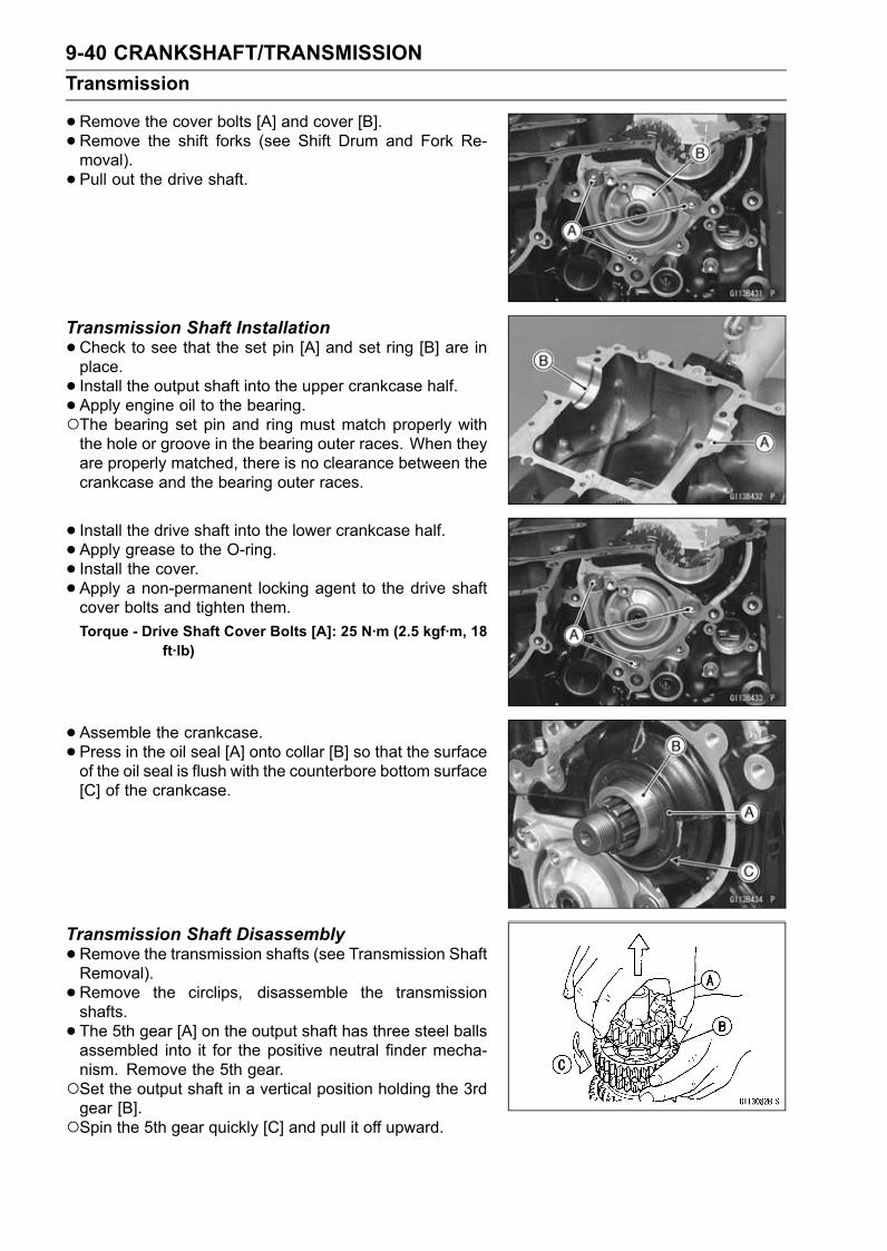
9-40 CRANKSHAFT/TRANSMISSIONTransmission
•Remove the cover bolts [A] and cover [B].• Remove the shift forks (see Shift Drum and Fork Re-moval).• Pull out the drive shaft.
Transmission Shaft Installation•Check to see that the set pin [A] and set ring [B] are inplace.• Install the output shaft into the upper crankcase half.• Apply engine oil to the bearing.The bearing set pin and ring must match properly withthe hole or groove in the bearing outer races. When theyare properly matched, there is no clearance between thecrankcase and the bearing outer races.
• Install the drive shaft into the lower crankcase half.• Apply grease to the O-ring.• Install the cover.• Apply a non-permanent locking agent to the drive shaftcover bolts and tighten them.Torque - Drive Shaft Cover Bolts [A]: 25 N·m (2.5 kgf·m, 18
ft·lb)
•Assemble the crankcase.• Press in the oil seal [A] onto collar [B] so that the surfaceof the oil seal is flush with the counterbore bottom surface[C] of the crankcase.
Transmission Shaft Disassembly•Remove the transmission shafts (see Transmission ShaftRemoval).• Remove the circlips, disassemble the transmissionshafts.• The 5th gear [A] on the output shaft has three steel ballsassembled into it for the positive neutral finder mecha-nism. Remove the 5th gear.Set the output shaft in a vertical position holding the 3rdgear [B].Spin the 5th gear quickly [C] and pull it off upward.

CRANKSHAFT/TRANSMISSION 9-41Transmission
•Remove the ball bearing [A] from each shafts.Special Tools - Bearing Puller [B]: 57001-135
Bearing Puller Adapter [C]: 57001-317
•Discard the bearing.
Transmission Shaft Assembly•Apply engine oil to the bushings, ball bearings and shafts.• Install the gear bushings [A] on the shaft with their holes[B] aligned.
• Replace any circlips removed with new ones.• Install the circlips [A] so that the opening [B] of it is alignedwith spline grooves [C].• Install the circlips so that the mark [D] on them faces toeach gear side.
• The drive shaft gears can be recognized by size: the gearwith the smallest diameter is 1st gear, and the largest oneis 6th gear. Be sure that all parts are put back in the cor-rect sequence and all circlips and washers are properly inplace.• Install the 3rd/4th gear onto the drive shaft with their oilholes aligned.• Install the 6th gear bushing onto the drive shaft with theiroil holes aligned.• The output shaft gears can be recognized by size: thegear with the largest diameter is 1st gear, and the small-est one is 6th gear. Be sure that all parts are put backin the correct sequence and all circlips and washers areproperly in place.• Install the 5th and 6th gears onto the output shaft withtheir oil holes aligned.• Install the 3rd/4th gear bushings onto the output shaft withtheir oil holes aligned.

9-42 CRANKSHAFT/TRANSMISSIONTransmission
•Fit the steel balls into the 5th gear holes in the outputshaft, aligning three oil holes [D].5th Gear [A]Output Shaft [B]Steel Balls [C]
CAUTIONDo not apply grease to the balls to hold them inplace. This will cause the positive neutral findermechanism to malfunction.
After assembling the 5th gear with steel balls in place onthe output shaft, check the ball-locking effect that the 5thgear doesn’t come out of the output shaft when moving itup and down by hand.• Check that each gear spins or slides freely on the trans-mission shafts without binding after assembly.
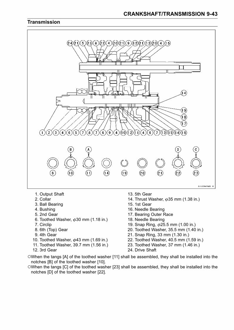
CRANKSHAFT/TRANSMISSION 9-43Transmission
1. Output Shaft2. Collar3. Ball Bearing4. Bushing5. 2nd Gear6. Toothed Washer, 30 mm (1.18 in.)7. Circlip8. 6th (Top) Gear9. 4th Gear10. Toothed Washer, 43 mm (1.69 in.)11. Toothed Washer, 39.7 mm (1.56 in.)12. 3rd Gear
13. 5th Gear14. Thrust Washer, 35 mm (1.38 in.)15. 1st Gear16. Needle Bearing17. Bearing Outer Race18. Needle Bearing19. Snap Ring, 25.5 mm (1.00 in.)20. Toothed Washer, 35.5 mm (1.40 in.)21. Snap Ring, 33 mm (1.30 in.)22. Toothed Washer, 40.5 mm (1.59 in.)23. Toothed Washer, 37 mm (1.46 in.)24. Drive Shaft
When the tangs [A] of the toothed washer [11] shall be assembled, they shall be installed into thenotches [B] of the toothed washer [10].When the tangs [C] of the toothed washer [23] shall be assembled, they shall be installed into thenotches [D] of the toothed washer [22].

9-44 CRANKSHAFT/TRANSMISSIONTransmission
Shift Drum and Fork Removal•Remove:Lower Crankcase Half (see Crankcase Splitting)External Shift Mechanism (see External Shift Mecha-nism Removal)Screws [A]Shift Drum Bearing Holder [B]• Pull out the shift rods [C], and take off the shift forks.• Pull out the shift drum [D].
Shift Drum and Fork Installation•Apply engine oil to the shift drum, forks and rods.• Install the shift rods [A], noting the groove position.Position the one with shortest ears [B] on the drive shaftand place the pin in the center groove in the shift drum.The two forks [C] on the output shaft are identical.
NOTEThe forks have marks (029 [D], 030 [E]), and positionthem so that so that their marks face the engine left side.
• Install the forks as shown.• Apply a non-permanent locking agent to the threads ofthe shift drum bearing holder screws and tighten them.Torque - Shift Drum Bearing Holder Screws: 4.9 N·m (0.50
kgf·m, 43 in·lb)
Shift Drum Disassembly•Remove the shift drum (see Shift Drum and Fork Re-moval).•While holding the shift drum with a vise, remove the shiftdrum cam holder bolt.Shift Drum Cam Holder Bolt [A]Dowel Pin [B]
Shift Drum Assembly•Be sure to install the dowel pin.• Apply a non-permanent locking agent to the threads ofthe shift drum cam holder bolt, and tighten it.Torque - Shift Drum Cam Holder Bolt: 12 N·m (1.2 kgf·m,
106 in·lb)

CRANKSHAFT/TRANSMISSION 9-45Transmission
Shift Fork Bending•Visually inspect the shift forks, and replace any fork that isbent. A bent fork could cause difficulty in shifting, or allowthe transmission to jump out of gear when under power.90° [A]
Shift Fork/Gear Groove Wear•Measure the thickness of the shift fork ears [A], and mea-sure the width [B] of the gear grooves.If the thickness of a shift fork ear is less than the servicelimit, the shift fork must be replaced.
Shift Fork Ear ThicknessStandard: 5.74 ∼ 6.000 mm (0.2260 ∼ 0.2362 in.)Service Limit: 5.6 mm (0.220 in.)
If the gear groove is worn over the service limit, the gearmust be replaced.
Gear Groove WidthStandard: 6.05 ∼ 6.15 mm (0.238 ∼ 0.242 in.)Service Limit: 6.25 mm (0.246 in.)
Shift Fork Guide Pin/Drum Groove Wear•Measure the diameter of each shift fork guide pin [A], andmeasure the width [B] of each shift drum groove.If the guide pin on any shift fork is less than the servicelimit, the fork must be replaced.
Shift Fork Guide Pin DiameterStandard: 6.9 ∼ 7.0 mm (0.272 ∼ 0.276 in.)Service Limit: 6.8 mm (0.268 in.)
If any shift drum groove is worn over the service limit, thedrum must be replaced.
Shift Drum Groove WidthStandard: 7.05 ∼ 7.20 mm (0.278 ∼ 0.283 in.)Service Limit: 7.3 mm (0.287 in.)
Gear Dog and Gear Dog Hole Damage•Visually inspect the gear dogs [A] and gear dog holes [B].Replace any damaged gears or gears with excessivelyworn dogs or dog holes.


WHEELS/TIRES 10-1
10
Wheels/TiresTable of Contents
Exploded View........................................................................................................................ 10-2Specifications ......................................................................................................................... 10-4Special Tools .......................................................................................................................... 10-5Wheels (Rims) ........................................................................................................................ 10-6
Front Wheel Removal ....................................................................................................... 10-6Front Wheel Installation .................................................................................................... 10-6Rear Wheel Removal........................................................................................................ 10-7Rear Wheel Installation..................................................................................................... 10-8Wheel Inspection .............................................................................................................. 10-10Axle Inspection.................................................................................................................. 10-10Balance Inspection............................................................................................................ 10-11Balance Adjustment .......................................................................................................... 10-11Balance Weight Removal.................................................................................................. 10-11Balance Weight Installation............................................................................................... 10-12
Tires........................................................................................................................................ 10-14Air Pressure Inspection/Adjustment.................................................................................. 10-14Tire Inspection .................................................................................................................. 10-14Tire Removal..................................................................................................................... 10-14Tire Installation.................................................................................................................. 10-14Tire Repair ........................................................................................................................ 10-16
Hub Bearing............................................................................................................................ 10-17Hub Bearing Removal....................................................................................................... 10-17Hub Bearing Installation.................................................................................................... 10-17Hub Bearing Inspection..................................................................................................... 10-17Hub Bearing Lubrication ................................................................................................... 10-18

10-2 WHEELS/TIRESExploded View

WHEELS/TIRES 10-3Exploded View
TorqueNo. Fastener
N·m kgf·m ft·lbRemarks
1 Front Axle Clamp Bolts 20 2.0 15 AL2 Front Axle Nut 127 13.0 943 Rear Axle Nut 127 13.0 944. Caliper Bracket (ZX1400B Models)AL: Tighten the two clamp bolts alternately two time to ensure even tightening.G: Apply grease.HG: Apply high-temperature grease.R: Replacement Parts
WL: Apply soap and water solution or rubber lubricant.

10-4 WHEELS/TIRESSpecifications
Item Standard Service LimitWheels (Rims)Rim Runout:Axial TIR 0.5 mm (0.02 in.) or less TIR 1.0 mm (0.04 in.)Radial TIR 0.8 mm (0.03 in.) or less TIR 1.0 mm (0.04 in.)
Axle Runout/100 mm (3.94 in.) TIR 0.03 mm (0.0012 in.) or less TIR 0.2 mm (0.01 in.)Wheel Balance 10 g (0.35 oz.) or less – – –Balance Weights 10 g (0.35 oz.), 20 g (0.71 oz.),
30 g (1.06 oz.)– – –
Rim Size:Front 17 × 3.50 – – –Rear 17 × 6.00 – – –
TiresAir Pressure (when Cold):Front Up to 180 kg (397 lb) load: – – –
290 kPa (2.9 kgf/cm², 42 psi)Rear Up to 180 kg (397 lb) load: – – –
290 kPa (2.9 kgf/cm², 42 psi)Tread Depth:Front 3.8 mm (0.15 in.) 1 mm (0.04 in.)
(AT, CH, DE) 1.6 mm (0.06 in.)Rear 4.8 mm (0.19 in.) Up to 130 km/h (80 mph):
2 mm (0.08 in.)Over 130 km/h (80 mph):
3 mm (0.12 in.)Standard Tires: Make, Type SizeFront BRIDGESTONE,
BATTLAX BT014 F RADIAL SL120/70 ZR17 M/C (58 W)
Rear BRIDGESTONE,BATTLAX BT014 R RADIAL L
190/50 ZR17 M/C (73 W)
WARNINGUse the same manufacturer’s tires on both front and rear wheels.

WHEELS/TIRES 10-5Special Tools
Bearing Driver Set:57001-1129
Jack:57001-1238
Bearing Remover Head, 25 × 28:57001-1346
Bearing Remover Shaft, 13:57001-1377
Jack Attachment:57001-1608

10-6 WHEELS/TIRESWheels (Rims)
Front Wheel Removal•Remove:Front Caliper Mounting Bolts [A]Front Calipers [B]
• Loosen:Axle Clamp Bolts [A] (Left Side)Axle Nut [B]Axle Clamp Bolts (Right Side)
• Remove the lower fairings (see Lower Fairing Removal inthe Frame chapter).• Raise the front wheel off the ground with the jack.Special Tools - Jack: 57001-1238
Jack Attachment: 57001-1608
•Remove the axle nut and pull out the axle to the right anddrop the front wheel out of the forks.
CAUTIONDo not lay the wheel down on one of the discs. Thiscan damage or warp the disc. Place blocks un-der the wheel so that the disc does not touch theground.
Front Wheel InstallationNOTE
The direction of the wheel rotation [A] is shown by anarrow [B] on the wheel spoke.
•Check the wheel rotation mark on the front wheel andinstall it.

WHEELS/TIRES 10-7Wheels (Rims)
•Apply high-temperature grease to the grease seal lip.• Fit the collars [A] on the both sides of the hub.The collars are identical.• Insert the axle from the right side.• Tighten the axle nut [B].Right Axle Clamp Bolts [C]Left Axle Clamp Bolts [D]Viewed from Rear [E]Torque - Front Axle Nut: 127 N·m (13.0 kgf·m, 94 ft·lb)
•Before tightening the axle clamp bolts on the right frontfork leg, pump the front fork up and down 4 or 5 times toall on the right front fork leg to seat on the front axle.
NOTEPut a block in front of the front wheel to stop moving.•Tighten the axle clamp bolts on the right fork leg first.Next, tighten the left axle clamp bolts.Torque - Front Axle ClampBolts: 20 N·m (2.0 kgf·m, 15 ft·lb)
NOTETighten the two clamp bolts alternately two times to en-sure even tightening torque.
• Install the lower fairings (see Lower Fairing Installation inthe Frame chapter).• Install the front calipers (see Caliper Installation in theBrakes chapter).• Check the front brake effectiveness (see Brake OperationInspection in the Periodic Maintenance chapter).
WARNINGDo not attempt to drive the motorcycle until a fullbrake lever is obtained by pumping the brake leveruntil the pads are against the disc. The brake willnot function on the first application of the lever ifthis is not done.
Rear Wheel Removal•Raise the rear wheel off the ground with the stand [A].

10-8 WHEELS/TIRESWheels (Rims)
•Remove:Rear Caliper Mounting Bolts [A]Rear Caliper [B]• Remove the rear wheel rotation sensor from the caliperbracket (see Rear Wheel Rotation Sensor Removal in theBrakes chapter) (ZX1400B Models).
• Remove:Cotter Pin [A]Axle Nut [B]Washer [C]Axle [D] (from Left Side)
• Remove the drive chain [A] from the rear sprocket towardthe left.•Move the rear wheel back and remove it.
CAUTIONDo not lay the wheel on the ground with the discfacing down. This can damage or warp the disc.Place blocks under the wheel so that the disc doesnot touch the ground.
Rear Wheel Installation•Apply high-temperature grease to the grease seal lips.• Fit the collars on the both sides of the hub.Right Side Collar [A]Left Side Collar [B]
• Engage the drive chain with the rear sprocket.• Install the caliper bracket [A] onto the swingarm stop [B].• Insert the axle from the left side of the wheel, and tightenthe axle nut.Torque - Rear Axle Nut: 127 N·m (13.0 kgf·m, 94 ft·lb)

WHEELS/TIRES 10-9Wheels (Rims)
• Insert a new cotter pin [A].NOTE
When inserting the cotter pin, if the slots in the nut donot align with the cotter pin hole in the axle, tighten thenut clockwise [B] up to next alignment.It should be within 30°.Loosen once and tighten again when the slot goes pastthe nearest hole.
•Bend the cotter pin [A] over the nut.WARNING
If the rear axle nut is not securely tightened or thecotter pin is not installed, an unsafe riding condi-tion may result.
•Adjust the drive chain slack after installation (see DriveChain Slack Inspection in the Periodic Maintenance chap-ter).• Install the rear caliper (see Caliper Installation in theBrakes chapter).• Install the rear wheel rotation sensor (see Rear WheelRotation Sensor Installation in the Brakes chapter)(ZX1400B Models).• Check the rear brake effectiveness (see Brake OperationInspection in the Periodic Maintenance chapter).
WARNINGDo not attempt to drive the motorcycle until a fullbrake pedal is obtained by pumping the brake pedaluntil the pads are against the disc. The brake willnot function on the first application of the pedal ifthis is not done.

10-10 WHEELS/TIRESWheels (Rims)
Wheel Inspection•Raise the front/rear wheel off the ground.Special Tools - Jack: 57001-1238
Jack Attachment: 57001-1608
•Spin the wheel lightly, and check for roughness or binding.If roughness or binding is found, replace the hub bearings(see Hub Bearing Removal/Installation).• Inspect the wheel for small cracks, dents, bending, orwarp.If there is any damage to the wheel, replace the wheel.• Remove the wheel, and support it with the tire by the axle.•Measure the rim runout, axial [A] and radial [B], with a dialgauge.If rim runout exceeds the service limit, check the hub bear-ings (see Hub Bearing Inspection).If the problem is not due to the bearings, replace thewheel.
Rim Runout (with tire installed)Standard:Axial TIR 0.5 mm (0.02 in.) or lessRadial TIR 0.8 mm (0.03 in.) or less
Service Limit:Axial TIR 1.0 mm (0.04 in.)Radial TIR 1.0 mm (0.04 in.)
WARNINGNever attempt to repair a damaged wheel. If thereis any damage besides wheel bearings, the wheelmust be replaced to insure safe operational condi-tion.
Axle Inspection•Remove the front and rear axles (see Front/Rear WheelRemoval).• Visually inspect the front and rear axle for damages.If the axle is damaged or bent, replace it.• Place the axle in V blocks that are 100 mm (3.94 in.) [A]apart, and set a dial gauge [B] on the axle at a pointhalfway between the blocks. Turn [C] the axle to mea-sure the runout. The difference between the highest andlowest dial readings is the amount of runout.If axle runout exceeds the service limit, replace the axle.
Axle Runout/100 mm (3.94 in.)Standard: TIR 0.03 mm (0.0012 in.) or lessService Limit: TIR 0.2 mm (0.01 in.)

WHEELS/TIRES 10-11Wheels (Rims)
Balance Inspection•Remove the front and rear wheels (see Front/Rear WheelRemoval).• Support the wheel so that it can be spun freely.• Spin the wheel lightly, and mark [A] the wheel at the topwhen the wheel stops.Repeat this procedure several times. If the wheel stopsof its own accord in various positions, it is well balanced.If the wheel always stops in one position, adjust the wheelbalance (see Balance Adjustment).
Balance Adjustment• If the wheel always stops in one position, provisionallyattach a balanceweight [A] on the rim at themarking usingadhesive tape.• Rotate the wheel 1/4 turn [B], and see whether or not thewheel stops in this position. If it does, the correct balanceweight is being used.If the wheel rotates and the weight goes up, replace theweight with the next heavier size. If the wheel rotates andthe weight goes down, replace the weight with the nextlighter size. Repeat these steps until the wheel remainsat rest after being rotated 1/4 turn.• Rotate the wheel another 1/4 turn and then another 1/4turn to see if the wheel is correctly balanced.• Repeat the entire procedure as many times as necessaryto achieve correct wheel balance.• Permanently install the balance weight.Balance Weight Removal• Insert a regular tip screwdrivers [A] [B] between the rib [C]and weight [D] as shown.• Pry the balance weight with two screwdrivers and removethe balance weight.• Discard the used balance weight.
CAUTIONDo not tap the screwdrivers. The rim could be dam-aged.

10-12 WHEELS/TIRESWheels (Rims)
Balance Weight Installation•Check if the weight portion has any play on the blade [A]and clip [B].If it does, discard it.
WARNINGIf the balance weight has any play on the rib of therim, the blade and/or clip have been stretched. Re-place the loose balance weight.Do not reuse used balance weight.Unbalanced wheels can create an unsafe ridingcondition.
Balance WeightPart Number Weight41075-0007 10 g (0.35 oz.)41075-0008 20 g (0.71 oz.)41075-0017 30 g (1.06 oz.)
NOTEBalance weights are available from Kawasaki dealersin 10, 20, and 30 grams (0.35 oz., 0.71 oz., and 1.06oz.) sizes. An imbalance of less than 10 grams (0.35oz.) will not usually affect running stability.Do not use four or more balance weight (more than 90gram, 3.2 oz.). If the wheel requires an excess balanceweight, disassemble the wheel to find the cause.

WHEELS/TIRES 10-13Wheels (Rims)
•Slip the balance weight [A] on to the rib [B], by pushing orlightly hammering [C] the clip [D].Install the balance weight at the left side of themotorcycle.Left Side [E]Right Side [F]
• Check that the blade [A] and clip [B] are fully seated onthe rim [C] and that the clip is hooked over the rib [D].Left Side [E]Right Side [F]

10-14 WHEELS/TIRESTires
Air Pressure Inspection/Adjustment•Refer to the Air Pressure Inspection in the Periodic Main-tenance chapter.
Tire Inspection•Refer to the Wheel/Tire Damage Inspection in the Peri-odic Maintenance chapter.
Tire Removal•Remove:Wheel (see Front/Rear Wheel Removal)Valve Core (Let out the air)• To maintain wheel balance, mark the valve stem positionon the tire with chalk so that the tire can be reinstalled inthe same position.Chalk Mark or Yellow Mark [A]Air Valve [B]Align [C]
• Lubricate the tire beads and rim flanges on both sides witha soap and water solution or rubber lubricant. This helpsthe tire beads slip off the rim flanges.
CAUTIONNever lubricate with engine oil or petroleum distil-lates because they will deteriorate the tire.
•Remove the tire from the rim using a suitable commer-cially available tire changer.
NOTEThe tires cannot be removed with hand tools becausethey fit the rims too tightly.
Tire InstallationWARNING
Use the same manufacture’s on both front and rearwheels.
• Inspect the rim and tire, and replace them if necessary.• Clean the sealing surfaces of the rim and tire, and smooththe sealing surfaces of the rim with a fine emery cloth ifnecessary.• Remove the air valve and discard it.
CAUTIONReplace the air valve whenever the tire is replaced.Do not reuse the air valve.

WHEELS/TIRES 10-15Tires
• Install a new valve in the rim.Remove the valve cap, lubricate the stem seal [A] with asoap and water solution or rubber lubricant, and pull [B]the valve stem through the rim from the inside out until itsnaps into place.
CAUTIONDo not use engine oil or petroleum distillates to lu-bricate the stem because they will deteriorate therubber.
The air valve is shown in the figure.Valve Cap [A]Valve Core [B]Stem Seal [C]Valve Stem [D]Valve Seat [E]Valve Opened [F]
• Check the tire rotation mark on the front and rear tires andinstall them on the rim accordingly.Tire Rotation Mark [A]Rotating Direction [B]
• Position the tire on the rim so that the valve [A] align withthe tire balance mark [B] (the chalk mark made duringremoval, or the yellow paint mark on a new tire).• Install the tire bead over the rim flange using a suitablecommercially available tire changer.• Lubricate the tire beads and rim flanges with a soap andwater solution or rubber lubricant to help seat the tirebeads in the sealing surfaces of the rim while inflating thetire.• Center the rim in the tire beads, and inflate the tire withcompressed air until the tire beads seat in the sealingsurfaces.
WARNINGBe sure to install the valve core whenever inflatingthe tire, and do not inflate the tire to more than 400kPa (4.0 kgf/cm², 57 psi). Overinflation can explodethe tire with possibility of injury and loss of life.

10-16 WHEELS/TIRESTires
•Check to see that the rim lines [A] on both sides of the tiresidewalls are parallel with the rim flanges.If the rim flanges and tire sidewall rim lines are not parallel,remove the valve core.• Lubricate the rim flanges and tire beads.• Install the valve core and inflate the tire again.• After the tire beads seat in the rim flanges, check for airleakage.Inflate the tire slightly above standard inflation.Use a soap and water solution or submerge the tire, andcheck for bubbles that would indicate leakage.• Adjust the air pressure to the specified pressure (see AirPressure Inspection in the Periodic Maintenance chap-ter).• Install the air valve cap.• Adjust the wheel balance (see Balance Adjustment).Tire RepairCurrently two types of repair for tubeless tires have come
into wide use. One type is called a temporary (external) re-pair which can be carried out without removing the tire fromthe rim, and the other type is called permanent (internal)repair which requires tire removal. It is generally under-stood that higher running durability is obtained by perma-nent (internal) repairs than by temporary (external) ones.Also, permanent (internal) repairs have the advantage ofpermitting a thorough examination for secondary damagenot visible from external inspection of the tire. For thesereasons, Kawasaki does not recommend temporary (exter-nal) repair. Only appropriate permanent (internal) repairsare recommended. Repair methods may vary slightly frommake to make. Follow the repair methods indicated by themanufacturer of the repair tools and materials so that saferesults can be obtained.

WHEELS/TIRES 10-17Hub Bearing
Hub Bearing Removal•Remove the wheel (see Front/Rear Wheel Removal), andtake out the following.CollarsCoupling (Out of rear hub)Grease Seals
•Use the bearing remover to remove the hub bearing [A].CAUTION
Do not lay the wheel on the ground with the discfacing down. This can damage or warp the disc.Place blocks under the wheel so that the disc doesnot touch the ground.
Special Tools - Bearing Remover Head, 25 × 28 [B]:57001-1346
Bearing Remover Shaft, 13 [C]: 57001-1377
Hub Bearing Installation•Before installing the hub bearings, blow any dirt or foreignparticles out of the hub with compressed air to preventcontamination of the bearings.• Replace the bearings with new ones.• Install the bearings by using the bearing driver set whichdoes not contact the bearing inner race.• Press in each right the bearing [A] until they are bottomed.Special Tool - Bearing Driver Set [B]: 57001-1129
•Replace the grease seals with new ones.• Press in the grease seals [A] so that the seal surface isflush [B] with the end of the hole.Apply high-temperature grease to the grease seal lips.Special Tool - Bearing Driver Set [C]: 57001-1129
Hub Bearing InspectionSince the hub bearings are made to extremely close tol-
erances, the clearance can not normally be measured.
NOTEDo not remove any bearings for inspection. If any bear-ings are removed, they will need to be replaced withnew ones.
•Turn each bearing in the hub back and forth [A] whilechecking for plays, roughness, or binding.If bearing play, roughness or binding is found, replace thebearing.• Examine the bearing seal [B] for tears or leakage.If the seal is torn or is leaking, replace the bearing.

10-18 WHEELS/TIRESHub Bearing
Hub Bearing LubricationNOTE
Since the hub bearings are packed with grease andsealed, lubrication is not required.

FINAL DRIVE 11-1
11
Final DriveTable of Contents
Exploded View ....................................................................................................................... 11-2Specifications ........................................................................................................................ 11-4Special Tools .......................................................................................................................... 11-5Drive Chain............................................................................................................................. 11-6
Drive Chain Slack Inspection ............................................................................................ 11-6Drive Chain Slack Adjustment .......................................................................................... 11-6Wheel Alignment Inspection/Adjustment .......................................................................... 11-6Drive Chain Wear Inspection ............................................................................................ 11-6Drive Chain Lubrication..................................................................................................... 11-6Drive Chain Removal ........................................................................................................ 11-6Drive Chain Installation ..................................................................................................... 11-6
Sprocket, Coupling ................................................................................................................. 11-7Engine Sprocket Removal ................................................................................................ 11-7Engine Sprocket Installation ............................................................................................. 11-7Rear Sprocket Removal.................................................................................................... 11-8Rear Sprocket Installation................................................................................................. 11-8Coupling Installation.......................................................................................................... 11-8Coupling Bearing Removal ............................................................................................... 11-9Coupling Bearing Installation ............................................................................................ 11-9Coupling Bearing Inspection ............................................................................................. 11-10Coupling Bearing Lubrication............................................................................................ 11-10Coupling Damper Inspection............................................................................................. 11-10Sprocket Wear Inspection................................................................................................. 11-10Rear Sprocket Warp Inspection ........................................................................................ 11-11

11-2 FINAL DRIVEExploded View

FINAL DRIVE 11-3Exploded View
TorqueNo. Fastener
N·m kgf·m ft·lbRemarks
1 Chain Guide Bolt 12 1.2 106 in·lb L2 Chain Guide Bolts 9.8 1.0 87 in·lb L3 Engine Sprocket Cover Bolts 9.8 1.0 87 in·lb4 Engine Sprocket Nut 125 13.0 92 MO5 Rear Axle Nut 127 13.0 946 Rear Sprocket Nuts 69 7.0 517 Speed Sensor Bolt 3.9 0.40 35 in·lb L8 Stud Bolts 14.7 1.5 11 LG: Apply grease.HG: Apply high-temperature grease.HO: Apply heavy oil.L: Apply a non-permanent locking agent.
MO: Apply molybdenum disulfide oil solution.(mixture of the engine oil and molybdenum disulfide grease in a weight ratio 10 : 1)
R: Replacement Parts

11-4 FINAL DRIVESpecifications
Item Standard Service LimitDrive ChainDrive Chain Slack 32 ∼ 38 mm (1.3 ∼ 1.5 in.) – – –Drive Chain Wear (20-link Length) 317.5 ∼ 318.2 mm (12.50 ∼ 12.53 in.) 323 mm (12.7 in.)Standard Chain:Make DAIDO – – –Type DID50ZVM4 GC&B – – –Link 116 links – – –
SprocketsRear Sprocket Warp 0.4 mm (0.016 in.) or less 0.5 mm (0.020 in.)

FINAL DRIVE 11-5Special Tools
Inside Circlip Pliers:57001-143
Bearing Driver Set:57001-1129

11-6 FINAL DRIVEDrive Chain
Drive Chain Slack Inspection•Refer to the Drive Chain Slack Inspection in the PeriodicMaintenance chapter.
Drive Chain Slack Adjustment•Refer to the Drive Chain Slack Adjustment in the PeriodicMaintenance chapter.
Wheel Alignment Inspection/Adjustment•Refer to the Wheel Alignment Inspection in the PeriodicMaintenance chapter.
Drive Chain Wear Inspection•Refer to the Drive Chain Wear Inspection in the PeriodicMaintenance chapter.
Drive Chain Lubrication•Refer to the Drive Chain Lubrication Condition Inspectionin the Periodic Maintenance chapter.
Drive Chain Removal•Remove the chain cover screws [A] and chain cover [B].Clear the chain cover from the swingarm.•Remove:Rear Wheel (see Rear Wheel Removal in theWheels/Tires chapter)Engine Sprocket (see Engine Sprocket Removal)Swingarm (see Swingarm Removal in the Suspensionchapter)
• Remove the drive chain [A] from the output shaft [B], andtake it off the chassis.
Drive Chain Installation• Install the drive chain to the output shaft.• Install:Swingarm (see Swingarm Installation in the Suspensionchapter)Engine Sprocket (see Engine Sprocket Installation)Rear Wheel (see Rear Wheel Installation in theWheels/Tires chapter)Chain Cover• Adjust the drive chain slack after installing the chain (seeDrive Chain Slack Adjustment in the Periodic Mainte-nance chapter).

FINAL DRIVE 11-7Sprocket, Coupling
Engine Sprocket Removal•Remove:Left Lower Fairing (see Lower Fairing Removal in theFrame chapter)Speed Sensor [A] (see Speed Sensor Removal in theElectrical System chapter)Clutch Slave Cylinder [B] (see Clutch Slave Cylinder inthe Clutch chapter)Engine Sprocket Cover Bolts [C]Engine Sprocket Cover [D]
• Flatten out the bended washer [A].• Remove the engine sprocket nut [B].NOTE
When loosening the engine sprocket nut, hold the rearbrake on.
•Remove:Washer [A]Chain Guide Bolts [B]Chain Guide [C]• Raise the rear wheel off the ground with the stand.• Remove the axle cotter pin, and loosen the rear axle nut.• Loosen the both chain adjuster locknut to loosen the drivechain.• Remove the drive chain from the rear sprocket toward theright.• Pull the engine sprocket [D] with drive chain [E] off theoutput shaft [F].• Disengage the drive chain from the engine sprocket.Engine Sprocket Installation•Replace the sprocket washer and axle cotter pin.• Install the engine sprocket onto the output shaft.• Apply a non-permanent locking agent to the threads ofthe chain guide bolts.• Install the chain guide, and tighten the bolts.Torque - Chain Guide Bolt: 12 N·m (1.2 kgf·m, 106 in·lb)
Chain Guide Bolts: 9.8 N·m (1.0 kgf·m, 87 in·lb)
•Apply molybdenum disulfide oil solution to the threads ofthe output shaft and the seating surface of the enginesprocket nut.• After torquing the engine sprocket nut, bend the one sideof the washer [A] over the nut.
NOTETighten the nut while applying the rear brake.Torque - Engine Sprocket Nut: 125 N·m (13.0 kgf·m, 92 ft·lb)
•Adjust the drive chain slack after installing the enginesprocket (see Drive Chain Slack Adjustment in the Pe-riodic Maintenance chapter).

11-8 FINAL DRIVESprocket, Coupling
• Install the engine sprocket cover.• Install the clamp [A] as shown in the figure, and tightenthe cover bolts.Torque - Engine Sprocket Cover Bolts: 9.8 N·m (1.0 kgf·m,
87 in·lb)
•Bend the end of axle cotter pin surely after tightening theaxle nut (see Rear Wheel Installation in the Wheels/Tireschapter).• Install the removed parts (see appropriate chapters).Rear Sprocket Removal•Remove the rear wheel (see Rear Wheel Removal in theWheels/Tires chapter).
CAUTIONDo not lay the wheel on the ground with the discfacing down. This can damage or warp the disc.Place blocks under the wheel so that the disc doesnot touch the ground.
•Remove the rear sprocket nuts [A].• Remove the rear sprocket [B].Rear Sprocket Installation• Install the sprocket facing the tooth number marking [A]outward.• Tighten the rear sprocket nuts.Torque - Rear Sprocket Nuts: 69 N·m (7.0 kgf·m, 51 ft·lb)
• Install the rear wheel (see Rear Wheel Installation in theWheels/Tires chapter).
Coupling Installation•High-temperature grease the following.Coupling Grease Seal Lips [A]Coupling Internal Surface [B]

FINAL DRIVE 11-9Sprocket, Coupling
• Install the collar [A].• Install the coupling.
Coupling Bearing Removal•Remove:CouplingGrease SealCirclip [A]Special Tool - Inside Circlip Pliers: 57001-143
•Remove the bearing [A] by tapping from the wheel side.Special Tool - Bearing Driver Set [B]: 57001-1129
Coupling Bearing Installation•Replace the bearing with a new one.
NOTEInstall the bearing so that the marked side faces out.•Press in the bearing [A] until it is bottomed.Special Tool - Bearing Driver Set [B]: 57001-1129
•Replace the circlip with a new one.Special Tool - Inside Circlip Pliers: 57001-143
•Replace the grease seal with a new one.• Press in the grease seal so that the seal surface is flushwith the end of the hole.Apply high-temperature grease to the grease seal lips.Special Tool - Bearing Driver Set: 57001-1129

11-10 FINAL DRIVESprocket, Coupling
Coupling Bearing InspectionSince the coupling bearing is made to extremely close
tolerances, the clearance can not normally be measured.
NOTEIt is not necessary to remove the coupling bearing forinspection. If the bearing is removed, it will need to bereplaced with a new one.
•Turn the bearing in the coupling back and forth [A] whilechecking for plays, roughness or binding.If the bearing play, roughness or binding is found, replacethe bearing.• Examine the bearing seal [B] for tears or leakage.If the seal is torn or is leaking, replace the bearing.
Coupling Bearing LubricationNOTE
Since the coupling bearing is packed with grease andsealed, lubrication is not required.
Coupling Damper Inspection•Remove the rear wheel coupling, and inspect the rubberdampers [A].• Replace the damper if it appears damaged or deterio-rated.
Sprocket Wear Inspection•Visually inspect the engine and rear sprocket teeth forwear and damage.If the teeth are worn as illustrated, replace the sprocket,and inspect the drive chain wear (see Drive Chain WearInspection in the Periodic Maintenance chapter).Worn Tooth (Engine Sprocket) [A]Worn Tooth (Rear Sprocket) [B]Direction of Rotation [C]
NOTEIf a sprocket requires replacement, the chain is proba-bly worn also. When replacing a sprocket, inspect thechain.

FINAL DRIVE 11-11Sprocket, Coupling
Rear Sprocket Warp Inspection•Raise the rear wheel off the ground with the stand so thatit will turn freely.• Set a dial gauge [A] against the rear sprocket [B] near theteeth as shown in the figure, and rotate [C] the rear wheelto measure the sprocket runout (warp). The differencebetween the highest and lowest dial gauge readings isthe amount of runout (warp).If the runout exceeds the service limit, replace the rearsprocket.
Rear Sprocket WarpStandard: 0.4 mm (0.016 in.) or lessService Limit: 0.5 mm (0.020 in.)


BRAKES 12-1
12
BrakesTable of Contents
Exploded View ....................................................................................................................... 12-3Specifications ........................................................................................................................ 12-12Special Tools .......................................................................................................................... 12-13Brake Lever, Brake Pedal....................................................................................................... 12-14
Brake Lever Position Adjustment...................................................................................... 12-14Brake Pedal Position Inspection ...................................................................................... 12-14Brake Pedal Position Adjustment ..................................................................................... 12-14Brake Pedal Removal ....................................................................................................... 12-14Brake Pedal Installation .................................................................................................... 12-15
Calipers .................................................................................................................................. 12-16Front Caliper Removal ...................................................................................................... 12-16Rear Caliper Removal....................................................................................................... 12-16Caliper Installation ............................................................................................................ 12-17Front Caliper Disassembly................................................................................................ 12-17Front Caliper Assembly..................................................................................................... 12-17Rear Caliper Disassembly ................................................................................................ 12-17Rear Caliper Assembly ..................................................................................................... 12-17Caliper Fluid Seal Damage............................................................................................... 12-18Caliper Dust Seal Damage ............................................................................................... 12-18Caliper Piston and Cylinder Damage................................................................................ 12-19
Brake Pads............................................................................................................................. 12-20Front Brake Pad Removal................................................................................................. 12-20Front Brake Pad Installation.............................................................................................. 12-20Rear Brake Pad Removal ................................................................................................ 12-21Rear Brake Pad Installation .............................................................................................. 12-21Brake Pad Wear Inspection .............................................................................................. 12-21
Master Cylinder ...................................................................................................................... 12-22Front Master Cylinder Removal ........................................................................................ 12-22Front Master Cylinder Installation ..................................................................................... 12-22Rear Master Cylinder Removal......................................................................................... 12-22Rear Master Cylinder Installation...................................................................................... 12-23Front Master Cylinder Disassembly .................................................................................. 12-23Rear Master Cylinder Disassembly................................................................................... 12-23Master Cylinder Assembly ................................................................................................ 12-23Master Cylinder Inspection (Visual Inspection)................................................................. 12-23
Brake Disc .............................................................................................................................. 12-25Brake Disc Removal ......................................................................................................... 12-25Brake Disc Installation ...................................................................................................... 12-25Brake Disc Wear ............................................................................................................... 12-25Brake Disc Warp ............................................................................................................... 12-25
Brake Fluid ............................................................................................................................. 12-26Brake Fluid Level Inspection............................................................................................. 12-26Brake Fluid Change .......................................................................................................... 12-26Brake Line Bleeding.......................................................................................................... 12-26
Brake Hose............................................................................................................................. 12-30Brake Hose and Pipe Removal/Installation....................................................................... 12-30Brake Hose and Pipe Inspection....................................................................................... 12-30
Anti-Lock Brake System (Equipped Models) .......................................................................... 12-31ABS Servicing Precautions ............................................................................................... 12-34ABS Troubleshooting Outline............................................................................................ 12-36

12-2 BRAKES
Inquiries to Rider............................................................................................................... 12-39Self-diagnosis Outline ....................................................................................................... 12-41Self-diagnosis Procedures ................................................................................................ 12-41Service Code Clearing Procedures................................................................................... 12-42How to Read Service Codes............................................................................................. 12-45How to Erase Service Codes ............................................................................................ 12-45ABS Indicator Light (LED) Inspection ............................................................................... 12-47ABS Indicator Light (LED) is Unlit (When the Ignition Switch turned to ON) .................... 12-47ABS Indicator Light (LED) Lights (When the Motorcycle is Running, - No Service Code) 12-48Solenoid Valve Inspection (Service Code 13,14,17,18).................................................... 12-48ABS Solenoid Valve Relay Inspection (Service Code 19) ................................................ 12-48Front, Rear Wheel Rotation Difference Abnormal (Service Code 25) .............................. 12-50ABS Pump Motor Relay Inspection (Service Code 35)..................................................... 12-50Front Wheel Rotation Sensor Signal Abnormal (Service Code 42) .................................. 12-51Front Wheel Rotation Sensor Wiring Inspection (Service Code 43) ................................. 12-52Rear Wheel Rotation Sensor Signal Abnormal (Service Code 44)................................... 12-53Rear Wheel Rotation Sensor Wiring Inspection (Service Code 45).................................. 12-54Power Supply Voltage Abnormal (Under-Voltage) (Service Code 52) .............................. 12-54Power Supply Voltage Abnormal (Over-Voltage) (Service Code 53) ................................ 12-55ECU Inspection (Service Code 55) ................................................................................... 12-56ABS Hydraulic Unit Removal ............................................................................................ 12-56ABS Hydraulic Unit Installation ......................................................................................... 12-58ABS Hydraulic Unit Inspection .......................................................................................... 12-59Front Wheel Rotation Sensor Removal ............................................................................ 12-59Front Wheel Rotation Sensor Installation ......................................................................... 12-59Rear Wheel Rotation Sensor Removal ............................................................................. 12-60Rear Wheel Rotation Sensor Installation .......................................................................... 12-60Wheel Rotation Sensor Inspection.................................................................................... 12-61Wheel Rotation Sensor Air Gap Inspection ...................................................................... 12-61Wheel Rotation Sensor Rotor Inspection.......................................................................... 12-62ABS Solenoid Valve Relay Fuse (20 A) Removal............................................................. 12-62ABS Motor Relay Fuse (30 A) Removal ........................................................................... 12-62ABS ECU Fuse (10 A) Removal ....................................................................................... 12-62Fuse Installation................................................................................................................ 12-63Fuse Inspection................................................................................................................. 12-63

BRAKES 12-3Exploded View
Dummy Page

12-4 BRAKESExploded View
ZX1400A Models

BRAKES 12-5Exploded View
TorqueNo. Fastener
N·m kgf·m ft·lbRemarks
1 Bleed Valves 7.8 0.80 69 in·lb2 Brake Hose Banjo Bolts 25 2.5 183 Brake Lever Pivot Bolt 1.0 0.10 9 in·lb Si4 Brake Lever Pivot Bolt Locknut 5.9 0.60 52 in·lb5 Front Brake Disc Mounting Bolts 27 2.8 20 L6 Front Brake Light Switch Screw 1.2 0.12 11 in·lb7 Front Brake Pad Pins 17.2 1.8 138 Front Brake Reservoir Cap Stopper Screw 1.2 0.12 11 in·lb9 Front Caliper Assembly Bolts 27 2.8 20 L10 Front Caliper Mounting Bolts 34 3.5 2511 Front Master Cylinder Bleed Valve 7.8 0.80 69 in·lb12 Front Master Cylinder Clamp Bolts 8.8 0.90 78 in·lb SB: Apply brake fluid.L: Apply a non-permanent locking agent.R: Replacement PartsS: Follow the specified tightening sequence.Si: Apply silicone grease (ex. PBC grease).

12-6 BRAKESExploded View

BRAKES 12-7Exploded View
TorqueNo. Fastener
N·m kgf·m ft·lbRemarks
1 Bleed Valves 7.8 0.80 69 in·lb2 Brake Hose Banjo Bolts 25 2.5 183 Brake Pedal Bolt 8.8 0.90 78 in·lb4 Rear Brake Disc Mounting Bolts 27 2.5 18 L5 Rear Brake Pad Pin 17.2 1.8 136 Rear Caliper Assembly Bolts 37 3.8 27 L7 Rear Caliper Mounting Bolts 25 2.5 188 Rear Master Cylinder Mounting Bolts 25 2.5 189 Rear Master Cylinder Push Rod Locknut 17.2 1.8 13B: Apply brake fluid.G: Apply grease.L: Apply a non-permanent locking agent.R: Replacement PartsSi: Apply silicone grease (ex. PBC grease).

12-8 BRAKESExploded View
ZX1400B Models

BRAKES 12-9Exploded View
TorqueNo. Fastener
N·m kgf·m ft·lbRemarks
1 Bleed Valves 7.8 0.80 69 in·lb2 Brake Hose Banjo Bolts 25 2.5 183 Brake Lever Pivot Bolt 1.0 0.10 9 in·lb Si4 Brake Lever Pivot Bolt Locknut 5.9 0.60 52 in·lb5 Brake Pipe Joint Nuts 18 1.8 136 Front Brake Disc Mounting Bolts 27 2.8 20 L7 Front Brake Light Switch Screw 1.2 0.12 11 in·lb8 Front Brake Pad Pins 17.2 1.8 139 Front Brake Reservoir Cap Stopper Screw 1.2 0.12 11 in·lb10 Front Caliper Assembly Bolts 27 2.8 20 L11 Front Caliper Mounting Bolts 34 3.5 2512 Front Master Cylinder Bleed Valve 7.8 0.80 69 in·lb13 Front Master Cylinder Clamp Bolts 8.8 0.90 78 in·lb SB: Apply brake fluid.L: Apply a non-permanent locking agent.R: Replacement PartsS: Follow the specified tightening sequence.Si: Apply silicone grease (ex. PBC grease).

12-10 BRAKESExploded View

BRAKES 12-11Exploded View
TorqueNo. Fastener
N·m kgf·m ft·lbRemarks
1 Bleed Valves 7.8 0.80 69 in·lb2 Brake Hose Banjo Bolts 25 2.5 183 Brake Pedal Bolt 8.8 0.90 78 in·lb4 Brake Pipe Joint Nuts 18 1.8 135 Rear Brake Disc Mounting Bolts 27 2.8 20 L6 Rear Brake Pad Pin 17.2 1.8 137 Rear Caliper Assembly Bolts 37 3.8 27 L8 Rear Caliper Mounting Bolts 25 2.5 189 Rear Master Cylinder Mounting Bolts 25 2.5 1810 Rear Master Cylinder Push Rod Locknut 17.2 1.8 13B: Apply brake fluid.G: Apply grease.L: Apply a non-permanent locking agent.R: Replacement PartsSi: Apply silicone grease (ex. PBC grease).

12-12 BRAKESSpecifications
Item Standard Service LimitBrake Lever, Brake PedalBrake Lever Position 6-way adjustable (to suit rider) – – –Brake Lever Free Play Non-adjustable – – –Pedal Free Play Non-adjustable – – –Pedal Position About 45 mm (1.8 in.) below footpeg top – – –
Brake PadsLining Thickness:Front 4.0 mm (0.16 in.) 1 mm (0.04 in.)Rear 5.0 mm (0.20 in.) 1 mm (0.04 in.)
Brake DiscsThickness:Front 4.8 ∼ 5.2 mm (0.19 ∼ 0.20 in.) 4.5 mm (0.18 in.)Rear 5.8 ∼ 6.2 mm (0.23 ∼ 0.24 in.) 5.5 mm (0.22 in.)
Runout TIR 0.15 mm (0.006 in.) or less TIR 0.3 mm (0.01 in.)Brake FluidGrade DOT4 – – –

BRAKES 12-13Special Tools
Inside Circlip Pliers:57001-143
Jack:57001-1238
Hand Tester:57001-1394
Jack Attachment:57001-1608

12-14 BRAKESBrake Lever, Brake Pedal
Brake Lever Position AdjustmentThe brake lever adjuster has 6 positions so that the brake
lever position can be adjusted to suit the operator’s hand.• Push the lever forward and turn the adjuster [A] to alignthe number with the arrow mark [B] on the lever holder.The distance from the grip to the lever is minimum at num-ber 6 and maximum at number 1.
Brake Pedal Position Inspection•Check that the brake pedal [A] is in the correct position.Footpeg [B]
Pedal PositionStandard: About 45 mm (1.8 in.) [C] below top of
footpeg
If it is incorrect, adjust the brake pedal position.
Brake Pedal Position AdjustmentNOTE
Usually it is not necessary to adjust the pedal position,but always adjust it when push rod locknut has beenloosened.
• Loosen the locknut [A] and turn the push rod with the hexhead [B] to achieve the correct pedal position.If the length [C] shown is 80 ±1 mm (3.1 ±0.04 in.), thepedal position will be within the standard range.• Tighten:Torque - RearMaster Cylinder PushRod Locknut: 17.2 N·m
(1.8 kgf·m, 13 ft·lb)
•Check the brake light switch operation (see Brake LightSwitch Operation Inspection in the Periodic Maintenancechapter).
Brake Pedal Removal•Remove:Rear Master Cylinder Mounting Bolts [A]Right Footpeg Bracket Bolts [B]

BRAKES 12-15Brake Lever, Brake Pedal
•Remove:Cotter Pin [A]Joint Pin [B]Rear Brake Light Switch Spring [C]Return Spring [D]• Remove the mounting bolt [E] and take out the brakepedal.
Brake Pedal Installation•Apply grease to the pivot shaft [A] and install the washer[B].• Install:Brake Pedal [C]Washer [D]Brake Pedal Bolt [E]Torque - Brake Pedal Bolt: 8.8 N·m (0.90 kgf·m, 78 in·lb)
•Hook the lower end of the rear brake light switch spring[A] on the pedal hook.• Hook the upper end of the return spring [B] on the pedalhook.
• Replace the cotter pin with a new one.• Insert the cotter pin [A] and bend the pin ends [B].
• Install the right footpeg bracket.Torque - Front Footpeg Bracket Bolts: 25 N·m (2.5 kgf·m,
18 ft·lb)Depress the brake pedal [A] and then align the bolts holesof the master cylinder [B].Torque - Rear Master Cylinder Mounting Bolts: 25 N·m (2.5
kgf·m, 18 ft·lb)
•Check the brake pedal position (see Brake Pedal PositionInspection).

12-16 BRAKESCalipers
Front Caliper Removal• Loosen the banjo bolt [A] at the brake hose lower end,and tighten it loosely.• Unscrew the caliper mounting bolts [B], and detach thecaliper [C] from the disc.
CAUTIONDo not loosen the caliper assembly bolts. Take outonly the caliper mounting bolts for caliper removal.Loosening the caliper assembly bolts will causebrake fluid leakage.
•Unscrew the banjo bolt and remove the brake hoses [D]from the caliper (see Brake Hose Removal/Installation).
CAUTIONImmediately wash away any brake fluid that spills.
NOTEIf the caliper is to be disassembled after removal and ifcompressed air is not available, disassemble the caliperbefore the brake hose is removed (see Front CaliperDisassembly).
Rear Caliper Removal• Loosen the banjo bolt [A] at the brake hose lower end,and tighten it loosely.• Unscrew the caliper mounting bolts [B], and detach thecaliper [C] from the disc.
CAUTIONDo not loosen the caliper assembly bolts. Take outonly the caliper mounting bolts for caliper removal.Loosening the caliper assembly bolts will causebrake fluid leakage.
•Unscrew the banjo bolt and remove the brake hose [D]from the caliper (see Brake Hose Removal/Installation).
CAUTIONImmediately wash away any brake fluid that spills.
NOTEIf the caliper is to be disassembled after removal and ifcompressed air is not available, disassemble the caliperbefore the brake hose is removed (see Rear CaliperDisassembly).

BRAKES 12-17Calipers
Caliper Installation• Install the caliper and brake hose lower end.Replace the washers on each side of hose fitting with newones.• Tighten:Torque - Caliper Mounting Bolts
Front: 34 N·m (3.5 kgf·m, 25 ft·lb)Rear: 25 N·m (2.5 kgf·m, 18 ft·lb)
Brake Hose Banjo Bolts: 25 N·m (2.5 kgf·m, 18ft·lb)
•Check the fluid level in the brake reservoirs.• Bleed the brake line (see Brake Line Bleeding).• Check the brake for good braking power, no brake drag,and no fluid leakage.
WARNINGDo not attempt to drive the motorcycle until a fullbrake lever or pedal is obtained by pumping thebrake lever or pedal until the pads are against thedisc. The brakes will not function on the first appli-cation of the lever or pedal if this is not done.
Front Caliper Disassembly•Refer to the Caliper Rubber Parts Replacement in the Pe-riodic Maintenance chapter.
Front Caliper Assembly•Refer to the Caliper Rubber Parts Replacement in the Pe-riodic Maintenance chapter.
Rear Caliper Disassembly•Refer to the Caliper Rubber Parts Replacement in the Pe-riodic Maintenance chapter.
Rear Caliper Assembly•Refer to the Caliper Rubber Parts Replacement in the Pe-riodic Maintenance chapter.

12-18 BRAKESCalipers
Caliper Fluid Seal DamageThe fluid seal (piston seal) [A] is placed around the pis-
ton to maintain clearance between the pad and the disc. Ifthe seal is in a poor condition, it could lead the pad to wearexcessively or the brake to drag, which may cause the tem-perature of the discs or the brake fluid to increase.• Replace the fluid seal if it exhibits any of the conditionslisted below.Brake fluid leakage around the pad.Brakes overheat.Considerable difference in inner and outer pad wear.Seal and piston are stuck together.If the fluid seal is replaced, replace the dust seal [B] aswell. Also, replace all seals every other time the pads arechanged.
Caliper Dust Seal Damage•Check that the dust seals [A] are not cracked, worn,swollen, or otherwise damaged.If they show any damage, replace the dust seals with newones.Pistons [B]Fluid Seals [C]

BRAKES 12-19Calipers
Caliper Piston and Cylinder Damage•Visually inspect the pistons [A] and cylinder surfaces [B].Replace the caliper if the cylinder and piston are badlyscores or rusty.

12-20 BRAKESBrake Pads
Front Brake Pad Removal• Loosen the pad pins [A].
• Remove:Pad Pins [A]Pad Springs [B]Brake Pads [C]
Front Brake Pad Installation•Push the caliper pistons in by hand as far as they will go.• Install the outside pad [A] and insert the pad pin [B] asshown in the figure.
• Set:Inside Pad [A]Pad Spring [B]
Pushing the pin holder [C] to hole of the pad and insertthe pad pin.Torque - Front Brake Pad Pins: 17.2 N·m (1.8 kgf·m, 13 ft·lb)
WARNINGDo not attempt to drive the motorcycle until a fullbrake lever is obtained by pumping the brake leverand the pads are against the disc. The brake willnot function on the first application of the lever ifthis is not done.

BRAKES 12-21Brake Pads
Rear Brake Pad Removal• Loosen the pad pin [A].• Unscrew the caliper mounting bolts [B].• Remove the caliper with the hose installed.
• Remove:Pad Pin [A]Pad Spring [B]Brake Pads [C]
Rear Brake Pad Installation•Push the caliper pistons in by hand as far as they will go.• Install the outside pad [A] and insert the pad pin [B] asshown in the figure.
• Set:Inside Pad [A]Pad Spring [B]
Pushing the pin holder [C] to hole of the pad and insertthe pad pin.• Install the caliper (see Caliper Installation).• Tighten the pad pin.Torque - Rear Brake Pad Pin: 17.2 N·m (1.8 kgf·m, 13 ft·lb)
WARNINGDo not attempt to drive the motorcycle until a fullbrake pedal is obtained by pumping the brake pedaluntil the pads are against the disc. The brake willnot function on the first application of the pedal ifthis is not done.
Brake Pad Wear Inspection•Refer to the Brake Pad Wear Inspection in the PeriodicMaintenance chapter.

12-22 BRAKESMaster Cylinder
Front Master Cylinder Removal•Remove the reservoir bracket bolt [A].• Remove the banjo bolt [B] to disconnect the brake hosefrom the master cylinder (see Brake Hose Removal/In-stallation).• Unscrew the clamp bolts [C], and take off themaster cylin-der [D] as an assembly with the reservoir, brake lever, andbrake switch installed.• Disconnect the front brake light switch connector [E].
CAUTIONImmediately wash away any brake fluid that spills.
•Remove:Brake Lever Pivot Bolt [A] and NutBrake Lever [B]Clamp [C] (Slide Out)Brake Hose [D]Front Brake Light Switch [E]
Front Master Cylinder Installation•Set the front master cylinder to match its mating surface[A] to the punch mark [B] of the handlebar.• The master cylinder clamp must be installed with the ar-row mark [C] upward.• Tighten the upper clamp bolt first, and then the lowerclamp bolt.Torque - Front Master Cylinder Clamp Bolts: 8.8 N·m (0.90
kgf·m, 78 in·lb)
•Replace the washers that are on each side of the hosefitting with new ones.• Tighten:Torque - Brake Hose Banjo Bolt: 25 N·m (2.5 kgf·m, 18 ft·lb)
•Bleed the brake line (see Brake Line Bleeding).• Check the brake for good braking power, no brake drag,and no fluid leakage.
Rear Master Cylinder Removal•Unscrew the brake hose banjo bolt [A] and brake hose[B].• Remove:Cotter Pin [C]Joint Pin [D]Bolts [E]Foot Guard [F]Rear Master Cylinder• Slide out the clamp [G].• Pull off the reservoir hose lower end, and drain the brakefluid into a container.

BRAKES 12-23Master Cylinder
Rear Master Cylinder Installation•Replace the cotter pin with a new one.• Replace the washers that are on each side of hose fittingwith new ones.• Tighten:Torque - Rear Master Cylinder Mounting Bolts: 25 N·m (2.5
kgf·m, 18 ft·lb)Brake Hose Banjo Bolt: 25 N·m (2.5 kgf·m, 18 ft·lb)
•Bleed the brake line (see Brake Line Bleeding).• Check the brake for good braking power, no brake drag,and no fluid leakage.
Front Master Cylinder Disassembly•Refer to the Master Cylinder Rubber Parts Replacementin the Periodic Maintenance chapter.
Rear Master Cylinder Disassembly•Refer to the Master Cylinder Rubber Parts Replacementin the Periodic Maintenance chapter.
Master Cylinder Assembly•Refer to the Master Cylinder Rubber Parts Replacementin the Periodic Maintenance chapter.
Master Cylinder Inspection (Visual Inspection)•Remove the master cylinders (see Front/Rear MasterCylinder Removal).• Disassemble the front and rear master cylinders (seeMaster Cylinder Rubber Parts Replacement in the Peri-odic Maintenance chapter).• Check that there are no scratches, rust or pitting on theinner wall [A] of each master cylinder and on the outsideof each piston [B].If a master cylinder or piston shows any damage, replacethem.• Inspect the primary cup [C] and secondary cup [D].If a cup is worn, damaged softened (rotted), or swollen,the piston assembly should be replaced to renew thecups.If fluid leakage is noted at the brake lever, the piston as-sembly should be replaced to renew the cups.Front Master Cylinder [J]

12-24 BRAKESMaster Cylinder
•Check the dust covers [E] for damage.If they are damaged, replace them.•Check the piston return spring [F] for any damage.If the springs are damaged, replace them.•Check that relief port [G] and supply port [H] are notplugged.If the relief port becomes plugged, the brake pads willdrag on the disc. Blow the ports clean with compressedair.Rear Master Cylinder [K]

BRAKES 12-25Brake Disc
Brake Disc Removal•Remove the wheels (see Front/Rear Wheel Removal inthe Wheels/Tires chapter).• Unscrew the mounting bolts, and take off the disc.Remove the sensor rotor (ZX1400B Models).Brake Disc Installation• Install the brake disc on the wheel so that the marked side[A] faces out.Install the sensor rotor on the brake disc so that themarked side faces out (ZX1400B Models).• Apply a non-permanent locking agent to the threads ofthe rear brake disc mounting bolts [B].• Tighten:Torque - Brake Disc Mounting Bolts: 27 N·m (2.8 kgf·m, 20
ft·lb)
Brake Disc Wear•Measure the thickness of each disc [A] at the point whereit has worn the most.If the disc has worn past the service limit, replace it.Measuring Area [B]
Brake Discs ThicknessStandard:Front 4.8 ∼ 5.2 mm (0.19 ∼ 0.20 in.)Rear 5.8 ∼ 6.2 mm (0.23 ∼ 0.24 in.)
Service Limit:Front 4.5 mm (0.18 in.)Rear 5.5 mm (0.22 in.)
Brake Disc Warp•Raise the front/rear wheel off the ground.Special Tools - Jack: 57001-1238
Jack Attachment: 57001-1608For front disc inspection, turn the handlebar fully to oneside.• Set up a dial gauge against the disc [A] as shown andmeasure disc runout, while turning [B] the wheel by hand.If runout exceeds the service limit, replace the disc.
Disc RunoutStandard: TIR 0.15 mm (0.006 in.) or lessService Limit: TIR 0.3 mm (0.01 in.)

12-26 BRAKESBrake Fluid
Brake Fluid Level Inspection•Refer to the Brake Fluid Level Inspection in the PeriodicMaintenance chapter.
Brake Fluid Change•Refer to the Brake Fluid Change in the Periodic Mainte-nance chapter.
Brake Line BleedingThe brake fluid has a very low compression coefficient so
that almost all the movement of the brake lever or pedalis transmitted directly to the caliper for braking action. Air,however, is easily compressed. When air enters the brakelines, brake lever or pedal movement will be partially usedin compressing the air. This will make the lever or pedal feelspongy, and there will be a loss in braking power.
WARNINGBe sure to bleed the air from the brake line when-ever brake lever or pedal action feels soft orspongy after the brake fluid is changed, or when-ever a brake line fitting has been loosened for anyreason.
NOTEThe procedure to bleed the front brake line is as follows.Bleeding the rear brake line is the same as for the frontbrake.
•Remove:Screw [A]Clamp [B]Front Brake Reservoir Cap [C]Diaphragm PlateDiaphragm•Fill the reservoir with fresh brake fluid to the upper levelline in the reservoir.• Slowly pump the brake lever several times until no airbubbles can be seen rising up through the fluid from theholes at the bottom of the reservoir.Bleed the air completely from the master cylinder by thisoperation.
• Remove the rubber cap from the bleed valve on the frontmaster cylinder.• Attach a clear plastic hose [A] to the bleed valve, and runthe other end of the hose into a container.

BRAKES 12-27Brake Fluid
•Bleed the brake line and the master cylinder.Repeat this operation until no more air can be seen com-ing out into the plastic hose.1. Pump the brake lever until it becomes hard, and applythe brake and hold it [A].
2. Quickly open and close [B] the bleed valve while hold-ing the brake applied.
3. Release the brake [C].
NOTEThe fluid level must be checked often during the bleed-ing operation and replenished with fresh brake fluid asnecessary. If the fluid in the reservoir runs completelyout any time during bleeding, the bleeding operationmust be done over again from the beginning since airwill have entered the line.
•Remove the clear plastic hose.• Tighten the bleed valve, and install the rubber cap.Torque - Front Master Cylinder Bleed Valve: 7.8 N·m (0.80
kgf·m, 69 in·lb)
•Remove the rubber cap [A] from the bleed valve on thecaliper.• Attach a clear plastic hose [B] to the bleed valve, and runthe other end of the hose into a container.
• Bleed the brake line and the caliper.Repeat this operation until no more air can be seen com-ing out into the plastic hose.1. Pump the brake lever until it becomes hard, and applythe brake and hold it [A].
2. Quickly open and close [B] the bleed valve while hold-ing the brake applied.
3. Release the brake [C].
NOTEThe fluid level must be checked often during the bleed-ing operation and replenished with fresh brake fluid asnecessary. If the fluid in the reservoir runs completelyout any time during bleeding, the bleeding operationmust be done over again from the beginning since airwill have entered the line.Tap the brake hose lightly from the caliper to the reser-voir for more complete bleeding.Front Brake: First bleeding the right caliper then repeatthe above steps for the left caliper.
•Remove the clear plastic hose.

12-28 BRAKESBrake Fluid
• Install:DiaphragmDiaphragm PlateFront Brake Reservoir Cap [A]Clamp [B]Screw [C]
• Follow the procedure below to install the front/rear brakefluid reservoir cap correctly.First, tighten the brake fluid reservoir cap [B] clockwise[C] by hand until slight resistance is felt indicating thatthe cap is seated on the reservoir body, then tighten thecap an additional 1/6 turn [D] while holding the brake fluidreservoir body [A].
• Tighten:Torque - Front Brake Reservoir Cap Stopper Screw: 1.2
N·m (0.12 kgf·m, 11 in·lb)
•Tighten the bleed valve, and install the rubber cap.Torque - Bleed Valve: 7.8 N·m (0.80 kgf·m, 69 in·lb)
•Check the fluid level (see Brake Fluid Level Inspection inthe Periodic Maintenance chapter).• After bleeding is done, check the brake for good brakingpower, no brake drag, and no fluid leakage.

BRAKES 12-29Brake Fluid
WARNINGWhen working with the disc brake, observe the pre-cautions listed below.1. Never reuse old brake fluid.2. Do not use fluid from a container that has been leftunsealed or that has been open for a long time.
3. Do not mix two types and brands of fluid for use inthe brake. This lowers the brake fluid boiling pointand could cause the brake to be ineffective. It mayalso cause the rubber brake parts to deteriorate.
4. Don’t leave the reservoir cap off for any length oftime to avoid moisture contamination of the fluid.
5. Don’t change the fluid in the rain or when a strongwind is blowing.
6. Except for the disc pads and disc, use only discbrake fluid, isopropyl alcohol, or ethyl alcohol forcleaning of the brake parts. Do not use any otherfluid for cleaning these parts. Gasoline, engine oil,or any other petroleum distillate will cause deterio-ration of the rubber parts. Oil spilled on any part willbe difficult to wash off completely and will eventuallydeteriorate the rubber used in the disc brake.
7. When handling the disc pads or disc, be careful thatno disc brake fluid or any oil gets on them. Clean offany fluid or oil that inadvertently gets on the pads ordisc with a high-flash point solvent. Do not use onewhich will leave an oily residue. Replace the padswith new ones if they cannot be cleaned satisfacto-rily.
8. Brake fluid quickly ruins painted surfaces; anyspilled fluid should be completely wiped up imme-diately.
9. If any of the brake line fittings or the bleed valve isopened at any time, theAIRMUSTBEBLED FROMTHE BRAKE LINE.

12-30 BRAKESBrake Hose
Brake Hose and Pipe Removal/Installation•Refer to the Brake Hose and Pipe Replacement in thePeriodic Maintenance chapter.
Brake Hose and Pipe Inspection•Refer to the Brake Hose and Pipe Damage and Instal-lation Condition Inspection in the Periodic Maintenancechapter.

BRAKES 12-31Anti-Lock Brake System (Equipped Models)
Parts Location
1. Front Wheel Rotation Sensor2. Front Wheel Rotation Sensor Rotor3. Rear Wheel Rotation Sensor4. Rear Wheel Rotation Sensor Rotor5. ABS Indicator Light (LED)6. ABS Hydraulic Unit7. ABS Fuse Box8. ABS Kawasaki Self-diagnosis System Connector

12-32 BRAKESAnti-Lock Brake System (Equipped Models)
ABS System Wiring Diagram
1. Ignition Switch2. Joint Connector 13. Front Brake Switch4. Water-proof Joint 15. Rear Brake Switch6. Frame Ground7. Battery 12 V 14 Ah8. Main Fuse 30 A9. Joint Connector 210. Main Relay11. Relay Box12. ECU Fuse 15 A13. ABS Motor Relay Fuse 30 A14. ABS Solenoid Valve Relay Fuse 20 A15. ABS ECU Fuse 10 A16. Ignition Fuse 10 A17. Fuse Box 218. Meter Unit19. ABS Hydraulic Unit20. ABS Kawasaki Self-diagnosis System Connector21. Front Wheel Rotation Sensor22. Rear Wheel Rotation Sensor23. ABS Self-diagnosis Terminal

BRAKES 12-33Anti-Lock Brake System (Equipped Models)
Terminal Names
1. Unused2. Power Supply to Rear Wheel Rotation Sensor3. Front Wheel Rotation Sensor Signal4. Front and Rear Brake Light Switch5. Unused6. Unused7. Unused8. Power Supply to ABS Solenoid Valve Relay9. Power Supply to ABS Motor Relay10. ABS Kawasaki Self-diagnosis System Terminal11. Unused12. Power Supply to Front Wheel Rotation Sensor13. ABS Self-diagnosis Terminal14. Unused15. Unused16. Power Supply17. Unused18. Rear Wheel Rotation Sensor Signal19. Unused20. Unused21. ABS Indicator Light (LED)22. Unused23. Unused24. Ground25. Ground to Motor

12-34 BRAKESAnti-Lock Brake System (Equipped Models)
ABS Servicing PrecautionsThere are a number of important precautions that should
be followed servicing the ABS system.This ABS system is designed to be used with a 12 Vsealed battery as its power source. Do not use anyother battery except for a 12 V sealed battery as a powersource.Do not reverse the battery cable connections. This willdamage the ABS hydraulic unit.To prevent damage to the ABS parts, do not disconnectthe battery cables or any other electrical connectionswhen the ignition switch is ON or while the engine isrunning.Take care not to short the leads that are directly con-nected to the battery positive (+) terminal to the chassisground.Do not turn the ignition switch ON while any of the ABSelectrical connectors are disconnected. The ABS hy-draulic unit memorizes service codes.Do not spray water on the electrical parts, ABS parts, con-nectors, leads and wiring.If a transceiver is installed on the motorcycle, make surethat the operation of the ABS system is not influencedby electric wave radiated from the antenna. Locate theantenna as far as possible away from the ABS hydraulicunit.Whenever the ABS electrical connections are to be dis-connected, first turn off the ignition switch.The ABS parts should never be struck sharply, as witha hammer, or allowed to fall on a hard surface. Such ashock to the parts can damage them.The ABS parts cannot be disassembled. Even if a fault isfound, do not try to disassemble and repair the ABS parts,replace it.The ABS has many brake lines, pipes, and leads. Andthe ABS cannot detect problems with the conventionalbraking system (brake disc wear, unevenly worn brakepad, and other mechanical faults). To prevent trouble,check the brake lines and pipes for correct routing andconnection, the wiring for correct routing, and the brakesfor proper braking power. Be sure to check for fluid leak-age, and bleed the brake line thoroughly.
WARNINGIf any of the brake line fittings, including the ABShydraulic unit joint nuts, or the bleed valve isopened at any time, the air must be bled completelyfrom the brake line.
CAUTIONDo not ride the motorcycle with air in the brake line,or the ABS could malfunction.

BRAKES 12-35Anti-Lock Brake System (Equipped Models)
The ABS indicator light (LED) [A] may light if the tire pres-sure is incorrect, a non-recommended tire is installed, orthe wheel is deformed. If the indicator light lights, remedythe problem and clear the service code.
WARNINGUse of non-recommended tiresmay causemalfunc-tioning of ABS and can lead to extended brakingdistance. The rider could have an accident as a re-sult. Always use recommended standard tires forthis motorcycle.
The ABS indicator light (LED) may come on if the engineis run with the motorcycle on its stand and the transmis-sion in gear. If the indicator light comes on, just turn theignition switch OFF, then clear service code 42, which in-dicates a “Faulty front wheel rotation sensor”.When the ABS operates, the ABS makes noise and therider feels the reaction force on the brake lever and brakepedal. This is a normal condition. It informs the rider thatthe ABS is operating normally.Service codes detected once by the ABS hydraulic unitwill be memorized in the ABS hydraulic unit. Therefore,after maintenance work is finished, be sure to erase theservice codes. Do not erase the service codes duringtroubleshooting. Wait until all the checks and repair workare finished to prevent duplication of previous servicecodes and unnecessary maintenance work.Before delivering the motorcycle to the customer, besure to erase any service codes which might be stored inthe ABS hydraulic unit. Using the self-diagnosis feature,make sure that the ABS indicator light (LED) lights. Afully charged battery is a must for conducting reliableself-diagnosis. Test run the motorcycle at a speed ofmore than 20 km/h (12 mph) to see that the ABS indicatorlight (LED) does not come on. Finally, test run the mo-torcycle at a speed of more than 30 km/h (20 mph) andbrake suddenly to see that the motorcycle stops withoutloss of steering control and the ABS operates normally(The reaction force generated is felt in the brake leverand pedal.). This completes the final inspection.Color Codes:
BK: BlackBL: BlueBR: BrownCH: ChocolateDG: Dark Green
G: GreenGY: GrayLB: Light BlueLG: Light GreenO: Orange
P: PinkPU: PurpleR: RedW: WhiteY: Yellow

12-36 BRAKESAnti-Lock Brake System (Equipped Models)
ABS Troubleshooting OutlineWhen an abnormality in the system occurs, the ABS in-
dicator light (LED) lights up to alert the rider. In addition,the nature of the fault is stored in the memory of the ABShydraulic unit and when in the self-diagnosis mode, the ser-vice code [A] is indicated by the number of times the ABSindicator light (LED) blinks. The service codes stored inmemory are not erased until the mode has been changedto the fault erase mode after the fault has been corrected.Therefore, after correcting the problem, always erase theservice codes and then run the self-diagnosis program toconfirm normal signal output. When, due to a malfunction,the ABS indicator light (LED) remains lit, get a thoroughunderstanding of the background before starting the repairwork. Ask the rider about the conditions [B] under whichthe problem occurred and try to determine the cause [C].Do not rely solely on the ABS self-diagnosis function, usecommon sense; check the brakes for proper braking power,and brake fluid level, search for leaks, etc.
Even when the ABS is operating normally, the ABS indi-cator light (LED) may light up under the conditions listed be-low. Turn the ignition switch OFF to stop the indicator light.If the motorcycle runs without erasing the service code, thelight may light up again.After continuous riding on a rough road.When the engine is started with the stand raised and thetransmission engaged, and the rear wheel turns.When accelerating so abruptly that the front wheel leavesthe ground.When the ABS has been subjected to strong electricalinterference.When tire pressure is abnormal. Adjust tire pressure.When a tire different in size from the standard size is beingused. Replace with standard size.When the wheel is deformed. Replace the wheel.Much of the ABS troubleshooting work consists of con-
firming continuity of the wiring. The ABS parts are assem-bled and adjusted by the manufacturer, so there is no needto disassemble or repair them. Replace the ABS hydraulicunit.The basic troubleshooting procedures are listed below.•Carry out pre-diagnosis inspections as a preliminary in-spection.• Determine the fault using the self-diagnosis function.• Check wiring and connections from the ABS hydraulicunit connector to the suspected faulty ABS part, using thehand tester.Special Tool - Hand Tester: 57001-1394

BRAKES 12-37Anti-Lock Brake System (Equipped Models)
•Visually inspect the wiring for signs of burning or fraying.If any wiring is poor, replace the damaged wiring.• Pull each connector [A] apart and inspect it for corrosion,dirt and damage.If the connector is corroded or dirty, clean it carefully. If itis damaged, replace it.• Check the wiring for continuity.Use the wiring diagram to find the ends of the lead whichis suspected of being a problem.Connect the hand tester between the ends of the leads.Special Tool - Hand Tester: 57001-1394Set the tester to the × 1 Ω range, and read the tester.If the tester does not read 0 Ω, the lead is defective. Re-place the main harness [B] if necessary.
• Narrow down suspicious parts and close in on the faultyABS part by repeating the continuity tests.If no abnormality is found in the wiring or connectors, theABS parts are the next likely suspects. Check each partone by one.If an abnormality is found, replace the affected ABS part.

12-38 BRAKESAnti-Lock Brake System (Equipped Models)
ABS Diagnosis Flow Chart

BRAKES 12-39Anti-Lock Brake System (Equipped Models)
Inquiries to RiderEach rider reacts to problems in different ways, so it is important to confirm what kind of conditionthe rider is dissatisfied with.Try to find out exactly what problem occurs under exactly what conditions by asking the rider; know-ing this information may help you reproduce the problem in the shop.The diagnosis sheet will help prevent you from overlooking any keys, so always use it.Sample Diagnosis SheetRider name: Registration No. (license plate No.):Year of initial registration: Model:Engine No.: Frame No.:Date problem occurred: Frequency:Weather: Mileage:
Brakelevervibrationor noise
Indicatorlightblinks
Abnor-malbrakelevermove-ment
Phenome-non Pedal
vibrationor noise
Indicatorlightremainslit up
Brakingdistancetoo long
Abnor-malpedalmove-ment
ABS notworking
ABSworksbutindicatorlightdoesn’tlight up
ABS op-eratingtoo fre-quently
Engine conditions atproblem
At start-up After starting At 5 000 r/min (rpm)or more
Road conditions Slippery road ( snow, gravel, other )Rough surfaceOther
Driving conditions High-speed corneringDriving 10 km/h (6 mph) or aboveDriving below 10 km/h (6 mph)When stoppingWhen turning
Brake application GradualAbrupt
Other conditions Large brake lever stroke Large pedal stroke

12-40 BRAKESAnti-Lock Brake System (Equipped Models)
Pre-Diagnosis Inspection 1

BRAKES 12-41Anti-Lock Brake System (Equipped Models)
Pre-Diagnosis Inspection 2
Self-diagnosis OutlineWhen the indicator light has blinked or come on, the ABS hydraulic unit memorizes and stores the
service code for the service person to troubleshoot easily. The service code memory is powereddirectly by the battery and cannot be canceled by the ignition switch.The ABS hydraulic unit can memorize up to all service codes (14 codes). Further service codes
are memorized after erasing the preceding all service codes (14 codes). If there is no fault, the ABSindicator light (LED) lights, indicating that “The ABS is normal”.
Self-diagnosis ProceduresWhen a problem occurs with the ABS system, the ABSindicator light (LED) [A] lights.
NOTEUse a fully charged battery when conductingself-diagnosis. Otherwise, the light blinks very slowlyor doesn’t blink.The motorcycle is stopped.Keep the self-diagnosis terminal grounded during self-diagnosis, with an auxiliary lead.

12-42 BRAKESAnti-Lock Brake System (Equipped Models)
•Remove the seat (see Seat Removal in the Frame chap-ter).•Ground the self-diagnosis terminal [A] (Gray) to theground terminal [B] (Black/Yellow), using a lead.• Turn on the ignition switch.Count the blinks of the light to read the service code.Keep the auxiliary lead ground until you finish reading theservice code.
Service Code Clearing Procedures•Start the service code erase mode with the following pro-cedure.The erase mode starts when the ABS self-diagnosis ter-minal is disconnected from the ground terminal after start-ing the self-diagnosis mode.The service code can be erased by grounding and un-grounding (each time for at least one second) the ABSself-diagnosis terminal three times or more within about12.5 seconds after starting the erase mode.The ABS indicator light (LED) remains lit during the erasemode.After erasing, the ABS indicator light (LED) blinks andlights.Once erasing is finished, enter the self-diagnosis modeagain to confirm that the service codes have beenerased. If the ABS has been reset and all codes havebeen erased, the ABS indicator light (LED) lights.

BRAKES 12-43Anti-Lock Brake System (Equipped Models)

12-44 BRAKESAnti-Lock Brake System (Equipped Models)
Self-diagnosis Flow Chart

BRAKES 12-45Anti-Lock Brake System (Equipped Models)
How to Read Service CodesService codes are shown by a series of long and short blinks of the ABS indicator light (LED) asshown below.Read 10th digit and unit digit as the ABS indicator light (LED) blinks.When there are a number of faults, a maximum of all service codes (14 codes) can be stored andthe display will begin starting from the small number code entered.For the display pattern, first the smallest number code is shown, next up to all service codes (14codes) starting with the last one stored, then the display is repeated from the smallest number codeonce again.
If there is no fault, the ABS indicator light (LED) lights as shown in the figure.
How to Erase Service CodesEven if the ignition switch is turned OFF, the battery or the ABS hydraulic unit are disconnected, allservice codes remain in the ABS hydraulic unit.Refer to the Service Code Clearing Procedure for the service code erasure.

12-46 BRAKESAnti-Lock Brake System (Equipped Models)
Service Code TableServiceCode ABS Indicator Light (LED) Problems Light State
13 Rear inlet solenoid valve trouble (shorted oropen, stuck valve (ON)) ON
14 Rear outlet solenoid valve trouble (shortedor open, stuck valve (ON)) ON
17 Front inlet solenoid valve trouble (shortedor open, stuck valve (ON)) ON
18 Front outlet solenoid valve trouble (shortedor open, stuck valve (ON)) ON
19 ABS solenoid valve relay trouble (wiringshorted or open, stuck relay (ON or OFF)) ON
25Front, rear tire abnormal (substandardtire, deformation wheel, sensor rotor teethnumber wrong)
ON
35 ABS motor relay trouble (wiring shorted,open or lock, stuck relay (ON or OFF) ON
42Front wheel rotation sensor signal abnormal(sensor or rotor missing, too largeclearance, rotor tooth worn or missing)
ON
43 Front wheel rotation sensor wiring abnormal(wiring shorted or open) ON
44Rear wheel rotation sensor signal abnormal(sensor or rotor missing, too largeclearance, rotor tooth worn or missing)
ON
45 Rear wheel rotation sensor wiring abnormal(wiring shorted or open) ON
52 Power supply voltage abnormal(under-voltage) ON
53 Power supply voltage abnormal(over-voltage) ON
55 ECU trouble (ECU operation abnormal) ON

BRAKES 12-47Anti-Lock Brake System (Equipped Models)
ABS Indicator Light (LED) Inspection•Turn the ignition switch ON.If the ABS indicator light (LED) [A] lights, it is normal.If the ABS indicator light (LED) does not light, go to step“ABS Indicator Light (LED) is Unlit (When the IgnitionSwitch turned to ON)”.
• Turn the ignition switch OFF.If the ABS indicator light (LED) [A] does not light, it isnormal.If the ABS indicator light (LED) lights, go to step “ABS In-dicator Light (LED) Lights (When the Motorcycle is Run-ning, - No Service Code)”.
ABS Indicator Light (LED) is Unlit (When theIgnition Switch turned to ON)•Do the 1st step test.Check the terminal voltage between the black/white leadterminal of the meter connector [A] and ground.Special Tool - Hand Tester: 57001-1394Turn the ignition switch ON.Terminal VoltageStandard: About 10 V
If the terminal voltage is not within the specification, 2ndstep.If the terminal voltage correct, replace the meter assem-bly.
• Do the 2nd step test.Disconnect the meter connector.Check for continuity between the black/white lead termi-nal of the main harness side connector [A] and ground.If there is the continuity in the lead, replace or repair themain harness.If there is not the continuity in the lead, 3rd step.

12-48 BRAKESAnti-Lock Brake System (Equipped Models)
•Do the 3rd step test.Disconnect the ABS hydraulic unit connector.Check for continuity between the black/white lead termi-nal of themain harness side connector [A] and black/whitelead terminal of the main harness side connector [B].If there is the continuity in the lead, replace the ABS hy-draulic unit.If there is not the continuity in the lead, replace or repairthe main harness.
ABS Indicator Light (LED) Lights (When theMotorcycle is Running, - No Service Code)•Do the 1st step test.Disconnect the ABS hydraulic unit connector and meterconnector.Check for continuity between the black/white lead termi-nal of themain harness side connector [A] and black/whitelead terminals of the main harness side connector [A].Special Tool - Hand Tester: 57001-1394If there is the continuity in the lead, replace the ABS hy-draulic unit.If there is not the continuity in the lead, replace or repairthe main harness.
Solenoid Valve Inspection (Service Code13,14,17,18)•Do the 1st step test.Recheck the service code indication; erase the servicecode, perform the pre-diagnosis inspection 1 and 2, andretrieve the service code.If the ABS indicator light (LED) [A] lit, faulty solenoid valvein the ABS hydraulic unit. Replace the ABS hydraulic unit.If the ABS indicator light (LED) unlit, ABS system is nor-mal (service code is not stored; temporary failure.).
ABS Solenoid Valve Relay Inspection (ServiceCode 19)•Do the 1st step test.Check the ABS solenoid valve relay fuse (20 A) [A].If the fuse blown, 2nd step.If the fuse correct, 4th step.

BRAKES 12-49Anti-Lock Brake System (Equipped Models)
•Do the 2nd step test.Disconnect the ABS hydraulic unit connector [A].Check for continuity between the light green andblack/yellow lead terminals of the ABS hydraulic unitconnector.If there is the continuity in the lead, replace the ABS hy-draulic unit.If there is not the continuity in the lead, 3rd step.
• Do the 3rd step test.Check for continuity between the light green lead terminalof the main harness side connector [A] and light greenlead terminal of the fuse box [B].If there is the continuity in the lead, replace the fuse.If there is not the continuity in the lead, replace or repairthe main harness.
• Do the 4th step test.Check the battery terminal voltage between the lightgreen lead terminal of the fuse box [A] and ground.Special Tool - Hand Tester 57001-1394
Battery Terminal VoltageStandard: Battery Voltage
If the battery terminal voltage is not within the specifica-tion, 5th step.If the battery terminal voltage correct, 6th step.
• Do the 5th step test.Check for continuity between the positive cable [A] of thebattery and light green lead terminal of the main harnessside connector [B].If there is the continuity in the lead, 4th step.If there is not the continuity in the lead, replace or repairthe main harness.
• Do the 6th step test.Recheck the service code indication; erase the servicecode, perform the pre-diagnosis inspection 1 and 2, andretrieve the service code.If the ABS indicator light (LED) [A] lit, faulty ABS solenoidvalve relay in the ABS hydraulic unit. Replace the ABShydraulic unit.If the ABS indicator light (LED) unlit, ABS system is nor-mal (service code is not stored; temporary failure.).

12-50 BRAKESAnti-Lock Brake System (Equipped Models)
Front, Rear Wheel Rotation Difference Abnormal(Service Code 25)•Do the 1st step test.Check the following and correct the faulty part.Incorrect the tire pressure.Tires not recommended for themotorcycle were installed(incorrect tire size).Deformation of the wheel or tire.Sensor rotor for missing teeth and clogging with foreignmatter.If the all parts correct, 2nd step.
• Do the 2nd step test.Recheck the service code indication; erase the servicecode, perform the pre-diagnosis inspection 1 and 2, andretrieve the service code.If the ABS indicator light (LED) [A] lit, faulty ECU in theABS hydraulic unit. Replace the ABS hydraulic unit.If the ABS indicator light (LED) unlit, ABS system is nor-mal (service code is not stored; temporary failure.).
ABS Pump Motor Relay Inspection (Service Code35)•Do the 1st step test.Check the ABS pump motor relay fuse (30 A) [A].If the fuse blown, 2nd step.If the fuse correct, 4th step.
• Do the 2nd step test.Disconnect the ABS hydraulic unit connector.Check for continuity between the red and light blue leadterminals of the ABS hydraulic unit connector [A].If there is the continuity in the lead, replace the ABS hy-draulic unit.If there is not the continuity in the lead, 3rd step.
• Do the 3rd step test.Check for continuity between the red lead terminal of themain harness side connector [A] and red lead terminal ofthe fuse box [B].If there is the continuity in the lead, replace the fuse.If there is not the continuity in the lead, replace or repairthe main harness.

BRAKES 12-51Anti-Lock Brake System (Equipped Models)
•Do the 4th step test.Check the battery terminal voltage between the red leadterminal of the fuse box [A] and ground.Special Tool - Hand Tester: 57001-1394
Battery Terminal VoltageStandard: Battery Voltage
If the battery terminal voltage is not within the specifica-tion, 5th step.If the battery terminal voltage correct, 6th step.
• Do the 5th step test.Check for continuity between the positive cable [A] of thebattery and red lead terminal of the main harness sideconnector [B].If there is the continuity in the lead, 4th step.If there is not the continuity in the lead, replace or repairthe main harness.
• Do the 6th step test.Recheck the service code indication; erase the servicecode, perform the pre-diagnosis inspection 1 and 2, andretrieve the service code.If the ABS indicator light (LED) [A] lit, faulty ABS pumpmotor relay in the ABS hydraulic unit. Replace the ABShydraulic unit.If the ABS indicator light (LED) unlit, ABS system is nor-mal (service code is not stored; temporary failure.).
Front Wheel Rotation Sensor Signal Abnormal(Service Code 42)•Do the 1st step test.Measure the air gap between the front wheel rotation sen-sor and sensor rotor.Thickness Gauge [A]
Air GapStandard: 0.7 ∼ 0.9 mm (0.028 ∼ 0.035 in.)
If the measurement is over standard, check each partfor deformation and looseness and correct accordingly.Recheck the air gap.If the measurement is correct, 2nd step.

12-52 BRAKESAnti-Lock Brake System (Equipped Models)
•Do the 2nd step test.Check that there is iron or other magnetic deposits be-tween the sensor [A] and sensor rotor [B], and the sensorrotor slots for obstructions.Check the installation condition of the sensor for loose-ness.Check the sensor and sensor rotor tip for deformation ordamage (e.g., chipped sensor rotor teeth).If the sensor and sensor rotor in bad condition, remove theany deposits. Install the properly or replace faulty part.If the all correct, 3rd step.
• Do the 3rd step test.Recheck the service code indication; erase the servicecode, perform the pre-diagnosis inspection 1 and 2, andretrieve the service code.If the ABS indicator light (LED) [A] lit, faulty ECU in theABS hydraulic unit. Replace the ABS hydraulic unit.If the ABS indicator light (LED) unlit, ABS system is nor-mal (service code is not stored; temporary failure.).
Front Wheel Rotation Sensor Wiring Inspection(Service Code 43)•Do the 1st step test.Disconnect the ABS hydraulic unit connector and frontwheel rotation sensor connector.Short the brown and green lead terminals of the main har-ness side connector [A] with a jumper lead, and check forcontinuity between the brown and green lead terminals ofthe main harness side connector [B].If there is the continuity in the lead, 2nd step.If there is not the continuity in the lead, replace or repairthe main harness.
• Do the 2nd step test.Check for continuity between the black lead terminal ofthe sensor connector [A] and ground, and white lead ter-minal of the sensor connector and ground.If there is the continuity in the lead, replace the front wheelrotation sensor.If there is not the continuity in the lead, 3rd step.

BRAKES 12-53Anti-Lock Brake System (Equipped Models)
•Do the 3rd step test.Recheck the service code indication; erase the servicecode, perform the pre-diagnosis inspection 1 and 2, andretrieve the service code.If the ABS indicator light (LED) [A] lit, faulty ECU in theABS hydraulic unit. Replace the ABS hydraulic unit.If the ABS indicator light (LED) unlit, ABS system is nor-mal (service code is not stored; temporary failure.).
Rear Wheel Rotation Sensor Signal Abnormal(Service Code 44)•Do the 1st step test.Measure the air gap between the rear wheel rotation sen-sor and sensor rotor.Thickness Gauge [A]
Air GapStandard: 0.7 ∼ 0.9 mm (0.028 ∼ 0.035 in.)
If the measurement is over standard, check each partfor deformation and looseness and correct accordingly.Recheck the air gap.If the measurement is correct, 2nd step.
• Do the 2nd step test.Check that there is iron or other magnetic deposits be-tween the sensor [A] and sensor rotor [B], and the sensorrotor slots for obstructions.Check the installation condition of the sensor for loose-ness.Check the sensor and sensor rotor tip for deformation ordamage (e.g., chipped sensor rotor teeth).If the sensor and sensor rotor in bad condition, remove theany deposits. Install the properly or replace faulty part.If the all correct, 3rd step.
• Do the 3rd step test.Recheck the service code indication; erase the servicecode, perform the pre-diagnosis inspection 1 and 2, andretrieve the service code.If the ABS indicator light (LED) [A] lit, faulty ECU in theABS hydraulic unit. Replace the ABS hydraulic unit.If the ABS indicator light (LED) unlit, ABS system is nor-mal (service code is not stored; temporary failure.).

12-54 BRAKESAnti-Lock Brake System (Equipped Models)
Rear Wheel Rotation Sensor Wiring Inspection(Service Code 45)•Do the 1st step test.Disconnect the ABS hydraulic unit connector and rearwheel rotation sensor connector.Short the black and white/red lead terminals of the mainharness side connector [A] with a jumper lead, and checkfor continuity between the black and white/red lead termi-nals of the main harness side connector [B].If there is the continuity in the lead, 2nd step.If there is not the continuity in the lead, replace or repairthe main harness.
• Do the 2nd step test.Check for continuity between the black lead terminal ofthe sensor connector [A] and ground, and white lead ter-minal of the sensor connector and ground.If there is the continuity in the lead, replace the rear wheelrotation sensor.If there is not the continuity in the lead, 3rd step.
• Do the 3rd step test.Recheck the service code indication; erase the servicecode, perform the pre-diagnosis inspection 1 and 2, andretrieve the service code.If the ABS indicator light (LED) [A] lit, faulty ECU in theABS hydraulic unit. Replace the ABS hydraulic unit.If the ABS indicator light (LED) unlit, ABS system is nor-mal (service code is not stored; temporary failure.).
Power Supply Voltage Abnormal (Under-Voltage)(Service Code 52)•Do the 1st step test.Disconnect the ignition switch connector and ABS hy-draulic unit connector.Check for continuity between the brown lead terminal ofthe main harness side connector [A] and yellow lead ter-minal of the main harness side connector [B].If there is the continuity in the lead, 2nd step.If there is not the continuity in the lead, inspect the ABSECU fuse (10 A) (see Fuse Inspection in the ElectricalSystem chapter) and replace or repair the main harness.

BRAKES 12-55Anti-Lock Brake System (Equipped Models)
•Do the 2nd step test.Connect the ignition switch connector and ABS hydraulicunit connector.Check the battery terminal voltage, connect the handtester to the brown terminal of ignition switch connector[A] and ground.Special Tool - Hand Tester: 57001-1394Turn the ignition switch ON.Battery Terminal VoltageStandard: 10 V or more
If the battery terminal voltage is not within the specifica-tion, 3rd step.If the battery terminal voltage correct, 4th step.
• Do the 3rd step test.Inspect the following parts.Battery (see Charging Condition Inspection in the Elec-trical System chapter)Ignition Switch (see Switch Inspection in the ElectricalSystem chapter)Main Harness (see Wiring Inspection in the ElectricalSystem chapter)Main Fuse 30 A (see Fuse Inspection in the ElectricalSystem chapter)
• Do the 4th step test.Recheck the service code indication; erase the servicecode, perform the pre-diagnosis inspection 1 and 2, andretrieve the service code.If the ABS indicator light (LED) [A] lit, faulty ECU in theABS hydraulic unit. Replace the ABS hydraulic unit.If the ABS indicator light (LED) unlit, ABS system is nor-mal (service code is not stored; temporary failure.).
Power Supply Voltage Abnormal (Over-Voltage)(Service Code 53)•Do the 1st step test.Disconnect the ignition switch connector and ABS hy-draulic unit connector.Check for continuity between the brown lead terminal ofthe main harness side connector [A] and yellow lead ter-minal of the main harness side connector [B].If there is the continuity in the lead, 2nd step.If there is not the continuity in the lead, inspect the ABSECU fuse (10 A) (see Fuse Inspection in the ElectricalSystem chapter) and replace or repair the main harness.

12-56 BRAKESAnti-Lock Brake System (Equipped Models)
•Do the 2nd step test.Connect the ignition switch connector and ABS hydraulicunit connector.Check the battery terminal voltage, connect the handtester to the brown terminal of ignition switch connector[A] and ground.Special Tool - Hand Tester: 57001-1394Turn the ignition switch ON.Battery Terminal VoltageStandard: 16 V or less
If the battery terminal voltage is not within the specifica-tion, 3rd step.If the battery terminal voltage correct, 4th step.
• Do the 3rd step test.Check the battery condition and regulator/rectifier (seeCharging Condition Inspection, Regulator/Rectifier In-spection in the Electrical System chapter).
• Do the 4th step test.Recheck the service code indication; erase the servicecode, perform the pre-diagnosis inspection 1 and 2, andretrieve the service code.If the ABS indicator light (LED) [A] lit, faulty ECU in theABS hydraulic unit. Replace the ABS hydraulic unit.If the ABS indicator light (LED) unlit, ABS system is nor-mal (service code is not stored; temporary failure.).
ECU Inspection (Service Code 55)•Do the 1st step test.Recheck the service code indication; erase the servicecode, perform the pre-diagnosis inspection 1 and 2, andretrieve the service code.If the ABS indicator light (LED) [A] lit, faulty ECU in theABS hydraulic unit. Replace the ABS hydraulic unit.If the ABS indicator light (LED) unlit, ABS system is nor-mal (service code is not stored; temporary failure.).
ABS Hydraulic Unit RemovalCAUTION
The ABS hydraulic unit [A] has been adjustedand set with precision at the factory. Therefore, itshould be handled carefully, never struck sharply,as with a hammer, or allowed to fall on a hardsurface.Be careful not to get water or mud on the ABS hy-draulic unit.
•Drain the brake fluid from the front and rear brake lines.Drain the brake fluid through the bleed valve by pumpingthe brake lever and pedal.

BRAKES 12-57Anti-Lock Brake System (Equipped Models)
•Remove:Fuel Tank (see Fuel Tank Removal in the Fuel System(DFI) chapter)Battery (see Battery Removal in the Electrical Systemchapter)Bolts [A]Cover [B]• Clean the ABS hydraulic unit.
CAUTIONClean all fittings on the ABS hydraulic unit and therear master cylinder because dirt around the banjobolts could contaminate the brake fluid in the lineduring removal/installation.Spread out a shop towel around the ABS hydraulicunit before removing the brake line so that brakefluid does not leak on the parts.
•Remove the brake pipe joint nuts [A] [B] [C] [D].• Tape the brake line opening to prevent brake fluid leakageor contamination by foreign matter.
CAUTIONBrake fluid quickly ruins painted plastic surfaces;any spilled fluid should be completely washed awayimmediately.
•Disconnect the connector [A].Unlock the joint lock [B] as shown in the figure.
• Remove the bolts [A].• Remove the ABS hydraulic unit with bracket.

12-58 BRAKESAnti-Lock Brake System (Equipped Models)
•Remove the bolts [A] and bracket [B].CAUTION
The ABS hydraulic unit has been adjusted and setwith precision at the factory. Do not try to disas-semble and repair the ABS hydraulic unit.
ABS Hydraulic Unit Installation• Install the ABS hydraulic unit to the bracket.
CAUTIONBrake fluid quickly ruins painted plastic surfaces;any spilled fluid should be completely washed awayimmediately.
• Insert the bolts [A] into the grommets [B].
• Route the lead correctly, and connector [A] securely.Lock the joint lock [B] as shown in the figure.
• Install the brake pipes correctly as shown in the figure.48° [A]71° [B]30° [C]38.5° [D]• Tighten the joint nuts.Torque - Brake Pipe Joint Nuts: 18 N·m (1.8 kgf·m, 13 ft·lb)
•Bleed the brake line (see Brake Line Bleeding).• Check the brake for good braking power, no brake drag,and no fluid leakage.• Install the removed parts (see appropriate chapters).

BRAKES 12-59Anti-Lock Brake System (Equipped Models)
ABS Hydraulic Unit Inspection•Remove the ABS hydraulic unit (see ABS Hydraulic UnitRemoval).• Visually inspect the ABS hydraulic unit.Replace the ABS hydraulic unit if any of them are cracked,or otherwise damaged.
• Visually inspect the connector terminals [A].Replace the ABS hydraulic unit or main harness if eitherof the terminals are cracked, bent, or otherwise damaged.If the ABS hydraulic unit connector is clogged with mudor dust, blow it off with compressed air.
Front Wheel Rotation Sensor RemovalCAUTION
The wheel rotation sensor should be handled care-fully, never struck sharply, as with a hammer, or al-lowed to fall on a hard surface since the wheel rota-tion sensor is precision made. Be careful not to getwater or mud on the wheel rotation sensor.Do not try to disassemble or repair the wheel rota-tion sensor.
•Remove:Left Middle Fairing (see Middle Fairing Removal in theFrame chapter)Connector [A] (Disconnect)Clamps [B]
• Remove:Bolts [A]Bracket Bolt [B]Clamps [C]Front Wheel Rotation Sensor [D]
Front Wheel Rotation Sensor Installation• Installation is the reverse of removal.Route the lead correctly (see Cable, Wire, and HoseRouting section in the Appendix chapter).

12-60 BRAKESAnti-Lock Brake System (Equipped Models)
Rear Wheel Rotation Sensor RemovalCAUTION
The wheel rotation sensor should be handled care-fully, never struck sharply, as with a hammer, or al-lowed to fall on a hard surface since the wheel rota-tion sensor is precision made. Be careful not to getwater or mud on the wheel rotation sensor.Do not try to disassemble or repair the wheel rota-tion sensor.
•Remove:Fuel Tank (see Fuel Tank Removal in the Fuel System(DFI) chapter)Connector [A] (Disconnect)• Clear the connector from the bracket.
• Remove:Bracket Bolts [A]Clamps [B]Bolts [C]Rear Wheel Rotation Sensor [D]
Rear Wheel Rotation Sensor Installation• Installation is the reverse of removal.Route the lead correctly (see Cable, Wire, and HoseRouting section in the Appendix chapter).

BRAKES 12-61Anti-Lock Brake System (Equipped Models)
Wheel Rotation Sensor Inspection•Remove the front wheel rotation sensor [A] from the frontfork.• Remove the rear wheel rotation sensor [B] from thecaliper bracket.• Visually inspect the wheel rotation sensors.Replace the wheel rotation sensor if it is cracked, bent, orotherwise damaged.
Wheel Rotation Sensor Air Gap Inspection•Raise the front/rear wheel off the ground (see Front/RearWheel Removal in the Wheels/Tires chapter).•Measure the air gap between the sensor and sensor rotorat several points by turning the wheel slowly.Thickness Gauge [A]
Air GapStandard:Front 0.7 ∼ 0.9 mm (0.028 ∼ 0.035 in.)Rear 0.7 ∼ 0.9 mm (0.028 ∼ 0.035 in.)
NOTEThe sensor air gap cannot be adjusted.If the air gap is not within the specification, inspect the hubbearing (see Hub Bearing Inspection in the Wheels/Tireschapter), sensor installation condition and sensor (seeWheel Rotation Sensor Inspection).

12-62 BRAKESAnti-Lock Brake System (Equipped Models)
Wheel Rotation Sensor Rotor Inspection•Remove:Wheels (see Front/Rear Wheel Removal in theWheels/Tires chapter)Brake Disc Mounting Bolts [A]Sensor Rotor [B]
• Visually inspect the wheel rotation sensor rotor.If the rotor is deformed or damaged (chipped teeth [A]),replace the sensor rotor with a new one.If there is iron or other magnetic deposits [B], remove thedeposits.
ABS Solenoid Valve Relay Fuse (20 A) Removal•Refer to the Fuse Box Fuse Removal in the Electrical Sys-tem chapter.
ABS Motor Relay Fuse (30 A) Removal•Refer to the Fuse Box Fuse Removal in the Electrical Sys-tem chapter.
ABS ECU Fuse (10 A) Removal•Refer to the Fuse Box Fuse Removal in the Electrical Sys-tem chapter.

BRAKES 12-63Anti-Lock Brake System (Equipped Models)
Fuse Installation• If a fuse fails during operation, inspect the electrical sys-tem to determine the cause, and then replace it with anew fuse of proper amperage (see Fuse Installation in theElectrical System chapter).
Fuse Inspection•Remove the fuses (see ABS Solenoid Valve Relay Fuse(20 A) /ABS Motor Relay Fuse (30 A) Removal).• Refer to the Fuse Inspection in the Electrical Systemchapter.


SUSPENSION 13-1
13
SuspensionTable of Contents
Exploded View........................................................................................................................ 13-2Specifications ......................................................................................................................... 13-6Special Tools .......................................................................................................................... 13-7Front Fork ............................................................................................................................... 13-9
Rebound Damping Force Adjustment............................................................................... 13-9Compression Damping Force Adjustment ........................................................................ 13-9Spring Preload Adjustment ............................................................................................... 13-10Front Fork Removal (Each Fork Leg) ............................................................................... 13-10Front Fork Installation ....................................................................................................... 13-11Front Fork Oil Change ...................................................................................................... 13-11Front Fork Disassembly .................................................................................................... 13-16Front Fork Assembly......................................................................................................... 13-16Inner Tube Inspection ....................................................................................................... 13-17Dust Seal Inspection ......................................................................................................... 13-18Spring Tension .................................................................................................................. 13-18
Rear Shock Absorber ............................................................................................................. 13-19Rebound Damping Force Adjustment............................................................................... 13-19Compression Damping Force Adjustment ........................................................................ 13-19Spring Preload Adjustment ............................................................................................... 13-19Rear Shock Absorber Removal ........................................................................................ 13-20Rear Shock Absorber Installation ..................................................................................... 13-21Rear Shock Absorber Inspection ...................................................................................... 13-21Rear Shock Absorber Scrapping ...................................................................................... 13-22
Swingarm................................................................................................................................ 13-23Swingarm Removal........................................................................................................... 13-23Swingarm Installation........................................................................................................ 13-24Swingarm Bearing Removal ............................................................................................. 13-25Swingarm Bearing Installation .......................................................................................... 13-25Swingarm Bearing, Sleeve Inspection .............................................................................. 13-26Chain Guide Inspection..................................................................................................... 13-27
Tie-Rod, Rocker Arm.............................................................................................................. 13-28Tie-Rod Removal .............................................................................................................. 13-28Tie-Rod Installation ........................................................................................................... 13-28Rocker Arm Removal........................................................................................................ 13-28Rocker Arm Installation..................................................................................................... 13-29Tie-Rod and Rocker Arm Bearing Removal...................................................................... 13-29Tie-Rod and Rocker Arm Bearing Installation................................................................... 13-29Rocker Arm/Tie-Rod Bearing, Sleeve Inspection ............................................................. 13-31Rocker Arm/Tie-Rod Bearing Lubrication ......................................................................... 13-31

13-2 SUSPENSIONExploded View

SUSPENSION 13-3Exploded View
TorqueNo. Fastener
N·m kgf·m ft·lbRemarks
1 Front Axle Clamp Bolts 20 2.0 15 AL2 Front Fork Bottom Allen Bolts 23 2.3 17 L3 Front Fork Clamp Bolts (Lower) 30 3.1 22 AL4 Front Fork Clamp Bolts (Upper) 20 2.0 155 Front Fork Top Plugs 22 2.2 166 Piston Rod Nuts 28 2.9 21AL: Tighten the two clamp bolts alternately two times to ensure even tightening torque.G: Apply grease.L: Apply a non-permanent locking agent.R: Replacement Parts

13-4 SUSPENSIONExploded View

SUSPENSION 13-5Exploded View
TorqueNo. Fastener
N·m kgf·m ft·lbRemarks
1 Rear Shock Absorber Nut (Lower) 34 3.5 252 Rear Shock Absorber Nut (Upper) 34 3.5 253 Swingarm Pivot Adjusting Collar 20 2.0 154 Swingarm Pivot Adjusting Collar Locknut 98 10.0 725 Swingarm Pivot Shaft Nut 108 11.0 806 Tie-Rod Nuts 59 6.0 447 Uni-Trak Rocker Arm Nut 34 3.5 25G: Apply grease.R: Replacement Parts

13-6 SUSPENSIONSpecifications
Item StandardFront Fork (Per One Unit)Fork Inner Tube Diameter 43 mm (1.7 in.)Air Pressure Atmospheric pressure (non-adjustable)Rebound Damper Setting 5th click from the 1st click of the fully clockwise position
(Usable range: 0 ←→ 11 clicks)Compression Damper Setting 10th click from the 1st click of the fully clockwise position
(Usable range: 0 ←→ 13 clicks)Fork Spring Preload Setting Adjuster protrusion is 15 mm (0.59 in.)
(Usable range: 4 ∼ 19 mm) (0.16 ∼ 0.75 in.)Fork Oil:Viscosity KAYABA 01 (KHL15-10) or equivalent SAE 5WAmount Approx. 480 mL (16.2 US oz.) (when changing oil)
563 ±4 mL (19.0 ±0.14 US oz.) (after disassembly and completelydry)
Fork Oil Level 88 ±2 mm (3.46 ±0.08 in.) (fully compressed, without fork spring,below from inner tube top)
Fork Spring Free Length 257 mm (10.12 in.) (Service Limit: 252 mm (9.92 in.))Rear Shock AbsorberRebound Damper Set 1 2/4 turns out from the fully clockwise position
(Usable range: 0 ←→ 2 2/4 turns out)Compression Damper Set 2 1/4 turns out from the fully clockwise position
(Usable range: 0 ←→ 4 turns out)Spring Preload SettingPosition:Standard Spring length: 175.5 mm (6.9 in.)Usable Range Spring length: 175.5 ∼ 191.5 mm (6.909 ∼ 7.539 in.)
(weaker to stronger)Gas Pressure 1 080 kPa (11.0 kgf/cm², 156 psi, non-adjustable)

SUSPENSION 13-7Special Tools
Inside Circlip Pliers:57001-143
Oil Seal & Bearing Remover:57001-1058
Bearing Driver Set:57001-1129
Jack:57001-1238
Fork Cylinder Holder:57001-1287
Fork Piston Rod Puller, M12 × 1.25:57001-1289
Fork Oil Level Gauge:57001-1290
Bearing Remover Head, 20 × 22:57001-1293
Bearing Remover Shaft, 13:57001-1377
Hook Wrench T=3.2 R37:57001-1522

13-8 SUSPENSIONSpecial Tools
Fork Oil Seal Driver, 43:57001-1530
Fork Spring Compressor:57001-1540
Fork Spring Compressor:57001-1587
Swingarm Pivot Nut Wrench:57001-1597
Jack Attachment:57001-1608
Needle Bearing Driver, 17/ 18:57001-1609
Stem Bearing Driver, 28:57001-1610
Spacer, 18:57001-1636
Spacer 28:57001-1663
Needle Bearing Driver, 20 & Spacer, 28:57001-1678

SUSPENSION 13-9Front Fork
Rebound Damping Force Adjustment•To adjust the rebound damping force, turn the rebounddamping adjuster [A] until you feel a click.The standard adjuster setting for the average-build riderof 68 kg (150 lb) with no passenger and no accessoriesis the 5th click from the 1st click of the fully clockwiseposition.
WARNINGIf both adjusters are not adjusted equally, handlingmay be impaired and a hazardous condition mayresult.
The damping force can be left soft for average riding. Butit should be adjusted harder for high speed riding or ridingwith a passenger. If the damping feels too soft or too stiff,adjust it in accordance with the following table.
Rebound Damping Force AdjustmentAdjusterPosition
DampingForce Setting Load Road Speed
11 Weak Soft Light Good Low↑ ↑ ↑ ↑ ↑ ↑↓ ↓ ↓ ↓ ↓ ↓0 Strong Hard Heavy Bad High
Compression Damping Force Adjustment•To adjust the compression damping force, turn the com-pression damping adjuster [A] until you feel a click.The standard adjuster setting for the average-build riderof 68 kg (150 lb) with no passenger and no accessoriesis the 10th click from the 1st click of the fully clockwiseposition.
WARNINGIf both adjusters are not adjusted equally, handlingmay be impaired and a hazardous condition mayresult.
The damping force can be left soft for average riding. Butit should be adjusted harder for high speed riding or ridingwith a passenger. If the damping feels too soft or too stiff,adjust it in accordance with the following table.
Compression Damping Force AdjustmentAdjusterPosition
DampingForce Setting Load Road Speed
13 Weak Soft Light Good Low↑ ↑ ↑ ↑ ↑ ↑↓ ↓ ↓ ↓ ↓ ↓0 Strong Hard Heavy Bad High

13-10 SUSPENSIONFront Fork
Spring Preload Adjustment•Turn the spring preload adjuster [A] to change springpreload setting.The standard adjuster setting for the average-build riderof 68 kg (150 lb) with no passenger and no accessories isthe 15 mm (0.59 in.) [B] from top as shown in the figure.
Adjuster Protrusion (from top)Standard: 15 mm (0.59 in.)Usable Range: 4 ∼ 19 mm (0.16 ∼ 0.75 in.)
WARNINGIf both adjusters are not adjusted equally, handlingmay be impaired and a hazardous condition mayresult.
The spring preload can be left soft for average riding. Butit should be adjusted harder for high speed riding or ridingwith a passenger. If the spring action feels too soft or toostiff, adjust it in accordance with the following table.
Spring ActionAdjusterPosition
DampingForce Setting Load Road Speed
19 mm Weak Soft Light Good Low↑ ↑ ↑ ↑ ↑ ↑↓ ↓ ↓ ↓ ↓ ↓
4 mm Strong Hard Heavy Bad High
Front Fork Removal (Each Fork Leg)•Remove:Middle Fairings (see Middle Fairing Removal in theFrame chapter)Inner Covers (see Inner Cover Removal in the Framechapter)Front Wheel (see Front Wheel Removal in theWheels/Tires chapter)Front Fender (see Front Fender Removal in the Framechapter)Loosen the upper fork clamp bolt [A] and fork top plug [B]beforehand if the fork leg is to be disassembled.
NOTELoosen the top plug after loosening the upper forkclamp bolt.
• Loosen the upper fork clamp bolt and lower fork clampbolts [C].•With a twisting motion, work the fork leg down and out.

SUSPENSION 13-11Front Fork
Front Fork Installation• Install the fork so that the top end [A] of the outer tube asshown in the figure.21.5 mm (0.85 in.) [B]• Tighten the lower fork clamp bolts and fork top plug.Torque - Front Fork Clamp Bolts (Lower): 30 N·m (3.1
kgf·m, 22 ft·lb)Front Fork Top Plug: 22 N·m (2.2 kgf·m, 16 ft·lb)
•Tighten the upper fork clamp bolt.Torque - Front Fork Clamp Bolt (Upper): 20 N·m (2.0 kgf·m,
15 ft·lb)
NOTETighten the two clamp bolts alternately two times to en-sure even tightening torque.Tighten the top plug before tightening the upper forkclamp bolt.
• Install the removed parts (see appropriate chapters).• Adjust the spring preload and the damping force.Front Fork Oil Change•Remove the front fork (see Front Fork Removal).• Hold the inner tube lower end in a vise.• Unscrew the top plug [A] out of the outer tube.
• Install the clamps [A] as shown in the figure.NOTE
Set the clamps so that the cutout [B] of the upper sidedoes not touch the tongue shape of stopper, pull up theouter tube [C] to hold it by the clamps, and then tightenthe two bolts [D]. The outer tube is used as a guide.
Special Tools - Fork Spring Compressor: 57001-1540Fork Spring Compressor: 57001-1587

13-12 SUSPENSIONFront Fork
• Insert the holder bar [A] into the axle hole of the front fork[B].
• Insert the compression shaft and install the nut.• Insert the lower end of the compression shaft [A] into thehole [B] of the holder bar.
• Screw the adjust nut [A] onto the compression shaft asshown in the figure.• Screw the locknut [B].About 20 mm (0.79 in.) [C]• Set the other side compression shaft same process.
• Set the holder bar [A] and compression shafts [B].
• Screw in nuts [A] come out the piston rod nut.

SUSPENSION 13-13Front Fork
•Holding the piston rod nut with a wrench [A], remove thetop plug [B] from the piston rod.
• Remove:Washer [A]Collar [B]Rebound Damping Adjuster Rod [C]Fork Spring [D]
• Drain the fork oil into a suitable container.Pump the piston rod [A] up and down at least ten times toexpel the oil from the fork.Special Tool - Fork Piston Rod Puller, M12 × 1.25 [B]:
57001-1289
•Hold the fork tube upright, press the inner tube [A] andthe piston rod all the way down.• Pour in the type and amount of fork oil specified.Fork OilViscosity: KAYABA 01 (KHL15-10) or equivalent SAE
5WAmount (per side):When changing oil: Approx. 480 mL (16.2 US oz.)After disassembly and completely dry:563 ±4 mL (19.0 ±0.14 US oz.)

13-14 SUSPENSIONFront Fork
If necessary, measure the oil level as follows.Hold the inner tube vertically in a vise.Pump the inner tube several times to expel air bubbles.Using the piston rod puller [A], move the piston rod [B] upand down more than ten times in order to expel all the airfrom the fork oil.Special Tool - Fork Piston Rod Puller, M12 × 1.25: 57001
-1289Remove the piston rod puller.Wait until the oil level settles.With the fork fully compressed and the piston rod fullypushed in, insert a tape measure or rod into the innertube, and measure the distance from the top of the innertube to the oil.
Oil Level (fully compressed, without spring)Standard: 88 ±2 mm (3.46 ±0.08 in.)
(from the top of the inner tube)
NOTEFork oil lever may also be measured using the fork oillevel gauge.
Special Tool - Fork Oil Level Gauge [A]: 57001-1290With the fork fully compressed and without fork spring,insert the gauge tube into the inner tube [B] and positionthe stopper across the top end [C] of the inner tube.Set the gauge stopper [D] so that its lower side shows theoil level distance specified [E].Pull the handle slowly to pump out the excess oil until theoil no longer comes out.If no oil is pumped out, there is insufficient oil in the innertube. Pour in enough oil, then pump out the excess oil asshown above.
• Screw the fork piston rod puller onto the end of the pistonrod.Special Tool - Fork Piston Rod Puller, M12 × 1.25: 57001
-1289
•Pull the puller up above the outer tube top.• Install the fork spring [A] with the smaller end facing [B]upward.• Install:CollarWasher
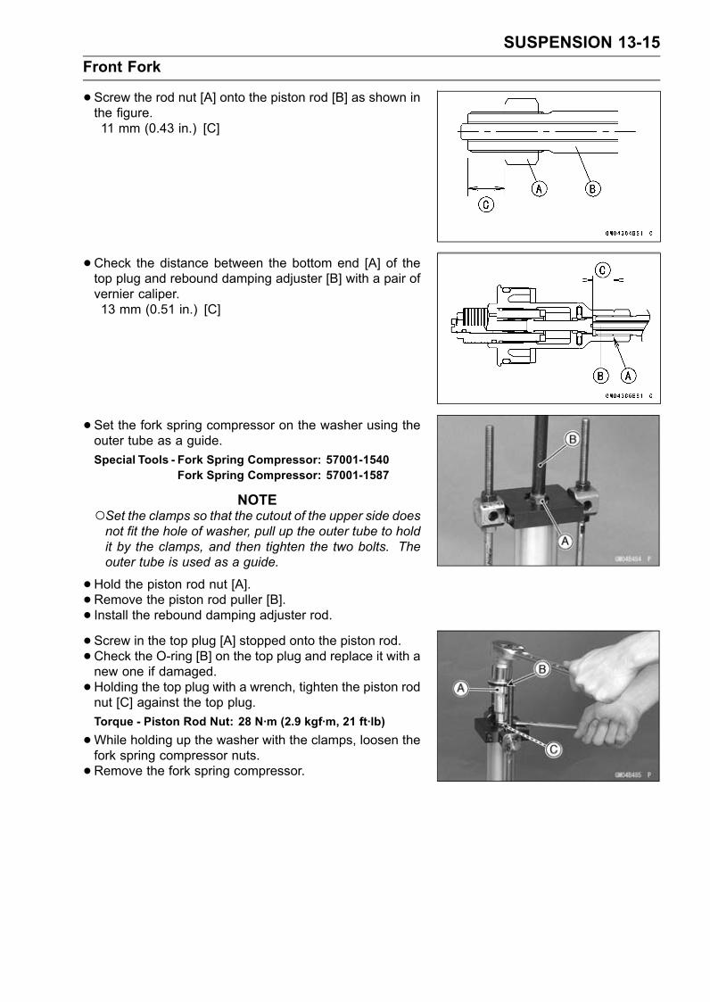
SUSPENSION 13-15Front Fork
•Screw the rod nut [A] onto the piston rod [B] as shown inthe figure.11 mm (0.43 in.) [C]
• Check the distance between the bottom end [A] of thetop plug and rebound damping adjuster [B] with a pair ofvernier caliper.13 mm (0.51 in.) [C]
• Set the fork spring compressor on the washer using theouter tube as a guide.Special Tools - Fork Spring Compressor: 57001-1540
Fork Spring Compressor: 57001-1587
NOTESet the clamps so that the cutout of the upper side doesnot fit the hole of washer, pull up the outer tube to holdit by the clamps, and then tighten the two bolts. Theouter tube is used as a guide.
•Hold the piston rod nut [A].• Remove the piston rod puller [B].• Install the rebound damping adjuster rod.• Screw in the top plug [A] stopped onto the piston rod.• Check the O-ring [B] on the top plug and replace it with anew one if damaged.• Holding the top plug with a wrench, tighten the piston rodnut [C] against the top plug.Torque - Piston Rod Nut: 28 N·m (2.9 kgf·m, 21 ft·lb)
•While holding up the washer with the clamps, loosen thefork spring compressor nuts.• Remove the fork spring compressor.

13-16 SUSPENSIONFront Fork
•Raise the outer tube and screw the top plug into it andinstall it to the steering stem.• Screw in the spring preload adjuster [A] of the top plugso that the distance between the adjuster top and the topplug surface is 15 mm (0.59 in.) [B].• Turn in the rebound damping adjuster until the fully tight-ened position and turn backward the 5th click.• Install the front fork (see Front Fork Installation).
Front Fork Disassembly•Remove the front fork (see Front Fork Removal).• Drain the fork oil (see Front Fork Oil Change).• Hold the front fork in a vise [A].• Stop the cylinder [B] from turning by using the fork cylinderholder [C].Special Tool - Fork Cylinder Holder: 57001-1287
•Unscrew the Allen bolt [D], then take the bolt and gasketout of the bottom of the inner tube.
• Take the cylinder unit [A].Do not disassemble the cylinder unit.
• Separate the outer tube from the inner tube.• Pull out the dust seal.• Remove the retaining ring [A] from the outer tube.• Remove the oil seal [B] and washer [C].
Front Fork Assembly•Replace the following parts with a new one.Oil SealBottom Allen Bolt Gasket• Insert the cylinder unit [A] into the inner tube [B].• Stop the cylinder from turning by using the fork cylinderholder.Special Tool - Fork Cylinder Holder: 57001-1287
•Apply a non-permanent locking agent to the thread of theAllen bolt, and tighten it.Torque - Front Fork Bottom Allen Bolt: 23 N·m (2.3 kgf·m,
17 ft·lb)

SUSPENSION 13-17Front Fork
• Install the following parts into the inner tube [A].Dust Seal [B]Retaining Ring [C]Oil Seal [D]Washer [E]
• Insert the inner tube to the outer tube.• After installing the washer, install the oil seal [A] by usingthe fork oil seal driver [B].Special Tool - Fork Oil Seal Driver, 43: 57001-1530
• Install the retaining ring and dust seal into the outer tube.• Pour in the specified type of oil (see Front Fork OilChange).
Inner Tube Inspection•Visually inspect the inner tube [A], and repair any dam-age.• Nicks or rust damage can sometimes be repaired by usinga wet-stone to remove sharp edges or raised areas whichcause seal damage.If the damage is not repairable, replace the inner tube.Since damage to the inner tube damages the oil seal,replace the oil seal whenever the inner tube is repairedor replaced.
CAUTIONIf the inner tube is badly bent or creased, replaceit. Excessive bending, followed by subsequentstraightening, can weaken the inner tube.
•Temporarily assemble the inner and outer tubes, andpump them back and forth manually to check for smoothoperation.• If you feel binding or catching, the inner and outer tubesmust be replaced.
WARNINGA straightened inner or outer fork tube may fall inuse, possibly causing an accident. Replace a badlybent or damaged inner or outer tube and inspect theother tube carefully before reusing it.

13-18 SUSPENSIONFront Fork
Dust Seal Inspection• Inspect the dust seal [A] for any signs of deterioration ordamage.Replace it if necessary.
Spring Tension•Since a spring becomes shorter as it weakens, check itsfree length [A] to determine its condition.If the spring of either fork leg is shorter than the servicelimit, it must be replaced. If the length of a replacementspring and that of the remaining spring vary greatly, theremaining spring should also be replaced in order to keepthe fork legs balanced for motorcycle stability.
Spring Free LengthStandard: 257 mm (10.12 in.)Service Limit: 252 mm (9.92 in.)

SUSPENSION 13-19Rear Shock Absorber
Rebound Damping Force Adjustment•To adjust the rebound damping force, turn the lowerdamping adjuster [A] to the desired position, until youfeel a click.The standard adjuster setting for an average-build riderof 68 kg (150 lb) with no passenger and no accessoriesis the 1 2/4 turns out from the fully clockwise position.
Rebound Damping Force AdjustmentAdjusterPosition
DampingForce Setting Load Road Speed
2 2/4 TurnsOut Weak Soft Light Good Low
↑ ↑ ↑ ↑ ↑ ↑↓ ↓ ↓ ↓ ↓ ↓0 Strong Hard Heavy Bad High
Compression Damping Force Adjustment•To adjust the compression damping force, turn the upperdamping adjuster [A] to the desired position until you feela click.The standard adjuster setting for the average-build riderof 68 kg (150 lb) with no passenger and no accessoriesis the 2 1/4 turns out from the fully clockwise position.
Rebound Damping Force AdjustmentAdjusterPosition
DampingForce Setting Load Road Speed
4 TurnsOut Weak Soft Light Good Low
↑ ↑ ↑ ↑ ↑ ↑↓ ↓ ↓ ↓ ↓ ↓0 Strong Hard Heavy Bad High
Spring Preload Adjustment•Remove the rear shock absorber from the frame (seeRear Shock Absorber Removal).• Loosen the locknut and turn out the adjusting nut to freethe spring.Special Tool - Hook Wrench T=3.2 R37: 57001-1522

13-20 SUSPENSIONRear Shock Absorber
•To adjust the spring preload, turn in the adjusting nut [A]to the desired position and tighten the locknut [B].Spring Length [C]
Spring Preload SettingStandard: Spring length 175.5 mm (6.9 in.)Usable Range: Spring length 175.5 ∼ 191.5 mm
(6.909 ∼ 7.539 in.)
The standard adjusting nut setting for an average-buildrider of 68 kg (150 lb) with no passenger and no acces-sories is 175.5 mm (6.9 in.) spring length.
• Remove the chain cover [A] (see Drive Chain Removal inthe Final Drive chapter).• Remove the bolts [B] and left foot guard [C] for turning thehook wrench easily.
• To adjust the spring preload, turn in the adjusting nut tothe desired position and tighten the locknut by using hookwrenches [A] with the rear shock absorber attached theframe.Special Tool - Hook Wrench T=3.2 R37: 57001-1522If the spring action feels too soft or too stiff, adjust it.
Spring AdjustmentAdjusterPosition
DampingForce Setting Load Road Speed
191.5 mm(7.539 in.)
Weak Soft Light Good Low
↑ ↑ ↑ ↑ ↑ ↑↓ ↓ ↓ ↓ ↓ ↓
175.5 mm(6.909 in.) Strong Hard Heavy Bad High
Rear Shock Absorber Removal•Remove:Rear Fairing (see Rear Fairing Removal in the Framechapter)Bolts [A] (Both Sides)Bracket [B]Lower Fairings (see Lower Fairings Removal in theFrame chapter).• Raise the rear wheel off the ground with the jack.Special Tools - Jack: 57001-1238
Jack Attachment: 57001-1608

SUSPENSION 13-21Rear Shock Absorber
•Squeeze the brake lever slowly and it with a band [A].WARNING
Be sure to hold the front brake when removing theshock absorber, or the motorcycle may fall over. Itcould cause an accident and injury.
•Remove:Lower Shock Absorber Nut and Bolt [A]Upper Tie-Rod Nut and Bolt [B]
• Remove the upper shock absorber nut and bolt [A]• Remove the shock absorber downward.
Rear Shock Absorber Installation•Tighten:Torque - Rear Shock Absorber Nuts: 34 N·m (3.5 kgf·m, 25
ft·lb)Tie-Rod Nuts: 59 N·m (6.0 kgf·m, 44 ft·lb)
Rear Shock Absorber Inspection•Remove the rear shock absorber (see Rear Shock Ab-sorber Removal).• Visually inspect the following items.Smooth StrokeOil LeakageCrack or DentIf there is any damage to the rear shock absorber, replaceit.• Visually inspect the rubber bushing.If it show any signs of damage, replace it.

13-22 SUSPENSIONRear Shock Absorber
Rear Shock Absorber ScrappingWARNING
Since the reservoir tank of the rear shock absorbercontains nitrogen gas, do not incinerate the reser-voir tank without first releasing the gas or it mayexplode.
•Remove the rear shock absorber (see Rear Shock Ab-sorber Removal).• Drill the hole [A] of the reservoir tank using about 2 mm(0.08 in.) drillbit.
WARNINGSince the high pressure gas is dangerous, do notpoint the drill toward your face or body.

SUSPENSION 13-23Swingarm
Swingarm Removal•Remove:Chain Cover (see Drive Chain Removal in the Final Drivechapter)Rear Wheel (see Rear Wheel Removal in theWheels/Tires chapter)Bolts [A]Brackets [B]
• Remove:Upper Tie-Rod Nut and Bolt [A]Rear Shock Absorber [B] (see Rear Shock Absorber Re-moval)
• Unscrew the swingarm pivot shaft locknut [A].
• Unscrew the swingarm pivot collar locknut [A] using thenut wrench [B].Special Tool - Swingarm Pivot Nut Wrench: 57001-1597
•Unscrew the swingarm pivot shaft [A] few times.Turn out the swingarm pivot adjusting collar [B].• Pull out the pivot shaft right side of the motorcycle andremove the swingarm.

13-24 SUSPENSIONSwingarm
Swingarm Installation•Apply plenty of grease to the lip of the oil seals [A].• Install the collar.
• Place the adjusting collar [A] the frame [B] as shown inthe figure.11 mm (0.43 in.) [C]
• Insert the pivot shaft [A] into the frame from the right side.• Tighten the pivot shaft so that the clearance between theadjusting collar [B] and the ball bearing [C] come to 0 mm(0 in.).Torque - Swingarm Pivot Adjusting Collar: 20 N·m (2.0
kgf·m, 15 ft·lb)
•Tighten the adjusting collar locknut [A] with the swingarmpivot nut wrench [B].Special Tool - Swingarm Pivot Nut Wrench: 57001-1597
Torque - Swingarm Pivot Adjusting Collar Locknut: 98 N·m(10.0 kgf·m, 72 ft·lb)
•Tighten the pivot shaft nut [A].Torque - Swingarm Pivot Shaft Nut: 108 N·m (11.0 kgf·m,
80 ft·lb)
• Install the removed parts (see appropriate chapters).

SUSPENSION 13-25Swingarm
Swingarm Bearing Removal•Remove:Swingarm (see Swingarm Removal)Collar [A]Oil Seals [B]Sleeve [C]Circlip [D] (Right Side)Special Tool - Inside Circlip Pliers: 57001-143
•Remove the ball bearing and needle bearings.Special Tool - Oil Seal & Bearing Remover [A]: 57001-1058
Swingarm Bearing Installation•Replace the ball and needle bearings [A] with new ones.• Install the ball and needle bearings so that the manufac-turer’s marks face out.Special Tools - Bearing Driver Set: 57001-1129
Needle Bearing Driver, 28 [B]: 57001-1610Spacer 28: 57001-1663

13-26 SUSPENSIONSwingarm
• Install the needle bearings [A], ball bearing [B] and oilseals [C] position as shown in the figure.Circlip [D]32 mm (1.26 in.) [E]17 mm (0.67 in.) [F]27.5 mm (1.08 in.) [G]9.5 mm (0.37 in.) [H]
Swingarm Bearing, Sleeve InspectionCAUTION
Do not remove the bearings for inspection. Re-moval may damage them.
• Inspect the needle bearings [A] and ball bearing installedin the swingarm.The rollers and ball in a bearing normally wear very little,and wear is difficult to measure. Instead of measuring,visually inspect the bearing for abrasion, discoloration, orother damage.If the needle bearing and sleeve [B] show any sings ofabnormal wear, discoloration, or damage, replace themas a set.

SUSPENSION 13-27Swingarm
•Turn the bearing in the swingarm back and forth [A] whilechecking for plays, roughness, or binding.If bearing play, roughness, or binding is found, replacethe bearing.• Examine the bearing seal [B] for tears or leakage.If the seal is torn or is leaking, replace the bearing.
Chain Guide Inspection•Refer to the Chain Guide Wear Inspection in the PeriodicMaintenance chapter.

13-28 SUSPENSIONTie-Rod, Rocker Arm
Tie-Rod Removal•Squeeze the brake lever slowly and hold it with a band[A].
• Remove:Lower Fairings (see Lower Fairing Removal in the Framechapter)Rear Fairing (see Rear Fairing Removal in the Framechapter)Bracket (see Rear Shock Absorber Removal)• Raise the rear wheel off the ground with the jack.Special Tools - Jack: 57001-1238
Jack Attachment: 57001-1608
•Remove:Upper Tie-Rod Nut and Bolt [A]Lower Tie-Rod Nut and Bolt [B]Tie-Rods [C]
Tie-Rod Installation•Apply grease to the inside of the grease seals.• Install each tie-rod so that the arrow faces [A] forward.• Tighten:Torque - Tie-Rod Nuts: 59 N·m (6.0 kgf·m, 44 ft·lb)
Rocker Arm Removal•Squeeze the brake lever slowly and hold it with a band.• Remove:Lower Fairings (see Lower Fairing Removal in the Framechapter)Rear Fairing (see Rear Fairing Removal in the Framechapter)Bracket (see Rear Shock Absorber Removal)Muffler Bodies (see Muffler Body Removal in the EngineTop End chapter)• Raise the rear wheel off the ground with the jack.Special Tools - Jack: 57001-1238
Jack Attachment: 57001-1608
•Remove:Lower Rear Shock Absorber Nut and Bolt [A]Lower Tie-Rod Nut and Bolt [B]Rocker Arm Nut and Bolt [C]Rocker Arm [D]

SUSPENSION 13-29Tie-Rod, Rocker Arm
Rocker Arm Installation•Apply grease to the inside of the grease seals.• Tighten:Torque - Uni-Trak Rocker Arm Nut: 34 N·m (3.5 kgf·m, 25
ft·lb)Tie-Rod Nuts: 59 N·m (6.0 kgf·m, 44 ft·lb)Rear Shock Absorber Nut (Lower): 34 N·m (3.5kgf·m, 25 ft·lb)
Tie-Rod and Rocker Arm Bearing Removal•Remove:Tie-Rods (see Tie-Rod Removal)Rocker Arm (see Rocker Arm Removal)Sleeves [A]Oil Seals [B]Swingarm [C] (see Swingarm Removal)• Remove the needle bearings [D], using the bearing re-mover head and bearing remover shaft.Special Tools - Bearing Remover Head, 20 × 22: 57001
-1293Bearing Remover Shaft, 13: 57001-1377
Tie-Rod and Rocker Arm Bearing Installation•Replace the needle bearing and oil seals with new ones.• Apply plenty of grease to the lips of the oil seals.• Install the needle bearings and oil seals position as shownin the figure.

13-30 SUSPENSIONTie-Rod, Rocker Arm
Screw the needle bearing driver [A] into the driver holder[B].Insert the needle bearing driver into the needle bearing[C] and press the needle bearing into the housing untilthe driver contacts the end surface of the housing.Bearing Pressing Depth: 5.5 mm (0.22 in.) [D]5.0 mm (0.20 in.) [E]
NOTEFor a bearing of inner diameter 18, select the pressingside of the needle bearing driver according to its press-ing depth.
Special Tools - Bearing Driver Set: 57001-1129Needle Bearing Driver, 17/ 18: 57001-1609
Spacer, 18 [F]: 57001-1636Needle Bearing Driver, 20 & Spacer, 28:57001-1678
NOTEInstall the needle bearings so that the marked sidefaces in.
Needle Bearing [A]Oil Seals [B]Front [C]Right Side [D]Left Side [E]Rear Shock Absorber [F]Tie-Rods [G]Rocker Arm [H]7.5 mm (0.30 in.) [I]10 mm (0.39 in.) [J]5.5 mm (0.22 in.) [K]5.0 mm (0.20 in.) [L]

SUSPENSION 13-31Tie-Rod, Rocker Arm
Rocker Arm/Tie-Rod Bearing, Sleeve InspectionCAUTION
Do not remove the bearings for inspection. Re-moval may damage them.
•Visually inspect the locker arm, or tie-rod sleeves [A] andneedle bearings [B].• The rollers in a needle bearing normally wear very little,and wear is difficult to measure. Instead of measuring,inspect the bearing for abrasion, color change, or otherdamage.If there is any doubt as to the condition of any of the nee-dle bearings or sleeve, replace the sleeve and needlebearings as a set.
Rocker Arm/Tie-Rod Bearing LubricationNOTE
Since the bearings are packed with grease, lubricationis not required.


STEERING 14-1
14
SteeringTable of Contents
Exploded View........................................................................................................................ 14-2Special Tools .......................................................................................................................... 14-4Steering .................................................................................................................................. 14-5
Steering Inspection ........................................................................................................... 14-5Steering Adjustment.......................................................................................................... 14-5
Steering Stem......................................................................................................................... 14-6Stem, Stem Bearing Removal........................................................................................... 14-6Stem, Stem Bearing Installation........................................................................................ 14-7Steering Stem Bearing Lubrication ................................................................................... 14-9Steering Stem Warp.......................................................................................................... 14-9Stem Cap Deterioration, Damage..................................................................................... 14-9
Handlebar ............................................................................................................................... 14-10Handlebar Removal .......................................................................................................... 14-10Handlebar Installation ....................................................................................................... 14-10

14-2 STEERINGExploded View

STEERING 14-3Exploded View
TorqueNo. Fastener
N·m kgf·m ft·lbRemarks
1 Front Fork Clamp Bolts (Lower) 30 3.1 22 AL2 Front Fork Clamp Bolts (Upper) 20 2.0 153 Handlebar Bolts 34 3.5 25 L4 Handlebar Holder Bolts 25 2.5 18 AL5 Steering Stem Head Nut 78 8.0 586 Steering Stem Nut 23 2.3 177 Switch Housing Screws 3.5 0.36 31 in·lbAD: Apply adhesive.AL: Tighten the two clamp bolts alternately two times to ensure even tightening torque.G: Apply grease.L: Apply a non-permanent locking agent.R: Replacement Parts

14-4 STEERINGSpecial Tools
Head Pipe Outer Race Press Shaft:57001-1075
Steering Stem Nut Wrench:57001-1100
Bearing Driver Set:57001-1129
Steering Stem Bearing Driver, 42.5:57001-1344
Steering Stem Bearing Driver Adapter, 41.5:57001-1345
Head Pipe Outer Race Driver, 55:57001-1446

STEERING 14-5Steering
Steering Inspection•Refer to the Steering Play Inspection in the Periodic Main-tenance chapter.
Steering Adjustment•Refer to the Steering Play Adjustment in the PeriodicMaintenance chapter.

14-6 STEERINGSteering Stem
Stem, Stem Bearing Removal•Remove:Upper Fairing (see Upper Fairing Removal in the Framechapter)Front Wheel (see Front Wheel Removal in theWheels/Tires chapter)Handlebars (see Handlebar Removal)Front Forks (see Front Fork Removal in the Suspensionchapter)Bracket Bolts [A]Cover Bolts [B] and Cover [C]
• Remove:Steering Stem Head Nut [A] and Washer [B]Steering Stem Head [C]
• Bend the claws [A] of lock washer straighten.• Remove the steering stem locknut [B].Special Tool - Steering Stem Nut Wrench: 57001-1100
•Remove the lock washer.
• Pushing up the stem base, and remove the steering stemnut [A] with stem cap [B].Special Tool - Steering Stem Nut Wrench [C]: 57001-1100
•Remove:Steering Stem [D]Upper Ball Bearing Inner Race and Ball Bearing
• To remove the ball bearing outer races [A] pressed intothe head pipe [B], insert a bar [C] into the recesses [D]of head pipe, and applying it to both recess alternatelyhammer it to drive the race out.
NOTEIf either steering stem bearing is damaged, it is recom-mended that both the upper and lower bearings (includ-ing outer races) should be replaced with new ones.

STEERING 14-7Steering Stem
•Remove the lower ball bearing inner race (with its oil seal)[A] which is pressed onto the steering stem with a suitablecommercially available chisel [B].
Stem, Stem Bearing Installation•Replace the bearing outer races with new ones.• Drive them into the head pipe at the same time.Special Tools - Head Pipe Outer Race Press Shaft [A]:
57001-1075Bearing Driver Set: 57001-1129Head Pipe Outer Race Driver, 55 [B]: 57001-1446
•Apply grease to the outer races.• Replace the bearing inner races and oil seal with newones.• Apply grease to the oil seal.• Install the oil seal [A] on the steering stem, and drive thelower ball bearing inner race [B] applied the grease ontothe stem.Special Tools - Steering Stem Bearing Driver, 42.5 [C]:
57001-1344Steering Stem Bearing Driver Adapter,
41.5 [D]: 57001-1345
• Install the lower ball bearing [A] onto the stem.•Grease the following.Inner and Outer RacesLower and Upper Ball Bearings
The lower and upper ball bearings are identical.
• Install the stem [A] through the head pipe and install theball bearing [B] and inner race [C] on it.• Install:Stem Cap [D]Steering Stem Nut [E]

14-8 STEERINGSteering Stem
•Settle the bearings in place as follows.Tighten the steering stem nut with 55 N·m (5.6 kgf·m, 41ft·lb) of torque first, and loosen it a fraction of a turn untilit turns lightly. Afterward tighten it again with specifiedtorque using a steering stem nut wrench [A].Special Tool - Steering Stem Nut Wrench: 57001-1100
Torque - Steering Stem Nut: 23 N·m (2.3 kgf·m, 17 ft·lb)
• Install the lock washer so that claw [A] of washer fit thenotch [B] of steering stem locknut [C].
• First tighten the steering stem locknut by hand until theresistance is felt fully, then tighten the steering stem locknut so that align the claw [A] of stem lock nut to the notch[B] of stem nut by hand.• Check that there is no play and the steering stem turnssmoothly without rattles. If not, the steering stem bearingmay be damaged.• Bend the claw of lock washer to steering stem nut notch.
• Install the stem head [A] to the steering stem [B].• Install the washer, and temporary tighten the stem headnut [C].• Install the front forks (see Front Fork Installation in theSuspension chapter).

STEERING 14-9Steering Stem
NOTETighten the upper front fork clamp bolts [A] first, next thestem head nut [B], last the lower front fork clamp bolts[C].Tighten the two lower fork clamp bolts alternately twotimes to ensure even tightening torque.
Torque - Front Fork Clamp Bolts (Upper): 20 N·m (2.0kgf·m, 15 ft·lb)
Steering Stem Head Nut: 78 N·m (8.0 kgf·m, 58ft·lb)
Front Fork Clamp Bolts (Lower): 30 N·m (3.1kgf·m, 22 ft·lb)
WARNINGDo not impede the handlebar turning by routing thecables, harnesses and hoses improperly (see Ca-ble, Wire, and Hose Routing section in the Appen-dix chapter).
• Install the removed parts (see appropriate chapters).Steering Stem Bearing Lubrication•Refer to the Steering Stem Bearing Lubrication in the Pe-riodic Maintenance chapter.
Steering Stem Warp•Whenever the steering stem is removed, or if the steeringcan not be adjusted for smooth action, check the steeringstem for straightness.If the steering stem [A] is bent, replace the steering stem.
Stem Cap Deterioration, DamageReplace the stem cap if its oil seal [A] shows damage.

14-10 STEERINGHandlebar
Handlebar Removal•Remove:Clutch Lever Clamp Bolts [A]Clutch Lever Assembly [B]Left Switch Housing [C]Handlebar Weight [D]
• Remove:Front Master Cylinder [A] (see Front Master Cylinder Re-moval in the Brakes chapter)Right Switch Housing [B]Throttle Case [C]Handlebar Weight [D]Throttle Grip [E]
• Unscrew the handlebar holder bolts [A].• Remove each handlebar holder [B] with handlebar [C].
• Hold the handlebar in a vise, and unscrew the handlebarbolt [A].• Remove the handlebar.• Remove the left handlebar grip.
Handlebar Installation•Apply adhesive cement to the inside of the left handlebargrip.• Fit the pin [A] of the handlebar to the recess [B] of thehandlebar holder.• Apply a non-permanent locking agent to the threads ofthe handlebar bolts.• Tighten:Torque - Handlebar Bolts: 34 N·m (3.5 kgf·m, 25 ft·lb)

STEERING 14-11Handlebar
• Install the handlebar holder with handlebar on the steeringstem head.• Tighten the handlebar holder bolts.
NOTETighten the handlebar holder bolt [A] first, next the han-dlebar holder bolt [B].Tighten the two handlebar holder bolts alternately twotimes to ensure even tightening torque.
Torque - Handlebar Holder Bolts: 25 N·m (2.5 kgf·m, 18ft·lb)
• Install the front master cylinder (see Front Master CylinderInstallation in the Brakes chapter).
• Install:Throttle GripThrottle Cable Tips [A]Throttle Cases [B]
Fit the projection into a small hole in the handlebar.• Apply a non-permanent locking agent to the threads ofthe handlebar weight bolts, and tighten them.
• Install the left and right switch housings.Fit the projection [A] into a small hole [B] in the handlebar.Torque - Switch Housing Screws: 3.5 N·m (0.36 kgf·m, 31
in·lb)
• Install the clutch lever (see Clutch Lever Installation in theClutch chapter).


FRAME 15-1
15
FrameTable of Contents
Exploded View........................................................................................................................ 15-2Seat ........................................................................................................................................ 15-10
Seat Removal ................................................................................................................... 15-10Seat Installation ................................................................................................................ 15-10
Fairings................................................................................................................................... 15-11Lower Fairing Removal ..................................................................................................... 15-11Lower Fairing Installation .................................................................................................. 15-11Fairing Cover Removal ..................................................................................................... 15-11Middle Fairing Removal .................................................................................................... 15-11Middle Fairing Installation ................................................................................................. 15-12Windshield Removal ......................................................................................................... 15-12Windshield Installation ...................................................................................................... 15-13Upper Fairing Removal ..................................................................................................... 15-13Upper Fairing Disassembly............................................................................................... 15-13Upper Fairing Assembly.................................................................................................... 15-13Upper Fairing Installation .................................................................................................. 15-14Inner Cover Removal ........................................................................................................ 15-14Inner Cover Installation ..................................................................................................... 15-14Upper Inner Fairing Removal............................................................................................ 15-14Upper Inner Fairing Installation......................................................................................... 15-15Upper Fairing Bracket Removal........................................................................................ 15-15Upper Fairing Bracket Installation..................................................................................... 15-15Inner Fairing Removal....................................................................................................... 15-15Inner Fairing Installation.................................................................................................... 15-15Rear Fairing Removal ....................................................................................................... 15-15Rear Fairing Installation .................................................................................................... 15-15
Seat Cover.............................................................................................................................. 15-16Seat Cover Removal......................................................................................................... 15-16Seat Cover Installation...................................................................................................... 15-16
Fenders .................................................................................................................................. 15-18Front Fender Removal ...................................................................................................... 15-18Front Fender Installation ................................................................................................... 15-18Flap and Rear Fender Removal........................................................................................ 15-18Flap and Rear Fender Installation..................................................................................... 15-19
Frame ..................................................................................................................................... 15-20Rear Frame Removal........................................................................................................ 15-20Rear Frame Installation..................................................................................................... 15-20Frame Inspection .............................................................................................................. 15-20
Center Stand, Sidestand ........................................................................................................ 15-21Center Stand Removal (Equipped Models) ...................................................................... 15-21Center Stand Installation (Equipped Models) ................................................................... 15-21Sidestand Removal........................................................................................................... 15-21Sidestand Installation........................................................................................................ 15-21

15-2 FRAMEExploded View

FRAME 15-3Exploded View
TorqueNo. Fastener
N·m kgf·m ft·lbRemarks
1 Center Stand Bolts 44 4.5 322 Front Footpeg Bracket Bolts 25 2.5 183 Sidestand Bolt 44 4.5 324 Sidestand Bracket Bolts 49 5.0 36 L5 Sidestand Switch Bolt 8.8 0.90 78 in·lb L6. Center Stand (Equipped Models)G: Apply grease.L: Apply a non-permanent locking agent.R: Replacement Parts

15-4 FRAMEExploded View

FRAME 15-5Exploded View
TorqueNo. Fastener
N·m kgf·m ft·lbRemarks
1 Rear Fender Mounting Screws 1.2 0.12 11 in·lb2 Rear Footpeg Bracket Bolts 25 2.5 183 Rear Frame Bolts 44 4.5 32 L4 Rear Frame Pipe Bolts 44 4.5 325 Rear Frame Pipe Nuts 44 4.5 326. Center Stand Grip (Equipped Models)G: Apply grease.L: Apply a non-permanent locking agent.R: Replacement Parts

15-6 FRAMEExploded View

FRAME 15-7Exploded View
TorqueNo. Fastener
N·m kgf·m ft·lbRemarks
1 Grab Rail Mounting Bolts 25 2.5 182 Seat Lock Bracket Screws 1.2 0.12 11 in·lb3. Reflector (United States and Canada Models)4. Grab Rail (Equipped Models)5. Seat Cover (Equipped Models)

15-8 FRAMEExploded View

FRAME 15-9Exploded View
TorqueNo. Fastener
N·m kgf·m ft·lbRemarks
1 Windshield Mounting Bolts 0.42 0.043 3.7 in·lb

15-10 FRAMESeat
Seat Removal• Insert the ignition switch key [A] into the seat lock, turningthe key counterclockwise, pulling up on the rear of theseat [B], and pulling the seat backward.
• For seat cover equipped models; note the following.• Remove:Bolts [A]Seat Cover [B]
Seat Installation• Insert the brackets [A] of the fuel tank into the slots [B] ofthe seat.
• Insert the projections [A] of the seat into the slots [B] ofthe frame, and insert the seat hook [C] into the slot [D] ofthe frame.• Push down the rear part of the seat until the lock clicks.

FRAME 15-11Fairings
Lower Fairing Removal•Pull up the core by the thin blade driver.• Remove the quick rivet [A].• Remove the bolts [B] with washers.• Clear the hook portions from the slots.• Separate the left lower fairing from the right lower fairing.
Lower Fairing Installation• Insert the hook portions [A] into the slots [B].• Tighten the bolts with washers.• Set the quick rivet and push the core.
Fairing Cover Removal•Remove the bolts [A].• Pull out the fairing cover [B], and clear the stoppers.
• Insert the projections [A] into the holes [B].• Tighten the bolts.
Middle Fairing Removal•Remove:Lower Fairings (see Lower Fairing Removal)Fairing Covers (see Fairing Cover Removal)Inner Covers (see Inner Cover Removal)Fuel Tank Cover (see Fuel Tank Removal in the FuelSystem (DFI) chapter)• Push the central pin, and then remove the quick rivets [A].

15-12 FRAMEFairings
•Remove:Bolts [A] with WashersTurn Signal Lead Connector• Remove each middle fairing.Clear the hook [B] from the bracket.
• Remove:Inner Fairing (see Inner Fairing Removal)ScrewsBracketTurn Signal Light
Middle Fairing Installation• Install the turn signal light to themiddle fairing, and tightenthe screws.• Install the inner fairing (see Inner Fairing Installation).• Connect the turn signal lead connector.• Hang the hook of the middle fairing to the bracket.• Install the washers and bolts.• Install the quick rivets.• Install the removed parts (see appropriate chapters).Windshield Removal•Remove:Bolts [A] with WashersWindshield [B]

FRAME 15-13Fairings
Windshield Installation•Put the front tongue [A] into the hollow [B].• Tighten:Torque - Windshield Mounting Bolts: 0.42 N·m (0.043
kgf·m, 3.7 in·lb)
Upper Fairing Removal•Remove:Lower Fairings (see Lower Fairing Removal)Fairing Covers (see Fairing Cover Removal)Inner Covers (see Inner Cover Removal)Middle Fairings (see Middle Fairing Removal)Windshield (see Windshield Removal)Vehicle-down Sensor Lead ConnectorImmobilizer Amplifier Lead Connector (Equipped Mod-els)• Unscrew the bracket screws [A].• Disconnect:Headlight Lead Connectors [A] (Both Sides)City Light Lead Connectors [B] (Both Sides)
• Remove the bolts [A].• Pull out the upper fairing forward.
Upper Fairing Disassembly•Remove:Upper Fairing (see Upper Fairing Removal)Upper Inner Fairing (see Upper Inner Fairing Removal)Headlights [A] (see Headlight Removal in the ElectricalSystem chapter)Nuts [B] and Rear View Mirrors (Both Sides)
Upper Fairing Assembly• Installation is the reverse of removal.

15-14 FRAMEFairings
Upper Fairing Installation• Installation is the reverse of removal.Inner Cover Removal•Remove the bolts [A].• Remove the inner cover [B].Pull the inner cover backward, and clear the hooks.
Inner Cover Installation• Insert the hooks [A] into the slots [B].• Tighten the bolts.
Upper Inner Fairing Removal•Remove:Upper Fairing (see Upper Fairing Removal)Bolt [A]Upper Inner Fairing [B]
Slide out the upper inner fairing backward.

FRAME 15-15Fairings
Upper Inner Fairing Installation• Insert the slots [A] of the upper inner fairing into the hooks[B] of the upper fairing.• Tighten the bolt.
Upper Fairing Bracket Removal•Remove:Upper Fairing (see Upper Fairing Removal)Front and Middle Inlet Ducts (see Front and Middle InletDuct Removal in the Fuel System (DFI) chapter)Rear Inlet Ducts (see Rear Inlet Duct Removal in theFuel System (DFI) chapter)Meter Unit (seeMeter Unit Removal in the Electrical Sys-tem chapter)Headlight Relays [A]Bolts [B]Upper Fairing Bracket [C]
Upper Fairing Bracket Installation• Installation is the reverse of removal.Inner Fairing Removal•Remove:Middle Fairings (see Middle Fairing Removal)Quick Rivet [A]Bolts [B]Inner Fairing [C]
Inner Fairing Installation• Installation is the reverse of removal.Rear Fairing Removal•Remove:Bolts [A]Rear Fairing [B]
Rear Fairing Installation• Installation is the reverse of removal.

15-16 FRAMESeat Cover
Seat Cover Removal•Remove:Seat (see Seat Removal)Bolts [A]Screws [B]Grab Rail [C] (Equipped Models)Center Seat Cover [D]
• Remove the quick rivets [A].
• Remove the bolts [A].• Clear the side seat covers [B] from the rear fender.• Disconnect the turn signal lead connectors, and removeeach side seat cover.
• Remove:Screws [A]Turn Signal Light [B]
Seat Cover Installation•Connect the turn signal lead connector.• Insert the hole [A] to the projection [B].• Install the bolts and quick rivets.

FRAME 15-17Seat Cover
• Insert the projection [A] into the hole [B].• Tighten the screws.• Install the grab rail (equipped models).• Tighten:Torque - Grab Rail Mounting Bolts: 25 N·m (2.5 kgf·m, 18
ft·lb)

15-18 FRAMEFenders
Front Fender Removal•Remove:Brake Hose Clamps [A] (Both Sides)Bolts [B] with Washer (Both Sides)Bracket [C] (ZX1400B Models)• Remove the front fender assy [D].
• Remove the screws [A].• Separate the front fender covers [B] and front fender [C].
Front Fender Installation• Install the front fender covers to the front fender.Insert the hooks [A] of the front fender cover into the slots[B] of the front fender.
• Install the front fender assy to the front fork.• Install the brake hose clamps to the front fender holes.Flap and Rear Fender Removal•Remove:Seat (see Seat Removal)Seat Covers (see Seat Cover Removal)Fuel Tank (see Fuel Tank Removal in the Fuel System(DFI) chapter)Tool Kit Case [A] (see ECU Removal in the Fuel System(DFI) chapter)Relay Box [B] (see Relay Box Removal in the ElectricalSystem chapter)ECU (see ECU Removal in the Fuel System (DFI) chap-ter)Rear Wheel (see Rear Wheel Removal in theWheels/Tires chapter)Fuse Box [C]Bolts [D] and Cover [E]Seat LockBolts [F]Screws [G]

FRAME 15-19Fenders
•Remove:Nuts [A]License Light Connector (Disconnect)Flap (with License Light)Tail/Brake Light (LED) (see Tail/Brake Light (LED) Re-moval in the Electrical System chapter)• Pull out the rear fender [B] backward and downward.
Flap and Rear Fender Installation•Hang the hook [A] of the rear fender to the slot [B] of therear frame.• Tighten:Torque - Rear Fender Mounting Screws: 1.2 N·m (0.12
kgf·m, 11 in·lb)
• Install the removed parts (see appropriate chapters).• Run the harness correctly (see Cable, Wire, and HoseRouting section in the Appendix chapter).

15-20 FRAMEFrame
Rear Frame Removal•Remove:Rear Fender (see Rear Fender Removal)Regulator/Rectifier [A] (see Regulator/Rectifier Inspec-tion in the Electrical System chapter)Tail/Brake Light (see Tail/Brake Light Removal in theElectrical System chapter)Bolts [B] (Both Sides)Rear Footpeg Bracket Bolts [C] and Brackets (BothSides)Frame Bolts [D]
Rear Frame Installation•Apply a non-permanent locking agent to the thread of therear frame bolt, and tighten them.Torque - Rear Frame Bolts: 44 N·m (4.5 kgf·m, 32 ft·lb)
Rear Footpeg Bracket Bolts: 25 N·m (2.5 kgf·m, 18ft·lb)
• Install the removed parts (see appropriate chapters).Frame Inspection•Visually inspect the frame [A] for cracks, dents, bending,or warp.If there is any damage to the frame, replace it.
WARNINGA repaired frame may fail in use, possibly causingan accident. If the frame is bent, dented, cracked,or warped, replace it.

FRAME 15-21Center Stand, Sidestand
Center Stand Removal (Equipped Models)•Remove:Muffler Bodies (see Muffler Body Removal in the EngineTop End chapter)Spring [A]Bolts [B]Bolts [C] and NutsCenter Stand [D]
Center Stand Installation (Equipped Models)•Apply grease to the sliding area [A] of the center stand[B].• Tighten the bolts [C] and lock them with the nuts.Torque - Center Stand Bolts: 44 N·m (4.5 kgf·m, 32 ft·lb)
•Hook the spring [D] so that face the long spring end up-ward.Install the spring hook direction as shown in the figure.
Sidestand Removal•Raise the rear wheel off the ground with the stand.• Remove:Sidestand Switch Bolt [A]Spring [B]Sidestand Bolt [C]Sidestand [D]Sidestand Bracket Bolts [E]
Sidestand Installation•Apply grease to the sliding area [A] of the sidestand [B].• Tighten the bolt and lock them with the nut.Torque - Sidestand Bracket Bolts [C]: 49 N·m (5.0 kgf·m, 36
ft·lb)Sidestand Bolt [D]: 44 N·m (4.5 kgf·m, 32 ft·lb)
•Hook the spring [E] so that face the long spring end up-ward.Install the spring hook direction as shown in the figure.• Install the sidestand switch.Apply a non-permanent locking agent to the thread of theswitch bolt, and tighten it.Torque - Sidestand Switch Bolt [F]: 8.8 N·m (0.90 kgf·m, 78
in·lb)

ELECTRICAL SYSTEM 16-1
16
Electrical SystemTable of Contents
Exploded View........................................................................................................................ 16-4Parts Location......................................................................................................................... 16-10Wiring Diagram (United States, Canada, New Zealand and Colombia)................................. 16-12Wiring Diagram (Other than United States, Canada, New Zealand and Colombia)............... 16-14Wiring Diagram (ZX1400B Models)........................................................................................ 16-16Specifications ......................................................................................................................... 16-18Special Tools and Sealant ...................................................................................................... 16-19Precautions............................................................................................................................. 16-21Electrical Wiring...................................................................................................................... 16-22
Wiring Inspection .............................................................................................................. 16-22Battery .................................................................................................................................... 16-23
Battery Removal ............................................................................................................... 16-23Battery Installation ............................................................................................................ 16-24Battery Activation .............................................................................................................. 16-24Precautions ....................................................................................................................... 16-27Interchange....................................................................................................................... 16-27Charging Condition Inspection.......................................................................................... 16-27Refreshing Charge............................................................................................................ 16-28
Charging System.................................................................................................................... 16-29Alternator Cover Removal................................................................................................. 16-29Alternator Cover Installation.............................................................................................. 16-29Stator Coil Removal .......................................................................................................... 16-29Stator Coil Installation ....................................................................................................... 16-30Alternator Rotor Removal ................................................................................................. 16-30Alternator Rotor Installation .............................................................................................. 16-30Alternator Inspection ......................................................................................................... 16-31Regulator/Rectifier Inspection........................................................................................... 16-33Charging Voltage Inspection ............................................................................................. 16-34
Ignition System....................................................................................................................... 16-36Crankshaft Sensor Removal ............................................................................................. 16-37Crankshaft Sensor Installation .......................................................................................... 16-38Crankshaft Sensor Inspection........................................................................................... 16-38Crankshaft Sensor Peak Voltage Inspection..................................................................... 16-38Stick Coil (Ignition Coil together with Spark Plug Cap) Removal...................................... 16-39Stick Coil (Ignition Coil together with Spark Plug Cap) Installation................................... 16-39Stick Coil (Ignition Coil together with Spark Plug Cap) Inspection.................................... 16-40Stick Coil Primary Peak Voltage ....................................................................................... 16-40Spark Plug Removal ......................................................................................................... 16-41Spark Plug Installation ...................................................................................................... 16-41Spark Plug Condition Inspection....................................................................................... 16-41Camshaft Position Sensor Removal ................................................................................. 16-42Camshaft Position Sensor Installation .............................................................................. 16-42Camshaft Position Sensor Inspection ............................................................................... 16-42Camshaft Position Sensor Peak Voltage Inspection......................................................... 16-43Interlock Operation Inspection .......................................................................................... 16-43IC Igniter Inspection .......................................................................................................... 16-44
Electric Starter System........................................................................................................... 16-46Starter Motor Removal...................................................................................................... 16-46Starter Motor Installation................................................................................................... 16-46Starter Motor Disassembly................................................................................................ 16-47

16-2 ELECTRICAL SYSTEM
Starter Motor Assembly .................................................................................................... 16-47Brush Inspection ............................................................................................................... 16-48Commutator Cleaning and Inspection............................................................................... 16-49Armature Inspection.......................................................................................................... 16-49Brush Lead Inspection ...................................................................................................... 16-49Right-hand End Cover Assembly Inspection .................................................................... 16-50Starter Relay Inspection.................................................................................................... 16-50
Lighting System...................................................................................................................... 16-52Headlight Beam Horizontal Vertical Adjustment ............................................................... 16-52Headlight Beam Vertical Adjustment................................................................................. 16-52Headlight Bulb Replacement ............................................................................................ 16-52City Light Bulb Replacement............................................................................................. 16-53Headlight Removal/Installation ......................................................................................... 16-53Headlight Relay Inspection ............................................................................................... 16-54Tail/Brake Light (LED) Removal........................................................................................ 16-54Tail/Brake Light (LED) Installation..................................................................................... 16-55License Plate Light Bulb Replacement ............................................................................. 16-55Turn Signal Light Bulb Replacement ................................................................................ 16-56Turn Signal Relay Inspection ............................................................................................ 16-58
Air Switching Valve ................................................................................................................. 16-60Air Switching Valve Operation Test ................................................................................... 16-60Air Switching Valve Unit Test ............................................................................................ 16-60
Radiator Fan System.............................................................................................................. 16-61Fan Motor Inspection ........................................................................................................ 16-61
Meter, Gauge, Indicator Unit................................................................................................... 16-62Meter Unit Removal .......................................................................................................... 16-62Meter Unit Installation ....................................................................................................... 16-62Meter Unit Disassembly .................................................................................................... 16-63Meter Unit Inspection ........................................................................................................ 16-63
Immobilizer System (Equipped Models) ................................................................................. 16-80Operational Cautions ........................................................................................................ 16-80Key Registration................................................................................................................ 16-80Immobilizer System Parts Replacement ........................................................................... 16-96ECU (Electric Control Unit) Replacement (for Immobilizer Models) ................................. 16-97Immobilizer System Inspection ......................................................................................... 16-98
Switches and Sensors ............................................................................................................ 16-100Brake Light Timing Inspection........................................................................................... 16-100Brake Light Timing Adjustment ......................................................................................... 16-100Switch Inspection .............................................................................................................. 16-100Water Temperature Sensor Inspection ............................................................................. 16-101Speed Sensor Removal .................................................................................................... 16-101Speed Sensor Installation ................................................................................................. 16-101Speed Sensor Inspection.................................................................................................. 16-102Fuel Level Sensor Inspection............................................................................................ 16-102Fuel Reserve Switch Inspection........................................................................................ 16-103Gear Position Switch Removal ......................................................................................... 16-104Gear Position Switch Installation ...................................................................................... 16-105Gear Position Switch Inspection ....................................................................................... 16-105
Relay Box ............................................................................................................................... 16-106Relay Box Removal .......................................................................................................... 16-106Relay Circuit Inspection .................................................................................................... 16-106Diode Circuit Inspection .................................................................................................... 16-107
Fuse........................................................................................................................................ 16-10930 A Main Fuse Removal.................................................................................................. 16-109Fuse Box Fuse Removal................................................................................................... 16-10915 A ECU Fuse Removal.................................................................................................. 16-110Fuse Installation................................................................................................................ 16-110

ELECTRICAL SYSTEM 16-3
Fuse Inspection................................................................................................................. 16-111

16-4 ELECTRICAL SYSTEMExploded View

ELECTRICAL SYSTEM 16-5Exploded View
TorqueNo. Fastener
N·m kgf·m ft·lbRemarks
1 Headlight Mounting Screws 1.2 0.12 11 in·lb2 Front Turn Signal Light Mounting Screws 1.2 0.12 11 in·lb3 Rear Turn Signal Light Mounting Screws 1.2 0.12 11 in·lb4 License Plate Light Mounting Screws 1.2 0.12 11 in·lb5 Tail/Brake Light Mounting Screws 1.2 0.12 11 in·lb6 License Plate Light Cover Mounting Screws 0.9 0.09 8 in·lb

16-6 ELECTRICAL SYSTEMExploded View

ELECTRICAL SYSTEM 16-7Exploded View
TorqueNo. Fastener
N·m kgf·m ft·lbRemarks
1 Camshaft Position Sensor Bolt 9.8 1.0 87 in·lb2 Water Temperature Sensor 25 2.5 183 Gear Position Switch Screws 2.9 0.30 26 in·lb L4 Gear Position Switch Lead Clamp Bolts 9.8 1.0 87 in·lb5 Spark Plugs 13 1.3 115 in·lb6 Stator Coil Bolts 12 1.2 106 in·lb
Alternator Rotor Bolt (First) 69 7.0 51 S7
Alternator Rotor Bolt (Final) 110 11.2 81 S8 Crankshaft Sensor Bolts 5.9 0.60 52 in·lb L9 Regulator/Rectifier Bolts 9.8 1.0 87 in·lb10 Engine Ground Terminal Bolt 9.8 1.0 87 in·lb11 Speed Sensor Bolt 3.9 0.40 35 in·lb L12 Alternator Cover Bolts 9.8 1.0 87 in·lb13 Alternator Lead Holding Plate Bolts 8.3 0.85 73 in·lb L14 Crankshaft Sensor Cover Bolts 9.8 1.0 87 in·lb L (1)15 Fuel Level Sensor Bolts 6.9 0.70 61 in·lb L16. Battery17. ECU18. Relay Box19. Headlight Relay (Low)20. Headlight Relay (Hi)21. Turn Signal RelayG: Apply grease.L: Apply a non-permanent locking agent.R: Replacement PartsS: Follow the specified tighten sequence.SS: Apply silicone sealant.

16-8 ELECTRICAL SYSTEMExploded View

ELECTRICAL SYSTEM 16-9Exploded View
TorqueNo. Fastener
N·m kgf·m ft·lbRemarks
1 Front Brake Light Switch Screw 1.2 0.12 11 in·lb2 Right Switch Housing Screws 3.5 0.36 31 in·lb3 Left Switch Housing Screws 3.5 0.36 31 in·lb4 Starter Motor Mounting Bolts 9.8 1.0 87 in·lb5 Sidestand Switch Bolt 8.8 0.90 78 in·lb L6 Starter Motor Cable Mounting Bolt 3.9 0.40 35 in·lb7 Starter Motor Cable Terminal Nut 5.9 0.60 52 in·lb8 Starter Lockout Switch Screw 0.7 0.07 6 in·lb9 Starter Motor Terminal Locknut 6.9 0.70 61 in·lb10 Starter Motor Through Bolts 3.4 0.35 30 in·lb11. Immobilizer Models12. ZX1400B Models13. Other than France and Malaysia Models14. France and Malaysia ModelsG: Apply grease.L: Apply a non-permanent locking agent.R: Replacement Parts

16-10 ELECTRICAL SYSTEMParts Location

ELECTRICAL SYSTEM 16-11Parts Location
1. Headlight Relay (High)2. Immobilizer Amplifier (Immobilizer Models)3. Ignition Switch with Immobilizer Antenna (Immobilizer Models)4. Starter Lockout Switch5. Fan Motor6. Starter Relay with Main Fuse 30 A7. Alternator8. Speed Senor9. Sidestand Switch10. Gear Position Switch11. Frame Ground 112. Fuse Box 113. Turn Signal Relay14. Relay Box15. Fuse Box 2 with ECU Fuse 15 A16. ECU (Electric Control Unit)17. Headlight Relay (Low)18. Meter Unit19. Front Brake Light Switch20. Air Switching Valve21. Camshaft Position Sensor22. Water Temperature Sensor23. Crankshaft Sensor24. Frame Ground 225. Battery 12 V 14 Ah26. Engine Ground27. Starter Motor28. Rear Brake Light Switch29. Regulator/Rectifier

16-12 ELECTRICAL SYSTEMWiring Diagram (United States, Canada, New Zealand and Colombia)

ELECTRICAL SYSTEM 16-13Wiring Diagram (United States, Canada, New Zealand and Colombia)

16-14 ELECTRICAL SYSTEMWiring Diagram (Other than United States, Canada, New Zealand and Colombia)

ELECTRICAL SYSTEM 16-15Wiring Diagram (Other than United States, Canada, New Zealand and Colombia)

16-16 ELECTRICAL SYSTEMWiring Diagram (ZX1400B Models)

ELECTRICAL SYSTEM 16-17Wiring Diagram (ZX1400B Models)

16-18 ELECTRICAL SYSTEMSpecifications
Item StandardBatteryType Sealed batteryModel Name FTZ14-BSCapacity 12 V 14 AhVoltage 12.6 V or more
Charging SystemType Three-phase ACAlternator Output Voltage 51 V or more @4 000 r/min (rpm)Stator Coil Resistance 0.05 ∼ 0.5 ΩCharging Voltage (Regulator/RectifierOutput Voltage)
14.2 ∼ 15.2 V
Ignition SystemCrankshaft Sensor Resistance 376 ∼ 564 ΩCrankshaft Sensor Peak Voltage 2.4 V or moreCamshaft Position Sensor Resistance 400 ∼ 460 ΩCamshaft Position Sensor Peak Voltage 2.8 V or moreSpark Plug Gap 0.8 ∼ 0.9 mm (0.031 ∼ 0.035 in.)Stick Coil:Primary Winding Resistance 1.2 ∼ 1.6 ΩSecondary Winding Resistance 8.5 ∼ 11.5 kΩPrimary Peak Voltage 72 V or more
Electric Starter SystemStarter Motor:Brush Length 10 mm (0.39 in.), Service limit 5.0 mm (0.20 in.)Commutator Diameter 28 mm (1.10 in.), Service limit 27 mm (1.06 in.)
Air Switching ValveResistance 18 ∼ 22 Ω at 20°C (68°F)
Meter, Gauge, Indicator UnitCan Communication Line Resistance (atMeter Unit)
122 ∼ 126 Ω
Speed Sensor Supply Voltage about 12 VSwitch and SensorRear Brake Light Switch Timing ON after about 10 mm (0.39 in.) pedal travelEngine Oil Pressure Switch Connections When engine is stopped: ON
When engine is running: OFFWater Temperature Sensor Resistance In the textFuel Level Sensor Resistance:Full Position 9 ∼ 11 ΩEmpty Position 213 ∼ 219 Ω

ELECTRICAL SYSTEM 16-19Special Tools and Sealant
Hand Tester:57001-1394
Flywheel Puller Assembly, M38 × 1.5/M35 × 1.5:57001-1405
Peak Voltage Adapter:57001-1415
Lead Wire - Peak Voltage Adapter:57001-1449
Needle Adapter Set:57001-1457
Harness Adapter:57001-1562
Key Registration Unit:57001-1582
Grip:57001-1591
Rotor Holder:57001-1672
Stopper:57001-1679

16-20 ELECTRICAL SYSTEMSpecial Tools and Sealant
Kawasaki Bond (Silicone Sealant):92104-0004

ELECTRICAL SYSTEM 16-21Precautions
There are a number of important precautions that aremusts when servicing electrical systems. Learn and ob-serve all the rules below.Do not reverse the battery cable connections. This willburn out the diodes on the electrical parts.Always check battery condition before condemning otherparts of an electrical system. A fully charged battery is amust for conducting accurate electrical system tests.The electrical parts should never be struck sharply, aswith a hammer, or allowed to fall on a hard surface. Sucha shock to the parts can damage them.To prevent damage to electrical parts, do not disconnectthe battery cables or any other electrical connectionswhen the ignition switch is on, or while the engine isrunning.Because of the large amount of current, never keep thestarter button pushed when the starter motor will not turnover, or the current may burn out the starter motor wind-ings.Do not use a meter illumination bulb rated for other thanvoltage or wattage specified in the wiring diagram, as themeter or gauge panel could be warped by excessive heatradiated from the bulb.Take care not to short the cables that are directly con-nected to the battery positive (+) terminal to the chassisground.Troubles may involve one or in some cases all items.Never replace a defective part without determining whatCAUSED the failure. If the failure was caused by someother item or items, they must be repaired or replaced, orthe new replacement will soon fail again.Make sure all connectors in the circuit are clean and tight,and examine wires for signs of burning, fraying, etc. Poorwires and bad connections will affect electrical system op-eration.Measure coil and winding resistance when the part is cold(at room temperature).Color Codes:
BK: Black G: Green P: PinkBL: Blue GY: Gray PU: PurpleBR: Brown LB: Light Blue R: RedCH: Chocolate LG: Light Green W: WhiteDG: Dark Green O: Orange Y: Yellow

16-22 ELECTRICAL SYSTEMElectrical Wiring
Wiring Inspection•Visually inspect the wiring for signs of burning, fraying,etc.If any wiring is poor, replace the damaged wiring.• Pull each connector [A] apart and inspect it for corrosion,dirt, and damage.If the connector is corroded or dirty, clean it carefully. If itis damaged, replace it.• Check the wiring for continuity.Use the wiring diagram to find the ends of the lead whichis suspected of being a problem.Connect the hand tester between the ends of the leads.Special Tool - Hand Tester: 57001-1394Set the tester to the × 1 Ω range, and read the tester.If the tester does not read 0 Ω, the lead is defective. Re-place the lead or the wiring harness [B] if necessary.

ELECTRICAL SYSTEM 16-23Battery
Battery Removal•Turn off the ignition switch.• Remove:Right Fairing Cover (see Fairing Cover Removal in theFrame chapter)Bolt [A]Battery Compartment Cover [B]
Clear the stoppers from the frame.
•Remove:Bolt [A]Bracket Bolts [B]Bracket [C]Connector [D] (Disconnect)
CAUTIONBe sure to disconnect the negative (–) cable first.
•Slightly pull out the battery tray [A].• Unhook the band [B].• Remove the battery cover [C].
• Slide the red cap [A] out.• Disconnect the positive (+) cable [B].• Remove the battery tray with battery [C].
• Disconnect the negative (–) cable [A].• Remove the battery [B] from the battery tray.

16-24 ELECTRICAL SYSTEMBattery
Battery Installation•Place the battery in the tray.• Connect the negative (–) cable to the battery.• Apply a light coat of grease on the terminals to preventcorrosion.• Insert the battery tray along with the battery into the bat-tery compartment.• Connect the positive (+) cable to the battery.• Cover the (+) terminal with its red cap [A].
• Install the battery cover on the battery, and hook the band.• Be sure insert the battery tray along with the battery intothe battery compartment.• Put the holes [A] of the bracket to the projections [B] ofthe battery tray.• Tighten the bracket bolts.• Connect the connector.• Connect the negative (–) cable to the frame.• Put the projections of the battery compartment cover intothe holes of the frame.• Install:BoltRight Fairing Cover (see Fairing Cover Installation in theFrame chapter)
Battery ActivationElectrolyte Filling•Make sure that the model name [A] of the electrolyte con-tainer matches the model name [B] of the battery. Thesenames must be the same.Battery Model Name for ZX1400A/B: FTZ14-BS
CAUTIONBe sure to use the electrolyte container with thesame model name as the battery since the elec-trolyte volume and specific gravity vary with thebattery type. This is to prevent overfilling of theelectrolyte, shorting the battery life, and deteriora-tion of the battery performance.
CAUTIONDo not remove the aluminum sealing sheet [A] fromthe filler ports [B] until just prior to use. Be sure touse the dedicated electrolyte container for correctelectrolyte volume.
•Place the battery on a level surface.• Check to see that the sealing sheet has no peeling, tears,or holes in it.• Remove the sealing sheet.
NOTEThe battery is vacuum sealed. If the sealing sheet hasleaked air into the battery, it may require a longer initialcharge.

ELECTRICAL SYSTEM 16-25Battery
•Remove the electrolyte container from the vinyl bag.• Detach the strip of caps [A] from the container and setaside, these will be used later to seal the battery.
NOTEDo not pierce or otherwise open the sealed cells [B] ofthe electrolyte container. Do not attempt to separateindividual cells.
•Place the electrolyte container upside down with the sixsealed cells into the filler ports of the battery. Hold thecontainer level, push down to break the seals of all sixcells. You will see air bubbles rising into each cell as theports fill.
NOTEDo not tilt the electrolyte container
•Check the electrolyte flow.If no air bubbles [A] are coming up from the filler ports, orif the container cells have not emptied completely, tap thecontainer [B] a few times.• Keep the container in place for 20minutes or more. Don’tremove the container from the battery until it’s empty, thebattery requires all the electrolyte from the container forproper operation.
CAUTIONRemoval of the container before it is completelyempty can shorten the service life of the battery. Donot remove the electrolyte container until it is com-pletely empty and 20 minutes have elapsed.
•Gently remove the container from the battery.• Let the battery sit for 60minutes prior to charging to allowthe electrolyte to permeate into the plates for optimumperformance.
NOTECharging the battery immediately after filling canshorten service life. Let the battery sit for at least 60minutes after filling.

16-26 ELECTRICAL SYSTEMBattery
Initial Charge•Place the strip [A] of caps loosely over the filler ports.• Newly activated sealed batteries require an initial charge.
Standard Charge: 1.4 A × 5 ∼ 10 hours
If using a recommended battery charger, follow thecharger’s instructions for newly activated sealed battery.
Kawasaki-recommended chargers:Optimate IIIYuasa 1.5 Amp Automatic ChargerBattery Mate 150-9
If the above chargers are not available, use equivalentone.
NOTECharging rates will vary depending on how long thebattery has been stored, temperature, and the type ofcharger used. Let battery sit 30 minutes after initialcharge, then check voltage using a voltmeter. If it isnot at least 12.6 volts, repeat charging cycle.
•After charging is completed, press down firmly with bothhands to seat the strip of caps [A] into the battery (don’tpound or hammer). When properly installed, the strip ofthe caps will be level with the top of the battery.
CAUTIONOnce the strip of the caps is installed onto the bat-tery, never remove the caps, nor add water or elec-trolyte to the battery.
NOTETo ensure maximum battery life and customer satisfac-tion, it is recommended the battery be load tested atthree times its amp-hour rating for 15 seconds.Re-check voltage and if less than 12.6 volts repeat thecharging cycle and load test. If still below 12.6 volts thebattery is defective.

ELECTRICAL SYSTEM 16-27Battery
Precautions1) No need of topping-upNo topping-up is necessary in this battery until it ends its life under normal use. Forcibly prying off theseal cap to add water is very dangerous. Never do that.2) Refreshing charge
If an engine will not start, a horn sounds weak, or lamps are dim, it indicates the battery has beendischarged. Give refresh charge for 5 to 10 hours with charge current shown in the specification(see this chapter).When a fast charge is inevitably required, do it following precisely the maximum charge current
and time conditions indicated on the battery.
CAUTIONThis battery is designed to sustain no unusual deterioration if refresh-charged accordingto the method specified above. However, the battery’s performance may be reduced no-ticeably if charged under conditions other than given above. Never remove the seal capduring refresh charge.If by chance an excessive amount of gas is generated due to overcharging, the relief valvereleases the gas to keep the battery normal.
3) When you do not use the motorcycle for months:Give a refresh charge before you store the motorcycle and store it with the negative cable re-
moved. Give a refresh charge once a month during storage.4) Battery life:
If the battery will not start the engine even after several refresh charges, the battery has ex-ceeded its useful life. Replace it (Provided, however, the vehicle’s starting system has no prob-lem).
WARNINGKeep the battery away from sparks and open flames during charging, since the batterygives off an explosive gas mixture of hydrogen and oxygen. When using a battery charger,connect the battery to the charger before turning on the charger.This procedure prevents sparks at the battery terminals which could ignite any batterygases.No fire should be drawn near the battery, or no terminals should have the tightening loos-ened.The electrolyte contains sulfuric acid. Be careful not to have it touch your skin or eyes. Iftouched, wash it off with liberal amount of water. Get medial attention if severe.
InterchangeA sealed battery can fully display its performance only when combined with a proper vehicle electric
system. Therefore, replace a sealed battery only on a motorcycle which was originally equipped witha sealed battery.Be careful, if a sealed battery is installed on a motorcycle which had an ordinary battery as original
equipment, the sealed battery’s life will be shortened.Charging Condition InspectionBattery charging condition can be checked by measuringbattery terminal voltage with a digital voltmeter [A].• Remove:Battery (see Battery Removal)•Measure the battery terminal voltage.
NOTEMeasure with a digital voltmeter which can be read onedecimal place voltage.

16-28 ELECTRICAL SYSTEMBattery
If the reading is 12.6 V or more, no refresh charge is re-quired, however, if the read is below the specified, refreshcharge is required.
Battery Terminal VoltageStandard: 12.6 V or more
Refreshing Charge•Remove the battery [A] (see Battery Removal).• Do refresh charge by following method according to thebattery terminal voltage.
WARNINGThis battery is sealed type. Never remove sealingcap [B] even at charging. Never add water. Chargewith current and time as stated below.
Terminal Voltage: 11.5 ∼ less than 12.6 VStandard Charge 1.4 A × 5 ∼ 10 h (see following chart)Quick Charge 7 A × 1 h
CAUTIONIf possible, do not quick charge. If quick charge isdone unavoidably, do standard charge later on.
Terminal Voltage: less than 11.5 VCharging Method: 1.4 A × 20 h
NOTEIncrease the charging voltage to a maximum voltage of25 V if the battery will not accept current initially. Chargefor nomore than 5minutes at the increased voltage thencheck if the battery is drawing current. If the batterywill accept current decrease the voltage and charge bythe standard charging method described on the batterycase. If the battery will not accept current after 5 min-utes, replace the battery.
Battery [A]Battery Charger [B]Standard Value [C]Current starts to flow [D]
• Determine the battery condition after refresh charge.Determine the condition of the battery left for 30 minutesafter completion of the charge by measuring the terminalvoltage according to the table below.
Criteria Judgement12.6 V or higher Good
12.0 ∼ lower than 12.6 V Charge insufficient → Rechargelower than 12.0 V Unserviceable → Replace

ELECTRICAL SYSTEM 16-29Charging System
Alternator Cover Removal•Remove:Fuel Tank (see Fuel Tank Removal in the Fuel System(DFI) chapter)Alternator Lead Connector [A]Fuel Tank Bracket [B]
• Remove:Bolts [A]Cover [B]• Pull the alternator lead out of between the engine andframe.
Alternator Cover Installation•Apply silicone sealant to the alternator lead grommet andcrankcase halves mating surface [A] on the front and rearsides of the cover mount.Sealant - Kawasaki Bond (Silicone Sealant): 92104-0004
•Check that dowel pins [B] are in place on the crankcase.• Install a new gasket and the alternator cover.• Tighten:Torque - Alternator Cover Bolts: 9.8 N·m (1.0 kgf·m, 87
in·lb)
Stator Coil Removal•Remove:Alternator Cover (see Alternator Cover Removal)Holding Plate Bolts [A] and PlateAlternator Lead Grommet [B]Stator Coil Bolts [C]• Remove the stator coil [D] from the alternator cover.

16-30 ELECTRICAL SYSTEMCharging System
Stator Coil Installation•Tighten the stator coil bolts to the specified torque.Torque - Stator Coil Bolts: 12 N·m (1.2 kgf·m, 106 in·lb)
•Apply silicone sealant to the circumference of the alter-nator lead grommet, and fit the grommet into the notch ofthe cover securely.Sealant - Kawasaki Bond (Silicone Sealant): 92104-0004
•Secure the alternator lead with a holding plate [A], andapply a non-permanent locking agent to the thread of theplate bolts and tighten them.Torque - Alternator Lead Holding Plate Bolts: 8.3 N·m (0.85
kgf·m, 73 in·lb)
• Install the alternator cover (see Alternator Cover Installa-tion).
Alternator Rotor Removal•Remove the alternator cover (see Alternator Cover Re-moval).• Clean off the oil from the outer circumference of the rotor.• Hold the alternator rotor steady with the rotor holder [A],and remove the rotor bolt [B] and washer.Special Tools - Grip [C]: 57001-1591
Rotor Holder: 57001-1672Stopper [D]: 57001-1679
•Using the flywheel puller [A], remove the alternator rotorfrom the crankshaft.Special Tool - Flywheel Puller, M38 × 1.5: 57001-1405
CAUTIONDo not attempt to strike the alternator rotor itself.Striking the rotor can cause the magnets to losetheir magnetism.
Alternator Rotor Installation•Using a cleaning fluid, clean off any oil or dirt on the fol-lowing portions and dry them with a clean cloth.Crankshaft Tapered Portion [A]Alternator Rotor Tapered Portion [B]• Install the alternator rotor.

ELECTRICAL SYSTEM 16-31Charging System
•Using a cleaning fluid, clean off any oil or dirt on thewasher [A] and dry if with a clean cloth.• Install the washer so that its chamfer side [B] faces therotor bolt [C].
NOTEConfirm the alternator rotor fit or not to the crankshaftbefore tightening it with specified torque.
• Install the rotor bolt [B] and tighten it with 69 N·m (7.0kgf·m, 51 ft·lb) of torque.
• Remove the rotor bolt and washer.• Check the tightening torque with flywheel puller [A].If the rotor is not pulled out with 20 N·m (2.0 kgf·m, 15ft·lb) of drawing torque, it is installed correctly.If the rotor is pulled out with under 20 N·m (2.0 kgf·m, 15ft·lb) of drawing torque, clean off any oil dirt or flaw of thecrankshaft and rotor tapered portion, and dry them witha clean cloth. Then, confirm that it is not pulled out withabove torque.
• Install the rotor bolt and washer.• Tighten the alternator rotor bolt [A] while holding the alter-nator rotor steadily with the holder [B].Special Tools - Grip [C]: 57001-1591
Rotor Holder: 57001-1672Stopper [D]: 57001-1679
Torque - Alternator Rotor Bolt: 110 N·m (11.2 kgf·m, 81 ft·lb)
• Install the alternator cover (see Alternator Cover Installa-tion).
Alternator InspectionThere are three types of alternator failures: short, open
(wire burned out), or loss in rotor magnetism. A short oropen in one of the coil wires will result in either a low output,or no output at all. A loss in rotor magnetism, which may becaused by dropping or hitting the alternator, by leaving itnear an electromagnetic field, or just by aging, will result inlow output.

16-32 ELECTRICAL SYSTEMCharging System
•To check the alternator output voltage, do the followingprocedures.Turn off the ignition switch.Remove the right seat cover (see Seat Cover Removal inthe Frame chapter).Disconnect the alternator lead connector [A].Connect the hand tester as shown in the table 1.Special Tool - Hand Tester: 57001-1394Start the engine.Run it at the rpm given in the table 1.Note the voltage readings (total 3 measurements).Table 1 Alternator Output Voltage
ConnectionsTesterRange Tester (+) to Tester (–) to
Reading@4 000 rpm
250 V AC One Black Lead Another Black Lead 51 V or more
If the output voltage shows the value in the table, the al-ternator operates properly.If the output voltage shows a much higher than the valuein the table, the regulator/rectifier is damaged. A muchlower reading than that given in the table indicates thatthe alternator is defective.
• Check the stator coil resistance as follows.Stop the engine.Connect the commercially available tester as shown in thetable 2.Note the readings (total 3 measurement).Table 2 Stator Coil Resistance at 20°C (68°F)
ConnectionsTesterRange Tester (+) to Tester (–) to
Reading
× 1 Ω One Black Lead Another Black Lead 0.05 ∼ 0.5Ω
If there is more resistance than shown in the table, orno tester reading (infinity) for any two leads, the statorhas an open lead and must be replaced. Much less thanthis resistance means the stator is shorted, and must bereplaced.• Using the highest resistance range of the hand tester,measure the resistance between each of the black leadsand chassis ground.Any hand tester reading less than infinity (∞) indicates ashort, necessitating stator replacement.If the stator coils have normal resistance, but the voltagecheck showed the alternator to be defective; then the rotormagnets have probably weakened, and the rotor must bereplaced.
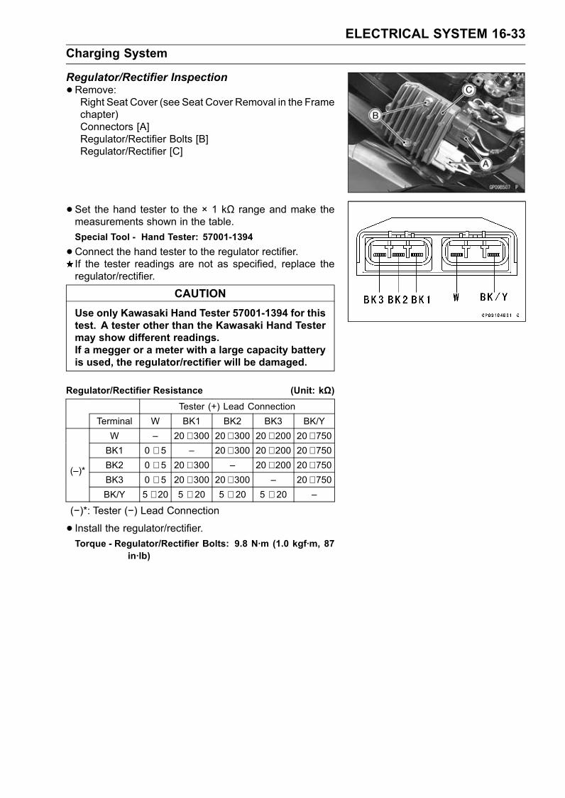
ELECTRICAL SYSTEM 16-33Charging System
Regulator/Rectifier Inspection•Remove:Right Seat Cover (see Seat Cover Removal in the Framechapter)Connectors [A]Regulator/Rectifier Bolts [B]Regulator/Rectifier [C]
• Set the hand tester to the × 1 kΩ range and make themeasurements shown in the table.Special Tool - Hand Tester: 57001-1394
•Connect the hand tester to the regulator rectifier.If the tester readings are not as specified, replace theregulator/rectifier.
CAUTIONUse only Kawasaki Hand Tester 57001-1394 for thistest. A tester other than the Kawasaki Hand Testermay show different readings.If a megger or a meter with a large capacity batteryis used, the regulator/rectifier will be damaged.
Regulator/Rectifier Resistance (Unit: kΩ)Tester (+) Lead Connection
Terminal W BK1 BK2 BK3 BK/YW – 20 ∼ 300 20 ∼ 300 20 ∼ 200 20 ∼ 750BK1 0 ∼ 5 – 20 ∼ 300 20 ∼ 200 20 ∼ 750BK2 0 ∼ 5 20 ∼ 300 – 20 ∼ 200 20 ∼ 750BK3 0 ∼ 5 20 ∼ 300 20 ∼ 300 – 20 ∼ 750
(–)*
BK/Y 5 ∼ 20 5 ∼ 20 5 ∼ 20 5 ∼ 20 –
(−)*: Tester (−) Lead Connection
• Install the regulator/rectifier.Torque - Regulator/Rectifier Bolts: 9.8 N·m (1.0 kgf·m, 87
in·lb)

16-34 ELECTRICAL SYSTEMCharging System
Charging Voltage Inspection•Check the battery condition (see Charging Condition In-spection).•Warm up the engine to obtain actual alternator operatingconditions.• Remove the right fairing cover (see Fairing Cover Re-moval in the Frame chapter).• Check that the ignition switch is turned off, and connectthe hand tester [A] to the battery (+) terminal and ground.Special Tool - Hand Tester: 57001-1394
•Start the engine, and note the voltage readings at var-ious engine speeds with the headlight turned on andthen turned off (To turn off the headlight, disconnectthe headlight connector on the headlight unit.). Thereadings should show nearly battery voltage when theengine speed is low, and, as the engine speed rises, thereadings should also rise. But they must be kept underthe specified voltage.
Charging VoltageConnections
Tester RangeTester (+) to Tester (–) to
Reading
25 V DC Battery (+) Ground 14.2 ∼ 15.2 V
• Turn off the ignition switch to stop the engine, and discon-nect the hand tester.If the charging voltage is kept between the values given inthe table, the charging system is considered to be workingnormally.If the charging voltage is much higher than the valuesspecified in the table, the regulator/rectifier is defectiveor the regulator/rectifier leads are loose or open.If the charging voltage does not rise as the engine speedincreases, then the regulator/rectifier is defective or thealternator output is insufficient for the loads. Check thealternator and regulator/rectifier to determine which partis defective.

ELECTRICAL SYSTEM 16-35Charging System
Charging System Circuit
1. Ignition Switch2. Regulator/Rectifier3. Alternator4. Load5. Main Fuse 30 A6. Frame Ground 17. Battery 12 V 14 Ah8. Joint Connector 19. Frame Ground 210. Engine Ground

16-36 ELECTRICAL SYSTEMIgnition System

ELECTRICAL SYSTEM 16-37Ignition System
WARNINGThe ignition system produces extremely high volt-age. Do not touch the spark plugs or stick coilswhile the engine is running, or you could receivea severe electrical shock.
CAUTIONDo not disconnect the battery cables or any otherelectrical connections when the ignition switch ison, or while the engine is running. This is to preventECU damage.Do not install the battery backwards. The negativeside is grounded. This is to prevent damage to theECU.
Crankshaft Sensor Removal•Remove:Right Lower Fairing (see Lower Fairing Removal in theFrame chapter)Right Middle Fairing (see Middle Fairing Removal in theFrame chapter)Crankshaft Sensor Lead Connector [A]
• Remove:Crankshaft Sensor Cover BoltsCrankshaft Sensor CoverCrankshaft Sensor Bolts [A]Crankshaft Sensor [B]

16-38 ELECTRICAL SYSTEMIgnition System
Crankshaft Sensor Installation•Apply a non-permanent locking agent to the threads ofthe crankshaft sensor bolts [A], and tighten it.Torque - Crankshaft Sensor Bolts: 5.9 N·m (0.60 kgf·m, 52
in·lb)
•Apply silicone sealant to the circumference of the crank-shaft sensor lead grommet [B], and fit the grommet intothe notch of the crankcase securely.• Apply silicone sealant to the mating surface [C] ofcrankcase halves.Sealant - Kawasaki Bond (Silicone Sealant): 92104-0004
•Replace the O-ring [D] with a new one.• Install the crankshaft sensor cover.• Apply a non-permanent locking agent to only one crank-shaft sensor cover bolt [E] shown in figure.• Tighten the crankshaft sensor cover bolts.Torque - Crankshaft Sensor Cover Bolts: 9.8 N·m (1.0
kgf·m, 87 in·lb)
•Route the crankshaft sensor lead correctly (see Cable,Wire, and Hose Routing section in the Appendix chapter).• Install the removed parts (see appropriate chapters).Crankshaft Sensor Inspection•Remove the right fairing cover (see Fairing Cover Re-moval in the Frame chapter).• Disconnect the crankshaft sensor lead connector (seeCrankshaft Sensor Removal).• Set the hand tester [A] to the × 100 Ω range and connectit to the crankshaft sensor lead connector [B].Special Tool - Hand Tester: 57001-1394
Crankshaft Sensor Resistance: 376 ∼ 564 Ω
If there is more resistance than the specified value, thecoil has an open lead and must be replaced. Much lessthan this resistance means the coil is shorted, and mustbe replaced.
• Using the highest resistance range of the tester, measurethe resistance between the crankshaft sensor leads andchassis ground.Any tester reading less than infinity (∞) indicates a short,necessitating replacement of the crankshaft sensor.
Crankshaft Sensor Peak Voltage InspectionNOTE
Be sure the battery is fully charged.Using the peak voltage adapter is a more reliable wayto determine the condition of the crankshaft sensor thancrankshaft sensor internal resistance measurements.
•Disconnect the crankshaft sensor lead connector (seeCrankshaft Sensor Removal).

ELECTRICAL SYSTEM 16-39Ignition System
•Set the hand tester [A] to the × 25 V DC range, and con-nect the peak voltage adapter [B].Special Tools - Hand Tester: 57001-1394
Peak Voltage Adapter: 57001-1415Type: KEK-54-9-B
Connections:Crankshaft SensorConnector [C] Adapter Hand Tester
Black ← Black → (–)Yellow ← Red → (+)
•Turn the ignition switch and engine stop switch ON.• Pushing the starter button, turn the engine 4 ∼ 5 sec-onds with the transmission gear in neutral to measure thecrankshaft sensor peak voltage.• Repeat the measurement 5 or more times.Crankshaft Sensor Peak VoltageStandard: 2.4 V or more
If the tester reading is not specified one, check the crank-shaft sensor.
Stick Coil (Ignition Coil together with Spark PlugCap) Removal•Remove:Middle Fairings (see Middle Fairing Removal in theFrame chapter)
• Disconnect the stick coil connectors [A].• Pull the stick coils [B] off the spark plugs.CAUTION
Do not pry the connector part of the coil while re-moving the coil.
Stick Coil (Ignition Coil together with Spark PlugCap) Installation•Apply grease to the stick coils.• Insert the stick coils [A] as shown being careful of the coilheads directions.Align the lines [B] of the cylinder head cover and coilheads.
CAUTIONDo not tap the coil head while installing the coil.
•Connect the stick coil connectors.• Run the hoses and harness correctly (see Cable, Wire,and Hose Routing section in Appendix chapter).• Install the removed parts (see appropriate chapters).

16-40 ELECTRICAL SYSTEMIgnition System
Stick Coil (Ignition Coil together with Spark PlugCap) Inspection•Remove the stick coils (see Stick Coil (Ignition Coil to-gether with Spark Plug Cap) Removal).•Measure the primary winding resistance [A] as follows.Connect the hand tester between the coil terminals.Set the tester to the × 1 Ω range, and read the tester.•Measure the secondary winding resistance [B] as follows.Connect the tester between the plug terminal and (–) coilterminal.Set the tester to the × 1 kΩ range and read the tester.Stick Coil Winding ResistancePrimary Windings: 1.2 ∼ 1.6 ΩSecondary Windings: 8.5 ∼ 11.5 kΩ
If the tester does not read as specified, replace the coil.
Stick Coil Primary Peak VoltageNOTE
Be sure the battery is fully charged.•Remove the stick coils (see Stick Coil (Ignition Coil to-gether with Spark Plug Cap) Removal).Do not remove the spark plug.•Measure the primary peak voltage as follows.Install the new spark plug [A] into each stick coil [B], andground them onto the engine.Connect the peak voltage adapter [C] to the hand tester[D] which is set to the × 250 V DC range.Connect the adapter to the lead wire-peak voltageadapter [E] which is connected between the stick coilconnector and stick coil.ECU [F]Battery [G]Special Tools - Hand Tester: 57001-1394
Peak Voltage Adapter: 57001-1415Type: KEK-54-9-BLead Wire-Peak Voltage Adapter: 57001-1449
Primary Lead ConnectionAdapter (R, +) to lead wire-peak voltage adapter (W)Adapter (BK, –) to lead wire-peak voltage adapter (R)

ELECTRICAL SYSTEM 16-41Ignition System
WARNINGTo avoid extremely high voltage shocks, do nottouch the spark plugs or tester connections.
•Turn the ignition switch and engine stop switch ON.• Pushing the starter button, turn the engine 4 ∼ 5 secondswith the transmission in neutral to measure the primarypeak voltage.• Repeat the measurements 5 times for one stick coil.Stick Coil Primary Peak VoltageStandard: 72 V or more
•Repeat the test for the other stick coils.If the reading is less than the specified value, check thefollowing.Stick Coils (see Stick Coil (Ignition Coil together withSpark Plug Cap) Inspection)Crankshaft Sensor (see Crankshaft Sensor Inspection)ECU (see ECUPower Supply Inspection in the Fuel Sys-tem (DFI) chapter)
Spark Plug Removal•Refer to the Spark Plug Replacement in the PeriodicMaintenance chapter (see Spark Plug Replacement inthe Periodic Maintenance chapter).
Spark Plug Installation•Refer to the Spark Plug Replacement in the PeriodicMaintenance chapter (see Spark Plug Replacement inthe Periodic Maintenance chapter).
Spark Plug Condition Inspection•Visually inspect the spark plugs.If the spark plug center electrode [A] and/or side elec-trode [B] are corroded or damaged, or if the insulator [C]is cracked, replace the plug.If the spark plug is dirtied or the carbon is accumulated,replace the spark plug.•Measure the gap [D] with a wire-type thickness gauge.If the gap is incorrect, replace the spark plug.Spark Plug Gap: 0.8 ∼ 0.9 mm (0.031 ∼ 0.035 in.)
•Use the standard spark plug or its equivalent.Spark Plug: CR9EIA-9

16-42 ELECTRICAL SYSTEMIgnition System
Camshaft Position Sensor Removal•Remove:Fuel Tank Cover (see Fuel Tank Removal in the FuelSystem (DFI) chapter)Right Middle Fairing (see Middle Fairing Removal in theFrame chapter)• Disconnect the camshaft position sensor lead connector[A].
• Remove:Camshaft Position Sensor Bolt [A]Camshaft Position Sensor [B]
Camshaft Position Sensor Installation•Replace the O-ring of the camshaft position sensor.• Apply grease to the new O-ring.• Tighten:Torque - Camshaft Position Sensor Bolt: 9.8 N·m (1.0
kgf·m, 87 in·lb)
•Route the camshaft position sensor lead correctly (seeCable, Wire, and Hose Routing section in the Appendixchapter).
Camshaft Position Sensor Inspection•Disconnect the camshaft position sensor lead connector(see Camshaft Position Sensor Removal).• Set the hand tester to the × 10 Ω range and connect it tothe terminals.Special Tool - Hand Tester: 57001-1394
Camshaft Position Sensor Resistance: 400 ∼ 460 Ω
If there is more resistance than the specified value, thesensor coil has an open lead andmust be replaced. Muchless than this resistance means the sensor coil is shorted,and must be replaced.• Using the highest resistance range of the tester, mea-sure the resistance between the camshaft position sensorleads and chassis ground.Any tester reading less than infinity (∞) indicates a short,necessitating replacement of the camshaft position sen-sor.

ELECTRICAL SYSTEM 16-43Ignition System
Camshaft Position Sensor Peak VoltageInspection•Disconnect the camshaft position sensor lead connector[A] (see Camshaft Position Sensor Removal).• Connect the harness adapter [B] between the camshaftposition sensor lead connector and harness connector[C].• Connect the peak voltage adapter [D] to the hand tester[E] which is set to the × 10 V range.• Connect the adapter to the harness adapter.[F] Camshaft Position SensorSpecial Tools - Hand Tester: 57001-1394
Peak Voltage Adapter: 57001-1415Type: KEK-54-9-BHarness Adapter: 57001-1562
Connections:
Harness Adapter Peak VoltageAdapter Hand Tester
Black/White ← Black → (–)Red ← Red → (+)
•Turn the ignition switch and engine stop switch ON.• Pushing the starter button, run the engine with the trans-mission gear in neutral to measure the camshaft positionsensor peak voltage.• Repeat the measurement 5 or more times.Camshaft Position Sensor Peak VoltageStandard: 2.8 V or more
If the peak voltage is lower than the standard, inspect thecamshaft position sensor.
Interlock Operation Inspection•Using the stand [A], raise the rear wheel off the ground.
1st Check•Start the engine to the following conditions.Condition:Transmission Gear → 1st PositionClutch Lever → ReleaseSidestand → Down or Up
Turn the ignition switch ON and push the starter button.Then the starter motor should not turn when the startersystem circuit is normality.If the engine is start, inspect the starter lockout switch,gear position switch, and relay box.If their parts are normality replace the ECU.

16-44 ELECTRICAL SYSTEMIgnition System
2nd Check•Start the engine to the following conditions.Condition:Transmission Gear → 1st PositionClutch Lever → Pulled inSidestand → Up
Turn the ignition switch ON and push the starter button.Then the starter motor should turn when the starter sys-tem circuit is normality.If the starter motor is not turn, inspect the starter lockoutswitch, gear position switch, sidestand switch and relaybox.If their parts are normality replace the ECU.
3rd Check• Inspect the engine for its secure stop after the followingoperations are completed.• Run the engine to the following conditions.Condition:Transmission Gear → 1st PositionClutch Lever → ReleaseSidestand → Up
•Set the sidestand on the ground, then the engine will stop.If whichevermay not be stopped, inspect the gear positionswitch, starter lockout switch, sidestand switch and relaybox.If their parts are normality, replace the ECU.
IC Igniter InspectionThe IC igniter is built in the ECU [A].• Refer to the following items.Interlock Operation Inspection (see Interlock OperationInspection)Ignition System Troubleshooting (see Ignition Systemsection)ECU Power Supply Inspection (see ECU Power SupplyInspection in the Fuel System (DFI) chapter)

ELECTRICAL SYSTEM 16-45Ignition System
Ignition System Circuit
1. Sidestand Switch2. Camshaft Position Sensor3. Joint Connector 14. Joint Connector 25. Gear Position Switch6. Water-proof Joint 17. Vehicle-down Sensor8. Water-proof Joint 29. Sub-throttle Sensor10. Main Throttle Sensor11. Crankshaft Sensor12. ECU13. Fuse Box 2
14. Ignition Fuse 10 A15. ECU Fuse 15 A16. Ignition Switch17. Main Fuse 30 A18. Battery 12 V 14 Ah19. Frame Ground 220. Engine Ground21. Starter Lockout Switch22. Relay Box23. Joint Connector 324. Engine Stop Switch25. Stick Coils26. Spark Plugs

16-46 ELECTRICAL SYSTEMElectric Starter System
Starter Motor Removal•Remove:Engine Sprocket Cover (see Engine Sprocket Removalin the Final Drive chapter)
• Take off the heat insulation rubber plate [A].• Slide out the rubber cap [B].• Remove the starter motor cable terminal nut [C].
• Remove the starter motor mounting bolts [A].• Pull out the starter motor [B] from the left side.
Starter Motor InstallationCAUTION
Do not tap the starter motor shaft or body. Tappingthe shaft or body could damage the motor.
•Clean the starter motor legs [A] and crankcase [B] wherethe starter motor is ground.• Replace the O-ring [C] with a new one.• Apply grease to the new O-ring.• Tighten:Torque - Starter Motor Mounting Bolts: 9.8 N·m (1.0 kgf·m,
87 in·lb)
• Install the starter motor cable [A] side by side with startermotor [B].• Tighten:Torque - Starter Motor Cable Terminal Nut: 5.9 N·m (0.60
kgf·m, 52 in·lb)
•Slide back the rubber cap [C] to the original position.

ELECTRICAL SYSTEM 16-47Electric Starter System
Starter Motor Disassembly•Remove the starter motor (see Starter Motor Removal).• Take off the starter motor through bolts [A] and removeboth end covers [B].
• Pull the armature [A] out of the yoke [B].
• Remove:Brush Plate Terminal Nut, Washer and Insulators [A]Brush Plate Assembly [B]
Starter Motor Assembly•Pry the spring end [A] and insert the brush [B].
• Install the brush plate assembly [A] into the right-hand endcover [B].• Replace the O-ring [C] with a new one.• Install:Insulators [D]Washer [E]• Tighten:Torque - Starter Motor Terminal Locknut [F]: 6.9 N·m (0.70
kgf·m, 61 in·lb)

16-48 ELECTRICAL SYSTEMElectric Starter System
• Install the armature [A] into the yoke [B].• Install thrust washer [C].• Replace the O-rings [D] with new ones.• Put the armature [E] among the brushes [F].
• Align the marks [A] to assembly the yoke and the endcovers.
• Replace the O-rings [A] with new ones.• Tighten:Torque - Starter Motor Through Bolts [B]: 3.4 N·m (0.35
kgf·m, 30 in·lb)
•Replace the O-ring [A] with new ones.• Apply grease to the new O-ring.
Brush Inspection•Measure the length [A] of each brush [B].If any is worn down to the service limit, replace the brushholder assembly.
Starter Motor Brush LengthStandard: 10 mm (0.39 in.)Service Limit: 5.0 mm (0.20 in.)

ELECTRICAL SYSTEM 16-49Electric Starter System
Commutator Cleaning and Inspection•Smooth the commutator surface [A] if necessary with fineemery cloth [B], and clean out the grooves.
•Measure the diameter [A] of the commutator [B].If the commutator diameter is less than the service limit,replace the starter motor with a new one.
Commutator DiameterStandard: 28 mm (1.10 in.)Service Limit: 27 mm (1.06 in.)
Armature Inspection•Using the × 1 Ω hand tester range, measure the resis-tance between any two commutator segments [A].Special Tool - Hand Tester: 57001-1394If there is a high resistance or no reading (∞) between anytwo segments, a winding is open and the starter motormust be replaced.• Using the highest hand tester range, measure the resis-tance between the segments and the shaft [B].If there is any reading at all, the armature has a short andthe starter motor must be replaced.
NOTEEven if the foregoing checks show the armature to begood, it may be defective in some manner not readilydetectable with the hand tester. If all other starter motorand starter motor circuit components check good, butthe starter motor still does not turn over or only turnsover weakly, replace the starter motor with a new one.
Brush Lead Inspection•Using the × 1 Ω hand tester range, measure the resis-tance as shown.Terminal Bolt and Positive Brush [A]Right-hand End Cover and Negative Brush [B]Special Tool - Hand Tester: 57001-1394If there is not close to zero ohms, the brush lead has anopen. Replace the brush holder assembly.

16-50 ELECTRICAL SYSTEMElectric Starter System
Right-hand End Cover Assembly Inspection•Using the highest hand tester range, measure the resis-tance as shown.Terminal and Right-hand End Cover [A]Special Tool - Hand Tester: 57001-1394If there is any reading, the right-hand end cover assemblyhave a short. Replace the right-hand end cover assembly.
Starter Relay Inspection•Remove the battery (see Battery Removal).• Disconnect the starter motor cable [A] and battery positive(+) cable [B] from the starter relay.• Disconnect the connector [C].• Pull out the starter relay from the damper.
• Connect the hand tester [A] and 12 V battery [B] to thestarter relay [C] as shown.Special Tool - Hand Tester: 57001-1394If the relay does not work as specified, the relay is defec-tive. Replace the relay.
Testing RelayTester Range: × 1 Ω rangeCriteria: When battery is connected→ 0 Ω
When battery is disconnected→ ∞ Ω
•Tighten:Torque - Starter Motor Cable Mounting Bolt: 3.9 N·m (0.40
kgf·m, 35 in·lb)

ELECTRICAL SYSTEM 16-51Electric Starter System
Electric Starter Circuit
1. Sidestand Switch2. Engine Stop Switch3. Starter Button4. Fuse Box 25. Ignition Fuse 10 A6. Ignition Switch7. Joint Connector 18. Joint Connector 29. Gear Position Switch10. Starter Lockout Switch11. Starter Circuit Relay12. Relay Box13. Starter Motor14. Main Fuse 30 A15. Starter Relay16. Battery 12 V 14 Ah17. Frame Ground 218. Engine Ground

16-52 ELECTRICAL SYSTEMLighting System
This motorcycle adopt the daylight system and have aheadlight relay in the relay box. The headlight does notgo on when the ignition switch and the engine stop switchare first turned on. The headlight comes on after the starterbutton is released and stays on until the ignition switch isturned off. The headlight will go out momentarily wheneverthe starter button is pressed and come back on when thebutton is released.
Headlight Beam Horizontal Vertical Adjustment•Refer to the Headlight Aiming Inspection in the PeriodicMaintenance chapter.
Headlight Beam Vertical Adjustment•Refer to the Headlight Aiming Inspection in the PeriodicMaintenance chapter.
Headlight Bulb Replacement•Remove the inner covers (see Inner Cover Removal inthe Frame chapter).• Disconnect the headlight connector [A].
• Turn the headlight bulb [A] counterclockwise and pull outthe bulb from the headlight.
CAUTIONWhen handling the quartz-halogen bulb, nevertouch the glass portion with bare hands. Alwaysuse a clean cloth. Oil contamination from hands ordirty rags can reduce bulb life or cause the bulb toexplode.
NOTEClean off any contamination that inadvertently gets onthe bulb with alcohol or soap and water solution.
•Replace the headlight bulb.• Fit the projections [A] of the bulb in the hollows [B] of theheadlight.
• Turn the headlight bulb clockwise.• Connect the headlight connector.• After installation, adjust the headlight aim (see HeadlightAiming Inspection in the Periodic Maintenance chapter).Other Bulbs: Repeat the above steps.

ELECTRICAL SYSTEM 16-53Lighting System
City Light Bulb Replacement•Remove the inner covers (see Inner Cover Removal inthe Frame chapter).• Unscrew the screw [A].• Disconnect the city light connector [B].
• Turn the city light bulb counterclockwise and pull out thesocket [A] together with the bulb.
• Pull the bulb [A] out of the socket [B].CAUTION
Do not turn the bulb. Pull the bulb out to preventdamage to the bulb. Do not use bulb rated forgreater wattage than the specified value.
•Replace the bulb with a new one.
• Insert the socket and to the headlight.Align the projections [A] of the socket and the grooves [B]of the headlight.• Turn the city light bulb clockwise.• Connect the city light connector.
Headlight Removal/Installation•Remove:Upper Fairing (see Upper Fairing Removal in the Framechapter)Upper Inner Fairing (see Upper Inner Fairing Removalin the Frame chapter)Headlight Mounting Screws [A]Headlights [B]• Tighten:Torque - Headlight Mounting Screws: 1.2 N·m (0.12 kgf·m,
11 in·lb)

16-54 ELECTRICAL SYSTEMLighting System
Headlight Relay Inspection•Remove the inner covers (see Inner Cover Removal inthe Frame chapter).• Take off the headlight relay [A] (both sides).
• Set the hand tester to the × 1 Ω range and make themeasurements shown in the figure.Headlight Relay [A]12 V Battery [B]Special Tool - Hand Tester [C]: 57001-1394If the tester readings are not as specified, replace theheadlight relay.
CAUTIONUse only Hand Tester 57001-1394 for this test. Anohmmeter other than the Kawasaki Hand Testermay show different readings. If a megger or a meterwith a large-capacity battery is used, the headlightrelay will be damaged.
Testing RelayCriteria When battery is connected→ 0 Ω
When battery is disconnected→ ∞ Ω
Tail/Brake Light (LED) Removal•Remove:Tool Kit Case [A] (see ECU Removal in the Fuel System(DFI) chapter)Relay Box [B] (see Relay Box Removal in the ElectricalSystem chapter)Fuse Box [C]Screws [D]
• Disconnect the connector [A].• Remove the tail/brake light [B].

ELECTRICAL SYSTEM 16-55Lighting System
Tail/Brake Light (LED) Installation•Connect the connector.• Insert the projections [A] of the tail/brake light into theholes [B] of the rear fender.Torque - Tail/Brake Light Mounting Screws: 1.2 N·m (0.12
kgf·m, 11 in·lb)
• Install the removed parts (see appropriate chapters).
License Plate Light Bulb Replacement•Remove:Screws [A]License Plate Light Cover [B]
• Push and turn the bulb [A] counterclockwise wise and re-move it.• Replace the bulb with a new one.
• Insert the new bulb [A] by aligning its upper and lower pins[B] with the upper and lower grooves [C] in the socket, andturn the bulb clockwise.Turn the bulb about 15°.• Tighten:Torque - Licence Plate Light Cover Mounting Screws: 0.9
N·m (0.09 kgf·m, 8 in·lb)

16-56 ELECTRICAL SYSTEMLighting System
Headlight/Tail Light Circuit
1. Ignition Switch2. Joint Connector 13. High Beam Indicator Light (LED)4. Right City Light5. Headlight (High Beam)6. Headlight (Low Beam)7. Left City Light8. Headlight Relay (Low)9. Headlight Relay (High)10. Dimmer Switch11. Passing Button (Other than US Models)12. Headlight Fuse 10 A13. Taillight Fuse 10 A14. Headlight Fuse (High) 10 A
15. Headlight Fuse (Low) 10 A16. Fuse Box 117. Relay Box18. Headlight Circuit Relay19. Alternator20. Main Fuse 30 A21. Starter Relay22. Battery 12 V 14 Ah23. Frame Ground24. Tail/Brake Light (LED)25. License Plate Light26. Joint Connector 227. Fuse Box 228. Ignition Fuse 10 A
Turn Signal Light Bulb ReplacementFront Turn Signal Light•Remove:Middle Fairings (see Middle Fairing Removal in theFrame chapter)Inner Fairings (see Inner Fairing Removal in the Framechapter)• Turn the socket [A] counterclockwise and pull out thesocket together with the bulb.
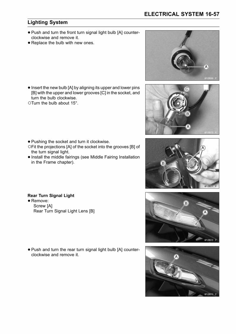
ELECTRICAL SYSTEM 16-57Lighting System
•Push and turn the front turn signal light bulb [A] counter-clockwise and remove it.• Replace the bulb with new ones.
• Insert the new bulb [A] by aligning its upper and lower pins[B] with the upper and lower grooves [C] in the socket, andturn the bulb clockwise.Turn the bulb about 15°.
• Pushing the socket and turn it clockwise.Fit the projections [A] of the socket into the grooves [B] ofthe turn signal light.• Install the middle fairings (see Middle Fairing Installationin the Frame chapter).
Rear Turn Signal Light•Remove:Screw [A]Rear Turn Signal Light Lens [B]
• Push and turn the rear turn signal light bulb [A] counter-clockwise and remove it.

16-58 ELECTRICAL SYSTEMLighting System
• Insert the new bulb [A] by aligning its upper and lower pins[B] with the upper and lower grooves [C] in the socket, andturn the bulb clockwise.Turn the bulb about 15°.
• Fit the projections [A] of the lens into the grooves [B] ofthe turn signal light.• Tighten the screw.
Turn Signal Relay Inspection•Remove:Left Seat Cover (see Seat Cover Removal in the Framechapter)Turn Signal Relay [A]• Disconnect the connector [B].
• Connect one 12 V battery and turn signal lights as indi-cated in the figure, and count how may times the lightsflash for one minute.Turn Signal Relay [A]Turn Signal Lights [B]12 V Battery [C]If the lights do not flash as specified, replace the turn sig-nal relay.
Testing Turn Signal RelayLoad
The Number of TurnSignal Lights Wattage (W)
Flashing Times(c/m*)
1** 21 or 23 140 ∼ 2502 42 or 46 75 ∼ 95
*: Cycle(s) per minute**: Corrected to “one light burned out”.

ELECTRICAL SYSTEM 16-59Lighting System
Turn Signal Light Circuit
1. Ignition Switch2. Joint Connector 13. Turn Signal Indicator Light (LED) (Right)4. Turn Signal Indicator Light (LED) (Left)5. Front Right Turn Signal Light6. Front Left Turn Signal Light7. Other than US Models8. Hazard Button9. Turn Signal Switch10. Turn Signal Fuse 10 A11. Fuse Box 112. Turn Signal Relay13. Joint Connector 214. Frame Ground15. Main Fuse 30 A16. Battery 12 V 14 Ah17. Rear Left Turn Signal Light18. Rear Right Turn Signal Light19. Ignition Fuse 10 A20. Fuse Box 2

16-60 ELECTRICAL SYSTEMAir Switching Valve
Air Switching Valve Operation Test•Refer to the Air Suction System Damage Inspection in thePeriodic Maintenance chapter.
Air Switching Valve Unit Test•Remove the air switching valve (see Air Switching ValveRemoval in the Engine Top End chapter).• Set the hand tester [A] to the × Ω range and connect it tothe air switching valve terminals as shown.Special Tool - Hand Tester: 57001-1394
Air Switching Valve ResistanceStandard: 18 ∼ 22 Ω at 20°C (68°F)
If the resistance reading is except the specified value, re-place it with a new one.
• Connect the 12 V battery [A] to the air switching valveterminals as shown.
• Blow the air to the inlet air duct [A], and make sure doesnot flow the blown air from the outlet air ducts [B].
• Disconnect the 12 V battery.• Blow the air to the inlet air duct [A] again, and make sureflow the blown air from the outlet air ducts [B].If the air switching valve dose not operate as described,replace it with a new one.
NOTETo check air flow through the air switching valve, justblow through the air switching valve hose (inlet side)[C].

ELECTRICAL SYSTEM 16-61Radiator Fan System
Fan Motor Inspection•Remove the left fairing cover (see Fairing Cover Removalin the Frame chapter).• Disconnect the connector [A].• Using an auxiliary leads, supply battery power to the fanmotor.If the fan does not rotate, the fan motor is defective andmust be replaced.
Radiator Fan Circuit
1. Ignition Switch2. Joint Connector 13. Fuse Box 24. Fan Fuse 15 A5. Relay Box6. Radiator Fan Relay7. Main Fuse 30 A8. Starter Relay
9. Battery 12 V 14 Ah10. Frame Ground 211. Engine Ground12. Radiator Fan13. Water Temperature Sensor14. Water-proof Joint 215. ECU

16-62 ELECTRICAL SYSTEMMeter, Gauge, Indicator Unit
Meter Unit Removal•Remove:Windshield (see Windshield Removal in the Framechapter)Immobilizer Amplifier [A] (Equipped Models)
• Remove:Immobilizer Amplifier Bracket and Bolt [A] (EquippedModels)Vehicle-down Sensor Bracket and Bolt [B]Meter Lead Connector [C]
• Remove:Meter Unit Mounting Nuts [A] and WashersMeter Unit [B]
CAUTIONPlace the meter unit so that the face is up. If a meterunit is left upside down or sideways for any lengthof time, it will malfunction.
Meter Unit Installation• Install:Meter Unit [A]Washers [B] and Meter Unit Mounting Nuts [C]
• Install:Meter Lead ConnectorVehicle-down Sensor Bracket (as shown) and Bolt [A]Immobilizer Amplifier Bracket and Bolt (Equipped Mod-els)Immobilizer Amplifier [B] (Equipped Models)Windshield (see Windshield Installation in the Framechapter)

ELECTRICAL SYSTEM 16-63Meter, Gauge, Indicator Unit
Meter Unit Disassembly•Remove:Meter Unit (see Meter Unit Removal)Screws [A]Lower Meter Cover [B]
• Separate:Upper Meter Cover [A]Middle Meter Cover [B]Meter Assembly [C]
Meter Unit Inspection•Remove the meter unit (see Meter Unit Removal).[1] High Beam Indicator Light (LED)[2] Oil Pressure Warning Indicator Light (LED) (–)[3] Right Turn Signal Indicator Light (LED) (+)[4] Neutral Indicator Light (LED) (–)[5] Unused[6] ABS Indicator Light (LED) (–)[7] Unused[8] Unused[9] Ignition (+)[10] Battery (+)[11] Speed Sensor Supply Voltage (+)[12] Ground (–)[13] Speed Sensor Signal[14] Unused[15] Fuel Reserve Switch[16] Fuel Level Sensor[17] CAN Communication Line (Hight)[18] CAN Communication Line (Low)[19] Left Turn Signal Indicator Light (LED) (+)[20] Unused
CAUTIONDo not drop the meter unit. Place the meter unit sothat it faces upward. If themeter assembly is left up-side down or sideways for a long time or dropped,it will malfunction. Do not short each terminals.

16-64 ELECTRICAL SYSTEMMeter, Gauge, Indicator Unit
Check 1: CAN Communication Line Resistance Inspec-tion•Set the hand tester [A] to the ×1 Ω range and connect itto the terminal [17] and [18] in the meter unit.Special Tool - Hand Tester: 57001-1394
CAN Communication Line Resistance (at Meter Unit)Standard: 122 ∼ 126 Ω
If the tester reading is not specified, replace the meterassembly.
Check 2: Meter Unit Primary Operation Check•Using the auxiliary leads, the 12 V battery [A] to the meterunit connector as follows.Connect the battery positive (+) terminal to the terminal[10].Connect the battery negative (–) terminal to the terminal[12].
• Check that the speedometer and tachometer needles [A]momentarily point their last readings and back to the min-imum position.If the meter unit does not work, replace the meter assem-bly.
• Connect terminal [9] to the battery (+) terminal.
• Check that the following items.The speedometer and tachometer needles momentarilypoint their last readings and back to theminimum position.The ABS indicator light (LED) [A] (equipped models)should go on.The K Kawasaki mark [B] in the LCD appears for threeseconds.

ELECTRICAL SYSTEM 16-65Meter, Gauge, Indicator Unit
After the K Kawasaki mark appeared, the TRIP A/B meter[A], water temperature gauge [B], fuel level gauge [C],odometer and clock appear in the display [D].The ABS indicator light (LED) [E] (equipped models)should go on.If the meter unit does not work, replace the meter assem-bly.
NOTEThe flashings of the three segments for the water tem-perature gauge and fuel level gauge do not failure of themeter unit.Currently, for the meter is disconnected from the mainharness each flashing occur.The flashing of water temperature gauge is communi-cation error to the ECU.The flashing of the fuel level gauge is open or short ofthe fuel reserve switch.Normally, each flashing disappears when the meter unitis connected to main harness.
Check 3: MODE and RESET Button Operation Check•Connect the leads in the same circuit as Check 2.• By pushing the MODE button [A] each time, check thatthe display [B] changes as follows.This display is ordinary indication.
If the display function does not work, replace the meterassembly.
• Push theMODE button [A] andRESET button [B] for morethan two seconds.
• Check that the display changes to the language settingmode [A].This display is system menu indication.• By pushing the RESET button each time, check that thedisplay selects the ENGLISH or FRANCAIS.If the display function does not work, replace the meterassembly.

16-66 ELECTRICAL SYSTEMMeter, Gauge, Indicator Unit
•By pushing the MODE button each time at the languagesettingmode, check that the display [A] selects as follows.
If the display function does not work, replace the meterassembly.
• Select the MILEAGE [A] indication.• Push the MODE button for more than two seconds, checkthat the unit setting menu [B] flashes.• By pushing the RESET button each time, check that thedisplay changes as follows.
• Check that the unit setting menu is decided by the MODEbutton push.If the display function does not work, replace the meterassembly.
• Select the ENGAGE LAMP [A] indication.• Push the MODE button for more than two seconds, checkthat the engine speed setting menu [B] flashes.• By pushing the RESET button each time, check that thedisplay changes as follows.
• Check that the engine speed setting menu is decided bythe MODE button pushing.If the display function does not work, replace the meterassembly.
• Select the SHIFT LAMP [A] indication.• Push the MODE button for more than two seconds, checkthat the engine speed setting menu [B] flashes.• By pushing the RESET button each time, check that thedisplay changes as follows.
• Check that the engine speed setting menu is decided bythe MODE button pushing.If the display function does not work, replace the meterassembly.

ELECTRICAL SYSTEM 16-67Meter, Gauge, Indicator Unit
•Select the LAMP MODE [A] indication.• Push the MODE button for more than two seconds, checkthat the lighting mode setting menu [B] flashes.• By pushing the RESET button [C] each time, check thatthe display changes as follows and the indicator light(LED) [D] goes on according to message.
• Check that the lighting mode setting menu is decided bythe MODE button pushing.If the display function does not work, replace the meterassembly.
• Select the CLOCK [A] indication.• Push the MODE button for more than two seconds.The clock settingmenu (hour andminute) [B] should flash.
• Push the RESET button.The hour display [A] starts flashing.• By pushing the MODE button each time, check that thehour display changes.
• By pushing the RESET button, check that the hour displaydecide and minute display [A] starts flashing.• By pushing the MODE button each time, check that theminute display changes.

16-68 ELECTRICAL SYSTEMMeter, Gauge, Indicator Unit
•By pushing the RESET button, check that the hour andminute display [A] starts flashing.• By pushing the MODE button, check that the hour andminute display decide.•When both hour and minute display flashing, by pushingthe RESET button, check that the hour display start flash-ing. This flashing returns the hour setting mode.If the display function does not work, replace the meterassembly.
Check 4: Battery Voltage Inspection•Connect the leads in the same circuit as Check 2.
• 1st, set the BATTERY display.• Check that the display indicates the battery voltage.
• 2nd, disconnect the terminal [10].• Check that the display changes 9.0 V within about 30 sec-onds.
• 3rd, connect the terminal [10].• Check that the display changes the current battery volt-age within about 30 seconds.The tolerance of the voltage is ±0.4 V.If the display function does not work, replace the meterassembly.

ELECTRICAL SYSTEM 16-69Meter, Gauge, Indicator Unit
Check 5: Immobilizer Flashing Mode Inspection(Equipped Models)•Connect the leads in the same circuit as Check 2.• Disconnect the terminal [9].
• Check that the warning light (LED) [A] starts flashing (Im-mobilizer Warning Light Flashing Mode).• Push the MODE [B] and RESET [C] buttons more than 2second, within 20 seconds after the terminal [9] discon-nected.• Check that the warning light (LED) goes on one second,and then the light goes off (Immobilizer Warning Light NoFlashing Mode).
NOTEFor this inspection, be sure the battery is 12.4 V ormore. Immobilizer Warning Light Flashing Mode doesnot work, when the battery voltage is less than 12±0.4V.
•Connect the terminal [9] to the battery (+) terminal.• And then, disconnect the terminal [9].• Push theMODE and RESET buttonsmore than 2 second,within 20 seconds after the terminal [9] disconnected.• Check that the warning light (LED) goes on one second,and then the light starts flashing (Immobilizer WarningLight Flashing Mode).If the meter function does not work, replace the meterassembly.
Check 6: High Beam Indicator Light (LED) Inspection•Connect the leads in the same circuit as Check 2.• Connect the terminal [1] to the battery (+) terminal.

16-70 ELECTRICAL SYSTEMMeter, Gauge, Indicator Unit
•Check that the high beam indicator light (LED) [A] goeson.If the indicator light does not go on, replace the meterassembly.
Check 7: Right Turn Signal Indicator Light (LED) In-spection•Connect the leads in the same circuit as Check 2.• Connect the terminal [3] to the battery (+) terminal.
• Check that the right turn signal indicator light (LED) [A]goes on.If the indicator light does not go on, replace the meterassembly.
Check 8: Left Turn Signal Indicator Light (LED) Inspec-tion•Connect the leads in the same circuit as Check 2.• Connect the terminal [19] to the battery (+) terminal.
• Check that the left turn signal indicator light (LED) [A]goes on.If the indicator light does not go on, replace the meterassembly.

ELECTRICAL SYSTEM 16-71Meter, Gauge, Indicator Unit
Check 9: Oil Pressure Warning Indicator Light (LED)Inspection•Connect the leads in the same circuit as Check 2.• Connect the terminal [2] to the battery (–) terminal.
• Check that the oil pressure warning indicator light (LED)goes on.If the indicator light does not go on, replace the meterassembly.
Check 10: Neutral Indicator Light (LED) Inspection•Connect the leads in the same circuit as Check 2.• Connect the terminal [4] to the battery (–) terminal.
• Check that the neutral indicator light (LED) goes on.If the indicator light does not go on, replace the meterassembly.
Check 11: ABS Indicator Light (LED) Inspection(Equipped Models)•Connect the leads in the same circuit as Check 2.• Check that the ABS indicator light (LED) [A] goes on.

16-72 ELECTRICAL SYSTEMMeter, Gauge, Indicator Unit
•Connect the terminal [6] to the battery (–) terminal.• Check that the ABS indicator light (LED) goes off.If the indicator light does not go on, replace the meterassembly.
Check 12: Fuel Level Warning Inspection•Connect the leads in the same circuit as Check 2.• Connect the variable rheostat [A] (about 22 Ω) to the ter-minal [15] and the battery (–) terminal.
• After about 5 seconds, check that one segment [A] in thefuel gauge starts flashing.• Check that the FUEL EMPTY [B] and fuel symbol [C] ap-pear alternately in the display.If the display function does not work, replace the meterassembly.This display is the warning message indication.
• Push the MODE button [A] more than 2 seconds.• Check that the warning light (LED) [B] goes on and displaychanges TRIP A/B meter [C] mode.The one segment [D] in the fuel gauge keeps flashing.• Push the MODE button more than 2 seconds.• Check that the warning light (LED) goes off and displaychanges the warning message indication mode.The one segment in the fuel gauge keeps flashing.If the display function does not work, replace the meterassembly.• Disconnect the battery to disappear the warning messageindication.

ELECTRICAL SYSTEM 16-73Meter, Gauge, Indicator Unit
Check 13: Fuel Gauge Inspection•Connect the leads in the same circuit as Check 2.• Connect the resistor [A] (about 1 kΩ) to the terminal [15]and the battery (–) terminal.• Connect the variable rheostat [B] to the terminal [16] andthe battery (–) terminal.• Check that the number of segments matches the resis-tance value of the variable rheostat.When the terminal [16] is connected, one segment in thefuel level gauge should appear about every 15 seconds.
Variable RheostatResistance (Ω) Display Segments [A]
10 6200 1
If the display function does not work, replace the meterassembly.
Check 14: Speedometer Inspection•Connect the leads in the same circuit as Check 2.• The speed equivalent to the input frequency is indicated inthe oscillator [A], if the square wave is input into terminal[13].Indicates approximately 60 mph if the input frequency isapproximately 131.2 Hz.Indicates approximately 60 km/h if the input frequency isapproximately 82 Hz.If the meter function does not work, replace the meterassembly.
Check 15: Trip A/B Meter Inspection•Connect the leads in the same circuit as Check 14.• Set the TRIP A/B meter mode in the display.• Raise the input frequency of the oscillator to see the resultof this inspection.If the value indicated by the trip meter A/B do not increase,replace the meter assembly.

16-74 ELECTRICAL SYSTEMMeter, Gauge, Indicator Unit
•By pushing the RESET button each time, check that thedisplay starts flashing as follows.
•When flushing the display, push the RESET button formore than two seconds, check that the display changes0.0 (TRIP A) and 0 (TRIP B).If the display function does not change, replace the meterassembly.
Check 16: Odometer Inspection•Connect the leads in the same circuit as Check 14.• Raise the input frequency of the oscillator to see the resultof odometer [A] inspection.Example: Indicates the increase of approximately 1 mile,if the input frequency is approximately 131.2 Hz for oneminute.Example: Indicates the increase of approximately 1km/h, if the input frequency is approximately 82 Hz forone minute.If the value indicated by the odometer does not increase,replace the meter assembly.
Check 17: Speed Sensor Supply Voltage Inspection•Connect the leads in the same circuit as Check 2.• Set the hand tester to the 25 V range and connect it in themeter unit as follows.Special Tool - Hand Tester: 57001-1394
Connections:Hand Tester (+) → Terminal [11]Hand Tester (–) → Terminal [12]
Speed Sensor Supply VoltageStandard: about 12 V
If the tester reading is not specified, replace the meterassembly.

ELECTRICAL SYSTEM 16-75Meter, Gauge, Indicator Unit
Check 18: Water Temperature Gauge Inspection•Connect the leads in the same circuit as Check 2.• Connect the CAN communication lines from meter con-nector [A] to main harness connector [B] as shown.
Connections:Meter Terminal [17] → Main Harness Terminal [17]Meter Terminal [18] → Main Harness Terminal [18]
•Turn the ignition switch ON.•Check that the only symbol [A] appears in the water tem-perature gauge.• Turn the ignition switch OFF.If the display function does not work, go to the Check 1and check the following items.Wiring (see Wiring Inspection)CAN Communication Line Resistance (at ECU) (seeCAN Communication Line Resistance Inspection in theFuel System (DFI) chapter)Water Temperature Sensor (see Water TemperatureSensor (Service Code 14) section in the Fuel System(DFI) chapter)If the above items are good, replace the meter assemblyand/or ECU.
Check 19: FI/IMMOBILIZER Error Inspection•Connect the leads in the same circuit as Check 18.• For example, disconnect the atmospheric pressure sen-sor [A].• Install the key registration unit [B] (see Key Registration)(Immobilizer equipped model).Special Tool - Key Registration Unit: 57001-1582

16-76 ELECTRICAL SYSTEMMeter, Gauge, Indicator Unit
•Turn the ignition switch ON by the current key.• Check that the warning light (LED) [A] starts flashing andthe display [B] changes as follows.
[C] Warning Message[D] Symbol
This display is the warning message indication.If the display function does not work, go to the Check 1and check the following items.Wiring (see Wiring Inspection)CAN Communication Line Resistance (at ECU) (seeCAN Communication Line Resistance Inspection in theFuel System (DFI) chapter)
Example:Immobilizer System (see Immobilizer Amplifier andBlank Key Detection section in the Fuel System (DFI)chapter)Atmospheric Pressure Sensor (see Atmospheric Pres-sure Sensor (Service Code 15) section in the Fuel Sys-tem (DFI) chapter)
Refer to Troubleshooting the DFI System section in theFuel System (DFI) chapter for other DFI partsIf the above items are good, replace the meter assemblyand/or ECU.
• By pushing the MODE button [A] each time, check thatthe display changes the error messages [B] only.During this operating, the symbols do not appear.The warning indicator light (LED) keeps flashing.
• Push the MODE and RESET buttons for more than twoseconds, check that each ERROR CODE [A] and num-bers appears in the display.The warning indicator light (LED) keeps flashing.• Again, push the MODE and RESET buttons for more thantwo seconds, check that the display returns the warningmessage indication.The warning indicator light (LED) keeps flashing.If the display function does not work, replace the meterassembly.

ELECTRICAL SYSTEM 16-77Meter, Gauge, Indicator Unit
Check 20: Tachometer Inspection•Connect the leads in the same circuit as Check 18.• Confirm the vehicle down sensor is correct position.• Start the engine.• Check that the needle [A] in the tachometer moves.If the needle does not move, go to the Check 1 and in-spect the following items.Wiring (see Wiring Inspection)CAN Communication Line Resistance (at ECU) (seeCAN Communication Line Resistance Inspection in theFuel System (DFI) chapter)Crankshaft Sensor (see Crankshaft Sensor Inspection)If the above items are good, replace the meter assemblyand/or ECU.
Check 21: Gear Position Indication Inspection• Install the meter unit (see Meter Unit Installation).• Turn the ignition switch ON.•Check that the N mark [A] appears in the display and neu-tral indicator light (LED) [B] goes on.• Set the low gear position, check that the display changesto 1 mark.• For the other gear position indication;• Using the stand, raise the rear wheel off the ground (seeInterlock Operation Inspection).• Start the engine, change the gear position.• Check that the display corresponding to each gear posi-tion appears.• Turn the ignition switch OFF.If the display function does not work, go to the Check 1and check the following items.Wiring (see Wiring Inspection)CAN Communication Line Resistance (at ECU) (seeCAN Communication Line Resistance Inspection in theFuel System (DFI) chapter)Gear Position Switch (see Gear Position Switch (ServiceCode 25) section in the Fuel System (DFI) chapter)Speed Sensor (see Speed Sensor (Service Code 24)section in the Fuel System (DFI) chapter)If the above items are good, replace the meter assemblyand/or ECU.

16-78 ELECTRICAL SYSTEMMeter, Gauge, Indicator Unit
Check 22: Other InspectionThe following items are displayed while running.AVERAGEINSTRANGEEngage Lamp/Shift Lamp Indication•When the above item is faulty indication check the follow-ing items.Wiring (see Wiring Inspection)CAN Communication Line Resistance (see Check 1 andCAN Communication Line Resistance Inspection in theFuel System (DFI) chapter)Fuel Injectors (see Fuel Injectors (Service Code 41, 42,43, 44) section in the Fuel System (DFI) chapter)Speed Sensor (see Speed Sensor (Service Code 24)section in the Fuel System (DFI) chapter)Crankshaft Sensor (see Crankshaft Sensor Inspection)Fuel Level Sensor (see Fuel Level Sensor Inspection)Fuel Reserve Switch (see Fuel Reserve Switch Inspec-tion)If the above items are good, replace the meter assemblyand/or ECU.

ELECTRICAL SYSTEM 16-79Meter, Gauge, Indicator Unit
Meter Unit Circuit
1. Meter Unit2. Dimmer Switch (High Beam)3. Turn Signal Switch (Right)4. Turn Signal Switch (Left)5. ABS Hydraulic Unit (Equipped Models)6. Oil Pressure Switch7. Gear Position Switch8. Speed Sensor9. Fuel Level Sensor10. Joint Connector 111. Joint Connector 212. Fuel Reserve Switch13. Water-proof Joint 2
14. Water Temperature Sensor15. Crankshaft Sensor16. ECU17. Frame Ground 118. Water-proof Joint 119. Ignition Fuse 10 A (in Fuse Box 2)20. ECU Fuse 15 A (in Fuse Box 2)21. Ignition Switch22. Main Fuse 30 A23. Battery 12 V 14 Ah24. Frame Ground 225. Engine Ground26. Immobilizer Amplifier (Equipped Models)

16-80 ELECTRICAL SYSTEMImmobilizer System (Equipped Models)
This motorcycle is equipped with an immobilizer system to protect the motorcycle from theft. Thissystem provides a theft proof device by means of matching a code between the inbuilt key transponderand ECU (Electronic Control Unit). If the code does not match, ignition system, injectors, and sub-throttle valve actuator will not operate and the engine will not start.Abstract•Do not keep more than one immobilizer key of any system on a key ring. Jamming of the key codesignal may occur and the operation of the system may be affected.• The warning indicator light (LED) will flash for a period of 24 hours once the ignition switch has beenswitched off and the key removed. This flashing can be set to on or off as desired by holding theMode and Reset buttons down for two seconds within twenty seconds of switching the ignition off.• If all coded keys (master key and user keys) are lost the ECU and ignition switch will have to bereplaced.• The immobilizer system can not function until the master key code is registered in the ECU.• A total of six keys can be registered in the ECU at any one time (one master key and five user keys).• If the master key is lost it is not possible to register new user keys.Operational Cautions1. Do not put two keys of any immobilizer system on the same key ring.2. Do not submerge any key in water.3. Do not expose any key to excessively high temperature.4. Do not place any key close to magnet.5. Do not place a heavy item on any key.6. Do not grind any key or alter its shape.7. Do not disassemble the plastic part of any key.8. Do not drop the key and/or apply any shocks to the key.9. When a user key is lost, the user should go to his dealer to invalidate the lost key registration inthe ECU.
10.When the master key is lost, the user should go to his dealer and have a new ECU installed andregister a new master key and user keys.
NOTENo.9 and 10 are strongly recommended to the customer to ensure security of the motorcycle.
Key RegistrationCase 1: When the user key has been lost or additionalspare user key is required.•Prepare a new spare user key.• Cut the key in accordance with the shape of the currentuser key.• Remove the seat (see Seat Removal in the Frame chap-ter).• Disconnect the immobilizer/Kawasaki diagnostic systemconnector [A].
• Connect the key registration unit [A].Special Tool - Key Registration Unit: 57001-1582

ELECTRICAL SYSTEM 16-81Immobilizer System (Equipped Models)
• Insert the master key to the ignition switch and turn it ON.VerifiedThe warning indicator light (LED) [A] blinks to display theregistration mode (go to the next step).
Not VerifiedThe warning indicator light (LED) [A] blinks to display thecollation error (refer to the following failure illustrations).Immobilizer Amplifier Failure
Master Key Collation Error
• Turn the master key OFF and remove the master key.The warning indicator light (LED) [A] blinks continuouslyto display that the ECU is in the registration mode for 15seconds.
NOTEInsert next key and turn ON within 15 seconds after pre-vious key is turned off and removed otherwise registra-tion mode will be ended and the warning indicator light(LED) stops flashing.To return to the registration mode start the master keyverification procedure. This applies to all user key reg-istration.
• Insert the user key 1 to the ignition switch and turn it ON.NOTE
Keep the other user key away from the immobilizer an-tenna.

16-82 ELECTRICAL SYSTEMImmobilizer System (Equipped Models)
If there is any problem in the registration, the warningindicator light (LED) [A] blinks to display the collation error.Immobilizer Amplifier Failure
When Registered User Key is Inserted.
User Key Collation Error
• The user key 1 is successfully registered in the ECU.The warning indicator light (LED) [A] blinks 2 times andstops for 1 second and then repeats this cycle.
• Turn the user key 1 OFF and remove the user key 1.The warning indicator light (LED) [A] blinks to display theregistration mode.
NOTETurn off the ignition switch and wait for the period of 15seconds or more. The registration mode automaticallyfinishes and the warning indicator light (LED) will switchoff.This procedure registered the master key and one userkey.Continue with the procedure to register the second andlater keys before the 15 seconds period has elapsed.
• Insert the user key 2 to the ignition switch and turn it ON.

ELECTRICAL SYSTEM 16-83Immobilizer System (Equipped Models)
If there is any problem in the registration, the warningindicator light [A] blinks to display the collation error.Immobilizer Amplifier Failure
When Registered User Key is Inserted.
User Key Collation Error
• The user key 2 is registered in the ECU.The warning indicator light (LED) [A] blinks 3 times andstops for 1 second and then repeats this cycle.This procedure has registered the master key and 2 userkeys.• Continue with the procedure to register an additional 3user keys.
NOTEThe ECU can store up the six key codes (master key ×1 and user key × 5).
User Key Indicator Light FlashesIndicator
Light BlinksIndicatorLight Stop Remarks
User Key 3 4 times 1 seconds RepeatUser Key 4 5 times 1 seconds RepeatUser Key 5 6 times 1 seconds Repeat
• Turn OFF the ignition switch and wait for period of morethan 15 seconds.• The registration mode automatically ends.

16-84 ELECTRICAL SYSTEMImmobilizer System (Equipped Models)
•Warning indicator light (LED) goes off [A].
• Remove the key registration unit and connect the immo-bilizer/Kawasaki diagnostic system connector.
NOTETurn the ignition switch ON with the registered user key.Check that the engine can be started using all regis-tered user keys.

ELECTRICAL SYSTEM 16-85Immobilizer System (Equipped Models)
Spare User Key Registration Flow Chart

16-86 ELECTRICAL SYSTEMImmobilizer System (Equipped Models)
Case 2: When the ignition switch is faulty and to bereplaced.•Prepare a new ignition switch [A] and two new user keys[B].These parts are available as a set. Prepare the currentmaster key [C].
• Remove:Ignition Switch and Immobilizer Antenna (see Immobi-lizer System Parts Replacement)Seat (see Seat Removal in the Frame chapter)• Disconnect the immobilizer/Kawasaki diagnostic systemconnector.• Connect the key registration unit [A].Special Tool - Key Registration Unit: 57001-1582
•Connect:New Ignition Switch Lead Connector [A]Immobilizer Antenna Lead Connector [B]
NOTEKeep the antenna more than 15 cm from the ignitionswitch.
•Put the current master key [C] at the antenna [D].• Insert the new user key 1 [E] to the new ignition switch [F]and turn it ON.
VerifiedThe warning indicator light (LED) [A] blinks to display theECU is in the registration mode (go to the next step).
Not VerifiedThe warning indicator light (LED) [A] blinks to display thecollation error.Immobilizer Amplifier Failure
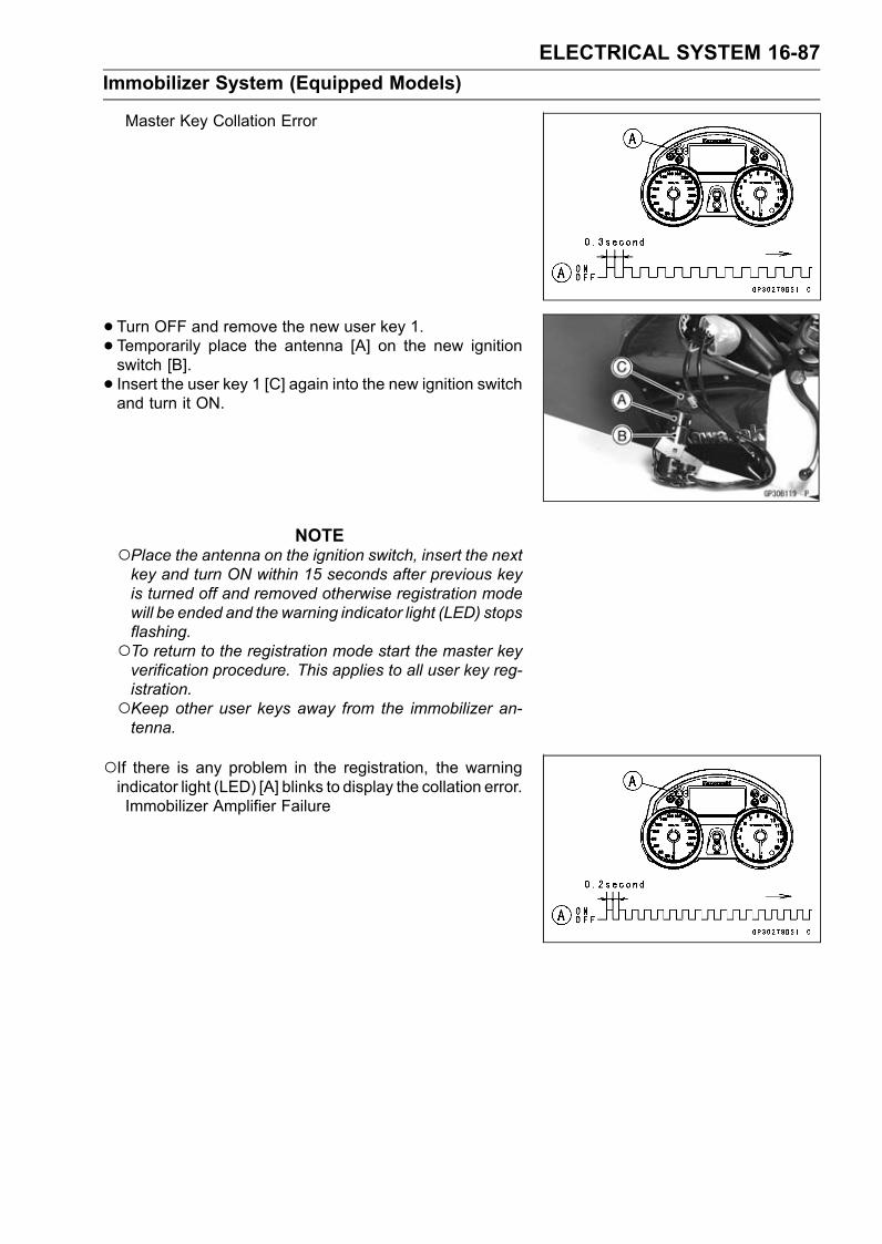
ELECTRICAL SYSTEM 16-87Immobilizer System (Equipped Models)
Master Key Collation Error
• Turn OFF and remove the new user key 1.• Temporarily place the antenna [A] on the new ignitionswitch [B].• Insert the user key 1 [C] again into the new ignition switchand turn it ON.
NOTEPlace the antenna on the ignition switch, insert the nextkey and turn ON within 15 seconds after previous keyis turned off and removed otherwise registration modewill be ended and the warning indicator light (LED) stopsflashing.To return to the registration mode start the master keyverification procedure. This applies to all user key reg-istration.Keep other user keys away from the immobilizer an-tenna.
If there is any problem in the registration, the warningindicator light (LED) [A] blinks to display the collation error.Immobilizer Amplifier Failure

16-88 ELECTRICAL SYSTEMImmobilizer System (Equipped Models)
When Registered User Key is Inserted.
User Key Collation Error
• The user key 1 is successfully registered in the ECU.The warning indicator light (LED) [A] blinks 2 times andstops for 1 second and then repeats this cycle to indicatesuccessful registering of user key 1.
• Turn OFF and remove user key 1.The warning indicator light (LED) [A] blinks to display theregistration mode.
NOTETurn off the ignition switch and wait for the period morethan 15 seconds. The registration mode automaticallyends and warning indicator light (LED) goes off.This procedure has , registered the master key and oneuser key.Continue the procedure to program the second andlater keys.
• Insert the user key 2 to the ignition switch and turn it ON.

ELECTRICAL SYSTEM 16-89Immobilizer System (Equipped Models)
If there is any problem in the registration, the warningindicator light (LED) [A] blinks to display the collation error.Immobilizer Amplifier Failure
When Registered User Key is Inserted.
User Key Collation Error
• The user key 2 is successfully registered in the ECU.The warning indicator light (LED) [A] blinks 3 times andstops for 1 second and then repeat this cycle to indicatesuccessful programming of user key 2.• Turn OFF the ignition switch and wait for period more than15 seconds.• The registration mode automatically ends.
•Warning indicator light (LED) [A] goes off.

16-90 ELECTRICAL SYSTEMImmobilizer System (Equipped Models)
•Remove the key registration unit and connect the immo-bilizer/Kawasaki diagnostic system connector.
NOTETurn the ignition switch ON with the registered user key.Check that the engine can be started using all regis-tered user keys.
• Install the new ignition switch and antenna.Case 3: When the electric control unit (ECU) is faultyand has to be replaced.•Prepare a new ECU [A], current master key [B] and cur-rent user keys [C].
NOTEThe key registration unit is not required.
•Replace:ECU [A] (see Immobilizer System Parts Replacement)
• Insert the current master key into the ignition switch andturn it ON.
If there is any problem in the registration, the warningindicator light (LED) [A] blinks to display the collation error.Immobilizer Amplifier Failure
Master Key Collation Error

ELECTRICAL SYSTEM 16-91Immobilizer System (Equipped Models)
•The master key is registered in the ECU.The warning indicator light (LED) [A] blinks 1 time andstops for 1 second and the repeats this cycle to indicatesuccessful registration of the master key.
• Turn OFF the master key and remove it.The warning indicator light (LED) [A] blinks to display theregistration mode.
NOTEInsert next key and turn ON within 15 seconds after pre-vious key is turned off and removed otherwise registra-tion mode will be ended and the warning indicator light(LED) goes off.To return to the registration mode start the master keyverification procedure. This applies to all user key reg-istration.
• Insert the user key 1 to the ignition switch and turn it ON.NOTE
Keep the other user keys away from the immobilizerantenna.
If there is any problem in the registration, the warningindicator light (LED) [A] blinks to display the collation error.Immobilizer Amplifier Failure
When Registered User Key is Inserted.

16-92 ELECTRICAL SYSTEMImmobilizer System (Equipped Models)
User Key Collation Error
• The user key 1 is registered in the ECU.The warning indicator light (LED) [A] blinks 2 times andstops for 1 second and then repeats this cycle to indicatesuccessful registration of user key.
• Turn OFF and remove the user key 1.The warning indicator light (LED) [A] blinks to display theregistration mode codes.
NOTEInsert next key and turn ON within 15 seconds after pre-vious key is turned off and removed otherwise registra-tion mode will be ended and the warning indicator lightgoes off.To return to the registration mode start the master keyverification procedure. This applies to all user key reg-istration.
• Insert the user key 2 to the ignition switch and turn it ON.If there is any problem in the registration, the warningindicator light (LED) [A] blinks to display the collation errorcode.Immobilizer Amplifier Failure

ELECTRICAL SYSTEM 16-93Immobilizer System (Equipped Models)
When Registered User Key is Inserted.
User Key Collation Error
• The user key 2 is registered in the ECU.The warning indicator light (LED) [A] blinks 3 times andstops for 1 second and then repeats this cycle to indicatesuccessful registration of user key 2.• Turn OFF the ignition switch and wait for period more than15 seconds.• The registration mode automatically ends.
•Warning indicator light (LED) [A] goes off.
NOTETurn the ignition switch ON with the registered user key.Check that the engine can be started using all regis-tered user keys.
Case 4: When master key is faulty or lost.Themaster key replacement is considered very rare case.
However if it is required, the following is necessary.
NOTEThe ECUmust be replaced with a new one because themaster key code that is registered in the current ECUcan not be rewritten.

16-94 ELECTRICAL SYSTEMImmobilizer System (Equipped Models)
•Prepare a new ECU [A], new master key [B] and currentuser keys [C].
NOTEThe key registration unit is not required.The key registration process is same as the electric con-trol unit replacement.
Case 5: When replacing the antenna.•Prepare a new antenna.• Refer to the Immobilizer System Parts Replacement.
NOTENo key registration is required.

ELECTRICAL SYSTEM 16-95Immobilizer System (Equipped Models)
All Keys Initial Registration Flow Chart

16-96 ELECTRICAL SYSTEMImmobilizer System (Equipped Models)
Immobilizer System Parts ReplacementImmobilizer Antenna•Remove the left inner cover (see Inner Cover Removal inthe Frame chapter).• Disconnect the lead connectors [A].
• Remove:Steering Stem Head (see Stem, Stem Bearing Removalin the Steering chapter)• Using a small chisel or punch [A], turn out the Torx bolts.
• Cut the band [A].• Remove the screw [B].• Remove the antenna [C] with the cover [D].Pull the lower parts [E] of the cover outside to clear theprojection [F] of the ignition switch.
• Tighten a new Torx bolt [A] until the bolt head [B] is broken.[C] Broken Head of Other Side•Run the leads correctly (see Cable, Wire, and Hose Rout-ing section in the Appendix chapter).
Immobilizer Amplifier Replacement•Remove the windshield (see Windshield Removal in theFrame chapter).• Disconnect the connector [A].• Remove the amplifier [B] from the bracket [C].

ELECTRICAL SYSTEM 16-97Immobilizer System (Equipped Models)
ECU (Electric Control Unit) Replacement (forImmobilizer Models)•Remove:Seat (see Seat Removal in the Frame chapter)Tool Kit [A]Fuse Box [B]
• Using small chisel or other suitable tool, cut off the screws[A].• Remove:Plate [B]Tool Kit Case [C]
• Remove:Relay Box [A]ECU Connectors [B]ECU [C]
• Install:ECU ConnectorsRelay Box• Insert the slits of the rubber protector to the projections[A] of the rear fender front.
• Install:Connector Holder [A]
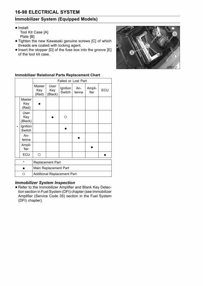
16-98 ELECTRICAL SYSTEMImmobilizer System (Equipped Models)
• Install:Tool Kit Case [A]Plate [B]• Tighten the new Kawasaki genuine screws [C] of whichthreads are coated with locking agent.• Insert the stopper [D] of the fuse box into the groove [E]of the tool kit case.
Immobilizer Relational Parts Replacement ChartFailed or Lost Part
MasterKey(Red)
UserKey(Black)
IgnitionSwitch
An-tenna
Ampli-fier ECU
MasterKey(Red)
•UserKey(Black)
• IgnitionSwitch •An-tenna •Ampli-fier •
*
ECU •* Replacement Part
• Main Replacement Part
Additional Replacement Part
Immobilizer System Inspection•Refer to the Immobilizer Amplifier and Blank Key Detec-tion section in Fuel System (DFI) chapter (see ImmobilizerAmplifier (Service Code 35) section in the Fuel System(DFI) chapter).

ELECTRICAL SYSTEM 16-99Immobilizer System (Equipped Models)
Immobilizer System Circuit
1. Ignition Switch2. Immobilizer Antenna3. Meter Unit4. Immobilizer Amplifier5. Joint Connector 16. Fuse Box 27. ECU Fuse 15 A8. Ignition Fuse 10 A9. Main Relay10. Relay Box11. Joint Connector 212. Main Fuse 30 A13. Starter Relay14. Battery 12 V 14 Ah15. Frame Ground 116. Frame Ground 217. Immobilizer/Kawasaki Diagnostic System Connector18. Water-proof Joint 119. ECU

16-100 ELECTRICAL SYSTEMSwitches and Sensors
Brake Light Timing Inspection•Refer to the Brake Light Switch Operation Inspection inthe Periodic Maintenance chapter.
Brake Light Timing Adjustment•Refer to the Brake Light Switch Operation Inspection inthe Periodic Maintenance chapter.
Switch Inspection•Using a hand tester, check to see that only the con-nections shown in the table have continuity (about zeroohms).For the switch housings and the ignition switch, refer tothe tables in the Wiring Diagram.If the switch has an open or short, repair it or replace itwith a new one.Special Tool - Hand Tester: 57001-1394
Rear Brake Light Switch Connections
Sidestand Switch Connections
Oil Pressure Switch Connections*
*: Engine lubrication system is in good condition.

ELECTRICAL SYSTEM 16-101Switches and Sensors
Water Temperature Sensor Inspection•Remove the water temperature sensor (see Removal/In-stallation in the Fuel System (DFI) chapter).• Suspend the sensor [A] in a container of coolant so thatthe threaded portion is submerged.• Suspend an accurate thermometer [B] with temperaturesensing portions [C] located in almost the same depth.
NOTEThe sensor and thermometer must not touch the con-tainer side or bottom.
•Place the container over a source of heat and gradu-ally raise the temperature of the coolant while stirring thecoolant gently.• Using the hand tester, measure the internal resistance ofthe sensor.The sensor sends electric signals to the ECU and coolanttemperature gauge in the meter unit.Measure the resistance across the terminals and the body(for the gauge) at the temperatures shown in the table.If the hand tester does not show the specified values, re-place the sensor.
Water Temperature SensorResistance for ECU [D]
Temperature Resistance (kΩ)(Terminal [1]-[3])
20°C (68°F) 2.46 +0.115–0.143
80°C (176°F) 0.32 ±0.011110°C (230°F) 0.1426 ±0.0041
Resistance for Water Temperature Gauge [E]
Temperature Resistance (Ω)(Terminal [2]-Body)
50°C (122°F) 210 ±40120°C (248°F) 21.2 ±1.5
Speed Sensor Removal• Loosen the bolt [A].• Disconnect the speed sensor lead connector [B].• Remove:Bolt [C]Speed Sensor [D]
Speed Sensor Installation•Apply a non-permanent locking agent to the sensor bolt.• Install the speed sensor.Torque - Speed Sensor Bolt: 3.9 N·m (0.40 kgf·m, 35 in·lb)

16-102 ELECTRICAL SYSTEMSwitches and Sensors
Speed Sensor Inspection•Remove the speed sensor (see Speed Sensor Removal).• Connect the speed sensor lead connector [A] with the bat-tery [B], 10 kΩ resistor [C] and hand tester [D] as shown.• Set the tester to the DC 25 V range.Special Tool - Hand Tester: 57001-1394
•Trace [A] each side of the speed sensor surface with thescrew driver.Then the tester indicator should flick [B].If the tester indicator does not flick, replace the speedsensor.
Fuel Level Sensor Inspection•Remove the fuel tank (see Fuel Tank Removal in the FuelSystem (DFI) chapter).•Open the clamps [A].• Remove:Bolts [B]Fuel Level Sensor [C]
• Check that the float moves up and down smoothly withoutbinding. It should go down under its own weight.If the float does not move smoothly, replace the sensor.Float in Full Position [A]Float in Empty Position [B]Float Arm Stoppers [C]
• Using the hand tester [A], measure the resistance acrossthe terminals in the fuel level sensor lead connector [B].Special Tools - Hand Tester: 57001-1394
Needle Adapter Set: 57001-1457If the tester readings are not as specified, or do notchange smoothly according as the float moves up anddown, replace the sensor.
Fuel Level Sensor ResistanceStandard: Full position [C]: 9 ∼ 11 Ω
Empty position: 213 ∼ 219 Ω
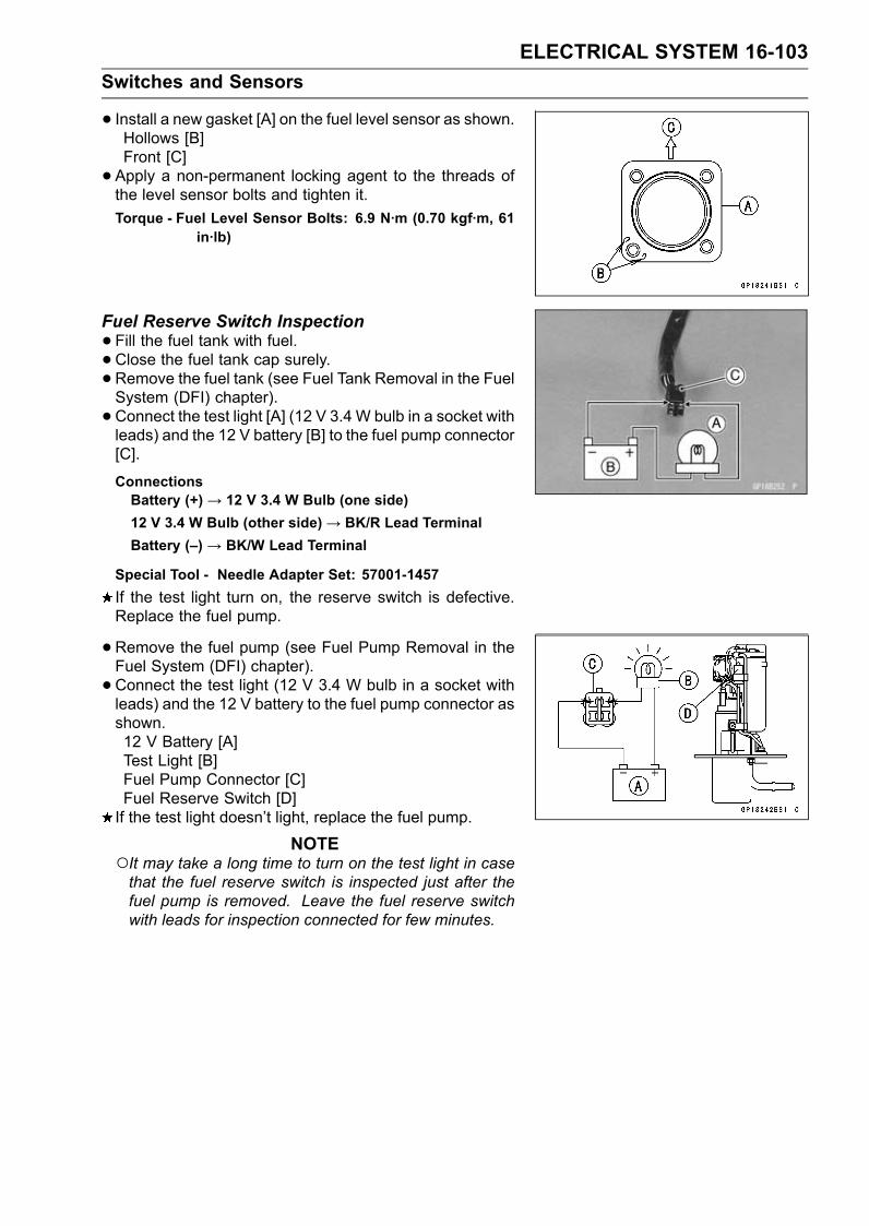
ELECTRICAL SYSTEM 16-103Switches and Sensors
• Install a new gasket [A] on the fuel level sensor as shown.Hollows [B]Front [C]• Apply a non-permanent locking agent to the threads ofthe level sensor bolts and tighten it.Torque - Fuel Level Sensor Bolts: 6.9 N·m (0.70 kgf·m, 61
in·lb)
Fuel Reserve Switch Inspection•Fill the fuel tank with fuel.• Close the fuel tank cap surely.• Remove the fuel tank (see Fuel Tank Removal in the FuelSystem (DFI) chapter).• Connect the test light [A] (12 V 3.4 W bulb in a socket withleads) and the 12 V battery [B] to the fuel pump connector[C].
ConnectionsBattery (+) → 12 V 3.4 W Bulb (one side)12 V 3.4 W Bulb (other side)→ BK/R Lead TerminalBattery (–) → BK/W Lead Terminal
Special Tool - Needle Adapter Set: 57001-1457If the test light turn on, the reserve switch is defective.Replace the fuel pump.
•Remove the fuel pump (see Fuel Pump Removal in theFuel System (DFI) chapter).• Connect the test light (12 V 3.4 W bulb in a socket withleads) and the 12 V battery to the fuel pump connector asshown.12 V Battery [A]Test Light [B]Fuel Pump Connector [C]Fuel Reserve Switch [D]If the test light doesn’t light, replace the fuel pump.
NOTEIt may take a long time to turn on the test light in casethat the fuel reserve switch is inspected just after thefuel pump is removed. Leave the fuel reserve switchwith leads for inspection connected for few minutes.

16-104 ELECTRICAL SYSTEMSwitches and Sensors
Gear Position Switch Removal•Remove the lower fairings (see Lower Fairing Removal inthe Frame chapter).• Slide out the rubber boot [A].• Loosen the oil pressure switch terminal bolt [B], and re-move the switch lead [C].
•Open the clamps [A].
• Remove:Engine Sprocket Cover (see Engine Sprocket Removalin the Final Drive chapter)Bolt [A]Clamp [B]• Disconnect the oil pressure switch/gear position switchlead connector [C].
•Open the clamp [A].• Remove:Screws [B]Gear Position Switch [C]
• Remove the pin [A] and spring from the shift drum.

ELECTRICAL SYSTEM 16-105Switches and Sensors
Gear Position Switch Installation•Securely place the spring [A] and pin [B] into the hole [C]of the shift drum.• Apply grease to the new O-ring [D].• Apply a non-permanent locking agent to the gear positionswitch screws.• Tighten:Torque - Gear Position Switch Screws: 3.0 N·m (0.31 kgf·m,
27 in·lb)Gear Position Switch Lead Clamp Bolt: 9.8 N·m(1.0 kgf·m, 87 in·lb)
•Run the gear position switch and oil pressure switch leadcorrectly (see Cable, Wire, and Hose Routing section inthe Appendix chapter).• Install the removed parts (see appropriate chapters).Gear Position Switch Inspection
NOTEBe sure the transmission mechanism is good condition.•Disconnect the connector [A].
• Set the hand tester [A] to the 1 kΩ or × 100 Ω range andconnect it to the terminals in the oil pressure switch/gearposition switch lead connector [B] and ground.[C] Internal Circuit[1] Light Green Lead[2] Green/Red Lead[3] Black LeadSpecial Tool - Hand Tester: 57001-1394
Gear Position Switch Resistance kΩConnections
GearPosition [1]-Ground [2]-Ground [3]-Ground
Neutral about 0 – –1st – 3.00 ∼ 3.32 11.63 ∼ 12.872nd – 1.70 ∼ 1.89 10.33 ∼ 11.443rd – 1.07 ∼ 1.19 9.70 ∼ 10.744th – 0.695 ∼ 0.769 9.32 ∼ 10.325th – 0.430 ∼ 0.476 9.06 ∼ 10.036th – 0.248 ∼ 0.274 8.89 ∼ 9.81
If the tester reading is not as specified, replace the gearposition switch with a new one.

16-106 ELECTRICAL SYSTEMRelay Box
The relay box [A] has relays and diodes. The relays anddiodes can not be removed.
Relay Box Removal•Remove the seat (see Seat Removal in the Frame chap-ter).• Take out the relay box [A] and disconnect the connectors[B].
Relay Circuit InspectionNOTE
The ECU main relay function is included in the ECU.•Remove the relay box (see Relay Box Removal).• Check conductivity of the following numbered terminalsby connecting the hand tester and one 12 V battery to therelay box as shown (see Relay Box Internal Circuit).If the tester does not read as specified, replace the relaybox.
Relay Circuit Inspection (with the battery disconnected)Tester Connection Tester Reading (Ω)
Headlight CircuitRelay 1-3 ∞
6-7 ∞Main Relay
4-5 Not ∞*7-8 ∞
Fuel Pump Relay9-10 Not ∞*11-16 ∞
Starter Circuit Relay11-12 ∞17-20 ∞
Fan Relay18-19 Not ∞*
*: The actual reading varies with the hand tester used.

ELECTRICAL SYSTEM 16-107Relay Box
Relay Circuit Inspection (with the battery connected)Battery
Connection(+) (–)
TesterConnection
TesterReading (Ω)
2-11 1-3 0Main Relay
4-5 7-6 0Fuel PumpRelay 9-10 7-8 0
Fan Relay 18-19 17-20 0
BatteryConnection(+) (–)
Tester ConnectionDC 25 V Range
TesterReading (V)
Starter CircuitRelay 16-12 11-12 Battery
Voltage
(+): Apply positive lead.(–): Apply negative lead.
Diode Circuit Inspection•Remove the relay box (see Relay Box Removal).• Check conductivity of the following pairs of terminals (seeRelay Box Internal Circuit).
Diode Circuit Inspection
Tester Connection 1-11, 2-11, 12-13, 12-15, 12-16, 13-14,13-15
The resistance should be low in one direction and morethan ten times as much in the other direction. If any diodeshows low or high in both directions, the diode is defectiveand the relay box must be replaced.
NOTEThe actual meter reading varies with the meter or testerused and the individual diodes, but generally speaking,the lower reading should be from zero to one half thescale.

16-108 ELECTRICAL SYSTEMRelay Box
Relay Box Internal Circuit
A. Headlight Circuit RelayB. Main RelayC. Fuel Pump RelayD. Starter Circuit RelayE. Fan Relay

ELECTRICAL SYSTEM 16-109Fuse
30 A Main Fuse Removal•Remove:Fuel Tank (see Fuel Tank Removal in the Fuel System(DFI) chapter)Bolts [A]Cover [B]
• Disconnect the 30 A main fuse connector [A].
• Pull out themain fuse [A] from the starter relay with needlenose pliers.
Fuse Box Fuse Removal•Remove the seat (see Seat Removal in the Frame chap-ter).• Unlock the hook [A] to lift up the lid [B].

16-110 ELECTRICAL SYSTEMFuse
•Pull the fuses [A] straight out of the fuse box with needlenose pliers.
15 A ECU Fuse Removal•Remove the seat (see Seat Removal in the Frame chap-ter).• Unlock the hook [A] to lift up the lid [B].
• Pull out the ECU fuse [A] from the fuse box.
Fuse InstallationIf a fuse fails during operation, inspect the electrical sys-tem to determine the cause, and then replace it with anew fuse of proper amperage.• Install the fuse box fuses on the original position as spec-ified on the lid.

ELECTRICAL SYSTEM 16-111Fuse
Fuse Inspection•Remove the fuse (see 30 A Main/Fuse Box/15 A ECUFuse Removal).• Inspect the fuse element.If it is blown out, replace the fuse. Before replacing ablown fuse, always check the amperage in the affectedcircuit. If the amperage is equal to or greater than thefuse rating, check the wiring and related components fora short circuit.Housing [A]Fuse Element [B]Terminals [C]Blown Element [D]
NOTEA mass current flows to the battery according to thestate of the battery which needs refreshing charge whenthe engine is turned causing main fuse blown out.
CAUTIONWhen replacing a fuse, be sure the new fusematches the specified fuse rating for that circuit.Installation of a fuse with a higher rating may causedamage to wiring and components.


APPENDIX 17-1
17
AppendixTable of Contents
Cable, Wire, and Hose Routing.............................................................................................. 17-2Troubleshooting Guide ........................................................................................................... 17-52

17-2 APPENDIXCable, Wire, and Hose Routing

APPENDIX 17-3Cable, Wire, and Hose Routing
1. Air Cleaner Drain Hose2. Gear Position Switch Lead3. Air Bleeder Hose for Water Pump4. Sidestand Switch Lead5. Clamp6. Clamp the leads and hose as shown in the figure.7. Tube8. Grommet9. Install the air switching valve hose until white paint is half hidden level.10. Approx. 41 mm (0.02 in.)11. Clamp12. First, put the clamp to the adjuster screw position of shown in the figure, next fix to the clutch
hose.13. Clutch Hose14. Idle Adjusting Screw15. Clamp16. Clamp the speed sensor lead.17. Speed Sensor Lead18. Breather Tube19. Clamp20. Align the white paint and the end of the plate.

17-4 APPENDIXCable, Wire, and Hose Routing

APPENDIX 17-5Cable, Wire, and Hose Routing
1. Idle Adjusting Screw2. Through the air cleaner drain hose to the front of the clamp.3. Main Harness4. Through the air cleaner drain hose and idle adjusting screw to the outside of the main harness.5. Clamp6. Position the clamp so that its pinch heads do not touch the frame and air cleaner drain hose.7. Clutch Hose8. Through the air cleaner drain hose to the backside of the clutch hose.

17-6 APPENDIXCable, Wire, and Hose Routing

APPENDIX 17-7Cable, Wire, and Hose Routing
1. Reserver Tank Hosel2. Reserver Tank Overflow Hose3. Reserver Tank4. Radiator5. Right View6. Air Bleeder Hose for Thermostat Housing7. Thermostat Housing8. Hose9. Air Bleeder Hose for Water Pump10. Outlet Hose11. Inlet Hose12. Oil Cooler13. Water Pump14. Hose15. Hose16. Left View17. Align the white paint of the hose and mark of the thermostat housing cover.18. About 45°19. Clamp20. Right View21. Air Bleeder Hose for Water Pump22. Air Bleeder Hose for Thermostat Housing23. Align the white paint of the hose and mark of the water pump.24. Install the hose so that white paint of the hose faces the front side.25. Insert the air bleeder hose so that straight to the center of the impeller shaft.26. Left View

17-8 APPENDIXCable, Wire, and Hose Routing

APPENDIX 17-9Cable, Wire, and Hose Routing
1. Clamp2. Install the clamp so that knob of the clamp faces right side of the frame as shown in the figure.3. Reserver Tank4. Clamp5. Clamp6. Install the hose until projection.7. Inlet Hose8. Install the hose so that white paint of the hose faces the front side.9. Install the hose so that white paint of the hose faces the front side.10. Outlet Hose11. Clamp12. Approx. 20 mm (0.79 in.)

17-10 APPENDIXCable, Wire, and Hose Routing

APPENDIX 17-11Cable, Wire, and Hose Routing
1. Clamp (Install the clamp from the arrow mark side.)2. Through the reserver tank hose on the air bleeder hose for thermostat housing.3. Through the subharness for sensor and valve between the #3 and #4 of the throttle body.4. Alternator Lead (To the regulator/rectifier connector through the alternator subharness.)5. Through the alternator lead backside of the air bleeder hose for water pump.6. Through the reserver tank hose between the air switching valve and bracket.7. Connect the gear position switch lead and sidestand switch lead to the main harness.8. Air Cleaner Drain Hose9. Through the air cleaner drain hose between the engine sprocket cover and clutch hose.10. Through the air cleaner drain hose on the water pump, put in the space of the lower fairing.11. Through the reserver tank overflow hose into the fairing bracket, and through the hose into the
clamp.12. Hose13. Reserver Tank Overflow Hose14. Hose15. Through the reserver tank overflow hose between the hose and hose.16. Through the gear position switch lead backside of the air bleeder hose for water pump.

17-12 APPENDIXCable, Wire, and Hose Routing

APPENDIX 17-13Cable, Wire, and Hose Routing
1. Pad2. Pad3. Fit the groove of the pad to the reserver tank, and fix the pad by the middle fairing.4. Fit the grooves of the pad to the radiator hose and reserver tank drain hose, and fix the pad bythe lower fairing.
5. Pad6. Fit the groove of the pad to the radiator hose, and fix the pad by the middle fairing.

17-14 APPENDIXCable, Wire, and Hose Routing

APPENDIX 17-15Cable, Wire, and Hose Routing
1. Band (Clamp the main harness, and insert the band to the rear fender.)2. Frame Ground Lead (Tighten the bolt with lead and bracket.)3. Through the alternator subharness to the outside of the frame ground lead.4. Alternator Connector (Install the alternator connector to the bracket.)5. Connector (Insert the connector to the bracket.)6. Alternator Subharness (Put the alternator subharness between the rear fender and frame.)7. Alternator Lead8. Through the alternator lead under the main harness.9. Align the gray tape and the end of the battery case.10. Fuel Hose11. Main Harness12. Alternator Lead (Through the alternator lead to the inside of the leads and hose.)13. Sidestand Switch Lead Connector14. Band (Clamp the main harness, and insert the band to the bracket.)15. Throttle Body Subharness Connector (Install the connector to the bracket.)16. Speed Sensor Lead Connector17. Oil Pressure Switch/Gear Position Switch Lead Connector18. Through the sidestand switch lead and oil pressure switch/gear position switch lead to the inside
of the chain cover from the hole of the notch.19. Clamp (Clamp the fan motor lead.)20. Through the engine harness to the outside of the clutch hose.21. Engine Harness Connector (Install the engine harness connector to the bracket.)22. Band (Clamp the main harness, and insert the band to the bracket.)23. Stick Coil Lead Connector (Install the stick coil lead connector to the bracket of the cylinder
head cover.)24. Through the stick coil lead under the throttle cables.25. Band (Clamp the engine harness with the subframe.)26. Clamp (Clamp the fan motor lead connector, and insert the clamp to the subframe.)27. Through the oil pressure switch/gear position switch lead to the inside of the water pump.28. Through the sidestand switch lead to the inside of the water pump.

17-16 APPENDIXCable, Wire, and Hose Routing

APPENDIX 17-17Cable, Wire, and Hose Routing
1. Through the headlight lead into the clamp (both sides).2. After ignition switch lead connector and left switch housing lead connector connecting, put theconnectors in the water-proof cover.
3. Clamp (Clamp the main harness, and insert the clamp to the middle air inlet duct.)4. Clamp (Clamp the left turn signal lead, and insert the clamp to the middle air inlet duct.)5. Left Turn Signal Light Lead Connector6. Headlight Lead7. Through the left switch housing lead and ignition switch lead into the clamp, and insert the clampto the bracket.
8. Through the left switch housing lead to the outside of the front fork, and through the lead intothe clamp.
9. Through the ignition switch lead to the backside of the front fork from the inside of the front fork,and through the lead into the clamp.
10. Clamp11. Left City Light12. Headlight (High)13. Headlight (Low)14. Install the clamp outside as shown in the figure, and clamp the immobilizer amplifier lead.15. Immobilizer Amplifier Lead Connector16. Vehicle-down Sensor Lead Connector17. Meter Unit Lead Connector18. Through the main harness and immobilizer amplifier lead into the clamp.19. Headlight Relay (High)20. Clamp (Clamp the main harness, and insert the clamp to the middle air inlet duct.)

17-18 APPENDIXCable, Wire, and Hose Routing

APPENDIX 17-19Cable, Wire, and Hose Routing
1. Right Turn Signal Light Lead Connector2. Clamp (Clamp the right turn signal lead, and insert the clamp to the middle air inlet duct.)3. *Front Wheel Rotation Sensor Lead Connector4. Clamp (Clamp the main harness, and insert the clamp to the middle air inlet duct.)5. Headlight Relay (Low)6. Clamp (Clamp the main harness, and insert the clamp to the middle air inlet duct.)7. Right Switch Housing Lead and Horn Lead8. Right Switch Housing Lead Connector9. Through the right switch housing lead, horn lead, headlight lead and *front wheel rotation sensorlead into the clamp.
10. Clamp (Clamp the horn lead, and insert the clamp to the cover.)11. Through the horn lead to the outside of the front fork.12. Through the right switch housing lead to the outside of the front fork.13. Through the right switch housing lead and horn lead into the clamp.14. Through the rear wheel rotation sensor lead to the inside of the rear brake reservoir tank.15. *Front Wheel Rotation Sensor Lead Connector (Install the front wheel rotation sensor lead con-
nector to the bracket.)16. Through the main harness lead on the rear brake reservoir tank hose.17. Fuse Box 118. Clamp19. Alternator Subharness20. Fuel Pump Lead Connector21. Fuel Level Sensor Lead Connector22. Clamp23. Clamp (Clamp the rear brake light switch lead and *rear wheel rotation sensor lead.)24. Rear Brake Light Switch Lead Connector25. Through the rear brake light switch lead to the outside of the separator.26. Rear Brake Light Switch Lead Connector27. Clamp (Clamp the rear brake light switch lead.)
* ZX1400B Models only

17-20 APPENDIXCable, Wire, and Hose Routing

APPENDIX 17-21Cable, Wire, and Hose Routing
1. Turn Signal Relay2. License Plate Light Lead Connector3. Atomospheric Pressure Sensor Lead Connector4. Through the license plate light lead to the inside of the atomospheric pressure sensor.5. License Plate Light Lead6. Through the turn signal relay lead between the rear frame and rear frame pipe.7. Rear Left Turn Signal Light Lead Connector8. Tail/Brake Light Lead Connector9. Rear Right Turn Signal Light Lead Connector10. *ABS Kawasaki Self-diagnosis System Connector (Fix the ABS Kawasaki self-diagnosis system
connector with the sponge.)11. Immobilizer/Kawasaki Diagnostic System Connector (Fix the Immobilizer/Kawasaki diagnositic
system connector with the sponge.)12. Fuse Box 213. ECU Lead14. ECU Lead15. Relay Box Leads16. Alternator Subharness17. Alternator Lead18. Clamp (Clamp the alternator lead and alternator subharness.)19. Through the alternator lead and alternator subharness to the outside of the rear frame.20. Through the alternator lead and alternator subharness under the rear brake reservoir tank.21. Fuse Box 122. Through the alternator subharness under the bracket.
* ZX1400B Models only

17-22 APPENDIXCable, Wire, and Hose Routing

APPENDIX 17-23Cable, Wire, and Hose Routing
1. Through the main harness to the hole of the lower side.2. Through the inlet air temperature sensor lead to the hole of the upper side.3. *ABS Hydraulic Unit Lead4. Inlet Air Temperature Sensor Lead5. Battery Negative Lead6. Starter Relay Lead7. Battery Positive Lead Connector (Install the battery positive lead connector to the battery case.)8. Starter Motor Cable9. Battery Negative Lead Connector (Install the battery negative lead connector to the bracket.)10. Battery Positive Cable11. Battery Negative Lead12. Battery Negative Cable13. Direction of Battery Negative Terminal Installation14. Tighten the bolt with battery negative cable and battery negative lead.15. Battery Negative Cable16. Clamp (Clamp the inlet air temperature sensor lead.)17. Inlet Air Temperature Sensor18. *Bracket
* ZX1400B Models only

17-24 APPENDIXCable, Wire, and Hose Routing

APPENDIX 17-25Cable, Wire, and Hose Routing
1. Fuel Tank Drain Hose2. Through the fuel tank drain hose under the bracket.3. Position a yellow tape at the rear end of bracket.4. Through the fuel tank drain hose to the backside of the clamp.5. Through the fuel tank drain hose under the fuel hose.6. Through the fuel tank drain hose under the clamp.7. Fuel Tank Drain Hose8. Through the fuel tank drain hose under the starter motor cable.9. Fuel Tank Drain Hose10. Through the fuel tank drain hose under the lower fairing.11. Through the fuel tank drain hose on the speed sensor lead.12. Through the fuel tank drain hose under the heat insulation rubber plate.13. Through the fuel tank drain hose under the clutch hose.14. Position a yellow tape at the end of lower fairing.15. Through the seat lock cable to the rear frame.

17-26 APPENDIXCable, Wire, and Hose Routing
ZX1400B Models
APPENDIX 17-27Cable, Wire, and Hose Routing
1. Through the fuel tank drain hose on the brake pipe.2. Brake Pipe3. Fuel Tank Drain Hose4. Through the fuel tank drain hose on the brake pipe.5. Brake Pipe6. Fuel Tank Drain Hose

17-28 APPENDIXCable, Wire, and Hose Routing

APPENDIX 17-29Cable, Wire, and Hose Routing
1. Through the throttle cables inside of the brake hose.2. Through the throttle cables to the clamp of the reservoir bracket.3. Through the throttle cables inside of the brake hose.4. Through the throttle cables to the clamp.5. Viewed Bottom

17-30 APPENDIXCable, Wire, and Hose Routing

APPENDIX 17-31Cable, Wire, and Hose Routing
1. Through the clutch hose inside the coolant reserver tank.2. Through the clutch hose outside the sidestand switch, speed sensor, oil pressure switch/gearposition switch leads.
3. Install the cluth hose joint as shown in the figure (face the clutch hose joint pipe inside).4. Through the clutch hose inside the main harness.5. Through the clutch hose outside the sidestand switch, speed sensor and oil pressure switch/gearposition switch lead connectors.
6. Clamp the clutch hose to the clamp of the subframe.7. Through the clutch hose inside the radiator fan lead.8. Through the clutch hose inside the subframe.9. Through the ignition switch lead upper the clutch hose.10. Through the clutch hose in the clamp.

17-32 APPENDIXCable, Wire, and Hose Routing

APPENDIX 17-33Cable, Wire, and Hose Routing
1. Install the clutch hose joint as shown in the figure (face the projection of the clutch hose jointbackward).
2. Through the clutch fluid reservoir hose inside the bracket.

17-34 APPENDIXCable, Wire, and Hose Routing

APPENDIX 17-35Cable, Wire, and Hose Routing
1. Brake Hose2. Bracket3. Clamps (Insert the clamps in the front fender.)4. Brake Hose5. Clamps6. Brake Hose7. Face the white paint mark upward.

17-36 APPENDIXCable, Wire, and Hose Routing
ZX1400B Models

APPENDIX 17-37Cable, Wire, and Hose Routing
1. Clamps2. Brake Hose3. Rear Wheel Rotation Sensor4. Rear Wheel Rotation Sensor Lead5. Rear Wheel Rotation Sensor Lead Connector6. Bracket7. ABS Hydraulic Unit8. Brake Pipes9. Damper10. Front Wheel Rotation Sensor Lead Connector11. Front Wheel Rotation Sensor Lead12. Front Wheel Rotation Sensor13. Brake Hose14. Approx. 38.5°15. Approx. 30°16. Approx. 71°17. Approx. 48°18. Front19. Install the brake hose joint pipes as shown in the figure.

17-38 APPENDIXCable, Wire, and Hose Routing
ZX1400B Models

APPENDIX 17-39Cable, Wire, and Hose Routing
1. Clamps (Insert the clamps in the front fender.)2. Clamp (Clamp the brake hose, and align the clamp with white tape of the front wheel rotationsensor lead.)
3. Brake Hose4. Brake Hose (Front Master Cylinder ∼ Right Front Caliper)5. Clamp (Clamp the front wheel rotation sensor.)6. Front Wheel Rotation Sensor Lead7. Front Wheel Rotation Sensor
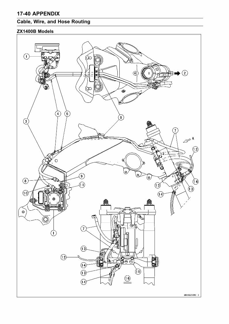
17-40 APPENDIXCable, Wire, and Hose Routing
ZX1400B Models

APPENDIX 17-41Cable, Wire, and Hose Routing
1. ABS Hydraulic Unit2. Front3. Bracket4. Brake Pipe (One Blue Paint Mark)5. Brake Pipe (One White Paint Mark)6. Damper7. Brake Hose8. Brake Hose (One Blue Paint Mark)9. Brake Hose Joint Pipe (One Blue Paint Mark)10. Brake Hose (One White Paint Mark)11. Brake Hose Joint Pipe (One White Paint Mark)12. Front Wheel Rotation Sensor Lead13. Clamps (Clamp the front wheel rotation sensor.)14. Clamps (Clamp the brake hose, and align the clamps with white tapes of the front wheel rotation
sensor lead.)15. Bracket16. Viewed A

17-42 APPENDIXCable, Wire, and Hose Routing
ZX1400B Models

APPENDIX 17-43Cable, Wire, and Hose Routing
1. ABS Hydraulic Unit2. Brake Pipe (Two White Paint Marks)3. Brake Hose4. Clamps (Through only the brake hose in the clamps.)5. Rear Wheel Rotation Sensor Lead6. Clamps (Clamp the brake hose, and align the clamps with white tape of the rear wheel rotationsensor lead.)
7. Clamp (Clamp the brake hose and rear wheel rotation sensor.)8. Clamp (Clamp the brake hose and rear wheel rotation sensor.)9. Brake Pipe (Two Blue Paint Marks)10. Bracket11. Rear Wheel Rotation Sensor12. Viewed Rear Side13. Brake Hose (Two Blue Paint Marks)14. Brake Hose Joint Pipe (Two Blue Paint Marks)15. Brake Hose (Two White Paint Marks)16. Brake Hose Joint Pipe (One White Paint Mark)

17-44 APPENDIXCable, Wire, and Hose Routing
ZX1400B Models

APPENDIX 17-45Cable, Wire, and Hose Routing
1. Brake Hose2. Clamps (Through the brake hose in the clamp on both sides.)3. Clamps (Clamp the brake hose, and align the clamps with white tapes of the front wheel rotationsensor lead.)
4. Brake Hose5. Clamp (Through only the brake hose in the clamp.)6. Clamp7. Front Wheel Rotation Sensor8. Install the brake hose joint as shown in the figure (face the projection of the brake hose jointbackward.)
9. Brake Hose10. Clamp (Clamp the brake hose, and align the clamp with white tape of the front wheel rotation
sensor lead.)11. Clamp12. Front Wheel Rotation Sensor Lead Connector13. Right Middle Air Inlet Duct14. Brake Hose15. Brake Hose16. Clamp17. Braket18. Braket19. Clamp20. Bracket21. Brake Pipe22. Brake Pipe23. Brake Hose24. Brake Hose

17-46 APPENDIXCable, Wire, and Hose Routing
ZX1400B Models

APPENDIX 17-47Cable, Wire, and Hose Routing
1. Bracket (Push the joint portions of the brake pipe, and clamp them.)2. Brake Pipe (One Blue Paint Mark, ABS Hydraulic Unit Side)3. Align the brake pipes with groove of the frame.4. Brake Pipe (One White Paint Mark, ABS Hydraulic Unit Side)5. Brake Hose (Two White Paint Marks) and Brake Hose Joint Pipe (One White Paint)6. Brake Hose (One White Paint Mark) and Brake Hose Joint Pipe (One White Paint)7. Brake Hose (One Blue Paint Mark) and Brake Hose Joint Pipe (One Blue Paint Mark)8. Brake Hose (Two Blue Paint Marks) and Brake Hose Joint Pipe (Two Blue Paint Mraks)9. Insert the brake pipes to the holes of damper, and fit the projection of damper into the hole ofbracket.
10. Brake Pipe (Two Blue Paint Marks)11. Brake Pipe (Two White Paint Marks)

17-48 APPENDIXCable, Wire, and Hose Routing
ZX1400B Models

APPENDIX 17-49Cable, Wire, and Hose Routing
1. Clamp2. Brake Hose3. Bracket (Install the bracket from back of the rear frame.)4. Rear Wheel Rotation Sensor Lead Connector5. Clamp the joint portion of the brake hose into the bracket.6. Clamp7. Clamp8. Clamp9. Clamps (Clamp the brake hose, and align the clamps with white tape of the rear wheel rotationsensor lead.)
10. Rear Wheel Rotation Sensor Lead11. Clamps (Through only the brake hose in the clamps.)

17-50 APPENDIXCable, Wire, and Hose Routing
California Model

APPENDIX 17-51Cable, Wire, and Hose Routing
1. Throttle Body Assy2. To the fitting of the throttle body #3.3. To the fitting of the throttle body #4.4. Clamps5. Clamp6. Insert the bracket to the holes of clamp.7. Hose (White)8. Hose (Green)9. Hose (White)10. Fittings11. Hose (Red)12. Hose (Blue)13. Hose (Blue)14. Hose (Green)15. Separator16. Clamp17. Fuel Tank18. Canister19. Band20. Connected position of the white hoses and fitting.21. Connected position of the green hoses and fitting.22. Face the paint marks upward.23. Face the paint marks to the right side.24. Through the hoses inside the throttle body subharness.25. Viewed Right Side26. Viewed Upside

17-52 APPENDIXTroubleshooting Guide
NOTERefer to the Fuel System chapter for mostof DFI trouble shooting guide.This is not an exhaustive list, giving everypossible cause for each problem listed. Itis meant simply as a rough guide to assistthe troubleshooting for some of the morecommon difficulties.
Engine Doesn’t Start, StartingDifficulty:Starter motor not rotating:Ignition and engine stop switch not ONStarter lockout switch or gear positionswitch trouble
Starter motor troubleBattery voltage lowStarter relay not contacting or operatingStarter button not contactingStarter system wiring open or shortedIgnition switch troubleEngine stop switch troubleMain 30A or ignition fuse blown
Starter motor rotating but engine doesn’tturn over:Vehicle-down sensor (DFI) coming offImmobilizer system troubleStarter clutch troubleStarter idle gear trouble
Engine won’t turn over:Valve seizureValve lifter seizureCylinder, piston seizureCrankshaft seizureConnecting rod small end seizureConnecting rod big end seizureTransmission gear or bearing seizureCamshaft seizureStarter idle gear seizureBalancer bearing seizure
No fuel flow:No fuel in tankFuel pump troubleFuel tank air vent obstructedFuel filter cloggedFuel line clogged
No spark; spark weak:Vehicle-down sensor (DFI) coming offIgnition switch not ONEngine stop switch turned OFFClutch lever not pulled in or gear not in neu-tral
Battery voltage lowImmobilizer system troubleSpark plug dirty, broken, or gap malad-justed
Spark plug incorrect
Stick coil shorted or not in good contactStick coil troubleECU troubleCamshaft position sensor troubleGear position, starter lockout, or side standswitch trouble
Crankshaft sensor troubleIgnition switch or engine stop switchshorted
Starter system wiring shorted or openMain 30A or ignition fuse blown
Fuel/air mixture incorrect:Bypass screw and/or idle adjusting screwmaladjusted
Air passage cloggedAir cleaner clogged, poorly sealed, or miss-ing
Leak from oil filler cap, crankcase breatherhose or air cleaner drain hose.
Compression Low:Spark plug looseCylinder head not sufficiently tighteneddown
Cylinder, piston wornPiston ring bad (worn, weak, broken, orsticking)
Piston ring/groove clearance excessiveCylinder head gasket damagedCylinder head warpedValve spring broken or weakNo valve clearanceValve not seating properly (valve bent,worn, or carbon accumulation on theseating surface)
Poor Running at Low Speed:Spark weak:Battery voltage lowImmobilizer system troubleStick coil troubleStick coil shorted or not in good contactSpark plug dirty, broken, or maladjustedSpark plug incorrectECU troubleCamshaft position sensor troubleCrankshaft sensor trouble
Fuel/air mixture incorrect:Bypass screw maladjustedAir passage cloggedAir bleed pipe bleed holes cloggedPilot passage cloggedAir cleaner clogged, poorly sealed, or miss-ing
Fuel tank air vent obstructedFuel pump troubleThrottle body assy holder looseAir duct holder loose

APPENDIX 17-53Troubleshooting Guide
Compression low:Spark plug looseCylinder head not sufficiently tighteneddown
No valve clearanceCylinder, piston wornPiston ring bad (worn, weak, broken, orsticking)
Piston ring/groove clearance excessiveCylinder head gasket damagedCylinder head warpedValve spring broken or weakValve not seating properly (valve bent,worn, or carbon accumulation on theseating surface)
Camshaft cam wormRun-on (dieseling):Ignition switch troubleEngine stop switch troubleFuel injector troubleLoosen terminal of battery (–) cable or ECUground lead
Carbon accumulating on valve seating sur-face
Engine overheatingOther:ECU troubleThrottle body assy not synchronizingEngine oil viscosity too highDrive train troubleBrake draggingClutch slippingEngine overheatingAir suction valve troubleAir switching valve trouble
Poor Running or No Power at HighSpeed:Firing incorrect:Spark plug dirty, broken, or maladjustedSpark plug incorrectStick coil shorted or not in good contacttrouble
Stick coil troubleECU trouble
Fuel/air mixture incorrect:Air cleaner clogged, poorly sealed, or miss-ing
Air duct holder looseWater or foreign matter in fuelThrottle body assy holder looseFuel to injector insufficientFuel tank air vent obstructedFuel line cloggedFuel pump trouble
Compression low:Spark plug loose
Cylinder head not sufficiently tighteneddown
No valve clearanceCylinder, piston wornPiston ring bad (worn, weak, broken, orsticking)
Piston ring/groove clearance excessiveCylinder head gasket damagedCylinder head warpedValve spring broken or weakValve not seating properly (valve bent,worn, or carbon accumulation on theseating surface.)
Knocking:Carbon built up in combustion chamberFuel poor quality or incorrectSpark plug incorrectECU trouble
Miscellaneous:Throttle valve won’t fully openBrake draggingClutch slippingEngine overheatingEngine oil level too highEngine oil viscosity too highDrive train troubleCamshaft cam wormAir suction valve troubleAir switching valve troubleCatalytic converter melt down due tomuffleroverheating (KLEEN)
Overheating:Firing incorrect:Spark plug dirty, broken, or maladjustedSpark plug incorrectECU trouble
Muffler overheating:For KLEEN, do not run the engine even ifwith only one cylinder misfiring or poorrunning (Request the nearest service fa-cility to correct it)
For KLEEN, do not push-start with a deadbattery (Connect another full-chargedbattery with jumper cables, and start theengine using the electric starter)
For KLEEN, do not start the engine undermisfire due to spark plug fouling or poorconnection of the stick coil
For KLEEN, do not coast the motorcyclewith the ignition switch off (Turn the igni-tion switch ON and run the engine)
ECU troubleFuel/air mixture incorrect:Throttle body assy holder looseAir duct holder looseAir cleaner poorly sealed, or missing

17-54 APPENDIXTroubleshooting Guide
Air cleaner cloggedCompression high:Carbon built up in combustion chamber
Engine load faulty:Clutch slippingEngine oil level too highEngine oil viscosity too highDrive train troubleBrake dragging
Lubrication inadequate:Engine oil level too lowEngine oil poor quality or incorrect
Oil cooler incorrect:Oil cooler clogged
Gauge incorrect:Water temperature gauge brokenWater temperature sensor broken
Coolant incorrect:Coolant level too lowCoolant deterioratedWrong coolant mixed ratio
Cooling system component incorrect:Radiator fin damagedRadiator cloggedThermostat troubleRadiator cap troubleRadiator fan relay troubleFan motor brokenFan blade damagedWater pump not turningWater pump impeller damaged
Over Cooling:Gauge incorrect:Water temperature gauge brokenWater temperature sensor broken
Cooling system component incorrect:Thermostat trouble
Clutch Operation Faulty:Clutch slipping:Friction plate worn or warpedSteel plate worn or warpedClutch spring broken or weakClutch hub or housing unevenly wornClutch master cylinder troubleClutch slave cylinder trouble
Clutch not disengaging properly:Clutch plate warped or too roughClutch spring compression unevenEngine oil deterioratedEngine oil viscosity too highEngine oil level too highClutch housing frozen on drive shaftClutch hub nut looseClutch hub spline damagedClutch friction plate installed wrong
Clutch slave cylinder troubleClutch fluid deterioratedAir in clutch fluid lineClutch master cylinder primary or sec-ondary cup damage
Clutch master cylinder scratched inside
Gear Shifting Faulty:Doesn’t go into gear; shift pedal doesn’treturn:Clutch not disengagingShift fork bent or seizedGear stuck on the shaftGear positioning lever bindingShift return spring weak or brokenShift return spring pin looseShift mechanism arm spring brokenShift mechanism arm brokenShift pawl broken
Jumps out of gear:Shift fork ear worn, bentGear groove wornGear dogs and/or dog holes wornShift drum groove wornGear positioning lever spring weak or bro-ken
Shift fork guide pin wornDrive shaft, output shaft, and/or gearsplines worn
Overshifts:Gear positioning lever spring weak or bro-ken
Shift mechanism arm spring broken
Abnormal Engine Noise:Knocking:ECU troubleCarbon built up in combustion chamberFuel poor quality or incorrectSpark plug incorrectOverheating
Piston slap:Cylinder/piston clearance excessiveCylinder, piston wornConnecting rod bentPiston pin, piston pin hole worn
Valve noise:Valve clearance incorrectValve spring broken or weakCamshaft bearing wornValve lifter worn
Other noise:Connecting rod small end clearance exces-sive
Connecting rod big end clearance exces-sive
Piston ring/groove clearance excessive

APPENDIX 17-55Troubleshooting Guide
Piston ring worn, broken, or stuckPiston ring groove wornPiston seizure, damageCylinder head gasket leakingExhaust pipe leaking at cylinder head con-nection
Crankshaft runout excessiveEngine mount looseCrankshaft bearing wornPrimary gear worn or chippedCamshaft chain tensioner troubleCamshaft chain, sprocket, guide wornAir suction valve damagedAir switching valve damagedAlternator rotor looseCatalytic converter melt down due tomuffleroverheating (KLEEN)
Abnormal Drive Train Noise:Clutch noise:Clutch damper weak or damagedClutch housing/friction plate clearance ex-cessive
Clutch housing gear wornWrong installation of outside friction plate
Transmission noise:Bearings wornTransmission gear worn or chippedMetal chips jammed in gear teethEngine oil insufficient
Drive line noise:Drive chain adjusted improperlyDrive chain wornRear and/or engine sprocket wornChain lubrication insufficientRear wheel misaligned
Abnormal Frame Noise:Front fork noise:Oil insufficient or too thinSpring weak or broken
Rear shock absorber noise:Shock absorber damaged
Disc brake noise:Pad installed incorrectlyPad surface glazedDisc warpedCaliper trouble
Other noise:Bracket, nut, bolt, etc. not properlymounted or tightened
Oil Pressure Warning Light Goes On:Engine oil pump damagedEngine oil screen cloggedEngine oil filter clogged
Engine oil level too lowEngine oil viscosity too lowCamshaft bearing wornCrankshaft bearing wornOil pressure switch damagedWiring faultyRelief valve stuck openO-ring at the oil passage in the crankcasedamaged
Exhaust Smokes Excessively:White smoke:Piston oil ring wornCylinder wornValve oil seal damagedValve guide wornEngine oil level too high
Black smoke:Air cleaner clogged
Brown smoke:Air duct holder looseAir cleaner poorly sealed or missing
Handling and/or StabilityUnsatisfactory:Handlebar hard to turn:Cable routing incorrectHose routing incorrectWiring routing incorrectSteering stem nut too tightSteering stem bearing damagedSteering stem bearing lubrication inade-quate
Steering stem bentTire air pressure too low
Handlebar shakes or excessively vibrates:Tire wornSwingarm pivot bearing wornRim warped, or not balancedWheel bearing wornHandlebar holder bolt looseSteering stem nut looseFront, rear axle runout excessiveEngine mounting bolt loose
Handlebar pulls to one side:Frame bentWheel misalignmentSwingarm bent or twistedSwingarm pivot shaft runout excessiveSteering maladjustedFront fork bentRight and left front fork oil level uneven
Shock absorption unsatisfactory:(Too hard)Front fork oil excessiveFront fork oil viscosity too highRear shock absorber adjustment too hard

17-56 APPENDIXTroubleshooting Guide
Tire air pressure too highFront fork bent(Too soft)Tire air pressure too lowFront fork oil insufficient and/or leakingFront fork oil viscosity too lowRear shock adjustment too softFront fork, rear shock absorber spring weakRear shock absorber oil leaking
Brake Doesn’t Hold:Air in the brake linePad or disc wornBrake fluid leakageDisc warpedContaminated padBrake fluid deterioratedPrimary or secondary cup damaged in mastercylinder
Master cylinder scratched inside
Battery Trouble:Battery discharged:Charge insufficientBattery faulty (too low terminal voltage)Battery cable making poor contactLoad excessive (e.g., bulb of excessivewattage)
Ignition switch troubleAlternator troubleWiring faultyRegulator/rectifier trouble
Battery overcharged:Alternator troubleRegulator/rectifier troubleBattery faulty

ZZR 1400ZZR1400 ABSNinja ZX-14