'16 Ducati XDiavel Motorcycle Owner's Manual PDF.pdf
347
OWNER’S MANUAL
-
Upload
khangminh22 -
Category
Documents
-
view
2 -
download
0
Transcript of '16 Ducati XDiavel Motorcycle Owner's Manual PDF.pdf

OWNER’S MANUAL

Owner’s manualENGLISH
1

This manual forms an integral part of the motorcycle and must be kept with it for its whole service life.If the motorcycle is resold, the manual must always be handed over to the new owner.This manual must be preserved with care. If it is lost or becomes damaged, contact a Ducati Dealer orauthorised Service Centre without delay to obtain a new copy of the manual.
The quality standards and safety of Ducati motorcycles are steadily improved as new design solutions,equipment and accessories are developed. While the information contained in this manual is current at thetime of going to print, Ducati Motor Holding S.p.A. reserves the right to make changes at any time withoutnotice and without any obligations. For this reason, the illustrations in this manual might differ from yourmotorcycle.
Any and all reproduction or spreading of the contents herein in whole or in part is forbidden. All rights reservedto Ducati Motor Holding S.p.A. Any request for written authorisation shall be addressed to this company,specifying the reasons for request.
Enjoy your ride!
2

Table of contents
Introduction 7Safety guidelines 7Warning symbols used in the manual 8Intended use 9Rider's obligations 10Rider's training 11Apparel 12Safety "Best Practices" 13Refuelling 15Carrying the maximum load allowed 16Information about carrying capacity 16Dangerous products - warnings 16Vehicle identification number 19Engine identification number 20
Instrument panel (Dashboard) 21
Instrument panel 21Acronyms and abbreviations used in theManual 26Technological Dictionary 26Function buttons 29Parameter setting/displaying 31Main functions 51Engine rpm indication (RPM) 52Motorcycle speed 56Riding Mode (RIDING MODE) 58DTC 65ABS 71Gear 77Fuel level 78Clock 80Menu functions 81Odometer (TOT) 83Engine Coolant temperature 85Trip meter 1 (TRIP 1) 87Trip meter 2 (TRIP 2) 89Residual range (RANGE) 90Average fuel consumption 91Instantaneous fuel consumption 93Average speed 95Trip time (TRIP TIME) 97Ambient air temperature 99
3

LAP TIME 101Auxiliary functions 103Infotainment 104Cruise Control 113Assisted start (LAUNCH CONTROL - DPL) 116Service indication (SERVICE) 124OIL SERVICE zero warning 126OIL SERVICE or ANNUAL SERVICE or DESMOSERVICE countdown indication 127OIL SERVICE or ANNUAL SERVICE or DESMOSERVICE indication 128Warnings/Alarms (WARNING) 129Error warnings 137Viewing side stand status 139Light mode indication (DRL) 140Setting menu 141Customising the RIDING MODE 145Customizing the Riding Mode: engineadjustment 148Customizing the Riding Mode: setting the DTClevel 151Customizing the Riding Mode: ABSadjustment 154Customising Riding Mode: restore default settings(DEFAULT) 157
Customising the Riding Mode: Reset to defaultsettings (ALL DEFAULT) 159Display mode setting 160Light mode setting (DRL) 163LAP 165PIN CODE 171Changing the PIN CODE 175Display backlighting setting 180Date setting 183Clock setting 189Service information 193Setting the units of measurement 194Bluetooth device setting 203Information (INFO) 193Light control 215Immobilizer system 226Keys 227Replacing the battery in the active key 230Key duplication 234Immobilizer unlock procedure 235
Controls 238Position of motorcycle controls 238"Hands free" system 239Left-hand switch 251
4

Clutch lever 255Right-hand switch 256Throttle twistgrip 258Front brake lever 259Rear brake pedal 260Gear change pedal 261Adjusting the position of the gearchange pedal andrear brake pedal 262
Main components and devices 264Position on the vehicle 264Tank filler plug 265Seat lock 266Side stand 270Bluetooth control unit 272Front fork adjusters 274Rear shock absorber adjusters 276
Riding the motorcycle 278Running-in recommendations 278Pre-ride checks 280Engine start/stop 283Moving off 286Braking 287
Anti-Lock Braking System (ABS) 287Stopping the motorcycle 290Parking 291Refuelling 293Tool kit and accessories 294
Main use and maintenanceoperations 295Changing the air filter 295Checking coolant level and topping up, ifnecessary 296Check clutch and brake fluid level 297Checking brake pads for wear 299Charging the battery 300Charging and maintenance of the battery duringwinter storage 305Drive belt tension check 307Replacing the high and low beam bulbs 308Aligning the headlight 309Adjusting the rear-view mirrors 311Tyres 312Check engine oil level 314Cleaning and replacing the spark plugs 316Cleaning the motorcycle 317Storing the motorcycle 319
5

Important notes 320
Scheduled maintenance chart 321Scheduled maintenance chart: operations to becarried out by the dealer 321Scheduled maintenance chart: operations to becarried out by the customer 325
Technical data 326Weights 326Dimensions 327Fuel, lubricants and other fluids 328Engine 330Timing system 331Performance data 332Spark plugs 332Fuel system 332Brakes 332Transmission 333Frame 334Wheels 334Tyres 334Suspension 334Exhaust system 335
Available colours 335Electric system 336
Routine maintenance record 342Routine maintenance record 342
6

Introduction
Safety guidelinesWe would like to welcome you among Ducatienthusiasts, and congratulate you on your excellentchoice of motorcycle. We think you will ride yourDucati motorcycle for long journeys as well as shortdaily trips. Ducati Motor Holding S.p.A. wishes yousmooth and enjoyable riding.
Your motorcycle is the result of Ducati Motor HoldingS.p.A.'s on-going research and development efforts.It is important that you preserve its quality standardby strictly observing the maintenance plan and usinggenuine spare parts. This manual providesinstructions on minor maintenance operations. Majormaintenance operations are described in theWorkshop Manual available to Ducati AuthorisedService Centres.In your own interest, for your safety and in order toguarantee product reliability, you are strongly advisedto refer to our authorised Dealers and Service Centres
for any operations listed in the scheduledmaintenance chart, see page 321.
Our highly skilled staff have access to specialimplements and appropriate equipment required toperform any servicing job at best, and use Ducatioriginal spare parts only as the best guarantee for fullinterchangeability, smooth running and long life.
All Ducati motorcycles come with a Warranty Card.The warranty does not apply to motorcycles used inracing competitions.Tampering with or altering any components, evenpartially, will make the warranty null and voideffective immediately. Improper or poormaintenance, using other than original spare parts orparts not expressly approved by Ducati may invalidateyour warranty rights and lead to damage or loss ofperformance.
Your safety and that of other road users are veryimportant. Ducati Motor Holding S.p.A. recommendsthat you ride responsibly.Before using your motorcycle for the first time, readthis entire manual carefully and closely follow theguidelines outlined in it. The manual provides fullinformation on proper motorcycle operation and
7
maintenance. In case of any doubts, please contact aDealer or Authorised Service Centre.
Warning symbols used in the manualSeveral kinds of warnings are used as an alert of thepossible hazards for you or other persons such as:
- Safety labels on the motorcycle;- Safety messages preceded by a warning symbol
and either WARNING or IMPORTANT.
WarningFailure to comply with these instructions may
put you at risk, and could lead to severe injury or evendeath of the rider or other persons.
ImportantPossibility of damaging the motorcycle and/or
its components.
NoteAdditional information about the current
operation.
The terms RIGHT and LEFT are referred to themotorcycle viewed from the riding position.
8

Intended use
WarningThis motorcycle was designed for both road use
and for light off-road and dirt road use. Heavy duty off-road use is not advised and can result in the riderlosing control of the vehicle, thereby increasing therisk of accidents.
WarningThis motorcycle may not be used to tow any
trailers or with a side-car attached; this can lead toloss of control and result in an accident.
This motorcycle carries the rider and can carry apassenger.
WarningThe total weight of the motorcycle in running
order including rider, passenger, luggage andadditional accessories should not exceed 440kg/970lb.
9

Rider's obligationsAll riders must hold a valid licence.
WarningRiding without a licence is illegal and is
prosecuted by law. Always make sure you have yourlicence with you when riding. Do not letinexperienced riders or persons without a validlicence use your motorcycle.
Do not ride under the influence of alcohol and/ordrugs.
WarningRiding under the influence of alcohol and/or
drugs is illegal and is prosecuted by law.
Do not take prescription or other drugs before ridingunless you have consulted your doctor about theirside effects.
WarningSome medications and drugs may cause
drowsiness or other effects that slow down reactiontime and the rider's ability to control the motorcycle,possibly leading to an accident.
Some states require vehicle insurance.
WarningCheck your state laws. Obtain insurance
coverage and keep your insurance document securewith the other motorcycle documents.
To protect rider and passenger safety, some statesmandate the use of a certified helmet.
WarningCheck your state laws. Riding without a helmet
may be punishable by law.
WarningRiders without helmets are more likely to suffer
severe bodily injury or die if they are in an accident.
10

WarningCheck that your helmet complies with safety
specifications, permits good vision, is the right sizefor your head, and carries a certification labelindicating that it conforms to the standards in force inyour state. Road traffic laws differ from state to state.Learn about traffic laws in your state before riding andalways obey them.
Rider's trainingAccidents are frequently due to inexperience. Riding,manoeuvres and braking must be performed in adifferent way than on the other vehicles.
WarningUntrained riders or a wrong use of the vehicle
may lead to loss of control, serous injuries or evendeath.
11
ApparelRiding gear is very important for safety. Unlike cars,a motorcycle offers no impact protection in anaccident.
Proper riding gear includes helmet, eye protection,gloves, boots, long sleeve jacket and long trousers.
- The helmet must meet the requirements listedat page 10; if your helmet does not have a visor,use suitable eye wear;
- Use five-finger gloves made from leather orabrasion-resistant material;
- Riding boots or shoes must have non-slip solesand offer ankle protection;
- Jacket, trousers or riding suit must be made fromleather or abrasion-resistant material and havehigh-visibility colours and inserts.
ImportantNever wear loose clothing, items or accessories
that may become tangled in motorcycle parts.
ImportantFor your safety, always wear suitable protective
gear, regardless of season and weather.
ImportantHave your passenger wear proper protective
clothing.
12

Safety "Best Practices"These few simple operations are critical to peoplesafety and to preserving the full performance of yourmotorcycle. Never forget to perform them before,while and after riding.
ImportantClosely follow the indications provided at
chapter "Riding the motorcycle" during the running-inperiod.Failure to follow these instructions releases DucatiMotor Holding S.p.A. from any liability whatsoever forany engine damage or shorter engine life.
WarningBefore riding your motorcycle, become familiar
with the controls you will need to use when riding.
Perform the checks recommended in this manualbefore each ride (see page 280).
WarningFailure to carry out these checks before riding
may lead to motorcycle damage and injury to riderand/or passenger.
WarningStart the engine outdoors or in a well ventilated
area. The engine should never be started or runindoors.Exhaust gases are poisonous and may lead to loss ofconsciousness or even death within a short time.Use proper body position while riding and ensure yourpassenger does the same.
ImportantRider must hold the handlebar with both hands
at ALL TIMES while riding.
ImportantBoth rider and passenger should keep their feet
on the footpegs when the motorcycle is in motion.
ImportantThe passenger should always hold on to the
grab handles under the seat with both hands.
13

ImportantBe very careful when tackling road junctions, or
when riding in areas near exits from private grounds,car parks or on slip roads to access motorways.
ImportantBe sure you are clearly visible and do not ride
within the blind spot of vehicles ahead.
ImportantALWAYS signal your intention to turn or pull to
the next lane in good time using the suitable turnindicators.
ImportantPark your motorcycle where no one is likely to
knock against it, and use the side stand. Never parkon uneven or soft ground, or your motorcycle may fallover.
ImportantVisually inspect the tyres at regular intervals for
detecting cracks and cuts, especially on the sidewalls, bulges or large spots that are indicative ofinternal damage. Replace them if badly damaged.Remove any stones or other foreign bodies caught inthe tread.
WarningEngine, exhaust pipes and silencers stay hot
long after the engine is switched off; pay particularattention not to touch the exhaust system with anybody part and do not park the vehicle next toflammable material (wood, leaves etc.).
14

RefuellingRefuel outdoors with engine off.Do not smoke or use open flames while refuelling.Be careful not to spill fuel on engine or exhaust pipe.Never completely fill the tank when refuelling. Fuelshould never be touching the rim of filler recess.When refuelling, avoid breathing the fuel vapours andprevent fuel from reaching your eyes, skin or clothes.
WarningThe motorcycle is only compatible with fuel
having a maximum content of ethanol of 10% (E10).Using fuel with ethanol content over 10% isforbidden. Using it could result in severe damage ofthe engine and motorcycle components. Using fuelwith ethanol content over 10% will make thewarranty null and void.
WarningIn case of indisposition caused by breathing fuel
vapours for a long time, stay in the open air andcontact your doctor. In case of contact with eyes,thoroughly flush with water; in case of contact withskin, immediately clean with water and soap.
WarningFuel is highly flammable, in case of accidental
spillage of fuel on your clothes it is necessary tochange into clean clothes.
15

Carrying the maximum load allowedYour motorcycle is designed for long-distance riding,carrying the maximum load allowed in full safety.Even weight distribution is critical to preserving thesesafety features and avoiding trouble whenperforming sudden manoeuvres or riding on bumpyroads.
WarningDo not exceed the total permitted weight for the
motorcycle and pay attention to information providedbelow regarding load capacity.
Information about carrying capacity
ImportantArrange your luggage or heavy accessories in
the lowest possible position and close to motorcyclecentre.
ImportantNever fix bulky or heavy objects to the
handlebar or to the front mudguard as this wouldaffect stability and cause danger.
ImportantBe sure to secure the luggage to the supports
provided on the motorcycle as firmly as possible.Improperly secured luggage may affect stability.
ImportantDo not insert any objects you may need to carry
into the gaps of the frame as these may foul movingparts.
WarningMake sure the tyres are inflated to the proper
pressure and that they are in good condition.
Refer to paragraph "Tyres" on page 312.
Dangerous products - warningsUsed engine oil
16
WarningProlonged or repeated contact with used engine
oil may cause skin cancer. If working with engine oilon a daily basis, we recommend washing your handsthoroughly with soap immediately afterwards. Keepaway from children.
Brake dust
Never clean the brake assembly using compressedair or a dry brush.
Brake fluid
WarningSpilling brake fluid onto plastic, rubber or
painted parts of the motorcycle may cause damages.Protect these parts with a clean shop cloth beforeproceeding to service the system. Keep away fromchildren.
WarningThe fluid used in the brake system is corrosive.
In the event of accidental contact with eyes or skin,wash the affected area with abundant running water.
Coolant
Engine coolant contains ethylene glycol, which mayignite under particular conditions, producing invisibleflames. Although the flames from burning ethyleneglycol are not visible, they are still capable of causingsevere burns.
WarningTake care not to spill engine coolant on the
exhaust system or engine parts.
These parts may be hot and ignite the coolant,which will subsequently burn with invisible flames.Coolant (ethylene glycol) is irritant and poisonouswhen ingested. Keep away from children. Neverremove the radiator cap when the engine is hot. Thecoolant is under pressure and will cause severeburns.The cooling fan operates automatically: keep handswell clear and make sure your clothing does not snagon the fan.
Battery
17

WarningThe battery gives off explosive gases; never
cause sparks or allow naked flames and cigarettesnear the battery. When charging the battery, ensurethat the working area is properly ventilated.
18

Vehicle identification number
NoteThese numbers identify the motorcycle model
and should always be indicated when ordering spareparts.
It is recommended to record the frame number ofyour motorcycle in the space below.
Frame number
Fig. 1
19

Engine identification number
NoteThese numbers identify the motorcycle model
and should always be indicated when ordering spareparts.
It is recommended to record the number of yourmotorcycle's engine in the space below.
Engine number
Fig. 2
20

Instrument panel (Dashboard)
Instrument panel1) Display.2) NEUTRAL LIGHT N (GREEN).Comes on when in neutral position.3) CRUISE CONTROL LIGHT (GREEN).Comes on to indicate operation of the Cruise Control.4) HIGH BEAM LIGHT (BLUE).It turns on to indicate that the high beam lights are onand when the flasher is activated.5) FUEL WARNING LIGHT (AMBER YELLOW).Comes on when fuel is low and there are about 4litres of fuel left in the tank.6) TURN INDICATOR LIGHTS (GREEN).Illuminates and flashes when the turn indicator is inoperation.7) ENGINE OIL PRESSURE LIGHT (RED).Comes on when engine oil pressure is too low. Itmust turn on at "KEY-ON", but must turn OFF a fewseconds after the engine has started. It may shortlycome on when the engine is hot, however, it shouldgo out as the engine revs up.
ImportantIf the ENGINE OIL light stays ON, stop the
engine or it may suffer severe damage.
21

8) DTC LIGHT (AMBER YELLOW).This light indicates DTC system enabling/disabling status.
Speed below 5 Km/h (3 mph)
Light OFF Light flashing Light steady on
DTC enabled and functioning DTC enabled but not yet function-ing since initialisation is in progressor functioning with degraded per-formance
DTC disabled and/or not functioningdue to a fault in the BBS control unit
Speed above 5 Km/h (3 mph)
Light OFF Light flashing Light steady on
DTC enabled and functioning DTC enabled but there is a fault inthe system causing degraded per-formance
DTC disabled and/or not functioningdue to a fault in the BBS control unit
9) "ENGINE DIAGNOSIS - MIL" LIGHT (AMBER YELLOW).It turns on in the case of "engine" errors and in some cases will lock the engine.
22

10) ABS LIGHT (AMBER YELLOW).Indicates ABS status.
Speed below 5 Km/h (3 mph)
Light OFF Light flashing Light steady on
- ABS enabled but not yet function-ing since initialisation is in progressor there is a fault of the IMU controlunit
ABS disabled and not functioningdue to a fault in the ABS control unit
Speed above 5 Km/h (3 mph)
Light OFF Light flashing Light steady on
ABS enabled and functioning ABS enabled but a fault is detectedby the IMU control unit
ABS disabled and not functioningdue to a fault in the ABS control unit
11) GENERIC ERROR WARNING LIGHT (AMBER YELLOW).It turns on when there are any "vehicle" errors, i.e. active errors triggered by any control unit other than theengine control unit.
23

12) OVER REV / DTC INTERVENTION /IMMOBILIZER SYSTEM (RED).
DTC
No intervention Light OFF
Spark advance cut Light steady ON
Injection cut Light steady ON
Over rev
No intervention Light OFF
First threshold (NRPM before the limit-er kicks in)
Light steady ON
Limiter Light ON flashing
NoteEach calibration of the Engine Control Unit may
have a different setting for the thresholds thatprecede the rev limiter and the rev limiter itself.
Immobilizer
Key-ON status Light OFF
Key-OFF status Light ON flashing
Key-off status for over1 hour
Light OFF
13) DRL LIGHT (GREEN)Only for the X Diavel S model (except for China, Japanand Canada versions).Indicates DRL light status.
DRL
Function not active Light OFF
Function active Light steady ON
Function active butwith an error
Light ON flashing
24

SET A
000Km/h
SPORT
LAP
1
2
3 4 5 67
8
9
10
DPL LEVEL 3
TOT 302721 Km
RPM x1000
N
CORE
2
6
12
111
7
3
41013895
6
12
Fig. 3
25

Acronyms and abbreviations used in theManualABSAntilock Braking SystemBBSBlack Box SystemCANController Area NetworkECUEngine Control UnitDPLDUCATI Power LaunchDRLDaytime Running LightDSBDashboardDTCDUCATI Traction ControlIMUInertial Measurement UnitLINLocal Interconnect Network
Technological DictionaryRiding Mode
The rider can choose from 3 different preset bikeconfigurations (Riding Modes) and pick the one thatbest suits his/her riding style or ground conditions.The Riding Modes allow the user to instantly changethe engine power delivery (Power Mode) and the ABSand DTC settings.Available Riding Modes: Sport, Touring and Urban.Within every Riding Mode, the rider can customiseany settings.
Power Mode
The Power Modes are the different engine maps therider can select to change power level and delivery tosuit his/her own riding style and surface conditions.There are three Power Modes, one for each RidingMode:
- LOW, with 'soft' power delivery;- MED, with 'soft' power delivery;- HIGH, with 'instant' power delivery.
Ride by Wire (RbW)
The Ride by Wire system is the electronic device thatcontrols throttle opening and closing. Since there isno mechanical connection between the throttletwistgrip and the throttle bodies, the ECU can adjust
26

power delivery by directly affecting throttle openingangle.The Ride by Wire system allows you to obtaindifferent power level and delivery according to theselected Riding Mode (Power Mode), but even toaccurately control the engine brake (EBC), therebyhelping to control the rear wheel slipping (DTC).
Ducati Traction Control (DTC)
The Ducati Traction Control system (DTC) supervisesthe rear wheel slipping control and settings varythrough eight different levels that are calibrated tooffer a different tolerance level to rear wheel slipping.Each Riding Mode features a pre-set interventionlevel. Level 8 indicates system interventionwhenever a slight slipping is detected, while level 1is for off-road use and very expert riders because it isless sensitive to slipping and intervention is hencesofter.
Anti-lock Braking System (ABS)
The ABS system fitted to the X Diavel is a safetysystem preventing wheel lockup while riding with themotorcycle not leaning over. The X Diavel ABS alsofeatures a "cornering" function that widens ABSfunctionality to the conditions where the motorcycle
is leaning over, thus preventing wheel lockup andslipping as much as possible, within the physicallimits allowed by the vehicle and by the roadconditions.The X Diavel ABS implements rear wheel lift-upcontrol in order to ensure not only smaller stoppingdistance under braking, but also the best possiblestability.These functions are divided into 3 different levels,each associated with a Riding Mode. ABS can bedisabled.
Inertial Measurement Unit (IMU)
The X Diavel is fitted with a Bosch inertial platform,equipped with inertial measurement unit (IMU). TheIMU constantly monitors motorcycle incidence andlean angle, matching them with ABS signals, therebyoptimising the efficiency of all these systems,regardless of motorcycle position.
Ducati Cruise Control
X Diavel features a system for maintaining the cruisespeed, the Ducati Cruise Control. System can beenabled with engaged gear equal to or higher than thesecond gear and vehicle speed ranging between 50Km/h (30 mph) and 200 Km/h (125 mph).
27

Desmodromic Variable Timing (DVT)
The DVT system allows optimised timing settingaccording to engine load and speed, as well as tocontinuously advance or delay exhaust and intakevalve timing through the rotation of the camshafts,thereby ensuring utmost efficiency throughout therpm range and high performance at high speed, withan optimised torque curve at low rpm.
Ducati Power Launch (DPL)
The Ducati Power Launch (DPL) helps the rider in thedelicate sport starting phase from a standstill tocontrol the power delivered by the vehicle.The DPL system works with three intervention levels,each calibrated to offer a different start assist degree.
28

Function buttons1) UP CONTROL SWITCH " "Button used to display and set instrument panelparameters with the position " ".2) DOWN CONTROL SWITCH " "Button used to display and set instrument panelparameters with the position " ".3) ON/OFF AND LIGHT BUTTON (LOW BEAMS /HIGH BEAMS) (Fig. 5)The high-beam flash button may also be used for LAPfunctions.4) CONFIRM MENU / SETTING MENU ENTRYBUTTONButton used to confirm and to navigate the MENU.5) CRUISE CONTROL BUTTON - ON/OFFButton used to switch the Cruise Control function on/off.
5
41
2 7
6
Fig. 4
29

6) CRUISE CONTROL BUTTON - RES (Resume) / +(more) (Fig. 4)Button used to increase set cruise speed for theCruise Control.7) CRUISE CONTROL BUTTON - SET (Setup) / - (less)(Fig. 4)Button used to set/decrease set cruise speed for theCruise Control.8) HAZARD BUTTONButton used to switch on/off all four turn indicators(Hazard function).9) DRL BUTTON (X Diavel S)Button used to enable/disable the DRL lights (only forX Diavel S, excluded China, Japan and Canadaversions).
3
8 9
Fig. 5
30

Parameter setting/displayingUpon key-on, the instrument panel displays theDUCATI logo and switches on the LED warning lightsin two steps ("initial check routine").At the end of the check, the instrument panel showsthe main screen in the CORE mode which is thedefault one for all riding styles.It is possible to change the display mode with theINFO MODE function in the Setting Menu.
During this first check stage, if the motorcycle speedexceeds 10 km/h (6 mph) (actual speed), theinstrument panel will stop:
- the display check routine and display thestandard screen containing updated information;
- the warning light check routine and leave ON onlythe warning lights that are actually active at themoment.
CORE
SET A
000Km/h
SPORT
LAP
1
2
3 4 5 67
8
9
10
DPL LEVEL 3
TOT 302721 Km
RPM x1000
N
Fig. 6
31

The main screen can have four different layouts:CORE, TRACK, FULL and CITY.
Data displayed on the main screen for CORE layoutare as follows:
1) Rev counter (RPM).2) Motorcycle speed.3) Gear indication.4) Set Riding Mode.5) Fuel level.6) Menu 1: Odometer, Engine coolant
temperature, Trip meter 1, Trip meter 2, Range,Average consumption, Instant fuelconsumption, Average speed, Trip time,Ambient air Temperature.
7) Bluetooth indication.8) DRL light status (Auto / Manual).9) DPL level indication (assisted start): active only
during an assisted launch.10) Cruise Control indication.11) LAP.
32

SET A
000Km/h
SPORT
LAP
1
2
3 4 5 67
8
9
10
DPL LEVEL 3
TOT 302721 Km
RPM x1000
N
CORE
4
6
9 3 5
2
11
8
10
7
1
Fig. 7
33
Data displayed on the main screen for TRACK layoutare as follows:
1) Rev counter (RPM).2) Motorcycle speed.3) Gear indication.4) Set Riding Mode.5) DTC level.6) ABS level.7) Menu 1: Odometer, LAP Time (only if active),
Engine coolant temperature, Trip meter 1, Tripmeter 2, Range, Average consumption, Instantfuel consumption, Average speed, Trip time,Ambient air Temperature.
8) Cruise Control indication.9) Bluetooth indication.10) DRL light status (Auto / Manual).11) DPL level indication (assisted start): active only
during an assisted launch.12) LAP.
34

000 NKm/h
TOTA
SET
DPL LEVEL 3
302721 Km
SPORT ABS 3
LAP
DTC 1
109876
5
4
3
2
1
TRACK
12
8
11
10 7 2 4 5
6
3
1
9
Fig. 8
35

Data displayed on the main screen for FULL layoutare as follows:
1) Rev counter (RPM).2) Motorcycle speed.3) Gear indication.4) Set Riding Mode.5) Fuel level.6) Clock.7) Menu 1: Odometer, Engine coolant
temperature, Player On / Off (active only if theBluetooth module is available and at least oneSmartphone is connected), Range, Trip meter1, Trip meter 2.
8) Menu 2: Average consumption, Instant fuelconsumption, Average speed, Trip time,Ambient air temperature).
9) Cruise Control indication.10) Bluetooth indication.11) Infotainment: Smartphone connected, Helmet
01 connected, Helmet 02 connected, Navigatorconnected.
12) DRL light status (Auto / Manual).13) DPL level indication (assisted start): active only
during an assisted launch.14) Infotainment: received message/s, missed call.
15) LAP.
36

FULL
000 NKm/h
P.M.
TOT
ASET
DPL 3 - ON
302721 Km
TOURING LAP
CONS. AVG 5.3 00:00L/100
10987654321
13
9
11
7
12 2 14 10 5
6
3
15
1411
Fig. 9
37

Data displayed on the main screen for CITY layout areas follows:
1) Motorcycle speed.2) Gear indication.3) Set Riding Mode.4) Fuel level.5) Clock.6) Menu 1: Odometer, Engine coolant
temperature, Player On / Off (active only if theBluetooth module is available and at least oneSmartphone is connected), Trip meter 1, Tripmeter 2, Range, Average consumption, Instantfuel consumption, Average speed, Trip time,Ambient air temperature.
7) Bluetooth indication8) Infotainment: Smartphone connected, Helmet
01 connected, Helmet 02 connected, Navigatorconnected, received message/s, missed call,Player + volume, incoming call, track name.
9) DRL light status (Auto / Manual).10) Cruise Control indication.11) LAP.
38

000 NKm/h
P.M.
TOT
A SET
302721 Km
TOURING
00:00
CITY
9
10
8
6 4
5
1
2
7
3 8
8
8
Fig. 10
39

From the main screen, with CORE layout, pressbutton (1) on LH switch to view Menu 1 information.
- Odometer;- Engine coolant temperature;- TRIP 1;- TRIP 2;- RANGE;- Average Fuel Consumption (CONS AVG);- Instant fuel consumption (CONS);- Average speed (SPEED AVG);- Trip time (TRIP TIME);- Air temperature (T-AIR).
40

SET A
000Km/h
SPORT
LAP
1
2
3 4 5 67
8
9
10
DPL LEVEL 3
TOT Km
RPM x1000
N302721
CORE
1
4
TRIP 1 RANGETOT TRIP 2
TRIP TIME
CONS. AVG
CONS.SPEED AVGT AIR
Fig. 11
41

From the main screen, with TRACK layout, pressbutton (1) on LH switch to view Menu 1 information.
- Odometer;- LAP time (only if active);- Engine coolant temperature;- TRIP 1;- TRIP 2;- RANGE;- Average Fuel Consumption (CONS AVG);- Instant fuel consumption (CONS);- Average speed (SPEED AVG);- Trip time (TRIP TIME);- Air temperature (T-AIR).
42

000 NKm/h
TOTA
SET
DPL LEVEL 3
302721 Km
SPORT ABS 3
LAP
DTC 1
109876
5
4
3
2
1
TRACK
1
4
TRIP 1 RANGETOT LAP TRIP 2
TRIP TIME CONS. AVGCONS.SPEED AVGT AIR
Fig. 12
43

From the main screen, with FULL layout, pressbutton (1) on LH switch to view Menu 1 information.
- Odometer;- Engine coolant temperature;- PLAYER ON/OFF (active only with connected
Smartphone);- RANGE;- TRIP 1;- TRIP 2.
Press button (2) on LH switch to view Menu 2information.
- Average fuel consumption (CONS. AVG);- Instant fuel consumption (CONS.);- Average speed (SPEED AVG);- TRIP TIME;- Air temperature (T-AIR).
44

000 NKm/h
P.M.
TOT
ASET
DPL 3 - ON
302721 Km
TOURING LAP
CONS. AVG 5.3 00:00L/100
10987654321
FULL
1
2
4
TRIP 1RANGETOT PLAYER TRIP 21
2 TRIP TIMECONS. AVG CONS. SPEED AVG T AIR
Fig. 13
45

From the main screen, with CITY layout, press button(1) on LH switch to view Menu 1 information.
- Odometer;- Engine coolant temperature;- Player On / Off (active only if the Bluetooth
module is available and at least one Smartphoneis connected)
- TRIP 1;- TRIP 2;- RANGE;- Average Fuel Consumption (CONS AVG);- Instant fuel consumption (CONS);- Average speed (SPEED AVG);- Trip time (TRIP TIME);- Air temperature (T-AIR).
46

000 NKm/h
P.M.
TOT
A SET
302721 Km
TOURING
00:00
CITY
1
4
TRIP 1 RANGETOT TRIP 2 PLAYER
TRIP TIME CONS. AVGCONS.SPEED AVGT AIR
Fig. 14
47

For the FULL display mode, the instrument panelstores Menu 1 and Menu 2 settings in use upon KEY-OFF. On the following KEY-ON, previously storedMenu 1 e Menu 2 pages are displayed.In case of sudden and unexpected power OFF, theinstrument panel displays the default settings forMenu 1 and Menu 2 upon the following KEY-ON; inparticular:
- Menu 1 default page = TOT (Odometer);- Menu 2 default page = RANGE.
For the CORE, TRACK and CITY display modes, theinstrument panel stores Menu 1 settings in use uponKEY-OFF. On the following KEY-ON, previouslystored Menu 1 page is displayed.In case of sudden and unexpected power OFF, theinstrument panel displays the default settings forMenu 1 upon the following KEY-ON; in particular:
- Menu 1 default page = TOT (Odometer).
48

When the standard screen of set layout is displayed,hold button (4) for 2 seconds to enter the Settingmenu, where you can set any function.
NoteYou can enter the SETTING MENU only if
vehicle actual speed is <= (lower than or equal to) 5km/h (3.1 mph). Within the SETTING MENU, if vehicleactual speed exceeds 5 km/h (3.1 mph), theinstrument panel automatically quits the menu andshows the Standard Screen.
RIDING MODE
SETTING MENU
INFO MODE
LAP
PIN CODE
DRL CONTROL
BACKLIGHT
INFO
EXIT
DATE SET
CLOCK SET
INFO SERTVICE
UNIT SETTING
BLUETOOTH
4
Fig. 15
49

If the key is not acknowledged upon Key-On and oncethe check routine is over, if the PIN CODE function isactive the instrument panel shows a screen where itis possible to enter the release PIN CODE. Usebutton (1) and button (2) to enter the code digit andconfirm by pressing button (4).
42
1
INSER PIN 0000
Fig. 16
50

Main functionsInformation displayed in the standard screen of theselected display layout (CORE, TRACK, FULL or CITY)are the following:Main information
- Engine rpm indication (RPM)- Motorcycle speed- Fuel level- Riding Mode- ABS- DTC- Gear- Clock
- the menus display the following functions:- Odometer (TOT)- Engine coolant temperature- Residual range (RANGE)- Trip meter 1 (TRIP1)- Trip meter 2 (TRIP2)- Trip time (TRIP TIME)- Instantaneous fuel consumption (CONS)- Average Fuel Consumption (CONS. AVG)- Average speed (SPEED AVG)- Ambient air temperature- LAP time- LAP time (only if active)- Player On / Off (active only if the Bluetoothmodule is available and at least one Smartphoneis connected)
Additional information
- DRL status- DPL level- Infotainment — Bluetooth- Cruise Control- Service indication (SERVICE)- Warnings/Alarms
51

Engine rpm indication (RPM)The instrument panel receives the engine rpminformation and displays it on the relevant bargraph(in TRACK, FULL and CORE display modes only). Theinformation is displayed by the bargraph filling fromthe left to the right according to the engine rpm andwith the enlargement of the numerical digit of therelevant miles (e.g., if the RPM value is "8000" orhigher, number "8" is displayed bigger).The range between 9000 and 10000 rpm (pre-warning area) is displayed in orange both for thebargraph filling and for the indication of value "9"(orange area).The range between 10000 and 10500 rpm (warningarea) is displayed in red both for the bargraph fillingand for the indication of value "10" (red area).
52

CORE layout indicates rpm in a different waycompared to TRACK and FULL layouts.CITY layout does not provide for rpm indication.
CORE
299Km/h
SPORT
LAP
1
2
3 4 5 67
8
9
10
TOT 302721 Km
RPM x1000
6
299Km/h
SPORT
LAP
1
2
3 4 5 67
8
9
10
TOT 302721 Km
RPM x1000
6
299Km/h
SPORT
LAP
1
2
3 4 5 67
8
9
10
TOT 302721 Km
RPM x1000
6
Fig. 17
53

299 6Km/h
P.M.
TOT 302721 Km
TOURING LAP
CONS. AVG 5.3 00:00L/100
10987654321
299 6Km/h
P.M.
TOT 302721 Km
TOURING LAP
CONS. AVG 5.3 00:00L/100
10987654321
299 6Km/h
P.M.
TOT 302721 Km
TOURING LAP
CONS. AVG 5.3 00:00L/100
10987654321
299 6Km/h
TOT 302721 Km
SPORT ABS 3
LAP
DTC 1
109876
5
4
3
2
1
299 6Km/h
TOT 302721 Km
SPORT ABS 3
LAP
DTC 1
109876
5
4
3
2
1
299 6Km/h
TOT 302721 Km
SPORT ABS 3
LAP
DTC 1
109876
5
4
3
2
1
TRACK
FULL
Fig. 18
54

When the threshold before the rpm limiter is reached,the corresponding warning lights will turn on.
Fig. 19
55

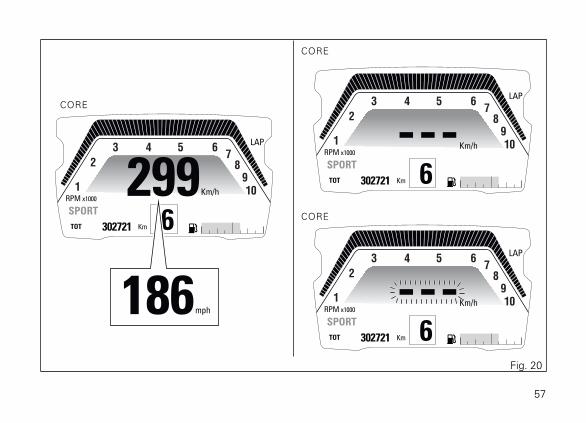
Motorcycle speedThe instrument panel receives information about theactual motorcycle speed (calculated in km/h) anddisplays the value increased by 5% and converted inthe set unit of measurement (km/h or mph).
A string of dashes "- - -" is displayed with the set unitof measurement if:
- speed is equal to 299 km/h or 186 mph or ifinstrument panel is not receiving the speed value("- - -" steady ON);
- the rear speed sensor is in fault (flashing "- - -").
Considering that the TRACK, FULL and CITY layoutsshow the values for this function in a similar way tothe CORE layout, the example shown depicts thefunction in CORE layout.
NoteIf the instrument panel does not receive any
information on the unit of measurement, the last unitof measurement set is displayed flashing.
56
CORE
CORE
CORE
299Km/h
SPORT
LAP
1
2
3 4 5 67
8
9
10
TOT 302721 Km
RPM x1000
6
---Km/h
SPORT
LAP
1
2
3 4 5 67
8
9
10
TOT 302721 Km
RPM x1000
6
---Km/h
SPORT
LAP
1
2
3 4 5 67
8
9
10
TOT 302721 Km
RPM x1000
6186mph
Fig. 20
57

Riding Mode (RIDING MODE)The Riding Mode can be selected from theinstrument panel. Three preset riding modes areavailable: SPORT, TOURING and URBAN.The selected and active riding mode is displayed onthe instrument panel in all four layouts.Every Riding Mode contains the followingparameters, set by Ducati or customised by the userthrough the setting function pages:
- a specific level of intervention for the DTCtraction control (1, 2, 3, 4, 5, 6, 7, 8, OFF);
- a specific ABS calibration (1, 2, 3, OFF);- a specific engine power that will change throttle
behaviour (HIGH, MED, LOW).
For each riding mode there are four informationdisplay layouts (TRACK, FULL, CORE and CITY) thatcan be set by the user in the setting function pages:the layout set by default by Ducati is CORE.
WarningDucati recommends changing the Riding mode
when the motorcycle is stopped. If the riding modeis changed while riding, be very careful (it isrecommended to change the Riding mode at a lowspeed).
58

CITY
CORE TRACK
FULL
299Km/h
SPORT
LAP
1
2
3 4 5 67
8
9
10
DPL LEVEL 3
TOT 302721 Km
RPM x1000
6
299 6Km/h
TOT 302721 Km
TOURING ABS B
LAP
DTC 1
109876
5
4
3
2
1
299 6Km/h
P.M.
TOT 302721 Km
TOURING LAP
CONS. AVG 5.3 00:00L/100
10987654321
299 6Km/h
P.M.
TOT 302721 Km
URBAN
00:00
URBAN
TOURING
SPORT
Fig. 21
59

Selecting the Riding Mode
Press CONFIRM MENU button (4) to view the menufor selecting the Riding Mode (A). The instrumentpanel displays the speed indication (on the RH side)and displays riding mode name (on the LH side):
- SPORT- TOURING- URBAN
One of them will be marked to indicate the lastmemorised condition that is currently active.
For the marked Riding Mode, instrument panelalways displays information concerning some of theassociated parameters:
- engine power (ENGINE): ENGINE letteringfollowed by set engine power (HIGH, MED,LOW);
- ABS system: ABS lettering followed by the setcalibration level (1, 2, 3) in case ABS is active orfollowed by OFF in case ABS is disabled.
- DTC system: DTC lettering followed by the setlevel (1, 2, 3, 4, 5, 6, 7, 8) in case DTC is active orfollowed by OFF in case DTC is disabled.
Any time CONFIRM MENU button (4) is pressed, theselected riding mode is highlighted together with theassociated parameters (A, Fig. 22).
Once the desired riding mode (A, Fig. 22) ishighlighted, confirm the selection by holding downthe CONFIRM MENU button (4) for 2 seconds: thenew riding mode selection is stored and the standardscreen (C, Fig. 22) is displayed for the selected ridingmode.Once the desired riding mode is highlighted, if theCONFIRM MENU button (4) is not pressed within 5seconds, the new riding mode selection is not storedand the standard screen is displayed.
60

CORE
0Km/h
SPORT
LAP
1
2
3 4 5 67
8
9
10
TOT 302721 Km
RPM x1000
N
0Km/h
TOURING
LAP
1
2
3 4 5 67
8
9
10
TOT 302721 Km
RPM x1000
N
SPORT ENGINE HIGH
TOURING DTC 2 Km/h
URBAN ABS 2
0SPORT ENGINE MED
TOURING DTC 4 Km/h
URBAN ABS 3
0
SPORT ENGINE MED
TOURING DTC 6 Km/h
URBAN ABS 3
0
4
A
A
AC
A
Fig. 22
61

Displayed information includes the values stored foreach single Riding Mode. The stored settings may bethe factory ones (Ducati default settings) or the onescustomised by the owner.
In the screen that allows changing the Riding Mode,the instrument panel, besides displaying informationconcerning each riding mode (ENGINE, DTC andABS) shows other information regarding functionsthat are active but could not be shown in the setdisplay mode: for example in the TRACK displaymode the fuel level is not shown as it is in the Ridingmode change screen.Available information:
- fuel level (L);- DRL light status (D): indication displayed if the
DRL lights are active; available only in the XDiavel S model, excluded the China, Japan andCanada versions;
- Cruise Control (E) status: indication shown onlyif the Cruise Control function is active;
- Service (F) indication: shown only if one Servicefunction is active (OIL SERVICE, ANNUALSERVICE or DESMO SERVICE);
- Infotainment indication (Call/Track) (G): shownonly if the Bluetooth function is available;
- Infotainment indication (paired devices) (H):shown only if the Bluetooth function is available;
62

TRACK
FULL
SPORT ENGINE HIGH
TOURING DTC 2 Km/h
URBAN ABS 2
0
SPORT ENGINE MED
TOURING DTC 4 Km/h
URBAN ABS 3
0
4
A
C
A
D E F G
H
L
0 2Km/h
TOT
SET
302721 Km
SPORT ABS 3
DTC 1
109876
5
4
3
2
1
SET
SET
A
A
0 NKm/h
P.M.
ASET
TOURING LAP
CONS. AVG 5.3 00:00L/100
10987654321
Fig. 23
63

When system requests rider to confirm the ridingmode change, the procedure will output an error if:
- the vehicle is stopped, the instrument panel onlychecks whether the throttle control is closed /open by indicating CLOSE THROTTLE if so;
- the vehicle is moving, the instrument panelchecks whether the throttle control is open /closed or whether the brakes are pulled or not;the instrument panel may display CLOSETHROTTLE AND RELEASE BRAKES or CLOSETHROTTLE or RELEASE BRAKES.
CLOSE
THROTTLE
AND
RELEASE
BRAKES
Fig. 24
64

DTCThe instrument panel displays DTC status as follows:
- if DTC is active, DTC lettering and the TractionControl intervention level number (1 to 8);
- if DTC is active, but system is in degradedoperation due to a fault, DTC lettering and theDTC intervention level number, 1 to 8 (flashing);also the DTC warning light starts flashing;
- if DTC is not active, DTC OFF warning;- if system is in fault, DTC lettering and the
intervention level number (1 to 8) in orange.
The DTC function status is shown only in the TRACKdisplay mode.
If DTC is in fault or the Black Box is in fault, theinstrument panel will display DTC Err and DTCwarning light will be steady on.
WarningIn case of system malfunction, contact a Ducati
Dealer or Authorised Service Centre.
65

299 6Km/h
TOT 302721 Km
SPORT ABS 3
LAP
DTC 1
109876
5
4
3
2
1
299 6Km/h
TOT 302721 Km
SPORT ABS 3
LAP
DTC 1
109876
5
4
3
2
1
TRACK
DTC 1
DTC 2
DTC 3
DTC 4
DTC 5
DTC 6
DTC 7
DTC 8
DTC OFF
DTC Err299 6Km/h
TOT 302721 Km
SPORT ABS 3
LAP
DTC Err
109876
5
4
3
2
1
Fig. 25
66

WarningDTC is a rider aid that can be used on the track,
on the road and off road. The system is designed tomake riding easier and to enhance safety, but in noway relieves the rider of the obligation to driveresponsibly and to maintain a high standard of ridingin order to avoid accidents, whether caused by hisown errors or those of other road users, throughmaking emergency manoeuvres, in accordance withthe prescriptions of the road traffic code.
The rider must always be aware that active safetysystems have a preventive function. The activeelements help the rider control the motorcycle,making it as easy and safe to ride as possible. Thepresence of an active safety system should notencourage the rider to ride at speeds beyond thereasonable limits, not in accordance with the roadconditions, the laws of physics, good riding standardsand the requirements of the road traffic code.
67
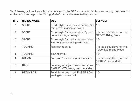
The following table indicates the most suitable level of DTC intervention for the various riding modes as wellas the default settings in the "Riding Modes" that can be selected by the rider.
DTC RIDING MODE USE DEFAULT
1 SPORT Sports style for very expert riders. Sys-tem permits sliding sideways.
NO
2 SPORT Sports style for expert riders. Systempermits sliding sideways.
It is the default level for the"SPORT" Riding Mode
3 SPORT Sports style for medium-expert riders.System permits sliding sideways.
NO
4 TOURING Fast touring style. It is the default level for the"TOURING" Riding Mode
5 TOURING Touring style. NO
6 URBAN "Very safe" style on any kind of path. It is the default level for the"URBAN" Riding Mode
7 RAIN For riding on slightly wet or moist road.ENGINE LOW setting recommended.
NO
8 HEAVY RAIN For riding on wet road. ENGINE LOWsetting recommended.
NO
68

Tips on how to select the sensitivity level
WarningAll levels of the DTC system of your vehicle
have been calibrated with original equipment tyres(Pirelli TL Diablo Rosso II 120/70 - 17 front and PirelliTL Diablo Rosso II 240/45 - 17 rear). The use of tyresof different size and characteristics to the originaltyres may alter the operating characteristics of thesystem.
In the case of minor differences, such as for example,tyres of a different make and/or model than the OEones, but with the same size (front = 120/70 - 17, rear= 240/45 - 17), it may be sufficient to simply selectthe suitable level setting from those available in orderto restore optimal system operation. If tyres of adifferent size class are used or if the tyre size differssignificantly from the original tyres, it may be that thesystem operation is affected to the point where noneof the 8 available level settings will give satisfactoryresults. In this case it is advisable to deactivate thetraction control system.
If level 8 is selected, the DTC system will kick in atthe slightest hint that the rear wheel is starting to
spin. Between level 8 and level 1 there areintermediate levels. DTC intervention decreasesfrom level 8 to level 1. Levels 1, 2 and 3 allow bothspinning and skidding of the rear wheel out of acorner: these levels are recommended only for expertriders.
The choice of the correct level mainly depends on thefollowing parameters:
1) The tyre/asphalt grip (type of tyre, amount of tyrewear, the road/track surface, weather conditions,etc.);
2) The characteristics of the path/circuit (bends alltaken at similar speeds or at very differentspeeds);
3) The riding mode (whether the rider has a"smooth" or a "rough" style).
Level depends on grip conditions
The choice of level setting depends greatly on thegrip conditions of the track/path (see below, tips foruse on the road).
Level depends on type of track/path
69

If the track/path features bends all taken at similarspeeds, it will be easier to find a level suitable for allbends; while a track/path with bends all requiringdifferent speeds will require a DTC level setting thatis the best compromise for all bends.
Level depends on riding style
The DTC will tend to kick in more with a "smooth"riding style, where the motorcycle is leaned overfurther, rather than with a "rough" style, where themotorcycle is straightened up as quickly as possiblewhen exiting a turn.
Tips for use on dry road
Activate the DTC, select level 6 and ride themotorcycle in your usual style; if the level of DTCsensitivity seems excessive, try levels 5, 4, etc., untilyou find the one that suits you best.If changes occur in the grip conditions and/or circuitcharacteristics and/or your riding style, and the levelsetting is no longer suitable, switch to the next levelup or down and proceed to determine the bestsetting (e.g. if with level 5 the DTC interventionseems excessive, switch to level 4; alternatively, if onlevel 5 you cannot perceive any DTC intervention,switch to level 6).
Tips for use on wet road
Level 7 is recommended when road is slightly wet ordamp and level 8 on wet road. It is also recommendedto select ENGINE LOW in these conditions.
70

ABSThe motorcycle is equipped with ABS, the instrumentpanel indicates ABS status (on or off) by switchingoff, on or flashing the ABS warning light.The instrument panel displays:
- if the ABS is active, the message ABS with theset intervention level number (1 to 3) (steadily);
- if ABS is active, but system is in degradedoperation due to a fault (no "cornering" feature"),ABS lettering and the ABS intervention levelnumber, 1 to 8 (flashing); also the ABS warninglight starts flashing;
- if system is in fault, ABS lettering and theintervention level in orange.
The ABS function status is shown only in the TRACKdisplay mode.
If the ABS is in fault, the instrument panel will displayABS Err and ABS warning light will be steady on.
WarningIn case of system malfunction, contact a Ducati
Dealer or Authorised Service Centre.
If ABS is disabled, the instrument panel will displayABS OFF indication and ABS light will be steady on.
71

299 6Km/h
TOT 302721 Km
SPORT ABS 1
LAP
DTC 3
109876
5
4
3
2
1 299 6Km/h
TOTA
SET
DPL LEVEL 3
302721 Km
SPORT ABS 1
LAP
DTC 3
109876
5
4
3
2
1
TRACK
ABS 1
ABS 2
ABS 3
ABS OFF
ABS Err
299 6Km/h
TOTA
SET
DPL LEVEL 3
302721 Km
SPORT ABS OFF
LAP
DTC 3
109876
5
4
3
2
1
299 6Km/h
TOT 302721 Km
SPORT ABS Err
LAP
DTC 1
109876
5
4
3
2
1
Fig. 26
72

Using the brakes correctly under adverse conditionsis the hardest – and yet the most critical - skill tomaster for a rider. Braking is one of the most difficultand dangerous moments when riding a two wheeledmotorcycle: the possibility of falling or having anaccident during this difficult moment is statisticallyhigher than any other moment. A locked front wheelleads to loss of traction and stability, resulting in lossof control.The Anti-Lock Braking System (ABS) has beendeveloped to enable riders to use the motorcyclebraking force to the fullest possible amount inemergency braking or under poor pavement oradverse weather conditions. ABS is an electro-hydraulic device that controls the pressure in thebrake circuit when the control unit, by processinginformation from wheel sensors, determines that oneor both wheels are about to lock up. In this case,pressure decrease in the brake circuit allows thewheel to carry on turning, thereby preserving grip.After that, the control unit restores the pressure inthe brake circuit, to resume the braking action. Thiscycle is repeated many times until the problem iscompletely eliminated. Normally, the rider willperceive ABS operation as a harder feel or a pulsation
of the brake lever and pedal. The front and rear brakesuse separate control systems.The X Diavel ABS also features a "cornering" functionthat widens ABS functionality to the conditionswhere the motorcycle is leaning over, thus controllingthe front and rear brake systems depending on thevehicle lean angle with the purpose of preventingwheel lockup and slipping as much as possible, withinthe physical limits allowed by the vehicle and by theroad conditions.If desired, the system can be deactivated from theinstrument panel, setting the level to OFF within theRiding Mode for which you wish to disable it.
WarningUsing the two brake controls separately
reduces the motorcycle braking power.
Never use the front brake control harshly or suddenlyas you may cause rear wheel lift-up and lose controlof the motorcycle (if the ABS is enabled).When riding in the rain or on slippery surfaces,braking will become less effective. Always use thebrakes very gently and carefully when riding underthese conditions. Any sudden manoeuvres may leadto loss of control.
73

When tackling long, high-gradient downhill roadtracts, shift down gears to use engine braking. Applyone brake at a time and use brakes sparingly. Keepingthe brakes applied all the time would cause thefriction material to overheat as well as a possiblegeneration of vapour lock (brake fluid boiling) with aconsiderable reduction of the braking power.Underinflated and overinflated tyres reduce brakingefficiency, handling accuracy and stability in a bend.
74

The following table indicates the most suitable level of ABS intervention for the various riding types as wellas the default settings in the "Riding Mode" that can be selected by the rider:
ABS RIDING MODE FEATURE DEFAULT
OFF The ABS is disabled NO
1 EXPERT This level is thought for extremely expertusers. ABS in this level only controls thefront wheel, and thus allows rear wheellockup.The system in this level does NOT controllift-up and the cornering feature is NOT ac-tive.
2 SPORT This level is designed for use with good gripconditions. ABS in this level controls bothwheels and the cornering function is active.In this level the system does NOT controlthe lift-up: this setting focuses on brakingpower.
It is the default level for the"SPORT" Riding Mode
3 SAFE & STABLE This level is designed for use in any ridingconditions to provide a safe and consistentbraking action. ABS in this level controlsboth wheels and the cornering and anti-lift-up functions are active.
It is the default level for the"TOURING" and "URBAN"riding modes.
75

Tips on how to select the sensitivity level
WarningExcellent operation of the ABS system, for all
available levels, is ensured only with the OE brakesystem and with OE tyres and/or with the onesrecommended by Ducati. In particular, OE tyres forthis motorcycle are TL PIRELLI Diablo Rosso II D inthe following sizes: front 120/70 ZR17 M/C (58W),rear 240/45 ZR17 M/C (82W). The use of tyres ofdifferent size and characteristics to the original tyresmay alter the operating characteristics of the systemthus making it unsafe. It is recommended not toinstall tyres of different size than the ones approvedfor your vehicle.
Selecting level 3, the ABS will ensure a very stablebraking thanks to lift-up control, and the motorcyclewill keep a good alignment during the whole brakingaction. ABS level 3 features active cornering functionwhich, with vehicle leaning over, prevents wheellockup and slipping as much as possible, within thephysical limits allowed by the vehicle and by the roadconditions.
Selecting level 2, the ABS will privilege more andmore the braking power and lift-up control, which isdisabled in level 2. ABS level 2 features activecornering function which, with vehicle leaning over,prevents wheel lockup and slipping as much aspossible, within the physical limits allowed by thevehicle and by the road conditions.ABS level 1 is conceived for very expert riders andABS is active only on the front wheel to helpperformance. In this level there is no lift-up controlnor cornering feature.The choice of the correct level mainly depends on thefollowing parameters:
1) The tyre/road grip (type of tyre, amount of tyrewear, the road/track surface, weather conditions,etc.).
2) The rider's experience and sensitivity: expertriders can tackle a lift-up in trying to reduce thestopping distance to a minimum, while lessexpert riders are recommended to use setting 3,that will help them keeping the motorcycle morestable even in emergency braking.
76

GearThe instrument panel receives information about thegear engaged and displays the corresponding value.If a gear is engaged, the displayed value may rangefrom 1 to 6, while if in neutral N is displayed.A string of flashing dashes "--" is displayed if gearteach-in procedure has not been carried out yet, or ifinstrument panel is not receiving gear information.If the gear sensor is in fault, a string of dashes "--" isdisplayed steady on.
Considering that the TRACK, FULL and CITY layoutsshow the values for this function in a similar way tothe CORE layout, the example shown depicts thefunction in CORE layout.
CORE
CORE
1N 2 3 4 5 6 -
10Km/h
SPORT
LAP
1
2
3 4 5 67
8
9
10
TOT 302721 Km
RPM x1000
-
10Km/h
SPORT
LAP
1
2
3 4 5 67
8
9
10
TOT 302721 Km
RPM x1000
2
Fig. 27
77

Fuel levelThis function displays the fuel level.The low fuel light turns on when the level goes downto 2 steady marks that become orange and the fuelpump symbol is steady and orange: this means thatthere are approximately 4 litres in the tank.If the level goes further down, the last mark will bered and flashing and the fuel pump symbol will besteady and red.
Considering that the FULL and CITY layouts show thevalues for this function in a similar way to the CORElayout, the example shown depicts the function inCORE layout. In the TRACK mode, this function is notshown.
10Km/h
SPORT
LAP
1
2
3 4 5 67
8
9
10
TOT 302721 Km
RPM x1000
2
CORE
Fig. 28
78

NoteIn case of fault or error of the fuel level sensor,
no level marks will be displayed, the fuel pumpsymbol will be red and flashing, and the Fuel Rangewarning light will be on.
79

ClockThe instrument panel receives information about thetime to be displayed.The instrument panel shows the time in the followingformat:
- hh (hours) : mm (minutes);- followed by a.m. (from 12:00 to 11:59) or p.m.
(from 12:00 to 11:59).
In case of a power off (Battery Off), upon thefollowing Key-On, the instrument panel displays 4dashes " - - : - - " steadily and with flashing colon, untilclock is set through the Setting Menu.
Considering that the CITY layout shows the values forthis function in a similar way to the FULL layout, theexample shown depicts the function in FULL layout.This function is not displayed in the CORE and TRACKmodes.
FULL
12:00A.M.
11:59A.M.
12:00P.M.
11:59P.M.
- - : - -P.M.
10 2Km/h
P.M.
TOT 302721 Km
TOURING
CONS. AVG 5.3 00:00L/100
10987654321
Fig. 29
80

Menu functionsFor each of the three riding modes (SPORT,TOURING, URBAN) menu functions can be displayedin one of the following four modes:
- CORE;- TRACK;- FULL;- CITY.
Available functions are:
- Odometer (TOT);- Engine Coolant temperature- Residual range (RANGE);- Trip meter 1 (TRIP1);- Trip meter 2 (TRIP2);- Trip time (TRIP TIME);- Instant fuel consumption (CONS);- Average Fuel Consumption (CONS AVG);- Average speed (SPEED AVG);- Ambient air temperature;- LAP time (if active);- LAP time (only if active)- Player On / Off (active only if the Bluetooth
module is available and at least one Smartphoneis connected).
81

299 6Km/h
TOT 302721 Km
SPORT ABS 3
DTC 1
109876
5
4
3
2
1
TRACKCORE
FULL CITY
299Km/h
SPORT
1
2
3 4 5 67
8
9
10
TOT 302721 Km
RPM x1000
6
299 6Km/h
P.M.
TOT 302721 Km
TOURING
CONS. AVG 5.3 00:00L/100
10987654321
299 6Km/h
P.M.
TOT 302721 Km
TOURING
00:00
Fig. 30
82
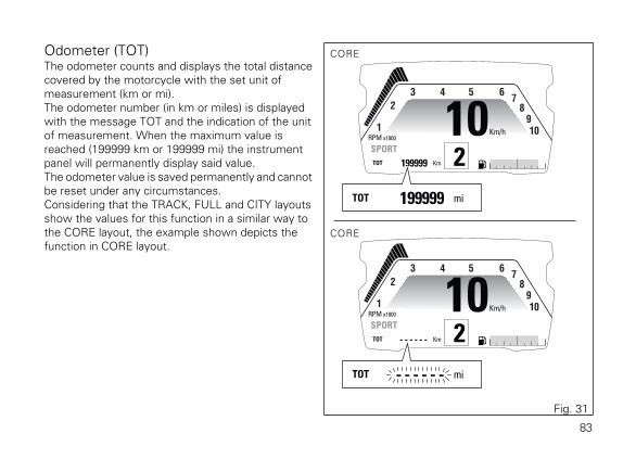
Odometer (TOT)The odometer counts and displays the total distancecovered by the motorcycle with the set unit ofmeasurement (km or mi).The odometer number (in km or miles) is displayedwith the message TOT and the indication of the unitof measurement. When the maximum value isreached (199999 km or 199999 mi) the instrumentpanel will permanently display said value.The odometer value is saved permanently and cannotbe reset under any circumstances.Considering that the TRACK, FULL and CITY layoutsshow the values for this function in a similar way tothe CORE layout, the example shown depicts thefunction in CORE layout.
10Km/h
SPORT
1
2
3 4 5 67
8
9
10
TOT 199999 Km
TOT 199999 mi
RPM x1000
2
10Km/h
SPORT
1
2
3 4 5 67
8
9
10
TOT - - - - - - Km
TOT - - - - - - mi
RPM x1000
2
CORE
CORE
Fig. 31
83

The reading is not lost in case of a power OFF (BatteryOFF).
NoteIf a string of flashing dashes " ----- " is displayed
within odometer function, please contact a DucatiDealer or Authorised Service Centre.
84

Engine Coolant temperatureThe instrument panel receives information about theengine temperature (already calculated in °C) anddisplays the value in the set unit of measurement (°Cor °F), followed by the unit of measurement and theengine temperature symbol.The temperature display range goes from 40 °C to+120 °C (+104 °F ÷ +248 °F).If reading is:
- <= (lower than or equal to) -40 °C (-40 °F), a stringof flashing dashes " - - - " is displayed;
- within the range -39 °C (-38 °F) to +39 °C (+102°F), "LOW" is displayed steadily;
- within the range +40 °C (+104 °F) to +120 °C(+248 °F), the value is displayed steadily;
- >= (higher than or equal to) +121 °C (+250 °F),"HIGH" is displayed flashing and in red, theCoolant Temperature symbol is steady and red.
CORE
10Km/h
SPORT
LAP
1
2
3 4 5 67
8
9
10
60 °C
RPM x1000
- - - °C
- - - °C
- - - °C
LOW °C
HIGH °C
60 °C
2
Fig. 32
85

If the coolant temperature sensor is in fault, a stringof flashing dashes "- - -" is displayed with the set unitof measurement and the MIL light turns on.If the instrument panel is not receiving coolanttemperature value, a string of steady dashes "- - -" isdisplayed, followed by the unit of measurement.
NoteIf the instrument panel does not receive any
information on the unit of measurement, the last unitof measurement set is displayed flashing.
86

Trip meter 1 (TRIP 1)The trip meter counts and displays the partial distancecovered by the motorcycle with the set unit ofmeasurement (km or mi) and is used as a basis tocalculate average fuel consumption, average speedand trip time. The TRIP1 number (in km or miles) isdisplayed with the message TRIP1 and the indicationof the unit of measurement.When the reading exceeds the maximum value of9999.9 km or 9999.9 mi, distance travelled is resetand the meter automatically starts counting from 0again.While the trip meter is displayed, press button (1) for2 seconds to reset TRIP 1. When TRIP1 is reset, theaverage fuel consumption, average speed and triptime data are reset as well.Considering that the TRACK, FULL and CITY layoutsshow the values for this function in a similar way tothe CORE layout, the example shown depicts thefunction in CORE layout.
10Km/h
SPORT
1
2
3 4 5 67
8
9
10
TRIP 1 299 Km
RPM x1000
TRIP 1 9999.9 Km TRIP 1 299 Km TRIP 1 0 Km
2
CORE
1
1
Fig. 33
87

The TRIP1 counter is automatically reset in case thesystem unit of measurement is changed manually orafter a Battery-OFF: the counter will then start backfrom zero, considering the new units ofmeasurement.
88

Trip meter 2 (TRIP 2)The trip meter counts and displays the partial distancecovered by the motorcycle with the set unit ofmeasurement (km or mi).The TRIP2 number (in km or miles) is displayed withthe message TRIP2 and the indication of the unit ofmeasurement.When the reading exceeds the maximum value of9999.9 km or 9999.9 mi, distance travelled is resetand the meter automatically starts counting from 0again.While the trip meter is displayed, press button (1) for2 seconds to reset TRIP 2.The TRIP2 counter is automatically reset in case thesystem unit of measurement is changed manually orafter a Battery-OFF: the counter will then start backfrom zero, considering the new units ofmeasurement.
Considering that the TRACK, FULL and CITY layoutsshow the values for this function in a similar way tothe CORE layout, the example shown depicts thefunction in CORE layout.
10Km/h
SPORT
1
2
3 4 5 67
8
9
10
TRIP 2 299 Km
RPM x1000
TRIP 2 9999.9 Km TRIP 2 299 Km TRIP 2 0 Km
2
CORE
1
1
Fig. 34
89

Residual range (RANGE)This function displays the range according to theremaining fuel in the tank.Information is indicated as RANGE, in the set unit ofmeasurement.If there is any function fault, the instrument panel willdisplay three flashing dashes "- - -".If the instrument panel is not receiving RANGEinformation, a string of three steady dashes "- - -" isdisplayed, followed by the unit of measurement.
NoteIf the instrument panel does not receive any
information on the unit of measurement, the last unitof measurement set is displayed flashing.
Considering that the TRACK, FULL and CITY layoutsshow the values for this function in a similar way tothe CORE layout, the example shown depicts thefunction in CORE layout.
10Km/h
SPORT
1
2
3 4 5 67
8
9
10
RANGE 299 Km
RPM x1000
RANGE 299 Km
RANGE 999.9 Km
RANGE - - - Km
RANGE - - - Km
2
CORE
Fig. 35
90

Average fuel consumptionThe instrument panel calculates and displays themotorcycle average fuel consumption, the set unit ofmeasurement and CONS. AVG.The calculation is made considering the quantity offuel used and the distance travelled since TRIP1 waslast reset.
NoteIt is possible to change the units of
measurement for "Consumption" (both average andinstantaneous together) from L/100 to km/L or mpgUK or mpg US through the SETTING MENU, usingthe UNITS SETTING function.
When TRIP1 is reset, the value is reset and the firstvalue available is displayed 10 seconds after thereset.During the first 10 seconds, when the value is not yetavailable, the display will show a string of threedashes "- - . - " steadily as average fuel consumption.Value is expressed in the set unit of measurement(litres / 100 km or mpg UK or mpg US).The active calculation phase occurs when the engineis running and the motorcycle is stopped: (moments
when the motorcycle is not moving and the engine isOFF are not considered).
91

CORE
10Km/h
SPORT
1
2
3 4 5 67
8
9
10
CONS.AVG 5.3 L/100
RPM x1000
2
CITY
TRACK FULL
10 2Km/h
P.M.
CONS.AVG 5.3 L/100
TOURING
00:00
10 2Km/h
CONS.AVG 5.3 L/100
SPORT ABS 3
DTC 1
109876
5
4
3
2
1
10 2Km/h
P.M.
TOT 302721 Km
TOURING
CONS.AVG 5.3 00:00L/100
10987654321
L/100
Km/l
MPG UK
MPG US
Fig. 36
92

Instantaneous fuel consumptionThe instrument panel calculates and displays themotorcycle instantaneous fuel consumption, the setunit of measurement and CONS. text.The calculation is made considering the quantity offuel used and the distance travelled during the lastsecond. Value is expressed in the set unit ofmeasurement: litres / 100 km or mpg UK or mpg US.The active calculation phase only occurs when theengine is running and the motorcycle is moving(moments when the motorcycle is not moving whenspeed is equal to 0 and/or when the engine is OFFare not considered). When the calculation is notmade, a string of three dashes is displayed " - - . - "steadily as instantaneous fuel consumption.
NoteIt is possible to change the units of
measurement for "Consumption" (both average andinstantaneous together) from L/100 to km/L or mpgUK or mpg US through the SETTING MENU, usingthe UNITS SETTING function.
93

CORE
10Km/h
SPORT
1
2
3 4 5 67
8
9
10
CONS. 5.3 L/100
RPM x1000
2
CITY
TRACK FULL
10 2Km/h
P.M.
CONS. 5.3 L/100
TOURING
00:00
10 2Km/h
CONS. 5.3 L/100
SPORT ABS 3
DTC 1
109876
5
4
3
2
1
10 2Km/h
P.M.
TOT 302721 Km
TOURING
CONS. 5.3 00:00L/100
10987654321
L/100
Km/l
MPG UK
MPG US
Fig. 37
94
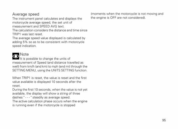
Average speedThe instrument panel calculates and displays themotorcycle average speed, the set unit ofmeasurement and SPEED AVG text.The calculation considers the distance and time sinceTRIP1 was last reset.The average speed value displayed is calculated byadding 5% so as to be consistent with motorcyclespeed indication.
NoteIt is possible to change the units of
measurement of Speed (and distance travelled aswell) from km/h (and km) to mph (and mi) through theSETTING MENU, using the UNITS SETTING function.
When TRIP1 is reset, the value is reset and the firstvalue available is displayed 10 seconds after thereset.During the first 10 seconds, when the value is not yetavailable, the display will show a string of threedashes " - - - " steadily as average speed.The active calculation phase occurs when the engineis running even if the motorcycle is stopped
(moments when the motorcycle is not moving andthe engine is OFF are not considered).
95

CORE
10Km/h
SPORT
1
2
3 4 5 67
8
9
10
SPEEDAVG 78 Km/h
RPM x1000
2
CITY
TRACK FULL
10 2Km/h
P.M.
SPEEDAVG 78 Km/h
TOURING
00:00
10 2Km/h
SPEEDAVG 78 Km/h
SPORT ABS 3DTC 1
109876
5
432
1
10 2Km/h
P.M.
TOT 302721 Km
TOURING
SPEEDAVG 78 00:00Km/h
10987654321
Km/h
mph
Fig. 38
96

Trip time (TRIP TIME)The instrument panel calculates and displays the triptime as hhh:mm followed by TRIP TIME. Thecalculation considers the time since TRIP1 was lastreset. When TRIP1 is reset, this value is reset as well.The time count active phase occurs when the engineis running and the motorcycle is stopped (the time isautomatically stopped when the motorcycle is notmoving and the engine is OFF and restarts when thecounting active phase starts again).When the reading exceeds 511:00 (511 hours and 00minutes), the meter is reset and automatically startscounting from 0 again.
If you change the unit of measurement for an itemconnected to Speed (and distance) or Consumptionor after a Battery-OFF, the trip time value will beautomatically reset.
NoteIf you change the unit of measurement for an
item connected to Speed (and distance) orConsumption or after a Battery-OFF, the trip timevalue will be automatically reset.
97

CORE
10Km/h
SPORT
1
2
3 4 5 67
8
9
10
TRIP
TIME 0:00
RPM x1000
2
CITY
TRACK FULL
10 2Km/h
P.M.
TRIP
TIME 0:00
TOURING
00:00
10 2Km/h
TRIPTIME 0:00
SPORT ABS 3
DTC 1
109876
5
4
3
2
1
10 2Km/h
P.M.
TOT 302721 Km
TOURING
TRIPTIME 0:00 00:00
10987654321
TRIP
TIME 511:00
Fig. 39
98
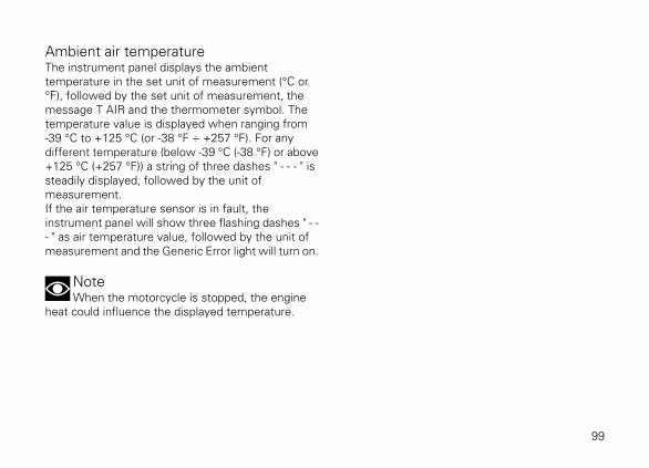
Ambient air temperatureThe instrument panel displays the ambienttemperature in the set unit of measurement (°C or°F), followed by the set unit of measurement, themessage T AIR and the thermometer symbol. Thetemperature value is displayed when ranging from-39 °C to +125 °C (or -38 °F ÷ +257 °F). For anydifferent temperature (below -39 °C (-38 °F) or above+125 °C (+257 °F)) a string of three dashes " - - - " issteadily displayed, followed by the unit ofmeasurement.If the air temperature sensor is in fault, theinstrument panel will show three flashing dashes " - -- " as air temperature value, followed by the unit ofmeasurement and the Generic Error light will turn on.
NoteWhen the motorcycle is stopped, the engine
heat could influence the displayed temperature.
99

CORE
10Km/h
SPORT
1
2
3 4 5 67
8
9
10
T AIR 20 °C
RPM x1000
2
CITY
TRACK FULL
10 2Km/h
P.M.
T AIR 20 °C
TOURING
00:00
10 2Km/h
T AIR 20 °C
SPORT ABS 3
DTC 1
109876
5
4
3
2
1
10 2Km/h
P.M.
TOT 302721 Km
TOURING
T AIR 20 00:00°C
10987654321
T AIR 68 °F
Fig. 40
100

LAP TIMEThe LAP function is visible only for the TRACK layoutunder menu 1.LAP function information is available when thefunction is active.When the LAP function is active, upon the first presson FLASH button (3) main screen will display LAPflashing at the top left-hand side, menu 1 will displayLAP 01, and START will be flashing for 4 secondswithin menu 1. Upon any further press of the FLASHbutton (3), the just ended lap number and time aredisplayed with a resolution of one hundredth of asecond ("0’00’’00") for 6 seconds and then lap timeris displayed again together with the number of newcurrent lap (if LAP function is selected from menu 1).
10 2Km/h
LAP START
SPORT ABS 3
LAP
DTC 1
109876
5
4
3
2
1
LAP 01 - 2’59”98 LAP 30 - 9’59”99 LAP FULL
TRACK 13
Fig. 41
101

If the LAP function is not selected from the menu, theinstrument panel will go back to the functions presentbefore the FLASH button (3) was pressed.It is possible to scroll the other menu functions at anytime.When storing the 15th LAP, the LAP function isstopped and, upon any further press on the FLASHbutton (3), the instrument panel will display flashingFULL message for 4 seconds warning that thestorage space for lap times is full.
NoteWhen the LAP function is active, the FLASH
button takes on the dual function of high beam flash.
LAP recording
If the LAP function is active, it is possible to recordthe lap time, for a total of 15 consecutive laps.Operation:
If the time is never stopped, it will roll over uponreaching 8 minutes, 59 seconds and 99 hundredths;the lap timer starts counting from zero and will keeprunning until the lap is stopped or the recordingfunction is disabled.During every lap, the following data are stored:
- no. 15 lap times (time between consecutive startand stop);
- no. 15 values for max. RPM (maximum RPMvalue reached in every lap);
- no. 15 values for max. speed (maximum speedvalue reached in every lap).
102

Auxiliary functionsLAP
The instrument panel displays the LAP functionstatus (LAP recording on or off).LAP message at top left-hand side is on if the LAPfunction is active, and is off if the LAP function is notactive; the same message will flash in the recordingstage.Considering that the FULL, CORE and CITY layoutsshow the values for this function in a similar to theTRACK layout, the example shown depicts thefunction in TRACK layout.
TRACK
10 2Km/h
TOT 302721 Km
SPORT ABS 3
LAP
DTC 1
109876
5
4
3
2
1
10 2Km/h
TOT 302721 Km
SPORT ABS 3
LAP
DTC 1
109876
5
4
3
2
1
10 2Km/h
TOT 302721 Km
SPORT ABS 3
LAP
DTC 1
109876
5
4
3
2
1
Fig. 42
103

InfotainmentX Diavel fits the Ducati Multimedia System (DMS) asstandard, thanks to which the user can answer phonecalls, select and listen to music tracks, and receiveSMS notifications by means of the Bluetoothtechnology.The instrument panel displays the Infotainmentfunction status: Bluetooth activation and anyconnected devices (smartphone, earphones,navigator).
When the Bluetooth is active, the main screendisplays the Bluetooth icon (A).In the FULL and CITY modes all Infotainmentfunctions are displayed; in the CORE and TRACKmodes none of these functions is displayed but it isnevertheless possible to answer/reject/terminatecalls using the relevant function buttons.
WarningAll data concerning the Infotainment (Player,
access to Contact List, Name of devices, etc.) aremanaged for use of Western character sets.
104
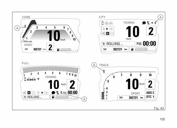
CORE CITY
TRACKFULL
10 2Km/h
TOT 302721 Km
SPORT ABS 3
DTC 1
109876
5
4
3
2
1
10Km/h
SPORT
1
2
3 4 5 67
8
9
10
TOT 302721 Km
RPM x1000
2
10 2Km/h
P.M.
TOT 302721 Km
TOURING
00:00
10 2Km/h
P.M.
TOURING
00:00
10987654321
A
A
A
A
Fig. 43
105

If Bluetooth is active, apart from the Bluetooth icon,also connected device indication is displayed, such assmartphone, rider and passenger helmet earphones,Ducati GPS navigator.It is possible to connect up to a maximum of 4devices.
CITY
FULL
10 2Km/h
P.M.
TOURING
00:00
10987654321
10 2Km/h
P.M.
TOT 302721 Km
TOURING
00:00
Fig. 44
106

Phone
Use the PHONE function:
- to manage incoming calls by means of button (1)and button (2);
- to recall the last calling number within 5 secondsfrom call interruption (RECALL function).
NoteIt is not possible to make a call by selecting the
name/number from the contact list through thefunction buttons.
When there is an incoming call (B) the blue colourfilling the rectangle is flashing; while, when youanswer the call, the blue background stops flashing.In the TRACK and CORE layouts, when there is anincoming call, the instrument panel will not displaythe caller's name or number. The rider will hear theringing tone through Bluetooth earphones upon anyincoming call.If there is an incoming call while the Player (E) isactive, the latter is paused throughout the phone calland will resume operation when call is over.To answer the call, press button (2).
To terminate the call, keep button (1) pressed for 2seconds.If main screen is set to FULL or CITY layout, during 5seconds after hang-up, the rectangle correspondingto the Recall function is activated to allow the recall.After this 5 second time, the rectangle for the recallfunction is disabled.To activate the Recall function within the 5 seconds,press button (2).In TRACK and CORE layouts, no recall function isprovided.
In case of missed calls from the moment thesmartphone is connected to the bike to the momentit is disconnected, the missed call symbol will bedisplayed (timed) (C). The number of missed calls isnot displayed.In case there is at least one SMS/MMS/EMAIL notread from the moment the smartphone is connectedto the bike to the moment it is disconnected, theunread message symbol will be displayed (timed) (D).The number of unread messages is not displayed.
107

CITY
FULL
10 2Km/h
P.M.
TOT 302721 Km
TOURING
00:00
CITY
10 2Km/h
P.M.
TOT 302721 Km
TOURING
00:00
10 2Km/h
P.M.
TOURING
00:00
10987654321
2
1B
E
B
E
B
D C
D C
Fig. 45
108

Player
The Player can be activated in the FULL and CITYmodes. If at least one Smartphone device isconnected (blue icon on main screen), Menu 1 willinclude PLAYER OFF (F) option.Only in the CITY display mode, press button (1) for 2seconds to activate the Player, in correspondence ofthe PLAYER OFF item shown upon activation.The instrument panel shows the PLAYER ON item inMenu 1. The Player graphics is activated for bothFULL and CITY modes: dedicated control panel andtrack name (E). If the Player is turned on, button (1),button (2) and button (4) can only be used to controlthe PLAYER.If the Player is ON, but instrument panel is notreceiving track name, it automatically pauses thetrack being played and the message NOT AVAILABLEis displayed instead of the track name.
ImportantThe Player function can not be activated through
Menu 1 when a call is incoming, in progress or inrecall.
Adjust volume as follows:
- increase volume: press button (1);- decrease volume: press button (2).
The Player can be cyclically set to pause/play bypressing button (4) for two seconds.It is possible to skip to next track, pressing button (4):system will skip forward once every time button ispressed.Press button (2) for two seconds to quit Playercontrols, although maintaining Player ON, in thecurrent status.The Player can be turned off by quitting the playercontrol and pressing, within three seconds, button (1)for two seconds in correspondence of the PLAYERON item: Menu 1 will show PLAYER OFF option.
109
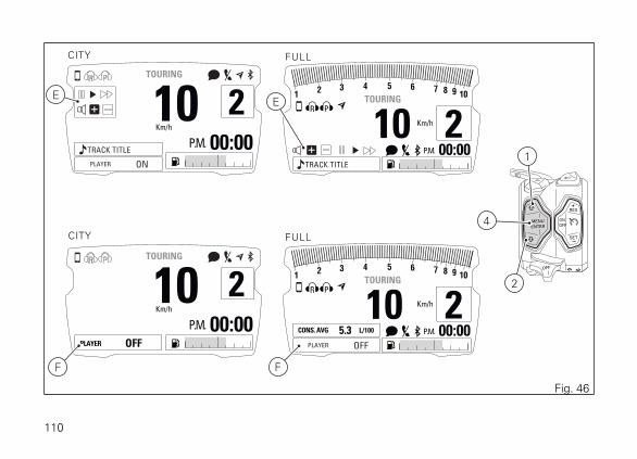
CITY FULL
FULL
10 2Km/h
P.M.
TOURING
00:00
CITY
10 2Km/h
P.M.
PLAYER OFF
TOURING
00:00
10 2Km/h
P.M.
TOURING
00:00
10987654321
TRACK TITLE
TRACK TITLE
10 2Km/h
P.M.
TOURING
00:00
10987654321
PLAYER OFF
CONS. AVG 5.3 L/100
PLAYER ON
2
1
EE
4
F F
Fig. 46
110

F.A.Q.
1) Why don't I receive any notification of receivede-mails?E-mails are notified only if configured on thetelephone source application. Check also that yourphone supports the MAP profile.If so, the DUCATI MULTIMEDIA SYSTEM, during thepairing phase, will send an access request to suchprofile which can be notified to the user explicitly(depending on the operating system) by requestingaccess authorisation to message notifications.
2) Why don't I receive any notification of receivedmessages?Check that your phone supports the MAP profile.If so, the DUCATI MULTIMEDIA SYSTEM, during thepairing phase, will send an access request to suchprofile which can be notified to the user explicitly(depending on the operating system) by requestingaccess authorisation to message notifications.
3) Earphones do not connect. Why?If they have been already paired once, werecommend resetting the earphones and pair themagain with the motorcycle (see earphones instructionmanual).
4) When I receive a call, the instrument paneldisplays the caller number but not the name(despite being saved in the contact list).Check that the phone supports the PBAP profile.If so, the DUCATI MULTIMEDIA SYSTEM, during thepairing phase, will send an access request to suchprofile which can be notified to the user explicitly(depending on the operating system) by requestingaccess authorisation to the phone contact list.
5) By activating the Player through theinstrument panel, music does not start.The activation depends on the phone settings. In thiscase, after activating the Player through theinstrument panel, also start the music application onyour Smartphone.
6) It happens that the music is played withcontinuous interruptions.If the devices have just been connected, it may bethat the Bluetooth control unit is sill completing theconnection phase with the concerned devices. It isfurthermore necessary to activate the PBAP andMAP profiles. Therefore, in case of iOS, please referto point 7). In case of Android, please refer to points2)4)
111

7) I do not receive any message notification on myiPhone. Why?Select Bluetooth in the Setting Menu. In the list "Mydevices" select "i" next to "Ducati Media System". Flag"Show notifications".
112

Cruise ControlX Diavel is equipped with a system for maintainingthe cruise speed: Ducati Cruise Control.
This function displays Cruise Control status and"target" speed.The Cruise Control can be turned on/off by pressingthe ON/OFF button (5). When the system is on, theCruise Control light (A) turns on on the instrumentpanel.Upon first activation, the Ducati Cruise Controlsystem is in stand-by mode and is ready to receivethe target speed value to be maintained automaticallyif the operating conditions are met (see below).Considering that the TRACK, FULL and CITY layoutsshow the values for this function in a similar way tothe CORE layout, the example shown depicts thefunction in CORE layout.
CORE
10Km/h
SPORT
1
2
3 4 5 67
8
9
10
TOT 302721 Km
RPM x1000
2
6
7
5A
Fig. 47
113

Once the system is on, it is possible to set the currentspeed as target speed by pressing the SET button (7).If no target speed had been previously set, it will bepossible to set the current speed as target also bypressing the RES button (6) instead of button SET (7).In this case, the system saves the vehicle currentspeed and keeps it without having to work on thetwistgrip.To confirm correct setting of cruise speed, the targetspeed is shown on the instrument panel for 5seconds then followed by the SET icon.In stand-by mode, if you press RES (6) and a targetspeed has been previously set and the operatingconditions are met, the system starts working againand brings the vehicle to the last set target speed.Also in this case the instrument panel shows thetarget speed for 5 seconds.
CORE
SET
10Km/h
SPORT
1
2
3 4 5 67
8
9
10
TOT 302721 Km
RPM x1000
2
6
7
5
150
Fig. 48
114

It is possible to increase or decrease set cruisespeed, by pressing buttons (6) and (7), respectively.Every "click" corresponds to a speed increase ordecrease of 1 Km/h.By keeping the RES button (6) pressed, the targetspeed increases progressively.By keeping the SET button (7) pressed, the targetspeed decreases progressively.Each time the target speed is modified, this is shownfor 5 seconds instead of the SET icon.
ImportantIn case of a long DTC (Traction Control) event,
the Cruise Control will automatically turn off.
It is possible to enable the Ducati Cruise Control onlyif the below conditions are met:
- second gear or higher engaged;- vehicle speed higher than or equal to 50 Km/h (30
mph) or lower than or equal to 200 Km/h (125mph).
The Ducati Cruise Control can be disabled as follows:
1) by pressing button (5);2) by pulling the front brake lever;
3) by pressing the rear brake pedal;4) by pulling the clutch lever.
Conditions 2-3-4 bring the system in stand-by mode:the Cruise Control light remains on.Condition 1 brings the system in OFF condition: theCruise Control is switched off.The Ducati Cruise Control system controls the vehiclespeed only between 50 Km/h (30 mph) and 200 Km/h (125 mph).
115

Assisted start (LAUNCH CONTROL - DPL)This Function allows activating the assisted startfunction (called DPL - Ducati Power Launch).
By pressing button (12) it is possible to access theLaunch Control menu only if the vehicle speed is ≤(less than or equal to) 5 km/h.
In the Launch Control menu, it is possible to selectthe desired DPL level (1, 2, 3) by pressing buttons (1)and (2), and to set the selected level by keepingbutton (4) pressed for two seconds.
NoteIf no change is made in this menu within ten
seconds, the instrument panel will set DPL to OFFand go back to the previous screen.
Once the DPL level is set, the instrument panelshows the wait screen for two seconds: during thistime, if you press button (4) the wait phase isinterrupted and the instrument panel displays themain screen and sets the DPL to OFF.
Once the two seconds of wait screen are over, theinstrument panel shows the "assisted start" screen.
After the assisted start, the instrument panel sets theDPL to OFF and shows the "main screen" again.The DPL is set to OFF by default by Ducati.
116

CORE
0Km/h
SPORT
1
2
3 4 5 67
8910
TOT 302721 Km
RPM x1000
N
1
2
3 4 5 67
8910
12
12 12
2
1AVAILABLE LAUNCHES:
DPL ON - LEVEL 1
DPL ON - LEVEL 2
DPL ON - LEVEL 3
2
EXIT
LAUNCH WAITING
- pull the clutch -
- open full throttle -
- engage 1st gear
EXIT
READY TO LAUNCH
Release the CLUTCHand START
N
Fig. 49
117

NoteIf the DTC is set to "OFF", the DPL function can
not be activated.
If the DTC is set to OFF and you press button (12),the instrument panel shows for five seconds theindication DTC OFF – DPL NOT AVAILABLE; whenthe five seconds are over, the instrument panel goesback to the main screen.
NoteIf the instrument panel detects a control unit
error when entering the DPL menu, regardless of thecurrently set display mode, it will show the blinkingmessage LAUNCH CONTROL ERROR for threeseconds and then again the main screen.
DTC OFF
DPL not available
EXIT
Fig. 50
LAUNCH CONTROL ERROR
Fig. 51
118
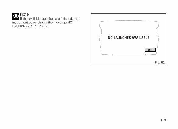
NoteIf the available launches are finished, the
instrument panel shows the message NOLAUNCHES AVAILABLE.
NO LAUNCHES AVAILABLE
EXIT
Fig. 52
119

The Ducati Power Launch (DPL) helps the rider in the delicate sport starting phase from a standstill to controlthe power delivered by the vehicle.The DPL system works with three intervention levels, each calibrated to offer a different start assist degree.The following table indicates the most suitable DPL intervention level depending on the various startingtypes. All levels are to be intended optimised for OEM (Original Equipment Manufactured) tyres.
DPL level Performance Use
1 High Use focused on the best performance for very expert riders.The system allows the wheelie and the rear wheel slipping, but re-duces the speed at which these two situations take place.
2 Medium Use for expert riders.The system reduces the tendency to wheelie and rear wheel slip-ping, besides intervening considerably in case these two situationstake place.
3 Medium Use for all kinds of riders.The system minimises the tendency to wheelie and rear wheelslipping, besides intervening considerably in case these two situa-tions take place.
120

WarningThe DPL system is to be used exclusively on
straight and level paths, on optimal grip conditions ofthe road.The DPL system is conceived to be used within acontrolled environment or in a closed circuit. Forsafety reasons it must not be used in unsuitableplaces.
Starting procedure
The starting procedure basically consists of twophases:
● The first: with completely released clutch so thatthe torque transmitted to the ground depends onthe clutch position and slipping;
● The second: with clutch not released so that thetorque transmitted to the ground depends on thetorque delivered by the engine.
The DPL system helps the rider to start from astandstill and during the first phase by automaticallyadjusting the torque delivered by the engine to keepthe engine rpm at the ideal value to start. This allowsthe rider to concentrate only on the clutch releasethat must be progressive and "smooth" instead of fast
or abruptly. The engine torque is adjusted also in thesecond phase, by maximising the delivered powerand limiting the vehicle wheeling or rear wheelslipping.To preserve the clutch, the DPL system calculates inreal time and shows in the dedicated menu on theinstrument panel the number of starts that can beperformed consecutively by decreasing it by one unitevery time a start is completed. The DPL systemincreases the value by one unit according to thedistance covered by the vehicle and the time duringwhich the vehicle engine was on and off.The DPL system allows performing other assistedstarts only when the number of remaining starts ishigher than zero.
WarningUsing the DPL system could reduce the useful
life of the engine and transmission mechanical parts.The DPL system should be used only when theengine has reached the operating temperature.
To perform an assisted start with the DPL, the ridermust first of all set the vehicle in the followingcondition:
121

● vehicle speed at zero;● vertical position;● engine on;● DTC set to ON.
If the count of the residual assisted starts is abovezero, the rider can select on the instrument panel thedesired DPL level by accessing the DPL level menuby pressing button (12).After selecting the level, the rider must pull theclutch, engage the first gear and fully open thethrottle twistgrip.
If all operations indicated above have beenperformed, the DPL system will show a confirmationscreen on the instrument panel indicating that thesystem is ready to start.The rider must then release the clutch progressivelyby keeping the throttle twistgrip fully open.When the vehicle speed exceeds 20 km/h, theinstrument panel shows the standard screen whilekeeping the indication of the selected DPL systemlevel for the entire duration of the start phase.
The DPL system is switched off when one of thefollowing conditions is met after completely releasingthe clutch:
● vehicle speed higher than 120 km/h;● third gear engaged.
The DPL system is switched off also if, after releasingthe clutch, the rider decides to interrupt the startphase by closing the throttle and bringing the vehiclespeed under 5 km/h.
WarningThe system manages the power delivered by
the engine but not the clutch lever release thatremains under the control of the rider.During the starting phase, an abrupt release of theclutch will prevent an optimal behaviour of thevehicle. Likewise, a prolonged activation of the clutchmay overheat and thus damage it.
WarningThe rider position on the bike may influence the
system behaviour.
Tips on how to select the intervention level
If level 3 is set, the DPL system intervenes byreducing the tendency to wheelie or rear wheel
122

slipping during the starting phase. Levels 2 and 1provide a limited intervention of the system.
To identify the DPL level most suitable to your ridingstyle we recommend to activate the system, selectlevel 3 and perform a start to become familiar withthe system. Then we recommend to try levels 2 and1 in sequence until finding the best intervention.
If non-OEM tyres of a different size class are used orif the tyre size differs significantly from the originaltyres, it may be that the system operation iscompromised.
WarningThe DPL is a rider assist system. The system is
designed to make riding easier and to enhance safety,but in no way relieves the rider of the obligation todrive responsibly and to maintain a high standard ofriding in order to avoid accidents, whether caused byhis own errors or those of other road users, throughmaking emergency manoeuvres, in accordance withthe prescriptions of the road traffic code.The rider must always be aware that active safetysystems have a preventive function. The activeelements help the rider control the motorcycle,making it as easy and safe to ride as possible. Thepresence of an active safety system should notencourage the rider to ride at speeds beyond thereasonable limits, not in accordance with the roadconditions, the laws of physics, good riding standardsand the requirements of the road traffic code.
123

Service indication (SERVICE)This indication shows the user that the motorcycle isdue for service and must be taken to a DucatiAuthorised Service Centre.The service warning indication can be reset only bythe Authorised Ducati Service Centre duringservicing.There are 3 types of scheduled maintenanceinterventions:
- OIL SERVICE ZERO: service at the first 1000 km(600 mi);
- OIL SERVICE and ANNUAL SERVICE: oil serviceor annual service (requiring the samemaintenance operations);
- DESMO SERVICE.
WarningThe ANNUAL SERVICE function is available
(active) only if the date has been set.
124

0 NKm/h
TOTA 302721 Km
SPORT ABS 3
DTC 1
109876
5
4
3
2
1
TRACKCORE
FULL CITY
0Km/h
SPORT
1
2
3 4 5 67
8
9
10
TOT 302721 Km
RPM x1000
N
0 NKm/h
P.M.
TOT
DPL 3 - ON
302721 Km
TOURING
CONS. AVG 5.3 00:00L/100
10987654321
0 NKm/h
P.M.
TOT 302721 Km
TOURING
00:00
Fig. 53
125

OIL SERVICE zero warningThe first service warning is the Oil Service (OIL) zeroand is triggered as soon as the odometer reaches thefirst 1,000 km (600 mi). Warning is displayed until"Reset" by the Ducati authorised service centre,during maintenance.
Fig. 54
126

OIL SERVICE or ANNUAL SERVICE orDESMO SERVICE countdown indicationAfter Oil Service zero indication first reset (at 1,000km - 600 mi), the instrument panel activates thefollowing indications in yellow for 5 seconds uponKey-ON:
- the count of the mileage in kilometres (miles)remaining before the next OIL SERVICE (A) 1000km (600 mi) earlier than the service threshold;
- the count of the days remaining before the nextANNUAL SERVICE (B) 30 days earlier than theservice threshold;
- the count of the mileage in kilometres (miles)remaining before the next DESMO SERVICE (C)1000 km (600 mi) earlier than the servicethreshold.
To know exactly the kilometres missing until theservice threshold or maintenance date, it is possibleto access the Setting menu and select the "INFOSERVICE" function page 193.
-1000
-30dd
-1000A
B
C
Fig. 55
127

OIL SERVICE or ANNUAL SERVICE orDESMO SERVICE indicationWhen the service threshold is reached, the warningfor the type of service required is triggered:
- Oil Service (A):- Annual Service (B);- Desmo Service (C).
To know the kilometres missing until the servicethreshold or maintenance date, access the Settingmenu and select the "INFO SERVICE" function page193.Required service warning is triggered and displayedin red until "Reset" by the Ducati authorised servicecentre, during maintenance.
DESMO
ANNUAL
Fig. 56
128

Warnings/Alarms (WARNING)The instrument panel manages a number ofwarnings / alarms, aimed at giving useful informationto the rider during use.Upon Key-On, if there are any active warnings, theinstrument panel displays the present warnings.During normal use, whenever a warning is triggered,the instrument panel automatically displays thewarning. Whenever a warning is triggered, it isdisplayed for 10 seconds in a (well-visible icon) "large"size and then continues being displayed in the smallsize ("small" icon).If several warnings are active, the correspondingicons will be displayed one after the other, eachremaining on display for 3 seconds.
WarningIf one or several warnings are triggered and, at
the same time, the Generic Error light turns on, thesmall warning icon is not displayed on instrumentpanel until the Generic Error light stays on; warningswill only be displayed within the first 10 seconds asa large-size icon.
129

0 NKm/h
TOTA 302721 Km
SPORT ABS 3
DTC 1
109876
5
4
3
2
1
TRACKCORE
FULL CITY
0Km/h
SPORT
1
2
3 4 5 67
8
9
10
TOT 302721 Km
RPM x1000
N
0 NKm/h
P.M.
TOT 302721 Km
TOURING
CONS. AVG 5.3 00:00L/100
10987654321
0 NKm/h
P.M.
TOT 302721 Km
TOURING
00:00
Fig. 57
130

Ice
This function warns the rider when there might be iceon the road, due to the low external temperature.This warning turns on when temperature drops to4°C (39°F) and turns off when temperature raises to6°C (43°F).
WarningThis warning does not eliminate the possibility
of icy road areas even with temperatures above 4°C(39°F); when ambient temperature is "low", rideresponsibly, especially on road areas not exposed tosunlight and/or on bridges. Fig. 58
131

Low battery indication (LOW Battery)
This function warns the user that the status of thevehicle battery is low.Warning is activated when battery voltage is approx.lower than/equal to 11.0 Volt.
NoteIn this case, Ducati recommends charging
battery in the shortest delay using the specialinstrument as engine could not be started.
Fig. 59
132
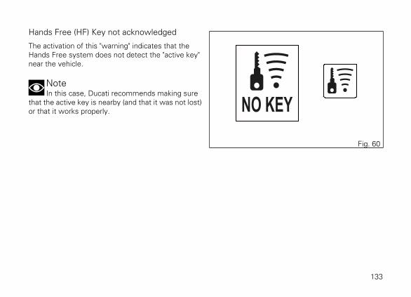
Hands Free (HF) Key not acknowledged
The activation of this "warning" indicates that theHands Free system does not detect the "active key"near the vehicle.
NoteIn this case, Ducati recommends making sure
that the active key is nearby (and that it was not lost)or that it works properly.
Fig. 60
133

"Low" battery level of Hands Free (HF) key
The activation of this "warning" indicates that theHands Free system has detected that the battery thatpermits the active key to communicate and turn thevehicle on is almost discharged.
NoteIn this case, Ducati recommends changing
battery in the shortest delay.
To change battery, refer to paragraph "Replacing thebattery in the active key" page 230. Fig. 61
134

Date setting
This function prompts the user to enter the date viathe Setting Menu.
NoteIn this case Ducati recommends to stop and
enter the calendar date using the function"DATESET".
Fig. 62
135

Steering unlock error - Steering still locked
The activation of this "warning" indicates that theHands Free System was not able to disengage thesteering lock.
WarningIn this case, Ducati recommends switching
vehicle off and on again (Key-Off / Key-On), keepinghandlebar fully turned. If warning is still present (andsteering does not "unlock"), contact a DucatiAuthorised Service Centre.
Fig. 63
136

Error warningsThe instrument panel manages error warnings inorder to allow the rider to identify any abnormalmotorcycle behaviour in real time.Upon Key-On, in case of errors, the instrument panelturns on the MIL light (B) (in case of errors directlyconnected to the engine control unit) or the GenericError light (A) (in case of any other errors).During normal operation, when an error is triggered,the instrument panel turns on the MIL light (B) or theGeneric Error light (A).
WarningWhen one or more errors are displayed, always
contact a Ducati Dealer or authorised Service Centre.
137

0 NKm/h
TOT 302721 Km
SPORT ABS 3
DTC 1
109876
5
4
3
2
1
TRACKCORE
FULLCITY
0Km/h
SPORT
1
2
3 4 5 67
8
9
10
TOT 302721 Km
RPM x1000
N
0 NKm/h
P.M.
TOT 302721 Km
TOURING
CONS. AVG 5.3 00:00L/100
10987654321
0 NKm/h
P.M.
TOT 302721 Km
TOURING
00:00
A
B
Fig. 64
138

Viewing side stand statusThe instrument panel shows the side stand statusand if side stand is down/open, the icon SIDE STANDis displayed on a red background.In case of Side stand sensor fault, the instrumentpanel will display the stand down/up indication withMIL light on.If instrument panel does not receive side standstatus, stand down/open SIDE STAND indication willflash to indicate an undefined status.
NoteWith side stand down and gear engaged it is not
possible to start the motorcycle. If you start withgearbox in neutral and then engage a gear with sidestand down, the motorcycle turns off.
10Km/h
SPORT
1
2
3 4 5 67
8
9
10
TOT 199999 Km
RPM x1000
2
10Km/h
SPORT
1
2
3 4 5 67
8
9
10
TOT 199999 Km
RPM x1000
2
CORE
CORE
Fig. 65
139

Light mode indication (DRL)The instrument panel indicates if the DRL control isset to AUTO or MANUAL by showing the relevanticon.When the DRL lights are in AUTO mode, theinstrument panel shows the green icon with letter "A".When the DRL lights are in MANUAL mode, theinstrument panel shows the amber icon with letter"M".
CORE
A
A
M
0Km/h
SPORT
1
2
3 4 5 67
8
9
10
TOT 302721 Km
RPM x1000
NFig. 66
140

Setting menuThis menu allows enabling, disabling and settingsome motorcycle functions.To enter the Setting Menu it is necessary to holdbutton (4) for two seconds, with Key-ON andmotorcycle actual speed ≤ (lower than or equal to) 5km/h (3.1 mph): within this menu, it is no longerpossible to view any other function.The Setting MENU displays the following functions:
- RIDING MODE- INFO MODE- LAP- PIN CODE- DRL CONTROL (active only if the DRL function
is available)- BACK LIGHT- DATE SET- CLOCK SET- INFO SERVICE- UNIT SETTING- BLUETOOTH (only if the Bluetooth module is
available)
- INFO- BATTERY- RPM- BLUETOOTH version (active only for X
Diavel S)
ImportantFor safety reasons, it is recommended to use
this Menu with the motorcycle at a standstill.
141

0Km/h
SPORT
1
2
3 4 5 67
8
9
10
TOT 302721 Km
RPM x1000
N
RIDING MODE
SETTING MENU
INFO MODE
LAP
PIN CODE
DRL CONTROL
BACKLIGHT
INFO
EXIT
DATE SET
CLOCK SET
INFO SERTVICE
UNIT SETTING
BLUETOOTH
CORE
4
Fig. 67
142
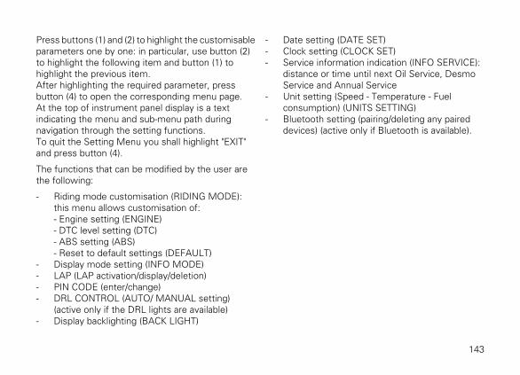
Press buttons (1) and (2) to highlight the customisableparameters one by one: in particular, use button (2)to highlight the following item and button (1) tohighlight the previous item.After highlighting the required parameter, pressbutton (4) to open the corresponding menu page.At the top of instrument panel display is a textindicating the menu and sub-menu path duringnavigation through the setting functions.To quit the Setting Menu you shall highlight "EXIT"and press button (4).
The functions that can be modified by the user arethe following:
- Riding mode customisation (RIDING MODE):this menu allows customisation of:- Engine setting (ENGINE)- DTC level setting (DTC)- ABS setting (ABS)- Reset to default settings (DEFAULT)
- Display mode setting (INFO MODE)- LAP (LAP activation/display/deletion)- PIN CODE (enter/change)- DRL CONTROL (AUTO/ MANUAL setting)
(active only if the DRL lights are available)- Display backlighting (BACK LIGHT)
- Date setting (DATE SET)- Clock setting (CLOCK SET)- Service information indication (INFO SERVICE):
distance or time until next Oil Service, DesmoService and Annual Service
- Unit setting (Speed - Temperature - Fuelconsumption) (UNITS SETTING)
- Bluetooth setting (pairing/deleting any paireddevices) (active only if Bluetooth is available).
143

OFF
ON
OFF
LAP DATA
ERASE ALL EXIT
RIDING MODE
SETTING MENU
INFO MODE
LAP
PIN CODE
DRL CONTROL
BACKLIGHT
INFO
EXIT
DATE SET
CLOCK SET
INFO SERTVICE
UNIT SETTING
BLUETOOTH
SETTING MENU > LAP
2 1
2 1
4
2
1
4
Fig. 68
144

Customising the RIDING MODEAll settings of every riding mode can be customised.You enter the Setting Menu.Select "RIDING MODE" option, by pressing button (1)or (2). Once function is highlighted, press button (4).Enter the "RIDING MODE" menu. Select the desiredriding mode (SPORT, TOURING, URBAN), bypressing button (1) or (2). Once the desired mode ishighlighted, press button (4). You open the selectedriding mode customisation Menu.While if you highlight "EXIT" and press button (4) youquit the sub-menu and go back to previous page.
RIDING MODE
SETTING MENU
INFO MODE
LAP
PIN CODE
DRL CONTROL
BACKLIGHT
INFO
EXIT
DATE SET
CLOCK SET
INFO SERTVICE
UNIT SETTING
BLUETOOTH
4
Fig. 69
42
1
EXITALL DEFAULT
TOURING
URBAN
SETTING MENU>RIDING MODE
SPORT
Fig. 70
145

The parameters that can be customised for everyriding mode are the following:
- ENGINE- DTC- ABS
Press buttons (1) and (2) to highlight the customisableparameters one by one: in particular, use button (1)to highlight the following item and button (2) tohighlight the previous item.After highlighting the required parameter, pressbutton (4) to open the corresponding menu page.Any parameter change made is saved and remains inthe memory also after a Battery-OFF.The riding parameters set by Ducati can be restoredfor each single riding mode through the DEFAULTFunction.If you highlight "EXIT" and press button (4) you quitthe sub-menu and go back to previous page.
WarningChanges should only be made to the
parameters by people who are experts in motorcycleset-up; if the parameters are changed accidentally,use the DEFAULT or ALL DEFAULT function torestore factory settings.
146

EXIT
MEDIUM
TOURING
URBAN
SETTING MENU>RIDING MODE>SPORT>ENGINE
SPORT
DEFAULT
ENGINE
DTC
ABS
LOW
MEDIUM
HIGH
EXIT
ON-05
TOURING
URBAN
SETTING MENU>RIDING MODE>SPORT>DTC
SPORT
DEFAULT
ENGINE
DTC
ABS
OFFON-01ON-02ON-03ON-04ON-05ON-06ON-07ON-08
EXIT
ON-05
TOURING
URBAN
SETTING MENU>RIDING MODE>SPORT>DTC
SPORT
DTC
OFFON-01ON-02ON-03ON-04ON-05ON-06ON-07ON-08
42
1
1
4
2
Fig. 71
147

Customizing the Riding Mode: engineadjustmentThis function customises engine power associatedwith each riding mode.You enter the Setting Menu. Select "RIDING MODE"option, by pressing button (1) or (2).Once function is highlighted, press button (4). Enterthe "RIDING MODE" menu.Select the desired riding mode (SPORT, TOURING,or URBAN) from the drop-down menu, by pressingbutton (1) or (2). Once the desired mode ishighlighted, press button (4).You open the selected riding mode customisationMenu.Select the parameter to be customised (ENGINE)from the drop-down menu, by pressing button (1) or(2). Once the desired parameter is highlighted, pressbutton (4).
EXIT
MEDIUM
TOURING
URBAN
SETTING MENU>RIDING MODE>SPORT>ENGINE
SPORT
DEFAULT
ENGINE
DTC
ABS
LOW
MEDIUM
HIGH
4
Fig. 72
148

When entering the function, currently set enginepower is indicated on the right (above the word EXIT)(e.g.: MEDIUM).The central drop-down menu lists the availablecustomisation options:
- LOW- MEDIUM- HIGH
Press buttons (1) and (2) to highlight the availablepower options one by one: in particular, use button(2) to highlight the following item and button (1) tohighlight the previous item.Once the desired power level is highlighted, pressbutton (4) to highlight MEMORY in orange.To save the new setting, hold button (4) for twoseconds while the message MEMORY is highlightedin orange.If storage is successful, MEMORIZED will behighlighted in green for two seconds, power level willbe refreshed and then EXIT will be highlighted ingreen.To exit the menu and go back to previous page, selectEXIT and press button (4).
149
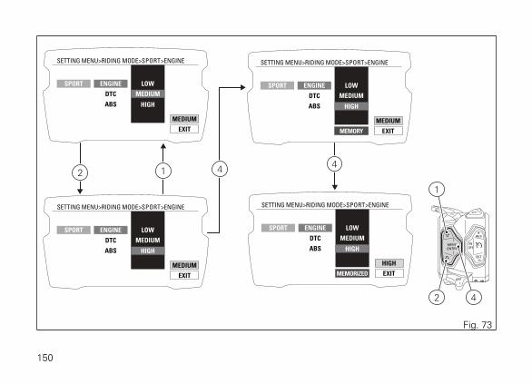
EXIT
MEDIUM
TOURING
URBAN
SETTING MENU>RIDING MODE>SPORT>ENGINE
SPORT ENGINE
DTC
ABS
LOW
MEDIUM
HIGH
EXIT
MEDIUM
TOURING
URBAN
SETTING MENU>RIDING MODE>SPORT>ENGINE
SPORT ENGINE
DTC
ABS
LOW
MEDIUM
HIGH
EXIT
MEDIUM
TOURING
URBAN
SETTING MENU>RIDING MODE>SPORT>ENGINE
SPORT ENGINE
DTC
ABS
MEMORY
LOW
MEDIUM
HIGH
EXIT
HIGH
TOURING
URBAN
SETTING MENU>RIDING MODE>SPORT>ENGINE
SPORT ENGINE
DTC
ABS
MEMORIZED
LOW
MEDIUM
HIGH
42
1
42 1 4
Fig. 73
150

Customizing the Riding Mode: setting theDTC levelThis function disables or sets DTC level for theselected riding mode.You enter the Setting Menu. Select "RIDING MODE"option, by pressing button (1) or (2).Once function is highlighted, press button (4).Enter the "RIDING MODE" menu. Select the desiredriding mode (SPORT, TOURING, or URBAN) from thedrop-down menu, by pressing button (1) or (2).Once the desired mode is highlighted, press button(4).You open the selected riding mode customisationMenu.Select the parameter to be customised (DTC) fromthe drop-down menu, by pressing button (1) or (2).Once the desired parameter is highlighted, pressbutton (4).
EXIT
ON-05
TOURING
URBAN
SETTING MENU>RIDING MODE>SPORT>DTC
SPORT ENGINE
DTC
ABS
OFFON-01ON-02ON-03ON-04ON-05ON-06ON-07ON-08
4
Fig. 74
151

When entering the function, the currently set DTClevel or status is indicated on the right (above theword EXIT) (e.g.: ON - 05, i.e. level 05).Customisation options are indicated on the centraldrop-down menu: levels 1 to 8 and status OFF.Once the desired new setting is highlighted, pressbutton (4) to highlight MEMORY in orange.To save the new setting, hold button (4) for twoseconds while the message MEMORY is highlightedin orange.If storage is successful, MEMORIZED will behighlighted in green for two seconds, set level orstatus will be refreshed and then EXIT will behighlighted in green.To exit the menu and go back to previous page, selectEXIT and press button (4).
152

EXIT
ON-05
TOURING
URBAN
SETTING MENU>RIDING MODE>SPORT>DTC
SPORT ENGINE
DTC
ABS
OFFON-01ON-02ON-03ON-04ON-05ON-06ON-07ON-08
EXIT
ON-05
TOURING
URBAN
SETTING MENU>RIDING MODE>SPORT>DTC
SPORT ENGINE
DTC
ABS
OFFON-01ON-02ON-03ON-04ON-05ON-06ON-07ON-08
EXIT
ON-05
TOURING
URBAN
SETTING MENU>RIDING MODE>SPORT>DTC
SPORT ENGINE
DTC
ABS
MEMORY
OFFON-01ON-02ON-03ON-04ON-05ON-06ON-07ON-08
EXIT
ON-03
TOURING
URBAN
SETTING MENU>RIDING MODE>SPORT>DTC
SPORT ENGINE
DTC
ABS
MEMORIZED
OFFON-01ON-02ON-03ON-04ON-05ON-06ON-07ON-08
42
1
42 1 4
Fig. 75
153

Customizing the Riding Mode: ABSadjustmentThis function disables or sets ABS level for theselected riding mode. You enter the Setting Menu.Select "RIDING MODE" option, by pressing button (1)or (2).Once function is highlighted, press button (4).Enter the "RIDING MODE" menu. Select the desiredriding mode (SPORT, TOURING, or URBAN) from thedrop-down menu, by pressing button (1) or (2).Once the desired mode is highlighted, press button(4). You open the selected riding mode customisationMenu. Select the parameter to be customised (ABS)from the drop-down menu, by pressing button (1) or(2). Once the desired parameter is highlighted, pressbutton (4).
EXIT
ON - 02
TOURING
URBAN
SETTING MENU>RIDING MODE>SPORT>ABS
SPORT ENGINE
DTC
ABS
OFFON - 01ON - 02ON - 03
4
Fig. 76
154

When entering the function, the currently set ABSlevel or status is indicated on the right (above theword EXIT) (e.g.: ON - 03, i.e. level 03).Customisation options are indicated on the centraldrop-down menu: levels 1 to 3 and status OFF.Press buttons (1) and (2) to highlight the levels oneby one: in particular, use button (1) to highlight thefollowing item and button (2) to highlight the previousitem.Once the desired level is highlighted, pressCONFIRM MENU button (4) to highlight MEMORY.Once the desired new setting is highlighted, pressbutton (4) to highlight MEMORY in orange.To save the new setting, hold button (4) for twoseconds while the message MEMORY is highlightedin orange.If storage is successful, MEMORIZED will behighlighted in green for two seconds, set level orstatus will be refreshed and then EXIT will behighlighted in green.To exit the menu and go back to previous page, selectEXIT and press button (4).
NoteWhen you enable or disable the ABS through
this function, i.e. toggling from disabled to enabledsystem or vice-versa, the procedure for activating ordeactivating the ABS is carried out: the change ofstatus of the ABS control unit is not instantaneous, itcan require up to 6 seconds.
155

EXIT
ON - 02
TOURING
URBAN
SETTING MENU>RIDING MODE>SPORT>ABS
SPORT ENGINE
DTC
ABS
OFFON - 01ON - 02ON - 03
EXIT
ON - 02
TOURING
URBAN
SETTING MENU>RIDING MODE>SPORT>ABS
SPORT ENGINE
DTC
ABS
OFFON - 01ON - 02ON - 03
EXIT
ON - 02
TOURING
URBAN
SETTING MENU>RIDING MODE>SPORT>ABS
SPORT ENGINE
DTC
ABS
MEMORY
OFFON - 01ON - 02ON - 03
EXIT
ON - 03
TOURING
URBAN
SETTING MENU>RIDING MODE>SPORT>ABS
SPORT ENGINE
DTC
ABS
MEMORIZED
OFFON - 01ON - 02ON - 03
42
1
42 1 4
Fig. 77
156

Customising Riding Mode: restore defaultsettings (DEFAULT)This function allows restoring the default values setby Ducati for the parameters associated to a specificriding mode.You enter the Setting Menu. Select "RIDING MODE"option, by pressing button (1) or (2).Once function is highlighted, press button (4). Enterthe "RIDING MODE" menu.Select the desired riding mode (SPORT, TOURING,or URBAN) from the drop-down menu, by pressingbutton (1) or (2). Once the desired mode ishighlighted, press button (4).You open the selected riding mode customisationMenu.Select DEFAULT option, by pressing button (1) or (2).Once desired parameter is highlighted, keep button(4) pressed for two seconds.
EXIT
TOURING
URBAN
SETTING MENU>RIDING MODE>SPORT>DEFAULT
SPORT
DEFAULT
ENGINE
DTC
ABS
42
1
Fig. 78
157

It will take three seconds to restore parameters,during which the display will show " WAIT... ".Once procedure is completed, "OK" will appear fortwo seconds to confirm that default parameters havebeen restored and the message EXIT will behighlighted.To exit the menu and go back to previous page, selectEXIT and press button (4).
NoteIf the DEFAULT option cannot be selected, it
means that all parameters of the riding mode arealready in the "Default" condition.
158

Customising the Riding Mode: Reset todefault settings (ALL DEFAULT)This function allows restoring the default values setby Ducati for all the parameters associated to all ridingmodes.To gain access to this function, enter the SettingMenu, use button (1) or (2) to select RIDING MODEand press button (4). Then use button (1) or (2) toselect ALL DEFAULT and keep button (4) pressed fortwo seconds.
NoteIf "ALL DEFAULT" option cannot be selected, it
means that all parameters for all riding modes arealready in the "Default" condition.
42
1
EXITALL DEFAULT
TOURING
URBAN
SETTING MENU>RIDING MODE
SPORT
Fig. 79
159
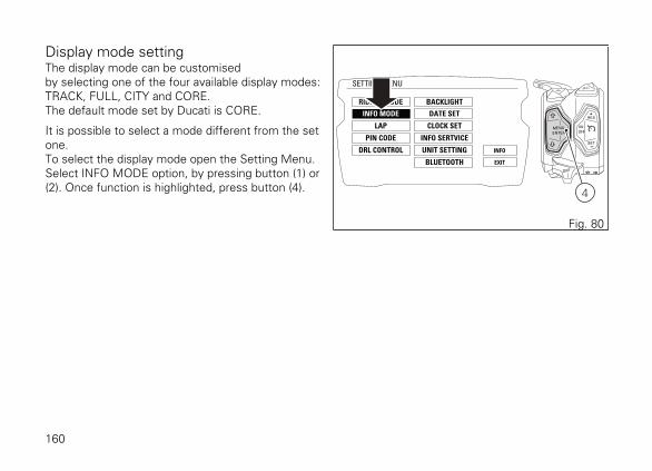
Display mode settingThe display mode can be customisedby selecting one of the four available display modes:TRACK, FULL, CITY and CORE.The default mode set by Ducati is CORE.
It is possible to select a mode different from the setone.To select the display mode open the Setting Menu.Select INFO MODE option, by pressing button (1) or(2). Once function is highlighted, press button (4).
RIDING MODE
SETTING MENU
INFO MODE
LAP
PIN CODE
DRL CONTROL
BACKLIGHT
INFO
EXIT
DATE SET
CLOCK SET
INFO SERTVICE
UNIT SETTING
BLUETOOTH
4
Fig. 80
160

Enter the INFO MODE menu.To select a layout, press button (1) or button (2). Oncemode is highlighted, press button (4). The selectedoption is stored, current mode indication is refreshedand the EXIT option is automatically highlighted.Press button (4) to go back to previous display mode.
By selecting DEFAULT, the display mode of all Ridingmodes becomes the CORE mode.By selecting RIDING MODE, the display modebecomes:
- the TRACK one for the SPORT Riding mode;- the FULL one for the TOURING Riding mode;- the CITY one for the URBAN Riding mode.
By selecting TRACK, the display mode of all Ridingmodes becomes the TRACK mode.By selecting FULL, the display mode of all Ridingmodes becomes the FULL mode.By selecting CITY, the display mode of all Ridingmodes becomes the CITY mode.
161

EXIT
DEFAULT
SETTING MENU>INFO MODE
CITY
RIDING MODE
TRACK
FULL
DEFAULT
EXIT
DEFAULT
SETTING MENU>INFO MODE
CITY
RIDING MODE
TRACK
FULL
DEFAULT >> CORE
>> CORE
EXIT
CORE
SETTING MENU>INFO MODE
CITY
RIDING MODE
TRACK
FULL
DEFAULT
42
1
2
4
1
Fig. 81
162

Light mode setting (DRL)This function, active only if the DRL is available,allows the user to choose the DRL status: AUTO orMANUAL.You enter the Setting Menu. Select "DRL CONTROL"option, by pressing button (1) or (2). Once function ishighlighted, press button (4).Enter the "DRL CONTROL" menu.
RIDING MODE
SETTING MENU
INFO MODE
LAP
PIN CODE
DRL CONTROL
BACKLIGHT
INFO
EXIT
DATE SET
CLOCK SET
INFO SERTVICE
UNIT SETTING
BLUETOOTH
4
Fig. 82
163

When entering the function on the left, the displaywill show the DRL settings: AUTO, MANUALwhereas on the right (above the word EXIT) thecurrently set mode.Press buttons (1) and (2) to highlight the available DRLstatus: in particular, use button (2) to highlight thefollowing item and button (1) to highlight the previousitem. Once the desired mode is selected, pressbutton (4) to confirm. The instrument panel activatesthe selected mode and highlights the correspondingname.When choosing the AUTO mode of the DRL lights,the high and/or low beams are automaticallyswitched from the DAY mode to the NIGHT modeand vice versa according to the ambient light.To exit the menu and go back to previous page, selectEXIT and press button (4).
EXIT
AUTO
EXIT
SETTING MENU>DRL CONTROL
AUTO
MANUAL
AUTO
MANUAL
42
1
Fig. 83
164

LAPTo open the LAP function menu, enter the SettingMenu. Select LAP option, by pressing button (1) or(2). Once function is highlighted, press button (4). Youopen the LAP Menu.The menu allows you to:
- OFF: disable the LAP function;- ON: enable the LAP function;- LAP DATA: view LAPs previously recorded by
means of the "LAP recording" function;- ERASE ALL: delete all recorded LAPs.
RIDING MODE
SETTING MENU
INFO MODE
LAP
PIN CODE
DRL CONTROL
BACKLIGHT
INFO
EXIT
DATE SET
CLOCK SET
INFO SERTVICE
UNIT SETTING
BLUETOOTH
4
Fig. 84
165

EXIT
OFF
SETTING MENU>LAP
OFF
ON
LAP DATA
E R A S E O K
EXIT
OFF
SETTING MENU>LAP
OFF
ON
LAP DATA
E R A S E O K
EXIT
OFF
SETTING MENU>LAP
OFF
ON
LAP DATA
E R A S E O K
42
1
12
4
Fig. 85
166
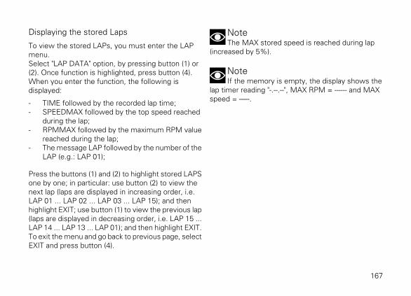
Displaying the stored Laps
To view the stored LAPs, you must enter the LAPmenu.Select "LAP DATA" option, by pressing button (1) or(2). Once function is highlighted, press button (4).When you enter the function, the following isdisplayed:
- TIME followed by the recorded lap time;- SPEEDMAX followed by the top speed reached
during the lap;- RPMMAX followed by the maximum RPM value
reached during the lap;- The message LAP followed by the number of the
LAP (e.g.: LAP 01);
Press the buttons (1) and (2) to highlight stored LAPSone by one; in particular: use button (2) to view thenext lap (laps are displayed in increasing order, i.e.LAP 01 ... LAP 02 ... LAP 03 ... LAP 15); and thenhighlight EXIT; use button (1) to view the previous lap(laps are displayed in decreasing order, i.e. LAP 15 ...LAP 14 ... LAP 13 ... LAP 01); and then highlight EXIT.To exit the menu and go back to previous page, selectEXIT and press button (4).
NoteThe MAX stored speed is reached during lap
(increased by 5%).
NoteIf the memory is empty, the display shows the
lap timer reading "-.--.--", MAX RPM = ------ and MAXspeed = -----.
167

EXIT
SETTING MENU>LAP>LAP DATA
1’28’98TIME:
238 KM/H LAP 01SPEED max:
9600RPM max:
EXIT
SETTING MENU>LAP>LAP DATA
1’21’95TIME:
248 KM/H LAP 02SPEED max:
9800RPM max:
EXIT
SETTING MENU>LAP>LAP DATA
1’19’90TIME:
256 KM/H LAP 15SPEED max:
9950RPM max:
42
1
12
Fig. 86
168

Erasing stored Laps
To erase the stored LAPs, you must enter the LAPmenu.LAPs can be erased from the LAP menu or from theLAP viewing page (LAP DATA).Select "ERASE ALL" option, by pressing button (1) or(2). Once function is highlighted, press CONFIRMMENU button (4).User must confirm deletion by pressing button (4) fortwo seconds.After two seconds, the instrument panel displayshows:
- WAIT... for two seconds;- and then ERASE OK for 2 seconds to inform
about the result of the deletion process.
EXIT
OFF
SETTING MENU>LAP
OFF
ON
LAP DATA
ERASE OK
EXIT
OFF
SETTING MENU>LAP
OFF
ON
LAP DATA
WAIT...
Fig. 87
169

Deletion is one single command that erases all storedlaps.After deletion, the Laps 01 to 15 are displayed withall parameters showing an indefinite value "–" (time =-’ - -’’ - - , rpm = - - - - - , speed = - - - ).
To exit the menu and go back to previous page, selectEXIT and press button (4).
EXIT
SETTING MENU>LAP>LAP DATA
-’--’--TIME:
--- KM/H NO
LAP
SPEED max:
----RPM max:
Fig. 88
170

PIN CODEThis function allows the user to activate or modify thePIN CODE.The PIN CODE is initially not present in themotorcycle, it must be activated by the user byentering his/her 4-digit PIN in the instrument panel,otherwise the motorcycle cannot be startedtemporarily in the case of a malfunction.To activate this function, refer to "Entering the PINCODE" procedure.To change the PIN refer to "Changing the PIN CODE"procedure.In order to temporarily start the motorcycle in case ofmalfunction, please refer to the Vehicle Overridingprocedure page 235.
WarningThe motorcycle owner must activate (store) the
PIN code; if there is already a stored PIN, contact anAuthorised Ducati Dealer to have the function "reset".To perform this procedure, the Authorised DucatiDealer may ask you to demonstrate that you are theowner of the motorcycle.
171

Activating the PIN CODE
To activate the PIN CODE function and enter yourown PIN CODE you must open the Setting Menu.Select PIN CODE option, by pressing button (1) or (2).Once function is highlighted, press button (4).You open the PIN CODE menu.
RIDING MODE
SETTING MENU
INFO MODE
LAP
PIN CODE
DRL CONTROL
BACKLIGHT
INFO
EXIT
DATE SET
CLOCK SET
INFO SERTVICE
UNIT SETTING
BLUETOOTH
4
Fig. 89
172
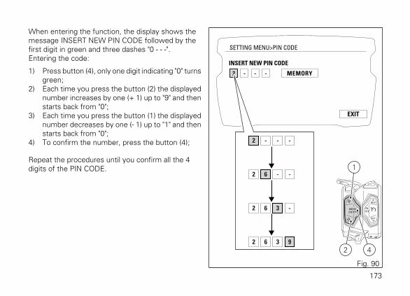
When entering the function, the display shows themessage INSERT NEW PIN CODE followed by thefirst digit in green and three dashes "0 - - -".Entering the code:
1) Press button (4), only one digit indicating "0" turnsgreen;
2) Each time you press the button (2) the displayednumber increases by one (+ 1) up to "9" and thenstarts back from "0";
3) Each time you press the button (1) the displayednumber decreases by one (- 1) up to "1" and thenstarts back from "0";
4) To confirm the number, press the button (4);
Repeat the procedures until you confirm all the 4digits of the PIN CODE.
EXIT
SETTING MENU>PIN CODE
- - - MEMORY
INSERT NEW PIN CODE
2
2 - - -
2 6 - -
2 6 3 -
2 6 3 9
42
1
Fig. 90
173

When you press button (4) to confirm the fourth andlast digit, the instrument panel highlights themessage MEMORY.To save the new setting, hold button (4) for twoseconds while the message MEMORY is highlightedin orange.If storage is successful, MEMORIZED will behighlighted in green for 1 second, and then EXIT willbe highlighted in green.Once the first PIN CODE is stored, this menu page isno longer available and is replaced by the page forchanging the PIN CODE. The page for entering thevery first PIN CODE is active and available again onlyin case the PIN CODE function is reset (but this is onlypossible at a DUCATI Authorised Service Centre).
EXIT
SETTING MENU>PIN CODE
6 3 9 MEMORY
INSERT NEW PIN CODE
2
EXIT
SETTING MENU>PIN CODE
6 3 9 MEMORIZED
INSERT NEW PIN CODE
2
EXIT
SETTING MENU>PIN CODE
6 3 9 MEMORY
INSERT NEW PIN CODE
2
Fig. 91
174

Changing the PIN CODETo change the existing PIN CODE and activate a newone, you must open the Setting Menu.Select "PIN CODE" option, by pressing button (1) or(2). Once function is highlighted, press button (4). Youopen the "PIN CODE" menu. When opening thefunction, the screen displays INSERT OLD PIN CODEand three dashes "0 - - -", the first digit "0" ishighlighted in green.Entering the "old" code:
1) Press button (4), only one digit indicating "0" turnsgreen;
2) Each time you press the button (2) the displayednumber increases by one (+ 1) up to "9" and thenstarts back from "0";
3) Each time you press the button (1) the displayednumber decreases by one (- 1) up to "1" and thenstarts back from "0";
4) To confirm the number, press the button (4);
2 - - -
2 6 - -
2 6 3 -
2 6 3 9
EXIT
SETTING MENU>PIN CODE
- - -
INSERT OLD PIN CODE
- - - - MEMORY
INSERT NEW PIN CODE
PIN CODE ALREADY PRESENT
0
42
1
Fig. 92
175

Repeat the procedures until you confirm all the 4digits of the PIN CODE.When you press button (4) to confirm the fourth andlast digit:
- if the PIN is not correct, the instrument paneldisplays WRONG for 3 seconds and thenhighlights the string of four dashes "- - - -" for theOLD PIN to allow you to try again;
- if the PIN code is correct, the instrument paneldisplays CORRECT for 3 seconds, the screendisplays INSERT NEW PIN CODE and fourdashes "- - - -", the first of which is highlighted ingreen, for the user to enter the new PIN CODE.
176

EXIT
SETTING MENU>PIN CODE
6 3 9
INSERT OLD PIN CODE
- - - - MEMORY
WRONG
INSERT NEW PIN CODE
PIN CODE ALREADY PRESENT
2
EXIT
SETTING MENU>PIN CODE
6 3 9
INSERT OLD PIN CODE
- - - - MEMORY
CORRECT
INSERT NEW PIN CODE
PIN CODE ALREADY PRESENT
2
EXIT
SETTING MENU>PIN CODE
6 3 9
INSERT OLD PIN CODE
- - - MEMORY
INSERT NEW PIN CODE
PIN CODE ALREADY PRESENT
2
EXIT
SETTING MENU>PIN CODE
- - -
INSERT OLD PIN CODE
- - - - MEMORY
INSERT NEW PIN CODE
PIN CODE ALREADY PRESENT
-
-
Fig. 93
177

Entering the "new" code:
1) Press button (4), only one digit indicating "0" turnsgreen;
2) Each time you press the button (2) the displayednumber increases by one (+ 1) up to "9" and thenstarts back from "0";
3) Each time you press the button (1) the displayednumber decreases by one (- 1) up to "1" and thenstarts back from "0";
4) To confirm the number, press the button (4)
Repeat the procedures until you confirm all the 4digits of the PIN CODE. 4 - - -
4 5 - -
4 5 1 -
4 5 1 3
EXIT
SETTING MENU>PIN CODE
6 3 9
INSERT OLD PIN CODE
- - - MEMORY
INSERT NEW PIN CODE
PIN CODE ALREADY PRESENT
2
0
42
1
Fig. 94
178

When you press button (4) to confirm the fourth andlast digit, the instrument panel highlights themessage MEMORY.To save the new setting, hold button (4) for twoseconds while the message MEMORY is highlightedin orange.If storage is successful, MEMORIZED will behighlighted in green for two seconds, and then EXITwill be highlighted in green.If settings have not been saved, the instrument panelhighlights again the string of four dashes "- - - -" of theNEW PIN to allow the rider to try again and enter anew code.
To exit the menu and go back to previous page, selectEXIT and press button (4).
EXIT
SETTING MENU>PIN CODE
6 3 9
INSERT OLD PIN CODE
5 1 3 MEMORY
INSERT NEW PIN CODE
PIN CODE ALREADY PRESENT
2
4
EXIT
SETTING MENU>PIN CODE
6 3 9
INSERT OLD PIN CODE
5 1 3 MEMORIZED
INSERT NEW PIN CODE
PIN CODE ALREADY PRESENT
2
4
EXIT
SETTING MENU>PIN CODE
6 3 9
INSERT OLD PIN CODE
5 1 3 MEMORY
INSERT NEW PIN CODE
PIN CODE ALREADY PRESENT
2
4
Fig. 95
179

Display backlighting settingThis function allows selecting the instrument panelbacklighting.You enter the Setting Menu. Select "BACKLIGHT"option, by pressing button (1) or (2). Once function ishighlighted, press button (4).You open the "BACKLIGHT" menu.
RIDING MODE
SETTING MENU
INFO MODE
LAP
PIN CODE
DRL CONTROL
BACKLIGHT
INFO
EXIT
DATE SET
CLOCK SET
INFO SERTVICE
UNIT SETTING
BLUETOOTH
4
Fig. 96
180

When entering the function, available backlightingoptions are indicated on the left: DAY, NIGHT, AUTO,while currently selected option is indicated on theright (above the word EXIT).Press buttons (1) and (2) to highlight the instrumentpanel backlighting options one by one: in particular,use button (2) to highlight the following item andbutton (1) to highlight the previous item. Once thedesired backlighting option is highlighted, pressbutton (4) to confirm. The instrument panelimmediately activates the option selected by the userand highlights the corresponding name.To exit the menu and go back to previous page, selectEXIT and press button (4).
EXIT
EXIT
AUTO
SETTING MENU>BACKLIGHT
AUTO
DAY
NIGHT
AUTO
DAY
NIGHT
42
1
Fig. 97
181

Select DAY (day mode) to permanently set display"white" background for improved readability -recommended in conditions of strong ambient light.Select NIGHT (night mode) to permanently setdisplay black background for dimmed visibility -recommended in case of poor ambient light and/or atnight.Select AUTO (automatic mode) to automaticallyadjust background colour according to ambient light(detected by a sensor).It will be "white" for better visibility with high ambientlight and "black" for a dimmed visibility with lowambient light.
182

Date settingThis function allows user to set or change the date.You enter the Setting MENU.Select "DATE SET" option, by pressing button (1) or(2).Once function is highlighted, press button (4).
ImportantEvery time the battery is disconnected, the date
is reset and must be set again.
RIDING MODE
SETTING MENU
INFO MODE
LAP
PIN CODE
DRL CONTROL
BACKLIGHT
INFO
EXIT
DATE SET
CLOCK SET
INFO SERTVICE
UNIT SETTING
BLUETOOTH
4
Fig. 98
183

When entering the function, available settings areindicated on the left: YEAR, MONTH, DAY, whilecurrent date is indicated on the right (e.g.:2014/08/02).
Year setting
Select "YEAR" option, by pressing button (1) or (2).Once highlighted, press CONFIRM MENU button (4).Year value starts flashing.Press button (1) to decrease year value by 1 unit:2099, 2098, ... 2000, 2099.Press button (2) to increase year value by 1 unit: 2000,2001, ... 2099, 2000.Once you reach the value to be set, press button (4)and the set year will stop flashing.
EXIT
SETTING MENU>DATE SET
YEAR
MONTH 2014 / 08 / 02DAY
Fig. 99
184
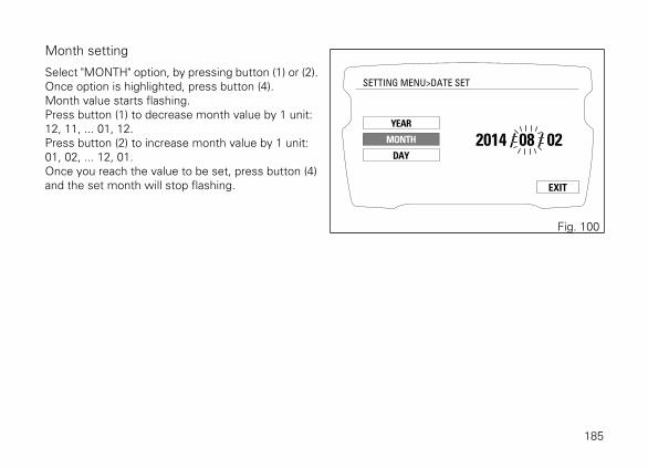
Month setting
Select "MONTH" option, by pressing button (1) or (2).Once option is highlighted, press button (4).Month value starts flashing.Press button (1) to decrease month value by 1 unit:12, 11, ... 01, 12.Press button (2) to increase month value by 1 unit:01, 02, ... 12, 01.Once you reach the value to be set, press button (4)and the set month will stop flashing. EXIT
SETTING MENU>DATE SET
YEAR
MONTH 2014 / 08 / 02DAY
Fig. 100
185

Day setting
Select "DAY" option, by pressing button (1) or (2).Once option is highlighted, press button (4).Day value starts flashing.Press button (1) to decrease day value by 1 unit: 31,30, ... 01, 31.Press button (2) to increase day value by 1 unit: 01,02, ... 31, 01.Once you reach the value to be set, press button (4)and the set day will stop flashing. EXIT
SETTING MENU>DATE SET
YEAR
MONTH 2014 / 08 / 02DAY
Fig. 101
186

Storing the date
To store set/modified date, select MEMORY usingbuttons (1) and (2) and press button (4) for 2 seconds.The instrument panel will display MEMORIZED fortwo seconds and then automatically highlight EXIT.
EXIT
SETTING MENU>DATE SET
YEAR
MONTH 2014 / 08 / 02DAY
MEMORY
MEMORIZED EXIT
SETTING MENU>DATE SET
YEAR
MONTH 2014 / 08 / 02DAY
Fig. 102
187

If date is not correct, the instrument panel will display"WRONG DATE" flashing for three seconds and thenwill automatically highlight EXIT, while date isindicated as "---- / -- / --" steady. It is still possible to seta new date.To go back to previous page (setting menu page),press button (4) when EXIT is highlighted.
EXIT
SETTING MENU>DATE SET
YEAR
MONTH ---- / -- / --DAY
WRONG DATE
EXIT
SETTING MENU>DATE SET
YEAR
MONTH 2014 / 08 / 02DAY
Fig. 103
188

Clock settingThis function allows user to set or adjust the time.You enter the Setting Menu. Select "CLOCK SET"option, by pressing button (1) or (2).Once function is highlighted, press button (4). Youopen the "CLOCKSET" Menu.
NoteEvery time the battery is disconnected, the
clock is reset and must be set again by the user.
RIDING MODE
SETTING MENU
INFO MODE
LAP
PIN CODE
DRL CONTROL
BACKLIGHT
INFO
EXIT
DATE SET
CLOCK SET
INFO SERTVICE
UNIT SETTING
BLUETOOTH
4
Fig. 104
189

When entering the function, available settings areindicated on the left: AM / PM, HOURS, MINUTES,while set time is indicated on the right (e.g.: AM 10 :30).
To exit the menu and go back to previous page, selectEXIT and press button (4).
Setting AM/PM
Select "AM/PM" option, by pressing button (1) or (2).Once highlighted, press CONFIRM MENU button (4).The value will start flashing.Select AM or PM option, by pressing button (1) or (2)respectively.Once you reach the value to be set, press button (4)and the set value will stop flashing.
EXIT
SETTING MENU>CLOCK SET
AM / PM
HOURS 10 : 25MINUTES
AM
Fig. 105
190

Setting the hours
Select "HOURS" option, by pressing button (1) or (2).Once option is highlighted, press button (4). Hourvalue starts flashing.Press button (1) to decrease hour value by 1 unit: 12,11, ... 1, 12.Press button (2) to increase hour value by 1 unit: 12,1, ... 12.Once you reach the value to be set, press button (4)and the set hour value will stop flashing. EXIT
SETTING MENU>CLOCK SET
AM / PM
HOURS 10 : 25MINUTES
AM
Fig. 106
191

Setting the minutes
Select "MINUTES" option, by pressing button (1) or(2).Once highlighted, press CONFIRM MENU button (4).Minute value starts flashing.Press button (1) to decrease minute value by 1 unit:59, 58, ... 00, 59.Press button (2) to increase minute value by 1 unit:00, 01, ... 59, 00.Once you reach the value to be set, press CONFIRMMENU button (4) and the set minutes will stopflashing.
EXIT
SETTING MENU>CLOCK SET
AM / PM
HOURS 10 : 25MINUTES
AM
Fig. 107
192

Service informationThis Function allows viewing information about theremaining time or mileage until the next Oil Service,Desmo Service and Annual Service.To view them, enter the Setting Menu, use button (1)or (2) to select INFO SERVICE and press button (4).Available information:
- DESMO SERVICE: indicates the km (or mile)count-down to the next DESMO SERVICE;
- OIL SERVICE: indicates the km (or mile) count-down to the next OIL SERVICE;
- ANNUAL SERVICE: indicates the ANNUALSERVICE expiration date.
RIDING MODE
SETTING MENU
INFO MODE
LAP
PIN CODE
DRL CONTROL
BACKLIGHT
INFO
EXIT
DATE SET
CLOCK SET
INFO SERTVICE
UNIT SETTING
BLUETOOTH
4
Fig. 108
EXIT
SETTING MENU>INFO SERVICE
DESMO SERVICE
ANNUAL SERVICE 28 / 02 / 2016
- 11550 KM
OIL SERVICE
- 8550 KM
Fig. 109
193
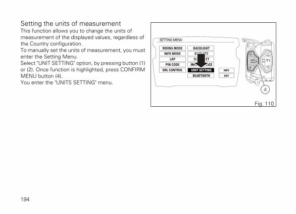
Setting the units of measurementThis function allows you to change the units ofmeasurement of the displayed values, regardless ofthe Country configuration.To manually set the units of measurement, you mustenter the Setting Menu.Select "UNIT SETTING" option, by pressing button (1)or (2). Once function is highlighted, press CONFIRMMENU button (4).You enter the "UNITS SETTING" menu.
RIDING MODE
SETTING MENU
INFO MODE
LAP
PIN CODE
DRL CONTROL
BACKLIGHT
INFO
EXIT
DATE SET
CLOCK SET
INFO SERTVICE
UNIT SETTING
BLUETOOTH
4
Fig. 110
194

When entering the function, the display shows on theleft the list of values for which units of measurementscan be set:
- SPEED;- TEMPERATURE;- fuel consumption (CONSUMPTION);- reset to automatic settings (DEFAULT).
To exit the menu and go back to previous page, selectEXIT and press button (4). EXIT
EXIT
SETTING MENU>UNITS SETTING
SPEED
SPEED
TEMPERATURE
TEMPERATURE
CONSUMPTION
CONSUMPTION
ALL DEFAULT
Km/h
Km/h °C L/100
°C
mph
°F
Km/L mpg Uk mpg USAL/100
ALL DEFAULT
42
1
Fig. 111
195
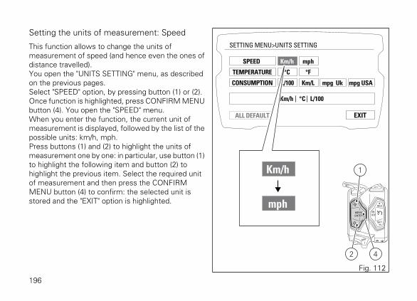
Setting the units of measurement: Speed
This function allows to change the units ofmeasurement of speed (and hence even the ones ofdistance travelled).You open the "UNITS SETTING" menu, as describedon the previous pages.Select "SPEED" option, by pressing button (1) or (2).Once function is highlighted, press CONFIRM MENUbutton (4). You open the "SPEED" menu.When you enter the function, the current unit ofmeasurement is displayed, followed by the list of thepossible units: km/h, mph.Press buttons (1) and (2) to highlight the units ofmeasurement one by one: in particular, use button (1)to highlight the following item and button (2) tohighlight the previous item. Select the required unitof measurement and then press the CONFIRMMENU button (4) to confirm: the selected unit isstored and the "EXIT" option is highlighted.
EXIT
SETTING MENU>UNITS SETTING
SPEED
TEMPERATURE
CONSUMPTION
Km/h
Km/h °C L/100
°C
mph
Km/h
mph
°F
Km/L mpg Uk mpg USAL/100
ALL DEFAULT
42
1
Fig. 112
196

The selected unit of measurement will be used by theinstrument panel for the following indications:
- Motorcycle speed and Average speed (km/h ormph);
- Odometer, Trip1, Trip2 and Range (km or mi).
197
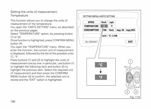
Setting the units of measurement:Temperature
This function allows you to change the units ofmeasurement of the temperature.You open the "UNITS SETTING" menu, as describedon the previous pages.Select "TEMPERATURE" option, by pressing button(1) or (2).Once function is highlighted, press CONFIRM MENUbutton (4).You open the "TEMPERATURE" menu. When youenter the function, the current unit of measurementis displayed, followed by the list of the possible units:°C, °F.Press buttons (1) and (2) to highlight the units ofmeasurement one by one: in particular, use button (1)to highlight the following item and button (2) tohighlight the previous item. Select the required unitof measurement and then press the CONFIRMMENU button (4) to confirm: the selected unit isstored and the "EXIT" option is highlighted.
EXIT
SETTING MENU>UNITS SETTING
SPEED
TEMPERATURE
CONSUMPTION
Km/h
Km/h °C L/100
°C
mph
°C
°F
°F
Km/L mpg Uk mpg USAL/100
ALL DEFAULT
42
1
Fig. 113
198

The selected unit of measurement will be used by theinstrument panel for the following indications:
- Engine coolant temperature and ambient airtemperature.
199

Setting the units of measurement: Fuelconsumption
This function allows you to change the units ofmeasurement of the fuel consumption.You open the "UNITS SETTING" menu, as describedon the previous pages.Select "CONSUMPTION" option, by pressing button(1) or (2).Once function is highlighted, press CONFIRM MENUbutton (4). You open the "CONSUMPTION" menu.When you enter the function, the current unit ofmeasurement is displayed, followed by the list of thepossible units: L / 100km, km / L, mpg (UK), mpg(USA).Press buttons (1) and (2) to highlight the units ofmeasurement one by one: in particular, use button (1)to highlight the following item and button (2) tohighlight the previous item.Select the required unit of measurement and thenpress the CONFIRM MENU button (4) to confirm: theselected unit is stored and the "EXIT" option ishighlighted.
EXIT
SETTING MENU>UNITS SETTING
SPEED
TEMPERATURE
CONSUMPTION
ALL DEFAULT
Km/h
Km/h °C L/100
°C
mph
°F
Km/L mpg Uk mpg USAL/100
Km/L
mpg Uk
mpg USA
L/100
42
1
Fig. 114
200

The selected unit of measurement will be used by theinstrument panel for the following indications:
- Instantaneous fuel consumption and Averagefuel consumption.
201
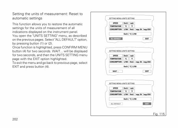
Setting the units of measurement: Reset toautomatic settings
This function allows you to restore the automaticsettings for the units of measurement of allindications displayed on the instrument panel.You open the "UNITS SETTING" menu, as describedon the previous pages. Select "ALL DEFAULT" option,by pressing button (1) or (2).Once function is highlighted, press CONFIRM MENUbutton (4) for two seconds. WAIT... will be displayedfor two seconds, and then the UNITS SETTING menupage with the EXIT option highlighted.To exit the menu and go back to previous page, selectEXIT and press button (4).
EXIT
SETTING MENU>UNITS SETTING
SPEED
TEMPERATURE
CONSUMPTION
ALL DEFAULT
Km/h
Km/h °C L/100
°C
mph
°F
Km/L mpg Uk mpg USAL/100
EXIT
SETTING MENU>UNITS SETTING
SPEED
TEMPERATURE
CONSUMPTION
WAIT . . .
Km/h
Km/h °C L/100
°C
mph
°F
Km/L mpg Uk mpg USAL/100
EXIT
SETTING MENU>UNITS SETTING
SPEED
TEMPERATURE
CONSUMPTION
ALL DEFAULT
Km/h
Km/h °C L/100
°C
mph
°F
Km/L mpg Uk mpg USAL/100
Fig. 115
202

Bluetooth device settingThis function allows pairing and/or deleting any pairedBluetooth devices (XDiavel S).To do this, you must enter the Setting Menu.Select "BLUETOOTH" option, by pressing button (1)or (2). Once function is highlighted, press button (4).You enter the "BLUETOOTH" menu, which is activeonly if the Bluetooth function is active.The BLUETOOTH menu is not available if the playeris active or being used, or when there is an incomingcall, a call is in progress or during recall.To carry out the pairing procedure, refer to "Pairing ofa new device".To delete any paired devices, refer to "Deleting apaired device".
RIDING MODE
SETTING MENU
INFO MODE
LAP
PIN CODE
DRL CONTROL
BACKLIGHT
INFO
EXIT
DATE SET
CLOCK SET
INFO SERTVICE
UNIT SETTING
BLUETOOTH
4
Fig. 116
203

Pairing of a new device
This function allows user to associate (pair) one orseveral Bluetooth devices by running the "PAIRING"control.Set the Bluetooth device to ensure it can be detectedby the control unit, so turn device on and make itvisible to other devices.A Bluetooth device in visible mode transmits awireless signal allowing it to be detected by otherdevices. This function is called pairing mode.The X Diavel S is equipped with a Bluetooth controlunit that works as a hub between the varioussupported electronic devices relying on a Bluetoothcommunication interface.
WarningBluetooth Headset device manufacturers may
incorporate certain changes within the standardprotocols over the course of the lifecycle of thedevice (Smartphones and Earphones).
WarningThese changes are outside the control of Ducati
and may result in Bluetooth Headset devicesfunctionality becoming impaired (sharing Music,multimedia player, etc.) and may equally affect sometypes of Smartphones (depending on supportedBluetooth profiles). This is why Ducati cannotguarantee multimedia player proper operation for:- any earphones not coming with the "Ducati Kit
part no. 981029498";- any Smartphones not supporting the required
Bluetooth profiles (even though paired toearphones coming with the "Ducati Kit part no.981029498").
WarningIn case of interference or noise due to particular
conditions of the external environment, the Ducatiearphone kit no. 981029498 also allows sharing themusic being played directly from rider helmet topassenger helmet (for further details please refer tothe manual of the earphones coming with the Ducatikit part no. 981029498).
204

NoteThe Ducati kit no. 981029498 can be purchased
separately at a Ducati Dealer or Authorised ServiceCentre.
Upon the first access to the BLUETOOTH SettingMenu, the first default displayed label will be"PAIRING" and on the left side the list of the devicealready paired.The Pairing function is activated by pressing button(4): this runs a search for all Bluetooth devicespresent within a certain range. Device search symbolis activated and message "WAIT…" is displayed.The pairing ends automatically when devices aredetected within the range and shown in the list on theright.If Pairing is not successful, "PAIRING LOST. PLEASEEXIT" message will be displayed. Now you can onlyquit the BLUETOOTH Setting Menu, and then goback in to run a new Pairing procedure.If Pairing is successful, as soon as Bluetooth devicesare detected, their name is displayed in the device liston the right.The list of devices found within the range during thePairing stage does not include already paired devices,that are displayed in the list on the left.
If two or more Bluetooth devices have the samename, the list of the devices detected will include twoor more labels with the same name.If one of the devices detected has no name, it is notincluded in the list of devices detected.During the search it is possible to scroll through thedevice list on the right by pressing buttons (1) and (2).In correspondence of the device that is to be paired,select "CONNECT" and press button (4) to pair it.To quit the Pairing stage, select EXIT and pressbutton (4).
205

EXIT
PAIRING
ASSOCIATED DEVICES
AGV_CITYLIGHT DEL
IPHONE_5S_MARK DEL
ARAI_SIGNET-Q DEL
ARAI_SIGNET-R DEL
SETTING MENU>BLUETOOTH
EXIT
PAIRING
ASSOCIATED DEVICESPAIRING LOST
PLEASE EXITAGV_CITYLIGHT DEL
IPHONE_5S_MARK DEL
ARAI_SIGNET-Q DEL
ARAI_SIGNET-R DEL
SETTING MENU>BLUETOOTH
EXIT
PAIRING
ASSOCIATED DEVICES
AGV_CITYLIGHT DEL
IPHONE_5S_MARK DEL
ARAI_SIGNET-Q DEL
ARAI_SIGNET-R DEL
SETTING MENU>BLUETOOTH
(( ))
EXIT
PAIRING
ASSOCIATED DEVICES TOMTOM_BT_22
AGV_CITYLIGHT DEL
CONNECT
GARMIN_NUVI_42 CONNECT
GALAXY_S5_MIKE CONNECT
NEXUS_5NIK CONNECT
IPHONE_5S_MARK DEL
ARAI_SIGNET-Q DEL
ARAI_SIGNET-R DEL
SETTING MENU>BLUETOOTH
(( ))
4
4
4
Fig. 117
206

It is possible to pair up to:
- 2 smartphones;- 1 navigator;- 1 rider helmet;- 1 passenger helmet.
If at least 5 devices have already been paired and theuser attempts to run the Pairing, the followingmessage will be displayed: "MAX 5 DEVICES CAN BEASSOCIATED" and "REFER TO USER MANUAL".System automatically highlights DELETE indicationfor the first associated device and user can delete oneor several devices (refer to Deleting associateddevices) or quit the Bluetooth Setting Menu, bypressing EXIT.
EXIT
PAIRING
ASSOCIATED DEVICES TOMTOM_BT_22
AGV_CITYLIGHT DEL
GARMIN_NUVI_42 DEL
WAIT...
GARMIN_NUVI_42 CONNECT
GALAXY_S5_MIKE CONNECT
NEXUS_5NIK CONNECTIPHONE_5S_MARK DEL
ARAI_SIGNET-Q DEL
ARAI_SIGNET-R DEL
SETTING MENU>BLUETOOTH
EXIT
PAIRING
ASSOCIATED DEVICES
AGV_CITYLIGHT DEL
GARMIN_NUVI_42 DEL
IPHONE_5S_MARK DEL
ARAI_SIGNET-Q DEL
ARAI_SIGNET-R DEL
SETTING MENU>BLUETOOTH
MAX 5 DEVICES
CAN BE ASSOCIATED
REFER TO
USER MANUAL
4
44
Fig. 118
207

When the device to be paired has been selected, thelabel in correspondence of that device replaces theword "CONNECTED" with "WAIT" and it is necessaryto select the type of device to be paired. The displayshows four icons that represent the available types.Types of devices can be:
- Smartphone;- Rider helmet;- Passenger helmet;- GPS navigation system.
Use buttons (1) and (2) to select the type and pressbutton (4) to confirm.
208
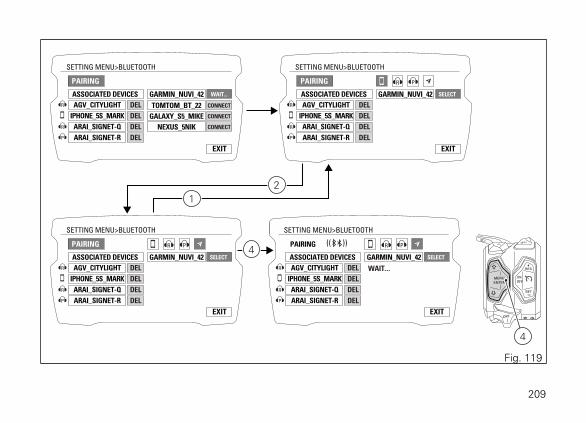
EXIT
PAIRING
ASSOCIATED DEVICES
AGV_CITYLIGHT DEL
IPHONE_5S_MARK DEL
ARAI_SIGNET-Q DEL
ARAI_SIGNET-R DEL
SETTING MENU>BLUETOOTH
GARMIN_NUVI_42 WAIT...
TOMTOM_BT_22 CONNECT
GALAXY_S5_MIKE CONNECT
NEXUS_5NIK CONNECT
EXIT
PAIRING
ASSOCIATED DEVICES
AGV_CITYLIGHT DEL
IPHONE_5S_MARK DEL
ARAI_SIGNET-Q DEL
ARAI_SIGNET-R DEL
SETTING MENU>BLUETOOTH
GARMIN_NUVI_42 SELECT
EXIT
PAIRING
ASSOCIATED DEVICES
AGV_CITYLIGHT DEL
IPHONE_5S_MARK DEL
ARAI_SIGNET-Q DEL
ARAI_SIGNET-R DEL
SETTING MENU>BLUETOOTH
GARMIN_NUVI_42 SELECT
EXIT
PAIRING
ASSOCIATED DEVICES
AGV_CITYLIGHT DEL
IPHONE_5S_MARK DEL
ARAI_SIGNET-Q DEL
ARAI_SIGNET-R DEL
SETTING MENU>BLUETOOTH
GARMIN_NUVI_42 SELECT
WAIT...
(( ))
4
2
1
4
Fig. 119
209

Smartphone
To pair a Smartphone, the pairing procedure with theBluetooth control unit requires user to enter a code(0000), which is only necessary the first time thedevice is paired with the Bluetooth control unit.In this case, during the pairing the display shows thePIN to be entered "INSERT PIN ON SMARTPHONE:0000".As soon as the user enters the PIN on theSmartphone, the device is paired and indicated in thelist on the left.
GPS navigation system
If you wish to pair a Bluetooth Navigator, the pairingprocedure is completed on the navigator, by selectingon the latter the connection with the motorcycleBluetooth control unit.In this case, during the pairing the display shows themessage "CONNECT ON NAVI" that disappears whenthe connection between the control unit and thenavigator is completed, and the name of the navigatoris indicated in the list on the left.
NoteIf user does not complete the pairing procedure
on the Navigator within 90 seconds, pairing screen oninstrument panel will go out, and display will go backto Bluetooth Setting Menu main screen.
If the navigator pairing is active for more than 90seconds and so there have been errors in theprocedure, it is not possible to select the detecteddevices. It is only possible to press on EXIT to abortthe procedure if deemed necessary.
Once the pairing is completed, the name of the paireddevice is shown in the device list on the left: only thefirst characters of the device name are displayed.Pairing deactivation takes place when quitting theBluetooth Setting Menu or when no more Bluetoothdevices are detected.
210

EXIT
PAIRING
ASSOCIATED DEVICES
AGV_CITYLIGHT DEL
DEL
GARMIN_NUVI_42 DEL
ARAI_SIGNET-Q DEL
ARAI_SIGNET-R DEL
SETTING MENU>BLUETOOTH
GALAXY_S5_MIKE
EXIT
PAIRING
ASSOCIATED DEVICES
AGV_CITYLIGHT DEL
GARMIN_NUVI_42 DEL
ARAI_SIGNET-Q DEL
ARAI_SIGNET-R DEL
SETTING MENU>BLUETOOTH
GALAXY_S5_MIKE SELECT
(( ))
INSERT PIN ON
SMARTPHONE: 0000
EXIT
PAIRING
ASSOCIATED DEVICES
AGV_CITYLIGHT DEL
IPHONE_5S_MARK DEL
ARAI_SIGNET-Q DEL
ARAI_SIGNET-R DEL
SETTING MENU>BLUETOOTH
GARMIN_NUVI_42 SELECT
(( ))
CONNECT
ON NAVI
EXIT
PAIRING
ASSOCIATED DEVICES
AGV_CITYLIGHT DEL
GARMIN_NUVI_42 DEL
IPHONE_5S_MARK DEL
ARAI_SIGNET-Q DEL
ARAI_SIGNET-R DEL
SETTING MENU>BLUETOOTH
42
1
Fig. 120
211

Deleting associated devices
From the Bluetooth setting menu it is possible toaccess the list of the paired devices on the left.From the list of paired devices, user can select thedevice to be deleted by pressing button (1) or button(2). When the device is selected and the relevant DELlabel is green, press button (4) for at least twoseconds to eliminate the device from the paireddevice list.Select EXIT by pressing button (1) or (2) and pressingbutton (4) you quit the Bluetooth Setting Menu andgo back to the main Setting Menu screen.
212

EXIT
PAIRING
ASSOCIATED DEVICES
AGV_CITYLIGHT DEL
GARMIN_NUVI_42 DEL
IPHONE_5S_MARK DEL
ARAI_SIGNET-Q DEL
ARAI_SIGNET-R DEL
SETTING MENU>BLUETOOTH
EXIT
PAIRING
ASSOCIATED DEVICES
AGV_CITYLIGHT DEL
GARMIN_NUVI_42 DEL
IPHONE_5S_MARK DEL
ARAI_SIGNET-Q DEL
ARAI_SIGNET-R DEL
SETTING MENU>BLUETOOTH
EXIT
PAIRING
ASSOCIATED DEVICES
AGV_CITYLIGHT DEL
GARMIN_NUVI_42 DEL
IPHONE_5S_MARK DEL
ARAI_SIGNET-Q DEL
ARAI_SIGNET-R DEL
SETTING MENU>BLUETOOTH
EXIT
PAIRING
ASSOCIATED DEVICES
GARMIN_NUVI_42 DEL
IPHONE_5S_MARK DEL
ARAI_SIGNET-Q DEL
ARAI_SIGNET-R DEL
SETTING MENU>BLUETOOTH
42
1
2
1
4
2
1
Fig. 121
213
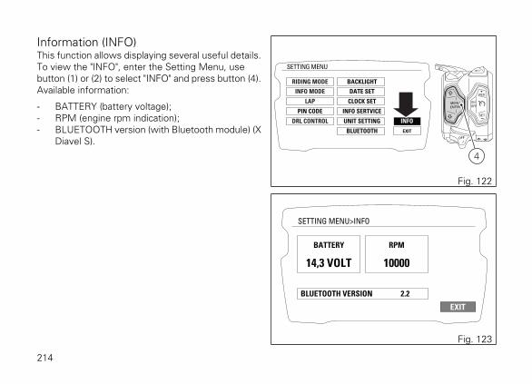
Information (INFO)This function allows displaying several useful details.To view the "INFO", enter the Setting Menu, usebutton (1) or (2) to select "INFO" and press button (4).Available information:
- BATTERY (battery voltage);- RPM (engine rpm indication);- BLUETOOTH version (with Bluetooth module) (X
Diavel S).
RIDING MODE
SETTING MENU
INFO MODE
LAP
PIN CODE
DRL CONTROL
BACKLIGHT
INFO
EXIT
DATE SET
CLOCK SET
INFO SERTVICE
UNIT SETTING
BLUETOOTH
4
Fig. 122
EXIT
SETTING MENU>INFO
BATTERY
BLUETOOTH VERSION 2.2
14,3 VOLT
RPM
10000
Fig. 123
214

Light controlLow/high beam (version without DRL)
At Key-On, the high beam and low beam lights areOFF: only the parking lights are turned on.Once the engine is started, the low beam isautomatically turned on; it is possible to switch fromlow beam to high beam and vice versa by pressingbutton (3) in positions (A) and (B). If engine is notstarted upon key-on, it is anyway possible to switchhigh/low beams on by pushing button (3) position (C)on LH switch.If within 60 seconds from the "manual" switching onof the low / high beam the engine is not started, thelights are disabled again (off).
33
C
A
B
Fig. 124
215

Low/high beam (version with DRL)
At Key-On, the high beam and low beam lights areOFF: only the parking lights and the DRL light areturned on.After starting the engine the high beam isautomatically turned on if the AUTO mode is set andthe instrument panel detects poor ambient light(NIGHT): if, on the other hand, the instrument paneldetects good light conditions (DAY), the DRL lightremains on and the low beam remains off; it ispossible to switch the DRL light to low beam (andvice versa) with button (9).It the low beam is activated, it is possible to switchon the high beam with button (3), position (A). Ifengine is not started upon key-on, it is anywaypossible to switch high/low beams on by pushingbutton (3) position (C) on LH switch.If within 60 seconds from the "manual" switching onof the low / high beam the engine is not started, thelights are disabled again (off).
33
9
C
A
Fig. 125
216

High/low beam switching off during vehiclestart (version without DRL light).
To preserve the motorcycle battery, if when startingthe engine the high/low beams are ON, the headlightis automatically switched off and then on again whenthe engine is started.
High/low beam switching off during vehiclestart (version with DRL lights).
To preserve the motorcycle battery, if when startingthe engine the high/low beams or the DRL lights areON, the headlight is automatically switched off andthen on again when the engine is started.
217

DRL (Daytime Running Light) — only forversion with DRL lights
Upon each Key-On, the DRL lights are turned on. It ispossible to switch off the DRL lights by means ofbutton (9) on the left-hand switch. By pressing button(9) again, the DRL lights are switched on again.
NoteEvery time button (9) is pressed, the DRL light
automatically switches to MANUAL mode. To goback to the AUTO mode, turn the Key Off and On orset the AUTO mode by means of the DRL CONTROLfunction in the Setting Menu.
By pressing button (3) the high and low beams areturned on whereas the DRL light is turned off. Uponreleasing the light button (3), the DRL light isautomatically switched on again.
33
9
Fig. 126
CORE
A
A
M
0Km/h
SPORT
1
2
3 4 5 67
8
9
10
TOT 302721 Km
RPM x1000
NFig. 127
218

DRL in AUTO modeIf the DRL is in this mode, when starting the engineit automatically switches off and the low beam isactivated if the instrument panel detects poor lightconditions (NIGHT). If the instrument panel detectsgood light conditions (DAY), the DRL remains on andthe low beam off: in this mode, the instrument panelautomatically switches from the DRL light to the lowbeam and vice versa, according to the detectedambient light conditions. The display shows thegreen logo with letter A.
WarningUsing the DRL light in AUTO (automatic) mode
in case of poor light conditions, especially in case offog or clouds, could impair safety: in this caseDUCATI recommends to manually activate the lowbeam.
DRL in MANUAL modeIf the DRL light is in this mode, it does not changestatus when starting the engine. To switch on or offthe DRL light it is necessary to press button (9). Thedisplay shows the yellow logo with letter M.
WarningUsing the DRL light in poor light conditions
(dark) could compromise the riding visibility anddazzle who is coming on the opposite lane.
NoteUsing the DRL light during the day improves
visibility as it is easier to perceive by those coming onthe opposite side compared with the low beam.
219

Turn indicators
Turn indicators are automatically reset by theinstrument panel.To activate the left turn indicators, press button (10)in position (I); to activate the right turn indicators,press button (10) in position (L).Turn indicators can be cancelled by pressing button(10) on LH switch.If the turn indicator is not reset manually, theinstrument panel will automatically switch it off afterthe motorcycle has travelled 500 m (0.3 miles) fromwhen the turn indicator was activated. The counterfor the distance travelled for automatic deactivationis only activated at speeds below 80 km/h (50 mph).If the calculation of the distance for automaticdeactivation is activated and then the motorcycleexceeds a speed of 80 km/h (50 mph), the calculationwill be interrupted and will restart when the speedreturns below the indicated threshold.
10
I L
Fig. 128
220

Hazard function
The "Hazard" function turns all four turn indicators onat the same time to signal an emergency condition.Push button (11) to activate the "Hazard" function. Itcan only be activated when vehicle is turned on (Key-ON). When the "Hazard" function is active, all four turnindicators blink at the same time as well as warninglights on the instrument panel. The "Hazard" functioncan be manually turned off exclusively when vehicleis on (Key-ON), by pressing button (11).
11
Fig. 129
Fig. 130
221

Once the "Hazard" function is activated, if vehicle isturned off (key turned to "OFF"), the function staysactive for 2 hours. After 2 hours, the turn indicatorsswitch OFF automatically in order to save batterycharge.
NoteWhen turning the vehicle key ON with "Hazard"
function still active, the function remains active.
NoteIf there is a sudden interruption in the battery
while the function is active, the instrument panel willdisable the function when the voltage is restored.
NoteThe "Hazard" function has higher priority
compared to normal operation of the single turnindicators, this means that, as long as it is active, itwill not be possible to activate the single right or leftturn indicators.
222

Warning reading "Keep pressed to lock" (uponKey-Off)
This warns that it is necessary to keep the buttonpressed to engage the steering lock.The steering lock can be turned on during the first 60seconds after turning off the vehicle by pressing thestarter button.Message "KEEP PRESSED TO LOCK" is displayed ifthe starter button is depressed for at least 1 second.
KEEPPRESSEDTO LOCK
Fig. 131
223

Warning reading "Steering locked" (upon Key-Off)
This warns that the steering lock was activated afterKey-Off.If the steering lock was activated correctly, theInstrument panel will display "STEERING LOCKED"indication for 5 seconds.
STEERINGLOCKED
Fig. 132
224

Indication of No Key Detected (upon Key-Off)
This function informs that it is not possible to engagethe steering lock since the key is not detected.The display shows "NO KEY DETECTED".
NO KEYDETECTED
Fig. 133
225

Immobilizer systemTo further improve the anti-theft protection, themotorcycle is equipped with an engine electronicblock system (IMMOBILIZER) that is automaticallyactivated every time the instrument panel is switchedoff.The grip of each ignition key contains an electronicdevice that modulates the output signal from aspecial antenna in the headlight fairing when theignition is switched On. The modulated signal is the"password", different upon every Key-On, used by thecontrol unit to acknowledge the key. Engine can bestarted only after key acknowledgement.
226

KeysThe Owner receives a set of keys comprising:
- 1 active key (1);- 1 passive key (2).
They contain the code used by the "Hands free"system for the Key-On, in different modes.
The active key (1) is the one that is normally used andhas a button (A) that, when pressed, makes the metalpart exit (B).The metal part returns inside the grip by pushing it in.
2
1
Fig. 134
1
A
B
Fig. 135
227

The active key contains a battery that must bereplaced when the message "low level" is displayedunder the key and battery symbols when theinstrument panel is turned on.
NoteIn this case, replace the battery as soon as
possible.
When the charge level goes below a certain limit, thekey can only work in passive mode, like the passivekey: in this case, the instrument panel will not displayany message. Fig. 136
228

WarningDo not ride with the (active or passive) key
inserted in the lock of the tank cap or in the seat lockas it could come out and represent a potential danger.Furthermore, if bumped, the key mechanism and theintegrated circuit could be damaged.Also riding in poor weather conditions with the keyinserted could cause damage to its integrated circuit.Do not leave the key on the motorcycle whenwashing it as it could be damaged, not beingwatertight.
229

Replacing the battery in the active key
NoteThe keys do not need to be reprogrammed after
replacing the battery.
Remove the metal part of the battery.Remove the rear plastic shell of the grip by pushingit forward and lifting it as shown in the figures.
Fig. 137
1
Fig. 138
230

After separating the plastic shells, remove the batteryprotection cap (2).Remove battery (3) and install a new one.
2
Fig. 139
2
3
+
Fig. 140
231

Install the battery in place, paying attention to respectpolarity: positive pole (+) must be facing up.
ImportantOnly use the required type of battery.
Refit protection cap (2) on the battery.
2
3
+
Fig. 141
2
Fig. 142
232

Reinstall the rear plastic shell and push slightly asshown in the figure.Make sure shells close properly and that the key iswell closed.
1
Fig. 143
Fig. 144
233

Key duplicationWhen a customer needs spare keys, he/she shallcontact a Ducati authorised service centre and bringall keys he/she still has.The Ducati authorised service centre will program allnew and old keys.The Ducati authorised service centre may ask to thecustomer to prove to be the motorcycle owner.The codes of the keys missing during theprogramming procedure will be erased to ensure thatany lost key can not start the engine.
234

Immobilizer unlock procedureIn case of key acknowledgement system or keymalfunction, the instrument panel allows the user toenter his/her own PIN code to temporarily restoremotorcycle operation.If the PIN CODE function is active, the instrumentpanel shows the message "INSER PIN" and four zeros("0") to enter the release PIN CODE.
235

Entering the code:
1) Press button (4), only one digit indicating "0" ishighlighted;
2) each time you press the button (2) the displayednumber increases by one (+ 1) up to "9" and thenstarts back from "0";
3) each time you press the button (1) the displayednumber decreases by one (- 1) up to "1" and thenstarts back from "0";
4) to confirm the number, press the button (4).
Repeat the procedures until you confirm all the digitsof the PIN CODE.
INSER PIN 0000
INSER PIN 2000
INSER PIN 2600
INSER PIN 2630
INSER PIN 263942
1
Fig. 145
236

When you press button (4) to confirm the fourth andlast digit:
- if the PIN code is not correct, the instrumentpanel displays PIN CODE WRONG for threeseconds and then highlights the string of fourzeros ("0") to allow you to try again. The numberof possible attempts is determined by a presettime-out of two minutes.
- if the PIN CODE is correct, the instrument panelshows PIN CODE CORRECT for three seconds,and then displays the "standard screen".
ImportantIf this procedure is necessary in order to start
the motorcycle, contact an Authorised Ducati ServiceCentre as soon as possible to fix the problem.
PIN CODE WRONG
Fig. 146
PIN CODE CORRECT
Fig. 147
237

Controls
Position of motorcycle controls
WarningThis section shows the position and function of
the controls used to ride the motorcycle. Be sure toread this information carefully before you use thecontrols.
1) Instrument panel on handlebar.2) "Hands free" system.3) Left-hand switch.4) Clutch lever.5) Rear brake pedal.6) Right-hand switch.7) Throttle twistgrip.8) Front brake lever.9) Gear change pedal.
9
8
7
5
62
4
3
1
Fig. 148
238

"Hands free" systemThe Hands free system consists of:
1) Hands free lock;2) Antenna;3) Active key;4) Passive key;5) Tank filler plug.
1 2
4
3
5
Fig. 149
239

Hands free system "Key-On" and "Key-Off"
Key-On consists in turning on the hands free systemand all electronic devices. Key-Off consists in turningoff the hands free system and all electronic devices,and ensures engine is turned off. Key-On is doneusing button (6) on the right switch on the handlebaror using the emergency button (7) on the Hands freelock. Key-Off is done using button (6) on the rightswitch on the handlebar or using button (7) on theHands free lock.
NoteUsing one of the two buttons (6) or (7) does not
exclude using the other one, namely if one is pressedfor switching on, the other one can be used forswitching off, and vice versa
6
Fig. 150
7
Fig. 151
240
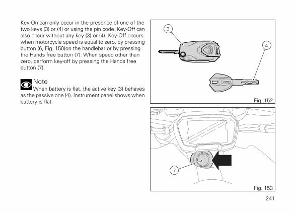
Key-On can only occur in the presence of one of thetwo keys (3) or (4) or using the pin code. Key-Off canalso occur without any key (3) or (4). Key-Off occurswhen motorcycle speed is equal to zero, by pressingbutton (6, Fig. 150)on the handlebar or by pressingthe Hands free button (7). When speed other thanzero, perform key-off by pressing the Hands freebutton (7).
NoteWhen battery is flat, the active key (3) behaves
as the passive one (4). Instrument panel shows whenbattery is flat.
4
3
Fig. 152
7
Fig. 153
241
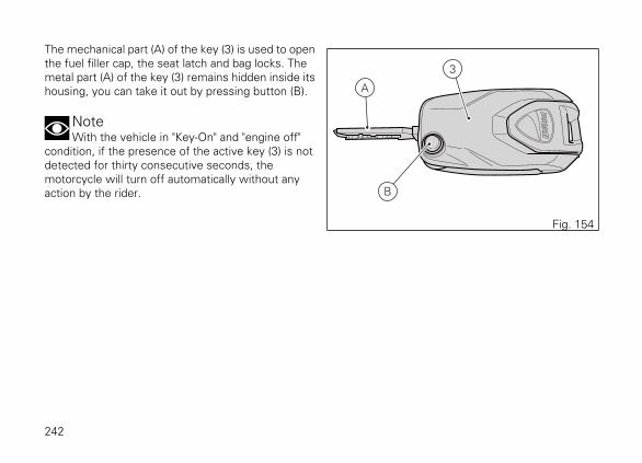
The mechanical part (A) of the key (3) is used to openthe fuel filler cap, the seat latch and bag locks. Themetal part (A) of the key (3) remains hidden inside itshousing, you can take it out by pressing button (B).
NoteWith the vehicle in "Key-On" and "engine off"
condition, if the presence of the active key (3) is notdetected for thirty consecutive seconds, themotorcycle will turn off automatically without anyaction by the rider.
3
B
A
Fig. 154
242
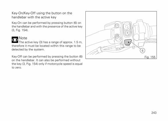
Key-On/Key-Off using the button on thehandlebar with the active key
Key-On can be performed by pressing button (6) onthe handlebar and with the presence of the active key(3, Fig. 154).
NoteThe active key (3) has a range of approx. 1.5 m,
therefore it must be located within this range to bedetected by the system.
Key-Off can be performed by pressing the button (6)on the handlebar. It can also be performed withoutthe key (3, Fig. 154) only if motorcycle speed is equalto zero.
6
Fig. 155
243
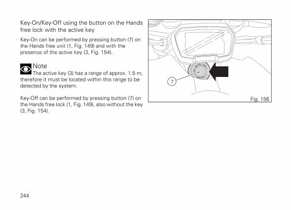
Key-On/Key-Off using the button on the Handsfree lock with the active key
Key-On can be performed by pressing button (7) onthe Hands free unit (1, Fig. 149) and with thepresence of the active key (3, Fig. 154).
NoteThe active key (3) has a range of approx. 1.5 m,
therefore it must be located within this range to bedetected by the system.
Key-Off can be performed by pressing button (7) onthe Hands free lock (1, Fig. 149), also without the key(3, Fig. 154).
7
Fig. 156
244

Key-On/Key-Off using the button on thehandlebar with the passive key
Key-On can be performed by pressing button (6) onthe handlebar and with the presence of the passivekey (4, Fig. 149).
NoteThe passive key (4) has a range of a few cm,
therefore it must be positioned close to the antenna(2).
Key-Off can be performed by pressing the button (6)on the handlebar. It can also be performed withoutthe passive key (4, Fig. 149) only if motorcycle speedis equal to zero.
6
Fig. 157
2
Fig. 158
245

Key-On/Key-Off using the button on the Handsfree lock with the passive key
Key-On can be performed by pressing button (7) onthe Hands free lock and with the presence of thepassive key (4, Fig. 149).
NoteThe passive key (4) has a range of a few cm,
therefore it must be positioned close to the antenna(2).
Key-Off can be performed by pressing button (7) onthe Hands free lock (1, Fig. 149), also without the key(4, Fig. 149).
7
Fig. 159
2
Fig. 160
246

Key-On/Key-Off using the pin code (immobilizeroverride)
Key-On can be performed by pressing button (7) onthe hands free lock (1, Fig. 149) without the presenceof the keys (3, Fig. 154) and (4, Fig. 149) and enteringthe pin code on the instrument panel.Key-Off can be performed by pressing button (6) onthe handlebar, from Engine On position to Engine Offposition.After each Key-Off, if the key is not present upon nextKey-On, the pin code must be entered. The pin codeis set by the customer upon delivery of themotorcycle. The function is not enabled unless a pincode has been set. When the Hands Free button (7)is pressed, the instrument panel allows entering thefour-digit pin code. Entering the correct pin turns onthe instrument panel and enables engine starting. Pincode must be entered within 120 seconds, afterwhich a Key-Off occurs automatically.
6
Fig. 161
7
Fig. 162
247

Entering PIN CODE function for overridingpurposes
This function allows the rider to "temporarily" turn onthe motorcycle in case of HF (Hands Free) system"malfunction".If the motorcycle cannot be turned on using thenormal starter button, press the "emergency" HandsFree button (7) to activate the function.After pressing the button, the instrument panelactivates the release Pin Code enter page. 7
Fig. 163
248

The instrument panel shows INSER PIN and fourzeros ("0") to allow entering the PIN CODE.Enter the code using the function buttons (8), (9) and(10) of the left-hand switch:
1) Press button (8), only one digit indicating "0" ishighlighted;
2) each time you press the button (9) the displayednumber increases by one (+ 1) up to "9" and thenstarts back from "0";
3) each time you press the button (10) the displayednumber decreases by one (- 1) up to "1" and thenstarts back from "0";
4) to confirm the number, press the button (8).
Repeat the procedures until you confirm all the digitsof the PIN CODE.
INSER PIN 0000
INSER PIN 2000
INSER PIN 2600
INSER PIN 2630
INSER PIN 263989
10
Fig. 164
249

When you press function button (8) of the left-handswitch to confirm the fourth and last digit:
- if the PIN code is not correct, the instrumentpanel displays PIN CODE WRONG for threeseconds and then highlights the string of fourzeros ("0") to allow you to try again. The numberof possible attempts is determined by a presettime-out of two minutes.
- if the PIN CODE is correct, the instrument panelshows PIN CODE CORRECT for three seconds,and then displays the "standard screen".
ImportantIf this procedure is necessary in order to start
the motorcycle, contact an Authorised Ducati ServiceCentre as soon as possible to fix the problem.
PIN CODE WRONG
Fig. 165
PIN CODE CORRECT
Fig. 166
250

Left-hand switch1) Dip switch, two-position light selector switch:- pushed up (A): high beam ON ( ), back to its initialposition (B): low beam ON ( );- (C) pushed down: high-beam flasher ( )- (FLASH), "Start-Stop lap" function.
2) 4 turn indicators (Hazard) on/off button.
3) DRL light activation/deactivation button (X DiavelS).
1
2 3
C
A
B
Fig. 167
251

4) Menu navigation button.5) Cruise Control button.6) 3-position turn indicator switch ( ):- centre position = OFF;- position ( ) = left turn;7) Turn indicators cancel button.8) Button ( ) = warning horn.
54
8
6
7
Fig. 168
67
Fig. 169
252

Button (4) for menu navigation features threepositions:- (D) for scrolling menu functions (UP);- (E) for scrolling menu functions (DOWN);- (F) for confirming menu functions.
Button (5) for Cruise Control features three positions:- (G) Cruise Control on/off;- (H) increase cruise speed or resume previous speed;- (I) decrease cruise speed or set a new speed;
5
4
EF
D
I
GH
Fig. 170
253

Key
A) Low beam.B) High beam.D) Menu UPE) Menu DOWN.F) Menu confirm.G) Cruise Off, On.H) Speed +.I) Speed set.2) Hazard.3) DRL (X Diavel S).5) Cruise.6) Turn indicator.7) Turn indicator off.8) Horn.
+
-
ENTER
A
F G
3
5
H
I
7
B
2
D
E
6
8
Fig. 171
254

Clutch leverLever (1) disengages the clutch. It features a dialadjuster (2) for lever distance from the twistgrip onhandlebar. The lever distance can be adjustedthrough 10 clicks of the dial (2). Turn clockwise toincrease lever distance from the twistgrip. Turn theadjuster counter clockwise to decrease leverdistance. When the clutch lever (1) is operated, drivefrom the engine to the gearbox and the drive wheelis disengaged. Using the clutch properly is essentialto smooth riding, especially when moving OFF.
WarningSet clutch lever when motorcycle is stopped.
ImportantUsing the clutch properly will avoid damage to
transmission parts and spare the engine.
12
Fig. 172
NoteThe engine can be started with the side stand
down and the gearbox in neutral. If starting with agear engaged, pull in the clutch lever (in this case theside stand must be up).
255

Right-hand switch1) Red ENGINE OFF switch.2) ENGINE START button.3) System SWITCH-ON/OFF (key-on/key-off) andsteering lock engagement.4) LAUNCH CONTROL button (DPL).
The switch (1) has two positions:
A) pushed up: RUN ON. The engine can only bestarted in this position, pushing the button (2).B) pushed down: KILL ENGINE. 3
21
Fig. 173
A
4
B
1
1
2
Fig. 174
256

Key
2) Engine starting.3) Electronic steering lock.4) Launch Control (DPL).A) Run ON.B) Run OFF.C) Key-on.D) Key-off.
4
2
BA
3
DC
Fig. 175
257

Throttle twistgripThe twistgrip (1) on the right handlebar opens thethrottles. When released, it will spring back to theinitial position (idling speed).
1
Fig. 176
258

Front brake leverPull in the lever (1) towards the twistgrip to operatethe front brake. The system is hydraulically operatedand you just need to pull the lever gently.The brake lever (1) has a dial (2) for adjusting thedistance between lever and twistgrip on thehandlebar.The lever distance can be adjusted through 10 clicksof the dial (2).Turn clockwise to increase lever distance from thetwistgrip. Turn the adjuster counter clockwise todecrease lever distance.
1 2
Fig. 177
259

Rear brake pedalPress pedal (1) down with your foot to operate therear brake.The control system is of the hydraulic type.
1
Fig. 178
260

Gear change pedalWhen released, the gear change pedal automaticallyreturns to rest position N in the centre. This isindicated by the instrument panel N light coming on.The pedal can be moved:
- down = press down the pedal to engage the 1st
gear and to shift down. The N light on theinstrument panel will go out;
- upwards= lift the pedal to engage 2nd gear andthen 3rd, 4th, 5th and 6th gears.
Each time you move the pedal you will engage thenext gear.
N
1
6
5
4
3
2
Fig. 179
261

Adjusting the position of the gearchangepedal and rear brake pedalThe position of the gearchange and rear brake pedalsin relation to the footrests can be adjusted to suit therequirements of the rider.Adjust the pedals as follows:
Gear change pedal
Hold the linkage (1) and slacken the lock nuts (2) and(3).
NoteNut (2) has a left-hand thread.
Fit an open-end wrench to hexagonal element oflinkage (1) and rotate until setting pedal in the desiredposition.Tighten both lock nuts onto linkage.
1
3
2
Fig. 180
262
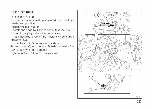
Rear brake pedal
Loosen lock nut (4).Turn pedal stroke adjusting screw (5) until pedal is inthe desired position.Tighten the lock nut (4).Operate the pedal by hand to check that there is 3 ÷6 mm of free play before the brake bites.If not, adjust the length of the master cylinder controlrod as follows:Loosen lock nut (6) on master cylinder rod.Screw the rod (7) into the fork (8) to decrease the freeplay, or screw it out to increase it.Tighten lock nut (6) and check play again.
5
8 6 7
4
Fig. 181
263

Main components anddevices
Position on the vehicle1) Tank filler plug.2) Seat lock.3) Side stand.4) Rear-view mirrors.5) Front fork adjusters.6) Rear shock absorber adjusters.7) Catalytic converter.8) Exhaust silencer.
4
4
5
1
2
6
8 37
Fig. 182
264

Tank filler plugOpening
Lift flap (1) and insert the active or passive key in thelock. Turn the key clockwise by 1/4 of a turn to releasethe lock.Lift the plug (2).
Closing
Close the plug (2) with the key inserted and push itdown into its seat. Remove the key and close flap (1)protecting the lock.
NotePlug can only be closed when key is inserted.
WarningAfter refuelling, always make sure that the plug
is perfectly in place and closed.
1
Fig. 183
2
Fig. 184
265

Seat lockBy working on the lock (1), it is possible to removethe rider seat, to reach the devices placed below it,as well as the passenger seat.
Removing the seats
Insert the active or passive key into the catch (1) andturn it clockwise until the rider seat latch disengageswith an audible click.To remove the rider seat (2), lift it up by sliding its frontside from tank pin (3).
1
OPEN
Fig. 185
2
3
Fig. 186
266

Remove the passenger seat (4) by sliding it from themotorcycle front side. 4
Fig. 187
267

Refitting the seats
Fit the passenger seat (4) by positioning it under belt(5) making it slide to the motorcycle's rear side, andinsert tab (6) in the relevant seat (7).
57
6
4
Fig. 188268

Position the rider seat (2) by making it slide to themotorcycle's front side: make sure that tab (8) isunder the subframe central plate (9), and tank pin (3)in tank slot (10).Slide the seat onwards until fully home and on therear side insert pin (13) in hole (14) and the lateral pins(11) in the vibration damping pads (12) by pressingdown until latch clicks in place. Make sure the riderseat is properly fastened by moderately pulling it up.Take key out of the lock.
2
3
8
12
10
11
9
14
13
Fig. 189
269

Side stand
ImportantPlace the motorcycle on the side stand only
when you are not going to use it for short periods oftime. Before lowering the side stand, make sure thatthe bearing surface is hard and flat.
Do not park on soft or pebbled ground or on asphaltmelt by the sun heat and similar or the motorcyclemay fall over. When parking in downhill road tracts,always park the motorcycle with its rear wheel facingdownhill.To pull down the side stand, hold the motorcyclehandlebar with both hands and push down on theside stand (1) with your foot until it is fully extended.Tilt the motorcycle until the side stand is resting onthe ground.To move the side stand to its rest position (horizontalposition), lean the motorcycle to the right while liftingthe thrust arm (1) with your foot.
1
2
Fig. 190
270

WarningDo not sit on the motorcycle when it is
supported on the side stand.
NoteCheck for proper operation of the stand
mechanism (two springs, one into the other) and thesafety sensor (2) at regular intervals.
NoteThe engine can be started with the side stand
down and the gearbox in neutral. If starting with agear engaged, pull in the clutch lever (in this case theside stand must be up).
271

Bluetooth control unitThe motorcycle (X Diavel S) is equipped with aBluetooth control unit that works as a hub betweenthe various supported electronic devices relying on aBluetooth communication interface.
WarningBluetooth Headset device manufacturers may
incorporate certain changes within the standardprotocols over the course of the lifecycle of thedevice (Smartphones and Earphones).
WarningThese changes are outside the control of Ducati
and may result in Bluetooth Headset devicesfunctionality becoming impaired (sharing Music,multimedia player, etc.) and may equally affect sometypes of Smartphones (depending on supportedBluetooth profiles). This is why Ducati cannotguarantee multimedia player proper operation for:- any earphones not coming with the "Ducati Kit
part no. 981029498";- any Smartphones not supporting the required
Bluetooth profiles (even though paired toearphones coming with the "Ducati Kit part no.981029498").
WarningIn case of interference or noise due to particular
conditions of the external environment, the Ducatiearphone kit no. 981029498 also allows sharing themusic being played directly from rider helmet topassenger helmet (for further details please refer tothe manual of the earphones coming with the Ducatikit part no. 981029498).
272

NoteThe Ducati kit no. 981029498 can be purchased
separately at a Ducati Dealer or Authorised ServiceCentre.
Check that your Smartphone supports the followingprofiles:
- MAP profile: for a correct display of SMS andMMS notifications;
- PBAP profile: for a correct display of theSmartphone contact list.
273

Front fork adjustersThe front fork used on this motorcycle has rebound(return), compression and spring preload adjustment.It is possible to adjust the spring preload andcompression on the left leg whereas the rebound canonly be adjusted on the right leg.Adjustment is done by external screw adjusters:
1) for rebound adjustment;2) for inner spring preload adjustment;3) for compression adjustment.
Put the motorcycle on the side stand and make sureit is stable. Turn adjuster (1) at the top end of the RHfork leg with a flat-blade screwdriver to adjustrebound. Turn adjuster (3) at the top end of the LHfork leg with a flat-blade screwdriver to adjustcompression. By turning adjuster screws (1) and (3)you will hear some clicks; each click corresponds toa damping setting.
3 1
2
- + - +
Fig. 191
274

The stiffest damping setting is obtained with theadjuster turned fully clockwise to the "0" position. Byturning counter clockwise starting from this position,count the clicks that will correspond to positions "1","2" etc.
STANDARD settings are as follows:
- compression: 2 turns from max. (fully closed);- rebound: 2 turns from max. (fully closed);- Spring preload: 5 turns from min. (fully
uncompressed).
275

Rear shock absorber adjustersThe rear shock absorber has adjusters that enable youto suit the setting to the load on the motorcycle.Adjuster (1), located on the swinging arm, adjusts thedamping during the rebound phase (return). Turnadjuster (1) clockwise to stiffen the damping, orcounter clockwise to soften it. The two ring nuts (2),located in the shock absorber upper side, adjust theexternal spring preload. To change spring preload,slacken the upper locking ring nut. Then TIGHTEN orSLACKEN the lower ring nut to INCREASE orDECREASE spring preload.
STANDARD setting from the fully closed position(clockwise):
- rebound: loosen adjuster (1) by 1.5 turns;- spring preload: 18 mm.
- +
12
Fig. 192
276

WarningTo turn the preload adjuster ring nut use a pin
wrench. Pay attention to avoid hand injuries by hittingmotorcycle parts in case the wrench tooth suddenlyslips on the ring nut groove while moving it.
WarningThe shock absorber is filled with gas under
pressure and may cause severe damage if taken apartby unskilled persons.
When carrying a passenger and luggage, set the rearshock absorber spring to proper preload to improvemotorcycle handling and keep safe clearance fromthe ground. You may find that rebound dampingneeds adjusting as well.
277

Riding the motorcycle
Running-in recommendationsMaximum rotation speed
Rotation speed for running-in period and duringstandard use (rpm):1) up to 1,000 km;2) from 1,000 to 2,500 km.
Up to 1,000 km
During the first 1000 km, keep an eye on the revcounter. It should never exceed: 5,500÷6,000 rpm.During the first hours of riding, it is advisable to runthe engine at varying load and rpm, though still withinrecommended limit.To this end, roads with plenty of bends and evenslightly hilly areas are ideal for a most efficientrunning-in of engine, brakes and suspensions.For the first 100 km use the brakes gently. Avoidsudden or prolonged braking. This will allow thefriction material on the brake pads to bed in againstthe brake discs.
For all mechanical parts of the motorcycle to adapt toone another and above all not to adversely affect thelife of basic engine parts, it is advisable to avoid harshaccelerations and not to run the engine at high rpmfor too long, especially uphill.We further recommend to check the drive chainoften.
278

From 1,000 to 2,500 km
At this point, you can squeeze some more power outof your engine. However never exceed 7,000 rpm.
ImportantDuring the whole running-in period, the
maintenance and service rules recommended in theWarranty Card should be observed carefully. Failureto follow these instructions releases Ducati MotorHolding S.p.A. from any liability whatsoever for anyengine damage or shorter engine life.
Strict observance of running-in recommendations willensure longer engine life and reduce the likelihood ofoverhauls and tune-ups.
279
Pre-ride checks
WarningFailure to carry out these checks before riding,
may lead to motorcycle damage and injury to riderand passenger.
Before riding, perform a thorough check-up on yourmotorcycle as follows:
- FUEL LEVEL IN THE TANKCheck the fuel level in the tank. Fill tank if needed(page 293).
- ENGINE OIL LEVELCheck oil level in the sump through the sightglass. Top up if needed (page 314).
- BRAKE AND CLUTCH FLUIDCheck fluid level in the relevant reservoirs (page297).
- COOLANTCheck coolant level in the expansion reservoir.Top up if needed (page 296).
- TYRE CONDITIONCheck tyre pressure and condition (page 312).
- CONTROLSWork the brake, clutch, throttle and gear changecontrols (levers, pedals and twistgrip) and checkfor proper operation.
- LIGHTS AND INDICATORSMake sure lights, indicators and horn workproperly. In case of light malfunction, contact aDucati Dealer or Authorised Service Centre.
- KEY LOCKSEnsure that tank filler plug (page 265) and seat(page 266) are properly locked.
- STANDMake sure side stand operates smoothly and isin the correct position (page 270).
280

ABS light
After Key-ON, the ABS light (10, Fig. 3) stays ON.When the motorcycle speed exceeds 5 km/h, thewarning light switches OFF to indicate the correctoperation of the ABS system.
WarningIn case of malfunction, do not ride the
motorcycle and contact a Ducati Dealer or authorisedService Centre.
281

ABS device
Check that the front (1) and rear (2) phonic wheels areclean.
WarningClogged reading slots would compromise
system proper operation. It is recommended todisable ABS system in case of muddy road surfacebecause under this condition the system might besubject to sudden failure.
WarningProlonged wheelies could deactivate the ABS
system.
1
Fig. 193
2
Fig. 194
282

Engine start/stop
WarningBefore starting the engine, become familiar
with the controls you will need to use when riding.
WarningNever start or run the engine indoors. Exhaust
gases are poisonous and may lead to loss ofconsciousness or even death within a short time.
In the presence of the active or passive key, performa Key-On (turning on the "Hands free" system and allon-board electronic devices) by taking the red switch(1), on the right side of the handlebar, upward andpressing button (2). The instrument panel willperform the initialisation and will control the on-boardsystems, turning on all lights in sequence, from thebottom to the top, for a few seconds. After thiscontrol, only the green light (3) and the red light (4)must remain on.
1
1
2 2
Fig. 195
3 4
Fig. 196
283

WarningThe side stand must be fully up (in a horizontal
position) as its safety sensor prevents engine startingwhen down.
After Key-On, but with the engine not yet started, thesystem will perform a Key-Off automatically if thepresence of the active key is not detected within 10seconds.
NoteIt is possible to start the engine with side stand
down and the gearbox in neutral. When starting themotorcycle with a gear engaged, pull the clutch lever(in this case the side stand must be up).
Move the red switch (1) up to uncover button (5).Push the button (5) to start the engine.
1
1
5
Fig. 197
ImportantDo not rev up the engine when it is cold. Allow
some time for oil to be heated and reach all pointsthat need lubricating.
284

The red oil pressure warning light (4, Fig. 196) shouldgo out a few seconds after the engine has started.The engine will shut off by turning the red button (1)on the handlebar to RUN OFF. To turn on the "Handsfree" system and all electronic onboard systems,refer to page 239 "Hands Free System".
1
1
Fig. 198
285

Moving off1) Squeeze the control lever to disengage the
clutch.2) Push down on gear change lever sharply with the
tip of your foot to engage the first gear.3) Speed up the engine by turning the throttle
twistgrip while gradually releasing the clutchlever; the motorcycle will start moving off.
4) Let go of clutch lever and speed up.5) To shift up, close the throttle to slow down
engine, disengage the clutch, lift the gear changelever and let go of clutch lever. To shift down,proceed as follows: release the twistgrip, pull theclutch lever, shortly speed up to help gearssynchronise, shift down (engage next lowergear) and release the clutch.
The controls should be used correctly and timely:when riding uphill do not hesitate to shift down assoon as the motorcycle tends to slow down, so youwill avoid stressing the engine and the motorcycleabnormally.
WarningAvoid harsh acceleration, as this may lead to
misfiring and transmission snatching. The clutchlever should not be held in longer than necessaryafter a gear is engaged, otherwise friction parts mayoverheat and wear out.
WarningProlonged wheelies could deactivate the ABS
system.
286

BrakingSlow down in time, shift down to use engine brakeand then brake by operating both front and rearbrakes. Pull the clutch before the motorcycle stops toavoid engine from suddenly stalling.
287

Anti-Lock Braking System (ABS)Using the brakes correctly under adverse conditionsis the hardest – and yet the most critical - skill tomaster for a rider. Braking is one of the most difficultand dangerous moments when riding a two wheeledmotorcycle: the possibility of falling or having anaccident during this difficult moment is statisticallyhigher than any other moment. A locked front wheelleads to loss of traction and stability, resulting in lossof control.The Anti-Lock Braking System (ABS) has beendeveloped to enable riders to use the motorcyclebraking force to the fullest possible amount inemergency braking or under poor pavement oradverse weather conditions.ABS is an electro-hydraulic device that controls thepressure in the brake circuit when the control unit, byprocessing information from wheel sensors,determines that one or both wheels are about to lockup. In this case, pressure decrease in the brake circuitallows the wheel to carry on turning, therebypreserving grip.After that, the control unit restores the pressure inthe brake circuit, to resume the braking action. Thiscycle is repeated many times until the problem iscompletely eliminated.
Normally, the rider will perceive ABS operation as aharder feel or a pulsation of the brake lever and pedal.The front and rear brakes use separate controlsystems.The X Diavel ABS also features a "cornering" functionthat widens ABS functionality to the conditionswhere the motorcycle is leaning over, thus controllingthe front and rear brake systems depending on thevehicle lean angle with the purpose of preventingwheel lockup and slipping as much as possible, withinthe physical limits allowed by the vehicle and by theroad conditions.If desired, the system can be deactivated from theinstrument panel, setting the level to OFF within theRiding Mode for which you wish to disable it.
288

WarningUsing the two brake controls separately
reduces the motorcycle braking power.Never use the front brake control harshly or suddenlyas you may cause rear wheel lift-up and lose controlof the motorcycle (if the ABS is enabled).When riding in the rain or on slippery surfaces,braking will become less effective. Always use thebrakes very gently and carefully when riding underthese conditions. Any sudden manoeuvres may leadto loss of control.When tackling long, high-gradient downhill roadtracts, shift down gears to use engine braking. Applyone brake at a time and use brakes sparingly. Keepingthe brakes applied all the time would cause thefriction material to overheat as well as a possiblegeneration of vapour lock (brake fluid boiling) with aconsiderable reduction of the braking power.Underinflated and overinflated tyres reduce brakingefficiency, handling accuracy and stability in a bend.
289

Stopping the motorcycleReduce speed, shift down and release the throttletwistgrip. Shift down to engage first gear and thenneutral.Apply the brakes and bring the motorcycle to acomplete stop.Stop the engine by pushing the red switch (1) down.Press button (2) for Key-off.
2
1
Fig. 199
290

ParkingStop the motorcycle, then put it on the side stand.Fully steer handlebar to the left or to the right. If thisoperation is performed within 60 seconds fromengine stop it will be possible to engage the steeringlock.If you wish to engage the steering lock, during thisinterval press button (1) and hold it depressed for 3seconds with steering turned completely to the leftor to the right. After 1 second, the message "KEEPPRESSED TO LOCK" will be displayed on instrumentpanel and will stay on for 2 seconds; steering lock willbe engaged after this time. After this 3 second time,if steering lock is properly engaged, the message"STEERING LOCKED" will be displayed on instrumentpanel.In case of failed engagement of steering lock, contacta Ducati Authorised Service Centre.
1
Fig. 200
WarningThe exhaust system might be hot, even after
engine is switched OFF; pay particular attention notto touch the exhaust system with any body part anddo not park the motorcycle next to inflammablematerial (wood, leaves etc.).
291

WarningUsing padlocks or other locks designed to
prevent motorcycle motion, such as brake disc locks,rear sprocket locks, and so on is dangerous and mayimpair motorcycle operation and affect the safety ofrider and passenger.
292

RefuellingNever overfill the tank when refuelling. Fuel shouldnever be touching the rim of filler recess.
WarningUse fuel with low lead content and an original
octane number of at least 95.
WarningThe motorcycle is only compatible with fuel
having a maximum content of ethanol of 10% (E10).Using fuel with ethanol content over 10% isforbidden. Using it could result in severe damage ofthe engine and motorcycle components. Using fuelwith ethanol content over 10% will make thewarranty null and void.
Max level
Fig. 201
293

Tool kit and accessoriesThe compartment under the passenger seat (1)houses an owner's manual and a tool kit (2), whichincludes the following:
- fuse pliers;- one helmet anti-theft system cable;- screwdriver;- screwdriver handgrip;- box wrench, 14/16 mm;- double-ended wrench, 8/10 mm;- 3 mm Allen wrench;- 5 mm Allen wrench.- 6 mm Allen wrench.
To access the compartment remove the seats.
Have the following part, supplied as standard,installed by a Ducati Dealer or authorised ServiceCentre:
- passenger back kit.
2 1
Fig. 202
294

Main use and maintenanceoperations
Changing the air filter
ImportantHave the air filter maintenance performed at a
Ducati Dealer or Authorised Service Centre.
295

Checking coolant level and topping up, ifnecessaryCheck that the coolant level is between the MIN andMAX notches on the expansion reservoir side, on themotorcycle's left side.Top up if the level is below the MIN mark.Position the motorcycle in vertical position, perfectlyflat. Unscrew the filler plug (1) of the expansionreservoir, on the motorcycle's right side, and add ENIAgip Permanent Spezial antifreeze (do not dilute, usepure), until reaching the MAX level. Screw plug (1)into seat.This type of mixture ensures the best operatingconditions (the coolant starts to freeze at -20 °C/-4 °F).
Cooling circuit capacity: 2.5 cu. dm (litres)
WarningThis operation must be performed with cold
engine. Failure to observe the aboverecommendation may lead to coolant or hot vapourleakage with possible consequent severe burns.
MAX
MIN
Fig. 203
1
Fig. 204
296

Check clutch and brake fluid levelThe level must not fall below the MIN marks on therespective reservoirs.The clutch and front brake fluid tanks are representedin (Fig. 205).The rear brake tank is represented in (Fig. 206).If level drops below the limit, air might get into thecircuit and affect the operation of the systeminvolved.Brake and clutch fluid must be topped up andchanged at the intervals specified in the scheduledmaintenance table reported in the Warranty Booklet;please contact a Ducati Dealer or authorised ServiceCentre.
ImportantIt is recommended all lines be changed every
four years.
MINMIN
Fig. 205
MAX
MIN
Fig. 206
297

Brake system
If you find exceeding clearance on brake lever orpedal and brake pads are still in good condition,contact your Ducati Dealer or authorised ServiceCentre to have the system inspected and any airdrained out of the circuit.
WarningBrake and clutch fluid can damage paintwork
and plastic parts, so avoid contact.Hydraulic fluid is corrosive; it may cause damage andlead to severe injuries. Never mix fluids of differentqualities. Check seals for proper sealing.
Clutch system
If the control lever has exceeding clearance and thetransmission snatches or jams as you try to engagea gear, it means that there might be air in the circuit.Contact your Ducati Dealer or authorised ServiceCentre to have the system inspected and air drainedout.
WarningClutch fluid level will increase as clutch plate
friction material wears down. Do not exceed thespecified level (3 mm above the minimum level).
298
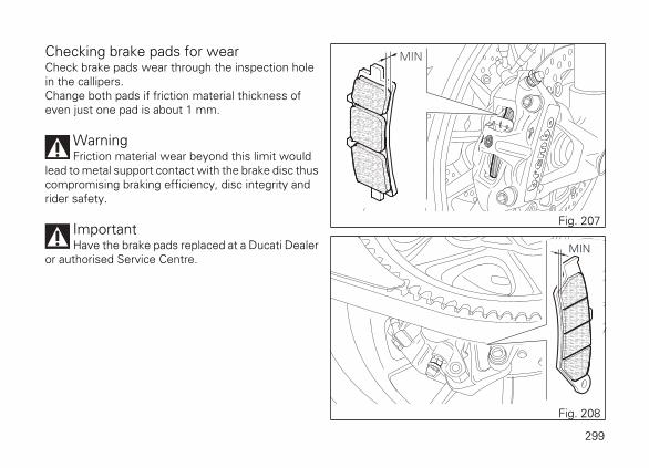
Checking brake pads for wearCheck brake pads wear through the inspection holein the callipers.Change both pads if friction material thickness ofeven just one pad is about 1 mm.
WarningFriction material wear beyond this limit would
lead to metal support contact with the brake disc thuscompromising braking efficiency, disc integrity andrider safety.
ImportantHave the brake pads replaced at a Ducati Dealer
or authorised Service Centre.
MIN
Fig. 207
MIN
Fig. 208
299

Charging the batteryBefore charging the battery, it is best to remove itfrom the motorcycle.
ImportantThe battery is located under the cowling; to
remove it, ALWAYS contact a Ducati Dealer orauthorised Service Centre.
Remove the right cowling (1) by loosening:
- the two screws (2) for side securing electricalcomponents compartment;
- the three screws (3) for lower securing to thecentral cowling;
- screw (4) securing central cowling to rightcowling;
12
2
3
Fig. 209
4
Fig. 210
300

Then, loosen two screws (5) and remove the batterysupport bracket (6).Slide out the battery (7) from its housing and, alwaysstarting from the negative terminal (-), loosen the twoscrews (8).Remove the positive cable (9), the ABS positive cable(10) from the positive terminal and the negative cable(11) from the negative terminal.
WarningThe battery produces explosive gases: keep it
away from heat sources
WarningKeep the battery out of the reach of children.
Charge the battery at 0.9 A for 5÷10 hours.Charge the battery in a ventilated room.
6
5
Fig. 211
7
911
8
Fig. 212
301

Connect the battery charger leads to the batteryterminals: the red one to the positive terminal (+), theblack one to the negative terminal (-).
ImportantMake sure the charger is OFF when you
connect the battery to it, or you might get sparks atthe battery terminals that could ignite the gasesinside the cells. Always connect the red positive (+)terminal first.
Lay down the ABS positive cable (10), onto positivecable (9) and start screw (8) on these cables.Connect the positive cable (9), previously assembledto ABS cable (10), to battery positive terminal, andnegative cable (11) to battery negative terminal, bystarting the other screw (8).Tighten the terminal two screws (8) to a torque of 4Nm ±10% and apply grease onto the batteryterminals to prevent oxidation.
7
911
8
Fig. 213
302

Refit the battery support bracket (6) by inserting thebracket end in the relevant seats (A) on the electriccomponent support.Start and tighten the two screws (5) to a torque of 5Nm ± 10%.
6
5
A
Fig. 214
303

Reposition the right cowling (1) on the motorcycle byfixing it as explained below:
- start the two screws (2) for side securingelectrical components compartment;
- start the three screws (3) for lower securing tothe central cowling;
- start screw (4) securing central cowling to rightcowling.
Tighten screws (2) and (3) to a torque of 4 Nm ± 10%.Tighten screw (4) to a torque of 4 Nm ±10%.
12
2
3
Fig. 215
4
Fig. 216
304

Charging and maintenance of the batteryduring winter storageYour motorcycle is equipped with a connector (1) towhich you can connect a special battery charger (2)(Battery maintainer kit part no. 69924601A - variouscountries; Battery maintainer kit part no.69924601AX - for Japan, China and Australia only)available from our sales network.
NoteThe electric system of this model is designed so
as to ensure there is a very low power drain when themotorcycle is OFF. Nevertheless, the batteryfeatures a certain self-discharge rate that is normaland depends on ambient conditions as well as on"non-use" time.
1
Fig. 217
2
Fig. 218
305

ImportantIf battery is not kept at a minimum charge level
by a suitable battery charge maintainer, sulphationmay occur and this is an irreversible phenomenoncausing decreasing battery performance.
NoteWhen the motorcycle is left unused
(approximately for more than 30 days) werecommend owners to use the Ducati battery chargemaintainer (Battery maintenance kit part no.69924601A - various countries; Battery maintainer kitpart no. 69924601AX - for Japan, China and Australiaonly) since its electronics monitors the batteryvoltage and features a maximum charge current of1.5 Ah. Connect the maintainer to the diagnosticssocket located in the rear side of the motorcycle.
NoteUsing charge maintainers not approved by
Ducati could damage the electric system; motorcyclewarranty does not cover the battery if damaged dueto failure to comply with the above indications, sinceit is considered as wrong maintenance.
306

Drive belt tension check
ImportantHave drive belt tension adjusted by a Ducati
Dealer or authorised Service Centre.
Fig. 219
307

Replacing the high and low beam bulbsHeadlight
The headlight is a full LED unit.
Figure shows the locations of the low beam (LO),high beam (HI) and parking lights (1).The light voltage and power values are indicated inparagraph "Electric System" page 336.
ImportantHave the headlight lights replaced by a Ducati
Dealer or an Authorised Service Centre.
WarningThe headlight might fog up if the motorcycle is
used under the rain or after washing. Switchheadlight on for a short time to dry up anycondensate.
LO
1
HI
Fig. 220
308
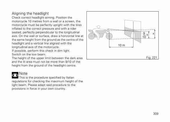
Aligning the headlightCheck correct headlight aiming. Position themotorcycle 10 metres from a wall or a screen, themotorcycle must be perfectly upright with the tiresinflated to the correct pressure and with a riderseated, perfectly perpendicular to the longitudinalaxis. On the wall or surface, draw a horizontal line atthe same height from the ground as the centre of theheadlight and a vertical line aligned with thelongitudinal axis of the motorcycle.If possible, perform this check in dim light.Switch on the low beam.The height of the upper limit between the dark areaand the lit area must not be more than 9/10 of theheight from the ground of the headlight centre.
NoteThis is the procedure specified by Italian
regulations for checking the maximum height of thelight beam. Please adapt said procedure to theprovisions in force in your own country.
10 m
9
10x x
Fig. 221
309

To vertically align the low beam, turn the screws (1).To vertically align the high beam, turn the screw (2). 1
2
Fig. 222
310

Adjusting the rear-view mirrorsManually adjust the rear-view mirror by pushing atpoints (A).
A
Fig. 223
311
TyresFront tyre pressure:2.50 bar (rider only) - 2.6 bar (with passenger and/orbags).Rear tyre pressure:2.50 bar (rider only) - 2.9 bar (with passenger and/orbags).As tyre pressure is affected by ambient temperatureand altitude variations,you are advised to check and adjust it whenever youare riding in areas where ample variations intemperature or altitude occur.
ImportantCheck and set tyre pressure when tyres are
cold. To avoid front wheel rim distortion, when ridingon bumpy roads, increase tyre pressure by 0.2 ÷ 0.3bar.
Tyre repair or change (Tubeless tyres)
In the event of a tiny puncture, tubeless tyres will takea long time to deflate, as they tend to keep air inside.If you find low pressure on one tyre, check the tyrefor punctures.
WarningPunctured tyres must be replaced. Replace
tyres with recommended standard tyres only. Besure to tighten the valve caps securely to avoid leakswhen riding. Never use tube type tyres. Failure toheed this warning may lead to sudden tyre burstingand to serious danger to rider and passenger.
After replacing a tyre, the wheel must be balanced.
WarningDo not remove or shift the wheel balancing
weights.
NoteHave the tyres replaced at a Ducati Dealer or
authorised Service Centre. Correct removal andinstallation of the wheels is essential. Some parts ofthe ABS (such as sensors and phonic wheels) aremounted to the wheels and require specificadjustment.
312

Minimum tread depth
Measure tread depth (S, Fig. 224) at the point wheretread is most worn down: it should not be less than2 mm, and in any case not less than the legal limit.
ImportantVisually inspect the tyres at regular intervals for
detecting cracks and cuts, especially on the sidewalls, bulges or large spots that are indicative ofinternal damage. Replace them if badly damaged.Remove any stones or other foreign bodies caught inthe tread.
S
Fig. 224
313

Check engine oil levelEngine oil level can be checked through the sightglass (1) located onto clutch cover. Oil level must bechecked with the motorcycle perfectly upright andthe engine cold. Oil level should be between themarks on the sight glass. If the level is low, top upwith engine oil.Ducati recommends you use Shell Advance 4T Ultra15W-50 oil. As an alternative it is possible to use amotorcycle engine oil having the same degree SAE15W-50 and meeting the following specificationsJASO: MA2 and API: SM.Remove the oil filler cap (2) and top up until the oilreaches the required level. Refit the plug.
ImportantEngine oil and oil filters must be changed by a
Ducati Dealer or authorised Service Centre at theintervals specified in the scheduled maintenancechart reported in the Warranty Card.
2
1
Fig. 225
314

Recommendations concerning oil
It is recommended to use oil complying with thefollowing specifications:
- viscosity grade SAE 15W-50;- standard API: SM;- standard JASO: MA2.
SAE 15W-50 is an alphanumerical code identifying oilclass based on viscosity: two figures with a W("winter") in-between; the first figure indicates oilviscosity at low temperature; the second figureindicates its viscosity at high temperature. API(American standard) and JASO (Japanese standard)standards specify oil characteristics.
315
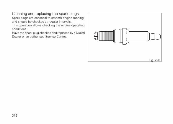
Cleaning and replacing the spark plugsSpark plugs are essential to smooth engine runningand should be checked at regular intervals.This operation allows checking the engine operatingconditions.Have the spark plug checked and replaced by a DucatiDealer or an authorised Service Centre.
Fig. 226
316

Cleaning the motorcycle
NoteTo preserve the finish of metal parts and
paintwork, wash and clean your motorcycle at regularintervals, anyway according to road conditions. Usespecific products only. Prefer biodegradableproducts. Avoid aggressive detergents or solvents.Use only water and neutral soap to clean the Plexiglasand the seat.Periodically clean by hand all aluminium components.Use special detergents, suitable for aluminium parts.Do NOT use abrasive detergents or caustic soda.
NoteDo not use sponges with abrasive parts or steel
wool: only use soft cloths.
However, the warranty does not apply to motorcycleswhenever poor maintenance status is ascertained.
ImportantDo not wash your motorcycle right after use.
When the motorcycle is still hot, water drops willevaporate faster and spot hot surfaces.Never clean the motorcycle using hot or high-pressure water jets.Cleaning the motorcycle with a high pressure waterjet may lead to seizure or serious faults in forks,wheel hubs, electric system, headlight (fogging), forkseals, air inlets or exhaust silencers, with consequentloss of compliance with the safety requirements.Clean off stubborn dirt or exceeding grease fromengine parts using a degreasing agent. Be sure toavoid contact with drive parts (belt, pulleys, etc.).
Rinse with warm water and dry all surfaces withchamois leather.
WarningBraking performance may be impaired
immediately after washing the motorcycle. Nevergrease or lubricate the brake discs to avoid losingbraking power. Clean the discs with an oil-freesolvent.
317

WarningThe headlight might fog up due to washing, rain
or moisture. Switch headlight on for a short time tohelp and dry up any condensate.
Carefully clean the phonic wheels of the ABS in orderto ensure system efficiency. Do not use aggressiveproducts in order to avoid damaging the phonicwheels and the sensors.
WarningAvoid direct contact between instrument panel
lens and oils/fuels that may stain or damage it therebyimpairing information readability. To clean such parts,do not use alcohol-based detergents, containingsolvent or abrasive agents; do not use sponges orcloths featuring hard or rough areas since they mightscratch the surface.
Pay special attention when cleaning the wheel rimssince they have parts in machined aluminium; cleanand dry them every time you use the motorcycle.
WarningTo clean the side panniers, sue warm water,
neutral soap and a soft cloth. Soap and soft brushesare suitable to clean the zips; rinse them with cleanwater. Do not use aggressive detergents and too hardcleaning tools. Zips that prove hard to be moved canbe loosened using a bit of talcum powder.
318

Storing the motorcycleIf the motorcycle is to be left unridden over longperiods, it is advisable to carry out the followingoperations before storing it away:
- clean the motorcycle;- empty the fuel tank;- pour a few drops of engine oil into the cylinders
through the spark plug seats, then crank theengine by hand a few times so a protective filmof oil will spread on cylinder inner walls;
- place the motorcycle on a service stand;- disconnect and remove the battery.
Battery should be checked and charged (or replaced,as required) whenever the motorcycle has been leftunridden for over a month.Protect the motorcycle with a suitable canvas. Thiswill protect paintwork and let condensate breatheout.The canvas is available from Ducati Performance.
319

Important notesSome countries, such as France, Germany, GreatBritain, Switzerland, etc. have compulsory emissionand noise standards that include mandatoryinspections at regular intervals.Periodically carry out the required checks and renewparts as necessary, using Ducati original spare parts,in compliance with the regulations in the countryconcerned.
320

Scheduled maintenance chartScheduled maintenance chart: operations to be carried out by the dealer
List of operations and type of interven-tion[set mileage (km/mi) or time interval *]
Km. x1000 1 15 30 45 60Time
(months)mi. x1,000 0.6 9 18 27 36
Reading of the error memory with DDS 2.0 and check ofsoftware version update on control units 12
Check the presence of any technical updates and recallcampaigns 12
Change engine oil and filter 12
Clean the engine oil mesh filter assembly -
Check and/or adjust valve clearance -
Change timing belts 60
Change spark plugs -
Clean plugs with metal mesh filters on heads -
Clean air filter -
Change air filter -
Check brake and clutch fluid level 12
Change brake and clutch fluid 36
Check brake disc and pad wear. Change, if necessary 12
321

List of operations and type of interven-tion[set mileage (km/mi) or time interval *]
Km. x1000 1 15 30 45 60Time
(months)mi. x1,000 0.6 9 18 27 36
Check the proper tightening of brake calliper bolts andbrake disc flange screws 12
Check front and rear wheel nuts tightening 12
Check frame-to-engine fasteners tightening -
Check wheel hub bearings -
Check and lubricate the rear wheel shaft -
Check silentblocks on driven pulley -
Check final drive driven and driving pulley nut tightening 12
Check final drive belt wear 12
Check final drive belt tension 12
Check steering bearings and lubricate, if necessary -
Change front fork fluid -
Visually check the front fork and rear shock absorberseals 12
Check the freedom of movement and tightening of theside and central stand (if any) 12
Visually check the fuel lines 12
322

List of operations and type of interven-tion[set mileage (km/mi) or time interval *]
Km. x1000 1 15 30 45 60Time
(months)mi. x1,000 0.6 9 18 27 36
Check rubbing points, clearance, freedom of movementand positioning of hoses and electric wiring in view 12
Lubricate the levers at the handlebar and pedal controls 12
Change coolant 48
Visually check the coolant level and sealing of the circuit 12
Check tyre pressure and wear 12
Check the battery charge level 12
Check the operation of all electric safety devices (sidestand sensor, front and rear brake switches, engine killswitch, gear/neutral sensor)
12
Check lighting, turn indicators, horn and controls 12
Reset the Service indication through the DDS 2.0 -
Final test and road test of the motorcycle, testing safetydevices (ex. ABS and DTC), Cruise Control device, elec-tric fans and idling
12
Softly clean the motorcycle 12
Fill out that the service was performed in on-board doc-umentation (Service Booklet) 12
323

* Service operation to be carried out in accordance with the specified distance or time intervals (km, milesor months), whichever occurs first.
324

Scheduled maintenance chart: operations to be carried out by the customer
List of operations and type of intervention [set mileage (km/mi) or timeinterval *]
Km. x1000 1
mi. x1,000 0.6
Months 6
Check engine oil level
Check brake fluid level
Check tyre pressure and wear
Check final drive belt tension
Check brake pads. If necessary, contact your dealer to replace pads
* Service operation to be carried out in accordance with the specified distance or time intervals (km, milesor months), whichever occurs first.
325

Technical data
WeightsOverall weight (in running order with 90% of fuel -93/93/EC): 247 Kg.Total weight (kerb weight without fuel): 237 Kg.Overall weight (dry conditions, without fluids andbattery): 220 Kg.Maximum allowed weight (carrying full load): 440 kg.
WarningFailure to observe weight limits could result in
poor handling and impair the performance of yourmotorcycle, and you may lose control of themotorcycle.
326

Dimensions
1010 mm
140 mm
1615 mm
2310 mm
75
5 m
m
1133 m
m
1094 m
m
335 mm484 mm
Fig. 227
327

Fuel, lubricants and other fluids
FUEL, LUBRICANTS AND OTHERFLUIDS
TYPE
Fuel tank, including a reserve of 4 cu. dm Unleaded fuel with a minimum octane rat-ing of RON 95
18 cu. dm (litres)
Oil sump and filter Ducati recommends you use Shell Ad-vance 4T Ultra 15W-50 oil. As an alterna-tive it is possible to use a motorcycle en-gine oil having the same degree SAE15W-50 and meeting the following speci-fications JASO: MA2 and API: SM
4.2 cu. dm (litres)
Front/rear brake and clutch circuits SHELL Advance Brake DOT 4 -
Protectant for electric contacts Protective spray for electric systems.SHELL Advance Contact Cleaner
-
Front fork SHELL Advance Fork 7.5 or Donax TA 835 cc (per leg)
Cooling circuit ENI Agip Permanent Spezial antifreeze (donot dilute, use pure)
2.5 cu. dm (litres)
ImportantDo not use any additives in fuel or lubricants. Using them could result in severe damage of the engine
and motorcycle components.
328

WarningThe motorcycle is only compatible with fuel having a maximum content of ethanol of 10% (E10).
Using fuel with ethanol content over 10% is forbidden. Using it could result in severe damage of the engineand motorcycle components. Using fuel with ethanol content over 10% will make the warranty null and void.
329

EngineDucati Testastretta "L" twin-cylinder engine with DVTsystem ("Desmodromic Variable Timing"), 4 valvesper cylinder, Dual Spark, liquid-cooled.Bore, mm: 106.Stroke, mm: 71.5.Total displacement, cu. cm: 1,262.Compression ratio: 13.1±0.5:1Max crankshaft power (95/1/EC), kW/HP:114.7 kW/156 HP at 9,500 rpm73 kW/98 HP at 6,750 rpm (for the French marketonly).Max torque at crankshaft (95/1/EC):13.1 kgm/128.9 Nm at 5,000 rpm12.7 kgm/125 Nm at 5,000 rpm (for the Frenchmarket only).Maximum rpm:10,30010,250 (for the French market only).
ImportantDo not exceed the specified rpm limits in any
running conditions.
330

Timing systemDESMODROMIC system with four valves percylinder controlled by eight rocker arms (four openingand four closing ones) and two overhead camshaftswith variable valve timing (DVT) both for the exhaustand intake side. This system is driven by thecrankshaft through spur gears, pulleys and toothedbelts.
Desmodromic timing system
1) Opening (or upper) rocker arm;2) Upper rocker arm shim;3) Closing (or lower) rocker arm shim;4) Return spring for lower rocker arm;5) Closing (or lower) rocker arm;6) Camshaft;7) Valve.8) Timing Variator.9) Actuators.
4
1
68
9
1 7 7
8 9
5
3
7
2
Fig. 228
331

Performance dataMaximum speed in any gear should be reached onlyafter a correct running-in period with the motorcycleproperly serviced at the recommended intervals.
ImportantFailure to follow these instructions releases
Ducati Motor Holding S.p.A. from any liabilitywhatsoever for any engine damage or shorter enginelife.
Spark plugsMake: NGK.Type: MAR10A-J.
Fuel systemBOSCH electronic injection.Type of throttle body: DEQ 56 elliptical with full Ride-by-Wire system.Diameter of throttle body: 56 mm.Injectors per cylinder: 1.Firing points per injector: 10.Fuel supply: 95-98 RON.
WarningThe motorcycle is only compatible with fuel
having a maximum content of ethanol of 10% (E10).Using fuel with ethanol content over 10% isforbidden. Using it could result in severe damage tothe engine and motorcycle components. Using fuelwith ethanol content over 10% will make thewarranty null and void.
BrakesSeparate-action anti-lock braking system, equippedalso with "cornering" function, operated by hall-typesensors mounted to each wheel with phonic wheeldetection: ABS can be disabled.
FRONT
Semi-floating drilled twin-disc.Braking material: stainless steel.Carrier material: stainless steelDisc diameter: 320 mm.Hydraulically operated by a control lever on handlebarright-hand side.Brake calliper make: BREMBO.Front brake type: M4.32B.Friction material make: TOSHIBA.
332

Friction material: TT 2182 FF.Brake master cylinder type: PR18/19.
REAR
With fixed drilled steel disc.Disc diameter: 265 mm.Hydraulically operated by a pedal on RH side.Brake calliper make: BREMBO, floating, with 4pistons.Rear brake type: PF 30/32A.Friction material make: TOSHIBA.Friction material: TT 2182 FF.Fixed, 32mm diameter 4-piston calliper.
WarningThe brake fluid used in the brake system is
corrosive.In the event of accidental contact with eyes or skin,wash the affected area with abundant running water.
TransmissionHydraulically-controlled slipper/progressive self-servo wet multiplate clutch.Drive is transmitted from engine to gearbox primaryshaft via spur gears.
Front chain sprocket/clutch gearwheel ratio: 33/61.6-speed gearbox with constant mesh gears, gearchange pedal on left side of motorcycle.
Driven pulley/driving pulley ratio: Z28/Z80.Total gear ratios:1st gear 15/372nd gear 17/303rd gear 20/274th gear 22/245th gear 24/236th gear 25/22
Drive belt from gearbox to rear wheel.Toothed belt: Z173 L35
ImportantThe above gear ratios are the homologated ones
and under no circumstances must they be modified.
However, if you wish to tune up your motorcycle forcompetitions or special tracks, Ducati Motor HoldingS.p.A. will be pleased to provide information aboutthe special ratios available. Contact a Ducati Dealer orAuthorised Service Centre.
333

WarningIf the rear pulley needs replacing, contact a
Ducati Dealer or authorised Service Centre.If improperly replaced, this component couldseriously endanger your safety, as well as thepassenger one, and cause irreparable damage to yourmotorcycle.
FrameSteel tubular trellis.Steering head angle: 30°.Steering angle: 34° LH side / 34° RH side.Trail: 130 mm.
WheelsFront
Light alloy cast rims.Size: MT3.50x17".
Rear
Light alloy cast rims.Size: MT8.00x17".
TyresFront
"Tubeless", radial tyre.Size: 120/70-ZR17Make and type: Pirelli Diablo Rosso II.
Rear
"Tubeless", radial tyre.Size: 240/45-ZR17Make and type: Pirelli Diablo Rosso II.
SuspensionFRONT
FrontMake: MarzocchiHydraulic fork with steel legs, preload andcompression adjuster (left leg) and rebound adjuster(right leg).Stanchion diameter:50 mm.
Rear
Make: SachsThe shock absorber (TBC) features adjustable preloadand rebound damping, with remote tank; it pivotsonto frame at the top and on the aluminium swingingarm at the bottom. The swinging arm is connected tothe pivot shaft going through the frame and the
334

engine. The whole system gives the motorcycleexcellent stability.Suspension travel: 59.5 mm.Rear wheel travel: 120 mm.
Exhaust system"2 into 1 into 2" manifolds layout with 2 lambdasensors and 2 catalytic converters.Split absorption tail pipe.Stainless steel silencer with double elliptical outlets.
Available coloursX Diavel
DARK STEALTHPrimer (Primer 2 K Black) code 873.A002 (PALINAL).Base (Black Stealth - Black 94) code 929.R223(PALINAL).Clear coat (clear coat 2K matt) code 923I.2176(PALINAL).Mineral Grey frame code 37321 (INVER SPA).Monocoque Grey rear subframe code 86176 (INVERSPA).Mineral Grey rims - varnish code SC-BK-15047 (Akzonobel).
X Diavel S
THRILLING BLACKPrimer 2 K Black code 873.A002 (Palinal).Primer, Black Stealth (Black 94) code 929.R223(Palinal).Clear coat code 923M1598 (Palinal).Mineral Grey frame code 37321 (INVER SPA).Wrinkled Mineral Grey rear subframe code 37418(INVER SPA).Rims, Glossy Black Base code 43NL0007 (AkzoNobel), Clear coat - Acrymine HP Clear (Peter Lacke).
335
Electric systemBasic electric items are:
Headlight
LED low beam light type: No. 4 LEDs (13.5V - 24.3W);LED high beam light type: No. 5 LEDs (13.5V -18.9W);LED parking light type: No. 5 LEDs (13.5V - 6.2W).
Turn indicators
Front turn indicators: LED (13.5V - 4.7W).rear turn indicators: LED (13.5V - 2.06W).Electrical switches on handlebar.
Tail light
Parking light: (13.5V - 0.3W);LED stop light: (13.5V - 1.4W);Number plate light: LED (13.5V - 0.7W).
Fuses
There are thirteen fuses that protect the electriccomponents, located inside the upper and lower fuseboxes, and one on the solenoid starter. There is aspare fuse (S) in every box.
Refer to the table below to identify the circuitsprotected by the various fuses and their ratings.
336
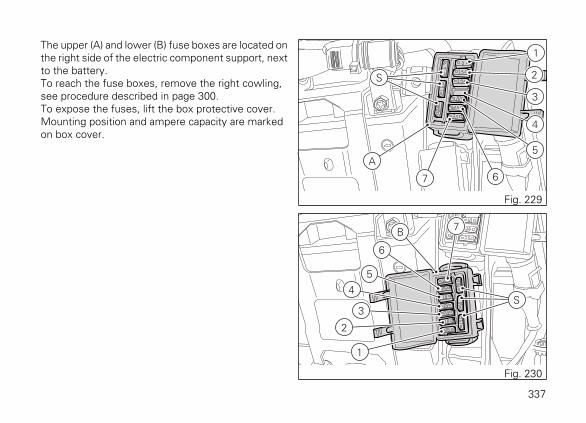
The upper (A) and lower (B) fuse boxes are located onthe right side of the electric component support, nextto the battery.To reach the fuse boxes, remove the right cowling,see procedure described in page 300.To expose the fuses, lift the box protective cover.Mounting position and ampere capacity are markedon box cover.
1
2
3
4
5
67
A
S
Fig. 229
1
2
3
4
5
6
7B
S
Fig. 230
337

Upper fuse box key (A)
Pos El. item Rat.
1 KEY EMS / ABS / IMU 5 A
2 KEY DSB / BBS 15 A
3 KEY Lights 5 A
4 - -
5 KEY Accessories 10 A
6 +30 Hands Free 25 A
7 +30 Diagnosis /charge
7.5 A
Lower fuse box key (B)
Pos El. item Rat.
1 +30 EMS LOAD RE-LAY
25 A
2 +30 FUEL PUMP RE-LAY
10 A
3 +30 Starter RELAY 7.5 A
4 +30 Instrument panel 15 A
Lower fuse box key (B)
5 +30 Black Box Sys-tem (BBS)
10 A
6 +30 ABS UBMR 25 A
7 +30 ABS UBVR 10 A
338

The main fuse (C) is positioned on the solenoidstarter. Remove the fuse cap to reach it. A blown fusecan be identified by breakage of the inner filament (F).
ImportantSwitch the ignition key to OFF before replacing
the fuse to avoid possible short-circuits.
WarningNever use a fuse with a rating other than
specified. Failure to observe this rule may damagethe electric system or even cause fire.
DC
E
Fig. 231
F F
Fig. 232
339

Injection/electric system diagram key
1) Front stop light2) Bluetooth3) Left-hand switch4) Right-hand switch5) Inertial sensor6) Immobilizer7) Hands free8) Hands Free Relay9) Battery10) Wiring ground11) Fused solenoid12) LH fan13) RH fan14) Generator15) Rectifier16) Data Acquisition / Diagnosis17) Anti-theft system alarm18) Right tail light19) Left tail light20) Rear right turn indicator21) Rear left turn indicator22) Rear wiring23) Number plate light24) Temperature sensor
25) LH heated handgrip connector (optional)26) RH heated handgrip connector (optional)27) Exhaust valve motor28) Vehicle control unit (BBS)29) Fuel level30) Fuse box (2)31) Fuse box (1)32) ABS33) Rear speed sensor34) Front speed sensor35) Fuel pump36) Main control unit relay37) Fuel pump relay38) Starter relay39) Injection control unit connector A (EMS)40) Injection control unit connector B (EMS)41) Gear sensor42) Throttle twistgrip position sensor (APS)43) Vertical ETV44) Horizontal ETV45) Main vertical injector46) Main horizontal injector47) Vertical lambda sensor48) Horizontal lambda sensor49) Timing/rpm sensor50) Vertical cylinder secondary coil
340

51) Vertical cylinder main coil52) Horizontal cylinder secondary coil53) Horizontal cylinder main coil54) Oil pressure sensor55) Purge valve56) Oil temperature57) Clutch switch58) Side stand switch59) Engine temperature sensor60) Air temperature sensor61) Vertical MAP sensor62) Horizontal MAP sensor63) Vertical cylinder knock sensor64) Horizontal cylinder knock sensor65) Secondary air sensor66) Vertical cylinder EX timing sensor67) Vertical cylinder IN timing sensor68) Horizontal cylinder EX timing sensor69) Horizontal cylinder IN timing sensor70) Vertical cylinder EX timing connector71) Vertical cylinder IN timing connector72) Horizontal cylinder EX timing connector73) Horizontal cylinder IN timing connector74) Front left turn indicator75) Instrument panel76) Front right turn indicator
77) Headlight78) Horn79) Rear stop light
Wire colour coding
B BlueW WhiteV VioletBk BlackY YellowR RedLb Light blueGr GreyG GreenBn BrownO OrangeP Pink
NoteThe electric system wiring diagram is at the end
of this manual.
341

Routine maintenance recordRoutine maintenance record
KM NAMEDUCATI SERVICE
MILEAGE DATE
1000
15000
30000
45000
60000
342


Stam
pato 12/2015C
od. 913.7.308.1A

24
26
25
78
77
76
74
7372 71 70 69 68 67 66 65 64 63
62 61 60 59 58 57 56 545553 52
51 50 4948 47
75
2 3 4
5
6
710
9
11
8 3130
12 13 1514
1617
20
21
2927
79
39
4038
35 34 32 33
3736
4241
28
1
23
22
18
19
43 42 45 46
XDiavel

cod. 913.7.308.1A