
Monitoring and Controlling of Greenhouse 101.pdf
55
Sudan University of Science and Technology Collage of Engineering School of Electrical and Nuclear Engineering MONITORING AND CONTROLLING OF GREENHOUSE البيوت المحمية اقبة والتحكم في المرA Project Submitted in Partial Fulfilment for the Requirements of the Degree of B.Sc. (Honor) in Electrical Engineering (Control) Prepared by: 1. Ahmed Adil Musa Mustafa 2. Ayman Mohamed Osman khidir 3. Mohaned Ahmed Abdallah Agab Eldour 4. Yousif Abdulwahid Jaafar Salim Supervised by: Dr. Awadalla Taifour Ali October 2015
-
Upload
khangminh22 -
Category
Documents
-
view
0 -
download
0
Transcript of Monitoring and Controlling of Greenhouse 101.pdf

Sudan University of Science and Technology
Collage of Engineering
School of Electrical and Nuclear Engineering
MONITORING AND CONTROLLING
OF GREENHOUSE
المراقبة والتحكم في البيوت المحميةA Project Submitted in Partial Fulfilment for the Requirements of the
Degree of B.Sc. (Honor) in Electrical Engineering (Control)
Prepared by:
1. Ahmed Adil Musa Mustafa
2. Ayman Mohamed Osman khidir
3. Mohaned Ahmed Abdallah Agab Eldour
4. Yousif Abdulwahid Jaafar Salim
Supervised by:
Dr. Awadalla Taifour Ali
October 2015

i
اآلية
قال هللا تعالى:
قالوا سبحانك ال علم لنا إال ما علمتنا
إنك أنت العليم الحكيم
32سورة البقرة , اآلية

ii
DEDICATION
To my beloved mother and father who supported me,
To my brothers and sisters,
To my friends and study partners
To everyone who make a positive effect on me.

iii
ACKNOWLEDGEMENT
First of all, we praise and thank our God, and we are kindly
grateful to our supervisor Dr. Awadallah Taifour Ali who was
extremely generous to us with his time, effort and concern, and who
was such a big help and supporter through this project. We also we
would like to thank anyone who helped us.
iv
ABSTRACT
The main idea of this project is to control the temperature, light, and irrigation
system inside the greenhouse to provide an appropriate growing environment to
plants. The environmental factors inside the greenhouse are studied, and
appropriate circuit to control those factors is designed and implemented using
suitable components. To control these environmental factors suitable sensors are
used such as temperature sensor (LM35) and light sensor (LDR). Sensors input a
certain voltage according to the measured factor, after that the microcontroller
compares between the measured value and the reference one and switches on the
appropriate actuator.
v
المستخلص
البيوت الفكرة االساسية من هذا المشروع هي التحكم في درجة الحرارة واالضاءة ونظام الري داخل
ية وبناءا على تم دراسة العوامل البيئية داخل البيوت المحم نباتي مناسب للبناتات.المحمية لكي تهيئ مناخ
ذلك تم تصميم دائرة مناسبة للتحكم في هذة العوامل و تطبيقها بإستخدام مكونات مناسبة. للتحكم في هذة
( . LDR( وحساس اإلضاءة ) LM35العوامل البيئية تم إستخدام حساسات مثل حساس درجة الحرارة )
بعد ذلك يقوم المتحكم الدقيق بمعالجة , معين مكافئ للعامل البيئي المقاستقوم الحساسات بإدخال جهد
ومقارنة القيمة المقاسة بالقيمة المرجعية وتشغيل الخرج المناسب.
vi
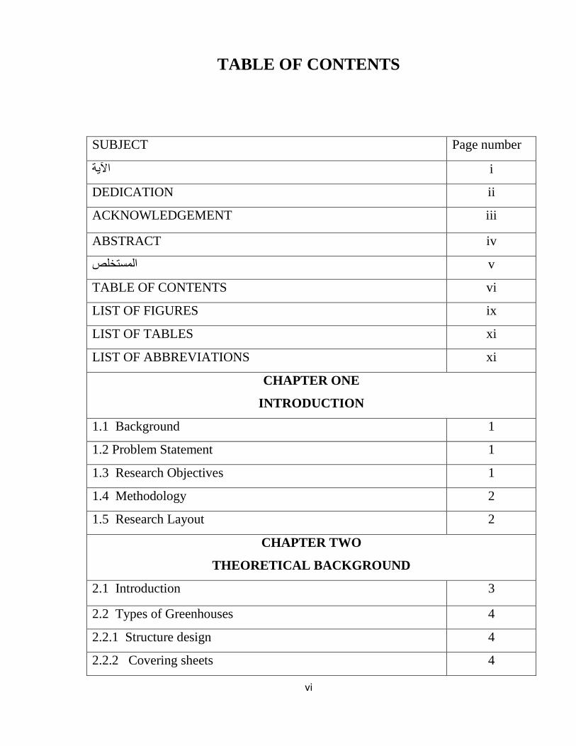
TABLE OF CONTENTS
Page number SUBJECT
i اآلية
ii DEDICATION
iii ACKNOWLEDGEMENT
iv ABSTRACT
v مستخلصال
vi TABLE OF CONTENTS
ix LIST OF FIGURES
xi LIST OF TABLES
xi LIST OF ABBREVIATIONS
CHAPTER ONE
INTRODUCTION
1 1.1 Background
1 1.2 Problem Statement
1 1.3 Research Objectives
2 1.4 Methodology
2 1.5 Research Layout
CHAPTER TWO
THEORETICAL BACKGROUND
3 2.1 Introduction
4 2.2 Types of Greenhouses
4 2.2.1 Structure design
4 2.2.2 Covering sheets
vii
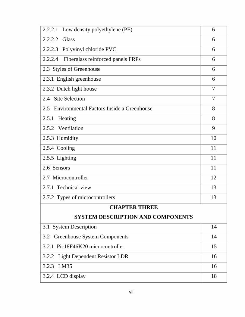
6 2.2.2.1 Low density polyethylene (PE)
6 2.2.2.2 Glass
6 2.2.2.3 Polyvinyl chloride PVC
6 2.2.2.4 Fiberglass reinforced panels FRPs
6 2.3 Styles of Greenhouse
6 2.3.1 English greenhouse
7 2.3.2 Dutch light house
7 2.4 Site Selection
8 2.5 Environmental Factors Inside a Greenhouse
8 2.5.1 Heating
9 2.5.2 Ventilation
10 2.5.3 Humidity
11 2.5.4 Cooling
11 2.5.5 Lighting
11 2.6 Sensors
12 2.7 Microcontroller
13 2.7.1 Technical view
13 2.7.2 Types of microcontrollers
CHAPTER THREE
SYSTEM DESCRIPTION AND COMPONENTS
14 3.1 System Description
14 3.2 Greenhouse System Components
15 3.2.1 Pic18F46K20 microcontroller
16 3.2.2 Light Dependent Resistor LDR
16 3.2.3 LM35
18 3.2.4 LCD display
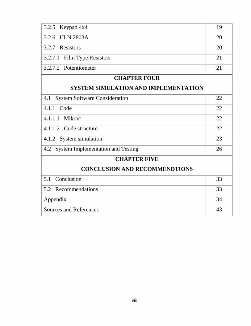
viii
19 3.2.5 Keypad 4x4
20 3.2.6 ULN 2803A
20 3.2.7 Resistors
21 3.2.7.1 Film Type Resistors
21 3.2.7.2 Potentiometer
CHAPTER FOUR
SYSTEM SIMULATION AND IMPLEMENTATION
22 4.1 System Software Consideration
22 4.1.1 Code
22 4.1.1.1 Mikroc
22 4.1.1.2 Code structure
23 4.1.2 System simulation
26 4.2 System Implementation and Testing
CHAPTER FIVE
CONCLUSION AND RECOMMENDTIONS
33 5.1 Conclusion
33 5.2 Recommendations
34 Appendix
43 Sources and References
ix
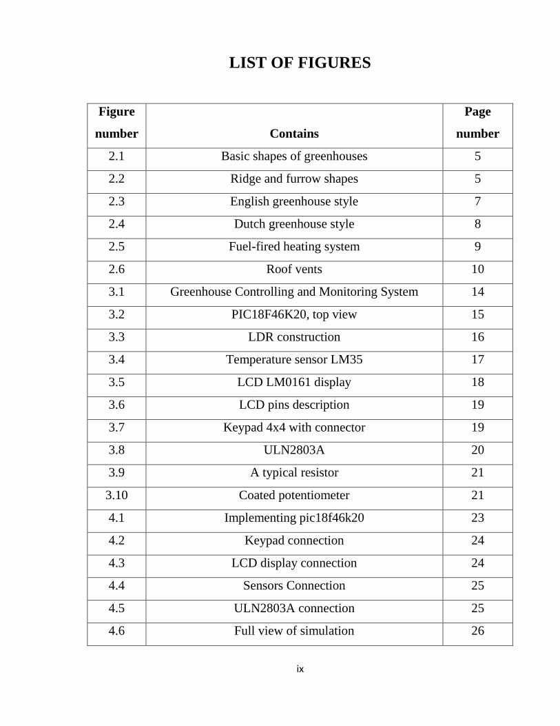
LIST OF FIGURES
Figure
number
Contains
Page
number
2.1 Basic shapes of greenhouses 5
2.2 Ridge and furrow shapes 5
2.3 English greenhouse style 7
2.4 Dutch greenhouse style 8
2.5 Fuel-fired heating system 9
2.6 Roof vents 10
3.1 Greenhouse Controlling and Monitoring System 14
3.2 PIC18F46K20, top view 15
3.3 LDR construction 16
3.4 Temperature sensor LM35 17
3.5 LCD LM0161 display 18
3.6 LCD pins description 19
3.7 Keypad 4x4 with connector 19
3.8 ULN2803A 20
3.9 A typical resistor 21
3.10 Coated potentiometer 21
4.1 Implementing pic18f46k20 23
4.2 Keypad connection 24
4.3 LCD display connection 24
4.4 Sensors Connection 25
4.5 ULN2803A connection 25
4.6 Full view of simulation 26

x
4.7 Connecting microcontroller and LCD 27
4.8 Relationship between voltage and temperature 28
4.9 Measuring temperature sensor’s voltage 29
4.10 Measuring voltage from light sensor 31
4.11 Circuit of the greenhouse 32

xi
LIST OF TABLES
Table
number
Contains Page
number
4.1 Measured voltage according to the temperature
sensor
28
4.2 Measured voltage according to the light sensor 30
LIST OF ABBREVIATIONS
PE Low density polyethylene
PVC Polyvinyl chloride
HID High-intensity discharge
VLSI Very large scale integrator
CPU Central processing unit
MCU Microcontroller unit
IC Integrated circuit
LCD Liquid crystal display
LDR Light dependent resistor
IRR Irrigation

1
CHAPTER ONE
INTRODUCTION
1.1 Background
Greenhouses are a special type of growing structure used to provide a
suitable growing environment to the plants and the flowers inside. Demand is
increasing day after day on food, as a natural result of the increase in population
on the one hand and increase the diversity of consumption on the other hand,
since the nature of the climate in Sudan and the Arab countries are not
appropriate overall length to produce enough fruits and vegetables to meet the
needs of the population and achieve food security, so protected Agriculture earn
particular importance in view of what can be done to fill the shortage of
agricultural production and achieve self-sufficiency.
1.2 Problem Statement
Climate in Sudan and Arab countries is not suitable to grow all kind of plants all
over the year, and even the plants that are grown sometimes they are not in their
high quality. This disability of growing all kind of plants makes a shortage in
vegetables and fruits.
1.3 Research Objectives
The main objectives of the research are:
Design of control circuit for greenhouse system using microcontroller.
Simulation of greenhouse control circuit.
Implementation and testing of proposed control circuit.
2
1.4 Methodology
The system is modelled using microcontroller type PIC18f46K20.
The system simulation has been carried out by using Mikro C as a
programming language.
Proteus software is used as a simulator and compiler.
The proposed circuit is implemented in bred board
1.5 Research layout
The research contains an abstract and five chapters. Chapter One consists of
general introduction, background of the greenhouse, problem statement that the
project deal with, objectives, methodology and research layout. Chapter Two
covers a theoretical background of greenhouse, sensors and the microcontroller.
In Chapter three the system is described and components are introduced.
Chapter Four is about system simulation and implementation. Chapter Five
consists of the conclusion, recommendations, references and the programming
code as appendix.
3
CHAPTER TWO
THEORETICAL BACKGROUND
2.1 Introduction
The scientific progress of the human enabled him to innovate and develop many
of the tools and methods used to increase production and improve the quality in
different areas of life, including the impact on the surrounding circumstances
where the advantage of that is positive for him, and could sometimes create
artificial conditions mimic the best conditions for the exercise of activity in
difficult environmental conditions. Protected agriculture one of the modern
scientific methods to overcome the environmental non-suitable for agricultural
production, which succeeded already in the desert regions, hot and harsh
conditions of water scarcity, lack of soil fertility and increase the proportion of
salts and as a result, the field of agriculture open (exposed) face numerous
difficulties. Thanks to research and experience, it has shown that the best way
for the production of vegetables and fruits is the method of protection from risk
of high temperatures in summer and winter frost, as well as protection from
sandstorms, which provides the opportunity to increase the yield and the quality
of the production throughout the year [1].
The greenhouse industry as we know it today probably originated in Holland
during its “Golden Age’’, the 1600s and it became an essential part of the
garden from the latter part of the eighteenth century onwards. Such structures
had long been in the mind of gardeners but their development had had to await
the invention and production of cheap sheet glass. This in its turn had to wait
upon the industrial revolution and the development of the necessary techniques
[2].

4
2.2 Types of Greenhouses
Greenhouses can be varied depending on a lot of characters but mainly it can be
varied into:
structure design
covering sheets
2.2.1 Structure design
Greenhouses are available in different shapes and sizes suitable for different
climatic zones prevailing in the world. Each zone requires different shapes for
providing favorable climatic conditions for the growth of plants. The greatest
amount of insulation possible, covering of maximum ground area for the least
cost and a structurally sound facility are some of the criteria for development of
several types of greenhouse as seen in figure (2.1) and figure (2.2) [2].
Greenhouse structures design such as:
Mansard
Maw tooth
Ridge and furrow
Vinery house
Arch
Standard peak
Venlo house Quonset
2.2.2 Covering sheets
Cladding cover will drastically affect the amount of sunlight reaching the
crops; the cladding will also determine heat loss of the structure. The most
common materials are:

5
Figure (2.1) Basic shapes of Greenhouse
Figure (2.2) Ridges and Furrow shapes
6
2.2.2.1 Low density polyethylene (PE)
Low cost. Resistant to extreme weather conditions, molding ability and it is
light hence it does not cause large loads on the structure. Not readily degradable
so its use must be measured [2].
2.2.2.2 Glass
The traditional greenhouse covering against which all others are judged. Good
quality glass is an attractive, very transparent, and formal (in appearance)
covering material [2].
2.2.2.3 Polyvinyl chloride PVC
Polyvinyl Chloride is the most economical and used choice widely used due to
its versatility, malleability and mechanical properties. It is lightweight so it does
not generate large stresses in the structure [2].
2.2.2.4 Fiberglass reinforced panels FRPs
Rigid plastic panels made from acrylic or polycarbonate that comes in large
corrugated or flat sheets. They are durable, retain heat better than glass does, and
are lightweight [2].
2.3 Styles of Greenhouses
There are two styles of modern greenhouses, the English greenhouse and the
Dutch light house.
2.3.1 English greenhouse
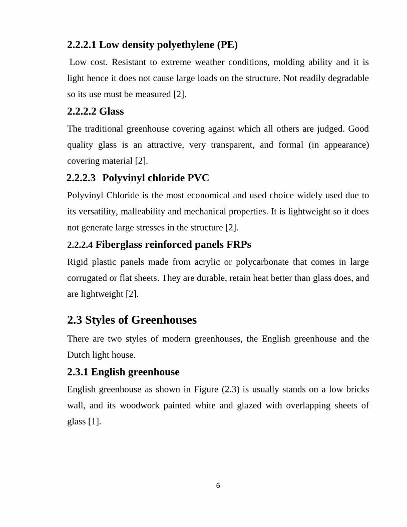
English greenhouse as shown in Figure (2.3) is usually stands on a low bricks
wall, and its woodwork painted white and glazed with overlapping sheets of
glass [1].
7
Figure (2.3) English greenhouse style
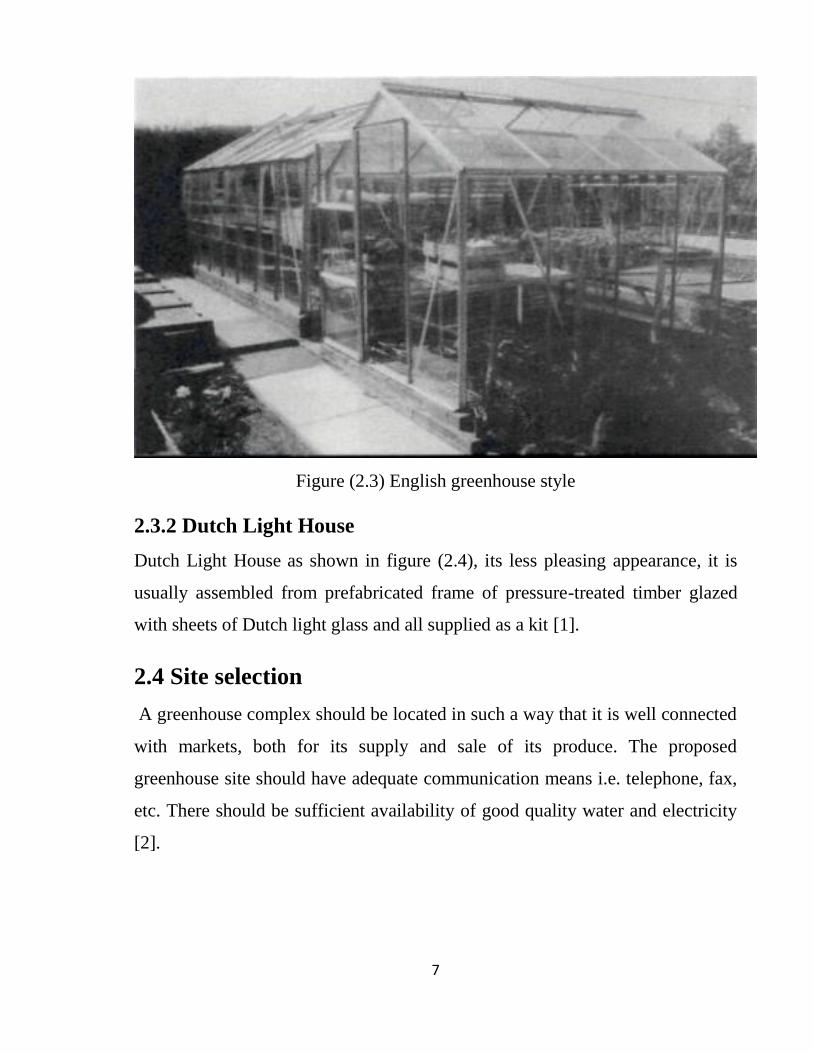
2.3.2 Dutch Light House
Dutch Light House as shown in figure (2.4), its less pleasing appearance, it is
usually assembled from prefabricated frame of pressure-treated timber glazed
with sheets of Dutch light glass and all supplied as a kit [1].
2.4 Site selection
A greenhouse complex should be located in such a way that it is well connected
with markets, both for its supply and sale of its produce. The proposed
greenhouse site should have adequate communication means i.e. telephone, fax,
etc. There should be sufficient availability of good quality water and electricity
[2].

8
Figure (2.4) Dutch light house style
2.5 Environmental Factors Inside a Greenhouse
In order to provide a suitable growing environment to the plants these are the
factor to be controlled:
2.5.1 Heating
Each type of plants has its own heating environmental conditions, some plants
grows better in cold weather, others grows better in worm weather and others
give you the best growing income in hot weather. Once you understand your
greenhouse heating requirements, you’ll need to determine what type of heater
to use and whether you'll need to run a gas line and power to the greenhouse.
The two main types of greenhouse heaters are electric and fuel-fired (gas,
propane, kerosene, or oil) as shown in figure (2.5). Also heat sink system can be
used to get use of the solar heat [3].

9
Figure (2.5) fuel-fired heating system
2.5.2 Ventilation
Whether your plants thrive depends on how well you control their environment.
Adequate sunlight is a good start, but ventilation is just as important: It expels
hot air, reduces humidity, and provides air circulation, which is essential even
during winter to move cold, stagnant air around, keep diseases at bay, and avoid
condensation problems. There are two main options for greenhouse ventilation:
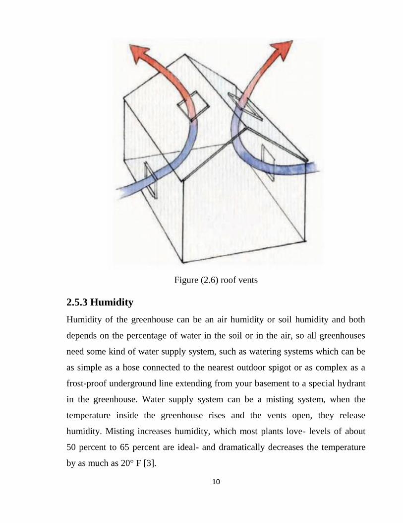
vents and fans. Because hot air rises, roof vents are the most common choice.
They should be staggered on both sides of the ridgeline, even exchange of air
and proper circulation [3].
10
Figure (2.6) roof vents
2.5.3 Humidity
Humidity of the greenhouse can be an air humidity or soil humidity and both
depends on the percentage of water in the soil or in the air, so all greenhouses
need some kind of water supply system, such as watering systems which can be
as simple as a hose connected to the nearest outdoor spigot or as complex as a
frost-proof underground line extending from your basement to a special hydrant
in the greenhouse. Water supply system can be a misting system, when the
temperature inside the greenhouse rises and the vents open, they release
humidity. Misting increases humidity, which most plants love- levels of about
50 percent to 65 percent are ideal- and dramatically decreases the temperature
by as much as 20° F [3].

11
2.5.4 Cooling
Although vents and fans arc the first line of defense when the temperature inside
the greenhouse starts to climb, other cooling methods such as misting,
humidifying, evaporative cooling, and shading can also help to maintain the idea
l growing environment. Cooling is crucial during summer, but it can be just as
important on a sunny winter day [3].
2.5.5 Lighting
All the plants need sunlight to complete the progress of photosynthesis, so
sunlight is a major factor during the day. Plants may need additional light. And
no matter where the greenhouse is located, you'll likely need to rely on
supplemental lighting during night. Supplementing natural light with artificial
light can be tricky. Natural light is made up of a spectrum of colors that you can
see (colors of the rainbow) and those you can't see. Plants absorb light from the
red and blue ends of the spectrum so its important to choose bulbs that provide
those spectrums, taking in mind the intensity and the distance between plants
and the artificial lighting system because Lights that are set too far away or that
don't provide enough brightness (measured in lumens or foot-candles) will
produce weak, spindly plants. There are three basic types of lights are available;
incandescent bulbs, fluorescent tubes, and high-intensity discharge (HID) lights.
Each has advantages and disadvantages, which is why greenhouse gardeners
often use a combination of two or more types to achieve light that is as close to
natural as possible [3].
2.6 Sensors
A sensor is a device that detects events or changes in quantities and provides a
corresponding output, generally as an electrical or optical signal; for example, a
thermocouple converts temperature to an output voltage. But a mercury-in-glass
12
thermometer is also a sensor; it converts the measured temperature into
expansion and contraction of a liquid which can be read on a calibrated glass
tube. Sensors are used in everyday objects such as; touch sensitive elevator
buttons (tactile sensor) and lamps which dim or brighten by touching the base,
besides innumerable applications of which most people are never aware. With
advances in micro machinery and easy-to use microcontroller platforms, the
uses of sensors have expanded beyond the more traditional fields of temperature,
pressure or flow measurement, for example into MARG sensors. Moreover,
analog sensors such as potentiometers and force-sensing resistors are still widely
used. Applications include manufacturing and machinery, airplanes and an
aerospace, cars, medicine and robotics. A sensor’s sensitivity indicates how
much the sensor’s output changes when the input quantity being measured
changes. For instance, if the mercury in a thermometer moves1cm when the
temperature changes by 1°C, the sensitivity is 1cm/°C (it is basically the slope
Dy/Dx as summing a linear characteristic). Some sensors can also have an
impact on what they measure; for instance, a room temperature thermometer
inserted into a hot cup of liquid cools the liquid while the liquid heats the
thermometer. Sensors need to be designed to have a small effect on what is
measured; making the sensor smaller often improves this and may introduce
other advantages. Technological progress allows more and more sensors to be
manufactured on a microscopic scale as micro sensors using MEMS technology.
In most cases, a micro sensor reaches a significantly higher speed and sensitivity
compared with macroscopic approaches [4].
2.7 Microcontroller
Microcontroller is a programmable single-chip integrated circuit (IC) that
controls the operation of the system. Also we can say microcontroller is a
microcomputer with few other application-specific devices on a single-chip of
13
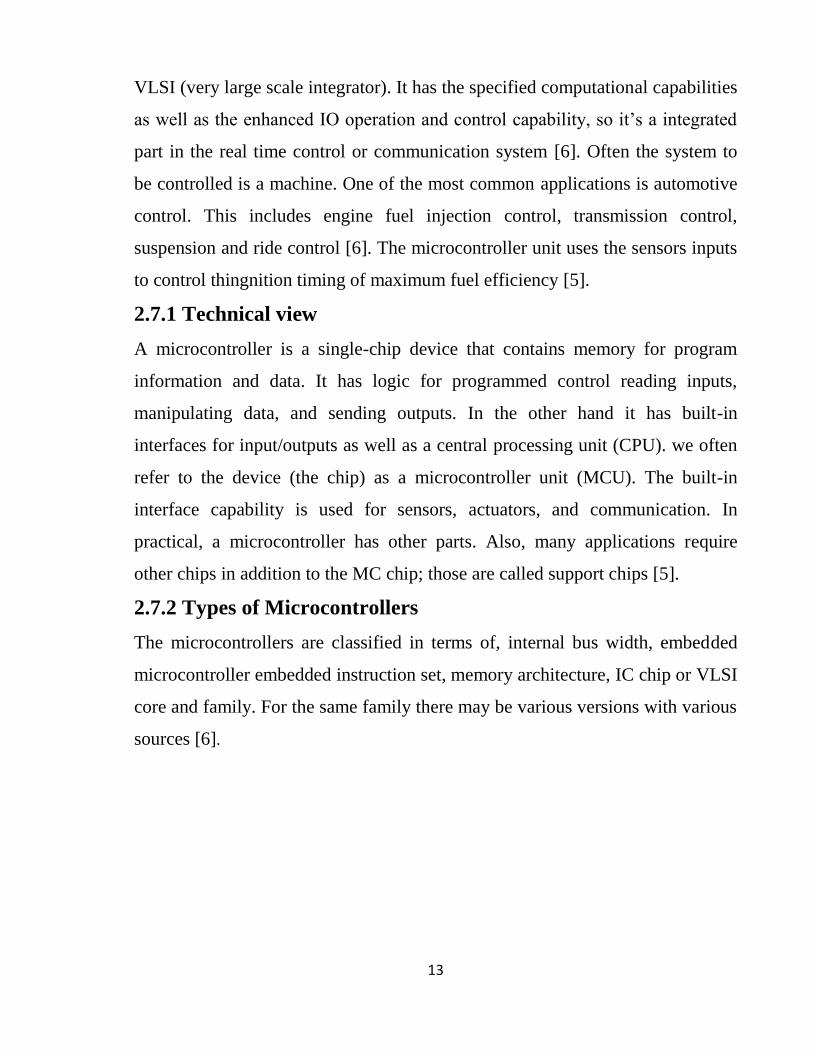
VLSI (very large scale integrator). It has the specified computational capabilities
as well as the enhanced IO operation and control capability, so it’s a integrated
part in the real time control or communication system [6]. Often the system to
be controlled is a machine. One of the most common applications is automotive
control. This includes engine fuel injection control, transmission control,
suspension and ride control [6]. The microcontroller unit uses the sensors inputs
to control thingnition timing of maximum fuel efficiency [5].
2.7.1 Technical view
A microcontroller is a single-chip device that contains memory for program
information and data. It has logic for programmed control reading inputs,
manipulating data, and sending outputs. In the other hand it has built-in
interfaces for input/outputs as well as a central processing unit (CPU). we often
refer to the device (the chip) as a microcontroller unit (MCU). The built-in
interface capability is used for sensors, actuators, and communication. In
practical, a microcontroller has other parts. Also, many applications require
other chips in addition to the MC chip; those are called support chips [5].
2.7.2 Types of Microcontrollers
The microcontrollers are classified in terms of, internal bus width, embedded
microcontroller embedded instruction set, memory architecture, IC chip or VLSI
core and family. For the same family there may be various versions with various
sources [6].
14
CHAPTER THREE
SYSTEM DESCRIPTION AND COMPONENTS
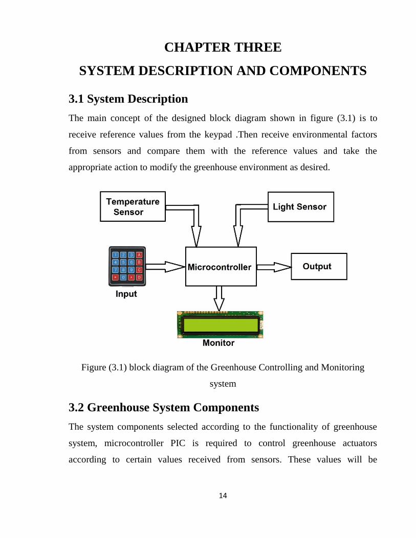
3.1 System Description
The main concept of the designed block diagram shown in figure (3.1) is to
receive reference values from the keypad .Then receive environmental factors
from sensors and compare them with the reference values and take the
appropriate action to modify the greenhouse environment as desired.
Figure (3.1) block diagram of the Greenhouse Controlling and Monitoring
system
3.2 Greenhouse System Components
The system components selected according to the functionality of greenhouse
system, microcontroller PIC is required to control greenhouse actuators
according to certain values received from sensors. These values will be
15
compared with reference values inserted by user using keypad. To monitor the
system characteristics we used LCD display.
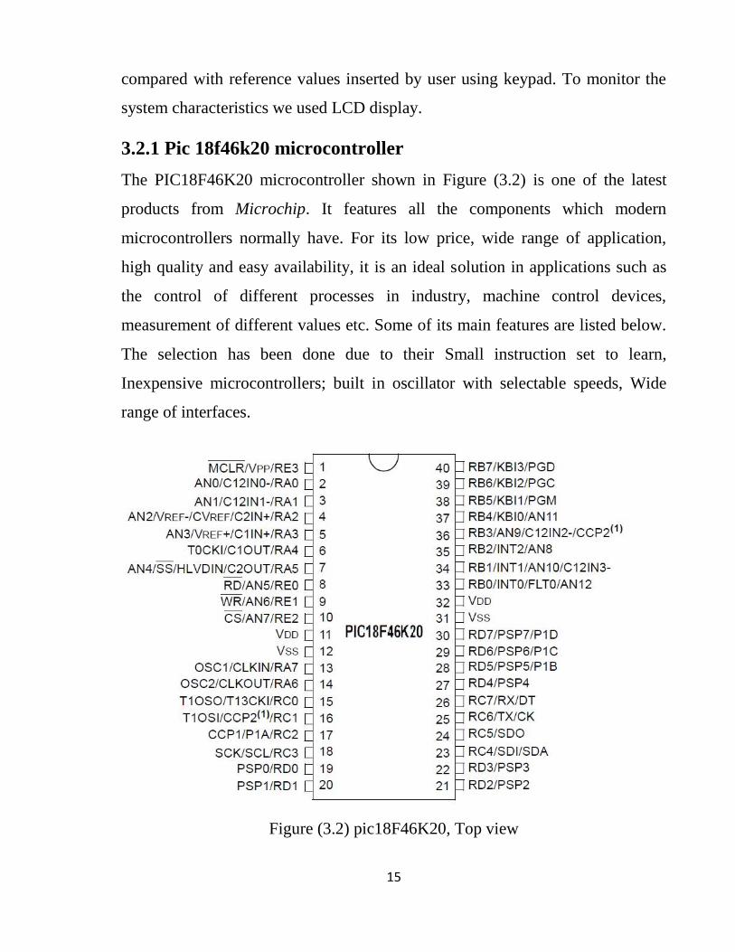
3.2.1 Pic 18f46k20 microcontroller
The PIC18F46K20 microcontroller shown in Figure (3.2) is one of the latest
products from Microchip. It features all the components which modern
microcontrollers normally have. For its low price, wide range of application,
high quality and easy availability, it is an ideal solution in applications such as
the control of different processes in industry, machine control devices,
measurement of different values etc. Some of its main features are listed below.
The selection has been done due to their Small instruction set to learn,
Inexpensive microcontrollers; built in oscillator with selectable speeds, Wide
range of interfaces.
Figure (3.2) pic18F46K20, Top view
16
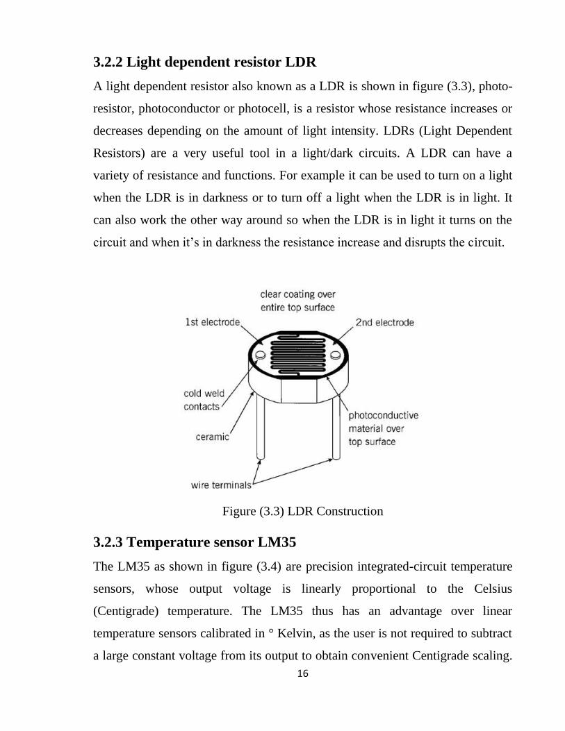
3.2.2 Light dependent resistor LDR
A light dependent resistor also known as a LDR is shown in figure (3.3), photo-
resistor, photoconductor or photocell, is a resistor whose resistance increases or
decreases depending on the amount of light intensity. LDRs (Light Dependent
Resistors) are a very useful tool in a light/dark circuits. A LDR can have a
variety of resistance and functions. For example it can be used to turn on a light
when the LDR is in darkness or to turn off a light when the LDR is in light. It
can also work the other way around so when the LDR is in light it turns on the
circuit and when it’s in darkness the resistance increase and disrupts the circuit.
Figure (3.3) LDR Construction
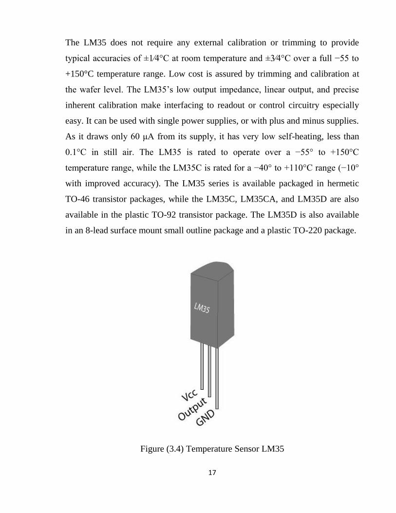
3.2.3 Temperature sensor LM35
The LM35 as shown in figure (3.4) are precision integrated-circuit temperature
sensors, whose output voltage is linearly proportional to the Celsius
(Centigrade) temperature. The LM35 thus has an advantage over linear
temperature sensors calibrated in ° Kelvin, as the user is not required to subtract
a large constant voltage from its output to obtain convenient Centigrade scaling.
17
The LM35 does not require any external calibration or trimming to provide
typical accuracies of ±1⁄4°C at room temperature and ±3⁄4°C over a full −55 to
+150°C temperature range. Low cost is assured by trimming and calibration at
the wafer level. The LM35’s low output impedance, linear output, and precise
inherent calibration make interfacing to readout or control circuitry especially
easy. It can be used with single power supplies, or with plus and minus supplies.
As it draws only 60 μA from its supply, it has very low self-heating, less than
0.1°C in still air. The LM35 is rated to operate over a −55° to +150°C
temperature range, while the LM35C is rated for a −40° to +110°C range (−10°
with improved accuracy). The LM35 series is available packaged in hermetic
TO-46 transistor packages, while the LM35C, LM35CA, and LM35D are also
available in the plastic TO-92 transistor package. The LM35D is also available
in an 8-lead surface mount small outline package and a plastic TO-220 package.
Figure (3.4) Temperature Sensor LM35

18
3.2.4 LCD display
A liquid-crystal display (LCD) shown in figure (3.5) is a flat panel display,
electronic visual display, or video display that uses the light modulating
properties of liquid crystals. Liquid crystals do not emit light directly.
LCDs are available to display arbitrary images (as in a general-purpose
computer display) or fixed images with low information content which can be
displayed or hidden, such as preset words, digits, and 7-segment displays as in a
digital clock. They use the same basic technology, They come in many sizes 8x1
, 8x2 , 10x2 , 16x1 , 16x2 , 16x4 , 20x2 , 20x4 ,24x2 , 30x2 , 32x2 , 40x2 etc.
Many multinational companies like Philips Hitachi Panasonic make their own
special kind of LCD's to be used in their products. All the LCD's performs the
same functions (display characters numbers special characters ASCII characters
etc.). Their programming is also same and they all have same 14 pins (0-13) or
16 pins (0 to 15) as shown in figure (3.6).
All LCDs have:
8 Data pins.
VCC (Apply 5v here).
GND (Ground this pin).
RS (Register select).
RW (read - write).
EN (Enable).
V0 (Set LCD contrast).
Figure (3.5) LCD LM016L Display
19
Figure (3.6) LCD Pins Description
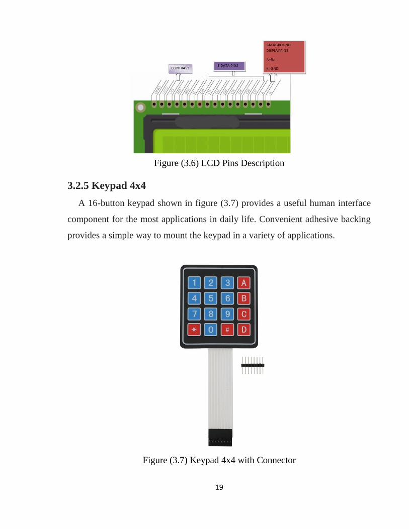
3.2.5 Keypad 4x4
A 16-button keypad shown in figure (3.7) provides a useful human interface
component for the most applications in daily life. Convenient adhesive backing
provides a simple way to mount the keypad in a variety of applications.
Figure (3.7) Keypad 4x4 with Connector
20
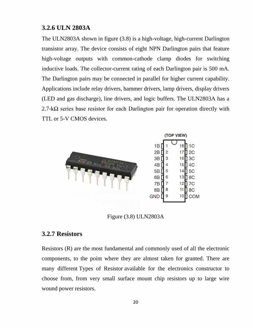
3.2.6 ULN 2803A
The ULN2803A shown in figure (3.8) is a high-voltage, high-current Darlington
transistor array. The device consists of eight NPN Darlington pairs that feature
high-voltage outputs with common-cathode clamp diodes for switching
inductive loads. The collector-current rating of each Darlington pair is 500 mA.
The Darlington pairs may be connected in parallel for higher current capability.
Applications include relay drivers, hammer drivers, lamp drivers, display drivers
(LED and gas discharge), line drivers, and logic buffers. The ULN2803A has a
2.7-kΩ series base resistor for each Darlington pair for operation directly with
TTL or 5-V CMOS devices.
Figure (3.8) ULN2803A
3.2.7 Resistors
Resistors (R) are the most fundamental and commonly used of all the electronic
components, to the point where they are almost taken for granted. There are
many different Types of Resistor available for the electronics constructor to
choose from, from very small surface mount chip resistors up to large wire
wound power resistors.

21
3.2.7.1 Film Type Resistors
The generic term Film Resistor as shown in figure (3.9) consists of Metal
Film, Carbon Film and Metal Oxide Film resistor types, which are generally
made by depositing pure metals, such as nickel, or an oxide film, such as tin-
oxide, onto an insulating ceramic rod or substrate.
Figure (3.9) A Typical Resistor
3.2.7.2 Potentiometer
Potentiometers (also called pots) shown in figure (3.10) are variable resistors,
used as voltage or current regulators in electronic circuits. By means of
construction, they can be divided into 2 groups: coated and wire-wound. With
coated potentiometers, (figure 1.6a), insulator body is coated with a resistive
material. There is a conductive slider moving across the resistive layer,
increasing the resistance between slider and one end of pot, while decreasing the
resistance between slider and the other end of pot.
Figure (3.10) Coated potentiometer

22
CHAPTER FOUR
SYSTEM SIMULATION AND
IMPLEMENTATION
4.1 System Software Considerations
In this project we decided to choose Mikroc language to program the
microcontroller and mikroc software from microchip as a compiler, and Proteus
as a simulator for the control circuit.
4.1.1 Code
The microcontroller code was written in mikroc language and compiled with the
mikroc PRO application.
4.1.1.1 Mikro C
The MikroC PRO is a powerful, feature-rich development tool for PIC
microcontrollers. It is designed to provide the programmer with the easiest
possible solution to developing applications for embedded systems, without
compromising performance or control, MikroC PRO for PIC is a complete IDE
for coding, simulating, programming, and debugging your PICs. Writing your
code in C brings advantages over writing it in assembler. This code will be
converted from binary to hex to be burned inside the microcontroller chip. The
code attached in the appendix.
4.1.1.2 Code structure
The first thing in the programming code is to identify the devices connected to
the microcontroller and specify which pins connected to every device. Then
each pin is identified as an input or output pin and each variable are identified.
After that the microcontroller receives the reference values from the keypad and
displays them on the LCD. Then it receives the environmental factors from the
23
sensors and compares them and takes action to modify the environment as
desired whether it's cooling or heating or increasing light intensity. There is a
counter designed to calculate the execution time and turn the irrigation on and
off according to the inserted time.
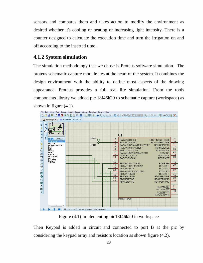
4.1.2 System simulation
The simulation methodology that we chose is Proteus software simulation. The
proteus schematic capture module lies at the heart of the system. It combines the
design environment with the ability to define most aspects of the drawing
appearance. Proteus provides a full real life simulation. From the tools
components library we added pic 18f46k20 to schematic capture (workspace) as
shown in figure (4.1).
Figure (4.1) Implementing pic18f46k20 in workspace
Then Keypad is added in circuit and connected to port B at the pic by
considering the keypad array and resistors location as shown figure (4.2).

24
Figure (4.2) Keypad connections
LM016L LCD display attached with port C on the pic considering the
potentiometer connection for word light intensity which is obvious in real
implementation as shown in figure (4.3).
Figure (4.3) LCD display connection

25
Then temperature sensor LM35 and light sensor LDR are added and connected
to PIC with analog pins A0 and A1 respectively as shown in figure (4.4).
Figure (4.4) Sensors connection
The output devices are connected to port D in the PIC through the ULN2803
chip giving a specific functionality which is more like switches as shown in
figure (4.5).
Figure (4.5) ULN2803A connection
26
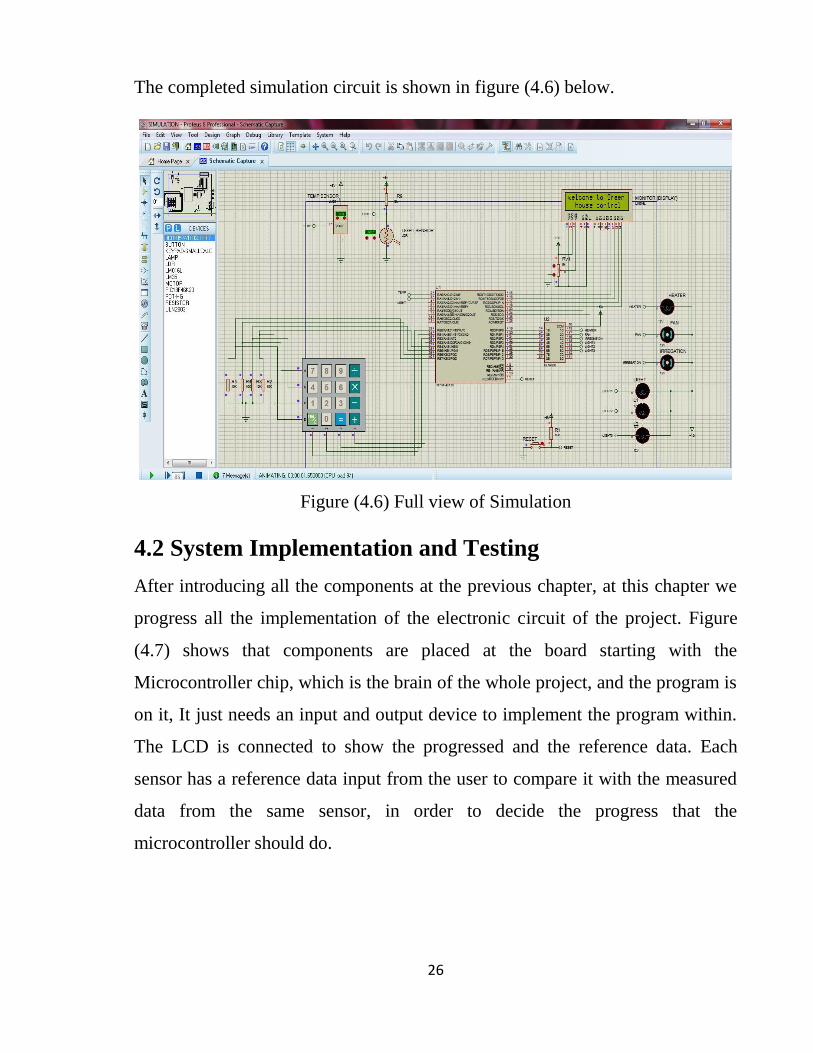
The completed simulation circuit is shown in figure (4.6) below.
Figure (4.6) Full view of Simulation
4.2 System Implementation and Testing
After introducing all the components at the previous chapter, at this chapter we
progress all the implementation of the electronic circuit of the project. Figure
(4.7) shows that components are placed at the board starting with the
Microcontroller chip, which is the brain of the whole project, and the program is
on it, It just needs an input and output device to implement the program within.
The LCD is connected to show the progressed and the reference data. Each
sensor has a reference data input from the user to compare it with the measured
data from the same sensor, in order to decide the progress that the
microcontroller should do.

27
Figure (4.7) Connecting Microcontroller chip and LCD
After that the input sensors and the keypad are placed on the board starting with
the temperature sensor (LM35), this sensor input a certain voltage to the
microcontroller as shown in figure (4.9) in its analogue input pin. The input
voltage control two output, one is the cooling fan in case the weather
temperature is higher that the required temperature inside the greenhouse, and
the other output is the heater when the weather temperature is lower than the
required. The required temperature will be inserted by the user at the beginning
of the program project. The relationship between the measured temperature from
the sensor (LM35) and the measured voltage from the voltmeter according to
that temperature is a positive relationship as shown in table (4.1), the voltage
increase when the temperature increases.
28
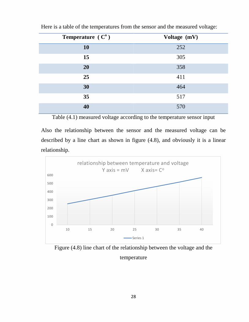
Here is a table of the temperatures from the sensor and the measured voltage:
Temperature ( Co )
Voltage (mV)
10 252
15 305
20 358
25 411
30 464
35 517
40 570
Table (4.1) measured voltage according to the temperature sensor input
Also the relationship between the sensor and the measured voltage can be
described by a line chart as shown in figure (4.8), and obviously it is a linear
relationship.
Figure (4.8) line chart of the relationship between the voltage and the
temperature
0
100
200
300
400
500
600
10 15 20 25 30 35 40
relationship between temperature and voltage Y axis = mV X axis= Co
Series 1

29
Figure (4.9) measuring temperature sensor’s voltage (mV)
Secondly, the light sensor (LDR) is connected and with it a (10k) resistor to
make a voltage share between it and the LDR sensor, the voltage (5v) will be
shared between them according to the change of the LDR resistor, The LDR
resistor change in the range of (0.1k to 200k). This sensor inputs voltage
according to the measured light from the sensor. It controls the lighting system
of the greenhouse, it open three levels of light, high light, medium light and low
light. Those levels will be decided according to the difference between the
required light and the measured one. Also the required light will be inserted in
the beginning of the program. The input voltage to the microcontroller has an
inverse relationship with the measured light as shown in table (4.2), when the
light increases the input voltage decrease and vice versa.

30
Here is a table of the measured voltages according to the light from the sensor:
Light (%) Voltage (v)
2.5 4.45
5 4.21
10 1.2
20 0.73
30 0.56
40 0.45
50 0.39
60 0.32
70 0.30
80 0.29
Table (4.2): measured voltage according to the light intensity
According the measured voltages which taken by using voltmeter as shown in
figure (4.10), it can be noticed that the relationship is almost an exponential
relationship, because when the measured light from the sensor reaches a certain
limit the input voltage become almost the same. For the humidity and the
irrigation system it will be controlled by a timing system, irrigation and mist
pump will be opened for a certain time, and it will be closed for another certain
time, those times will be inserted by the user as (Irr on and Irr off) at the
beginning of the program. The outputs pins of the microcontroller are connected
to the input pins of a chip called ULN2803A. This chip is a set of high voltage,
high current transistors. At the end the overall circuit contains two analogue
input sensor (temperature sensor (LM35) and light sensor (LDR)) and an
internal programmed timer, to control four outputs (heater, cooling fans, lighting
system and mist and irrigation system), each output is connected to voltage

31
source (12v) and the ground wire is connected to the output pin of ULN2803A
to complete the circuit and switch on the certain output according to its Input.
Figure (4.10) measuring voltage from light sensor
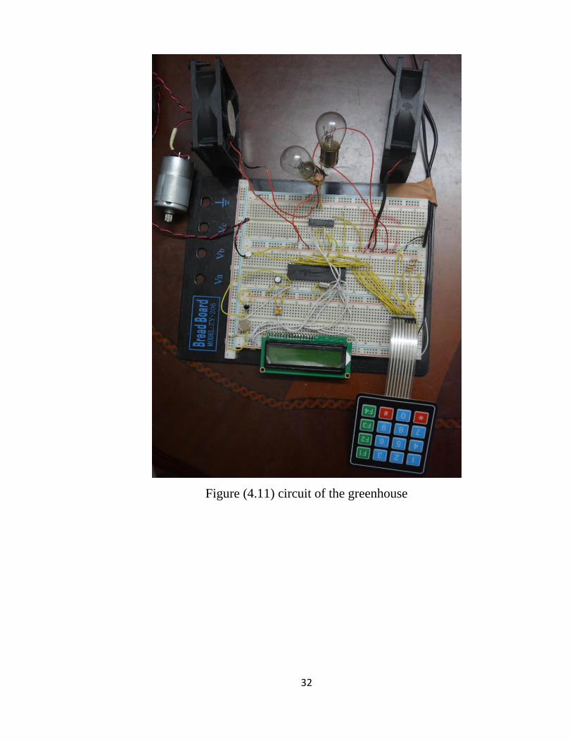
The completed circuit is shown in figure (4.11). Those are the factors that we
control electronically, and there is the ventilation factor which it is controlled
structurally by making some ventilation roof vents.
32
Figure (4.11) circuit of the greenhouse
33
CHAPTER FIVE
CONCLUSION AND RECOMMENDATIONS
5.1 Conclusion
In this project the control circuit that controlling light, temperature and irrigation
of greenhouse is designed, simulated, implemented and tested successfully. The
temperature system and the light system are capable to maintain the required
temperature and light intensity after comparing it with the measured values from
the sensors. The irrigation system is capable to provide plants with water for a
certain time and stop doing that for another certain time.
5.2 Recommendations
To improve the performance of the project it recommended that:
The lighting system become full analogue or works on a big number of
lighting levels to provide the plants with the exact amount of light it
needs.
The irrigation works by using humidity sensor.
Use of intelligent control algorithm for the microcontroller.
34
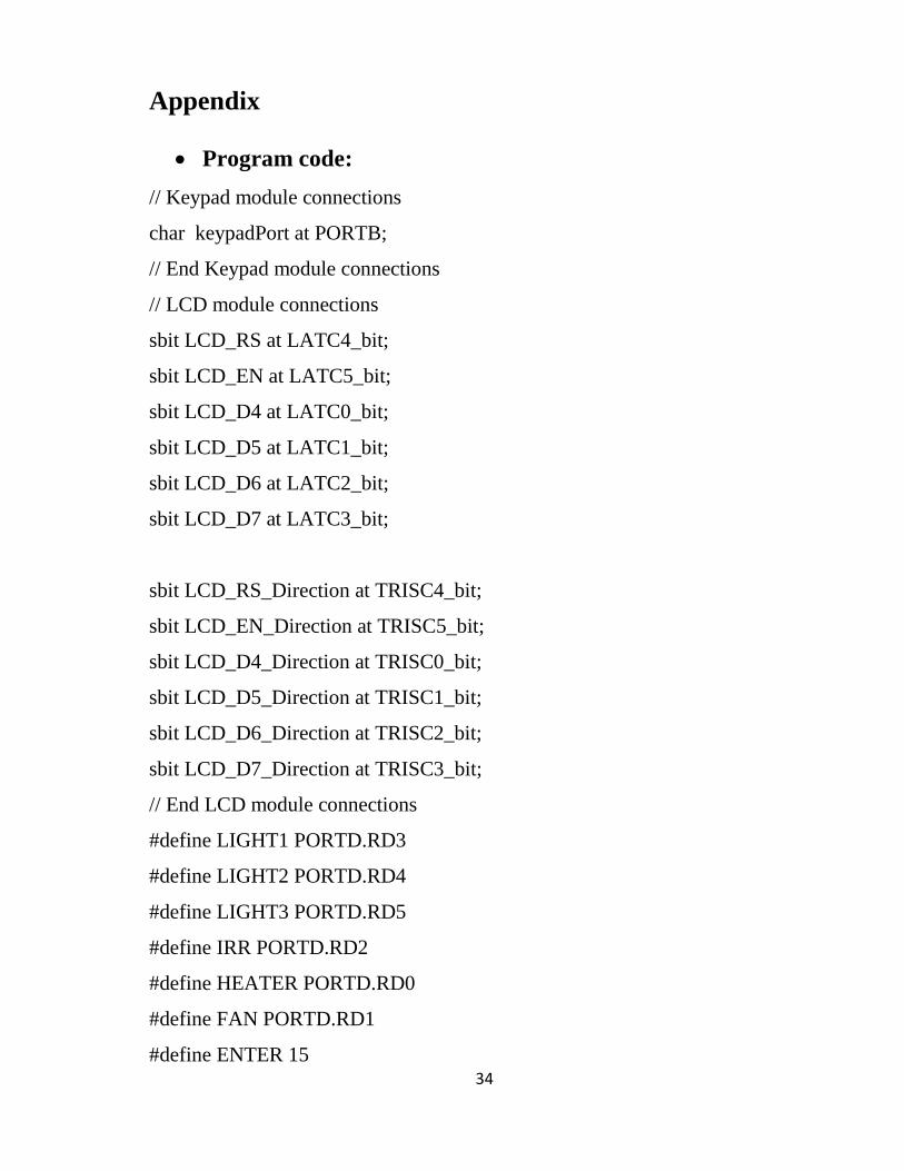
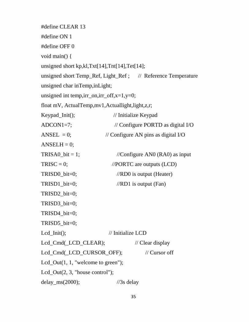
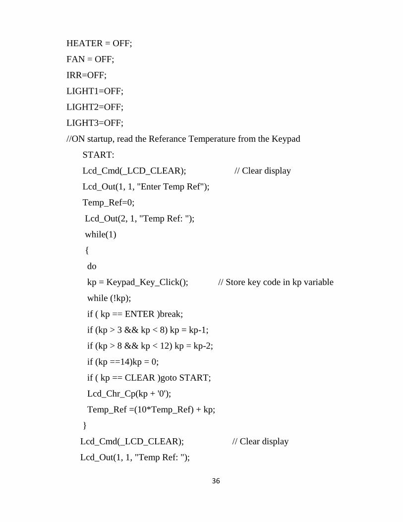
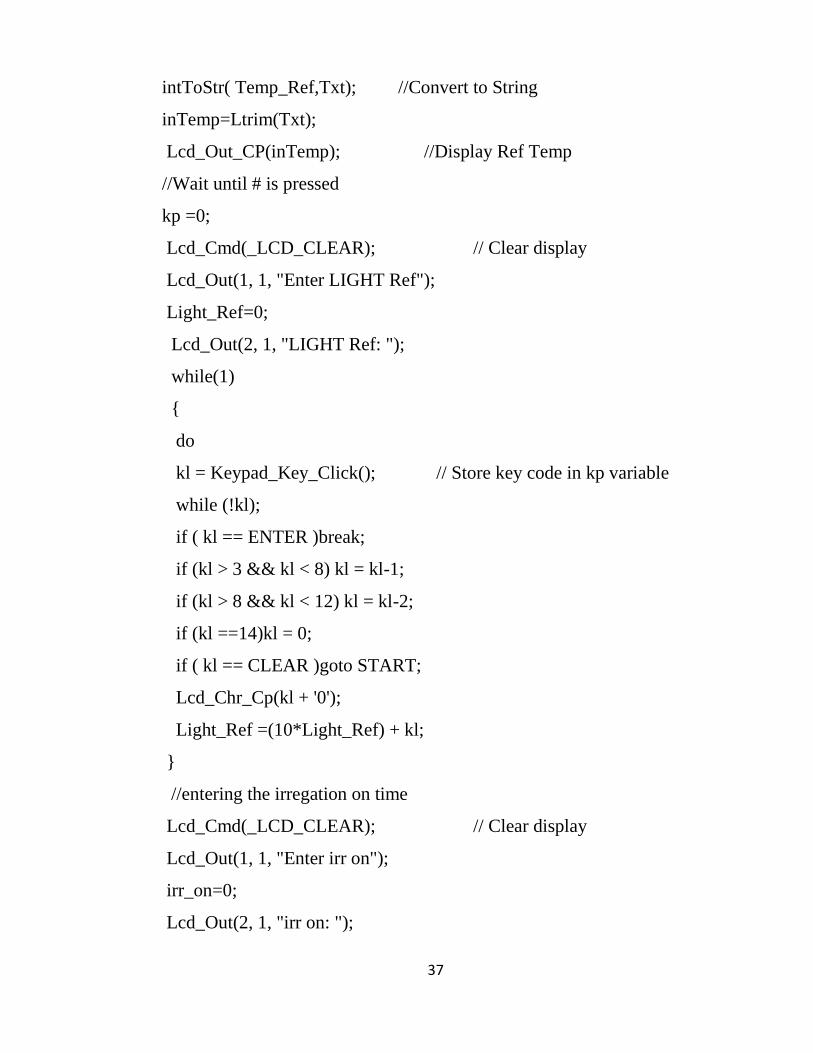
Appendix
Program code:
// Keypad module connections
char keypadPort at PORTB;
// End Keypad module connections
// LCD module connections
sbit LCD_RS at LATC4_bit;
sbit LCD_EN at LATC5_bit;
sbit LCD_D4 at LATC0_bit;
sbit LCD_D5 at LATC1_bit;
sbit LCD_D6 at LATC2_bit;
sbit LCD_D7 at LATC3_bit;
sbit LCD_RS_Direction at TRISC4_bit;
sbit LCD_EN_Direction at TRISC5_bit;
sbit LCD_D4_Direction at TRISC0_bit;
sbit LCD_D5_Direction at TRISC1_bit;
sbit LCD_D6_Direction at TRISC2_bit;
sbit LCD_D7_Direction at TRISC3_bit;
// End LCD module connections
#define LIGHT1 PORTD.RD3
#define LIGHT2 PORTD.RD4
#define LIGHT3 PORTD.RD5
#define IRR PORTD.RD2
#define HEATER PORTD.RD0
#define FAN PORTD.RD1
#define ENTER 15
35
#define CLEAR 13
#define ON 1
#define OFF 0
void main()
unsigned short kp,kl,Txt[14],Tnt[14],Tet[14];
unsigned short Temp_Ref, Light_Ref ; // Reference Temperature
unsigned char inTemp,inLight;
unsigned int temp,irr_on,irr_off,x=1,y=0;
float mV, ActualTemp,mv1,Actuallight,light,z,r;
Keypad_Init(); // Initialize Keypad
ADCON1=7; // Configure PORTD as digital I/O
ANSEL = 0; // Configure AN pins as digital I/O
ANSELH = 0;
TRISA0_bit = 1; //Configure AN0 (RA0) as input
TRISC = 0; //PORTC are outputs (LCD)
TRISD0_bit=0; //RD0 is output (Heater)
TRISD1_bit=0; //RD1 is output (Fan)
TRISD2_bit=0;
TRISD3_bit=0;
TRISD4_bit=0;
TRISD5_bit=0;
Lcd_Init(); // Initialize LCD
Lcd_Cmd(_LCD_CLEAR); // Clear display
Lcd_Cmd(_LCD_CURSOR_OFF); // Cursor off
Lcd_Out(1, 1, "welcome to green");
Lcd_Out(2, 3, "house control");
delay_ms(2000); //3s delay
36
HEATER = OFF;
FAN = OFF;
IRR=OFF;
LIGHT1=OFF;
LIGHT2=OFF;
LIGHT3=OFF;
//ON startup, read the Referance Temperature from the Keypad
START:
Lcd_Cmd(_LCD_CLEAR); // Clear display
Lcd_Out(1, 1, "Enter Temp Ref");
Temp_Ref=0;
Lcd_Out(2, 1, "Temp Ref: ");
while(1)
do
kp = Keypad_Key_Click(); // Store key code in kp variable
while (!kp);
if ( kp == ENTER )break;
if (kp > 3 && kp < 8) kp = kp-1;
if (kp > 8 && kp < 12) kp = kp-2;
if (kp ==14)kp = 0;
if ( kp == CLEAR )goto START;
Lcd_Chr_Cp(kp + '0');
Temp_Ref =(10*Temp_Ref) + kp;
Lcd_Cmd(_LCD_CLEAR); // Clear display
Lcd_Out(1, 1, "Temp Ref: ");
37
intToStr( Temp_Ref,Txt); //Convert to String
inTemp=Ltrim(Txt);
Lcd_Out_CP(inTemp); //Display Ref Temp
//Wait until # is pressed
kp =0;
Lcd_Cmd(_LCD_CLEAR); // Clear display
Lcd_Out(1, 1, "Enter LIGHT Ref");
Light_Ref=0;
Lcd_Out(2, 1, "LIGHT Ref: ");
while(1)
do
kl = Keypad_Key_Click(); // Store key code in kp variable
while (!kl);
if ( kl == ENTER )break;
if (kl > 3 && kl < 8) kl = kl-1;
if (kl > 8 && kl < 12) kl = kl-2;
if (kl ==14)kl = 0;
if ( kl == CLEAR )goto START;
Lcd_Chr_Cp(kl + '0');
Light_Ref =(10*Light_Ref) + kl;
//entering the irregation on time
Lcd_Cmd(_LCD_CLEAR); // Clear display
Lcd_Out(1, 1, "Enter irr on");
irr_on=0;
Lcd_Out(2, 1, "irr on: ");
38
while(1)
do
kp = Keypad_Key_Click(); // Store key code in kp variable
while (!kp);
if ( kp == ENTER )break;
if (kp > 3 && kp < 8) kp = kp-1;
if (kp > 8 && kp < 12) kp = kp-2;
if (kp ==14)kp = 0;
if ( kp == CLEAR )goto START;
Lcd_Chr_Cp(kp + '0');
irr_on =(10*irr_on)+kp;
//entering irregation off time
Lcd_Cmd(_LCD_CLEAR); // Clear display
Lcd_Out(1, 1, "Enter irr off");
irr_off=0;
Lcd_Out(2, 1, "irr off: ");
while(1)
do
kp = Keypad_Key_Click(); // Store key code in kp variable
while (!kp);
if ( kp == ENTER )break;
if (kp > 3 && kp < 8) kp = kp-1;
if (kp > 8 && kp < 12) kp = kp-2;
if (kp ==14)kp = 0;
39
if ( kp == CLEAR )goto START;
Lcd_Chr_Cp(kp + '0');
irr_off =(10*irr_off)+kp;
Lcd_Cmd(_LCD_CLEAR); // Clear display
Lcd_Out(1, 1, "Light Ref= ");
intToStr( Light_Ref,Tnt); //Convert to String
inLight=Ltrim(Tnt);
Lcd_Out_CP(inLight); //Display Ref Light
Lcd_Cmd(_LCD_CLEAR); // Clear display
Lcd_Out(1, 1, "T=");
Lcd_Chr(1,6,223); // Different LCD displays have different
Lcd_Chr(1,7,'C'); // Display "C" for Celsius
Lcd_Out(1, 13, "L=");
Lcd_Out(1, 15, inLight);
//Program loop
while(1)
//Display Referance Temperature and Actual Temperature
temp = ADC_Read(0); //Read temperature from AN0
mV = temp * 5000.0/1024.0; //Convert to mV
ActualTemp = mV/10.0 ; // Convert to degrees Celcius
intToStr( Temp_Ref,Txt); //Convert to String
inTemp=Ltrim(Txt);
light = ADC_Read(1); //Read light from AN1
Actuallight=34410/(light)-33;
r=Actuallight/10;

40
floattostr(r,Tet);
lcd_out(2,12,"L=");
lcd_out(2,14,Tet);
//Lcd_Out(1, 1, "Temp Ref: ");
Lcd_Out(1, 3, inTemp); //Display Ref Temp
Lcd_Out(2, 1, "Temp= ");
FloatToStr(ActualTemp,Txt); //Convert to string
Txt[4] = 0;
Lcd_Out(2,7,Txt);
//Compare ref temp with actual emp
if (Temp_Ref > ActualTemp) //If Temp Ref is less than actual Temp,
Switch ON Heater
HEATER = ON,
FAN = OFF;
if (Temp_Ref < ActualTemp) //If Temp Ref is greater than actual Temp,
Switch ON Fan
HEATER = OFF,
FAN = ON;
if (Temp_Ref == ActualTemp) //If Temp Ref is equal to actual Temp,
Switch OFF Fan and Heater
HEATER = OFF,
FAN = OFF;
41
Delay_ms(1000); //Wait 10 s
z=Light_Ref-r;
if(z>0)
if(z<20)
LIGHT1=ON;
LIGHT2=OFF;
LIGHT3=OFF;
if(z>20&&z<50)
LIGHT2=ON;
LIGHT1=OFF;
LIGHT3=OFF;
if(z>50)
LIGHT3=ON;
LIGHT1=OFF;
LIGHT2=OFF;
if(x>0)
y=0;
42
x=x+1;
if(x==irr_off+1)
x=0;
y=1;
IRR=ON;
if(y>0)
x=0;
y=y+1;
if(y==irr_on+1)
y=0;
x=1;
IRR=OFF;

43
Sources and References
[1] peter Kincaid Willmott. Scientific Greenhouse Gardening, EP publishing
limited 1982.
[2] Pedro ponce, Arturo Molina, Paul Cepeda, Esther Lugo, Brain MacCleery.
Greenhouse Design and Control. CRC Press Taylor & Francis group.
[3] black and decker.’ The complete guide to greenhouses and garden projects’.
Creative publishing international, Minneapolis, Minnesota.
[4] Bennett, S. (1993). A History of Control Engineering 1930-1955. London:
Peter Peregrines Ltd. On behalf of the Institution of Electrical Engineers.
[5] Peter Spasov ‘Microcontroller technology ‘fifth edition.
[6] Raj Kamal “microcontrollers: architecture, programming, interfacing and
system design’ Pearson India ,1 September 2011.


![[5437]-101 M.Sc ENVIRONMENTAL SCIENCE EVSC 101](https://static.fdokumen.com/doc/165x107/631d8020ec7900c0c80d1eb7/5437-101-msc-environmental-science-evsc-101.jpg)


![[3937]-101 P553](https://static.fdokumen.com/doc/165x107/63338430a6138719eb0aa5bc/3937-101-p553.jpg)


