Module 5 - IFP-2000
76
IFP-2000 Farenhyt PHD Farenhyt PHD
-
Upload
khangminh22 -
Category
Documents
-
view
0 -
download
0
Transcript of Module 5 - IFP-2000

IFP-2000
Farenhyt PHDFarenhyt PHD

Module 5
Signaling Line Circuit
Module 5

ObjectivesObjectivesAt the end of this section you will be able to:�Explain the functions of each SLC device
�Demonstrate how to set addresses for the IDP devices
�Explain the unique wiring considerations for each SLC device
�Describe how to calculate wiring distances for an SLC loop
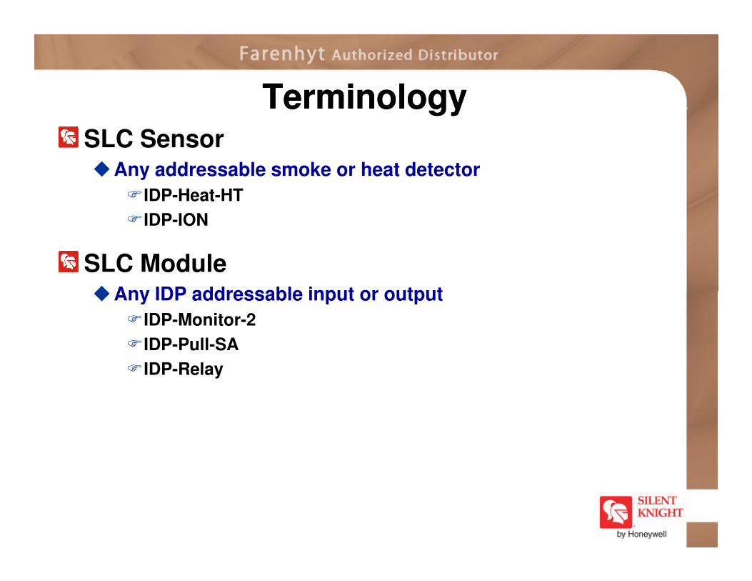
TerminologyTerminologySLC Sensor�Any addressable smoke or heat detector
�IDP-Heat-HT
�IDP-ION
SLC Module�Any IDP addressable input or output�Any IDP addressable input or output
�IDP-Monitor-2
�IDP-Pull-SA
�IDP-Relay

Wiring RequirementsWiring RequirementsMaximum resistance 40 ohms
Measure from start to last device�Class A measures the whole loop
�Has to be the same gauge if you want to T-tap
feet for whole SLC
T-taps cannot exceed 40,000
feet for whole SLC
Wire gauge Max Distance
22 AWG 1,200 ft
18 AWG 3,100 ft
16 AWG 4,900 ft
14 AWG 7,900 ft
12 AWG 10,000 ft

Wiring RequirementsWiring RequirementsWire distance is calculated at the end of the run�NOT back
Wire distance must be less than max for the gauge
Distance to end of run

Wiring Requirements Wiring Requirements TT--TapsTaps
Use the distance of the device that is furthest from the panel to determine the gauge
� DO NOT mix gauges
Furthest from the panel

Wiring Requirements Wiring Requirements TT--TapsTaps
Wire gauge Max Distance
22 AWG 1,200 ft
18 AWG 3,100 ft
16 AWG 4,900 ft
14 AWG 7,900 ft
12 AWG 10,000 ft
2900 Feet awayFurthest smoke 2900 Feet away
entire SLCNeed 18 AWG for the
entire SLC

SLC TroubleshootingSLC Troubleshooting
Check voltage red to black�Should be about 20VDC

Rotary Wheel AddressingRotary Wheel AddressingAll of the IDP addressable product come with Rotary Wheels to set the addresses
There are two wheels �The first one is used to set the address by tens
�The second wheel is used to set the address by ones
Example = 35

Rotary Wheel AddressingRotary Wheel Addressing
Remember that you have up to 159 contact modules and 159 sensors on a loop�Do not duplicate addresses of modules or sensors on the
same loop
�You can have the same address for a contact module and a sensor on the same loop
�0 is an invalid address
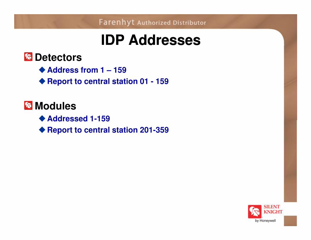
IDP AddressesIDP AddressesDetectors�Address from 1 – 159
�Report to central station 01 - 159
Modules�Addressed 1-159�Addressed 1-159
�Report to central station 201-359

ReviewReview
How far can you run an SLC loop using 18 AWG wire?
3100 feet
True or False:You must use the same gauge wire for
any t-tap runs.
True

IDPIDP--MinimonMinimonGives an address to a non addressable, normally open contact�Waterflow switches
�Pull stations
The IDP-Minimon supports Class B supervised wiring to the load device wiring to the load device
Conventional 4-wire smoke detectors can be monitored for alarm and trouble conditions

IDPIDP--Minimon WiringMinimon WiringEOL = 47K ohm
(supplied with monitor module)
Maximum initiating device circuit wiring resistance is 1500 Ohms
Maximum distance of dry contact devicefrom monitor module is 2,500 feet.
Wiring OnlyClass B
Wiring Only

IDPIDP--MonitorMonitorGives an address to a non addressable, normally open contact�Waterflow switches
�Pull stations
Same as Minimon�Except allows for Class A wiring�Except allows for Class A wiring
�Mounts in 4 square electrical box

IDPIDP--Monitor WiringMonitor Wiring

IDPIDP--MonitorMonitor--22The IDP-Monitor-2 is an addressable monitor module with two initiating circuits
Used for non-addressable dry contact input devices �Waterflows (most common)
�Supervisory
�Pull stations
�etc
Each of the two circuits has a unique address and can be programmed independently for any dry contact input type
Class B wiring only

IDPIDP--MonitorMonitor--2 Wiring2 Wiring
Wiring OnlyClass B
Wiring Only

IDPIDP--MonitorMonitor--1010
10 point addressable monitor module �10 Class B supervised inputs
�5 Class A supervised inputs
�Conventional 4-wire smoke detectors can be monitored for alarm and trouble conditions

IDPIDP--MonitorMonitor--10 Wiring10 Wiring

ReviewReview
True or False:All IDP-monitors utilize Class A & Class B
wiring?
FalseFalse
How many Class A supervised inputs can an IDP-Monitor-10 handle?
5

IDPIDP--Photo / PhotoPhoto / Photo--TT
Photoelectric smoke detector
IDP-Photo-T = photoelectric smoke detector with thermal
Have a unique optical sensing chamber �Engineered to sense smoke produced by a wide range of �Engineered to sense smoke produced by a wide range of
combustion sources
� In the IDP-Photo-T, dual electronic thermistors add 135ºF (57ºC) thermal technology to maximize detection

IDPIDP--IonIonAddressable Ion Sensor�Used in areas where early warning of trouble from super-
heated or flaming combustibles is expected
� IDP-Ion incorporates a unique single source, dual chamber design to response quickly to a broad range of fires

IDPIDP--HeatHeatFixed Heat Detector�Uses a thermistor sensing circuit to produce 135ºF (57ºC)
fixed thermal detection

IDPIDP-- HeatHeat--HTHTVariable high temperature detector�Provides high temperature detection at 135ºF – 190ºF
�Programmed by zone

IDPIDP--HeatHeat--RORROR
Rate of Rise Thermal Detector� Is a fixed temperature and rate-of-rise thermal detector
�The rate of rise is 15 degree F/min
�Uses a thermistor sensing circuit to produce 135ºF (57ºC) thermal protection

IDPIDP--AcclimateAcclimateAcclimate Smoke Detector�Combines photoelectric and rate of rise detectors

SLC LEDsSLC LEDs
Smoke detector heads - two LEDS
� Both red
SLC modules – 1 LED
� Can be red or green
Flash once every 40 seconds during communications with FACPwith FACP
First two devices in alarm latch their LEDs on
� However, all other devices will flash their LEDs 3 times when they go into alarm, then turn them off

SLCIN OUT
Detector WiringDetector Wiring

ReviewReview
What is the temperature range for an IDP- Heat-HT?
135 - 190 ºF
What does a IDP-Photo-T add to maximize detection?
135 ºF thermal sensor

IDP IDP -- DUCTDUCT
Duct detector� Includes photo smoke detector
�Detects smoke moving through an HVAC duct to prevent re-circulation of smoke into the air handling system
�When smoke is detected, the unit communicates the condition to the panel
�Panel decides if supervisory or Fire Alarm
�The air velocity rating is from 100 to 4000 feet per minute
�(0.5 to 20.32 meters per second)
�Has a flexible housing

Optional relay�Shut down HVAC, air handlers, etc.
Optional remote test switch�Test detector without climbing to the DUCT
�Terminals with remote test with LED annunciators
IDP IDP –– DUCTDUCT

IDP IDP –– Duct Detector WiringDuct Detector Wiring
FACPSLC
SLC Devices
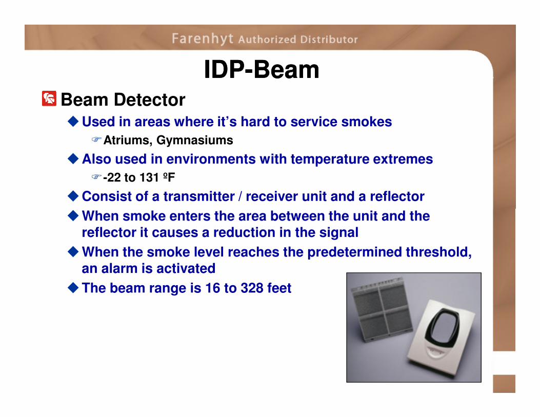
Beam Detector�Used in areas where it’s hard to service smokes
�Atriums, Gymnasiums
�Also used in environments with temperature extremes
�-22 to 131 ºF
�Consist of a transmitter / receiver unit and a reflector
�When smoke enters the area between the unit and the
IDPIDP--Beam Beam
�When smoke enters the area between the unit and the reflector it causes a reduction in the signal
�When the smoke level reaches the predetermined threshold, an alarm is activated
�The beam range is 16 to 328 feet

Beam Detector with sensitivity test feature
�Test filter attached to a servo motor inside the detector optics
�Using the remote test station, SSRTS451, the motor is
activated and moves the filter in the pathway of the light
beam, which tests the detector sensitivity
IDPIDP--BeamBeam--T T

Beam Detector WiringBeam Detector Wiring
Power Requirements� IDP-Beam needs 20 mA
� IDP-Beam-T needs 500 mA
Voltage Rage� 15-32 VDC

RTSRTS--451Key451KeyRemote test station�Allows you to remotely test the duct & beam detectors
�Remote test switch
�Red alarm LED
Looks like a single gang annunciator
Wiring instructions can be found on install sheet Wiring instructions can be found on install sheet for corresponding product

IDPIDP--PullPull--SA / PullSA / Pull--DADAPull Station – Single Action
Pull Station – Dual Action
Both addressable
The dual color LED is visible through the handle �Blinks green for normal conditions
�Steady red in alarm conditions�Steady red in alarm conditions
Key operated and use the same key as the FACP lock set �The operator can open the pull stations without causing an
alarm condition

Pull Station WiringPull Station Wiring

IDPIDP--RelayRelayAddressable Relay Module
Allows you to control a wide variety of normally open and normally closed applications, including:�Elevator recall
�Door closing
�Fan operation
�Auxiliary notification�Auxiliary notification
The LED on the relay module �LED flashes only during communications
with FACP
LED blinks once every15-20 seconds when communicating with
the panel
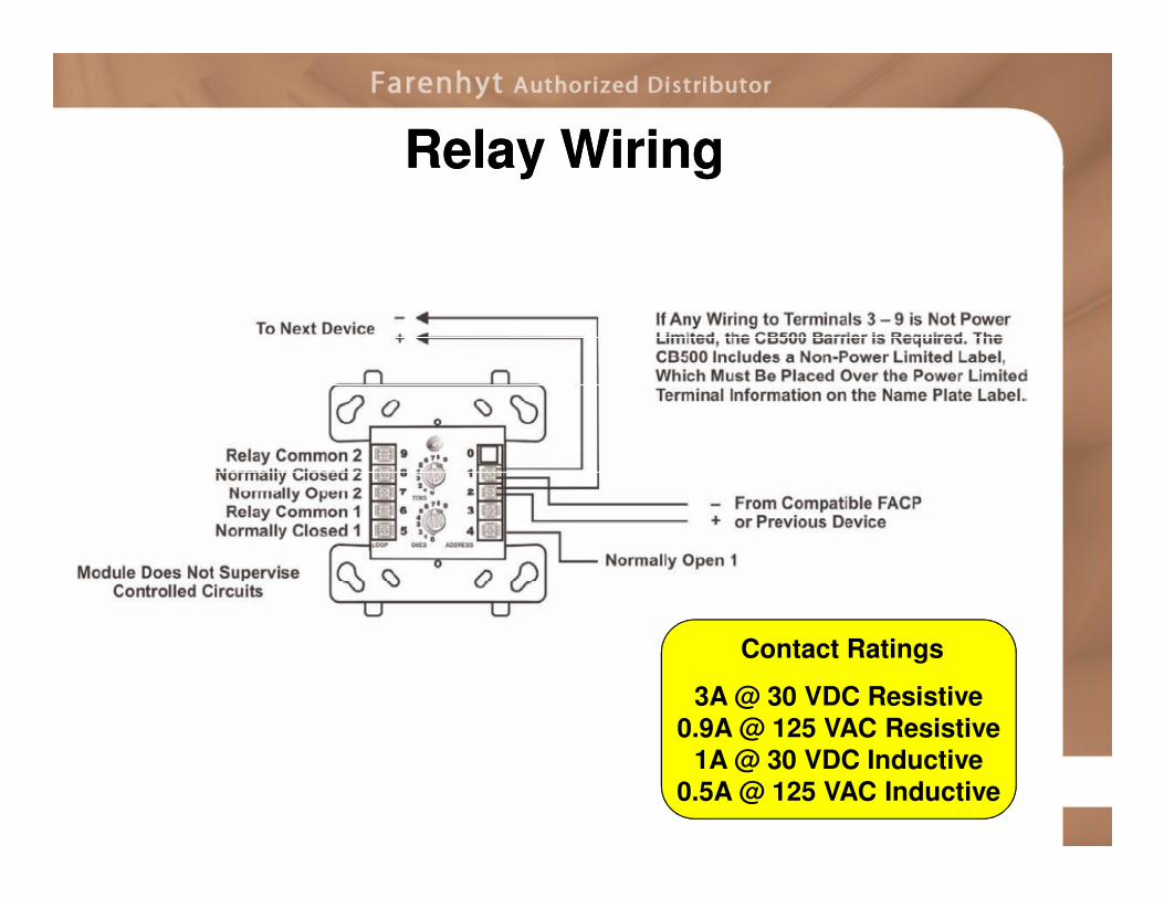
Relay WiringRelay Wiring
Contact Ratings
3A @ 30 VDC Resistive0.9A @ 125 VAC Resistive
1A @ 30 VDC Inductive0.5A @ 125 VAC Inductive

IDPIDP--RelayRelay--66Relay Module with 6 relays�This device has six isolated sets of
Form C contacts that operate as a SPDT switch
�Activation of the contacts is controlled from the FACP by any device or zone of devicesdevice or zone of devices
�Each relay has its own LED for normal and activation conditions
�You can disable up to three unused relays on this device

IDPIDP--RelayRelay--6 Wiring6 Wiring
Contact Ratings
3A @ 30 VDC Resistive0.9A @ 125 VAC Resistive
1A @ 30 VDC Inductive0.5A @ 125 VAC Inductive

ReviewReview
What temperatures can beam detectors operate in?
-22 - 135 ºF
How do you set the address of the 2nd
relay output on a IDP-Relay-6?
It follows the address of the 1st relay

IDPIDP--ZoneZoneAddressable Module for 2-wire conventional smoke detectors�This means you can retrofit an existing building and use
existing conventional devices
�Check install sheet for compatible smoke detectors
�LED status
�Blinking green = normal
�Solid red = alarm

IDPIDP--Zone WiringZone Wiring
Be sure to run 24 VDC auxiliary power to this module
It will supervise the power and give a trouble on this device if it is missing

IDPIDP--ZoneZone--66Addressable Module for 6 circuits of conventional
2-wire smoke detectors
�Provides six zone inputs that allow a Silent Knight FACP to
interface and monitor two-wire conventional smoke detectors
�This means you can retrofit an existing building and use
existing conventional devices
�Check install sheet for compatible smoke detectors
�LED status for each individual input zone

IDPIDP--ZoneZone--6 Wiring6 Wiring
Be sure to run 24 VDC auxiliary power to this module
It will supervise the power and give a trouble on this device if it is missing

IDPIDP--ControlControl
Addressable Notification Module�The IDP-Control gives you the flexibility to add notification
circuits wherever they are needed
�Supervised addressable notification device that provides you with additional notification circuits
�The maximum current available�The maximum current available
�3A in a Class B
�2A in a Class A
� It can be programmed to activate from any input device or zone of input devices

IDPIDP--Control Wiring Class B Control Wiring Class B -- Style YStyle Y
Relay supervises power to IDP-Control

IDPIDP--Control Wiring Class A Control Wiring Class A –– Style ZStyle Z
Relay supervises power to IDP-Control
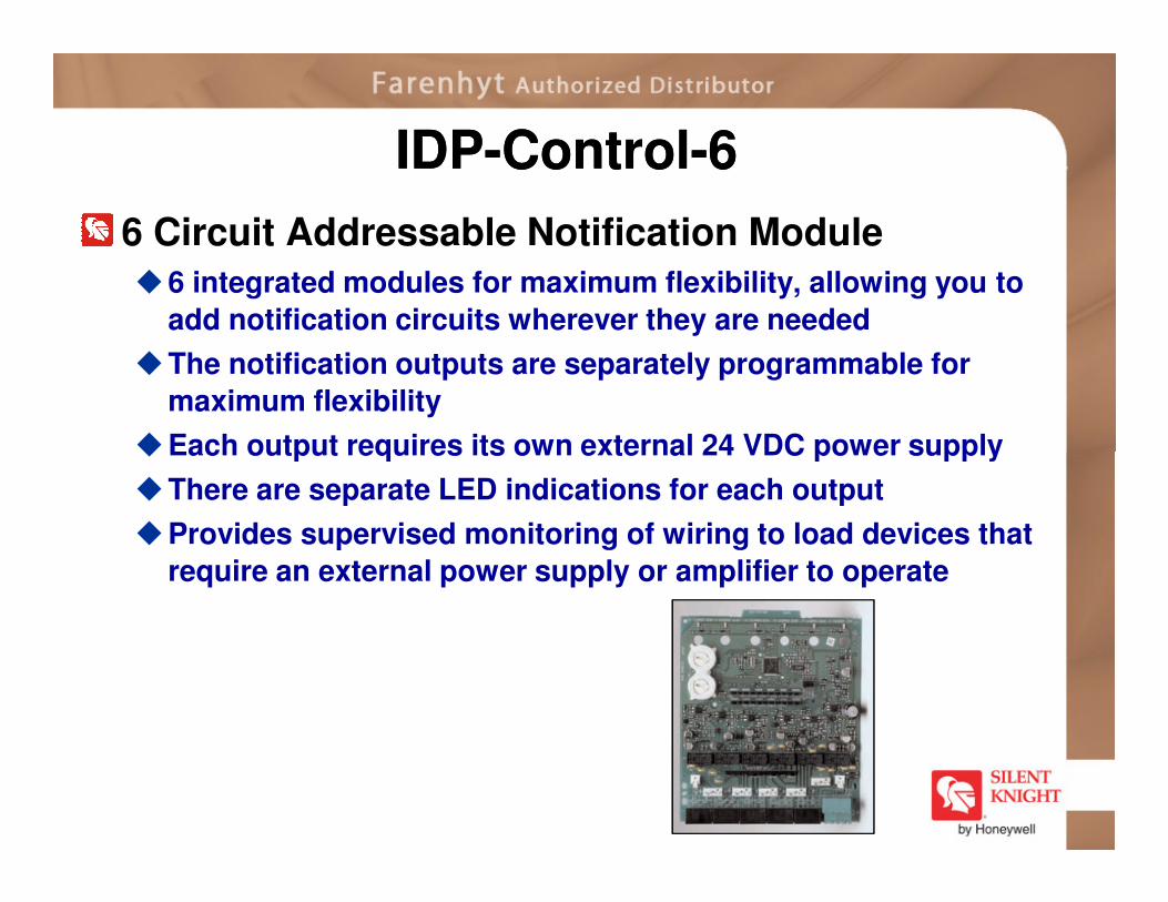
IDPIDP--ControlControl--66
6 Circuit Addressable Notification Module
�6 integrated modules for maximum flexibility, allowing you to
add notification circuits wherever they are needed
�The notification outputs are separately programmable for
maximum flexibility
�Each output requires its own external 24 VDC power supply �Each output requires its own external 24 VDC power supply
�There are separate LED indications for each output
�Provides supervised monitoring of wiring to load devices that
require an external power supply or amplifier to operate

IDPIDP--ControlControl--6 Wiring6 Wiring
Relay supervises power to IDP-ControlRelay supervises power to IDP-Control

ReviewReview
What is the maximum current in an IDP-Control?
3A in class B, 2A in class A
True or False:Each IDP-Control-6 output requires its own external 24 VDC power supply ?
True

IDPIDP--IsoIso
Addressable Line Isolator Module� Acts as an automatic switch that opens
when the line voltage on the signaling line circuit (SLC) loop drops below 4VDC
� Should be spaced between groups of sensors or modules in a loop to protect the rest of the loop
� If a short occurs between any two isolators, then both isolators immediately switch to an open circuit state and isolate the devices between them
� The remaining units on the SLC loop continue to fully operate. No more than 25 sensors or modules are required for each pair of Isos
does NOT take up
the SLC loop
does NOT take up an address on the SLC loop

Wiring Without IDPWiring Without IDP--IsoIso
Short anywhere across the SLC�Panel communicates = SLC shorted
�All devices lose power

Wiring with IDPWiring with IDP--IsoIso
Short across SLC after Iso �Rest of loop keeps operating
�Helps you find the short

IDPIDP--Iso Class AIso Class A
Class A style 6 designed to minimize loss of protection during a short

IDPIDP--Iso Class AIso Class A
Not protecting the panel can lead to an SLC short

IDPIDP--Iso Class AIso Class A
Protect the panel with an Iso on BOTH the SLC input and SLC output!

IDPIDP--Iso Class A Style 7Iso Class A Style 7
3 ft3 ft
2 IDP-Isos for each SLC device & 2 for the FACPUsed in Government buildings3 feet max between Iso and FACP� 1 foot between Iso and SLC device
1 ft1 ft
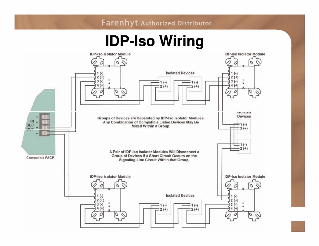
IDPIDP--Iso WiringIso Wiring

IDPIDP--SSB224BISSB224BI
6 inch mounting base with built-in Isolator Module�Prevents an entire communication loop from being disabled
when a short circuit occurs
�The SSB224BI isolates any part of a loop that has a short from the rest of the loop
�The base also automatically restores the entire loop when �The base also automatically restores the entire loop when the cause of the short circuit is corrected

IDPIDP--SSB224BI WiringSSB224BI WiringWorks like style 7 without all the modules
Smoke detector is truly isolated from the base

IDPIDP--SSB224BI WiringSSB224BI Wiring

IDPIDP--6AB6AB6 inch mounting base for IDP style detectors�Plug in detector bases for IDP style detectors intended for use
with Silent Knight IFP-series fire alarm control panels

IDPIDP--SSB501SSB5014 inch mounting base for IDP style detectors�Plug in detector bases for IDP style detectors intended for use
with Silent Knight IFP-series fire alarm control panels in Asia or South America

IDPIDP--6AB / SSB501 Wiring6AB / SSB501 Wiring

IDPIDP--SSB224RBSSB224RB6 inch mounting base with built-in Relay Module� lets you control a wide variety of normally open and normally
closed applications
�Because the relay is addressable, the relay device can be located at any point in the signaling line circuit

IDPIDP--SSB224RB WiringSSB224RB Wiring

IDPIDP--SSB501BHTSSB501BHT6 inch mounting base with built-in Sounder Module� Incorporates the distinctive three-pulse temporal pattern fire
alarm evacuation signal

IDPIDP--SSB501BHT WiringSSB501BHT Wiring
ReviewReview
What is the advantage of an IDP-Iso?
If a device shorts in the system, all the SLC devices that are protected by a line isolator module will continue to operateisolator module will continue to operate
How many addresses does an IDP-Iso take on the SLC??
0

ObjectivesObjectivesAt the end of this section you will be able to:�Explain the functions of each SLC device
�Demonstrate how to set addresses for the IDP devices
�Explain the unique wiring considerations for each SLC device
�Describe how to calculate wiring distances for an SLC loop

Module 5
Signaling Line Circuit
Module 5