Module 3 Chapter 1-Drilling machine
37
Module 3 Chapter 1-Drilling machine Drilling machine is one of the most important machine tools in a workshop. It was designed to produce a cylindrical hole of required diameter and depth on metal work pieces. Types of drilling machines 1. Portable drilling machine (or) Hand drilling machine 2. Sensitive drilling machine (or) Bench drilling machine 3. Upright drilling machine 4. Radial drilling machine 5. Gang drilling machine 6. Multiple spindle drilling machine 7. Deep hole drilling machine Types of drilling machines The different types of drilling machines are: 1. Portable drilling machine (or) Hand drilling machine- Portable drilling machine Portable drilling machine can be carried and used anywhere in the workshop. It is used for drilling holes on work pieces in any position, which is not possible in a standard drilling machine. 2. Sensitive drilling machine (or) Bench drilling machine It is designed for drilling small holes at high speeds in light jobs. High speed and hand feed are necessary for drilling small holes 3. Upright drilling machine The upright drilling machine is designed for handling medium sized workpieces. Though it looks like a sensitive drilling machine, it is larger and heavier than a sensitive drilling machine. Holes of diameter upto 50mm can be made with this type of machine 4. Radial drilling machine 5. Gang drilling machine Gang drilling machine has a long common table and a base. Four to six drill heads are placed side by side. 6. Multiple spindle drilling machine
-
Upload
khangminh22 -
Category
Documents
-
view
0 -
download
0
Transcript of Module 3 Chapter 1-Drilling machine

Module 3
Chapter 1-Drilling machine
Drilling machine is one of the most important machine tools in a workshop. It was
designed to produce a cylindrical hole of required diameter and depth on metal
work pieces.
Types of drilling machines
1. Portable drilling machine (or) Hand drilling machine 2. Sensitive drilling machine (or) Bench drilling
machine 3. Upright drilling machine 4. Radial drilling machine 5. Gang drilling machine
6. Multiple spindle drilling machine 7. Deep hole drilling machine
Types of drilling machines
The different types of drilling machines are:
1. Portable drilling machine (or) Hand drilling machine-
Portable drilling machine Portable drilling machine can be carried and used anywhere in the workshop.
It is used for drilling holes on work pieces in any position, which is not possible in a standard drilling
machine.
2. Sensitive drilling machine (or) Bench drilling machine
It is designed for drilling small holes at high speeds in light jobs. High speed and hand feed are necessary
for drilling small holes
3. Upright drilling machine
The upright drilling machine is designed for handling medium sized workpieces. Though it looks like a
sensitive drilling machine, it is larger and heavier than a sensitive drilling machine. Holes of diameter
upto 50mm can be made with this type of machine
4. Radial drilling machine
5. Gang drilling machine
Gang drilling machine has a long common table and a base. Four to six drill heads are placed side by
side.
6. Multiple spindle drilling machine

This machine is used for drilling a number of holes in a work piece simultaneously and for reproducing
the same pattern of holes in a number of identical pieces
7. Deep hole drilling machine
A special machine and drills are required to drill deeper holes in barrels of gun, spindles and connecting
rods. The machine designed for this purpose is known as deep hole drilling machine
Radial drilling machine
Base- The base is a large rectangular casting and is mounted on the floor of the shop.
Column -The column is a cylindrical casting, which is mounted vertically at one end of the base. It
supports the radial arm and allows it to slide up and down on its face.

Radial arm -The radial arm is mounted on the column parallel to the base and can be adjusted vertically.
The vertical front surface is accurately machined to provide guide ways for the drill head.
Drill head -The drill head is mounted on the radial arm and houses all mechanism for driving the drill at
different speeds and at different feed. A motor is mounted on top of the drill head for this purpose
Table-It is provided to hold the work holding device.
Work holding devices
The work should be held firmly on the machine table before performing any operation on it.
The devices used for holding the work in a drilling machine are
1. Drill vise
2. ‘T’ - bolts and clamps
3. Step block
4. V – block
5. Angle plate
6. Drill jigs
1. Drill vise
Vise is one of the important devices used for holding work piece on a drilling machine table. The work is
clamped in a vise between a fixed jaw and a movable jaw.
2. ‘T’ - bolts and clamps

The work pieces can be held directly on the machine table by means of ‘T’ - bolts and clamps. The top of
the machine table has ‘T’ - slots into which ‘T’ - bolts may be fitted.
3. Step block
4. V – block

5. Angle plate
Tool holding devices used in a drilling machine
Different tools are used for performing different operations. They are fitted into the drill spindle by
different methods. They are
1. By directly fitting in the spindle
2. By a sleeve
3. By a socket

4. By a chuck
5. Tapping attachment
1. Spindle
Almost all drilling machines have their spindle bored out to a standard taper(1:20) to receive the taper
shank of the tool. While fitting the tool, the shank of the drill (or any other tool) is forced into the
tapered hole and the tool is gripped by friction.
2. Sleeve
The drill spindle is suitable for holding only one size of tool shank. If the shank of the tool is smaller than
the taper in the spindle hole, a taper sleeve is used. The outside taper of the sleeve conforms to the
spindle taper and the inside taper holds the shanks of the smaller size tools
3. Socket

4. Chuck
This type of chuck is particularly adapted for holding tools having straight shanks. The drill chuck has a
taper shank which fits into the taper hole of the spindle. The jaws fitted in the body of the chuck holds
the straight shank drills.

Types of drill bits
A drill is a tool used to originate a hole in a solid material. A helical groove known as ‘flute’ is
cut along the length of the drill. Different types of drills are 1. Flat Drill 2. Straight fluted drill 3.
Twist drill 4. Centre drill.
Nomenclature of taper shank twist drill.
Twist drills are the type generally used in shop work. They are made of High speed steel (HSS) or High
carbon steel. Main parts are
Axis- It is the longitudinal centerline of the drill running through the centers of the tang and the chisel
edge.
Body- It is the part of the drill from its extreme point to the commencement of the neck
Shank -It is the part of the drill by which it is held and driven.
Tang -The flattened end of the taper shank is known as tang.
Neck It is the part of the drill, which is diametrically undercut between the body and the shank of the
drill.
Point- It is the sharpened end of the drill.
Lip -It is the edge formed by the intersection of flank and face
Land- It is the cylindrically ground surface on the leading edges of the drill flutes adjacent to the body
clearance surface.
Flutes -The grooves in the body of the drill are known as flutes. Flutes form the cutting edges on the
point
Angles –
Chisel edge angle
Helix angle or rake angle
Point angle
Lip clearance angle
Drilling machine operations
Though drilling is the primary operation performed in a drilling machine, a number of similar operations
are also performed on holes using different tools. The different operations that can be performed in a
drilling machine are:
1. Drilling
2. Reaming
3. Boring
4. Counter boring
5. Countersinking
6. Spot facing
7. Tapping
8. Trepanning
1. Drilling

2. Reaming
3. Boring

4. Counter boring
5. Countersinking
Countersinking is the operation of making a cone shaped enlargement at the end of the hole.
The included angle of the conical surface may be in the range of 60° to 90°. It is used to provide
recess for a flat headed screw or a counter sunk rivet fitted into the hole.

6. Spot facing
7. Tapping
Tapping is the operation of cutting internal threads by means of a cutting tool called ‘tap’.
Tapping in a drilling machine may be performed by hand or by power.

8. Trepanning
Cutting speed, Feed & Depth of cut
Cutting speed -The cutting speed in a drilling operation refers to the peripheral speed of a point on the
cutting edge of the drill. It is usually expressed in meters per minute.
The cutting speed (v) may be calculated as

Feed -The feed of a drill is the distance the drill moves into the work at each revolution of the spindle. It
is expressed in millimeters.
Depth of cut- The depth of cut in drilling is equal to one half of the drill diameter. If ‘d’ is the diameter of
the drill, the depth of cut (t) t = d/2 mm.

CHAPTER NO 2:
MILLING MACHINE
Milling is a process of removing metal by feeding the work against a rotating multipoint cutter.
The machine tool intended for this purpose is known as milling machine
Horizontal milling machine
.
Base -It is made of cast iron and supports all the other parts of the machine tool. A vertical column is
mounted upon the base

Column- It is mounted upon the base and is box shaped. It houses the mechanism for providing drive for
the spindle.
Knee -It slides up and down on the guide ways of the column. An elevating screw mounted on the base
obtains this movement.
Saddle- It is mounted on the guide ways of the knee and moves towards or away from the face of the
column.
Table- The table is moved longitudinally either by power or manually on the guide ways of the saddle.
Spindle- It is located in the upper part of the column. It receives power from the motor through belt,
gears and clutches.
VERTICAL MILLING MACHINE
Work holding devices used in milling machine
Different work holding devices used in milling machine are
1. Vices 2.Angle plate 3.V-block 4.Step block 5.Special milling attachments (Indexing head)

Cutter holding devices used in milling machine
Depending on the design of the cutter, there are several methods of supporting milling cutters on the
machine spindle.
1) Arbor 2) Collet 3) Adapter
1. Arbor- Milling cutters with central holes are mounted and keyed on a shaft called arbor. There are
three different types of arbor namely Pilot end arbor, ‘A’ type arbor and stub arbor. The arbors are
made with taper shanks for correct alignment with the machine spindle. The left side of the arbor is
threaded internally to receive a draw bolt. This draw bolt connects the arbor with the spindle.
2 Collet- It is a form of sleeve bushing used to hold arbors or cutters having a smaller shank than the
spindle taper. Collets are connected to the spindle by a drawbolt and the rotary motion is transmitted to
the cutters.
3. Adapters- Milling cutters having shanks are generally mounted on adapters. The outside taper of the
adapter conforms to the taper hole of the spindle. The shank of the cutter fits into the taper hole of the
adapter.

Milling cutters used in milling machine
There are different types of milling cutters used in a milling machine. A suitable milling cutter is selected
according to the need. They are
1. Plain milling cutter 2. Side milling cutter 3. Metal slitting saw 4. Angle milling cutter
5. End milling cutter 6. ‘T’ – Slot milling cutter 7. Fly cutter 8. Formed cutter.
Plain milling cutter -Plain milling cutters are cylindrical in shape and have teeth on the circumferential
surface only. They are used for producing flat surfaces parallel to the axis of rotation of the spindle. The
teeth of the cutter may be straight or helical according to the size.
Side milling- cutter Side milling cutters have teeth on its periphery and also on one or both of its sides.
They are intended for removing metal from the sides of the work piece.

End mill -These cutters have cutting teeth on the end as well as on the periphery of the cutter. It is made
of two parts – body and shank. The shanks of the cutter may be straight or taper. These cutters are
useful in machining long narrow slots, holes and flat surfaces.
Elements of a plain milling cutter

Body of cutter: It is the part of the cutter left after exclusion of the teeth.
Face: The portion of the teeth next to the cutting edge is known as face.
Land: The relieved back portion of the tooth adjacent to the cutting edge. It is relieved to avoid
interference between the surface being machined and the cutter.
Outside diameter: The diameter of the circle passing through the peripheral cutting edges.
Central hole: It refers to the hole present at the centre of the cutter. A keyway is cut inside the hole
Cutter angles
Relief angle: It is angle the between the land of the tooth and the tangent to the outside diameter of
the cutter at the cutting edge of the particular tooth. (approx 7.5 °)
Primary clearance angle: It is the angle between the back of the tooth and the tangent drawn to the
outside diameter of the cutter at the cutting edge. (approx 15 °)
Secondary clearance angle: It is the angle formed by the secondary clearance surface and the tangent to
the periphery of the cutter at the cutting edge.

Rake angle: The angle measured in the diametral plane between the face of the tooth and a radial line
passing through the cutting edge of the tooth.
Milling machine operations
The following operations are performed using suitable milling cutters.
1. Plain milling 2. Flute milling 3. Face milling 4. Keyway milling
5. Side milling 6. Drilling & reaming 7. Straddle milling 8. Boring 9. Angular milling
10. Gear cutting 11. Gang milling 12. Thread milling 13. Form milling
14. Cam milling 15. End milling
Plain milling- It is the operation of production of a flat surface parallel to the axis of rotation of the
cutter. It is also called as slab milling. Plain milling cutters and slab milling cutters are used to perform
this operation.
Plain milling can be classified as up milling and down milling.
Up milling
In this method, the workpiece mounted on the table is fed against the direction of rotation of
the milling cutter. The cutting force is minimum during the beginning of the cut and maximum
at the end of cut. The thickness of chip is more at the end of the cut. As the cutting force is
directed upwards, it tends to lift the workpiece from the fixtures. A difficulty is felt in pouring
coolant on the cutting edge.

Down milling
The workpiece mounted on the table is moved in the same direction as that of the rotation of
the milling cutter. The cutting force is maximum at the beginning and minimum at the end of
cut. The chip thickness is more at the beginning of the cut. The workpiece is not disturbed
because of the bite of the cutter on the work. The coolant directly reaches to the cutting point.
Face milling The face milling is the operation performed by the face milling cutter rotated
about an axis at right angles to the work surface.
Straddle milling- It is the operation of production of two vertical surfaces on both sides of the
work by two side milling cutters mounted on the same arbor. By using suitable spacing collars,
the distance between the two cutters is adjusted correctly. The straddle milling is commonly
used to produce square or hexagonal surfaces.

Gang milling- It is the operation of machining several surfaces of work simultaneously by
feeding the table against a number of cutters (either of same type or of different type)
mounted on the arbor of the machine.
Indexing methods
Indexing can be defined as the process of equally dividing the surface of circular work material.
Eg:- such as in cutting gear teeth, cutting splines, milling grooves in reamers and taps, and spacing holes on a circle.

There are different indexing methods in popularity. These are :
(a) Direct indexing (b) Simple indexing ……
Direct Indexing
It is also named as rapid indexing. For this direct indexing plate is used which has 24 equally spaced holes in a circle. It is possible to divide the surface of workpiece into any number of equal divisions out of 2, 3, 4, 56, 8, 12, 24 parts. These all numbers are the factors of 24.
In this case fist of all worm and worm wheel is disengaged. We find number of holes by which spring loaded pin is to be moved. If we want to divide the surface into 6 parts than number of holes by which pin is to be moved 24 N for 6 parts N = 6. So number of holes 26 4 6 holes that is after completing one pair of milling whole surface of workpiece we have to move the pin by 4 holes before next milling operation, that is to be done for 5 number of times for making hexagonal bolt.
Simple Indexing
It is also named as plain indexing. It overcomes the major limitation of direct indexing.The arrangement is shown below
Here inside the index head,there is a worm and worm gear arrangement.The worm wheel has 40 teeths.With one revolution of the crank,the worm wheel will rotates 1/40 revolution.
Three indexing plates are used. These plates have concentric circles of holes with their different numbers as described below :

Indexing Procedure
(a) Divide 40 by the number of divisions to be done on the circumference of workpiece. This gives movement of indexing crank. Indexing crank movement 40 N N is the number of divisions to be made on the circumference of workpiece.
(b) If the above number is a whole number, then crank is rotated by that much number of revolutions after each milling operations, till the completion of the work. For example, if we want to divide the circumference into 10 number of parts. Indexing crank movement 40 4 10 revolutions. That is the indexing crank is given 4 revolutions after each of milling operation for 9 more milling operations.
(c) If indexing crank movement calculated by 40 N is not whole number, it is simplified and then expressed as a whole number and a fraction.
Eg:- Let us do the indexing to cut 19 teeth on a spur gear blank that means we need to divide the circumference of gear blank into 19 identical, parts. Crank movement is calculated s given below.
Crank movement =40/N
=40/19 =2(⅔)
Which means….After cutting the first teeth,put the crank pin to the 19 holes circle of the crank plate.Then do 2 times rotation and the put the crank pin to the second hole of 19 holes circle.Cut the second teeth at this position.
MOULE 4
SHAPER MACHINE, SLOTTER MACHINE AND PLANER MACHINE
Shaping is a process of machining a flat surface which may be horizontal, vertical, inclined, concave or
convex using a reciprocating single point tool. A shaping machine is a reciprocating type of machine tool.
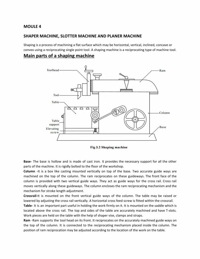
Main parts of a shaping machine
Base- The base is hollow and is made of cast iron. It provides the necessary support for all the other
parts of the machine. It is rigidly bolted to the floor of the workshop.
Column -It is a box like casting mounted vertically on top of the base. Two accurate guide ways are
machined on the top of the column. The ram reciprocates on these guideways. The front face of the
column is provided with two vertical guide ways. They act as guide ways for the cross rail. Cross rail
moves vertically along these guideways. The column encloses the ram reciprocating mechanism and the
mechanism for stroke length adjustment.
Crossrail-It is mounted on the front vertical guide ways of the column. The table may be raised or
lowered by adjusting the cross rail vertically. A horizontal cross feed screw is fitted within the crossrail.
Table- It is an important part useful in holding the work firmly on it. It is mounted on the saddle which is
located above the cross rail. The top and sides of the table are accurately machined and have T-slots.
Work pieces are held on the table with the help of shaper vise, clamps and straps.
Ram -Ram supports the tool head on its front. It reciprocates on the accurately machined guide ways on
the top of the column. It is connected to the reciprocating mechanism placed inside the column. The
position of ram reciprocation may be adjusted according to the location of the work on the table.
Tool head- The tool head is fitted on the face of the ram and holds the tool rigidly. It provides vertical
and angular feed movement of the tool. The swivel tool head can be positioned at any required angle
and the vertical slide can be moved vertically or at any desired angle to machine vertical or inclined
surfaces.
SHAPER MECHANISMS: -
In a shaper machine, the materials are removed from the workpiece only during the forward stroke of
the ram and also the backward stroke of the ram will be faster than the forward stroke.This is achieved
by one of the following explaind mechanism
1.Crank and slotted link mechanism
2. Whitworth quick return mechanism
3.Hydraulic mechanism
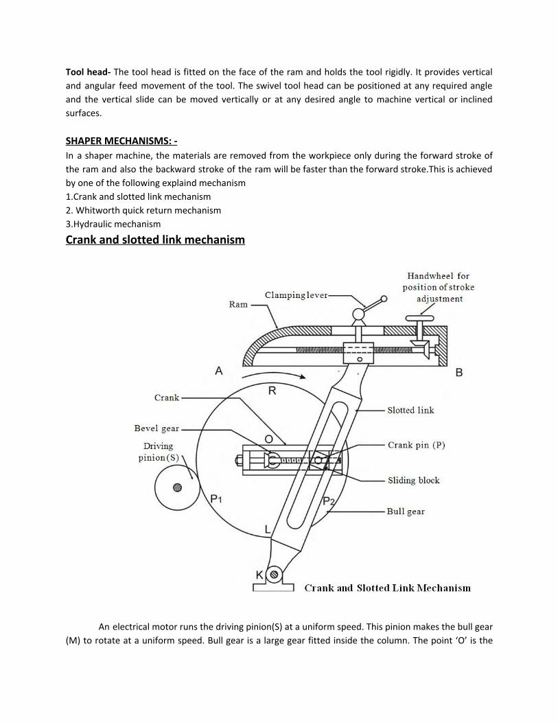
Crank and slotted link mechanism
An electrical motor runs the driving pinion(S) at a uniform speed. This pinion makes the bull gear
(M) to rotate at a uniform speed. Bull gear is a large gear fitted inside the column. The point ‘O’ is the

centre of the bull gear. A slotted link having a long slot along its length is pivoted about the point ‘K’. A
sliding block ‘N’ is fitted inside the slot and slides along the length of the slotted link. ‘P’ is the crank pin
and ‘OP’ can be considered as a crank. Fig. 3.3 shows the crank & slotted link mechanism.
When the bull gear rotates, the sliding block also rotates in the crank pin circle. This
arrangement provides a rocking movement to the rocker arm. As the top of the slotted link is connected
to the ram, the ram reciprocates horizontally. So, bull gear rotation is converted into the reciprocating
movement of the ram.
The mechanism can simply shown as
From the fig
Time taken for forward cutting stroke angle P1 RP2
------------------------------------------------------ = --------------------
Time taken for the idle return stroke angle P2 LP1
Whitworth quick return mechanism Fig. shows the whitworth quick return mechanism.This arrangement consists of
Pinion,Bull gear,Crank plate,sliding block,connecting rod and ram.
Here the crank plate is connected with the bull gear.The other end of the crank plate is
connected with the connecting rod.

Now the bull gear rotates by the pinion and thus the crank also rotates.With the
rotation of the crank, the sliding block will slides through the slot and connecting rod will
reciprocates and ram will geets the motion.
Here also, the angle covered by the crank during forward motion will be more than he
angle covered during backward motion.
Hydraulic mechanism
Hydraulic shaper mechanism mainly consists of
Oil collecting tank,gear pump,valves,pipes,piston cylinder arrangement,ram,dogs and reversing
lever
Inside the hydraulic cylinder a piston reciprocates. Between the piston and the
ram a piston rod is connected. So, the ram reciprocates along with the piston. Two
entries are provided near the each end of the cylinders. A four-way control valve
connects these two entries with the reservoir which contains the fluid. The reservoir is
connected to the valve with the help of a drain pipes and a supply pipe.

The supply pipe is again connected to the reservoir by a pump and relief valve.
The valve is actuated by the lever and trip dog fitted to the ram. Oil is sucked by the gear
pump from the reservoir at a particular pressure. This high pressure oil goes to the
cylinder through the four-way valve. The oil allowed from the pump to the left side of
the piston which forces the piston to move the ram towards right (R). It is called as
forward or cutting stroke. In this stroke, oil flows out on the right side entry to the
reservoir through the four-way valve and drain pipe. The lever hits one trig dog at the
end of this stroke. Now, the lever position is changed. Due to this, the supply pipe
supplies the oil on the right side of the piston which moves the ram towards left called as
return stroke or nan-cutting stroke. in this stroke the high pressure oil covers on lesser
area on the cylinder. Due to this, the pressure force will increase. Hence, this return
stroke is faster by supplying the same quantity of oil.
Different operations performed on a shaper machine are(Functions of a shaper machine) 1.Machining horizontal surfaces:- A shaper is mostly Used to machine a flat, true surface on a work
piece. Horizontal surfaces are machined by moving the work mounted on the machine table at a cross
direction with respect to the ram movement.

2.Machining vertical surfaces:- A vertical cut is made while machining the end of a workpiece,squaring up a block or machining shoulder.The feed is given to the tool by rotating the downfeed screw of the vertical slide. The table is not moved vertically for this purpose. The apron is swiveled away from the vertical surface being machined as shown in the diagram.
.3 Machining angular surfaces If the surface to be machined is neither horizontal nor perpendicular, the
surface is called inclined surface. Machining ‘V’ grooves and dovetail grooves are some examples for
angular machining.

Automatic feed mechanism in shaper(Ratchet & pawl mechanism)
The table of a shaping machine travels in a cross direction when the cross feed
screw is rotated. The cross feed screw is attached to the ratchet wheel. A spring loaded
‘pawl’ is positioned to be placed between the teeth of the ratchet wheel. The pawl is
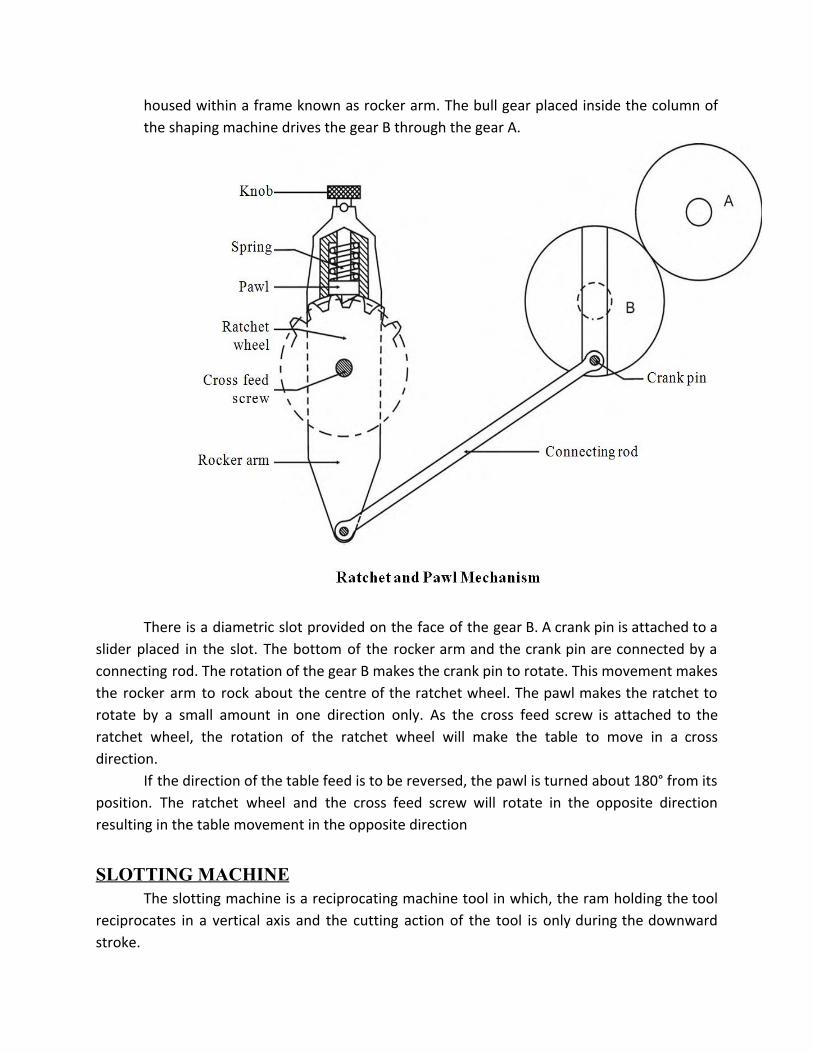
housed within a frame known as rocker arm. The bull gear placed inside the column of
the shaping machine drives the gear B through the gear A.
There is a diametric slot provided on the face of the gear B. A crank pin is attached to a
slider placed in the slot. The bottom of the rocker arm and the crank pin are connected by a
connecting rod. The rotation of the gear B makes the crank pin to rotate. This movement makes
the rocker arm to rock about the centre of the ratchet wheel. The pawl makes the ratchet to
rotate by a small amount in one direction only. As the cross feed screw is attached to the
ratchet wheel, the rotation of the ratchet wheel will make the table to move in a cross
direction.
If the direction of the table feed is to be reversed, the pawl is turned about 180° from its
position. The ratchet wheel and the cross feed screw will rotate in the opposite direction
resulting in the table movement in the opposite direction
SLOTTING MACHINE
The slotting machine is a reciprocating machine tool in which, the ram holding the tool
reciprocates in a vertical axis and the cutting action of the tool is only during the downward
stroke.
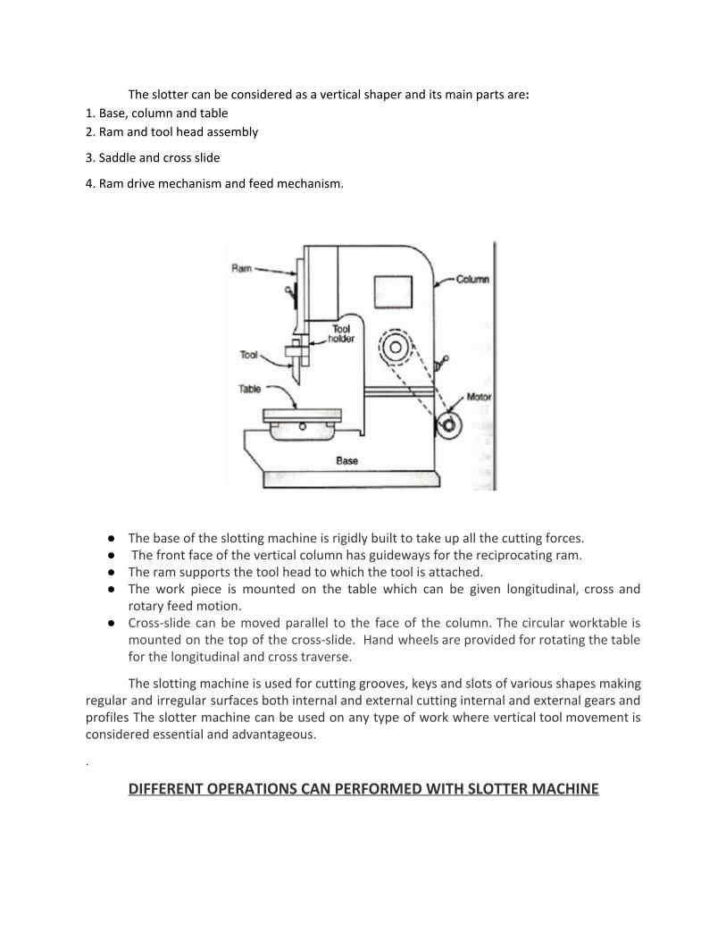
The slotter can be considered as a vertical shaper and its main parts are: 1. Base, column and table
2. Ram and tool head assembly
3. Saddle and cross slide
4. Ram drive mechanism and feed mechanism.
● The base of the slotting machine is rigidly built to take up all the cutting forces. ● The front face of the vertical column has guideways for the reciprocating ram. ● The ram supports the tool head to which the tool is attached. ● The work piece is mounted on the table which can be given longitudinal, cross and
rotary feed motion. ● Cross-slide can be moved parallel to the face of the column. The circular worktable is
mounted on the top of the cross-slide. Hand wheels are provided for rotating the table for the longitudinal and cross traverse.
The slotting machine is used for cutting grooves, keys and slots of various shapes making regular and irregular surfaces both internal and external cutting internal and external gears and profiles The slotter machine can be used on any type of work where vertical tool movement is considered essential and advantageous.
.
DIFFERENT OPERATIONS CAN PERFORMED WITH SLOTTER MACHINE

1. The slotting machine can be used to cut slots, splines keyways for both internal and external jobs such as machining internal and external gears.
2. It can be used for shaping internal and external forms or profiles. 3. It can be used for works as machining concave, circular, semi-circular and convex
surfaces. 4. It can be used for machining vertical surfaces, machining angular or inclined
surfaces, machining of shapes which are difficult to produce on a shaper machine and machining dies and punches.
5. It can be used for internal machining of blind holes.
PLANNING MACHINE
The planer is a machine tool designed to produce plane and flat surface on a workpiece which is too large or too heavy.
The work piece is securely fixed on a table called platen, and it reciprocates horizontally against a single edged cutting tool. The surface machined may be horizontal, vertical or at an angle.

Construction: The main parts of the double Housing Planer machine is Bed and table, Housings, Crossrail, , Tool heads, Driving and feed mechanism.
Bed and table: The bed is a long heavy base and table made of cast iron. Its top surface is flat and machined accurately. The flat top surface has slots in which the workpiece can be securely clamped. The workpiece needs rigid fixing so that it does not shift out of its position. The standard clamping devices used on planer machine are: Heavy duty vice, T-holders and clamps, angle plate, planer jack, step blocks and stop. The table movement may be actuated by a variable speed drive through a rack and pinion arrangement, or a hydraulic system.
Housings: The housings are the rigid and upright column like castings. These are located near the centre on each side of the base.
Cross rail: The cross rail is a horizontal member supported on the machined ways of the upright columns. Guideways are provided on vertical face of each column and that enables up and vertical movement of the cross rail. The vertical movement of the cross rail allows to accommodate workpiece of different heights. Since the cross rail is supported at both the ends, this type of planer machine is rigid in construction.
Tool heads: Generally two tool heads are mounted in the horizontal cross rail and one on each of the vertical housing. Tool heads may be swiveled so that angular cuts can be made.
Driving and feed mechanism: The tool heads may be fed either by hand or by power in crosswise or vertical direction. The motor drive is usually at one side of the planer near the centre and drive mechanism is located under the table.
The size of the planer is specified by the maximum length of the stroke, and also by the size of the largest rectangular solid that can be machined on it.
Operations of planer machine:
The planer is used for:
1. Planing flat horizontal, vertical and curved surfaces.
2. Planing at an angle and machining dovetails.
3. Planing slots and grooves.