Models 512, 513, 514 - Instruction Manual
26
MAN.PORT.REVE.06302015 Instruction Manual 5200 Convair Drive Carson City, NV 89706 • Phone: 775-883-2500 • Fax: 775-883-6388 • www.universalanalyzers.com
-
Upload
khangminh22 -
Category
Documents
-
view
0 -
download
0
Transcript of Models 512, 513, 514 - Instruction Manual
MAN.PORT.REVE.06302015
Instruction ManualModels 512, 513, 514
Portable Sample Systems
5200 Convair Drive Carson City, NV 89706 • Phone: 775-883-2500 • Fax: 775-883-6388 • www.universalanalyzers.com
Page 2 of 26 Page 3 of 26MAN.PORT.REVE.06302015
Contents
Receiving and Storage 3
Definition of Symbols 4
Product Identification 5
Specifications 6
Description and Principle of Operation 7
Installation 8
Electrical Connections 9
Start-Up 11
Shutdown 11
Maintenance 12
Troubleshooting 14
Spare Parts 16
Drawings 17
All Models (512, 513, 514) 17
Limited Warranty 24

Page 2 of 26 Page 3 of 26 MAN.PORT.REVE.06302015
Receiving and Storage
The UAI Models 512, 513, 514 Portable Sample Systems are a complete pre-installed unit. No assembly is necessary when received on-site.
Carefully inspect the product and any special accessories included with it immediately on arrival by removing them from the packing and checking for missing articles against the packing list.
Check the items for any damage in transit and, if required, inform the shipping insurance company immediately of any damage found.
Storage Location should be protected from the elements. Although all components provided are designed to resist corrosion, additional protection from heat (>140°F/ 60°C) and humidity is recommended.

Page 4 of 26 Page 5 of 26MAN.PORT.REVE.06302015
Definition of Symbols
WARNING - EXPLOSION HAZARD - DO NOT DISCONNECT EQUIPMENT UNLESS POWER HAS BEEN SWITCHED
OFF OR THE AREA IS KNOWN TO BE NON-HAZARDOUS.
WARNING - EXPLOSION HAZARD - SUBSTITUTION OF COMPONENTS MAY IMPAIR SUITABILITY FOR
HAZARDOUS AREA INSTALLATION.
THE SUPPLY POWER CIRCUIT MUST INCLUDE AN OVERPROTECTION DEVICE WITH A MAXIMUM RATING OF 20A. A DISCONNECT SWITCH MUST BE LOCATED IN CLOSE PROXIMITY TO THE PROBE.
IF THE EQUIPMENT IS USED IN A MANNER NOT SPECIFIED BY THE MANUFACTURER, THE PROTECTION PROVIDED BY THE EQUIPMENT MAY BE IMPAIRED PER CLAUSE 5.4.4(i) IN STANDARD EN 61010-1
CAUTION, RISK OF DANGER SYMBOL INDICATES INJURY MAY OCCUR IF MANUFACTURER’S INSTRUCTIONS ARE NOT ADHERED TO. PLEASE READ MANUAL CAREFULLY WHEN SYMBOL IS DISPLAYED
CAUTION, HOT SURFACE SYMBOL INDICATES EXPOSED SURFACE TEMPERATURE CAN CAUSE BURNS OR PERSONAL INJURY. CARE SHOULD BE TAKEN WHEN CONTACT IS REQUIRED.
CAUTION, RISK OF ELECTRICAL SHOCK SYMBOL INDICATES ELECTRICAL SHOCK MAY OCCUR. CAUTION SHOULD BE TAKEN BEFORE DISCONNECTING OR CONTACTING ANY ELECTRICAL CONNECTIONS.
PROTECTIVE CONDUCTOR TERMINAL SYMBOL INDICATES THE TERMINAL LOCATION FOR THE PROTECTIVE CONDUCTOR. FAILURE TO CONNECT TO THE PROTECTIVE CONDUCTOR TERMINAL MAY RESULT
IN A SHOCK HAZARD.

Page 4 of 26 Page 5 of 26 MAN.PORT.REVE.06302015
Product Identification
Lead Time Cooler (Part Number Configurator: 500T)
2 wks512 One (1) Sample Point - One (1) Active 5” Heat Exchanger513 One (1) Sample Point - Two (2) Passive/Active 5” Heat Exchangers514 One (1) Sample Point - Two (2) Active/Active 5” Heat Exchangers
5” Heat Exchanger Material (Price per Heat Exchanger)SS 316SSPV Glass/KynarC Hastelloy C276
+1 wkST Teflon Coated 316SSSW 316 Welded SS (High Pressure)SN Sulfinert® coated 316SSKK Kynar/Kynar
Voltage115 115VAC 50/60 Hz; General Purpose (GP) Area230 230VAC 50/60 Hz; General Purpose (GP) Area
Flow Meter with 316SS Needle ValveFM5 5.0 l/m
512 -SS -115 -FM5 -N Sample Part #
NOTE: LEAD TIMES ARE NOT COMPOUNDED. LEAD TIME IS COOLER + LONGEST OPTION
Flow Capacity l/m500 Series 512 513 514Ambient Temperature (°F) 77° 90° 105° 77° 90° 105° 77° 90° 105°12% H20 Vol. 2.5 2 1.5 4 3 2 5 4 315% H20 Vol. 2 1.8 1.2 4 3 2 4 3.5 2.530% H20 Vol. 1 0.9 0.6 4 3 2 2 1.8 1.3
50% H20 Vol. 0.6 0.5 0.3 4 3 2 1 0.9 0.7Exit Dew Point (C°) 4 4 4 4 4 4 4 4 4
Standard Features • Water Carry-Over Input • Alarm Contact: Moisture • LED Status Indicators: Moisture, Cooling

Page 6 of 26 Page 7 of 26MAN.PORT.REVE.06302015
Specifications
OPERATING SPECIFICATIONSSample Flow Rate Model 512, 513, 514 See table on previous pageMaximum Inlet Temperature Stainless Steel Heat Exchanger 700°F (371°C) Kynar/Glass Heat Exchanger 280°F (138°C)Maximum Inlet Gas Dew Point 178°F (81°C)*Maximum Inlet Water Vapor Content 50%*Minimum Ambient Temperature 34°F (1°C)Maximum Ambient Temperature 105°F (41°C)*Maximum Active Cooling Power Model 512, 513 63 BTUs per hour (60 kJ/Hr) Model 514 126 BTUs per hour (120 kJ/Hr)Outlet Sample Dew Point 39°F (4°C)Heat Exchanger (HE) Configuration Model 512 1 Active Model 513 1 Passive, 1 Active Model 514 2 ActiveGas Sample Inlet (Compression Fitting) 3/8"Gas Sample Outlet (Compression Fitting) 1/4" Bottom Condensate Drain (Compression Fitting) 3/8" Maximum Input Power Model 512, 513 175 watts Model 514 250 wattsVoltage (Not Field Configurable) Model 512, 513, 514 120/230VAC, 50/60 Hz Electrical Classification General Purpose, NEMA 1Dimensions 15" H x 10" W x 15" DWeight Model 512 32 lbs (14kg) Model 513, 514 35 lbs (15kg)Soluble Gas Removal Rates NO 0% loss
NO2 <10% lossSO2 < 2% lossCO 0% lossCO2 < 2% loss
*AT REDUCED FLOW RATE
Page 6 of 26 Page 7 of 26 MAN.PORT.REVE.06302015
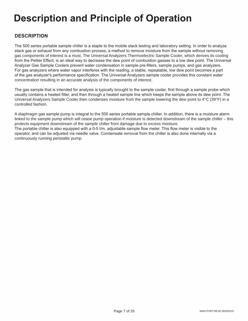
Description and Principle of OperationDESCRIPTION
The 500 series portable sample chiller is a staple to the mobile stack testing and laboratory setting. In order to analyze stack gas or exhaust from any combustion process, a method to remove moisture from the sample without removing gas components of interest is a must. The Universal Analyzers Thermoelectric Sample Cooler, which derives its cooling from the Peltier Effect, is an ideal way to decrease the dew point of combustion gasses to a low dew point. The Universal Analyzer Gas Sample Coolers prevent water condensation in sample pre-filters, sample pumps, and gas analyzers. For gas analyzers where water vapor interferes with the reading, a stable, repeatable, low dew point becomes a part of the gas analyzer's performance specification. The Universal Analyzers sample cooler provides this constant water concentration resulting in an accurate analysis of the components of interest.
The gas sample that is intended for analysis is typically brought to the sample cooler, first through a sample probe which usually contains a heated filter, and then through a heated sample line which keeps the sample above its dew point. The Universal Analyzers Sample Cooler then condenses moisture from the sample lowering the dew point to 4°C (39°F) in a controlled fashion.
A diaphragm gas sample pump is integral to the 500 series portable sample chiller. In addition, there is a moisture alarm linked to the sample pump which will cease pump operation if moisture is detected downstream of the sample chiller – this protects equipment downstream of the sample chiller from damage due to excess moisture. The portable chiller is also equipped with a 0-5 l/m, adjustable sample flow meter. This flow meter is visible to the operator, and can be adjusted via needle valve. Condensate removal from the chiller is also done internally via a continuously running peristaltic pump.

Page 8 of 26 Page 9 of 26MAN.PORT.REVE.06302015
InstallationThe UAI Models 512, 513, 514 Portable Sample Systems should be installed away from heat sources in a well ventilated area of an instrument rack or enclosure. Completely enclosing the instrument which generated between 175 and 250 watts of energy will cause the temperature of the interior of the enclosure to rise to a temperature too great for the sample cooler to perform reliably. Universal Analyzers supplies NEMA 1 type enclosures modified to duct outside air directly into the heat sink. The heated air is then exhausted to the outside of the enclosure with two fans, thermostatically controlled.
Sample tubing should be brought to the heat exchanger inlet. A 3/8” tubing fitting is provided on the front of the enclosure for the sample inlet to the sample cooler. The dry sample outlet is a 1/4” tubing fitting located next to the sample inlet.
A 3/8” tubing fitting is provided as the condensate drain connection towards the bottom of the front side of the enclosure. There is roughly six inches of 3/8" drain tubing. This should be run to the common drain or a container. Proper drainage is imperative in avoiding the accumulation of liquid near electrical equipment. The tubing can be connected via a 3/8" tube fitting or an 8mm barb fitting.
Page 8 of 26 Page 9 of 26 MAN.PORT.REVE.06302015
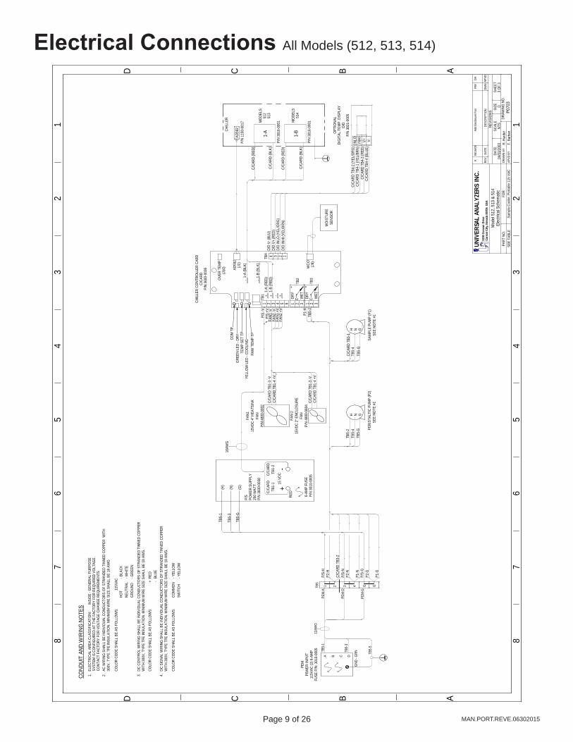
Electrical Connections All Models (512, 513, 514)
ABCD
ABC
12
34
56
78
12
34
56
7
D
8
P070
3
04/0
1/20
03
Sam
ple
Cool
er, P
orta
ble
115
VAC
REV
REVI
SIO
NS
FOR
PART
NO
.R.
Har
der
APVD
BY
DRAW
N BY
DRAW
ING
NO
.
DATE
SEE
TABL
E
Mod
el 5
12, 5
13 &
514
Elec
trica
l Sch
emat
ic
DATE
DESC
RIPT
ION
DWN
APVD
SCAL
ESI
ZESH
EET
NTS
D3
OF
3
UNIV
ERSA
L AN
ALYZ
ERS
INC.
5200
Con
vair
Driv
eCa
rson
City
, Nev
ada
8970
6 U
SA
12AW
G
TB5-
5
GND
- G
RNTB5-
3
TB5-
1
DCBA
TB5
1 2 3 4 G G
(H)
(N)
(G)
TB5-
G
TB5-
3
TB5-
1
15 V
DC+
-
16AW
G
RED
FAN1
15VD
C 4"
HEA
TSIN
KFA
NP/
N 48
00-0
002
C/CA
RD T
B1-3
-VC/
CARD
TB1
-4 +
V
1234TB4
TB1
1 2 3 4 5 6
+ + - +
--
COM
TP
GRE
EN L
ED -
DRY
TEM
P SE
T TP
YELL
OW
LED
- CO
OLI
NGRA
W T
EMP
TP
WCO (J9)
AD59
2(J
1)
OVE
R TE
MP
(J10
)
WET
DRY
CWET
DRY
C1 2 3 1 2 3
TB2
TB3
CHIL
LER
CONT
ROLL
ER C
ARD
C/CA
RDP/
N 36
00-0
036
MO
ISTU
RESE
NSO
R
1-A
AD59
2
FAN1
-V
FAN1
+V
1-B
PEM
-A
PEM
-D
PEM
-G
P/S
+VP/
S -V
C/CA
RD (R
ED)
C/C
ARD
(BLK
)
C/C
ARD
(RED
)
C/C
ARD
(BLK
)
1-B
(BLK
)
1-A
(RED
)1-A
(BLK
)
P/S-
H
P/S-
N
P/S-
G
P2-H
C/CA
RD T
B3-2
P2-N
P1-N
P2-G
P1-G
TB5-
GTB
5-4
TB5-
2
TB5-
GTB
5-4
C/CA
RD T
B3-1
SEE
NOTE
#1
PERI
STAL
TIC
PUM
P (P
2)SE
E NO
TE #
1SA
MPL
E PU
MP
(P1)
GNH
GNH
P1-H
TB5-
2
OPT
IONA
LDI
GIT
AL T
EMP.
DIS
PLAY
D/D
P/N
3021
-000
5
D/D
V- (B
LU)
D/D
V+ (R
ED)
D/D
INLO
(YEL
/ORG
)D/
D IN
HI (Y
EL/B
RN)
V-V+INHI
INLO
-CO
LOR
CODE
SHA
LL B
E AS
FO
LLO
WS:
RED
+BL
UE
DC C
ONT
ROL
WIR
ING
SHA
LL B
E IN
DIVI
DUAL
CON
DUCT
ORS
OF
STRA
NDED
TIN
NED
COPP
ERW
ITH
300V
, TYP
E TF
E IN
SULA
TIO
N. M
INIM
UM W
IRE
SIZE
SHA
LL B
E 18
AW
G.
COND
UIT
AND
WIR
ING
NOTE
SEL
ECTR
ICAL
ARE
A CL
ASSI
FICA
TIO
N:
AC W
IRIN
G S
HALL
BE
INDI
VIDU
AL C
ONDU
CTO
RS O
F ST
RAND
ED T
INNE
D CO
PPER
WIT
H30
0V, T
YPE
TFE
INSU
LATI
ON.
MIN
IMUM
WIR
E SI
ZE S
HALL
BE
18 A
WG
COLO
R CO
DE S
HALL
BE
AS F
OLL
OW
S:HO
T- B
LACK
NEUT
RAL
GRO
UND
INSI
DE -
GEN
ERAL
PUR
POSE
- WHI
TE- G
REEN
2.1. 3.
SWIT
CHCO
LOR
CODE
SHA
LL B
E AS
FO
LLO
WS:
- YEL
LOW
COM
MO
N- Y
ELLO
W
DC S
IGNA
L W
IRIN
G S
HALL
BE
INDI
VIDU
AL C
ONDU
CTO
RS O
F ST
RAND
ED T
INNE
D CO
PPER
WIT
H 30
0V, T
YPE
TFE
INSU
LATI
ON.
MIN
IMUM
WIR
E SI
ZE S
HALL
BE
18 A
WG
.4.
115V
AC
SYST
EM IS
CO
NFIG
URED
AT
THE
FACT
ORY
FO
R RE
QUI
RED
VOLT
AGE.
CONT
ACT
FACT
ORY
FO
R VO
LTAG
E CH
ANG
E RE
QUIR
EMEN
TS
C/CA
RDTB
1-1
C/CA
RDTB
1-2
CHIL
LER
T. B
arbe
n
C/CA
RD T
B4-2
(YEL
/ORG
)C/
CARD
TB4
-1 (Y
EL/B
RN)
C/CA
RD T
B4-3
(RED
)
P/S
POW
ER S
UPPL
Y25
0 W
ATT
P/N
3600
-003
8
6-AM
P FU
SEP/
N 30
10-0
005
MO
DELS
512
513
MO
DELS
514
P/N
1150
-001
7
P/N
3016
-000
1
P/N
3016
-000
1
PEM
P0W
ER IN
PUT
115V
AC (2
) 6-A
MP
FUSE
P/N
: 301
0-00
05
1-B
(RED
)
C/CA
RD T
B4-4
(BLU
E)
K
06/
16/0
9
Ad
d En
closu
re F
an
RW
DA
FAN
215
VDC
2" E
NCLO
SURE
FAN
P/N
4800
-060
4C/
CARD
TB1
-3 -V
C/CA
RD T
B1-4
+V
FAN2
-V
FAN2
+V

Page 10 of 26 Page 11 of 26MAN.PORT.REVE.06302015
Electrical Connections All Models (512, 513, 514)
ABCD
ABC
12
34
56
78
12
34
56
7
D
8
P070
3
04/0
1/20
03
Sam
ple
Cool
er, P
orta
ble
115
VAC
REV
REVI
SIO
NS
FOR
PART
NO
.R.
Har
der
APVD
BY
DRAW
N BY
DRAW
ING
NO
.
DATE
SEE
TABL
E
Mod
el 5
12, 5
13 &
514
P &
ID
DATE
DESC
RIPT
ION
DWN
APVD
SCAL
ESI
ZESH
EET
NTS
D2
OF
3
UNIV
ERSA
L AN
ALYZ
ERS
INC.
Cars
on C
ity, N
evad
a 89
706
USA
LIQ
UID
DRAI
N
ENCL
OSU
RERA
TED
NEC
GEN
ERAL
PURP
OSE
WCO
UNIV
ERSA
L AN
ALYZ
ERS
INC.
PORT
ABLE
SAM
PLE
COO
LER
P1
P2
FI
CHIL
LER
FM1
D
It
em
Q
ty
Desc
riptio
n
U
AI P
art N
o.W
ater
Car
ry O
ver S
enso
r Kyn
ar P
anel
Mou
ntSa
mpl
e Pu
mp
- Micr
o Di
a-Va
c 11
5Vac
Alu
m/T
FE S
ingl
e He
adPe
rista
ltic D
rain
Pum
p - 1
15Va
c Si
ngle
Hea
d (M
odel
512
)Pe
rista
ltic D
rain
Pum
p - 1
15Va
c Du
al H
ead
(Mod
el 5
13 &
514
)Fl
owm
eter
w/ N
eedl
e Va
lve 0
-5 l/
mUn
ivers
al A
nalyz
ers
Mod
el 51
2, 5
13, 5
14 P
V or
S.S
.
6020
-000
549
58-0
118
4958
-002
749
58-0
057
4965
-000
800
00-0
000
1 1 1 1 1 1
WCO
P1 P2 P2 FM1
CHIL
LER
SAM
PLE
INLE
T(3
/8" T
UBE)
SAM
PLE
OUT
LET
(1/4
" TUB
E)
T. B
arbe
n
Mod
el #
# of
Im
ping
ers
Activ
e/Pa
ssiv
e51
21
(1) A
ctiv
e
513
2(1
) Act
ive
(1) P
assiv
e51
42
(2) A
ctiv
e
MO
DEL
513
(ACT
IVE)
MO
DEL
514
(ACT
IVE)
MO
DEL
512
(ACT
IVE)
MO
DEL
513
(PAS
SIVE
)M
ODE
L 51
4(A
CTIV
E)
K
06/
16/0
9
R
evise
d Pe
r She
et 1
R
W
DA
5200
Con
vair
Driv
e
Page 10 of 26 Page 11 of 26 MAN.PORT.REVE.06302015
Start-UpNOTE: IT IS IMPORTANT THAT THE HEATED PROBE AND SAMPLE SHOULD BE AT OPERATING TEMPERATURE BEFORE STARTING THE CHILLER AND SAMPLE PUMP.
Apply power to the sample cooler. The indicated temperature will start to drop immediately. It should be below the over-temperature set point in approximately four minutes and the “COOL” green LED lamp should light. When the temperature reaches the control point (set at 4°C), the rate at which the temperature drops will be reduced. It will stabilize between 4°C and 5°C.
Start the sample gas flow. Condensate may be observed flowing through the peristaltic pump/drain when steady state conditions are established.
If moisture sensors are installed, the (DRY) light should remain on as dry gas is transported to the analyzer(s). Turn on the analyzer(s) and calibrate as required.
ShutdownIf there is excessive condensate that needs to be drained, a moisture alarm can be simulated by bridging the connection on the moisture sensor. This will turn off the sample pump while allowing the peristaltic pump to continue operation. After all condensate has been drained, the power switch on the Power Entry Module can be put in the off position.
Page 12 of 26 Page 13 of 26MAN.PORT.REVE.06302015
MaintenanceHEAT SINK FINSThe cooler heat sink is used to dissipate heat away from the heat transfer block/ Peltier elements. Over time in an industrial environment, dust/ debris can build up between the fins on the back side of the heat sink. This build will reduce the efficiency of the cooler and can cause premature failure of the Peltier elements.
Using a flash light (or other light source), shine a light through the heat sink fins. If the fins are obstructed, or laden with debris, the fins should be cleaned. One simple method is using a computer-safe aerosol cleaner.
PERISTALTIC TUBINGWhile the standard Phar-Med tubing is resilient to most chemicals, there is a potential for chemical degradation of the tubings integrity. Inspect the tubing for weak points. The tubing can also wear physically where it is in contact with the rollers on the pump heads.
SAMPLE PUMPIf the chiller appears to be lacking in regard to inlet vacuum or outlet pressure, inspect the diaphragm sample pump head. There are rebuild kits available. See the associated chiller spare parts list.

Page 12 of 26 Page 13 of 26 MAN.PORT.REVE.06302015
MaintenanceBefore performing any maintenance on the cooler, ensure that all plant safety procedures are followed. As with any electrical device, ensure power is removed before performing any procedures.
The cooler is designed for maintenance free operation but if any is required, ensure power has been removed before maintenance or repair is performed.
For the best performance of the cooler, the following maintenance schedule is recommended:
Maintenance Activity FrequencyPeristaltic Pump Replace Tubing every 3 monthsDiaphragm Sample Pump Replace Diaphragm every 6 monthsClean Heat Exchanger AnnuallyInspect Heat Sink Fins Monthly
REPLACEMENT OF PERISTALTIC TUBING (IF EQUIPPED)1. Please refer to manufactures website for instructions: http://www.masterflex.com/catalog/product_view.
asp?sku=07015202. YouTube: http://www.youtube.com/watch?v=zC1INbSnf8o&feature=player_embedded#at=242
REPLACEMENT OF SAMPLE PUMP DIAPHRAGM1. Please refer to manufactures website for instructions: http://www.airdimensions.com
INSTALLING OR REPLACING HEAT EXCHANGERSRemoving the heat exchanger1. Remove the inlet and outlet tubes by loosening the compression fittings. Always use a backup wrench on the fitting
body to ensure no damage to the heat exchanger occurs.2. Remove the drain fitting using the same procedure as the inlet/ outlet. Remove the drain fittings from the exchanger.
Use a backup wrench on the lower heat exchanger hex to prevent damage to the exchanger.
Replacing the heat exchanger1. Dry and clean the heat exchanger opening in the heat transfer block using a dry, lint-free cloth (If reusing the heat
exchanger, clean the outside as well.) Dried heat transfer paste can be removed by using a very fine abrasive pad wrapped around a drill bit.
2. Smear the outer diameter of the heat exchanger with heat transfer paste.3. Gently push the heat exchanger into the heat transfer block until the head is fully seated against the insulation on top.4. Reinstall the drain fitting. Ensure pipe tape is used on the pipe threads before installation. Use a backup wrench on
the heat exchanger lower hex to prevent damage to the exchanger. 5. Reconnected the drain, inlet and outlet tubes.
Page 14 of 26 Page 15 of 26MAN.PORT.REVE.06302015
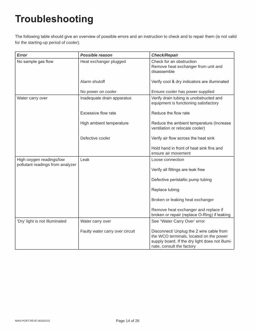
TroubleshootingThe following table should give an overview of possible errors and an instruction to check and to repair them (is not valid for the starting-up period of cooler).
Error Possible reason Check/RepairNo sample gas flow Heat exchanger plugged
Alarm shutoff
No power on cooler
Check for an obstructionRemove heat exchanger from unit and disassemble
Verify cool & dry indicators are illuminated
Ensure cooler has power suppliedWater carry over Inadequate drain apparatus
Excessive flow rate
High ambient temperature
Defective cooler
Verify drain tubing is unobstructed and equipment is functioning satisfactory
Reduce the flow rate
Reduce the ambient temperature (Increase ventilation or relocate cooler)
Verify air flow across the heat sink
Hold hand in front of heat sink fins and ensure air movement
High oxygen readings/low pollutant readings from analyzer
Leak Loose connection
Verify all fittings are leak free
Defective peristaltic pump tubing
Replace tubing
Broken or leaking heat exchanger
Remove heat exchanger and replace if broken or repair (replace O-Ring) if leaking
‘Dry’ light is not Illuminated Water carry over
Faulty water carry over circuit
See “Water Carry Over’ error
Disconnect/ Unplug the 2 wire cable from the WCO terminals, located on the power supply board. If the dry light does not illumi-nate, consult the factory

Page 14 of 26 Page 15 of 26 MAN.PORT.REVE.06302015
Troubleshooting
‘Cool’ light is not illuminated Ambient temperature too high
Flow rate/water content too high
Failed peltier element
Reduce the ambient temperature (Increase ventilation or relocate cooler)
Lower the flow rate through the cooler and observe the results. If condition corrects itself, consult the factory for further trouble-shooting
Measure resistance between the red & black peltier leads. A failed peltier element will read high resistance or ‘Open’. Consult wiring diagram for wire location details
Power only on drain pump Blown fuse (F1)
Defective transformer (T1)
Replace fuse
Replace power supply board

Page 16 of 26 Page 17 of 26MAN.PORT.REVE.06302015
Spare Parts
Level A, Consumable Parts (All Models)Part P/NTube, 5' Peri Phar-Med #15 for Master-Flex Peristaltic Pump 5' 9216-0002
Level B, Basic Parts (512SS, 513SS, 514SS)Part P/NHeat Exchanger 5" SS 5200-S050O-Ring 2-021 Viton for Separable Heat Exchangers & Panel Mount Filters 4904-0013Compound Zinc Heat Transfer Paste, 1 oz Container for Kit 8010-0001Fuse, 6 Amp 250V Time Delay 3010-0005
Level B, Basic Parts (Models 512PV, 513PV, 514PV)Part P/NHeat Exchanger 5" Kynar/Glass 5200-K050Tube Glass - 1" Diameter x 6" for 5" PV Heat Exchanger 5201-0002O-Ring, 018 Viton For PV Exchanger Drain 4904-0003O-Ring, 120 Viton 4904-0004Compound Zinc Heat Transfer Paste, 1 oz Container for Kit 8010-0001
Level C, Critical Parts (All Models)Part P/NTransducer Temperature Assembly - 19 Inch AD592 in Brass Housing 1150-0017
Level D, In-Depth Parts (All Models)Part P/NMotor Only 6RPM 115V Motor 4958-0028PCB Assembly 600 Series 15-24VDC Controller 3600-0036PCB Assembly Power Supply 250W Short Bar 500 Series 3600-0038Pump Sample 1 Head Teflon Coated Alum 115VAC Micro Dia-VAC 4958-0118Pump Sample 1 Head Teflon Coated Alum 230VAC Micro Dia-VAC 4958-1067Sensor Replacement Assembly with O-Ring "Sensor Only" for WCO 5101-0001Fan, 12VDC 102CFM 4800-0002Fan, 12VDC 14CFM 2" x 1" For 520530 540 Power Supply, 2800RPM 4800-0004Flowmeter 0-5 lpm with SS Valve 4965-0008

Page 16 of 26 Page 17 of 26 MAN.PORT.REVE.06302015
Drawings All Models (512, 513, 514)
ABCD
ABC
12
34
56
78
12
34
56
7
D
8
P070
3
04/0
1/20
03
Sam
ple
Cool
er, P
orta
ble
115
VAC
REV
REVI
SIO
NS
FOR
PART
NO
.R.
Har
der
APVD
BY
DRAW
N BY
DRAW
ING
NO
.
DATE
SEE
TABL
E
Mod
el 5
12, 5
13 &
514
Layo
ut &
Dim
ensio
ns
DATE
DESC
RIPT
ION
DWN
APVD
SCAL
ESI
ZESH
EET
1 : 2
D1
OF
3
K
06/
16/0
9
Sh
ow E
nclo
sure
Fan
R
W
DA
UNIV
ERSA
L AN
ALYZ
ERS
INC.
Cars
on C
ity, N
evad
a 89
706
USA
FRO
NT V
IEW
TOP
VIEW
BOTT
OM
VIE
W
LEFT
SID
E
1). V
IEW
S AR
E SH
OW
N IN
MO
DEL
514
CONF
IGUR
ATIO
N.2)
. CO
VER
REM
OVE
D O
N TH
E FR
ONT
AND
TO
P
VIE
WS
TO S
HOW
N IN
TERI
OR.
3). S
EE S
HEET
2 F
OR
P &
ID.
4). S
EE S
HEET
3 F
OR
ELEC
TRIC
AL S
CHEM
ATIC
.
FLO
WM
ETER
(FM
1)0-
5 lp
m
WAT
ER C
ARRY
OVE
RSE
NSO
R (W
CO)
DIG
ITAL
TEM
P. D
ISPL
AY(D
/D)
TERM
INAL
BLO
CK(T
B5)
HEAT
SINK
FAN
SAM
PLE
INLE
T3/
8" T
UBE
SAM
PLE
OUT
LET
1/4"
TUB
E
ENCL
OSU
RE C
OVE
RSH
OW
N EX
PLO
DED
FOR
ASSE
MBL
Y CL
ARIT
Y
CARR
Y HA
NDLE
4" F
AN G
RILL
POW
ER E
NTRY
MO
DULE
115
VAC
6-AM
P(P
EM)
RUBB
ER F
EET
4 TY
P.
VENT
ILAT
ION
HOLE
S
COVE
R SC
REW
#10-
32 x
3/8
" LO
NG12
TYP
.
3/4"
14 1
1/16
"
15"
10 1
/8"
10 5
/8"
10 1
/8"
COND
ENSA
TE D
RAIN
OUT
LET
PERI
STAL
TIC
PUM
P HE
ADS
(P2)
HEAT
SINK
AIR
EXH
AUST
BOTH
SID
ES
AIR
INTA
KE
SAM
PLE
INLE
T3/
8" T
UBE
SAM
PLE
OUT
LET
1/4"
TUB
E
12"
FOAM
RUB
BER
SEAL
TAP
E2
TYP.
P/N
4903
-001
9
T. B
arbe
n
(OPT
IONA
L)
MO
DEL
#
# O
F IM
PING
ERS
AC
TIVE
/ PA
SSIV
E
512
1
(1) A
CTIV
E
513
2
514
2
(2) A
CTIV
E
(1) A
CTIV
E
(1
) PAS
SIVE
C
H
ASTE
LLO
Y C
PV
G
LASS
/ KY
NAR
ST
T
EFLO
N CO
ATED
S
TAIN
LESS
STE
EL
SS
STA
INLE
SS S
TEEL
IM
PING
ER M
ATER
IAL
PAR
T NU
MBE
R M
ATRI
X
512
C
ENCL
OSU
RE F
AN
2" F
AN G
RILL
AIR
OUT
LET
5200
Con
vair
Driv
e

Page 18 of 26 Page 19 of 26MAN.PORT.REVE.06302015
12
34
56
78
ABCD
12
34
56
78
ABCD
HE
AT
SIN
K S
UB
-AS
SE
MB
LY
FO
RM
OD
EL 5
12, 513 &
514
A0
23
8
04/0
8/20
032
OF 2
NTS
Sa
mp
le C
oo
ler,
Port
ab
le
____
SPEC
IFIE
DO
THER
WIS
EU
NLE
SS
ALL
+ .0
15"
FRAC
TIO
NAL
.000 +
.005
".00
+ .0
10"
.0 +
.015
"TO
LERA
NCES
FOR
PART
NO.
R. Ha
rder
APVD
BY
DR
AWN
BY
DRAW
ING
NO
EDA
TESC
ALE
SIZE
SHEE
T
No
t Is
su
ed
DE
SC
RIP
TIO
NP
AR
T N
O.
DW
G N
O.
QTY
ITEM
UNIV
ERSA
L AN
ALYZ
ERS
INC.
1701 S
ou
th S
utr
o T
err
ace
Cars
on
Cit
y, N
evad
a 8
9706 U
SA
DIM
ENSI
ON
SIN
INC
HES
ANGL
ES 1
30'
_+
1 4
-
4
71
1-0
00
1 6
-32
Nu
t
APVD
DWN
DESC
RIPT
ION
DATE
REV
REVI
SION
S
C
0
7/22
/07
R
emov
ed Ja
ck S
crew
R
W
JK
2 4
-
4
71
0-0
00
9 6
In
tern
al S
tar
3 1
-
4
80
0-0
00
2 F
an
, 1
2V
4 4
-
4
70
4-0
01
6 6
-32
x 3
/8 P
.H.
5 4
-
4
71
0-0
00
9 6
In
tern
al S
tar
6 4
-
4
71
0-0
01
0 6
Fla
t W
ash
er
7 1
M
09
58
5
00
8-0
28
9 P
len
nu
m8
4
-
4
70
4-0
01
3 6
-32
x 1
/2"
FH
9 1
M
09
57
4
40
2-0
05
2 H
ea
tsin
k1
0 -
-
-
Im
pin
ge
r1
1 -
-
-
H
T X
fer
Blo
ck
12
2
-
4
95
3-0
009
Dra
in F
ittin
g1
3 4
A
02
37
4
91
0-0
12
5 S
tan
do
ff A
ssy.
14
4
-
4
70
4-0
007
6-3
2 x
1/4
" P
H1
5 1
M
09
59
5
00
8-0
290
Su
b-P
late
17
4
-
4
71
0-0
009
#6
In
tern
al S
tar
18
4
-
4
71
1-0
015
6-3
2 A
co
rn N
ut
1 2
3
6
7
8
9
10
1113
14
15
1920
ASSE
MBL
ED V
IEW
LOC
TIG
HT
(RED
)
AIR
FLO
W
19
1
-
3
60
0-0
036
Co
ntr
olle
r C
ard
20
4
-
4
91
0-0
008
Th
rea
de
d N
ut
J. Kre
ck
17
5
FAN
WIR
ES
PELT
IER
WIR
ES
12
4
Drawings All Models (512, 513, 514)

Page 18 of 26 Page 19 of 26 MAN.PORT.REVE.06302015
Drawings All Models (512, 513, 514) 1
23
45
67
8
ABCD
12
34
56
78
ABCD
HE
AT
SIN
K S
UB
-AS
SE
MB
LY
FO
RM
OD
EL 5
12, 513 &
514
A0238
04/0
8/20
031
OF 2
NTS
Sa
mp
le C
oo
ler,
Port
ab
le
____
SPEC
IFIE
DO
THER
WIS
EU
NL
ES
S
ALL
+ .0
15"
FRAC
TIO
NAL
.000 +
.005
".00
+ .0
10"
.0 +
.015
"TO
LERA
NCES
FOR
PART
NO.
R. Ha
rder
APVD
BY
DR
AWN
BY
DRAW
ING
NO
EDA
TESC
ALE
SIZE
SHEE
T
No
t Is
su
ed
DE
SC
RIP
TIO
NP
AR
T N
O.
DW
G N
O.
QTY
ITEM
UNIV
ERSA
L AN
ALYZ
ERS
INC.
1701 S
ou
th S
utr
o T
err
ace
Cars
on
Cit
y, N
evad
a 8
9706 U
SA
DIM
ENSI
ON
SIN
INC
HES
ANGL
ES 1
30'
_+
1
4
-
4
71
1-0
00
1 6
-32
Nu
t
EXPL
OD
ED V
IEW
APVD
DWN
DESC
RIPT
ION
DATE
REV
REVI
SION
S
C
0
8/22
/07
R
emov
ed Ja
ck S
crew
RW
JK
2
4
-
4
71
0-0
00
9 6
In
tern
al S
tar
3
1
-
4
80
0-0
00
2 F
an
, 1
2V
4
4
-
4
70
4-0
01
6 6
-32
x 3
/8 P
.H.
5
4
-
4
71
0-0
00
9 6
In
tern
al S
tar
6
4
-
4
71
0-0
01
0 6
Fla
t W
ash
er
7
1
M
09
58
5
00
8-0
28
9 P
len
nu
m8
4
-
4
70
4-0
01
3 6
-32
x 1
/2"
FH
9
1
M
09
57
4
40
2-0
05
2 H
ea
tsin
k1
0
-
-
-
Im
pin
ge
r1
1
-
-
-
H
T X
fer
Blo
ck
12
2
- 4
95
3-0
009
Dra
in F
ittin
g1
3
4 A
02
37
4
91
0-0
12
5 S
tan
do
ff A
ssy.
14
4
- 4
70
4-0
007
6-3
2 x
1/4
" P
H1
5
1
M0
95
9
50
08
-02
90
Su
b-P
late
17
4
- 4
71
0-0
009
#6
In
tern
al S
tar
18
4
- 4
71
1-0
015
6-3
2 A
co
rn N
ut
12
3
6
7
8
9
10
11
14
15
1920
ASSE
MBL
ED V
IEW
LOC
TIG
HT
(RED
)
AIR
FLO
W
19
1
- 3
60
0-0
036
Co
ntr
olle
r C
ard
20
4
- 4
91
0-0
008
Th
rea
de
d N
ut
J. Kre
ck
17
FAN
WIR
ES
PELT
IER
WIR
ES
Page 20 of 26 Page 21 of 26MAN.PORT.REVE.06302015
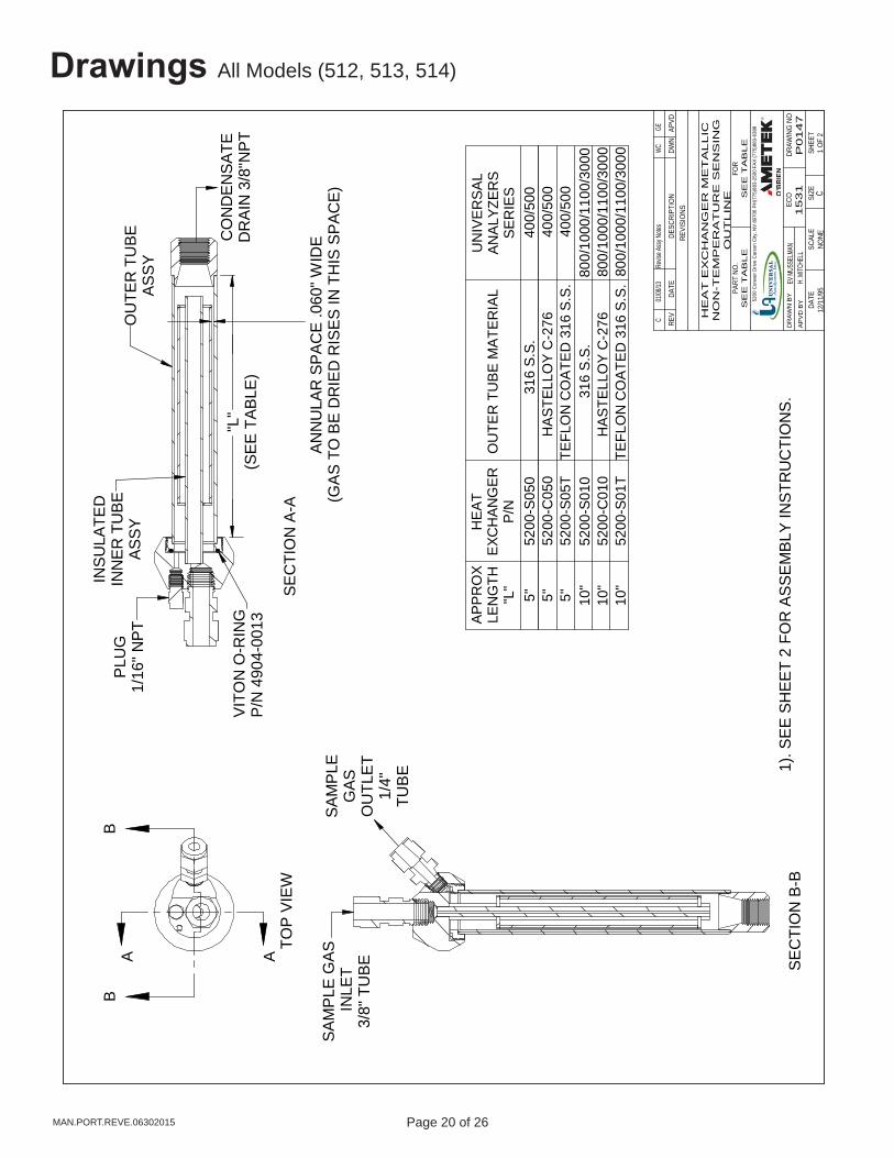
Drawings All Models (512, 513, 514)
TOP
VIEW
A A
BB
SAM
PLE
GAS
INLE
T3/
8" T
UBE
PLU
G1/
16" N
PT
VITO
N O
-RIN
GP/
N 4
904-
0013
INSU
LATE
DIN
NER
TU
BEAS
SY
ANN
ULA
R S
PAC
E .0
60" W
IDE
(GAS
TO
BE
DR
IED
RIS
ES IN
TH
IS S
PAC
E)
OU
TER
TU
BEAS
SY
CO
ND
ENSA
TED
RAI
N 3
/8"N
PT
SAM
PLE
GAS
OU
TLET
1/4"
TUBE
"L"
(SEE
TAB
LE)
1). S
EE S
HEE
T 2
FOR
ASS
EMBL
Y IN
STR
UC
TIO
NS.
APPR
OX
LEN
GTH
"L"
HEA
TEX
CH
ANG
ERP/
NO
UTE
R T
UBE
MAT
ERIA
LU
NIV
ERSA
LAN
ALYZ
ERS
SER
IES
5"
520
0-S0
50
316
S.S.
400
/500
10"
520
0-S0
10
3
16 S
.S.
80
0/10
00/1
100/
3000
5"
520
0-C
050
H
ASTE
LLO
Y C
-276
400
/500
5"
520
0-S0
5T
TEF
LON
CO
ATED
316
S.S
.
400
/500
10"
520
0-C
010
H
ASTE
LLO
Y C
-276
80
0/10
00/1
100/
3000
10"
520
0-S0
1T
TEF
LON
CO
ATED
316
S.S
. 80
0/10
00/1
100/
3000
SEC
TIO
N B
-B
HE
AT
EX
CH
AN
GE
R M
ET
AL
LIC
NO
N-T
EM
PE
RA
TU
RE
SE
NS
ING
OU
TL
INE
15
31
12/1
1/95
1 OF
2NO
NE
SE
E T
AB
LE
APVD
DWN
DESC
RIPT
ION
DATE
REV
REVI
SIO
NS
FOR
PART
NO
.
EV M
USSE
LMAN
AP
VD
BY
DR
AW
N B
YEC
O CDA
TESC
ALE
SIZE
SHEE
T
SE
E T
AB
LE
H. M
ITCHE
LLP
0147
DRAW
ING
NO
5200
Con
vair
Driv
e C
arso
n C
ity, N
V 89
706
PH(7
75)8
83-2
500
FAX
(775
)883
-638
8
SEC
TIO
N A
-A
C
0
1/08/1
3
Rev
ise As
sy N
otes
W
C
GE

Page 20 of 26 Page 21 of 26 MAN.PORT.REVE.06302015
Drawings All Models (512, 513, 514)
VITO
N O
-RIN
G#2
-021
SEE
NO
TES
OU
TER
TU
BE A
SSEM
BLY
MET
ALLI
C
INN
ER T
UBE
ASS
EMBL
Y
NO
TES:
1. O
-RIN
G IS
FAC
TOR
Y IN
STAL
LED
IN
MET
ALLI
C O
UTE
R T
UBE
.
2. L
IGH
TLY
LUBR
ICAT
E O
-RIN
G W
ITH
S
ILIC
ON
E G
REA
SE B
EFO
RE
ASSE
MBL
Y.
3. A
NTI
-SEI
ZE O
N O
UTE
R T
UBE
TH
REA
DS.
HEA
T EX
CH
ANG
ERSE
PER
ABLE
SPAR
E PA
RTS
LIS
T
S
OU
TER
TU
BEM
ATER
IAL
IDEN
TIFI
ER
"L"
10"
5
200-
S01T
52
01-0
042
52
01-0
044
"
"
10"
5
200-
C01
0
"
520
1-00
21
"
"10
"
520
0-S0
10
5201
-001
6
5201
-001
3
49
04-0
013
49
51-0
058
5"
5
200-
S050
52
01-0
015
52
01-0
012
4
904-
0013
4
951-
0058
APPR
OX
"L"
LEN
GTH
P/N
INN
ERTU
BE A
SSY
P/N
OU
TER
TUBE
ASS
YP/
N
VITO
N O
-RIN
G#2
-021
P/N
PLU
G1/
16"N
PTP/
N
5"
5
200-
C05
0
"
520
1-00
20
"
" 5
"
520
0-S0
5T
5201
-004
1
5201
-004
3
"
"
15"
5
200-
S015
52
01-0
107
52
01-0
055
"
"
HE
AT
EX
CH
AN
GE
R A
SS
EM
BL
YN
ON
-TE
MP
ER
AT
UR
E S
EN
SIN
GM
ET
ALLIC
P0147
12/1
1/95
2 OF
2NO
NE
INS
TR
UM
EN
T
APVD
DWN
DESC
RIPT
ION
DATE
REV
REVI
SIO
NS
FOR
PART
NO
.
EV M
USSE
LMAN
AP
VD
BY
DR
AW
N B
YDR
AWIN
G N
O
CDA
TESC
ALE
SIZE
SHEE
T
SE
E T
AB
LE
H. M
ITCHE
LL
C
0
1/08/1
3
Rev
ise As
sy N
otes
W
C
GE
1531
ECO
5200
Con
vair
Driv
e C
arso
n C
ity, N
V 89
706
PH(7
75)8
83-2
500
FAX
(775
)883
-638
8

Page 22 of 26 Page 23 of 26MAN.PORT.REVE.06302015
Drawings All Models (512, 513, 514)
DRY
GAS
OUT
LET
1/4"
TUB
E
SAM
PLE
GAS
INLE
T3/
8" T
UBE
SIDE
VIE
W
TOP
VIEW
1). S
EE S
HEET
2 F
OR
ASSE
MBL
Y IN
STRU
CTIO
NS.
COND
ENSA
TE D
RAIN
3/8"
NPT
INSU
LATE
D SE
CTIO
N
0.30
0" IN
SIDE
DIA
MET
ER
CHIL
LED
SURF
ACE
ANNU
LAR
SPAC
E .0
60" W
IDE
(GAS
TO
BE
DRIE
D RI
SES
IN T
HIS
SPAC
E)
(SEE
TAB
LE)
QTY
OF
EXCH
ANG
ERS
PER
SAM
PLE
COO
LER
1 2 2 4 1 2 2 2 4
UNIV
ERSA
LAN
ALYZ
ERS
SAM
PLE
COO
LER
MO
DELS
520
530
540
570
1040
1050
1060
1080
1090
GLA
SS K
YNAR
HEA
TEX
CHAN
GER
ASSE
MBL
Y P/
N
5200
-K05
0
5200
-K01
0
LENG
TH"L
"
5" 10"
" L "
PLUG
1/16
" NPT
1FG
A252
00-K
015
15"
12
34
56
78
ABCD
12
34
56
78
ABCD
HE
AT
EX
CH
AN
GE
R G
LA
SS
/K
YN
AR
NO
N-T
EM
PE
RA
TU
RE
SE
NS
ING
OU
TL
INE
P014
9
12/11
/951 O
F 2
1 : 1
INS
TR
UM
EN
T
APVD
DWN
DESC
RIPT
ION
DATE
REV
REVI
SION
S
FOR
PART
NO.
EV M
USSE
LMAN
APVD
BY
DR
AWN
BYDR
AWIN
G NO
CDA
TESC
ALE
SIZE
SHEE
T
SE
E T
AB
LE
UNIV
ERSA
L ANA
LYZE
RS IN
C.170
1 S
ou
th S
utr
o T
err
ace
Car
son
Cit
y, N
evad
a 8
9706
U
SA
H. MI
TCHE
LL
C
0
1/19/0
4
Revi
sion P
er Sh
eet 2
RP
H
TB

Page 22 of 26 Page 23 of 26 MAN.PORT.REVE.06302015
Drawings All Models (512, 513, 514)
COM
PLET
E G
LASS
KYN
AR
#2-0
18 V
ITO
NO
-RIN
G(S
EE N
OTE
2)
KYNA
R DR
AIN
FITT
ING
(SEE
NO
TE 1
)
GLA
SS T
UBE
#2-1
20 V
ITO
NO
-RIN
G(S
EE N
OTE
2)
KYNA
R HE
AD(S
EE N
OTE
1)
GLA
SS K
YNAR
HEAT
EXC
HANG
ERAS
SEM
BLY
LENG
TH "L
"P/
N52
00-K
050
5"
KYNA
RIN
SULA
TED
SECT
ION
ASSY
P/N
5110
-200
3
GLA
SSTU
BE
5201
-000
2P/
N
KYNA
RDR
AIN
FITT
ING
P/N
5110
-200
2
#2-1
20VI
TON
O-R
ING
P/N
4904
-000
4
#2-0
18 V
ITO
NO
-RIN
GP/
N49
04-0
003
HEAT
EXC
HANG
ER A
SSEM
BLY
SPAR
E PA
RTS
LIST
EXPL
ODE
D G
LASS
KYN
AR H
EAT
EXCH
ANG
ER
1). O
-RIN
GS
ARE
FACT
ORY
INST
ALLE
DIN
KYN
AR H
EAD
AND
KYNA
R DR
AIN
FITT
ING
S
2). L
IGHT
LY L
UBRI
CATE
O-R
ING
SW
ITH
SILI
CONE
GRE
ASE
BEFO
REAS
SEM
BLY.
NOTE
S:
7/8"
WR
ENCH
FLAT
S
KYNA
R IN
SULA
TED
SECT
ION
ASSE
MBL
Y
5200
-K01
010
"51
10-2
004
5201
-000
1"
""
KYNA
R HEA
D
P/N
5201
-001
7"
PLUG
1/6"
NPT
1/16" N
PT PL
UGP/
N49
51-0
066
"52
00-K
015
15"
5110
-200
652
01-0
078
5201
-006
6"
""
"
12
34
56
78
ABCD
12
34
56
78
ABCD
HE
AT
EX
CH
AN
GE
R G
LA
SS
/K
YN
AR
NO
N-T
EM
PE
RA
TU
RE
SE
NS
ING
SP
AR
E P
AR
TIN
ST
AL
LA
TIO
N
P014
9
12/11
/952 O
F 2
1 : 1
INS
TR
UM
EN
T
APVD
DWN
DESC
RIPT
ION
DATE
REV
REVI
SION
S
FOR
PART
NO.
EV M
USSE
LMAN
APVD
BY
DR
AWN
BYDR
AWIN
G NO
CDA
TESC
ALE
SIZE
SHEE
T
SE
E T
AB
LE
UNIV
ERSA
L ANA
LYZE
RS IN
C.170
1 S
ou
th S
utr
o T
err
ace
Car
son
Cit
y, N
evad
a 8
9706
U
SA
H. MI
TCHE
LL
C
0
1/19/0
4
Add
ed Ky
nar D
rain P
/N for
15" L
ength
RPH
T
B
KYNA
R DR
AIN
FITT
ING
15" V
ERSI
ON
Page 24 of 26 Page 25 of 26MAN.PORT.REVE.06302015
Limited WarrantyI. Limited Warranty
1. Limited Warranty. Universal Analyzers, Inc (UAI) offers a limited warranty on each of its products against failure due to defects in material and workmanship for a period ending the earlier of (i) fifteen (15) months from the date of the invoice relating to the sale of the product and (ii) twelve (12) months from the date of installation of the product (collectively, the “Initial Warranty”). During the Initial Warranty, UAI offers a limited warranty against failure due to defects in material and workmanship on each part of a product repaired or replaced by an authorized service person for a period ending the later of (a) the remaining term of the Initial Warranty of the product and (b) ninety (90) days from the date of such repair or replacement. After expiration of the Initial Warranty, UAI offers a limited warranty against failure due to defects in material and workmanship on each part of a product repaired or replaced by an authorized service person for a period ending ninety (90) days from the date of such repair or replacement. UAI further offers a limited warranty that the products and parts it sells will conform to UAI’s written specifications therefor. The foregoing limited warranties cover parts and labor only and UAI does not warrant and will not reimburse the buyer of its products (“Buyer”) for any costs relating to the access by service persons of UAI to the product at issue. The foregoing limited warranties cover only the repair or replacement of defective parts and such determination will be in the sole discretion of UAI. In its sole discretion, UAI may make repairs or replacements under these limited warranties with either new or refurbished parts. To the extent Buyer’s product cannot be remedied under these limited warranties through repair or replacement of parts, Buyer may return the product for a refund of the purchase price, less a reasonable reduction in such purchase price equal to the depreciation expense incurred by Buyer relating to such product. The limited warranties of this Section I.1. are further subject to those warranty exclusions set forth below in Section I.2.
2. Limited Warranty Exclusions. Excluding the warranties provided for in Section I.1., UAI provides all products to Buyer “as-is,” without any other warranty of any kind. UAI disclaims any and all express or implied warranties of merchantability, fitness for a particular purpose and non-infringement of the intellectual property of others. UAI makes no warranty, express or implied, as to the design, sale, installation or use of its products. UAI’s warranties will not be enlarged by, nor will any obligation or liability of UAI arise due to UAI providing technical advice, facilities or service in connection with any product. There is no warranty by UAI with respect to any product’s: (i) uninterrupted or error-free operation; (ii) actual performance, other than the product’s capability to meet UAI’s specifications therefor; (iii) removal or installation from a worksite or process; (iv) electronic components or associated accessories (including without limitation circuit boards and integrated circuits); (v) maintenance (including without limitation gasket and seal replacements, adjustments, minor repairs and other inspection requirements, preventative or otherwise); (vi) use under inappropriate conditions or not in accordance with operating instructions; or (vii) use in connection with the operation of a nuclear facility. There is no warranty for labor expenses associated with field repairs or the repair or replacement of defective parts in the engine or power unit of any product if such product has been in the possession of the owner or operator for greater than twelve (12) months. There is no warranty for products determined to be, in UAI’s sole discretion, damaged as a result of (a) misuse, neglect or accident; (b) improper application, installation, storage or use; (c) improper or inadequate maintenance or calibration; (d) operation outside of the published environmental specification; (e) improper site preparation or maintenance; (f) unauthorized repairs or replacements; (g) modifications negligently or otherwise improperly made or performed by persons other than UAI; (h) Buyer-supplied software or supplies; (i) use in conjunction with or interfacing with unapproved accessory equipment; (j) use of ABC-style or dry powder fire suppression agents; or (k) leaked sample materials. To the extent a UAI product is used in connection with the operation of a nuclear power facility, Buyer agrees to indemnify and hold UAI harmless from any and all actions, claims, suits, damages and expenses arising from such use. UAI provides no warranty on the oral representations made by its personnel while they are attempting to assist Buyer in the operation of a product. This Standard Limited Warranty does not apply to items consumed by the products during their ordinary use, including but not limited to fuses, batteries, paper, septa, fittings, screws, fuses, pyrolysis, dryer or scrubber tubes, sample boats, furnaces or UV lamps.
3. Non-UAI Products. UAI does not in any way warrant products it does not manufacture except to the extent the warranty of the manufacturer of the product at issue passes through or is otherwise assigned to UAI. If a manufacturer warranty is so assigned to UAI, UAI will only be bound to comply with the length of time associated with such warranty. All other terms of such warranty will be governed by this Standard Limited Warranty and UAI’s General Terms and Conditions incorporated herein by reference.

Page 24 of 26 Page 25 of 26 MAN.PORT.REVE.06302015
Limited Warranty
4. Expenses on Non-Warranty Work. All repairs or replacements by UAI after the expiration of any applicable limited warranty period will be performed in accordance with UAI’s standard rate for parts and labor. Further, if upon UAI’s inspection and review, UAI determines the condition of the products is not caused by a defect in UAI’s material and workmanship, but is the result of some other condition, including but not limited to damage caused by any of the events or conditions set forth in Section I.2., Buyer shall be liable for all direct expenses incurred by UAI to conduct the inspection and review of the product.
5. Exclusive Remedy. The foregoing limited warranty constitutes Buyer’s exclusive remedy with respect to products sold by UAI and UAI’s liability shall be exclusively limited to the written limited warranty specified herein. No employee, representative or agent of UAI is authorized to either expressly or impliedly modify, extend, alter or change any of the limited warranties expressed herein to Buyer.
6. Procedure and Costs. All limited warranty claims must be made in writing promptly following discovery of any defect. Buyer must hold defective products for inspection by UAI. If requested by UAI, Buyer must send the product to UAI for inspection. Any such returns by Buyer will be at Buyer’s expense and Buyer will remain liable for any loss of or damage to the product during such product’s transportation to UAI. No products will be sent to UAI for inspection unless UAI has authorized Buyer to do so.
7. Terms and Conditions. UAI’s General Terms and Conditions are incorporated herein by reference and Buyer accordingly agrees to be bound by the terms thereof.
II. Limitations on UAI Liability
1. In General. Buyer agrees UAI shall not be liable for any direct, indirect, incidental, punitive or consequential damages, including lost profits, lost savings or loss of use, whether Buyer’s claim is based in contract, tort, warranty, strict liability or otherwise, which Buyer may suffer for any reason, including reasons attributable to UAI. Buyer agrees these limitations on UAI’s liability are reasonable and reflected in the amounts charged by UAI for its products.
2. Force Majeure. This Standard Limited Warranty does not cover and UAI shall not be liable for either direct or consequential damage caused, either directly or indirectly, as a result of: (i) any act of God, including but not limited to natural disaster, such as floods, earthquakes, or tornadoes; (ii) damages resulting from or under the conditions of strikes or riots, war, damages or improper operation due to intermittent power line voltage, frequency, electrical spikes or surges, unusual shock or electrical damage; or (iii) accident, fire or water damage, neglect, corrosive atmosphere or causes other than ordinary use.
3. Limitation on Warranty Claims. Prior to any obligation of UAI to perform any limited warranty service as set forth herein, Buyer must have: (i) paid all invoices to UAI in full, whether or not they are specifically related to the product at issue; and (ii) notified UAI of the limited warranty claim within sixty (60) days from the date Buyer knew or had reason to know of the defect

Page 26 of 26 Page PB of 1MAN.PORT.REVE.06302015
5200 Convair Drive Carson City, NV 89706 • Phone: 775-883-2500 • Fax: 775-883-6388 • www.universalanalyzers.com


![“Legal grounds for the return of the Parthenon Marbles” [2002] 2 Revue Hellénique de droit International 513](https://static.fdokumen.com/doc/165x107/6334715776a7ca221d08b192/legal-grounds-for-the-return-of-the-parthenon-marbles-2002-2-revue-hellenique.jpg)