Structural aspects of stochastic mechanics and stochastic field theory
Upload
khangminh22Category
view
1download
0
University of TwenteFormal Methods and Tools
Master’s Thesis
Model Validation for StochasticHybrid Automata
Author:Michiel Bakker
Supervisors:Dr. Ir. Rom Langerak
Dr. Ir. André Kokkeler
August 24, 2020

Abstract
A hybrid automaton is a mathematical formalism used to model systemswith both discrete and continuous behaviour. The theory of hybrid automatahas been applied in a wide spectrum of research areas, including systems biology,automotive and avionic control systems and other cyber-physical systems. Oneof the available tools to model hybrid automata is Uppaal SMC, which uses asimulation-based method named statistical model checking to verify propertiesof a model. As models grow larger and more complex, it becomes more likely foran error to be accidentally introduced to the system. The process of confirmingthat a model is free of errors is called model validation. However, little researchhas been done on model validation tools for hybrid automata. In this research,we examined several methods for model validation, and put them into practicein a tool for Uppaal SMC. The validation methods were examined using theo-retical analysis and evaluated using case studies, which indicated that the toolprovides an effective way of performing model validation.
1

Contents
1 Introduction 41.1 Problem Statement . . . . . . . . . . . . . . . . . . . . . . . . . . 41.2 Hybrid Automata . . . . . . . . . . . . . . . . . . . . . . . . . . . 51.3 Model Validation . . . . . . . . . . . . . . . . . . . . . . . . . . . 51.4 Research Questions . . . . . . . . . . . . . . . . . . . . . . . . . . 61.5 Contributions . . . . . . . . . . . . . . . . . . . . . . . . . . . . . 61.6 Structure . . . . . . . . . . . . . . . . . . . . . . . . . . . . . . . 7
2 Background 82.1 Timed Automata . . . . . . . . . . . . . . . . . . . . . . . . . . . 82.2 Timed Automata in UPPAAL . . . . . . . . . . . . . . . . . . . . 112.3 Stochastic Timed Automata . . . . . . . . . . . . . . . . . . . . . 132.4 Stochastic Hybrid Automata . . . . . . . . . . . . . . . . . . . . 152.5 Hybrid Automata in UPPAAL SMC . . . . . . . . . . . . . . . . 16
3 Related Work 203.1 Validation of Timed Automata . . . . . . . . . . . . . . . . . . . 203.2 Abstraction Refinement . . . . . . . . . . . . . . . . . . . . . . . 213.3 UPPAAL Slicing . . . . . . . . . . . . . . . . . . . . . . . . . . . 21
4 Method 234.1 Tool Design . . . . . . . . . . . . . . . . . . . . . . . . . . . . . . 234.2 Evaluation Method . . . . . . . . . . . . . . . . . . . . . . . . . . 23
5 Implementation 255.1 Architecture . . . . . . . . . . . . . . . . . . . . . . . . . . . . . . 25
5.1.1 Model views . . . . . . . . . . . . . . . . . . . . . . . . . . 255.1.2 Validation Specification . . . . . . . . . . . . . . . . . . . 26
5.2 Separation of Model Checker and Property . . . . . . . . . . . . 275.3 UPPAAL Editor Integration . . . . . . . . . . . . . . . . . . . . . 27
6 Reachability Algorithms 306.1 Concrete Checking . . . . . . . . . . . . . . . . . . . . . . . . . . 306.2 Symbolic Checking . . . . . . . . . . . . . . . . . . . . . . . . . . 31
6.2.1 Abstraction Algorithm for Hybrid Automata . . . . . . . 316.2.2 Abstractions of UPPAAL SMC Models . . . . . . . . . . 336.2.3 Time Bounding . . . . . . . . . . . . . . . . . . . . . . . . 356.2.4 Constant Variable Overwrite . . . . . . . . . . . . . . . . 36
2

7 Validation Properties 387.1 Model Invariant . . . . . . . . . . . . . . . . . . . . . . . . . . . . 387.2 Synchronisation Check . . . . . . . . . . . . . . . . . . . . . . . . 38
7.2.1 Implementation . . . . . . . . . . . . . . . . . . . . . . . . 397.2.2 Usage . . . . . . . . . . . . . . . . . . . . . . . . . . . . . 40
7.3 Synchronisation Post-Condition . . . . . . . . . . . . . . . . . . . 417.3.1 Implementation . . . . . . . . . . . . . . . . . . . . . . . . 417.3.2 Usage . . . . . . . . . . . . . . . . . . . . . . . . . . . . . 42
7.4 UrPal Checks . . . . . . . . . . . . . . . . . . . . . . . . . . . . . 427.4.1 Unwanted Deadlocks . . . . . . . . . . . . . . . . . . . . . 427.4.2 Template Location Reachability . . . . . . . . . . . . . . . 43
8 Evaluation 448.1 Case Studies . . . . . . . . . . . . . . . . . . . . . . . . . . . . . 44
8.1.1 Cancer Immunotherapy Model . . . . . . . . . . . . . . . 448.1.2 Tooth Wear Model . . . . . . . . . . . . . . . . . . . . . . 48
8.2 Discussion . . . . . . . . . . . . . . . . . . . . . . . . . . . . . . . 508.2.1 Reachability Algorithms . . . . . . . . . . . . . . . . . . . 508.2.2 Validation Properties . . . . . . . . . . . . . . . . . . . . . 52
9 Conclusion 539.1 Future Work . . . . . . . . . . . . . . . . . . . . . . . . . . . . . 53
9.1.1 Hybrid Reachability Checking . . . . . . . . . . . . . . . . 539.1.2 Improved Support for UrPal Checks . . . . . . . . . . . . 54
3

1 Introduction
Uppaal is a tool used for formal verification of timed systems. It has been usedin the development of various applications, ranging from communication proto-cols to automotive systems [11, 13]. Uppaal is based on the theory of timedautomata [2], and has support for features such as custom data structures anda specification language to aid in modelling. There are, however, limitations tothe expressiveness of timed automata. Extending the formalism with behaviourssuch as variable clock rates make reachability checking of properties undecid-able. This means that complex timed systems can only be approximated whenmodelled with Uppaal.
In order to support modelling of complex timed systems, an extension toUppaal called Uppaal SMC was created. Uppaal SMC supports a moregeneral model, where, among other extensions, the clock rates can be describedusing ordinary differential equations. Analysis of statistical properties of thesemodels is done using statistical model checking (SMC). This is a simulationbased approach, and can be seen as a compromise between testing and classicalmodel checking. Uppaal SMC has been used in research areas such as systemsbiology, energy-centric systems, and recently, in modelling healthcare processes[6].
1.1 Problem StatementUppaal SMC can be effectively used to model complex timed systems. Analysisof the models using SMC can then be used to validate these systems. However,system validation is only effective when the model itself accurately models thesystem. Only a correct model can be used to verify properties of the systemunder test. Any tool used for system validation must therefore have ways for themodeller to find errors in their model, and to verify that the model is correct.
As models get larger and more complex, it becomes more likely for themodeller to make a mistake. In other programming and modelling applicationsthis problem can be reduced using (automatic) analysis of the model, to spoterrors early in the process. For example, research has been done on automaticvalidation of timed automata in Uppaal [14].
However, little similar research has been done on stochastic hybrid automata,the underlying formalism of Uppaal SMC. At this moment, there are no effec-tive tools in Uppaal SMC that enable model validation. When the modellersuspects that there is an error in the model, one of the few ways to debug theprogram is to add extra debug variables and execute debug queries. This processcan take a long time, and is also error-prone. There is therefore a clear need foradditional methods to perform model validation of Uppaal SMC models.
4

1.2 Hybrid AutomataA hybrid automaton is a finite state machine extended with a finite set of real-valued variables. The values of the variables are described by ordinary differ-ential equations. This combination of a discrete state (the nodes or ‘locations’of the automaton) and a continuous state (the real-valued variables) allow themodelling of hybrid systems with both digital and analogue behaviours.
A simple example of a hybrid automaton would be a thermostat regulatingthe temperature of a room. This automaton could have two discrete statesfor the thermostat being either off or on. The temperature over time in eitherstate can be modelled using differential equations derived from thermodynamics.Transitions between the discrete states can be restricted using expressions overthe continuous state.
An effective method for the analysis of hybrid automata is stochastic modelchecking, where simulations (also called runs) are used to determine propertiesof the model. To achieve this, the definition of the model is extended suchthat non-deterministic transitions between states are replaced by probabilisticchoices. This is the method used by Uppaal SMC to verify properties of itsmodels.
A notable sub-class of hybrid automata are timed automata. A timed au-tomaton can be seen as a hybrid automaton where all variables (usually calledclocks) have a derivative over time of 1. In other words, all clocks are uniformand grow at the same rate. These restrictions make the reachability problemfor timed automata decidable.
1.3 Model ValidationFor this report, we define model validation in the context of formal verificationas follows:
Model validation is the process of confirming that a model is correct.
It is interesting to note that this definition can apply to models in a verygeneral sense. For example, consider a model in physics of material properties,like the friction of an object. Confidence that this model is correct can be gainedby performing experiments, and confirming that the model accurately predictsthe outcomes. Similarly, creators of software models must perform some formof validation to confirm correctness of the model.
In the field of formal methods, model validation is generally performed byalgorithmically checking if the model conforms to a formal specification. Thisassumes that such a specification exists, and itself is complete and error-free.Intuitively, as the system to be modelled increases in complexity, so does itsspecification. This is especially true in timed systems, where behaviour of amodel may depend on complex interactions between automata or precise timingconstraints.
In this research, we consider the construction of a formal specification of amodel, as well as its verification, part of model validation. This implies that
5

model validation is equal parts a verification problem as a part of the develop-ment process.
1.4 Research QuestionsThis research attempts to find a solution to the problem stated above. In orderto guide the research, the following research question is formulated:
In what ways is it possible to perform model validation of stochastic hybridautomata?
The research question is answered through the implementation of a tool forthe model validation of Uppaal SMC models. It employs various methods toachieve this, which are evaluated using case studies. In order to further structurethe research we define the following three sub-questions:
1. Which properties of stochastic hybrid automata can be used to validatemodels?
2. How can properties of stochastic hybrid automata be verified?
3. How can the results of the validation best be communicated to the modeller?
Question 1 is answered by defining several properties related to the validityof a model, and by implementing a method to verify these properties. Theimplementation and evaluation of two distinct verification methods is used toanswer question 2. The evaluation of the validation properties and verificationmethods is done using case studies, where the tool is applied to models used inresearch. Here, errors in the models are attempted to be found and correctedusing the tool, which is used to form an answer to question 3.
1.5 ContributionsThis research examines and evaluates several methods to perform model val-idation for hybrid automata. These methods are implemented in a tool forUppaal SMC, which is subsequently subjected to a qualitative evaluation. Dueto the undecidability of the reachability checking problem for hybrid automata,several approximative methods for verification were examined. One of thesemethods is a novel technique where the hybrid automata is reduced to a timedautomata, of which reachability checking is decidable. To our knowledge, thisis the first time such a verification method has been applied to hybrid au-tomata. Furthermore, it is also possible to perform verification using a simpler,simulation-based method.
6

1.6 StructureThe structure of this report is as follows. Section 2 provides an overview of thetheory of timed automata and hybrid automata, and their respective implemen-tations in Uppaal. Section 3 provides an overview of related research and itsapplication to our research. The evaluation method and metrics are discussedin Section 4. Details of the implementation of the tool are discussed in Section5, with the implemented verification methods and validation properties furtherelaborated on in Sections 6 and 7 respectively. The results of the evaluation arefound in Section 8, and the report concludes in Section 9.
7

2 Background
2.1 Timed AutomataThe formalism used by Uppaal is based on the theory of timed automata [2].A timed automaton (TA) can be seen as a finite state machine extended witha finite set of real-valued clocks. All clocks increase at the same rate, andtransitions between states may or may not be taken based on predicates overclock values. This section will explain the basics of the theory of timed automataand its analysis.
s1s2
y ≤ 9
onx ≥ 2y := 0
offy ≥ 9x := 0
onx ≥ 2y := 0
Figure 1: An example of a timed automaton modelling a light switch.
Example
Figure 1 shows an example of a simple timed automaton modelling a light switch.The light switch has two buttons, off and on. After 2 seconds of being off, thelight can be switched on by pressing the on button. The light stays on untileither the off button is pushed, or 9 seconds have elapsed. If the on button ispressed again before the 9 seconds have elapsed, the timer is reset and the lightstays on for another 9 seconds. When the light turns off, it cannot be turnedon again for two seconds.
The model has two locations, s1 and s2, two labels, on and off and twoclocks, x and y. Location s2 has the invariant y ≤ 9. The two edges with the onlabel have a guard with the clock constraint x ≥ 2 and {y} as the set of clocksto be reset.
Syntax
A timed automaton is a tuple A = ⟨L,L0,Σ, X, I, E⟩ where
• L is the finite set of locations.Note that in timed automata the term location is used instead of state.This is to avoid confusion, because the state of a timed automaton isdescribed by the current location and by the valuation of the clocks.
8

• L0 ⊆ L is the set of initial locations.
• Σ is a finite set of labels.
• X is a finite set of clocks.
• I : L 7→ Φ(X) maps every location to an invariant. The definition of aclock constraint Φ(X) is given below.
• E ⊆ L× Σ× 2X × Φ(X)× L is a set of switches.A switch (s, a, ϕ, λ, s′) is an edge from location s to s′ with label a. ϕ isthe guard that enables the switch, i.e. the clock valuation that is requiredto take the switch. λ is the set of clocks that is reset (valuation set to 0)when the switch is taken.Note again that the term switch is used instead of transition, as a transi-tion in a timed automaton may change the current location as well as thevaluation of the clocks.
Clock constraints are used as invariants of locations and guards of switches.For a set of clocks X, the set Φ(X) of clock constraints ϕ is defined by thegrammar
ϕ ::= x ≺ c | x− y ≺ c | ϕ ∧ ϕ
where clock x, y ∈ X, c is a constant in N and ≺∈ {=, >,≥, <,≤}.
Transition System
A timed automaton can take two kinds of transitions: time transitions, wheresome amount of time passes, and switch transitions, where the discrete statechanges.
Let SA be the transition system of a timed automaton A. A state is notedas a pair (s, v), where s is a location in A, and v is a clock valuation. A clockvaluation v is a mapping from the set of clocks X to the set of positive realnumbers R+. For a delay δ ∈ R+, let v + δ map every clock x to the valuev(x) + δ. A state of SA is a pair (s, v), where v satisfies the invariant I(s).
Delay transitions only affect the clock valuation, leaving the discrete stateunchanged. They are a transition (s, v)
δ−→ (s, v + δ), where δ ≥ 0, and for allδ′ ∈ [0, δ], v + δ′ satisfies I(s).
With a switch transition the discrete state changes, while no time passes.Given a switch (s, a, ϕ, λ, s′) and a state (s, v) where v satisfies ϕ, the transitionis noted (s, v)
a−→ (s′, v[λ = 0]). v[λ = 0] denotes the clock valuation where everyclock x ∈ λ is assigned the value 0, and the other clocks are unchanged.
As an example, the following transition sequence is possible in the automataof Figure 1. Here, four delay transitions and three switch transitions are taken.
(s1, [x = 0, y = 0])1−→
(s1, [x = 1, y = 1])2−→ on−→
9

(s2, [x = 3, y = 0])1−→ on−→
(s2, [x = 4, y = 0])9−→ off−→
(s1, [x = 0, y = 9])
Product construction
A particularly useful feature of the analysis of timed automata is the productconstruction of two automata, also known as parallel automata. This allows alarge and complex model to be made by composing multiple smaller models.Given two timed automata A1 and A2, the product construction is noted byA = A1 ∥ A2. The set of (initial) locations of A is the cartesian product ofthe (initial) locations of A1 and A2. Switches that share a common label aresynchronised. The guard of the synchronised switch is the conjunction of thetwo guards, and the set of clocks to be reset is the union of the clock resets ofthe two switches.
s0s1
x ≤ 2
a
x := 0
bx ≥ 1
(a) A1
t0t1
y ≤ 2
b
y := 0
cy ≥ 1
(b) A2
(s0, t0)(s1, t0)x ≤ 2
(s1, t1)y ≤ 2
(s0, t1)y ≤ 2∧x ≤ 2
a
x := 0
bx ≥ 1y := 0
cy >= 1
cy >= 1
a
x := 0
(c) A1 ∥ A2
Figure 2: Two timed automata and their product construction.
Figure 2 shows an example of the product construction of two automata.Note that the set of locations of A1 ∥ A2 is the cartesian product of the locationsof the two automata. A1 and A2 both have a switch with label b, so these twoswitches are synchronised.
10

Model checking
In model checking applications, the specification of the model is often formalisedusing CTL. A CTL formula can, for example, specify that some property p musthold in all reachable states, in at least one state or hold until some other propertyq holds. Timed Computation Tree Logic (TCTL) is an extension of CTL wherethe temporal operators can have time bounds [1]. With TCTL it is possible toexpress properties such as “property p always leads to property q within 3 timeunits”.
A brief overview of the subset of TCTL used in this report is given here.TCTL has two quantifiers over paths, Aϕ and Eϕ, where ϕ must hold on allpaths or any path from the current state respectively. Path formulas are of theform □ϕ or 3ϕ. With □ϕ, ϕ holds on all states of the current path and 3ϕnotes that ϕ holds in any state of the path.
Clocks in a TA are real-valued, causing the transition system of a model tohave an infinite set of states and transitions. Because of this, model checkers forTA must represent the model abstractly in order to have a decidable algorithmto verify logical properties. This is done by transforming the timed automatonto a region automata, which can represent the infinite set of clock values in afinite set of states [2].
2.2 Timed Automata in UPPAALAmodel in Uppaal is a Network of multiple Timed Automata (NTA) in parallel.To facilitate modelling the model is extended beyond the pure timed automataformalism with a couple of extra features [3]. One of those features is theinclusion of bounded discrete variables that are part of the state. These variablescan be read, written to and can be used in guards and invariants.
Uppaal terminology varies slightly from the standard terminology of timedautomata. For instance, switches are usually called edges, an automaton is oftencalled a process, and the term channel is used instead of label. An edge canbe fired, meaning that the system is in a state where that switch transition canbe taken. This report will in most cases use the terminology used in Uppaalliterature instead of standard TA terminology.
Discrete Variables
Uppaal extends the TA formalism by adding bounded discrete variables thatare part of the state. These variables can be used in expressions in guardsand invariants, and their values can change according to an update expression.Uppaal also includes an extensive specification language that is used to observeand change the discrete state of the model. This language is based on C, andallows the user to model complex behaviours.
The discrete state is shared across all automata in the model. This allows itto be used to transfer data between processes. The sending process can (tem-porarily) assign values to discrete variables, which can be read by the receiving
11

process. This can, for instance, be used to model communicating nodes in acomputer network.
UPPAAL models
In Uppaal channels are declared using the syntax chan c. Two processescan synchronise if one has an edge label with c! enabled, and other an edgewith c?. If the channel is marked as a broadcast channel (using the syntaxbroadcast chan c), the sending edge labelled c! can synchronise with zero ormore receiving edges labelled c?. An edge with label c! can still fire even if noedge with c? is enabled, which means that sending a broadcast is not blocking.
A location in a Uppaal system can be marked as urgent. When one of theautomata in the system is in an urgent location, no time is allowed to pass.A location can also be marked as committed, which is similar but even morerestrictive. When one or more of the locations in the state is committed, notime is allowed to pass, and the next transition must involve an edge movingout of a committed location.
Syntax and Semantics
We use the following syntax for Uppaal models. Let Ai = ⟨Li, l0i ,Σ, X, Ii, Ei⟩
be an network of n timed automata where
• Li is the set of locations for TA Ai.
• li0 is the initial location vector.
• Σ = Σ!∪Σ? is the set of labels (or channels), where Σ! is the set of sendinglabels, and Σ? the set of receiving labels.
• X is the set of clock and data variables.
• Ii is the mapping from a location to an invariant expression.
• Ei is the set of edges.A switch (l, a, g, u, l′) is a switch from location l to l′, with label a ∈{τ}∪Σ, guard expression g and update expression u. An update expressionis a set of expressions in the form v := e with v ∈ X and e an expressionif v is a data variable, or 0 if v is a clock.
For an expression e and valuation v, we write v |= e to mean that theexpression is satisfied with the given valuation. v[u] denotes the valuation vchanged according to update expression u. Given a location vector l̄, we useI(l̄) to mean the conjunction of all invariants Ii(li) in l̄. We write l̄[l′i/li] tomean the location vector where location li is replaced with location l′i.
A state in a NTA is a pair (l̄, v) with a location vector l, and valuation vmapping clocks and data variables to their current values.
12

The definition of a delay transition remains mostly unchanged, being a tran-sition (l̄, v)
δ−→ (l̄, v + δ) with δ ∈ R+ and for all δ′ ∈ [0, δ], v + δ′ |= I(l̄)The definition of switch transitions are changed to account for blocking syn-
chronisations and changes to the discrete variable valuation. We distinguish twocases:
• Internal transitions (l̄, v) τ−→ (l̄[l′i/li], v′) iff there exists an edge (li, τ, g, u, l′i)
where v |= g and v′ = v[u].
• Binary synchronisation transitions (l̄, v) τ−→ (l̄[l′i/li, l′j/lj ], v
′) iff there existsedges (li, c!, gi, ui, l
′i) and (lj , c?, gj , uj , l
′j) where i ̸= j, v |= (gi ∧ gj) and
v′ = v[ui ∧ uj ].
Templates
Processes are instantiated from templates as defined in the system declaration.A template can have zero or more parameters of any type. These parameters canbe referenced anywhere in the model, and are replaced by their actual argumentas defined in the system declaration. Templates are a useful feature for modelswith a number of almost-equal automata, such as a train-gate controller with ntrains.
Queries
The query language used by Uppaal is a simplified version of TCTL wherenested path formulas are not allowed. Queries fall in three different classes:reachability, safety and liveness properties. Reachability properties can be seenas questions in the form “does property p hold eventually?” and are writtenusing the syntax E<> p. A safety property states that some property alwaysholds, and are usually formulated to say that something bad never happens.The query A[] p is satisfied when p holds in all reachable states. Livenessproperties state that something good will eventually happen. A useful operatorfor specifying liveness properties is the leads to operator p --> q, which statesthat whenever p is satisfied, q is eventually satisfied.
State formulas are boolean expressions over the discrete and clock variablesof the models, location expressions and the special deadlock expression. Loca-tion expressions are of the form Process.Location, and evaluate to true if thespecified location is in the location vector of the current state. The deadlockexpression is only allowed in symbolic queries. It evaluates to true for state(l̄, v) if for all δ ≥ 0, (l̄, v + δ) has no enabled action transition.
2.3 Stochastic Timed AutomataTimed automata can be effectively used for the modelling and analysis of cyber-physical systems. But even though the formalism is powerful, many real worldcomplex systems depend on complex dynamics or stochastic behaviour. Thesesystems can only be approximated when modelled using TA. Furthermore, the
13

computation time of model checking a TA is heavily dependant on the size ofthe state space. Extensions to the model can lead to an exponential increaseof computation time. This can make the analysis of models with a large statespace practically infeasible.
In answer to the above problems a new formalism, stochastic timed automata,is proposed. STAs are an extension to the timed automata formalism, wherestochastic semantics are added to the model. The transition system of an STAremains unchanged from its TA counterpart. The non-deterministic choicesof delay and switch transitions of TA are instead interpreted as probabilisticchoices. The added semantics allows for a richer analysis of the model. Instead ofasking whether a state is reachable, it is now possible to ask what the probabilityof reaching a state is. Networks of STAs (NSTA) are created by composingmultiple STAs. Stochastic semantics for NSTAs are based on races betweencomponents, and are used to efficiently generate simulations of the model.
The stochastic interpretation of the model allows for analysis using statis-tical model checking instead of traditional model checking methods. SMC usessimulations of the model to test a hypothesis, and uses the outcome of thesesimulations as the statistical data for quantitative properties of the model. Be-cause SMC is based on runs instead of searching the state space, it can be vastlymore efficient in terms of time and memory consumption compared to exhaus-tive model checking methods. The rest of this section describes the stochasticsemantics of STAs and details of SMC methods for NSTAs. Full formal defini-tions and semantics for NPTAs (of which NSTAs are a subset) can be found inwork by David et al. [5].
Delay distributions
With the stochastic interpretation of a TA, delays are chosen from a probabilitydistribution. Two cases to be distinguished: bounded or unbounded delay. If theinvariant of the current location of the automaton contains an upper bound on aclock, that location is bounded, and a delay is chosen from a uniform distributionup to the limit of said constraint.
If the location has no upper bound, the delay is chosen from an exponentialdistribution. The model is extended with a function P : L 7→ R+ mappinga location to an exponential rate. The probability density function of delayδ ∈ [0,∞) is F (δ) = λe−λδ. During run generation, the concrete delay isgenerated by −ln(u)
λ , where u is a uniform random real from the interval (0, 1].For example, the delay of the transition to location End in Figure 3a is
chosen with an uniform distribution from the interval [2, 4]. Similarly, the delayin Figure 3b is chosen from an exponential distribution with rate 1
2 .
Statistical Model Checking
The basis of SMC approaches for NSTAs is an algorithm that generates runsof a model, an outline of which is given here. Inputs to the algorithm are anNSTA A, consisting of automata A1...An, a clock bound c ∈ R and a clock C
14

(a) (b)
Figure 3: STAs with a bounded and an unbounded delay.
of automaton A. Runs are generated until the value of the clock v(C) ≥ c.Starting from the initial state (l̄0, v0), let the current state be noted as (l̄, v).Each automaton picks a delay δi ∈ R+ as described in the previous section. Theautomaton Ak with the lowest delay δk is the ‘winner’ of the race. If multipleautomata have delays δi = min1≤i≤n(δi), an automaton is chosen uniformly outof the possible automata. A switch a is chosen uniformly from the set of enabledswitch transitions in state (l̄, v + δk)
1. The transitions δk−→ (l̄, v + δk)a−→ (l̄′, v′)
are added to the run, and (l̄′, v′) is assigned to the current state. This processis repeated until v(C) ≥ c.
Runs of the model are used as the statistical evidence for SMC queries.Probabilistic properties are expressed using the following syntax:
ψ ::= P(3C≤cϕ) | P(□C≤cϕ)
Where C and c are clock bounds as described above and ϕ a state property.The expression denotes the probability that property ϕ is satisfied in either atleast one state of a run, or in all states of a run respectively. The notationis a fragment of Probabilistic CTL (PCTL). Full semantics of PCTL appliedto NSTAs can be found in work by David et al. [5]. Since P(□C≤cϕ) ≡ 1 −P(3C≤c¬ϕ), SMC algorithms only need a procedure to compute if the property3C≤cϕ holds for an NSTA.
SMC queries can be either qualitative or quantitative. In the qualitativecase, the probability p = P(3C≤cϕ) is compared against some bound b ∈ [0, 1].In the quantitative case, the value of p is approximated. In both cases, the usersupplies a number of parameters describing the interval in which p may lie, andthe allowable chances of false or true positives. These parameters are used todetermine the number of runs needed for the computation.
2.4 Stochastic Hybrid AutomataThe formalism of timed automata is quite restricted because in general evensmall extensions to the formalism (such as variable clock rates) lead to the loss ofdecidability of reachability algorithms. However, because SMC uses simulationsof the model instead of reachability algorithms, the restrictions of TA can berelaxed. If the formalism is extended such that clock rates and clock resets can
1This is possible because a valid NSTA is assumed to be input-enabled, i.e. in every statea sending switch transition is possible.
15

be specified by an arbitrary expression over clocks, the formalism is generalisedto that of hybrid automata [8]. In this report, we refer to hybrid automata withdefined stochastic semantics as stochastic hybrid automata (SHA).
Standard terminology for hybrid automata differs slightly from that of timedautomata. For instance, the equivalent of clocks in HA are called variables, loca-tions are control modes and guards are jump conditions. For clarity, this reportsuses timed automata terminology over HA terminology wherever applicable.
Hybrid automata is a powerful formalism suitable for the modelling of manysystems with both discrete and complex continuous dynamics. The reachabilityproblem of HA is not decidable in the general case, except for more limitedsub-classes such as initialized rectangular hybrid automata.
Syntax and Transition System
As with timed automata, the state space of a hybrid automata A is every pair(s, v) where the clock valuation v satisfies the invariant I(s) of location s. Thenotation of clock delay v+δ with δ ∈ R+ is extended to mean all clocks updatedaccording to clock rates in the current location.
With the generalised clock delay function, the definition of delay transitionsremains unchanged. Instead of only resetting clocks, switch transitions canassign any real value to the clocks according to an expression over clocks.
Analysis
Model checking tools for hybrid automata are limited, but available. An earlytool for the analysis of HA is HyTech [9]. It is a symbolic model checker, andlimited to the class of linear hybrid automata.
To support the analysis of general hybrid automata, SMC techniques mustbe used. Uppaal SMC is a notable tool capable of this. SMC algorithms for(networks of) HA are similar to those of NSTAs. The difference is in the rungeneration algorithm, which must be updated to support the richer formalismof HA. Since clock rates are defined by general expressions over clocks, the ratemay be described by an ordinary differential equation (ODE). Thus, the clockvaluations after a delay transition must be computed using an ODE solver. Up-paal SMC uses fixed time step Euler’s integration method. Note that this onlycomputes an approximation of the value of the clock, and results are sensitiveto the time step configured by the user.
2.5 Hybrid Automata in UPPAAL SMCThis section provides an overview of the extended formalism of Uppaal SMCand its analysis methods. When verifying SMC queries, the Uppaal formalismis extended to support the modelling of stochastic hybrid systems by allowingclock rates to be defined by general expressions over clocks. Additionally, Up-paal SMC models support branches with weighted edges to model probabilisticbehaviour on discrete state changes.
16

Branches
When multiple switch transitions are enabled in a TA model, the choice of whichtransition to take next is non-deterministic. In an NSTA, this non-deterministicchoice is replaced by a probabilistic choice over the currently enabled edges.Uppaal SMC allows the modeller to define branches, where outgoing edges arelabelled with a weight. If a switch transition has multiple enabled branches,the chance that branch i is taken equals wi/Σjwj with wi being the weight ofbranch i and Σjwj the sum of all enabled branches. Weights of branches aredefined by general expressions over the variables, and may thus change basedon the state of the model. As an example, the branch to L1 in Figure 4b istaken with a probability of 1
4 .
(a) (b)
Figure 4: A TA with a non-deterministic choice and its STA counterpart.
Clock rates
In an NHA model, the rate at which clocks evolve may vary from each other.These clock rates can be defined by simple constants, or by general expressionsinvolving clocks, allowing clock valuations to be defined by ordinary differentialequations.
Figure 5a shows an example of an HA with variable clock rates, with Figure5b showing the result of a simulation of the HA. While in the Start location,clock x increases by 2 units per time unit elapsed. After two time units, themiddle location is reached, and the value of x is defined by the differentialequation x′ = −4
x .
Query language
Uppaal SMC allows for the checking of queries related to the stochastic in-terpretation of timed automata. Instead of verifying whether some property issatisfiable, the additional queries allow for reasoning about the probability thatsome property holds. These results of these queries are approximated using sta-tistical model checking algorithms. This means that no exact answer is given.Instead, an answer with a certain confidence is given.
For example, if we refer back to Figure 3a, we can ask what the probabilityp is that after 3 time units the system is in the End location. The probability
17

(a)
(b)
Figure 5: An HA with variable clock rates and the result of its simulation.
estimation algorithm computes how many runs are needed to produce an interval[p− ε, p+ ε] with confidence 1− a, where ε and a are user-provided constants.Here, the term confidence is used to mean the chance that the true probabilityof the query lies in the interval [p − ε, p + ε]. In Uppaal SMC syntax, this isexpressed using the following query:
Pr [<=3] (<> Process.End)
A result of this query is that p is in [0.46857, 0.568559] with a confidenceof 0.95. The statistical model checking algorithm determines the amount ofsimulations required to compute an answer with the specified confidence a andprecision ε on the fly. In this case, 401 simulations were needed.
Additionally, it is possible to perform hypothesis testing, where the user asksthe question if the probability of a certain property is greater or equal than acertain value. Also it is possible to test whether the probability of one propertyis greater than the probability of a second property.
Synchronisation
Synchronisations in Uppaal SMC are restricted to broadcast synchronisations.This means that synchronisations are never blocking, and that one process cansynchronise with zero or more processes. Multiple processes can synchroniseusing channels and communicate using shared variables to generate a Networkof Stochastic Hybrid Automata (NSHA).
Floating-Point support
An additional type is added to the syntax to allow for double precision floating-point variables. Variables of this type can be used in general expressions and
18

used to store arithmetic expressions. When the clocks are declared as hybridclock and the floating-point variables are not used for control of the automata(i.e. not used in guards, invariants etc.) model checking of the system is stillpossible. This means variables that track costs are able to be modelled whilestill being able to model check the system.
19
3 Related Work
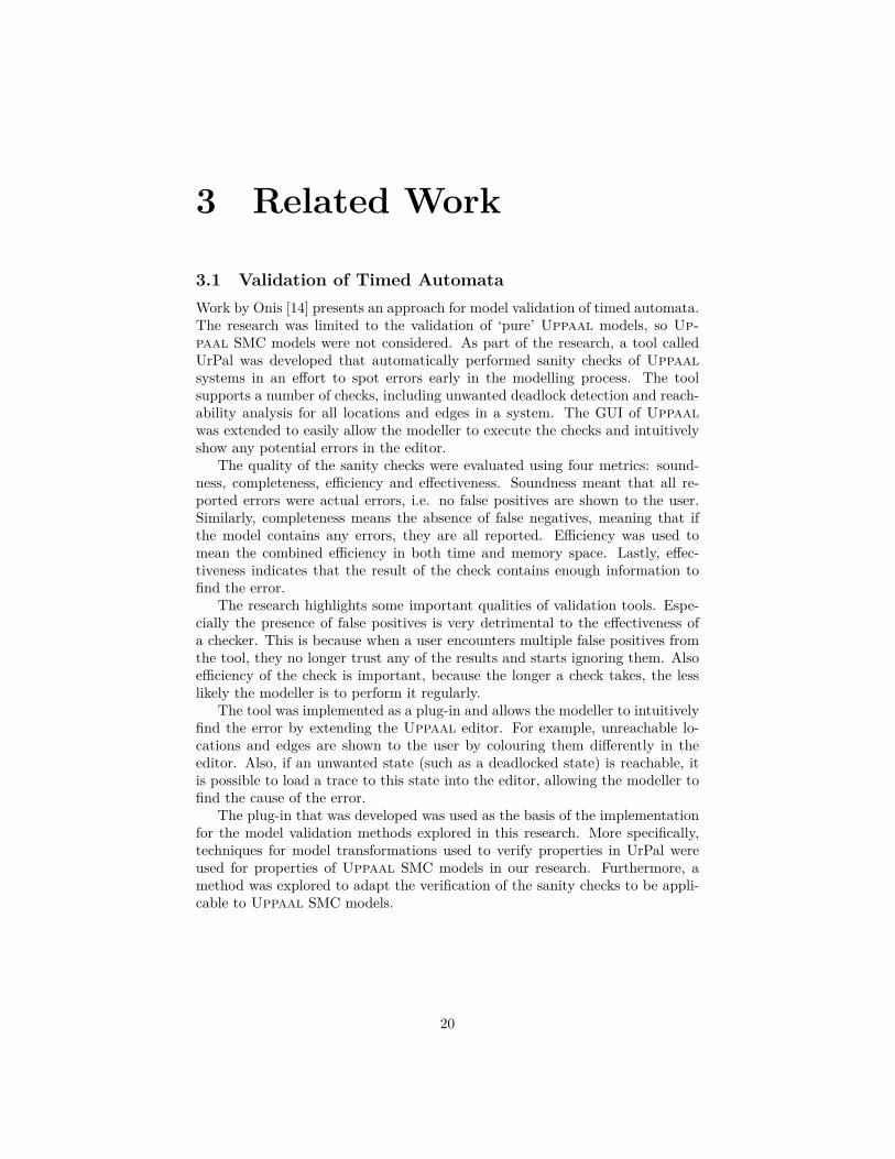
3.1 Validation of Timed AutomataWork by Onis [14] presents an approach for model validation of timed automata.The research was limited to the validation of ‘pure’ Uppaal models, so Up-paal SMC models were not considered. As part of the research, a tool calledUrPal was developed that automatically performed sanity checks of Uppaalsystems in an effort to spot errors early in the modelling process. The toolsupports a number of checks, including unwanted deadlock detection and reach-ability analysis for all locations and edges in a system. The GUI of Uppaalwas extended to easily allow the modeller to execute the checks and intuitivelyshow any potential errors in the editor.
The quality of the sanity checks were evaluated using four metrics: sound-ness, completeness, efficiency and effectiveness. Soundness meant that all re-ported errors were actual errors, i.e. no false positives are shown to the user.Similarly, completeness means the absence of false negatives, meaning that ifthe model contains any errors, they are all reported. Efficiency was used tomean the combined efficiency in both time and memory space. Lastly, effec-tiveness indicates that the result of the check contains enough information tofind the error.
The research highlights some important qualities of validation tools. Espe-cially the presence of false positives is very detrimental to the effectiveness ofa checker. This is because when a user encounters multiple false positives fromthe tool, they no longer trust any of the results and starts ignoring them. Alsoefficiency of the check is important, because the longer a check takes, the lesslikely the modeller is to perform it regularly.
The tool was implemented as a plug-in and allows the modeller to intuitivelyfind the error by extending the Uppaal editor. For example, unreachable lo-cations and edges are shown to the user by colouring them differently in theeditor. Also, if an unwanted state (such as a deadlocked state) is reachable, itis possible to load a trace to this state into the editor, allowing the modeller tofind the cause of the error.
The plug-in that was developed was used as the basis of the implementationfor the model validation methods explored in this research. More specifically,techniques for model transformations used to verify properties in UrPal wereused for properties of Uppaal SMC models in our research. Furthermore, amethod was explored to adapt the verification of the sanity checks to be appli-cable to Uppaal SMC models.
20

3.2 Abstraction RefinementCounterexample guided abstraction refinement (CEGAR) [4] is a technique forthe model checking of systems with large state spaces. Model checking thesesystems with traditional methods is infeasible because of state space explosion.The solution that CEGAR offers is to first create an abstraction of the originalmodel that over-approximates the original behaviour. This abstracted modelhas a smaller state space, which enables regular model checkers to verify prop-erties of it. If the abstracted model satisfies a property, then the concrete modelalso satisfies the property. If not, the counterexample produced by the modelchecker is used for further analysis. If the counterexample is also a counterexam-ple for the concrete model, the property is unproven. If not, the counterexampleis spurious and the process continues. As long as the property is not proven orunproven the abstracted model is continuously refined using information fromthe counterexample.
In research by Dierks et al. the CEGAR technique is applied to timed au-tomata model checking using Uppaal [7]. In their work, the model is abstractedusing variable hiding. In the coarsest abstraction, all variables are hidden, andwith every abstraction refinement loop one or more variables are removed fromthe list of hidden variables. Counterexamples are analysed by transforming thetrace to a linear test automaton, and model checking the composition of thetest automaton and the concrete model.
A similar approach is used in research by Jha et al. [12]. Their researchproposes a method for reachability analysis of linear hybrid automata inspiredby the CEGAR technique. Their abstraction technique is similar to that ofDierks et al., in that first all continuous variables are hidden, and with everyrefinement loop a set of variables is chosen to be added to the set of usedvariables.
We cannot directly apply the CEGAR technique for the validation of HAsbecause the reachability problem for the model is in general undecidable. In-stead, the abstraction technique using variable hiding is used as the basis forthe HA to TA abstraction method explored in this research. In our method, theabstraction is not used to reduce the state space, but is instead used to trans-form a model from an undecidable formalism (HA) to a decidable one (TA) byhiding clock variables with a non-uniform rate. While not explored in this re-search, the method for verifying whether a counter-example is spurious throughthe use of a test automaton could be applied to check if a trace obtained fromthe abstract TA model is part of the language of the original model.
3.3 UPPAAL SlicingThe implementation of variable-hiding abstractions for timed automata, as de-scribed in the previous section, is relatively straight-forward using reductions ofexpressions in guards and invariants. Doing the same for Uppaal models intro-duces complications, since Uppaal extends the TA formalism by (among otherfeatures) a C-like modelling language. The valuation of a hidden variable can
21

affect other variables in the model depending on the control flow of a function.Automatic analysis of the modelling language to determine the dependencies ofsuch variables is a non-trivial problem.
Work by Sørensen and Thrane [16] introduces a method for automatic pro-gram slicing [18] of Uppaal models. Program slicing is the (automated) methodof reducing a program to use a subset of its variables while preserving (a partof) the behaviour of the original program. The work describes a program slicingtechnique for Uppaal models that preserves reachability.
The intended use of the method was to reduce the state space for models,in order to make verification practically possible, where previously it was not.While the method was not used in our research, it could be applied in conjunc-tion with the variable hiding abstraction method to produce a model with aminimal abstraction of the discrete variables.
22

4 Method
Recall the research question: In what ways is it possible to perform modelvalidation of stochastic hybrid automata?. This research attempts to answerthis question by bringing potential model validation techniques into practice,by implementing them as part of a tool for Uppaal SMC models. Next, thetechniques are evaluated in two ways. Firstly, a theoretical analysis of theverification methods is made to determine whether the procedures are sound andcomplete (i.e., unable to produce false positives or false negatives). Secondly,a qualitative evaluation of the tool is performed using case studies. The casesuse Uppaal SMC models used in research, and attempt to replicate the modelvalidation process with the aid of our tool in a real-world context.
4.1 Tool DesignThe tool is designed so that the three sub-research questions can be answered.The first question ‘Which properties of stochastic hybrid automata can be used tovalidate models?’ is answered in Section 7. It describes all implemented modelvalidation properties in detail. The practical utility of these properties as a toolto specify a valid model is explored in the case studies.
Section 6 answers the second question, ‘How can properties of stochastichybrid automata be verified?’ by discussing two implemented algorithms. Thearchitecture separates the verification algorithms from the model specificationso that it becomes possible to compare them. Soundness and completenessof the verification methods for properties of hybrid automata are determined.A qualitative evaluation is performed as part of the case studies, the resultsof which are used to make a comparison of the merits and demerits of bothmethods.
The final research question, ‘How can the results of the validation best becommunicated to the user?’, is answered through implementation in the tooland evaluation through case studies. The design of the user interface is suchthat it allows the user to perform two aspects of model validation: finding faultsand verifying the absence of faults. The evaluation assesses the effectiveness ofthis process by determining the use of the tool in finding and fixing faults in amodel.
4.2 Evaluation MethodIn the case studies, the tool is used for the validation of Uppaal SMC modelsused in research. For each model, a specification is made which is consequentlyverified. The result of this is either that the model is valid (according to thespecification), or that it contains faults. If the model contains a fault, thetool is used to alleviate the problem, and the steps required to produce a valid
23

model are noted. To structure the evaluation, several qualitative metrics for theproperties used for validation and the verification methods. For the verificationmethods, we use the following metrics:
• Soundness – If the outcome of the procedure is that a model is valid,then the model is valid in truth. In other words, the procedure does notproduce false positives.
• Completeness – If a model is valid, then the outcome of the procedureis that the model is valid. In other words, the procedure does not producefalse negatives.
• Time performance – The time required for verification is measured.Since these measurements can be highly dependent on characteristics ofthe model (e.g. number of locations, edges, variables et cetera) the indi-vidual measurements are not very meaningful. Instead, the measurementsare used to determine the practicality of the method. For instance, a pro-cedure might produce correct outcomes, yet if the computations takes overa day its practical utility is limited.
• Utility – The above metrics are used to make an assessment of the utilityof the verification method in the following three use cases: proving validity,finding faults and fixing faults. This can be used to show the specificstrengths of a method in a particular use case.
For the evaluation of the validation properties we use the following qualita-tive metrics:
• Ease of use – A measure of how easy it is to configure the property toaccurately specify correct behaviour of the model.
• Improvement over existing methods –What alternatives to this prop-erty exist, and how much of an improvement is the property over saidalternatives?
• Applicability – What is the range of use cases where the property ishelpful?
24

5 Implementation
In order to evaluate model validation methods a plug-in for the Uppaal editorwas developed. When installed, an additional tab is present in the editor, inwhich the modeller can configure the model validation procedure. This config-uration can be manipulated using an user interface that visualises all availableoptions. Alternatively, this configuration can be specified with a textual format,and verification can be performed using the command line. This option can beused to automate the model validation procedure. The rest of this section willgo into further detail of the internal implementation of the tool.
5.1 Architecture5.1.1 Model views
As mentioned above, the tool is mainly intended to be used as a plug-in forUppaal. This choice was made because it made for a user-friendly way ofinstalling and using the tool (requiring only the user to place a file in the Uppaalinstallation directory). Furthermore, all of the various options for validation arelaid out in the GUI, allowing the modeller to try out various methods withouthaving to resort to reading a manual every time.
The tool is a heavily adapted version of the UrPal tool developed by Onis[14]. Re-using this existing code base allowed for faster development, since italready provided practical ways of manipulating the Uppaal editor, parsingand transforming models and verifying queries on (transformed) models.
Plain text NSTA
Document UppaalSystem
Figure 6: Representations of Uppaal SMC models and their transformations.
Figure 6 gives an overview of the various representations of Uppaal SMCmodels used internally. Plug-ins can read and modify models loaded in theeditor as a Document object. This view is a thin wrapper over the XML formatof models, and also includes ‘stylistic’ information such as positions of locations,comments and node colours. Since this is a direct view of the model loaded in theeditor, invalid models (e.g. models with syntax errors) can also be representedusing this format.
A Document object can be compiled to an UppaalSystem object. Here, thetemplates are instantiated into zero or more processes and the specifications
25

ValidationSpec PropertyConfig
Property
Parameter
Constant overwrite
Clock Bounds
*
*
0..1
1
*
Figure 7: Simplified class diagram of the validation specification.
and expressions are compiled to an intermediate format. Naturally, all stylisticinformation such as text formatting and node positions is lost in the compi-lation process. A successfully compiled UppaalSystem object can be used forverification of applicable Uppaal queries.
In a Document object, all expressions and declarations of a model are storedas plain text. In order to effectively manipulate the loaded models they arefirst parsed to an NSTA 2 object. This interface is provided as a library withJava code generated from EMF [17] metamodels, developed by Schivo et al.[15]. The library represents Uppaal models in an object-oriented way, withexpressions and the specification language being parsed to an AST. Using thelibrary facilitates writing model transformations, since writing a custom parserfor Uppaal syntax is avoided, and any model generated from an NSTA objectwill already be syntactically correct.
The transformations between Uppaal XML files and NSTA objects (and vice-versa) only preserves structural information. Any comments or special format-ting in the expressions and specification language are lost because of the conver-sion to an AST. Furthermore, layout information such as positions of locations,edges or labels and location colours is lost in the parsing and serialisation pro-cess.
5.1.2 Validation Specification
The plug-in allows the modeller to create a simple specification for their model,called the validation specification. The modeller constructs this specificationsuch that when all checks pass, the model is considered valid. This is a differentapproach to the interface of validation tools when compared to UrPal. WhereasUrPal provided a list of checks that required no configuration at all, our im-
2The class as used by the library is called NSTA. This is a slight misnomer since the modelsupports clock rates defined by expressions over clocks, and thus is a hybrid automaton insteadof a (stochastic) timed automaton. This report refers to the class NSTA using a monospacedfont, being distinct from the formalism of Networks of Stochastic Timed Automata (NSTA).
26

plemented validation methods requires configuration of the checks according tothe desired behaviour of the model. This is a compromise in the user-interfacephilosophy, trading ease and speed of setting up the tool for more powerfulverification methods.
The specification consists of a sequence of checks combined with a configu-ration for model checking and a pre-processing step. Figure 7 shows a partialclass diagram of the validation specification. A ValidationSpec contains a listof PropertyConfig objects, which have a reference to the actual property beingchecked (further explained in Section 7) and its parameters. The parameter fieldis a key-value mapping containing both mandatory and optional parameters, de-pending on the property. A ValidationSpec optionally has clock bounds, andzero or more constant variable overwrites, both related to pre-processing steps.These options are further elaborated on in section 6.2.3 and 6.2.4 respectively.
The validation specification can be parsed from and serialised to a JSONformat. When using the plug-in, this allows the specification to be saved withthe Uppaal model, preserving the specification and allowing it to be easilyshared.
5.2 Separation of Model Checker and PropertyAs the reachability problem for hybrid automata is not decidable, some ap-proximative method must be developed to verify properties of the model. Thisresearch investigated two methods, a symbolic and a concrete checking method,which are further elaborated on in section 6.
Furthermore, the tool uses several validation properties. Conceptually, avalidation property is a yes/no question over the model, with a positive an-swer indicating validity. Section 7 goes into further detail on the implementedproperties.
For maximal flexibility, the tool can pair both model checking methods withany validation property. Figure 8 gives an overview of the verification methodfor the validation properties. First, a number of pre-processing steps are appliedto the model, related to reducing the verification time and restricting model be-haviour (further discussed in sections 6.2.3 and 6.2.4). A validation property isabstracted to a function that takes an Uppaal SMC model as parameter, andreturns a transformed model, and a state formula. The abstract view of a reach-ability checker is a function with an Uppaal SMC model and a state formulaas parameters, which returns whether the model can reach a state satisfying thegiven state formula. Optionally, a trace leading to such a state is produced, asillustrated in Figure 9. This abstraction allows the verification algorithm to beagnostic of the reachability checking method used, and thus easily allows themodeller to choose the method that suits their use case optimally.
5.3 UPPAAL Editor IntegrationManipulation of the Uppaal editor is done using the recently supported plug-in API. This API allows the currently loaded model to be read and modified
27

Uppaal SMCModel
Pre-processing
Transformmodel
Check query Show trace
Property valid
Property satisfiable
Property unsatisfiable
Figure 8: Schematic view of the verification method for validation properties.
using the Document interface. Additionally, traces obtained from the verificationof Uppaal queries can be loaded in the editor. However, only the loading ofsymbolic traces is currently supported. These traces are tightly coupled tothe currently loaded model in the editor, which causes traces obtained fromtransformed models not to be easily loaded in the editor without additionaltransformations. In order to be shown in the editor, traces from transformedmodels must be modified such that the general structure (number of variables,template instantiations et cetera) matches the original loaded model. This isthe approach that was used for one of the sanity checks implemented in UrPal.
Since the intended usage of our tool involves showing both symbolic andconcrete traces, and these traces are obtained from queries over transformedmodels, loading traces using the plug-in API is circumvented. Instead, tracesare shown using manipulation of UI elements in the editor. Effectively, thisemulates manually loading the transformed model, adding a query to the querylist, and pressing the button to show a trace in the editor.
This alternative approach has the benefit of working with any transformedmodel, without the need to transform the trace. Also, concrete traces are sup-ported without requiring any additional work. The drawback to this approach isthat trace view in the editor shows the transformed model, instead of the orig-inal model. This causes auxiliary variables required for property verificationto be visible to the user. The formatting information of expressions (guards,invariants et cetera) is lost in the conversion of a model to a NSTA view andback. This causes the model shown in the trace view to differ visually from theoriginal model, and may lead to overlap of expression labels.
The NSTA model view does not contain the positions of locations, location
28

(a) UI component of an unsatisfied val-idation property. Pressing the ‘LoadTrace’ button loads a trace leading tothe unsafe state in the editor, as seenin Figure 9b. (b) A partial view of the trace window
in Uppaal. Selecting any of the statesof this trace shows the exact state ofthe model at that time in the rest ofthe window.
Figure 9: Example usage of showing a trace to an unsafe state. This propertyconfiguration is part of the case study detailed in Section 8.1.1
names, edge segments or expressions as shown in the Uppaal editor view. Thetool implements an extended NSTA to Document transformation with the originalUppaal model as additional parameter. The original model is used to set thepositions of elements in the transformed model. As a result, the model shownin the trace view closely resembles the original model.
29

6 Reachability Algorithms
Some of the implemented validation properties can be generalised as either safetyproperties (an unsafe state is never reached), or reachability properties (a desiredstate is eventually reached). For greater flexibility in model validation methods,the tool separates validation properties from model checking procedures. Avalidation property is generalised to a procedure that performs some kind ofmodel transformation, and returns a state formula specifying either a desiredor unwanted state (i.e. a reachability property or a safety property).
In TCTL, safety properties can be expressed as A□¬ϕ, and reachabilityproperties can be expressed as E3ϕ . Since A□¬ϕ ≡ ¬E3ϕ, we only requirean algorithm that decides if an NHA M can reach a state satisfying ϕ.
The problem here is that reachability checking of hybrid automata is, in gen-eral, undecidable. However, for the purposes of model validation, an algorithmthat is either unsound or incomplete could provide enough useful informationto the modeller. Presented below are the different approaches to reachabilitychecking that are used in this research.
6.1 Concrete CheckingThe simplest way to perform reachability checking is to use a simulation-basedapproach. Here, the simulation algorithm produces n runs of the model, andterminates if at any time the state of the model satisfies ϕ, concluding that thestate is reachable. However, if the algorithm has not found a run satisfying ϕafter n runs, no definitive conclusion can be made. This results indicates thateither the state is unreachable, or that, by chance, the state has not been visitedyet.
Even though the algorithm is not complete, it still provides useful infor-mation to the modeller. For large enough n, if no accepting run is found, themodeller gains confidence that the state is indeed unreachable.
Uppaal SMC provides a way to perform a number of simulations and filterthe runs using a state formula. The syntax of this query is as follows:
simulate [<=t;n] {expression+} : m : ϕ
Where t is the global time bound of the simulation and n is the number ofruns performed. The simulator plots the trajectories of one or more expressionsspecified in expression+. The runs are limited to the predicate ϕ, meaning thatthe simulation stops when ϕ is satisfied. If the run does not satisfy the predicateat any point it is discarded and not shown in the results. The simulator stopsafter m satisfying runs have been found.
We use the following query for reachability checking:
simulate [<=t;n] {0} : 1 : ϕ
30

Here, t and n are constants provided by the modeller, and ϕ is the stateformula specified by the validation property. Because at least one expressionmust be provided, and we are not interested in plots of the simulation, wesimply give the constant 0 as the expression list. After one satisfying run hasbeen found it is known that ϕ is reachable, so the search can stop.
6.2 Symbolic CheckingWhereas the reachability problem is undecidable for hybrid automata, it is de-cidable for timed automata. Because TA are a sub-class of HA, it is possible tocreate a TA that is an abstraction of the original HA. Standard model checkingalgorithms can then be used to determine reachability. The limitation is thatthe abstract model is only an approximation of the original (concrete) model.This section first discusses an abstraction algorithm for hybrid automata, andthe implication of model checking an abstraction instead of the concrete model.Next, the implementation of the abstraction algorithm for Uppaal SMC mod-els is discussed, along with other transformations required for practical modelchecking.
The terminology used in this section is derived from CEGAR [4] terminology.The original, untransformed model is called the concrete model, and is notedas M . An abstraction, or the abstract model of the original is noted as M̂ .The abstraction function h maps a model to its abstract counterpart. Theabstraction method presented here is derived from work on CEGAR techniquesfor timed automata by Dierks et al. [7]. Recall that in their work the basisof the abstraction function was variable hiding, where the abstract model onlyuses a subset of the set of clocks, and guards and invariants are relaxed so thatthey do not reference hidden clocks. The abstraction algorithm presented hereis similar, but differs in that it is an HA to TA transformation instead of TA toTA.
6.2.1 Abstraction Algorithm for Hybrid Automata
If an HA contains a clock that can grow at a non-uniform rate (i.e. the derivativeof the clock over time is not 1), reachability checking is undecidable in thegeneral case [10]. The basis of our approach is to remove non-uniform clocksfrom the model while relaxing the guards and invariants as little as possible.
First, a set H containing all non-uniform clock variables is created. A non-uniform clock is a clock whose rate is defined and unequal to 1 in one or moreinvariants. All clocks in H are removed from the set of clocks in M̂ . Next, allinvariants, guards and updates are changed so that they no longer reference avariable in H. We define the abstraction function h over expressions as follows:
h(ϕ1 ∧ ... ∧ ϕn) ≡ h′(ϕ1) ∧ ... ∧ h′(ϕn)
h′(ϕ) ≡
{true if ϕ ∈ EH
ϕ otherwise
31

Where EH is the set of all expressions containing a variable in H. Theexpression abstraction h is chosen such that if ϕ is satisfied for some valuationv, h(ϕ) is also satisfied for v.
Lemma 1. For any valuation v, v |= ϕ⇒ v |= h(ϕ).
Proof. To prove Lemma 1, we assume v |= ϕ and attempt to prove v |= h(ϕ).For ϕ ≡ ϕ1 ∧ .. ∧ ϕn, since v |= ϕ, we have v |= ϕi for i ≤ n. For ϕi, we haveeither:
• h(ϕi) ≡ ϕi. In this case, v |= ϕi implies v |= h(ϕi).
• Or h(ϕi) ≡ true. Trivially, in this case v |= h(ϕi).
Since we have v |= h(ϕi) for i ≤ n, and h(ϕ) = h(ϕ1) ∧ .. ∧ h(ϕn), we haveshown that v |= ϕ⇒ v |= h(ϕ).
Proof Sketch of Over-Approximation
A general contract for the abstraction function h is that the abstracted modelM̂ must be a strict over-approximation of the concrete model M . Formally, wedefine this property as s → s′ ⇒ h(s) → h(s′). This means that for any state,if M is able to take a transition, M̂ must be able to take the same transition.To prove this, we consider both kinds of transition that an NHA or NTA maytake, delay- and action transitions.
For delay transitions, we have (L, v)d−→ (L, v′), where d ∈ R+, L is the
location vector, and v and v′ are valuations of the clocks and data variables.We have v′ = v + d, where v′ is obtained by delaying all clock valuations by d(according to clock rates). Delay transitions are restricted by invariants, wherefor all d′ ∈ [0, d], v + d′ |= Inv(L) must hold (where Inv(L) is the conjunctionof the invariants in L).
If we have s d−→ s′ in M , we must also have h(s) d−→ h(s′) in M̂ . If s d−→ s′ is avalid transition, then the invariants hold for any delay up to d. Using Lemma 1,we know that the abstracted invariants also hold, and therefore the transitionh(s)
d−→ h(s′) is valid in M̂ .For action transitions, we can take a similar approach. An action transition
is a transition (L, v)c−→ (L′, v′), with c either a channel or τ (signifying an
internal transition). Among other restrictions, the transition is enabled whenv satisfies all guards of the involved edges, and v′ satisfies the invariants in L′.Using Lemma 1, we know that if an action transition is enabled inM , then h(v)satisfies the relevant guards in M̂ , and h(v′) satisfies the abstract invariants.The only updates that are removed are those assigning values to non-uniformclocks, so the valuation of every ‘uniform’ clock is equal between v′ and h(v′).
32

s0M ψ1 ψ2M̂
Figure 10: The reachable state space of a model M and its abstraction M̂ , andstate predicates ψ1 and ψ2.
Implications of Over-Abstractions
Since the abstract model M̂ is an over-abstraction of M , checking safety prop-erties using this method is sound, but not complete. So for any safety propertyϕs ≡ A□ψ with ψ a state predicate, M̂ |= ϕs ⇒ M |= ϕs, but converselyM |= ϕs ̸⇒ M̂ |= ϕs. Similarly, for reachability properties ϕr ≡ E3ψ, propertychecking is complete since M |= ϕr ⇒ M̂ |= ϕr, yet not sound.
These implications are illustrated in Figure 10, where the regions markedM and M̂ note the set of reachable states of a model and its abstraction re-spectively, s0 being the initial state, and ψ1 and ψ2 note the sets of states thatsatisfy the two state predicates. Here, checking the formula E3ψ1 using anover-approximative model would result in the correct answer, seeing as a statein ψ1 is indeed reachable from s0 (as shown using the solid transition sequence).Using the same method to check E3ψ2 results in a false positive, since it isonly reachable through states in M̂ and not M (shown by the dotted transitionsequence).
6.2.2 Abstractions of UPPAAL SMC Models
We now describe how the abstraction method for NHAs is applied to Up-paal SMC models. Since the Uppaal and Uppaal SMC formalisms are exten-sions to NTAs and NHAs additional transformations are required. Specifically,Uppaal SMC supports models with double-type floating-point variables, whichcannot be used with symbolic model checking. The abstraction algorithm is ex-tended so that the set H of hidden variables not only contains clocks with anon-uniform rate, but also all data variables of type double.
This causes complications because the model may contain functions whosecontrol flow is dependant on a hidden variable. Consider the model in Figure 11,where a function may assign different values to a variable depending on a condi-tion expression containing a double-typed variable. If the abstraction algorithmwere to simply remove the reference to d in the branch condition, changing d
33
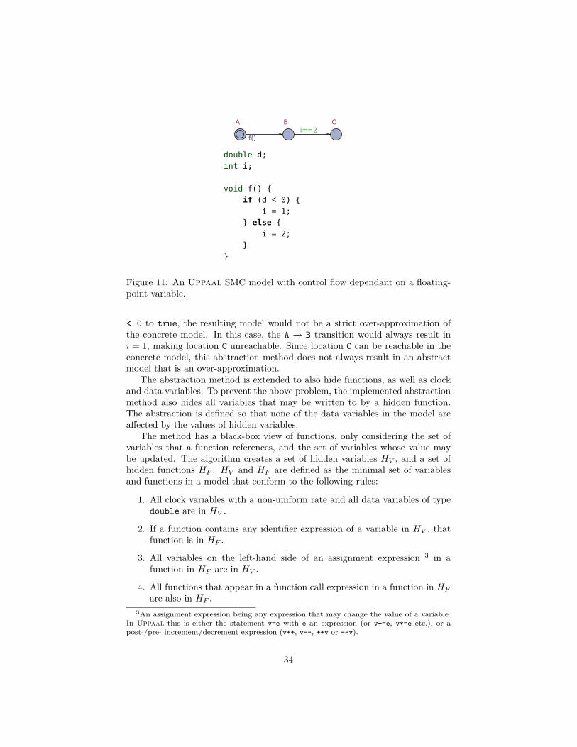
double d;int i;
void f() {if (d < 0) {
i = 1;} else {
i = 2;}
}
Figure 11: An Uppaal SMC model with control flow dependant on a floating-point variable.
< 0 to true, the resulting model would not be a strict over-approximation ofthe concrete model. In this case, the A −→ B transition would always result ini = 1, making location C unreachable. Since location C can be reachable in theconcrete model, this abstraction method does not always result in an abstractmodel that is an over-approximation.
The abstraction method is extended to also hide functions, as well as clockand data variables. To prevent the above problem, the implemented abstractionmethod also hides all variables that may be written to by a hidden function.The abstraction is defined so that none of the data variables in the model areaffected by the values of hidden variables.
The method has a black-box view of functions, only considering the set ofvariables that a function references, and the set of variables whose value maybe updated. The algorithm creates a set of hidden variables HV , and a set ofhidden functions HF . HV and HF are defined as the minimal set of variablesand functions in a model that conform to the following rules:
1. All clock variables with a non-uniform rate and all data variables of typedouble are in HV .
2. If a function contains any identifier expression of a variable in HV , thatfunction is in HF .
3. All variables on the left-hand side of an assignment expression 3 in afunction in HF are in HV .
4. All functions that appear in a function call expression in a function in HF
are also in HF .3An assignment expression being any expression that may change the value of a variable.
In Uppaal this is either the statement v=e with e an expression (or v+=e, v*=e etc.), or apost-/pre- increment/decrement expression (v++, v--, ++v or --v).
34

5. All functions that contain a function call expression to a function in HF
are in HF .
Rule 2 states that any function that has any reference to a hidden variableis also hidden. Since the control flow of a hidden function depends on hiddenvariables, any variable that the function may write to must also be hidden,resulting in rule 3. If a hidden function f calls another function g, the variableswritten to by g are affected by the hidden function f and must therefore alsobe hidden, resulting in rule 4. Similarly, if a function calls a hidden function,its control flow is dependant on a hidden function and thus must be hidden aswell, resulting in rule 5.
The algorithm is implemented using mutable sets HV , initially filled accord-ing to rule 1, and HF , initially empty. For every function in the model, thealgorithm iterates over the nodes of its AST, adding any variable or functionthat conform to rules 2 to 5 to the sets. This process repeats until no newvariable or function is added to HV or HF .
It can be seen that the proposed abstraction algorithm is coarse, and pro-duces an abstract model which may hide more behaviour than is strictly re-quired. Future work may research alternate approaches in an effort to producefiner abstractions (i.e. abstractions where fewer variables are hidden). Thiscould be performed by analysis of the control-flow graph of the function, todetermine whether the values of data variables are affected by expressions overhidden (double) variables.
The implemented abstraction algorithm supports a limited but significantsubset of Uppaal SMC models. One of the unsupported features of Up-paal SMC is the dynamic creation of processes, where during runtime processcan ‘spawn’ an arbitrary amount of new processes to be added to the model.
6.2.3 Time Bounding
With Uppaal SMC, every query is bounded, meaning that the SMC algorithmgenerates runs that end when the value of a clock x exceeds d. When no clockis specified, x is used to signify global time, and is substituted for a new clockthat is never reset. The modeller might therefore rely on the fact that simula-tions of the model will eventually terminate. This, however, presents a problemwhen using our TA abstraction method, as TCTL formulas are not bounded.For example, a cycle-based Uppaal SMC model might contain some countervariable that keeps track of how often a certain event occurs. Since simulationsof the model are bounded, the value of this variable will never exceed some finitevalue. If this model is subsequently abstracted to a TA and model checking isperformed, there is no end state of the system. The value of the counter variablewould thus grow indefinitely, making the state space of the model infinite.
Our tool provides a practical solution to this problem. When using TAabstraction, the user has the option to specify an optional clock x and a time-bound for said clock. If no clock is specified, x is assigned to a new global clockthat is never reset. When this option is enabled, an additional automaton is
35

Figure 12: A time-bounded automaton.
added to the network, as visualised in Figure 12. When x = n, an invariantrestricts further delay transitions and the automaton enters an urgent locationEnd. In this state, the model is not able to take delay transitions, but onlyaction transitions, ensuring that a state where x > n is unreachable.
Figure 13: The time bounding dialog in the Uppaal plug-in window.
6.2.4 Constant Variable Overwrite
As this method uses model checking methods over the abstract model, it issubject to the problem of state-space explosion. Uppaal SMC queries aresimulation-based and therefore do not suffer from the same problem. As aconsequence, the creator of an Uppaal SMC model does not have a large in-centive to reduce the state space of said model. This presents an obstacle forsymbolic checking of NHAs, as the abstract model might have a state spacetoo large to be checked in a practical amount of time. If this is the case, ourtool offers some simple methods to simplify the model enough to make modelchecking feasible.
Uppaal models often contain multiple similar processes that are instantiatedfrom one template (the train-gate model is an example of this). The amount oftemplate instantiations is often determined by some constant N in the globaldeclarations of the model. The complex behaviour that occurs when a number ofprocesses interact is often of interest to the modeller. Every additional processincreases the symbolic state-space exponentially. However, for the purposes ofmodel validation, one or two instantiations might be enough to find errors or toverify correctness.
Figure 14: The constant overwrite dialog in the Uppaal plug-in window.
36

To effectively allow the user to change the number of process instantiationswhen using symbolic model checking, a pre-processing step is added to thevalidation method. Figure 14 shows the UI dialog of this option in the Uppaaleditor. The user is able to specify zero or more global constants of the model,and assign a new value to them. This changed model is then used for thevalidation procedure.
37

7 Validation Properties
This section discusses the definitions and implementations of the validationproperties used in the model validation tool. Sections 7.1 through 7.3 discussthe original properties developed for this work, and Section 7.4 describes how asubset of the checks in UrPal were implemented in the tool.
7.1 Model InvariantThe simplest and most general validation property implemented is the modelinvariant. This property states that all reachable states of the checked modelshould satisfy the given invariant ϕ. Expressed in TCTL, the property is definedasM |= A□ϕ, withM the model under test. The invariant is the only parameterof this property, and can be noted as any valid Uppaal state predicate. Thismakes it possible to express properties over the variables of the model (e.g.x > 4) or the currently active location in a process (using the Process.Locationsyntax). Additionally, the deadlock keyword can be used if the property isverified using symbolic model checking (deadlock checking cannot be performedusing Uppaal SMC queries because it relies on finite runs of the model).
The modeller can use this property to ensure that states that should beunreachable if the model is correct are indeed not reachable. If a state thatdoes not satisfy the invariant can be reached, the model is considered invalid.Depending on the reachability checking method used, either a symbolic or aconcrete trace to such a state can be shown in the Uppaal editor. The traceshows a transition sequence leading to the incorrect state, which can help theuser to determine the exact cause of the incorrect behaviour and resolve theerror.
7.2 Synchronisation CheckIt was observed that a common pattern in Uppaal models is to have a processthat should be able to react to a synchronisation in every possible state. Forexample, if a different process sends a reset signal, the receiving process shouldalways return to an initial location and state. Because the modeller has tomanually add the receiving transitions, it is not unlikely for a mistake to occur,which would lead to incorrect behaviour of the model. In Uppaal SMC, thiscan occur even more frequently, because only broadcast synchronisations areallowed. Broadcast synchronisations are one-to-many, and are non-blocking,meaning that the sending process can always take a synchronisation-sendingtransition, even if there is no process ready to receive the synchronisation.
In order to find mistakes related to failing to synchronise, we added a mecha-nism to check whether a process in an NHA is always capable of synchronisationon a given channel. Expressed more formally, the checked property is satisfied
38

if all processes P instantiated from a given template T take a receiving-edgetransition when some other process takes a sending-edge transition, unless theignore condition ϕ is satisfied. The modeller can specify an ignore condition tofilter out false-negatives. For instance, a process would probably not have toreact to a reset signal if it already is in the initial state.
7.2.1 Implementation
Our approach works by transforming the model to count the number ofreceiving-edge transitions taken, and checking if it equals the expected value.Given a user-specified channel c and template T , let n be the number of processesinstantiated from this template. The model is extended with a global integervariable m, representing the number of receiving-edge transitions ‘missed’. Onevery edge in the model with the synchronisation c!, the update m := n is ap-pended. On every edge of template T with the synchronisation c? or c!, theupdate m := m − 1 is appended. Then, the property m ̸= 0 is checked forreachability. If it is reachable, a process is unable to take the receiving-edgetransition in some state, and an error is reported to the user.
The above method is able to work because in Uppaal, updates are evaluatedsequentially, not concurrently. Furthermore, updates on the sending edge areevaluated before updates on the receiving edge. This means that setting thevalue of m to n always happens before the decrements. So, if all n receivingprocesses are able to synchronise, m is decremented n times, and equals 0 againafter the transition. The decrement update is also added to a sending edge if itbelongs to template T , so that the check is still correct if the sending process isone of the processes instantiated from T . This update must be evaluated afterthe initial assignment of m to n.
However, incorporating an ignore condition ϕ requires additional modeltransformations. It is not sufficient to simply check reachability for the statem ̸= 0 ∧ ¬ϕ, because if a ‘missed’ synchronisation occurs while ϕ is true, themodel remains in a state where m > 0. It is then possible that the model canreach a state where ϕ becomes true and the value of m remains unchanged,which would lead to a false positive reported to the user.
To illustrate this, consider the example in Figure 15. Here, the goal is tocheck if the reset? synchronisation is always taken in process P , unless theprocess is already in the initial location Start, so ignore condition ϕ ≡ P.Start.With the model transformation as described above, the predicate m ̸= 0 ∧ ¬ϕis reachable with the following transition sequence:
((Start,Q1),m = 0)reset−−−→ ((Start,Q1),m = 1) −→ ((Work,Q1),m = 1)
It can be seen that this is a false positive, because the reset synchronisationwas taken while process P was in the Start location, even though the ignorecondition was meant to filter out this case.
To circumvent this incorrect behaviour, the model transformation must beextended so that the searched property can only be true after a synchronising
39

(a) Process P . (b) Process Q.
Figure 15: An example of an NHA communicating with a broadcast channel.
transition, and that any action or delay transition after that makes the propertyfalse. The model transformation is extended as follows:
• On every edge that does not synchronise over the specified channel c, theupdate m := 0 is appended.
• An additional clock t is added, and the update t := 0 is appended to everyedge labelled with c!.
Now, the property ψ ≡ m ̸= 0 ∧ ¬ϕ ∧ t = 0 is checked for reachability. Thefirst additional model transformation ensures that any action transition resetm,and thus the state m > 0 cannot persist between action transitions. The clockreset of t and the additional condition t = 0 ensures that any delay transitionafter c−→ invalidates the property.
(a) Process P . (b) Process Q.
Figure 16: The NHA of Figure 15 with model transformations supporting ignoreconditions.
Figure 16 shows the NHA of Figure 15 with the extended model transforma-tions. It can be seen that the transition sequence that led to the false positiveearlier is now no longer possible, because the edge Start −→ Work now has theupdate m := 0.
7.2.2 Usage
The results of the reachability check of ψ are reported to the user. If ψ isunreachable, the model behaves according to the specification, and a positiveresult is reported. If not, Uppaal generates a trace (either concrete or sym-bolic), which is loaded in the editor for the modeller to inspect. The trace showsthe exact transitions taken to reach the invalid state, and allows the modellerto deduce why the model was able to reach the undesired state.
40

broadcast chan a, u;chan priority default < u;
Figure 17: The checker process for synchronisation post-condition verification.
7.3 Synchronisation Post-ConditionThis property allows specifying an expression that should always be satisfieddirectly after a synchronisation on a broadcast channel takes place. Expressedformally, the property is valid if for a given state predicate ϕ and channel a, themodel cannot reach a state s where s′ a−→ s and s ̸|= ϕ. Essentially, the propertyallows the modeller to specify a contract for channel synchronisations.
7.3.1 Implementation
Since the Uppaal query language provides no mechanism to specify a stateafter a channel synchronisation, model transformations are required to verifythe property. Our approach works by adding a checker process to the modelthat listens to the specified broadcast channel a. Figure 17 shows this template.
The process is constructed such that when a synchronisation over channel aoccurs, the only enabled transition sequence is the following:
((l1, ..., ln−1,Wait), v)a−→ ((l′1, ..., l
′n−1, Check), v
′)u−→ ((l′1, ..., l
′n−1,Wait), v′)
This specifies that the locations of the other processes and the clock valuationcannot change when the system is in the Check location.
The process remains in the Wait location until an action transition withchannel a is taken, and the process enters the Check location. The model isdefined so that while the system is in the Check location, the only enabledtransition is the internal transition to the Wait location. Because the Checklocation is marked as committed, no delay transitions can be taken, and onlyedge transitions starting from a committed location are enabled.
To avoid the possibility of another process taking a transition from a com-mitted location, another restricting mechanism is required. Channel prioritiesare used to ensure that the Check −→ Wait transition is the only enabled tran-sition. In the Uppaal formalism, a transition is enabled if no higher prioritytransition is enabled. Channel priorities are defined in the global declarationsof an Uppaal model where, for example, the declaration chan priority a <b means that channel b has a higher priority than channel a.
The model transformation adds an auxiliary channel u to the model, andensures that it has the highest priority. If no channel priority was earlier defined
41
in the model, the statement chan priority default < u; is appended to theglobal declarations. If the model already contained a channel priority statement,u is appended at the end so that all other channels have a lower priority. Thesynchronisation u! is added to the Check −→ Wait edge, guaranteeing that itstransition takes precedence over all other transitions.
Unfortunately, channel priorities are not supported in the verification of Up-paal SMC queries. When concrete reachability checking is used for verification,the channel u is left out of the transformed model. As a result, it becomes pos-sible for a false positive to occur if another process takes a transition leavinga committed location while the checker process is in the Check location. SinceUppaal SMC provides no other mechanism to prioritise a transition, this falsepositive remains a possibility. As a work-around, the modeller can manuallyrelax the post-condition predicate ϕ such that the erroneous state is filtered out.
7.3.2 Usage
Like the two validation properties discussed above, this property can be checkedeither symbolically or using concrete simulations. Again, a trace leading to theinvalid state can be loaded in the editor to determine the cause of the incorrectbehaviour.
7.4 UrPal ChecksBesides the validation properties described in the sections above, our tool alsosupports a number of the sanity checks developed for UrPal. Since the sanitychecks are verified using symbolic model checking, the Uppaal SMC models arefirst abstracted to a ‘pure’ Uppaal model before further verification. Using thismethod, it takes little engineering effort to adapt the existing sanity checks tosupport SMC models, only requiring changes to handle the updated architectureand user interface changes. As a proof of concept, the model validation toolcurrently supports two of the sanity checks, further discussed below.
7.4.1 Unwanted Deadlocks
In a timed automaton, a deadlocked state is a state for which no action tran-sitions are enabled in the time-abstract transition system (i.e. a state s whereonly delay transitions are enabled, and no state s′ with an enabled action tran-sition can be reached from s). Since in some models a deadlocked state is partof the intended behaviour of the model, UrPal defines a wanted deadlock asa deadlocked state where one or more locations in the location vector has nooutgoing edges. The assumption is that these locations are intended to be dead-lock locations, and a deadlock state containing one of these locations is thereforenot erroneous. Consequently, an unwanted deadlock is defined as a deadlockedstate where all of the locations in the location vector have one or more outgoingedges.
42

The implementation first creates the set of locations in the model with nooutgoing edges. The following Uppaal query is checked symbolically on theabstract model:
A[] deadlock imply (P1.L1 or ... or Pn.Ln)
With Pi.Li a location without outgoing edges. Similar to the validationproperties, if the property is satisfied, a positive result is reported to the user.If not, a negative result is displayed, and the user has the option to load a traceleading to the deadlock state in the Uppaal editor.
Since this property is a safety condition and the abstracted model is an over-approximation, verification is sound but not complete. In other words, if theresult of the verification is positive, it is guaranteed that the concrete model isunable to reach an unwanted deadlock state. If the outcome is negative eitherthe concrete model may indeed reach an unwanted deadlock state, or this stateis only reachable because of the relaxed guards and invariants of the abstractmodel. If so, the user can inspect the symbolic trace, and determine whetherthis transition sequence is indeed possible in the original model.
7.4.2 Template Location Reachability
This property is satisfied when every location of a template is reachable by one ormore of the processes instantiated from said template. To avoid having to verifya reachability query for every location in the model, UrPals implementationuses meta-declared variables to mark ‘visited’ locations during a state spacesearch. Using this method, the state space of the model only has to be searchedonce. Full details of the implementation of this check can be found in work byOnis [14]. If one or more locations were found to be unreachable, a negativeresult is reported to the user. These locations are marked red in the editor tocommunicate exactly which are unreachable.
Our work extends this procedure to work with Uppaal SMC models byperforming the above routine on an abstract over-approximation of the model.Because the check is a reachability property, verification is complete but notsound. Effectively, this means that no false positives can occur. However, falsenegatives can occur when the relaxation of guards and invariants cause locationsthat are unreachable in the concrete model to become reachable.
43

8 Evaluation
8.1 Case Studies8.1.1 Cancer Immunotherapy Model
The first case study examines an Uppaal model used in research of cancerimmunotherapy healthcare processes. Specifically, it models side effects of thetherapy (immune-related adverse events, called toxics in the model), and studiesthe impact of test accuracy on the progression of these toxics. The model wasconstructed based on expert consultations and calibrated using empirical patientdata.
The system models the healthcare process of one patient, who can potentiallycontract six different toxics, each with a grade of severity. According to aformalised protocol, these toxics are periodically monitored and tested, where atest has a certain chance of a false positive or false negative. Depending on testoutcomes and previous recovery steps, the protocol dictates either a recoveryphase or palliative care for the patient. The system has concurrent processesfor the protocol, the patient, a periodic check for disease progression, six toxicprocesses with varying parameters, each with a corresponding test automaton,and a monitor automaton used for statistical queries.
Three variants of the model are used in the case study, each representingdifferent points in the model development process. In the first model a bug ispresent, which is partially fixed in the second model, and fully removed in thethird variant. We refer to these model variants with the label 1A, 1B and 1C.Consultation with the model developer allowed the exact cause of the fault to beknown. As part of the study, we emulate the bug fixing procedure by creating aspecification that ‘captures’ the bug, and thus allows the evaluation of the toolin bug finding and proving the absence of errors.
The bug was caused by a toxic process failing to synchronise correctly withthe protocol process. Behaviour of a toxic process changes if the protocol isin a recovery phase, so broadcast channels are used to synchronise this state.Erroneous behaviour occurred because the toxic process was able to reach astate where a synchronisation over these channels was not enabled, leaving thesystem in an invalid state.
Validation specification Synchronisation of the recovery state is done us-ing the startrecov and endrecov channels for entering and exiting the staterespectively. The validation specification is configured to have ‘SynchronisationCheck’ properties for these channels on the toxic template. In two locationsof the template, PreG0 and G0 (indicating a toxic with grade 0, i.e. no toxic),behaviour of the process is not dependant on the recovery state, so no synchro-nisation is needed. To model this, the ignore condition exists (n: id_t)
44

# Property Type Parameters1 Synchronisation Check template = Toxic
channel = startrecov2 Synchronisation Check template = Toxic
channel = endrecov3 Model Invariant condition = Protocol.Palliative ==
ProgCheck.Palliative4 Unwanted Deadlocks5 Template Location Reach-
ability
Table 1: Overview of validation properties used in case study 1.
(Toxic(n).G0 or Toxic(n).PreG0) is configured for the properties. This ex-pression is satisfied when one of the toxic processes is in the PreG0/G0 location,avoiding any false negatives in the model validation.
Another property was configured in order to verify that two processes syn-chronise properly. The protocol process and disease progression process bothhave a state representing palliative care for the patient. Whenever one of theseprocesses is in such a state, the other should be as well. Furthermore, if oneof the processes is not in a palliative care state, the other must not be as well.Since both processes can independently enter this state, it is possible that anerror in the model is made, causing the processes to be out of synchronisa-tion. To verify the lack of this error, a model invariant with the conditionProtocol.Palliative == ProgCheck.Palliative is configured.
Lastly, two sanity checks adapted from UrPal were added to the specification.These are the unwanted deadlock check and the template location reachabilitycheck. Both checks are only verifiable using symbolic checking of the abstractmodel. An overview and numbering of all properties is given in Table 1.
Verification Two configurations were investigated, one using symbolic check-ing and one using concrete checking. In order to make symbolic checking pos-sible, some changes to the model and validation specification were necessary.Without any changes, the model contains six toxic and test processes. With acut-off time of 600 seconds no property could be verified due to the large statespace of the abstract model. The model was adapted to introduce a constantvariable ENABLED specifying the number of toxic and test processes that shouldbe instantiated. This allows the validation specification to include a ‘constantoverwrite’ to lower the number of instantiations to 1 or 2, which allowed sym-bolic model checking in a practical amount of time due to the reduced statespace. Note that reducing the number of template instantiations may alter thebehaviour of the model, and therefore verification outcomes may not be repre-sentative for the unaltered model. In this case, there is no direct communicationbetween the toxic and text processes, giving confidence that we can adequately
45

verify the properties on the reduced system.It was also necessary to introduce a time bound on the system, as detailed
in Section 6.2.3. Without this time bound a discrete variable keeping track ofthe number of monitoring cycles is able to increment indefinitely. This variableis used as an index for an array of parameters, and increasing this variableout of the expected range of cycles would lead to an out-of-bounds error whenindexing said array, terminating the verification. Introducing a time-boundingautomaton with an upper bound of 66 time-units (being 11 6-week periods,which is the intended time bound of the model) made the state space finite andthus allowed symbolic model checking.
In order to verify the properties using concrete simulations the only config-uration required is the number of runs and the time bound of the runs. In thiscase, 10,000 runs up to a time bound of 66 time-units were performed. Thishighlights a practical benefit of the verification method, as no significant timeor expertise of the user is required to configure it.
Results As expected, the verification outcome of the ‘Synchronisation Check’properties on the startrecov and endrecov channels showed that the processwas able to reach a state with no receiving synchronisation transition enabled,meaning that the model variant 1A is invalid according to the specification. Atrace leading to this state was able to be shown in the editor, allowing the userto quickly spot a location without the required synchronisation edges. This par-allels the manual bug finding procedure used in the development of the model,where this problem was alleviated by adding synchronising self-loops to the lo-cation. This step was repeated in the case study, leading to model variant 1B,after which the validation specification was verified again.
With this step applied, there was still a possibility for erroneous behaviour.This could occur if the protocol exited the recovery state and then entered thestate again without any delay transitions between the actions. If this happenedwhile the toxic process was in a specific urgent location, it could not synchroniseover the startrecov channel, causing further erroneous behaviour. Verificationof the ‘Synchronisation Check’ property was able to confirm that this was pos-sible, and provided a trace leading to the described state.
This second fault is a demonstration of the use of the automatic verificationof model validation properties. Whereas manual inspection and manipulationof the model was eventually successful in finding and fixing the fault, consulta-tion with the model developer did indicate that this was a time-consuming anddifficult process due to the complex interactions required to reach the invalidstate. With the use of our tool, the presence of the fault was able to be shownquickly, and using traces was a practical way of finding the exact cause of theproblem.
The fault was resolved by changing a location in the toxic process to bemarked as committed instead of urgent. With this change, creating modelvariant 1C, it was possible to verify that the synchronisations were able tobe received in all reachable states of the model. Notably, this outcome was
46

1A 1B 1CProperty Satisfied Time (s) Satisfied Time (s) Satisfied Time (s)1 No 1.430 No 2.082 Yes 26.3232 No 0.551 No 0.557 Yes 26.8833 Yes 29.628 Yes 54.617 Yes 23.906
Table 2: Verification outcomes and computation time for case study 1 usingsymbolic model checking.
1A 1B 1CProperty Satisfied Time (s) Satisfied Time (s) Satisfied Time (s)1 No 1.743 No 3.298 Yes 8.6642 No 0.387 No 0.661 Yes 7.6083 Yes 7.201 Yes 6.562 Yes 7.369
Table 3: Verification outcomes and computation time for case study 1 usingconcrete model checking.
verifiable using both concrete and symbolic model checking, both having equalresults and similar traces to invalid states.
With every iteration of the model the model invariant of property 3 wassatisfied. Since it is a safety property, symbolic verification is sound. Thisallows the conclusion that, at least in the reduced model, states satisfying theexpressions are indeed unreachable. The same outcome was achieved using theconcrete checking method.
Property 4 was also satisfied in all model variants, meaning that no un-wanted deadlocked state is reachable. Again, because the deadlock check is asafety property verification through symbolic model checking of the abstractionis sound. Verification of property 5 indicated that one location in the monitor-ing process was unreachable. Closer inspection of the model indicates that thislocation was only reachable as part of a debug mechanism which was disabledin the analysed models. Therefore, the unreachability of this location was partof the intended behaviour of the model.
Tables 2 and 3 show the outcomes and computation times for the verificationusing both verification methods. The benchmarks were run on a Intel Core i5-3230M CPU, using Uppaal version 1.23. It can be seen that computation timewith symbolic checking is significantly increased if the property is satisfied.This can be attributed to the fact that safety properties are verified, and toshow the absence of an invalid state the entire state space must be searched.The same observation applies to the concrete checking method, where all runsof the system (in this case, 10,000 runs) must be performed if the unsafe stateis not found.
Using 50,000 simulations, the probability of a run of model variant 1Bentering the unsafe state described by property 1 was determined to be0.027%± 0.015% with a confidence of 95%. This highlights the classical down-side of the monte carlo method for model checking, being that rare events arehard to verify. In this case the number of runs required to verify the propertywith a false positive chance of 5% is ln(95%)
ln(1−0.027%) ≈ 11, 093.
47

Figure 18: Partial view of the Patient template of the Tooth Wear Model.
8.1.2 Tooth Wear Model
The second case study uses an Uppaal model developed for research of toothwear monitoring [19]. It models a periodic counselling and treatment protocolover the entire life span of a patient. Analysis of the model was used to determinethe benefits of a one-year monitoring cycle compared to a five-year cycle. Severalaspects of the dental health of a patient such as enamel thickness and dietaryinfluences on tooth wear are modelled using discrete variables. Depending onthe stages of tooth wear, counselling or restorative treatment may be performed,each with a corresponding cost and effect on the tooth wear.
Compared to the first case study, the model contains fewer processes, onlyhaving a single instantiation of the three templates, being a process for thepatient Patient (illustrated in Figure 18), the monitoring system Twes and aprocess marking the end of the simulation period End. Whereas in the firstmodel non-uniform clocks were only used for monitoring costs, in the toothwear model a non-uniform clock representing tooth wear is used in guards.This implies that in the abstract model used for symbolic model checking thisclock must be hidden, and therefore the reachable state space is larger.
Validation Specification Cyclically, the Twes process checks the grade of thetooth wear and starts either a counsel or treatment. Synchronisation of this statewith the Patient process happens using the counsel or treatment broadcastchannel respectively. To validate whether the Patient process is able to take areceiving synchronising transition in all reachable states ‘Synchronisation Check’properties are configured for the two channels.
After a treatment the tooth wear is restored, causing the patient to havea tooth wear classification score or ‘grade’ g of one. This behaviour is spec-ified using a ‘Synchronisation Post-condition’ property, where the channel istreatment and the post-condition is g == 1.
The tooth wear grade is represented in two ways in the model: as one of fourlocations in the Patient process, and using a integer variable g. For correctbehaviour of the model, it is important that these two mechanisms stay synchro-nised (i.e. if g equals 2, Patient is in the G2 location). This is specified usinga model invariant with the condition Patient.G2 == (g == 2). Similar model
48

# Property Type Parameters1 Synchronisation Check template = Patient
channel = counsel2 Synchronisation Check template = Patient
channel = treatment3 Synchronisation Post-condition channel = treatment
condition = g == 14 Model Invariant condition = Patient.G2 == (g
== 2)5 Unwanted Deadlocks6 Template Location Reachability
Table 4: Overview of validation properties used in case study 2.
invariants could be configured for the other possible grades, but are omitted forbrevity.
Again, the unwanted deadlock and template location reachability checkswere added to the specification, requiring no further configuration. All specifiedproperties are enumerated in Table 4.
Verification Again, two configurations for the verification were made, oneusing symbolic model checking and one using concrete simulations. Similarlyto the first case some additional configuration was required in order to be ableto use symbolic model checking. A time bound of 74 time-units was introducedto limit the state space, being the age in years of the patient at the end of themodelled monitoring period.
In order to reduce the state space of the abstract model, and therefore reducethe verification time to a practical amount, additional work was required. In theoriginal model enamel thickness was modelled using an integer variable. Duringthe initialisation of the model, the value of this variable was randomly chosenfrom an uniform range using a select label. This select label picked an integervalue l uniformly from the range [0, 100]. With SMC verification, this value ischosen stochastically. However, with symbolic verification this select causes 100distinct transitions to be enabled, increasing the state space significantly.
In an effort to reduce the verification time the discretisation size was in-creased. This was done by replacing l with l′ chosen with a select label with arange of [0, 20]. Every occurrence of l in the update statements was replacedwith l′ × 5, ensuring that the same range of values could be chosen, but theamount of possible values was reduced with a factor 5.
For the verification using concrete model checking an upper bound of 10,000runs was configured, with a time limit of 74 units. Again, no further configura-tion was required for the concrete method.
49

Symbolic ConcreteProperty Satisfied Time (s) Satisfied Time (s)1 No 1.441 Yes 2.0522 Yes 15.900 Yes 1.1923 Yes 27.038 Yes 0.8824 Yes 16.890 Yes 1.0305 Yes 27.823 N/A6 Yes 16.892 N/A
Table 5: Verification results and computation time for case study 2.
Results Table 5 summarises the verification outcomes for all validation prop-erties using both verification methods, together with the computation time re-quired to produce the outcome. Notably, all outcomes are in agreement witheach other except for property 1. Recall that property 1 was a ‘SynchronisationCheck’ property for the counsel channel.
The symbolic trace leading to the unsafe state of property 1 includes atransition of the Patient process from the G3 to the G4 location while theTwes process is in a location leading to a counsel! transition. Since counselsonly happen with a wear grade of 2 or 3 the Patient process does not have areceiving synchronisation transition, leading to the invalid state. In the abstractmodel, the G3 −→ G4 transition is always enabled due to the hiding of tooth wearvariable w, whereas in the concrete model this transition is only enabled whenw exactly equals a constant. Further verification of the property using 500,000runs indicates that either the unsafe state is unreachable in the concrete modelor that reaching it is exceedingly improbable.
We conclude that the negative outcome of property 1 is a false negative withthe current iteration of the model. It is however not unlikely for a change in theconstant values of the model to enable the specific timing constraints leading tothe error in the concrete model. A change in the marking of locations in Twesfrom urgent to committed would guarantee that the Patient process cannottake transitions before a counsel signal, alleviating the problem. Symbolicverification of the model with said change indicates that the property is valid,guaranteeing that the problem is no longer present.
8.2 DiscussionBased on the observations of the case studies, an evaluation of the implementedreachability algorithms and validation properties is performed. Each method isevaluated using the qualitative metrics detailed in Section 4.2.
8.2.1 Reachability Algorithms
Soundness and Completeness Table 6 provides an overview of the sound-ness and completeness of the reachability algorithms. Due to the over-approximative nature of the symbolic checking method, it is sound but not
50

Safety Properties Reachability PropertiesSound Complete Sound Complete
Symbolic Abstraction Yes No No YesConcrete Simulations No No Yes No
Table 6: An overview of the soundness and completeness of the reachabilityalgorithms.
complete for safety properties, and inversely, complete but not sound for reach-ability properties. The theoretical analysis of these statements is detailed inSection 6.2.1.
The concrete checking method is sound for reachability properties, since thepresence of a trace leading to the specified state proves the property. However,for sufficiently rare events, the algorithm may not find a trace before the runlimit is reached, so the method is not complete for reachability problems. Forthe same reason, the method is not sound for safety properties. A positive resultindicates that either the specified state is unreachable, or that due to chance,the state was not reached by the run generation algorithm. As such, the methodis also not complete for safety properties.
Time performance In both case studies it was necessary to reduce the statespace of the models in order to reduce the computation times of the symbolicmethod to a practical amount. Even so, the symbolic method had higher com-putation times for nearly all cases compared to the concrete method. Only incases where the state space did not have to be fully explored could the symbolicmethod perform roughly equally.
This results highlights the effectiveness of the statistical model checkingmethod, since it can offer dramatically reduced computation times compared tosymbolic model checking methods. The result can also be partially explained bythe fact that the models were developed to be only analysed using Uppaal SMCqueries. As such, no particular effort was made to reduce the state space, sinceit would not have a large impact on the computation times of statistical queries.
Utility Based on the results, it can be argued that the symbolic checkingmethod is most effective in the verification of safety properties, since a positiveresult definitively proves that the property is valid. The concrete method cannotgive the same guarantee for safety properties. During model development, theconcrete checking method has distinct advantages in the reduced computationtime, reduced configuration required, and lack of false negatives when verifyingsafety properties. Both methods proved capable of providing useful informationto alleviate errors through providing traces to unsafe states.
51

8.2.2 Validation Properties
Here, we evaluate the three implemented validation properties used in this re-search. We refer the reader to [14] for an in-depth evaluation of the checks usedin UrPal. The qualitative evaluation metrics are ease of use, improvement overexisting methods, and applicability.
Model Invariant This is the simplest property to configure, requiring onlyone parameter, the safety condition. Since standard Uppaal expression syntaxis used, it should prove easy for most users to configure the property. Fur-thermore, the contract of the property (all reachable states must satisfy theexpression) is simple.
The Model Invariant property could also be checked manually, without theuse of our tool, using simple Uppaal or Uppaal SMC queries. The added ben-efit of the use of our tool to verify model invariants is that pre-processing stepssuch as constant overwrites or the TA abstraction method are automaticallyapplied.
The property can be used as a general way to specify safety properties. Dueto the expressiveness of Uppaal predicate expressions, this property can beused in a wide range of use cases depending on the configuration.
Synchronisation Check This property requires more configuration, sincethe user has to specify a channel, a template and an optional ignore condition.Verifying this property using standard Uppaal queries would require manualmodel transformations, which would be time-intensive and error-prone. The useof our tool improves on this by automating the process, eliminating potentialmistakes.
This check can be applied in a large range of cases because of the fact thatonly broadcast synchronisations are allowed in Uppaal SMC models. Becauseof this, a failure of two processes to synchronise does not result in blocking, andmay therefore be challenging to detect. In these cases, this check is an effectiveway to verify validity.
Synchronisation Post-Condition This property also requires some config-uration, since the user has to specify a channel and a post-condition expression.This expression can be seen as a specialised form of the model invariant, wherethe condition must hold in all states after a synchronisation, instead of in allreachable states. The check is useful because using Uppaal state predicateexpressions, it is not possible to specify a state after an action transition. Toverify this property without the use of our tool would, again, require manualmodel transformations.
Like the model invariant property, the general form of the synchronisationpost-condition property allows it to be used in a wide range of use cases. Itcan be used as a general way to specify safety properties related to processsynchronisations.
52

9 Conclusion
In this work we examined methods for model validation of stochastic hybridautomata. The methods were implemented in a tool for Uppaal SMC models.Next, the tool was evaluated using practical case studies.
The case studies showed that the examined validation properties effectivelyallowed for the specification of a model. Using the tool, it is possible to createa formal specification which can be automatically verified. This is an improve-ment over the state of the art, since previously these properties could only beverified using manual model transformations. Use of our tool allows for an im-proved development process of models, where a formal specification is createdand verified continuously. This work flow allows errors to be found early, andensures that the model is valid throughout development.
As part of the research, a novel verification method using abstract over-approximations of hybrid automata was examined. The method uses a trans-formation from a hybrid automaton to a timed automaton to be able to usesymbolic verification of properties. The case studies showed the effectiveness ofthe method, at the cost of requiring extra configuration to limit the state spaceof a model. It can be concluded from the case studies that the method is mosteffective when verifying safety properties, where a positive outcome definitivelyproves that unsafe states are unreachable.
Previously, no tools related to model validation of hybrid automata existed,and thus validation would have to be performed manually. We have improvedon the state of the art by the introduction of a tool that provides an automatedwork flow to verify that the model under development is valid. Based on thecase studies, we conclude that the examined methods provide an effective wayof performing model validation.
9.1 Future WorkWe consider the following research directions to be of interest for future work.
9.1.1 Hybrid Reachability Checking
With the symbolic and concrete reachability checking methods studied in thisresearch both having specific advantages and disadvantages, the intuitive nextstep could be to combine the two methods. This ‘hybrid’ method could poten-tially share advantages of both methods while reducing the disadvantages.
A possible approach would be to adapt the procedure used to check if atrace is spurious, as detailed in work by Dierks et al. [7]. Here, it will beverified whether the trace obtained from the abstract over-approximation of themodel is part of the language of the concrete model (i.e. check if the trace isspurious). This could be done using the same technique proposed by Dierks
53

et al., in which a test automaton that only allows transitions from the traceis constructed. The product of the test automaton and the concrete modelis then used for simulation-based verification. Because the traces obtained bysymbolic model checking are themselves symbolic, i.e. describing sets of statestransitioning to sets of states, a number of runs may be required to reach thespecified state. If the symbolic trace is found to be spurious another trace maybe computed and checking in the concrete model, which would be repeated untilno unique traces remain.
The hybrid method has two main advantages. For one, if the abstract modelcannot reach the specified state it is certain that it is unreachable. If not, thetraces are used to ‘guide’ concrete runs, making it more likely that rare statesare reached.
The proposed hybrid method was briefly explored as part of this research.However, assumptions of the Uppaal run generation algorithm made it difficultto create a practical implementation of the method. This is because everyprocess in a Uppaal SMC model must not be time-locked, i.e. always able totake a delay or action transition. Because of this assumption it was not possibleto construct a model transformation where exactly one process is able to takea transition in a given state according to the symbolic trace.
9.1.2 Improved Support for UrPal Checks
For this research, 2 out of the 8 sanity checks of the UrPal tool were adapted forUppaal SMCmodels. The checks were adapted so that the Uppaal SMCmodelis first abstracted to a TA, after which the rest of the verification procedure is leftunchanged. For extended functionality of our tool the rest of the sanity checkscould be implemented using the same method. This is largely an engineeringeffort, requiring little research of new techniques.
However, verification using an abstract over-approximation can lead to falsepositives due to the fact that most sanity checks are reachability problems. Apossible research direction could be to adapt the checks to use concrete simula-tions instead of symbolic model checking. A concrete verification method avoidssome of the problems associated with symbolic checking, such as explosion ofthe abstract state space.
The concrete verification method of the checks could use a similar approachas the original method, where meta variables were used to store results betweenqueries. Here, the SMC run generation algorithm is used to explore (most of)the state space, instead of the symbolic verifier.
54

References
[1] R. Alur, C. Courcoubetis, and D. Dill. Model-checking in dense real-time.Information and computation, 104(1):2–34, 1993.
[2] R. Alur and D. L. Dill. A theory of timed automata. Theoretical computerscience, 126(2):183–235, 1994.
[3] G. Behrmann, A. David, and K. G. Larsen. A tutorial on uppaal 4.0.Department of computer science, Aalborg university, 2006.
[4] E. Clarke, O. Grumberg, S. Jha, Y. Lu, and H. Veith. Counterexample-guided abstraction refinement. In International Conference on ComputerAided Verification, pages 154–169. Springer, 2000.
[5] A. David, K. G. Larsen, A. Legay, M. Mikučionis, D. B. Poulsen,J. Van Vliet, and Z. Wang. Statistical model checking for networks ofpriced timed automata. In International Conference on Formal Modelingand Analysis of Timed Systems, pages 80–96. Springer, 2011.
[6] K. Degeling, S. Schivo, N. Mehra, H. Koffijberg, R. Langerak, J. S. de Bono,and M. J. IJzerman. Comparison of timed automata with discrete eventsimulation for modeling of biomarker-based treatment decisions: an illus-tration for metastatic castration-resistant prostate cancer. Value in health,20(10):1411–1419, 2017.
[7] H. Dierks, S. Kupferschmid, and K. G. Larsen. Automatic abstractionrefinement for timed automata. In International Conference on FormalModeling and Analysis of Timed Systems, pages 114–129. Springer, 2007.
[8] T. A. Henzinger. The theory of hybrid automata. In Verification of digitaland hybrid systems, pages 265–292. Springer, 2000.
[9] T. A. Henzinger, P.-H. Ho, and H. Wong-Toi. Hytech: A model checker forhybrid systems. In International Conference on Computer Aided Verifica-tion, pages 460–463. Springer, 1997.
[10] T. A. Henzinger, P. W. Kopke, A. Puri, and P. Varaiya. What’s decidableabout hybrid automata? In Proceedings of the twenty-seventh annual ACMsymposium on Theory of computing, pages 373–382, 1995.
[11] A. Hessel and P. Pettersson. Model-based testing of a wap gateway: an in-dustrial case-study. In International Workshop on Parallel and DistributedMethods in Verification, pages 116–131. Springer, 2006.
55

[12] S. K. Jha, B. H. Krogh, J. E. Weimer, and E. M. Clarke. Reachabilityfor linear hybrid automata using iterative relaxation abstraction. In Inter-national Workshop on Hybrid Systems: Computation and Control, pages287–300. Springer, 2007.
[13] J. H. Kim, K. G. Larsen, B. Nielsen, M. Mikučionis, and P. Olsen. Formalanalysis and testing of real-time automotive systems using uppaal tools. InInternational Workshop on Formal Methods for Industrial Critical Systems,pages 47–61. Springer, 2015.
[14] R. Onis. Does your model make sense? : Automatic verification of timedsystems. Master’s thesis, University of Twente, Formal Methods and Tools,December 2018.
[15] S. Schivo, B. M. Yildiz, E. Ruijters, C. Gerking, R. Kumar, S. Dziwok,A. Rensink, and M. Stoelinga. How to efficiently build a front-end toolfor uppaal: a model-driven approach. In International Symposium on De-pendable Software Engineering: Theories, Tools, and Applications, pages319–336. Springer, 2017.
[16] U. Sørensen and C. Thrane. Slicing for uppaal. Master’s thesis, AalborgUniversity. Department of Computer Science, 2007.
[17] D. Steinberg, F. Budinsky, E. Merks, and M. Paternostro. EMF: eclipsemodeling framework. Pearson Education, 2008.
[18] F. Tip. A survey of program slicing techniques. Centrum voor Wiskundeen Informatica Amsterdam, 1994.
[19] P. Wetselaar, F. Lobbezoo, P. de Jong, U. Choudry, J. van Rooijen, andR. Langerak. A methodology for evaluating tooth wear monitoring usingtimed automata modelling. Journal of oral rehabilitation, 47(3):353–360,2020.
56
Copyright © 2022 FDOKUMEN