Model-Based Testing for IoT Systems - Methods and Tools
148
THESE DE DOCTORAT DE L’ETABLISSEMENT UNIVERSITE BOURGOGNE FRANCHE-COMTE PREPAREE A EASY GLOBAL MARKET Ecole doctorale n°37 SCIENCES PHYSIQUES POUR L'INGENIEUR ET MICROTECHNIQUES (SPIM) Doctorat d’Informatique Par Abbas AHMAD Model-Based Testing for IoT Systems - Methods and Tools Thèse présentée et soutenue à Besançon, le 01/06/2018 Composition du Jury : Bruno LEGEARD PR1 Université Bourgogne - Franche-Comté Directeur de thèse César VIHO Professeur Université de Rennes 1 Rapporteur BOUQUET FABRICE Professeur Université Bourgogne - Franche-Comté CoDirecteur de thèse Franck LE GALL Docteur Easy Global Market CoDirecteur de thèse Antonio SKARMETA Professeur UNIVERSITY OF MURCIA Examinateur Laurent PHILIPPE Professeur Université Bourgogne - Franche-Comté Président du jury Hacene FOUCHAL Professeur Université de Reims Champagne-Ardenne Rapporteur Elizabeta FOURNERET Ingénieur de Recherche Smartesting Solutions & Services Examinateur
-
Upload
khangminh22 -
Category
Documents
-
view
0 -
download
0
Transcript of Model-Based Testing for IoT Systems - Methods and Tools
THESE DE DOCTORAT DE L’ETABLISSEMENT UNIVERSITE BOURGOGNE FRANCHE-COMTE
PREPAREE A EASY GLOBAL MARKET
Ecole doctorale n°37
SCIENCES PHYSIQUES POUR L'INGENIEUR ET MICROTECHNIQUES (SPIM)
Doctorat d’Informatique
Par
Abbas AHMAD
Model-Based Testing for IoT Systems - Methods and Tools
Thèse présentée et soutenue à Besançon, le 01/06/2018
Composition du Jury :
Bruno LEGEARD PR1 Université Bourgogne - Franche-Comté Directeur de thèse
César VIHO Professeur Université de Rennes 1 Rapporteur
BOUQUET FABRICE Professeur Université Bourgogne - Franche-Comté CoDirecteur de thèse
Franck LE GALL Docteur Easy Global Market CoDirecteur de thèse
Antonio SKARMETA Professeur UNIVERSITY OF MURCIA Examinateur
Laurent PHILIPPE Professeur Université Bourgogne - Franche-Comté Président du jury
Hacene FOUCHAL Professeur Université de Reims Champagne-Ardenne Rapporteur
Elizabeta FOURNERET Ingénieur de Recherche Smartesting Solutions & Services Examinateur


ACKNOWLEDGEMENTS
Õ�æk�
��QË�@ á
�
�Ô
�g��QË
�@ é�
��<Ë
�@ Õ
���.�
Firstly, I would like to express my sincere gratitude to my Ph.D director Prof. BrunoLEGEARD, my co-Director Prof. Fabrice BOUQUET and COO at Easy Global MarketDr. Franck LE-GALL for the continuous support of my Ph.D study and related research,for their patience, motivation, and immense knowledge. Their guidance helped me at alltimes of this thesis. I could not have imagined having better advisor’s and mentors for myPh.D study.
I would like to specially thank Dr.Elizabeta FOURNERET, Dr.Alexandre VERNOTTE andDr. Fabien PEUREUX for their insightful comments, continuous support and advice’sleading me to widen my research from various perspectives and improving the quality ofthis thesis.
My sincere thanks also goes to all the Easy Global Market team who provided me withexcellent research and moral conditions in order to complete my thesis, for the stimulatingdiscussions and for the sleepless nights we were working together before deadlines, andfor all the fun we have had in the last three years. Without their precious support it wouldnot be possible to conduct this research.
Last but not the least, I would like to thank my family: my parents, brothers and sister forsupporting unconditionally throughout this thesis and my life in general. My achievementsare shared with them.
This thesis is dedicated to my parents.Mama, your patience, endless love, support, encouragement and sacrifice will remain myinspiration throughout my life.Baba, I may have more height than you, but I can never have so much contributions andsacrifices that you have for me.
Thank you from the bottom of my heart.
v

TABLE OF CONTENTS
I Thesis presentation 1
1 Overview of Thesis Research 3
1.1 The Internet of Things Era . . . . . . . . . . . . . . . . . . . . . . . . . . . . 4
1.2 Model-Based Testing for IoT Systems: Motivation & Research scope . . . 4
1.3 Contribution of the Thesis . . . . . . . . . . . . . . . . . . . . . . . . . . . . 7
1.4 Thesis outline . . . . . . . . . . . . . . . . . . . . . . . . . . . . . . . . . . . 9
2 Context 11
2.1 IoT Systems . . . . . . . . . . . . . . . . . . . . . . . . . . . . . . . . . . . 11
2.2 Explored IoT Systems . . . . . . . . . . . . . . . . . . . . . . . . . . . . . . 12
2.2.1 FIWARE . . . . . . . . . . . . . . . . . . . . . . . . . . . . . . . . . . 12
2.2.2 oneM2M . . . . . . . . . . . . . . . . . . . . . . . . . . . . . . . . . . 14
2.3 Model-Based Testing (MBT) . . . . . . . . . . . . . . . . . . . . . . . . . . . 17
3 Research challenges 21
3.1 Testing for standardized IoT platforms . . . . . . . . . . . . . . . . . . . . . 21
3.1.1 Testing the conformance of one component . . . . . . . . . . . . . . 22
3.1.2 Testing for Integration . . . . . . . . . . . . . . . . . . . . . . . . . . 22
3.1.2.1 Integration testing of pair components . . . . . . . . . . . . 23
3.1.2.2 Integration testing of multi-components . . . . . . . . . . . 24
3.2 Security Testing of IoT systems . . . . . . . . . . . . . . . . . . . . . . . . . 24
3.2.1 Vulnerability testing . . . . . . . . . . . . . . . . . . . . . . . . . . . 25
3.2.2 End-to-End security testing . . . . . . . . . . . . . . . . . . . . . . . 25
3.3 Robustness Testing for IoT Systems . . . . . . . . . . . . . . . . . . . . . . 26
3.3.1 Robustness testing for one component . . . . . . . . . . . . . . . . . 26
3.3.2 Robustness testing for large scale IoT system . . . . . . . . . . . . . 27
4 State Of The Art 29
4.1 IoT testing . . . . . . . . . . . . . . . . . . . . . . . . . . . . . . . . . . . . . 30
4.1.1 Conformance Testing . . . . . . . . . . . . . . . . . . . . . . . . . . 30
vii
viii TABLE OF CONTENTS
4.1.2 Security Testing . . . . . . . . . . . . . . . . . . . . . . . . . . . . . 31
4.1.3 Robustness Testing . . . . . . . . . . . . . . . . . . . . . . . . . . . 32
4.2 Model-Based Testing for IoT . . . . . . . . . . . . . . . . . . . . . . . . . . . 33
4.3 Languages and Tools for Testing . . . . . . . . . . . . . . . . . . . . . . . . 35
4.3.1 TTCN-3 . . . . . . . . . . . . . . . . . . . . . . . . . . . . . . . . . . 35
4.3.1.1 TTCN-3 Language history . . . . . . . . . . . . . . . . . . 35
4.3.1.2 Language specifics . . . . . . . . . . . . . . . . . . . . . . 36
4.3.2 CertifyIt . . . . . . . . . . . . . . . . . . . . . . . . . . . . . . . . . . 39
4.3.3 MBeeTle . . . . . . . . . . . . . . . . . . . . . . . . . . . . . . . . . 39
5 Contribution Summary 43
5.1 Methods for MBT of IoT systems . . . . . . . . . . . . . . . . . . . . . . . . 43
5.1.1 MBT behavioral modeling for standardized IoT platforms . . . . . . . 44
5.1.2 Pattern-driven and model-based security testing . . . . . . . . . . . 44
5.1.3 Behavioral fuzzing for IoT systems . . . . . . . . . . . . . . . . . . . 45
5.2 Tooling . . . . . . . . . . . . . . . . . . . . . . . . . . . . . . . . . . . . . . . 47
5.2.1 Around CertifyIt . . . . . . . . . . . . . . . . . . . . . . . . . . . . . . 47
5.2.2 MBTAAS: Integrated Framework . . . . . . . . . . . . . . . . . . . . 48
II Technical contributions 49
6 MBT behavioral modeling for standardized IoT platforms 51
6.1 MBT Behavioral Model Process . . . . . . . . . . . . . . . . . . . . . . . . . 52
6.2 Test Objectives . . . . . . . . . . . . . . . . . . . . . . . . . . . . . . . . . . 53
6.3 MBT Behavioral Test Generation . . . . . . . . . . . . . . . . . . . . . . . . 55
7 Pattern-driven and model-based security testing 61
7.1 Expressing Test scenarios From Test Patterns . . . . . . . . . . . . . . . . . 61
7.2 Test Generation . . . . . . . . . . . . . . . . . . . . . . . . . . . . . . . . . . 63
7.3 Using TP for MBS Functional and Vulnerability Testing . . . . . . . . . . . . 65
8 Model Based-Testing As A Service 69
8.1 Architecture . . . . . . . . . . . . . . . . . . . . . . . . . . . . . . . . . . . . 69
8.2 MBTAAS main services . . . . . . . . . . . . . . . . . . . . . . . . . . . . . 70
8.2.1 Customization Service . . . . . . . . . . . . . . . . . . . . . . . . . . 70
8.2.2 Publication service . . . . . . . . . . . . . . . . . . . . . . . . . . . . 71
TABLE OF CONTENTS ix
8.2.3 Execution service . . . . . . . . . . . . . . . . . . . . . . . . . . . . 72
8.2.4 Reporting service . . . . . . . . . . . . . . . . . . . . . . . . . . . . 73
8.3 Approach synthesis . . . . . . . . . . . . . . . . . . . . . . . . . . . . . . . 73
9 Behavioral fuzzing for IoT systems 75
9.1 MBT specificities for the IoT behavioral fuzzing testing . . . . . . . . . . . . 75
9.2 MBT Model . . . . . . . . . . . . . . . . . . . . . . . . . . . . . . . . . . . . 76
9.3 Test generation . . . . . . . . . . . . . . . . . . . . . . . . . . . . . . . . . . 77
9.4 Behavioral fuzzing approach synthesis . . . . . . . . . . . . . . . . . . . . . 79
III Experimentations 81
10 Experiments 83
10.1 Guideline for Experimentation’s . . . . . . . . . . . . . . . . . . . . . . . . . 84
10.1.1 MBT for IoT systems . . . . . . . . . . . . . . . . . . . . . . . . . . . 84
10.1.2 Model-based security testing for IoT . . . . . . . . . . . . . . . . . . 84
10.1.3 MBT for large scale IoT systems . . . . . . . . . . . . . . . . . . . . 85
10.2 FIWARE Testing Process using MBT . . . . . . . . . . . . . . . . . . . . . . 85
10.2.1 MBT Model . . . . . . . . . . . . . . . . . . . . . . . . . . . . . . . . 85
10.2.2 Test case generation . . . . . . . . . . . . . . . . . . . . . . . . . . . 87
10.2.3 Test case reification & execution . . . . . . . . . . . . . . . . . . . . 89
10.2.4 Experimentation synthesis . . . . . . . . . . . . . . . . . . . . . . . 89
10.3 oneM2M Testing Process using MBT . . . . . . . . . . . . . . . . . . . . . . 91
10.3.1 Requirements and Test Purposes . . . . . . . . . . . . . . . . . . . 91
10.3.2 Model-Based Testing modelisation . . . . . . . . . . . . . . . . . . . 92
10.3.3 Generating TTCN-3 tests . . . . . . . . . . . . . . . . . . . . . . . . 93
10.3.4 Execution and Reporting . . . . . . . . . . . . . . . . . . . . . . . . 94
10.4 Access Control Policies (ACP) testing in oneM2M IoT standard . . . . . . . 96
10.5 ARMOUR Large scale end-to-end security . . . . . . . . . . . . . . . . . . 97
10.5.1 MBT Model . . . . . . . . . . . . . . . . . . . . . . . . . . . . . . . . 99
10.5.2 Test case generation . . . . . . . . . . . . . . . . . . . . . . . . . . . 102
10.5.3 Test case reification . . . . . . . . . . . . . . . . . . . . . . . . . . . 103
10.5.4 Test case execution . . . . . . . . . . . . . . . . . . . . . . . . . . . 104
10.5.5 Experimentation & Results . . . . . . . . . . . . . . . . . . . . . . . 105
10.6 ARMOUR Behavioral Fuzzing . . . . . . . . . . . . . . . . . . . . . . . . . . 106
x TABLE OF CONTENTS
10.6.1 Synergies between ARMOUR experiment 5 & 6 . . . . . . . . . . . 106
10.6.2 MBT Model . . . . . . . . . . . . . . . . . . . . . . . . . . . . . . . . 107
10.7 Test generation . . . . . . . . . . . . . . . . . . . . . . . . . . . . . . . . . . 108
10.8 Experimentation results summary . . . . . . . . . . . . . . . . . . . . . . . 110
10.8.1 MBT behavioral modeling . . . . . . . . . . . . . . . . . . . . . . . . 110
10.8.2 Pattern-driven and model-based security testing analysis . . . . . . 110
10.8.3 Behavioral fuzzing results . . . . . . . . . . . . . . . . . . . . . . . . 111
11 Conclusion and future work 113
11.1 Summary . . . . . . . . . . . . . . . . . . . . . . . . . . . . . . . . . . . . . 113
11.2 Future work . . . . . . . . . . . . . . . . . . . . . . . . . . . . . . . . . . . . 115
IV Appendix 127
A ARMOUR Security Vulnerabilities tables 129
B Example of single TTCN-3 fuzzing Test case with 20 steps 137
ITHESIS PRESENTATION
1

1OVERVIEW OF THESIS RESEARCH
Contents1.1 The Internet of Things Era . . . . . . . . . . . . . . . . . . . . . . . . . 4
1.2 Model-Based Testing for IoT Systems: Motivation & Researchscope . . . . . . . . . . . . . . . . . . . . . . . . . . . . . . . . . . . . . 4
1.3 Contribution of the Thesis . . . . . . . . . . . . . . . . . . . . . . . . . 7
1.4 Thesis outline . . . . . . . . . . . . . . . . . . . . . . . . . . . . . . . . 9
This PhD is a Conventions Industrielles de Formation par la Recherche (CIFRE) thesis. Itwas conducted within the Departement Informatique des Systeme Complexes (DISC) ofthe Institut Femto-ST1 of the Universite de Franche-Comte (Besancon - France) and EasyGlobal Market2 (EGM) company (Sophia-Antipolis - France), between 2015 and 2018. ACIFRE thesis aims to strengthen the exchanges between public research laboratoriesand socio-economic circles, encouraging the employment of doctors in companies andcontributing to the process of innovation of companies in France. This is the vocation ofthe CIFRE, financed by the National Association of Research and Technology3 (ANRT).The ANRT brings together public and private research stakeholder by funding the thesiswhere a contract of collaboration is established between the company and the laboratoryspecifying the conditions of conduct of the research and the ownership clauses of theresults obtained by the doctoral student.
Based in Sophia-Antipolis - France, first science and technology park in Europe, EGMis strongly active in the major technology clusters, innovation networks and is a pioneerin IoT systems deployment, testing and validation. Easy Global Market SAS providessolutions and services to develop market confidence in technologies making the globalmarket “easy” for companies looking for globalisation. EGM developed experience andcore competences in validation, interoperability, certification and label programmes, work-ing with state of the art tools and validation approaches such as TTCN-3, Verification andValidation (V&V), Model Based Testing (MBT) techniques. EGM is also member of keyclusters, standard bodies and alliances such as ETSI [59] and oneM2M [37], AIOTI [57],french Mov’eo [64], SCS cluster [65]. . . This thesis fits in EGMs ambition towards holdingstate of the art innovation and on studying solutions to the key challenges of the emergingIoT adoption.
1http://www.femto-st.fr/ [Last visited October 2017]2http://www.eglobalmark.com [Last visited October 2017]3http://www.anrt.asso.fr/fr [Last visited October 2017]
3
4 CHAPTER 1. OVERVIEW OF THESIS RESEARCH
1.1 THE INTERNET OF THINGS ERA
It has been over a decade since the term Internet of Things (IoT) was first introduced tothe public. Making its way to the spotlight, it has now become mainstream. Prudently,leading companies are adopting the term vigorously into their most advanced productsand services [32]. It is in vogue and reflects state-of-the-art. However, as the term iswidely used, its interpretations become more diverse. Some would call any connecteddevice an IoT solution, while others will only refer to big data analytics as the IoT aspectof a product.
The IoT is already changing how the industry operates at almost every level of theirbusiness and in their interactions with clients and personnel. Gartner Group estimates anincrease up to 21 billion connected things by 2020. By then, the number of IoT devices inuse will surpass the number of smartphones, tablets and PCs combined. This representsa major opportunity for companies since the most valuable IoT applications will almostcertainly be used by enterprises [55].
The traditional way, where discrete products were developed behind the doors of R&Dlabs has been superseded by a much more dynamic and open approach to innovation.Every industry, no matter how traditional — agriculture, automotive, aviation, energy — isbeing overturned by the addition of sensors, internet connectivity, and software. Manufac-turers often already have the supply chain in place, the brand recognition and a reputationin their respective marketplaces. However, this doesn’t mean that suddenly connectingeverything up to the Internet and tying customers to new services is easy.
Success in this environment will depend on more than just creating better digital-enabledproducts. We are in an era where it is possible to collect data from everywhere in ourenvironment, infrastructures, businesses and even ourselves. This massive amount ofinformation is creating a new ecosystem of opportunities for the industry around its stor-age, analysis and accessibility. The IoT is becoming the next technological revolutionthat we will all participate in one way or another. We are all headed toward a future whenpractically everything will be connected and available to us. The Internet of Things is hereto stay.
Building confidence in IoT by responding to its key challenges, foregrounds the motivationof the thesis. The next session states the thesis research objectives and questions thatcomes along.
1.2 MODEL-BASED TESTING FOR IOT SYSTEMS: MOTIVATION &RESEARCH SCOPE
The Internet of Things inter-connects people, objects and complex systems. While this isas vast as it sounds, spanning all industries, enterprises, and consumers - testing IoT de-vices, which range from refrigerators that automatically place orders to the supermarketto self-driving cars, will be one of the biggest challenges encountered by the device man-ufacturers and integrators in the coming years. Their real use case environment: servicebased and large scale deployments - poses scalability issues in ensuring quality overtime. At its most basic level, the Internet of Things is all about connecting various devicesand sensors to the Internet. Device-to-device communication represents two or more
1.2. MODEL-BASED TESTING FOR IOT SYSTEMS: MOTIVATION & RESEARCH SCOPE 5
devices that directly connect and communicate between one another. Device-to-cloudcommunication involves an IoT device connecting directly to an Internet cloud servicelike an application service provider to exchange data and control message traffic. TheDevice-to-Gateway model is where IoT devices connect to an intermediary device to ac-cess a cloud service. One of the challenges facing the IoT is the enablement of seamlessinteroperability between each connection. The massive scale of recent Distributed De-nial of Service (DDoS) attacks (October 2016) on DYN’s servers [49] that brought downmany popular online services in the US, gives us just a glimpse of what is possible whensecurity is not ensured. When attackers can leverage up to 100,000 unsecured IoTdevices as malicious endpoints, some effort in security testing is unarguably required.
Model-Based Testing (MBT) is a software testing approach in which both test cases andexpected results are automatically derived from an abstract model of the System Un-der Test (SUT). More precisely, MBT techniques derive abstract test cases from an MBTmodel, which formalizes the behavioral aspects of the SUT in the context of its environ-ment and at a given level of abstraction. The test cases generated from such modelsallow the validation of the functional aspects of the system by comparing back-to-backthe results observed on it with those specified by the MBT model. MBT is usually per-formed to automate functional black-box testing. It is a widely-used approach that hasgained much interest in recent years, from academic as well as from industrial domains.
The purpose of this thesis is to investigate solutions to the challenges carried by the fastadoption of IoT systems and the need to ensure user’s and data security and privacy. In afirst step, it implies to evaluate how relevant is the application of MBT in the IoT framework,to calculate its effectiveness in error detection over existing methods. To be adopted bythe industry, MBT has to prove its capability of providing significant advantages in tacklingthe key challenges in verification and validation of the IoT systems. This translates in thefollowing research questions (RQ).
RQ 1: TO WHAT EXTENT MBT MODELING CAN REPRESENT THE BEHAVIOUR OF AN IOTSYSTEM ?
Two core concepts of Model Based-Testing, namely abstraction and automation, are to-gether the best solution to the key challenges of the IoT. Abstraction facilitates the speci-fication and design of complex IoT systems through the activity of modeling. ConnectedIoT devices rely on fast communication. Consequently, network status can have a sig-nificant effect on device performance. Smart devices often experience problems withnetwork infrastructure, such as overburdened Wi-Fi channels, unreliable network hard-ware, and slow or inconsistent Internet connections. The IoT devices and applicationsmust be tested across these different conditions to ensure that they respond correctlywithout losing data. The determination of the modeling scope and its feasibility is impor-tant as it gives an insight to what can be tested within the targeted infrastructure. Canan MBT model represent a standard in order to validate its conformance ? Determining ifrepresenting the behavioral aspects of an IoT system through a MBT model is enough tovalidate its conformance is one of the research question tackled by this thesis. Further-more, the research objective leads towards an other question on how can an MBT modelcan be reused to test security and robustness. Can an MBT model used for conformancevalidation be used for security testing ? Evaluating the feasibility and cost of this approachis tackled in this thesis.
6 CHAPTER 1. OVERVIEW OF THESIS RESEARCH
RQ 2: HOW EFFECTIVE IS AN MBT MODEL IN REPRESENTING THE BEHAVIOURAL AS-PECTS OF AN IOT SYSTEM ?
Determining the percentage of specifications covered by the model and ensuring a highcoverage is a measure to MBT adoption for IoT systems testing. As stated in the previousparagraph, one of the core concepts of Model Based-Testing is automation. Automationin MBT is not only present at the execution level. We find automation at test case gen-eration level. Through the automation and traceability process of MBT test casesgeneration, can we evaluate the effective behavioral coverage of the intended IoTsystem targeted ? Unprecedented levels of systems understanding can be achievedthrough MBT, and we further investigate the research questions that have been risen bythis research objective.
RQ 3: HOW CAN MBT IMPROVE IOT TESTING WHILE REDUCING ITS COST ?
Currently, the verification & validation process for the IoT having no systematic or au-tomatic process is often outsourced to reduce costs as testing is a difficult and time-consuming activity [6]. All these factors affect the quality of current products. Indeed, it isnot possible to test everything because the quantity of test cases to be applied could bepotentially infinite for the majority of modern systems. The difficulty of testing lies in theselection of relevant test cases for each phase of validation. It also lies in the absence ofa true reflection of test optimization guided by the maintenance of the final quality whileminimizing costs. How can MBT improve IoT testing while reducing its cost ? EachIoT device has its own hardware and relies on software to drive it. Application softwarewill also integrate with the IoT devices, issuing commands to the device and analysingdata gathered by the device. Connecting ”things” as devices requires one to overcome aset of problems arising in the different layers of the communication model. Using devicedata or responding to a device’s requests requires an IoT deployment to interact with aheterogeneous and distributed environment. Indeed, devices are most likely to be runningseveral protocols (such as HTTP, MQTT, COAP ), through multiple wireless technologies.Devices have many particularities and it is not feasible to provide a testing solution whereone size fits all. Some devices are resource constrained and cannot use full standardprotocol stacks because they cannot transmit information too frequently due to batterydrainage; they are not always reachable due to the wireless connection based on lowduty-cycles, their communication protocols are IoT-specific, lack an integrated approach,and use different data encoding languages. A global IoT platform deployment is difficult toforesee as a direct result of these limitations. Developers face complex scenarios wheremerging the information is a real challenge.
RQ 4: DOES AN MBT APPROACH PROVIDE ENOUGH AUTOMATION AND QUALITY FOR IOTSECURITY CERTIFICATION ?
Securing an entire ”classical” infrastructure is a challenge in itself, but the IoT demandsan even larger security approach to keep endpoints and networks protected against moresophisticated cyber-crime techniques and tools, such as sniffer attacks, DoS attacks,compromised-key attacks, password-based attacks, and man-in-the-middle (MITM) at-tacks. Furthermore, security certification is needed to ensure that a product satisfies the
1.3. CONTRIBUTION OF THE THESIS 7
required security requirements, which can be both proprietary requirements (i.e., definedby a company for their specific products) and market requirements (i.e., defined in pro-curement specifications or market standards). The main interrogations is in exploring howMBT can be applied to increase security and user’s trust in IoT systems.
The next section gives an overview of the contribution of the thesis, where we providesome answers on the risen research questions.
1.3 CONTRIBUTION OF THE THESIS
This thesis provides the following contributions:
• C1: Model-Based Testing for IoT standard conformance
• C2: Model-Based Testing As A Service
• C3: Model-Based Testing for IoT security testing
The IoT has a bull’s-eye on its back, and it is easy to see why: With no central IoTstandards and no real oversight over development, the nearly five billion smart devicesGartner estimates will be in use by the end of 2017 are an enticing target for hackers.IoT standards talks began in early 2013, but by that point it might have already been toolate. The tech industry is not one to sit idle while standards are developed. Too manytechnological battles are won or lost before standards are ever close to being adopted. Asis often the case when standards talks gets started, various alliances have been formed.By 2014, a handful of these standards were maturing, and today a few have even beguncertifying products. That said, just about everyone agrees that we are still a long wayfrom a universal IoT standard, and in fact few hold out hope that a single standard willever become dominant in the way standards like Wi-Fi and DVD have. Nevertheless,an IoT standard success depends on its degree of trust. Thus, testing is an essential,but time and resource consuming activity in the IoT development process. Generating ashort, but effective test suite usually needs a lot of manual work and expert knowledge.In a model-based process, among other subtasks, test construction and test executioncan be partially automated. It is this automation process that we wanted to introduceto the IoT testing world. The thesis shows how behavioral modeling of an IoT standardcan be used to validate the standard compliance implementations (C1) . The process ofdeveloping a standard is typically facilitated by a Standards Development Organization(SDO), which adheres to fair and equitable processes that ensure the highest quality out-puts and reinforce the market relevance of standards. SDOs, such as IEEE, IEC, ISO,and others, offer time-tested platforms, rules, governance, methodologies and even facili-tation services that objectively address the standards development lifecycle, and facilitatethe development, distribution and maintenance of standards. We introduce MBT behav-ioral modeling for IoT standardized IoT platforms by defining a modeling process and allthe steps following a practical Model-Based Testing approach (see Section 4 for furtherdetails). The thesis contributed to the automation of model test generation and test exe-cution for standard implementations. The MBT method reveals itself to be a catalyst fora standard adoption with long and expensive task of traditional testing are minimized andmade accessible. Furthermore, we investigated on how reusable the new approach iswhen dealing with testing security of IoT systems. We reveal how we can, starting from
8 CHAPTER 1. OVERVIEW OF THESIS RESEARCH
a behavioral model, use MBT tools to enhance it for security testing: a behavioral modelis modified in a relatively short amount of time in order to be fit for security testing. Theintegration of pattern-driven and model-based security testing to MBT behavioral testingis a novelty in the security testing domain as well as it lowers the efforts required for en-suring not only the standard compliance of an IoT system but its security as well. Thethesis takes a logical lead into testing robustness and security features with innovativemodel based Behavioral fuzzing. Behavioral fuzzing gives an extensive amount of depthin the testing process of a product, and shows how the reusability of a behavioral modelcan be used to deeply test robustness aspect of the IoT system. We introduced in thesame principles for security testing the behavioral testing for IoT systems. We provideanswers on how a behavioural model that is adapted to security testing, can be usedfor behavioral fuzzing. We introduce the term MBT behavioural security fuzzing and theground breaking advances made in the field as applied to a real use case in IoT largescale security testing.
By nature IoT services are presented and offered as services to its end user. Internet ofThings-as-a-Service (IoTaaS) is one of the latest iterations in the ”as-a-Service” modelthat has become so common in today’s commoditized IT world. But there is some debateover how well IoT can translate into a service. That is partly because the term itself isnot always used in the same way across the technology ecosystem or in the commercialworld. If IoT is considered to be simply the edge devices that are deployed to sense infor-mation, that’s a very limited definition. Some technologists claim that IoT really describessensors, the process by which they communicate information to the network, the cloudlayer itself, and the various tools that are used to analyze the data once it is collected.We investigated in a new way of providing IoT testing for test engineers that are as closeas possible to the reality of the IoT nature: ”as-a-Service”. Model Based Testing As AService (MBTAAS)(C2) is the result of our combined will of making IoT testing as userfriendly as it can be and real life look alike testing experiment. The new state of the arttechnique is presented in section 8 and it shows the benefits of MBTAAS by providingsimplicity to IoT conformance and security testers.
All of the approaches mentioned above are validated in European H2020 projects. Thethesis contributions are as a matter of fact responding to industrial needs that come withthe rapidly growing IoT industry needs. Chapter 10 gives more details on how the re-search is applied in order to respond to the challenges faced when testing IoT platformswith the explanations and discussion over different experiments.
The initial results where obtained in the context of the FP7 FIWARE [51] European (EU)commission funded project. The goal of the FIWARE project is to advance the globalcompetitiveness of the EU economy by introducing an innovative IoT infrastructure forcost-effective creation and delivery of services, providing high quality of service (QoS)and security guarantees. FIWARE has a community of over 1,000 start-ups and is beingadopted in over 80 cities mainly in Europe, but also around the world. Ensuring the inter-operability to such a large number of companies using the FIWARE standard is primordialto its successful adoption. We depict in further details the architecture of FIWARE in sec-tion 2.2.1. FIWARE was an ongoing project facing testing problems when we decided tointroduce MBT to its community. The introduction required to adapt the existing FIWAREtesting process. It has also served as a starting point in order to investigate if MBT wasindeed suitable for IoT systems. The work contributed in the FIWARE project validatedthe MBT approach for modeling IoT systems.
1.4. THESIS OUTLINE 9
The work on mbt security testing and behavioural fuzzing is made in the Horizon 2020ARMOUR project. The ARMOUR project aims to provide duly tested, bench-markedand certified security and trust technological solutions for IoT and especially for largescale IoT deployments. Suitable duly tested solutions are needed to cope with security,privacy and safety in the large scale IoT deployments, because uncertainty is intrinsicin IoT Systems due to novel interactions of embedded systems, networking equipment,smart sensors, cloud infrastructures, and humans. Unfortunately, considering marketpressure, security and privacy issues are not considered as a main goal and are usuallynot properly addressed. A clear evidence of this fact is the Mirai IoT Botnet [63], whichinfected tens of millions of vulnerable IoT devices that were used in a DDOS Attack.This attack affected major websites including Amazon, Spotify, and Twitter. Motivatedby this kind of attacks, the thesis contribution is to go one step further, and to proposean integrated approach allowing not only the certification of IoT devices already in themarket, but also to improve the devices’ certification level in an after market fashion.In the certification process proposed in ARMOUR [48], the security functional behavioris tested using test cases derived automatically using a model-based approach (C3).The work accomplished in ARMOUR allowed to investigate on the reusability of previousconformance models for security testing on a first step using the FIWARE standard. Wethen investigated the reusability of the research on other standard such as oneM2M [37].The purpose and goal of oneM2M is to develop technical specifications which addressthe need for a common machine to machine (M2M) Service Layer that can be readilyembedded within various hardware and software, and relied upon to connect the myriadof devices in the field with M2M application servers worldwide.
The next section presents the thesis outline.
1.4 THESIS OUTLINE
This thesis dissertation is organized into three parts as follows.
Part I (I Thesis presentation) presents the thesis, and is composed of five chapters:Chapter 1 introduces the overview of the thesis research. As we explain why nowadayswe are entering in the IoT era, we state our research scope over three researchobjectives and introduce the contributions of the thesis.Chapter 2 defines the context of the thesis and the motivation that led to this thesis inexploring the needs for IoT Testing, we also introduce the explored IoT systems anddefine the fundamental Model-Basel Testing process.Chapter 3 presents the research challenges in testing for standardized IoT platforms,security testing of IoT systems and robustness testing for IoT systems. We explorethe specificities in testing with the different processes for one component and formulti-component systems.Chapter 4 defines the state of the art in IoT testing for IoT systems. We present solutionsin conformance testing for standards, security testing and robustness testing. We alsopresent the related work on MBT for IoT and the tools that we used to apply our ownMBT methodology for ioT systems testing.Chapter 5 describes in more details the contributions of the thesis previously introducedin section 1.3 .

10 CHAPTER 1. OVERVIEW OF THESIS RESEARCH
The second part (II Technical contribution) present in details all the technical contribu-tions of the thesis, it is composed of four chapters:Chapter 6 presents the MBT behavioural modeling for standardized IoT platform con-tribution, this chapter defines the vocabulary and methodology for test generation, testimplementation and test execution.Chapter 7 presents the pattern-driven and model-based security testing contribution,where we explore the specific aspects of model-based security testing and the method-ology behind the introduction of test purposes into the fundamental MBT process forsecurity testing.Chapter 8 presents the Model-Based Testing As A Service (MBTAAS) contribution. Weshow in details how MBTAAS brings MBT to IoT systems testing.Chapter 9 presents the behavioral fuzzing for IoT systems contribution, where we seethe details and specificities of its MBT model and test generation process.
The third and last part of this thesis (III Experimentation and synthesis) presents theexperiments and synthesis, it is composed of two chapters:Chapter 10 gives a guideline for our experimentation’s, raised questions give an insighton how our experiment validates our technical contributionsChapter 11 concludes the thesis with a synthesis and exploration of future work.
Apendix A defines a series of ARMOUR Security vulnerability tables.
Apendix B presents a behavioral fuzzing TTCN-3 test case example.
2CONTEXT
Contents2.1 IoT Systems . . . . . . . . . . . . . . . . . . . . . . . . . . . . . . . . . 112.2 Explored IoT Systems . . . . . . . . . . . . . . . . . . . . . . . . . . . 12
2.2.1 FIWARE . . . . . . . . . . . . . . . . . . . . . . . . . . . . . . . . 122.2.2 oneM2M . . . . . . . . . . . . . . . . . . . . . . . . . . . . . . . . 14
2.3 Model-Based Testing (MBT) . . . . . . . . . . . . . . . . . . . . . . . . 17
This chapters provides the context of the thesis. An introductory explanation of the com-position of an IoT System is given in order to fully understand its different layers. We thenintroduce two standardized IoT systems explored throughout the thesis and we finish witha detailed explanation of the Model-Based Testing (MBT) process.
2.1 IOT SYSTEMS
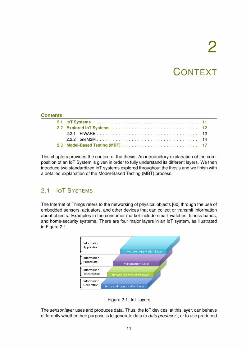
The Internet of Things refers to the networking of physical objects [60] through the use ofembedded sensors, actuators, and other devices that can collect or transmit informationabout objects. Examples in the consumer market include smart watches, fitness bands,and home-security systems. There are four major layers in an IoT system, as illustratedin Figure 2.1.
Figure 2.1: IoT layers
The sensor layer uses and produces data. Thus, the IoT devices, at this layer, can behavedifferently whether their purpose is to generate data (a data producer ), or to use produced
11
12 CHAPTER 2. CONTEXT
data (a data consumers). For example, a Complex Event Processing (CEP) applicationis a data consumer application within the application layer. Its purpose is to read inputdata and produce output data depending on a defined rule. An example of a rule definedin a CEP application: if the data of two temperature sensors in the same room exceeds acertain value, then an alert is triggered. The produced data is in this case the generatedalert.
The service connectivity and network layers, are represented by the sensors, actuators,tags (which include Radio Frequency ID s (RFID) and barcodes), and other types of dataproducers/consumers. At the gateway and network layer, wide area networks, mobilecommunication networks, Wi-Fi, Ethernet, gateway control, etc. are considered. Then,in the management service layer, device modelling configuration and management is amajor focus. Data-flow management and security control need to be provided at themanagement service layer. Finally, the overall application layer is where the applicationsdedicated to energy, environment, healthcare, transportation, supply chain, retail, peopletracking, surveillance, and many other endless applications are located.
The different layers of the IoT bring a new level of complexity to performance monitoringand conformance testing in terms of scalability, interoperability, and security. Testers mustadapt to new platforms and techniques to ensure that they can address the challenges oftesting IoT devices and applications to deliver the best experience to the end user. Withlarge numbers of devices involved when talking about the IoT and the mass of differentdevices that the IoT introduces, each with different protocols, brings along all the perks ofa heterogeneous environment: scalability issues and interoperability. With many differentdevices and the amount of generated data in the IoT infrastructure, it is difficult to keeptrack of the privacy and confidentiality of the produced data. Security is a major challengefor the success of the IoT adoption.
We introduce in the next section the explored IoT systems that allowed us to respond tothe research questions and obtain our research objectives.
2.2 EXPLORED IOT SYSTEMS
In this thesis, we explored the previously introduced IoT systems: FIWARE and oneM2M.A detailed description of their infrastructure and standard is explained.
2.2.1 FIWARE
FIWARE provides an enhanced Open Stack-based cloud environment including a richset of open standard Application Programming Interfaces (APIs) that make it easier toconnect to the heterogeneous IoTs, process and analyse Big Data and real-time me-dia or incorporate advanced features for user’s interaction. The FIWARE platform easesthe development of smart applications in multiple vertical sectors. The specifications ofthese APIs are public and royalty-free. Besides, an open source reference implemen-tation ”Generic Enabler implementation” (GEi) of each of the FIWARE components ispublicly available so that multiple FIWARE providers can emerge faster in the market witha low-cost proposition. Generic Enablers offer a number of general-purpose functionsand provide high-level APIs in:
2.2. EXPLORED IOT SYSTEMS 13
• Cloud Hosting
• Data/Context Management
• Internet of Things Services Enablement
• Applications, Services and Data Delivery
• Security of data
• Interface to Networks and Devices (I2ND)
• Advanced Web-based User Interface
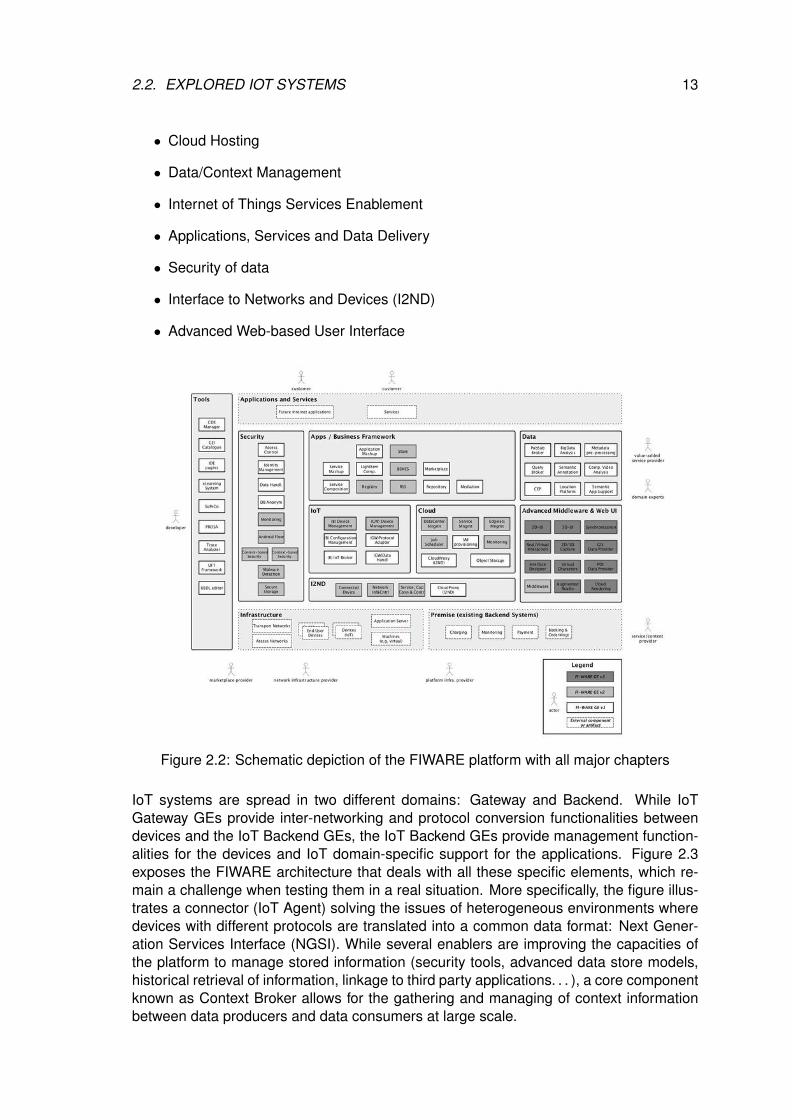
Figure 2.2: Schematic depiction of the FIWARE platform with all major chapters
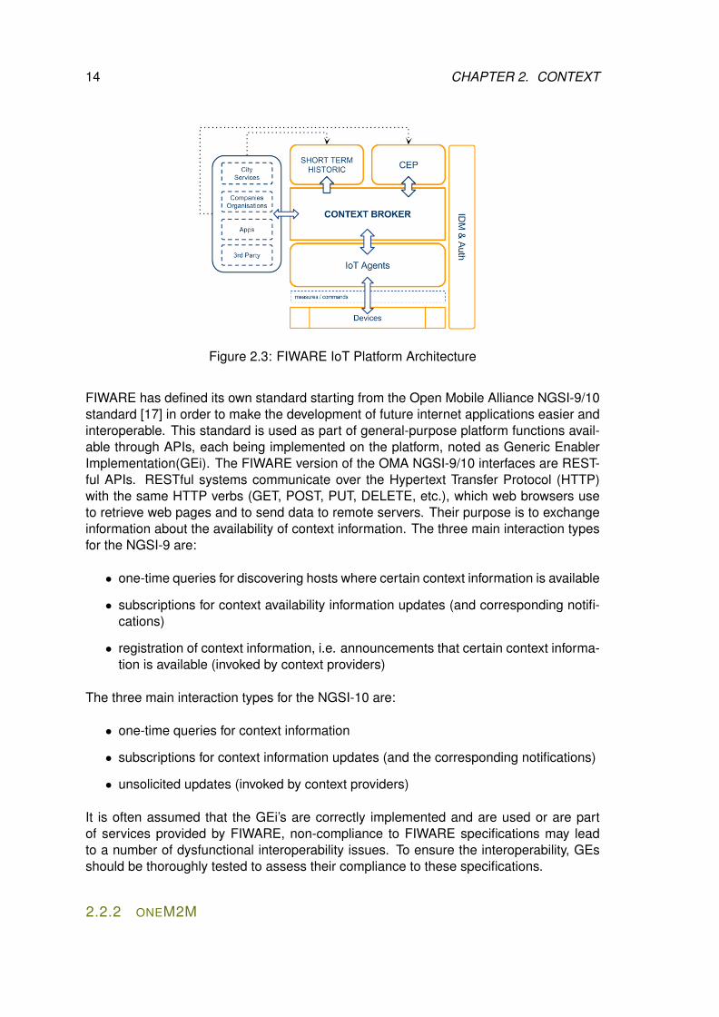
IoT systems are spread in two different domains: Gateway and Backend. While IoTGateway GEs provide inter-networking and protocol conversion functionalities betweendevices and the IoT Backend GEs, the IoT Backend GEs provide management function-alities for the devices and IoT domain-specific support for the applications. Figure 2.3exposes the FIWARE architecture that deals with all these specific elements, which re-main a challenge when testing them in a real situation. More specifically, the figure illus-trates a connector (IoT Agent) solving the issues of heterogeneous environments wheredevices with different protocols are translated into a common data format: Next Gener-ation Services Interface (NGSI). While several enablers are improving the capacities ofthe platform to manage stored information (security tools, advanced data store models,historical retrieval of information, linkage to third party applications. . . ), a core componentknown as Context Broker allows for the gathering and managing of context informationbetween data producers and data consumers at large scale.
14 CHAPTER 2. CONTEXT
Figure 2.3: FIWARE IoT Platform Architecture
FIWARE has defined its own standard starting from the Open Mobile Alliance NGSI-9/10standard [17] in order to make the development of future internet applications easier andinteroperable. This standard is used as part of general-purpose platform functions avail-able through APIs, each being implemented on the platform, noted as Generic EnablerImplementation(GEi). The FIWARE version of the OMA NGSI-9/10 interfaces are REST-ful APIs. RESTful systems communicate over the Hypertext Transfer Protocol (HTTP)with the same HTTP verbs (GET, POST, PUT, DELETE, etc.), which web browsers useto retrieve web pages and to send data to remote servers. Their purpose is to exchangeinformation about the availability of context information. The three main interaction typesfor the NGSI-9 are:
• one-time queries for discovering hosts where certain context information is available
• subscriptions for context availability information updates (and corresponding notifi-cations)
• registration of context information, i.e. announcements that certain context informa-tion is available (invoked by context providers)
The three main interaction types for the NGSI-10 are:
• one-time queries for context information
• subscriptions for context information updates (and the corresponding notifications)
• unsolicited updates (invoked by context providers)
It is often assumed that the GEi’s are correctly implemented and are used or are partof services provided by FIWARE, non-compliance to FIWARE specifications may leadto a number of dysfunctional interoperability issues. To ensure the interoperability, GEsshould be thoroughly tested to assess their compliance to these specifications.
2.2.2 ONEM2M
2.2. EXPLORED IOT SYSTEMS 15
Figure 2.4: oneM2M logo
The Internet of Things revolves around increasedmachine-to-machine communication; it’s built on cloudcomputing and networks of data-gathering sensors. But amachine is an instrument, it’s a tool, it’s something that’sphysically doing something. When we talk about makingmachines ”smart”, we are not referring strictly to M2M.We are talking about sensors. All the information gath-ered by all the sensors in the world isn’t worth very muchif there isn’t an infrastructure in place to analyse it in realtime.
Usually, the infrastructure is vendor-specific thing and every manufacturer develops itsown infrastructure that connects the IoT in between, the sensors to the cloud, and thento the end user. But when all the manufacturers produce their own infrastructures thatcan be used only with their devices, the IoT sector becomes chaos where only vendor orvendor-friendly devices work on one type of infrastructure. This is where the oneM2M[37]standard wants to put pressure and unify the existing infrastructure into one standard thatcan be used by everyone.
oneM2M is the global standards initiative for Machine to Machine Communications andthe Internet of Things. It was formed in 2012 and consists of eight of the world’spre-eminent standards development organizations, notably: ARIB (Japan), ATIS (USA),CCSA (China), ETSI (Europe), TIA (USA), TSDSI (India), TTA (Korea) and TTC (Japan).These partners collaborate with industry fora or consortia and over 200 member orga-nizations (and one of them is EGM) to produce and maintain globally applicable techni-cal specifications for a common M2M/IoT Service Layer, which provides functions thatM2M applications across different industry segments commonly need and are exposedvia APIs. The service layer is developing into a critical component of future IoT architec-tures.
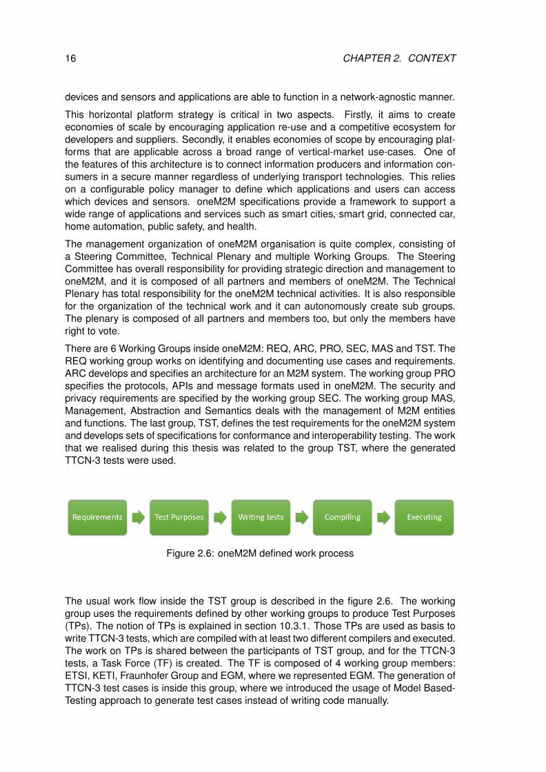
As shown in figure 2.5, the oneM2M standard employs a simple horizontal platform archi-tecture that fits within a three layer model comprising applications, services and networks.
Figure 2.5: oneM2M Architecture
On the top layer, Application Entities (AEs) reside within individual device and sensorapplications. They provide a standardized interface to manage and interact with appli-cations. Common Services Entities (CSEs) play a similar role in the service layer whichresides between the application layer (where data processing occurs) and the in the net-work layer (where communications hardware resides). The network layer ensures that
16 CHAPTER 2. CONTEXT
devices and sensors and applications are able to function in a network-agnostic manner.
This horizontal platform strategy is critical in two aspects. Firstly, it aims to createeconomies of scale by encouraging application re-use and a competitive ecosystem fordevelopers and suppliers. Secondly, it enables economies of scope by encouraging plat-forms that are applicable across a broad range of vertical-market use-cases. One ofthe features of this architecture is to connect information producers and information con-sumers in a secure manner regardless of underlying transport technologies. This relieson a configurable policy manager to define which applications and users can accesswhich devices and sensors. oneM2M specifications provide a framework to support awide range of applications and services such as smart cities, smart grid, connected car,home automation, public safety, and health.
The management organization of oneM2M organisation is quite complex, consisting ofa Steering Committee, Technical Plenary and multiple Working Groups. The SteeringCommittee has overall responsibility for providing strategic direction and management tooneM2M, and it is composed of all partners and members of oneM2M. The TechnicalPlenary has total responsibility for the oneM2M technical activities. It is also responsiblefor the organization of the technical work and it can autonomously create sub groups.The plenary is composed of all partners and members too, but only the members haveright to vote.
There are 6 Working Groups inside oneM2M: REQ, ARC, PRO, SEC, MAS and TST. TheREQ working group works on identifying and documenting use cases and requirements.ARC develops and specifies an architecture for an M2M system. The working group PROspecifies the protocols, APIs and message formats used in oneM2M. The security andprivacy requirements are specified by the working group SEC. The working group MAS,Management, Abstraction and Semantics deals with the management of M2M entitiesand functions. The last group, TST, defines the test requirements for the oneM2M systemand develops sets of specifications for conformance and interoperability testing. The workthat we realised during this thesis was related to the group TST, where the generatedTTCN-3 tests were used.
Figure 2.6: oneM2M defined work process
The usual work flow inside the TST group is described in the figure 2.6. The workinggroup uses the requirements defined by other working groups to produce Test Purposes(TPs). The notion of TPs is explained in section 10.3.1. Those TPs are used as basis towrite TTCN-3 tests, which are compiled with at least two different compilers and executed.The work on TPs is shared between the participants of TST group, and for the TTCN-3tests, a Task Force (TF) is created. The TF is composed of 4 working group members:ETSI, KETI, Fraunhofer Group and EGM, where we represented EGM. The generation ofTTCN-3 test cases is inside this group, where we introduced the usage of Model Based-Testing approach to generate test cases instead of writing code manually.

2.3. MODEL-BASED TESTING (MBT) 17
2.3 MODEL-BASED TESTING (MBT)
Models are described in many ways, depending on the discipline. They can be describedby use of diagrams, tables, text, or other kinds of notations. They might be expressedin a mathematical formalism or informally, where the meaning is derived by convention.Although computing equipment and software plays an important role for the application ofmodeling in science and engineering, modeling is not as ubiquitous in software engineer-ing as it is in other engineering disciplines. However, formal methods is one disciplinewhere modeling has been applied in the areas of safety- and security-critical softwaresystems. Test phases are the last stages of system development. They are thereforestrongly constrained by delivery periods. In general, they are subject to all of the delaysaccumulated during the overall project. Currently, test phases still correspond to 30% oreven to 50% of the total cost of system development and thus represent an importantpoint for possible improvements.
We present hereafter a technology which is more and more used in industry to avoidbugs, to improve quality and reduce costs: Model-Based Testing (MBT). MBT is the auto-matic generation of software test procedures, using models of system requirements andbehavior. Although this type of testing requires more up-front effort in building the model,it offers substantial advantages over traditional software testing methods:
• Rules are specified once.
• Project maintenance is lower. There is no need to write new tests for each newfeature. Once we have a model it is easier to generate and re-generate test casesthan it is with hand-coded test cases.
• Design is fluid. When a new feature is added, a new action is added to the model torun in combination with existing actions. A simple change can automatically ripplethrough the entire suite of test cases.
• Design more and code less.
• High coverage. Tests continue to find bugs, not just regressions due to changes inthe code path or dependencies.
• Model authoring is independent of implementation and actual testing so that theseactivities can be carried out by different members of a team concurrently.
Model-Based Testing - Importance:
• Unit testing won’t be sufficient to check the functionalities
• To ensure that the system is behaving in the same sequence of actions.
• Model-based testing techniques are adopted as an integrated part of the testingprocess.
• Commercial tools are developed to support model-based testing.
Model-Based Testing (MBT) is considered to be a lightweight formal method to validatesoftware systems. It is formal because it works out of a formal (that is, machine-readable)
18 CHAPTER 2. CONTEXT
specification (or model) of the software system one intends to test (usually called theimplementation or System Under Test, SUT). It is lightweight because, contrary to otherformal methods, MBT does not aim at mathematically proving that the implementationmatches the specifications under all possible circumstances. What MBT does is to sys-tematically generate from the model a collection of tests (a ”test suite”) that, when runagainst the SUT, will provide sufficient confidence that it behaves as the model predictedit would. The difference between lightweight and heavyweight formal methods is basicallyabout sufficient confidence vs. complete certainty. Now, the price to pay for absolute cer-tainty is not low, which results in heavyweight formal methods being very hard (sometimesprohibitively hard) to apply to real-life projects. MBT on the other hand scales much betterand has been used to test life-size systems in large scale projects [9].
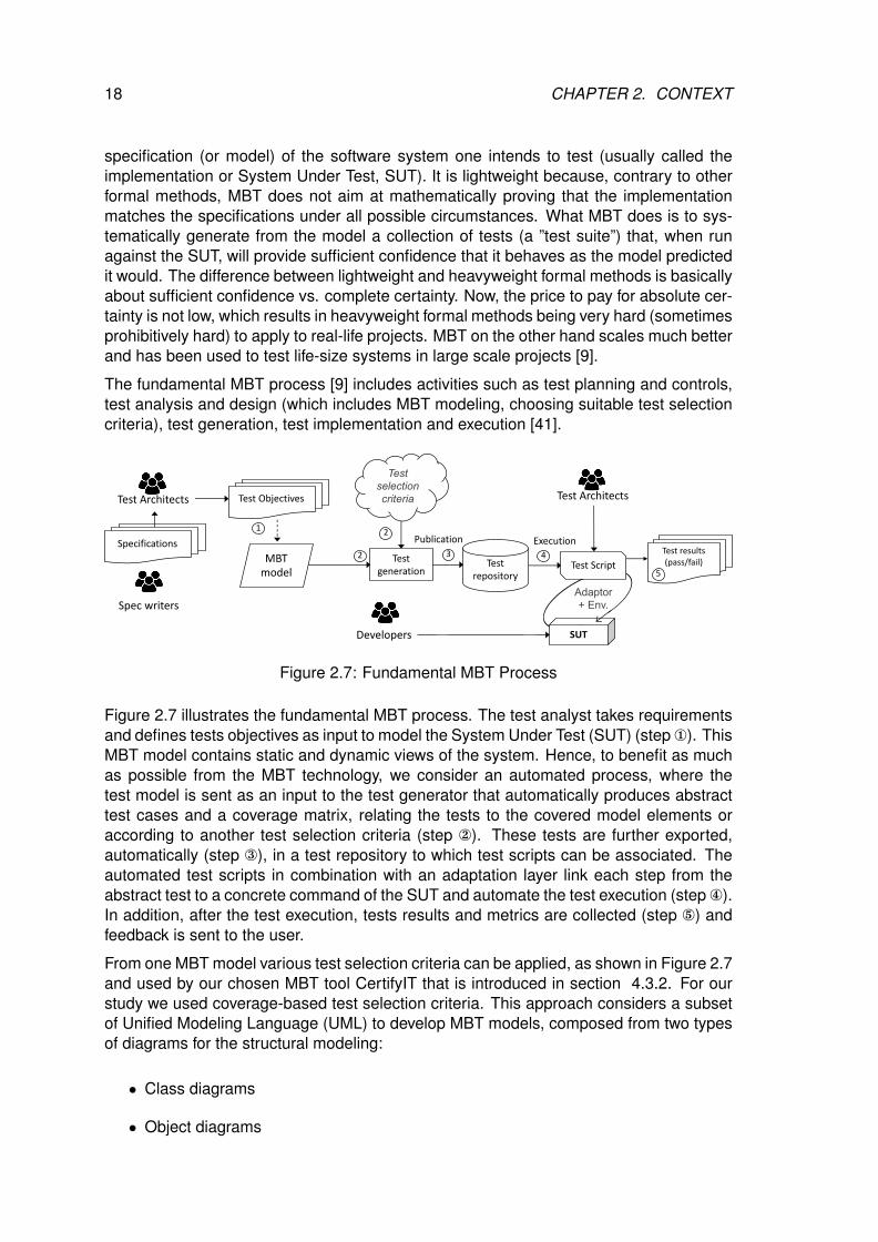
The fundamental MBT process [9] includes activities such as test planning and controls,test analysis and design (which includes MBT modeling, choosing suitable test selectioncriteria), test generation, test implementation and execution [41].
Test repository
Test generation
Publication
Test Objectives
MBT model
1
3Test Script
SUT
Test results (pass/fail)
Execution4
2
Test selection criteria
2
Adaptor + Env.
Specifications
Spec writers
Test Architects
Developers
Test Architects
5
Figure 2.7: Fundamental MBT Process
Figure 2.7 illustrates the fundamental MBT process. The test analyst takes requirementsand defines tests objectives as input to model the System Under Test (SUT) (step ¬). ThisMBT model contains static and dynamic views of the system. Hence, to benefit as muchas possible from the MBT technology, we consider an automated process, where thetest model is sent as an input to the test generator that automatically produces abstracttest cases and a coverage matrix, relating the tests to the covered model elements oraccording to another test selection criteria (step ). These tests are further exported,automatically (step ®), in a test repository to which test scripts can be associated. Theautomated test scripts in combination with an adaptation layer link each step from theabstract test to a concrete command of the SUT and automate the test execution (step ¯).In addition, after the test execution, tests results and metrics are collected (step °) andfeedback is sent to the user.
From one MBT model various test selection criteria can be applied, as shown in Figure 2.7and used by our chosen MBT tool CertifyIT that is introduced in section 4.3.2. For ourstudy we used coverage-based test selection criteria. This approach considers a subsetof Unified Modeling Language (UML) to develop MBT models, composed from two typesof diagrams for the structural modeling:
• Class diagrams
• Object diagrams
2.3. MODEL-BASED TESTING (MBT) 19
Each type has a separate role in the test generation process. The class diagram de-scribes the system’s structure, namely the set of classes that represents the static viewof the system:
• Its entities, with their attributes
• Operations that model the API of the SUT
• Observations that serve as oracles (for instance an observation returns the currentstate of the user’s connection to a web site)
Next, this static view, given by the class diagram, is instantiated by an object diagram.The object diagrams provides the initial state of the system and also all objects thatwill be used in the test input data as parameters for the operations in the generatedtests. Finally, the dynamic view of the system or its behaviors are described by ObjectiveConstraint Language (OCL) constraints written as pre/postcondition in operations in aclass of a class diagram. The test generation engine sees these behavior objects astest targets. The operations can have several behaviors, identified by the presence ofthe conditional operator if-then-else. The precondition is the union of the operation’sprecondition and the conditions of a path that is necessary to traverse for reaching thebehavior’s postcondition. The postcondition corresponds to the behavior described by theaction in the ”then” or ”else” clause of the conditional operator. Finally, each behavior isidentified by a set of tags (as initially defined in the Test Objective Charter(TOC)), whichrefers to a requirement covered by the behavior. For each requirement, two types of tagsexists:
• @REQ - a high-level requirement
• @AIM - the refinement of a high-level requirement
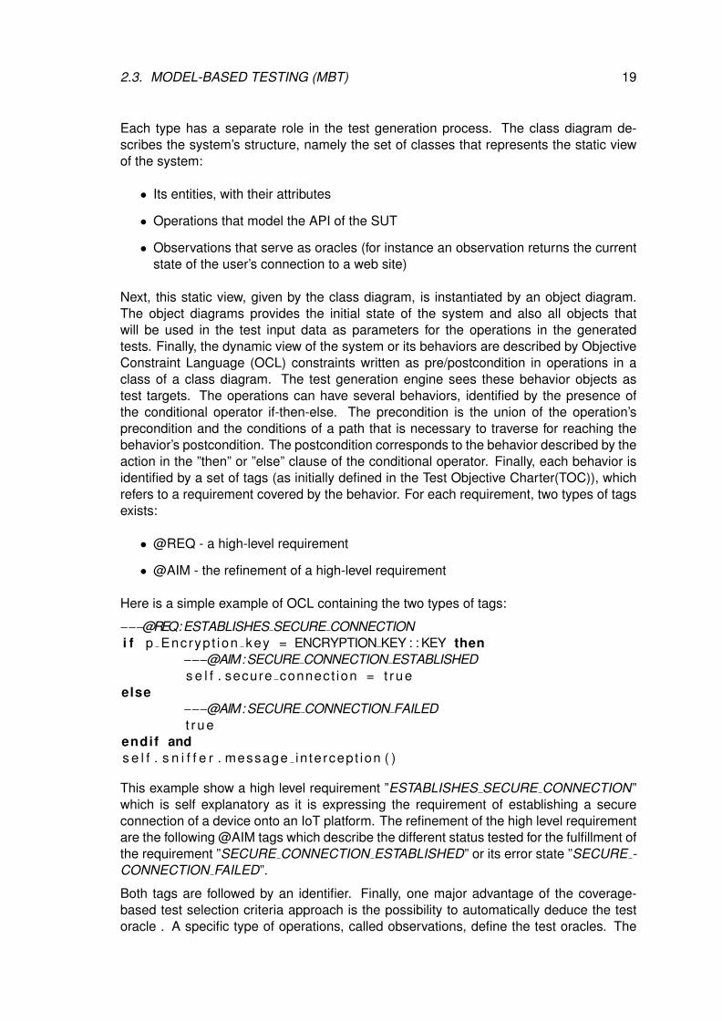
Here is a simple example of OCL containing the two types of tags:
−−−@REQ:ESTABLISHES SECURE CONNECTIONi f p Encryp t ion key = ENCRYPTION KEY : : KEY then
−−−@AIM:SECURE CONNECTION ESTABLISHEDs e l f . secure connect ion = t rue
else−−−@AIM:SECURE CONNECTION FAILEDt r ue
endif ands e l f . s n i f f e r . message in tercept ion ( )
This example show a high level requirement ”ESTABLISHES SECURE CONNECTION”which is self explanatory as it is expressing the requirement of establishing a secureconnection of a device onto an IoT platform. The refinement of the high level requirementare the following @AIM tags which describe the different status tested for the fulfillment ofthe requirement ”SECURE CONNECTION ESTABLISHED” or its error state ”SECURE -CONNECTION FAILED”.
Both tags are followed by an identifier. Finally, one major advantage of the coverage-based test selection criteria approach is the possibility to automatically deduce the testoracle . A specific type of operations, called observations, define the test oracles. The
20 CHAPTER 2. CONTEXT
tester with these special operations can define the system points or variables to observe,for instance a function return code. Thus, based on these observations, the test oracle isautomatically generated for each test step.
There is two main approaches to Model-Based Testing: online and offline. Offline MBTis as presented in Figure 10.7. Offline MBT means generation a finite set of test in orderto execute those later. This allows automatic test execution in third party test executionplatform.
On the other hand, online MBT test case generation and execution are in motion, eachnew test step generated takes into consideration the result of the previous one. OnlineMBT is suited to test non deterministic systems and enables an infinite test suite execu-tion. The main difference is that we do not have a test repository and the execution of astep is executed right after its creation.
The next section presents the research challenges of the thesis.
3RESEARCH CHALLENGES
Contents3.1 Testing for standardized IoT platforms . . . . . . . . . . . . . . . . . 21
3.1.1 Testing the conformance of one component . . . . . . . . . . . . 223.1.2 Testing for Integration . . . . . . . . . . . . . . . . . . . . . . . . 22
3.2 Security Testing of IoT systems . . . . . . . . . . . . . . . . . . . . . 243.2.1 Vulnerability testing . . . . . . . . . . . . . . . . . . . . . . . . . 253.2.2 End-to-End security testing . . . . . . . . . . . . . . . . . . . . . 25
3.3 Robustness Testing for IoT Systems . . . . . . . . . . . . . . . . . . 263.3.1 Robustness testing for one component . . . . . . . . . . . . . . . 263.3.2 Robustness testing for large scale IoT system . . . . . . . . . . . 27
The main work we want to tackle is to validate IoT systems. The complexity of the systemis marked by its composition of several elements with many interactions (as presentedin previous section). In order to bring trust and validation in the IoT there must be afriendly approach to testing things in IoT systems, thus keeping low testing costs andproviding a higher accessibility by the means of easy to use testing tools. In the severalapproaches to depict the IoT some standards are defined. We can use it to realize thevalidation of the system. So, in complementary of the functional and security aspects, wecan also validate the conformance of the system’s elements in regards of this standards.In the next sections, we detail the research challenges associated with several aspects ofvalidation.
3.1 TESTING FOR STANDARDIZED IOT PLATFORMS
The IoT is a jungle where major electronic actors (as Apple, Google, Microsoft...) canpropose proprietary format and consortium try to share their format. In regards of thoseshared formats, some standards are defined. We are speaking about testing for stan-dardized IoT platforms and not IoT systems because as much as we would like to havea whole IoT system standardized, reality begs to differs. IoT platforms are in most casesstandardized and we will focus on two of them. An IoT system is composed of manyobject interacting together, and each object has the possibility to implement a differentstandard. They communicate with each other by means of interworking proxy in the caseof oneM2M and IoT Agent in the case of FIWARE. We will describe those process inmore details in their respective sections further. As much as we would like to test the
21
22 CHAPTER 3. RESEARCH CHALLENGES
standardization of an IoT systems, the reallity is that we have to test the standardizationof all IoT platforms that combined end up building the IoT system. During this PhD, weworked on two standard: oneM2M and FIWARE. The validation process is to validateindividually each component and then validate the integration of the components. Theprocess is repeated until the system is totally integrated. We present in the next sectionthe challenges associated with this process.
3.1.1 TESTING THE CONFORMANCE OF ONE COMPONENT
The IoT is a growing trend in the software industry. With a combination of software andhardware/sensor devices, both individuals and enterprise consumers want to be able tomonitor, activate and control their devices from the comfort of their homes and offices.This is feasible through the advancements of embedded systems into the Internet ofThings (IoT). The quality and performance of such systems still require the improvementof existing testing methods to ensure quality while taking into consideration speed andscalability. Embedded systems have been around for decades now, while the IoT is stillin its initial phase. The difference between the two is that embedded systems are self-contained and isolated, while IoT are in permanent communication with the server andwith each other. Such a degree of integration and interoperability poses significant prob-lems regarding testing due to differences in protocols. There are no generally acceptedstandards when it comes to IoT, and this impacts security and large-scale adoption. Bothestablished organizations such as the IEEE and other alliances or even independent com-panies have designed attempts to define a single standard with no success. The hugenumber of sensors deployed annually (about 35 Billion in 2016 alone) means that if 99%of the sensor work as intended, 350 million will either fail or report inaccurate data. Con-ceptualize the waste a smart city would experience if 1% of its traffic, parking, smoke andhazardous chemical sensors either failed or delivered wrong information.
Conformance testing is a functional test that verifies whether the behaviour satisfy de-fined requirements.The requirements or criteria for conformance must be specified in thestandard or specification, usually in a conformance clause or conformance statement.Some standards have subsequent standards for the test methodology and assertions tobe tested. If the criteria or requirements for conformance are not specified there can beno conformance testing [68]. With any standards or specification project, eventually thediscussion turns to ”how will we know if an application/device conforms to our standardor specification?” Thus begins the discussion on conformance testing. Although this typeof testing has been done for a long time there is still usually some confusion about whatis involved. There are many types of conformance testing like performance, security androbustness. We consider here the functional and interoperability aspects of tests. Theother types will be then presented in their specific sections.
3.1.2 TESTING FOR INTEGRATION
Traditional testing methods take time, which is no longer a viable option. The entire de-velopment process needs to be agile, detecting problems as early as possible. The newslogan is ”test early, test often” and the result is continuous integration, which is evenmore important in an IoT environment. Sensors, communication channels, protocols,software-hardware interactions, and configurations determine an unprecedented magni-
3.1. TESTING FOR STANDARDIZED IOT PLATFORMS 23
tude of complexity. As far as it goes for the cost in component testing methods for IoT,traditional methods are not pro-efficient. This is why a more automated approach is nec-essary.
Before integration testing, it is required to test each component individually. Once all thecomponents have been tested in isolation, they are combined (i.e. integrated) and thenext phase of the testing process is to validate their correct interaction, hence integrationtesting. The meaning of Integration testing is quite straightforward- Integrate/combinethe unit tested module one by one and test the behaviour as a combined unit. Integra-tion testing checks the interactions between the combination of behaviours, and validatewhether the requirements are implemented correctly or not. Here we should understandthat Integration testing does not happen at the end of the cycle, rather it is conductedsimultaneously with the development. In most cases, all the modules are not actuallyavailable for testing and this is where the challenge lies, testing something which doesnot exist.
What is the purpose of integrating Integration testing in the testing strategy?
• In the real world, when applications are developed, the process is broken down intosmaller modules and individual developers are assigned one module. The logicbeing implemented may vary significantly from one developer to another, so it be-comes important to check its integrity e.g., it renders the correct output in accor-dance to the standards.
• The structure of data changes when it travels from one module to another. Somevalues are appended or removed along the way, which may causes issues in thesubsequent modules.
• Modules also interact with multiple third party tools or APIs which also need to betested, typically to make sure that the data accepted by that API / tool is correct andthat the generated output is also as expected.
• A very common problem in testing – Frequently requirements change often. Devel-opers often deploy changes without prior validation through unit testing. Integrationtesting becomes important at that time to ensure that each component has beenfully unit tested as the two approaches are complementary.
The next sessions present the challenges encountered when testing integration respec-tively between two components and between all the components covering a specific stan-dard.
3.1.2.1 INTEGRATION TESTING OF PAIR COMPONENTS
By nature IoT systems are not designed to be built upon one atomic solution that en-velops all of the components required for a proper execution. An IoT system is dividedinto many components that interact together to bring alive the system. Let us take theexample of a temperature sensor whose purpose is to send measured values each timethe temperature changes. The sensor communicates the measured value to an IoT plat-form through a local gateway. The gateway is the middle node that receives the sensorvalue in his own protocol and then send the data in a standardized manner to the IoT plat-form. Making sure that each component of the system is working individually is a matter
24 CHAPTER 3. RESEARCH CHALLENGES
of conformance testing covered in the previous section. Interactions between the com-ponents (gateway-platform) require the ability for each part to be able to communicatetogether. The communication must be understood by both sides so it has to be standard-ized. Standards describe interfaces that each component need to implement in order tocommunicate with the rest of the system.
3.1.2.2 INTEGRATION TESTING OF MULTI-COMPONENTS
The previous section covers the topic of a standalone component and pair wise compo-nents. As these methods can surely reveal some errors, they do not cover all the defaultthat can occur during a real life deployment. As a matter of fact, real life IoT systems arerarely limited to the integration of one or two components. At the worst case scenario afull application integrates more then half a dozen of components that are communicatingwith each other to fulfill their purpose, e.g., transmit a sensed value, standardizing data,storing data for big data or even displaying the sensed data on a screen in real time. Theadvantages of starting with pair components testing is that we already have the tools inorders to start the integration testing of multi-components. The same model is reusablefor test generation and execution. The principle differences are the interpretation of theresults. In a multi-component environment are large scale IoT deployments for a smartcity, the results are not proof of default in one component in particular but in the integra-tion of the whole system and pin pointing where an error has occurred can sometimes bedifficult. MBT has strong traceability capabilities, and the challenge is to see how it canmake the correction less costly and give a fast view on the requirement that is making atest fail.
3.2 SECURITY TESTING OF IOT SYSTEMS
Manufacturers of every kind of electronic or electrical devices are rushing to add featureswhich require connection to the internet. In their rush to market these companies manyof which have no prior experience with networked devices are bound to overlook thecomplications of hardware and software security design and construction in the hasteto get the newest function working at the lowest cost. For a start, there is no graphicaluser interface (GUI) to test IoT instances. Consumers of parts of an IoT system may benon-human and wireless connections create more attack vectors, therefore more securitychallenges. To tackle these challenges, testers of IoT need to have a better understandingof basic electronics and network systems. The GUI is no longer king; APIs (ApplicationProgramming Interfaces) are becoming the de facto standard for connecting IoT modules,thus, for better or worse, API testing is becoming a must-have skill for the average tester.Security and penetration testing have to become part of the testing regime. The biggestconcerns related to IoT are security and privacy. Without properly defined standards,hackers can hijack the devices linked to a network – many of which owner have paid for– and transform them into listening or monitoring tools. Moreover, since an IoT deviceconsists of several layers and operates at a low network level, general Internet securityrules designed for apps and browsers are not enough. Security must be tested after everyupdate in a continuous approach.
3.2. SECURITY TESTING OF IOT SYSTEMS 25
3.2.1 VULNERABILITY TESTING
As a critical tool for information security management, a vulnerability testing campaigncan spot weaknesses in an IoT platform’s security defenses before an attacker can ex-ploit them. Hackers are constantly innovating their methods as they look for new waysto breach defenses. A regular vulnerability testing campaign can help uncovering andaddressing security flaws and improving the cyber security strategy of a deployment tolimit the breaches. But a vulnerability testing campaign is only as good as the securityexperts who design and execute it. An effective vulnerability testing campaign requiresproven methodologies created by security professionals with extensive knowledge of thelatest threats and technology available to mitigate them. This process provides guidelinesfor the development of countermeasures to prevent a genuine attack.
3.2.2 END-TO-END SECURITY TESTING
End-to-end security is used successfully today, for example, in online banking applica-tions. Correct and complete end-to-end security in the growing IoT is required to ensuredata privacy, integrity, etc. Introducing MBT to this problem may raise certain questionson the feasibility of the models being generic enough to withstand the wide range of IoTapplications. It is impossible to provide an exhaustive list of all application domains ofthe IoT. The IoT components involved in a solution have in most common cases, a widerange of different components, such as Hardware (devices, sensors, actuators . . . ), soft-ware and network protocols. Security on their endpoints (client-server, or client-client forpeer-to-peer) is an absolute requirement for secure communications. Such a solutioncontains the following components:
• Identity: This component encompasses the known and verifiable entity identities onboth ends.
• Protocols (for example, TLS): Protocols are used to dynamically negotiate the ses-sion keys, and to provide the required security functions (for example, encryptionand integrity verification) for a connection. Protocols use cryptographic algorithmsused to implement these functions.
• Cryptographic algorithms (for example, Advanced Encryption Standard [AES] andSecure Hash Algorithm [SHA-1]): These algorithms use the previously mentionedsession keys to protect the data in transit, for example, through encryption or in-tegrity checks.
• Secure implementation: The endpoint (client or server) that runs one of the afore-mentioned protocols must be free of bugs that could compromise security.
• Secure operations: Users and operators must understand the security mechanisms,and how to manage exceptions. For example, web browsers warn about invalidserver certificates, but users can override the warning and still make the connection.This concern is a non-technical one, but is of critical concern today.
In addition, for full end-to-end security, all these components should be seen globallyto ensure their security. For instance, in networks with end-to-end security, both ends
26 CHAPTER 3. RESEARCH CHALLENGES
can typically (depending on the protocols and algorithms used) rely on the fact that theircommunication is not visible to anyone else, and that no one else can modify the data intransit.
In the next section we talk about the research challenges of robustness testing for IoTSystems.
3.3 ROBUSTNESS TESTING FOR IOT SYSTEMS
The term ”robust” is synonymous with strength. So robustness testing consists of as-sessing the quality of an IoT system deployment. It is the process of verifying whethersystem components perform well under stress conditions or not. Robustness testing hasalso been used to describe the process of verifying the robustness (i.e. correctness) oftest cases in a test process. ANSI and IEEE have defined robustness as the degree towhich a system or component can function correctly in the presence of invalid inputs orstressful environmental conditions. Robustness testing is carried out in those steps: acombination of valid and invalid inputs is passed to the system component, the behaviorof the system checked and how it reacts over long testing traces. Hence a system istested and validated under different conditions.
This section explains how the objective of robustness testing for IoT systems differs whendoing Robustness testing for one component or for multi-components also know as largescale deployment. We explore how the challenges differs when taking different point ofviews (one component/multi component) in the IoT system.
3.3.1 ROBUSTNESS TESTING FOR ONE COMPONENT
When speaking about robustness testing for one component in IoT services, the point ofview is very important. If we take the example of robustness testing of an IoT platform inthe IoT system, robustness testing may be compared to a platform having a high numberof devices that are sending data. The test objectives in this case are to analyze how theplatform reacts in stress conditions and if it is put in an unexpected error state. Whentaking a device point of view, the same problems are faced. By nature, IoT platforms andgateways are more robust having larger infrastructures. IoT devices like energy harvest-ing temperature sensor are harder to test in a effective way with robustness testing. Alldevices are not eligible to robustness testing as this method requires being able to send acommand to the device and therefore it is limited to actuators or sensing device that canbe interrogated about their data. In some cases this challenge can be lifted with the imple-mentation of a upper tester module that comes along the device for testing purposes only.The upper tester allows a tester to put a device into testing mode and gives him accessto stimulate it, for example asking a temperature sensor to send its data. Upper testerare still uncommon, and a relatively low number of device manufacturer are implementingthem.
Knowing that, it is much easier to execute a robustness testing campaign on a singledevice as it would imply low effort in developing the upper tester. The next step is usingrobustness testing in a large scale point of view.
3.3. ROBUSTNESS TESTING FOR IOT SYSTEMS 27
3.3.2 ROBUSTNESS TESTING FOR LARGE SCALE IOT SYSTEM
When speaking about large scale robustness testing in IoT system, one must first con-sider defining the term large scale. Indeed, the test objectives are widely different whenconsidering a smart-city with millions of devices or a smart home with a few dozen ofsensing devices. Either way, large scale can be seen as an IoT deployment involving upto about hundreds devices. The limit is mainly testing hardware dependent. As a matterof fact, large scale tests are not different than the single component tests. The challengeis on running in parallel hundreds of instances of the same test case over an IoT de-ployment. The success of robustness testing a large scale IoT system depends on theinfrastructure, large amount of data are transmitted into the infrastructure and an evenlarger amount of data needs to be collected. The testing equipment also need to be fit toanalyze testing results and give a final verdict on the test result in real time.
The next chapter presents the state of the art of IoT testing, Model-Based Testing and thetools available that where used as is or augmented in order to respond to our researchchallenges.

4STATE OF THE ART
Contents4.1 IoT testing . . . . . . . . . . . . . . . . . . . . . . . . . . . . . . . . . . 30
4.1.1 Conformance Testing . . . . . . . . . . . . . . . . . . . . . . . . 30
4.1.2 Security Testing . . . . . . . . . . . . . . . . . . . . . . . . . . . 31
4.1.3 Robustness Testing . . . . . . . . . . . . . . . . . . . . . . . . . 32
4.2 Model-Based Testing for IoT . . . . . . . . . . . . . . . . . . . . . . . 334.3 Languages and Tools for Testing . . . . . . . . . . . . . . . . . . . . . 35
4.3.1 TTCN-3 . . . . . . . . . . . . . . . . . . . . . . . . . . . . . . . . 35
4.3.2 CertifyIt . . . . . . . . . . . . . . . . . . . . . . . . . . . . . . . . 39
4.3.3 MBeeTle . . . . . . . . . . . . . . . . . . . . . . . . . . . . . . . 39
In this section, we review work related to our proposed approach in the area of MBTfor Internet of things systems, more specifically mobile and cloud testing, and MBT as aservice. MBT has been extensively studied in the literature [25], however, the majority ofexisting approaches in connexion to the IoT domain are mostly designed for mobile appli-cation. For instance, authors in [22] propose a state machine models of Graphical UserInterface (GUI) approach for testing Android applications. Another instance in [43], saythat one of the main domains to use this approach is web-based applications. But suchtest sequences are very low-level and fragile, so it is desirable to have higher-level ap-proaches to generating the test sequences, which is an area where MBT can contribute.Other work concentrates on vulnerability testing of mobile applications based on mod-els, for instance authors in [29] propose an MBT approach to generate automatically testcases using vulnerability patterns, that target specifically the Android Intent Messagingmechanism.
In addition, a recent survey by Incki et al. [23] reports on the work done on testing inthe cloud, including mobile, cloud applications and infrastructures, testing the migrationof applications in the cloud. They report a categorization of the literature on cloud testingbased on several elements among which: test level and type, as well as contribution interms of test execution, generation and testing framework. They report that testing as aservice for the interoperability for cloud infrastructures today still remains a challenge. Au-thors in [15] propose a MBT approach based on graph modeling for system and functionaltesting in cloud computing. Hence, contrary to these approaches that refer to testing ap-proaches of the different layers of the cloud (Software as a service, Platform as a serviceand Infrastructure as a service), our approach proposes MBT as a service for complianceand security testing of IoT systems, were the cloud is one element of it.
29
30 CHAPTER 4. STATE OF THE ART
Testing services provided to cloud consumers as well as cloud providers are generallycalled Testing as Service (TaaS) [19]. Previous work on testing as a service, to the bestof our knowledge, specifically relates to web services and cloud computing. Zech et al.in [26] propose a model-based approach using risk analysis to generate test cases toensure the security of a Cloud computing environment when outsourcing IT langscapes.More recently Zech et al. [38] proposed a model-based approach to evaluate the securityof the cloud environment by means of negative testing based on the Telling Test StoriesFramework. MBT provides the benefit of being implementation independent. In this thesiswe propose MBT as service to the Internet of Things, thus making the test cases availablefor any platform implementation of the specification. Our model-based test generationtakes into account risk analysis elements and security requirements and it is an extensionof this module of our Model-Based Testing for IoT systems.
4.1 IOT TESTING
This section addresses the panel of existing MBT approaches with a view on the IoTsystems. The MBT can be offline, whereby the test cases are generated in a repositoryfor future execution or online, whereby the test cases are automatically generated andexecuted [44]. In this chapter, we discuss both: offline MBT techniques with respect tofunctional and security testing and online MBT techniques. Nevertheless, recent studiesshow that current MBT approaches, although they can be suitable for testing the IoTsystems, need to be adapted [42].
4.1.1 CONFORMANCE TESTING
Standards are a well-known methods used to increase the user’s confidence and trustin a product. MBT approaches supporting conformance testing to standards have beenapplied to different domains, such as electronic transactions and notably for CommonCriteria (CC) certifications, for instance, on the Global Platform (GP). Authors in [42]propose a testing framework for IoT services, which has been evaluated on IoT test bed,for test design using behavioural modelling, based on state machines and test executionin TTCN-3. In addition, IoT Behavioral models (IoTBM) represent a chosen explicit model,describing the service logic, used protocols, and interfaces as well as the interactions withthe connected services. IBM reports as well on the application of MBT for compliance tostandards based on the IBM tool suite (Rhapsody and Jazz) [47].
Conformance test suites increase the probability that software products are conform totheir specification. Correct implementation and utilization of standards lead to portabilityand interoperability. Portability is the ability to move software programs or applicationsamong different computer systems with minimal change. Interoperability is defined asthe capability of two or more systems to exchange and use information. Although con-formance testing is not a guarantee for interoperability, it is an essential step towards it.Conformance testing provides software developers and users with assurance and confi-dence that the conforming product behaves as expected, performs functions in a knownmanner, or possesses a prescribed interface or format.
In order to test that a specification is faithfully adhered to, one must carefully examine thespecification and compare the implementation’s result against the syntax and semantics
4.1. IOT TESTING 31
contained in the specification. Oftentimes, errors or ambiguities in the specification arediscovered. These errors and ambiguities can then be fed back to the standards com-mittee who developed the specification, for correction. For software developers, usingconformance test suites early-on in the development process can help improve the qual-ity of their implementations by identifying areas in which they conform as well as thoseareas in which they do not.
4.1.2 SECURITY TESTING
Mode-Based Security Testing (MBST) is a Dynamic Application Security Testing (DAST)approach consisting of dynamically checking the security of the systems’s securityrequirements [69]. Furthermore, MBST has recently gained relative importance inacademia as well as in the industry, as it allows for systematic and efficient specifica-tion and documentation of security test objectives, security test cases and test suites,and automated or semi-automated test generation [24]. Existing work in MBST focusesmainly on functional security and vulnerability testing. Functional security testing aimsat ensuring the correct implementation of the security requirements. Vulnerability testingis based on risk assessment analysis, aiming to discover potential vulnerabilities. Au-thors in [44] discuss extensively the existing approaches on both aspects of MBST. Exist-ing approaches address various domains, such as electronic transactions, cryptographiccomponents, but not directly the IoT domain.
A security certification is needed to ensure that a product satisfies the required securityrequirements, which can be both proprietary requirements (i.e., defined by a companyfor their specific products) and market requirements (i.e., defined in procurement spec-ifications or market standards). The process for certification of a product is generallysummarized in four phases [45]:
1. Application. A company submits a product for evaluation to obtain certification.
2. An evaluation is performed to obtain certification. The evaluation can be done inthree ways:
• It can be conducted internally to support self-certification.
• It can be performed by a testing company, who legally belongs to the productcompany.
• It can be a third-party certification where the company asks a third-party com-pany to perform the evaluation of its product.
3. In the case of an internal company or a third-party company evaluation, the evalua-tion company provides a decision on the evaluation.
4. Surveillance. This is a periodic check on the product to ensure that the certificationis still valid or it requires a new certification.
In the market requirements case, the requirements are also defined to support securityinteroperability. For example, to ensure that two products are able to mutually authenti-cate or to exchange secure messages. Security certifications are needed to ensure thatproducts are secure against specific security attacks or that they have specific securityproperties, such as:
32 CHAPTER 4. STATE OF THE ART
• Authentication: Data sender and receiver can always be verified.
• Resistance to replay attacks: Intermediate nodes can store a data packet andreplay it at a later stage. Thus, mechanisms are needed to detect duplicate orreplayed messages.
• Resistance to dictionary attacks: An intermediate node can store some datapackets and decipher them by performing a dictionary attack if the key used tocipher them is a dictionary word.
• Resistance to DoS attacks: Several nodes can access the server at the sametime to collapse it. For this reason, the server must have DoS protection or a fastrecovery after this attack.
• Integrity: Received data are not tampered with during transmission; if this does nothappen, then any change can be detected.
• Confidentiality: Transmitted data can be read only by the communication end-points.
• Resistance to MITM attacks: The attacker secretly relays and possibly alters thecommunications.
• Authorization: Services should be accessible to users who have the right to accessthem.
• Availability: The communication endpoints can always be reached and cannot bemade inaccessible.
• Fault tolerance: The overall service can be delivered even when a number ofatomic services are faulty.
• Anonymization: If proper countermeasures are not taken, even users employingpseudonyms could be tracked by their network locator.
Nevertheless, in the IoT domain, initiatives exists for security certification, such as theAlliance for IoT Innovation (AIOTI) [57] through its standardization and policy workinggroups that complement the existing certifications, such as the Common Criteria (CC).However, enabling technologies that help to formally address the specific testing chal-lenges and that enable the IoT certification today are lacking [39].
4.1.3 ROBUSTNESS TESTING
Online techniques can indeed address the uncertain behavior of IoT systems, but lackin application and maturity for the IoT domain, as current techniques mostly address atestbed set-up for execution in a real-life environment, without dealing with the test casesconception.
Several online tools exist in the MBT literature. For instance, UPPAAL for Testing Real-time systems Online (UPPAAL TRON) [7] supports the generation of test cases frommodels and their online execution on the SUT.
4.2. MODEL-BASED TESTING FOR IOT 33
Authors in [35] express the system and its properties as Boolean equations, and thenused an equation library to check the equations on-the fly. A model-checker is used on amodel with faults produces counter examples, seen as negative abstract test cases.
Shieferdecker et al. designed a mutation-based fuzzing approach that uses fuzzing op-erators on scenario models specified by sequence diagrams. A set of fuzzing operatorsmutate the diagrams resulting in an invalid sequence. Shieferdecker et al. use on-linebehavioral fuzzing which generates tests at run-time [30].
4.2 MODEL-BASED TESTING FOR IOT
The key challenges in testing for scalability, interoperability, and security of the IoT haveproven to be problematic when trying to resolve them with traditional testing methods,which is a strong roadblock for wide adoption of this innovative technology. This sectionaims to describe how the MBT has addressed this problem though IoT testing.
MBT designates any type of “testing based on or involving models” [41]. Models rep-resent the SUT, its environment, or the test itself, which directly supports test analysis,planning, control, implementation, execution, and reporting activities. According to theWorld Quality Report 2016 [40], the future testing technologies require agile developmentoperations for more intelligence-led testing to meet speed, quality, and cost imperatives.Hence, MBT, as a promising solution, aims to formalize and automate as many activitiesrelated to testing as possible and thereby increase both the efficiency and effectivenessof testing. Following the progress of Model-Based Engineering [1] technologies, MBThas increasingly attracted research attention. Many MBT tools are developed to supportthe practice and utilization of MBT approaches in real cases. They provide functionsthat cover three MBT aspects i.e., generation of test cases, generation of test data, andgeneration of test scripts [9], and are used to conduct different types of testing, such asfunctional, performance, and usability testing [31].
Nevertheless, functions of MBT tools vary largely from one to another. Users with-out prior knowledge struggle to choose appropriate tools corresponding to their testingneeds among the wide list. MBT tools require input in terms of different models (e.g.,UML, PetriNet, BPMN, etc.) and focus on different MBT aspects with different genera-tion strategies for data, test cases, and test scripts. Moreover, most of the existing MBTtools support mainly automatic test case generation rather than test data generation andtest script generation due to two reasons: first, test case generation requires complicatedstrategies involving various test selection criteria from MBT models, and the generationresults highly reply on the selected criteria and strategies; second, test case generationbrings many more testing benefits, as the main efforts spent on traditional testing lie inmanual preparation of test cases. To provide users with a common understanding andsystematic comparison, this chapter reviews the identified set of MBT tools, focusing onthe test case generation aspect. MBT tools have been previously reported and comparedin several surveys: the first report is presented in [5] in 2002 to illustrate the basic princi-ples of test case generation and relevant tools; a later comparison is made in [46] fromperspectives of modeling, test case generation, and tool extensibility; since more andmore MBT tools rely on state-based models, the review in [18] illustrates the state-basedMBT tools following criteria of test coverage, automation level, and test construction. Themost recent work [36] presents an overview of MBT tools focusing on requirement-based
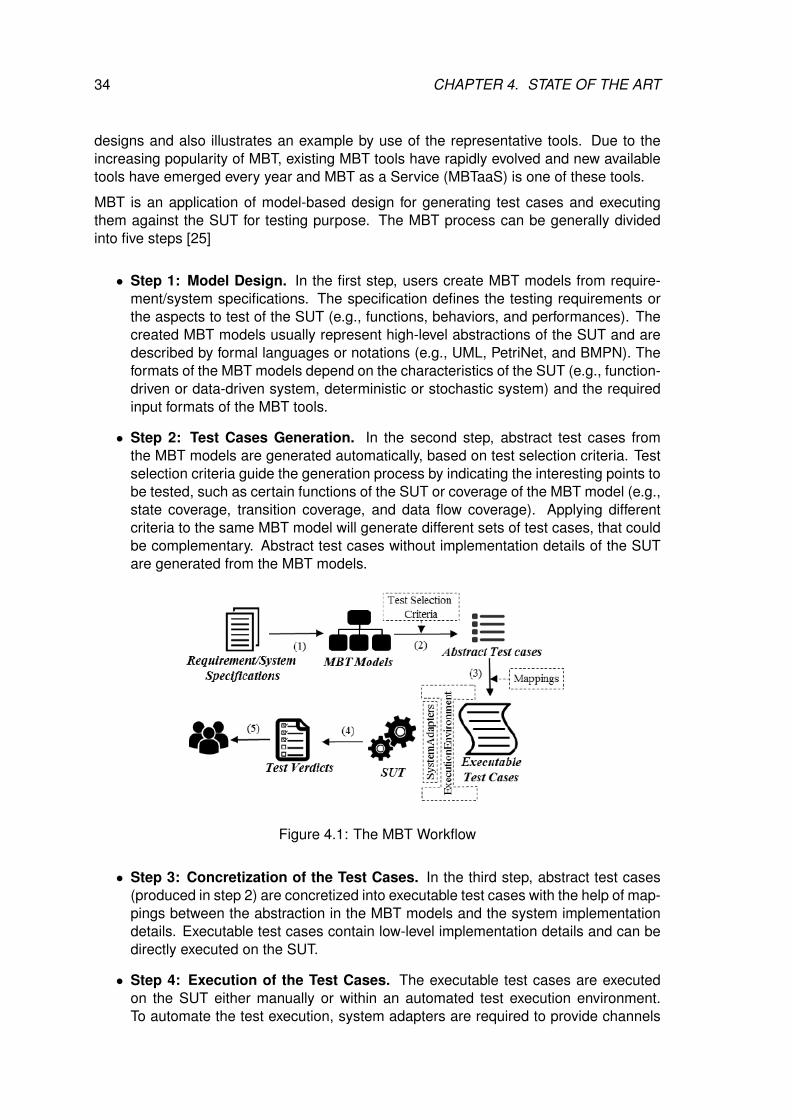
34 CHAPTER 4. STATE OF THE ART
designs and also illustrates an example by use of the representative tools. Due to theincreasing popularity of MBT, existing MBT tools have rapidly evolved and new availabletools have emerged every year and MBT as a Service (MBTaaS) is one of these tools.
MBT is an application of model-based design for generating test cases and executingthem against the SUT for testing purpose. The MBT process can be generally dividedinto five steps [25]
• Step 1: Model Design. In the first step, users create MBT models from require-ment/system specifications. The specification defines the testing requirements orthe aspects to test of the SUT (e.g., functions, behaviors, and performances). Thecreated MBT models usually represent high-level abstractions of the SUT and aredescribed by formal languages or notations (e.g., UML, PetriNet, and BMPN). Theformats of the MBT models depend on the characteristics of the SUT (e.g., function-driven or data-driven system, deterministic or stochastic system) and the requiredinput formats of the MBT tools.
• Step 2: Test Cases Generation. In the second step, abstract test cases fromthe MBT models are generated automatically, based on test selection criteria. Testselection criteria guide the generation process by indicating the interesting points tobe tested, such as certain functions of the SUT or coverage of the MBT model (e.g.,state coverage, transition coverage, and data flow coverage). Applying differentcriteria to the same MBT model will generate different sets of test cases, that couldbe complementary. Abstract test cases without implementation details of the SUTare generated from the MBT models.
Figure 4.1: The MBT Workflow
• Step 3: Concretization of the Test Cases. In the third step, abstract test cases(produced in step 2) are concretized into executable test cases with the help of map-pings between the abstraction in the MBT models and the system implementationdetails. Executable test cases contain low-level implementation details and can bedirectly executed on the SUT.
• Step 4: Execution of the Test Cases. The executable test cases are executedon the SUT either manually or within an automated test execution environment.To automate the test execution, system adapters are required to provide channels
4.3. LANGUAGES AND TOOLS FOR TESTING 35
connecting the SUT with the test execution environment. During the execution, theSUT is respectively stimulated by inputs from each test case, and the reactions ofthe SUT (e.g., output and performance information) are collected to assign a testverdict. For each test case, a test verdict is assigned indicating if a test passes orfails (or is inconclusive).
• Step 5: Results Analysis. At the end of the execution, testing results are reportedto the users. For non-satisfactory test verdicts, the MBT process records tracesto associate elements from specifications to the MBT models and then to the testcases, which are used to retrieve the possible defects.
4.3 LANGUAGES AND TOOLS FOR TESTING
This section revolves around the tools and main testing languages used in the rest of thisthesis. We will present the main test execution language, the main modeling tool used fortest case generation and the tool used for behavioral fuzzing testing.
4.3.1 TTCN-3
Figure 4.2: TTCN-3 logo.
The Testing and Test Control Notation version 3 (TTCN-3) is an standardized language designed for testing andcertification. It is developed and maintained by the Euro-pean Telecommunication Standardization Institute (ETSI)and also is adopted by the International Telecommunica-tion Union - Telecommunication Standardization Sector(ITU-T).
TTCN-3 is a widely used language, well established in thetelecommunication, automotive and medical domains, with intentions to expand to thebanking sector. For example, TTCN-3 is the language of choice of the third GenerationPartnership Program (3GPP) [56] for all their test suites, including the prestigious testsuite for Long Term Evolution (LTE)/4G terminals. The WiMax Forum used TTCN-3 forcertifying the conformance of terminals and the interoperability of terminals and networkelements. Also, ETSI is using it in all of its projects, including electronic passport and NextGeneration Networks (NGNs). The success of the language can be noticed in the annualinternational TTCN-3 User Conference, where the future development of the language isdiscussed[20].
As TTCN-3 is a key test language to this thesis and its specificities are extremely impor-tant to understand, in this section we will start with a brief of the language’s history andcontinue with its characteristics, its similarities and differences from other programminglanguages.
4.3.1.1 TTCN-3 LANGUAGE HISTORY
The work on the Tree and Tabular Combined Notation (TTCN) first started in 1983 in theInternational Organization for Standardization (ISO) and was published in 1992, after 9
36 CHAPTER 4. STATE OF THE ART
years of development. It was first developed as an international standard as part 3 ofthe ISO 9646 Methodology and Framework for Conformance Testing. This first version ofTTCN had some interesting characteristics that contributed to its wide acceptance, as itstabular notation and its verdict system.
The second version addressed some design faults of the first version, like the difficulty todescribe the concurrent behaviours in the tests. This was soon recognized and in the newversion was added the parallelism and the concepts of modules to increase re-usability.This extended TTCN was named TTCN version 2 (TTCN-2) in ISO and in ITU-T in 1998.After the release, there were reported some defects in TTCN-2. The experts working onETSI projects found and corrected them. The release of this revised version of TTCN-2was published in ETSI technical report TR 101 666. But because ISO did not publishthis version of TTCN, it became known as TTCN-2++. This version of the languagewas designed for conformance protocol testing (used for OSI-based protocol testing), butwas not appropriate for other testing paradigms like interoperability, robustness, system,regression and load. Also, there was no language support for API/platform testing.
In the meantime, ISO transferred the responsibility for the TTCN standard to ETSI. Hav-ing these limitations in mind, ETSI created the Special Task Force (STF) 133 and 156and started working on a new version of TTCN in 1998 and completed it in October 2000.Among the other things, this new version had entirely new name, so since then, TTCNmeans ”Testing and Test Control Notation” instead of ”Tree and Tabular Combined Nota-tion”.
There are a lot of changes in this version: The tabular notation is replaced by a usualprogramming language-like notation. This greatly improves the language because thenew version has a well-defined syntax, static semantic and precise execution algorithm.The old tabular presentation format is not anymore preserved in a legacy form (the lastversions of the documents describing tabular and graphical presentation formats are fromFebruary 2007). The language now supports dynamic concurrent testing configurations,operations for synchronous and asynchronous communications, ability to specify encod-ing information and other attributes, data and signature templates with powerful matchingmechanisms, type and value parametrization, assignment and handling of test verdict,test suite parameterization and test case selection mechanisms[4], making it a languageof choice for testing purposes.
4.3.1.2 LANGUAGE SPECIFICS
The last version of TTCN-3 has introduced a wide range of changes to the language, min-imizing the efforts needed by a user, already familiar with other programming languages,to learn and use TTCN-3.
A TTCN-3 test suite consists of one or more modules. A module is identified by a nameand may contain type, port and component declarations and definitions, templates, func-tions, test cases and control part for executing test cases. The control part can be seenas the main function in other programming languages as C or Java.
All code must be inside a module. A module can import definitions (types, templates,ports, components, functions, testcases and altsteps) from other modules and use themin its own definitions or control parts. Also, using the visibility flags public, friend andprivate we can manage the visibility of an element. Public is the visibility by default. We
4.3. LANGUAGES AND TOOLS FOR TESTING 37
can see an element ”friend” when two modules in-between are declared as ”friends andthe private elements aren’t visible outside the module. Inside a module, we can groupcertain elements with the definition of a group. The group is visible by default, but themembers of the group follow their visibility parameters inside of the group. For example,when a private element is declared inside of a group that contains two other elements,the two public elements in the group are visible, but not the third element with ”private”scope.
Compared to the ”traditional” programming languages, TTCN-3 has much larger rangeof data types. This way, TTCN-3 allows creating a close correspondence between thedata types in the SUT and the testbed. The standard data types that we can find in otherprogramming languages are also present (integer, float, boolean, (universal) charstring).There are some data types that are unique to TTCN-3 that allows managing the test caseresult verdicttype and reflect its usage as a test scripting language with a protocol testingbackground (bitstring, hexstring, octetstring). Every user-defined type is a subtype ofan already defined type because it restricts the range of the root type. In order to calltwo types compatible one with the other, they have to share the same root type. Thereis one special type, called anytype, which is an union of all the types that are visible inthe module. Anytype is always defined in each module and is a different type for eachmodule. The name for each variant of the anytype is the name of the type of that variant.
Because TTCN-3 is a statically typed language, each entity is declared along with itstype. A variable has its type to describe which values can be stored inside, a function hasits types to describe the structure of the parameters and the return value, and a port hasits types to describe which values can be sent and received thorough the port.
Test cases produced by TTCN-3 is abstract, because it does not know how or where tosend the content, it only knows that it has to send it. This is where the TTCN-3 ControlInterface (TCI) and the TTCN-3 Runtime Interface (TRI) get into the process. The TCIis composed of Test Management (TM) module, Test Logging (TL) module, Coding andDecoding (CD/CoDec) module and Component Handling (CH) module. The TRI is Sys-tem Adapter (SA) and Platform Adapter (PA) modules, as shown on the figure 4.3. All ofthese modules are already provided by most TTCN-3 tools, except the CoDec and the SAmodules. The first is needed to convert TTCN-3 structures to a binary, text, XML, JSONor some other serializable format, and the latter is needed in order to communicate withthe SUT, because it implements the protocols that specify how the converted data fromthe codec can be sent or received from the SUT (for example convert the structure to aHTTP request or response, if the protocol used is HTTP).
TTCN-3 is a language constructed for protocol testing. In order to make sure that themessages sent and received in the communication with the SUT are correct, we need tovalidate the data inside. This is made possible with a language structure called templatethat is closely related to the data type. In a template, for example, we can specify thevalues needed to be sent to the SUT. But the real benefit of the templates comes when weuse them for checking the received value. Instead of checking for one concrete value, wecan specify multiple values, intervals, or simply check if that data structure is received (forexample, a HTTP request) without verifying its content. This check is made by a powerfulmatching mechanism that works on per-field basis. If there is at least one field that doesnot match the value with the template, the result is failed. To allow more flexibility, thetemplates can be parameterized like a function. In the parameters one can specify theparameters (or even other templates) to be used as reference values in the template.
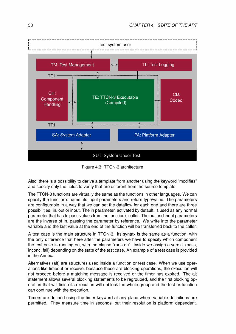
38 CHAPTER 4. STATE OF THE ART
SA: System adapter
Test system user
SUT: System Under Test
TM: Test Management TL: Test Logging
SA: System Adapter PA: Platform Adapter
TCI
TRI
TE: TTCN-3 Executable(Compiled)
CH:Component
Handling
CD:Codec
Figure 4.3: TTCN-3 architecture
Also, there is a possibility to derive a template from another using the keyword ”modifies”and specify only the fields to verify that are different from the source template.
The TTCN-3 functions are virtually the same as the functions in other languages. We canspecify the function’s name, its input parameters and return type/value. The parametersare configurable in a way that we can set the dataflow for each one and there are threepossibilities: in, out or inout. The in parameter, activated by default, is used as any normalparameter that has to pass values from the function’s caller. The out and inout parametersare the inverse of in, passing the parameter by reference. We write into the parametervariable and the last value at the end of the function will be transferred back to the caller.
A test case is the main structure in TTCN-3. Its syntax is the same as a function, withthe only difference that here after the parameters we have to specify which componentthe test case is running on, with the clause ”runs on”. Inside we assign a verdict (pass,inconc, fail) depending on the state of the test case. An example of a test case is providedin the Annex.
Alternatives (alt) are structures used inside a function or test case. When we use oper-ations like timeout or receive, because these are blocking operations, the execution willnot proceed before a matching message is received or the timer has expired. The altstatement allows several blocking statements to be regrouped, and the first blocking op-eration that will finish its execution will unblock the whole group and the test or functioncan continue with the execution.
Timers are defined using the timer keyword at any place where variable definitions arepermitted. They measure time in seconds, but their resolution is platform dependent.
4.3. LANGUAGES AND TOOLS FOR TESTING 39
Timers are useful in the communication phase of a test case combined with an alternative,to ”fire” a time-out when there is no response from the SUT after a certain time.
In order to specify how the test system will communicate with the SUT, in TTCN-3 oneuse the notion of ports and components. A TTCN-3 port is specified with the type ofmessages it can send and receive. In an implementation of a port, there can be practicallimits of the number of messages a port can hold in its queue. The behaviour of a testcase is executed in one or more test components composed from one or more portsthat describe its interface. Every port in the component has its own message queue tostore received messages. The component can have its own state with local variables,constants and timers.
TTCN-3 is a language that is created with the idea of testing. A maturity proof for thelanguage is that it’s developed and used extensively in the international standardisationbodies like ITU-T and ETSI for nearly all new standards produced by them. It containsall the features needed to write and execute a lot of test types and can be used to testthe SUT from different perspectives in the same time. A number of research projects andinitiatives are exploring different areas of application but it still remains to be seen to whatextent industry and ETSI will see a need and use it for such an extension.
4.3.2 CERTIFYIT
CertifyIt [53] is a modeling tool proposed by Smartesting Solution & Services [66]. TheCertifyIt tool supports the modeling of application behaviour as well as business pro-cesses and rules to control the automatic generation and maintenance of test cases.Traceability is managed automatically and the produced test cases are published andmaintained in the form of manual tests or automatic scripts composed of keywords to beimplemented. CertifyIt helps to industrialize and optimizes test process: the test modelmakes it possible to master the functional complexity and to generate the most effectivetests by ensuring the traceability links. It is also the single point of maintenance facilitatingthe update of test cases when specifications change. The various publications modulesaccelerate the production of reporting documents, for example for security assessments.The tool comes with many optional modules that are used in this thesis in order to takefull advantages of it. Here are a couple of used optional modules :
• Test Purpose: The ”Test Purpose” module provides a dedicated language that en-ables the representation of test patterns and generate tests that are variations ofit.
• MBeeTle is a module dedicated to automated exploratory testing for robustness pur-poses; more precisely, MbeeTle implements intelligent exploratory testing becauseexploration is guided by the test model. This will be further detailed in section 4.3.3.
CertifyIt is a test generation tool and the target is to execute them.
4.3.3 MBEETLE
Behavioral fuzzing aims at verifying the robustness of the systems to ensure that they willnot enter in an unpredictable state where the system is vulnerable and for instance that
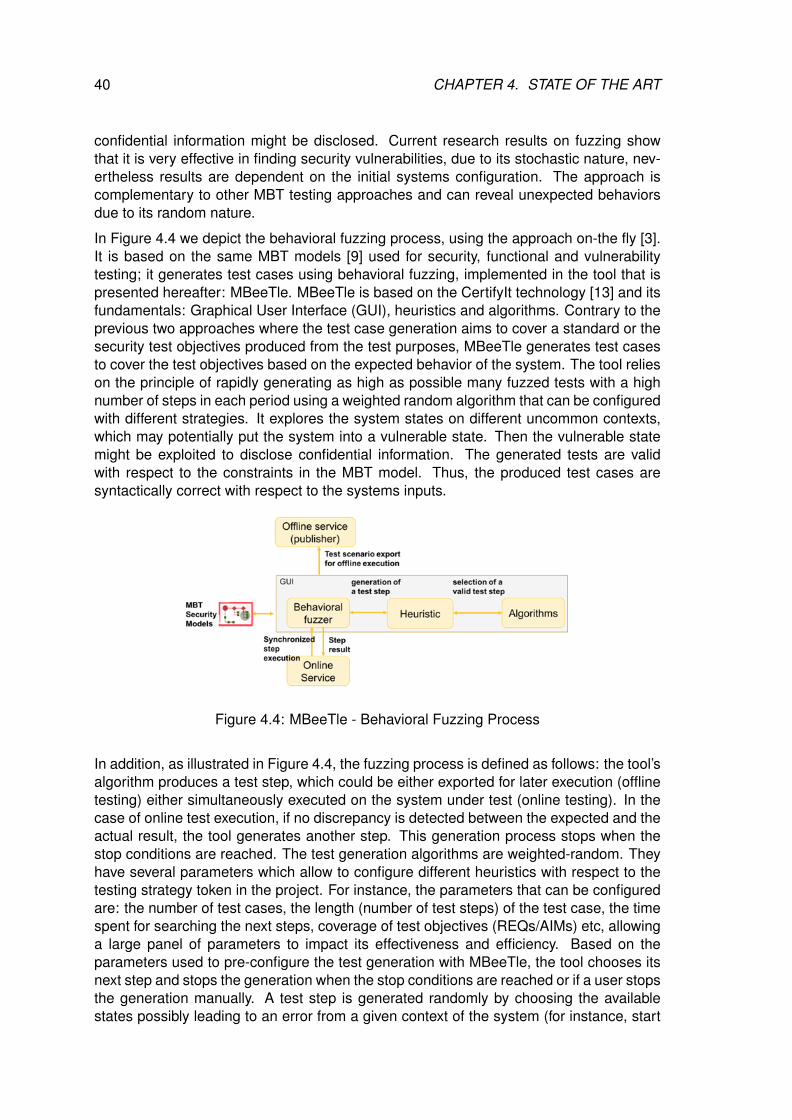
40 CHAPTER 4. STATE OF THE ART
confidential information might be disclosed. Current research results on fuzzing showthat it is very effective in finding security vulnerabilities, due to its stochastic nature, nev-ertheless results are dependent on the initial systems configuration. The approach iscomplementary to other MBT testing approaches and can reveal unexpected behaviorsdue to its random nature.
In Figure 4.4 we depict the behavioral fuzzing process, using the approach on-the fly [3].It is based on the same MBT models [9] used for security, functional and vulnerabilitytesting; it generates test cases using behavioral fuzzing, implemented in the tool that ispresented hereafter: MBeeTle. MBeeTle is based on the CertifyIt technology [13] and itsfundamentals: Graphical User Interface (GUI), heuristics and algorithms. Contrary to theprevious two approaches where the test case generation aims to cover a standard or thesecurity test objectives produced from the test purposes, MBeeTle generates test casesto cover the test objectives based on the expected behavior of the system. The tool relieson the principle of rapidly generating as high as possible many fuzzed tests with a highnumber of steps in each period using a weighted random algorithm that can be configuredwith different strategies. It explores the system states on different uncommon contexts,which may potentially put the system into a vulnerable state. Then the vulnerable statemight be exploited to disclose confidential information. The generated tests are validwith respect to the constraints in the MBT model. Thus, the produced test cases aresyntactically correct with respect to the systems inputs.
Figure 4.4: MBeeTle - Behavioral Fuzzing Process
In addition, as illustrated in Figure 4.4, the fuzzing process is defined as follows: the tool’salgorithm produces a test step, which could be either exported for later execution (offlinetesting) either simultaneously executed on the system under test (online testing). In thecase of online test execution, if no discrepancy is detected between the expected and theactual result, the tool generates another step. This generation process stops when thestop conditions are reached. The test generation algorithms are weighted-random. Theyhave several parameters which allow to configure different heuristics with respect to thetesting strategy token in the project. For instance, the parameters that can be configuredare: the number of test cases, the length (number of test steps) of the test case, the timespent for searching the next steps, coverage of test objectives (REQs/AIMs) etc, allowinga large panel of parameters to impact its effectiveness and efficiency. Based on theparameters used to pre-configure the test generation with MBeeTle, the tool chooses itsnext step and stops the generation when the stop conditions are reached or if a user stopsthe generation manually. A test step is generated randomly by choosing the availablestates possibly leading to an error from a given context of the system (for instance, start

4.3. LANGUAGES AND TOOLS FOR TESTING 41
exploring the systems behavior when administrator operations are called from normaluser connection). At each test step, the tool based on the model calculates the expectedstate of the system. Then, based on this expected state and the chosen heuristics andalgorithm, it chooses the next step. The generation of the test case stops either if thepre-configured conditions are reached or if a discrepancy between the expected and theactual result is detected.
The next section presents with more details the contributions of the thesis previouslyintroduced in Section 1.3.

5CONTRIBUTION SUMMARY
Contents5.1 Methods for MBT of IoT systems . . . . . . . . . . . . . . . . . . . . . 43
5.1.1 MBT behavioral modeling for standardized IoT platforms . . . . . 44
5.1.2 Pattern-driven and model-based security testing . . . . . . . . . 44
5.1.3 Behavioral fuzzing for IoT systems . . . . . . . . . . . . . . . . . 45
5.2 Tooling . . . . . . . . . . . . . . . . . . . . . . . . . . . . . . . . . . . . 47
5.2.1 Around CertifyIt . . . . . . . . . . . . . . . . . . . . . . . . . . . . 47
5.2.2 MBTAAS: Integrated Framework . . . . . . . . . . . . . . . . . . 48
In this chapter we talk about the contributions of the thesis. Starting with the methods forModel-Based Testing of IoT systems where we discuss how to apply MBT on the differentpoints expressed in section 1.3 of the introduction. We also see the contribution toolwise, how we used existing tools that are introduced in the state of the art and what arethe modifications and the specificities that we applied in order to respond to our researchchallenges.
5.1 METHODS FOR MBT OF IOT SYSTEMS
The implementation process of IoT involves the sum of all activities of handling, process-ing and storing the data collected from sensors. This aggregation increases the valueof data by increasing the scale, scope, and frequency of data available for analysis. Butaggregation can only be achieved through the use of various standards depending on theIoT application in use.
There are two types of standards relevant for the aggregation process; technology stan-dards (including network protocols, communication protocols, and data-aggregation stan-dards) and regulatory standards (related to security and privacy of data, among other is-sues). Challenges facing the adoption of standards within IoT are: standards for handlingunstructured data, security and privacy issues in addition to regulatory standards for datamarkets.
43
44 CHAPTER 5. CONTRIBUTION SUMMARY
5.1.1 MBT BEHAVIORAL MODELING FOR STANDARDIZED IOT PLATFORMS
FIWARE uses the Open Mobile Alliance (OMA) NGSI-9/10 standardized RESTful inter-faces [21]. This standardized interface is evolving in parallel with the IoT technology, tobe able to take into consideration its novelties. For instance, the OMA released the NGSIinterfaces - version 1 (NGSI v1) and FIWARE is aiming to contribute to the standard to re-lease NGSI v2. Thus, it needs to be easy to perform regression testing when the standardevolves. MBT offers a relatively safe, effective, and systematic way to create regressiontest suites and new test suites to cover new functionalities, based on models [34].
In addition, RESTful systems communicate over the Hypertext Transfer Protocol (HTTP)with the same HTTP verbs (GET, POST, PUT, DELETE, etc.) that web browsers use toretrieve web pages and to send data to remote servers. Their purpose is to exchangeinformation about the availability of contextual information.
In our context of testing the implementation of the data handling GE, we are interestedin applying conformance testing on NGSI-9/10. Moreover, although it is often assumedthat GEs are correctly implemented and are used by or are part of the services providedby FIWARE, non-compliance to the FIWARE specifications may lead to several dysfunc-tional interoperability issues. To ensure the interoperability, the GEs should be thoroughlytested to assess their compliance to these specifications. Model-Based Testing (MBT) isconsidered to be a lightweight formal method to validate software systems. It is formalbecause it works of formal (that is, machine-readable) specifications (or models) of thesoftware SUT (usually called the implementation or just SUT). It is lightweight because,contrary to other formal methods, such as B and Z notation, MBT does not aim at math-ematically proving that the implementation matches the specifications, under all possiblecircumstances, by refinement process from model to code. In MBT, the model is an ab-straction of the SUT and represents the tested perimeter based on the specifications,which is not necessarily the entire system. As such, it allows to systematically generatefrom the model a collection of tests (a ”test suite”) that, when run against the SUT, willprovide sufficient confidence that the system behaves accordingly to the specification.Testing follows the paradigm of not proving the absence of errors, but showing their pres-ence [2]. MBT, on the other hand, scales much better and has been used to test life-sizesystems in very large projects [9].
In FIWARE, we show that MBT conformance model is a representation of the standard.Model includes all the behaviours of the NGSI-v1 and generates the complete suite of testcases that are needed to test for implementation compliance to that standard. Changingan MBT model designed for conformance testing implies that the standard has changed.
5.1.2 PATTERN-DRIVEN AND MODEL-BASED SECURITY TESTING
The notion of test pattern is widely known and it is an effective and an efficient possibilityto capitalize the knowledge on testing solutions addressing vulnerabilities testing [8]. Asecurity test pattern is defined as a solution to describe the testing procedure for eachvulnerability. oneM2M IoT vulnerabilities where identified and enhanced to target a widerrange of IoT systems in the H2020 ARMOUR project (Appendix A) as part of the thesisresearch work. Vulnerability testing (pattern driven) aims to identify and discover potentialvulnerabilities based on risk and threat analysis. Security test patterns are used to deriveaccurate test cases focused on the security threats formalized by the targeted test pattern.
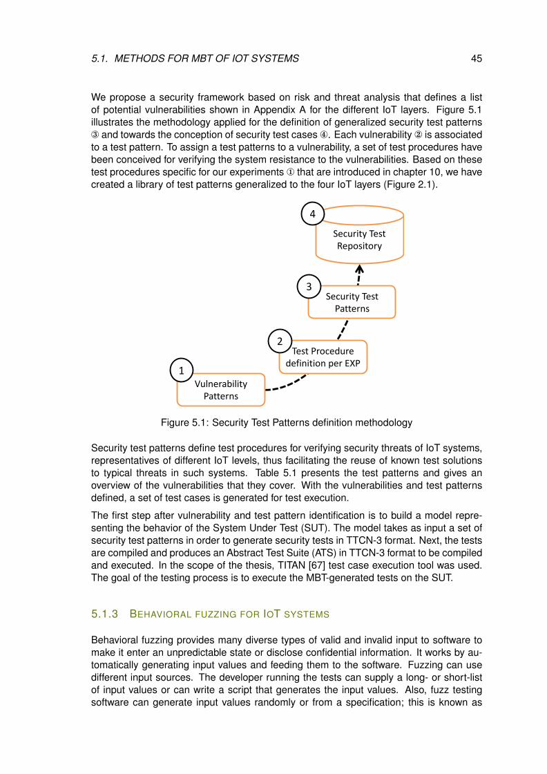
5.1. METHODS FOR MBT OF IOT SYSTEMS 45
We propose a security framework based on risk and threat analysis that defines a listof potential vulnerabilities shown in Appendix A for the different IoT layers. Figure 5.1illustrates the methodology applied for the definition of generalized security test patterns® and towards the conception of security test cases ¯. Each vulnerability is associatedto a test pattern. To assign a test patterns to a vulnerability, a set of test procedures havebeen conceived for verifying the system resistance to the vulnerabilities. Based on thesetest procedures specific for our experiments ¬ that are introduced in chapter 10, we havecreated a library of test patterns generalized to the four IoT layers (Figure 2.1).
Vulnerability Patterns
Security Test Patterns
Security Test Repository
Test Procedure definition per EXP1
2
3
4
Figure 5.1: Security Test Patterns definition methodology
Security test patterns define test procedures for verifying security threats of IoT systems,representatives of different IoT levels, thus facilitating the reuse of known test solutionsto typical threats in such systems. Table 5.1 presents the test patterns and gives anoverview of the vulnerabilities that they cover. With the vulnerabilities and test patternsdefined, a set of test cases is generated for test execution.
The first step after vulnerability and test pattern identification is to build a model repre-senting the behavior of the System Under Test (SUT). The model takes as input a set ofsecurity test patterns in order to generate security tests in TTCN-3 format. Next, the testsare compiled and produces an Abstract Test Suite (ATS) in TTCN-3 format to be compiledand executed. In the scope of the thesis, TITAN [67] test case execution tool was used.The goal of the testing process is to execute the MBT-generated tests on the SUT.
5.1.3 BEHAVIORAL FUZZING FOR IOT SYSTEMS
Behavioral fuzzing provides many diverse types of valid and invalid input to software tomake it enter an unpredictable state or disclose confidential information. It works by au-tomatically generating input values and feeding them to the software. Fuzzing can usedifferent input sources. The developer running the tests can supply a long- or short-listof input values or can write a script that generates the input values. Also, fuzz testingsoftware can generate input values randomly or from a specification; this is known as
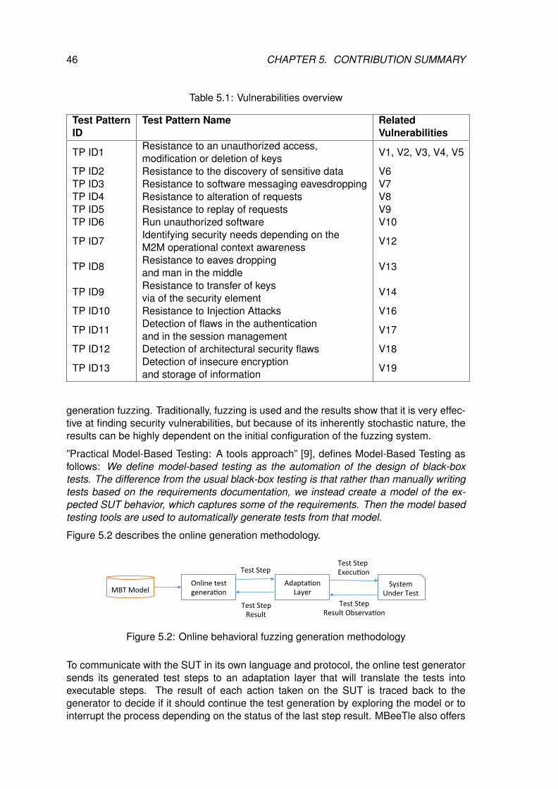
46 CHAPTER 5. CONTRIBUTION SUMMARY
Table 5.1: Vulnerabilities overview
Test Pattern Test Pattern Name RelatedID Vulnerabilities
TP ID1Resistance to an unauthorized access,modification or deletion of keys V1, V2, V3, V4, V5
TP ID2 Resistance to the discovery of sensitive data V6TP ID3 Resistance to software messaging eavesdropping V7TP ID4 Resistance to alteration of requests V8TP ID5 Resistance to replay of requests V9TP ID6 Run unauthorized software V10
TP ID7Identifying security needs depending on theM2M operational context awareness V12
TP ID8Resistance to eaves droppingand man in the middle V13
TP ID9Resistance to transfer of keysvia of the security element V14
TP ID10 Resistance to Injection Attacks V16
TP ID11Detection of flaws in the authenticationand in the session management V17
TP ID12 Detection of architectural security flaws V18
TP ID13Detection of insecure encryptionand storage of information V19
generation fuzzing. Traditionally, fuzzing is used and the results show that it is very effec-tive at finding security vulnerabilities, but because of its inherently stochastic nature, theresults can be highly dependent on the initial configuration of the fuzzing system.
”Practical Model-Based Testing: A tools approach” [9], defines Model-Based Testing asfollows: We define model-based testing as the automation of the design of black-boxtests. The difference from the usual black-box testing is that rather than manually writingtests based on the requirements documentation, we instead create a model of the ex-pected SUT behavior, which captures some of the requirements. Then the model basedtesting tools are used to automatically generate tests from that model.
Figure 5.2 describes the online generation methodology.
MBTModelOnlinetestgenera1on
Adapta1onLayer
SystemUnderTest
TestStepTestStepExecu1on
TestStepResultObserva1on
TestStepResult
Figure 5.2: Online behavioral fuzzing generation methodology
To communicate with the SUT in its own language and protocol, the online test generatorsends its generated test steps to an adaptation layer that will translate the tests intoexecutable steps. The result of each action taken on the SUT is traced back to thegenerator to decide if it should continue the test generation by exploring the model or tointerrupt the process depending on the status of the last step result. MBeeTle also offers
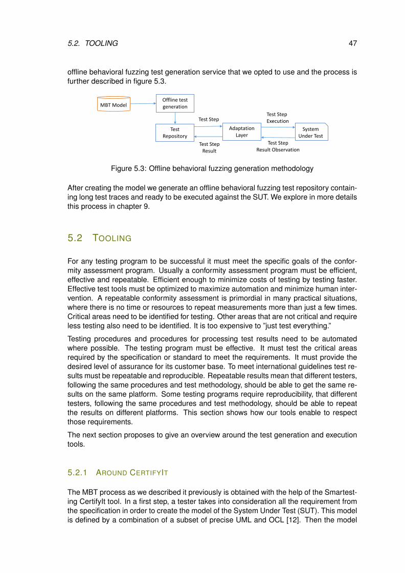
5.2. TOOLING 47
offline behavioral fuzzing test generation service that we opted to use and the process isfurther described in figure 5.3.
MBT ModelOffline test generation
Adaptation Layer
System Under Test
Test StepTest StepExecution
Test StepResult Observation
Test StepResult
Test Repository
Figure 5.3: Offline behavioral fuzzing generation methodology
After creating the model we generate an offline behavioral fuzzing test repository contain-ing long test traces and ready to be executed against the SUT. We explore in more detailsthis process in chapter 9.
5.2 TOOLING
For any testing program to be successful it must meet the specific goals of the confor-mity assessment program. Usually a conformity assessment program must be efficient,effective and repeatable. Efficient enough to minimize costs of testing by testing faster.Effective test tools must be optimized to maximize automation and minimize human inter-vention. A repeatable conformity assessment is primordial in many practical situations,where there is no time or resources to repeat measurements more than just a few times.Critical areas need to be identified for testing. Other areas that are not critical and requireless testing also need to be identified. It is too expensive to ”just test everything.”
Testing procedures and procedures for processing test results need to be automatedwhere possible. The testing program must be effective. It must test the critical areasrequired by the specification or standard to meet the requirements. It must provide thedesired level of assurance for its customer base. To meet international guidelines test re-sults must be repeatable and reproducible. Repeatable results mean that different testers,following the same procedures and test methodology, should be able to get the same re-sults on the same platform. Some testing programs require reproducibility, that differenttesters, following the same procedures and test methodology, should be able to repeatthe results on different platforms. This section shows how our tools enable to respectthose requirements.
The next section proposes to give an overview around the test generation and executiontools.
5.2.1 AROUND CERTIFYIT
The MBT process as we described it previously is obtained with the help of the Smartest-ing CertifyIt tool. In a first step, a tester takes into consideration all the requirement fromthe specification in order to create the model of the System Under Test (SUT). This modelis defined by a combination of a subset of precise UML and OCL [12]. Then the model
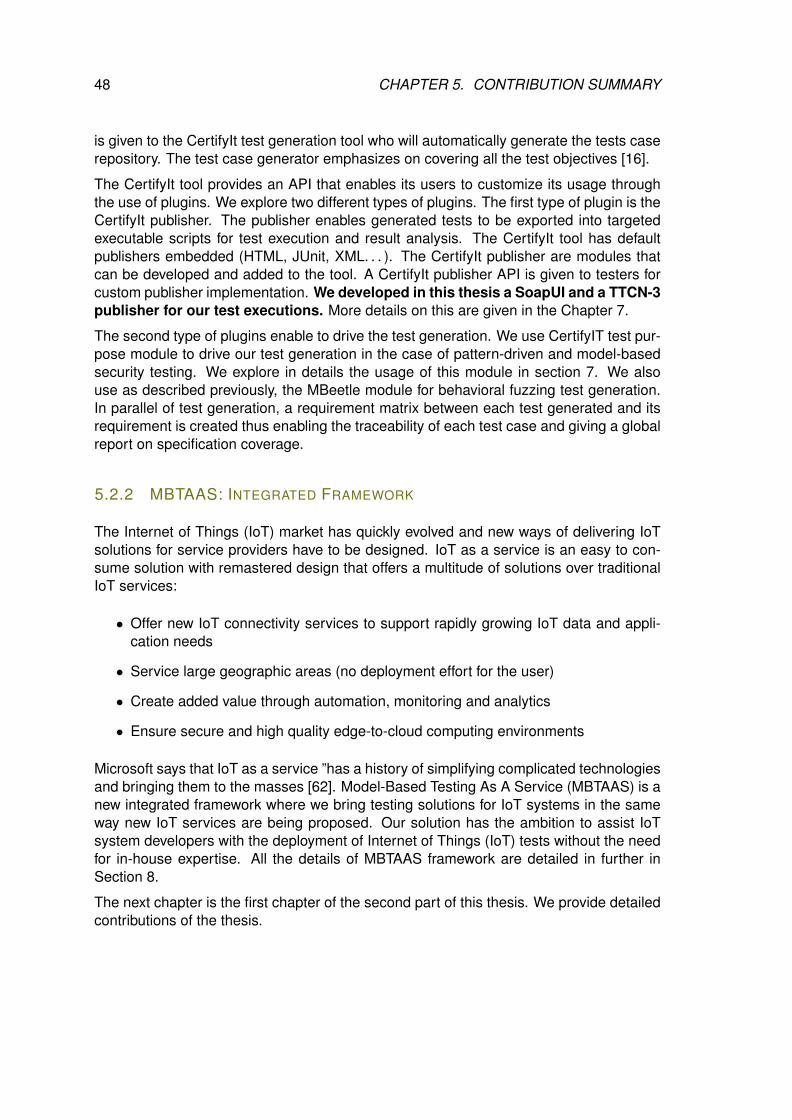
48 CHAPTER 5. CONTRIBUTION SUMMARY
is given to the CertifyIt test generation tool who will automatically generate the tests caserepository. The test case generator emphasizes on covering all the test objectives [16].
The CertifyIt tool provides an API that enables its users to customize its usage throughthe use of plugins. We explore two different types of plugins. The first type of plugin is theCertifyIt publisher. The publisher enables generated tests to be exported into targetedexecutable scripts for test execution and result analysis. The CertifyIt tool has defaultpublishers embedded (HTML, JUnit, XML. . . ). The CertifyIt publisher are modules thatcan be developed and added to the tool. A CertifyIt publisher API is given to testers forcustom publisher implementation. We developed in this thesis a SoapUI and a TTCN-3publisher for our test executions. More details on this are given in the Chapter 7.
The second type of plugins enable to drive the test generation. We use CertifyIT test pur-pose module to drive our test generation in the case of pattern-driven and model-basedsecurity testing. We explore in details the usage of this module in section 7. We alsouse as described previously, the MBeetle module for behavioral fuzzing test generation.In parallel of test generation, a requirement matrix between each test generated and itsrequirement is created thus enabling the traceability of each test case and giving a globalreport on specification coverage.
5.2.2 MBTAAS: INTEGRATED FRAMEWORK
The Internet of Things (IoT) market has quickly evolved and new ways of delivering IoTsolutions for service providers have to be designed. IoT as a service is an easy to con-sume solution with remastered design that offers a multitude of solutions over traditionalIoT services:
• Offer new IoT connectivity services to support rapidly growing IoT data and appli-cation needs
• Service large geographic areas (no deployment effort for the user)
• Create added value through automation, monitoring and analytics
• Ensure secure and high quality edge-to-cloud computing environments
Microsoft says that IoT as a service ”has a history of simplifying complicated technologiesand bringing them to the masses [62]. Model-Based Testing As A Service (MBTAAS) is anew integrated framework where we bring testing solutions for IoT systems in the sameway new IoT services are being proposed. Our solution has the ambition to assist IoTsystem developers with the deployment of Internet of Things (IoT) tests without the needfor in-house expertise. All the details of MBTAAS framework are detailed in further inSection 8.
The next chapter is the first chapter of the second part of this thesis. We provide detailedcontributions of the thesis.
IITECHNICAL CONTRIBUTIONS
49

6MBT BEHAVIORAL MODELING FOR
STANDARDIZED IOT PLATFORMS
Contents6.1 MBT Behavioral Model Process . . . . . . . . . . . . . . . . . . . . . . 526.2 Test Objectives . . . . . . . . . . . . . . . . . . . . . . . . . . . . . . . 536.3 MBT Behavioral Test Generation . . . . . . . . . . . . . . . . . . . . . 55
This chapter defines the vocabulary and methodology for test generation, test implemen-tation and test execution. Test generation includes automated activities for derivingtest-relevant artefacts such as test cases, test data, test oracle and test code. Testimplementation describes the steps to be performed for transforming test cases, oftendescribed in an abstract form, into test suites executed onto the SUT. This requires, inparticular, the development of adaptation layers between the test system (the Tester) andthe System Under Test. Test Execution is about configuring, executing in the targetedenvironment and reporting test results of experiments. Results can be stored and ex-ploited in contexts such as labeling and certification.
To execute a test, 2 parts are needed:
1. The System Under Test (SUT), which is the part one want to test and seen as ablack box
2. The Tester (human or an automated service or process) that executes tests byinteracting with the SUT
In an IoT deployment, the SUT usually consists of the following three types of nodes:
1. Server nodes (SN): most often referred to as Server. It provides advanced servicesand is most of the time located in the cloud
2. Client nodes (EN for End Node): these include in particular all sensors and ac-tuators deployed. These can be associated with more or less communicating andcomputing capabilities but are in general rather constraints. These could also beapplications such as mobile one.
3. Middle nodes (MN): this includes all gateways, router, etc. used
Nodes can have different roles as they can be exclusively or both at the same time:
51
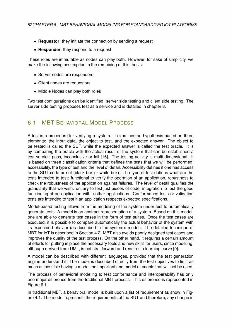
52CHAPTER 6. MBT BEHAVIORAL MODELING FOR STANDARDIZED IOT PLATFORMS
• Requestor: they initiate the connection by sending a request
• Responder: they respond to a request
These roles are immutable as nodes can play both. However, for sake of simplicity, wemake the following assumption in the remaining of this thesis:
• Server nodes are responders
• Client nodes are requestors
• Middle Nodes can play both roles
Two test configurations can be identified: server side testing and client side testing. Theserver side testing proposes test as a service and is detailed in chapter 8.
6.1 MBT BEHAVIORAL MODEL PROCESS
A test is a procedure for verifying a system. It examines an hypothesis based on threeelements: the input data, the object to test, and the expected answer. The object tobe tested is called the SUT, while the expected answer is called the test oracle. It isby comparing the oracle with the actual result of the system that can be established atest verdict: pass, inconclusive or fail [16]. The testing activity is multi-dimensional. Itis based on three classification criteria that defines the tests that we will be performed:accessibility, the type of test and the level of detail. Accessibility defines if one has accessto the SUT code or not (black box or white box). The type of test defines what are thetests intended to test: functional to verify the operation of an application, robustness tocheck the robustness of the application against failures. The level of detail qualifies thegranularity that we wish: unitary to test just pieces of code, integration to test the goodfunctioning of an application within other applications. Conformance tests or validationtests are intended to test if an application respects expected specifications.
Model-based testing allows from the modeling of the system under test to automaticallygenerate tests. A model is an abstract representation of a system. Based on this model,one are able to generate test cases in the form of test suites. Once the test cases areexecuted, it is possible to compare automatically the actual behavior of the system withits expected behavior (as described in the system’s model). The detailed technique ofMBT for IoT is described in Section 4.2. MBT also avoids poorly designed test cases andimproves the quality of the test process. On the other hand, it requires a certain amountof efforts for putting in place the necessary tools and new skills for users, since modeling,although derived from UML, is not straitforward and requires a learning curve [9].
A model can be described with different languages, provided that the test generationengine understand it. The model is described directly from the test objectives to limit asmuch as possible having a model too important and model elements that will not be used.
The process of behavioral modeling to test conformance and interoperability has onlyone major difference from the traditional MBT process. This difference is represented inFigure 6.1.
In traditional MBT, a behavioral model is built upon a list of requirement as show in Fig-ure 4.1. The model represents the requirements of the SUT and therefore, any change in
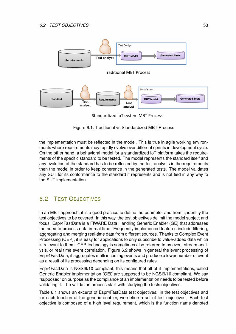
6.2. TEST OBJECTIVES 53
Test Design
Generated TestsMBT ModelTest analyst
Test Design
Generated TestsMBT ModelTest
analyst
Standard Requirements Test
analyst
Traditional MBT Process
Standardized IoT system MBT Process
Requirements
Figure 6.1: Traditional vs Standardized MBT Process
the implementation must be reflected in the model. This is true in agile working environ-ments where requirements may rapidly evolve over different sprints in development cycle.On the other hand, a behavioral model for a standardized IoT platform takes the require-ments of the specific standard to be tested. The model represents the standard itself andany evolution of the standard has to be reflected by the test analysts in the requirementsthen the model in order to keep coherence in the generated tests. The model validatesany SUT for its conformance to the standard it represents and is not tied in any way tothe SUT implementation.
6.2 TEST OBJECTIVES
In an MBT approach, it is a good practice to define the perimeter and from it, identify thetest objectives to be covered. In this way, the test objectives delimit the model subject andfocus. Espr4FastData is a FIWARE Data Handling Generic Enabler (GE) that addressesthe need to process data in real time. Frequently implemented features include filtering,aggregating and merging real-time data from different sources. Thanks to Complex EventProcessing (CEP), it is easy for applications to only subscribe to value-added data whichis relevant to them. CEP technology is sometimes also referred to as event stream anal-ysis, or real time event correlation. Figure 6.2 shows in general the event processing ofEspr4FastData, it aggregates multi incoming events and produce a lower number of eventas a result of its processing depending on its configured rules.
Espr4FastData is NGSI9/10 compliant, this means that all of it implementations, calledGeneric Enabler implementation (GEi) are supposed to be NGSI9/10 compliant. We say”supposed” on purpose as the compliance of an implementation needs to be tested beforevalidating it. The validation process start with studying the tests objectives.
Table 6.1 shows an excerpt of Espr4FastData test objectives. In the test objectives andfor each function of the generic enabler, we define a set of test objectives. Each testobjective is composed of a high level requirement, which is the function name denoted
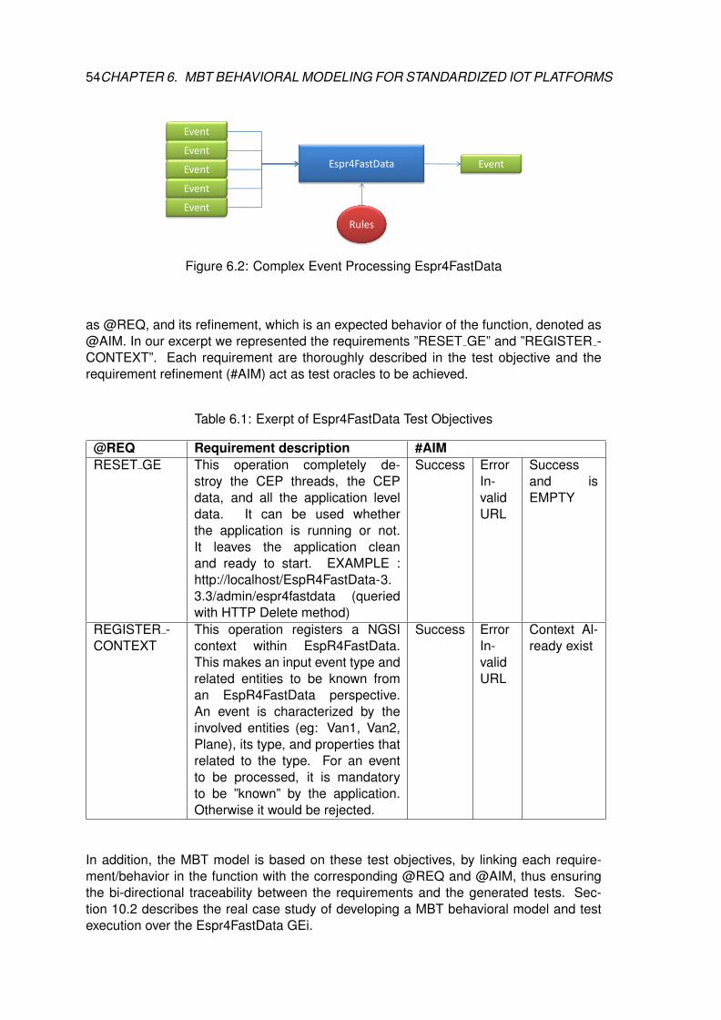
54CHAPTER 6. MBT BEHAVIORAL MODELING FOR STANDARDIZED IOT PLATFORMS
Event
EventEventEventEvent
Espr4FastData Event
Rules
Figure 6.2: Complex Event Processing Espr4FastData
as @REQ, and its refinement, which is an expected behavior of the function, denoted as@AIM. In our excerpt we represented the requirements ”RESET GE” and ”REGISTER -CONTEXT”. Each requirement are thoroughly described in the test objective and therequirement refinement (#AIM) act as test oracles to be achieved.
Table 6.1: Exerpt of Espr4FastData Test Objectives
@REQ Requirement description #AIMRESET GE This operation completely de-
stroy the CEP threads, the CEPdata, and all the application leveldata. It can be used whetherthe application is running or not.It leaves the application cleanand ready to start. EXAMPLE :http://localhost/EspR4FastData-3.3.3/admin/espr4fastdata (queriedwith HTTP Delete method)
Success ErrorIn-validURL
Successand isEMPTY
REGISTER -CONTEXT
This operation registers a NGSIcontext within EspR4FastData.This makes an input event type andrelated entities to be known froman EspR4FastData perspective.An event is characterized by theinvolved entities (eg: Van1, Van2,Plane), its type, and properties thatrelated to the type. For an eventto be processed, it is mandatoryto be ”known” by the application.Otherwise it would be rejected.
Success ErrorIn-validURL
Context Al-ready exist
In addition, the MBT model is based on these test objectives, by linking each require-ment/behavior in the function with the corresponding @REQ and @AIM, thus ensuringthe bi-directional traceability between the requirements and the generated tests. Sec-tion 10.2 describes the real case study of developing a MBT behavioral model and testexecution over the Espr4FastData GEi.
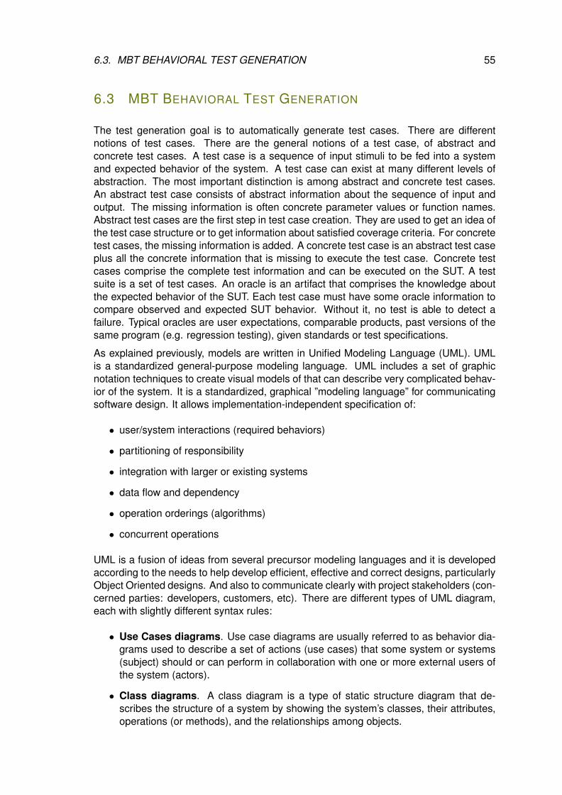
6.3. MBT BEHAVIORAL TEST GENERATION 55
6.3 MBT BEHAVIORAL TEST GENERATION
The test generation goal is to automatically generate test cases. There are differentnotions of test cases. There are the general notions of a test case, of abstract andconcrete test cases. A test case is a sequence of input stimuli to be fed into a systemand expected behavior of the system. A test case can exist at many different levels ofabstraction. The most important distinction is among abstract and concrete test cases.An abstract test case consists of abstract information about the sequence of input andoutput. The missing information is often concrete parameter values or function names.Abstract test cases are the first step in test case creation. They are used to get an idea ofthe test case structure or to get information about satisfied coverage criteria. For concretetest cases, the missing information is added. A concrete test case is an abstract test caseplus all the concrete information that is missing to execute the test case. Concrete testcases comprise the complete test information and can be executed on the SUT. A testsuite is a set of test cases. An oracle is an artifact that comprises the knowledge aboutthe expected behavior of the SUT. Each test case must have some oracle information tocompare observed and expected SUT behavior. Without it, no test is able to detect afailure. Typical oracles are user expectations, comparable products, past versions of thesame program (e.g. regression testing), given standards or test specifications.
As explained previously, models are written in Unified Modeling Language (UML). UMLis a standardized general-purpose modeling language. UML includes a set of graphicnotation techniques to create visual models of that can describe very complicated behav-ior of the system. It is a standardized, graphical ”modeling language” for communicatingsoftware design. It allows implementation-independent specification of:
• user/system interactions (required behaviors)
• partitioning of responsibility
• integration with larger or existing systems
• data flow and dependency
• operation orderings (algorithms)
• concurrent operations
UML is a fusion of ideas from several precursor modeling languages and it is developedaccording to the needs to help develop efficient, effective and correct designs, particularlyObject Oriented designs. And also to communicate clearly with project stakeholders (con-cerned parties: developers, customers, etc). There are different types of UML diagram,each with slightly different syntax rules:
• Use Cases diagrams. Use case diagrams are usually referred to as behavior dia-grams used to describe a set of actions (use cases) that some system or systems(subject) should or can perform in collaboration with one or more external users ofthe system (actors).
• Class diagrams. A class diagram is a type of static structure diagram that de-scribes the structure of a system by showing the system’s classes, their attributes,operations (or methods), and the relationships among objects.
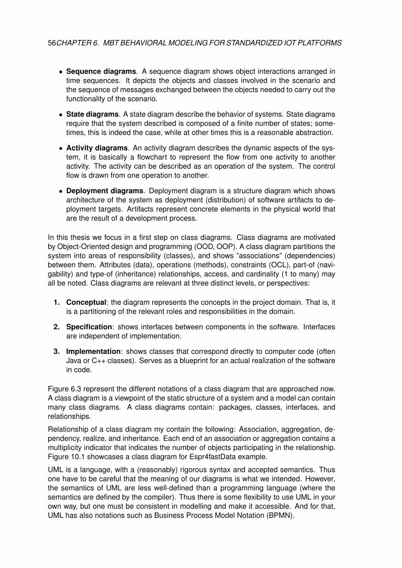
56CHAPTER 6. MBT BEHAVIORAL MODELING FOR STANDARDIZED IOT PLATFORMS
• Sequence diagrams. A sequence diagram shows object interactions arranged intime sequences. It depicts the objects and classes involved in the scenario andthe sequence of messages exchanged between the objects needed to carry out thefunctionality of the scenario.
• State diagrams. A state diagram describe the behavior of systems. State diagramsrequire that the system described is composed of a finite number of states; some-times, this is indeed the case, while at other times this is a reasonable abstraction.
• Activity diagrams. An activity diagram describes the dynamic aspects of the sys-tem, it is basically a flowchart to represent the flow from one activity to anotheractivity. The activity can be described as an operation of the system. The controlflow is drawn from one operation to another.
• Deployment diagrams. Deployment diagram is a structure diagram which showsarchitecture of the system as deployment (distribution) of software artifacts to de-ployment targets. Artifacts represent concrete elements in the physical world thatare the result of a development process.
In this thesis we focus in a first step on class diagrams. Class diagrams are motivatedby Object-Oriented design and programming (OOD, OOP). A class diagram partitions thesystem into areas of responsibility (classes), and shows ”associations” (dependencies)between them. Attributes (data), operations (methods), constraints (OCL), part-of (navi-gability) and type-of (inheritance) relationships, access, and cardinality (1 to many) mayall be noted. Class diagrams are relevant at three distinct levels, or perspectives:
1. Conceptual: the diagram represents the concepts in the project domain. That is, itis a partitioning of the relevant roles and responsibilities in the domain.
2. Specification: shows interfaces between components in the software. Interfacesare independent of implementation.
3. Implementation: shows classes that correspond directly to computer code (oftenJava or C++ classes). Serves as a blueprint for an actual realization of the softwarein code.
Figure 6.3 represent the different notations of a class diagram that are approached now.A class diagram is a viewpoint of the static structure of a system and a model can containmany class diagrams. A class diagrams contain: packages, classes, interfaces, andrelationships.
Relationship of a class diagram my contain the following: Association, aggregation, de-pendency, realize, and inheritance. Each end of an association or aggregation contains amultiplicity indicator that indicates the number of objects participating in the relationship.Figure 10.1 showcases a class diagram for Espr4fastData example.
UML is a language, with a (reasonably) rigorous syntax and accepted semantics. Thusone have to be careful that the meaning of our diagrams is what we intended. However,the semantics of UML are less well-defined than a programming language (where thesemantics are defined by the compiler). Thus there is some flexibility to use UML in yourown way, but one must be consistent in modelling and make it accessible. And for that,UML has also notations such as Business Process Model Notation (BPMN).
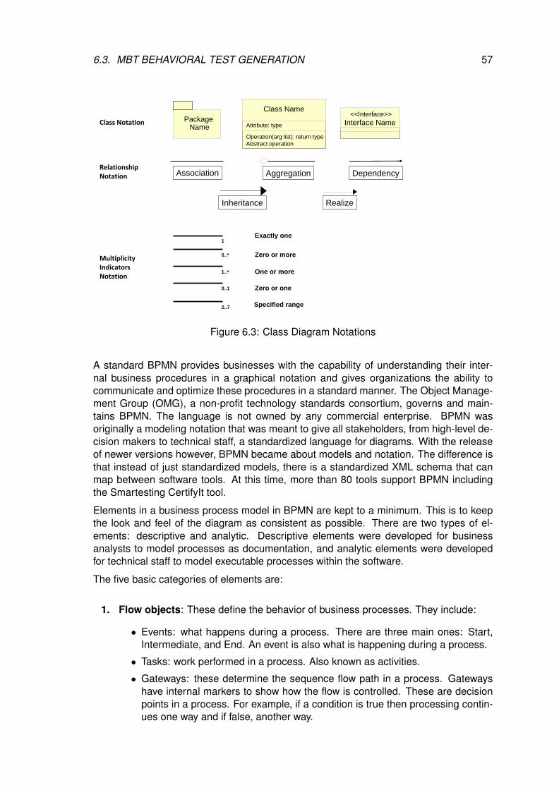
6.3. MBT BEHAVIORAL TEST GENERATION 57
Package Name
Class Name
Interface Name<<Interface>>
Association Aggregation Dependency
Inheritance Realize
Zero or more0..*
One or more1..*
Zero or one0..1
Specified range2..7
Exactly one1
Class Notation
RelationshipNotation
MultiplicityIndicators Notation
Attribute: type
Operation(arg list): return type
Abstract operation
Figure 6.3: Class Diagram Notations
A standard BPMN provides businesses with the capability of understanding their inter-nal business procedures in a graphical notation and gives organizations the ability tocommunicate and optimize these procedures in a standard manner. The Object Manage-ment Group (OMG), a non-profit technology standards consortium, governs and main-tains BPMN. The language is not owned by any commercial enterprise. BPMN wasoriginally a modeling notation that was meant to give all stakeholders, from high-level de-cision makers to technical staff, a standardized language for diagrams. With the releaseof newer versions however, BPMN became about models and notation. The difference isthat instead of just standardized models, there is a standardized XML schema that canmap between software tools. At this time, more than 80 tools support BPMN includingthe Smartesting CertifyIt tool.
Elements in a business process model in BPMN are kept to a minimum. This is to keepthe look and feel of the diagram as consistent as possible. There are two types of el-ements: descriptive and analytic. Descriptive elements were developed for businessanalysts to model processes as documentation, and analytic elements were developedfor technical staff to model executable processes within the software.
The five basic categories of elements are:
1. Flow objects: These define the behavior of business processes. They include:
• Events: what happens during a process. There are three main ones: Start,Intermediate, and End. An event is also what is happening during a process.
• Tasks: work performed in a process. Also known as activities.
• Gateways: these determine the sequence flow path in a process. Gatewayshave internal markers to show how the flow is controlled. These are decisionpoints in a process. For example, if a condition is true then processing contin-ues one way and if false, another way.
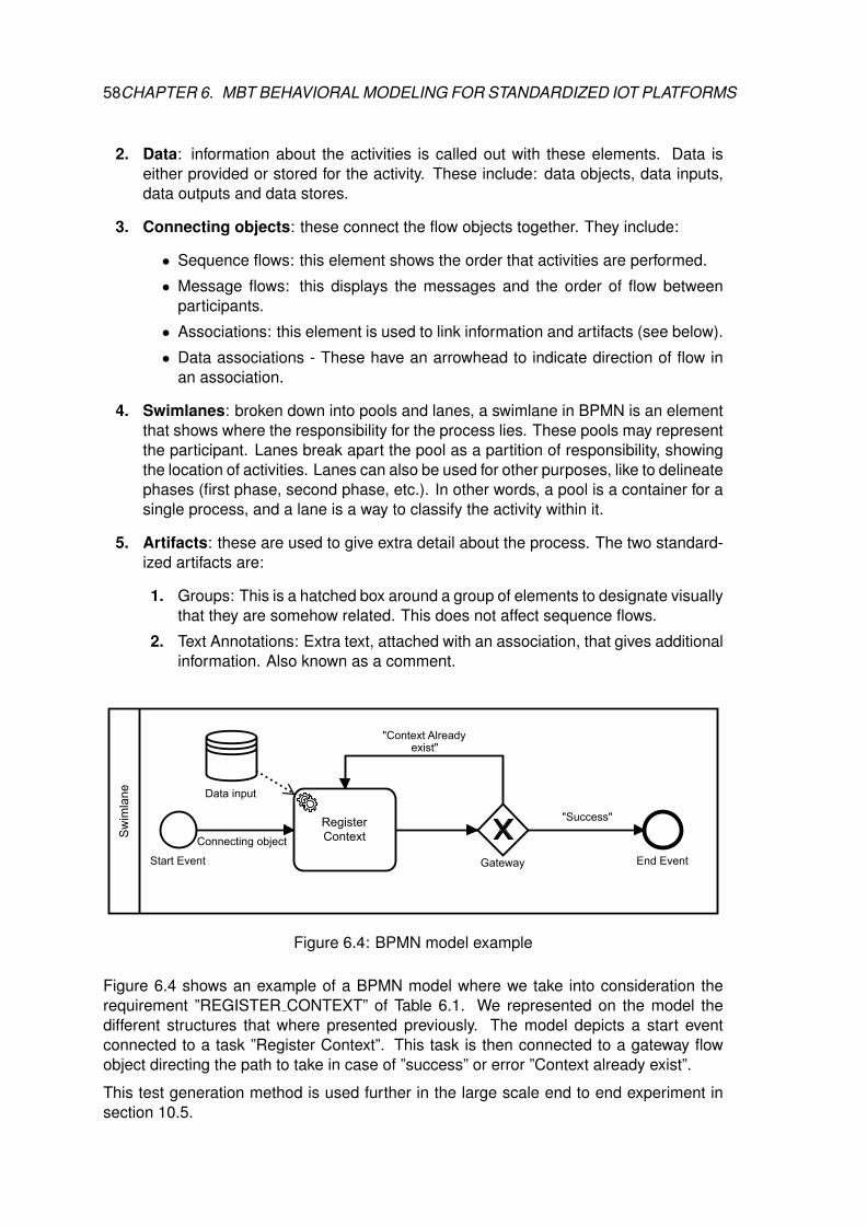
58CHAPTER 6. MBT BEHAVIORAL MODELING FOR STANDARDIZED IOT PLATFORMS
2. Data: information about the activities is called out with these elements. Data iseither provided or stored for the activity. These include: data objects, data inputs,data outputs and data stores.
3. Connecting objects: these connect the flow objects together. They include:
• Sequence flows: this element shows the order that activities are performed.
• Message flows: this displays the messages and the order of flow betweenparticipants.
• Associations: this element is used to link information and artifacts (see below).
• Data associations - These have an arrowhead to indicate direction of flow inan association.
4. Swimlanes: broken down into pools and lanes, a swimlane in BPMN is an elementthat shows where the responsibility for the process lies. These pools may representthe participant. Lanes break apart the pool as a partition of responsibility, showingthe location of activities. Lanes can also be used for other purposes, like to delineatephases (first phase, second phase, etc.). In other words, a pool is a container for asingle process, and a lane is a way to classify the activity within it.
5. Artifacts: these are used to give extra detail about the process. The two standard-ized artifacts are:
1. Groups: This is a hatched box around a group of elements to designate visuallythat they are somehow related. This does not affect sequence flows.
2. Text Annotations: Extra text, attached with an association, that gives additionalinformation. Also known as a comment.
Sw
imla
ne Data input
RegisterContext
Gateway End EventStart Event
"Context Alreadyexist"
"Success"
Connecting object
Figure 6.4: BPMN model example
Figure 6.4 shows an example of a BPMN model where we take into consideration therequirement ”REGISTER CONTEXT” of Table 6.1. We represented on the model thedifferent structures that where presented previously. The model depicts a start eventconnected to a task ”Register Context”. This task is then connected to a gateway flowobject directing the path to take in case of ”success” or error ”Context already exist”.
This test generation method is used further in the large scale end to end experiment insection 10.5.
6.3. MBT BEHAVIORAL TEST GENERATION 59
The next section introduces the specifities of pattern-driven and model-based securitytesting. We will also see how we can evolve from an behavioral model for conformancetesting to security testing by introducing test purposes to the model conception in MBT.

7PATTERN-DRIVEN AND MODEL-BASED
SECURITY TESTING
Contents7.1 Expressing Test scenarios From Test Patterns . . . . . . . . . . . . 61
7.2 Test Generation . . . . . . . . . . . . . . . . . . . . . . . . . . . . . . . 63
7.3 Using TP for MBS Functional and Vulnerability Testing . . . . . . . 65
Security, confidentiality and trust are critical elements of the IoT landscape where inad-equacy of these is a barrier to the deployment of IoT systems and to broad adoption ofIoT technologies. Some of the more frightening vulnerabilities found on IoT devices havebrought IoT security into the daylight of issues that need to be addressed quickly. In mid2015, researchers found critical vulnerabilities in a wide range of IoT baby monitors [58],which could be used by hackers to carry out a number of unwanted activities, includingspying on live feeds and authorizing other users to remotely access to the monitor. Thearticle quotes: ”Internet of Things security still isn’t ready for prime time.” and states ”Theinternet of insecure things”. In another development, it is demonstrated that connectedcars can be compromised [61] as well, and hackers can carry out dangerous maliciousactivities, including taking control of the entertainment system, unlocking the doors oreven shutting down the car mid highway. Authors is [27] proposes to use a trusted ThirdParty, tasked with assuring specific security characteristics within a cloud environment.The solution presents a horizontal level of service, available to all implicated entities, thatrealizes a security mesh, within which essential trust is maintained. We propose in thissection to address IoT systems security issues with MBT and test purposes.
7.1 EXPRESSING TEST SCENARIOS FROM TEST PATTERNS
A test purpose in Test Purpose Language (hereafter denoted as TPLan) [11] is a stan-dardized and structured notation developed by ETSI for concise and unambiguous de-scription of what is to be tested rather than how the testing is performed. It is an ab-stract test scenario derived from one or more requirements, defining the steps neededto be tested if the SUT respects the corresponding requirement. More concretely, it is astructured natural language that defines a minimal set of keywords for use in the TPLancombined natural language or even graphical representations. Although it is minimal, it isgeneric and if there is a need, the user can define his own extensions to the notation spe-
61
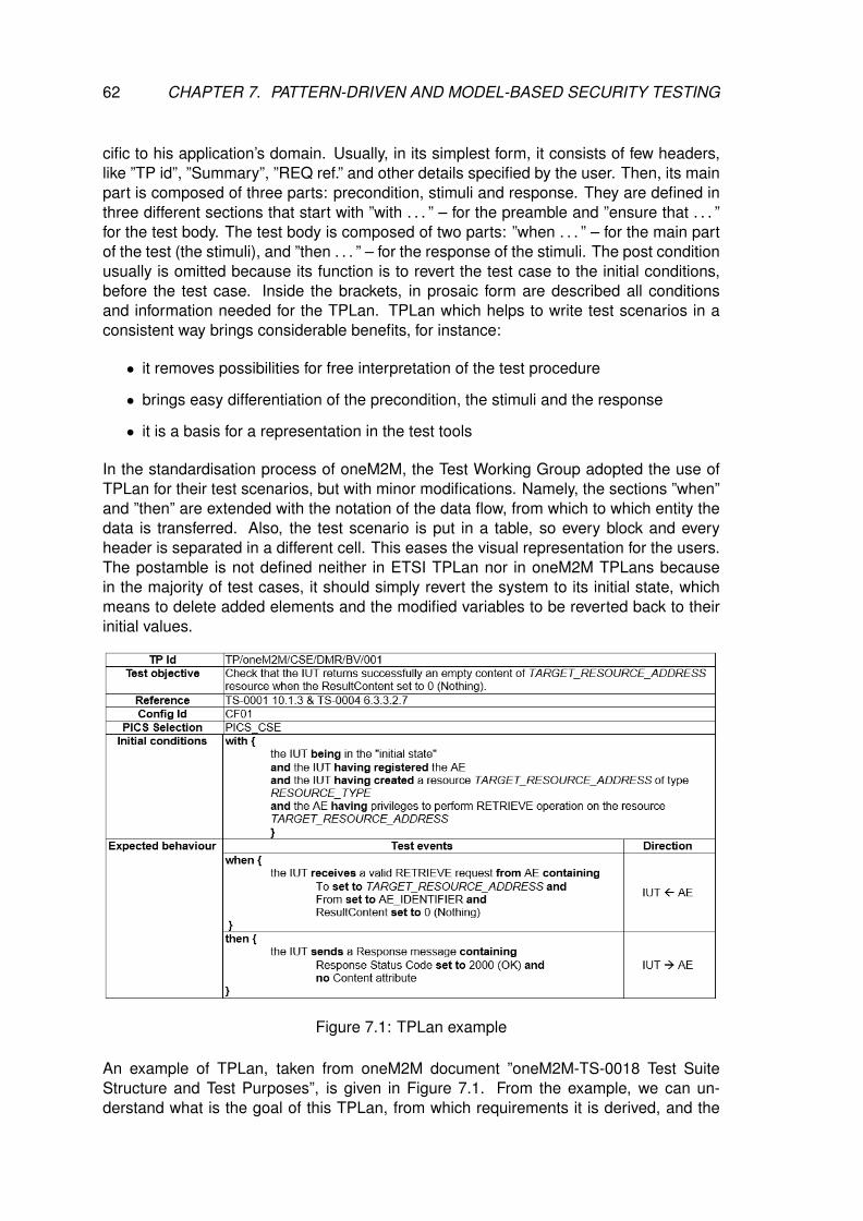
62 CHAPTER 7. PATTERN-DRIVEN AND MODEL-BASED SECURITY TESTING
cific to his application’s domain. Usually, in its simplest form, it consists of few headers,like ”TP id”, ”Summary”, ”REQ ref.” and other details specified by the user. Then, its mainpart is composed of three parts: precondition, stimuli and response. They are defined inthree different sections that start with ”with . . . ” – for the preamble and ”ensure that . . . ”for the test body. The test body is composed of two parts: ”when . . . ” – for the main partof the test (the stimuli), and ”then . . . ” – for the response of the stimuli. The post conditionusually is omitted because its function is to revert the test case to the initial conditions,before the test case. Inside the brackets, in prosaic form are described all conditionsand information needed for the TPLan. TPLan which helps to write test scenarios in aconsistent way brings considerable benefits, for instance:
• it removes possibilities for free interpretation of the test procedure
• brings easy differentiation of the precondition, the stimuli and the response
• it is a basis for a representation in the test tools
In the standardisation process of oneM2M, the Test Working Group adopted the use ofTPLan for their test scenarios, but with minor modifications. Namely, the sections ”when”and ”then” are extended with the notation of the data flow, from which to which entity thedata is transferred. Also, the test scenario is put in a table, so every block and everyheader is separated in a different cell. This eases the visual representation for the users.The postamble is not defined neither in ETSI TPLan nor in oneM2M TPLans becausein the majority of test cases, it should simply revert the system to its initial state, whichmeans to delete added elements and the modified variables to be reverted back to theirinitial values.
Figure 7.1: TPLan example
An example of TPLan, taken from oneM2M document ”oneM2M-TS-0018 Test SuiteStructure and Test Purposes”, is given in Figure 7.1. From the example, we can un-derstand what is the goal of this TPLan, from which requirements it is derived, and the
7.2. TEST GENERATION 63
test details: in which state should the SUT be in order to execute the test, the content ofthe test body and the correct response in order the test to pass. We have to note that inthose figures we changed some of the header fields used by oneM2M to adapt them tothe security testing context. For example, instead of using Requirement reference, as itis described in oneM2M, we changed the field to refer to the Test Pattern from which it isderived. Unlike the initial Test Patterns, these are augmented with a communication dia-gram and more details on how the test should be rolled out. The Test Pattern describescommunication between Sensor and a Firmware Manager: The sensor requests a newfirmware from the Firmware Manager and verifies the signature of the received firmware.If the signature is valid, the firmware will be installed, and will be rejected otherwise. Inorder to facilitate and unify the experiments in this thesis, we propose using the TPLanas described here for all TPLans examples we have to define. Compared to the initialtest pattern, it is clearer and more concise, the entities and the communication betweenare well defined. Hence, TPLans help to disambiguate the testing intentions, thus theycannot be used for automated test generations. Based on this property of the TPLans, wepropose to use the TPLan’s knowledge for generation of executable scripts. On the onehand, communication with the domain experts familiar with TPLan is made possible, andon the other hand, scripts are ready for automated execution. In the next section we de-scribe the MBT approach and how we express formally the TPLans towards a generationof executable scripts.
7.2 TEST GENERATION
M2M existing standards as well as emerging standards, such as oneM2M, put extremeimportance into the definition of security requirements related to security functions in ad-dition to functional requirements. Moreover, our experience in testing and analysis of IoTsystems, showed that the IoT system’s Security and Trust will depend on the resistanceof the system with respect to:
• misuses of the security functions
• security threats and vulnerabilities
• intensive interactions with other users/systems
We have identified four IoT segments that cover different aspects of IoT security testing:Availability, Security, Privacy and Integrity. Based on the work performed and the testingneeds of each segment, we have identified a set of security requirements and vulnerabili-ties that must be fulfiled by the developed systems. In order to validate them with respectto the set of requirements, we have identified three test strategies:
Security Functional testing (compliance with agreed standards/specification): aims toverify that system behavior complies with the targeted specification, which enables to de-tect possible security misuses and that the security functions are implemented correctly.
Vulnerability testing (pattern driven): aims to identify and discover potential vulnerabili-ties based on risk and threat analysis. Security test patterns are used as a starting point,which enable to derive accurate test cases focused on the security threats formalized bythe targeted test pattern.
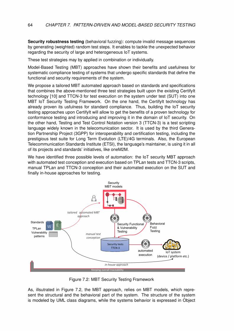
64 CHAPTER 7. PATTERN-DRIVEN AND MODEL-BASED SECURITY TESTING
Security robustness testing (behavioral fuzzing): compute invalid message sequencesby generating (weighted) random test steps. It enables to tackle the unexpected behaviorregarding the security of large and heterogeneous IoT systems.
These test strategies may by applied in combination or individually.
Model-Based Testing (MBT) approaches have shown their benefits and usefulness forsystematic compliance testing of systems that undergo specific standards that define thefunctional and security requirements of the system.
We propose a tailored MBT automated approach based on standards and specificationsthat combines the above-mentioned three test strategies built upon the existing CertifyIttechnology [10] and TTCN-3 for test execution on the system under test (SUT) into oneMBT IoT Security Testing Framework. On the one hand, the CertifyIt technology hasalready proven its usfulness for standard compliance. Thus, building the IoT securitytesting approaches upon CertifyIt will allow to get the benefits of a proven technology forconformance testing and introducing and improving it in the domain of IoT security. Onthe other hand, Testing and Test Control Notation version 3 (TTCN-3) is a test scriptinglanguage widely known in the telecomunication sector. It is used by the third Genera-tion Partnership Project (3GPP) for interoperability and certification testing, including theprestigious test suite for Long Term Evolution (LTE)/4G terminals. Also, the EuropeanTelecommunication Standards Institute (ETSI), the language’s maintainer, is using it in allof its projects and standards’ initiatives, like oneM2M.
We have identified three possible levels of automation: the IoT security MBT approachwith automated test conception and execution based on TPLan tests and TTCN-3 scripts,manual TPLan and TTCN-3 conception and their automated execution on the SUT andfinally in-house approaches for testing.
automated execution
Security Functional & Vulnerability Testing
Security MBT models
IoT system (device / platform etc.)
BehavioralFuzzTestingVulnerability
patterns
Standards
tailored automated MBT approach
in-house approach
manual testconception
Keeping overall traceability
Security tests TTCN-3
TPLan
Figure 7.2: MBT Security Testing Framework
As, illsutrated in Figure 7.2, the MBT approach, relies on MBT models, which repre-sent the structural and the behavioral part of the system. The structure of the systemis modeled by UML class diagrams, while the systems behavior is expressed in Object
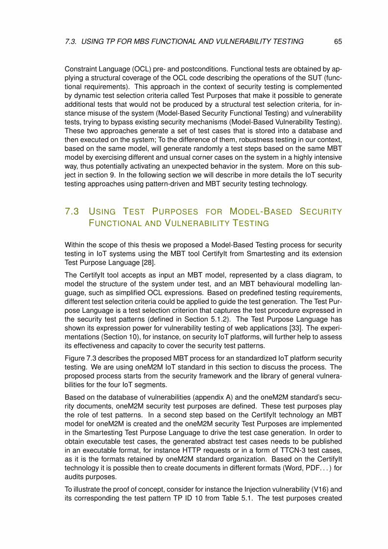
7.3. USING TP FOR MBS FUNCTIONAL AND VULNERABILITY TESTING 65
Constraint Language (OCL) pre- and postconditions. Functional tests are obtained by ap-plying a structural coverage of the OCL code describing the operations of the SUT (func-tional requirements). This approach in the context of security testing is complementedby dynamic test selection criteria called Test Purposes that make it possible to generateadditional tests that would not be produced by a structural test selection criteria, for in-stance misuse of the system (Model-Based Security Functional Testing) and vulnerabilitytests, trying to bypass existing security mechanisms (Model-Based Vulnerability Testing).These two approaches generate a set of test cases that is stored into a database andthen executed on the system; To the difference of them, robustness testing in our context,based on the same model, will generate randomly a test steps based on the same MBTmodel by exercising different and unsual corner cases on the system in a highly intensiveway, thus potentially activating an unexpected behavior in the system. More on this sub-ject in section 9. In the following section we will describe in more details the IoT securitytesting approaches using pattern-driven and MBT security testing technology.
7.3 USING TEST PURPOSES FOR MODEL-BASED SECURITY
FUNCTIONAL AND VULNERABILITY TESTING
Within the scope of this thesis we proposed a Model-Based Testing process for securitytesting in IoT systems using the MBT tool CertifyIt from Smartesting and its extensionTest Purpose Language [28].
The CertifyIt tool accepts as input an MBT model, represented by a class diagram, tomodel the structure of the system under test, and an MBT behavioural modelling lan-guage, such as simplified OCL expressions. Based on predefined testing requirements,different test selection criteria could be applied to guide the test generation. The Test Pur-pose Language is a test selection criterion that captures the test procedure expressed inthe security test patterns (defined in Section 5.1.2). The Test Purpose Language hasshown its expression power for vulnerability testing of web applications [33]. The experi-mentations (Section 10), for instance, on security IoT platforms, will further help to assessits effectiveness and capacity to cover the security test patterns.
Figure 7.3 describes the proposed MBT process for an standardized IoT platform securitytesting. We are using oneM2M IoT standard in this section to discuss the process. Theproposed process starts from the security framework and the library of general vulnera-bilities for the four IoT segments.
Based on the database of vulnerabilities (appendix A) and the oneM2M standard’s secu-rity documents, oneM2M security test purposes are defined. These test purposes playthe role of test patterns. In a second step based on the CertifyIt technology an MBTmodel for oneM2M is created and the oneM2M security Test Purposes are implementedin the Smartesting Test Purpose Language to drive the test case generation. In order toobtain executable test cases, the generated abstract test cases needs to be publishedin an executable format, for instance HTTP requests or in a form of TTCN-3 test cases,as it is the formats retained by oneM2M standard organization. Based on the CertifyIttechnology it is possible then to create documents in different formats (Word, PDF. . . ) foraudits purposes.
To illustrate the proof of concept, consider for instance the Injection vulnerability (V16) andits corresponding the test pattern TP ID 10 from Table 5.1. The test purposes created
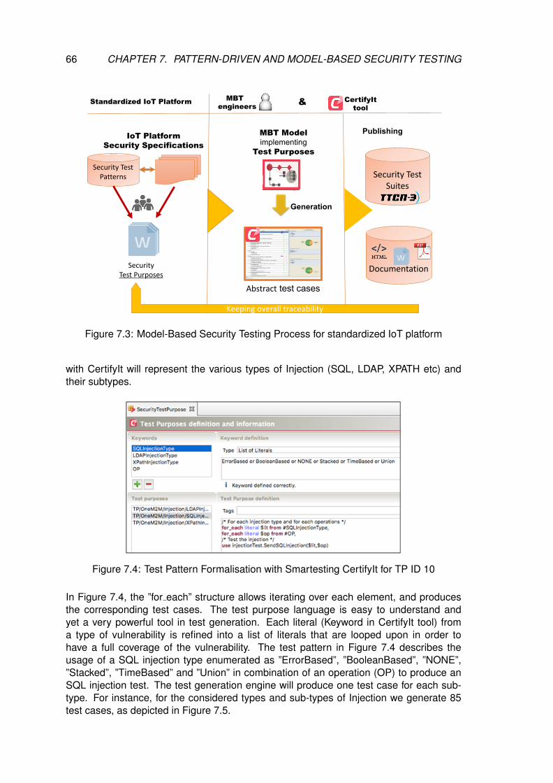
66 CHAPTER 7. PATTERN-DRIVEN AND MODEL-BASED SECURITY TESTING
IoT PlatformSecurity Specifications
Security Test Suites
MBT Modelimplementing
Test Purposes
SecurityTest Purposes
MBT engineers
Abstract test cases
CertifyIt tool
&
Documentation
Keeping overall traceability
Publishing
Generation
Security Test Patterns
Standardized IoT Platform
Figure 7.3: Model-Based Security Testing Process for standardized IoT platform
with CertifyIt will represent the various types of Injection (SQL, LDAP, XPATH etc) andtheir subtypes.
Figure 7.4: Test Pattern Formalisation with Smartesting CertifyIt for TP ID 10
In Figure 7.4, the ”for each” structure allows iterating over each element, and producesthe corresponding test cases. The test purpose language is easy to understand andyet a very powerful tool in test generation. Each literal (Keyword in CertifyIt tool) froma type of vulnerability is refined into a list of literals that are looped upon in order tohave a full coverage of the vulnerability. The test pattern in Figure 7.4 describes theusage of a SQL injection type enumerated as ”ErrorBased”, ”BooleanBased”, ”NONE”,”Stacked”, ”TimeBased” and ”Union” in combination of an operation (OP) to produce anSQL injection test. The test generation engine will produce one test case for each sub-type. For instance, for the considered types and sub-types of Injection we generate 85test cases, as depicted in Figure 7.5.
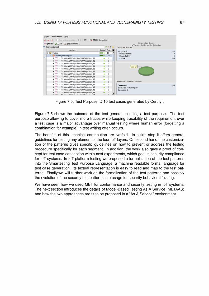
7.3. USING TP FOR MBS FUNCTIONAL AND VULNERABILITY TESTING 67
Figure 7.5: Test Purpose ID 10 test cases generated by CertifyIt
Figure 7.5 shows the outcome of the test generation using a test purpose. The testpurpose allowing to cover more traces while keeping tracability of the requirement overa test case is a major advantage over manual testing where human error (forgetting acombination for example) in test writing often occurs.
The benefits of this technical contribution are twofold. In a first step it offers generalguidelines for testing any element of the four IoT layers. On second hand, the customiza-tion of the patterns gives specific guidelines on how to prevent or address the testingprocedure specifically for each segment. In addition, the work also gave a proof of con-cept for test case conception within next experiments, which goal is security compliancefor IoT systems. In IoT platform testing we proposed a formalization of the test patternsinto the Smartesting Test Purpose Language, a machine readable formal language fortest case generation. Its textual representation is easy to read and map to the test pat-terns. Finally,we will further work on the formalization of the test patterns and possiblythe evolution of the security test patterns into usage for security behavioral fuzzing.
We have seen how we used MBT for conformance and security testing in IoT systems.The next section introduces the details of Model-Based Testing As A Service (MBTAAS)and how the two approaches are fit to be proposed in a ”As A Service” environment.

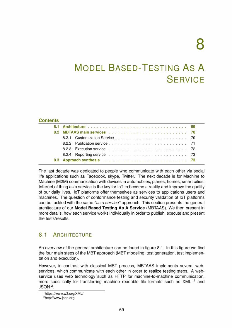
8MODEL BASED-TESTING AS A
SERVICE
Contents8.1 Architecture . . . . . . . . . . . . . . . . . . . . . . . . . . . . . . . . . 698.2 MBTAAS main services . . . . . . . . . . . . . . . . . . . . . . . . . . 70
8.2.1 Customization Service . . . . . . . . . . . . . . . . . . . . . . . . 708.2.2 Publication service . . . . . . . . . . . . . . . . . . . . . . . . . . 718.2.3 Execution service . . . . . . . . . . . . . . . . . . . . . . . . . . 728.2.4 Reporting service . . . . . . . . . . . . . . . . . . . . . . . . . . 73
8.3 Approach synthesis . . . . . . . . . . . . . . . . . . . . . . . . . . . . 73
The last decade was dedicated to people who communicate with each other via sociallife applications such as Facebook, skype, Twitter. The next decade is for Machine toMachine (M2M) communication with devices in automobiles, planes, homes, smart cities.Internet of thing as a service is the key for IoT to become a reality and improve the qualityof our daily lives. IoT platforms offer themselves as services to applications users andmachines. The question of conformance testing and security validation of IoT platformscan be tackled with the same ”as a service” approach. This section presents the generalarchitecture of our Model Based Testing As A Service (MBTAAS). We then present inmore details, how each service works individually in order to publish, execute and presentthe tests/results.
8.1 ARCHITECTURE
An overview of the general architecture can be found in figure 8.1. In this figure we findthe four main steps of the MBT approach (MBT modeling, test generation, test implemen-tation and execution).
However, in contrast with classical MBT process, MBTAAS implements several web-services, which communicate with each other in order to realize testing steps. A web-service uses web technology such as HTTP for machine-to-machine communication,more specifically for transferring machine readable file formats such as XML 1 andJSON 2.
1https://www.w3.org/XML/2http://www.json.org
69
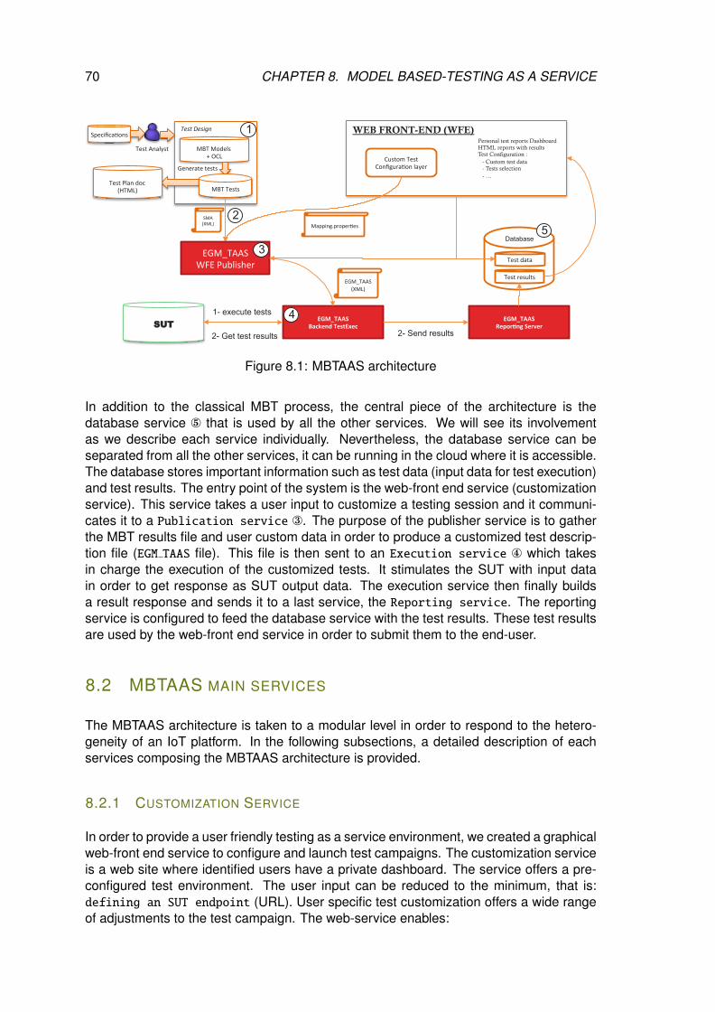
70 CHAPTER 8. MODEL BASED-TESTING AS A SERVICE
WEB FRONT-END (WFE)
Personal test reports Dashboard HTML reports with results Test Configuration : - Custom test data - Tests selection - …
Specifica(ons,Test%Design%
MBT,Models,+,OCL,
Test,Plan,doc,(HTML), MBT,Tests,
Test,Analyst,
Generate,tests,
SUT
EGM_TAAS((Backend(TestExec(
EGM_TAAS(Repor7ng(Server(
Test,results,
Test,data,
Database
,,
EGM_TAAS,,(XML),
,
EGM_TAAS,WFE,Publisher,
Custom,Test,Configura(on,layer,
,,
Mapping.proper(es,
,
,,
SMA,(XML),
,
2- Get test results
1- execute tests
2- Send results
1
2
3
4
5
Figure 8.1: MBTAAS architecture
In addition to the classical MBT process, the central piece of the architecture is thedatabase service ° that is used by all the other services. We will see its involvementas we describe each service individually. Nevertheless, the database service can beseparated from all the other services, it can be running in the cloud where it is accessible.The database stores important information such as test data (input data for test execution)and test results. The entry point of the system is the web-front end service (customizationservice). This service takes a user input to customize a testing session and it communi-cates it to a Publication service ®. The purpose of the publisher service is to gatherthe MBT results file and user custom data in order to produce a customized test descrip-tion file (EGM TAAS file). This file is then sent to an Execution service ¯ which takesin charge the execution of the customized tests. It stimulates the SUT with input datain order to get response as SUT output data. The execution service then finally buildsa result response and sends it to a last service, the Reporting service. The reportingservice is configured to feed the database service with the test results. These test resultsare used by the web-front end service in order to submit them to the end-user.
8.2 MBTAAS MAIN SERVICES
The MBTAAS architecture is taken to a modular level in order to respond to the hetero-geneity of an IoT platform. In the following subsections, a detailed description of eachservices composing the MBTAAS architecture is provided.
8.2.1 CUSTOMIZATION SERVICE
In order to provide a user friendly testing as a service environment, we created a graphicalweb-front end service to configure and launch test campaigns. The customization serviceis a web site where identified users have a private dashboard. The service offers a pre-configured test environment. The user input can be reduced to the minimum, that is:defining an SUT endpoint (URL). User specific test customization offers a wide rangeof adjustments to the test campaign. The web-service enables:
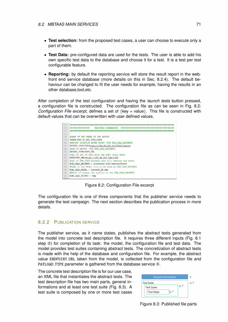
8.2. MBTAAS MAIN SERVICES 71
• Test selection: from the proposed test cases, a user can choose to execute only apart of them.
• Test Data: pre-configured data are used for the tests. The user is able to add hisown specific test data to the database and choose it for a test. It is a test per testconfigurable feature.
• Reporting: by default the reporting service will store the result report in the web-front end service database (more details on this in Sec. 8.2.4). The default be-haviour can be changed to fit the user needs for example, having the results in another database,tool,etc.
After completion of the test configuration and having the launch tests button pressed,a configuration file is constructed. The configuration file as can be seen in Fig. 8.2:Configuration File excerpt, defines a set of {key = value}. This file is constructed withdefault values that can be overwritten with user defined values.
Figure 8.2: Configuration File excerpt
The configuration file is one of three components that the publisher service needs togenerate the test campaign. The next section describes the publication process in moredetails.
8.2.2 PUBLICATION SERVICE
The publisher service, as it name states, publishes the abstract tests generated fromthe model into concrete test description file. It requires three different inputs (Fig. 8.1step ) for completion of its task: the model, the configuration file and test data. Themodel provides test suites containing abstract tests. The concretization of abstract testsis made with the help of the database and configuration file. For example, the abstractvalue ENDPOINT URL taken from the model, is collected from the configuration file andPAYLOAD TYPE parameter is gathered from the database service °.
General'informa,on'
Test'Suite''
1'
1..*'
Test'Cases'
Test'Steps'
1..*'
1..*'
Figure 8.3: Published file parts
The concrete test description file is for our use case,an XML file that instantiates the abstract tests. Thetest description file has two main parts, general in-formations and at least one test suite (Fig. 8.3). Atest suite is composed by one or more test cases

72 CHAPTER 8. MODEL BASED-TESTING AS A SERVICE
and a test case itself is composed of one or moretest steps. This hierarchy respects the IEEE 829-2008, Standard for Software and System Test Documentation.
The general information part of the file is useful to execute the tests (Sec. 8.2.3) andreport the results. Here are some of the most important parameters that can be found inthat part:
• owner: used for traceability purposes. It allows to know who is the detainer of thetest in order to present it in his personal cloud dashboard.
• sut endpoint: the hostname/ip address of the System Under Test. This addressshould be reachable from the execution service point of view.
• location: the hostname/ip address of the reporting service (Sec. 8.2.4).
The test suites contain all useful test information. In our case, for FIWARE, the appli-cations are HTTP-based RESTful applications. The mandatory informations required tosucceed a RESTful query are: the URL (SUT endpoint) and the HTTP method (GET,POST, PUT, DELETE). The Test suite and test cases purpose is the ordering and namingof the test but the test information and test data are stored in the test steps. Each teststep have its own configuration. Once the file published, it is sent to the execution servicein order to execute the tests.
8.2.3 EXECUTION SERVICE
The execution service is the functional core of the MBTAAS architecture. The executionservice will run the test and collect results depending on the configuration of the receivedtest description file. FIWARE RESTful interface tests are executed with the REST ex-ecution module. Each test is run against the SUT and a result report (Listing 8.1) isconstructed on test step completion. The result report contains information on date-timeof execution, time spent executing the step and some other test specific values. The ”end-point” represent the URL value and validity of where the step should be run. An invalidendpoint would allow to skip the type check on the endpoint value and thus allowing togather an execution error. The response of each step is validated within the ”assertion -list” tags (test oracle). It validates each assertion depending on the assertion type andvalues with the response received.
Listing 8.1 – Test step result report<t e s t s t e p name= ” UpdateEnt i ty1 ”>
<execut ionResu l ts><t imestamp>{TIMESTAMP}< / t imestamp>
<executionTimeMs>22< / executionTimeMs>< / execut ionResu l ts><endpoint>
<value>{ IP} : {PORT} / upContext< / value>< i s i n v a l i d>f a l s e< / i s i n v a l i d>
< / endpoint><method>POST< / method><headers>{HEADERS}< / headers><payload>{PAYLOAD}< / payload><a s s e r t i o n l i s t>
<asse r t i on><type>JSON< / type><key>code< / key>
<value>404< / value><r e s u l t>f a l s e< / r e s u l t>
< / asse r t i on>< / a s s e r t i o n l i s t><r e s u l t>f a l s e< / r e s u l t><response>{
” errorCode ” : {” code ” : ” 400 ” ,” reasonPhrase ” : ”Bad Request ” ,” d e t a i l s ” : ”JSON Parse Er ro r ”
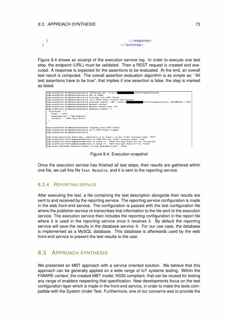
8.3. APPROACH SYNTHESIS 73
}}
< / response>< / t e s t s t e p>
Figure 8.4 shows an excerpt of the execution service log. In order to execute one teststep, the endpoint (URL) must be validated. Then a REST request is created and exe-cuted. A response is expected for the assertions to be evaluated. At the end, an overalltest result is computed. The overall assertion evaluation algorithm is as simple as: ”Alltest assertions have to be true”, that implies if one assertion is false, the step is markedas failed.
Figure 8.4: Execution snapshot
Once the execution service has finished all test steps, their results are gathered withinone file, we call this file Test Results, and it is sent to the reporting service.
8.2.4 REPORTING SERVICE
After executing the test, a file containing the test description alongside their results aresent to and received by the reporting service. The reporting service configuration is madein the web front-end service. The configuration is passed with the test configuration filewhere the publisher service re-transcribes that information to the file sent to the executionservice. The execution service then includes the reporting configuration in the report filewhere it is used in the reporting service once it receives it. By default the reportingservice will save the results in the database service °. For our use case, the databaseis implemented as a MySQL database. This database is afterwards used by the webfront-end service to present the test results to the user.
8.3 APPROACH SYNTHESIS
We presented an MBT approach with a service oriented solution. We believe that thisapproach can be generally applied on a wide range of IoT systems testing. Within theFIWARE context, the created MBT model, NGSI compliant, that can be reused for testingany range of enablers respecting that specification. New developments focus on the testconfiguration layer which is made in the front-end service, in order to make the tests com-patible with the System Under Test. Furthermore, one of our concerns was to provide the
74 CHAPTER 8. MODEL BASED-TESTING AS A SERVICE
IoT platform tests to the community in the easiest way possible, including the possibilityto choose the version of standard compliance only by model selection. This is done withthe service oriented approach, providing to all involved stakeholders (not only testers) thecapacity to test their IoT system remotely. The MBTAAS approach is suitable for testingboth approaches introduced previously: behavioral (Chapter 6) and Security (Chapter 7)testing. Using a behavioral model in an MBTAAS approach, the proposed tests result willreflect on the conformance of the SUT to the standard represented by the model. Onthe other hand, and with the same principles, if a security model is used in combinationof test purposes, the result with reflect the level of resistance of the SUT over the testedvulnerabilities. MBTAAS is a test synchronization element, a proxy for test execution. Itbrings the transition from modelling and test generation to test execution directly withoutworrying about test adaptation for test execution. As a matter of fact, with standard IoTplatforms and standarized IoT systems, the standard describes an interface that all im-plementation are required to develop. This enables to have a common adaptation layerto test all systems under tests implementing a modelized standard.
That being said, the drawbacks of this approach are observed when approaching imma-ture IoT systems or implementation that are still under development. Those systems areoften developed internally and are not deployed on an accessible internet environmentto the public. The MBTAAS approach rely on its SUT being available through a public IPaddress in order to reach it and execute the tests. This approach show that it is somewhatnot so straightforward in testing less mature systems but it is more adapted to deployedIoT systems that require constant validation over it’s lifetime. The need of validation canbe a result of system patching after deployment or the implementation of new securityfeatures after a zero day attack.
The next session presents the behavioral fuzzing for IoT systems and its capabilities todetect errors that cannot be detected with the behavioral and security MBT approaches.
9BEHAVIORAL FUZZING FOR IOT
SYSTEMS
Contents9.1 MBT specificities for the IoT behavioral fuzzing testing . . . . . . . 759.2 MBT Model . . . . . . . . . . . . . . . . . . . . . . . . . . . . . . . . . . 769.3 Test generation . . . . . . . . . . . . . . . . . . . . . . . . . . . . . . . 779.4 Behavioral fuzzing approach synthesis . . . . . . . . . . . . . . . . . 79
The MBT for the IoT behavioral fuzzing testing model is based on the same MBT modelsused for security functional and vulnerability testing; it generates test cases using behav-ioral fuzzing. Contrary to the previous two approaches where the test case generationaims to cover the test objectives produced from the test purposes, the MBeeTle fuzzingtool generates weighted random test cases to cover the test objectives based on the ex-pected behavior of the system. The tool relies on the principle to rapidly generate ashigh as possible many fuzzed tests with a substantial number of steps in each periodusing a weighted random algorithm. The generated tests are valid with respect to theconstraints in the MBT model. Thus, contrary to most fuzzers, the produced test caseson the one hand are syntactically correct with respect to the systems inputs. On the otherhand, since it uses a weighted random algorithm and measures the coverage of the be-haviors, it avoids duplication of the generated tests, which makes the test evaluation andassessment easier. This section introduces in a first place the MBT specifities for theIoT behavioral fuzzing testing and show how the model is designed to obtain test casegeneration and execution.
9.1 MBT SPECIFICITIES FOR THE IOT BEHAVIORAL FUZZING TEST-ING
The rapidity of MBT behavioral fuzzing is an asset for the methodology and contrary toclassical functional testing approach, it explores the system states in various uncommoncontexts and potentially placing the system into a failed state. Figure 9.1 depicts at ahigh level the test generation algorithm. Each step covers a test objective, which corre-sponds to one behavior of the system identified in the model in the OCL expression in anoperation with specific pre-existing tags @REQ/@AIM (illustrated in the figure). A step isgenerated by randomly choosing the available states possibly leading to an error from a
75
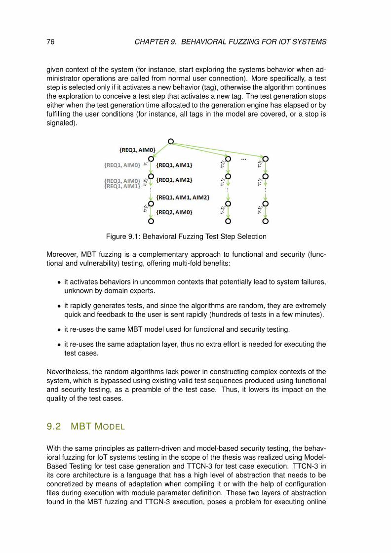
76 CHAPTER 9. BEHAVIORAL FUZZING FOR IOT SYSTEMS
given context of the system (for instance, start exploring the systems behavior when ad-ministrator operations are called from normal user connection). More specifically, a teststep is selected only if it activates a new behavior (tag), otherwise the algorithm continuesthe exploration to conceive a test step that activates a new tag. The test generation stopseither when the test generation time allocated to the generation engine has elapsed or byfulfilling the user conditions (for instance, all tags in the model are covered, or a stop issignaled).
Figure 9.1: Behavioral Fuzzing Test Step Selection
Moreover, MBT fuzzing is a complementary approach to functional and security (func-tional and vulnerability) testing, offering multi-fold benefits:
• it activates behaviors in uncommon contexts that potentially lead to system failures,unknown by domain experts.
• it rapidly generates tests, and since the algorithms are random, they are extremelyquick and feedback to the user is sent rapidly (hundreds of tests in a few minutes).
• it re-uses the same MBT model used for functional and security testing.
• it re-uses the same adaptation layer, thus no extra effort is needed for executing thetest cases.
Nevertheless, the random algorithms lack power in constructing complex contexts of thesystem, which is bypassed using existing valid test sequences produced using functionaland security testing, as a preamble of the test case. Thus, it lowers its impact on thequality of the test cases.
9.2 MBT MODEL
With the same principles as pattern-driven and model-based security testing, the behav-ioral fuzzing for IoT systems testing in the scope of the thesis was realized using Model-Based Testing for test case generation and TTCN-3 for test case execution. TTCN-3 inits core architecture is a language that has a high level of abstraction that needs to beconcretized by means of adaptation when compiling it or with the help of configurationfiles during execution with module parameter definition. These two layers of abstractionfound in the MBT fuzzing and TTCN-3 execution, poses a problem for executing online
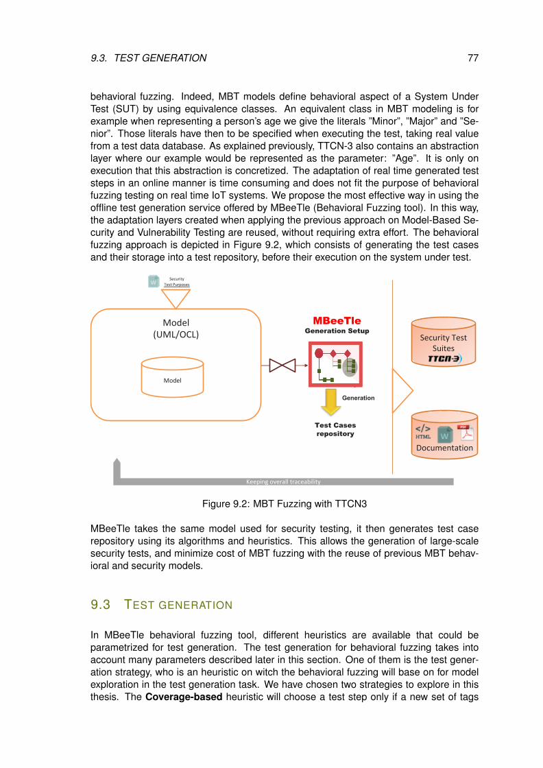
9.3. TEST GENERATION 77
behavioral fuzzing. Indeed, MBT models define behavioral aspect of a System UnderTest (SUT) by using equivalence classes. An equivalent class in MBT modeling is forexample when representing a person’s age we give the literals ”Minor”, ”Major” and ”Se-nior”. Those literals have then to be specified when executing the test, taking real valuefrom a test data database. As explained previously, TTCN-3 also contains an abstractionlayer where our example would be represented as the parameter: ”Age”. It is only onexecution that this abstraction is concretized. The adaptation of real time generated teststeps in an online manner is time consuming and does not fit the purpose of behavioralfuzzing testing on real time IoT systems. We propose the most effective way in using theoffline test generation service offered by MBeeTle (Behavioral Fuzzing tool). In this way,the adaptation layers created when applying the previous approach on Model-Based Se-curity and Vulnerability Testing are reused, without requiring extra effort. The behavioralfuzzing approach is depicted in Figure 9.2, which consists of generating the test casesand their storage into a test repository, before their execution on the system under test.
Model(UML/OCL)
Model
MBeeTleGeneration Setup
SecurityTest Purposes
Generation
Test Cases repository
Documentation
Security Test Suites
Keeping overall traceability
Figure 9.2: MBT Fuzzing with TTCN3
MBeeTle takes the same model used for security testing, it then generates test caserepository using its algorithms and heuristics. This allows the generation of large-scalesecurity tests, and minimize cost of MBT fuzzing with the reuse of previous MBT behav-ioral and security models.
9.3 TEST GENERATION
In MBeeTle behavioral fuzzing tool, different heuristics are available that could beparametrized for test generation. The test generation for behavioral fuzzing takes intoaccount many parameters described later in this section. One of them is the test gener-ation strategy, who is an heuristic on witch the behavioral fuzzing will base on for modelexploration in the test generation task. We have chosen two strategies to explore in thisthesis. The Coverage-based heuristic will choose a test step only if a new set of tags
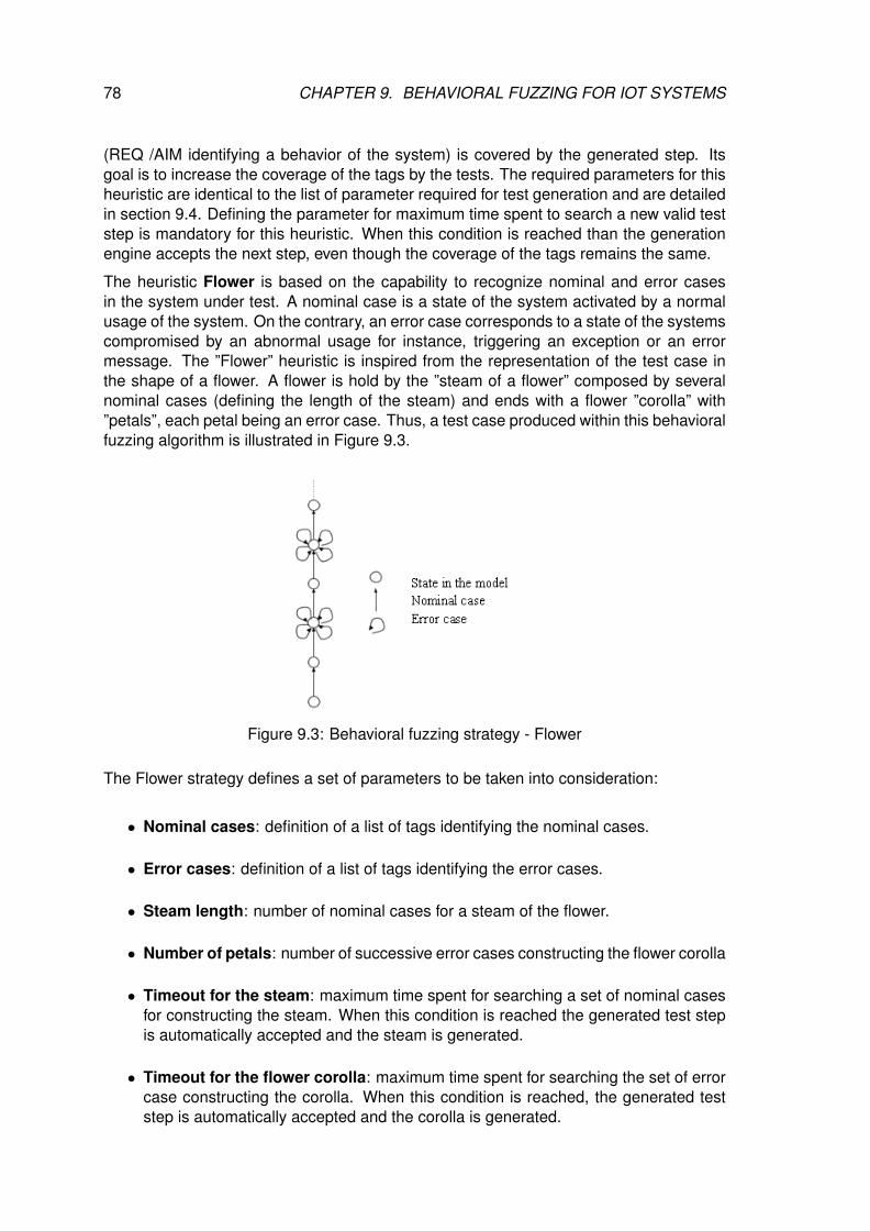
78 CHAPTER 9. BEHAVIORAL FUZZING FOR IOT SYSTEMS
(REQ /AIM identifying a behavior of the system) is covered by the generated step. Itsgoal is to increase the coverage of the tags by the tests. The required parameters for thisheuristic are identical to the list of parameter required for test generation and are detailedin section 9.4. Defining the parameter for maximum time spent to search a new valid teststep is mandatory for this heuristic. When this condition is reached than the generationengine accepts the next step, even though the coverage of the tags remains the same.
The heuristic Flower is based on the capability to recognize nominal and error casesin the system under test. A nominal case is a state of the system activated by a normalusage of the system. On the contrary, an error case corresponds to a state of the systemscompromised by an abnormal usage for instance, triggering an exception or an errormessage. The ”Flower” heuristic is inspired from the representation of the test case inthe shape of a flower. A flower is hold by the ”steam of a flower” composed by severalnominal cases (defining the length of the steam) and ends with a flower ”corolla” with”petals”, each petal being an error case. Thus, a test case produced within this behavioralfuzzing algorithm is illustrated in Figure 9.3.
Figure 9.3: Behavioral fuzzing strategy - Flower
The Flower strategy defines a set of parameters to be taken into consideration:
• Nominal cases: definition of a list of tags identifying the nominal cases.
• Error cases: definition of a list of tags identifying the error cases.
• Steam length: number of nominal cases for a steam of the flower.
• Number of petals: number of successive error cases constructing the flower corolla
• Timeout for the steam: maximum time spent for searching a set of nominal casesfor constructing the steam. When this condition is reached the generated test stepis automatically accepted and the steam is generated.
• Timeout for the flower corolla: maximum time spent for searching the set of errorcase constructing the corolla. When this condition is reached, the generated teststep is automatically accepted and the corolla is generated.
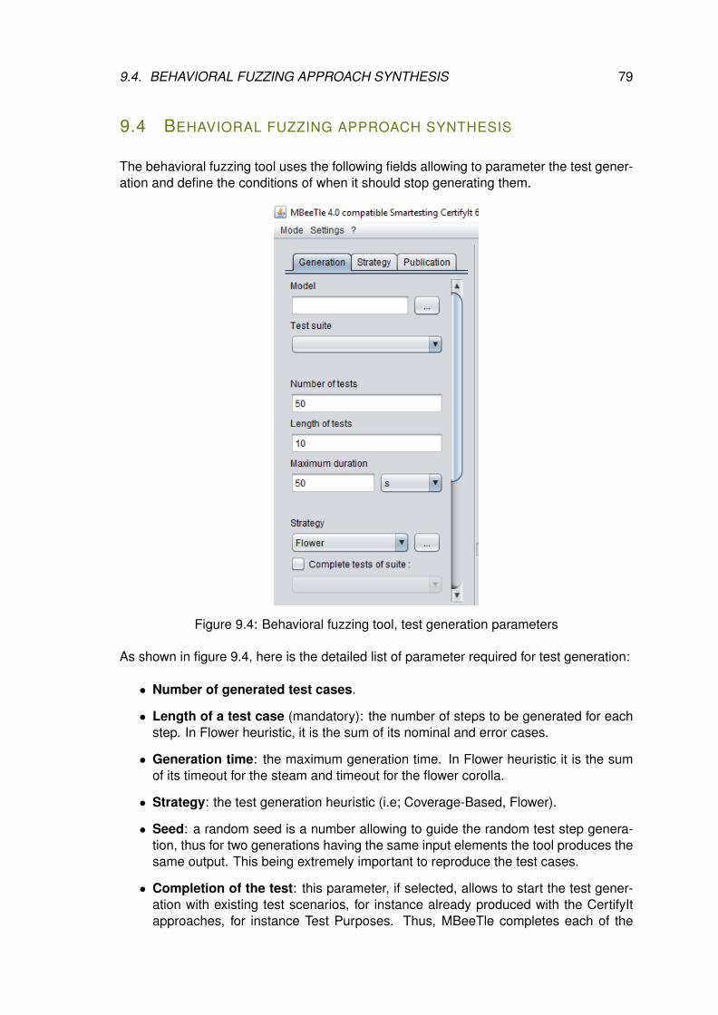
9.4. BEHAVIORAL FUZZING APPROACH SYNTHESIS 79
9.4 BEHAVIORAL FUZZING APPROACH SYNTHESIS
The behavioral fuzzing tool uses the following fields allowing to parameter the test gener-ation and define the conditions of when it should stop generating them.
Figure 9.4: Behavioral fuzzing tool, test generation parameters
As shown in figure 9.4, here is the detailed list of parameter required for test generation:
• Number of generated test cases.
• Length of a test case (mandatory): the number of steps to be generated for eachstep. In Flower heuristic, it is the sum of its nominal and error cases.
• Generation time: the maximum generation time. In Flower heuristic it is the sumof its timeout for the steam and timeout for the flower corolla.
• Strategy: the test generation heuristic (i.e; Coverage-Based, Flower).
• Seed: a random seed is a number allowing to guide the random test step genera-tion, thus for two generations having the same input elements the tool produces thesame output. This being extremely important to reproduce the test cases.
• Completion of the test: this parameter, if selected, allows to start the test gener-ation with existing test scenarios, for instance already produced with the CertifyItapproaches, for instance Test Purposes. Thus, MBeeTle completes each of the
80 CHAPTER 9. BEHAVIORAL FUZZING FOR IOT SYSTEMS
test cases according to the parametrized strategy. This allows to bypass classicaldifficulties of random algorithms to reach complex behaviors in an IoT system.
The number of test cases and the maximum length allow to determine the test generationstop conditions. If none of the conditions is reached than the test generation could bestopped only manually, using the stop button available in the tool. Section 10.6 proposea real use case visiting the implementation of the behavioral fuzzing methodology.
Powered by its powerful generation strategies, MBeeTle behavioral fuzzing tool, offers acomplementary approach to functional and security (functional and vulnerability) testing,with multi-fold benefits :
• it activates behaviors in uncommon contexts that potentially lead to system failures,unknown by domain experts.
• it rapidly generates tests, and since the algorithms are random, they are extremelyquick and feedback to the user is sent rapidly (hundreds of tests in a few minutes).
• it re-uses the same MBT model used for behavioral and security testing.
• it re-uses the same adaptation layer, thus no extra effort is needed for executing thetest cases.
The next part of the thesis explore the experimentation realized by restating the re-searches question and gives a synthesis of the results obtained.
IIIEXPERIMENTATIONS
81

10EXPERIMENTS
Contents10.1 Guideline for Experimentation’s . . . . . . . . . . . . . . . . . . . . . 84
10.1.1 MBT for IoT systems . . . . . . . . . . . . . . . . . . . . . . . . . 84
10.1.2 Model-based security testing for IoT . . . . . . . . . . . . . . . . 84
10.1.3 MBT for large scale IoT systems . . . . . . . . . . . . . . . . . . 85
10.2 FIWARE Testing Process using MBT . . . . . . . . . . . . . . . . . . . 85
10.2.1 MBT Model . . . . . . . . . . . . . . . . . . . . . . . . . . . . . . 85
10.2.2 Test case generation . . . . . . . . . . . . . . . . . . . . . . . . . 87
10.2.3 Test case reification & execution . . . . . . . . . . . . . . . . . . 89
10.2.4 Experimentation synthesis . . . . . . . . . . . . . . . . . . . . . 89
10.3 oneM2M Testing Process using MBT . . . . . . . . . . . . . . . . . . 91
10.3.1 Requirements and Test Purposes . . . . . . . . . . . . . . . . . 91
10.3.2 Model-Based Testing modelisation . . . . . . . . . . . . . . . . . 92
10.3.3 Generating TTCN-3 tests . . . . . . . . . . . . . . . . . . . . . . 93
10.3.4 Execution and Reporting . . . . . . . . . . . . . . . . . . . . . . 94
10.4 Access Control Policies (ACP) testing in oneM2M IoT standard . . . 96
10.5 ARMOUR Large scale end-to-end security . . . . . . . . . . . . . . . 97
10.5.1 MBT Model . . . . . . . . . . . . . . . . . . . . . . . . . . . . . . 99
10.5.2 Test case generation . . . . . . . . . . . . . . . . . . . . . . . . . 102
10.5.3 Test case reification . . . . . . . . . . . . . . . . . . . . . . . . . 103
10.5.4 Test case execution . . . . . . . . . . . . . . . . . . . . . . . . . 104
10.5.5 Experimentation & Results . . . . . . . . . . . . . . . . . . . . . 105
10.6 ARMOUR Behavioral Fuzzing . . . . . . . . . . . . . . . . . . . . . . . 106
10.6.1 Synergies between ARMOUR experiment 5 & 6 . . . . . . . . . 106
10.6.2 MBT Model . . . . . . . . . . . . . . . . . . . . . . . . . . . . . . 107
10.7 Test generation . . . . . . . . . . . . . . . . . . . . . . . . . . . . . . . 108
10.8 Experimentation results summary . . . . . . . . . . . . . . . . . . . . 110
10.8.1 MBT behavioral modeling . . . . . . . . . . . . . . . . . . . . . . 110
10.8.2 Pattern-driven and model-based security testing analysis . . . . 110
10.8.3 Behavioral fuzzing results . . . . . . . . . . . . . . . . . . . . . . 111
83
84 CHAPTER 10. EXPERIMENTS
This chapter describes the experiments of the thesis. We show case our real use-casesof the different approaches expressed in the second part of the thesis on technical con-tributions. We show how we applied MBT behavioral approach on a standardized IoTplatform, how we made usage of the pattern-driven and model-based security testing inorder to asses the security risks in a IoT platform and on a large scale IoT system. Wethen show the first steps realized in the behavioral fuzzing approach.
10.1 GUIDELINE FOR EXPERIMENTATION’S
This section introduces the experimentation and synthesis part of the thesis. We discussthe interrogations that lead us from theoretical work to experiments. Questions such aswhy have we done those experiments and how they validate our research objectives.
10.1.1 MBT FOR IOT SYSTEMS
For most IoT system that hit the market, they are tested against their specification for vali-dation. Hence, it is possible to find possible failures in a semi-automatic way without priormodeling. The beginning point of the thesis was to asses how we can fully automatizethe test procedure and reduce cost of testing for better testing coverage and adoption.Model-Based testing approach is based on building a behavioral model of the system un-der test in order to test its validity over its specification. We decided to investigate if MBTis a suitable solution in testing IoT system and started with exploring MBT behavioralmodeling for IoT platforms. In conformance testing, the goal is to gain knowledge aboutthe behaviour of a black-box system, by executing tests. We are interested in the syn-thesis aspect of testing where we perform an analysis task, i.e. we check conformanceto a given model of the IoT platform. By means of a case study, we wanted to show howeffective this approach is. We carried out experiments in which we implemented differ-ent models of two IoT standard implementations of FIWARE (section 10.2) and oneM2M(section 10.3) widely used in the Internet of Things.
10.1.2 MODEL-BASED SECURITY TESTING FOR IOT
With more and more objects connected these days, it is time to investigate how they canbe secured in a efficient way. The biggest concern, is that the users of IoT devices will notregard the security of the devices they are connecting. IoT will likely create unique andin some cases complex security challenges. As machines become autonomous they areable to interact with other machines and make decisions which impact upon the physicalworld. The systems may have fail-safes built in, but these are coded by humans who arefallible. Minimizing time to test without neglecting testing quality is primordial. From theprinciple that we have validated an MBT approach for an IoT system we investigated onhow we can respond to the need of better security testing in the domain. A methodol-ogy based on pattern-driven and model-based security testing emerged as we want todemonstrate the flexibility of MBT in testing IoT systems in general. As a matter of fact,we show in our experiments on the oneM2M standard (section 10.4) how a conformance

10.2. FIWARE TESTING PROCESS USING MBT 85
model, the same ones used in MBT for IoT systems, can be extended using test purposesto become security models for validation.
10.1.3 MBT FOR LARGE SCALE IOT SYSTEMS
A botnet is a collection of internet-connected devices, which may include PCs, servers,mobile devices and internet of things devices that are infected and controlled by a com-mon type of malware. Users are often unaware of a botnet infecting their system. Pre-venting botnet attacks has been complicated by the emergence of malware like Mirai [63],which targets routers and internet of things devices that have weak or factory defaultpasswords, and which can be easily compromised. As botnet malware has become moresophisticated, and communications have become decentralized (i.e, cloud), testing ef-forts have shifted away from single component testing to other large scale approaches.These approaches include identifying malware infections at the source devices, identify-ing and replicating the large scale communication methods. We investigated on tools ofbehavioral fuzzing enabling to test extensively IoT systems and provide security breachesthat are not detectable by the other approaches. We propose a case study (section 10.6)using the CertifyIt MbeeTle module. We want to show that Behavioral Fuzzing for largescale IoT can be achieved with minimal cost without compromising the quality of the testby reusing already provided conformance/security model.
The next section presents the FIWARE use case realized to validate our MBT approachfor IoT Systems.
10.2 FIWARE TESTING PROCESS USING MBT
This approach considers a subset of the UML to develop the MBT models, composed oftwo types of diagrams for the structural modelling: class diagrams and object diagrams,and OCL to represent the system’s behavior. From one MBT model, various test selectioncriteria can be applied, as shown in Figure 4.1. For FIWARE conformance testing, weused the Smartesting MBT approach and its test generation tool - CertifyIt, which usesthe coverage-based test selection criteria.
Tested requirements are manually extracted from the specification in order to asses anSUT conformance against the standard it implements. Each of the requirements is thantagged into the model, which serves as a basis to maintain traceability to the specification.Based on the specification information and tested requirements perimeter, the structureof the system is represented in a class diagram, which is a static view of the systemlimited to elements used for test generation.
10.2.1 MBT MODEL
The FIWARE class diagram (Fig. 10.1) is an abstraction of the IoT system:
• Its entities, with their attributes. The class Sut represents the system under testwhere things can register to it. The Complex Event Processing statement Cep-
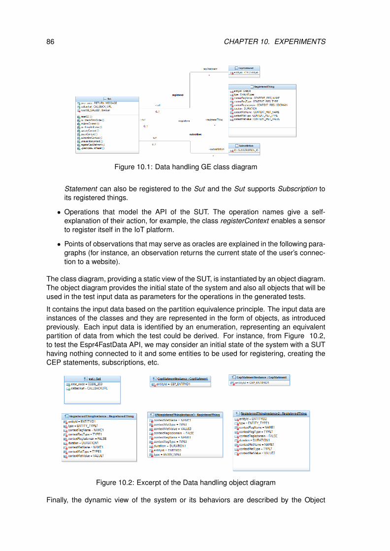
86 CHAPTER 10. EXPERIMENTS
Figure 10.1: Data handling GE class diagram
Statement can also be registered to the Sut and the Sut supports Subscription toits registered things.
• Operations that model the API of the SUT. The operation names give a self-explanation of their action, for example, the class registerContext enables a sensorto register itself in the IoT platform.
• Points of observations that may serve as oracles are explained in the following para-graphs (for instance, an observation returns the current state of the user’s connec-tion to a website).
The class diagram, providing a static view of the SUT, is instantiated by an object diagram.The object diagram provides the initial state of the system and also all objects that will beused in the test input data as parameters for the operations in the generated tests.
It contains the input data based on the partition equivalence principle. The input data areinstances of the classes and they are represented in the form of objects, as introducedpreviously. Each input data is identified by an enumeration, representing an equivalentpartition of data from which the test could be derived. For instance, from Figure 10.2,to test the Espr4FastData API, we may consider an initial state of the system with a SUThaving nothing connected to it and some entities to be used for registering, creating theCEP statements, subscriptions, etc.
Figure 10.2: Excerpt of the Data handling object diagram
Finally, the dynamic view of the system or its behaviors are described by the Object

10.2. FIWARE TESTING PROCESS USING MBT 87
Constraint Language (OCL) constraints written as pre/postconditions in the operations ina class within a class diagram, as depicted in Fig 10.3. The test generation engine seesthese behavioral objects as test targets. The operations can have several behaviors,identified by the presence of the conditional operator, if-then-else. The precondition isthe union of the operation’s precondition and the conditions of a path that is necessary totraverse for reaching the behavior’s postcondition. The postcondition corresponds to thebehavior described by the action in the ”then” or ”else” clause of the conditional operator.
Figure 10.3: Object Constraint Language (OCL) example
A specific type of operation, called observation, defines the test oracle. The tester withthese special operations can define the system points or variables to observe, for in-stance, a function returns a code. Thus, based on these observations, the test oracle isautomatically generated for each test step. The next section provides us an inside viewon the test case generation process.
10.2.2 TEST CASE GENERATION
Based on the chosen test selection criteria, CertifyIt extracts the test objectives into a testsuite, called with the CertifyIt terminology a smartsuite.
In our case study, two smartsuites named EspR4FastData GETestSuite andUserTestScenarios were created (see Figure 10.4). The EspR4FastData GETestSuitetest suite indicates that the generation should be done for all defined test objectiveswhereas for the UserTestScenarios SmartSuite, they are user-defined scenarios of teststo define some very specific cases with the help of the MBT model. Based on the objectdiagram and the OCL postcondition, the CertifyIt tool automatically extracts a set of testtargets, which is the tool comprehensible form of a test. The test targets are used to drivethe test generation. As discussed previously, each test has a set of tags associated withit, which ensures the coverage and traceability to the specification. Figure 10.4 gives asnapshot of a test in the CertifyIt tool. On the left side, the tool lists all generated testsclustered per covered requirement. On the right side, the test case can be visualizedand for each step a test oracle is generated. As discussed, the tester with the obser-vation manually defines the system points to observe when calling any function. Figure,
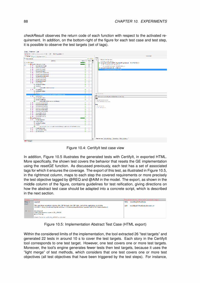
88 CHAPTER 10. EXPERIMENTS
checkResult observes the return code of each function with respect to the activated re-quirement. In addition, on the bottom-right of the figure for each test case and test step,it is possible to observe the test targets (set of tags).
Figure 10.4: CertifyIt test case view
In addition, Figure 10.5 illustrates the generated tests with CertifyIt, in exported HTML.More specifically, the shown test covers the behavior that resets the GE implementationusing the resetGE function. As discussed previously, each test has a set of associatedtags for which it ensures the coverage. The export of this test, as illustrated in Figure 10.5,in the rightmost column, maps to each step the covered requirements or more preciselythe test objective tagged by @REQ and @AIM in the model. The export, as shown in themiddle column of the figure, contains guidelines for test reification, giving directions onhow the abstract test case should be adapted into a concrete script, which is describedin the next section.
Figure 10.5: Implementation Abstract Test Case (HTML export)
Within the considered limits of the implementation, the tool extracted 26 ”test targets” andgenerated 22 tests in around 10 s to cover the test targets. Each story in the CertifyIttool corresponds to one test target. However, one test covers one or more test targets.Moreover, the tool’s engine generates fewer tests then test targets, because it uses the”light merge” of test methods, which considers that one test covers one or more testobjectives (all test objectives that have been triggered by the test steps). For instance,
10.2. FIWARE TESTING PROCESS USING MBT 89
the test shown in Figure 10.4 covers two test objectives. The ”light merge” of the testsshortly and on a high-level means that the generator will not produce separate tests forthe previously reached test targets.
The generated tests are abstract and to execute them on the SUT, they should be furtheradapted. For our study, a SoapUI exporter was created, which publishes tests into SoapUIXML projects using the SoapUI library.
10.2.3 TEST CASE REIFICATION & EXECUTION
In the used MBT approach, to execute tests on the system under test, the activity oftest cases reification, also named test case adaptation, is performed first; it consists ofcreating an adaptation layer to fulfil the gap between the abstract test case generatedfrom the MBT model, the concrete interface, and the initial set of test data of the systemunder test. As classically required for the test adaptation activities, exporting the AbstractTest Cases (ATS) into executable scripts is the first step to perform, in this case, theATS are exported into XML files which can be imported and executed on the SoapUI. Toillustrate the test adaptation activities, let us consider the following simple test case givenin Figure 10.5:
sut.resetGE(INVALIDURL)
-> sut.checkErrorCode () = URL_ERROR
This test has one step that calls the function to reset the data with a URL set to ”IN-VALIDURL”. CertifyIt automatically generates the test oracle, by using an observationoperation defined in the model, in our example, it is called ”checkErrorCode ”. For in-stance, the expected result of the test is the error URL ERROR. Further, we createda SoapUI exporter, which from the CertifyIt tool publishes the abstract test cases intoconcrete SoapUI projects. These projects can be imported and executed on SoapUI.Figure 10.6 shows an example of four executed test cases after importing the SoapUIproject. On the left side, the test cases are illustrated. On the right side, it is possibleto observe the test case execution status for each step. The green color on a test steprepresents its successful execution status while the red color represents a failed test step.On the top, a global test pass/fail result is summarized.
10.2.4 EXPERIMENTATION SYNTHESIS
In order to test the NGSI interfaces of FIWARE Generic Enablers implementations, asdescribed by the experimentation in section 10.2, we used a Model-Based Testing asa service execution approach. Execution of each test case produces a result log thatwere compiled into one testing report. As an illustration, the following XML code provideexecution result as obtained from the execution of test cases obtained from the NGSI9/10model.
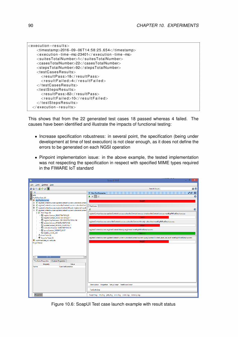
90 CHAPTER 10. EXPERIMENTS
<execut ion− r e s u l t s><t imestamp>2016−09−06T14:58:25 .654< / t imestamp><execut ion−t ime−ms>23401< / execut ion−t ime−ms><sui tesTotalNumber>1< / sui tesTotalNumber><casesTotalNumber>22< / casesTotalNumber><stepsTotalNumber>92< / stepsTotalNumber><testCasesResul ts>
<resu l tPass>18< / resu l tPass><r e s u l t F a i l e d>4< / r e s u l t F a i l e d>
< / testCasesResul ts><tes tS tepsResu l ts>
<resu l tPass>82< / resu l tPass><r e s u l t F a i l e d>10< / r e s u l t F a i l e d>
< / tes tS tepsResu l ts>< / execut ion− r e s u l t s>
This shows that from the 22 generated test cases 18 passed whereas 4 failed. Thecauses have been identified and illustrate the impacts of functional testing:
• Increase specification robustness: in several point, the specification (being underdevelopment at time of test execution) is not clear enough, as it does not define theerrors to be generated on each NGSI operation
• Pinpoint implementation issue: in the above example, the tested implementationwas not respecting the specification in respect with specified MIME types requiredin the FIWARE IoT standard
Figure 10.6: SoapUI Test case launch example with result status
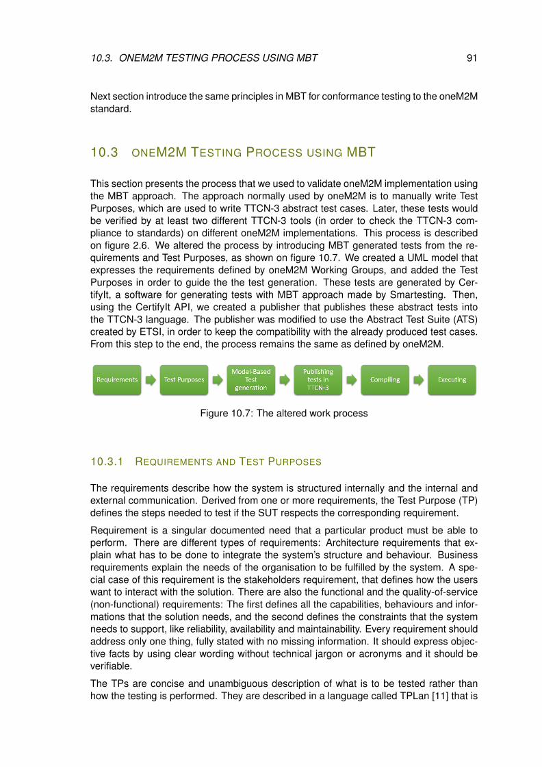
10.3. ONEM2M TESTING PROCESS USING MBT 91
Next section introduce the same principles in MBT for conformance testing to the oneM2Mstandard.
10.3 ONEM2M TESTING PROCESS USING MBT
This section presents the process that we used to validate oneM2M implementation usingthe MBT approach. The approach normally used by oneM2M is to manually write TestPurposes, which are used to write TTCN-3 abstract test cases. Later, these tests wouldbe verified by at least two different TTCN-3 tools (in order to check the TTCN-3 com-pliance to standards) on different oneM2M implementations. This process is describedon figure 2.6. We altered the process by introducing MBT generated tests from the re-quirements and Test Purposes, as shown on figure 10.7. We created a UML model thatexpresses the requirements defined by oneM2M Working Groups, and added the TestPurposes in order to guide the the test generation. These tests are generated by Cer-tifyIt, a software for generating tests with MBT approach made by Smartesting. Then,using the CertifyIt API, we created a publisher that publishes these abstract tests intothe TTCN-3 language. The publisher was modified to use the Abstract Test Suite (ATS)created by ETSI, in order to keep the compatibility with the already produced test cases.From this step to the end, the process remains the same as defined by oneM2M.
Figure 10.7: The altered work process
10.3.1 REQUIREMENTS AND TEST PURPOSES
The requirements describe how the system is structured internally and the internal andexternal communication. Derived from one or more requirements, the Test Purpose (TP)defines the steps needed to test if the SUT respects the corresponding requirement.
Requirement is a singular documented need that a particular product must be able toperform. There are different types of requirements: Architecture requirements that ex-plain what has to be done to integrate the system’s structure and behaviour. Businessrequirements explain the needs of the organisation to be fulfilled by the system. A spe-cial case of this requirement is the stakeholders requirement, that defines how the userswant to interact with the solution. There are also the functional and the quality-of-service(non-functional) requirements: The first defines all the capabilities, behaviours and infor-mations that the solution needs, and the second defines the constraints that the systemneeds to support, like reliability, availability and maintainability. Every requirement shouldaddress only one thing, fully stated with no missing information. It should express objec-tive facts by using clear wording without technical jargon or acronyms and it should beverifiable.
The TPs are concise and unambiguous description of what is to be tested rather thanhow the testing is performed. They are described in a language called TPLan [11] that is
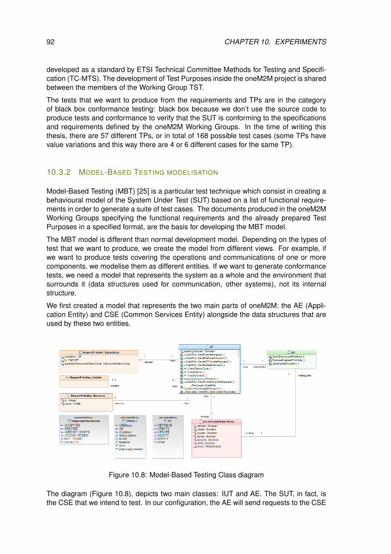
92 CHAPTER 10. EXPERIMENTS
developed as a standard by ETSI Technical Committee Methods for Testing and Specifi-cation (TC-MTS). The development of Test Purposes inside the oneM2M project is sharedbetween the members of the Working Group TST.
The tests that we want to produce from the requirements and TPs are in the categoryof black box conformance testing: black box because we don’t use the source code toproduce tests and conformance to verify that the SUT is conforming to the specificationsand requirements defined by the oneM2M Working Groups. In the time of writing thisthesis, there are 57 different TPs, or in total of 168 possible test cases (some TPs havevalue variations and this way there are 4 or 6 different cases for the same TP).
10.3.2 MODEL-BASED TESTING MODELISATION
Model-Based Testing (MBT) [25] is a particular test technique which consist in creating abehavioural model of the System Under Test (SUT) based on a list of functional require-ments in order to generate a suite of test cases. The documents produced in the oneM2MWorking Groups specifying the functional requirements and the already prepared TestPurposes in a specified format, are the basis for developing the MBT model.
The MBT model is different than normal development model. Depending on the types oftest that we want to produce, we create the model from different views. For example, ifwe want to produce tests covering the operations and communications of one or morecomponents, we modelise them as different entities. If we want to generate conformancetests, we need a model that represents the system as a whole and the environment thatsurrounds it (data structures used for communication, other systems), not its internalstructure.
We first created a model that represents the two main parts of oneM2M: the AE (Appli-cation Entity) and CSE (Common Services Entity) alongside the data structures that areused by these two entities.
Figure 10.8: Model-Based Testing Class diagram
The diagram (Figure 10.8), depicts two main classes: IUT and AE. The SUT, in fact, isthe CSE that we intend to test. In our configuration, the AE will send requests to the CSE
10.3. ONEM2M TESTING PROCESS USING MBT 93
and the CSE will respond to the AE’s requests. All test cases will be based on the samecommunication scheme. The underlying communication protocol (HTTP, CoAP, MQTT)will be defined by the TTCN-3 test port, which is different for every TTCN-3 tool.
CertifyIt uses different technologies and criteria to control the test generation. It uses themodel structure as a criteria, the input data space (splitting the data space into equiv-alence classes or using the Pairwise method to define couples of data) and uses thedescribed requirements as criteria to control the tests. Also, one can use the stochas-tic criteria to drive the test generation. From the model and the specifications, the testcases can be generated manually. But the benefits of MBT is in the automation of theprocess. A test suite can be generated automatically by means of algorithms based ondifferent techniques: random generation, graph and metaheuristic search algorithms andconstraint resolution with symbolic execution.
10.3.3 GENERATING TTCN-3 TESTS
At the moment we successfully generate all possible tests in CertifyIt, we have to convert(or, in the CertifyIt terminology - publish) them in a target language. The default publishersin CertifyIt are XML, JUnit and HTML. The XML publisher is the base publisher that willconvert all test cases and other model data to a XML file that then can be used by otherpublishers to generate tests in other formats. The publisher in JUnit generates tests thatcan be executed in Java with a glue code i.e. a code that will be an adapter between theSUT and the JUnit tests converting the abstract values into concrete ones. The HTMLpublisher serves mostly as documentation because its output is simply a web page whereall steps for every test case are shown. A matrix between requirements and test casescan be included in the document too.
Because we need our tests in TTCN-3 format, we have to use the Smartesting Certi-fyIt API in order to create a custom publisher for our needs. Our situation is somewhatunique: on one side we have the model and the generated tests; on the other we have theAbstract Test Suite (ATS) written by ETSI that contains TTCN-3 test cases, templates andcomponents. They use already defined types by the XSD documents that are convertedto TTCN-3 types automatically. So, our publisher has to write TTCN-3 tests adapted tothe ATS. In a normal case, it’s the publisher that will generate the skeleton of the adapter.That is the case, for example, with the JUnit publisher: every test case is generated in itsown file, and all the test cases (grouped in folders by test suite) share the same Adapter.This adapter usually consists of more files, some for the operations needed by the tests(construct a request, send a request or receive response) and some for data structures.In our case, we need to make modifications to the publisher in order to adapt the model tothe ATS. We need to adapt the model’s operations and data types to the ATS operationsand data types. That means that the object-oriented nature of the MBT process shouldbe transformed to a procedural type of language. Also, TTCN-3 supports structures thatdon’t exist in other programming languages. For example we need to decide when to usethe TTCN-3 send or receive function, or when and which templates to use. Usually, thepublisher takes all the informations from the model, that is, the model structure (types,instances, operations, values) and the test cases. It uses that information to ”translate”the test cases in the target language, TTCN-3. In this process, all structures remain withtheir names as they are created in the model.
The test structure inside the CertifyIt publisher is organised like this: Inside a project (that
94 CHAPTER 10. EXPERIMENTS
is, the model), there is a collection of test suites (defined by the tester) and every one ofthem contains generated test cases. A test case is ordered list of test steps, that basicallyare the model’s operations. We have access to these elements from the Smartesting APIusing a loop mechanism, for each test suite we create a separate file, inside which wewrite the corresponding test cases. TTCN-3 needs a control structure, and it implies twooptions: either write the control structure in each test suite file for the test cases insidethe suite, or make a separate file that imports all test suites and has a control structurethat executes all tests. In the loop of a test case, we have access to the test case metadata, but also it is in this process we export the static parts, like the test case postamble.The published tests cases have to use the created ATS, therefore, the publisher needto be configured to use ATS types, functions and data.Two different methods are used:hard-coding values and a mapping file. The mapping file is a clean solution because inthe event of changes, we don’t have to make changes inside the publisher in order toproduce TTCN-3 tests aligned with the existing ATS, but we don’t have the flexibility thathas the method of hard-coded values. Thus, we use the mapping files for values thatdon’t change thorough all of the test cases, like port names and timer timeouts, type orvalue conversion and renaming variables. The changes that has to be bound inside atest case must be hard-coded. This, for example, is used to differentiate between the testpreamble and the test body (usually the last operation in a test case is the test body, andall other operations are preambles) while the postamble is static. The difference betweenthe preamble and the test body is that in the body, being the main part of the test) wemanually prepare the data to be send and insert send/receive function calls directly in thetest case, instead of calling another function to do it. The send/receive part is one of theinstances where we had a lot of problems to synchronise the model data with the ATS.Namely, the model uses descriptive names for status codes that we expect to be returnedfrom the SUT instead of numeric ones, for example, instead of using status code 4004,we use ”NOT FOUND”. The descriptive names are used in order to avoid changing themodel if the oneM2M standard changes, because the meaning will be the same, but thevalue can change. In the beginning, in the model there was only a subset of values usedfor status code, so implementing the translation to their numeric value was simple in themapping file. But to avoid making a long ”dictionary” of names and values, we startedto search for alternative where to insert the data in the model so we don’t have to add itmanually in the mapping file. In the end, the solution was found: adding numeric valuesin the description field for every text value in the status code (to clarify, the status codewas implemented as enumeration class in the model, see Figure 10.8).
Other changes to the publisher linking it closely to the model and ATS, as already men-tioned, was separating the preamble from the test body. Every TP in the model was imple-mented as few requests that are created and sent, and thorough the observer functionswe wait for the response. The ATS is implemented otherwise: the preamble is separatedin functions that contain at least one send/receive call, and the test body send/receivecalls are implemented directly in the test case. Because the test structure in the modeland the ATS is different, the publisher’s role is to find a way to transform the first type oftest to the other.
10.3.4 EXECUTION AND REPORTING
TTCN-3 is an abstract language and it does not manage communication with the SUT. Inorder to do that, we need few things: A compiler/executor for TTCN-3 code and codec/-
10.3. ONEM2M TESTING PROCESS USING MBT 95
port implementation to communicate with the SUT. This is entirely compiler dependentbecause the codec and the port are only declared in TTCN-3. Usually, all of the com-pilers follow this procedure: compile TTCN-3 to a target language (TITAN1 uses C++,TTWorkbench2 uses Java), then add the Codec and System Adapter (SA) written in thetarget language. In the case of TITAN, the SA and the Codec are added as additionalC++ files that are compiled together, but in the TTWorkbench case, the SA and the Codecuse an API and compile separately from the tests and are added to the test executableas plugins and executed.
In our case, we used the open source tool TITAN as platform to compile and executeTTCN-3 tests. It’s based on Eclipse, and as of 2015 is a open source project supportedby the Eclipse Foundation and developed primarily by Ericsson. It has three major roles:
• The TTCN-3 design environment provides an efficient way to create the TTCN-3test suites. It’s built on the Eclipse Platform and has editors that provide the usualIDE features for TTCN-3 and the TITAN configuration file. Also, it allows generatingC++ code from TTCN-3 code and uses the built-in makefile generator to produceGCC makes to build the C++ code to an executable.
• The compiler compiles the TTCN-3 ATS tests and the TITAN runtime to an exe-cutable. Usually it needs a configuration file in order to be executed, because onehas to specify a lot of parameters, like IP address and port of the SUT. In this wayflexible execution scenarios can be created without re-building the ATS.
• TITAN runtime control, controls the execution of test cases in a distributed multi-platform environment. This control part produces logs in different format thoroughits logging API, and the logging is done via plugins. Several logging mechanismsmay be activated at the same time. Logging can be configured by verbosity and byevent types. Logs can be written into files or be send to another process or via anetwork connection to a 3rd party tool.
In a MBT scenario, the test cases generated from the model are necessarily abstract, asthe model itself does not contain low level information. Therefore the abstract test caseshas to be completed by a test harness, to become executable test cases. In order to sendand receive the data to and from the SUT we have to create the codec that will convert theTTCN-3 structures to real data and send it through the specified port, be it the network,or simple USB, serial port, radio signals, etc. oneM2M supports three different protocols,HTTP, CoAP and MQTT, the TITAN SA supports all of them. TITAN’s developer, Ericsson,has made SAs for every protocol, but it isn’t really useful to recompile every time whenthe SUT is tested with HTTP, MQTT and CoAP, but more than that, every protocol shouldsupport XML and JSON formatting. As a result, we have 6 different combinations. Tosolve this problem, we created a oneM2M SA that unifies all of these together.
1https://projects.eclipse.org/projects/tools.titan2http://www.spirent.com/Products/TTworkbench
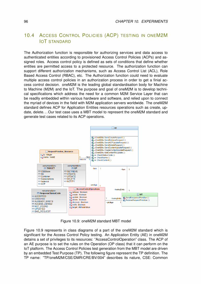
96 CHAPTER 10. EXPERIMENTS
10.4 ACCESS CONTROL POLICIES (ACP) TESTING IN ONEM2MIOT STANDARD
The Authorization function is responsible for authorizing services and data access toauthenticated entities according to provisioned Access Control Policies (ACPs) and as-signed roles. Access control policy is defined as sets of conditions that define whetherentities are permitted access to a protected resource. The authorization function cansupport different authorization mechanisms, such as Access Control List (ACL), RoleBased Access Control (RBAC), etc. The Authorization function could need to evaluatemultiple access control policies in an authorization process in order to get a finial ac-cess control decision. oneM2M is the leading global standardisation body for Machineto Machine (M2M) and the IoT. The purpose and goal of oneM2M is to develop techni-cal specifications which address the need for a common M2M Service Layer that canbe readily embedded within various hardware and software, and relied upon to connectthe myriad of devices in the field with M2M application servers worldwide. The oneM2Mstandard defines ACP for Application Entities resources operations such as create, up-date, delete. . . Our test case uses a MBT model to represent the oneM2M standard andgenerate test cases related to its ACP operations.
Figure 10.9: oneM2M standard MBT model
Figure 10.9 represents in class diagrams of a part of the oneM2M standard which issignificant for the Access Control Policy testing. An Application Entity (AE) in oneM2Mdetains a set of privileges to its resources: ”AccessControlOperation” class. The ACP ofan AE purpose is to set the rules on the Operation (OP class) that it can perform on theIoT platform. The Access Control Policies test generation from the MBT model are drivenby an embedded Test Purpose (TP). The following figure represent the TP definition. TheTP name: ”TP/oneM2M/CSE/DMR/CRE/BV/004” describes its nature, CSE: Common
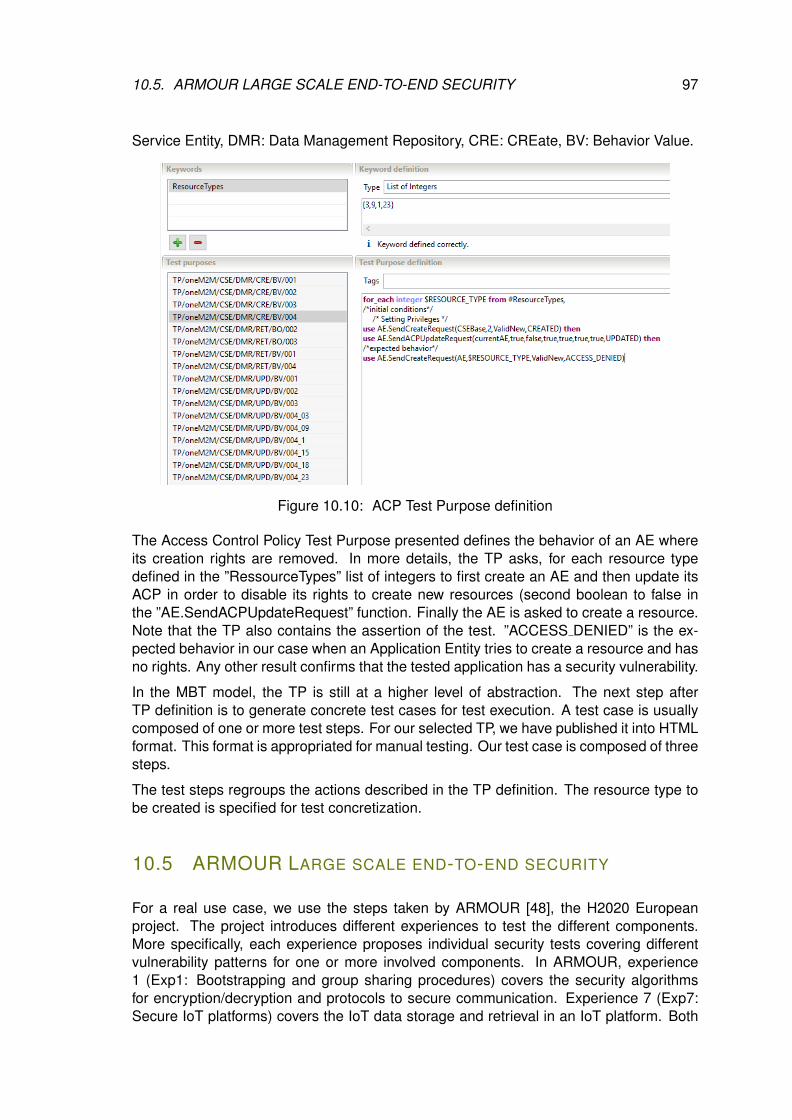
10.5. ARMOUR LARGE SCALE END-TO-END SECURITY 97
Service Entity, DMR: Data Management Repository, CRE: CREate, BV: Behavior Value.
Figure 10.10: ACP Test Purpose definition
The Access Control Policy Test Purpose presented defines the behavior of an AE whereits creation rights are removed. In more details, the TP asks, for each resource typedefined in the ”RessourceTypes” list of integers to first create an AE and then update itsACP in order to disable its rights to create new resources (second boolean to false inthe ”AE.SendACPUpdateRequest” function. Finally the AE is asked to create a resource.Note that the TP also contains the assertion of the test. ”ACCESS DENIED” is the ex-pected behavior in our case when an Application Entity tries to create a resource and hasno rights. Any other result confirms that the tested application has a security vulnerability.
In the MBT model, the TP is still at a higher level of abstraction. The next step afterTP definition is to generate concrete test cases for test execution. A test case is usuallycomposed of one or more test steps. For our selected TP, we have published it into HTMLformat. This format is appropriated for manual testing. Our test case is composed of threesteps.
The test steps regroups the actions described in the TP definition. The resource type tobe created is specified for test concretization.
10.5 ARMOUR LARGE SCALE END-TO-END SECURITY
For a real use case, we use the steps taken by ARMOUR [48], the H2020 Europeanproject. The project introduces different experiences to test the different components.More specifically, each experience proposes individual security tests covering differentvulnerability patterns for one or more involved components. In ARMOUR, experience1 (Exp1: Bootstrapping and group sharing procedures) covers the security algorithmsfor encryption/decryption and protocols to secure communication. Experience 7 (Exp7:Secure IoT platforms) covers the IoT data storage and retrieval in an IoT platform. Both
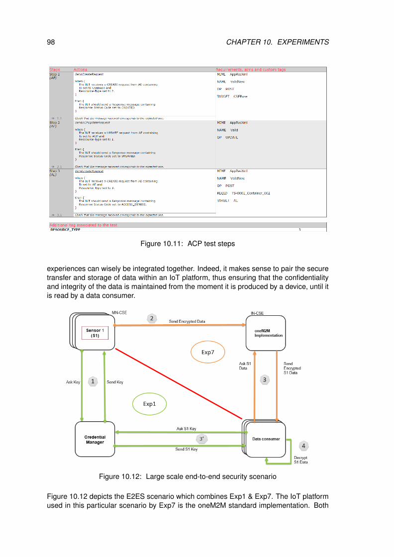
98 CHAPTER 10. EXPERIMENTS
Figure 10.11: ACP test steps
experiences can wisely be integrated together. Indeed, it makes sense to pair the securetransfer and storage of data within an IoT platform, thus ensuring that the confidentialityand integrity of the data is maintained from the moment it is produced by a device, until itis read by a data consumer.
Figure 10.12: Large scale end-to-end security scenario
Figure 10.12 depicts the E2ES scenario which combines Exp1 & Exp7. The IoT platformused in this particular scenario by Exp7 is the oneM2M standard implementation. Both
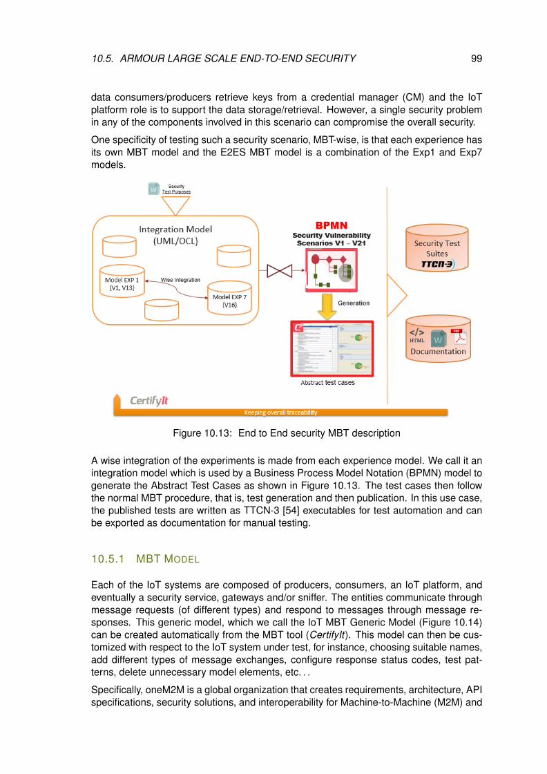
10.5. ARMOUR LARGE SCALE END-TO-END SECURITY 99
data consumers/producers retrieve keys from a credential manager (CM) and the IoTplatform role is to support the data storage/retrieval. However, a single security problemin any of the components involved in this scenario can compromise the overall security.
One specificity of testing such a security scenario, MBT-wise, is that each experience hasits own MBT model and the E2ES MBT model is a combination of the Exp1 and Exp7models.
Figure 10.13: End to End security MBT description
A wise integration of the experiments is made from each experience model. We call it anintegration model which is used by a Business Process Model Notation (BPMN) model togenerate the Abstract Test Cases as shown in Figure 10.13. The test cases then followthe normal MBT procedure, that is, test generation and then publication. In this use case,the published tests are written as TTCN-3 [54] executables for test automation and canbe exported as documentation for manual testing.
10.5.1 MBT MODEL
Each of the IoT systems are composed of producers, consumers, an IoT platform, andeventually a security service, gateways and/or sniffer. The entities communicate throughmessage requests (of different types) and respond to messages through message re-sponses. This generic model, which we call the IoT MBT Generic Model (Figure 10.14)can be created automatically from the MBT tool (CertifyIt). This model can then be cus-tomized with respect to the IoT system under test, for instance, choosing suitable names,add different types of message exchanges, configure response status codes, test pat-terns, delete unnecessary model elements, etc. . .
Specifically, oneM2M is a global organization that creates requirements, architecture, APIspecifications, security solutions, and interoperability for Machine-to-Machine (M2M) and
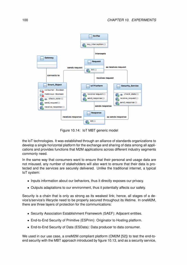
100 CHAPTER 10. EXPERIMENTS
Figure 10.14: IoT MBT generic model
the IoT technologies. It was established through an alliance of standards organizations todevelop a single horizontal platform for the exchange and sharing of data among all appli-cations and provides functions that M2M applications across different industry segmentscommonly need.
In the same way that consumers want to ensure that their personal and usage data arenot misused, any number of stakeholders will also want to ensure that their data is pro-tected and the services are securely delivered. Unlike the traditional internet, a typicalIoT system:
• Inputs information about our behaviors, thus it directly exposes our privacy.
• Outputs adaptations to our environment, thus it potentially affects our safety.
Security is a chain that is only as strong as its weakest link; hence, all stages of a de-vice’s/service’s lifecycle need to be properly secured throughout its lifetime. In oneM2M,there are three layers of protection for the communications:
• Security Association Establishment Framework (SAEF): Adjacent entities.
• End-to-End Security of Primitive (ESPrim): Originator to Hosting platform.
• End-to-End Security of Data (ESData): Data producer to data consumer.
We used in our use case, a oneM2M compliant platform (OM2M [52]) to test the end-to-end security with the MBT approach introduced by figure 10.13, and as a security service,
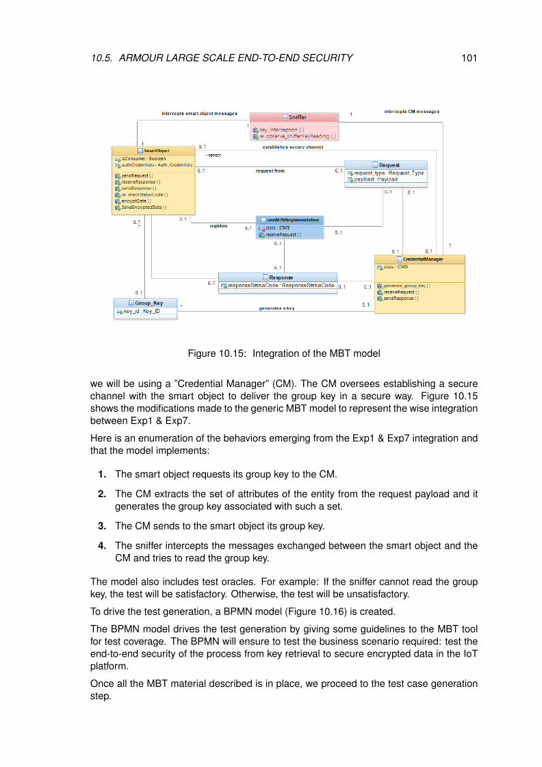
10.5. ARMOUR LARGE SCALE END-TO-END SECURITY 101
Figure 10.15: Integration of the MBT model
we will be using a ”Credential Manager” (CM). The CM oversees establishing a securechannel with the smart object to deliver the group key in a secure way. Figure 10.15shows the modifications made to the generic MBT model to represent the wise integrationbetween Exp1 & Exp7.
Here is an enumeration of the behaviors emerging from the Exp1 & Exp7 integration andthat the model implements:
1. The smart object requests its group key to the CM.
2. The CM extracts the set of attributes of the entity from the request payload and itgenerates the group key associated with such a set.
3. The CM sends to the smart object its group key.
4. The sniffer intercepts the messages exchanged between the smart object and theCM and tries to read the group key.
The model also includes test oracles. For example: If the sniffer cannot read the groupkey, the test will be satisfactory. Otherwise, the test will be unsatisfactory.
To drive the test generation, a BPMN model (Figure 10.16) is created.
The BPMN model drives the test generation by giving some guidelines to the MBT toolfor test coverage. The BPMN will ensure to test the business scenario required: test theend-to-end security of the process from key retrieval to secure encrypted data in the IoTplatform.
Once all the MBT material described is in place, we proceed to the test case generationstep.
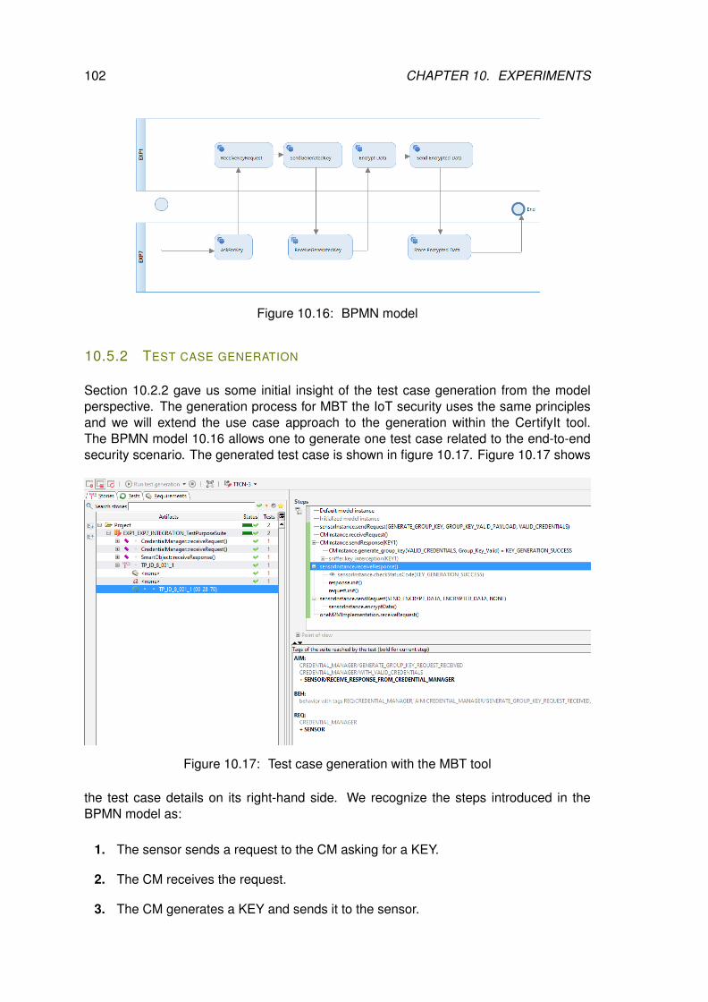
102 CHAPTER 10. EXPERIMENTS
Figure 10.16: BPMN model
10.5.2 TEST CASE GENERATION
Section 10.2.2 gave us some initial insight of the test case generation from the modelperspective. The generation process for MBT the IoT security uses the same principlesand we will extend the use case approach to the generation within the CertifyIt tool.The BPMN model 10.16 allows one to generate one test case related to the end-to-endsecurity scenario. The generated test case is shown in figure 10.17. Figure 10.17 shows
Figure 10.17: Test case generation with the MBT tool
the test case details on its right-hand side. We recognize the steps introduced in theBPMN model as:
1. The sensor sends a request to the CM asking for a KEY.
2. The CM receives the request.
3. The CM generates a KEY and sends it to the sensor.
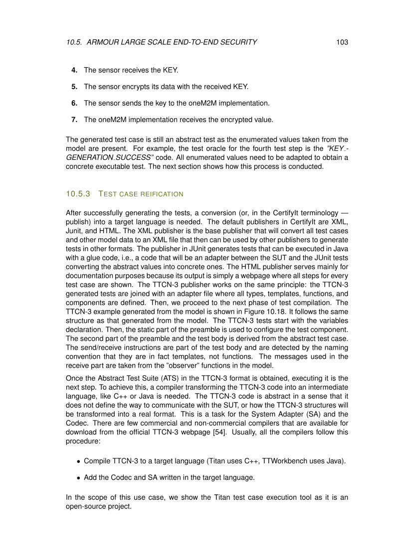
10.5. ARMOUR LARGE SCALE END-TO-END SECURITY 103
4. The sensor receives the KEY.
5. The sensor encrypts its data with the received KEY.
6. The sensor sends the key to the oneM2M implementation.
7. The oneM2M implementation receives the encrypted value.
The generated test case is still an abstract test as the enumerated values taken from themodel are present. For example, the test oracle for the fourth test step is the ”KEY -GENERATION SUCCESS” code. All enumerated values need to be adapted to obtain aconcrete executable test. The next section shows how this process is conducted.
10.5.3 TEST CASE REIFICATION
After successfully generating the tests, a conversion (or, in the CertifyIt terminology —publish) into a target language is needed. The default publishers in CertifyIt are XML,Junit, and HTML. The XML publisher is the base publisher that will convert all test casesand other model data to an XML file that then can be used by other publishers to generatetests in other formats. The publisher in JUnit generates tests that can be executed in Javawith a glue code, i.e., a code that will be an adapter between the SUT and the JUnit testsconverting the abstract values into concrete ones. The HTML publisher serves mainly fordocumentation purposes because its output is simply a webpage where all steps for everytest case are shown. The TTCN-3 publisher works on the same principle: the TTCN-3generated tests are joined with an adapter file where all types, templates, functions, andcomponents are defined. Then, we proceed to the next phase of test compilation. TheTTCN-3 example generated from the model is shown in Figure 10.18. It follows the samestructure as that generated from the model. The TTCN-3 tests start with the variablesdeclaration. Then, the static part of the preamble is used to configure the test component.The second part of the preamble and the test body is derived from the abstract test case.The send/receive instructions are part of the test body and are detected by the namingconvention that they are in fact templates, not functions. The messages used in thereceive part are taken from the ”observer” functions in the model.
Once the Abstract Test Suite (ATS) in the TTCN-3 format is obtained, executing it is thenext step. To achieve this, a compiler transforming the TTCN-3 code into an intermediatelanguage, like C++ or Java is needed. The TTCN-3 code is abstract in a sense that itdoes not define the way to communicate with the SUT, or how the TTCN-3 structures willbe transformed into a real format. This is a task for the System Adapter (SA) and theCodec. There are few commercial and non-commercial compilers that are available fordownload from the official TTCN-3 webpage [54]. Usually, all the compilers follow thisprocedure:
• Compile TTCN-3 to a target language (Titan uses C++, TTWorkbench uses Java).
• Add the Codec and SA written in the target language.
In the scope of this use case, we show the Titan test case execution tool as it is anopen-source project.
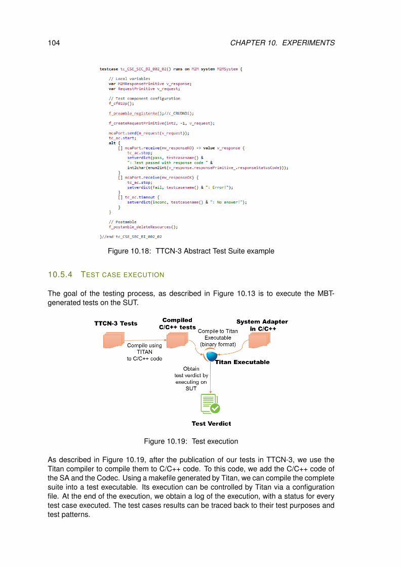
104 CHAPTER 10. EXPERIMENTS
Figure 10.18: TTCN-3 Abstract Test Suite example
10.5.4 TEST CASE EXECUTION
The goal of the testing process, as described in Figure 10.13 is to execute the MBT-generated tests on the SUT.
Figure 10.19: Test execution
As described in Figure 10.19, after the publication of our tests in TTCN-3, we use theTitan compiler to compile them to C/C++ code. To this code, we add the C/C++ code ofthe SA and the Codec. Using a makefile generated by Titan, we can compile the completesuite into a test executable. Its execution can be controlled by Titan via a configurationfile. At the end of the execution, we obtain a log of the execution, with a status for everytest case executed. The test cases results can be traced back to their test purposes andtest patterns.
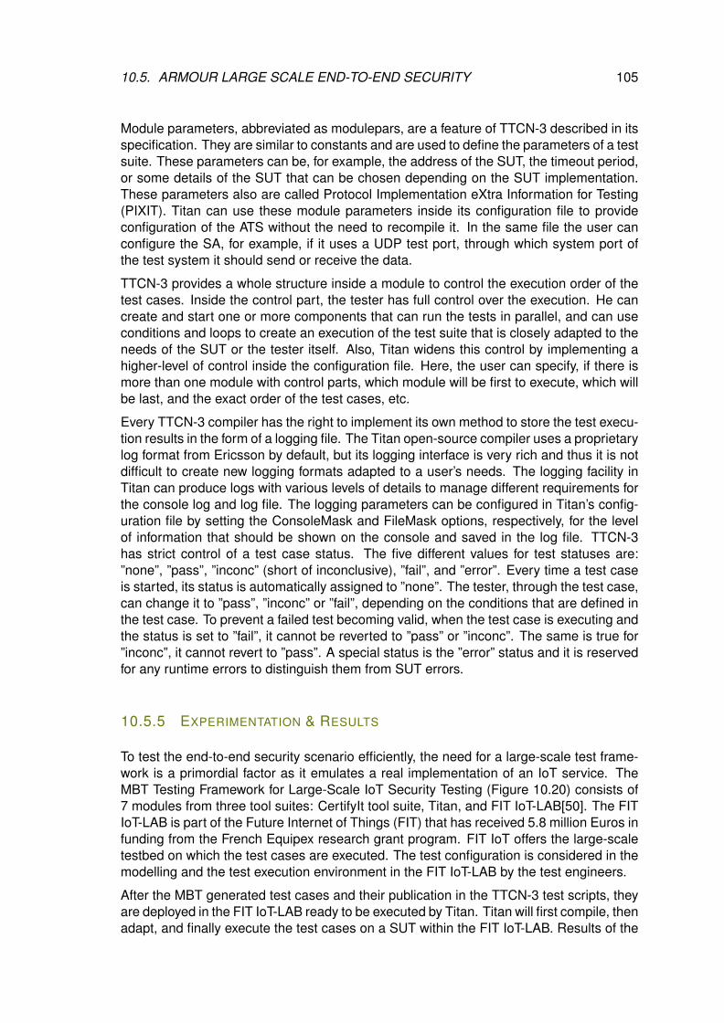
10.5. ARMOUR LARGE SCALE END-TO-END SECURITY 105
Module parameters, abbreviated as modulepars, are a feature of TTCN-3 described in itsspecification. They are similar to constants and are used to define the parameters of a testsuite. These parameters can be, for example, the address of the SUT, the timeout period,or some details of the SUT that can be chosen depending on the SUT implementation.These parameters also are called Protocol Implementation eXtra Information for Testing(PIXIT). Titan can use these module parameters inside its configuration file to provideconfiguration of the ATS without the need to recompile it. In the same file the user canconfigure the SA, for example, if it uses a UDP test port, through which system port ofthe test system it should send or receive the data.
TTCN-3 provides a whole structure inside a module to control the execution order of thetest cases. Inside the control part, the tester has full control over the execution. He cancreate and start one or more components that can run the tests in parallel, and can useconditions and loops to create an execution of the test suite that is closely adapted to theneeds of the SUT or the tester itself. Also, Titan widens this control by implementing ahigher-level of control inside the configuration file. Here, the user can specify, if there ismore than one module with control parts, which module will be first to execute, which willbe last, and the exact order of the test cases, etc.
Every TTCN-3 compiler has the right to implement its own method to store the test execu-tion results in the form of a logging file. The Titan open-source compiler uses a proprietarylog format from Ericsson by default, but its logging interface is very rich and thus it is notdifficult to create new logging formats adapted to a user’s needs. The logging facility inTitan can produce logs with various levels of details to manage different requirements forthe console log and log file. The logging parameters can be configured in Titan’s config-uration file by setting the ConsoleMask and FileMask options, respectively, for the levelof information that should be shown on the console and saved in the log file. TTCN-3has strict control of a test case status. The five different values for test statuses are:”none”, ”pass”, ”inconc” (short of inconclusive), ”fail”, and ”error”. Every time a test caseis started, its status is automatically assigned to ”none”. The tester, through the test case,can change it to ”pass”, ”inconc” or ”fail”, depending on the conditions that are defined inthe test case. To prevent a failed test becoming valid, when the test case is executing andthe status is set to ”fail”, it cannot be reverted to ”pass” or ”inconc”. The same is true for”inconc”, it cannot revert to ”pass”. A special status is the ”error” status and it is reservedfor any runtime errors to distinguish them from SUT errors.
10.5.5 EXPERIMENTATION & RESULTS
To test the end-to-end security scenario efficiently, the need for a large-scale test frame-work is a primordial factor as it emulates a real implementation of an IoT service. TheMBT Testing Framework for Large-Scale IoT Security Testing (Figure 10.20) consists of7 modules from three tool suites: CertifyIt tool suite, Titan, and FIT IoT-LAB[50]. The FITIoT-LAB is part of the Future Internet of Things (FIT) that has received 5.8 million Euros infunding from the French Equipex research grant program. FIT IoT offers the large-scaletestbed on which the test cases are executed. The test configuration is considered in themodelling and the test execution environment in the FIT IoT-LAB by the test engineers.
After the MBT generated test cases and their publication in the TTCN-3 test scripts, theyare deployed in the FIT IoT-LAB ready to be executed by Titan. Titan will first compile, thenadapt, and finally execute the test cases on a SUT within the FIT IoT-LAB. Results of the
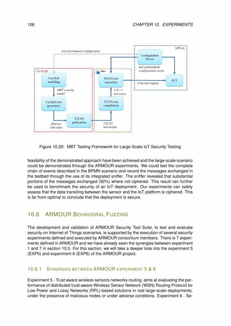
106 CHAPTER 10. EXPERIMENTS
Figure 10.20: MBT Testing Framework for Large-Scale IoT Security Testing
feasibility of the demonstrated approach have been achieved and the large-scale scenariocould be demonstrated through the ARMOUR experiments. We could test the completechain of events described in the BPMN scenario and record the messages exchanged inthe testbed through the use of its integrated sniffer. The sniffer revealed that substantialportions of the messages exchanged (92%) where not ciphered. This result can furtherbe used to benchmark the security of an IoT deployment. Our experiments can safelyassess that the data transiting between the sensor and the IoT platform is ciphered. Thisis far from optimal to conclude that the deployment is secure.
10.6 ARMOUR BEHAVIORAL FUZZING
The development and validation of ARMOUR Security Tool Suite, to test and evaluatesecurity on Internet of Things scenarios, is supported by the execution of several securityexperiments defined and executed by ARMOUR consortium members. There is 7 experi-ments defined in ARMOUR and we have already seen the synergies between experiment1 and 7 in section 10.5. For this section, we will take a deeper look into the experiment 5(EXP5) and experiment 6 (EXP6) of the ARMOUR project.
10.6.1 SYNERGIES BETWEEN ARMOUR EXPERIMENT 5 & 6
Experiment 5 - Trust aware wireless sensors networks routing, aims at evaluating the per-formance of distributed trust-aware Wireless Sensor Network (WSN) Routing Protocol forLow Power and Lossy Networks (RPL)-based solutions in real large-scale deployments,under the presence of malicious nodes or under adverse conditions. Experiment 6 - Se-
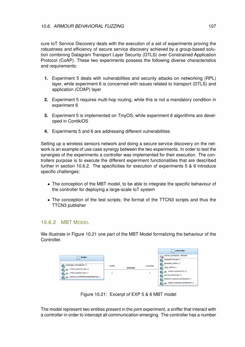
10.6. ARMOUR BEHAVIORAL FUZZING 107
cure IoT Service Discovery deals with the execution of a set of experiments proving therobustness and efficiency of secure service discovery achieved by a group-based solu-tion combining Datagram Transport Layer Security (DTLS) over Constrained ApplicationProtocol (CoAP). These two experiments possess the following diverse characteristicsand requirements:
1. Experiment 5 deals with vulnerabilities and security attacks on networking (RPL)layer, while experiment 6 is concerned with issues related to transport (DTLS) andapplication (COAP) layer
2. Experiment 5 requires multi-hop routing, while this is not a mandatory condition inexperiment 6
3. Experiment 5 is implemented on TinyOS, while experiment 6 algorithms are devel-oped in ContikiOS
4. Experiments 5 and 6 are addressing different vulnerabilities
Setting up a wireless sensors network and doing a secure service discovery on the net-work is an example of use case synergy between the two experiments. In order to test thesynergies of the experiments a controller was implemented for their execution. The con-trollers purpose is to execute the different experiment functionalities that are describedfurther in section 10.6.2. The specificities for execution of experiments 5 & 6 introducespecific challenges:
• The conception of the MBT model, to be able to integrate the specific behaviour ofthe controller for deploying a large-scale IoT system
• The conception of the test scripts; the format of the TTCN3 scripts and thus theTTCN3 publisher
10.6.2 MBT MODEL
We illustrate in Figure 10.21 one part of the MBT Model formalizing the behaviour of theController.
Figure 10.21: Excerpt of EXP 5 & 6 MBT model
The model represent two entities present in the joint experiment, a sniffer that interact witha controller in order to intercept all communication emerging. The controller has a number
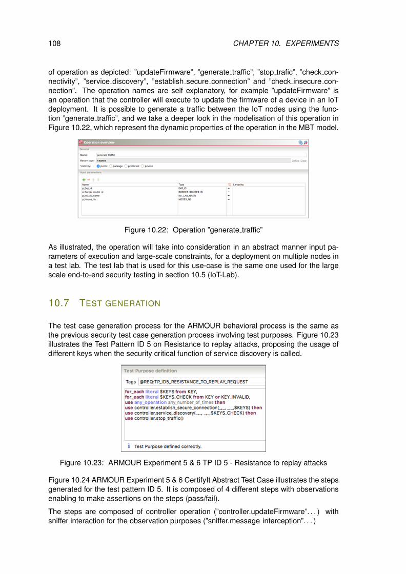
108 CHAPTER 10. EXPERIMENTS
of operation as depicted: ”updateFirmware”, ”generate traffic”, ”stop trafic”, ”check con-nectivity”, ”service discovery”, ”establish secure connection” and ”check insecure con-nection”. The operation names are self explanatory, for example ”updateFirmware” isan operation that the controller will execute to update the firmware of a device in an IoTdeployment. It is possible to generate a traffic between the IoT nodes using the func-tion ”generate traffic”, and we take a deeper look in the modelisation of this operation inFigure 10.22, which represent the dynamic properties of the operation in the MBT model.
Figure 10.22: Operation ”generate traffic”
As illustrated, the operation will take into consideration in an abstract manner input pa-rameters of execution and large-scale constraints, for a deployment on multiple nodes ina test lab. The test lab that is used for this use-case is the same one used for the largescale end-to-end security testing in section 10.5 (IoT-Lab).
10.7 TEST GENERATION
The test case generation process for the ARMOUR behavioral process is the same asthe previous security test case generation process involving test purposes. Figure 10.23illustrates the Test Pattern ID 5 on Resistance to replay attacks, proposing the usage ofdifferent keys when the security critical function of service discovery is called.
Figure 10.23: ARMOUR Experiment 5 & 6 TP ID 5 - Resistance to replay attacks
Figure 10.24 ARMOUR Experiment 5 & 6 CertifyIt Abstract Test Case illustrates the stepsgenerated for the test pattern ID 5. It is composed of 4 different steps with observationsenabling to make assertions on the steps (pass/fail).
The steps are composed of controller operation (”controller.updateFirmware”. . . ) withsniffer interaction for the observation purposes (”sniffer.message interception”. . . )
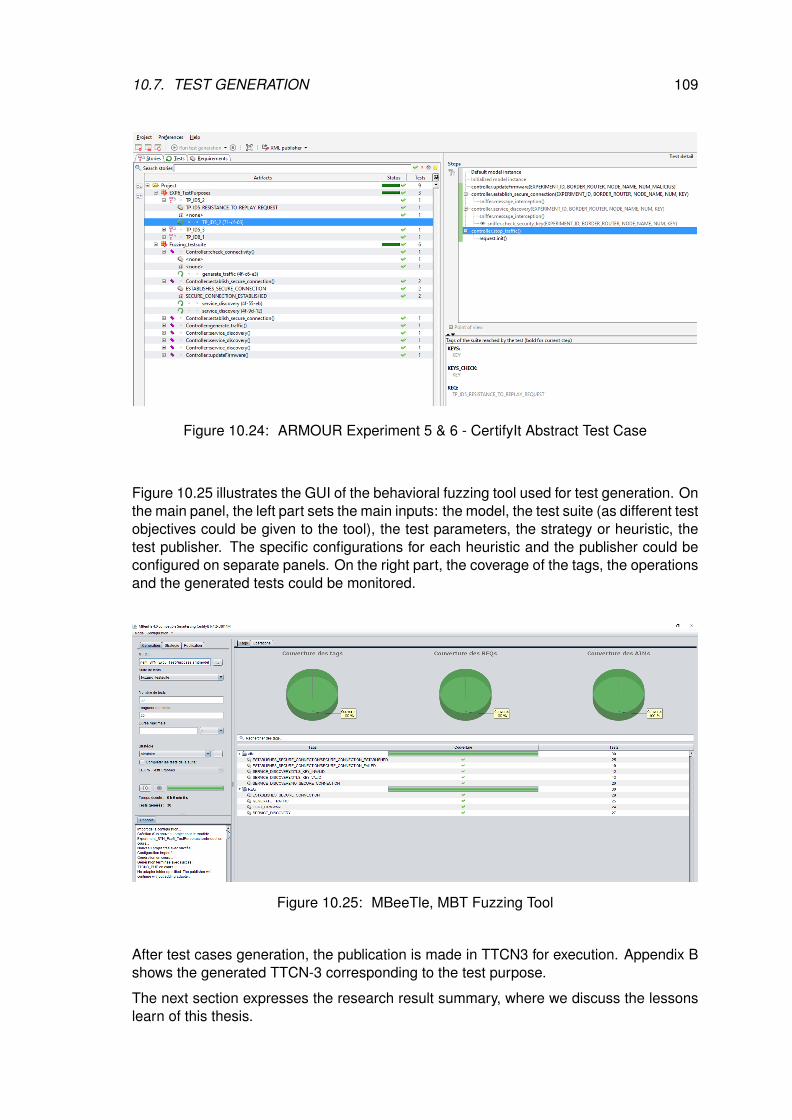
10.7. TEST GENERATION 109
Figure 10.24: ARMOUR Experiment 5 & 6 - CertifyIt Abstract Test Case
Figure 10.25 illustrates the GUI of the behavioral fuzzing tool used for test generation. Onthe main panel, the left part sets the main inputs: the model, the test suite (as different testobjectives could be given to the tool), the test parameters, the strategy or heuristic, thetest publisher. The specific configurations for each heuristic and the publisher could beconfigured on separate panels. On the right part, the coverage of the tags, the operationsand the generated tests could be monitored.
Figure 10.25: MBeeTle, MBT Fuzzing Tool
After test cases generation, the publication is made in TTCN3 for execution. Appendix Bshows the generated TTCN-3 corresponding to the test purpose.
The next section expresses the research result summary, where we discuss the lessonslearn of this thesis.
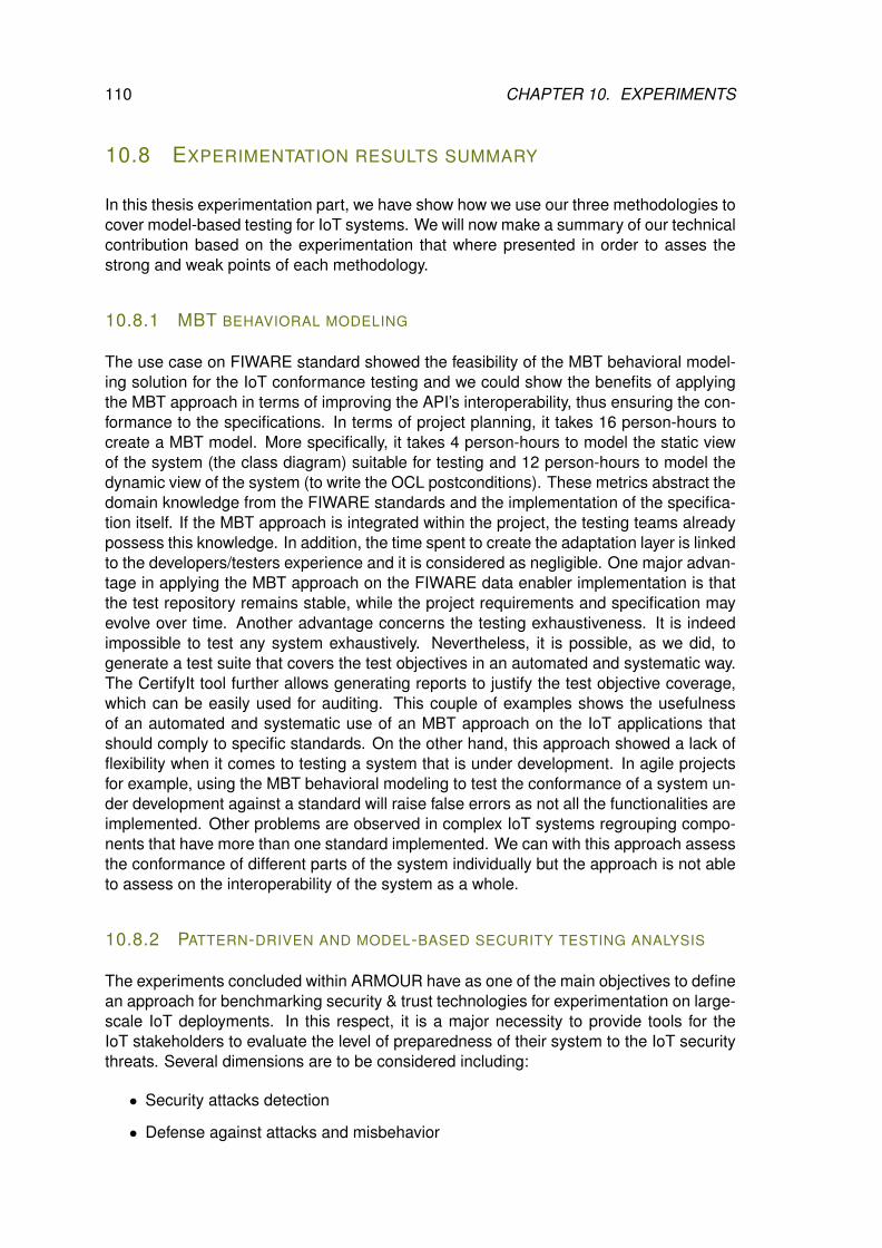
110 CHAPTER 10. EXPERIMENTS
10.8 EXPERIMENTATION RESULTS SUMMARY
In this thesis experimentation part, we have show how we use our three methodologies tocover model-based testing for IoT systems. We will now make a summary of our technicalcontribution based on the experimentation that where presented in order to asses thestrong and weak points of each methodology.
10.8.1 MBT BEHAVIORAL MODELING
The use case on FIWARE standard showed the feasibility of the MBT behavioral model-ing solution for the IoT conformance testing and we could show the benefits of applyingthe MBT approach in terms of improving the API’s interoperability, thus ensuring the con-formance to the specifications. In terms of project planning, it takes 16 person-hours tocreate a MBT model. More specifically, it takes 4 person-hours to model the static viewof the system (the class diagram) suitable for testing and 12 person-hours to model thedynamic view of the system (to write the OCL postconditions). These metrics abstract thedomain knowledge from the FIWARE standards and the implementation of the specifica-tion itself. If the MBT approach is integrated within the project, the testing teams alreadypossess this knowledge. In addition, the time spent to create the adaptation layer is linkedto the developers/testers experience and it is considered as negligible. One major advan-tage in applying the MBT approach on the FIWARE data enabler implementation is thatthe test repository remains stable, while the project requirements and specification mayevolve over time. Another advantage concerns the testing exhaustiveness. It is indeedimpossible to test any system exhaustively. Nevertheless, it is possible, as we did, togenerate a test suite that covers the test objectives in an automated and systematic way.The CertifyIt tool further allows generating reports to justify the test objective coverage,which can be easily used for auditing. This couple of examples shows the usefulnessof an automated and systematic use of an MBT approach on the IoT applications thatshould comply to specific standards. On the other hand, this approach showed a lack offlexibility when it comes to testing a system that is under development. In agile projectsfor example, using the MBT behavioral modeling to test the conformance of a system un-der development against a standard will raise false errors as not all the functionalities areimplemented. Other problems are observed in complex IoT systems regrouping compo-nents that have more than one standard implemented. We can with this approach assessthe conformance of different parts of the system individually but the approach is not ableto assess on the interoperability of the system as a whole.
10.8.2 PATTERN-DRIVEN AND MODEL-BASED SECURITY TESTING ANALYSIS
The experiments concluded within ARMOUR have as one of the main objectives to definean approach for benchmarking security & trust technologies for experimentation on large-scale IoT deployments. In this respect, it is a major necessity to provide tools for theIoT stakeholders to evaluate the level of preparedness of their system to the IoT securitythreats. Several dimensions are to be considered including:
• Security attacks detection
• Defense against attacks and misbehavior
10.8. EXPERIMENTATION RESULTS SUMMARY 111
• Ability to use trusted sources and channels
• Levels of security & trust conformity, etc. . .
Additional benchmarks of reference secure & trusted IoT solutions are performed to es-tablish a baseline ground-proof for the ARMOUR experiments but also to create a properbenchmarking database of secure & trusted solutions appropriate for the large-scale IoT.To define this methodology and the different dimensions to be considered for benchmark-ing, ARMOUR will:
• Consider the methodology defined for generic test patterns and test models basedon the threats and vulnerability identified for the IoT
• Identify metrics per functional block (authentication, data security, etc. . . ) to performvarious micro- and macro-benchmarking scenarios on the target deployments
• Collect metrics from the evaluation and then use the metrics to categorize them(taxonomy) into different functional aspects, and based on this, provide a label ap-proach to the security assessment.
Micro-benchmarks provide useful information to understand the performance of subsys-tems associated with a smart object. Micro-benchmarks are useful to identify possibleperformance bottlenecks at the architectural level and allow embedded hardware andsoftware engineers to compare and assess the various design trade-offs associated withcomponent level design. Macro-benchmarks provide statistics relating to a specific func-tion at the application level and may consist of multiple component level elements workingtogether to perform an application layer task.
Pattern-driven and model-based security testing has showed its efficiency in terms ofreusability of conformance models, in addition with test purposes for security test casegeneration. The automation of test case generation and the ability of adding new vulner-abilities(Zero day attacks or new system functionalities) in the model, enables keepingthe security test updated faster thus providing constant thrust in the system. The com-plication that face this approach are located on the test execution level. Security testexecution are strongly linked to the SUT. We have to first assess the vulnerabilities thatare specifically applicable to our SUT and then develop for each SUT an adaptation layerin order to execute the test. Depending on the complexity of the system tested, the effortin executing a security test campaign are proportional.
10.8.3 BEHAVIORAL FUZZING RESULTS
We have introduced the model-based methodology on implementing behavioral fuzzingtesting of IoT Systems. Our method is kept generic in a sense that indeed it requires acustom Model (i.e., security Vulnerability knowledge of attacks and their enabling vulnera-bilities). In addition, the security risk analysis and its generation of abstract test cases aregeneric as well as its execution on different large scale testbeds. Our analysis, showedthat some changes are expected to be done with respect to the test scripts in the adap-tation layer, requiring more robustness. For example, if the SUT was not designed to runmultiple requests over long period of time.
Our experience in using a Fuzzing approach based on models with a tool such as MBee-Tle, showed several advantages, such as:
112 CHAPTER 10. EXPERIMENTS
• Minimal initial configuration is required to start a fuzzing campaign.
• Minimal supervision of the fuzzing campaign is required.
• Uniqueness determination is handled through an intelligent backtrace analysis.
• Automated test-case minimization reduces the effort required to analyze the results.
The approach is complementary to other MBT testing approaches and can reveal un-expected behavior due to its random nature. We observe also that the IoT system, be-cause it integrates complex and unexpected reactions, lacks observation points to testthe desired vulnerabilities. Thus, the experiment should allow artificially observations, forinstance through sniffers as one of the simplest. Further, the MBT Model used for fuzzingshould not be permissive and allow the generation of test steps that are not executable.Otherwise the execution result of many tests will be false positive, which will increase theeffort required for analysis of the failed tests.
The next section is the last one of this thesis. It aims to conclude by giving a synthesis ofthe work done and explore future work on IoT certification and benchmarking.
11CONCLUSION AND FUTURE WORK
Contents11.1 Summary . . . . . . . . . . . . . . . . . . . . . . . . . . . . . . . . . . . 113
11.2 Future work . . . . . . . . . . . . . . . . . . . . . . . . . . . . . . . . . 115
This last chapter makes a summary of the works presented in this thesis. We state ourfeelings on MBT role in testing IoT and how it will continue to be as important as it isnow. We strongly believe that MBT is one of the new techniques that will need to be moreand more developed to handle verification and validation in the domain of IoT becauseit introduces an ease of access to conformance, security and behavioral fuzzing testing.We then conclude this thesis by having an overview of the future works related to IoTsystems certification. The idea is to push our testing approaches for IoT certification andlabeling.
11.1 SUMMARY
This thesis addresses the problematic of the validation of the Internet of Things (IoT).More specifically, it provides answers that address the key challenges of scalability, in-teroperability, and security of the IoT with real use cases. The solutions that we proposehave a common execution approach: Model Based Testing As A Service (MBTAAS). TheMBT used for the IoT conformance testing shows that the specificities in generating testcases to validate the correct behavior of an SUT with respect to its standard lies in themodel creation. In this case, the model is a representation of the standard. Any testexecuted on the SUT that fails could represent a gap between the specification and im-plementation, or a compliance from the SUT towards the standard it is implementing.The MBT used for the IoT security testing diverted from the traditional MBT setup with itsspecific test case reification environment. Finally, we have a first view on the specificitiesof an MBT for the IoT robustness testing approach. It illustrates how MBT fuzzing couldbe applied to the IoT systems. The tooling we presented gives the possibility to re-usealready created model during the functional/security testing phase; thus, no additionaltime is spent for modeling. This approach is considered as complimentary to securityor conformance testing, as we expect that the detected inconstancies will differ from theothers.
The standardization institutes and certification entities that make available tomorrow’sstandards have the process of testing as the highest importance. They provide standard
113
114 CHAPTER 11. CONCLUSION AND FUTURE WORK
implementers a set of test cases to assess the conformance, scalability, and security oftheir products. Test cases traceability after execution is also a major factor as it is usedto benchmark the test results. With security threats constantly evolving, and to maintainhigh confidence and trust, the proposed test cases must be continuously maintained.This is where MBT finds its interest and added value. The traceability starts with thespecification, then the requirements, and finally to the test cases which are an embeddedfeature to that of the classical MBT approach. The test case traceability provided byMBT gives the possibility to implement test generation strategies which aim to cover amaximum of the specification. The automated test generation is low time-consumingcomparing to hand written tests, and thus makes the maintenance of generated test casescheaper. MBT has major advantages in terms of test coverage, test maintenance, etc.Those advantages are accelerating the adoption of MBT over time.
The MBT approach for test case generation and execution in the IoT domain is relativelynew. Nowadays, it is becoming more and more visible and accepted compared to acouple of years ago. The approach was previously reserved for a smaller number of usecases due to the high difficulty of taking in hand the modeling. Modeling requires highly-skilled testers and the profession is not common in the software industry. Only highlycritical companies have the privilege of modeling their concepts to test them. The IoTsector is reaching this critical level nowadays. Security intrusions are more sophisticatedthan ever and occur more frequently then we realize. The need for quality assurance inthe field of the IoT testing is essential to accompany its growth. With MBT, the evolutionof the security threads is added into the model and they are by this process considered inthe test generation process. The process saves time when it is not started from scratch.The models for conformance testing are reusable and adapted to security testing. Model-Based Testing (MBT) shows its benefits in the medium to long term as it has a highinitial cost and it has been one of the strongest roadblocks for MBT adoption. The MBTapproach requires highly-skilled testers and it is complicated to change the daily habitsof testers in the field. It requires a significant time investment that most are not willingto partake. One other roadblock for the MBT approach adoption is the complexity of theexisting tools. Nevertheless, MBT is still relatively new and we see more and more toolsemerging. However, these tools require a high degree of formation and skill for practicalusage. The test generation tools are complicated and the complexity of test generationcan take a significant amount of time (NP-complete problems). In the future, the MBTapproach requires significant evolution to survive and show a rise in its adoption. Newtechniques have already been developed by tool makers, MBeeTle is one of the emergingtools for behavioral fuzzing testing that responds to the need for a real-time analysis ofthe test cases on the IoT deployments. This new tool allows for a loss of non-determinismin a real-time system.
The technology for automated model-based test case generation has matured to the pointwhere the large-scale deployments of this technology are becoming commonplace. Theprerequisites for success, such as qualification of the test team, integrated tools chainavailability and methods are now identified, and a wide range of commercial and open-source tools are available, as introduced in this thesis. Although MBT will not solve alltesting problems in the IoT systems domain, it is extremely useful and brings consider-able progress within the state of the practice for functional software testing effectiveness,increasing productivity, and improving functional coverage. Moreover, the MBT approachhas shown its importance in the IoT by introducing an ease of access to conformance,security, and behavioral fuzzing testing. The technology is constantly evolving, making
11.2. FUTURE WORK 115
it tester friendly and considerably reducing the high initial cost that is typically the case.Because of its easier accessibility for testers, as well as more fine-grained integration withthe large-scale IoT testbeds, MBT should expect a larger approval rate.
This thesis is emphasized with a strong practical approach trough a heavy investmentin experimentation. We had the chance to be involved in many European project thatrequired not only theoretical solutions for testing the IoT but also to provide concreteworking solution. A lot of resources where spent on experimentation in order to validateproposed methodologies and solutions. More notably, after validating MBT capabilitiesto test IoT standards with FIWARE, we worked on the oneM2M standard. With oneM2Mstandard validation, we explored deeply its security features. This lead us to have a firsthand on developing a methodology and tools for the IoT security certification.
The next and last section, propose to explore the future work of this thesis taking intoconsideration the lessons learned.
11.2 FUTURE WORK
Putting into perspective the work done in this thesis, we find two interesting path of conti-nuity. The first path relates to the amelioration’s in the problematics faced with respect toour experimentation’s. With behavioral modeling for conformance testing, our main chal-lenge is faced during the execution phase. We propose a MBTAAS approach in order tobring accessible tests to IoT system developers. This approach reveals to be less adaptedto IoT system that are not mature enough to be deployed and therefore tested in a ”asa service” environment. Our approach lacks of flexibility to test systems that are in earlystage development. The solution resides in proposing testing solution in the develomentenvironement of the IoT system. Even if that means losing the notion of ”as a service”execution, the tests can be delivered to the users own test bed for later execution. Thisraises many issues that have to be taken into consideration such as for example the needof development of a system adapter for test execution and the delivery of a reporting toolto asses the testing results and keep their traceability to ensure non regression.
The second path of continuity relates to the outcome of our pattern-driven and model-based security testing approach. We investigate how to use the approach in cybersecu-rity evaluation and certification. In the certification process, electronic products are eval-uated against a set of requirements and using a process usually based on well-definedstandards like Common Criteria (CC). Cybersecurity certification can be a quite compre-hensive process but it may have limitations, which must be taken in consideration. Toaddress the limitations of cybersecurity certification, this thesis explores complementaryapproaches, which aim to support parts of the product lifecycle on the different phases(e.g., IoT device): requirements collection, testing/security evaluation. The final objectiveis to provide the security benchmarking and assurance that should include a measure ofour level of confidence in the tested IoT system. As an example of such a measure ofconfidence used to evaluate the security of an IoT product or system, we mention theEvaluation Assurance Level (EAL) from the Common Criteria (CC). The EAL is a discretenumerical grade (from EAL1 through EAL7) assigned to the IoT product or system fol-lowing the completion of a CC security evaluation, which is an international standard ineffect since 1999. These increasing levels of assurance reflect the fact that incrementalassurance requirements must be met to achieve CC certification. The intent of the higher
116 CHAPTER 11. CONCLUSION AND FUTURE WORK
assurance levels is a higher level of confidence that the systems security features havebeen reliably implemented. The EAL level does not measure the security of the system; itrather simply states at what level the system was tested. The EAL’s include the following:
• EAL 1 Functionally Tested
• EAL 2 Structurally Tested
• EAL 3 Methodically Tested and Checked
• EAL 4 Methodically Designed, Tested and Reviewed
• EAL 5 Semi-formally Designed and Tested
• EAL 6 Semi-formally Verified Design and Tested
• EAL 7 Formally Verified Design and Tested
Security certification is needed to ensure that a product satisfies the required securityrequirements, which can be both proprietary requirements (i.e., defined by a company fortheir specific products) and market requirements (i.e., defined in procurement specifica-tions or market standards). In the market case, these requirements are also defined tosupport security interoperability. For example, to ensure that two products are able to mu-tually authenticate or to exchange secure messages. Security certification is needed toensure that products are secure against specific security attacks or that they have specificsecurity properties.
The process for certification of a product is generally summed up in four phases:
1. Application: A company applies a product for evaluation to obtain a certification.
2. An evaluation is performed to obtain certification. The evaluation can be mostlydone in three ways: a) the evaluation can be done internally to support self-certification. b) The evaluation can be performed by a testing company, which islegally belonging to the product company. c) It can be third party certification wherethe company asks a third party company to perform the evaluation of its product.
3. Internal company or third party company evaluation: the evaluation companyprovides a decision on the evaluation.
4. Surveillance. It is a periodic check on the product to ensure that the certification isstill valid or it requires a new certification.
As described in [14], the initial efforts to define a security testing and certification frame-work for products originated in the defense domain. An obvious reason was that themilitary systems are designed to operate in a hostile environment and must be protectedagainst security threats, which are more likely to appear than with those systems that be-long to a commercial domain. That being said, with the development of IoT, new threatshave emerged and the consequences are far from benign. The huge scale some IoT sys-tem, having so many devices interconnected can be convenient, if not tested and certifiedbefore deployment. This is where we propose to set foot in our future works. Bringing theadoption of MBT to support a formal definition of the tests and the security requirementsfor IoT systems, which drives the certification. In addition, they can be used to supportharmonization of the tests for security certification.
BIBLIOGRAPHY
[1] Model-based engineering forum. http://modelbasedengineering.com/.
[2] DIJKSTRA, E. Ewd 249 Notes on Structured Programming: 2nd Ed. TechnischeHogeschool Eindhoven. Department of Mathematics, 1970.
[3] FERNANDEZ, J. C., JARD, C., JERON, T., AND VIHO, C. Using on-the-fly verifi-cation techniques for the generation of test suites. Springer Berlin Heidelberg,Berlin, Heidelberg, 1996, pp. 348–359.
[4] ITU-T. The evolution of ttcn, 2001.
[5] HARTMAN, A. Model based test generation tools.
[6] SRIVASTAVA, A., AND THIAGARAJAN, J. Effectively prioritizing tests in devel-opment environment. In Proceedings of the 2002 ACM SIGSOFT InternationalSymposium on Software Testing and Analysis (New York, NY, USA, 2002), ISSTA’02, ACM, pp. 97–106.
[7] LARSEN, K., MIKUCIONIS, M., AND NIELSEN, B. Online testing of real-time sys-tems using UPPAAL. In Formal Approaches to Testing of Software (Linz, Austria,Sept. 2004), vol. 3395 of Lecture Notes in Computer Science, Springer, pp. 79–94.
[8] SCHUMACHER, M., FERNANDEZ, E., HYBERTSON, D., AND BUSCHMANN, F. Se-curity Patterns: Integrating Security and Systems Engineering. John Wiley &Sons, 2005.
[9] UTTING, M., AND LEGEARD, B. Practical Model-Based Testing - A tools ap-proach. Morgan Kaufmann, San Francisco, CA, USA, 2006.
[10] BOUQUET, F., GRANDPIERRE, C., LEGEARD, B., PEUREUX, F., VACELET, N., AND
UTTING, M. A subset of precise uml for model-based testing. In Workshop onAdvances in Model Based Testing (2007).
[11] SCHULZ, S., WILES, A., AND RANDALL, S. Tplan - a notation for expressing testpurposes. In PTS (2007).
[12] UTTING, M., LEGEARD, B., BOUQUET, F., PEUREUX, F., GRANDPIERRE, C., AND
VACELET, N. A subset of precise uml for model-based testing. In A-MOST’07,3rd int. Workshop on Advances in Model Based Testing (London, United Kingdom,jul 2007), pp. 95–104.
[13] BOUQUET, F., GRANDPIERRE, C., LEGEARD, B., AND PEUREUX, F. A test gener-ation solution to automate software testing. In Proceedings of the 3rd Interna-tional Workshop on Automation of Software Test (New York, NY, USA, 2008), AST’08, ACM, pp. 45–48.
117
118 BIBLIOGRAPHY
[14] ANDERSON, R., AND FULORIA, S. Certification and evaluation: A security eco-nomics perspective. In 2009 IEEE Conference on Emerging Technologies FactoryAutomation (Sept 2009), pp. 1–7.
[15] CHAN, W. K., MEI, L., AND ZHANG, Z. Modeling and testing of cloud applica-tions. In 2009 IEEE Asia-Pacific Services Computing Conference (APSCC) (Dec2009), pp. 111–118.
[16] LEGEARD, B., BOUQUET, F., AND PICKAERT, N. Industrialiser le test fonctionnel(des exigences metier au referentiel de tests automatises). Dunod, apr 2009.
[17] BAUER, M., KOVACS, E., SCHULKE, A., ITO, N., CRIMINISI, C., GOIX, L. W., AND
VALLA, M. The context api in the oma next generation service interface. In2010 14th International Conference on Intelligence in Next Generation Networks(Oct 2010), pp. 1–5.
[18] M. SHAFIQUE, Y. L. A systematic review of model based testing tool support.
[19] RIUNGU, L. M., TAIPALE, O., AND SMOLANDER, K. Research issues for softwaretesting in the cloud. In 2010 IEEE Second International Conference on CloudComputing Technology and Science (Nov 2010), pp. 557–564.
[20] WILLCOCK, C., DEISS, T., TOBIES, S., KEIL, S., ENGLER, F., SCHULZ, S., AND
WILES, A. An Introduction to TTCN-3. 2011.
[21] ALLIANCE, O. M. Ngsi context management.
[22] AMALFITANO, D., FASOLINO, A. R., TRAMONTANA, P., CARMINE, S. D., AND
MEMON, A. M. Using gui ripping for automated testing of android applications.In 2012 Proceedings of the 27th IEEE/ACM International Conference on AutomatedSoftware Engineering (Sept 2012), pp. 258–261.
[23] INCKI, K., ARI, I., AND SOZER, H. A survey of software testing in the cloud.In 2012 IEEE Sixth International Conference on Software Security and ReliabilityCompanion (June 2012), pp. 18–23.
[24] SCHIEFERDECKER, I., GROSSMANN, J., AND SCHNEIDER, M. Model-based secu-rity testing. In MBT (2012), pp. 1–12.
[25] UTTING, M., PRETSCHNER, A., AND LEGEARD, B. A taxonomy of model-basedtesting approaches. Software Testing, Verification and Reliability 22, 5 (2012),297–312.
[26] ZECH, P., FELDERER, M., AND BREU, R. Towards a model based security testingapproach of cloud computing environments. In 2012 IEEE Sixth InternationalConference on Software Security and Reliability Companion (June 2012), pp. 47–56.
[27] ZISSIS, D., AND LEKKAS, D. Addressing cloud computing security issues. Fu-ture Generation Computer Systems 28, 3 (2012), 583 – 592.
[28] BOTELLA, J., BOUQUET, F., CAPURON, J. F., LEBEAU, F., LEGEARD, B., AND SCHA-DLE, F. Model-based testing of cryptographic components – lessons learnedfrom experience. In 2013 IEEE Sixth International Conference on Software Testing,Verification and Validation (March 2013), pp. 192–201.
BIBLIOGRAPHY 119
[29] SALVA, S., AND ZAFIMIHARISOA, S. R. Data vulnerability detection by securitytesting for android applications. In 2013 Information Security for South Africa(Aug 2013), pp. 1–8.
[30] SCHNEIDER, M., GROSSMANN, J., SCHIEFERDECKER, I., AND PIETSCHKER, A. On-line model-based behavioral fuzzing. In 2013 IEEE Sixth International Conferenceon Software Testing, Verification and Validation Workshops (March 2013), pp. 469–475.
[31] A. SPILLNER, T. LINZ, H. S. Software testing foundations: a study guide for thecertified tester exam: foundation level, istqb compliant.
[32] BAUM, A. A link to the internet of things, iot made easy with simplelinkTM
wi-fi R© solutions. http://www.ti.com/lit/wp/swry009/swry009.pdf, 2014. Last visited:April 2015.
[33] BOTELLA, J., LEGEARD, B., PEUREUX, F., AND VERNOTTE, A. Risk-based vul-nerability testing using security test patterns. In Leveraging Applications of For-mal Methods, Verification and Validation. Specialized Techniques and Applications(Berlin, Heidelberg, 2014), T. Margaria and B. Steffen, Eds., Springer Berlin Heidel-berg, pp. 337–352.
[34] FOURNERET, E., CANTENOT, J., BOUQUET, F., LEGEARD, B., AND BOTELLA, J.SeTGaM: Generalized Technique for Regression Testing Based on UML/OCLmodels. In 8th International Conference on Software Security and Reliability, SERE,2014 (2014), pp. 147–156.
[35] KRIOUILE, A., AND SERWE, W. Using a formal model to improve verification ofa cache-coherent system-on-chip. In Tools and Algorithms for the Constructionand Analysis of Systems, C. Baier and C. Tinelli, Eds., vol. 9035 of Lecture Notes inComputer Science. Springer Berlin Heidelberg, 2015, pp. 708–722.
[36] MARINESCU, R., SECELEANU, C., AND H. LE GUZEN, P. P. A Research Overviewof Tool-Supported Model-based Testing of Requirements-based Designs. El-sevier, 2015.
[37] ONEM2M PARTNERS. onem2m, the interoperability enabler for the entire m2mand iot ecosystem whitepaper, 2015.
[38] ZECH, P., KALB, P., FELDERER, M., AND BREU, R. Threatening the cloud: Secur-ing services and data by continuous, model-driven negative security testing.pp. 789–814.
[39] BALDINI, G., SKARMETA, A., FOURNERET, E., NEISSE, R., LEGEARD, B., AND
GALL, F. L. Security certification and labelling in internet of things. In 2016IEEE 3rd World Forum on Internet of Things (WF-IoT) (2016), pp. 627–632.
[40] CAPGEMINI. World quality report 2016-17.
[41] KRAMER A., L. B. Model-based testing essentials - guide to the istqb certifiedmodel-based tester: Foundation level.
[42] REETZ, E. S. Service Testing for the Internet of Things. PhD thesis, Universityof Surrey, 2016.
120 BIBLIOGRAPHY
[43] UTTING, M., LEGEARD, B., BOUQUET, F., FOURNERET, E., PEUREUX, F., AND VER-NOTTE, A. Recent advances in model-based testing. Advances in Computers101 (2016), 53–120.
[44] UTTING, M., LEGEARD, B., BOUQUET, F., FOURNERET, E., PEUREUX, F., AND VER-NOTTE, A. Chapter two - recent advances in model-based testing. vol. 101 ofAdvances in Computers. Elsevier, 2016, pp. 53 – 120.
[45] MEMON, A. Advances in Computers. No. v. 108 in Advances in Computers. Else-vier Science, 2018.
[46] C.J. BUDNIK, R. SUBRAMANYAN, M. V. Peer-to-peer comparison of model-basedtest.
[47] IBM. Model-based testing (mbt) at interconnect 2016? yes!
[48] Armour h2020 project. http://www.armour-project.eu/, Last visited: April 2017.
[49] Dyn ddos attack report. http://www.computerworld.com/article/3135434/security/ddos-attack-on-dyn-came-from-100000-infected-devices.html, Last visited:April 2017.
[50] Fit iot lab, large scale testbed. https://www.iot-Iab.info/, Last visited: April 2017.
[51] Fiware. https://www.fiware.org/, Last visited: April 2017.
[52] Om2m, onem2m standard implementation. http://www.eclipse.org/om2m/, Lastvisited: April 2017.
[53] Smartesting certifyit. http://www.smartesting.com/en/certifyit/, Last visited: April2017.
[54] The testing and test control notation version 3 (ttcn-3). http://www.ttcn-3.org/,Last visited: April 2017.
[55] Iot usages in enterprises. https://www.computerworlduk.com/galleries/cloud-computing/internet-of-things-best-business-enterprise-offerings-3626973/,Last visited: February 2018.
[56] 3rd generation partnership project. http://www.3gpp.org/, Last visited: January2018.
[57] Alliance for internet of things innovation (aioti). https://aioti.eu/, Last visited:January 2018.
[58] Critical vulnerabilities in a wide range of iot baby mon-itors. https://arstechnica.com/information-technology/2015/09/9-baby-monitors-wide-open-to-hacks-that-expose-users-most-private-moments/,Last visited: January 2018.
[59] European telecommunications standards institute (etsi). http://www.etsi.org/,Last visited: January 2018.
[60] Gartner iot glossary. https://www.gartner.com/it-glossary/internet-of-things/, Lastvisited: January 2018.
BIBLIOGRAPHY 121
[61] Internet-connected cars can be compromised. http://www.latimes.com/business/autos/la-fi-hy-car-hacking-20150914-story.html, Last visited: January 2018.
[62] Microsoft on iot taas. http://www.zdnet.com/article/microsoft-launches-iot-as-a-service-offering-for-enterprises/, Last visited: Jan-uary 2018.
[63] The mirai botnet. https://krebsonsecurity.com/tag/mirai-botnet/, Last visited: Jan-uary 2018.
[64] Mov’eo imagine mobility. http://pole-moveo.org/en/, Last visited: January 2018.
[65] Secured comunication solution cluster. http://en.pole-scs.org/, Last visited: Jan-uary 2018.
[66] Smartesting solutions and services. http://www.smartesting.com/, Last visited:January 2018.
[67] Titan, ttcn-3 tool. http://www.ttcn-3.org/index.php/tools/16-tools-noncom/112-non-comm-titan, Last visited: January 2018.
[68] What is this thing called conformance ? https://www.nist.gov/itl/ssd/information-systems-group/what-thing-called-conformance, Last visited: January2018.
[69] SCHIEFERDECKER, I., GROSSMANN, J., AND RENNOCH, A. Model based securitytesting Selected Considerations. Keynote at SECTEST at ICST 2011 [accessed:Septmber 25, 2012].

LIST OF FIGURES
2.1 IoT layers . . . . . . . . . . . . . . . . . . . . . . . . . . . . . . . . . . . . . 11
2.2 Schematic depiction of the FIWARE platform with all major chapters . . . . 13
2.3 FIWARE IoT Platform Architecture . . . . . . . . . . . . . . . . . . . . . . . 14
2.4 oneM2M logo . . . . . . . . . . . . . . . . . . . . . . . . . . . . . . . . . . . 15
2.5 oneM2M Architecture . . . . . . . . . . . . . . . . . . . . . . . . . . . . . . 15
2.6 oneM2M defined work process . . . . . . . . . . . . . . . . . . . . . . . . . 16
2.7 Fundamental MBT Process . . . . . . . . . . . . . . . . . . . . . . . . . . . 18
4.1 The MBT Workflow . . . . . . . . . . . . . . . . . . . . . . . . . . . . . . . . 34
4.2 TTCN-3 logo. . . . . . . . . . . . . . . . . . . . . . . . . . . . . . . . . . . . 35
4.3 TTCN-3 architecture . . . . . . . . . . . . . . . . . . . . . . . . . . . . . . . 38
4.4 MBeeTle - Behavioral Fuzzing Process . . . . . . . . . . . . . . . . . . . . 40
5.1 Security Test Patterns definition methodology . . . . . . . . . . . . . . . . . 45
5.2 Online behavioral fuzzing generation methodology . . . . . . . . . . . . . . 46
5.3 Offline behavioral fuzzing generation methodology . . . . . . . . . . . . . . 47
6.1 Traditional vs Standardized MBT Process . . . . . . . . . . . . . . . . . . . 53
6.2 Complex Event Processing Espr4FastData . . . . . . . . . . . . . . . . . . 54
6.3 Class Diagram Notations . . . . . . . . . . . . . . . . . . . . . . . . . . . . 57
6.4 BPMN model example . . . . . . . . . . . . . . . . . . . . . . . . . . . . . . 58
7.1 TPLan example . . . . . . . . . . . . . . . . . . . . . . . . . . . . . . . . . . 62
7.2 MBT Security Testing Framework . . . . . . . . . . . . . . . . . . . . . . . . 64
7.3 Model-Based Security Testing Process for standardized IoT platform . . . . 66
7.4 Test Pattern Formalisation with Smartesting CertifyIt for TP ID 10 . . . . . . 66
7.5 Test Purpose ID 10 test cases generated by CertifyIt . . . . . . . . . . . . . 67
8.1 MBTAAS architecture . . . . . . . . . . . . . . . . . . . . . . . . . . . . . . 70
8.2 Configuration File excerpt . . . . . . . . . . . . . . . . . . . . . . . . . . . . 71
8.3 Published file parts . . . . . . . . . . . . . . . . . . . . . . . . . . . . . . . . 71
123
124 LIST OF FIGURES
8.4 Execution snapshot . . . . . . . . . . . . . . . . . . . . . . . . . . . . . . . 73
9.1 Behavioral Fuzzing Test Step Selection . . . . . . . . . . . . . . . . . . . . 76
9.2 MBT Fuzzing with TTCN3 . . . . . . . . . . . . . . . . . . . . . . . . . . . . 77
9.3 Behavioral fuzzing strategy - Flower . . . . . . . . . . . . . . . . . . . . . . 78
9.4 Behavioral fuzzing tool, test generation parameters . . . . . . . . . . . . . . 79
10.1 Data handling GE class diagram . . . . . . . . . . . . . . . . . . . . . . . . 86
10.2 Excerpt of the Data handling object diagram . . . . . . . . . . . . . . . . . . 86
10.3 Object Constraint Language (OCL) example . . . . . . . . . . . . . . . . . . 87
10.4 CertifyIt test case view . . . . . . . . . . . . . . . . . . . . . . . . . . . . . . 88
10.5 Implementation Abstract Test Case (HTML export) . . . . . . . . . . . . . . 88
10.6 SoapUI Test case launch example with result status . . . . . . . . . . . . . 90
10.7 The altered work process . . . . . . . . . . . . . . . . . . . . . . . . . . . . 91
10.8 Model-Based Testing Class diagram . . . . . . . . . . . . . . . . . . . . . . 92
10.9 oneM2M standard MBT model . . . . . . . . . . . . . . . . . . . . . . . . . 96
10.10ACP Test Purpose definition . . . . . . . . . . . . . . . . . . . . . . . . . . 97
10.11ACP test steps . . . . . . . . . . . . . . . . . . . . . . . . . . . . . . . . . . 98
10.12Large scale end-to-end security scenario . . . . . . . . . . . . . . . . . . . 98
10.13End to End security MBT description . . . . . . . . . . . . . . . . . . . . . 99
10.14IoT MBT generic model . . . . . . . . . . . . . . . . . . . . . . . . . . . . . 100
10.15Integration of the MBT model . . . . . . . . . . . . . . . . . . . . . . . . . . 101
10.16BPMN model . . . . . . . . . . . . . . . . . . . . . . . . . . . . . . . . . . . 102
10.17Test case generation with the MBT tool . . . . . . . . . . . . . . . . . . . . 102
10.18TTCN-3 Abstract Test Suite example . . . . . . . . . . . . . . . . . . . . . 104
10.19Test execution . . . . . . . . . . . . . . . . . . . . . . . . . . . . . . . . . . 104
10.20MBT Testing Framework for Large-Scale IoT Security Testing . . . . . . . . 106
10.21Excerpt of EXP 5 & 6 MBT model . . . . . . . . . . . . . . . . . . . . . . . 107
10.22Operation ”generate traffic” . . . . . . . . . . . . . . . . . . . . . . . . . . . 108
10.23ARMOUR Experiment 5 & 6 TP ID 5 - Resistance to replay attacks . . . . 108
10.24ARMOUR Experiment 5 & 6 - CertifyIt Abstract Test Case . . . . . . . . . . 109
10.25MBeeTle, MBT Fuzzing Tool . . . . . . . . . . . . . . . . . . . . . . . . . . 109
LIST OF TABLES
5.1 Vulnerabilities overview . . . . . . . . . . . . . . . . . . . . . . . . . . . . . 46
6.1 Exerpt of Espr4FastData Test Objectives . . . . . . . . . . . . . . . . . . . . 54
125

IVAPPENDIX
127


AARMOUR SECURITY
VULNERABILITIES TABLES
129
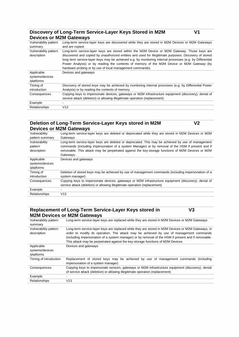
Discovery of Long-Term Service-Layer Keys Stored in M2M Devices or M2M Gateways
V1
Vulnerability pattern
summary
Long-term service-layer keys are discovered while they are stored in M2M Devices or M2M Gateways
and are copied.
Vulnerability pattern
description
Long-term service-layer keys are stored within the M2M Device or M2M Gateway. Those keys are
discovered and copied by unauthorized entities and used for illegitimate purposes. Discovery of stored
long term service-layer keys may be achieved e.g. by monitoring internal processes (e.g. by Differential
Power Analysis) or by reading the contents of memory of the M2M Device or M2M Gateway (by
hardware probing or by use of local management commands).
Applicable
systems/devices
/platforms
Devices and gateways
Timing of
introduction
Discovery of stored keys may be achieved by monitoring internal processes (e.g. by Differential Power
Analysis) or by reading the contents of memory.
Consequences Copying keys to impersonate devices, gateways or M2M infrastructure equipment (discovery), denial of
service attack (deletion) or allowing illegitimate operation (replacement)
Example -
Relationships V13
Deletion of Long-Term Service-Layer Keys stored in M2M Devices or M2M Gateways
V2
Vulnerability
pattern summary
Long-term service-layer keys are deleted or deprecated while they are stored in M2M Devices or M2M
Gateways
Vulnerability
pattern
description
Long-term service-layer keys are deleted or deprecated. This may be achieved by use of management
commands (including impersonation of a system Manager) or by removal of the HSM if present and if
removable. This attack may be perpetrated against the key-storage functions of M2M Devices or M2M
Gateways.
Applicable
systems/devices
/platforms
Devices and gateways
Timing of
introduction
Deletion of stored keys may be achieved by use of management commands (including impersonation of a
system manager)
Consequences Copying keys to impersonate devices, gateways or M2M infrastructure equipment (discovery), denial of
service attack (deletion) or allowing illegitimate operation (replacement)
Example -
Relationships V13
Replacement of Long-Term Service-Layer Keys stored in M2M Devices or M2M Gateways
V3
Vulnerability pattern
summary
Long-term service-layer keys are replaced while they are stored in M2M Devices or M2M Gateways
Vulnerability pattern
description
Long-term service-layer keys are replaced while they are stored in M2M Devices or M2M Gateways, in
order to modify its operation. The attack may be achieved by use of management commands
(including impersonation of a system manager) or by removal of the HSM if present and if removable.
This attack may be perpetrated against the key-storage functions of M2M Devices
Applicable
systems/devices
/platforms
Devices and gateways
Timing of introduction Replacement of stored keys may be achieved by use of management commands (including
impersonation of a system manager)
Consequences Copying keys to impersonate sensors, gateways or M2M infrastructure equipment (discovery), denial
of service attack (deletion) or allowing illegitimate operation (replacement)
Example -
Relationships V13
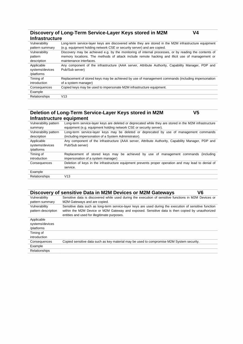
Discovery of Long-Term Service-Layer Keys stored in M2M Infrastructure
V4
Vulnerability
pattern summary
Long-term service-layer keys are discovered while they are stored in the M2M infrastructure equipment
(e.g. equipment holding network CSE or security server) and are copied.
Vulnerability
pattern
description
Discovery may be achieved e.g. by the monitoring of internal processes, or by reading the contents of
memory locations. The methods of attack include remote hacking and illicit use of management or
maintenance interfaces.
Applicable
systems/devices
/platforms
Any component of the infrastructure (AAA server, Attribute Authority, Capability Manager, PDP and
Pub/Sub server)
Timing of
introduction
Replacement of stored keys may be achieved by use of management commands (including impersonation
of a system manager)
Consequences Copied keys may be used to impersonate M2M infrastructure equipment.
Example
Relationships V13
Deletion of Long-Term Service-Layer Keys stored in M2M Infrastructure equipment
V5
Vulnerability pattern
summary
Long-term service-layer keys are deleted or deprecated while they are stored in the M2M infrastructure
equipment (e.g. equipment holding network CSE or security server).
Vulnerability pattern
description
Long-term service-layer keys may be deleted or deprecated by use of management commands
(including impersonation of a System Administrator).
Applicable
systems/devices
/platforms
Any component of the infrastructure (AAA server, Attribute Authority, Capability Manager, PDP and
Pub/Sub server)
Timing of
introduction
Replacement of stored keys may be achieved by use of management commands (including
impersonation of a system manager)
Consequences Deletion of keys in the infrastructure equipment prevents proper operation and may lead to denial of
service.
Example
Relationships V13
Discovery of sensitive Data in M2M Devices or M2M Gateways V6 Vulnerability
pattern summary
Sensitive data is discovered while used during the execution of sensitive functions in M2M Devices or
M2M Gateways and are copied.
Vulnerability
pattern description
Sensitive data such as long-term service-layer keys are used during the execution of sensitive function
within the M2M Device or M2M Gateway and exposed. Sensitive data is then copied by unauthorized
entities and used for illegitimate purposes.
Applicable
systems/devices
/platforms
Timing of
introduction
Consequences Copied sensitive data such as key material may be used to compromise M2M System security.
Example
Relationships
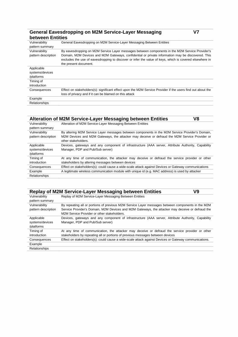
General Eavesdropping on M2M Service-Layer Messaging between Entities
V7
Vulnerability
pattern summary
General Eavesdropping on M2M Service-Layer Messaging Between Entities
Vulnerability
pattern description
By eavesdropping on M2M Service Layer messages between components in the M2M Service Provider's
Domain, M2M Devices and M2M Gateways, confidential or private information may be discovered. This
excludes the use of eavesdropping to discover or infer the value of keys, which is covered elsewhere in
the present document.
Applicable
systems/devices
/platforms
Timing of
introduction
Consequences Effect on stakeholders(s): significant effect upon the M2M Service Provider if the users find out about the
loss of privacy and if it can be blamed on this attack
Example
Relationships
Alteration of M2M Service-Layer Messaging between Entities V8 Vulnerability
pattern summary
Alteration of M2M Service-Layer Messaging Between Entities
Vulnerability
pattern description
By altering M2M Service Layer messages between components in the M2M Service Provider's Domain,
M2M Devices and M2M Gateways, the attacker may deceive or defraud the M2M Service Provider or
other stakeholders.
Applicable
systems/devices
/platforms
Devices, gateways and any component of infrastructure (AAA server, Attribute Authority, Capability
Manager, PDP and Pub/Sub server)
Timing of
introduction
At any time of communication, the attacker may deceive or defraud the service provider or other
stakeholders by altering messages between devices
Consequences Effect on stakeholders(s): could cause a wide-scale attack against Devices or Gateway communications
Example A legitimate wireless communication module with unique id (e.g. MAC address) is used by attacker
Relationships
Replay of M2M Service-Layer Messaging between Entities V9 Vulnerability
pattern summary
Replay of M2M Service-Layer Messaging Between Entities
Vulnerability
pattern description
By repeating all or portions of previous M2M Service Layer messages between components in the M2M
Service Provider's Domain, M2M Devices and M2M Gateways, the attacker may deceive or defraud the
M2M Service Provider or other stakeholders.
Applicable
systems/devices
/platforms
Devices, gateways and any component of infrastructure (AAA server, Attribute Authority, Capability
Manager, PDP and Pub/Sub server)
Timing of
introduction
At any time of communication, the attacker may deceive or defraud the service provider or other
stakeholders by repeating all or portions of previous messages between devices
Consequences Effect on stakeholders(s): could cause a wide-scale attack against Devices or Gateway communications.
Example
Relationships

Unauthorized or corrupted Applications or Software in M2M Devices/Gateways
V10
Vulnerability
pattern summary
Unauthorised or Corrupted Application and Service-Layer Software in M2M Devices/Gateways
Vulnerability
pattern description
This attack may be used to:
• commit fraud, e.g. by the incorrect reporting of energy consumption;
• cause a breach of privacy by obtaining and reporting confidential information to the attacker;
cause the disclosure of sensitive data such as cryptographic keys or other credentials;
• prevent operation of the affected M2M Devices/Gateways.
The attack may be perpetrated locally or by illicit use of remote management functions.
Applicable
systems/devices
/platforms
Devices and gateways
Timing of
introduction
The attack may be perpetrated locally or by illicit use of remote management functions
Consequences An attacker installs unauthorised M2M Service-layer software or modifies authorised software functions in
M2M Devices or M2M Gateways
Example
Relationships
M2M System Interdependencies Threats and cascading Impacts V11 Vulnerability
pattern summary
M2M System interdependencies threats and cascading impacts
Vulnerability
pattern description
While M2M endpoints and M2M Gateways might be dedicated to specific M2M Services, M2M Systems
as a whole will frequently share resources with a variety of other un-related systems and applications.
Applicable
systems/devices
/platforms
Timing of
introduction
Consequences Underlying systems and resources may impose many forms of interdependency with the M2M
Application, M2M Device / Gateway or M2M Infrastructure which is not apparent during period of normal
operation.
Example
Relationships
M2M Security Context Awareness V12 Vulnerability
pattern summary
Context-awareness
Vulnerability
pattern description
If the provided Security Level is sufficient and appropriate depends on the use case and the context of the
operation. Keeping the security level static for all use cases may lead to inefficient usage of resources (in
terms or processor, memory, network, operationally and financially).
Applicable
systems/devices
/platforms
Timing of
introduction
Consequences A lack of context awareness for M2M endpoints, gateways and applications may increase the risks
associated with resource exhaustion and under provisioning, triggering service impacts or outages.
Example
Relationships
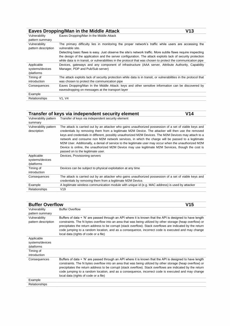
Eaves Dropping/Man in the Middle Attack V13 Vulnerability
pattern summary
Eaves Dropping/Man In the Middle Attack
Vulnerability
pattern description
The primary difficulty lies in monitoring the proper network’s traffic while users are accessing the
vulnerable site.
Detecting basic flaws is easy. Just observe the site’s network traffic. More subtle flaws require inspecting
the design of the application and the server configuration. The attack exploits lack of security protection
while data is in transit, or vulnerabilities in the protocol that was chosen to protect the communication pipe
Applicable
systems/devices
/platforms
Devices, gateways and any component of infrastructure (AAA server, Attribute Authority, Capability
Manager, PDP and Pub/Sub server)
Timing of
introduction
The attack exploits lack of security protection while data is in transit, or vulnerabilities in the protocol that
was chosen to protect the communication pipe
Consequences Eaves Dropping/Man In the Middle Attack: keys and other sensitive information can be discovered by
eavesdropping on messages at the transport layer
Example
Relationships V1, V4
Transfer of keys via independent security element V14 Vulnerability pattern
summary
Transfer of keys via independent security element
Vulnerability pattern
description
The attack is carried out by an attacker who gains unauthorized possession of a set of viable keys and
credentials by removing them from a legitimate M2M Device. The attacker will then use the removed
keys and credentials in different, possibly unauthorized M2M Devices. The M2M Devices may attach to a
network and consume non M2M network services, in which the charge will be passed to a legitimate
M2M User. Additionally, a denial of service to the legitimate user may occur when the unauthorized M2M
Device is online, the unauthorized M2M Device may use legitimate M2M Services, though the cost is
passed on to the legitimate user.
Applicable
systems/devices
/platforms
Devices, Provisioning servers
Timing of
introduction
Devices can be subject to physical exploitation at any time
Consequences The attack is carried out by an attacker who gains unauthorized possession of a set of viable keys and
credentials by removing them from a legitimate M2M Device.
Example A legitimate wireless communication module with unique id (e.g. MAC address) is used by attacker
Relationships V19
Buffer Overflow V15 Vulnerability
pattern summary
Buffer Overflow
Vulnerability
pattern description
Buffers of data + ‘N’ are passed through an API where it is known that the API is designed to have length
constraints. The N bytes overflow into an area that was being utilized by other storage (heap overflow) or
precipitates the return address to be corrupt (stack overflow). Stack overflows are indicated by the return
code jumping to a random location, and as a consequence, incorrect code is executed and may change
local data (rights of code or a file)
Applicable
systems/devices
/platforms
Timing of
introduction
Consequences Buffers of data + ‘N’ are passed through an API where it is known that the API is designed to have length
constraints. The N bytes overflow into an area that was being utilized by other storage (heap overflow) or
precipitates the return address to be corrupt (stack overflow). Stack overflows are indicated by the return
code jumping to a random location, and as a consequence, incorrect code is executed and may change
local data (rights of code or a file)
Example
Relationships

Injection V16 Vulnerability
pattern summary
Injection
Vulnerability
pattern description
Attacker sends simple text-based attacks that exploit the syntax of the targeted interpreter. Almost any
source of data can be an injection vector, including internal sources. Injection flaws occur when an
application sends untrusted data to an interpreter. Injection flaws are very prevalent, particularly in legacy
code, often found in SQL queries, LDAP queries, XPath queries, OS commands, program arguments,
etc. Injection flaws are easy to discover when examining code, but more difficult via testing.
Applicable
systems/devices
/platforms
Timing of
introduction
Consequences Send inappropriate queries to the application-level server that will exploit vulnerabilities of the query
interpreter in order to gain un-authorized access.
Example
Relationships
Session Management and Broken Authentication V17 Vulnerability pattern
summary
Session Management and Broken Authentication
Vulnerability pattern
description
Consider anonymous external attackers, as well as users with their own accounts, who may attempt to
steal accounts from others. Also consider insiders wanting to disguise their actions. Exploitation spoof
this type is of average difficulty, Attacker uses leaks or flaws in the authentication or session
management functions (e.g., exposed accounts, passwords, session IDs) to impersonate users.
Applicable
systems/devices
/platforms
Devices and gateways
Timing of
introduction
The attacker uses leaks or flaws in the authentication or session management functions (e.g., exposed
accounts, passwords, session IDs) to impersonate users
Consequences Custom session and authentication schemes frequently have flaws in areas such as logout, password
management, timeouts, remember me, secret question and account update allowing the attacker to
impersonate other entity
Example
Relationships V18
Security Misconfiguration V18 Vulnerability pattern
summary
Security Misconfiguration
Vulnerability pattern
description
Consider anonymous external attackers as well as users with their own accounts that may attempt to
compromise the M2M System. Also consider insiders wanting to disguise their actions. Easy to exploit,
attacker accesses default accounts, unused pages, un-patched flaws, unprotected files and directories,
etc. to gain unauthorized access to or knowledge of the M2M System.
Applicable
systems/devices
/platforms
Devices, gateways and any component of infrastructure (AAA server, Attribute Authority, Capability Manager, PDP and Pub/Sub server)
Timing of
introduction
The attacker decides to access default accounts, unused pages, unpatched flaws, unprotected files and
directories, etc.
Consequences Attacker accesses default accounts, unused pages, un-patched flaws, unprotected files and directories,
etc. to gain unauthorized access to or knowledge of the M2M System
Example
Relationships V17
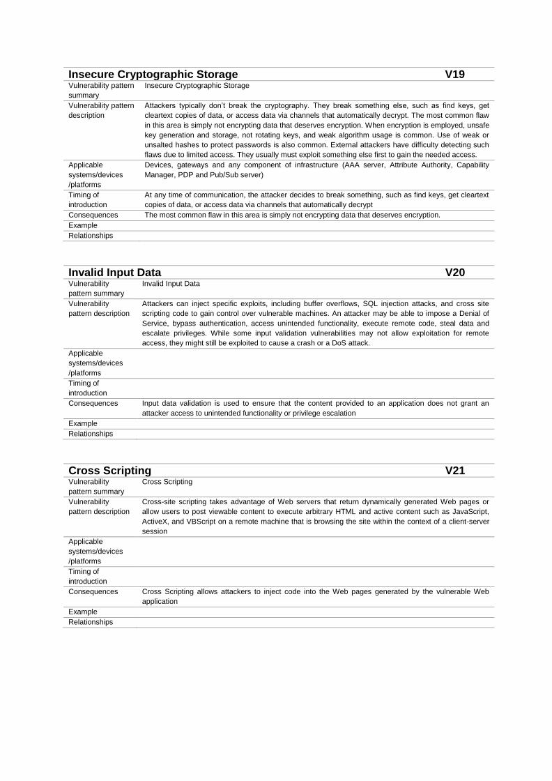
Insecure Cryptographic Storage V19 Vulnerability pattern
summary
Insecure Cryptographic Storage
Vulnerability pattern
description
Attackers typically don’t break the cryptography. They break something else, such as find keys, get
cleartext copies of data, or access data via channels that automatically decrypt. The most common flaw
in this area is simply not encrypting data that deserves encryption. When encryption is employed, unsafe
key generation and storage, not rotating keys, and weak algorithm usage is common. Use of weak or
unsalted hashes to protect passwords is also common. External attackers have difficulty detecting such
flaws due to limited access. They usually must exploit something else first to gain the needed access.
Applicable
systems/devices
/platforms
Devices, gateways and any component of infrastructure (AAA server, Attribute Authority, Capability
Manager, PDP and Pub/Sub server)
Timing of
introduction
At any time of communication, the attacker decides to break something, such as find keys, get cleartext
copies of data, or access data via channels that automatically decrypt
Consequences The most common flaw in this area is simply not encrypting data that deserves encryption.
Example
Relationships
Invalid Input Data V20 Vulnerability
pattern summary
Invalid Input Data
Vulnerability
pattern description
Attackers can inject specific exploits, including buffer overflows, SQL injection attacks, and cross site
scripting code to gain control over vulnerable machines. An attacker may be able to impose a Denial of
Service, bypass authentication, access unintended functionality, execute remote code, steal data and
escalate privileges. While some input validation vulnerabilities may not allow exploitation for remote
access, they might still be exploited to cause a crash or a DoS attack.
Applicable
systems/devices
/platforms
Timing of
introduction
Consequences Input data validation is used to ensure that the content provided to an application does not grant an
attacker access to unintended functionality or privilege escalation
Example
Relationships
Cross Scripting V21 Vulnerability
pattern summary
Cross Scripting
Vulnerability
pattern description
Cross-site scripting takes advantage of Web servers that return dynamically generated Web pages or
allow users to post viewable content to execute arbitrary HTML and active content such as JavaScript,
ActiveX, and VBScript on a remote machine that is browsing the site within the context of a client-server
session
Applicable
systems/devices
/platforms
Timing of
introduction
Consequences Cross Scripting allows attackers to inject code into the Web pages generated by the vulnerable Web
application
Example
Relationships

BEXAMPLE OF SINGLE TTCN-3
FUZZING TEST CASE WITH 20 STEPS
module F u z z i n g t e s t s u i t e {impor t from ARMOUR Adapter HTTP a l l ;impor t from ARMOUR PIXIT a l l ;tes tcase ARMOUR message interception4fc780 ( ) runs on ARMOURComponent {
f c f01Up ( ) ;g e n e r a t e t r a f f i c (PX EXPERIMENT ID , PX BORDER ROUTER, PX NODE NAME, PX NUM ) ;check connec t i v i t y (PX EXPERIMENT ID , PX BORDER ROUTER, PX NODE NAME ) ;check packet loss (PX EXPERIMENT ID , PX BORDER ROUTER, PX NODE NAME, PX NUM ) ;message in tercept ion ( ) ;es tab l i sh secu re connec t i on (PX EXPERIMENT ID , PX BORDER ROUTER,
PX NODE NAME, PX NUM, PX KEY ) ;message in tercept ion ( ) ;s t o p t r a f f i c ( ) ;message in tercept ion ( ) ;message in tercept ion ( ) ;se rv i ce d i scove ry (PX EXPERIMENT ID , PX BORDER ROUTER, PX NODE NAME,
PX NUM, PX KEY ) ;check secur i t y key (PX EXPERIMENT ID , PX BORDER ROUTER, PX NODE NAME,
PX NUM, PX KEY ) ;g e n e r a t e t r a f f i c (PX EXPERIMENT ID , PX BORDER ROUTER, PX NODE NAME, PX NUM ) ;check connec t i v i t y (PX EXPERIMENT ID , PX BORDER ROUTER, PX NODE NAME ) ;check packet loss (PX EXPERIMENT ID , PX BORDER ROUTER, PX NODE NAME, PX NUM ) ;s t o p t r a f f i c ( ) ;message in tercept ion ( ) ;se rv i ce d i scove ry (PX EXPERIMENT ID , PX BORDER ROUTER, PX NODE NAME, PX NUM,
PX KEY ) ;check secur i t y key (PX EXPERIMENT ID , PX BORDER ROUTER, PX NODE NAME, PX NUM,
PX KEY ) ;updateFirmware (PX EXPERIMENT ID , PX BORDER ROUTER, PX NODE NAME,
PX NUM MALICIUS ) ;message in tercept ion ( ) ;es tab l i sh secu re connec t i on (PX EXPERIMENT ID , PX BORDER ROUTER,
PX NODE NAME, PX NUM, PX KEY INVALID ) ;g e n e r a t e t r a f f i c (PX EXPERIMENT ID , PX BORDER ROUTER, PX NODE NAME, PX NUM ) ;check connec t i v i t y (PX EXPERIMENT ID , PX BORDER ROUTER, PX NODE NAME ) ;check packet loss (PX EXPERIMENT ID , PX BORDER ROUTER, PX NODE NAME, PX NUM ) ;s t o p t r a f f i c ( ) ;s t o p t r a f f i c ( ) ;g e n e r a t e t r a f f i c (PX EXPERIMENT ID , PX BORDER ROUTER, PX NODE NAME, PX NUM ) ;check connec t i v i t y (PX EXPERIMENT ID , PX BORDER ROUTER, PX NODE NAME ) ;check packet loss (PX EXPERIMENT ID , PX BORDER ROUTER, PX NODE NAME, PX NUM ) ;message in tercept ion ( ) ;
}}
137


Document generated with LATEX and:the LATEX style for PhD Thesis created by S. Galland — http://www.multiagent.fr/ThesisStyle
the tex-upmethodology package suite — http://www.arakhne.org/tex-upmethodology/
n École doctorale SPIM 1 rue Claude Goudimel F - 25030 Besançon cedex
n tél. +33 (0)3 81 66 66 02 n [email protected] n www.ed-spim.univ-fcomte.fr
Abstract:
The Internet of Things (IoT) is nowadays globally a mean of innovation and transformation for manycompanies. Applications extend to a large number of domains, such as smart cities, smart homes,healthcare, etc. The Gartner Group estimates an increase up to 21 billion connected things by 2020.The large span of ”things” introduces problematic aspects, such as conformance and interoperabilitydue to the heterogeneity of communication protocols and the lack of a globally-accepted standard.The large span of usages introduces problems regarding secure deployments and scalability of thenetwork over large-scale infrastructures. This thesis deals with the problem of the validation ofthe Internet of Things to meet the challenges of IoT systems. For that, we propose an approachusing the generation of tests from models (MBT). We have confronted this approach through multipleexperiments using real systems thanks to our participation in international projects. The importanteffort which is needed to be placed on the testing aspects reminds every IoT system developer thatdoing nothing is more expensive later on than doing it on the go.
Keywords: Internet of Things, Model-Based Testing, Test, Security, Conformity, Behavioral Fuzzing
Resume :
L’internet des objets (IoT) est aujourd’hui un moyen d’innovation et de transformation pour denombreuses entreprises. Les applications s’etendent a un grand nombre de domaines, tels queles villes intelligentes, les maisons intelligentes, la sante, etc. Le Groupe Gartner estime a 21milliards le nombre d’objets connectes d’ici 2020. Le grand nombre d’objets connectes introduit desproblemes, tels que la conformite et l’interoperabilite en raison de l’heterogeneite des protocoles decommunication et de l’absence d’une norme mondialement acceptee. Le grand nombre d’utilisationsintroduit des problemes de deploiement securise et d’evolution du reseau des IoT pour former desinfrastructures de grande taille. Cette these aborde la problematique de la validation de l’internet desobjets pour repondre aux defis des systemes IoT. Pour cela, nous proposons une approche utilisantla generation de tests a partir de modeles (MBT). Nous avons confronte cette approche a traversde multiples experimentations utilisant des systemes reels grace a notre participation a des projetsinternationaux. L’effort important qui doit etre fait sur les aspects du test rappelle a tout developpeurde systeme IoT que: ne rien faire est plus cher que de faire au fur et a mesure.
Mots-cles : Internet des Objets, Tests bases sur des modeles, Test, Conformite, Securite, Exploration com-portementale