Model 820 - Sound Level Meter Technical Reference Manual
193
Sound Level Meter Technical Reference Manual Model 820
-
Upload
khangminh22 -
Category
Documents
-
view
1 -
download
0
Transcript of Model 820 - Sound Level Meter Technical Reference Manual

Sound Level MeterTechnical Reference Manual
Model 820

Model 820
Technical Reference Manual
Larson Davis, a division of PCB Piezotronics, Inc.1681 West 820 North
Provo, UT 84601-134124 Hour Hotline: (716) 926-8243Toll Free (US): (888) 258-3222
www.larsondavis.comI820.01 Rev.D

Copyright
Copyright 2009 by PCB Piezotronics, Inc. This manual is copyrighted, with all rights reserved. Themanual may not be copied in whole or in part for any use without prior written consent of PCBPiezotronics, Inc.
Disclaimer
The following paragraph does not apply in any state or country where such statements are notagreeable with local law:
Even though PCB Piezotronics, Inc. has reviewed its documentation, PCB Piezotronics Inc. makesno warranty or representation, either expressed or implied, with respect to this software anddocumentation, its quality, performance, merchantability, or fitness for a particular purpose. Thisdocumentation is subject to change without notice, and should not be construed as a commitment orrepresentation by PCB Piezotronics, Inc.
This publication may contain inaccuracies or typographical errors. PCB Piezotronics, Inc. willperiodically update the material for inclusion in new editions. Changes and improvements to theinformation described in this manual may be made at any time
Equal Opportunity Employer
PCB Piezotronics is an equal opportunity employer and does not discriminate on the basis of race,color, religion, gender, national origin, disability or veteran status.
..Please examine your instrument and record the following information below. You may be asked togive this information in any future communications you have with PCB Piezotronics, Inc.
Customer Service
In the U.S. call toll-free: 888-258-3222
International customers:+1 716- 926-8243
FAX: +1 716-926-8215
Email: [email protected]
Worldwide Web: www.LarsonDavis.com

Record of Serial Number and Purchase Date
Recycling
Larson Davis, Inc. is an environmentally friendly organization and encourages our customers to beenvironmentally conscious. When this product reaches its end of life, please recycle the productthrough a local recycling center or return the product to:
Larson Davis, Inc.Attn: Recycling Coordinator1681 West 820 NorthProvo, Utah, USA 84601
where it will be accepted for disposal
PRM828 Pre-amp. Serial #: ______________Microphone Serial # ____________________
System 820 Serial #: _____________________Microphone Model #: ___________________
Purchase Date: _________________________

Table of ContentsChapter 1 Introduction 1-1
About This Manual .................................................................................................1-1About This Chapter.................................................................................................1-3Formatting Conventions .........................................................................................1-3Features ...................................................................................................................1-5Model 820 Components..........................................................................................1-7
Block Diagram .................................................................................................1-10Getting Started ......................................................................................................1-11
Unpacking and Inspection................................................................................1-12Accessories.......................................................................................................1-12Optional Equipment .........................................................................................1-13Battery Installation...........................................................................................1-17Environmental Considerations .........................................................................1-18Preparing to Use the Model 820 - Connecting the Mic/Preamp ......................1-18
Chapter 2 Overview to Model 820 2-1Understanding the Model 820 Keypad ...................................................................2-1Getting to Know Screen Symbols...........................................................................2-8Understanding the Model 820 Screen.....................................................................2-9Turning On the Model 820 .....................................................................................2-9Checking the Battery Voltage...............................................................................2-10Turning Off the Model 820...................................................................................2-11
Chapter 3 Calibration 3-1Calibrating the Model 820 ......................................................................................3-1
Chapter 4 Quick Start 4-1Setting Parameters Using Function Keys ...............................................................4-1Setting Parameters Using Numbers and Other Characters .....................................4-3Setting Time, Date, and Day parameters ................................................................4-7AC/DC Output ........................................................................................................4-8
Chapter 5 Performing a Measurement/Reading the Data 5-1Taking a Measurement............................................................................................5-1
SLM ...................................................................................................................5-1Lmax-Lmin ........................................................................................................5-5PEAK-UWPK ....................................................................................................5-7
Ln .......................................................................................................................5-8Leq .....................................................................................................................5-9Dose-LDL ..........................................................................................................5-9BATTERY .......................................................................................................5-14MEMORY........................................................................................................5-14
Stopping the Measurement ...................................................................................5-15
Chapter 6 Timed Measurement 6-1Using the Timer for Unattended Readings. ............................................................6-1Using the Time Key Functions ...............................................................................6-4Setting the Password Lock to Protect Settings .......................................................6-5
Chapter 7 History Functions 7-1Setting and Viewing Advanced Functions..............................................................7-1
Time History ......................................................................................................7-1Time History Data..............................................................................................7-3Log .....................................................................................................................7-4Interval History ..................................................................................................7-5Exceedance.........................................................................................................7-8Setting PassBy Functions.................................................................................7-12
Overload................................................................................................................7-14Setting the Daily History Parameter .....................................................................7-14
Chapter 8 Parameters 8-1Parameter Key Access Review ...............................................................................8-1
Entering and Exiting the Setup Menu ................................................................8-1Locating Parameters...........................................................................................8-2Changing Parameters — Enter, Modify.............................................................8-3Error Messages...................................................................................................8-4
Learning to Store and Retrieve Setup Memory ......................................................8-4Storing a Setup ...................................................................................................8-5Recalling a Setup ...............................................................................................8-6
Model 820 Setup Parameters ..................................................................................8-7System (1-20) R U S..............................................................................8-7Timer (21-27) U T............................................................................................8-10Lock (28-34) U L .............................................................................................8-10Calibration (35-38) U C ...................................................................................8-11Sound Level Meter (39-50) .......................................................................... C8-11Dose (51) ...................................................................................................... E8-13
Ln Statistical Levels (55-60) B ........................................................................8-13Exceedance Levels (61-65) V ..........................................................................8-14Exceedance History (66-70, 161-163) .............................................................8-14Interval History (72-79) MTime History (80-87) ...................................................................................H8-15Print Options (89-112) s...................................................................................8-18Additional System Functions (152, 154-161) ..................................................8-19
Chapter 9 Memory Usage 9-1Determine Storable Data.........................................................................................9-1Estimating Memory Usage .....................................................................................9-3
Chapter 10 Printing a Report 10-1Normal Printout Parameters..................................................................................10-1Printing Reports ....................................................................................................10-3Real-time Printing.................................................................................................10-4
Appendix A Specifications A-1Type .......................................................................................................................A-2Reference Direction ...............................................................................................A-2Measurement Ranges .............................................................................................A-3
RMS Detector ...................................................................................................A-3Other Detectors .................................................................................................A-4
Reference Level .....................................................................................................A-4Frequency Weightings ...........................................................................................A-4Detector Time Weightings.....................................................................................A-7Effects of Temperature ..........................................................................................A-7Effects of Humidly.................................................................................................A-7Limits of Temperature and Humidity ....................................................................A-7Microphone Extension Cables ...............................................................................A-7Instrument/Observer Positioning for Best Measurements .....................................A-8AC and DC Outputs ...............................................................................................A-8
AC Output .........................................................................................................A-8DC Output .........................................................................................................A-8
Reference Frequency .............................................................................................A-8Stabilization Time..................................................................................................A-9Microphone Electrical Impedance .........................................................................A-9Functions Measured ...............................................................................................A-9Data Storage...........................................................................................................A-9

Data Communications..........................................................................................A-10Digital Display .....................................................................................................A-10Digital Display Resolution...................................................................................A-10Display Bargraph .................................................................................................A-10Real-time Clock/Calendar....................................................................................A-10Run-time Clock....................................................................................................A-11Standards Met ......................................................................................................A-11CE Information ....................................................................................................A-11Power Supply .......................................................................................................A-12Dimensions/Weight (with Microphone, Preamplifier and Battery).....................A-12
Appendix B Serial Port Interface Remote Control B-1Model INT002 Interface Cable .........................................................................B-2Daisy Chain Addressing....................................................................................B-2Commands ........................................................................................................B-3History Oriented CommandsMode Commands ..............................................................................................B-4“Read” Variables...............................................................................................B-5Other Read Commands ...................................................................................B-11Group Read Programming .............................................................................. B-11Setting Parameters........................................................................................... B-12
Numeric Parameters ...................................................................................B-12Indexed Parameters .................................................................................... B-13Character String Parameters....................................................................... B-14Template Parameters .................................................................................. B-14
Query Parameters ............................................................................................ B-15Histogram Reports...................................................................................... B-19Tailored Report .......................................................................................... B-19Miscellaneous............................................................................................. B-20Error Checking I/O..................................................................................... B-22
History Records............................................................................................... B-24Types of History......................................................................................... B-24Advance...................................................................................................... B-24Backup........................................................................................................ B-25Find............................................................................................................. B-25
History Data Variables.................................................................................... B-25Exceedance History Variables ................................................................... B-25Interval History Variables .......................................................................... B-26Daily History Variables - (D1-D102)........................................................ B-28

Run Log Variables ..................................................................................... B-29Calibration History Variables..................................................................... B-29Time History Variables .............................................................................. B-29Histogram Table Variables......................................................................... B-30
Print Commands.............................................................................................. B-31Error Messages and Warnings ........................................................................ B-32Modem Control Mode .................................................................................... B-34
Modem Mode (154) ...................................................................................B-34Dial Out Mode (155) .................................................................................. B-34Monitor Number......................................................................................... B-34820 Phone Dialing Procedure..................................................................... B-35Model 820 Answering Procedure............................................................... B-35
Appendix C Glossary C-1

C H A P T E R
1 Introduction
Welcome to the Larson Davis Model 820. Your new hand heldModel 820 from Larson Davis is a combination Type 1 preci-sion integrating sound level meter and a statistical data loggerthat exceeds all worldwide accuracy requirements for the mea-surement of noise.
The Model 820 measures sound with the ease of operation of a“point and shoot” sound level meter. The latest advances insurface mount technology, air condenser microphones, andinternal firmware have been combined in a rugged,lightweight yet extremely versatile unit.
Many sound level meters in the market can create significantmeasurement errors because of their limited dynamic range,pulse range, and crest factor. The Model 820 does not havethese limitations.
Furthermore, its internal firmware is designed toaccommodate changing regulations and to overcome soundmeasurement problems. While the Model 820 is the size of adosimeter, it is also a complete environmental noise monitoroffering features which will ensure quality measurements formany years.
We invite you to read this manual to get the most out of yournew Larson Davis sound level meter.
About This Manual
This manual has 10 chapters and 3 appendices covering thefollowing topics:
Model 820 Technical Reference Manual Introduction 1-1
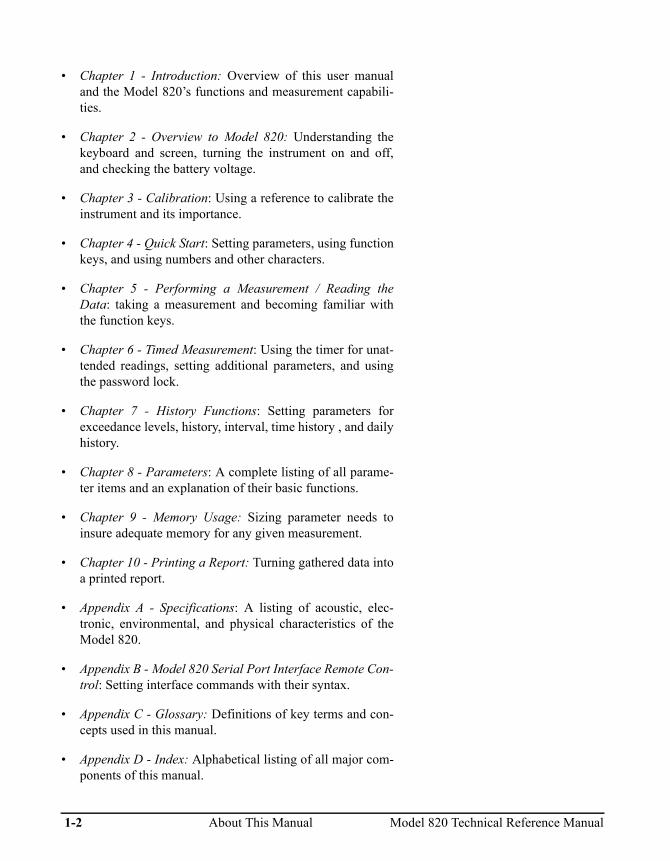
• Chapter 1 - Introduction: Overview of this user manualand the Model 820’s functions and measurement capabili-ties.
• Chapter 2 - Overview to Model 820: Understanding thekeyboard and screen, turning the instrument on and off,and checking the battery voltage.
• Chapter 3 - Calibration: Using a reference to calibrate theinstrument and its importance.
• Chapter 4 - Quick Start: Setting parameters, using functionkeys, and using numbers and other characters.
• Chapter 5 - Performing a Measurement / Reading theData: taking a measurement and becoming familiar withthe function keys.
• Chapter 6 - Timed Measurement: Using the timer for unat-tended readings, setting additional parameters, and usingthe password lock.
• Chapter 7 - History Functions: Setting parameters forexceedance levels, history, interval, time history , and dailyhistory.
• Chapter 8 - Parameters: A complete listing of all parame-ter items and an explanation of their basic functions.
• Chapter 9 - Memory Usage: Sizing parameter needs toinsure adequate memory for any given measurement.
• Chapter 10 - Printing a Report: Turning gathered data intoa printed report.
• Appendix A - Specifications: A listing of acoustic, elec-tronic, environmental, and physical characteristics of theModel 820.
• Appendix B - Model 820 Serial Port Interface Remote Con-trol: Setting interface commands with their syntax.
• Appendix C - Glossary: Definitions of key terms and con-cepts used in this manual.
• Appendix D - Index: Alphabetical listing of all major com-ponents of this manual.
1-2 About This Manual Model 820 Technical Reference Manual

About This Chapter
Specifically, this introductory chapter covers the followingtopics:
• Formatting Conventions: Explanation of the fonts andother formatting conventions used in this manual.
• Model 820 Features: A listing of the featured characteris-tic, and capabilities of the Model 820.
• Model 820 Components: Description and diagrams of theModel 820 external parts.
• Getting Started: Instructions for unpacking, a listing ofaccessories and optional equipment and initial setup.
Formatting Conventions
This manual uses the following formatting conventions:
Functions accessed by pressing a key on the Model 820keypad are shown with an icon, for example:
Press e and then press c.
In step-by-step directions, the process (what you do) is shownin the left column, and the rationale (why you do it) with othercautions and comments are shown in the right column. Forexample:
Microphone Polarization Voltage is preset by Larson Davis at200 volts. Should this parameter be incorrect, the Model 820will not calibrate correctly.
Model 820 Technical Reference Manual About This Chapter 1-3

Step 1 Check the microphone polarization. To do this turn on the Model 820, press R, m, 4 and 3, and e. The following display will appear:
The flashing (f), the Keyboard Sta-tus Indicator, displays which keyfunctions are active. This indicatesthat the function keys are used fordifferent purpose in current func-tion.
Step 2 Should the brackets contain a value other than [200] e.g. [28, 0],press ther until the value [200] appears, and then press e.
In this screen the value [200} isselected from three options: [200,28, 0]
1-4 Formatting Conventions Model 820 Technical Reference Manual

Especially important information is shown in italics, forexample:
Features
The Larson Davis Model 820 meets the requirements of theAmerican National Standards Institute (ANSI) S1.4,International Electrotechnical Commission (IEC) 651, and804-1985 standards for Type 1 accuracy and offers thefollowing features:
• Dynamic range of more than 100 dB for error free mea-surements.
• Impulse measuring range greater than 100 dB.
• Standard microphone allows measurements typicallybetween 30 and 140 db(A) in one range. Optional micro-phones allow measurements as low as 20 dB or as high as190 dB(A). Mic. bias is user selectable: 0, 28, and 200 V.
• Selectable A and C frequency weightings for hearing pro-tector applications.
• Multiple detectors provide simultaneous RMS and PEAKmeasurements.
• Leq integrated level (duration ranging from 1 second to 99hours, manually controlled).
• Measures FAST, SLOW, Unweighted PEAK, WeightedPEAK, Impulse, Leq, LDOD, LOSHA, Dose, Projected Dose,TWA, Sel (Lae), Lmax, Lmin, six user defined Lns, Ldn,CNEL, and more.
• User selectable dose exchange rate, criterion, threshold,and reference duration.
• Measures and stores more than 40,000 different DOSE
To access items 48-50, Overall Exchange Rate, Overall Threshold, Overall Criterion, press the d key.
Model 820 Technical Reference Manual Features 1-5

combinations in a single measurement. Allows compari-sons of different DOSE standards using the same data.
• Complete data logging capabilities with 256 kB standardmemory.
• Passby event data such as time, duration, Lmax, Leq, SEL,integrated about 10 dB of the maximum.
• Selectively logs Exceedance when signal level rises abovea user-set threshold for a time longer than a user-set period.
• Time history sampling periods are user selectable from 32samples/second up to one sample every 255 minutes.
• Quartz clock/calendar system for data annotation.
• Calibration from front panel (using an appropriate calibra-tion source).
• Easy one step reset of measurement.
• Battery level indication.
• Standard 9V internal alkaline battery life of more than 16hours (or external power using Larson Davis cable #CBL035 for longer measurements).
• RS-232 computer and modem interface standard. All func-tions fully programmable. Comes complete with PCSWW_SLM_UTIL software for data retrieval and translatebinary files to ASCII format. Other PC software also avail-able.
• Large, two line, 32 character, high contrast LCD display.
• Small [33cm x 7.5cm x 2.5cm (13” H x 3” W x 1” D) andlightweight, 370g (13 oz), including microphone and bat-tery.
• Rugged ABS case with EMI and RFI protection.
• Environmental enclosures available for system securityand protection from inclement weather.
• Durable membrane keypad.
1-6 Features Model 820 Technical Reference Manual

Model 820 Components
A layout of the Model 820 is shown below
Figure 1-1 Model 820. The Model 820 is a convenient hand-held sound level meter with a simple user interface.
TIME TIMER LDL
CAL UWPK BATT
LOCK MEM LOG
STR RCL RESET
SHIFT
MIN
DNL
L
LARSON DAVIS 820 SLM
LEQ SEL T.A. DOSE
EXCD INTV HIST
PRINT SETUP R/S
SLM LMAX PEAK LN
TYPE 1 INTEGRATING SOUND LEVEL METER
. Enter0Cancel
2 31
5 64
8 97
Modify
Microphone
MicrophonePreamplifier
LCD Display
Connector AC/DC Out
Keypad
Connector(Cal/HeaterPort) Optional
Connector SerialPortBattery
Compartment
Model 820 Technical Reference Manual Model 820 Components 1-7

As can be seen, the standard Model 820 includes thefollowing:
• Model PRM828 is a 5 1/2 inch precision preamplifierusing a standard 5 pin SwitchCraft™ connector and maybe extended up to 20 feet with EXCXXX microphonecable. The preamplifier is removed by depressing the smallblack latch button with a fingertip, while gently pulling itaway from the mating connector.
• A two-line, 32-character, high-contrast LCD display.
• One of the 1⁄2 inch precision air condenser microphones inTable 1-1, “Microphones for use with 820,” on page 1-8.The microphones are rugged and reliable but should bekept in their protective case when not in use. Avoid unnec-essary shock (Although an Larson Davis microphone canusually survive being dropped, it is a delicate, precisetransducer that should be handled with care).
Keep clean and protect from con-densing moisture and water. Themicrophone’s ultra-thin diaphragmis covered by a protective gridwhich should not be removed innormal use. Rain droplets or otherforeign matter on the diaphragmmay alter the microphones’s
Microphone TypeSensitivitymV/Pa Bias
2540 Free-field 14.5 Voltage Required
2541, 377B41 Free-field 44.5 Voltage Required
377B02 Free-field 50.0 Prepolarized
377A20 Random 50.0 Prepolarized
2559 Random 12.9 Voltage Required
2560, 377A60 Random 45.2 Voltage Required
Table 1-1 Microphones for use with 820
1-8 Model 820 Components Model 820 Technical Reference Manual

response. Please use a windscreenwhenever possible.
• A 20-key membrane keypad.
• Model 820 precision hand-held Sound Level Meter withintegral nose cone. Powered internally by 9 volt cell, or byan external battery or AC/DC adapter.
• WS001 3 1/2 inch windscreen.
• An AC/DC mini phone connector with pinout shown onpage 4-8.
• A 5-pin cable connector with the pinout shown in figureFigure 1-2: (Note that this connector is used to accessexternal power)
Using cable CBL038 or INT002and related software, the 5-pinconnector is used both for externalpower and for the remote interface.
Figure 1-2 External 5-pin Cable Connector Pinout.
1 - Ground
1
23
45
2 - TXD Transmitted Data fm 820
3 - RXD Received Data to 820
5 - DTR Data Terminal Ready
4 - External Battery to 820
Model 820 Technical Reference Manual Model 820 Components 1-9

Block Diagram
All the standard functions of a precision sound level meter areprovided: instantaneous level, Leq, SEL, Lmax, Lmin, dose,projected dose, etc. In addition, many valuable parameters canbe stored: time history interval data such as Ln’s and Leq,exceedance and exceedance time history, etc. Level calibrationis performed in a few key strokes, and every change or checkis entered in a calibration log.
The Model 820’s large data memory relieves the user from theconcern of data loss caused by memory limitations.Furthermore, measurements can be printed or transmitted at upto 19.2 K baud via RS-232 for further manipulation orarchiving.
Despite its numerous functions, the Model 820 is easy to use.
Annotated displays indicate units and measurement mode. Thesingle setup menu lets the user scroll through and programparameters or use an index key to modify specific information.Multiple measurement setups can be stored in memory forlater recall. And of course, complete setups can also betransferred from a computer.
Figure 1-3 Block Diagram.
A Filter
CFilter
RMS 39Slow, Fast, Impl
Peak 1
Peak 2
40
42
Weighted
Flat
Microphone
0/28/200 V 43 Bias Supply
41
A:D
ClockTimer
LCD Keypad
RAM256K
PowerSupply
5-pinConnector
Internal9V Battery
AC/DC Output
20 dB
0 dB
Micro-processor
Indicates parameter numberN
Flash128K
820 Block Diagram
1-10 Model 820 Components Model 820 Technical Reference Manual

The block diagram above shows how the Model 820 soundlevel meter merges state-of-the-art analog circuitry, a powerfulmicrocomputer controller and a large amount of usable datamemory.
The signal from the precision air condenser microphone/preamplifier is input directly to the linear peak detector and,through the selected A- or C-weighting filter, to the root-mean-square (rms) and weighted peak detectors. Analog todigital conversion is performed maintaining a full 110 dBrange for the RMS signal. The numeric data is then analyzedby the Model 820’s dedicated digital processor.
With system programming residing in PROMs (programmableread-only memory), upgrades or future changes in regulationscan easily be accommodated. Measurement modes areselected and shown in informative screens on the 32 characterliquid crystal diode (LCD) display. The custom keypadprovides direct access to the needed data or setup item. Anaccurate built-in Quartz clock/calendar and timer are ideal forunattended measurements and time stamping of events.
The 256 kB memory can be used to store time, exceedance orinterval data as selected by the user. All can be printed ortransferred to an external computer via the serial port, evenduring data gathering. Larson Davis PC-compatible softwareemploys a binary data dump method for even faster datatransfer. External battery or DC power may be suppliedthrough the same five pin connector.
Getting Started
This section outlines the steps you need to follow when youfirst receive and unpack the Model 820. The following topicsare covered:
• Unpacking and Inspection.
• Accessories and Optional Equipment.
• Connecting Internal or External Power.
• Environmental Considerations.
Model 820 Technical Reference Manual Getting Started 1-11

• Preparing to use the Model 820
• Connecting the Microphone to the Preamp.
You will then be ready to use the Model 820 for actualmeasurements (as described later in Chapter 4 of this manual).
Unpacking and Inspection
Your Model 820 has been shipped in protective packaging.Please verify the package contents with the following list(Accessories and Optional Equipment) and retain the shippingcontainers for safe shipment at a future date. Report anydamage or shortage immediately to Larson Davis, Inc. at (801)375-0177.
If you have not already done so, please record, at thebeginning of this manual (see the copyright page), yourinstrument’s serial number (located on the label on the back ofthe Model 820), the microphone serial number (located insidethe microphone), the preamp serial number, and the purchasedate. You will be asked to give this information in any futurecommunications you may have with Larson Davis, Inc.
Accessories
The Model 820 is delivered with the following standardaccessories:
• The standard Model 820 Precision Sound Level Meterincluding one of the 1/2 inch precision air condensermicrophones in Table 1-1, “Microphones for use with820,” on page 1-8 and Model 828 preamplifier.
• Alkaline battery, 9 volts (IEC GLR61 or NEDA/ANSI1604A).
A good quality alkaline cell should provide more than 16hours of Model 820 operation. Since most rechargeablecells have less capacity, expect shorter use.
• User manual.
1-12 Getting Started Model 820 Technical Reference Manual

• Soft carrying case belt pouch (Larson Davis part #CCS009).
• WS001 a 3 1/2 inch windscreen.
Wind noise can adversely affect measurements. Using thewindscreen on the microphone reduces wind noise andprotects the element from dust and bumps.
• SWW_SLM_UTIL software.
Utility software package allowing data retrieval and trans-lation of binary files, generated by the Model 820, toASCII File Format via RS-232 connection, and is capableof editing and storing instrument setup parameter to thePC, or loaded directly to sound level meter.
Optional Equipment
The following optional equipment is also available:
• ADP005: BNC to preamp thread adapter to input directsignal through preamp. Includes equivalent capacitanceand shorting connector for noise floor testing.
• ADP012: Adapter for direct signal input to the Model 820.Must be used only with DC coupled sources (1200 ohms orless).
• CBL033: Printer cable for direct printout to serial printer, 6feet.
• CBL034: Connects Model 820 to un-wired cable end (4-conductor shielded).
• CBL035: Connects Model 820 and customer suppliedexternal battery.
• CBL040: Similar to INT002 but allows one to “daisychain” an additional Model 820.
• CBL042 AC/DC output of the Model 820 to RCA/BNCconnectors.
• CBL116 Connects Model 820 to a PC or a modem. Pro-
Model 820 Technical Reference Manual Getting Started 1-13

vides connection for external power adaptor such asPSA017 or similar.
• CCS002: Custom hard shell, airtight, watertight case (13 1/2 X 12 7/8 X 6 in).
• EPS012:CCS002 weatherproof fiberglass case with cus-tom-cut foam interior and desiccant. Sealed signal cablefeed through. Features lock hasp and may be chainedthrough handle for security.
• EPS013: Same as EPS012 but with 8 Ah, 12 Volt recharge-able battery BAT004. Provides 1 week operation in normalconditions. Includes CBL038 and battery charger.
1-14 Getting Started Model 820 Technical Reference Manual

• EXCXXX: Microphone extension cable, length XXX feet.
• Epson Printer.
• INT002: RS-232 cable level converter for data transfer toPC. Requires 9 V battery or external AC power supply(PSA001 included). Note that external supply will alsopower the Model 820.
• PSA001: AC/DC power adapter, 115 Vac to 9 Vdc, 50-60Hz for use with INT002.
• PSA002: AC/DC power adapter, 220 Vac to 9Vdc, 50-60Hz for use with INT002.
• 820-OPT01: Modification of the Model 820 for use in out-door noise monitoring system using the Model PRM2101Outdoor Preamplifier. Includes addition of a second con-nection to the 820 for control of the electrostatic actuator.Also includes environmental testing and certification asfollows: Separate testing of 820 and PRM2101 in a com-puter controlled environmental chamber.
Note Figure 1–4 or call Larson Davis for additionalinformation on these and other accessories.
Model 820 Technical Reference Manual Getting Started 1-15

Figure 1-4 820 System Diagram
ADP011
ADP008
2570
2575
2540
2559
2541
2560
2520
2530
PRM828*
2551
WS001*
PRM2101
1/2-inch Microphone
EXCXXX(20’ Max)
CBL042 (6’)DC Out (red)
CBL009-020 (820 OPT01 required)
(1.5’)Battery (powers 2101 heater and EA)
(20’)
CBL034 (6’)4 Conductor Shielded
CBL035 (4’)
INT002 (12’)
PSA001
PSA001
CBL040 (12’)
CBL116 (1.5’) CBL077 (6’, optional)
(2’)Battery
CBL033 (6’)
Battery(2’)
CBL116 (1.5’) CBL077 (6’, optional)
Desktop Computer
Laptop Computer
Serial Printer
Modem
Larson DavisWEB Page
SoftwareSWW SLM UTIL*SWW SLM LINKSWW ENVSWW REMSWW NMSSWW ACS
EPS012 Environmental Case
EPS013 Environmental Case w/ Battery
CCS009Soft Case*
To next SLM
Note: Those items marked with "*"are standard included accessories.
(alligator clips)
Rainhat withelectrostatic actuator
Battery topower 820
PSA005 AC/DC Adaptor
WS005 Windscreenwith birdspikes
AC Out (black)
2106/7/8
WS005
820 SYSTEM
TIME TIMER LDL
CAL UWPK BATT
LOCK MEM LOG
STR RCL RESET
SHIFT
MIN
DNL
L
LARSON DAVIS 820 SLM
LEQ SEL T.A. DOSE
EXCD INTV HIST
PRINT SETUP R/S
SLM LMAX PEAK LN
TYPE 1 INTEGRATING SOUND LEVEL METER
. Enter0Cancel
2 31
5 64
8 97
Modify
1-16 Getting Started Model 820 Technical Reference Manual

Battery Installation
To insert the 9 volt battery in the Model 820, remove thebattery cover at the lower left side of the instrument by slidingit out as shown in Figure 1-5 .
Figure 1-5 Remove Battery
With the battery door removed, drop the battery into theopening in the case as shown in Figure 1-6 , making certainthat the battery is aligned with the positive and negativeelectrodes as shown on the graphic inside the batterycompartment.
Figure 1-6 Inserting Battery
Model 820 Technical Reference Manual Getting Started 1-17

Internal battery life is approximately 16 hours. (Refer to thedescription in Chapter 2 of this manual for additional batteryinformation.)
The cable CBL116 SLN serial connectivity kit, which allowsconnection of the 820 to a PC or modem, provides theconnection of an external power adaptor such as the PSA017or similar
Alternatively, you may use anexternal power source via pin1(GND) and pin 4(+) of the 5-pinconnector. To do this, order cable#CBL035 from Larson Davis. TheModel 820 accepts 7-16 Vdc @ 30mA and is internally fused at 0.5 A.
Environmental Considerations
The Model 820 sound level meter can be both used and storedin a wide range of temperatures, free of moisture and non-condensing humidity conditions. Moisture will cause thebreakdown of an air condenser microphone. Some precautionsshould be taken. For example, allow the Model 820 ampletime to adjust to abrupt temperature changes. Condensationmay form inside a cold Model 820 if it is brought into a warmroom or vehicle and may persist long after the outside case hasadjusted to the ambient temperature.
Also, temperatures inside closed vehicles can reach excessivelevels. Therefore, do not leave the instrument in direct sunlightin a vehicle. A simple safeguard is to keep the instrumentinside a sealed foam insulated case or bag with desiccant silicagel, available at photographic equipment stores or from LarsonDavis.
Preparing to Use the Model 820 - Connecting the Mic/Preamp
Before powering the SLM, carefully thread the microphone onthe preamplifier. The microphone bias voltage is notdangerous, but installing or removing the microphone with theinstrument on may damage the electronics. Insert the 828 inthe nose cone or extension cable by lining up the latch buttonwith the channel in the mating connector. The small black dotshould click and protrude at the base of the 828 after insertion.It must be depressed completely to remove the preamplifierfrom the mating connector.
1-18 Getting Started Model 820 Technical Reference Manual

C H A P T E R
2 Overview to Model 820
Once your Model 820 is unpacked and connected to a battery(or external power supply), you can turn it on and take simplemeasurements. In this chapter, we discuss the following:
• Understanding the Model 820 Keypad.
• Understanding the Model 820 Screen.
• Getting to Know Screen Symbols.
• Turning on the Model 820.
• Checking the Battery Voltage.
• Turning off the Model 820.
Understanding the Model 820 Keypad
The keypad for the Model 820 has 20 keys as seen in the fol-lowing figure (Figure 2-1):
Model 820 Technical Reference Manual Overview to Model 820 2-1

Figure 2-1 Model 820 Keypad.
TIME TIMER LDL
CAL UWPK BATT
LOCK MEM LOG
STR RCL RESET
SHIFT
MIN
DNL
L
LARSON DAVIS 820 SLM
LEQ SEL T.A. DOSE
EXCD INTV HIST
PRINT SETUP R/S
SLM LMAX PEAK LN
TYPE 1 INTEGRATING SOUND LEVEL METER
. Enter0Cancel
2 31
5 64
8 97
Modify
2-2 Understanding the Model 820 Keypad Model 820 Technical Reference Manual

These keys perform the following functions. (This informationis covered in more detail in chapter 4, of this manual.)
Keys Functions
White
Orange
White functions are accessed by pushing but-tons directly.Orange functions are accessed by first press-ing the U key.The smaller letters/numbers above the keys are accessed by the adjoining key at the appropriate time to be explained later.
Oc
ON: Turns on the Model 820. Cancel: When the Model 820 is on, this but-ton serves to return to a previous menu, or “Cancel” the present function.OFF: SHIFT OFF turns off the Model 820 after it has been stopped.
s PRINT: Access to a list of reports scrolled through the display; a key name is indicated for each one. If there is a “+” following the key name then the options function will be invoked after selecting that key, otherwise the particular report will be printed immediately.STR: A permanent storage register for param-eters and calibration data in EEPROM type memory that is not lost when all power is lost. There are 10 RAM registers to store data.
R SETUP: Enables the setting of desired parameters, each accessed by using the up and down arrow keys.RCL: The EEPROM register and the RAM register may be recalled by pressing the RCL key, scrolling to the desired register and pressing ENTER.
Model 820 Technical Reference Manual Understanding the Model 820 Keypad 2-3

Se
R/S: This key starts and stops measurementsRESET: Restarts a measurement by erasing the values just measured.This function can be used whether a measurement is in the “run” or “stop” mode.Enter: used to enter new parameters selected by the user.
U SHIFT: Allows access to the Orange letter functions on the keypad.
L EXCD: The Exceedance History is a record of noise events which exceed a programmed level for a time greater than a programmed minimum time period. See parameters 66-70.LOCK: The lock functions protect instrument data and configuration.The level of security is configured in Setup.
M INTV: The Interval History provides a history of a number of measurement values for a moderate size time interval, 1 minute to larger than 99 hours in one minute or greater steps. It is programmed by parameters #72-79.MEM: Memory use in percent, bytes free and total byte available are provided as well as a count of all of the History Records stored in memory.
H HIST: The Time History function is a record of short interval Leq reading and optionally, a Peak, UWPK, or Lmax reading. The interval can vary from 1 second to 255 minutes. His-tory period is set by parameters #83-84.LOG: The Run/Stop Log is a time record of all the actions which start or stop the data tak-ing process of the Model 820.
Keys Functions
2-4 Understanding the Model 820 Keypad Model 820 Technical Reference Manual

C CAL: Calibration information and control. Initially, in the CAL-a display, the current calibration offset is displayed with a flashing prompt to press either the u key to check the calibration or press the d key to change the calibration.SLM: The Sound Level Meter function dis-plays the current Sound Pressure Level (SPL) while the instrument is in the Run Mode or the SPL at the instant it was last stopped.
V LMAX: The maximum SPL, or Lmax, is the largest sampled SPL for the overall measure-ment period, displayed with the date and time of its occurrence. Two additional screens, accessed by pressing the left or right arrows, show the number of times the SPL exceeded two fixed levels.LMIN: The minimum SPL, or Lmin, is the low-est sampled SPL for the overall measurement.
K PEAK: The highest weighted Peak Detector output level, Lpk. Date and time of the occur-rence of the Lpk is also shown. The number of times the weighted peak level exceeds a programmed threshold is also counted and displayed (-b window).UWPK: The highest UnWeighted Peak Detector output level, Luwpk. The date and time of the occurrence of the Luwpk is also shown. The number of times the weighted peak level exceeds a programmed threshold is also counted and displayed (-b window).
Keys Functions
Model 820 Technical Reference Manual Understanding the Model 820 Keypad 2-5

B LN: The Ln values represent the SPL exceeded n% of the run time. All values from 1% to 99% are available, four or six of these are displayed at a time and can be changed even while running.BATT: This key gives the percentage of power remaining in the 9 V battery, or exter-nal supply.BATT-b: Gives Model 820 revision number and date.
T LEQ: The Equivalent Level or Leq is a Time Weighted Average based on an exchange rate of 3dB (true energy measure) with no thresh-old.Time: The date and time of last reset or mea-surement start are available from the Time-a display. The current date and time are shown with the Time-b display.
t SEL: The Single Event Level or Sound Expo-sure Level is an energy reading in decibels. It is the TWA level plus 10 times the log of measurement time in seconds.SEL-b: Gives exposure in Pa2H which is a linear representation of energy.TIMER: The ability to take a measurement at a specific time and date is available, thus per-mitting unattended measurements, i.e. one or two measurements/day between two dates or a single block measurement from a start date and time to a stop date and time.
Keys Functions
2-6 Understanding the Model 820 Keypad Model 820 Technical Reference Manual

D T.A.: Time Weighted Average SPL(TWA) and the German Takt Maximal Levels(TAKT), are available through the T.A. key. The first display (-a) shows the Overall TWA and Run-Time.LDN: The LDN is a TWA with a 10dB pen-alty added to the levels measured from 10 pm to 7 am. It is used to assess, correlate or pre-dict annoyance to noise in residential area; noise at night is generally less tolerated than noise in daytime hours. CNEL is also shown.LDN-b: Shows the average levels of the exceedances and the average levels (Bk Gnd), of energy not contained in exceedances.
E DOSE: The Dose and Projected Dose sound exposure percentages are displayed in these screens. Parameters #48-51 control the Dose measurement.LDL: Logged Dated Logic allows the user to recalculate TWA, SEL, DOSE and Projected Dose using new Exchange Rate, Threshold, and Criterion parameters during or after a measurement.
udlrm
Arrows: Up, Down, Left and Right arrows are used to change fields, to modify information within a given field and can be used in con-junction with other keys to allow other func-tions.Modify: Prepares the field for changes while in setup.
Keys Functions
Model 820 Technical Reference Manual Understanding the Model 820 Keypad 2-7

Getting to Know Screen Symbols
Symbols basic to the Model 820 are included below. These aregenerally found to the right of the screen. The Operating ModeIndicator, upper right character, indicates whether data is beingaccumulated or not and has the modes indicated by the firstfour examples.
The Keyboard Status Indicator displays which key functionsare active. The lower four modes are possible and appear inthe lower right corner or the display.
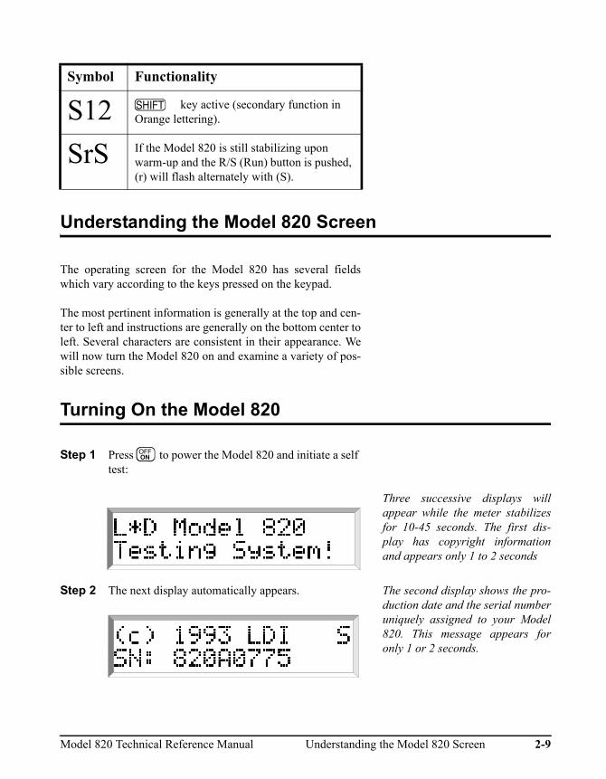
Symbol Functionality
SsS (flashing upper case to lower case) - Model 820 is stabilizing upon warm-up (10-45 sec.), or SETUP weighting (8s), or bias voltage (30s) change in stop mode.
Stop mode - no data is being taken.
Run mode
OVLD
Overload - These letters in succession occuralternately with the stick figure with 8 secondintervals when an overload has occurred.
f (flashing) - Indicates that the function keys(Lmin, Dose, etc.) are used for different pur-pose in the current function.
n Indicates that numeric key input mode isactive.
2-8 Getting to Know Screen Symbols Model 820 Technical Reference Manual
Understanding the Model 820 Screen
The operating screen for the Model 820 has several fieldswhich vary according to the keys pressed on the keypad.
The most pertinent information is generally at the top and cen-ter to left and instructions are generally on the bottom center toleft. Several characters are consistent in their appearance. Wewill now turn the Model 820 on and examine a variety of pos-sible screens.
Turning On the Model 820
Step 1 Press O to power the Model 820 and initiate a self test:
Three successive displays willappear while the meter stabilizesfor 10-45 seconds. The first dis-play has copyright informationand appears only 1 to 2 seconds
Step 2 The next display automatically appears. The second display shows the pro-duction date and the serial numberuniquely assigned to your Model820. This message appears foronly 1 or 2 seconds.
S12 U key active (secondary function in Orange lettering).
SrS If the Model 820 is still stabilizing upon warm-up and the R/S (Run) button is pushed, (r) will flash alternately with (S).
Symbol Functionality
M
Model 820 Technical Reference Manual Understanding the Model 820 Screen 2-9

Step 3 The third screen automatically appears: This screen will remain until theuser inputs other commands.Theflashing uppercase (S) indicatessystem initiation and will continue10-45 seconds.
The third screen appears almost immediately showing the titleinformation for the current or last reading and is programma-ble by the operator.
At this point, you can change the parameters and begin takingactual measurements.
When the system initiation is com-plete, a stick figure in the upperright corner of the display willappear seated indicating theModel 820 is in STOP mode.
Checking the Battery Voltage
The Model 820 continuously monitors its battery voltage toensure accurate measurements. It has a battery life of aboutsixteen hours. It will turn off automatically when the voltagefalls below 5.7 volts. Therefore you should verify that theremaining battery capacity is sufficient before you make anespecially critical or lengthy measurement.
Do not press the B key during ameasurement since it will pausethe measurement while pressed.
2-10 Checking the Battery Voltage Model 820 Technical Reference Manual

Step 1 To manually check battery voltage, simply press the UB keys. Information similar to the follow-ing will display:
Remember, pushing a button canproduce small low-level noiseswhich can affect your readings. Inaddition, the Model 820 momen-tarily pauses the current measure-ment whenever a key is pressed (inorder to interpret the keyboardevent). Therefore, where possible,do not press the B key during avalid event you wish to measure.
The first screen (a) displays thepercentage of power left in the bat-tery, an internal power source,“INT”; or indicates externalpower is being used, “EXTV.”
The second screen (b) gives revi-sion number and date.
Turning Off the Model 820
To turn off the Model 820, simply press the UO key. The instrument will not allow itselfto be turned off until in (Stop)mode. This feature will insure thatno important data is lost.
Model 820 Technical Reference Manual Turning Off the Model 820 2-11

C H A P T E R
3 Calibration
Because of variation in microphone sensitivities, a sound levelmeter must be calibrated to a reference sound level for accu-rate measurements. This is easily performed with the Model820. You will need a calibrator with an appropriate adapter forthe Model 820 microphone, such as the Larson DavisCAL200. This Larson Davis calibrator outputs 114 dB, or 94dB, with respect to 20 µPa, and at a frequency of 1000 Hz. Atthis frequency, the relative response for A and C weightings isthe same.
NOTE: A precision calibrator is not necessary for this part of thetutorial, but you should make it a regular practice to perform aninstrument calibration before and after you take actual measurementsin the field. However, you do not have to recalibrate the Model 820when you change the settings.
Please note that if you use a calibrator which uses another fre-quency some corrections may be required depending on theweighting. The output level and the frequency of your calibra-tor should be listed on its label. Use this level with specificenvironmental and weighting corrections to calibrate theModel 820 level.
In order to perform calibration, the Microphone PolarizationVoltage needs to be properly set.
Calibrating the Model 820
Microphone Polarization Voltage is preset by Larson Davis at200 volts. Should this parameter be incorrect, the Model 820will not calibrate correctly.
Step 1 Check the microphone polarization by looking at
Model 820 Technical Reference Manual Calibration 3-1

setup parameter 43. To do this turn on the Model 820, press R, m, 4 and 3, and e. The following display will appear:
The flashing (f), the Keyboard Sta-tus Indicator, displays which keyfunctions are active. This indicatesthat the function keys are used fordifferent purpose in current func-tion.
Step 2 Should the brackets contain a value other than [200] e.g. [28] or [0], press ther until the value [200] appears, and then press e. If you are using a pre-polarized microphone, this parameter should be set to 0.
In this screen the value [200} isselected from three options: [200,28, 0]
Step 3 Press c to return to the main screen:
Step 4 To begin the calibration process check or insert the new calibration level given in parameter 35. To do this press R, m, 3 and 5, then e. The following screen will appear:
The Larson-Davis Model CAL200calibrator outputs 114 dB or 94 dBre20 µPa. Note that the Model 820automatically uses the C-weight-ing while calibrating. This ensuresa correct reading at typical cali-bration frequencies of 250 Hz to 1kHz.
3-2 Calibrating the Model 820 Model 820 Technical Reference Manual

Step 5 Press m, then enter the “SPL” value of your cal-ibrator (if other than [114.0]), including any correc-tions for pressure, etc.
Step 6 The next setup item allows entry of the calibrator serial number, for record keeping purposes. Press the d, or R, m, 3 and 6, and e.Press m to change the serial number, enter the correct numbers and press e.
Step 7 Seat the microphone fully in the calibrator cavity. If possible both units should be at the same tempera-ture and stationary so that hand vibrations are not transmitted to the SLM.
Refer to the specific instructionsaccompanying your calibrator foraccomplishing this step.
Step 8 Press c to exit calibration setup. Then, acti-vate the calibrator by pressing the button on its side.
Step 9 Press the U and C on the Model 820. This display indicates the current sensitivity off set and will be blinking between two settings:
Pressing the u will check cali-bration, pressing the d willchange it.
Model 820 Technical Reference Manual Calibrating the Model 820 3-3

Step 10 Pressing the d key will initiate a calibration change. Do that now:
In this screen, an error messageinitially prompted for a reset(seestep 12 to reset). The differencebetween the current and the lastcalibration is 0 dB. If the level isnot stable enough for proper cali-bration, the Model 820 will exit thecalibration mode without chang-ing its calibration level. The “c”indicates the instrument is cali-brating.
The Model 820 will wait until thereading is stable (indicator isSsSsSs...., then adjust the offset forthe proper reading CcCcCc..... Animproper calibration offset (forinstance, something greater than34.0 dB) may indicate that the cal-ibration tone was shut off beforecalibration was completed, or thatpolarization was not properly set.You may repeat the previous stepsor perform a Cal check.
Step 11 To Reset the Model 820 for re-calibration, press U and R.
The display will ask if you want to“Reset ALL Data?” You do.
Step 12 Press e. Reset is complete and the instrument will return to the calibration mode.
Step 13 To leave the calibration mode, press c.
3-4 Calibrating the Model 820 Model 820 Technical Reference Manual

C H A P T E R
4 Quick Start
Before running a simple measurement it is important to set afew parameters to meet your needs and become familiar withrelated functions. In this chapter we will discuss these items:
• Setting parameters using R, m, and e• Using numbers and other characters
• Setting Time, Date, and Day parameters
Setting Parameters Using Function Keys
The Parameter fields can be accessed in several ways:
• By entering numbers assigned to each parameter (the num-bers are located above the keys on the keypad and are dis-cussed later in the chapter)
• By scrolling up or down using the u or d keys
• By using any white or Orange function keys
Follow these steps to access the parameters using numeric val-ues:
Step 1 With the Model 820 on, press R and the follow-ing screen appears:
Model 820 Technical Reference Manual Quick Start 4-1

A complete list of parameters and their assigned numbers is found in chapter 8. You have already vis-ited parameter 43, Microphone Polarization, and found it preset to [200].
Step 2 To access parameters using numeric values, press m:
Notice that the flashing (f) hasbeen replaced by a flashing (n)indicating the numeric key access.The flashing parenthesis, indicatethis field is ready to receivenumeric input.
Step 3 To access the Current Time, press 0 and then 6. The number 6 is assigned to the Current Time parameter:
Entering 0 before the new num-ber will remove any prior parame-ter settings.
Step 4 Press m to prepare the screen for changes in the Current Time. Notice the flashing (f) changes to (n).
The third way to access CurrentTime parameter, press RUT. Remember, pressm to change or correct thefield and press e.
4-2 Setting Parameters Using Function Keys Model 820 Technical Reference Manual

Step 5 Using numeric keys make changes and press e, or if the time is correct, just press e.
Step 6 To exit the setup mode, press c.
Setting Parameters Using Numbers and Other Characters
The Model 820 has the ability to show 3 lines for your Com-pany Name and one line for the Measurement Title which isused on the reports. These parameters are entered from thekeyboard.
Through the keyboard, you can enter all of the capital lettersfrom A to Z, the digits 0 to 9, and some punctuation charac-ters. There are three levels of U functions when in the“Alpha Parameter Modify Mode.”
The charts below (Figures 4-1 to 4-4), show the characters thatare available. They are listed according to the number of timesyou consecutively press the U key. The shift indicator inthe lower right corner of the instrument’s display will show thenumber of times the U key has been pressed by showingthe letter n and S, then 2 and 3 respectively for 0 to 3 presses.
This panel is available withoutpressing the shift key, or the equiv-alent of 0 presses.
Figure 4-1 Standard Alpha-Numeric Keyboard Layout
Model 820 Technical Reference Manual Setting Parameters Using Numbers and Other

This panel is accessed by pressingthe shift key one time. The (S) willappear in the lower right corner ofthe display indicating this panel isaccessed.
Figure 4-2 S Shift Level-1 Alpha Numeric Keyboard
This panel is accessed by pressingthe shift key two times. The number(2) appears in the lower right cor-ner of the display indicating thispanel is accessed.
Figure 4-3 2 Shift Level - 2 Alpha-Numeric Keyboard
This final panel is accessed bypressing the shift key three times.The number (3) appears in thelower right corner of the displayindicating this panel is accessed.
Figure 4-4 3 Shift Level - 3 Alpha-numeric Keyboard
4-4 Setting Parameters Using Numbers and Other Characters Model 820 Technical Reference

Step 1 To enter a name, for example, turn the Model 820 on and press these keys to access the first name field: R m 0 2 e:
All but the last of these screens youhave seen before. This display is toset one of four custom instrumentname screens which will appearseach time you turn the instrumenton.
Step 2 Press m. Notice the parentheses begin toflash and the (f) changes to (n) andthe (L) is underscored (Larson-Davis). You may now enter theappropriate letters here by usingthe “Alpha Character KeyboardEntry” shown above.
Step 3 Press U. The flashing (n) is replaced by (S)and will remain for five seconds.At this time you may select anycharacter from the S-table, pressthat key and it will replace the let-ter at the cursor (_). The cursorthen moves to the next letter
Step 4 Press U twice. The (n) is replaced by (2) for fiveseconds. Letters from the 2-panelare available for entry.
_
Model 820 Technical Reference Manual Setting Parameters Using Numbers and Other

Step 5 Press U three times,
Example: To enter the company name of Larson Davis in the first line, follow these steps:
a. To access the Name Display turn on the meter. Press R m 02 e.
b. Press m to place the cursor at the beginning or use the l or r to position the cursor.
c. To clear the field, if necessary, press U twice and the l key.
d. The letter (L) is on the S-field. Press U.
e. The letter (A) is on the S-field. Press U again.
f. The (R,S,O) keys are in the 2-field. Press U twice to access the 2-field.
g. To Clear the field, press U twice to access the 2-chart and press the Clear key.
h. To replace a character with a Space, press U twice to access the 2-field and press the Space key.
A (3) will appear for five seconds.The letters from the 3-panel areavailable for entry.
The display in Step 1 above willappear.
If you change your mind aboutclearing the field, hit c toreturn to the original title. Repeata and b in Step 5 to return to thispoint.
Enter the (L) key, second from thelower left. The cursor will auto-matically move to the next letter.
Enter the (A) key.
Enter the (R,S,O) keys consecu-tively or one at a time.
Complete the rest of the entries inthe same fashion.
Step 6 When the first line is completed press the d to go to the next field, the second line.
Step 7 Press m and select the appropriate chart by pressing U and the desired character key.
Three lines are available for entry,i.e. company address, telephone.
Step 8 When the second line is complete, press thed to go to the next field, the third line, and repeat the pro-cess.
Step 9 The fourth line is for the Measurement Title. Press thedkey.
The first/fourth lines appear onscreen when the 820 is turned on.
4-6 Setting Parameters Using Numbers and Other Characters Model 820 Technical Reference

Step 10 To exit the setup mode, press c.
Setting Time, Date, and Day parameters
Once you have set the parameters, you can now enter the cor-rect time and date. The Model 820 has a 24 hour (militarytime) clock where afternoon hours are denoted by adding 12hours, e.g. 3:45 p.m. = 15:45 hrs. Modify this parameter as fol-lows:
Step 1 With the Model 820 on, press R UT: The current time is displayed. If itis incorrect, enter the correct time.
Step 2 Press the mkey and use the numeric keys to enter correct time and then press e.
Step 3 The Current Date is the next field. Press the d to the next display:
The current date will appear. If itis incorrect press m to accessthe field, enter the correct dateusing the corresponding numberkeys and press e.
Step 4 The Day of the Week is in the next field. Pressd to access that field.
If the day is incorrect press mand r or l to the correct day.Press e.
Model 820 Technical Reference Manual Setting Time, Date, and Day parameters 4-7

Step 5 To exit the setup mode, press c.
AC/DC Output
AC and DC is accessed by the use of the optional CBL042 orby using a stereo miniphone plug as shown in figure 4-5. TheDC output provides a voltage from the RMS detector that isproportional to the sound level. The scale is 20.3 mV/dB. Theoutput voltage is 0-3 volts with an output impedance of 600¾.The AC output gives an AC signal proportional to input signaland can be Flat or A and C weighted. It is used to record inputsignal to the Model 820 (note Appendix A for more details).
Figure 4-5 AC/DC Output Connector
4-8 AC/DC Output Model 820 Technical Reference Manual

C H A P T E R
5 Performing a Measurement/Reading the Data
With the basic parameters set and the instrument calibrated (asdiscussed in Chapters 3 and 4), you are ready to take a mea-surement and examine the readings from the data collected.
Taking an actual measurement with the Model 820 onlyrequires pressing the S or RUN/STOP key.
In this chapter we will:
• Take a measurement.
• Examine and briefly explain the function keys associatedwith the measurement, i.e. -CVKBTDtE and M.
• Stopping the measurement.
Taking a Measurement
This section will address measurements and the informationavailable during and after the measurement has been taken.The most basic function of the Model 820 is to measure soundpressure. Follow these steps to examine the SLM function key:
SLM
Step 1 Turn the Model 820 on and wait for the unit to become stable. Press S. The stick figure in the
Model 820 Technical Reference ManualPerforming a Measurement/Reading the Data 5-1

upper right corner will appear to be running. This instrument can store a greatvariety of measurements in mem-ory depending on the currentparameter setup. Nevertheless,current measurements are alwayseasily available from the keypad.
Step 2 With the instrument in RUN mode, press C. The current sound pressure level is displayed:
The display now reads a C-weighted, slow average reading of 84.5 dBC (re 20 µPa). The level is also shown on a semi-analog bar graph. Parameters 39-43 affect these values and parameters 45-47 effect the Current SLM.
Step 3 An additional six screens are available from this dis-play. Press the d key to access the first:
a. Parameter 61: RMS Exceedance.
b. Parameter 62: RMS Exceedance 2.
c. Parameter 63: Peak Exceedance.
d. Parameter 64: UWPK Exceedance.
e. Parameter 112: Overload (current).
f. Parameter 160: O.OVLD (overall overload).
The Lmin and Lmax for the currentreading at the current time are dis-played in the first screen. Noticethat the current sound pressurelevel continues to read in the upperleft corner and fluctuates. Notethat even in the stop mode theModel 820 continues to monitorSPL while in this window.
The space beneath “88.4” in thisscreen, where the “****” arelocated, is a field where six itemsof information are available.Respectively, with the controllingparameter, these are listed to theleft. If these parameter values havebeen triggered, the “*” willappear to indicate that the recordcontains information related tothat occurrence.
* * * *
5-2 Taking a Measurement Model 820 Technical Reference Manual

Step 4 Press the d key again for the second screen: The Peak and Unweighted Peakare displayed here. Note that evenin the stop mode, the Model 820continues to display the detectedvalues on the upper right handside of the screen.The numbers on the left are thehighest during the measurementand the values on the right are thecurrent Peak and UnweightedPeak.
Step 5 Press the d key for the third screen: The Leq values are shown here tobe 85.5 dB, C-weighted, the mea-surement ran for nearly four min-utes. Should one of four letters,(OVLD), flash intermittently withthe stick figure, an Overload hasoccurred in this measurement (seeChapter 7).
Step 6 Press the d key for the fourth screen: The SEL level (using 3dBexchange rate) is 109.1 dB and theduration of the measurement isgiven.
Step 7 The next screen addresses the Alarm time and cur-rent temperature. Press the d key and the fifth screen will appear:
The Alarm can be set to begin ameasurement at a designated time.The “??:??” here indicates thenext measurement has not beenchosen. The current internal tem-perature as measured by the Model820 is shown in the lower portionof the screen.
Model 820 Technical Reference Manual Taking a Measurement 5-3

Step 8 The property controlling the final screen in this series is built into the Model 820 to conserve power. Press the d key.
The Model 820 has been pro-grammed to save power wheneverit can. Each time input is made theinternal timer will start at 100 andcount downward. If not pro-grammed to do otherwise, theModel 820 will turn itself off whenthis screen reaches 0, just over twominutes.
Pressing the d key again willscroll loop you back to the SLMoriginal screen.
Now that you are more familiar with the information availablein the displays above, lets take a closer look at the parametersthat affect these readings.
Step 1 To access these parameters turn the Model 820 on by pressing c. Next press R m 3 9 e (Or press R, C), and the following screen will appear:
Slow: exponential avg.: 1 secondconstant.Fast: exponential avg.: 1/8 secondconstant.Impl: impulse response.
For OSHA measurements, this isnormally set to Slow. For environ-mental measurements, Fast orSlow may be used. Within a givenperiod of time, the Fast detectorwill take more measurements thanthe Slow. Therefore, the Fastdetector is likely to measure morehigher and lower levels than theSlow detector.
Step 2 The Detector prompt has three possibilities indi-cated above. Press mr to access desired set-ting, and e
Step 3 To set the Frequency Weighting, press d to item 40. There are several possibilities here:
[A, A16, C, C16, Flt]
The A and C weightings simulatehuman hearing response and meetType 1 precision standards foraccuracy. Flat (no weighting)allows the signal to pass through
0
5-4 Taking a Measurement Model 820 Technical Reference Manual

unfiltered (A16, C16 and Flat donot apply to the Model 820).
Step 4 The Model 820 has been preset at [A]. To change the setting press mr to the preferred setting and e.
Step 5 Find item 41 by pressing d, AC Out Weighting, which has the values listed here. Choose one by pressing r.
[Flat, Whgt, F+20, W+20]
F+20 means Flat plus 20 dB oflevel added.
W+20 means Weighted with 20 dBof level added.
Step 6 Item 42, UwPk Weighting, press thed again. Chose from the values listed with r.
[Flat, C]
Flat record all sound and Cweighting simulates the humanhearing at higher sound levels.
Step 7 Item 43, Mic Polarization, was touched upon earlier. This selects the polarization volt-age for the microphone. Choose 28or 200 V (typically 200 V is cho-sen) for condenser type micro-phones and 0 V for pre-polarizedmicrophones (electret).
Step 8 Press c to exit setup mode.
Lmax-Lmin
We have already looked at the Lmax and Lmin in a previousscreen. These values are also available directly from displaykeys. They can be accessed while the unit is taking a measure-ment or in the stop mode. Only when the unit is running is thedata recorded. These measurements are usually read after theyhave been taken and the measurement is stopped. Here we willexamine them while a measurement is being taken:
Step 1 Press Vto display the greatest RMS SPL value since the beginning of the measurement:
The highest RMS level occurred at9:19 hrs., and was 99.2 dBA on thegiven date. Additional screens areavailable here recording the num-ber of times the current readinghas reached predetermined levels(selected in parameters 61-62.
Model 820 Technical Reference Manual Taking a Measurement 5-5

Step 2 Press the r key and examine the second screen available in this series:
In this example, parameter 61 wasset to 55 dB and C-weighted(parameter 40). In this measure-ment the RMS has topped this level11 times.
Step 3 Press the r key to find the third screen: The display shows that parameter62 was set to (65 dB) and is C-weighted. This measurementtopped this level 6 times.
The same key, V, finds the Lmin values in conjunction withthe U key.
Step 1 Examine these values; press these keys together and the following display will appear:
The current measurement Lminoccurred on November 27, 1996,at 9:21 A.M. (Remember, theModel 820 used military time todesignate between A.M. and P.M.)That Lmin value was 51.5 dB.
There are no other screens avail-able from this display.
5-6 Taking a Measurement Model 820 Technical Reference Manual

PEAK-UWPK
The Model 820 also has a peak level detector. Its values, dur-ing the measurement (or when stopped), are found by pressingthe K key.
Step 1 Access Peak values. Press K: PEAK is a weighted value and rep-resents a true Peak SPL from theon-board Peak Detector. In thisexample the PEAK is 116.2 dB andoccurred at the time and dateshown on the screen. Parameter 63sets the level above which thereadings must go to be recorded bythe Model 820.
Step 2 The second display available from this function is accessed by pressing the r key:
Parameter 63 controls the settingfor this measurement. Here the set-ting is 74 dB, C-weighted and inthis measurement was equal to orexceeded 46 times.
Unweighted Peak (UWPK) has two screens available as welland are accessed with the U and K keys.
The unweighted Peak value is theunfiltered (no A or C weighting)signal from the Peak Detector).
Model 820 Technical Reference Manual Taking a Measurement 5-7

Step 1 Press U and K and examine these values for the current reading:
Step 2 For the second screen, press the r key: The value for the UWPK is set inparameter 64 and is 85 dB. Thisvalue was reached 30 times.
Ln
Ln values are determined by parameters 55-60 and should beexamined next in our current measurement.
Step 1 Access Ln by pressing the B key and a screen similar to the following will appear:
Parameters 55-56 in this examplewere set to 5 and 10 respectively.This screen shows their values inthis measurement. These indicatethe sound pressure levels that wereexceeded 5 and 10% of the mea-surement duration.
Step 2 Press the r key to access the second screen of three:
Parameters 57-58 were set at thegiven values shown in the screenand their readings are apparent.Press the r key to see the thirdscreen and the values recordedthere.
5-8 Taking a Measurement Model 820 Technical Reference Manual

Leq
The average RMS level, the Leq, is displayed by pressing T: The average RMS level in thisreading is 68.2 dB, slow, averagefor the 12 minute and 14.9 secondmeasurement period.
Dose-LDL
DOSE, the noise exposure, may be calculated with three dif-ferent sets of parameters:
• Current.
• LDL (Log Data Logic).
• Overall.
Parameters 45-54 are used with the calculation to arrive at thecurrent dose from the current data and sets the exchange rate,threshold level, and criteria level for the current measurement.These can be set differently from the overall in order to givedifferent dose readings.
To protect the measurement, the OVERALL Dose settings(parameters 48-50) may not be modified once the measure-ment has started without a reset. However, OVERALL CRI-TERION may be changed at any time.
Parameter 51, Full Dose Period(or Criterion Time) applies to Cur-rent Overall and LDL.
Model 820 Technical Reference Manual Taking a Measurement 5-9

If you wish to look at dose with different exchange and thresh-old values, LDL may be used by modifying the LDL settings(parameters 52-54). Note that the run time for LDL andOVERALL is always the same.
A new measurement may be started at any time without effect-ing the Overall Dose using the Current Dose settings by modi-fying the CURRENT exchange rate and threshold settings. Anautomatic reset occurs when CURRENT settings are modifiedcreating a new CURRENT dose measurement based on datacollected from that time on.
Before we continue with our present measurement, take a min-ute to examine the parameter values available, all of whichwill effect the measurement.
The Current Exchange Rate parameter, item 45, is quicklyaccessed by following the following steps:
Step 1 Press O,R, m, 4 and 5, then e. The choices here are listed below:
[3dB, 4dB, 5dB, 6dB]
The appropriate value for thisparameter is established byenforcement authorities in variouscountries. In the USA, OSHA man-dates a 5 dB exchange rate. 3 dB iscommon in most other countries.
Note that these can be changedwithout a (Reset-all).
The Current Threshold, item 46, has a range from 0 to 255 dB.
Step 2 Press the d key and choose the desired dB level for the Current Threshold. Larson Davis has preset this parameter to 80 dB.
The normal Dose setting forthreshold is 80 dB which allowsthe instrument to virtually ignoresound below that level as it doesnot contribute significantly to theweight of the measurement datasought, and saves memory as well.If you wish to change this levelpress m, enter the desired dBnumerically and press e.
5-10 Taking a Measurement Model 820 Technical Reference Manual

The Current Criterion is the next parameter, item 47, and hasbeen preset to 90 dB in a range of 0 to 255 dB.
Step 3 Press the d key, item 47. Press e if you wish to keep the 90 dB level, or press m, enter the desired dB numerically and press e.
Damage to hearing normallyoccurs with lengthy exposure tosound at 90 dB and above. For thisreason the Criterion is generallyset at 90 dB.
The Current Dose is often used as a second Dose measure-ment. The collected data is available on the printout.
The Overall Dose parameters have the same available settingsas the current settings and are accessed in the same way.
Step 4 To access items 48-50, Overall Exchange Rate, Overall Threshold, Overall Criterion, press the d key.
Changes can be made in any dis-play by pressing m, enteringdesired values, and pressinge.
Full Dose Hours, item 51, has a range of 0 to 99 hours but isnormally set to an 8 hour workday.
Step 5 To access Full Dose Hours press the d key. The overall criterion level set initem 50 and the dose hours set initem 51 determine what is 100%dose.
Parameters 52-54 are a second set used to calculate overalldose from the overall data. Data already in memory is recalcu-lated with new parameters using LDL (log Data Logic).
OSHA criterion is 90 dB, Thresh-old is 80 dB, Exchange Rate is 5dB, and the Full Dose hours (Cri-terion Time) is 8 dB.
Step 6 To look at DOSE, press E.
Step 7 To look at Projected Dose, press r to the PROJ-b screen.
This step will not work while in theSETUP mode.
Step 8 If you wish to alter the LDL Exchange, Threshold or Criterion settings, press m, enter the desired val-ues, and press e.
Step 9 To look at LDL, press U and E. This step will not work while in theSETUP mode either.
Model 820 Technical Reference Manual Taking a Measurement 5-11

Dose readings are usually read and have more meaning afterthe measurement is completed. Returning to our recent mea-surement, let’s examine the DOSE key and look at the valuesrecorded there:
Step 1 Press the E key where two screens are available. Press the r key to access the second screen:
The measurement ran for nearlyfour hours and the dose was0.28%.
The Projected Dose extrapolatesthe eight hour dose from dose Awhich is the current measureddose.
LDL readings are displayed on four screens. We will visitthree of these screens using the following steps:
Step 1 Press the U and E keys: Notice in the reading the LDLThreshold is set at 80 (parameter49) The Overall Exchange Rate isset at 3 dB (parameter 48). TheOverall Criterion has been set at90 (parameter 50). Any of these 3parameters can be modified and anew dose, projected dose, Leq andSEL will be computed.
5-12 Taking a Measurement Model 820 Technical Reference Manual

Step 2 Press the d key to check the LDL-d screen, PROJ DOSE that is calculated based on the current LDL settings.
Ldn readings are displayed on two screens.
Step 3 Access Ldn by pressing U andD. Two screens are available using the r key:
Ldn is the noise descriptor thatapplies a 10 dB weighting factorbetween the hours of 10:00 PMand 7:00 AM when calculating theTime-Weighted average. CNELadds an additional 5 dB betweenthe hours of 7:00 PM and 10:00PM. Ex in the second screen takesall exceedance records and aver-ages them together. BkGnd is theoverall Leq of all samples thatwere not an event.
Model 820 Technical Reference Manual Taking a Measurement 5-13

BATTERY
In Chapter 2 we accessed the Battery information to check theamount or voltage remaining in our battery. This function hasadditional screens available. The first two indicate the amountof voltage remaining and the second shows the informationrelated to the last revision.
Step 1 Access the Battery display by pressing U and B. Press the r key to access the second screen:
The Revision date is shown.
Step 2 Press the d key and a screen similar to the follow-ing will appear:
Eight additional screens are avail-able from this function. Warning orError messages encountered dur-ing normal operation will be dis-played here in the order theyhappen. They are accessed byeither the l and r keys, or theu and d keys which will scrollonly the warning messages.
MEMORY
Memory will be addressed in Chapter 9, but it would be wellto examine the M key functions here. Standard memory sizeis 250 KBytes. Three screens are available from this function.
Step 1 Press U and M. A screen similar to the fol-lowing will appear:
This screen shows the percentageof memory left of the total avail-able.
248837 divided by 250793 =99.21%
5-14 Taking a Measurement Model 820 Technical Reference Manual

Step 2 Press the r key to access the next screen: Total Exceedances were 27, totalIntervals were 3 and 1Daily Histo-ries.
Step 3 The third screen gives additional information. Press the r key to examine this screen:
This display indicates there are 8Histories in memory, 3 Logs and 0Calibrations. Hs is the number oftime history samples. Lg is thenumber of RUN/STOPs made, andCL is the number of calibrationcheck records.
Stopping the Measurement
Press S to stop the measurement. The stick figure willreturn to the resting position. To view any of the previous mea-surement data simply press the appropriate key and the infor-mation will appear.
Model 820 Technical Reference Manual Stopping the Measurement 5-15

C H A P T E R
6 Timed Measurement
The ability to take a measurement at a specific time and date isone of the unique qualities of the Model 820. This featureallows you to take unattended measurements. Accessedthrough the TIMER key, this flexible system has modes to per-mit one or two measurements a day between two dates, or, asingle block measurement from a start date and time to a stopdate and time.
In this chapter we will discuss:
• Using the Timer for Unattended Readings.
• Using the Time Key Functions.
• Setting the Password Lock to Protect Settings.
Using the Timer for Unattended Readings.
Examine the t capabilities by looking at the parameterfields:
Step 1 Turn the Model 820 on, press O followed by R, U, and t. The following display will appear:
The Timer parameters, 21-27begin with this screen, parameter21.
Model 820 Technical Reference Manual Timed Measurement 6-1

Step 2 Press m to access the cursor in brackets. With the brackets flashing use the r to select one of four possibilities:
[Off, Block, 1/Day, or 2/Day].
Block: Run Time 1 on Run Date toStop Time 1 on Stop Date.1/Day: Run Time 1 to Stop Time 1each day from Run Date to StopDate.2/Day: Run Time 1 to Stop Time1and Run Time 2 to Stop Time 2each day from Run Date to StopDate.
Example: Suppose we want to measure a given area near alarge machine in a factory for 5 days, 2 periods each day.
Step 3 To do this, choose [2/Day] and press e.
Step 4 To continue, press the d to access the next parame-ter screen.
To continue our example, we want to start 26 September at8:30 A.M. and end at 12:00 noon, begin again at 1:00 P.M. andend at 4:30 P.M. each day for 5 days.
Step 5 Press m to change the date and enter 09 26 96. Press e. The new Timer Run Date is now 26 Sep 1996.
If the date is incorrect, simplypress m and enter the correctdata, then press e.
6-2 Using the Timer for Unattended Readings. Model 820 Technical Reference Manual

Step 6 To access Timer Stop, press thed. A Previously entered date will appear.
Step 7 To change the date, press m and enter the 5 day ending date, i.e. October 1, i.e. 01 10 96 e and the following display will appear.
The five day block is now set. Next we will set the time periods each day within the block.
Step 8 Press thed to Run Time 1, and press m. Our start up time is 8:30 A.M. so press 08 30 and e, and the display should look like this:
Step 9 Press the d to Stop Time 1. Press m to enter the numbers 12 00, and then press e:
Step 10 Press thed to Run Time 2. Press m to enter 13 00, our afternoon start time. Press e.
Notice that military time is used(0:01-24:00) to avoid confusionA.M. to P.M.
Model 820 Technical Reference Manual Using the Timer for Unattended Readings. 6-3

Step 11 Press thed to Stop Time 2. Press m to enter 16 30 and e.
Step 12 To check your Timer setup, press c. This will return you to the main screen. Press Ut and the following screen should appear:
Step 13 If you press the r key, it will give you the morning time run. If you press the r again it will give you the afternoon time run settings:
The Model 820 can now be turned off by pressingUOand placed in the test area. Make sure to check thebattery (Chapter 2) or connect to external power. Also con-sider the safety of the instrument during the test period.Finally, verify that the current time and date are set correctlyin the internal clock of the 820. The following section coverssetting the time and date. The Model 820 will turn itself on andbegin measurement at the appropriate time.
Using the Time Key Functions
In Chapter 5 we learned to take a measurement and examinesome of the data gathered during that reading. The TIME keyfunctions as a record of when the last measurement started.
6-4 Using the Time Key Functions Model 820 Technical Reference Manual

Two screens are available in this function.
Step 1 Press U and T to access this information: Current time, day, and day of weekare controlled by parameter 6-8.
This screen displays the time anddate the current or last measure-ment began.
Step 2 Press the r key to access the second screen: The second display shows the cur-rent date, day, and time.
Step 3 Press c to return to the main screen.
Setting the Password Lock to Protect Settings
The Model 820 SLM can insure that your settings will not bedisturbed by providing a Lock Password parameter (items 28-34.).
Step 1 From the previous field press d, or from the main screen, press Rm 2 8 e. You can also press R, U, L:
Step 2 Press m and enter your personal combination of numbers or letters from 1-8 characters.
Refer to Chapter 4 to review enter-ing numbers or letters by using theU key.
Model 820 Technical Reference Manual Setting the Password Lock to Protect Settings 6-5

If you choose to use this feature,enter something you won’t forgeti.e. a name or birth year, and presse.
Step 3 To turn on the Lock, press the d, m and r keys. When [Yes} appears, press e.
These setup items control whetheror not the lock feature will workfor that particular function. Forexample, if Yes is entered for LockSetup, then the R/S and other func-tion can be used when Setup Lockfunction is implemented. Press dto see other functions that can belocked See chapter 8, parameters28-34.
Step 4 If you should wish to unlock the system for further input or readings, press U and L, then m.
Notice that as you enter your code,only (********) appear to protectyour password. Again, make thepassword easy to remember shouldyou wish to use this function.
Enter your password code andpress e. The Model 820 isnow unlocked and accessible foradditional entries.
6-6 Setting the Password Lock to Protect Settings Model 820 Technical Reference Manual

C H A P T E R
7 History Functions
The process of measuring and recording units of sound andretrieving the data for study and understanding is enhanced byadditional functional capabilities of the Model 820 SoundLevel Meter.
This chapter will cover:
• Setting and Viewing Advanced Functions
- Time History- Time History Data- Log and Data- Interval History- Interval History Data- Exceedance- Setting PassBy functions
• Dealing with OVERLOAD.
• Setting the Daily History Parameter.
Setting and Viewing Advanced Functions
The Model 820 has a variety of advanced functions that allowfor gathering and storing great amounts of data with any givenmeasurement. In this section you will learn how to access theparameters, choose the proper settings, and view some of thedata collected.
Time History
Model 820 Technical Reference Manual History Functions 7-1

Time History records include the rms integrated level and, ifselected, Peak, Unweighted Peak, or Lmax. Parameters 80-87allow you to select the period for the history and what data areto be saved.
Step 1 Turn the Model 820 on and access Time History parameters. Press R H. The following screen, item 80, Time history Enable appears:
Yes: With this item set to “Yes”, thetime history function is enabled.Despite Model 820’s large mem-ory, ensure anticipated require-ments do not exceed availablememory.
Step 2 To enable the Time History, press m r to [Yes] and e.
Step 3 Press the d to item 81, History Resolution:
(1.0 d/B, 0.1 dB).
Normally all data is taken with 0.1dB resolution (2 bytes/level). Tosave memory, this option allowsstorage of history in 1.0 dB resolu-tion.
Step 4 To change this setting press m r e.
Step 5 To access item 82, Hist Save Peak press d:
[No, Peak, UWPK, Lmax]
This option allows saving theweighted peak (Peak), unweightedPeak (UWPK) or Max RMS level(Lmax) with each RMS history sam-ple.
Step 6 You may press m and make your selection with r and then press e.
Step 7 Press thed to item 83, Hist Period:
(0-255 units)
See the following step.
Step 8 Press the d to item 84, Hist Period Units
[1/32s, 1.0s, 10.0s, 60.0s]
These options select the historyperiod length as determined by thevalue set in parameter #83 timesthe units set in parameter #84. Forexample, selecting a period of 180and a unit of 10 seconds would
7-2 Setting and Viewing Advanced Functions Model 820 Technical Reference Manual

give 1800 seconds or 30 minutesfor each Leq history period. Aperiod of 2 and a unit of 1/32 sec-ond would result in a historystored every 1/16 second. SettingItem #83 to 0 is equivalent to set-ting it to 256.
Step 9 Use the m and r to select the value you want for this field.
Step 10 Press the d to item 85, Hist Base. The setting range is:
(0-255 dB).
This is for editing purposes only.All history is stored regardless ofthis base level. However, only dataabove the base level are displayed.
Step 11 To enter a value, press m, the value, e.
Step 12 Press thed to item 86, Hist Base Mode:
[Off, RMS, Peak].
This parameter controls the storeddata which the preceding baselevel operates. For example, if thiswas set to Peak and the base levelset to 100 dB, only peaks 100 dBand above would be displayed.
Step 13 To change the field press m, r, and e.
Step 14 Press the d to item 87, Histogram Resolution for these options:
[1/8, 1/2, 1.0, 2.0, 5.0, 10]
The Model 820 provides an ampli-tude distribution that can beprinted. If the resolution is not sat-isfactory, a different one may beselected and the amplitude distri-bution re-displayed or printed.This is possible because all data isstored to the nearest 1/8 dB.
Step 15 Select the value you want. Press m, r to the proper setting, and then press e.
Time History Data
Chapter 5 explained how to perform a measurement. To exam-ine the Time History of that measurement take the followingsteps:
The Time History is used to viewthe data that was acquired with thesettings discussed in the previous
Model 820 Technical Reference Manual Setting and Viewing Advanced Functions 7-3

section. In this example we areviewing the Leq and Peak datathat was gathered during the his-tory period.
Step 1 To access Time History, press H, and a screen sim-ilar to the following will appear:
This display contains Historyinformation about the measure-ment. It was started by a keystroke.
Step 2 Press the d key to sequence through the stored his-tory data:
Press the d key to view otherreadings.
Log
The Log key function is a Run/Stop log. It indicates how manytimes the measurement was started and stopped, and at whattime.
Once a measurement is in progress, information can be exam-ined as follows:
Step 1 Press U and H to access Log screens: This screen gives you informationabout the most current readings.This measurement was started by akey stroke. If it had been started bypreset alarm, “Key” would havebeen replaced with “Alm”.
7-4 Setting and Viewing Advanced Functions Model 820 Technical Reference Manual

Step 2 View the start and stop times and date by pressing the r key:
Step 3 Go back to LOG-a by pressing the r key. Toggle through the record logs by pressing d:
The Log information indicates thatthe measurement was stopped bykeystroke. If a low battery hadbeen the reason for the measure-ment stopping, “BATT” wouldhave appeared. To retain dataalready gathered, the Model 820will terminate the measurementwhen battery power becomes low.
Step 4 The u and d keys may be used to look at addi-tional records. Press the r to look at associated dates and times.
Interval History
The Interval History Parameters allow you to select and definethe interval size and determine what data are to be saved.
Each interval gives you Leq, SEL, Min, Max, Peak, UWPK,Exceedance count, and, if you turn this feature on, Ln’s. Listedbelow is each parameter and a brief explanation of its function.
Step 1 To access the Interval History parameters press OR M. You may also use numeric values, i.e. OR m 7 2 e. The choices are:
[Yes, No]
With this item set to (Yes), theInterval Time History (ITH) isenabled. Note: Be sure that totalmemory requirements do notexceed available memory.
Step 2 Press the d to access the next parameter, 73, Intv Exchange Rate for these choices:
[3dB, 4dB, 5dB, 6dB]
This parameter is the exchangerate used for each interval. Set thisto 3 dB for community noise and 5dB for OSHA studies.
Model 820 Technical Reference Manual Setting and Viewing Advanced Functions 7-5

Step 3 Press the d to item 74, Intv Threshold. You may find 80 dB preset but you may enter another value:
(0-255)
This sets the TWA threshold for theinterval time history. For hearingconservation purposes, 80 dB isrecommended. For most commu-nity noise purposes, set thisparameter to 0 or slightly abovethe noise floor.
Step 4 Press the d to item 75, Intv Period. Press m and the numeric values for the interval period desired, and then press e:
(hh:mm)
This sets the period for the intervalhistory. (A 1 second Interval maybe selected by entering 00:00)
Step 5 Press the d to Intv Time Sync, item 76 for these choices:
[Yes, No]
The Model 820 allows synchroniz-ing the interval report with theDaily History Report. If (Yes) isentered, the Interval Report will bestarted (or restarted if already run-ning) at the start of each hour. Forthis to work properly the IntervalTime should be one hour or somemultiples of hours. The benefit ofsynchronizing the hourly levelsand the interval reports is that allthe statistics (Lmax, Ln, etc.) areavailable for the hourly noise lev-els that make up the daily report.
Step 6 Press thed to item 77, Intv Save Ln’s. The Choices are:
[Yes, No]
Yes: This option allows the six Lnsfor the interval report to be stored.
Step 7 Press the d to item 79, Intv Auto Stop. The choices are:
[Yes, No]
Yes: This option will cause theModel 820 to automatically stop atthe end of each interval, allowingthe precise timing of a series ofmanual measurements. To start anew measurement, the S keymust be pushed. No: This mode must be off for allautomated measurements. It is rec-ommended that Intv Time Sync be
7-6 Setting and Viewing Advanced Functions Model 820 Technical Reference Manual

set to “No” to get the full desiredperiod.
Step 8 To view Interval Histories after a measurement has been taken, press M. A screen similar to the one below will appear:
Eight screens are available fromthe INTV mode. The screen at theleft gives the Time and Date of agiven Interval. Duration, Leq, Lminand Lmax, Peak and UWPK, andthe level setting measurements.
Step 9 Examine the data available in each INTV. Press r and scroll to each. The l will also work and the scroll is a loop.
INTV-a gives time, interval num-ber and dateINTV-b gives duration and intervalnumberINTV-c gives SEL and Leq.INTV-d gives min and max leveland the number of times level wentover RMS exceedance 1.INTV-e gives peak and unweightedpeak levels.INTV- f-h gives statistical informa-tion.
Model 820 Technical Reference Manual Setting and Viewing Advanced Functions 7-7

Step 10 Press the d or u to view the next or previous Interval, respectively.
Exceedance
Exceedance is defined as an acoustic event characterized bythe sound level going above or exceeding a predeterminedlevel. An exceedance event requires the following to occur:
• The SPL must be above the RMS EXCD LVL 1 (parameter61), or
• the weighted peak level must be above the PEAK EXCDLEVEL (parameter 63), or
• the unweighted peak level must be above the UWPKEXCD LEVEL (parameter 64), and
• must be true for longer than the minimum duration (param-eter 68).
An exceedance count, on the other hand, is obtained wheneverthe level goes above RMS EXCD LVL 1, RMS EXCD LVL 2,PEAK EXCD LVEL, and UWPK EXCD LEVEL and are indi-cated on the printout respectively. This count has nothing to dowith duration but only indicates the number of times the levelwent above the various exceedance levels.
Exceedance Level parameters are used to define the noisethreshold levels to be used when counting the number ofExceedance during a measurement. The number of times thefour levels were exceeded will be given in the data report.
To find the Exceedance parameters, items 61-65, turn theModel 820 on and follow these steps:
Step 1 Press the R V. Notice the available settings, 0 to 255 dB for items 61-64:
• 61 - RMS Excd Lvl 1 - First RMS detector exceedancelevel.
• 62 - RMS Excd Lvl 2 - Set above Level 1.
• 63 - Peak Excd Level - Weighted peak exceedance level.
7-8 Setting and Viewing Advanced Functions Model 820 Technical Reference Manual

• 64 - Uwpk Excd Level - Unweighted peak exceedancelevel.
• 65 - Excd Hysteresis - (0-9) After an exceedance, the level mustdrop this amount below theexceedance threshold before a newexceedance is logged. This pre-vents multiple exceedance for asingle event if level fluctuatesabout the threshold.
The Exceedance History parameters, items 66-70, allow youto select and define what data are to be saved in memory dur-ing an exceedance.
Each exceedance indicates the time it started, durations, sym-metry, Leq, SEL, Lmax, Peak, and Time History (if desired).
Step 1 Press R and L to access item 66 from the pre-vious field, or press R, m, 66, and e.
Here is a brief explanation of each parameter:
• 66 - Excd Enable - [Yes, No] [Yes} would insure the exceedancereport will be stored in memorywhen exceedance conditions 61-65are met.
• 67 - Excd Exchange - [3dB, 4dB, 5dB, 6dB] Used to calculate exceedance inte-grated level and normally set at 3dB (Leq). 4 dB gives LDOD, 5 dBgives LOSHA, 6 dB gives Lavg.
• 68 - Ex Min Duration - (0-255) This parameter sets the minimumduration in seconds of exceedancerecords.
• 69 - Excd Time Hist - (Yes, No) With this item set to (Yes), a timehistory is saved only during thetime an exceedance event occurs.
• 70 - Excd Hist Per n/32 - (0-255) The exceedance time history sam-ple period is in 1/32 seconds. Tensamples before and after theexceedance are normally stored,up to a maximum of 255 samples.
Model 820 Technical Reference Manual Setting and Viewing Advanced Functions 7-9

Use the d key to scroll through the fields. Use the m,r and e keys to make any changes desired within eachfield.
Figure 7-1 Exceedance diagram
The diagram above is an example of an exceedance withmarkings of explanation.
It should be noted here that additional parameter settings havebeen added out of numerical sequence to satisfy additionalneeds found in the field. These will now be explained:
• 161 - Timed EXCD Per.: (mm:ss) Exceedance Time history isrecorded from 10 samples beforeexceedance to 10 samples afterthis period.
• 162 - Excd Trigger: [Level, PassBy] Must be in [Level]. [Passby]treated later.
• 163 - Excd Time: [Start, Max] Start: This setting will begin theexceedance measurement as itoccurs.Max: This setting will register themeasurement at the Exceedancemaximum point.
____________
Tmax
Lmax
___________Threshold______________________________
______Duration____________
Start ofExceedance
End of Exceedance
Hysteresis(Tstart)
7-10 Setting and Viewing Advanced Functions Model 820 Technical Reference Manual

Occurrence Time = Tstart if set to [Start].Occurrence Time = Tmax if set to [Max].
Lmax must be > rms Level 1.
Only events that are longer than the minimum duration set andhaving Lmax greater than the RMS Exceedance Level 1,parameter 61, will be recorded. It is also important to set theExcd Time History Period to 0.5 or 1 second by entering a 16or 32 for parameter 70, since the exceedance time history buf-fer is used to create this function. The max duration of apassby event is 128 samples which is 64 or 128 secondsdepending on whether 16 or 30 is used in parameter 70.
To examine Exceedance data collected follow these steps:
Step 1 Press L. The following screen appears with some variation:
Five screens are available. Timeand Date and the Exceedancenumber, (as seen in the screen tothe left), Duration, Leq compari-sons, Lmax, Symmetry, Peak andUWPK.
SymmetryTmax Tstart–
duration-------------------------------=
Model 820 Technical Reference Manual Setting and Viewing Advanced Functions 7-11

Step 2 Press the r key to access the five screens available in the EXCD mode, including Duration, Leq, Lmax, Pk, UWPK.
Step 3 To examine the properties of each exceedance record use the l or r keys to see screens a-e.
Step 4 Press the d or u to view the next or previous exceedance.
Setting PassBy Functions
The PassBy Function is a special exceedance event detectorthat measures the Lmax, Leq, and SEL of the highest event toraise and lower Š 10 dB in SPL. It is used to capture singleevents such as a vehicle or aircraft passby, or other eventnoises such as blasts or gas getting noise. In addition to thelevels measured, the date and time of the Lmax and the dura-tion of the event are recorded.The maximum duration ofpassby event may be 1 or 2 minutes depending on the shape ofthe event. Maximum passby duration will be reduced ifexceedance is reduced.
Step 1 To enable the Passby function, turn on the Model 820 and then press R, m, 162, and e. The screen will show either of two options:
[Level, PassBy].
When the Exceedance History andPassby, parameter 66 and 162, isenabled, a Passby record will becreated whenever a delta 10dBevent is detected (See Figure 7-2).
Step 2 Press m and then press r to [PassBy] and then press e.
The occurrence time or MaximumLevel must be equal to or greaterthan the RMS EXCD LVL 1(parameter 61).
7-12 Setting and Viewing Advanced Functions Model 820 Technical Reference Manual

Figure 7-2 Passby Diagram
After taking a reading with [Passby] enabled, you may wish toexamine the Passby events. You may also look at this while theinstrument is running. To do this follow this step:
Step 1 Press L (Exceedance, which is now Passby), and using the u or d keys, scroll through the events. Use the l or r keys to look at information about this event.
a. EXCD-a: Time, PassBy record, and date.
b. EXCD-b: Duration and record number of PassBy event.
c. EXCD-c: SEL and Leq of PassBy event.
d. EXCD-d: Max RMS level and Symmetry of PassBy record.
e. EXCD-e: Peak PassBy level and UWPK of PassBy record.
If “PSBY” appears in the screen itmeans you are in the Max PassBydata screen. Hit U l to getinto the Exceedance PassByscreen.Five screens are available here byusing the r key, giving time anddate of the occurrence, duration,and Leq comparisons.
Symmetry when used in PassBymode is an indication of whereOccurrence Time (or Max Level)occurs in the event. To clarify, 25%symmetry would indicate MaxLevel happened 1/4 of the way intothe event in linear time. 50%would suggest that the Occur-rence Time happened half way intothe event, and so forth.
_________________________
Occurrence
___________________________________
______Duration__________
Start ofExceedance
Passby’s Max
Time10dB
Model 820 Technical Reference Manual Setting and Viewing Advanced Functions 7-13

Step 2 To examine the Maximum PassBy of all those col-lected, press U and the l key. Use the l and r keys to access the following data windows:
PSBY-a: Time and Date of maximum PassBy.
PSBY-b: Duration of maximum PassBy.
PSBY-c: Leq and SEL of maximum PassBy.
PSBY-d: Leq and Max RMS level.
The Single Highest Passby event isaccessed by pressing U andl while in the EXCD Mode.
Step 3 To return to the Exceedance PassBy data screens, press U l.
Overload
It should be noted that during any measurement an OVER-LOAD may occur. Such occurrences happen when input sig-nals exceed internal circuitry limits (such as dropping orjarring the instrument). Should an OVERLOAD occur during ameasurement, the data accumulated during the occurrence willnot be accurate.
The Model 820 registers an OVERLOAD in the upper rightcorner of the display where the running figure appears. Thefigure takes one step each second. At intervals, 8 secondsapart, the letters O, V, L, D, will appear in succession. Themeasurement should be retaken. The Interval Report on theprintout will indicate which interval had the OVERLOAD.
Setting the Daily History Parameter
The Model 820 automatically calculates daily sound statistics,including: Leq 24, Ldn, CNEL, Lpeak, Luwpk, Ln’s*, Lmax, andLmin; and for each hour of the day the hourly Leq, the hourlyEXCD Leq and the resultant Background Leq.
*Six Ln percentiles (optional) seeparameter 206.
7-14 Overload Model 820 Technical Reference Manual

Step 1 To access item 88, Daily Enable, press R, U, and D.
[Yes, No]
Choose [Yes] if you wish thisoption enables.
Daily Noise History can only be viewed in the Daily NoiseHistory printout or downloaded to a computer.
Model 820 Technical Reference Manual Setting the Daily History Parameter 7-15

C H A P T E R
8 Parameters
As we have seen in previous chapters, the Model 820 owes itsversatility in great part to a flexible setup. More than 160parameters and options can be selected to tailor the Model 820to any measurement. Four preprogrammed setups for standardapplications are in memory. One may use these as blueprintsfor modifications. It is also possible to store up to 11 other set-ups in memory for later recall. Along with downloadable set-ups from software, this truly makes the Model 820 a myriad ofinstruments in one.
In this chapter we will review the following:
• Parameter access keys, R m e c• Learn to store and retrieve complete setups from the vari-
ous memory registers
• List all parameters with a short explanation.
Parameter Key Access Review
Entering and Exiting the Setup Menu
Some setup items may be changed while the Model 820 is run-ning, but parameters influencing data integrity require a mem-ory Reset ALL.
Step 1 Enter the setup by pressing R.The following will
Model 820 Technical Reference Manual Parameters 8-1

appear:
Step 2 To exit back to the main screen, press c.
Step 3 Return to the setup menu. Press R.
Locating Parameters
When in the setup menu, the arrow keys allow movement fromone parameter to another. One may also use a function key ordirectly index to the appropriate parameters.
Step 1 From the Setup menu press d to move down the list of parameters one at a time.
All items in the list of parameterscan be accessed by using the uand d.
Step 2 When the arrow keys are used in conjunction with the Shift key, U, the Model 820 will take you to the top or bottom of the parameters list.
Step 3 Press U d to move to the bottom of the parameter list.
Step 4 Press the C key. The Model 820 moves you to therms detector parameters.
Step 5 Press the U m keys and then 6 1. Press e.
You are now at the beginning of theExceedance parameters, item 61.
8-2 Model 820 Technical Reference Manual

NOTE: Numbers are entered at the current cursor position. Enterleading zeros if necessary.
Changing Parameters — Enter, Modify
Parameters may consist of numerical values, character fieldsor selected choices. Numerical or character fields are shownbetween parentheses:
This one has rounded brackets thatmean this is an “entry parameter”.Type the number or characterdesired (see Chapter 4). If there isan angle bracket “>” then theentry field is too big to fit thescreen and will scroll with the rkey.
Another parameter type is the template entry parameter. Theseprompt for specific data entry. For example:
For both types, follow these simple steps:
Step 1 Press m.
Step 2 Enter a value from the numerical keypad. Use the U key for alphabetical input.
For complete coverage of numeri-cal and alpha entry see chapter 4.
Model 820 Technical Reference Manual 8-3

Step 3 Confirm any change with e.
Step 4 Cancel any change by pressing c before e.
Parameters whose value is selected from a few possiblechoices are displayed with the current setting inside squarebrackets:
To make a selection:
Step 1 Press m and then the l and r keys.
Step 2 Confirm change with e.
Step 3 Cancel change by pressing c before e.
Error Messages
Entry errors will be noted by a warning message. For example:
Verify the correct entry format.
Learning to Store and Retrieve Setup Memory
The current setup parameters can be stored internally in twoways for later recall:
• In two RAM (random access memory) registers
• In one EEPROM register (electronically erasable program-
8-4 Model 820 Technical Reference Manual

mable read-only memory)
Setups stored in RAM occupy the same memory as the data(256 KB). They may be lost if battery power is removed formore than a few minutes. One set of parameters at a time canbe stored in the EEPROM. Parameters in the EEPROM regis-ter are secure even if the batteries are disconnected, since theEEPROM does not require bias voltage to maintain its state. Aminimum of 5,000 STORE operations are possible with theEEPROM.
Storing a Setup
The Model 820 must be stopped and memory reset to store tothe EEPROM.
Remember, to reset memory pressU S e.
Step 1 Press U s: The EEPROM (.) register is thedefault. In this instance, the title ofthe measurement is “TECHWRITER”.
Model 820 Technical Reference Manual 8-5

Step 2 The u d keys will scroll through the two RAM registers (0-9). For example, press d twice:
The RAM register “1” is empty.
Step 3 To store the current setup to the displayed RAM 1, register, press e:
Recalling a Setup
Memory must be reset before a recall of setup parameters canbe accomplished.
Step 1 In the stop mode, press U S e to reset memory. Then press U R.
Step 2 The EEPROM (.) is again the default. Use d to scroll through the ten RAM registers or the pro-grammed ROM setups.
RAM registers 0 to 9 andEEPROM register will recall pre-viously stored calibration data.STORE saves the CAL data so thatthe calibration for several differentmicrophones may be stored andrecalled as desired. For example,Register 1 could store the calibra-tion for a Model 2560 microphone,2 for a Model 2540, 3 for dBµV.
8-6 Model 820 Technical Reference Manual

ROM registers A, B, and = do notaffect calibration data.
Model 820 Setup Parameters
Setup parameters of the Model 820 are listed below. Modify-ing some setup parameters, such as going from a FAST to aSLOW meter response, may not be allowed unless the data isreset. This prevents corruption of the overall noise data.
Parameters are listed below in logical groups, with their num-ber and direct index key (if available). Valid entry formats arelisted, (0), for numerical, [0], for selection. Some reservedparameters, or selections are not available. Many of these areactive in the Model 870, the Model 820’s big brother.
System (1-20) R U S
The following parameters define measurement names, anddetermine interface parameters.
No. Prompt Entry Comment
1 Reset ALL Data? [No Yes] This parameter allows a SHIFT RESET without leaving SETUP. Note: If this parameter is set to Yes, a RESET will occur, and the parameter will automatically revert to No.
2-4 Name (up to 30 characters) Place any message you desire in these 3 lines. (The 3 lines of name are sav-able only in EEPROM.)
5 Title (up to 30 characters) Used to describe a measurement or setup
6 Current Time (hh:mm:ss) also accessed w/ U t
Model 820 Technical Reference Manual 8-7

7 Current Date (mm/dd/yy) Leap years are considered. For years less than the year manufactured, the 21st century is assumed (2000-2092), otherwise the 20th century is used (1993-1999)
8 Day of Week [Sun-Sat]
9 Baud Rate [300-19200] Baud rate of the serial interface. Serial printer or computer rate should be the same.
10 RS-232 Address (0-127) Enables addressed communication mode for a network of Larson Davis SLMs. Each must have a unique address. Normally only one Model 820 is used, thus the address should be set to 0 to disable.
12 COM Ports Hand-shaking Register
[None, Hdwr, XOFF, Both]
Serial handshaking protocol. Model 820 -SW1 uses [None]. Note: To con-serve power, the Model 820 turns off the serial port after 255 sec. of non-use. To keep unit on and connected, an external power supply must be used.
8-8 Model 820 Technical Reference Manual

14 Output 1 Logic Off
RMS (R)PEAK (P)R + PINTV (I)
R + IP + IR + P + IA:DR + AP + AR + P + AI + AR + I + AP + I + AR + P + I + AR/S
True takes it to 5 volts.When set to Off, DTR is DTR
Indication that Interval started and will stay on time set in parameter 15.
Logic control including “A” are not applicable to the Model 820.
Run/Stop
15 Output 1 Timer (enter time) There are 2 modes to the Logic Out-put Time now: If the time is set to 5 sec or less it is assumed to be a mini-mum time and the output will be asserted for a minimum of the time selected. If the time is programmed to be greater than 5 sec then the time is considered to be the maximum dura-tion that the pulse should last and the output will be asserted for a minimum of 5 sec and a maximum of the time programmed.
20 Power Save [Auto Off, Manual Off, Audio Off]
Auto Off: If in the Stop mode and if no keys are pressed or commands given for 12 min, the Model 820 will turn off automatically. Manual Off: The Model 820 will not turn off until the OFF key is pressed, a computer OFF command is given, or the batteries become low. Audio Off: Not available on the Model 812.
Model 820 Technical Reference Manual 8-9

Timer (21-27) U T
These parameters are used when Start and Stop ofmeasurements are to be controlled by the clock.
Lock (28-34) U L
These parameters limit access of certain functions to thosewith the correct password.
Step 1 After setting password and lock options, exit the setup and press UL to lock.
For complete instruction on set-ting the Lock parameters, seechapter 6.
Step 2 To unlock, press UL, then m, and enter the password.
No. Prompt Entry Comment
21 Timer Mode [Off, Block, 1/day, 2/day
Block: Run Time 1 on Run Date to Stop Time 1 on Stop Date1/day: Run Time 1 to Stop Time 1 each day from Run Date to Stop Date2/day: Run Time 1 to Stop Time 1 and Run Time 2 to Stop Time 2 each day from Run date to Stop Date
22 Timer Run Date (dd/mm/yy) See Timer Mode comment
23 Timer Stop Date (dd/mm/yy) See Timer Mode comment
24 Timer Run Time 1 (hh:mm:ss) See Timer Mode comment
25 Timer Stop Time 1 (hh:mm:ss) See Timer Mode comment
26 Timer Run Time 2 (hh:mm:ss) See Timer Mode comment
27 Timer Stop Time 2 (hh:mm:ss) See Timer Mode comment
No. Prompt Entry Comment
8-10 Model 820 Technical Reference Manual

Calibration (35-38) U C
Sound Level Meter (39-50) C
These parameters define the sound level meter characteristics.Most changes will require a US if memory holds pre-vious data.
28 Lock Password (8 characters) Enter your password
29 Lock R/S Key [No, Yes] Lock mode change
30 Lock Setup [No, Yes]
31 Lock Function [No, Yes]
32 Lock Reset [No, RES-ALL, Cur+All]
33 Lock ON Key [No, Yes]
34 Lock I/O [No, Yes]
No. Prompt Entry Comment
35 CAL Level (114.00)(0-255 dB)
Enter the sound pressure level of your calibrator
36 Calibrator S/N (to 8 char.) Calibrator serial no. will be printed
37 Auto-Cal Mode [No, Yes] unused
38 Auto-Cal Time (00:00) (hh:mm) Allows automatic daily calibration check with LDL electrostatic actuator (available at later date).
No. Prompt Entry Comment
Model 820 Technical Reference Manual 8-11

39 Detector [Slow, Fast, Impl] Slow: exponential avg: 1 second con-stant.Fast: exponential avg: 1/8 second con-stant. Impl: impulse response.
40 Frequency Weighting [A,A16,C,C16] A and C weightings meet Type 1 spec-ifications. Note: A16 and C16 not applicable to the Model 820.
41 AC Out Weighting [Flat, Wght, F+20, W+20]
F+20: Flat Level with 20 dB gain.W+20: Weighted with 20 dB gain.
42 Unweighted Peak [Flat, C]
43 Mic. Polarization Voltage
[0, 28, 200] This selects the polarization voltage for the microphone. Chose 28 or 200 V for condenser type microphones and 0 V for pre-polarized microphones (electret).
44 Reference Level (0 to 255 dB) measured level - reference level = rel-ative level used in some functions
45 Currant Exchange Rate 1
[3dB,4dB,5dB,6dB] Exchange rate for currant TWA or Dose readings. For OSHA use 5dB.
46 Current Threshold 1
(0 to 255 dB) Levels above threshold are integrated into currant TWA or Dose readings. For OSHA use 80 dB.
47 CurrantCriterion 1
(0 to 255 dB) 100% dose if this level is maintained for full dose period. For OSHA use 90 dB.
48 OverallExchange Rate 2
[3dB,4dB,5dB,6dB] Exchange rate for overall TWA or Dose readings.
49 OverallThreshold 2
(0 to 255 dB) Levels above threshold are integrated into overall TWA or Dose readings.
50 OverallCriterion 2
(0 to 255 dB) 100% dose if this level is maintained for full dose period.
8-12 Model 820 Technical Reference Manual

Dose (51) E
The noise exposure Dose may be calculated with three differ-ent set of parameters: CURRENT, OVERALL, and LDL. Seesection on occupational noise for additional information. Thedose displayed with the DOSE key is Dose 2.
Ln Statistical Levels (55-60) B
Lnn is the rms noise level which was exceeded nn% of thetime. The Ln’s are computed from the overall level distributionhistogram or each interval’s level histogram (see item 77). Themeasured and displayed Lnn may be changed during the mea-surement. The six nn are automatically listed in increasingorder.
No. Prompt Entry Comment
51 Full Dose Hours (0 - 99) This is normally set to 8 for an 8 hour workday. It is used with the criterion level to determine a 100% projected dose.
52 LDL Exchange [3dB,4dB,5dB,6dB] Use LDL function to reevaluate stored data with new dose parameters.
53 LDL Threshold (0-255 dB)
54 LDL Criterion (0-255 dB)
No. Prompt Entry Comment
55 Lnn 1 Percent (0 to 99)
56 Lnn 2 Percent (0 to 99)
57 Lnn 3 Percent (0 to 99)
58 Lnn 4 Percent (0 to 99)
59 Lnn 5 Percent (0 to 99)
60 Lnn 6 Percent (0 to 99)
Model 820 Technical Reference Manual 8-13

Exceedance Levels (61-65) V
These parameters define noise threshold levels to be usedwhen counting the number of exceedances during a measure-ment (viewed in MAX-b and c displays for rms, PEAK-b,UWPK-b for peak exceedance), and triggering the exceedancehistory (see parameter 66).
Exceedance History (66-70, 161-163)
These parameters select and define what data are to be savedin memory during an exceedance.
No. Prompt Entry Comment
61 RMS Excd Lvl 1 (0 - 255 dB) First rms detector exceedance level.
62 RMS Excd Lvl 2 (0 - 255 dB) Set above Level 1.
63 Peak Excd Level (0 - 255 dB) Weighted peak exceedance level.
64 Uwpk Excd Level (0 - 255 dB) Unweighted peak exceedance level.
65 Excd Hysteresis (0 - 9) This sets the amount, once an exceedance occurs, that the level must drop below the exceedance level before the Exceedance event ends and a new exceedance can occur. Normally set this level to 2 or 3 dB. This pre-vents multiple exceedances for a sin-gle event if the level flickers around the threshold.
No. Prompt Entry Comment
66 Excd Enable [No, Yes] Yes: Exceedance report will be stored in memory when exceedance condi-tions above are met.
8-14 Model 820 Technical Reference Manual

Interval History (72-79) M
67 Excd Exchange [3dB,4dB,5dB,6dB] Used to calculate exceedance inte-grated level. Normally this is set to 3dB (Leq). 4dB gives L_DOD, 5dB gives LOSHA, 6dB gives L_Avg.
68 Ex Min Duration (0-255) Exceedance must last at least this many seconds to be logged.
69 Excd Time-Hist [No Yes] Exceedance time history is saved if set to [Yes].
70 Excd Hist Per. (0-255) Exceedance time history sample period in 1/32 s. Ten samples before and after the exceedances are nor-mally stored, up to a maximum of 255 samples.
161 Timed EXCD Per. (mm:ss) Exceedance Time history is recorded from 10 samples before exceedance to 10 samples after this period.
162 Excd Trigger [Level, Bypass] Bypass: Enables a variable threshold.
163 EXCD Time [Start, Max] Start: The exceedance will be mea-sured at the beginning.Max: The exceedance will be mea-sured at the maximum.
No. Prompt Entry Comment
72 Intv Enable [No, Yes] Interval report will be stored in mem-ory if Yes is entered.
73 Intv Exchange [3dB, 4dB, 5dB, 6dB] Used to calculate interval integrated level. Normally this is set to 3 dB (Leq). 4 dB gives L_DOD, 5 dB: LOSHA, 6 dB: L_Avg.
74 Intv Threshold (0 to 255 dB) Levels above threshold are integrated during each interval, normally 0 dB for Leq. For noise hygiene interval TWA, set to dose threshold.
Model 820 Technical Reference Manual 8-15

Time History (80-87) H
This third type of history is the most conventional. The rmsintegrated level and, if selected, a maximum reading are storedin memory at the end of each time history period.
75 Intv Period (hh:mm) This sets the period for the interval history from 1 minute up to 99:59. A 1 second interval may also be selected by entering 00:00.
76 Intv Time Sync [No, Yes] Synchronizes start of interval with clock and daily history report. If Yes is entered, the interval report will be started (or restarted if already run-ning) at the start of each hour or min-ute depending on Intv duration.
77 Intv Save Ln’s [No, Yes] Selects whether interval Ln’s are stored. The Ln’s stored are those in effect (items 55-60) at end of interval.
79 Intv Auto Stop [No, Yes] If yes, automatically stops instrument at the end of each interval for precise timing of series of manual measure-ments. Use R/S key to restart.
No. Prompt Entry Comment
80 HIST Enable [No, Yes] Time history report will be stored if Yes is entered. Despite the Model 820’s large memory, ensure antici-pated requirements do not exceed available memory.
81 Hist Resolution [0.1dB, 1.0dB] Normally, all data is taken with 0.1 dB resolution (2bytes/level). Allows stor-age of history with 1 dB resolution to conserve memory(1byte/level).
8-16 Model 820 Technical Reference Manual

82 Hist Save Peak [No, Peak, UWPk, Lmax]
This option allows saving the history period’s highest weighted (Peak), unweighted Peak (UWPk) or rms level (Lmax) with each RMS history sample.
83 Hist Period (1-255 units) Multiplier of units of time in parame-ter #84 sets rate at which history sam-ples are stored. Ex: 1 x 60.0s for minute by minute history, 16 x 1/32s for 0.5 second history.
84 Hist Per. Units [1/32s, 1.0s, 10.0s, 60.0s]
Note: The rms detector is sampled 32 times/s. These samples are averaged into an integrated sound level (Leq) stored every time history period.
85 Hist Base (0-255 dB) This is for editing purposes only. All history is stored regardless of this base level. However, only noise data above the base level are displayed on the screen.
86 Hist Base Mode [Off, RMS, Peak] Type of noise data used by the base mode
87 Hist Resolution [1/8, 1/2, 1.0, 2.0, 5.0, 10]
Selects the interval in dB of the over-all time level amplitude distribution.
88 Daily Enable [No, Yes] [Yes] to store daily data such as Ldn, CNEL, Leq and background level. This option provides the storage of 24 hourly noise levels for each one of these quantities when interval dura-tion is 1 hour and Intv Time Sync = Yes.
Model 820 Technical Reference Manual 8-17

Print Options (89-112) s
These parameters allow for tailored reports of LDL Model 820data during or after the measurement. They can be accessedfrom outside the SETUP by pressing s, then 7 for printertype and options. Refer to section on printouts for samples ofinformation found on each printout.
No. Prompt Entry Comment
89 Prn Data Report [No, Yes] Prints quick data report.
90 R/S and Cal Log [No, Yes] Prints Run/Stop and calibration log report.
91 Setup Report [No, Yes] Prints list of current setup parameters.
92 RMS Histogram [No, Yes] Prints histogram of overall rms levels.
93 Lowest Level (0 - 255) RMS Histogram lowest printed level
94 Highest Level (0 - 255) RMS Histogram highest printed level
95 Histogram Resl. [1/8, 1/2, 1.0,2.0,5.0,10] Spacing in dB between histogram entries
96 Peak Histogram [No, Yes] Prints histogram of overall peak lev-els.
97 Lowest Level (0 - 255) Peak Histogram lowest printed level
98 Highest Level (0 - 255) Peak Histogram highest printed level
99 Histogram Resl. [1.0,2.0,5.0,10] Spacing in dB between histogram entries
100 UwPk Histogram [No, Yes] Prints histogram of overall unweighted peak levels.
101 Lowest Level (0 - 255) UWPk Histogram lowest printed level
102 Highest Level (0 - 255) UWPk Histogram highest printed level
8-18 Model 820 Technical Reference Manual

NOTE: Parameters 168-173 for additional printing options
Additional System Functions (152, 154-161)
The functions below apply to the LDL Model 820 when usedin remote applications such as in airport or perimeter noisemonitoring systems. Requires Model 820 option 01. Theseparameters are for control in Model 2101.
103 Histogram Resl. [1.0,2.0,5.0,10] Spacing in dB between histogram entries
104 EXCD Report [No, Short, Long] Prints exceedance report.
105 Lowest Rec. # (0 - 65535) Starting exceedance record number of printout
106 Highest Rec. # (0 - 65535) Ending exceedance record number of printout
107 INTV Report [No, Short, Long] Prints interval report
108 Lowest Rec. # (0 - 65535) Starting interval record number of printout
109 Highest Rec. # (0 - 65535) Ending interval record number of printout
110 HIST Report [No, Yes] Prints time history report
111 Lowest Rec. # (0 ->999999) Starting history record number of printout
112 Highest Rec. # (0 ->999999) Ending history record number of printout
113 Daily Report [No, Short, Long]Prints daily report
No. Prompt Entry Comment
Model 820 Technical Reference Manual 8-19

152 E. A. Cal Tone [No Yes] Automatic electrostatic actuator cali-bration tone control (820 OPT-01 must be installed).
153 Heater On [Yes, No]
154 Modem Mode [No, Yes] Select if Model 820’s RS-232 port is connected to modem
155 Deal Out Mode [None, EXCD, ALRM, Both]
Instrument automatically dials out if:EXCD: RMS Exceedance level 2 is ExceededALRM: Enclosure intruder alarm is triggered orBoth.
156 Phone #
157 Monitor Number (0-127) Monitor Identification number.
158 M Init Modem Initialization Sequence
159 Power Mode [Normal, Ext CO] Normal: meter uses internal battery unless greater external voltage is also applied.Ext CO: (external cutoff) when exter-nal power falls below 10.5 V, meter turns off to prevent battery damage.
161 Timed EXCD Per. (mm:ss) Exceedance Time history is recorded from 10 samples before exceedance to 10 samples after this period.
162 EXCD Trigger [Level, Bypass Bypass: Enables a variable threshold
163 EXCD Time [Start, Max] Start: The exceedance will be mea-sured at the beginning.Max: The exceedance will be mea-sured at the maximum.
168 Rt EXCD Report (No, Yes) Print exceedance report in real-time.
169 Rt INTV Report (No, Yes) Print interval report in real-time.
170 Rt HIST Report (No, Yes) Print history report in real-time.
8-20 Model 820 Technical Reference Manual

171 Rt RUN-LOG (No, Yes) Print run-log history.
172 Rt Daily Report (No, Yes) Print daily report.
173 Rt CAL Report (No, Yes) Print cal report.
206 Daily Save Ln’s (Yes, No) Enables Ln table for daily history.
Model 820 Technical Reference Manual 8-21
C H A P T E R
9 Memory Usage
Each of the Model 820’s History Functions use space out of acommon memory. The amount each record takes is based onthe options selected. In this chapter we will provide informa-tion that will assist you to:
• Determine the amount of storable data considering thegiven options.
• Estimate memory usage by giving an example of a testreading and an associated chart to determine the memoryneeded to complete the reading.
Determine Storable Data
The following tables indicate the amount of memory used foreach type of record:
Exceedance Records Excd History Enable = [Yes] Prm66
Options -- add bytes shown if enabled Bytes
Basic Exceedance Record 32
Excd Time - Hist = [Yes] Prm 69 +1 plus number of samples(129 bytes max)
Save full accumulator and Count in Binary(Aux Cntl Reg bit value 16) Prm 210
+16
Model 820 Technical Reference Manual Memory Usage 9-1

Interval Records Intv History Enable = [Yes] Prm 72
Options -- add bytes shown if enabled Bytes
Basic Interval Record 34
Intv Save Ln’s = [Yes] Prm 77 +18
Intv Ln Table (Aux Cntl Reg Bit Value 1) Prm 210 +384
Daily Records Daily History Enable = [Yes] Prm 88
Options -- add bytes shown if enabled Bytes
Basic Daily Record 175
Save Daily Ln’s = [Yes] Prm 206 +18
Daily Ln Table (Aux Cntl Reg Bit Value 1) Prm 210 +440
Time History Records Time History Enable = [Yes] Prm 80
Options Bytes
Hist Resolution Prm 81 Hist Save Peak Prm 82
[1.0dB] [No] 1
[0.1dB] [No] 2
[1.0dB] [Peak, UwPk, Max, Wind] 2
[0.1dB] [Peak, UwPk, Max, Wind] 4
Other Histories and Memory Usage Bytes
Run Log History 20 bytes per record
Calibration Log History 17 bytes per record
Ram Setup Register(REgisters 0-9, Bytes used per register stored)
506 bytes per register
9-2 Determine Storable Data Model 820 Technical Reference Manual

Estimating Memory Usage
The easiest way to estimate the memory usage is to work on atime basis such as one day. Consider the following:
• Estimate how many Exceedances will occur in a normalday
• Calculate the number of Interval, Time History, Daily, RunLog and Calibration Check records that will be performedin a day.
• Based on the options chosen calculate the number of bytesrequired for each record type.
• Multiply by the number of records expected per day,
• Sum these values and this is the number of bytes requiredper day.
• Divide this value into the amount of available memory inthe Model 820 (see UM) and this is the number ofdays the Model 820 can gather data.
As an example, let's assume a job requires monitoring thenoise made by trucks coming and going from a factory near aresidential area. From an initial site survey it is discovered thatall trucks are over 65dBA at the boundary of the road and resi-dential property and that there seems to be a truck passing thesite every 3 minutes. The occupants of the residential areawant to know how many trucks are traveling this road and whythey are disturbed by some more than others. The ExceedanceFunction will be used to detect events over 65dBA and there isexpected 20 events per hour or 240 per day (20 events/hourtime 12 hours/day) assuming that the plant operations will bereduced during the night. Statistics based on hourly intervalsand a one minute time history are desired to identify distur-bance pattern. The following completed work sheet shows thecalculations for this example:
Model 820 Technical Reference Manual Estimating Memory Usage 9-3

Line Exceedance Memory Estimation Bytes 4Used Bytes needed
1 Basic Exceedance Record 32 4 32
2 Excd Time-Histn=estimated # of samples (129 bytes max)
21+n20sec/Excd
4 41
3 TOTAL Bytes / Excd sum lines 1-4 >>>>>> 73
4 Anticipated Excd / Day Enter Number >>>>>> 240
5 TOTAL Excd Bytes / Day Multiply lines 5&6
>>>>>> 16520
Line Interval Memory Estimation Bytes 4Used Bytes needed
6 Basic Interval Record 34 4 34
7 Intv Save Ln’s=[Yes] Prm 77 18 4 18
8 Intv Save Ln Table 384 0
9 TOTAL Bytes / Intv sum lines 6-8 >>>>>> 52
10 Anticipated Intv / Day Enter Number >>>>>> 24
11 TOTAL Excd Bytes / Day Multiply lines 9&10
>>>>>> 1248
Line Daily History Memory Calculation Bytes 4Used Bytes needed
12 Basic Daily Record 175 4 175
13 Daily Save 6 Ln Values 18 4 18
14 Daily Save Ln Table 440
15 TOTAL Daily Bytes / Day Add lines 12 thru 15
>>>>>> 193
Line Time History Memory Calculation Bytes Bytes
Hist Resolution Hist Save Peak
16 [1.0dB] [No] 1
9-4 Estimating Memory Usage Model 820 Technical Reference Manual

17 [0.1dB] [No] 2
18 [1.0dB] [Peak|UwPk|Max|Wind] 2
19 [0.1dB] [Peak|UwPk|Max|Wind] 4
20 TOTAL bytes / Hist Record Select the appropriate # of bytes from lines 16-19
2
21 Hist Records / Day24 hours divided by Hist Period in hours
Enter Number Calculatei.e. 24/(60 sec/3600 sec per hour)= 1440
1440
22 TOTAL Hist Bytes / Day Multiply lines 23 and 24 - copy -copy to 29
2880
Line Memory Use per Day Calculation Bytes Bytes
23 Exceedance History bytes / day from line 5 16520
24 Interval History bytes / day from line 11 1248
25 Daily History bytes / day from line 15 193
26 Time History bytes / day from line 22 2880
27 Run Log bytes / dayn= number of Run Log records / day
2/(nx20) X 20 =n x 20 bytes/record
40
28 Calibration Log bytes / day 1/(nx17) X 17n x 17 bytes/record
17
29 Setup RAM Registers bytes usedn=number of registers stored / day
0/(nx506) =n x 506 bytes/record
0
30 TOTAL bytes used / day Sum lines 23-29 20898
31 Model 820’s Memory Size (252661) See SYSTEM-b 251,805
32 TOTAL Run Time in days until out of memory
Divide line 34 by 33 12.05
Line Time History Memory Calculation Bytes Bytes
Model 820 Technical Reference Manual Estimating Memory Usage 9-5

C H A P T E R
10 Printing a Report
The Model 820 allows for tailored reports of data during andafter measurements. In this chapter we will access the printingoption parameters for the following topics:
• Normal Printouts.
• Printing Reports.
• Real-time Printing.
Normal Printout Parameters
Before proceeding with printing, baud rate needs to be deter-mined and entered. Set parameter 9 to proper baud rate deter-mined by type of printer used. If, after starting printing, badinformation is printed, baud rate or printer type is probably setincorrectly. To cancel printing, hit U and S.
Normal printouts can be accessed from outside the SETUPmode by following these steps:
Step 1 Turn the Model 820 on and press s. The follow-ing display will appear briefly and then scroll auto-matically through several options:
Step 2 To tailor your report and select the printer type and
Model 820 Technical Reference Manual Printing a Report 10-1

options, press 7 and the following screen will appear:
There are several options here which include:
[HPJet, HPLzr, ASCII, Epson, IBM]
Step 3 You can change the printer selection by pressing the m key and then r to the printer you will use, and press e.
Step 4 Press the d key to the next display, item 89 (dupli-cated here as item 177), the beginning of the param-eters that manage printouts:
Items 89-113 allow you to selectthe reports which are to be printedand how the output data are to beconfigured.
Items 89-113 are copied sequen-tially into items 177-201 for print-ing tailored reports, and may beedited directly for one printing,and then they will revert to settingsentered in parameters 89-113.
Step 5 Scroll through these parameters with the d key and make your selections. Press m to access the appropriate choice and press e.
For a complete list of PrintOptions, see Chapter 8, page 21.
10-2 Normal Printout Parameters Model 820 Technical Reference Manual

Printing Reports
Printing reports is easy as connecting your Model 820 to aprinter and pressing a key. Using the CBL033 serial printercable, connect your serial printer to the Model 820 at its bot-tom port. Let’s look at the print options again:
Step 1 Turn the Model 820 on and press s. The display will begin to scroll through the various print options available. Here are some of the screens:
You will notice that the scroll isquite rapid. To slow it down so youcan study the options, use the uor d keys and the display willremain for five seconds beforereturning to automatic scroll.
This option allows you to accessthe printer setup status.
This option will return you to thePrintout Parameters and will startwith the printer type selection. Thed key will access item 89 of thePrintout Parameters.
This option allows you to tailoryour own report changing the set-tings of parameter items 89-113but imputting the entries in items177-201. After the printout is com-plete, the values will revert back tofactory settings.
Model 820 Technical Reference Manual Printing Reports 10-3

Step 2 Press the d key until you find the Exceedance History report screen:
The brackets contain the commandthat will produce the ExceedanceReport, i.e. [EXCD].
Step 3 To generate an Exceedance Report, press the L key. Assuming your reading has Exceedances, the report will contain all recorded occurrences during the test period.
Real-time Printing
Another feature of the Model 820 is the ability to print outreports in real-time. These are called the real-time printerparameters or Rt print parameters. These parameters are listedin Chapter 8 and duplicated here for your study:
168 Rt EXCD Report (No, Yes) Print exceedance report in real-time.
169 Rt INTV Report (No, Yes) Print interval report in real-time.
170 Rt HIST Report (No, Yes) Print history report in real-time.
171 Rt RUN-LOG (No, Yes) Print run-log history.
172 Rt Daily Report (No, Yes) Print daily report.
173 Rt CAL Report (No, Yes) Print cal report.
10-4 Real-time Printing Model 820 Technical Reference Manual

These reports are automatically printed when you push S.As the data is collected it is printed out according to thoseparameters settings in the Time History (80-87), Interval His-tory (72-79), and the Exceedance History (61-65).
For instance, if the history period (parameter 83) is set to 6seconds the printer will print a bar graph every 6 seconds. Thiswill continue until you push S again.
These parameters are only available by pressing R andentering the parameter numbers directly.
Model 820 Technical Reference Manual Real-time Printing 10-5

A P P E N D I X
A Specifications
This Appendix contains the specifications for the Model 820in the following order:
• Type
• Reference Direction
• Measurement Ranges
• Reference Level
• Frequency Weighting
• Detector Time Weightings
• Effects of Temperature
• Effects of Humidity
• Limits of Temperature and Humidity
• Microphone Extension Cables
• Positioning of Instrument and Observer for Best Measure-ments
• AC and DC Outputs
• Reference Frequency
• Stabilization Time
• Microphone Electrical Impedance
• Functions Measured
• Data Storage
Model 820 Technical Reference Manual Specifications A-1

• Data Communications
• Digital Display
• Digital Display Resolution
• Display Bargraph
• Real-time Clock/Calendar
• Run-time Clock
• Typical Noise Floors
• Standards Met
• Power Supply
• Dimensions/Weight (with Microphone, Preamplifier, andBattery)
Type
The Larson Davis Model 820 with attached PRM 828 preampand Model 2541 microphone is a combination Type 1 preci-sion integrating sound level meter and statistical data logger.The Model 820 can also be used with any of the Larson Davis1/2" condenser microphones. They may also be used with anyLarson Davis 1/4" or 1" microphones provided they are usedwith an ADP011 (1/4"to 1/2"preamp adapter) or an ADP008(1" to1/2" preamp adapter) attached to the PRM 828. TheModel 820 polarization voltage can be set to either 200V or28V.
Reference Direction
The reference direction is perpendicular to the plane of themicrophone diaphragm when using a free field microphone(e.g. 2540 or 2541) in a free field. The microphone should bepointed directly at the source.
When using a random incident microphone in a free field, the
A-2 Type Model 820 Technical Reference Manual

microphone should be pointed 80 degrees off axis of thesource of the sound.
When in a random sound field, a random incident microphone(2559 or 2560) may be pointed in any direction.
Measurement Ranges
RMS Detector
Dynamic Range > 110.0 dB
Primary Indicator Range > 105.0 dB
The instrument will have a different Noise Floor, Lower Limit,and Overload Level, depending on the sensitivity of the micro-phone used. Some typical values, for 2 different Larson Davismicrophones, are listed in the table below.
MicrophoneA Weight
Noise Floor - dBSPL
C Weight Noise Floor -
dBSPLLower Limit
dBSPLOverload
LeveldBSPL
Max Peak Level dBSPL
Max Level for Pulses of
Crest Factor = 10
dBSPL
2541 17.5 16.5 23.5 130.0 133.0 112.0
2559 29.0 28.0 35.0 141.5 144.5 123.5
Model 820 Technical Reference Manual Measurement Ranges A-3

The data in the above table was obtained by electrically testinga number of instruments. For all electrical tests, the micro-phone was replaced with an equivalent electrical impedance(Larson Davis ADP005 microphone adapter).
Other Detectors
• Weighted Peak Detector = 85.0 dB
• Unweighted Peak Detector = 38.0 dB
• AC Output = 88.0 dB
• DC Output = 105.0 dB
Reference Level
The reference level is 114.0 dB SPL.
Frequency Weightings
The available frequency weightings for the Models 820 aredescribed in the table below.
NOTES:
1. The RMS frequency weighting is selected via parameter#40, “Frequency Weighting”. The Weighted Peak Detector,and DC Output frequency weighting always matches the RMSDetector frequency weighting.
Detector A Weight C Weight Flat Weight-ing
RMS √ √
Weighted Peak √ √
Unweighted Peak √ √
AC Output √ √ √
DC Output √ √
A-4 Reference Level Model 820 Technical Reference Manual

2. The Unweighted Peak Detector frequency weighting isselected via parameter #42 “UWPK Weighting”; therefore, itcan be set independent of the RMS Detector frequencyweighting. The Unweighted Peak Detector’s typical FLAT fre-quency response is shown in the table below.
3. The AC Output frequency weighting is selected via parame-ter #41, “AC Out Weighting”. It can be set to Flat weighting,or it can be set to match the RMS Detector frequency weight-ing. The AC output’s FLAT frequency response is shown inthe table below.
Unweighted Peak FLAT Frequency Response
Nominal Frequency Hz
Unweighted Peak FLAT Weighting -
dBNominal Fre-
quency HzUnweighted Peak FLAT Weighting -
dBNominal
Frequency HzUnweighted Peak FLAT Weighting -
dB
10 -3.4 160 0.0 2500 0.0
12.5 -2.5 200 0.0 3150 -0.1
16 -1.7 250 0.0 4000 -0.2
20 -1.2 315 0.0 5000 -0.2
25 -0.8 400 0.0 6300 -0.3
31.5 -0.5 500 0.0 8000 -0.4
40 -0.3 630 0.0 10000 -0.5
50 -0.2 800 0.0 12500 -0.8
63 -0.1 1000 0.0 16000 -0.9
80 0.0 1250 0.0 20000 -1.2
100 0.0 1600 0.0
125 0.0 2000 0.0
AC Output FLAT Frequency ResponseNominal
Frequency HzAC Output FLAT Weighting - dB
Nominal Frequency Hz
AC Output FLAT Weighting - dB
Nominal Frequency Hz
AC Output FLAT Weighting - dB
10 -7.6 160 -0.1 2500 0.0
12.5 -6.2 200 -0.1 3150 0.0
16 -4.7 250 -0.1 4000 0.0
20 -3.5 315 0.0 5000 0.0
25 -2.5 400 0.0 6300 0.0
31.5 -1.7 500 0.0 8000 -0.1
40 -1.2 630 0.0 10000 -0.1
50 -0.9 800 0.0 12500 -0.2
63 -0.6 1000 0.0 16000 -0.3
80 -0.3 1250 0.0 20000 -0.5
100 -0.3 1600 0.0
Model 820 Technical Reference Manual Frequency Weightings A-5

125 -0.2 2000 0.0
AC Output FLAT Frequency Response
A-6 Frequency Weightings Model 820 Technical Reference Manual

Detector Time Weightings
The available RMS detector time weightings are FAST,SLOW, and IMPULSE. There are also two available PEAKdetectors (Weighted Peak, Unweighted Peak).
• Weighted Peak Detector Rise Time: 60 µs
• Unweighted Peak Detector Rise Time: 30 µs
Effects of Temperature
The SPL level varies ð 0.5 dB when the complete instrument istested over the -10° C to 50° C temperature range. The refer-ence reading, for this test, is taken at 20° C and 36% relativehumidity (RH); the input signal is at 1000 Hz.
Effects of Humidly
The SPL level varies ð 0.5 dB when the complete instrument istested over the 30% to 90% RH range. This test is performedat 40° C, with an input signal of 1000 Hz.
Limits of Temperature and Humidity
Permanent damage can occur when stored or operated above60° C or below -20° C. Condensation of moisture will makereadings inaccurate but will be correct when moisture has dis-sipated.
Microphone Extension Cables
When measuring signals below 20 kHz, up to a 12 foot micro-phone extension cable may be used with the Model 820.
Model 820 Technical Reference Manual Detector Time Weightings A-7

Instrument/Observer Positioning for Best Measurements
Measurements can be made with the Model 820 held in onehand, with the arm extended away from the body; however,better measurements can be made with the Model 820 placedon a tripod.
AC and DC Outputs
The output impedance is 600 ¾ for both the AC and DC out-puts of the Model 820. For minimal error use instruments withŠ 100 k¾ input impedance when making AC or DC outputreadings.
AC Output
• Output Impedance: 600 ¾
• Gain: 0 dB or 20 dB (User Selectable)
• Measurement Range: 88.0 dB
DC Output
• Output Impedance: 600 ¾
• Scale: 20 mV/dB
• Measurement Range: 105.0 dB
• Voltage Range: 0 to 3 volts
• Temperature Coefficient: 936 µV/° C
Reference Frequency
The reference frequency is 1000 Hz.
A-8 Instrument/Observer Positioning for Best Measurements Model 820 Technical Reference
Stabilization Time
The Model 820 will not proceed to a running condition until itis allowed to stabilize. At power-on, with the polarization volt-age set to 200V or 28V, the stabilization time is approximately45 seconds. With the polarization voltage set to 0V, the stabili-zation time is approximately 10 seconds. A shorter stabiliza-tion time is also invoked when certain settings (Weighting,Detector, etc.) are changed.
Microphone Electrical Impedance
The Larson Davis ADP005 should be substituted for the 1/2"microphone when performing electrical tests on the Model820. The Larson Davis ADP002 is used in place of a 1/4"microphone, and the Larson Davis ADP006 is used in place ofthe 1" microphones.
Functions Measured
• Leq, Lmax, Lmin, TWA, SEL
• Dose, Projected Dose, Ln (1% - 99%)
• Sound Exposure in pascal squared hours (SE in Pa2H)
• Time History, Histograms, Measurement Time-Date-Dura-tion
• Taktmaximal 3 and 5
• Ldn, Exceedance Events
Data Storage
• 820: 256k byte Memory
Typically, 3 month memory retention with fresh battery.
Model 820 Technical Reference Manual Stabilization Time A-9

Memory protected during battery change (2 minutes mini-mum).
Data Communications
• Serial interface for computer, printer, and modem commu-nications
• Data Rate: 19,200 bits per second
Digital Display
• 2 line, 32 digit, 7 segment LCD
• Full ASCII character set
• Fully annotated date displays parameter with units
Digital Display Resolution
• dB levels: 0.1 dB
• Dose: 0.01%
• Elapsed Time: 0.1 second
Display Bargraph
• 120 dB range, 1 dB resolution for SPL
Real-time Clock/Calendar
• 24 hour clock: hh:mm:ss
• 1 second resolution
• 100 year calendar: 01JAN1999
A-10 Data Communications Model 820 Technical Reference Manual

• Automatic run/stop timer with two alarms and four alarmtimes
Run-time Clock
• 0.1 second resolution
• Format: hhhhh:mm:ss.s
• Maximum > 4 years
Standards Met
• ANSI S1.4-1983 Type 1
• ANSI S1.25-1991 Type 1
• IEC 651 Type 1
• IEC 804 Type 1
• Directive 86/188/EEC
• Directive IEC/TC-29
CE Information
The Model 820 SLM complies with the European Community EMC Directive (2004/108/EC) and alsothe Low Voltage Safety Directive (2006/95/EC) by meeting the following standards:
• IEC61326-1:2005: Electrical equipment for measurement, control and laboratory use - EMCrequirements.
•IEC61000-4-2:2008 Electrostatic discharge (ESD) immunity. ± 4kV contact discharges and± 8 kV air discharges.
Model 820 Technical Reference Manual Run-time Clock A-11

•IEC61000-4-3:2006 Radiated, radio frequency, electromagnetic field immunity. 26 MHz to 1GHz at 10 V/m, 1.4 GHz to 2 GHzat 3 V/m, 2.0 GHz to 2.7 GHz at 1 V/m with 1 kHz 80%AM.
•IEC61000-4-4:2004 Electrical fast transient (EFT)/burst immunity. ±2 kV (5/50 ns, 5 kHz).
•IEC61000-4-6:2008 Immunity to RF conducted line disturbances. 10 V, 1 kHz 80% AM from150 kHz to 80 MHz.
•IEC61000-4-8:2001 Power frequency magnetic field immunity. 80 A/m. 50/60 Hz.
•CISPR 11:2009: Industrial, scientific and medical (ISM) radio-frequency equipment - Elec-tromagnetic disturbance characteristics - Limits and methods of measuremen.t Class B
• IEC61010-1:2001 Safety requirements for electrical equipment for measurement, control and labo-ratory use - Part 1: General Requirements.
Power Supply
• Internal: 9 V battery, typically 20 hour operation (actualrun-times vary depending on operating conditions)
• External: 7 to 16 VDC, 30 mA current drain
• Battery-life indication selected from keyboard or computerprogram
Dimensions/Weight (with Microphone, Preamplifier and Battery)
• Width: 3in. (7.6 cm)
• Length: 13 in. (33 cm)
• Depth: 1.0 in. (2.5 cm)
• Weight: 13 oz. (370 gm)
• Weight (w/o preamp & microphone): 11 oz. (310 gm)
• Shipping weight: 3 lbs (1.4 kg)
A-12 Power Supply Model 820 Technical Reference Manual

A P P E N D I X
B Serial Port Interface Remote Control
The Model 820 is fully controllable remotely via Serial Portinterface. Setup items and operational mode can be altered.Data can also be dumped to or queried by the controlling com-puter.
The Model 820 may be connected to the computer directly orthrough a modem. A network of many instruments can beformed, all controlled by one computer by using the address-ability mode.
This chapter will describe the Serial Port interfacing of theModel 820 and the various interface commands with their syn-tax. Modem control is also covered. These commands are asubset of the Larson Davis Model 870 commands.
In this chapter we will cover the following items:
• Model INT002 Interface Cable ...............................................2
• Daisy Chain Addressing..........................................................3
• Commands...............................................................................3
• Group Read Programming.....................................................11
• Setting Parameters.................................................................12
• Query Parameters ..................................................................15
• History Records.....................................................................23
• History Data Variables...........................................................25
• Print Commands ....................................................................30
• Error Messages and Warnings ...............................................31
• Modem Control Mode. ..........................................................36
Model 820 Technical Reference Manual Serial Port Interface Remote Control B-1

Model INT002 Interface Cable
The Serial Port communication is made through the 5-pin con-nector at the base of the Model 820. Interface, interface signalsusually need to be converted for proper communication withdesktop computers. The Model INT002 Cable/level converteris required for this purpose. Its electronic circuits provide thecorrect signal levels and polarities. When used with the AC/DC adapter, the INT002 also powers the units externally, min-imizing battery depletion which can be substantial duringSerial Port transfers.
Step 1 With the instrument turned off, insert the cable con-nector in the 5-pin port.
Step 2 Connect the cable to the of the computer, using the supplied 9-25 pin adapter if necessary.
Baud rate, Serial Port address andhandshaking protocol are selectedusing parameters 9, 10 and 12.Unless using addressing, set theaddress to (0).
Signal 5-Pin configurations for the INT002 follow:
Daisy Chain Addressing
A network of instruments may be interconnected to one com-puter using the appropriate cabling, such as the CBL040, andeach may be controlled individually. Each is given a uniqueaddress (parameter or item 10). The addresses are sent as a sin-gle byte ranging in value from 129 to 255 representing address1 to 127 respectively (address plus 128). Whenever an addressbyte is received only the corresponding instrument is enabledto receive commands.
The following instruments arecompatible on a common net-work: Models 712, 720, 812, 820,870, and TAC100. Future instru-ments may also be compatible withthis network.
820 5-pin Connector End Computer DB-9 Connector End
Ground Pin1/Shield Pin5/ShieldTXD Pin 2/Red Pin 3/RedRXD Pin3/Yellow Pin 2/YellowPower Pin4/BlueDTR Pin 5/White Pin 4/BlueDSR Pin 6/WhiteCTS Pin 8/White
B-2 Model 820 Technical Reference Manual

A broadcast command can be sent. By sending an address ofzero, CHR$(128), all units on the chain will become addressedand accept the commands that follow. Only the device with anaddress of 1 will respond to the commands if data transfer isrequired. This will allow all units to be started at the samemoment, or to have the same parameter sent to all devices withone command, i.e. set all clocks to the same time.
These devices cannot be just paralleled together. That wouldshort outputs together and damage the instruments. Use thedesignated cables.
Commands
The commands are a series of ASCII characters with an alphacommand and one or two numeric operands followed by acharge return, ASCII 13. The commands may be spelled outthough only the first character is significant. i.e. READ 123may be abbreviated to R123. Every command has a responseto acknowledge that it was received correctly and to providedata requested. For high reliability systems there is an error-checking protocol that is added to ensure proper commanddata transferal. See Error Checking Protocol on page 34.
The following tables summarize all of the commands and arelisted in this order: mode control commands first, parametercommands next, data extraction command and report/datadownload command last.
[.] Square brackets indicate optional characters or operands.
Syntax Response
R[ead] variable_number 0, operand_2] variable_value
S[et] parameter_number, parameter_value acknowledge
S[et] parameter_number, fixed_parameter_index acknowledge
S[et] parameter_number; fixed_parameter_prompt acknowledge i.e. “Set 8; [Thu]” will set day of week to Thursday
Q[uery] parameter_number 0, option_flags] parameter_value
Model 820 Technical Reference Manual B-3

Option flags may be added for combined effect.
History Oriented Commands
Mode Commands
Format for the Mode Commands is:
32-Index Number
8-Tab over response
2-print in braces
1-Print parameter name
K[ey] key_simulation_string acknowledge
M[ode] mode_number acknowledge
E[xceedance] variable_number [,relative_rec0 variable_value
E[xceedance] variable_number [,time_hist_num] variable_value
I[nterval] variable_number [,relative_rec#] variable_value
D[aily] variable_number [,hour_num] variable_value
L[og] variable_number [,relative_rec0, variable_value
C[alibration] variable_number variable_value
H[istory] variable_number [,relative_rec#] variable_value
T[ables] variable_number [, table] variable_value
A[dvance] range [,history_number] acknowledge
B[ackup] range [,history_number] acknowledge
F[ind] record_number [,history_number] acknowledge
P[rint] report_number acknowledge
Command Description
M 1 Power On, clear error message list and reset display functions to “–a” windows
M 2 Power Off
M 3 Run
M 4 Stop
B-4 Model 820 Technical Reference Manual

“Read” Variables
A short form of the status command is R3,1 which has a 5character response.
• The first is an “s” when stabilizing or a space when stable.
• The second is the current mode: “S” for Stopped, “R” forRunning, “P” for Paused, “C” for Calibrating, “V” forView mode, “O” for stopped with overall data reset and“C” for stopped with Current data set reset.
• The third character is the Lock Status and is either an “L”or a “U”. The fourth character is the Halt Line Status and isa “1” if high and a “0” if low. The fifth or last characterwill be an “a” if an Alarm has been detected.
M 5 View
M 6 Mark
M 7 Reset Current Data (use S1,1 for Reset-All)
M 8 Reset Histories Only
M 9 High Resolution Levels (to I/O channel only). Increased resolution I/O is possible by using the M9,1 command. Allsound levels are then sent with an additional fractional character (nnn.nn) giving 1/100th dB resolution. The Model 820acquires noise data with 1/32 dB resolution. Greater resolution is achieved through averaging. HOWEVER, THIS DOESNOT IMPROVE ACCURACY. Refer to the specifications or device specific performance results for the accuracy of thesystem.
M 10 Lock 820 (leave 820’s power on)
M 11 Lock 820 and Power Off.To unlock the unit and send the lock combination to the unlock parameter with the S230,cccccccc command where cccccccc is the correct combination entered before locking.
M 12 Disconnect Modem
M 1000 Non-destructive memory test (walking bit)
M 1001 Destructive memory test (pattern test)
Syntax Variable Description Response
R 1 _DEVTYPE Device manf. and model String
R 2 _DT.TM Current Date and Time ddd ddmmmyyyy hh:mm:ss
R 3 _STAT Status RUN/PAUSE/STOP/RESET-C/RESET-O, LOCKED
R 4 _C.SPL Current SPL nnn.nn dB
Model 820 Technical Reference Manual B-5

R 5 _O.RTIME OverAll Runtime hhhhh:mm:ss.s
R 6 _O.STIME OverAll Start Date and Time ddmmmyy hh:mm:ss
R 7 _C.RTIME Current Runtime hhhhh:mm:ss.s
R 8 _C.STIME Current Start Date and Time ddmmmyy hh:mm:ss
R 9 _O.TWA Overall TWA (Time Wght Avg) nnn.n dB
R 10 _O.XR Overall Exchange Rate Text ccccc
R 11 _C.TWA Current TWA (Time Wght Avg) nnn.n dB
R 12 _C.XR Current Exchange Rate Text ccccc
R 13 _O.SEL Overall SEL nnn.n dB
R 14 _C.SEL Current SEL nnn.n dB
R 15 _O.LMIN OverAll Minimum Level nnn.n dB
R 16 _O.TMIN OverAll Lmin Date and Time ddmmmyy hh:mm:ss
R 17 _C.LMIN Current Minimum Level nnn.n dB
R 18 _C.TMIN Current Lmin Date and Time ddmmmyy hh:mm:ss
R 19 _O.LMAX OverAll Maximum Level nnn.n dB
R 20 _O.TMAX OverAll Lmax Date and Time ddmmmyy hh:mm:ss
R 21 _C.LMAX Current Maximum Level nnn.n dB
R 22 _C.TMAX Current Lmax Date and Time ddmmmyy hh:mm:ss
R 23 _O.LPEAK OverAll Peak Level nnn.n dB
R 24 _O.TPEAK OverAll Lpeak Date and Time ddmmmyy hh:mm:ss
R 25 _C.LPEAK Current Peak Level nnn.n dB
R 26 _C.TPEAK Current Lpeak Date and Time ddmmmyy hh:mm:ss
R 27 _O.LUWPK OverAll UWPk Level nnn.n dB
R 28 _O.TUWPK OverAll Luwpk Date and Time ddmmmyy hh:mm:ss
R 29 _C.LUWPK Current UWPk Level nnn.n dB
R 30 _C.TUWPK Current Luwpk Date and Time ddmmmyy hh:mm:ss
R 31 _RMSCNT OverAll RMS Exceedances #1 nnnnn
R 32 _RMSCNT2 OverAll RMS Exceedances #2 nnnnn
R 33 _PEAKCNT OverAll Peak Exceedances nnnnn
R 34 _UWPKCNT OverAll UWPk Exceedances nnnnn
R 35 _OVLDCNT Overloads nnnnn
B-6 Model 820 Technical Reference Manual

R 36 _PSECNT Number of PAUSES nnnnn
R 37 _PTIME PAUSE Time (OFF not inc.) hhhhh:mm:ss
R 38 _LN1 Ln 1 nnn.n dB
R 39 _LN2 Ln 2 nnn.n dB
R 40 _LN3 Ln 3 nnn.n dB
R 41 _LN4 Ln 4 nnn.n dB
R 42 _LN5 Ln 5 nnn.n dB
R 43 _LN6 Ln 6 nnn.n dB
R 44 _O.DOSE Overall Dose nnnnn.n%
R 45 _C.DOSE Current Dose nnnnn.n%
R 46 _O.PROJ Overall Projected Dose nnnnn.n%
R 47 _C.PROJ Current Projected Dose nnnnn.n%
R 48 _LDLDOSE LDL Dose nnnnn.n%
R 49 _LDLPROJ LDL Projected Dose nnnnn.n%
R 50 _LDLLINT LDL Lint nnn.n dB
R 51 _LDLSEL LDL SEL nnn.n dB
R 52 _LDLXR LDL Exchange Rate Text ccccc
R 53 _LDLVALID LDL Valid display (see note below) cccccc
R 54 _RELLVL Last Level Relative to REFLVL -nnn.n
R 55 _TABLE Display Histogram Selected ccc
R 56 _COUNT Display Overall Count nnnnnk
R 57 _O.LEQ Overall Leq nnn.n dB
R 58 _D.LEQ Daily Leq nnn.n dB
R 59 _H.LEQ Hourly Leq nnn.n dB
R 60,h _HNL Hourly Leq 0-23 nnn.n dB
R 61,h _HNLPART Hourly Leq partial indicator nnn.n dB
R 62 _O.LDN Overall LDN nnn.n dB
R 63 _D.LDN Daily LDN nnn.n dB
R 64 _H.LDN Hourly LDN nnn.n dB
R 65 _O.CNEL Overall CNEL nnn.n dB
R 66 _D.CNEL Daily CNEL nnn.n dB
Model 820 Technical Reference Manual B-7

NOTE: An LDL (Logged Data Logic) recalculation can be startedwith a _LDLVALID I/O Read Command. When the Model 820 isRUNNING the Valid condition will remain in effect for 1 second. The_LDLVALID Read Command provides three responses, LDL Valid,Calculating, and LDL Invalid.
NOTE: The exceedance Leq, R68, and exceedance time, R69, includedata from qualified events that are stored in the EXCD History. If anevent is discarded because it was shorter than the minimum durationthen it will not be included in these values.
R 67 _H.CNEL Hourly CNEL nnn.n dB
R 68 _EXLEQ Total EXCD Leq nnn.n dB
R 69 _EXTIM Total EXCD Time hhhhh:mm:ss.s
R 70 _BGLEQ Background Leq nnn.n dB
R 71-85 _unused unused variable
R 86 _BATT Battery Level nnn%
R 87 _BATTSRC Battery Source (INT/EXT) ccc
R 88 _TEMP Temperature -nnn.n
R 89 _SERNUM Serial Number ccccc
R 90 _REVNUM Software Rev. & Rev. Date n.nnn ddmmmyyyy
R 91 _FREEMEM Free Memory nnnnnnn
R 92 _RECLOG Number of RUN/STOP Records nnnnn
R 93 _RECEXCD Number of EXCD Records nnnnn
R 94 _RECINTV Number of INTV Records nnnnn
R 95 _RECHIST Number of HIST Records nnnnn
R 96 _RECDALY Number of Daily Records nnnnn
R 97 _RECCAL Number of Daily Records nnnnn
R 98,n _ERRMSG Error Message List cccccccccccccccccccccc(n) is the error list number, 1-8, 1 being latest error, or nnn, nnn...nnn if n=0 or omitted then the 8 error codes are output as number.
R 99 _LOGIC1 Logic Output 1 State {On/Off} unused
R 100 _LOGIC2 Logic Output 2 State {On/Off} unused
R 101 _REPORT Report Number nnnnn
R 102 _PAGE Page Number nnnnn
B-8 Model 820 Technical Reference Manual

R 103 _PRNLINE Printer Line Number nnn
R 104 _CALTIME Calibration Date/Time ddmmmyy hh:mm:ss
R 105 _CHKTIME Cal Check Date/Time ddmmmyy hh:mm:ss
R 106 _OFFSET Cal Offset nnn.n
R 107 _CHKLVL Cal check Level nnn.n + OFFSET
R 108 _RMSEX RMS Exceedance Flag 1 *
R 109 _RMSEX2 RMS Exceedance Flag 2 *
R 110 _PKEX PEAK Exceedance Flag *
R 111 _UWPKEX UWPK Exceedance Flag *
R 112 _OVLD System Overload Flag *
R 113 _EXXR Excd Exchange Rate Text ccccc
R 114 _IVXR Intv Exchange Rate Text ccccc
R 115 _AUTOADV Auto-Advance History Ind. +
R 116-131 _unused unused variable
R 132 _DYMIN Today’s Minimum Level nnn.n dB
R 133 _DYMAX Today’s Maximum Level nnn.n dB
R 134 _DYPEAK Today’s Peak Level nnn.n dB
R 135 _DYUWPK Today’s UWPk Level nnn.n dB
R 136 _DYRNTIM Today’s Runtime hh:mm:ss | mm:ss.ss
R 137 _ALMTIM Next Alarm Time hh:mm
R 138 _IVTIME Interval Date and Time of Occurrence ddmmmyy hh:mm:ss
R 139 _IVDUR Interval Duration hh:mm:ss / mm:ss.ss
R 140 _IVLINT Interval Lint nnn.n dB
R 141 _IVSEL Interval SEL nnn.n dB
R 142 _IVMAX Interval Lmin nnn.n dB
R 143 _IVMIN Interval Lmax nnn.n dB
R 144 _IVPEAK Interval Lpeak nnn.n dB
R 145 _IVUWPK Interval UnWeighted Peak nnn.n dB
R 146 _HISTLEQ AUTO-SEND HISTORY LEQ nnn.n dB
R 147-149 _unused unused variable
R 150 _RUNCNT Number of RUNS & CONTINUES nnnnn
Model 820 Technical Reference Manual B-9

An indicator has been added to the ON display on the top lineof the 820’s display to show faults that were detected by thepower on test procedure. The R151 command will display thefault character to a computer. The indicators are:
R 151 _POFAULT Power On Fault Cause Character cD Data Checksum CorruptE EEPROM Checksum CorruptK Key Reset (4+ RESET+ l+ On)P Parameter Checksum CorruptO Opcode ErrorR RAM Setup Register CorruptT Test Memory CorruptW Watchdog Reset
R 152 _INRMS Internal RMS detector level nnn.nn dB
R 153 _INPEAK Internal PEAK detector level nnn.nn dB
R 154 _INUWPK Internal UwPk detector level nnn.nn dB
R 155 _KEYCNT Free Bytes in Keyboard Stack nnna
R 156 _BGTIM Background Leq Time hhhhh:mm:ss.ss
R 157 _CALSTAT Calibration Status <<UnStable>>
R 158 _MEMSIZ Total number of bytes for histories nnnnnnn
R 159 _MEMUSE Memory Available in percent nnn.nn
R 160 _O.OVLD OVERALL OVERLOAD FLAG c
R 161 _unused unused variable
R 162 _O.SE Overall Sound Exposure nnnnn.n P2H
a. The number of keys in the keyboard stack is available with the R155 command. This is used with keyboard simulation to prevent the loss of keys.
B-10 Model 820 Technical Reference Manual

Other Read Commands
Sound Exposure (E) is calculated and displayed in pascalsquared hours as needed in some of the European Countries.This value is read with the R162 command and is available inthe top line of the DOSE-a display. The formula used is:
E = T • (10^(Leq/10)) • 20µPa2,
where E is the Exposure, T is the elapsed time in hours, and20µPa2 is the reference sound pressure 20 micro pascalsquared.
Group Read Programming
The group read command G0 and the O[ther]3 commandreturn the values of a list of up to 8 read variables previouslydefined by the programmer.
In order to define the variables read by group read commands,use the following command for each desired read variable.
R 163 _TAKT3 Takt Maximal 3 Second nnn.n dB
R 164 _TAKT5 Takt Maximal 5 Second nnn.n dB
Code Description Response
O 1 Read SLM data nnn.n, nnn.n, nnn.n, nnn.n<CR><LF> R 4 (SPL), R 11 (TWA), R 17, (Lmin), R 21 (Lmax)<CR><LF>
O 2 _unused unused variable
O 3 Read Group of “R” variables pro-grammed by G n,r
O 4 Read 820’s LCD Display, each line sep-arated by <LF>
Syntax Response
G0 or 03 cr values of variables, separated by commas
Syntax Response
G[roup]n, var_no cr lf
Model 820 Technical Reference Manual B-11
Where n is from 1 to 8, indicating the group list index andvar_no is the number of the “R” variable associated with theindex. Use var_no of “0” to define the last group list indexwhen n<8.
Example
After programming this group read list, the response to G0 is59.5, 38.6, 102.2, the SPL, Lmin and Lmax.
Setting Parameters
All commands begin with S. See Chapter 8 for a list of all theparameters and their settings. Note that the parameter numbersare for both Set (S) and Query (Q) commands. There are fourtypes of parameters:
• Numeric
• Indexed
• Character strings
• Template
Brackets indicate optional characters and operands.
cr = carriage return; lf = line feed; _ = space
Numeric Parameters
G1, 4 crG2, 15 crG3, 19 crG4, 0 cr
assigns the current SPL to the first group indexassigns Lmin to the second indexassigns Lmax to the third indexterminates group command programming
Syntax Response
S[et]item_number, parameter_valuecr lf
B-12 Model 820 Technical Reference Manual

Example:
Indexed Parameters
Indexed parameters can be set in two ways: a. index numberand b. actual indexed parameter value.
a.Index Number
Example:
b.Index Parameter Text
Indexed parameter texts must be preceded by a semicolon andenclosed by brackets. Indexed parameter texts must includethe maximum number of characters, including spaces, whichare indicated below with “__”. This command may be usedwith flag 2 of the query command, which automaticallyencloses the parameter and required spaces in brackets.
Examples:
S62, 120 sets RMS Excd Level 2 to 120.
Syntax Response
S[et]item_number,index_number cr lf
S9, 3 sets parameter 9:Baud Rate to third possible value of 2400.
S66, 1 sets Excd History Enable to Yes.
S84, 0 sets Hist Period Units to _1/32s
S84, 1 sets Hist Period Units to _1.0s
Syntax Response
S[et]item_number; [indexed_parameter_text] cr lf
S9; [_2400] sets Baud Rate to 2400.
S66; [Yes] sets Excd History Enable to Yes.
S84; [_1/32s] sets Hist Period Units to 1/32s
S84; [_1.0s] sets Hist Period Units to 1.0s
Model 820 Technical Reference Manual B-13

Character String Parameters
To include leading spaces in a character string parameter, pre-cede the character string with a “`” (leading single quote orgrave accent, ASCII 9610 or 6016).
Example:
Template Parameters
_Date
The month, day, and year are entered in that order and are sep-arated by “/”. The display shows day, month(abbreviated), andyear in that order.
Example:
_Time
The hour, minutes, and seconds are entered in that order andare separated by “:”. Military (24 hour clock) time is used: i.e.add 12 to afternoon hours.
Example:
Syntax Response
S[et]item_number;`character_string cr l f
S2; ` ABC Acoustics sets Name to ABC Acoustics.
Syntax Response
S[et]item_number; mm/dd/yy cr lf
S22, 05/23/89 sets Timer Run Date to 23May1989.
Syntax Response
S[et]item_number; hh:mm:ss cr lf
S24, 14:25:33 sets Timer Run Time 1 to 14:25:33.
B-14 Model 820 Technical Reference Manual

Query Parameters
All these commands begin with Q. Brackets indicate optionalcharacters and operands. See Chapter on SETUP for a list ofall the parameters and their settings. cr = carriage return; lf =line feed; _ = space
Option flags elicit the following responses:
Flag values may be added together for desired combinations:
Responses are denoted by (x) if Yes/No or (n) if numerical.
Syntax Response
Q[uery]item_number[,flag] Depends on flag
Flag Response
none Current parameter
1 Parameter name and current setting
2 Current parameter setting (including spaces) in brackets or parentheses
3 Parameter name and current setting (including spaces) in brackets or parentheses
32 Index number for indexed parameter
Example: Response
1.Q66 No
2.Q66, 1 Excd History Enable=No
3.Q66, 2 [_No]
4.Q66, 32 0
5.Q66, 3 Excd History Enable=[_No]
Command Variable Description Comment
Q 1 Q.RESALL RESET-ALL
Q 2 Q.HDG1 HEADING LINE #1
Q 3 Q.HDG2 HEADING LINE #2
Q 4 Q.HDG3 HEADING LINE #3
Model 820 Technical Reference Manual B-15

Q 5 Q.TITLE MEASUREMENT TITLE
Q 6 Q.TIME CURRENT TIME
Q 7 Q.DATE CURRENT DATE
Q 8 Q.DAY DAY OF WEEK
Q 9 Q.BAUD COM1 BAUD RATE
Q 10 Q.SADDR COM1 ADDRESS
Q 11 Q.NI RESERVED PARAMETER
Q 12 Q.HS COM PORT HANDSHAKING REGISTER
Q 13 Q.NI RESERVED PARAMETER
Q 14 Q.LOGIC1 OUTPUT 1 LOGIC unused
Q 15 Q.OUT1TIM OUTPUT 1 HOLD TIME unused
Q 16 Q.LOGIC2 OUTPUT 2 LOGIC
Q 17 M Q.OUT2TI OUTPUT 2 HOLD TIME unused
Q 18 Q.HALT HALT LINE MODE Halt Line Mode Q18 has a [None] stateavailable. This allows systems withintrusion alarm hardware to be disabledduring servicing. The choices are:[None | Pause | Toggle | Level | Alarm].
The Model 820 dials out when in theModem Mode and remaining memorygets below 5000 bytes. It now usesRMS Threshold #2 to dial out on EXCDevents.
Q 19 Q.BEEP BEEP WHILE RUNNING unused
Q 20 Q.PWRSV POWER SAVE OPTIONS
Q 21 Q.TIMMD TIMER MODE
Q 22 Q.RUND TIMER RUN DATE
Q 23 Q.STOPD TIMER STOP DATE
Q 24 Q.RUNT1 TIMER RUN TIME 1
Q 25 Q.STOPT1 TIMER STOP TIME 1
Q 26 Q.RUNT2 TIMER RUN TIME 2
Q 27 Q.STOPT2 TIMER STOP TIME 2
Q 28 Q.LKCOMB LOCK COMBINATION
B-16 Model 820 Technical Reference Manual

Q 29 Q.LKRS LOCK R/S KEY
Q 30 Q.LKSU LOCK SETUP
Q 31 Q.LKFN LOCK FUNCTION
Q 32 Q.LKRES LOCK RESET
Q 33 Q.LKPWR LOCK THE ‘ON’ KEY
Q 34 Q.LKIO LOCK I/O
Q 35 Q.CALLVL CAL LEVEL
Q 36 Q.CALSN CALIBRATOR S/N
Q 37 Q.AUTOCAL AUTO-CALIBRATION MODE
Q 38 Q.CALTIM AUTO CAL TIME
Q 39 Q.DETC DETECTOR
Q 40 Q.WGHT FREQUENCY WEIGHTING
Q 41 Q.HPASS HIGH PASS FILTER unused
Q 42 Q.LPASS LOW PASS FILTER unused
Q 43 Q.MICV MIC POLARIZATION unused
Q 44 Q.REFLVL RELATIVE LEVEL REFERANCE
Q 45 Q.CXRATE CURRENT EXCHANGE RATE
Q 46 Q.CTHOLD CURRENT THRESHOLD
Q 47 Q.CCRIT CURRENT CRITERION
Q 48 Q.OXRATE OVERALL EXCHANGE RATE
Q 49 Q.OTHOLD OVERALL THRESHOLD
Q 50 Q.OCRIT OVERALL CRITERION
Q 51 Q.DOSET DOSE PERIOD
Q 52 Q.LDLXRATE LDL EXCHANGE RATE
Q 53 Q.LDLTHOLD LDL THRESHOLD
Q 54 Q.LDLCRIT LDL CRITERION
Q 55 Q.LNN1 Lnn 1 PERCENT
Q 56 Q.LNN2 Lnn 2 PERCENT
Q 57 Q.LNN3 Lnn 3 PERCENT
Q 58 Q.LNN4 Lnn 4 PERCENT
Q 59 Q.LNN5 Lnn 5 PERCENT
Model 820 Technical Reference Manual B-17

Q 60 Q.LNN6 Lnn 6 PERCENT
Q 61 Q.RMSTH1 RMS EXCD LEVEL 1
Q 62 Q.RMSTH2 RMS EXCD LEVEL 2
Q 63 Q.PKTH PEAK EXCD LEVEL
Q 64 Q.UWTH UWPK EXCD LEVEL
Q 65 Q.HYST EXCD HYSTERESIS
Q 66 Q.EXENB ENABLE EXCD HISTORY
Q 67 Q.EXXRT EXCD EXCHANGE RATE
Q 68 Q.EXMIN EXCD MINIMUM DURATION
Q 69 Q.EXHENB EXCD TIME-HIST ENABLE
Q 70 Q.EXPER EXCD TIME-HIST PERIOD
Q 71 Q.EXADEN EXCD SAVE A:D ENABLE unused
Q 72 Q.IVENB ENABLE INTV HISTORY
Q 73 Q.IVXRT INTV EXCHANGE RATE
Q 74 Q.IVTHOLD INTV THRESHOLD
Q 75 Q.IVPER INTV PERIOD
Q 76 Q.IVSYNC INTV TIME SYNC
Q 77 Q.IVLN INTV SAVE Ln’S
Q 78 Q.IVADEN INTV SAVE A:D unused
Q 79 Q.IVSTOP INTV AUTO STOP
Q 80 Q.HSTENB ENABLE TIME HIST
Q 81 Q.HSTRES HIST RESOLUTION
Q 82 Q.HSTPK HIST SAVE PEAK
Q 83 Q.HSTPER HIST PERIOD
Q 84 Q.HSTUNIT HIST PERIOD UNITS
Q 85 Q.HSTBASE HIST BASE
Q 86 Q.HSTMODE HIST BASE MODE
Q 87 Q.HGRES HISTOGRAM TABLE RESOLUTION
Q 88 Q.DYENB ENABLE DAILY LDN HISTORY
Q 89 Q.PRNRPT DATA REPORT (x)
Q 90 Q.PRNLOG R/S AND CAL LOG (x)
B-18 Model 820 Technical Reference Manual

Histogram Reports
The RMS, Peak and UWPk histogram reports have beenimplemented with this revision. The unformatted reports havealso been developed and the format is the level of the first binfollowed by the number of samples in each bin (in hex, 0-9 &a–). There are 1024 RMS bins and 128 Peak and UWPk bins,this corresponds to 1/8th dB resolution for RMS and 1dB reso-lution for the peak tables.
Q 91 Q.PRN... SETUP REPORT (x)
Q 92 Q.PRN... RMS HISTOGRAM TABLE (x)
Q 93 Q.PRN... RMS HISTOGRAM TABLE LOW VALUE (n)
Q 94 Q.PRN... RMS HISTOGRAM TABLE HI VALUE (n)
Q 95 Q.PRN... RMS HISTOGRAM TABLE RESOLUTION (x)
Q 96 Q.PRN... PEAK HISTOGRAM TABLE (x)
Q 97 Q.PRN... PEAK HISTOGRAM TABLE LOW VALUE (n)
Q 98 Q.PRN... PEAK HISTOGRAM TABLE HI VALUE (n)
Q 99 Q.PRN... PEAK HISTOGRAM TABLE RESOL (x)
Q 100 Q.PRN... UWPK HISTOGRAM TABLE (x)
Q 101 Q.PRN... UWPK HISTOGRAM TABLE LOW VALUE (n)
Q 102 Q.PRN... UWPK HISTOGRAM TABLE HI VALUE (n)
Q 103 Q.PRN... UWPK HISTOGRAM TABLE RESOL (x)
Tailored Report
Q 104 Q.PRN... EXCD REPORT (x)
Q 105 Q.PRN... EXCD REPORT LOW RECORD (n)
Q 106 Q.PRN... EXCD REPORT HIGH RECORD (n)
Q 107 Q.PRN... INTV REPORT (x)
Q 108 Q.PRN... INTV REPORT LOW RECORD (n)
Q 109 Q.PRN... INTV REPORT HIGH RECORD (n)
Q 110 Q.PRN... HIST REPORT (x)
Q 111 Q.PRN... HIST REPORT LOW RECORD (n)
Q 112 Q.PRN... HIST REPORT HIGH RECORD (n)
Q 113 Q.PRN... DAILY NOISE REPORT (x)
Model 820 Technical Reference Manual B-19

Q 114-120 RESERVED PARAMETER 18-24 respectively
Q 121-150 Reserved
Miscellaneous
Q 151 Q.AUTOLEQ AUTO-SEND HISTORY LEQ TO PRN unused
Q 152 Q.EAON ELECTROSTATIC ACTUATOR OFF/ON
Q 153 Q.HEATER HEATER LINE OFF/ON unused
Q 154 Q.MDMMD MODEM MODE (x)
Q 155 Q.DIAL MODEM DIAL OUT MODE (x)
Q 156 Q.PHONE MODEM PHONE NUMBER (30 char)
Q 157 Q.MONNUM 20 20
Q 158 Q.MDMI MODEM INIT STRING (30 char)
Q 159 Q.PWRMD POWER MODE [Normal|Ext CO]
Q 160 Q.PWRCO EXTERNAL POWER CUT OFF VOLTAGE
Q 161 Q.TMEXPR TIMED EXCD PERIOD
Special Functions - Advanced use only. Remaining commands are not available on SETUP menu.
Q 162-167 Q.NI18-23 RESERVED PARAMETER 18-23
Q 168 Q.RTEXCD REAL-TIME EXCD REPORT (x)
Q 169 Q.RTINTV REAL-TIME INTV REPORT (x)
Q 170 Q.RTHIST REAL-TIME HIST REPORT (x)
Q 171 Q.RTLOG REAL-TIME RUN-LOG RPT (x)
Q 172 Q.RTDAY REAL-TIME DAILY REPORT (x)
Q 173 Q.RTCAL REAL-TIME CAL REPORT (x)
Q 174 Q.RTFRMT UNFORMATTED REPORTS (x)
Q 175 Q.RPTBEG Begin Printing (x)
Q 176 Q.PTYPE PRINTER TYPE (x)
Q 177 Q.RPT DATA REPORT (x)
Q 178 Q.RPT--- R/S AND CAL LOG (x)
Q 179 Q.RPT--- SETUP REPORT (x)
Q 180 Q.RPT--- RMS HISTOGRAM TABLE (x)
Q 181 Q.RMSLO RMS HISTOGRAM TABLE LOW VALUE (n)
B-20 Model 820 Technical Reference Manual

Q 182 Q.RMSHI RMS HISTOGRAM TABLE HI VALUE (n)
Q 183 Q.RMSRS RMS HISTOGRAM TABLE RESOLUTION (x)
Q 184 Q.RPT--- PEAK HISTOGRAM TABLE (x)
Q 185 Q.RPT--- PEAK HISTOGRAM TABLE LOW VALUE (n)
Q 186 Q.RPT--- PEAK HISTOGRAM TABLE HI VALUE (n)
Q 187 Q.RPT--- PEAK HISTOGRAM TABLE RESOL (x)
Q 188 Q.RPT--- UWPK HISTOGRAM TABLE (x)
Q 189 Q.RPT--- UWPK HISTOGRAM TABLE LOW VALUE (n)
Q 190 Q.RPT--- UWPK HISTOGRAM TABLE HI VALUE (n)
Q 191 Q.RPT--- UWPK HISTOGRAM TABLE RESOL (x)
Q 192 Q.RPT--- EXCD REPORT (x)
Q 193 Q.RPT--- EXCD REPORT LOW RECORD (n)
Q 194 Q.RPT--- EXCD REPORT HIGH RECORD (n)
Q 195 Q.RPT--- INTV REPORT (x)
Q 196 Q.RPT--- INTV REPORT LOW RECORD (n)
Q 197 Q.RPT--- INTV REPORT HIGH RECORD (n)
Q 198 Q.RPT--- HIST REPORT (x)
Q 199 Q.RPT--- HIST REPORT LOW RECORD (n)
Q 200 Q.RPT--- HIST REPORT HIGH RECORD (n)
Q 201 Q.RPTEND DAILY NOISE REPORT (x)
Q 202 Q.CALMODE CALIBRATION MODE
Q 203 Q.ULCOMB UNLOCK COMBINATION(cccccccc)
Q 204 Q.IONAME I/O FILENAME(cccccccc)
Q 205 Q.ERCHK ENABLE ERROR CHECKING I/O
Model 820 Technical Reference Manual B-21

Error Checking I/O
The error checking I/O protocol verifies that commands anddata are transferred without errors.
• To enable error checking the @ command or S205,1 com-mand is used.
• To disable error checking two <CR> characters in a rowmay be sent (if not in the Modem Mode) or the S205, 0Fcommand is sent.
The “F” is the check character for the S205, 0 command. Adetailed description of the protocol is available from LarsonDavis and the latest revisions of software utilize the protocol.
This parameter is set to the noise floor of the instrument sothat it can properly indicate “Near Noise Floor” messageswhen within 10dB of the noise floor. It is also used with NFCompensate, Q208, which will place the Model 820 in anextended Linearity Range Mode. The true noise floor of theentire system must be measured and entered in Q207. This willvary with the selected input weighting or microphone sensitiv-ity. An equivalent microphone capacitance can be used aftercalibration to determine the noise floor. It may also be possibleto remove the microphone bias to obtain this value. Whenproperly set up the linearity range can be increased by 10dB.
NOTE: The mode is always turned off with a CAL Change.
Q 206 Q.TBLMODE Ln table mode [Overall| Daily]
Q 207 Q.NFLVL NOISE FLOOR LEVEL
Q 208 Q.NFMODE NOISE FLOOR COMP MODE
Q 209 Q.875MD 875 RTA MODE [None|Excd|Intv|Dual] unused
Q 210 Q.CNTLREG AUX CONTROL REG
Q 211 Q.EXREC EXCD RECORD NUMBER
Q 212 Q.IVREC INTV RECORD NUMBER
Q 213 Q.HSTREC HIST RECORD NUMBER
Q 214 Q.LOGREC RUN-LOG RECORD NUMBER
Q 215 Q.DYREC DAILY RECORD NUMBER
B-22 Model 820 Technical Reference Manual

Q 216 Q.CALREC CALIBRATION RECORD NUMBER
Q 217 Q.TBLLVL LOCATE HISTOGRAM TABLE LEVEL
Q 218-225 Q.NI42-Q.N149 RESERVED PARAMETER 42-49 respectively
Q 226 Q.OVLDLVL OVERLOAD LEVEL
Q 227 Q.RMSOS RMS CALIBRATION OFFSET
Q 228 Q.PKOS PEAK TO RMS CAL OFFSET
Q 229 Q.UWPKOS UwPk TO RMS CAL OFFSET
Q 230-231 Q.NI51-Q.N152 RESERVED PARAMETER 51-52
Q 232 Q.TEMP ENTER CURRENT TEMPERATURE
Q 233 Q.SERNUM ENTER SERIAL NUMBER
Model 820 Technical Reference Manual B-23

History Records
The various histories of the Model 820 are accessed in a simi-lar fashion. After using a direct index to the correct record, onecan advance or back up a certain number of records to the newvalue to be read.
Brackets in the syntax indicate optional characters and oper-ands.
cr = carriage return; lf = line feed
Types of History
Denoted in syntax by history_no:1=Exceedance (E)2=Interval (I)3=Daily (D)4=Run Log (L)5=Calibration (C)6=Time (H)7=Histogram Table (T)
Advance
Advance a number of records from present record number.
If no num_record (number of records) is provided, 1 isassumed.
Example:
Syntax Response
A[dvance][num_record][, history_no] cr lf
A9, 5 (current record is 17): calibration history(s) record 26 (17+9) is located.
B-24 Model 820 Technical Reference Manual

Backup
Backup a number of records from present record number.
If no num_record (number of records) is provided, 1 isassumed.
Example:
B9, 5 (current record is 17): locates calibration history record8 (17-9).
Find
Find record number directly.
Example:
Generally one uses the Find command to get to the first record(F1,2) and the Advance command (A) to move up through therecords.
History Data Variables
Exceedance History Variables
Brackets in the syntax indicate optional characters and oper-ands.
Syntax Response
[Backup][num_record][, history_no] cr lf
Syntax Response
F[ind]rec_no[, history_no] cr lf
F9,5: locates calibration history record 9
Syntax Response
E[xceedance]var_no Excd_var
Example: E9 Overload count from current record
Model 820 Technical Reference Manual B-25

Interval History Variables
Brackets in the syntax indicate optional characters and oper-ands.
Example:
E 1 Date and Time of Occurrence ddmmmyy hh:mm:ss
E 2 Duration hh:mm:ss / mm:ss.ss
E 3 Lint nnn.n dB
E 4 SEL nnn.n dB
E 5 Lmax nnn.n dB
E 6 Lpeak nnn.n dB
E 7 UnWeighted Peak nnn.n dB
E 8 Peak Exceedance Count nnn
E 9 Overload Counts nnn
E 10 Illegal Indication BEEP$+”ILLEGAL”
E 17 Excd Time-Hist Samples nnn
E 18<,n> Excd Time-History nnn.n dB
E 19<,n> Excd T.H. Time -sss.ss
E 20<,n> Excd T.H. Number -nnn
E 21<,n> Excd T.H. Bargraph **********************
E 25 EXCD SYMETRY nnn.nn%
E 101 Excd Variables 1-10 Macro
E 102 Excd Time-Hist 17, 18... Macro
Syntax Response
I[nterval]var_noIntv_var
I9, -5 (current record is 17)
B-26 Model 820 Technical Reference Manual

RMS Exceedance count in record 12.
Example:
RMS Exceedance count in record 22
I9, 5 (current record is 17)
I 1 Date and Time of Occurrence ddmmmyy hh:mm:ss
I 2 Duration hh:mm:ss / mm:ss.ss
I 3 Lint nnn.n dB
I 4 SEL nnn.n dB
I 5 Lmin nnn.n dB
I 6 Lmax nnn.n dB
I 7 Lpeak nnn.n dB
I 8 UnWeighted Peak nnn.n dB
I 9 RMS Exceedance Count nnn
I 10 Peak Exceedance Count nnn
I 11 UnWeighted Peak Excd Count nnn
I 12 Overload Counts nnn
I 13 nn 1 Lnn
I 14 Ln 1 nnn.n dB
I 15 nn 2 Lnn
I 16 Ln 2 nnn.n dB
I 17 nn 3 Lnn
I 18 Ln 3 nnn.n dB
I 19 nn 4 Lnn
I 20 Ln 4 nnn.n dB
I 21 nn 5 Lnn
I 22 Ln 5 nnn.n dB
I 23 nn 6 Lnn
I 24 Ln 6 nnn.n dB
I 101 Intv Variables 1-24 Macro
Model 820 Technical Reference Manual B-27

Daily History Variables - (D1-D102)
Brackets in the syntax indicate optional characters and oper-ands.
Syntax Response
D[aily]var_no[,hour] daily_var
Example: D5, 5 hourly noise level for hour 5 to 5:59:59 a.m.
D 1 Date ddd ddmmmyyyy
D 2 Daily Leq nnn.n dB
D 3 Daily LDN nnn.n dB
D 4 Daily CNEL nnn.n dB
D 5,hn HNL (for hour 0-23) nnn.n dB
D 6,hn HNL partial hour indicator c
D 7 Daily Lmin nnn.n dB
D 8 Daily Lmax nnn.n dB
D 9 Daily Lpeak nnn.n dB
D 10 Daily Luwpk nnn.n dB
D 11 Daily Run Time hh:mm:ss | mm:ss.ss
D 12 Daily Avg Wind Speed nnn.n or nnnnn unused
D 13 Daily Gust nnn.n or nnnnn unused
D 14 Daily Gust Direction ccc unused
D 15 Daily Gust Time hh:mm:ss unused
D 16 Daily Wind Excd Count nnnnn unused
D 17 Daily Windy Percentage nnn unused
D 18,n Daily Direction% (n=1-8) cccnnn unused
D 19 Daily Ln Table in hexadecimal hhhhhh, hhhhhh,...hhhhhh <ih>
D 101 Daily Variables 1-4, 7-11 Macro
D 102 Daily HNLs 5(0-23),6(0-23) Macro
D 103 Daily Wind 12-17, 18(1-8) Macro unused
B-28 Model 820 Technical Reference Manual

Run Log Variables
Brackets in the syntax indicate optional characters and oper-ands.
Calibration History Variables
Brackets in the syntax indicate optional characters.
Example:
Time History Variables
Brackets in the syntax indicate optional characters and oper-ands.
Syntax Response
L[og]var_nolog_var
Example: L1 Run/Stop number
L 1 Run/Stop Number nnnnn
L 2 Run/Stop Type {RUN/STOP/CONT/PAUSE/MARK}
L 3 Cause {TIMER/KEY/A:D-n/HALT/INTV/BATT}
L 4 Day, Date and Time ddd ddmmmyyyy hh:mm:ss
L 101 Run-Log Variables L1-L4 all variable values
Syntax Response
C[alibration]var_no cal_var
C1 checked level
C 1 Checked Level nnn.n
C 2 Day, Date and Time ddd ddmmmyyyy hh:mm:ss
C 3 Calibration Mode [Manual/Auto]
C 4 Cal Status [OK/Bad]
C 101 Cal Variables 1-4 all variable values
Syntax Response
Model 820 Technical Reference Manual B-29

Example:
Histogram Table Variables
Brackets in the syntax indicate optional characters and oper-ands.
Table:
• 1=RMS,
• 2=Peak,
• 3=Unweighted Peak.
Default is last used table or RMS.
Example:
H[istory]var_no time_var
H2 Peak level in current record
H 1 RMS Level nnn.n dB
H 2 Peak Level nnn.n dB
H 3 Run Time of Sample (calc) hhhhh:mm/hh:mm:ss/mm:ss.ss
H 4 HISTORY BARGRAPH ==========-----
Syntax Response
T[able]var_no[, table] table_var
T1,1 RMS current bin level
T 1,na Level of current bin nnn.n dB
T 2,n Count of samples nnnnnc (c= K or M for Kilo or Mega)
T 3,n Percent of total nnn.nn%
T 5 [, n] Prints the accumulated timer for the current level/bin. The table number is optional.
hhhhh:mm:ss.s
B-30 Model 820 Technical Reference Manual

Print Commands
Brackets in the syntax indicate optional characters.
cr = carriage return; lf = line feed
Example:
Example:
a. Where n equals the table number: 1-RMS, 2-Peak, & 3-UnWeighted Peak.
Syntax Response
P[rint]print_no cr lf
P1 cr lf
P9crS177,1crS178,1crS192,1crP100cr
(1) sets all report enables in setup to [No] (2) sets the Data report, Run-log, and EXCD report enables (short) to [Yes] and (3) begins printing to the computer
Syntax Description
P 0 Standard Report (Formatted from normal setup parameters)
P 1 Data Report
P 2 Data & Histograms
P 3 Short Full Report (Histories with SHORT option)
P 4 Long Full Report (Histories with LONG option)
P 9 All Report Enables Turned OFF
P 100 Begin Printing a Report
P 101 Begin Printing using RXD as Hardware Handshake flow control
P 999 Abort Printing
X 100 XMODEM Begin Printing (same as P100 except through the XMODEM communication protocol)
^X^X CANcel transfer mode, 2 in a row (ASCII <CAN> or CHR$(24))
Model 820 Technical Reference Manual B-31

Error Messages and Warnings
The code listed is the number provided by R98.
All error messages begin with: CHR$(7), “ERROR - ”
All warning messages begin with: CHR$(7), “WARNING - “
Add 128 to these numbers to get the actual warning number.
Error Code Message
1 “COUNT OVERFLOW”
2 “EXPONENTIAL OVERFLOW”
3 “RTX TASK SELECT”
4 “ILLEGAL EXCHANGE RATE”
5 “UNKNOWN INTERRUPT”
6 “WATCHDOG RESET”
7 “OPCODE ERROR”
Warning Code Message
128 “Out of Memory”
129 “Battery Low”
130 “POWER FAILURE”
131 “DIVISION BY ZERO”
132 “Operand-1 Range”
133 “Operand-2 Range”
134 “DPC Format”
135 “Key Has No Effect”
136 “Stop Required”
137 “Key Has No Effect In “VIEW””
138 “Parameter Entered Wrong”
139 “RESET-ALL Required”
140 “Use ARROWS, (ON) to Exit”
141 “Use NEXT/PREV or ENTER”
B-32 Model 820 Technical Reference Manual

142 “Invalid Numeric Entry”
143 “OPEN #”
144 “Already Open”
145 “No History Yet”
146 “At End of History”
147 “At Start of History”
148 “History Format Error”
149 “Unknown I/O Command”
150 “I/O Operand Invalid”
151 “Unable to Calibrate”
152 “EEPROM Write Error”
153 “Memory was Lost, Data Reset!”
154 “RECALL- Not Found”
155 “Function Not Implemented”
156 “System Locked”
157 “A:D Stack Full”
158 “A:D Over-Run”
159 “Serial Port Framing”
160 “Serial Port Line Noisy”
161 “Serial Port Over-Run”
162 “Wait for Stabilization”
163 “Power Turned Off”
164 “Time/Date Not Set!”
165 “Printer Already BUSY”
166 “Lithium Battery Low”
167 “Timer ON Pending”
Model 820 Technical Reference Manual B-33

Modem Control Mode
The modem control mode enables the Model 820 to automati-cally dial out upon an exceedance or a low memory condition.This mode also enables the Model 820 to answer the phone sothat instructions can be received. The modem must be Hayes(TM) compatible and set to respond to commands usingnumeric codes (non-verboses). Setup parameters 154 to 157control this feature.
Modem Mode (154)
If the Modem Mode is [Yes], the Model 820 will dial thePhone# on the events selected by the Dial Out Mode definedbelow.
Dial Out Mode (155)
• None: The Model 820 will not dial a computer for any rea-son.
• Excd: The Model 820 will dial a computer to report whenan illegal exceedance is logged into memory. An illegalexceedance is when Excd Lmax > RMS Excd Level 2(parameter 62).The phone will also be dialed if the mem-ory is low.
• Phone#: The valid characters in Phone# are those recog-nized by the modem to which the Model 820 is attachedand generally include:
W: will wait for another dial toneP: selects pulse dialingT: selects tone dialing,: will pause dialing for 2 sspace or -: used to make the number more readable.
Example: T9W 1-412-555-1212 indicates to use tone dialing,dial 9 for an outside line, wait until the dial tone is detected,and then dial the number.
Monitor Number
The monitor number is used to specifically address the moni-tor.
B-34 Model 820 Technical Reference Manual

820 Phone Dialing Procedure
The Model 820 dialing process is as follows:
Step 1 The Model 820 recognizes an exceedance or low memory condition.
Step 2 The Model 820 asks the modem to dial the phone number.
Example: 820: ATDT 1-555-1234(Enter)
Step 3 The modem informs the Model 820 that a connec-tion has been made. The Model 820 modifies its baud rate to that of the connected modem. If the con-nection is unsuccessful, the procedure is retried in 4 min.
Modem: 10(Enter)
Step 4 The Model 820 sends the following announcement: “820: 820A0123:001:2” (enter), where (0123) is the Model 820’s serial number, (001) is the monitor number entered, and (2) is a flag: 1-Alarm 2-Exceedance 4-Low Memory. More than one of these can be set at a time, in which case x is the sum of all set flags.
Step 5 The Model 820 awaits a response code, which should be: “820 A0123:11111111” (enter), where (0123) is the Model 820’s serial number and (11111111) is the Lock Combination (parameter 28) which is required whether or not the Model 820 is currently locked. If the response is incorrect, the announcement is resent. Four chances are given to respond correctly. A “3 cr” sequence will cause the Model 820 to hang up.
Step 6 When a correct response is received, the Model 820 indicates it is ready to send data when requested with “820:Ready”(enter).
Model 820 Answering Procedure
Step 1 The modem informs the Model 820 that a connec-tion has been requested; that is, the phone is ringing.
Modem:2 (enter)
Step 2 The Model 820 answers the phone. 820: ATA (enter)
Model 820 Technical Reference Manual B-35

Step 3 The modem informs the Model 820 that a connec-tion has been made. The Model 820 modifies its baud rate to that of the connected modem. If the con-nection is unsuccessful, the procedure is retried in 4 min.
Modem: 10 (enter)
Step 4 The Model 820 sends the following announcement: “820:820A0123:001:0” (enter), where (0123) is the Model 820’s serial number, (001) is the monitor number entered, and (0) is a flag: 1-Alarm 2-Exceedance 4-Low Memory. More than one of these can be set at a time, in which case x is the sum of all set flags.
Step 5 The Model 820 awaits a response code, which should be: “820A0123:11111111” (enter), where (0123) is the Model 820’s serial number and (11111111) is the Lock Combination (parameter 28) which is required whether or not the Model 820 is currently locked. If the response is incorrect, the announcement is resent. Four chances are given to respond correctly. A “3 cr” sequence will cause the Model 820 to hang up.
Step 6 When a correct response is received, the Model 820 indicates it is ready to send data when requested with “820: Ready” (enter).
B-36 Model 820 Technical Reference Manual

A P P E N D I X
C Glossary
This appendix contains technical definitions of key acoustical and vibration terms commonly usedwith Larson Davis instruments. The reader is referred to American National Standards Institute docu-ment S1.1-1994 for additional definitions. Specific use of the terms defined are in the main body of thetext.
Allowed Exposure Time (Ti) It is the allowed time of exposure to sound of a constant A-weighted sound level given a chosen Criterion Level, CriterionDuration, and Exchange Rate. The equation for it is
where Lc is the Criterion Level, Tc is the Criterion Duration, Q isthe Exchange Rate, K is the Exchange Rate Factor and Lavg is theAverage Sound Level.
Example: If Lc = 90, Tc = 8, Q = 3 and Li = 95 then
This means that if a person is in this area for 5 hours and 39 min-utes he will have accumulated a Noise Dose of 100%.Standard: ANSI S12.19
Average Sound Level (Lavg) It is the logarithmic average of the sound during a MeasurementDuration (specific time period), using the chosen Exchange RateFactor. Exposure to this sound level over the period would result inthe same noise dose and the actual (unsteady) sound levels. If the
TiTc
Lavg Lc–( ) Q⁄2-----------------------------------------
TcLavg Lc–( ) q⁄
10-----------------------------------------= =
Ti8
10 95 90–( ) 10⁄------------------------------- 8
2 95 90–( ) 3⁄-------------------------- 5.656 = 5 hours and 39 minutes= = =
Model 820 Technical Reference Manual Glossary C-1

Measurement Duration is the same as the Criterion Duration, thenLavg=LTWA(LC)
where the Measurement Duration (specified time period) is T=T2-T1 and q is the Exchange Rate Factor. Only sound levels above theThreshold Level are included in the integral.Standard: ANSI S12.19
Calibration Adjustment of a sound or vibration measurement system so that itagrees with a reference sound or vibration source. It should bedone before each set of measurements.
Community Noise Equivalent Level (CNEL, Lden) A rating of community noise exposure to allsources of sound that differentiates between daytime, evening andnighttime noise exposure. The equation for it is
The continuous equivalent sound level is generally calculated onan hourly basis and is shown in the equation as L. The levels forthe hourly periods from midnight to 7 a.m. have 10 added to themto represent less tolerance for noise during sleeping hours. Thesame occurs from 10 p.m. to midnight. The levels for the hourlyperiods between 7 p.m. and 10 p.m. have 5 added to them to repre-sent a lessened tolerance for noise during evening activities. Theyare energy summed and converted to an average noise exposurerating.
Lavg qLog101T--- 10
Lp t( )( ) q⁄
T1
T2
∫ dt⎝ ⎠⎜ ⎟⎜ ⎟⎛ ⎞
=
Lden 10log10 10Li 10+( ) 10⁄
0000
0700
∑ 10Li 10⁄
0700
1900
∑ 10Li 5+( ) 10⁄
1900
2200
∑ 10Li 10+( ) 10⁄
2200
2400
∑+ + +=
C-2 Model 820 Technical Reference Manual

Criterion Duration (Tc) It is the time required for a constant sound level equal to the Crite-rion Level to produce a Noise Dose of 100%. Criterion Duration istypically 8 hours.Example: If the Criterion Level = 90 dB and the Criterion Durationis 8 hours, then a sound level of 90 dB for 8 hours, will produce a100% Noise Dose. See Noise Dose.Standard: ANSI S12.19
Criterion Sound Exposure (CSE) The product of the Criterion Duration and the mean square soundpressure associated with the Criterion Sound Level when adjustedfor the Exchange Rate. It is expressed in Pascals-squared secondswhen the exchange rate is 3 dB.where q is the Exchange Rate Factor. See Exchange Rate.
Standard: ANSI S1.25
Criterion Sound Level (Lc) It is the sound level which if continually applied for the CriterionDuration will produce a Noise Dose of 100%. The current OSHACriterion Level is 90 dB.Standard: ANSI S12.19
Daily Personal Noise Exposure (LEP,d) It is the level of a constant sound over the Criterion Durationthat contains the same sound energy as the actual, unsteady soundover a specific period. The period is generally shorter, so the soundenergy is spread out over the Criterion Duration period.Example: If the Criterion Duration = 8 hours and the specificperiod is 4 hours and the average level during the 4 hours is 86 dB,then the LEP,d = 83 dB.
Day-Night Average Sound Level (DNL, Ldn) A rating of community noise exposure to all sources ofsound that differentiates between daytime and nighttime noiseexposure. The equation for it is
CSE Tc10Lc q⁄
=
Ldn 10Log10 10Li 10+( ) 10⁄
0000
0700
∑ 10Li 10⁄
0700
2200
∑ 10Li 10+( ) 10⁄
2200
2400
∑+ +=
Model 820 Technical Reference Manual C-3

The continuous equivalent sound level (See definition) is generallycalculated on an hourly basis and is shown in the equation as L.The values for the hourly periods from midnight to 7 a.m. have 10added to them to represent less tolerance for noise during sleepinghours. The same occurs from 10 p.m. to midnight. They are energysummed and converted to an average noise exposure rating.
Decibel (dB) A logarithmic form of any measured physical quantity, typicallyused in sound and vibration measurements. Whenever the wordlevel is used it implies this logarithmic form. The relationship isrelatively simple, but the mathematics can become complex. It iswidely used and was developed so that the very wide range of anyquantity could be represented more simply. It is not possible todirectly add or subtract physical quantities when expressed in deci-bel form. The word level is always attached to a physical quantitywhen it is expressed in decibels; for example Lp represents thesound pressure level. The table below shows the actual value of aspecific item, such as sound pressure, for which the level is to bedetermined. First the value is put into exponential form in powersof ten; the exponent is the Bel. The exponent is then multiplied byten to yield the decibel. This procedure converts multiplicationinto addition; every time 10 is added to the level, the value is mul-tiplied by 10. When the value is not a even multiple of ten theexponent is more complicated as shown in the table. Every time thelevel increases by 3 dB, the value is multiplied by 2 (doubled).These two rules are worth remembering.
The definition of decibel is intended for power-like quantities (W).Sometimes power is represented by the square of a measured quan-tity and this results in a different form of the equation (See SoundPressure Level).
The value of the item in the table is not the value of the quantityitself but the ratio of that quantity to a reference quantity. So for
Linear form Level form
Ration of Value to ReferenceExponential Form of
Ratio10•Exponent
1 100 010 101 10
100 102 20200 102.3 23
1000 103 3010000 104 40
100000 105 501000000 106 60
C-4 Model 820 Technical Reference Manual

every level in decibels there must be a reference quantity. Whenthe quantity equals the reference quantity the level is zero. To keepthe values above zero, the reference is generally set to be the low-est value of the quantity.
Department of Defense Level (LDOD) The Average Sound Level calculated in accordance withDepartment of Defense Exchange Rate and Threshold Level. SeeAverage Sound Level
Dose (See Noise Dose)
Detector The part of a sound level meter that converts the actual fluctuatingsound or vibration signal from the microphone to one that indicatesits amplitude. It first squares the signal, then averages it in accor-dance with the time-weighting characteristic, and then takes thesquare root. This results in an amplitude described as rms (root-mean-square).
Eight Hour Time-Weighted Average Sound Level (L TWA(8)) It is the constant sound level thatwould expose a person to the same Noise Dose as the actual(unsteady) sound levels. The equation for it is
NOTE: This definition applies only for a Criterion Duration of 8hours. Standard: ANSI S12.19
Energy Equivalent Sound Level (Leq) The level of a constant sound over a specific time period thathas the same sound energy as the actual (unsteady) sound over thesame period.
where p is the sound pressure and the Measurement Duration (spe-cific time period) T=T2-T1. See Sound Exposure Level.
L 10Log10WW0-------= W W010L 10⁄=
LTWA 8( ) Lc qLog10D
100---------⎝ ⎠⎛ ⎞+=
Leq 10Log10
p2 t( ) tdT1
T2∫po
2T--------------------------=
Model 820 Technical Reference Manual C-5

Exchange Rate (Q), Exchange Rate Factor (q), Exposure Factor (k) It is defined in ANSI S1.25 as“the change in sound level corresponding to a doubling or halvingof the duration of a sound level while a constant percentage of cri-terion exposure is maintained.” The rate and the factors are givenin the table below.Standard: ANSI S12.19
Far Field There are two types of far fields: the acoustic far field and the geo-metric far field.
Acoustic Far Field: The distance from a source of sound is greaterthan an acoustic wavelength. In the far field, the effect of the typeof sound source is negligible. Since the wavelength varies with fre-quency (See the definition of Wavelength), the distance will varywith frequency. To be in the far field for all frequencies measured,the lowest frequency should be chosen for determining the dis-tance. For example, if the lowest frequency is 20 Hz, the wave-length at normal temperatures is near 56 ft. (17 m); at 1000 Hz, thewavelength is near 1.1 ft. (1/3 m). See the definition of AcousticNear Field for the advantages of in the acoustic far field.
Geometric Far Field: The distance from a source of sound isgreater than the largest dimension of the sound source. In the farfield, the effect of source geometry is negligible. Sound sourcesoften have a variety of specific sources within them, such asexhaust and intake noise. When in the far field, the sources have allmerged into one, so that measurements made even further awaywill be no different. See the definition of Geometric Near Field forthe advantages of being in the geometric far field.
Free Field A sound field that is free of reflections. This does not mean that thesound is all coming from one direction as is often assumed, sincethe source of sound may be spatially extensive. See the definitionsof near and far fields for more detail. This definition is often usedin conjunction with reverberant field.
Frequency (Hz, rad/sec) The rate at which an oscillating signal completes a complete cycleby returning to the original value. It can be expressed in cycles persecond and the value has the unit symbol Hz (Hertz) added and the
Exchange Rate, Q Exchange Rate Factor, q
Exposure Factor, k
3.01 10 14 13.333 .755 16.667 .60
6.02 20 .50
C-6 Model 820 Technical Reference Manual

letter f is used for a universal descriptor. It can also be expressed inradians per second, which has no symbol, and the greek letter ω isused for a universal descriptor. The two expressions are relatedthrough the expression ω=2¼f.
Frequency Band Pass Filter The part of certain sound level meters that divides the frequencyspectrum on the sound or vibration into a part that is unchangedand a part that is filtered out. It can be composed of one or more ofthe following types:
Low Pass: A frequency filter that permits signals to pass throughthat have frequencies below a certain fixed frequency, called a cut-off frequency. It is used to discriminate against higher frequencies.
High Pass: A frequency filter that permits signals to pass throughthat have frequencies above a certain fixed frequency, called a cut-off frequency. It is used to discriminate against lower frequencies.
Bandpass: A frequency filter that permits signals to pass throughthat have frequencies above a certain fixed frequency, called alower cutoff frequency, and below a certain fixed frequency, calledan upper cutoff frequency. The difference between the two cutofffrequencies is called the bandwidth. It is used to discriminateagainst both lower and higher frequencies so it passes only a bandof frequencies.
Octave band: A bandpass frequency filter that permits signals topass through that have a bandwidth based on octaves. An octave isa doubling of frequency so the upper cutoff frequency is twice thelower cutoff frequency. This filter is often further subdivided in 1/3and 1/12 octaves (3 and 12 bands per octave) for finer frequencyresolution. Instruments with these filters have a sufficient numberof them to cover the usual range of frequencies encountered insound and vibration measurements.The frequency chosen todescribe the band is that of the center frequency. Note table in Fre-quency Filter - Frequency Weighting.
Frequency Filter - Weighted A special frequency filter that adjusts the amplitude of all parts ofthe frequency spectrum of the sound or vibration unlike band passfilters. It can be composed of one or more of the following types:
A-Weighting: A filter that adjusts the levels of a frequency spec-trum in the same way the human ear does when exposed to low lev-els of sound. This weighting is most often used for evaluation ofenvironmental sounds. See table below.
Model 820 Technical Reference Manual C-7

B-Weighting: A filter that adjusts the levels of a frequency spec-trum in the same way the human ear does when exposed to higherlevels of sound. This weighting is seldom used. See table below.C-Weighting: A filter that adjusts the levels of a frequency spec-trum in the same way the human ear does when exposed to highlevels of sound. This weighting is most often used for evaluation ofequipment sounds. See table below.Flat-Weighting: A filter that does not adjust the levels of a fre-quency spectrum. It is usually an alternative selection for the fre-quency-weighting selection.
Leq See “Energy Equivalent Sound Level”, “Sound Level”, EnergyAverage”, and “Time Weighted Average”
Level (dB) A descriptor of a measured physical quantity, typically used insound and vibration measurements. It is attached to the name of thephysical quantity to denote that it is a logarithmic measure of thequantity and not the quantity itself. The word decibel is often
Center Frequencies, Hz Weighting Network Frequency Response1/3 Octave 1 Octave A B C
20 -50.4 -24.2 -6.225 -44.7 -20.4 -4.4
31.5 31.5 -39.4 -17.1 -3.040 -34.6 -14.2 -2.050 -30.2 -11.6 -1.363 63 -26.2 -9.3 -0.880 -22.5 -7.4 -0.5
100 -19.1 -5.6 -0.3125 125 -16.1 -4.2 -0.2160 -13.4 -3.0 -0.1200 -10.9 -2.0 0250 250 -8.6 -1.3 0315 -6.6 -0.8 0400 -4.8 -0.5 0500 500 -3.2 -0.3 0630 -1.9 -0.1 0800 -0.8 0 0
1000 1000 0 0 01250 0.6 0 01600 1.0 0 -0.12000 2000 1.2 -0.1 -0.22500 1.3 -0.2 -0.33150 1.2 -0.4 -0.54000 4000 1.0 -0.7 -0.85000 0.5 -1.2 -1.36300 -0.1 -1.9 -2.08000 8000 -1.1 -2.9 -3.0
10000 -2.5 -4.3 -4.412500 -4.3 -6.1 -6.216000 16000 -6.6 -8.4 -8.520000 -9.3 -11.1 -11.2
C-8 Model 820 Technical Reference Manual

added after the number to express the same thing. When frequencyweighting is used the annotation is often expressed as dB(A) ordB(B).
Measurement Duration (T) The time period of measurement. It applies to hearing damage riskand is generally expressed in hours.Standard: ANSI S12.19
Microphone Guidelines Microphone - Types: A device for detecting the presence of sound.Most often it converts the changing pressure associated with soundinto an electrical voltage that duplicates the changes. It can becomposed of one of the following types:
Capacitor (Condenser): A microphone that uses the motion of athin diaphragm caused by the sound to change the capacitance ofan electrical circuit and thereby to create a signal. For high sensi-tivity, this device has a voltage applied across the diaphragm froman internal source.Electret: A microphone that uses the motion of a thin diaphragmcaused by the sound to change the capacitance of an electrical cir-cuit and thereby to create a signal. The voltage across the dia-phragm is caused by the charge embedded in the electret materialso no internal source is needed.
Microphone - Uses: The frequency response of microphones canbe adjusted to be used in specific applications. Among those usedare:
Frontal incidence (Free Field): The microphone has been adjustedto have an essentially flat frequency response when in a space rela-tively free of reflections and when pointed at the source of thesound.Random incidence: The microphone has been adjusted to have anessentially flat frequency response for sound waves impinging onthe microphone from all directions.Pressure: The microphone has not been adjusted to have an essen-tially flat frequency response for sound waves impinging on themicrophone from all directions.
What a microphone measures: A microphone detects more thanjust sound. The motion of a microphone diaphragm is in
Microphone Guidelines, cont.response to a force acting on it. The force can be caused by a numberof sources only one of which are we interested: sound. Non-soundforces are: (1) direct physical contact such as that with a finger or a
Model 820 Technical Reference Manual C-9

raindrop; (2) those caused by the movement of air over the dia-phragm such as environmental wind or blowing; (3) those causedby vibration of the microphone housing; and (4) those caused bystrong electrostatic fields.Rules:1. Do not permit any solid or liquid to touch the microphone dia-phragm. Keep a protective grid over the diaphragm.2. Do not blow on a microphone and use a wind screen over themicrophone to reduce the effect of wind noise.3. Mount microphones so their body is not subject to vibration, par-ticularly in direction at right angles to the plane of the diaphragm.4. Keep microphones away from strong electrical fields.A microphone measures forces not pressures. We would like themicrophone to measure sound pressure (force per unit area) insteadof sound force. If the pressure is applied uniformly over the micro-phone diaphragm a simple constant (the diaphragm area) relatesthe two, but if the pressure varies across the diaphragm the rela-tionship is more complex. For example, if a negative pressure isapplied on one-half the diaphragm and an equal positive pressure isapplied to the other half, the net force is zero and essentially nomotion of the diaphragm occurs. This occurs at high frequenciesand for specific orientations of the microphone.Rules:1. Do not use a microphone at frequencies higher than specified bythe manufacturer; to increase the frequency response choosesmaller microphones.2. Choose a microphone for free field or random incidence to mini-mize the influence of orientation.
A microphone influences the sound being measured. The micro-phone measures very small forces, low level sound can run aboutone-billionth of a PSI! Every measurement instrument changes thething being measured, and for very small forces that effect can besignificant. When sound impinges directly on a microphone theincident wave must be reflected since it cannot pass through themicrophone. This results in the extra force required to reflect thesound and a microphone output that is higher than would exist ifthe microphone were not there. This is more important at high fre-quencies and when the microphone is facing the sound source.Rules:1. Do not use a microphone at frequencies higher than specified bythe manufacturer; to increase the frequency response choosesmaller microphones.2. Choose a microphone for free field or random incidence to mini-mize the influence of orientation.
C-10 Model 820 Technical Reference Manual

A microphone measures what is there from any direction: Mostmeasurements are intended to measure the sound level of a specificsource, but most microphones are not directional so they measurewhatever is there, regardless of source.Rules:1. When making hand-held measurements, keep your body at rightangles to the direction of the sound you are interested in and holdthe meter as far from your body as possible. Use a tripod wheneverpossible.2. Measure the influence of other sources by measuring the back-ground sound level without the source of interest. You may have tocorrect for the background.
Near Field There are two types of near fields: the acoustic near field and thegeometric near field.
Acoustic Near Field: The distance from a source of sound is lessthan an acoustic wavelength. In the near field, the effect of the typeof sound source is significant. Since the wavelength varies withfrequency (See the definition of Wavelength), the distance willvary with frequency. The most common example of a near field isdriving an automobile with an open window. As you move your earto the plane of the window, the sound pressure level builds up rap-idly (wind noise) since most of the pressure changes are to movethe air and very little of it compresses the air to create sound. Per-sons not far way, can hardly hear what you hear. The acoustic nearfield is characterized by pressures that do not create sound that canbe measured in the far field. Therefore measurements made hereare not useful in predicting the sound levels far way or the soundpower of the source.
Geometric Near Field: The distance from a source of sound is lessthan the largest dimension of the sound source. In the near field,effect of source geometry is significant. Sound sources often have avariety of specific sources within them, such as exhaust and intakenoise. When in the near field, the sound of a weaker, but close,source can be louder than that of a more distant, but stronger,source. Therefore measurements made here can be used to separatethe various sources of sound, but are not useful in predicting thesound levels and sound spectrum far from the source.
Noise Typically it is unwanted sound. This word adds the response ofhumans to the physical phenomenon of sound. The descriptorshould be used only when negative effects on people are known to
Model 820 Technical Reference Manual C-11

occur. Unfortunately, this word is used also to describe sounds withno tonal content (random):
Ambient: The all encompassing sound at a given location causedby all sources of sound. It is generally random, but need not be.Background: The all encompassing sound at a given locationcaused by all sources of sound, but excluding the source to be mea-sured. It is essentially the sound that interferes with a measure-ment.Pink: It is a random sound that maintains constant energy peroctave. Pink light is similar to pink noise in that it has a higherlevel at the lower frequencies (red end of the spectrum). White: It is a random sound that contains equal energy at each fre-quency. In this respect, it is similar to white light.
Noise Dose (D) It is the percentage of time a person is exposed to noise that ispotentially damaging to hearing. Zero represents no exposure and100 or more represents complete exposure. It is calculated bydividing the actual time of exposure by the allowed time of expo-sure. The allowed time of exposure is determined by the CriterionDuration and by the sound level (the higher the level, the shorterthe allowed time). The sound levels must be measured with A-fre-quency weighting and slow exponential time weighting. See Pro-jected Noise Dose.
where T is the Measurement Duration and Ti is the Allowed Expo-sure Time.Standard: ANSI S12.19
Noise Exposure (See Sound Exposure)
OSHA Level (LOSHA) The Average Sound Level calculated in accordance with the Occu-pational Safety and Health Administration Exchange Rate andThreshold Level.
D 100 TTi---- 100T
Tc------------10
Li Lc–( ) Q⁄= =
C-12 Model 820 Technical Reference Manual

Preamplifier A part of the sound level meter that matches a particular model ofmicrophone to the meter. It must be chosen in conjunction with amicrophone and a cable that connects them.
Projected Noise Dose It is the Noise Dose expected if the current rate of noise exposurecontinues for the full Criterion Duration period.
Single Event Noise Exposure Level (SENEL, LAX) The total sound energy over a specific period. Itis a special form of the Sound Exposure Level where the timeperiod is defined as the start and end times of a noise event such asan aircraft or automobile passby.
Sound The rapid oscillatory compressional changes in a medium (solid,liquid or gas) that propagate to distant points. It is characterized bychanges in density, pressure, motion, and temperature as well asother physical quantities. Not all rapid changes in the medium aresound (wind noise) since they do not propagate.The auditory sensation evoked by the oscillatory changes.
Difference between sound and noise: Sound is the physical phe-nomenon associated with acoustic (small) pressure waves. Use ofthe word sound provides a neutral description of some acousticevent. Generally, noise is defined as unwanted sound. It can also bedefined as sound that causes adverse effects on people such ashearing loss or annoyance. It can also be defined as the sound madeby other people. In every case, noise involves the judgment ofsomeone and puts noise in the realm of psychology not physics.Rules: 1. Use word sound to describe measurements to remove the emo-tional overtones associated with the word noise. Some sound met-rics use noise in their name and it is proper to use the name as it is.
Sound Exposure (SE) It is the total sound energy of the actual sound during a specifictime period. It is expressed in Pascals-squared seconds.
where pA is the sound pressure and T2 - T1 is the MeasurementDuration (specific time period).When applied to hearing damage potential, the equation is changedtowhere k is the Exposure Factor. See Exchange Rate.Standard: ANSI S1.25
SE pA2 t( ) td
T1
T2
∫=
Model 820 Technical Reference Manual C-13

Sound Exposure Level (SEL, LET) The total sound energy in a specific time period. The equation forit is
The sound pressure is squared and integrated over a specific periodof time (T2-T1) this is called the sound exposure and has the unitsPascal squared- seconds or Pascal squared- hours. P0 is the refer-ence pressure of 20 µPa and T is the reference time of 1 second. Itis then put into logarithmic form. It is important to note that it isnot an average since the reference time is not the same as the inte-gration time.
Sound Pressure The physical characteristic of sound that can be detected by micro-phones. Not all pressure signals detected by a microphone aresound (e.g., wind noise). It is the amplitude of the oscillating soundpressure and is measured in Pascals (Pa), Newtons per squaremeter, which is a metric equivalent of pounds per square inch. Tomeasure sound, the oscillating pressure must be separated from thesteady (barometric) pressure with a detector. The detector takes outthe steady pressure so only the oscillating pressure remains. It thensquares the pressure, takes the time average, and then takes thesquare root (this is called rms for root-mean square). There are sev-eral ways this can be done.
SE pA2 t( )[ ]
ktd
T1
T2
∫=
SEL 10Log10
p2 t( ) tdT1
T2
∫p0
2T-------------------------=
C-14 Model 820 Technical Reference Manual

Moving Average: The averaging process is continually acceptingnew data so it is similar to an exponential moving average. Theequation for it is
The sound pressure is squared and multiplied by a exponentialdecay factor so that when the time of integration is near the currenttime (t) it is essentially undiminished. For times older (less) thanthe current time, the value is diminished and so becomes lessimportant. The rate at which older data are made less influential isexpressed by the constant T. The larger is it the slower the decayfactor reduces and the slower the response of the system to rapidchanges. These are standardized into three values called TimeWeighting. See the values below.
Fixed Average: The averaging process is over a fixed time period.The equation for it is
The sound pressure is squared and averaged over a fixed timeperiod. Unlike the moving average, the sound pressures in all timeintervals are equally weighted.
Sound Pressure Level (SPL, Lp) The logarithmic form of sound pressure. It is also expressed byattachment of the word decibel to the number. The logarithm istaken of the ratio of the actual sound pressure to a reference soundpressure which is 20 MicroPascals (μ Pa). There are variousdescriptors attached to this level depending on how the actualsound pressure is processed in the meter:
Instantaneous: The time varying reading on a meter face on in ameter output due to changes in the sound pressure. The readingwill depend on the time-weighting applied.
The fundamental relationship between the two is logarithmic
prms1T--- p2 ξ( )e t ξ–( ) T⁄– ξd
ts
t
∫=
prms1
T2 T1–( )----------------------- p2 t( ) td
T1
T2
∫=
Model 820 Technical Reference Manual C-15

where p0 is the reference sound pressure of 20 µPa. The square ofthe sound pressure is a power-like quantity that can be expressed inthe original form of the level definition
Sound Pressure Level can be converted to sound pressure as fol-lows. If the sound pressure is 1 Pascal, then the sound pressurelevel is
Calibrators often use a level of 94 dB so they generate a soundpressure of 1 Pascal.
If the sound pressure level = 76.3 dB, then the sound pressure is
Energy Average (Leq): The value of a steady sound measured overa fixed time period that has the same sound energy as the actualtime varying sound over the same period. This descriptor is widelyused. It is a fixed average (See Sound Pressure).
Impulse: The value of an impulsive sound. The reading will dependon the time-weighting applied.
Unweighted Peak: The peak value of a sound with a meter that hasflat frequency weighting and a peak detector.
Lp 20log10prms
p0----------= prms p010
Lp 20⁄=
Lp 10log10prms
2
p02----------= prms
2 p0210
Lp 10⁄=
Lp 20log101
20 10 6–•---------------------- 20log10 50000[ ] 20 4.699[ ] 94.0dB= = ==
Pa 20 10 6Х 1076.3 20ڥ 20 103.815 6Х 20 10 2.185Х 20 0.0065[ ] 0.13= = = = =
C-16 Model 820 Technical Reference Manual

Weighted Peak: The peak value of a sound with a meter that has afrequency weighting other than flat and a peak detector.
Sound Power(W) The sound power emitted by a sound source. It is measured inWatts.
Sound Power Level (PWL, Lw) The logarithmic form of sound power. It is also expressed by attach-ment of the word decibel to the number. The logarithm is taken ofthe ratio of the actual sound power to a reference sound power,which is 1 pico-watt. Sound power level cannot be measureddirectly, but can only be deduced through measurements of soundintensity or sound pressure around the source. The equation for it is
Sound Speed, (c,) The speed at which sound waves propagate. It is measured inmeters per second. It should not be confused with sound or particlevelocity which relates to the physical motion of the medium itself.
Spectrum (Frequency Spectrum) The amplitude of sound or vibration at various frequencies. It isgiven by a set of numbers that describe the amplitude at each fre-quency or band of frequencies. It is often prefixed with a descriptorthat identifies it such as sound pressure spectrum. It is generallyexpressed as a spectrum level.
Threshold Sound Level (Lt) The A-weighted sound level below which the sound produces littleor no Noise Dose accumulation and may be disregarded. It is usedfor hearing damage risk assessment.Standard: ANSI S1.25
Time Weighted Average Sound Level (TWA, LTWA(TC)) It is the level of a constant sound over theCriterion Duration, that would expose a person to the same Noise
Lw 10log10WW0-------= W W010
Lw 10⁄=
c 20.05 degC 273+= m sec⁄
c 49.03 degF 460+= ft sec⁄
Model 820 Technical Reference Manual C-17

Dose as the actual (unsteady) sound over the same period. If theExchange Rate is 3 dB then the TWA is equal to the Leq.
where Tc=T2-T1 and K is the Exchange Rate Factor. It is used forhearing damage risk assessment.Standard: ANSI S12.19
Time Weighting The response speed of the detector in a sound level meter. Thereare several speeds used.
Slow: The time constant is 1 second (1000 ms). This is the slowestand is commonly used in environmental noise measurements.Fast: The time constant is 1/8 second (125 ms). This is a less com-monly used weighting but will detect changes in sound level morerapidly.Impulse: The time constant is 35ms for the rise and 1.5 seconds(1500 ms) for the decay. The reason for the double constant is toallow the very short signal to be captured and displayed.
Vibration The oscillatory movement of a mechanical system (generally takento be solid). It is used as a broad desciptor of oscillations.
Wavelength (l) The distance between peaks of a propagating wave with a welldefined frequency. It is related to the frequency through the follow-ing equation
where c is the sound speed and f is the frequency in Hz. It has thedimensions of length.
Wavenumber (k) A number that is related to the wavelength of sound and is used tocompare the size of objects relative to the wavelength or the timedelay in sound propagation. It is related to wavelength through thefollowing equation
LTWA TC( ) Klog101T--- 10
Lp t( )( ) K⁄td
T1
T2
∫⎝ ⎠⎜ ⎟⎜ ⎟⎛ ⎞
=
λ cf--=
C-18 Model 820 Technical Reference Manual

where λ is the wavelength, c is the sound speed, f is the frequencyin Hz, and ω is the radian frequency. It has the dimensions ofinverse length.
Yearly Average Sound Level (YDNL, Lydn) The Day-Night Average Sound Level for each day isaveraged over the entire year. It is calculated as follows
k 2πλ
------ 2πfc-------- ω
c----= = =
Lydn 10 1365--------- 10
Ldn1 10⁄
i 1=
365
∑log=
Model 820 Technical Reference Manual C-19

IndexAAC
output specifications................... A-8Accessories ................................. 1-12AC/DC Output ............................. 4-8American National Standards
Institute (see ANSI) ........ 1-5ANSI
standards met............................ A-11Answering Procedure................. B-35Appendix A
Specifications ............................ 1-2Appendix C
Serial Port Interface Remote Control 1-2Arrows
key............................................ 2-7
BBattery .......................................... 5-14
directions for checking voltage .... 2-10internal life of ............................. 1-18key............................................ 2-6
Baud Rate .................................... 8-8Block ............................................. 1-10Block diagram
Model 820 ................................. 1-10
CCalendar
real-time .................................... A-10Calibration.................................... 1-6,
8-11,.................................... C-1glossary .................................... C-2key............................................ 2-5Model 820 ................................. 1-2,
3-1Character Parameters ............... B-14
Clockreal-time .................................... A-10run-time..................................... A-11
Commandsstatus ........................................ B-5
Conventionsformatting .................................. 1-3
Criterion........................................ 8-12, C-3
sound level ................................ C-3Customer Support ...................... i-iii
DDaily History ................................ 8-18
setting parameters ..................... 7-14variables ................................... B-28
Datadetermine storable ..................... 9-1time history................................ 7-3
Data, ReadingChapter 5 .................................. 5-1
Date .............................................. 8-8Dc
output specifications................... A-8Decibel ......................................... C-4Department of Defense
level .......................................... C-5Detector........................................ 8-12,
C-5Diagram
exceedance ............................... 7-10passby ...................................... 7-13
Dial Out Mode ............................. B-34Dialing Procedure ....................... B-35Display
digital ........................................ A-10Dose ............................................. 5-9
Index

key ........................................... 2-7projected .................................. 5-13
DSP80Components ............................. 1-7
Durationmeasurement............................ C-9
Dynamic range ........................... 1-5
EEEPROM ..................................... 8-6
Register.................................... 8-5Enter
changing parameters ................. 8-3key ........................................... 2-4
Environment................................ 1-18effects of Temperature............... A-7
Equivalent Level(See Leq) ....... 2-6Error ............................................. B-32
messages and warnings ............ 8-4, B-32
Error CheckingI/O............................................ B-22
Exceedance ................................ 8-14diagram .................................... 7-10key ........................................... 2-4parameters ............................... 7-8
Exceedance History................... 8-14Exchange Rate........................... 8-12
glossary.................................... C-6Exchange Rate Factor
glossary.................................... C-6Exposure Factor
glossary.................................... C-6
FFar Field ...................................... C-6
acoustic .................................... C-6geometric.................................. C-6
Features ...................................... 1-5Model 820................................. 1-5
Formatting ................................... 1-3
conventions .............................. 1-3Free field ..................................... C-6Frequency
band pass filter.......................... C-7glossary.................................... C-6Hz, rad/sec ............................... C-7
Frequency Weightingsspecifications ............................ A-4
Frequency weightings ............... 1-5Functions
additional system ...................... 8-19history ...................................... 7-1setting and viewing.................... 7-1time history ............................... 7-1
Functonspassby...................................... 7-12
GGlossary App D .......................... 1-2
HHistogram
variables................................... B-30Histogram Reports..................... B-19History
commands ................................ B-4Exceedance.............................. 8-14History Functions Chapter 7 ....... 7-1Interval ..................................... 8-15key ........................................... 2-4records ..................................... B-24Time......................................... 8-16
History FunctionsModel 820................................. 1-2
Hysteresis ................................... 8-14
IImpulse ........................................ 5-4indexed ........................................ B-13Indexed Parameters .................. B-13Interal
Index

key............................................ 2-4interface ....................................... 8-7International Electrotechnical
Commission (IEC) .......... 1-5Interval History ............................ 8-15
parameter settings ..................... 7-5Interval Variables ........................ B-26Intrusion alarm ............................ B-16I/O Error Checking...................... B-22
KKey
arrows ....................................... 2-7BATT ........................................ 2-6Blue .......................................... 2-3CAL .......................................... 2-5date parameters......................... 4-7day parameters.......................... 4-7DOSE ....................................... 2-7Dose ......................................... 8-13Enter ......................................... 2-4EXCD........................................ 2-4,
8-10functions of................................ 2-3HIST ......................................... 2-4INTV ......................................... 2-4,
8-15LDL........................................... 2-7LDN .......................................... 2-7Leq ........................................... 2-6,
8-10Lmax......................................... 2-5Lmin.......................................... 2-5Lmin/Lmax................................. 8-14Ln ............................................. 2-6,
8-13LOCK........................................ 8-10Lock.......................................... 2-4log ............................................ 2-4memory ..................................... 2-4,
5-14Modify ....................................... 2-7numeric ..................................... 4-3
parameter.................................. 4-1PEAK ........................................ 2-5Print .......................................... 8-18RCL .......................................... 8-7RESET...................................... 8-7Reset ........................................ 2-4Run/Stop ................................... 2-4R/S ........................................... 8-7SEL .......................................... 2-6SETUP...................................... 8-7Setup ........................................ 2-3SHIFT ....................................... 8-10Shift .......................................... 2-3,
2-4SLM .......................................... 2-5,
8-11TIME ......................................... 2-6,
8-10Time ......................................... 8-10Time History .............................. 8-16Time key functions ..................... 6-4time parameters......................... 4-7TIMER ...................................... 2-6Timer mode ............................... 8-10Timer run................................... 8-10Timer stop ................................. 8-10T.A............................................ 2-7UWPK....................................... 2-5White ........................................ 2-3
Key Leq ........................................ 8-10
LLDL ............................................... 5-9
key............................................ 2-7Ldn
Key ........................................... 2-7Leq ................................................ 5-9
glossary .................................... C-5Leq (Eqivalent Level) ................. 1-5Leq(Equivalent Level)
Key ........................................... 2-6Level ............................................. C-8
Dept of Defense......................... C-5
Index

Lmaxkey ........................................... 2-5parameters ............................... 5-5
Lminkey ........................................... 2-5parameters ............................... 5-5
LNLM Statistical Levels.................. 8-13
Ln.................................................. 5-8key ........................................... 2-6
LN Statistical Levels .................. 8-13Lock.............................................. 8-10
key ........................................... 2-4Log
key ........................................... 2-4Logged Dated Logic (see LDL) 2-7
MMeasurement
Chapter 5.................................. 5-1Performing a ............................. 5-1stopping.................................... 5-15
Measurement, TimedChapter 6.................................. 6-1
Memory........................................ 8-5estimating usage ....................... 9-3key ........................................... 2-4,
5-14setup ........................................ 8-4store and retrieve ...................... 8-4usage, Chapter 9....................... 9-1
Memory UsageChapter 9.................................. 1-2
Messageserror messages and warnings .... B-32
Microphone ................................. 1-5connecting ................................ 1-18guidelines ................................. C-9reference number ...................... 1-12what it measures ....................... C-9
Microphone Extension Cablesspecifications ............................ A-7
Microphonescapacitor................................... C-9electrit ...................................... C-9uses ......................................... C-9
Modecommands ................................ B-4
Model ........................................... 2-1, 2-9
Model 820accessories............................... 1-12block diagram ........................... 1-10Calibration ................................ 1-2,
3-1Components ............................. 1-7features .................................... 1-5Glossary ................................... 1-2Glossary, App C ........................ C-1History Functions ...................... 1-2Introduction............................... 1-2Memory Usage.......................... 1-2,
9-1microphone............................... 1-5Overview .................................. 1-2,
2-1parameters ............................... 1-2Performing a Measurement........ 1-2Quick Start................................ 1-2Specifications, App A................. A-1Timed Measurement.................. 1-2turn on...................................... 2-3Type 1 ...................................... 1-1
Modemanswering procedure ................. B-35control mode ............................. B-34dial out mode ............................ B-34monitor numbers ....................... B-34phone dialing procedure ............ B-35
Modifykey ........................................... 2-7parameters ............................... 8-3
NNear Field
Index

acoustic..................................... C-11geometric .................................. C-11glossary .................................... C-11
Noiseambient ..................................... C-12Background ............................... C-12compensate............................... B-22Daily History .............................. 7-15daily personal exposure.............. C-3dose(D) ..................................... C-12exposure ................................... C-12floor .......................................... B-22glossary .................................... C-2,
C-11pink........................................... C-12projected noise dose .................. C-13single event exposure level(SENEL,Lax)
............................................C-13white ......................................... C-12
Numeric Parameters .................. B-12
OOptional ........................................ 1-13OSHA
level .......................................... C-12Overload....................................... 7-14Overview Model 820 .................. 2-1
PParameter .................................... B-13,
B-14character ................................... B-14character strings ........................ B-12Daily History .............................. 7-14DOSE ....................................... 8-13Exceedance .............................. 7-8,
8-14Exceedance History ................... 8-14exceedance history .................... 7-9exceedance level ....................... 7-8indexed ..................................... B-12Interval history ........................... 7-5key access ................................ 8-1
Model 820 ................................. 1-2numeric ..................................... B-12printout...................................... 10-1query ........................................ B-15setting ....................................... B-12setting and viewing .................... 7-1setting keys ............................... 4-1system 1-20............................... 8-7template .................................... B-12Time History Data ...................... 7-3Timer ........................................ 8-10
ParametersAdditional System Functions (152, 154-
161 ............................... 8-19changing ................................... 8-3Lmax/Lmin ................................ 5-5locating ..................................... 8-2Model 820 Chapter 8.................. 8-1time history................................ 7-1
Passby.......................................... 7-13diagram..................................... 7-13setting functions......................... 7-12
PEAK ............................................ 5-7Peak.............................................. 8-17
key............................................ 2-5Phone Dialing .............................. B-35Pin ................................................. B-2Pin configurations ....................... B-2Polarization .................................. 5-5Power
ac/dc output............................... 4-8connecting................................. 1-17external ..................................... 1-17,
1-18internal ...................................... 1-17Model 820 ................................. 1-18specifications............................. A-12
Power Save ................................. 8-9Preamp
connecting................................. 1-18Preamplifier ................................. C-13Print............................................... 2-3,
Index

8-18Chapter 10................................ 1-2commands ................................ B-31daily report................................ 8-19normal printout parameters ........ 10-1Printing a Report ....................... 10-1real-time ................................... 10-4reports...................................... 10-3
RRAM registers............................. 8-6Real-time
printing ..................................... 10-4Reference Direction
specifications ............................ A-2Reference Level ......................... 8-12
specifications ............................ A-4Register
RAM......................................... 8-5Register, EEPROM.................... 8-5Remote control Serial Port ....... 1-2Report
printing ..................................... 10-1Reports
printing ..................................... 10-3Reset
key ........................................... 2-4RESET-ALL ................................ 8-1RS-232......................................... 1-6
data communications................. A-10RS-232 Address ......................... 8-8RS-232 interface ........................ B-1Run Log Variables ..................... B-29Run/Stop key .............................. 2-4
SScreen
Symbols ................................... 2-8SEL
key ........................................... 2-6Serial number ............................. 1-12
Serial PortApp C ....................................... 1-2
Setupenter and exit ............................ 8-1key ........................................... 2-3recalling.................................... 8-6storing ...................................... 8-5
Setup Parameters ...................... 8-7Shift .............................................. 2-3
key ........................................... 2-4SLM .............................................. 5-1
key ........................................... 2-5SLM(Sound Level Meter).......... 8-11Sound
average level (lavg) ................... C-1day-night average level.............. C-3energy average(Leq) ................. C-16exposure .................................. C-13exposure level........................... C-14fixed average ............................ C-15glossary.................................... C-13impulse..................................... C-16instantaneous ........................... C-15intensity(l) ................................. C-17moving average ........................ C-15pressure ................................... C-14sound pressure level(SPL,Lp) .... C-15unweighted peak ....................... C-16weighted peak........................... C-17yearly average level(YDNL, Lydn) C-19
Sound Event Level (see SEL).. 2-6Sound Level
threshold(Lt) ............................. C-17Sound Level Meter
SLM ......................................... 8-11Sound Power .............................. C-17
level(PWL,Lw)........................... C-17Sound Pressure Level (see Sound)
C-15Sound Speed .............................. C-17Specifications
App A ....................................... 1-2
Index

frequency weightings.................. A-4microphone extension cables...... A-7reference direction ..................... A-2reference level ........................... A-4temperature ............................... A-7type........................................... A-2
Spectrumfrequency .................................. C-17
StandardsANSI ......................................... A-11
Statuscommand .................................. B-5
Storedetermine strorable data............. 9-1
Symbolflashing (f) ................................. 2-8numeric ..................................... 2-8OVLD (Overload) ....................... 2-8run ............................................ 2-8SHIFT ....................................... 2-8stop........................................... 2-8
SymbolsScreen ...................................... 2-8stabilizing .................................. 2-8
TTechnical Support....................... i-iiiTemperature
specifications ............................. A-7template ....................................... B-14Template Parameters ................ B-14Threshold ..................................... 8-12Time
allowed Exposure time(Ti) .......... C-1Key ........................................... 2-6weighting................................... C-18
Time History ................................ 8-15data .......................................... 7-3
Time History (see History)......... 2-4Time Weighted Average (see T.A.)
2-7
Timed MeasurementChapter 6 .................................. 6-1
Timerfor unattended readings.............. 6-1internal ...................................... 5-4key............................................ 2-6parameters ................................ 8-10
Turning ......................................... 2-9Turning Off, directions for.......... 2-11TWA
time weighted average sound level(TWA, LTWA(TC).... C-17
Typespecifications............................. A-2
Type 1Model 820 ................................. 1-1,
1-5T.A.
key............................................ 2-7
UUnweighted Peak
key............................................ 2-5UWPK........................................... 5-5,
5-7
VVariables
calibration history ....................... B-29daily history ............................... B-28exceedance history .................... B-25histogram .................................. B-30histogram table .......................... B-30interval ...................................... B-26interval history ........................... B-26run log....................................... B-29time history................................ B-29
Vibration ....................................... C-18
WWarnings error messages ......... B-32
Index

Wavelength(l)glossary.................................... C-18
Wavenumberglossary.................................... C-18
Weighted8-hour time weighted average sound
level ............................. C-5Weighting .................................... 8-12
frequency.................................. C-7slow ......................................... 5-4time .......................................... C-18
WeightingsA and C .................................... 5-4
Index

Total Customer Satisfaction Guaranteed3425 Walden Avenue, Depew NY USA 14043Phone: 716-926-8243 Toll Free: 888-258-3222
LarsonDavis.com FAX: 716-926-8215