MM23000 Series - Cole-Parmer
84
MM23000 Series SCR, Adjustable Speed Drives for DC Brush Motors User’s Manual
-
Upload
khangminh22 -
Category
Documents
-
view
0 -
download
0
Transcript of MM23000 Series - Cole-Parmer
MMMM2233000000SSeerriieess
SCR, Adjustable Speed Drives for DC Brush Motors
User’s M
anual

Copyright 2001 byMinarik Corporation
All rights reserved. No part of this manual may be reproduced or transmitted in anyform without written permission from Minarik Corporation. The information andtechnical data in this manual are subject to change without notice. MinarikCorporation and its Divisions make no warranty of any kind with respect to thismaterial, including, but not limited to, the implied warranties of its merchantabilityand fitness for a given purpose. Minarik Corporation and its Divisions assume noresponsibility for any errors that may appear in this manual and make nocommitment to update or to keep current the information in this manual.
Printed in the United States of America.

i
Safety Warnings• This symbol denotes an important safety tip or warning.
Please read these instructions carefully before performing any of the procedures contained in this manual.
• DO NOT INSTALL, REMOVE, OR REWIRE THIS EQUIPMENTWITH POWER APPLIED. Have a qualified electrical technicianinstall, adjust and service this equipment. Follow the NationalElectrical Code and all other applicable electrical and safetycodes, including the provisions of the Occupational Safety andHealth Act (OSHA), when installing equipment.
• Reduce the chance of an electrical fire, shock, or explosion byproper grounding, over-current protection, thermal protection,and enclosure. Follow sound maintenance procedures.
It is possible for a drive to run at full speed as a resultof a component failure. Minarik strongly recommends theinstallation of a master switch in the main power input tostop the drive in an emergency.
Circuit potentials are at 115 VAC or 230 VAC above earthground. Avoid direct contact with the printed circuit board orwith circuit elements to prevent the risk of serious injury orfatality. Use a non-metallic screwdriver for adjusting thecalibration trimpots. Use approved personal protectiveequipment and insulated tools if working on this drive withpower applied.

ii
Contents
Safety Warnings . . . . . . . . . . . . . . . . . . . . . . . . . . . . . . . . . . . . . . . . . . . . . . .iSpecifications . . . . . . . . . . . . . . . . . . . . . . . . . . . . . . . . . . . . . . . . . . . . . . . .1Specifications (Continued) . . . . . . . . . . . . . . . . . . . . . . . . . . . . . . . . . . . . . . .2
Suffix Definitions . . . . . . . . . . . . . . . . . . . . . . . . . . . . . . . . . . . . . . . . . . . . .2Dimensions . . . . . . . . . . . . . . . . . . . . . . . . . . . . . . . . . . . . . . . . . . . . . . . . . . .3Installation . . . . . . . . . . . . . . . . . . . . . . . . . . . . . . . . . . . . . . . . . . . . . . . . . . .11
Chassis drives . . . . . . . . . . . . . . . . . . . . . . . . . . . . . . . . . . . . . . . . . . . . .11Mounting . . . . . . . . . . . . . . . . . . . . . . . . . . . . . . . . . . . . . . . . . . . . . . . .11Wiring . . . . . . . . . . . . . . . . . . . . . . . . . . . . . . . . . . . . . . . . . . . . . . . . . .12Shielding guidelines . . . . . . . . . . . . . . . . . . . . . . . . . . . . . . . . . . . . . . . .13Heat sinking . . . . . . . . . . . . . . . . . . . . . . . . . . . . . . . . . . . . . . . . . . . . .14Quick-disconnect terminal block (C-Q drives only) . . . . . . . . . . . . . . . . .15Speed adjust potentiometer . . . . . . . . . . . . . . . . . . . . . . . . . . . . . . . . . .16Chassis drive connections . . . . . . . . . . . . . . . . . . . . . . . . . . . . . . . . . . .17Power, fuse and motor connections . . . . . . . . . . . . . . . . . . . . . . . . . . . .17Voltage follower . . . . . . . . . . . . . . . . . . . . . . . . . . . . . . . . . . . . . . . . . . .23
Cased drives . . . . . . . . . . . . . . . . . . . . . . . . . . . . . . . . . . . . . . . . . . . . . . .24Mounting (NEMA 1 enclosures) . . . . . . . . . . . . . . . . . . . . . . . . . . . . . . .24Mounting (NEMA 12 enclosures) . . . . . . . . . . . . . . . . . . . . . . . . . . . . . .25Heat sinking . . . . . . . . . . . . . . . . . . . . . . . . . . . . . . . . . . . . . . . . . . . . .26Line fusing . . . . . . . . . . . . . . . . . . . . . . . . . . . . . . . . . . . . . . . . . . . . . .26Connections . . . . . . . . . . . . . . . . . . . . . . . . . . . . . . . . . . . . . . . . . . . . .27Field output connections . . . . . . . . . . . . . . . . . . . . . . . . . . . . . . . . . . . . .28
Current limit LED (C models only) . . . . . . . . . . . . . . . . . . . . . . . . . . . . . . .30Current limit header block (C-H models only) . . . . . . . . . . . . . . . . . . . . . . .30Meter header block (cased C models only) . . . . . . . . . . . . . . . . . . . . . . . . .30MM23001C-Q, MM23071, and MM23072 diagnostic LEDs . . . . . . . . . . . . .31Before applying power . . . . . . . . . . . . . . . . . . . . . . . . . . . . . . . . . . . . . . . .32
Operation . . . . . . . . . . . . . . . . . . . . . . . . . . . . . . . . . . . . . . . . . . . . . . . . . . . .32Voltage select switches . . . . . . . . . . . . . . . . . . . . . . . . . . . . . . . . . . . . . . .33
Input voltage select (SW501) . . . . . . . . . . . . . . . . . . . . . . . . . . . . . . . . .33Armature voltage select (SW502) . . . . . . . . . . . . . . . . . . . . . . . . . . . . .33
Startup . . . . . . . . . . . . . . . . . . . . . . . . . . . . . . . . . . . . . . . . . . . . . . . . . . .34MM23001, MM23011, MM23071, and MM23072 . . . . . . . . . . . . . . . . . .34MM23101, MM23111, MM23401, and MM23411 . . . . . . . . . . . . . . . . . .34MM23201 and MM23211 . . . . . . . . . . . . . . . . . . . . . . . . . . . . . . . . . . . .35MM23501 . . . . . . . . . . . . . . . . . . . . . . . . . . . . . . . . . . . . . . . . . . . . . . . .36Line starting and line stopping . . . . . . . . . . . . . . . . . . . . . . . . . . . . . . . .37
Starting and stopping methods . . . . . . . . . . . . . . . . . . . . . . . . . . . . . . . . . .37Inhibit terminals . . . . . . . . . . . . . . . . . . . . . . . . . . . . . . . . . . . . . . . . . . .38Decelerating to minimum speed . . . . . . . . . . . . . . . . . . . . . . . . . . . . . . .39Dynamic braking . . . . . . . . . . . . . . . . . . . . . . . . . . . . . . . . . . . . . . . . . . .40
Calibration . . . . . . . . . . . . . . . . . . . . . . . . . . . . . . . . . . . . . . . . . . . . . . . . . . .42MINIMUM SPEED (MIN SPD) . . . . . . . . . . . . . . . . . . . . . . . . . . . . . . . . . .43MAXIMUM SPEED (MAX SPD) . . . . . . . . . . . . . . . . . . . . . . . . . . . . . . . . .43IR COMPENSATION (IR COMP) . . . . . . . . . . . . . . . . . . . . . . . . . . . . . . . .45ACCELERATION (ACCEL) . . . . . . . . . . . . . . . . . . . . . . . . . . . . . . . . . . . .47DECELERATION (DECEL) . . . . . . . . . . . . . . . . . . . . . . . . . . . . . . . . . . . .48
Application Notes . . . . . . . . . . . . . . . . . . . . . . . . . . . . . . . . . . . . . . . . . . . . .49Multiple fixed speeds . . . . . . . . . . . . . . . . . . . . . . . . . . . . . . . . . . . . . . . . .49Adjustable speeds using potentiometers in series . . . . . . . . . . . . . . . . . . . .50Independent adjustable speeds . . . . . . . . . . . . . . . . . . . . . . . . . . . . . . . . .51RUN/JOG switch . . . . . . . . . . . . . . . . . . . . . . . . . . . . . . . . . . . . . . . . . . . .52
RUN/JOG switch option #1 . . . . . . . . . . . . . . . . . . . . . . . . . . . . . . . . . .52RUN/JOG switch option #2 . . . . . . . . . . . . . . . . . . . . . . . . . . . . . . . . . .53
Leader-follower application . . . . . . . . . . . . . . . . . . . . . . . . . . . . . . . . . . . .54Reversing . . . . . . . . . . . . . . . . . . . . . . . . . . . . . . . . . . . . . . . . . . . . . . . . .56Reversing with a DIGI-LOK controller . . . . . . . . . . . . . . . . . . . . . . . . . . . . .57Before troubleshooting . . . . . . . . . . . . . . . . . . . . . . . . . . . . . . . . . . . . . . . .58
Troubleshooting . . . . . . . . . . . . . . . . . . . . . . . . . . . . . . . . . . . . . . . . . . . . . .58Replacement Parts . . . . . . . . . . . . . . . . . . . . . . . . . . . . . . . . . . . . . . . . . .66
CE Compliance . . . . . . . . . . . . . . . . . . . . . . . . . . . . . . . . . . . . . . . . . . . . . . .68Line filters . . . . . . . . . . . . . . . . . . . . . . . . . . . . . . . . . . . . . . . . . . . . . . . . .69Armature filters . . . . . . . . . . . . . . . . . . . . . . . . . . . . . . . . . . . . . . . . . . . . .70
Unconditional Warranty . . . . . . . . . . . . . . . . . . . . . . . . . . .inside back cover
iii

iv
Illustrations
Figure 1. MM23001 and MM23011 Dimensions . . . . . . . . . . . . . . . . .3
Figure 2. MM23001C-Q and MM23011C-Q Dimensions . . . . . . . . . .4
Figure 3. MM23101 and MM23111 Dimensions . . . . . . . . . . . . . . . . .5
Figure 4. MM23201 and MM23211 Dimensions . . . . . . . . . . . . . . . . .6
Figure 5. MM23401 and MM23411 Dimensions . . . . . . . . . . . . . . . . .7
Figure 6. MM23501 Dimensions . . . . . . . . . . . . . . . . . . . . . . . . . . . .8
Figure 7. MM23071 and MM23072 Dimensions . . . . . . . . . . . . . . . .9
Figure 8. Heat Sink Dimensions . . . . . . . . . . . . . . . . . . . . . . . . . . .10
Figure 9. Quick-Disconnect Terminal Block . . . . . . . . . . . . . . . . . .15
Figure 10. Speed Adjust Potentiometer . . . . . . . . . . . . . . . . . . . . . .16
Figure 11. Chassis Drive Connections . . . . . . . . . . . . . . . . . . . . . . .21
Figure 12. MM23201C-Q and MM23011C-Q Connections . . . . . . . .22
Figure 13. Voltage Follower Connections . . . . . . . . . . . . . . . . . . . .23
Figure 14. Cased Drive Connections . . . . . . . . . . . . . . . . . . . . . . . .29
Figure 15. Voltage Switches . . . . . . . . . . . . . . . . . . . . . . . . . . . . . .33
Figure 16. INHIBIT Terminals . . . . . . . . . . . . . . . . . . . . . . . . . . . . .38
Figure 17. Run/Decelerate to Minimum Speed Switch . . . . . . . . . . .39
Figure 18. Dynamic Brake Connection . . . . . . . . . . . . . . . . . . . . . .41
Figure 19. Recommended Torque and IR COMP Settings . . . . . . .46
Figure 20. Multiple Fixed Speeds . . . . . . . . . . . . . . . . . . . . . . . . . .49
Figure 21. Adjustable Fixed Speeds Using
Potentiometers in Series . . . . . . . . . . . . . . . . . . . . . . . .50
Figure 22. Independent Adjustable Speeds . . . . . . . . . . . . . . . . . . .51

v
Figure 23. RUN/JOG Switch Connection to Inhibit Plug (Option #1) .52
Figure 24. RUN/JOG Switch Connection to
Speed Adjust Potentiometer (Option #2) . . . . . . . . . . . . .53
Figure 25. Leader-Follower Application . . . . . . . . . . . . . . . . . . . . . .54
Figure 26. Single Speed Potentiometer Control of Multiple Drives . .55
Figure 27. Reversing Circuit Connection . . . . . . . . . . . . . . . . . . . . .56
Figure 28. Reversing with a DLC600 . . . . . . . . . . . . . . . . . . . . . . . .57
FIgure 29. MM23000 Series Block Diagram . . . . . . . . . . . . . . . . . .62
FIgure 30. MM23101, MM23111, MM23401 and MM23411
Terminal Block Connections . . . . . . . . . . . . . . . . . . . . . .63
FIgure 31. MM23201 and MM23211 Terminal Block Connections . .64
Figure 32. MM23501 Terminal Block Connections . . . . . . . . . . . . . .65

vi
Tables
Table 1. Recommended Line Fuse Sizes . . . . . . . . . . . . . . . . . . . .19
Table 2. Field Output Connections . . . . . . . . . . . . . . . . . . . . . . . . .20
Table 3. Field Output Connections . . . . . . . . . . . . . . . . . . . . . . . . .28
Table 4. Minimum Recommended Dynamic Brake Resistor Values .41
Table 5. Replacement Parts . . . . . . . . . . . . . . . . . . . . . . . . . . . . . .66
Table 6. Corcom® Filters . . . . . . . . . . . . . . . . . . . . . . . . . . . . . . . .69
Table 7. Minarik Filters . . . . . . . . . . . . . . . . . . . . . . . . . . . . . . . . . .70

1
Specifications Max.
Armature HP Range HP RangeCurrent with 115 VAC with 230 VAC
Model (Amps DC) Applied Applied StyleMM23011 1.5 1/20–1/8 1/10–1/4 ChassisMM23111 NEMA 1MM23211 NEMA 1MM23411 NEMA 4/4X/ 12MM23072 ChassisMM23001 † 5.0 1/8–1/2 1/4–1 ChassisMM23101 ‡ NEMA 1MM23201 ‡ NEMA 1MM23071 † ChassisMM23401 10.0 1/8–1 1/4–2 NEMA 4/4X/12MM23501 NEMA 4/4X/12
† Double maximum armature current and horsepower when drive is mounted on heatsink part number 223-0159.
‡ Double maximum armature current and horsepower when drive is mounted on heatsink part number 223-0174.
AC Line Voltage 115 VAC or 230 VAC ±10%, 50/60 Hz, single phase
Armature Voltage (115 VAC Input) 0–90 VDC
Armature Voltage (230 VAC Input) 0–180 VDC
Form Factor 1.37 at base speed
Field Voltage (115 VAC Input) 50 VDC (F1 to L1); 100 VDC (F1 to F2)
Field Voltage (230 VAC Input) 100 VDC (F1 to L1); 200 VDC (F1 to F2)
Max. Field Current 1 ADC
Accel. Time Range:
for 0–90 VDC Armature Voltage 0.5–11 seconds
for 0–180 VDC Armature Voltage 0.5–22 seconds
Decel. Time Range:
for 0-90 VDC Armature Voltage coast to a stop–13 seconds
for 0–180 VDC Armature Voltage coast to a stop–25 seconds
Analog Input Voltage Range (signal must be isolated; S1 to S2):
for 0–90 VDC Armature Voltage 0–1.4 VDC
for 0–180 VDC Armature Voltage 0–2.8 VDC

2 Specifications
Input Impedance (S1 to S2) 100K ohms
Load Regulation 1% base speed or better
Vibration 0.5G max (0–50 Hz)
0.1G max (>50 Hz)
Safety Certification UL Recognized Component, file # E132235
CSA Certified Component, file # LR41380
CE Certificate of Compliance
Ambient Temp. Range (chassis drive) 10°C–55°C
Ambient Temp. Range (cased drive) 10°C–40°C
Suffix DefinitionsA: Basic driveC: Basic drive with current limit LED C-H: Basic drive with current limit header blockC-Q: Basic drive with current limit LED, power LED, and quick-
disconnect terminal block
Note:
• C suffix applies to all models except MM23071 and MM23072.
• C-H and C-Q suffixes apply only to models MM23001 and
MM23011.
• MM23071A and MM23072A drives include a current limit and
power LED; trimmer potentiometers (trimpots) are
perpendicular to the PC board.
Specifications (Continued)

3
Dimensions
Figure 1. MM23001 and MM23011 Dimensions
ALL DIMENSIONS IN INCHES [MILLIMETERS]

4 Dimensions
Figure 2. MM23001C-Q and MM23011C-Q Dimensions
ALL DIMENSIONS IN INCHES [MILLIMETERS]

5Dimensions
TWO 0.88 [22] CONDUIT HOLES
Figure 3. MM23101 and MM23111 Dimensions
ALL DIMENSIONS IN INCHES [MILLIMETERS]

6
ALL DIMENSIONS IN INCHES [MILLIMETERS]
TWO 0.88 [22] KNOCKOUTS
FOUR MOUNTING SLOTS 0.19 INCHES [5 MILLIMETERS] WIDE
Dimensions
Figure 4. MM23201 and MM23211 Dimensions

7Dimensions
Figure 5. MM23401 and MM23411 Dimensions
ALL DIMENSIONS IN INCHES [MILLIMETERS]
TWO 0.88 [22] KNOCKOUTS
FOUR MOUNTING SLOTS 0.19 INCHES [5 MILLIMETERS] WIDE

8 Dimensions
Figure 6. MM23501 Dimensions
ALL DIMENSIONS IN INCHES [MILLIMETERS]
TWO 0.88 [22] KNOCKOUTS
FOUR MOUNTING SLOTS 0.19 INCHES [5 MILLIMETERS] WIDE

9
ALL DIMENSIONS IN INCHES [MILLIMETERS]
Figure 7. MM23071 and MM23072 Dimensions
Dimensions

10 Dimensions
PART NO. DIM “A” DIM “B” DIM “C” DIM “D” DIM “E”
223-0159 4.40 [112] 3.00 [76] 0.7 [18] 1.75 [44] 3.90 [100]
223-0174 7.78 [198] 6.00 [152] 0.89 [23] 6.00 [152] 5.35 [136]
Heat sinks sold separately.
Figure 8. Heat Sink Dimensions
MOUNTING SLOTS 0.19 X 0.34 [5 X 9]ALL DIMENSIONS IN INCHES [MILLIMETERS]

11
Chassis drivesMounting
• Drive components are sensitive to electrostatic fields. Avoidcontact with the circuit board directly. Hold drive by the chassisonly.
• Protect the drive from dirt, moisture, and accidental contact. • Provide sufficient room for access to the terminal block and
calibration trimpots.• Mount the drive away from other heat sources. Operate the drive
within the specified ambient operating temperature range.• Prevent loose connections by avoiding excessive vibration of the
drive.• Mount drive with its board in either a horizontal or vertical plane.
Six 0.19 inch (5 mm) wide slots in the chassis accept #8 panhead screws. Fasten either the large base or the narrow flangeof the chassis to the subplate.
• The chassis must be earth grounded. To ground the chassis, usea star washer beneath the head of at least one of the mountingscrews to penetrate the anodized chassis surface and to reachbare metal.
InstallationWarning
Do not install, rewire, or remove this control with inputpower applied. Doing so may cause fire or serious injury.Make sure you have read and understood the SafetyWarnings before attempting installation.

12 Installation
• Use 18-24 AWG wire for speed adjust potentiometer wiring. Use14–16 AWG wire for AC line (L1, L2) and motor (A1 and A2)wiring.
Wiring
Warning
Do not install, remove, or rewire this equipment with powerapplied. Failure to heed this warning may result in fire,explosion, or serious injury.
Circuit potentials are at 115 or 230 VAC above ground. Toprevent the risk of injury or fatality, avoid direct contact withthe printed circuit board or with circuit elements.
Do not disconnect any of the motor leads from the driveunless power is removed or the drive is disabled. Openingany one motor lead may destroy the drive.

13
Shielding guidelines
Warning
Under no circumstances should power and logic leads bebundled together. Induced voltage can cause unpredictablebehavior in any electronic device, including motor controls.
As a general rule, Minarik recommends shielding of all conductors.
If it is not practical to shield power conductors, Minarikrecommends shielding all logic-level leads. If shielding of logicleads is not practical, the user should twist all logic leads withthemselves to minimize induced noise.
It may be necessary to earth ground the shielded cable. If noise isproduced by devices other than the drive, ground the shield at thedrive end. If noise is generated by a device on the drive, groundthe shield at the end away from the drive. Do not ground both endsof the shield.
If the drive continues to pick up noise after grounding the shield, itmay be necessary to add AC line filtering devices, or to mount thedrive in a less noisy environment.
Logic wires from other input devices, such as motion controllersand PLL velocity controllers, must be separated from power lines inthe same manner as the logic I/O on this drive.
Installation

14 Installation
Heat sinking
Models MM23001 and MM23071 require an additional heat sink when the continuous armature current is above 5 ADC. UseMinarik part number 223-0159. All other chassis drives havesufficient heat sinking in their basic configurations. Use a thermallyconductive heat sink compound (such as Dow Corning® 340 HeatSink Compound) between the drive chassis and heat sink surfacefor optimum heat transfer.
15
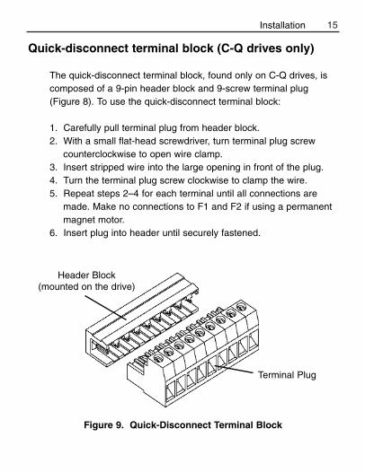
Quick-disconnect terminal block (C-Q drives only)
The quick-disconnect terminal block, found only on C-Q drives, iscomposed of a 9-pin header block and 9-screw terminal plug(Figure 8). To use the quick-disconnect terminal block:
1. Carefully pull terminal plug from header block.2. With a small flat-head screwdriver, turn terminal plug screw
counterclockwise to open wire clamp.3. Insert stripped wire into the large opening in front of the plug.4. Turn the terminal plug screw clockwise to clamp the wire.5. Repeat steps 2–4 for each terminal until all connections are
made. Make no connections to F1 and F2 if using a permanentmagnet motor.
6. Insert plug into header until securely fastened.
Figure 9. Quick-Disconnect Terminal Block
Header Block(mounted on the drive)
Terminal Plug
Installation

16 Installation
Speed adjust potentiometer
Mount the speed adjust potentiometer through a 0.38 in. (10 mm)hole with the hardware provided (Figure 9). Install the circularinsulating disk between the panel and the 10K ohm speed adjustpotentiometer.
Twist the speed adjust potentiometer wire to avoid picking upunwanted electrical noise. If speed adjust potentiometer wires arelonger than 18 in. (457 mm), use shielded cable. Keep speedadjust potentiometer wires separate from power leads (L1, L2, A1,A2).
Warning
Be sure that the potentiometer tabs do not make contact withthe potentiometer enclosure. Grounding the input will causedamage to the drive.
Figure 10. Speed Adjust Potentiometer

17
Power, fuse and motor connections
Connect the power input leads, an external line fuse and a DCmotor to TB501 on the drive’s printed circuit board (PCB) as shownin Figure 10, page 20.
MotorMinarik drives supply motor armature voltage from A1 and A2terminals. It is assumed throughout this manual that, when A1 ispositive with respect to A2 , the motor will rotate clockwise (CW)while looking at the output shaft protruding from the front of themotor. If this is opposite of the desired rotation, simply reverse thewiring of A1 and A2 with each other.
Chassis drive connections
Warning
Do not connect this equipment with power applied.Failure to heed this directive may result in fire or seriousinjury.
Minarik strongly recommends the installation of a masterpower switch in the voltage input line, as shown inFigure 10 (page 20). The switch contacts should be rated ata minimum of 200% of motor nameplate current and 250volts.
Installation

18 Installation
Connect a DC motor to PCB terminals A1 and A2 as shown inFigure 11, page 21. Ensure that the motor voltage rating isconsistent with the drive’s output voltage.
Power inputConnect the AC line power leads to TB501 terminals L1 and L2, orto a double-throw, single-pole master power switch(recommended). The switch should be rated at a minimum of 250volts and 200% of motor current. Refer to Figure 11, page 21.
Line fuse
Minarik drives require an external fuse for protection. Use fastacting fuses rated for 250 VAC or higher, and approximately 150%of the maximum armature current. Fuse only the HOT leg of theAC line that connects to L1 and leave L2 unfused when the AC linevoltage is 115 VAC. Table 1 (page 19) lists the recommended linefuse sizes.
Wire an external line fuse between the stop switch (if installed) andthe L1 terminal on terminal board TB501. An additional line fuseshould be installed on L2 if the input voltage is 230VAC. The linefuse(s) should be rated at 250 volts and 150 - 200% of maximummotor nameplate current.

19Installation
Table 1. Recommended Line Fuse Sizes90 VDC Motor 180 VDC Max. DC Armature AC Line Fuse
Horsepower Horsepower Current (amps) Size (amps)
1/20 1/10 0.5 1
1/15 1/8 0.8 1.5
1/8 1/4 1.5 3
1/6 1/3 1.7 3
1/4 1/2 2.5 5
1/3 3/4 3.5 8
1/2 1 5.0 10
3/4 1 1/2 7.5 15
1 2 10 15
Minarik Corporation offers two fuse kits: part number 050–0066 (1–5A Fuse Kit) and 050–0071 (5–15A Fuse Kit).

20 Installation
See Table 2 for field output connections. Use 18 AWG wire toconnect the field output to a shunt wound motor.
Table 2. Field Output ConnectionsLine Voltage Approximate Connect Motor
(VAC) Field Voltage (VDC) Field To115 50 F1 and L1115 100 F1 and F2230 100 F1 and L1230 200 F1 and F2
Warning
The field output is for shunt wound motors only. Do not make any connections to F1 and F2 when using apermanent magnet motor.
Field output connections
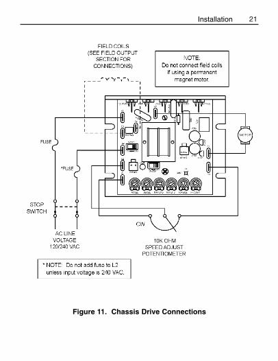
21
Figure 11. Chassis Drive Connections
Installation

22
Figure 12. MM23201C-Q and MM23011C-Q Connections
Installation

23
Voltage follower
Instead of using a speed adjust potentiometer, the drive may bewired to follow an analog input voltage signal that is isolated fromearth ground (Figure 12). Connect the signal input (+) to S2.Connect the signal common (–) to S1. Make no connection to S3.A potentiometer can be used to scale the analog input voltage. Aninterface device, such as Minarik model PCM4, may be used toscale and isolate an analog input voltage.
With either 115 VAC or 230 VAC line voltage, an analog input voltage range of approximately 0–1.4 VDC is required toproduce an armature voltage range of 0–90 VDC. With 230 VACline voltage, an analog input voltage range of approximately 0–2.8VDC is required to produce an armature voltage range of 0–180VDC.
Figure 13. Voltage Follower Connections
Installation

24 Installation
Mounting (NEMA 1 enclosures)
NEMA 1 cased drives come with 0.88 inch (22 mm) conduit holesat the bottom of the case. The units may be vertically wall mountedor horizontally bench mounted using the three keyholes on theback of the case.
1. For access to the keyholes and the terminal strip, remove thetwo screws from the front of the case by turning themcounterclockwise. Grasp the front cover and lift it straight out.
2. Install the mounting screws in the three keyholes.3. Install conduit hardware through the conduit holes at the bottom
of the case. Connect external wiring to the terminal block.4. Reinstall the front cover. Avoid pinching any wires between the
front cover and the case.5. Replace the two screws to the front cover. Turn the screws
clockwise to tighten.6. Set the POWER switch to the OFF position before applying the
AC line voltage.
Cased drives
Warning
Do not install, rewire, or remove this control with inputpower applied. Doing so may cause fire or serious injury.Make sure you have read and understood the SafetyWarnings before attempting installation.

25
Mounting (NEMA 12 enclosures)
NEMA 12 cased drives come with two 0.88 inch (22 mm) conduit knockout holes at the bottom of the case. The units may be vertically wall mounted using the four 0.19 inch (5 mm)slotted holes on the attached heat sink. For motor loads less than 5ADC, the drive may be bench mounted horizontally, or operatedwithout mounting.
1. Install the mounting screws.2. For access to the terminal strip, turn the slotted screw on the
front cover counterclockwise until it is free from the case. Theright side of the cover is hinged to the case. Pull the slottedscrew to open the case.
3. Carefully remove the conduit knockouts by tapping them intothe case and twisting them off with pliers.
4. Install conduit hardware through the 0.88 inch (22 mm)knockout holes. Connect external wiring to the terminal block.
5. Grasp the slotted screw and tilt the front cover back into place.Avoid pinching any wires between the front cover and the case.
6. Turn the slotted screw clockwise until tight to secure the frontcover.
7. Set the POWER switch to the OFF position before applying theAC line voltage.
Installation

26 Installation
Heat sinking
Models MM23101 and MM23201 require additional heat sinkingwhen the continuous armature current is above 5 ADC. UseMinarik part number 223-0174. All other cased drives havesufficient heat sinking in their basic configurations. Use a thermallyconductive heat sink compound (such as Dow Corning® 340 HeatSink Compound) between the back of the drive case and heat sinksurface for optimum heat transfer.
Line fusing
15 amp line fuses are preinstalled on the cased models MM23101,MM23201, MM23401, and MM23501. 3 amp line fuses arepreinstalled on the cased models MM23111, MM23211, andMM23411.
If the horsepower rating of the motor being used is less than themaximum horsepower rating of the drive, the line fuse may have tobe replaced with a lower rated one. Refer to the “RecommendedLine Fuse Sizes” table on page 18 to install a lower rated fuse.

27
Connections
Warning
Do not connect this equipment with power applied.Failure to heed this directive may result in fire or seriousinjury.
Minarik strongly recommends the installation of a masterpower switch in the voltage input line. The switchcontacts should be rated at a minimum of 200% of motornameplate current and 250 volts.
Power and motor connections
Connect the power input leads and a DC motor to TB501 as shownin Figure 13, page 28.
MotorMinarik drives supply motor voltage from A1 and A2 terminals. It isassumed throughout this manual that, when A1 is positive withrespect to A2 , the motor will rotate clockwise (CW) while lookingat the output shaft protruding from the front of the motor. If this isopposite of the desired rotation, simply reverse the wiring of A1and A2 with each other.
Connect a DC motor to PCB terminals A1 and A2 as shown inFigure 13. Ensure that the motor voltage rating is consistent withthe drive’s output voltage.
Installation

28 Installation
Power inputConnect the AC line power leads to TB501 terminals L1 and L2, orto a double-throw, single-pole master power switch(recommended).
Field output connections
Warning
The field output is for shunt wound motors only. Do not make any connections to F1 and F2 when using apermanent magnet motor.
See Table 3 for field output connections. Use 18 AWG wire toconnect the field output to a shunt wound motor.
Table 3. Field Output ConnectionsLine Voltage Approximate Connect Motor
(VAC) Field Voltage (VDC) Field To115 50 F1 and L1115 100 F1 and F2230 100 F1 and L1230 200 F1 and F2

29
Figure 14. Cased Drive Connections
Installation

30 Installation
Current limit LED (C models only)
MM23000C series drives are equipped with a red current limit LED.The red current limit LED turns on whenever the drive reachescurrent limit and turns off whenever the drive is not in current limit(normal operation).
Current limit header block (C-H models only)
MM23000C-H series drives are equipped with a 2-pin current limitheader block. The current limit header block outputs approximatelya floating 5 VDC (5 mADC) signal whenever the drive reachescurrent limit. The signal may be used as an input to an externaldevice, such as an alarm or shut down circuit, that works when thedrive reaches current limit.
Meter header block (cased C models only)To supply power to external devices, the Meter header block can supply an unregulated +9 VDC (5 mA) signal when the motorand the power supply of the drive are fully loaded. More current isavailable with less motor loading. Meter can supply an unregulated+15V (10 mA) signal in typical applications.

31
MM23001C-Q, MM23071, and MM23072diagnostic LEDs
Models MM23001C-Q, MM23071, and MM23072 are equipped withtwo diagnostic LEDs:
Power (PWR): Lights whenever the AC line voltage is applied tothe drive.
Current Limit (CURR LIMIT or CL): Lights whenever the drivereaches current limit.
Installation

32
Operation
Before applying power
• Verify that no conductive material is present on the printed circuit
board.
• Ensure that the voltage select switches switches are properly set.
Warning
Change voltage switch settings only when the drive isdisconnected from AC line voltage. Make sure both switchesare set to their correct position. If the switches are improperlyset to a lower voltage position, the motor will not run at fullvoltage and may cause damage to the transformer. If theswitches are improperly set to a higher voltage position, themotor will overspeed, which may cause motor damage, orresult in bodily injury or loss of life.
Dangerous voltages exist on the drive when it is powered.BE ALERT. High voltages can cause serious or fatal injury.For your safety, use personal protective equipment (PPE)when operating this drive.
If the motor or drive does not perform as described,disconnect the AC line voltage immediately. Refer to theTroubleshooting section, page 57, for further assistance.

33Operation
Figure 15. Voltage Switches
Voltage select switches
Input voltage select (SW501)
Set the voltage switch SW501 to either 115V or 230V to match the AC line voltage. See Figure 14.
Armature voltage select (SW502)
Set the voltage switch SW502 to either 90V or 180V to match themaximum armature voltage. See Figure 14.
ARMATUREVOLTAGE SELECT
(SW502)
INPUT VOLTAGESELECT (SW501)

34 Operation
StartupMM23001, MM23011, MM23071, and MM23072
1. Turn the speed adjust potentiometer full counterclockwise(CCW).
2. Apply AC line voltage.3. Slowly advance the speed adjust potentiometer clockwise (CW).
The motor slowly accelerates as the potentiometer is turned CW.Continue until the desired speed is reached.
4. Remove AC line voltage from the drive to coast the motor to astop.
MM23101, MM23111, MM23401, and MM23411
1. Set the speed adjust potentiometer to “0” (full CCW).2. Apply AC line voltage.3. Set the POWER switch to the ON position.4. Slowly advance the speed adjust potentiometer clockwise
(CW). The motor slowly accelerates as the potentiometer isturned CW. Continue until the desired speed is reached.
5. Set the POWER switch to the OFF position to coast themotor to a stop.

35
1. Set the RUN/BRAKE switch to the BRAKE position. 2. Set the speed adjust potentiometer to “0” (full CCW).3. Apply AC line voltage.4. Set the POWER switch to the ON position.5. Set the FORWARD/REVERSE switch to the desired direction of
rotation.6. Set the RUN/BRAKE switch to the RUN position.7. Slowly advance the speed adjust potentiometer clockwise (CW).
The motor slowly accelerates as the potentiometer is turned CW.Continue until the desired speed is reached.
8. To reverse direction:a. Set the RUN/BRAKE switch to the BRAKE position.b. Set the FORWARD/REVERSE switch to the desired
direction of rotation.c. Set the RUN/BRAKE switch to the RUN position.
9. To brake the motor, set the RUN/BRAKE switch to the BRAKEposition. To coast the motor to a stop, set the POWER switch tothe OFF position.
MM23201 and MM23211
Warning
Do not change the FORWARD / REVERSE switch while themotor is running. The motor must come to a complete stopbefore reversing. Changing motor direction before allowingthe motor to completely stop will cause excessively highcurrent to flow in the armature circuit, and will damage thedrive and/or motor.
Operation

36 Operation
1. Set the FORWARD/BRAKE/REVERSE switch to the BRAKEposition.
2. Set the speed adjust potentiometer to “0” (full CCW).3. Apply AC line voltage.4. Set the POWER switch to the ON position.5. Set the FORWARD/BRAKE/REVERSE switch to the desired
direction of rotation.7. Slowly advance the speed adjust potentiometer clockwise (CW).
The motor slowly accelerates as the potentiometer is turned CW.Continue until the desired speed is reached.
8. To reverse direction:a. Set the FORWARD/BRAKE/REVERSE switch to the
BRAKE position.b. After the motor comes to a complete stop, set the
FORWARD/BRAKE/REVERSE switch to the desireddirection of rotation.
9. To brake the motor, set the FORWARD/BRAKE/REVERSEswitch to the BRAKE position. To coast the motor to a stop, setthe POWER switch to the OFF position.
MM23501
Warning
The motor must come to a complete stop before reversing.Changing motor direction before allowing the motor tocompletely stop will cause excessively high current to flow inthe armature circuit, and will damage the drive and/or motor.

37
Starting and stopping methods
Line starting and line stopping
Line starting and line stopping (applying and removing AC linevoltage) is recommended for infrequent starting and stopping of adrive only. When AC line voltage is applied to the drive, the motoraccelerates to the speed set by the speed adjust potentiometer.When AC line voltage is removed, the motor coasts to a stop.
Warning
Decelerating to minimum speed, dynamic braking, or coastingto a stop is recommended for frequent starts and stops. Donot use any of these methods for emergency stopping. Theymay not stop a drive that is malfunctioning. Removing AC linepower (both L1 and L2) is the only acceptable method foremergency stopping.
For this reason, Minarik strongly recommends installingan emergency stop switch on both the L1 and L2 inputs(see connection diagrams on pages 20 & 21).
Operation

38 Operation
Inhibit terminals
Short the INHIBIT terminals to coast the motor to minimum speed(see Figure 15 for INHIBIT terminal location). Open the INHIBITterminals to accelerate the motor to set speed.
Twist inhibit wires and separate them from power-carrying wires orsources of electrical noise. Use shielded cable if the inhibit wiresare longer than 18 inches (46 cm). If shielded cable is used,ground only one end of the shield to earth ground. Do not groundboth ends of the shield.
Minarik Corporation offers two accessory plug harnesses forconnecting to the INHIBIT terminals: part number 201-0024 [inhibitplug with 18 inches (46 cm) leads]; and part number 201-0079 [inhibit plug with 36 inches (91 cm) leads].
Figure 16. INHIBIT Terminals
INHIBITTERMINALS

39
Decelerating to minimum speed
The switch shown in Figure 16 may be used to decelerate a motor to a minimum speed. Closing the switch between S1 and S2decelerates the motor from set speed to a minimum speeddetermined by the MIN SPD trimpot setting. If the MIN SPD trimpotis set full CCW, the motor decelerates to zero speed when theswitch between S1 and S2 is closed. The DECEL trimpot settingdetermines the rate at which the drive decelerates. By opening theswitch, the motor accelerates to set speed at a rate determined bythe ACCEL trimpot setting.
Figure 17. Run/Decelerate to Minimum Speed Switch
Operation

40 Operation
Dynamic braking
Warning
For frequent starts and stops, short the inhibit terminals,decelerate to a minimum speed, or apply a dynamic brake tothe motor. Do not use any of these methods for emergencystopping. They may not stop a drive that is malfunctioning.Removing AC line power (both L1 and L2) is the onlyacceptable method for emergency stopping.
Frequent starting and stopping can produce high torque. This may cause damage to motors, especially gearmotors that arenot properly sized for the application.
Dynamic braking may be used to rapidly stop a motor (Figure 17, page 40). For the RUN/BRAKE switch, use a two pole,two position switch rated for at least 125 VDC, 6 amps. For thedynamic brake resistor, use a 40 watt minimum, high power,wirewound resistor.
Sizing the dynamic brake resistor depends on load inertia, motorvoltage, and braking time. Use a lower-value, higher-wattagedynamic brake resistor to stop a motor more rapidly. Refer to Table4 (page 40) for recommended dynamic brake resistor sizes.
Note: Models MM23201, MM23211, and MM23501 incorporatedynamic braking in their designs.

41
Table 4. Minimum Recommended Dynamic BrakeResistor Values
Motor Armature Dynamic BrakeVoltage Resistor Value90 VDC 15 ohms180 VDC 30 ohms
For motors rated 1/17 horsepower and lower, a brake resistor is notnecessary since the armature resistance is high enough to stop themotor without demagnetization. Replace the dynamic brake with12-gauge wire.
Figure 18. Dynamic Brake Connection
Operation

42
MM23000-series drives have user-adjustable trimpots. Each driveis factory calibrated to its maximum current rating. Readjust thecalibration trimpot settings to accommodate lower current ratedmotors.
All adjustments increase with CW rotation, and decrease with CCWrotation. Use a non-metallic screwdriver for calibration. Eachtrimpot is identified on the printed circuit board.
Calibration
Warning
Dangerous voltages exist on the drive when it is powered.When possible, disconnect the voltage input from the drivebefore adjusting the trimpots. If the trimpots must be adjustedwith power applied, use insulated tools and the appropriatepersonal protection equipment. BE ALERT. High voltages cancause serious or fatal injury.

43Calibration
MINIMUM SPEED (MIN SPD)
The MIN SPD trimpot establishes the motor speed obtained in
response to the minimum input signal. It is factory set for zero
speed.
To calibrate the MIN SPD pot, apply the minimum signal. Adjust the
MIN SPD trimpot until the motor runs at the desired speed or is just
at the threshold of rotation.
MAXIMUM SPEED (MAX SPD)
The MAX SPD setting determines the maximum motor speed when
the speed adjust potentiometer, or voltage input signal is set for
maximum forward speed. It is factory set for maximum rated motor
speed.
To calibrate MAX SPD:
1. Set the MAX SPD trimpot full CCW.
2. Set the speed adjust potentiometer or voltage input signal for
maximum forward speed.
3. Adjust MAX SPD until the desired maximum forward speed is
reached.
Note: Check the MIN SPD and MAX SPD adjustments afterrecalibrating to verify that the motor runs at the desired minimumand maximum speed.

TORQUE
44 Calibration
The TORQUE setting determines the maximum torque foraccelerating and driving the motor. To calibrate TORQUE, refer tothe recommended TORQUE settings in Figure 18 (page 45) or usthe following procedure:
1. With the power disconnected from the drive, connect a DC
ammeter in series with the armature.
2. Set the TORQUE trimpot to minimum (full CCW).
3. Set the speed adjust potentiometer to maximum speed
(full CW).
4. Carefully lock the motor armature. Be sure that the motor is
firmly mounted.
5. Apply line power. The motor should be stopped.
6. Slowly adjust the TORQUE trimpot CW until the armature
current is 150% of motor rated armature current.
7. Turn the speed adjust potentiometer CCW until the motor stops.
8. Remove line power.
9. Remove the stall from the motor.
10. Remove the ammeter in series with the motor armature if it is
no longer needed.
Warning
TORQUE should be set to 150% of motor nameplate currentrating. Continuous operation beyond this rating may damagethe motor. If you intend to operate beyond the rating, contactyour Minarik representative for assistance.

45
IR COMPENSATION (IR COMP)
The IR COMP trimpot setting determines the degree to whichmotor speed is held constant as the motor load changes. It isfactory set for optimum motor regulation.
Use the following procedure to recalibrate the IR COMP setting:1. Set the IR COMP trimpot to minimum (full CCW).2. Rotate the speed adjust potentiometer until the motor runs at
midspeed without load (for example, 900 RPM for an 1800 RPMmotor). A hand held tachometer may be used to measuremotor speed.
3. Load the motor armature to its full load armature current rating.The motor should slow down.
4. While keeping the load on the motor, rotate the IR COMPtrimpot until the motor runs at the speed measured in step 2. Ifthe motor oscillates (overcompensation), the IR COMP trimpotmay be set too high (CW). Turn the IR COMP trimpot CCW tostabilize the motor.
5. Unload the motor.
See Figure 18, for recommended IR COMP settings.
Calibration

46 Calibration
Figure 19. Recommended Torque and IR COMP Settings(actual settings may vary with each application)

47
ACCELERATION (ACCEL)
The ACCEL setting determines the time the motor takes to ramp to a higher speed. See Specifications on page 1 forapproximate acceleration times. ACCEL is factory set for thefastest acceleration time (full CCW).
To set the acceleration time:1. Set the speed adjust potentiometer full CCW. The motor
should run at minimum speed.2. Turn the speed adjust potentiometer full CW and measure
the time it takes the motor to go from minimum tomaximum speed.
3. If the time measured in step 2 is not the desired accelerationtime, turn the ACCEL trimpot CW for a slower accelerationtime, or CCW for a faster acceleration time. Repeat steps 1through 3 until the acceleration time is correct.
Calibration

DECELERATION (DECEL)The DECEL setting determines the time the motor takes to ramp toa lower speed. See Specifications on page 1 for approximatedeceleration times. DECEL is factory set for the fastestdeceleration time (full CCW).
To set the deceleration time:1. Set the speed adjust potentiometer full CW. The motor should
run at maximum speed.2. Turn the speed adjust potentiometer full CCW and measure the
time it takes the motor to go from maximum to minimum speed.3. If the time measured in step 2 is not the desired deceleration
time, turn the DECEL trimpot CW for a slower deceleration time,or CCW for a faster deceleration time. Repeat steps 1 through 3until the deceleration time is correct.
48 Calibration

49
Multiple fixed speeds
Replace the speed adjust potentiometer with series resistors with a total series resistance of 10K ohms (Figure 19). Add a singlepole, multi-position switch with the correct number of positions forthe desired number of fixed speeds.
Application Notes
Figure 20. Multiple Fixed Speeds
50 Application Notes
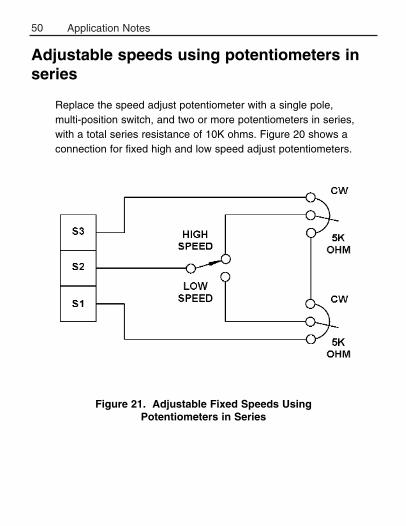
Adjustable speeds using potentiometers inseries
Replace the speed adjust potentiometer with a single pole, multi-position switch, and two or more potentiometers in series,with a total series resistance of 10K ohms. Figure 20 shows aconnection for fixed high and low speed adjust potentiometers.
Figure 21. Adjustable Fixed Speeds UsingPotentiometers in Series

51
Independent adjustable speeds
Replace the speed adjust potentiometer with a single pole, multi-position switch, and two or more potentiometers in parallel, with atotal parallel resistance of 10K ohms. Figure 21 shows theconnection of two independent speed adjust potentiometers thatcan be mounted at two separate operating stations.
Figure 22. Independent Adjustable Speeds
Application Notes

52 Application Notes
RUN/JOG switchRUN/JOG switch option #1
Using a RUN/JOG switch is recommended in applications wherequick stopping is not needed and frequent jogging is required. Usea single pole, two position switch for the RUN/JOG switch, and asingle pole, normally closed, momentary operated pushbutton forthe JOG pushbutton.
In the first wiring option, connect the RUN/JOG switch and JOGpushbutton to the inhibit plug as shown in Figure 22. The motorcoasts to a stop when the RUN/JOG switch is set to JOG. Pressthe JOG pushbutton to jog the motor. Return the RUN/JOG switchto RUN for normal operation.
Figure 23. RUN/JOG Switch Connection to Inhibit Plug (Option #1)

53
RUN/JOG switch option #2
In the second wiring option, connect the RUN/JOG switch and theJOG pushbutton as shown in the Figure 23. When the RUN/JOGswitch is set to JOG, the motor decelerates to minimum speed(minimum speed is determined by the MIN SPD trimpot setting).Press the JOG pushbutton to jog the motor. Return the RUN/JOGswitch to RUN for normal operation.
Figure 24. RUN/JOG Switch Connection toSpeed Adjust Potentiometer (Option #2)
Application Notes

54 Application Notes
Leader-follower applicationIn this application, use a PCM4 to monitor the speed of the leader motor (Figure 24). The PCM4 isolates the leader motor fromthe follower drive, and outputs a voltage proportional to the leadermotor armature voltage. The follower drive uses this voltagereference to set the speed of the follower motor. An optional ratiopotentiometer may be used to scale the PCM4 output voltage.
Figure 25. Leader-Follower Application
55
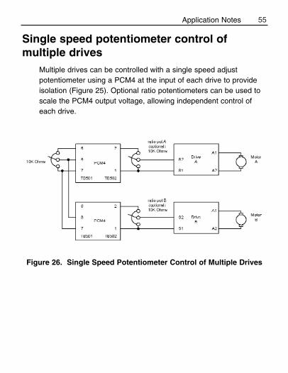
Single speed potentiometer control ofmultiple drives
Multiple drives can be controlled with a single speed adjustpotentiometer using a PCM4 at the input of each drive to provideisolation (Figure 25). Optional ratio potentiometers can be used toscale the PCM4 output voltage, allowing independent control ofeach drive.
Figure 26. Single Speed Potentiometer Control of Multiple Drives
Application Notes

56
Reversing
A dynamic brake may be used when reversing the motor direction(Figure 26). Use a three pole, three position switch rated for atleast the maximum DC armature voltage and maximum brakingcurrent. Wait for the motor to stop completely before switching it toeither the forward or reverse direction. See the Dynamic brakingsection, page 39, for recommended dynamic brake resistor sizes
Note: Model MM23501 is equipped with this reversing feature.
Figure 27. Reversing Circuit Connection
Application Notes

57
Reversing with a DIGI-LOK controller
A DIGI-LOK controller, model DLC600, can be used in a reversingapplication. The DIGI-LOK must be inhibited while braking. Withoutthe inhibit feature, the DIGI-LOK will continue to regulate. This willcause overshoot when the DIGI-LOK is switched back to the drive.
Figure 27 shows the connection of the reversing circuit to aMM23000 series drive and to a DLC600. Note: Only one DLCoption (Optical Encoder or Magnetic Pickup) may be used at atime.
Figure 28. Reversing with a DLC600
Application Notes

58
Troubleshooting
Before troubleshooting
Perform the following steps before starting any procedure in thissection:
1. Disconnect AC line voltage from the drive.2. Check the drive closely for damaged components.3. Check that no conductive or other foreign material has become
lodged on the printed circuit board.4. Verify that every connection is correct and in good condition.5. Verify that there are no short circuits or grounded connections.6. Check that the voltage selection switch settings match the AC
line and output voltages.7. Check that the drive’s rated armature and field outputs are
consistent with the motor ratings.
For additional assistance, contact your local Minarik Distributor, orthe factory direct at: Tel.: 1-800-MINARIK (646-2745) or Fax: 1-800-394-6334
Warning
Dangerous voltages exist on the drive when it is powered.When possible, disconnect the drive while troubleshooting.High voltages can cause serious or fatal injury.

59Troubleshooting
Line fuse blows. 1. Line fuse is the wrongsize.
2. Motor cable orarmature is shorted toground.
3. Nuisance trippingcaused by acombination of ambientconditions and high-current spikes (i.e.reversing).
1. Check that the linefuse is correct for themotor size.
2. Check motor cable andarmature for shorts.
3. Add a blower to coolthe drive components;decrease TORQUEsettings, or resizemotor and drive foractual load demand, orcheck for incorrectlyaligned mechanicalcomponents or “jams”.See page 43 forinformation onadjusting the TORQUEtrimpot.
Problem PossibleCauses
SuggestedSolutions

60 Troubleshooting
Line fuse does not blow,but the motor does notrun.
Motor does not stop when the speed adjustpotentiometer is full CCW.
Motor runs in the oppositedirection (non-reversingdrives).
1. Speed adjust pot orspeed referencevoltage is set to zerospeed.
2. INHIBIT terminals arejumpered.
3. S2 is shorted to S1.
4. Drive is in current limit.
5. Drive is not receivingAC line voltage.
6. Motor is not connected.
MIN SPD setting is toohigh.
Motor connections to A1and A2 are reversed.
1. Increase the speedadjust pot or speedreference voltageetting.
2. Remove jumper fromthe INHIBIT terminals.
3. Remove short.
4. Verify that motor is not jammed. IncreaseTORQUE setting ifthey are set too low.See page 43.
5. Apply AC line voltageto L1 and L2.
6. Connect motor to A1and A2.
Calibrate MIN SPD. Seepage 42.
Reverse connections toA1 and A2.
Problem PossibleCauses
SuggestedSolutions
61
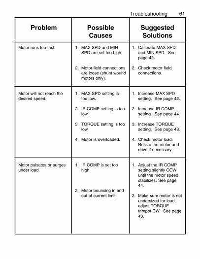
Motor runs too fast.
Motor will not reach thedesired speed.
Motor pulsates or surgesunder load.
1. MAX SPD and MINSPD are set too high.
2. Motor field connectionsare loose (shunt woundmotors only).
1. MAX SPD setting istoo low.
2. IR COMP setting is toolow.
3. TORQUE setting is toolow.
4. Motor is overloaded.
1. IR COMP is set toohigh.
2. Motor bouncing in andout of current limit.
1. Calibrate MAX SPDand MIN SPD. Seepage 42.
2. Check motor fieldconnections.
1. Increase MAX SPDsetting. See page 42.
2. Increase IR COMPsetting. See page 44.
3. Increase TORQUEsetting. See page 43.
4. Check motor load.Resize the motor anddrive if necessary.
1. Adjust the IR COMPsetting slightly CCWuntil the motor speedstabilizes. See page44.
2. Make sure motor is notundersized for load;adjust TORQUEtrimpot CW. See page43.
Problem PossibleCauses
SuggestedSolutions
Troubleshooting

62Troubleshooting
FIgure 29. MM23000 Series Block Diagram

63
FIgure 30. MM23101, MM23111, MM23401 and MM23411 Terminal Block Connections
Troubleshooting

64 Troubleshooting
FIgure 31. MM23201 and MM23211 Terminal Block Connections

65
Figure 32. MM23501 Terminal Block Connections
Troubleshooting

66 Troubleshooting
Replacement Parts
Replacement parts are available from Minarik Corporation and itsdistributors for this drive series.
Table 5. Replacement Parts
Model No. Symbol Description Minarik P/NMM23001 and SCR501, 502 800 V, 20 A SCR 072-0043MM23071 D501-503 800 V, 20 A Diode 071-0039
R501 0.01 OHM, 5 W Resistor 032-0129T501 3FD-224-001 Transformer 230-0083
10KΩ potentiometer kit 202-0031
MM23011 Same as MM23001 except:SCR501, 502 600 V, 8 A SCR 072-0024D501-503 600 V, 3 A Diode 071-0007R501 0.05 OHM, 5W Resistor 032-0089
MM23101 Same as MM23001 except potentiometer kit, and including:Case Bottom 223-0170Case Cover 223-0169240V Pilot Light 040-004310K OHM, 5W Potentiometer 120-0009Knob 140-0013DPST Power Switch 080-003715 A, 3AB Fuse 050-0018
MM23111 Same as MM23011 except potentiometer kit. Same as MM23101except fuse. Include:
3 A, 3AG Fuse 050-0021
MM23201 Same as MM23101 except case cover, and including:Case Cover 223-016840 OHM, 40W Resistor 032-0076
SW4 DPST Run/Brake Switch 080-0037SW5 DPST FWD/REV Switch 080-0037
67
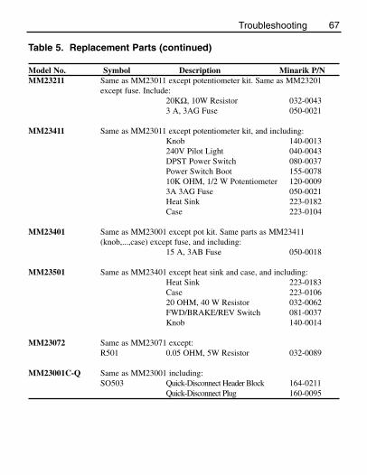
Table 5. Replacement Parts (continued)
Model No. Symbol Description Minarik P/NMM23211 Same as MM23011 except potentiometer kit. Same as MM23201
except fuse. Include:20KΩ, 10W Resistor 032-00433 A, 3AG Fuse 050-0021
MM23411 Same as MM23011 except potentiometer kit, and including:Knob 140-0013240V Pilot Light 040-0043DPST Power Switch 080-0037Power Switch Boot 155-007810K OHM, 1/2 W Potentiometer 120-00093A 3AG Fuse 050-0021Heat Sink 223-0182Case 223-0104
MM23401 Same as MM23001 except pot kit. Same parts as MM23411(knob,...,case) except fuse, and including:
15 A, 3AB Fuse 050-0018
MM23501 Same as MM23401 except heat sink and case, and including:Heat Sink 223-0183Case 223-010620 OHM, 40 W Resistor 032-0062FWD/BRAKE/REV Switch 081-0037Knob 140-0014
MM23072 Same as MM23071 except:R501 0.05 OHM, 5W Resistor 032-0089
MM23001C-Q Same as MM23001 including:SO503 Quick-Disconnect Header Block 164-0211
Quick-Disconnect Plug 160-0095
Troubleshooting

68
CE Compliance
Minarik Corporation hereby certifies that its MM23000 series driveshave been approved to bear the “CE” mark provided the conditionsof approval have been met by the end user.
The MM23000 series has been tested to the following testspecifications:
EN55011:1991 (emissions), andEN50082-1:1992 (immunity)
Compliance allows Minarik’s MM23000 series to bear the CE mark.
The end user, as described herein, falls into one of two categories:1. The Consumer will deploy a stand-alone unit as an
integral, yet external, portion of the machine beingoperated.
2. The Original Equipment Manufacturer (OEM) willimplement the product as a component of the machinebeing manufactured.
In addition to EMI/RFI safeguards inherent in the MM23000 series’design, external filtering is required.

69CE Compliance
Line filters
Minarik requires the Corcom® line filters listed below.
Table 6. Corcom® FiltersNameplate Current of Corcom® Filter
Motor Wired to the Drive Part Number0 to 4 amps 6VV1
4.1 to 13 amps 20VV1
If the exact line filter is not available, the specifications are asfollows:
L = (1.73 + 0.03) milliHenries.C = (0.27 + 0.54) microFarads (X); 0.0055 microFarads (Y).R = 330Kohms.Rated current: 1.4 times maximum DC motor current.Filter type: Balanced 2-section.
The line filters should be wired to the AC line within 0.25 meters ofthe drive. The ground connection from the line filter must be wiredto solid earth ground (resistance less than 500 ohms); not machineground. This is very important!
If the end-user is using a CE-approved motor, the correct line filterlisted above is all that is necessary to meet the EMC directiveslisted herein.

Armature filters
If the end-user is not using a CE-approved motor, a second filter on the armature must be used. It is Minarik’s CEXXMM. XX =rated current of the filter. Minarik Filters are listed below.
Table 7. Minarik FiltersNameplate Current of Minarik Filter
Motor Wired to the Drive Part Number0 to 4 amps CE4MM
4.1 to 13 amps CE20MM
The filters listed above are Real-Pole Balanced-Pi 3-pole filters. If the exact filter is not available, the specifications are as follows:
L & L1 = 2 * (0.8) milliHenries.C & C1 = 2 * (0.1) microFarads @ 400W VDC.Rin = 0.1 ohm; Rout = 1.2 ohm.
The filters listed above must be wired to the DC output of the drive,as close to the drive as possible.
70 CE Compliance

The end user must use the filters listed in this section to complywith CE. The OEM may choose to provide alternative filtering thatencompasses the Minarik drive and other electronics within thesame panel.
The OEM has this liberty because CE is a machinery directive.Whether or not every component in the OEM’s machinery meetsCE, the OEM must still submit his machine for CE approval.
Thus, no component must necessarily meet CE within the machine,as long as the OEM takes the necessary steps to guarantee themachine does meet CE. By the same token, even if everycomponent in the OEM’s machine does meet CE, the machine willnot necessarily meet CE as a machine.
Using CE-approved wiring practices (like proper shielding) and thefilters listed in this section help the drive meet EN55011 (1991emissions standard) and EN50082-1 (1992 immunity standard).
71CE Compliance

NOTES
72

NOTES
73

NOTES
74

Unconditional Warranty
A. Warranty - Minarik Corporation (referred to as “the Corporation”) warrants that itsproducts will be free from defects in workmanship and material for twelve (12) months or3,000 hours, whichever comes first, from date of manufacture thereof. Within this warrantyperiod, the Corporation will repair or replace, at its sole discretion, such products that arereturned to Minarik Corporation, 901 East Thompson Avenue, Glendale, CA 91201-2011USA.
This warranty applies only to standard catalog products, and does not apply to specials. Anyreturns for special controls will be evaluated on a case-by-case basis. The Corporation isnot responsible for removal, installation, or any other incidental expenses incurred inshipping the product to and from the repair point.
B. Disclaimer - The provisions of Paragraph A are the Corporation’s sole obligation andexclude all other warranties of merchantability for use, express or implied. The Corporationfurther disclaims any responsibility whatsoever to the customer or to any other person forinjury to the person or damage or loss of property of value caused by any product that hasbeen subject to misuse, negligence, or accident, or misapplied or modified by unauthorizedpersons or improperly installed.
C. Limitations of Liability - In the event of any claim for breech of any of the Corporation’sobligations, whether express or implied, and particularly of any other claim or breech ofwarranty contained in Paragraph A, or of any other warranties, express or implied, or claimof liability that might, despite Paragraph B, be decided against the Corporation by lawfulauthority, the Corporation shall under no circumstances be liable for any consequentialdamages, losses, or expense arising in connection with the use of, or inability to use, theCorporation’s product for any purpose whatsoever.
An adjustment made under warranty does not void the warranty, nor does it imply anextension of the original 12-month warranty period. Products serviced and/or parts replacedon a no-charge basis during the warranty period carry the unexpired portion of the originalwarranty only.
If for any reason any of the foregoing provisions shall be ineffective, the Corporation’s liabilityfor damages arising out of its manufacture or sale of equipment, or use thereof, whethersuch liability is based on warranty, contract, negligence, strict liability in tort, or otherwise,shall not in any event exceed the full purchase price of such equipment.
Any action against the Corporation based upon any liability or obligation arising hereunderor under any law applicable to the sale of equipment or the use thereof, must be commencedwithin one year after the cause of such action arises.

901 E Thompson AvenueGlendale, CA 91201-2011Tel.: 1-800-MINARIK (646-2745)
Fax: 1-800-394-6334www.minarikcorp.com
Document number 250–0091, Revision 5Printed in the U.S.A – 10/01
North America $12.00, Outside North America $15.00
DLC600
XP Series(AC or DC Input)
MM-PCM SeriesPCM20000 Series
Other drives from Minarik Corporation:


![Cole Porter Collection [finding aid]. Music Division, Library of ...](https://static.fdokumen.com/doc/165x107/632887b0cedd78c2b50e1935/cole-porter-collection-finding-aid-music-division-library-of-.jpg)