Microwire Feeder for Laser Applications
12
Biomedical Engineering Research Jun. 2013, Vol. 2 Iss. 2, PP. 96-107 - 96 - DOI: 10.5963/BER0202006 Microwire Feeder for Laser Applications Amogh Shenoy, Frank Liou * Department of Mechanical Engineering Missouri University of Science and Technology, Rolla, Missouri 65409-0050, USA Email: * [email protected] Abstract- This paper focuses on the design and development of a fine microwire feeder for laser applications. The use of metallic wires as a medium of deposition has been popular in aerospace and car manufacturing industries. These micro sized wires are also gaining importance in medical and semi-conductor industries. The use of wire-feeders in laser welding and electrical discharge machining applications has been prominent. There are devices used in laser applications which can handle wires from 0.25mm to 10.0 mm in diameter. The handling of microsized wire in laser application is often considered difficult due to its low buckling strength exposure to harsh environment. The primary function of the microwire feeder described in this paper was to feed wires of varying microdiameters to a desired location with high accuracy and precision to be used in a laser aided manufacturing processes. This can be designed by dividing the microwire feeder into four basic sub-mechanisms: (1) feeding mechanism (2) transfer mechanism (3) precision guidance mechanism (4) adjustment mechanism. These sub-mechanisms are integrated to account for compactness, flexibility and precision. This microwire feeder is capable of handling wires as low as 0.05 mm in diameter. The precision and accuracy of the device was experimentally tested prior to its practical application. A case study on laser deposition was presented; where; a 316 stainless steel microwire of 0.125 mm diameter was fed into a melt pool of 0.2 mm. The wire feed and the traverse speed of the table were varied to achieve a uniformly distributed clad. The effect of wire feed and traverse speed were studied and a deposition process window was developed for future experimentation. Keywords- Microwire Feeder, Design, Laser Metal Deposition I. INTRODUCTION In industrial manufacturing, the application of laser beam as a tool has been popular in aerospace and automotive industries. Laser application allows batch as well as individual production and its wide range of applications from welding, and cutting to direct metal deposition is a great advantage. The need to meet these wide ranges of applications drives the development of system components such as wire feeders and sensor systems for automation for laser aided manufacturing processes. The use of metallic wires as a deposition material in the field of laser manufacturing is gaining popularity, and the number of feasible industrial applications is still growing [1].Many researchers have been studying basic process characteristics of wire-based additive manufacturing and material properties of deposited beads and 3D parts [2-10]. Until now few scientific works have been reported on microwire handling devices being used in small business applications, due to the high cost associated with laser manufacturing processes. In direct laser deposition (DLD), powder or wire is delivered to the laser generated melt pool, which melts the powder and solidifies after removal of the laser. Manufacture of three-dimensional prototype parts is possible by overlapping multiple individual tracks [11]. So far, the widespread use of metallic wire as a deposition medium has been limited; about 80% of the application is laser welding and there have been only a few studies of the basic phenomena of laser cladding with wire feeding [12]. Compared to powder, wire as a medium for deposition, has a much lower material cost and high material efficiency. But due to the lack of availability of microwires of different sizes and materials, powder deposition has been more popular. The use of wire feeders in laser welding and electrical discharge machining applications has been prominent. There are devices which can handle wires from 0.25mm [13]to 10.0 mm in diameter [14]. These wire feeders were used in high power laser applications with melt pool sizes varying from 0.5 to4.0 mm. The initial cost associated with this laser technology is very high, which limits its application mainly to aerospace and automotive industries. These micro sized wires are gaining importance in the medical and semi-conductor industries. The development of this microwire handling device was initiated to effectively feed wires of microdiameters to a mini-laser deposition machine which required a high precision wire feeding equipment. The mini-laser deposition machine for which the wire feeder is developed has a small melt pool spot size of 0.2 mm and is significantly less expensive than its larger counter parts. The development of this system was targeted to increase acceptance of laser deposition technology, by reducing the cost and using metallic wire as a medium for deposition. Thus a compact, robust, cost-efficient, and high precision microwire feeder was developed which is capable of handling microwires of sizes as low as 0.05 mm effectively. II. BASIC DESIGN OF MICROWIRE FEEDERS The major issue of the wire feeder is to feed a wire of unusually small diameter and springy nature, continuously to a very small melt pool. The problem to be solved was to ensure adequate force to grip the small diameter wire, without damaging it for continuous operation. For this it was essential to have a simple feeding mechanism which would impart the necessary force on the wire to continuously feed the wire without damaging it. Another important consideration is the poor buckling strength
-
Upload
khangminh22 -
Category
Documents
-
view
0 -
download
0
Transcript of Microwire Feeder for Laser Applications

Biomedical Engineering Research Jun. 2013, Vol. 2 Iss. 2, PP. 96-107
- 96 -
DOI: 10.5963/BER0202006
Microwire Feeder for Laser Applications Amogh Shenoy, Frank Liou
*
Department of Mechanical Engineering
Missouri University of Science and Technology, Rolla, Missouri 65409-0050, USA
Email: *[email protected]
Abstract- This paper focuses on the design and development of a fine microwire feeder for laser applications. The use of metallic
wires as a medium of deposition has been popular in aerospace and car manufacturing industries. These micro sized wires are also
gaining importance in medical and semi-conductor industries. The use of wire-feeders in laser welding and electrical discharge
machining applications has been prominent. There are devices used in laser applications which can handle wires from 0.25mm to
10.0 mm in diameter. The handling of microsized wire in laser application is often considered difficult due to its low buckling
strength exposure to harsh environment. The primary function of the microwire feeder described in this paper was to feed wires of
varying microdiameters to a desired location with high accuracy and precision to be used in a laser aided manufacturing processes.
This can be designed by dividing the microwire feeder into four basic sub-mechanisms: (1) feeding mechanism (2) transfer
mechanism (3) precision guidance mechanism (4) adjustment mechanism. These sub-mechanisms are integrated to account for
compactness, flexibility and precision. This microwire feeder is capable of handling wires as low as 0.05 mm in diameter. The
precision and accuracy of the device was experimentally tested prior to its practical application. A case study on laser deposition was
presented; where; a 316 stainless steel microwire of 0.125 mm diameter was fed into a melt pool of 0.2 mm. The wire feed and the
traverse speed of the table were varied to achieve a uniformly distributed clad. The effect of wire feed and traverse speed were
studied and a deposition process window was developed for future experimentation.
Keywords- Microwire Feeder, Design, Laser Metal Deposition
I. INTRODUCTION
In industrial manufacturing, the application of laser beam as a tool has been popular in aerospace and automotive industries.
Laser application allows batch as well as individual production and its wide range of applications from welding, and cutting to
direct metal deposition is a great advantage. The need to meet these wide ranges of applications drives the development of
system components such as wire feeders and sensor systems for automation for laser aided manufacturing processes.
The use of metallic wires as a deposition material in the field of laser manufacturing is gaining popularity, and the number
of feasible industrial applications is still growing [1].Many researchers have been studying basic process characteristics of
wire-based additive manufacturing and material properties of deposited beads and 3D parts [2-10].
Until now few scientific works have been reported on microwire handling devices being used in small business applications,
due to the high cost associated with laser manufacturing processes. In direct laser deposition (DLD), powder or wire is
delivered to the laser generated melt pool, which melts the powder and solidifies after removal of the laser. Manufacture of
three-dimensional prototype parts is possible by overlapping multiple individual tracks [11]. So far, the widespread use of
metallic wire as a deposition medium has been limited; about 80% of the application is laser welding and there have been only
a few studies of the basic phenomena of laser cladding with wire feeding [12]. Compared to powder, wire as a medium for
deposition, has a much lower material cost and high material efficiency. But due to the lack of availability of microwires of
different sizes and materials, powder deposition has been more popular.
The use of wire feeders in laser welding and electrical discharge machining applications has been prominent. There are
devices which can handle wires from 0.25mm [13]to 10.0 mm in diameter [14]. These wire feeders were used in high power
laser applications with melt pool sizes varying from 0.5 to4.0 mm. The initial cost associated with this laser technology is very
high, which limits its application mainly to aerospace and automotive industries. These micro sized wires are gaining
importance in the medical and semi-conductor industries. The development of this microwire handling device was initiated to
effectively feed wires of microdiameters to a mini-laser deposition machine which required a high precision wire feeding
equipment. The mini-laser deposition machine for which the wire feeder is developed has a small melt pool spot size of 0.2
mm and is significantly less expensive than its larger counter parts. The development of this system was targeted to increase
acceptance of laser deposition technology, by reducing the cost and using metallic wire as a medium for deposition. Thus a
compact, robust, cost-efficient, and high precision microwire feeder was developed which is capable of handling microwires of
sizes as low as 0.05 mm effectively.
II. BASIC DESIGN OF MICROWIRE FEEDERS
The major issue of the wire feeder is to feed a wire of unusually small diameter and springy nature, continuously to a very
small melt pool. The problem to be solved was to ensure adequate force to grip the small diameter wire, without damaging it
for continuous operation. For this it was essential to have a simple feeding mechanism which would impart the necessary force
on the wire to continuously feed the wire without damaging it. Another important consideration is the poor buckling strength

Biomedical Engineering Research Jun. 2013, Vol. 2 Iss. 2, PP. 96-107
- 97 -
DOI: 10.5963/BER0202006
of microwire under the axial loading condition existing on the output side of a wire feed device. To reduce this problem to a
minimum, the position of any such feed rolls must be as near the melt pool as possible. Moreover, the size of the wire feeding
unit is important, as it has to be mounted around the laser application, which would require fixture modifications and high
setup and changeover time. To resolve these problems, it was required to make a compact, robust and high precision wire
feeder, which is capable of continuously feeding microdiameter wires to a desired location with high precision and can be
easily mounted for various applications.
A. Roller Design
For handling and orientation of microdiameter wires; it is important to guide the wire accurately to the desired location.
The straightening of these wires is not as important as guiding them accurately. But it is important to determine the number of
rollers required for straightening of the wire to avoid bird-nesting and to keep the wire taut at all times. To determine the
minimum number of rollers required for the application, the initial bend and yield point of the wire are considered to be the
most important product parameters [15].Yield points are determined by tensile testing on various wire sections. The initial
bend range is easy to determine by simple measurement of the original condition of several wire sections. To determine the
initial bend Ka it suffices to measure the camber of the wire over a random but fixed reference length. Figure 1 shows the
schematic for measurement of camber, where the camber can be measured by placing a fixed reference length of wire on a flat
surface and against a straight edge.
Figure 1 Calculation of camber in a circular wire
The greatest distance between the straight edge and the wire is the maximum camber and the least distance between them is
the minimum camber. Calculation of initial bend is given by Equation (1) [15]
(
)
(1)
Where:
Ka (max/min)= Maximum/minimum initial bend in the wire
= fixed reference length
h(max/min) = Maximum/minimum initial camber in the wire
The maximum values of initial camber h(max) yield the maximum initial bend Ka (max). The same relationship applies for the
minimum values.
With the values of the bends and yield points it is possible to determine the minimum number of rollers, which is verified
by the following equation [15]
[
√
√
]
(2)
where, R p 0.2 (max/min) = Maximum/minimum yield point at R p 0.2
If the value of RA < 2; the minimum number of rollers to be used is 3 rollers. If the value of RA is, 2.0< RA≤ 2.9, then the
minimum number of rollers can be calculated by the following equation [15]
*( ) + (3)
According to the above equations the minimum number of rollers required for the microwire feeder, was experimentally
determined to be three rollers. Based on theory of wire straightening, it should be possible fundamentally, to straighten the
wire and feed accurately with a three-roller straightening unit [15].The fact that this becomes difficult in practical applications,
is owed generally to fluctuation in the initial bend of the wire, the material of wire, and tolerances of precision feeding. Thus to
Camber Fixed
referencelength

Biomedical Engineering Research Jun. 2013, Vol. 2 Iss. 2, PP. 96-107
- 98 -
DOI: 10.5963/BER0202006
avoid this problem and develop a simple, compact and high precision microwire feeder; after determining the minimum
number of rollers, the unit can be divided into four different sub-mechanisms: feeding mechanism, transfer mechanism,
precision guidance mechanism and adjustment mechanism. Moreover, limiting the device to three-rollers, helps to make it
compact and considerably smaller in size, which helps it to be mounted around the laser application and requires minimal
fixture modifications, ease of setup, reduces changeover time and makes it cost effective.
B. Feeding Mechanism
A feeding mechanism feeds the wire continuously from the spool to the desired location with no slippage or deformation in
the wire. It must impart the necessary axial and frictional force to keep the wire in tension. Due to the very small diameter of
the wire, this mechanism should keep the wire taut at all times. The force applied should not deform the microwire. The larger
the diameter of the wire is, the easier it is to handle due to its rigidity. Rollers were used to pull/push the wire through the
various components of the system. The alignment of the wire as it enters the rollers is crucial to the performance of the system.
The feeding mechanism should be able to accommodate a range of wire diameters.
Figure 2 shows the prototype of feeding mechanism in which the wire was wound on a spool and rigidly mounted on the
base plate which was connected to a torque motor. The initial tension in the wire was determined by applying a known force to
keep the wire taut and thus preventing it from kinking. A V-groove idler can be used to change the direction of the wire and
impart the necessary friction force required to avoid slippage. A stepper motor connected to a microprocessor-based controller
allows for both continuous and pulse feeding [16].The pinch roller was the driving mechanism for the system; it ensured
continuous feeding of the wire. The roller was made of polyurethane and mounted on a shaft of a stepper motor and a V-
groove steel bearing pinched together by means of a pivot-spring holder.
Figure 2 Prototype of microwire feeder
1) Angle of Inclination:
As shown in Figure 3, the angle of inclination is the angle of contact between the steel wire and the idler. The wire from the
spool was passed over an idler, which induced adequate tension in the wire due to the frictional force. The lower the angle of
inclination is, the higher the frictional force would be. The angle of inclination can be changed by changing the angle made by
the wire between spool and idler with the horizontal surface. The angle between the idler and spool was determined by the
amount of force required to keep the wire taut without damaging it. This angle was found experimentally to be suitable in the
range of 10°-30°.
Figure 3 Basic feeding mechanism for microwire feeder

Biomedical Engineering Research Jun. 2013, Vol. 2 Iss. 2, PP. 96-107
- 99 -
DOI: 10.5963/BER0202006
2) Pinch Roller Mechanism:
As seen in Figure 3, pinch roller is the drive wheel mechanism of the wire feeder. The material used for the drive and
driven wheel is critical as it has to ensure adequate grip on small diameter wires without damaging them. The drive wheel also
has to account for the change in the sizes of wire and accordingly adjust the imparted pressure on the wire. In some wire
feeders a capstan wheel is used as the drive wheel mechanism [12].which makes the system bulky due to the size of the capstan.
To reduce the size of the microwire feeder, polyurethane foam was mounted on the motor shaft, which acted as the drive
wheel for the system, and a bearing with a precision V-groove was used as the driven wheel. Polyurethane foam is used as it
has high coefficient of friction with steel. The V-groove was provided for the self-alignment of the wire, during feeding. Axial
load is applied on the polyurethane shaft roller by means of a compressive spring. This arrangement also prevents the
deformation of the wire and ensures an adequate grip which is required to avoid slippage of the wire.
3) Precision Grooved Rollers:
As shown in Figure 3, a precision grooved roller is the key to continuously feed the wire without kinking or damaging it. It
is also required to self-align the wire which reduces slippage of the wire to a great extent. The groove designs generally include
V-groove style, radius-groove style and special shape groove to suit some applications [16].A radius-groove roller is best
suited for the straightening application and has a high durability; but is limited to the size of wires it can handle. Special shape
groove requires custom production as per the requirement of the laser application and wire shape and size, with accurate
tolerances and diameter. Standard V-groove is the most cost effective and is the most common with a wide range for handling
wires of different sizes, for which the same rollers can be used. The limitation in V-groove is the high wear that occurs at
contact points during continuous operation.
In the microwire feeder a radial-groove roller is modified into a V-groove roller with the help of a precision diamond cutter.
This is done due to the extreme small size of the wire and the V-groove is cut in the radial roller bearing, which helps in the
self-alignment of the wire, provides the flexibility of using multiple wires and has high durability.
4) Force Analysis:
Figure 4, shows the free body diagram (FBD) of the feeding mechanism, required for force analysis of the system. The
spool holding the wire was mounted on the base plate with the support of friction brakes that imparted the force necessary to
determine the tension in the string. The tension T1 required to keep the wire taut can be calculated by attaching a known mass,
M, causing the spool to roll. Based on the free body diagram (FBD) of Figure 4, the initial tension T1 is given by:
(4)
where represents the angle of inclination between wire and horizontal surface.
Figure 4 Free body diagram of feeding mechanism for force analysis
The wire from the spool was then passed over a nylon idler, which induced adequate tension in the wire due to the
frictional force. The angle between the idler and spool, which is the angle of inclination, was determined by the amount of
force required to keep the wire taut, as calculated in Equation 4. This angle was found experimentally to be suitable in the
range of 10°-30°.Based on the FBD of Figure 4,
(5)

Biomedical Engineering Research Jun. 2013, Vol. 2 Iss. 2, PP. 96-107
- 100 -
DOI: 10.5963/BER0202006
Where T2represents tension in the wire after it passes through idler
The friction force Fr1 between the wire and nylon idler is given by
(6)
where µs1 is the coefficient of static friction between the nylon and the wire material.
As indicated by FBD of Figure 4, the friction force can also be calculated by
(7)
The coefficient of static friction between the nylon idler and the wire is calculated as
(8)
This value should lie within the range of the coefficient of friction between the nylon and the wire material, and thus satisfy
the frictional force required to keep the wire taut.
Polyurethane ensured an adequate grip so that the wire could be fed continuously without slippage. The friction force
required for the drive wheel was provided by the V-groove steel bearing which imparted an axial spring load on the
polyurethane shaft roller, assuming a uniform distribution of axial spring force F, the frictional force Fr2 between the drive
wheel and the driven wheel is given by:
(9)
where µs2 equal to 0.6-0.9 is the coefficient of friction between polyurethane and steel bearing, and F/2 is the axial load applied
by the bearing, which is half of axial spring force applied assuming uniform distribution of load.
The friction force Fr2 is equal to the tension T2 in the wire after it passes through the idler. From Equation (9), we know
(10)
This value should lie within the range of the coefficient of friction between polyurethane and steel.
C. Transfer Mechanism
The transfer mechanism provides the necessary flexibility to separate the feeding mechanism from the precision guidance
mechanism. The wire must to be routed through to a precision guidance mechanism through a transfer conduit. This conduit
must have a low coefficient of friction, and it must be wear resistant and structurally sound. The conduit is typically a pliable
outer tube with a diameter larger than that of the wire. An advantage of separating the feeding mechanism from the precision
guidance mechanism is ease of maintenance and repair in an industrial environment. The transfer mechanism allows flexibility
in the installation of the precision guidance mechanism; depending on the application requirements.
As shown in Figures 2 and 3, a polytetrafluoroethylene (PTFE) tube was used to transfer the wire from the pinch roller to
the hypodermic needle. This material has very low friction [17] and prevents deformation in the wire. The tube was rigidly
held in a barb hose adapter which was mounted on the base plate in such a way that the tube was aligned with the center of the V-
groove bearing. This arrangement ensured smooth transfer of wire to the hypodermic needle as it emerged from pinch rollers,
preventing slippage and deformation. The size of the PTFE tube can vary according to the size of the hypodermic needle to ensure
sung fit. To feed a wire with a diameter of 0.1 mm through a hypodermic needle of outside diameter 3.0 mm, a PTFE tube with an
inside diameter of 3.048 mm or 0.12 inch is appropriate. The inner diameter of the tube depends on the outer diameter of the
hypodermic needle because a snug fit between the needle and the tube is necessary for smooth transfer of the wire. A heat shrink
tube was applied on both ends of the PTFE tube to provide structural support and avoid resistance during feeding.
D. Precision Guidance Mechanism
For precision guidance of wire to a particular position, it requires a rigid guide member with a diameter almost equal to the
wire being handled. This minimizes position error due to swaying of the wire within the guide member. The conduit used in
the transfer mechanism should have a snug fit with the guide member to ensure smooth transfer of the wire. The guide member
should be adjustable in various axes to feed the wire to the desired location. Angular adjustment is also recommended as it may
be required in certain applications.
Figure 5 shows the precision guidance mechanism of the microwire feeder; where; a hypodermic needle was used to guide
the wire, because such needles have low coefficient of friction with steel wires and are available with small inner diameters.
Linear guide-ways were used to guide the wire to the desired location. The size of the hypodermic needle can vary according
to the size of the wire. Linear guide-ways were used to orient the collet-needle arrangement along the X, Y, and Z axes and an
angle bracket clamped on the Y-axis provided the necessary angular adjustment.

Biomedical Engineering Research Jun. 2013, Vol. 2 Iss. 2, PP. 96-107
- 101 -
DOI: 10.5963/BER0202006
Figure 5 Precision wire guidance mechanism for microwire feeder
The selection of the hypodermic needle according to different wire sizes is critical for the smooth functioning of the
microwire feeder. The selection becomes critical in applications, where the wire has to be fed into a very small melt pool, with
minimal scope for error. A needle with a large inner diameter can hamper the accuracy of feeding and in the case of an inner
diameter which is too small; the smooth feeding of wire is affected. Thus it becomes very important to select the right size
needle for the specified wire diameter. The hypodermic needle used in this application is a 316L stainless steel with a very
high tolerance of +0.0125 mm. The wall thickness should be as large as possible, which helps to keep the inner surface of the
needle intact without any deformation. A number of microwires were tested with various hypodermic needles, experimentally,
to determine the smooth feeding of wire without any interruption. A good fit for wires of different sizes was determined
experimentally, as shown in Table I.
TABLE I SELECTION OF HYPODERMIC NEEDLE ACCORDING TO WIRE DIAMETER
Wire Dia (d) Hypodermic Needle Inside Dia (D) Wire/Needle Dia Ratio (d/D)
mm mm (%)
0.05 0.08 62.5%
0.1 0.15 66.7%
0.125 0.2 62.5%
0.15 0.25 60.0%
0.2 0.3 66.7%
0.25 0.4 62.5%
From Table I it can be observed that the ratio between the diameter of the wire and the inside diameter of the hypodermic
needle is fairly constant and within the range of 60% to 67%. Thus the needle diameter limits the maximum deflection of the
wire from the central axis to minimize positioning errors and ensures smooth feeding of wire with minimum frictional force.
This largely limits the deflection error of the wire at the output end, as the wire is constrained by the inner walls of the
hypodermic needle.
E. Adjustment Mechanism
In order for the microwire handling devices to handle wire of different diameters, it is necessary to have flexibility in
handling wires to account for the same. This involves design of interchangeable parts which can be changed according to the
diameter of wire which needs to be handled. Thus, the entire system is designed keeping in mind the change in the
performance requirements.
As shown in Figure 5, the hypodermic needle was encompassed in a mechanical collet capable of accommodating needles
of various outside diameters. To feed a wire of 0.05-1.0 mm in diameter, the only change necessary would be the hypodermic
needle and the PTFE tube. The collet can hold needles with outer diameters of 1-4 mm. The needle is held such that a very
small portion of it is suspended at either end of the collet to minimize the cantilever effect. This arrangement makes the
feeding precise and flexible for various applications. To hold the collet-needle arrangement rigidly, a clamp with machined
markers permit changes in the angle at which feeding would take place. This clamp was then mounted on the Y-axis of the
linear guide-ways. This arrangement provides 4 degrees of freedom for guiding the wire to the desired location.
These four mechanisms: feeding mechanism, transfer mechanism, precision guidance mechanism and adjustment
mechanism are integrated together for development of the microwire handling device. The primary function of the device is to
continuously feed the wire without slippage or deformation and be able to handle wires of various micro-diameters.
Biomedical Engineering Research Jun. 2013, Vol. 2 Iss. 2, PP. 96-107
- 102 -
DOI: 10.5963/BER0202006
III. MICROWIRE FEEDER TESTING
The precision of a measurement system, also called reproducibility or repeatability, is the degree to which repeated
measurements under unchanged conditions show the same results [18]. For the microwire feeder it is important for the system
to be accurate and precise as it is one of the primary functions of the device. Thus, it was required to test the equipment before
using it for laser applications.
A. Accuracy and Precision
The theoretical length of wire to be fed was calculated in inches per second based on the stepper motors step angle and
based on the drive wheel diameter. The device was tested at various speeds, for a specified duration to experimentally verify
the precision and linearity of the system. The setup was designed to compare the actual length of wire delivered to the
theoretical length. The wire used for this experiment was 316 stainless steel with a diameter of 0.10 mm. This wire was used as
it was readily available and is considerably smaller in diameter, which later could be used for practical purposes in mini-laser
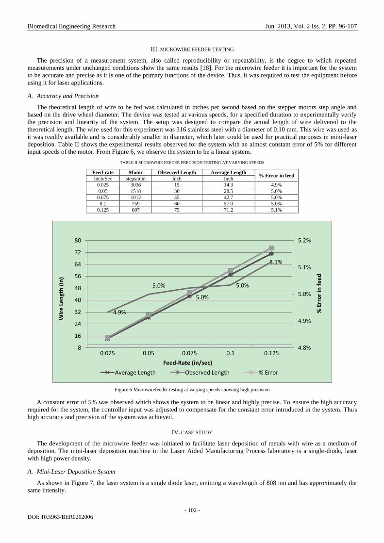
deposition. Table II shows the experimental results observed for the system with an almost constant error of 5% for different
input speeds of the motor. From Figure 6, we observe the system to be a linear system.
TABLE II MICROWIRE FEEDER PRECISION TESTING AT VARYING SPEEDS
Feed-rate Motor Observed Length Average Length % Error in feed
Inch/Sec steps/min Inch Inch
0.025 3036 15 14.3 4.9%
0.05 1518 30 28.5 5.0%
0.075 1012 45 42.7 5.0%
0.1 759 60 57.0 5.0%
0.125 607 75 71.2 5.1%
Figure 6 Microwirefeeder testing at varying speeds showing high precision
A constant error of 5% was observed which shows the system to be linear and highly precise. To ensure the high accuracy
required for the system, the controller input was adjusted to compensate for the constant error introduced in the system. Thus
high accuracy and precision of the system was achieved.
IV. CASE STUDY
The development of the microwire feeder was initiated to facilitate laser deposition of metals with wire as a medium of
deposition. The mini-laser deposition machine in the Laser Aided Manufacturing Process laboratory is a single-diode, laser
with high power density.
A. Mini-Laser Deposition System
As shown in Figure 7, the laser system is a single diode laser, emitting a wavelength of 808 nm and has approximately the
same intensity.
4.9%
5.0%
5.0%
5.0%
5.1%
4.8%
4.9%
5.0%
5.1%
5.2%
8
16
24
32
40
48
56
64
72
80
0.025 0.05 0.075 0.1 0.125
Wir
e L
en
gth
(in
)
Feed-Rate (in/sec)
Average Length Observed Length % Error
% E
rro
r in
fe
ed

Biomedical Engineering Research Jun. 2013, Vol. 2 Iss. 2, PP. 96-107
- 103 -
DOI: 10.5963/BER0202006
Figure 7 Mini-laser deposition experimental arrangement
The laser beam has a focal length of 50 mm along the z-axis and a melt pool size is 0.2 mm when the laser beam is directed
perpendicular on a 316 stainless steel substrate of a 5 mm thickness. The very small melt pool size due to the fine spot of the
laser which is 0.2 mm (200 microns), initiated the development of a fine microwire feeder which is capable of handling wires
of very small sizes with high accuracy and precision. Moreover, the focal length of the beam is just 50 mm, which required the
microwire feeder to be compact and robust. The experimental setup consists of a diode laser with a beam delivery system, a
microwire feeder, and a computer numerically controlled (CNC) table for 3 axes; horizontal motion (x and y axis) and vertical
motion (z axis). The microwire feeder, the single-diode laser, and the CNC table are controlled by a single controller unit,
which helps to make it compatible and ensures high performance. The laser, feeder, and the CNC table are connected to a
single power supply and are controlled by standard G and M codes with modifications to allow for the deposition process. In
addition, the system also includes:
an air cooling system (top and base cooling plates)
a 200X USB camera device to initially guide the wire accurately to the melt pool
vision camera system developed for process observation and video capture
an Argon cover gas
This complete arrangement is the mini-laser deposition system used in the Laser Aided Manufacturing Process laboratory.
The entire system is a table-top system, which requires a 5 foot by 5 foot space and is significantly less expensive than other
laser deposition systems. This helps in targeting small manufacturing industries and helps in making very small parts which
cannot be easily manufactured by using conventional methods.
However, the limitation of this system is that wire of various sizes of different materials is not readily available. Moreover,
due to the extreme small melt pool size, it is limited to the size of parts that can be developed by this system. Due to the
volume of wire fed in the melt pool is approximately equal to the size of the melt-pool itself, the volume causes a high
fluctuation in heat dissipation.
B. Material
The wire used for deposition was 316 stainless steel wire with a 0.125 mm diameter and was chosen due to its resistance to
oxidation and ease of availability for testing purposes. The laser beam was directed perpendicular to the substrate, made of
mild steel with dimensions of 10 mm by 5 mm by 0.2 mm. This thin substrate was selected to study the effectiveness of the
laser, parameters of the system, limitations of the process during deposition and to check the precision and accuracy of the
wire-feeder.
C. Arrangement of the Experiment
The experimental arrangement was set up to feed the wire to the melt pool as shown in Figure 7. Front-feeding implies
when the movement of the substrate is away from the feeder, this was chosen as it is considered to facilitate good clads
[14].The wire was oriented at an angle of 45 degrees from the horizontal surface of the substrate, with the help of an angle
marker provided on the wire feeder. This arrangement was selected to study the efficiency of microwire feeding in laser
deposition [19].
D. Results and Discussion
During the feeding of the wire to the melt pool it was observed that, the wire tends to melt and loosely stick to the substrate
rather than forming a good clad. This can be due to the high volume of wire entering a relatively small volume of melt pool,
Substrate
X
Z
Y
45°
Single diode laser
CNC table traverse direction
50 mm
Front-feeding setup
Microwire
feeder

Biomedical Engineering Research Jun. 2013, Vol. 2 Iss. 2, PP. 96-107
- 104 -
DOI: 10.5963/BER0202006
which chills the melt pool. To address this problem a delay of 0.05 sec was set in the start of wire feeding by the controller,
which ensured a continuous clad. The wire feed rate and traverse speed of the table are critical to achieve a good deposit. Thus
the traverse speed of the table and wire feed rate were varied at maximum constant laser power and observations were made
during the experiment. In the mini-laser deposition system the wire is fed by the controller, thus the wire feed rate is given as
the ratio of wire fed by the microwire feeder per 0.5 inch of the travel of the table. This was done to ensure compatibility in
feeding the wire and having an accurate response time. Table III shows the effect on the clad surface observed by varying the
wire feed rate and traverse speed. These speed and feeds were chosen as the values outside these regions were observed to be
not suitable for the experiment. The qualitative analysis was done by observing the cladding surface under optical microscope,
and a continuous uniform clad was termed to be a good clad. Figure 8 (a), (b), and (c) show the three variations in cladding
observed during the experiment. At a traverse speed of 1.5 inch/min and the wire feed of 0.5 inch/ 0.5 inch of table travel, a
continuous uniform clad was observed; which is the best deposition as seen in Figure 8 (c).
TABLE III EFFECTS ON CLADDING AT VARYING WIRE FEED AND TRAVERSE SPEEDS
Traverse Speed Wire Feed Surface Cladding
Quality inch/min inch/ 0.5 inch of travel
2 0.25 Discontinuous
1.5 0.25 Discontinuous
2 0.375 Non-Uniform
1.5 0.375 Non-Uniform
2 0.5 Discontinuous
1.5 0.5 Uniform
2 0.75 Failed to Melt
1.5 0.75 Failed to Melt
(a) (b)
(c)
Figure 8 (a) Discontinuous track (b) Continuous non-uniform track
(c) Continuous uniform track Deposition of 0.125 mm 316 stainless steel wire on 0.2 mm mild steel substrate
Table III shows the effects of cladding at varying traverse speeds and wire feeds, as per experimental observation. The aim
is to achieve continuous uniform deposition. Discontinuous deposits were observed when the wire fed to the melt pool was not
adequate. It was also observed that when the wire was fed in excess, it tended to sway away from the melt pool due to
resistance in the wire, which was termed as failed to melt in the table. The deposit in the non-uniform and uniform category is
1 1
1
Direction of deposit Direction of deposit
Direction of deposit

Biomedical Engineering Research Jun. 2013, Vol. 2 Iss. 2, PP. 96-107
- 105 -
DOI: 10.5963/BER0202006
in our area of interest, where modifications can be made to facilitate a good uniform continuous deposit.
To verify the uniformity of the deposition obtained in Figure 8 (c), 5 points at equal intervals were selected on the deposit,
and the width of the deposit was measured and compared to Figure 8 (b) as shown in Table IV. The standard deviation was
calculated and found out to be below 2% in uniform deposit as compared to 6.2% in non-uniform deposit. These show the
effect of varying wire feed and traverse speeds on deposition and consolidates the result quantitatively.
TABLE IV DEPOSITION WIDTH OF 0.125 MM 316 STAINLESS STEEL WIRE ON MILD STEEL
Deposition Standard Deviation
Uniform 1.9%
Non-uniform 6.2%
All the results found experimentally were noted down, and a Deposition Process Window was developed as shown in
Figure 9. The dark square region in the figure indicated the parameters by which a good deposit was achieved, the deposition
shown in Figure 8 (c) falls in this category. The grey square indicates the region where a continuous deposit was formed, but
the deposition width is not uniform, as shown in Figure 8 (b). The circular region depicts the zone where the deposits were
discontinuous, as shown in Figure 8 (a), and it defines the boundaries for experimentation.
Figure 9 Boundaries defined for deposition of 0.125 mm 316 stainless steel wire on 0.2 mm mild steel substrate
During deposition of 0.25 mm 316 stainless steel wire on a 0.2 mm mild steel substrate, it was observed that the substrate
tends to warp due to heat conductivity, which can be one of the reasons for non-uniform deposition of wire. Moreover, the
scope of error being extremely small, it can also cause the wire to misalign itself during this process. It is also necessary to
ensure that the surface is flat and the laser remains in focus, as the melt pool size can vary significantly, causing non-uniform
deposition. These factors need to be taken into account, which can affect the deposition, for which the grey square region is
defined in deposition process window in Figure 9. This region is critical for further study. For further experiments, with
varying traverse speed and wire feeds, the ratio of wire feed and traverse speed in the square region should be considered, for
effective deposition. These show the effect of varying speed and wire feed rate on the deposition.
Thus the effectiveness of the microwire feeder in terms of its accuracy and precision of delivering micro-diameter wires to
a very small melt pool to achieve continuous uniform deposition is demonstrated.
V. FUTURE WORK
During; the effective usage of the microwire feeder in practical application, there were no problems observed with feeding
the wire of micro-diameters, which is the primary function of the device. But it was observed that the set up procedure for the
feeding the wire initially from the spool to transfer mechanism; varied largely on the expertise of the person running the
experiment. This was due to the arrangement of the pivot-bearing and the transfer mechanism. The two components are
independent of each other and during the setup for feeding the wire; it causes misalignment of the PTFE tube at the entrance of
the pinch roller. Thus the development of a robust setup mechanism initiated the need for a second generation microwire
feeder.
In the second generation microwire feeder, as shown in Figure 10, the basic mechanisms would remain the same, but the
design would be modified for the ease of set up irrespective of the user expertise. The positioning of the spool, idler and the
motor would remain unchanged, just with an addition of a guide clamp provided between spool and idler for support. The
1
1.5
2
2.5
0 0.25 0.5 0.75 1
Tra
ver
se S
pee
d o
f th
e ta
ble
(in
ch/m
in)
Wire feed length(inch/0.5 inch of travel)
Discontinuous
/failed to melt
deposit
Ccontinuous
non-uniform
deposit
Ccontinuous
uniform
deposit

Biomedical Engineering Research Jun. 2013, Vol. 2 Iss. 2, PP. 96-107
- 106 -
DOI: 10.5963/BER0202006
pivot-bearing arrangement and the transfer mechanism are modified and clamped to become a single unit, held by a pivot-
clamp and spring arrangement. This would ensure accurate alignment required during setup. This design focuses on
automation where the user can place the wire in the V-groove of the bearing and the motor would drive the wire through the
PTFE tubing. This would help in reducing the setup time in applications which requires part manufacturing flexibility.
Figure 10 Second generation microwire feeder for ease of setup
VI. CONCLUSION
The design and development of microwire feeders, capable of handling microdiameter wires is often considered to be
difficult due to its low buckling strength and high precision required for laser application usage. There are wire feeders which
can feed wires as low as 0.25 mm diameter. Thus the need for systematically developing a wire feeder capable of handling
wires as low as 0.05 mm was initiated. In this paper, the design and embodiment of a fine microwire feeder for laser
applications, capable of handling wires as low as 0.05 mm was discussed. This was done by integrating four different sub-
mechanisms: feeding mechanism, transfer mechanism, precision guidance mechanism and adjustment mechanism. These
mechanisms facilitated the compactness, flexibility and high precision requirements for varying laser applications. This
microwire feeder was tested for its accuracy and precision which was experimentally verified to be 95 % precise. A case study
on mini-laser deposition was presented to verify the effectiveness of the microwire feeder, where a 0.125 mm wire was fed into
a melt pool of 0.2 mm. The effect on deposition quality with varying wire feed rate and table traverse speed were studied to
obtain a continuous uniform deposit. The results show standard deviation of deposition width between a uniform and non-
uniform continuous deposit. Thus the validity and effectiveness of the microwire feeder in terms of its accuracy and precision
of delivering micro-diameter wires to very small melt pool sizes in laser applications is experimentally verified.
ACKNOWLEDGMENTS
This research was supported by national Science Foundation Grant IIP-1046492, Intelligent Systems Centerand Material
Research Center at Missouri University of Science and Technology. Their support is greatly appreciated.
REFERENCES
[1] Salminen, A. S., Kujanpää, V.P. 2003. Effect of wire feed position on laser welding with filler wire. Journal of Laser
Applications - Volume 15, Issue 1, pp. 2-10.
[2] Kim, J.-D. and Y. Peng, 2000. “Plunging method for Nd: YAG laser cladding with wire feeding,” Opt Laser Eng, vol. 33,
no. 4, pp. 299–309.
[3] Syed, W. and L. Li, 2005. “Effects of wire feeding direction and location in multiple layer diode laser direct metal
deposition,” Appl Surf Sci, vol. 248, pp. 518–524.
[4] Moures, F., E. Cicala, P. Sallamand, D. Grevey, B. Vannes, and S. Ignat, 2005. “Optimisation of refractory coatings
realised with cored wire addition using a high-power diode laser,” Int J Mach Tool Manu, vol. 200, pp. 2283–2292.
[5] Mok, S., G. Bi, J. Folkes, and I. Pashby, 2008. Deposition of Ti6Al4V using a high power diode laser and wire, Part I:
Investigation on the process characteristics,” Surf Coat Technol, vol. 202, pp. 3933–3939.

Biomedical Engineering Research Jun. 2013, Vol. 2 Iss. 2, PP. 96-107
- 107 -
DOI: 10.5963/BER0202006
[6] Mok, S., G. Bi, J. Folkes, I. Pashby, and J. Segal, 2008. “Deposition of Ti6Al4V using a high power diode laser and wire,
Part II: Investigation on the mechanical properties,” Surf Coat Technol, vol. 202, pp. 4613–4619.
[7] Miranda, R., G. Lopes, L. Quintino, J. Rodrigues, and S. Williams, 2008. “Rapid prototyping with high power fiber lasers,”
Mater Design, vol. 29, pp. 2072–2075.
[8] Cao, X., M. Jahazi, J. Fournier, and M. Alain, 2008. “Optimization of bead spacing during laser cladding of ZE41A-T5
magnesium alloy castings,” J Mater Process Technol, vol. 205, pp. 322–331.
[9] Medrano, A., J. Folkes, J. Segal, and I. Pashby, 2009. “Fibre laser metal deposition with wire: parameters study and
temperature monitoring system,” in Proceedings of the SPIE, vol. 7131, p. 713122.
[10] Heralic, Almir, 2012. Monitoring and Control of Robotized Laser Metal-Wire Deposition, Ph.D. dissertation, Chalmers
University of Technology, Sweden.
[11] Kobryn, P. A., 2000. Moore, E.H., Semiatin, S. L. Scripta Mater. 43, 299.
[12] Syed, W. H., Pinkerton, A. J., Li, L. 2005. A comparative study of wire feeding and powder feeding in direct diode laser
deposition for rapid prototyping. Applied Surface Science 247, 268–276.
[13] Brandon, E. D. 1995. Development of a Precision Wire Feeder for Small-Diameter Wire. Mechanical Processes
Engineering Sandia National Laboratories.
[14] Syed, W. H., Li, L. 2005. Effects of wire feeding direction and location in multiple layer diode laser direct metal
deposition. Applied Surface Science 248, 518-524.
[15] Schneidereit, H., Schilling, M. 1996. Determining the minimum number of rollers for wire straightening units. Wire
Industry Vol63, Issue 775, pp. 769-771.
[16] Anderson, C. 2006. Advances in wire-feeder technology: what you need to know. Welding Design & Fabrication 79.3.
[17] Weast, R.C. 1965-1966. Handbook of Chemistry and Physics. 46th
Edition; pp F12-4.
[18] Taylor, J. R. 1999. An Introduction to Error Analysis: The Study of Uncertainties in Physical Measurements. University
Science Books. pp. 128–129.
[19] Mok, S. H., Bi, G., Folkes, J., Pashby, I., Segal, J. 2008. Deposition of Ti–6Al–4V using a high power diode laser and wire,
Part II: Investigation on the mechanical properties. Surface & Coating Technology 202, 3933-3939.