MIC7400/1 Programming Board User's Guide - Microchip ...
28
2017 Microchip Technology Inc. DS50002593A MIC7400/1 Programming Board User’s Guide
-
Upload
khangminh22 -
Category
Documents
-
view
0 -
download
0
Transcript of MIC7400/1 Programming Board User's Guide - Microchip ...

2017 Microchip Technology Inc. DS50002593A
MIC7400/1Programming Board
User’s Guide

DS50002593A-page 2 2017 Microchip Technology Inc.
Information contained in this publication regarding deviceapplications and the like is provided only for your convenienceand may be superseded by updates. It is your responsibility toensure that your application meets with your specifications.MICROCHIP MAKES NO REPRESENTATIONS ORWARRANTIES OF ANY KIND WHETHER EXPRESS ORIMPLIED, WRITTEN OR ORAL, STATUTORY OROTHERWISE, RELATED TO THE INFORMATION,INCLUDING BUT NOT LIMITED TO ITS CONDITION,QUALITY, PERFORMANCE, MERCHANTABILITY ORFITNESS FOR PURPOSE. Microchip disclaims all liabilityarising from this information and its use. Use of Microchipdevices in life support and/or safety applications is entirely atthe buyer’s risk, and the buyer agrees to defend, indemnify andhold harmless Microchip from any and all damages, claims,suits, or expenses resulting from such use. No licenses areconveyed, implicitly or otherwise, under any Microchipintellectual property rights unless otherwise stated.
Note the following details of the code protection feature on Microchip devices:
• Microchip products meet the specification contained in their particular Microchip Data Sheet.
• Microchip believes that its family of products is one of the most secure families of its kind on the market today, when used in the intended manner and under normal conditions.
• There are dishonest and possibly illegal methods used to breach the code protection feature. All of these methods, to our knowledge, require using the Microchip products in a manner outside the operating specifications contained in Microchip’s Data Sheets. Most likely, the person doing so is engaged in theft of intellectual property.
• Microchip is willing to work with the customer who is concerned about the integrity of their code.
• Neither Microchip nor any other semiconductor manufacturer can guarantee the security of their code. Code protection does not mean that we are guaranteeing the product as “unbreakable.”
Code protection is constantly evolving. We at Microchip are committed to continuously improving the code protection features of ourproducts. Attempts to break Microchip’s code protection feature may be a violation of the Digital Millennium Copyright Act. If such actsallow unauthorized access to your software or other copyrighted work, you may have a right to sue for relief under that Act.
Microchip received ISO/TS-16949:2009 certification for its worldwide headquarters, design and wafer fabrication facilities in Chandler and Tempe, Arizona; Gresham, Oregon and design centers in California and India. The Company’s quality system processes and procedures are for its PIC® MCUs and dsPIC® DSCs, KEELOQ® code hopping devices, Serial EEPROMs, microperipherals, nonvolatile memory and analog products. In addition, Microchip’s quality system for the design and manufacture of development systems is ISO 9001:2000 certified.
QUALITYMANAGEMENTSYSTEMCERTIFIEDBYDNV
== ISO/TS16949==
Trademarks
The Microchip name and logo, the Microchip logo, AnyRate, dsPIC, FlashFlex, flexPWR, Heldo, JukeBlox, KeeLoq, KeeLoq logo, Kleer, LANCheck, LINK MD, MediaLB, MOST, MOST logo, MPLAB, OptoLyzer, PIC, PICSTART, PIC32 logo, RightTouch, SpyNIC, SST, SST Logo, SuperFlash and UNI/O are registered trademarks of Microchip Technology Incorporated in the U.S.A. and other countries.
ClockWorks, The Embedded Control Solutions Company, ETHERSYNCH, Hyper Speed Control, HyperLight Load, IntelliMOS, mTouch, Precision Edge, and QUIET-WIRE are registered trademarks of Microchip Technology Incorporated in the U.S.A.
Analog-for-the-Digital Age, Any Capacitor, AnyIn, AnyOut, BodyCom, chipKIT, chipKIT logo, CodeGuard, dsPICDEM, dsPICDEM.net, Dynamic Average Matching, DAM, ECAN, EtherGREEN, In-Circuit Serial Programming, ICSP, Inter-Chip Connectivity, JitterBlocker, KleerNet, KleerNet logo, MiWi, motorBench, MPASM, MPF, MPLAB Certified logo, MPLIB, MPLINK, MultiTRAK, NetDetach, Omniscient Code Generation, PICDEM, PICDEM.net, PICkit, PICtail, PureSilicon, RightTouch logo, REAL ICE, Ripple Blocker, Serial Quad I/O, SQI, SuperSwitcher, SuperSwitcher II, Total Endurance, TSHARC, USBCheck, VariSense, ViewSpan, WiperLock, Wireless DNA, and ZENA are trademarks of Microchip Technology Incorporated in the U.S.A. and other countries.
SQTP is a service mark of Microchip Technology Incorporated in the U.S.A.
Silicon Storage Technology is a registered trademark of Microchip Technology Inc. in other countries.
GestIC is a registered trademarks of Microchip Technology Germany II GmbH & Co. KG, a subsidiary of Microchip Technology Inc., in other countries.
All other trademarks mentioned herein are property of their respective companies.
© 2017, Microchip Technology Incorporated, Printed in the U.S.A., All Rights Reserved.
ISBN: 978-1-5224-2168-9

EU Declaration of Conformity This declaration of conformity is issued by the manufacturer. The development/evaluation tool is designed to be used for research and development in a laboratory environment. This development/evaluation tool is not a Finished Appliance, nor is it intended for incorporation into Finished Appliances that are made commercially available as single functional units to end users under EU EMC Directive 2004/108/EC and as supported by the European Commission's Guide for the EMC Directive 2004/108/EC (8th February 2010). This development/evaluation tool complies with EU RoHS2 Directive 2011/65/EU. This development/evaluation tool, when incorporating wireless and radio-telecom functionality, is in compliance with the essential requirement and other relevant provisions of the R&TTE Directive 1999/5/EC and the FCC rules as stated in the declaration of conformity provided in the module datasheet and the module product page available at www.microchip.com. For information regarding the exclusive, limited warranties applicable to Microchip products, please see Microchip’s standard terms and conditions of sale, which are printed on our sales documentation and available at www.microchip.com. Signed for and on behalf of Microchip Technology Inc. at Chandler, Arizona, USA.
Object of Declaration: MIC7400/1 Programming Board User’s Guide
2017 Microchip Technology Inc. DS50002593A-page 3

MIC7400/1 Programming Board User’s Guide
NOTES:
DS50002593A-page 4 2017 Microchip Technology Inc.

MIC7400/1PROGRAMMING BOARD
USER’S GUIDE
Table of Contents
Preface ........................................................................................................................... 6
Chapter 1. Product Overview1.1 Introduction ................................................................................................... 101.2 MIC7400/1 Programming Board Short Overview ......................................... 101.3 MIC7400/1 Programming Board Key Features ............................................ 101.4 What is the MIC7400/1 Programming Board? .............................................. 101.5 What does the MIC7400/1 Programming Board kit include? ....................... 11
Chapter 2. Installation and Operation2.1 Introduction ................................................................................................... 122.2 MIC7400/1 Programming Board – Overview ................................................ 122.3 MIC7400/1 Programming Board Connectors ............................................... 132.4 Using the MIC7400/1 Programming Board .................................................. 142.5 Typical Usage Examples .............................................................................. 16
Appendix A. Schematic and LayoutsA.1 Introduction .................................................................................................. 20A.2 Board – Schematic ....................................................................................... 21A.3 Board – Top Silk ........................................................................................... 22A.4 Board – Top Copper and Silk ....................................................................... 22A.5 Board – Top Copper ..................................................................................... 23A.6 Board – Bottom Copper ............................................................................... 23A.7 Board – Bottom Copper and Silk ................................................................. 24A.8 Board – Bottom Silk ..................................................................................... 24
Appendix B. Bill of Materials (BOM)
Worldwide Sales and Service .................................................................................... 28
2017 Microchip Technology Inc. DS50002593A-page 5
MIC7400/1 Programming Board User’s Guide
NOTES:
DS50002593A-page 6 2017 Microchip Technology Inc.

MIC7400/1PROGRAMMING BOARD
USER’S GUIDE
Preface
INTRODUCTIONThis chapter contains general information that will be useful to know before using the MIC7400/1 Programming Board. Items discussed in this chapter include:
• Document Layout• Conventions Used in this Guide
•
• Recommended Reading• The Microchip Web Site• Customer Support• Document Revision History
DOCUMENT LAYOUTThis document describes how to use the MIC7400/1 Programming Board as a development tool to emulate and debug firmware on a target board. The manual layout is as follows:
• Chapter 1. “Product Overview” – Important information about the MIC7400/1 Programming Board.
• Chapter 2. “Installation and Operation” – Provides a detailed overview of the MIC7400/1 Programming Board main hardware components and connectors; includes an in-depth account of the MIC7400/1 Programming Board modes of operation, and the board’s typical usage scenarios.
• Appendix A. “Schematic and Layouts” – Shows the schematic and layout diagrams for the MIC7400/1 Programming Board.
• Appendix B. “Bill of Materials (BOM)” – Lists the parts used to build the MIC7400/1 Programming Board.
NOTICE TO CUSTOMERS
All documentation becomes dated, and this manual is no exception. Microchip tools and documentation are constantly evolving to meet customer needs, so some actual dialogs and/or tool descriptions may differ from those in this document. Please refer to our website (www.microchip.com) to obtain the latest documentation available.
Documents are identified with a “DS” number. This number is located on the bottom of each page, in front of the page number. The numbering convention for the DS number is “DSXXXXXXXXA”, where “XXXXXXXX” is the document number and “A” is the revision level of the document.
For the most up-to-date information on development tools, see the MPLAB® IDE online help. Select the Help menu, and then Topics, to open a list of available online help files.
2017 Microchip Technology Inc. DS50002593A-page 7

MIC7400/1 Programming Board User’s Guide
CONVENTIONS USED IN THIS GUIDE
This manual uses the following documentation conventions:
DOCUMENTATION CONVENTIONS
Description Represents Examples
Arial font:
Italic characters Referenced books MPLAB® IDE User’s Guide
Emphasized text ...is the only compiler...
Initial caps A window the Output window
A dialog the Settings dialog
A menu selection select Enable Programmer
Quotes A field name in a window or dialog
“Save project before build”
Underlined, italic text with right angle bracket
A menu path File>Save
Bold characters A dialog button Click OK
A tab Click the Power tab
N‘Rnnnn A number in verilog format, where N is the total number of digits, R is the radix and n is a digit.
4‘b0010, 2‘hF1
Text in angle brackets < > A key on the keyboard Press <Enter>, <F1>
Courier New font:
Plain Courier New Sample source code #define START
Filenames autoexec.bat
File paths c:\mcc18\h
Keywords _asm, _endasm, static
Command-line options -Opa+, -Opa-
Bit values 0, 1
Constants 0xFF, ‘A’
Italic Courier New A variable argument file.o, where file can be any valid filename
Square brackets [ ] Optional arguments mcc18 [options] file [options]
Curly brackets and pipe character: { | }
Choice of mutually exclusive arguments; an OR selection
errorlevel {0|1}
Ellipses... Replaces repeated text var_name [, var_name...]
Represents code supplied by user
void main (void){ ...}
DS50002593A-page 8 2017 Microchip Technology Inc.

Preface
RECOMMENDED READING
This user’s guide describes how to use the MIC7400/1 Programming Board. Other useful documents are listed below. The following Microchip documents are available and recommended as a supplemental reference resource:
• MIC7400 Data Sheet, Revision 1.0
• MIC7401 Data Sheet, Revision 1.0
• MIC7400 Evaluation Board User’s Guide, Revision 1.0
• MIC7401 Evaluation Board User’s Guide, Revision 1.0
THE MICROCHIP WEB SITE
Microchip provides online support via our web site at www.microchip.com. This website is used as a means to make files and information easily available to customers. Acces-sible by using your favorite Internet browser, the web site contains the following infor-mation:
• Product Support – Data sheets and errata, application notes and sample programs, design resources, user’s guides and hardware support documents, latest software releases and archived software
• General Technical Support – Frequently Asked Questions (FAQs), technical support requests, online discussion groups, Microchip consultant program member listing
• Business of Microchip – Product selector and ordering guides, latest Microchip press releases, listing of seminars and events, listings of Microchip sales offices, distributors and factory representatives
PRODUCT CHANGE NOTIFICATION SERVICE
Microchip’s customer notification service helps keep customers current on Microchip products. Subscribers will receive e-mail notifications whenever there are changes, updates, revisions or errata related to a specified product family or development tool of interest.
To register, access the Microchip website at www.microchip.com, click on Product Change Notification and follow the registration instructions.
CUSTOMER SUPPORT
Users of Microchip products can receive assistance through several channels:
• Distributor or Representative
• Local Sales Office
• Field Application Engineer (FAE)
• Technical Support
Customers should contact their distributor, representative or field application engineer (FAE) for support. Local sales offices are also available to help customers. A listing of sales offices and locations is included in the back of this document.
Technical support is available through the web site at: http://www.microchip.com/support.
DOCUMENT REVISION HISTORY
Revision A (September 2017)
• Initial Release of this Document.
2017 Microchip Technology Inc. DS50002593A-page 9

MIC7400/1PROGRAMMING BOARD
USER’S GUIDE
Chapter 1. Product Overview
1.1 INTRODUCTION
This chapter provides an overview of the MIC7400/1 Programming Board and covers the following topics:
• MIC7400/1 Programming Board Short Overview
• MIC7400/1 Programming Board Key Features
• What Is the MIC7400/1 Programming Board?
• What Does the MIC7400/1 Programming Board kit Include?
1.2 MIC7400/1 PROGRAMMING BOARD SHORT OVERVIEW
The MIC7400/1 Programming Board is designed to demonstrate the MIC7400/1 Power Management IC (PMIC) when programmed by a microcontroller, using an easy-to-understand interface. The board offers increased functionality by the addition of an on-board EEPROM and allows the user to copy, store and also reprogram all the registers in the MIC7400/1 devices.
1.3 MIC7400/1 PROGRAMMING BOARD KEY FEATURES
The MIC7400/1 Programming Board has the following features:
• Power options: stand-alone battery powered by one-coin cell (CR2032), USB or external 5V source
• On-board EEPROM(2K) for MIC7400/1’s parameters backup and reprogramming
• 8 modes of operation for extensive functionality
• Power-Good live LED indicators for all 6 outputs
• LCD screen with intuitive text for an easy-to-use experience
• MIC7400/1 device cloning when interfaced with the MIC7400/1 GUI, using the MIC2221 integrated on the MIC7400 and MIC7401 Evaluation Boards.
1.4 WHAT IS THE MIC7400/1 PROGRAMMING BOARD?
The MIC7400/1 Programming Board is used to demonstrate the Microchip Technology, Inc., MIC7400/1 PMIC on-the-fly programmability by a microcontroller. The MIC7400/1 Programming Board is used to:
• copy and store the content of the MIC7400/1’s internal EEPROM into the on-board EEPROM
• program a new MIC7400/1 with the stored configuration
• modify the output voltages and current limits for both Normal and Stand-by modes
• program the regulators outputs start-up sequence and the delay between them.
The LCD interface is user friendly and intuitive, with all the information needed being provided on the screen. A rotary switch is used to change modes of operation.
2017 Microchip Technology Inc. DS50002593A-page 10

MIC7400/1 Programming Board User’s Guide
1.5 WHAT DOES THE MIC7400/1 PROGRAMMING BOARD KIT INCLUDE?
The MIC7400/1 Programming Board kit includes the following items:
• MIC7400/1 Programming Board (ADM00760)
• Important Information Sheet
DS50002593A-page 11 2017 Microchip Technology Inc.

MIC7400/1PROGRAMMING BOARD
USER’S GUIDE
Chapter 2. Installation and Operation
2.1 INTRODUCTION
This chapter details the components, setup and utilization of the MIC7400/1 Program-ming Board.
2.2 MIC7400/1 PROGRAMMING BOARD – OVERVIEW
The main components of the MIC7400/1 Programming Board are:
• Battery ON/OFF switch - used to turn on the MIC7400/1 Programming Board while being powered by the on-board coin-cell battery
• PIC16F1509 - the main controller of the MIC7400/1 Programming Board that communicates with the MIC7400/1 and the LCD display, as well as interfacing with other on-board hardware peripherals, such as the LED indicators, switches and potentiometers
• LCD display - shows information relevant to the mode selected, depending on the action taken by means of the Select switch
• PG1 to PG 6 LEDs used to indicate if the MIC7400/1 output voltages are above 91% of the target value. This information is read from the MIC7400/1 Power-Good Register (00'h)
• Select switch - used to select the desired mode of operation
• Voltage and Current potentiometers used for selecting:
- voltage and current, while in modes 1-6
- channel and sequence (with SEL set to NORM), or sequence delay (with SEL set to STBY), while in mode 7
• READ button:
- used to copy the MIC7400/1 internal EEPROM into the on-board EEPROM, while in mode 0
- switching operating states, from Normal to Standby and vice-versa, while in modes 1-6
• WRITE button:
- used to copy the content of the on-board EEPROM into the MIC7400/1 internal EEPROM, while in mode 0 (registers 02'h - 23'h)
- in modes 1-6: used to write the selected voltage to the MIC7400/1 volatile memory and the on-board EEPROM
- in mode 7: used to save the channel and start-up delay to the MIC7400/1 vol-atile memory and the internal EEPROM
• SEL switch:
- used to select between Normal and Standby operation while writing the desired voltages and currents, in modes 1-6
- used to select between changing the channel sequence and sequence delay, in mode 7
• 2 Kbit of EEPROM for easy copy, back-up and restore of the MIC7400/1 internal registers
• an on-board battery (CR2032) for stand-alone usage. The MCP1624 Boost
2017 Microchip Technology Inc. DS50002593A-page 12

MIC7400/1 Programming Board User’s Guide
Converter is used to create a regulated 5V supply for MIC7400/1 Program-ming Board. It boosts the coin-cell voltage (3V nominal) to the 5V needed by the LCD, EEPROM and the microcontroller. This voltage is also available on the J2 (if a jumper is placed on J7) connector (see Figure 2-2).
FIGURE 2-1: MIC7400/1 Programming Board Top View – Main Hardware Components.
There are four options of powering up the MIC7400/1 Programming Board:
• the on-board coin cell with the MCP1624 boost converter
• the USB power supply via a micro USB connector
• external power supply (requires 5V stable power supply)
• J2 header (by connecting a jumper to J7)
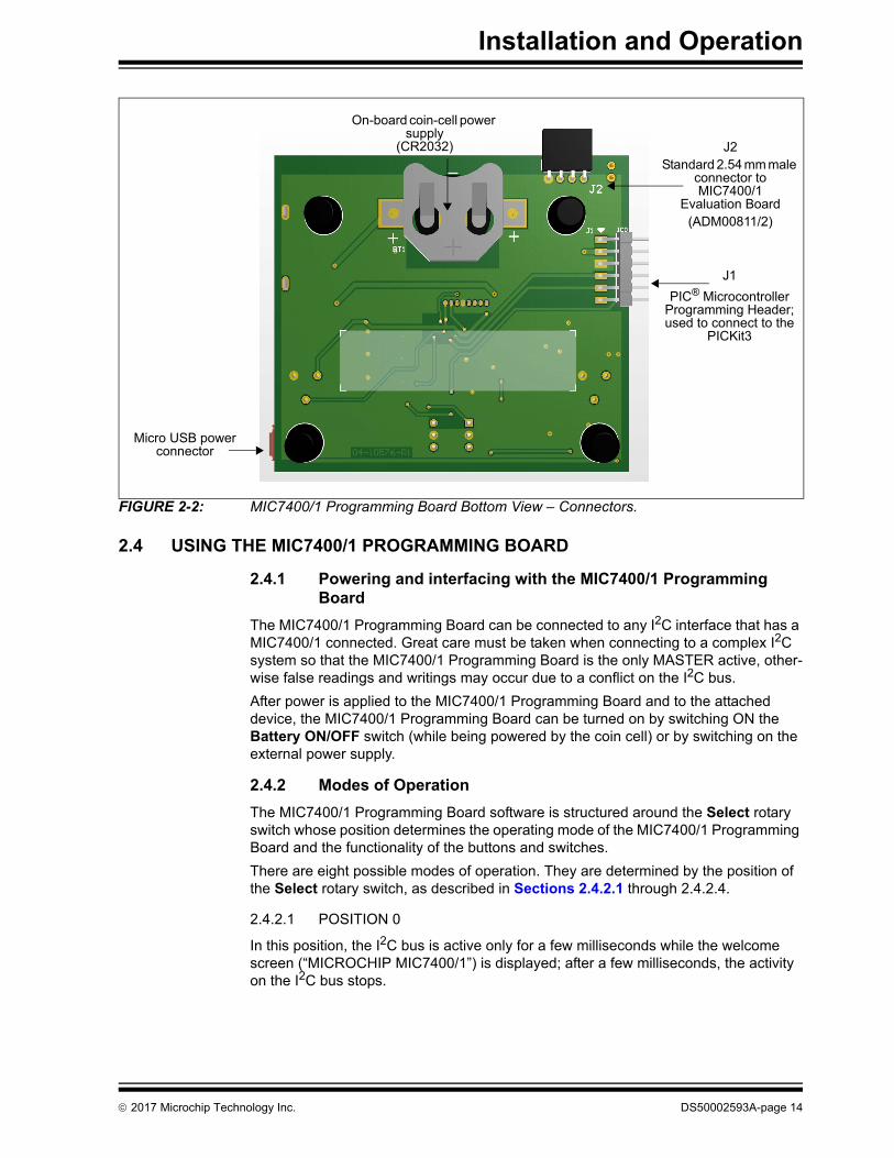
2.3 MIC7400/1 PROGRAMMING BOARD CONNECTORS
The MIC7400/1 Programming Board comes equipped with a standard 2.54 mm male connector for easy interfacing with the MIC7400/1 Evaluation Boards (ADM00811 and ADM00812). In order to enable communication with the MIC74001 GUI, the Programming Board must be connected to the MIC7400/1 Evaluation Board (using J2) and the Evaluation Board must be connected to a PC via USB.
To be recognized by the MIC7400/1 GUI, the on-board EEPROM must first be initialized (by reading any MIC7400/1 device).
LED display
Voltage setpotentiometer
READbutton
WRITEbutton
Selectrotaryswitch
SELswitch
Current setpotentiometer
Battery ON/OFF switch
PG1-6 (Power-Good)
LEDs
PIC16F1509Memory serial 2k EEPROM
MCP1624 boost DC-DC
External USB power option
NOTICE
In order to prevent conflict on the I2C bus, the Select switch must be moved to position 0 before connecting the MIC700/1 Evaluation Boards.
DS50002593A-page 13 2017 Microchip Technology Inc.
Installation and Operation
FIGURE 2-2: MIC7400/1 Programming Board Bottom View – Connectors.
2.4 USING THE MIC7400/1 PROGRAMMING BOARD
2.4.1 Powering and interfacing with the MIC7400/1 Programming Board
The MIC7400/1 Programming Board can be connected to any I2C interface that has a MIC7400/1 connected. Great care must be taken when connecting to a complex I2C system so that the MIC7400/1 Programming Board is the only MASTER active, other-wise false readings and writings may occur due to a conflict on the I2C bus.
After power is applied to the MIC7400/1 Programming Board and to the attached device, the MIC7400/1 Programming Board can be turned on by switching ON the Battery ON/OFF switch (while being powered by the coin cell) or by switching on the external power supply.
2.4.2 Modes of Operation
The MIC7400/1 Programming Board software is structured around the Select rotary switch whose position determines the operating mode of the MIC7400/1 Programming Board and the functionality of the buttons and switches.
There are eight possible modes of operation. They are determined by the position of the Select rotary switch, as described in Sections 2.4.2.1 through 2.4.2.4.
2.4.2.1 POSITION 0
In this position, the I2C bus is active only for a few milliseconds while the welcome screen (“MICROCHIP MIC7400/1”) is displayed; after a few milliseconds, the activity on the I2C bus stops.
J2Standard 2.54 mm male
connector to MIC7400/1
Evaluation Board(ADM00811/2)
Micro USB power connector
J1
PIC® Microcontroller Programming Header; used to connect to the
PICKit3
On-board coin-cell power supply
(CR2032)
2017 Microchip Technology Inc. DS50002593A-page 14

MIC7400/1 Programming Board User’s Guide
In order to read the on-board EEPROM, the device address in the MIC7400/1 GUI must be changed to 0b1010000x (50h).
When not using the MIC2221 integrated on the MIC7400/1 Evaluation Board, the READ button can be used to read the content of the MIC7400/1 internal EEPROM and copy it to the on-board EEPROM. The PG 1-6 LEDs will light up in sequence to signal the start of the reading process and a “Reading...” message will be displayed on the LCD screen. If the action is successful, a message (“DONE”) will briefly be displayed on the screen and the I2C activity will stop.
When not using the MIC2221 integrated on the MIC7400/1 Evaluation Board, the WRITE button can be used to write the content of the on-board EEPROM to the MIC7400/1 internal EEPROM. The PG 1-6 LEDs will light up in sequence to signal the start of the writing process and a “Writing...” message will appear on the LCD screen. If the action is successful, the message “DONE” will briefly be displayed on the screen and the I2C activity will stop.
If a read/write action cannot be started, due to an error on the I2C bus or to the MIC7400/1 not responding, an “ERROR” message will appear on the screen and all PG1-6 LEDs will flash five times, after which the I2C bus activity stops.
If a read/write action is started but cannot be completed, an “Action not comp.” mes-sage will be displayed on the screen and all PG 1 – 6 LEDs will flash five times, after which the I2C bus activity stops.
2.4.2.2 POSITIONS 1-6
In this mode, the Voltage and Current potentiometers can be used to set the voltage and the current limit of the selected regulator. Mode selection is done by means of the SEL switch, which enables writing to either the Standby (STBY) or Normal (NORM) mode of operation. Using the Read button, the current mode of operation for the attached MIC7400/1 can be changed.
After the desired voltage and current limit have been selected, press the WRITE button to write the new values to the MIC7400/1 temporary register and to the on-board EEPROM. These values will not be saved directly into the internal EEPROM of the MIC7400/1 and can be canceled by performing a power-down/power-up sequence. To save the newly-input values into the MIC7400/1 internal EEPROM, the Select switch must be changed to position 0 and the WRITE button must be pressed.
2.4.2.3 POSITION 7
This mode is used to assign each selected converter to the selected sequence and the delay between sequences.
When the SEL switch is set to NORM:
- the channel (buck or boost) can be selected with the Voltage potentiometer
- the sequence can be selected with the Current potentiometer
Once the desired channel and sequence have been selected, press the WRITE button to send the new configuration to the MIC7400/1 and to the on-board EEPROM. Flashing the PG LEDs 2 times confirms that the write action has been completed successfully.
Note: The integrated MCP2221 on the MIC7400/1 Evaluation Board can only be used while the MIC7400/1 Programming Board is in this mode, so there is no conflict between the microcontroller and the MCP2221. While using the MCP2221 (using the GUI to program the on-board EEPROM), pressing the READ or WRITE buttons is not advised.
DS50002593A-page 15 2017 Microchip Technology Inc.

Installation and Operation
Switching SEL to STBY selects the sequence delay from 0 ms to 7 ms, by using the Current potentiometer. The configuration can be saved by pressing the WRITE button. Flashing the PG LEDs 2 times confirms that the write action has been completed successfully.
2.4.2.4 PG 1-6 (Power-Good) Status LEDs
The MIC7400/1 Programming Board is equipped with six green LEDs used to indicate the Power-Good status of the MIC7400/1 converters. These LEDs use the internal Power Good Register (00h) to determine the status of all six converters and work only when the board is in mode 1-7 (in mode 0 there is no activity on the I2C bus).
2.5 TYPICAL USAGE EXAMPLES
2.5.1 Configure Device Settings and Upload Them to the MIC7400/1 EEPROM
Configuring the device settings by means of the Voltage and Current potentiometers is the most basic functionality of the MIC7400/1 Programming Board. Next are the steps necessary for configuring:
• connect the MIC7400/1 Programming Board to the desired MIC7400/1 via J2 con-nector (refer to Figure 2-2)
• power the MIC7400/1 Programming Board and the desired MIC7400/1
• bring the Select switch to position 0
• press the READ button to copy the MIC7400/1 registers to the MIC7400/1 Pro-gramming Board’s EEPROM. The successful completion of the action is con-firmed by a “DONE” message displayed on the screen (refer to Section 2.4.2.1 “Position 0”). This action is necessary in order to maintain the register values that are not modified by the board
• choose the desired channel by rotating the Select switch to a position that ranges from 1 to 6
• with the desired channel selected, choose the mode of operation (Stand-by or Normal) to which the configuration should be saved, by using the SEL switch
• use the Voltage and Current potentiometers to select the desired output voltage and current limit, respectively
• press the WRITE button to save the new configuration to the MIC7400/1 tempo-rary memory and the on-board EEPROM.
• to copy the on-board EEPROM into the permanent MIC7400/1 internal EEPROM:
- the Select switch must be changed to position 0
- the WRITE button must be pressed
At any point, if the MIC7400/1 is powered down or reset, all settings in the temporary memory will be lost, but these will still be present in the on-board EEPROM, so that a write cycle to MIC7400/1 will restore and save them.
Note that regardless if the MIC7400/1 is connected to the MIC7400/1 Programming Board or not, the on-board EEPROM will still be written to.
2.5.2 Copy the Settings from the MIC7400/1 GUI to the MIC7400/1 Programming Board, Then Upload Them to Any MIC7400/1 EEPROM
If the MIC7400/1 configurations have already been done and saved using the MIC7400/1 GUI, the user can save all the registers to the MIC7400/1 Programming Board’s EEPROM and then program other MIC7400/1 devices without the help of the MIC7400/1 GUI.
2017 Microchip Technology Inc. DS50002593A-page 16

MIC7400/1 Programming Board User’s Guide
2.5.2.1 MIC7400/1 GUI SETTINGS TO THE MIC7400/1 PROGRAMMING BOARD EEPROM
To copy the MIC7400/1 GUI configurations to the MIC7400/1 Programming Board, this sequence must be used:
• if the MIC7400/1 Programming Board was previously used to read the registers of a MIC7400/1, these steps will be optional; otherwise, the board must first be ini-tialized (by reading a MIC7400/1):
- connect a MIC7400/1 to the MIC7400/1 Programming Board via J2 connector (refer to Figure 2-2).
- power the desired MIC7400/1 and the MIC7400/1 Programming Board
- bring the Select switch to position 0
- press the READ button. The successful completion of the action is confirmed by a “DONE” message displayed on the screen. Refer to Section 2.4.2.1 “Position 0”
• connect any MIC7400/1 Evaluation Board by using the standard 2.54 mm female header situated on the board's top left corner (J2) and power the MIC7400/1 Pro-gramming Board
• rotate the Select switch to position 0
• connect the MIC7400/1 Evaluation Board to the GUI by using a USB cable
• start the MIC7400/1 GUI
• select the desired configuration
• in the MIC7400/1 GUI, click the ScanAddr button. In the Addr box, two devices should be detected: the MIC7400/1 PMIC (address 0x30, if powered) and the MIC7400/1 Programming Board on-board EEPROM (address: 0x50). Select the 0x50 address and press Connect button.
• go to the OPERATION section and click the WriteAll button. For additional infor-mation, refer to the MIC7400/MIC7401 Evaluation Board User’s Guide
2.5.2.2 MIC7400/1 PROGRAMMING BOARD SETTINGS TO ANY MIC7400/1 DEVICE
To upload the MIC7400/1 Programming Board configurations to any MIC7400/1 device, the following steps must be taken:
• connect a MIC7400/1 device to the MIC7400/1 Programming Board via J2 con-nector (refer to Figure 2-2)
• power the MIC7400/1 and the MIC7400/1 Programming Board
• bring the Select switch to position 0
• press the WRITE button; the successful completion of the action is confirmed by a “DONE” message. Refer to Section 2.4.2.1 “Position 0” for more information
2.5.3 Copy the Configuration across Multiple MIC7400/1 Devices; Export the Configuration to the MIC7400/1 GUI
The MIC7400/1 Programming Board can be used to copy the configuration of a MIC7400/1 device to another MIC7400/1 device, as well as, export the register values written in the board’s EEPROM to the MIC7400/1 GUI.
DS50002593A-page 17 2017 Microchip Technology Inc.

Installation and Operation
2.5.3.1 MIC7400/1 DEVICE TO MIC7400/1 DEVICE
To copy the configuration of a MIC7400/1 to another MIC7400/1, this sequence must be applied:
• connect the MIC7400/1 with the desired settings to the MIC7400/1 Programming Board via J2 connector
• power both the desired MIC7400/1 and the MIC7400/1 Programming Board
• rotate the Select switch to position 0
• press the READ button; the successful completion of the action is confirmed by a a “DONE” message. See Section 2.4.2.1 “Position 0”
• disconnect the MIC7400/1 Programming Board and reconnect it to the MIC7400/1 that the configuration needs to be transferred to
• power both the successive MIC7400/1 and the MIC7400/1 Programming Board
• make sure the board Select switch is in position 0
• press the WRITE button; a “DONE” message confirms that the action was suc-cessfully completed. See Section 2.4.2.1 “Position 0”
2.5.3.2 MIC7400/1 PROGRAMMING BOARD EEPROM TO MIC7400/1 GUI
To export the settings from the MIC7400/1 Programming Board to the MIC7400/1 GUI, the following sequence must be applied:
• connect any MIC7400/1 Evaluation Board to the MIC7400/1 Programming Board using the standard 2.54 mm female header situated on the boards top left corner (J2)
• bring the Select switch to position 0
• connect the MIC7400/1 Evaluation Board to the GUI using a USB cable
• power the MIC7400/1 Programming Board and start the MIC7400/1 GUI
• click the ScanAddr button. In the Addr box, two devices should be detected: the MIC7400/1 PMIC (address 0x30, if powered) and the MIC7400/1 Programming Board on-board EEPROM (address: 0x50). Select the 0x50 address and press Connect button.
• go to the OPERATION section tab and click the ReadAll button to read the configurations
2.5.4 Setting the Start-Up Sequence and Saving It to the MIC7400/1 EEPROM
This feature of the MIC7400/1 Programming Board allows the MIC7400/1 regulators to start in a predefined sequence and with a preset delay between them, necessary for the new generation of microprocessors and FPGAs.
These are the steps necessary for configuring the start-up sequence:
• connect the MIC7400/1 Programming Board to a MIC7400/1
• power both the MIC7400/1 Programming Board and the device connected to it
• bring the Select switch to position 7
• set the SEL switch to NORM
• use the Voltage potentiometer to select the desired channel (channels 1-5 for buck converters, and channel 6 for boost converter) and the Current potentiome-ter for selecting the desired place in the start-up sequence
• press the WRITE button to transfer the new data to the MIC7400/1 volatile mem-ory and to the on-board EEPROM
• after the desired sequence has been set, move the SEL switch to STBY
• set the sequence delay by using the Current potentiometer. The sequence delay can be set between 0 and 7 ms. The display will show the newly set delay together with the previous delay set in the MIC7400/1
2017 Microchip Technology Inc. DS50002593A-page 18

MIC7400/1 Programming Board User’s Guide
• press the WRITE button to memorize the new delay
• to make the new configuration permanent, rotate the Select switch to position 0 and press the WRITE button
Note: Note that pressing the WRITE button will permanently save the on-board EEPROM into the MIC7400/1 internal EEPROM.
DS50002593A-page 19 2017 Microchip Technology Inc.
MIC7400/1PROGRAMMING BOARD
USER’S GUIDE
Appendix A. Schematic and Layouts
A.1 INTRODUCTION
This appendix contains the following schematics and layouts for the MIC7400/1 Programming Board (ADM00760):
• Board – Schematic
• Board – Top Silk
• Board – Top Copper and Silk
• Board – Top Copper
• Board – Bottom Copper
• Board – Bottom Copper and Silk
• Board – Bottom Silk
2017 Microchip Technology Inc. DS50002593A-page 20

MIC
7400/1 Pro
gram
min
g B
oard
User’s G
uid
e
DS
50002593A
-page 21
2017 M
icrochip Technolo
gy Inc.
GREENLD1
GREENLD2
GREENLD3
GREENLD4
GREENLD5
GREENLD6
GND GND
GND GND
GND GND
LE
D1
LE
D2
LE
D3
LE
D4
LE
D5
LE
D6
GND
10kR14
10kR15
GND
MC
LR
GND
ICSP
DA
TIC
SPC
LK
2 3 4 5 6
Vdd
Vdd
Vdd SDA
SCL
10kR5
10kR6
10kR3
10kR4
10kR1
10kR2
11
C 243 24 C 5
86
ROTARY OCTAL
SW3
11 2
HDR-2.54 Male 1x2J7
1 2 3 4HDR-2.54 Female 1x4J2
Knob
ACT1
A.2 BOARD – SCHEMATIC
5 6
Vbat
GND
GND GND
DIP SPST
SW5
DIP SPSTSW4
GND
SDA
SCL
POT1 POT2
POT1POT2
10kR9
10kR10
10kR17
GND
GNDGND
SW1
SW2SW3
SW1SW2 SW3
LED1
LED2
LED3LED4
LED5LED6
100pF50V
C3
Vdd
GND
ROT_SWITCH3ROT_SWITCH2ROT_SWITCH1
10kR13
ROT_SWITCH3ROT_SWITCH2 ROT_SWITCH1
GND
SDASC
L
1.5kR18
GND
MCLR
ICSPDATICSPCLK
10k 2
13R11
10k 2
13R12
1
J1
D1
1
TP LOOP TinJ3
1 TP LOOP TinJ5
GND
ID4
VBUS1
GND5
D-2
D+3
0
USB2.0 MICRO-B FEMALE
J4
GND GND
GND GND
Vbat
Vconv
Vconv
Vdd Vdd Vdd
VddVdd
Vdd
Vdd
Vdd
Vdd
Vdd
Vdd
3.09MR16
1.1MR19
GND Vdd
GND
SDASCL
BAT
BAT
A01
SDA 5A23 A12 WP 7
VSS 4
SCL 6
VCC8
24LC024
U3
100pF50V
C4
GND
Vdd
VIN6 SW 1
EN3
GND2 VFB 4
VOUT 5
MCP1624/2V to 5.5V
U2
VDD1
RA5 2RA4 3RA3/MCLR/VPP 4
RC55 RC46 RC37
RC68
RC79 RB7 10RB6 11RB5 12RB4 13
RC214 RC115 RC016
RA2 17RA1/ICSPCLK 18RA0/ICSPDAT 19
VSS20
PIC16F1509
U1
12
+-
CR20
16, C
R202
0, C
R202
5, C
R203
2
BT1
PAD1 PAD2 PAD3 PAD4
EEPROM ADRESS0b1010000x
50h
TACT SPST
SW1
TACT SPST
SW2
VOUT1
CAP1N2
CAP1P3
VDD4
VSS5
SDA6
SCL7
RST8
K 9
A 10
RX1602A3-GHW-TS
LCD1
4.7uH
L1
4.7kR7
4.7kR8
10uFC1
10uFC2
S2 1G2 2
S14
G15
D26 S2G2
S1G1D2
D1 3
2N7002DW-7-F
Q1 10kR20
10kR21
Vdd
Vdd
GND GND

Schematic and Layouts
A.3 Board – Top Silk
A.4 Board – Top Copper and Silk
2017 Microchip Technology Inc. DS50002593A-page 22

MIC7400/1 Programming Board User’s Guide
A.5 Board – Top Copper
A.6 Board – Bottom Copper
DS50002593A-page 23 2017 Microchip Technology Inc.

Schematic and Layouts
A.7 Board – Bottom Copper and Silk
A.8 Board – Bottom Silk
2017 Microchip Technology Inc. DS50002593A-page 24

MIC7400/1 Programming Board User’s Guide
NOTES:
DS50002593A-page 25 2017 Microchip Technology Inc.

MIC7400/1PROGRAMMING BOARD
USER’S GUIDE
Appendix B. Bill of Materials (BOM)
TABLE B-1:
Qty. Reference Description Manufacturer Part Number
1 ACT1 MECH HW KNOB WE-714287050 BLUE
Wurth Elektronik 714287050
1 BT1 BATT HOLDER Retainer SMD CR2016, CR2020, CR2025, CR2032
Keystone Electronics Corp.
3002TR
2 C1, C2 CAP CER 10uF 25V 10% X5R SMD 0805
TDK Corporation C2012X5R1C106M/0.85
2 C3, C4 CAP CER 100pF 50V 1% C0G SMD 0603
TDK Corporation C1608C0G1H101F
1 D1 DIO SCTKY B0520WS 430mV 500mA 20V SOD-323
Diodes Incorporated® B0520WS-7-F
1 J1 CON HDR-2.54 Male 1x6 Gold 5.84MH SMD R/A
Sullins Connector Solutions
GBC06SBSN-M89
1 J2 CON HDR-2.54 Female 1x4 Gold TH R/A
Samtec, Inc. SSW-104-02-G-S-RA
2 J3, J5 CON TP LOOP Tin SMD Harwin Plc. S1751-46R
1 J4 CON USB2.0 MICRO-B FEMALE SMD R/A
FCI 10118192-0001LF
1 J7 CON HDR-2.54 Male 1x2 Tin 6.10MH TH VERT
Molex® 0022284020
1 L1 INDUCTOR 4.7uH 230mOhm 20% 0805
Taiyo Yuden Co., Ltd. 587-2773-1-ND
1 LCD1 DISPLAY LCD RX1602A3-GHW-TS 16x2 Alpha 3V-5V TH
Midas, Inc MCCOG21605C6W-SPTLYI
6 LD1, LD2, LD3, LD4, LD5, LD6
DIO LED GREEN 2V 30mA 35mcd Clear SMD 0603
Lite-On®, Inc. LTST-C191KGKT
4 PAD1, PAD2, PAD3, PAD4
MECH HW RUBBER PAD CYLINDRICAL D7.9 H5.3 BLACK
3M SJ61A11
1 Q1 TRANS FET DUAL N-CH 2N7002DW-7-F 60V 230mA 310mW SOT-363
Diodes Incorporated® 2N7002DW-7-F
1 PCB1 MIC7400/1 Programming Board - Printed Circuit Board
— 04-10576-R1
14 R1, R2, R3, R4, R5, R6, R9, R10, R13, R14, R15, R17, R20, R21
RES TKF 10k 5% 1/10W SMD 0603
Panasonic® - ESG ERJ-3GEYJ103V
2 R7, R8 RES TF 4.7k 0.5% 1/10W SMD 0603
Yageo Corporation RT0603DRD074K7L
Note 1: The components listed in this Bill of Materials are representative of the PCB assembly. The released BOM used in manufacturing uses all RoHS-compliant components.
2017 Microchip Technology Inc. DS50002593A-page 26

MIC7400/1 Programming Board User’s Guide
2 R11, R12 RES TRIMMER Cermet 10k 10% 500mW TH 3386F
Bourns®, Inc. 3386F-1-103TLF
1 R16 RES TKF 3.09M 1% 1/10W SMD 0603
Vishay/Dale CRCW06033M09FKEA
1 R19 RES TKF 1.1M 1% 1/10W SMD 0603
Vishay/Dale CRCW06031M10FKEA
2 SW1, SW2 SWITCH TACT SPST 24V 50mA KSR231GLFS SMD 6X3.5mm
TE Connectivity Alcoswitch
147873-2
1 SW3 SWITCH ROTARY Octal 24V 150mA 428527520908 TH
Wurth Electronik 428527520908
2 SW4, SW5 SWITCH DIP SPST 24V 25mA 418121270801 SMD
OMRON Corporation A6S-1104-H
1 U1 MCHP MCU 8-BIT 20MHz 14kB 512B PIC16F1509-I/SS SSOP-20
MicrochipTechnology, Inc.
PIC16F1509T-I/SS
1 U2 MCHP ANALOG SWITCHER Boost 2V to 5.5V MCP1624T-I/CHY SOT-23-6
MicrochipTechnology, Inc.
MCP1624T-I/CHY
1 U3 MCHP MEMORY SERIAL EEPROM 2k I2C 24LC024T-E/MS MSOP-8
MicrochipTechnology, Inc.
24LC024T-E/MS
TABLE B-1: (CONTINUED)
Qty. Reference Description Manufacturer Part Number
Note 1: The components listed in this Bill of Materials are representative of the PCB assembly. The released BOM used in manufacturing uses all RoHS-compliant components.
DS50002593A-page 27 2017 Microchip Technology Inc.
DS50002593A-page 28 2017 Microchip Technology Inc.
AMERICASCorporate Office2355 West Chandler Blvd.Chandler, AZ 85224-6199Tel: 480-792-7200 Fax: 480-792-7277Technical Support: http://www.microchip.com/supportWeb Address: www.microchip.com
AtlantaDuluth, GA Tel: 678-957-9614 Fax: 678-957-1455
Austin, TXTel: 512-257-3370
BostonWestborough, MA Tel: 774-760-0087 Fax: 774-760-0088
ChicagoItasca, IL Tel: 630-285-0071 Fax: 630-285-0075
DallasAddison, TX Tel: 972-818-7423 Fax: 972-818-2924
DetroitNovi, MI Tel: 248-848-4000
Houston, TX Tel: 281-894-5983
IndianapolisNoblesville, IN Tel: 317-773-8323Fax: 317-773-5453Tel: 317-536-2380
Los AngelesMission Viejo, CA Tel: 949-462-9523Fax: 949-462-9608Tel: 951-273-7800
Raleigh, NC Tel: 919-844-7510
New York, NY Tel: 631-435-6000
San Jose, CA Tel: 408-735-9110Tel: 408-436-4270
Canada - TorontoTel: 905-695-1980 Fax: 905-695-2078
ASIA/PACIFICAsia Pacific OfficeSuites 3707-14, 37th FloorTower 6, The GatewayHarbour City, Kowloon
Hong KongTel: 852-2943-5100Fax: 852-2401-3431
Australia - SydneyTel: 61-2-9868-6733Fax: 61-2-9868-6755
China - BeijingTel: 86-10-8569-7000 Fax: 86-10-8528-2104
China - ChengduTel: 86-28-8665-5511Fax: 86-28-8665-7889
China - ChongqingTel: 86-23-8980-9588Fax: 86-23-8980-9500
China - DongguanTel: 86-769-8702-9880
China - GuangzhouTel: 86-20-8755-8029
China - HangzhouTel: 86-571-8792-8115 Fax: 86-571-8792-8116
China - Hong Kong SARTel: 852-2943-5100 Fax: 852-2401-3431
China - NanjingTel: 86-25-8473-2460Fax: 86-25-8473-2470
China - QingdaoTel: 86-532-8502-7355Fax: 86-532-8502-7205
China - ShanghaiTel: 86-21-3326-8000 Fax: 86-21-3326-8021
China - ShenyangTel: 86-24-2334-2829Fax: 86-24-2334-2393
China - ShenzhenTel: 86-755-8864-2200 Fax: 86-755-8203-1760
China - WuhanTel: 86-27-5980-5300Fax: 86-27-5980-5118
China - XianTel: 86-29-8833-7252Fax: 86-29-8833-7256
ASIA/PACIFICChina - XiamenTel: 86-592-2388138 Fax: 86-592-2388130
China - ZhuhaiTel: 86-756-3210040 Fax: 86-756-3210049
India - BangaloreTel: 91-80-3090-4444 Fax: 91-80-3090-4123
India - New DelhiTel: 91-11-4160-8631Fax: 91-11-4160-8632
India - PuneTel: 91-20-3019-1500
Japan - OsakaTel: 81-6-6152-7160 Fax: 81-6-6152-9310
Japan - TokyoTel: 81-3-6880- 3770 Fax: 81-3-6880-3771
Korea - DaeguTel: 82-53-744-4301Fax: 82-53-744-4302
Korea - SeoulTel: 82-2-554-7200Fax: 82-2-558-5932 or 82-2-558-5934
Malaysia - Kuala LumpurTel: 60-3-6201-9857Fax: 60-3-6201-9859
Malaysia - PenangTel: 60-4-227-8870Fax: 60-4-227-4068
Philippines - ManilaTel: 63-2-634-9065Fax: 63-2-634-9069
SingaporeTel: 65-6334-8870Fax: 65-6334-8850
Taiwan - Hsin ChuTel: 886-3-5778-366Fax: 886-3-5770-955
Taiwan - KaohsiungTel: 886-7-213-7830
Taiwan - TaipeiTel: 886-2-2508-8600 Fax: 886-2-2508-0102
Thailand - BangkokTel: 66-2-694-1351Fax: 66-2-694-1350
EUROPEAustria - WelsTel: 43-7242-2244-39Fax: 43-7242-2244-393
Denmark - CopenhagenTel: 45-4450-2828 Fax: 45-4485-2829
Finland - EspooTel: 358-9-4520-820
France - ParisTel: 33-1-69-53-63-20 Fax: 33-1-69-30-90-79
France - Saint CloudTel: 33-1-30-60-70-00
Germany - GarchingTel: 49-8931-9700Germany - HaanTel: 49-2129-3766400
Germany - HeilbronnTel: 49-7131-67-3636
Germany - KarlsruheTel: 49-721-625370
Germany - MunichTel: 49-89-627-144-0 Fax: 49-89-627-144-44
Germany - RosenheimTel: 49-8031-354-560
Israel - Ra’anana Tel: 972-9-744-7705
Italy - Milan Tel: 39-0331-742611 Fax: 39-0331-466781
Italy - PadovaTel: 39-049-7625286
Netherlands - DrunenTel: 31-416-690399 Fax: 31-416-690340
Norway - TrondheimTel: 47-7289-7561
Poland - WarsawTel: 48-22-3325737
Romania - BucharestTel: 40-21-407-87-50
Spain - MadridTel: 34-91-708-08-90Fax: 34-91-708-08-91
Sweden - GothenbergTel: 46-31-704-60-40
Sweden - StockholmTel: 46-8-5090-4654
UK - WokinghamTel: 44-118-921-5800Fax: 44-118-921-5820
Worldwide Sales and Service
11/07/16