MEX-BT31PW/BT3100P/BT3100U/ BT3150U/BT3153U
84
SERVICE MANUAL Sony Corporation Published by Sony Techno Create Corporation MEX-BT31PW/BT3100P/BT3100U/ BT3150U/BT3153U SPECIFICATIONS 9-893-549-02 2012K33-1 © 2012.11 US Model MEX-BT31PW/BT3100P Canadian Model MEX-BT3100P AEP Model UK Model MEX-BT3100U E Model MEX-BT3150U Indian Model MEX-BT3153U Ver. 1.1 2012.11 Model Name Using Similar Mechanism MEX-BT4000P/BT4000U/ BT4050U/BT4054U Mechanism Type MG-101CA-188 Optical Pick-up Name DAX-25A • The tuner and CD sections have no adjustments. Tuner section (BT31PW/BT3100P) FM Tuning range: 87.5 – 107.9 MHz Antenna (aerial) terminal: External antenna (aerial) connector Intermediate frequency: 25 kHz Usable sensitivity: 8 dBf Selectivity: 75 dB at 400 kHz Signal-to-noise ratio: 80 dB (stereo) Separation: 50 dB at 1 kHz Frequency response: 20 – 15,000 Hz AM Tuning range: 530 – 1,710 kHz Antenna (aerial) terminal: External antenna (aerial) connector Intermediate frequency: 9,115 kHz or 9,125 kHz/5 kHz Sensitivity: 26 μV FOR UNITED STATES CUSTOMERS. NOT APPLICABLE IN CANADA, INCLUDING IN THE PROVINCE OF QUEBEC. POUR LES CONSOMMATEURS AUX ÉTATS-UNIS. NON APPLICABLE AU CANADA, Y COMPRIS LA PROVINCE DE QUÉBEC. CEA2006 Standard Power Output: 17 Watts RMS 4 at 4 Ohms < 1% THD+N SN Ratio: 80 dBA (reference: 1 Watt into 4 Ohms) AUDIO POWER SPECIFICATIONS (BT3100P only) (BT31PW/BT3100P only) CD Player section Signal-to-noise ratio: 120 dB Frequency response: 10 – 20,000 Hz Wow and flutter: Below measurable limit USB Player section Interface: USB (Full-speed) Maximum current: 1 A Power amplifier section Output: Speaker outputs Speaker impedance: 4 – 8 ohms Maximum power output: 52 W u 4 (at 4 ohms) Tuner section (BT3100U) FM Tuning range: 87.5 – 108.0 MHz Antenna (aerial) terminal: External antenna (aerial) connector Intermediate frequency: 25 kHz Usable sensitivity: 8 dBf Selectivity: 75 dB at 400 kHz Signal-to-noise ratio: 80 dB (stereo) Separation: 50 dB at 1 kHz Frequency response: 20 – 15,000 Hz MW/LW Tuning range: MW: 531 – 1,602 kHz LW: 153 – 279 kHz Antenna (aerial) terminal: External antenna (aerial) connector Intermediate frequency: 9,124.5 kHz or 9,115.5 kHz/4.5 kHz Sensitivity: MW: 26 μV, LW: 45 μV Frequency band: 2.4 GHz band (2.4000 – 2.4835 GHz) Modulation method: FHSS Compatible Bluetooth Profiles* 2 : A2DP (Advanced Audio Distribution Profile) 1.2 AVRCP (Audio Video Remote Control Profile) 1.3 HFP (Handsfree Profile) 1.5 PBAP (Phone Book Access Profile) SPP (Serial Port Profile) *1 e actual range will vary depending on factors such as obstacles between devices, magnetic fields around a microwave oven, static electricity, reception sensitivity, antenna (aerial)’s performance, operating system, soſtware application, etc. *2 Bluetooth standard profiles indicate the purpose of Bluetooth communication between devices. General Outputs: Audio outputs terminal (front, rear/sub switchable) Power antenna (aerial)/Power amplifier control terminal (REM OUT) Inputs: SiriusXM input terminal (BT3100P only) Remote controller input terminal Antenna (aerial) input terminal MIC input terminal AUX input jack (stereo mini jack) USB port Power requirements: 12 V DC car battery (negative ground (earth)) Dimensions: Approx. 178 u 50 u 177 mm (7 1 /8 u 2 u 7 in) (w/h/d) Mounting dimensions: Approx. 182 u 53 u 160 mm (7 1 /4 u 2 1 /8 u 6 5 /16 in) (w/h/d) Mass: Approx. 1.2 kg (2 lb 11 oz) Supplied accessories: Remote commander: RM-X231 (BT31PW/BT3100P/BT3150U/BT3153U only) Microphone (BT3100P only) Parts for installation and connections (1 set) Design and specifications are subject to change without notice. Wireless Communication Communication System: Bluetooth Standard version 2.1 + EDR Output: Bluetooth Standard Power Class 2 (Max. +4 dBm) Maximum communication range: Line of sight approx. 10 m (33 ſt)* 1 Tuner section (BT3150U: E, Mexican, Argentina/BT3153U) FM Tuning range: For non-Argentine models: 87.5 – 108.0 MHz (at 50 kHz step) 87.5 – 108.0 MHz (at 100 kHz step) 87.5 – 107.9 MHz (at 200 kHz step) For Argentine models: 87.5 – 107.9 MHz FM tuning step (for non-Argentine models): 50 kHz/100 kHz/200 kHz switchable Antenna (aerial) terminal: External antenna (aerial) connector Intermediate frequency: 25 kHz Usable sensitivity: 8 dBf Selectivity: 75 dB at 400 kHz Signal-to-noise ratio: 80 dB (stereo) Separation: 50 dB at 1 kHz Frequency response: 20 – 15,000 Hz AM Tuning range: For non-Argentine models: 531 – 1,602 kHz (at 9 kHz step) 530 – 1,710 kHz (at 10 kHz step) For Argentine models: 530 – 1,710 kHz AM tuning step (for non-Argentine models): 9 kHz/10 kHz switchable Antenna (aerial) terminal: External antenna (aerial) connector Intermediate frequency: For non-Argentine models: 9,124.5 kHz or 9,115.5 kHz/4.5 kHz (at 9 kHz step) 9,115 kHz or 9,125 kHz/5 kHz (at 10 kHz step) For Argentine models: 9,115 kHz or 9,125 kHz/5 kHz Sensitivity: 26 μV Tuner section (BT3150U: Saudi Arabia model) FM Tuning range: 87.5 – 108.0 MHz Antenna (aerial) terminal: External antenna (aerial) connector Intermediate frequency: 25 kHz Usable sensitivity: 8 dBf Selectivity: 75 dB at 400 kHz Signal-to-noise ratio: 80 dB (stereo) Separation: 50 dB at 1 kHz Frequency response: 20 – 15,000 Hz MW Tuning range: 531 – 1,602 kHz Antenna (aerial) terminal: External antenna (aerial) connector Intermediate frequency: 9,124.5 kHz or 9,115.5 kHz/4.5 kHz Sensitivity: 26 μV SW Tuning range: SW1: 2,940 – 7,735 kHz SW2: 9,500 – 18,135 kHz (except for 10,140 – 11,575 kHz) Antenna (aerial) terminal: External antenna (aerial) connector Intermediate frequency: 9,124.5 kHz or 9,115.5 kHz/4.5 kHz Sensitivity: Photo: MEX-BT3100P AUDIO SYSTEM
-
Upload
khangminh22 -
Category
Documents
-
view
1 -
download
0
Transcript of MEX-BT31PW/BT3100P/BT3100U/ BT3150U/BT3153U

SERVICE MANUAL
Sony CorporationPublished by Sony Techno Create Corporation
MEX-BT31PW/BT3100P/BT3100U/BT3150U/BT3153U
SPECIFICATIONS
9-893-549-022012K33-1© 2012.11
US ModelMEX-BT31PW/BT3100P
Canadian ModelMEX-BT3100P
AEP ModelUK Model
MEX-BT3100U
E ModelMEX-BT3150U
Indian ModelMEX-BT3153U
Ver. 1.1 2012.11
Model Name Using Similar Mechanism MEX-BT4000P/BT4000U/BT4050U/BT4054U
Mechanism Type MG-101CA-188Optical Pick-up Name DAX-25A
• The tuner and CD sections have no adjustments.
Tuner section (BT31PW/BT3100P)
FMTuning range: 87.5 – 107.9 MHz
Antenna (aerial) terminal:
External antenna (aerial) connector
Intermediate frequency: 25 kHz
Usable sensitivity: 8 dBf
Selectivity: 75 dB at 400 kHz
Signal-to-noise ratio: 80 dB (stereo)
Separation: 50 dB at 1 kHz
Frequency response: 20 – 15,000 Hz
AMTuning range: 530 – 1,710 kHz
Antenna (aerial) terminal:
External antenna (aerial) connector
Intermediate frequency:
9,115 kHz or 9,125 kHz/5 kHz
Sensitivity: 26 μV
FOR UNITED STATES CUSTOMERS. NOT APPLICABLE IN CANADA, INCLUDING IN THE PROVINCE OF QUEBEC.
POUR LES CONSOMMATEURS AUX ÉTATS-UNIS. NON APPLICABLE AU CANADA, Y COMPRIS LA PROVINCE DE QUÉBEC.
CEA2006 Standard
Power Output: 17 Watts RMS 4 at
4 Ohms < 1% THD+N
SN Ratio: 80 dBA
(reference: 1 Watt into 4 Ohms)
AUDIO POWER SPECIFICATIONS
(BT3100P only)
(BT31PW/BT3100P only)
CD Player sectionSignal-to-noise ratio: 120 dB
Frequency response: 10 – 20,000 Hz
Wow and flutter: Below measurable limit
USB Player sectionInterface: USB (Full-speed)Maximum current: 1 A
Power amplifier sectionOutput: Speaker outputs
Speaker impedance: 4 – 8 ohms
Maximum power output: 52 W 4 (at 4 ohms)
Tuner section (BT3100U)
FMTuning range: 87.5 – 108.0 MHz
Antenna (aerial) terminal:
External antenna (aerial) connector
Intermediate frequency: 25 kHz
Usable sensitivity: 8 dBf
Selectivity: 75 dB at 400 kHz
Signal-to-noise ratio: 80 dB (stereo)
Separation: 50 dB at 1 kHz
Frequency response: 20 – 15,000 Hz
MW/LWTuning range:
MW: 531 – 1,602 kHz
LW: 153 – 279 kHz
Antenna (aerial) terminal:
External antenna (aerial) connector
Intermediate frequency:
9,124.5 kHz or 9,115.5 kHz/4.5 kHz
Sensitivity: MW: 26 μV, LW: 45 μV
Frequency band:
2.4 GHz band (2.4000 – 2.4835 GHz)
Modulation method: FHSS
Compatible Bluetooth Profiles*2:
A2DP (Advanced Audio Distribution Profile)
1.2
AVRCP (Audio Video Remote Control Profile)
1.3
HFP (Handsfree Profile) 1.5
PBAP (Phone Book Access Profile)
SPP (Serial Port Profile)
*1 The actual range will vary depending on
factors such as obstacles between devices,
magnetic fields around a microwave oven,
static electricity, reception sensitivity, antenna
(aerial)’s performance, operating system,
software application, etc.
*2 Bluetooth standard profiles indicate the
purpose of Bluetooth communication
between devices.
GeneralOutputs:
Audio outputs terminal (front, rear/sub
switchable)
Power antenna (aerial)/Power amplifier control
terminal (REM OUT)
Inputs:
SiriusXM input terminal (BT3100P only)
Remote controller input terminal
Antenna (aerial) input terminal
MIC input terminal
AUX input jack (stereo mini jack)
USB port
Power requirements: 12 V DC car battery
(negative ground (earth))
Dimensions: Approx. 178 50 177 mm
(7 1/8 2 7 in) (w/h/d)
Mounting dimensions: Approx. 182 53 160 mm
(7 1/4 2 1/8 6 5/16 in) (w/h/d)
Mass: Approx. 1.2 kg (2 lb 11 oz)
Supplied accessories:
Remote commander: RM-X231(BT31PW/BT3100P/BT3150U/BT3153U only)Microphone (BT3100P only)
Parts for installation and connections (1 set)
Design and specifications are subject to change
without notice.
Wireless CommunicationCommunication System:
Bluetooth Standard version 2.1 + EDR
Output:
Bluetooth Standard Power Class 2 (Max. +4
dBm)
Maximum communication range:
Line of sight approx. 10 m (33 ft)*1
Tuner section(BT3150U: E, Mexican, Argentina/BT3153U)FMTuning range:
For non-Argentine models:
87.5 – 108.0 MHz (at 50 kHz step)
87.5 – 108.0 MHz (at 100 kHz step)
87.5 – 107.9 MHz (at 200 kHz step)
For Argentine models:
87.5 – 107.9 MHz
FM tuning step (for non-Argentine models):
50 kHz/100 kHz/200 kHz switchable
Antenna (aerial) terminal:
External antenna (aerial) connector
Intermediate frequency: 25 kHz
Usable sensitivity: 8 dBf
Selectivity: 75 dB at 400 kHz
Signal-to-noise ratio: 80 dB (stereo)
Separation: 50 dB at 1 kHz
Frequency response: 20 – 15,000 Hz
AMTuning range:
For non-Argentine models:
531 – 1,602 kHz (at 9 kHz step)
530 – 1,710 kHz (at 10 kHz step)
For Argentine models:
530 – 1,710 kHz
AM tuning step (for non-Argentine models):
9 kHz/10 kHz switchable
Antenna (aerial) terminal:
External antenna (aerial) connector
Intermediate frequency:
For non-Argentine models:
9,124.5 kHz or 9,115.5 kHz/4.5 kHz
(at 9 kHz step)
9,115 kHz or 9,125 kHz/5 kHz
(at 10 kHz step)
For Argentine models:
9,115 kHz or 9,125 kHz/5 kHz
Sensitivity: 26 μV
Tuner section(BT3150U: Saudi Arabia model)
FMTuning range:
87.5 – 108.0 MHz
Antenna (aerial) terminal:
External antenna (aerial) connector
Intermediate frequency: 25 kHz
Usable sensitivity: 8 dBf
Selectivity: 75 dB at 400 kHz
Signal-to-noise ratio: 80 dB (stereo)
Separation: 50 dB at 1 kHz
Frequency response: 20 – 15,000 Hz
MWTuning range:
531 – 1,602 kHz
Antenna (aerial) terminal:
External antenna (aerial) connector
Intermediate frequency:
9,124.5 kHz or 9,115.5 kHz/4.5 kHz
Sensitivity: 26 μV
SWTuning range:
SW1: 2,940 – 7,735 kHz
SW2: 9,500 – 18,135 kHz
(except for 10,140 – 11,575 kHz)
Antenna (aerial) terminal:
External antenna (aerial) connector
Intermediate frequency:
9,124.5 kHz or 9,115.5 kHz/4.5 kHz
Sensitivity:
Photo: MEX-BT3100P
AUDIO SYSTEM

MEX-BT31PW/BT3100P/BT3100U/BT3150U/BT3153U
2
NOTES ON CHIP COMPONENT REPLACEMENT• Never reuse a disconnected chip component.• Notice that the minus side of a tantalum capacitor may be dam-
aged by heat.
FLEXIBLE CIRCUIT BOARD REPAIRING• Keep the temperature of soldering iron around 270 °C during
repairing.• Do not touch the soldering iron on the same conductor of the
circuit board (within 3 times).• Be careful not to apply force on the conductor when soldering
or unsoldering.
SAFETY-RELATED COMPONENT WARNING!
COMPONENTS IDENTIFIED BY MARK 0 OR DOTTED LINE WITH MARK 0 ON THE SCHEMATIC DIAGRAMS AND IN THE PARTS LIST ARE CRITICAL TO SAFE OPERATION.REPLACE THESE COMPONENTS WITH SONY PARTS WHOSE PART NUMBERS APPEAR AS SHOWN IN THIS MANUAL OR IN SUPPLEMENTS PUBLISHED BY SONY.
ATTENTION AU COMPOSANT AYANT RAPPORT À LA SÉCURITÉ!
LES COMPOSANTS IDENTIFIÉS PAR UNE MARQUE 0 SUR LES DIAGRAMMES SCHÉMATIQUES ET LA LISTE DES PIÈCES SONT CRITIQUES POUR LA SÉCURITÉ DE FONC-TIONNEMENT. NE REMPLACER CES COMPOSANTS QUE PAR DES PIÈCES SONY DONT LES NUMÉROS SONT DON-NÉS DANS CE MANUEL OU DANS LES SUPPLÉMENTS PUBLIÉS PAR SONY.
CAUTIONUse of controls or adjustments or performance of procedures other than those specifi ed herein may result in hazardous radia-tion exposure.
US and Canadian models:CAUTIONThe use of optical instruments with this product will increase eye hazard.
SiriusXM Connect Vehicle Tuner and
Subscription sold separately.
www.siriusxm.com
Sirius, XM and all related marks and logos
are trademarks of Sirius XM Radio Inc. All
rights reserved.
The Bluetooth word mark and logos are
owned by the Bluetooth SIG, Inc. and any
use of such marks by Sony Corporation is
under license. Other trademarks and trade
names are those of their respective owners.
This product is protected by certain
intellectual property rights of Microsoft
Corporation. Use or distribution of such
technology outside of this product is
prohibited without a license from Microsoft
or an authorized Microsoft subsidiary.
For the State of California, USA onlyPerchlorate Material – special handling may apply, See www.dtsc.ca.gov/hazardouswaste/perchloratePerchlorate Material: Lithium battery contains perchlorate
ZAPPIN and Quick-BrowZer aretrademarks of Sony Corporation.
Windows Media is either a registered trademark or trademark of Microsoft Corporation in the United States and/or other countries.
iPhone, iPod, iPod classic, iPod nano, and iPod touch are trademarks of Apple Inc., registered in the U.S. and other countries.App Store is a service mark of Apple Inc.
MPEG Layer-3 audio coding technology and patents licensed from Fraunhofer IIS and Thomson.
Pandora, the Pandora logo, and the Pandora trade dress are trademarks or registered trademarks of Pandora Media, Inc., used with permission.
Android is a trademark of Google Inc. Use
of this trademark is subject to Google
Permissions.
BlackBerry® is the property of Research In
Motion Limited and is registered and/or
used in the U.S. and countries around the
world. Used under license from Research In
Motion Limited.

MEX-BT31PW/BT3100P/BT3100U/BT3150U/BT3153U
3
SECTION 1SERVICING NOTES
NOTES ON HANDLING THE OPTICAL PICK-UP BLOCK OR BASE UNIT
The laser diode in the optical pick-up block may suffer electro-static break-down because of the potential difference generated by the charged electrostatic load, etc. on clothing and the human body.During repair, pay attention to electrostatic break-down and also use the procedure in the printed matter which is included in the repair parts.The fl exible board is easily damaged and should be handled with care.
NOTES ON LASER DIODE EMISSION CHECKNever look into the laser diode emission from right above when checking it for adjustment. It is feared that you will lose your sight.
If the optical pick-up block is defective, please replace the whole optical pick-up block.Never turn the semi-fi xed resistor located at the side of optical pick-up block.
optical pick-up
semi-fixed resistor
UNLEADED SOLDERBoards requiring use of unleaded solder are printed with the lead-free mark (LF) indicating the solder contains no lead.(Caution: Some printed circuit boards may not come printed with
the lead free mark due to their particular size)
: LEAD FREE MARKUnleaded solder has the following characteristics.• Unleaded solder melts at a temperature about 40 °C higher
than ordinary solder. Ordinary soldering irons can be used but the iron tip has to be
applied to the solder joint for a slightly longer time. Soldering irons using a temperature regulator should be set to
about 350 °C.Caution: The printed pattern (copper foil) may peel away if
the heated tip is applied for too long, so be careful!• Strong viscosity Unleaded solder is more viscous (sticky, less prone to fl ow)
than ordinary solder so use caution not to let solder bridges occur such as on IC pins, etc.
• Usable with ordinary solder It is best to use only unleaded solder but unleaded solder may
also be added to ordinary solder.
1. SERVICING NOTES ............................................. 3
2. GENERAL .................................................................. 8
3. DISASSEMBLY3-1. Disassembly Flow ........................................................... 203-2. Mini Fuse (Blade Type) (10A/32V) (FU1), Cover ......... 213-3. CD Mechanism Deck (MG-101CA-188) ....................... 213-4. Sub Panel Block .............................................................. 223-5. Connection Cable (MIC) (MJ1) ...................................... 223-6. MAIN Board ................................................................... 233-7. SERVO Board ................................................................. 233-8. Chassis (T) Sub Assy ...................................................... 243-9. Roller Arm Assy .............................................................. 243-10. Chassis (OP) Assy ........................................................... 253-11. Chucking Arm Sub Assy ................................................. 253-12. Sled Motor Assy .............................................................. 263-13. Optical Pick-up Section .................................................. 273-14. Optical Pick-up ............................................................... 27
4. TEST MODE ............................................................ 28
5. DIAGRAMS5-1. Block Diagram - SERVO Section - ................................ 295-2. Block Diagram - MAIN Section - ................................... 305-3. Block Diagram
- PANEL/POWER SUPPLY Section - ............................ 315-4. Schematic Diagram - MAIN Section (1/5) - ................... 335-5. Schematic Diagram - MAIN Section (2/5) - ................... 345-6. Schematic Diagram - MAIN Section (3/5) - ................... 355-7. Schematic Diagram - MAIN Section (4/5) - ................... 365-8. Schematic Diagram - MAIN Section (5/5) - ................... 375-9. Printed Wiring Board - MAIN Section (1/2) - ................ 385-10. Printed Wiring Boards - MAIN Section (2/2) - .............. 395-11. Printed Wiring Board - KEY Board -.............................. 405-12. Schematic Diagram - KEY Board - ................................ 41
6. EXPLODED VIEWS6-1. Main Section ................................................................... 506-2. Front Panel Section ......................................................... 516-3. CD Mechanism Deck Section (MG-101CA-188) .......... 52
7. ELECTRICAL PARTS LIST .............................. 53
Accessories are given in the last of the electrical parts list.
TABLE OF CONTENTS

MEX-BT31PW/BT3100P/BT3100U/BT3150U/BT3153U
4
NOTE THE MAIN BOARD OR SYSTEM CONTROLLER (IC501) REPLACINGWhen the MAIN board or system controller (IC501) is replaced, the destination setting is necessary.
1. Destination SettingSet destination according to the procedure below.
1-1. Setting the Destination Code1. In the state of source off (the clock is displayed), enter the test
mode by pressing the buttons in order of the [SHUF 4] t [MIC/ZAP 5] t [PAUSE 6] (press only the [PAUSE 6] button for two seconds).
2. In the state in which the system controller version is displayed on the liquid crystal display (refer to following fi gure), enter the destination setting mode by pressing the buttons in order of the [SEEK+ > M] t [m . SEEK–] t [PUSH EN-TER/MENU/ APP].
(Displayed characters/values in the following fi gure are ex-ample)
System controller versionSHUF
3. Input the alphanumeric character of 12 digits of “F XXXXXX” displayed on the liquid crystal display, and execute the destina-tion setting.
Note: Refer to following “1-3. Entering the Destination Code” for opera-tion method.
4. The resetting operation is executed by pressing the [ OFF SOURCE] button for 1 second after the setting ends, and the unit returns to the normal condition.
1-2. Display in Destination Setting Mode(Displayed characters/values in the following fi gure are example)
Destination code
12 digit
OP5 OP4 OP3 OP2 OP1 OP0
SHUF
1-3. Entering the Destination Code• Method of operation by main unit
1. Rotate the control dial, and select the alphanumeric character of “0 to F”.
2. The digit advances by pressing the [PUSH ENTER/MENU/ APP] or [SEEK+ > M] button.
The digit returns by pressing the [ MODE] or [m .
SEEK–] button.3. The setting is completed by pressing the [PUSH ENTER/
MENU/ APP] button, and the initialization operation is done.
• Method of operation by remote commander (BT31PW/BT3100P/BT3150U/BT3153U only) Note: The model to which the remote commander is not attached can
also be operated by using the remote commander.
1. Press the [ ] or [ ] button, and select the alphanumeric char-acter of “0 to F”.
2. The digit advances by pressing the [ ] button. The digit returns by pressing the [ ] button.3. The setting is completed by pressing the [ENTER] button, and
the initialization operation is done.
1-4. Destination CodeModel Destination OP5 OP4 OP3 OP2 OP1 OP0
MEX-BT31PW US 0 6 B 1 1 2MEX-BT3100P US, Canadian 5 6 B 1 0 2MEX-BT3100U AEP, UK 4 5 F 1 2 1MEX-BT3150U E, Mexican 4 5 F 9 3 0MEX-BT3150U Saudi Arabia 4 5 F 9 3 4MEX-BT3150U Argentina 4 5 F 9 3 3MEX-BT3153U Indian 4 5 F 9 5 0
2. Confi rmation After Destination SettingExecute the following operation after completing the destination setting, and confi rm a correct destination was set.
Destination setting checking method:1. In the state of source off (the clock is displayed on the liquid
crystal display), enter the test mode by pressing the buttons in order of the [SHUF 4] t [MIC/ZAP 5] t [PAUSE 6] (press only the [PAUSE 6] button for two seconds).
2. In the state in which the system controller version is displayed on the liquid crystal display (refer to following fi gure), enter the destination setting value display mode by pressing the [ SCRL DSPL] button three times.
(Displayed characters/values in the following fi gure are ex-ample)
System controller versionSHUF
3. Confi rm the alphanumeric character of 12 digits in liquid crys-tal display is an value correctly input.
(Displayed characters/values in the following fi gure are ex-ample)
Destination code
12 digit
OP5 OP4 OP3 OP2 OP1 OP0
SHUF
4. The resetting operation is executed by pressing the [ OFF SOURCE] button for 1 second after the confi rming ends, and the unit returns to the normal condition.
Ver. 1.1

MEX-BT31PW/BT3100P/BT3100U/BT3150U/BT3153U
5
REPLACING THE LITHIUM BATTERYOF THE REMOTE COMMANDER
CLEANING THE CONNECTORS
When the battery becomes weak, the range
of the remote commander becomes shorter.
Replace the battery with a new CR2025
lithium battery. Use of any other battery
may present a risk of fire or explosion.
Notes on the lithium batteryKeep the lithium battery out of the reach of
children. Should the battery be swallowed,
immediately consult a doctor.
Wipe the battery with a dry cloth to assure a
good contact.
Be sure to observe the correct polarity when
installing the battery.
Do not hold the battery with metallic tweezers,
otherwise a short-circuit may occur.
The unit may not function properly if the
connectors between the unit and the front
panel are not clean. In order to prevent this,
detach the front panel and clean the
connectors with a cotton swab. Do not apply
too much force. Otherwise, the connectors
may be damaged.
Notes
For safety, turn off the ignition before cleaning
the connectors, and remove the key from the
ignition switch.
Never touch the connectors directly with your
fingers or with any metal device.
+ side up
WARNINGBattery may explode if mistreated.Do not recharge, disassemble, or dispose of in fire.
CANCELLING THE DEMO MODEYou can cancel the demonstration display
which appears while this unit is turned off.
1 Press , rotate the control dial until “DISPLAY” appears, then press it.
2 Rotate the control dial until “DEMO” appears, then press it.
3 Rotate the control dial to select “DEMO-OFF,” then press it.The setting is complete.
4 Press (BACK) to return to the previous display.The display returns to normal reception/
play mode.
TEST DISCSUse following TEST DISC (for CD) when this set confi rms the operation and checks it.
Part No. Description3-702-101-01 DISC (YEDS-18), TEST4-225-203-01 DISC (PATD-012), TEST
NOTE FOR REPLACEMENT OF THE BT BOARDWhen repairing, the complete BT board should be replaced since any parts in the BT board cannot be repaired.
NOTE FOR REPLACEMENT OF THE SERVO BOARDWhen the complete SERVO board should be replaced since any parts in the SERVO board cannot be repaired.
NOTE FOR REPLACEMENT OF THE SENSOR BOARDWhen the SENSOR board is defective, exchange the MECHANI-CAL BLOCK ASSY.
IMPORTANT NOTE OF “INITIALIZING”The purpose of “Bluetooth Initialize” is to initialize the Bluetooth connection history (HF/Audio Streaming). (To delete the device information for the devices that you connected to when searching, etc.)When the complete BT board or complete MAIN board (including BT board) are replaced, it is necessary to initialize this unit.Refer to the following, initialize this unit.Note: Phonebook data and dialed/received call history can be deleted by
executing “Reset.”
Initializing Bluetooth SettingsYou can initialize all the Bluetooth related
settings (pairing information, preset
number, device information, etc.) from this
unit.
1 Press and hold for 1 second to turn off the power.
2 Press , rotate the control dial until "BT" appears, then press it.The menu list appears.
3 Rotate the control dial to select “BT INIT,” then press it.The confirmation appears.
4 Rotate the control dial to select “INIT-YES,” then press it.“INITIAL” flashes while initializing the
Bluetooth settings; “COMPLETE”
appears when initializing has finished.
5 Press (BACK) to return to the previous display.
Note
When disposing of this unit, preset numbers
should be deleted with “BT INIT.”

MEX-BT31PW/BT3100P/BT3100U/BT3150U/BT3153U
6
EXTENSION CABLE AND SERVICE POSITIONWhen repairing or servicing this unit, connect the jig cable (extension cable (CD mecha)) as shown below.
• Connect the MAIN board (CN700) and the SERVO board (CN401) with the jig cable.
Jig cable:Part No. DescriptionA-1818-424-A EXTENSION CABLE (CD MECHA)
SERVO board(CN401)
MAIN board(CN700) extension cable (CD mecha)
MODEL IDENTIFICATION
– Bottom View –
Part No.
Model Number Label
Part No. Destination4-428-352-0[] BT31PW: US model
4-428-353-0[] BT3100P: US and Canadian models
4-428-354-0[] BT3150U: Saudi Arabia model
4-428-355-0[] BT3150U: E model
4-428-356-0[] BT3150U: Mexican model
4-428-357-0[] BT3153U: Indian model
4-428-358-0[] BT3100U: AEP and UK models
4-436-087-0[] BT3150U: Argentina model
NOTE FOR REPLACEMENT OF THE USB CONNEC-TOR (CN903) AND AUX JACK (J901)To replace the USB connector and AUX jack requires alignment.1. Insert the USB connector and AUX jack into the front panel.2. Place the KEY board on the front panel and align the terminals
of the USB connector and AUX jack with the holes in the KEY board.
3. Solder seven terminals of the connector and three terminals of the jack.
KEY board
front panel
USB (socket) connector(CN903)
AUX jack(J901)
Ver. 1.1

MEX-BT31PW/BT3100P/BT3100U/BT3150U/BT3153U
7
6. Bluetooth Phone (Hands Free) Function CheckNote: Depending on the connecting device, Signal-strength/Battery-re-
maining indications might not be displayed. Or, depending on the connecting device, the levels of indications are
shown incorrectly. Even if you see no indications or wrong indications, they are not fail-
ures of MEX-BT31PW/BT3100P/BT3100U/BT3150U/BT3153U.
1. Search for this unit from the Bluetooth device (cellular phone), and confi rm whether this unit (“Sony Automotive”) is dis-played.
2. Search for the distance of this unit and the Bluetooth device (cellular phone) about 5 m apart.
Confi rm whether the Bluetooth device (or this unit) is dis-played after it searches.
3. Do the pairing of the cellular phone and this unit (input of passkey).
4. Connect the cellular phone with this unit, and confi rm the “HF” icon ( ) lights.
5. Confi rm the connection continues even if the distance of the cellular phone and this unit is separated by about 5 m.
6. Set this unit besides the “BT PHONE” source, and call the cel-lular phone connected with this unit.
Confi rm the automatic change of this unit into “BT PHONE” source, and the change into the screen for incoming calls.
Confi rm the ring tone is heard from the front speaker.7. Take a phone call (press the [CALL ] button), and start a
conversation. Confi rm the other person voice is heard from the speaker. Speak toward the microphone of this unit, and confi rm wheth-
er the other party hears its voice (At the external microphone noncontact).
Compare the sound quality with a normal set. Confi rm that there is no big difference.
8. Speak toward an external microphone at the following condi-tion, and confi rm the other party hears its voice.
• An external microphone is connected.9. Turn on ACC from off, and confi rm whether this unit connects
Bluetooth with the cellular phone again.Note: Depending on the cellular phone, it might not reconnect automati-
cally when ACC is turned on.
7. Bluetooth Audio Function CheckNote: Depending on the connecting BT Audio device, track information
(e.g. track name, playback time) can be on display. If the device doesn’t support AVRCP1.3, or, if AVRCP1.3 feature of
the device has not been validated with MEX-BT31PW/BT3100P/BT3100U/BT3150U/BT3153U;
the track information won't be shown. Even if there is no track information on display during playback
of an AVRCP1.3 device, it is not a failure of MEX-BT31PW/BT3100P/BT3100U/BT3150U/BT3153U.
1. Connect the Bluetooth audio device (or cellular phone with Bluetooth audio function) with this unit, and confi rm the “Au-dio Streaming” icon ( ) lights.
2. Playback Bluetooth audio. Confi rm the sound is emitted from this unit when this unit is switched to “Bluetooth Audio” source.
3. Confi rm whether Bluetooth audio can be controlled by oper-ating this unit (the [SEEK+ > M], [m . SEEK–] and [PAUSE 6] buttons operation).
Note: Varies depending on the connected Bluetooth audio device.
8. What to Do after Checking• After checking, select “BT INIT” from the menu list of this
unit to execute initialization. (Connected device information is deleted)
BLUETOOTH FUNCTION CHECKING METHOD USING A CELLULAR PHONE1. Required Equipment• Set to be tested (MEX-BT31PW/BT3100P/BT3100U/BT3150U/
BT3153U), external microphone of attachment if necessary• Cellular phone (Recommended SEMC W880 or W910i, or se-
lect from connectable cellular phones list)• Bluetooth audio devices (SONY NWZ-A826, or select from
connectable cellular phones/audio devices list)• Speaker connection (at least Front L/R ch)• DC power supply (12 V)
2. Preparation• Confi rm the setting of the MEX-BT31PW/BT3100P/BT3100U/
BT3150U/BT3153U, and note down it.• Press the [CALL ] button and rotate the control dial until
“SET PAIRING” appears, then press it, confi rm that the Blue-tooth signal icon ( ) is fl ashing.
• Turn on the Bluetooth function of the cellular phone.
3. Test Environment• No other Bluetooth device is making a communication in the
periphery (within 20 m).• No other MEX-BT31PW/BT3100P/BT3100U/BT3150U/BT3153U
are supplied with electric power.• There are no two or more wireless LAN access points in the
periphery (with 50 m) (one is OK).• The set should be tested in a place such as a meeting room, free
from ambient noise.• The speaker at the far end should be in a place such as another
meeting room separated acoustically.
4. SettingInstall the MEX-BT31PW/BT3100P/BT3100U/BT3150U/BT3153U on the desktop.
Speaker
Approx. 50 cm
MEX-BT31PW/BT3100P/BT3100U/BT3150U/BT3153U
Tester
Approx. 80 cm
5. PrecautionsBeware of the following points when conducting the talking test:• There is no fault if a talking can be made by adjusting ap-
propriately the volume of the telephone of the other party and the cellular phone connected through the Bluetooth, besides the setup of MEX-BT31PW/BT3100P/BT3100U/BT3150U/BT3153U.
• The speaker’s voice will become loud naturally if the periph-ery is noisy, or become low if quiet (even though the speaker intents to talk on the same volume level).
• The speaker’s voice will become loud naturally if the other party’s voice is loud.
Ver. 1.1

MEX-BT31PW/BT3100P/BT3100U/BT3150U/BT3153U
8
SECTION 2GENERAL
This section is extracted from instruction manual.
(MEX-BT31PW)
Notes on speaker connectionBefore connecting the speakers, turn the unit off.Use speakers with an impedance of 4 to 8 ohms, and with adequate power handling capacities to avoid its damage.Do not connect the speaker terminals to the car chassis, or connect the terminals of the right speakers with those of the left speaker.Do not connect the ground (earth) lead of this unit to the negative (–) terminal of the speaker.Do not attempt to connect the speakers in parallel.Connect only passive speakers. Connecting active speakers (with built-in amplifiers) to the speaker terminals may damage the unit.To avoid a malfunction, do not use the built-in speaker leads installed in your car if the unit shares a common negative (–) lead for the right and left speakers.Do not connect the unit’s speaker leads to each other.
Note on connectionIf speaker and amplifier are not connected correctly, “FAILURE” appears in the display. In this case, make sure the speaker and amplifier are connected correctly.
English
Cautions
Be sure to install this unit in the dashboard of the car as the rear side of the unit becomes hot during use.
This unit is designed for negative ground (earth) 12 V DC operation only.Do not get the leads under a screw, or caught in moving parts (e.g. seat railing).Before making connections, turn the car ignition off to avoid short circuits.Connect the yellow and red power supply leads only after all other leads have been connected.Run all ground (earth) leads to a common ground (earth) point.Be sure to insulate any loose unconnected leads with electrical tape for safety.The use of optical instruments with this product will increase eye hazard.
Notes on the power supply lead (yellow)When connecting this unit in combination with other stereo components, the connected car circuit’s rating must be higher than the sum of each component’s fuse.When no car circuits are rated high enough, connect the unit directly to the battery.
Connection example ( )
Subwoofer Direct Connection ( -B)For details on the setting for the connection, see the supplied Operating Instruction.
* Do not connect a speaker in this connection.
NotesBe sure to connect the ground (earth) lead before connecting the amplifier.The alarm will only sound if the built-in amplifier is used.
Español
Precauciones
Asegúrese de instalar la unidad en el tablero del automóvil, ya que la parte posterior de la unidad se calienta durante el uso.
Esta unidad ha sido diseñada para alimentarse sólo con cc de 12 V de masa negativa.No coloque los cables debajo de ningún tornillo, ni los aprisione con partes móviles (p. ej. los rieles del asiento).Antes de realizar las conexiones, apague el automóvil para evitar cortocircuitos.Conecte los cables de fuente de alimentación amarillo y rojo solamente después de haber conectado los demás.Conecte todos los cables de conexión a masa a un punto común.Por razones de seguridad, asegúrese de aislar con cinta aislante los cables sueltos que no estén conectados.El uso de instrumentos ópticos con este producto aumenta el riesgo de sufrir daños oculares.
Notas sobre el cable de fuente de alimentación (amarillo)
Cuando conecte esta unidad en combinación con otros componentes estéreo, la capacidad nominal del circuito conectado del automóvil debe ser superior a la suma del fusible de cada componente.Si no hay circuitos del automóvil con capacidad nominal suficientemente alta, conecte la unidad directamente a la batería.
Ejemplo de conexiones ( )
Conexión directa de altavoz de subgraves ( -B)Para obtener más información sobre cómo configurar la conexión, consulte el Manual de instrucciones suministrado.
* No conecte un altavoz a esta conexión.
NotasAsegúrese de conectar primero el cable de conexión a masa antes de realizar la conexión del amplificador.La alarma sonará únicamente si se utiliza el amplificador incorporado.
Connection diagram ( ) To a metal surface of the carFirst connect the black ground (earth) lead, then connect the yellow and red power supply leads.
To the power antenna (aerial) control lead or power supply lead of antenna (aerial) boosterNotes
It is not necessary to connect this lead if there is no power antenna (aerial) or antenna (aerial) booster, or with a manually-operated telescopic antenna (aerial).When your car has a built-in FM/AM antenna (aerial) in the rear/side glass, see “Notes on the control and power supply leads.”
To AMP REMOTE IN of an optional power amplifierThis connection is only for amplifiers and a power antenna (aerial). Connecting any other system may damage the unit.
To the +12 V power terminal which is energized in the accessory position of the ignition switchNotes
If there is no accessory position, connect to the +12 V power (battery) terminal which is energized at all times. Be sure to connect the black ground (earth) lead to a metal surface of the car first.When your car has a built-in FM/AM antenna (aerial) in the rear/side glass, see “Notes on the control and power supply leads.”
To the +12 V power terminal which is energized at all timesBe sure to connect the black ground (earth) lead to a metal surface of the car first.
Notes on the control and power supply leadsREM OUT lead (blue/white striped) supplies +12 V DC when you turn on the unit.When your car has built-in FM/AM antenna (aerial) in the rear/side glass, connect REM OUT lead (blue/white striped) or the accessory power supply lead (red) to the power terminal of the existing antenna (aerial) booster. For details, consult your dealer.A power antenna (aerial) without a relay box cannot be used with this unit.
Memory hold connectionWhen the yellow power supply lead is connected, power will always be supplied to the memory circuit even when the ignition switch is turned off.
Diagrama de conexión ( )A una superficie metálica del automóvilConecte primero el cable de conexión a masa negro, y después los cables amarillo y rojo de fuente de alimentación.
Al cable de control de la antena motorizada o al cable de fuente de alimentación del amplificador de señal de la antenaNotas
Si no se dispone de antena motorizada ni de amplificador de señal de la antena, o se utiliza una antena telescópica accionada manualmente, no será necesario conectar este cable.Si el automóvil tiene una antena de FM/AM incorporada en el cristal trasero o lateral, consulte “Notas sobre los cables de control y de fuente de alimentación”.
A AMP REMOTE IN de un amplificador de potencia opcionalEsta conexión es sólo para amplificadores y una antena motorizada. La conexión de cualquier otro sistema puede dañar la unidad.
Al terminal de alimentación de +12 V que recibe energía en la posición de accesorio del interruptor de encendidoNotas
Si no hay posición de accesorio, conéctelo al terminal de alimentación (batería) de +12 V que recibe energía sin interrupción. Asegúrese de conectar primero el cable de conexión a masa negro a una superficie metálica del automóvil.Si el automóvil tiene una antena de FM/AM incorporada en el cristal trasero o lateral, consulte “Notas sobre los cables de control y de fuente de alimentación”.
Al terminal de alimentación de +12 V que recibe energía sin interrupciónAsegúrese de conectar primero el cable de conexión a masa negro a una superficie metálica del automóvil.
Notas sobre los cables de control y de fuente de alimentaciónEl cable REM OUT (rayado azul y blanco) suministra cc +12 V al encender la unidad.Si el automóvil dispone de una antena de FM/AM incorporada en el cristal trasero o lateral, conecte el cable REM OUT (rayado azul y blanco) o el cable de fuente de alimentación auxiliar (rojo) al terminal de alimentación del amplificador de señal de la antena existente. Para obtener más detalles, consulte a su distribuidor.Con esta unidad no es posible utilizar una antena motorizada sin caja de relé.
Conexión para protección de la memoriaSi conecta el cable de fuente de alimentación amarillo, el circuito de la memoria recibirá siempre alimentación, aunque apague el interruptor de encendido.
Notas sobre la conexión de los altavocesAntes de conectar los altavoces, desconecte la alimentación de la unidad.Utilice altavoces con una impedancia de 4 a 8 Ω con la capacidad de potencia adecuada para evitar que se dañen.No conecte los terminales de altavoz al chasis del automóvil, ni conecte los terminales del altavoz derecho con los del izquierdo.No conecte el cable de conexión a masa de esta unidad al terminal negativo (–) del altavoz.No intente conectar los altavoces en paralelo.Conecte solamente altavoces pasivos. Si conecta altavoces activos (con amplificadores incorporados) a los terminales de altavoz, puede dañar la unidad.Para evitar fallas de funcionamiento, no utilice los cables de altavoz incorporados instalados en el automóvil si la unidad comparte un cable negativo común (–) para los altavoces derecho e izquierdo.No conecte los cables de altavoz de la unidad entre sí.
Nota sobre la conexiónSi el altavoz y el amplificador no están conectados correctamente, aparecerá “FAILURE” en la pantalla. Si es así, compruebe la conexión de ambos dispositivos.
A
*
*1
*1
REM OUT
Max. supply current 0.4 ACorriente máx. de alimentación de 0,4 A
Fuse (10 A)Fusible (10 A)
Blue/white stripedCon rayas azules y blancas
ACC
BATTERY
RedRojo
YellowAmarillo
BlackNegro
WhiteBlanco
GreenVerde
PurpleMorado
White/black stripedCon rayas blancas y negras
Gray/black stripedCon rayas grises y negras
Green/black stripedCon rayas verdes y negras
GrayGris
LeftIzquierdo
RightDerecho
LeftIzquierdo
RightDerecho
Purple/black stripedCon rayas moradas y negras
from car antenna (aerial) desde la antena del automóvil *1 RCA pin cord (not supplied).
*2 AUDIO OUT can be switched SUB or REAR. For details, see the supplied Operating Instructions.
*3 Depending on the type of car, use an adaptor for a wired remote control (not supplied).
*4 Whether in use or not, route the microphone input cord such that it does not interfere with driving. Secure the cord with a clamp, etc., if it is installed around your feet.
B
*1 Cable con terminales RCA (no suministrado).*2 AUDIO OUT (salida de audio) puede cambiarse a SUB o REAR.
Para obtener información, consulte el manual de instrucciones suministrado.
*3 Según el tipo de automóvil, utilice un adaptador para control remoto por cable (no suministrado).
*4 Se esté utilizando o no, coloque el cable de entrada del micrófono de modo que no interfiera en el manejo del automóvil. Si instala los cables cerca de la zona de los pies, fíjelos con una abrazadera, etc.
Equipment used in illustrations (not supplied)Equipo utilizado en las ilustraciones (no suministrado)
Front speakerAltavoz frontal
SubwooferAltavoz potenciador de graves
Power amplifierAmplificador de potencia
Rear speakerAltavoz posterior
Microphone XA-MC10Micrófono XA-MC10
Ver. 1.1

MEX-BT31PW/BT3100P/BT3100U/BT3150U/BT3153U
9
Fuse replacement ( )When replacing the fuse, be sure to use one matching theamperage rating stated on the original fuse. If the fuse blows, check the power connection and replace the fuse. If the fuse blows again after replacement, there may be an internal malfunction. In such a case, consult your nearest Sony dealer.
Sustitución del fusible ( )Al sustituir el fusible, asegúrese de utilizar uno cuyo amperaje coincida con el especificado en el original. Si el fusible se funde, verifique la conexión de alimentación y sustitúyalo. Si el fusible vuelve a fundirse después de sustituirlo, es posible que exista alguna falla de funcionamiento interno. En tal caso, consulte con el distribuidor Sony más cercano.
Mounting the unit in a Japanese car ( )
You may not be able to install this unit in some makes of Japanese cars. In such a case, consult your Sony dealer.
NoteTo prevent malfunction, install only with the supplied screws .
How to detach and attach the front panel ( )
Before installing the unit, detach the front panel.
-A To detachBefore detaching the front panel, be sure to press and hold
. Press the front panel release button, and pull it off towards you.
-B To attachEngage part of the front panel with part of the unit, as illustrated, and push the left side into position until it clicks.
Warning if your car’s ignition has no ACC position
Be sure to set the Auto Off function. For details, see the supplied Operating Instructions.The unit will shut off completely and automatically in the set time after the unit is turned off, which prevents battery drain.If you do not set the Auto Off function, press and hold
until the display disappears each time you turn the ignition off.
Montaje de la unidad en un automóvil japonés ( )
Es posible que no pueda instalar esta unidad en algunos automóviles japoneses. En tal caso, consulte a su distribuidor Sony.
NotaPara evitar que se produzcan fallas de funcionamiento, realice la instalación solamente con los tornillos suministrados .
Forma de extraer e instalar el panel frontal ( )
Antes de instalar la unidad, extraiga el panel frontal.
-A Para extraerloAntes de extraer el panel frontal, asegúrese de mantener presionado . Presione el botón de liberación del panel frontal y extraiga el panel frontal hacia usted.
-B Para instalarloColoque la parte del panel frontal en la parte de la unidad, como se muestra en la ilustración, y después presione la parte izquierda hasta que encaje.
Advertencia: si el encendido del automóvil no dispone de una posición ACC
Asegúrese de ajustar la función de desconexión automática. Para obtener más información, consulte el manual de instrucciones suministrado.La unidad se apagará completa y automáticamente en el tiempo establecido después de que se desconecte la unidad, lo que evita que se desgaste la batería.Si no ha ajustado la función de desconexión automática, mantenga presionado cada vez que apague el interruptor de encendido, hasta que la pantalla desaparezca.
Español
PrecaucionesElija cuidadosamente el lugar de montaje de forma que la unidad no interfiera con las funciones normales de conducción.Evite instalar la unidad donde pueda quedar expuesta a polvo, suciedad, vibraciones excesivas o altas temperaturas, por ejemplo, a la luz solar directa o cerca de conductos de calefacción.Para realizar una instalación segura y firme, utilice solamente elementos de instalación suministrados.
Ajuste del ángulo de montajeAjuste el ángulo de montaje a menos de 45°.
Extracción del marco de protección y del soporte ( )
Antes de instalar la unidad, retire el marco de protección y el soporte de la misma.1 Retire el marco de protección .
Apriete ambos bordes del marco de protección y, a continuación, tire de él hacia fuera.
2 Retire el soporte . Inserte ambas llaves de liberación entre la unidad y el soporte hasta que encajen.
Presione el soporte y, a continuación, levante la unidad para separar ambos elementos.
NotaAntes de instalar esta unidad, extraiga el tornillo y el compartimento que se encuentran en la parte posterior de la unidad. No utilice las piezas anteriores que extrajo al instalar la unidad ( -3).
Ejemplo de montaje ( )
Instalación en el tableroNotas
Antes de instalar la unidad, compruebe que los enganches de ambos lados del soporte estén doblados hacia adentro 2 mm. Si no lo están o están doblados hacia afuera, la unidad no se instalará correctamente y puede saltar ( -1).Si es necesario, doble las uñas hacia fuera para que encaje firmemente ( -2).Compruebe que los 4 enganches del marco de protección estén bien fijados en las ranuras de la unidad ( -3).
English
PrecautionsChoose the installation location carefully so that the unit will not interfere with normal driving operations.Avoid installing the unit in areas subject to dust, dirt, excessive vibration, or high temperatures, such as in direct sunlight or near heater ducts.Use only the supplied mounting hardware for a safe and secure installation.
Mounting angle adjustmentAdjust the mounting angle to less than 45°.
Removing the protection collar and the bracket ( )
Before installing the unit, remove the protection collar and the bracket from the unit.1 Remove the protection collar .
Pinch both edges of the protection collar , then pull it out.
2 Remove the bracket . Insert both release keys together between the unit and the bracket until they click.
Pull down the bracket , then pull up the unit to separate.
NoteBefore installing this unit, remove the screw and box on the back of the unit. Do not use the previous parts you removed when installing the unit ( -3).
Mounting example ( )
Installation in the dashboardNotes
Before installing, make sure that the catches on both sides of the bracket are bent inwards 2 mm (3/32 in). If the catches are straight or bent outwards, the unit will not be installed securely and may spring out ( -1).Bend these claws outward for a tight fit, if necessary ( -2).Make sure that the 4 catches on the protection collar are properly engaged in the slots of the unit ( -3).
BracketSoporte
BracketSoporte
BracketSoporte
BracketSoporte
A TOYOTA
B NISSAN
to dashboard/center consoleal tablero o consola central
to dashboard/center consoleal tablero o consola central
Existing parts supplied with your carPiezas existentes suministradas con su automóvil
Existing parts supplied with your carPiezas existentes suministradas con su automóvil
size 5 × max. 8 mm(7/32 × max. 5/16 in)Tamaño 5 × 8 mm máx.
size 5 × max. 8 mm(7/32 × max. 5/16 in)Tamaño 5 × 8 mm máx.
size 5 × max. 8 mm(7/32 × max. 5/16 in)Tamaño 5 × 8 mm máx.
size 5 × max. 8 mm(7/32 × max. 5/16 in)Tamaño 5 × 8 mm máx.
1
2
3
Face the hook inwards.El gancho debe encontrarse en la parte interior.
A
B
Fuse (10 A)Fusible (10 A)
Front panel release buttonBotón de liberación del panel frontal
DashboardTablero
Claws Uñas
2
3
1
CatchEnganche
ScrewTornillo
BoxCompartimento
182 mm (7 1/4 in)
53 mm (2 1/8 in)
Ver. 1.1

MEX-BT31PW/BT3100P/BT3100U/BT3150U/BT3153U
10
(MEX-BT3100P)
Notes on speaker connectionBefore connecting the speakers, turn the unit off.Use speakers with an impedance of 4 to 8 ohms, and with adequate power handling capacities to avoid its damage.Do not connect the speaker terminals to the car chassis, or connect the terminals of the right speakers with those of the left speaker.Do not connect the ground (earth) lead of this unit to the negative (–) terminal of the speaker.Do not attempt to connect the speakers in parallel.Connect only passive speakers. Connecting active speakers (with built-in amplifiers) to the speaker terminals may damage the unit.To avoid a malfunction, do not use the built-in speaker leads installed in your car if the unit shares a common negative (–) lead for the right and left speakers.Do not connect the unit’s speaker leads to each other.
Note on connectionIf speaker and amplifier are not connected correctly, “FAILURE” appears in the display. In this case, make sure the speaker and amplifier are connected correctly.
English
Cautions
Be sure to install this unit in the dashboard of the car as the rear side of the unit becomes hot during use.
This unit is designed for negative ground (earth) 12 V DC operation only.Do not get the leads under a screw, or caught in moving parts (e.g. seat railing).Before making connections, turn the car ignition off to avoid short circuits.Connect the yellow and red power supply leads only after all other leads have been connected.Run all ground (earth) leads to a common ground (earth) point.Be sure to insulate any loose unconnected leads with electrical tape for safety.The use of optical instruments with this product will increase eye hazard.
Notes on the power supply lead (yellow)When connecting this unit in combination with other stereo components, the connected car circuit’s rating must be higher than the sum of each component’s fuse.When no car circuits are rated high enough, connect the unit directly to the battery.
Connection diagram ( )To a metal surface of the carFirst connect the black ground (earth) lead, then connect the yellow and red power supply leads.
To the power antenna (aerial) control lead or power supply lead of antenna (aerial) boosterNotes
It is not necessary to connect this lead if there is no power antenna (aerial) or antenna (aerial) booster, or with a manually-operated telescopic antenna (aerial).When your car has a built-in FM/AM antenna (aerial) in the rear/side glass, see “Notes on the control and power supply leads.”
To AMP REMOTE IN of an optional power amplifierThis connection is only for amplifiers and a power antenna (aerial). Connecting any other system may damage the unit.
To the +12 V power terminal which is energized in the accessory position of the ignition switchNotes
If there is no accessory position, connect to the +12 V power (battery) terminal which is energized at all times. Be sure to connect the black ground (earth) lead to a metal surface of the car first.When your car has a built-in FM/AM antenna (aerial) in the rear/side glass, see “Notes on the control and power supply leads.”
To the +12 V power terminal which is energized at all timesBe sure to connect the black ground (earth) lead to a metal surface of the car first.
Notes on the control and power supply leadsREM OUT lead (blue/white striped) supplies +12 V DC when you turn on the unit.When your car has built-in FM/AM antenna (aerial) in the rear/side glass, connect REM OUT lead (blue/white striped) or the accessory power supply lead (red) to the power terminal of the existing antenna (aerial) booster. For details, consult your dealer.A power antenna (aerial) without a relay box cannot be used with this unit.
Memory hold connectionWhen the yellow power supply lead is connected, power will always be supplied to the memory circuit even when the ignition switch is turned off.
Connection example ( )
Subwoofer Direct Connection ( -C)For details on the setting for the connection, see the supplied Operating Instruction.
*1 not supplied ( -B)*2 Do not connect a speaker in this connection ( -C).
NotesBe sure to connect the ground (earth) lead before connecting the amplifier.The alarm will only sound if the built-in amplifier is used.
Français
Précautions
Installez cet appareil sur le tableau de bord de la voiture, car l’arrière de l’appareil chauffe en cours d’utilisation.
Cet appareil est exclusivement conçu pour fonctionner sur une tension de 12 V CC avec masse négative.Évitez de fixer des vis sur les câbles ou de coincer ceux-ci dans des pièces mobiles (par exemple, armature de siège).Avant d’effectuer les raccordements, coupez le moteur pour éviter un court-circuit.Raccordez les câbles d’alimentation jaune et rougeseulement après avoir terminé tous les autres raccordements.Rassemblez tous les câbles de mise à la masse en un point de masse commun.Pour des raisons de sécurité, veillez à isoler avec du ruban isolant tout câble libre non raccordé.L’utilisation d’instruments optiques avec ce produit augmente les risques pour les yeux.
Remarques sur le câble d’alimentation (jaune)Lorsque cet appareil est raccordé à d’autres éléments stéréo, la valeur nominale du circuit de la voiture raccordé doit être supérieure à la somme des fusibles de chaque élément.Si aucun circuit de la voiture n’est assez puissant, raccordez directement l’appareil à la batterie.
Schéma de raccordement ( )À un point métallique de la voitureBranchez d’abord le câble de mise à la masse noir et, ensuite, les câbles d’alimentation jaune et rouge.
Au câble de commande d’antenne électrique ou au câble d’alimentation de l’amplificateur d’antenneRemarques
Il n’est pas nécessaire de raccorder ce câble s’il n’y a pas d’antenne électrique ni d’amplificateur d’antenne, ou avec une antenne télescopique manuelle.Si votre voiture est équipée d’une antenne FM/AM intégrée dans la vitre arrière/latérale, voir « Remarques sur les câbles de commande et d’alimentation ».
Au niveau de AMP REMOTE IN de l’amplificateur de puissance en optionCe raccordement s’applique uniquement aux amplificateurs et à une antenne électrique. Le branchement de tout autre système risque d’endommager l’appareil.
À la borne d’alimentation +12 V qui est alimentée quand la clé de contact est sur la position accessoiresRemarques
S’il n’y a pas de position accessoires, raccordez la borne d’alimentation (batterie) +12 V qui est alimentée en permanence. Raccordez d’abord le câble de mise à la masse noir à un point métallique du véhicule.Si votre voiture est équipée d’une antenne FM/AM intégrée dans la vitre arrière/latérale, voir « Remarques sur les câbles de commande et d’alimentation ».
À la borne d’alimentation +12 V qui est alimentée en permanenceRaccordez d’abord le câble de mise à la masse noir à un point métallique du véhicule.
Remarques sur les câbles de commande et d’alimentationLe câble REM OUT (rayé bleu/blanc) fournit une alimentation de +12 V CC lorsque vous mettez l’appareil en marche.Lorsque votre voiture est équipée d’une antenne FM/AM intégrée dans la vitre arrière/latérale, raccordez le câble REM OUT (rayé bleu/blanc) ou le câble d’alimentation des accessoires (rouge) à la borne d’alimentation de l’amplificateur d’antenne existant. Pour plus de détails, consultez votre détaillant.Une antenne électrique sans boîtier de relais ne peut pas être utilisée avec cet appareil.
Raccordement pour la conservation de la mémoireLorsque le câble d’alimentation jaune est raccordé, le circuit de la mémoire est alimenté en permanence même si la clé de contact est sur la position d’arrêt.
Remarques sur le raccordement des haut-parleursAvant de raccorder les haut-parleurs, éteignez l'appareil.Utilisez des haut-parleurs ayant une impédance de 4 à 8 ohms avec une capacité électrique adéquate pour éviter de les endommager.Ne raccordez pas les bornes du système de haut-parleurs au châssis de la voiture et ne raccordez pas les bornes du haut-parleur droit à celles du haut-parleur gauche.Ne raccordez pas le câble de mise à la masse de cet appareil à la borne négative (–) du haut-parleur.N’essayez pas de raccorder les haut-parleurs en parallèle.Raccordez uniquement des haut-parleurs passifs. Le raccordement de haut-parleurs actifs (avec amplificateurs intégrés) aux bornes des haut-parleurs peut endommager l’appareil.Pour éviter tout problème de fonctionnement, n’utilisez pas les câbles des haut-parleurs intégrés installés dans votre voiture si l’appareil possède un câble négatif commun (–) pour les haut-parleurs droit et gauche.Ne raccordez pas entre eux les cables des haut-parleurs de l’appareil.
Remarque sur le raccordementSi le haut-parleur et l’amplificateur ne sont pas raccordés correctement, le message « FAILURE » s’affiche. Dans ce cas, assurez-vous que les haut-parleurs et l’amplificateur sont bien raccordés.
Exemple de raccordement ( )
Raccordement direct d’un caisson de graves ( -C)Pour plus de détails sur le réglage pour le raccordement, reportez-vous au mode d’emploi fourni.
*1 non fourni ( -B)*2 Ne raccordez pas un haut-parleur avec cette connexion ( -C).
RemarquesRaccordez d’abord le câble de mise à la masse avant de raccorder l’amplificateur.L’alarme est émise uniquement lorsque l’amplificateur intégré est utilisé.
Equipment used in illustrations (not supplied)Appareils utilisés dans les illustrations (non fournis)
Front speakerHaut-parleur avant
SubwooferCaisson de graves
Power amplifierAmplificateur de puissance
*1
*1
REM OUT
Max. supply current 0.4 ACourant max. fourni 0,4 A
Fuse (10 A)Fusible (10 A)
Blue/white stripedRayé bleu/blanc
ACC
BATTERY
WhiteBlanc
GreenVert
PurpleViolet
White/black stripedRayé blanc/noir
Gray/black stripedRayé gris/noir
Green/black stripedRayé vert/noir
GrayGris
LeftGauche
RightDroit
LeftGauche
RightDroit
Purple/black stripedRayé violet/noir
from car antenna (aerial)à partir de l’antenne du véhicule
Satellite radio tuner (SiriusXM)*4
Syntoniseur radio satellite (SiriusXM)*4
*1 RCA pin cord (not supplied).*2 AUDIO OUT can be switched SUB or REAR. For details, see the
supplied Operating Instructions.*3 Depending on the type of car, use an adaptor for a wired remote
control (not supplied).*4 not supplied*5 For details on installing the microphone, see “Installing the
microphone ( )” on the reverse side.*6 Whether in use or not, route the microphone input cord such that
it does not interfere with driving. Secure the cord with a clamp, etc., if it is installed around your feet.
*1 Cordon à broche RCA (non fourni).*2 AUDIO OUT peut être commuté sur SUB ou REAR. Pour obtenir
plus de détails, reportez-vous au mode d’emploi fourni.*3 Selon le type de voiture, il pourrait être nécessaire d’utiliser une
télécommande câblée (non fournie).*4 non fourni*5 Pour les détails sur l’installation du microphone, référez-vous à
« Installation du microphone ( ) » au verso.*6 Qu’il soit en usage ou non, acheminez le cordon d’entrée du
microphone de telle sorte qu’il ne gêne pas votre conduite. Fixez le cordon à l’aide d’une attache, etc., s’il est installé autour de vos pieds.
RedRouge
YellowJaune
BlackNoir
Rear speakerHaut-parleur arrière
*5
A
*2
B
C
Satellite radio tuner (SiriusXM)*1
Syntoniseur radio satellite (SiriusXM)*1

MEX-BT31PW/BT3100P/BT3100U/BT3150U/BT3153U
11
Fuse replacement ( )When replacing the fuse, be sure to use one matching theamperage rating stated on the original fuse. If the fuse blows, check the power connection and replace the fuse. If the fuse blows again after replacement, there may be an internal malfunction. In such a case, consult your nearest Sony dealer.
Installing the microphone ( )
To capture your voice during handsfree calling, you need to install the microphone (supplied).
CautionsKeep the microphone away from extremely high temperatures and humidity.It is extremely dangerous if the cord becomes wound around the steering column or gearstick. Be sure to keep it and other parts from obstructing your driving.If airbags or any other shock-absorbing equipment is in your car, contact the store where you purchased this unit, or the car dealer, before installation.
-A Installing on the sun visor1 Install the microphone on the clip .2 Install the clip on the sun visor.3 Install clips (not supplied) and adjust the length
and position of the cord so that it does not obstruct your driving.
-B Installing on the dashboard1 Install the microphone on the clip , then
place the cord along the groove of the clip .2 Attach the clip to the dashboard with the
double-sided tape .3 Install a clip (not supplied) and adjust the length
and position of the cord so that it does not obstruct your driving.
NotesBefore attaching the double-sided tape , clean the surface of the dashboard with a dry cloth.Adjust the microphone angle to the proper position.The microphone can be installed without using the clip .In this case, directly attach the microphone to the dashboard with the double-sided tape . Keep the unused clip for future use.
Remplacement du fusible ( )Lorsque vous remplacez le fusible, veillez à utiliser un fusible dont l’intensité, en ampères, correspond à la valeur indiquée sur le fusible usagé. Si le fusible grille, vérifiez le branchement de l’alimentation et remplacez le fusible. Si le nouveau fusible grille également, il est possible que l’appareil soit défectueux. Dans ce cas, consultez votre détaillant Sony le plus proche.
Installation du microphone ( )
Pour capturer votre voix au cours d’un appel en mains libres, vous devez installer le microphone (fourni).
AvertissementsÉloignez le microphone de l’humidité et des températures extrêmement élevées.Il est extrêmement dangereux que le cordon s'enroule autour de la colonne de direction ou du levier de vitesses. Assurez-vous d’éviter que le cordon et les autres parties puissent encombrer votre conduite.Si des coussins gonflables ou tout équipement antichoc se trouvent dans votre voiture, communiquez avec le magasin où vous avez acheté cet appareil, ou le concessionnaire, avant l’installation.
-A Installation sur le pare-soleil1 Installez le microphone sur la pince .2 Installez la pince sur le pare-soleil.3 Installez les pinces (non fournies) et réglez la
longueur et la position du cordon de façon à ne pas encombrer votre conduite.
-B Installation sur le tableau de bord1 Installez le microphone sur la pince , puis
placez le cordon le long de la rainure de la pince .
2 Fixez la pince au tableau de bord à l’aide d’un ruban adhésif à double face .
3 Installez la pince (non fournie) et réglez la longueur et la position du cordon de façon à ne pas encombrer votre conduite.
RemarquesAvant de fixer le ruban adhésif à double face , nettoyez la surface du tableau de bord avec un tissu sec.Réglez l’angle du microphone à la bonne position.Le microphone peut être installé sans utiliser la pince .Le cas échéant, fixez directement le microphone au tableau de bord à l’aide d’un ruban adhésif à double face . Gardez la pince inutilisée pour utilisation ultérieure.
Mounting the unit in a Japanese car ( )
You may not be able to install this unit in some makes of Japanese cars. In such a case, consult your Sony dealer.
NoteTo prevent malfunction, install only with the supplied screws .
How to detach and attach the front panel ( )
Before installing the unit, detach the front panel.
-A To detachBefore detaching the front panel, be sure to press and hold
. Press the front panel release button, and pull it off towards you.
-B To attachEngage part of the front panel with part of the unit, as illustrated, and push the left side into position until it clicks.
Warning if your car’s ignition has no ACC position
Be sure to set the Auto Off function. For details, see the supplied Operating Instructions.The unit will shut off completely and automatically in the set time after the unit is turned off, which prevents battery drain.If you do not set the Auto Off function, press and hold
until the display disappears each time you turn the ignition off.
Montage de l’appareil dans une voiture japonaise ( )
Cet appareil ne peut pas être installé dans certaines voitures japonaises. Consultez, dans ce cas, votre détaillant Sony.
RemarquePour éviter tout problème de fonctionnement, utilisez uniquement les vis
fournies pour le montage.
Retrait et fixation de la façade ( )
Avant d’installer l’appareil, retirez la façade.
-A Pour la retirerAvant de retirer la façade, n’oubliez pas de maintenir enfoncée la touche . Appuyez sur la touche de déverrouillage de la façade, puis faites glisser la façade vers vous.
-B Pour la fixerEngagez la partie de la façade dans la partie de l’appareil, comme illustré, puis appuyez sur le côté gauche jusqu’au déclic indiquant que la façade est en position.
Avertissement si le contact de votre véhicule ne comporte pas de position ACC
Veillez à régler la fonction Auto Off. Pour obtenir davantage d’informations, reportez-vous au mode d’emploi fourni.L’appareil s’éteint complètement et automatiquement après le laps de temps choisi une fois l’appareil arrêté afin d’éviter que la batterie ne se décharge.Si vous ne réglez pas la fonction Auto Off, appuyez sur la touche et maintenez-la enfoncée jusqu’à ce que l’affichage disparaisse à chaque fois que vous coupez le contact.
Français
PrécautionsChoisissez soigneusement l’emplacement d’installation pour que l’appareil ne gêne pas le conducteur pendant la conduite.Évitez d’installer l’appareil dans un endroit exposé à la poussière, à la saleté, à des vibrations excessives ou à des températures élevées comme en plein soleil ou à proximité de conduits de chauffage.Pour garantir un montage sûr, n’utilisez que le matériel fourni.
Réglage de l’angle de montageRéglez l’inclinaison à un angle inférieur à 45°.
Retrait du tour de protection et du support ( )
Avant d’installer l’appareil, retirez le tour de protection et le support de l’appareil.1 Retirez le tour de protection .
Pincez les deux bords du tour de protection ,puis sortez-le.
2 Retirez le support . Insérez les clés de déblocage en même temps entre l’appareil et le support jusqu’au déclic.
Tirez le support vers le bas, puis tirez sur l’appareil vers le haut pour les séparer.
Exemple de montage ( )
Installation dans le tableau de bordRemarques
Avant l’installation, assurez-vous que les loquets des deux côtés du support sont bien pliés de 2 mm (3/32 po) vers l’intérieur. Si les loquets sont droits ou pliés vers l’extérieur, l’appareil ne peut pas être fixé solidement et peut se détacher ( -1).Si nécessaire, pliez ces griffes vers l’extérieur pour assurer une prise correcte ( -2).Assurez-vous que les 4 loquets situés sur le tour de protection sont correctement engagés dans les fentes de l’appareil ( -3).
English
PrecautionsChoose the installation location carefully so that the unit will not interfere with normal driving operations.Avoid installing the unit in areas subject to dust, dirt, excessive vibration, or high temperatures, such as in direct sunlight or near heater ducts.Use only the supplied mounting hardware for a safe and secure installation.
Mounting angle adjustmentAdjust the mounting angle to less than 45°.
Removing the protection collar and the bracket ( )
Before installing the unit, remove the protection collar and the bracket from the unit.1 Remove the protection collar .
Pinch both edges of the protection collar , then pull it out.
2 Remove the bracket . Insert both release keys together between the unit and the bracket until they click.
Pull down the bracket , then pull up the unit to separate.
Mounting example ( )
Installation in the dashboardNotes
Before installing, make sure that the catches on both sides of the bracket are bent inwards 2 mm (3/32 in). If the catches are straight or bent outwards, the unit will not be installed securely and may spring out ( -1).Bend these claws outward for a tight fit, if necessary ( -2).Make sure that the 4 catches on the protection collar are properly engaged in the slots of the unit ( -3).
BracketSupport
BracketSupport
BracketSupport
BracketSupport
A TOYOTA
B NISSAN
to dashboard/center consolevers le tableau de bord/la console centrale
to dashboard/center consolevers le tableau de bord/la console centrale
Existing parts supplied with your carPièces existantes fournies avec la voiture
Existing parts supplied with your carPièces existantes fournies avec la voiture
size 5 × max. 8 mm(7/32 × max. 5/16 in)dimension5 × max. 8 mm(7/32 × 5/16 po max.)
size 5 × max. 8 mm(7/32 × max. 5/16 in)dimension5 × max. 8 mm(7/32 × 5/16 po max.)
size 5 × max. 8 mm(7/32 × max. 5/16 in)dimension5 × max. 8 mm(7/32 × 5/16 po max.)
size 5 × max. 8 mm(7/32 × max. 5/16 in)dimension5 × max. 8 mm(7/32 × 5/16 po max.)
1
2
Face the hook inwards.Tournez le crochet vers l’intérieur.
A A
B
B
Fuse (10 A)Fusible (10 A)
Front panel release buttonTouche de déverrouillage de la façade
DashboardTableau de bord
Claws Griffes
2
2
2
3
1 1
1
Unit: mm (in)Unité: mm (po)
CatchLoquet
182 (7 1/4)
53 (2 1/8)
Clips (not supplied)Pinces (non fournies)
Clips (not supplied)Pinces (non fournies)

MEX-BT31PW/BT3100P/BT3100U/BT3150U/BT3153U
12
(MEX-BT3100U)
Collegamento per la conservazione della memoriaQuando il cavo di ingresso alimentazione giallo è collegato, viene sempre fornita alimentazione al circuito di memoria anche quando l’interruttore di accensione è spento.
Note sul collegamento dei diffusoriPrima di collegare i diffusori spegnere l’apparecchio.Usare diffusori di impedenza compresa tra 4 e 8 ohm e con capacità di potenza adeguata, altrimenti i diffusori potrebbero venire danneggiati.Non collegare i terminali del sistema diffusori al telaio dell’auto e non collegare i terminali del diffusore destro a quelli del diffusore sinistro. Non collegare il cavo di terra di questo apparecchio al terminale negativo (–) del diffusore.Non collegare i diffusori in parallelo.Assicurarsi di collegare soltanto diffusori passivi, poiché il collegamento di diffusori attivi, dotati di amplificatori incorporati, ai terminali dei diffusori potrebbe danneggiare l’apparecchio.Per evitare problemi di funzionamento, non utilizzare i cavi dei diffusori incorporati installati nell’automobile se l’apparecchio condivide un cavo comune negativo (–) per i diffusori destro e sinistro.Non collegare fra loro i cavi dei diffusori dell’apparecchio.
Nota sui collegamentiSe l’amplificatore e il diffusore non sono collegati correttamente, “FAILURE” viene visualizzato nel display. In tal caso, accertarsi che l’amplificatore e il diffusore siano collegati correttamente.
Nederlands
Let op
Installeer dit apparaat in het dashboard van de auto omdat de achterkant van het apparaat tijdens gebruik heet kan worden.
Dit apparaat is ontworpen voor gebruik op een auto-accu van 12 V gelijkstroom, negatieve aarde.Zorg ervoor dat de draden niet onder een schroef of tussen bewegende onderdelen (bv. rail van de autostoel) terechtkomen.Voordat u de aansluitingen maakt, moet u het contact uitzetten om kortsluiting te vermijden.Sluit de voedingskabel aan op het apparaat en de luidsprekers voordat u de kabel aansluit op de hulpvoedingsaansluiting.Sluit alle aardingskabels op een gemeenschappelijk aardpunt aan.Voorzie niet-aangesloten kabels om veiligheidsredenen altijd van isolatietape.
Opmerkingen bij de voedingskabel (geel)Wanneer u dit apparaat aansluit samen met andere componenten, moet het vermogen van de aangesloten autostroomkring groter zijn dan de som van de zekeringen van elke component afzonderlijk.Wanneer het vermogen ontoereikend is, moet u het apparaat rechtstreeks aansluiten op de accu.
Italiano
Attenzione
Assicurarsi di installare l’apparecchio nel cruscotto dell’auto, poiché la parte posteriore dell’apparecchio stesso si surriscalda durante l’uso.
Questo apparecchio è stato progettato per l’uso solo a 12 V CC con massa negativa.Evitare che i cavi rimangano bloccati da una vite o incastrati nelle parti mobili (ad esempio nelle guide scorrevoli dei sedili).Prima di effettuare i collegamenti, spegnere il motore dell’automobile onde evitare di causare cortocircuiti.
Voorbeeldaansluitingen ( )
Rechtstreekse subwooferverbinding ( -B)Raadpleeg de bijgeleverde gebruiksaanwijzing voor meer informatie over het doorvoeren van de verbinding.
* Sluit geen luidspreker aan in deze verbinding.
OpmerkingenSluit eerst de aarddraad aan voordat u de versterker aansluit.U hoort de pieptoon alleen als de ingebouwde versterker wordt gebruikt.
Aansluitschema ( )
WaarschuwingIndien u een elektrische antenne hebt zonder relaiskast, kan het aansluiten van dit apparaat met de bijgeleverde voedingskabel de antenne beschadigen.
Opmerkingen over de bedienings- en voedingskabelsDe REM OUT-kabel (blauw/wit gestreept) levert +12 V DC als u het apparaat inschakelt.Als u een optionele versterker gebruikt, sluit u de REM OUT-kabel (blauw/wit gestreept) of de voedingskabel voor accessoires (rood) aan op de AMP REMOTE IN-aansluiting van de versterker.Als uw auto uitgerust is met een FM/MW/LW-antenne in de achter- of zijruit, sluit u de REM OUT-kabel (blauw/wit gestreept) of de voedingskabel voor accessoires (rood) aan op de voedingsaansluiting van de bestaande antenneversterker. Contacteer uw handelaar voor meer informatie.Met dit apparaat is het niet mogelijk een elektrische antenne zonder relaiskast te gebruiken.
Instandhouden van het geheugenZolang de gele voedingskabel is aangesloten, blijft de stroomvoorziening van het geheugen intact, ook wanneer het contact van de auto wordt uitgeschakeld.
Opmerkingen betreffende het aansluiten van de luidsprekersZorg dat het apparaat is uitgeschakeld, alvorens de luidsprekers aan te sluiten.Gebruik luidsprekers met een impedantie van 4 tot 8 ohm en let op dat die het vermogen van de versterker kunnen verwerken. Als u dit niet doet, kunnen de luidsprekers ernstig beschadigd raken.Verbind in geen geval de aansluitingen van de luidsprekers met het chassis van de auto en sluit de aansluitingen van de rechter- en linkerluidspreker niet op elkaar aan.Verbind de aarddraad van dit apparaat niet met de negatieve (–) aansluiting van de luidspreker.Probeer nooit de luidsprekers parallel aan te sluiten.Sluit geen actieve luidsprekers (met ingebouwde versterkers) aan op de luidsprekeraansluiting van dit apparaat. Dit zal leiden tot beschadiging van de actieve luidsprekers. Sluit dus altijd uitsluitend luidsprekers zonder ingebouwde versterker aan.Om defecten te vermijden mag u de bestaande luidsprekerbedrading in uw auto niet gebruiken wanneer er een gemeenschappelijke negatieve (–) draad is voor de rechter- en linkerluidsprekers.Verbind de luidsprekerdraden niet met elkaar.
Opmerking over aansluitenAls de luidspreker en versterker niet correct zijn aangesloten, wordt "FAILURE" in het display weergegeven. In dit geval moet u zorgen dat de luidspreker en versterker correct zijn aangesloten.
Collegare il cavo di alimentazione all’apparecchio e ai diffusori prima di collegarlo al connettore di alimentazione ausiliaria.Portare tutti i cavi di messa a terra a un punto di massa comune.Per sicurezza, assicurarsi di isolare qualsiasi cavo non collegato utilizzando del nastro adesivo.
Note sul cavo di alimentazione (giallo)Se questo apparecchio viene collegato in combinazione con altri componenti stereo, la potenza nominale dei circuiti dell’automobile deve essere superiore a quella prodotta dalla somma dei fusibili di ciascun componente.Se la potenza nominale dei circuiti dell’automobile non è sufficiente, collegare l’apparecchio direttamente alla batteria.
Esempio di collegamento ( )
Connessione diretta al subwoofer ( -B)Per informazioni sull’impostazione della connessione, vedere le istruzioni per l’uso in dotazione.
* Non collegare un diffusore in questa connessione.
Note Assicurarsi di collegare il cavo di terra prima di collegare l’apparecchio all’amplificatore.L’allarme viene emesso solo se è in uso l’amplificatore incorporato.
Schema di collegamento ( )
AvvertenzaQuando si collega l’apparecchio con il cavo di alimentazione in dotazione , si potrebbe danneggiare l’antenna elettrica se questa non dispone di scatola a relè.
Note sui cavi di controllo e di alimentazioneIl cavo REM OUT (rigato blu e bianco) fornisce alimentazione da +12 V CC all’accensione dell’apparecchio.Quando si utilizza un amplificatore di potenza opzionale, collegare il cavo REM OUT (rigato blu e bianco) o il cavo di alimentazione accessoria (rosso) al rispettivo AMP REMOTE IN.Se l’automobile è dotata di antenna FM/MW/LW incorporata nel vetro posteriore/laterale, collegare il cavo REM OUT (rigato blu e bianco) o il cavo di alimentazione accessoria (rosso) al terminale di alimentazione del preamplificatore dell’antenna esistente. Per ulteriori informazioni, consultare il rivenditore.Non è possibile usare un’antenna elettrica senza scatola a relè con questo apparecchio.
Notes on the control and power supply leadsREM OUT lead (blue/white striped) supplies +12 V DC when you turn on the unit.When using an optional power amplifier, connect REM OUT lead (blue/white striped) or the accessory power supply lead (red) to its AMP REMOTE IN.When your car has built-in FM/MW/LW antenna (aerial) in the rear/side glass, connect REM OUT lead (blue/white striped) or the accessory power supply lead (red) to the power terminal of the existing antenna (aerial) booster. For details, consult your dealer.A power antenna (aerial) without a relay box cannot be used with this unit.
Memory hold connectionWhen the yellow power supply lead is connected, power will always be supplied to the memory circuit even when the ignition switch is turned off.
Notes on speaker connectionBefore connecting the speakers, turn the unit off.Use speakers with an impedance of 4 to 8 ohms, and with adequate power handling capacities to avoid its damage.Do not connect the speaker terminals to the car chassis, or connect the terminals of the right speakers with those of the left speaker.Do not connect the ground (earth) lead of this unit to the negative (–) terminal of the speaker.Do not attempt to connect the speakers in parallel.Connect only passive speakers. Connecting active speakers (with built-in amplifiers) to the speaker terminals may damage the unit.To avoid a malfunction, do not use the built-in speaker leads installed in your car if the unit shares a common negative (–) lead for the right and left speakers.Do not connect the unit’s speaker leads to each other.
Note on connectionIf speaker and amplifier are not connected correctly, “FAILURE” appears in the display. In this case, make sure the speaker and amplifier are connected correctly.
English
Cautions
Be sure to install this unit in the dashboard of the car as the rear side of the unit becomes hot during use.
This unit is designed for negative ground (earth) 12 V DC operation only.Do not get the leads under a screw, or caught in moving parts (e.g. seat railing).Before making connections, turn the car ignition off to avoid short circuits.Connect the power supply lead to the unit and speakers before connecting it to the auxiliary power connector.Run all ground (earth) leads to a common ground (earth) point.Be sure to insulate any loose unconnected leads with electrical tape for safety.
Notes on the power supply lead (yellow)When connecting this unit in combination with other stereo components, the connected car circuit’s rating must be higher than the sum of each component’s fuse.When no car circuits are rated high enough, connect the unit directly to the battery.
Connection example ( )
Subwoofer Direct Connection ( -B)For details on the setting for the connection, see the supplied Operating Instruction.
* Do not connect a speaker in this connection.
NotesBe sure to connect the ground (earth) lead before connecting the amplifier.The alarm will only sound if the built-in amplifier is used.
Connection diagram ( )
WarningIf you have a power antenna (aerial) without a relay box, connecting this unit with the supplied power supply lead
may damage the antenna (aerial).
Anschlussdiagramm ( )
WarnungWenn Sie eine Motorantenne ohne Relaiskästchen verwenden, kann durch Anschließen dieses Geräts mit dem mitgelieferten Stromversorgungskabel die Antenne beschädigt werden.
Hinweise zu den Steuer- und StromversorgungsleitungenDie REM OUT-Leitung (blauweiß gestreift) liefert +12 V Gleichstrom, wenn Sie das Gerät einschalten.Wenn Sie einen gesondert erhältlichen Endverstärker verwenden, schließen Sie die REM OUT-Leitung (blauweiß gestreift) oder die Stromversorgungsleitung für Zubehörgeräte (rot) an AMP REMOTE IN an.Wenn das Fahrzeug mit einer in der Heck-/Seitenfensterscheibe integrierten FM (UKW)/MW/LW-Antenne ausgestattet ist, schließen Sie die REM OUT-Leitung (blauweiß gestreift) oder die Stromversorgungsleitung für Zubehörgeräte (rot) an den Stromversorgungsanschluss des vorhandenen Antennenverstärkers an. Einzelheiten dazu erhalten Sie bei Ihrem Händler.Es kann nur eine Motorantenne mit Relaiskästchen angeschlossen werden.
Stromversorgung des SpeichersWenn die gelbe Stromversorgungsleitung angeschlossen ist, wird der Speicher stets (auch bei ausgeschalteter Zündung) mit Strom versorgt.
Hinweise zum LautsprecheranschlussSchalten Sie das Gerät aus, bevor Sie die Lautsprecher anschließen.Verwenden Sie Lautsprecher mit einer Impedanz zwischen 4 und 8 Ohm und ausreichender Belastbarkeit. Ansonsten können die Lautsprecher beschädigt werden.Verbinden Sie die Lautsprecheranschlüsse nicht mit dem Wagenchassis und verbinden Sie auch nicht die Anschlüsse des rechten mit denen des linken Lautsprechers.Verbinden Sie die Masseleitung dieses Geräts nicht mit dem negativen (–) Lautsprecheranschluss.Versuchen Sie nicht, Lautsprecher parallel anzuschließen.An die Lautsprecheranschlüsse dieses Geräts dürfen nur
Passivlautsprecher angeschlossen werden. Schließen Sie keine Aktivlautsprecher (Lautsprecher mit eingebauten Verstärkern) an, da das Gerät sonst beschädigt werden könnte.Um Fehlfunktionen zu vermeiden, verwenden Sie nicht die im Fahrzeug installierten, integrierten Lautsprecherleitungen, wenn am Ende eine gemeinsame negative (–) Leitung für den rechten und den linken Lautsprecher verwendet wird.Verbinden Sie nicht die Lautsprecherkabel des Geräts miteinander.
Hinweis zum AnschließenWenn Lautsprecher und Verstärker nicht richtig angeschlossen sind, erscheint „FAILURE“ im Display. Vergewissern Sie sich in diesem Fall, dass Lautsprecher und Verstärker richtig angeschlossen sind.
connexion, reportez-vous au mode d’emploi fourni.
* Ne raccordez pas de haut-parleur à cette connexion.
Remarques Raccordez d’abord le câble de mise à la masse avant de connecter l’amplificateur.L’alarme est émise uniquement lorsque l’amplificateur intégré est utilisé.
Schéma de raccordement ( )
AvertissementSi vous disposez d’une antenne électrique sans boîtier de relais, le branchement de cet appareil au moyen du cordon d’alimentation fourni risque d’endommager l’antenne.
Remarques sur les câbles de commande et d’alimentationFil REM OUT (rayé bleu/blanc) fournit une tension de +12 V CC lors de la mise sous tension de l’appareil.Si vous utilisez un amplificateur de puissance en option, raccordez le fil REM OUT (rayé bleu/blanc) ou le fil d’alimentation des accessoires (rouge) à son AMP REMOTE IN.Si votre véhicule est équipé d’une antenne FM/MW (PO)/LW (GO) intégrée dans la vitre arrière/latérale, raccordez le fil REM OUT (rayé bleu/blanc) ou le fil d’alimentation des accessoires (rouge) à la borne d’alimentation de l’amplificateur d’antenne existant. Pour plus d’informations, consultez votre revendeur.Une antenne électrique sans boîtier de relais ne peut pas être utilisée avec cet appareil.
Raccordement pour la conservation de la mémoireLorsque le câble d’alimentation jaune est raccordé, le circuit de la mémoire est alimenté en permanence même si la clé de contact est en position d’arrêt.
Remarques sur le raccordement des haut-parleursAvant de raccorder les haut-parleurs, mettre l’appareil hors tension.Utiliser des haut-parleurs ayant une impédance de 4 à 8 ohms et une capacité adéquate sous peine de les endommager.Ne pas raccorder les bornes du système de haut-parleurs au châssis de la voiture et ne pas connecter les bornes des haut-parleurs droit à celles des haut-parleurs gauche.Ne pas raccorder le câble de mise à la masse de cet appareil à la borne négative (–) du haut-parleur.Ne pas tenter de raccorder les haut-parleurs en parallèle.Connecter uniquement des haut-parleurs passifs. La connexion de haut-parleurs actifs (avec des amplificateurs intégrés) aux bornes des haut-parleurs pourrait endommager l’appareil.Pour éviter tout problème de fonctionnement, n’utilisez pas les câbles des haut-parleurs intégrés (–) installés dans votre voiture si l’appareil dispose d’un câble négatif commun pour les haut-parleurs droit et gauche.Ne raccordez pas entre eux les cordons des haut-parleurs de l’appareil.
Remarque sur le raccordementSi les haut-parleurs et l’amplificateur ne sont pas raccordés correctement, le message « FAILURE » s’affiche. Dans ce cas, assurez-vous que les haut-parleurs et l’amplificateur sont raccordés correctement.
Remarques sur le câble d’alimentation (jaune)Lorsque cet appareil est raccordé à d’autres équipements stéréo, la valeur nominale du circuit raccordé du véhicule doit être supérieure à la somme des fusibles de chaque élément.Si aucun circuit de la voiture n’est assez puissant, raccordez directement l’appareil à la batterie.
Exemple de raccordement ( )
Connexion directe du caisson de graves ( -B)Pour plus d’informations sur l’établissement de la
Anschlussbeispiel ( )
Direktverbindung mit Tiefsttonlautsprecher ( -B)Einzelheiten zur Einstellung für die Verbindung finden Sie in der mitgelieferten Bedienungsanleitung.
* Schließen Sie an diesen Anschluss keinen Lautsprecher an.
HinweiseSchließen Sie unbedingt zuerst das Massekabel an, bevor Sie den Verstärker anschließen.Der Warnton wird nur ausgegeben, wenn der integrierte Verstärker verwendet wird.
Deutsch
Warnhinweise
Installieren Sie das Gerät unbedingt im Armaturenbrett des Fahrzeugs, denn die Rückseite des Geräts erwärmt sich bei Betrieb.
Dieses Gerät ist ausschließlich für den Betrieb bei 12 V Gleichstrom (negative Erdung) bestimmt.Achten Sie darauf, dass die Kabel nicht unter einer Schraube oder zwischen beweglichen Teilen wie (z. B. in einer Sitzschiene eingeklemmt werden.).Schalten Sie, bevor Sie irgendwelche Anschlüsse vornehmen, die Zündung des Fahrzeugs aus, um Kurzschlüsse zu vermeiden.Verbinden Sie das Stromversorgungskabel mit dem Gerät und den Lautsprechern, bevor Sie es mit dem Hilfsstromanschluss verbinden.Schließen Sie alle Erdungskabel an einen gemeinsamen Massepunkt an.Aus Sicherheitsgründen müssen alle losen, nicht angeschlossenen Drähte mit Isolierband abgeklebt werden.
Hinweise zum Stromversorgungskabel (gelb)Wenn Sie dieses Gerät zusammen mit anderen Stereokomponenten anschließen, muss der Autostromkreis, an den die Geräte angeschlossen sind, eine höhere Leistung aufweisen als die Summe der Sicherungen der einzelnen Komponenten.Wenn kein Autostromkreis eine so hohe Leistung aufweist, schließen Sie das Gerät direkt an die Batterie an.
Français
Précautions
Installez cet appareil sur le tableau de bord de la voiture, car l’arrière de l’appareil chauffe en cours d’utilisation.
Cet appareil est conçu pour fonctionner uniquement sur un courant continu de 12 V avec masse négative.Evitez de coincer les câbles sous des vis ou dans des pièces mobiles (par exemple, armature de siège).Avant d’effectuer des raccordements, éteignez le moteur pour éviter les courts-circuits.Branchez le câble d’alimention sur l’appareil et les haut-parleurs avant de le brancher sur le connecteur d’alimentation auxiliaire.Rassemblez tous les câbles de mise à la masse en un point de masse commun.Veillez à isoler tout câble lâche non raccordé avec du ruban isolant.
*1 Depending on the type of car, use an adaptor (not supplied) if the antenna connector does not fit.
*2 RCA pin cord (not supplied).*3 AUDIO OUT can be switched SUB or REAR. For details,
see the supplied Operating Instructions.*4 Depending on the type of car, use an adaptor for a
wired remote control (not supplied).*5 Speaker impedance: 4 – 8 ohms × 4*6 Whether in use or not, route the microphone input
cord such that it does not interfere with driving. Secure the cord with a clamp, etc., if it is installed around your feet.
*1 Abhängig vom Autotyp müssen Sie einen Adapter (nicht mitgeliefert) verwenden, wenn der Antennenanschluss nicht passt.
*2 Cinchkabel (nicht mitgeliefert).*3 AUDIO OUT kann zwischen SUB und REAR
umgeschaltet werden. Näheres hierzu finden Sie in der mitgelieferten Bedienungsanleitung.
*4 Abhängig vom Autotyp müssen Sie einen Adapter für eine kabelgebundene Fernbedienung (nicht mitgeliefert) verwenden.
*5 Lautsprecherimpedanz: 4 – 8 Ohm × 4*6 Führen Sie das Mikrofoneingangskabel so, dass es
beim Fahren nicht hinderlich ist, unabhängig davon, ob es gerade in Gebrauch ist oder nicht. Sichern Sie das Kabel mit einer Kabelklemme usw., falls es durch den Fußraum geführt werden muss.
*1 Selon le type de voiture, utilisez un adaptateur (non fourni) si le connecteur de l’antenne ne convient pas.
*2 Cordon à broche RCA (non fourni).*3 AUDIO OUT peut être commuté sur SUB ou REAR. Pour
obtenir plus de détails, reportez-vous au mode d’emploi.
*4 Selon le type de voiture, utilisez un adaptateur pour télécommande filaire (non fournie).
*5 Impédance des haut-parleurs : 4 – 8 ohms × 4*6 Que vous utilisiez ou non le microphone, acheminez
son cordon de manière à ce qu’il ne gêne pas la conduite. Fixez le cordon à l’aide d’une attache, par exemple, si vous l’installez à proximité des pieds.
*1 In base al tipo di automobile, utilizzare un adattatore (non in dotazione) nel caso in cui il connettore dell'antenna non sia adatto.
*2 Cavo a piedini RCA (non in dotazione).*3 AUDIO OUT può essere impostato su SUB o su REAR.
Per ulteriori informazioni, consultare il manuale di istruzioni per l’uso in dotazione.
*4 In base al tipo di automobile, utilizzare un adattatore per un telecomando cablato (non in dotazione).
*5 Impedenza diffusori: 4 – 8 ohm × 4*6 Indipendentemente dal fatto che venga utilizzato o
meno, sistemare il cavo di ingresso del microfono in modo che non interferisca con la guida. Se il cavo è installato nella parte dell’abitacolo riservato ai piedi, fissarlo con un fermacavo o simili.
*1 Afhankelijk van het soort wagen gebruikt u een adapter (niet bijgeleverd) als de antenneconnector niet past.
*2 Tulpstekkersnoer (niet bijgeleverd).*3 AUDIO OUT kan worden ingesteld op SUB of REAR.
Raadpleeg de gebruiksaanwijzing voor meer informatie.
*4 Afhankelijk van het soort wagen gebruikt u een adapter voor een bedrade afstandsbediening (niet bijgeleverd).
*5 Luidsprekerimpedantie: 4 – 8 ohm × 4*6 Zorg ervoor dat de microfooningangskabel u niet kan
hinderen tijdens het rijden. Bevestig de kabel met een klem enz. als deze in de buurt van uw voeten geïnstalleerd is.
A
B
*
Equipment used in illustrations (not supplied)In Abbildungen dargestellte Geräte (nicht mitgeliefert)Appareils utilisés dans les illustrations (non fournis)Apparecchiatura utilizzata nelle illustrazioni (non in dotazione)Apparatuur gebruikt in de afbeeldingen (niet bijgeleverd)
Front speakerFrontlautsprecherHaut-parleur avantDiffusore anterioreVoorluidspreker
Rear speakerHecklautsprecherHaut-parleur arrièreDiffusore posterioreAchterluidspreker
Microphone XA-MC10Mikrofon XA-MC10Microphone XA-MC10Microfono XA-MC10Microfoon XA-MC10
SubwooferTiefsttonlautsprecherCaisson de gravesSubwooferSubwoofer
Power amplifierEndverstärkerAmplificateur de puissanceAmplificatore di potenzaEindversterker
Positions 1, 2, 3, and 6 do not have pins.An Position 1, 2, 3 und 6 befinden sich keine Stifte.Les positions 1, 2, 3 et 6 ne comportent pas de broches.Le posizioni 1, 2, 3 e 6 non hanno piedini.De posities 1, 2, 3 en 6 hebben geen pins.
4
YellowGelbJauneGialloGeel
continuous power supplypermanente Stromversorgungalimentation continuealimentazione continuacontinue voeding
5
Blue/white stripedBlauweiß gestreiftRayé bleu/blancRigato blu e biancoBlauw/wit gestreept
power antenna (aerial) /power amplifier control (REM OUT)Steueranschluss für Motorantenne/Endverstärker (REM OUT)commande de l’antenne électrique/amplificateur de puissance (REM OUT)antenna elettrica/controllo dell’amplificatore di potenza (REM OUT)elektrische antenne / versterker (REM OUT)
7
RedRotRougeRossoRood
switched power supplygeschaltete Stromversorgungalimentation commutéealimentazione commutatageschakelde voeding
8
BlackSchwarzNoirNeroZwart
ground (earth)massemasseterraaarding
Negative polarity positions 2, 4, 6, and 8 have striped leads.An den negativ gepolten Positionen 2, 4, 6 und 8 befinden sich gestreifte Adern.Les positions de polarité négative 2, 4, 6 et 8 sont dotées de cordons rayés.Le posizioni a polarità negativa 2, 4, 6 e 8 hanno cavi rigati.De posities voor negatieve polariteit (2, 4, 6 en 8) hebben gestreepte kabels.
1PurpleViolettVioletViolaPaars
+
Speaker, Rear, RightLautsprecher hinten rechtsHaut-parleur, arrière, droitDiffusore, posteriore, destroLuidspreker, achter, rechts
2 –
Speaker, Rear, RightLautsprecher hinten rechtsHaut-parleur, arrière, droitDiffusore, posteriore, destroLuidspreker, achter, rechts
3GrayGrauGrisGrigioGrijs
+
Speaker, Front, RightLautsprecher vorne rechtsHaut-parleur, avant, droitDiffusore, anteriore, destroLuidspreker, voor, rechts
4 –
Speaker, Front, RightLautsprecher vorne rechtsHaut-parleur, avant, droitDiffusore, anteriore, destroLuidspreker, voor, rechts
5WhiteWeißBlancBiancoWit
+
Speaker, Front, LeftLautsprecher vorne linksHaut-parleur, avant, gaucheDiffusore, anteriore, sinistroLuidspreker, voor, links
6 –
Speaker, Front, LeftLautsprecher vorne linksHaut-parleur, avant, gaucheDiffusore, anteriore, sinistroLuidspreker, voor, links
7GreenGrünVertVerdeGroen
+
Speaker, Rear, LeftLautsprecher hinten linksHaut-parleur, arrière, gaucheDiffusore, posteriore, sinistroLuidspreker, achter, links
8 –
Speaker, Rear, LeftLautsprecher hinten linksHaut-parleur, arrière, gaucheDiffusore, posteriore, sinistroLuidspreker, achter, links
Fuse (10 A)Sicherung (10 A)Fusible (10 A)Fusibile (10 A)Zekering (10 A)
from the car’s power connectorvom Stromanschluss des Fahrzeugsdu connecteur d’alimentation de la voituredal connettore di alimentazione dell’autovan de autovoedingsaansluiting
See “Power connection diagram ( )” on the reverse side for details.
Näheres dazu finden Sie im „Stromanschlussdiagramm ( ) “. Blättern Sie dazu bitte um.
Voir le « Schéma de raccordement d’alimentation ( ) » au verso pour plus de détails.
Per ulteriori informazioni, vedere “Diagramma dei collegamenti di alimentazione ( )” che si trova sul retro.
Zie "Voedingsaansluitschema ( )" op de achterkant voor meer details.
from the car’s speaker connectorvom Lautsprecheranschluss des Fahrzeugsdu connecteur de haut-parleur de la voituredal connettore dei diffusori dell’autovan de autoluidsprekeraansluiting
*1 from car antenna (aerial) von Autoantenne de l’antenne de la voiture dall’antenna dell’auto van een auto-antenne
*5
*2
*2

MEX-BT31PW/BT3100P/BT3100U/BT3150U/BT3153U
13
Abnehmen und Anbringen der Frontplatte ( )
Nehmen Sie die Frontplatte vor dem Einbau des Geräts ab.
-A AbnehmenHalten Sie vor dem Abnehmen der Frontplatte unbedingt
gedrückt. Drücken Sie die Taste zum Lösen der Frontplatte und ziehen Sie die Frontplatte auf sich zu und heraus.
-B AnbringenSetzen Sie Teil der Frontplatte wie in der Abbildung dargestellt an Teil des Geräts an und drücken Sie die linke Seite der Frontplatte an, bis sie mit einem Klicken einrastet.
Warnhinweis, wenn die Zündung Ihres Fahrzeugs nicht über eine Zubehörposition (ACC oder I) verfügt
Aktivieren Sie unbedingt die Abschaltautomatik. Näheres dazu finden Sie in der mitgelieferten Bedienungsanleitung.Nach dem Ausschalten wird das Gerät dann nach der voreingestellten Zeit automatisch vollständig abgeschaltet, so dass der Autobatterie kein Strom mehr entzogen wird.Wenn Sie die Abschaltautomatik nicht aktivieren, müssen Sie jedes Mal, wenn Sie die Zündung ausschalten, die Taste
gedrückt halten, bis die Anzeige ausgeblendet wird.
Austauschen der Sicherung ( )
Wenn Sie eine Sicherung austauschen, achten Sie darauf, eine Ersatzsicherung mit dem gleichen Ampere-Wert wie die Originalsicherung zu verwenden. Dieser ist auf der Originalsicherung angegeben. Wenn die Sicherung durchbrennt, überprüfen Sie den Stromanschluss und tauschen die Sicherung aus. Brennt die neue Sicherung ebenfalls durch, kann eine interne Fehlfunktion vorliegen. Wenden Sie sich in einem solchen Fall an Ihren Sony-Händler.
Stromanschlussdiagramm ( )Der Hilfsstromanschluss kann je nach Fahrzeugtyp unterschiedlich sein. Sehen Sie im Hilfsstroman-schlussdiagramm für Ihr Fahrzeug nach, wie die Verbindung ordnungsgemäß vorgenommen werden muss. Es gibt, wie unten abgebildet, drei grundlegende Typen ( -1, -2, -3). Sie müssen möglicherweise die rote und gelbe Leitung des Stromversorgungskabels der Autostereoanlage vertauschen.Stellen Sie die Anschlüsse her, schließen Sie die geschalteten Stromversorgungsleitungen richtig an und verbinden Sie dann das Gerät mit der Stromversorgung Ihres Fahrzeugs. Wenn beim Anschließen des Geräts Fragen oder Probleme auftreten, die in dieser Anleitung nicht erläutert werden, wenden Sie sich bitte an den Autohändler.
English
PrecautionsChoose the installation location carefully so that the unit will not interfere with normal driving operations.Avoid installing the unit in areas subject to dust, dirt, excessive vibration, or high temperature, such as in direct sunlight or near heater ducts.Use only the supplied mounting hardware for a safe and secure installation.
Mounting angle adjustmentAdjust the mounting angle to less than 45°.
Removing the protection collar and the bracket ( )
Before installing the unit, remove the protection collar and the bracket from the unit.1 Remove the protection collar .
Pinch both edges of the protection collar , then pull it out.
2 Remove the bracket . Insert both release keys together between the unit and the bracket until they click.
Pull down the bracket , then pull up the unit to separate.
Mounting example ( )
Installation in the dashboardNotes
Before installing, make sure that the catches on both sides of the bracket are bent inwards 2 mm (3/32 in). If the catches are straight or bent outwards, the unit will not be installed securely and may spring out ( -1).Bend these claws outward for a tight fit, if necessary ( -2).Make sure that the 4 catches on the protection collar are properly engaged in the slots of the unit ( -3).
How to detach and attach the front panel ( )
Before installing the unit, detach the front panel.
-A To detachBefore detaching the front panel, be sure to press and hold
. Press the front panel release button, and pull it off towards you.
-B To attachEngage part of the front panel with part of the unit, as illustrated, and push the left side into position until it clicks.
Warning if your car’s ignition has no ACC position
Be sure to set the Auto Off function. For details, see the supplied Operating Instructions.The unit will shut off completely and automatically in the set time after the unit is turned off, which prevents battery drain.If you do not set the Auto Off function, press and hold
until the display disappears each time you turn the ignition off.
Fuse replacement ( )When replacing the fuse, be sure to use one matching the amperage rating stated on the original fuse. If the fuse blows, check the power connection and replace the fuse. If the fuse blows again after replacement, there may be an internal malfunction. In such a case, consult your nearest Sony dealer.
Power connection diagram ( )
Auxiliary power connector may vary depending on the car. Check your car’s auxiliary power connector diagram to make sure the connections match correctly. There are three basic types ( -1, -2, -3). You may need to switch the positions of the red and yellow leads in the car stereo’s power supply lead.After matching the connections and switched power supply leads correctly, connect the unit to the car’s power supply. If you have any questions and problems connecting your unit that are not covered in this manual, please consult the car dealer.
Deutsch
SicherheitshinweiseWählen Sie den Einbauort sorgfältig so aus, dass das Gerät beim Fahren nicht hinderlich ist.Bauen Sie das Gerät so ein, dass es keinen hohen Temperaturen (keinem direkten Sonnenlicht, keiner Warmluft von der Heizung), keinem Staub, keinem Schmutz und keinen starken Vibrationen ausgesetzt ist.Für eine sichere Befestigung verwenden Sie stets die mitgelieferten Montageteile.
Hinweis zum MontagewinkelDas Gerät sollte in einem Winkel von weniger als 45° montiert werden.
Abnehmen der Schutzumrandung und der Halterung ( )
Nehmen Sie vor dem Installieren des Geräts die Schutzumrandung und die Halterung vom Gerät ab.1 Entfernen Sie die Schutzumrandung .
Fassen Sie die Schutzumrandung mit den Fingern an den Seitenkanten und ziehen Sie sie heraus.
2 Entfernen Sie die Halterung . Führen Sie beide Löseschlüssel zwischen dem Gerät und der Halterung ein, bis sie mit einem Klicken einrasten.
Ziehen Sie die Halterung nach unten und das Gerät nach oben, um die beiden zu trennen.
Montagebeispiel ( )
Installation im ArmaturenbrettHinweise
Vergewissern Sie sich vor dem Installieren, dass die Verriegelungen an beiden Seiten der Halterung um 2 mm nach innen gebogen sind. Wenn die Verriegelungen gerade oder nach außen gebogen sind, lässt sich das Gerät nicht sicher installieren und kann herausspringen ( -1).Falls erforderlich, biegen Sie diese Klammern für einen sicheren Halt nach außen ( -2).Achten Sie darauf, die 4 Verriegelungen an der Schutzumrandung korrekt in die Aussparungen am Gerät einzusetzen ( -3).
Français
PrécautionsChoisir soigneusement l’emplacement de l’installation afin que l’appareil ne gêne pas la conduite normale du véhicule.Eviter d’installer l’appareil dans un endroit exposé à de la poussière, de la saleté, des vibrations violentes ou à des températures élevées, comme en plein soleil ou à proximité d’un conduit de chauffage.Pour garantir un montage sûr, n’utiliser que le matériel fourni.
Réglage de l’angle de montageAjuster l’inclinaison à un angle inférieur à 45°.
Retrait du tour de protection et du support ( )
Avant d’installer l’appareil, retirez le tour de protection et le support de l’appareil.1 Retirez le tour de protection .
Saisissez les deux bords du tour de protection ,puis tirez pour l'extraire.
2 Retirez le support . Insérez les deux clés de déblocage simultanément entre l’appareil et le support jusqu’au déclic indiquant qu’elles sont en place.
Tirez le support vers le bas, puis tirez l’appareil vers le haut pour les séparer.
Exemple de montage ( )
Installation dans le tableau de bordRemarques
Avant l’installation, assurez-vous que les loquets des deux côtés du support sont bien pliés de 2 mm vers l’intérieur. Si les loquets sont droits ou pliés vers l’extérieur, l’appareil ne peut pas être fixé solidement et peut se détacher ( -1).Pliez ces griffes vers l’extérieur pour assurer une prise correcte si nécessaire ( -2).Assurez-vous que les 4 loquets du tour de protection sont correctement insérés dans les fentes de l’appareil ( -3).
Retrait et fixation de la façade ( )
Avant d’installer l’appareil, retirez la façade.
-A Pour la retirerAvant de retirer la façade, veillez à appuyer sur la touche
et à la maintenir enfoncée. Appuyez sur la touche de déverrouillage de la façade et détachez-la en la tirant vers vous.
-B Pour la fixerFixez la partie de la façade sur la partie de l’appareil, comme indiqué sur l’illustration, puis appuyez sur le côté gauche jusqu’au déclic.
Avertissement au cas où le contact de votre voiture ne dispose pas d’une position ACC
Veillez à régler la fonction de mise hors tension automatique. Pour obtenir davantage d’informations, reportez-vous au mode d’emploi fourni.L’appareil s’éteint complètement et automatiquement après le laps de temps choisi une fois qu’il a été mis hors tension afin d’éviter que la batterie ne se décharge.Si vous ne réglez pas la fonction de mise hors tension automatique, appuyez sur la touche et maintenez-la enfoncée jusqu’à ce que l’affichage disparaisse à chaque fois que vous coupez le contact.
Remplacement du fusible ( )Lorsque vous remplacez le fusible, veillez à utiliser un fusible dont l’intensité, en ampères, correspond à la valeur indiquée sur le fusible usagé. Si le fusible saute, vérifiez le branchement de l’alimentation et remplacez-le. Si le nouveau fusible saute également, il est possible que l’appareil soit défectueux. Dans ce cas, consultez votre revendeur Sony le plus proche.
Schéma de raccordement d’alimentation ( )
Le connecteur d’alimentation auxiliaire peut varier suivant le type de voiture. Vérifiez le schéma du connecteur d’alimentation auxiliaire de votre voiture pour vous assurer que les connexions correspondent. Il en existe trois types de base ( -1, -2, -3). Il se peut que vous deviez commuter la position des fils rouge et jaune du câble d’alimentation de l’autoradio.Après avoir établi les connexions et commuté correctement les câbles d’alimentation, raccordez l’appareil à l’alimentation de la voiture. Si vous avez des questions ou des difficultés à propos de cet appareil qui ne sont pas abordées dans le présent mode d’emploi, consultez votre concessionnaire automobile.
Italiano
PrecauzioniScegliere con attenzione la posizione per l’installazione in modo che l’apparecchio non interferisca con le operazioni di guida del conducente.Evitare di installare l’apparecchio dove sia soggetto ad alte temperature, come alla luce solare diretta o al getto di aria calda dell’impianto di riscaldamento, o dove possa essere soggetto a polvere, sporco e vibrazioni eccessive.Usare solo il materiale di montaggio in dotazione per un’installazione stabile e sicura.
Regolazione dell’angolo di montaggioRegolare l’angolo di montaggio in modo che sia inferiore a 45°.
Rimozione della staffa e della cornice protettiva ( )
Prima di installare l’apparecchio, rimuovere la cornice protettiva e la staffa dall’apparecchio.1 Rimuovere la cornice protettiva .
Afferrare la cornice di protezione dai bordi laterali, quindi estrarla.
2 Rimuovere la staffa . Inserire contemporaneamente entrambe le chiavette di rilascio tra l’apparecchio e la staffa fino a che non scattano in posizione.
Estrarre la staffa , quindi sollevare l’apparecchio per rimuoverlo.
Esempio di montaggio ( )
Installazione nel cruscottoNote
Prima di installare l’unità, accertarsi di ripiegare i fermi presenti su entrambi i lati della staffa verso l’interno di 2 mm. Se i fermi sono diritti o ripiegati verso l’esterno, l’apparecchio non verrà installato in modo sicuro e potrebbe fuoriuscire ( -1).Piegare verso l’esterno questi morsetti per un’installazione più sicura, se necessario ( -2).Assicurarsi che i 4 fermi sulla cornice protettiva siano correttamente inseriti negli alloggiamenti dell’apparecchio ( -3).
Come rimuovere e reinserire il pannello anteriore ( )
Prima di installare l’apparecchio rimuovere il pannello anteriore.
-A Per rimuoverloPrima di rimuovere il pannello anteriore, assicurarsi di tenere premuto . Premere il tasto rilascio pannello anteriore, quindi tirare il pannello verso di sé.
-B Per reinserirloApplicare la parte del pannello anteriore alla parte dell’apparecchio come mostrato nell’illustrazione e premere il lato sinistro fino a sentire uno scatto.
Avvertenza relativa all’installazione su un’auto sprovvista della posizione ACC (accessoria) sul blocchetto di accensione
Accertarsi di impostare la funzione di spegnimento automatico. Per ulteriori informazioni, fare riferimento alle istruzioni per l’uso in dotazione.L’apparecchio si spegne completamente e automaticamente all’ora impostata dopo che è stato disattivato, onde evitare che la batteria si scarichi.Se la funzione di spegnimento automatico non è stata impostata, ogni volta che il motore viene spento tenere premuto finché il display non viene disattivato.
Sostituzione del fusibile ( )Per la sostituzione del fusibile, assicurarsi di utilizzare un fusibile dello stesso amperaggio di quello indicato sull’originale. Se il fusibile si brucia, controllare i collegamenti dell’alimentazione e sostituire il fusibile. Se dopo la sostituzione il fusibile si brucia di nuovo, è possibile che si tratti di un problema interno. In tal caso, rivolgersi al più vicino rivenditore Sony.
Diagramma dei collegamenti di alimentazione ( )
Il connettore di alimentazione ausiliaria può variare a seconda della macchina. Controllare il diagramma del connettore di alimentazione ausiliaria della macchina per essere sicuri che i collegamenti corrispondano correttamente. Vi sono tre tipi di base ( -1, -2, -3).Potrebbe essere necessario cambiare le posizioni dei fili rosso e giallo nel cavo di alimentazione dello stereo della macchina. Dopo aver fatto corrispondere i collegamenti e aver commutato i cavi di alimentazione, collegare l’apparecchio all’alimentazione della macchina. Se si hanno domande o se sorgono problemi che non sono stati trattati nel manuale nel collegare l’apparecchio, contattare l’autoconcessionario.
Nederlands
VoorzorgsmaatregelenKies de installatieplaats zorgvuldig zodat het apparaat de bestuurder niet hindert tijdens het rijden.Installeer het apparaat niet op plaatsen waar het blootgesteld wordt aan hoge temperaturen, bv. in direct zonlicht of bij de warme luchtstroom van de autoverwarming, aan sterke trillingen, of waar het in contact komt met veel stof of vuil.Gebruik voor het veilig en stevig monteren van het apparaat uitsluitend de bijgeleverde montage-onderdelen.
Maximale montagehoekInstalleer het apparaat nooit in een hoek van meer dan 45° met het horizontale vlak.
De beschermende rand en de beugel verwijderen ( )
Voordat u het apparaat gaat installeren, moet u de beschermende rand en de beugel verwijderen van het apparaat.1 Verwijder de beschermende rand .
Druk beide zijden van de beschermende rand in en trek de rand naar u toe.
2 Verwijder de beugel . Plaats de ontgrendelingssleutels tussen het apparaat en de beugel tot deze vastklikken.
Trek de beugel omlaag en trek het apparaat omhoog om deze van elkaar te scheiden.
Montagevoorbeeld ( )
Montage in het dashboardOpmerkingen
Voordat u het apparaat installeert, moet u de grepen aan beide zijden van de beugel 2 mm naar binnen buigen. Als de grepen recht zijn of naar buiten gebogen, kan het apparaat niet goed worden bevestigd en kan dit losschieten ( -1).Indien nodig kunt u deze klemhaken ombuigen voor een stevigere bevestiging ( -2).De 4 grepen op de beschermende rand moeten goed in de sleuven van het apparaat zijn geplaatst ( -3).
Het voorpaneel verwijderen en bevestigen ( )
Verwijder, alvorens met het installeren te beginnen, het afneembare voorpaneel.
-A VerwijderenVoordat u het voorpaneel verwijdert, moet u
ingedrukt houden. Druk op de toets om het voorpaneel los te maken en trek het voorpaneel naar u toe.
-B BevestigenBreng deel van het voorpaneel aan op deel van het apparaat zoals afgebeeld en druk op de linkerzijde tot deze vastklikt.
Waarschuwing als het contactslot van de auto geen ACC-positie heeft
Zorg ervoor dat u de functie voor automatisch uitschakelen instelt. Raadpleeg de bijgeleverde gebruiksaanwijzing voor meer informatie.Het apparaat wordt na de ingestelde tijd automatisch volledig uitgeschakeld nadat het apparaat is uitgeschakeld. Zo wordt voorkomen dat de accu leegloopt.Als u de functie voor automatisch uitschakelen niet instelt, moet u ingedrukt houden tot het display verdwijnt telkens wanneer u het contact uitschakelt.
Zekering vervangen ( )Vervang een zekering altijd door een exemplaar van eenzelfde ampèrage als op de oorspronkelijke zekering wordt vermeld. Als de zekering doorbrandt, moet u de voedingsaansluiting controleren en de zekering vervangen. Brandt de zekering vervolgens nogmaals door, dan kan er sprake zijn van een defect in het apparaat. Raadpleeg in dat geval de Sony-dealer bij u in de buurt.
Voedingsaansluitschema ( )De hulpvoedingsaansluiting kan verschillen afhankelijk van de auto. Controleer het hulpvoedingsaansluitschema dat bij dit apparaat wordt geleverd om te zien of de aansluitingen kloppen. Er zijn drie basistypes ( -1,
-2, -3). Het is mogelijk dat u de posities van de rode en gele kabels in de voedingskabel van het autoaudiosysteem moet omwisselen.Als de aansluitingen en geschakelde voedingskabels kloppen, sluit u het apparaat aan op de voeding van de auto. Indien u nog vragen of problemen hebt in verband met het aansluiten van het apparaat die niet in deze handleiding worden behandeld, raadpleeg dan de autodealer.
DashboardArmaturenbrettTableau de bordCruscottoDashboard
Fire wallMotorraumtrennwandParoi ignifugeParete tagliafiammaBrandschot
Face the hook inwards.Der Haken muss nach innen weisen.Tournez le crochet vers l’intérieur.Con il gancetto rivolto verso l’interno.Het haakje moet naar binnen wijzen.
ClawsKlammernGriffesMorsettiKlemhaken
Fuse (10 A)Sicherung (10 A)Fusible (10 A)Fusibile (10 A)Zekering (10 A)
Front panel release buttonTaste zum Lösen der FrontplatteTouche de déverrouillage de la façadeTasto rilascio pannello anterioreToets om het voorpaneel los te maken
CatchVerriegelungLoquetFermoGreep
182 mm (7 1/4 in)
53 mm (2 1/8 in)
1 221 3 A B
1 32
Auxiliary power connectorHilfsstromanschlussConnecteur d’alimentation auxiliaireConnettore di alimentazione ausiliariaHulpvoedingsaansluiting
RedRotRougeRossoRood
RedRotRougeRossoRood
YellowGelbJauneGialloGeel
YellowGelbJauneGialloGeel
the car without ACC positionFahrzeug ohne Zubehörposition (ACC oder I)
Véhicule sans position ACCAuto priva della posizione ACC
Auto zonder ACC-positie
RedRotRougeRossoRood
RedRotRougeRossoRood
YellowGelbJauneGialloGeel
YellowGelbJauneGialloGeel
4
YellowGelbJauneGialloGeel
continuous power supplypermanente Stromversorgungalimentation continuealimentazione continuacontinue voeding
7
RedRotRougeRossoRood
switched power supplygeschaltete Stromversorgungalimentation commutéealimentazione commutatageschakelde voeding
RedRotRougeRossoRood
RedRotRougeRossoRood
YellowGelbJauneGialloGeel
YellowGelbJauneGialloGeel
4
YellowGelbJauneGialloGeel
switched power supplygeschaltete Stromversorgungalimentation commutéealimentazione commutatageschakelde voeding
7
RedRotRougeRossoRood
continuous power supplypermanente Stromversorgungalimentation continuealimentazione continuacontinue voeding

MEX-BT31PW/BT3100P/BT3100U/BT3150U/BT3153U
14
(MEX-BT3150U: E, Mexican/BT3153U)
Notes on speaker connectionBefore connecting the speakers, turn the unit off.Use speakers with an impedance of 4 to 8 ohms, and with adequate power handling capacities to avoid its damage.Do not connect the speaker terminals to the car chassis, or connect the terminals of the right speakers with those of the left speaker.Do not connect the ground (earth) lead of this unit to the negative (–) terminal of the speaker.Do not attempt to connect the speakers in parallel.Connect only passive speakers. Connecting active speakers (with built-in amplifiers) to the speaker terminals may damage the unit.To avoid a malfunction, do not use the built-in speaker leads installed in your car if the unit shares a common negative (–) lead for the right and left speakers.Do not connect the unit’s speaker leads to each other.
Note on connectionIf speaker and amplifier are not connected correctly, “FAILURE” appears in the display. In this case, make sure the speaker and amplifier are connected correctly.
English
Cautions
Be sure to install this unit in the dashboard of the car as the rear side of the unit becomes hot during use.
This unit is designed for negative ground (earth) 12 V DC operation only.Do not get the leads under a screw, or caught in moving parts (e.g. seat railing).Before making connections, turn the car ignition off to avoid short circuits.Connect the yellow and red power input leads only after all other leads have been connected.Run all ground (earth) leads to a common ground (earth) point.Be sure to insulate any loose unconnected leads with electrical tape for safety.
Notes on the power supply lead (yellow)When connecting this unit in combination with other stereo components, the connected car circuit’s rating must be higher than the sum of each component’s fuse.When no car circuits are rated high enough, connect the unit directly to the battery.
Connection example ( )
Subwoofer Direct Connection ( -B)For details on the setting for the connection, see the supplied Operating Instruction.
* Do not connect a speaker in this connection.
NotesBe sure to connect the ground (earth) lead before connecting the amplifier.The alarm will only sound if the built-in amplifier is used.
Español
Precauciones
Asegúrese de instalar la unidad en el tablero del automóvil, ya que la parte posterior de la unidad se calienta durante el uso.
Esta unidad ha sido diseñada para alimentarse sólo con cc de 12 V de masa negativa.No coloque los cables debajo de ningún tornillo, ni los aprisione con partes móviles (p. ej. los rieles del asiento).Antes de realizar las conexiones, apague el automóvil para evitar cortocircuitos.Conecte los cables de fuente de alimentación amarillo y rojo solamente después de haber conectado los demás.Conecte todos los cables de conexión a masa a un punto común.Por razones de seguridad, asegúrese de aislar con cinta aislante los cables sueltos que no estén conectados.
Notas sobre el cable de fuente de alimentación (amarillo)
Cuando conecte esta unidad en combinación con otros componentes estéreo, la capacidad nominal del circuito conectado del automóvil debe ser superior a la suma del fusible de cada componente.Si no hay circuitos del automóvil con capacidad nominal suficientemente alta, conecte la unidad directamente a la batería.
Ejemplo de conexiones ( )
Conexión directa de altavoz de subgraves ( -B)Para obtener más información sobre cómo configurar la conexión, consulte el Manual de instrucciones suministrado.
* No conecte un altavoz a esta conexión.
NotasAsegúrese de conectar primero el cable de conexión a masa antes de realizar la conexión del amplificador.La alarma sonará únicamente si se utiliza el amplificador incorporado.
Connection diagram ( ) To a metal surface of the carFirst connect the black ground (earth) lead, then connect the yellow, and red power supply leads.
To the power antenna (aerial) control lead or power supply lead of antenna (aerial) boosterNotes
It is not necessary to connect this lead if there is no power antenna (aerial) or antenna (aerial) booster, or with a manually-operated telescopic antenna (aerial).When your car has a built-in FM/AM antenna (aerial) in the rear/side glass, see “Notes on the control and power supply leads.”
To AMP REMOTE IN of an optional power amplifierThis connection is only for amplifiers and a power antenna (aerial). Connecting any other system may damage the unit.
To the +12 V power terminal which is energized in the accessory position of the ignition switchNotes
If there is no accessory position, connect to the +12 V power (battery) terminal which is energized at all times. Be sure to connect the black ground (earth) lead to a metal surface of the car first.When your car has a built-in FM/AM antenna (aerial) in the rear/side glass, see “Notes on the control and power supply leads.”
To the +12 V power terminal which is energized at all timesBe sure to connect the black ground (earth) lead to a metal surface of the car first.
Notes on the control and power supply leadsREM OUT lead (blue/white striped) supplies +12 V DC when you turn on the unit.When your car has built-in FM/AM antenna (aerial) in the rear/side glass, connect REM OUT lead (blue/white striped) or the accessory power supply lead (red) to the power terminal of the existing antenna (aerial) booster. For details, consult your dealer.A power antenna (aerial) without a relay box cannot be used with this unit.
Memory hold connectionWhen the yellow power input lead is connected, power will always be supplied to the memory circuit even when the ignition switch is turned off.
Diagrama de conexión ( )A una superficie metálica del automóvilConecte primero el cable de conexión a masa negro, y después los cables amarillo y rojo de fuente de alimentación.
Al cable de control de la antena motorizada o al cable de fuente de alimentación del amplificador de señal de la antenaNotas
Si no se dispone de antena motorizada ni de amplificador de señal de la antena, o se utiliza una antena telescópica accionada manualmente, no será necesario conectar este cable.Si el automóvil tiene una antena de FM/AM incorporada en el cristal trasero o lateral, consulte “Notas sobre los cables de control y de fuente de alimentación”.
A AMP REMOTE IN de un amplificador de potencia opcionalEsta conexión es sólo para amplificadores y una antena motorizada. La conexión de cualquier otro sistema puede dañar la unidad.
Al terminal de alimentación de +12 V que recibe energía en la posición de accesorio del interruptor de encendidoNotas
Si no hay posición de accesorio, conéctelo al terminal de alimentación (batería) de +12 V que recibe energía sin interrupción. Asegúrese de conectar primero el cable de conexión a masa negro a una superficie metálica del automóvil.Si el automóvil tiene una antena de FM/AM incorporada en el cristal trasero o lateral, consulte “Notas sobre los cables de control y de fuente de alimentación”.
Al terminal de alimentación de +12 V que recibe energía sin interrupciónAsegúrese de conectar primero el cable de conexión a masa negro a una superficie metálica del automóvil.
Notas sobre los cables de control y de fuente de alimentaciónEl cable REM OUT (rayado azul y blanco) suministra cc +12 V al encender la unidad.Si el automóvil dispone de una antena de FM/AM incorporada en el cristal trasero o lateral, conecte el cable REM OUT (rayado azul y blanco) o el cable de fuente de alimentación auxiliar (rojo) al terminal de alimentación del amplificador de señal de la antena existente. Para obtener más detalles, consulte a su distribuidor.Con esta unidad no es posible utilizar una antena motorizada sin caja de relé.
Conexión para protección de la memoriaSi conecta el cable de fuente de alimentación amarillo, el circuito de la memoria recibirá siempre alimentación, aunque apague el interruptor de encendido.
Notas sobre la conexión de los altavocesAntes de conectar los altavoces, desconecte la alimentación de la unidad.Utilice altavoces con una impedancia de 4 a 8 Ω con la capacidad de potencia adecuada para evitar que se dañen.No conecte los terminales de altavoz al chasis del automóvil, ni conecte los terminales del altavoz derecho con los del izquierdo.No conecte el cable de conexión a masa de esta unidad al terminal negativo (–) del altavoz.No intente conectar los altavoces en paralelo.Conecte solamente altavoces pasivos. Si conecta altavoces activos (con amplificadores incorporados) a los terminales de altavoz, puede dañar la unidad.Para evitar fallas de funcionamiento, no utilice los cables de altavoz incorporados instalados en el automóvil si la unidad comparte un cable negativo común (–) para los altavoces derecho e izquierdo.No conecte los cables de altavoz de la unidad entre sí.
Nota sobre la conexiónSi el altavoz y el amplificador no están conectados correctamente, aparecerá “FAILURE” en la pantalla. Si es así, compruebe la conexión de ambos dispositivos.
A
B
*
Equipment used in illustrations (not supplied)Equipo utilizado en las ilustraciones (no suministrado)
Front speakerAltavoz frontal
SubwooferAltavoz potenciador de graves
Power amplifierAmplificador de potencia
Rear speakerAltavoz posterior
Microphone XA-MC10Micrófono XA-MC10
REM OUT
Max. supply current 0.4 ACorriente máx. de alimentación de 0,4 A
Fuse (10 A)Fusible (10 A)
Blue/white stripedCon rayas azules y blancas
RedRojo
YellowAmarillo
WhiteBlanco
GreenVerde
PurpleMorado
White/black stripedCon rayas blancas y negras
Gray/black stripedCon rayas grises y negras
Green/black stripedCon rayas verdes y negras
GrayGris
LeftIzquierdo
RightDerecho
ACC
BATTERY
BlackNegro
Purple/black stripedCon rayas moradas y negras
*2
*2
*1
from car antenna (aerial) desde la antena del automóvil
LeftIzquierdo
RightDerecho
*1 Impedancia de los altavoces: de 4 a 8 Ω × 4*2 Cable con terminales RCA (no suministrado).*3 AUDIO OUT (salida de audio) puede cambiarse a SUB o REAR.
Para obtener información, consulte el manual de instrucciones suministrado.
*4 Según el tipo de automóvil, utilice un adaptador para control remoto por cable (no suministrado).
*5 Se esté utilizando o no, coloque el cable de entrada del micrófono de modo que no interfiera en el manejo del automóvil. Si instala los cables cerca de la zona de los pies, fíjelos con una abrazadera, etc.
*1 Speaker impedance: 4 – 8 ohms × 4*2 RCA pin cord (not supplied).*3 AUDIO OUT can be switched SUB or REAR. For details, see the
supplied Operating Instructions.*4 Depending on the type of car, use an adaptor for a wired
remote control (not supplied).*5 Whether in use or not, route the microphone input cord such
that it does not interfere with driving. Secure the cord with a clamp, etc., if it is installed around your feet.
Ver. 1.1

MEX-BT31PW/BT3100P/BT3100U/BT3150U/BT3153U
15
Fuse replacement ( )When replacing the fuse, be sure to use one matching theamperage rating stated on the original fuse. If the fuse blows, check the power connection and replace the fuse. If the fuse blows again after replacement, there may be an internal malfunction. In such a case, consult your nearest Sony dealer.
Notes on the tuning stepFor how to set the tuning step, see the supplied Operating Instructions.If replacing the car battery or changing the connections, the tuning step setting will be erased.
Sustitución del fusible ( )Al sustituir el fusible, asegúrese de utilizar uno cuyo amperaje coincida con el especificado en el original. Si el fusible se funde, verifique la conexión de alimentación y sustitúyalo. Si el fusible vuelve a fundirse después de sustituirlo, es posible que exista alguna falla de funcionamiento interno. En tal caso, consulte con el distribuidor Sony más cercano.
Notas acerca de la sintonizaciónPara obtener información sobre cómo ajustar la sintonización, consulte el manual de instrucciones suministrado.Si se reemplaza la batería del auto o se cambian las conecciones, la configuración de la sintonización se borrará.
Mounting the unit in a Japanese car ( )
You may not be able to install this unit in some makes of Japanese cars. In such a case, consult your Sony dealer.
NoteTo prevent malfunction, install only with the supplied screws .
How to detach and attach the front panel ( )
Before installing the unit, detach the front panel.
-A To detachBefore detaching the front panel, be sure to press and hold
. Press the front panel release button, and pull it off towards you.
-B To attachEngage part of the front panel with part of the unit, as illustrated, and push the left side into position until it clicks.
Warning if your car’s ignition has no ACC position
Be sure to set the Auto Off function. For details, see the supplied Operating Instructions.The unit will shut off completely and automatically in the set time after the unit is turned off, which prevents battery drain.If you do not set the Auto Off function, press and hold
until the display disappears each time you turn the ignition off.
Montaje de la unidad en un automóvil japonés ( )
Es posible que no pueda instalar esta unidad en algunos automóviles japoneses. En tal caso, consulte a su distribuidor Sony.
NotaPara evitar que se produzcan fallas de funcionamiento, realice la instalación solamente con los tornillos suministrados .
Forma de extraer e instalar el panel frontal ( )
Antes de instalar la unidad, extraiga el panel frontal.
-A Para extraerloAntes de extraer el panel frontal, asegúrese de mantener presionado . Presione el botón de liberación del panel frontal y extraiga el panel frontal hacia usted.
-B Para instalarloColoque la parte del panel frontal en la parte de la unidad, como se muestra en la ilustración, y después presione la parte izquierda hasta que encaje.
Advertencia: si el encendido del automóvil no dispone de una posición ACC
Asegúrese de ajustar la función de desconexión automática. Para obtener más información, consulte el manual de instrucciones suministrado.La unidad se apagará completa y automáticamente en el tiempo establecido después de que se desconecte la unidad, lo que evita que se desgaste la batería.Si no ha ajustado la función de desconexión automática, mantenga presionado cada vez que apague el interruptor de encendido, hasta que la pantalla desaparezca.
Español
PrecaucionesElija cuidadosamente el lugar de montaje de forma que la unidad no interfiera con las funciones normales de conducción.Evite instalar la unidad donde pueda quedar expuesta a polvo, suciedad, vibraciones excesivas o altas temperaturas, por ejemplo, a la luz solar directa o cerca de conductos de calefacción.Para realizar una instalación segura y firme, utilice solamente elementos de instalación suministrados.
Ajuste del ángulo de montajeAjuste el ángulo de montaje a menos de 45°.
Extracción del marco de protección y del soporte ( )
Antes de instalar la unidad, retire el marco de protección y el soporte de la misma.1 Retire el marco de protección .
Apriete ambos bordes del marco de protección y, a continuación, tire de él hacia fuera.
2 Retire el soporte . Inserte ambas llaves de liberación entre la unidad y el soporte hasta que encajen.
Presione el soporte y, a continuación, levante la unidad para separar ambos elementos.
Ejemplo de montaje ( )
Instalación en el tableroNotas
Antes de instalar la unidad, compruebe que los enganches de ambos lados del soporte estén doblados hacia adentro 2 mm. Si no lo están o están doblados hacia afuera, la unidad no se instalará correctamente y puede saltar ( -1).Si es necesario, doble las uñas hacia fuera para que encaje firmemente ( -2).Compruebe que los 4 enganches del marco de protección estén bien fijados en las ranuras de la unidad ( -3).
English
PrecautionsChoose the installation location carefully so that the unit will not interfere with normal driving operations.Avoid installing the unit in areas subject to dust, dirt, excessive vibration, or high temperatures, such as in direct sunlight or near heater ducts.Use only the supplied mounting hardware for a safe and secure installation.
Mounting angle adjustmentAdjust the mounting angle to less than 45°.
Removing the protection collar and the bracket ( )
Before installing the unit, remove the protection collar and the bracket from the unit.1 Remove the protection collar .
Pinch both edges of the protection collar , then pull it out.
2 Remove the bracket . Insert both release keys together between the unit and the bracket until they click.
Pull down the bracket , then pull up the unit to separate.
Mounting example ( )
Installation in the dashboardNotes
Before installing, make sure that the catches on both sides of the bracket are bent inwards 2 mm (3/32 in). If the catches are straight or bent outwards, the unit will not be installed securely and may spring out ( -1).Bend these claws outward for a tight fit, if necessary ( -2).Make sure that the 4 catches on the protection collar are properly engaged in the slots of the unit ( -3).
BracketSoporte
BracketSoporte
BracketSoporte
BracketSoporte
A TOYOTA
B NISSAN
to dashboard/center consoleal tablero o consola central
to dashboard/center consoleal tablero o consola central
Existing parts supplied with your carPiezas existentes suministradas con su automóvil
Existing parts supplied with your carPiezas existentes suministradas con su automóvil
size 5 × max. 8 mm(7/32 × max. 5/16 in)tamaño5 × 8 mm máx.
size 5 × max. 8 mm(7/32 × max. 5/16 in)tamaño5 × 8 mm máx.
size 5 × max. 8 mm(7/32 × max. 5/16 in)tamaño5 × 8 mm máx.
size 5 × max. 8 mm(7/32 × max. 5/16 in)tamaño5 × 8 mm máx.
1
2
Face the hook inwards.El gancho debe encontrarse en la parte interior.
2
3DashboardTablero
Fire wallCortafuegos
Claws Uñas
1
CatchEnganche
182 mm (7 1/4 in)
53 mm (2 1/8 in)
A
B
Fuse (10 A)Fusible (10 A)
Front panel release buttonBotón de liberación del panel frontal
Ver. 1.1

MEX-BT31PW/BT3100P/BT3100U/BT3150U/BT3153U
16
(MEX-BT3150U: Saudi Arabia model)
Ver. 1.1
( مخطط التوصيل (إلى سطح معدني من السيارة
قم أوالً بتوصيل سلك التأريض األسود، ثم قم بتوصيل أسالك إمداد الطاقة األصفر واألحمر.
إلى سلك التحكم بالهوائي اآللي أو سلك إمداد الطاقة لمضخم الصوت المركب في معزز مضخم الهوائي
مالحظاتليس من الضروري توصيل هذا السلك في حالة عدم وجود هوائي آلي أو معزز
هوائي أو عند وجود هوائي تلسكوبي يتم تشغيله يدويًا.عندما تكون سيارتك مجهزة بهوائي FM/MW/SW داخلي مركب في الزجاج
الخلفي/ الجانبي، راجع «مالحظات حول أسالك التحكم وإمداد الطاقة».إلى طرف التوصيل AMP REMOTE IN على مضخم الصوت
النشط االختياريهذه الوصلة مخصصة فقط لمضخمات الصوت والهوائي اآللي. القيام بتوصيل أي
نظام آخر قد يتلف الجهاز.إلى طرف توصيل الطاقة 12+ فولط الذي يسري فيه التيار عندما
يكون مفتاح إشعال المحرك في موضع الكمالياتمالحظات
في حالة عدم وجود موضع الكماليات، قم بالتوصيل إلى طرف توصيل الطاقة فولط الذي يسري فيه التيار دائًما. تأكد من توصيل سلك (بطارية) 12+
التأريض األسود إلى السطح المعدني من السيارة أوالً.داخلي مركب في الزجاج FM/MW/SW عندما تكون سيارتك مجهزة بهوائي
الخلفي/ الجانبي، راجع «مالحظات حول أسالك التحكم وإمداد الطاقة».إلى طرف توصيل الطاقة 12+ فولط الذي يسري فيه التيار دائًما
تأكد من توصيل سلك التأريض األسود إلى السطح المعدني من السيارة أوالً.مالحظات حول أسالك التحكم وإمداد الطاقة
سلك REM OUT (مخطط أزرق/أبيض) يقوم بإمداد تيار مباشر 12+ فولط عندما تقوم بتشغيل الوحدة
عندما تكون سيارتك مجهزة بهوائي FM/MW/SW داخلي مركب في الزجاج الخلفي/الجانبي، قم بتوصيل سلك REM OUT (مخطط أزرق/أبيض) أو سلك إمداد الطاقة للكمالية (أحمر) إلى طرف توصيل الطاقة لمعزز الهوائي الموجود أصالً. للحصول
على تفاصيل، استشر الوكيل.ال يمكن استعمال الهوائي اآللي الذي ال يحتوي على صندوق مناوبة في هذا الجهاز.
توصيل حفظ الذاكرةعند توصيل سلك دخل الطاقة األصفر، سيتم إمداد الطاقة إلى دائرة الذاكرة أيًضا حتى
عندما يكون مفتاح إشعال المحرك في وضع اإليقاف.مالحظات حول توصيل السماعة
قبل توصيل السماعات، أطفئ الجهاز.استعمل سماعات بمعاوقة 4 إلى 8 أوم، وقابليات كفوءة على التعامل مع القدرة
لتفادي تعرضها للتلف.ال تقم بتوصيل أطراف توصيل السماعات إلى هيكل السيارة، أو توصيل أطراف
توصيل السماعات اليمنى بأطراف توصيل السماعات اليسرى.ال تقم بتوصيل سلك تأريض هذا الجهاز إلى طرف التوصيل السالب (–) للسماعة.
ال تحاول توصيل السماعات على التوازي.قم بتوصيل سماعات غير فعالة فقط. القيام بتوصيل سماعات نشطة (بمضخمات
صوت داخلية) إلى أطراف توصيل السماعات قد يؤدي إلى تلف الجهاز.لتفادي حدوث خلل، ال تستعمل أسالك السماعة الداخلية المركبة في سيارتك إذا
كان الجهاز يحتوي على سلك سالب (–) مشترك للسماعات اليمنى واليسرى.ال تقم بتوصيل أسالك سماعة الجهاز ببعضها البعض.
مالحظة حول التوصيلإذا لم يتم توصيل السماعة ومضخم الصوت بشكل صحيح، فيتم عرض "FAILURE" في
الشاشة. في هذه الحالة، تأكد من توصيل السماعة ومضخم الصوت بشكل صحيح.
English
Cautions
Be sure to install this unit in the dashboard of the car as the rear side of the unit becomes hot during use.
This unit is designed for negative ground (earth) 12 V DC operation only.Do not get the leads under a screw, or caught in moving parts (e.g. seat railing).Before making connections, turn the car ignition off to avoid short circuits.Connect the yellow and red power input leads only after all other leads have been connected.Run all ground (earth) leads to a common ground (earth) point.Be sure to insulate any loose unconnected leads with electrical tape for safety.
Notes on the power supply lead (yellow)When connecting this unit in combination with other stereo components, the connected car circuit’s rating must be higher than the sum of each component’s fuse.When no car circuits are rated high enough, connect the unit directly to the battery.
Connection example ( )
Subwoofer Direct Connection ( -B)For details on the setting for the connection, see the supplied Operating Instruction.
* Do not connect a speaker in this connection.
NotesBe sure to connect the ground (earth) lead before connecting the amplifier.The alarm will only sound if the built-in amplifier is used.
اللغة العربية
تنبيهاتتأكد من تركيب هذه الو حدة في لوحة عدادات السيارة ألن الجهة
الخلفية للو حدة تصبح ساخنة أثناء االستعمال.هذه الوحدة مصممة للتشغيل بتيار مباشر 12 فولط بتأريض سالب
فقط.ال تدع األسالك تمر من تحت برغي، أو تالمس األجزاء المتحركة (على
سبيل المثال، قضبان تحريك المقعد). قبل تنفيذ التوصيالت، أطفئ مفتاح إشعال المحرك لتفادي حدوث
تماس كهربائي. قم بتوصيل أسالك دخل الطاقة األصفر واألحمر فقط بعد االنتهاء من
توصيل األسالك األخرى.قم بتمرير جميع أسالك التأريض إلى نقطة تأريض مشتركة.
تأكد من عزل أي ارتخاء في األسالك غير الموصولة باستعمال شريط كهربائي لضمان السالمة.
مالحظات حول سلك إمداد الطاقة (أصفر)عند توصيل هذه الوحدة باالشتراك مع مكونات ستيريو أخرى، يجب أن
تكون معايرة دائرة السيارة الموصولة أعلى من مقدار كل فيوز من فيوزات المكونات.
عندما ال توجد دوائر في السيارة معايرة بمقدار مرتفع بما فيه الكفاية، قم بتوصيل الجهاز إلى البطارية مباشرة.
( مثال التوصيل (( -B) الوصلة المباشرة لمضخم الصوت
للحصول على تفاصيل حول إعداد الوصلة، انظر تعليمات التشغيل المرفقة.
ال تقم بتوصيل أية سماعة في هذه الوصلة. *
مالحظاتتأكد من توصيل سلك التأريض قبل توصيل مضخم الصوت.
سيصدر صوت إنذار فقط إذا تم استعمال مضخم الصوت الداخلي.Connection diagram ( )
To a metal surface of the carFirst connect the black ground (earth) lead, then connect the yellow, and red power supply leads.
To the power antenna (aerial) control lead or power supply lead of antenna (aerial) boosterNotes
It is not necessary to connect this lead if there is no power antenna (aerial) or antenna (aerial) booster, or with a manually-operated telescopic antenna (aerial).When your car has a built-in FM/MW/SW antenna (aerial) in the rear/side glass, see “Notes on the control and power supply leads.”
To AMP REMOTE IN of an optional power amplifierThis connection is only for amplifiers and a power antenna (aerial). Connecting any other system may damage the unit.
To the +12 V power terminal which is energized in the accessory position of the ignition key switchNotes
If there is no accessory position, connect to the +12 V power (battery) terminal which is energized at all times. Be sure to connect the black ground (earth) lead to a metal surface of the car first.When your car has a built-in FM/MW/SW antenna (aerial) in the rear/side glass, see “Notes on the control and power supply leads.”
To the +12 V power terminal which is energized at all timesBe sure to connect the black ground (earth) lead to a metal surface of the car first.
Notes on the control and power supply leadsREM OUT lead (blue/white striped) supplies +12 V DC when you turn on the unit.When your car has built-in FM/MW/SW antenna (aerial) in the rear/side glass, connect REM OUT lead (blue/white striped) or the accessory power supply lead (red) to the power terminal of the existing antenna (aerial) booster. For details, consult your dealer.A power antenna (aerial) without a relay box cannot be used with this unit.
Memory hold connectionWhen the yellow power input lead is connected, power will always be supplied to the memory circuit even when the ignition switch is turned off.
Notes on speaker connectionBefore connecting the speakers, turn the unit off.Use speakers with an impedance of 4 to 8 ohms, and with adequate power handling capacities to avoid its damage.Do not connect the speaker terminals to the car chassis, or connect the terminals of the right speakers with those of the left speaker.Do not connect the ground (earth) lead of this unit to the negative (–) terminal of the speaker.Do not attempt to connect the speakers in parallel.Connect only passive speakers. Connecting active speakers (with built-in amplifiers) to the speaker terminals may damage the unit.To avoid a malfunction, do not use the built-in speaker leads installed in your car if the unit shares a common negative (–) lead for the right and left speakers.Do not connect the unit’s speaker leads to each other.
Note on connectionIf speaker and amplifier are not connected correctly, “FAILURE” appears in the display. In this case, make sure the speaker and amplifier are connected correctly.
( نمودار اتصال (به یک سطح فلزی اتومبیل
ابتدا سیم سیاه زمین را وصل کنید، سپس سیم های منبع زرد و قرمز را وصل کنید.
به سیم کنترل آنتن هوایی برقی یا سیم منبع برق آمپلی فایر تقویت کننده آنتن هوایی
نکاتدر صورتی که آنتن هوایی برقی یا تقویت کننده آنتن هوایی وجود ندارد،
وصل کردن این سیم ضروری نیست.هنگامی که اتومبیل شما دارای یک آنتن هوایی FM/MW/SW در شیشه
عقبی/کناری می باشد، "نکات در مورد سیم های کنترل و منبع برق" را مالحظه نمایید.
به AMP REMOTE IN یک آمپلی فایر برقی اختیاری این اتصال تنها برای آمپلی فایرها و یک آنتن قوی است. اتصال هر سیستم
دیگری می تواند باعث صدمه به دستگاه شود.به ترمینال برق 12+ ولت که در موقعیت جانبی کلید سوییچ
استارت نیرو می گیردنکات
ولت که اگر هیچ موقعیت جانبی وجود ندارد، به ترمینال برق (باتری) 12+همواره نیرو می گیرد وصل کنید. حتما ابتدا سیم سیاه زمین را به سطح فلزی
اتومبیل وصل کنید.در شیشه FM/MW/SW هنگامی که اتومبیل شما دارای یک آنتن هوایی
عقبی/کناری می باشد، "نکاتی در مورد سیم های کنترل و منبع برق" را مالحظه نمایید.
به ترمینال برق 12+ ولت که همواره نیرو می گیرد حتما ابتدا سیم سیاه زمین را به سطح فلزی اتومبیل وصل کنید.
نکاتی در مورد سیم های کنترل و منبع برقهنگام روشن کردن دستگاه، سیم REM OUT (آبی/سفید راه راه) برق مستقیم 12+
را تولید می کند.هنگامی که اتومبیل شما دارای یک آنتن هوایی FM/MW/SW در شیشه عقبی/
کناری است، سیم REM OUT (آبی/سفید راه راه) یا سیم منبع برق جانبی (قرمز) را به ترمینال برق تقویت کننده آنتن موجود متصل کنید. برای جزئیات با فروشنده
خود مشورت نمایید.یک آنتن هوایی بدون یک ایستگاه تقویت نمی تواند با این دستگاه مورد استفاده
قرار گیرد.اتصال حفظ حافظه
هنگامی که سیم منبع برق زرد وصل شده است. برق همواره به مدار حافظه داده می شود حتی هنگامی که کلید احتراق خاموش باشد.
نکاتی در مورد اتصال بلندگوپیش از وصل کردن بلندگوها، دستگاه را خاموش کنید.
از بلندگوها با امپدانس 4 تا 8 اهم، و با ظرفیت باالی برق استفاده کنید تا از صدمه به آن جلوگیری شود.
ترمینال های بلندگو را به شاسی اتومبیل وصل نکنید، یا ترمینال های بلندگوهای راست را به ترمینال های بلندگوهای چپ وصل نکنید.
سیم زمین این دستگاه را به ترمینال منفی (–) بلندگو وصل نکنید.سعی نکنید بلندگوها را بطور موازی وصل کنید.
تنها بلندگوهای غیر فعال را وصل کنید. وصل کردن بلندگوهای فعال (با تقویت کننده های داخلی) به ترمینال های بلندگو ممکن است به دستگاه صدمه وارد کند.
برای اجتناب از یک سوء عملکرد، از سیم های بلندگوی داخلی نصب شده در اتومبیل خود در صورتی که دستگاه دارای یک سیم منفی (–) مشترک برای
بلندگوهای راست و چپ می باشد استفاده نکنید.سیم های بلندگوی دستگاه را به یکدیگر وصل نکنید.
نکته ای در مورد اتصالاگر بلندگو و آمپلی فایر بطور صحیح وصل نشده باشند، "FAILURE" در صفحه نمایش
ظاهر می شود. در چنین حالتی، مطمئن شوید که بلندگو و آمپلی فایر بطور صحیح نصب شده اند.
فارسی
احتیاطاتحتما اين دستگاه را در داشبورد اتومبيل نصب كنيد زيرا سمت پشت
دستگاه در حين استفاده داغ مى شود.این دستگاه تنها برای عملیات برق مستقیم 12 ولت منفی زمین
طراحی شده است.سیم را زیر یک پیچ قرار ندهید، یا میان قطعات متحرک (برای مثال
ریل صندلی) گیر ندهید. قبل از ایجاد اتصاالت، سوییچ استارت اتومبیل را خاموش کنید تا از
اتصاالت کوتاه جلوگیری کنید. سیم های منبع برق زرد و قرمز را تنها هنگامی که سایر سیم ها وصل
شده اند وصل کنید.تمام سیم های زمین را به یک نقطه مشترک زمین بکشید.
حتما به منظور ایمنی هر سیم وصل نشده شل را با نوار چسب برقی عایق بندی کنید.
نکات در مورد سیم منبع برق (زرد)هنگام وصل کردن این دستگاه در ترکیب با دستگاه های استریو دیگر، سطح مدار اتومبیل وصل شده باید از مجموع فیوز هر دستگاه باالتر
باشد.هنگامی که هیچ مدار اتومبیل به اندازه کافی باال نیست، دستگاه را
مستقیما به باتری وصل کنید.
( نمونه اتصال (( -B) اتصال مستقیم ساب ووفر
درخصوص جزئیات مربوط به اتصال، به دستورالعمل های عملیاتی ضمیمه مراجعه کنید.
در این اتصال بلندگو وصل نکنید. *
نکاتحتما سیم زمین را پیش از اتصال آمپلی فایر وصل کنید.
تنها هنگام استفاده از آمپلی فایر داخلی زنگ صدا می کند.
A
B
*
*2
*2
*1
REM OUT
Max. supply current 0.4 Aأقصى إمداد للتيار 0.4 أمبيرحداکثر ذخیره فعلی 0.4 آمپر
Fuse (10 A)منصهر (10 أمبير)فیوز (10 آمپر)
Blue/white stripedمخطط أزرق/أبيضسیم راه راه آبی/سفید
ACC
BATTERY
from car antenna (aerial)
من هوائي السيارة از آنتن خودرو
*1 Speaker impedance: 4 – 8 ohms × 4 *2 RCA pin cord (not supplied).*3 AUDIO OUT can be switched SUB or REAR. For details, see the
supplied Operating Instructions.*4 Depending on the type of car, use an adaptor for a wired
remote control (not supplied).*5 Whether in use or not, route the microphone input cord such
that it does not interfere with driving. Secure the cord with a clamp, etc., if it is installed around your feet.
امپدانس بلندگو: 4 تا 8 اهم × 4 1*سیم پین RCA (ارائه نشده است). 2*
AUDIO OUT می تواند به SUB یا REAR تغییر پیدا کند. برای کسب 3*جزئیات، دستورالعمل های عملیاتی ارائه شده را مشاهده کنید.
بسته به نوع ماشین، از یک آداپتور برای کنترل از راه دور سیم دار 4*استفاده کنید (ارائه نشده است).
چه در حال استفاده باشد یا خیر، سیم ورودی میکروفون را طوری 5*مسیریابی کنید که در رانندگی اختالل ایجاد نکند. اگر سیم اطراف پای
شماست، آن را با استفاده از بست یا غیره محکم کنید.
معاوقة السماعة: 4 – 8 أوم × 4 1*سلك دبوسي RCA (غير مرفق). 2*
يمكن تغيير خرج الصوت AUDIO OUT بين SUB أو REAR. للتفاصيل، 3*راجع تعليمات التشغيل المرفقة.
وفًقا لنوع السيارة، استخدم محوالً لوحدة التحكم عن بعد السلكية (غير مرفق). 4*سواء كان قيد االستخدام أم ال، قم بتوجيه سلك دخل الميكروفون بحيث ال 5*يتداخل مع القيادة. قم بتثبيت السلك باستخدام مشبك أو ما إلى ذلك، إذا
كان مثبًتا حول القدمين.
Front speakerالسماعة األماميةبلندگوی جلویی
Subwooferمضخم الصوتسابووفر
Equipment used in illustrations (not supplied)أجهزة مستخدمة في األشكال التوضيحية (غير مرفقة)تجهیزات مورد استفاده در تصاویر (ضمیمه نیست)
Power amplifierمضخم نشطآمپلی فایر برقی
Rear speakerالسماعة الخلفيةبلندگوی عقبی
Yellow
White
Green
Purple
White/black striped
Gray/black striped
Green/black striped
Gray
Left
Right
Purple/black striped
Left
Right
أصفر
أبيض
مخطط أبيض/أسود
رمادي
مخطط رمادي/أسود
أخضر
مخطط أخضر/أسود
بنفسجي
مخطط بنفسجي/أسود
يسرى
يمنى
يسرى
يمنىزرد
سفید
سیم راه راه سفید/سیاه
خاکستری
سیم راه راه خاکستری/سیاه
سبز
سیم راه راه سبز/سیاه
ارغوانی
سیم راه راه ارغوانی/سیاه
چپ
راست
چپ
راست
Redأحمرقرمز
Blackأسودسیاه
Microphone XA-MC10XA-MC10 ميكر فونXA-MC10 ميكر وفون

MEX-BT31PW/BT3100P/BT3100U/BT3150U/BT3153U
17
Ver. 1.1
( تركيب الجهاز في سيارة يابانية (قد ال تتمكن من تركيب هذا الجهاز في بعض السيارات اليابانية. في هذه
.Sony الحالة، استشر وكيل سونيمالحظة
لتفادي حدوث خلل، قم بالتركيب مستخدًما البراغي المرفقة فقط.
( كيفية فصل وتركيب اللوحة األمامية (قبل تركيب الجهاز، تأكد من فصل اللوحة األمامية.
A- للفصل
قبل فصل اللوحة األمامية، تأكد من الضغط مع االستمرار على . اضغط على زر تحرير اللوحة األمامية واسحبها
للخارج تجاهك.
B- للتركيبقم بتعشيق الجزء الموجود على اللوحة األمامية مع الجزء
الموجود على الوحدة، كما هو مبين في الشكل التوضيحي، ثم ادفع الجانب األيسر في مكانه إلى أن تسمع طقة.
تحذير إذا كان نظام إشعال المحرك الخاص ACC بسيارتك غير مجهز بموضع الكماليات
تأكد من تهيئة وظيفة اإليقاف التلقائي. للتفاصيل، راجع تعليمات التشغيل المرفقة.
سينطفئ الجهاز بشكل كامل تلقائًيا في الوقت المحدد بعد انطفاء الجهاز، وذلك لتفادي استهالك شحنة البطارية.
إذا لم تقم بتهيئة وظيفة اإليقاف التلقائي، فاحتفظ بضغط الزر إلى أن تختفي الشاشة كلما قمت بإطفاء نظام
إشعال المحرك.
( استبدال المنصهر (عند استبدال المنصهر، تأكد من استعمال منصهر يتالئم مع معدل
األمبيرية المكتوب على المنصهر األصلي. إذا احترق المنصهر، فتأكد من توصيل الطاقة واستبدل المنصهر. إذا احترق المنصهر مرة أخرى بعد
االستبدال، فقد يوجد خلل داخلي. في هذه الحالة، استشر أقرب وكيل .Sony سوني
فارسی
اخطارهامحل نصب را به دقت انتخاب کنید تا دستگاه با عملیات معمول
رانندگی تداخل پیدا نکند.از نصب دستگاه در مناطقی که در معرض گرد و خاک، کثیفی، لرزش
بیش از حد، یا دماهای باال، مانند نور مستقیم خورشید یا نزدیک کانال های گرمایی خودداری کنید.
برای یک نصب ایمن و مطمئن تنها از دستگاه نصب ضمیمه شده استفاده کنید.
تنظیم زاویه نصبزاویه نصب را به کمتر از درجه تنظیم کنید.
( خارج کردن بدنه محافظ و قالب (پیش از نصب دستگاه، بدنه محافظ و قالب را از دستگاه جدا
کنید.بدنه محافظ را خارج کنید. 1
هر دو گوشه بدنه محافظ را فشار دهید، سپس آن را بیرون بکشید.
قالب را خارج کنید. 2 هر دو کلید آزادسازی را با یکدیگر به میان دستگاه و
قالب وارد کنید تا صدای تیک بدهند. قالب را به پایین بکشید، سپس دستگاه را به باال بکشید
تا جدا شود.
( نمونه نصب (نصب در داشبورد
نکاتپیش از نصب، مطمئن شوید که گیره ها در هر دو طرف قالب 2 میلیمتر به سمت داخل خم شده اند. اگر گیره ها صاف هستند یا به سمت بیرون خم شده
اند، دستگاه بطور ایمن نصب نخواهد شد و ممکن است به بیرون پرتاب شود .( -1)
. -2 این گیره ها را برای جاگیری محکم، در صورت نیاز، به بیرون خم کنید اطمینان حاصل کنید که 4 گیره بر روی بدنه محافظ بطور صحیح در شکاف
. -3 های دستگاه جا افتاده اند Mounting the unit in a Japanese car ( )
You may not be able to install this unit in some makes of Japanese cars. In such a case, consult your Sony dealer.
NoteTo prevent malfunction, install only with the supplied screws .
How to detach and attach the front panel ( )
Before installing the unit, detach the front panel.
-A To detachBefore detaching the front panel, be sure to press and hold
. Press the front panel release button, and pull it off towards you.
-B To attachEngage part of the front panel with part of the unit, as illustrated, and push the left side into position until it clicks.
Warning if your car’s ignition has no ACC position
Be sure to set the Auto Off function. For details, see the supplied Operating Instructions.The unit will shut off completely and automatically in the set time after the unit is turned off, which prevents battery drain.If you do not set the Auto Off function, press and hold
until the display disappears each time you turn the ignition off.
Fuse replacement ( )When replacing the fuse, be sure to use one matching theamperage rating stated on the original fuse. If the fuse blows, check the power connection and replace the fuse. If the fuse blows again after replacement, there may be an internal malfunction. In such a case, consult your nearest Sony dealer.
نصب کردن دستگاه در یک اتومبیل ژاپنی ( )
شما ممکن است قادر نباشید دستگاه را در بعضی از اتومبیل های ساخت ژاپن نصب کنید. در چنین حالتی، با فروشنده سونی خود
مشورت نمایید. نکته
برای جلوگیری از سوء عملکرد، تنها با پیچ های ضمیمه شده نصب کنید.
نحوه جدا کردن و وصل کردن پانل جلویی ( )
پیش از نصب کردن دستگاه، پانل جلویی را جدا کنید.
A- برای جدا کردنقبل از جدا کردن صفحه جلویی، را فشار دهید و
نگهدارید. دکمه رهاسازی صفحه جلو را فشار دهید و آن را به سمت خود بکشید تا بیرون بیاید.
B- برای وصل کردنقسمت از پانل جلویی را با قسمت دستگاه، همانطور که شکل
نشان می دهد، درگیر کنید و سمت چپ را به داخل موقعیت بکشید تا صدای تیک بدهد.
هشدار در صورتی که سوییچ استارت اتومبیل شما دارای موقعیت ACC نمی باشد
اطمینان حاصل کنید که عملکرد خاموشی خودکار را تنظیم می کنید. برای جزئیات، دستورالعمل های عملیاتی ضمیمه شده را
مالحظه نمایید. دستگاه بعد از خاموشی در زمان تعیین شده بطور کامل و خودکار
خاموش می شود، که از خالی شدن باتری جلوگیری می کند. اگر شما عملکرد خاموشی خودکار را تنظیم نکرده اید، هر بار که شما احتراق را خاموش می کنید را فشار
داده و نگاه دارید تا صفحه نمایش محو شود.
( جایگزینی فیوز (هنگام جایگزین کردن فیوز، مطمئن شوید که از یک فیوز مطابق با
میزان آمپر ذکر شده در فیوز اصلی استفاده می کنید. اگر فیوز سوخت، اتصال برق را بازبینی کنید و فیوز را جایگزین کنید. اگر فیوز بعد از
جایگزینی دوباره سوخت، ممکن است یک سوء عملکرد داخلی وجود داشته باشد. در چنین حالتی، با نزدیکترین فروشنده سونی Sony خود
مشورت نمایید.
اللغة العربية
تنبيهات احتياطيةاختر موضع التركيب بعناية بحيث ال تتداخل الوحدة مع عمليات
القيادة العادية.تجنب تركيب الجهاز في أماكن معرضة للغبار أو األوساخ أو االهتزاز
المفرط أو درجات الحرارة العالية، كأن تكون تحت أشعة الشمس المباشرة أو بالقرب من جهاز التدفئة.
استعمل أداة التركيب المرفقة فقط وذلك لتحقيق السالمة والتركيب اآلمن.
ضبط زاوية التركيبقم بتركيب الجهاز بزاوية أقل من درجة.
( إخراج طوق الحماية وقاعدة التر كيب (قبل تركيب الجهاز، قم بإخراج طوق الحماية وقاعدة التركيب
من الجهاز.. قم بإخراج طوق الحماية 1
، ثم اسحبه للخارج. أمسك حافتي طوق الحماية . افصل قاعدة التركيب 2
أدخل مفتاحي التحرير في آن واحد بين الجهاز وقاعدة التركيب إلى أن تسمع طقة.
اسحب قاعدة التركيب لألسفل، ثم اسحب الجهاز لألعلى لفصلها.
( مثال التركيب (التركيب في لوحة العدادات
مالحظاتقبل التركيب، تأكد من ثني المزالجات الموجودة على جانبي قاعدة التركيب للداخل بمقدار 2 مم. إذا كانت المزالجات مستقيمة أو مثنية للخارج، فلن يتم
.( تركيب الجهاز بإحكام وقد يبرز للخارج (1-اثِن هذه المخالب المتجهة للخارج لتحقيق مالئمة محكمة، إذا كان ذلك ضرورًيا
. -2تأكد من تعشيق 4 مشابك الموجودة على طوق الحماية في الفتحات الموجودة
. -3 على الوحدة بشكل مناسب
English
PrecautionsChoose the installation location carefully so that the unit will not interfere with normal driving operations.Avoid installing the unit in areas subject to dust, dirt, excessive vibration, or high temperatures, such as in direct sunlight or near heater ducts.Use only the supplied mounting hardware for a safe and secure installation.
Mounting angle adjustmentAdjust the mounting angle to less than 45°.
Removing the protection collar and the bracket ( )
Before installing the unit, remove the protection collar and the bracket from the unit.1 Remove the protection collar .
Pinch both edges of the protection collar , then pull it out.
2 Remove the bracket . Insert both release keys together between the unit and the bracket until they click.
Pull down the bracket , then pull up the unit to separate.
Mounting example ( )
Installation in the dashboardNotes
Before installing, make sure that the catches on both sides of the bracket are bent inwards 2 mm (3/32 in). If the catches are straight or bent outwards, the unit will not be installed securely and may spring out ( -1).Bend these claws outward for a tight fit, if necessary ( -2).Make sure that the 4 catches on the protection collar are properly engaged in the slots of the unit ( -3).
Bracketقاعدة التركيبقالب
Bracketقاعدة التركيبقالب
Bracketقاعدة التركيبقالب
Bracketقاعدة التركيبقالب
A TOYOTA
B NISSAN
to dashboard/center consoleإلى لوحة العدادات/الصندوق الحاوي األوسطبه داشبورد/پایانه مرکزی
to dashboard/center consoleإلى لوحة العدادات/الصندوق الحاوي األوسطبه داشبورد/پایانه مرکزی
Existing parts supplied with your carاألجزاء الموجودة مرفقة مع سيارتكقسمت های موجود ضمیمه شده با اتومبیل خود
Existing parts supplied with your carاألجزاء الموجودة مرفقة مع سيارتكقسمت های موجود ضمیمه شده با اتومبیل خود
size 5 × max. 8 mm(7/32 × max. 5/16 in)
الحجم8 × 5 ملم كحد أقصى
اندازه5 × حداکثر 8 میلیمتر
size 5 × max. 8 mm(7/32 × max. 5/16 in)
الحجم8 × 5 ملم كحد أقصى
اندازه5 × حداکثر 8 میلیمتر
size 5 × max. 8 mm(7/32 × max. 5/16 in)
الحجم8 × 5 ملم كحد أقصى
اندازه5 × حداکثر 8 میلیمتر
size 5 × max. 8 mm(7/32 × max. 5/16 in)
الحجم8 × 5 ملم كحد أقصى
اندازه5 × حداکثر 8 میلیمتر
1
2
Face the hook inwards.اجعل الخطاف متجًها للداخل.قالب را رو به داخل قرار دهید.
A
B
Fuse (10 A)منصهر (10 أمبير)
فیوز (10 آمپر)
Front panel release buttonزر تحرير اللوحة األماميةدکمه رهاسازی صفحه جلو
Dashboardلوحة العداداتداشبورد
Claws مخالبگیره ها
2
3
1
Catchمزالجگیره
182 mm (7 1/4 in)
53 mm (2 1/8 in)
Firewall
جدار الفصلدیوار آتشین

MEX-BT31PW/BT3100P/BT3100U/BT3150U/BT3153U
18
(MEX-BT3150U: Argentina model)
Fuse (10 A)Fusible (10 A)
*2
*2
See “Power connection diagram ( )” on the reverse side for details.Para obtener más información, consulte el “Diagrama de conexión de la alimentación ( )” que encontrará al dorso.
from the car’s power connectordesde un conector de alimentación del automóvil
from the car’s speaker connectordesde un conector de altavoces del automóvil
from car antenna (aerial) desde la antena del automóvil
*1
Notes on speaker connectionBefore connecting the speakers, turn the unit off.Use speakers with an impedance of 4 to 8 ohms, and with adequate power handling capacities to avoid its damage.Do not connect the speaker terminals to the car chassis, or connect the terminals of the right speakers with those of the left speaker.Do not connect the ground (earth) lead of this unit to the negative (–) terminal of the speaker.Do not attempt to connect the speakers in parallel.Connect only passive speakers. Connecting active speakers (with built-in amplifiers) to the speaker terminals may damage the unit.To avoid a malfunction, do not use the built-in speaker leads installed in your car if the unit shares a common negative (–) lead for the right and left speakers.Do not connect the unit’s speaker leads to each other.
Note on connectionIf speaker and amplifier are not connected correctly, “FAILURE” appears in the display. In this case, make sure the speaker and amplifier are connected correctly.
English
Cautions
Be sure to install this unit in the dashboard of the car as the rear side of the unit becomes hot during use.
This unit is designed for negative ground (earth) 12 V DC operation only.Do not get the leads under a screw, or caught in moving parts (e.g. seat railing).Before making connections, turn the car ignition off to avoid short circuits.Connect the power connecting lead to the unit and speakers before connecting it to the auxiliary power connector.Run all ground (earth) leads to a common ground (earth) point.Be sure to insulate any loose unconnected leads with electrical tape for safety.
Notes on the power supply lead (yellow)When connecting this unit in combination with other stereo components, the connected car circuit’s rating must be higher than the sum of each component’s fuse.When no car circuits are rated high enough, connect the unit directly to the battery.
Español
Precauciones
Asegúrese de instalar la unidad en el tablero del automóvil, ya que la parte posterior de la unidad se calienta durante el uso.
Esta unidad ha sido diseñada para alimentarse sólo con cc de 12 V de masa negativa.No coloque los cables debajo de ningún tornillo, ni los aprisione con partes móviles (p. ej. los rieles del asiento).Antes de realizar las conexiones, apague el automóvil para evitar cortocircuitos.Conecte el cable de conexión de alimentación a la unidad y a los altavoces antes de conectarlo al conector de alimentación auxiliar.Conecte todos los cables de conexión a masa a un punto común.Por razones de seguridad, asegúrese de aislar con cinta aislante los cables sueltos que no estén conectados.
Notas sobre el cable de fuente de alimentación (amarillo)
Cuando conecte esta unidad en combinación con otros componentes estéreo, la capacidad nominal del circuito conectado del automóvil debe ser superior a la suma del fusible de cada componente.Si no hay circuitos del automóvil con capacidad nominal suficientemente alta, conecte la unidad directamente a la batería.
Connection example ( )
Subwoofer Direct Connection ( -B)For details on the setting for the connection, see the supplied Operating Instruction.
* Do not connect a speaker in this connection.
NotesBe sure to connect the ground (earth) lead before connecting the amplifier.The alarm will only sound if the built-in amplifier is used.
Connection diagram ( )
WarningIf you have a power antenna (aerial) without a relay box, connecting this unit with the supplied power connecting lead may damage the antenna (aerial).
Notes on the control and power supply leadsREM OUT lead (blue/white striped) supplies +12 V DC when you turn on the unit.When using an optional power amplifier, connect REM OUT lead (blue/white striped) or the accessory power supply lead (red) to its AMP REMOTE IN.When your car has built-in FM/AM antenna (aerial) in the rear/side glass, connect REM OUT lead (blue/white striped) or the accessory power supply lead (red) to the power terminal of the existing antenna (aerial) booster. For details, consult your dealer.A power antenna (aerial) without a relay box cannot be used with this unit.
Memory hold connectionWhen the yellow power input lead is connected, power will always be supplied to the memory circuit even when the ignition switch is turned off.
Ejemplo de conexiones ( )
Conexión directa de altavoz de subgraves ( -B)Para obtener más información sobre cómo configurar la conexión, consulte el Manual de instrucciones suministrado.
* No conecte un altavoz a esta conexión.
NotasAsegúrese de conectar primero el cable de conexión a masa antes de realizar la conexión del amplificador.La alarma sonará únicamente si se utiliza el amplificador incorporado.
Diagrama de conexión ( )
AdvertenciaSi la antena motorizada no dispone de caja de relé, es posible que la conexión de esta unidad mediante el cable de conexión de alimentación suministrado provoque daños en la antena.
Notas sobre los cables de control y de fuente de alimentaciónEl cable REM OUT (con rayas azules y blancas) suministra alimentación de +12 V CC al activar la unidad.Si utiliza un amplificador de potencia opcional, conecte el cable REM OUT (con rayas azules y blancas) o el cable de alimentación auxiliar (rojo) a su toma AMP REMOTE IN.Si su vehículo dispone de antena FM/AM integrada en la luna trasera o lateral, conecte el cable REM OUT (con rayas azules y blancas) o el cable de alimentación auxiliar (rojo) al terminal de alimentación del motor de la antena existente. Para obtener más información, consulte a su distribuidor.Con esta unidad no es posible utilizar una antena motorizada sin caja de relé.
Conexión para protección de la memoriaSi conecta el cable de fuente de alimentación amarillo, el circuito de la memoria recibirá siempre alimentación, aunque apague el interruptor de encendido.
Notas sobre la conexión de los altavocesAntes de conectar los altavoces, desconecte la alimentación de la unidad.Utilice altavoces con una impedancia de 4 a 8 Ω con la capacidad de potencia adecuada para evitar que se dañen.No conecte los terminales de altavoz al chasis del automóvil, ni conecte los terminales del altavoz derecho con los del izquierdo.No conecte el cable de conexión a masa de esta unidad al terminal negativo (–) del altavoz.No intente conectar los altavoces en paralelo.Conecte solamente altavoces pasivos. Si conecta altavoces activos (con amplificadores incorporados) a los terminales de altavoz, puede dañar la unidad.Para evitar fallas de funcionamiento, no utilice los cables de altavoz incorporados instalados en el automóvil si la unidad comparte un cable negativo común (–) para los altavoces derecho e izquierdo.No conecte los cables de altavoz de la unidad entre sí.
Nota sobre la conexiónSi el altavoz y el amplificador no están conectados correctamente, aparecerá “FAILURE” en la pantalla. Si es así, compruebe la conexión de ambos dispositivos.
A
B
*
Equipment used in illustrations (not supplied)Equipo utilizado en las ilustraciones (no suministrado)
Front speakerAltavoz frontal
SubwooferAltavoz potenciador de graves
Power amplifierAmplificador de potencia
Rear speakerAltavoz posterior
Microphone XA-MC10Micrófono XA-MC10
Negative polarity positions 2, 4, 6, and 8 have striped leads.Los cables de las posiciones de polaridad negativa 2, 4, 6 y 8 son rayados.
1PurpleMorado
+ Speaker, Rear, RightAltavoz, posterior, derecho
2 – Speaker, Rear, RightAltavoz, posterior, derecho
3GrayGris
+ Speaker, Front, RightAltavoz, frontal, derecho
4 – Speaker, Front, RightAltavoz, frontal, derecho
5WhiteBlanco
+ Speaker, Front, LeftAltavoz, frontal, izquierdo
6 – Speaker, Front, LeftAltavoz, frontal, izquierdo
7GreenVerde
+ Speaker, Rear, LeftAltavoz, posterior, izquierdo
8 – Speaker, Rear, LeftAltavoz, posterior, izquierdo
Positions 1, 2, 3 and 6 do not have pins.Las posiciones 1, 2, 3 y 6 no tienen pines.
4 YellowAmarillo
continuous power supplyfuente de alimentación continua
5
Blue/white stripedCon rayas azules y blancas
power antenna (aerial) /power amplifier control (REM OUT)control de la antena motorizada/amplificador de potencia (REM OUT)
7 RedRojo
switched power supplyfuente de alimentación conmutada
8 BlackNegro
earthmasa
*1 Nota sobre la conexión de la antena Si la antena del automóvil es del tipo ISO (International Organization for Standardization), emplee el adaptador suministrado para conectarla. En primer lugar, conecte la antena del automóvil al adaptador suministrado y, a continuación, a la toma de antena de la unidad principal.
*2 Cable con terminales RCA (no suministrado)*3 AUDIO OUT (salida de audio) puede cambiarse a SUB o REAR. Para
obtener información, consulte el manual de instrucciones suministrado.
*4 Según el tipo de automóvil, utilice un adaptador para control remoto por cable (no suministrado).
*5 Impedancia de los altavoces: de 4 a 8 Ω × 4*6 Se esté utilizando o no, coloque el cable de entrada del micrófono
de modo que no interfiera en el manejo del automóvil. Si instala los cables cerca de la zona de los pies, fíjelos con una abrazadera, etc.
*1 Note for the antenna (aerial) connecting If your car antenna (aerial) is an ISO (International Organisation for Standardisation) type, use the supplied adaptor to connect it. First connect the car antenna (aerial) to the supplied adaptor, then connect it to the antenna (aerial) jack of the master unit.
*2 RCA pin cord (not supplied)*3 AUDIO OUT can be switched SUB or REAR. For details, see the
supplied Operating Instructions.*4 Depending on the type of car, use an adaptor for a wired remote
control (not supplied).*5 Speaker impedance: 4 – 8 ohms × 4*6 Whether in use or not, route the microphone input cord such that it
does not interfere with driving. Secure the cord with a clamp, etc., if it is installed around your feet.
*5
Ver. 1.1

MEX-BT31PW/BT3100P/BT3100U/BT3150U/BT3153U
19
Ver. 1.1
Fuse replacement ( )When replacing the fuse, be sure to use one matching the amperage rating stated on the original fuse. If the fuse blows, check the power connection and replace the fuse. If the fuse blows again after replacement, there may be an internal malfunction. In such a case, consult your nearest Sony dealer.
Power connection diagram ( )Auxiliary power connector may vary depending on the car. Check your car’s auxiliary power connector diagram to make sure the connections match correctly. There are three basic types ( -1, -2, -3). You may need to switch the positions of the red and yellow leads in the car stereo’s power connecting lead.After matching the connections and switched power supply leads correctly, connect the unit to the car’s power supply. If you have any questions and problems connecting your unit that are not covered in this manual, please consult the car dealer.
Sustitución del fusible ( )Al sustituir el fusible, asegúrese de utilizar uno cuyo amperaje coincida con el especificado en el original. Si el fusible se funde, verifique la conexión de alimentación y sustitúyalo. Si el fusible vuelve a fundirse después de sustituirlo, es posible que exista alguna falla de funcionamiento interno. En tal caso, consulte con el distribuidor Sony más cercano.
Diagrama de conexión de la alimentación ( )
El conector de alimentación auxiliar puede variar en función del automóvil. Compruebe el diagrama del conector de alimentación auxiliar del automóvil para asegurarse de que las conexiones coinciden correctamente. Existen tres tipos básicos, ilustrados a continuación ( -1,
-2, -3). Es posible que sea necesario cambiar las posiciones de los cables rojo y amarillo del cable de conexión de alimentación del sistema estéreo del automóvil.Después de hacer coincidir correctamente las conexiones y los cables de alimentación conmutada, conecte la unidad al suministro de alimentación del automóvil. Si desea realizar alguna consulta o solucionar algún problema referentes a la conexión de la unidad que no aparezcan en este manual, consulte con el concesionario automovilístico.
Mounting the unit in a Japanese car ( )
You may not be able to install this unit in some makes of Japanese cars. In such a case, consult your Sony dealer.
NoteTo prevent malfunction, install only with the supplied screws .
How to detach and attach the front panel ( )
Before installing the unit, detach the front panel.
-A To detach Before detaching the front panel, be sure to press and hold
. Press the front panel release button, and pull it off towards you.
-B To attach Engage part of the front panel with part of the unit, as illustrated, and push the left side into position until it clicks.
Warning if your car’s ignition has no ACC position
Be sure to set the Auto Off function. For details, see the supplied Operating Instructions.The unit will shut off completely and automatically in the set time after the unit is turned off, which prevents battery drain.If you do not set the Auto Off function, press and hold
until the display disappears each time you turn the ignition off.
Montaje de la unidad en un automóvil japonés ( )
Es posible que no pueda instalar esta unidad en algunos automóviles japoneses. En tal caso, consulte a su distribuidor Sony.
NotaPara evitar que se produzcan fallas de funcionamiento, realice la instalación solamente con los tornillos suministrados .
Forma de extraer e instalar el panel frontal ( )
Antes de instalar la unidad, extraiga el panel frontal.
-A Para extraerloAntes de extraer el panel frontal, asegúrese de mantener presionado . Presione el botón de liberación del panel frontal y extraiga el panel frontal hacia usted.
-B Para instalarloColoque la parte del panel frontal en la parte de la unidad, como se muestra en la ilustración, y después presione la parte izquierda hasta que encaje.
Advertencia: si el encendido del automóvil no dispone de una posición ACC
Asegúrese de ajustar la función de desconexión automática. Para obtener más información, consulte el manual de instrucciones suministrado.La unidad se apagará completa y automáticamente en el tiempo establecido después de que se desconecte la unidad, lo que evita que se desgaste la batería.Si no ha ajustado la función de desconexión automática, mantenga presionado cada vez que apague el interruptor de encendido, hasta que la pantalla desaparezca.
Español
PrecaucionesElija cuidadosamente el lugar de montaje de forma que la unidad no interfiera con las funciones normales de conducción.Evite instalar la unidad donde pueda quedar expuesta a polvo, suciedad, vibraciones excesivas o altas temperaturas, por ejemplo, a la luz solar directa o cerca de conductos de calefacción.Para realizar una instalación segura y firme, utilice solamente elementos de instalación suministrados.
Ajuste del ángulo de montajeAjuste el ángulo de montaje a menos de 45°.
Extracción del marco de protección y del soporte ( )
Antes de instalar la unidad, retire el marco de protección y el soporte de la misma.1 Retire el marco de protección .
Apriete ambos bordes del marco de protección y, a continuación, tire de él hacia fuera.
2 Retire el soporte . Inserte ambas llaves de liberación entre la unidad y el soporte hasta que encajen.
Presione el soporte y, a continuación, levante la unidad para separar ambos elementos.
Ejemplo de montaje ( )
Instalación en el tableroNotas
Antes de instalar la unidad, compruebe que los enganches de ambos lados del soporte estén doblados hacia adentro 2 mm. Si no lo están o están doblados hacia afuera, la unidad no se instalará correctamente y puede saltar ( -1).Si es necesario, doble las uñas hacia fuera para que encaje firmemente ( -2).Compruebe que los 4 enganches del marco de protección estén bien fijados en las ranuras de la unidad ( -3).
English
PrecautionsChoose the installation location carefully so that the unit will not interfere with normal driving operations.Avoid installing the unit in areas subject to dust, dirt, excessive vibration, or high temperatures, such as in direct sunlight or near heater ducts.Use only the supplied mounting hardware for a safe and secure installation.
Mounting angle adjustmentAdjust the mounting angle to less than 45°.
Removing the protection collar and the bracket ( )
Before installing the unit, remove the protection collar and the bracket from the unit.1 Remove the protection collar .
Pinch both edges of the protection collar , then pull it out.
2 Remove the bracket . Insert both release keys together between the unit and the bracket until they click.
Pull down the bracket , then pull up the unit to separate.
Mounting example ( )
Installation in the dashboardNotes
Before installing, make sure that the catches on both sides of the bracket are bent inwards 2 mm (3/32 in). If the catches are straight or bent outwards, the unit will not be installed securely and may spring out ( -1).Bend these claws outward for a tight fit, if necessary ( -2).Make sure that the 4 catches on the protection collar are properly engaged in the slots of the unit ( -3).
A TOYOTA
B NISSAN
BracketSoporte
BracketSoporte
to dashboard/center consoleal tablero o consola central
Existing parts supplied with your carPiezas existentes suministradas con su automóvil
size 5 × max. 8 mm(7/32 × max. 5/16 in)Tamaño 5 × 8 mm máx.
size 5 × max. 8 mm(7/32 × max. 5/16 in)Tamaño 5 × 8 mm máx.
BracketSoporte
BracketSoporte
to dashboard/center consoleal tablero o consola central
Existing parts supplied with your carPiezas existentes suministradas con su automóvil
size 5 × max. 8 mm(7/32 × max. 5/16 in)Tamaño 5 × 8 mm máx.
size 5 × max. 8 mm(7/32 × max. 5/16 in)Tamaño 5 × 8 mm máx.
2
3
DashboardTablero
Claws Uñas
1
2
Face the hook inwards.El gancho debe encontrarse en la parte interior.
1
CatchEnganche
Fire wallCortafuegos
Fuse (10 A)Fusible (10 A)
RedRojo
RedRojo
YellowAmarillo
YellowAmarillo
RedRojo
RedRojo
YellowAmarillo
YellowAmarillo
Auxiliary power connectorConector de alimentación auxiliar
the car without ACC positionautomóvil sin posición ACC
4 YellowAmarillo
switched power supplyfuente de alimentación conmutada
7 RedRojo
continuous power supplyfuente de alimentación continua
RedRojo
YellowAmarillo
RedRojo
YellowAmarillo
4 YellowAmarillo
continuous power supplyfuente de alimentación continua
7 RedRojo
switched power supplyfuente de alimentación conmutada
A
B
Front panel release buttonBotón de liberación del panel frontal
1
2
3
182 mm (7 1/4 in)
53 mm (2 1/8 in)

MEX-BT31PW/BT3100P/BT3100U/BT3150U/BT3153U
20
SECTION 3DISASSEMBLY
• This set can be disassembled in the order shown below.
3-1. DISASSEMBLY FLOW
3-2. MINI FUSE (BLADE TYPE) (10A/32V) (FU1), COVER (Page 21)
3-5. CONNECTION CABLE (MIC) (MJ1) (Page 22)
3-4. SUB PANEL BLOCK (Page 22)
3-3. CD MECHANISM DECK (MG-101CA-188) (Page 21)
3-6. MAIN BOARD (Page 23)
SET
FRONT PANEL SECTIONNote: Illustration of disassembly is omitted.
3-7. SERVO BOARD (Page 23)
3-8. CHASSIS (T) SUB ASSY (Page 24)
3-9. ROLLER ARM ASSY (Page 24)
3-10. CHASSIS (OP) ASSY (Page 25)
3-12. SLED MOTOR ASSY (Page 26)
3-13. OPTICAL PICK-UP SECTION (Page 27)
3-14. OPTICAL PICK-UP (Page 27)
3-11. CHUCKING ARM SUB ASSY (Page 25)

MEX-BT31PW/BT3100P/BT3100U/BT3150U/BT3153U
21
Note: Follow the disassembly procedure in the numerical order given.
3-2. MINI FUSE (BLADE TYPE) (10A/32V) (FU1), COVER
2 two bosses
3 three claws
2 two bosses
4 cover
1 mini fuse (blade type) (10A/32V) (FU1)
3-3. CD MECHANISM DECK (MG-101CA-188)
3 connector (CN700)
1 screw (PTT2.6 6)
1 screw(PTT2.6 6)
2 Lift up the CD mechanism deck block.
6 CD mechanism deck (MG-101CA-188)
4 two screws (PTT2.6 4)
5 bracket (CD)
1 two screws (PTT2.6 6)

MEX-BT31PW/BT3100P/BT3100U/BT3150U/BT3153U
22
3-5. CONNECTION CABLE (MIC) (MJ1)
3-4. SUB PANEL BLOCK
3 two claws
MAIN board
tape
BT board
MIC wire
front side
2 connector (CN1003)
1 tape
3 two claws
4 sub panel block
(BT31PW/BT3100U/BT3150U/BT3153U)
MAIN board BT board
front side
lead pin
2 connector (CN1002)
1 Remove the connection cable (MIC) from the lead pin.
3 connection cable (MIC) (MJ1)
connection cable (MIC)(MJ1)
Ver. 1.1

MEX-BT31PW/BT3100P/BT3100U/BT3150U/BT3153U
23
3-6. MAIN BOARD
1 three ground point screws (PTT2.6 6)
2 screw (PTT2.6 8)
2 screw (PTT2.6 8)
3 MAIN board
3-7. SERVO BOARD
6 SERVO board
3 claw
4 claw
SERVO board
2 toothed lock screw (M1.7 2.5)
2 toothed lock screw (M1.7 2.5)
1 Remove the eleven solders.
GRYYELBLUORGREDBLKREDWHT
BLKREDWHT
5 optical pick-up (16 core) (CN101)
CD mechanism deck– CD mechanism deck bottom side view –
Note: When the complete MAIN board is replaced, the destination setting is necessary. Refer to “NOTE THE MAIN BOARD OR SYSTEM CONTROLLER (IC501) REPLACING” on page 4.

MEX-BT31PW/BT3100P/BT3100U/BT3150U/BT3153U
24
3-8. CHASSIS (T) SUB ASSY
3-9. ROLLER ARM ASSY
3 chassis (T) sub assy
2 claw
1 two screws (M1.7 2.5)
1 two screws (M1.7 2.5)
3 washer
5 roller arm assy
1 spring (RAL)
2 spring (RAR)
4 gear (HRA)

MEX-BT31PW/BT3100P/BT3100U/BT3150U/BT3153U
25
3-10. CHASSIS (OP) ASSY
3-11. CHUCKING ARM SUB ASSY
6 two coil springs (damper) (natural)
8 chassis (OP) assy
5
1 tension spring (KF)
2 gear (LE1)
3 lever (D)
4 slider (R)7 coil spring (damper) (Blue)
3 chucking arm sub assy
2
1 spring
Note 1: Have this portion receive the chassis.
Note 1: Have this portion receive the chassis.
Note 2: Be careful not to touch the turn table.

MEX-BT31PW/BT3100P/BT3100U/BT3150U/BT3153U
26
3-12. SLED MOTOR ASSY
3 sled motor assy
sled motor assy
1 spring
spring
stand
stand
turn table
2 three serration screws (M2 3)
three serration screws (M2 3)
bearing (F)
bearing (R)
Note 1: Place the stand with care not to touch the turn table.
Note 2: Never remove these parts since they were adjusted.
Note 3: Take care to prevent the chassis from being bent when tightening the three machine screws.
– –
– –
– –

MEX-BT31PW/BT3100P/BT3100U/BT3150U/BT3153U
27
3-13. OPTICAL PICK-UP SECTION
3-14. OPTICAL PICK-UP
1
2 optical pick-up section
Note: Be careful not to touch the lens and hologram terminal when removing the optical pick-up section.
– bottom side view –
There is space at the end of the leaf spring (OPS) to avoid contact with the slide.
5 optical pick-up
4 lead screw assy
Prevent the end of the leaf spring (OPS) from being in contact with the OP slide base.
Prevent the end of the leaf spring (OPS) from being in contact with the OP slide base.
1 tapping screw (P 1.4)
2 leaf spring (OPS)
3 rack
– bottom side view – Notes for Assembly

MEX-BT31PW/BT3100P/BT3100U/BT3150U/BT3153U
28
SECTION 4TEST MODE
SETTING THE TEST MODE
Setting method:1. Press the [ OFF SOURCE] button for 1 second to turn the
power off.2. Press the [SHUF 4] t [MIC/ZAP 5] t [V ALBUM 1] but-
tons sequentially (the [V ALBUM 1] button is pressed for two seconds).
3. It is set to the test mode, and all segments of the liquid crystal display light.
Releasing method:Press the [ OFF SOURCE] button for 1 second.
MICROPHONE AUDIO LOOPBACKTo confi rm the state of the external microphone/internal micro-phone used when a handsfree function is used, the microphone audio is output from the speaker.The breakdown judgment of the microphone can be done without connecting H/F with the cellular phone.
Procedure:1. Enter the test mode.2. Press the [ OFF SOURCE] button to select the Bluetooth
Phone function.3. On/off of the microphone audio loopback function changes
whenever the [ALBUM v 2] button is pressed (“ALBM” is displayed in the liquid crystal display).
LOOPBACK ALBMON LitOFF None
THE EXTERNAL MICROPHONE DETECTION STATE DISPLAYConnected confi rmation of the external microphone detection line is done.The trouble that doesn’t change into an external microphone oc-curs when this detection circuit is broken.
Procedure:1. Enter the test mode.2. Press the [ OFF SOURCE] button to select the Bluetooth
Phone function.3. Plug in the external microphone into the MIC IN terminal.4. The detection state of the external microphone is displayed in
the liquid crystal display (“TRACK” is displayed). For MEX-BT3100P “TRACK” still show every time when
pull out and pull in external microphone.

MEX-BT31PW/BT3100P/BT3100U/BT3150U/BT3153U
MEX-BT31PW/BT3100P/BT3100U/BT3150U/BT3153U
2929
SECTION 5DIAGRAMS
5-1. BLOCK DIAGRAM - SERVO Section -
SIGNAL PATH
: AUDIO
: CD
: USB
R-ch is omitted due to same as L-ch.
CD MECHANISMDECK BLOCK
(MG-101CA-188)
AUTO POWERCONTROL
Q710
FPI1A
B
C
FE
1/2VCC
PD
LD
18
FNI215FNI116FPI217
TNI21TPI20
VRO22
LDO25
MDI24
CD HEAD AMP,DIGITAL SERVO PROCESSOR,
AUDIO DSPIC701
FOCUS FOO31TRACK TRO32
SL FMO34SP DMO35
DRV_ON DRV_ON3
LOAD MEC_LOAD41EJECT MEC_EJECT42
DM127
DP125
D_SW MEC_DSW69IN_SW MEC_INSW68
L_SW MEC_LIMIT7
SELF MEC_SELFSW16
X70116.934MHz
XO
XI
67
66
X60112MHz
XO
XI
130
132
70ADIN1 (IN_L-CH)
74ADIN2 (IN_R-CH)
PRE_L
PRE_R
A
B
57DAO3 (F_L-CH)
54DAO2 (F_R-CH) R-CH
59DAO4 (R_L-CH)
61DAO5 (SUB-CH)
52DAO1 (R_R-CH) R-CH
FL FL, RL, SUB
CRESET
RL
SUB
24
BSIF
_LRC
K
37
CD_B
US0
38
CD_B
US1
39
CD_B
US2
41
CD_B
UCK
22
BSIF
_DAT
A
25
BSIF
_BCK
5DE
C_IN
T9
DEC_
XMUT
E
92
BSIF
_LRC
K
91
BSIF
_BCK
93
DEC_
XMUT
E23
BSIF
_GAT
E
89
BSIF
_GAT
E
63 DSP_RST85/RST64 DSP_SSTBY37/SRAMSTB
4
BSIF
_INT
88
BSIF
_INT
87
DEC_
INT
90
BSIF
_DAT
A
CD_B
US0
77
CD_B
US1
78
CD_B
US2
79
CD_B
UCK
81
45
CD_X
CCE
CD_X
CCE
82
40
CD_B
US3
CD_B
US3
80
3
2
1
D+
D–
VBUS-USB USB_VBUS
CN903
95
SP_D
ATA
SP_D
ATA
15
96
SP_C
LKSP
_CLK
14
17A-ATT MD_MUTE_IN728CD_XRST CD_XRST71
113DOWNLD_DET DOWNLD_DET99
59MC_RX MC_TX2258MC_TX MC_RX20
94
ZDET
CD_Z
DET
16
SDA EEPROMIC704
2SCL660I2C_SCL
61I2C_SDA
CSSERIALFLASHIC602
1WP3HOLD711SF_HOLD
10SF_WP20SF_CE
DO2DI5CLK621SF_CLK
18SF_SO19SF_SI
MAIN SYSTEMCONTROLLER
IC501 (1/3)
SUB SYSTEMCONTROLLER
IC601 (1/3)
2RESETn GHOST_RST59
(Page 30)
(Page 30)
(Page 30)

MEX-BT31PW/BT3100P/BT3100U/BT3150U/BT3153U
MEX-BT31PW/BT3100P/BT3100U/BT3150U/BT3153U
3030
5-2. BLOCK DIAGRAM - MAIN Section -
C
ELECTRICAL VOLUME, INPUT SELECTORIC401
MAIN SYSTEM CONTROLLERIC501 (2/3)
AU_OUT_FL 36
AU_OUT_RL 38
AU_OUT_SL 40
R-CH
FL+
FL–5
6
8
FR+
FR–2
7
RL+
CN301 (1/2)POWER AMP
IC301 (1/2)
RL–
RR+3
4
1
RR–
R-CH
MUTINGQ406
MUTINGQ404
MUTINGQ402
IN-RL11
IN-FL12
I2C_S
DA
2
I2C_S
CL
4
OUT-RL- 7
OUT-RL+ 9
OUT-FL- 3
OUT-FL+ 5
R-CH
R-CH
R-CH
FRONTAUDIO OUT
L
REAR/SUB AUDIO OUT
R
L
R
DIAG
25
STB
22
BEEP
16
R-CH
R-CH
R-CH
45 HIT2_DATA46 HIT2_CLK47 HIT2_RESET
28I2C_SIO27I2C_SCK
57DIAG58AMPSTB26BEEP
56ATT
J1(ANTENNA IN)
TU_LCH5
I2C_S
DA
23
I2C_S
CL
22
BPRE_R
PRE_L
27AU_OUT_RCH
28AU_OUT_LCH
30 AU_IN_SUB
RESET
31 AU_IN_RL
33 AU_IN_FL
SUB
RL
FL
XM_LCH11
AUX_LCH8
: TUNER
: AUX: Bluetooth
: AUDIO
: SIRIUS/XM
FP114
FN115
SIGNAL PATHR-ch is omitted due to same as L-ch.
BT_MUTE_IN73BT_MIC_POWER100
50 BT_RX49 BT_TX51 BT_CTS52 BT_RTS56 BT_MIC_DET
55 BT_RST54 BT_POWER
BT BOARD
LCH_PLCH_NRCH_PRCH_N
BT_CTS
RESETBT_POWER
MIC_DET
BT_TX
BT_RTSBT_RX
MUTEBT_MIC_PWR
MIC IN
R-CH
CNC2
J402
CN01TUX-DSP02 (TUNER UNIT)
AUDIO_OUT_LRF_ANT_IN
SDASCL
RSTN
AUDIO_OUT_R
CN802
1
4
6
2
10
9
SIRIUSXM IN
J901AUX
XM_TX33XM_RX34XM_POWER EN35
BUFFERIC830, 831
F3B/U B+
(BT3100P)
SUB SYSTEM CONTROLLERIC601 (2/3)
A FL, RL, SUB
D602
MIC1
BT31PW/BT3100U/BT3150U/BT3153U
MUTING CONTROLQ407, 409 (Suffix-21)Q407 – 409 (Suffix-22)
(Page 29)
(Page 29)
(Page 29)
Ver. 1.1
Note: Refer to “MAIN AND KEY BOARDS DISCRIMINATION” on page 2 on supplement-1 for how to distinguish Suffi x-21 and Suffi x-22 of the MAIN board.

MEX-BT31PW/BT3100P/BT3100U/BT3150U/BT3153U
MEX-BT31PW/BT3100P/BT3100U/BT3150U/BT3153U
3131
5-3. BLOCK DIAGRAM - PANEL/POWER SUPPLY Section -
LIQUID CRYSTALDISPLAY DRIVER
IC901
LED DRIVEQ931
LIQUID CRYSTALDISPLAY PANEL
LCD901
LED939, 941, 943, 945(Former type),
LED967, 969 (New type),LED931, 933, 935,LED937, 947, 951LED953, 955, 957,
LED959, 961, 963, 965(KEY ILLUMINATION)
COLOR12
LED DRIVEQ930
LED940, 944 (Former type),LED930, 932, 934,LED936, 938, 942,LED946, 950, 952,LED954, 956, 958, LED960, 962, 964
(KEY ILLUMINATION)
COLOR23
LED DRIVEQ901 BACK-LIGHT1
LED901(LCD BACK LIGHT)
S [1] – S [49] SEG1 – SEG4949
COM [1] – COM [4] COM1 – COM44
(BT3100U/BT3150U/BT3153U)
SUB SYSTEMCONTROLLER
IC601 (3/3)
MAIN SYSTEM CONTROLLERIC501 (3/3)
ACC13
AMP_REM9
15 VCC
B/U B+
REGULATORIC301 (2/2)
CN301 (2/2)
AUDIO+B (8.5V)30
VP2 6
+8.5V
AMP-REM 29
SERVO-3.3V31
PANEL+B34
BU+B37
BU +3.3V
VP1 20BU +5V
MECHA-6V33
+3.3VREGULATOR
IC402
ACCESSORYDETECT
Q301ACC_IN 55
VP 35
IC701 VDD +1.5V
IC601 +1.2V
IC701 VDDM +1.5V+1.5V
REGULATORIC682
ILL +B
DR +6V
VDD +3.3V
USB1_ON 116USB1_OVR 115
EN_SYS 51
BUIN 17
SYNC_OUT 24
USB_VBUS
DSP_1_5V 65
VIN 32 LXUSB_IN 75 USB_OUT
DC/DC CONVERTERIC1300 SY
NC
8
EN_S
YS
4
EN_U
SB
12
FLT_
USB
9
D805, 806BATTERYCHECK
Q801 - 803
NOSE_SW1
S901 – 907,S909 – 916,RE901 (1/2)
(FRONT PANEL KEY)
RC_IN119RC_IN095
J801REMOTE IN
(VOLUME) 80 RE-IN079 RE-IN1
ROTARYENCODERRE901 (2/2)
89 KEY_ACK0
90 KEY_ACK1
92 KEYIN193 KEYIN0
OSCOUT
OSCIN
X5017.92MHz
X50232.768kHz
XOUT
XIN
11
13
9
8
SIRCS2REMOTE CONTROL
RECEIVERIC902
LCD_DATA 64LCD_CLK 63LCD_CE 62 LCD_CE28
LCD_CLK29LCD_DO26
+1.5VREGULATOR
IC681
IC601 +3.3V
+1.2VREGULATOR
IC703
GHOST_3_3V 67
+3.3VREGULATOR
IC603
1717
CN901 CN102
Ver. 1.1
Note: Refer to “MAIN AND KEY BOARDS DISCRIMINATION” on page 2 on supplement-1 for New/Former types.

MEX-BT31PW/BT3100P/BT3100U/BT3150U/BT3153U
MEX-BT31PW/BT3100P/BT3100U/BT3150U/BT3153U
3232
For Schematic Diagrams.Note:• All capacitors are in μF unless otherwise noted. (p: pF) 50
WV or less are not indicated except for electrolytics and tantalums.
• All resistors are in Ω and 1/4 W or less unless otherwise specifi ed.
• f : Internal component.• C : Panel designation.
THIS NOTE IS COMMON FOR PRINTED WIRING BOARDS AND SCHEMATIC DIAGRAMS.(In addition to this, the necessary note is printed in each block.)
• A : B+ Line.• Power voltages is dc 14.4V and fed with regulated dc
power supply from ACC and BATT cords.• Voltages and waveforms are dc with respect to ground
under no-signal (detuned) conditions. no mark : TUNER (FM) < > : CD PLAY * : Impossible to measure• Voltages are taken with VOM (Input impedance 10 M). Voltage variations may be noted due to normal production
tolerances.• Waveforms are taken with a oscilloscope. Voltage variations may be noted due to normal production
tolerances.• Circled numbers refer to waveforms.• Signal path. F : AUDIO f : TUNER J : CD d : USB h : SIRIUS/XM E : AUX a : Bluetooth• Abbreviation AR : Argentina model EA : Saudi Arabia model MX : Mexican model
For Printed Wiring Boards.Note:• X : Parts extracted from the component side.• Y : Parts extracted from the conductor side.• f : Internal component.• : Pattern from the side which enables seeing. (The other layers’ patterns are not indicated.)
Note: The components identi-fi ed by mark 0 or dotted line with mark 0 are criti-cal for safety. Replace only with part number specifi ed.
Note: Les composants identifi és par une marque 0 sont critiques pour la sécurité. Ne les remplacer que par une pièce portant le nu-méro spécifi é.
• Indication of transistor.
C
BThese are omitted.
E
Q
Caution:Pattern face side:(Conductor Side)Parts face side: (Component Side)
Parts on the pattern face side seen from the pattern face are indicated.Parts on the parts face side seen from the parts face are indicated.
Note 1: When the complete MAIN board is replaced, the destination setting is necessary. Refer to “NOTE THE MAIN BOARD OR SYSTEM CONTROLLER (IC501) REPLACING” on page 4.
Note 2: When the complete BT board or complete MAIN board (in-cluding BT board) is replaced, it is necessary to confi rm op-eration. Refer to “BLUETOOTH FUNCTION CHECKING METHOD USING A CELLULAR PHONE” on page 7.
• Circuit Boards Location
MAIN board
SENSOR boardSERVO board
KEY board
– Front panel –
– Main unit –
BT board
TUX-DSP02(Tuner unit)
Ver. 1.1
• Abbreviation AR : Argentina model EA : Saudi Arabia model MX : Mexican model

MEX-BT31PW/BT3100P/BT3100U/BT3150U/BT3153U
MEX-BT31PW/BT3100P/BT3100U/BT3150U/BT3153U
3333
5-4. SCHEMATIC DIAGRAM - MAIN Section (1/5) - • See page 42 for IC Block Diagrams.
BOARD(4/5)
MAIN
2
(3/5)BOARDMAIN
3
MAIN
(2/5)
1BOARD
IC B/D
IC B/D
5
14.3
14.4
10.36
0 <3
.3>8.4
13.83.3
4.9
3.3
4.9
14.44.9
4.9
3.7
3.7
3.7
3.7
3.7
3.7
4.9
4.9
14.44.9
3.3
4.9
3.3
5
0
6.9
0
3.3
5
0
5
0
0.6
6.9
0
5
0
5
3.3
0
3.3
0
3.3
5
0.22C301
47kR312
4.7kR314
0.22
C30
8
150R307
1C306
22R429
R818220k
1kR820
47kR313
100
R30
1
100
R30
2
J801
RKZ18B2KGP1D806
47kR309
47pC326
RKZ
18B2
KGP1
D32
3
16V47
C313
R30
80
BU_3.3V
DR_6V
BU_GND
VDD_3.3V
GN1GD324
GN1GD318 G
N1G
D32
1
D306GN1G
10V
C307220
25V47
C416
R8741k
100kR834
12kR872
0.1C830
100kR831
2.2kR870
R8730
1kR875
12kR871
C8761000p
0R300
C8310.1
R3400
TDF8556AJ/N5IC301
1
TAB
2
I2C
_SD
A
3
OU
T-FL
–
4
I2C
_SC
L
5
OU
T-FL
+
6
VP2
7
OU
T-R
L–
8
P-G
ND
1
9
OU
T-R
L+
10
SVR
11
IN-R
L
12
IN-F
L
13
S-G
ND
14
IN-F
R
15
IN-R
R
16
BEEP
17
OU
T-R
R+
18
P-G
ND
3
19
OU
T-R
R–
20
VP1
21
OU
T-FR
+
22
STB
23
OU
T-FR
–
24
P-G
ND
4
25
DIA
G
26
RST
27
ANT-
REM
28
CR
ES
29
AMP-
REM
30
AUD
IO+B
(8.5
V)
31
SERV
O-3
.3V
32
GN
D
33
MEC
HA-
6V
34
PAN
EL+B
35
VP
36
CBU
37
BU+B
R8191k
RKZ7.5B2KGP1D805
2.2
C31
4
C877100p
1000pC323
6.3V
C309220
6.3V
C403220
C39
91
0R400
0R396
IC83074LVC1G17GW-125
1 NC
2
3 GND 4
5VCC
FB39
8
MM1836A33NREIC402
1
CO
NT
2
GN
D
3
NC
4
VOU
T
5
VIN
39kR830
DA2J10100LD401
FB801
FB802
FB803
JL009
JL010
16V3300C334
JL01
2
JL01
3
RKZ18B2KGP1D831
RKZ18B2KGP1D832
D820RKZ18B2KGP1
1C
305
1C
327
1C
30210
00p
R31
0
0.47
C31
5
0.47
C31
7
0.47
C31
9
0.47
C32
1
0.47C331
0.47C330
C39
80.
001
0.1C335
0.1C407
36V
F32A
C878100p
R856100
R857100
R855100
1C402
CN80210P
10
9
8
7
6
5
4
3
2
1
16V220
C387
C4010.1
140uHL301
1
2
3
4
5
6
7
8
9
10
11
12
13
14
15
16
16PCN301
RR+
RL+
RR–
RL–
FR+
FL+
FR–
FL–
NC
NC
NC
AMP_REM
ACC
TELL_ATT
VCC
GND C32
010
16V470
C411
JL014
2.2u
HL3
95
R3870
JL503
JL504
JL01
5
JL01
6
R30
622
0
R303220
R305220
R304220
LTC014EUBFS8TLQ802
LTC044EUBFS8TLQ801
LSCR523UBFS8TLQ301
LSCR523UBFS8TLQ803
R32
31k 1k
R32
5
R32
41k1k
R32
6
47pC364
47pC365
47pC366
47pC367
C30
310
22R836
IC831TC7WH126FK(T5RSOYF
1
2
3
4 GND 5
6
7
8VCC
0R837
C8021000p
C8011000p
10kR311
10kR378
47p
C35
5
47p
C35
6
47p
C35
4
47p
C35
3
47p
C35
2
47p
C35
1
47p
C13
27
47p
C35
9
C31147p
47p
C35
8
47p
C32
4
JL505
JL506
47pC357
FB30
6
FB31
4
FB891
0R899
DR_GNDFB890
A_GND
D_GND
BEEP
STB
DIA
G
XM_T
X
I2C
_SC
L
I2C
_SD
A
RESET
ACC
XM_L
CH
XM_P
WR
EN
RC
IN1
RC
IN0
XM_R
CH
XM_R
X
D830RKZ18B2KGP1
IC301POWER AMP, REGULATOR
IC830BUFFER
IC831BUFFER
MAIN BOARD (1/5)
1
2
4
5
6
7
8
9
10
3
11
13
12
14
88
15
16
+3.3V REGULATOR
IC402
8
RR+
REAR RCH (+)
4
FL–
10
RR–4
8
FL+
11
RL+
REAR RCH (–)
5
6
6
FU1
3
TO
CN301
CN301
(BT3100U/BT3150U: AR)
12
13
FR-
ACC
REM OUT
11
BATT
6
10A
3
GND
14
7
REM OUT MAX0.4A
5
4
ACC
7
PW1
GND
16
RL–
15
FRONT RCH (–)
4
32V
8
1
1
6
FR+
7
FRONT LCH (+)
15
3
RR-
FRONT RCH (+)
REAR LCH (+)
BATT
BATT
RL–
7
9
2
9
(BT31PW/BT3100P/BT3150U: E, EA, MX/BT3153U)
16
2
1
5
FL-
2
FL+
13
RR+
REAR LCH (–)
FR+
14
GND
3
12
5
FR-
8
ACC
2
10
1
AMT REM
TORL+
PW1
FRONT LCH (–)
(CHASSIS)
BK301
INREMOTE
Q801 - 803BATTERY CHECK
INSIRIUSXM
R833
100k (BT31PW/BT3100U/BT3150U/BT3153U)68k (BT3100P)
ACCESSORY DETECT
(BT3100U)
I
6
H
151
C
12
K
135
F
1682
B
D
G
1110
E
J
9
A
43 7 14 17
(BT3100P)
(Page 34)
(Page 35)
(Page 36)
Ver. 1.1

MEX-BT31PW/BT3100P/BT3100U/BT3150U/BT3153U
MEX-BT31PW/BT3100P/BT3100U/BT3150U/BT3153U
3434
5-5. SCHEMATIC DIAGRAM - MAIN Section (2/5) - • See page 42 for IC Block Diagrams.
(3/5)BOARD
4MAIN
BOARD
1(1/5)
MAIN
(4/5)BOARD
5MAIN
KEY
CN901BOARD
A
IC B/D
8(5/5)
BOARDMAIN
13.8
0
0 0 0
4.2
8.4
4.2
3.3
3.3
8.4
0
4.2
4.2
3.3
2.5
2.3
8.4
000
13.8
13.8
4.2
4.2
4.2
4.2
4.2
4.2
4.2
4.2
0 0 00 0 0
0
4.2
4.2
4.2
4.2
4.2
4.2
4.2
4.2
4.2
4.2
4.2
4.2
4.2
4.2
4.2
4.2
4.2
40
39
38
37
36
35
34 7
6
5
4
3
2
1
33
32
30
31
8
27
28
29
9
10
11
12
13
14
24 17
25
26
23
22
21 20
19
18
15
16
BD3467FV-E2IC401
BUS_LCH
BUS_RCH
NCO
NCO
TU_LCH
TU_GND
TU_RCH
AUX_LCH
AUX_GND
AUX_RCH
XM_LCH
XM_GND
XM_RCH
FP1
FN1
FN2
FP2
NCO
NCO
NCOMUTE
I2C_SCL
I2C_SDA
GND
FIL
VCC(8.5V)
AU_OUT_RCH
AU_OUT_LCH
NCO
AU_IN_SUB
AU_IN_RL
AU_IN_RR
AU_IN_FL
AU_IN_FR
AU_OUT_FR
AU_OUT_FL
AU_OUT_RR
AU_OUT_RL
AU_OUT_SR
AU_OUT_SL
1kR415
2.2kR419
12kR418
1kR416
1C436
1C437
C1000.1
0R116
R4060
12kR417
RKZ6.8B2KGP1D114
RKZ6.8B2KGP1D115
D11
9R
KZ6.
8B2K
GP1
CL081
CL069
CL074
CL077
CL070
CL079
CL071
CL063
CL075
CL064
CL078
CL066
CL072
CL067
CL065
CL068
CL073
CL061
AU_GND
RF_ANT_IN
RF_GND
AUDIO_OUT_L
AUDIO_OUT_R
RSTN
SCL
SDA
+8.5V
POWER_GND
CN01
9
4
5
3
1
2
6
7
8
R43210k
C4501
C4521
R4330
J1
C1010.001
4PJ402
R4340
1C10
16V47
C11
4.7uHL1
1C15
0R10
1kR13
R1020
JL011 FB19
C4401000p
C4391000p
C1030.1
0.1C414
C4512.2
C4420.1
DM
DP
16V10
C420
16V10
C424
16V10
C425
16V10
C413
47kR405
1C438
C41910
CL076
R4700
R4710
R4680
R4690
C1581
2.2uHL431
0R426
LTA014EUBFS8TLQ407
LTC014EUBFS8TLQ409
1000pC457
10kR409
10kR424
10kR411
10kR422
1000pC105
R40347k
R190
FB420
FB411
FB412
FB413
FB414
FB415
47pC480
47pC481
CAM003
CAM002
FB416
2.2C422
C4102.2
220R490
220R491
220R492
220R493
220R494
220R495
1C499
C41247p 47p
C42347p
C42647p
C421
C10447p
C2011
FB404
FB405
FB406
FB407
FB408
FB410
LTC014TUBFS8TLQ401
LTC014TUBFS8TLQ402
LTC014TUBFS8TLQ403
LTC014TUBFS8TLQ404
LTC014TUBFS8TLQ405 Q406
LTC014TUBFS8TL
220R407
220R421
220R423
220R410
220R404
0R466
0R465
0R464
0R463
0R462
0R442
0R443
0R444
0R445
0R446
R402220
CN10220P
1 USB_GND
2 USB_VBUS
3 GND
4 KEY_GND
5 AUX_L
6 AUX_R
7 AUX_GND
8 RE_0
9 RE_1
10 KEY_1
11 KEY_0
12 SIRCS
13 LCD_DATA
14 LCD_CE
15 LCD_CLK
16 ILL
17 PANEL_SW
18 D–
19 D+
20 GND
AU_SUB_CH
AU_FR_CH
AU_RR_CH
AU_RL_CH
AU_IN_LCH
AU_IN_RCH
AU_FL_CH
AU_IN_RCH
AU_IN_LCH
XM_LCH
XM_RCH
KEY0
RE1
LCD_CE
I2C_SCL
AU_FR_CH
AU_FL_CH
AU_RR_CH
AU_RL_CH
AU_SUB_CH
I2C_SDA
LCD_DATA
NOSE_SW
SIRCS
KEY1
RE0
AU_IN_RCH
AU_SUB_CH
AU_RL_CH
AU_RR_CH
AU_FL_CH
AU_IN_LCH
AU_FR_CH
LCD_CLK
1000pC446
MAIN BOARD (2/5)
8
7
4
2
6
9
10
1
5
3
27
89
25
24
20
26
21
22
23
IC401ELECTRICAL VOLUME, INPUT SELECTOR
BUS1
TUX-DSP02(TUNER UNIT)
(BT31PW/BT3100P)
(BT3100U/BT3150U/BT3153U)
Q401 - 406MUTING
18
Q407, 409MUTING CONTROL
(BT3100P)
(ANTENNA IN)
L
R
AUDIO OUTFRONT
L
AUDIO OUTREAR/SUB
R
I
6
H
1
C
12
K
135
F
82
B
D
G
11
L
10
E
J
9
A
43 7 14
LCH_P
C4311 LCH_N
C4321 RCH_N
C4341 RCH_P
C4351
(Page 37)
(Page 41)
(Page 36)
(Page 33)
(Page 35)
Ver. 1.1

MEX-BT31PW/BT3100P/BT3100U/BT3150U/BT3153U
MEX-BT31PW/BT3100P/BT3100U/BT3150U/BT3153U
3535
5-6. SCHEMATIC DIAGRAM - MAIN Section (3/5) - • See page 42 for Waveforms. • See page 42 for IC Block Diagrams. • See page 44 for IC Pin Function Description.
Note 1: When the BT board is defective, exchange the complete mounted board.
Note 2: When IC501 is replaced, the destination setting is necessary. Refer to “NOTE THE MAIN BOARD OR SYSTEM CONTROLLER (IC501) REPLACING” on page 4.
BOARD(1/5)
MAIN
3
(2/5)
4BOARDMAIN
BOARD(5/5)
MAIN
6
IC B/D
1
3 2
(4/5)
10MAIN
BOARD
2.9
0 3.3
3.3
<0>
<3.3
>
3.3
3.3
<3.3
>
<3.3
>
3.3
3.3
3.3
3.3
0 0 3.3
3.3
0
3.3
0
3.3 0
1.3
1.4
3.3
1.6
1.4
3.3
3.3
<3.3
>
3.3
3.3
3.3
3.3
0.8
3.3
2.3
2.5
3.3
<0>
<0>
0
3.3
3.3
0
0
0
0
0
3.3
3.3
0
6
1.5
0
3.3
0
0.9
3.3
10.3
5
14.4
3.3
5
0.9
5
0.8
3.3
3.3
3.3
3.3
3.3
3.3
3.3
3.3
3.3
3.3
3.3
100k
R54
5
0R543
100kR536
10MR541
220kR542
1000pC502
100R525
100R524
100R523
1000pC512
1000pC514
0.01C523
0.01C522
100k
R57
6
1kR517
1kR518
0R561
0R562
2.2kR556
2.2kR557
47pC521
47pC520
R584100k
CL003
CL004
0R
548
R5441M
100kR560
FB50
1
JL001
100kR577
JL0080
R555
0R864
1C1301
100R1301
0R1314
0.1C1310
22pC507
R506220k
100kR1302
39kR1311
0.01C1307 32.768kHz
X502
2.2C1308
0.01C1312
0.01C1309
0.01C513
22C1305
IC1300OZ539IGN-A1-0-TR
1 BST
2 LX
3 VIN
4 EN_SYS
5 USB_OUT
6 FB_US
7 USB_IN
8 SYNC 9FLT_USB
10ISET_USB
11VIC_USB
12EN_USB
13SS_SYS
14GNDA
15RT
16VREF
22C1315
16V
C1311100
82kR1307
82kR1308
680pC1306
0.047C518
10kR1312
100R552
100kR550
100kR567
0.022C1325
0.1C1320
DC_DC
100kR531
470R535
100R563
USB1_ON
0R587
CL005
100R510
100R511
0R790
G_HOST_GND
JL500
0FB1301
33kR522
33kR521
0R590
USB_OVER
R1010
33kR582
30kR583
4.7kR505
100kR580
100kR581
100kR554
100kR575
100kR502
10kR579
10k
R57
8
0.1C504
CL002
R507100k
100kR540
JL501
JL502
100R595
100R573
RB7
51V4
0,11
5D
530
DB2
X414
00L
D13
00
0R553
R131510k150k
R1313
10kR1305
C13181000p
IC501
1
NO
SE_S
W
2
SIR
CS
3
UN
ISO
4
UN
ISI
5
UN
ISC
K
6
BYTE
7
CN
VSS
8
XIN
9
XOU
T
10
RES
ET
11
OSC
OU
T
12
VSS
13
OSC
IN
14
VCC
1
15
NM
I
16
MEC
_SEL
FSW
17
BUIN
18
NC
O
19
RC
_IN
1
20
MC
_RX
21
NC
O
22
MC
_TX
23
NC
O
24
SYN
C_O
UT
25
SYN
C_P
RE5
V_O
N
26BEEP
27I2C_SCK
28I2C_SIO
29FW_TXD
30FW_RXD
31FW_CLK
32FW_BUSY
33XM_TX
34XM_RX
35XM_POWER EN
36NCO
37NCO
38NCO
39EPM
40NCO
41MEC_LOAD
42MEC_EJECT
43NCO
44CE
45HIT2_DATA
46HIT2_CLK
47HIT2_RESET
48NCO
49NCO
50NCO
51
EN_S
YS
52
IPO
D
53
NC
O
54
NC
O
55
ACC
_IN
56
ATT
57
DIA
G
58
AMPS
TB
59
GH
OST
_RST
60
VCC
2
61
GH
OST
_1_5
V
62
VSS
63
DSP
_RST
64
DSP
_SST
BY
65
DSP
_1_5
V
66
NC
O
67
GH
OST
_3_3
V
68
MEC
_IN
SW
69
MEC
_DSW
70
NC
O
71
CD
_XR
ST
72
MD
_MU
TE_I
N
73
BT_M
UTE
_IN
74
MU
TE_P
RE4
V
75
MEC
ON
_CH
ECK
76
DEBUG_3
77
DEBUG_1
78
DEBUG_2
79
RE-IN1
80 RE-IN0
81 RE_ON
82 RE_ON(RESERVE)
83 NCO
84 NCO
85 NCO
86 NA
87 NCO
88 NCO
89 KEYACK0
90 KEYACK1
91 NCO
92 KEYIN1
93 KEYIN0
94 AVSS
95 RC_IN0
96 AVRH
97 AVDD
98 NCO
99
DOWNLD_DET
100
BT_MIC_POWER
47uHL1301
0.1C106
X5017.92MHz
1
2
1C510
R13001k 1k
R1320
C5098p
C5118p
47C1304
10k
R51
4
100k
R58
8
10k
R51
5
10kR516
47pC1326
22pC508
1C1316
100k
R13
16
JL00
7 JL006
JL005
JL004
JL003
JL00
2
BEEP
KEY0
EN_S
YS
BU_I
N
MC
_TX
A_AT
T
CD
_XR
ST
DSP
_1_5
V
SSTB
Y
DSP
_RST
EJECT
LOAD
XM_PWREN
XM_RX
XM_TX
GH
OST
_ON
MC
_RX
SYN
C
RES
ET
RC
IN1
RE1
RE0
GH
OST
_RST
IN_S
W
DO
WN
LD_D
ET
D_S
W
I2C_SDA
EN_SYS
RCIN0
KEY1
SIR
CS
NO
SE_S
W
SYN
C
SELF
BU_IN
I2C_SCL
STB
DIA
G
ACC
DC/DC CONVERTER
IC1300
IC501MAIN SYSTEM CONTROLLER
MAIN BOARD (3/5)
14
11
15
13
16
12
18
20
21
22
23
24
25
27
26
89
BUS3
BUS4
BUS2
R5F3650ECDZ98FB
R5F3650KCDZ95FB(BT31PW/BT3100U/BT3150U/BT3153U)
(BT3100P)
I
6
H
151
C
12
K
135
F
1682
B
D
G
1110
E
17
J
9
A
43 7 14
22 GND
21 GND
20 GND
19 GND
18 MUTE
17 RESET
16 BT_MIC_PWR
15 AUDIO_GND
14 RCH_N
13 RCH_P
12 LCH_P
11 LCH_N
RCH_N
RCH_P
LCH_P
LCH_N
10 NC
9 BT_RX
8 BT_TX
7 BT_RTS
6 BT_CTS
5 BT_POWER
BT_RST
BT_RX
BT_TX
BT_RTS
BT_CTS
BT_POWER
4 D_GND
3 VCC
2 D_GND
1 MIC_DET BT_MIC_DET
0R200
BTBOARD
R1070
88
0R201
0R203
R1000
MIC1
MIC INMJ1
BT31PW/BT3100U/BT3150U/BT3153U
(Page 36)
(Page 37)
(Page 34)
(Page 33)
Ver. 1.1

MEX-BT31PW/BT3100P/BT3100U/BT3150U/BT3153U
MEX-BT31PW/BT3100P/BT3100U/BT3150U/BT3153U
3636
5-7. SCHEMATIC DIAGRAM - MAIN Section (4/5) - • See page 40 for Waveforms. • See page 40 for IC Block Diagrams. • See page 42 for IC Pin Function Description.
Note 1: When the SERVO board is defective, exchange the complete mounted board.
Note 2: When the SENSOR board is defective, exchange the MECHANICAL BLOCK ASSY.
BOARD
2MAIN
(1/5)
(2/5)BOARD
5MAIN
IC B/D
IC B/D
4
MAIN
7(5/5)
BOARD
(3/5)
10BOARDMAIN
<1.5>
<1.5>
<1.5>
<3.3>
<3.3>
<3.3>
<0>
<3.3>
<0>
<0>
<0>
<0>
<0>
<0>
1.5
3.3
<3.3>
<3.3>
<0>
<0>
<0>
<0>
<0>
<1.3
>
<1.5
>
<1>
<0>
3.3
<1.5
>
<1.5
>
<1.5
>
<1.5
>
<1.5
>
<1.5
>
<1.5
>
<1.7
>
<1.7
>
<1.7
>
<1.7
>
<1.9
>
<1.5
>
<1.7
>
<1.7
>
<0>
1.5
<1.5>
3.3
<2.1>
<1.5>
<1.5>
<1.5>
<1.5>
<1.7>
1.5
<3.3>
1.5
3.3
3.3
<1.5
>
<1.5
>
<1.5
>
<1.5
>3.3
3.3
3.3
<1.5
>
<1.5
> 1.5
<1.4
>
<1.5
> 3.3
<1.5
>
<0.5
>
<2.5
>
<1.5
>
<1.5
>
<3.3><1.8>
<2.7>
1.5
1.5
3.3
3.3
3.3
3.3
0.015C772
TP720
DR_6V
0.1C721
6.3V
22C
725
2200
pC
747
0.033C718
TP743
TP734
0.1C768
0R763
JL727
VDD_3.3V
TP719
TP733
AU_IN_LCH
TP724
TP736
3300
pC
730
TP742
0R749
330
R71
9
DR_GND
330
R72
0
22k
R75
1
0.01C759
2.2C689
2200
pC
748
22k
R75
0
0R
716
TP740
15kR743
D_GND
0.1C720
TP78
5
330R717
C7571000p
0.1
C78
2
0R
746
1MR722
TP695
330
R71
8
0R714
TP738
1.5kR723
2.7k
R72
5
TC94A99FG-003 (SY, HIC701
1
LPFO
2
PVR
EF
3
VCO
F
4
RVSS
3
5
VCO
I
6
RVD
D3
7
SLC
O
8
RFI
9
RFR
PI
10
RFE
QO
11
DC
OFC
12
AGC
I
13
RFO
14
RVSS
3
15
FNI2
16
FNI1
17
FPI2
18
FPI1
19
VDD
1-1
20
TPI
21
TNI
22
VRO
23
AVSS
3
24
MD
I
25
LDO
26 FSMONIT
27 RFZI
28 RFRP
29 TEI
30 AVDD3
31 FOO
32 TRO
33 VSS-1
34 FMO
35 DMO
36 VDDM1
37 /SRAMSTB
38 VDD1-2
39 VDD3-1
40 PIO10
41 PIO11
42 PIO12
43 PIO13
44 PIO14
45 PIO15
46 PIO16
47 PIO17
48 PIO18
49 PiO19
50 PiO20
51
DVD
D12
52
DAO
1 (R
_R-C
H)
53
DVS
S12
54
DAO
2 (F
_R-C
H)
55
DVR
EF
56
DVD
D34
57
DAO
3 (F
_L-C
H)
58
DVS
S34
59
DAO
4 (R
_L-C
H)
60
DVD
D5
61
DAO
5 (S
UB-
CH
)
62
DVS
S5
63
VDD
1-3
64
VSS-
2
65
XVSS
3
66
XI
67
XO
68
XVD
D3
69
ADVD
D3
70
ADIN
1 (IN
_L-C
H)
71
ADVR
EFL
72
ADVC
M
73
ADVR
EFH
74
ADIN
2 (IN
_R-C
H)
75
ADVS
S3
76MS
77CD_BUS0
78CD_BUS1
79CD_BUS2
80CD_BUS3
81CD_BUCK
82CD_XCCE
83VDD3-2
84VSS-3
85/RST
86VDD1-4
87DEC_INT
88BSIF_INT
89BSIF_GATE
90BSIF_DATA
91BSIF_BCK
92BSIF_LRCK
93DEC_XMUTE
94ZDET
95SP_DATA
96SP_CLK
97TEST
98PDO
99TMAX
100LPFN
TP721
TP722
AU_RR_CH
2200pC789
4V47
C712
10k
R72
7
0.1C724
0.1C767
2.2C688
0.01
C77
7
330
R72
1
100
R74
5
3300
pC
727
TP735
TP732
JL728
330kR744
TP78
1
3300
pC
729
AU_RL_CH
TP741
TP761
0R
748
1kR710
470pC715
3300
pC
726
0.1C739
3300
pC
728
0.01C779
TP737
2.7kR724
0.1
C78
3
10k
R72
6
TP718
AU_SUB_CH
0R693
1000pC756
TP696
0R
747
27pC734
0.1C787
0.1C722
0.1C735
0.1C786
JL726
0.1C717
JL72
9
A_GND
AU_IN_RCH
TP739
TP723
10R711
3.3R712
AU_FR_CH
AU_FL_CH
0.1
C77
8
16.934MHzX701
AU_GND
JL70
0
JL70
1
JL70
2
JL70
3
JL70
4
JL70
5
JL70
6
JL70
7
JL70
8
JL70
9
JL71
0
JL71
1
JL71
2
JL71
3
JL71
4
JL71
5
JL71
6
JL71
7
JL71
8
JL71
9
JL720
JL72
1
JL72
2
JL72
3
JL72
4
JL72
5
JL730
0R765
C6871
C6901
1000pC686
C7321000p
35V
4.7
C75
0
35V
4.7
C75
1
35V
4.7
C75
2
35V
4.7
C75
3
FB724
FB782
0.047C713
0.047C714
0R766
0.1C792
0.1C711
0.1C760
0.1C761
0.1C776
28PCN700
1SP
3SL
5SE
LF
7D
RV_O
N
9LO
AD
11EJ
ECT
13L_
SW
15IN
_SW
17D
_SW
19BU
_GN
D
21D
RV_G
ND
23D
RV_G
ND
25D
RV_6
V
27D
RV_6
V
14O
P_G
ND
161/
2VC
C
18O
P_VC
C
20E
22F
24A
26C
28B
OP_
GN
D24
TRAC
K
6FO
CU
S
8D
RV_V
REF
10LD
12PD
100kR767
100R741
1kR740
100R732
100R733
R736100k
47pC771
BU_3.3V
BU_GND
0.01
5C
784
5600
pC
780
0.1
C78
1
470pC716
5600pC719
1000
pC
788
0.1C796
IC681
1VIN
2GND
3STBY4 NC
5 VOUT
IC682
1VIN
2GND
3STBY4 NC
5 VOUT
0R715
2.2
C73
7
2.2
C73
8
2.2C798
2.2C797
2.2
C75
4
0.1C733
0FB
722
1C703
1C704
1C702
1C705
2SA2119KQ710
2.2
C74
2
2.2
C74
4
2.2
C74
6
47kR742
0.1C701
DEC_XMUTE
SP_CLK
SP_DATA
BSIF_GATE
CD_BUS2
CD_BUS3
CD_BUCK
CD_XCCE
CD_BUS1
D_S
W
IN_S
W
EJEC
T
LOAD
SELF
BSIF_BCK
ZDET
BSIF_DATA
CD_BUS0
SSTBY
DSP_1_5V
BSIF_LRCK
BSIF_INT
DEC_INT
DSP_RST
BU15TD3WG-TR
BU15TD3WG-TR
CD HEAD AMP,
IC701
IC681
IC682
(4/5)MAIN BOARD
BUS4
30
31
32
33
34
PICK-UPBLOCK
(DAX-25A)
OPTICAL
SENSOR
(MG-101CA-188)DECK BLOCK
BOARDSERVO
BOARD
CD MECHANISMAUDIO DSP
DIGITAL SERVO PROCESSOR,
I
6
H
1
C
12
K
135
F
82
B
D
G
11
L
10
E
J
9
A
43 7 14
AUTO POWERCONTROL
+1.5V REGULATOR
+1.5V REGULATOR
(Page 35)
(Page 37)
(Page 34)
(Page 33)

MEX-BT31PW/BT3100P/BT3100U/BT3150U/BT3153U
MEX-BT31PW/BT3100P/BT3100U/BT3150U/BT3153U
3737
5-8. SCHEMATIC DIAGRAM - MAIN Section (5/5) - • See page 42 for Waveforms. • See page 42 for IC Block Diagrams. • See page 44 for IC Pin Function Description.
(3/5)
MAIN
6BOARD
IC B/D
5
MAINBOARD
(4/5)
7
MAIN
8(2/5)
BOARD
0
3.3
3.3
3.3
3.3
0
3.3
0
3.3
1.2
1.2
0.9
0.7
3.3
3.3
3.3
3.3
0
0
0
0
1.2
1.2
1.2
03.3
0 <3
.3>
<0>
<0>
<0>
<0>
<0>
<0>
0 0 0 0 003.3
3.3
3.3
3.3
<0>
<3.3
>
<3.3
>
<3.3
>
3.3
3.3
3.3
3.3
3.3
1.2
1.2
<0>
3.3
3.3
3.3
3.3
3.3
3.3
1.2
1.2
<3.3>
3.3
3.3
<3.3>
<0>
<0>
<0>
1.2
3.3
3.3
3.3
3.35
51.2
3.3
3.3
3.3
0
3.3
3.3
3.3
3.3
3.3
0
0
12MHzX601
1
2
12pC601
12pC602
3.3kR601
0.1C603
10kR607
0.1C605
100k
R61
1
100k
R61
2
100
R61
4
100
R61
5
0.1C606
0.1C607
1C608
1C615
0.1C616
100kR643
0.1C617
0.1C618
0.1C794
0.1C619
0.1C620
0.1C621
0.1C623
0.1C622
0.1C624
1C625
44.2R768
0.1C629
0.1C627
0.1C628
0R664
C6661
C6681
DM
DP
JL73
1
JL73
2
JL73
3
JL73
4
JL73
5
JL73
6
JL73
7
JL73
8
JL74
4
JL74
5
JL74
6
JL74
7
JL74
8
JL75
0
JL751
JL756
JL757
JL600
JL601
DC_DC
R6021M
100R572
100R570
100kR569
USB1_ON
R698100k
JL74
9
BU33TD3WG-TRIC603
1
VIN
2
GN
D
3
STBY
4
NC
5
VOU
T
IVSS
O
S-1206B12-U3T1GIC703
1
2
3
0.47C662
0.47C664
2.2kR647
2.2kR646
R645 100k
470
R62
1
JL609
JL608
JL611
JL612
G_HOST_GND
JL60
3
JL60
2
R656100k
100kR616
JL758
JL760
JL761
JL762
JL763
JL759
JL765
JL764
JL77
9
JL78
0
JL77
1
JL78
5
JL78
8
JL76
8
JL77
2
JL78
6
JL76
9
JL76
7
JL79
2
JL77
3
JL78
7
JL77
0
JL77
5
JL77
8
JL78
2
JL78
9
JL77
6
JL78
3
JL79
0
JL77
7
JL76
6
JL79
1
JL78
1
JL77
4
JL78
4
JL60
4
JL60
5
JL794
JL793
JL739
JL74
0
JL614
JL613
TMPM320C1DFG-9999IC601
1
MO
DE1
2
RES
ETn
3
DRV
_ON
4
BSIF
_IN
T
5
DEC
_IN
T
6
(DO
OR
_SW
)
7
MEC
_LIM
IT
8
CD
_XR
ST
9
DEC
_XM
UTE
10
SF_W
P
11
SF_H
OLD
12
DVC
C3.
3IO
13
DVS
SCO
M
14
SP_C
LK
15
SP_D
ATA
16
CD
_ZD
ET
17
A-AT
T
18
SF_S
O
19
SF_S
I
20
SF_C
E
21
SF_C
LK
22
BSIF
_DAT
A
23
BSIF
_GAT
E
24
BSIF
_LR
CK
25
BSIF
_BC
K
26
LCD
_DO
27
ILL_
IN
28
LCD
_CE
29
LCD
_CLK
30
DVC
C3.
3IO
31
DVS
SCO
M
32
DVC
C1.
2DR
M
33
DVC
C1.
2DR
M
34
DVS
SCO
M
35
SWD
CK
36
SWD
IO
37 CD_BUS0
38 CD_BUS1
39 CD_BUS2
40 CD_BUS3
41 CD_BUCK
42 DVCC3.3IO
43 DVCC3.3DRM
44 DVSSCOM
45 CD_XCCE
46 USB_EN
47 CP_SEL
48 DVCC1.2
49 BT_TX
50 BT_RX
51 BT_CTS
52 BT_RTS
53 DVSS_COM
54 BT_POWER
55 BT_RESET
56 BT_MIC_DET
57 CP_RESET
58 MC_TX
59 MC_RX
60 I2C_SCL
61 I2C_SDA
62 DVCC1.2
63 D0
64 D1
65 D2
66 D3
67 D4
68 D5
69 DVSSCOM
70 D6
71 DVCC3.3IO
72 D7
73
D8
74
D9
75
D10
76
D11
77
D12
78
D13
79
D14
80
D15
81
A0
82
A1
83
DVS
SCO
M
84
A2
85
A3
86
A4
87
DVC
C1.
2
88
DVC
C3.
3IO
89
A5
90
A6
91
A7
92
A8
93
A9
94
A10
95
A11
96
A12
97
A13
98
DVS
SCO
M
99
A14
100
A15
101A1
6102
A17
103
A18
104
DVC
C3.
3IO
105
DT1
0_D
ATA1
106
DT1
0_D
ATA2
107
DT1
0_D
ATA3
108
DT1
0_D
ATA4
109OE
110WE
111DT10_CLK
112DT10_CE
113DOWNLD_DET
114NCO
115USB1_OVR
116USB1_ON
117DVCC1.2
118DVSSCOM
119DVSSPULL
120DVCC1.2PULL
121DVCC1.2
122DVSSCOM
123AVDD3.3USB
124AVSS3.3USB
125DP
126TXRTUNE
127DM
128AVSS3.3USB
129AVDD3.3USB
130XO
131AVSS3.3USBC
132XI
133DVSSUSB
134DVDD1.2USB
135ANALOGTEST
136DVSSCOM
137DVCC1.2
138(N.C.)
139(N.C.)
140(N.C.)
141(N.C.)
142AVSSADC
143AVDD3.3DC
144MODE0
USB_OVER
JL795
JL796
JL79
7
JL799
10k
R61
0
JL623
JL624
100R770
0R677
0R678
W25Q16CVSSIG-A01 IC602
1CS
2DO
3WP
4GND5 DI
6 CLK
7 HOLD
8 VCC
MFI337S3959IC704
1GND
2SDA
3NC
4NC5 NC
6 SCL
7 RST
8 VCC
R674100k
100kR672
100R604
100kR568
0R673
10kR679
4.7kR680
0R682
220
R62
3
220
R61
9
DEC
_XM
UTE
SP_C
LK
SP_D
ATA
BSIF
_GAT
E
CD_BUS1
CD_BUS2
CD_BUS3
CD_BUCK
CD_XCCE
A_AT
T
BSIF
_DAT
A
BSIF
_LR
CK
BSIF
_BC
K
ZDET
MC_TX
MC_RX
DEC
_IN
T
BSIF
_IN
T
GHOST_ON
CD
_XR
ST
LCD
_DAT
A
LCD
_CE
LCD
_CLK
GH
OST
_RST
CD_BUS0
DOWNLD_DET
IC601SUB SYSTEM CONTROLLER
IC704EEPROM
IC703
IC603+3.3V REGULATOR
SERIAL FLASH
IC602
BUS1
BUS2
BUS3
(5/5)MAIN BOARD
30
33
31
34
32
+1.2V REGULATOR
I
6
H
151
C
12
K
135
F
82
B
D
G
11
L
10
E
J
9
A
43 7 14
R638100k
RB751V40,115D602
BT_MIC_DET
BT_RST
BT_POWER
BT_CTS
BT_RTS
BT_TX
BT_RX
100kR641
R631 100
R632 100
R635 100
R636 100
R637 100
R633 100
R634 100
R639100k
(Page 34)
(Page 36)
(Page 35)

MEX-BT31PW/BT3100P/BT3100U/BT3150U/BT3153U
MEX-BT31PW/BT3100P/BT3100U/BT3150U/BT3153U
3838
5-9. PRINTED WIRING BOARD - MAIN Section (1/2) -
Note: When IC501 is replaced, the destination setting is necessary. Refer to “NOTE THE MAIN BOARD OR SYSTEM CONTROLLER (IC501) REPLACING” on page 4.
8 1
169
20 1
21 40
75
50
51
1
25
26
76 100
75
51
1
25
76100
5026
41
13
54
58
36
1
144
73
108
109
37
14
1
4
8
5
85
72
R400
JL790
JL791
FB41
1
R402
JL792
FB412FB414
R403
JL79
3
FB41
3
C1310
R404
JL79
4
C1311
R405
FB41
5
C131
2
R406
FB416
R407
JL797
R409
C1315
C1316
C131
8 R601
R602
R410
R604
R411
R607
C1320
R417
D1300
R418
R419
C1325
C1326
C132
7
R1300
R610
R611
R612
R1302
R614 R615
R1305
R421
R616
R422
R130
7
R423
R130
8
IC1300
R424
R429
R131
1
R1312
R131
3
R131
4
R818
R131
5
R819
R432
R1316
R433
R820
R1320
C401
C402
C403
C407
R830
C601
R831
C602
R833
C603
R834
C410
C605
C411
C606
R836R837
R643
C607
C413
C608
C414
R645
R646
C416
R647
C419
X601
C420
C615 C616
C422
C617
C424
C618
C425
C619
JL600
JL601
JL602JL603
JL604
C620
JL605C621
C622C623C624
R855
C625
R856
R857
C627
R664
C628
C629
C436
C437
C438
TP718
TP719
R672
R673R674
R677
TP72
0
C830
R678
R679
C831
TP721
TP72
2
TP723
R870
TP724
R871R872
R873
R680
R874R875
R682
C457
Q301
TP732
TP733
TP734
TP735
TP736
TP737TP738
TP739
D401R693
TP740
R698
TP741
TP742TP743
D602
C662
F3
C664C666
C668
D805
D806
Q710
C480
IC401
C481
IC402
TP761
IC601
IC602
C876
C877
IC603
C878
C686
C687
C688C689
C499
C690
TP781
TP785
FB306
FB501
R300
R301R302
R303
R304
R305
R306
R307
R308
R309
R116
R502
IC830IC831
R311
R505
R312
R506
R313
R507
R314
FB1301
R514
R515
R516
R517
R518
R710
R711
FB722
R712
R714
FB724
R521
R716
R522
R717
R523
R718
R524
C100
R719
R525
C104
R720R721
R722R723
R724
R725
R531
R726
R727
C303
R340
R535
R536
C307
C308
L1301
C309
CL002
CL003 CL004
CL005
R732
C502
R733
C504
R540
R541
R736
R542
R543
C313
C507
R10
R544
C314
C508
R545
C315
C509
R13
C317
R548
IC681
C319
IC682
R740
C510R7
41
C511
X501
R742
C512
R743
C513
R744
C514
R550
C320
R745
C321
R746
R552R7
47
R553
C323
R748
C518
R554
R749
R555
C326
R556 R557
JL500
C711
X701
C712
C713
R750
C714
C520
R751
C715
C521
C716
C522
C717
C523
C718
R560
C330
C331
R561R562
R563
R567
C720
C721
R569
C722
C724
R378
C725
C726
R763
C727
C728
R570
C729
R572
R767
R573
R575
R576
R577
C730
R578
R579
C732
C734
FB398
R770
FB782
C738
C737
R580
C351
C739
R581
C352
R582
C353
R583
C354
R584
C355
C356
R587
C357
R588
C359
C742
C744
C746
C747
C748
R590
Q401
JL731
D306
Q402
JL732
Q403
JL733
C750
D114
Q404
JL734
C751
D115
Q405
JL735
C752
Q406
JL736
C753
Q407
JL737
C754
JL738
Q409
JL739
C756
C757
C759
JL740
C760
JL744
C761
JL746
JL747
Q801 Q802
C767
Q803
C768
D321
D323
C387
C771
C772
JL756JL757
JL75
8
IC501
JL75
9
C777C778
C779
JL760
JL76
1
JL76
2
JL763
C780
C398
JL764
C781
IC701
JL765
C782
JL766
C783
IC703
JL767D530
JL768
IC704
JL769
C786
C787
C789
JL770JL771
JL772
JL773JL774JL775
L431
C792
JL776JL777
C794
JL778
JL779
C796C797
C798
JL780
C11
JL781JL782
JL783
JL78
4
C1301
C15
JL785JL786
JL787
C1304
JL788
C1305
JL789
C130
6 C1307
C1308C130
9
C201
C431C432C434C435
R631R632
R633 R634R635
R636R637
R638
R639
R641
EK A
(BT3100U)
A K
EEE
E
A
K
E E E E E
K
A1
1
3
5
4
1
3
5
4
3
5 4
EE
KA
AK
AK
K
K
A
A
1
3 31
5 4
E
X701
MAIN BOARD (COMPONENT SIDE)
1-886-982-
1-887-147-
(BT3100P)
(BT3100P)
(BT3100P)(CHASSIS)
(CHASSIS)
(CHASSIS)
A
B
C
D
E
F
G
H
1 2 3 4 5 6 7 8 9
12
11(BT3100U/BT3150U: EA)
BT31PW/BT3100P/BT3150U: E, MX, AR/BT3153U
• : Uses unleaded solder.• See page 32 for Circuit Boards Location.
Ver. 1.1

MEX-BT31PW/BT3100P/BT3100U/BT3150U/BT3153U
MEX-BT31PW/BT3100P/BT3100U/BT3150U/BT3153U
3939
Note 3: When the SENSOR board is defective, exchange the MECHANICAL BLOCK ASSY.
5-10. PRINTED WIRING BOARDS - MAIN Section (2/2) -
Note 2: When the SERVO board is defective, exchange the complete mounted board.
FB41
0
JL795
FB801
JL799JL796
FB802
FB803
FB420R415 R416
R1301
R619
R426
R621
R623
R434
JL001 JL002
R442
JL003
R443
JL004
R444
JL005
R445
JL006
R446
JL007
JL008
JL009
JL010
JL011
JL012JL013
JL014
C801
JL015
C802
JL016
C421
R656
C426
R462
R463
R464
R465
R466
R468
JL608
JL609
R471
C412C423
R470 R469
JL611
C439
JL612JL613JL614
R864
C440
C442
JL623
JL624
C450
C451
C452
R490
R491
R492
R493
R494
R495
FB890
FB891
R899
D820
D830
D831
D832
R100
R101
R102
R107
FB31
4
L1
R510
R511
R323R324
R325
R326
R715
C101
C103
C105
C106
C301
C302
C305C306
L395
C311
C701
C702
C703
C704
C705
R19 (BT3100U/BT3150U/BT3153U)
C324
C327
JL501
JL502
X502
JL503
JL504
JL505JL506
C719
JL700
JL701
C335
JL702
JL703JL704
R568
JL705
JL706JL707
JL708
JL709
R765
R766
JL710
R768
JL711
JL712
JL713
JL714
JL715
JL716
JL717
R387
JL718
C158
JL719JL720
JL721JL722
JL723
JL724
C358
JL725
JL726
R396
JL727
JL728
JL729
JL730
C364
R595
C365C366
C367
CL061
CL063
CL06
4
R790
CL065
D119
CL066
CL067
CL068
CL069
CL07
0
D318
CL07
1
JL745
CL07
2CL
073
CL07
4
JL748
CAM001
CL07
5
JL749
CAM002
CL07
6
CAM003
CL077
CL07
8CL
079
D324
JL750
JL751JL752
JL753
JL754
CL081
JL755
C776
C399
FB19 (BT31PW/BT3100P)
C784
C788
C10
FB40
4FB
405
FB40
6FB
407
FB40
8
TP695
TP696
4 8 9 10 7
1 5 2 6 3
15
161 132 14
137
236
9
1
2
28
1
27
1
2 20
19
CN802
J801
L301
CN01TUX-DSP02
(TUNER UNIT)
J1(ANTENNA IN)
CN102
CN700
C334
IC301
BK301R310C446
R200
R201
R203
19
2021
22
10
18 9
1
MAIN BOARD (CONDUCTOR SIDE)
AK
K K K K
A A A A
A KEY BOARDCN901
(BT3100P)
J402
RL
REAR/SUBAUDIO OUT
RL
FRONTAUDIO OUT
(CHASSIS)
REMOTEIN 1
PW1
PW1
2 GRNVIOGRN/BLKVIO/BLKWHTGRYWHT/BLKGRY/BLK
BLU/WHT
REDBLKYEL
REAR LCH (+)REAR RCH (+)REAR LCH (–)REAR RCH (–)FRONT LCH (+)FRONT RCH (+)FRONT LCH (–)FRONT RCH (–)
REM OUT MAX 0.4A
ACCGNDBATT
3 4
5 6
7 8
9 10
11 12
13 14
15 16
(BT3100U/BT3150U: AR)
(BT31PW/BT3100P/BT3150U: E, EA, MX/BT3153U)
7 8
5 6
3 4
1 2
7 8
5 6
3 4
1 2
1 2VIO VIO/BLK GRY GRY/BLK BLU/WHT
3 4
5 6
7 8
9 10
11 12
13 14
15 16
RL+ RL– GRN/BLK
WHT/BLK
GRY/BLK
VIO/BLK
GRN
GRN/BLK
WHT
WHT/BLK
GRN WHT GRY VIO
FL+ FL–
FR+ FR–
RR+ RR–
ACC GND BLK
YEL
RED
YEL BLK
RED
BLU/WHTAMPREM NC
NC BATT
NC NC
TOCN301
TOCN301
SENSORBOARD
CD MECHANISMDECK BLOCK
(MG-101CA-188)
SERVOBOARD
OPTICALPICK-UPBLOCK
(DAX-25A)
FU1
CN301
1 2 35 6 74
8 9 10
(FRONT VIEW)(BT3100P)
SIRIUSXMIN
A
B
C
D
E
F
G
H
I
1 2 3 4 5 6 7 8 9 10 11
BTBOARD
MJ1MIC IN
MIC1
1-886-982-
1-887-147-
12
11(BT3100U/BT3150U: EA)
BT31PW/BT3100P/BT3150U: E, MX, AR/BT3153U
BT31PW/BT3100U/BT3150U/BT3153U
Note 1: When the BT board is defective, exchange the complete mounted board.
• : Uses unleaded solder.• See page 32 for Circuit Boards Location.
(Page 40)
Ver. 1.1

MEX-BT31PW/BT3100P/BT3100U/BT3150U/BT3153U
MEX-BT31PW/BT3100P/BT3100U/BT3150U/BT3153U
4040
5-11. PRINTED WIRING BOARD - KEY Board -
1
2
19
20
Q901
L903Q931FB902
FB903FB901
R906
R916
R917
R918
R919
CN901
R920
R921
R922
R925R962
R926R927R928R929
R954
R931
R933
R935
R934
R937
R936
R940
R939 R938
R941
R943
R942R945R944
R949
R948
C911
C912
R951
C916
R953R952
R955
R976R957
R956
R959
C922
C923
C924 C9
21
C925
R961
R960
C926C927
R963
C928
R967R966
R969
R950
R970
R968
R971
R972
R973
R975
R977
R995R996
R997
16
17 32
64 49
1
33
48
R998
R999 D906
D908
D909D907
IC901
D935D936
153
LCD901LIQUID CRYSTAL DISPLAY PANEL
LED9
31
LED9
30
LED9
33
LED9
32
LED935
LED937
LED936
LED9
39
LED9
38
LED9
41
LED9
40LED945
LED947
LED9
50
LED9
52
LED9
54
LED9
56
LED9
58
LED9
60
LED9
62
LED964LED951 LED953 LED9
55
LED9
57
LED9
59
LED9
61
LED9
63
LED965
CN903
R923R924
S901S902
S903
S904
S905
S906
S907
S909S910S911S912S913S914S915S916
IC902
RE901
J901
LED901
LED943
R947
R946
LED934
LED942 LED9
44
LED946
R932
R930
Q930
R958
E
1
4
KA
A
K
K K K
A A AE
KA
1
5
2
3
3 1
4
KEY BOARD (COMPONENT SIDE)
KEY BOARD (CONDUCTOR SIDE)
ROTARYENCODER
> MSEEK+
LED934, 935, S903 LED946, 947, S901
LED964, 965,S909
PAUSE6
LED962, 963,S910
LED960, 961,S911
SHUF4
LED958, 959,S912
3
LED954, 955,S914
LED956, 957,S913
LED952, 953,S915
LED950, 951, S916
LED942 - 945(ILLUMINATION)
S901 - 907, 909 - 916 LED930 - 947LED950 - 965 ALBUM v
2 V ALBUM
1
SEEK–m .
LED936, 937, S905
LED930, 931, S902
LED932, 933, S904
A K
(LCD BACK LIGHT)
LED938, 939, S907
LED940, 941, S906
1-886-920-
11
(11)
1-886-920-
11
(11)
OFFSOURCE
MODE
SCRLDSPL
(BT3100P)
(BT31PW/BT3150U/BT3153U)
(BT3100U)AUX
RE901
A
B
C
D
E
1 2 3 4 5 6 7
K
K
A
K
K
AK
A
K
A
K
A
K
K K K K
A A A A
AA
K
A
A
AK
(BT3100U/BT3150U/BT3153U)
(BT3100U/BT3150U/BT3153U)
K AK A
AAKK
AAKK
AAKK
AAKK
(BT3100U)AA
KKAA
KKAA
KKAA
K
KAKA
K
(BT3100U/BT3150U/BT3153U)
(BT3100U/BT3150U/BT3153U)
(BT3100U/BT3150U/BT3153U)
(BT3100U/BT3150U/BT3153U)
(BT3100U/BT3150U/BT3153U)
(BT3100U/BT3150U/BT3153U)
(BT3100U/BT3150U/BT3153U)
E
(BT3100U/BT3150U/BT3153U)
CALL
CATPTY
PTYAF/TA
MIC/ZAP5
PUSH ENTER/MENU/ APP
(VOLUME)
PUSH ENTER/MENU
(VOLUME)
MAINBOARDCN102
A
PTY
(BT31PW)
(BT3100P/BT3100U/BT3150U/BT3153U)
(BT3100U/BT3150U/BT3153U)(BT3100U/BT3150U/BT3153U)
(BT3100U/BT3150U/BT3153U) (BT3100U/BT3150U/BT3153U)
(BT3100U/BT3150U/BT3153U)
(BT3100U/BT3150U/BT3153U)
(BT3100U/BT3150U/BT3153U)
(BT3
100U
/BT3
150U
/BT3
153U
)
(BT3100U/BT3150U/BT3153U)
(BT3100U/BT3150U/BT3153U)(BT3100U/BT3150U/BT3153U)
(BT3100U/BT3150U/BT3153U) (BT3100U/BT3150U/BT3153U) (BT3100U/BT3150U/BT3153U) (BT3100U/BT3150U/BT3153U)
Note: Refer to the servicing notes “NOTE FOR REPLACEMENT OF THE USB CONNECTOR (CN903) AND THE AUX JACK (J901)” on page 6, if replacing CN903 and J901.
• : Uses unleaded solder.• See page 32 for Circuit Boards Location.
(Page 39)
Ver. 1.1

MEX-BT31PW/BT3100P/BT3100U/BT3150U/BT3153U
MEX-BT31PW/BT3100P/BT3100U/BT3150U/BT3153U
4141
5-12. SCHEMATIC DIAGRAM - KEY Board - • See page 42 for IC Block Diagrams.
Note: Refer to the servicing notes “NOTE FOR REPLACEMENT OF THE USB CONNECTOR (CN903) AND THE AUX JACK (J901)” on page 6, if replacing CN903 and J901.
A
CN102(2/5)
MAINBOARD
IC B/D
0
0
2.6
0
3.3
0
5
2.6
1.7
3.4
5.2
2.6
2.6
2.6
2.6
2.6
2.6
5.2
5.2
5.2
2.6
2.6
2.6
2.6
2.6
2.6
2.6
2.6
2.6
2.6
2.6
2.6
2.6
2.6
2.6
2.6
2.6
2.6
2.6
2.6
2.6
2.6
2.6
2.6
2.6
2.6
2.6
2.6
2.6
2.6
2.6
2.6
2.6
2.6
2.6
2.6
2.6
2.6
2.6
2.6
2.6
2.6
2.6
2.6
2.65.
2
5.2
5.2
0
5.2
5.2
C9120.1
FB903
FB901
FB902
1kR906
RKZ
6.8B
2KG
P1D
907
RKZ
6.8B
2KG
P1D
909
RKZ
6.8B
2KG
P1D
908
RKZ
18B2
KGP1
D90
6
C9161000p
C9111000p
20PCN901
1USB_GND
2USB_VBUS
3D_GND
4KEY_GND
5AUX_L
6AUX_R
7AUX_GND
8RE_0
9RE_1
10KEY_1
11KEY_0
12SIRCS
13LCD_DATA
14LCD_CE
15LCD_CLK
16ILL
17PANEL_SW
18D–
19D+
20GND
D93
5R
KZ5.
1B2K
GP1
1
2
3
4
4PCN903
0R975
0R996
DA2
J101
00L
D93
6
VCC
OU
T
GN
D
PNJ4813M01S0IC902
1 23
100R973
R955
R923820
R9241k
R9251k
R9271.5k
R9281.8k
R9292.2k
NHSW157AT(LCD BACK LIGHT)
LED901
LED935LED931
LED937LED933
LED953
LED941
LED939
LED951
LED945
LED963
LED955
LED957
LED947
LED959
LED943
LED961
R953 R957
R959
R961
R963
RE901
2 45
3 1
67
J901
R977
R967
LTC014TUBFS8TLQ901
LTC914TUBFS8TLQ931
LED965
L903
3
1 2
4
LCD901
15678910111213141516171819202122232425262728293031323334353637383940414243444546474852 244951 35053
R935
R937
R945 R951
R931
R933 R941
R939
R943 R947
R949
R916820
R9171k
R9181k
R9191.2k
R9201.5k
R9211.8k
2.2kR922
R9261.2k
R971150
R972150
R968120
R969120
R970120
C9280.1
C9220.47
1MR995
C9230.1
0.1C921
C9240.1
C92618p
C92718p
C92518p
470R997
470R999
470R998
PT16512-LQIC901
1
BAC
K-LI
GH
T
2
CO
LOR
1
3
CO
LOR
2
4
SEG
49
5
SEG
48
6
SEG
47
7
SEG
46
8
SEG
45
9
SEG
44
10
SEG
43
11
SEG
42
12
SEG
41
13
SEG
40
14
SEG
39
15
SEG
38
16
SEG
37
17SEG36
18SEG35
19SEG34
20SEG33
21SEG32
22SEG31
23SEG30
24SEG29
25SEG28
26SEG27
27SEG26
28SEG25
29SEG24
30SEG23
31SEG22
32SEG21
33
SEG
20
34
SEG
19
35
SEG
18
36
SEG
17
37
SEG
16
38
SEG
15
39
SEG
14
40
SEG
13
41
SEG
12
42
SEG
11
43
SEG
10
44
SEG
9
45
SEG
8
46
SEG
7
47
SEG
6
48
SEG
5
49 SEG4
50 SEG3
51 COM4
52 COM3
53 COM2
54 COM1
55 SEG2
56 VDD
57 VDD1
58 VDD2
59 VSS
60 SEG1
61 INH
62 LCD_CE
63 LCD_CLK
64 LCD_DATA
S[1]
S[2]
COM[1]
COM[2]
COM[3]
COM[4]
S[3]
S[4]
S[5]
S[6]
S[7]
S[8]
S[9]
S[10
]
S[11
]
S[12
]
S[13
]
S[14
]
S[15
]
S[16
]
S[17
]
S[18
]
S[19
]
S[20
]
S[21]
S[22]
S[23]
S[24]
S[25]
S[26]
S[27]
S[28]
S[29]
S[30]
S[31]
S[32]
S[33]
S[34]
S[35]
S[36]
S[1]
S[2]
S[3]
S[4]
S[5]
S[6]
S[7]
S[8]
S[9]
S[10
]
S[11
]
S[12
]
S[13
]
S[14
]
S[15
]
S[16
]
S[17
]
S[18
]
S[19
]
S[20
]
S[21
]
S[22
]
S[23
]
S[24
]
S[25
]
S[26
]
S[27
]
S[28
]
S[29
]
S[30
]
S[31
]
S[32
]
S[33
]
S[34
]
S[35
]
S[36
]
S[37
]
S[38
]
S[39
]
S[40
]
S[41
]
S[42
]
S[43
]
S[44
]
S[45
]
S[46
]
S[47
]
S[48
]
CO
M[4
]
CO
M[3
]
CO
M[2
]
S[48
]
S[47
]
S[46
]
S[45
]
S[43
]
S[42
]
S[41
]
S[40
]
S[39
]
S[38
]
S[37
]
CE
DATA
CLK
S[44
]
CO
M[1
]
S[49
]
CE
DATA
CLK
S[49
]
S901
S902
S903
S904
S905
S906
S907
S909
S910
S911
S912
S913
S914
S915
S916
(ILLUMINATION)
6PAUSE
SHUF4
REMOTE CONTROL
IC902RECEIVER
IC901
LIQUID CRYSTAL DISPLAY PANEL
4SHUF
5MIC/ZAP 6
PAUSE
KEY BOARD
LIQUID CRYSTAL DISPLAY DRIVER
LED958
LED960
R960
R962
4SHUF
5
470
P1L015BC7TT86C
P1L015BC7TT86C
470
LED946
R950
R946
R948
560
470
330
SML-D12D8WT86TQ
LED940
LED938
R940
R938
P1L015BC7TT86C
P1L015BC7TT86C
470
470
MODE
SOURCEOFF
LED930
LED932
R930
R932
220
P1L015BC7TT86C
P1L015BC7TT86C
220
MODE
SOURCEOFF
SEEK+
OFFSOURCE
SEEK–
SEEK+
MODE
(ILLUMINATION)
LED944
LED942
R944
R942
(ILLUMINATION)
680
680
P1L015BC7TT86C
P1L015BC7TT86C(ILLUMINATION)
SCRLDSPL
1ALBUM
ALBUM2
3
DSPLSCRL
LED962
R976
R966
LED964
6PAUSE
470
470
P1L015BC7TT86C
P1L015BC7TT86C
DSPLSCRL
3
ALBUM2
LED954
LED956
R956
R958470
P1L015BC7TT86C
P1L015BC7TT86C
470
3
ALBUM2
1ALBUM
PTYAF/TA
PTYAF/TA
(VOLUME)
ROTARYENCODER
PUSH ENTER/
LED DRIVE
LED DRIVE
LTC914TUBFS8TLQ930
LED DRIVE
AUX
SML-D12V8WT86TN (BT3100U/BT3150U/BT3153U)
LED951, 953, 955, 957, 959, 961, 963, 965P1L015BC7TT86C (BT31PW/BT3100P)
LED931, 933, 935, 937, 939, 941, 943, 945, 947,
1k (BT3100U/BT3150U/BT3153U)680 (BT31PW/BT3100P)R935, 943
1.2k (BT3100U/BT3150U/BT3153U)680 (BT31PW/BT3100P)R937, 945
820 (BT3100U/BT3150U/BT3153U)470 (BT31PW/BT3100P)R941
680 (BT3100U/BT3150U/BT3153U)470 (BT31PW/BT3100P)R939R931
220 (BT31PW/BT3100P)680 (BT3100U/BT3150U/BT3153U)
220 (BT31PW/BT3100P)820 (BT3100U/BT3150U/BT3153U)
R933
I
6
H
151
C
12 135
F
16 17 1882
B
D
G
1110
E
J
9
A
43 7 14
SEEK–
LED934
LED936
R934
R936
P1L015BC7TT86C
P1L015BC7TT86C
680
680
SEEK+
SEEK–
R954
LED952
R952
470
P1L015BC7TT86C
470
1ALBUM
(BT3100U) (BT3100U)
(BT3100P)
(BT3100U)
LED950P1L015BC7TT86C
1.2K (BT3100U/BT3150U/BT3153U)470 (BT31PW/BT3100P)R949, 955, 959, 963, 977
1.2K (BT3100U/BT3150U/BT3153U)560 (BT31PW/BT3100P)R951
1K (BT3100U/BT3150U/BT3153U)470 (BT31PW/BT3100P)R953, 957, 961, 967
PTYCAT
CALL
CALL
5MIC/ZAP
MENU
(VOLUME)
PUSH ENTER/MENU/APP
1.2K (BT3100U/BT3150U/BT3153U)330 (BT31PW/BT3100P)R947
CALL
BT3153UBT3150U/BT3100U/
BT3153UBT3150U/BT3100U/
BT3153UBT3150U/BT3100U/
BT3153UBT3150U/BT3100U/
PTY
PTYBT3150U/BT3153U
BT3100P/BT3100U/BT3150U/BT3153U
(BT31PW)
BT3153UBT3150U/BT3100U/
BT3153UBT3150U/BT3100U/
BT3153UBT3150U/BT3100U/
BT3153UBT3150U/BT3100U/
BT3153UBT3150U/BT3100U/
BT31PW/BT3150U/BT3153U
PTYAF/TA
(BT3100P)
(BT3100U)
PTYCAT
PTY BT31PW/BT3150U/BT3153U
(BT3100U)
(Page 34)
Ver. 1.1

MEX-BT31PW/BT3100P/BT3100U/BT3150U/BT3153U
MEX-BT31PW/BT3100P/BT3100U/BT3150U/BT3153U
4242
• IC Block Diagrams
– MAIN Board –IC301 TDF8556AJ/N5
IC402 MM1836A33NRE
VOUT4
CONT 1
GND 2NC 3
VIN5
+–
VOLTAGEREFERENCE
REGULATOR
CURRENTLIMIT
THERMALSHUTDOWN
BIAS
IC401 BD3467FV-E2
MUTE
MUTE
ENABLELOGIC
STANDBY/MUTE
CHIP DETECT/DIAGNOSTIC
PROTECTION/DIAGNOSTIC
SWITCH
REGU
LATO
R
SWITCH
REFERENCEVOLTAGE
LOAD DUMPPROTECTION
TEMPERATUREPROTECTION
BACK-UPSWITCHREGULATOR
1
3
5
7
9
11
13
15
17
19
21
23
25
27
29
31
33
35
37
2
4
6
8
10
12
14
16
18
20
22
24
26
28
30
32
34
36
TAB
OUT-FL–
OUT-FL+
OUT-RL–
OUT-RL+
IN-RL
S-GND
IN-RR
OUT-RR+
OUT-RR–
OUT-FR+
OUT-FR–
DIAG
ANT-REM
AMP-REM
SERVO+3.3V
MECHA+6V
VP
BU+B
I2C_SIO
I2C_SCK
VP2
P-GND1
SVR
IN-FL
IN-FR
BEEP
P-GND3
VP1
STB
P-GND4
RST
CRES
AUDIO+B(8.5V)
GND
PANEL+B
CBU
FL
RL
RR
VP
FR
I2C BUS
A1 1
INPU
T SE
LECT
OR(2
SIN
GLE-
END
AND
4 STE
REO
ISO)
MUTE
MAIN
GAI
NAD
JUST
SUB
GAIN
ADJU
ST
I2CBUS
LOGIC
2ND
ORDE
R LO
W-P
ASS
FILT
ER
INPU
T GA
IN
OUTC40
A2 2
B1 3
B2 4
CP1 5
CN 6
CP2 7
ISOGND
AMP
ISOGND
AMP
DP1 8
DN 9
DP2 10
ISOGND
AMP
ISOGND
AMP
EP1 11
EN 12
EP2 13
ISOGND
AMP
ISOGND
AMP
FP1 14
FN1 15
ISOGND
AMP
FN2 16
FP2 17
MIN 18
SPA1 19
SPA2 20
ISOGND
AMP
OUTS39
OUTR138
OUTR237
OUTF136
OUTF235
INF234
IG128
IG227
VCC26
INF133
INR232
INR131
INS30
INC29
FADER ATT
FADER ATT
FADER ATT
FADER ATT
FADER ATT
FADER ATT
FADERBOOST
FADERBOOST
FADERBOOST
FADERBOOST
FADERBOOST
FADERBOOST
+
+
VCC
FIL25GND24
SDA23SCL22MUTEB21
IC603 BU33TD3WG-TRIC681, 682 BU15TD3WG-TR
2GND
1VIN
VOUT5
VOLTAGEREFERENCE
3STBY
NC4
STANDBY
OVER CURRENTPROTECTION
THERMALSHUTDOWN
+–
• Waveforms
– MAIN Board –
1 IC1300 1 (BST)
5 V/DIV, 1 s/DIV
2.46 s18.2 Vp-p
3 IC501 qa (OSCOUT)
1 V/DIV, 50 ns/DIV126.5 ns
3.6 Vp-p
2 IC501 9 (XOUT)
1 V/DIV, 20 s/DIV
30.4 s2.6 Vp-p
4 IC701 yj (XO)
1 V/DIV, 20 ns/DIV59 ns
3.7 Vp-p
5 IC601 <zc/ (XO)
500mV/DIV, 50 ns/DIV
83 ns1.1 Vp-p

MEX-BT31PW/BT3100P/BT3100U/BT3150U/BT3153U
43
– KEY Board –IC901 PT16512-LQ
IC1300 OZ539IGN-A1-0-TR
BST 1
LX 2
FLT_USB9
VIN 3
EN_SYS 4
USBOUT 5
ISET_USB10
RT15
VREF16
FB_USB 6
USBIN
2VUVLS
7
SYNC 8
GNDA14
VIC_USB11
SS_SYS13
EN_USB12
HDR
+
OSCILLATOR
REFERENCEGENERATOROVER CURRENT
PROTECTION
VSSEL
QSR
ADJUSTMENTGENERATOR
CHARGEPUMP
OVER-CURRENTLIMIT
USB FAULTPROTECITON
VOUT_SYS (USBIN)FAULT PROTECTION
+ –
+–
+–
+–
GP1/SEG1/PW1 1GP2/SEG2/PW2 2GP3/SEG3/PW3 3
GP4/SEG4 4GP5/SEG5 5GP6/SEG6 6GP7/SEG7 7GP8/SEG8 8
SEG9 9SEG10 10SEG11 11SEG12 12SEG13 13SEG14 14SEG15 15SEG16 16
SEG4242SEG4141SEG4040SEG3939SEG3838SEG3737
SEG4848SEG4747SEG4646SEG4545SEG4444SEG4343
SEG3636SEG3535SEG3434SEG3333
SEG1
7
17
SEG1
8
18
SEG1
9
19
SEG2
0
20
SEG2
1
21
SEG2
2
22
SEG2
3
23
SEG2
4
24
SEG2
5
25
SEG2
6
26
SEG2
7
27
SEG2
8
28
SEG2
9
29
SEG3
0
30
SEG3
1
31
SEG3
2
32
INHB
61
VLCD
1
57
VDD
56
SEG5
2/OSC
60
VSS
59
VLCD
2
58
SEG5
1
55
SEG4
9
49
SEG5
0
50
COM1
54
COM2
53
COM3
52
COM4
51
CLOCKGENERATOR
SEGMENT DRIVER&
LATCH
COMMONDRIVER
CS
62
SI
64
CLK
63
SHIFTREGISTER
ADDRESSDETECTOR
PWMDRIVER

MEX-BT31PW/BT3100P/BT3100U/BT3150U/BT3153U
44
• IC Pin Function Description
MAIN BOARD IC501 R5F3650ECDZ98FB (MAIN SYSTEM CONTROLLER) (BT31PW/BT3100U/BT3150U/BT3153U) IC501 R5F3650KCDZ95FB (MAIN SYSTEM CONTROLLER) (BT3100P)
Pin No. Pin Name I/O Description1 NOSE_SW I Front panel remove/attach detection signal input terminal “L”: Front panel is attached2 SIRCS I Remote control signal input from the remote control signal receiver3 UNISO - Not used4 UNISI - Not used5 UNISCK - Not used6 BYTE I External data bus width select signal input Connect to VSS in this unit7 CNVSS I Flash write signal input terminal Normally operation: “L”, Flash write: “H”8 XIN I Low speed operation clock signal input terminal (32.768 kHz)9 XOUT O Low speed operation clock signal output terminal (32.768 kHz)10 RESET I System reset signal input terminal Not used11 OSCOUT O High speed operation clock signal output terminal (7.92 MHz)12 VSS - Ground terminal13 OSCIN I High speed operation clock signal input terminal (7.92 MHz)14 VCC1 - Power supply terminal (+3.3V)15 NMI I Non-maskable interrupt signal input terminal Fixed at “H” in this unit16 MEC_SELFSW I Detection signal input from the CD section (self switch)17 BUIN I Back up power supply detection signal input terminal “L” is input at low voltage18 NCO - Not used19 RC_IN1 I Rotary remote commander shift key input terminal20 MC_RX I Serial data input from the sub system controller21 NCO - Not used22 MC_TX O Serial data output to the sub system controller23 NCO - Not used24 SYNC_OUT O Synchronize signal output to the DC/DC converter25 SYNC_PRE5V_ON - Not used26 BEEP O Beep sound drive signal output to the power amplifi er27 I2C_SCK O IIC serial clock signal output terminal28 I2C_SIO I/O IIC two-way serial data bus terminal29 FW_TXD O Flash writer data output terminal30 FW_RXD I Flash writer data input terminal31 FW_CLK I Flash writer clock signal output terminal32 FW_BUSY O Flash writer busy signal output terminal33 XM_TX O Serial data output to the SIRIUSXM IN connector (BT3100P only)34 XM_RX I Serial data input from the SIRIUSXM IN connector (BT3100P only)
35 XM_POWER_EN O Power supply on/off control signal output to the SIRIUSXM IN connector “H”: power on (BT3100P only)
36 to 38 NCO - Not used39 EPM O EPM signal output terminal Fixed at “L” in this unit40 NCO - Not used41 MEC_LOAD O Motor (Loading) signal output to the CD section42 MEC_EJECT O Motor (Eject) signal output to the CD section43 NCO - Not used44 CE I Chip enable signal input terminal Fixed at “H” in this unit45 HIT2_DATA I/O IIC two-way serial data bus with the tuner unit46 HIT2_SCL O IIC serial clock signal output to the tuner unit47 HIT2_RESET O Reset signal output to the tuner unit “L”: reset
48 to 50 NCO - Not used51 EN_SYS O Power supply on/off control signal output to the DC/DC converter “H”: power on52 IPOD - Not used
53, 54 NCO - Not used55 ACC_IN I Accessory power detection signal input terminal “L”: accessory power on56 ATT O Muting on/off control signal output terminal “H”: muting on57 DIAG I Diagnostic signal input from the power amplifi er58 AMPSTB O Standby control signal output to the power amplifi er59 GHOST_RST O Reset signal output to the sub system controller “L”: reset60 VCC2 - Power supply terminal (+3.3V)
Ver. 1.1

MEX-BT31PW/BT3100P/BT3100U/BT3150U/BT3153U
45
Pin No. Pin Name I/O Description61 GHOST_1_5V - Not used62 VSS - Ground terminal63 DSP_RST O Reset signal output to the audio DSP “L”: reset64 DSP_SSTBY O SRAM standby mode control signal output to the audio DSP65 DSP_1_5V O Power supply on/off control signal output terminal for the audio DSP “H”: power on66 NCO - Not used67 GHOST_3_3V O Power supply on/off control signal output terminal for the sub system controller “H”: power on68 MEC_INSW I Detection signal input from the CD section (in switch)69 MEC_DSW I Detection signal input from the CD section (D switch)70 NCO - Not used71 CD_XRST I Reset request signal input from the sub system controller “L”: reset72 MD_MUTE_IN I Muting request signal input from the sub system controller “H”: muting on73 BT_MUTE_IN I Bluetooth audio muting request signal input from the Bluetooth section “H”: muting on74 MUTE_PRE4V - Not used75 MECON_CHECK I Power supply voltage detection terminal for CD mechanism section76 DEBUG_3 - Not used77 DEBUG_1 - Not used78 DEBUG_2 - Not used
79, 80 RE-IN1, RE-IN0 I Jog dial pulse input from the rotary encoder81 RE_ON O Jog dial pulse pull-up signal output terminal82 RE_ON (RESERVE) - Not used
83 to 85 NCO - Not used86 NA - Not apply
87, 88 NCO - Not used89, 90 KEYACK0, KEYACK1 I Acknowledge signal (wake up signal) input terminal
91 NCO - Not used92, 93 KEYIN1, KEYIN0 I Front panel key input terminal
94 AVSS - Ground terminal (for A/D converter)95 RC_IN0 I Rotary remote commander shift key input terminal96 AVRH I Reference voltage (+3.3V) input terminal (for A/D converter)97 AVDD - Power supply terminal (+3.3V) (for A/D converter)98 NCO - Not used99 DOWNLD_DET I Serial fl ash downloader status detection signal input terminal
100 BT_MIC_POWER O Power supply on/off control signal output terminal for the Bluetooth microphone “H”: power on

MEX-BT31PW/BT3100P/BT3100U/BT3150U/BT3153U
46
MAIN BOARD IC601 TMPM320C1DFG-9999 (SUB SYSTEM CONTROLLER)
Pin No. Pin Name I/O Description1 MODE1 I Operation mode setting terminal Fixed at “L” in this unit2 RESETn I Reset signal input terminal from the main system controller3 DRV_ON O Driver control signal output to the CD section4 BSIF_INT I Request signal input from the audio DSP5 DEC_INT I Request signal input from the audio DSP6 (DOOR_SW) - Not used7 MEC_LIMIT I Detection signal input from the CD section (limit switch)8 CD_XRST O Reset request signal output to the main system controller “L”: reset9 DEC_XMUTE O Muting on/off control signal output to the audio DSP10 SF_WP O Write protect signal output to the serial fl ash11 SF_HOLD O Hold signal output to the serial fl ash12 DVCC3.3IO - Power supply terminal (+3.3V)13 DVSSCOM - Ground terminal14 SP_CLK O Spectrum analyzer data transfer clock signal output to the audio DSP15 SP_DATA I Spectrum analyzer data input from the audio DSP16 CD_ZDET I Zero detection signal input from the audio DSP17 A-ATT O Muting on/off control signal output to the main system controller18 SF_SO O Serial data output to the serial fl ash19 SF_SI I Serial data input from the serial fl ash20 SF_CE O Chip enable signal output to the serial fl ash21 SF_CLK O Serial data transfer clock signal output to the serial fl ash22 BSIF_DATA O Audio data output to the audio DSP23 BSIF_GATE O Gate signal output to the audio DSP 24 BSIF_LRCK O L/R sampling clock signal output to the audio DSP25 BSIF_BCK O Bit clock signal output to the audio DSP26 LCD_DO O Serial data output to the liquid crystal display driver27 ILL_IN I Illuminate line detect signal input terminal Not used28 LCD_CE O Chip enable signal output to the liquid crystal display driver29 LCD_CLK O Serial data transfer clock signal output to the liquid crystal display driver30 DVCC3.3IO - Power supply terminal (+3.3V)31 DVSSCOM - Ground terminal32 DVCC1.2DRM - Power supply terminal (+1.2V)33 DVCC1.2DRM - Power supply terminal (+1.2V)34 DVSSCOM - Ground terminal35 SWDCK O Debug terminal (for ICE) Not used36 SWDIO I/O Debug terminal (for ICE) Not used
37 to 40 CD_BUS0 to CD_BUS3 O Serial data output to the audio DSP
41 CD_BUCK O Serial data transfer clock signal output to the audio DSP42 DVCC33IO - Power supply terminal (+3.3V)43 DVCC3.3DRM - Power supply terminal (+3.3V)44 DVSSCOM - Ground terminal45 CD_XCCE O Chip enable signal output to the audio DSP46 USB_EN - Not used47 CP_SEL I EEPROM setting terminal “H”: EEPROM use48 DVCC1.2 - Power supply terminal (+1.2V)49 BT_TX O Serial data output to the Bluetooth section50 BT_RX I Serial data input from the Bluetooth section51 BT_CTS I Clear to send signal input from the Bluetooth section52 BT_RTS O Return to send signal output to the Bluetooth section53 DVSS_COM - Ground terminal54 BT_POWER O Power supply on/off control signal output terminal for the Bluetooth section “H”: power on55 BT_RESET O Reset signal output to the Bluetooth section “L”: reset56 BT_MIC_DET I Bluetooth microphone detection signal input terminal “L”: microphone is connected57 CP_RESET O Reset signal output terminal Not used58 MC_TX O Serial data output to the main system controller59 MC_RX I Serial data input from the main system controller60 I2C_SCL O Serial data transfer clock signal output to the EEPROM

MEX-BT31PW/BT3100P/BT3100U/BT3150U/BT3153U
47
Pin No. Pin Name I/O Description61 I2C_SDA I/O Two-way data bus with the EEPROM62 DVCC1.2 - Power supply terminal (+1.2V)
63 to 68 D0 to D5 I/O Two-way data bus terminal Not used69 DVSSCOM - Ground terminal70 D6 I/O Two-way data bus terminal Not used71 DVCC3.3IO - Power supply terminal (+3.3V)
72 to 80 D7 to D15 I/O Two-way data bus terminal Not used81, 82 A0, A1 O Address signal output terminal Not used
83 DVSSCOM - Ground terminal84 to 86 A2 to A4 O Address signal output terminal Not used
87 DVCC1.2 - Power supply terminal (+1.2V)88 DVCC3.3IO - Power supply terminal (+3.3V)
89 to 97 A5 to A13 O Address signal output terminal Not used98 DVSSCOM - Ground terminal
99 to 103 A14 to A18 O Address signal output terminal Not used104 DVCC3.3IO - Power supply terminal (+3.3V)
105 to 108
DT10_DATA1 toDT10_DATA4 - Not used
109 OE O Output enable signal output Not used110 WE O Write enable signal output Not used111 DT10_CLK - Not used112 DT10_CE - Not used113 DOWNLD_DET O Serial fl ash downloader status detection signal output terminal114 NCO - Not used115 USB1_OVR I USB over current detection signal input from the DC/DC converter “L”: over current116 USB1_ON O Power supply on/off control signal output to the DC/DC converter “H”: power on117 DVCC1.2 - Power supply terminal (+1.2V)118 DVSSCOM - Ground terminal119 DVSSPULL - Ground terminal120 DVCC1.2PULL - Power supply terminal (+1.2V)121 DVCC1.2 - Power supply terminal (+1.2V)122 DVSSCOM - Ground terminal123 AVDD3.3USB - Power supply terminal (+3.3V)124 AVSS3.3USB - Ground terminal125 DP I/O Two-way USB data (positive) with the USB connector126 TXRTUNE I External resistor connection terminal for USB127 DM I/O Two-way USB data (negative) with the USB connector128 AVSS3.3USB - Ground terminal129 AVDD3.3USB - Power supply terminal (+3.3V)130 XO O System clock output terminal (12 MHz)131 AVSS3.3USBC - Ground terminal132 XI I System clock input terminal (12 MHz)133 DVSSUSB - Ground terminal134 DVDD1.2USB - Power supply terminal (+1.2V)135 ANALOGTEST - Not used136 DVSSCOM - Ground terminal137 DVCC1.2 - Power supply terminal (+1.2V)
138 to 141 (N.C.) - Not used
142 AVSSADC - Ground terminal143 AVDD3.3DC - Power supply terminal (+3.3V)144 MODE0 I Operation mode setting terminal Fixed at “L” in this unit

MEX-BT31PW/BT3100P/BT3100U/BT3150U/BT3153U
48
MAIN BOARD IC701 TC94A99FG-003 (SY, H (CD HEAD AMP, DIGITAL SERVO PROCESSOR, AUDIO DSP)Pin No. Pin Name I/O Description
1 LPFO O Signal output from the operation amplifi er for PLL loop fi lter2 PVREF I Reference voltage (+1.65V) input terminal3 VCOF O Terminal for VCO fi lter4 RVSS3 - Ground terminal5 VCOI I DSP VCO control voltage input terminal6 RVDD3 - Power supply terminal (+3.3V)7 SLCO O EFM slice level output terminal8 RFI I RF signal input terminal9 RFRPI I RF ripple signal input terminal10 RFEQO O EFM slice level output terminal11 DCOFC O Not used12 AGCI I RF signal amplitude adjustment amplifi cation input terminal13 RFO O RF signal generation amplifi cation output terminal14 RVSS3 - Ground terminal15 FNI2 I Main beam input terminal (Connect with pin diode B)16 FNI1 I Main beam input terminal (Connect with pin diode C)17 FPI2 I Main beam input terminal (Connect with pin diode C)18 FPI1 I Main beam input terminal (Connect with pin diode A)19 VDD1-1 - Power supply terminal (+1.5V)20 TPI I Sub beam amplifi cation input terminal (Connect with pin diode F)21 TNI I Sub beam amplifi cation input terminal (Connect with pin diode E)22 VRO O Reference voltage (+1.65V) output terminal23 AVSS3 - Ground terminal24 MDI I Monitor photo diode amplifi cation input terminal25 LDO O Laser diode amplifi cation output terminal26 FSMONIT - Not used27 RFZI I RF ripple zero crossing signal input terminal28 RFRP O RF ripple signal output terminal29 TEI I Tracking error signal input terminal30 AVDD3 - Power supply terminal (+3.3V)31 FOO O Focus servo equalizer signal output terminal32 TRO O Tracking servo equalizer signal output terminal33 VSS-1 - Ground terminal34 FMO O Feeding servo equalizer signal output terminal35 DMO O Disc servo equalizer signal output terminal36 VDDM1 - Power supply terminal (+1.5V)37 /SRAMSTB I Strobe signal input from the main system controller “L”: standby mode38 VDD1-2 - Power supply terminal (+1.5V)39 VDD3-1 - Power supply terminal (+3.3V)
40 to 50 PIO10 to PIO20 - Not used51 DVDD12 - Power supply terminal (+3.3V)52 DAO1 (R_R-CH) O R_R channel data output terminal53 DVSS12 - Ground terminal54 DAO2 (F_R-CH) O F_R channel data output terminal55 DVREF - Reference voltage input terminal56 DVDD34 - Power supply terminal (+3.3V)57 DAO3 (F_L-CH) O F_L channel data output terminal58 DVSS34 - Ground terminal59 DAO4 (R_L-CH) O R_L channel data output terminal60 DVDD5 - Power supply terminal (+3.3V)61 DAO5 (SUB-CH) O SUB channel data output terminal62 DVSS5 - Ground terminal63 VDD1-3 - Power supply terminal (+1.5V)64 VSS-2 - Ground terminal65 XVSS3 - Ground terminal66 XI I System clock input terminal (16.934 MHz)67 XO O System clock output terminal (16.934 MHz)68 XVDD3 - Power supply terminal (+3.3V)

MEX-BT31PW/BT3100P/BT3100U/BT3150U/BT3153U
49
Pin No. Pin Name I/O Description69 ADVDD3 - Power supply terminal (+3.3V)70 ADIN1 (IN_L-CH) I Audio signal input terminal (L channel)71 ADVREFL O Reference voltage output terminal72 ADVCM O Reference voltage output terminal73 ADVREFH O Reference voltage output terminal74 ADIN2 (IN_R-CH) I Audio signal input terminal (R channel)75 ADVSS3 - Ground terminal76 MS I I/F mode selection signal input terminal Fixed at “L” in this unit
77 to 80 CD_BUS0 toCD_BUS3 I Serial data input from the sub system controller
81 CD_BUCK I Serial data transfer clock signal input from the sub system controller82 CD_XCCE I Chip enable signal input from the sub system controller83 VDD3-2 - Power supply terminal (+3.3V)84 VSS-3 - Ground terminal85 /RST I Reset signal input from the main system controller86 VDD1-4 - Power supply terminal (+1.5V)87 DEC_INT O Request signal output to the sub system controller88 BSIF_INT O Request signal output to the sub system controller89 BSIF_GATE I Gate signal input from the sub system controller90 BSIF_DATA I Audio data input from the sub system controller91 BSIF_BCK I Bit clock signal input from the sub system controller92 BSIF_LRCK I L/R sampling clock signal (44.1 kHz) input terminal for audio data input93 DEC_XMUTE I Muting on/off control signal input from the sub system controller94 ZDET O Zero detection signal output terminal95 SP_DATA O Spectrum analyzer data output to the sub system controller96 SP_CLK I Spectrum analyzer data transfer clock signal input from the sub system controller97 TEST I Setting terminal for test mode Normally fi xed at “L”98 PDO O Phase error margin signal between EFM signal and PLCK signal output terminal99 TMAX O TMAX detection result output terminal100 LPFN I Inverted signal input from the operation amplifi er for PLL loop fi lter

50
MEX-BT31PW/BT3100P/BT3100U/BT3150U/BT3153USECTION 6
EXPLODED VIEWS
1 X-2581-176-3 PANEL ASSY, SUB (BT3100P) 1 X-2581-177-3 PANEL ASSY, SUB
(BT31PW/BT3100U/BT3150U/BT3153U) 2 3-042-244-11 SCREW (T) 3 A-1885-443-A MAIN BOARD, COMPLETE (Including BT board)
(BT3100P) 3 A-1885-444-A MAIN BOARD, COMPLETE (Including BT board)
(BT3100U)
3 A-1885-445-A MAIN BOARD, COMPLETE (Including BT board) (BT3150U: E, MX, AR/BT3153U)
3 A-1889-437-A MAIN BOARD, COMPLETE (Including BT board) (BT3150U: EA)
3 A-1891-247-A MAIN BOARD, COMPLETE (Including BT board) (BT31PW)
4 X-2547-583-4 LOCK ASSY (T) 5 4-410-504-01 SCREW (+PTT 2.6X6), GROUND POINT
6 A-1888-219-A BT BOARD, COMPLETE (Included in MAIN board) (BT3100P)
6 A-1888-220-A BT BOARD, COMPLETE (Included in MAIN board) (BT31PW/BT3100U/BT3150U/BT3153U)
7 2-898-980-01 HOLDER (MIC SLOT) (BT31PW/BT3100U/BT3150U/BT3153U)
8 3-250-543-21 SCREW (+B P-TITE M2) (BT31PW/BT3100U/BT3150U/BT3153U)
9 3-243-844-02 CUSHION (SUB PANEL)
CN01 A-1878-198-A TUX-DSP02 (TUNER UNIT) FU1 1-523-227-11 MINI FUSE (BLADE TYPE) (10 A/32 V) MIC1 1-542-914-11 MICROPHONE
(BT31PW/BT3100U/BT3150U/BT3153U) MJ1 1-846-310-11 CABLE, CONNECTION (MIC) (MIC IN) (BT3100P) MJ1 1-846-311-11 CABLE, CONNECTION (MIC) (MIC IN)
(BT31PW/BT3100U/BT3150U/BT3153U)
PW1 1-846-032-11 CONNECTION CABLE (ISO) (POWER) (BT3100U/BT3150U: AR)
PW1 1-846-036-11 CONNECTION CABLE, AUTOMOBILE (POWER) (BT31PW/BT3100P/BT3150U: E, EA, MX/
BT3153U) #1 7-685-792-09 SCREW +PTT 2.6X6 (S) #2 7-685-790-01 SCREW +PTT 2.6X4 (S) #3 7-685-793-01 SCREW +PTT 2.6X8 (S)
#4 7-685-794-01 SCREW +PTT 2.6X10 (S) #5 7-685-134-19 SCREW +P 2.6X8 TYPE2 NON-SLIT
Ref. No. Part No. Description Remark Ref. No. Part No. Description Remark
Note:• -XX and -X mean standardized parts, so
they may have some difference from the original one.
• Items marked “*” are not stocked since they are seldom required for routine ser-vice. Some delay should be anticipated when ordering these items.
6-1. MAIN SECTION
The components identifi ed by mark 0 or dotted line with mark 0 are critical for safety.Replace only with part number specifi ed.
Les composants identifi és par une marque 0 sont critiques pour la sécurité.Ne les remplacer que par une pièce por-tant le numéro spécifi é.
front panel section
#1B
A
#3
2
41
8
3
2
7
CN01
notsupplied
not supplied
not supplied
not supplied
not supplied
MAIN board
#2
#2
#4
CD mechanism section(MG-101CA-188)
#4 #4 #5
A
C
#1
MIC1#1
#1
B
H
C
DE
D
F
E
F
55
6
5
PW1FU1#3
#5#4
(BT3100P)
(BT31PW/BT3100U/BT3150U/BT3153U)
not supplied
MJ1
G
G
H
(BT31PW/BT3100P)
9
Note 1: When the complete MAIN board is replaced, the destination setting is necessary. Refer to “NOTE THE MAIN BOARD OR SYSTEM CONTROLLER (IC501) REPLACING” on page 4
Note 2: When the complete BT board or complete MAIN board (including BT board) is replaced, it is necessary to confi rm operation. Refer to “BLUETOOTH FUNCTION CHECKING METHOD USING A CELLULAR PHONE” on page 7.
• The mechanical parts with no reference number in the exploded views are not sup-plied.
• Color Indication of Appearance Parts Ex-ample:
KNOB, BALANCE (WHITE) . . . (RED) Parts Color Cabinet’s Color• Abbreviation AR : Argentina model CND : Canadian model EA : Saudi Arabia model
Ver. 1.1
IND : Indian model MX : Mexican model

51
MEX-BT31PW/BT3100P/BT3100U/BT3150U/BT3153U
6-2. FRONT PANEL SECTION
51 X-2584-857-1 PANEL (SV) ASSY, FRONT (BT3100P) 51 X-2584-858-1 PANEL (SV) ASSY, FRONT (BT31PW) 52 X-2581-858-1 KNOB (VOL) (SV) ASSY 53 4-421-521-01 BUTTON (EJECT) (Z) 54 4-421-520-01 BUTTON (PRESET) (AF/TA, 1, 2, 3, 4, 5, 6, DSPL)
(BT3100U)
54 4-421-520-11 BUTTON (PRESET) (PTY, 1, 2, 3, 4, 5, 6, DSPL) (BT31PW/BT3100P/BT3150U/BT3153U)
55 4-421-519-01 BUTTON (RELEASE) 56 2-639-881-01 SPRING (RELEASE) 57 4-278-080-01 ILLUMINATOR (LCD) 58 4-290-177-01 SCREW (+B P-TITE M2)
59 4-421-508-02 PANEL, BACK 60 X-2187-544-5 CASE ASSY (BT3100U/BT3150U/BT3153U) CCB1 1-780-968-11 CONDUCTIVE BOARD, CONNECTION CN903 1-822-798-11 USB CONNECTOR ( )
FP1 A-1885-552-A PANEL OVERALL ASSY, FRONT (BT3100P)
FP1 A-1885-553-A PANEL OVERALL ASSY, FRONT (BT31PW) FP1 A-1885-554-A PANEL OVERALL ASSY, FRONT (BT3100U) FP1 A-1885-555-A PANEL OVERALL ASSY, FRONT
(BT3150U: E, EA, AR) FP1 A-1885-556-A PANEL OVERALL ASSY, FRONT (BT3153U) FP1 A-1893-323-A PANEL OVERALL ASSY, FRONT (BT3150U: MX)
IC902 6-600-806-01 IC PNJ4813M01S0 ( ) J901 1-842-936-12 JACK (SMALL TYPE) (DIA. 3.5) (AUX) LCD901 1-811-485-21 DISPLAY PANEL, LIQUID CRYSTAL RE901 1-487-023-22 ROTARY ENCODER
(PUSH ENTER/MENU (VOLUME)) (BT31PW) RE901 1-487-023-22 ROTARY ENCODER
(PUSH ENTER/MENU/ APP (VOLUME)) (BT3100P/BT3100U/BT3150U/BT3153U)
Ref. No. Part No. Description Remark Ref. No. Part No. Description Remark
Note: Refer to the servicing notes “NOTE FOR REPLACEMENT OF THE USB CONNECTOR (CN903) AND THE AUX JACK (J901)” on page 6, if replacing CN903 and J901.
not supplied
G G
CN903
FP1
not supplied
not suppliednot supplied
not supplied(KEY board)
57J901
G
(BT31PW/BT3100P)
53
51
54
52
5655
(BT3100U/BT3150U/BT3153U)
53
54
52
5655
not supplied(for FRONT PANEL)
(BT31PW/BT3100P) (BT3100U/BT3150U/BT3153U)
60
RE901
LCD901
CCB1 IC902
59
58
58
Ver. 1.1

52
MEX-BT31PW/BT3100P/BT3100U/BT3150U/BT3153U
6-3. CD MECHANISM DECK SECTION (MG-101CA-188)
101 3-352-758-31 SCREW (M1.7X2.5), TOOTHED LOCK 102 A-1866-089-A SERVO BOARD, COMPLETE 103 2-134-636-71 SCREW (M1.7X2.5) 104 2-626-869-31 SCREW (M2X3), SERRATION 105 3-686-458-21 SCREW (P1.4), TAPPING
CDM1 A-1866-801-A MECHANICAL BLOCK (11CA) ASSY (US, CND, AEP, UK, E, MX, AR)
CDM1 A-1922-404-A MECHANICAL BLOCK (11CA2) ASSY (EA, IND)0 DAX1 A-1284-705-A DAXEV080 OP1 X-2149-672-1 OPTICAL PICK-UP (DAX-25A) (for SERVICE)
Ref. No. Part No. Description Remark Ref. No. Part No. Description Remark
not supplied
SENSOR board
CDM1DAX1
OP1notsupplied
not supplied
not supplied
not supplied
not supplied
not supplied
not supplied
not supplied
not supplied
not supplied
not supplied
101101
102
105
104
103103
Ver. 1.1

53
MEX-BT31PW/BT3100P/BT3100U/BT3150U/BT3153USECTION 7
ELECTRICAL PARTS LIST
A-1888-219-A BT BOARD, COMPLETE (BT3100P) A-1888-220-A BT BOARD, COMPLETE
(BT31PW/BT3100U/BT3150U/BT3153U) ******************
(Included in MAIN board)
When the BT board is defective, exchange the complete mounted board.*************************************************************
KEY BOARD **********
< CAPACITOR >
C911 1-162-964-11 CERAMIC CHIP 0.001uF 10% 50V C912 1-100-597-91 CERAMIC CHIP 0.1uF 10% 25V C916 1-162-964-11 CERAMIC CHIP 0.001uF 10% 50V C921 1-100-597-91 CERAMIC CHIP 0.1uF 10% 25V C922 1-125-891-11 CERAMIC CHIP 0.47uF 10% 10V
C923 1-100-597-91 CERAMIC CHIP 0.1uF 10% 25V C924 1-100-597-91 CERAMIC CHIP 0.1uF 10% 25V C925 1-162-918-11 CERAMIC CHIP 18PF 5% 50V C926 1-162-918-11 CERAMIC CHIP 18PF 5% 50V C927 1-162-918-11 CERAMIC CHIP 18PF 5% 50V
C928 1-100-597-91 CERAMIC CHIP 0.1uF 10% 25V
< CONNECTOR >
CN901 1-842-265-22 PLUG, CONNECTOR 20P
< DIODE >
D906 6-503-213-01 DIODE RKZ18B2KGP1 D907 6-503-205-01 DIODE RKZ6.8B2KGP1 D908 6-503-205-01 DIODE RKZ6.8B2KGP1 D909 6-503-205-01 DIODE RKZ6.8B2KGP1 D935 6-503-202-01 DIODE RKZ5.1B2KGP1
D936 6-502-961-01 DIODE DA2J10100L
< FERRITE BEAD >
FB901 1-500-113-22 BEAD, FERRITE (CHIP) (1608) FB902 1-500-113-22 BEAD, FERRITE (CHIP) (1608) FB903 1-500-113-22 BEAD, FERRITE (CHIP) (1608)
< IC >
IC901 6-718-828-02 IC PT16512-LQ
< COIL >
L903 1-457-223-11 COMMON MODE CHOKE COIL
< LED >
LED901 6-503-828-01 LED NHSW157AT (LCD BACK LIGHT) LED930 6-502-542-02 LED P1L015BC7TT86C ( OFF, SOURCE)
(BT3100U/BT3150U/BT3153U) LED931 6-502-193-11 LED SML-D12V8WT86TN ( OFF, SOURCE)
(BT3100U/BT3150U/BT3153U) LED931 6-502-542-02 LED P1L015BC7TT86C ( OFF, SOURCE)
(BT31PW/BT3100P) LED932 6-502-542-02 LED P1L015BC7TT86C ( , MODE)
(BT3100U/BT3150U/BT3153U)
LED933 6-502-193-11 LED SML-D12V8WT86TN ( , MODE) (BT3100U/BT3150U/BT3153U)
LED933 6-502-542-02 LED P1L015BC7TT86C ( , MODE) (BT31PW/BT3100P)
LED934 6-502-542-02 LED P1L015BC7TT86C (> M, SEEK+) (BT3100U/BT3150U/BT3153U)
LED935 6-502-193-11 LED SML-D12V8WT86TN (> M, SEEK+) (BT3100U/BT3150U/BT3153U)
LED935 6-502-542-02 LED P1L015BC7TT86C (> M, SEEK+) (BT31PW/BT3100P)
LED936 6-502-542-02 LED P1L015BC7TT86C (SEEK–, m .) (BT3100U/BT3150U/BT3153U)
LED937 6-502-193-11 LED SML-D12V8WT86TN (SEEK–, m .) (BT3100U/BT3150U/BT3153U)
LED937 6-502-542-02 LED P1L015BC7TT86C (SEEK–, m .) (BT31PW/BT3100P)
LED938 6-502-542-02 LED P1L015BC7TT86C (CALL, ) (BT3100U/BT3150U/BT3153U)
LED939 6-502-193-11 LED SML-D12V8WT86TN (CALL, ) (BT3100U/BT3150U/BT3153U)
LED939 6-502-542-02 LED P1L015BC7TT86C (CALL, ) (BT31PW/BT3100P)
LED940 6-502-542-02 LED P1L015BC7TT86C ( ) (BT3100U/BT3150U/BT3153U)
LED941 6-502-193-11 LED SML-D12V8WT86TN ( ) (BT3100U/BT3150U/BT3153U)
LED941 6-502-542-02 LED P1L015BC7TT86C ( ) (BT31PW/BT3100P)
LED942 6-502-542-02 LED P1L015BC7TT86C (ILLUMINATION) (BT3100U/BT3150U/BT3153U)
LED943 6-502-193-11 LED SML-D12V8WT86TN (ILLUMINATION) (BT3100U/BT3150U/BT3153U)
LED943 6-502-542-02 LED P1L015BC7TT86C (ILLUMINATION) (BT31PW/BT3100P)
Ref. No. Part No. Description Remark Ref. No. Part No. Description Remark
When indicating parts by reference num-ber, please include the board name.
Note:• Due to standardization, replacements in
the parts list may be different from the parts specifi ed in the diagrams or the com-ponents used on the set.
• -XX and -X mean standardized parts, so they may have some difference from the original one.
• Items marked “*” are not stocked since they are seldom required for routine ser-vice. Some delay should be anticipated when ordering these items.
• RESISTORS All resistors are in ohms. METAL: Metal-fi lm resistor. METAL OXIDE: Metal oxide-fi lm resistor. F: nonfl ammable
• CAPACITORS uF: μF• COILS uH: μH• SEMICONDUCTORS In each case, u: μ, for example: uA. . : μA. . , uPA. . , μPA. . , uPB. . : μPB. . , uPC. . , μPC. . , uPD. . : μPD. .• Abbreviation AR : Argentina model CND : Canadian model EA : Saudi Arabia model IND : Indian model MX : Mexican model
The components identifi ed by mark 0 or dotted line with mark 0 are critical for safety.Replace only with part number specifi ed.
Les composants identifi és par une marque 0 sont critiques pour la sécurité.Ne les remplacer que par une pièce por-tant le numéro spécifi é.
Note: When the complete BT board is replaced, it is necessary to con-fi rm operation. Refer to “BLUETOOTH FUNCTION CHECK-ING METHOD USING A CELLULAR PHONE” on page 7.
BT KEYVer. 1.1

Ref. No. Part No. Description Remark Ref. No. Part No. Description Remark
MEX-BT31PW/BT3100P/BT3100U/BT3150U/BT3153U
54
LED944 6-502-542-02 LED P1L015BC7TT86C (ILLUMINATION) (BT3100U/BT3150U/BT3153U)
LED945 6-502-193-11 LED SML-D12V8WT86TN (ILLUMINATION) (BT3100U/BT3150U/BT3153U)
LED945 6-502-542-02 LED P1L015BC7TT86C (ILLUMINATION) (BT31PW/BT3100P)
LED946 6-502-542-02 LED P1L015BC7TT86C (Z) (BT3100U/BT3150U/BT3153U)
LED947 6-502-193-11 LED SML-D12V8WT86TN (Z) (BT3100U/BT3150U/BT3153U)
LED947 6-502-542-02 LED P1L015BC7TT86C (Z) (BT31PW/BT3100P) LED950 6-502-542-02 LED P1L015BC7TT86C ( PTY, AF/TA)
(BT3100U) LED950 6-502-542-02 LED P1L015BC7TT86C (PTY)
(BT3150U/BT3153U)
LED951 6-502-193-11 LED SML-D12V8WT86TN ( PTY, AF/TA) (BT3100U)
LED951 6-502-193-11 LED SML-D12V8WT86TN (PTY) (BT3150U/BT3153U)
LED951 6-502-542-02 LED P1L015BC7TT86C (PTY) (BT31PW) LED951 6-502-542-02 LED P1L015BC7TT86C (CAT, PTY) (BT3100P) LED952 6-502-542-02 LED P1L015BC7TT86C (V ALBUM, 1)
(BT3100U/BT3150U/BT3153U)
LED953 6-502-193-11 LED SML-D12V8WT86TN (V ALBUM, 1) (BT3100U/BT3150U/BT3153U)
LED953 6-502-542-02 LED P1L015BC7TT86C (V ALBUM, 1) (BT31PW/BT3100P)
LED954 6-502-542-02 LED P1L015BC7TT86C (ALBUM v, 2) (BT3100U/BT3150U/BT3153U)
LED955 6-502-193-11 LED SML-D12V8WT86TN (ALBUM v, 2) (BT3100U/BT3150U/BT3153U)
LED955 6-502-542-02 LED P1L015BC7TT86C (ALBUM v, 2) (BT31PW/BT3100P)
LED956 6-502-542-02 LED P1L015BC7TT86C ( , 3) (BT3100U/BT3150U/BT3153U)
LED957 6-502-193-11 LED SML-D12V8WT86TN ( , 3) (BT3100U/BT3150U/BT3153U)
LED957 6-502-542-02 LED P1L015BC7TT86C ( , 3) (BT31PW/BT3100P)
LED958 6-502-542-02 LED P1L015BC7TT86C (SHUF, 4) (BT3100U/BT3150U/BT3153U)
LED959 6-502-193-11 LED SML-D12V8WT86TN (SHUF, 4) (BT3100U/BT3150U/BT3153U)
LED959 6-502-542-02 LED P1L015BC7TT86C (SHUF, 4) (BT31PW/BT3100P)
LED960 6-502-542-02 LED P1L015BC7TT86C (MIC/ZAP, 5) (BT3100U/BT3150U/BT3153U)
LED961 6-502-193-11 LED SML-D12V8WT86TN (MIC/ZAP, 5) (BT3100U/BT3150U/BT3153U)
LED961 6-502-542-02 LED P1L015BC7TT86C (MIC/ZAP, 5) (BT31PW/BT3100P)
LED962 6-502-542-02 LED P1L015BC7TT86C (PAUSE, 6) (BT3100U/BT3150U/BT3153U)
LED963 6-502-193-11 LED SML-D12V8WT86TN (PAUSE, 6) (BT3100U/BT3150U/BT3153U)
LED963 6-502-542-02 LED P1L015BC7TT86C (PAUSE, 6) (BT31PW/BT3100P)
LED964 6-502-542-02 LED P1L015BC7TT86C ( SCRL, DSPL) (BT3100U/BT3150U/BT3153U)
LED965 6-502-193-11 LED SML-D12V8WT86TN ( SCRL, DSPL) (BT3100U/BT3150U/BT3153U)
LED965 6-502-542-02 LED P1L015BC7TT86C ( SCRL, DSPL) (BT31PW/BT3100P)
< TRANSISTOR >
Q901 6-552-937-01 TRANSISTOR LTC014TUBFS8TL Q930 6-552-856-01 TRANSISTOR LTC914TUBFS8TL
(BT3100U/BT3150U/BT3153U) Q931 6-552-856-01 TRANSISTOR LTC914TUBFS8TL
< RESISTOR >
R906 1-216-821-11 METAL CHIP 1K 5% 1/10W R916 1-216-820-11 METAL CHIP 820 5% 1/10W R917 1-216-821-11 METAL CHIP 1K 5% 1/10W R918 1-216-821-11 METAL CHIP 1K 5% 1/10W R919 1-216-822-11 METAL CHIP 1.2K 5% 1/10W
R920 1-216-823-11 METAL CHIP 1.5K 5% 1/10W R921 1-216-824-11 METAL CHIP 1.8K 5% 1/10W R922 1-216-825-11 METAL CHIP 2.2K 5% 1/10W R923 1-216-820-11 METAL CHIP 820 5% 1/10W R924 1-216-821-11 METAL CHIP 1K 5% 1/10W
R925 1-216-821-11 METAL CHIP 1K 5% 1/10W R926 1-216-822-11 METAL CHIP 1.2K 5% 1/10W R927 1-216-823-11 METAL CHIP 1.5K 5% 1/10W R928 1-216-824-11 METAL CHIP 1.8K 5% 1/10W R929 1-216-825-11 METAL CHIP 2.2K 5% 1/10W
R930 1-216-813-11 METAL CHIP 220 5% 1/10W (BT3100U/BT3150U/BT3153U)
R931 1-216-813-11 METAL CHIP 220 5% 1/10W (BT31PW/BT3100P)
R931 1-216-819-11 METAL CHIP 680 5% 1/10W (BT3100U/BT3150U/BT3153U)
R932 1-216-813-11 METAL CHIP 220 5% 1/10W (BT3100U/BT3150U/BT3153U)
R933 1-216-813-11 METAL CHIP 220 5% 1/10W (BT31PW/BT3100P)
R933 1-216-820-11 METAL CHIP 820 5% 1/10W (BT3100U/BT3150U/BT3153U)
R934 1-216-819-11 METAL CHIP 680 5% 1/10W (BT3100U/BT3150U/BT3153U)
R935 1-216-819-11 METAL CHIP 680 5% 1/10W (BT31PW/BT3100P)
R935 1-216-821-11 METAL CHIP 1K 5% 1/10W (BT3100U/BT3150U/BT3153U)
R936 1-216-819-11 METAL CHIP 680 5% 1/10W (BT3100U/BT3150U/BT3153U)
R937 1-216-819-11 METAL CHIP 680 5% 1/10W (BT31PW/BT3100P)
R937 1-216-822-11 METAL CHIP 1.2K 5% 1/10W (BT3100U/BT3150U/BT3153U)
R938 1-216-817-11 METAL CHIP 470 5% 1/10W (BT3100U/BT3150U/BT3153U)
R939 1-216-817-11 METAL CHIP 470 5% 1/10W (BT31PW/BT3100P)
R939 1-216-819-11 METAL CHIP 680 5% 1/10W (BT3100U/BT3150U/BT3153U)
R940 1-216-817-11 METAL CHIP 470 5% 1/10W (BT3100U/BT3150U/BT3153U)
R941 1-216-817-11 METAL CHIP 470 5% 1/10W (BT31PW/BT3100P)
R941 1-216-820-11 METAL CHIP 820 5% 1/10W (BT3100U/BT3150U/BT3153U)
R942 1-216-819-11 METAL CHIP 680 5% 1/10W (BT3100U/BT3150U/BT3153U)
R943 1-216-819-11 METAL CHIP 680 5% 1/10W (BT31PW/BT3100P)
KEYVer. 1.1

Ref. No. Part No. Description Remark Ref. No. Part No. Description Remark
MEX-BT31PW/BT3100P/BT3100U/BT3150U/BT3153U
5555
R943 1-216-821-11 METAL CHIP 1K 5% 1/10W (BT3100U/BT3150U/BT3153U)
R944 1-216-819-11 METAL CHIP 680 5% 1/10W (BT3100U/BT3150U/BT3153U)
R945 1-216-819-11 METAL CHIP 680 5% 1/10W (BT31PW/BT3100P)
R945 1-216-822-11 METAL CHIP 1.2K 5% 1/10W (BT3100U/BT3150U/BT3153U)
R946 1-216-815-11 METAL CHIP 330 5% 1/10W (BT3100U/BT3150U/BT3153U)
R947 1-216-815-11 METAL CHIP 330 5% 1/10W (BT31PW/BT3100P)
R947 1-216-822-11 METAL CHIP 1.2K 5% 1/10W (BT3100U/BT3150U/BT3153U)
R948 1-216-817-11 METAL CHIP 470 5% 1/10W (BT3100U/BT3150U/BT3153U)
R949 1-216-817-11 METAL CHIP 470 5% 1/10W (BT31PW/BT3100P)
R949 1-216-822-11 METAL CHIP 1.2K 5% 1/10W (BT3100U/BT3150U/BT3153U)
R950 1-216-818-11 METAL CHIP 560 5% 1/10W (BT3100U/BT3150U/BT3153U)
R951 1-216-818-11 METAL CHIP 560 5% 1/10W (BT31PW/BT3100P)
R951 1-216-822-11 METAL CHIP 1.2K 5% 1/10W (BT3100U/BT3150U/BT3153U)
R952 1-216-817-11 METAL CHIP 470 5% 1/10W (BT3100U/BT3150U/BT3153U)
R953 1-216-817-11 METAL CHIP 470 5% 1/10W (BT31PW/BT3100P)
R953 1-216-821-11 METAL CHIP 1K 5% 1/10W (BT3100U/BT3150U/BT3153U)
R954 1-216-817-11 METAL CHIP 470 5% 1/10W (BT3100U/BT3150U/BT3153U)
R955 1-216-817-11 METAL CHIP 470 5% 1/10W (BT31PW/BT3100P)
R955 1-216-822-11 METAL CHIP 1.2K 5% 1/10W (BT3100U/BT3150U/BT3153U)
R956 1-216-817-11 METAL CHIP 470 5% 1/10W (BT3100U/BT3150U/BT3153U)
R957 1-216-817-11 METAL CHIP 470 5% 1/10W (BT31PW/BT3100P)
R957 1-216-821-11 METAL CHIP 1K 5% 1/10W (BT3100U/BT3150U/BT3153U)
R958 1-216-817-11 METAL CHIP 470 5% 1/10W (BT3100U/BT3150U/BT3153U)
R959 1-216-817-11 METAL CHIP 470 5% 1/10W (BT31PW/BT3100P)
R959 1-216-822-11 METAL CHIP 1.2K 5% 1/10W (BT3100U/BT3150U/BT3153U)
R960 1-216-817-11 METAL CHIP 470 5% 1/10W (BT3100U/BT3150U/BT3153U)
R961 1-216-817-11 METAL CHIP 470 5% 1/10W (BT31PW/BT3100P)
R961 1-216-821-11 METAL CHIP 1K 5% 1/10W (BT3100U/BT3150U/BT3153U)
R962 1-216-817-11 METAL CHIP 470 5% 1/10W (BT3100U/BT3150U/BT3153U)
R963 1-216-817-11 METAL CHIP 470 5% 1/10W (BT31PW/BT3100P)
R963 1-216-822-11 METAL CHIP 1.2K 5% 1/10W (BT3100U/BT3150U/BT3153U)
R966 1-216-817-11 METAL CHIP 470 5% 1/10W (BT3100U/BT3150U/BT3153U)
R967 1-216-817-11 METAL CHIP 470 5% 1/10W (BT31PW/BT3100P)
R967 1-216-821-11 METAL CHIP 1K 5% 1/10W (BT3100U/BT3150U/BT3153U)
R968 1-216-810-11 METAL CHIP 120 5% 1/10W
R969 1-216-810-11 METAL CHIP 120 5% 1/10W R970 1-216-810-11 METAL CHIP 120 5% 1/10W R971 1-216-811-11 METAL CHIP 150 5% 1/10W R972 1-216-811-11 METAL CHIP 150 5% 1/10W R973 1-216-809-11 METAL CHIP 100 5% 1/10W
R975 1-216-295-91 SHORT CHIP 0 R976 1-216-817-11 METAL CHIP 470 5% 1/10W
(BT3100U/BT3150U/BT3153U) R977 1-216-817-11 METAL CHIP 470 5% 1/10W
(BT31PW/BT3100P) R977 1-216-822-11 METAL CHIP 1.2K 5% 1/10W
(BT3100U/BT3150U/BT3153U) R995 1-216-857-11 METAL CHIP 1M 5% 1/10W
R996 1-216-864-11 SHORT CHIP 0 R997 1-216-817-11 METAL CHIP 470 5% 1/10W R998 1-216-817-11 METAL CHIP 470 5% 1/10W R999 1-216-817-11 METAL CHIP 470 5% 1/10W
< SWITCH >
S901 1-798-448-11 TACTILE SWITCH (Z) S902 1-798-448-11 TACTILE SWITCH ( OFF, SOURCE) S903 1-798-448-11 TACTILE SWITCH (> M, SEEK+) S904 1-798-448-11 TACTILE SWITCH ( , MODE) S905 1-798-448-11 TACTILE SWITCH (SEEK–, m .)
S906 1-798-448-11 TACTILE SWITCH ( ) S907 1-798-448-11 TACTILE SWITCH (CALL, ) S909 1-798-448-11 TACTILE SWITCH ( SCRL, DSPL) S910 1-798-448-11 TACTILE SWITCH (PAUSE, 6) S911 1-798-448-11 TACTILE SWITCH (MIC/ZAP, 5)
S912 1-798-448-11 TACTILE SWITCH (SHUF, 4) S913 1-798-448-11 TACTILE SWITCH ( , 3) S914 1-798-448-11 TACTILE SWITCH (ALBUM v, 2) S915 1-798-448-11 TACTILE SWITCH (V ALBUM, 1) S916 1-798-448-11 TACTILE SWITCH (PTY)
(BT31PW/BT3150U/BT3153U)
S916 1-798-448-11 TACTILE SWITCH (CAT, PTY) (BT3100P) S916 1-798-448-11 TACTILE SWITCH ( PTY, AF/TA) (BT3100U)*************************************************************
A-1885-443-A MAIN BOARD, COMPLETE (BT3100P) A-1885-444-A MAIN BOARD, COMPLETE (BT3100U) A-1885-445-A MAIN BOARD, COMPLETE
(BT3150U: E, MX, AR/BT3153U) A-1889-437-A MAIN BOARD, COMPLETE (BT3150U: EA) A-1891-247-A MAIN BOARD, COMPLETE (BT31PW) ********************
(Including BT board)
7-685-134-19 SCREW +P 2.6X8 TYPE2 NON-SLIT 7-685-794-01 SCREW +PTT 2.6X10 (S)
< CAPACITOR >
C10 1-100-591-91 CERAMIC CHIP 1uF 10% 25V C11 1-137-765-21 ELECT CHIP 47uF 20% 16V C15 1-112-717-91 CERAMIC CHIP 1uF 10% 6.3V C100 1-114-582-91 CERAMIC CHIP 0.1uF 10% 16V C101 1-162-964-11 CERAMIC CHIP 0.001uF 10% 50V
C103 1-114-868-11 CERAMIC CHIP 0.1uF 10% 50V C104 1-162-923-11 CERAMIC CHIP 47PF 5% 50V C105 1-162-964-11 CERAMIC CHIP 0.001uF 10% 50V
Note 1: When the complete MAIN board is replaced, the destination setting is necessary. Refer to “NOTE THE MAIN BOARD OR SYSTEM CONTROLLER (IC501) REPLACING” on page 4.
Note 2: When the complete MAIN board (including BT board) is replaced, it is necessary to confi rm operation. Refer to “BLUETOOTH FUNCTION CHECKING METHOD USING A CELLULAR PHONE” on page 7.
KEY MAINVer. 1.1

Ref. No. Part No. Description Remark Ref. No. Part No. Description Remark
MEX-BT31PW/BT3100P/BT3100U/BT3150U/BT3153U
56
C106 1-100-597-91 CERAMIC CHIP 0.1uF 10% 25V C158 1-116-733-11 CERAMIC CHIP 1uF 10% 25V
C201 1-112-717-91 CERAMIC CHIP 1uF 10% 6.3V C301 1-127-715-11 CERAMIC CHIP 0.22uF 10% 16V C302 1-116-733-11 CERAMIC CHIP 1uF 10% 25V C303 1-100-966-91 CERAMIC CHIP 10uF 20% 10V C305 1-116-733-11 CERAMIC CHIP 1uF 10% 25V
C306 1-165-908-11 CERAMIC CHIP 1uF 10% 10V C307 1-128-394-11 ELECT CHIP 220uF 20% 10V C308 1-112-863-91 CERAMIC CHIP 0.22uF 10% 10V C309 1-100-354-21 ELECT CHIP 220uF 20% 6.3V C311 1-162-923-11 CERAMIC CHIP 47PF 5% 50V
C313 1-137-765-21 ELECT CHIP 47uF 20% 16V C314 1-114-983-91 CERAMIC CHIP 2.2uF 10% 16V C315 1-112-780-11 CERAMIC CHIP 0.47uF 10% 16V C317 1-112-780-11 CERAMIC CHIP 0.47uF 10% 16V C319 1-112-780-11 CERAMIC CHIP 0.47uF 10% 16V
C320 1-100-966-91 CERAMIC CHIP 10uF 20% 10V C321 1-112-780-11 CERAMIC CHIP 0.47uF 10% 16V C323 1-164-937-11 CERAMIC CHIP 0.001uF 10% 50V C324 1-162-923-11 CERAMIC CHIP 47PF 5% 50V C326 1-164-866-11 CERAMIC CHIP 47PF 5% 50V
C327 1-116-733-11 CERAMIC CHIP 1uF 10% 25V C330 1-116-739-11 CERAMIC CHIP 0.47uF 10% 50V C331 1-116-739-11 CERAMIC CHIP 0.47uF 10% 50V C334 1-118-067-11 ELECT 3300uF 20% 16V C335 1-114-868-11 CERAMIC CHIP 0.1uF 10% 50V
C351 1-164-866-11 CERAMIC CHIP 47PF 5% 50V C352 1-164-866-11 CERAMIC CHIP 47PF 5% 50V C353 1-164-866-11 CERAMIC CHIP 47PF 5% 50V C354 1-164-866-11 CERAMIC CHIP 47PF 5% 50V C355 1-164-866-11 CERAMIC CHIP 47PF 5% 50V
C356 1-164-866-11 CERAMIC CHIP 47PF 5% 50V C357 1-164-866-11 CERAMIC CHIP 47PF 5% 50V C358 1-162-923-11 CERAMIC CHIP 47PF 5% 50V C359 1-164-866-11 CERAMIC CHIP 47PF 5% 50V C364 1-162-923-11 CERAMIC CHIP 47PF 5% 50V
C365 1-162-923-11 CERAMIC CHIP 47PF 5% 50V C366 1-162-923-11 CERAMIC CHIP 47PF 5% 50V C367 1-162-923-11 CERAMIC CHIP 47PF 5% 50V C387 1-128-398-11 ELECT CHIP 220uF 20% 16V C398 1-100-905-11 CERAMIC CHIP 0.001uF 10% 50V
C399 1-100-591-91 CERAMIC CHIP 1uF 10% 25V C401 1-114-582-91 CERAMIC CHIP 0.1uF 10% 16V C402 1-112-717-91 CERAMIC CHIP 1uF 10% 6.3V C403 1-100-354-21 ELECT CHIP 220uF 20% 6.3V C407 1-100-597-91 CERAMIC CHIP 0.1uF 10% 25V
C410 1-116-728-11 CERAMIC CHIP 2.2uF 10% 10V C411 1-127-931-21 ELECT CHIP 470uF 20% 16V C412 1-162-923-11 CERAMIC CHIP 47PF 5% 50V C413 1-124-779-00 ELECT CHIP 10uF 20% 16V C414 1-100-597-91 CERAMIC CHIP 0.1uF 10% 25V
C416 1-128-992-21 ELECT CHIP 47uF 20% 25V C419 1-100-966-91 CERAMIC CHIP 10uF 20% 10V C420 1-124-779-00 ELECT CHIP 10uF 20% 16V C421 1-162-923-11 CERAMIC CHIP 47PF 5% 50V C422 1-116-728-11 CERAMIC CHIP 2.2uF 10% 10V
C423 1-162-923-11 CERAMIC CHIP 47PF 5% 50V C424 1-124-779-00 ELECT CHIP 10uF 20% 16V C425 1-124-779-00 ELECT CHIP 10uF 20% 16V
C426 1-162-923-11 CERAMIC CHIP 47PF 5% 50V C431 1-165-908-11 CERAMIC CHIP 1uF 10% 10V
C432 1-165-908-11 CERAMIC CHIP 1uF 10% 10V C434 1-165-908-11 CERAMIC CHIP 1uF 10% 10V C435 1-165-908-11 CERAMIC CHIP 1uF 10% 10V C436 1-112-717-91 CERAMIC CHIP 1uF 10% 6.3V C437 1-112-717-91 CERAMIC CHIP 1uF 10% 6.3V
C438 1-112-717-91 CERAMIC CHIP 1uF 10% 6.3V C439 1-162-964-11 CERAMIC CHIP 0.001uF 10% 50V C440 1-162-964-11 CERAMIC CHIP 0.001uF 10% 50V C442 1-100-597-91 CERAMIC CHIP 0.1uF 10% 25V C446 1-162-964-11 CERAMIC CHIP 0.001uF 10% 50V
C450 1-165-908-11 CERAMIC CHIP 1uF 10% 10V(BT3100P)
C451 1-114-983-91 CERAMIC CHIP 2.2uF 10% 16V(BT3100P)
C452 1-165-908-11 CERAMIC CHIP 1uF 10% 10V(BT3100P)
C457 1-164-937-11 CERAMIC CHIP 0.001uF 10% 50V C480 1-162-923-11 CERAMIC CHIP 47PF 5% 50V
C481 1-162-923-11 CERAMIC CHIP 47PF 5% 50V C499 1-112-717-91 CERAMIC CHIP 1uF 10% 6.3V C502 1-164-937-11 CERAMIC CHIP 0.001uF 10% 50V C504 1-125-777-11 CERAMIC CHIP 0.1uF 10% 10V C507 1-164-858-11 CERAMIC CHIP 22PF 5% 50V
C508 1-164-858-11 CERAMIC CHIP 22PF 5% 50V C509 1-164-848-11 CERAMIC CHIP 8PF 0.5PF 50V C510 1-165-908-11 CERAMIC CHIP 1uF 10% 10V C511 1-164-848-11 CERAMIC CHIP 8PF 0.5PF 50V C512 1-164-937-11 CERAMIC CHIP 0.001uF 10% 50V
C513 1-100-567-81 CERAMIC CHIP 0.01uF 10% 25V C514 1-164-937-11 CERAMIC CHIP 0.001uF 10% 50V C518 1-119-923-11 CERAMIC CHIP 0.047uF 10% 10V C520 1-164-866-11 CERAMIC CHIP 47PF 5% 50V C521 1-164-866-11 CERAMIC CHIP 47PF 5% 50V
C522 1-100-567-81 CERAMIC CHIP 0.01uF 10% 25V C523 1-100-567-81 CERAMIC CHIP 0.01uF 10% 25V C601 1-164-852-11 CERAMIC CHIP 12PF 5% 50V C602 1-164-852-11 CERAMIC CHIP 12PF 5% 50V C603 1-125-777-11 CERAMIC CHIP 0.1uF 10% 10V
C605 1-125-777-11 CERAMIC CHIP 0.1uF 10% 10V C606 1-125-777-11 CERAMIC CHIP 0.1uF 10% 10V C607 1-125-777-11 CERAMIC CHIP 0.1uF 10% 10V C608 1-112-717-91 CERAMIC CHIP 1uF 10% 6.3V C615 1-112-717-91 CERAMIC CHIP 1uF 10% 6.3V
C616 1-125-777-11 CERAMIC CHIP 0.1uF 10% 10V C617 1-125-777-11 CERAMIC CHIP 0.1uF 10% 10V C618 1-125-777-11 CERAMIC CHIP 0.1uF 10% 10V C619 1-125-777-11 CERAMIC CHIP 0.1uF 10% 10V C620 1-125-777-11 CERAMIC CHIP 0.1uF 10% 10V
C621 1-125-777-11 CERAMIC CHIP 0.1uF 10% 10V C622 1-125-777-11 CERAMIC CHIP 0.1uF 10% 10V C623 1-125-777-11 CERAMIC CHIP 0.1uF 10% 10V C624 1-125-777-11 CERAMIC CHIP 0.1uF 10% 10V C625 1-112-717-91 CERAMIC CHIP 1uF 10% 6.3V
C627 1-125-777-11 CERAMIC CHIP 0.1uF 10% 10V C628 1-125-777-11 CERAMIC CHIP 0.1uF 10% 10V C629 1-125-777-11 CERAMIC CHIP 0.1uF 10% 10V C662 1-125-891-11 CERAMIC CHIP 0.47uF 10% 10V C664 1-125-891-11 CERAMIC CHIP 0.47uF 10% 10V
MAIN

Ref. No. Part No. Description Remark Ref. No. Part No. Description Remark
MEX-BT31PW/BT3100P/BT3100U/BT3150U/BT3153U
5757
C666 1-112-717-91 CERAMIC CHIP 1uF 10% 6.3V C668 1-112-717-91 CERAMIC CHIP 1uF 10% 6.3V C686 1-164-937-11 CERAMIC CHIP 0.001uF 10% 50V C687 1-112-717-91 CERAMIC CHIP 1uF 10% 6.3V C688 1-165-884-91 CERAMIC CHIP 2.2uF 10% 6.3V
C689 1-165-884-91 CERAMIC CHIP 2.2uF 10% 6.3V C690 1-112-717-91 CERAMIC CHIP 1uF 10% 6.3V C701 1-100-597-91 CERAMIC CHIP 0.1uF 10% 25V C702 1-165-908-11 CERAMIC CHIP 1uF 10% 10V C703 1-116-733-11 CERAMIC CHIP 1uF 10% 25V
C704 1-165-908-11 CERAMIC CHIP 1uF 10% 10V C705 1-165-908-11 CERAMIC CHIP 1uF 10% 10V C711 1-100-597-91 CERAMIC CHIP 0.1uF 10% 25V C712 1-126-208-21 ELECT CHIP 47uF 20% 4V C713 1-119-923-11 CERAMIC CHIP 0.047uF 10% 10V
C714 1-119-923-11 CERAMIC CHIP 0.047uF 10% 10V C715 1-164-935-11 CERAMIC CHIP 470PF 10% 50V C716 1-164-935-11 CERAMIC CHIP 470PF 10% 50V C717 1-114-582-91 CERAMIC CHIP 0.1uF 10% 16V C718 1-127-772-81 CERAMIC CHIP 0.033uF 10% 10V
C719 1-164-172-11 CERAMIC CHIP 0.0056uF 10% 25V C720 1-125-777-11 CERAMIC CHIP 0.1uF 10% 10V C721 1-114-582-91 CERAMIC CHIP 0.1uF 10% 16V C722 1-114-582-91 CERAMIC CHIP 0.1uF 10% 16V C724 1-114-582-91 CERAMIC CHIP 0.1uF 10% 16V
C725 1-124-778-00 ELECT CHIP 22uF 20% 6.3V C726 1-164-940-11 CERAMIC CHIP 0.0033uF 10% 16V C727 1-164-940-11 CERAMIC CHIP 0.0033uF 10% 16V C728 1-164-940-11 CERAMIC CHIP 0.0033uF 10% 16V C729 1-164-940-11 CERAMIC CHIP 0.0033uF 10% 16V
C730 1-164-940-11 CERAMIC CHIP 0.0033uF 10% 16V C732 1-164-937-11 CERAMIC CHIP 0.001uF 10% 50V C733 1-114-582-91 CERAMIC CHIP 0.1uF 10% 16V C734 1-164-860-11 CERAMIC CHIP 27PF 5% 50V C735 1-114-582-91 CERAMIC CHIP 0.1uF 10% 16V
C737 1-165-884-91 CERAMIC CHIP 2.2uF 10% 6.3V C738 1-165-884-91 CERAMIC CHIP 2.2uF 10% 6.3V C739 1-114-582-91 CERAMIC CHIP 0.1uF 10% 16V C742 1-165-884-91 CERAMIC CHIP 2.2uF 10% 6.3V C744 1-165-884-91 CERAMIC CHIP 2.2uF 10% 6.3V
C746 1-165-884-91 CERAMIC CHIP 2.2uF 10% 6.3V C747 1-164-939-11 CERAMIC CHIP 0.0022uF 10% 50V C748 1-164-939-11 CERAMIC CHIP 0.0022uF 10% 50V C750 1-126-603-11 ELECT CHIP 4.7uF 20% 35V C751 1-126-603-11 ELECT CHIP 4.7uF 20% 35V
C752 1-126-603-11 ELECT CHIP 4.7uF 20% 35V C753 1-126-603-11 ELECT CHIP 4.7uF 20% 35V C754 1-116-728-11 CERAMIC CHIP 2.2uF 10% 10V C756 1-164-937-11 CERAMIC CHIP 0.001uF 10% 50V C757 1-164-937-11 CERAMIC CHIP 0.001uF 10% 50V
C759 1-100-567-81 CERAMIC CHIP 0.01uF 10% 25V C760 1-100-597-91 CERAMIC CHIP 0.1uF 10% 25V C761 1-100-597-91 CERAMIC CHIP 0.1uF 10% 25V C767 1-125-777-11 CERAMIC CHIP 0.1uF 10% 10V C768 1-125-777-11 CERAMIC CHIP 0.1uF 10% 10V
C771 1-164-866-11 CERAMIC CHIP 47PF 5% 50V C772 1-127-988-81 CERAMIC CHIP 0.015uF 10% 16V C776 1-100-597-91 CERAMIC CHIP 0.1uF 10% 25V C777 1-100-567-81 CERAMIC CHIP 0.01uF 10% 25V C778 1-125-777-11 CERAMIC CHIP 0.1uF 10% 10V
C779 1-100-567-81 CERAMIC CHIP 0.01uF 10% 25V C780 1-100-579-81 CERAMIC CHIP 0.0056uF 10% 25V C781 1-125-777-11 CERAMIC CHIP 0.1uF 10% 10V C782 1-114-582-91 CERAMIC CHIP 0.1uF 10% 16V C783 1-125-777-11 CERAMIC CHIP 0.1uF 10% 10V
C784 1-164-245-11 CERAMIC CHIP 0.015uF 10% 25V C786 1-114-582-91 CERAMIC CHIP 0.1uF 10% 16V C787 1-114-582-91 CERAMIC CHIP 0.1uF 10% 16V C788 1-115-416-11 CERAMIC CHIP 0.001uF 5% 25V C789 1-164-939-11 CERAMIC CHIP 0.0022uF 10% 50V
C792 1-125-777-11 CERAMIC CHIP 0.1uF 10% 10V C794 1-125-777-11 CERAMIC CHIP 0.1uF 10% 10V C796 1-125-777-11 CERAMIC CHIP 0.1uF 10% 10V C797 1-116-728-11 CERAMIC CHIP 2.2uF 10% 10V C798 1-116-728-11 CERAMIC CHIP 2.2uF 10% 10V
C801 1-162-964-11 CERAMIC CHIP 0.001uF 10% 50V C802 1-162-964-11 CERAMIC CHIP 0.001uF 10% 50V C830 1-114-582-91 CERAMIC CHIP 0.1uF 10% 16V
(BT3100P) C831 1-114-582-91 CERAMIC CHIP 0.1uF 10% 16V
(BT3100P) C876 1-164-937-11 CERAMIC CHIP 0.001uF 10% 50V
(BT3100P)
C877 1-164-874-11 CERAMIC CHIP 100PF 5% 50V(BT3100P)
C878 1-164-874-11 CERAMIC CHIP 100PF 5% 50V(BT3100P)
C1301 1-100-591-91 CERAMIC CHIP 1uF 10% 25V C1304 1-116-705-11 CERAMIC CHIP 47uF 20% 16V C1305 1-100-055-21 CERAMIC CHIP 22uF 20% 16V
C1306 1-164-936-11 CERAMIC CHIP 680PF 10% 50V C1307 1-164-943-81 CERAMIC CHIP 0.01uF 10% 16V C1308 1-114-983-91 CERAMIC CHIP 2.2uF 10% 16V C1309 1-114-323-11 CERAMIC CHIP 0.01uF 10% 50V C1310 1-114-582-91 CERAMIC CHIP 0.1uF 10% 16V
C1311 1-117-681-11 ELECT CHIP 100uF 20% 16V C1312 1-100-567-81 CERAMIC CHIP 0.01uF 10% 25V C1315 1-100-055-21 CERAMIC CHIP 22uF 20% 16V C1316 1-112-298-91 CERAMIC CHIP 1uF 10% 16V C1318 1-164-937-11 CERAMIC CHIP 0.001uF 10% 50V
C1320 1-100-597-91 CERAMIC CHIP 0.1uF 10% 25V C1325 1-164-227-11 CERAMIC CHIP 0.022uF 10% 25V C1326 1-162-923-11 CERAMIC CHIP 47PF 5% 50V C1327 1-164-866-11 CERAMIC CHIP 47PF 5% 50V
< TUNER UNIT/CONNECTOR >
CN01 A-1878-198-A TUX-DSP02 (TUNER UNIT) CN102 1-842-266-22 SOCKET, CONNECTOR 20P CN301 1-843-330-11 PIN, CONNECTOR 16P CN700 1-842-487-12 CONNECTOR, BOARD TO BOARD 28P CN802 1-779-886-11 SOCKET, MINIATURE DIN CONNECTOR
(SIRIUSXM IN) (BT3100P)
< DIODE >
D114 6-503-205-01 DIODE RKZ6.8B2KGP1 D115 6-503-205-01 DIODE RKZ6.8B2KGP1 D119 6-503-205-01 DIODE RKZ6.8B2KGP1 D306 6-503-238-01 DIODE GN1G (BT3100U) D318 6-503-238-01 DIODE GN1G
D321 6-503-238-01 DIODE GN1G D323 6-503-213-01 DIODE RKZ18B2KGP1 D324 6-503-238-01 DIODE GN1G
MAIN

Ref. No. Part No. Description Remark Ref. No. Part No. Description Remark
MEX-BT31PW/BT3100P/BT3100U/BT3150U/BT3153U
58
D401 6-502-961-01 DIODE DA2J10100L D530 6-503-759-01 DIODE RB751V40, 115
D602 6-503-759-01 DIODE RB751V40, 115 D805 6-503-206-01 DIODE RKZ7.5B2KGP1 D806 6-503-213-01 DIODE RKZ18B2KGP1 D820 6-503-213-01 DIODE RKZ18B2KGP1 (BT3100P) D830 6-503-213-01 DIODE RKZ18B2KGP1 (BT3100P)
D831 6-503-213-01 DIODE RKZ18B2KGP1 (BT3100P) D832 6-503-213-01 DIODE RKZ18B2KGP1 (BT3100P) D1300 6-503-319-01 DIODE DB2X41400L
< FUSE >
F3 1-576-415-11 FUSE (2 A/32 V) (BT3100P)
< FERRITE BEAD/JUMPER RESISTOR >
FB19 1-400-334-21 FERRITE, EMI (SMD) (1608) (BT31PW/BT3100P) FB306 1-500-113-22 BEAD, FERRITE (CHIP) (1608) FB314 1-481-051-21 BEAD, FERRITE (CHIP) (1608) FB398 1-469-084-21 INDUCTOR, FERRITE BEAD (1005) FB404 1-400-040-22 BEAD, FERRITE (CHIP) (1608)
FB405 1-400-040-22 BEAD, FERRITE (CHIP) (1608) FB406 1-400-040-22 BEAD, FERRITE (CHIP) (1608) FB407 1-400-040-22 BEAD, FERRITE (CHIP) (1608) FB408 1-400-040-22 BEAD, FERRITE (CHIP) (1608) FB410 1-400-040-22 BEAD, FERRITE (CHIP) (1608)
FB411 1-400-632-21 BEAD, FERRITE (1005) FB412 1-400-632-21 BEAD, FERRITE (1005) FB413 1-400-632-21 BEAD, FERRITE (1005) FB414 1-400-632-21 BEAD, FERRITE (1005) FB415 1-400-632-21 BEAD, FERRITE (1005)
FB416 1-481-051-21 BEAD, FERRITE (CHIP) (1608) FB420 1-500-113-22 BEAD, FERRITE (CHIP) (1608) FB501 1-414-595-11 INDUCTOR, FERRITE BEAD FB722 1-218-990-81 SHORT CHIP 0 FB724 1-469-084-21 INDUCTOR, FERRITE BEAD (1005)
FB782 1-469-084-21 INDUCTOR, FERRITE BEAD (1005) FB801 1-500-113-22 BEAD, FERRITE (CHIP) (1608) FB802 1-500-113-22 BEAD, FERRITE (CHIP) (1608) FB803 1-500-113-22 BEAD, FERRITE (CHIP) (1608) FB890 1-500-113-22 BEAD, FERRITE (CHIP) (1608)
FB891 1-500-113-22 BEAD, FERRITE (CHIP) (1608) FB1301 1-216-864-11 SHORT CHIP 0
< IC >
IC301 6-715-848-21 IC TDF8556AJ/N5 IC401 6-714-623-01 IC BD3467FV-E2 IC402 6-716-993-01 IC MM1836A33NRE IC501 6-719-019-02 IC R5F3650ECDZ98FB (for SERVICE)
(BT31PW/BT3100U/BT3150U/BT3153U) IC501 6-719-022-02 IC R5F3650KCDZ95FB (for SERVICE) (BT3100P)
IC601 6-715-714-01 IC TMPM320C1DFG-9999 IC602 6-719-044-01 IC W25Q16CVSSIG-A01 (for SERVICE) IC603 6-717-694-01 IC BU33TD3WG-TR IC681 6-716-355-01 IC BU15TD3WG-TR IC682 6-716-355-01 IC BU15TD3WG-TR
IC701 6-715-712-11 IC TC94A99FG-003 (SY, H IC703 6-715-716-01 IC S-1206B12-U3T1G IC704 6-718-324-01 IC MFI337S3959 IC830 6-710-376-01 IC 74LVC1G17GW-125 (BT3100P) IC831 6-709-182-01 IC TC7WH126FK (BT3100P)
IC1300 6-718-913-01 IC OZ539IGN-A1-0-TR
< JACK >
J1 1-843-172-11 JACK (ANT) (ANTENNA IN) J402 1-822-712-11 JACK, PIN 4P (FRONT/REAR/SUB AUDIO OUT) J801 1-566-822-81 JACK (REMOTE IN)
< COIL >
L1 1-400-073-21 INDUCTOR 4.7uH L301 1-460-443-11 CHOKE COIL 140uH L395 1-469-844-11 INDUCTOR 2.2uH L431 1-469-844-11 INDUCTOR 2.2uH L1301 1-457-630-11 COIL, CHOKE 47uH
< TRANSISTOR >
Q301 6-552-892-01 TRANSISTOR LSCR523UBFS8TL Q401 6-552-937-01 TRANSISTOR LTC014TUBFS8TL Q402 6-552-937-01 TRANSISTOR LTC014TUBFS8TL Q403 6-552-937-01 TRANSISTOR LTC014TUBFS8TL Q404 6-552-937-01 TRANSISTOR LTC014TUBFS8TL
Q405 6-552-937-01 TRANSISTOR LTC014TUBFS8TL Q406 6-552-937-01 TRANSISTOR LTC014TUBFS8TL Q407 6-552-922-01 TRANSISTOR LTA014EUBFS8TL Q409 6-552-936-01 TRANSISTOR LTC014EUBFS8TL Q710 6-551-120-01 TRANSISTOR 2SA2119K
Q801 6-552-949-01 TRANSISTOR LTC044EUBFS8TL Q802 6-552-936-01 TRANSISTOR LTC014EUBFS8TL Q803 6-552-892-01 TRANSISTOR LSCR523UBFS8TL
< RESISTOR/CAPACITOR >
R10 1-218-990-81 SHORT CHIP 0 R13 1-216-821-11 METAL CHIP 1K 5% 1/10W R19 1-216-864-11 SHORT CHIP 0 (BT3100U/BT3150U/BT3153U) R100 1-216-864-11 SHORT CHIP 0 R101 1-216-296-11 SHORT CHIP 0
R102 1-216-864-11 SHORT CHIP 0 R107 1-216-296-11 SHORT CHIP 0 R116 1-216-864-11 SHORT CHIP 0 R200 1-216-864-11 SHORT CHIP 0 R201 1-216-295-91 SHORT CHIP 0
R203 1-216-864-11 SHORT CHIP 0 R300 1-216-296-11 SHORT CHIP 0 R301 1-218-941-81 METAL CHIP 100 5% 1/16W R302 1-218-941-81 METAL CHIP 100 5% 1/16W R303 1-216-182-00 METAL CHIP 220 5% 1/8W
R304 1-216-182-00 METAL CHIP 220 5% 1/8W R305 1-216-182-00 METAL CHIP 220 5% 1/8W R306 1-216-182-00 METAL CHIP 220 5% 1/8W R307 1-218-943-11 METAL CHIP 150 5% 1/16W R308 1-216-864-11 SHORT CHIP 0
R309 1-218-973-11 METAL CHIP 47K 5% 1/16W R310 1-162-964-11 CERAMIC CHIP 0.001uF 10% 50V R311 1-216-073-91 METAL CHIP 10K 5% 1/10W R312 1-218-973-11 METAL CHIP 47K 5% 1/16W R313 1-218-973-11 METAL CHIP 47K 5% 1/16W
R314 1-218-961-11 METAL CHIP 4.7K 5% 1/16W R323 1-216-821-11 METAL CHIP 1K 5% 1/10W R324 1-216-821-11 METAL CHIP 1K 5% 1/10W R325 1-216-821-11 METAL CHIP 1K 5% 1/10W R326 1-216-821-11 METAL CHIP 1K 5% 1/10W
MAIN
Note: When IC501 is replaced, the destination setting is necessary. Refer to “NOTE THE MAIN BOARD OR SYSTEM CONTROLLER (IC501) REPLACING” on page 4.
Ver. 1.1

Ref. No. Part No. Description Remark Ref. No. Part No. Description Remark
MEX-BT31PW/BT3100P/BT3100U/BT3150U/BT3153U
5959
R340 1-216-864-11 SHORT CHIP 0 R378 1-216-073-91 METAL CHIP 10K 5% 1/10W R387 1-216-864-11 SHORT CHIP 0 R396 1-216-296-11 SHORT CHIP 0 R400 1-216-864-11 SHORT CHIP 0
R402 1-218-945-11 METAL CHIP 220 5% 1/16W R403 1-216-841-11 METAL CHIP 47K 5% 1/10W R404 1-218-945-11 METAL CHIP 220 5% 1/16W R405 1-216-841-11 METAL CHIP 47K 5% 1/10W R406 1-218-990-81 SHORT CHIP 0
R407 1-218-945-11 METAL CHIP 220 5% 1/16W R409 1-216-833-11 METAL CHIP 10K 5% 1/10W R410 1-218-945-11 METAL CHIP 220 5% 1/16W R411 1-216-833-11 METAL CHIP 10K 5% 1/10W R415 1-216-821-11 METAL CHIP 1K 5% 1/10W
R416 1-216-821-11 METAL CHIP 1K 5% 1/10W R417 1-218-966-11 METAL CHIP 12K 5% 1/16W R418 1-218-966-11 METAL CHIP 12K 5% 1/16W R419 1-218-957-11 METAL CHIP 2.2K 5% 1/16W R421 1-218-945-11 METAL CHIP 220 5% 1/16W
R422 1-216-833-11 METAL CHIP 10K 5% 1/10W R423 1-218-945-11 METAL CHIP 220 5% 1/16W R424 1-216-833-11 METAL CHIP 10K 5% 1/10W R426 1-216-296-11 SHORT CHIP 0 R429 1-218-933-11 METAL CHIP 22 5% 1/16W
R432 1-218-965-11 METAL CHIP 10K 5% 1/16W R433 1-216-296-11 SHORT CHIP 0 R434 1-216-295-91 SHORT CHIP 0 R442 1-216-864-11 SHORT CHIP 0 R443 1-216-864-11 SHORT CHIP 0
R444 1-216-864-11 SHORT CHIP 0 R445 1-216-864-11 SHORT CHIP 0 R446 1-216-864-11 SHORT CHIP 0 R462 1-216-864-11 SHORT CHIP 0 R463 1-216-864-11 SHORT CHIP 0
R464 1-216-864-11 SHORT CHIP 0 R465 1-216-864-11 SHORT CHIP 0 R466 1-216-864-11 SHORT CHIP 0 R468 1-216-864-11 SHORT CHIP 0 R469 1-216-864-11 SHORT CHIP 0
R470 1-216-864-11 SHORT CHIP 0 R471 1-216-864-11 SHORT CHIP 0 R490 1-216-813-11 METAL CHIP 220 5% 1/10W R491 1-216-813-11 METAL CHIP 220 5% 1/10W R492 1-216-813-11 METAL CHIP 220 5% 1/10W
R493 1-216-813-11 METAL CHIP 220 5% 1/10W R494 1-216-813-11 METAL CHIP 220 5% 1/10W R495 1-216-813-11 METAL CHIP 220 5% 1/10W R502 1-218-977-11 METAL CHIP 100K 5% 1/16W R505 1-218-961-11 METAL CHIP 4.7K 5% 1/16W
R506 1-218-981-91 METAL CHIP 220K 5% 1/16W R507 1-218-977-11 METAL CHIP 100K 5% 1/16W R510 1-216-809-11 METAL CHIP 100 5% 1/10W R511 1-216-809-11 METAL CHIP 100 5% 1/10W R514 1-250-519-11 METAL CHIP 10K 1% 1/16W
R515 1-250-519-11 METAL CHIP 10K 1% 1/16W R516 1-250-519-11 METAL CHIP 10K 1% 1/16W R517 1-218-953-11 METAL CHIP 1K 5% 1/16W R518 1-218-953-11 METAL CHIP 1K 5% 1/16W R521 1-218-971-11 METAL CHIP 33K 5% 1/16W
R522 1-218-971-11 METAL CHIP 33K 5% 1/16W R523 1-218-941-81 METAL CHIP 100 5% 1/16W R524 1-218-941-81 METAL CHIP 100 5% 1/16W R525 1-218-941-81 METAL CHIP 100 5% 1/16W R531 1-218-977-11 METAL CHIP 100K 5% 1/16W
R535 1-218-949-11 METAL CHIP 470 5% 1/16W R536 1-218-977-11 METAL CHIP 100K 5% 1/16W R540 1-218-977-11 METAL CHIP 100K 5% 1/16W R541 1-245-604-11 METAL CHIP 10M 5% 1/16W R542 1-218-981-91 METAL CHIP 220K 5% 1/16W
R543 1-218-990-81 SHORT CHIP 0 R544 1-216-857-11 METAL CHIP 1M 5% 1/10W R545 1-218-977-11 METAL CHIP 100K 5% 1/16W R548 1-218-990-81 SHORT CHIP 0 R550 1-218-977-11 METAL CHIP 100K 5% 1/16W
R552 1-218-941-81 METAL CHIP 100 5% 1/16W R553 1-218-990-81 SHORT CHIP 0 R554 1-218-977-11 METAL CHIP 100K 5% 1/16W R555 1-218-990-81 SHORT CHIP 0 R556 1-218-957-11 METAL CHIP 2.2K 5% 1/16W
R557 1-218-957-11 METAL CHIP 2.2K 5% 1/16W R560 1-218-977-11 METAL CHIP 100K 5% 1/16W R561 1-218-990-81 SHORT CHIP 0 R562 1-218-990-81 SHORT CHIP 0 R563 1-218-941-81 METAL CHIP 100 5% 1/16W
R567 1-218-977-11 METAL CHIP 100K 5% 1/16W R568 1-216-845-11 METAL CHIP 100K 5% 1/10W R569 1-218-977-11 METAL CHIP 100K 5% 1/16W R570 1-218-941-81 METAL CHIP 100 5% 1/16W R572 1-218-941-81 METAL CHIP 100 5% 1/16W
R573 1-218-941-81 METAL CHIP 100 5% 1/16W R575 1-218-977-11 METAL CHIP 100K 5% 1/16W R576 1-218-977-11 METAL CHIP 100K 5% 1/16W R577 1-218-977-11 METAL CHIP 100K 5% 1/16W R578 1-218-965-11 METAL CHIP 10K 5% 1/16W
R579 1-218-965-11 METAL CHIP 10K 5% 1/16W R580 1-218-977-11 METAL CHIP 100K 5% 1/16W R581 1-218-977-11 METAL CHIP 100K 5% 1/16W R582 1-218-971-11 METAL CHIP 33K 5% 1/16W R583 1-220-200-81 METAL CHIP 30K 5% 1/16W
R584 1-218-977-11 METAL CHIP 100K 5% 1/16W R587 1-218-990-81 SHORT CHIP 0 R588 1-218-977-11 METAL CHIP 100K 5% 1/16W R590 1-218-990-81 SHORT CHIP 0 R595 1-216-809-11 METAL CHIP 100 5% 1/10W
R601 1-218-959-11 METAL CHIP 3.3K 5% 1/16W R602 1-216-857-11 METAL CHIP 1M 5% 1/10W R604 1-216-809-11 METAL CHIP 100 5% 1/10W R607 1-218-965-11 METAL CHIP 10K 5% 1/16W R610 1-218-965-11 METAL CHIP 10K 5% 1/16W
R611 1-218-977-11 METAL CHIP 100K 5% 1/16W R612 1-218-977-11 METAL CHIP 100K 5% 1/16W R614 1-218-941-81 METAL CHIP 100 5% 1/16W R615 1-218-941-81 METAL CHIP 100 5% 1/16W R616 1-218-977-11 METAL CHIP 100K 5% 1/16W
R619 1-216-813-11 METAL CHIP 220 5% 1/10W R621 1-216-817-11 METAL CHIP 470 5% 1/10W R623 1-216-813-11 METAL CHIP 220 5% 1/10W R631 1-218-941-81 METAL CHIP 100 5% 1/16W R632 1-218-941-81 METAL CHIP 100 5% 1/16W
MAIN

Ref. No. Part No. Description Remark Ref. No. Part No. Description Remark
MEX-BT31PW/BT3100P/BT3100U/BT3150U/BT3153U
60
R633 1-218-941-81 METAL CHIP 100 5% 1/16W R634 1-218-941-81 METAL CHIP 100 5% 1/16W R635 1-218-941-81 METAL CHIP 100 5% 1/16W R636 1-218-941-81 METAL CHIP 100 5% 1/16W R637 1-218-990-81 SHORT CHIP 0
R638 1-218-977-11 METAL CHIP 100K 5% 1/16W R639 1-218-977-11 METAL CHIP 100K 5% 1/16W R641 1-218-977-11 METAL CHIP 100K 5% 1/16W R643 1-218-977-11 METAL CHIP 100K 5% 1/16W R645 1-218-977-11 METAL CHIP 100K 5% 1/16W
R646 1-218-957-11 METAL CHIP 2.2K 5% 1/16W R647 1-218-957-11 METAL CHIP 2.2K 5% 1/16W R656 1-216-845-11 METAL CHIP 100K 5% 1/10W R664 1-218-990-81 SHORT CHIP 0 R672 1-218-977-11 METAL CHIP 100K 5% 1/16W
R673 1-218-990-81 SHORT CHIP 0 R674 1-218-977-11 METAL CHIP 100K 5% 1/16W R677 1-218-990-81 SHORT CHIP 0 R678 1-218-990-81 SHORT CHIP 0 R679 1-218-965-11 METAL CHIP 10K 5% 1/16W
R680 1-218-961-11 METAL CHIP 4.7K 5% 1/16W R682 1-218-990-81 SHORT CHIP 0 R693 1-218-990-81 SHORT CHIP 0 R698 1-218-977-11 METAL CHIP 100K 5% 1/16W R710 1-218-953-11 METAL CHIP 1K 5% 1/16W
R711 1-218-929-11 METAL CHIP 10 5% 1/16W R712 1-220-802-11 METAL CHIP 3.3 5% 1/16W R714 1-218-990-81 SHORT CHIP 0 R715 1-216-864-11 SHORT CHIP 0 R716 1-218-990-81 SHORT CHIP 0
R717 1-218-947-11 METAL CHIP 330 5% 1/16W R718 1-218-947-11 METAL CHIP 330 5% 1/16W R719 1-218-947-11 METAL CHIP 330 5% 1/16W R720 1-218-947-11 METAL CHIP 330 5% 1/16W R721 1-218-947-11 METAL CHIP 330 5% 1/16W
R722 1-218-989-11 METAL CHIP 1M 5% 1/16W R723 1-218-955-11 METAL CHIP 1.5K 5% 1/16W R724 1-218-958-11 METAL CHIP 2.7K 5% 1/16W R725 1-218-958-11 METAL CHIP 2.7K 5% 1/16W R726 1-218-965-11 METAL CHIP 10K 5% 1/16W
R727 1-218-965-11 METAL CHIP 10K 5% 1/16W R732 1-218-941-81 METAL CHIP 100 5% 1/16W R733 1-218-941-81 METAL CHIP 100 5% 1/16W R736 1-218-977-11 METAL CHIP 100K 5% 1/16W R740 1-218-953-11 METAL CHIP 1K 5% 1/16W
R741 1-218-941-81 METAL CHIP 100 5% 1/16W R742 1-216-841-11 METAL CHIP 47K 5% 1/10W R743 1-218-967-11 METAL CHIP 15K 5% 1/16W R744 1-218-983-11 METAL CHIP 330K 5% 1/16W R745 1-218-941-81 METAL CHIP 100 5% 1/16W
R746 1-218-990-81 SHORT CHIP 0 R747 1-218-990-81 SHORT CHIP 0 R748 1-218-990-81 SHORT CHIP 0 R749 1-218-990-81 SHORT CHIP 0 R750 1-218-969-11 METAL CHIP 22K 5% 1/16W
R751 1-218-969-11 METAL CHIP 22K 5% 1/16W R763 1-216-864-11 SHORT CHIP 0 R765 1-216-864-11 SHORT CHIP 0 R766 1-216-864-11 SHORT CHIP 0 R767 1-218-977-11 METAL CHIP 100K 5% 1/16W
R768 1-250-337-21 METAL CHIP 44.2 1% 1/10W R770 1-218-941-81 METAL CHIP 100 5% 1/16W R790 1-216-864-11 SHORT CHIP 0 R818 1-218-981-91 METAL CHIP 220K 5% 1/16W R819 1-218-953-11 METAL CHIP 1K 5% 1/16W
R820 1-218-953-11 METAL CHIP 1K 5% 1/16W R830 1-218-972-11 METAL CHIP 39K 5% 1/16W
(BT3100P) R831 1-218-977-11 METAL CHIP 100K 5% 1/16W
(BT3100P) R833 1-218-975-11 METAL CHIP 68K 5% 1/16W
(BT3100P) R833 1-218-977-11 METAL CHIP 100K 5% 1/16W
(BT31PW/BT3100U/BT3150U/BT3153U)
R834 1-218-977-11 METAL CHIP 100K 5% 1/16W(BT3100P)
R836 1-216-801-11 METAL CHIP 22 5% 1/10W(BT3100P)
R837 1-216-864-11 SHORT CHIP 0 (BT3100P) R855 1-216-809-11 METAL CHIP 100 5% 1/10W
(BT3100P) R856 1-216-809-11 METAL CHIP 100 5% 1/10W
(BT3100P)
R857 1-216-809-11 METAL CHIP 100 5% 1/10W(BT3100P)
R864 1-216-864-11 SHORT CHIP 0 R870 1-218-957-11 METAL CHIP 2.2K 5% 1/16W
(BT3100P) R871 1-218-966-11 METAL CHIP 12K 5% 1/16W
(BT3100P) R872 1-218-966-11 METAL CHIP 12K 5% 1/16W
(BT3100P)
R873 1-216-864-11 SHORT CHIP 0 (BT3100P) R874 1-216-821-11 METAL CHIP 1K 5% 1/10W
(BT3100P) R875 1-216-821-11 METAL CHIP 1K 5% 1/10W
(BT3100P) R899 1-216-295-91 SHORT CHIP 0 R1300 1-218-953-11 METAL CHIP 1K 5% 1/16W
R1301 1-216-809-11 METAL CHIP 100 5% 1/10W R1302 1-218-977-11 METAL CHIP 100K 5% 1/16W R1305 1-218-965-11 METAL CHIP 10K 5% 1/16W R1307 1-208-933-11 METAL CHIP 82K 0.5% 1/16W R1308 1-208-933-11 METAL CHIP 82K 0.5% 1/16W
R1311 1-208-721-11 METAL CHIP 39K 0.5% 1/16W R1312 1-208-911-11 METAL CHIP 10K 0.5% 1/16W R1313 1-218-979-11 METAL CHIP 150K 5% 1/16W R1314 1-216-296-11 SHORT CHIP 0 R1315 1-218-965-11 METAL CHIP 10K 5% 1/16W
R1316 1-218-977-11 METAL CHIP 100K 5% 1/16W R1320 1-218-953-11 METAL CHIP 1K 5% 1/16W
< VIBRATOR >
X501 1-814-626-11 VIBRATOR, CRYSTAL (7.92 MHz) X502 1-814-629-11 VIBRATOR, CRYSTAL (32.768 kHz) X601 1-814-304-11 VIBRATOR, CRYSTAL (12 MHz) X701 1-795-561-21 VIBRATOR, CERAMIC (16.934 MHz)*************************************************************
MAINVer. 1.1

Ref. No. Part No. Description Remark Ref. No. Part No. Description Remark
MEX-BT31PW/BT3100P/BT3100U/BT3150U/BT3153U
6161
SENSOR BOARD *************
When the SENSOR board is defective, exchange the MECHANICAL BLOCK ASSY.*************************************************************
A-1866-089-A SERVO BOARD, COMPLETE **********************
When the SERVO board is defective, exchange the complete mounted board.*************************************************************
MISCELLANEOUS **************
CCB1 1-780-968-11 CONDUCTIVE BOARD, CONNECTION CDM1 A-1866-801-A MECHANICAL BLOCK (11CA) ASSY
(US, CND, AEP, UK, E, MX, AR) CDM1 A-1922-404-A MECHANICAL BLOCK (11CA2) ASSY (EA, IND) CN903 1-822-798-11 USB CONNECTOR ( )0 DAX1 A-1284-705-A DAXEV08
FP1 A-1885-552-A PANEL OVERALL ASSY, FRONT (BT3100P) FP1 A-1885-553-A PANEL OVERALL ASSY, FRONT (BT31PW) FP1 A-1885-554-A PANEL OVERALL ASSY, FRONT (BT3100U) FP1 A-1885-555-A PANEL OVERALL ASSY, FRONT
(BT3150U: E, EA, AR) FP1 A-1885-556-A PANEL OVERALL ASSY, FRONT (BT3153U)
FP1 A-1893-323-A PANEL OVERALL ASSY, FRONT (BT3150U: MX) FU1 1-523-227-11 MINI FUSE (BLADE TYPE) (10 A/32 V) IC902 6-600-806-01 IC PNJ4813M01S0 ( ) J901 1-842-936-12 JACK (SMALL TYPE) (DIA. 3.5) (AUX) LCD901 1-811-485-21 DISPLAY PANEL, LIQUID CRYSTAL
MIC1 1-542-914-11 MICROPHONE (BT31PW/BT3100U/BT3150U/BT3153U)
MJ1 1-846-310-11 CABLE, CONNECTION (MIC) (MIC IN) (BT3100P) MJ1 1-846-311-11 CABLE, CONNECTION (MIC) (MIC IN)
(BT31PW/BT3100U/BT3150U/BT3153U)0 OP1 X-2149-672-1 OPTICAL PICK-UP (DAX-25A) (for SERVICE) PW1 1-846-032-11 CONNECTION CABLE (ISO) (POWER)
(BT3100U/ BT3150U: AR)
PW1 1-846-036-11 CONNECTION CABLE, AUTOMOBILE (POWER) (BT31PW/BT3100P/BT3150U: E, EA, MX/
BT3153U) RE901 1-487-023-22 ROTARY ENCODER
(PUSH ENTER/MENU (VOLUME)) (BT31PW) RE901 1-487-023-22 ROTARY ENCODER
(PUSH ENTER/MENU/ APP (VOLUME)) (BT3100P/BT3100U/BT3150U/BT3153U)
*************************************************************
ACCESSORIES ************
1-489-810-41 REMOTE COMMANDER (RM-X231) (BT31PW/BT3100P/BT3150U/BT3153U)
4-427-433-13 MANUAL, INSTRUCTION (ENGLISH, FRENCH) (BT3100P)
4-427-433-21 MANUAL, INSTRUCTION (ENGLISH, SPANISH) (BT31PW)
4-427-433-31 MANUAL, INSTRUCTION (ENGLISH, GERMAN, FRENCH, ITALIAN, DUTCH) (BT3100U)
4-427-433-41 MANUAL, INSTRUCTION (ENGLISH, SPANISH) (BT3150U: E, AR/BT3153U)
4-427-433-51 MANUAL, INSTRUCTION (ENGLISH, SPANISH) (BT3150U: MX)
4-427-433-61 MANUAL, INSTRUCTION (ENGLISH, ARABIC, PERSIAN) (BT3150U: EA)
SENSOR SERVO
Note: Refer to the servicing notes “NOTE FOR REPLACEMENT OF THE USB CONNECTOR (CN903) AND THE AUX JACK (J901)” on page 6, if replacing CN903 and J901.
Ver. 1.1
4-427-434-11 MANUAL, INSTRUCTION INSTALL (ENGLISH, FRENCH) (BT3100P)
4-427-434-21 MANUAL, INSTRUCTION INSTALL (ENGLISH, SPANISH) (BT31PW)
4-427-434-31 MANUAL, INSTRUCTION INSTALL (ENGLISH, GERMAN, FRENCH, ITALIAN, DUTCH) (BT3100U)
4-427-434-41 MANUAL, INSTRUCTION INSTALL (ENGLISH, SPANISH) (BT3150U: E, MX/BT3153U)
4-427-434-51 MANUAL, INSTRUCTION INSTALL (ENGLISH, SPANISH) (BT3150U: AR)
4-427-434-61 MANUAL, INSTRUCTION INSTALL (ENGLISH, ARABIC, PERSIAN) (BT3150U: EA)
*************************************************************

Ref. No. Part No. Description Remark
MEX-BT31PW/BT3100P/BT3100U/BT3150U/BT3153U
62
FITTING FRAME ASSY1
POWER CORD1
FITTING SCREW1
BUSHING1
FITTING SCREW ASSY (BS)1
+K5 84COLLAR
1
(BT3100U)
501
507506
FITTING SCREW1
BUSHING1
FITTING SCREW ASSY (BS4)1
(BT3150U/BT3153U)
507509
503
KEY (FRAME)2
502
504
(BT31PW/BT3100P/BT3150U: E, EA, MX/BT3153U)
505
+K5 84
505
(BT31PW/BT3100P)
POWER CORD (ISO)1
503
(BT3100U/BT3150U: AR)
MICROPHONE UNIT1
CLIP1
MICROPHONE1
DOUBLE-SIDED TAPE1
508(BT3100P)
ANTENNA ADAPTER1
510(BT3150U: AR)
PARTS FOR INSTALLATION AND CONNECTIONS **************************************
501 X-2583-962-1 FRAME ASSY, FITTING 502 4-276-003-01 KEY (FRAME) (1 piece) 503 1-846-032-11 CONNECTION CABLE (ISO) (POWER)
(BT3100U/BT3150U: AR) 503 1-846-036-11 CONNECTION CABLE, AUTOMOBILE (POWER)
(BT31PW/BT3100P/BT3150U: E, EA, MX/BT3153U)
504 4-278-065-01 COLLAR
505 3-934-325-01 SCREW, +K (5X8) TAPPING (1 piece) (BT31PW/BT3100P/BT3150U/BT3153U)
506 X-3382-926-1 SCREW ASSY (BS), FITTING (BT3100U) 507 3-349-410-11 BUSHING (BT3100U/BT3150U/BT3153U) 508 1-542-870-11 MICROPHONE UNIT
(Including CLIP, DOUBLE-SIDED TAPE) (BT3100P) 509 X-3381-154-1 SCREW ASSY (BS4), FITTING
(BT3150U/BT3153U)
510 1-465-459-51 ADAPTOR, ANTENNA (BT3150U: AR)
Ver. 1.1

SERVICE MANUAL
SUPPLEMENT-1
MEX-BT31PW/BT3100P/BT3100U/BT3150U/BT3153U
9-893-549-81
US ModelMEX-BT31PW/BT3100P
Canadian ModelMEX-BT3100P
AEP ModelUK Model
MEX-BT3100U
E ModelMEX-BT3150U
Indian ModelMEX-BT3153U
Ver. 1.1 2012.11
The MAIN and KEY boards have been changed in the midway of production.New/former discrimination, printed wiring board, schematic diagram and electrical parts list of the MAIN and KEY boards of New type are described in this service manual SUPPLEMENT-1.Refer to original service manual for information of Former type.
File this supplement with the service manual.
SUPPLEMENT-1
Subject: Change of MAIN board (Suffi x-21/-22) (BT31PW/BT3100P/BT3150U: E, Mexican, Argentina/BT3153U)
Change of MAIN board (Suffi x-21) (BT3100U/BT3150U: Saudi Arabia model)Change of KEY board (Suffi x-21/-22)
1. MAIN AND KEY BOARDS DISCRIMINATION ................................................... 2
2. DIAGRAMS2-1. Printed Wiring Board
- MAIN Board (Component Side) (Suffi x-21) - ............. 32-2. Printed Wiring Board
- MAIN Board (Component Side) (Suffi x-22) (BT31PW/BT3100P/BT3150U: E, Mexican, Argentina/BT3153U) - ..................................................................... 4
2-3. Printed Wiring Board - MAIN Board (Conductor Side) (Suffi x-21/-22) - ........ 5
2-4. Schematic Diagram - MAIN Board (1/5) - ..................... 62-5. Schematic Diagram - MAIN Board (2/5) - ..................... 72-6. Schematic Diagram - MAIN Board (3/5) - ..................... 82-7. Schematic Diagram - MAIN Board (4/5) - ..................... 92-8. Schematic Diagram - MAIN Board (5/5) - ..................... 102-9. Printed Wiring Board - KEY Board -.............................. 112-10. Schematic Diagram - KEY Board - ................................ 12
3. ELECTRICAL PARTS LIST .............................. 13
TABLE OF CONTENTS

MEX-BT31PW/BT3100P/BT3100U/BT3150U/BT3153U
2
1. MAIN AND KEY BOARDS DISCRIMINATIONConfi rm by the part number of the MAIN and KEY boards.
2. DIAGRAMS
THIS NOTE IS COMMON FOR PRINTED WIRING BOARDS AND SCHEMATIC DIAGRAMS.(In addition to this, the necessary note is printed in each block.)
– KEY Board (Component Side) –– MAIN Board (Component Side) –
Former : 1-886-982-12 (BT31PW/BT3100P/BT3150U: E, Mexican, Argentina/BT3153U) 1-887-147-11 (BT3100U/BT3150U: Saudi Arabia model)New : 1-886-982-21 or 1-886-982-22 (BT31PW/BT3100P/BT3150U: E, Mexican, Argentina/BT3153U) 1-887-147-21 (BT3100U/BT3150U: Saudi Arabia model)
Former : 1-886-920-11New : 1-886-920-21 or 1-886-920-22
For Schematic Diagrams.Note:• All capacitors are in μF unless otherwise noted. (p: pF) 50
WV or less are not indicated except for electrolytics and tantalums.
• All resistors are in Ω and 1/4 W or less unless otherwise specifi ed.
• f : Internal component.• C : Panel designation.• A : B+ Line.• Power voltages is dc 14.4V and fed with regulated dc
power supply from ACC and BATT cords.• Voltages are dc with respect to ground under no-signal
(detuned) conditions. no mark : TUNER (FM) < > : CD PLAY * : Impossible to measure• Voltages are taken with VOM (Input impedance 10 M). Voltage variations may be noted due to normal production
tolerances.• Signal path. F : AUDIO f : TUNER J : CD d : USB h : SIRIUS/XM E : AUX a : Bluetooth• Abbreviation AR : Argentina model EA : Saudi Arabia model MX : Mexican model
For Printed Wiring Boards.Note:• X : Parts extracted from the component side.• Y : Parts extracted from the conductor side.• f : Internal component.• : Pattern from the side which enables seeing. (The other layers’ patterns are not indicated.)
• Indication of transistor.
C
BThese are omitted.
E
Q
Caution:Pattern face side:(Conductor Side)Parts face side: (Component Side)
Parts on the pattern face side seen from the pattern face are indicated.Parts on the parts face side seen from the parts face are indicated.
• Abbreviation AR : Argentina model EA : Saudi Arabia model MX : Mexican model
Note: When the complete MAIN board is replaced, the desti-nation setting is necessary. Refer to “NOTE THE MAIN BOARD OR SYSTEM CONTROLLER (IC501) RE-PLACING” on page 4 on original service manual.
Note: When the complete MAIN board is replaced, the desti-nation setting is necessary. Refer to “NOTE THE MAIN BOARD OR SYSTEM CONTROLLER (IC501) RE-PLACING” on page 4 on original service manual.

MEX-BT31PW/BT3100P/BT3100U/BT3150U/BT3153U
MEX-BT31PW/BT3100P/BT3100U/BT3150U/BT3153U
33
2-1. PRINTED WIRING BOARD - MAIN Board (Component Side) (Suffi x-21) - • : Uses unleaded solder.
8 1
169
20 1
21 40
75
50
51
1
25
26
76 100
75
51
1
25
76100
5026
41
13
54
58
36
1
144
73
108
109
37
14
1
4
8
5
85
72
R400
JL790
JL791
FB41
1
R402
JL792
FB412FB414
R403
JL79
3
FB41
3
C1310
R404
JL79
4
C1311
R405
FB41
5
C131
2
R406
FB416
R407
JL797
R409
C1315
C1316
C131
8 R601
R602
R410
R604
R411
R607
C1320
R417R418
R419
C1325
C1326
C132
7
R1300
R610
R611
R612
R1302
R614 R615
R1305
R421
R616
R422
R130
7
R423
R130
8
IC1300
R424
R429
R131
1
R1312
R131
3
R131
4
R818
R131
5
R819
R432
R1316
R433
R820
R1320
C401
C402
C403
C407
R830
C601
R831
C602
R833
C603
R834
C410
C605
C411
C606
R836R837
R643
C607
C413
C608
C414
R645
R646
C416
R647
C419
X601
C420
C615 C616
C422
C617
C424
C618
C425
C619
JL600
JL601
JL602JL603
JL604
C620
JL605C621
C622C623C624
R855
C625
R856
R857
C627
R664
C628
C629
C436
C437
C438
TP718
TP719
R672
R673R674
R677
TP72
0
C830
R678
R679
C831
TP721
TP72
2
TP723
R870
TP724
R871R872
R873
R680
R874R875
R682
C457
Q301
TP732
TP733
TP734
TP735
TP736
TP737TP738
TP739
D401R693
TP740
R698
TP741
TP742TP743
D602
C662
F3
C664C666
C668
D805
D806
Q710
C480
IC401
C481
IC402
TP761
IC601
IC602
C876
C877
IC603
C878
C686
C687
C688C689
C499
C690
TP781
TP785
FB306
FB501
R300
R301R302
R303
R304
R305
R306
R307
R308
R309
R116
R502
IC830IC831
R311
R505
R312
R506
R313
R507
R314
FB1301
R514
R515
R516
R517
R518
R710
R711
FB722
R712
R714
FB724
R521
R716
R522
R717
R523
R718
R524
C100
R719
R525
C104
R720R721
R722R723
R724
R725
R531
R726
R727
C303
R340
R535
R536
C307
C308
L1301
C309
CL002
CL003 CL004
CL005
R732
C502
R733
C504
R540
R541
R736
R542
R543
C313
C507
R10
R544
C314
C508
R545
C315
C509
R13
C317
R548
IC681
C319
IC682
R740
C510
R741
C511
X501
R742
C512
R743
C513
R744
C514
R550
C320
R745
C321
R746
R552
R747
R553
C323
R748
C518
R554
R749
R555
C326
R556 R557
JL500
C711
X701
C712
C713
R750
C714
C520
R751
C715
C521
C716
C522
C717
C523
C718
R560
C330
C331
R561R562
R563
R567
C720
C721
R569
C722
C724
R378
C725
C726
R763
C727
C728
R570
C729
R572
R767
R573
R575
R576
R577
C730
R578
R579
C732
C734
FB398
R770
FB782
C738
C737
R580
C351
C739
R581
C352
R582
C353
R583
C354
R584
C355
C356
R587
C357
R588
C359
C742
C744
C746
C747
C748
R590
Q401
JL731
D306
Q402
JL732
Q403
JL733
C750
D114
Q404
JL734
C751
D115
Q405
JL735
C752
Q406
JL736
C753
Q407
JL737
C754
JL738
Q409
JL739
C756
C757
C759
JL740
C760
JL744
C761
JL746
JL747
Q801 Q802
C767
Q803
C768
D321
D323
C387
C771
C772
JL756JL757
JL75
8
IC501
JL75
9
C777C778
C779
JL760
JL76
1
JL76
2
JL763
C780
C398
JL764
C781
IC701
JL765
C782
JL766
C783
IC703
JL767D530
JL768
IC704
JL769
C786
C787
C789
JL770JL771
JL772
JL773JL774JL775
L431
C792
JL776JL777
C794
JL778
JL779
C796C797
C798
JL780
C11
JL781JL782
JL783JL
784
C1301
C15
JL785JL786
JL787
C1304
JL788
C1305
JL789
C130
6 C1307
C1308C130
9
C201
C431C432C434C435
R631R632
R633 R634R635
R636R637
R638
R639
R641
D1300
EK A
(BT3100U)
A K
EEE
E
A
K
E E E E E
K
A1
1
3
5
4
1
3
5
4
3
5 4
EE
KA
AK
AK
K A
1
3 31
5 4
E
X701
MAIN BOARD (COMPONENT SIDE)
1-886-982-
1-887-147-
(BT3100P)
(BT3100P)
(BT3100P)(CHASSIS)
(CHASSIS)
(CHASSIS)
A
B
C
D
E
F
G
H
1 2 3 4 5 6 7 8 9
21
21(BT3100U/BT3150U: EA)
BT31PW/BT3100P/BT3150U: E, MX, AR/BT3153U
A
K
Note 1: When IC501 is replaced, the destination setting is necessary. Refer to “NOTE THE MAIN BOARD OR SYSTEM CONTROLLER (IC501) REPLACING” on page 4 on original service manual.
Note 2: Refer to “MAIN AND KEY BOARDS DISCRIMINATION” (page 2) for how to distinguish Suffi x-21 and Suffi x-22 of the MAIN board.

MEX-BT31PW/BT3100P/BT3100U/BT3150U/BT3153U
MEX-BT31PW/BT3100P/BT3100U/BT3150U/BT3153U
44
2-2. PRINTED WIRING BOARD - MAIN Board (Component Side) (Suffi x-22) (BT31PW/BT3100P/BT3150U: E, Mexican, Argentina/BT3153U) - • : Uses unleaded solder.
8 1
169
20 1
21 40
75
50
51
1
25
26
76 100
75
51
1
25
76100
5026
41
13
54
58
36
1
144
73
108
109
37
14
1
4
8
5
85
72
R400
JL790
JL791
FB41
1
R402
JL792
FB412FB414
R403
JL79
3
FB41
3
C1310
R404
JL79
4
C1311
R405
FB41
5
C131
2
R406
FB416
R407
JL797
R409
C1315
C1316
C131
8 R601
R602
R410
R604
R411
R607
C1320
R417R418
R419
C1325
C1326
C132
7
R1300
R610
R611
R612
R1302
R614 R615
R1305
R421
R616
R422
R130
7
R423
R130
8
IC1300
R424
R429
R131
1
R1312
R131
3
R131
4
R818
R131
5
R819
R432
R1316
R433
R820
R1320
C401
C402
C403
C407
R830
C601
R831
C602
R833
C603
R834
C410
C605
C411
C606
R836R837
R643
C607
C413
C608
C414
R645
R646
C416
R647
C419
X601
C420
C615 C616
C422
C617
C424
C618
C425
C619
JL600
JL601
JL602JL603
JL604
C620
JL605C621
C622C623C624
R855
C625
R856
R857
C627
R664
C628
C629
C436
C437
C438
TP718
TP719
R672
R673R674
R677
TP72
0
C830
R678
R679
C831
TP721
TP72
2
TP723
R870
TP724
R871R872
R873
R680
R874R875
R682
C457
Q301
TP732
TP733
TP734
TP735
TP736
TP737TP738
TP739
D401R693
TP740
R698
TP741
TP742TP743
D602
C662
F3
C664C666
C668
D805
D806
Q710
C480
IC401
C481
IC402
TP761
IC601
IC602
C876
C877
IC603
C878
C686
C687
C688C689
C499
C690
TP781
TP785
FB306
FB501
R300
R301R302
R303
R304
R305
R306
R307
R308
R309
R116
R502
IC830IC831
R311
R505
R312
R506
R313
R507
R314
FB1301
R514
R515
R516
R517
R518
R710
R711
FB722
R712
R714
FB724
R521
R716
R522
R717
R523
R718
R524
C100
R719R5
25
C104
R720R721
R722R723
R724
R725
R531
R726
R727
C303
R340
R535
R536
C307
C308
L1301
C309
CL002
CL003 CL004
CL005
R732
C502
R733
C504
R540
R541
R736
R542
R543
C313
C507
R10
R544
C314
C508
R545
C315
C509
R13
C317
R548
IC681
C319
IC682
R740
C510
R741
C511
X501
R742
C512
R743
C513
R744
C514
R550
C320
R745
C321
R746
R552
R747
R553
C323
R748
C518
R554
R749
R555
C326
R556 R557
JL500
C711
X701
C712
C713
R750
C714
C520
R751
C715
C521
C716
C522
C717
C523
C718
R560
C330
C331
R561R562
R563
R567
C720
C721
R569
C722
C724
R378
C725
C726
R763
C727
C728
R570
C729
R572
R767R5
73
R575
R576
R577
C730
R578
R579
C732
C734
FB398
R770
FB782
C738
C737
R580
C351
C739
R581
C352
R582
C353
R583
C354
R584
C355
C356
R587
C357
R588
C359
C742
C744
C746
C747
C748
R590
Q401
JL731
Q402
JL732
Q403
JL733
C750
D114
Q404
JL734
C751
D115
Q405
JL735
C752
Q406
JL736
C753
Q407
JL737
C754
JL738
Q409Q408
JL739
C756
C757
C759
JL740
C760
JL744
C761
JL746
JL747
Q801 Q802
C767
Q803
C768
D321
D323
C387
C771
C772
JL756JL757
JL75
8
IC501
JL75
9
C777C778
C779
JL760
JL76
1
JL76
2
JL763
C780
C398
JL764
C781
IC701
JL765
C782
JL766
C783
IC703
JL767D530
JL768
IC704
JL769
C786
C787
C789
JL770JL771
JL772
JL773JL774JL775
L431
C792
JL776JL777
C794
JL778
JL779
C796C797
C798
JL780
C11
JL781JL782
JL783
JL78
4
C1301
C15
JL785JL786
JL787
C1304
JL788
C1305
JL789
C130
6 C1307
C1308C130
9
C201
C431C432C434C435
R631R632
R633 R634R635
R636R637
R638
R639
R641
D1300
E
A K
EEE
E
A
K
E E E E E
K
A1
1
3
5
4
1
3
5
4
3
5 4
EEE
KA
AK
AK
K A
1
3 31
5 4
E
X701
MAIN BOARD (COMPONENT SIDE)
1-886-982-
(BT3100P)
(BT3100P)
(BT3100P)(CHASSIS)
(CHASSIS)
(CHASSIS)
A
B
C
D
E
F
G
H
1 2 3 4 5 6 7 8 9
22
A
K
Note 1: When IC501 is replaced, the destination setting is necessary. Refer to “NOTE THE MAIN BOARD OR SYSTEM CONTROLLER (IC501) REPLACING” on page 4 on original service manual.
Note 2: Refer to “MAIN AND KEY BOARDS DISCRIMINATION” on page 2 for how to distinguish Suffi x-21 and Suffi x-22 of the MAIN board.

MEX-BT31PW/BT3100P/BT3100U/BT3150U/BT3153U
MEX-BT31PW/BT3100P/BT3100U/BT3150U/BT3153U
55
2-3. PRINTED WIRING BOARD - MAIN Board (Conductor Side) (Suffi x-21/-22) - • : Uses unleaded solder.
FB41
0
JL795
FB801
JL799JL796
FB802
FB803
FB420R415 R416
R1301
R619
R426
R621
R623
R434
JL001 JL002
R442
JL003
R443
JL004
R444
JL005
R445
JL006
R446
JL007
JL008
JL009
JL010
JL011
JL012JL013
JL014
C801
JL015
C802
JL016
C421
R656
C426
R462
R463
R464
R465
R466
R468
JL608
JL609
R471
C412C423
R470 R469
JL611
C439
JL612JL613JL614
R864
C440
C442
JL623
JL624
C450
C451
C452
R490
R491
R492
R493
R494
R495
FB890
FB891
R899
D820
D830
D831
D832
R100
R101
R102
R107
FB31
4
L1
R510
R511
R323R324
R325
R326
R715
C101
C103
C105
C106
C301
C302
C305C306
L395
C311
C701
C702
C703
C704
C705
R19 (BT3100U/BT3150U/BT3153U)
C324
C327
JL501
JL502
X502
JL503
JL504
JL505JL506
C719
JL700
JL701
C335
JL702
JL703JL704
R568
JL705
JL706JL707
JL708
JL709
R765
R766
JL710
R768
JL711
JL712
JL713
JL714
JL715
JL716
JL717
R387
JL718
C158
JL719JL720
JL721JL722
JL723
JL724
C358
JL725
JL726
R396
JL727
JL728
JL729
JL730
C364
R595
C365C366
C367
CL061
CL063
CL06
4
R790
CL065
D119
CL066
CL067
CL068
CL069
CL07
0
D318
CL07
1
JL745
CL07
2CL
073
CL07
4
JL748
CAM001
CL07
5
JL749
CAM002
CL07
6
CAM003
CL077
CL07
8CL
079
D324
JL750
JL751JL752
JL753
JL754
CL081
JL755
C776
C399
FB19 (BT31PW/BT3100P)
C784
C788
C10
FB40
4FB
405
FB40
6FB
407
FB40
8
TP695
TP696
4 8 9 10 7
1 5 2 6 3
15
161 132 14
137
236
9
1
2
28
1
27
1
2 20
19
CN802
J801
L301
CN01TUX-DSP02
(TUNER UNIT)
J1(ANTENNA IN)
CN102
CN700
C334
IC301
BK301R310C446
R200
R201
R203
19
2021
22
10
18 9
1
MAIN BOARD (CONDUCTOR SIDE)
AK
K K K K
A A A A
A KEY BOARDCN901
(BT3100P)
J402
RL
REAR/SUBAUDIO OUT
RL
FRONTAUDIO OUT
(CHASSIS)
REMOTEIN 1
PW1
PW1
2GRNVIOGRN/BLKVIO/BLKWHTGRYWHT/BLKGRY/BLK
BLU/WHT
REDBLKYEL
REAR LCH (+)REAR RCH (+)REAR LCH (–)REAR RCH (–)FRONT LCH (+)FRONT RCH (+)FRONT LCH (–)FRONT RCH (–)
REM OUT MAX 0.4A
ACCGNDBATT
3 4
5 6
7 8
9 10
11 12
13 14
15 16
(BT3100U/BT3150U: AR)
(BT31PW/BT3100P/BT3150U: E, EA, MX/BT3153U)
7 8
5 6
3 4
1 2
7 8
5 6
3 4
1 2
1 2VIO VIO/BLK GRY GRY/BLK BLU/WHT
3 4
5 6
7 8
9 10
11 12
13 14
15 16
RL+ RL– GRN/BLK
WHT/BLK
GRY/BLK
VIO/BLK
GRN
GRN/BLK
WHT
WHT/BLK
GRN WHT GRY VIO
FL+ FL–
FR+ FR–
RR+ RR–
ACC GND BLK
YEL
RED
YEL BLK
RED
BLU/WHTAMPREM NC
NC BATT
NC NC
TOCN301
TOCN301
CD MECHANISMDECK BLOCK
(MG-101CA-188)
FU1
CN301
1 2 35 6 74
8 9 10
(FRONT VIEW)(BT3100P)
SIRIUSXMIN
A
B
C
D
E
F
G
H
I
1 2 3 4 5 6 7 8 9 10 11
BTBOARD
1-886-982-
1-887-147-
21, 22
21(BT3100U/BT3150U: EA)
BT31PW/BT3100P/BT3150U: E, MX, AR/BT3153U
Refer to page39 on original
service manual
Refer to page39 on original
service manual
(Page 11)
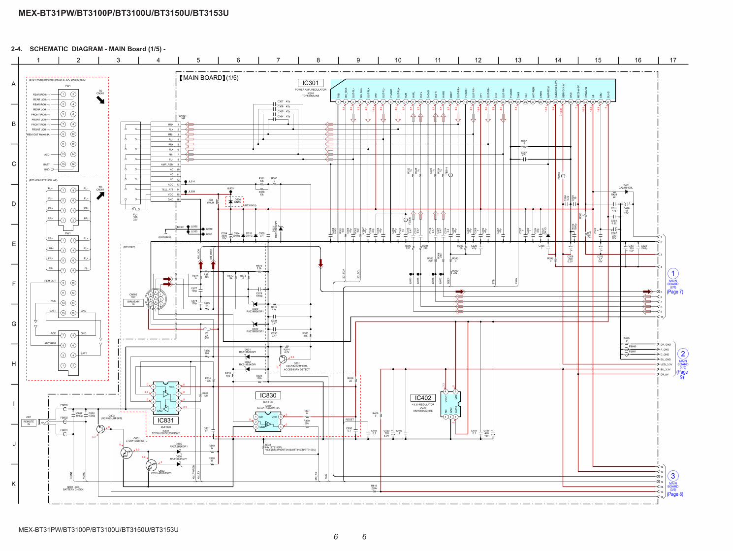
MEX-BT31PW/BT3100P/BT3100U/BT3150U/BT3153U
MEX-BT31PW/BT3100P/BT3100U/BT3150U/BT3153U
66
2-4. SCHEMATIC DIAGRAM - MAIN Board (1/5) -
BOARD(4/5)
MAIN
2
(3/5)BOARDMAIN
3
MAIN
(2/5)
1BOARD
5
14.3
14.4
10.36
0 <3
.3>8.4
13.83.3
4.9
3.3
4.9
14.44.9
4.9
3.7
3.7
3.7
3.7
3.7
3.7
4.9
4.9
14.44.9
3.3
4.9
3.3
5
0
6.9
0
3.3
5
0
5
0
0.6
6.9
0
5
0
5
3.3
0
3.3
0
3.3
5
0.22C301
47kR312
4.7kR314
0.22
C30
8
150R307
1C306
22R429
R818220k
1kR820
47kR313
100
R30
1
100
R30
2
J801
RKZ18B2KGP1D806
47kR309
47pC326
RKZ
18B2
KGP1
D32
3
16V47
C313
R30
80
BU_3.3V
DR_6V
BU_GND
VDD_3.3V
GN1GD324
GN1GD318 G
N1G
D32
1
D306GN1G
10V
C307220
25V47
C416
R8741k
100kR834
12kR872
0.1C830
100kR831
2.2kR870
R8730
1kR875
12kR871
C8761000p
0R300
C8310.1
R3400
TDF8556AJ/N5IC301
1
TAB
2
I2C
_SD
A
3
OU
T-FL
–
4
I2C
_SC
L
5
OU
T-FL
+
6
VP2
7
OU
T-R
L–
8
P-G
ND
1
9
OU
T-R
L+
10
SVR
11
IN-R
L
12
IN-F
L
13
S-G
ND
14
IN-F
R
15
IN-R
R
16
BEEP
17
OU
T-R
R+
18
P-G
ND
3
19
OU
T-R
R–
20
VP1
21
OU
T-FR
+
22
STB
23
OU
T-FR
–
24
P-G
ND
4
25
DIA
G
26
RST
27
ANT-
REM
28
CR
ES
29
AMP-
REM
30
AUD
IO+B
(8.5
V)
31
SERV
O-3
.3V
32
GN
D
33
MEC
HA-
6V
34
PAN
EL+B
35
VP
36
CBU
37
BU+B
R8191k
RKZ7.5B2KGP1D805
2.2
C31
4
C877100p
1000pC323
6.3V
C309220
6.3V
C403220
C39
91
0R400
0R396
IC83074LVC1G17GW-125
1 NC
2
3 GND 4
5VCC
FB39
8
MM1886A33NREIC402
1
CO
NT
2
GN
D
3
NC
4
VOU
T
5
VIN
39kR830
DA2J10100LD401
FB801
FB802
FB803
JL009
JL010
16V3300C334
JL01
2
JL01
3
RKZ18B2KGP1D831
RKZ18B2KGP1D832
D820RKZ18B2KGP1
1C
305
1C
327
1C
30210
00p
R31
0
0.47
C31
5
0.47
C31
7
0.47
C31
9
0.47
C32
1
0.47C331
0.47C330
C39
80.
001
0.1C335
0.1C407
36V
F32A
C878100p
R856100
R857100
R855100
1C402
CN80210P
10
9
8
7
6
5
4
3
2
1
16V220
C387
C4010.1
140uHL301
1
2
3
4
5
6
7
8
9
10
11
12
13
14
15
16
16PCN301
RR+
RL+
RR–
RL–
FR+
FL+
FR–
FL–
NC
NC
NC
AMP_REM
ACC
TELL_ATT
VCC
GND C32
010
16V470
C411
JL014
2.2u
HL3
95
R3870
JL503
JL504
JL01
5
JL01
6
R30
622
0
R303220
R305220
R304220
LTC014EUBFS8TLQ802
LTC044EUBFS8TLQ801
LSCR523UBFS8TLQ301
LSCR523UBFS8TLQ803
R32
31k 1k
R32
5
R32
41k1k
R32
6
47pC364
47pC365
47pC366
47pC367
C30
310
22R836
IC831TC7WH126FK(T5RSOYF
1
2
3
4 GND 5
6
7
8VCC
0R837
C8021000p
C8011000p
10kR311
10kR378
47p
C35
5
47p
C35
6
47p
C35
4
47p
C35
3
47p
C35
2
47p
C35
1
47p
C13
27
47p
C35
9
C31147p
47p
C35
8
47p
C32
4
JL505
JL506
47pC357
FB30
6
FB31
4
FB891
0R899
DR_GNDFB890
A_GND
D_GND
BEEP
STB
DIA
G
XM_T
X
I2C
_SC
L
I2C
_SD
A
RESET
ACC
XM_L
CH
XM_P
WR
EN
RC
IN1
RC
IN0
XM_R
CH
XM_R
X
D830RKZ18B2KGP1
IC301POWER AMP, REGULATOR
IC830BUFFER
IC831BUFFER
MAIN BOARD (1/5)
1
2
4
5
6
7
8
9
10
3
11
13
12
14
88
15
16
+3.3V REGULATOR
IC402
8
RR+
REAR RCH (+)
4
FL–
10
RR–4
8
FL+
11
RL+
REAR RCH (–)
5
6
6
FU1
3
TO
CN301
CN301
(BT3100U/ BT3150U: AR)
12
13
FR-
ACC
REM OUT
11
BATT
6
10A
3
GND
14
7
REM OUT MAX0.4A
5
4
ACC
7
PW1
GND
16
RL–
15
FRONT RCH (–)
4
32V
8
1
1
6
FR+
7
FRONT LCH (+)
15
3
RR-
FRONT RCH (+)
REAR LCH (+)
BATT
BATT
RL–
7
9
2
9
(BT31PW/BT3100P/BT3150U: E, EA, MX/BT3153U)
16
2
1
5
FL-
2
FL+
13
RR+
REAR LCH (–)
FR+
14
GND
3
12
5
FR-
8
ACC
2
10
1
AMT REM
TORL+
PW1
FRONT LCH (–)
(CHASSIS)
BK301
INREMOTE
Q801 - 803BATTERY CHECK
INSIRIUSXM
R833
100k (BT31PW/BT3100U/BT3150U/BT3153U)68k (BT3100P)
ACCESSORY DETECT
(BT3100U)
I
6
H
151
C
12
K
135
F
1682
B
D
G
1110
E
J
9
A
43 7 14 17
(BT3100P)
(Page 7)
(Page 8)
(Page 9)

MEX-BT31PW/BT3100P/BT3100U/BT3150U/BT3153U
MEX-BT31PW/BT3100P/BT3100U/BT3150U/BT3153U
77
2-5. SCHEMATIC DIAGRAM - MAIN Board (2/5) -
(3/5)BOARD
4MAIN
BOARD
1(1/5)
MAIN
(4/5)BOARD
5MAIN
KEY
CN901BOARD
A
8(5/5)
BOARDMAIN
13.8
0
0 0 0
4.2
8.4
4.2
3.3
3.3
8.4
0
4.2
4.2
3.3
2.5
2.3
8.4
000
13.8
13.8
4.2
4.2
4.2
4.2
4.2
4.2
4.2
4.2
0 0 00 0 0
0
0
0
4.2
4.2
4.2
4.2
4.2
4.2
4.2
4.2
4.2
4.2
4.2
4.2
4.2
4.2
4.2
4.2
4.2
40
39
38
37
36
35
34 7
6
5
4
3
2
1
33
32
30
31
8
27
28
29
9
10
11
12
13
14
24 17
25
26
23
22
21 20
19
18
15
16
BD3467FV-E2IC401
BUS_LCH
BUS_RCH
NCO
NCO
TU_LCH
TU_GND
TU_RCH
AUX_LCH
AUX_GND
AUX_RCH
XM_LCH
XM_GND
XM_RCH
FP1
FN1
FN2
FP2
NCO
NCO
NCOMUTE
I2C_SCL
I2C_SDA
GND
FIL
VCC(8.5V)
AU_OUT_RCH
AU_OUT_LCH
NCO
AU_IN_SUB
AU_IN_RL
AU_IN_RR
AU_IN_FL
AU_IN_FR
AU_OUT_FR
AU_OUT_FL
AU_OUT_RR
AU_OUT_RL
AU_OUT_SR
AU_OUT_SL
1kR415
2.2kR419
12kR418
1kR416
1C436
1C437
C1000.1
0R116
R4060
12kR417
RKZ6.8B2KGP1D114
RKZ6.8B2KGP1D115
D11
9R
KZ6.
8B2K
GP1
CL081
CL069
CL074
CL077
CL070
CL079
CL071
CL063
CL075
CL064
CL078
CL066
CL072
CL067
CL065
CL068
CL073
CL061
AU_GND
RF_ANT_IN
RF_GND
AUDIO_OUT_L
AUDIO_OUT_R
RSTN
SCL
SDA
+8.5V
POWER_GND
CN01
9
4
5
3
1
2
6
7
8
R43210k
C4501
C4521
R4330
J1
C1010.001
4PJ402
R4340
1C10
16V47
C11
4.7uHL1
1C15
0R10
1kR13
R1020
JL011 FB19
C4401000p
C4391000p
C1030.1
0.1C414
C4512.2
C4420.1
DM
DP
16V10
C420
16V10
C424
16V10
C425
16V10
C413
47kR405
1C438
C41910
CL076
R4700
R4710
R4680
R4690
C1581
2.2uHL431
0R426
LTA014EUBFS8TLQ407
LTC014EUBFS8TLQ409
1000pC457
10kR409
10kR424
10kR411
10kR422
1000pC105
R40347k
R190
FB420
FB411
FB412
FB413
FB414
FB415
47pC480
47pC481
CAM003
CAM002
FB416
2.2C422
C4102.2
220R490
220R491
220R492
220R493
220R494
220R495
1C499
C41247p 47p
C42347p
C42647p
C421
C10447p
C2011
FB404
FB405
FB406
FB407
FB408
FB410
LTC014TUBFS8TLQ401
LTC014TUBFS8TLQ402
LTC014TUBFS8TLQ403
LTC014TUBFS8TLQ404
LTC014TUBFS8TLQ405 Q406
LTC014TUBFS8TL
220R407
220R421
220R423
220R410
220R404
0R466
0R465
0R464
0R463
0R462
0R442
0R443
0R444
0R445
0R446
R402220
CN10220P
1 USB_GND
2 USB_VBUS
3 GND
4 KEY_GND
5 AUX_L
6 AUX_R
7 AUX_GND
8 RE_0
9 RE_1
10 KEY_1
11 KEY_0
12 SIRCS
13 LCD_DATA
14 LCD_CE
15 LCD_CLK
16 ILL
17 PANEL_SW
18 D–
19 D+
20 GND
AU_SUB_CH
AU_FR_CH
AU_RR_CH
AU_RL_CH
AU_IN_LCH
AU_IN_RCH
AU_FL_CH
AU_IN_RCH
AU_IN_LCH
XM_LCH
XM_RCH
KEY0
RE1
LCD_CE
I2C_SCL
AU_FR_CH
AU_FL_CH
AU_RR_CH
AU_RL_CH
AU_SUB_CH
I2C_SDA
LCD_DATA
NOSE_SW
SIRCS
KEY1
RE0
AU_IN_RCH
AU_SUB_CH
AU_RL_CH
AU_RR_CH
AU_FL_CH
AU_IN_LCH
AU_FR_CH
LTA014EUBFS8TLQ408
LCD_CLK
1000pC446
MAIN BOARD (2/5)
8
7
4
2
6
9
10
1
5
3
27
89
25
24
20
26
21
22
23
IC401ELECTRICAL VOLUME, INPUT SELECTOR
BUS1
TUX-DSP02(TUNER UNIT)
(BT31PW/BT3100P)
(BT3100U/BT3150U/BT3153U)
Q401 - 406MUTING
18
Q407 - 409MUTING CONTROL
(BT3100P)
(ANTENNA IN)
L
R
AUDIO OUTFRONT
L
AUDIO OUTREAR/SUB
R
I
6
H
1
C
12
K
135
F
82
B
D
G
11
L
10
E
J
9
A
43 7 14
LCH_P
C4311 LCH_N
C4321 RCH_N
C4341 RCH_P
C4351
(Suf
fix-2
1)
(Suffix-22)
(Page 6)
(Page 8)
(Page 10)
(Page 9)
(Page 12)
Note: Refer to “MAIN AND KEY BOARDS DISCRIMINATION” on page 2 for how to distinguish Suffi x-21 and Suffi x-22 of the MAIN board.

MEX-BT31PW/BT3100P/BT3100U/BT3150U/BT3153U
MEX-BT31PW/BT3100P/BT3100U/BT3150U/BT3153U
88
2-6. SCHEMATIC DIAGRAM - MAIN Board (3/5) -
Note: When IC501 is replaced, the destination setting is necessary. Refer to “NOTE THE MAIN BOARD OR SYSTEM CONTROLLER (IC501) REPLACING” on page 4 on original service manual.
BOARD(1/5)
MAIN
3
(2/5)
4BOARDMAIN
BOARD(5/5)
MAIN
6
(4/5)
10MAIN
BOARD
BTBOARD
2.9
0 3.3
3.3
<0>
<3.3
>
3.3
3.3
<3.3
>
<3.3
>
3.3
3.3
3.3
3.3
0 0 3.3
3.3
0
3.3
0
3.3 0
1.3
1.4
3.3
1.6
1.4
3.3
3.3
<3.3
>
3.3
3.3
3.3
3.3
0.8
3.3
2.3
2.5
3.3
<0>
<0>
0
3.3
3.3
0
0
0
0
0
3.3
3.3
0
6
1.5
0
3.3
0
0.9
3.3
10.3
5
14.4
3.3
5
0.9
5
0.8
3.3
3.3
3.3
3.3
3.3
3.3
3.3
3.3
3.3
3.3
3.3
100k
R54
5
0R543
100kR536
10MR541
220kR542
1000pC502
100R525
100R524
100R523
1000pC512
1000pC514
0.01C523
0.01C522
100k
R57
6
1kR517
1kR518
0R561
0R562
2.2kR556
2.2kR557
47pC521
47pC520
R584100k
CL003
CL004
0R
548
R5441M
100kR560
FB50
1
JL001
100kR577
JL0080
R555
0R864
1C1301
100R1301
0R1314
0.1C1310
22pC507
R506220k
100kR1302
39kR1311
0.01C1307 32.768kHz
X502
2.2C1308
0.01C1312
0.01C1309
0.01C513
22C1305
IC1300OZ539IGN-A1-0-TR
1 BST
2 LX
3 VIN
4 EN_SYS
5 USB_OUT
6 FB_US
7 USB_IN
8 SYNC 9FLT_USB
10ISET_USB
11VIC_USB
12EN_USB
13SS_SYS
14GNDA
15RT
16VREF
22C1315
16V
C1311100
82kR1307
82kR1308
680pC1306
0.047C518
10kR1312
100R552
100kR550
100kR567
0.022C1325
0.1C1320
DC_DC
100kR531
470R535
100R563
USB1_ON
0R587
CL005
100R510
100R511
0R790
G_HOST_GND
JL500
0FB1301
33kR522
33kR521
0R590
USB_OVER
R1010
33kR582
30kR583
4.7kR505
100kR580
100kR581
100kR554
100kR575
100kR502
10kR579
10k
R57
8
0.1C504
CL002
R507100k
100kR540
JL501
JL502
100R595
100R573
RB7
51V4
0,11
5D
530
DB2
4416
00L
D13
00
0R553
R131510k150k
R1313
10kR1305
C13181000p
IC501
1
NO
SE_S
W
2
SIR
CS
3
UN
ISO
4
UN
ISI
5
UN
ISC
K
6
BYTE
7
CN
VSS
8
XIN
9
XOU
T
10
RES
ET
11
OSC
OU
T
12
VSS
13
OSC
IN
14
VCC
1
15
NM
I
16
MEC
_SEL
FSW
17
BUIN
18
NC
O
19
RC
_IN
1
20
MC
_RX
21
NC
O
22
MC
_TX
23
NC
O
24
SYN
C_O
UT
25
SYN
C_P
RE5
V_O
N
26BEEP
27I2C_SCK
28I2C_SIO
29FW_TXD
30FW_RXD
31FW_CLK
32FW_BUSY
33XM_TX
34XM_RX
35XM_POWER EN
36NCO
37NCO
38NCO
39EPM
40NCO
41MEC_LOAD
42MEC_EJECT
43NCO
44CE
45HIT2_DATA
46HIT2_CLK
47HIT2_RESET
48NCO
49NCO
50NCO
51
EN_S
YS
52
IPO
D
53
NC
O
54
NC
O
55
ACC
_IN
56
ATT
57
DIA
G
58
AMPS
TB
59
GH
OST
_RST
60
VCC
2
61
GH
OST
_1_5
V
62
VSS
63
DSP
_RST
64
DSP
_SST
BY
65
DSP
_1_5
V
66
NC
O
67
GH
OST
_3_3
V
68
MEC
_IN
SW
69
MEC
_DSW
70
NC
O
71
CD
_XR
ST
72
MD
_MU
TE_I
N
73
BT_M
UTE
_IN
74
MU
TE_P
RE4
V
75
MEC
ON
_CH
ECK
76
DEBUG_3
77
DEBUG_1
78
DEBUG_2
79
RE-IN1
80 RE-IN0
81 RE_ON
82 RE_ON(RESERVE)
83 NCO
84 NCO
85 NCO
86 NA
87 NCO
88 NCO
89 KEYACK0
90 KEYACK1
91 NCO
92 KEYIN1
93 KEYIN0
94 AVSS
95 RC_IN0
96 AVRH
97 AVDD
98 NCO
99
DOWNLD_DET
100
BT_MIC_POWER
47uHL1301
0.1C106
X5017.92MHz
1
2
1C510
R13001k 1k
R1320
C5098p
C5118p
47C1304
10k
R51
4
100k
R58
8
10k
R51
5
10kR516
47pC1326
22pC508
1C1316
100k
R13
16
JL00
7 JL006
JL005
JL004
JL003
JL00
2
BEEP
KEY0
EN_S
YS
BU_I
N
MC
_TX
A_AT
T
CD
_XR
ST
DSP
_1_5
V
SSTB
Y
DSP
_RST
EJECT
LOAD
XM_PWREN
XM_RX
XM_TX
GH
OST
_ON
MC
_RX
SYN
C
RES
ET
RC
IN1
RE1
RE0
GH
OST
_RST
IN_S
W
DO
WN
LD_D
ET
D_S
W
I2C_SDA
EN_SYS
RCIN0
KEY1
SIR
CS
NO
SE_S
W
SYN
C
SELF
BU_IN
I2C_SCL
STB
DIA
G
ACC
DC/DC CONVERTER
IC1300
IC501MAIN SYSTEM CONTROLLER
MAIN BOARD (3/5)
14
11
15
13
16
12
18
20
21
22
23
24
25
27
26
89
BUS3
BUS4
BUS2
R5F3650ECDZ98FB
R5F3650KCDZ95FB(BT31PW/BT3100U/BT3150U/BT3153U)
(BT3100P)
I
6
H
151
C
12
K
135
F
1682
B
D
G
1110
E
17
J
9
A
43 7 14
22 GND
21 GND
20 GND
19 GND
18 MUTE
17 RESET
16 BT_MIC_PWR
15 AUDIO_GND
14 RCH_N
13 RCH_P
12 LCH_P
11 LCH_N
RCH_N
RCH_P
LCH_P
LCH_N
10 NC
9 BT_RX
8 BT_TX
7 BT_RTS
6 BT_CTS
5 BT_POWER
BT_RST
BT_RX
BT_TX
BT_RTS
BT_CTS
BT_POWER
4 D_GND
3 VCC
2 D_GND
1 MIC_DET BT_MIC_DET
0R200
R1070
88
R201
0
0
R203
R1000
Refer to page
service manual35 on original
(Page 6)
(Page 10)
(Page 9)
(Page 7)

MEX-BT31PW/BT3100P/BT3100U/BT3150U/BT3153U
MEX-BT31PW/BT3100P/BT3100U/BT3150U/BT3153U
99
2-7. SCHEMATIC DIAGRAM - MAIN Board (4/5) -
BOARD
2MAIN
(1/5)
(2/5)BOARD
5MAIN
MAIN
7(5/5)
BOARD
(3/5)
10BOARDMAIN
CD MECHANSIMDECK BLOCK
(MG-101CA-188)
<1.5>
<1.5>
<1.5>
<3.3>
<3.3>
<3.3>
<0>
<3.3>
<0>
<0>
<0>
<0>
<0>
<0>
1.5
3.3
<3.3>
<3.3>
<0>
<0>
<0>
<0>
<0>
<1.3
>
<1.5
>
<1>
<0>
3.3
<1.5
>
<1.5
>
<1.5
>
<1.5
>
<1.5
>
<1.5
>
<1.5
>
<1.7
>
<1.7
>
<1.7
>
<1.7
>
<1.9
>
<1.5
>
<1.7
>
<1.7
>
<0>
1.5
<1.5>
3.3
<2.1>
<1.5>
<1.5>
<1.5>
<1.5>
<1.7>
1.5
<3.3>
1.5
3.3
3.3
<1.5
>
<1.5
>
<1.5
>
<1.5
>3.3
3.3
3.3
<1.5
>
<1.5
> 1.5
<1.4
>
<1.5
> 3.3
<1.5
>
<0.5
>
<2.5
>
<1.5
>
<1.5
>
<3.3><1.8>
<2.7>
1.5
1.5
3.3
3.3
3.3
3.3
0.015C772
TP720
DR_6V
0.1C721
6.3V
22C
725
2200
pC
747
0.033C718
TP743
TP734
0.1C768
0R763
JL727
VDD_3.3V
TP719
TP733
AU_IN_LCH
TP724
TP736
3300
pC
730
TP742
0R749
330
R71
9
DR_GND
330
R72
0
22k
R75
1
0.01C759
2.2C689
2200
pC
748
22k
R75
0
0R
716
TP740
15kR743
D_GND
0.1C720
TP78
5
330R717
C7571000p
0.1
C78
2
0R
746
1MR722
TP695
330
R71
8
0R714
TP738
1.5kR723
2.7k
R72
5
TC94A99FG-003 (SY, HIC701
1
LPFO
2
PVR
EF
3
VCO
F
4
RVSS
3
5
VCO
I
6
RVD
D3
7
SLC
O
8
RFI
9
RFR
PI
10
RFE
QO
11
DC
OFC
12
AGC
I
13
RFO
14
RVSS
3
15
FNI2
16
FNI1
17
FPI2
18
FPI1
19
VDD
1-1
20
TPI
21
TNI
22
VRO
23
AVSS
3
24
MD
I
25
LDO
26 FSMONIT
27 RFZI
28 RFRP
29 TEI
30 AVDD3
31 FOO
32 TRO
33 VSS-1
34 FMO
35 DMO
36 VDDM1
37 /SRAMSTB
38 VDD1-2
39 VDD3-1
40 PIO10
41 PIO11
42 PIO12
43 PIO13
44 PIO14
45 PIO15
46 PIO16
47 PIO17
48 PIO18
49 PiO19
50 PiO20
51
DVD
D12
52
DAO
1 (R
_R-C
H)
53
DVS
S12
54
DAO
2 (F
_R-C
H)
55
DVR
EF
56
DVD
D34
57
DAO
3 (F
_L-C
H)
58
DVS
S34
59
DAO
4 (R
_L-C
H)
60
DVD
D5
61D
AO5
(SU
B-C
H)
62D
VSS5
63
VDD
1-3
64
VSS-
2
65
XVSS
3
66
XI
67
XO
68
XVD
D3
69
ADVD
D3
70
ADIN
1 (IN
_L-C
H)
71
ADVR
EFL
72
ADVC
M
73
ADVR
EFH
74
ADIN
2 (IN
_R-C
H)
75
ADVS
S3
76MS
77CD_BUS0
78CD_BUS1
79CD_BUS2
80CD_BUS3
81CD_BUCK
82CD_XCCE
83VDD3-2
84VSS-3
85/RST
86VDD1-4
87DEC_INT
88BSIF_INT
89BSIF_GATE
90BSIF_DATA
91BSIF_BCK
92BSIF_LRCK
93DEC_XMUTE
94ZDET
95SP_DATA
96SP_CLK
97TEST
98PDO
99TMAX
100LPFN
TP721
TP722
AU_RR_CH
2200pC789
4V47
C712
10k
R72
7
0.1C724
0.1C767
2.2C688
0.01
C77
7
330
R72
1
100
R74
5
3300
pC
727
TP735
TP732
JL728
330kR744
TP78
1
3300
pC
729
AU_RL_CH
TP741
TP761
0R
748
1kR710
470pC715
3300
pC
726
0.1C739
3300
pC
728
0.01C779
TP737
2.7kR724
0.1
C78
3
10k
R72
6
TP718
AU_SUB_CH
0R693
1000pC756
TP696
0R
747
27pC734
0.1C787
0.1C722
0.1C735
0.1C786
JL726
0.1C717
JL72
9
A_GND
AU_IN_RCH
TP739
TP723
10R711
3.3R712
AU_FR_CH
AU_FL_CH
0.1
C77
8
16.934MHzX701
AU_GND
JL70
0
JL70
1
JL70
2
JL70
3
JL70
4
JL70
5
JL70
6
JL70
7
JL70
8
JL70
9
JL71
0
JL71
1
JL71
2
JL71
3
JL71
4
JL71
5
JL71
6
JL71
7
JL71
8
JL71
9
JL720
JL72
1
JL72
2
JL72
3
JL72
4
JL72
5
JL730
0R765
C6871
C6901
1000pC686
C7321000p
35V
4.7
C75
0
35V
4.7
C75
1
35V
4.7
C75
2
35V
4.7
C75
3
FB724
FB782
0.047C713
0.047C714
0R766
0.1C792
0.1C711
0.1C760
0.1C761
0.1C776
28PCN700
1SP
3SL
5SE
LF
7D
RV_O
N
9LO
AD
11EJ
ECT
13L_
SW
15IN
_SW
17D
_SW
19BU
_GN
D
21D
RV_G
ND
23D
RV_G
ND
25D
RV_6
V
27D
RV_6
V
14O
P_G
ND
161/
2VC
C
18O
P_VC
C
20E
22F
24A
26C
28B
OP_
GN
D24
TRAC
K
6FO
CU
S
8D
RV_V
REF
10LD
12PD
100kR767
100R741
1kR740
100R732
100R733
R736100k
47pC771
BU_3.3V
BU_GND
0.01
5C
784
5600
pC
780
0.1
C78
1
470pC716
5600pC719
1000
pC
788
0.1C796
IC681
1VIN
2GND
3STBY4 NC
5 VOUT
IC682
1VIN
2GND
3STBY4 NC
5 VOUT
0R715
2.2
C73
7
2.2
C73
8
2.2C798
2.2C797
2.2
C75
4
0.1C733
0FB
722
1C703
1C704
1C702
1C705
2SA2119KQ710
2.2
C74
2
2.2
C74
4
2.2
C74
6
47kR742
0.1C701
DEC_XMUTE
SP_CLK
SP_DATA
BSIF_GATE
CD_BUS2
CD_BUS3
CD_BUCK
CD_XCCE
CD_BUS1
D_S
W
IN_S
W
EJEC
T
LOAD
SELF
BSIF_BCK
ZDET
BSIF_DATA
CD_BUS0
SSTBY
DSP_1_5V
BSIF_LRCK
BSIF_INT
DEC_INT
DSP_RST
BU15TD3WG-TR
BU15TD3WG-TR
CD HEAD AMP,
IC701
IC681
IC682
(4/5)MAIN BOARD
BUS4
30
31
32
33
34
AUDIO DSPDIGITAL SERVO PROCESSOR,
I
6
H
1
C
12
K
135
F
82
B
D
G
11
L
10
E
J
9
A
43 7 14
AUTO POWERCONTROL
+1.5V REGULATOR
+1.5V REGULATOR
Refer to page
service manual36 on original
(Page 7)
(Page 6)
(Page 10)
(Page 8)

MEX-BT31PW/BT3100P/BT3100U/BT3150U/BT3153U
MEX-BT31PW/BT3100P/BT3100U/BT3150U/BT3153U
1010
2-8. SCHEMATIC DIAGRAM - MAIN Board (5/5) -
(3/5)
MAIN
6BOARD
MAINBOARD
(4/5)
7
MAIN
8(2/5)
BOARD
0
3.3
3.3
3.3
3.3
0
3.3
0
3.3
1.2
1.2
0.9
0.7
3.3
3.3
3.3
3.3
0
0
0
0
1.2
1.2
1.2
03.3
0 <3
.3>
<0>
<0>
<0>
<0>
<0>
<0>
0 0 0 0 003.3
3.3
3.3
3.3
<0>
<3.3
>
<3.3
>
<3.3
>
3.3
3.3
3.3
3.3
3.3
1.2
1.2
<0>
3.3
3.3
3.3
3.3
3.3
3.3
1.2
1.2
<3.3>
3.3
3.3
<3.3>
<0>
<0>
<0>
1.2
3.3
3.3
3.3
3.35
51.2
3.3
3.3
3.3
0
3.3
3.3
3.3
3.3
3.3
0
0
12MHzX601
1
2
12pC601
12pC602
3.3kR601
0.1C603
10kR607
0.1C605
100k
R61
1
100k
R61
2
100
R61
4
100
R61
5
0.1C606
0.1C607
1C608
1C615
0.1C616
100kR643
0.1C617
0.1C618
0.1C794
0.1C619
0.1C620
0.1C621
0.1C623
0.1C622
0.1C624
1C625
44.2R768
0.1C629
0.1C627
0.1C628
0R664
C6661
C6681
DM
DPJL
731
JL73
2
JL73
3
JL73
4
JL73
5
JL73
6
JL73
7
JL73
8
JL74
4
JL74
5
JL74
6
JL74
7
JL74
8
JL75
0
JL751
JL756
JL757
JL600
JL601
DC_DC
R6021M
100R572
100R570
100kR569
USB1_ON
R698100k
JL74
9
BU33TD3WG-TRIC603
1
VIN
2
GN
D
3
STBY
4
NC
5
VOU
T
IVSS
O
S-1206B12-U3T1GIC703
1
2
3
0.47C662
0.47C664
2.2kR647
2.2kR646
R645 100k
470
R62
1
JL609
JL608
JL611
JL612
G_HOST_GND
JL60
3
JL60
2
R656100k
100kR616
JL758
JL760
JL761
JL762
JL763
JL759
JL765
JL764
JL77
9
JL78
0
JL77
1
JL78
5
JL78
8
JL76
8
JL77
2
JL78
6
JL76
9
JL76
7
JL79
2
JL77
3
JL78
7
JL77
0
JL77
5
JL77
8
JL78
2
JL78
9
JL77
6
JL78
3
JL79
0
JL77
7
JL76
6
JL79
1
JL78
1
JL77
4
JL78
4
JL60
4
JL60
5
JL794
JL793
JL739
JL74
0
JL614
JL613
TMPM320C1DFG-9999IC601
1
MO
DE1
2
RES
ETn
3
DRV
_ON
4
BSIF
_IN
T
5
DEC
_IN
T
6
(DO
OR
_SW
)
7
MEC
_LIM
IT
8
CD
_XR
ST
9
DEC
_XM
UTE
10
SF_W
P
11
SF_H
OLD
12
DVC
C3.
3IO
13
DVS
SCO
M
14
SP_C
LK
15
SP_D
ATA
16
CD
_ZD
ET
17
A-AT
T
18
SF_S
O
19
SF_S
I
20
SF_C
E
21
SF_C
LK
22
BSIF
_DAT
A
23
BSIF
_GAT
E
24
BSIF
_LR
CK
25
BSIF
_BC
K
26
LCD
_DO
27
ILL_
IN
28
LCD
_CE
29
LCD
_CLK
30
DVC
C3.
3IO
31
DVS
SCO
M
32
DVC
C1.
2DR
M
33
DVC
C1.
2DR
M
34
DVS
SCO
M
35
SWD
CK
36
SWD
IO
37 CD_BUS0
38 CD_BUS1
39 CD_BUS2
40 CD_BUS3
41 CD_BUCK
42 DVCC3.3IO
43 DVCC3.3DRM
44 DVSSCOM
45 CD_XCCE
46 USB_EN
47 CP_SEL
48 DVCC1.2
49 BT_TX
50 BT_RX
51 BT_CTS
52 BT_RTS
53 DVSS_COM
54 BT_POWER
55 BT_RESET
56 BT_MIC_DET
57 CP_RESET
58 MC_TX
59 MC_RX
60 I2C_SCL
61 I2C_SDA
62 DVCC1.2
63 D0
64 D1
65 D2
66 D3
67 D4
68 D5
69 DVSSCOM
70 D6
71 DVCC3.3IO
72 D7
73
D8
74
D9
75
D10
76
D11
77
D12
78
D13
79
D14
80
D15
81
A0
82
A1
83
DVS
SCO
M
84
A2
85
A3
86
A4
87
DVC
C1.
2
88
DVC
C3.
3IO
89
A5
90
A6
91
A7
92
A8
93
A9
94
A10
95
A11
96
A12
97A1
398
DVS
SCO
M
99
A14
100
A15
101
A16
102
A17
103
A18
104
DVC
C3.
3IO
105
DT1
0_D
ATA1
106
DT1
0_D
ATA2
107
DT1
0_D
ATA3
108
DT1
0_D
ATA4
109OE
110WE
111DT10_CLK
112DT10_CE
113DOWNLD_DET
114NCO
115USB1_OVR
116USB1_ON
117DVCC1.2
118DVSSCOM
119DVSSPULL
120DVCC1.2PULL
121DVCC1.2
122DVSSCOM
123AVDD3.3USB
124AVSS3.3USB
125DP
126TXRTUNE
127DM
128AVSS3.3USB
129AVDD3.3USB
130XO
131AVSS3.3USBC
132XI
133DVSSUSB
134DVDD1.2USB
135ANALOGTEST
136DVSSCOM
137DVCC1.2
138(N.C.)
139(N.C.)
140(N.C.)
141(N.C.)
142AVSSADC
143AVDD3.3DC
144MODE0
USB_OVER
JL795
JL796
JL79
7
JL799
10k
R61
0
JL623
JL624
100R770
0R677
0R678
W25Q16CVSSIG-A01 IC602
1CS
2DO
3WP
4GND5 DI
6 CLK
7 HOLD
8 VCC
MFI337S3959IC704
1GND
2SDA
3NC
4NC5 NC
6 SCL
7 RST
8 VCC
R674100k
100kR672
100R604
100kR568
0R673
10kR679
4.7kR680
0R682
220
R62
3
220
R61
9
DEC
_XM
UTE
SP_C
LK
SP_D
ATA
BSIF
_GAT
E
CD_BUS1
CD_BUS2
CD_BUS3
CD_BUCK
CD_XCCE
A_AT
T
BSIF
_DAT
A
BSIF
_LR
CK
BSIF
_BC
K
ZDET
MC_TX
MC_RX
DEC
_IN
T
BSIF
_IN
TGHOST_ON
CD
_XR
ST
LCD
_DAT
A
LCD
_CE
LCD
_CLK
GH
OST
_RST
CD_BUS0
DOWNLD_DET
IC601SUB SYSTEM CONTROLLER
IC704EEPROM
IC703
IC603+3.3V REGULATOR
SERIAL FLASH
IC602
BUS1
BUS2
BUS3
(5/5)MAIN BOARD
30
33
31
34
32
+1.2V REGULATOR
I
6
H
151
C
12
K
135
F
82
B
D
G
11
L
10
E
J
9
A
43 7 14
R638100k
RB751V40,115D602
BT_MIC_DET
BT_RST
BT_POWER
BT_CTS
BT_RTS
BT_TX
BT_RX
100kR641
R631 100
R632 100
R635 100
R636 100
R637 100
R633 100
R634 100
R639100k
(Page 9)
(Page 7)
(Page 8)

MEX-BT31PW/BT3100P/BT3100U/BT3150U/BT3153U
MEX-BT31PW/BT3100P/BT3100U/BT3150U/BT3153U
1111
2-9. PRINTED WIRING BOARD - KEY Board -
Note: Refer to the servicing notes “NOTE FOR REPLACEMENT OF THE USB CONNECTOR (CN903) AND THE AUX JACK (J901)” on page 6 on original service manual, if replacing CN903 and J901.
• : Uses unleaded solder.
1
2
19
20
Q901
L903Q931FB902
FB903FB901
R906
R968
R917
R918
R919
CN901
R920
R921
R922
R925R962
R926R927R928R929
R954
R931
R933
R935
R934
R937
R936 R940
R939 R938
R941
R943
R942
R945
R944
R949
R948
C911
C912
R951C916
R952
R953
R955
R976R957
R956
R959
C922
C923
C924 C9
21
C925
R961
R960
C926C927
R963
C928
R967R966
R969
R970
R916
R971
R972
R973
R975
R977
R995R996
R997
16
17 32
64 49
1
33
48
R998
R999 D906
D908
D909D907
IC901
D935D936
153
LCD901LIQUID CRYSTAL DISPLAY PANEL
LED9
31
LED9
30
LED9
33
LED9
32LED935
LED937
LED936
LED947
LED9
50
LED9
52
LED9
54
LED9
56
LED9
58
LED9
60
LED9
62
LED964LED951 LED953 LED9
55
LED9
57
LED9
59
LED9
61
LED9
63
LED965
CN903
R923R924
S901S902
S903
S904
S905
S906
S907
S909S910S911S912S913S914S915S916
IC902
RE901
J901
LED901
R947R946
LED934 LED946
R932
R930
Q930
R958
LED9
67
LED969LED942
LED9
38
R950
E
1
4
KA
A
K
K K K
A A AE
KA
1
5
2
3
3 1
4
KEY BOARD (COMPONENT SIDE)
KEY BOARD (CONDUCTOR SIDE)
ROTARYENCODER
> MSEEK+
LED934, 935, S903 LED946, 947, S901
LED964, 965,S909
PAUSE6
LED962, 963,S910
LED960, 961,S911
SHUF4
LED958, 959,S912
3
LED954, 955,S914
LED956, 957,S913
LED952, 953,S915
LED950, 951, S916
LED942, 969(ILLUMINATION)
S901 - 907, 909 - 916 LED930 - 938,LED942, 946, 947
LED950 - 965, 967, 969ALBUM v
2 V ALBUM
1
SEEK–m .
LED936, 937, S905
LED930, 931, S902
LED932, 933, S904
A K
(LCD BACK LIGHT)
LED938, 967, S907
LED967, S906
1-886-920-
21, 22
(21, 22)
1-886-920-
OFFSOURCE
MODE
SCRLDSPL
(BT3100P)
(BT31PW/BT3150U/BT3153U)
(BT3100U)AUX
RE901
A
B
C
D
E
1 2 3 4 5 6 7
K
K
A
K
K
A
A
K
A
A
AK
(BT3100U/BT3150U/BT3153U)
K AK A
AAKK
AAKK
AAKK
AAKK
(BT3100U)AA
KKAA
KKAA
KKAA
K
KAKA
K
(BT3100U/BT3150U/BT3153U)
(BT3100U/BT3150U/BT3153U)
(BT3100U/BT3150U/BT3153U)
(BT3100U/BT3150U/BT3153U)
(BT3100U/BT3150U/BT3153U)
E
CALL
CATPTY
PTYAF/TA
MIC/ZAP5
PUSH ENTER/MENU/ APP
(VOLUME)
PUSH ENTER/MENU
(VOLUME)
MAINBOARDCN102
A
PTY
(BT31PW)
(BT3100P/BT3100U/BT3150U/BT3153U)
(BT3100U/BT3150U/BT3153U)(BT3100U/BT3150U/BT3153U) (BT3100U/BT3150U/BT3153U)
(BT3100U/BT3150U/BT3153U)
(BT3100U/BT3150U/BT3153U)
(BT3100U/BT3150U/BT3153U)
(BT3
100U
/BT3
150U
/BT3
153U
)
(BT3100U/BT3150U/BT3153U)
(BT3100U/BT3150U/BT3153U) (BT3100U/BT3150U/BT3153U) (BT3100U/BT3150U/BT3153U) (BT3100U/BT3150U/BT3153U)
K
A
K
A
KA
KA(BT3100U/BT3150U/BT3153U)
(BT3100U/BT3150U/BT3153U)
(BT3100U/BT3150U/BT3153U)
21, 22
(21, 22)
(Page 5)

MEX-BT31PW/BT3100P/BT3100U/BT3150U/BT3153U
MEX-BT31PW/BT3100P/BT3100U/BT3150U/BT3153U
1212
Note: Refer to the servicing notes “NOTE FOR REPLACEMENT OF THE USB CONNECTOR (CN903) AND THE AUX JACK (J901)” on page 6 on original service manual, if replacing CN903 and J901.
2-10. SCHEMATIC DIAGRAM - KEY Board -
A
CN102(2/5)
MAINBOARD
0
0
2.6
0
3.3
0
5
2.6
1.7
3.4
5.2
2.6
2.6
2.6
2.6
2.6
2.6
5.2
5.2
5.2
2.6
2.6
2.6
2.6
2.6
2.6
2.6
2.6
2.6
2.6
2.6
2.6
2.6
2.6
2.6
2.6
2.6
2.6
2.6
2.6
2.6
2.6
2.6
2.6
2.6
2.6
2.6
2.6
2.6
2.6
2.6
2.6
2.6
2.6
2.6
2.6
2.6
2.6
2.6
2.6
2.6
2.6
2.6
2.6
2.65.
2
5.2
5.2
0
5.2
5.2
C9120.1
FB903
FB901
FB902
1kR906
RKZ
6.8B
2KG
P1D
907
RKZ
6.8B
2KG
P1D
909
RKZ
6.8B
2KG
P1D
908
RKZ
18B2
KGP1
D90
6
C9161000p
C9111000p
20PCN901
1USB_GND
2USB_VBUS
3D_GND
4KEY_GND
5AUX_L
6AUX_R
7AUX_GND
8RE_0
9RE_1
10KEY_1
11KEY_0
12SIRCS
13LCD_DATA
14LCD_CE
15LCD_CLK
16ILL
17PANEL_SW
18D–
19D+
20GND
D93
5R
KZ5.
1B2K
GP1
1
2
3
4
4PCN903
0R975
0R996
DA2
J101
00L
D93
6
VCC
OU
T
GN
D
PNJ4813M01S0IC902
1 23
100R973
R955
R923820
R9241k
R9251k
R9271.5k
R9281.8k
R9292.2k
NHSW157AT(LCD BACK LIGHT)
LED901
LED935LED931
LED937LED933
LED953
LED967
LED951
LED963
LED955
LED957
LED947
LED959
LED969
LED961
R953 R957
R959
R961
R963
RE901
2 45
3 1
67
J901
R977
R967
LTC014TUBFS8TLQ901
LTC914TUBFS8TLQ931
LED965
L903
3
1 2
4
LCD901
15678910111213141516171819202122232425262728293031323334353637383940414243444546474852 244951 35053
R935
R937
R945 R951
R931
R933 R941
R939
R943 R947
R949
R916820
R9171k
R9181k
R9191.2k
R9201.5k
R9211.8k
2.2kR922
R9261.2k
R971150
R972150
R968120
R969120
R970120
C9280.1
C9220.47
1MR995
C9230.1
0.1C921
C9240.1
C92618p
C92718p
C92518p
470R997
470R999
470R998
PT16512-LQIC901
1
BAC
K-LI
GH
T
2
CO
LOR
1
3
CO
LOR
2
4
SEG
49
5
SEG
48
6
SEG
47
7
SEG
46
8
SEG
45
9
SEG
44
10
SEG
43
11
SEG
42
12
SEG
41
13
SEG
40
14
SEG
39
15
SEG
38
16
SEG
37
17SEG36
18SEG35
19SEG34
20SEG33
21SEG32
22SEG31
23SEG30
24SEG29
25SEG28
26SEG27
27SEG26
28SEG25
29SEG24
30SEG23
31SEG22
32SEG21
33
SEG
20
34
SEG
19
35
SEG
18
36
SEG
17
37
SEG
16
38
SEG
15
39
SEG
14
40
SEG
13
41
SEG
12
42
SEG
11
43
SEG
10
44
SEG
9
45
SEG
8
46
SEG
7
47
SEG
6
48
SEG
5
49 SEG4
50 SEG3
51 COM4
52 COM3
53 COM2
54 COM1
55 SEG2
56 VDD
57 VDD1
58 VDD2
59 VSS
60 SEG1
61 INH
62 LCD_CE
63 LCD_CLK
64 LCD_DATA
S[1]
S[2]
COM[1]
COM[2]
COM[3]
COM[4]
S[3]
S[4]
S[5]
S[6]
S[7]
S[8]
S[9]
S[10
]
S[11
]
S[12
]
S[13
]
S[14
]
S[15
]
S[16
]
S[17
]
S[18
]
S[19
]
S[20
]
S[21]
S[22]
S[23]
S[24]
S[25]
S[26]
S[27]
S[28]
S[29]
S[30]
S[31]
S[32]
S[33]
S[34]
S[35]
S[36]
S[1]
S[2]
S[3]
S[4]
S[5]
S[6]
S[7]
S[8]
S[9]
S[10
]
S[11
]
S[12
]
S[13
]
S[14
]
S[15
]
S[16
]
S[17
]
S[18
]
S[19
]
S[20
]
S[21
]
S[22
]
S[23
]
S[24
]
S[25
]
S[26
]
S[27
]
S[28
]
S[29
]
S[30
]
S[31
]
S[32
]
S[33
]
S[34
]
S[35
]
S[36
]
S[37
]
S[38
]
S[39
]
S[40
]
S[41
]
S[42
]
S[43
]
S[44
]
S[45
]
S[46
]
S[47
]
S[48
]
CO
M[4
]
CO
M[3
]
CO
M[2
]
S[48
]
S[47
]
S[46
]
S[45
]
S[43
]
S[42
]
S[41
]
S[40
]
S[39
]
S[38
]
S[37
]
CE
DATA
CLK
S[44
]
CO
M[1
]
S[49
]
CE
DATA
CLK
S[49
]
S901
S902
S903
S904
S905
S906
S907
S909
S910
S911
S912
S913
S914
S915
S916
(ILLUMINATION)
6PAUSE
SHUF4
REMOTE CONTROL
IC902RECEIVER
IC901
LIQUID CRYSTAL DISPLAY PANEL
4SHUF
5MIC/ZAP 6
PAUSE
KEY BOARD
LIQUID CRYSTAL DISPLAY DRIVER
LED958
LED960
R960
R962
4SHUF
5
470
P1L015BC7TT86C
P1L015BC7TT86C
470
470
LED946
R950
R946
R948
560
470
330
SML-D12D8WT86TQ
LED938
R940
R938
P1L015BC7TT86C
270
220
MODE
SOURCEOFF
LED930
LED932
R930
R932
220
P1L015BC7TT86C
P1L015BC7TT86C
220
MODE
SOURCEOFF
SEEK+
OFFSOURCE
SEEK–
SEEK+
MODE
LED942
R944
R942
(ILLUMINATION)
470
330
P1L015BC7TT86C
SCRLDSPL
1ALBUM
ALBUM2
3
DSPLSCRL
LED962
R976
R966
LED964
6PAUSE
470
470
P1L015BC7TT86C
P1L015BC7TT86C
DSPLSCRL
3
ALBUM2
LED954
LED956
R956
R958470
P1L015BC7TT86C
P1L015BC7TT86C
470
3
ALBUM2
1ALBUM
PTYAF/TA
PTYAF/TA
(VOLUME)
ROTARYENCODER
PUSH ENTER/
LED DRIVE
LED DRIVE
LTC914TUBFS8TLQ930
LED DRIVE
AUX
SML-D12V8WT86TN (BT3100U/BT3150U/BT3153U)
LED957, 959, 961, 963, 965, 967, 969P1L015BC7TT86C (BT31PW/BT3100P)
LED931, 933, 935, 937, 947, 951, 953, 955,
1k (BT3100U/BT3150U/BT3153U)680 (BT31PW/BT3100P)R935
1.2k (BT3100U/BT3150U/BT3153U)680 (BT31PW/BT3100P)R937
470 (BT3100U/BT3150U/BT3153U)270 (BT31PW/BT3100P)R941
470 (BT3100U/BT3150U/BT3153U)220 (BT31PW/BT3100P)R939R931
220 (BT31PW/BT3100P)680 (BT3100U/BT3150U/BT3153U)
220 (BT31PW/BT3100P)820 (BT3100U/BT3150U/BT3153U)
R933
I
6
H
151
C
12 135
F
16 17 1882
B
D
G
1110
E
J
9
A
43 7 14
SEEK–
LED934
LED936
R934
R936
P1L015BC7TT86C
P1L015BC7TT86C
680
680
SEEK+
SEEK–
R954
LED952
R952
470
P1L015BC7TT86C
470
1ALBUM
(BT3100U) (BT3100U)
(BT3100P)
(BT3100U)
LED950P1L015BC7TT86C
1.2K (BT3100U/BT3150U/BT3153U)470 (BT31PW/BT3100P)R949, 955, 959, 963, 977
1.2K (BT3100U/BT3150U/BT3153U)560 (BT31PW/BT3100P)R951
1K (BT3100U/BT3150U/BT3153U)470 (BT31PW/BT3100P)R953, 957, 961, 967
PTYCAT
CALL
CALL
5MIC/ZAP
MENU
(VOLUME)
PUSH ENTER/MENU/APP
1.2K (BT3100U/BT3150U/BT3153U)330 (BT31PW/BT3100P)R947
470 (BT3100U/BT3150U/BT3153U)330 (BT31PW/BT3100P)R943
CALL
BT3153UBT3150U/BT3100U/
BT3153UBT3150U/BT3100U/
BT3153UBT3150U/BT3100U/
BT3153UBT3150U/BT3100U/
PTY
PTYBT3150U/BT3153U
BT3100P/BT3100U/BT3150U/BT3153U
(BT31PW)
BT3153UBT3150U/BT3100U/
BT3153UBT3150U/BT3100U/
BT3153UBT3150U/BT3100U/
BT3153UBT3150U/BT3100U/
BT3153UBT3150U/BT3100U/
BT31PW/BT3150U/BT3153U
PTYAF/TA
(BT3100P)
(BT3100U)
PTYCAT
PTY BT31PW/BT3150U/BT3153U
(BT3100U)
(Page 7)

13
MEX-BT31PW/BT3100P/BT3100U/BT3150U/BT3153U
3. ELECTRICAL PARTS LIST
KEY BOARD **********
< CAPACITOR >
C911 1-162-964-11 CERAMIC CHIP 0.001uF 10% 50V C912 1-100-597-91 CERAMIC CHIP 0.1uF 10% 25V C916 1-162-964-11 CERAMIC CHIP 0.001uF 10% 50V C921 1-100-597-91 CERAMIC CHIP 0.1uF 10% 25V C922 1-125-891-11 CERAMIC CHIP 0.47uF 10% 10V
C923 1-100-597-91 CERAMIC CHIP 0.1uF 10% 25V C924 1-100-597-91 CERAMIC CHIP 0.1uF 10% 25V C925 1-162-918-11 CERAMIC CHIP 18PF 5% 50V C926 1-162-918-11 CERAMIC CHIP 18PF 5% 50V C927 1-162-918-11 CERAMIC CHIP 18PF 5% 50V
C928 1-100-597-91 CERAMIC CHIP 0.1uF 10% 25V
< CONNECTOR >
CN901 1-842-265-22 PLUG, CONNECTOR 20P
< DIODE >
D906 6-503-213-01 DIODE RKZ18B2KGP1 D907 6-503-205-01 DIODE RKZ6.8B2KGP1 D908 6-503-205-01 DIODE RKZ6.8B2KGP1 D909 6-503-205-01 DIODE RKZ6.8B2KGP1 D935 6-503-202-01 DIODE RKZ5.1B2KGP1
D936 6-502-961-01 DIODE DA2J10100L
< FERRITE BEAD >
FB901 1-500-113-22 BEAD, FERRITE (CHIP) (1608) FB902 1-500-113-22 BEAD, FERRITE (CHIP) (1608) FB903 1-500-113-22 BEAD, FERRITE (CHIP) (1608)
< IC >
IC901 6-718-828-02 IC PT16512-LQ
< COIL >
L903 1-457-223-11 COMMON MODE CHOKE COIL
< LED >
LED901 6-503-828-01 LED NHSW157AT (LCD BACK LIGHT) LED930 6-502-542-02 LED P1L015BC7TT86C ( OFF, SOURCE)
(BT3100U/BT3150U/BT3153U)
LED931 6-502-193-11 LED SML-D12V8WT86TN ( OFF, SOURCE) (BT3100U/BT3150U/BT3153U)
LED931 6-502-542-02 LED P1L015BC7TT86C ( OFF, SOURCE) (BT31PW/BT3100P)
LED932 6-502-542-02 LED P1L015BC7TT86C ( , MODE) (BT3100U/BT3150U/BT3153U)
LED933 6-502-193-11 LED SML-D12V8WT86TN ( , MODE) (BT3100U/BT3150U/BT3153U)
LED933 6-502-542-02 LED P1L015BC7TT86C ( , MODE) (BT31PW/BT3100P)
LED934 6-502-542-02 LED P1L015BC7TT86C (> M, SEEK+) (BT3100U/BT3150U/BT3153U)
LED935 6-502-193-11 LED SML-D12V8WT86TN (> M, SEEK+) (BT3100U/BT3150U/BT3153U)
LED935 6-502-542-02 LED P1L015BC7TT86C (> M, SEEK+) (BT31PW/BT3100P)
LED936 6-502-542-02 LED P1L015BC7TT86C (SEEK–, m .) (BT3100U/BT3150U/BT3153U)
LED937 6-502-193-11 LED SML-D12V8WT86TN (SEEK–, m .) (BT3100U/BT3150U/BT3153U)
LED937 6-502-542-02 LED P1L015BC7TT86C (SEEK–, m .) (BT31PW/BT3100P)
LED938 6-502-542-02 LED P1L015BC7TT86C (CALL, ) (BT3100U/BT3150U/BT3153U)
LED942 6-502-542-02 LED P1L015BC7TT86C (ILLUMINATION) (BT3100U/BT3150U/BT3153U)
LED946 6-502-542-02 LED P1L015BC7TT86C (Z) (BT3100U/BT3150U/BT3153U)
LED947 6-502-193-11 LED SML-D12V8WT86TN (Z) (BT3100U/BT3150U/BT3153U)
LED947 6-502-542-02 LED P1L015BC7TT86C (Z) (BT31PW/BT3100P) LED950 6-502-542-02 LED P1L015BC7TT86C ( PTY, AF/TA)
(BT3100U) LED950 6-502-542-02 LED P1L015BC7TT86C (PTY)
(BT3150U/BT3153U)
LED951 6-502-193-11 LED SML-D12V8WT86TN ( PTY, AF/TA) (BT3100U)
LED951 6-502-193-11 LED SML-D12V8WT86TN (PTY) (BT3150U/BT3153U)
LED951 6-502-542-02 LED P1L015BC7TT86C (PTY) (BT31PW) LED951 6-502-542-02 LED P1L015BC7TT86C (CAT, PTY) (BT3100P) LED952 6-502-542-02 LED P1L015BC7TT86C (V ALBUM, 1)
(BT3100U/BT3150U/BT3153U)
LED953 6-502-193-11 LED SML-D12V8WT86TN (V ALBUM, 1) (BT3100U/BT3150U/BT3153U)
LED953 6-502-542-02 LED P1L015BC7TT86C (V ALBUM, 1) (BT31PW/BT3100P)
Ref. No. Part No. Description Remark Ref. No. Part No. Description Remark
When indicating parts by reference num-ber, please include the board name.
Note:• Due to standardization, replacements in
the parts list may be different from the parts specifi ed in the diagrams or the com-ponents used on the set.
• -XX and -X mean standardized parts, so they may have some difference from the original one.
• Items marked “*” are not stocked since they are seldom required for routine ser-vice. Some delay should be anticipated when ordering these items.
• RESISTORS All resistors are in ohms. METAL: Metal-fi lm resistor. METAL OXIDE: Metal oxide-fi lm resistor. F: nonfl ammable
• CAPACITORS uF: μF• COILS uH: μH• SEMICONDUCTORS In each case, u: μ, for example: uA. . : μA. . , uPA. . , μPA. . , uPB. . : μPB. . , uPC. . , μPC. . , uPD. . : μPD. .• Abbreviation AR : Argentina model EA : Saudi Arabia model MX : Mexican model
KEY

Ref. No. Part No. Description Remark Ref. No. Part No. Description Remark
MEX-BT31PW/BT3100P/BT3100U/BT3150U/BT3153U
14
LED954 6-502-542-02 LED P1L015BC7TT86C (ALBUM v, 2) (BT3100U/BT3150U/BT3153U)
LED955 6-502-193-11 LED SML-D12V8WT86TN (ALBUM v, 2) (BT3100U/BT3150U/BT3153U)
LED955 6-502-542-02 LED P1L015BC7TT86C (ALBUM v, 2) (BT31PW/BT3100P)
LED956 6-502-542-02 LED P1L015BC7TT86C ( , 3) (BT3100U/BT3150U/BT3153U)
LED957 6-502-193-11 LED SML-D12V8WT86TN ( , 3) (BT3100U/BT3150U/BT3153U)
LED957 6-502-542-02 LED P1L015BC7TT86C ( , 3) (BT31PW/BT3100P)
LED958 6-502-542-02 LED P1L015BC7TT86C (SHUF, 4) (BT3100U/BT3150U/BT3153U)
LED959 6-502-193-11 LED SML-D12V8WT86TN (SHUF, 4) (BT3100U/BT3150U/BT3153U)
LED959 6-502-542-02 LED P1L015BC7TT86C (SHUF, 4) (BT31PW/BT3100P)
LED960 6-502-542-02 LED P1L015BC7TT86C (MIC/ZAP, 5) (BT3100U/BT3150U/BT3153U)
LED961 6-502-193-11 LED SML-D12V8WT86TN (MIC/ZAP, 5) (BT3100U/BT3150U/BT3153U)
LED961 6-502-542-02 LED P1L015BC7TT86C (MIC/ZAP, 5) (BT31PW/BT3100P)
LED962 6-502-542-02 LED P1L015BC7TT86C (PAUSE, 6) (BT3100U/BT3150U/BT3153U)
LED963 6-502-193-11 LED SML-D12V8WT86TN (PAUSE, 6) (BT3100U/BT3150U/BT3153U)
LED963 6-502-542-02 LED P1L015BC7TT86C (PAUSE, 6) (BT31PW/BT3100P)
LED964 6-502-542-02 LED P1L015BC7TT86C ( SCRL, DSPL) (BT3100U/BT3150U/BT3153U)
LED965 6-502-193-11 LED SML-D12V8WT86TN ( SCRL, DSPL) (BT3100U/BT3150U/BT3153U)
LED965 6-502-542-02 LED P1L015BC7TT86C ( SCRL, DSPL) (BT31PW/BT3100P)
LED967 6-502-193-11 LED SML-D12V8WT86TN (CALL, , ) (BT3100U/BT3150U/BT3153U)
LED967 6-502-542-02 LED P1L015BC7TT86C (CALL, , ) (BT31PW/BT3100P)
LED969 6-502-193-11 LED SML-D12V8WT86TN (ILLUMINATION) (BT3100U/BT3150U/BT3153U)
LED969 6-502-542-02 LED P1L015BC7TT86C (ILLUMINATION) (BT31PW/BT3100P)
< TRANSISTOR >
Q901 6-552-937-01 TRANSISTOR LTC014TUBFS8TL Q930 6-552-856-01 TRANSISTOR LTC914TUBFS8TL
(BT3100U/BT3150U/BT3153U) Q931 6-552-856-01 TRANSISTOR LTC914TUBFS8TL
< RESISTOR >
R906 1-216-821-11 METAL CHIP 1K 5% 1/10W R916 1-216-820-11 METAL CHIP 820 5% 1/10W R917 1-216-821-11 METAL CHIP 1K 5% 1/10W R918 1-216-821-11 METAL CHIP 1K 5% 1/10W R919 1-216-822-11 METAL CHIP 1.2K 5% 1/10W
R920 1-216-823-11 METAL CHIP 1.5K 5% 1/10W R921 1-216-824-11 METAL CHIP 1.8K 5% 1/10W R922 1-216-825-11 METAL CHIP 2.2K 5% 1/10W R923 1-216-820-11 METAL CHIP 820 5% 1/10W R924 1-216-821-11 METAL CHIP 1K 5% 1/10W
R925 1-216-821-11 METAL CHIP 1K 5% 1/10W R926 1-216-822-11 METAL CHIP 1.2K 5% 1/10W
R927 1-216-823-11 METAL CHIP 1.5K 5% 1/10W R928 1-216-824-11 METAL CHIP 1.8K 5% 1/10W R929 1-216-825-11 METAL CHIP 2.2K 5% 1/10W
R930 1-216-813-11 METAL CHIP 220 5% 1/10W (BT3100U/BT3150U/BT3153U)
R931 1-216-813-11 METAL CHIP 220 5% 1/10W (BT31PW/BT3100P)
R931 1-216-819-11 METAL CHIP 680 5% 1/10W (BT3100U/BT3150U/BT3153U)
R932 1-216-813-11 METAL CHIP 220 5% 1/10W (BT3100U/BT3150U/BT3153U)
R933 1-216-813-11 METAL CHIP 220 5% 1/10W (BT31PW/BT3100P)
R933 1-216-820-11 METAL CHIP 820 5% 1/10W (BT3100U/BT3150U/BT3153U)
R934 1-216-819-11 METAL CHIP 680 5% 1/10W (BT3100U/BT3150U/BT3153U)
R935 1-216-819-11 METAL CHIP 680 5% 1/10W (BT31PW/BT3100P)
R935 1-216-821-11 METAL CHIP 1K 5% 1/10W (BT3100U/BT3150U/BT3153U)
R936 1-216-819-11 METAL CHIP 680 5% 1/10W (BT3100U/BT3150U/BT3153U)
R937 1-216-819-11 METAL CHIP 680 5% 1/10W (BT31PW/BT3100P)
R937 1-216-822-11 METAL CHIP 1.2K 5% 1/10W (BT3100U/BT3150U/BT3153U)
R938 1-216-813-11 METAL CHIP 220 5% 1/10W(BT3100U/BT3150U/BT3153U)
R939 1-216-813-11 METAL CHIP 220 5% 1/10W(BT31PW/BT3100P)
R939 1-216-817-11 METAL CHIP 470 5% 1/10W(BT3100U/BT3150U/BT3153U)
R940 1-216-814-11 METAL CHIP 270 5% 1/10W(BT3100U/BT3150U/BT3153U)
R941 1-216-814-11 METAL CHIP 270 5% 1/10W(BT31PW/BT3100P)
R941 1-216-817-11 METAL CHIP 470 5% 1/10W(BT3100U/BT3150U/BT3153U)
R942 1-216-815-11 METAL CHIP 330 5% 1/10W(BT3100U/BT3150U/BT3153U)
R943 1-216-815-11 METAL CHIP 330 5% 1/10W(BT31PW/BT3100P)
R943 1-216-817-11 METAL CHIP 470 5% 1/10W(BT3100U/BT3150U/BT3153U)
R944 1-216-817-11 METAL CHIP 470 5% 1/10W(BT3100U/BT3150U/BT3153U)
R945 1-216-817-11 METAL CHIP 470 5% 1/10W R946 1-216-815-11 METAL CHIP 330 5% 1/10W
(BT3100U/BT3150U/BT3153U) R947 1-216-815-11 METAL CHIP 330 5% 1/10W
(BT31PW/BT3100P)
R947 1-216-822-11 METAL CHIP 1.2K 5% 1/10W (BT3100U/BT3150U/BT3153U)
R948 1-216-817-11 METAL CHIP 470 5% 1/10W (BT3100U/BT3150U/BT3153U)
R949 1-216-817-11 METAL CHIP 470 5% 1/10W (BT31PW/BT3100P)
R949 1-216-822-11 METAL CHIP 1.2K 5% 1/10W (BT3100U/BT3150U/BT3153U)
R950 1-216-818-11 METAL CHIP 560 5% 1/10W (BT3100U/BT3150U/BT3153U)
R951 1-216-818-11 METAL CHIP 560 5% 1/10W (BT31PW/BT3100P)
KEY

Ref. No. Part No. Description Remark Ref. No. Part No. Description Remark
MEX-BT31PW/BT3100P/BT3100U/BT3150U/BT3153U
1515
R951 1-216-822-11 METAL CHIP 1.2K 5% 1/10W (BT3100U/BT3150U/BT3153U)
R952 1-216-817-11 METAL CHIP 470 5% 1/10W (BT3100U/BT3150U/BT3153U)
R953 1-216-817-11 METAL CHIP 470 5% 1/10W (BT31PW/BT3100P)
R953 1-216-821-11 METAL CHIP 1K 5% 1/10W (BT3100U/BT3150U/BT3153U)
R954 1-216-817-11 METAL CHIP 470 5% 1/10W (BT3100U/BT3150U/BT3153U)
R955 1-216-817-11 METAL CHIP 470 5% 1/10W (BT31PW/BT3100P)
R955 1-216-822-11 METAL CHIP 1.2K 5% 1/10W (BT3100U/BT3150U/BT3153U)
R956 1-216-817-11 METAL CHIP 470 5% 1/10W (BT3100U/BT3150U/BT3153U)
R957 1-216-817-11 METAL CHIP 470 5% 1/10W (BT31PW/BT3100P)
R957 1-216-821-11 METAL CHIP 1K 5% 1/10W (BT3100U/BT3150U/BT3153U)
R958 1-216-817-11 METAL CHIP 470 5% 1/10W (BT3100U/BT3150U/BT3153U)
R959 1-216-817-11 METAL CHIP 470 5% 1/10W (BT31PW/BT3100P)
R959 1-216-822-11 METAL CHIP 1.2K 5% 1/10W (BT3100U/BT3150U/BT3153U)
R960 1-216-817-11 METAL CHIP 470 5% 1/10W (BT3100U/BT3150U/BT3153U)
R961 1-216-817-11 METAL CHIP 470 5% 1/10W (BT31PW/BT3100P)
R961 1-216-821-11 METAL CHIP 1K 5% 1/10W (BT3100U/BT3150U/BT3153U)
R962 1-216-817-11 METAL CHIP 470 5% 1/10W (BT3100U/BT3150U/BT3153U)
R963 1-216-817-11 METAL CHIP 470 5% 1/10W (BT31PW/BT3100P)
R963 1-216-822-11 METAL CHIP 1.2K 5% 1/10W (BT3100U/BT3150U/BT3153U)
R966 1-216-817-11 METAL CHIP 470 5% 1/10W (BT3100U/BT3150U/BT3153U)
R967 1-216-817-11 METAL CHIP 470 5% 1/10W (BT31PW/BT3100P)
R967 1-216-821-11 METAL CHIP 1K 5% 1/10W (BT3100U/BT3150U/BT3153U)
R968 1-216-810-11 METAL CHIP 120 5% 1/10W R969 1-216-810-11 METAL CHIP 120 5% 1/10W
R970 1-216-810-11 METAL CHIP 120 5% 1/10W R971 1-216-811-11 METAL CHIP 150 5% 1/10W R972 1-216-811-11 METAL CHIP 150 5% 1/10W R973 1-216-809-11 METAL CHIP 100 5% 1/10W R975 1-216-295-91 SHORT CHIP 0
R976 1-216-817-11 METAL CHIP 470 5% 1/10W (BT3100U/BT3150U/BT3153U)
R977 1-216-817-11 METAL CHIP 470 5% 1/10W (BT31PW/BT3100P)
R977 1-216-822-11 METAL CHIP 1.2K 5% 1/10W (BT3100U/BT3150U/BT3153U)
R995 1-216-857-11 METAL CHIP 1M 5% 1/10W R996 1-216-864-11 SHORT CHIP 0
R997 1-216-817-11 METAL CHIP 470 5% 1/10W R998 1-216-817-11 METAL CHIP 470 5% 1/10W R999 1-216-817-11 METAL CHIP 470 5% 1/10W
< SWITCH >
S901 1-798-448-11 TACTILE SWITCH (Z) S902 1-798-448-11 TACTILE SWITCH ( OFF, SOURCE) S903 1-798-448-11 TACTILE SWITCH (> M, SEEK+) S904 1-798-448-11 TACTILE SWITCH ( , MODE) S905 1-798-448-11 TACTILE SWITCH (SEEK–, m .)
S906 1-798-448-11 TACTILE SWITCH ( ) S907 1-798-448-11 TACTILE SWITCH (CALL, ) S909 1-798-448-11 TACTILE SWITCH ( SCRL, DSPL) S910 1-798-448-11 TACTILE SWITCH (PAUSE, 6) S911 1-798-448-11 TACTILE SWITCH (MIC/ZAP, 5)
S912 1-798-448-11 TACTILE SWITCH (SHUF, 4) S913 1-798-448-11 TACTILE SWITCH ( , 3) S914 1-798-448-11 TACTILE SWITCH (ALBUM v, 2) S915 1-798-448-11 TACTILE SWITCH (V ALBUM, 1) S916 1-798-448-11 TACTILE SWITCH (PTY)
(BT31PW/BT3150U/BT3153U)
S916 1-798-448-11 TACTILE SWITCH (CAT, PTY) (BT3100P) S916 1-798-448-11 TACTILE SWITCH ( PTY, AF/TA) (BT3100U)*************************************************************
A-1885-443-A MAIN BOARD, COMPLETE (BT3100P) A-1885-444-A MAIN BOARD, COMPLETE (BT3100U) A-1885-445-A MAIN BOARD, COMPLETE
(BT3150U: E, MX, AR/BT3153U) A-1889-437-A MAIN BOARD, COMPLETE (BT3150U: EA) A-1891-247-A MAIN BOARD, COMPLETE (BT31PW) ********************
(Including BT board)
7-685-134-19 SCREW +P 2.6X8 TYPE2 NON-SLIT 7-685-794-01 SCREW +PTT 2.6X10 (S)
< CAPACITOR >
C10 1-100-591-91 CERAMIC CHIP 1uF 10% 25V C11 1-137-765-21 ELECT CHIP 47uF 20% 16V C15 1-112-717-91 CERAMIC CHIP 1uF 10% 6.3V C100 1-114-582-91 CERAMIC CHIP 0.1uF 10% 16V C101 1-162-964-11 CERAMIC CHIP 0.001uF 10% 50V
C103 1-114-868-11 CERAMIC CHIP 0.1uF 10% 50V C104 1-162-923-11 CERAMIC CHIP 47PF 5% 50V C105 1-162-964-11 CERAMIC CHIP 0.001uF 10% 50V C106 1-100-597-91 CERAMIC CHIP 0.1uF 10% 25V C158 1-116-733-11 CERAMIC CHIP 1uF 10% 25V
C201 1-112-717-91 CERAMIC CHIP 1uF 10% 6.3V C301 1-127-715-11 CERAMIC CHIP 0.22uF 10% 16V C302 1-116-733-11 CERAMIC CHIP 1uF 10% 25V C303 1-100-966-91 CERAMIC CHIP 10uF 20% 10V C305 1-116-733-11 CERAMIC CHIP 1uF 10% 25V
C306 1-165-908-11 CERAMIC CHIP 1uF 10% 10V C307 1-128-394-11 ELECT CHIP 220uF 20% 10V C308 1-112-863-91 CERAMIC CHIP 0.22uF 10% 10V C309 1-100-354-21 ELECT CHIP 220uF 20% 6.3V C311 1-162-923-11 CERAMIC CHIP 47PF 5% 50V
C313 1-137-765-21 ELECT CHIP 47uF 20% 16V C314 1-114-983-91 CERAMIC CHIP 2.2uF 10% 16V C315 1-112-780-11 CERAMIC CHIP 0.47uF 10% 16V C317 1-112-780-11 CERAMIC CHIP 0.47uF 10% 16V C319 1-112-780-11 CERAMIC CHIP 0.47uF 10% 16V
C320 1-100-966-91 CERAMIC CHIP 10uF 20% 10V C321 1-112-780-11 CERAMIC CHIP 0.47uF 10% 16V C323 1-164-937-11 CERAMIC CHIP 0.001uF 10% 50V
KEY MAIN
Note 1: When the complete MAIN board is replaced, the destination setting is necessary. Refer to “NOTE THE MAIN BOARD OR SYSTEM CONTROLLER (IC501) REPLACING” on page 4 on original service manual.
Note 2: When the complete MAIN board (including BT board) is re-placed, it is necessary to confi rm operation. Refer to “BLUE-TOOTH FUNCTION CHECKING METHOD USING A CEL-LULAR PHONE” on page 7 on original service manual.

Ref. No. Part No. Description Remark Ref. No. Part No. Description Remark
MEX-BT31PW/BT3100P/BT3100U/BT3150U/BT3153U
16
C324 1-162-923-11 CERAMIC CHIP 47PF 5% 50V C326 1-164-866-11 CERAMIC CHIP 47PF 5% 50V
C327 1-116-733-11 CERAMIC CHIP 1uF 10% 25V C330 1-116-739-11 CERAMIC CHIP 0.47uF 10% 50V C331 1-116-739-11 CERAMIC CHIP 0.47uF 10% 50V C334 1-126-936-11 ELECT 3300uF 20% 16V C335 1-114-868-11 CERAMIC CHIP 0.1uF 10% 50V
C351 1-164-866-11 CERAMIC CHIP 47PF 5% 50V C352 1-164-866-11 CERAMIC CHIP 47PF 5% 50V C353 1-164-866-11 CERAMIC CHIP 47PF 5% 50V C354 1-164-866-11 CERAMIC CHIP 47PF 5% 50V C355 1-164-866-11 CERAMIC CHIP 47PF 5% 50V
C356 1-164-866-11 CERAMIC CHIP 47PF 5% 50V C357 1-164-866-11 CERAMIC CHIP 47PF 5% 50V C358 1-162-923-11 CERAMIC CHIP 47PF 5% 50V C359 1-164-866-11 CERAMIC CHIP 47PF 5% 50V C364 1-162-923-11 CERAMIC CHIP 47PF 5% 50V
C365 1-162-923-11 CERAMIC CHIP 47PF 5% 50V C366 1-162-923-11 CERAMIC CHIP 47PF 5% 50V C367 1-162-923-11 CERAMIC CHIP 47PF 5% 50V C387 1-128-398-11 ELECT CHIP 220uF 20% 16V C398 1-100-905-11 CERAMIC CHIP 0.001uF 10% 50V
C399 1-100-591-91 CERAMIC CHIP 1uF 10% 25V C401 1-114-582-91 CERAMIC CHIP 0.1uF 10% 16V C402 1-112-717-91 CERAMIC CHIP 1uF 10% 6.3V C403 1-100-354-21 ELECT CHIP 220uF 20% 6.3V C407 1-100-597-91 CERAMIC CHIP 0.1uF 10% 25V
C410 1-116-728-11 CERAMIC CHIP 2.2uF 10% 10V C411 1-127-931-21 ELECT CHIP 470uF 20% 16V C412 1-162-923-11 CERAMIC CHIP 47PF 5% 50V C413 1-124-779-00 ELECT CHIP 10uF 20% 16V C414 1-100-597-91 CERAMIC CHIP 0.1uF 10% 25V
C416 1-128-992-21 ELECT CHIP 47uF 20% 25V C419 1-100-966-91 CERAMIC CHIP 10uF 20% 10V C420 1-124-779-00 ELECT CHIP 10uF 20% 16V C421 1-162-923-11 CERAMIC CHIP 47PF 5% 50V C422 1-116-728-11 CERAMIC CHIP 2.2uF 10% 10V
C423 1-162-923-11 CERAMIC CHIP 47PF 5% 50V C424 1-124-779-00 ELECT CHIP 10uF 20% 16V C425 1-124-779-00 ELECT CHIP 10uF 20% 16V C426 1-162-923-11 CERAMIC CHIP 47PF 5% 50V C431 1-165-908-11 CERAMIC CHIP 1uF 10% 10V
C432 1-165-908-11 CERAMIC CHIP 1uF 10% 10V C434 1-165-908-11 CERAMIC CHIP 1uF 10% 10V C435 1-165-908-11 CERAMIC CHIP 1uF 10% 10V C436 1-112-717-91 CERAMIC CHIP 1uF 10% 6.3V C437 1-112-717-91 CERAMIC CHIP 1uF 10% 6.3V
C438 1-112-717-91 CERAMIC CHIP 1uF 10% 6.3V C439 1-162-964-11 CERAMIC CHIP 0.001uF 10% 50V C440 1-162-964-11 CERAMIC CHIP 0.001uF 10% 50V C442 1-100-597-91 CERAMIC CHIP 0.1uF 10% 25V C446 1-162-964-11 CERAMIC CHIP 0.001uF 10% 50V
C450 1-165-908-11 CERAMIC CHIP 1uF 10% 10V(BT3100P)
C451 1-114-983-91 CERAMIC CHIP 2.2uF 10% 16V(BT3100P)
C452 1-165-908-11 CERAMIC CHIP 1uF 10% 10V(BT3100P)
C457 1-164-937-11 CERAMIC CHIP 0.001uF 10% 50V C480 1-162-923-11 CERAMIC CHIP 47PF 5% 50V
C481 1-162-923-11 CERAMIC CHIP 47PF 5% 50V C499 1-112-717-91 CERAMIC CHIP 1uF 10% 6.3V C502 1-164-937-11 CERAMIC CHIP 0.001uF 10% 50V C504 1-125-777-11 CERAMIC CHIP 0.1uF 10% 10V C507 1-164-858-11 CERAMIC CHIP 22PF 5% 50V
C508 1-164-858-11 CERAMIC CHIP 22PF 5% 50V C509 1-164-848-11 CERAMIC CHIP 8PF 0.5PF 50V C510 1-165-908-11 CERAMIC CHIP 1uF 10% 10V C511 1-164-848-11 CERAMIC CHIP 8PF 0.5PF 50V C512 1-164-937-11 CERAMIC CHIP 0.001uF 10% 50V
C513 1-100-567-81 CERAMIC CHIP 0.01uF 10% 25V C514 1-164-937-11 CERAMIC CHIP 0.001uF 10% 50V C518 1-119-923-11 CERAMIC CHIP 0.047uF 10% 10V C520 1-164-866-11 CERAMIC CHIP 47PF 5% 50V C521 1-164-866-11 CERAMIC CHIP 47PF 5% 50V
C522 1-100-567-81 CERAMIC CHIP 0.01uF 10% 25V C523 1-100-567-81 CERAMIC CHIP 0.01uF 10% 25V C601 1-164-852-11 CERAMIC CHIP 12PF 5% 50V C602 1-164-852-11 CERAMIC CHIP 12PF 5% 50V C603 1-125-777-11 CERAMIC CHIP 0.1uF 10% 10V
C605 1-125-777-11 CERAMIC CHIP 0.1uF 10% 10V C606 1-125-777-11 CERAMIC CHIP 0.1uF 10% 10V C607 1-125-777-11 CERAMIC CHIP 0.1uF 10% 10V C608 1-112-717-91 CERAMIC CHIP 1uF 10% 6.3V C615 1-112-717-91 CERAMIC CHIP 1uF 10% 6.3V
C616 1-125-777-11 CERAMIC CHIP 0.1uF 10% 10V C617 1-125-777-11 CERAMIC CHIP 0.1uF 10% 10V C618 1-125-777-11 CERAMIC CHIP 0.1uF 10% 10V C619 1-125-777-11 CERAMIC CHIP 0.1uF 10% 10V C620 1-125-777-11 CERAMIC CHIP 0.1uF 10% 10V
C621 1-125-777-11 CERAMIC CHIP 0.1uF 10% 10V C622 1-125-777-11 CERAMIC CHIP 0.1uF 10% 10V C623 1-125-777-11 CERAMIC CHIP 0.1uF 10% 10V C624 1-125-777-11 CERAMIC CHIP 0.1uF 10% 10V C625 1-112-717-91 CERAMIC CHIP 1uF 10% 6.3V
C627 1-125-777-11 CERAMIC CHIP 0.1uF 10% 10V C628 1-125-777-11 CERAMIC CHIP 0.1uF 10% 10V C629 1-125-777-11 CERAMIC CHIP 0.1uF 10% 10V C662 1-125-891-11 CERAMIC CHIP 0.47uF 10% 10V C664 1-125-891-11 CERAMIC CHIP 0.47uF 10% 10V
C666 1-112-717-91 CERAMIC CHIP 1uF 10% 6.3V C668 1-112-717-91 CERAMIC CHIP 1uF 10% 6.3V C686 1-164-937-11 CERAMIC CHIP 0.001uF 10% 50V C687 1-112-717-91 CERAMIC CHIP 1uF 10% 6.3V C688 1-165-884-91 CERAMIC CHIP 2.2uF 10% 6.3V
C689 1-165-884-91 CERAMIC CHIP 2.2uF 10% 6.3V C690 1-112-717-91 CERAMIC CHIP 1uF 10% 6.3V C701 1-100-597-91 CERAMIC CHIP 0.1uF 10% 25V C702 1-165-908-11 CERAMIC CHIP 1uF 10% 10V C703 1-116-733-11 CERAMIC CHIP 1uF 10% 25V
C704 1-165-908-11 CERAMIC CHIP 1uF 10% 10V C705 1-165-908-11 CERAMIC CHIP 1uF 10% 10V C711 1-100-597-91 CERAMIC CHIP 0.1uF 10% 25V C712 1-126-208-21 ELECT CHIP 47uF 20% 4V C713 1-119-923-11 CERAMIC CHIP 0.047uF 10% 10V
C714 1-119-923-11 CERAMIC CHIP 0.047uF 10% 10V C715 1-164-935-11 CERAMIC CHIP 470PF 10% 50V C716 1-164-935-11 CERAMIC CHIP 470PF 10% 50V C717 1-114-582-91 CERAMIC CHIP 0.1uF 10% 16V C718 1-127-772-81 CERAMIC CHIP 0.033uF 10% 10V
MAIN

Ref. No. Part No. Description Remark Ref. No. Part No. Description Remark
MEX-BT31PW/BT3100P/BT3100U/BT3150U/BT3153U
1717
C719 1-164-172-11 CERAMIC CHIP 0.0056uF 10% 25V C720 1-125-777-11 CERAMIC CHIP 0.1uF 10% 10V C721 1-114-582-91 CERAMIC CHIP 0.1uF 10% 16V C722 1-114-582-91 CERAMIC CHIP 0.1uF 10% 16V C724 1-114-582-91 CERAMIC CHIP 0.1uF 10% 16V
C725 1-124-778-00 ELECT CHIP 22uF 20% 6.3V C726 1-164-940-11 CERAMIC CHIP 0.0033uF 10% 16V C727 1-164-940-11 CERAMIC CHIP 0.0033uF 10% 16V C728 1-164-940-11 CERAMIC CHIP 0.0033uF 10% 16V C729 1-164-940-11 CERAMIC CHIP 0.0033uF 10% 16V
C730 1-164-940-11 CERAMIC CHIP 0.0033uF 10% 16V C732 1-164-937-11 CERAMIC CHIP 0.001uF 10% 50V C733 1-114-582-91 CERAMIC CHIP 0.1uF 10% 16V C734 1-164-860-11 CERAMIC CHIP 27PF 5% 50V C735 1-114-582-91 CERAMIC CHIP 0.1uF 10% 16V
C737 1-165-884-91 CERAMIC CHIP 2.2uF 10% 6.3V C738 1-165-884-91 CERAMIC CHIP 2.2uF 10% 6.3V C739 1-114-582-91 CERAMIC CHIP 0.1uF 10% 16V C742 1-165-884-91 CERAMIC CHIP 2.2uF 10% 6.3V C744 1-165-884-91 CERAMIC CHIP 2.2uF 10% 6.3V
C746 1-165-884-91 CERAMIC CHIP 2.2uF 10% 6.3V C747 1-164-939-11 CERAMIC CHIP 0.0022uF 10% 50V C748 1-164-939-11 CERAMIC CHIP 0.0022uF 10% 50V C750 1-126-603-11 ELECT CHIP 4.7uF 20% 35V C751 1-126-603-11 ELECT CHIP 4.7uF 20% 35V
C752 1-126-603-11 ELECT CHIP 4.7uF 20% 35V C753 1-126-603-11 ELECT CHIP 4.7uF 20% 35V C754 1-116-728-11 CERAMIC CHIP 2.2uF 10% 10V C756 1-164-937-11 CERAMIC CHIP 0.001uF 10% 50V C757 1-164-937-11 CERAMIC CHIP 0.001uF 10% 50V
C759 1-100-567-81 CERAMIC CHIP 0.01uF 10% 25V C760 1-100-597-91 CERAMIC CHIP 0.1uF 10% 25V C761 1-100-597-91 CERAMIC CHIP 0.1uF 10% 25V C767 1-125-777-11 CERAMIC CHIP 0.1uF 10% 10V C768 1-125-777-11 CERAMIC CHIP 0.1uF 10% 10V
C771 1-164-866-11 CERAMIC CHIP 47PF 5% 50V C772 1-127-988-81 CERAMIC CHIP 0.015uF 10% 16V C776 1-100-597-91 CERAMIC CHIP 0.1uF 10% 25V C777 1-100-567-81 CERAMIC CHIP 0.01uF 10% 25V C778 1-125-777-11 CERAMIC CHIP 0.1uF 10% 10V
C779 1-100-567-81 CERAMIC CHIP 0.01uF 10% 25V C780 1-100-579-81 CERAMIC CHIP 0.0056uF 10% 25V C781 1-125-777-11 CERAMIC CHIP 0.1uF 10% 10V C782 1-114-582-91 CERAMIC CHIP 0.1uF 10% 16V C783 1-125-777-11 CERAMIC CHIP 0.1uF 10% 10V
C784 1-164-245-11 CERAMIC CHIP 0.015uF 10% 25V C786 1-114-582-91 CERAMIC CHIP 0.1uF 10% 16V C787 1-114-582-91 CERAMIC CHIP 0.1uF 10% 16V C788 1-115-416-11 CERAMIC CHIP 0.001uF 5% 25V C789 1-164-939-11 CERAMIC CHIP 0.0022uF 10% 50V
C792 1-125-777-11 CERAMIC CHIP 0.1uF 10% 10V C794 1-125-777-11 CERAMIC CHIP 0.1uF 10% 10V C796 1-125-777-11 CERAMIC CHIP 0.1uF 10% 10V C797 1-116-728-11 CERAMIC CHIP 2.2uF 10% 10V C798 1-116-728-11 CERAMIC CHIP 2.2uF 10% 10V
C801 1-162-964-11 CERAMIC CHIP 0.001uF 10% 50V C802 1-162-964-11 CERAMIC CHIP 0.001uF 10% 50V C830 1-114-582-91 CERAMIC CHIP 0.1uF 10% 16V
(BT3100P) C831 1-114-582-91 CERAMIC CHIP 0.1uF 10% 16V
(BT3100P)
C876 1-164-937-11 CERAMIC CHIP 0.001uF 10% 50V(BT3100P)
C877 1-164-874-11 CERAMIC CHIP 100PF 5% 50V(BT3100P)
C878 1-164-874-11 CERAMIC CHIP 100PF 5% 50V(BT3100P)
C1301 1-100-591-91 CERAMIC CHIP 1uF 10% 25V C1304 1-116-705-11 CERAMIC CHIP 47uF 20% 16V C1305 1-100-055-21 CERAMIC CHIP 22uF 20% 16V
C1306 1-164-936-11 CERAMIC CHIP 680PF 10% 50V C1307 1-164-943-81 CERAMIC CHIP 0.01uF 10% 16V C1308 1-114-983-91 CERAMIC CHIP 2.2uF 10% 16V C1309 1-114-323-11 CERAMIC CHIP 0.01uF 10% 50V C1310 1-114-582-91 CERAMIC CHIP 0.1uF 10% 16V
C1311 1-117-681-11 ELECT CHIP 100uF 20% 16V C1312 1-100-567-81 CERAMIC CHIP 0.01uF 10% 25V C1315 1-100-055-21 CERAMIC CHIP 22uF 20% 16V C1316 1-112-298-91 CERAMIC CHIP 1uF 10% 16V C1318 1-164-937-11 CERAMIC CHIP 0.001uF 10% 50V
C1320 1-100-597-91 CERAMIC CHIP 0.1uF 10% 25V C1325 1-164-227-11 CERAMIC CHIP 0.022uF 10% 25V C1326 1-162-923-11 CERAMIC CHIP 47PF 5% 50V C1327 1-164-866-11 CERAMIC CHIP 47PF 5% 50V
< TUNER UNIT/CONNECTOR >
CN01 A-1878-198-A TUX-DSP02 (TUNER UNIT) CN102 1-842-266-22 SOCKET, CONNECTOR 20P CN301 1-843-330-11 PIN, CONNECTOR 16P CN700 1-842-487-12 CONNECTOR, BOARD TO BOARD 28P CN802 1-779-886-11 SOCKET, MINIATURE DIN CONNECTOR
(SIRIUSXM IN) (BT3100P)
< DIODE >
D114 6-503-205-01 DIODE RKZ6.8B2KGP1 D115 6-503-205-01 DIODE RKZ6.8B2KGP1 D119 6-503-205-01 DIODE RKZ6.8B2KGP1 D306 6-503-238-01 DIODE GN1G (BT3100U) D318 6-503-238-01 DIODE GN1G
D321 6-503-238-01 DIODE GN1G D323 6-503-213-01 DIODE RKZ18B2KGP1 D324 6-503-238-01 DIODE GN1G D401 6-502-961-01 DIODE DA2J10100L D530 6-503-759-01 DIODE RB751V40, 115
D602 6-503-759-01 DIODE RB751V40, 115 D805 6-503-206-01 DIODE RKZ7.5B2KGP1 D806 6-503-213-01 DIODE RKZ18B2KGP1 D820 6-503-213-01 DIODE RKZ18B2KGP1 (BT3100P) D830 6-503-213-01 DIODE RKZ18B2KGP1 (BT3100P)
D831 6-503-213-01 DIODE RKZ18B2KGP1 (BT3100P) D832 6-503-213-01 DIODE RKZ18B2KGP1 (BT3100P) D1300 6-503-548-01 DIODE DB2441600L
< FUSE >
F3 1-576-415-11 FUSE (2 A/32 V) (BT3100P)
< FERRITE BEAD/JUMPER RESISTOR >
FB19 1-400-334-21 FERRITE, EMI (SMD) (1608) (BT31PW/BT3100P) FB306 1-500-113-22 BEAD, FERRITE (CHIP) (1608) FB314 1-481-051-21 BEAD, FERRITE (CHIP) (1608) FB398 1-469-084-21 INDUCTOR, FERRITE BEAD (1005) FB404 1-400-040-22 BEAD, FERRITE (CHIP) (1608)
MAIN

Ref. No. Part No. Description Remark Ref. No. Part No. Description Remark
MEX-BT31PW/BT3100P/BT3100U/BT3150U/BT3153U
18
FB405 1-400-040-22 BEAD, FERRITE (CHIP) (1608) FB406 1-400-040-22 BEAD, FERRITE (CHIP) (1608) FB407 1-400-040-22 BEAD, FERRITE (CHIP) (1608) FB408 1-400-040-22 BEAD, FERRITE (CHIP) (1608) FB410 1-400-040-22 BEAD, FERRITE (CHIP) (1608)
FB411 1-400-632-21 BEAD, FERRITE (1005) FB412 1-400-632-21 BEAD, FERRITE (1005) FB413 1-400-632-21 BEAD, FERRITE (1005) FB414 1-400-632-21 BEAD, FERRITE (1005) FB415 1-400-632-21 BEAD, FERRITE (1005)
FB416 1-481-051-21 BEAD, FERRITE (CHIP) (1608) FB420 1-500-113-22 BEAD, FERRITE (CHIP) (1608) FB501 1-414-595-11 INDUCTOR, FERRITE BEAD FB722 1-218-990-81 SHORT CHIP 0 FB724 1-469-084-21 INDUCTOR, FERRITE BEAD (1005)
FB782 1-469-084-21 INDUCTOR, FERRITE BEAD (1005) FB801 1-500-113-22 BEAD, FERRITE (CHIP) (1608) FB802 1-500-113-22 BEAD, FERRITE (CHIP) (1608) FB803 1-500-113-22 BEAD, FERRITE (CHIP) (1608) FB890 1-500-113-22 BEAD, FERRITE (CHIP) (1608)
FB891 1-500-113-22 BEAD, FERRITE (CHIP) (1608) FB1301 1-216-864-11 SHORT CHIP 0
< IC >
IC301 6-715-848-21 IC TDF8556AJ/N5 IC401 6-714-623-01 IC BD3467FV-E2 IC402 6-720-463-01 IC MM1886A33NRE IC501 6-719-019-02 IC R5F3650ECDZ98FB (for SERVICE)
(BT31PW/BT3100U/BT3150U/BT3153U) IC501 6-719-022-02 IC R5F3650KCDZ95FB (for SERVICE) (BT3100P)
IC601 6-715-714-01 IC TMPM320C1DFG-9999 IC602 6-719-044-01 IC W25Q16CVSSIG-A01 (for SERVICE) IC603 6-717-694-01 IC BU33TD3WG-TR IC681 6-716-355-01 IC BU15TD3WG-TR IC682 6-716-355-01 IC BU15TD3WG-TR
IC701 6-715-712-11 IC TC94A99FG-003 (SY, H IC703 6-715-716-01 IC S-1206B12-U3T1G IC704 6-718-324-01 IC MFI337S3959 IC830 6-710-376-01 IC 74LVC1G17GW-125 (BT3100P) IC831 6-709-182-01 IC TC7WH126FK (BT3100P)
IC1300 6-718-913-01 IC OZ539IGN-A1-0-TR
< JACK >
J1 1-843-172-11 JACK (ANT) (ANTENNA IN) J402 1-822-712-11 JACK, PIN 4P (FRONT/REAR/SUB AUDIO OUT) J801 1-566-822-81 JACK (REMOTE IN)
< COIL >
L1 1-400-073-21 INDUCTOR 4.7uH L301 1-460-443-11 CHOKE COIL 140uH L395 1-469-844-11 INDUCTOR 2.2uH L431 1-469-844-11 INDUCTOR 2.2uH L1301 1-457-630-11 COIL, CHOKE 47uH
< TRANSISTOR >
Q301 6-552-892-01 TRANSISTOR LSCR523UBFS8TL Q401 6-552-937-01 TRANSISTOR LTC014TUBFS8TL Q402 6-552-937-01 TRANSISTOR LTC014TUBFS8TL Q403 6-552-937-01 TRANSISTOR LTC014TUBFS8TL Q404 6-552-937-01 TRANSISTOR LTC014TUBFS8TL
Q405 6-552-937-01 TRANSISTOR LTC014TUBFS8TL Q406 6-552-937-01 TRANSISTOR LTC014TUBFS8TL Q407 6-552-922-01 TRANSISTOR LTA014EUBFS8TL Q408 6-552-922-01 TRANSISTOR LTA014EUBFS8TL (Suffi x-22) Q409 6-552-936-01 TRANSISTOR LTC014EUBFS8TL
Q710 6-551-120-01 TRANSISTOR 2SA2119K Q801 6-552-949-01 TRANSISTOR LTC044EUBFS8TL Q802 6-552-936-01 TRANSISTOR LTC014EUBFS8TL Q803 6-552-892-01 TRANSISTOR LSCR523UBFS8TL
< RESISTOR/CAPACITOR >
R10 1-218-990-81 SHORT CHIP 0 R13 1-216-821-11 METAL CHIP 1K 5% 1/10W R19 1-216-864-11 SHORT CHIP 0 (BT3100U/BT3150U/BT3153U) R100 1-216-864-11 SHORT CHIP 0 R101 1-216-296-11 SHORT CHIP 0
R102 1-216-864-11 SHORT CHIP 0 R107 1-216-296-11 SHORT CHIP 0 R116 1-216-864-11 SHORT CHIP 0 R200 1-216-864-11 SHORT CHIP 0 R201 1-216-295-91 SHORT CHIP 0
R203 1-216-864-11 SHORT CHIP 0 R300 1-216-296-11 SHORT CHIP 0 R301 1-218-941-81 METAL CHIP 100 5% 1/16W R302 1-218-941-81 METAL CHIP 100 5% 1/16W R303 1-216-182-00 METAL CHIP 220 5% 1/8W
R304 1-216-182-00 METAL CHIP 220 5% 1/8W R305 1-216-182-00 METAL CHIP 220 5% 1/8W R306 1-216-182-00 METAL CHIP 220 5% 1/8W R307 1-218-943-11 METAL CHIP 150 5% 1/16W R308 1-216-864-11 SHORT CHIP 0
R309 1-218-973-11 METAL CHIP 47K 5% 1/16W R310 1-162-964-11 CERAMIC CHIP 0.001uF 10% 50V R311 1-216-073-91 METAL CHIP 10K 5% 1/10W R312 1-218-973-11 METAL CHIP 47K 5% 1/16W R313 1-218-973-11 METAL CHIP 47K 5% 1/16W
R314 1-218-961-11 METAL CHIP 4.7K 5% 1/16W R323 1-216-821-11 METAL CHIP 1K 5% 1/10W R324 1-216-821-11 METAL CHIP 1K 5% 1/10W R325 1-216-821-11 METAL CHIP 1K 5% 1/10W R326 1-216-821-11 METAL CHIP 1K 5% 1/10W
R340 1-216-864-11 SHORT CHIP 0 R378 1-216-073-91 METAL CHIP 10K 5% 1/10W R387 1-216-864-11 SHORT CHIP 0 R396 1-216-296-11 SHORT CHIP 0 R400 1-216-864-11 SHORT CHIP 0
R402 1-218-945-11 METAL CHIP 220 5% 1/16W R403 1-216-841-11 METAL CHIP 47K 5% 1/10W R404 1-218-945-11 METAL CHIP 220 5% 1/16W R405 1-216-841-11 METAL CHIP 47K 5% 1/10W R406 1-218-990-81 SHORT CHIP 0
R407 1-218-945-11 METAL CHIP 220 5% 1/16W R409 1-216-833-11 METAL CHIP 10K 5% 1/10W R410 1-218-945-11 METAL CHIP 220 5% 1/16W R411 1-216-833-11 METAL CHIP 10K 5% 1/10W R415 1-216-821-11 METAL CHIP 1K 5% 1/10W
R416 1-216-821-11 METAL CHIP 1K 5% 1/10W R417 1-218-966-11 METAL CHIP 12K 5% 1/16W R418 1-218-966-11 METAL CHIP 12K 5% 1/16W R419 1-218-957-11 METAL CHIP 2.2K 5% 1/16W R421 1-218-945-11 METAL CHIP 220 5% 1/16W
MAIN
Note 1: When IC501 is replaced, the destination setting is necessary. Refer to “NOTE THE MAIN BOARD OR SYSTEM CONTROLLER (IC501) REPLACING” on page 4 on original service manual.
Note 2: Refer to “MAIN AND KEY BOARDS DISCRIMINATION” on page 2 for how to distinguish Suffi x-21 and Suffi x-22 of the MAIN board.

Ref. No. Part No. Description Remark Ref. No. Part No. Description Remark
MEX-BT31PW/BT3100P/BT3100U/BT3150U/BT3153U
1919
R422 1-216-833-11 METAL CHIP 10K 5% 1/10W R423 1-218-945-11 METAL CHIP 220 5% 1/16W R424 1-216-833-11 METAL CHIP 10K 5% 1/10W R426 1-216-296-11 SHORT CHIP 0 R429 1-218-933-11 METAL CHIP 22 5% 1/16W
R432 1-218-965-11 METAL CHIP 10K 5% 1/16W R433 1-216-296-11 SHORT CHIP 0 R434 1-216-295-91 SHORT CHIP 0 R442 1-216-864-11 SHORT CHIP 0 R443 1-216-864-11 SHORT CHIP 0
R444 1-216-864-11 SHORT CHIP 0 R445 1-216-864-11 SHORT CHIP 0 R446 1-216-864-11 SHORT CHIP 0 R462 1-216-864-11 SHORT CHIP 0 R463 1-216-864-11 SHORT CHIP 0
R464 1-216-864-11 SHORT CHIP 0 R465 1-216-864-11 SHORT CHIP 0 R466 1-216-864-11 SHORT CHIP 0 R468 1-216-864-11 SHORT CHIP 0 R469 1-216-864-11 SHORT CHIP 0
R470 1-216-864-11 SHORT CHIP 0 R471 1-216-864-11 SHORT CHIP 0 R490 1-216-813-11 METAL CHIP 220 5% 1/10W R491 1-216-813-11 METAL CHIP 220 5% 1/10W R492 1-216-813-11 METAL CHIP 220 5% 1/10W
R493 1-216-813-11 METAL CHIP 220 5% 1/10W R494 1-216-813-11 METAL CHIP 220 5% 1/10W R495 1-216-813-11 METAL CHIP 220 5% 1/10W R502 1-218-977-11 METAL CHIP 100K 5% 1/16W R505 1-218-961-11 METAL CHIP 4.7K 5% 1/16W
R506 1-218-981-91 METAL CHIP 220K 5% 1/16W R507 1-218-977-11 METAL CHIP 100K 5% 1/16W R510 1-216-809-11 METAL CHIP 100 5% 1/10W R511 1-216-809-11 METAL CHIP 100 5% 1/10W R514 1-250-519-11 METAL CHIP 10K 1% 1/16W
R515 1-250-519-11 METAL CHIP 10K 1% 1/16W R516 1-250-519-11 METAL CHIP 10K 1% 1/16W R517 1-218-953-11 METAL CHIP 1K 5% 1/16W R518 1-218-953-11 METAL CHIP 1K 5% 1/16W R521 1-218-971-11 METAL CHIP 33K 5% 1/16W
R522 1-218-971-11 METAL CHIP 33K 5% 1/16W R523 1-218-941-81 METAL CHIP 100 5% 1/16W R524 1-218-941-81 METAL CHIP 100 5% 1/16W R525 1-218-941-81 METAL CHIP 100 5% 1/16W R531 1-218-977-11 METAL CHIP 100K 5% 1/16W
R535 1-218-949-11 METAL CHIP 470 5% 1/16W R536 1-218-977-11 METAL CHIP 100K 5% 1/16W R540 1-218-977-11 METAL CHIP 100K 5% 1/16W R541 1-245-604-11 METAL CHIP 10M 5% 1/16W R542 1-218-981-91 METAL CHIP 220K 5% 1/16W
R543 1-218-990-81 SHORT CHIP 0 R544 1-216-857-11 METAL CHIP 1M 5% 1/10W R545 1-218-977-11 METAL CHIP 100K 5% 1/16W R548 1-218-990-81 SHORT CHIP 0 R550 1-218-977-11 METAL CHIP 100K 5% 1/16W
R552 1-218-941-81 METAL CHIP 100 5% 1/16W R553 1-218-990-81 SHORT CHIP 0 R554 1-218-977-11 METAL CHIP 100K 5% 1/16W R555 1-218-990-81 SHORT CHIP 0 R556 1-218-957-11 METAL CHIP 2.2K 5% 1/16W
R557 1-218-957-11 METAL CHIP 2.2K 5% 1/16W R560 1-218-977-11 METAL CHIP 100K 5% 1/16W R561 1-218-990-81 SHORT CHIP 0 R562 1-218-990-81 SHORT CHIP 0 R563 1-218-941-81 METAL CHIP 100 5% 1/16W
R567 1-218-977-11 METAL CHIP 100K 5% 1/16W R568 1-216-845-11 METAL CHIP 100K 5% 1/10W R569 1-218-977-11 METAL CHIP 100K 5% 1/16W R570 1-218-941-81 METAL CHIP 100 5% 1/16W R572 1-218-941-81 METAL CHIP 100 5% 1/16W
R573 1-218-941-81 METAL CHIP 100 5% 1/16W R575 1-218-977-11 METAL CHIP 100K 5% 1/16W R576 1-218-977-11 METAL CHIP 100K 5% 1/16W R577 1-218-977-11 METAL CHIP 100K 5% 1/16W R578 1-218-965-11 METAL CHIP 10K 5% 1/16W
R579 1-218-965-11 METAL CHIP 10K 5% 1/16W R580 1-218-977-11 METAL CHIP 100K 5% 1/16W R581 1-218-977-11 METAL CHIP 100K 5% 1/16W R582 1-218-971-11 METAL CHIP 33K 5% 1/16W R583 1-220-200-81 METAL CHIP 30K 5% 1/16W
R584 1-218-977-11 METAL CHIP 100K 5% 1/16W R587 1-218-990-81 SHORT CHIP 0 R588 1-218-977-11 METAL CHIP 100K 5% 1/16W R590 1-218-990-81 SHORT CHIP 0 R595 1-216-809-11 METAL CHIP 100 5% 1/10W
R601 1-218-959-11 METAL CHIP 3.3K 5% 1/16W R602 1-216-857-11 METAL CHIP 1M 5% 1/10W R604 1-216-809-11 METAL CHIP 100 5% 1/10W R607 1-218-965-11 METAL CHIP 10K 5% 1/16W R610 1-218-965-11 METAL CHIP 10K 5% 1/16W
R611 1-218-977-11 METAL CHIP 100K 5% 1/16W R612 1-218-977-11 METAL CHIP 100K 5% 1/16W R614 1-218-941-81 METAL CHIP 100 5% 1/16W R615 1-218-941-81 METAL CHIP 100 5% 1/16W R616 1-218-977-11 METAL CHIP 100K 5% 1/16W
R619 1-216-813-11 METAL CHIP 220 5% 1/10W R621 1-216-817-11 METAL CHIP 470 5% 1/10W R623 1-216-813-11 METAL CHIP 220 5% 1/10W R631 1-218-941-81 METAL CHIP 100 5% 1/16W R632 1-218-941-81 METAL CHIP 100 5% 1/16W
R633 1-218-941-81 METAL CHIP 100 5% 1/16W R634 1-218-941-81 METAL CHIP 100 5% 1/16W R635 1-218-941-81 METAL CHIP 100 5% 1/16W R636 1-218-941-81 METAL CHIP 100 5% 1/16W R637 1-218-990-81 SHORT CHIP 0
R638 1-218-977-11 METAL CHIP 100K 5% 1/16W R639 1-218-977-11 METAL CHIP 100K 5% 1/16W R641 1-218-977-11 METAL CHIP 100K 5% 1/16W R643 1-218-977-11 METAL CHIP 100K 5% 1/16W R645 1-218-977-11 METAL CHIP 100K 5% 1/16W
R646 1-218-957-11 METAL CHIP 2.2K 5% 1/16W R647 1-218-957-11 METAL CHIP 2.2K 5% 1/16W R656 1-216-845-11 METAL CHIP 100K 5% 1/10W R664 1-218-990-81 SHORT CHIP 0 R672 1-218-977-11 METAL CHIP 100K 5% 1/16W
R673 1-218-990-81 SHORT CHIP 0 R674 1-218-977-11 METAL CHIP 100K 5% 1/16W R677 1-218-990-81 SHORT CHIP 0 R678 1-218-990-81 SHORT CHIP 0 R679 1-218-965-11 METAL CHIP 10K 5% 1/16W
MAIN

Ref. No. Part No. Description Remark Ref. No. Part No. Description Remark
MEX-BT31PW/BT3100P/BT3100U/BT3150U/BT3153U
20
R680 1-218-961-11 METAL CHIP 4.7K 5% 1/16W R682 1-218-990-81 SHORT CHIP 0 R693 1-218-990-81 SHORT CHIP 0 R698 1-218-977-11 METAL CHIP 100K 5% 1/16W R710 1-218-953-11 METAL CHIP 1K 5% 1/16W
R711 1-218-929-11 METAL CHIP 10 5% 1/16W R712 1-220-802-11 METAL CHIP 3.3 5% 1/16W R714 1-218-990-81 SHORT CHIP 0 R715 1-216-864-11 SHORT CHIP 0 R716 1-218-990-81 SHORT CHIP 0
R717 1-218-947-11 METAL CHIP 330 5% 1/16W R718 1-218-947-11 METAL CHIP 330 5% 1/16W R719 1-218-947-11 METAL CHIP 330 5% 1/16W R720 1-218-947-11 METAL CHIP 330 5% 1/16W R721 1-218-947-11 METAL CHIP 330 5% 1/16W
R722 1-218-989-11 METAL CHIP 1M 5% 1/16W R723 1-218-955-11 METAL CHIP 1.5K 5% 1/16W R724 1-218-958-11 METAL CHIP 2.7K 5% 1/16W R725 1-218-958-11 METAL CHIP 2.7K 5% 1/16W R726 1-218-965-11 METAL CHIP 10K 5% 1/16W
R727 1-218-965-11 METAL CHIP 10K 5% 1/16W R732 1-218-941-81 METAL CHIP 100 5% 1/16W R733 1-218-941-81 METAL CHIP 100 5% 1/16W R736 1-218-977-11 METAL CHIP 100K 5% 1/16W R740 1-218-953-11 METAL CHIP 1K 5% 1/16W
R741 1-218-941-81 METAL CHIP 100 5% 1/16W R742 1-216-841-11 METAL CHIP 47K 5% 1/10W R743 1-218-967-11 METAL CHIP 15K 5% 1/16W R744 1-218-983-11 METAL CHIP 330K 5% 1/16W R745 1-218-941-81 METAL CHIP 100 5% 1/16W
R746 1-218-990-81 SHORT CHIP 0 R747 1-218-990-81 SHORT CHIP 0 R748 1-218-990-81 SHORT CHIP 0 R749 1-218-990-81 SHORT CHIP 0 R750 1-218-969-11 METAL CHIP 22K 5% 1/16W
R751 1-218-969-11 METAL CHIP 22K 5% 1/16W R763 1-216-864-11 SHORT CHIP 0 R765 1-216-864-11 SHORT CHIP 0 R766 1-216-864-11 SHORT CHIP 0 R767 1-218-977-11 METAL CHIP 100K 5% 1/16W
R768 1-250-337-21 METAL CHIP 44.2 1% 1/10W R770 1-218-941-81 METAL CHIP 100 5% 1/16W R790 1-216-864-11 SHORT CHIP 0 R818 1-218-981-91 METAL CHIP 220K 5% 1/16W R819 1-218-953-11 METAL CHIP 1K 5% 1/16W
R820 1-218-953-11 METAL CHIP 1K 5% 1/16W R830 1-218-972-11 METAL CHIP 39K 5% 1/16W
(BT3100P) R831 1-218-977-11 METAL CHIP 100K 5% 1/16W
(BT3100P) R833 1-218-975-11 METAL CHIP 68K 5% 1/16W
(BT3100P) R833 1-218-977-11 METAL CHIP 100K 5% 1/16W
(BT31PW/BT3100U/BT3150U/BT3153U)
R834 1-218-977-11 METAL CHIP 100K 5% 1/16W(BT3100P)
R836 1-216-801-11 METAL CHIP 22 5% 1/10W(BT3100P)
R837 1-216-864-11 SHORT CHIP 0 (BT3100P) R855 1-216-809-11 METAL CHIP 100 5% 1/10W
(BT3100P)
R856 1-216-809-11 METAL CHIP 100 5% 1/10W(BT3100P)
R857 1-216-809-11 METAL CHIP 100 5% 1/10W(BT3100P)
R864 1-216-864-11 SHORT CHIP 0 R870 1-218-957-11 METAL CHIP 2.2K 5% 1/16W
(BT3100P) R871 1-218-966-11 METAL CHIP 12K 5% 1/16W
(BT3100P) R872 1-218-966-11 METAL CHIP 12K 5% 1/16W
(BT3100P)
R873 1-216-864-11 SHORT CHIP 0 (BT3100P) R874 1-216-821-11 METAL CHIP 1K 5% 1/10W
(BT3100P) R875 1-216-821-11 METAL CHIP 1K 5% 1/10W
(BT3100P) R899 1-216-295-91 SHORT CHIP 0 R1300 1-218-953-11 METAL CHIP 1K 5% 1/16W
R1301 1-216-809-11 METAL CHIP 100 5% 1/10W R1302 1-218-977-11 METAL CHIP 100K 5% 1/16W R1305 1-218-965-11 METAL CHIP 10K 5% 1/16W R1307 1-208-933-11 METAL CHIP 82K 0.5% 1/16W R1308 1-208-933-11 METAL CHIP 82K 0.5% 1/16W
R1311 1-208-721-11 METAL CHIP 39K 0.5% 1/16W R1312 1-208-911-11 METAL CHIP 10K 0.5% 1/16W R1313 1-218-979-11 METAL CHIP 150K 5% 1/16W R1314 1-216-296-11 SHORT CHIP 0 R1315 1-218-965-11 METAL CHIP 10K 5% 1/16W
R1316 1-218-977-11 METAL CHIP 100K 5% 1/16W R1320 1-218-953-11 METAL CHIP 1K 5% 1/16W
< VIBRATOR >
X501 1-814-626-11 VIBRATOR, CRYSTAL (7.92 MHz) X502 1-814-629-11 VIBRATOR, CRYSTAL (32.768 kHz) X601 1-814-304-11 VIBRATOR, CRYSTAL (12 MHz) X701 1-795-561-21 VIBRATOR, CERAMIC (16.934 MHz)
MAIN

MEMO
MEX-BT31PW/BT3100P/BT3100U/BT3150U/BT3153U
21

MEX-BT31PW/BT3100P/BT3100U/BT3150U/BT3153U
REVISION HISTORY
Checking the version allows you to jump to the revised page.Also, clicking the version at the top of the revised page allows you to jump to the next revised page.
Ver. Date Description of Revision1.0 2012.09 New
1.1 2012.11 Addition of MEX-BT31PW/BT3150U/BT3153U
Change of MAIN board (Suffi x-21/-22) (BT31PW/BT3100P/BT3150U: E, Mexican, Argentina/BT3153U)
(SUPPLEMENT-1)
Change of MAIN board (Suffi x-21) (BT3100U/BT3150U: Saudi Arabia model) (SUPPLEMENT-1)
Change of KEY board (Suffi x-21/-22) (SUPPLEMENT-1) (SMR-12050)