
Medalist i3070 Series 5i Inline ICT System
46
Medalist i3070 Series 5i Inline ICT System System Installation
-
Upload
khangminh22 -
Category
Documents
-
view
1 -
download
0
Transcript of Medalist i3070 Series 5i Inline ICT System

Medalist i3070 Series 5iInline ICT System
System Installation
Notices© Agilent Technologies, Inc. 2013
No part of this manual may be reproduced in any form or by any means (including electronic storage and retrieval or translation into a foreign language) without prior agreement and written consent from Agilent Technologies, Inc. as governed by United States and international copyright laws.
Manual Part Number
E9988-96004
Edition
First edition, August 2013
Printed in Malaysia
Agilent Technologies Microwave Products (Malaysia) Sdn. Bhd.Bayan Lepas Free Industrial Zone11900 Penang, Malaysia
Warranty
The material contained in this document is provided “as is,” and is subject to being changed, without notice, in future editions. Further, to the maximum extent permitted by applicable law, Agilent disclaims all warranties, either express or implied, with regard to this manual and any information contained herein, including but not limited to the implied warranties of merchantability and fitness for a particular purpose. Agilent shall not be liable for errors or for incidental or consequential damages in connection with the furnishing, use, or performance of this document or of any information contained herein. Should Agilent and the user have a separate written agreement with warranty terms covering the material in this document that conflict with these terms, the warranty terms in the separate agreement shall control.
Technology Licenses
The hardware and/or software described in this document are furnished under a license and may be used or copied only in accordance with the terms of such license.
Restricted Rights Legend
If software is for use in the performance of a U.S. Government prime contract or subcontract, Software is delivered and licensed as “Commercial computer software” as defined in DFAR 252.227-7014 (June 1995), or as a “commercial item” as defined in FAR 2.101(a) or as “Restricted computer software” as defined in FAR 52.227-19 (June 1987) or any equivalent agency regulation or contract clause. Use, duplication or disclosure of Software is subject to Agilent Technologies’ standard commercial license terms, and non-DOD Departments and Agencies of the U.S. Government will receive no greater than Restricted Rights as defined in FAR 52.227-19(c)(1-2) (June 1987). U.S. Government users will receive no greater than Limited Rights as defined in FAR 52.227-14 (June 1987) or DFAR 252.227-7015 (b)(2) (November 1995), as applicable in any technical data.
Safety Notices
A CAUTION notice denotes a hazard. It calls attention to an operating procedure, practice, or the like that, if not correctly performed or adhered to, could result in damage to the product or loss of important data. Do not proceed beyond a CAUTION notice until the indicated conditions are fully understood and met.
A WARNING notice denotes a hazard. It calls attention to an operating procedure, practice, or the like that, if not correctly performed or adhered to, could result in personal injury or death. Do not proceed beyond a WARNING notice until the indicated conditions are fully understood and met.
CAUTION
WARNING

iii
Contents
Legal Notices, Warranty, and Safety iv
Emergency Stop viii
Site Preparation 1
Site Preparation Process and Responsibilities 2
Structural Requirements 4Floor Space Requirements 4Moving Access Requirements 7
Power Requirements 8Medalist i3070 Series 5i Main Power 8Medalist i3070 Series 5i PDU 9Mains Disconnect 10Power Cord 11
Compressed Air Requirements 13
SMEMA Communication 14
Uncrating the System 25
Overview 26Handling Guidelines 27
Uncrating Procedure 28
Installing the System 31
Installation Overview 32
Open the Shutters 33
Release the Press Safety Locks 34
Install the Tower Light 36
Connect Compressed Air Supply 37
Connect SMEMA Cables 38
Adjust Conveyor Height and Alignment 38
Power Up and Verify the System 40
Connect to the Network 43
Install the Barcode Reader (Optional) 44
iv
Legal Notices, Warranty, and Safety
• Legal Notices• Service and Support• Safety Summary• Warning and Hazard Labels• Emergency Stop
Legal Notices
This section provides important legal information about this product.
Notice
The material contained in this documentation is provided “as is” and is subject to being changed without notice in future editions. Further, to the maximum extent permitted by applicable law, Agilent disclaims all warranties, either express or implied, with regard to this documentation and any information contained herein, including but not limited to the implied warranties of merchantability and fitness for a particular purpose. Agilent shall not be liable for errors or for incidental or consequential damages in connection with the furnishing, use, or performance of this documentation or of any information contained herein. Should Agilent and the user have a separate written agreement with warranty terms covering the material in this documentation that conflict with these terms, the warranty terms in the separate agreement shall control.
Copyrights
© 2013 Agilent Technologies, Inc. All rights reserved.No part of this documentation may be reproduced in any form or by any means (including electronic storage and retrieval or translation into a foreign language) without prior agreement and written consent from Agilent Technologies, Inc. as governed by United States and international copyright laws.
Warranty
The material contained in this documentation is subject to change without notice. Agilent Technologies makes no warranty of any kind with regard to this material, including, but not limited to, the implied warranties of merchantability and fitness for a particular purpose. Agilent Technologies shall not be liable for errors contained herein or for incidental or consequential damages in connection with the furnishing, performance, or use of this material.
U.S. Government Restricted Rights
If software is for use in the performance of a U.S. Government prime contract or subcontract, Software is delivered and licensed as "Commercial computer software" as defined in DFAR 252.227- 7014 (June 1995), or as a "commercial item" as defined in FAR 2.101(a) or as "Restricted computer software" as defined in FAR 52.227- 19 (June 1987) or any equivalent agency regulation or contract clause. Use, duplication or disclosure of Software is subject to Agilent Technologies' standard commercial license terms, and non- DOD Departments and
v
Agencies of the U.S. Government will receive no greater than Restricted Rights as defined in FAR 52.227- 19(c)(1- 2) (June 1987). U.S. Government users will receive no greater than Limited Rights as defined in FAR 52.227- 14 (June 1987) or DFAR 252.227- 7015 (b)(2) (November 1995), as applicable in any technical data.
Technology Licenses Notice
The Hardware and/or Software described in this documentation are furnished under a license and may be used or copied only in accordance with the terms of such license.
Service and Support
To contact Agilent technical support, go to www.agilent.com/find/contactus and select your country for the support phone numbers.
Any adjustment, maintenance, or repair of this product must be performed by qualified personnel. Contact a customer engineer through your local Agilent representative.
Safety Summary
The following general safety precautions must be observed during all phases of operation, service and repair of this product. Failure to comply with these precautions or with specific warnings elsewhere in this documentation violates safety standards of design, manufacture, and intended use of the product. Agilent Technologies, Inc. assumes no liability for the customer’s failure to comply with these requirements.
General
For Safety Class 1 equipment (equipment provided with a protective earth terminal), an uninteruptable safety earth ground must be provided from the main power source to the product input wiring terminal or supplied power cable. The protective features of this product may be impaired if it is used in a manner not specified in the operation instructions.
Before Applying Power
Verify that the product is set to match the available line voltage, the correct fuses or circuit breakers are installed, and all safety precautions are taken.
Ground the Equipment
To minimize shock hazard, the system chassis and cover must be connected to an electrical protective earth ground. The system must be connected to the AC power mains through a grounded power cable, with the ground wire firmly connected to an electrical ground (safety ground) at the power outlet. Any interruption of the protective (grounding) conductor or disconnection of the protective earth terminal will cause a potential shock hazard that could result in personal injury.
vi
Fuses
For continued protection against fire, use only fuses with the required rated current, voltage, and specified type (normal blow, time delay, etc.) Do not use repaired fuses or short- circuited fuse holders. To do so could cause a shock or fire hazard.
Do Not Operate in an Explosive Atmosphere
Do not operate the product in an explosive atmosphere or the presence of flammable gases or fumes.
Do Not Remove Equipment Cover
Operating personnel must not remove equipment covers or shields. Component replacement and internal adjustments must be made only by qualified service personnel. Under certain conditions, dangerous voltages may exist even with the equipment switched off. To avoid dangerous electrical shock, DO NOT perform procedures involving cover or shield removal.
Equipment that appears damaged or defective should be made inoperative and secured against unintended operation until it can be repaired by qualified service personnel.
Do Not Operate Damaged Equipment
Whenever it is possible that the safety protection features built into this product have been impaired, either through physical damage, excessive moisture, or any other reason, REMOVE POWER and do not use the product until safe operation can be verified by qualified service personnel. If necessary, request service and repair from your Agilent Sales and Service Office to ensure that safety features are maintained.
Do Not Service or Adjust Alone
Do not attempt internal service or adjustment of this equipment unless another person, capable of rendering first aid and resuscitation, is present.
Do Not Substitute Parts or Modify Equipment
Because of the danger of introducing additional hazards, do not install substitute parts or perform any unauthorized modification to the product. If necessary, request service and repair from your Agilent Sales and Service Office to ensure that safety features are maintained.
Radiated Immunity
When subjected to high RFI fields (greater than 1 V/m), reduced performance may be experienced when making low- level analog measurements.
Insulation Rating for Wires Connected to Agilent Medalist ICT Systems
Use only external wiring with insulation rated for the maximum voltage (Vrms, Vpk or Vdc) and temperature to which the wire may be subjected in a fault condition.
vii
Example: The system is connected to a source whose output is set for 50 Vrms. The source could be set for as high as 300 Vrms, intentionally or unintentionally. Therefore, the external wiring connected between this source and the system must be rated for 300 Vrms.
Maintain the System as Recommended
The recommended preventive maintenance for the system is documented in the on- line help. Preventive Maintenance should always include testing the Emergency Stop Switch by pressing it and verifying that all AC and DC power to the testhead turns off.
Warning, Caution, and Note
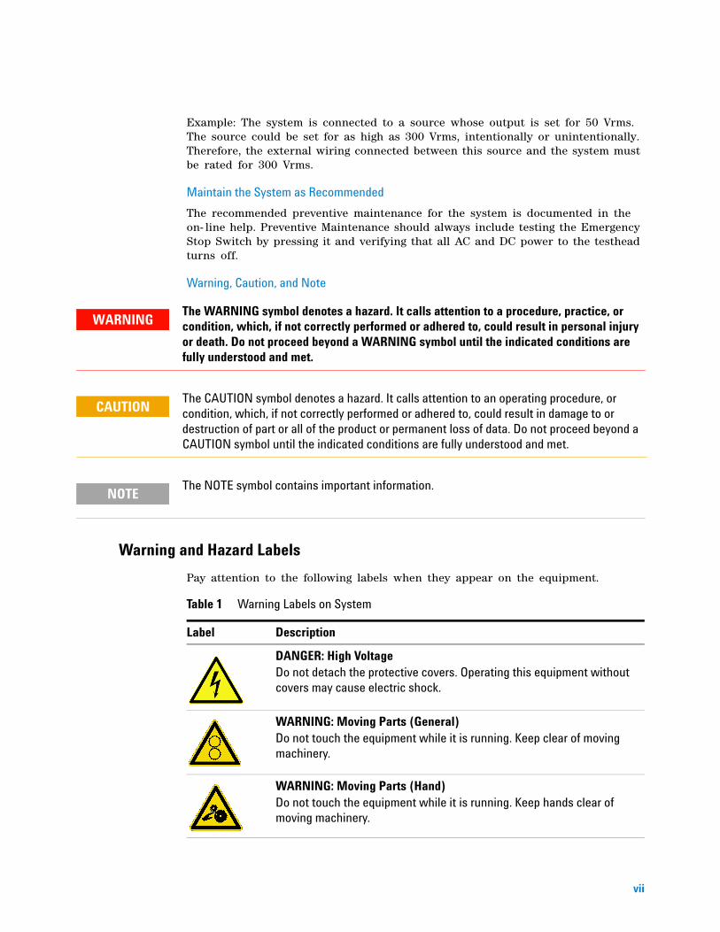
Warning and Hazard Labels
Pay attention to the following labels when they appear on the equipment.
The WARNING symbol denotes a hazard. It calls attention to a procedure, practice, or condition, which, if not correctly performed or adhered to, could result in personal injury or death. Do not proceed beyond a WARNING symbol until the indicated conditions are fully understood and met.
The CAUTION symbol denotes a hazard. It calls attention to an operating procedure, or condition, which, if not correctly performed or adhered to, could result in damage to or destruction of part or all of the product or permanent loss of data. Do not proceed beyond a CAUTION symbol until the indicated conditions are fully understood and met.
The NOTE symbol contains important information.
WARNING
CAUTION
NOTE
Table 1 Warning Labels on System
Label Description
DANGER: High VoltageDo not detach the protective covers. Operating this equipment without covers may cause electric shock.
WARNING: Moving Parts (General)Do not touch the equipment while it is running. Keep clear of moving machinery.
WARNING: Moving Parts (Hand)Do not touch the equipment while it is running. Keep hands clear of moving machinery.

viii
Emergency Stop
In case of emergency, press the red Emergency Stop switch (Figure 1) to cut off power to the system.
Resetting the Emergency Stop
1 Turn the red Emergency Stop switch clockwise to release it.
2 Press the Reset button to reset the safety relay and resume operation.
Figure 1 Emergency Stop Button
WARNING: Pinch HazardDo not touch the equipment while it is running. Keep hands away from the indicated areas to avoid pinched fingers.
Table 1 Warning Labels on System
Label Description
DO NOT use the Emergency Shutdown Switch as a substitute for correct power-down (unboot) procedures
Reset Button
NOTE
1
Medalist i3070 Series 5i Inline ICT SystemSystem Installation
Site Preparation
Site Preparation Process and Responsibilities 2
Structural Requirements 4
Power Requirements 8
Compressed Air Requirements 13
SMEMA Communication 14
This chapter describes the requirements for installation of the Medalist i3070 Series 5i system. Please read it carefully and follow the recommendations to ensure that your site is prepared and properly equipped, and to minimize the possibility of problems or delays in system installation.
If you have any questions, please contact your Agilent representative.
2System
Installation
Site Preparation
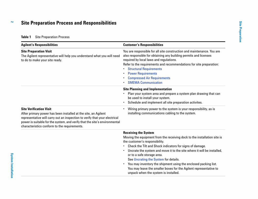
Site Preparation Process and Responsibilities
Table 1 Site Preparation Process
Agilent’s Responsibilities Customer’s Responsibilities
Site Preparation VisitThe Agilent representative will help you understand what you will need to do to make your site ready.
You are responsible for all site construction and maintenance. You are also responsible for obtaining any building permits and licenses required by local laws and regulations.Refer to the requirements and recommendations for site preparation:• Structural Requirements• Power Requirements• Compressed Air Requirements• SMEMA Communication
Site Planning and Implementation• Plan your system area and prepare a system plan drawing that can
be used to install your system.• Schedule and implement all site preparation activites.
Site Verification VisitAfter primary power has been installed at the site, an Agilent representative will carry out an inspection to verify that your electrical power is suitable for the system, and verify that the site’s environmental characteristics conform to the requirements.
• Wiring primary power to the system is your responsibility, as is installing communications cabling to the system.
Receiving the SystemMoving the equipment from the receiving dock to the installation site is the customer’s responsibility.• Check the Tilt and Shock indicators for signs of damage. • Uncrate the system and move it to the site where it will be installed,
or to a safe storage area. See Uncrating the System for details.
• You may inventory the shipment using the enclosed packing list. You may leave the smaller boxes for the Agilent representative to unpack when the system is installed.
Site Preparation
System Installation
3
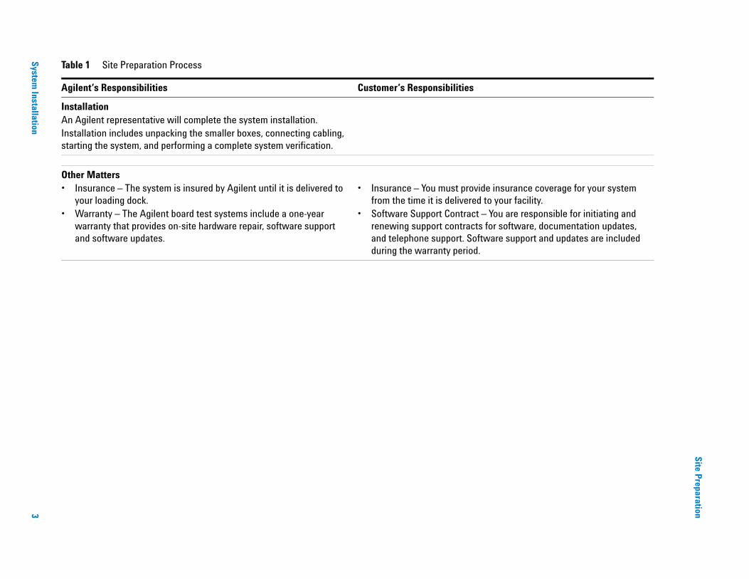
InstallationAn Agilent representative will complete the system installation. Installation includes unpacking the smaller boxes, connecting cabling, starting the system, and performing a complete system verification.
Other Matters• Insurance – The system is insured by Agilent until it is delivered to
your loading dock.• Warranty – The Agilent board test systems include a one-year
warranty that provides on-site hardware repair, software support and software updates.
• Insurance – You must provide insurance coverage for your system from the time it is delivered to your facility.
• Software Support Contract – You are responsible for initiating and renewing support contracts for software, documentation updates, and telephone support. Software support and updates are included during the warranty period.
Table 1 Site Preparation Process
Agilent’s Responsibilities Customer’s Responsibilities
4 Medalist i3070 Series 5i System Installation
Site Preparation
Structural Requirements
• Floor Space Requirements• Moving Access Requirements
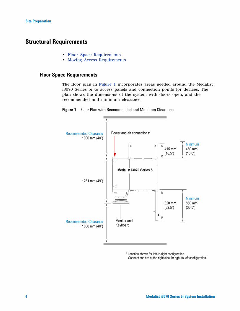
Floor Space Requirements
The floor plan in Figure 1 incorporates areas needed around the Medalist i3070 Series 5i to access panels and connection points for devices. The plan shows the dimensions of the system with doors open, and the recommended and minimum clearance.
Figure 1 Floor Plan with Recommended and Minimum Clearance
1000 mm (40”)
Monitor and 1000 mm (40”)
Medalist i3070 Series 5i
415 mm
820 mm 850 mm
450 mm(16.5”) (18.0”)
(32.5”) (33.5”)
Recommended Clearance
Recommended Clearance
Minimum
Minimum
1231 mm (49”)
Power and air connections*
Keyboard
* Location shown for left-to-right configuration.Connections are at the right side for right-to-left configuration.
Site Preparation
Medalist i3070 Series 5i System Installation 5
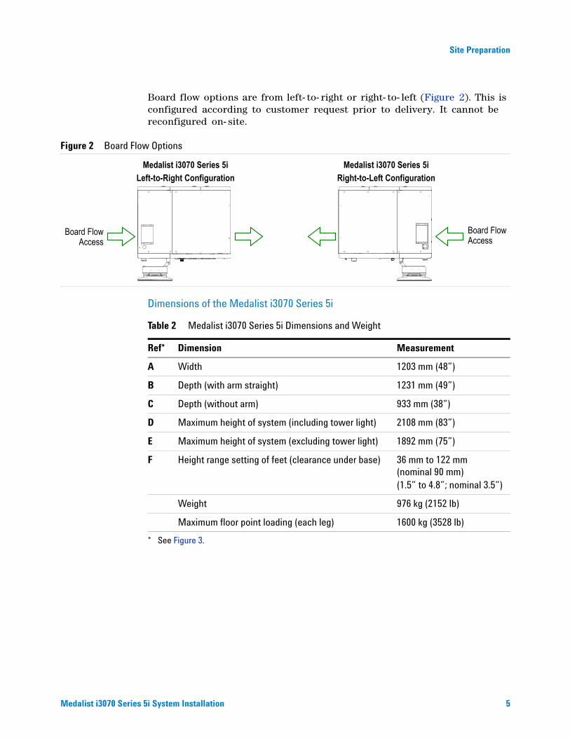
Board flow options are from left- to- right or right- to- left (Figure 2). This is configured according to customer request prior to delivery. It cannot be reconfigured on- site.
Figure 2 Board Flow Options
Dimensions of the Medalist i3070 Series 5i
Board Flow
Medalist i3070 Series 5i
Board FlowAccess
Left-to-Right ConfigurationMedalist i3070 Series 5i
Right-to-Left Configuration
Access
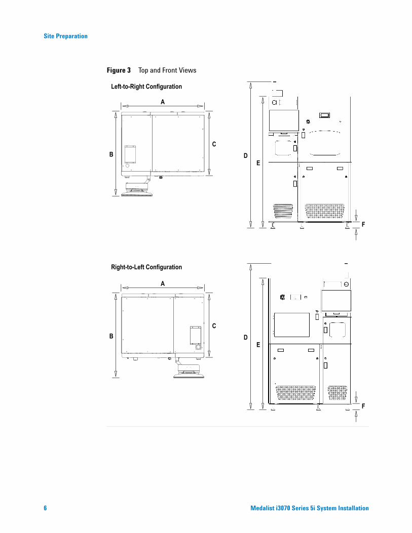
Table 2 Medalist i3070 Series 5i Dimensions and Weight
Ref*
* See Figure 3.
Dimension Measurement
A Width 1203 mm (48”)
B Depth (with arm straight) 1231 mm (49”)
C Depth (without arm) 933 mm (38”)
D Maximum height of system (including tower light) 2108 mm (83”)
E Maximum height of system (excluding tower light) 1892 mm (75”)
F Height range setting of feet (clearance under base) 36 mm to 122 mm(nominal 90 mm)(1.5” to 4.8”; nominal 3.5”)
Weight 976 kg (2152 lb)
Maximum floor point loading (each leg) 1600 kg (3528 lb)
6 Medalist i3070 Series 5i System Installation
Site Preparation
Figure 3 Top and Front Views
A
BC
DE
F
Left-to-Right Configuration
Right-to-Left Configuration
A
BC
DE
F
Site Preparation
Medalist i3070 Series 5i System Installation 7
Moving Access Requirements
Space for Moving
The Medalist i3070 Series 5i will be crated for delivery. The crated system requires a vertical clearance of at least 1500 mm (75”) and a horizontal clearance of at least 1730 mm (56”) in all areas.
This is the minimum space required for the system to pass. Take into account the turning radius of the forklift or moving equipment as well.
Forklift Requirements
A forklift with tines of at least 1530 mm (54”) and capable of lifting at least 1500 kg (5000 lb) at a load centre of 1140 mm (45”) is needed to unload and move the system.
Other transportation can be used as long as the full weight of the main unit is fully and properly supported.
Table 3 Dimensions of the Crated System
Dimension Measurement
Width 1440 mm (57”)
Depth 1460 mm (57”)
Height 2400 mm (94”)
Weight 1014 kg (2235 lb)
Failure to meet the above requirements could result in serious injury to personnel and/or damage to the Medalist i3070 Series 5i system.WARNING
8 Medalist i3070 Series 5i System Installation
Site Preparation
Power Requirements
• Medalist i3070 Series 5i Main Power• Medalist i3070 Series 5i PDU• Mains Disconnect• Power Cord
The system power and PDU must be factory configured to match the power at the customer site. This is done prior to delivery and installation at the customer site. The power cannot be reconfigured on- site.
The power configuration for the system is shown on a label at the rear of the system (bottom right). The voltage of the PDU is indicated on the front panel of the PDU.
Customer Responsibilities
It is the customer’s responsibility to (a) prepare the site with adequate AC power for the system, and (b) connect the system to the AC power source. These are not Agilent’s responsibilities.
Medalist i3070 Series 5i Main Power
This is the main 3- phase AC power input connected from the customer site.
After connecting power to the system, do not power up the system. An Agilent service representative will verify the power and complete the system installation and verification.CAUTION
Table 4 Main Power Options
Power Option Frequency Voltage line-to-neutral/ line-to-line
200–240V 3-Phase Delta 3PD 50/60 Hz 200220230240
208–220V 3-Phase Wye 3PY 50/60 Hz 208220
380–415V 3-Phase Wye with Neutral
3PN 50/60 Hz 220 / 380230 / 400240 / 415
Site Preparation
Medalist i3070 Series 5i System Installation 9
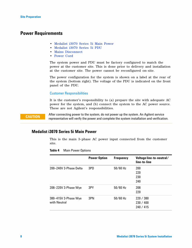
Medalist i3070 Series 5i PDU
The PDU (Power Distribution Unit) is the device in the system to which AC power is connected. The PDU is wired differently for different power configurations and will be configured to match the system power configuration. The voltage of the PDU is marked on the front panel of the PDU.
The E1135 PDU is connected via a 3- phase AC terminal block wired out from the system main power.
Figure 4 PDU (Power Distribution Unit)
PDU
Mains Disconnect Switch
Rear View
3-phase AC Terminal Block

10 Medalist i3070 Series 5i System Installation
Site Preparation
Mains Disconnect
The system must be equipped with a mains disconnect that provides over- current and short- circuit protection. It may be a fused disconnect or a circuit breaker (see Figure 5).
If a fused disconnect is used, it must:
• Be rated for 30 amps in each phase.
• Open all line conductors and neutral conductors where local code applies, but not the protective earth conductor.
• Be marked “System Mains Disconnect” or the equivalent in your local language.
• Be marked with a “ON” for the On position or “OFF” for the Off position.
• Be capable of being locked in the Off position, but not in the On position.
• Be installed within 3 m (10 ft) of the system, where it can be easily reached by the system operator without requiring the system to be moved to access the disconnect.
If a circuit breaker is used, it must meet all of the above requirements plus:
• Be rated for a minimum of 10,000 Amperes Interrupting Capacity (AIC) if used on a 200–240 volt circuit, or 14,000 AIC if used on a higher voltage circuit.
Figure 5 Wiring Diagram for Customer Site
Site Preparation
Medalist i3070 Series 5i System Installation 11
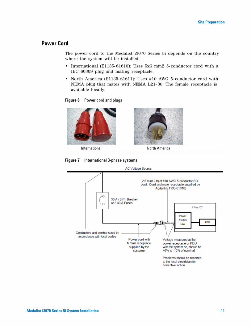
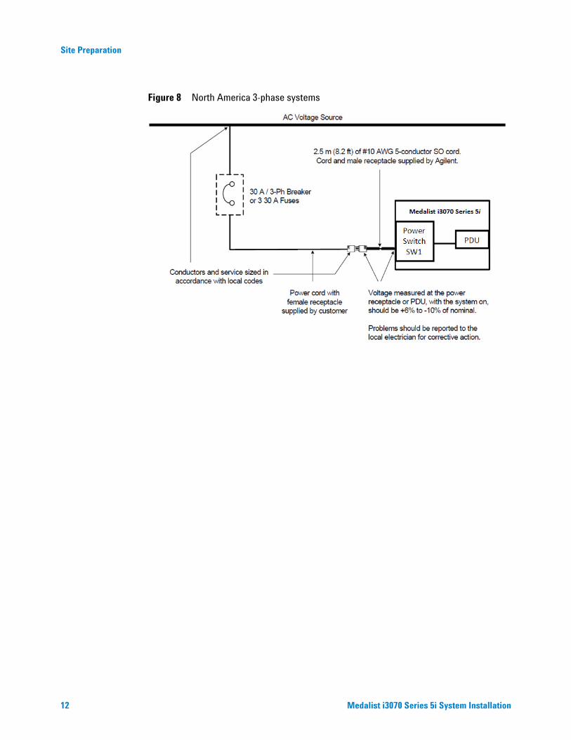
Power Cord
The power cord to the Medalist i3070 Series 5i depends on the country where the system will be installed:
• International (E1135- 61610): Uses 5x6 mm2 5- conductor cord with a IEC 60309 plug and mating receptacle.
• North America (E1135- 61611): Uses #10 AWG 5- conductor cord with NEMA plug that mates with NEMA L21- 30. The female receptacle is available locally.
Figure 6 Power cord and plugs
Figure 7 International 3-phase systems
International North America
12 Medalist i3070 Series 5i System Installation
Site Preparation
Figure 8 North America 3-phase systems

Site Preparation
Medalist i3070 Series 5i System Installation 13
Compressed Air Requirements
The Medalist i3070 Series 5i uses compressed air to pressurize air cylinders that actuate the fixture drawer and fixture pull- down towers. The pull- down towers pull and hold a fixture down onto the testhead, enabling contact between the pins on the fixture and the spring- loaded interface pins in the testhead.
Install compressed air lines (using rigid lines, 8 mm diameter) to a point at the rear of the system (Figure 1). A male quick- disconnect air fitting is provided at the rear of the system to connect to the compressed air supply.
Figure 9 Compressed Air Supply
An air cutoff valve is recommended for situations when the air line must be disconnected.
Table 5 Compressed Air Requirements
Description Measurement
Maximum Pressure 700 kPa (7 bar/102 psi)
Minimum Pressure 500 kPa (5 bar/73 psi)
Minimum Flow Rate 0.66 L/s at STP (1.4 SCFM)
Relative Humidity Allowed 70% for compressed air (150 psi) at 25°C50% for compressed air (150 psi) at 40°CDew point must be not more than 5°C
Rear View
MAIN AIR SUPPLY
14 Medalist i3070 Series 5i System Installation
Site Preparation
SMEMA Communication
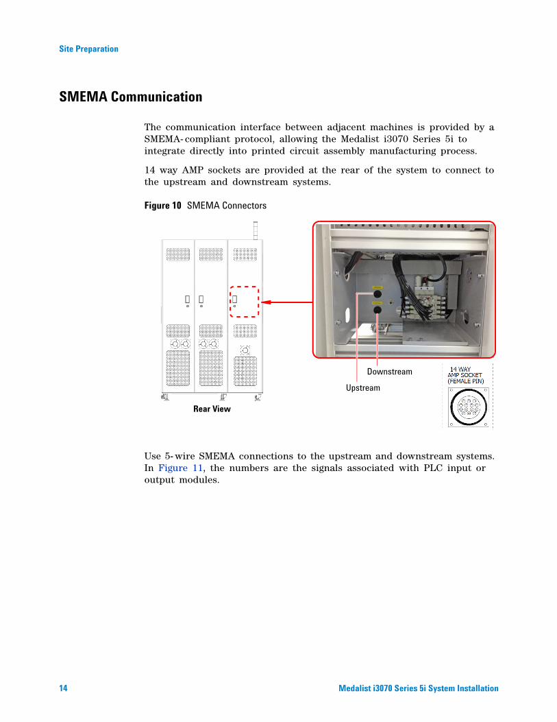
The communication interface between adjacent machines is provided by a SMEMA- compliant protocol, allowing the Medalist i3070 Series 5i to integrate directly into printed circuit assembly manufacturing process.
14 way AMP sockets are provided at the rear of the system to connect to the upstream and downstream systems.
Figure 10 SMEMA Connectors
Use 5- wire SMEMA connections to the upstream and downstream systems. In Figure 11, the numbers are the signals associated with PLC input or output modules.
Rear View
Upstream
Downstream

Site Preparation
Medalist i3070 Series 5i System Installation 15
Figure 11 SMEMA Communication
Table 6 SMEMA Signals
Signal Description
UBAG Upstream Board Available Good Input signal to ICT system.Upstream system forces this signal to low when Good board is available to send to downstream (ICT) system.
UBAB Upstream Board Available Bad Input signal to ICT system.Upstream system forces this signal to low when Bad board is available to send to downstream (ICT) system.
USB Upstream System Ready Output signal to upstream system.ICT system forces this signal to low when it is ready to receive a board.
DSB Downstream System Busy Input signal to ICT system.Downstream system forces this signal to low when it is ready to receive a board.
DBAG Good Board Available For Downstream
Output signals from ICT system.ICT system forces these signals to low when it ready to transfer the board with status to downstream system. DBAB Bad Board Available For
Downstream
UpstreamConnector
DownstreamConnector
16 Medalist i3070 Series 5i System Installation
Site Preparation
Upstream and ICT SMEMA Interface
1 Upstream system closes UBA relay to indicate to ICT system that a board is available for testing.
2 After a delay of 500 ms, ICT system closes USB relay to indicate to upstream system that it is ready to receive the board.
3 Once upstream system detects USB, it starts transferring the board to ICT system.
4 Upstream system opens the UBA relay once the board exits the upstream system.
5 ICT system opens USB relay when the board is in the ICT system. This signal remains until the board clears the system (that is, Zone 1 for the Medalist i3070 Series 5i).
ICT and Downstream SMEMA Interface
1 A board status (either PASS or FAIL) will be sent to the PLC when testing is completed. At the same time, ICT system closes the DBAG or DBAB relay to indicate to downstream system that a board is available.
2 When downstream system detects DBAG or DBAB, it closes DSB relay to indicate to ICT system that it is ready to receive the board.
3 When ICT system detects DSB signal, it starts transferring the board.
4 After the board exits the ICT system, ICT system opens DBAG or DBAB relay after a 500 ms delay.
5 Downstream system opens DSB relay when the board is in the downstream system.
Usually the transfer is initiated by the upstream system.
Usually the transfer is initiated by the ICT system.
NOTE
NOTE

25
Medalist i3070 Series 5i Inline ICT SystemSystem Installation
Uncrating the System
Overview 26
Uncrating Procedure 28
26 Medalist i3070 Series 5i System Installation
Uncrating the System
Overview
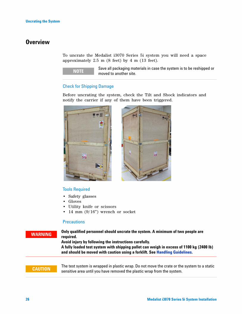
To uncrate the Medalist i3070 Series 5i system you will need a space approximately 2.5 m (8 feet) by 4 m (13 feet).
Check for Shipping Damage
Before uncrating the system, check the Tilt and Shock indicators and notify the carrier if any of them have been triggered.
Tools Required
• Safety glasses• Gloves• Utility knife or scissors• 14 mm (9/16”) wrench or socket
Precautions
Save all packaging materials in case the system is to be reshipped or moved to another site.NOTE
Only qualified personnel should uncrate the system. A minimum of two people are required. Avoid injury by following the instructions carefully. A fully loaded test system with shipping pallet can weigh in excess of 1100 kg (2400 lb) and should be moved with caution using a forklift. See Handling Guidelines.
The test system is wrapped in plastic wrap. Do not move the crate or the system to a static sensitive area until you have removed the plastic wrap from the system.
WARNING
CAUTION
Uncrating the System
Medalist i3070 Series 5i System Installation 27
Handling Guidelines
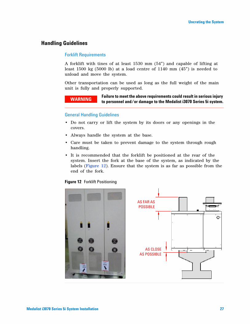
Forklift Requirements
A forklift with tines of at least 1530 mm (54”) and capable of lifting at least 1500 kg (5000 lb) at a load centre of 1140 mm (45”) is needed to unload and move the system.
Other transportation can be used as long as the full weight of the main unit is fully and properly supported.
General Handling Guidelines
• Do not carry or lift the system by its doors or any openings in the covers.
• Always handle the system at the base.
• Care must be taken to prevent damage to the system through rough handling.
• It is recommended that the forklift be positioned at the rear of the system. Insert the fork at the base of the system, as indicated by the labels (Figure 12). Ensure that the system is as far as possible from the end of the fork.
Figure 12 Forklift Positioning
Failure to meet the above requirements could result in serious injury to personnel and/or damage to the Medalist i3070 Series 5i system.WARNING
AS FAR ASPOSSIBLE
AS CLOSEAS POSSIBLE

28 Medalist i3070 Series 5i System Installation
Uncrating the System
Uncrating Procedure
1 With one person on each side of the front wall, release the latches and remove the front wall from the crate.
2 Remove the bolts along the bottom of the rear and side walls.
Crates are custom built for individual systems and may have slight differences in how they are assembled. For instance, the front wall may be attached with ¼-turn draw latches or by bolts. Another variation is how the system is secured to the base. It may be secured using poly straps or braced by wooden blocks that are attached by screws from the side walls.
NOTE
At least two people are required for the next step.
Front view of crated system on pallet
Latches
Front wall removed
AccessoriesBox
Rear and side walls
Bolts
WARNING
Uncrating the System
Medalist i3070 Series 5i System Installation 29
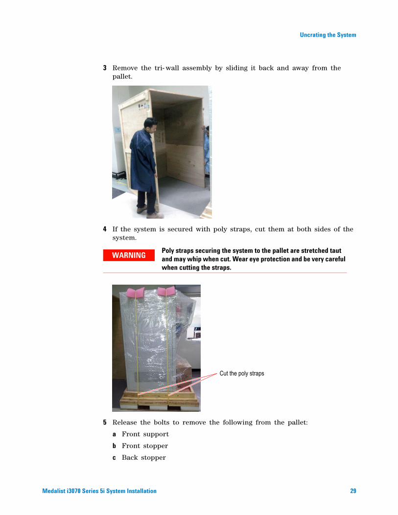
3 Remove the tri- wall assembly by sliding it back and away from the pallet.
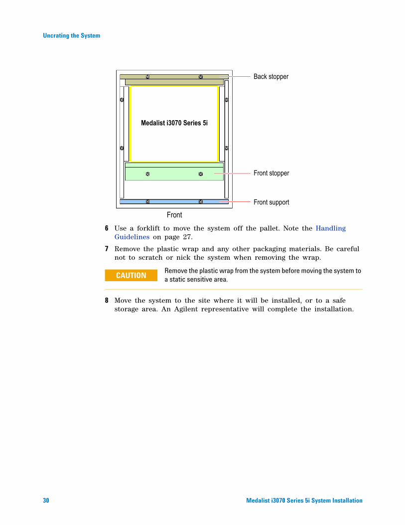
4 If the system is secured with poly straps, cut them at both sides of the system.
5 Release the bolts to remove the following from the pallet:
a Front support
b Front stopper
c Back stopper
Poly straps securing the system to the pallet are stretched taut and may whip when cut. Wear eye protection and be very careful when cutting the straps.
WARNING
Cut the poly straps
30 Medalist i3070 Series 5i System Installation
Uncrating the System
6 Use a forklift to move the system off the pallet. Note the Handling Guidelines on page 27.
7 Remove the plastic wrap and any other packaging materials. Be careful not to scratch or nick the system when removing the wrap.
8 Move the system to the site where it will be installed, or to a safe storage area. An Agilent representative will complete the installation.
Remove the plastic wrap from the system before moving the system to a static sensitive area.
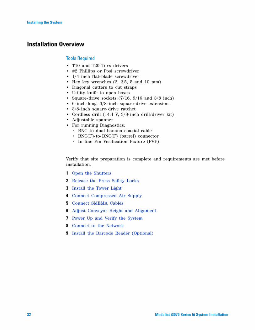
Medalist i3070 Series 5i
Front
Front support
Front stopper
Back stopper
CAUTION

31
Medalist i3070 Series 5i Inline ICT SystemSystem Installation
Installing the System
Installation Overview 32
Open the Shutters 33
Release the Press Safety Locks 34
Install the Tower Light 36
Connect Compressed Air Supply 37
Connect SMEMA Cables 38
Adjust Conveyor Height and Alignment 38
Power Up and Verify the System 40
Connect to the Network 43
Install the Barcode Reader (Optional) 44
The system should only be installed by an Agilent-authorized service representative.
If the system has been kept in low temperature storage conditions (0°C to –40°C), it must be allowed to soak for at least 24 hours in a normal operating environment (10°C to 35°C) prior to installation. Make sure the system is completely dry prior to connecting power.
CAUTION
CAUTION
32 Medalist i3070 Series 5i System Installation
Installing the System
Installation Overview
Tools Required
• T10 and T20 Torx drivers• #2 Phillips or Posi screwdriver• 1/4 inch flat- blade screwdriver• Hex key wrenches (2, 2.5, 5 and 10 mm)• Diagonal cutters to cut straps• Utility knife to open boxes• Square- drive sockets (7/16, 9/16 and 3/8 inch)• 6- inch- long, 3/8- inch square- drive extension• 3/8- inch square- drive ratchet• Cordless drill (14.4 V, 3/8- inch drill/driver kit)• Adjustable spanner• For running Diagnostics:
• BNC- to- dual banana coaxial cable• BNC(F)- to- BNC(F) (barrel) connector• In- line Pin Verification Fixture (PVF)
Verify that site preparation is complete and requirements are met before installation.
1 Open the Shutters
2 Release the Press Safety Locks
3 Install the Tower Light
4 Connect Compressed Air Supply
5 Connect SMEMA Cables
6 Adjust Conveyor Height and Alignment
7 Power Up and Verify the System
8 Connect to the Network
9 Install the Barcode Reader (Optional)
Installing the System
Medalist i3070 Series 5i System Installation 33
Open the Shutters
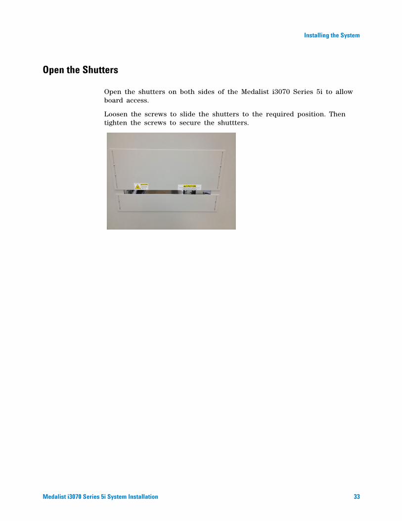
Open the shutters on both sides of the Medalist i3070 Series 5i to allow board access.
Loosen the screws to slide the shutters to the required position. Then tighten the screws to secure the shuttters.
34 Medalist i3070 Series 5i System Installation
Installing the System
Release the Press Safety Locks
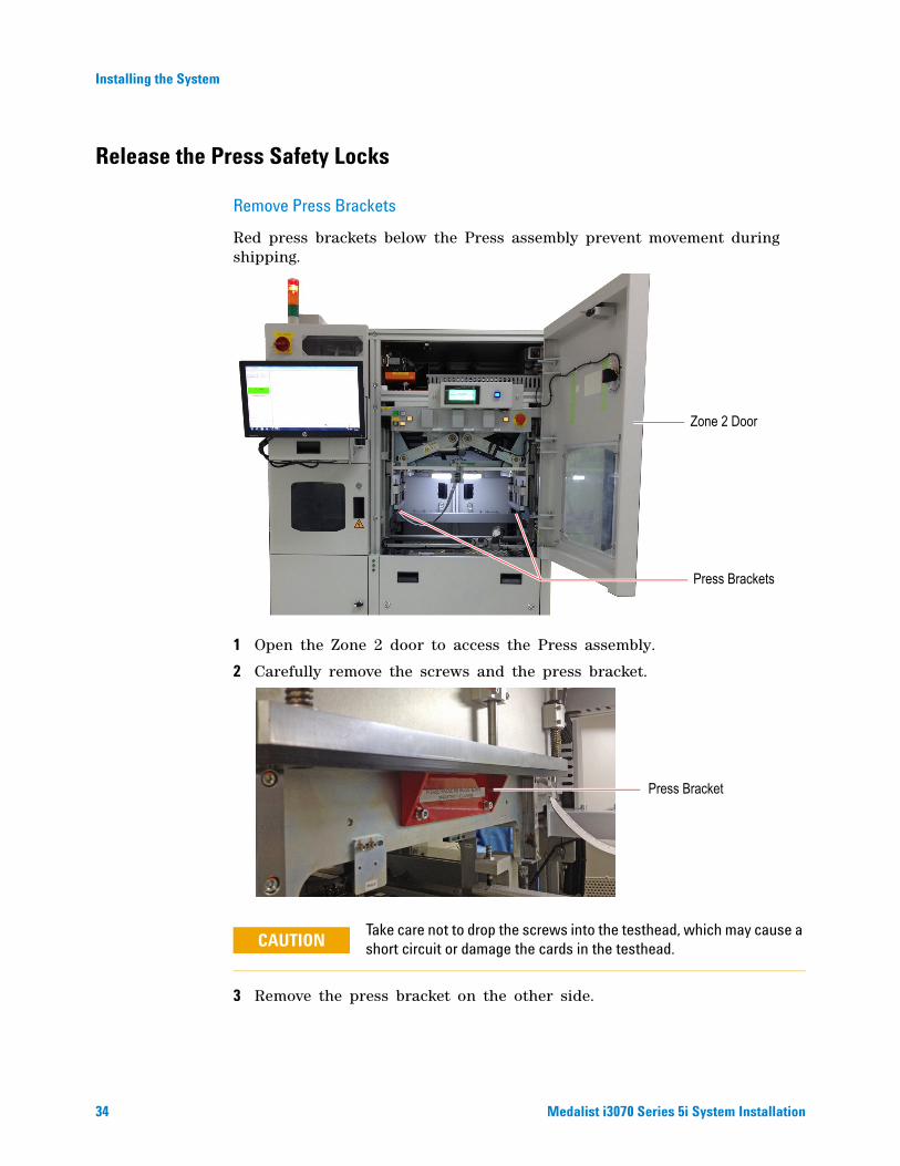
Remove Press Brackets
Red press brackets below the Press assembly prevent movement during shipping.
1 Open the Zone 2 door to access the Press assembly.
2 Carefully remove the screws and the press bracket.
3 Remove the press bracket on the other side.
Take care not to drop the screws into the testhead, which may cause a short circuit or damage the cards in the testhead.
Press Brackets
Zone 2 Door
Press Bracket
CAUTION

Installing the System
Medalist i3070 Series 5i System Installation 35
Unlock Press Hooks
Locked press hooks prevent the Press from moving down accidentally when the system is not in use.
Push each hook clockwise to unlock it.
Make sure power to the system is off before unlocking the press hooks.
Front Hook
Rear Hook
Locked
Locked
CAUTION
Unlocked
36 Medalist i3070 Series 5i System Installation
Installing the System
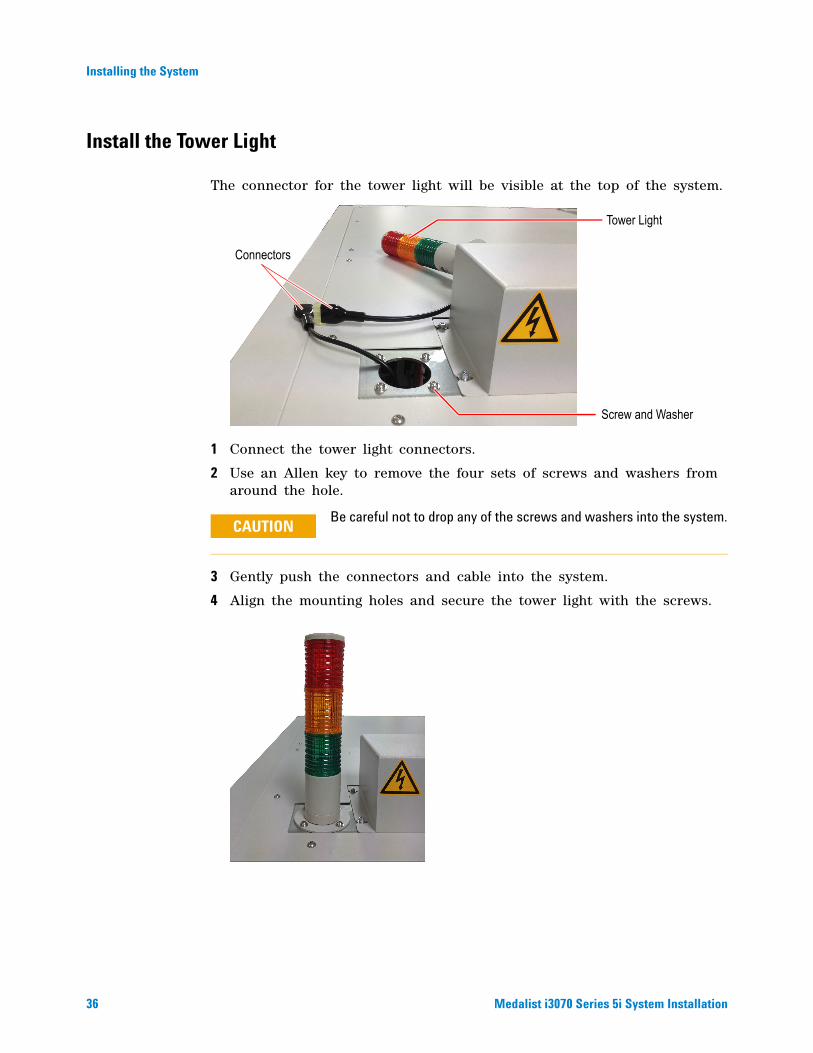
Install the Tower Light
The connector for the tower light will be visible at the top of the system.
1 Connect the tower light connectors.
2 Use an Allen key to remove the four sets of screws and washers from around the hole.
3 Gently push the connectors and cable into the system.
4 Align the mounting holes and secure the tower light with the screws.
Be careful not to drop any of the screws and washers into the system.
Screw and Washer
Tower Light
Connectors
CAUTION
Installing the System
Medalist i3070 Series 5i System Installation 37
Connect Compressed Air Supply
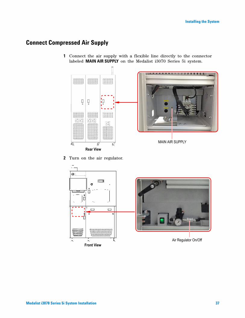
1 Connect the air supply with a flexible line directly to the connector labeled MAIN AIR SUPPLY on the Medalist i3070 Series 5i system.
2 Turn on the air regulator.
Rear View
MAIN AIR SUPPLY
Front ViewAir Regulator On/Off

38 Medalist i3070 Series 5i System Installation
Installing the System
Connect SMEMA Cables
1 Connect the cables to the upstream and downstream systems. Route the cables through the cutout at the base of the system.
Adjust Conveyor Height and Alignment
Conveyor Height
Adjust the height of the Medalist i3070 Series 5i conveyor to the site requirements, using the six adjustable feet.
Rear ViewSMEMA Connectors

Installing the System
Medalist i3070 Series 5i System Installation 39
Conveyor Alignment
Adjust the conveyor alignment and offset between upstream and downstream systems. Use PCBs as a visual aid to checking the alignment.
1 Place a board on each conveyor.
2 Adjust the position of the machines until the angular misalignment and offset are minimized.
3 Adjust the height so that the upstream system is slightly higher than the downstream system.
4 Test the alignment by sliding the boards across the conveyor. Adjust the alignment if necessary.
Transport Height
To facilitate the smooth transfer of PCBs, it is suggested that the height of the upstream conveyor be slightly higher than the downstream conveyor.
1 Place a board on each conveyor.

40 Medalist i3070 Series 5i System Installation
Installing the System
Power Up and Verify the System
Connect Power
1 Ensure that the voltage of the system is correct for the site.
The power configuration for the system is shown on a label at the rear of the system (Figure 13).
2 Connect the power cable from the system to the power source.
3 Ensure that the Emergency Stop switch is not activated.
4 Ensure that all the doors are closed.
5 Turn ON the Mains Disconnect Switch (Figure 13).
High Leakage CurrentThe safety ground in most installations is included in the AC cord. The system has a high leakage current therefore a safety ground must be connected to the same panel or location where the AC voltage is connected. A shock hazard can arise if the AC input and the safety ground are not grounded to the same point.
DO NOT open the PDU for any reason.Voltages capable of causing injury or death are present inside the PDU, even with the switches off.
To avoid damage to the testhead, disconnect testhead power before connecting or disconnecting testhead cables.
The PDU is not serviceable; if it is defective, it must be replaced.
WARNING
WARNING
CAUTION
NOTE
Installing the System
Medalist i3070 Series 5i System Installation 41
Figure 13 Powering Up
PDU
Mains Disconnect Switch
Rear View
Nameplate
Main Power Switch
PDU On/Off Switch
Controller
Reset Button
42 Medalist i3070 Series 5i System Installation
Installing the System
Boot the Testhead
1 Turn the Main Power Switch to ON.
2 Turn ON the PDU on/off switch that enables power to the testhead.
3 Turn on the controller and monitor.
4 Log on as calibrate (the default password is Agilent1).
5 Start DGN (Diagnostics) if it does not start automatically.
a Select Start > All Programs > Agilent ICT > KornShell.
b At the KornShell prompt, type dgn.
6 In the DGN window, boot the testhead using the Testhead Functs and Testhead Power On function keys.
Run AutoAdjust All
1 Select AutoAdjust on the Service Package - Level 1 menu, and click f1, Enter.
2 On the AutoAdjust - Level 2 menu, click f6, AutoAdj All.
3 Verify that there are no errors.
If there are errors, isolate the cause by running Full Diagnostics.
Run Full Diagnostics
1 Place a pin verification fixture on the testhead and lock it down.
2 Change Manual Intervention to Yes (press Next Value).
3 Run Full Diagnostics.
4 Verify that there are no errors.
Compressed air must be attached to the system to run full Diagnostics.
Do not press Save Config as that will make the Manual Intervention selection permanent.
NOTE
NOTE

Installing the System
Medalist i3070 Series 5i System Installation 43
Connect to the Network
If the system will be connected to a network,
1 Connect the LAN cable from the RJ45 coupler at the rear of the controller pod to the site network.
2 Configure the network. Instructions for network configuration can be found in System Administration in the online help.
Rear View
RJ45 Coupler
44 Medalist i3070 Series 5i System Installation
Installing the System
Install the Barcode Reader (Optional)
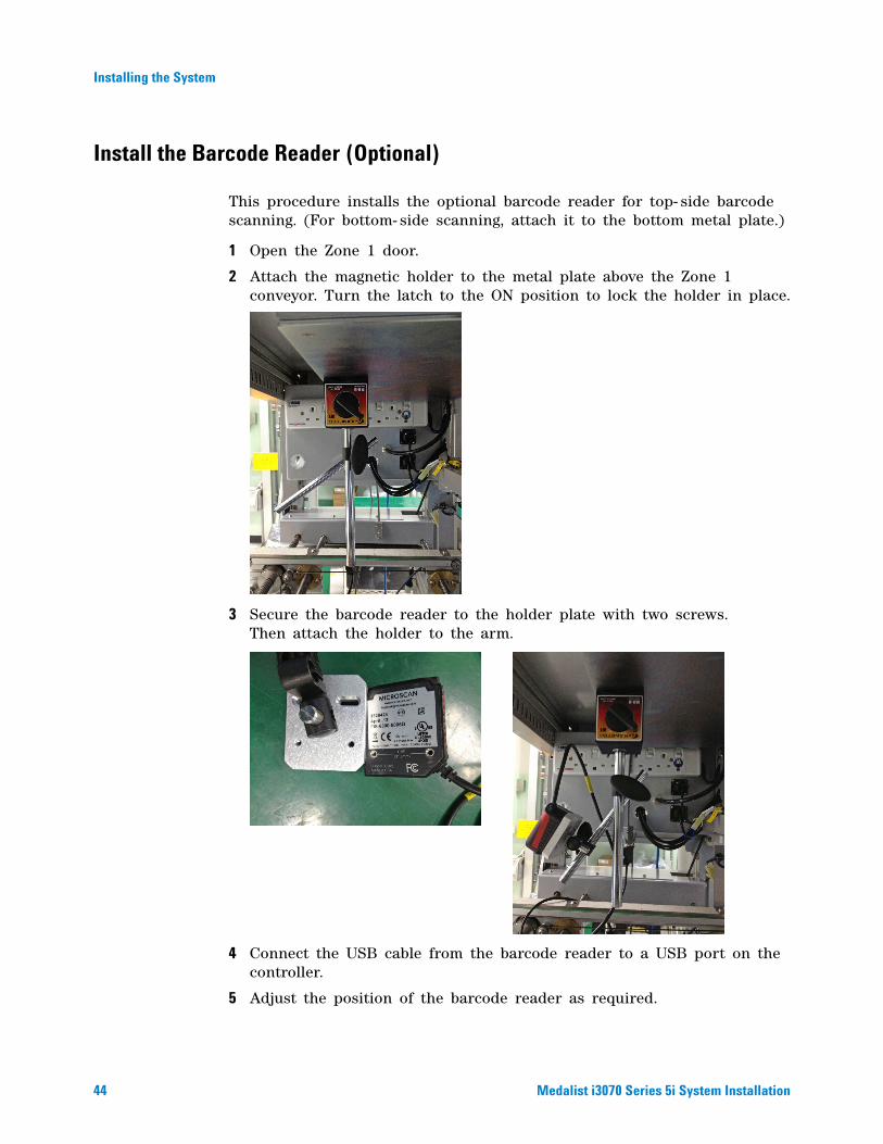
This procedure installs the optional barcode reader for top- side barcode scanning. (For bottom- side scanning, attach it to the bottom metal plate.)
1 Open the Zone 1 door.
2 Attach the magnetic holder to the metal plate above the Zone 1 conveyor. Turn the latch to the ON position to lock the holder in place.
3 Secure the barcode reader to the holder plate with two screws. Then attach the holder to the arm.
4 Connect the USB cable from the barcode reader to a USB port on the controller.
5 Adjust the position of the barcode reader as required.


© Agilent Technologies, Inc. 2013Printed in MalaysiaFirst edition, November 2013
E9988-96004
www.agilent.com