Patch Testing for Contact Allergy and Allergic Contact Dermatitis
Upload
khangminh22Category
view
0download
0
1153
ACTA UNIVERSITATIS AGRICULTURAE ET SILVICULTURAE MENDELIANAE BRUNENSIS
Volume 63 127 Number 4, 2015
http://dx.doi.org/10.11118/actaun201563041153
MECHANICAL PERFORMANCE AND CONTACT ZONE OF TIMBER JOINT WITH OBLIQUE FACES
Jiří Kunecký1,2, Václav Sebera2, Jan Tippner2, Hana Hasníková1, Michal Kloiber1, Anna Arciszewska-Kędzior1, Jaromír Milch2
1 The Institute of Theoretical and Applied Mechanics AS CR, v. v. I., Prosecká 809/76, 190 00 Praha, Czech Republic 2 Department of Wood Science, Mendel University in Brno, Zemědělská 1, 613 00 Brno, Czech Republic
Abstract
KUNECKÝ JIŘÍ, SEBERA VÁCLAV, TIPPNER JAN, HASNÍKOVÁ HANA, KLOIBER MICHAL, ARCISZEWSKA-KĘDZIOR ANNA, MILCH JAROMÍR. 2015. Mechanical Performance and Contact Zone of Timber Joint With Oblique Faces. Acta Universitatis Agriculturae et Silviculturae Mendelianae Brunensis, 63(4): 1153–1159.
The goal of the work was to evaluate mechanical performance of full-scale timber beams containing scarf joint with a dowel. Work focused on standard testing using modular system to obtain eff ective stiff ness and strength of the beams with and without the joint. The work further researched a contact zone between two timber parts of the joint – at the scarf face. This was carried out using non-destructive optical technique – digital image correlation (DIC) and newly developed algorithm. The joint was made of Norway spruce, dims. 6×0.2×0.24 m and was loaded by two modes: a) 3-point bending and b) 4-point bending. During the loading, a sequence of images was acquired for further investigation of contact zone using the proposed algorithm. The joint with scarf and dowel provided enough eff ective stiff ness, ie. 73–93% for 3-point bending test and 71% for 4-point bending with respect to MOE measured on reference solid beams. Eff ective strength of the joint was also relatively high and in a range of 55% and 60% with respect to reference solid beams in both 3-point and 4-point bending tests. Contact length diff ered for loading modes. Mean contact length in symmetrical 4-point bending was about 40%, for asymmetrical 3-point bending test, it was approx. 20% on face closer to support and 44% on a face closer to loads.
Keywords: timber joint, contact zone, bending, digital image correlation, non-destructive testing, dowel
INTRODUCTIONEvaluation of mechanical behavior of timber
joints used in historical constructions is of high interest in the Czech Republic. The reasons are a) a high number of historical structures in the area of Czech Republic and central Europe and their signifi cance to the national heritage; b) a lack of information about their behavior when mechanically loaded, and c) a lack of design codes for the practical structural design of the historical joints when their reconstruction or replacement is inevitable. For the analyses of such joints one can use experimental, analytical or numerical approach. The analytical approach, especially in the context of dowel-like joints, is mostly based on the Johansen theory (1949) and is incorporated in the standards such as Eurocode 5. Experimental assessment
of timber joints’ behavior is a main source of data collection used in research and engineering practice. Currently, it is to a convenience to employ optical-based techniques such as digital image correlation (DIC) that can provide full-fi eld displacements and strains. Not only in historic timber joints but also in other engineering areas DIC has broad range of applications. Historic timber joints is one of the areas where the strengths of the method can be effi ciently used. Timber joints are prone to brittle cracking which can lead to damage of the testing equipment.
Area of a place at which two bodies interact – contact zone – is an important geometrical parameter infl uencing stress/strain transfer and, consequently, behavior of the whole structure. In structural calculations of joints, the contact zone
1154 Jiří Kunecký, Václav Sebera, Jan Tippner, Hana Hasníková, Michal Kloiber, Anna Arciszewska-Kędzior, Jaromír Milch
is o en idealized in terms of its size and, moreover, is assumed as time-independent. It was reported in many various disciplines such assumptions reduces the physical behavior of the interaction (Ojolo and Awe, 2011; Kar and Mohanty, 2008; Ivanov and Augsburg, 2008). The same assumptions o en underlie analyses of the timber joints used in civil engineering (Li et al., 2009) where, moreover, metal connectors are o en used to position the wooden parts while providing effi cient load transfer (Branco et al., 2011). In a case metal connectors cannot be used due to inducing brittle-like behavior of joint (Parisi and Piazza, 2000), the contact zone should be of higher interest since parameters such as wood heterogeneity and geometrical imperfections may substantially contribute to lower strength and rigidity (Bodig and Jayne, 1993; Aman et al., 2008).
Experimental determination of contact zone in wooden joints has not been paid attention and is mostly missing in literature. There are partial studies reporting infl uence of loose joints that are special case of reduced contact length (Likos et al., 2012). Principally, the most robust solution for contact zone detection would be to use an X-ray CT scan to record whole loading process of a joint. Subsequent digital volume correlation (DVC) analysis would provide strains in 3D and in time and would give an exact detection of contact zone. Nonetheless, such approach was tested just on laboratory level for 3-point bending test of micro-sample (Forsberg et al., 2008 and 2010) and it is far to be applied on full-scale joints and more frequent use. More practical approach instead is to use optical techniques either working in full-fi eld regime (Muszyński and Launey, 2010; Stemolkas et al., 1997) or point-wise as showed in Schober (2000). The contact zone determination is not the issue in numerical analyses of wooden joints because they standardly use the contact elements that, though, geometrically and physically simplify the contact zones, but allow opening, sliding and closing of contact pair according to the physical situation, so one can learn where parts of the joints came into a contact (Feio et al., 2013; Mackerle, 2003; Jandejsek et al., 2011).
Therefore, to address issues of experimental detection of contact zone in timber scarf joints, we propose a new algorithm based on DIC principle. The specifi c goals were: 1) to test and measure
mechanical performance of full-scale timber beams with joints subjected to bending; 2) to develop an eff ective and quick procedure to determine contact zone from optical images.
MATERIALS AND METHODSFor all experimental work real-size wooden
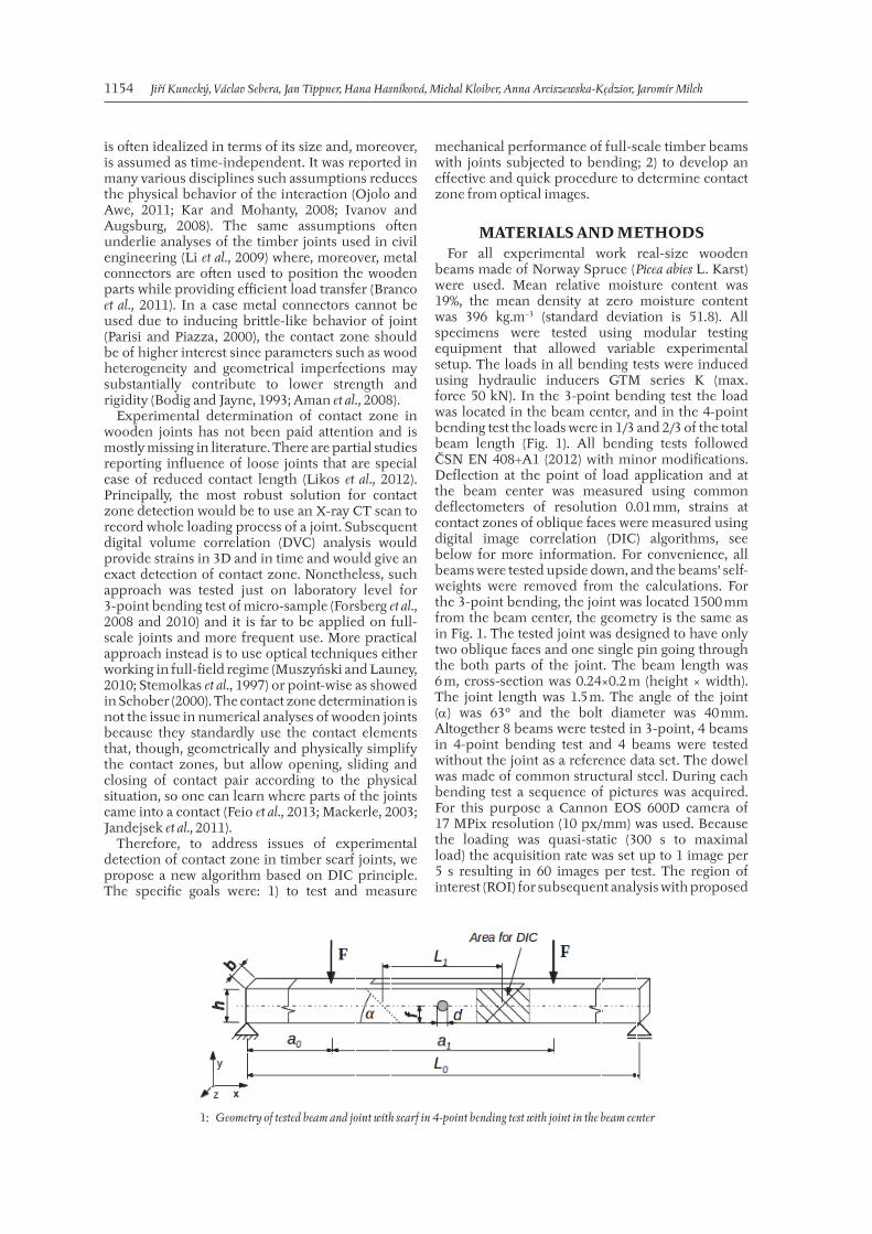
beams made of Norway Spruce (Picea abies L. Karst) were used. Mean relative moisture content was 19%, the mean density at zero moisture content was 396 kg.m−3 (standard deviation is 51.8). All specimens were tested using modular testing equipment that allowed variable experimental setup. The loads in all bending tests were induced using hydraulic inducers GTM series K (max. force 50 kN). In the 3-point bending test the load was located in the beam center, and in the 4-point bending test the loads were in 1/3 and 2/3 of the total beam length (Fig. 1). All bending tests followed ČSN EN 408+A1 (2012) with minor modifi cations. Defl ection at the point of load application and at the beam center was measured using common defl ectometers of resolution 0.01 mm, strains at contact zones of oblique faces were measured using digital image correlation (DIC) algorithms, see below for more information. For convenience, all beams were tested upside down, and the beams’ self-weights were removed from the calculations. For the 3-point bending, the joint was located 1500 mm from the beam center, the geometry is the same as in Fig. 1. The tested joint was designed to have only two oblique faces and one single pin going through the both parts of the joint. The beam length was 6 m, cross-section was 0.24×0.2 m (height × width). The joint length was 1.5 m. The angle of the joint () was 63° and the bolt diameter was 40 mm. Altogether 8 beams were tested in 3-point, 4 beams in 4-point bending test and 4 beams were tested without the joint as a reference data set. The dowel was made of common structural steel. During each bending test a sequence of pictures was acquired. For this purpose a Cannon EOS 600D camera of 17 MPix resolution (10 px/mm) was used. Because the loading was quasi-static (300 s to maximal load) the acquisition rate was set up to 1 image per 5 s resulting in 60 images per test. The region of interest (ROI) for subsequent analysis with proposed
1: Geometry of tested beam and joint with scarf in 4-point bending test with joint in the beam center
Mechanical Performance and Contact Zone of Timber Joint With Oblique Faces 1155
algorithm was defi ned at the interface where both parts of the joint come into a contact – oblique face.
The eff ective modulus in elasticity in 3-point (MOET) and 4-point (MOEF) bending test were calculated following formulas:
=T 3
FlMOE
bh y
3
4, =F
FlMOE
bh y
3
3
23108
,
whereF .... measured load [N],l...... total beam length [m], b..... beam width [m],h .... beam height [m], y..... the defl ection [m].
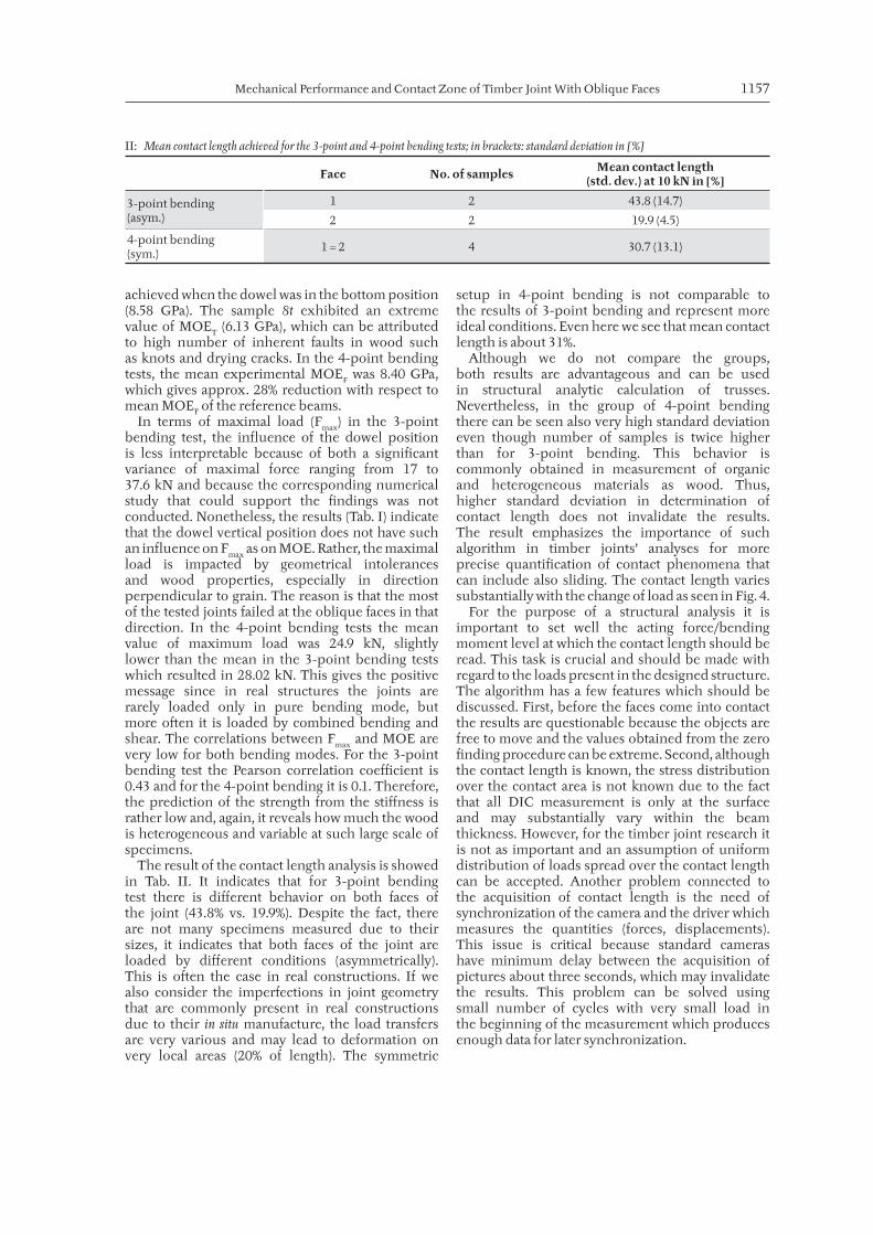
Description of Contact Determination Algorithm
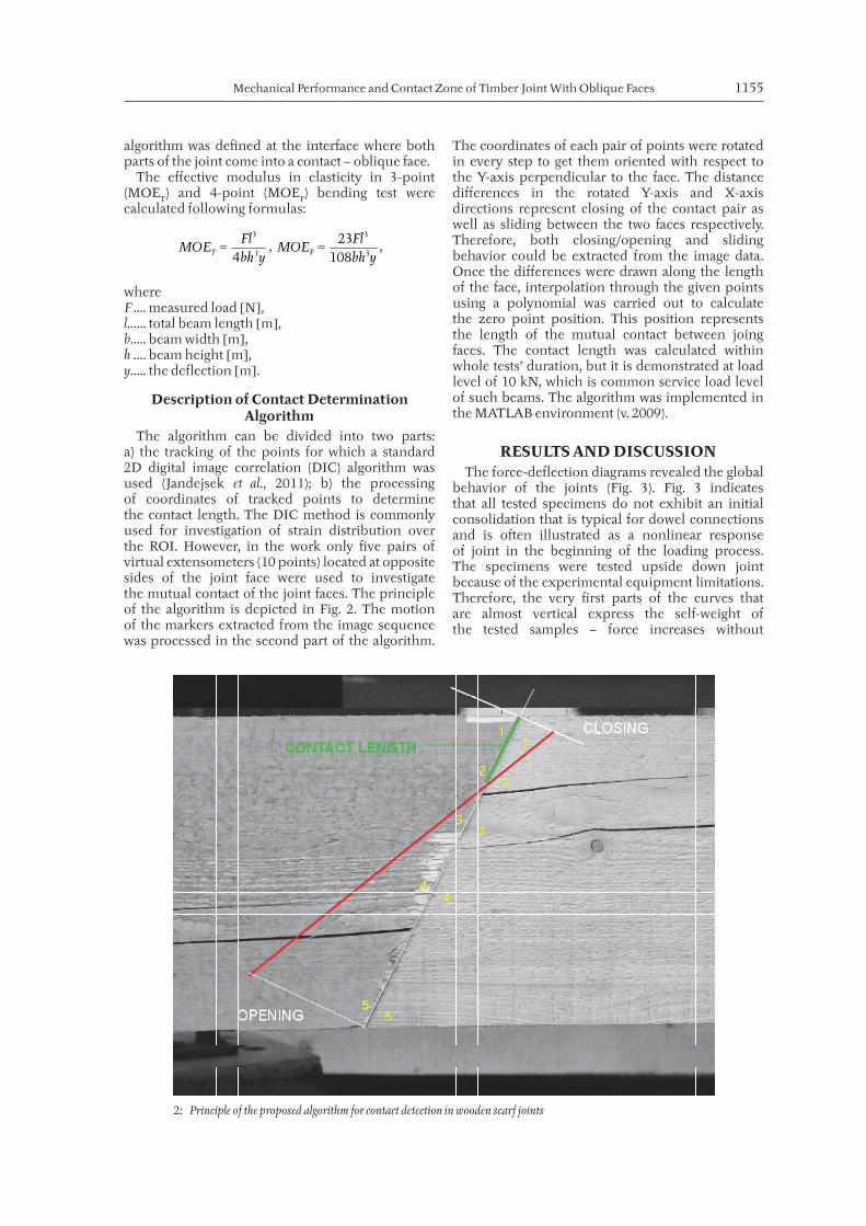
The algorithm can be divided into two parts: a) the tracking of the points for which a standard 2D digital image correlation (DIC) algorithm was used (Jandejsek et al., 2011); b) the processing of coordinates of tracked points to determine the contact length. The DIC method is commonly used for investigation of strain distribution over the ROI. However, in the work only fi ve pairs of virtual extensometers (10 points) located at opposite sides of the joint face were used to investigate the mutual contact of the joint faces. The principle of the algorithm is depicted in Fig. 2. The motion of the markers extracted from the image sequence was processed in the second part of the algorithm.
The coordinates of each pair of points were rotated in every step to get them oriented with respect to the Y-axis perpendicular to the face. The distance diff erences in the rotated Y-axis and X-axis directions represent closing of the contact pair as well as sliding between the two faces respectively. Therefore, both closing/opening and sliding behavior could be extracted from the image data. Once the diff erences were drawn along the length of the face, interpolation through the given points using a polynomial was carried out to calculate the zero point position. This position represents the length of the mutual contact between joing faces. The contact length was calculated within whole tests’ duration, but it is demonstrated at load level of 10 kN, which is common service load level of such beams. The algorithm was implemented in the MATLAB environment (v. 2009).
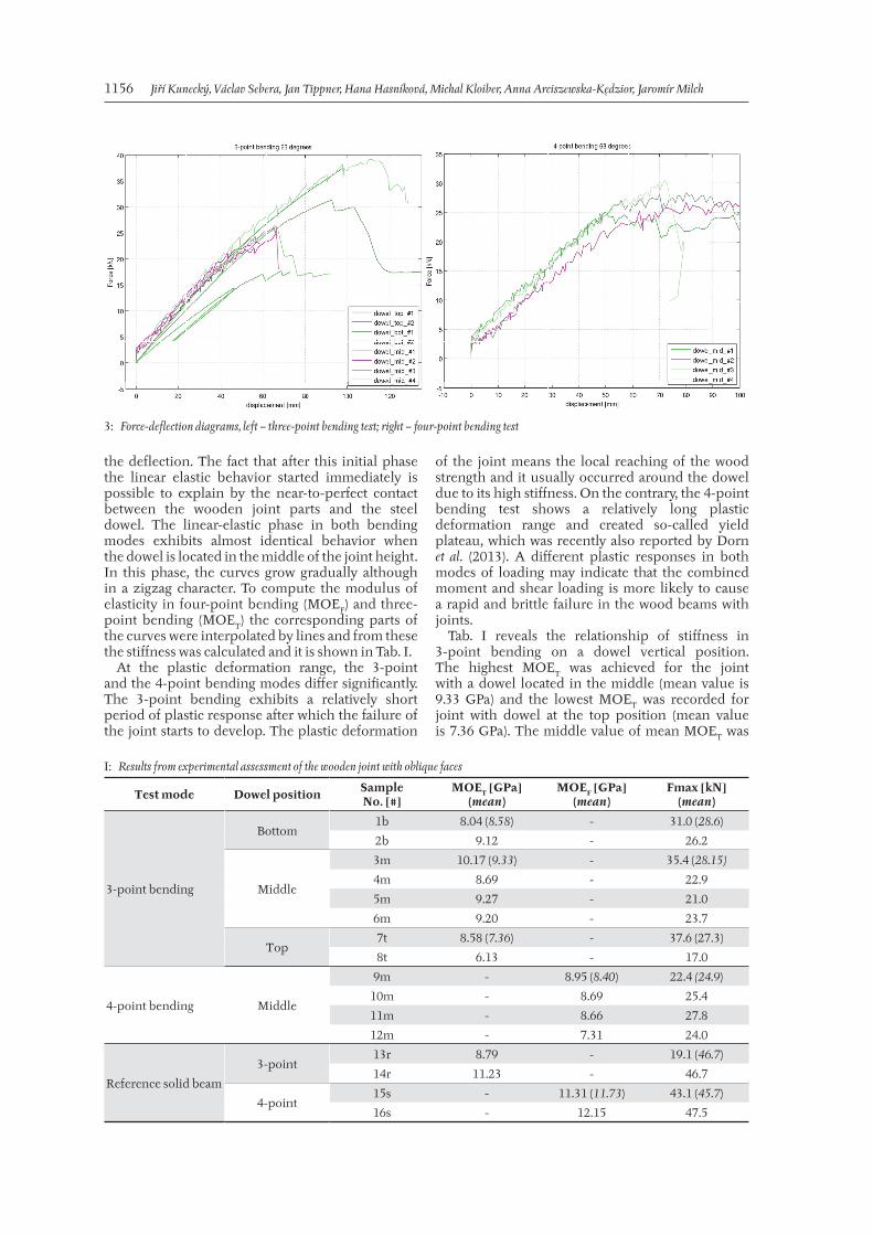
RESULTS AND DISCUSSIONThe force-defl ection diagrams revealed the global
behavior of the joints (Fig. 3). Fig. 3 indicates that all tested specimens do not exhibit an initial consolidation that is typical for dowel connections and is o en illustrated as a nonlinear response of joint in the beginning of the loading process. The specimens were tested upside down joint because of the experimental equipment limitations. Therefore, the very fi rst parts of the curves that are almost vertical express the self-weight of the tested samples – force increases without
2: Principle of the proposed algorithm for contact detection in wooden scarf joints
1156 Jiří Kunecký, Václav Sebera, Jan Tippner, Hana Hasníková, Michal Kloiber, Anna Arciszewska-Kędzior, Jaromír Milch
the defl ection. The fact that a er this initial phase the linear elastic behavior started immediately is possible to explain by the near-to-perfect contact between the wooden joint parts and the steel dowel. The linear-elastic phase in both bending modes exhibits almost identical behavior when the dowel is located in the middle of the joint height. In this phase, the curves grow gradually although in a zigzag character. To compute the modulus of elasticity in four-point bending (MOEF) and three-point bending (MOET) the corresponding parts of the curves were interpolated by lines and from these the stiff ness was calculated and it is shown in Tab. I.
At the plastic deformation range, the 3-point and the 4-point bending modes diff er signifi cantly. The 3-point bending exhibits a relatively short period of plastic response a er which the failure of the joint starts to develop. The plastic deformation
of the joint means the local reaching of the wood strength and it usually occurred around the dowel due to its high stiff ness. On the contrary, the 4-point bending test shows a relatively long plastic deformation range and created so-called yield plateau, which was recently also reported by Dorn et al. (2013). A diff erent plastic responses in both modes of loading may indicate that the combined moment and shear loading is more likely to cause a rapid and brittle failure in the wood beams with joints.
Tab. I reveals the relationship of stiff ness in 3-point bending on a dowel vertical position. The highest MOET was achieved for the joint with a dowel located in the middle (mean value is 9.33 GPa) and the lowest MOET was recorded for joint with dowel at the top position (mean value is 7.36 GPa). The middle value of mean MOET was
3: Force-deflection diagrams, left – three-point bending test; right – four-point bending test
I: Results from experimental assessment of the wooden joint with oblique faces
Test mode Dowel position SampleNo. [#]
MOET [GPa](mean)
MOEF [GPa](mean)
Fmax [kN] (mean)
3-point bending
Bottom1b 8.04 (8.58) - 31.0 (28.6)
2b 9.12 - 26.2
Middle
3m 10.17 (9.33) - 35.4 (28.15)
4m 8.69 - 22.9
5m 9.27 - 21.0
6m 9.20 - 23.7
Top7t 8.58 (7.36) - 37.6 (27.3)
8t 6.13 - 17.0
4-point bending Middle
9m - 8.95 (8.40) 22.4 (24.9)
10m - 8.69 25.4
11m - 8.66 27.8
12m - 7.31 24.0
Reference solid beam
3-point13r 8.79 - 19.1 (46.7)
14r 11.23 - 46.7
4-point15s - 11.31 (11.73) 43.1 (45.7)
16s - 12.15 47.5
Mechanical Performance and Contact Zone of Timber Joint With Oblique Faces 1157
achieved when the dowel was in the bottom position (8.58 GPa). The sample 8t exhibited an extreme value of MOET (6.13 GPa), which can be attributed to high number of inherent faults in wood such as knots and drying cracks. In the 4-point bending tests, the mean experimental MOEF was 8.40 GPa, which gives approx. 28% reduction with respect to mean MOEF of the reference beams.
In terms of maximal load (Fmax) in the 3-point bending test, the infl uence of the dowel position is less interpretable because of both a signifi cant variance of maximal force ranging from 17 to 37.6 kN and because the corresponding numerical study that could support the fi ndings was not conducted. Nonetheless, the results (Tab. I) indicate that the dowel vertical position does not have such an infl uence on Fmax as on MOE. Rather, the maximal load is impacted by geometrical intolerances and wood properties, especially in direction perpendicular to grain. The reason is that the most of the tested joints failed at the oblique faces in that direction. In the 4-point bending tests the mean value of maximum load was 24.9 kN, slightly lower than the mean in the 3-point bending tests which resulted in 28.02 kN. This gives the positive message since in real structures the joints are rarely loaded only in pure bending mode, but more o en it is loaded by combined bending and shear. The correlations between Fmax and MOE are very low for both bending modes. For the 3-point bending test the Pearson correlation coeffi cient is 0.43 and for the 4-point bending it is 0.1. Therefore, the prediction of the strength from the stiff ness is rather low and, again, it reveals how much the wood is heterogeneous and variable at such large scale of specimens.
The result of the contact length analysis is showed in Tab. II. It indicates that for 3-point bending test there is diff erent behavior on both faces of the joint (43.8% vs. 19.9%). Despite the fact, there are not many specimens measured due to their sizes, it indicates that both faces of the joint are loaded by diff erent conditions (asymmetrically). This is o en the case in real constructions. If we also consider the imperfections in joint geometry that are commonly present in real constructions due to their in situ manufacture, the load transfers are very various and may lead to deformation on very local areas (20% of length). The symmetric
setup in 4-point bending is not comparable to the results of 3-point bending and represent more ideal conditions. Even here we see that mean contact length is about 31%.
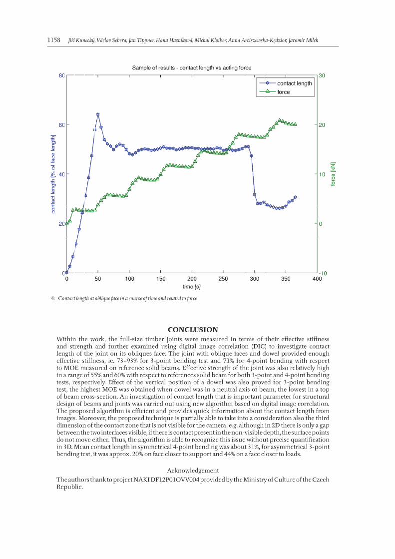
Although we do not compare the groups, both results are advantageous and can be used in structural analytic calculation of trusses. Nevertheless, in the group of 4-point bending there can be seen also very high standard deviation even though number of samples is twice higher than for 3-point bending. This behavior is commonly obtained in measurement of organic and heterogeneous materials as wood. Thus, higher standard deviation in determination of contact length does not invalidate the results. The result emphasizes the importance of such algorithm in timber joints’ analyses for more precise quantifi cation of contact phenomena that can include also sliding. The contact length varies substantially with the change of load as seen in Fig. 4.
For the purpose of a structural analysis it is important to set well the acting force/bending moment level at which the contact length should be read. This task is crucial and should be made with regard to the loads present in the designed structure. The algorithm has a few features which should be discussed. First, before the faces come into contact the results are questionable because the objects are free to move and the values obtained from the zero fi nding procedure can be extreme. Second, although the contact length is known, the stress distribution over the contact area is not known due to the fact that all DIC measurement is only at the surface and may substantially vary within the beam thickness. However, for the timber joint research it is not as important and an assumption of uniform distribution of loads spread over the contact length can be accepted. Another problem connected to the acquisition of contact length is the need of synchronization of the camera and the driver which measures the quantities (forces, displacements). This issue is critical because standard cameras have minimum delay between the acquisition of pictures about three seconds, which may invalidate the results. This problem can be solved using small number of cycles with very small load in the beginning of the measurement which produces enough data for later synchronization.
II: Mean contact length achieved for the 3-point and 4-point bending tests; in brackets: standard deviation in [%]
Face No. of samples Mean contact length(std. dev.) at 10 kN in [%]
3-point bending(asym.)
1 2 43.8 (14.7)
2 2 19.9 (4.5)
4-point bending(sym.)
1 = 2 4 30.7 (13.1)
1158 Jiří Kunecký, Václav Sebera, Jan Tippner, Hana Hasníková, Michal Kloiber, Anna Arciszewska-Kędzior, Jaromír Milch
4: Contact length at oblique face in a course of time and related to force
CONCLUSIONWithin the work, the full-size timber joints were measured in terms of their eff ective stiff ness and strength and further examined using digital image correlation (DIC) to investigate contact length of the joint on its obliques face. The joint with oblique faces and dowel provided enough eff ective stiff ness, ie. 73–93% for 3-point bending test and 71% for 4-point bending with respect to MOE measured on reference solid beams. Eff ective strength of the joint was also relatively high in a range of 55% and 60% with respect to references solid beam for both 3-point and 4-point bending tests, respectively. Eff ect of the vertical position of a dowel was also proved for 3-point bending test, the highest MOE was obtained when dowel was in a neutral axis of beam, the lowest in a top of beam cross-section. An investigation of contact length that is important parameter for structural design of beams and joints was carried out using new algorithm based on digital image correlation. The proposed algorithm is effi cient and provides quick information about the contact length from images. Moreover, the proposed technique is partially able to take into a consideration also the third dimension of the contact zone that is not visible for the camera, e.g. although in 2D there is only a gap between the two interfaces visible, if there is contact present in the non-visible depth, the surface points do not move either. Thus, the algorithm is able to recognize this issue without precise quantifi cation in 3D. Mean contact length in symmetrical 4-point bending was about 31%, for asymmetrical 3-point bending test, it was approx. 20% on face closer to support and 44% on a face closer to loads.
Acknowledgement
The authors thank to project NAKI DF12P01OVV004 provided by the Ministry of Culture of the Czech Republic.
Mechanical Performance and Contact Zone of Timber Joint With Oblique Faces 1159
REFERENCES AMAN, R. L., WEST, H. A., CORMIER, D. R. 2008.
An evaluation of loose tenon joint strength. Forest products journal, 58(3): 61–64.
BODIG, J., JAYNE, B. A. 1993. Mechanics of wood and wood composites. Krieger Pub, New York.
BRANCO, J. M., PIAZZA, M., CRUZ, P. J. S. 2011. Experimental evaluation of diff erent strengthening techniques of traditional timber connections. Engineering Structures, 33: 2259–2270.
CZECH OFFICE FOR STANDARDS, METROLOGY AND TESTING. 2012. Timber structures – Structural timber and glued laminated timber – Determination of some physical and mechanical properties. ČSN EN 408.
DORN, M., DE BORST, K., EBERHARDSTEINER, J. 2013. Experiments on dowel-type timber connections. Engineering Structures, 47: 67–80.
FEIO, A. O., LOURENC, P. B., MACHADO, J. S. 2013. Testing and modeling of a traditional timber mortise and tenon joint. Materials and structures. DOI 10.1617/s11527-013-0056-y.
FORSBERG, F., MOOSER, R., ARNOLD, M., HACK, E., WYSS, P. 2008. 3D micro-scale deformations of wood in bending: synchrotron radiation μCT data analyzed with digital volume correlation. J. Struct. Biol., 164(3): 255–262.
FORSBERG, F., SJÖDAHL, M., MOOSER, R., HACK, E., WYSS, P. 2010. Full Three-Dimensional Strain Measurements on Wood Exposed to Three-Point Bending: Analysis by Use of Digital Volume Correlation Applied to Synchrotron Radiation Micro-Computed Tomography Image Data. Strain, 46(1): 47–60.
IVANOV, V., AUGSBURG, K. 2008. Assessment of Tire Contact Properties by Nondestructive Analysis. Part 1. The Contact Length in the Region of Adhesion at Slow Rolling Velocities. Journal of Friction and Wear, 29(5): 362–368.
JANDEJSEK, I., NACHTRAB, F., UHLMANN, N., VAVŘÍK, D. 2011. X-ray dynamic defectoscopy utilizing digital image correlation. Nuclear instruments & methods in physics research section A-accelerators spectrometers detectors and associated equipment. 11th International Workshop on Radiation Imaging Detectors, 633(1): 185–186.
JOHANSEN, K. W. 1949. Theory of timber connections. International Association of Bridge and Structural Engineering Publications, 9: 249–62.
KAR, C., MOHANTY, A. R. 2008. Determination of time-varying contact length, friction force, torque and forces at the bearings in a helical gear system. Journal of Sound and Vibration, 309(1–2): 307–319.
KUNECKÝ, J., SEBERA, V., TIPPNER, J., ARCISZEWSKA-KEDZIOR, A., HASNÍKOVÁ, H., KLOIBER, M. 2014. Experimental assessment of historical full-scale timber joint accompanied by a fi nite element analysis and digital image correlation. Construction and Building Materials, in press.
LI, Y. F., TSAI, M. J., LIAO, C. N., TSAI, J. H. 2009. Eff ects of Tenon Depths and Bolt Constraint Conditions on the Mechanical Behavior of Semi-rigid Joints of Wooden Historical Buildings. Advances in structural engineering, 12(3): 349–358.
LIKOS, E., HAVIAROVA, E., ECKELMAN, C. A., ERDIL, Y. Z., OZCIFCI, A. 2012. Eff ect of tenon geometry, grain orientation, and shoulder on bending moment capacity and moment rotation characteristics of mortise and tenon joints. Wood and Fiber Science, 44(4): 462–469.
MACKERLE, J. 2003. Finite element analysis of fastening and joining: A bibliography (1990–2002), International Journal of Pressure Vessels and Piping, 80: 253–271.
MUSZYŃSKI, L., LAUNEY, M. E. 2010. Advanced imaging techniques in wood-based panels research. In: THOEMEN, H., IRLE, M., SERNEK, M. (eds.), Wood-Based Panels – An Introduction for Specialists. Brunel University Press, 177–201.
OJOLO, S. J., AWE, O. 2011. Investigation into the Eff ect of Tool-Chip Contact Length on Cutting Stability. Journal of Emerging Trends in Engineering and Applied Sciences, 2(4): 626–630.
PARISI, M. A., PIAZZA, M. 2000. Mechanics of plain and retro_tted traditional timber connections. Journal of Structural Engineering, 126(12): 1395–1403.
STEMOLKAS, J. W., ZINK A. G., LOFERSKI, J. R. 1997. Image correlation analysis of multiple-bolt wood connections. Wood and Fiber Science, 29(3): 210–227.
SCHOBER, K. U. 2000. Numerical simulation of contact problems – traditional timber joints under monotonous loading. Universität Dortmund. 13.
Contact information
Jiří Kunecký: [email protected]áclav Sebera: [email protected] Tippner: [email protected] Kloiber: [email protected]
Copyright © 2022 FDOKUMEN