


Mechanical Devices in the Home - Forgotten Books
256
-
Upload
khangminh22 -
Category
Documents
-
view
1 -
download
0
Transcript of Mechanical Devices in the Home - Forgotten Books

MECHANICAL DEVICES
IN THE HOME
EDITH ALLEN, M . A
Assistant Editor U . S . Department of Agniculc'
iire
Formerly
Specialist in HorneEconomics in Kansas State AgriculturalCollege, University of Texas, and Oklahoma
Agricultural and M echanical College
THE MANUAL ARTS PRESSPEORIA, ILLINOIS
Copyrigh t 1922Edi t h Al len12 C 22
Printed in the United S ta tes of Am e
PREFACE
N WR IT ING this book, my aim has been (1) t o give in
I form ation which will guide househo lders in selecting and
installing the best cooking and heating devices, and in
using them with the greatest economy of fuel and safety
against accidents ; (2) t o explain the construction o f lighting
fixtures and how t o determine the amount o f light for health
needed in various places ; (3) t o explain the principles of coo l
ing ; (4) t o show h ow t o make small repairs which save plumb
ers’ bills ; (5) t o guide in the cho ice and care o f laundry appli
auces and cooking utensils ; (6) t o familiarize women with the
construction o f electric, acetylene and gas plants and engines,and (7) t o furnish tables o fmeasure o ften needed for reference .
There is a lack of material of this type which is non-tech
nical enough for the use of home econom ics students and
housewives . The material which I have o rganized applies
directly t o the appliances with which women work and is of
a nature t o fill their need in this field .
The book is designed as a text for senior-high schoo l and
junior-co llege classes, as well as for the needs o f home-demon
st rat ion agents, housewives and other women .
EDITH ALLEN
5 7 3 6 90
ACKNOWLEDGM ENTS
The author is particularly indebted in the preparation of
this book t o John G . Thompson, professor o f economics, Uni
versity of I llino is ; J. K. T . Ekblaw,instruct or o f farm mech
anics, University of Illino is, and editor o f Farm Power ; An
drey A . Potter, professor of steam and gas engineermg , Kan
sas State Agricultural Co llege ; J. M . Bryant, professor of
electrical engineering, University of Texas ; Harrison E. Howe,
National Council of Research ; M iss M inna C . Denton,home
economics specialist, United States Department of Agricul
ture ; M iss M arie Dallas, Washington, D . C . ; F . F . Good, in
st ruc t or in applied physics, Teachers’
Co llege , Co lumbia
University, NewYork .
The fo llowing is a list of companies furnishing illustrations ,data and other information
Am erican B lower Com pany .
Am erican Ironing Machine Co .
Am erican Lava Co .
Am erican Radiato r Co .
Am erican Stove Co .
Autom ati c E lectricWasher Co .
Baltim ore Gas Appliance Co .
Bates Edm onds Mo to r Co .
Bisse l’
s Carpet Sweeper Co .
B lake M fg . Co .
C . Brown M fg . Co .
B . Bryan Co .
Central Construction SupplyCo .
Central O il Gas Stove Co .
Cham bers Fireless Cooker StoveCo .
Ge o . M . C lark Co .
C leveland Metal Products Co .
Co lem an Lam p Co .
Conso lidated Gas , E lectric Lightand Power Co .
Cyphers Incubator Co .
Dangler Stove Co .
Davis Acetylene Co .
The DeLav al Separator Co .
Delco Mo to r Co .
The D em ing Co .
Detro it Heating Lighting Co .
Detro it StoveWorks .
Detro it Vapo r Stove Co .
A . B . D ick Co .
W . S . D ickey C lay Mfg . Co .
The Durham Mfg . Co .
Eagle Generator C o .
Fuller , Warren Co .
General E lectric Co .
Hamm ond Typewriter Co .
Hart Crouse Co .
ACKNOWLEDGMENTS 5
Herrick Refrigerator Co . Sears , Roebuck Co .
Huenfie ld Co . Sharples Separator Co .
Hum phrey Co . Singer Sewing Machine Co .
Hurley Machine Co . L . C . Sm ith Bros . TypewritingKalam azo o Stove Co . Com pany f
.
Kewanee Water Supply Co . Standard O il Co .
Klau-Van Pie t ersom -Dunlap . Edward L . Stock .
Landers, Frary , C lark Co . Thatcher Furnace Co .
Laundry e t t e M fg . Co . The Torrington Co .
Manning , Bowm an Co . To ledo Co oker Co .
Mantle Lam p Co . o f Am erica . Trenton Potteries Co .
H . G . M cFadden Co . United E lectri c Co .
The Monitor Stove Co . United Pum p Power Co .
National E lectric Supply Co . United States Dept . of Agricul
Northwestern Steel IronWorks . ture .Pacific Flush Tank Co . United States Radiator Co .
Po tom ac Power Lighting Co . Voss Bros . M fg . Co .
Rathbone , Sard Co . Walker Bros . Co .
Reliable Stove Co . Welsbach Co .
Remnert Mfg . C o . Western E lectric Co .
Rhinelander Refrigerator Co . White Frost Refrigerato r Co .
Ringen Stove Co . White M op and Wringer Co .
Ro chester RotaryWasher Co . Wi lcox Gibbs Sewing MachineRo chester Stam ping Co . Co .
The Yale Towne Mfg . Co .

TABLE OF CONTENTS
PART I . COOKING STOVES
CHAPTER I . WOOD AND COAL STOVEs
1 . Air supply O f fire . 2 . The grate . 3 . Drafts or dam pers .
Starting t he fire . 5 . Keep ing a fire . 6 . Heating the oven .
Ashes . 8 . Ash chutes .
CHAPTER I I . GAS STOVEs 23
9 . Burners . 10. Simm e rers . 11 . Air m ixer . 12 . Regulating thegas . 13 . Lighting the stove . 14 . C leaning the stove . 15 . Accidents with gas stove . 16 . Pilo t l ight . 17 . P ilo t for t op burners .
18 . Gas-stove lighter . 19 . Am ount O f gas used . 20. Co ld-pro cessgaso l ine gas stoves . 21 . Acetylene stoves .
CHAPTER I I I . O IL STOVEs 31
22 . Purpose O f Oil stoves . 23 . Mechanical parts o f kerosene stove .24 . The burner . 25 . The ch im ney . 26 . Lighting the stove . 27 .
Managem ent o f the flam e . 28 . Adjustm ent and care o f the stove .29 . Wh en the stoves gives trouble . 30. Construction O f gaso linestoves . 31 . T o light the stove . 32 . Filling the gaso line stove .33 . When a burner blazes and canno t be contro lled . 34 . Changingfuel in vapor stoves . 35 . Operation Of vapor stoves .
CHAPTER IV . ELECTRIC STOVEs 42
Heating unit o f electric stove . 37 . Wiring Of stoves . 38 .
Operation Of electric stoves . 39 . Care o f ele ctric stoves . 40.
Utensils for electric stoves . 41 . Deta chable co oking devices .
CHAPTER V . ALCOHOL, ACETYLENE , AND CANNED HEAT 47
42 . Alcoh o l st ov es . 43 . Vapo r st o v es . 44 . Wick less st o v es . 45 .
Canned heat . 46 . Acetylene gas stoves .
CHAPTER VI . FIRELEss AND STEAM CooKERs 50
47 . The fire less co oker . 48 . The stones o f fire le ss co okers . 49 .
8 CONTENTS
Heating the stones . 50. Care o f the co oker . 51 . Other devicesbelonging t o cookers . 52 . D irections for using the cooker . 53 .
Tim e o f cooking food . 54 . Gas cookers . 55 . Steam cookers .
PART I I . HEATING DEVICES
CHAPTER VI I . WARM-AIR FURNACES 57
56 . Principle upon which a furnace works . 57 . The stove part .58 . The co ld-air shaft . 59 . Ho t -air pipes . 60. Lo cation Of thefurnace . 61 . Air . 62 . Pipeless furnaces .
C HAPTER VI I I . HOT-WATER SYSTEM OF HEATING 64
63 . E quipm ent for h o t -water heat . 64 . Heating unit . 65 . Them anagem ent Of the fire . 66 . The pipes . 67 . Expansion tank .
68 . Water . 69 . Radiators .
CHAPTER IX . STEAM-HEATING SYSTEMS70. Equipm ent for steam heat . 71 . Steam gages .
valve .
CHAPTER X . FIREPLACES AND HEATING STOVES 74
73 . Construction Of fireplace . 74 . Managem ent o f fireplace .75 . Operating heating stoves . 76 . Care o f the stove .
CHAPTER XI . GAS , ELECTRICANDKEROSENE HEATERS 77
77 . Kinds o f gas heaters . 78 . Bunsen burner and asbestos-backheater . 79 . Lighting gas stoves . 80. Care o f gas stoves . 81 . I I
lum inating flam e and bright m etal reflecto r heaters . 82. Gas ra
diat or'
h eat ers . 83 . Managem ent Of gas radiato r . 84 . Keroseneheaters . 85 . E lectric heaters . 86 . Acetylene heaters .
PART I I I . LIGHTING DEVICES
CHAPTER X I I . ELECTRIC LIGHTS 82
87 . Kinds o f electric lam ps in use . 88 . E lectrical m easurem ents .
89 . Carbon lam ps . 90. Mazda or tungsten l am ps . 91 . Selectinglam ps for a ro om . 92 . E ffe ct of co lor schemes upon illum ination .
93 . Distribution o f light .
CONTENTS 9
CHAPTER X I I I . GAS LIGHT 88
94 .Construction o f m antles . 95 . Care o f m antles . 96 . Fixtures
for burning gas . 97 . Adj ustm ent . 98 . Care o f lam ps . 99 . Lighting a gas light . 100. Co ld-pro cess gaso line gas . 101 . Acetylenelam ps . 102 . Care Of burners Of acetylene lam ps .
CHAPTER X IV. KEROSENE LAMPS 93
103 . Construction O f kerosene lam ps . 104 . Managem ent o f kerosene lam ps . 105 . Lighting a kerosene lam p . 106 . TO extinguisha lam p . 107 . Care O f lam ps . 108 . Kerosene m antle lam ps .
CHAPTER XV. ALCOHOL AND GASOLINE LAMPS 96
109 . C lassification o f lam ps . 110. Gravity lam ps . 111 . Lighting the gravity lam p . 112 . Pressure lam ps . 113 . Gaso line lam pswith wicks . 114 . Al coho l lam ps with wi cks . 115 . Lighting alcoh ol or gaso line lam ps .
PART IV . COOLING DEVICES
CHAPTER XVI . REFRIGERATORS 100
116 . Principles o f refrigeration . 117 . The construction o f refrigerat ors . 118 . Lining refrigerators . 119. Insulation Of refrigerat ors . 120. C irculation in refrigerators . 121 . Drip from m elting ice . 122 . Arrangem ent o f food in the ice box . 123 . Filling andcare o f the ice box .
CHAPTER XVI I . ICELESS REFRIGERATORS ; WATERCOOLERS 105
124 . Com parative efficiency o f iceless refrigerato rs . 125 . Icelessrefrigerator . 126 . Sm all co o ler . 127 . Covered pail . 128 . Un
glazed earthenware . 129 . Coo ling with running water . 130. Refrigerat ing plants . 131 . Water coo lers . 132. Care o f water coo lers .
CHAPTER XVI I I . FANS AND VENTILATORS
133 . Selecting a fan . 134 . The constru ction o f the fan in comm onuse . 135 . Ventilator .
10 CONTENTS
PART V. WATER SUPPLYAND SEWAGE D ISPOSALCHAPTER X IX . PUMPS AND WATER FILTERS 112
136 . Suction pum ps. 137 . Care o f pum ps . 138 . Force pum ps .
139 . Com pressed-air pum ps . 140. Water filters .
CHAPTER XX . PRESSURE TANKS ; PLUMBING FIXTURES 117
141 . Pressure tanks . 142 . Construction Of the pressure tank .
143 . Care of pressure tanks . 144 . Ho t -water kitchen tank.
145 . Instantaneous water heaters . 146 . Heaters for tanks . 147 .
The elevated water tank . 148 . Faucets . 149. Valves. 150. Overflows . 151 . Traps for bath tubs and basins .
CHAPTER XX I . CESSPOOLS, SEPTIC TANHS AND CITYSEWER SYSTEMS
152 . Re leat iv e value Of cesspo o l and septic tank . 153 . Construotion Of the septic tank . 154 . The Size o f tank . 155 . D isposal o fwaste in cities .
CHAPTER XXI I . WATER CLOSETS
156 . Constru ction of water closets . 157 . Siphoning the trap . 158 .
The flushing tank. 159. Repairing the flushing tank
PART VI . LAUNDRYEQUIPMENTCHAPTER XXI I I . WASHING MACHINES 132
160. Kinds o f washing m achines . 161 . Suction m achines . 162 .
Cylinder washers . 163 . Ro tary washers . 164 . Machine withan oscillating washing device . 165 . Oscillating washers . 166 .
Lo com otive washer . 167 . Centrifugal washer . 168 . Care O f
washers .
CHAPTER XXIV . WRINGERS 138
169 . Ro ller wringer . 170. Care Of wringers. 171 . Centrifugalwringer or drier . 172 . Care o f the m achine . 173 . Com binationwasher and wringer .
CONTENTS 11
CHAPTER XXV. MANGLES AND IRONS 141
174 . Construction o f m angles . 175 . Co ld m angles . 176 . Heatedm angles . 177 . Care and use O f m angles . 178 . Flat , or sadirons .
179 . Charcoal irons . 180. E lectric irons . 181 . Gas irons . 182 .
Acetylene irons . 183 . Al coho l irons . 184 . Gaso line irons .
PART VI I . HOUSE-CLEAN ING EQUIPMENT
CHAPTER XXVI . VACUUM CLEANERS AND CLEANINGTOOLS 147
185 . Principle upon which vacuum cleaners work . 186 . Differentkinds o f vacuum cleaners . 187 . No zzle of vacuum cleaner . 188 .
Cautions in us ing vacuum cleaners . 189 . D ifference between handand power cleaners . 190. Carpet sweeper . 191 . M op wringers .
PART VI I I . DEVICES FOR PREPARAT ION ANDCONSERVAT ION OF FOOD
CHAPTER XXVI I . POTS, PANs AND OTHER DEVICES
192. Materials from which utensils are m ade . 193 . Alum inumalloy . 194 . Cast-iron utensils . 195 . Earthenware . 196 . Alum inumand graniteware . 197 . M ixing Spo ons .
CHAPTER XXVI I I . PARERS, SEEDERS, GRINDERS,SLICERS, ETC.
198 . Fruit and vegetable parers and knives . 199 . Parers whichgrate O ff Skins . 200. Seeders and Stoners . 201 . Cherry stoner .202. Grinders . 203 . Choppers o r m eat grinders. 204 . Choppers .
205 . Slicers . 206 . Lard and fru it presses , sausage stuffers .
CHAPTER XX IX . MIXERS, BEATERS AND CHURNS ;COFFEE POTS
207 . Use o f m ixers , beaters and churns . 208 . Care O f these devices . 209 . Freezers . 210. Care Of freezers .
~ 211 . Churns . 212 .
Drip co ffee pots . 213 . Perco lato r co ffee pots .
12 CONTENTS
CHAPTER XXX . DISH-WASHERS, CANNERS ANDDRYERS
214 . Dish dryer . 215 . C leaning Silve r. 216 . Canners . 217 .
Water seal . 218 . Pressure canners . 219. Use of the canner .220. Dryers . 221 . Care o f dryers .
CHAPTER XXX I . SEPARATORS AND EMULSIFIERS
222 . Cream separators . 223 . D ifferent types o f separato rs . 224 .
Washing the m achine . 225 . O iling . 226 . Whey separator . 227 .
Em ulsifier.
PART IX . SUNDRYDEVICESCHAPTER XXX I I . DUMBWAITERS AND OTHER HOUSE
FURNISHINGS
228 . Dum bwaiters and window ad justm ents . 229. Check valves .
230. Doo r fastener . 231 . Window shades . 232 . Hinges . 233 .
Sliding do o rs .
CHAPTER XXX I I I . SEWING MACHINES
234 . D ifferent types Of sewing m achines . 235 . Lo ck-stitch sewingm achine . 236 . Feed plate . 237 . Bobb ins . 238 . Shuttle bob
bins . 239 . Chain-stitch m achine . 240. Cautions for all m a
chines . 241 . General instructions .
CHAPTER XXX IV. AUTOMOBILES 192
242. Starting the m otor. 243. Driving the autom obile . 244 .
Care of car .
CHAPTER XXXV. LAWN MOWERS ; INCUBATORS 195
245 . Operation and care O f lawn m owers . 246 . Storing m owers .
247 . Scisso rs and shears . 248 . Principles upon which incubato rworks . 249. The body Of the incubato r . 250. Incubato rs heatedby a lam p. 251. The wick . 252 . Therm ostat . 253 . The therm om e t er. 254 . O peratio n Of incubator . 255 . Egg tester .
CON TEN TS 13
CHAPTER XXXVI . TYPEWRITERS
256 . Construction o f typewriter . 257 . Special features o f typewriter . 258 . Interchangeable-type typewriters . 259 . Car e O f
typewriters . 260. The hectograph . 261 . M im eograph andm ultigraph .
PART X . MOTORS , FUELS AND GAS PLANTS
CHAPTER XXXVI I . TREADLES AND WATER MOTORS 209
262 . Definition o f m otor . 263 . The treadle . 264 . Water m o
tors . 265 . Selecting a water m o to r . 266 . Two types O f waterm o to rs .
CHAPTER XXXVI I I . ENGINES ; MOTORS AND BATTERIES ; FUELS 212
267 . Gaso line engines . 268 . Figuring speed o f pulleys . 269 .
Operating the engine . 270. Po ints in caring for engine . 271 .
Generating electricity for hom es . 272 . Batteries . 273 . Liquidbatteries . 274 . A dry-cell batte ry . 275 . Storage batteries . 276 .
Som e uses for electric m otors . 277 . Definition tables .
CHAPTER XXX IX . GAS PLANTS
278 . Gaso line gas plants . 279 . Acetylene-gas plant . 280. Dire c
tions for operating acetylene plant . 281 . Cautions t o be Observedin using acetylene gas . 282 . Com pressed gases and o ils .
PART X I . MEASUR ING DEVICES
CHAPTER XL. SCALES FORWEIGHING 225
283 . E qua l-arm balances . 284 . Unequal-arm balances . 285 . Springscales .
CHAPTER XLI . DEVICES FORMEASURING VOLUME 227
286 . Graduate and m easuring cup . 287 . Tablespoons . 288 . Teaspoons . 289. Standard m easuring spoons . 290. Liquid and cooking m easures . 291. Dry m easures . 292 . Cub ic , square and linearm easures .
14 CONTENTS
CHAPTER XLI I . GAS, WATER AND ELECTRIC METERS 230
293 . D ifferent kinds o f m eters . 294 . Construction Of a gas m eter .295 . Reading the gas m eter . 296 . _Water m eters . 297 . Prepaym ent m eters . 298 . The electric m eter .
CHAPTER XLI I I . THERMOMETERS AND THERMOSTATS 233
299 . Mercury therm om eters . 300. Oven therm om eter . 301 . Maxim um therm om eters . 302 . Therm ostats .
CHAPTER XLIV . HYDROMETERS AND BAROMETERS
303 . Hydrom eter . 304 . Hygroscopes . 305 . Barom eters .
PART I
COOKING STOVES
C HAPTER I
WOOD AND COAL STOVES
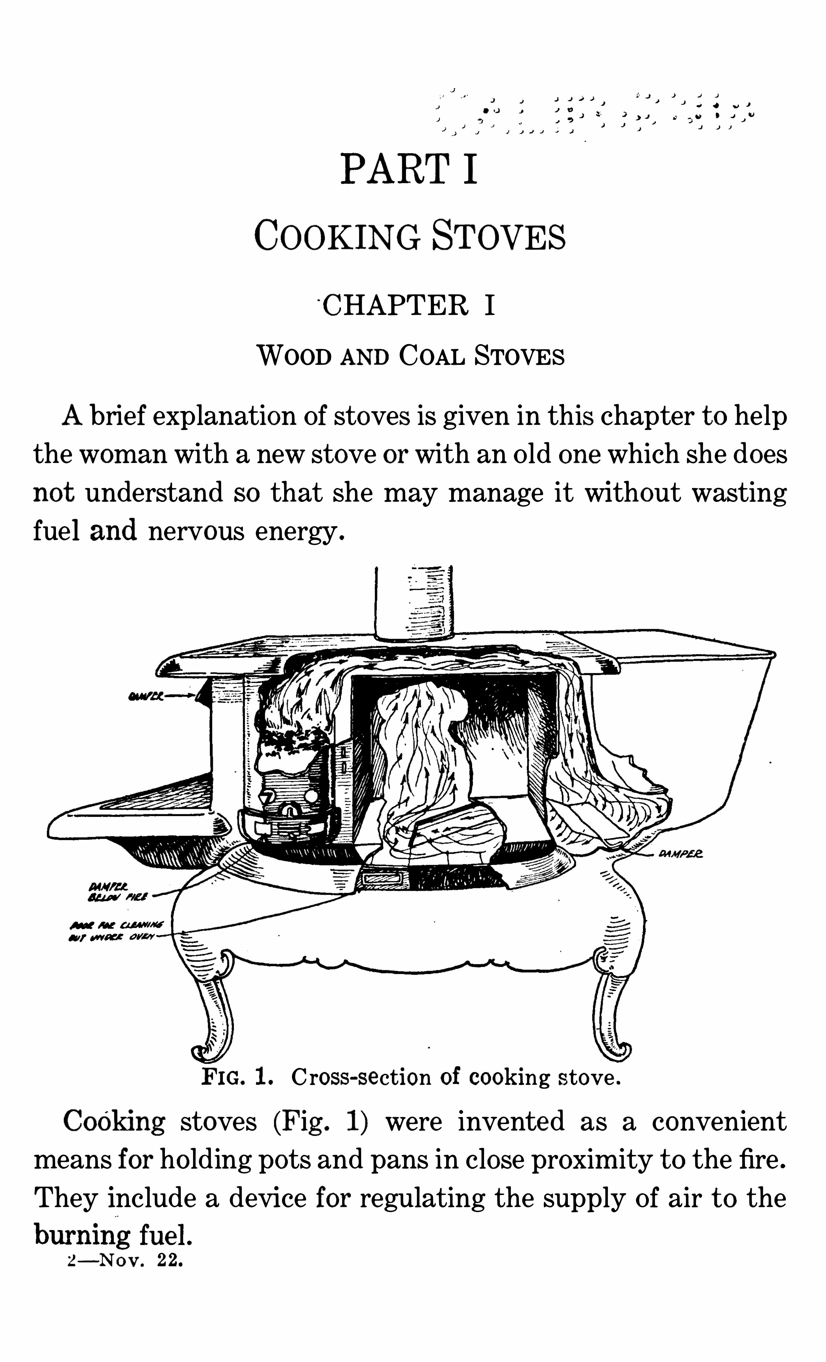
Abrief explanation Of stoves is given in this chapter t o help
the woman with a new stove or with an Old one which she does
not understand SO that She may manage it without wasting
fuel and nervous energy .
FIG. C ross-section of cooking stove .
COOking stoves (Fig . 1) were invente d as a convenient
means for ho lding pots and pans in close proxim ity t o the fire .
They include a device for regulating the supply Of air t o the
z—No v . 22.
16 M ECHANICAL iDEVICES IN THE HOME
3 EAirSupply for Fire Aproper amount of air must be
supplied to the fuel t o produce a ho t fire . A smoky or yellow
flame indicates a lack Of sufficient air t o produce complete
combustion Of the fuel . Smoke is unburnt fuel . A smoky
fire does not produce as much heat as one which burns with a
blue or almost co lorless flame . It is usually not the fault Of
the fuel , but the way it is being used that causes a smoky fire .
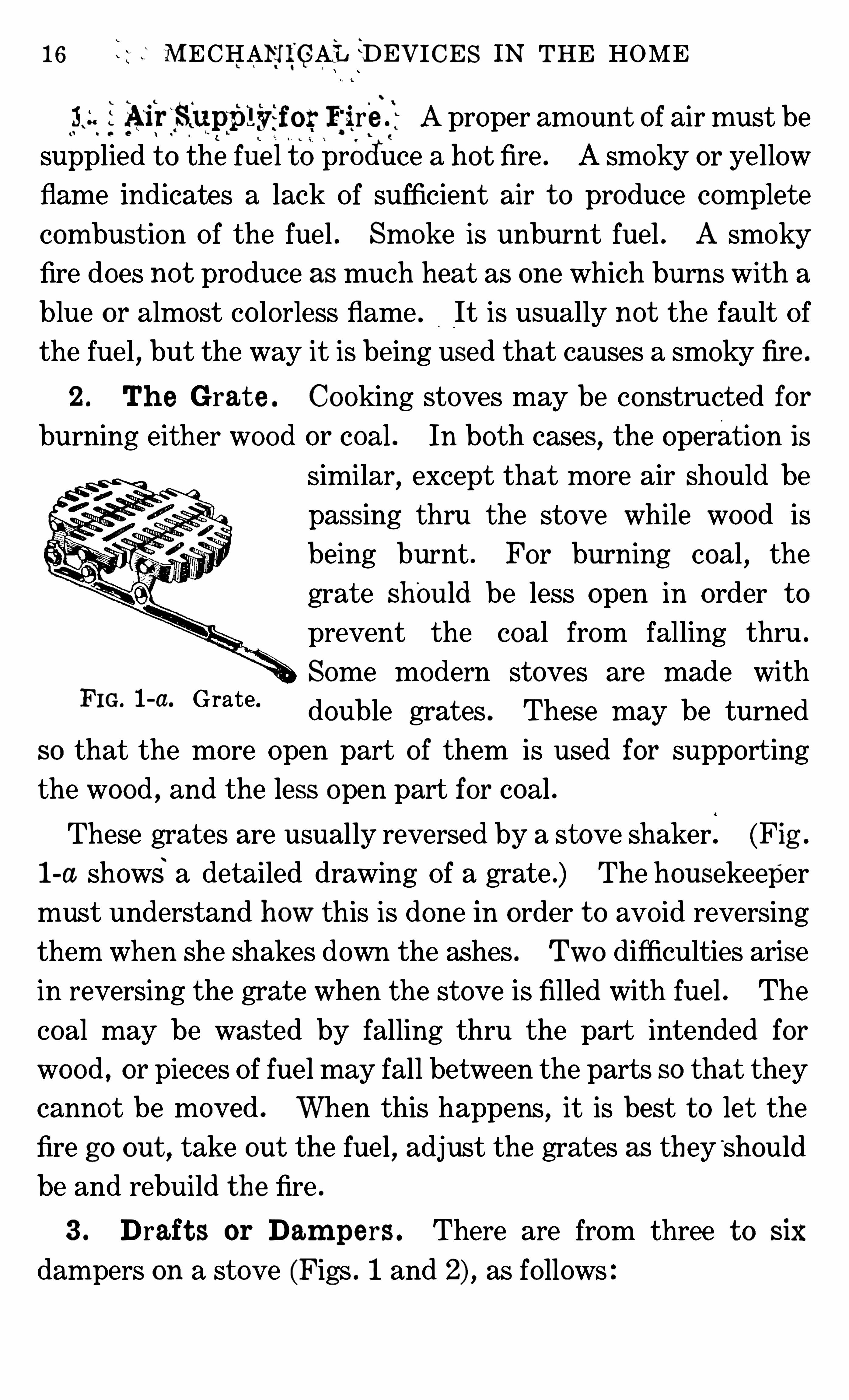
2 . Th e Grate . Cooking stoves may be constructed for
burning either wood or coal . In both cases,the operation is
similar, except that more air Should be
passing thru the stove while wood is
being burnt . For burning coal,the
grate shOuld be less open in order t o
prevent the coal from falling thru .
Some modern stoves are made with
double grates . These may be turned
SO that the more Open part of them is used for supporting
the wood , and the less open part for coal .
FIG. l -a. Grate.
These grates are usually reversed by a stove shaker . (Fig .
1-a shows a detailed drawing Of a grate .) The housekeeper
must understand how this is done in order t o avo id reversing
them when She shakes down the ashes . Two difficulties arise
in reversing the grate when the stove is filled with fuel . The
coal may be wasted by falling thru the part intended for
wood , or pieces Of fuel may fall between the parts so that they
cannot be moved . When this happens, it is best t o let the
fire go out , take out the fuel , adjust the grates as they‘
should
be and rebuild the fire .
3 . Draft s or Dam pers . There are from three t o six
dampers on a stove (Figs . 1 and as fo llows
18 MECHANICAL DEVICES IN THE HOME
5) A damper, or shutter, found in the pipe or chimney Of
most stoves, when closed , checks the draft up the chimney,and , when open, lets it pass freely.
6) The reservo ir damper, found on some stoves having
reservo irs, lets the hot gases pass next t o the reservo ir when
open and prevents this when closed .
4 . St art ing t h e Fire . If th e stove has a reversible
grate, see that it is adjusted t o suit the fuel before building
the fire ; then adjust the drafts . Open the draft below the
fire box, the oven dam per, and the shutter in the chimney ;close the draft above the fire box, and the draft which lets air
from the room into the pipe, so that the air may pass up thru
the fire box and directly up the chimney . Some chimneys
produce such strong drafts that the Shutter in the chimney
has t o be kept closed most Of the time,evenwhen starting the
fire . After the fuel has become ignited , the draft below the
fire may be partly closed so that it burns less rapidly. If the
fire is t o be used for heating water or food on t op o f the stove,it is now ready for use . If it is still burning t oo rapidly, the
draft may be entirely c losed , or the shutter in the chimney
partly closed . If at any time the sto ve smokes, the Shutte r
or drafts above the fire may be closed t oo much and should be
opened enough t o let all the smoke pass . Adding t oo much
fuel at one time and no t spreading it in a thin layer over the
entire surface Of the fire may cause the stove t o smoke .
5 . Keeping a Fire . If,after a fire has been used , it is
wanted for use later, close the draft below the fire box, open
the one above the fire box, or, if there chances t o be no draft
here,tilt the lids on the sto ve t o let in the air ; close the shut
ter in the chim ney and open the draft in the pipe that lets in
WOOD AND COAL STOVES 19
air from the room . With the drafts so adjusted , the fire
should keep a long time, as it will burn very slowly .
6 . Heat ing t h e O v en . When baking is t o be done , wait
until the fire is well started ; then'
c lose the oven damper . The
ev eness Of heat in the oven depends upon the even dist ribu
tion Of the hot gases below and on the sides of it . This is pro
v ided for in the manufacture Of the stove itself . The heat in
the Ov en may be regulated by the intensity Of the heat from
the fire as well as by the damper . Whenever a coo ler oven is
wanted , the flame m ay be permitted t o go directly up thechimney. Since ho t air is always seeking a higher level than
cold air, opening the oven door coo ls the oven, but it will no tprevent food se t on the bottom Of the oven from burning on
the bottom . In a closed oven, the greatest degree of heat is
at the t op, excepting sometimes the surface Of the bottom Of
the oven . M any stoves require the placing o f a thin gratingon the bottom Of the oven t o prevent food from burning onthe bottom . If food does nOt brown sufficiently on the bott om , remove the grating SO that the dish comes in closer c on
tact with the heating unit .
The insulation Of the oven door helps t o ho ld heat in the'
oven , but‘
the amount lost’
here is so small that many house
keepers prefer the convenience Of the glass door, which, inturn , saves heat by do ing away with the necessity Of openingthe oven door t o watch the cooking food .
Some housewives adjust the dam pers for heating the ovenand then never change them . They heat the kitchen in summer more than is necessary and use more fuel than they needfor cooking. It has been estimated that where the carefulmanager Of a stove uses one pound Of fuel
,the careless man
ager uses three and a half pounds .
20 MECHANICAL DEVICES IN THE HOME
One experiment station estimated that the househo ld coalrange is used on an average Of six hours a day
,and
,if used
carefully, seven pounds Of coal is consumed . Careless man
agem ent , then , makes the waste Of coal quite an item in the
course Of a year,'
as it is not unusual for the Careless manager
t o use twenty-four pounds Of coal per six-hour day .
There is always some soot formed, even in the best-man
aged stoves , and the flame Often carries ashes with it. These
in tim e fill the narrow space about the oven and cut Off or
check the passage Of the hot gases about the oven . When
this happens and the oven damper is closed , the stove willsmoke and not bake well . NO stove Should be allowed t o ge tin this condition . The housewife can watch the accumula
tion Of ashes in the stove and remove them before they be
come one-fourth inch thick . If this is no t done , the Oven will
no t heat well ’ and some parts may be considerably coo ler than
others .
7 . Ash es . Ashes allowed t o accumulate in the fire box
will cause t he lining Of the stove t o burn out . Ashes will also
interfere with the heating of the rest of the stove . To
lengthen the life Of a stove, keep the ash pan em pty. If a full
pan Of ashes becom es hot , it wil l keep the grate Of the stove so
hot that it wil l warp and burn out , and sometimes cause
the oven t o warp .
If a housewife tries t o build a fresh fire in a stove with a full
ash pan, she will have t o wait f or the ashes t o become heat ed
thru before sh e can get satisfactory use Of the‘
Oven. She will
be unable t o regulate the temperature Of the o ven if it becomes t oo hot . It is a great waste Of fuel t o heat a large pan
full Of ashes .
WOOD AND COAL STOVES
A‘ UN ING ofFUEL bO X
JHAKfiR
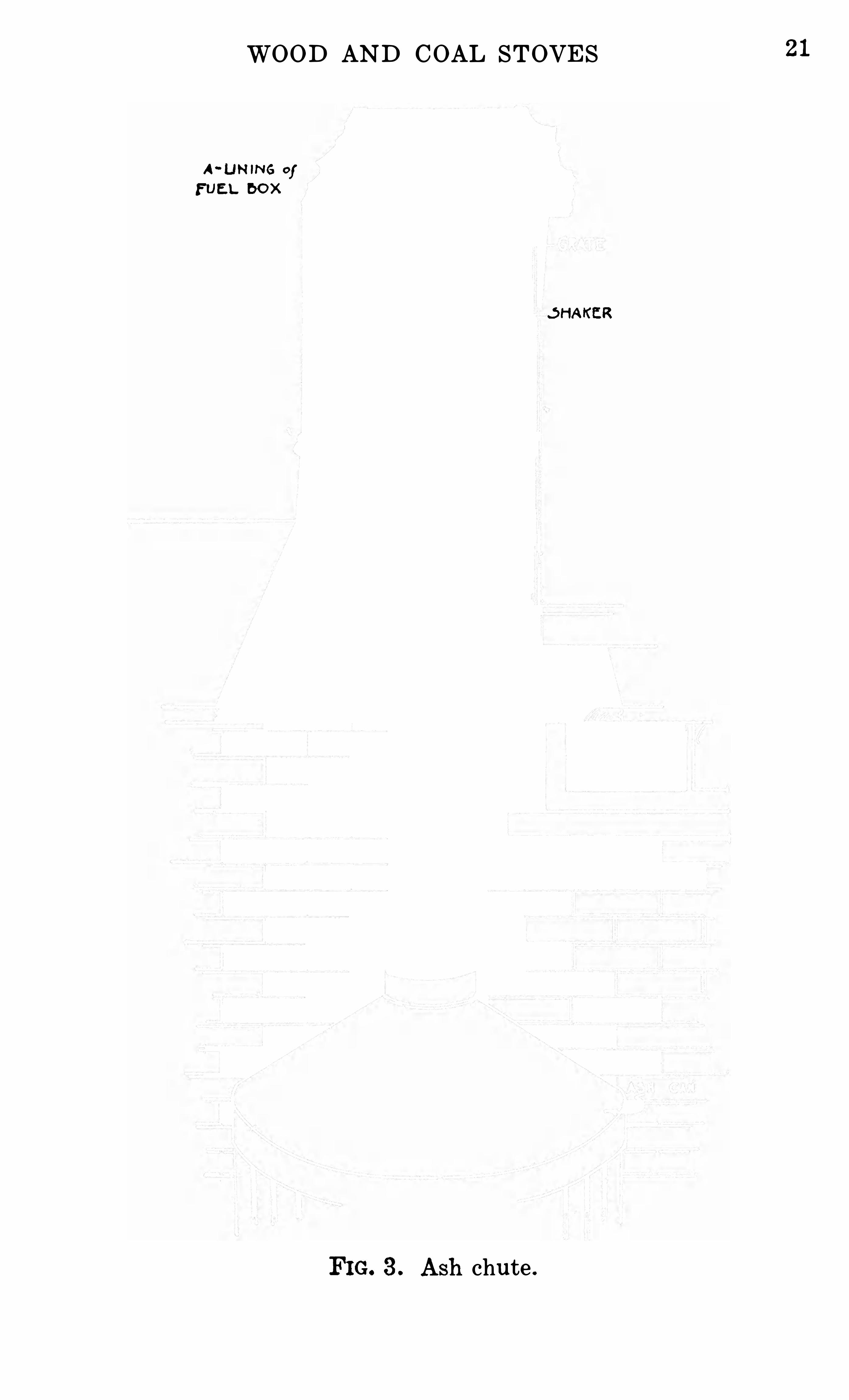
FIG. 3 . Ash chute .
21
22 MECHAN ICAL DEVICES IN THE HOME
8 . Ash Ch utes . In some modern houses, there are ash
chutes which carry the ashes directly from the kitchen sto ve
t o a receptacle in the basement (Fig . These have t o be
installed with care . If there is a draft Of air which cannot -be
regulated from the basement up thru the fire box, the fire will
burn t oo fast . There should be a damper t o regulate drafts
here . An ash chute saves much dirt in the kitchen .
CHAPTER II
GAS STOVES
The gas stove is the simplest stove made . It consists Of a
burner or burners Of different shapes mounted on a suitable
frame . The best example Of a gas burner is a p ipe with ho les
punched in it, where the gas flows out and is se t on fire . This
pipe may be co iled into a circle and make a round burner, or
the ho les may all come at the end , which is arranged t o spread
the gas into a disc shape .
9 . Burne rs . Stoves are usually made with different
sizes Of burners . One manufacturer states that the gas
stoves made by his firm consum e per t op burner per hour
fourteen t o eighteen feet Of gas, and the oven burners con
sume eighteen t o twenty feet when the gas is turned on full .
Simm erers consume much less than this .
10. Sim m erers . Every gas range should have a sim
merer on it . This is a small burner, usually about an inch in
diameter . After a large kettle full Of food has been heated t o
bo iling, this burner may keep it Simmering for hours, using
very little gas . This burner will keep small kettles Of food
bo iling .
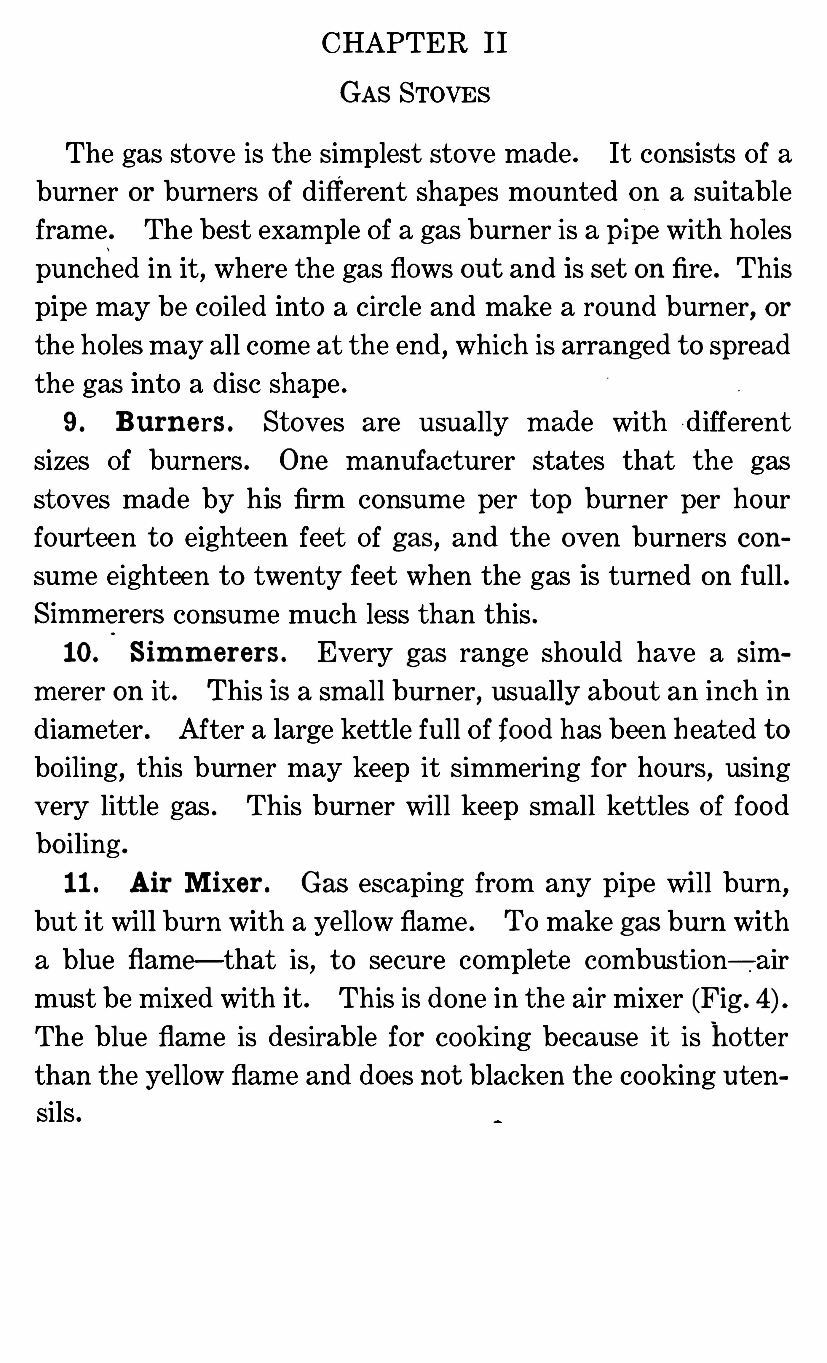
11 . Air Mixer . Gas escaping from any pipe will burn,
but it will burn with a yellow flame . TO make gas burn with
a blue flam e—that is, t o secure complete combustion— airmust be mixed with it . This is done in the air mixer (Fig .
The blue flame is desirable for cooking because it is hotter
than the yellow flame and does no t blacken the cooking uten
Sils .
24 MECHANICAL DEVICES IN THE HOME
Gas passes thru the aIr m ixer before entering the burner .
Sometimes the air inlet is only a ho le put in the under side Of
the pipe . The Opening for entrance Of air is shielded so that
the gas will not escape from the mixer,but will gO on into the
burner. A gas pipe looks about half an inch in diameter, but
the stream Of gas which is allowed t o flow into the burner is
Very small, in some cases being about
the d iameter Of a darning needle .
The opening for air is so large, that
a person ’s finger may be put into it .
TOO much air interferes with the
burning Of the gas ; in fact, there can
be SO much air mixed with gas that it
will no t burn . The air mixer regu
lates the amount Of air which flows
into the pipe . Once this is adjusted
for the kind o f gas t o be used , it se l
FIG. 4 .
‘
Part.
of gas stove dom needs t o be changed . The airShom ng an
.
m l xers‘ Shutter has t o be changed, however,
if the gas pressure varies markedly from tim e t o time . Re
adjustment may be required if the stove is moved and con
nect ed with a different supply Of gas . When adjusting the
mixer for high pressure, artificial or natural gas, close the
Shutter until the flame will not blow away from the cone, but
will burn with a b lue, almost co lorless, flame .
12. Regulat ing t h e Gas . The amount Of gas which
passes into the stove is also regulated , first, by adjustment Of
the size Of the small opening thru which the gas must flow.
Once this is adjusted,it does not need t o be changed SO long as
the gas com es from the same source . Second , the flow Of gas
26 MECHAN ICAL DEVICES IN THE HOME
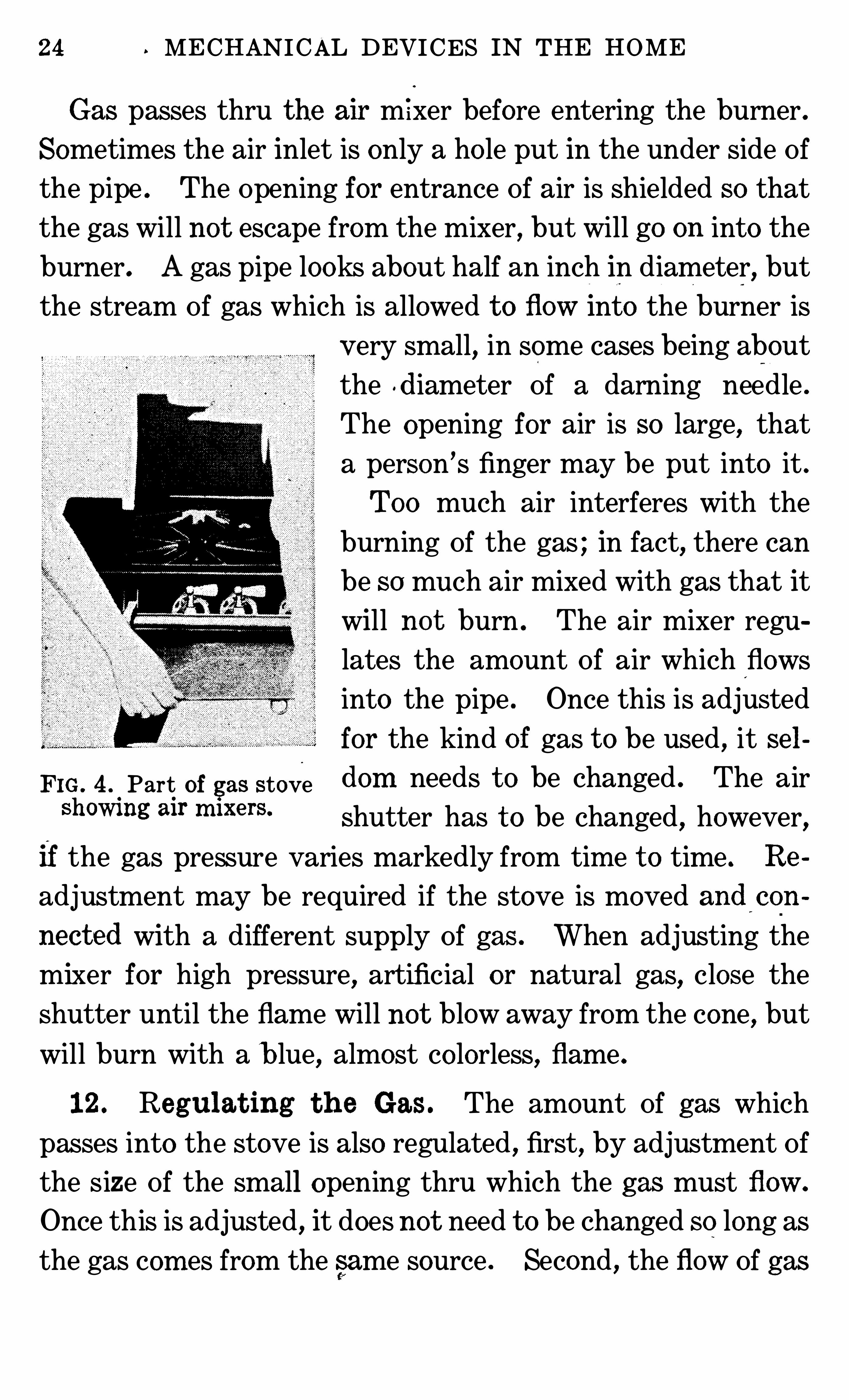
15 . Ac cid en t s wit h Gas St ove . Accidents with gas
st o ves are the result Of m ism anagem ent . The Odor Of gas in a
room indicates a leak in the gas fixtures,such as stoves or
pipes . When such an Odor is noticed , open windows and ex
t inguish all fires in the room or building . Next search for the
leak . It may be due t o an Open valve . See that these are all
shut tight . If no valves are open, send for a plum ber who
looks afte r gas fixtures . Leave the windows Open and do no t
carry lighted matches or
lam ps into the room until
the leak has been stopped .
M any accidents happen
at the tim e the o ven is
being lighted . Som etimes
gas escapes into a closed
o ven, so that it s Odo r is
no t no t iced in the kitchen .
This gas catches fire or ex
p lo de s when the o ven
burner is lighted,blowing the oven door open or Off the
hinges,flashing out Of the o ven, and burning any person near
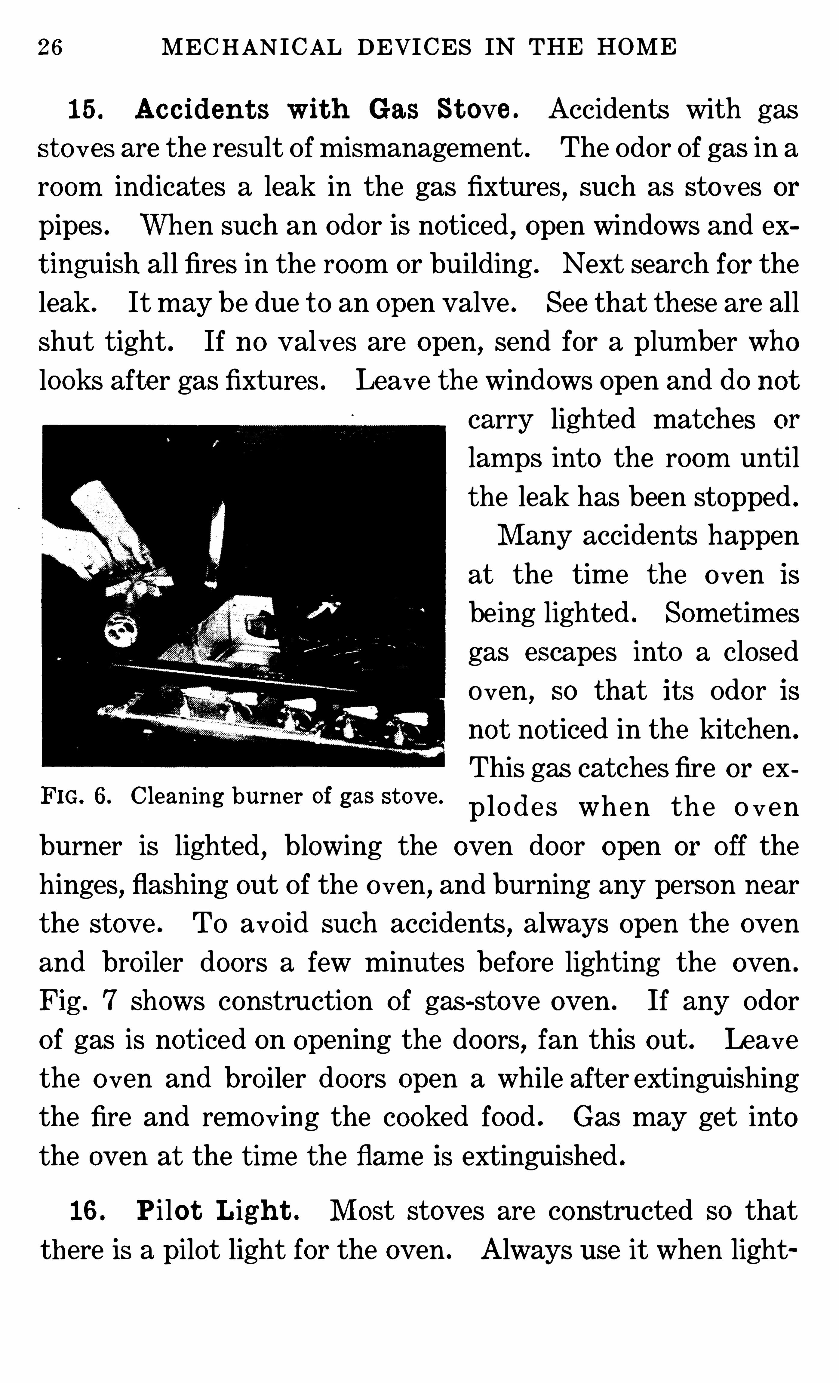
the stove . TO avo id such accidents , always open the oven
and bro iler doors a few minutes before lighting the oven .
Fig . 7 Shows construction of gas-stove oven . If any Odor
Of gas is noticed on opening the doors, fan this out . Leave
the o ven and bro iler doors open a while after extinguishing
the fire and removing the cooked food . Gas may get into
the oven at the tim e the flam e is extinguished .
FIG. 6. Cleaning burner of gas stove.
16 . Pi lot Ligh t . M ost stoves are constructed so that
there is a pilot light for the oven . Always use it when light
GAS STOVES 27
ing the oven . It IS put there for the safety Of those using the
stove . There is no need for alarm when a pilot burns back,
no matter how much no ise it makes, since SO little gas flows
thru the opening . One Of
the functions Of a pilot
light is t o prevent people
from being burnt in case Of
an explosion in the oven .
Fo r t h i s r e a s o n , t h e y
should be at the side Of
the stove .
If the pilot burns back,
close it ; wait a minute , and
then try lighting it again .
The regular burners Of the
stove should no t burn back
if properly lighted by the
pilot . Be careful t o see that every part Of the oven burner
becom es lighted . Turn
t h e b u r n e r s o n fu l l
whi le l i ght ing them .
Afte r they are o nce
lighted , turn them as
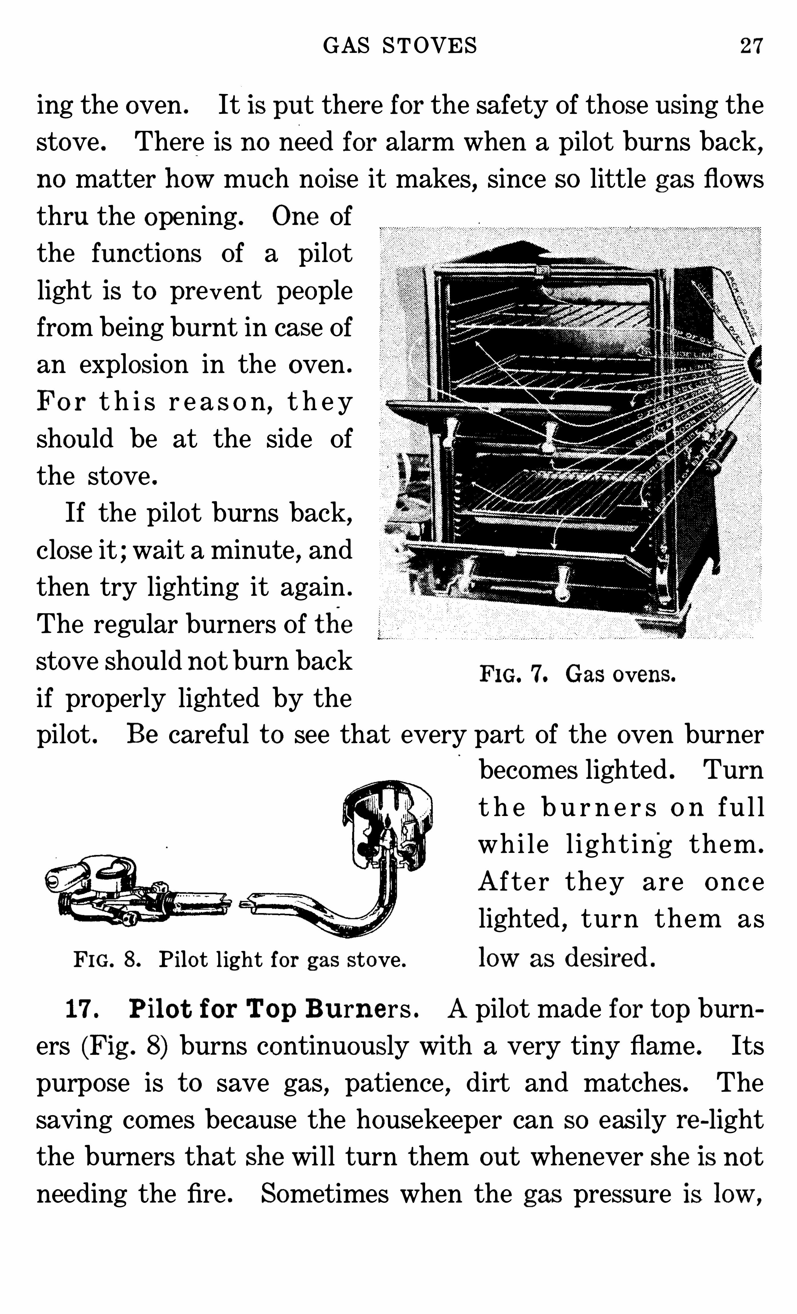
FIG. 8 . Pilot light for gas stove . 1OW as deSiI‘ed .
FIG. 7. Gas ovens.
17 . Pilo t for Top Burne rs . Apilot made for t op burn
ers (Fig . 8) burns continuously with a very tiny flam e . Its
purpose is t o save gas, patience , dirt and matches . The
saving comes because the housekeeper can SO easily re -light
the burners that she will turn them out whenever She is not
needing the fire . Sometimes when the gas pressure is low ,
28 MECHAN ICAL DEVICES IN THE HOME
t he pilot light will go out . It can be re -hgh t ed by pres'
sing
the valve as for light ing the burners and touching a match t o
it . If the pilot goes out , the Odor Of gas will be no t iced in the
kitchen until it is re -lighted .
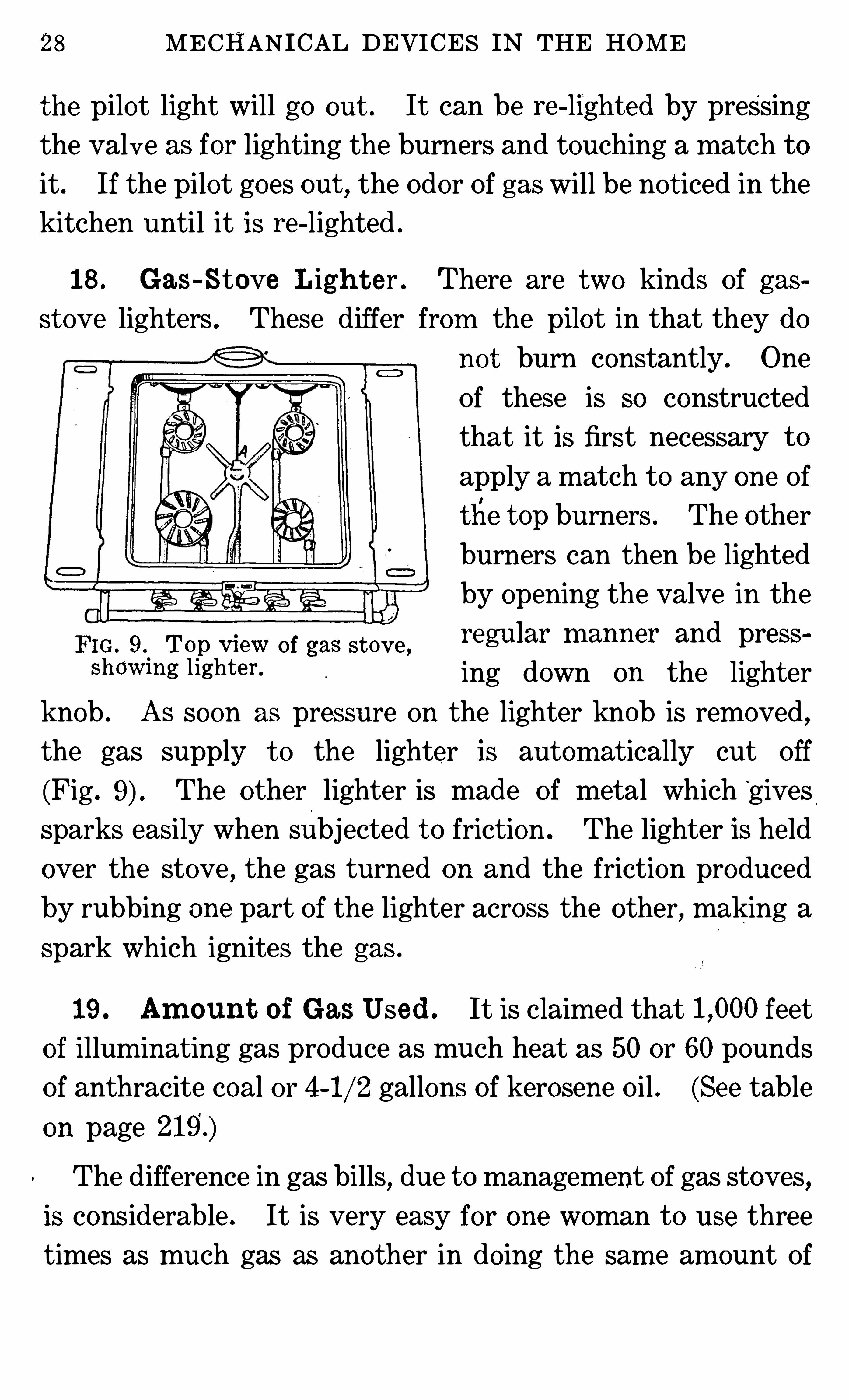
18 . Gas-Stove Ligh t er . There are two kinds Of gas
st ove lighters . These differ from the pilot in that they do
no t burn constantly . One
Of these is so constructed
that it is first necessary t o
apply a match t o any one Of
the t op burners . The other
burners can then be lighted
by opening the valve in the
FIG . 9 Top Vl eW Of gas stove , regular m anner and press ‘
ShGW IHg lighten ing down on the lighter
knob . As soon as pres sure on the lighter knob is removed ,
the gas supply t o the lighter is autom atically cut Off
(Fig . The other lighter is made of metal which”
givessparks easily when subjected t o friction . The lighter is held
over the stove , the gas turned on and the friction produced
by rubbing one part Of the lighter across the other, making a
spark which ignites the gas .
19 . Am ount of Gas Used . It is claimed that feet
of illuminating gas produce as much heat as 50 or 60 pounds
Of anthracite coal or 4 gallons Of kerosene Oil . (See table
on page
The difference in gas bills, due t o management Of gas stoves,
is considerable . It is very easy for one woman t o use three
times as much gas as another in doing the sam e am ount Of
GAS STOVES 29
work . Some women do not realize when they are wasting
Water bo ils in an uncovered vessel at 212 degrees Fahren
heit,and no amount Of heat applied t o it will make it any hot
ter . When a pot Of food has reached the bo iling po int, a
smaller flame will keep it bo iling . Turn the gas as low as it
may be safely turned and still
keep the po t bo iling, and the
food will cook as rapidly as
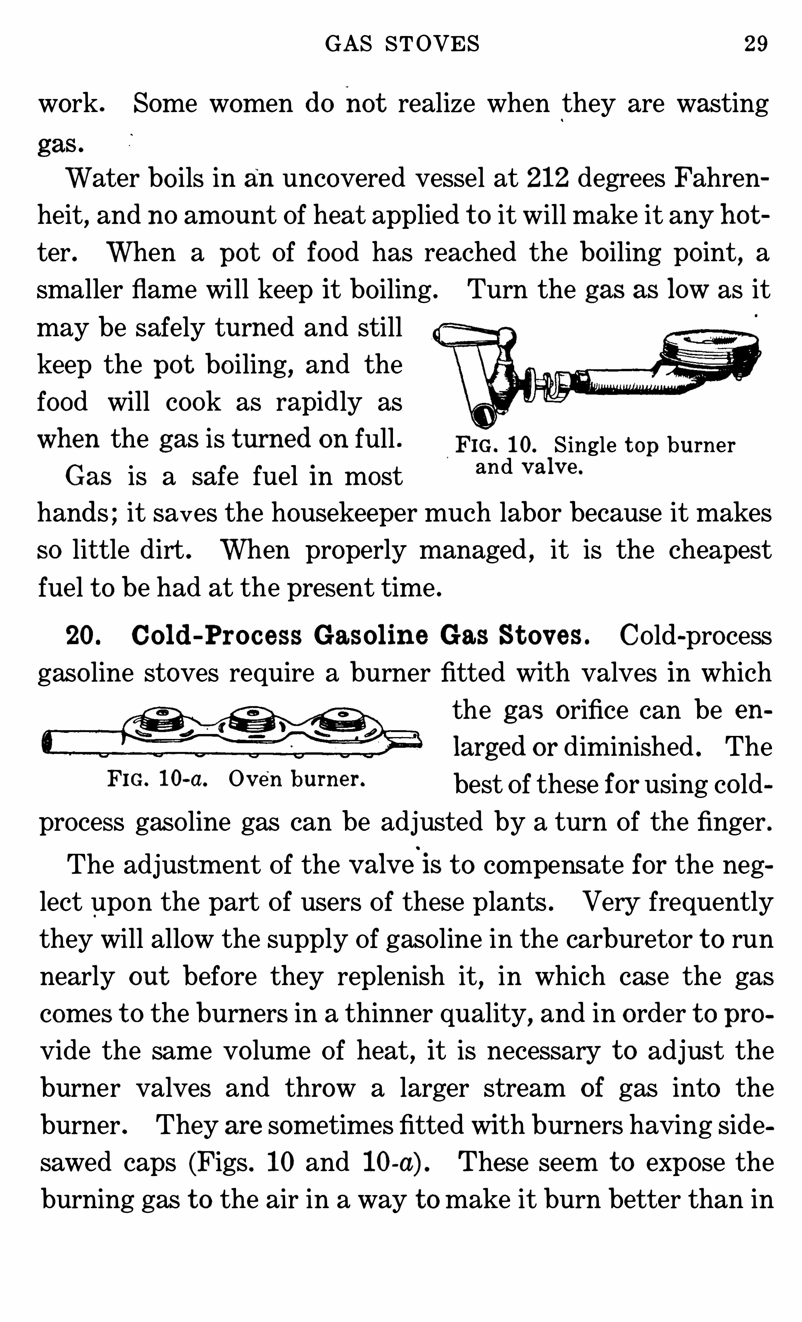
When the gas is turned on full FIG. 10. S ingle t op burnerGas is a safe fuel in most and v al”
hands ; it saves the housekeeper much labor because it makes
SO lit tle dirt . When properly managed , it is the cheapest
fuel t o be had at the present time .
20. Cold -Proc ess Gasoline Gas St ov es . Co ld-processgaso line stoves require a burner fitted with valves in which
the gas orifice can be en
larged or diminished . TheFIG ~ l 0' a~ Ov en bum “ best Of these for using co ld
process gaso line gas can be adjusted by a turn Of the finger .
The adjustm ent Of the v alv eis t o compensate for the neg
lect upon the part Of users Of these plants . Very frequently
they will allow the supply Of gaso line in the carbureto r t o run
nearly out before they replenish it, in which case the gas
comes t o the burners in a thinner quality, and in o rder t o pro
vide the same vo lume Of heat,it is necessary t o adjust the
burner valves and throw a larger stream o f gas into the
burner . They are sometimes fitted with burners having side
sawed caps (Figs . 10 and 10-a) . These seem t o expose the
burning gas t o the air in a way t o make it burn better than in
30 MECHANICAL DEVICES IN THE HOME
other burners built for gas forced into them by greater pres
sure than is this gas . The opening for air must be adjusted
from time t o time so as t o keep the proportion Of gas and air
such that it will produce a blue flame .
21 . Ac et ylene St ov es . Stoves for the burning Of acetylene are similar in construction t o gas stoves . Tho acetylene
furnishes a satisfactory and economical light, it is not an
economical fuel when compared with kerosene, gas, wood or
coal . For this reason, it is not much used . It requires two
and three-tenths units Of acetylene gas t o equal one unit Of
natural gas for heating .
CHAPTER I I I
O IL STOVES
22. Purpose of O il St ove s . Oil stoves are designed for
the comfort Of the wom an who cannot have a gas or an elec
tric stove . They consist of tank, feed pipe and burners (Figs .
11-a and 11 -b) . AS they are portable, they can be moved t o a
summer kitchen or sheltered back porch on ho t summer days .
Oil stoves are no t foo l-proof and
should never be used by those who
are afraid Of them and who do not
understand them . M anufacturers
have done much t o make accidents
avo idable,and they send detailed
instructions with each sto ve . These
should be fo llowed exactly .
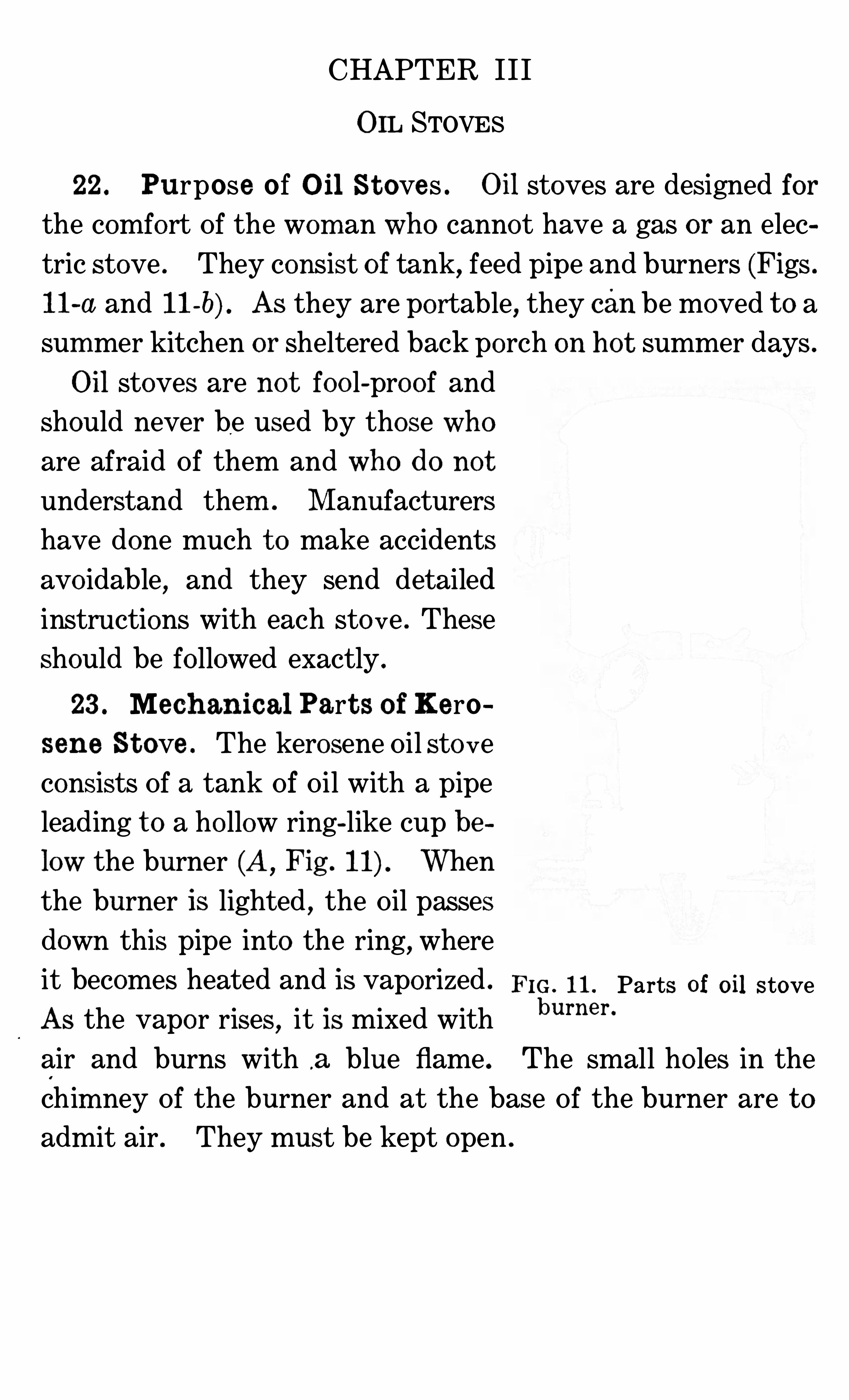
23 . Mech anical Part s o f Kero
sene St ove . The kerosene Oil sto ve
consists Of a tank Of Oil with a pipe
leading t o a ho llow ring-like cup be
low the burner (A, Fig . When
the burner is lighted,the Oil passes
down this pipe into the ring,where
it becomes heated and is vaporized . Fm . 11 , Parts of oil stoveAS the vapo r rises
,it is mixed with
burne r ‘
air and burns with .a blue flame . The small ho les in the
chim ney Of the burner and at the base Of the burner are t o
admit air . They must be kept open .
32 MECHANI CAL DEVICES IN THE HOME
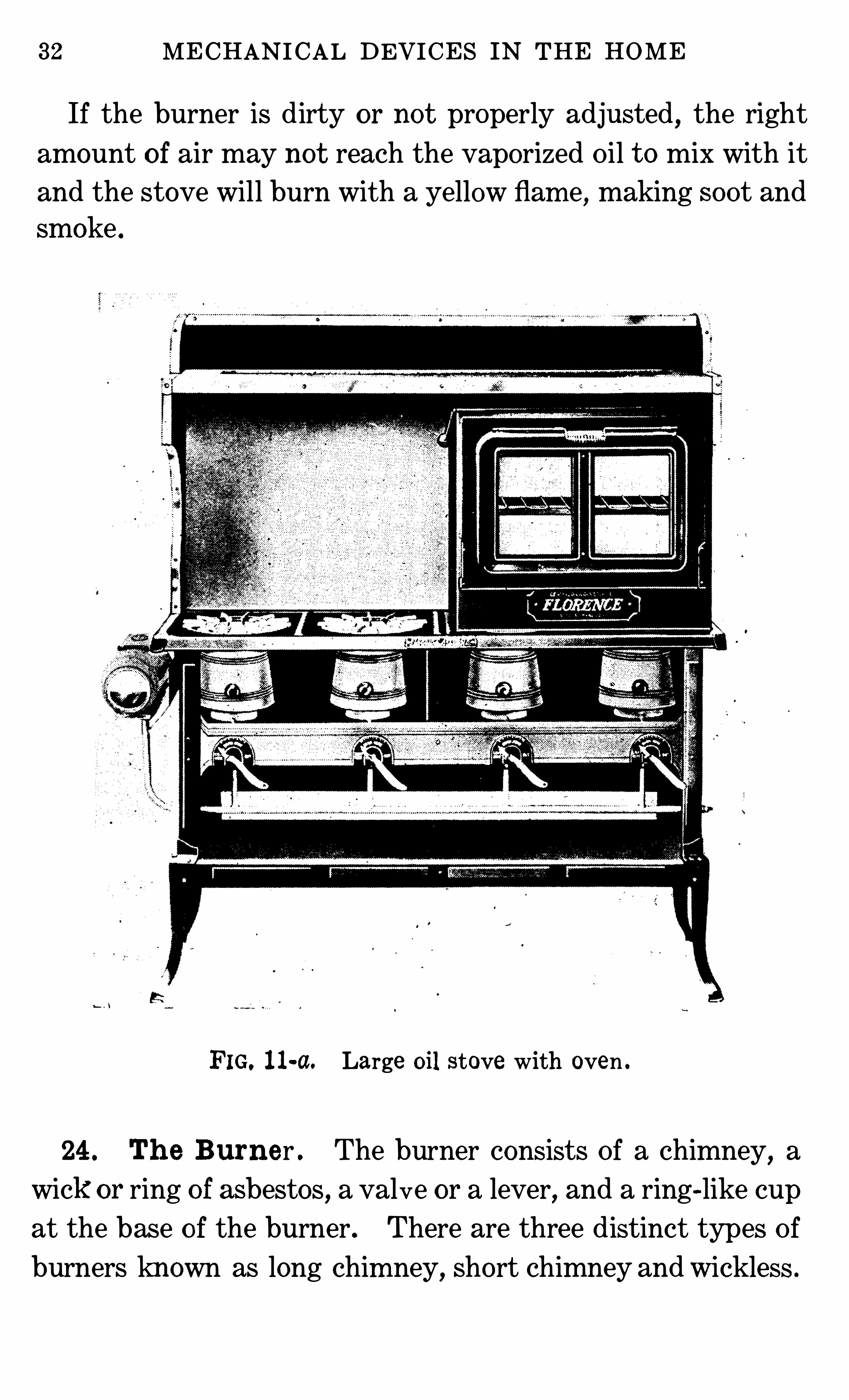
If the burner is dirty or not properly adjusted,the right
amount o f air may not reach the vaporized Oil t o mix with it
and the stove will burn with a yellow flam e,making soot and
smoke .
FIG. 11-a. Large oil stove with oven .
24 . Th e Burner . The burner consists Of a chimney,a
wick or ring of asbestos,a valve or a lever
,and a ring-like cup
at the base of the burner . There are three distinct types Of
burners known as long chim ney, Short chimney and Wickless .
34 MECHANI CAL DEVICES IN THE HOME
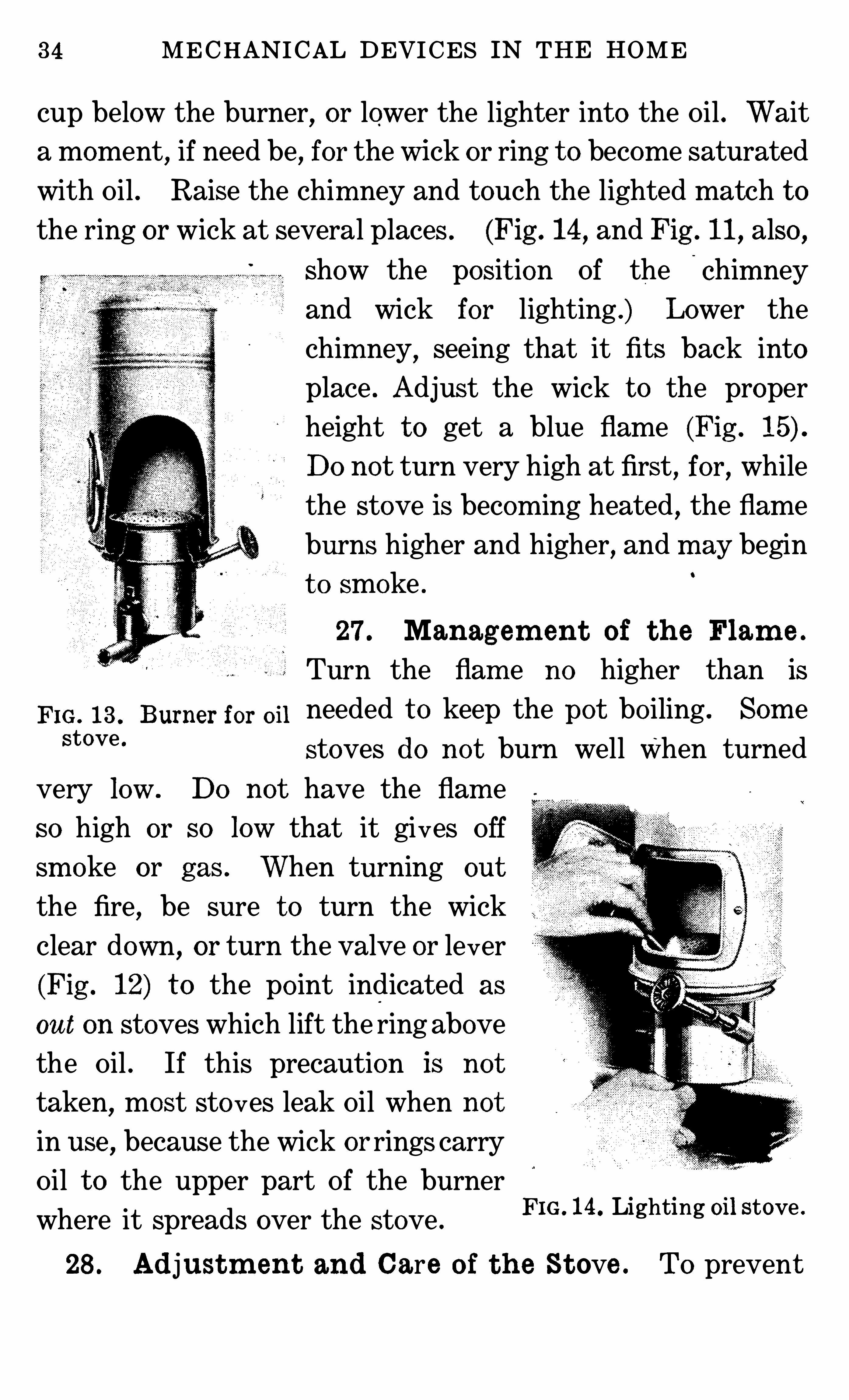
cup below the burner, or lower the lighter into the Oil . Wait
a moment, if need be, for the wick or ring t o become saturated
with Oil . Raise the chim ney and touch the lighted match t o
the ring or wick at several places . (Fig . 14,and Fig . 11, also ,
Show the posit ion Of the Chim ney
and wick for lighting .) Lower the
chim ney, seeing that it fits back into
place . Adjust the wick t o the proper
height t o get a blue flame (Fig .
DO no t turn very high at first, for, while
the stove is becom ing heated,the flame
burns higher and higher, and m ay begin
t o smoke .
27 . Managem en t o f t h e Flam e .
Turn the flam e no higher than is
Fm , 13 , Burner for on needed t o keep the po t bo iling . Som eStove ‘
stoves do no t burn well When turned
very low . DO not have the flam e
so high or so low that it gives Off
sm oke or gas . When turning out
the fire, be sure t o turn the wick
clear down , or turn the valve or lever
(Fig . 12) t o the po int indicated as
out on stoves which lift the ring above
the Oil . If this precaution is no t
taken,most sto ves leak Oil when not
in use,because the wick or rings carry
Oil t o the upper part Of the burner
where it spreads over the stove .
28 . Ad justm en t and Care o f t h e St ove . To prevent
FIG. 14 . Lighting oil stove .
OIL STOVES 35
trouble with uneven flames,set the stove perfectly level , par
t icularly the Wickless one . Keep the tank filled , but not t oo
full . Stoves are made so that it is difficult t o fill them t oo
full . An Oil stove cannot explode unless gas has formed in
some part, like the tank, and becomes ignited by heat or a
spark . Gas is more likely t o co l
lect in the tank when it is almost
When the tank is removed for
filling,any gas forming passes out
into the room and mixes with so
much air that it is harmless . If it
is filled before the Oil burns out Of
the pipe above the level of the
burners,no gas will be formed .
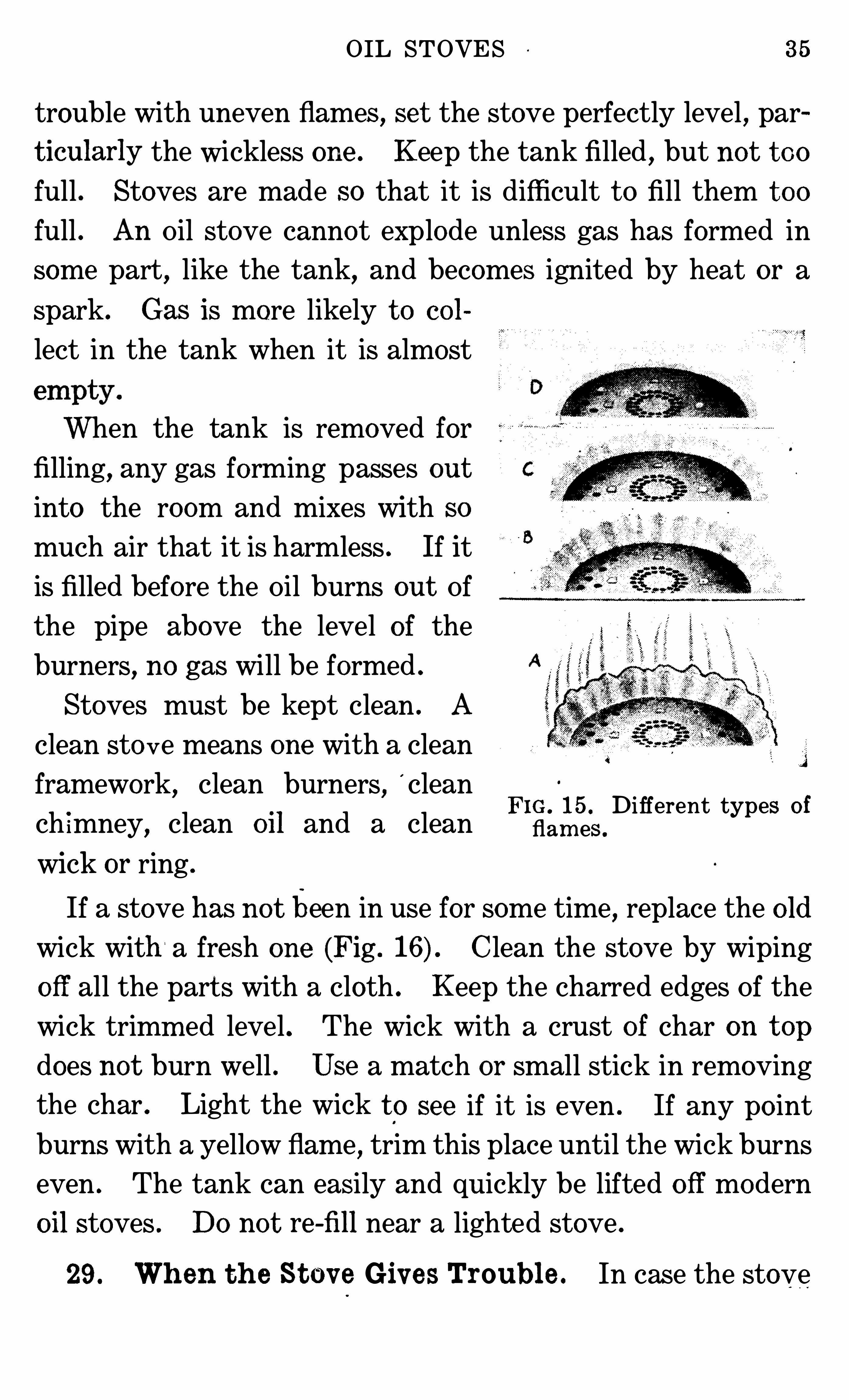
Stoves must be kept clean . A
clean sto ve means one with a clean
framework, clean burners,'
cleanFIG . 15 . Different types o f
ch imney,clean 0 11 and a clean flam es ,
wick or ring .
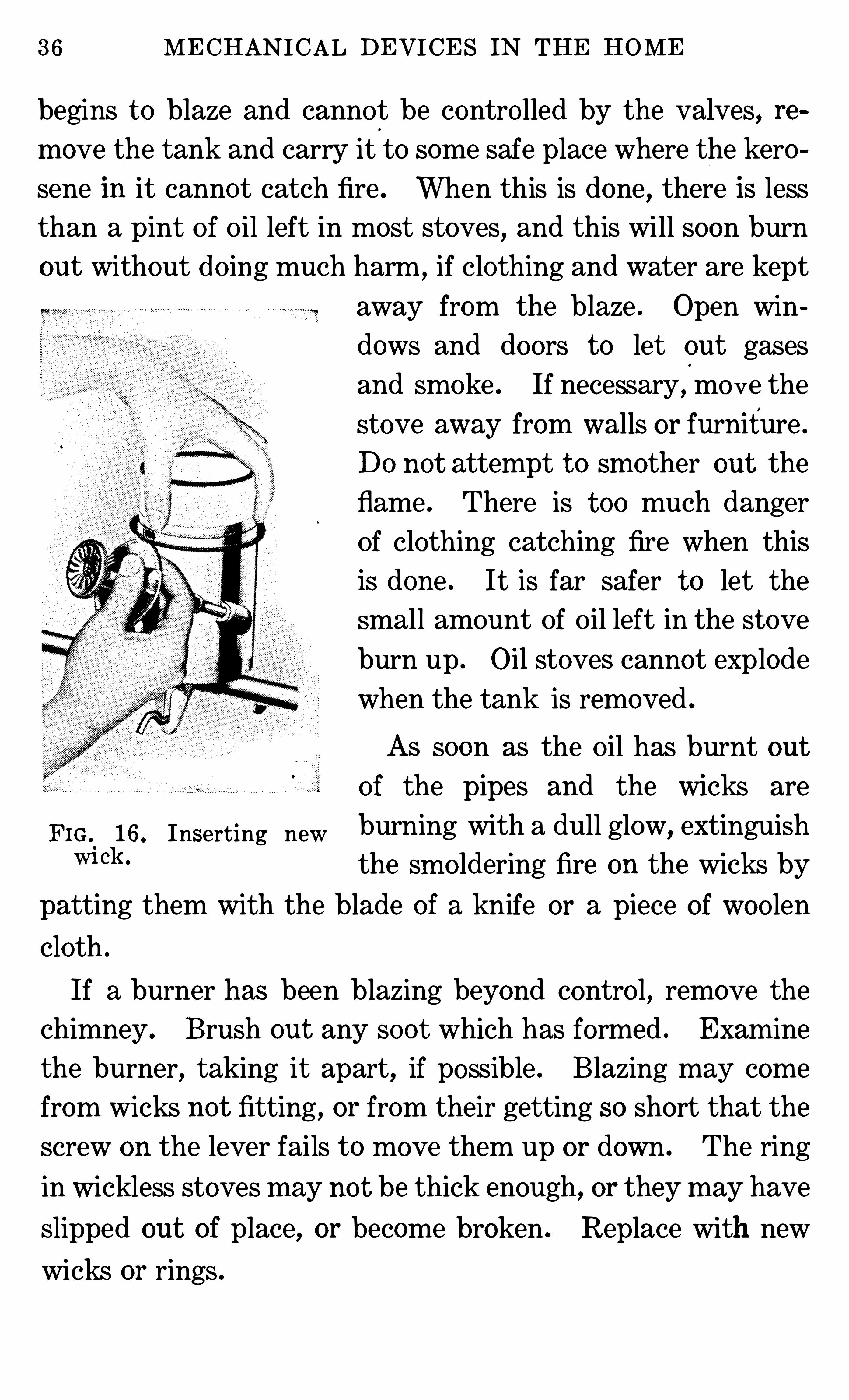
If a stove has no t been in use for some time, replace the o ld
wick with a fresh one (Fig . Clean the stove by wiping
off all the part s with a cloth . Keep the charred edges Of the
wick trimm ed level . The wick with a crust of char on t op
does not burn well . Use a match or small stick in removing
the char . Light the wick to see if it is even . If any po int
burns with a yellow flame, trim this place until the wick burns
even . The tank can easily and quickly be lifted O ff modern
oil stoves . DO no t re -fill near a lighted stove .
29 . Wh en t h e St e v e Giv es Troubl e . In case the stove
36 MECHANICAL DEVICES IN THE HOME
begins t o blaze and cannot be contro lled by the valves, remove the tank and carry it
'
to some safe place where the kero
sene In it cannot catch fire . When this is done , there IS less
than a pint Of Oil left in most stoves, and this will soon burn
out without do ing much harm ,if clothing and water are kept
away from the blaze . Open windows and doors t o let out gases
and smoke . If necessary, mo ve the
stove away from walls or furniture .
DO not attempt t o smother out the
flame . There is t oo much danger
Of clothing catching fire when this
is done . It is far safer t o let the
sm all amount Of Oil left in the st ove
burn up . Oil stoves cannot explode
when the tank is removed .
As soon as the Oil has burnt out
of the pipes and the wicks are
FIG 16. Inserting new burning with a dull glow, extinguishm ok ' the sm o ldering fire on the wicks by
patting them with the blade of a knife or a piece of woo len
cloth .
If a burner has been blazing beyond contro l , remove the
chimney . Brush out any soot which has formed . Examine
the burner,taking it apart
,if possible . Blazing may come
from wicks no t fitting, or from their getting so short that the
screw on the lever fails t o move them up or down . The ring
in Wickless stoves may no t be thick enough, or they may have
Slipped out of place, or become broken . Replace with new
wicks or rings .
OIL STOVES 7
Notice if any part Of the burner shows evidence o f
melting . If it does, do no t use this burner until inspected
and mended by an expert . If the lever has become worn so
that it fails t o work, it must be replaced or a new burner put
on the stove .
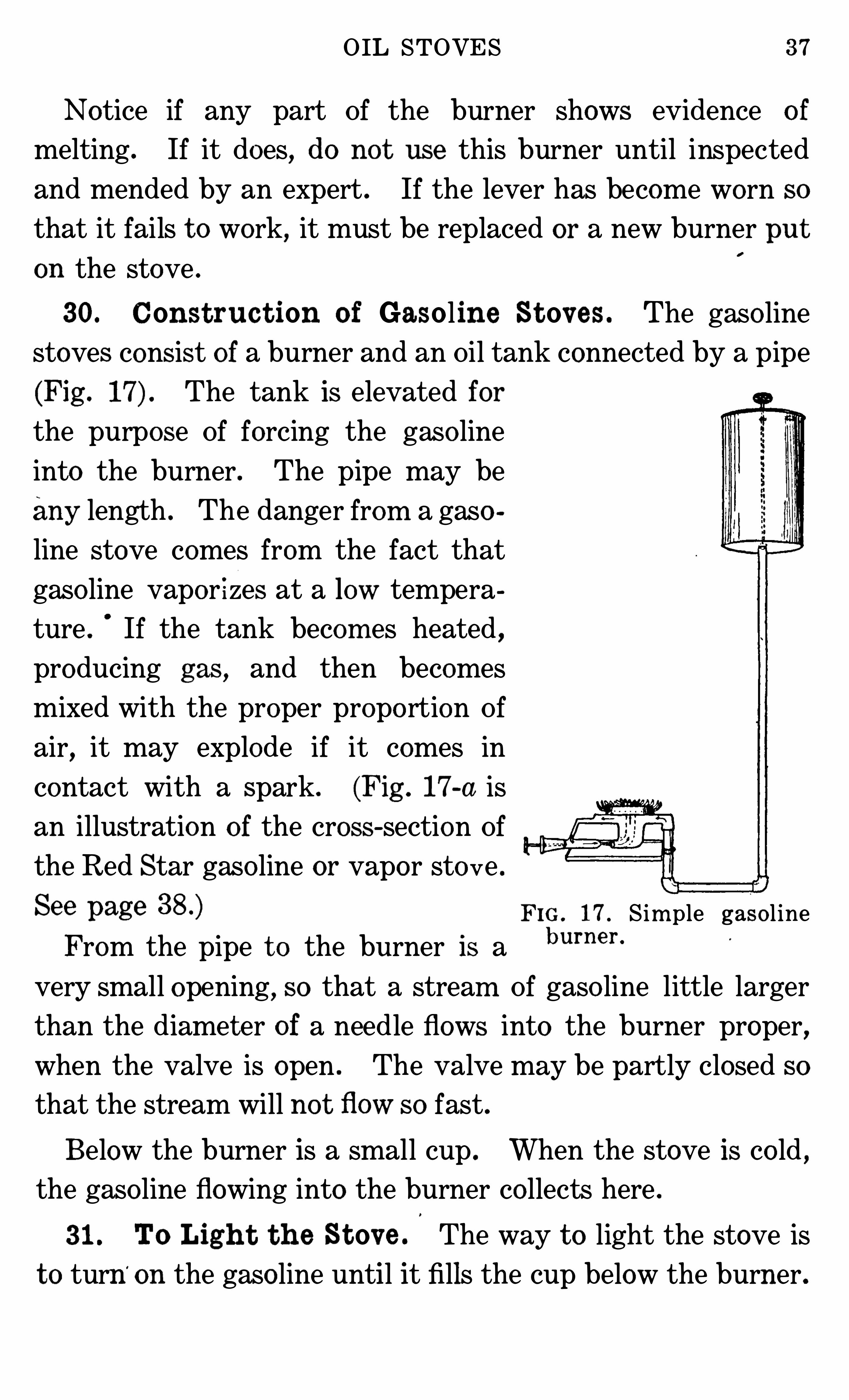
30. Const ruc t ion o f Gasoline St ov es . The gaso line
stoves consist of a burner and an Oil tank connected by a pipe
(Fig . The tank is elevated for
the purpose Of forcing the gaso line
into the burner . The pipe may be
any length . The danger from a gaso
line stove comes from the fact that
gaso line vapor izes at a low tempera
ture . If the tank becom es heated ,
producing gas , and then becomes
mixed with the proper propo rtion Of
air,it may explode if it comes in
contact with a spark . (Fig . 17-a is
an illustration o f the cross-section Of
the Red Star gaso line or vapo r stove .
See page Fm . 17 . S im ple gaso l ineFrom the pipe t o the burner is a burner '
very small opening, SO that a stream Of gaso line little larger
than the diameter of a needle flows into the burner proper,when the valve is open . The valve may be partly closed so
that the stream will no t flow SO fast .
Below the burner is a small cup . When the stove is co ld ,the gaso line flowing into the burner co llects here .
31 . To Ligh t t h e St ov e . The way t o light the stove is
t o turn‘
on the gaso line until it fills the cup below the burner.
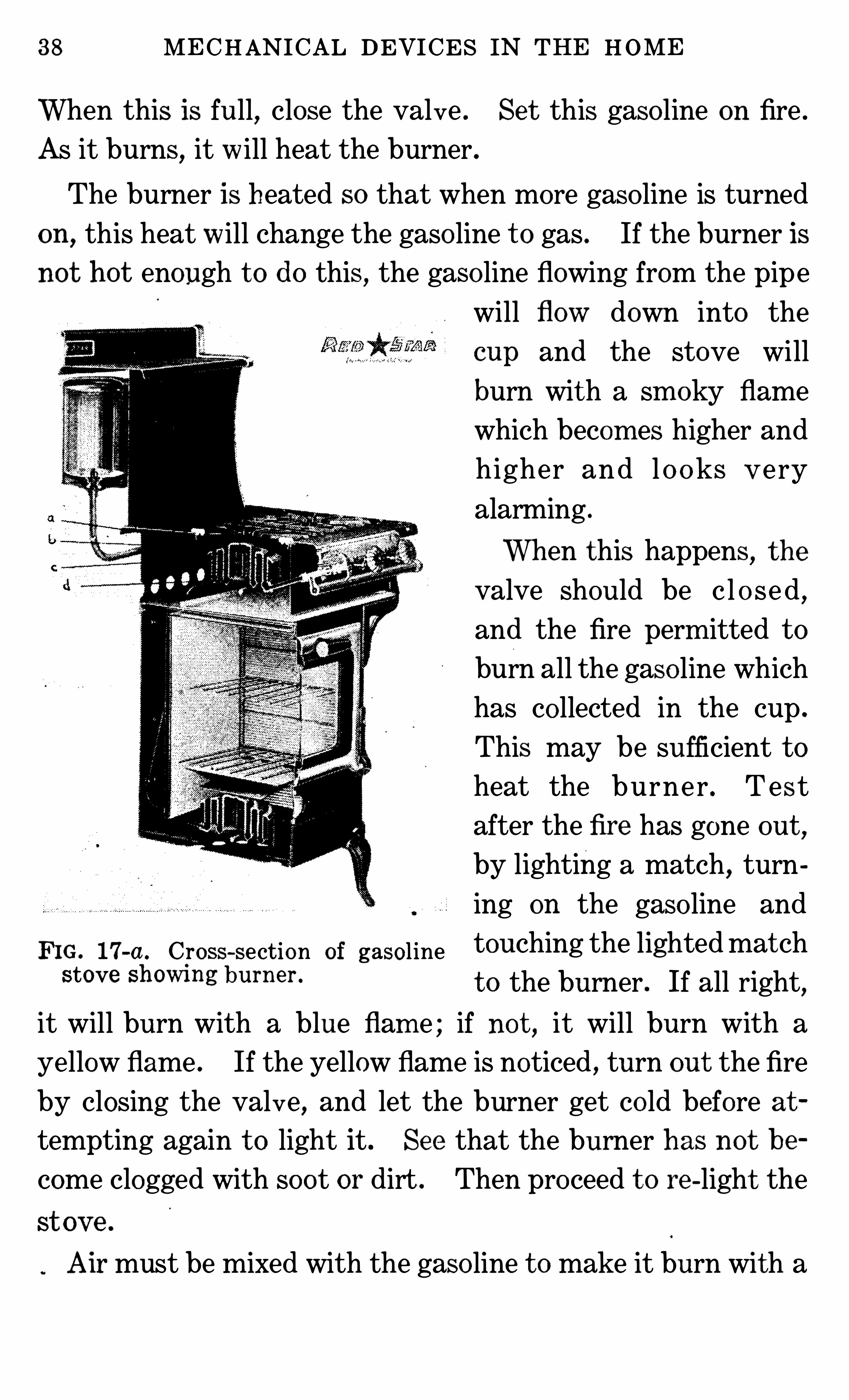
38 MECHANICAL DEVICES IN THE HOME
When this is full, close the valve . Set this gaso line on fire .
As it burns,it will heat the burner .
The burner is heated so that when more gaso line is turned
on, this heat will change the gaso line t o gas . If the burner is
not hot enough t o do this, the gaso line flowing from the pipe
will flow down into the
cup and the stove will
burn with a sm oky flame
which becom es higher and
higher and l o o ks V ery
alarming .
When this happens, t he
valve should be c l o se d ,
and the fire perm itted t o
burn all the gaso line which
has co llected in the cup .
This may be sufficient t o
heat the burner . Test
after the fire has gone out ,
by lighting a match, turn
ing on the gaso line and
FIG. 17-a . Cross-section of gasoline touching the lightedmat chStove Sh OWing burner ‘
t o the burner . If all right,
it will burn with a blue flam e ; if no t , it will burn with a
yellow flame . If the yellow flame is noticed , turn out the fire
by closing the valve, and let the burner get co ld before at
tempting again t o light it . See that the burner has not be
come clogged with soot or dirt . Then proceed t o re -light the
Air must be mixed with the gaso line t o make it burn with a
OIL STOVES 39
blue flame . The air enters the burner through the same tube
that the gaso line flows into the cups when the burner is co ld .
In the burner are small ho les for the escape Of the gas mixed
with air,and here the blue flame Should appear, and nowhere
else . If it appears elsewhere, the burner is not working prop
erly . Sometimes the gas ignites at the po int where the air is
mixed with it . The fire should then be turned out and the
stove re-lighted immediately .
If the little ho les where the flames should be , or if any other
part Of the stove is clogged with Soot, it will no t burn as it
should . It must be cleaned . A dirty gasoline stove is dan
gerons .
32 . F i ll ing t h e Gaso l ine Stove . Never get Oil on the
tank or any part of the stove while filling it . If Oil is Spilled ,wipe it up
,
before igniting the stove . DO no t fill the tank
when the stove is lighted or when there is a fire anywhere near
the tank . If the fire has been burning, close all the valves
and wait until it goes out before Opening the tank . Close the
valve from tank t o pipe before filling . Fill the tank and cover
it before lighting the stove again .
Keep the tank filled . As soon as the indicator, which is
at tached t o a cork which floats on t op Of the gaso line, shows
that the Oil is low, turn out the fire and refill the tank . DO
not fill the tank t o overflowing . Gases from the stove can
only get into the tank when it is em pty and while there is gas
o line in the pipe t o feed the stove . Gaso line gas is very in
flamm able and will cause an explosion if it becomes ignited .
The tanks from gaso line stoves cannot be rem oved , as all the
jo ints must be tight t o prevent the escape o f gaso line fumes
as well as the Oil itself . The opening t o the tank must nev er:
40 MECHANICAL DEVICES IN THE HOME
be left uncovered , except for the few minutes while the tank
is being filled . The greate st care is required in using a gaso
line Stove ; in fact, they are so dangerous , that they Should'
not
be highly recommended for househo ld use . The description
and care Of them are given here because some persons persist
in using them when they desire a quick, ho t fire in cases where
fuel gas is not available .
33 . Wh en aBurner B lazes and Cannot Be Cont roll ed .
When a gaso line stove burner blazes and cannot be contro lled,
first close the valve leading from the tank into the pipe .
There will then be little gaso line t o burn, and no gases can
get back into the tank .
Keep clothing and water away from the blaze . Remember that
the stove is set on a metal frame which is not inflammable .
Shield walls and other Objects so that the burner may blaze
high without do ing damage . Clothing catches fire easily,
but the metal stove will not be consumed .
If the valves are Shut,the blaze will cease when the gaso line
has burnt out Of the burner and pipe . If the gaso line contin
ues t o flow out of the burner in spite Of turning the valve and
there is a danger Of its spreading t o the floor or table, se t a
shallow pan under the stove t o catch the gaso line . It can
burn in this way with considerable safety . Do not attempt
t o carry a burning stove . Simply protect floor, walls and fur
niture from catching fire, and let the gaso line burn .
34 . Ch anging Fue l in Vapor St ov es . There are some
stoves which are interchangeable, in that they may be ad
justed t o burn kerosene , gaso line or distillate . These are Of
the type called “ vapor” because they change the Oil t o gas be
fore it is ignited . A change from one kind Of fuel t o another
CHAPTER IV
ELECTRIC STOVES
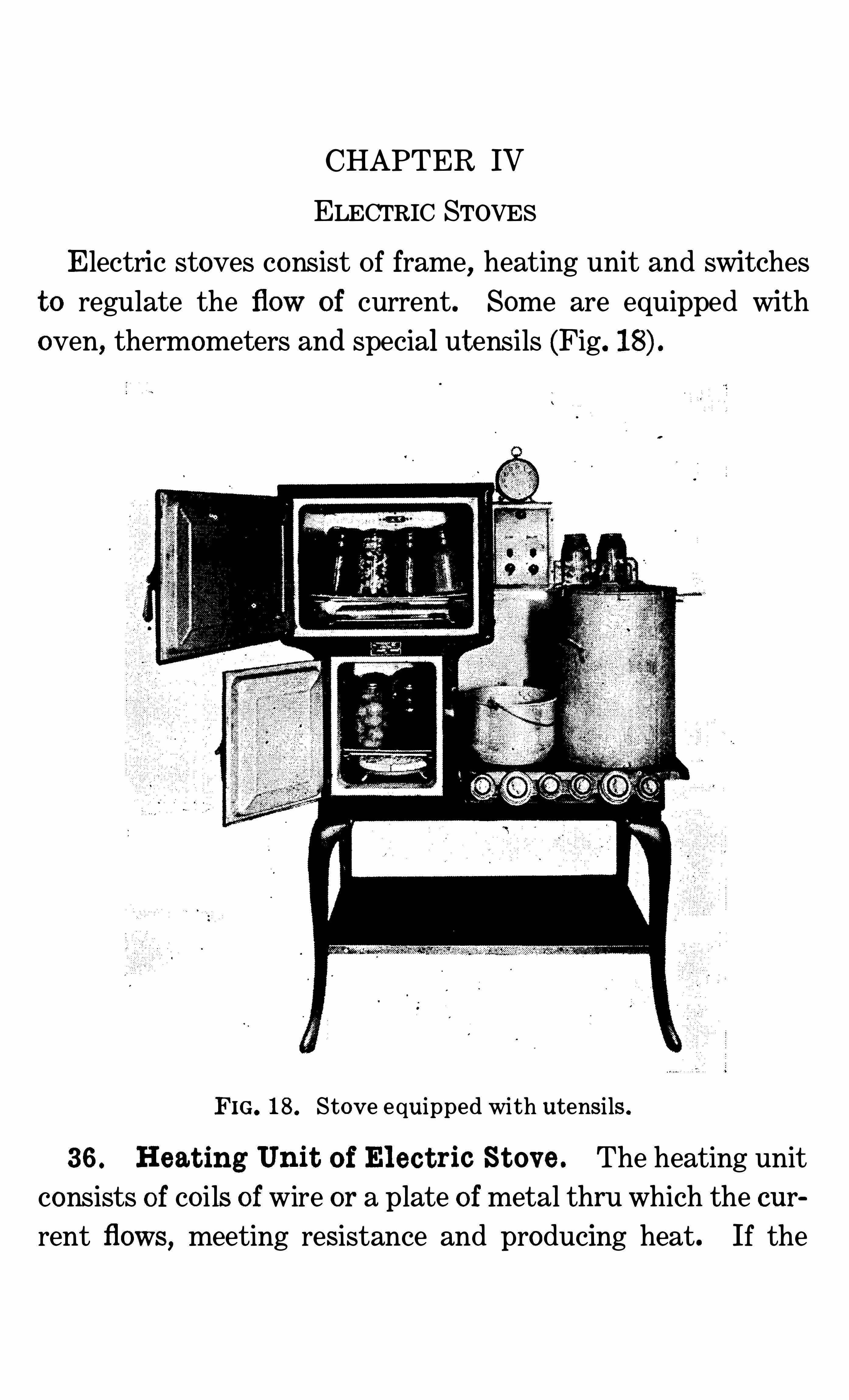
Electric stoves consist Of frame, heating unit and switches
t o regulate the flow of current. Some are equipped with
oven, thermometers and special utensils (Fig.
FIG. 18 . Stove equipped with utensils .
36 . Heat ing Unit o f El ec t ric St ov e . The heating unit
consists o f co ils of wire or a plate of metal thru which the cur
rent flows, meeting resistance and producing heat. If the
ELECTRI C STOVES 43
current flowed freely thru the wires , little heatwould be gene
rated (Figs . 19 and
37 . Wiring o f St ov es . It is advocated“ that a separate
circuit of heavy wire be put into all houses where current is
used for purposes other than light
ing, t o provide for cooking and power
connections .
TOO heavy loading of wires with
electric appliances causes the burning
of fuses and sometimes damages the FIG. Heating unit ofelectric stove .
electric system . F ind out how much
current the wiring of the house will carry before attaching
new devices . There is danger o f fire if t oo much current is
allowed t o pas s over a wire Of t oo sm all size .
38 . Operat ion of El ec t ric St ov es . M any stoves are
with a switch which permits different amounts Of
FIG. 20. Heating unit of electric stove .
current t o pass thru the stove according t o the way the device
is set . At one po int it gives low heat another, medium,and
a third, high heat, and , lastly, no heat .
The cooking o f food on an open burner should be started
44 MECHANI CAL DEVICES IN THE HOME
with high heat turned on SO that the food m ay cook quickly .
I f a large amount of food is cooking, there will be so much
radiation from the vessel that it may require all the current
t o keep it cooking . After food has started cooking, the switch
can be turned t o medium,and
,later
, t o low,depending upon
the amount o f food and th e temperature desired . Low will
keep an o rdinary pan o f water bo iling, once it has started .
A few minutes before the food is t o be removed from theopen burner, the current should be turned Off, as the heat in
the stove will continue the cooking for several minutes . From
tests Of electric stoves,it appears that in most Of them the
food will continue t o cook after the switch is turned Off for
about the same number ofminutes that it requires t o raise the
heating unit t o a temperature sufficient t o bo il water in a
small Shallow pan . A housekeeper who is using electricity
for cooking can soon learn how long the open burners and
o ven o f her stove will keep food cooking after the current is
turned O ff , and by putting this information t o use , She can
save many do llars in a year .
39 . Care of El ec t ric St ov es . When thru with a stove ,always turn Off the current. Great care Should be taken that
the stoves do no t become o verheated . This shortens the life
o f the stove .
Sudden Cooling Of the co ils o f wire caused by liquids spilling
on them,and corrosion Of the wires caused by dampness , wear
out stoves faster than need be . DO not wash or brush dirt
from burners having open co ils Of wire . Burn all dirt from
the burners .
40. Ut ensils for Elec t ric St ov es. The most economical
use of electricity can be secured with utensils built around the
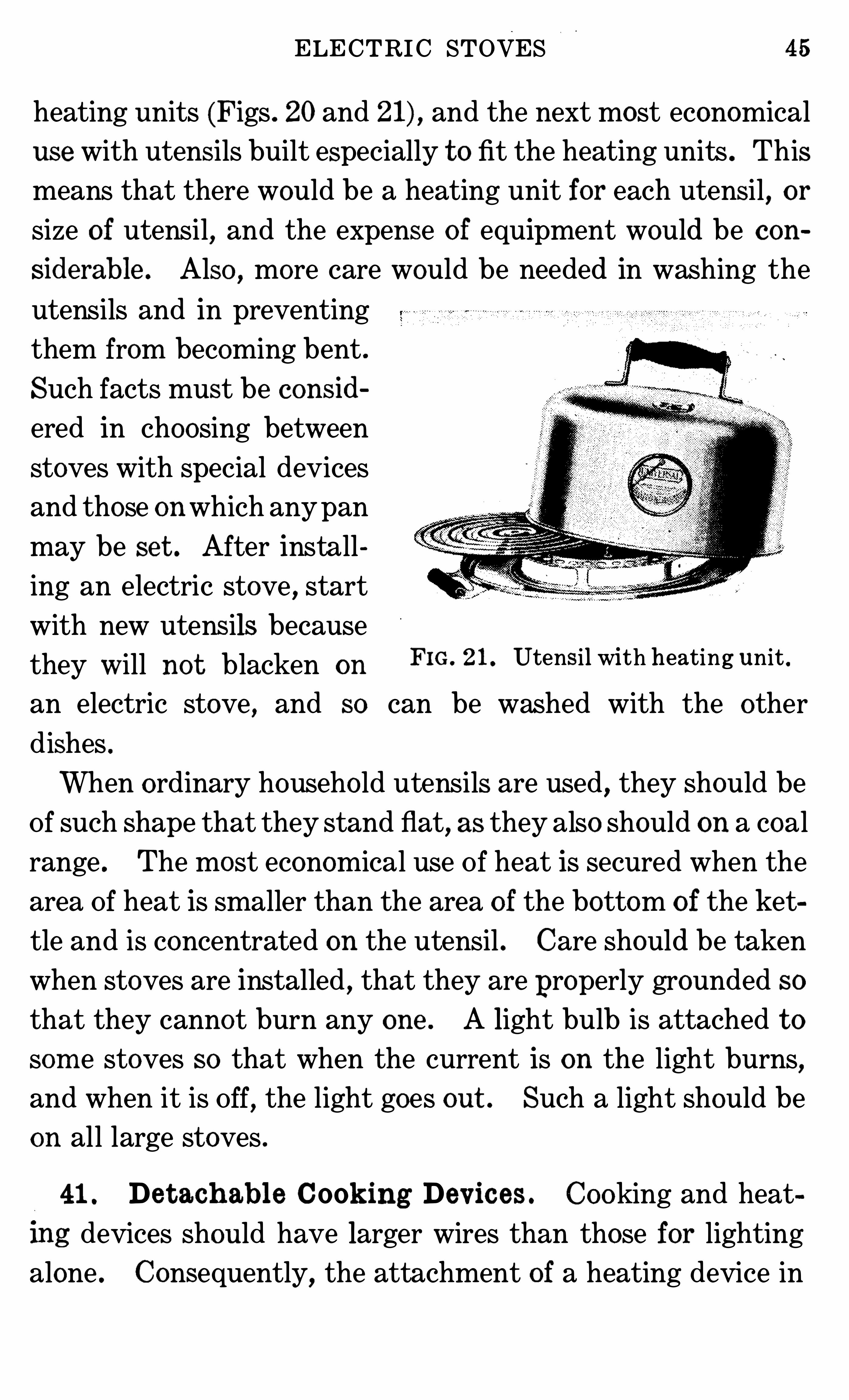
ELECTRI C STOVES 5
heating units (Figs . 20 and and the next most economical
use with utensils built especially t o fit the heating units . This
means that there would be a heating unit for each utensil, or
size of utensil, and the expense o f equipment would be c on
siderable . Also , more care would be needed in washing the
utensils and in preventing
them from becoming bent .
Such facts must be consid
ered in choosing between
stoves with special devices
and those onwhich anypan
may be set . After install
ing an electric stove , start
with new utensils becausethey Will no t blacken on
FIG . 21. Utensil with heating unit .
an electric stove , and SO can be washed with the other
dishes .
When ordinary househo ld utensils are used , they Should be
Of such Shape that they stand flat, as they also Should on a coal
range . The most economical use Of heat is secured when the
area Of heat is smaller than the area of the bottom o f the ket
tle and is concentrated on the utensil . Care should be taken
when stoves are installed , that they are properly grounded so
that they cannot burn any one . A light bulb is attached t osom e stoves so that when the current is on the light burns,and when it is Off, the light goes out . Such a light should be
on all large stoves .
41 . De t ach abl e Cook ing Dev ic es . Cooking and heat
lng devices should have larger wires than those for lightingalone . Consequently, the attachment of a heating device in
46 MECHANICAL DEVICES IN THE HOME
a common light socket may cause burning out of fuses or other
damage .
One danger in using detachable electric devices occurs in
not turn ing Off the current when the stove is not in use , thus
permitting it t o becom e overheated . This Shortens the life
Of the sto ve .
Any tendency Of a stove or other electric device t o give
people a Shock when being used Should be taken as a warning
t o have the device examined by an expert and the trouble
corrected . Have the wires repa ired as soon as the insulation
breaks or burns O ff . Uninsulated W ires, such as cables and
cords , are unsafe .
CHAPTER V
ALCOHOL, ACETYLENE , AND CANNED HEAT
42 . Al coh o l St oves . Alcoho l sto ves are made only in
small sizes for light housekeeping . There are three general
types Of these—those which burn with a wick, those whichgenerate gas
,and those which permit the alcoho l t o burn Off
of the t op surface of the container .
Alcoho l does no t produce much smoke in burning, evenwhen no provision is made for mixing air with it . The o rdi
nary alcoho l lamp, having a wick, may be used as a heating
stove . Stoves with wicks draw the alcoho l up by capillaryattraction t o the po int Of ignition , and themetal jacket about
the wick prevents the fire burning back into the bowl con
taining the alcoho l . The char from the t op Of the wick must
be brushed Off from time t o time . NO other care is needed
for these stoves or lamps . Some Of them are pro v ided with
devices for checking the burning Of the alcoho l in o rder t o
regulate the heat . This is desirable since a small flame o f
alcoho l produces much heat .
Extinguish the fire by covering the wick with a metal cup .
43 . Vapor St ov es . Alcoho l vapo r stoves which generate
gas ho ld the alcoho l in a tank slightly raised above the level Of
the burner. A pipe leads from this t o the burner,where a
small stream Of alcoho l is permitted t o enter when the valveis open .
When starting these stoves,the valve is first Opened and
enough alcoho l allowed t o flow out t o fill a cup which is below
8 MECHANICAL DEVICES IN THE HOME
the burner . This generally ho lds about a tablespoonful Of
alcoho l . When the cup is full , the valve is closed and the
alcoho l in the cup ignited .
This heats the burner enough t o vaporize the alcoho l .
When the burner is heated , open the valve and ignite the gas .
If all the alcoho l is no t vaporized, the burner has no t been
heated ho t enough . Close the valve until all the alcoho l inthe cup is burnt .
44 . Wick l ess St o v es . Wickless alcoho l stoves are used
commonly on chafing dishes . The burner of one type con
sists of a metal dish packed with a porous material which is
non-inflamm able , but a good conductor Of liquids by capillary
attraction , and the t op is covered o ver by a wire screen . The
alcoho l is poured into the dish . The packing and screen pre
vent air from ent ering the bowl with sufficient rapidity t o let
the fire burn below the screen SO the flame stays above it,
burning Off any alcoho l which is conducted t o the surface .
The only possible way t o contro l these sto ves is by a device
which can cut Off air . One of these is a plate-like device witha handle . This fits over the stove and only that portion Ofthe t op burns which is exposed t o air thru the ho le in the
plate . M aking the ho le larger o r smaller makes the burn ing
surface larger or sm aller .
To extinguish the fire, cover the entire t op with a so lid
plate t o cut Off all air .
45 . Canned Heat . Canned heat is alcoho l combinedwith other substances into a cake about the consistency o f
hard soap . The co ver t o the can is used t o extinguish the
fire . It Should no t be fitted into the t op Of the can until the
flame has been extinguished for two or three seconds . Then
CHAPTER VI
FIRELESS AND STEAM COOKERS
47 . Th e Fire l ess Cook er . The fire less cooker Is a boxor can having a diameter som ewhat larger than that of the
largest vessel t o be placed in it . The space left around the
vessel is packed with some insulating material t o keep in the
heat (Fig . In home-m ade cookers, this material may be
hay, feathers , pillows, shredded newspapers, wo od Shavings
or sawdust.In commercially-made cookers, it is felt, ashes
t os woo l, cork, or other insulating material . Because most
insulating material will no t stay in place and readily absorbs
mo isture and Odors, some kind Of lining is put between it and
the vessel ho lding the food . This makes a little nest, into
which the vessel fits . In the better made cookers , this lining
is made Of metal , and the seams are water-tight .
The steam from the cooking foOd is absorbed by the insu
lating material if this lining is not impervious t o water.
Enameled or earthen linings, if well glazed , would also serve
this purpose as long as they did not chip or crack .
The cover, as well as the sides, Of the fire less cooker has t o
be padded with the insulating material . The cover must also
fit well SO that the steam and heat will no t escape thru cracks
between it and the body of the cooker.
48 . Th e St ones of Firel ess Cook ers . The stones for
fire less cookers are usually made Of soapstone or some com
posit e which will absorb considerable heat . They should be
slightly smaller in diameter than the nest . They can only be
used with safety in cookers which are metal-lined and insu
FIRELESS AND STEAM COOKERS 51
lated with material which will not ignite at a low temperature .
Stones should no t be put in home-made cookers which are not
insulated with asbestos or other fireproof material . Hot
stones can be used with safety in any of the commercial cook
ers which come fitted with them .
The temperature in a fire less cooker is below bo iling most
FIG. 22. Section of fireless cooker.
of the time . It is, therefore , a device for Simmering food,and Should be used for cooking meats
,fruits, vegetablesand
cereal dishes which require or are improved by long,slow
cooking .
Since the food has t o be shut in a fire less cooker t o keep in
the heat, fire less cookery is a method of steaming of food .
For this reason, I t has a slightly different flavor from food
baked in the oven, much as fried food differs from roasted
food . Hot Stones (Fig . 22) are put in mo st fire less cookers .
The heat from these brown the food and give t o the otherwise
steamed food a flavor similar t o that developed in bak ing,roasting and frying.
52 MECHANICAL DEVICES IN THE HOME
49 . Heat ing t h e St ones . M o isture given Off by the
cooking food is absorbed by the stones . They must be dried
or heated very slowly t o prevent this mo isture from crackingthem . When the stones have been removed from the cooker
,
wash them , because they absorb Odors from the food . Keep
them in som e warm, dry place while they are no t in use , such
as in the warming oven Of the cook sto ve or on a radiator .
When wanted for use , they will then be dry enough t o be
placed over the gas-stove burner if it is not turned t oo high at
first . Drying thus saves tim e when the stones are needed .
50. Care of t h e Cook er . The cooker Should be left
open t o air while no t in use .As soon as the food_and stones are
removed from it, t he mo isture should be wiped out and the
inside washed with soap and'
wat er, wiped dry and left t o air .
Such care is needed t o prevent the cooker from taking on the
Odor Of dishes previously cooked and transmitting som e of
them t o those cooked later .
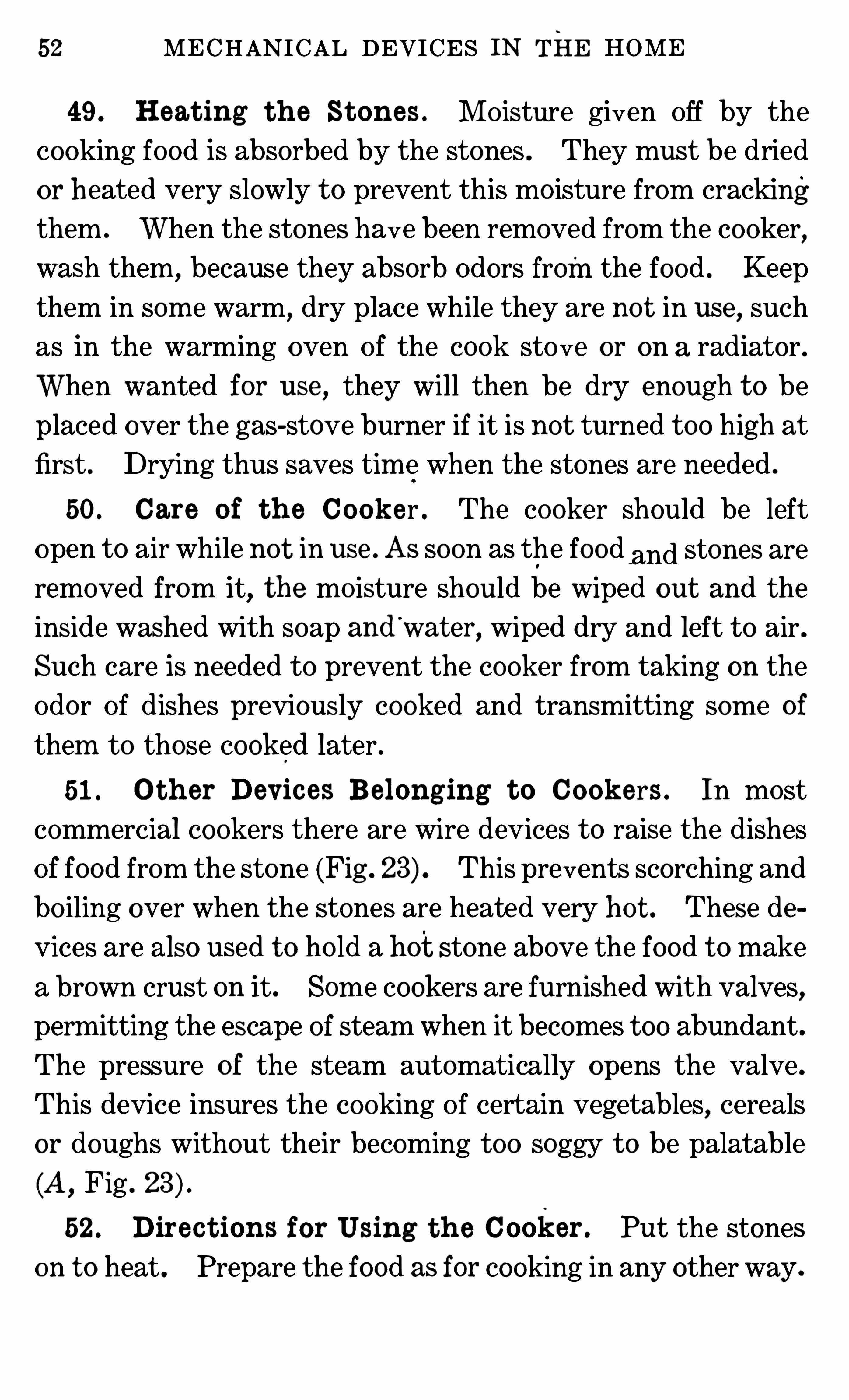
51 . O t h er Dev ic es Be longing t o Cook ers . In most
commercial cookers there are wire devices t o raise the dishesOf food from the stone (Fig . 23) This prevents scorching and
bo iling over when the stones are heated very ho t . These de
vices are also used t o ho ld a hot stone above the food t o make
a brown crust on it . Some cookers are furnished with valves,permitting the escape of steam when it becomes t oo abundant .
The pressure of the steam automatically opens the valve .
This device insures the cooking Of certain vegetables, cereals
or doughs without their becoming t oo soggy t o be palatable
(A,Fig .
52 . Direc t ions for Using t h e Cooker . Put the stones
on t o heat . Prepare the food as for cooking in any other way .
FIRELESS AND STEAM COOKERS 53
Then heat it , either in the oven or on t op Of t he st ove . It is
preferable t o heat the food in the same Vessel in which it is t obe cooked in the fire less cooker. Transferring food t o a co ld
FIG. 23 . Devi ces for fire less co oker .
vessel entails a loss Of heat,Since the first Vessel is already
,When the stones and food are hot , place the stone in thebottom of the cooker. Put in any asbestos mats or other
54 MECHANICAL DEVICES IN THE HOME
devices which are needed t o protect the food . The stone should
be hot enough t o respond t o the te st for flat irons . It Should
make the Snappy no ise Of a good hot iron when the finger is
mo istened and touched t o it . Place the food in the cooker .
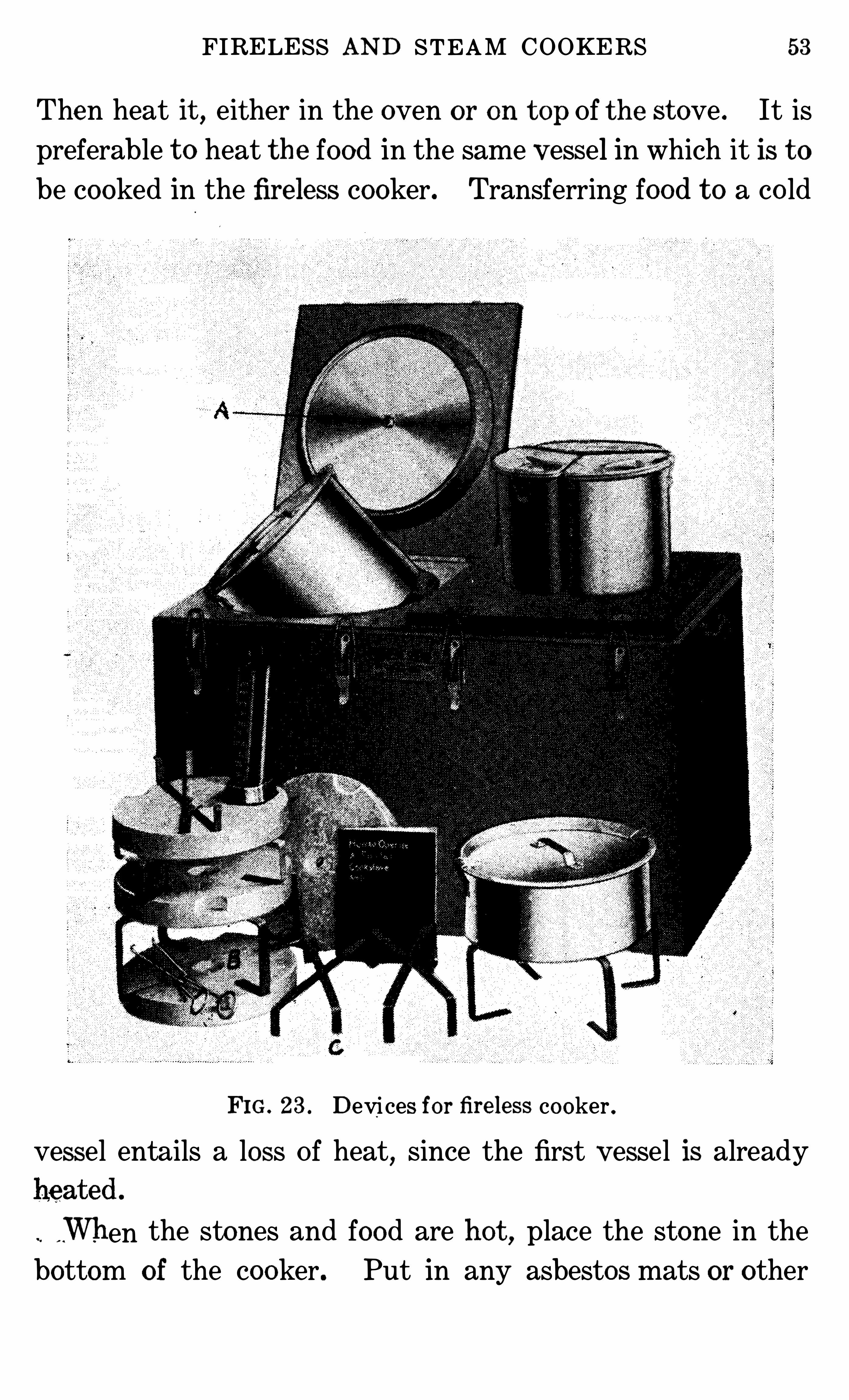
Place another stone above the utensil if it is desirable t o have
FIG. 24 . Gas co okers .
the food brown on t op . Close the fire less cooker, and let it
stand until ready for use .
53 . Tim e of Cook ing Food . Six hours or over night
Should be allowed for the cooking O f cereals . Stews Should
be given two t o three hours’
time for cooking .
Large roasts and hams require five t o six hours . It is
sometimes necessary, when they are large, t o remove them
and heat the food and the stones on the stove once during the
process Of cooking Dumplings and angel cakes cook well in a
fire less cooker . So do all dried peas and beans .
FIRELESS AND STEAM COOKERS 55
It is profitable t o cook foods requiring more than forty
minute s ’ heating in a fire less cooker . The heating unit is a
part of some cookers .
Electric cookers , instead Ofbeing furnished with stones t o
be put inside the nest, have a heating unit and plate for ho ld
ing heat in the cooker.
Co ld food may be put in
t o this cooker, the current
turned on,and the heat
ing and cooking all be
done inside the cooker.
The electric oven which
is well insulated answersthe purpose of a fire less
cooker when the current
is disconnected . Either a
thermometer, which the
housewife may watch, or
thermostat, which con
tro ls the current, must be
attached t o electric cook
ers t o prevent burning
the food or injuring the cooker with t oo much heat .
FIG. 25 . Steam cooker .
54 . Gas Cook ers. Since heated air rises, special cookers
in the fo rm Of insulated caps are made t o put over dishes Of
food heated on gas burners (Fig .
The inside of the cap must be kept clean . Ge t the dishes
hot with the cap suspended over the food , but leaving about
an inch space for the escape o f gases from the heating unit .
As soon as the food and cap have been sufficiently heated
56 MECHANICAL DEVICES IN THE HOME
over the fire, turn Off the gas and lower the cap so that it willretain the heat . After the cooker has been used
,it should be
wiped out clean ; otherwise it will retain som e o f the Odors o f
the cooked food .
55 . St eam Cook ers . There are several steam cookers
in use in homes . The Simplest of these 1s a covered pan
which has a perforated bottom, which is set over another pan
(A, Fig . in which water is placed for forming steam . Oneof the difficulties Of this cooker is that the water in the lower
pan cannot be watched and may bo il dry . On the more im
proved cookers a whistling device (B ,Fig . 25) is attached t o the
pan,and when the water becomes low and steam ceases t o
flow thru it, air begins t o come in, and the device makes a
wh istling no ise .
QUESTIONS FOR PART I
1 . What is sm oke ! Under what conditions is the greatest am ounto f heat for cooking or o ther househo ld purposes produced from fuel !2 . How is an oven m ade t o heat evenly !3 . Explain the purpose o f each draft and dam per on a stove .4 . Observe the am ount o f fuel used in a coal
‘
st ov e from day t oday . Make the sam e kind o f observation for a gas or electric stove .How was the stove m anaged when the least fuel was used !5 . Des cribe the construction o f a gas stove . Find t h e vent thruwhich the gas enters the burner . I s this large or sm all !6 . Where is the air regulator ! For what is it used !7 . What has happened when the gas in a burner “ burns back” !8 . How Should a kerosene stove be regulated ! How Should it becared for !9. What precautions should you take against fire from kerosene andgaso line stoves !10. Describe the heating unit o f an electric stove .11 . How m ay electric current be saved in the operation o f an electric stove !12. How does a fireless co oker cook fo od !13 . How m ay one determ ine when it is econom ical t o use a firelesscooker !
58 MECHANICAL DEVICES IN THE HOME
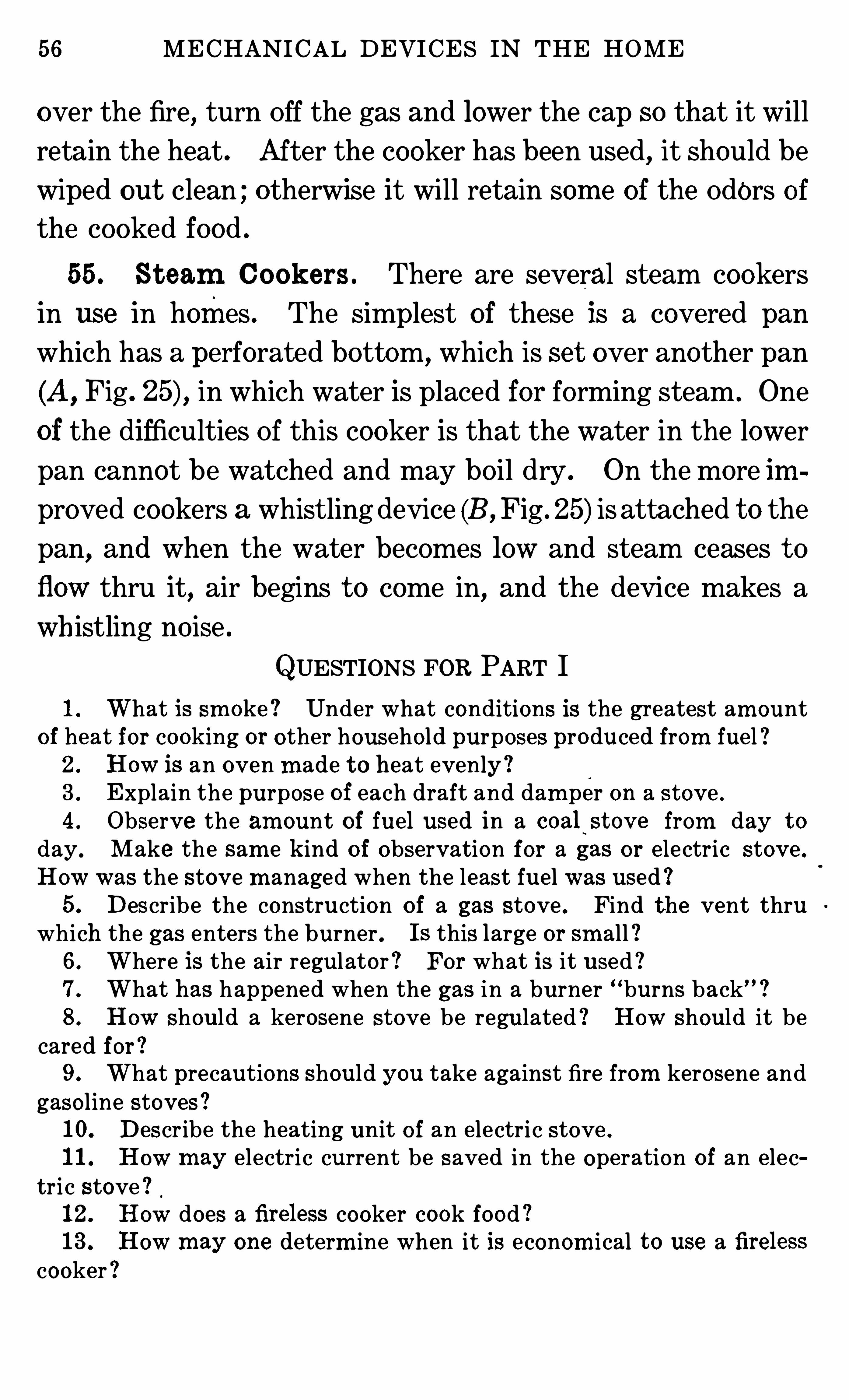
below the grate in the fire po t lets in air which is essential t o
the proper burning Of the fuel . In this respect, it is similar
to a cook stove. A draft above the fire when opened a littlelets in air which aids in the complete combustion of the gases
FIG. 26. Warm -air furnace .
given Off by the fuel . Burning these gases adds t o the amount
of heat secured from the fuel. Opening the draft wider checksthe burning o f the fire . There Should be a damper in thesmoke pipe . When this is closed , it checks the draft up the
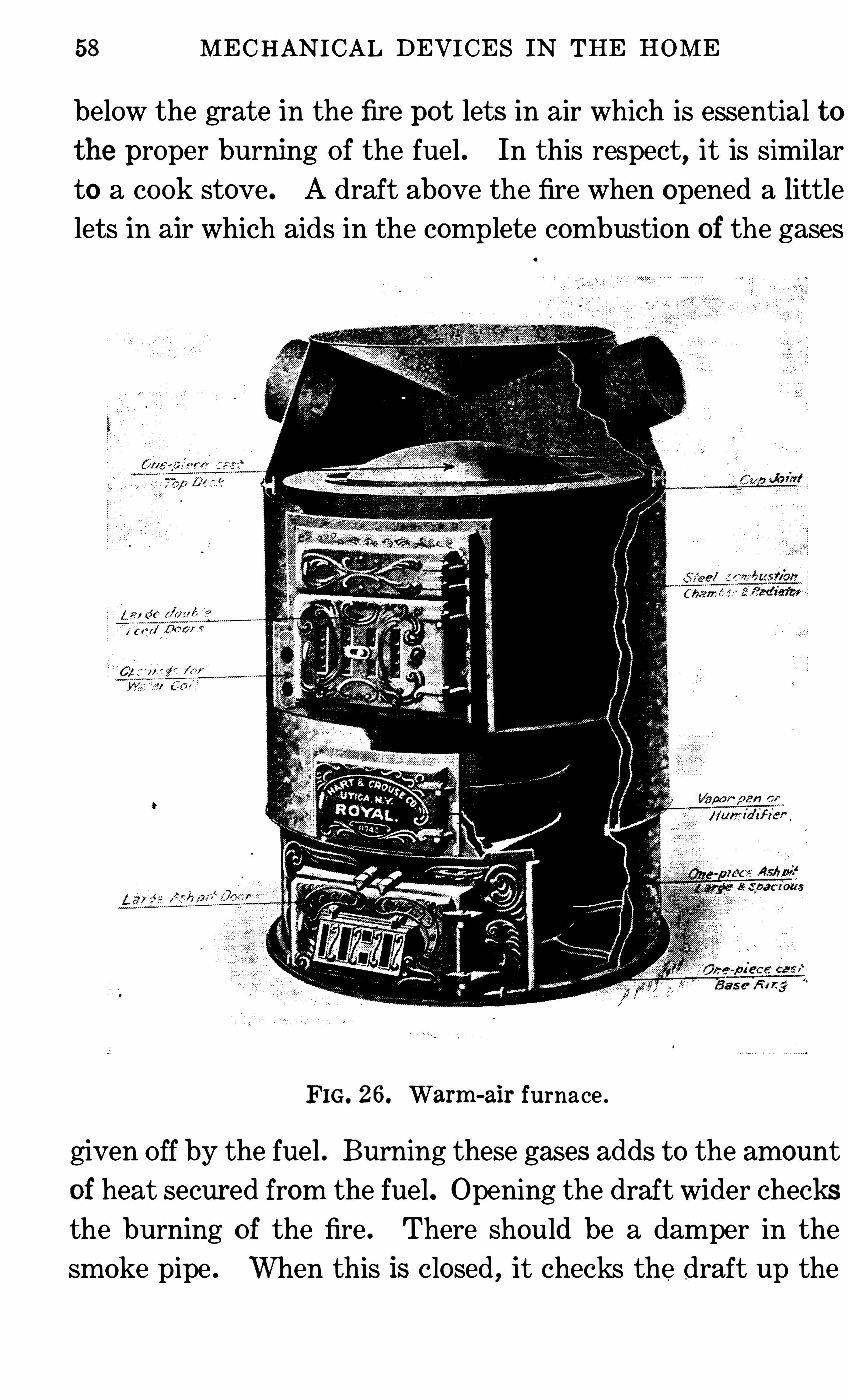
WARM-AIR FURNACES 9
chimney. This is needed because some chimneys Often draw
up air t oo fast t o make the fire burn well . When checking the
fire,close the draft below, open the one above the fire box,
and close the one in the pipe . TO make the fire burn fast,
Open the draft below,close the one above the fire box, and
FIG. 27 C irculation Of warm air .
open t he one in the pipe . Remem ber that a fire will no t burn
well if there is t oo much draft . Adjust the drafts until the
fire burns with a clear, bright flame without giving Off smoke .
After a fire is built,the manner of adding fuel makes a differ
ence in the efficiency of the furnace . When using coal, add
it in rather sm all amounts, spreading it in a layer over the
entire fire . DO not make this layer so thick that the fire
smokes . The fuel will not burn with a clear flame if the fire
is being smothered . Much fuel is wasted by ignorant and
careless management Of furnaces .
60 MECHAN ICAL DEVICES IN THE HOME
58 . Th e Cold -Air Sh aft . It is thru a co ld-air shaft that
the coo ler air com es int o the furnace . Som e furnaces have
this bui lt so that it draws the coo ling air from the rooms abo ve
down into the furnace t o be heated again . This is an e conom
ical arrangement . Some others draw fresh air from out of
doors into the furnace, letting the co ld air from the rooms
above drain into the cellar and out of doors . This is more
expensive, as the air t o be heated is usually co lder, but it has
the advantage Of helping ventilate the room s by bringing a
constant supply Of fresh air .
The co ld-air Shaft leading from out Of doors Should have
the outer end covered with wire mesh , and a cloth which
Should be washed or renewed Often .
Never sweep dirt down a register or cold-air Shaft .“
It
com es back into the room in time . Dust the regist ers o cca
Sionally .
In Older heat ing system s,there was but one large co ld-air
shaft t o drain t he co ld air from the room s above . In more
modern houses , a co ld-air shaft is placed in every room that
may be Shut Off from the others . This does away with the
Old difficulty Of heating a closed room, for it is as im portant
that the co lder air gets out as that the warm air gets in .
59 . Ho t -Air Pipes . The hot -air pipes lead from the t op
Of the jacket about the furnace t o the floor abo ve . In most
houses, one pipe goes t o each room . Th is IS unnecessary if
the room s are not closed Off, but if they are, they need the
pipe entering the room . TO economize with heat and regu
late the am ount O f air passing up these pipes, there must be
a Shutter in them,near the furnace, as well as in the regist er.
This shutter is placed near t he furnace SO that no heat passes
WARM-AIR FURNACES 61
into the pipe when no t wanted in the room t o which it leads .
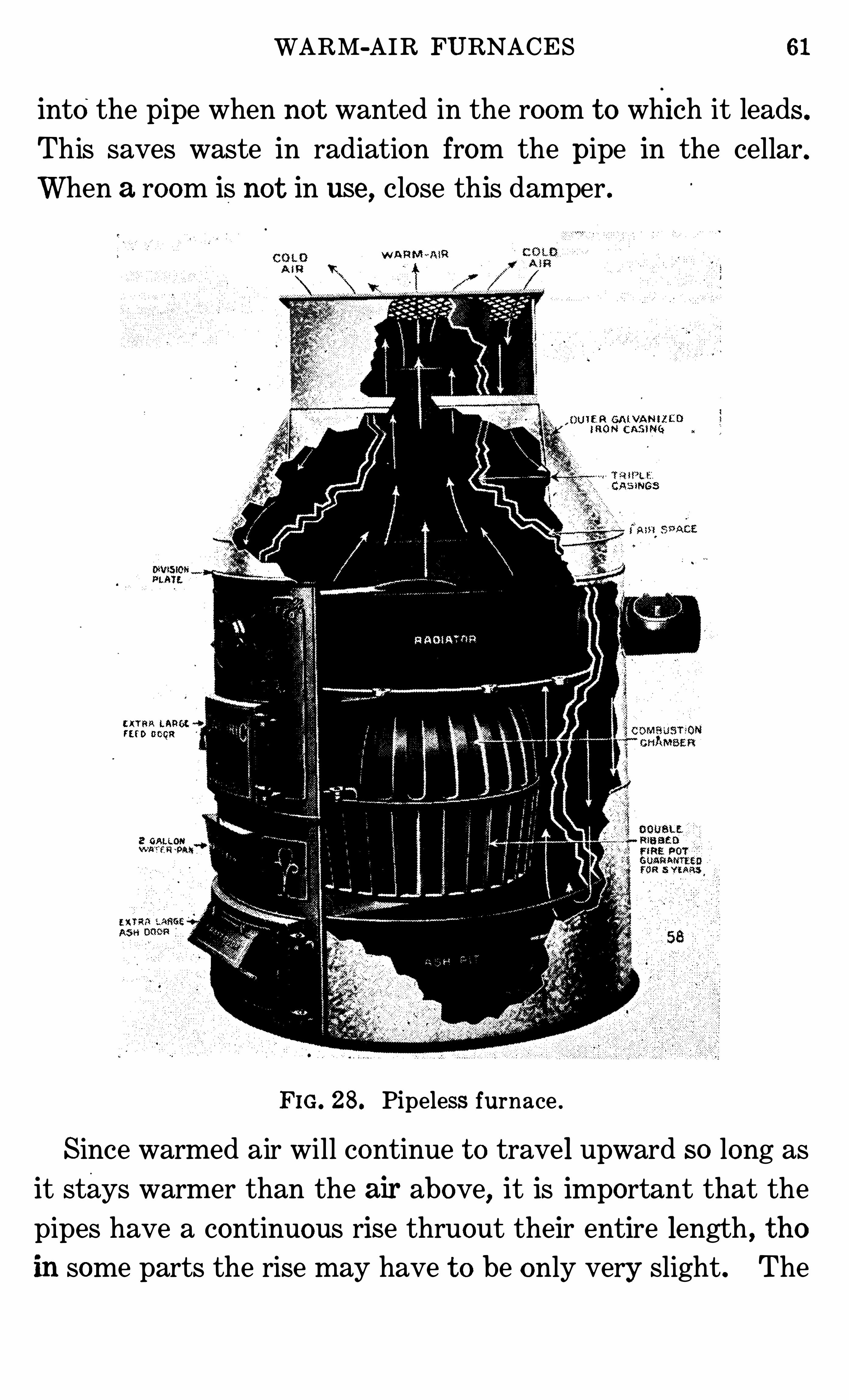
This saves waste in radiation from the pipe in the cellar.When a room is not in use , close this damper .
W ARM -em!
UIER GAIVANM CD”1 0h! (2385 1946
Casmes
u rns LAN! .
ru b coca
2 GALLON
FIG. 28. Pipeless furnace .
Since warmed air will continue t o travel upward so long as
it stays warmer than the air above, it is important that the
pipes have a continuous rise thruout their entire length , thoin some parts the rise may have t o be only very Slight . The
62 MECHANICAL DEVICES IN THE HOME
Shorter the pipes, the better, for there will be less loss Of heat
from radiation on the way t o the room s .
60. Locat ion o f t h e Furnac e . A central location for
the furnace is best because the pipes m ay be shorter, and this
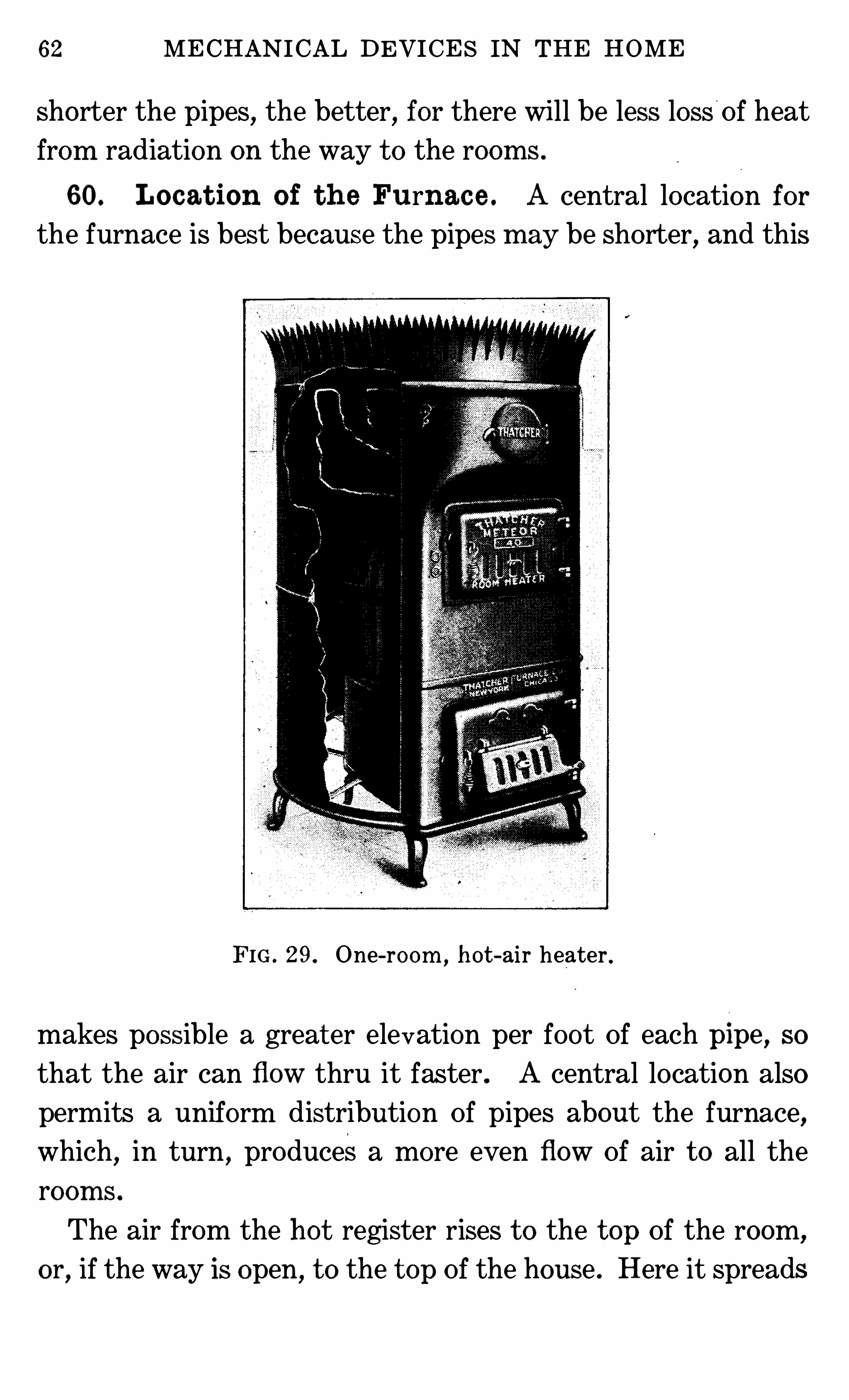
FIG . 29. One-room ,h ot -air heater .
makes possible a great er elevation per foot Of each plpe , SO
that the air can flow thru it faster . A central location also
permits a uniform distribution Of pipes about the furnace,
which,in turn , producesa more even flow Of air t o all the
room s .
The air from the hot register rises t o the t op Of the room,
or, if the way is open, t o the t op Of the house . Here it spreads
WARM-AIR FURNACES 63
o ver the upper area . As it coo ls or is displaced by still hott er
air,it falls . When it reaches the floor, it flows down the co ld
air shaft in the floo r . If the co ld-air Shaft is no t in the floor ,there may be a layer Of co lder air there SO the room
‘
will no t
be com fortable .
61 . Air . There is a constant change of air in all houses,
due t o Opening o f doors and the fact that walls are no t air
tight . This may no t be enough for comfort . If a room is no t
heating well,it has been found that opening the window t o
change the air in the room , even when the outside air is very
co ld , helps in the circulation Of air in the room,and so with
the warming Of it . It is difficult t o warm a room filled with
stagnant air .
62 . Pipel ess Furnac es . The pipeless furnace works on
the same principle as the one with pipes (Fig . One large
Opening above the furnace lets the heat in t o some central
room ,and from here it circulates Into all other rooms no t
closed Off from the central room . The co ld-air shaft may be
around the opening for heated air .
Stoves encased in a metal jacket that operate like hot -air
furnaces (Fig . 29) are used in heating one -room schoo lhouses
and other small public buildings .
CHAPTER VI I I
HOT-WATER SYSTEM OF HEATING
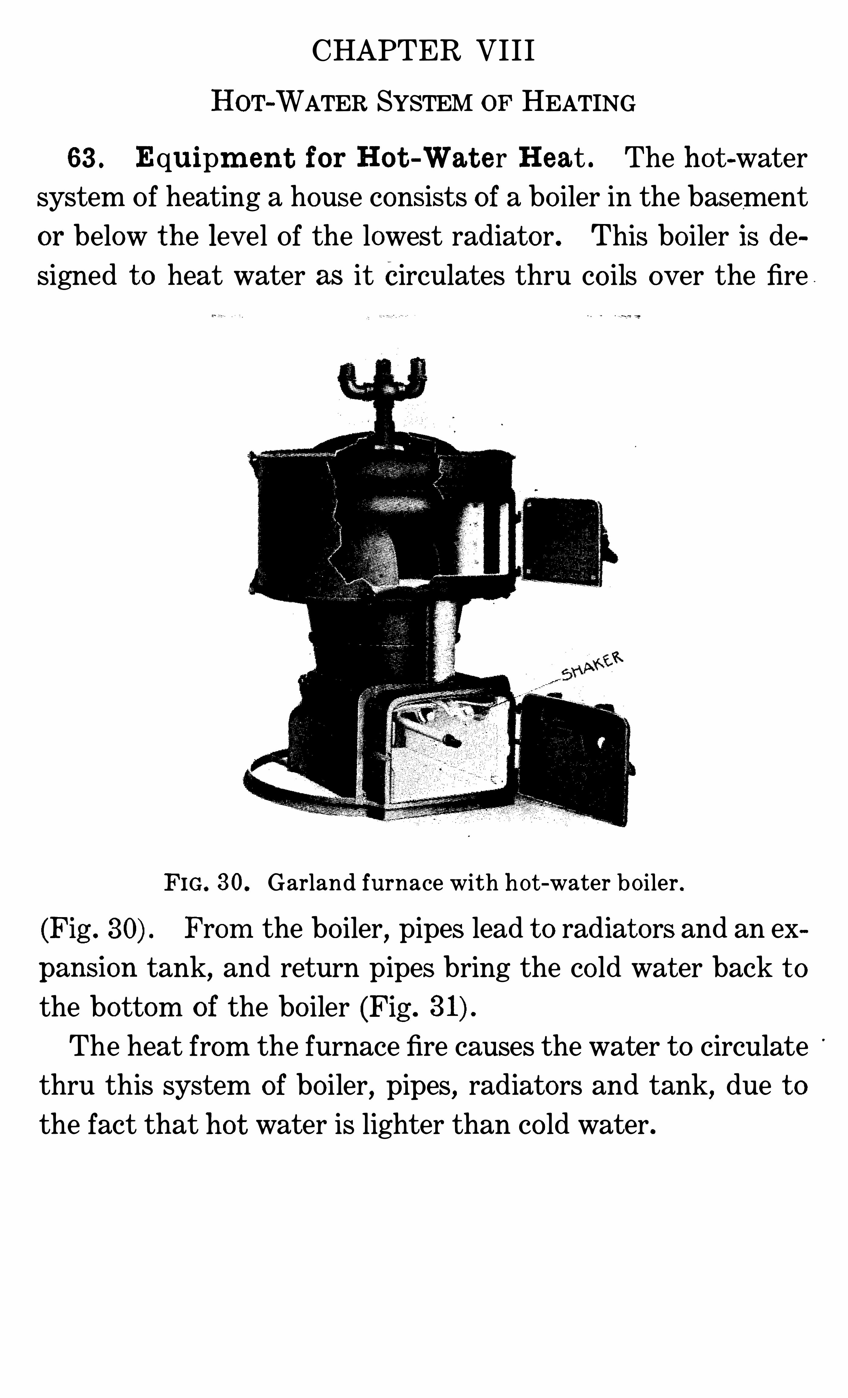
63 . Equipm en t for Ho t -Wat e r Heat . The ho t -water
system Of heating a house consists o f a bo iler in the basement
or below the level Of the lowest radiator . This bo iler is de
signed t o heat water as it Circulates thru co ils over the fire
F IG. 30. Garland furnace with h o t -water bo iler .
(Fig . From the bo iler, pipes lead t o radiat ors and an ex
pansion tank, and return pipes bring the co ld wat er back t o
the bottom o f the bo iler (Fig .
The heat from the furnace fire causes the water t o circulate
thru this system of bo iler,pipes
,radiators and tank, due t o
the fact that ho t water is lighter than co ld water .
6 MECHANICAL DEVICES IN THE HOME
used . A gas burner is som etimes placed in the fire pot and
used for heating a furnace , but this is one Of the most wasteful
ways Of usm g gas . A real gas furnace is much more econom
ical . The fire and heat from the fire circulate around the co ils
containing the water . If the co ils are no t constantly kept
full Of water, they will be injured by the heat .
65 . Th e Manag em en t o f t h e Fire . When burning
coal , spread the coal all o ver the surface o f the fire in a thin
layer so as not t o smother it and thus make it burn with a
smoky flame . Keep the ashes cleaned out from underneath
the fire and around the fire po t . Clean the flues every forty
eight hours . Soot on the co ils is more effective than asbestos
would be in keeping heat from penetrating t o the water.
Regulate the fire with the drafts . Open the one below the
fire box t o let in air t o aid combustion . Open the one found
in most furnace doors a very little . This aids in the combus
tion Of gases,thus making more economical use Of the fuel,
while opening it wider checks the burning o f the fire . Broken
and warped doors and drafts let in t oo much air and destroythe
efficiency Of the heater . Open the chinm ey dam per, shown
in Fig . 2, Sec . 3 , admitting air t o check the draft . Close the
chim ney or pipe damper of the type Of cook stove shown in
Fig . 2, Sec . 3, t o check the draft up the chimney.
66 . Th e Pipes . The pipe carrying the hot water from
the bo iler out t o the heating system leads t o the expansion
tank, tho sometim es separate pipes lead from the bo iler t o a
radiator . Insulate each pipe , except the part in the room t o
be heated,with asbestos or som e other covering, t o keep the ,
heat in it. Keep the pipes full Of water . When they are in
stalled, see that they are put in so that they gradually rise
HOT-WATER SYSTEM OF HEAT ING 67
upward . If they dip downward at any po int, air will co llect
at these places and check the circulation Of ho t water thru
pipes .
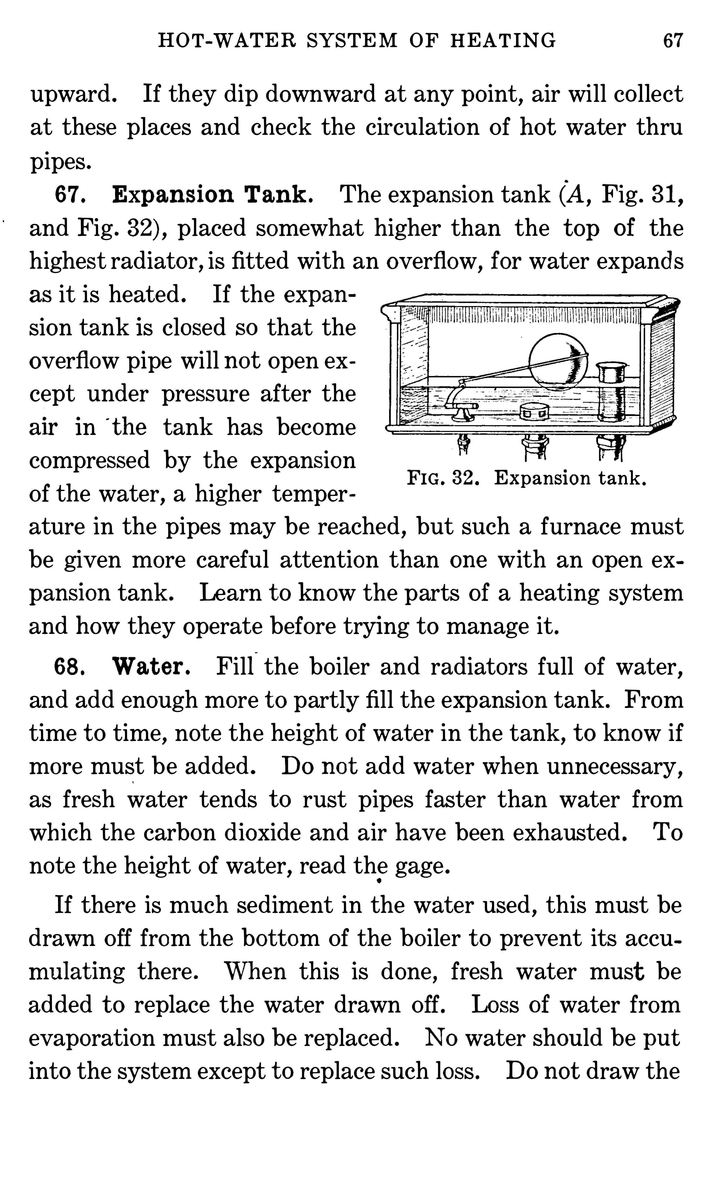
67 . Expansion Tank . The expansion tank (A, Fig . 31,
and Fig . placed somewhat higher than the t op of the
highest radiator, is fitted with an overflow, for water expands
as it is heated . If the expan
sion tank is closed so that the
overflow pipe will no t open ex
cept under pressure after the
alr in t he tank has become
compressed by the expansion
Of the water, a higher temper
ature in the pipes may be reached , but such a furnace must
be given more careful attention than one with an open ex
pansion tank . Learn t o know the parts of a heating system
and how they operate before trying t o manage it .
68 . Wat er . Fill the bo iler and radiators full Of water,
and add enough more t o partly fill the expansion tank . From
time t o time, note the height Of water in the tank, t o know if
more must be added . DO no t add water when unnecessary,
as fresh water tends t o rust pipes faster than water from
wh ich the carbon dioxide and air have been exhausted . To
note the height Of water, read the gage .
FIG . 32. Expansion tank .
If there is much sediment in the water used,this must be
drawn Off from the bottom Of the bo iler t o prevent its accu
mulat ing there . Wh en this is done , fresh water must be
added t o replace the water drawn Off . Lo ss of water from
evaporation must also be replaced . NO water should be put
into the system except t o replace such loss . Do not draw the
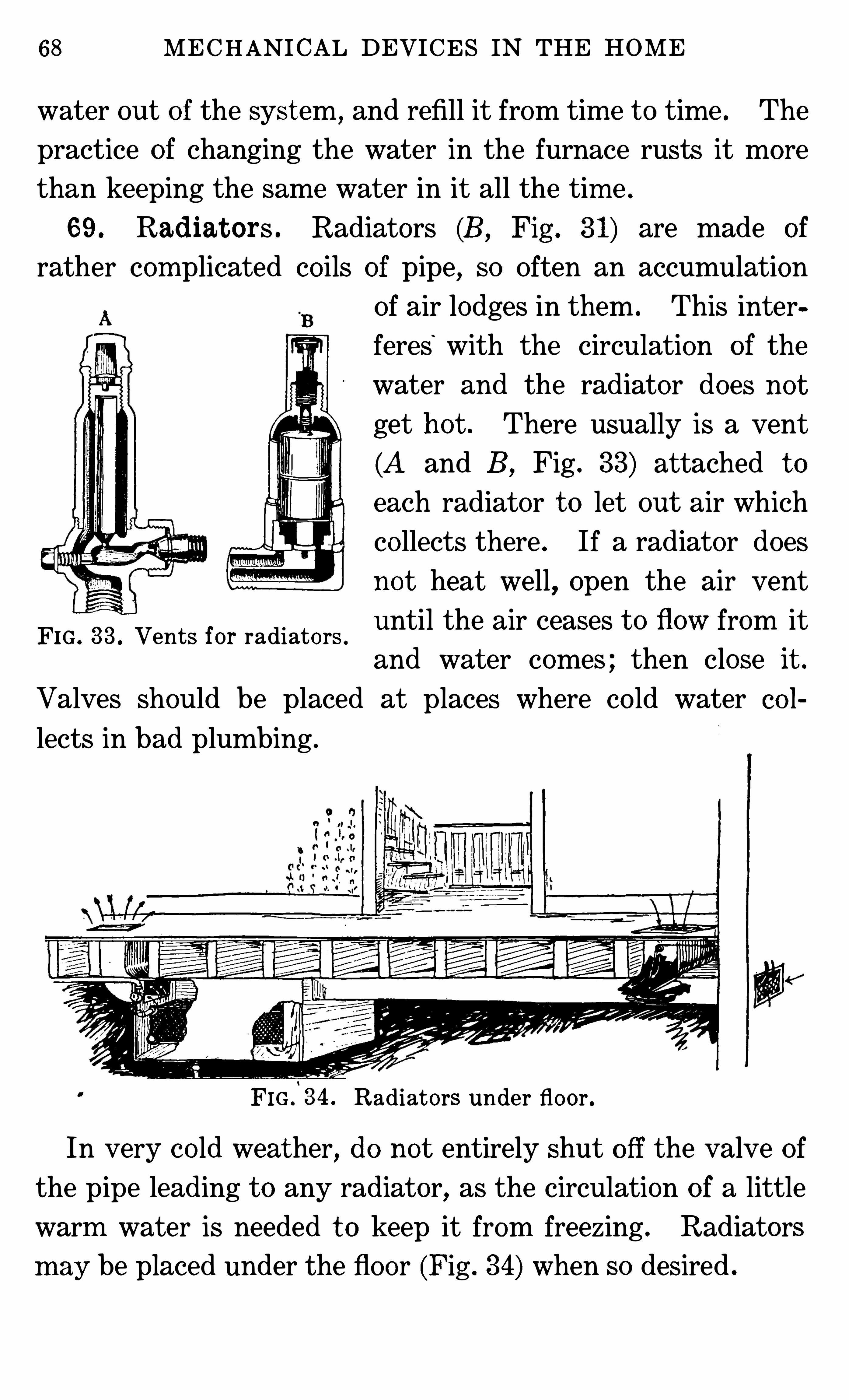
68 MECHANICAL DEVICES IN THE HOME
water out o f the syst em , and refill it from tim e t o time . The
practice o f changing the water in the furnace rusts it more
than keeping the same water in it all the tim e .
69 . Radiat ors . Radiators (B ,Fig . 31) are made of
rather complicated co ils of pipe, so Often an accumulation
Of air lodges in them . This inter
feres’
with the circulation of the
water and the radiator does no t
get hot . There usually is a vent
(A and B ,Fig . 33) attached t o
each radiator t o let out air which
co llects there . If a radiator does
not heat well, open the air vent
until the air ceases t o flow from itFIG. 33 . Vents for radiators .
and water comes ; then close It .
Valves should be placed at places where co ld water co l
lects in bad plumbing .
FIG .
‘
34 . Radiators under floor .
In very co ld weather, do not entirely shut Off the valve Of
the pipe leading t o any radiator, as the circulation of a little
warm water is needed t o keep it from freezing . Radiators
m ay be placed under the floor (Fig . 34) when so desired .
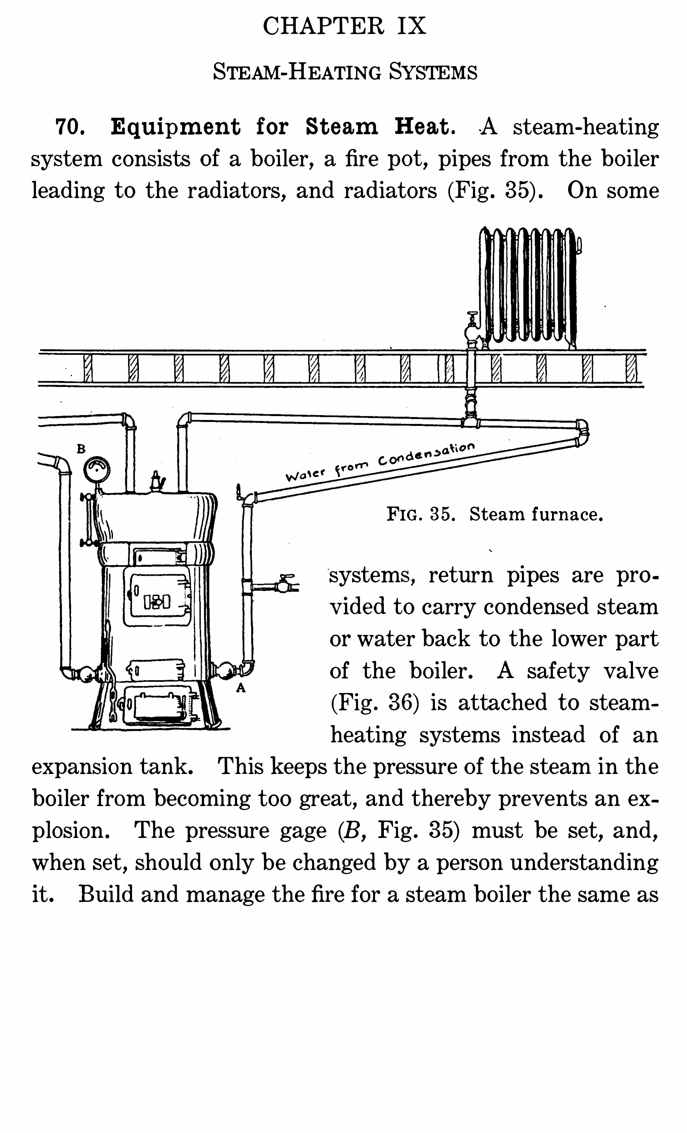
CHAPTER IX
STEAM-HEATING SYSTEMS
70. Equipm ent for St eam Heat . A steam-heating
system consists of a bo iler, a fire pot , pipes from the bo iler
leading t o the radiators, and radiators (Fig . On some
FIG . 35 . Steam furnace .
systems, return pipes are pro
v ided t o carry condensed steam
or water back t o the lower part
Of the bo iler . A safety valve
(Fig . 36) is attached t o steam
heating systems instead Of an
expansion tank. This keeps the pressure Of the steam in the
bo iler from becoming t oo great, and thereby prevents an ex
plosion . The pressure gage (B , Fig . 35) must be se t , and ,when set , Should only be changed by a person understanding
it . Build and manage the fire for a steam bo iler the same as
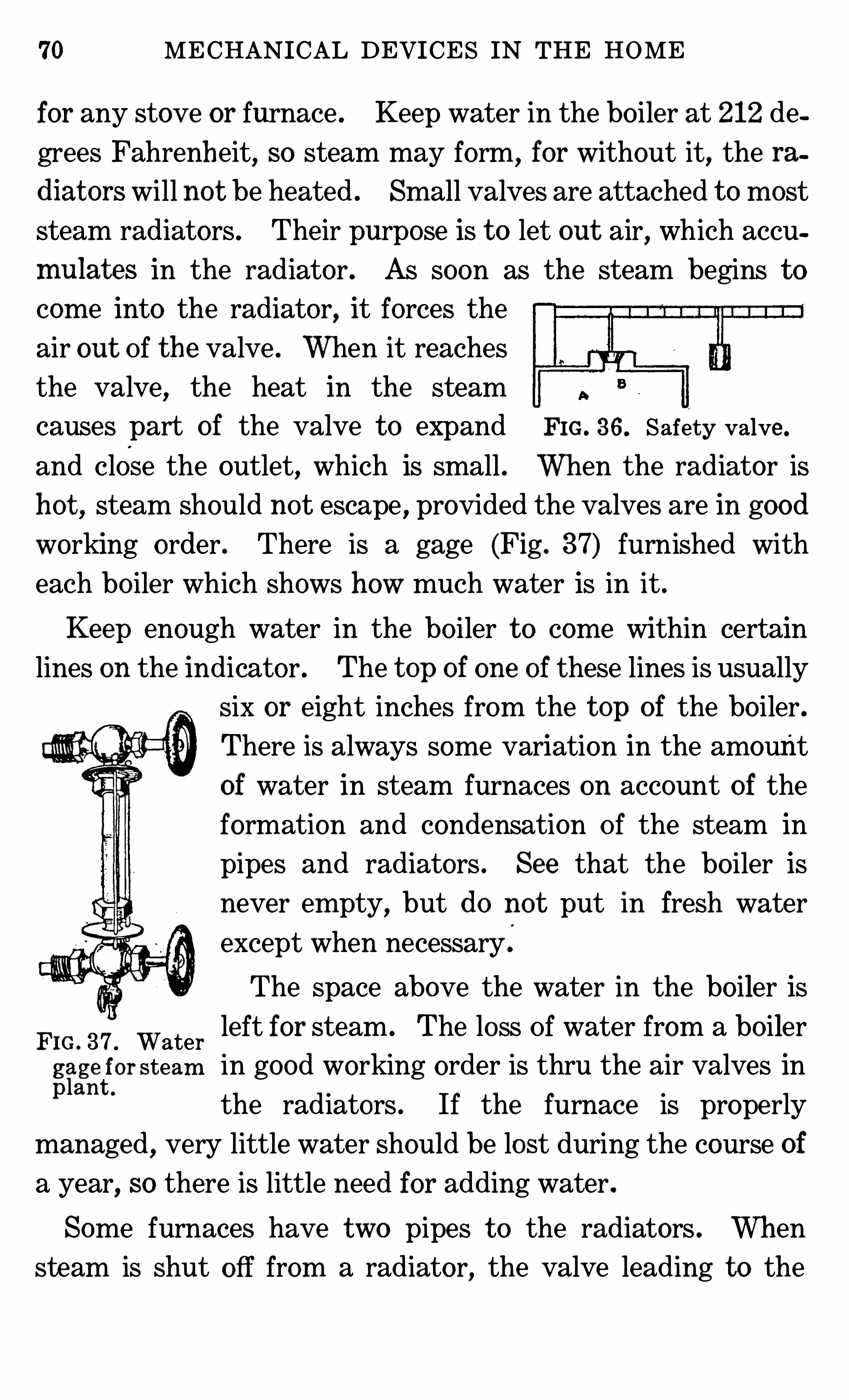
70 MECHANICAL DEVICES IN THE HOME
for any stove or furnace . Keep water in the bo iler at 212 de
grees Fahrenheit, so steam may form, for without it, the ra
diat ors will not be heated . Small valves are attached t o most
steam radiators . Their purpose is t o let out air, which accu
mulat es in the radiator . As soon as the steam begins t o
come into the radiator, it forces the
air out Of the valve . When it reaches
the valve, the heat in the steam
causes part of the valve t o expand FIG. 36. Safety valve .
and close the outlet, which is small . When the radiator is
hot , steam Should no t escape , provided the valves are in goodworking order . There is a gage (Fig . 37) furnished with
each bo iler which Shows how much water is in it .
Keep enough water in the bo iler t o come within certain
lines on the indicator . The t op of one of these lines is usually
six or eight inches from the t op of the bo iler .
There is always some variation in the amount
of water in steam furnaces on account of the
formation and condensation Of the steam in
pipes and radiators . See that the bo iler is
never empty,but do not put in fresh water
except when necessary .
The Space above the water in the bo iler is
FIG. 37 . Water left for steam . The loss Of water from a boiler
gage for steam in good working order is thru the air valves inplant
the radiators . If the furnace is properly
managed, very little water Should be lost during the course of
a year, so there is little need for adding water.
Some furnaces have two pipes t o the radiators . When
steam is shut Off from a radiator, the valve leading to the
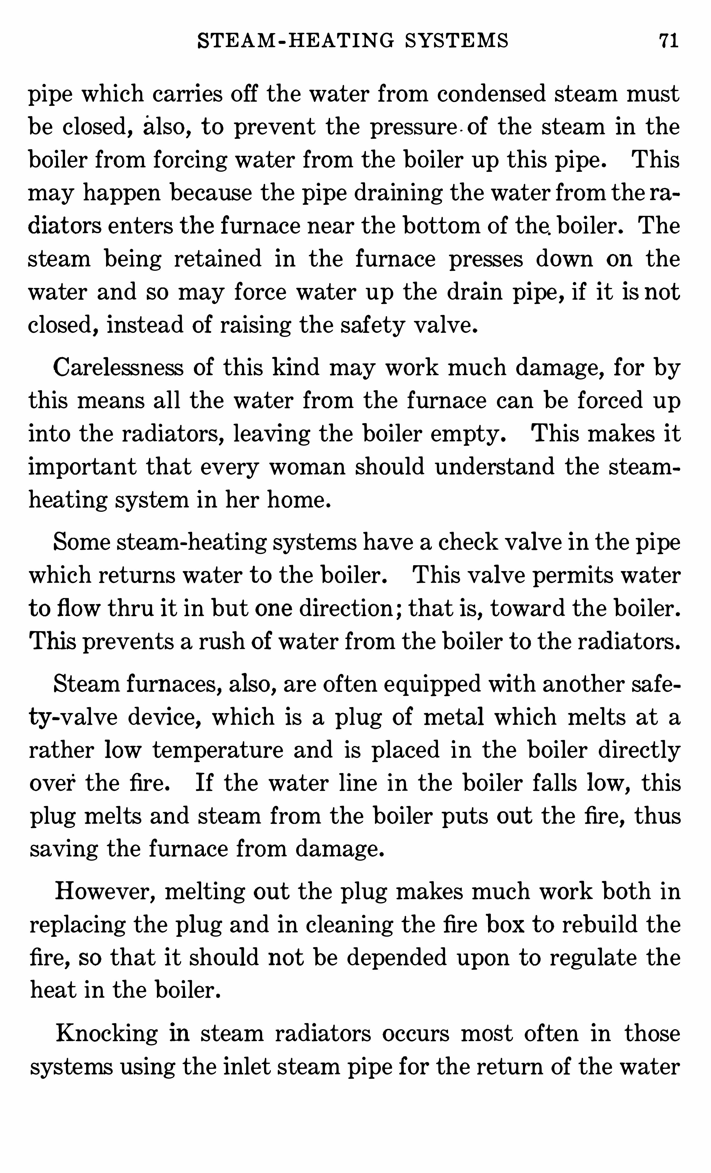
STEAM -HEATING SYSTEMS 71
pipe which carries Off the water from condensed steam must
be closed , also , t o prevent the pressure -Of the steam in the
bo iler from forcing water from the bo iler up this pipe . This
may happen because the pipe draining the water from the ra
diat ors enters the furnace near the bottom Of the. bo iler . The
steam being retained in the furnace presses down on the
water and so may force water up the drain pipe , if it is no t
closed , instead of raising the safety valve .
Carelessness of this kind may work much damage, for bythis means all the water from the furnace can be forced up
into the radiators , leaving the bo iler empty. This makes it
important that every woman Should understand the steam
heating system in her home .
Some steam-heating systems have a check valve in the pipe
which returns water t o the bo iler . This valve permits water
t o flow thru it in but one direction ; that is, toward the bo iler .
This prevents a rush of water from the bo iler t o the radiators .
Steam furnaces, also , are Often equipped with another safe
ty-valve device, which is a plug of metal which melts at a
rather low temperature and is placed in the bo iler directly
over the fire . If the water line in the bo iler falls low,this
plug melts and steam from the bo iler puts out the fire,thus
saving the furnace from damage .
However, melting out the plug makes much work both in
replacing the plug and in cleaning the fire box t o rebuild the
fire, so that it should not be depended upon t o regulate theheat in the bo iler .
Knocking in steam radiators occurs most Often in those
systems using the inlet steam pipe for the return Of the water
2 MECHANICAL DEVICES IN THE HOME
which has formed as ar esult of condensation . It is caused by
water accumulating at some po int and the steamComing up
the pipe, vio lently forcing it back into the radiator . This
only reaches a danger po int in systems which do not have
pipes Of the proper size, or when the pipes do not slope grad
ually downward , SO that all the water may flow back t o the
furnace . On co ld days, there will be some knocking in asteam radiator when it is being heated in the morning . A
two-pipe system,while it is somewhat more expensive, is less
subject t o this trouble .
71 . St eam Gag es . Steam gages (B , Fig . 35) are de
vices for indicating the pressure of steam within an inclosure .
They are a kind Of spring balance . When the pressure of the
steam increases,it pushes up on the spring, and this turns the
hand of the indicator, which Shows the number Of pounds of
pressure that the steam is exerting on the inside of the boiler
or container.
72. Safet y Valv e . A safety valve (Fig . 36 and A, Fig .
38) consists Of a small opening t o a bo iler over which is a
weight. When steam is developed until itmakes enough pressure on the inside Of the valve t o raise this weight, some Of the
steam escapes, thus lowering the pressure on the inside until
the weight falls back into place . Never let anything interfere
with the action Of safety valves .
M ost safety valves have the weight attached t o a lever
which has a movable weight on it so that the position of the
weight on the lever makes a difference in the number of
pounds of pressure required t o open the valve . By means o f
this device,the temperature of the inside of the bo iler can be
CHAPTER X
FIREPLACES AND HEATING STOVES
73 . Const ruc t ion o f Fireplac e . Fireplaces are an en
largement in the base of a chimney where fire is built . The
upper part of the fireplace is Sloped forward,and
,in some
cases,a damper is placed in the chimney t o regulate the flow
of air upward . The damper Should not be SO constructed
that it will close entirely, for if it did, the smoke would comeinto the room . The fire in the fireplace burns best when the
fuel is put in a grate or on andirons SO that air can get under
it and be drawn thru it by the draft Of the chimney. A
steady draft makes the combustion Of the fuel complete and
thus prevents smoking.
The hearth is made of fireproof material and should be
wide enough t o catch all Sparks flying from the fire . A screen
is Often nee ded for safety from fire . DO no t pile reserved
fuel or put rugs on the hearth .
Fireplaces and chimneys Should be built Of fireproof brick,stone or concrete . Have them examined once a year for
cracks,as these make them unsafe . The walls Of the chim
ney and the fireplace Should be thick enough t o prevent dan
ger from fire .
74 . Manag em en t o f Fireplac e . The management Of a
fireplace is very simple . The draft up the chimney Should be
properly regulated SO that the fire does not smoke . Sparks
and bits Of fuel Should not be drawn up the chimney. The
fire Should be built SO that it is not sm othered . Air Should
circulate thru the fuel. Keep the ashes cleared away.
FIREPLACES AND HEAT ING STOVES 75
There are some fireplaces which are intended t o heat rooms
after the manner of hot -air furnaces . The heat and smoke
fr om the fire pass upward thru a metal heater, encased by an
air chamber. Much Of the heat passes thru the metal , warm
ing the air in the chamber. This warmed air passes thru
pipes and registers into the rooms, while the smoke finds its
way t o the chimney ; TO complete the circulation Of air, the
co ld air from the floor passes into the air chamber near the
floor at the Sides of the fireplace . Sometimes fresh air from
the out side Of the building is mixed with the air in the cham
be r.
If there is an opening in the floor Of the fireplace , a damper
Should be put in this opening t o regulate the flow of air . The
heater in a fireplace must be kept free from soot and ashes .
If the metal is covered with soot,heat will no t readily pass
thru it, and the soot will co llect mo isture and cause rusting .
One way t o keep the heater clean is t o regulate the draft up
the chimney so that ashes and bits Of burning fuel are no t
drawn into it . Also , the fire Should be kept burning with a
clear (no t smoky) blaze . Soot is unburnt fuel .
75 . Operat ing Heat ing St oves . Astove is a device for
ho lding the fuel and for permitting the heat t o pass readily
into the room . In the stove there is space below the fire for
co llecting ashes . There is an opening for fresh air t o enter
below the fuel,t o aid combustion, and a damper above t o act
as a check draft when open,a chimney t o carry O ff smoke, and
one or two dampers in the chimney t o regulate the draft .Wh en a fire is being built
,close the draft over the fire box
and open the one below ; open the damper in the chimney
this allows the free passage o f the air up the chimney .
76 MECHANICAL DEVICES IN THE HOME
76 . Care o f t h e St ov e . DO no t permit a large bed Of
ashes t o accumulate in the bottom Of a stove . Athin layer o f
ashes must be kept in the bottom o f some wood sto ves t o
keep the fire away from the metal bottom .
The po lish or finish Of the stove is a matter Of taste . Some
stoves are made Of iron, which”
does no t need blacking ;some must be blacked . Blacking keeps them from rusting .
All must be kept free from dust and dirt , as this accumulates
mo isture and causes the stove t o rust .
Letting the stove get red hot warps it . It Should not be
permitted t o get so ho t .
The grate (Fig . 3) in stoves ho lds the fuel so that air can
flow up thru it. If the grat e is clogged with ashes,this cannot
happen . The grate should be Shaken t o make the ashes dropthru . A clean grate is important t o the complete combustion
of the fuel . Shaking after glowing coals begin t o fall is a
waste Of fuel .
When an attempt t o Shake the grate is made, it may sud
denly refuse t o move . In this case, something mayhave lodged
between its parts, or it may have been Shaken from its proper
position . Shaking the stove t oo hard may displace the grate .
The common remedy for a displaced grate is t o let the fire
go out , remove all ashes and cinders, and readjust the grate .
Some kinds o f soft coal form “ clinkers,” and these catch in
the grat e . In burning fuel that makes clinkers, shake the
ashes from the fire several times a day . Rem o ve all accumu
lat ions in the fire box daily. Clinkers are made from sub
stances which melt and recombine, forming a different mate
rial which is quit e hard and does not burn . Constant atten
tion t o the fire prevents clinkers from forming in large masses .
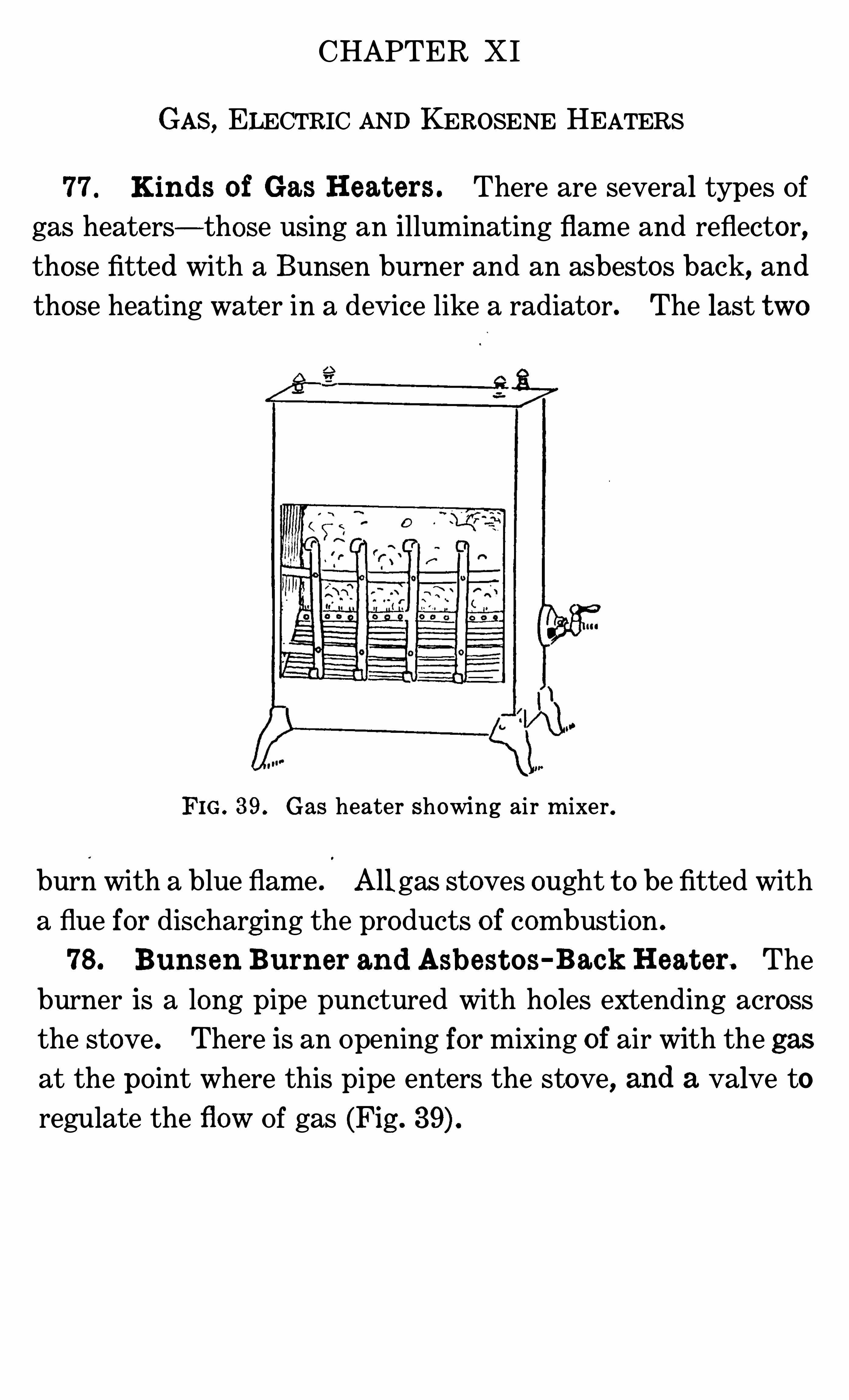
CHAPTER X I
GAS, ELECTRIC AND KEROSENE HEATERS
77 Kinds of Gas Heat ers . There are several types Of
gas heaters—those using an illuminating flame and reflector,those fitted with a Bunsen burner and an asbestos back, and
those heating wate r in a device like a radiator. The last two
FIG . 39 . Gas heater Showing air m ixer .
burn with a blue flame . All gas stoves ought t o be fitted with
a flue for discharg ing the products o f combustion .
78 . Bunsen Burner and Asbest os-Back Heat er. The
burner is a long pipe punctured with ho les extending across
the stove . There is an Opening for mixing of air with the gas
at the po int where this pipe enters the stove, and a valve to
regulate the flow Of gas (Fig .
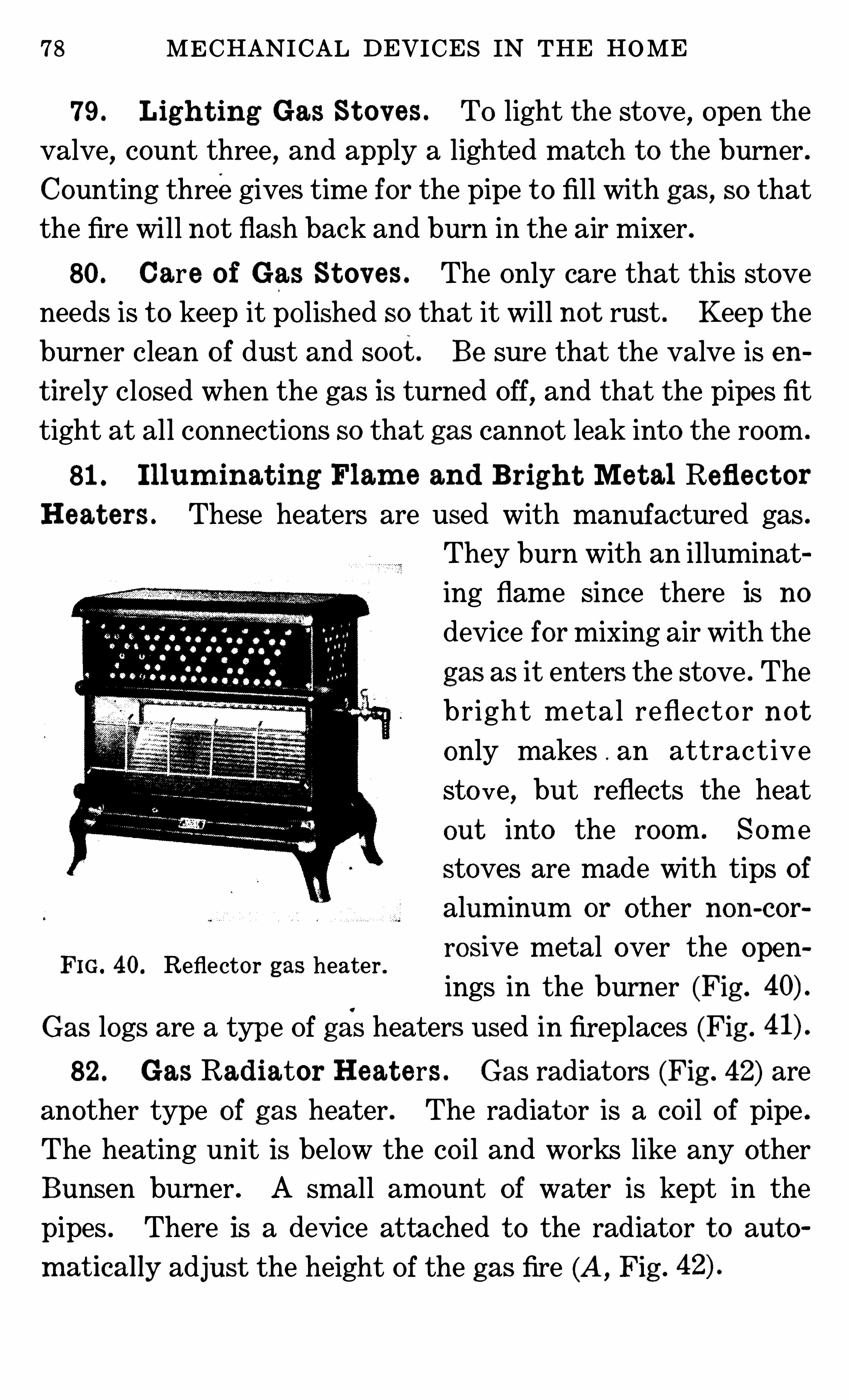
78 MECHANICAL DEVICES IN THE HOME
79 . Ligh t ing Gas St o v es . TO light the stove,open the
valve,count three, and apply a lighted match t o the burner .
Counting threegives time for the pipe t o fill with gas, SO that
the fire will no t flash back and burn in the air mixer .
80. Care o f Gas St ov es . The only care that this stove
needs is t o keep it po lished SO that it will no t rust . Keep the
burner clean of dust and soot . Be sure that the valve is en
t ire ly closed when the gas is turned Off, and that the pipes fit
tight at all connections SO that gas cannot leak into the room .
81 . I l lum inat ing Flam e and Brigh t Me t al Refle c t or
Heat ers . These heaters are used with manufactured gas .
They burn with an illuminat
ing flame Since there is no
device formixing air with the
gas as it enters the stove . The
bright metal reflecto r no t
only makes . an attract ive
sto ve, but reflects the heat
out into the room . Some
stoves are made with tips of
aluminum or other non-cor
rosiv e metal over the open
ings in the burner (Fig .
Gas logs are a type Of gas heaters used in fireplaces (Fig .
82 . Gas Radiator Heat ers . Gas radiators (Fig . 42) are
another type of gas heater . The radiator is a co il o f pipe .
The heating unit is below the co il and works like any other
Bunsen burner . A sm all amount of wate r is kept in the
pipes . There is a device attached t o the radiator t o auto
m at ically adjust the height Of the gas fire (A,Fig .
FIG. 40. Reflector gas heater .
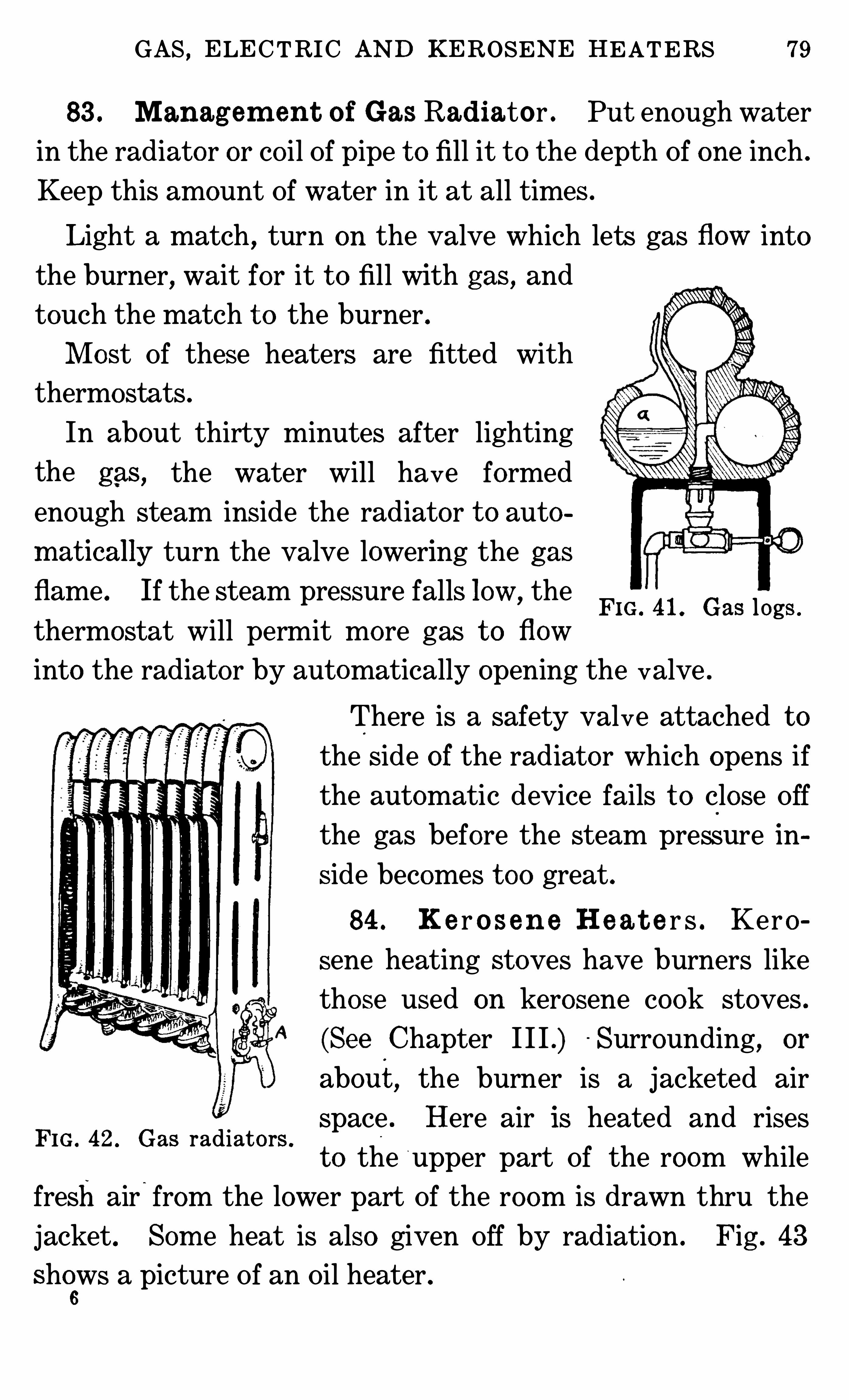
GAS,ELECTRIC AND KEROSENE HEATERS 79
83 . Manag em en t o f Gas Radiator . Put enough water
in the radiato r or co il Of pipe t o fill it t o the depth Of one inch .
Keep this amount Of water in it at all times .
Light a match , turn on the valve which lets gas flow into
the burner, wait for it t o fill with gas , and
touch the match t o the burner .
M ost Of these heaters are fitted with
thermostats .
In about thirty minutes after lighting
the gas , the water will have formed
enough steam inside the radiator t o auto
m atically turn the valve lowering the gas
flame . If the steam pressure falls low,the
thermostat will permit more gas t o flow
into the radiator by automatically opening the valve .
FIG . 41 . Gas logs .
There is a safety valve attached t o
the Side of the radiator which opens if
the automatic device fails t o close Off
the gas before the steam pressure in
side becomes t oo great .
84 . Ke r o sen e H e a t e r s . Kero
sene heating stoves have burners like
those used on kerosene cook stoves .
(See Chapter I I I .) Surrounding, or
about, the burner is a jacketed air
FIG . 42 . Gas radiators .
space . Here air is heated and rises
t o the upper part Of the room while
fresh air“
from the lower part Of the room is drawn thru the
jacket . Som e heat is also given Off by radiation . Fig . 43
shews a picture Of an Oil heater .
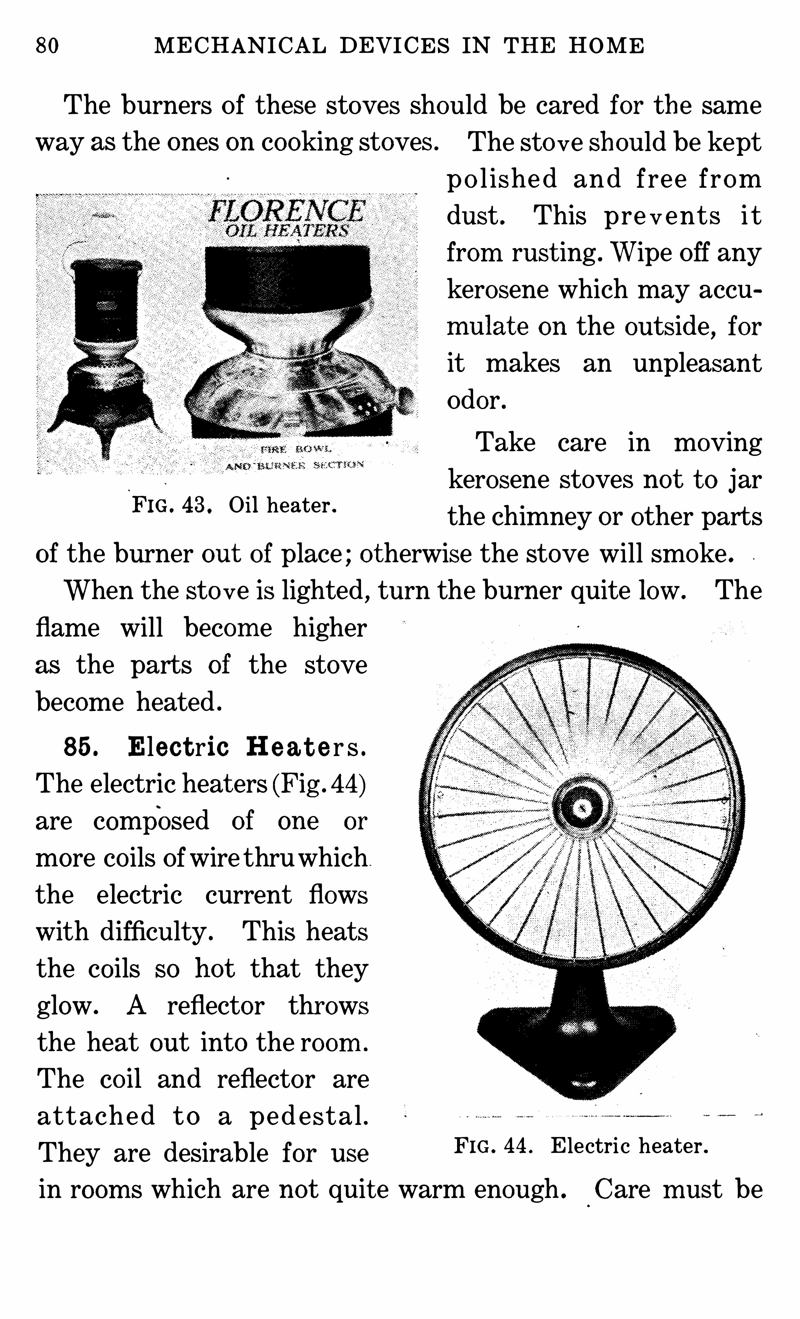
80 MECHANICAL DEVICES IN THE HOME
The burners Of these stoves Should be cared for the same
way as the ones on cooking stoves .
FIG . 43 . Oil heater .
The sto ve should be kept
p o l ished and free from
dust . This pre v ents i t
from rust ing .Wipe Off any
kerosene which may accu
mulat e on the outside, for
it makes an unpleasant
Odor .
Take care in moving
kerosene stoves no t t o jar
the chimney or other parts
of the burner out of place ; o therwise the stove will smoke .
When the sto ve is lighted , turn the burner quite low. The
flame will becom e higher
as the parts of the stove
become heated .
85 . Elec t ric H e a t e r s .
The electric heat ers (Fig . 44)
are composed of one or
more co ils Ofwire thruwhich
the electric current flows
with difficulty . This heats
the co ils SO ho t that they
glow . A reflector throws
the heat out into the room .
The cOil and reflector are
attached t o a ped estal .
They are desirable for useFIG . 44 . E lectric heater .
in room s which are not quit e warm enough . Care m ust be
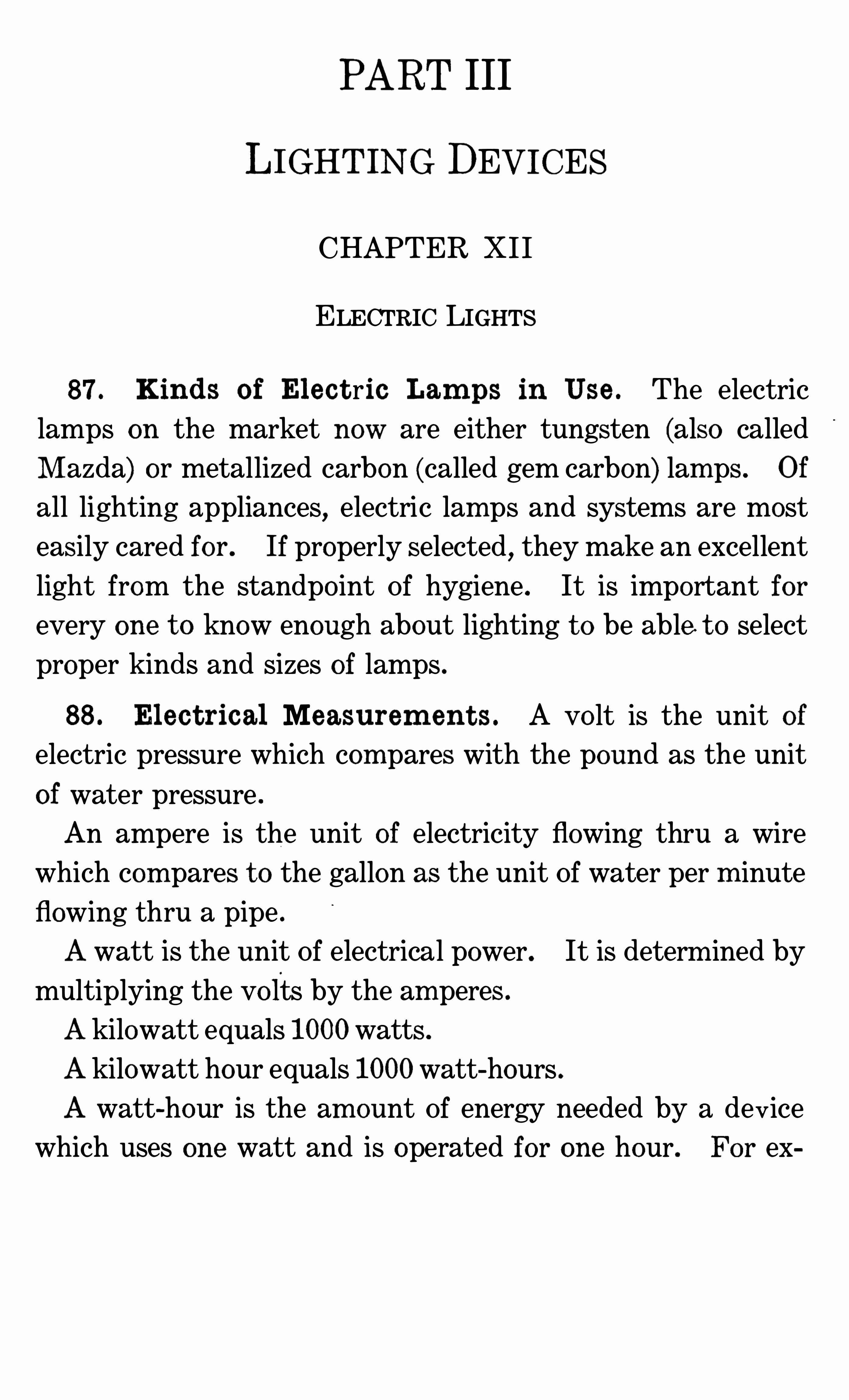
PART III
LIGHTING DEVICES
CHAPTER XI I
ELECTRIC LIGHTS
87 . Kind s o f El ec t ric Lam ps in Use . The electric
lamps on the market now are either tungsten (also called
M azda) or metallized carbon (called gem carbon) lamps . Of
all lighting appliances, electric lamps and systems are most
easily cared for . If properly selected,they make an excellent
light from the standpo int Of hygiene . It is important for
every one t o know enough about lighting t o be able t o select
proper kinds and sizes of lamps .
88 . El ec t rical Measurem en t s . A vo lt is the unit o f
electric pressure which com pares with the pound as the unit
of water pressure .
An ampere is the unit of electricity flowing thru a wire
which com pares t o the gallon as the unit Of water per m inute
flowing thru a pipe .
Awatt is the unit Of electrical power. It is determ ined by
multiplying the volts by the am peres .
Akilowatt equals 1000watts .
Akilowatt hour equals 1000watt-hours .
A watt-hour is the am ount Of energy needed by a device
which uses one watt and is operated for one hour. For ex
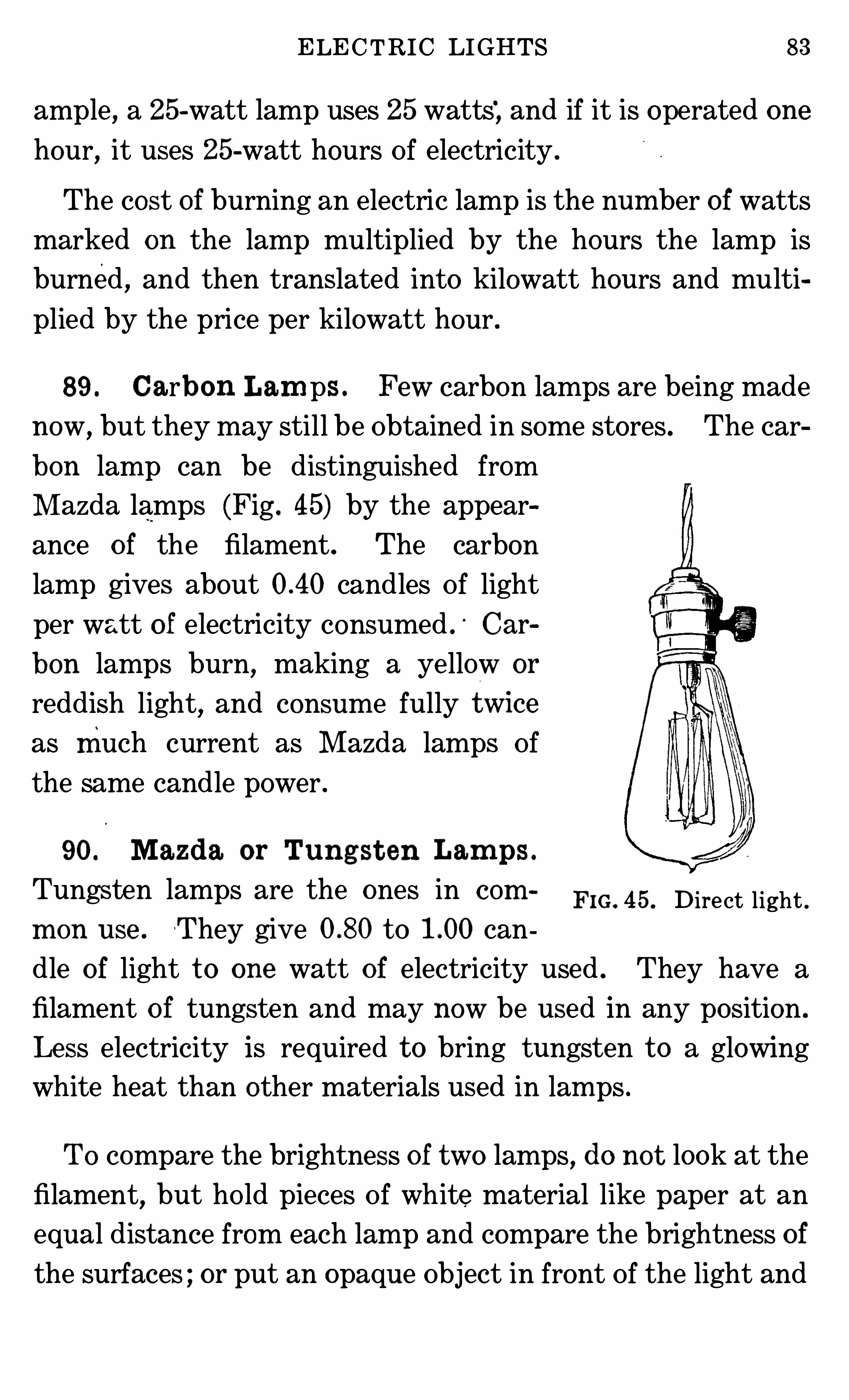
ELECTRIC LIGHTS 83
am ple, a 25-watt lamp uses 25 watts‘
, and if it is operated one
hour, it uses 25-watt hours Of electricity .
The cost of burning an electric lamp is the num ber of watts
marked on the lamp multiplied by the hours the lamp is
burned , and then translated into kilowatt hours and multi
plied by the price per kilowatt hour .
89 . Carbon Lam ps . Few carbon lamps are being made
now,but they may still be Obtained in some stores . The car
bon lamp can be distinguished from
M azda lamps (Fig . 45) by the appear
ance o f the filament . The carbon
lamp g ives about candles Of light
per watt o f electricity consumed . Car
bon lamps burn, making a yellow or
reddish light,and consume fully tw1ce
as much current as M azda lamps Ofthe same candle power .
90. Mazda or Tung st en Lam ps .
Tungsten lamps are the ones in com FIG. 45 . Direct light .m on use . T hey give t o can
dle of light t o one watt of electricity used . They have a
filament o f tungsten and may now be used in any position .
Le ss electricity is required t o bring tungsten t o a glowing
white heat than other materials used in lam ps .
To compare the brightness of two lamps , do no t look at the
filament, but ho ld pieces Of white material like paper at an
equal distance from each lamp and compare the brightness of
the surfaces ; or put an opaque Object in front Of the light and
84 MECHANICAL DEVICES IN THE HOME
let a Shadow be cast on‘
another Object . The brighter light
will cast a heav ier shadow .
When substituting a new tungsten lamp for a carbon lamp ,select one about one -half the number o f watts , unless more
light is wanted . In houses, it is a common practice t o sub
stitut e a 40-wat t M azda for a 50-watt gem carbon lamp , thus
saving ten watts per hour and getting more light .
91 . Se l e c t ing Lam ps for a Room . There are so many
possibilities for the use , of electricity in lighting a house, that
it becomes a fine art . When buying lights for a room , con
sider (1) the Size Of the room , (2) the use o f the room, and (3)the co lor o f walls
,floors, ceilings, furnishings and decorations .
For lighting purposes, lamps may be obtained ranging from10 or leSS t o more than 100-Candle power .
There are co lored , transparent and frosted globes . There
are reflectors and Shades Of various co lors and patterns . TO
Obtain the same degree Of illum ination , smaller lamps are
needed in small rooms than in large ones .
92 . Effec t o f Color Sch em es Upon I l lum inat ion . The
co lor Of the walls and furnishings makes a difference in the
candle power required t o give a certain amount of light .
Those co lors which absorb the most light require the higher
candle power,and tho se reflecting the highest per cent of
light require the lower candle power
Tho frosted globes absorb some light, they diffuse the rest
of it . They dispense with the annoyance Of glare from lamps,
and are useful in places where the full intensity Of the lamps
is not required .
The light absorbed by different co lors varies considerably,
as shown by the accom panying table
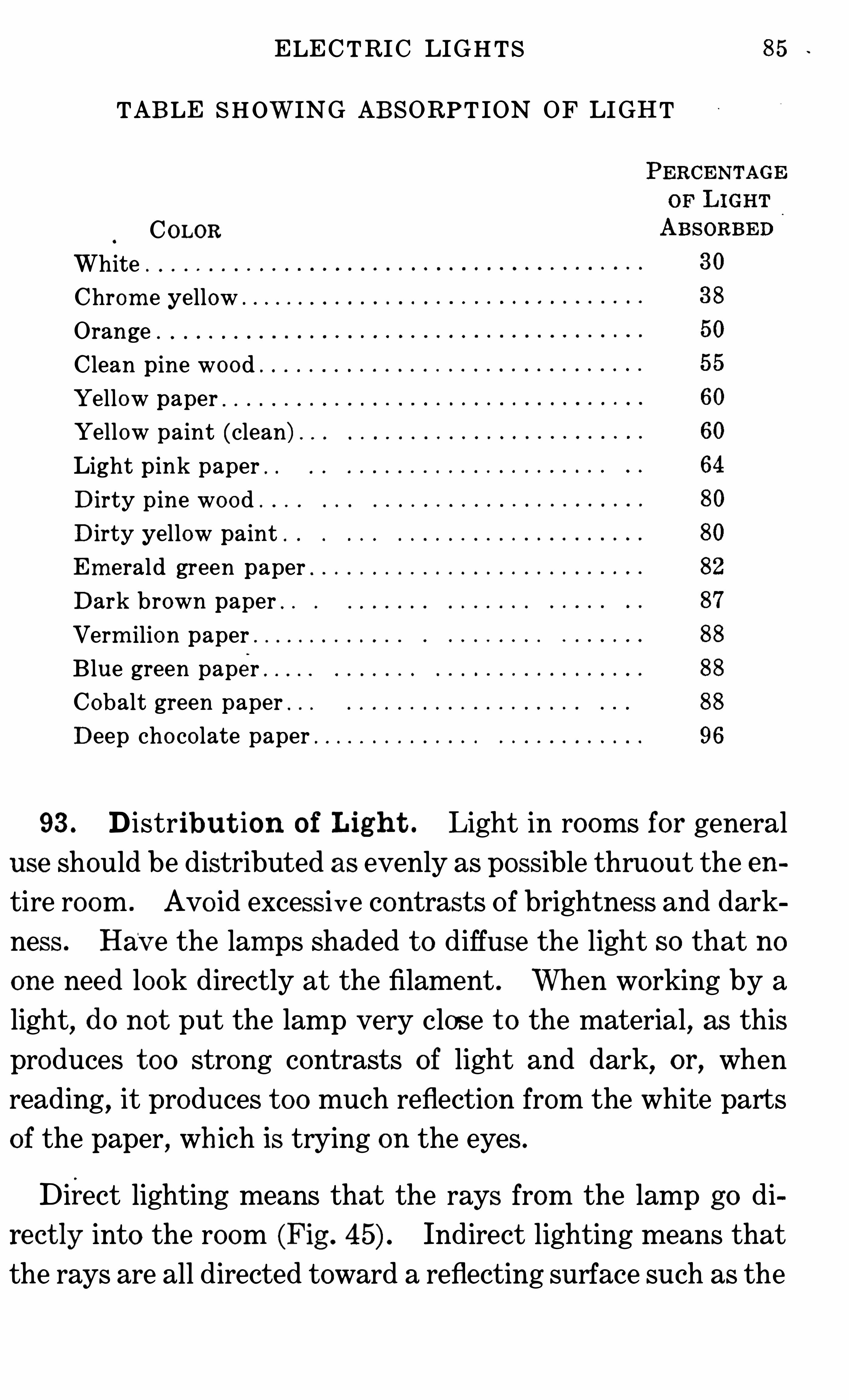
ELECTRIC LIGHTS 5
TABLE SHOWING ABSORPT ION OF LIGHT
COLOR
WhiteChrom e yellowOrange .
C lean pine woodYellow paper .
Yellow paint (clean)Light p ink paper .
D irty p ine wo odD irty yellow paint .
Em erald green paperDark brown paper .
Verm ilion paperB lue green paperCobalt green paper .
Deep cho co late paper
93 . D istribut ion o f Ligh t . Light in rooms for general
use should be distributed as evenly as possible thruout the en
tire room . Avo id excessive contrasts Of brightness and dark
ness . Hav e the lamps Shaded t o diffuse the light so that no
one need look directly at the filament . When working by a
light,do no t put the lamp very close t o the material, as this
produces t oo strong contrasts o f light and dark, or, when
reading, it produces t oo much reflection from the white parts
of the paper, wh ich is trying on the eyes .
Direct lighting means that the rays from the lamp go di
re ct ly into the room (Fig . Indirect lighting means that
the rays are all directed toward a reflecting surface such as the

86 MECHAN ICAL DEVICES IN THE HOME
ceiling (Fig . From here they are reflect ed,giv ing an
even amount Of light t o other parts of the room . When di
rec t ed toward the ceiling, they make it the brightest part Of
the ro om .
A semi-indirect light avo ids this difficulty (Fig .
In diffused lighting,the lam p is covered , as by frosting, SO
that the rays o f light are broken up and so scattered that no
FIG. 46 . Indirect light .
direct ray shines into th e eyes, and there is no bright Spot Of
light in the room .
When costs must be lim ited , certain decorative effects must
be weighed for their value, som e being more expensive than
others .
City lighting plants can provide current for any num ber o f
lamps in a house if it is properly wired . If more lamps are
attached than the wiring will carry,and all are turned on, the
fuses will burn out .
Electric plants for private homes (see Sec . 271) usually fur
nish current Of a different vo ltage from city electric plants,
SO special equipm ent and lam ps must be used with small
plants .
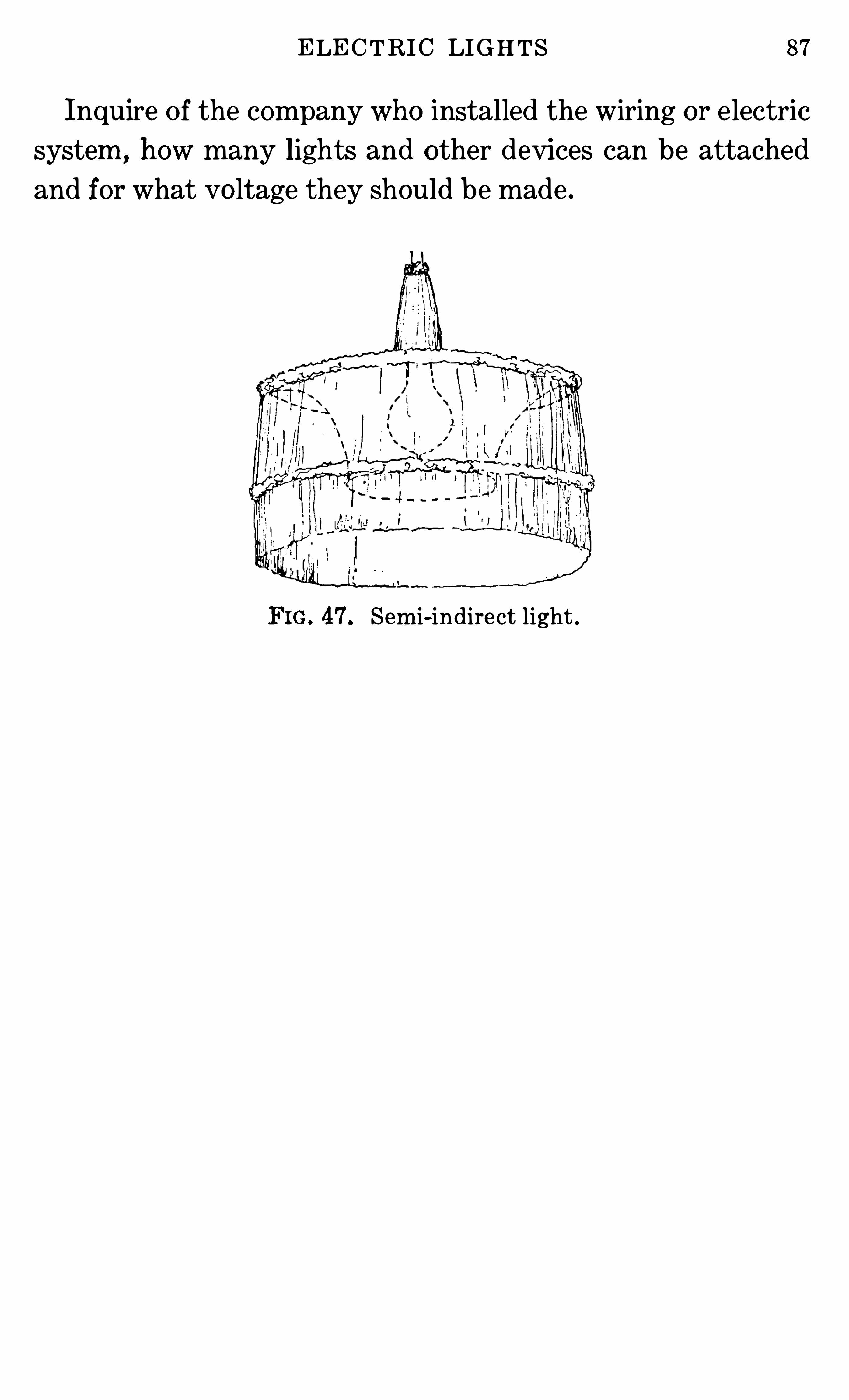
ELECTRIC LIGHTS 87
Inquire Of the company who installed the wiring or electric
system , how many lights and other devices can be attached
and for what vo ltage they Should be made .
FIG. 47. Sem i-indirect light .
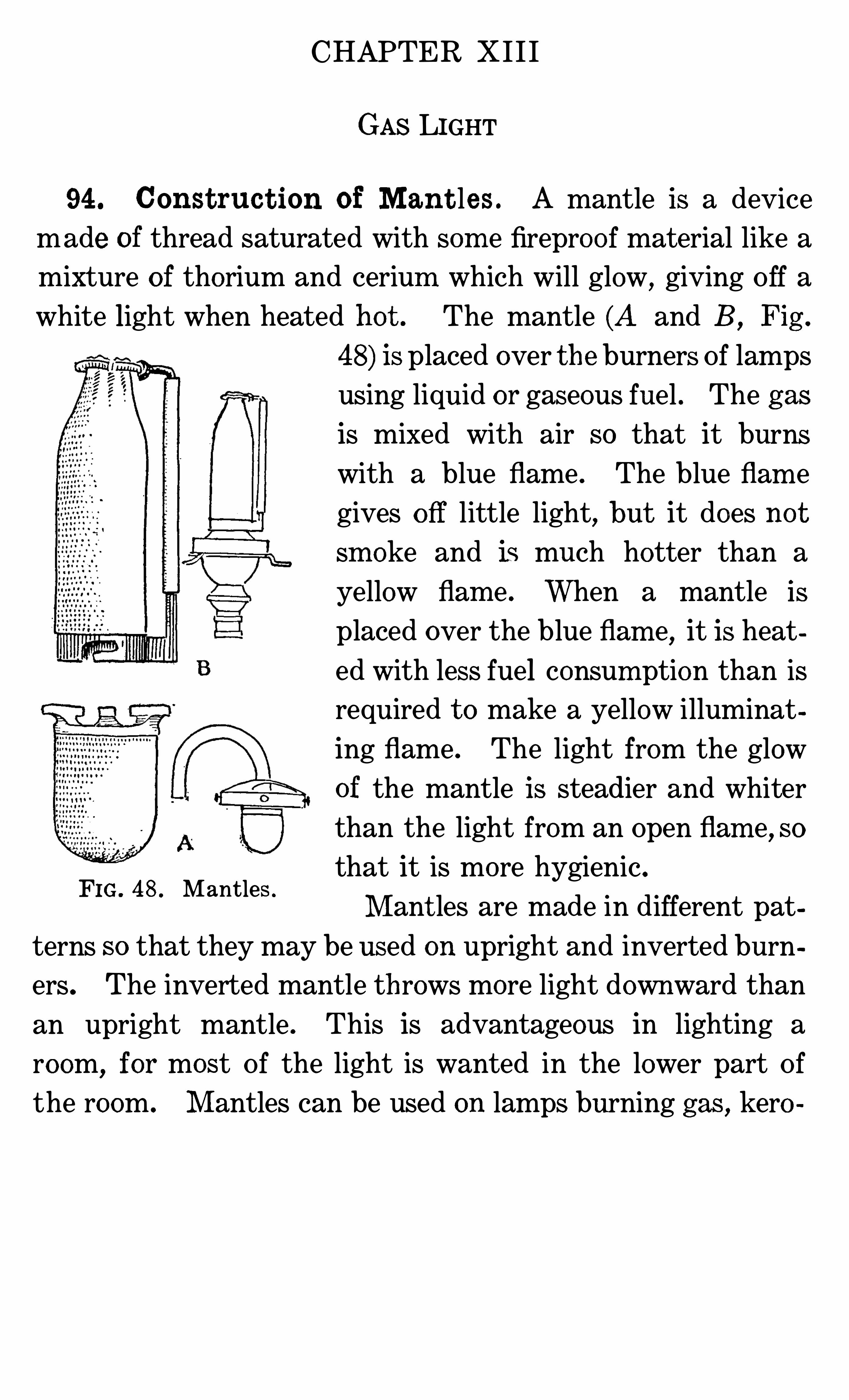
CHAPTER X I I I
GAS LIGHT
94 . Const ruc t ion of M an t les . A mantle is a device
made of thread saturated with som e fireproo f material like a
mixture o f thorium and cerium which will glow,giving Off a
white light when heated ho t . The mantle (A and B , Fig .
FIG. 48 . Mantles .
48) is placed over the burners Of lamps
using liquid or gaseous fuel . The gas
is mixed with air so that it burns
with a blue flame . The blue flam e
gives O ff little light, but it does no t
sm oke and is much hotter than a
yellow flam e . When a mantle is
placed over the blue flam e,it is heat
ed with less fuel consum ption than isrequired t o make a yellow illuminat
ing flame . The light from the glow
of the mantle is steadier and whiterthan the light from an Open flam e
,SO
that it is more hygienic.
M ant les are made in different pat
terns SO that they may be used on upright and inverted burn
ers. The inverted mantle throws more light downward than
an upright mantle . This is advantageous in lighting a
ro om, for most Of the light is wanted in the lower part Of
the room . M antles can be used on lamps burning gas , kero
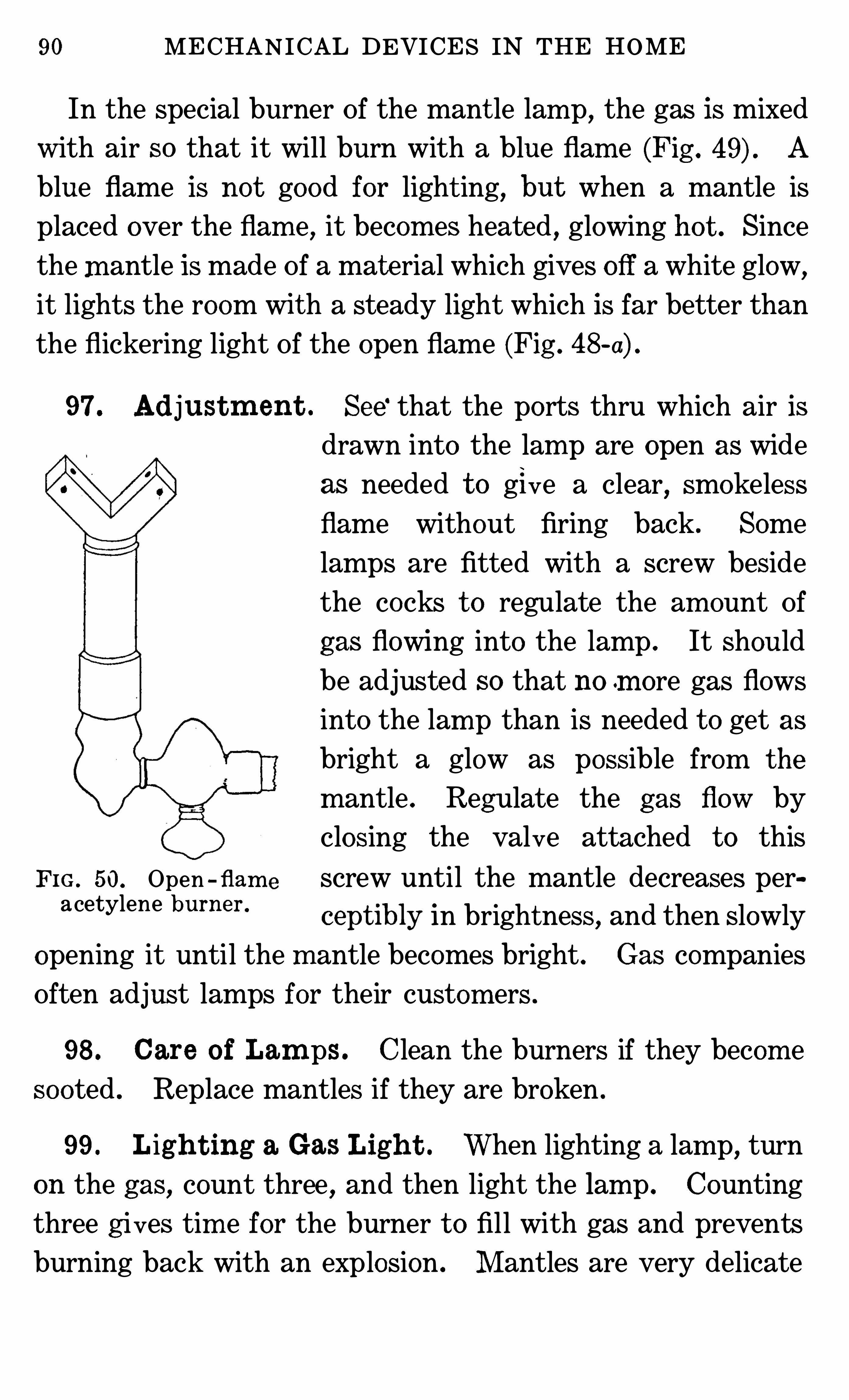
90 MECHAN ICAL DEVICES IN THE HOME
In the special burner Of the mant le lam p, the gas is mixed
with air SO that it will burn with a blue flam e (Fig . A
blue flame is not good for light ing, but when a mantle is
placed over the flam e, it becom es heated , glowing ho t . Since
the mantle is made Of a mat erial which gives Off a white glow,
it lights the room with a steady light which is far better than
the flickering light Of the open flame (Fig . 48 a) .
97 . Ad justm en t . See‘ that the ports thru which air is
drawn into the lam p are open as wide
as needed t o give a clear, smokeless
flame without firing back . Some
lamps are fitted with a screw beside
the cocks t o regulate the am ount Of
gas flowing into the lamp . It Should
be adjusted so that no m ore gas flows
into the lam p than is needed t o get as
bright a glow as possible from t he
m antle . Regulate the gas flow by
closing the valve attached t o this
Fm , 50,Open - flam screw until the mantle decreases per
acetylene burner '
ceptibly in brightness, and then Slowly
opening it until the m antle becom es bright . Gas companies
Often adjust lamps for their custom ers .
98 . Care o f Lam ps . Clean the burners if they becom e
sooted . Replace mantles if they are broken .
99 . Ligh t ing a Gas Ligh t . When lighting a lam p, turn
on the gas, count three , and then light the lam p . Counting
three g ives tim e for the burner t o fill with gas and prevents
burning back with an explosion . M antles are very delicate
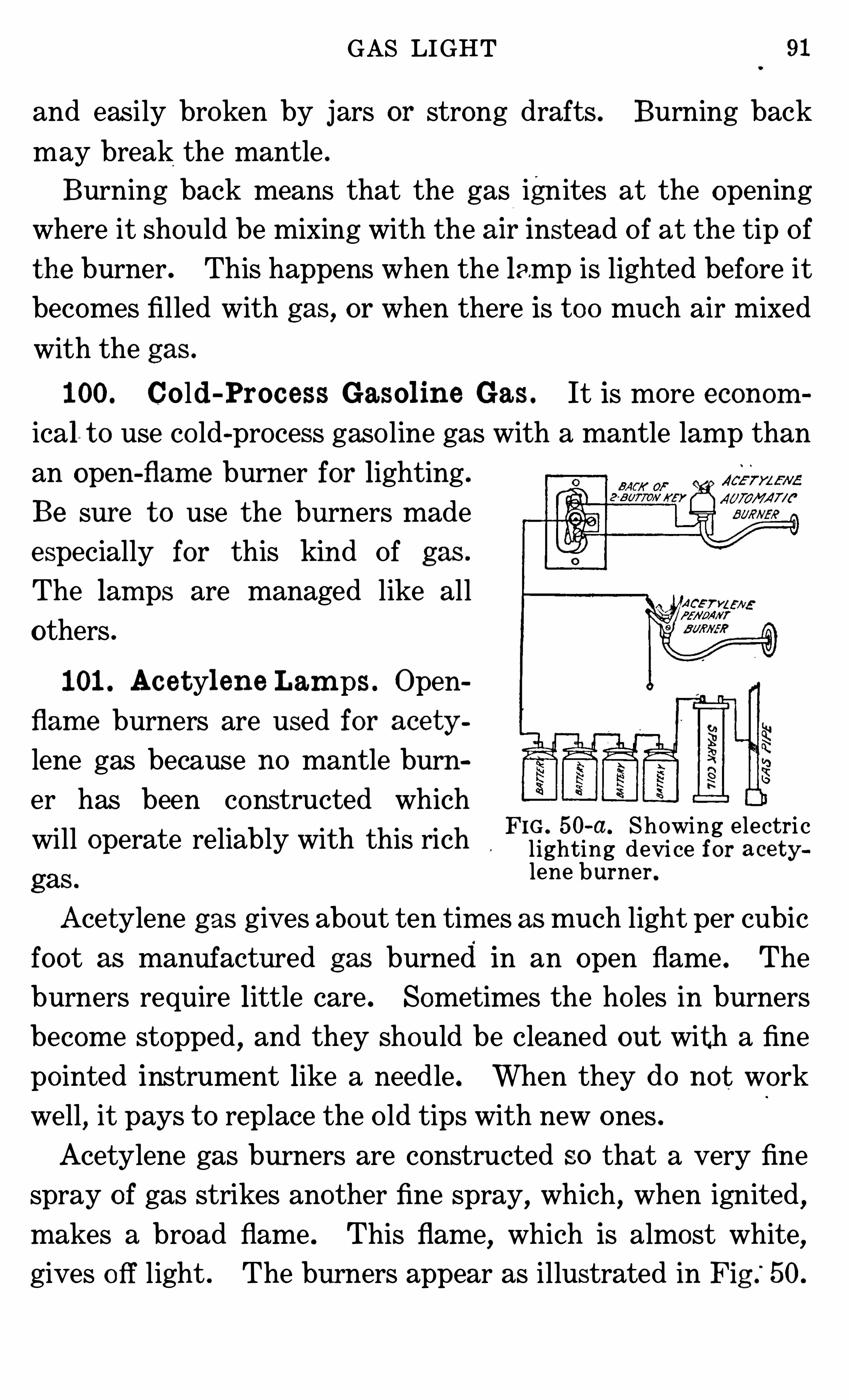
GAS LIGHT
and easily broken by jars or strong drafts . Burning back
may break the mantle .
Burning back means that the gas ignites at the opening
where it should be mixing with the a l r instead Of at the tip Of
the burner . This happens when the lamp is lighted before itbecomes filled with gas , or when there is t oo much air mixed
with the gas .
100. Cold -Proc ess Gasol ine Gas . It is more econom
ical t o use co ld-process gaso line gas with a mantle lamp than
an open-flam e burner for lighting .
Be sure t o use the burners made
especially for this kind Of gas .
The lam ps are managed like all
others .
101 . Ac e tyl ene Lam ps . Open
flam e burners are used for ace ty
lene gas because no mantle burn
er has been constructed whichFIG . 50-a. Showing electri c
will operate reliably with this rich l ighting devi ce for ace t ylene burner .
Acetylene gas gives about ten tim es as much light per cubic
foot as manufactured gas burned in an open flame . The
burners require little care . Sometimes the ho les in burners
become stopped , and they Should be cleaned out with a fine
po inted instrument like a needle . When they do no t work
well, it pays t o replace the Old tips with new ones .
Acetylene gas burners are constructed so that a very fine
spray of gas strikes another fine Spray,which
,when ignited
,
makes a broad flame . This flame,which is almost white
,
gives O ff light . The burners appear as illustrated in Fig .
“
50.
92 MECHANICAL DEVICES IN THE HOME
102 . Care o f Burners o f Ac et yl ene Lam ps . Keep the
two ho les Open . Clean them with a large needle . See that
there are no leaks about the burners or pipes. If these are
found,
fil l with white lead or some similar substance, and
tighten connections . If this does no t suffice, the trouble
should be referred t o a plumber . Fig . 50-a shows an acety
lene burner .
Acetylene lamp mantles can be used only with acetylene
which is under high pressure . Therefore, they cannot be
used with all plants . The special burner for m ix ing a ir Withthe acetylene t o make it burn with a blue flam e must be used
with the mantle .
CHAPTER X IV
KEROSENE LAMPS
103 . Const ruc t ion o f Kerosene Lam ps . A kerosene
lamp consists o f a bowl, a burner, a wick and a chimney.
In the ordinary lam p , the bowl for ho lding the oil is placed
below the burner (Fig . The Wick carries the oil from
the bowl into the burner by
capillary attraction one end
being in the oil and the other in
the burner .
The burner, which has ho les
in it t o let in air, ho lds the
W ick so that only the oil reach
ing the t op burns . The area
and shape o f the flam e depends FIG 51 Lam ps and lam pchim neys .
upon the form o f the t op sur
face of the wick . The glass chimney is used t o cause an
air current thru the burner and t o protect the flam e from out
side drafts . A screw moves the wick thru the burner . If
the wick is t oo small , the fire may burn back thru the burner
and ignit e the oil in the bowl . It is im portant that a wick
fit the burner . If the chim ney is t oo short or broken,the
lam p will smoke (A,B
,Fig.
104 . Manag em en t o f Kero sene Lam ps . When the
lam p sm okes,it is wasting fuel . Smoke is incompletely burnt
fuel . The oil in the lam p should be clean . It should never
be mixed with gaso line or other more explosive o ils .
Fill the bowl each day the lamp is used t o within one-half
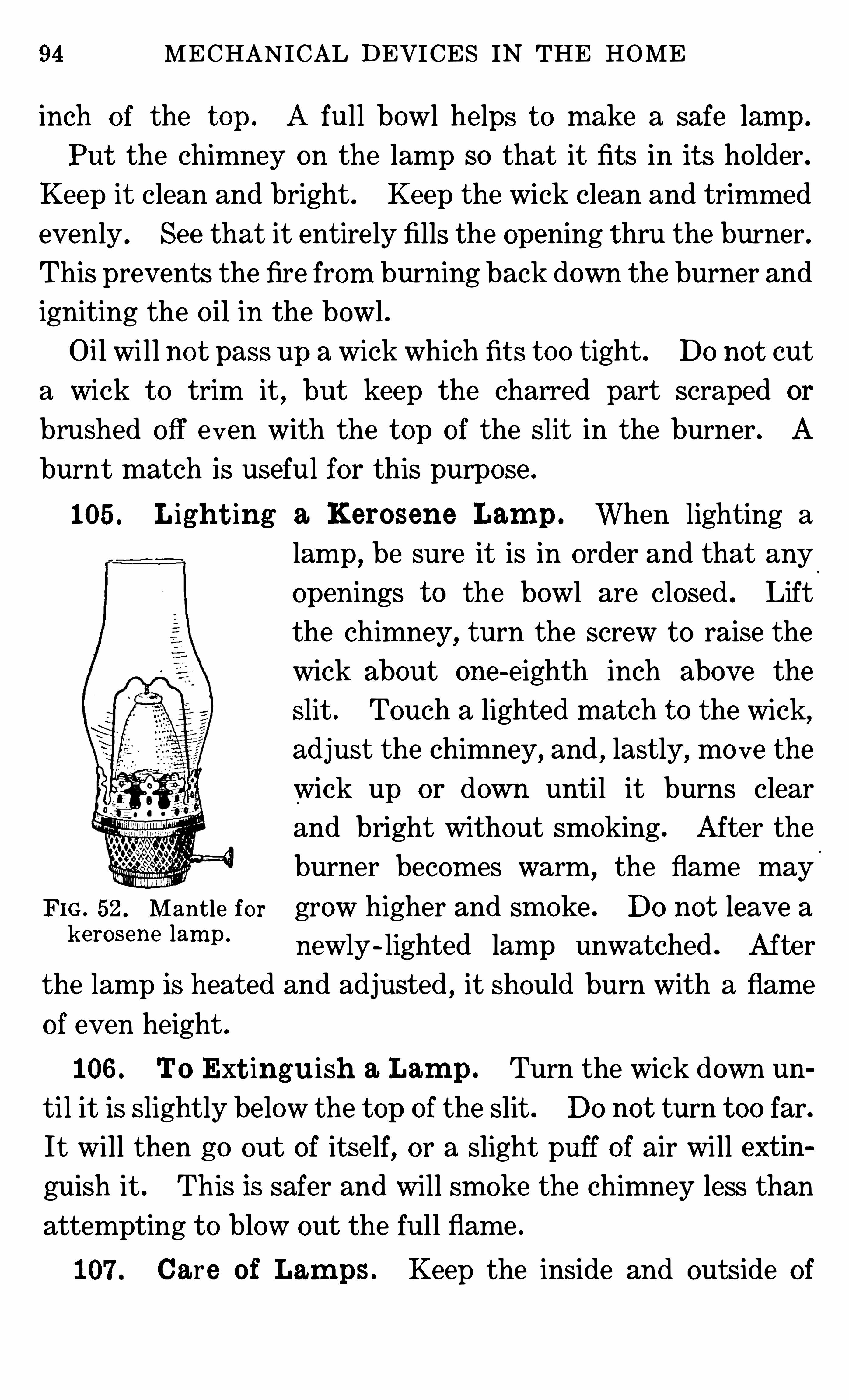
94 MECHANICAL DEVICES IN THE HOME
inch o f the t op . A full bowl helps t o make a safe lamp .
Put the chim ney on the lamp so that it fits in it s ho lder .
Keep it clean and bright . Keep the wick clean and trimm ed
evenly . See that it entirely fills the opening t hru the burner .
This prevents the fire from burning back down the burner and
igniting the oil in the bowl .
Oil will no t pass up a wick which fit s t oo tight . Do no t cut
a wick t o trim it, but keep the charred part scraped or
brushed o ff even with the t op of the slit in the burner . A
burnt match is useful for this purpose .
105 . Ligh t ing a Kerosene Lam p . When lighting a
lamp,be sure it is in order and that any
openings t o the bowl are closed . Lift
the chimney,turn the screw t o raise the
wick about one -eighth inch above the
slit . Touch a lighted match t o the wick,
adjust the chimney, and , lastly, mo ve the
wick up or down until it burns clear
and bright without smoking . After the
burner becom es warm, the flame may
Fm , 52 ,Mantle for grow higher and sm oke . Do not leave a
k erosene lam p ’ newly - lighted lam p unwatched . After
the lamp is heated and adjusted , it should burn with a flame
of even height .
106 . To Ext ingu ish a Lam p . Turn the wick down un
til it is slightly below the t op of the slit . Do not turn t oo far.
It will then go out of itself, or a slight puff of air will ext in
guish it . This is safer and will smoke the chimney less than
attempting t o blow out the full flame .
107 . Care of Lam ps . Keep the inside and outside of
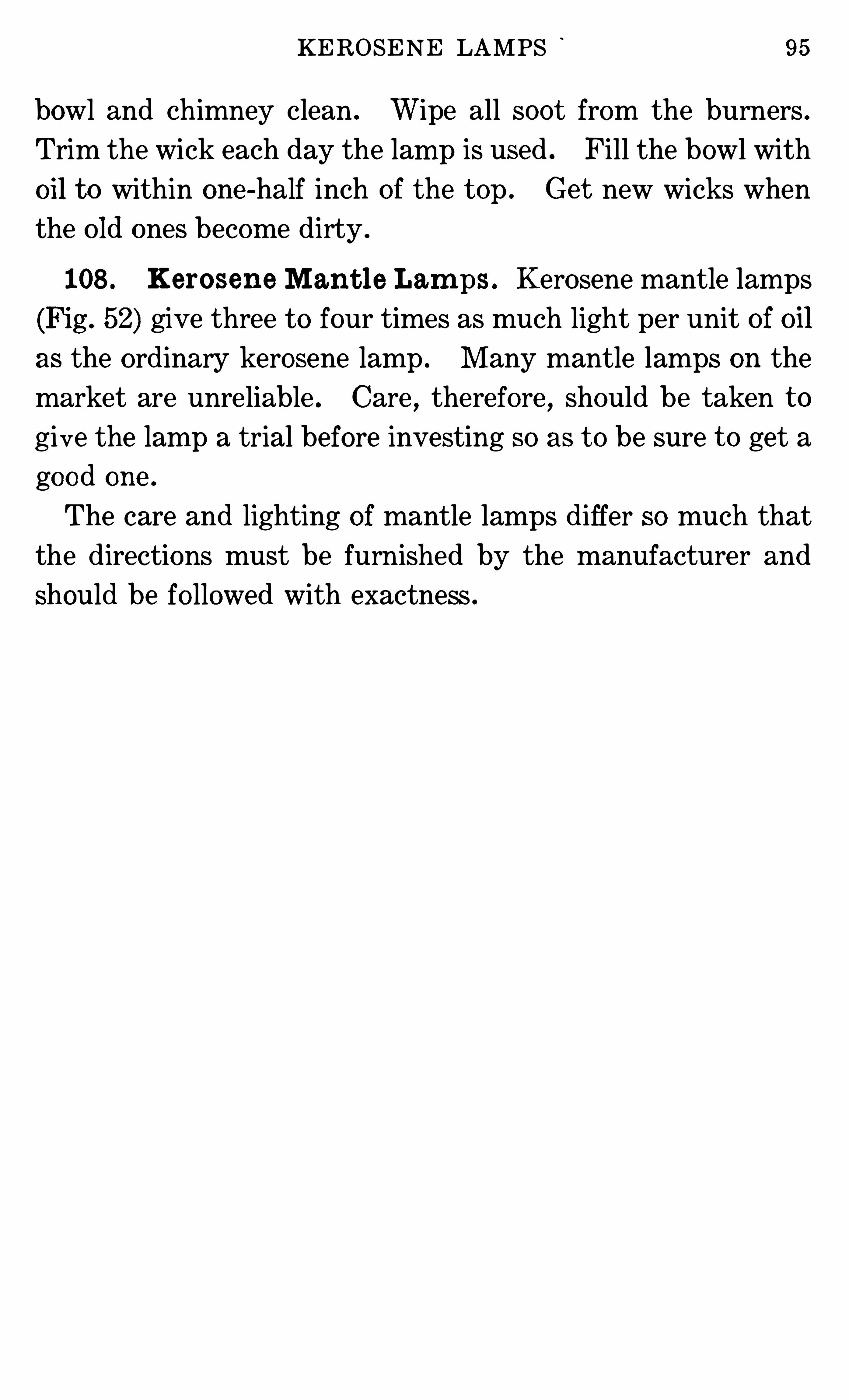
KEROSENE LAMPS 95
bowl and chimney clean . Wipe all soot from the burners .
Trim the wick each day the lam p is used . Fill the bowl with
oil t o within one -half inch o f the t op . Ge t new wicks when
the o ld ones becom e dirty .
108 . Kerosene Man t l e Lam ps . Kerosene mantle lamps
(Fig . 52) give three t o four times as much light per unit of oil
as the o rdinary kerosene lamp . M any mantle lamps on the
market are unreliable . Care , therefore , should be taken t o
give the lamp a trial before investing so as t o be sure t o get a
good one .
The care and lighting of mantle lamps differ so much that
the directions must be furnished by the manufacturer and
should be fo llowed with exactness .
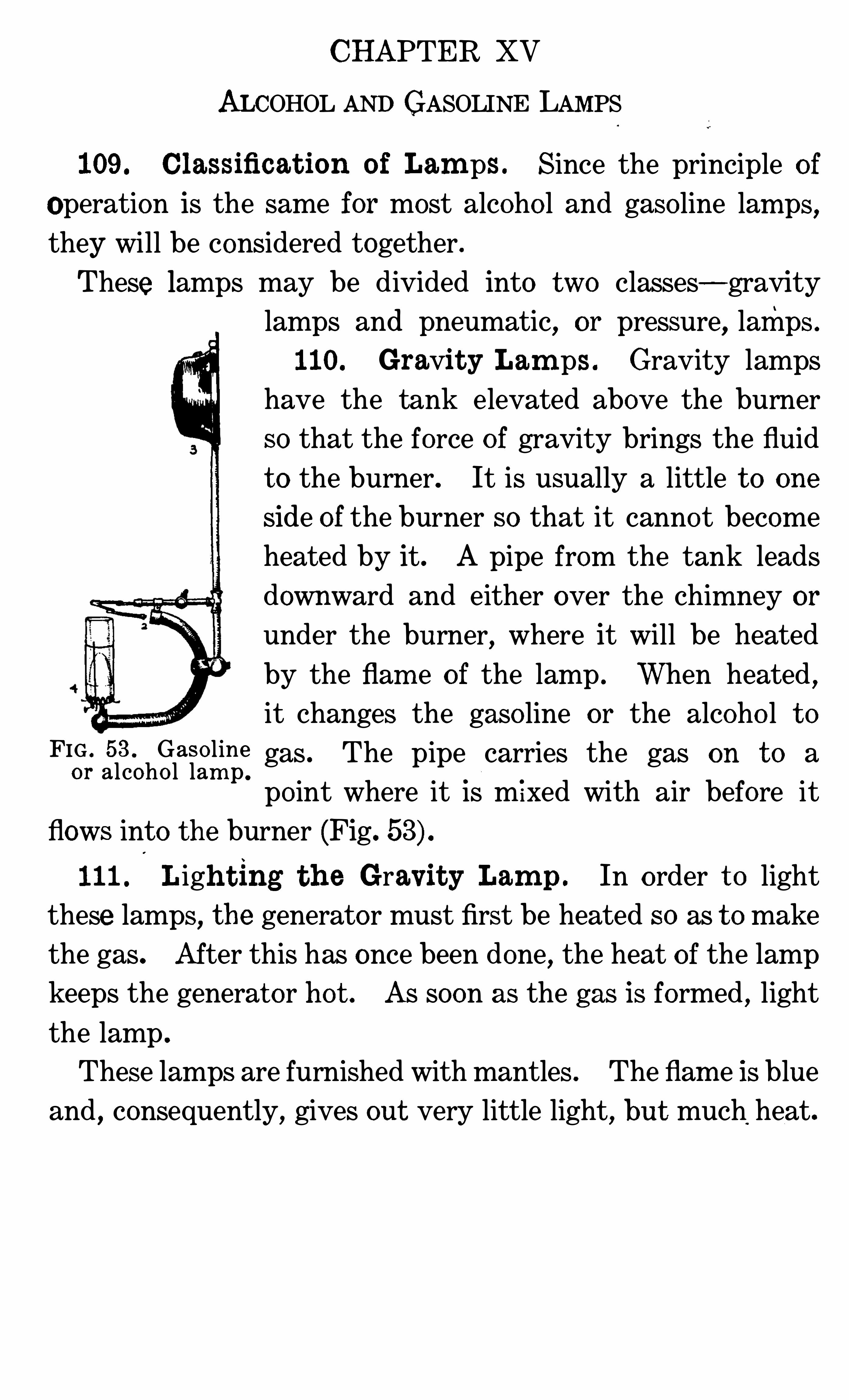
CHAPTER XV
ALCOHOL AND GASOLINE LAMPS
109. Classificat ion o f Lam ps . Since the principle o f
Operation is the same for most alcoho l and gaso line lam ps,
they will be considered together .
These lamps may be divided into two classes—gravitylamps and pneumatic, or pressure
,lamps .
110. Gravit y Lam ps . Gravity lamps
have the tank elevated above the burner
so that the force of gravity brings the fluid
t o the burner. It is usually a little t o one
side of the burner so that it cannot becomeheated by it. A pipe from the tank leads
downward and either over the chim ney or
under the burner, where it will be heated
by the flam e o f the lamp . When heated ,it changes the gaso line or the alcoho l t o
FIG . 53 Gaso line gas . The pipe carries the gas on t o aor alcoho l lam p .
po int where it is m ixed with air before it
flows into the burner (Fig.
111 . Ligh t ing t h e Gravit y Lam p . In o rder t o light
these lamps, the generator must first be heated so as t o make
the gas. After this has once been done, the heat o f the lamp
keeps the generat or hot . As soon as the gas is formed , light
the lamp .
These lamps are furnished with mantles . The flam e is blue
and,consequently, gives out very little light, but much heat.
98 MECHANICAL DEVICES IN THE HOME
t o rise . It passes thru a place where it is mixed with air,and
goes on into the burner, where it is ignited . If the lamp
burns low, more air must be pum ped into the tank t o force up
the gaso line or alcoho l . When all the fluid has been burned,
the lamp will go out , since , then , only the air which is under
pressure in the tank will be com ing into the burner.
Extinguish the lam p by turning o ff the supply of fuel t o thegenerator . To light these lam ps, first heat the generator
,as
directed for the particular lam p in use , and then light the
burners . Detailed directions cannot be given here, as they
differ with different lamps .
113 . Gaso line Lam ps wit h Wick s . There are Some
gaso line lamps made with wicks which help conduct the oil
into the burner, where it is changed t o gas by the heat from
the lamp,mixed with air and burned in a mantle . The flam e,
from a mixture o f alcoho l or gaso line and air, is blue and gives
o ff little light, but much heat . It is used with a mantle .
114 . Alc oh o l Lam ps wit h Wick s . The wick o f one
type o f alcoho l lamp conducts the alcoho l up thru a round
tube which it completely fills . The tube prevents the fire
from burn ing down into the bowl of the lamp . Alcoho l
makes a very hot and alm ost sm okeless flame, even when
little air is present . The mantle is put o ver the flam e, and ,when heated , gives a good light . Other ordinary fuelscannot
be used on so sim ple a lam p because they would smoke the
mantle .
115 . Ligh t ing Al coh ol or Gaso line Lam ps . Heat the
conducting pipe at the po int where the fuel is t o be changed t o
gas . (D irections for this come with each lam p, and they dif
fer considerably .) Aft er being heated sufficiently, the valve
ALCOHOL AND GASOLINE LAMPS 99
leading t o the burner is opened and the burner lighted with a
match or torch . Use clean gaso line for these lamps, un
mixed with water or other substances .
QUESTIONS FOR PART III
1 Are there any differences in the electri c light globes on the m arket !I f so ,
in what ways do they d iffer ! How d o these differences affect thelighting power of the globes !2 . What influence has the s ize and decoration of the ro om on thebrillian cy o f light from a given lam p !3 . How should the l ight in a l iv ing-room be distributed !4 . What are the diff eren ces in direct , sem i-direct and indirect lighting !5 . What is the purpose o f a m antle for a gas or kerosene lam p !6 . What is the difference in burners t o be used with and without
m antles !7 . How is the light from a lam p m easured !8 . Wh ich lam p gives the greatest candle power o f light for theam ount o f fuel used—the one with or the one without a m antle !
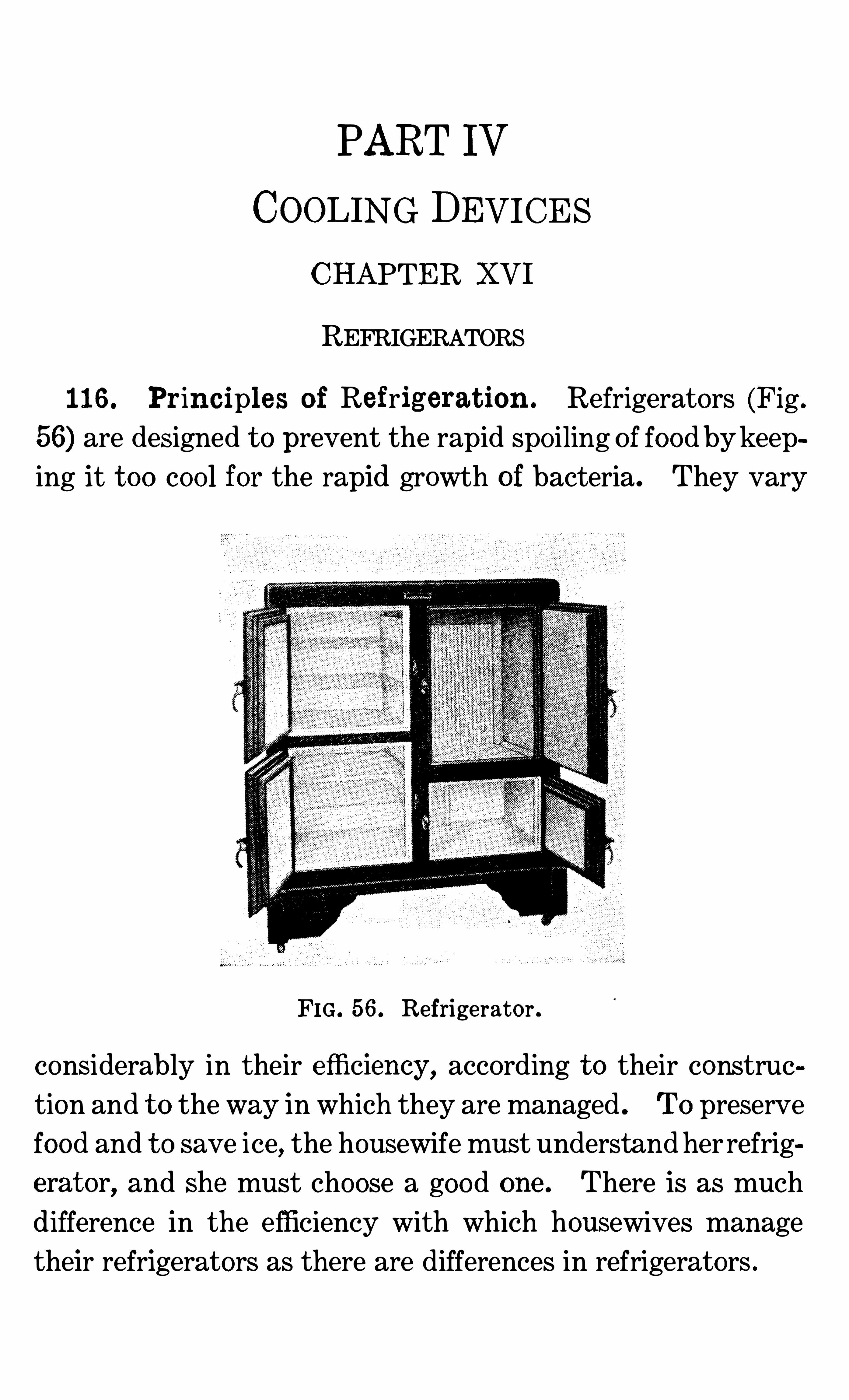
PART IV
COOLING DEVICES
CHAPTER XVI
REFRIGERATORS
116 . Principl es o f Refrigerat ion . Refrigerators (Fig .
56) are designed t o prevent the rapid spo iling of food bykeeping it t oo coo l for the rapid growth of bacteria. They vary
FIG. 56. Refrigerator .
considerably in their efliciency , according t o their construe
tion and t o the way in which they are managed . To preserve
food and t o save ice, the housewife must understand her refrig
erat or, and she must choose a good one . There is as much
difference in the efficiency with which housewives managetheir refrigerators as there are differences in refrigerators .
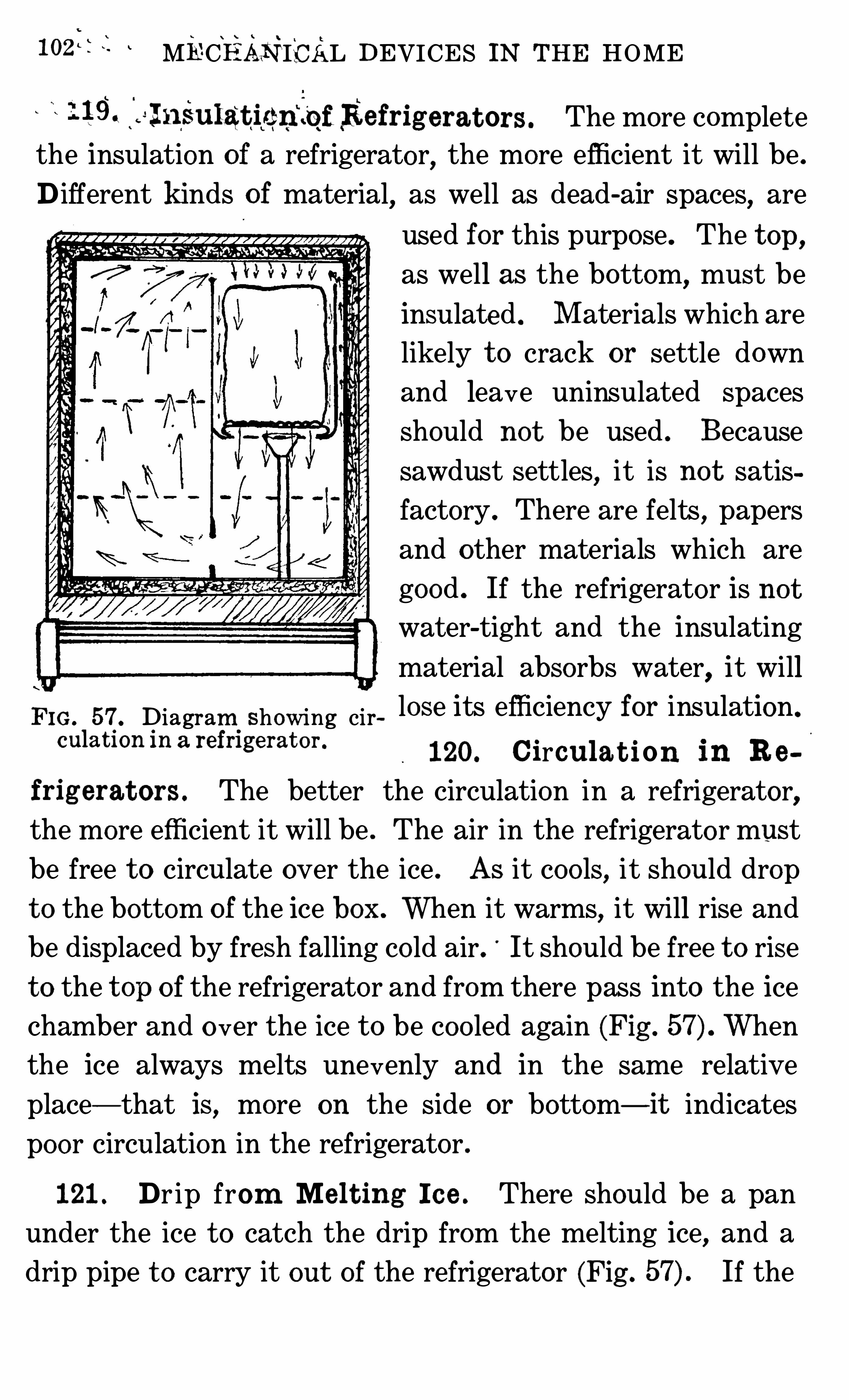
iozit 3, MECHANICAL DEVICES IN THE HOME
19 . fa l n‘
Sulatien‘
l‘
qfRefrig erat ors . The more complet e
the insulation of a refrigerator, the more efficient it will be .
D ifferent k inds o f material, as well as dead-air spaces, are
used for this purpose . The t op,
as well as the bottom,must be
insulated . M aterials which are
likely t o crack or settle down
and leave uninsulated spaces
should not be used . Because
sawdust settles, it is no t satis
factory . There are felts,papers
and other materials which are
good . If the refrigerato r is no t
water-tight and the insulating
material absorbs water,it will
FIG . 57 . Diagram showing cir lose its efficiency for insulation .
culation in a refrigerat or .
120. Circula t ion in R e
frig erat ors . The better the circulation in a refrigerator,the more efficient it will be . The air in the refrigerato r must
be free t o circulate over the ice . As it coo ls, it should drop
t o the bottom of the ice box . When it warms, it will rise andbe displaced by fresh falling co ld air. It should be free t o rise
t o the t op o f the refrigerato r and from there pass into the ice
chamber and o ver the ice t o be coo led again (Fig . When
the ice always melts unevenly and in the same relative
place— that is, more on the side or bottom—it indicates
poor circulation in the refrigerator .
121 . Dr ip from Me l t ing I c e . There should be a pan
under the ice t o catch the drip from the melting ice, and a
drip pipe t o carry it out of the refrigerator (Fig . If the
REFRIGEBATORS 103
drip pipe passes into a pan set under the refrigerator, the pan
should be emptie d so that it will no t overflow. The water in
the pan should no t be allowed t o become stagnant .
If this pipe passes t o a drain, it should no t be attached t o
the drain,but drip into it . The small amount of fresh air pass
ing up the drip p ipe from the room is advantageous . Because
some air does flow thru here, t he drip'
pipe and the drain pipe
must be clean and free from gases and odors .
The drip pipe should be straight and free from places in
which dirt may co llect . It must be removable, so that it canbe cleaned . The doors o f the refrigerator must shut so tightly
that frost or dew will no t fo rm about their edges on a ho t day .
122 . Arrang em en t o f Food in t h e I c e Box. Ice boxes
are usually coo ler at the bottom than at the t op. Do no t put
food in the ice chamber because this necessitates Opening the
doo r and wastes ice . Do not put papers or flat boxes on the
shelves which will interfere with the circulation of air in the
refrigerator .
123 . Filling and Care o f t h e I c e Box. The housewife
must open the doors of the ice box as seldom as possible,and
close them quickly. Do no t cut off the circulation of air
from the ice by wrapping it in a blanket or newspapers . It
cannot do its work then . The ice box is kept co ld by the
gradual melting of the ice . The ice melts fastest as the tem
perature of the Ice box rises . Covering the ice may keep itfrom melting, but it will also allow the refrigerator t o get
warm , and so , whatever is gained in saving ice at first, will be
lost at the higher temperature and in coo ling the box again .
Steady melting does the most good .
104 MECHANICAL DEVICES IN THE HOME
The shelves and drain pipe should be removable , and these
and the refrigerator should be washed and thoro ly scalded
once in every t wo weeks .
There is a saving in planning t o open the refrigerator as
little as possible . The filling of the ice box with a large piece
of ice two or three tim es a week, rather than with a small
piece every day, is m ore economical .
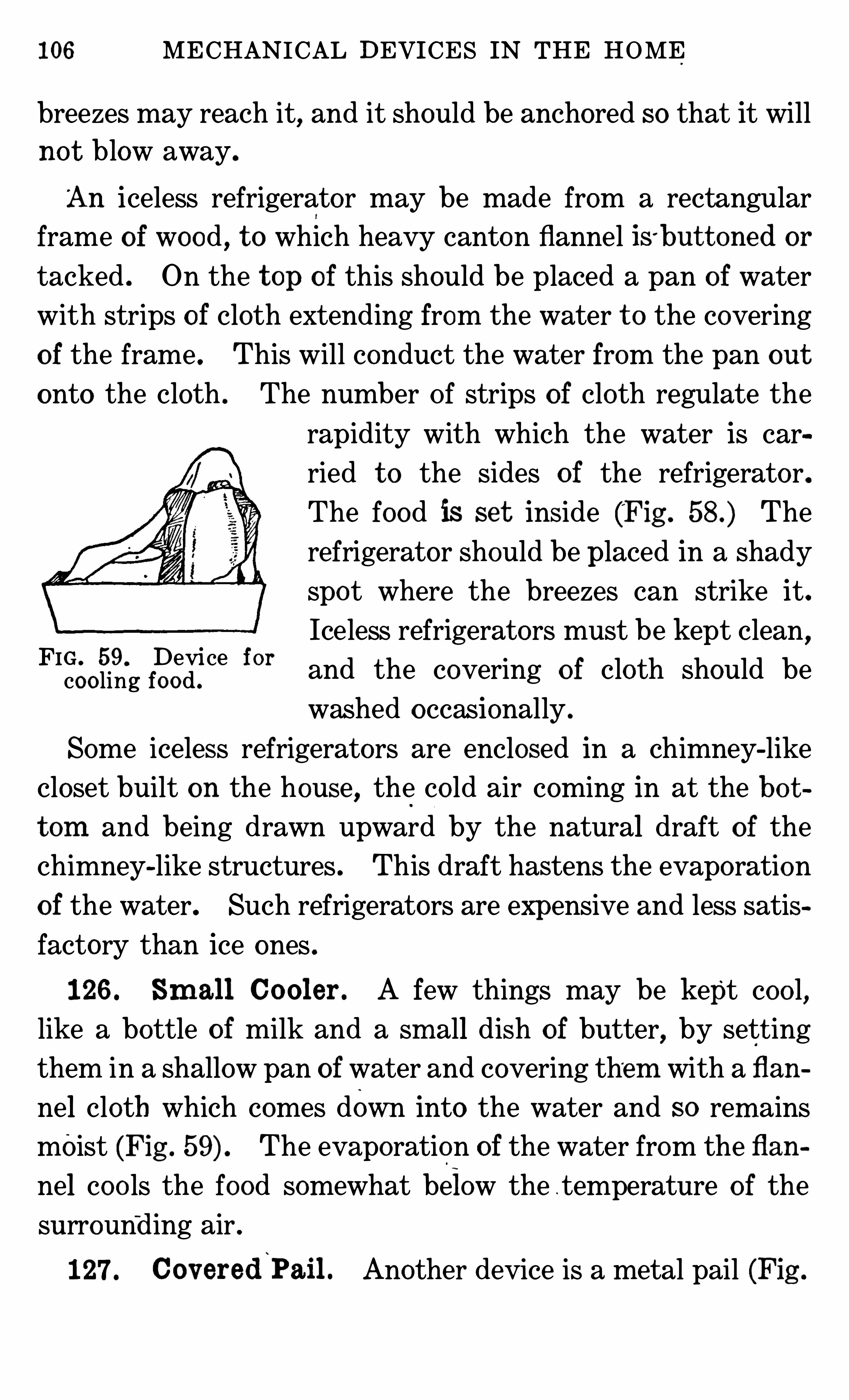
106 MECHANICAL DEVICES IN THE HOME
breezes may reach it, and it should be anchored so that it will
no t blow away.
'
An iceless refrigerator may be made from a rectangular
frame o f wood , t o which heavy canton flannel iS 'but t oned or
tacked . On the t op of this should be placed a pan of water
with strips of cloth extending from the water t o the covering
of the frame . This will conduct the water from the pan out
onto the cloth . The number Of strips of cloth regulate the
rapidity with which the water is car
ried t o the sides of the refrigerato r.
The food is set inside (Fig . The
refrigerator should be placed in a shadyspot where the breezes can strike it.
Iceless refrigerators must be kept clean,
and the covering o f cloth should be
washed o ccasionally .
Some iceless refrigerators are enclosed in a chimney-like
closet built on the house, the co ld air coming in at the bo t
t om and being drawn upward by the natural draft of thechimney-like structures . This draft hastens the evaporation
of the water. Such refrigerators are expensive and less satis
factory than ice ones .
FIG . 59. Device forcoo ling food .
126 . Sm al l Co oler . A few things may be kept coo l,like a bottle o f milk and a sm all dish of butter, by sett ing
them in a shallow pan of water and covering them with a flan
nel cloth which comes down into the water and so rem ains
moist (Fig . The evaporation of the water from the flan
nel coo ls the food somewhat below the temperature o f the
surround ing air .
127 . Cov ered‘
Pail . Another device is a metal pail (Fig .
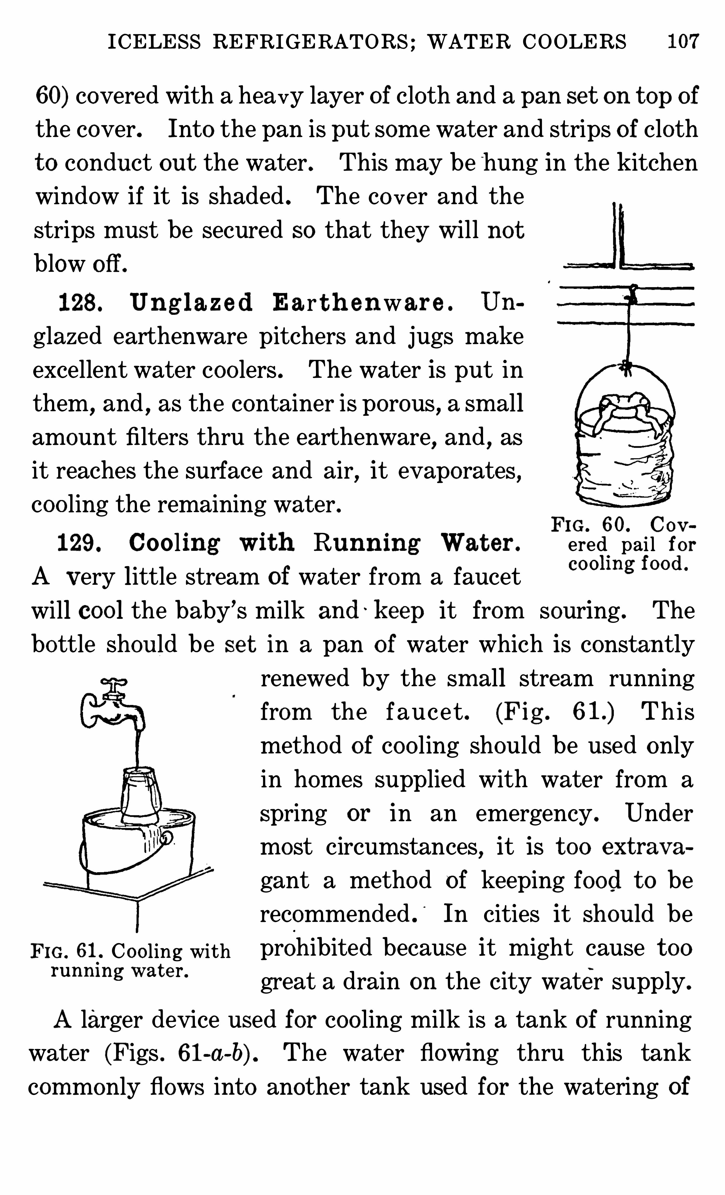
ICELESS REFRIGERATORS ; WATER COOLERS
60) covered with a heavy layer of cloth and a pan se t on t op of
the cover. Into the pan is put some water and strips o f cloth
t o conduct out the water . This may be"
hung in the kitchen
window if it is shaded . The co ver and the
strips must be secured so that they will no t
blow off .
128 . Un g l az e d Ear t h enwar e . Un
glazed earthenware pitchers and jugs make
excellent water coo lers . The water is put in
them, and , as the container is porous , a sm all
amount filters thru the earthenware, and , as
it reaches the surface and air,it evaporates
,
coo ling the remaining water .FIG . 60. Go v
129. Cooling Wit h Running Wat er . ered.
pai l f or
A Very little stream of water from a faucetCO Ohng f0°d °
will coo l the baby’s milk and ' k eep it from souring . The
bottle should be se t in a pan o f water which is constantly
renewed by the sm all stream running
from the faucet . (Fig . This
method o f coo ling should be used only
in homes supplied with water from a
spring or in an emergency . Under
most circumstances,it is t oo ext rav a
gant a method of keeping food t o be
recommended .
‘
In cities it should be
Fro . Coo ling with prohibited because it might cause t oorunm ng wat e r‘ great a drain on the city water supply.
A larger device used for coo ling milk is a tank of running
water (Figs . 61-a-b) . The water flowing thru this tank
commonly flows into another tank used for the watering of
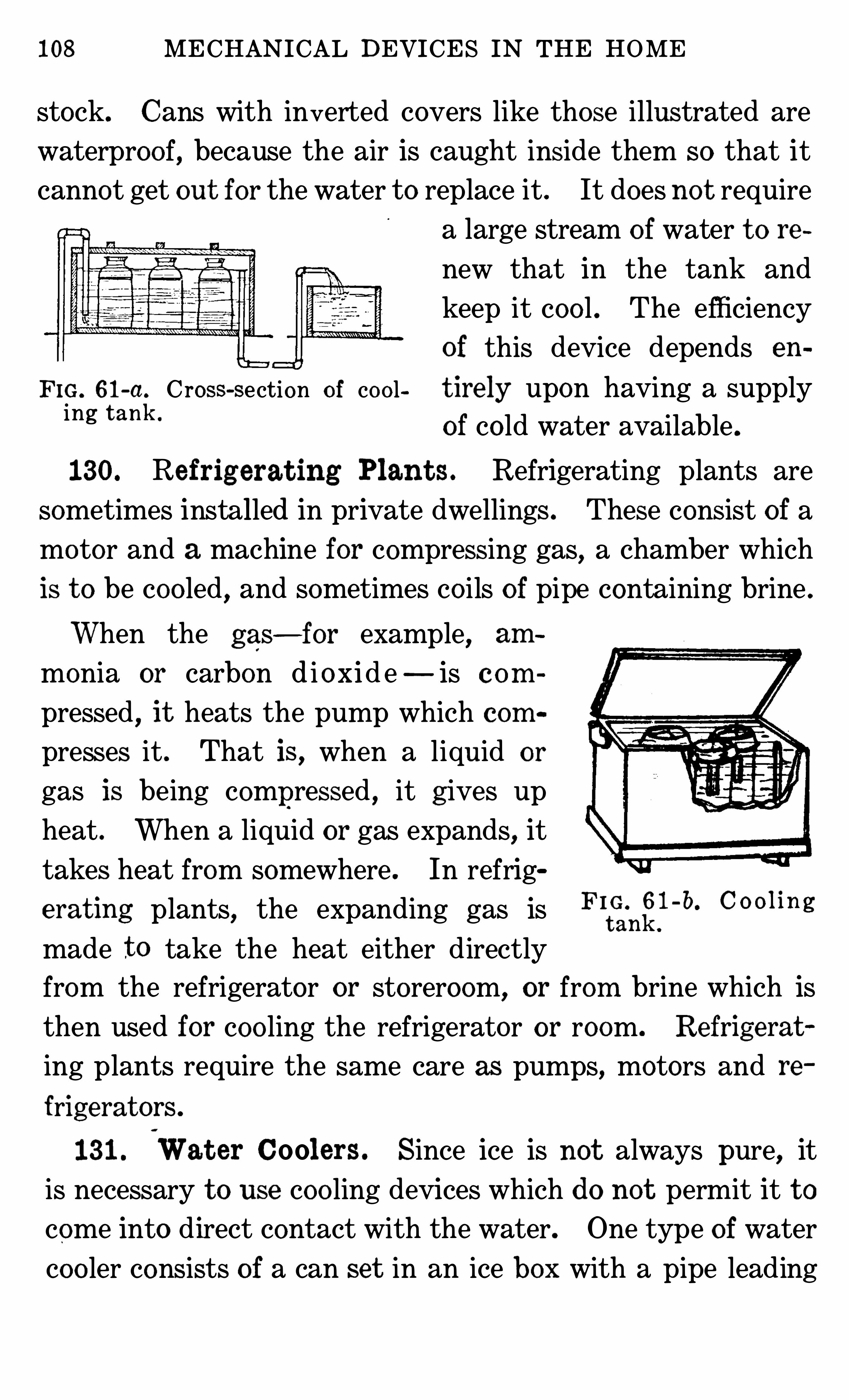
108 MECHANICAL DEVICES IN THE HOME
stock. Cans with inverted covers like those illustrated are
waterproo f, because the air is caught inside them so that it
cannot get out for the water t o replace it . It does no t require
a large stream o f water t o re
new that in the tank and
keep it coo l . The efficiency
of this device depends en
F IG. 61-a. C ross-section o f co o l t ire ly upon having a supplying t ank '
of co ld water available .
130. Refrigerat ing Plant s . Refrigerating plants are
sometimes installed in private dwellings . These consist of a
motor and a machine for compressing gas, a chamber which
is t o be coo led,and sometimes co ils of pipe containing brine .
When the gas—for example, am
monia or carbon d i o xid e—is c om
pressed, it heats the pump which com
presses it . That is , when a liquid or
gas is being compressed , it g ives up
heat . When a liquid or gas expands, it
takes heat from somewhere . In refrig
erating plants, the expanding gas is0 0 0 1n
made t o take the heat either directly
from the refrigerator or storeroom, or from brine which is
then used for coo ling the refrigerator or room . Refrigerat
ing plants require the same care as pumps, motors and re
frigerat ors .
131 .
‘
Wat er Coolers. Since ice is not always pure, it
is necessary t o use coo ling devices which do not permit it t o
come into direct contact with the water. One type of water
coo ler consists of a can set in an ice box with a pipe leading
CHAPTER XVI I I
FANS AND VENTILATORS
133 . Se lec t ing a Fan . With the com ing o f electricity
into the home, fans have become practical home devices . Donot buy a fan or other electrical device without ascertainingwhether the current is direct or alternating, and what vo ltage
is needed t o run it. M ost city homes are now supplied with
current ranging between 105 and 115 vo lts, so most fans are
FIG . 64 . B lower . FIG . 65. Stationary fan .
made for that . Fans will run on a small wire like that used
for lighting.
134 . Th e Const ruc t ion o f t h e Fan in Com m on Use .
Amoto r turns the fan . There is a regulator on some fans, so
that they can be run at different rates of speed . Oil cups areimportant parts o f fans . When a new fan is purchased , these
cups are full of oil . The oil will last for many months,but if
an o ld fan heats and sparks while being run , have an elec
t rician exam ine it t o see if all the parts are in o rder and there
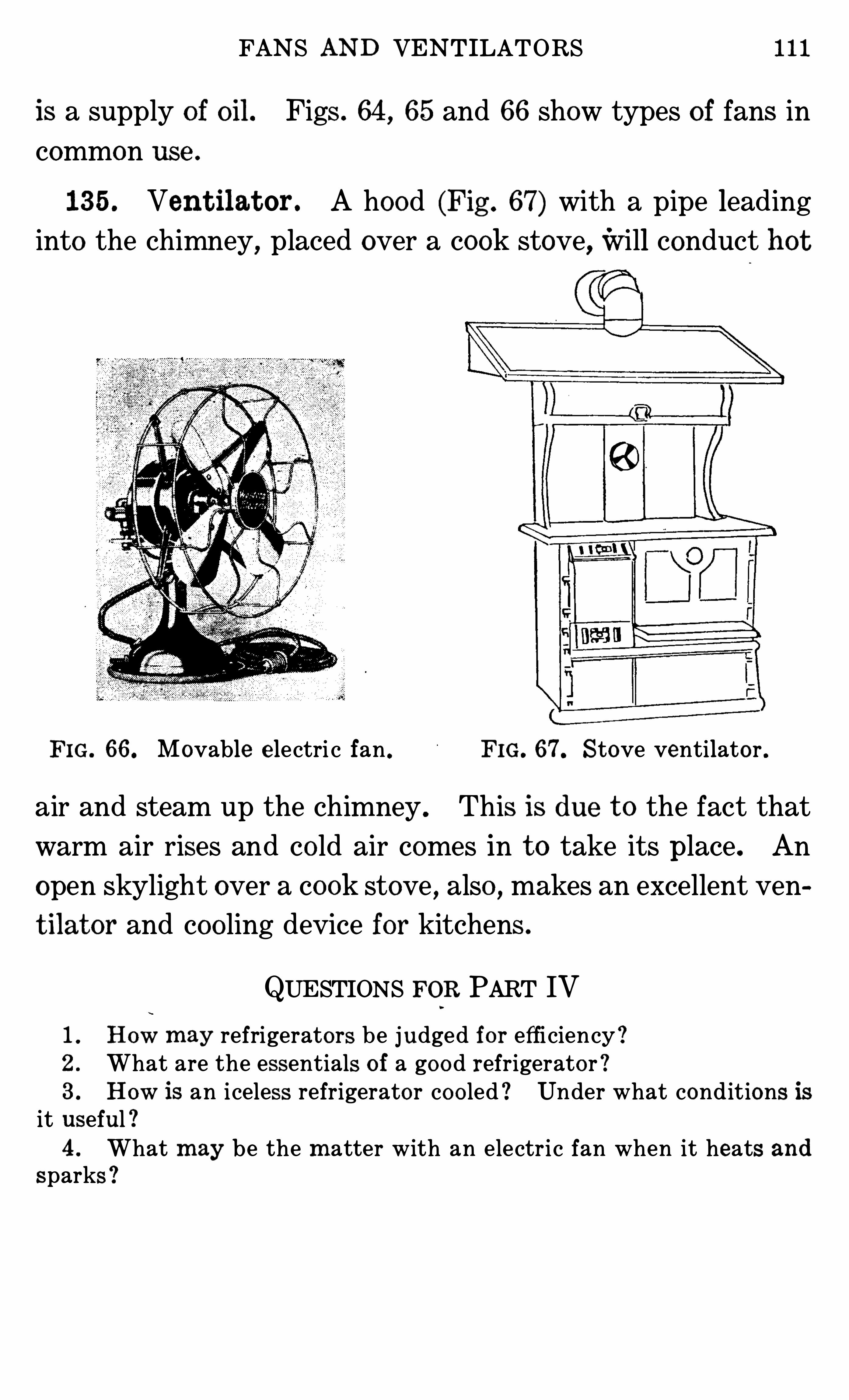
FANS AND VENTILATORS 111
is a supply of oil . Figs . 64 , 65 and 66 show types o f fans in
common use .
135 . Vent ilat or . A hood (Fig . 67) with a pipe leadinginto the chimney
,placed over a cook stove,will conduct hot
FIG. 66 . Movable e lectri c fan . FIG. 67 Stove ventilator .
air and steam up the chimney . This is due t o the fact that
warm air rises and co ld air comes in t o take its place . An
open skylight over a cook stove , also , makes an excellent ven
t ilat or and coo ling device for kitchens .
QUESTIONS FOR PART IV
1 . How m ay refrigerators be judged fo r efficiency !2 . What are the essentials o f a go o d refrigerato r !3 . How is an iceless refrigerator co o led ! Under what cond it ions isit useful !4 . What m ay be the m atter with an electric fan when it heats and
sparks !
PART V
WATER SUPPLYAND SEWAGE DISPOSAL .
CHAPTER X IX
PUMPS ANDWATER FILTERS
136 .
‘
Suc t ion Pum ps . A pump is a device for lifting
water. The pumps in common use work on the principle
that water which is under the pressure o f air will rise t o fill a
vacuum or a partial vacuum . The pump is composed o f a .
combination of valves and a piston for forcing the air out o f
the pipe t o allow the water from below t o be forced into it . A‘
valve catches the water as it starts t o flow back . The weight
o f the water ho lds the valve closed .
An outlet above the piston permits the wat er t o flow into atank or sink when the piston is again lifted t o make a new
vacuum and draw more water (Fig .
137 . Care o f Pum ps . The leather or m aterial form ing
the piston must be kept mo ist, or it will shrink and leak.
When it becomes worn and o ld , it must be renewed . It is not
a difficult task t o put new packing on a small suction pump .
To do this , remove the pin attaching the piston t o the handle .
Lift out the piston , unscrew the bo lt wh ich ho lds the leather
packing in place ; put on the new packing, and replace the
bo lt, piston and pin .
Always pump with a regular,even stroke—a jerky one
tends t o wear the working part s o f the pump .
The cylinder and pipe containing water must no t be al
lowed t o freeze . There is usually a plug in the pipe which
114 MECHANICAL DEVICES IN THE HOME
These act automat ically . Whenever an out let pipe is opened ,the extra pressure o f air from the storage tank raises the wat er
from the well or cistern (Fig . Air should be kept in the
pressure tank.
When this arrangement is used ; open and close faucets
FIG. 7O. Compressed-air pum p system .
slowly, no t with a jerk . Fig . 70-a shows plumbing where
such a system is used .
140. Water Filt ers . Water filters are devices for strain
ing minute particles out of water. They are made o f sand ,
charcoal or porcelain, kisse lguhr and other materials . They
are without value unless they are kept clean . A dirty filter is
worse than none . Alm ost the only way t o clean them is t o
sterilize them or put new material in them . Only with ex
pert care can filters be made effective for removing disease
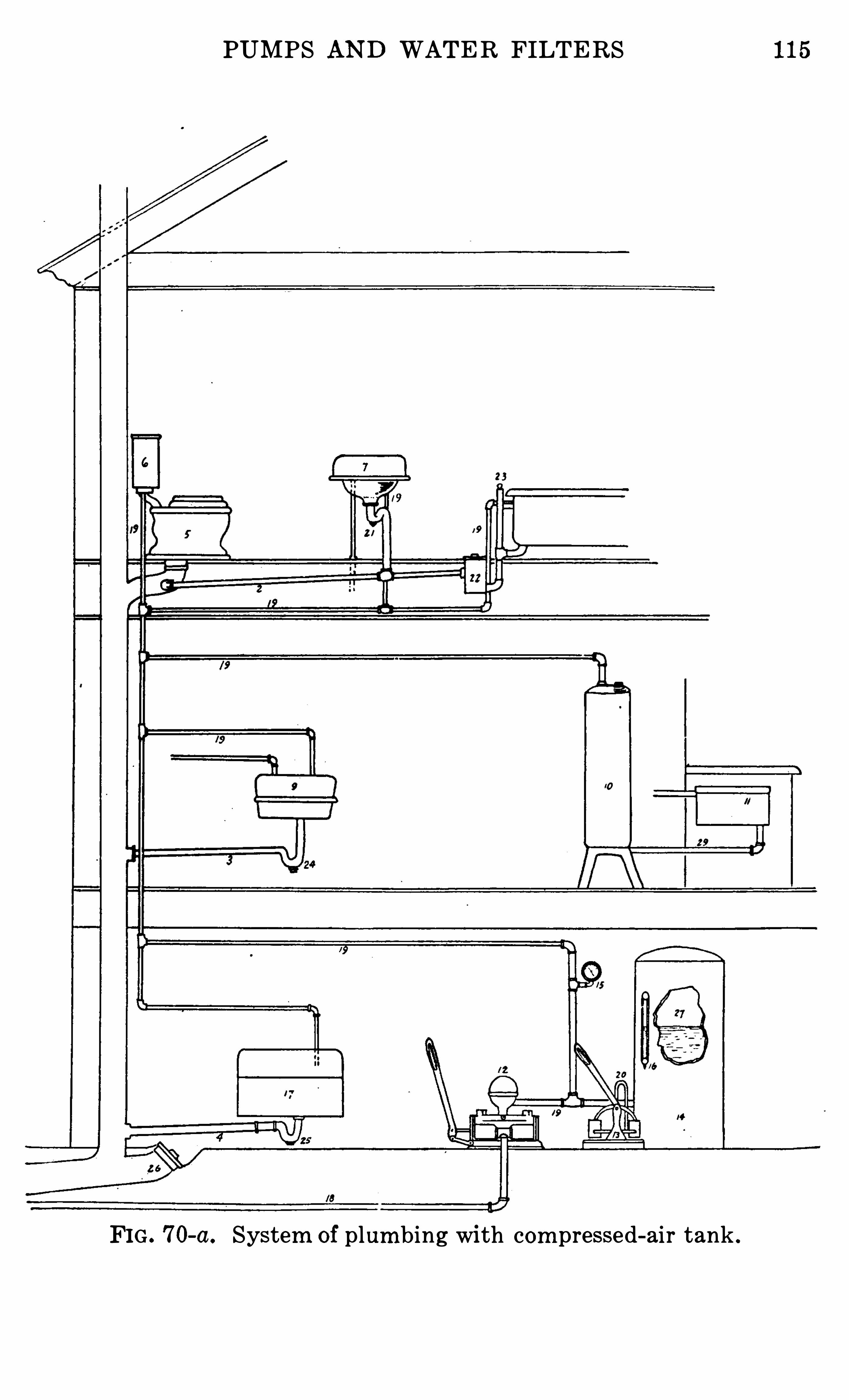
PUMPS AND WATER FILTERS 115
FIG . 7O-a. System of plum bing with com pressed-air tank .
116 MECHANICAL DEVICES IN THE HOME
germs . A dirty filter may prove a menace . Filters are val
uable for removing coarse dirt from the water .
Filters on faucets should be cleaned or renewed every day .
Large filt ers for rain water should be renewed every few
months .
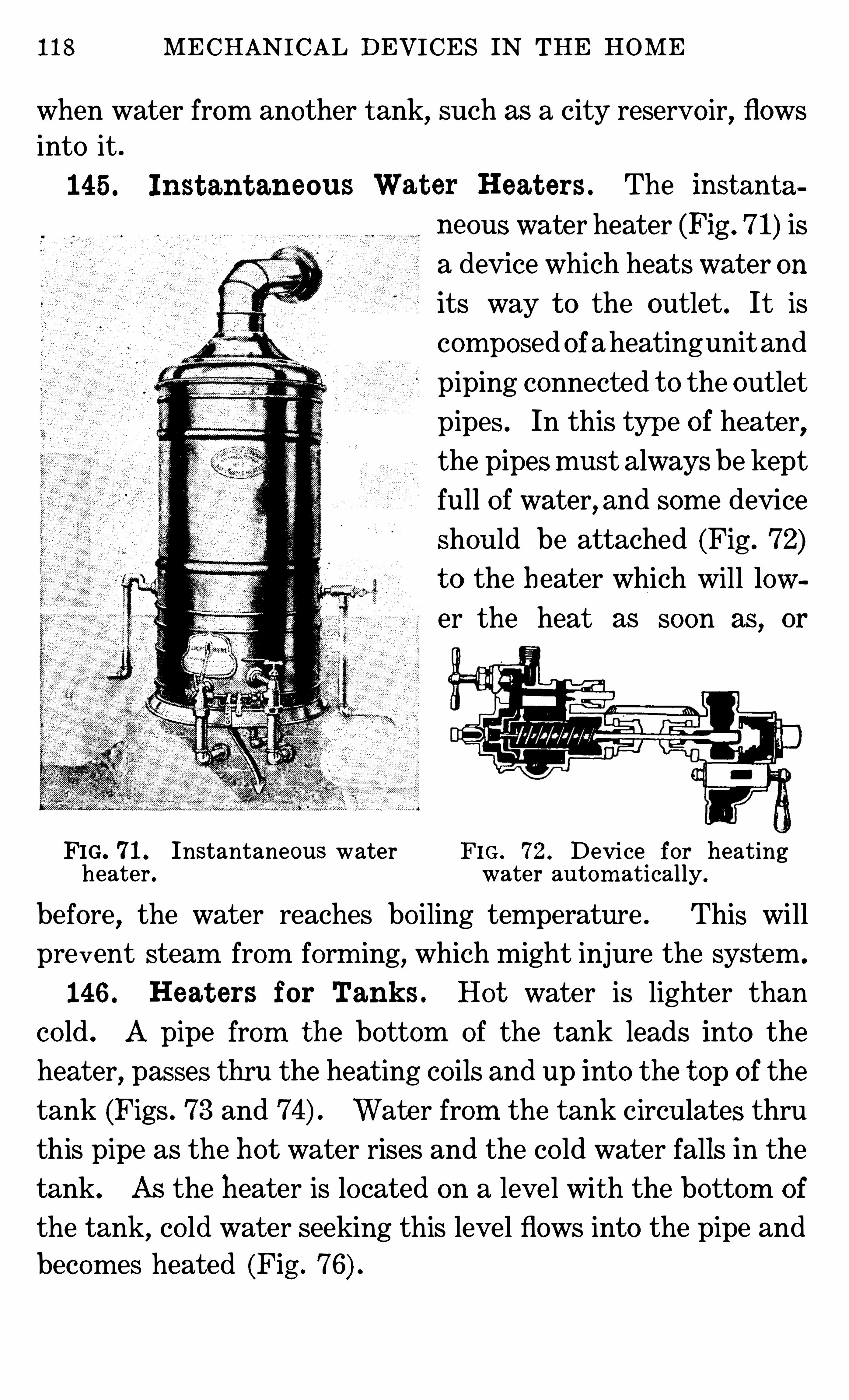
118 MECHANICAL DEVICES IN THE HOME
when water from another t ank, such as a city reservo ir, flows
into it .
145 . Inst ant aneous
FIG. 71. Instantaneous water F I G . 72 . Device for heatingheater . water autom atically.
before, the water reaches bo iling temperature . This will
prevent steam from form ing, which might injure the system .
146 . Heat ers for Tank s . Hot water is lighter than
co ld . A pipe from t he bottom of the tank leads into the
heater,passes thru the heating co ils and up into the t op o f the
tank (Figs . 73 and Water from the tank circulates thru
this pipe as the ho t water rises and the co ld water falls in the
tank. As the heater is located on a level with the bottom of
the tank,co ld water seeking this level flows into the pipe and
becom es heated (Fig .
Wat er Heat ers . The instanta
neous water heater (Fig . 71) is
a device which heats water on
its way t o the outlet . It is
com posed ofaheatingunit and
piping connected t o the outlet
pipes . In this type of heater,the pipesmust always be kept
full of water,and some device
should be attached (Fig . 72)t o the heater which will low
er the heat as soon as, or
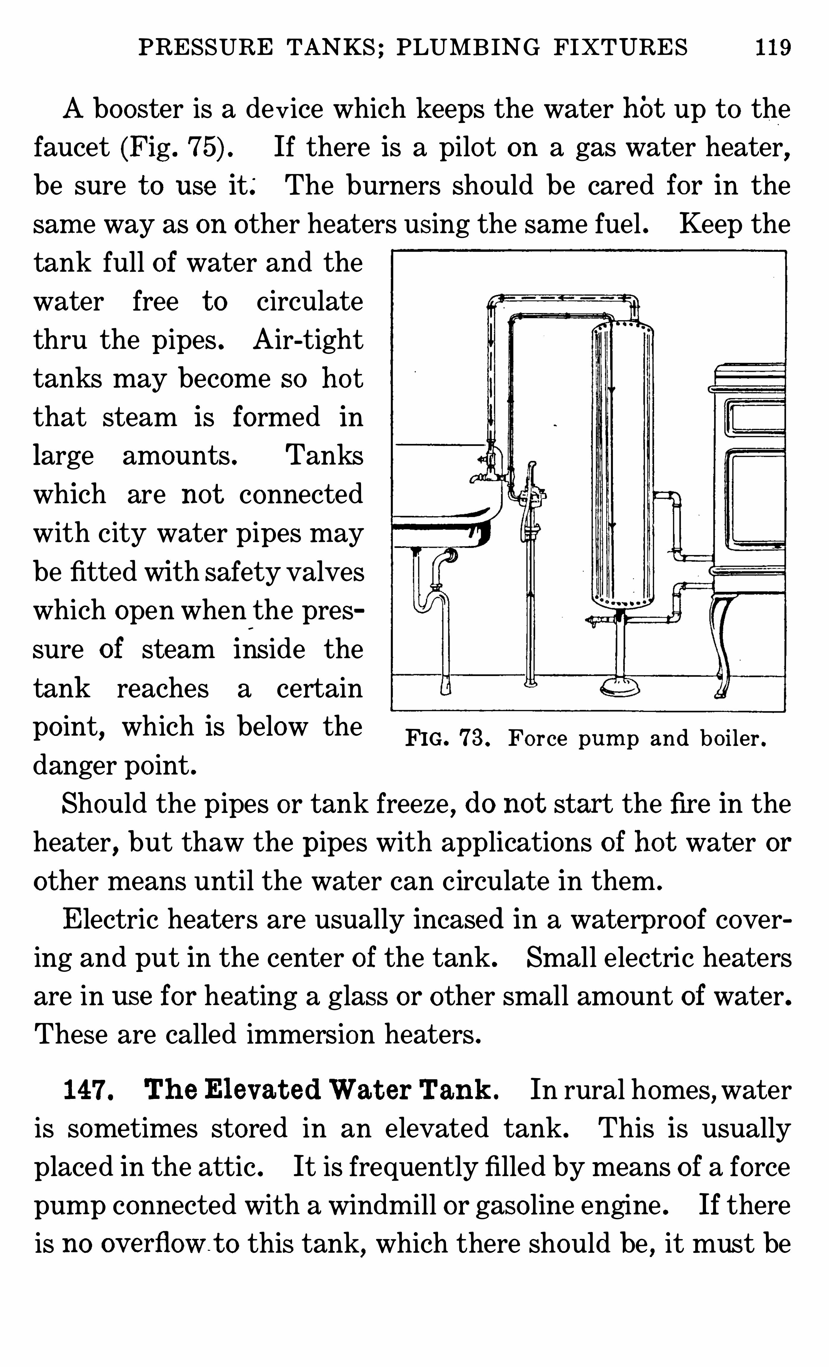
PRESSURE TANKS ; PLUMB ING FIXTURES 119
A booster is a device which keeps the water hOt up t o the
faucet (Fig . If there is a pilot on a gas water heater,be sure t o use it .
‘
The burners should be cared for in the
sam e way as on other heaters using the same fuel . Keep the
tank full of water and the
water free t o circulate
thru the pipes . Air-tight
tanks may become so ho t
that steam is formed in
large amounts . Tanks
which are not connected
with city water pipes may
be fitted with safety valves
which open when'
the pres
sure of steam inside the
tank reaches a certain
po int,which is below the
danger po int .
Should the pipes or tank freeze,do not start the fire in the
heater, but thaw the pipes with applications of ho t water or
other means until the water can circulate in them .
Electric heate rs are usually incased in a waterproo f covering and put in the center of the tank . Small electric heaters
are in use for heating a glass or other small amount of water.
These are called immersion heaters .
FIG . 73 . Fo rce pum p and bo iler .
147 . Th e El evat ed Wat er Tank . In rural homes,water
is sometimes stored in an elevated tank. This is usually
placed in the attic . It is frequently filled by means o f a force
pump connected with a windmill or gaso line engine . If there
is no ov erflowt o this tank, which there should be , it must be
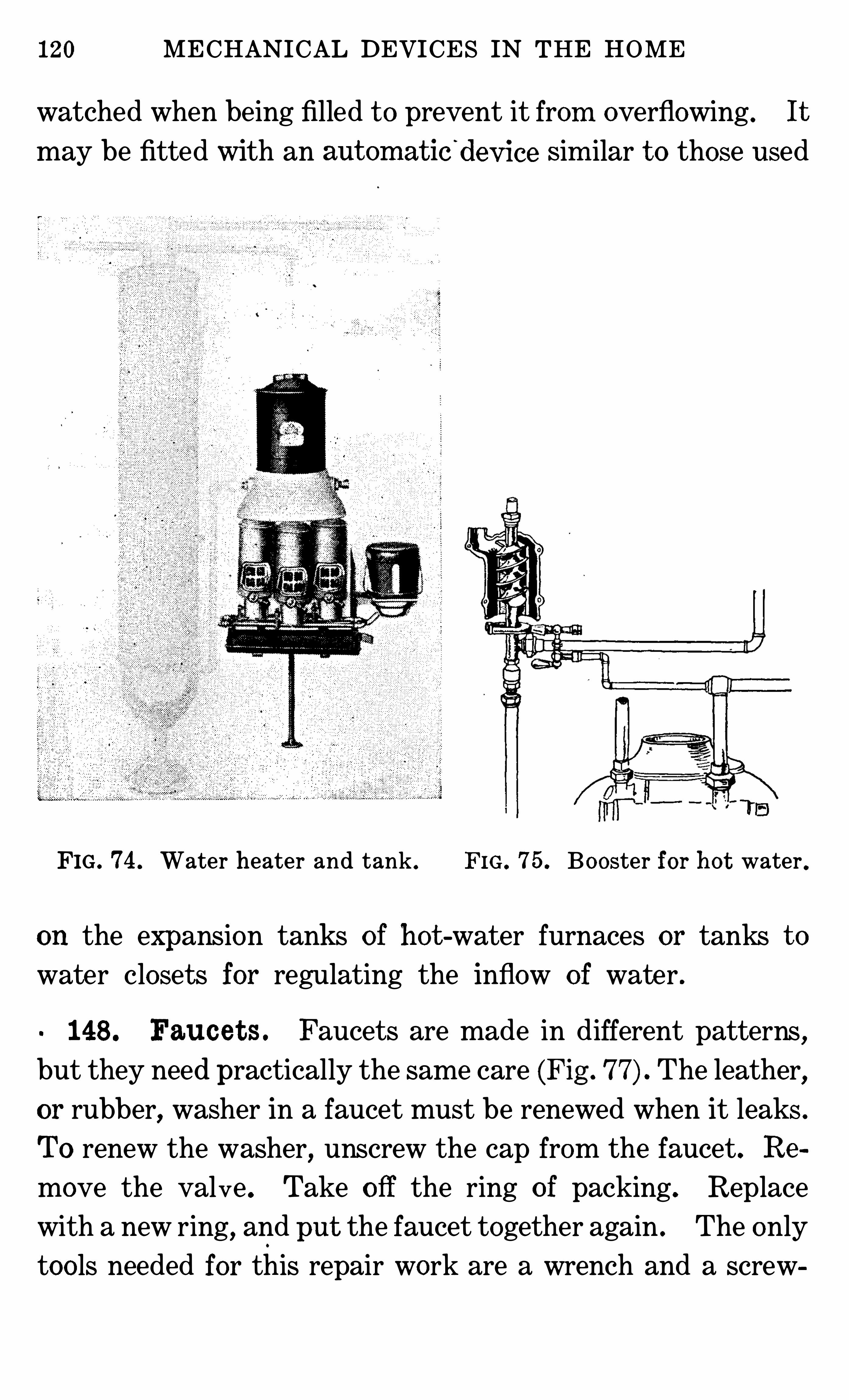
120 MECHANICAL DEVICES IN THE HOME
watched when being filled t o prevent it from overflowing . It
may be fitted with an aut om at ic'
dev ice sim ilar t o those used
FIG . 74 . Water heater and tank . FIG . 75 . Booster for h ot water .
on the expansion tanks of hot -water furnaces or tanks t o
water closet s for regulating the inflow of water .
148 . Fauce t s . Faucets are made in different patterns,
but they need practically the same care (Fig . 77) The leather,
or rubber, washer in a faucet must be renewed when it leaks .
To renew the washer, unscrew the cap from the faucet. Re
move the valve . Take o ff the ring o f packing. Replace
with a new ring, and put the faucet together again . The only
too ls needed for this repair work are a wrench and a screw
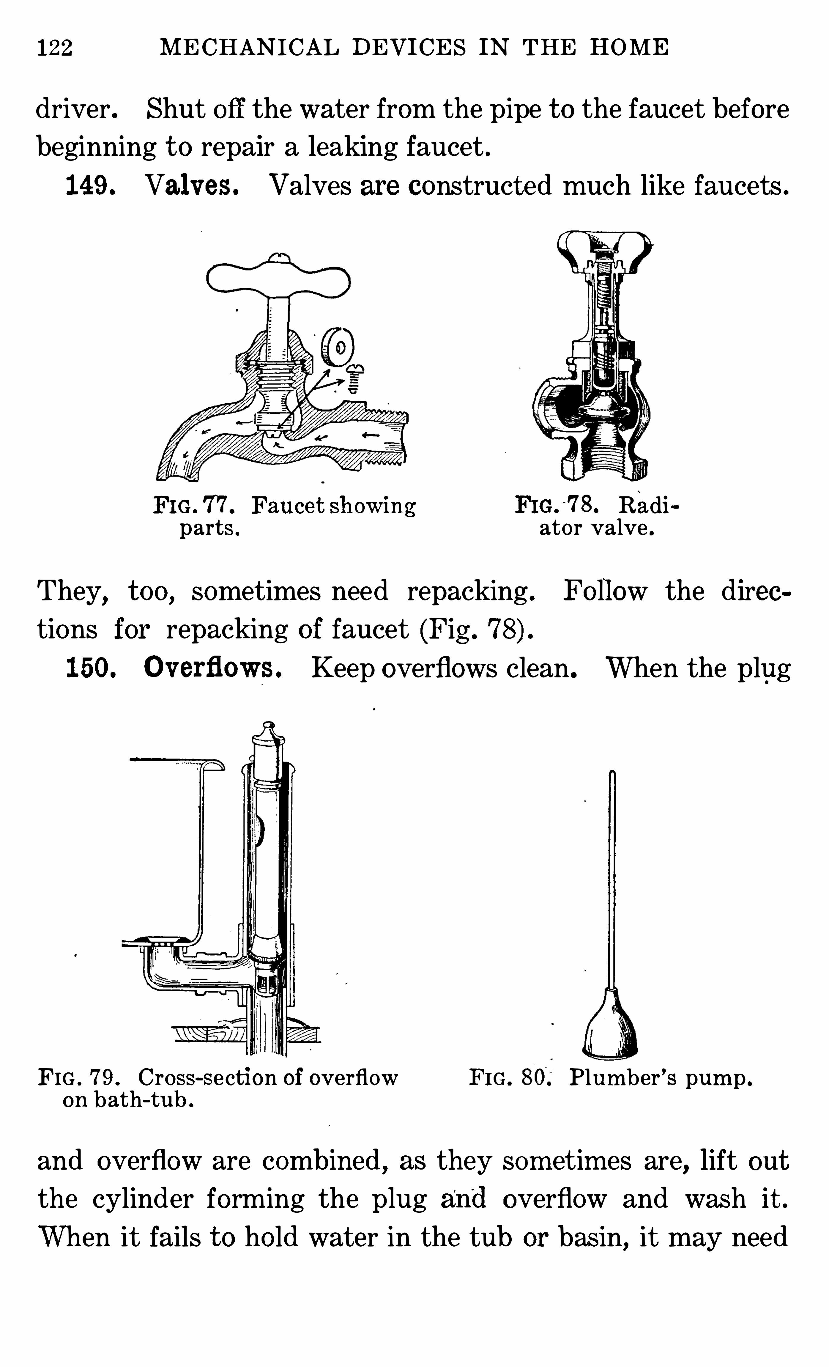
122 MECHANICAL DEVICES IN THE HOME
driver. Shut off the water from the pipe t o the faucet before
beginning t o repair a leaking faucet .
149 . Valv es . Valves are construct ed much like faucets .
FI G. 77 . Fauce t sh owing FIG.
'
78 . Radiparts . ator valve .
They, t oo , sometimes need repacking . Fo llow the dirce
tions for repacking of faucet (Fig .
150. O v erflows. Keep overflows clean. When the plug
FIG . 79 . Cross-section of overflow Plum ber ’s pum p .
on bath-tub .
and overflow are combined, as they som etim es are, lift out
the cylinder forming the plug and overflow and wash it .
When it fails t o ho ld water in the tub or basin, it may need
PRESSURE TANKS ; PLUMB ING FIXTURES 123
a new washer on the lower part . This may be replaced very
easily . Fig. 79 shows one type of overflow.
I t is more difficult t o keep other overflows clean . They
may be flushed or cleaned with a brush attached t o a wire .
151 . Traps for Bat h Tubs and Basins . Dirt and
slime co llects in traps . Clean them frequently. Always
leave clean water in the traps o f bathroom fixtures and
sinks . Only matter quickly so luble in water should passinto drain pipes . Keep matches
,hair
,sweepings, rags, fruit
skins and stones out o f the fixtures .
If the drain from a basin,sink or tub fails t o carry away the
water, the stoppage may be removed with a sm all plumber ’s
pump (Fig . This is a small rubber cone-like devicewhich is placed over the outlet t o the drain and moved up and
down so that it sucks air, water and whatever may be m ov
able up the pipe .
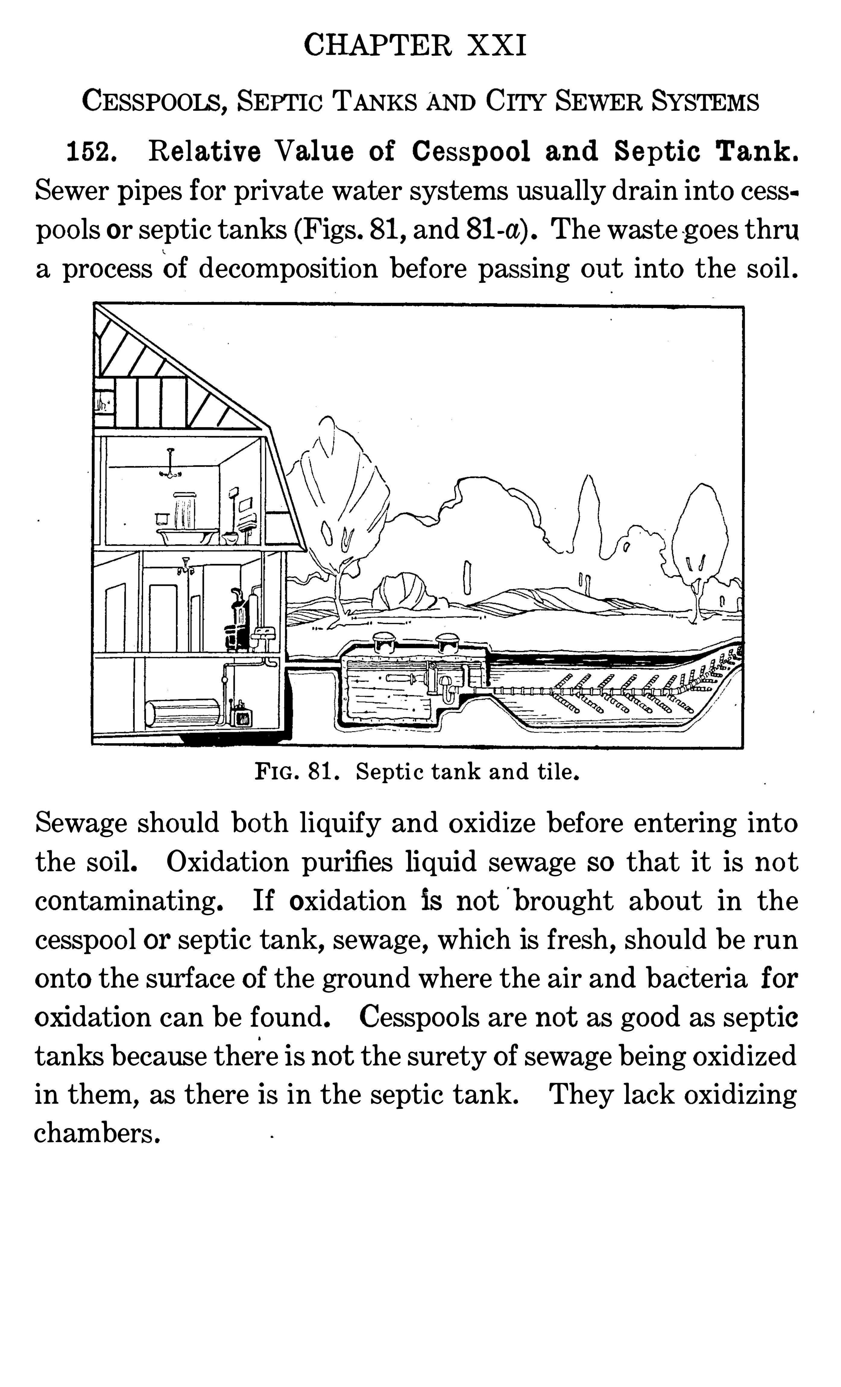
CHAPTER XXI
CESSPOOLS, SEPTIC TANKS AND CITY SEWER SYSTEMS
152. Re lat iv e Value o f Cesspo o l and Sept ic Tank .
Sewer pipes for private water systems usually drain into cesspoo ls or septic tanks (Figs. 81, and 81-a) . The waste g oes thrua process Of decom position before passing out into the so il .
FIG . 81 . Septi c tank and ti le .
Sewage should bo th liquify and oxidize before entering into
the so il. Oxidation purifies liquid sewage so that it is no tcontaminating. If oxidation is not b rought about in the
cesspoo l or septic tank, sewage, which is fresh, should be run
onto the surf ace of the ground where the air and bact eria foroxidation can be found. Cesspoo ls are not as good as septictanks because there is not the surety of sewage being oxidized
in them,as there is in the septic tank . They lack oxidizing
chambers .
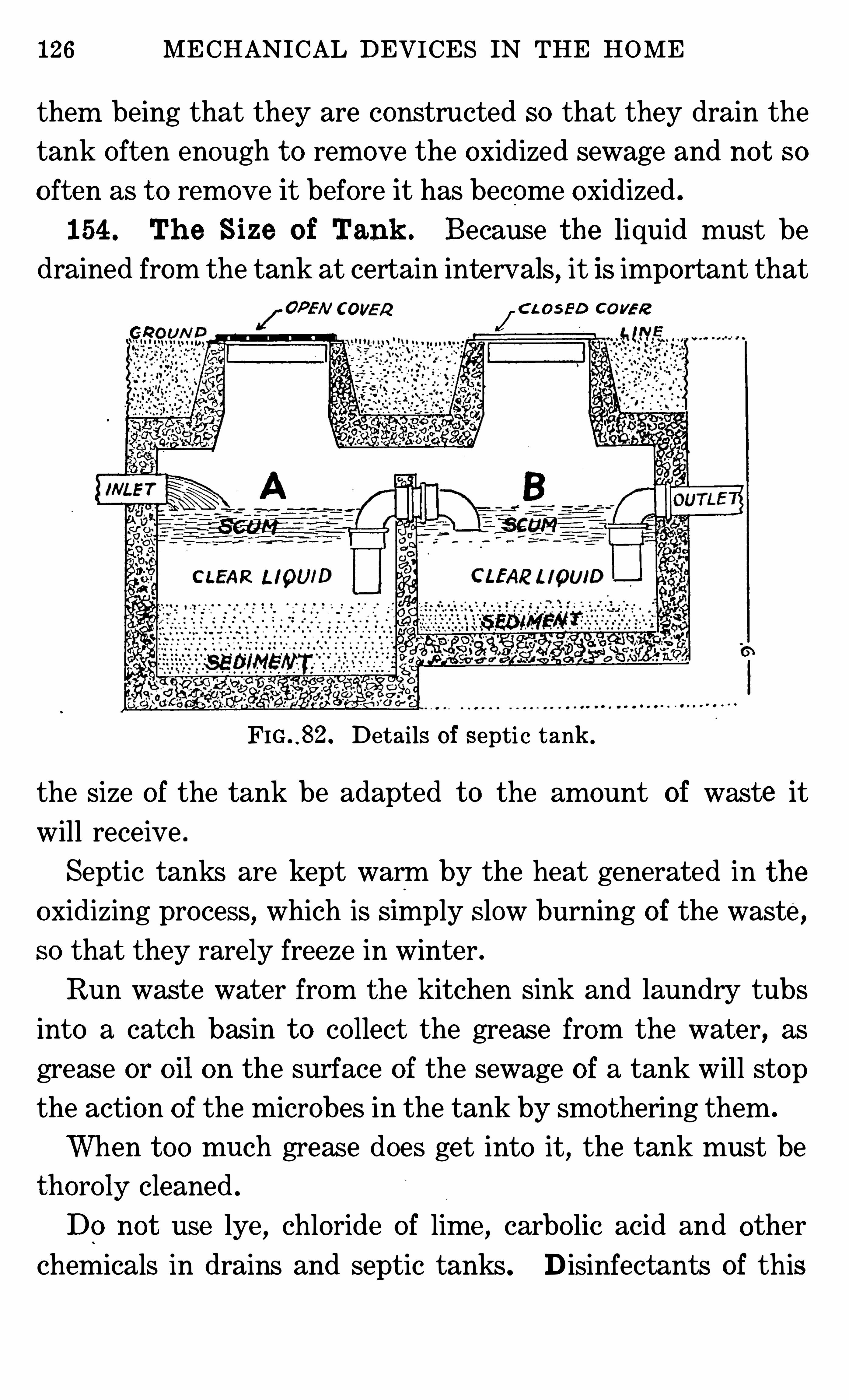
126 MECHANICAL DEVICES IN THE HOME
them being that they are constructed so that they drain the
tank Often enough t o remove the oxidized sewage and not so
o ften as t o remove it before it has become oxidized .
154 . Th e Size o f Tank . Because the liquid must bedrained from the tank at certain intervals, it is important that
C LO SED CO VER
FIG . . 82. Details of septi c tank .
the size of the tank be adapted t o the amount of waste it
will receive .
Septic tanks are kept warm by the heat generated in t he
oxidizing process,which is Simply slow burning of the waste ,
so that they rarely freeze in winter .
Run waste water from the kitchen Sink and laundry tubs
into a catch basin t o co llect the grease from the water, as
grease or oil on the surface of the sewage of a tank will stop
the action o f the microbes in the tank by smothering them .
When t oo much grease does get into it, the tank must be
thoro ly cleaned .
Do no t use lye,chloride of lime , carbo lic acid and other
chemicals in drains and septic tanks. D isinfectants of this
CESSPOOLS,SEPTIC TANKS , SEWER SYSTEMS
type put into pipes leading t o a septic tank will kill the useful
bacteria which decompose the sewage .
Use clear bo iling water t o clean the pipes . This will be
coo led by the time it reaches the tank so that it will no t kill
the useful bacteria .
Inso luble mineral matter gradually accumulates in septic
tanks, so that they must be cleaned once every few years .
Care will postpone t he times for cleaning .
Do notwash vegetables with much earth adhering t o themin sinks leading t o cesspoo ls or septic tanks . Shake or rinse
off the dirt before washing them .
155. Disposal o f Wast e in Cit ies . In some cities,
househo lders are required by law t o have catch basins c onnec t ed t o their sewer systems t o remove leaves and dirt fromstorm water and grease from kitchen sinks and laundry tubs .
The laws of other cities forbid the use of catch basins, but urge
househo lders t o help care for the city sewer system by not
putting grease into sewer pipes .Strong chemicals Should not be put into the pipes . Use
only bo iling water in clean ing pipes . Do not wash v ege
tables ou which there is much loose dirt in sinks .
CHAPTER XXI I
WATER CLOSETS
156 . Const ruc t ion of Wat er Close t s . The water closet
is a device for the disposal o f excrement. The closet includes
a tank of water for flushing the waste from the bowl t o the
sewer or waste pipe . Between the bowl and the waste pipe is
a device called a trap which ho lds water and seals the end o fthe waste pipe so that gases from the sewer or the septic tank
cannot come into the house . (Fig . 83 -a . )
The bowl of the newermodels ofwat er closets have the trap
as a part of the bowl, which saves jo ints and connections
likely t o catch dirt and stop up the trap (Fig . The
water coming from the flushing tank is carried around the
bowl so that it is flushed clean by the swift-flowing water.
When the water reaches the bottom o f the bowl, it rushes
upward a few inches before it can turn downward t o the
waste pipe . This it does while flowing rapidly and cleansing
the bowl ; when the tank empties, water co llects in the bowl t o
the level,where it can flow down the waste pipe (Fig . As
soon as all the water above this level has gone down the pipe,
the rem ainder stays in the bowl , form ing the seal until the
next time the bowl is flushed . Fig . 83-a shows two kinds of
traps .
If water flows at t oo rapid a rate thru the trap of the bowl,
as in cases when there is t oo much pressure on the water or
the tank is se t t oo high so that grav ity gives it t oo much force,
or if an excessive suction is produced in the drain pipe, all the
water m ay run out o f the bowl , leaving the t rap unsealed .
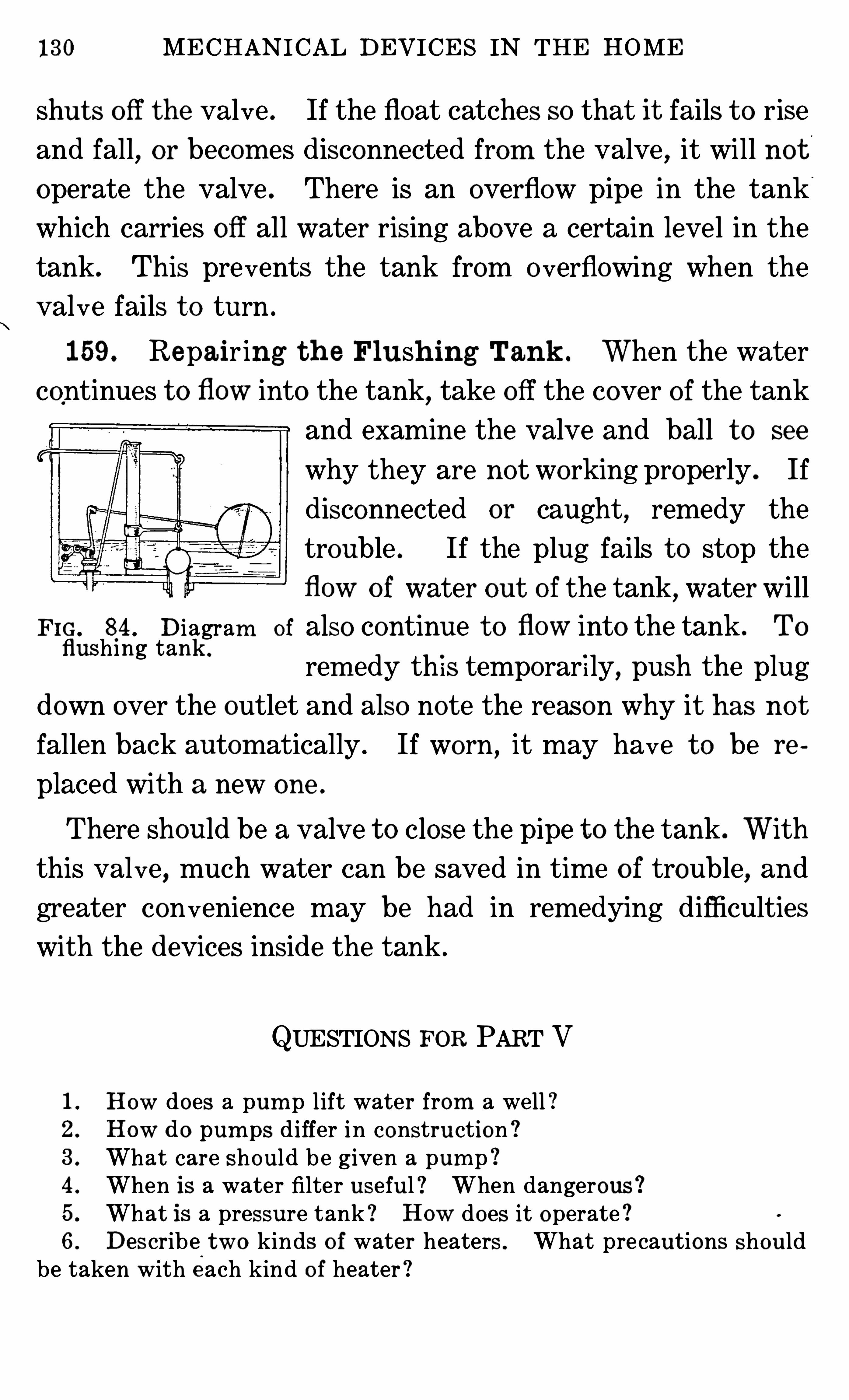
130 MECHANICAL DEVICES IN THE HOME
shut s o ff t he valve . If the float catches so that it fails t o rise
and fall, or becom es disconnected from the valve , it will no t
operate the valve . There is an overflow pipe in the tank
which carries o ff all water rising above a certain level in the
tank. This prevents the tank from o verflowing when the
valve fails t o turn .
159 . Repair ing t h e Flush ing Tank . When the water
continues t o flow into the tank, take o ff the cover o f the tank
and examine the valve and ball t o see
why they are not working properly . If
disconnected or caught,remedy the
trouble . If the plug fails t o stop the
flow o f water out o f the tank, water will
F IG. 84 . Diagram of also continue t o flow into the tank . Toflushing tank .
rem edy th is temporar i ly, push the plug
down over the outlet and also note the reason why it has no t
fallen back autom atically . If worn ,it may have t o be re
placed with a new one .
There should be a valve t o close the pipe t o the tank . With
this valve, much water can be saved in time o f trouble, and
greater convenience may be had in rem edying difficulties
with the devices inside the tank .
QUESTIONS FOR PART V
How does a pum p l ift water from a well !How d o pum ps d iffer in construction !What care should be given a pum p !When is a water filter useful ! When dangerous !What is a pressure tank ! How does it operate !Describe two kinds o f water heaters . What precautions should
be taken with each kind o f heater !S’
P‘
P
SD
N
Y"
QUESTIONS 131
7 . Describe a water faucet . Try t o replace an o ld washer with anew one .
8 . Have y ou ever cleaned the overflow t o a t ub or basin ! Shouldthey be cleaned !9. What are traps ! What m ay cause them t o fail t o wo rk !10. How woul d y ou select a go od trap ! How woul d y ou clean it !11 . Describe the construction o f a septic tank . What is the actionthat takes place in a septic tank ! What care should be given t o it !12 . Exam ine the tank t o a water closet . How does it Operate !
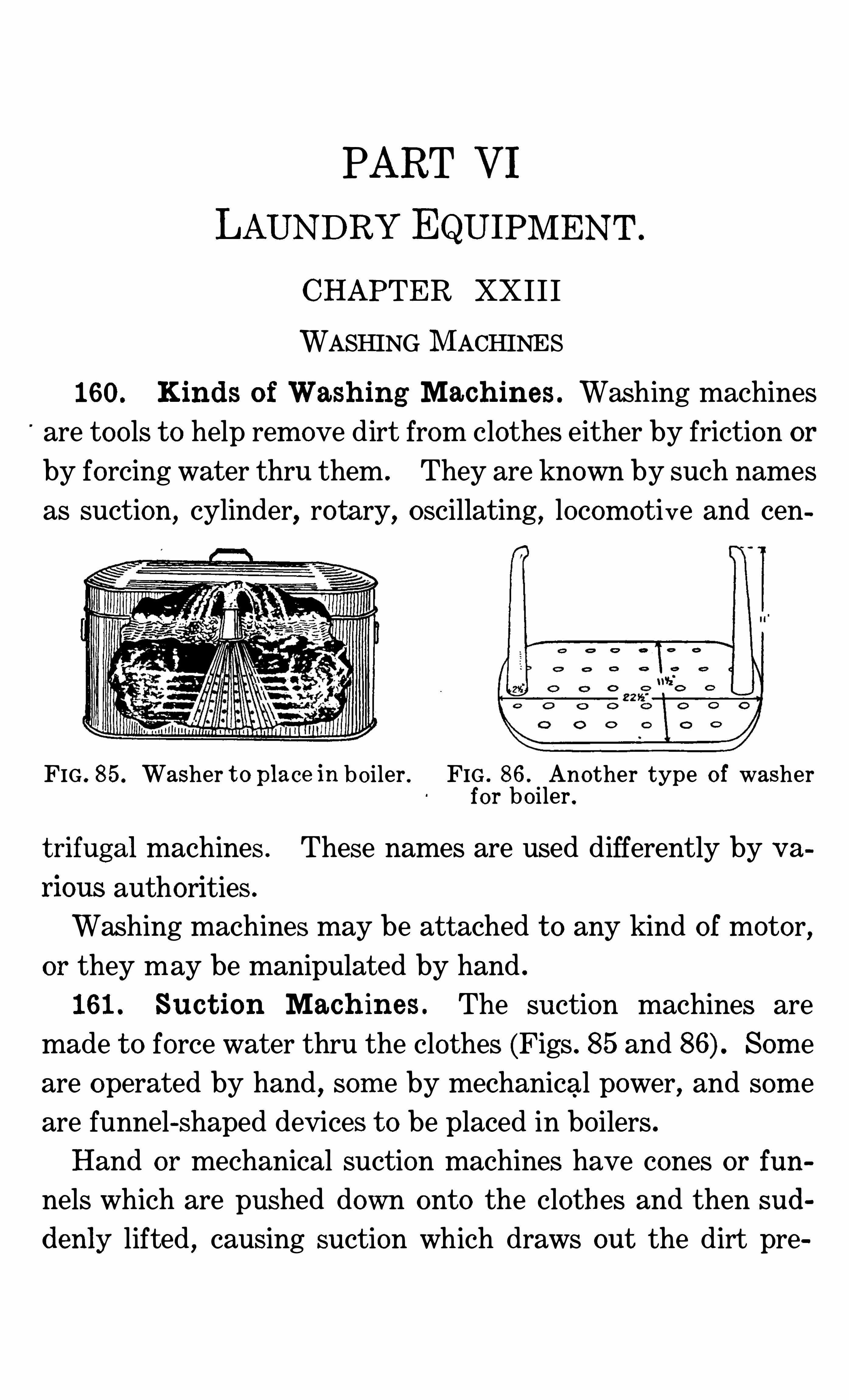
PART VI
LAUNDRYEQUIPMENT .
CHAPTER XX I I I
WASHING MACHINES
160. Kinds o f Wash ing Mach ines . Washing machines
are tools t o help remove dirt from clothes either by friction or
by forcing water thru them . They are known by such names
as suction, cylinder, rotary, oscillating, locom o t ive and cen
FIG . 85. Washer t o place in bo iler . FIG . 86 . Another type o f washerfor bo iler .
t rifugal machines . These names are used differently by v a
rious authorities .
Washing machines may be att ached t o any kind of motor,
or they may be manipulated by hand .
161 . Suc t ion Mach in es . The suction machines are
made t o force water thru the clothes (Figs . 85 and Som e
are operated by hand , som e by mechanical power, and som e
are funnel-shaped devices t o be placed in bo ilers .
Hand or mechanical suction machines have cones or fun
nels which are pushed down onto the clothes and then sud
denly lifted , causing suction which draws out the dirt pre
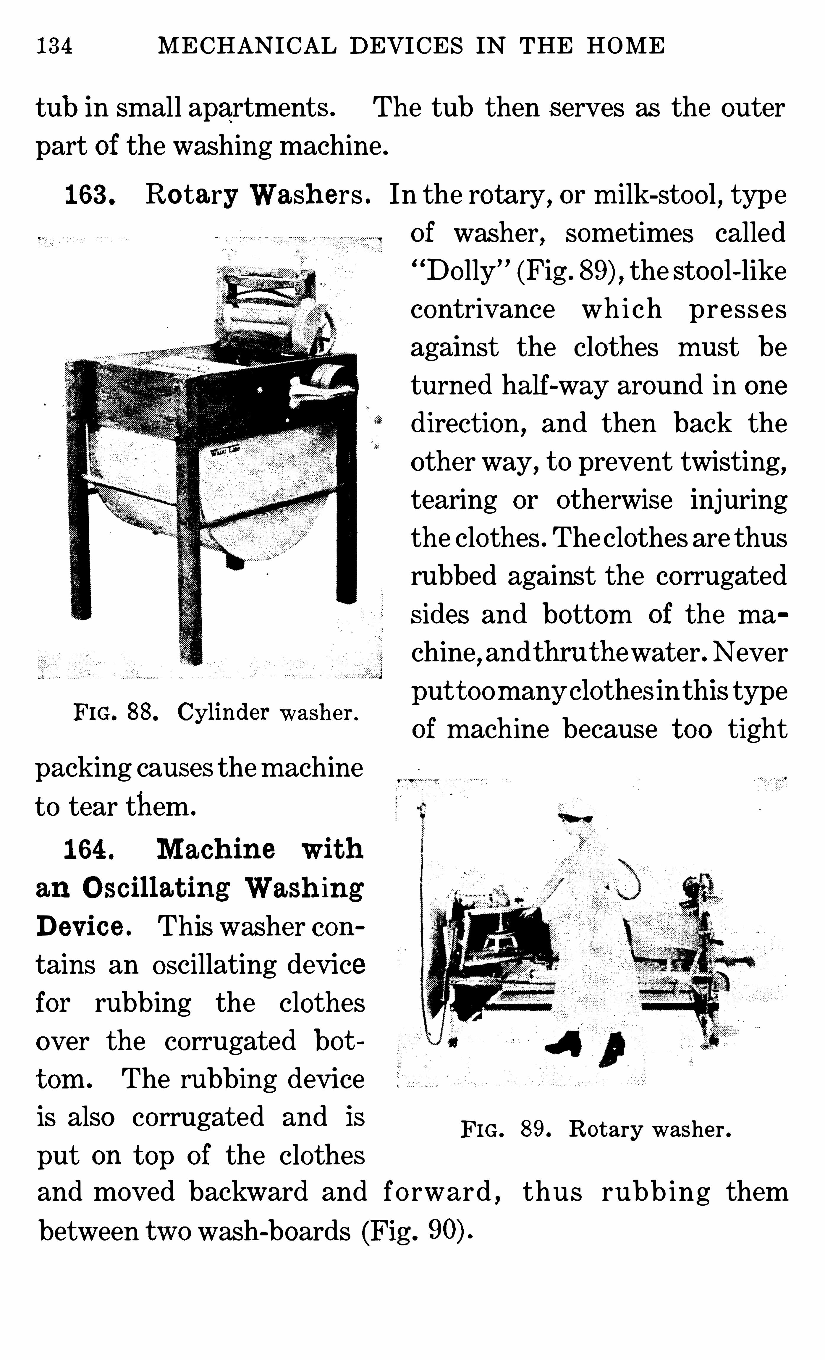
134 MECHANICAL DEVICES IN THE HOME
tub in small apartments . The tub then serves as the outer
part of the washing machine .
163 . Rotary Wash ers . In the rotary, or milk-stoo l , type
of washer, som etimes called“
Do lly”
(Fig . the stoo l-like
contrivance whi ch presses
against the clothes must be
turned half-way around in one
direction, and then back the
o ther way, t o prevent twisting,
tearing or otherwise injuring
the clothes . Theclothes are thus
rubbed against the corrugated
sides and bottom of the ma
chine,and thru thewater.Never
put t oom any clothesin this typeFIG' 88 ’ Cyhnder wash er °
of machine because t oo tight
packing causes themachine
t o tear them .
164 . M ach ine wit h
an O scil lat ing Wash ing
Dev ice . This washer con
tains an oscillating device
for rubbing the clothes
over the corrugated bot
t om . The rubbing device
is also corrugated and is
put on t op of the clothes
and moved backward and fo rward , thus rubb ing them
between two wash-boards (Fig .
FIG . 89. Rotary washer .
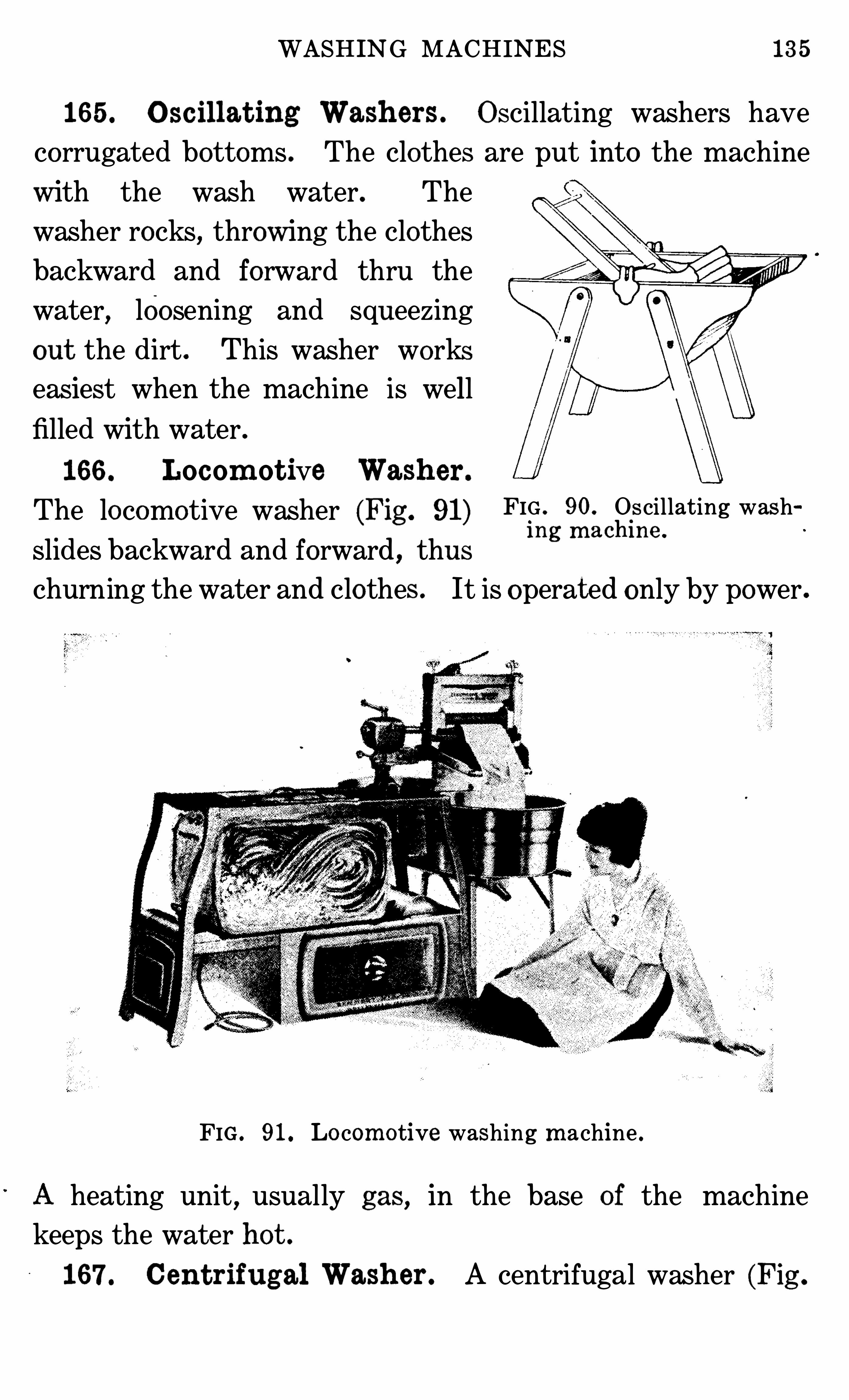
WASHING MACHINES 135
165 . O scil lat ing Wash ers . Oscillating washers have
corrugated bottoms . The clothes are put into the machine
with the wash water. The
washer rocks, throwing the clothes
backward and forward thru the
water,loosening and squeezing
out the dirt . This washer works
easiest when the machine is well
filled with water .
166 . Locom ot ive Wash er .
The locomotive washer (Fig . 91) FIG . 90. Oscillating washh
'
slides backward and forward , thusm g m ac m e
churning the water and clothes . It is operated only by power ,
FIG . 91. Lo com otive washing m achine .
heating unit,usually gas, in the base of the machine
keeps the water hot .
167 . Cent rifugal Wash er . A centrifugal washer (Fig .
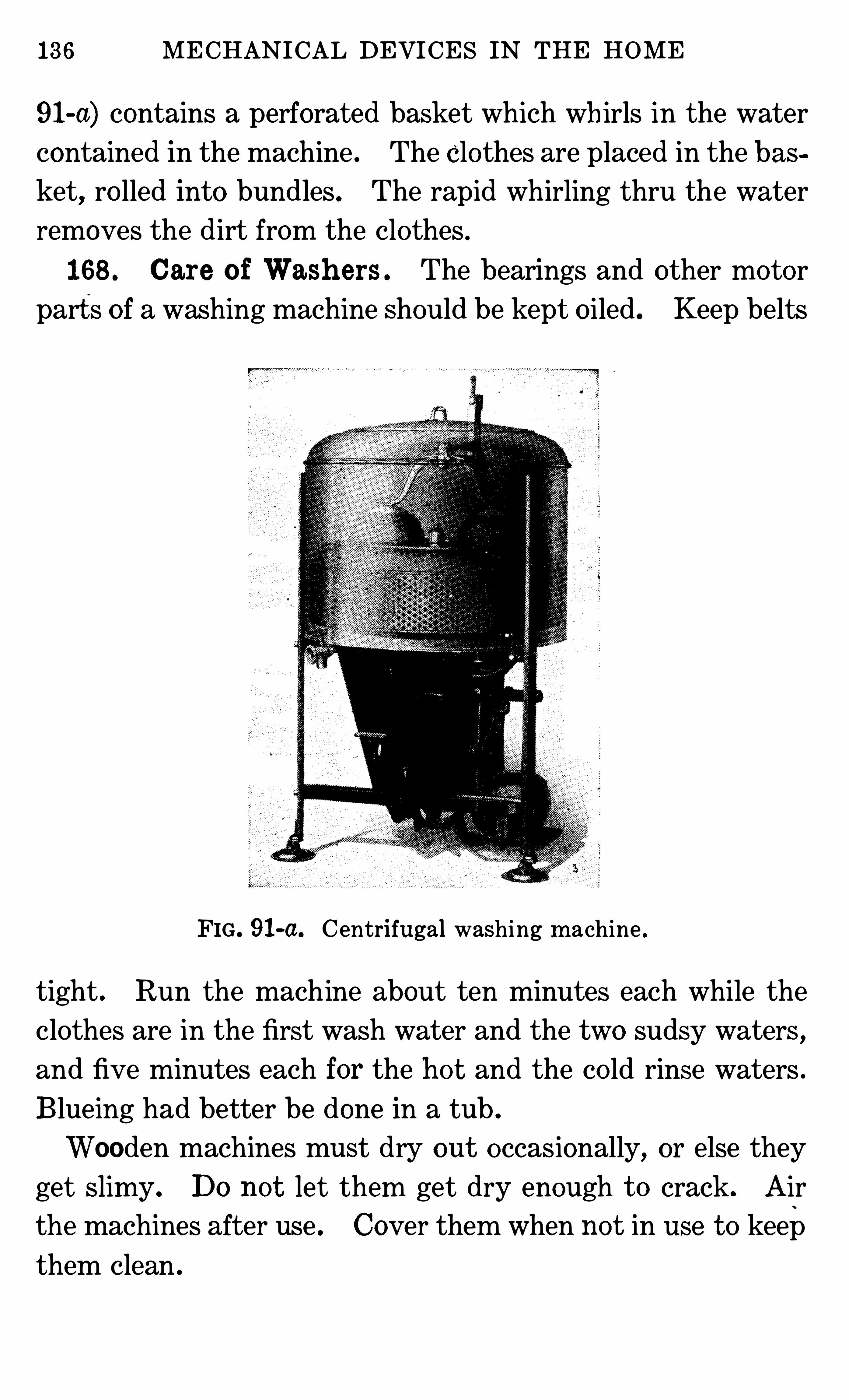
136 MECHANICAL DEVICES IN THE HOME
91-a) contains a perforated basket which wh irls in the water
contained in the machine . The clothes are placed in the bas
ket, ro lled into bundles . The rapid whirling thru the water
removes the dirt from the clothes .
168 . Care o f Wash ers . The bearings and other motorparts of a washing machine should be kept o iled . Keep belts
FIG. 91-a. Centrifugal washing m achine .
tight . Run the machine about ten minutes each while the
clothes are in the first wash water and the two sudsy waters ,
and five minutes each for the ho t and the co ld rinse waters .
Blueing had better be done in a tub .
Wooden machines must dry out occasionally, or else they
get slimy. Do not let them get dry enough t o crack. Air
the machines after use . Cover them when not in use t o keep
them clean .
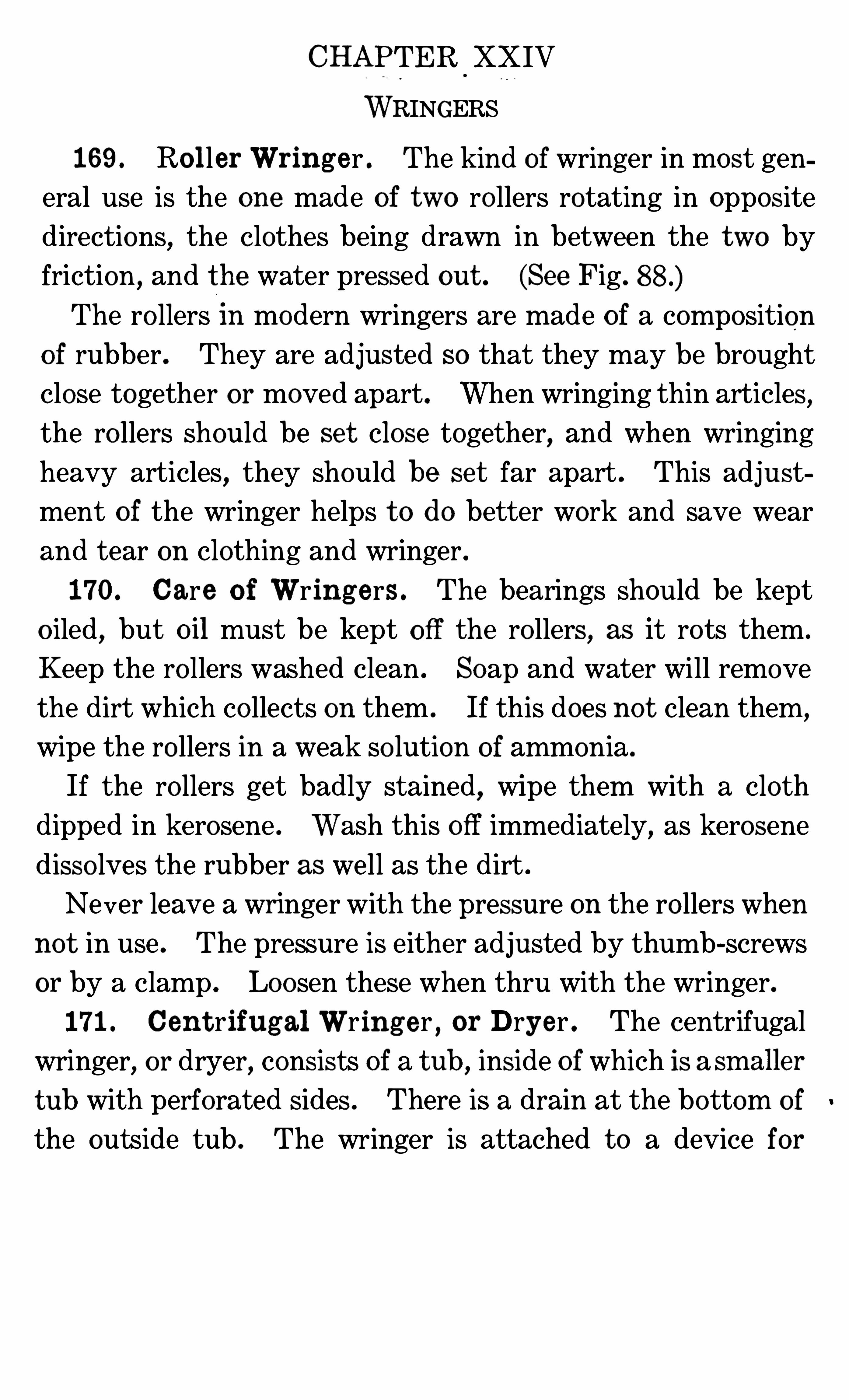
CHAPTER XXIV
WRINGERS
169 . Ro l ler Wring e r . The kind of wringer in most gen
eral use is the one made of two ro llers rotating in opposite
directions, the clothes being drawn in between the two by
friction , and the water pressed out . (See Fig .
The ro llers In modern wringers are made of a composition
o f rubber. They are adjusted so that they may be brought
close together or moved apart. When wringing thin articles,
the ro llers should be se t close together, and when wringing
heavy articles, they should be se t far apart . This adjust
ment of the wringer helps t o do better work and save wear
and tear on clothing and wringer .
170. Care o f Wring e rs . The bearings should be kept
o iled, but oil must be kept o ff the ro llers, as it rots them .
Keep the ro llers washed clean . Soap and water will remove
the dirt which co llects on them . If this does not clean them,
wipe the ro llers in a weak so lution of ammonia .
If the ro llers get badly stained, wipe them with a cloth
dipped in kerosene . Wash this off immediately, as kerosene
disso lves the rubber as well as the dirt .
Never leave a wringer with the pressure on the ro llers when
no t in use . The pressure is either adjusted by thum b-screws
or by a clamp . Loosen these when thru with the wringer.
171 . Cen t rifugal Wring er , or Dryer . The centrifugal
wringer,or dryer
,consists of a tub ,
inside o f which is a sm aller
tub with perforated sides . There is a drain at the bottom of
the outside tub . The wringer is attached t o a device for
WRINGERS 139
mak ing the inside tub turn rapidly. The power used is either
band o r machine (Fig .
The rapid turning of the inner tub for three minutes throws
the c lothing and water in them t o the outside of the revo lving
center. This tub being perforated, lets the water thru whileretaining t he clothing . Thus
,the clothes are wrung as dry as
FIG . 92 . Washer and dryer .
in a wringer o f the ro ller type . If the machine is turned a
longer tim e,the clothes can be wrung entirely dry
172 . Care o f t h e Mach ine . When loading centrifugal
wringers, put the heavy pieces at the bottom o f the basket .
Put articles in basket in bunches , and pack fairly tight . Do
not have loose ends hanging out . Fo ld sleeves into garments .
Load the basket full if there are clothes enough . A cover
helps t o ho ld the clothes in place . Load so that it runs even
and does no t wobble .
Nev er ho ld your hand on the extractor after it has started .
140 MECHANICAL DEVICES IN THE HOME
173 . Com binat ion Wash er and Wring er . The cent rif
ugal washer and wringer combined is built so that the basket
can be lowered into a tub of water. The clothes rotating in
water are washed . After this is accom plished , the cylinder
is raised,and , when rotated , serves as a wringer o f the centri
fugal type .
Load the washer with fewer clothes than for wringing .
Ro ll each garment into a bunch before putting it into the
washer .
Centrifugal wringers are used also as dry-cleaning machines .
For this use , they should be operated out of doors and at a
slower speed than when water is used . Friction heats gaso
line, causing it t o evaporate rapidly. The friction between
clothing, tub and gaso line when turned at a high speed may
produce a spark which will ignite the gaso line .
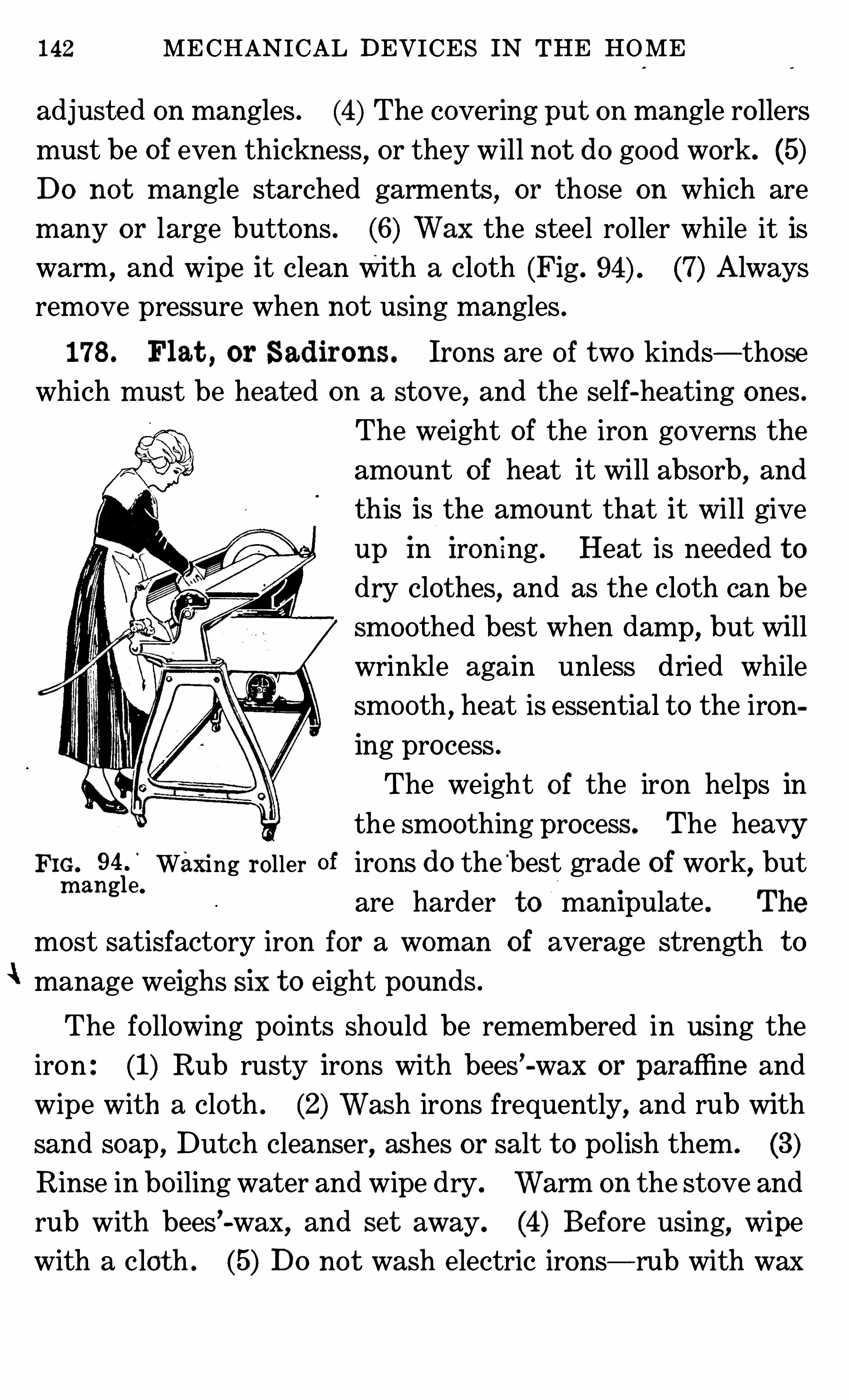
142 MECHANICAL DEVICES IN THE HOME
adjusted on mangles . (4) The covering put on mangle ro llers
must be of even thickness, or they will not do good work. (5)Do not mangle starched garments, or those on which are
many or large buttons . (6) Wax the steel ro ller while it is
warm , and wipe it clean With a cloth (Fig . (7) Always
remove pressure when not using mangles .
178 . Flat , or Sadirons. Irons are o f two kinds— those
which must be heated on a stove, and the self-heating ones .
The weight of the iron governs the
amount of heat it will absorb,and
this is the amount that it will give
up In Iron ing . Heat is needed t o
dry clothes, and as the cloth can be
smoothed best when damp, but will
wrinkle again unless dried whilesmooth , heat is essential t o the iron
ing process .
The weight of the iron helps in
the smoothing process . The heavyFIG. Waxing roller irons do the
‘
best grade of work, butm angl e'
are harder t o manipulate . The
most satisfactory iron for a woman of average strength t o
i manage weighs SIX t o eight pounds .
The fo llowing po ints should be remembered in using the
iron : (1) Rub rusty irons with bees’-wax or paraffine and
wipe with a cloth . (2) Wash irons frequently, and rub with
sand soap , Dutch cleanser, ashes or salt t o po lish them . (3)
Rinse in bo iling water and wipe dry. Warm on the stove and
rub with bees’-wax, and set away. (4) Before using, wipe
with a clot h . (5) Do no t wash electric irons— rub with wax
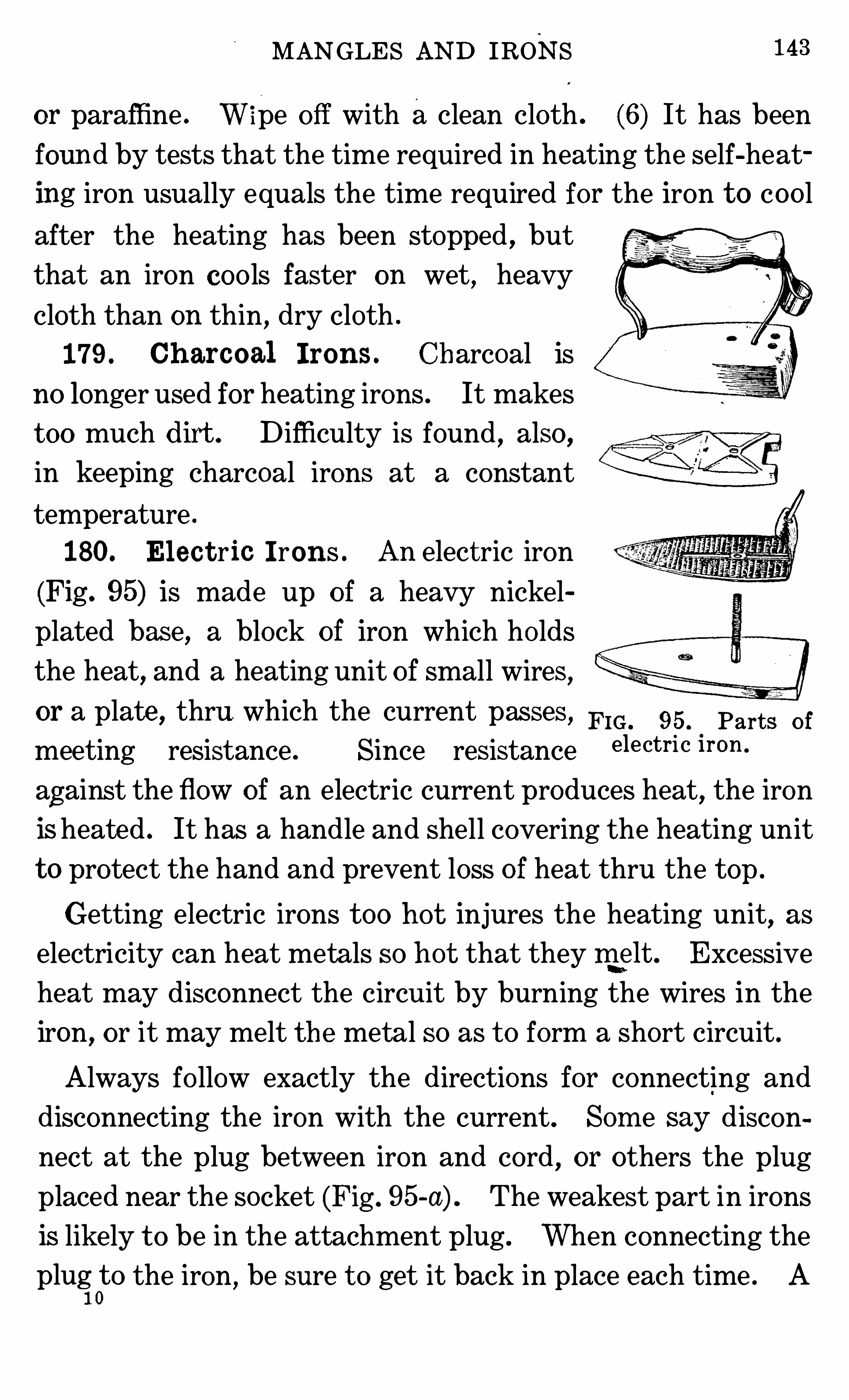
MANGLES AND IRONS 143
or paraffine . W ipe o ff with a clean cloth . (6) It has been
found by tests that the time required in heating the self-heat
ing iron usually equals the time required for the iron t o co o l
after the heating has been stopped , but
that an iron coo ls faster on wet, heavy
cloth than on thin , dry cloth .
179 . Ch arcoal I rons . Charcoal is
no longer used for heating irons . It makes
t oo much dirt . D ifficulty is found , also ,
in keeping charcoal irons at a constant
temperature .
180. El ec t ric I rons . An elect ric iron
(Fig . 95) is made up o f a heavy nickel
plated base, a block of iron which ho lds
the heat,and a heating unit o f small wires,
or a plate , thru which the current passes , FIG. 95. Parts o f
meeting resistance . Since resistance electri c iron
against the flow of an electric current produces heat, the iron
is heated . It has a handle and shell covering the heating unit
t o protect the hand and prevent loss o f heat thru the t op .
Getting electric irons t oo ho t injures the heating unit, as
electricity can heat metals so ho t that they ril elt . Excessive
heat may disconnect the circuit by burning the wires in the
iron, or it may melt the metal so as t o form a short circuit .
Always fo llow exactly the directions for connecting and
disconnecting the iron with the current . Som e say discon
neet at the plug between iron and cord , or others the plug
placed near the socket (Fig . 95-a) . The weakest part in irons
is likely t o be in the attachment plug . When connecting the
plug0t o the iron , be sure t o get it back in place each time . A
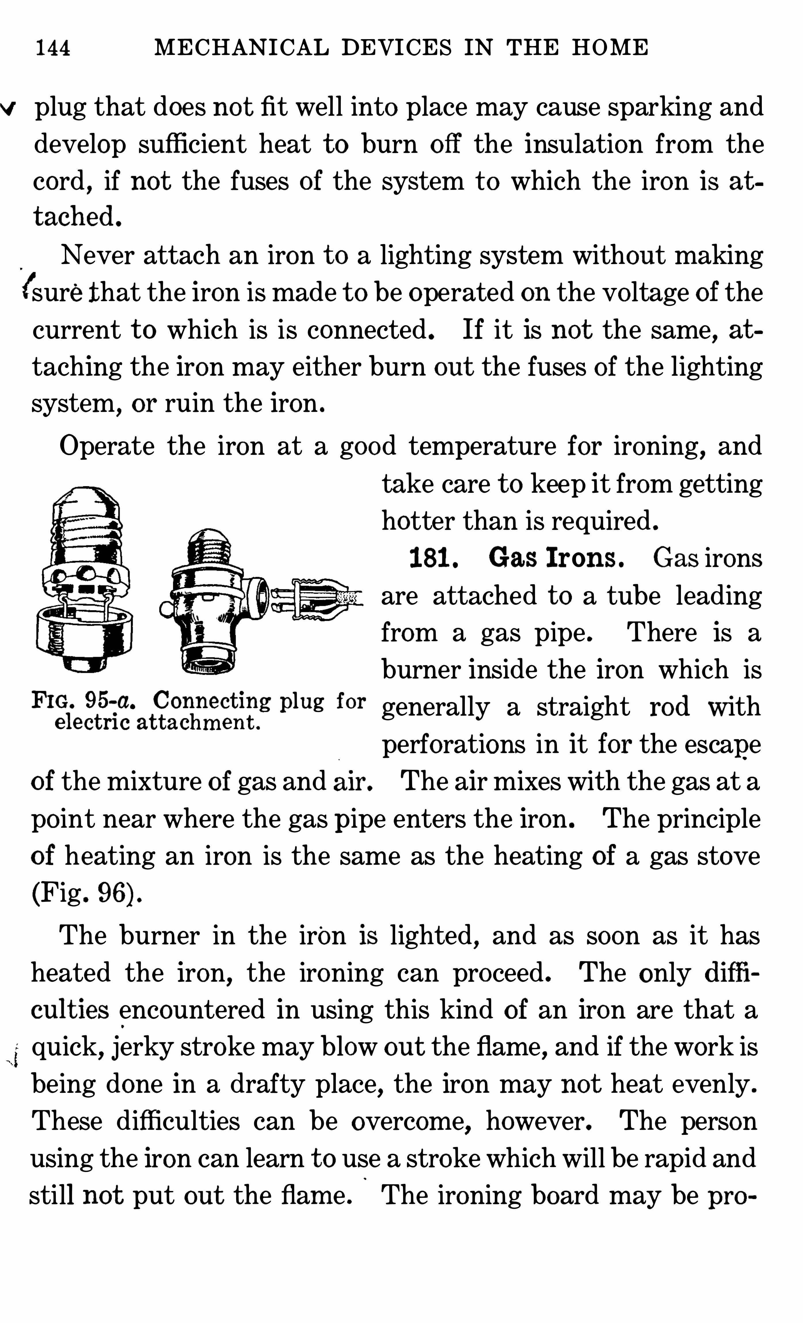
144 MECHANICAL DEVICES IN THE HOME
v plug that does no t fit well into place may cause sparking and
develop sufficient heat t o burn o ff the insulation from the
cord , if not the fuses of the system t o which the iron is at
tach ed .
Never attach an iron t o a lighting system without making
(sure that the iron is made t o be operated on the vo ltage of the
current t o which is is connected . If it is not the same, at
taching the iron may either burn out the fuses of the lighting
system, or ruin the iron .
Operate the iron at a good temperature for ironing, and
take care t o keep it from getting
hotter than is required .
181 . Gas Irons . Gas irons
are attached t o a tube leading
from a gas pipe . There is a
burner inside the iron which isFlgfecgfr
‘
ifiaggghn
n
‘
ifigg Plug for generally a straight rod with
perforations in it for the escape
o f the mixture o f gas and air. The air mixes with the gas at a
po int near where the gas pipe enters the iron . The principle
o f heating an iron is the same as the heating of a gas stove
(Fig .
The burner in the iron is lighted, and as soon as it has
heated the iron,the ironing can proceed . The only diffi
cult ies encountered in using this kind of an iron are that a
quick, jerky stroke may blow out the flame, and if the work is
being done in a drafty place, the iron may not heat evenly .
These difficulties can be overcome, however. The person
using the iron can learn t o use a stroke which will be rapid and
still not put out the flam e . The ironing board may be pro
146 MECHANICAL DEVICES IN THE HOME
Gasoline irons with the tank . attached are operated the
same as alcoho l irons . The danger in these irons comes
in the tanks becoming overheated . Alcoho l is used first t o
heat the generator because it will no t sm oke the iron . The
gaso line, when lighted , Should burn with a blue flam e .
The tank should be one which has been tested t o stand a
high gas pressure, as the gaso line in the tank may become
heated and vaporize . The gas so formed must not escape
into the room , where it might be ignited by a spark . If not
allowed t o escape, it exerts considerable pressure inside the
tank . If the pressure becomes t oo great, it will break the
tank,escape and ignite from the flam e In the iron . The open
ing for filling must always be kept closed when the iron is in
use .
QUESTIONS FOR PART VI
1 . Explain the construction o f various types of washing m achines .
What are the advantages o f each !2 . What care should a ro ller wringer receive !3 . How does a centrifugal wringer dry clo thes !4 . How does a m angle d iffer from a wringer !5 . What is the diff erence in care that should be given t o a plain flatiron and an electric iron !
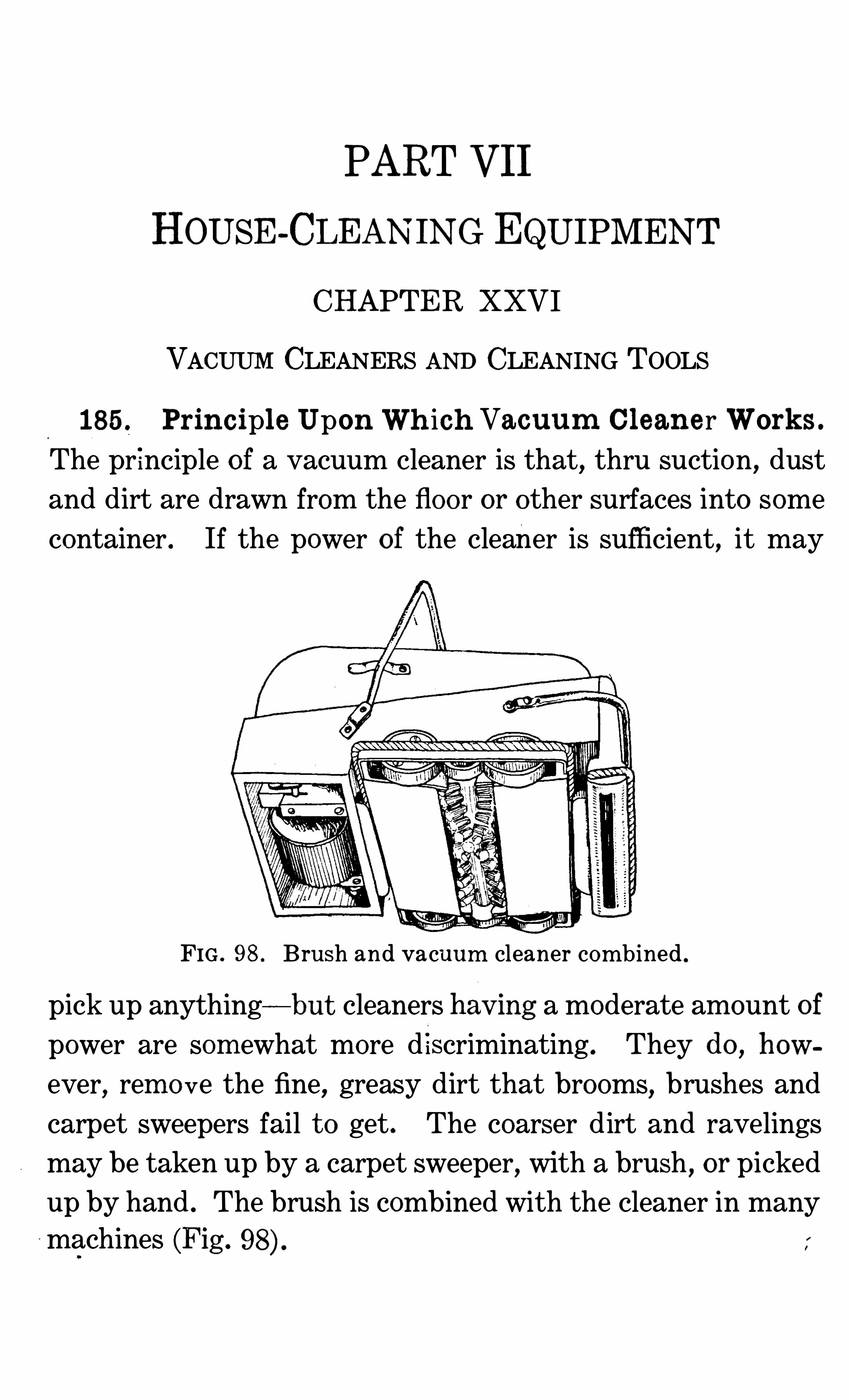
PART VII
HOUSE-CLEANING EQUIPMENT
CHAPTER XXVI
VACUUM CLEANERS AND CLEANING TOOLS
185 . Principl e Upon Wh ich Vacuum Clean e r Work s .
The pr inciple of a vacuum cleaner is that, thru suction, dust
and dirt are drawn from the floor or other surfaces into some
container . If the power o f the cleaner is sufficient, it may
FIG . 98 . Brush and vacuum cleaner com bined .
pick up anything—but cleaners hav m g a moderate am ount of
power are som ewhat more d iscriminating . They do , how
ever, rem o ve the fine, greasy dirt that brooms, brushes and
carpet sweepers fail t o get . The coarser dirt and ravelings
may be taken up by a carpet sweeper,with a brush
, or picked
up by hand . The brush is combined with the cleaner in many
machines (Fig .
148 MECHANICAL DEVICES IN'
THE HOME
186 . D iff eren t Kinds of Vacuum Cleaners . There are
cleaners with bellows, pumps or fans t o draw in air and dirt .
The ones with bellows in them work on the principle o f a bel
lows which is reversed so that when the air is drawn in,it
brings the dirt with it . The other kind works with a fan
which draws or sucks air from the floor thru a nozzle into the
machine . In the machine, the dust is filtered out of the air
and co llected in a pan .
The machines with fans in them are mostly power ma
chines,as the fan must revo lve very rapidly. The hand ma
chines are mostly o f the pump and bellows types . Som e are
combined with the carpet sweeper, making two machines in
one . With this device once go ing over the floor is sufficient
for removing both coarse and fine dirt . The hand machines
do no t have as much power of suction as the power machines,but they do very satisfactory work . They are more effective
than a carpet sweeper in remo ving dirt , but they do not get as
much of it as the stationary cleaner . Removing the sharp
grit from rugs and carpets lengthens the life of them so that
the more grit a cleaner can remove without tearing the carpet,
the more valuable it is .
When the pump type is being used , the piston is drawn up,drawing with it air and the dirt which is present at the po int
from which the air comes . Acloth filters out the dust. The
air escapes from the machine be fore the piston is lowered t o
draw in more air and dirt . If this were not true, the dust
would be forced back as the piston was lowered .
187 No zzle of Vacuum Cleaner . The nozzle, or po int
of entry o f air into the machine, is an important part of a
vacuum cleaner . This is constructed so that it fits the sur
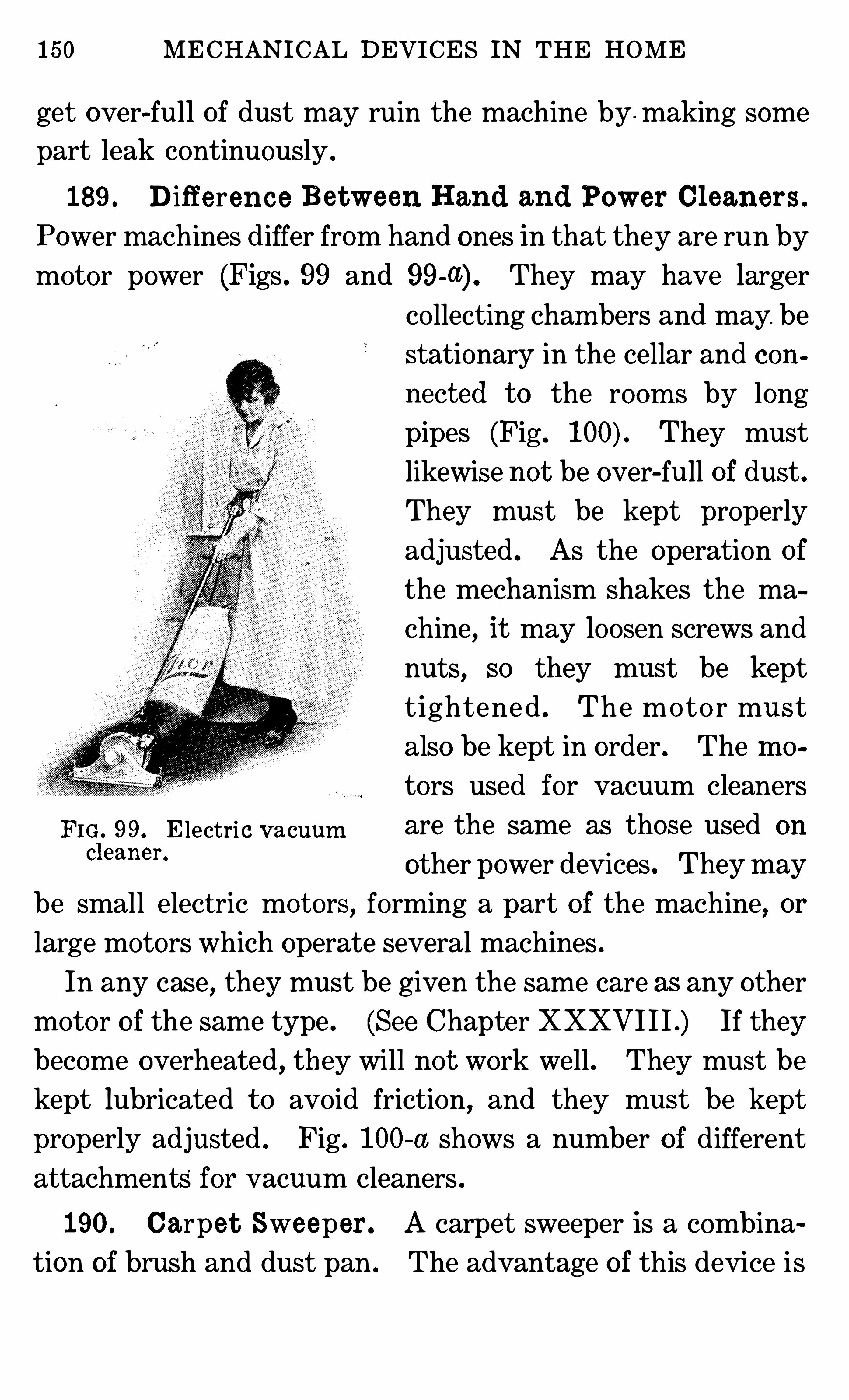
150 MECHANICAL DEVICES IN THE HOME
get over-full of dust may ruin the machine by . making some
part leak continuously .
189 . D ifferen c e Between Hand and Power Cl eaners .
Power machines differ from hand ones in that they are run by
motor power (Figs . 99 and They may have larger
co llecting cham bers and may. be
stationary in the cellar and con
nect ed t o the room s by long
pipes (Fig . They must
likewise not be over-full o f dust .
They must be kept properly
adjusted . As the operation of
the mechanism shakes the ma
chine, it may loosen screws and
nuts, so they mus t be kept
t ightened . The mo to r must
also be kept in order . The m o
tors used for vacuum cleaners
FIG . 99, E lectric v acuum are the same as those used on
d eaner ‘other power devices. They may
be small elect ric mo t ors, forming a part o f the machine, or
large motors which operate several machines .
In any case, they must be given the same care as any other
moto r o f the same type . (See Chapter XXXVI I I .) If they
become overheated , they will not work well . They must be
kept lubricated t o avo id friction, and they must be keptproperly adjusted . Fig . 100-a shows a num ber of different
at tachm ents for vacuum cleaners .
190. Carpe t Sweeper . A carpet sweeper is a combina
tion of brush and dust pan . The advantage of this device i s
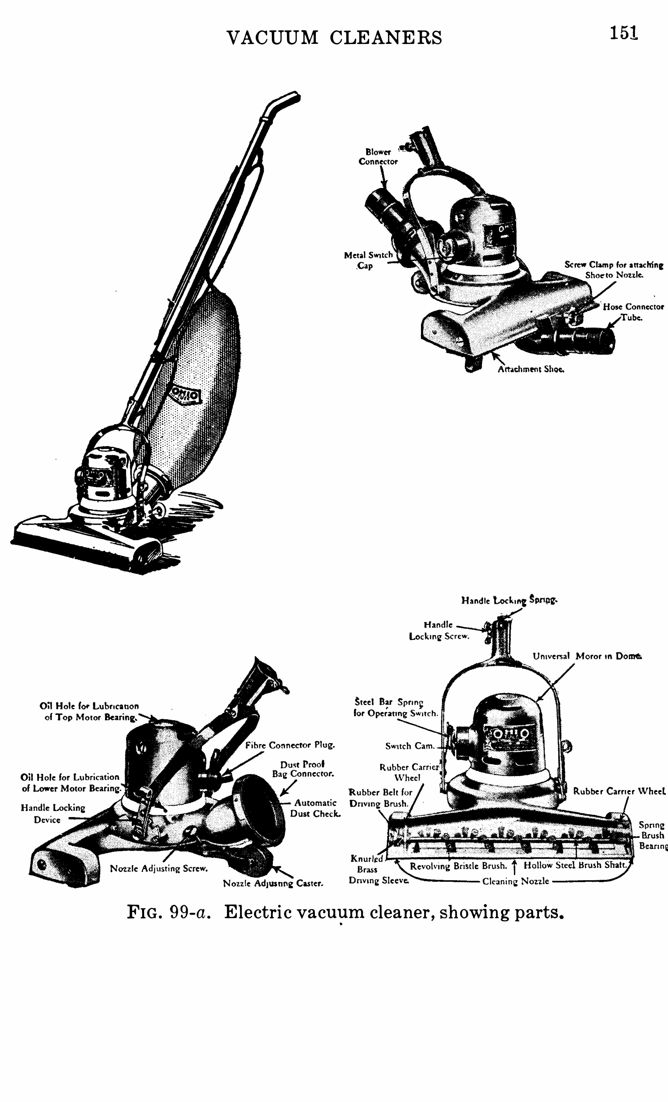
VACUUM CLEANERS
M etal SwiSc rew C lam p fo r attac hing
Hand le Lockueg Smog.
Univ ersal M o ror m Dome;
O il Hole for Lubrication Steel Bar Sprungo f To p Mo tor fo r O perating Swnc h
Rubbe r Carrie r W heel.Check.
Nozz le Adjusting Ca ter.
FIG . 99-a . E lectri c vacuum cleaner , showing parts.
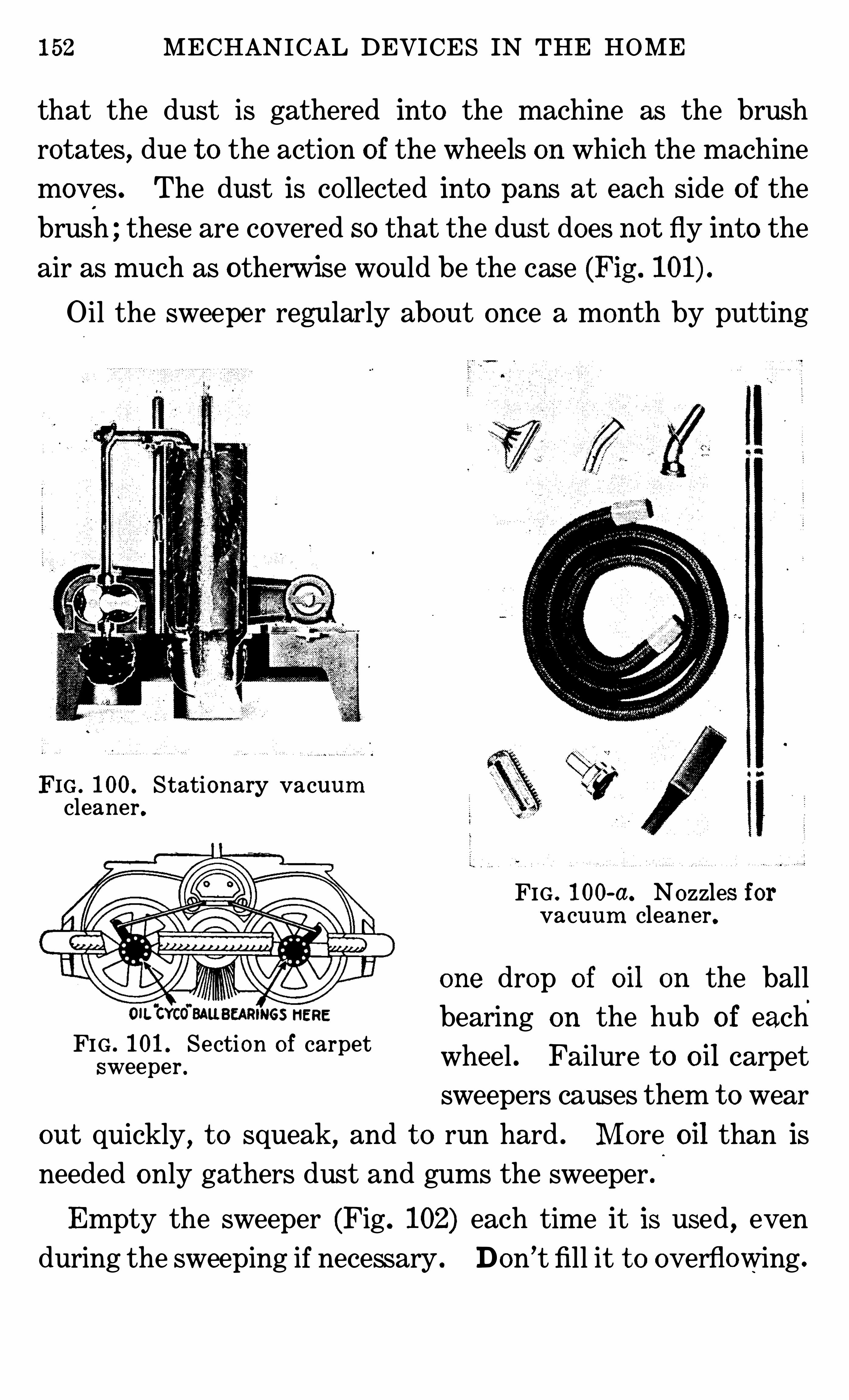
152 MECHAN ICAL DEVICES IN THE HOME
that the dust is gathered into the machine as the brush
rotates, due t o the action o f the wheels on which the machine
moves . The dust is co llected into pans at each side o f the
brush ; these are covered so that the dust does not fly into the
air as much as otherwise would be the case (Fig .
O il the sweeper regularly about once a month by putting
FIG . 100. Stationary vacuumcleaner.
FIG . 100-a. Nozzles forvacuum cleaner.
one drop of oil on the ball
bearing on the hub o f each
wheel . Failure t o oil carpet
sweepers causes them t o wear
out quickly, t o squeak, and t o run hard . M ore oil than is
needed only gathers dust and gums the sweeper .
FIG . 101 . Section o f carpetsweeper .
Empty the sweeper (Fig . 102) each time it is used , even
during the sweeping if necessary . Don ’t fill it t o overflowing .
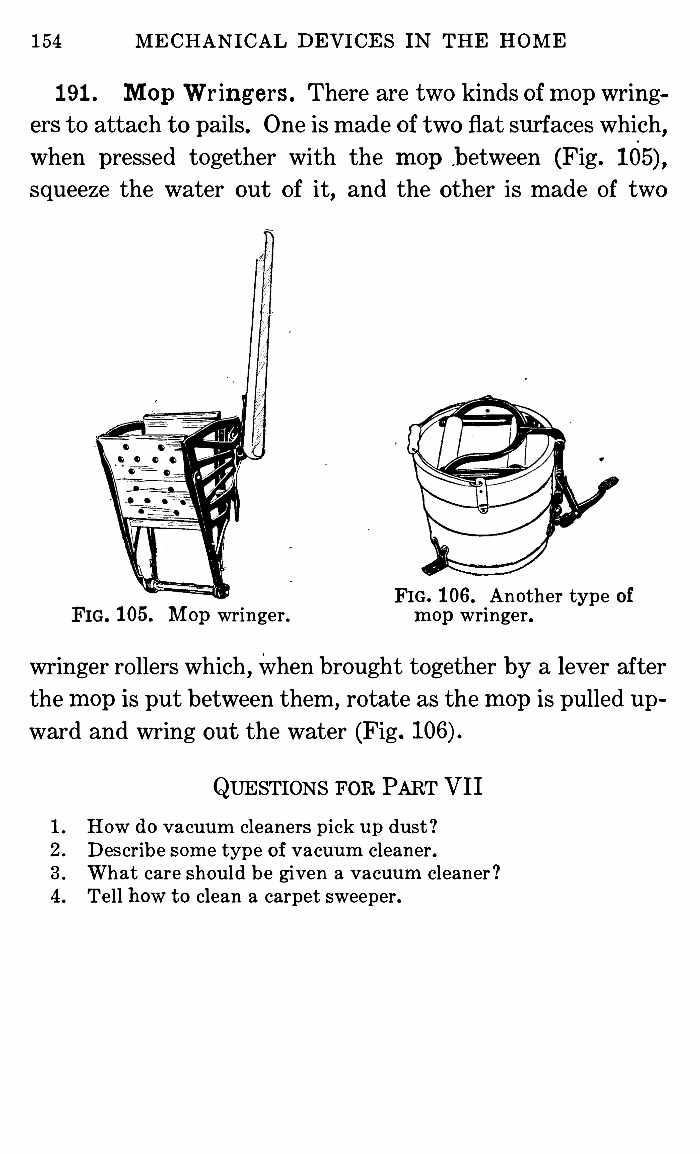
154 MECHANICAL DEVICES IN THE HOME
191 . M op Wr ing ers . There are two kinds o f m op wring
em t o attach t o pails. One is made of two flat surfaces which,
when pressed together with the m op b etween (Fig .
squeeze the water out of it, and the other is made of two
FIG . 106. Another type of105. M op wringer. m op wringer .
wringer ro llers which ,when brought together by a lever afterthe m op is put between them, rotate as the m op is pulled up
ward and wring out the water (Fig.
QUESTIONS FOR PART VII
1 . How do vacuum cleaners p ick up dust !2 . Describe som e type o f vacuum cleaner .3 . What care should be given a vacuum cleaner !4 . Tell how t o clean a carpet sweeper .
PART VIII
DEVICES FOR PREPARATION AND CON
SERVATION OF FOOD
CHAPTER XXVI I
POTS,PANS
, AND OTHER DEVICES
192 . Mat erials from Wh ich U t ens i lsAre Mad e . Since
there is considerable cho ice in utensils made from different
materials,the housekeeper may like t o know something about
these materials and about their care, and the effect o f acids
and alkalis upon them .
Russia iron is one of the o lder materials for pots and pans,and it still ho lds a place in cookery, for it makes bread , loafcake and cooky pans, which give t o the food a thin, brown
crust,due
, undoubtedly, t o the way in which it conducts
heat. (See tables on page
Tinned metal,which is well tem pered , also , gives a thin,
and pies. It makes good bread ,
M ost o f the cheap tin o f today is
oes good work, but
utensils kept as well po lished and as attractive re heavily-tinned ones .
Sheet iron make the most popular frying pans. ho lding heat as it does,
makes a desirable brown coating on most foods without the
danger of burning pans of other
156 MECHANICAL DEVICES IN THE HOME
materials . This is due t o specific heat and conductivity o f
the metal . Sheet-iron frying pans are useful in cooking foods
which are wanted on Short notice . The small-sized ones are
most in use .
193 . Alum inum Al loy. Satisfactory frying pans are
made from aluminum alloyed with other metal and cast.
Real aluminum frying pans warp. They do not brown the
food as well as materials that conduct heat less rapidly .
194 . Cast -I ron U t ensils . Heavy cast iron finds special
favor in the making of po t roasts, bread sticks and popovers.JIt browns the roast and makes a thick crust on bread sticks
and popovers .All iron o r tin utensils give better service as they become
tempered with use . They must be kept dry in order t o pre
vent rust. Do not use them for cooking acid foods .
Granite, cast aluminum and Russia iron are the popular
and satisfactory materials for roasting pans .
195 . Eart h enware . For cassero les and bean pot s, earth
enware is a favorite material, tho heavy glass gives equally
good results . These materials are fitted for long, slow baking
of food . They ho ld heat and conduct it t o the food in such a
way as t o produce results which are difficult t o duplicate witho f other materials .
Alum inum and Granit eware . Stew pans are
sat isfactory when made o f aluminum and o f high
grade graniteware . An assortment of pans and double bo il
ers containing utensils o f each material gives the best results,
as the granite is most desirable for cooking some acid and very
salt!! food , while aluminum is light and satisfactory for pre
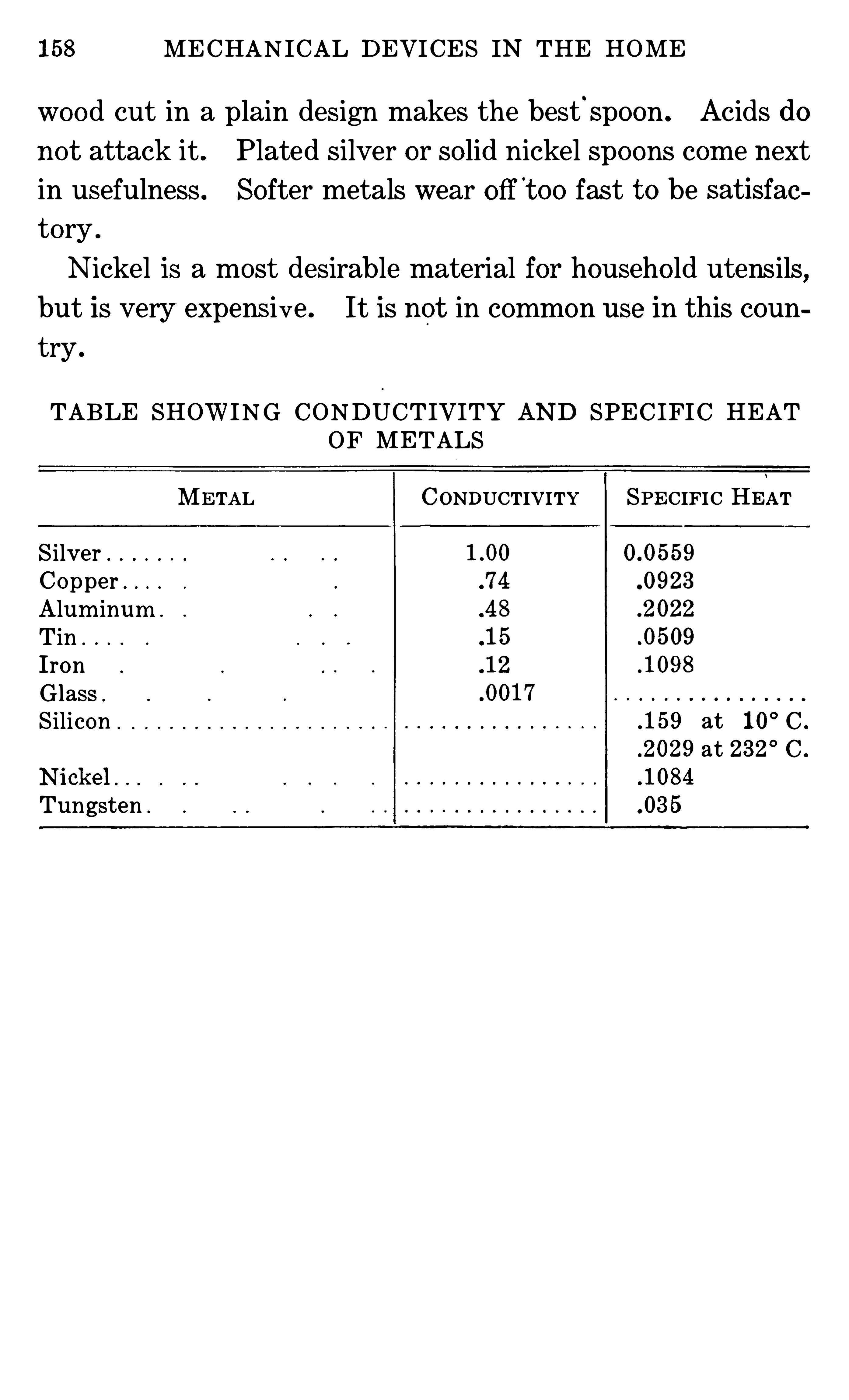
158 MECHANICAL DEVICES IN THE HOME
wood cut in a plain design makes the best.
spoon . Acids do
no t attack it . Plated silver or so lid nickel spoons com e next
in usefulness . Softer metals wear o ff t oo fast t o be satisfac
to ry .
Nickel is a most desirable material for househo ld utensils,
but is very expens ive . It is not in common use in this coun
try .
TABLE SHOWING CONDUCT IVITY AND SPEC IFIC HEATOF METALS
METAL CONDUCTIVITY SPECIFIC HEAT
S ilverCopper .
Alum inum .
T in .
IronGlassSilicon
Tungsten .
.159 at 10° C .
.2029 at 232° C .
.1084
.035
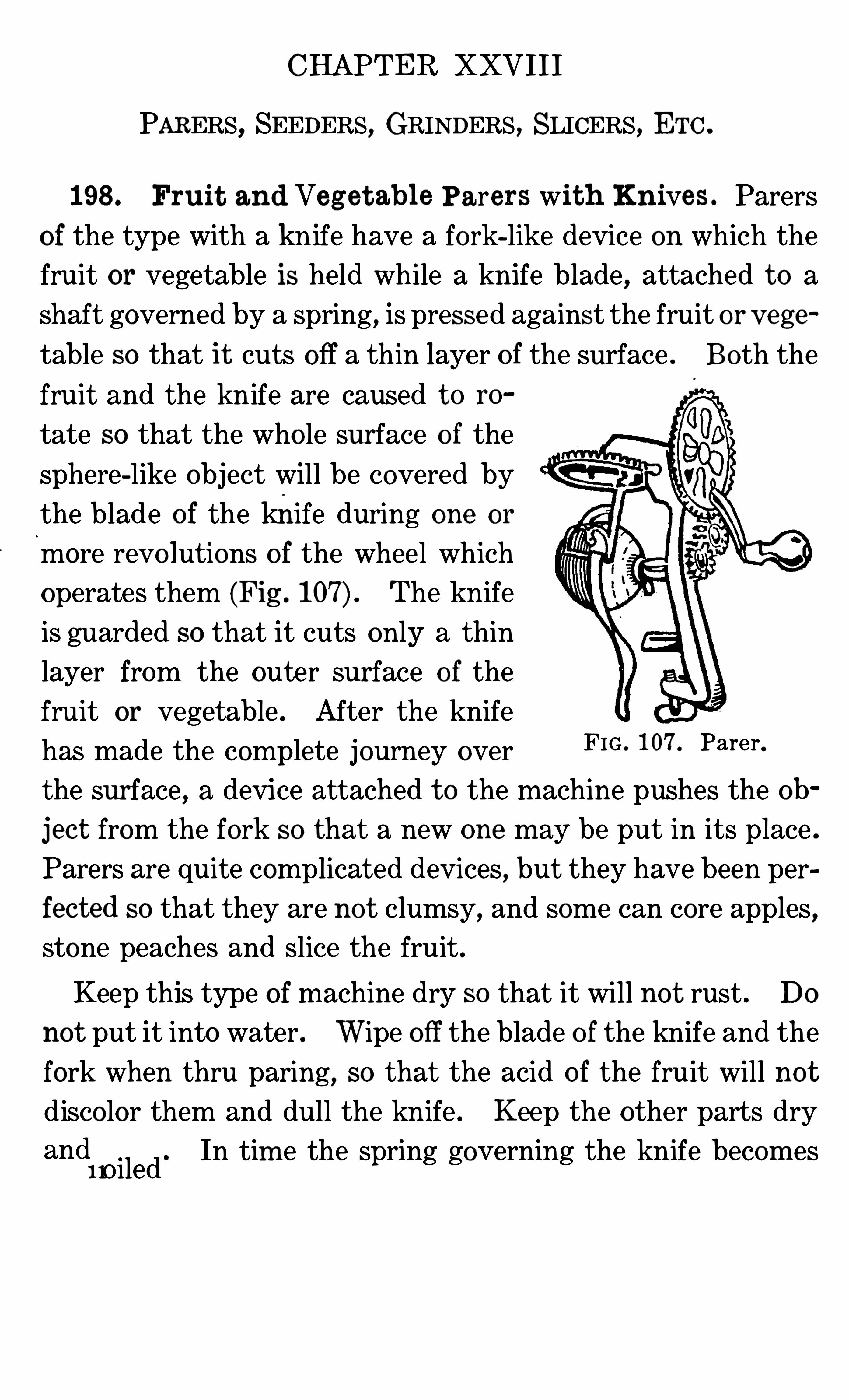
CHAPTER XXVI I I
PARERS, SEEDERS, GRINDERS, SLICERS, ETC .
198 . Fruit and Veg e t abl e Parers wit h Knives . Parers
of the type with a knife have a fork-like device on which the
fruit or vegetable is held while a knife blade , attached t o a
shaft governed by a spring, is pressed against the fruit or v ege
table so that it cuts off a thin layer o f the surface . Both the
fruit and the knife are caused t o ro
tate so that the who le surface o f the
sphere-like object will be covered by
the blade o f the knife during one or
more revo lutions o f the wheel which
operates them (Fig . The knife
is guarded so that it cuts only a thin
layer from the outer surface of the
fruit or vegetable . After the knife
has made the complete journey over
the surface , a device attached t o the machine pushes the ob
jec t from the fork so that a new one may be put in its place .
Parers are quite complicated devices , but they have been per
fected so that they are no t clumsy, and some can core apples,
stone peaches and slice the fruit .
FIG . 107 Parer .
Keep this type of machine dry so that it will no t rust . Do
not put it into water. Wipe o ff the blade o f the knife and the
fork when thru paring, so that the acid o f the fruit will not
disco lor them and dull the knife . Keep the other parts dry
and11Oiled
. In tim e the spring governing the knife becom es
160 MECHANICAL DEVICES IN THE HOME
weak and the machine will no t do good work. This spring
can be replaced on some machines. Parers are usually made
o f cheap material so that a new machine costs less than
the repairs .
199 . Parers Wh ich Grat e O ff Sk ins . Another type o f
parer is a grater-like device . This is used in larger establish
ments than the ordinary
home , but is useful where
there is much canning
o f hard fruits or vegetables
t o be done at home . It
consists of a co ntainer,
FIG . 108 . Cherry stoner. FIG . 109. Grinder .
the inside of which is rough like a grater. The vegetables
or apples are put into the container with water enough t o
float and separate them, and the who le is agitated so that
the.
vegetables com ing against the Sides have the outer
surface removed or grated o ff. The water acts as the
medium for moving the vegetables and for rem o ving the bits
o f skin from the Sides of the parer
Keep this parer clean by scrubbing the inside with a stiff
brush and rinsing well with water after using. Keep in a dry
place .
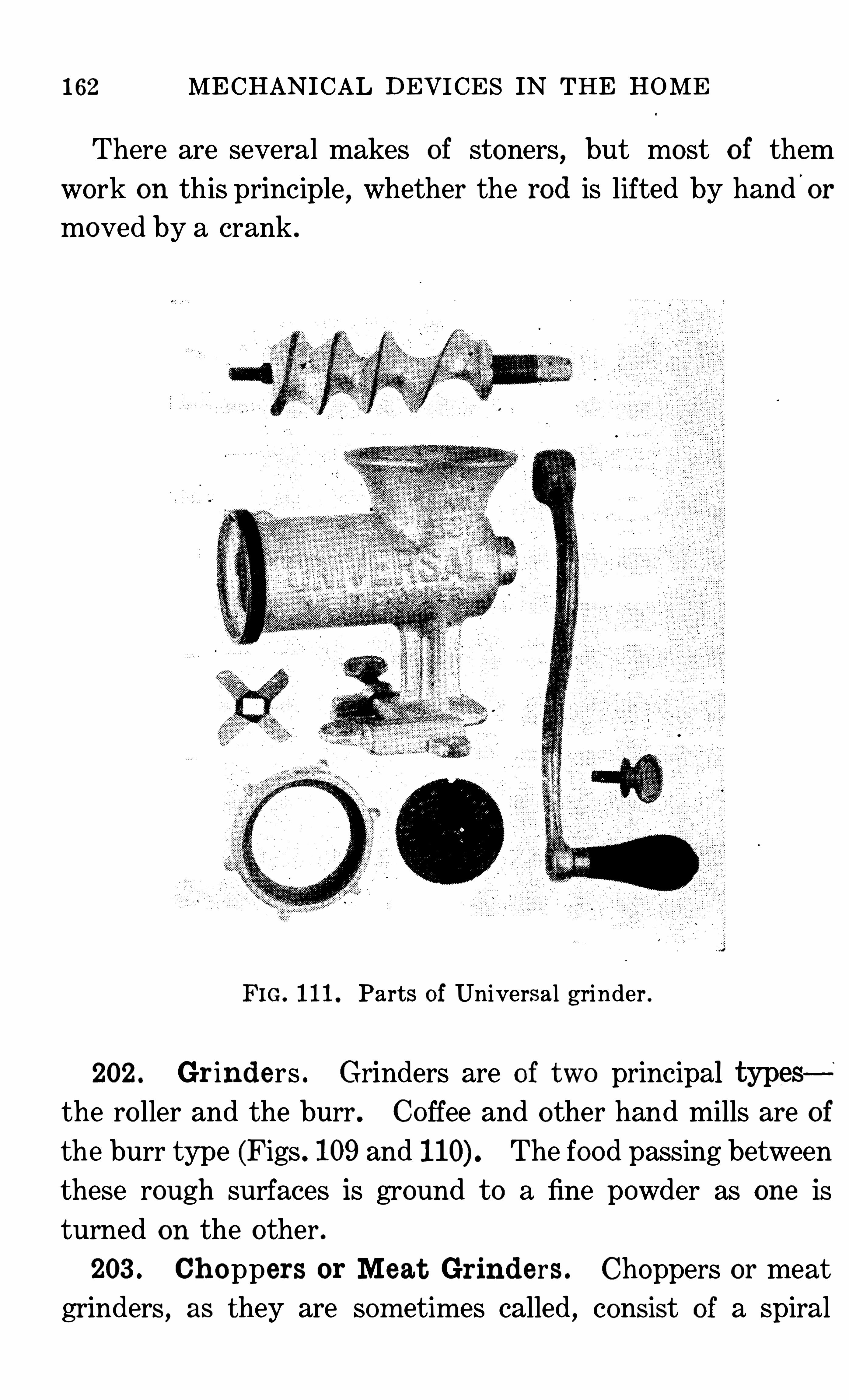
162 MECHANICAL DEVICES IN THE HOME
There are several makes of stoners, but most o f them
work on this principle, whether the rod is lifted by hand or
moved by a crank .
FIG. 111 . Parts of Universal grinder .
202 . Gr ind ers . Grinders are of t wo principalthe ro ller and the burr . Coffee and other hand mills are of
the burr type (Figs . 109 and The food passing between
these rough surfaces is ground t o a fine powder as one is
turned on the other .
203 . Ch oppers or Meat Grinders . Choppers or meat
grinders , as they are som etim es called, consist of a Spiral
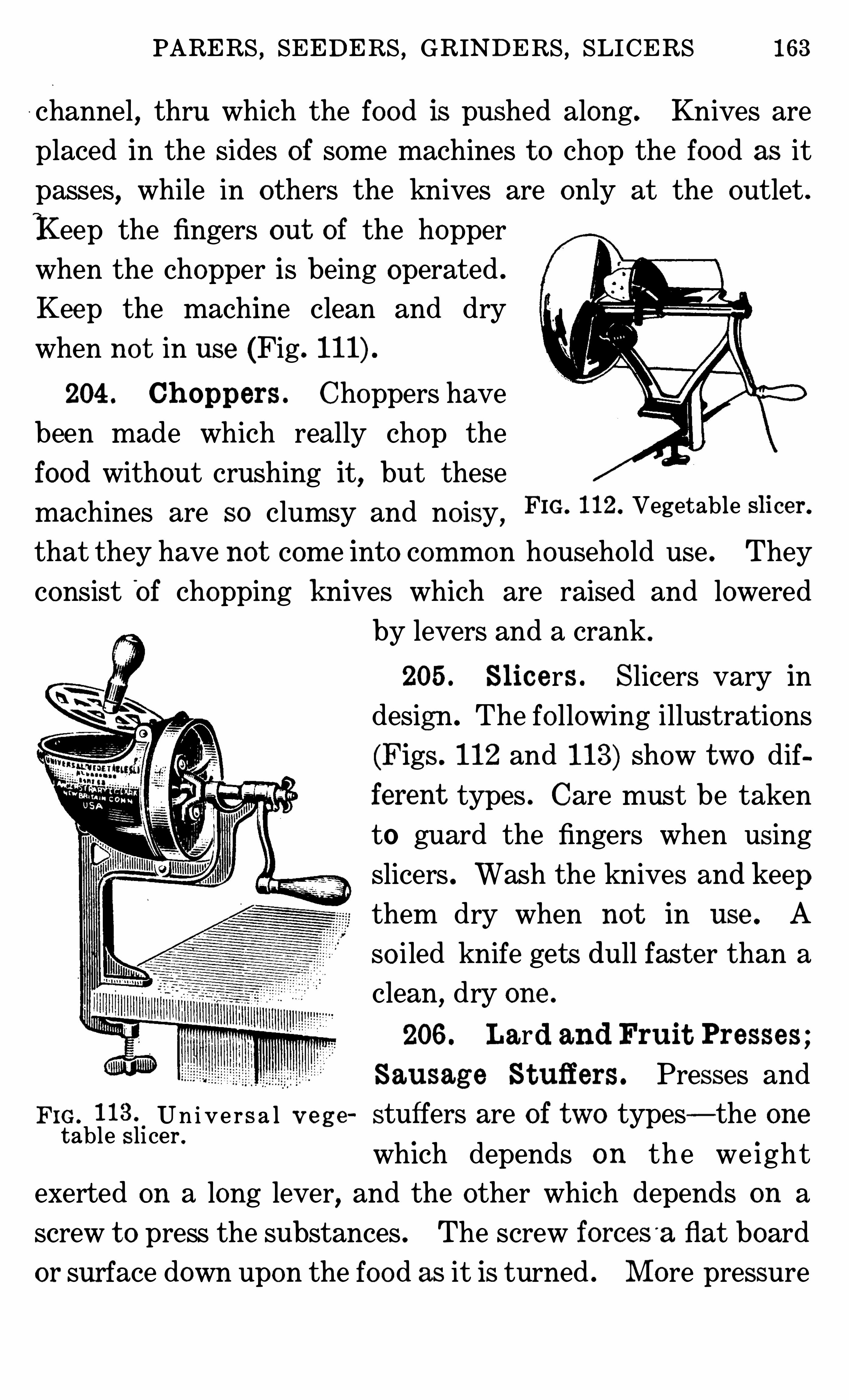
PARERS , SEEDERS , GRINDERS , SLICERS 163
channel, thru which the food is pushed along. Knives are
placed in the Sides of some machines t o chop the food as it
passes,while in others the knives are only at the outlet .
Keep the fingers out of the hopper
when the chopper is being operated .
Keep the machine clean and dry
when no t in use (Fig.
204 . Ch oppers . Choppers have
been made which really chop the
food without crushing it, but these
machines are so clumsy and no isy, FIG 112 Vegetable Slicefi
that they have no t come into common househo ld use . They
consist'
of chopping knives which are raised and lowered
by levers and a crank .
205 . Slic ers . Slicers vary in
design . The fo llowing illustrations
(Figs . 112 and 113) Show two dif
ferent types . Care must be taken
to guard the fingers when using
Slicers . Wash the knives and keepthem dry when no t in use . A
so iled knife gets dull faster than a
clean,dry one .
206 . Lard and Fruit Presses ;
Sausag e St uffers. Presses and
FIG . Un i ve r s a l v e g e stuffers are of two types—the onetable s licer .
which depends on th e we ight
exerted on a long lever,and the other which depends on a
screw t o press the substances . The screw forceS '
a flat board
or surface down upon the food as it is turned . M ore pressure
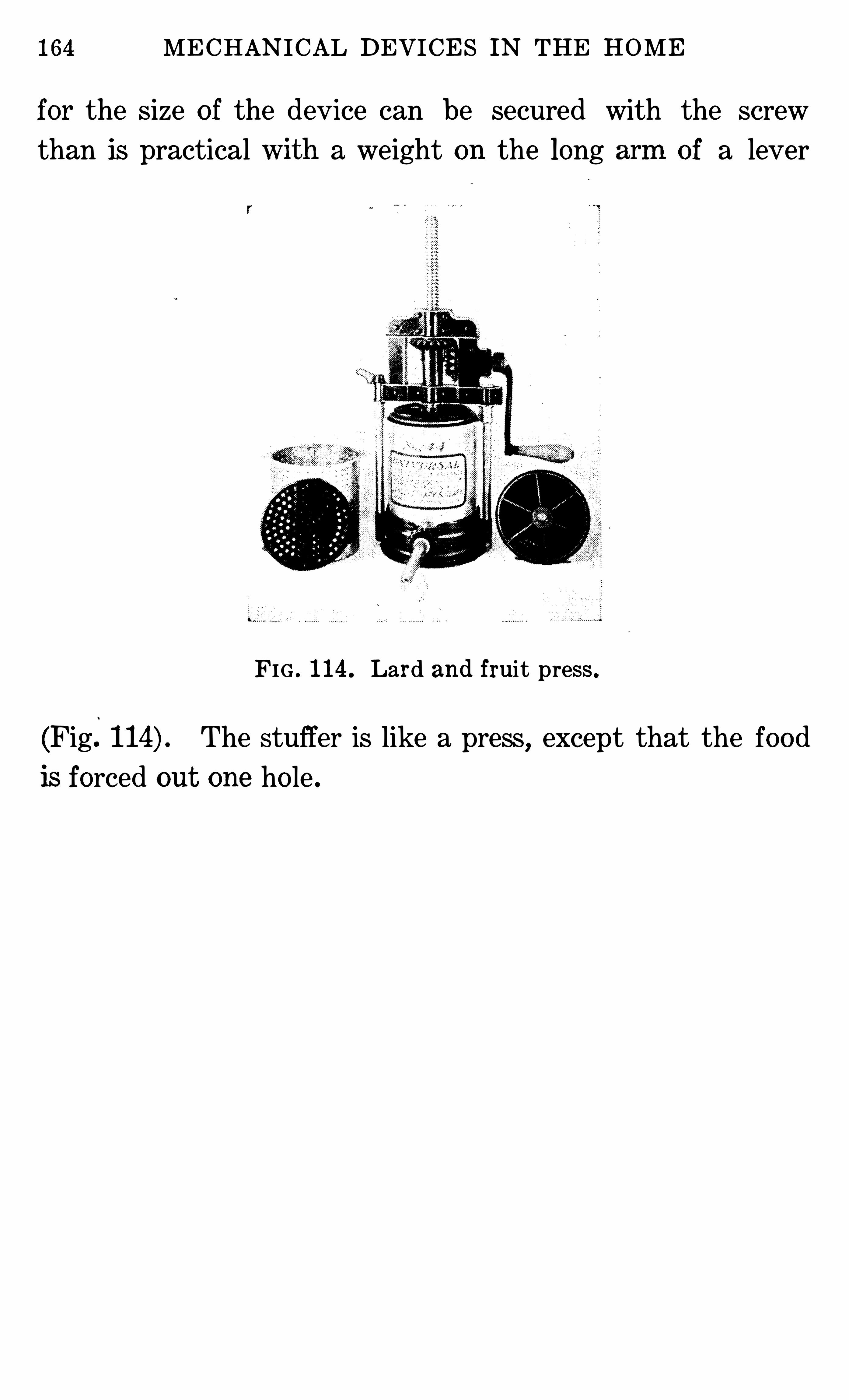
164 MECHANICAL DEVICES IN THE HOME
for the Size of the device can be secured with the screw
than is practical a weight on the long of a lever
FIG . 114 . Lard and fruit press .
(Fig. The stuffer is like a press,except that the food
is forced out one ho le .
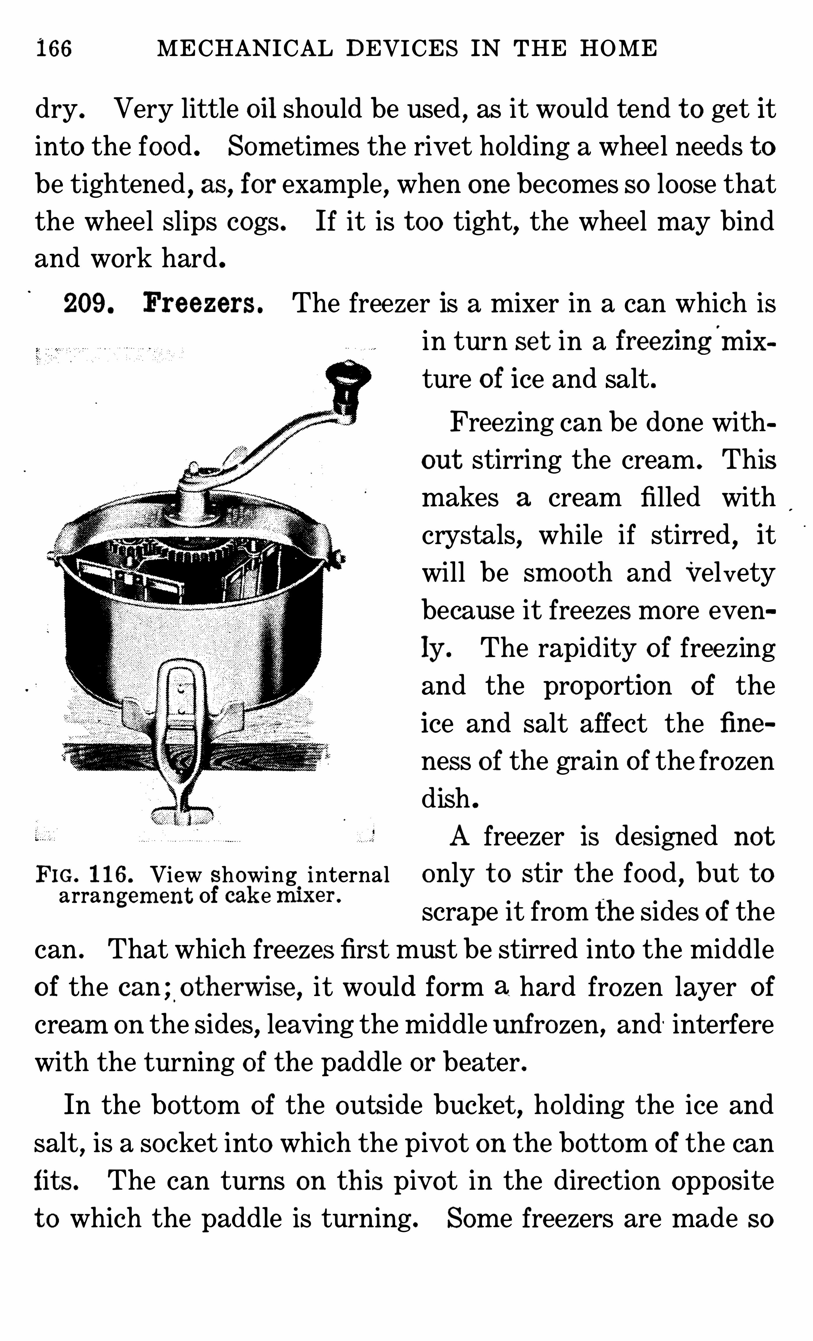
166 MECHANICAL DEVICES IN THE HOME
dry . Very little oil should be used , as it would tend t o get it
into the food . Sometimes the rivet ho lding a wheel needs t o
be tightened , as, for example , when one becomes so loose that
the wheel slips cogs . If it is t oo tight,the wheel may bind
and work hard .
209. Freezers . The freezer is a mixer in a can which is
in turn se t in a freezing'
m ix
ture of ice and salt .
Freezing can be done with
out stirring the cream . This
makes a cream filled with
crystals, while if stirred , it
will be sm ooth and Velvety
because it freezes more even
ly . The rapidity o f freezing
and the proportion o f the
ice and salt affect the fine
ness o f the grain of the frozen
dish .
A freezer is designed not
FIG. 1 16. View showing.
internal only t o stir the food,but t o
arrangem ent Of cak e m en
scrape it from the sides o f the
can . That which freezes first must be stirred into the middle
o f the can ;.
o therwise , it would form a hard frozen layer o f
cream on the sides,leaving the middle unf rozen, and
' interfere
with the turning of the paddle or beater .
In the bottom of the outside bucket, ho lding the ice and
salt,is a socket into which the pivot on the bottom of the can
fits . The can turns on th is pivot in the direction opposite
t o which the paddle is turning . Some freezers are made so
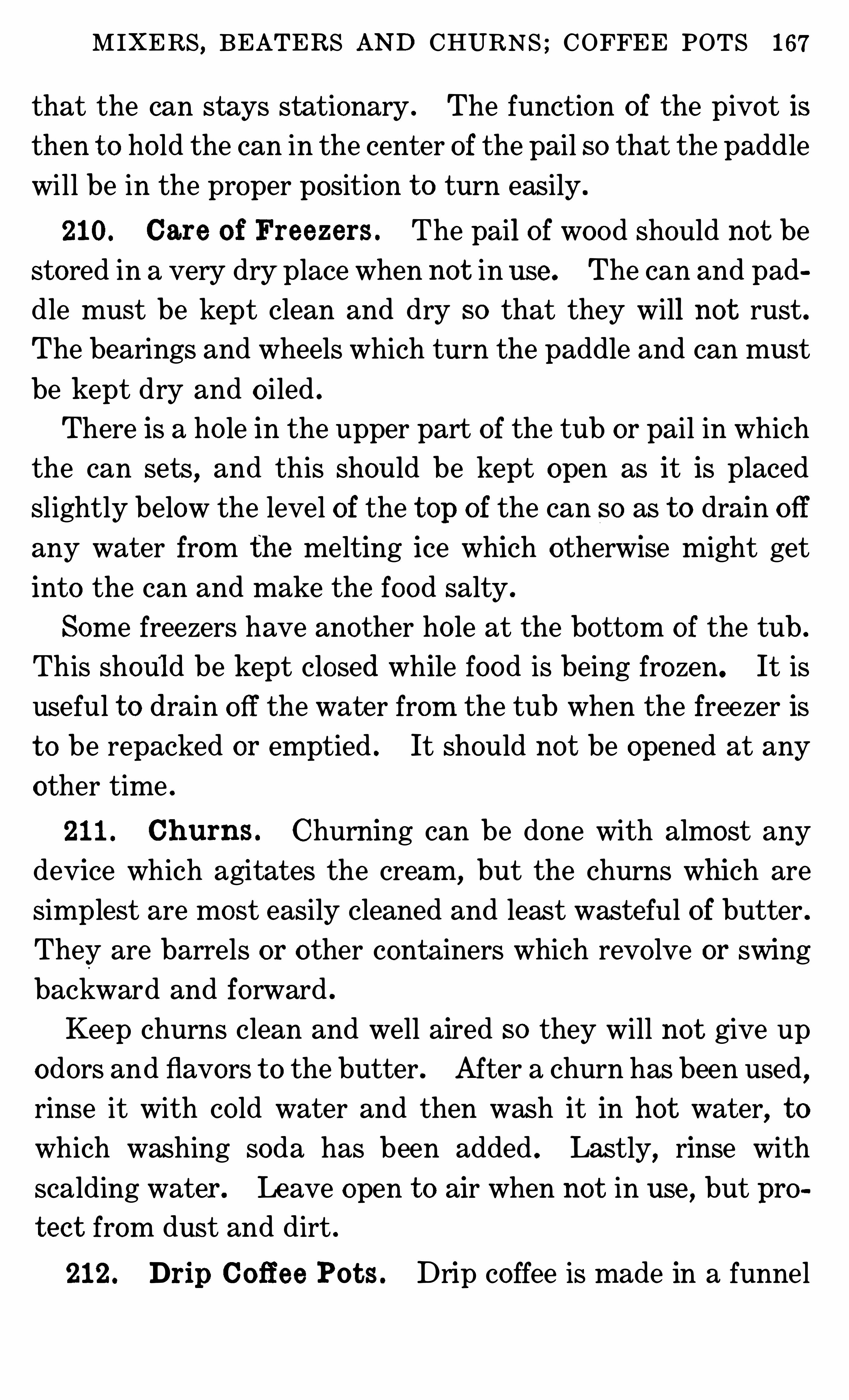
M IXERS , BEATERS AND CHURNS ; COFFEE POTS 167
that the can stays stationary . The function of the pivot is
then t o ho ld the can in the center of the pail so that the paddle
will be in the proper position t o turn easily .
210. Care o f Freezers . The pail o f wood should no t be
stored in a very dry place when not in use . The can and pad
dle must be kept clean and dry so that they will not rust.The bearings and wheels which turn the paddle and can must
be kept dry and o iled .
There is a ho le in the upper part of the tub or pail in which
the can sets,and this should be kept open as it is placed
slightly below the level of the t op of the can so as t o drain o ff
any water from the melting ice which otherwise might get
into the can and make the food salty .
Some freezers have another ho le at the bottom o f the tub .
This should be kept closed while food is being frozen. It is
useful t o drain off the water from the tub when the freezer is
t o be repacked or emptied . It should no t be opened at any
other time .
211 . Ch um s . Churning can be done with almost any
device which agitates the cream, but the churns which are
simplest are most easily cleaned and least wasteful of butter .
They are barrels or o ther containers which revo lve or swing
backward and fo rward .
Keep churns clean and well aired so they will no t give up
odors and flavors t o the butter . After a churn has been used,
rinse it with co ld water and then wash it in hot water, t o
which washing soda has been added . Lastly,rinse with
scalding water . Le ave open t o air when no t in use , but pro
t ec t from dust and dirt .
212 . Drip Co ff ee Pot s . Drip coffee is made in a funnel
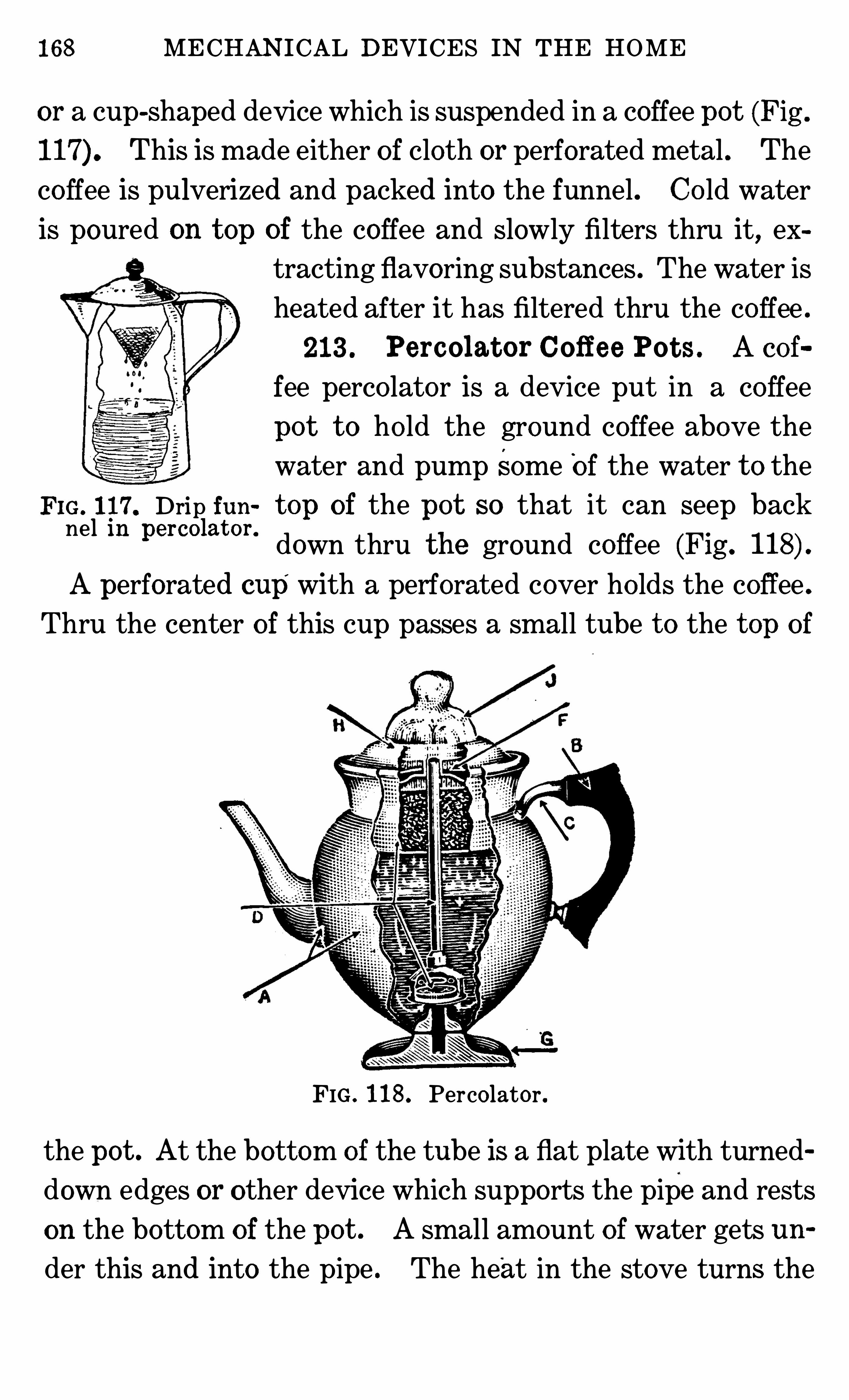
168 MECHANICAL DEVICES IN THE HOME
or a cup-shaped device which is suspended in a coffee pot (Fig .
This is made either o f cloth or perforated metal . The
coffee is pulverized and packed into the funnel . Co ld water
is poured on t op of the coffee and slowly filters thru it,ex
tracting flavoring substances . The water is
heated after it has filtered thru the co ffee .
213 . Percolat or Coff ee Pot s . A eof
fee perco lator is a device put in a co ffee
po t t o ho ld the ground coffee above the
water and pump Some Of the water t o the
FIG. 117. Drip fun t op of the pot so that it can seep backnel m percomt on down thru the ground coffee (Fig .
Aperforated cup with a perforated cover ho lds the coffee .
Thru the center of this cup passes a small tube t o the t op of
FIG . 118 . Percolator .
the pot . At the bottom of the tube is a flat plate with turned
down edges or other device which supports the pipe and rests
on the bottom of the pot . A small amount of water gets un
der this and into the pipe . The heat in the stove turns the
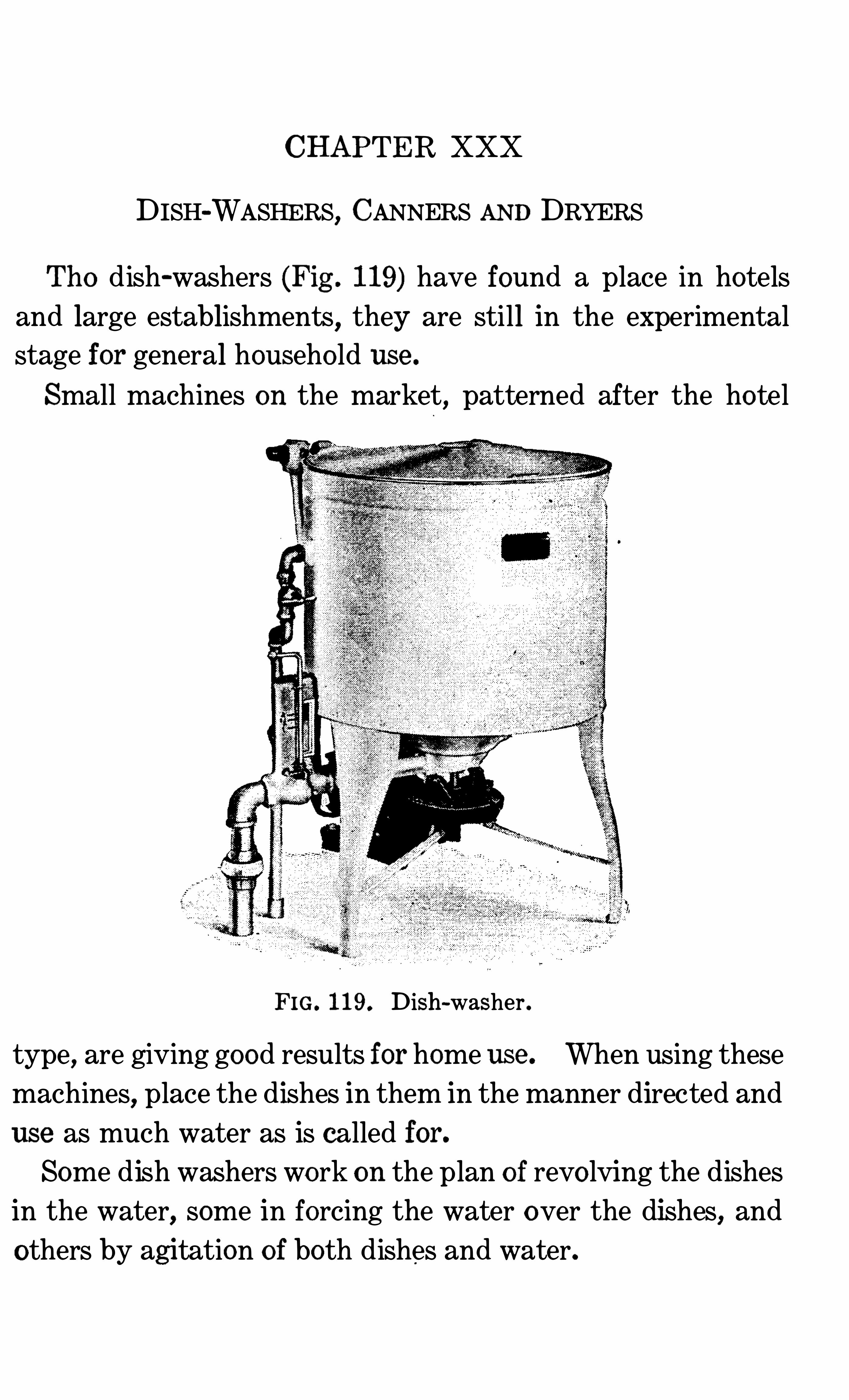
CHAPTER XXX
DISH-WASHERS, CANNERS AND DRYERS
Tho dish-washers (Fig . 119) have found a place in hotels
and large establishments, they are still in the experimentalstage for general househo ld use .
Small machines on the market,patterned after the hotel
FIG. 119. Dish-washer .
type,are giving good results for home use . When using these
machines,place the dishes in them in the manner directed and
use as much water as is called for.
Some d ish washers wo rk on the plan o f revo lving the dishes
in the water, some in forcing the water over the dishes, and
others by agitation of both dishes and water.
DISH-WASHERS , CANNERS AND DRYERS 71
Keep the pan washed clean . Keep all bearings properly
o iled . Have the machine dry when not in use . There is
least breakage in the washers which ho ld the dishes stationary (Figs . 119, -a,
-b and -c) .
One type o f dish-washer has
no motor ; the force of the run
ning water washes the dishes .
This can only be used where
the water supply is abundant
and under considerable pres
Sl l l‘
e The washers equipped FIG . 119-a . Sm all dish-washerwith paddles for throwing the f°r h°useh°1d use
water over the dishes use about a dishpanful o f '
water for
washing the dishes, and as much more for scalding and rinsing
them . When well scalded in thedish-washer, the. dishes will dry if
the cover t o the washer is left Open.
214 . Dish Dryer . There is
a number of dish dryers on the
market which ho ld the dishes separate from each other. Into these
dryers , bo iling hot water is poured,over the dishes. There is provision for the water being drained
away immediately, and the heatFIG. 119-b. Walker dish it imparts t o the dishes dries them .
washer.(Fig . 119
215 . Cl eaning Silv e r . Silver can be cleaned in an alu
minum pan filled with water and soda. There are silver
cleaners which are merely aluminum pans with which come
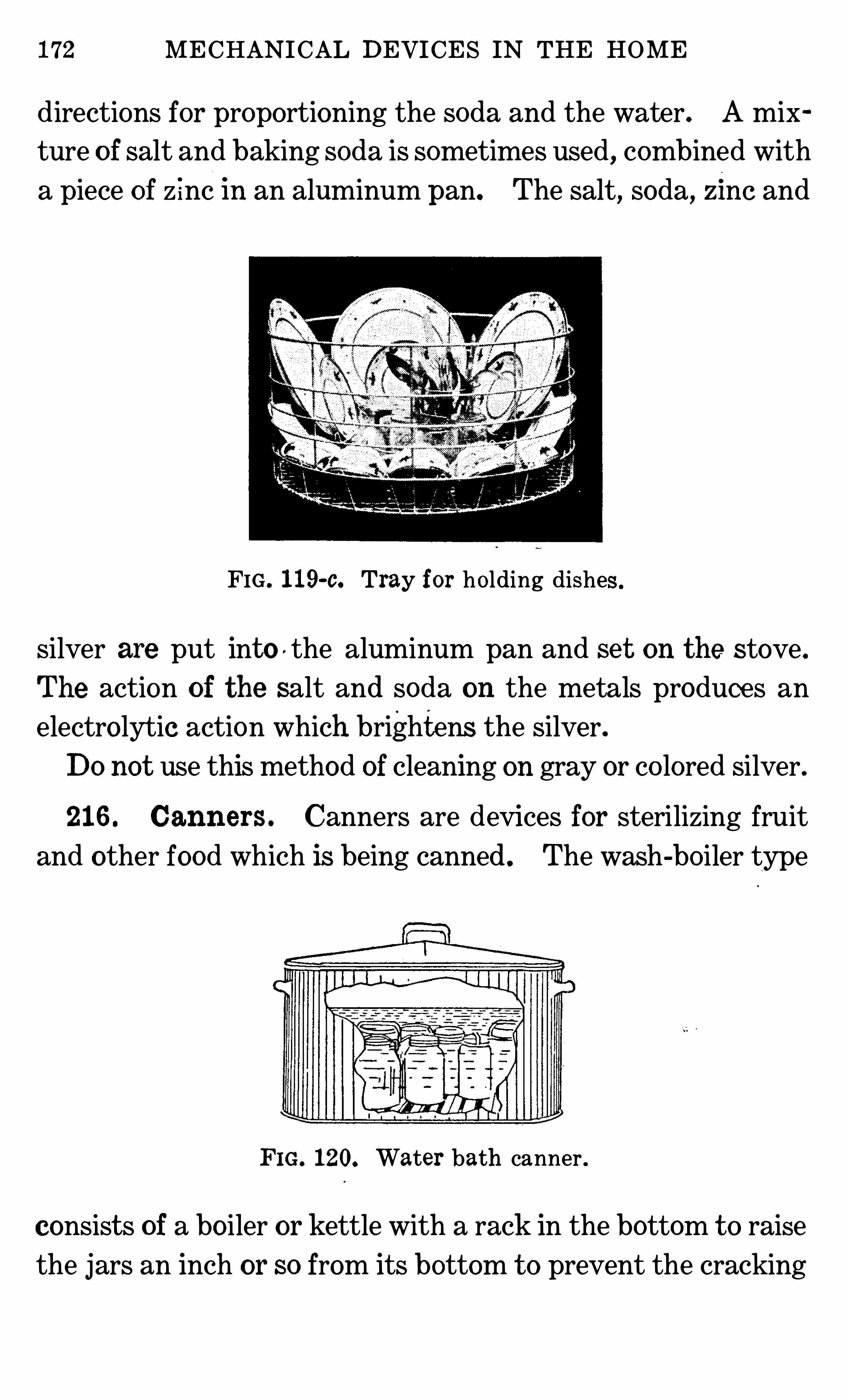
172 MECHANICAL DEVICES IN THE HOME
directions for proportioning the soda and the water. A mix
ture o f salt and baking soda is sometimes used,combined with
a piece of z inc in an aluminum pan. The salt, soda, zm c and
FIG . 119-c. Tray for holding dishes .
Silver are put into ' the aluminum pan and se t on the stove.
The action of the salt and soda on the metals produces anelectro lytic action which brightens the silver.Do not use this method of cleaning on gray or co lored silver.
216 . Canners . Canners are devices for sterilizing fruit
and other food which is being canned . The wash-bo iler type
FIG. 120. Water bath canner .
consist s of a bo iler or kettle with a rack in the bottom t o raise
the jars an inch or so from its bottom t o prevent the cracking
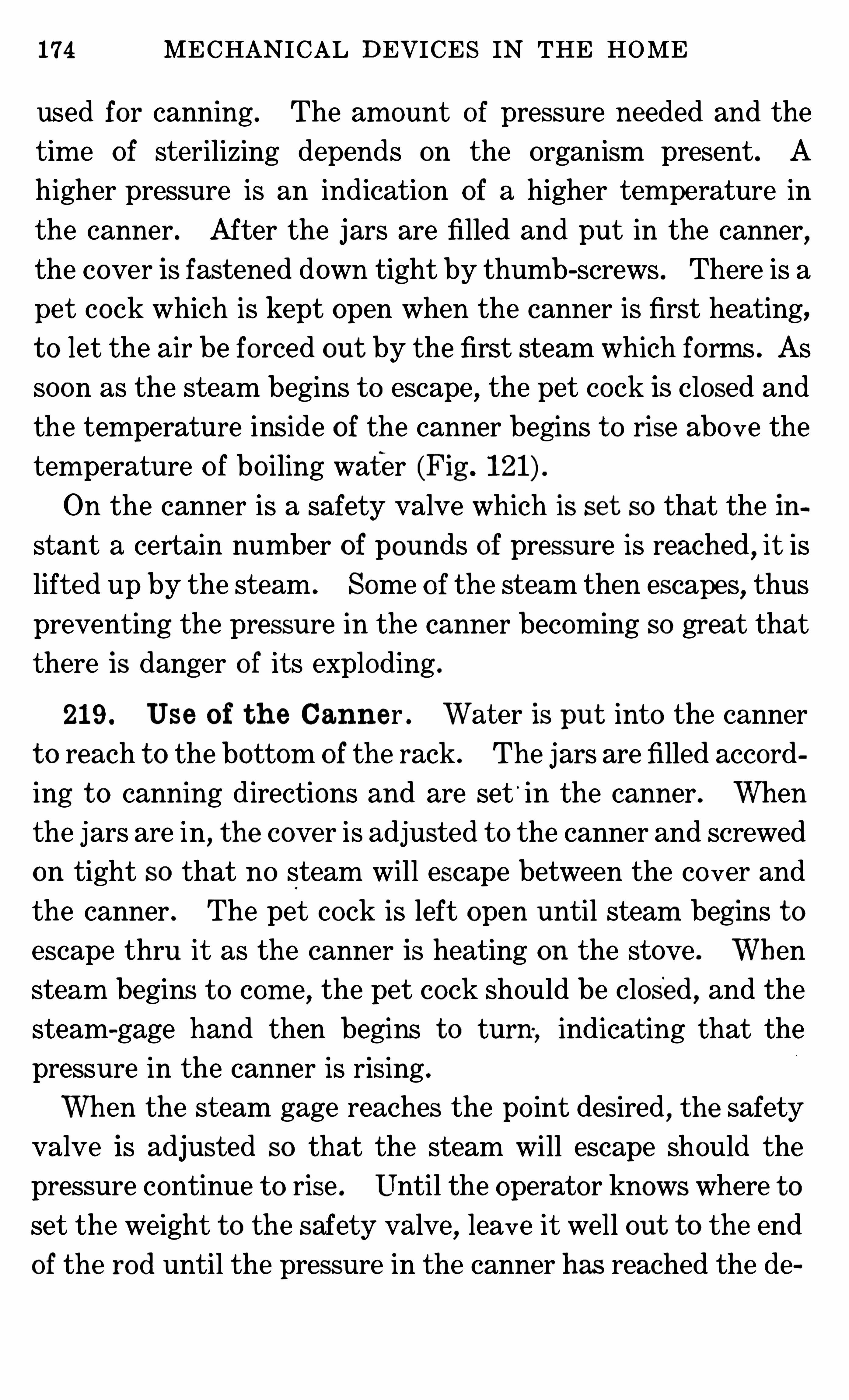
174 MECHANICAL DEVICES IN THE HOME
used for canning . The amount of pressure needed and the
time o f sterilizing depends on the organism present . A
higher pressure is an indication of a higher tem perature in
the canner . After the jars are filled and put in the canner,
the cover is fastened down tight by thumb-screws . There is a
pet cock which is kept open when the canner is first heating,
t o let the air be forced out by the first steam which forms . As
soon as the steam begins t o escape,the pet cock is closed and
the temperature inside o f the canner begins t o rise abo ve the
temperature o f bo iling water (Fig .
On the canner is a safety valve which is set so that the instant a certain number of pounds of pressure is reached
,it is
lifted up by the steam . Some o f the steam then escapes,thus
preventing the pressure in the canner becom ing so great that
there is danger o f its exploding .
219 . Use o f t h e Canner . Wat er is put into the canner
t o reach t o the bottom of the rack . The jars are filled accord
ing t o canning directions and are set‘
in the canner . When
the jars are in,t he cover is adjusted t o the canner and screwed
on tight so that no steam will escape between the co ver and
the canner . The pet cock is left open until steam begins t o
escape thru it as the canner is heating on the stove . When
steam begins t o com e,the pet cock should be closed
,and the
steam-gage hand then begins t o turn , indicating that the
pressure in the canner is rising .
When the steam gage reaches the po int desired , t he safety
valve is adjusted so that the steam will escape should the
pressure continue t o rise . Until the operator knows where t o
set the weight t o the safety valve,leave it well out t o the end
of the rod until the pressure in the canner has reached the de
D ISH-WASHERS,CANNERS AND DRYERS 175
sired po int .Then mo ve the weight t o the po int on the arm
o f the valve which will just keep in the st eam .
Be sure the cover is properly adjusted . Be sure t o exhaust
the air from the canner before closing the pet cock. Keep the
fire so that the desired pressure will be maintained without
the escape of steam
from the safetyvalve .
When steam escapes
from the canner thru
the pet cock at a
rapid rate,it may
cause liquid t o flow
out of the jars .
Be certain t o let
the canner coo l until
the indicator on the
s t e am g ag e h a s
reached zero before
opening the canner .
Wh en the indicator
po ints to zero , open
the pet cock . If a heavy stream o f steam starts t o escape
from it, close it again and wait a few minutes longer . Test
again by Opening the pet cock ; if a very little stream o f steam
escapes, leave the pet cock open and wait until steam has
stopped escaping from it . Now loosen the screws ho lding
the cover in place . Partially loosen each screw. When this
is done, fully loosen all and lift o ff the cover . These precau
tions are taken t o prevent the operato r from being burned
by1
s
z
t eam or gett ing hurt by the cover being lifted by the
FI G . 122 . Device for sealing tin can .
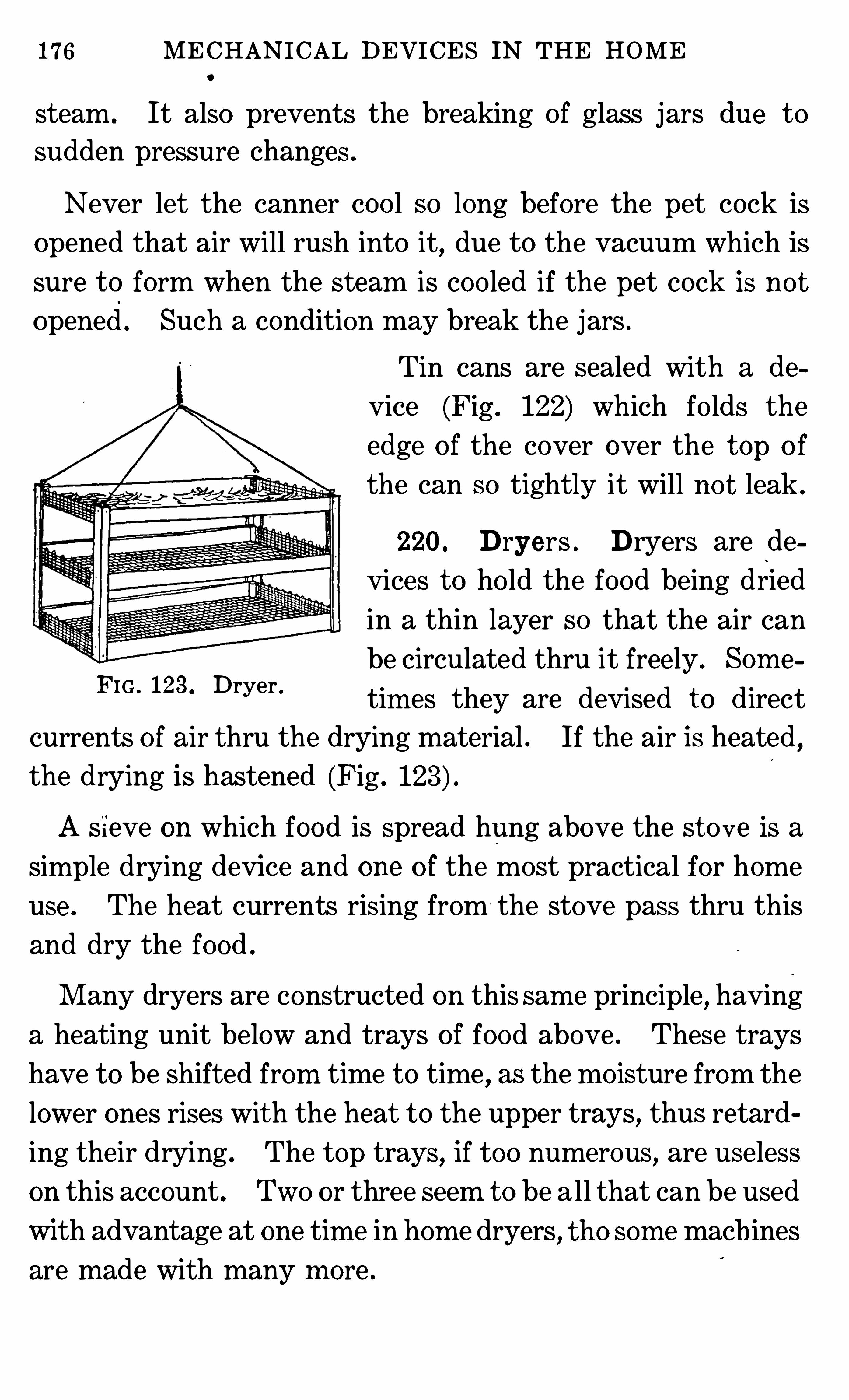
176 MECHANICAL DEVICES IN THE HOME
steam . It also prevents the breaking of glass jars due t o
sudden pressure changes .
Never let the canner coo l so long before the pet cock is
opened that air will rush into it,due t o the vacuum which is
sure t o form when the steam is coo led if the pet cock is no t
opened. Such a condition may break the jars .
Tin cans are sealed with a de
vice (Fig . 122) which fo lds the
edge o f the cover over the t op o f
the can so tightly it will no t leak .
220. Dryers . Dryers are de
vices t o ho ld the food being dried
in a thin layer so that the air can
be circulated thru it free ly . Som e
tim es they are devised t o direct
currents o f air thru the drying material . If the air is heated,
the drying is hastened (Fig .
FIG . 123. Dryer .
A S ieve on which food is spread hung above the st o ve is a
sim ple dry ing device and one o f the most practical for home
use . The heat currents rising from the stove pass thru this
and dry the food .
M any dryers are constructed on this sam e principle, having
a heating unit below and trays of food above . These trays
have t o be shifted from time t o time , as the mo isture from the
lower ones rises wit h the heat t o the upper trays, thus retard
ing their drying . The t op trays , if t oo numerous, are useless
on this account . Two or three seem t o be all that can be used
with advantage at one tim e in hom e dryers, t ho som e mach ines
are made with many m ore .
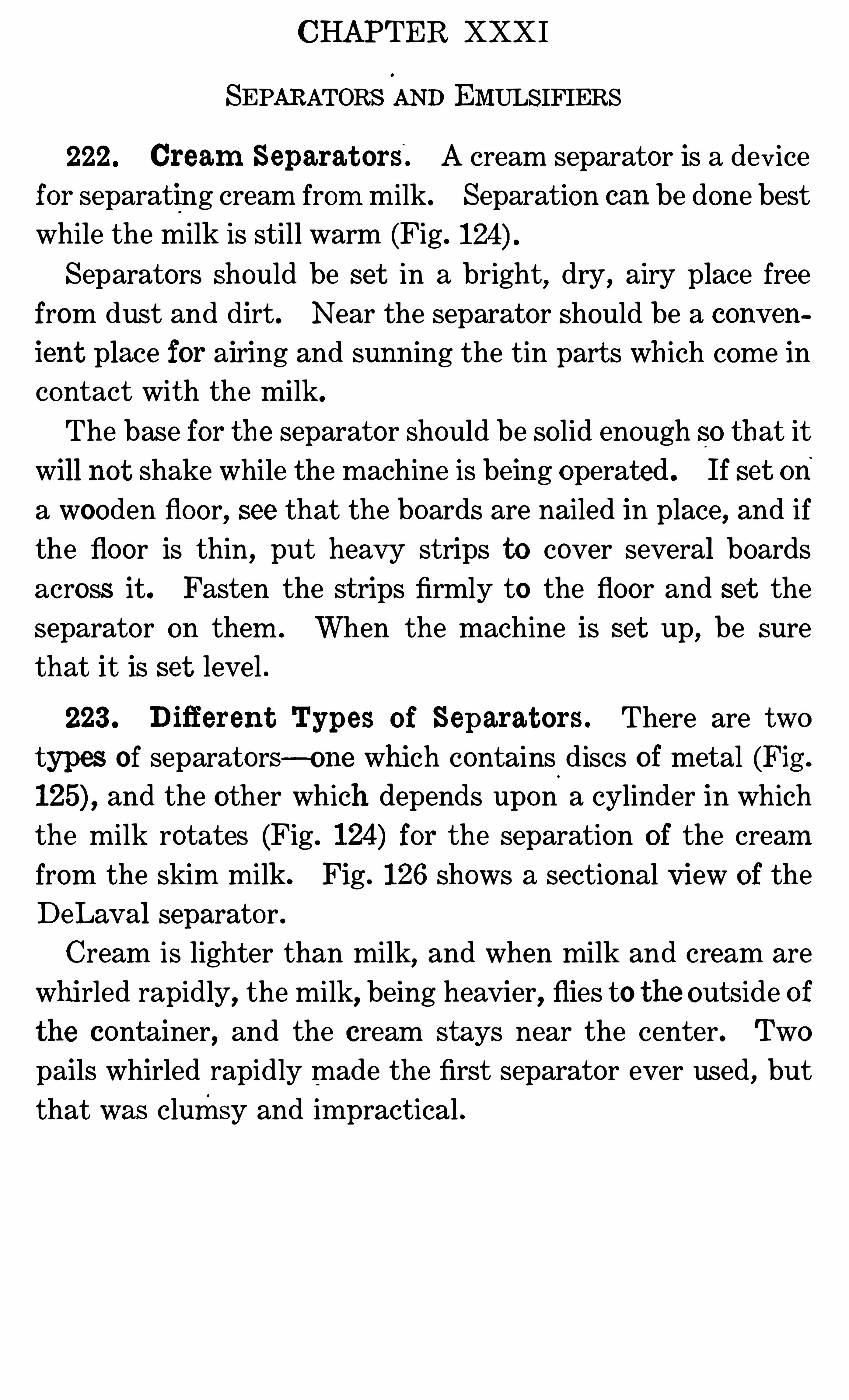
CHAPTER XXXI
SEPARATORS AND EMULSIFIERS
222. Cream Separat ors. A cream separator is a device
for separating cream from milk. Separation can be done best
while the milk is still warm (Fig.
Separators should be set in a bright,dry
,airy place free
from dust and dirt . Near the separator should be a conv en
ient place for airing and sunn ing the tin part s wh ich come incontact with the milk.
The base for the separator should be so lid enough so that it
will not shake while the machine is being operated . If set on
a wooden floor, see that the boards are nailed in place, and if
the floor is thin, put heavy strips to cover several boards
across it. Fasten the st rips firmly to the floor and set the
separato r on them . When the machine is set up, be sure
that it is set level .
223 . Difi erent Types o f Separat ors . There are two
types of separators—o ne which contains discs of metal (Fig .
and the other which depends upon a cylinder in whichthe milk rotates (Fig . 124) for the separation of the cream
from the skim milk. Fig . 126 shows a sectional View of the
DeLav al separator .
Cream is lighter than milk,and when milk and cream are
whirled rapidly, the milk, being heavier, flies to the outside o f
t he container, and the cream stays near the center. Two
pails whirled rapidly made the first separator ever used , but
that was clumsy and im practical .
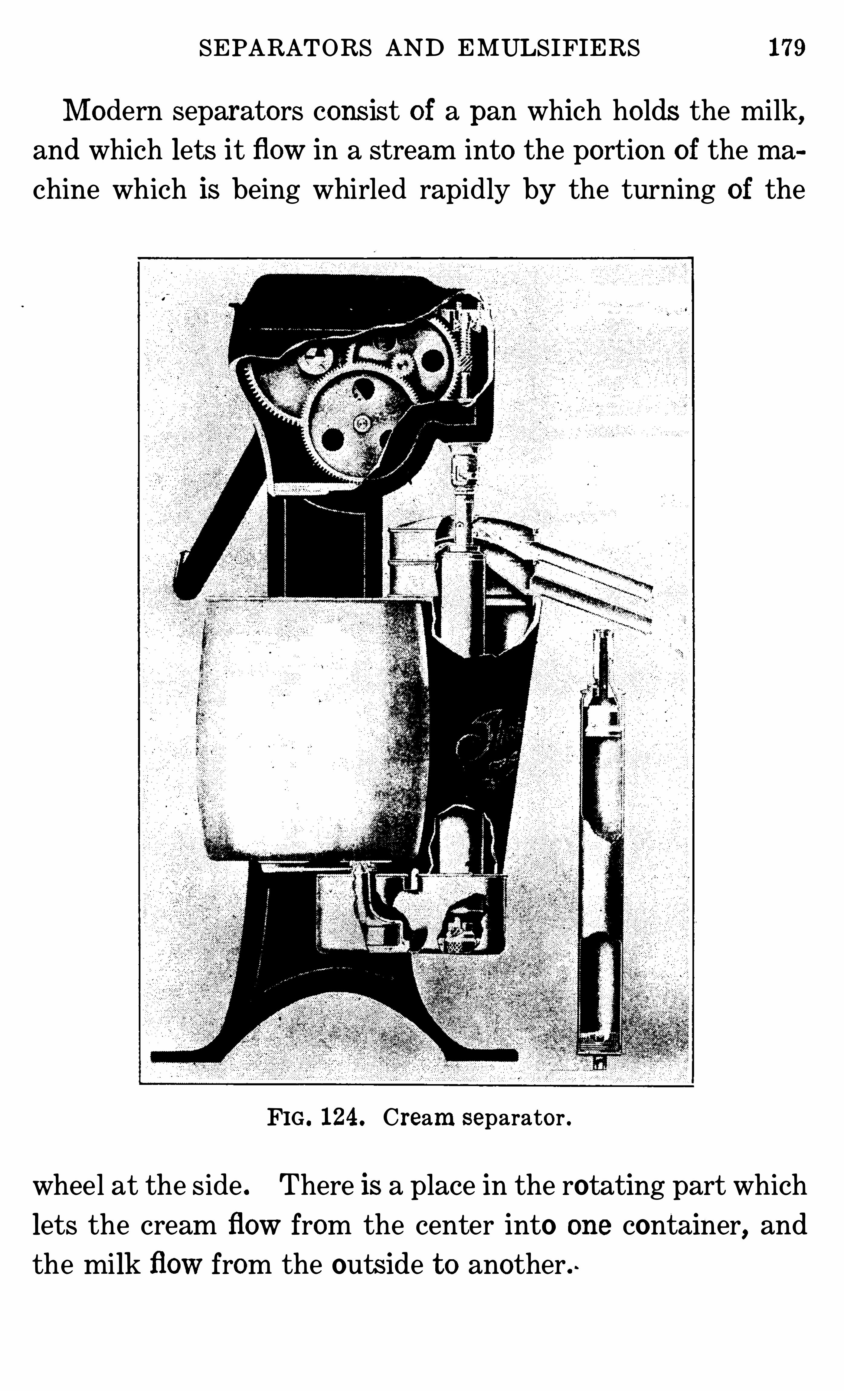
SEPARATORS AND EMULSIFIERS 179
M odern separators cons ist of a pan which ho lds the milk,and which lets it flow in a stream into the portion of the ma
chine which is being whirled rapidly by the turning of the
FIG . 124. Cream separator .
wheel at the side . There is a place in the rotating part which
lets the cream flow from the center into one container, and
the milk flow from the outside t o another . ~
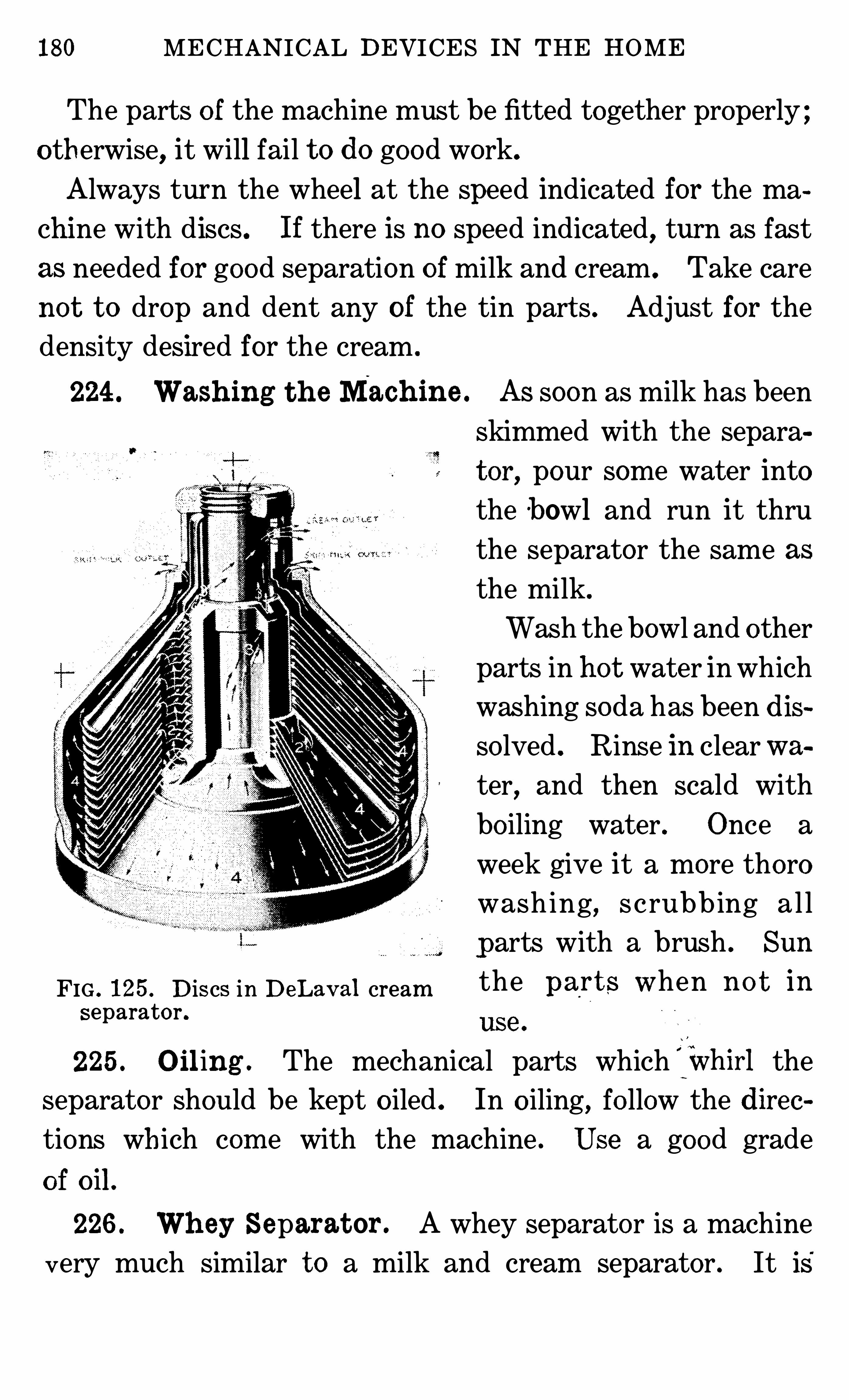
180 MECHANICAL DEVICES IN THE HOME
The parts o f the machine must be fitted together properly ;o therwise, it will fail t o do good work.
Always turn the wheel at the speed indicated for the machine with discs . If there is no speed indicated
,turn as fast
as needed for good separation o f milk and cream . Take care
no t t o drop and dent any of the tin part s . Adjust for the
density desired for the cream .
224 . Wash ing t h e Mach ine . As soon as milk has been
skimmed with the separa
t or, pour some water into
the bowl and run it thru
the separator the same as
the milk.
Wash the bowl and other
parts in ho t water in which
washing soda has been dis
so lved . Rinse in clearwa
ter,and then scald with
bo iling water . Once a
week give it a more thoro
washing, s crubbing a l l
parts with a brush . Sun
FIG . 125 . D iscs in DeLav al cream the Fa l l/S When 110 13 in
separator .use
225 . O il ing . The mechanical parts which fwhirl theseparator should be kept o iled . In o iling, fo llow the direc
tions wh ich com e with the machine . Use a good grade
o f oil .
226 . Wh ey Separat or . A whey separator is a machine
very much similar t o a milk and cream separator . It is'
182 MECHANICAL DEVICES IN THE HOME
is o f interest t o the woman who lives in the city . Emulsifiers
are used in large institutions . Some have been installed in
settlement houses and public schoo ls. They might be owned
by communities where people might use a large amount o f
dried milk. In the emulsifier, the milk, water and sweet but
ter are warmed . Af ter this, they pass thru a device looking
much like a separator, but which mixes the ingredients t ogether instead o f separating them . From the mixer the milk
passes over a coo ling device, and is ready for use . This ma
chine should be kept clean , and the parts which come in c on
tact with the milk scalded out with hot water after being
rinsed with co ld water .
QUESTIONS FOR PART VI I I
1 . What m etals would y ou select for a pan t o use when a thin crustis wanted ! What m aterials produce thick crusts !2 . For what purposes would y ou choose alum inum ! Granite ! Castiron ! Glass ! Earthenware ! On what basis would y ou m ake a cho iceo f utensils ! Why wouldn ’t glass m ake a go o d i ce-cream freezer !3 . What are the essentials o f go o d parers , slicers and co rers !4 . What kind o f dish washers are proving the m ost helpful !5 . Describe a silver-cleaning device . Does the use o f such devicesharm the silverware !6 . What is a water-bath canner ! How would y ou m ake one !7 . What m ay cause glass j ars in pressure co okers t o break !8 . How m ay the breakage be prevented !9 . Explain the ways in which cream m ay be separated from m ilk.
10. How do separators help !
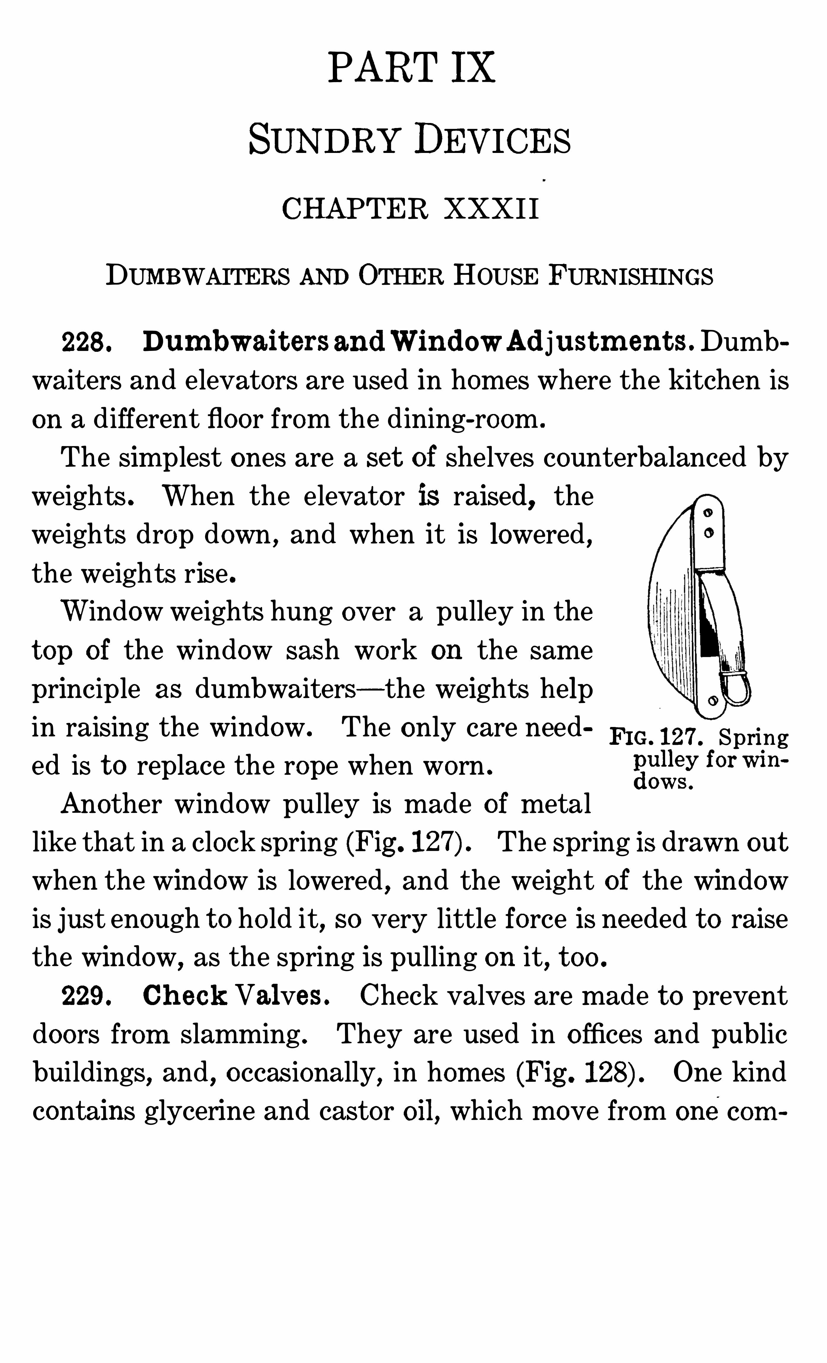
PART IX
SUNDRYDEVICESCHAPTER XXXI I
DUMBWAITERS AND OTHER HOUSE FURNISHINGS
228 . Dum bwait ers andWindowAd justm ent s.Dumb
waiters and elevators are used in homes where the kitchen is
on a different floor from the dining-room .
The simplest ones are a set of Shelves counterbalanced by
weights . When the elevator is raised, theweights drop down , and when it is lowered ,the weights rise .
Window weights hung over a pulley in the
t op of the window sash work on the same
principle as dumbwaiters—the weights help
in raising the window. The only care need FIG. 127 . Springed is t o replace the rope when worn . 3
1
3nfor Win“
Another window pulley is made of metal
like that in a clock spring (Fig . The spring is drawn out
when the window is lowered , and the weight of the window
is just enough t o ho ld it, so very little force is needed t o raise
the window,as the spring is pulling on it, t oo .
229 . Ch eck Valves . Check valves are made t o prevent
doors from slamming . They are used in o ffices and public
buildings, and , o ccasionally, in homes (Fig . One kind
contains glycerine and castor oil, which move from one c om
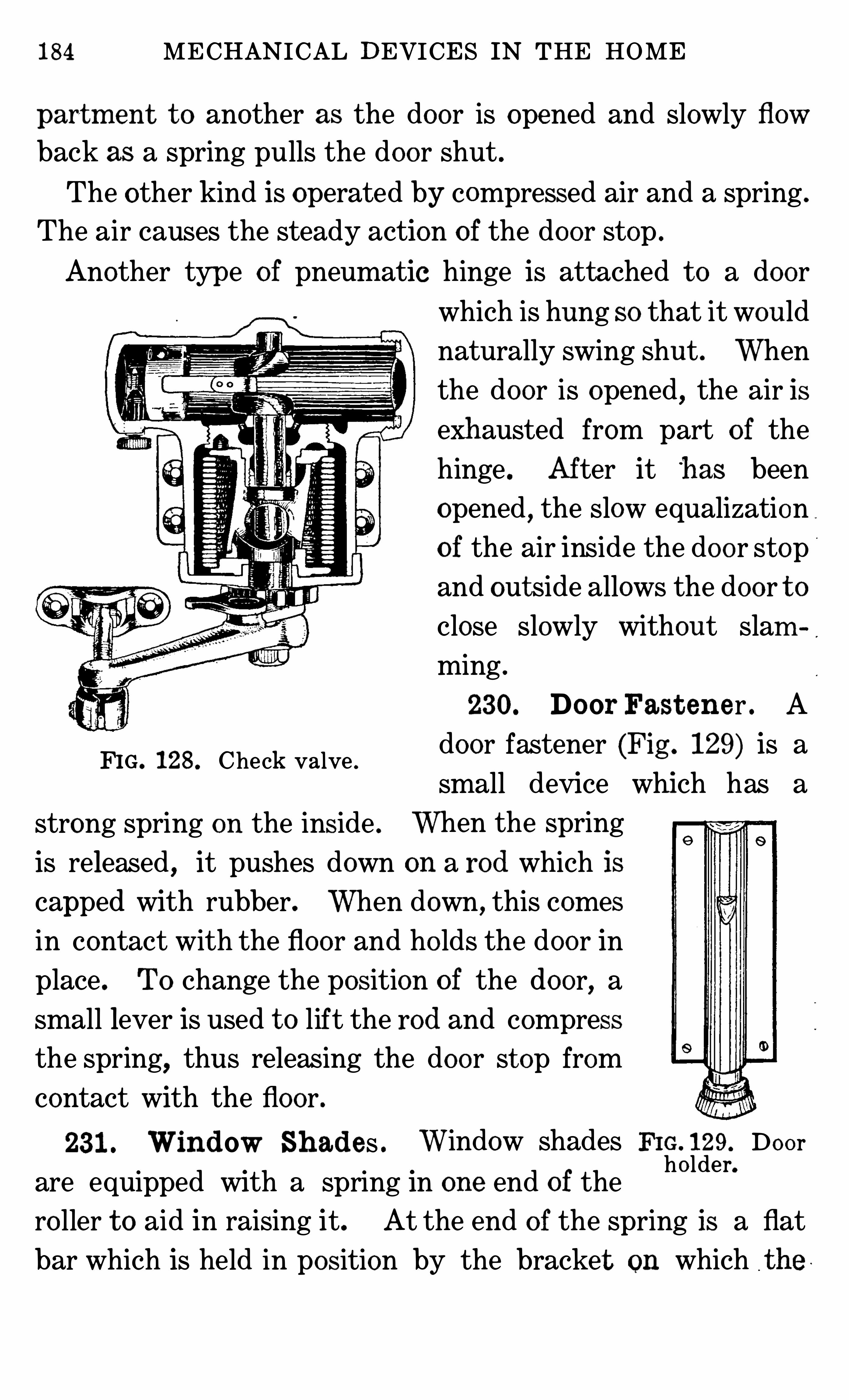
184 MECHANICAL DEVICES IN THE HOME
partm ent t o another as the door is opened and slowly flow
back as a spring pulls the door shut .
The other kind is operated by compressed air and a spring .
The air causes the steady action of the door stop .
Another type of pneumatic hinge is attached t o a door
FIG . 128 . Check valve .
strong spring on the inside .
which is hung so that it would
naturally swing shut . When
the door is opened,the air is
exh austed from part of the
hinge . Af ter it h as been
opened,the slow equalization
of the air inside the doo r stop
and out side allows the door t o
close slowly without slam
ming .
230. Door Fast ener . A
door fastener (Fig . 129) is a
small device which has a
When the spring
is released , it pushes down on a rod which is
capped with rubber. When down, this comes
in contact with the floor and ho lds the door in
place . To change the position o f the door, asmall lever is used t o lift the rod and compress
the spring,thus releasing the door st op from
contact with the floor .
231 . Window Sh ad es . Window shades FIG. 129. Doo rho lder.
are equipped with a spring in one end of the
ro ller t o aid in raising it. At the end o f the spring is a flat
bar which is held in position by the bracket on which t he
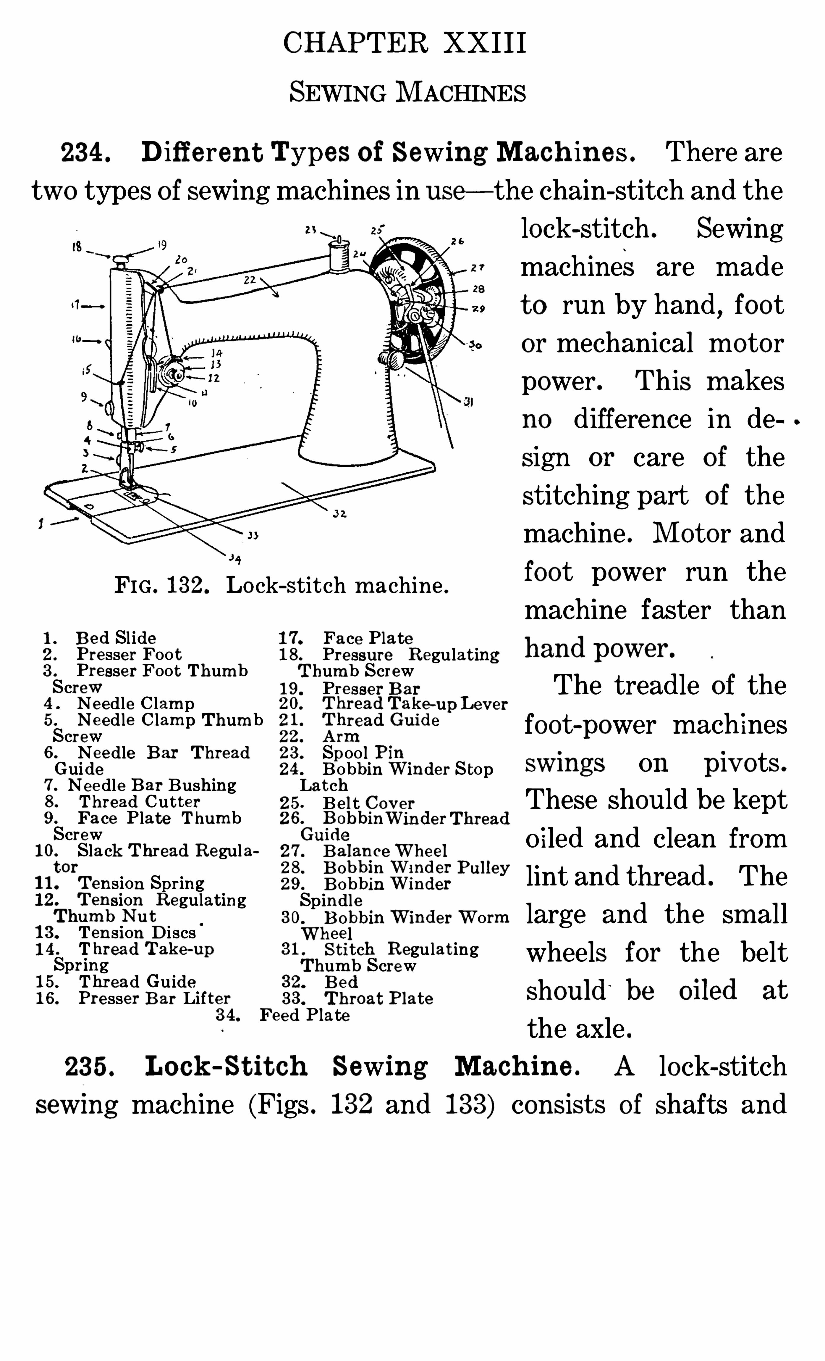
CHAPTER XXI I I
SEWING M ACHINES
234 . D iffe ren t Types o f Sewing Mach ine s . There are
two types o f sewing machines in use—the chain-stitch and the
lock—stitch . Sewing
machines are made
t o run by hand , foot
or mechanical motor
power . This m akes
no difference in de
sign or care of the
stitching part o f the
machine . M otor and
FIG . 132. Lo ck-stitch m achine . foot power run the
B e d Sl idePresser Foo tPre sser Foot Thum bScrewNe edle C lam pNe edle C lam p Thum bScrew6 . Ne edle Bar Thre adGui de7 . Ne e dle B ar Bushing8 . Thre ad Cut t e r9 . Fa ce Plate Thum bScrew
10. Slack Thread Regulat or
11. T ension Spring12 . T ension RegulatingThum b Nu t
13. Tension D iscs14 . T hread Tak e-upSpr ing15 . Thread Guide16 . Pre sser B ar Lift e r
1
2
3
4
5
machine faster than17. Face Plate18 . Pre ssure R egulat ing hand pOWQI
‘
.
T hum b Screw19 . Pre sse r B ar The treadle of thegfl
l .
gfire a
dl'
gak
g-up Le v e r
rea 111 e
22 . Armfoot power mach ines
23 . Spoo l Pin24 . Bobbin W inder S top SwlngS OI! . p ots .
Lat ch25 Be l t Q o v er These should be kept26.
G BiobbinWinde rThreade
27 . B a
fia
fic e
33711
39 1P I
O i led and clean from
3310152wigs!“1 ey lint and thread . The
Spindle30.
W11301
bbin Winder Worm large and the sm alle e
31,1,
hSt it ch Regu lat ing wheels for the beltum b Screw
3 4 . Fe ed Platethe axle .
235 . Lo ck -St it ch Sewing Mach in e . A lock-stitch
sewm g machine (Figs . 132 and 133) consist s of shafts and
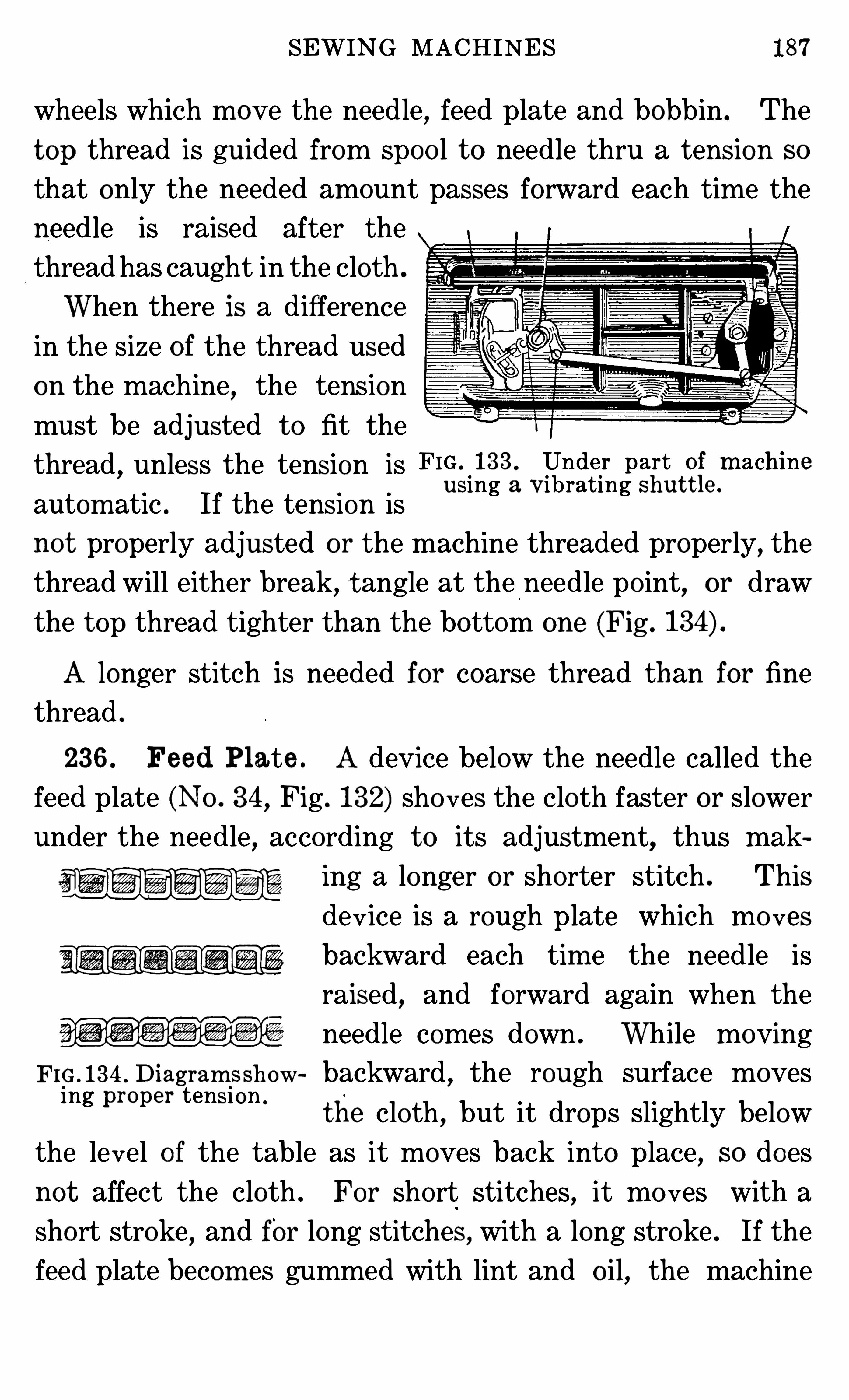
SEWING MACHINES 87
wheels which move the needle, feed plate and bobbin . The
t op thread is guided from spoo l t o needle thru a tension so
that only the needed amount passes forward each time the
needle is raised after the
thread has caught in the cloth .
When there is a difference
in the size of the thread used
on the machine,the tension
must be adjusted t o fit the
thread,unless the tension is FIG . 133 Under part of m achine
autom atic . If the tension isusing a Vibrating Shut t le
not properly adjusted o r the machine threaded properly, the
thread will either break, t angle at the needle po int, or draw
the t op thread tighter than the bottom one (Fig .
A longer stitch is needed for coarse thread than for fine
thread .
236 . Feed Plate . A device below the needle called the
feed plate (No . 34, Fig . 132) sho ves the cloth faster or slower
under the needle,according t o its adjustment, thus mak
544 ,m m ing a longer or shorter stitch . This
W
dev ice is a rough plate which mo ves
backward each tim e the needle is
raised , and forward again when the
needle comes down . While moving
F IG . 134 . Diagram ssh ow backward,the rough surface moves
ing pm per tensionthe cloth , but it drops slightly below
the level o f the table as it moves back into place, so does
not affect the cloth . For short stitches, it mo ves with a
sho rt stroke,and for long stitches , with a long stroke . If the
feed plate becom es gummed with lint and oil,the machine
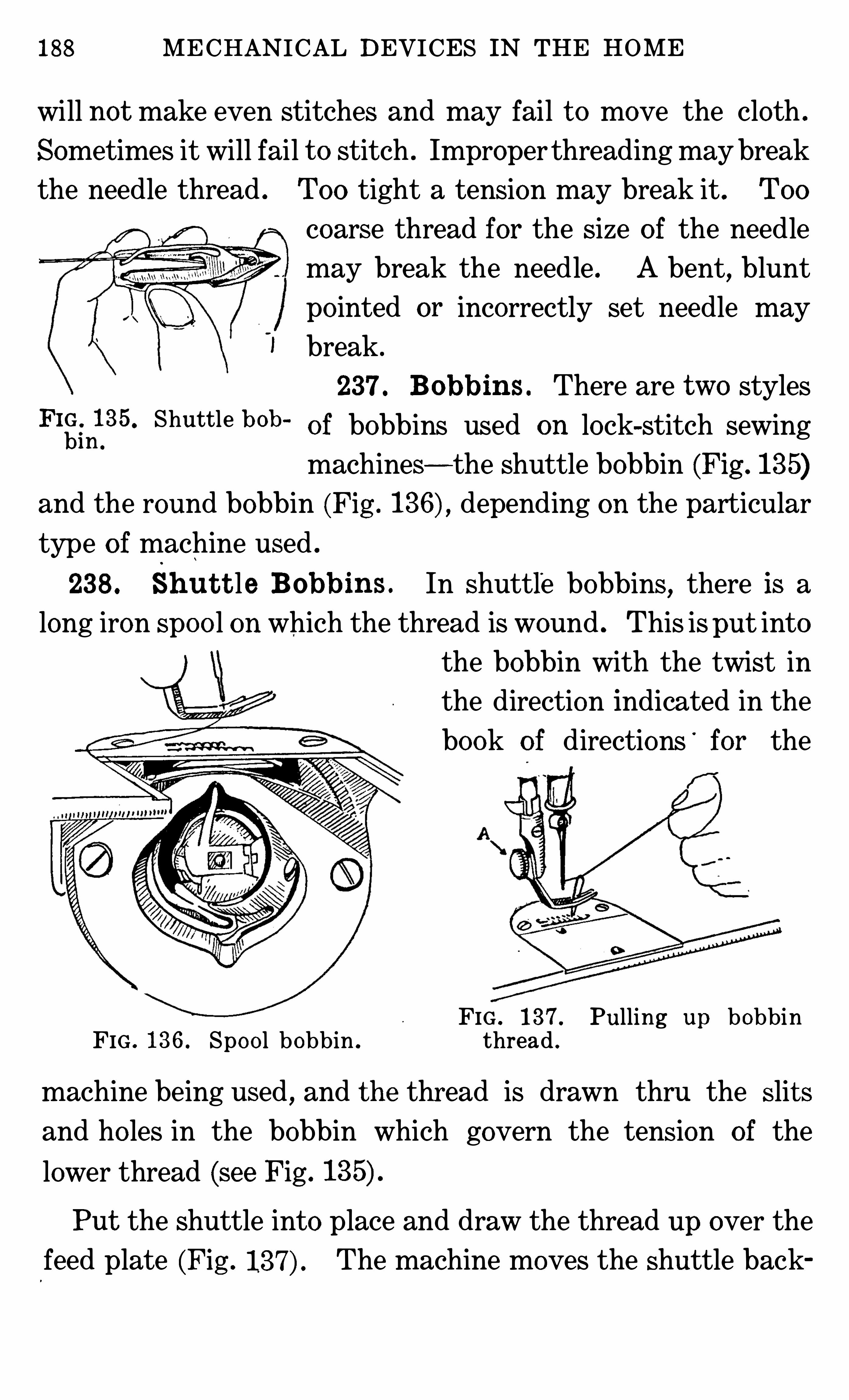
188 MECHANICAL DEVICES IN THE HOME
will not make even stitches and may fail t o move the cloth .
Sometimes it will fail t o stitch . Improper threading maybreak
the needle thread . Too tight a tension may break it . Too
coarse thread for the size o f the needle
may break the needle . A bent, blunt
po inted or incorrectly set needle may
I break .
237 . Bobbins . There are two stylesFlgm1
0
35 Shuttle bOb ‘
of bobbins used on lock-stitch sewing
machines— the Shuttle bobbin (Fig . 135)and the round bobbin (Fig . depending on the particular
type o f machine used .
238 . Sh u t t le Bobbins . In shuttle bobbins, there is a
long iron spoo l on which the thread is wound . This isput into
the bobbin with the twist in
the direction indicated in the
book o f directions'
for the
FIG . 137 . Pulling up bobbinFIG . 136 . Spo o l bobbin . thread .
machine being used , and the thread is drawn thru the slit s
and ho les in the bobbin which govern the tension of the
lower thread (see Fig .
Put the shuttle into place and draw the thread up over the
feed plate (Fig . The machine moves the shuttle back
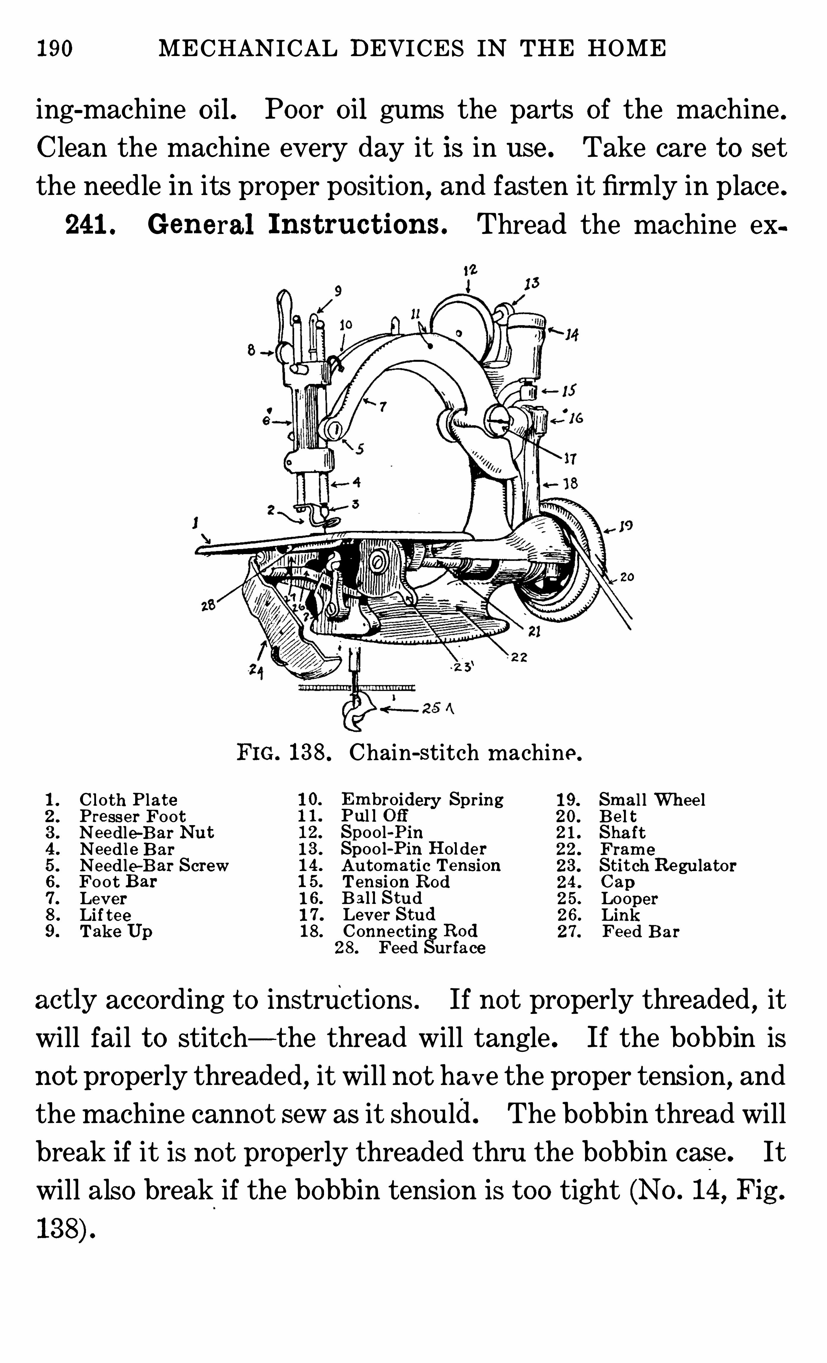
190 MECHANICAL DEVICES IN THE HOME
ing-machine oil . Poor oil gums the parts o f the machine .
Clean the machine every day it is in use . Take care t o set
the needle in its proper position,and fasten it firmly in place .
241 . Gen eral Inst ruc t ions. Thread the machine ex
1 . C lot h Plat e 19. Sm a l l Whee l2 . Pre sse r Foot 20. Be l t3 . Nee dle-Bar Nu t 2 1 . Sha ft4 . Needl e B ar 22 . Fram e
5 . Ne edle-B ar Screw 23 . St it ch Re gulat or6 . Foot B ar 24 . Cap7 . Le v er 25 . Looper8 . Li f t e e 26. Link9 . Tak e Up 27. Fe e d B ar
ac t ly according t o instructions . If not properly threaded,it
will fail t o stitch— the thread will tangle . If the bobbin is
no t properly threaded, it will not have the proper tension, and
the machine cannot sew as it should. The bobbin thread will
break if it is no t properly threaded thru the bobbin case . It
will also break if the bobbin tension is t oo tight (No . 14, Fig .
138 . Chain-stitch m achine .
10. Em broidery Spring1 1 . Pul l O ff12. Spoo l-Pin13 . Spoo l-Pin Hol de r14 . Aut om at ic Tension1 5 . T ension Rod1 6 . Bal l S tud1 7 . Lev er Stud18 . Conne ct ing Rod
28 . Fee d Surface
SEWING MACHINES 191
Always regulate the stitch and the size o f needle for each
Size and kind o f thread used . A table for this usually com es
With each machine, or is o ften stamped on the machine . Se
lect the thread suitable t o the material . The number of aneedle is marked on the shank . Needles made for one kind
of machine will no t always work on another.
An automatic tension should no t be changed or meddled
with . Some tens ions must be adjusted t o the thread . Fo llow
directions coming with the machine for adjusting tensions .
Remove any thread which has become entangled in the mech
anism o f the machine .
Never use a bent needle . A bent needle drops stitches on a
chain-stitch machine . Soaping the needle helps it t o go thru
goods difficult t o penetrate .
When a machine runs hard , it needs oil or has become gum
med up with poor oil . When gummed , clean with kerosene
oil. Thread or ravelings wound about the axles o f the wheels
also makes the machine run hard . Learn t o use the attach
ments of your machine—take care that they do not become
bent .
The lock-stitch does not rip easily.
The ends of the thread o f chain stitches should be carefully
fastened . If started from the end where the seam was com
plet ed , the loopstitch may be easily unraveled and thus save
time when mistakes are made in sewing or when garm ents are
being made over .
CHAPTER XXXIV
AUTOMOBILES
No lengthy treatise on automobiles can be given here, but a
few facts o f general information are well in o rder .
Each car has its special features,but the basic principles o f
Operation and contro l are the same for all makes . Let us con
sider, first, the contro l of the machine on the road
242. St art ing t h e M o to r . Open the throttle from one
fourt h t o one-third way,t o permit entry of plenty of gas into
the motor. Set the time contro l about as far down as the
throttle . Turn on the ignition switch and turn the motor
with the starter .
A co ld motor may dem and use o f the choker before start
ing, but, again, t oo free use of the choker floods the carburetor
with a rich; non-explosive mixture which can be removed only
by use o f the star ter. Should the motor flood t oo easily,or
should it take t oo much choking, have the carburetor read
justed . Common mistakes in starting the motor are (1) t oo
free use o f the starter,which is injurious t o the battery ; (2)
starting with the timer se t too far down , causing back-fire.
Occasionally, a novice attem pts t o start a car with the gears
set and the brakes on . With the motor started and running
smoothly, shift the gears into low and take o ff the brake . Let
the clutch back gently t o prevent the car from starting with a
jerk . In shifting gears,the throttle should be kept down t o
prevent the motor from racing upon releasing the clutch. (3)
A common mistake is the attempt t o shift gears with the
194 MECHAN ICAL DEVICES IN THE HOME
starting . Care o f the battery consists largely in keeping it
charged and filled t o the proper level with distilled water.
Tires should be kept inflated at all times . In case of trouble,
never run on a flat tire,as it will soon be worthless under such
treatment . Never drive a machine while out of order—stop
and have repairs or adjustm ents made .
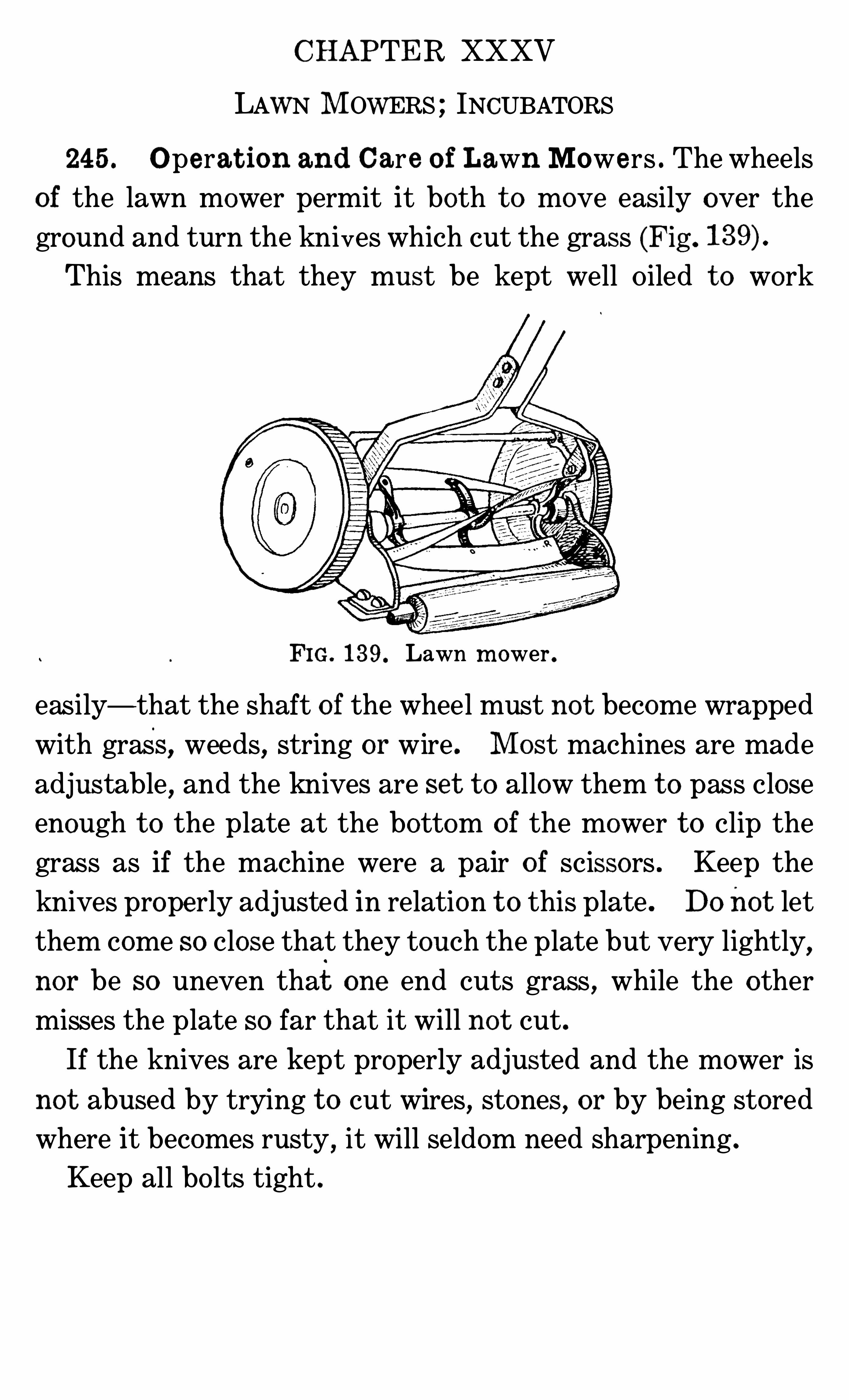
CHAPTER XXXV
LAWN M OWERS ; INCUBATORS
245 . O perat ion and Care o f Lawn Mowe rs . The wheels
of the lawn mower permit it both t o move easily over the
ground and turn the knives which cut the grass (Fig .
This means that they must be kept well Oiled t o work
FIG. 139. Lawn m ower .
easily— that the shaft o f the wheel must no t become wrapped
with grass, weeds, string or wire . M ost machines are made
adjustable , and the knives are set t o allow them t o pass close
enough t o the plate at the bottom o f the mower t o clip the
grass as if the machine were a pair o f scissors . Keep the
knives prope rly adjusted in relation t o this plate . Do not let
them come so close that they touch the plate but very lightly,nor be so uneven that one end cuts grass , while the other
misses the plate so far that it will no t cut .
If the knives are kept properly adjusted and the mower is
not abused by trying t o cut wires,stones , or by being stored
where it becomes rusty,it will seldom need sharpening .
Keep all bo lts tight .
196 MECHANICAL DEVICES IN THE HOME
246 . St o ring Mowers . When storing for the winter,
grease the kn ives with a heavy coat o f unsalted lard , or cover
them with some other protective material .
247 . Sc issors and Sh ears . In popular language , thereis no distinction made between scissors and shears . Technic
ally defined, scissors are less t han six inches in length . Any
similar cutting device o f greater length is called shears . Both
are devices used for cutting cloth , paper, pruning trees, and
many other purposes . They consist of two kn ives riveted t o
gether at some po int between the handle and t he po int of theblade . The two blades are so adjusted that as the open scis
sors are closed,they touch lightly as they pass each other un
til the tip is reached . When the scissors are closed , the blades
should touch only at rivet and tip . Scissors not so adjusted
will not cut well , even tho the blades are very sharp . Drop
ping scissors often bends the blades. Blades may be straight
ened as well as sharpened , and thus make good metal scissors
like new .
248 . Principles Upon Wh ich Incubat or Work s . A
device for hatching chickens is called an incubator. In o rder
t o hatch chickens, the incubator must keep an average tem
perature of 102 degrees Fahrenheit . The thermometer
should be placed in the center o f the tray and on a level withthe t op of the eggs. The temperature of 102—é degrees Fahrenh eit must no t vary greatly during the incubation of eggs .
The incubator must also permit of suitable ventilation and
contro l of the mo isture in the eggs .
There are incubators heated with ho t water and others with
hot air. The air or water in those commonly used in homes
is heated with a kerosene lamp .
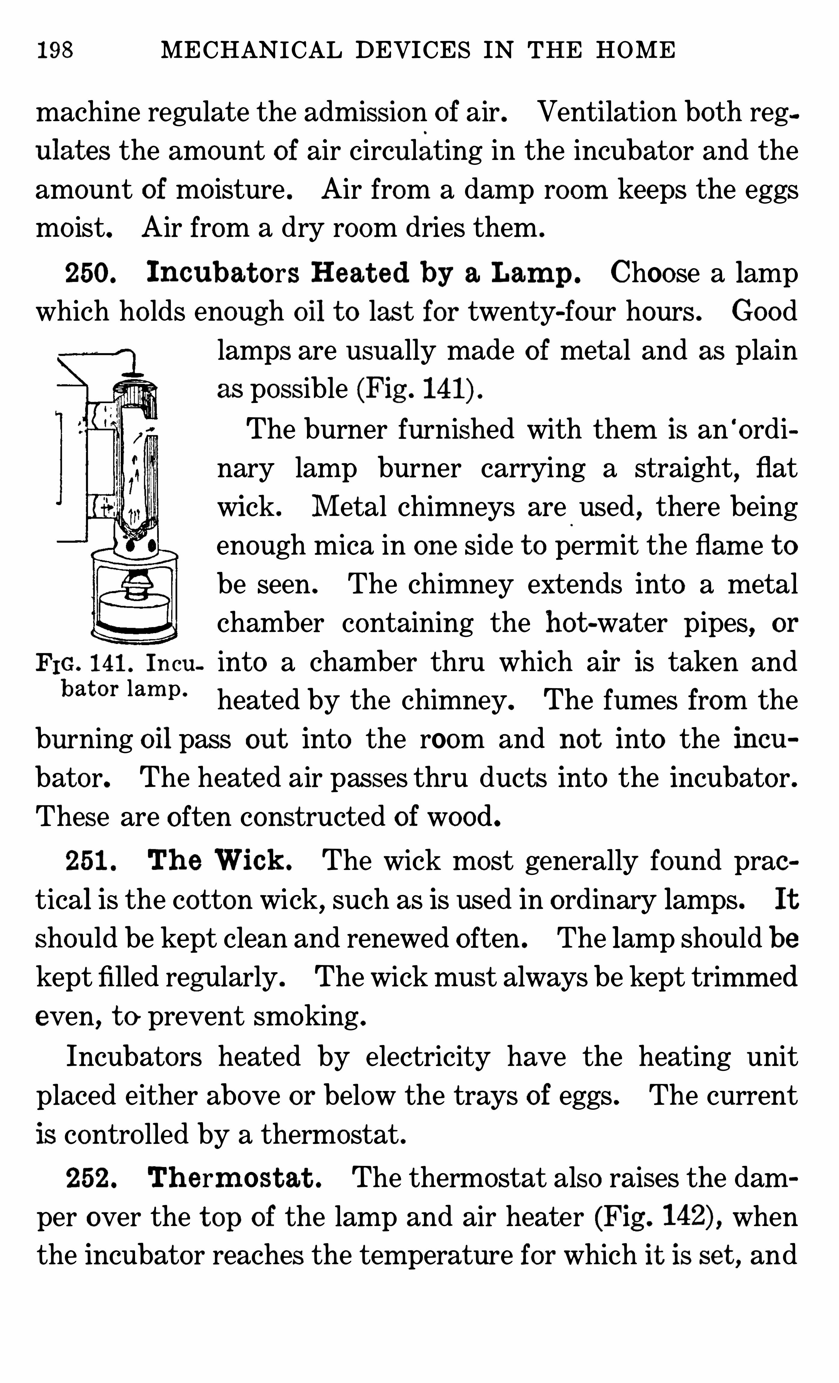
198 MECHANICAL DEVICES IN THE HOME
machine regulate the adm ission of air . Ventilation both reg
ulat es the amount o f air circulating in the incubator and the
amount of mo isture . Air from a dam p ro om keeps the eggs
mo ist. Air from a dry room dries them .
250. Incubat o rs Heat ed by a Lam p . Choose a lampwhich ho lds enough oil t o last for twenty-four hours . Good
lamps are usually made of metal and as plain
as possible (Fig .
The burner furnished with them is an‘
ordi
nary lamp burner carrying a straight,
flat
wick . M etal chimneys are.
used,there being
enough mica in one side t o permit the flam e t o
be seen . The chimney extends into a metal
chamber containing the hot -water pipes, or
F m, 141 , Incu into a chamber thru which air is taken andbat o r lam p ‘ heated by the chimney. The fumes from the
burning oil pass out into the room and not into the incu
bator. The heate d air passes thru ducts into the incubator.
These are often constructed o f wood.
251 . Th e Wick . The wick most generally found prae
tical is the cotton wick, such as is used in o rdinary lamps. It
should be kept clean and renewed o ften . The lamp should be
kept filled regularly . The wick must always be kept trimm ed
even, t o prevent smoking .
Incubators heated by electricity have the heating unit
placed either above or below the trays of eggs . The current
is contro lled by a thermostat .
252. Th erm ost at . The thermostat also raises the dam
per over the t op of the lamp and air heater (Fig . when
the incubator reaches the temperature for which it is set , and
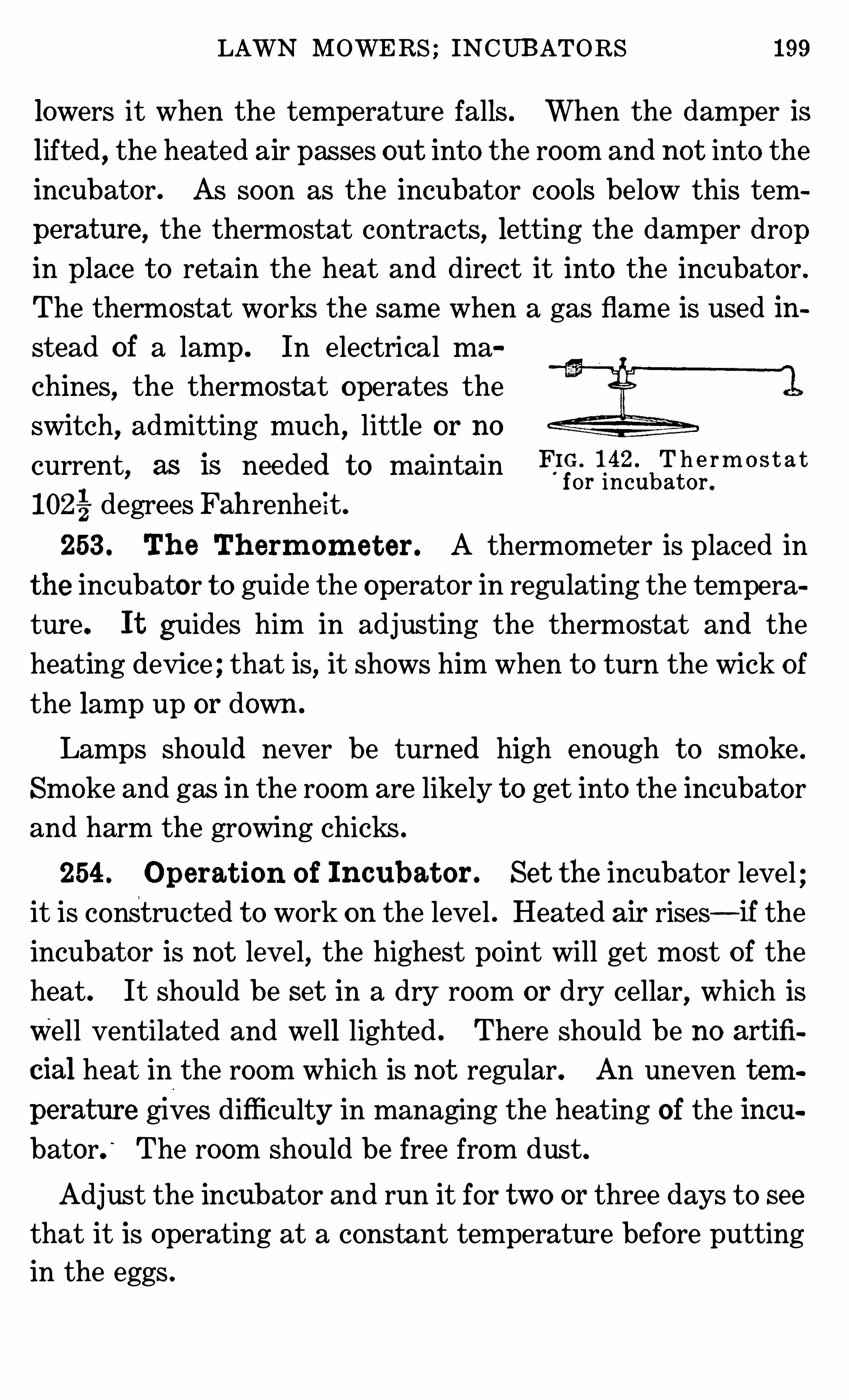
LAWN MOWERS ; INCUBATORS 199
lowers it when the temperature falls . When the damper is
lifted,the heated air passes out into the room and not into the
incubator. As soon as the incubator coo ls below this tem
perature , the thermostat contracts, letting the damper dropin place t o retain the heat and direct it into the incubator .
The thermostat works the same when a gas flame is used in
stead of a lamp . In electrical ma
chines,the thermostat operates the
switch,admitting much , little or no
current, as is needed t o maintain FIG 142 T h e rm o s t a tfor incubato r .
102 degrees Fah renhe it .
253 . Th e Th erm om et er . A thermometer is placed in
the incubator t o guide the operator in regulating the tempera
ture. I t guides him in adjusting the thermostat and the
heating device ; that is, it shows him when t o turn the wick o fthe lamp up or down .
Lamps should never be turned high enough t o smoke .
Smoke and gas in the room are likely t o get into the incubator
and harm the growing chicks .
254 . Operat ion o f Incubat or . Set the incubator level
it is const ructed t o work on the level . Heated air rises—if theincubator is not level, the highest po int will get most o f the
heat . It should be set in a dry room or dry cellar, which is
Well ventilated and well lighted . There should be no art ifi
cial heat in the room which is not regular. An uneven tem
perature gives difficulty in managing the heating of the incubator.
‘
The room should be free from dust.
Adjust the incubator and run it for two or three days t o see
that it is operating at a constant temperature before putting
in the eggs .
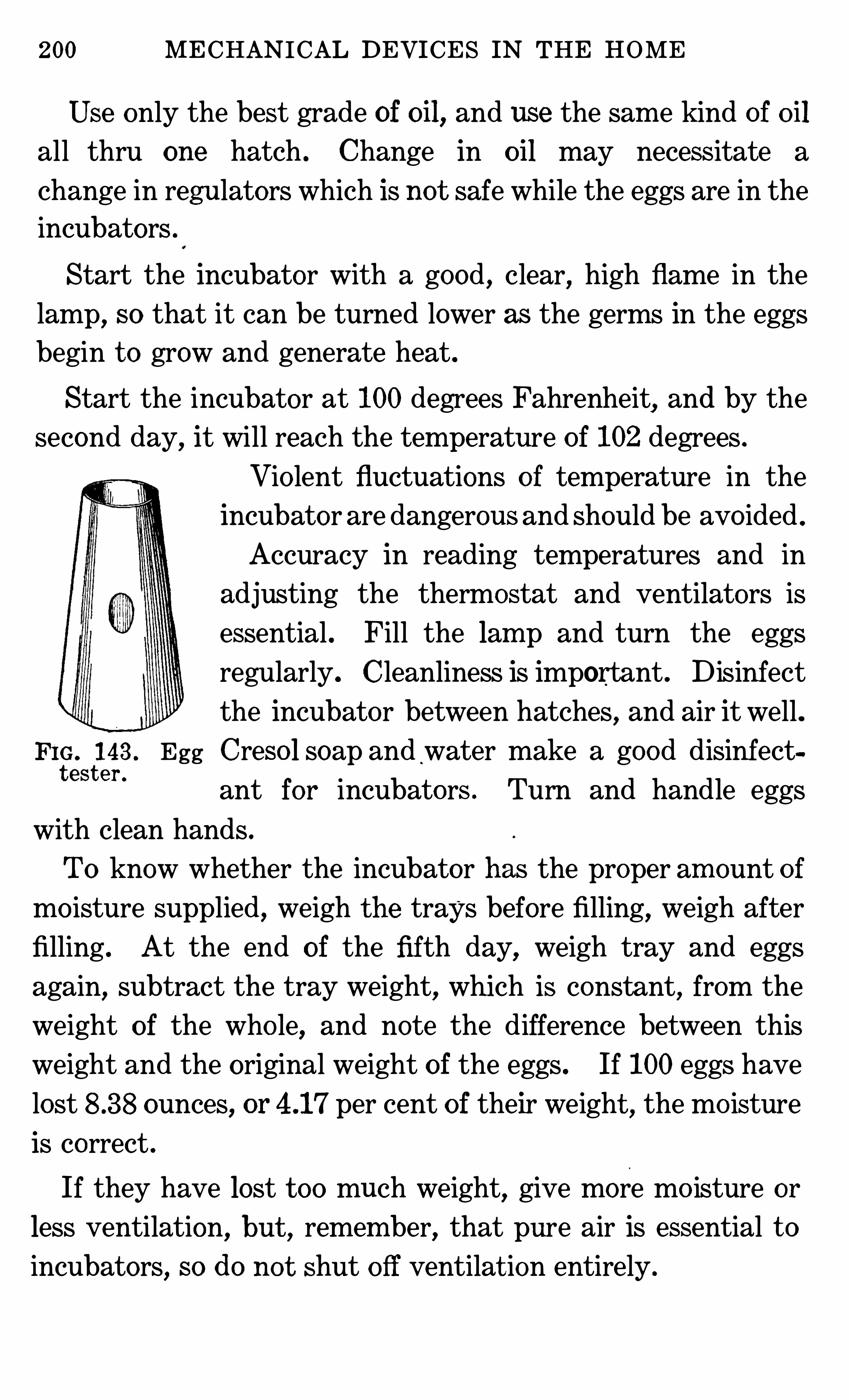
200 MECHANICAL DEVICES IN THE HOME
Use only the best grade of oil, and use the sam e kind of oil
all thru one hatch . Change in oil may necess itate a
change in regulators which is not safe while the eggs are in the
incubators
Start the incubator with a good , clear, high flame in the
lamp, so that it can be turned lower as the germs in the eggs
begin t o grow and generate heat .
Start the incubator at 100 degrees Fahrenheit, and by thesecond day, it will reach the tem perature of 102 degrees .
Vio lent fluctuations of temperature in the
incubator are dangerous and should be avo ided .
Accuracy in reading temperatures and in
adjusting the thermostat and ventilators is
essential . Fill the lam p and turn the eggsregularly. Cleanliness is important . D isinfect
the incubator between hatches, and air it well .FIG. 143 . Egg Creso l soap and water make a good disinfectt est er '
ant for incubators . Turn and handle eggs
with clean hands .
To know whether the incubator has the proper am ount o f
mo isture supplied , weigh t he trays before filling, weigh after
filling . At the end of the fifth day, weigh tray and eggs
again,subtract the tray weight, which is constant, from the
weight of the who le, and note the difference between this
weight and the original weight o f the eggs . If 100 eggs have
lost ounces, or per cent of their weight , the mo isture
is correct .
If they have lost t oo much weight, give more mo isture or
less ventilation, but , remember, that pure air is essential t o
incubators, so do no t shut off ventilat ion entirely .
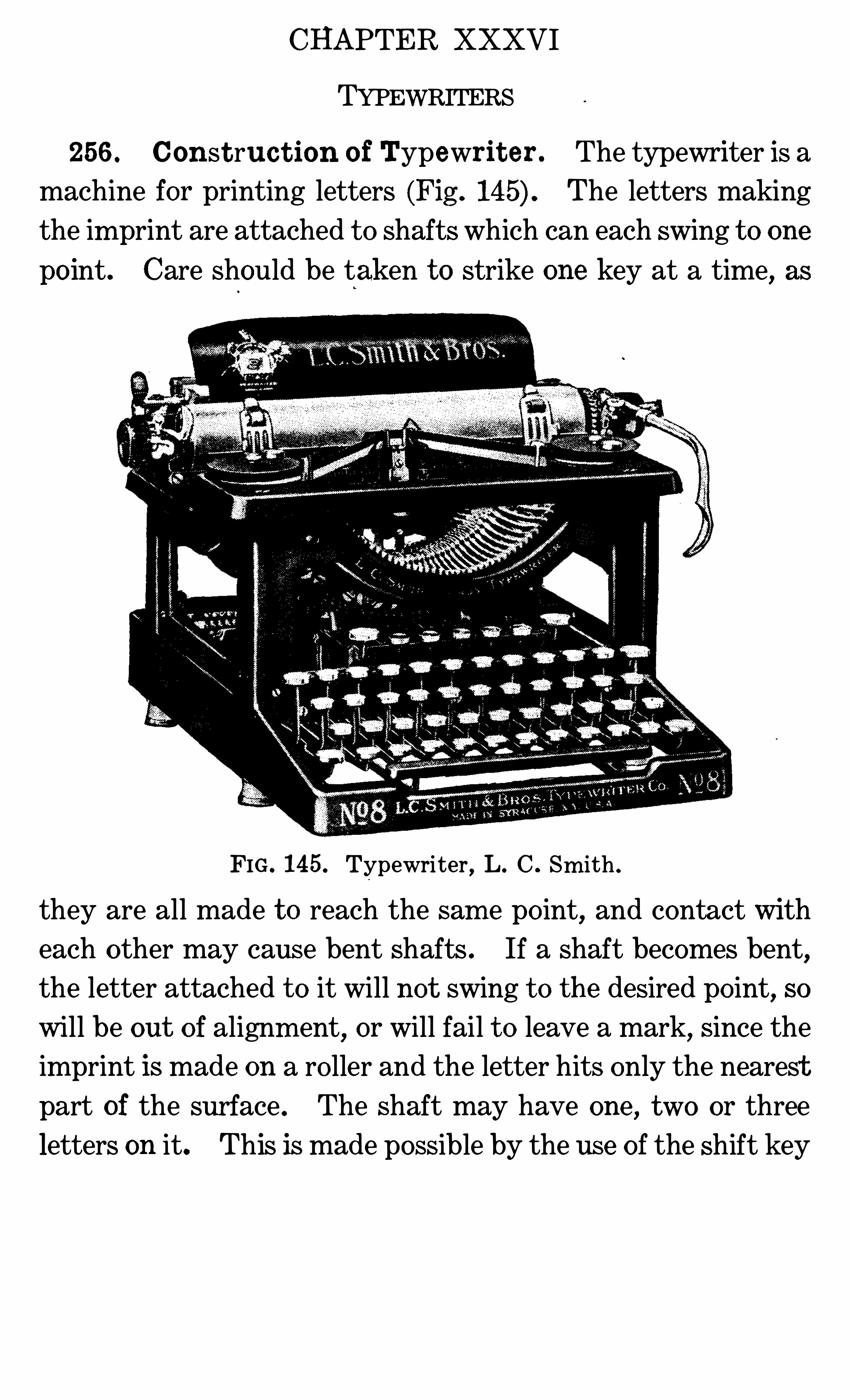
CHAPTER XXXVI
TYPEWRITERS
256 . Const ruc t ion o f Typewrit er . The typewriter is a
machine for printing letters (Fig . The letters making
the im print are attached t o shafts which can each swing t o one
po int. Care should be taken t o strike one key at a time, as
FIG . 145. Typewriter , L. C . Sm ith .
they are all made t o reach the sam e po int, and contact with
each other may cause bent shafts . If a shaft becomes bent,
the letter attached t o it will not swing t o the desired po int, so
will be out o f alignm ent,or will fail t o leave a mark, since the
imprint is made on a ro ller and the letter hits only the nearest
part of the surface . The shaft may have one , two or three
letters on it. This is made possible by the use of the shift key
TYPEWRITERS 03
which raises or lowers the framework t o which the ro ller is att ached , so that when the machine is in normal position, one
se t Of type on the keys will be im printed , and , upon the ho ld
ing down o f a shift key and simultaneously striking a letter,
another set of type will make the imprint . On som e typewriters there are two shift keys, allowing three sets of charac
ters t o be used . The motion of the keys turns a small wheel
which shoves the ro ller from right t o left, and , also , turns the
spoo ls of ribbons so that a new bit o f ribbon comes under the
letter each time a key is struck . If the ribbon did not move,
t he letters would soon cut a ho le thru it . This ribbon carries
the ink which reproduces the imprint o f the letter. When the
end of a ribbon is reached , mo st machines reverse its direction
so that it again winds onto the spoo l from which it has just
unwound . On other machines, it is necessary t o release the
bar which contro ls the spoo ls t o reverse the winding of the
ribbon .
257 . Special Feat ures o f Typewrit er . Learn how t o
use the attachments on the typewriter t o get the greatest
service from it . If a machine is equipped with tabulating
keys,much tim e is saved by using them for the indentations
instead of working the space bar until the desired place is
reached,or by using both hands t o release the carriage and
move it t o it s desired place . Som e machines are equipped
with a key marked “ ribbon” key . This key,when pressed
,
lowers the ribbon so that no impression from it is made on the
paper. When the ribbon is removed,stencils may be cut
with the letters for mimeographic work . These are only
t wo examples . There are many automatic aids on each
make o f machine .
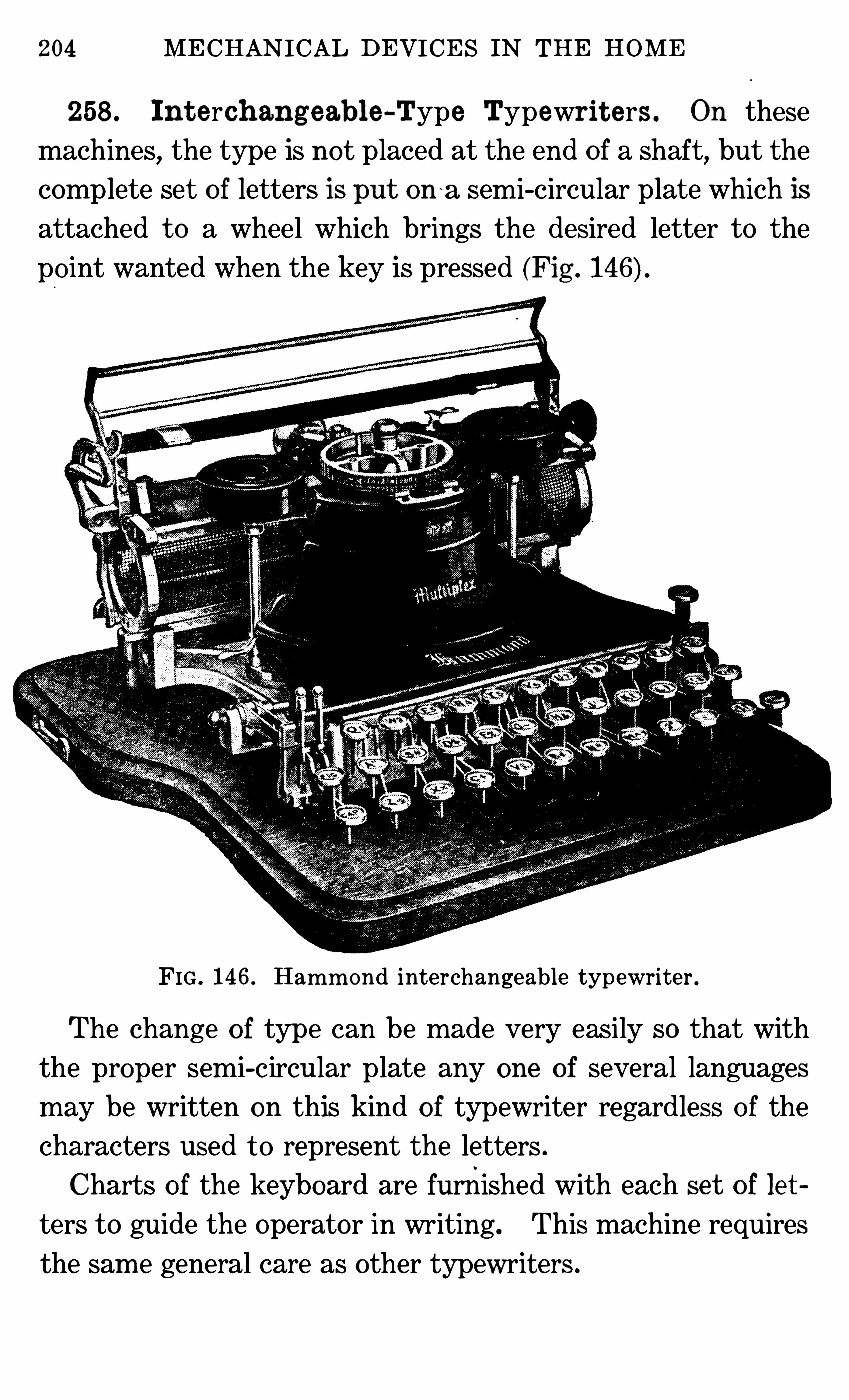
204 MECHANICAL DEVICES IN THE HOME
258 . In t erch ang eable -Type Typewrit e rs . On these
machines, the type is not placed at the end of a shaft, but the
complete set of letters is put on~
a sem i-circular plate which is
attached t o a wheel which brings the desired letter t o the
po int wanted when the key is pressed (Fig .
FIG . 146 . Hamm ond interchangeable typewriter .
The change o f type can be made very easily so that with
the proper semi-circular plate any one o f several languages
may be written on this kind o f typewriter regardless o f the
characters used t o represent the letters .
Charts of the keyboard are furnished with each se t o f le t
ters t o guide the operator in writing. This machine requires
the sam e general care as other typewriters .
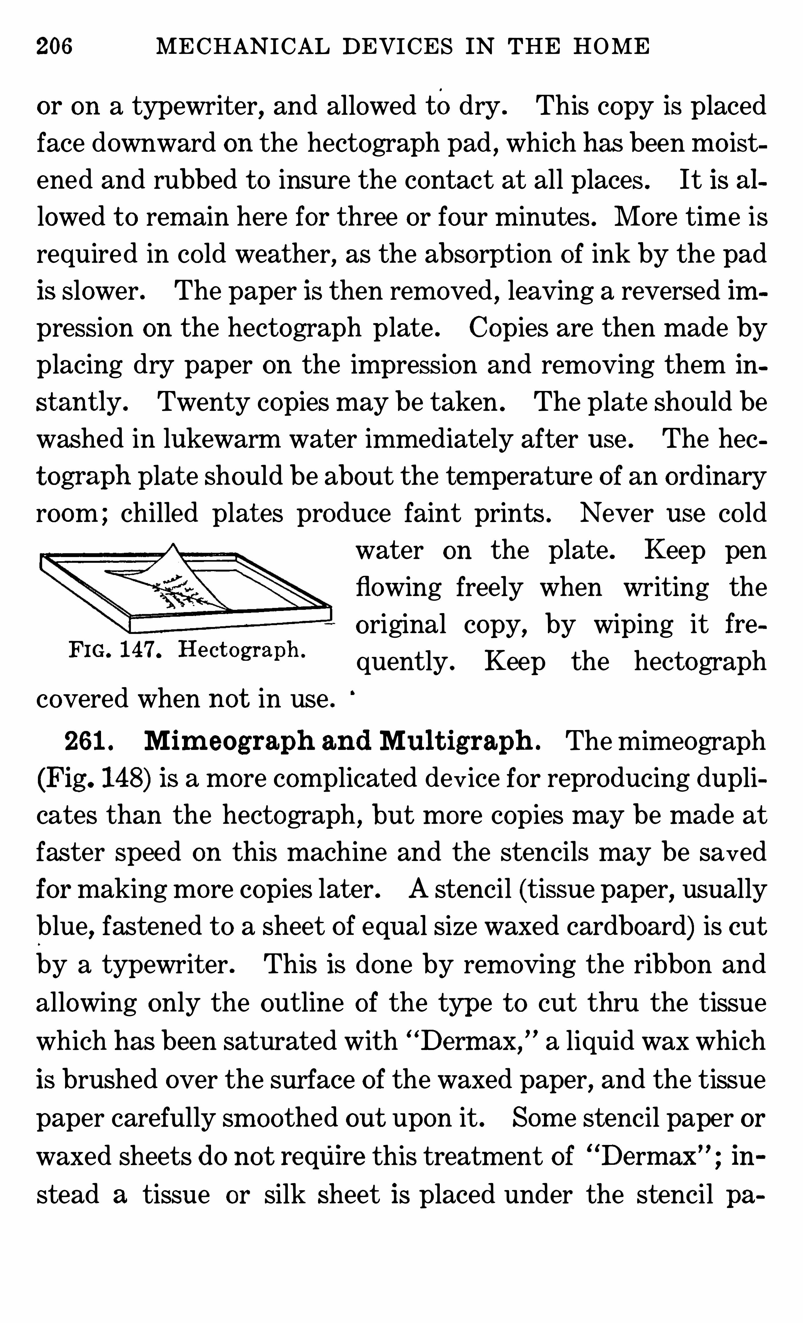
206 MECHANICAL DEVICES IN THE HOME
or on a typewriter, and allowed todry . This copy is placed
face downward on the hectograph pad , which has been m o ist
ened and rubbed t o insure the contact at all places . It is al
lowed t o rem ain here for three or four m inutes . M ore tim e is
required in co ld weather, as the absorption of ink by the pad
is slower . The paper is then rem oved , leaving a reversed im
pression on the hectograph plate . Copies are then made by
placing dry paper on the impression and rem oving them in
stant ly . Twenty copies may be taken . The plat e should be
washed in lukewarm water imm ediately after use . The hec
t ograph plate Should be about the temperature of an o rdinary
room ; chilled plat es produce faint prints . Never use co ld
water on the plate . Keep pen
flowing freely when writing the
o riginal copy, by wiping it freFIG’ 147‘ He cmgraph ' quently . Keep the hectograph
covered when not in use .
261 . Mim eograph and Mul t igraph . The mimeograph
(Fig . 148) is a more complicated device for reproducing dupli
cates than the hectograph , but more copies may be made at
faster speed on this machine and the stencils may be saved
for making more copies lat er . A stencil (tissue paper, usually
blue,fastened t o a sheet o f equal size waxed cardboard) is cut
by a typewriter . This is done by rem oving the ribbon and
allowing only the outline of the type t o cut thru the tissue
which has been saturated with “
Derm ax,
” a liquid wax which
is brushed over the surface of the waxed paper, and the tissue
paper carefully sm oothed out upon it . Som e stencil paper or
waxed sheets do not rq iire this treatm ent o f“
Dermax”
; in
stead a tissue or silk sheet is placed under the stencil pa
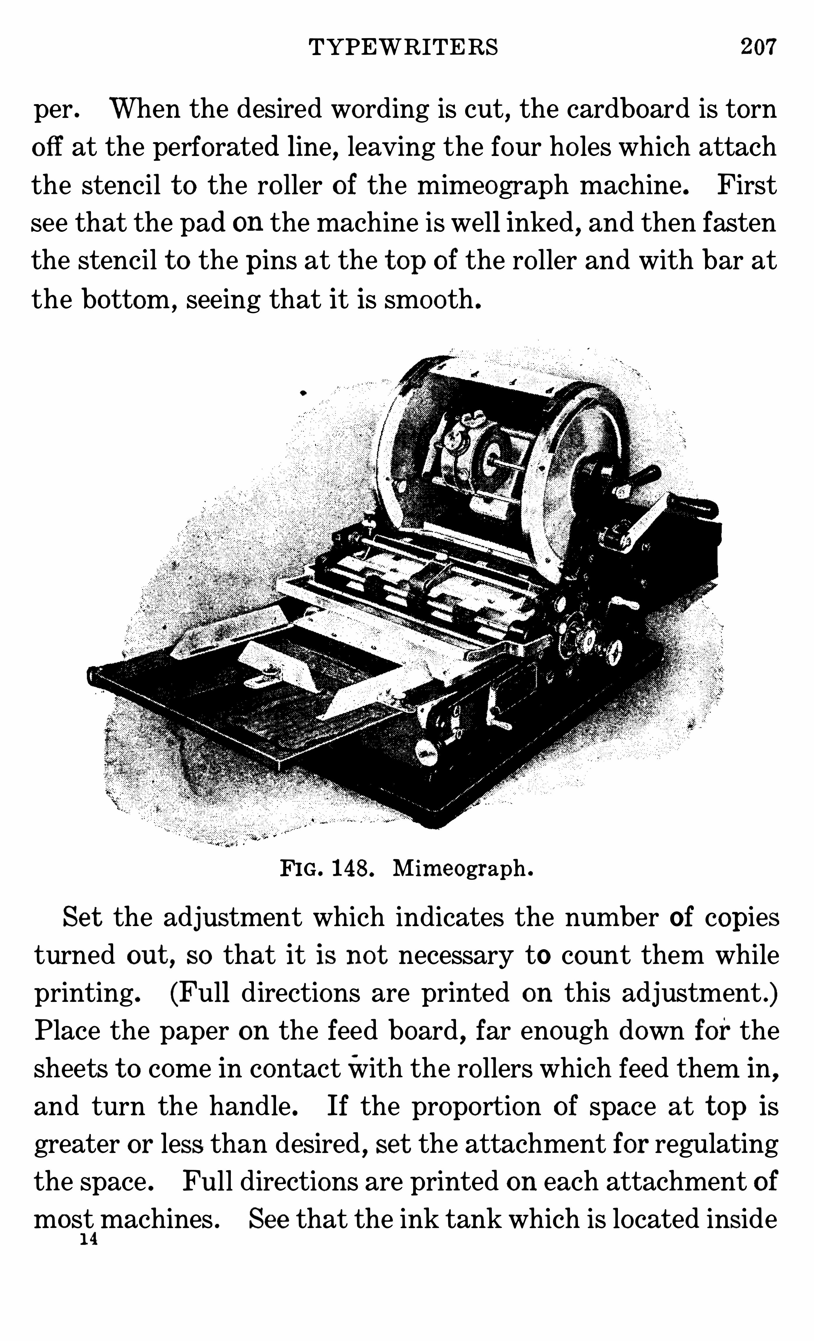
TYPEWRITERS 07
per. When the desired wording is cut , the cardboard is torn
o ff at the perforated line, leaving the four ho les which attach
the stencil t o the ro ller o f the mimeograph machine . First
see that the pad on the machine is well inked , and then fastenthe stencil t o the pins at the t op of the ro ller and with bar at
the bottom ,seeing that it is smooth .
FIG . 148 . Mim eograph .
Se t the adjustment which indicates the num ber of copies
turned out , so that it is no t necessary to count them while
printing. (Full directions are printed on this adjustment .)
Place the paper on the feed board,far enough down for the
sheets t o come in contactWith the ro llers which feed them in,and turn the handle . If the propo rtion o f space at t op is
greater or less than desired, set the attachment for regulating
the space . Full directions are printed on each attachment o f
mos1
t4machines . See that the ink tank which is located inside
208 MECHANICAL DEVICES IN THE HOME
the cylinder is kept full of the best ink. Ink the pad by push
ing the brush across the inside of the perforated cylinder .M ultigraphs differ frommimeographs in that they print the
copy from type instead of thru a stencil . The type is set in a
cylinder that is covered by an inked ribbon . M anuscripts
printed by a multigraph look more like typewriting than those
printed by a mimeograph . When turning out less than a
thousand copies, the mimeograph will be found more e conom
ical on account o f the small amount o f t im e requ ired in pre
paring the stencil .
QUESTIONS FOR PART IX
1 . By what m eans are dum bwaiters o perated !2 . Can y ou se e any relation between the construction o f door stopsand force pum ps !3 . What is the power for ro lling up a window shade !
‘
4 . What does lo ck-stitch look like ! How does chain-stitch d ifferfrom lo ck-stitch !5 . In what way d o lo ck-stitch m achines differ from chain-stitch
m achines !6 . What are the advantages o f each ! What are the d isadvantages !7 . What is the tension ! How is it adjusted ! How is the length o f
stitch adjusted !9 . In what ways is an autom ob ile engine like the gaso line engine andthe electric m oto r used in rural hom es for o perating househo ld m a
chinery !10. What is the shape o f the knives on a lawn m ower that m akes it
cut the sam e as a pair o f s cissors !11 . What m ay be the reasons for scisso rs no t cutting as they should12 . What are the essential features o f a go o d in cubator !13 . What is a therm ostat ! How do es it work ! Are therm ostats o fany use t o the housewife on any o ther device than the incubato r !14 . What m echanica l facto rs are em bodied in a typewriter ! Findthe pulley , the levers , the springs , etc .15 . What are the differences in a hecto graph , a m im eograph and
m ultigraph !
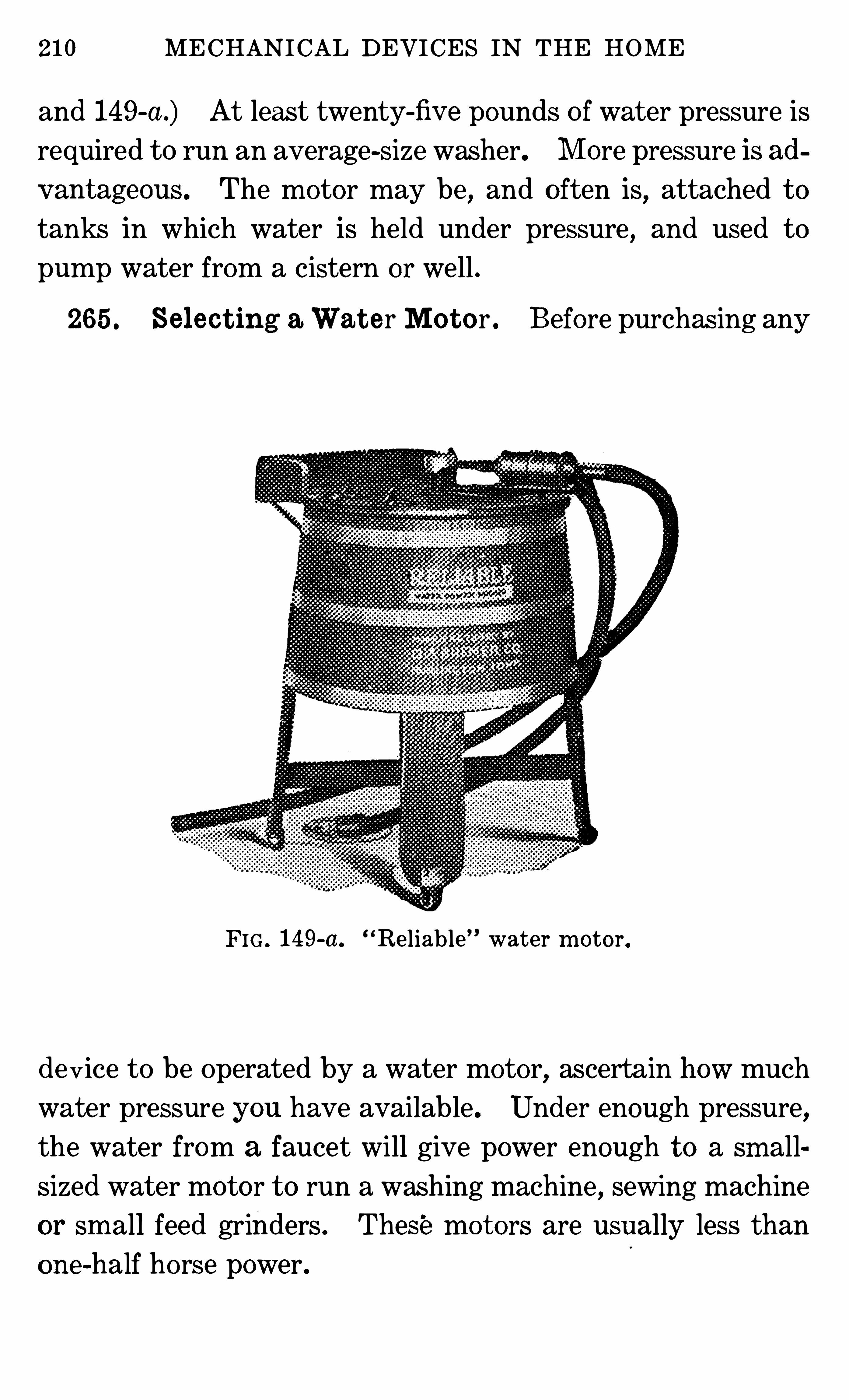
210 MECHANICAL DEVICES IN THE HOME
and 149-a .) At least twenty-fiv e pounds o f water pressure is
required t o run an average-size washer. M ore pressure is ad
v antageous . The motor may be,and o ften is
,attached t o
tanks in which water is held under pressure, and used t o
pump water from a cistern or well .
265 . Se lec t ing a Wat e r Mo t o r . Before purchasing any
F IG. 149-a. Reliable water m otor.
dev ice t o be Operated by a water motor,ascertain how much
water pressure you have available. Under enough pressure,
the water from a faucet will give power enough t o a sm allsized water motor t o run a washing machine, sewing machine
or sm all feed grinders . These mo t ors are usually less than
one-half horse power .
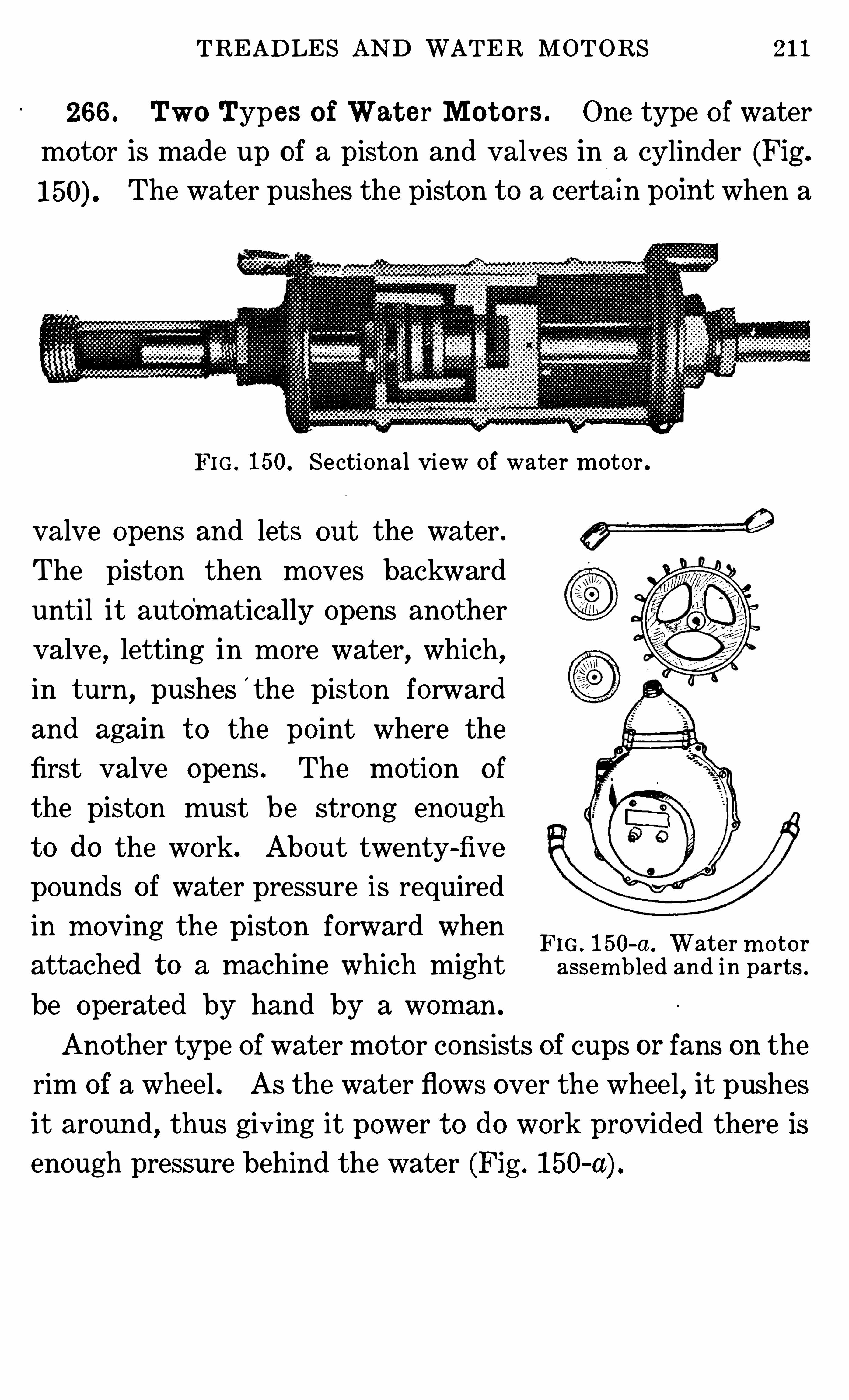
TREADLES AND WATER MOTORS 211
266 . Two Types o f Wat e r Mo t o rs . One type o f water
motor is made up of a piston and valves in a cylinder (Fig .
The water pushes the piston t o a certa in pom t when a
FI G . 150. Sectional view of water m otor .
valve opens and lets out the water .
The piston then moves backward
until it automatically Opens another
valve,letting in more water, which,
in turn,pushes
'
the piston forward
and again t o the po int where the
first valve opens . The motion of
the piston must be strong enough
t o do the work. About twenty-fiv e
pounds o f water pressure is required
in moving the piston forward whenFIG . 150-a . Water m o t o r
attached t o a machine which might assem bled and i n parts .
be operated by hand by a wom an .
Another type of water motor consists of cups or fans on the
rim of a wheel . As the water flows over the wheel,it pushes
it around , thus giv ing it power t o do work provided there is
enough pressure behind the water (Fig . 150-a) .
CHAPTER XXXVI I I
ENGINES ; M OTORS AND BATTERIES ; FUELS
267 . Gasol ine Eng ines . A gaso line engine (Fig . 151)should be operated out of doors or in a well-ventilated room
,
except in cases where the exhaust pipe is carried thru the wal l
of the building t o the outside . The fum es may cause illness,or even death , t o any one staying in the room .
A gasoline engine should be mounted on a substantial base
of concrete or heavy timbers, or on a well-built truck,and
should be put in good o rder before the woman or girl begins t o
use it . The engine must be level . If more than one device
is attached t o it, be sure t o use the right pulleys on the engine
and the machine t o be operated . An engine is usually equip
pad with pulleys o f two or more sizes . The size o f the wheel
on the washing machine o r vacuum cleaner must be of a size
t o make the desired number o f revo lutions per minute .
268 . Figuring Speed o f Pul leys . For example,if the
speed o f t he engine is 425 revo lutions per minute and the
diam eter of the pulley on the engine is 12 inches, and thema
chine is t o be run at 150 revo lutions per minute, have a pulley
on the machine o f a diameter which equals 425 times 12, or
divided by 150, or 34 inches .
It would be more convenient t o have a sm allerpulley on this
machine . Since there is a smaller wheel on the engine which,
we will say , is 6 inches in diameter, put the belt on the sm aller
wheel, and then a wheel only 17 inches in diameter will be
needed on the machine .
214 MECHANICAL DEVICES IN THE HOME
269 . Operat ing t h e Engine . One person should be re
sponsible for the care of an engine . Starting the engine is
usually t oo heavy work for most women . Since a man usually
starts a gas engine which the women are t o use , it is more im
po rtant that they know how t o stop the engine and t o recog
nize when it is no t running properly. A co ld engine can be
started easier if warmed with h’
o t water.
Running an engine which is out of order may damage it se
riously . Have some one Show you how t o operate your en
gine . Stop it when not running properly .
270. Point s in Caring for Engine . The fo llowing are
po ints t o keep in mind when operating an internal combus
tion engine
1) Black smoke issuing from the exhaust pipe means there
is not enough air in proportion t o fuel .
2) When an engine misses more explosions than it should,
or backfires, the cause is likely t o be t oo much air in the fuel .
3) If the mixture o f fuel and air is in the proper propor
tion , but there is t oo little o f it, the engine will have no power.
4) Premature ignition may be caused by deposition o f car
bon or soot on the walls o f the cylinder ; the compression
being t oo high for the fuel used ; overheating of the piston, or
exhaust valve, or of some poorly-jacketed part .
5) Using t oo much or a poor quality o f lubricating oil, or a
mixture t oo rich in fuel, causes deposition of carbon on the
cylinder .
6) The use o f t oo m uch cylinder oil is indicated by a blue
smoke issuing from the exhaust .
7) Pre-ignition, or a bearing out of order, or the engine no t
being securely fastened t o it s foundation, causes pounding .
ENGINES ; MOTORS AND BATTERIES ; FUELS 2 15
8) Too much water in the.
oil used for fuel causes white
smoke t o issue from the exhaust pipe . This may be caused
by a leaky jacket on gaso line engines .
9) Stop the engine by shutting off the supply of fuel . Open
the switch t o the ignition system . Close the lubricators and
oil cups, and turn o ff the jacket water .
10) In co ld weather, drain o ff the jacket water to prevent
freezing .
11) Always leave the engine clean and in order t o start
again .
12) For safety, belts and wheels should be boxed“
in wher
ever possible .
Fig . 151 should be studied closely for a better understand
ing of the engine .
271 . Generat ing Elec t ricit y for Hom es . Water m o
tors, kerosene, gas and gaso line engines are the sources o f
power commonly used t o generate electricity for private
homes . A device for generating electricity is called a dyna
m o (Fig . The electricity generated is either used di
rec t ly while the engine is running, or it is stored in storage
batte ries . From here it is conducted thru wires and used for
lighting, heating and turning motors t o do work.
272 . Bat t eries . Batteries . are used mainly where a
small amount o f current is needed,as on oil or gaso line en
gines, t o make the spark t o ignite the gaso line or oil, and in
lighting gas and acetylene lam ps,and for some door bells .
There are several kinds o f batteries , as liquid , dry-cell andstorage .
273 . Liquid Bat t eries . In liquid batteries,electric cur
rent is generated by means o f direct chemical action between
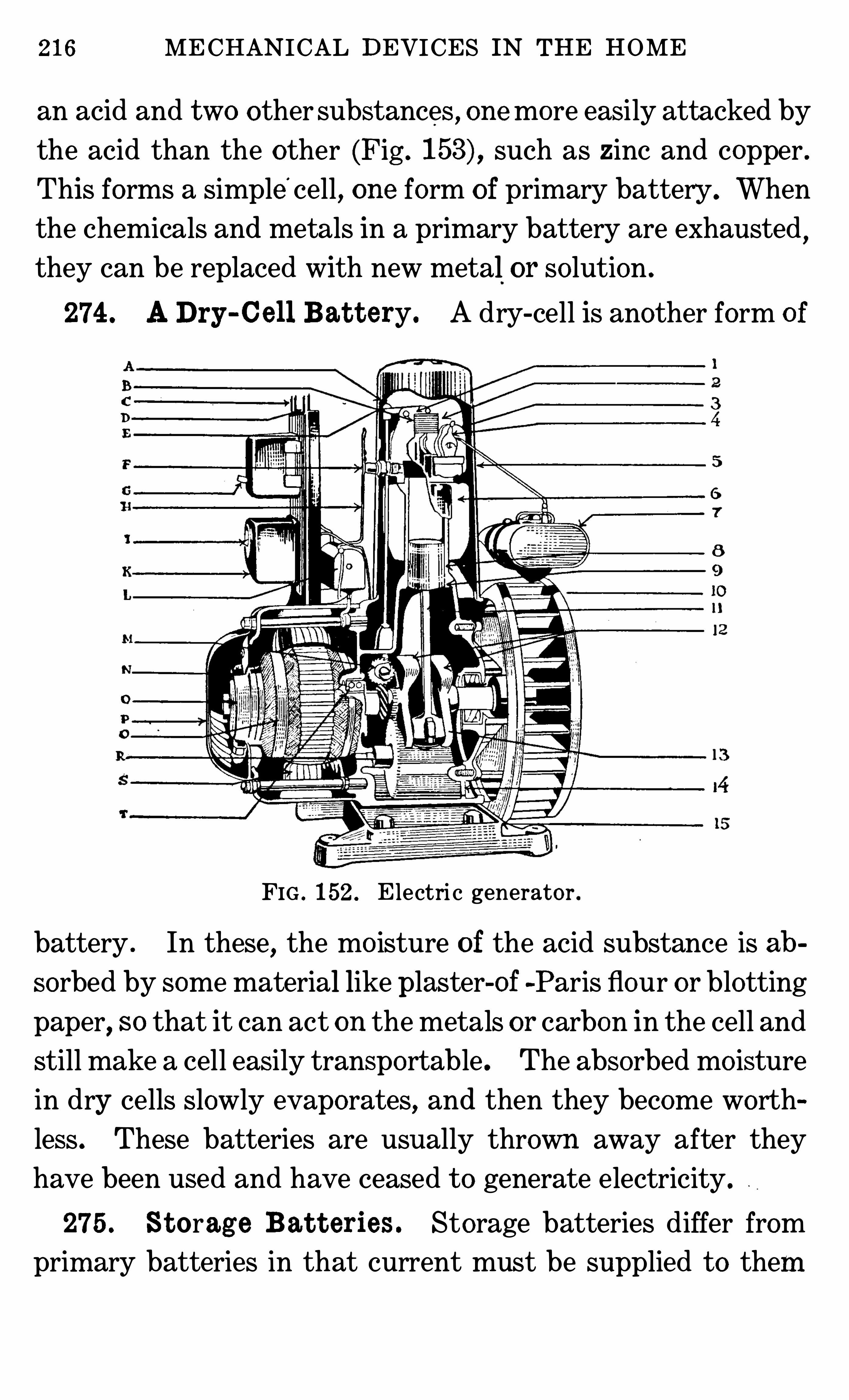
216 MECHANICAL DEVICES IN THE HOME
an acid and two other substances , onemore easily attacked by
the acid than the other (Fig . such as zinc and copper .
This forms a simple cell, one form of primary battery . When
the chemicals and metals in a primary battery are exhausted,
they can be replaced with new metal or so lution .
274 . ADry-Cel l Bat t ery. A dry-cell is another form o f
FIG . 152 . E lectri c generator .
battery . In these, the mo isture o f the acid substance is ab
sorbed by some material like plaster-Of -Paris flour or blotting
paper, so that it can act on the metals or carbon in the cell and
still make a cell easily transportable . The absorbed mo isture
in dry cells slowly evaporates, and then they become worthless . These batteries are usually thrown away after they
have been used and have ceased t o generate electricity .
275 . St orag e Bat t eries . Storage batteries differ from
prim ary batteries in that current must be supplied t o them
218 MECHANICAL DEVICES IN THE HOME
276 . Som e Uses for El ect ric Mot ors . M o tors are now
used on sewing machines, washing machines, dish washers,vacuum cleaners, wringers, fans, refrigerating systems, pumps,grinders
,freezers, churns and separators. They are made
either for direct or alternating current. When purchasing a
motor, be sure t o designate the type of currentwith which it is
t o be used . Select motors of the right size t o operate the ma
chine . It costs more t o operate a large motor on a small device than a small motor .
277 . Definit ion Tables . A British thermal unit is theamount of heat required t o warm one pound of water one de
gree Fahrenheit .
The flash po int o f an oil is that temperature at which it will
fo rm an inflammable vapor. The accompanying table shows
amount of heat generated from a number of sources .
The total heat in a gallon of kerosene is greater than that in
a gallon of gaso line because the kerosene is heavier than the
gaso line . A gallon of gaso line will give on an average but
about fiv e-sixt hs as much tota l heat as a gallon Of kerosene .
This is approximately true , whether the heaviest grades of
kerosene are compared with the heaviest grades o f gaso line, or
the lightest grade of kerosene is compared with the lightest
grade of gaso line .
D istillate is the refuse left from the distillation of petroleum .
The flash po int o f kerosene may be between 70and 150de
grees Fahrenheit, depending upon the grade . For illumin
ating purposes, do not use kerosene with the flash po int lower
than 120 degrees Fahrenheit .
The flash po int of gaso line is 10 t o 20 degrees Fahrenheit ;
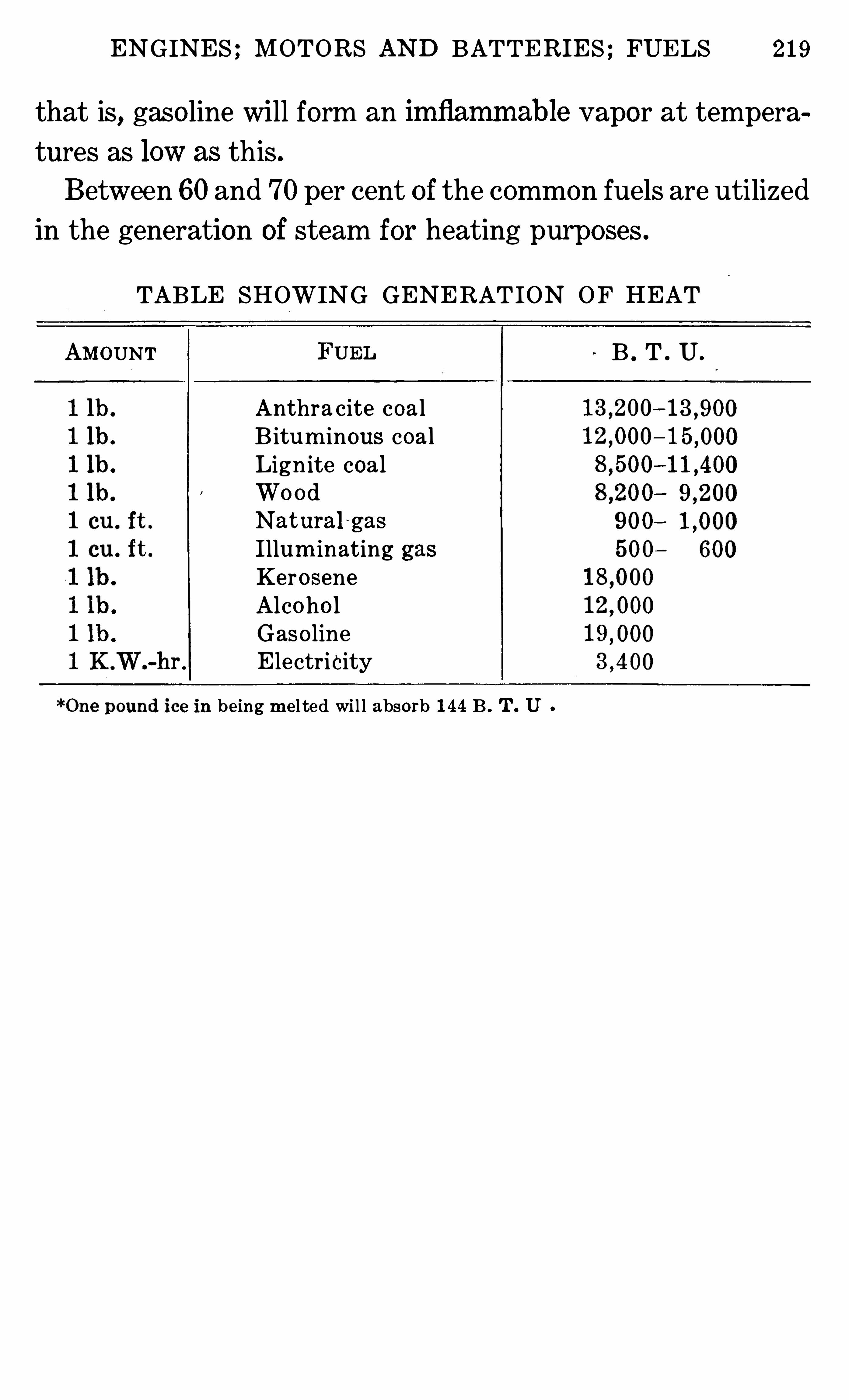
ENGINES ; MOTORS AND BATTERIES ; FUELS 219
that is,gaso line will form an imflammable vapor at tempera
tures as low as this .
Between 60 and 70per cent of the common fuels are utilized
in the generation of steam for heating purposes .
TABLE SHOWING GENERAT ION OF HEAT
AMOUNT B . T . U .
Anthra cite coalB itum inous coalLignite coalWo o dNat ural '
gas
Illum inating gasKero seneAlco ho lGaso lineE lectricity
be ing m e l te d wi l l absorb 144 B . T . U
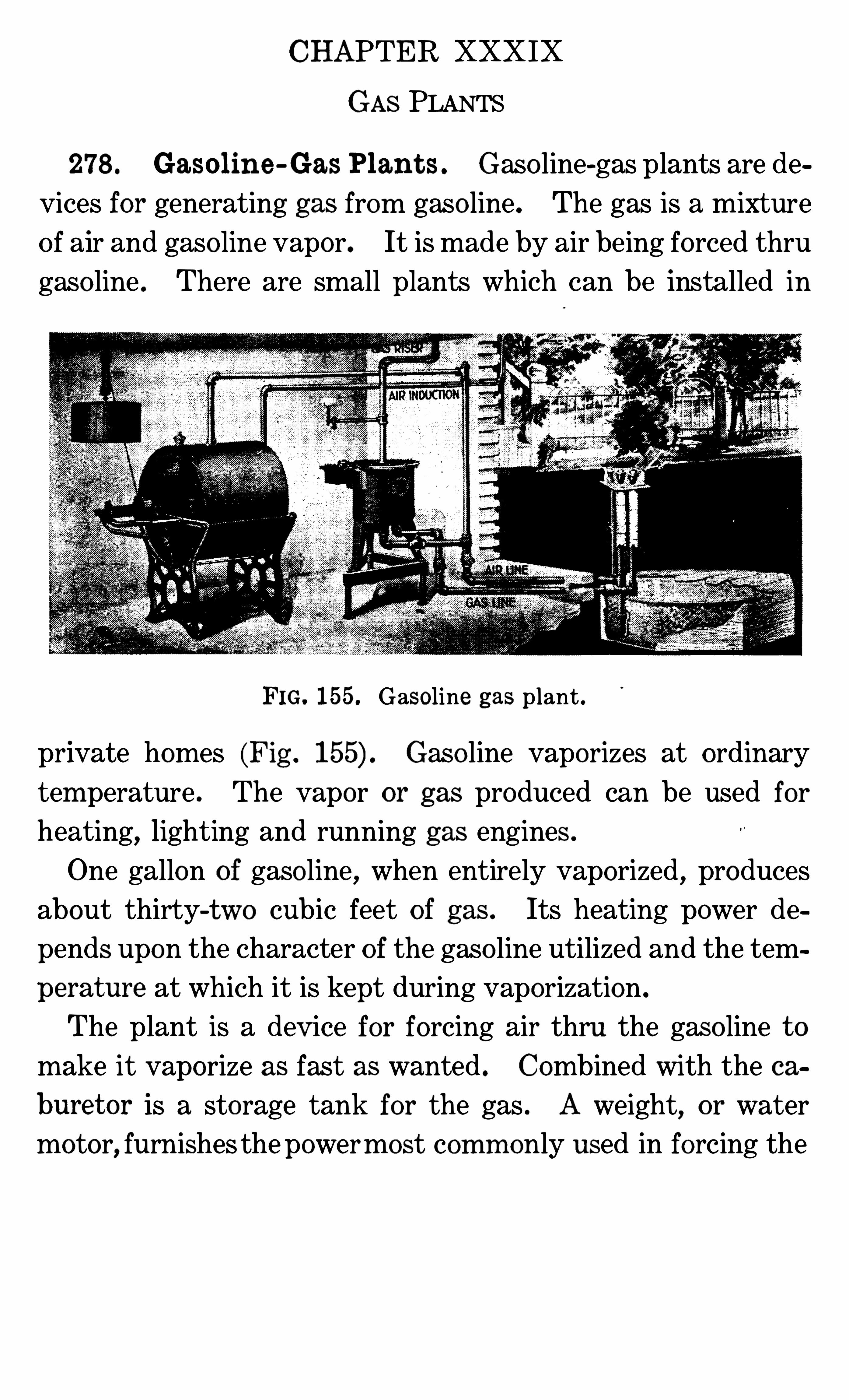
CHAPTER XXXIX
GAS PLANTS
278 . Gasolin e -Gas Plan t s . Gaso line-gas plants are de
vices for generating gas from gaso line . The gas is a mixture
Of air and gaso line vapor. It is made by air being forced thru
gaso line . There are small plants which can be installed in
FIG. 155. Gasoline gas plant .
private homes (Fig . Gaso line vaporizes at ordinary
tem perature . The vapor or gas produced can be used for
heating,lighting and running gas engines .
One gallon of gaso line, when entirely vaporized , produces
about thirty-two cubic feet of gas . Its heating power de
pends upon the character o f the gaso line utilized and the tem
perature at which it is kept during vaporization .
The plant is a dev ice for forcing air thru the gaso line t o
make it vaporize as fast as wanted . Combined with the ca
buret or is a storage tank for the gas . A weight, or water
motor, furnishes the powermost comm only used in forcing the
222 MECHANICAL DEVICES IN THE HOME
and coke fused together in an electrical furnace . It must be
kept stored in a dry place .
The plants for making acetylene are inexpensive enough t o
be installed in individual homes o f moderate means . Calcium
carbide for making the gas can be transpo rted without diffi
culty .
There are t wo types of machines . In one the wate r drips
on the carbide ; in the other, the more common type , the car
bide is dropped into the water. As soon as the carbide
touches the water, it gives o ff acetylene gas . The gas is
caught in and fills a bell above the water . AS it fil ls the bell ,it raises it, and when the bell reaches a certain height,it tripsa lever t o the doo r which lets in the
'
carbide and closes it .
When the gas is used , the bell goes down and , passing the
lever, opens the door t o let in a small amount of carbide .
Improvements have been made in the plants and in install
ing them until there is less danger from explosions than for
merly. Great care should be taken in operating them t o
avo id accidents . Since the gas . is highly explosive, fire,
lighted lamps and cigars must be kept away from the Vicinity
of all acetylene plants . Only one person should take the care
o f the plant, tho others should understand how.
280. Direc t ions for O perat ing Ac et yl ene Plan t .
1) Charge by daylight —remove all residuum, and fill with
fresh water before adding any carbide .
2) Fo llow exact directions for the machine used in the order
directed .
281 . Caut ion s t o Be Observ ed inUsingAc et ylene Gas .
1) Do not apply a light t o any opening that is not equipped
with a regular acetylene burner tip .
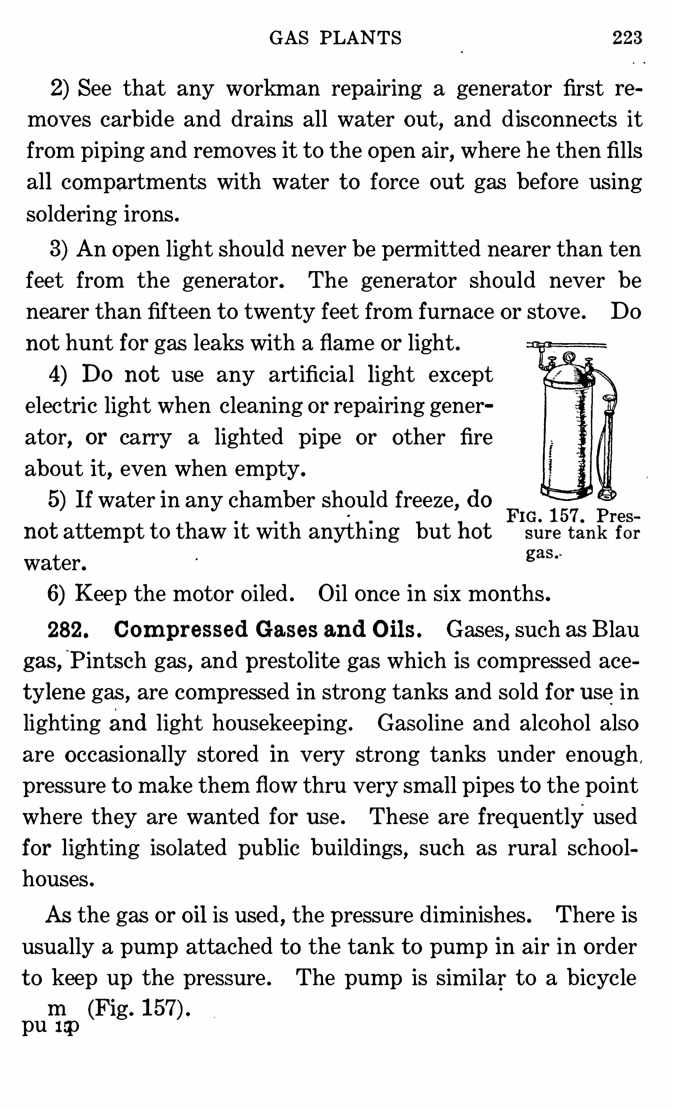
GAS PLANTS 223
2) See that any workman repairing a generator first re
moves carbide and drains all water out , and disconnects it
from piping and removes it t o the open air, where he then fills
all compartments with water t o force out gas before using
so ldering irons .
3) An open light should never be permitted nearer than ten
feet from the generator. The generator should never be
nearer than fifteen t o twenty feet from furnace or stove . Do
not hunt for gas leaks with a flame or light .
4) Do not use any artificial light exceptelectric light when cleaning or repairing gener
ator, or carry a lighted pipe or other fire
about it, even when empty.
5) If water in any cham ber should freeze, doFIG. 157 Pres
not atte mpt t o thaw it With anyth ing but hot sure tank foras .
water. g
6) Keep the motor o iled . Oil once in six months .
282. Com pressed Gases and O ils . Gases , such as Blau
gas ,
”
Pintsch gas,and prest o lit e gas which is com pressed ace
ty lene gas, are compressed in strong tanks and so ld for use in
lighting and light housekeeping . Gaso line and alcoho l also
are occasionally stored in very strong tanks under enough ,
pressure t o make them flow thru very small pipes t o the po int
where they are wanted for use . These are frequently usedfor lighting iso lated public buildings
,such as rural schoo l
houses .
As the gas or oil is used,the pressure diminishes . There is
usually a pump attached t o the tank t o pump in air in o rder
t o keep up the pressure . The pump is sim ilar t o a bicycle
pump (Fig . 157)
224 MECHANICAL DEVICES IN THE HOME
QUESTIONS FOR PART X
1 . What is the difference between the treadle and a m otor-powerm achine !2 . How is power secured from water in a water m otor ! Or what isthe source o f power utilized by a water m otor !3 . How d o y ou determ ine the s ize o f pulleys t o use on the gaso lineengine and on the device it is t o o perate !4 . What are som e indications that a gaso line engine or autom ob ile
m otor is no t running properly !5 . What are the kinds of batteries , and t o what uses is each best
suited !6 . Do batteries need care ! If so , what care !7 . How is acetylene gas m ade ! Describe the device for m aking it .8 . How is gas for househo ld use m ade from gaso line !
226 MECHANICAL DEVICES IN THE HOME
285 . Spring Scal es . Spring scales depend on the action
of a spring, t o which an indicating po inte r is attached . When
there is no weight on the spring, the place t o which the indi
cato r po ints is marked zero . When these scales are manu
factured , a pound weight is placed so that it pulls on the
spring and the indicato r is pulled down t o another place, and
this is marked one . Scales are thus marked for the number
of pounds they are t o weigh . The spaces between the pounds
marked are divided int o equal. divisions, such as sixteenths
which indicates ounces . These scales cannot be relied on for
accuracy, for springs stretch or become weaker as they are
used . Avo irdupo is is the weight in common use for market
ing,while many tables for calculating dietaries are in the
metric system .
The housewife can have her balances corrected for weighing
by the city or county sealer of weights and measures so that
she can ascertain whether or not her food purchases are c or
rec t ly weighed .
TABLE OF WE IGHTS
AVOIRDUPO IS16 o z .—1 pound
100 lb .-1 hundred-weight
2000 lbs.—1 t on
oz .-1 gram (Metric
system )
APOTHECARIES27 gram s—1 dram16 dram s—l o z .
METRIC1 m illigram—l /I OOO
'
.001 gram1 centigram—l /l OO .01 gram1 decigram—l /l O .1 gramGram—1 gramDekagram—I O gramsHectogram—l OO gramsKilogram—1000 grams
CHAPTER XLI
DEVICES FOR MEASURING VOLUME
286 . Graduat e and Measuring Cup . Graduate ho ld
ing up t o four fluid ounces is helpful t o use t o check up liquidsbought in bottles . The standard measuring cup referred t o
in modern cook books ho lds half a pint of liquid . It also
ho lds about sixteen level tablespoonfuls of dry mate rial such
as sugar . The divisions on glass cups are less likely t o be ac
curate than onmetal ones, as the bottom may be thick or thin
unless carefully made . In selecting a cup, see that the bottom
section is equal t o the other sections .
1 cup 2 gills pint 16 tablespoons
48 teaspoons 8 fluid ounces .
1 cup is also of a quart and about 4/17 of a
liter.287 . Tab l espoons . Tablespoons vary in size . The size
chosen for measuring is the one in most common use and
ho lds about three level teaspoonfuls of material like sugar or
flour .
1 tablespoon 4 drains of liquid 3 teaspoons .
4 tablespoons cup 2 fluid ounces .
288 . Teaspoons . Teaspoons vary in size,but the spoon
in common use is the one understood as the measure in cook
ery. It ho lds about one and one-third fluid dram s .
289 . St andard M easuring Spo ons . Standard meas
uring spoons in sets can be purchased at a very moderate
228 MECHANICAL DEVICES IN THE HOME
price . They are part icularly valuable for checking the capac
ity o f the spoons more commonly used .
290. Li qu id and Cook ing Measures .
1 teaspoonful= 1 fluid dram s
3 teaspo onfuls= 1 tablespo onful= 4 dram s
2 tablespo onfuls= 1 fluid ouncecup= 1 gill
2 gills : 1 cupful= 8 fluid ounces16 tablespo onfuls= 1 cupful2 cupfuls= 1 p int2 pints==1 quart= 4 cupfuls4 quarts : 1 galloncupfuls= 1 liter
1000 cub i c centim eters= 1 literliquid quart s= lit er
31 gallons= 1 barrel1 m illiliter==one-thousandth liter1 centiliter one-hundredth liter1 de cilit er= one-tenth literLiter= 1 l iter1 dek alit er= t en (10) liters1 hecto liter= one hundred (100) liters1 kilo liter= 1 thousand (1000) liters
291 . Dry Measure s . It is wise for a housewife t o have a
se t o f dry measures, consisting of a pint, quart, gallon, peckand half-bushel measure . A quart or gallon liquid measureis not equal t o the dry one . It ho lds less. The diameter of
dry measures should be as fo llows
D IAMETERS OF DRY MEASURESMEASURE *D IAMETER1 pint 4 in ches1 quart 5-3/8 inches2 quarts 8 inchespeck 8 in ches
1 peck 10 inches1 bushel 13 inches
Th ese diam e t ers al low fo r proper h eaping .
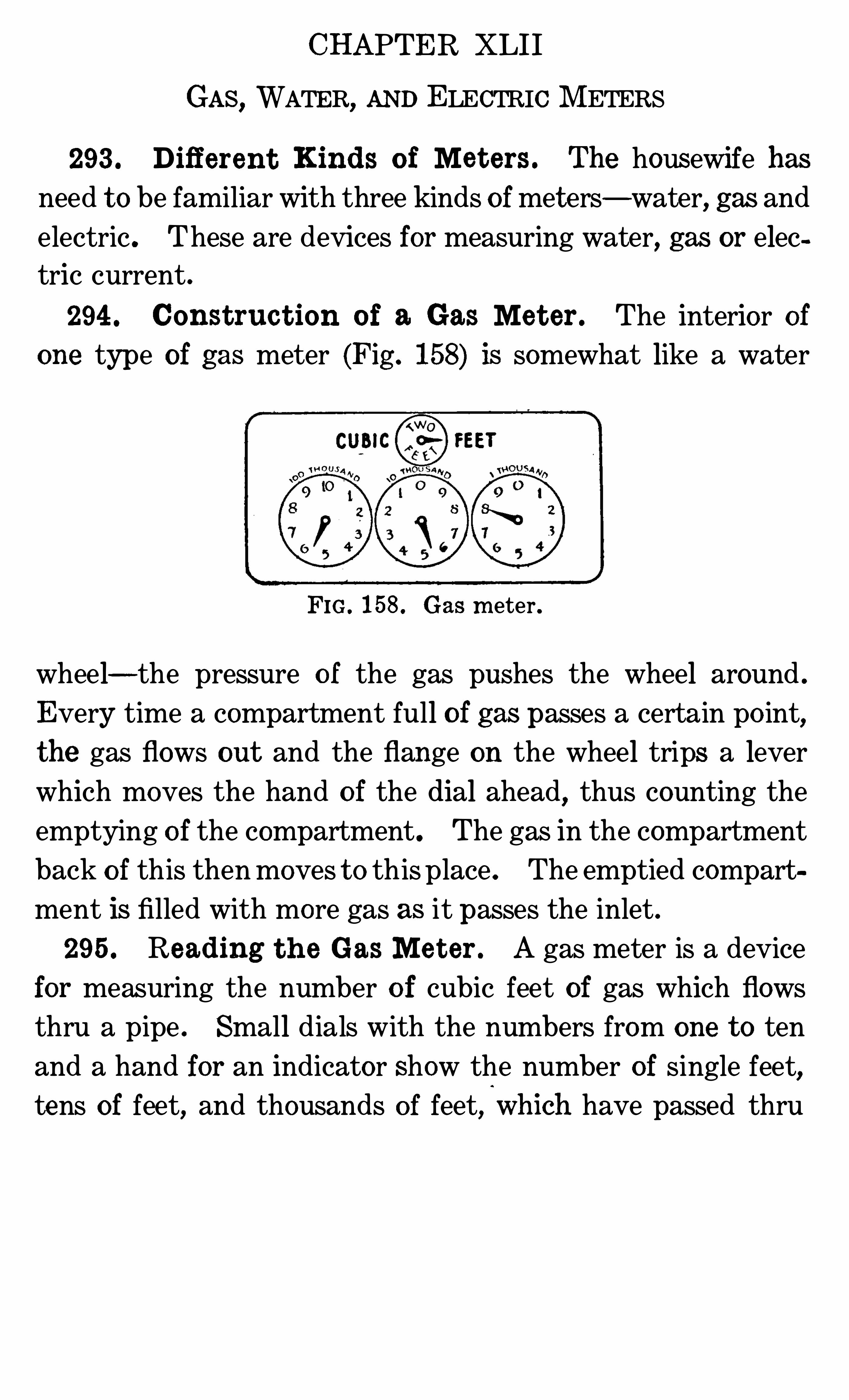
CHAPTER XLII
GAS, WATER, AND ELECTRIC M ETERS
293 . Different Kinds o f Me t ers . The housewife has
need t o be familiar with three kinds ofmet ers—water, gas and
electric . These are devices for measuring water, gas or elec
tric current .
294 . Const ruc t ion o f a Gas Me t er . The interior ofone type of gas meter (Fig . 158) is somewhat like a water
FIG . 158 . Gas m eter .
wheel—the pressure o f the gas pushes the wheel around .
Every time a compartment full o f gas passes a certain po int,the gas flows out and the flange on the wheel trips a lever
which moves the hand o f the dial ahead,thus counting the
emptying o f the compartment. The gas in the compartment
back o f this then moves t o this place . The emptied compart
ment is filled with more gas as it passes the inlet .
295 . Reading t h e Gas M e t er . A gas meter is a device
for measuring the number o f cubic feet of gas which flows
thru a pipe . Small dials with the numbers from one t o ten
and a hand for an indicator Show the number of single feet,tens of feet, and thousands of feet,
i
which have passed thru
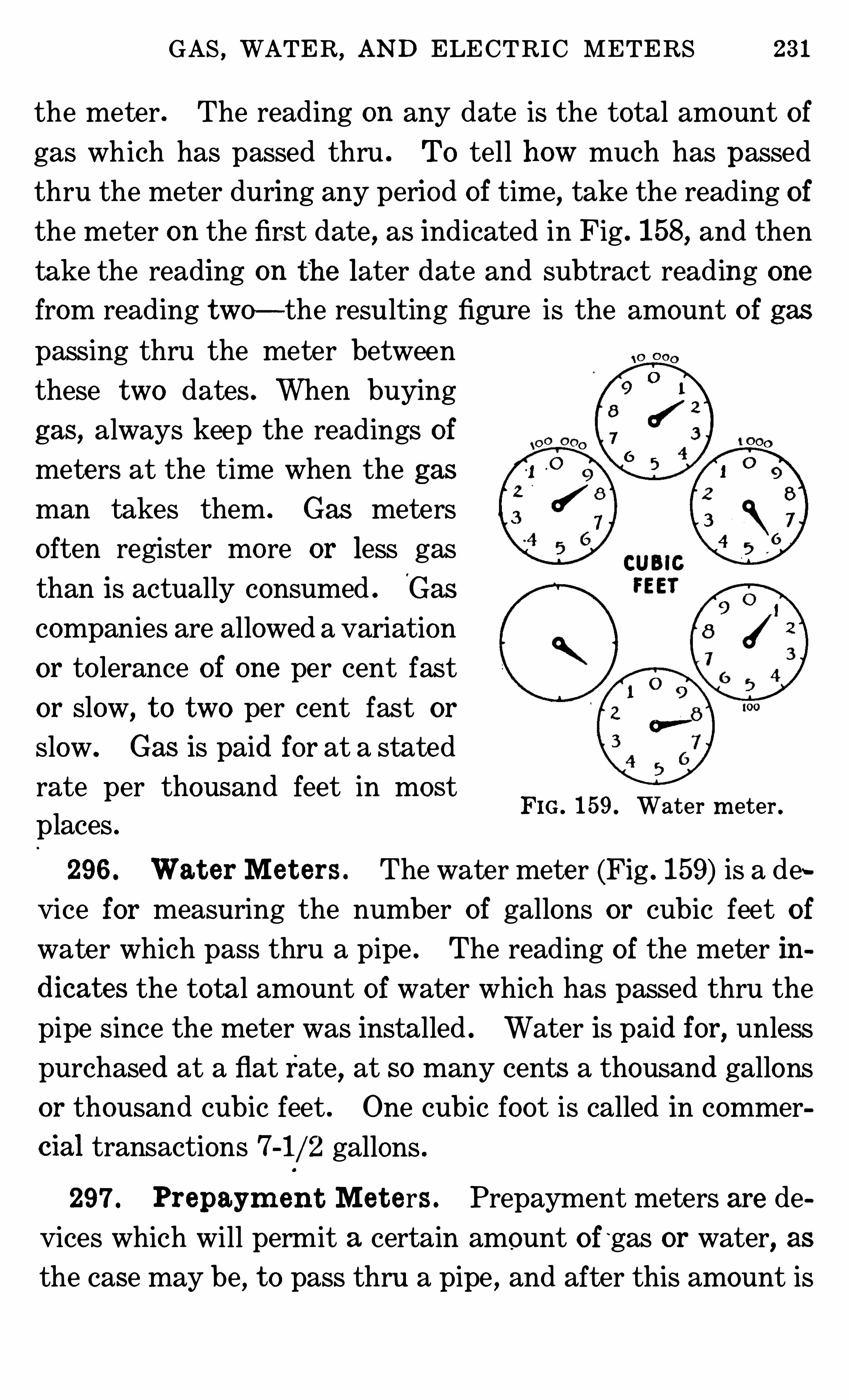
GAS,WATER
, AND ELECTRIC METERS 231
the meter . The reading on any date is the total amount of
gas which has passed thru . To tell how much has passed
thru the meter during any period of time, take the reading of
the meter on the firs t date , as indicated in Fig . 158, and then
take the reading on th e later date and subtract reading one
from reading two—the resu lting figure is the amount o f gas
passing thru the meter between
these two dates . When buying
gas, always keep the readings of
mete rs at the time when the gas
man takes them . Gas meters
o ften register mo re or less gas
than is actually consumed . Gas
companies are allowed a variation
or to lerance of one per cent fast
or slow, t o two per cent fast or
slow. Gas is paid for at a stated
rate per thousand feet in most
places .
296 . Wat er Me t ers . The water mete r (Fig . 159) is a de
vice for measuring the number of gallons or cubic feet of
water which pass thru a pipe . The reading o f the meter in
dicates the tota l amount of wate r which has passed thru the
pipe since the meter was installed . Water is paid for, unless
purchased at a flat rate,at so many cents a thousand gallons
or thousand cubic feet . One cubic foot is called in commercial transactions 7-1/2 gallons .
FIG . 159. Water m eter .
297 . Prepaym en t Me t ers . Prepayment meters are de
vices which will permit a certain amount of~gas or water, as
the case may be, t o pass thru a pipe , and after this amount is
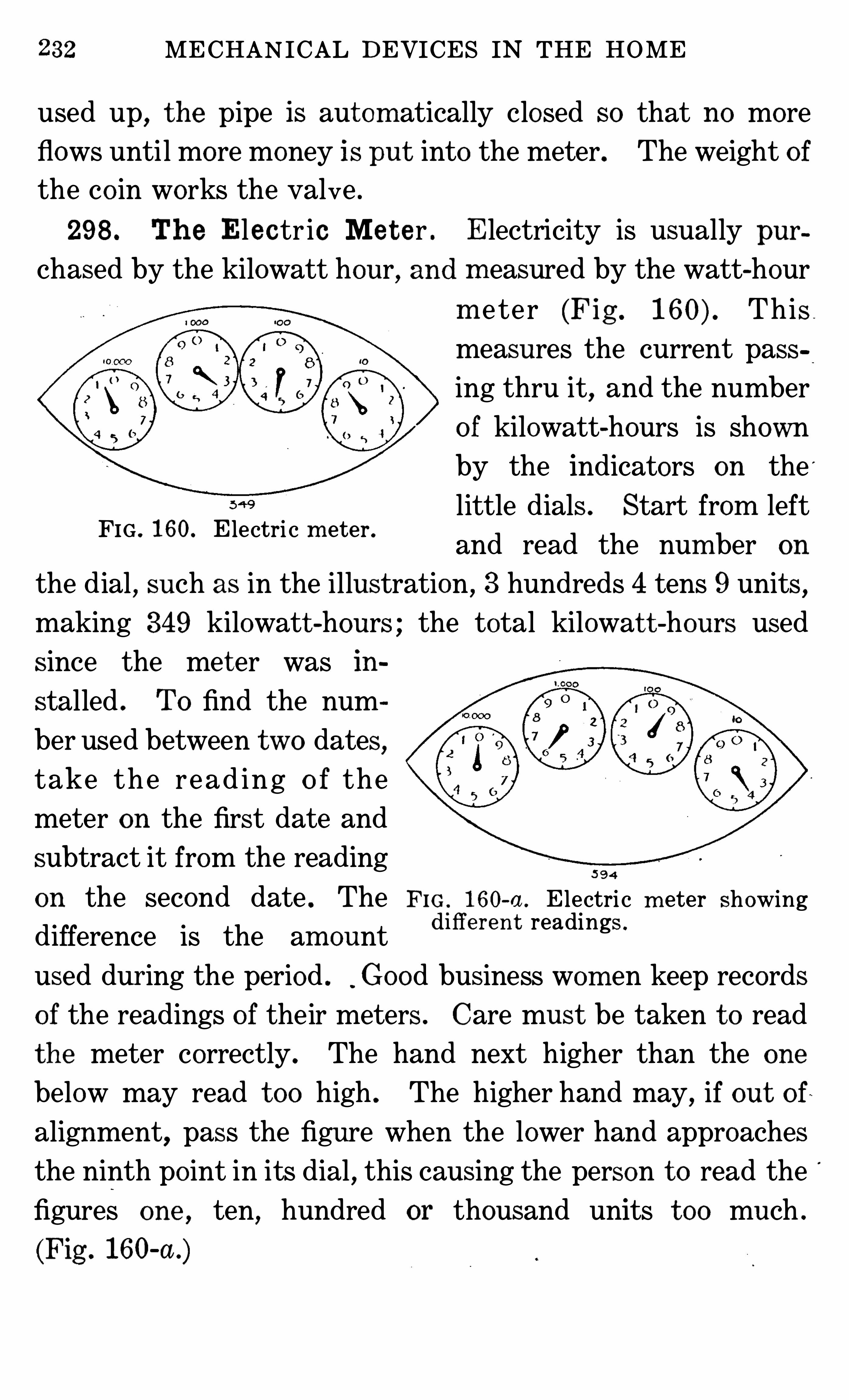
32 MECHANICAL DEVICES IN THE HOME
used up, t he pipe is aut om atically closed so that no more
flows until more money is put into the meter. The weight o f
the co in works the valve .
298 . Th e Elec tr ic Me t e r . Electricity is usually pur
chased by the kilowatt hour, and m easured by the watt-hour
m e te r (Fig . This
measures the current pass
ing thru it, and the number
o f kilowatt-hours is shown
by the indicators on the '
little dials . Start from left
and read the num ber on
the dial , such as in the illustration , 3 hundreds 4 tens 9 units ,making 349 kilowatt -hours ; the total kilowat t -hours used
since the met er was in
stalled . To find the num
ber used between two dates,
take th e re ad ing o f the
meter on the first date and
subtract it from the reading5 9 4
on the second date . The F IG 160-a . E lectri c m eter showingdifference is the am ount
d l fl erem readings '
used dur ing the period . Good business wom en keep records
o f the readings o f their meters . Care must be taken t o read
the meter correctly . The hand next higher than the one
below may read t oo high . The higher hand may, if out o f
alignment, pass the figure when the lower hand approaches
the ninth po int in its dial,this causing the person t o read the
figures one , ten, hundred or thousand units t oo much .
(Fig . 160-a .)
FIG . 160. E lectri c m eter .
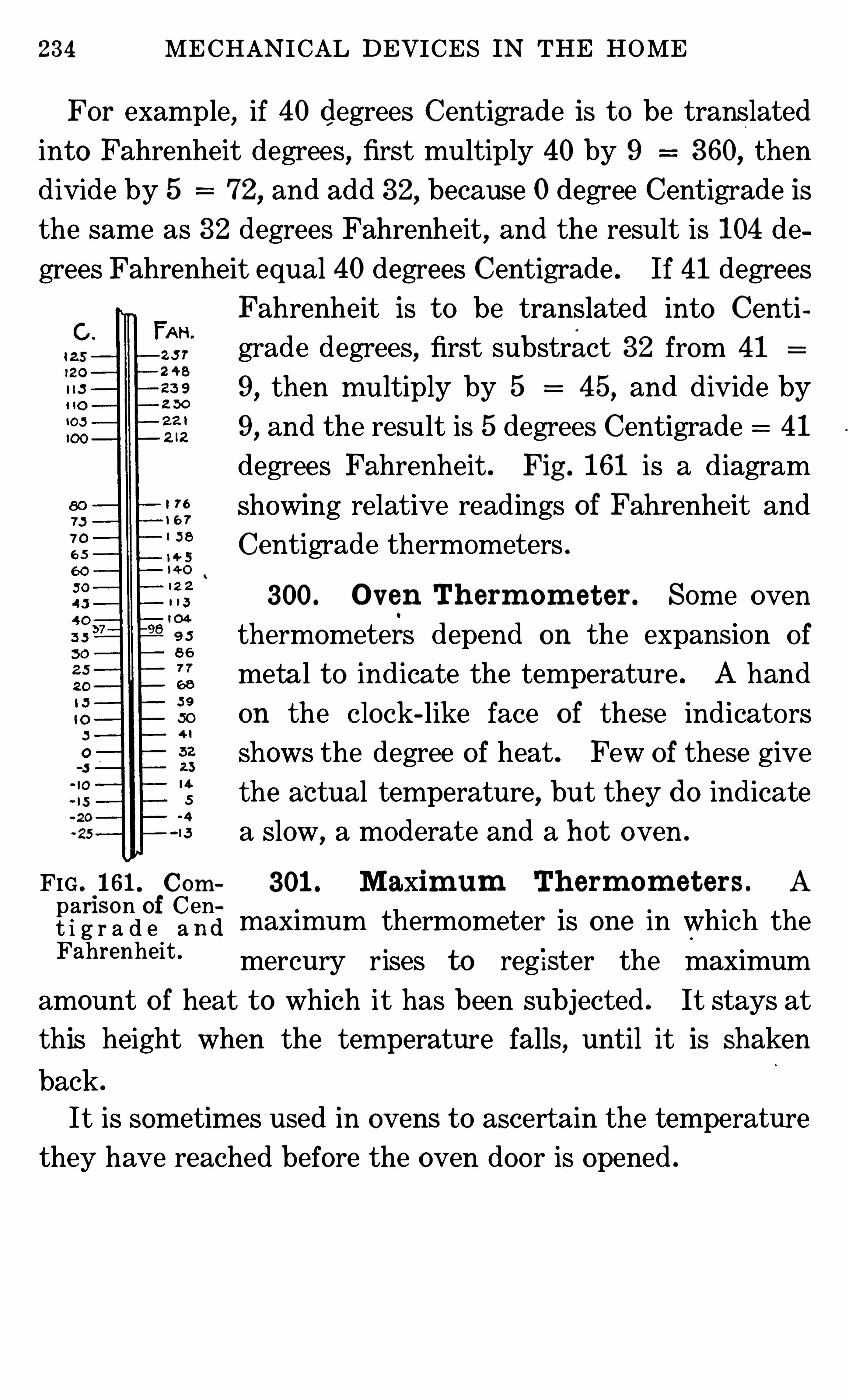
234 MECHANICAL DEVICES IN THE HOME
For example, if 40 degrees Centigrade is t o be translated
into Fahrenheit degrees, first multiply 40 by 9 360, then
divide by 5 72, and add 32, because 0 degree Centigrade is
the same as 32 degrees Fahrenheit, and the result is 104 de
grees Fahrenheit equal 40 degrees Centigrade . If 41 degrees
FIG . 161. Comparison of Cent i g r a d e a ndFahrenheit
Fahrenheit is t o be translated into Centi
grade degrees, first substract 32 from 41
9, then multiply by 5 45, and divide by
9, and the result is 5 degrees Centigrade 41
degrees Fahrenheit. Fig . 161 is a diagram
showing relative readings o f Fahrenheit and
Centigrade thermometers .
300. O v en Th erm om et er . Some oven
thermometers depend on the expansion of
metal t o indicate the tem perature . A hand
on the clock-like face o f these indicato rs
shows the degree o f heat . Few of these give
the actual temperature, but they do indicate
a slow,a moderate and a ho t oven .
301 . Maxim um Th erm om et ers . A
maximum thermometer is one in which the
mercury rises to reg ister the maximum
amount o f heat t o which it has been subjected . It stays at
this height when the tem perature falls , until it is shaken
back .
It is sometimes used in ovens t o ascertain the temperature
they have reached before the oven doo r is opened .
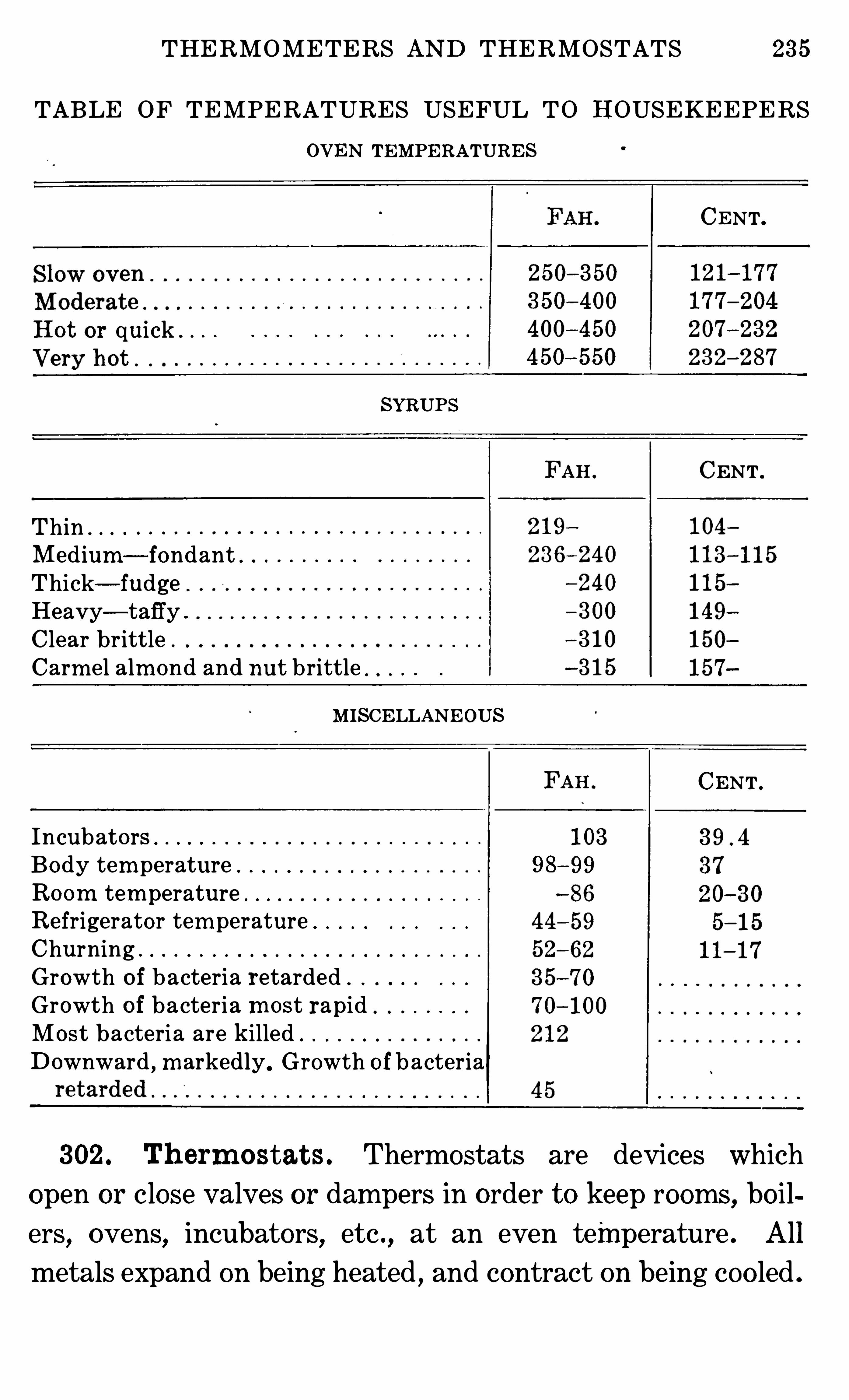
THERMOMETERS AND THERMOSTATS 235
TABLE OF TEMPERATURES USEFUL TO HOUSEKEEPERS
OVEN TEMPERATURES
CENT.
Ho t o r quick .
SYRUPS
CENT .
ThinMedium—fondantThick—fudge .
Heavy—taffy .
C lear brittle .
Carm el alm ond and nut brittle
M ISCELLANEOUS
CENT .
Incubato rsBody tem perature . 98—99
Ro om tem perature .
Refrigerato r tem peratureChurningGrowth o f bacteria retardedGrowth o f bacteria m o st rapidMost bacteria are killed .
Downward , m arkedly. Growth o f bacteria
302 . Th erm ostat s . Thermostats are devices which
open or close valves or dampers in order t o keep rooms,bo il
ers, ovens, incubators, etc ., at an even temperature . All
metals expand on being heated , and contract on being coo led .
236 MECHANICAL DEVICES IN THE HOME
Some expand more than o thers . Two materials which ex
pand at different rates are frequently used in making ther
mostats .
‘
Any certain temperature causes a given piece of
metal t o expand t o a certain size , or t o contract on coo ling t o a
different size . Som e thermostats are made o f a straight rod
of metal like copper which expands more than iron when
heated . The rod is so placed that when coo l it will allow fuel
like gas or oil t o pass thru a pipe,and when heated , it will
expand enough t o close the pipe,shut ting o ff the fuel . They
are placed so that they close the pipe at the t em perature de
sired for an oven or supply o f ho t water .
Other therm ostats are more complicated,as the expanding
metal moves a ser ies o f levers . These therm ostats are used
t o regulate dampers on coal and wood furnaces , when they are
placed in the rooms t o be heated . They are o ften used on
other devices , such as incubators .
Still others contro l an electric current . Wh en the metal
expands,it closes the circuit , causing the electricity t o do the
work desired . When it contracts , it opens the circuit . Ther
m ostat s can be se t t o do work at different temperatures .
These are som etimes attached t o clocks which , with a de
vice similar t o the alarm ,will change the indicator o f the
therm ostat so as t o se t it from one tem perature t o another at
a stated tim e for which the clock is set and turn it back at
another hour .
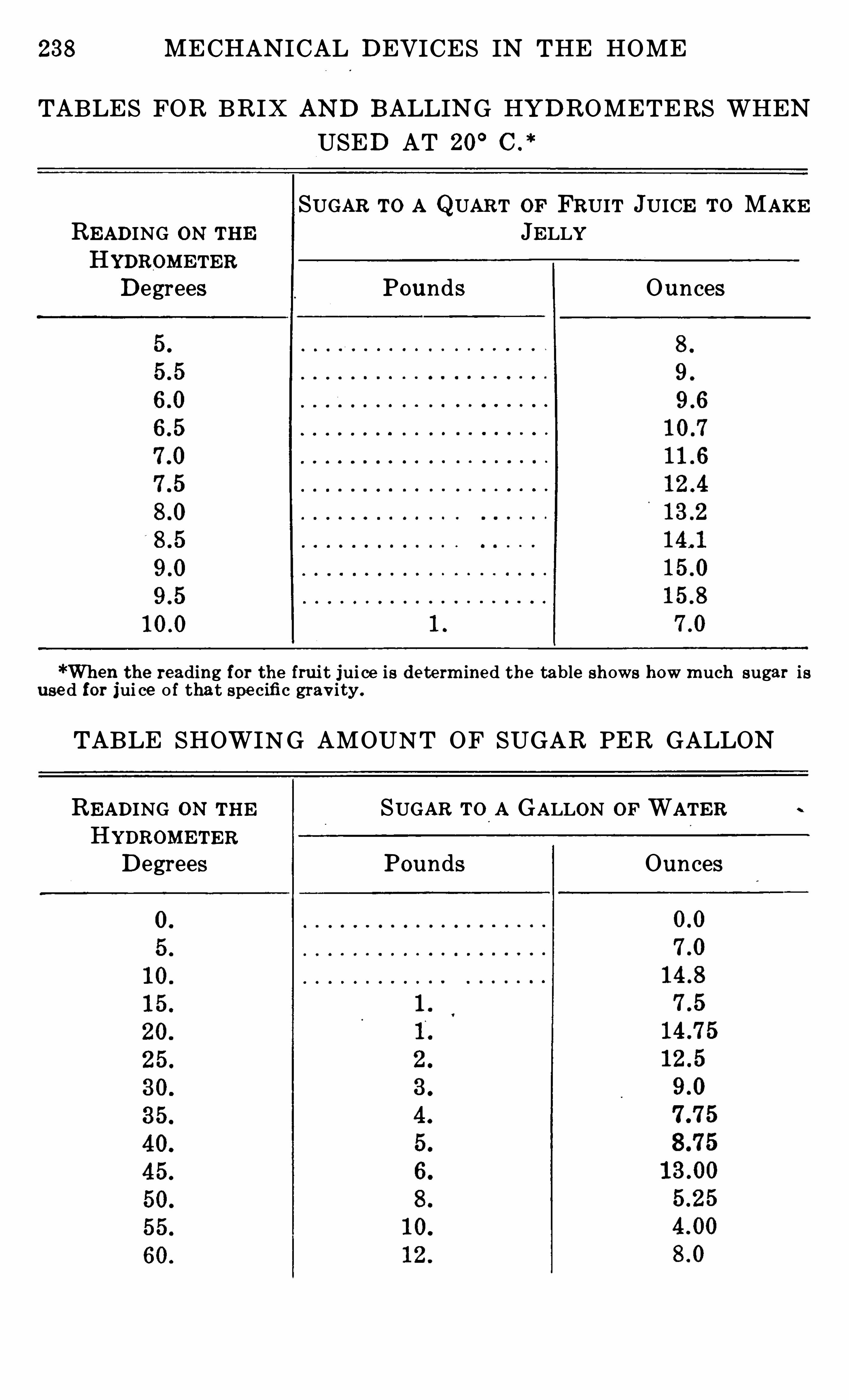
238 MECHANICAL DEVICES IN THE HOME
TABLES FOR BRIX AND BALLING HYDROMETERS WHENUSED AT 20
°C .
*
SUGAR To A QUART OF FRUIT JUICE To MAKEREADING ON THE JELLYHYDROMETERDegrees Pounds Ounces
*When t he reading for t h e fruit jui ce is de te rm ine d t he table sh ows how m uch sugar isuse d for jui ce o f that spe cifi c grav i ty .
TABLE SHOWING AMOUNT OF SUGAR PER GALLON
READING ON THE SUGAR To A GALLON OF WATERHYDROMETERDegrees Pounds Ounces
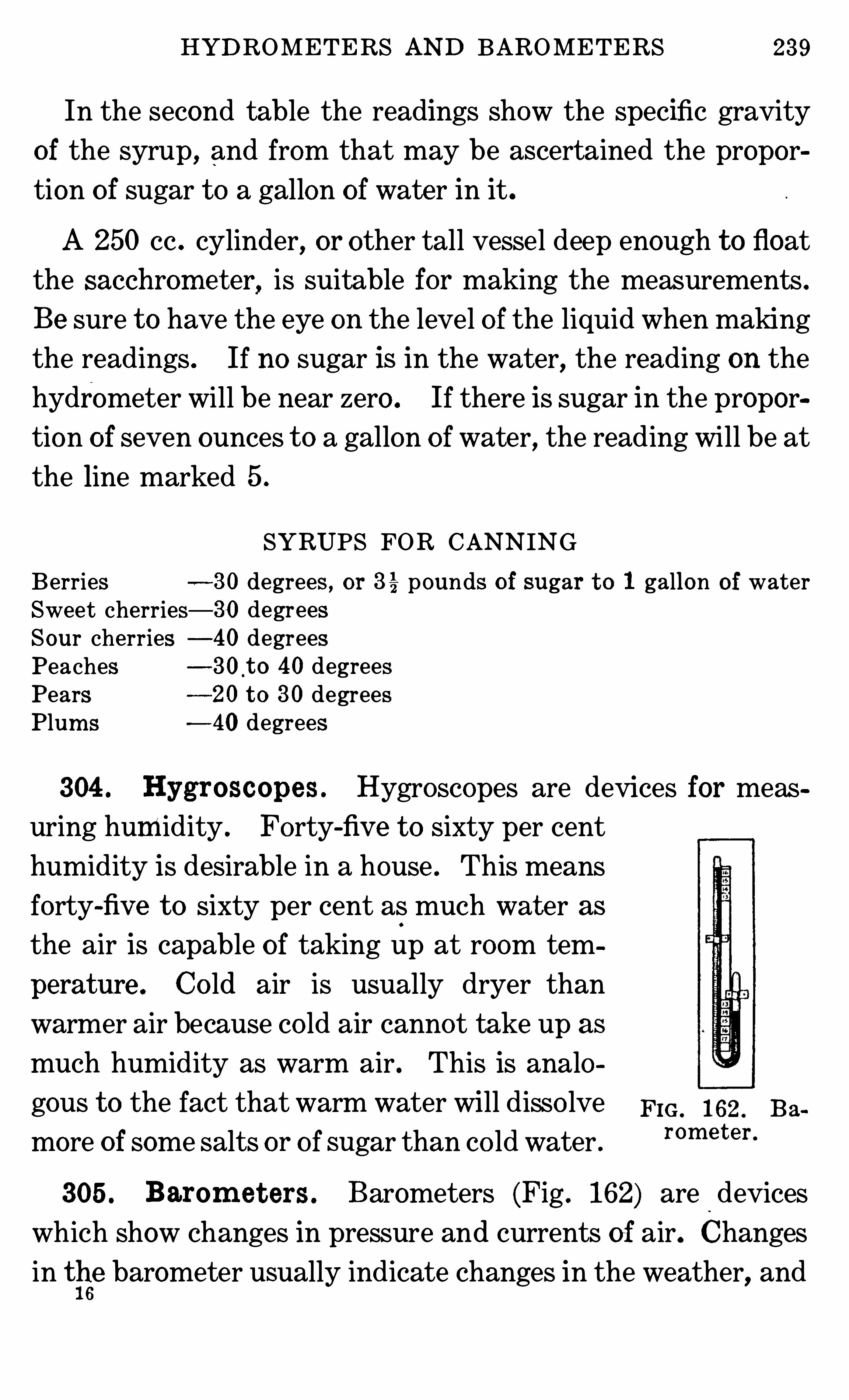
HYDROMETERS AND BAROMETERS 239
In the second table the readings show the specific gravity
of the syrup , and from that may be ascertained the propor
tion o f sugar t o a gallon of wate r in it .
A 250 cc . cylinder, or other tall vessel deep enough t o float
the sacchrom e t er, is suitable for making the measurements .
Be sure t o have the eye on the level of the liquid when making
the readings . If no sugar is in the water, the reading on the
hydrometer will be near zero . If there is sugar in the propor
tion o f seven ounces t o a gallon o f water, the reading will be at
the line marked 5 .
SYRUPS FOR CANNINGBerries 30 degrees , or 3 % pounds o f sugar 1 gallon waterSweet cherries— 30 degreesSour cherries —40 degreesPeaches —30 t o 40 degreesPears 20 t o 30 degreesPlum s 40 degrees
304 . Hygroscopes . Hygroscopes are devices for meas
uring humidity . Forty-fiv e t o sixty per cent
humidity is desirable in a house . This means
forty-fiv e t o sixty per cent as much wat er as
the air is capable o f taking up at room tem
perature . Co ld air is usually dryer than
warmer air because co ld air cannot take up as
much humidity as warm air . This is analo
gous t o the fact that warm water will disso lve Fm , 162 . Ba
more of some salts or o f sugar than co ld water .
rom e t e r ‘
305 . Barom e t ers . Barometers (Fig . 162) are devices
which show changes in pressure and currents of air. Changes
in the barometer usually indicate changes in the weather, and
240 MECHANICAL DEVICES IN THE HOME
thus they are of interest t o all persons . A decided fall in the
mercury of a barometer usually precedes foul weather,while a
rise indicates the approach o f fair weather. Wh en the pressure is low in any locality, air begins t o rush toward that
po int as it would t o fill a vacuum . So a fall in the barom eter
precedes the com ing of a high wind or a rainstorm . A rise in
the barometer precedes a calm,and since most rain is accom
panied with wind , the calm is a tim e o f fair weather .
242 INDEX
PageCerium 88Cesspo o l 124
‘
Charcoal filter 114Chain stitch 186Cherry stonerCheck valve 71 183Chim ney
33 , 57 , 59, 74 , 75, 80, 9394 , 111
Chloride o f l im e . 126Choker 192Chopper 162 , 163Churns 165,C istern 114C lam p 138
Cleanin 25, 3 5, 127 , 172
C leaning equipm ent147 , 148 , 149, 150, 152 , 153
C linkers 76C lo ck 236C lutch . 192
C oal . 66 , 76Co ffeemill 162
po t
Co g wheels “ . 165Co ils . 8 80Coke 222Co ld-pro cess gaso line-gas
29 , 91 , 145C o lo r and illum ination 84Com pressed-air pum p
113 , 115 , 117C om bustion
16 , 17 , 23 , 24 , 58 , 66 , 74 , 76, 77
Conductivity o f materials156 , 157 , 158
Contraction o f m aterials 235Co okers 50, 51 , 55 , 56Coo lers . . 105 , 106 , 108 , 109
C opper . 158 , 216 , 236Crank . 163
Cream separato r . 178 , 179
Cub i c m easure 229
Cup , m easuringCurrent , electric
42, 46 , 80, 83 , 86 , 110, 143 ,232
Curtain ro ller 185
Cylinderwasher 133
EarthenwareEgg testerE lectric appliances
DDam pers16 , 17 , 18 , 19, 20, 22 , 58 , 61 , 66
74 , 75 , 197 , 198 , 235, 236Decom position of sewage
124 , 125 , 127Degree . 233 , 234Dekagra 226Dekaliter 228Dekam eter . 229Derm ax . 206Density of liquids 237D irect current 110D irect lighting 85D ish-washer 170, 171D isinfectant 126 , 200D istillate . 40, 218Do lly washer 134Do o rs . 103 , 183 , 184 , 185 , 2 15Drafts
16 , 17 , 18 , 19 , 57 , 58 , 59 , 74Drain 103 , 104 , 122 , 138Dram 226 , 228Drip pipe 102 , 103Drip sheet 25Dryer 171 , 176Dry
-cleaning equipm ent 140Dry
- cell battery 215 , 2 16Dulling o f edges 159 , 163Dum bwaiters 183Dust 76 78 80 148 , 150Dynam o 215, 216
. 107 , 156
. 201
42, 44 , 46 , 81heating 42 , 43 , 80, 1 19m easurem ents . . 43 , 82 , 230, 232
E lectric m otors 217E lectricity . 215 , 219
E lectro lyt e 217
Enam eled ware 157Engine , gaso line 137 , 2 12
Evaporation . . 67, 105 , 106 , 140Exhaust pipe 212 , 214Expansion o f m aterials
108 , 234 , 235tank 66 , 67 , 120
valve 70
INDEX
Explosions , prevented25 , 35 , 37 , 39, 69
util iz ed 192 , 214 , 222
139
F
Fahrenheit therm om eter 233 , 234Fan . 110, 148 , 177
Fastener , do o r 184
Faucet . 109, 114 , 116 , 119, 120, 122
Feed plate 187 , 188 , 189, 207
Filam ent for lam p 83
Filter, water . . 114 , 1 16 , 168
Fire 18 , 19 , 34 , 41 , 66 , 75
Fireless co oker 50, 51
Fireplace .
Fire-po t . 20, 57 , 58 , 65 , 76
Flam e 23 , 35 , 38
Flam e , blue 3 1 , 3 8 , 49, 96
illum inating . 77 , 78 , 88 , 89 , 93 , 94
Flash p o int . 218
Flat-iron 142
Float for flushing tank 129 , 130
Flue 66 , 77
Fo rce pum p . 113 , 117 , 119
Freezer .
Freezing . . 68 , 112 , 126 , 166 , 233
Friction , danger from 140
Fuel 16 , 58 , 65 , 76 , 88 , 119
econom ical use o f19
Funnel 133 , 167 , 168
Furnace . . 57 , 62 , 63 , 64 , 75 , 222
G
Gage 67 , 69 , 70, 73 , 117
Gage , steam 72 , 173
Gallon . 228
Gas26 , 34 , 35 , 36, 37 , 38 , 40, 58 , 88
108 , 192 , 199, 214 , 215 , 219
221 , 230burners . 77 , 79 , 90, 144consum ption 23 , 28 , 29 , 66form ation 96 , 97 , 98kinds o f
29, 222,223
Gaso line89, 97 , 99, 140, 219, 223
0 0 0 0 0 0
243
Gaso l ineburner . 37 , 96
engine 119 , 137 , 212 , 215
Gaso line-gas 29 , 37 , 91 , 220
Gears 192
Generation o f heat and gas219 , 220
Generator 96 , 223
G ill 227 , 228
Glass utensils 156, 157 , 158
Graduate . 227
Gram . 226
Granite ware 156 , 1 57
Grate . 16 ,Grater . 160
Gravity lam p 96
Gravity , specific . . 217 , 237 , 239
Grinder 159 , 162
H
Heat . 48 , 89, 156 , 158 , 218
production o f42 , 140, 143 , 200, 219
use o f
II eat e r
141 , 143 , 196 , 197
Hectograph 205 , 206
Hecto liter 228
Hectom eter 229
H inge 184 , 185
Hom ogenizer . 180
Horse power 210
Ho t -water furnace . 64
Ho t -water tank 117
Hum idity . . 239
Hundred-weight . . 226
. 217 , 237 , 238 , 239
Hygros cope 239
I
Ice 100, 101, 102 , 103 , 104 ,I celess refrigerato r 105 , 106Incubator 235adjustm ent o f 199
Ignition o f gas 140, 214 , 215Illum ination28 , 77 , 78 , 82 , 84 , 85 , 88 , 218 , 219Inch 228 , 229
Ink 205 , 208
Insulation . 19, 46, 50, 55, 57, 66 , 102
244 INDEX
PageIron 155,Ironing board . 144Irons .
r
Jars , fruit .
Je llom e t e r
K
Kerosene lam ps 95oil .
stoves . 80Kisse lguhr filter 114
Keyboard . 202 , 204Kilogram 226Kilo liter 228Kilom eter 229
Kilowatt . 82 , 232Kneading m achine 165Knives 159, 163 , 196Kno cking, cause o f 71 , 214
Lard press . 163Lam p , adjustingburners
93 , 94
electric . . 82 , 83 , 84 , 87
gas o r o il
Laundry tubs . 127
Lawn m owerLava tip 89Leather , preventing shrinkin
g1ff2
Lever . . 72 , 154 , 163 , 190, 236Light . 83 , 84 , 85 , 86 , 98Lights . 82 , 88 , 98Lighters . 28 , 91 , 215
Lighting , lam ps . 89, 90, 94 , 95stoves25 , 27 , 33 , 34 , 37 , 38 , 78 , 79 , 80
Lighting plants . 86 , 114
Lim e 221Lining refrigerator . 101Lignite coal . 219Liquify , sewage . 124 , 125
. 237
Liter . 227, 228Lo com o tiv e wash er . 13 5
Logs , gas . 78
Leek-stitchLubrication
Natural gasNeedleNickelNo zzle
O O O O O O O O O O O O O
M
0 0 0 0 0 0 0 0
Mangles . 141Mantles for lam ps
88 , 89, 90, 91 , 95 , 98Manufactured gas 78 , 89 , 91Maxim um therm om eters 234
Mazda lam ps . 82, 83 , 84
Measurem ents 225
Melting i ce 103
Metal , conductivity o f . . 156 , 158
Meter 229, 230, 231 , 232M icrobes, septic . 126
M ile 229
M illim eter 226M illiliter 228
M illigram 226
M im eograph . 206
M ixer 165Mo isture . 200, 239M op wringer . .
hdo t or
108 , 110, 133 , 150, 186, 192 , 209care o f 214 , 217
water . . 210, 211 , 220Mower 196Multigraph . . 206 , 208
N
0
O il 31, 93 , 110, 200, 214 , 218 , 223O il cups 33 , 3 5
Oscillating washer . 134 , 135
Ounce . 226 , 228
Oven 19, 20, 26 , 27 , 42 , 235
Overflow 67 , 119, 120, 122, 130
P
Packing .
PansParersPeck .
Perco lato r .
Pet co ckPilot light
246 INDEX
Steamcooker 56valves and gages . 70, 72 , 73 , 173
Steel for co oking . 155Stencil . 206Stitch . 188,Stones , fire le ss co oker . . 50, 54Stoner . . 161Storage tank . 113 , 220
Sto rage battery . . 215 , 216 , 217
Stove37 , 49, 57 , 58 , 63 , 65 , 70electric 42 , 44 , 1 57
gas . 23 t o 30, 144
heating . . 75 , 76 , 78 , 80, 141Stove , wo o d and coal 15 , 22Stoves, care o f
4 1 , 44 , 76, 78Stuffer . 163 , 164Suction pum p 112
, 113washer . 132 , 133 , 169
Sweeper , carpet 147 , 148 , 150Swit ch , ignition 192
Syrup , tem peratures o f . . 235
TTables85 , 158 , 219, 226, 227 , 228 , 229
235 , 238
Tablespo ons . 227 , 228
Tank30, 3 1 , 35 , 37 , 39 , 40, 64 , 67 , 96 ,
146 , 220, 223septic . . 124 , 125,water107 , 109, 113 , 117 , 119,
30Teaspo on 227 , 228
Tem perature20, 51 , 73 , 101 , 103 , 105 , 173 , 196
198 , 200, 206 , 220, 233 , 236Tem pering of m etal 156
Tension . 187 , 188 , 189Tester , egg 201
Thawing . 233
Therm al unit . 218
Therm om eter 197 , 199, 233 , 234
Therm ostat197 , 198 , 199 , 200, 235 , 236
Thorium .88
Thread 187 , 188
Throttle . 192
UUtensils for co oking . . . 44 , 155 , 156
V
Page
Thum b—screwT im e for co oking fo od 54T im er 193T in 155 ,T on . . 226
122 , 128Trays . 176, 197 , 200TreadleTungsten 82 , 83 , 158
. 203 , 204 , 208Typewriter . . 202, 203 , 206
Vacuumcleaner
Valve25 , 26 , 29, 33 , 37 , 52 , 68 ,71 , 72 , 90, 119,129, 130, 145, 211
Vapor 40,Vent , radiator 68Ventilators . 110, 111 , 197 ,Vo lt . 82
217
WWarping . 76Washboard . 134
Wash bo iler . 172Washers for valves, etc 120Washing equipm ent, care o f
Washing m achines136, 209
Waste 76 , 124Water 67 , 102, 106closets . 128coo lers . . 105 , 108
filters . 114
for coo ling 107 , 215
for furnaces64 , 66, 67 , 68 , 70, 71 , 72, 8 1
heater 118 , 119
m eter 230
m otors137 , 209, 210, 211 , 220
tanks . 119-bath canner .
173—seal canner 173
INDEX
PageWatt . 82 , 84
220, 226We 113 , 125
Wheels 137 , 165 , 211 , 230Whey separato r 180
Whistle 56
Wick . . 32 , 35 , 93 , 94 , 95 , 98 , 198
Wickless burner 32 , 33
Window , adjustm ent o f . . 63 , 183
shades 184
0 0 0 0 0
Yard
Z ero
247
WireWo odWringer, clo thesm op
Y
INDEX OF ILLUSTRATIONS
AAcetylene burner 90
gas . 221Adjusting gas light . 89
Air m ixer . 24 , 77Alcoho l iron 145
Ash chute . 21
Autom atic devices for heatingwater 118
tension 190
B
Balance wheel .
Ball bearingsBarom eterBath-t ub overflow .
Battery . .
B lower .
B obb in shuttlespoo l .threadwinder .
worm wheel .
B o iler , washer forBo oster .
Bread m ixerBrush , electric cleaner .
carpet sweeperBunsen burnerBurner , acetyleneBunsen .
cleaning .
gaso line .
gaso line-gas .
oil stove .
0
Cam . 213
Canner,pressure 173
water-bath 172
Can sealer . 175
Cap, sewing m achine 190
Carpet sweeper . 152, 153
Centigrade therm om eter . . 234
Centrifugal washer . . 136
Cham bers ’
fire less co oker range 54Check valve for do or 184
Cherry stoner . 160
Chim neys , lam p . 93
C irculation in refrigerator 102
152
PageC lean-out for cook stove . 15C loth plate , sewing m achine 190Com pressed-air pum p . . 114Cooker , gas 54steam . 55Co oking stove 25Co o ler for fo odCrank shaft 213Cream separatorCurtain ro ller 185
Cylinder washer 134
D
Dam pers .
D irect lightD iscs in separator .
D ish dryerv washer .
Do or ho lder .
check valveDraft .
Dryer .
Egg tester 200Egg , appearan ce when tested 201E lectric fan 111
generato r . 216
heater 80
heating unit . 43
lighter . 91
m eter . . 232
plug 144
stovevacuum cleaner . 150, 151
Em bro idery sprin 190
Engine , gaso line . 213Expansion tank 67
Exhaust v alVe . 213
F
Fahrenheit therm om eter 234
Faucet showing parts 122
Feed bar , sewing m achine . 190
pipe . 31, 32 , 33
Fireless co oker . 51 , 53
Flam es , clear and sm oky . . 35
Flushing tank 130
Flywheel 213
250 INDEX
O il heaterstoveburnerl ighting
Oscillating washerOven burner , gas
0 0 0 0 0 0 0 0 0 0 0 0 0 0 0
Overflow .
P
Pail for cooking fo od 107Parer 159
Pet co ck 173
Pilo t light 27
Pipes , h o t -water 65
steam . 69
Piston 213
Plant , acetylene-gas 221
gasoline-gas 220
Plug, ele ctric . 144
Pneum ati c gasohne lam p 97
Press , lard and fruit 164
Presser foot , sewing m achine
Pressure canners 173
thum b-screw for 186
tank 223
Pum p , com pressed-air 114
force 113 , 119plum ber ’s . 122
suction . 113
Pulley wheel . 213
Pulley , window 183
R
Rack for canner 173Radiato r . 65 , 68 , 79valve . . 122
vents . 68
Reflecto r gas heater . 78
. 100
circul ation o f a ir in . 102
i celess 105
Ro ller , m angle 142
wringer . 133 , 134 , 135
Rotary washer . 134
S
Safety valveSealer , fruit-canSem i-indirect lightS eparator, d isc
SeparatorDeLav al . 181
Sharpless 179
Septi c tank . 124 , 125 , 126Sewing ma ch lne , chain-stitch . 190
bobb in 188
lo ck-stitch 186
under part . 187
shaft 213
Shaft,crank . 213
Shaker, stove . 21 , 64
Shuttle . 187 188
S iphon . 126
Slicer 163
Spoo l ho lder . 186 , 190
for bobb in . 188
Spring i n curtain ro ller 185
Steam co oker . 55
furnace 69 , 73
Stoner 160
Stones , fire less co oker 51 , 53
Sto rage battery 217
Stove , coal 15
electric . 42 , 43 , 80
gasgaso line 37 38
21
62 , 77 , 7 8 , 80
34 , 80
p ipe .17
shaker 21 64
V entilat o r . 111
wood .15
Suctio n pum p . . 113
washer 133
Sweeper,carpet . 153
T
Tank.
65, 121
coo ling 108
expansion .. 67
flushing .130
gas .223
septic 124 , 125, 126
Tension , sewing m ach ine186 , 187, 190
Therm om eter , Fahrenheit . . 234
Centigrade . 234
Therm ostat . 199
Thread , bobb in 188
cutter 186
guide 186
INDEX 251
Threadtake-upTraps .
Tray for dishesTypewriter , Ham m ond .
L . C . Sm ith .
U
Universal grinderUtensils for electric stovefor fireless co oker
V
Vacuum cleaner .147 , 150, 151 , 152nozzles . 152
Valve , co oker 51do o r check . 184safety 69radiato r . 122
Vegetable slicer . . 163
Vents 68 122
Ventilato r 111
WWasher , centrifugal 136 , 139cylinder 134
for bo iler 132
lo com otive 135
o scillating .
rotary . 134
suction . 133
Water-bath canner 172
Water closet 129
co o ler . 109
heater 120
m eter 231
m oto r 209 , 2 10, 211tank 121
for co o ling 107
Wheel 186 , 190Wick 36Window pulley 183
Wringer , centrifugal 139
m op . . 154
roHer

RETURN CIRCULATION DEPARTMENT
ALL BO O KS MAYBERECALLED AFTER 7 DAYSRe ne wa ls and Re cha rge s m ay be m ade 4 days prio r to the due da t e .
Bo o ks m ay be Re ne w e d by ca lling 642-3405 .
DUEAS STAMPED BELOW
UNIVERSITY O FCALIFO RNIA,BERKELEY
FO RM NO . DDo BERKELEY,CA9 4 7 20
YC 8586
U.C. BERKELEYLIBRARIES
( 005 7 3 11 5 7 5
UNIVERSITY O F CALIFORNIA LIBRARY
5 7 3 6 9 0‘
TXZ‘ZK