Mechanical and damage behaviour of mortar–rubber aggregates mixtures: experiments and simulations
12
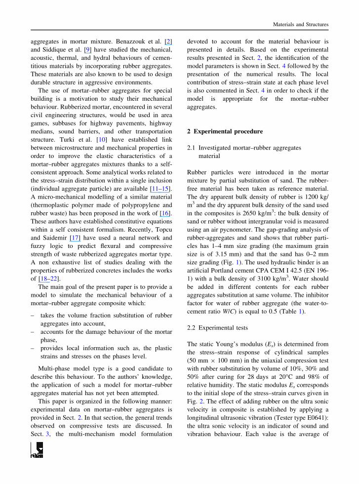
ORIGINAL ARTICLE Mechanical and damage behaviour of mortar–rubber aggregates mixtures: experiments and simulations M. Turki I. Ben Naceur M. Makni J. Rouis K. Saı ¨ Received: 10 July 2008 / Accepted: 3 November 2008 Ó RILEM 2008 Abstract The reuse of rubber wastes of worn tires in aggregate form, to serve as a building material, is appreciated to preserve environment. This study aims to examine the mechanical behaviour of a mortar– rubber aggregates material. A multi-phase model called 2M2C (2 Mechanisms and 2 Criteria) which take the volume fraction substitution of rubber into account is investigated with the help of stress–strain curves. The proposed model is based on the locali- zation of the stress on the phases level (rubber and mortar, respectively) and the homogenization of the local plastic strains. The model has also incorporated an isotropic damage variable to describe the loss of compressive strength. The experimental tests are well simulated by the model. Also, the simulations provide local informations such as damage evolution and local plastic strains. Keywords Mortar Rubber aggregates Mechanical behaviour Damage Multi-mechanism model 1 Introduction Waste management is one of the principal axes of sustainable development in many countries in recent years. It counts today among the main priorities with regards to environmental protection. The conven- tional storage of worn tires has an adverse effect on the environment such: fire danger, rodents and mosquitoes proliferation. Due to these problems, several states recycle the worn tires in order to introduce them into new products. In addition, the rubber particles of worn tire reveal many qualities in the mortar–rubber aggregate mixtures such as flexi- bility and resistance [1–3]. Several studies have been interested in different kind of waste valorization. This includes the work of [4–7] who have used a lightweight aggregate concrete as composite materials to study their mechanical behaviour in order to combine the durability phe- nomenon and microstructure. Kaufman et al. [8] have demonstrated the improvement of the material duc- tility containing Portland cement by addition of metal fibres. Other researches have focused on the waste of worn tires valorization by the addition of rubber M. Turki J. Rouis LGEMC, Ecole Nationale d’Inge ´nieurs de Sfax, BP 3038, Sfax, Tunisia I. B. Naceur K. Saı ¨(&) LGPMM, Ecole Nationale d’Inge ´nieurs de Sfax, BP 3038, Sfax, Tunisia e-mail: [email protected] M. Makni Institut Supe ´rieur des Etudes Technologiques de Sfax, Sfax, Tunisia Materials and Structures DOI 10.1617/s11527-008-9451-1
-
Upload
independent -
Category
Documents
-
view
2 -
download
0
Transcript of Mechanical and damage behaviour of mortar–rubber aggregates mixtures: experiments and simulations
ORIGINAL ARTICLE
Mechanical and damage behaviour of mortar–rubberaggregates mixtures: experiments and simulations
M. Turki Æ I. Ben Naceur Æ M. Makni ÆJ. Rouis Æ K. Saı
Received: 10 July 2008 / Accepted: 3 November 2008
� RILEM 2008
Abstract The reuse of rubber wastes of worn tires
in aggregate form, to serve as a building material, is
appreciated to preserve environment. This study aims
to examine the mechanical behaviour of a mortar–
rubber aggregates material. A multi-phase model
called 2M2C (2 Mechanisms and 2 Criteria) which
take the volume fraction substitution of rubber into
account is investigated with the help of stress–strain
curves. The proposed model is based on the locali-
zation of the stress on the phases level (rubber and
mortar, respectively) and the homogenization of the
local plastic strains. The model has also incorporated
an isotropic damage variable to describe the loss of
compressive strength. The experimental tests are well
simulated by the model. Also, the simulations provide
local informations such as damage evolution and
local plastic strains.
Keywords Mortar � Rubber aggregates �Mechanical behaviour � Damage �Multi-mechanism model
1 Introduction
Waste management is one of the principal axes of
sustainable development in many countries in recent
years. It counts today among the main priorities with
regards to environmental protection. The conven-
tional storage of worn tires has an adverse effect on
the environment such: fire danger, rodents and
mosquitoes proliferation. Due to these problems,
several states recycle the worn tires in order to
introduce them into new products. In addition, the
rubber particles of worn tire reveal many qualities in
the mortar–rubber aggregate mixtures such as flexi-
bility and resistance [1–3].
Several studies have been interested in different
kind of waste valorization. This includes the work of
[4–7] who have used a lightweight aggregate concrete
as composite materials to study their mechanical
behaviour in order to combine the durability phe-
nomenon and microstructure. Kaufman et al. [8] have
demonstrated the improvement of the material duc-
tility containing Portland cement by addition of metal
fibres.
Other researches have focused on the waste of
worn tires valorization by the addition of rubber
M. Turki � J. Rouis
LGEMC, Ecole Nationale d’Ingenieurs de Sfax, BP 3038,
Sfax, Tunisia
I. B. Naceur � K. Saı (&)
LGPMM, Ecole Nationale d’Ingenieurs de Sfax, BP 3038,
Sfax, Tunisia
e-mail: [email protected]
M. Makni
Institut Superieur des Etudes Technologiques de Sfax,
Sfax, Tunisia
Materials and Structures
DOI 10.1617/s11527-008-9451-1
aggregates in mortar mixture. Benazzouk et al. [2]
and Siddique et al. [9] have studied the mechanical,
acoustic, thermal, and hydral behaviours of cemen-
titious materials by incorporating rubber aggregates.
These materials are also known to be used to design
durable structure in aggressive environments.
The use of mortar–rubber aggregates for special
building is a motivation to study their mechanical
behaviour. Rubberized mortar, encountered in several
civil engineering structures, would be used in area
games, subbases for highway pavements, highway
medians, sound barriers, and other transportation
structure. Turki et al. [10] have established link
between microstructure and mechanical properties in
order to improve the elastic characteristics of a
mortar–rubber aggregates mixtures thanks to a self-
consistent approach. Some analytical works related to
the stress–strain distribution within a single inclusion
(individual aggregate particle) are available [11–15].
A micro-mechanical modelling of a similar material
(thermoplastic polymer made of polypropylene and
rubber waste) has been proposed in the work of [16].
These authors have established constitutive equations
within a self consistent formalism. Recently, Topcu
and Saidemir [17] have used a neural network and
fuzzy logic to predict flexural and compressive
strength of waste rubberized aggregates mortar type.
A non exhaustive list of studies dealing with the
properties of rubberized concretes includes the works
of [18–22].
The main goal of the present paper is to provide a
model to simulate the mechanical behaviour of a
mortar–rubber aggregate composite which:
– takes the volume fraction substitution of rubber
aggregates into account,
– accounts for the damage behaviour of the mortar
phase,
– provides local information such as, the plastic
strains and stresses on the phases level.
Multi-phase model type is a good candidate to
describe this behaviour. To the authors’ knowledge,
the application of such a model for mortar–rubber
aggregates material has not yet been attempted.
This paper is organized in the following manner:
experimental data on mortar–rubber aggregates is
provided in Sect. 2. In that section, the general trends
observed on compressive tests are discussed. In
Sect. 3, the multi-mechanism model formulation
devoted to account for the material behaviour is
presented in details. Based on the experimental
results presented in Sect. 2, the identification of the
model parameters is shown in Sect. 4 followed by the
presentation of the numerical results. The local
contribution of stress–strain state at each phase level
is also commented in Sect. 4 in order to check if the
model is appropriate for the mortar–rubber
aggregates.
2 Experimental procedure
2.1 Investigated mortar–rubber aggregates
material
Rubber particles were introduced in the mortar
mixture by partial substitution of sand. The rubber-
free material has been taken as reference material.
The dry apparent bulk density of rubber is 1200 kg/
m3 and the dry apparent bulk density of the sand used
in the composites is 2650 kg/m3: the bulk density of
sand or rubber without intergranular void is measured
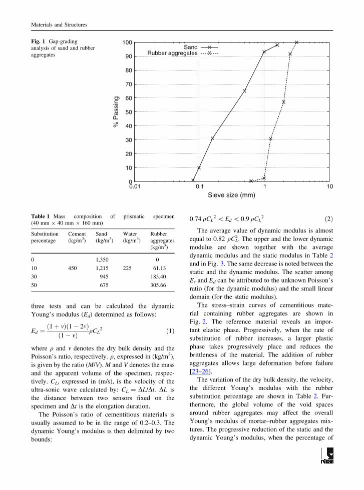
using an air pycnometer. The gap-grading analysis of
rubber-aggregates and sand shows that rubber parti-
cles has 1–4 mm size grading (the maximum grain
size is of 3.15 mm) and that the sand has 0–2 mm
size grading (Fig. 1). The used hydraulic binder is an
artificial Portland cement CPA CEM I 42.5 (EN 196-
1) with a bulk density of 3100 kg/m3. Water should
be added in different contents for each rubber
aggregates substitution at same volume. The inhibitor
factor for water of rubber aggregate (the water-to-
cement ratio W/C) is equal to 0.5 (Table 1).
2.2 Experimental tests
The static Young’s modulus (Es) is determined from
the stress–strain response of cylindrical samples
(50 mm 9 100 mm) in the uniaxial compression test
with rubber substitution by volume of 10%, 30% and
50% after curing for 28 days at 20�C and 98% of
relative humidity. The static modulus Es corresponds
to the initial slope of the stress–strain curves given in
Fig. 2. The effect of adding rubber on the ultra sonic
velocity in composite is established by applying a
longitudinal ultrasonic vibration (Tester type E0641):
the ultra sonic velocity is an indicator of sound and
vibration behaviour. Each value is the average of
Materials and Structures
three tests and can be calculated the dynamic
Young’s modulus (Ed) determined as follows:
Ed ¼ð1þ mÞð1� 2mÞð1� mÞ qCL
2 ð1Þ
where q and m denotes the dry bulk density and the
Poisson’s ratio, respectively. q, expressed in (kg/m3),
is given by the ratio (M/V). M and V denotes the mass
and the apparent volume of the specimen, respec-
tively. CL, expressed in (m/s), is the velocity of the
ultra-sonic wave calculated by: CL = DL/Dt. DL is
the distance between two sensors fixed on the
specimen and Dt is the elongation duration.
The Poisson’s ratio of cementitious materials is
usually assumed to be in the range of 0.2–0.3. The
dynamic Young’s modulus is then delimited by two
bounds:
0:74 qCL2 \ Ed \ 0:9 qCL
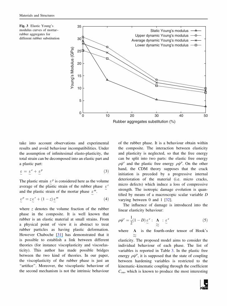
2 ð2ÞThe average value of dynamic modulus is almost
equal to 0.82 qCL2. The upper and the lower dynamic
modulus are shown together with the average
dynamic modulus and the static modulus in Table 2
and in Fig. 3. The same decrease is noted between the
static and the dynamic modulus. The scatter among
Es and Ed can be attributed to the unknown Poisson’s
ratio (for the dynamic modulus) and the small linear
domain (for the static modulus).
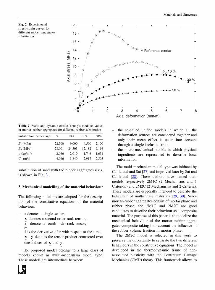
The stress–strain curves of cementitious mate-
rial containing rubber aggregates are shown in
Fig. 2. The reference material reveals an impor-
tant elastic phase. Progressively, when the rate of
substitution of rubber increases, a larger plastic
phase takes progressively place and reduces the
brittleness of the material. The addition of rubber
aggregates allows large deformation before failure
[23–26].
The variation of the dry bulk density, the velocity,
the different Young’s modulus with the rubber
substitution percentage are shown in Table 2. Fur-
thermore, the global volume of the void spaces
around rubber aggregates may affect the overall
Young’s modulus of mortar–rubber aggregates mix-
tures. The progressive reduction of the static and the
dynamic Young’s modulus, when the percentage of
0
10
20
30
40
50
60
70
80
90
100
0.01 0.1 1 10
% P
assi
ng
Sieve size (mm)
SandRubber aggregates
Fig. 1 Gap-grading
analysis of sand and rubber
aggregates
Table 1 Mass composition of prismatic specimen
(40 mm 9 40 mm 9 160 mm)
Substitution
percentage
Cement
(kg/m3)
Sand
(kg/m3)
Water
(kg/m3)
Rubber
aggregates
(kg/m3)
0 1,350 0
10 450 1,215 225 61.13
30 945 183.40
50 675 305.66
Materials and Structures
substitution of sand with the rubber aggregates rises,
is shown in Fig. 3.
3 Mechanical modelling of the material behaviour
The following notations are adopted for the descrip-
tion of the constitutive equations of the material
behaviour:
– x denotes a single scalar,
– x�
denotes a second order rank tensor,
– x��
denotes a fourth order rank tensor,
– _x is the derivative of x with respect to the time,
– x�
: y�
denotes the tensor product contracted over
one indices of x�
and y�
.
The proposed model belongs to a large class of
models known as multi-mechanism model type.
These models are intermediate between:
– the so-called unified models in which all the
deformation sources are considered together and
only their mean effect is taken into account
through a single inelastic strain,
– the micro-mechanical models in which physical
ingredients are represented to describe local
information.
The multi-mechanism model type was initiated by
Cailletaud and Saı [27] and improved later by Saı and
Cailletaud [28]. These authors have named their
models respectively 2M1C (2 Mechanisms and 1
Criterion) and 2M2C (2 Mechanisms and 2 Criteria).
These models are especially intended to describe the
behaviour of multi-phase materials [29, 30]. Since
mortar–rubber aggregates consist of mortar phase and
rubber phase, the 2M1C and 2M2C are good
candidates to describe their behaviour as a composite
material. The purpose of this paper is to modelize the
mechanical behaviour of the mortar–rubber aggre-
gates composite taking into account the influence of
the rubber volume fraction in mortar phase.
The 2M2C model is selected in this work to
preserve the opportunity to separate the two different
behaviours in the constitutive equations. The model is
developed in the thermodynamic frame of non-
associated plasticity with the Continuum Damage
Mechanics (CMD) theory. This framework allows to
0
2
4
6
8
10
12
14
16
18
20
0 1 2 3 4 5 6 7 8
Axi
al s
tres
s (M
Pa)
Axial deformation (mm/m)
Reference mortar
10 %
30 %
50 %
Fig. 2 Experimental
stress–strain curves for
different rubber aggregates
substitution
Table 2 Static and dynamic elastic Young’s modulus values
of mortar–rubber aggregates for different rubber substitution
Substitution percentage 0% 10% 30% 50%
Es (MPa) 22,500 9,000 4,500 2,100
Ed (MPa) 28,001 24,303 12,182 9,116
q (kg/m3) 2,086 2,010 1,746 1,651
CL (m/s) 4,046 3,840 2,917 2,595
Materials and Structures
take into account observations and experimental
results and avoid behaviour incompatibilities. Under
the assumption of infinitesimal elasto-plasticity, the
total strain can be decomposed into an elastic part and
a plastic part:
e�¼ e�
e þ e�
p ð3Þ
The plastic strain e�
p is considered here as the volume
average of the plastic strain of the rubber phase e�
r
and the plastic strain of the mortar phase e�
m.
e�
p ¼ z e�
r þ ð1� zÞ e�
m ð4Þ
where z denotes the volume fraction of the rubber
phase in the composite. It is well known that
rubber is an elastic material at small strains. From
a physical point of view it is abstract to treat
rubber particles as having plastic deformation.
However Chaboche [31] has demonstrated that it
is possible to establish a link between different
theories (for instance viscoplasticity and viscoelas-
ticity). This author has made possible bridges
between the two kind of theories. In our paper,
the viscoplasticity of the rubber phase is just an
‘‘artifice’’. Moreover, the viscoplastic behaviour of
the second mechanism is not the intrinsic behaviour
of the rubber phase. It is a behaviour obtain within
the composite. The interaction between elasticity
and plasticity is neglected, so that the free energy
can be split into two parts: the elastic free energy
qwe and the plastic free energy qwp. On the other
hand, the CDM theory supposes that the crack
initiation is preceded by a progressive internal
deterioration of the material (i.e. micro cracks,
micro defects) which induce a loss of compressive
strength. The isotropic damage evolution is quan-
tified by means of a macroscopic scalar variable D
varying between 0 and 1 [32].
The influence of damage is introduced into the
linear elasticity behaviour:
qwe ¼ 1
2ð1� DÞ e
�e : K��
: e�
e ð5Þ
where K��
is the fourth-order tensor of Hook’s
elasticity. The proposed model aims to consider the
individual behaviour of each phase. The list of
variables is reported in Table 3. In the plastic free
energy qwp, it is supposed that the state of coupling
between hardening variables is restricted to the
kinematic–kinematic coupling through the coefficient
Crm, which is known to produce the most interesting
0
5
10
15
20
25
30
35
0 10 20 30 40 50
You
ng’s
Mod
ulus
(G
Pa)
Rubber aggregates substitution (%)
Static Young’s modulusUpper dynamic Young’s modulus
Average dynamic Young’s modulusLower dynamic Young’s modulus
Fig. 3 Elastic Young’s
modulus curves of mortar–
rubber aggregates for
different rubber substitution
Materials and Structures

mechanical effect [27]. On the other hand, only the
mortar phase is affected by the damage. So that:
qwp ¼ 1
3Crr a�
r : a�
r þ 1
3Crm a
�r : a�
m þ 1
3Cmm a
�m : a
�m
þ 1
2QrðrrÞ2 þ 1
2ð1� DÞQmðrmÞ2
ð6Þ
where the material parameters Crr, Cmm and Crm
characterize the kinematic hardening whereas Qm and
Qr are isotropic material parameters. The overall
stress tensor and the two local stresses simply write:
r�¼ q
owo e�
r�
m ¼ qowo e�
m ¼ ð1� zÞ r�
r�
r ¼ qowo e�
r¼ z r
�
8>>>>>>>><
>>>>>>>>:
ð7Þ
This ‘‘multiplicative’’ transition rule (too drastic for
the local stress modification) to compute the local
stresses may be changed by a localization rule
inspired from the self consistent formalism:
r�
m ¼ r�þ A �
�p � �
�m
� �
r�
r ¼ r�þ A �
�p � �
�r
� �
8<
:ð8Þ
where A is an accommodation material parameter.
The local strains in Eq. 8 may be replaced by
phenomenological variables to better capture the
plastic accommodation:
r�
m ¼ r�þ A b
�� b�
m
� �
r�
r ¼ r�þ A b
�� b�
r
� �
b�¼ zb
�r þ 1� zð Þb
�m
8>>>>><
>>>>>:
ð9Þ
The rubber phase (soft phase) exhibits a plastic
deformation ��
r higher than the average deformation
��
p. Thus, the stress level r�
r supported by the rubber
phase will be less pronounced than the macroscopic
stress r�
. Inversely, the mortar phase (hard phase) will
be subjected to a higher stress level r�
m comparing to
r�
. Indeed, the plastic deformation ��
m is less than the
average deformation ��
p. The evolution laws of these
variables are generated by two plastic potentials Fr
and Fm, using the generalized normally rule:
Fm ¼ f m þ 3Dm
4Cmmð1� DÞX�m : X
�m
þ bm
2Qmð1� DÞðRmÞ2 þ 1
ð1� DÞbA
cþ 1
Y
A
� �cþ1
Fr ¼ f r þ 3Dr
4CrrX�
r : X�
r þ br
2QrðRrÞ2
8>>>>>>><
>>>>>>>:
ð10Þ
The formulation of these two plastic potentials is
obtained thanks to the multi-mechanism approach
[28] for the hardening and the CDM theory for the
damage [32]. Each local stress (r�
r and r�
m respec-
tively) is involved in a different yield function (fr and
fm respectively), defining two different criteria:
f m ¼ Jðr�
m � X�
mÞ � Rm � Rm0
f r ¼ Jðr�
r � X�
rÞ � Rr � Rr0
(
ð11Þ
where R0m and R0
r are the size of the initial elastic
domains. Rm and Rr describe their evolution. X�
m and
X�
r denotes respectively the center of the elastic
domain of the mortar phase and the rubber phase.
Jðr�� X�Þ represents a distance associated with the
von Mises invariant in the stress space:
Jðr�� X�Þ ¼
ffiffiffiffiffiffiffiffiffiffiffiffiffiffiffiffiffiffiffiffiffiffiffiffiffiffiffiffiffiffiffiffiffiffiffiffiffiffiffiffiffi3
2ðS�� X�Þ : ðS
�� X�Þ
r
ð12Þ
where S�
and X�
denotes respectively the deviators
associated with r�
and X�
.
Table 3 List of the variables for the proposed model
State variables Associated forces
Observable
variables
Internal
variables
��
(total strain) r�
Overall stress
��
r r�
r Inelastic stress
��
m r�
m Inelastic stress
a�
r X�
r Kinematic hardening
a�
m X�
m Kinematic hardening
Qr Rr Isotropic hardening
Qm Rm Isotropic hardening
D Y Damage variable
Materials and Structures

The evolution of the state variables is then given
by the following expressions:
_km and _kr are the plastic multipliers obtained thanks
to the consistency conditions. n�
m and n�
r are the
normal tensor to the two elastic domains.
The evolution of the kinematic variables a�
and the
accommodation variable b�
is obtained as the result of
the competition between a linear term ( _e�
m or _e�
r) and
a fading memory term depending on the actual value
of X�
:
_a�
m ¼ � _kmoFm
oX�
m ¼ _��
m � 3Dm
2CmmX�
m _km
_a�
r ¼ � _kr oFr
oX�
r ¼ _��
r � 3Dr
2CrrX�
r _kr
_b�
m ¼ _���m � dm b
�m _km
_b�
r ¼ _��
r � dr b�
br _kr
8>>>>>>>>>>><
>>>>>>>>>>>:
ð14Þ
For the isotropic hardening variables, non linearities
are also given as fading memory terms:
_rm ¼ � _kmoFm
oRm¼ _km 1
ffiffiffiffiffiffiffiffiffiffiffiffi1� Dp � bmQm
� �
_rr ¼ � _kroFr
oRr¼ _krð1� brQrÞ
8>><
>>:
ð15Þ
Finally the isotropic ductile evolution is defined by
the damage [32] rate given by:
_D ¼ � _km oFm
oY¼ _km Y
A
� �c1
ð1� DÞbð16Þ
Table 4 summarizes the constitutive equations of the
proposed model in both 3D and 1D case. The 2M2C
model is implemented into the FE code Zebulon [33]
using a h—method solved by an implicit Newton
scheme for the local integration.
4 Results and discussions
In the previous section, Eqs. 3–15 display some
material coefficients that have to be determined. The
identification of these parameters is performed with
the help of Zset FE code [34] provided with an
optimizer routine [33]. The Young’s modulus E is
supposed to be known and equivalent to Es (see
Sect. 2). From the compressive tests (Fig. 2), the
apparent Young’s modulus are checked by calculat-
ing the initial slope of the stress–strain curve.
The parameters used for the simulations of the
numerical results (Table 5) are found by best fit to the
experimental compressive tests as given in Fig. 4.
These parameters are unique for all the rubber phase
level except the initial size of the elastic domain R0
and Young’s modulus E. Good agreement is encoun-
tered by both simulations and experimental curve for
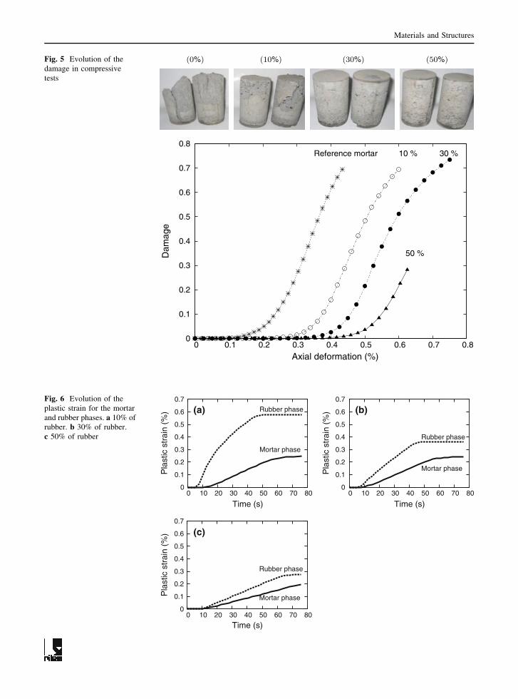
the whole range of the rubber phase. Figure 5 shows
the evolution of the simulated damage variable D
with deformation. It can be seen that, for a fixed
strain level, the damage decreases when the percent-
age of rubber substitution increase. As a matter of
fact, brittleness is reduced by the addition of rubber
particles. This result is confirmed by the photographs
of each specimen (0%, 10%, 30%, 50%) after
compressive tests.
On the other hand, the plastic strain is more
pronounced (as expected) for the ‘‘soft’’ rubber phase
than for the ‘‘hard’’ mortar phase (Fig. 6). This
difference is more important for the low rubber
substitution.
For higher percentage of rubber, the two plastic
strains become closer thanks to the coupling param-
eter Crm. Note that these two different behaviours are
depicted when the two phases interact in the aggre-
gates (they are not their ‘‘intrinsic’’ behaviours).
It is to be mentioned that this number of param-
eters is rather great if the purpose is just to simulate
the uniaxial stress–strain curves. In this work, it is
assumed that all parameters are activated even if
actually no relevant tests have been carried out in
order to address individually each coefficient. Some
of these parameters may be set to zero which is not
performed here. Additional experiments such as
_e�
m ¼ � _km of m
or�
m¼ _km n
�m with n
�m ¼ 3
2ffiffiffiffiffiffiffiffiffiffiffiffi1� Dp Sm � Xm
Jðr�
m � X�
mÞ
_e�
r ¼ � _kr of r
or�
r¼ _kr n
�r with n
�r ¼ 3
2
Sr � Xr
Jðr�
r � X�
rÞ
8>>><
>>>:
ð13Þ
Materials and Structures
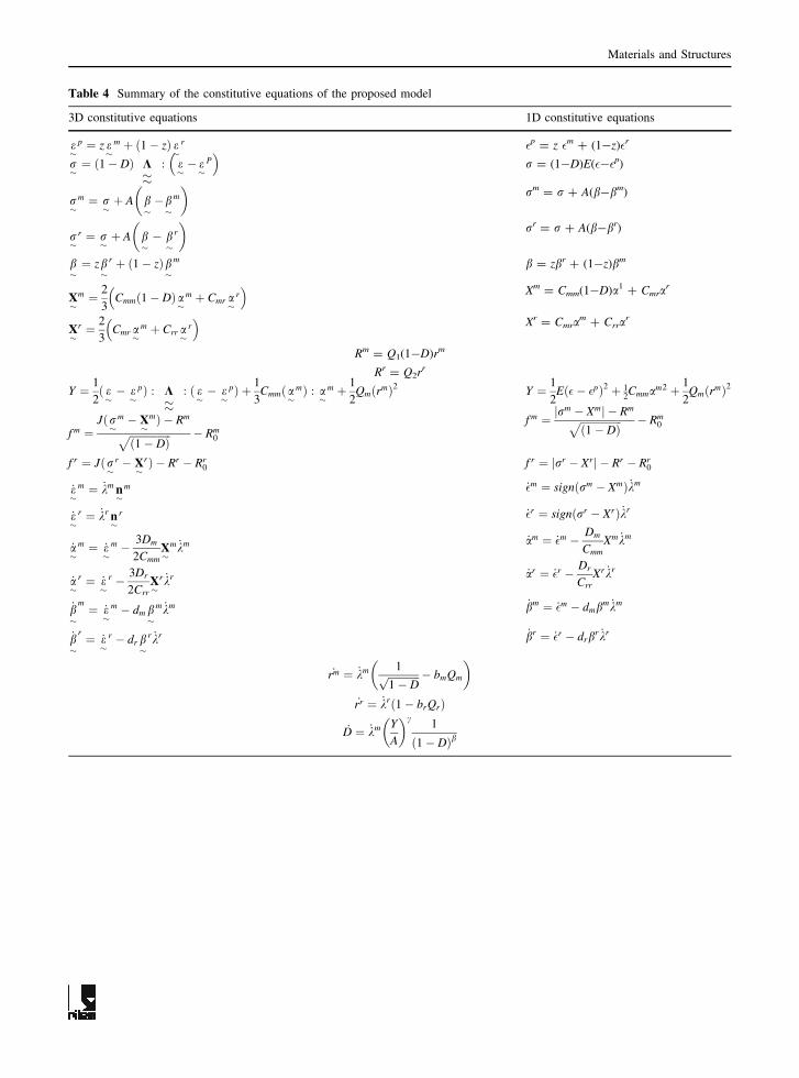
Table 4 Summary of the constitutive equations of the proposed model
3D constitutive equations 1D constitutive equations
e�
p ¼ z e�
m þ ð1� zÞ e�
r �p = z �m ? (1-z)�r
r�¼ ð1� DÞ K
��: e�� e�
P� �
r = (1-D)E(�-�p)
r�
m ¼ r�þ A b
��b�
m
� �rm = r ? A(b-bm)
r�
r ¼ r�þ A b
�� b�
r
� �rr = r ? A(b-br)
b�¼ zb
�r þ ð1� zÞb
�m b = zbr ? (1-z)bm
X�
m ¼ 2
3Cmmð1� DÞa
�m þ Cmr a
�r
� �Xm = Cmm(1-D)a1 ? Cmra
r
X�
r ¼ 2
3Cmr a
�m þ Crr a
�r
� �Xr = Cmra
m ? Crrar
Rm = Q1(1-D)rm
Rr = Q2rr
Y ¼ 1
2ð e�� e�
pÞ : K��
: ð e�� e�
pÞ þ 1
3Cmmða�
mÞ : a�
m þ 1
2QmðrmÞ2 Y ¼ 1
2Eð�� �pÞ2 þ 1
2Cmmam2 þ 1
2QmðrmÞ2
f m ¼Jðr�
m � X�
mÞ � Rm
ffiffiffiffiffiffiffiffiffiffiffiffiffiffiffiffið1� DÞ
p � Rm0
f m ¼ jrm � Xmj � Rm
ffiffiffiffiffiffiffiffiffiffiffiffiffiffiffiffið1� DÞ
p � Rm0
f r ¼ Jðr�
r � X�
rÞ � Rr � Rr0 f r ¼ jrr � Xrj � Rr � Rr
0
_e�
m ¼ _km n�
m _�m ¼ signðrm � XmÞ _km
_e�
r ¼ _kr n�
r _�r ¼ signðrr � XrÞ _kr
_a�
m ¼ _e�
m � 3Dm
2CmmX�
m _km _am ¼ _�m � Dm
CmmXm _km
_a�
r ¼ _e�
r � 3Dr
2CrrX�
r _kr _ar ¼ _�r � Dr
CrrXr _kr
_b�
m ¼ _e�
m � dm b�
m _km _bm ¼ _�m � dmbm _km
_b�
r ¼ _e�
r � dr b�
r _kr _br ¼ _�r � drbr _kr
_rm ¼ _km 1ffiffiffiffiffiffiffiffiffiffiffiffi1� Dp � bmQm
� �
_rr ¼ _krð1� brQrÞ
_D ¼ _km Y
A
� �c1
ð1� DÞb
Materials and Structures

loading unloading tests (under study) are then needed
to provide more consistent parameter set. Readers can
refer, for instance, to the ratchetting tests (necessary
to activate kinematic hardening parameters) in
Fig. 12 of the work of [2]. Moreover, the model
being developed in a three dimensional framework,
multi directional tests can be used to fix some
material parameters.
0
5
10
15
20
25
0 0.1 0.2 0.3 0.4 0.5 0.6 0.7 0.8
Axi
al s
tres
s (M
Pa)
Axial deformation (%)
Reference mortar
10 %
30 %
50 %
Fig. 4 Experimental
(symbols) and modelling
results (dashed lines) of
stress–strain curves for
different rubber aggregates
substitution
Table 5 Identified parameters of the proposed model
Parameters Values Units
Elasticity z 0 0.1 0.3 0.5
E 22,500 9,000 4,500 2,100 MPa
m 0.3
Mortar
phase
km 90 MPa s
nm 2
R0m 11.0 3.5 2.4 1.1 MPa
Qm 31.4 MPa
bm 20.3
Cmm 1800 MPa
Dm 37
Rubber
phase
kr 90 MPa s
nr 2
Table 5 continued
Parameters Values Units
R0r 14 5.5 3.1 1.3 MPa
Qr 21.4 MPa
br 16.9
Crr 1400 MPa
Dr 51
Interaction A 25 MPa
Cmr 800 MPa
dm 5
dr 7
Damage B 0.0045
c 5.8
b 0.005
Materials and Structures
0
0.1
0.2
0.3
0.4
0.5
0.6
0.7
0 10 20 30 40 50 60 70 80
Pla
stic
str
ain
(%)
Time (s)
Rubber phase
Mortar phase
0
0.1
0.2
0.3
0.4
0.5
0.6
0.7
0 10 20 30 40 50 60 70 80
Pla
stic
str
ain
(%)
Time (s)
Rubber phase
Mortar phase
0
0.1
0.2
0.3
0.4
0.5
0.6
0.7
0 10 20 30 40 50 60 70 80
Pla
stic
str
ain
(%)
Time (s)
Rubber phase
Mortar phase
(a) (b)
(c)
Fig. 6 Evolution of the
plastic strain for the mortar
and rubber phases. a 10% of
rubber. b 30% of rubber.
c 50% of rubber
0
0.1
0.2
0.3
0.4
0.5
0.6
0.7
0.8
0 0.1 0.2 0.3 0.4 0.5 0.6 0.7 0.8
Dam
age
Axial deformation (%)
Reference mortar 10 % 30 %
50 %
Fig. 5 Evolution of the
damage in compressive
tests
Materials and Structures

5 Conclusion
The purpose of this paper is to test the capabilities of
a multi-mechanism model to represent the mechan-
ical behaviour of the mortar–rubber aggregate
composites with different percentage of rubber par-
ticles (0%, 10%, 30% and 50%). The comparison
between experimental data and simulated results
shows good accordance. The local contributions of
the plastic strain at each level are then correctly
estimated. This model is implemented in the FE code
Zebulon. The constitutive equations of the model can
be used to analyze inelastic behaviour of structures
made of mortar–rubber aggregates in multi-direc-
tional framework. The next step of this work is to
validate the model for a successive loading-unloading
cycles tests with different percentage of substitution.
References
1. Toutanji HA (1996) The use of rubber tire particles in
concrete to replace mineral aggregates. Cem Concr Comp
18:135–139
2. Benazzouk A, Mezreb K, Doyen G, Goullieux A, Que-
neudec M (2003) Effect of rubber aggregates on the
physico-mechanical behaviour of cement–rubber compos-
ites-influence of the alveolar texture of rubber aggregates.
Cem Concr Comp 25:711–720
3. Turatsinze A, Granju JL, Bonnet S (2006) Positive synergy
between steel-fibres and rubber aggregates: effect on the
resistance of cement-based mortars to shrinkage cracking.
Cem Concr Res 36(9):1692–1697
4. Gao XF, Lo YT, Tam CM (2002) Investigation of micro-
craks and microstructure of high performance lightweight
aggregate concrete. Build Environ 37:485–489
5. Kayali O, Haque MN, Zhu B (2003) Some characteristics
of high strength fiber reinforced lighweight aggregate
concrete. Cem Concr Comp 25:207–213
6. Campione G, Mendola LL (2004) Behaviour in compression
of lightweight fiber reinforced concrete confined with trans-
verse steel reinforcement. Cem Concr Comp 26:645–656
7. Cusson D, Hoogeveen T (2008) Internal curing of high-
performance concrete with pre-soaked fine lightweight
aggregates for prevention of autogenous shrinkage crack-
ing. Cem Concr Res 38:757–765
8. Kaufmann J, Winnefeld F, Hesselbarth D (2004) Effect of
the addition of ultrafine cement and short fiber reinforce-
ment on shrinkage, rheological and mechanical properties
of Portland cement pastes. Cem Concr Comp 26:541–549
9. Siddique R, Naik TR (2004) Properties of concrete con-
taining scrap-tire rubber—an overview. Waste Manag
24:563–569
10. Turki M, Molines E, Dheilly RM, Rouis MJ, Queneudec M
(2007) Leffet de lajout granulats de caoutchouc dans les dans
composites cimentaires. In: Proceedings of the 8th internation
conference on eco-materials, The Brunel University, UK
11. Yankelevsky DZ (1985) Analytical model for bond-slip
behavior under monotonic loading. Build Environ
20(3):163–168
12. Babu DS, Babu GK, Wee TH (2005) Properties of ligh-
weight expanded polystyrene aggregate concretes
containing fly ash. Cem Concr Res 35:1218–1223
13. Dundar C, Tokgoz S, Tanrikulu AK, Baran T (2008)
Behaviour of reinforced and concrete-encased composite
columns subjected to biaxial bending and axial load. Build
Environ 43:1109–1120
14. Rahal K (2007) Mechanical properties of concrete with
recycled coarse aggregates. Build Environ 47:407–415
15. Goncalves JP, Tavares LM, Toledo Filho RD, Fairbairn
EMR, Cunha ER (2007) Comparison of natural and man-
ufactured fine aggregates in cement mortars. Cem Concr
Res 37:924–932
16. Ausias G, Thuillier S, Omnes B, Wiessner S, Pilvin P
(2007) Micro-mechanical model of TPE made of poly-
propylene and rubber waste. Polymer 48:3367–3376
17. Topcu IB, Saridemir M (2008) Prediction of rubberized
mortar properties using artificial neural network and fuzzy
logic. J Mater Process Technol 199:108–118
18. Topcu IB, Avcular N (1997) Collision behaviours of rub-
berized concrete. Cem Concr Res 27(12):1893–1898
19. Segre N, Joekes I (2000) Use of tire rubber particles as
addition to cement paste. Cem Concr Res 30(9):1421–
1425
20. Rossignolo JA, Agnesini MVC (2002) Mechanical prop-
erties of polymer-modified lightweight aggregate concrete.
Cem Concr Res 32(3):329–334
21. Pera J, Ambroise J, Chabannet M (2004) Valorization of
automotive shredder residue in building materials. Cem
Concr Res 34(4):557–562
22. Guneyisi E, Gesoglu M, Ozturan T (2004) Properties of
rubberized concretes containing silica fume. Cem Concr
Res 34(12):2309–2317
23. Al-Akhras NM, Smadi MM (2004) Properties of tire rubber
ash mortar. Cem Concr Comp 26:821–826
24. Lura P, Jensen OM (2005) On the measurement of free
deformation of early age cement paste and concrete. Cem
Concr Comp 27:854–856
25. Papakonstantinou CG, Tobolski MJ (2006) Use of waste
tire steel beads in Portland cement concrete. Cem Concr
Res 36(9):1686–1691
26. Odelson JB, Kerr EA, Vadakan WV (2007) Young’s
modulus of cement paste at elevated temperatures. Cem
Concr Res 37:258–263
27. Cailletaud G, Sai K (1995) Study of plastic/viscoplastic
models with various inelastic mechanisms. Int J Plast
11:991–1005
28. Sai K, Cailletaud G (2007) Multi-mechanism models for
the description of ratchetting: effect of the scale transition
rule and of the coupling between hardening variables. Int J
Plast 23:1589–1617
29. Gautier E, Cailletaud G (2004) N-phase modeling applied
to phase transformations in steels: a coupled kinetics-
mechanics approach. In: ICHMM-2004 international con-
ference on heterogeneous material mechanics, Chongqing,
China
Materials and Structures
30. Sai K, Aubourg V, Cailletaud G, Strudel JL (2004) Phys-
ical basis for model with various in elastic mechanisms for
nickel base super alloy. Mat Sci Tech 20:747–755
31. Chaboche JL (1997) Thermodynamic formulation of con-
stitutive equations and application to the viscoplasticity
and viscoelasticity of metals and polymers. Int J Solids
Struct 34:2239–2254
32. Chaboche JL (1987) Continum damage mechanics: present
state and future trends. Nucl Eng Des 105:19–33
33. Besson J, Leriche R, Foerch R, Cailletaud G (1998)
Object-oriented programming applied to the finite element
method. Part II. Application to material behaviors. Revue
Europeenne des Elements Finis 7:567–588
34. Besson J, Foerch R (1997) Large scale object-oriented
finite element code design. Comput Methods Appl Mech
Eng 142:165–187
Materials and Structures