MEC 257 - Chapter-02 (Shawkut Sir)
126
Chapter : 02 Strain Simple Strain Stress-strain Diagram Axial Deformation Shearing Deformation Statically Indeterminate Members Thermal Stress Prof. Dr. Md. Shawkut Ali Khan Faculty Department of Mechanical Engineering IUBAT
Transcript of MEC 257 - Chapter-02 (Shawkut Sir)

Chapter : 02 Strain
Simple Strain Stress-strain Diagram Axial Deformation Shearing Deformation Statically Indeterminate Members Thermal Stress
Prof. Dr. Md. Shawkut Ali KhanFaculty
Department of Mechanical EngineeringIUBAT

Simple Strain:
Strain
strain is the ratio of the change in length caused by the applied force, to the original length.
where δ is the deformation and L is the original length, thus ε is dimensionless.
Stress-strain Diagram

Proportional Limit (Hooke's Law):
Strain
According to Hooke's Law within the proportional limit, the stress is directly proportional to strain.
orThe constant of proportionality k is called the Modulus of Elasticity E or Young's Modulus and is equal to the slope of the stress-strain diagram from O to P. Then Elastic Limit: It is the stress beyond which the material will not return to its original shape when unloaded, but will retain a permanent deformation called permanent set. Yield point: The yield point is the point at which there is an appreciable elongation or yielding of the material without any corresponding increase of load.Ultimate Strength : The ultimate strength is commonly taken as the maximum stress of the material.
Rupture Strength: The rupture strength is the stress at failure.

Strain
Problem 209:-
An aluminum bar having a cross-sectional area of 0.5 in2 carries the axial loads applied at the positions shown in Fig. P-209. Compute the total change in length of the bar if E = 10 × 106 psi. Assume the bar is suitably braced to prevent lateral buckling.
Solution 209 :-
P1 = 6000 lb tensionP2 = 1000 lb compressionP3 = 4000 lb tension
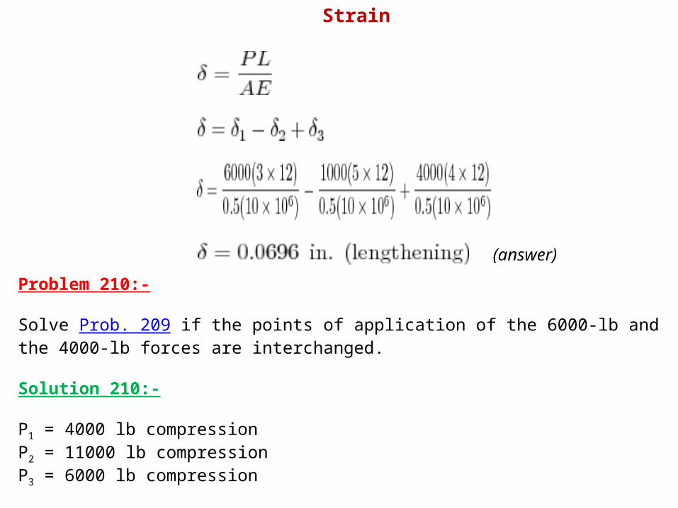
(answer)Problem 210:-
Solve Prob. 209 if the points of application of the 6000-lb and the 4000-lb forces are interchanged.
Solution 210:-
P1 = 4000 lb compressionP2 = 11000 lb compressionP3 = 6000 lb compression
Strain

(answer)
Strain

Problem 211:-
A bronze bar is fastened between a steel bar and an aluminum bar as shown in Fig. p-211. Axial loads are applied at the positions indicated. Find the largest value of P that will not exceed an overall deformation of 3.0 mm, or the following stresses: 140 MPa in the steel, 120 MPa in the bronze, and 80 MPa in the aluminum. Assume that the assembly is suitably braced to prevent buckling. Use Est = 200 GPa, Eal = 70 GPa, and Ebr = 83 GPa.
Solution 211:-
Strain

Based on allowable stresses:Steel:
Bronze:
Aluminum:
Strain

Based on allowable deformation:(steel and aluminum lengthens, bronze shortens)
Use the smallest value of P, P = 12.8 kN
Strain
Problem 212:-
The rigid bar ABC shown in Fig. P-212 is hinged at A and supported by a steel rod at B. Determine the largest load P that can be applied at C if the stress in the steel rod is limited to 30 ksi and the vertical movement of end C must not exceed 0.10 in.

Strain
Solution 212:-
Based on maximum stress of steel rod:

Strain
Based on movement at C:

Strain
Use the smaller value, P = 4.83 kips

Problem 213:-
The rigid bar AB, attached to two vertical rods as shown in Fig. P-213, is horizontal before the load P is applied. Determine the vertical movement of P if its magnitude is 50 kN. Solution 213:-
Free body diagram:
(Answer)

Problem 214:-The rigid bars AB and CD shown in Fig. P-214 are supported by pins at A and C and the two rods. Determine the maximum force P that can be applied as shown if its vertical movement is limited to 5 mm. Neglect the weights of all members.
Strain
Solution 214:-Member AB:

By ratio and proportion:
→ movement of B
Strain

StrainMember CD:
Movement of D:

By ratio and proportion:
(answer)
Strain

Problem 215:-A uniform concrete slab of total weight W is to be attached, as shown in Fig. P-215, to two rods whose lower ends are on the same level. Determine the ratio of the areas of the rods so that the slab will remain level.Solution 215:-
(Answer)

Problem 216:-As shown in Fig. P-216, two aluminum rods AB and BC, hinged to rigid supports, are pinned together at B to carry a vertical load P = 6000 lb. If each rod has a cross-sectional area of 0.60 in.2 and E = 10 × 106 psi, compute the elongation of each rod and the horizontal and vertical displacements of point B. Assume α = 30° and θ = 30°.
Strain
Solution 216:-From FBD of Joint B

tension
compression
(answer)
(answer)
Strain

From 'Movement of B' diagram:Strain
DB = δAB = 0.12 inchBE = δBE = 0.072 inchδB = BB' = displacement of B
B' = final position of B after elongation
Triangle BDB':
Triangle BEB':

Triangle BFB':
Strain

→ horizontal displacement of B (answer)
→ vertical displacement of B (answer)
Problem 217:-Solve Prob. 216 if rod AB is of steel, with E = 29 × 106 psi. Assume α = 45° and θ = 30°; all other data remain unchanged.
Solution 217:-By Sine Law:
(Tension)
Strain

(Compression)
(lengthening)
(shortening)
From "Movement of B" diagramDB = δAB = 0.0371 inchBE = δBE = 0.0527 inchδB = BB' = displacement of BB' = final position of B after deformation
Triangle BDB':
Strain

Triangle BEB':
Triangle BFB':
→ horizontal displacement of B (answer)
Strain

→ vertical displacement of B answer
Problem 218:-A uniform slender rod of length L and cross sectional area A is rotating in a horizontal plane about a vertical axis through one end. If the unit mass of the rod is ρ, and it is rotating at a constant angular velocity of ω rad/sec, show that the total elongation of the rod is ρω2 L3/3E.Solution 218:-
from the frigure:
Where:dP = centrifugal force of differential massdP = dM ω2 x = (ρA dx)ω2 xdP = ρAω2 x dx
Strain

Okay!
Problem 219:-A round bar of length L, which tapers uniformly from a diameter D at one end to a smaller diameter d at the other, is suspended vertically from the large end. If w is the weight per unit volume, find the elongation of ω the rod caused by its own weight. Use this result to determine the elongation of a cone suspended from its base.Solution 219:-
Strain
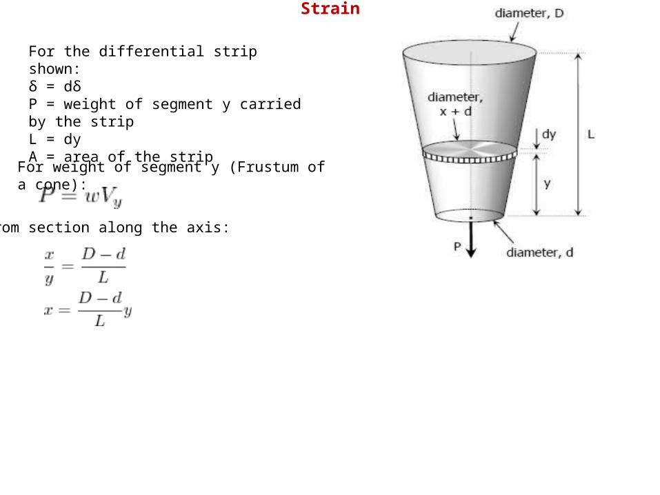
For the differential strip shown:δ = dδP = weight of segment y carried by the stripL = dyA = area of the stripFor weight of segment y (Frustum of
a cone):
From section along the axis:
Strain

Volume for frustum of cone:
Area of the strip:
Thus,
Strain

Let:and
Strain

The quantity:
Strain

Strain
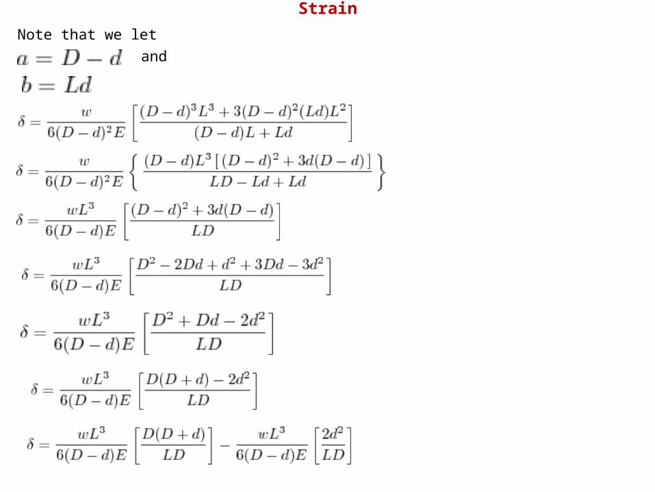
Note that we let and
Strain

answer
For a cone:and
answer
Strain

(okay)
Solution 222:-
Problem 222:-A solid cylinder of diameter d carries an axial load P. Show that its change in diameter is 4Pν / πEd.
Strain

Problem 223:- A rectangular steel block is 3 inches long in the x direction, 2 inches long in the y direction, and 4 inches long in the z direction. The block is subjected to a triaxial loading of three uniformly distributed forces as follows: 48 kips tension in the x direction, 60 kips compression in the y direction, and 54 kips tension in the z direction. If ν = 0.30 and E = 29 × 106 psi, determine the single uniformly distributed load in the x direction that would produce the same deformation in the y direction as the original loading.Solution 223:- For triaxial deformation (tensile triaxial stresses):(compressive stresses are negative stresses)
(tension)
(compression)
(tension)
Strain

Thus,
εy is negative, thus, tensile force is required in the x-direction to produce the same deformation in the y-direction as the original forces.
For equivalent single force in the x-direction:(uniaxial stress)
Strain

(tension)(tension) answer
Problem 224:-For the block loaded triaxially as described in Prob. 223, find the uniformly distributed load that must be added in the x direction to produce no deformation in the z direction.
Solution 224:-
Whereσx = 6.0 ksi (tension)σy = 5.0 ksi (compression)σz = 9.0 ksi (tension)
εz is positive, thus positive stress is needed in the x-direction to eliminate deformation in z-direction.
Strain

The application of loads is still simultaneous:(No deformation means zero strain)
Whereσy = 5.0 ksi (compression)σσz = 9.0 ksi (tension)
answer
Strain

Problem 225:-A welded steel cylindrical drum made of a 10-mm plate has an internal diameter of 1.20 m. Compute the change in diameter that would be caused by an internal pressure of 1.5 MPa. Assume that Poisson's ratio is 0.30 and E = 200 GPa. Solution 225 :-σy = longitudinal stress
σx = tangential stress
Strain

answer
Problem 226:-A 2-in.-diameter steel tube with a wall thickness of 0.05 inch just fits in a rigid hole. Find the tangential stress if an axial compressive load of 3140 lb is applied. Assume ν = 0.30 and neglect the possibility of buckling.
Solution 226:-
Whereσx = tangential stressσy = longitudinal stressσy = Py / A = 3140 / (π × 2 × 0.05)σy = 31,400/π psi
Strain

Thus,
answer
Problem 227:-A 150-mm-long bronze tube, closed at its ends, is 80 mm in diameter and has a wall thickness of 3 mm. It fits without clearance in an 80-mm hole in a rigid block. The tube is then subjected to an internal pressure of 4.00 MPa. Assuming ν = 1/3 and E = 83 GPa, determine the tangential stress in the tube.
Solution 227 :-Longitudinal stress:
The strain in the x-direction is:
→ tangential stress
answer
Strain

Problem 228:-A 6-in.-long bronze tube, with closed ends, is 3 in. in diameter with a wall thickness of 0.10 in. With no internal pressure, the tube just fits between two rigid end walls. Calculate the longitudinal and tangential stresses for an internal pressure of 6000 psi. Assume ν = 1/3 and E = 12 × 106 psi.Solution 228 :-
→ longitudinal stress→ tangential stress
answer
answer
Strain


Problem 233:-A steel bar 50 mm in diameter and 2 m long is surrounded by a shell of a cast iron 5 mm thick. Compute the load that will compress the combined bar a total of 0.8 mm in the length of 2 m. For steel, E = 200 GPa, and for cast iron, E = 100 GPa.Solution 233:-
answer
Strain

Problem 234:-A reinforced concrete column 200 mm in diameter is designed to carry an axial compressive load of 300 kN. Determine the required area of the reinforcing steel if the allowable stresses are 6 MPa and 120 MPa for the concrete and steel, respectively. Use Eco = 14 GPa and Est = 200 GPa.
Solution 234 :-
When σst = 120 MPa
→ (not okay!)When σco = 6 MPa
Strain
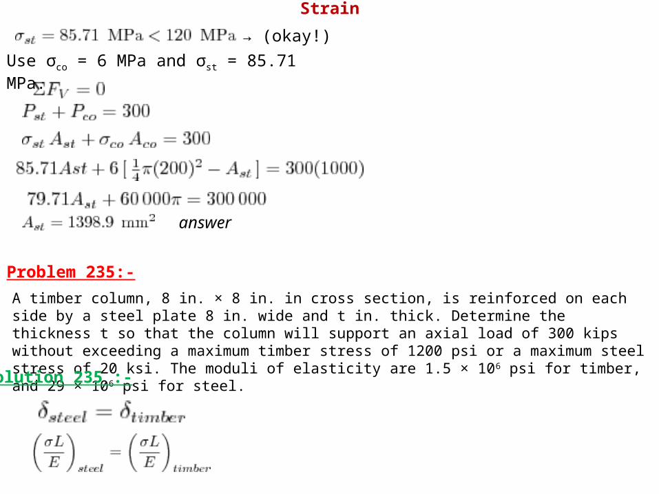
→ (okay!)Use σco = 6 MPa and σst = 85.71 MPa.
answer
Problem 235:-A timber column, 8 in. × 8 in. in cross section, is reinforced on each side by a steel plate 8 in. wide and t in. thick. Determine the thickness t so that the column will support an axial load of 300 kips without exceeding a maximum timber stress of 1200 psi or a maximum steel stress of 20 ksi. The moduli of elasticity are 1.5 × 10⁶ psi for timber, and 29 × 106 psi for steel.Solution 235 :-
Strain

When σtimber = 1200 psi
(not ok!)When σsteel = 20 ksi
Use σsteel = 20 ksi and σtimber = 1.03 ksi
answer
Strain

Problem 236:-A rigid block of mass M is supported by three symmetrically spaced rods as shown in Fig. P-236. Each copper rod has an area of 900 mm2; E = 120 GPa; and the allowable stress is 70 MPa. The steel rod has an area of 1200 mm2; E = 200 GPa; and the allowable stress is 140 MPa. Determine the largest mass M which can be supported.
Solution 236 :-
Strain

When σst = 140 MPa
(not okay!)When σco = 70 MPa
(okay!)Use σco = 70 MPa and σst = 77.78 MPa.
answer
Strain

Problem 237:-In Problem 236, how should the lengths of the two identical copper rods be changed so that each material will be stressed to its allowable limit? Solution 237:-Use σco = 70 MPa and σst = 140
MPa
answer
Problem 238:-The lower ends of the three bars in Fig. P-238 are at the same level before the uniform rigid block weighing 40 kips is attached. Each steel bar has a length of 3 ft, and area of 1.0 in.2, and E = 29 × 106 psi. For the bronze bar, the area is 1.5 in.2 and E = 12 × 106 psi. Determine (a) the length of the bronze bar so that the load on each steel bar is twice the load on the bronze bar, and (b) the length of the bronze that will make the steel stress twice the bronze stress.
Strain

Solution 238 :-(a) Condition: Pst = 2Pbr
Strain

answer
(b) Condition: σst = 2σbr
answer
Strain

Problem 239:-The rigid platform in Fig. P-239 has negligible mass and rests on two steel bars, each 250.00 mm long. The center bar is aluminum and 249.90 mm long. Compute the stress in the aluminum bar after the center load P = 400 kN has been applied. For each steel bar, the area is 1200 mm2 and E = 200 GPa. For the aluminum bar, the area is 2400 mm2 and E = 70 GPa.
Solution 239:-
Strain

answer
Problem 240:-Three steel eye-bars, each 4 in. by 1 in. in section, are to be assembled by driving rigid 7/8-in.-diameter drift pins through holes drilled in the ends of the bars. The center-line spacing between the holes is 30 ft in the two outer bars, but 0.045 in. shorter in the middle bar. Find the shearing stress developed in the drip pins. Neglect local deformation at the holes.Solution 240 :-Middle bar is 0.045 inch shorter between holes than outer bars.
Strain

(For steel: E = 29 × 106 psi)
Use shear force Shearing stress of drip pins (double shear):
answer
Strain

Problem 241:-As shown in Fig. P-241, three steel wires, each 0.05 in.2 in area, are used to lift a load W = 1500 lb. Their unstressed lengths are 74.98 ft, 74.99 ft, and 75.00 ft.(a) What stress exists in the longest wire?(b) Determine the stress in the shortest wire if W = 500 lb.
Solution 241 :-Let L1 = 74.98 ft; L2 = 74.99 ft; and L3 = 75.00 ft
Part (a)
Bring L1 and L2 into L3 = 75 ft length:(For steel: E = 29 × 106 psi)
For L1:
For L2:
Strain

LetP = P3 (Load carried by L3)P + P2 (Total load carried by L2)P + P1 (Total load carried by L1)
answerPart (b)
From the above solution:P1 + P2 = 580.13 lb > 500 lb (L3 carries no load)Bring L1 into L2 = 74.99 ft
Strain

Let P = P2 (Load carried by L2) P + P1 (Total load carried by L1)
answer
Problem 242:-The assembly in Fig. P-242 consists of a light rigid bar AB, pinned at O, that is attached to the steel and aluminum rods. In the position shown, bar AB is horizontal and there is a gap, Δ = 5 mm, between the lower end of the steel rod and its pin support at C. Compute the stress in the aluminum rod when the lower end of the steel rod is attached to its support.
Strain

Solution 242 :-
Strain

By ratio and proportion:
answer
Problem 243:-A homogeneous rod of constant cross section is attached to unyielding supports. It carries an axial load P applied as shown in Fig. P-243. Prove that the reactions are given by R1 = Pb/L and R2 = Pa/L.
Strain

Solution 243 :-
(okay!)
Strain

(okay!)
Problem 244:-A homogeneous bar with a cross sectional area of 500 mm2 is attached to rigid supports. It carries the axial loads P1 = 25 kN and P2 = 50 kN, applied as shown in Fig. P-244. Determine the stress in segment BC. (Hint: Use the results of Prob. 243, and compute the reactions caused by P1 and P2 acting separately. Then use the principle of superposition to compute the reactions when both loads are applied.)
Solution 244 :-From the solution of Problem 243:
Strain

For segment BC
answer
Strain

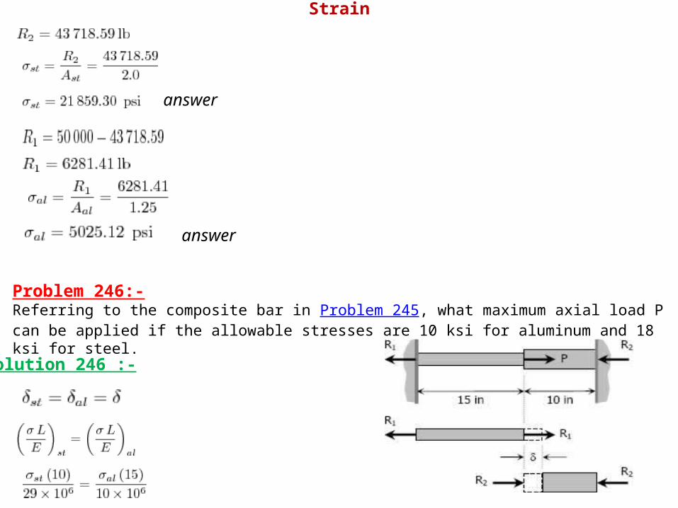
Problem 245:-The composite bar in Fig. P-245 is firmly attached to unyielding supports. Compute the stress in each material caused by the application of the axial load P = 50 kips.
Solution 245 :-
Strain
answer
answer
Problem 246:-Referring to the composite bar in Problem 245, what maximum axial load P can be applied if the allowable stresses are 10 ksi for aluminum and 18 ksi for steel.
Solution 246 :-
Strain

When σal = 10 ksi
(not okay!)When σst = 18 ksi
(okay!)Use σal = 4.14 ksi and σst = 18 ksi
answer
Strain

Problem 247:-The composite bar in Fig. P-247 is stress-free before the axial loads P1 and P2 are applied. Assuming that the walls are rigid, calculate the stress in each material if P1 = 150 kN and P2 = 90 kN. Solution 247 :-
(Answer)
(Answer)
(Answer)

Problem 248:-Solve Problem 247 if the right wall yields 0.80 mm.
Solution 248 :-
Strain

answer
answer
Problem 249:-There is a radial clearance of 0.05 mm when a steel tube is placed over an aluminum tube. The inside diameter of the aluminum tube is 120 mm, and the wall thickness of each tube is 2.5 mm. Compute the contact pressure and tangential stress in each tube when the aluminum tube is subjected to an internal pressure of 5.0 MPa.
Solution 249:-Internal pressure of aluminum tube to cause contact with the steel:
Strain

→ pressure that causes aluminum to contact with the steel, further increase of pressure will expand both aluminum and steel tubes. Let pc = contact pressure between steel and aluminum tubes
→ Equation (1)
The relationship of deformations is (from the figure):
Strain

→ Equation (2)
From Equation (1)
From Equation (2)
Contact Force
answer
Strain

Problem 250:-In the assembly of the bronze tube and steel bolt shown in Fig. P-250, the pitch of the bolt thread is p = 1/32 in.; the cross-sectional area of the bronze tube is 1.5 in.2 and of steel bolt is 3/4 in.2 The nut is turned until there is a compressive stress of 4000 psi in the bronze tube. Find the stresses if the nut is given one additional turn. How many turns of the nut will reduce these stresses to zero? Use Ebr = 12 × 106 psi and Est = 29 × 106 psi.
Solution 250 :-
For one turn of the nut:
Strain

Initial stresses:
Final stresses:answer
answerRequired number of turns to reduce σbr to zero:
The nut must be turned back by 1.78 turns
Strain

Problem 251:-The two vertical rods attached to the light rigid bar in Fig. P-251 are identical except for length. Before the load W was attached, the bar was horizontal and the rods were stress-free. Determine the load in each rod if W = 6600 lb.
Solution 251 :-
→ Equation (1)By ratio and proportion
Strain

From Equation (1)
answer
answer
Problem 252:-The light rigid bar ABCD shown in Fig. P-252 is pinned at B and connected to two vertical rods. Assuming that the bar was initially horizontal and the rods stress-free, determine the stress in each rod after the load after the load P = 20 kips is applied.
Strain

Solution 252:-
→ equation (1)
Strain

→ equation (2)From equation (1)
answerFrom equation (2)
answer
Strain

Problem 253:-As shown in Fig. P-253, a rigid beam with negligible weight is pinned at one end and attached to two vertical rods. The beam was initially horizontal before the load W = 50 kips was applied. Find the vertical movement of W.
Solution 253 :-
Equation (1)
Strain

From equation (1)
answer
Strain

Check by δst:
answer
Problem 254:-As shown in Fig. P-254, a rigid bar with negligible mass is pinned at O and attached to two vertical rods. Assuming that the rods were initially stress-free, what maximum load P can be applied without exceeding stresses of 150 MPa in the steel rod and 70 MPa in the bronze rod.
Strain

Solution 254 :-
Strain

When σst = 150 MPa
(not ok!)When σbr = 70 MPa
(ok!)Use σst = 112.45 MPa and σbr = 70 MPa
answer
Strain

Problem 255:-Shown in Fig. P-255 is a section through a balcony. The total uniform load of 600 kN is supported by three rods of the same area and material. Compute the load in each rod. Assume the floor to be rigid, but note that it does not necessarily remain horizontal.
Solution 255:-
Strain

→ Equation (1)
→ Equation (2)
→ Equation (3)Substitute PB = 450 - 1.5 PC to Equation (2)
answer
Strain

From Equation (3)
answer
answer
From Equation (1)
Problem 256:-Three rods, each of area 250 mm2, jointly support a 7.5 kN load, as shown in Fig. P-256. Assuming that there was no slack or stress in the rods before the load was applied, find the stress in each rod. Use Est = 200 GPa and Ebr = 83 GPa.
Solution 256 :-
Strain

→ Equation (1)
→ Equation (2)
From Equation (1)
answer
Strain

From Equation (2)
Problem 257:-Three bars AB, AC, and AD are pinned together as shown in Fig. P-257. Initially, the assembly is stress free. Horizontal movement of the joint at A is prevented by a short horizontal strut AE. Calculate the stress in each bar and the force in the strut AE when the assembly is used to support the load W = 10 kips. For each steel bar, A = 0.3 in.2 and E = 29 × 106 psi. For the aluminum bar, A = 0.6 in.2 and E = 10 × 106 psi.
answer
Solution 257 :-
→ Equation (1)
Strain
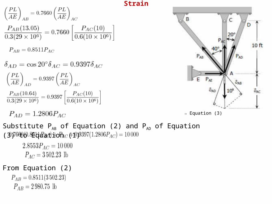
→ Equation (2)
→ Equation (3)
Substitute PAB of Equation (2) and PAD of Equation (3) to Equation (1)
From Equation (2)
Strain

From Equation (3)
Stresses:
answer
answer
answer
answer
Strain

Solution:
Here, from the sketch of deformations, we see that


Prob. 259


Problem 261:-A steel rod with a cross-sectional area of 0.25 in2 is stretched between two fixed points. The tensile load at 70°F is 1200 lb. What will be the stress at 0°F? At what temperature will the stress be zero? Assume α = 6.5 × 10⁻⁶ in/(in·°F) and E = 29 × 106 psi. Solution 261 :-
For the stress at 0°F:
For the temperature that causes zero stress:
answer
answer
Strain

Problem 262:-A steel rod is stretched between two rigid walls and carries a tensile load of 5000 N at 20°C. If the allowable stress is not to exceed 130 MPa at -20°C, what is the minimum diameter of the rod? Assume α = 11.7 µm/(m·°C) and E = 200 GPa. Solution 262 :-
answer
Strain
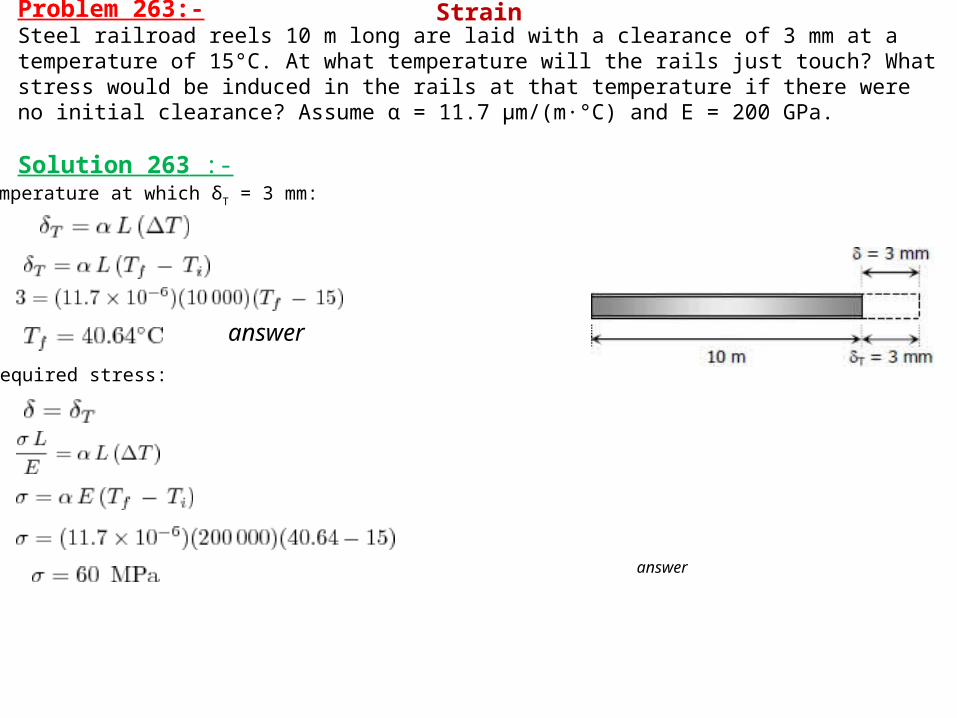
Problem 263:-Steel railroad reels 10 m long are laid with a clearance of 3 mm at a temperature of 15°C. At what temperature will the rails just touch? What stress would be induced in the rails at that temperature if there were no initial clearance? Assume α = 11.7 µm/(m·°C) and E = 200 GPa. Solution 263 :-
Temperature at which δT = 3 mm:
Required stress:
answer
answer
Strain

Problem 264:-A steel rod 3 feet long with a cross-sectional area of 0.25 in.2 is stretched between two fixed points. The tensile force is 1200 lb at 40°F. Using E = 29 × 106 psi and α = 6.5 × 10⁻⁶ in./(in.·°F), calculate (a) the temperature at which the stress in the bar will be 10 ksi; and (b) the temperature at which the stress will be zero.Solution 264:-
(a) Without temperature change:
A drop of temperature is needed to increase the stress to 10 ksi. See figure below.
Required temperature: (temperature must drop from 40°F) answer
Strain

(b) Temperature at which the stress will be zero:
From the figure below:
answer
Problem 265:-A bronze bar 3 m long with a cross sectional area of 320 mm2 is placed between two rigid walls as shown in Fig. P-265. At a temperature of -20°C, the gap Δ = 2.5 mm. Find the temperature at which the compressive stress in the bar will be 35 MPa. Use α = 18.0 × 10⁻⁶ m/(m·°C) and E = 80 GPa. Solution 265 :-
answer
Strain

Problem 266:-Calculate the increase in stress for each segment of the compound bar shown in Fig. P-266 if the temperature increases by 100°F. Assume that the supports are unyielding and that the bar is suitably braced against buckling.
Solution 266 :-
Where Pst = Pal = P. Thus,
Strain

answer
answer
Problem 267:-At a temperature of 80°C, a steel tire 12 mm thick and 90 mm wide that is to be shrunk onto a locomotive driving wheel 2 m in diameter just fits over the wheel, which is at a temperature of 25°C. Determine the contact pressure between the tire and wheel after the assembly cools to 25°C. Neglect the deformation of the wheel caused by the pressure of the tire. Assume α = 11.7 μm/(m·°C) and E = 200 GPa.
Solution 267 :-
answer
Strain

Problem 268:-The rigid bar ABC in Fig. P-268 is pinned at B and attached to the two vertical rods. Initially, the bar is horizontal and the vertical rods are stress-free. Determine the stress in the aluminum rod if the temperature of the steel rod is decreased by 40°C. Neglect the weight of bar ABC.
Solution 268 :-Contraction of steel rod, assuming complete freedom:
The steel rod cannot freely contract because of the resistance of aluminum rod. The movement of A (referred to as δA), therefore, is less than 0.4212 mm. In terms of aluminum, this movement is (by ratio and proportion):
Strain

(Answer)
Strain

Problem 269:-As shown in Fig. P-269, there is a gap between the aluminum bar and the rigid slab that is supported by two copper bars. At 10°C, Δ = 0.18 mm. Neglecting the mass of the slab, calculate the stress in each rod when the temperature in the assembly is increased to 95°C. For each copper bar, A = 500 mm2, E = 120 GPa, and α = 16.8 µm/(m·°C). For the aluminum bar, A = 400 mm2, E = 70 GPa, and α = 23.1 µm/(m·°C).
Solution 269 :-Assuming complete freedom:
From the figure:
Strain

answer
answer
Problem 270:-A bronze sleeve is slipped over a steel bolt and held in place by a nut that is turned to produce an initial stress of 2000 psi in the bronze. For the steel bolt, A = 0.75 in2, E = 29 × 106 psi, and α = 6.5 × 10⁻⁶ in/(in·°F). For the bronze sleeve, A = 1.5 in2, E = 12 × 106 psi and α = 10.5 × 10⁻⁶ in/(in·°F). After a temperature rise of 100°F, find the final stress in each material.
Strain

Solution 270 :- Before temperature change:
compression
tension
tensile stress
shortening
lengthening
With temperature rise of 100°F: (Assuming complete freedom)
Strain

(see figure below)
→ Equation (1)
Strain

Equations (1) and (2)
→ Equation (2)
compressive stress answer
tensile stress answer
Strain

Solution 271 :-
Stress in bronze when σst = 55 MPa
By ratio and proportion:
Strain
Problem 271:-A rigid bar of negligible weight is supported as shown in Fig. P-271. If W = 80 kN, compute the temperature change that will cause the stress in the steel rod to be 55 MPa. Assume the coefficients of linear expansion are 11.7 µm/(m·°C) for steel and 18.9 µm/(m·°C) for bronze.

A temperature drop of 28.3°C is needed to stress the steel to 55 MPa. answer
Problem 272:-For the assembly in Fig. 271, find the stress in each rod if the temperature rises 30°C after a load W = 120 kN is applied.
Solution 272 :-
Strain

Equation (1)
answer
answer
Strain

Problem 273:-The composite bar shown in Fig. P-273 is firmly attached to unyielding supports. An axial force P = 50 kips is applied at 60°F. Compute the stress in each material at 120°F. Assume α = 6.5 × 10⁻⁶ in/(in·°F) for steel and 12.8 × 10⁻⁶ in/(in·°F) for aluminum.
Solution 273 :-
Strain

Problem 274:-At what temperature will the aluminum and steel segments in Prob. 273 have numerically equal stress?
Strain
(Answer)

Solution 274 :-
A drop of 44.94°F from the standard temperature will make the aluminum and steel segments equal in stress. answer
Strain

Problem 275:-A rigid horizontal bar of negligible mass is connected to two rods as shown in Fig. P-275. If the system is initially stress-free. Calculate the temperature change that will cause a tensile stress of 90 MPa in the brass rod. Assume that both rods are subjected to the change in temperature.
Solution 275 :-
Strain

By ratio and proportion
drop in temperature answer
Strain

Problem 276:-Four steel bars jointly support a mass of 15 Mg as shown in Fig. P-276. Each bar has a cross-sectional area of 600 mm2. Find the load carried by each bar after a temperature rise of 50°C. Assume α = 11.7 µm/(m·°C) and E = 200 GPa.
Solution 276 :-
Strain

→ Equation (1)
Strain

answer
answer
Strain