![[Second Edition,.]](https://static.fdokumen.com/doc/165x107/6322fad1887d24588e04752c/second-edition.jpg)
May 1999 Edition - Index of
252
May 1999 Edition HP LaserJet Family Quick Reference Service Guide Volume II
-
Upload
khangminh22 -
Category
Documents
-
view
0 -
download
0
Transcript of May 1999 Edition - Index of

May 1999 Edition
HP LaserJet FamilyQuick ReferenceService Guide
Volume II
Copyright© 1999Hewlett-Packard Co.Printed in USA
Manual Part No.5090-3390
*5090-3390**5090-3390*
5090-3390
HP
LaserJet Fam
ily Quick R
eference Service G
uide – Vol. II
Printed on at least50% Total Recycled Fiber withat least 10% Post-Consumer Paper
Supported Products
HP LaserJet 2100/2100 M/2100 TN printerHP LaserJet 4050/4050 T/4050 N/4050 TN printerHP LaserJet 4000/4000 T/4000 N/4000 TN printerHP LaserJet CompanionHP LaserJet 5000/5000 N/5000 GN printerHP LaserJet 3100 multifunction printerHP LaserJet 8000/8000 N/8000 DN printerHP LaserJet Mopier 240HP LaserJet 8100/8100 N/8100 DN printerHP LaserJet 1100/1100XI/1100SE printerHP LaserJet 1100A/1100AXI/1100ASE printer


HP LaserJet Family Quick Reference Service Guide
Volume II

Hewlett-Packard Company11311 Chinden BoulevardBoise, Idaho 83714 U.S.A.
© Copyright Hewlett-Packard Company, 1999
All Rights Reserved. Reproduction, adaptation, or translation without prior written permission is prohibited, except as allowed under the copyright laws.
Publication number5090-3390
First edition, May 1999
Warranty
The information contained in this document is subject to change without notice.
Hewlett-Packard makes no warranty of any kind with respect to this information. HEWLETT-PACKARD SPECIFICALLY DISCLAIMS THE IMPLIED WARRANTY OF MERCHANTABILITY AND FITNESS FOR A PARTICULAR PURPOSE.
Hewlett-Packard shall not be liable for any direct, indirect, incidental, consequential, or other damage alleged in connection with the furnishing or use of this information.
Trademark credits
MS-DOS® is a U.S. registered trademark of Microsoft Corporation.
UNIX is a registered trademark in the United States and other countries, licensed exclusively through X/Open Company Limited.

Contents
1 Control panel messages. . . . . . . . . . . . . . . . . . . . . . . . . . . . . . . 7
Error listings, descriptions, and recommended actions
2 Service mode. . . . . . . . . . . . . . . . . . . . . . . . . . . . . . . . . . . . . . . 61
How to access service mode and related functions
3 Power supply . . . . . . . . . . . . . . . . . . . . . . . . . . . . . . . . . . . . . . . 85
DC voltages, test points, and tools
4 Input/output (I/O) . . . . . . . . . . . . . . . . . . . . . . . . . . . . . . . . . . . . 99
Printer interface and cabling information
5 Media specifications . . . . . . . . . . . . . . . . . . . . . . . . . . . . . . . . 105
Supported sizes and specifications for paper and special media
6 Toner cartridge information . . . . . . . . . . . . . . . . . . . . . . . . . . 121
Cartridge weights, capacities, and potential service issues
7 Printer options and replaceable parts. . . . . . . . . . . . . . . . . . 131
Support matrix and part numbers for accessories
8 Printer parts. . . . . . . . . . . . . . . . . . . . . . . . . . . . . . . . . . . . . . . 143
Selected high-usage replacement parts
9 Image quality . . . . . . . . . . . . . . . . . . . . . . . . . . . . . . . . . . . . . . 181
Image defect samples, suspect causes, and remedies
10 Wiring diagrams . . . . . . . . . . . . . . . . . . . . . . . . . . . . . . . . . . . 213
Main wiring schematics
11 Services and support/resources and training . . . . . . . . . . . 229
How and where to get training, support, and materials
12 Hewlett-Packard LaserJet Companion . . . . . . . . . . . . . . . . . 235
HP LaserJet Companion information and specifications
A Acronyms and abbreviations . . . . . . . . . . . . . . . . . . . . . . . . . 239
Index. . . . . . . . . . . . . . . . . . . . . . . . . . . . . . . . . . . . . . . . . . . . . 243
EN Contents 3

Ordering other manuals
The HP LaserJet Quick Reference Service Guide, Volume II, provides support for newer monochrome printers (see the following page for a complete list of supported printers). It has been created to help the HP LaserJet service engineer quickly troubleshoot common printer problems.
For older monochrome printers, see the HP LaserJet Quick Reference Service Guide, Volume I. It provides support for the following printers: LJ 6L, LJ 5Si Mopier, LJ 5Si, LJ 5Si MX, LJ 5L, LJ 6P, LJ 6MP, LJ 5P, LJ 5MP, LJ 5, LJ 5M, LJ 5N, LJ 4V, LJ 4MV, LJ 4P, LJ 4MP, LJ 4L, LJ 4ML, LJ 4+, LJ 4M+, LJ4, LJ 4M, LJ 4Si, LJ 4Si MX, LJ IIISi, LJ IIIP, LJ IIP+, LJ IIP, LJ IIID, LJ III, LJ IID, LJ II, LJ 2686D, LJ 2686A.
To obtain service support for HP LaserJet 240 and 320 Mopiers, see the HP Mopier Family Quick Reference Service Guide.
While the quick reference guides are intended to provide all the information the service engineer will need for on-site repair of HP products, they are not intended to replace the service manual for any HP LaserJet product. For detailed information about the HP LaserJet products described in this guide, see the user guide or service manual for that product.
Service manuals for HP LaserJet products are available from Hewlett-Packard. The phone number for the Service Parts Order Desk is:
(800) 227-8164 (U.S. only)
If you are located outside of the U.S., contact your local HP Sales and Service office.
4 Ordering other manuals EN

Supported products
NoteThis guide is updated on a regular basis as the service needs change, as new products are introduced, and as additional information becomes available.
Reference name used in this guide
Model number Maximum pages per month
Service manual part number
LJ 2100/2100 M/ 2100 TN
C4170A/C4171A/C4172A
15K C4170-90959(hard copy)C4170A-60129 (CD)
LJ 4050/4050 T/4050 N/4050 TNLJ 4000/4000 T4000 N/4000 TN
C4251A/C4252A/C4253A/C4254AC4118A/C4119A/C4120A/C4121A
65K C4251-91003
LJ Companion LJ C3989A/C3979A/C4106A
N/A HP Central Repair Only
LJ 5000/5000 N/ 5000 GN
C4110A/C4111A/C4112A
65K C4110-91033
LJ8000/8000 N/8000 DN
C4085A/C4086A/C4087A
130K C4085-91017
LJ 3100 C3948A 6K C3948-90958
LJ 8100/8100 N/8100 DN
C4214A/C4215A/C42164
150K C4214-91000
LJ 1100/1100XI/1100 SE/1100 A/1100 AXI/1100 ASE
C4224A/C4225A/C4226A/C4218A/C4219A/C4220A
7K C4224-60140
EN Supported products 5

6 Supported products EN
1 Cm
EN
ontrol panel essages
OverviewThis chapter provides information on the display lights for the HP LaserJet 1100 and 2100 series printers, and lists printer control panel messages for these HP LaserJet printers:
• LJ 4050 series
• LJ 4000 series
• LJ 5000 series
• LJ 3100
• LJ 8000 series
• LJ 8100 series
Alphabetical messages are listed first, followed by numerical messages. Control panel messages that are self-explanatory are not included.
NoteIf you need more detailed information, see the service manual for the printer you are servicing.
7

LaserJet 2100 series printer light-emitting diode (LED) displays
The control panel for the LaserJet 2100 is composed of 3 light-emitting diodes (LEDs). The messages displayed on the LJ 2100 control panel are: 1) Status and attendance messages; 2) Continuable error messages; 3) Service or fatal error messages; and 4) Accessory error messages. The following table shows status and attendance messages. (Note the legend following the table for a description of the error and the recommended course of action.)
Status and attendance messages
LED displays Key
1. Go, Ready, and Attention LEDs are cycling.
2. Ready LED is on.
3. Ready LED is blinking.
4. Ready LED is blinking; Go LED is on.
5. Go LED is blinking.
6. Attention LED is on
7. Go LED is on. 8. Attention LED is blinking.
Job Cancel Button
Attention LEDReady LED
Go ButtonOff On Blinking
8 Chapter 1 Control panel messages EN

1
Legend for LJ 2100 series LED displays
Status and attendance messages legend
Item Description Recommended action
1 Start up. The buttons will cycle one after another until the printer is ready to print.
• No action is needed
2 Ready. The printer is ready to print.
• No action is needed; however, pressing the GO button will print a demo page.
3 Processing • No action is needed; however, pressing JOB CANCEL cancels the current job.
4 Data. Data is in the printer memory waiting to be printed.
• Pressing GO prints from Tray 1 or from another tray if Tray 1 is empty and the paper size is supported in the other tray. Pressing JOB CANCEL cancels the current job and the printer returns to ready.
5 Manual feed with pause.
• Pressing GO prints from Tray 1 or from another tray if Tray 1 is empty. Pressing JOB CANCEL cancels the current job and the printer returns to ready.
6 Paper out • Fill the printer with paper.
7 Paper out (requested tray)
• Add paper to the requested tray. Pressing GO prints from another tray. Pressing JOB CANCEL cancels the current job.
8 Attention. The printer requires attention for one of the following reasons:
– The door is open.– The toner
cartridge is missing.
– Paper is jammed in the printer.
• Pressing GO to clear the paper jam.Note: It may be necessary to clear the jam manually, and then push GO or close the top cover.
EN LaserJet 2100 series printer light-emitting diode (LED) displays 9

LaserJet 2100 series printer LED displays for primary error messages
Continuable, service, and accessory errors consist of a primary and secondary LED pattern. The primary LED pattern is the one initially displayed by the control panel. The following table shows the primary error LED patterns. To view secondary error LED patterns, simultaneously press GO and JOB CANCEL . A decription of and recommended action for secondary LED patterns begins on page 12.
Primary error messages
LED displays Key
1. Attention and Go LEDs are on.
2. All LEDs are on.
3. All LEDs are blinking.
Job Cancel Button
Attention LEDReady LED
Go Button
Off On Blinking
10 Chapter 1 Control panel messages EN

1
Legend for LJ 2100 series primary LED messages
The following legend provides a description of the primary LED messages. For detailed information about the secondary error messages, see the page numbers referenced in the following legend.
Item Description Recommended action
1 Continuable error • For secondary information, see page 12.
2 Service error • For secondary information, see page 15.
3 Accessory error • For secondary information, see page 18.
EN LaserJet 2100 series printer light-emitting diode (LED) displays 11

LaserJet 2100 series printer LED displays for continuable errors
The following table shows secondary continuable error messages. The legend following the table provides a description of each error and the recommended course of action.
Secondary continuable error messages
LED displays Key
1. The Attention LED is on.
2. The Ready LED is on.
3. The Attention and Go LEDs are on.
4. The Ready and Go LEDs are on.
5. All LEDs are on.
6. The Attention LED is blinking.
7. The Ready LED is blinking.
8. The Attention and Go LEDs are blinking.
9. The Attention and Ready LEDs are on.
10. The Attention, Ready, and Go LEDs are blinking.
Job Cancel Button
Attention LEDReady LED
Go Button
Off On Blinking
12 Chapter 1 Control panel messages EN

1
Legend for LJ 2100 series LED displays
Secondary continuable error messages legend
Item Description Recommended action
1 Memory Overflow (20 error/Mem Full
Press GO to print the transferred data (some data might be lost), then simplify the print job or install additional memory.
2 Temporary Engine Error (41.x errors)
• Press GO. The page containing the error will automatically be reprinted. If the error persists:1 Reseat the connections to the laser
scanner and the engine controller assembly.
2 Replace the laser scanner.
3 Replace the engine controller assembly.
4 Replace the intermediate PCB.
3 Print Overrun (21 error)
Press GO to print the transferred data (some data might be lost), then simplify the print job or install additional memory.
4 I/O Error (22 error - Buffer Flow Error)
Press GO to clear the message (some data will be lost).Check for a loose cable connection and be sure to use a high-quality cable. Some non-HP cables might be missing pin connections, or might otherwise not conform to the IEEE-1284 B specification.
5 I/O Error (40 error-bad connection)
The connection between the printer and the EIO card has been broker.1 Turn the printer off and reseat the card.
2 Press GO to clear the message and continue printing.
EN LaserJet 2100 series printer light-emitting diode (LED) displays 13

6 NVRAM Error (68 error)
Press GO to clear the message and continue printing.An error occurred in the printer’s nonvolatile memory (NVRAM) and one or more printer settings has been reset to its factory default.1 Print a configuration page and check the
printer settings to determine which values have changed.
2 While turning the printer on, hold JOB CANCEL until all lights come on and stay on. This cleans up the NVRAM by removing old areas that are not being used.
7 I/O Error (81 error) The EIO accessory has encountered a critical error. 1 Power cycle the printer.
2 Reseat or replace the EIO accessory.
8 Memory Configuration Error
1 Reprint the job.
2 Perform a cold reset.
3 Replace a DIMM/memory.
4 Replace the formatter.
9 Personality, Job Related Error
1 Perform a cold reset.
2 Remove/replace the language DIMM (PS DIMM).
3 If all else fails, replace the formatter.
10 General Continuable Error
1 Check connections on the intermediate PCB.
2 Replace the formatter PCB.
Secondary continuable error messages legend (continued)
Item Description Recommended action
14 Chapter 1 Control panel messages EN

1
LaserJet 2100 series printer LED displays for service errors
The following table shows secondary service error messages. The legend following the table provides a description of each error and the recommended course of action.
Secondary service error messages
LED displays Key
1. The Attention LED is on.
2. The Ready LED is on.
3. The Go LED is on.
4. The Attention and Ready LEDs are on.
5. The Ready and Go LEDs are on.
6. All LEDs are on.
7. The Attention LED is blinking.
8. The Ready LED is blinking.
9. The Go LED is on.
10. The Attention and Ready LEDs are blinking.
11. The Attention and Go LEDs are blinking.
12. All LEDs are blinking.
Job Cancel Button
Attention LEDReady LED
Go Button
Off On Blinking
EN LaserJet 2100 series printer light-emitting diode (LED) displays 15

Legend for LJ 2100 series LED displays
Secondary service error messages legend
Item Description Recommended action
1 Engine Error (Error 55 - Engine Communication Error
A printer error has occurred. Press GO to clear the error message.
• Check the connections to the intermediate PCB and the engine controller assembly.
• Replace the engine controller assembly.
2 Scanner Error (Error 52)
Press GO. The page containing the error will automatically be reprinted. Turn the printer off and reseat the laser scanner cables.Replace the laser scanner.
3 Beam Error (Error 51 - Bad Beam Detect)
Press GO. The page containing the error will automatically be reprinted.
• Turn the printer off and reseat the laser scanner cables.
• Replace the laser scanner.
4 Motor Error (57 Service-Scan Motor Error)
1 Turn the printer off, then turn it back on.
2 Turn the printer off, then reseat the connection between the laser scanner assembly and the intermediate PCB.
3 Replace the laser scanner.
5 Fuser Error (50 service-bad fuser)
1 Be sure that the fuser is installed correctly and is fully seated.
2 Reseat the fuser cables.
3 Replace the fuser.
4 Replace the engine controller assembly.
5 Replace the intermediate PCB.
6 Formatter internal RAM or ROM error
Replace the formatter.
7 Fan Error (58 service - Fan Motor Error)
1 Turn the printer off, then turn it back on.
2 Turn the printer off, then reseat the connection between the fan and the intermediate PCB.
3 Replace the fan.
4 Replace the engine controller assembly.
16 Chapter 1 Control panel messages EN

1
8 NVRAM Error (68 service)Replace the formatter.
9 Scan Buffer Error (64 service)
Cycle power. If the message persists, replace the formatter.
10 Dynamic Ram Controller Error (65 service)
Replace the formatter.
11 Miscellaneous Interface Hardware Error (67 service)
Check the I/O connections.Verify that the cable is IEEE-1284 B-compliant (if applicable).
12 General Fatal Error Cycle power.
Secondary service error messages legend (continued)
Item Description Recommended action
EN LaserJet 2100 series printer light-emitting diode (LED) displays 17

LaserJet 2100 series printer LED displays for accessory errors
The following table shows secondary accessory error messages. The legend following the table provides a description of each error and the recommended course of action.
Secondary accessory error messages legend
Secondary accessory error messages
LED displays Key
1. Attention LED is on.
2. Go LED is on. 3. Ready LED is on.
4. Attention and Ready LEDs are on.
Item Description Recommended action
1 EIO Port Error • Verify connections.
• Reseat or replace the EIO accessory.
• Replace the formatter
2 DIMM Slot 1 Error • Reseat the DIMM in slot 1. If the problem persists, replace the DIMM.
3 DIMM Slot 2 Error • Reseat the DIMM in slot 2. If the problem persists, replace the DIMM.
4 DIMM Slot 3 Error • Reseat the DIMM in slot 3. If the problem persists, replace the DIMM.
Job Cancel Button
Attention LEDReady LED
Go Button
Off On Blinking
18 Chapter 1 Control panel messages EN

1
LaserJet 1100 series printer light-emitting diode (LED) displays
Status messages for the LJ 1100 series printers can be viewed in the table below. Error messages appear in the “Error and service messages,” table on page 22. (The legends following the tables provide a description of each error and the recommended course of action.)
Continuable error messages
LED displays Key
1. Error LED is on. 2. Error LED is blinking.
3. Attention and Data LEDs are on.
4. All LEDs are blinking.
5. Data LED is blinking.
6. All LEDs are off.
7. Data LED is blinking.
8. All LEDs are on.
Go ReadyAttention
(Error)
(Data)
OffOnBlinking
EN LaserJet 1100 series printer light-emitting diode (LED) displays 19

Legend for LJ 1100 series LED displays
Status messages legend
Item Description Recommended action
1 Paper out • The paper tray is empty.
• The sensor arm is stuck or broken.
2 Door openNo toner cartridgePaper jam
• Check that the toner cartridge is fully seated and that the door is firmly closed.
• The actuator or tab is missing or broken.
• Install a new toner cartridge.
• The high-voltage contacts are dirty or defective.
• The ECU is defective.
• Remove the jammed paper. Check the entire paper path for other pieces of paper.
• Check sensors and flags in the paper path for proper operation.
• The media does not meet HP specifications.
• The paper path is dirty or obstructed.– Clean the paper path components; ensure
that the transfer roller is seated properly.
• The pickup (or other) roller or the separation pad is worn.
• The media is not correctly loaded.
• The solenoid operation is bad.– Verify proper solenoid operation and
replace if necessary.
• The gear(s) is bad or not meshing in the drive train.– Replace the bad gear(s) or check the
toner cartridge gears for damage.
• The main motor is bad.
20 Chapter 1 Control panel messages EN
1
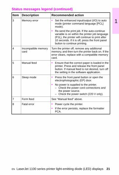
3 Memory error • Set the enhanced input/output (I/O) to auto mode (printer command language [PCL] mode).• Re-send the print job. If the auto-continue variable is on within the printer job language (PJL), the printer will continue to print after 10 seconds. If it is off, press the front panel button to continue printing.
4 Incompatible memory card
Turn the printer off, remove any additional memory, and then turn the printer back on. If the error clears, replace with a compatible memory card.
5 Manual feed • Ensure that the correct paper is loaded in the printer. Press and release the front panel button. If manual feed is not desired, turn off the setting in the software application.
6 Sleep mode • Press the front panel button or open the electrophotographic (EP) door.
• No power is supplied to the printer.– Check the power cord connections and
the power source.– Check the power switch (220 V only).
7 Form feed See “Manual feed” above.
8 Fatal error • Power cycle the printer.
• If the error persists, replace the formatter PCA.
Status messages legend (continued)
Item Description Recommended action
EN LaserJet 1100 series printer light-emitting diode (LED) displays 21

LaserJet 1100 series printer LED displays
The legend following the table provides a description of each error and the recommended course of action.
Error and service messagesLED displays Key
Note: When all the lights are on, a service error has occurred. Press and hold the GO (Data) button to display the secondary LED error code pattern. The code will be shown only while the button is pressed. The following illustrations show the possible LED error patterns.
1. All LEDs are on. 2. Data and Error LEDs are on.
3. Error LED is on. 4. Error LED is blinking.
5. Ready LED is on.
6. Data and Ready LEDs are on.
7. Data LED is on. 8. Ready LED is blinking.
9. Ready and Error LEDs are blinking.
Go ReadyAttention
(Error)
(Data)
OffOnBlinking
22 Chapter 1 Control panel messages EN

1
Legend for LJ 1100 series LED displays
NoteBefore troubleshooting any service error, power cycle the printer to see if the error persists.
Error and service messages legend
Item Description Recommended Action
1 RAM/ROM error • Power cycle the printer.
• The memory card is defective or incompatible.– Turn the printer off, remove any additional
memory, then turn the printer back on. If the message clears, replace the memory card.
• The formatter PCA is defective.
2 Firmware error/processor error
• Power-cycle the printer.
• The formatter PCA is defective.
3 Print engine error • Temporary Error– Power cycle the printer. If the error
persists, reseat the formatter PCA to the ECU.
• If the error persists, replace the ECU PCA
4 Document scan engine error
1 Unplug the printer, remove and reattach the laser scanner, and then replug the printer.
2 Replace the document scanner unit.
5 Print laser scanner error
• A temporary error has occurred. – Power cycle the printer.
• The laser scanner assembly is improperly fitted.
• A problem has occurred with the laser scanner cable.
• The laser scanner assembly is defective.
• The ECU PCA is defective.
6 Fuser error • Turn the printer off, wait 20 minutes, and then turn the printer on.
• Check the fuser connections.
• Replace the fuser.
EN LaserJet 1100 series printer light-emitting diode (LED) displays 23

7 Beam error • A temporary error has occurred.– Power cycle the printer.
• The laser scanner assembly is not seated.
• The laser scanner assembly is defective.– Replace the laser scanner assembly or
cable.
8 Document scan engine NVRAM error
1 Unplug the printer, remove and reattach the laser scanner, and then replug the printer.
2 Replace the document scanner unit.
9 DIMM error • An error has been found in the RAM.– Power cycle the printer.
• The memory card is defective or incompatible.– Turn the printer off; remove any additional
memory;’ then turn the printer back on. If the message clears, replace the memory card.
• The formatter PCA is defective.
Error and service messages legend (continued)
Item Description Recommended Action
24 Chapter 1 Control panel messages EN

1
Alphabetical messages
The following control panel messages are for the LJ 4050 series, LJ 4000 series, LJ 5000 series, LJ 3100, LJ 8000 series, and LJ 8100 series printers. Numerical messages begin on page 46.
• Enter a different one-touch key or an unassigned speed-dial code.
• Ask the network administrator to unlock the function.
While programming a group-dial code, a fax number has been added that is already in the group.
• Add the next fax number to the group.
• Re-install the duplexer.
• If the message persists, make sure that the duplexer is connected and that the connector is not damaged.
• Replace the duplexer.
• Re-install the optional tray.
• Make sure that the optional tray is connected and that the connector is not damaged.
• Replace the optional tray.
(number) is a group, group not allowed
Access denied, menus locked
Already in group
Bad duplexer connection
Bad opt tray connection
EN Alphabetical messages 25

The attempted fax number has received a voice answer or no answer, was busy on the first dial and redials, or was busy with redials pending.
• Unplug the power cord for the fax machine from the power strip or outlet, and then plug it back in.
• Check the fax number and try resending the fax. If the message appears again, try sending to another fax machine or try again later.
• Back space was pressed while in a group-dial code in the Group Dial Setup level of the menu.
1 Press START to return to the group-dial code and continue editing.
2 Press ENTER/MENU to go to the Group Dial Setup level of the menu. (Press ENTER/MENU again to choose a different group-dial code.)
3 Press STOP/CLEAR to exit the menu settings.
• Check to see if paper is jammed in the external paper-handling finishing device.
• Check to see if an alignment error has occurred in the external paper-handling finishing device.
Blacklisted (France only)
Busy
Cancel group edit, ENTER to confirm
Check finisher device alternates with Clear jam
Check finisher device alternates with Finisher align error
26 Chapter 1 Control panel messages EN
1
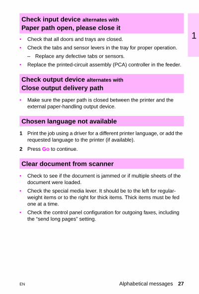
• Check that all doors and trays are closed.• Check the tabs and sensor levers in the tray for proper operation.
– Replace any defective tabs or sensors.
• Replace the printed-circuit assembly (PCA) controller in the feeder.
• Make sure the paper path is closed between the printer and the external paper-handling output device.
1 Print the job using a driver for a different printer language, or add the requested language to the printer (if available).
2 Press GO to continue.
• Check to see if the document is jammed or if multiple sheets of the document were loaded.
• Check the special media lever. It should be to the left for regular-weight items or to the right for thick items. Thick items must be fed one at a time.
• Check the control panel configuration for outgoing faxes, including the “send long pages” setting.
Check input device alternates with Paper path open, please close it
Check output device alternates with Close output delivery path
Chosen language not available
Clear document from scanner
EN Alphabetical messages 27

• The printer door is open.
• Check that the toner cartridge is fully seated and that the covers are firmly closed.
• The ECU is defective.
• The actuator or tab is missing or broken.
1 Try resending the fax.
2 If the call fails again, check that the telephone cord is securely connected. Then check for a dial tone on the phone line by pressing MANUAL DIAL .
3 Wait; try resending the fax later.
NoteFor additional details, see the HP LaserJet 3100 Product Service Manual.
An error was detected in the static random-access memory (SRAM).
• Unplug the power cord from the power source, wait 10 seconds, and replug the power cord.
• If the error persists, replace the formatter.
• In Service mode, run the SRAM stuck address test.
– Unplug the power cord from the power source, wait 10 seconds, and replug the power cord.
• If the error persists, replace the formatter.
Close printer doors/Close covers
Communication error
Configuration err # (number 1-4)
Config. stuck addr
28 Chapter 1 Control panel messages EN
1
• In Service mode, run the SRAM tied address test.– Unplug the power cord from the power source, wait 10 seconds, and replug the power cord.
• If the error persists, replace the formatter.
The battery has failed.
• You can continue to use the HP LaserJet 3100 product without replacing the battery, but if you re-enter the menu settings and then turn off the power, the settings will be erased again.
• Unplug the power cord from the power source, wait 10 seconds, and replug the power cord.
• If the error persists, replace the formatter.
• Reseat the enhanced input/output (EIO) disk or replace the old disk device with a new disk.
• Check the filename and directory name.
• Reattempt the operation.
• Delete the files from the EIO disk and then try again, or add a Flash dual inline memory module (DIMM).
• Download or delete files from the HP JetAdmin software, and download or delete fonts from the HP FontSmart software.
Config. tied addr.
[Date] [Time]
Decoding error # (number 1-3)
Disk device failure
Disk file operation failed
Disk file system is full
EN Alphabetical messages 29
• Use the HP JetAdmin software to disable the write protection.
1 Press START. A report is printed.
2 Check the fax log status column for the “Fax Document was Lost” message.
3 Resend the associated outgoing faxes. Ask the sender to resend incoming faxes.
• The printer door is open.
• Check that the toner cartridge is fully seated and that the covers are firmly closed.
• The ECU is defective.
• The actuator or tab is missing or broken.
• Check the duplexer for a paper jam.
• Reseat the duplex assembly, and check the connection.
• Replace the duplex unit.
• Stand by until the EIO disk is done initializing.
• Stand by until the disk accessory card is done initializing.
Disk is write protected
Documents were lost, START to continue
Door open
Duplex error, check duplexer
EIO x disk initializing
EIO x disk spinning up
30 Chapter 1 Control panel messages EN

1
• Replace the EIO disk.• Unplug the power cord from the power source, wait 10 seconds, and replug the power cord.
• If the error persists, replace the formatter.
1 Load the requested envelope type and size into the envelope feeder.
2 Make sure that the envelope size and type are set correctly on the Paper-handling menu in the printer control panel.
3 Press GO if the envelope is already loaded in the feeder.
4 Press -VALUE+ to scroll through the available types and sizes.
• Resend the fax or ask the sender to resend the fax to you.
• If you set up faxes to be sent at a future time or to be polled, print a fax log to identify which faxes were lost. Then re-enter the faxes.
• Faxes that were received to memory (instead of printing) have been lost. Ask the sender to resend the fax.
EIO disk x non-functional
Encoding error
Envelope feeder load
Errors likely in pages: (page range)
Fax document was lost
EN Alphabetical messages 31

• Unplug the power cord from the power source, wait 10 seconds, and replug the power cord.
• If you set up faxes to be sent at a future time or to be polled, print a fax log to identify which faxes may have been lost. Then, re-enter the faxes.
• Faxes that were received to memory (instead of printing) have been lost. Ask the sender to resend the fax.
• If the error persists, replace the formatter.
• Remove the Flash DIMM and replace it with a new one.
• Check the filename and directory name.
• Reattempt the operation.
• Delete files from the Flash DIMM or add another DIMM.
• Download or delete files from the HP JetAdmin software, and download or delete fonts from the HP FontSmart software.
• Use the HP JetAdmin software to disable the write protection.
1 Begin adding fax numbers to the group-dial code by pressing the one-touch key for each number or by pressing SPEED DIAL .
2 Enter the speed-dial code for the fax number.
3 Press ENTER/MENU.
Fax memory error # (number 1-5)
Flash device failure
Flash file operation failed
Flash file system is full
Flash is write protected
Group is empty, use ONE-TOUCH/SPEED DIAL
32 Chapter 1 Control panel messages EN
1
• Reseat the DIMM(s).1st x = Device number in chain
2nd x = Device type (3 types):
1 = Input
2 = Output
3 = Stapler/stacker unit
yy = Device specific error
• See the documentation that came with the paper-handling device.
• The maximum number of fax numbers that can be added to an ad-hoc group is 100. Resend the fax, but only to 100 or fewer fax numbers.
• Re-insert the duplexer’s front cover.
• Reseat or install a new toner cartridge.
• The high-voltage contacts are dirty or defective.
• The ECU is defective.
Initializing
Input device condition xx.yy
Input limit reached
Install front duplex cover
Install toner cartridge
EN Alphabetical messages 33

• Re-insert the specified tray.
• Check for damaged tabs in the tray.
• Check for damaged switches in the printer.
• Replace the PCA controller in the feeder.
• Re-enter the date and time.
• Run the keypad test again.
• If the error persists, try each of the following in the order given:
– Check the cabling.– Replace the control panel.– Replace the formatter.
• Wait for the program to load.
• Press START to continue scanning. If START is not pressed within 3 seconds, the message disappears and the document scanner stops scanning because it thinks the page has jammed.
• If sending a fax or copying a document longer than 991 mm (39 in), the control panel configuration can also be set to “Send long pages.” This ensures that long pages feed without having to monitor the task. Press START before the document scanner shuts off.
Install Tray x
Invalid date or time
Keypad test failed
Loading program <number> alternates with Do not power off
Long page? START to continue
34 Chapter 1 Control panel messages EN

1
1 Load the requested paper into Tray 1.2 Press GO if the appropriate paper is already loaded in Tray 1.
3 Press -VALUE+ to scroll through the available types and sizes.
4 Press SELECT to accept the alternate type or size.
• Reload the unscanned pages and re-send them to finish the fax job.
• Scan the unscanned pages to the computer and fax them from the computer.
• Add more memory to the printer or simplify the print job.
This message should clear automatically when the next task starts (for example, when you start a copy or receive a fax).
• Try changing the memory settings for I/O Buffering and Resource Saving (although default settings are usually best).
• Install additional memory in the printer.
• Press GO to continue.
• On the printer control panel, change the setting for resource saving, or add more memory to the printer.
Manually feed [type] [size]
Memory full - send unscanned pages
Memory full - stored data lost
Memory is full
Memory settings changed
Memory shortage job cleared
EN Alphabetical messages 35
• Press GO to continue.
• Add more memory to the printer.
• Unplug the power cord from the power source, wait 10 seconds, and replug the power cord.
• If the error persists, try each of the following in the order given:
– Check the cabling.– Replace the line interface unit (LIU).– Replace the formatter.
• Check the fax number and try resending the fax. If the message appears again, try sending to another fax machine or try again later.
• Check that the telephone cord is securely connected.
• Check for a dial tone on the phone line by pressing MANUAL DIAL .
• If necessary, check the wall outlet by plugging in a phone and attempting to place a call.
• Check the fax number and try resending the fax. If the message appears again, try sending to another fax machine or try again later.
• Wait for a fax. As soon as a fax is in the memory, the fax will reprint.
Memory shortage page simplified
Modem error # (number 1-3)
No answer
No dial tone
No fax in (number) tries
No fax pages in memory to reprint
36 Chapter 1 Control panel messages EN

1
• Print all faxes that have been received in memory.• If you have several faxes set up to be sent at a future time or to be polled, use job status to clear them.
There is a problem with the line interface unit (LIU).
• Unplug the power cord from the power source, wait 10 seconds, and replug in the power cord.
• If the problem persists, replace the LIU.
• If the problem persists, replace the formatter.
The fax log was unable to print because of an error, such as out-of-paper.
• Load paper in the paper input bin so the HP LaserJet 3100 product can print the log.
• Try resending the job. If the error persists, try reducing the amount of activity on the HP LaserJet product. Cancel jobs in memory before resending the job.
The HP LaserJet product continues to copy, but only one copy is output.
– Divide the copy job into smaller sections and then try copying again.
– If you are collating the job, turn the collation feature off, make only one copy of the document at a time, or see the user guide for instructions about using the Document Assistant.
No memory for report, erase/print document
No modem installed
No room in fax log
Not enough memory
Out of memory—switching to ONE COPY
EN Alphabetical messages 37

1 Remove the media from the face-down tray.
2 Check PS1401 on the sensor PCA.
3 Make sure the sensor flag moves freely.
1 Load paper.
2 If paper is already loaded, remove it.
3 Check for, remove, and discard any jammed sheets.
4 Reload the paper.
• Re-enter a four-digit password.
• Reduce the size of the print job, or wait for other jobs to finish so memory will be freed.
• If faxes are set up to be polled or sent at a future time, you may want to cancel these jobs to free memory.
Reset the maintenance page count only after a maintenance kit has been installed. Resetting the maintenance page count causes PERFORM PRINTER MAINTENANCE to appear after another 150,000 (LJ 5000 series); 200,000 (LJ 4000 and LJ 4050 series); or 350,000 (LJ 8000 series) pages have printed.
1 Hold down the ITEM- and VALUE- keys while turning the printer on.
2 Wait until RESET MAINTENANCE COUNT appears, and then release both keys.
Output bin full alternates with Clear paper from [bin name]
Paper bin is empty, please add paper
Password must be 4 digits
Paused (memory full)
Perform printer maintenance
38 Chapter 1 Control panel messages EN

1
• Let the “print jobs retry” continue for 5 minutes. If theHP LaserJet 3100 product still does not print, resend the print job.
• The maximum number of characters that can be entered is 40. If you have a number longer than 40 characters, break the number into smaller chunks.
1 Enter the first part of the number, and press REDIAL/PAUSE as the last character in the first number.
2 Enter the second part of the number as if it were a second number going to a group. When the product dials, it will treat both numbers as if they are one.
• Make sure that the sender’s fax machine is ready to be polled, and check the fax number. Then set up to poll again.
• Check that the parallel cable is securely connected between the HP LaserJet 3100 product and the computer.
• If the problem persists, unplug the power cord from the power source for 5 seconds, and then replug it.
• If the problems persists, replace the formatter.
• Verify that the printer door is closed.
• Check the toner cartridge for proper installation.
PC print timed out
Phone number error
Polling-in error
Printer comm error^1
Printer cover open or no cartridge
EN Alphabetical messages 39

• There is an error with the print engine.
• Check the cabling to the heating element.
• If the problem persists, replace the heating element.
• If the problem persists, replace the ECU.
• No action is needed. If you already started another job, the job will be completed when the HP LaserJet product becomes available.
• Open and reclose the printer door.
• Unplug the power cord from the power source, wait 10 seconds, and replug the power cord.
• If the problem persists, replace the laser scanner assembly.
A problem has occurred with the print engine.
• Unplug the power cord from the power source, wait 10 seconds, and then replug the power cord.
• If the problem persists, replace the motor.
• If the problem persists, replace the ECU.
• Check the input areas, the output areas, and the interior for the jam, and then clear the jam. The job should continue to print. If it does not, try reprinting the job.
Printer fixing error, replace fixing unit
Printer is busy
Printer laser error, call for service
Printer motor error, call for service
Printer paper jam, check paper path
40 Chapter 1 Control panel messages EN

1
• Open and close the printer door.• Unplug the power cord from the power source, wait 10 seconds, and replug the power cord.
• If the problem persists, replace the laser scanner assembly.
• Check the tray selected and the type settings. If the printer does not respond after you press the control panel keys, turn the printer off, and then turn the printer on to clear the message.
• If paper is loaded when the printer is in Power Save mode, it might not be recognized. Open and close the affected paper tray when the printer is in a READY state.
• Turn the printer off and on to clear the message.
• If the message persists, install a new RAM disk.
• Check the filename and directory name.
• Reattempt the operation.
• Delete files and then try again, or turn the printer off and then turn the printer on to delete all files on the device. (Use HP JetAdmin software, HP FontSmart software, or another software utility to delete files.)
• If the message persists, increase the size of the RAM disk.
– Change the RAM disk size from the Configuration menu in the printer control panel.
Printer signal error
Processing job from Tray x
RAM disk device failure
RAM disk file operation failed
RAM disk file system is full
EN Alphabetical messages 41

• Use HP JetAdmin software to disable the write protection.
• Ask the sender to resend the fax.
• Try resending the fax. If the fax still fails to transmit, call the recipient to check that the fax machine is on and working and to verify the fax number.
• Try resending the fax. If the fax still fails to transmit, call the recipient to check that the fax machine is on is on and working and to verify the fax number.
• Recalibrate the document scanner.
• If the problem persists, replace the CIS.
An error has occurred within the SRAM.
• Press and hold down the STOP/CLEAR key for 7 seconds to reset the product.
• If the error persists, unplug the power cord from its power source for 10 seconds, and then replug it.
• If the error persists, replace the CIS.
• If the error persists, replace the formatter.
RAM disk is write protected
Received error
Redial failed
Remote fax was busy
Scan reference error
Scanner error #1
42 Chapter 1 Control panel messages EN

1
The document scanner mechanism is in use.• Wait until the document scanner has finished the current job before sending the next job.
• Pull the document release door open and then remove the jammed document.
• Choose a speed-dial code that has already been assigned a fax number.
• Unplug the power cord from the power source, wait 10 seconds, and replug the power cord.
• If the message is still displayed, replace the formatter.
• No action is required. There are no faxes to retrieve.
• Load the empty paper tray (X) to clear the message.
• Inspect the tray for damaged tabs.
• Check the sensor-arm flags for damage. Be sure the flags can move freely.
• Replace any defective sensors.
Scanner isn’t available
Scanner jam - reload
Speed dial (number) is not assigned
System error
There are no documents in memory
Tray x empty
EN Alphabetical messages 43

• Verify that the media can be pulled from another tray.
• Replace the paper tray.
1 Load the requested paper into the specified tray (X). Ensure that the trays are correctly adjusted for size.
2 Press GO to print from the next available tray.
3 Press -VALUE+ to scroll through the available types and sizes.
4 Press SELECT to accept the alternate type or size.
5 Inspect the switches in the tray.
6 Remove the tray, and then turn the printer on. Push the switches by hand to see if the switches register.
When printing, the incorrect printer driver was selected or an error occurred with the parallel interface.
1 After selecting the Print command in the software application you are using, select the HP LaserJet 3100 as the printer.
2 Reprint the job.
• Check the fax number and try resending the fax.
• If the message appears again, try sending to another fax machine or try again later.
Tray x lifting
Tray x load
Unrecognized format
Unsuccessful call
44 Chapter 1 Control panel messages EN

1
• Load a supported paper size in the tray. See chapter 5 for a list ofsupported paper sizes.
1 Press -VALUE+ to scroll through the available types and sizes.
2 Press SELECT to accept the alternate type or size.
Unsupported size in tray [yy]
Use [type] [size] instead?
EN Alphabetical messages 45

Numerical messages
Press GO on the printer control panel to clear the error message.
• Remove the jammed paper from the specified location. Check the entire paper path for other pieces of paper.
• Open and close the top cover to clear the message.
• Check sensors and flags in the paper path for proper operation.
• The media does not meet HP specifications.
• The paper path is dirty or obstructed.
– Clean the paper path components; ensure that the transfer roller is seated properly.
• The pickup (or other) rollers and/or the separation pad is worn.
• The paper is the wrong length or the paper size is selected incorrectly in the software.
• The exit sensor or flag is defective.
• A defective input (paper-out) sensor does not sense that the printer is out of paper.
• The paper is not correctly loaded.
• The solenoid operation is bad.
– Verify proper solenoid operation and replace if necessary.
• The gear(s) might be bad or might not be meshing in the drive train.
– Replace the bad gear(s) or check the toner cartridge gear(s) for damage.
• The main motor is bad.
XX.YY printer error, press Go to continue
13 Paper jam/Remove paper jam
46 Chapter 1 Control panel messages EN

1
• Ensure that the paper trays are loaded properly so that paper can feed from the trays.• Check the input area for obstructions such as paper in the paper path or damage to the registration assembly.
• Verify that the transfer roller is positioned correctly.
• Check PS 102 and PS 103 (4000/4050 series) and PS 402 and PS 403 (5000 series) for proper operation.
– Replace any defective sensors or flags.
• Check the transfer roller and small media belt to ensure that the roller and belt are operating and can feed the paper.
• Check the paper path for obstructions at the transfer roller, toner cartridge, paper feed guide, and fuser.
• Check PS 501 and PS 106 (4000/4050 series), PS 1307 (5000 series), or PS 1403 (8000 series) for proper operation. Replace any defective sensors or flags.
• Inspect the path between the fuser and delivery assemblies.
• Check the diverter assembly.
• Check the duplexer and the rear area of the printer for obstructions or damage.
• In the duplexer, check PS 701 and PS 703 for proper operation.
• Replace the duplexer if a sensor is defective.
13.1 Paper delay jam at paper feed area13.2 Paper stopped jam at paper feed area
13.5 Paper delay jam at fuser13.6 Paper stopped jam at fuser
13.9 Check left door
13.10 Paper delay jam at paper reversing area/ duplexer
EN Numerical messages 47

• Check the entire paper path for obstructions.
• Reseat the duplexer.
• Try the Paper Path test.
• Replace the duplexer.
1 Open the vertical transfer unit (VTU) and remove the media.
2 Verify that the entry or exit sensor can move freely.
3 If the problem persists, open the VTU and override its open door sensor, perform a Paper Path test from the 2,000-sheet Input Tray (or 2x500-sheet Input Tray), and make sure the feed rollers are advancing the paper.
– If the rollers do not rotate, verify the connections at the main drive assembly, pickup assembly, controller PCA, and power supply. If the rollers still do not rotate or do not drop down, replace the pickup assembly.
– If the rollers rotate and drop down without advancing the paper, replace the feed rollers using the maintenance kit.
– If the problem persists, replace the VTU.
• Check the paper path between the fuser and duplex assembly.
• Reseat the duplexer.
• Replace the duplexer.
13.11 Paper jam
13.11 Paper jam in input device
13.12 Paper jam
48 Chapter 1 Control panel messages EN

1
• Check the entire paper path for obstructions.• Remove the duplex assembly and look for paper in the side of the assembly.
– Retest.
• Replace the duplexer.
• Check the paper path for obstructions.
• Check that all assemblies are seated and all doors are closed.
• Check all sensors and flags in the paper path.
• Check that all assemblies are seated and all doors are closed.
• Check all sensors and flags in the paper path.
• Open the flipper jam access door and remove the media.
• Make sure the sensor flag moves freely.
• Make sure that the flipper shaft is in place.
• If the problem persists, replace the flipper assembly.
• If the problem persists, replace the mailbox controller PCA.
• Press GO to print the transferred data (some data might be lost); then simplify the print job or install additional memory.
13.13 Paper jam
13.20 Paper jam
13.21 Door open jam
13.22 Paper jam in output device
20 Insufficient memory alternates with Press Go to continue
EN Numerical messages 49

• Set the enhanced input/output (I/O) to auto mode (printer command language [PCL] mode).
– Resend the print job. If the auto-continue variable is on within the printer job language (PJL), the printer will continue to print after 10 seconds. If it is off, press the front panel button to continue printing.
• Press GO to print the transferred data. (Some data could be lost).
• To print the job without losing data, select PAGE PROTECT=ON from the Configuration menu in the printer control panel and then print the job. Afterward, return to PAGE PROTECT=AUTO. Do not leave PAGE PROTECT=ON; doing so could degrade performance.
• If this message appears often, simplify the print job or install additional memory.
• Press GO to clear the message. (Data will be lost.)
• Check for a loose cable connection. Use a high-quality IEEE-1284 cable.
• Press GO to clear the error message. (Data will be lost.)
20 Error/Memory overflow
21 Page too complex
22 EIO x buffer overflow alternates with
Press Go to continue (too much data sent to EIO card)
22 Parallel I/O buffer overflow (too much data sent to parallel port)
50 Chapter 1 Control panel messages EN

1
• Verify that the correct option for serial pacing is selected on the I/Omenu.
• Print a menu map and verify that the serial pacing item (from the I/O menu on the printer control panel) matches the setting on the computer.
• Press GO to clear the error message. (Data will be lost.)
• Verify cable connections.
• Verify that the printer serial configuration is set the same as the computer.
– Access the serial baud rate setting from the I/O menu on the printer control panel.
• Press GO to clear the error message and continue printing.
X = Description
1 = EIO slot 1
2 = EIO slot 2
• Turn the printer off and reseat the card.
• Press GO to clear the error message and continue printing.
22 Serial I/O buffer overflow alternates with
Press Go to continue (too much data sent to the serial port)
40 Bad serial transmission (data transfer error)
40 EIO x bad transmission (connection between printer and EIO card broken)
EN Numerical messages 51

• Verify that all trays are adjusted correctly for size. (The printer attempts to print the job until the size settings are correct.)
• If you are trying to print from Tray 1, make sure that the paper-size setting in the printer control panel is configured correctly.
• If you are trying to print from the optional 500-sheet tray, be sure to set the paper-size dial to match the paper size loaded in the tray.
• Press GO. The page containing the error is automatically reprinted. (Or, press CANCEL JOB to clear the job from the printer’s memory.)
• A temporary printing error occurred.
X = Description
1 = Unknown misprint error
2 = Beam detect error
4 = No VSYNC error
5 = Media feed error
9 = Noise VSREQ error
• Press GO. The page containing the error reprints automatically. If the error persists, try the following procedures:
– Reseat the connections to the laser scanner and the engine controller board.
– Replace the laser scanner.– Replace the engine controller board.
41.3 Unexpected paper size
41.x Printer error alternates with Press Go to continue
52 Chapter 1 Control panel messages EN

1
1 Turn the printer off, wait 20 minutes, and then turn the printer on.2 If the message persists, reseat the fuser.
3 If the message persists, replace the fuser.
4 The line voltage is low or bad--printer is hooked up to uninterruptable power supply (UPS).
X = Description
1 = Beam detect error
2 = Laser error
• Press GO. The page containing the error reprints automatically.
• Turn the printer off and then on.
• Reseat the cables.
• Replace the laser scanner.
X = Description
1 = Scanner startup error
2 = Scanner rotation error
• Press GO. The page containing the error reprints automatically.
• Turn the printer off and then on.
• Reseat the cables.
• Replace the laser scanner.
50.x Fuser error
51.x Printer error (loss of beam detect)
52.x Printer error (the laser scanner speed is incorrect)
EN Numerical messages 53
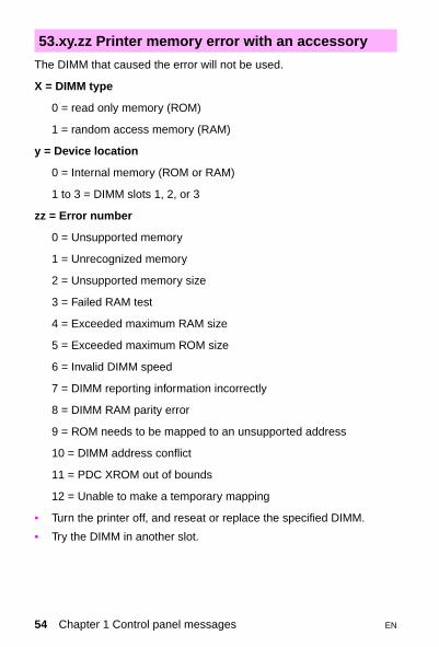
The DIMM that caused the error will not be used.
X = DIMM type
0 = read only memory (ROM)
1 = random access memory (RAM)
y = Device location
0 = Internal memory (ROM or RAM)
1 to 3 = DIMM slots 1, 2, or 3
zz = Error number
0 = Unsupported memory
1 = Unrecognized memory
2 = Unsupported memory size
3 = Failed RAM test
4 = Exceeded maximum RAM size
5 = Exceeded maximum ROM size
6 = Invalid DIMM speed
7 = DIMM reporting information incorrectly
8 = DIMM RAM parity error
9 = ROM needs to be mapped to an unsupported address
10 = DIMM address conflict
11 = PDC XROM out of bounds
12 = Unable to make a temporary mapping
• Turn the printer off, and reseat or replace the specified DIMM.
• Try the DIMM in another slot.
53.xy.zz Printer memory error with an accessory
54 Chapter 1 Control panel messages EN
1
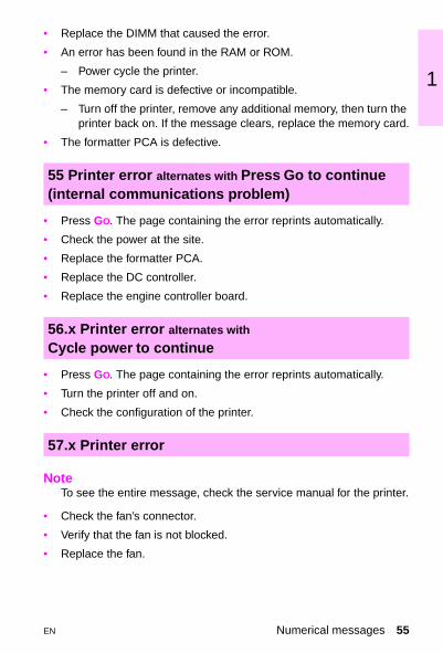
• Replace the DIMM that caused the error.
• An error has been found in the RAM or ROM.
– Power cycle the printer.
• The memory card is defective or incompatible.
– Turn off the printer, remove any additional memory, then turn the printer back on. If the message clears, replace the memory card.
• The formatter PCA is defective.
• Press GO. The page containing the error reprints automatically.
• Check the power at the site.
• Replace the formatter PCA.
• Replace the DC controller.
• Replace the engine controller board.
• Press GO. The page containing the error reprints automatically.
• Turn the printer off and on.
• Check the configuration of the printer.
NoteTo see the entire message, check the service manual for the printer.
• Check the fan’s connector.
• Verify that the fan is not blocked.
• Replace the fan.
55 Printer error alternates with Press Go to continue (internal communications problem)
56.x Printer error alternates with
Cycle power to continue
57.x Printer error
EN Numerical messages 55

X = Description
0 = Motor error
1 = Motor startup error
2 = Motor rotation error
• Turn the printer off and then on.
• Make sure that the fuser or toner cartridge is not hindering gear movement in the drive train.
• Verify that the cable in the main motor is seated properly.
• If the error persists, replace the motor.
X = Location of problem
0 = Internal memory
1 to 3 = DIMM slots 1, 2, or 3
• Reseat or replace the specified DIMM.
The formatter PCA is defective.
• Power cycle the printer. Disconnect the parallel I/O cable and run a self test. If the error persists, replace the formatter PCA.
• Turn the printer off and then on.
• If the message persists, replace the formatter.
59.x Printer error
62.x Printer error (printer memory)
63 Service
64.x Printer error (scan buffer)
56 Chapter 1 Control panel messages EN

1
First X = Device number in chainSecond X = Device type (3 types):
1 = Input
2 = Output
3 = Stapler/stacker unit
yy = Device-specific error
• Press GO to clear the message.
• Turn the printer off and then on.
• Check all of the cables.
• Reseat the external paper-handling device.
• Verify that the lifting plate lifts up freely by hand.
• Verify that the paper size plates are installed correctly and are not bent.
• Check the pickup roller for proper installation.
• Check the pickup assembly and replace if necessary.
• Replace Tray 4.
66 Error (external paper-handling device)
66.11 Input device failure
EN Numerical messages 57
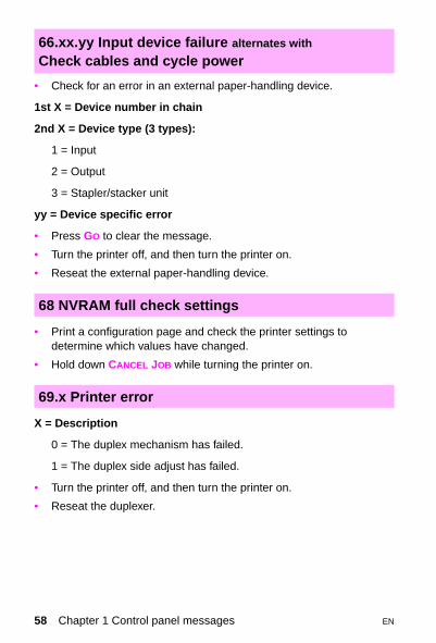
• Check for an error in an external paper-handling device.
1st X = Device number in chain
2nd X = Device type (3 types):
1 = Input
2 = Output
3 = Stapler/stacker unit
yy = Device specific error
• Press GO to clear the message.
• Turn the printer off, and then turn the printer on.
• Reseat the external paper-handling device.
• Print a configuration page and check the printer settings to determine which values have changed.
• Hold down CANCEL JOB while turning the printer on.
X = Description
0 = The duplex mechanism has failed.
1 = The duplex side adjust has failed.
• Turn the printer off, and then turn the printer on.
• Reseat the duplexer.
66.xx.yy Input device failure alternates with
Check cables and cycle power
68 NVRAM full check settings
69.x Printer error
58 Chapter 1 Control panel messages EN

1
The printer detected an error. The numbers (xxxx) indicate the specific type of error. (See the printer service manual for the specific type of error.)• Turn the printer off and then on.
• Try printing a job from a different software application. If the job prints, go back to the first application and try printing a different file. (If the message appears only with a certain software application or print job, the customer should contact the software vendor for assistance.)
If the message persists, try the following procedures:
• Turn the printer off and then on.
• Reseat or replace the interface cable and power cycle the printer.
• Remove the DIMMs one at a time and power cycle the printer.
• If possible, use the parallel interface.
• With the EIO cards removed from the printer, perform a cold reset.
• If the error persists, replace the formatter.
79.xxxx Error (printing)
EN Numerical messages 59

The EIO accessory in slot x has encountered a critical error as specified by yyyy.
X = Description
1 = EIO slot 1 -The printer detected an error with the EIO card.
2 = EIO slot 2 -The printer detected an error with the EIO card.
6 = EIO slot 1 -The EIO card detected an error. The EIO card may be defective.
7 = EIO slot 2 -The EIO card detected an error. The EIO card may be defective.
• Turn the printer off, and then turn the printer on.
• Reseat or replace the EIO board.
8x.yyyy critical error (EIO accessory)
60 Chapter 1 Control panel messages EN

2 S
EN
ervice mode
Overview
Service mode allows service personnel to verify and manipulate internal printer settings and to access the diagnostic feature. Service mode should be used only by authorized service personnel.
Overview 61

Service mode tasks
You can perform the following tasks while in service mode.
• Print a service mode self-test.
• Verify the page count.
• Set the page count.
• Set the maintenance count.
• Verify and set the serial number.
• Set the cold reset default. This sets the factory default paper size to either Letter or A4.
• Turn the diagnostic function on or off (for software developer use only).
• Clear the event log.
• Use the extended service mode.
• Reset softswitches.
• Perform a firmware download.
• Recalibrate the document scanner.
• Set the page count at which the next PERFORM PRINTER MAINTENANCE message appears on the control panel.
• Set the Demo Page =True/False (used to remove the demo page from the service mode self-test).
62 Chapter 2 Service mode EN
2
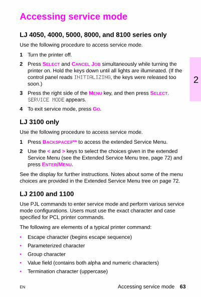
Accessing service mode
LJ 4050, 4000, 5000, 8000, and 8100 series onlyUse the following procedure to access service mode.
1 Turn the printer off.
2 Press SELECT and CANCEL JOB simultaneously while turning the printer on. Hold the keys down until all lights are illuminated. (If the control panel reads INITIALIZING, the keys were released too soon.)
3 Press the right side of the MENU key, and then press SELECT.SERVICE MODE appears.
4 To exit service mode, press GO.
LJ 3100 onlyUse the following procedure to access service mode.
1 Press BACKSPACE #** to access the extended Service Menu.
2 Use the < and > keys to select the choices given in the extended Service Menu (see the Extended Service Menu tree, page 72) and press ENTER/MENU.
See the display for further instructions. Notes about some of the menu choices are provided in the Extended Service Menu tree on page 72.
LJ 2100 and 1100Use PJL commands to enter service mode and perform various service mode configurations. Users must use the exact character and case specified for PCL printer commands.
The following are elements of a typical printer command:
• Escape character (begins escape sequence)
• Parameterized character
• Group character
• Value field (contains both alpha and numeric characters)
• Termination character (uppercase)
EN Accessing service mode 63

Escape sequences may be combined into one escape sequence string. There are three important rules to follow when combining code:
1 The first two characters after the EC character (the parameterized and group characters) must be the same in all of the commands to be combined.
2 When combining escape sequences, change the uppercase (termination) character in each individual escape sequence to lowercase.
3 The final character of the combined escape sequence must be uppercase.
Enterin g Escape Characters
Printer commands always begin with the escape character (EC). The following table shows how the escape character can be entered from various DOS software applications.
The following table shows how to use PJL commands to enter service mode and perform various service mode configurations.
DOS Software Application Entry What Appears
Lotus 1-2-3 and Symphony Type \027 027
Microsoft Word for DOS Hold down ALT and type 027 on the numeric keypad
<--
WordPerfect for DOS Type <27> <27>
MS-DOS Edit Hold down CTRL-P, and press ESC
<--
MS-DOS Edlin Hold down CTRL-V, and press [
^[
DBASE Type ?? CHR(27)+"command"
?? CHR(27)+" "
64 Chapter 2 Service mode EN

2
PJL Service mode commands
Customization variable (LJ 2100 and 1100 only)The customization variable will determine the default paper size after a cold reset. This is set to A4/Letter at the manufacturer. This variable may need to be reset when replacing the formatter.
NoteBefore removing the old formatter PCB, print a self-test/configuration page to verify the current page count of the printer, if possible.
Resetting the printer (LJ 2100 only)To perform a cold reset, turn the LJ 2100 printer off, then press and hold the JOB CANCEL button. Turn the printer back on and after all the LEDs come on release the JOB CANCEL button.
A cold reset changes most system parameters in NVRAM to the factory defaults. The JOB CANCEL button must be released within 20 seconds after all of the LEDs come on; otherwise, an NVRAM initialization is performed instead of a cold reset.
PJL command Description
EC%-12345X@PJL@PJL SET SERVICEMODE=HPBOISEID@PJL SET PAGES=0@PJL SET CRPAPER=LETTER@PJL SET SKIPDEMO=FALSE@PJL SET DIAGNOSTICS-OFF@PJL SET SERVICEMODE=EXITDEFAULT PAPER=LETTER@PJL RESETEC%-12345XECZECE
Start PJL job.
Enter Service ModeSet page count [= xxxxx]Sets cold reset page size [=Letter/A4]Skips demo/PCL type page [=true/false]Sets diagnostics [=OFF/ON] (for ISV use)Exits Service ModeSelects user paper size defaultPerforms PJL resetExits PJL modePrints self test/configuration pageResets the printer
EN Accessing service mode 65
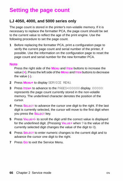
Setting the page count
LJ 4050, 4000, and 5000 series onlyThe page count is stored in the printer’s non-volatile memory. If it is necessary to replace the formatter PCA, the page count should be set to the current value to reflect the age of the print engine. Use the following procedure to set the page count.
1 Before replacing the formatter PCA, print a configuration page to verify the current page count and serial number of the printer, if possible. Use the information on the configuration page to reset the page count and serial number for the new formatter PCA.
NotePress the right side of the MENU and ITEM buttons to increase the value (+). Press the left side of the MENU and ITEM buttons to decrease the value (-).
2 Press MENU+ to display SERVICE MENU.
3 Press ITEM+ to advance to the PAGES=XXXXXX display. XXXXXX represents the page count currently stored in the non-volatile memory. The underlined character denotes the position of the cursor.
4 Press SELECT to advance the cursor one digit to the right. If the last digit is currently selected, the cursor will move to the first digit when you press the SELECT key.
5 Press VALUE+/- to scroll the digit until the correct value is displayed for the underlined digit. (Pressing VALUE+ when 9 is the value of the currently selected digit changes the value of the digit to 0).
6 Press SELECT to enter numeric changes to the current digit and to advance the cursor one digit to the right.
7 Press GO to exit the Service Menu.
66 Chapter 2 Service mode EN

2
Resetting the maintenance counter
LJ 4050, 4000, 5000, 8000, and 8100 series onlyThe maintenance count should be reset only after a maintenance kit has been installed. Resetting the maintenance count resets the maintenance counter so that the message PERFORM PRINTER MAINTENANCE displays after another 150,000 (5000 series) 200,000 (4000 series) or 350,000 (8000, 8100 series) pages are printed.
NoteMAINTENANCE COUNT in the service mode menu sets the page count interval for when the next printer service is due for the printer. The maintenance count is set initially at the factory. Editing this number is similar to editing the PAGES item.
1 Hold down the ITEM- and VALUE- keys while turning the printer on.
2 Wait until RESET MAINTENANCE COUNT displays and then release both keys.
EN Resetting the maintenance counter 67

Setting the serial number
LJ 4050, 4000, and 5000 series onlyRe-enter the serial number whenever you replace a formatter.
1 Press MENU to display the SERVICE MENU.
2 Press ITEM+ three times. SERIAL NUMBER=XXXXXX displays. XXXXXX represents the page count currently stored in the printer’s non-volatile memory. The underlined character denotes the position of the cursor.
3 Press SELECT to advance the cursor one digit to the right. If the last digit is currently selected, the cursor wraps around the first digit when you press the SELECT key.
4 Press VALUE+/- to scroll the digit until the correct value is displayed for the underlined digit. (Pressing VALUE+ when 9 is the value of the currently selected digit will change the value of the digit to 0).
5 Press SELECT to enter numeric changes to the current digit and to advance the cursor one digit to the right.
6 Press GO to exit the Service Menu.
68 Chapter 2 Service mode EN

2
Non-volatile memory settings
LJ 4050, 4000, 5000, 8000, and 8100 series onlyThe page count, maintenance count, printer serial numbers, and maintenance interval are stored in non-volatile memory.
• PAGECOUNT is the total number of images printed by the printer.
• MAINTCOUNT is the page count when the next preventive maintenance should be performed (every 350,000 images).
• S.N. is the printer serial number (located on the back cover of the printer).
• MAINTENANCE INTERVAL is primarily for customers who knowingly use media that does not meet specifications and causes premature wear to maintenance parts. This allows a maintenance message to be set to a desired number.
If it is necessary to replace the formatter PCA, these numbers should be set to the current values to accurately reflect the age of the print engine. The printer service manual provides the procedure for setting these values.
Before removing the old formatter PCA, print a configuration page to verify the current values, if possible.
NoteIf it is not possible to print a configuration page, try to verify the values before replacing the formatter PCA by following steps 1 through 5, below.
EN Non-volatile memory settings 69

After verifying the page count, maintenance count, and printer serial number from the old formatter PCA, replace it with the new PCA.
1 Enter service mode. See “Service Mode” in the printer service manual for instructions.
2 When SERVICE MODE is displayed, press MENU to access the Service Menu.
3 Press ITEMS to display PAGES = MAINTENANCE COUNT = MAINTENANCE INTERVAL = SERIAL NUMBER =.
4 Enter the appropriate values for each item.
5 Press GO to exit service mode.
Setting the default paper size used in a cold reset
LJ 4050, 4000, 5000, 8000, and 8100 series onlyCold reset clears all data from the printer memory and sets all defaults back to the factory setting.
The default paper size is stored in NVRAM. When a cold reset is performed, the default paper size is restored. The default paper size is set to the factory setting. Possible values are COLD RESET PAPER=LETTER and COLD RESET PAPER=A4. When replacing the formatter in countries that use the A4 paper size (in place of the letter- size paper), set the cold reset paper size to A4.
To customize the cold reset paper size:
1 Enter the service mode. See “Accessing service mode” on page 63.
2 Press MENU to display SERVICE MENU.
3 Press ITEM+ until COLD RESET PAPER=LETTER* or A4 displays.
4 Press ITEM+ to toggle between LETTER and A4.
5 Press SELECT to activate your choice.
6 Press GO to exit the Service Menu.
70 Chapter 2 Service mode EN

2
Diagnostics
LJ 4050, 4000, 5000, 8000, and 8100 series onlyThe diagnostics menu item enables or disables the use of the firmware diagnostic features. These features are accessible when DIAGNOSTICS=ON displays. To access the diagnostic features, verify that the printer is in the READY state and press SELECT.
NoteThis procedure is for software developers only.
Clear event log
Select this item to clear the internal event log.
EN Diagnostics 71

Extended Service Menu
LJ 3100 onlyUse the extended Service Menu to run various self-tests and to change softswitch settings, such as the country code softswitch setting.
The following page shows the layout of the extended Service Menu settings in a hierarchical diagram.
Reports
Memory/softswitch
Control panel
Scanner
Self test
Modem/PTT
HelpT.30 protocol traceSRAM dumpScanner plotsLog debug reportTask stacksTranslationsPrinter fonts
SoftswitchesClear memoryCheck documentsEdit SRAMSRAM dumpFirmware version
Keypad testLCD testControl panel testSensor statesSpeaker testAll LCD characters
Scanner plotsScanner LED
ADF feed test
ADF motor testDo TWAIN scanWhite ref summary
Burn-inIndividual diagnosticsSystem reset
Modem toneModem modulationModem type
Help prints a menu report for the product.
See “To change the country code softswitch” on page 78.
Various tests under Control panel can assist in troubleshooting the product.
Scanner LED is the contact image sensor light bar test.ADF feed test runs the document feeder pickup rollers once.ADF motor test runs the document scanner motor.
Burn-in prints a report after running the following tests: Program test, Configuration test #1, Fax memory test #2, Modem test #2, Scanner test #1, Scanner LED.
72 Chapter 2 Service mode EN

2
Self-test in extended service mode
LJ 3100 onlyIf you perform a self-test from the extended Service Menu, the printed report will also show the firmware revision number and details.
NotePrint the internal reports before performing extended service mode tests. The reports contain a record of all settings and can assist you in restoring the product to its settings.
The table below lists the tests that are performed during a self-test and the actions to take when tests fail.
Extended service mode self-test failures
Test If the test fails, take these actions:
Configuration test #1 Replace the formatter.
Fax memory test #1
Program test #1 1 Cycle power by unplugging the power cord from the power source, waiting 10 seconds, and replugging the power cord.
2 If the test fails again, clear all memory (see the extended Service Menu tree, page 72).
3 If the test fails again, replace the formatter.
Configuration test #2
Configuration test #3
Configuration test #4
Fax memory test #2
Fax memory test #3
Fax memory test #4
Fax memory test #5
Modem 1 test #1
Modem 1 test #2
Modem 1 test #3
EN Extended Service Menu 73
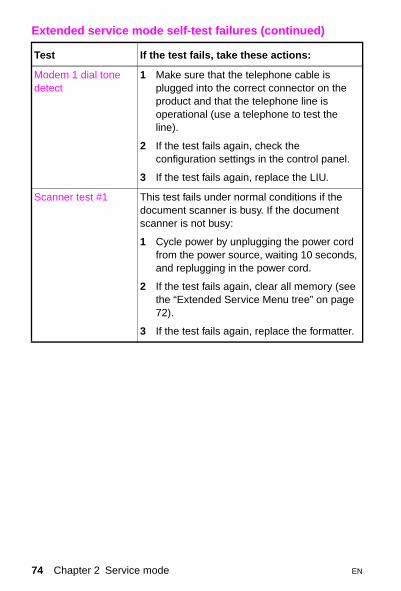
Modem 1 dial tone detect
1 Make sure that the telephone cable is plugged into the correct connector on the product and that the telephone line is operational (use a telephone to test the line).
2 If the test fails again, check the configuration settings in the control panel.
3 If the test fails again, replace the LIU.
Scanner test #1 This test fails under normal conditions if the document scanner is busy. If the document scanner is not busy:
1 Cycle power by unplugging the power cord from the power source, waiting 10 seconds, and replugging in the power cord.
2 If the test fails again, clear all memory (see the “Extended Service Menu tree” on page 72).
3 If the test fails again, replace the formatter.
Extended service mode self-test failures (continued)
Test If the test fails, take these actions:
74 Chapter 2 Service mode EN

2
Other tests in extended service mode
LJ 3100 onlyThe following chart shows tests that can be performed in extended service mode and provides a brief explanation of each test:
Extended service mode tests
Test Explanation
Keypad test Tests that all keys are functioning (by pressing the keys in sequence)
LCD test Tests the control panel display
Control panel test Tests the control panel lights
Sensor states Shows current detector activation levels. Detector 1 and detector 2 are paper-size detectors. The control panel display shows the percentage of time each detector is activated.
All LCD characters Scrolls through the full list of control panel display characters
Scanner plots Tests and recalibrates the document scanner
Scanner LED After selecting this menu item, lift the document release door and verify that all of the LEDs in the contact image sensor are lit
ADF feed test Runs the document scanner pickup rollers once
ADF motor test Runs the document scanner motor once
Individual diagnostics Run individual tests from the self-test sequence (see the extended service mode self-test failures table)
Modem tone Generates tones with various frequencies from 300 Hz to 2425 Hz
Modem modulation Generates various fax identification signals
EN Extended Service Menu 75

Reports in extended service mode
LJ 3100 onlyThe following chart shows reports that can be printed from extended service mode and provides a brief explanation of each report.
Extended service mode reports
Report Explanation
T.30 protocol trace Prints a report of the G3 protocol transmissions and receptions
SRAM dump Prints SRAM address values in an address range that you select
Scanner plots Prints the calibration page
Log debug report Prints detailed fax and memory address information. Fax information includes job number, start time used, fax ID, transmission type, pages, communication mode, and status.
Task stacks Prints address locations of various tasks
Translations Prints text strings used in the display, beginning with the number you select. These text strings are printed in the language currently in use by the product. Compare the numbers in this report to the numbers in an English report to translate non-English messages on the display.
Printer fonts Prints all characters of fonts available in memory
Firmware version (under “memory/softswitch”)
Shows firmware revision information on the control panel display
White reference summary (under “scanner”)
Displays average, minimum, and maximum white reference values
76 Chapter 2 Service mode EN

2
Clear memory in extended service mode
LJ 3100 only
CAUTIONClearing memory clears all parameters, which can render the product illegal or inoperable. Print the internal reports before clearing memory in extended service mode. The reports contain a record of all settings and can assist you in restoring the product to its settings.
To perform a system reset, use extended service mode to choose MEMORY/SOFTSWITCH, and then choose CLEAR MEMORY. Use the < and > keys to select the memory you want to clear:
• DOCUMENTS (AND LOG) deletes all documents stored in memory and all log information.
• PHONEBOOK deletes all numbers stored in the phonebook.
• CONFIGURATION resets all menu settings printed in the configuration report to their defaults.
• SOFTSWITCHES resets all softswitches to their defaults.
• COUNTERS resets all page counts except the total number of pages printed. These page counts are printed at the end of the configuration report.
• EVERYTHING deletes and resets all of the above. Information retained includes white reference curve, total page count, and serial number.
EN Extended Service Menu 77

Softswitches
LJ 3100 only
NoteReset the country code softswitch whenever the formatter board is replaced or otherwise removed from the product, or when softswitches are reset to defaults.
Extended service mode allows you to change softswitches on the LJ 3100 product. A softswitch is a set of eight bits. See the software service manual for a complete list of softswitches.
To change the country code softswitch1 Press BACKSPACE , #, *, and *, in sequence, to access the extended
Service Menu.
2 Press < or > until MEMORY/SOFTSWITCHES appears below SERVICE on the control panel.
3 Press ENTER/MENU.
4 If SOFTSWITCHES does not appear below MEMORY/SOFTSWITCHES on the control panel, press < or > until it appears.
5 Press ENTER/MENU.
6 Use the keypad to enter 101 (the “country code” softswitch).
7 Press ENTER/MENU.
8 Use the keypad to enter the sequence that corresponds to the country in which the product is used. (See the list of country code softswitch sequences on the following page.)
78 Chapter 2 Service mode EN
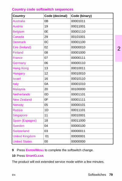
2
9 Press ENTER/MENU to complete the softswitch change.
10 Press STOP/CLEAR.
The product will exit extended service mode within a few minutes.
Country code softswitch sequences
Country Code (decimal) Code (binary)
Australia 0B 00001011
Austria 19 00011001
Belgium 0E 00001110
Canada 29 00101001
Denmark 0C 00001100
Eire (Ireland) 02 00000010
Finland 08 00001000
France 07 00000111
Germany 06 00000110
Hong Kong 13 00010011
Hungary 12 00010010
Israel 16 00010110
Italy 0A 00001010
Malaysia 20 00100000
Netherlands 0D 00001101
New Zealand 0F 00001111
Norway 05 00000101
Russia 1D 00011101
Singapore 11 00010001
Spain (Espagne) 18 00011000
Sweden 04 00000100
Switzerland 03 00000011
United Kingdom 01 00000001
United States 00 00000000
EN Softswitches 79

Firmware download
LJ 3100 onlyNewer versions of the firmware for the HP LaserJet 3100 product can be downloaded to the product.
To perform a firmware download1 Restart the computer in MS-DOS® mode (do not use an MS-DOS
window).
2 Press down and hold STOP/CLEAR while performing step 3.
3 Cycle power by unplugging the power cord from the power source, and then replugging in the power cord.
4 Type the following, substituting the current version of the firmware for xxx : Copy /b leonXXX.rom lpt1:
80 Chapter 2 Service mode EN

2
Calibrating the document scanner
LJ 3100 onlyCalibrate the document scanner if you notice that copies, items scanned to the computer, or faxes you send have black or white lines running through them.
To calibrate the document scanner1 Clean the HP LaserJet 3100 product before calibrating it. (See
“Cleaning the HP LaserJet 3100 product” in the product service manual.)
2 On the control panel, press ENTER/MENU.
3 Press < once to display SERVICE and press ENTER/MENU.
4 Use the < and > keys to select SCAN CORRECTION and press ENTER/MENU.
5 Insert a blank, bright white piece of letter-sized paper into the document feeder tray.
The HP LaserJet 3100 product pulls the piece of paper through and then prints a recalibration test page. Discard this page. The calibration procedure is complete.
EN Calibrating the document scanner 81
Calibrating the document scanner
LJ 1100 onlyIf images are showing defects, the scanner may need to be calibrated. First, verify that the problem is not printer related. If the problem is not printer related, clean the scanner. If image defects persist, then calibrate the scanner. To do so, follow the instructions below:
1 Create a page that measures 219 mm by at least 153 mm (8.6 in by at least 6 in). Use bright, white paper.
2 Insert the page into the paper input tray, wide side first, and begin calibration.
To access the calibration utility, see “Accessing the calibration utility”, below.
NoteFor more information about calibration, see the online help.
Accessing the calibration utility
Windows 9x and NT 4.0From the Document Assistant , click Tools , and then Calibration .
Windows 3.1xFrom the Program Manager , double-click the HP LaserJet 1100 icon, and then double-click on Calibrate Scanner .
82 Chapter 2 Service mode EN

2
Service mode functions (PJL software commands)
Setting the service mode in the LJ 1100 series printer allows the following functionality:
• Sets the following NVRAM variables:
– Factory printer DEFAULT PAPER: the factory default paper size for the scanner (if one is attached) will be set to the same value automatically.
– Factory printer DEFAULT LPARM:PCL SYMSET– Factory DEFAULT OEM bit– Factory DEFAULT PRINTPAGECOUNT– Factory DEFAULT SCANPAGECOUNT (if the scanner is attached)– Factory DEFAULT COPYPAGECOUNT (if the scanner is attached)
NoteThe default quick-copy paper size is also stored in the scanner NVRAM; however, it can be changed only within the software or set back to the factory default setting with an NVRAMINIT.
The quick-copy image type and the contrast have a default value stored in NVRAM; however, they can only be changed within the software or by NVRAMINIT, which returns them to a ROM default value.
• Provides NVRAMINIT, which restores all default variables stored in NVRAM to the factory default values or a default ROM value depending on the variable. It also performs a system reset. To do this, turn off the printer, hold down the GO button, and then turn the printer on. All LEDs will flash once, and then turn off. Continue holding the button down until you the see LEDs cycle once; then release the button. The LEDs will cycle twice as fast after the RAM/ROM checks and the NVRAM variables will be restored to the factory default values. This will not clear page counts.
EN Service mode functions (PJL software commands) 83

The following table provides a detailed description of the NVRAM PJL factory variables or commands and possible settings.
NoteSet SERVICEMODE=HPBOISEID before trying to set the variable. The PJL reset is also necessary to make sure the SERVICEMODE status is cleared.
NVRAM PJL factory variables
NVRAM PJL variable or command
Possible settings
DEFAULT PAPER “Letter”, “Legal”, “A4”, “Executive”, “Com10”, “Monarch”, “DL”, “C5”, “B5”, “Custom”
DEFAULT LPARM:PCL SYMSET
“Roman8”, “ISOL1”, “ISOL2”, “ISOL5”, “PC8”, “PC8DN”, “PC850”, PC852”, “PC8TK”, “WINL1”, “WINL2”, “WINL5”, “DESKTOP”, “PSTEXT”, “VNINTL”, “VNUS”, “MSPUBL”, “MATH8”, “PSMATH”, “VNMATH”, “PIFONT”, “LEGAL”, “ISO4”, “ISO6”, “ISO11”, “ISO15”, “ISO17”, “ISO21”, “IS060”, “ISO69”, “WIN30”
DEFAULT OEM “On”, “Off”
DEFAULT PRINTPAGECOUNT
0-2147483647
DEFAULT SCANPAGECOUNT
0-2147483647
DEFAULT COPYPAGECOUNT
0-2147483647
NVRAMINIT None (command)
84 Chapter 2 Service mode EN

3 P
EN
ower supply
Overview
This chapter details the distribution of AC and DC power.
Overview 85

AC and DC power distribution
HP LaserJet 2100 series printer• AC power is supplied to the low-voltage power supply circuit when
the power switch is turned on. This circuit supplies DC voltage (+24V, +5V, +3.3V) to the main motor, laser scanner unit, interlock switch, video controller, solenoids, paper feeder, high-voltage power supply, and formatter.
• Opening the top cover interrupts the DC voltage supplied to the high-voltage power supply circuit.
• The low-voltage power supply circuit contains an overcurrent/overvoltage protection circuit that automatically turns off the output voltage when an overcurrent condition occurs because of a short or abnormal voltage on the load side.
• The protection circuit automatically resets after the input power is turned off then on. The low-voltage power supply circuit also contains a fuse that shuts off the power supply to the circuit when overcurrent conditions occur. See “Engine Control System” in the printer service manual for more information.
• In response to the engine controller assembly, the high-voltage power supply circuit (see “Engine Control System” in the printer service manual) supplies DC and AC voltage to the various parts of the image formation system.
86 Chapter 3 Power supply EN

3
Low- and high-voltage power supply circuit (2100 series)
EN AC and DC power distribution 87

HP LaserJet 4050 and 4000 series
AC power is supplied to the low-voltage power supply circuit in the engine controller board when the power switch (SW 101) is turned on. The low-voltage power supply circuit supplies +24 Vdc and +3.3 Vdc to the printer. DC power drives the following items:
+24 Vdc
• main motor
• scanner motor
• fan
• high-voltage power supply
+3.3 Vdc
• sensors
• ICs on the engine controller board
• EIO accessories
88 Chapter 3 Power supply EN
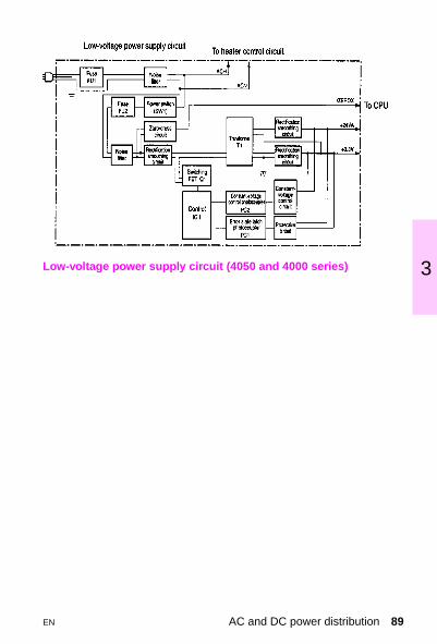
3
Low-voltage power supply circuit (4050 and 4000 series)EN AC and DC power distribution 89

HP LaserJet 5000 series
The AC line voltage for the LaserJet 5000 printer is applied through the main switch (SW 101) and supplied to the low-voltage power supply circuit through the fuse (FU1). The low-voltage power supply divides the AC voltage to +24 Vdc, +5 Vdc and +3.4 Vdc and supplies them to the DC controller PCA. This circuit generates a zero-cross signal (ZEROX) and supplies it to the DC controller PCA.
DC power is supplied as follows:
+3.4 Vdc
• ICs on the DC controller PCA and the BD PCA
+5 Vdc
• laser driver PCA
• sensors
+24 Vdc
• high-voltage power supply PCA to drive the main motor
• exhaust fan
• scanner motor
• clutches
• solenoids
90 Chapter 3 Power supply EN

3
Low-voltage power supply circuit (5000 series)
EN AC and DC power distribution 91

HP LaserJet 3100
The AC, DC, and high-voltage power supply circuits are all contained within the ECU.
The AC power circuitry supplies AC voltage whenever the power cord is connected to the AC power source. AC voltage is distributed to the DC power supply circuitry and to the AC driver circuitry. The AC driver circuitry controls AC voltage to the heating element in the fusing assembly.
The DC power distribution circuitry distributes +5 Vdc and +12 Vdc as follows:
+5 Vdc
• formatter
• photosensors
• ECU circuitry
• laser/beam detect circuitry
+12 Vdc
• printer main motor
• document scanner motor
• solenoid
+12 VAdc
• high-voltage power supply (on ECU)
92 Chapter 3 Power supply EN

3
Low-voltage power supply circuit (3100)
EN AC and DC power distribution 93

HP LaserJet 8000 series
The AC and DC power supply circuits are contained in the low-voltage power supply (LVPS). The high voltages required for image formation are generated by the high-voltage power supply (HVPS). The low-voltage power supply and distribution system are illustrated below.
Low-voltage power supply circuit (8000 series)
94 Chapter 3 Power supply EN

3
HP LaserJet 8100 series
The AC and DC power supply circuits are contained in the low-voltage power supply (LVPS). The high voltages required for image formation are generated by the high-voltage power supply (HVPS). The low-voltage power supply and distribution system are illustrated below.
Low-voltage power supply circuit (8100 series)
EN AC and DC power distribution 95

HP LaserJet 1100 series
The AC, DC, and high-voltage power supply circuits are all contained within the ECU.
The AC power circuitry supplies AC voltage whenever the power cord is connected to the AC power source. AC voltage is distributed to the DC power supply circuitry and to the AC driver circuitry. The AC driver circuitry controls AC voltage to the heating element in the fusing assembly.
The DC power distribution circuitry distributes +3.3 Vdc, +5 Vdc, and +24 Vdc as follows:
+3.3 Vdc
• formatter
• laser/beam detect circuitry
• ECU
+ 5 Vdc
• formatter
• photosensors
• printer laser scanner
+24 Vdc
• printer main motor
• document scanner motor
• solenoid
• formatter
+24 VAdc
• high-voltage power supply (on ECU)
96 Chapter 3 Power supply EN

3
Low-voltage power supply circuit (1100 series)
EN AC and DC power distribution 97

Protection systems
Problems on the load side, such as short circuits, can cause an excessive flow of current from the DC power supplies or can generate abnormal voltage. When this happens, the excess-current and excess-voltage protection systems automatically shut off the output voltage to protect the power supplies.
If the protection systems are activated and the power supply circuit does not output DC voltage, turn the printer off, correct the problem in the faulty load, and then turn the printer on again.
98 Chapter 3 Power supply EN
4 I
EN
nput/output (I/O)
Overview
This chapter provides information on cabling and the printer interface.
Overview 99

Bidirectional parallel interface
The formatter PCA receives incoming data through its bidirectional interface (IEEE 1284).
The bidirectional parallel interface (IEEE-1284 compliant) is compatible with Centronics parallel interfaces. To take advantage of its enhanced capabilities, such as bidirectional communication, the following must be provided:
• Software application support for these features.
• IEEE-1284 compliant parallel cable with the correct pin configuration (see the following table).
4050, 4000, 5000, 8000, and 8100 onlyThe user may configure the HIGH SPEED item in the Control panel menu. The default setting, YES, allows the I/O to run at the higher speeds supported by most newer computers. When set to NO, the parallel interface runs at the slower mode that is compatible for older computers. The user may also configure the ADVANCED FUNCTIONS item. The default setting, ON, allows for two-way parallel communications. The OFF mode disables this advanced functionality.
100 Chapter 4 Input/output (I/O) EN

4
Pin configuration
Signal name Printer pin # Parallel portpin #
nSTROBE 1 1
DATA 1 2 2
DATA 2 3 3
DATA 3 4 4
DATA 4 5 5
DATA 5 6 6
DATA 6 7 7
DATA 7 8 8
DATA 8 9 9
nACKNLG 10 10
BUSY 11 11
CALL (PE) 12 12
SELECT 13 13
nAUTOFd 14 14
On VDC (GND) 19 THRU 30 18 THRU 25
nFAULT 32 15
nSelIn 36 17
EN Bidirectional parallel interface 101

IEEE-1284 compliant parallel cables
HP helped develop the IEEE-1284 standard and is one of the first companies to introduce products that are compliant with it. HP offers four IEEE-1284 compliant parallel cables. Each is described below.
IEEE-1284 compliant parallel cables
Part number Length Connector type
C2950A 2 meters(7 feet)
Host A to printer B (large) connector
C2951A 3 meters (10 feet)
Host A to printer B (large) connector
C2946A 3 meters(10 feet)
Host A to printer C (small) connector
C2947A 10 meters(33 feet)
Host A to printer C (small) connector
Maximum I/O cable lengths
Serial RS-232CRS-422A
15 meters (50 feet)610 meters (2000 feet)
Parallel (non-IEEE-1284) 3 meters (10 feet)
Parallel (IEEE-1284) with “B” type connector
3 meters (10 feet)
Parallel (IEEE-1284) with “C” type connector
3 meters (10 feet) (LJ 3100)10 meters (33 feet) (LJ 1100)
102 Chapter 4 Input/output (I/O) EN

4
Attaching the printer cables
The printer’s parallel port can have one or both of the following connectors:
• B-type parallel (large)
• C-type parallel (small)
Printer interface connections
RS-232-C/RS-422-A serial interfaceFor this information, see the wiring diagram for common serial input/output cables in the printer service manual.
Configuring the network interfaceTo configure the printer network interface, see the HP JetDirect Print Server User Manual.
B-type
C-type
EN Bidirectional parallel interface 103

LocalTalk I/O*
The printer implements AppleTalk networking protocol through LocalTalk hardware. The LocalTalk network cable (HP part number 92215N) is connected through the EIO card.
Expanded I/O*
The optional expanded I/O card can be installed in the slots provided on the formatter PCA. The expanded I/O card provides automatic I/O switching between multiple computers or networks connected to the printer. The network version printers include the HP JetDirect Multi-protocol Network Card with Ethernet/10Base-T and 10Base-2, and LocalTalk.
Flash*
Flash is provided in optional 2 and 4 megabyte (MB) flash memory DIMMs for storage of forms, fonts, and signatures.
Disk*
The optional EIO-based hard disk is used for creating multiple original prints (mopies) and for storing forms, fonts, and signatures.
*This feature does not apply to the HP LJ 2100, LJ 3100, or LJ 1100.
104 Chapter 4 Input/output (I/O) EN

5 M
EN
edia specifications
Overview
Use media that meet the specifications listed on the following pages. By doing so, you will minimize the incidents of paper jams, prevent premature wear to the printer, and reduce repair costs.
Hewlett-Packard recommends testing print media before buying it in large quantities.
NoteFor complete paper specifications for all HP LaserJet printers, see the HP LaserJet Family Paper Specification Guide.
Overview 105
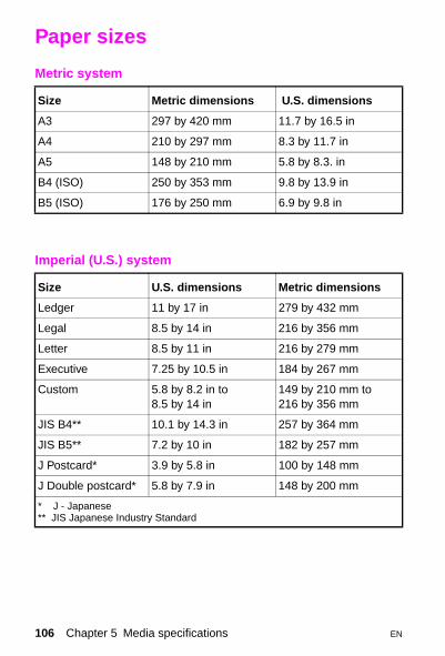
Paper sizes
Metric system
Size Metric dimensions U.S. dimensions
A3 297 by 420 mm 11.7 by 16.5 in
A4 210 by 297 mm 8.3 by 11.7 in
A5 148 by 210 mm 5.8 by 8.3. in
B4 (ISO) 250 by 353 mm 9.8 by 13.9 in
B5 (ISO) 176 by 250 mm 6.9 by 9.8 in
Imperial (U.S.) system
Size U.S. dimensions Metric dimensions
Ledger 11 by 17 in 279 by 432 mm
Legal 8.5 by 14 in 216 by 356 mm
Letter 8.5 by 11 in 216 by 279 mm
Executive 7.25 by 10.5 in 184 by 267 mm
Custom 5.8 by 8.2 in to8.5 by 14 in
149 by 210 mm to216 by 356 mm
JIS B4** 10.1 by 14.3 in 257 by 364 mm
JIS B5** 7.2 by 10 in 182 by 257 mm
J Postcard* 3.9 by 5.8 in 100 by 148 mm
J Double postcard* 5.8 by 7.9 in 148 by 200 mm
* J - Japanese** JIS Japanese Industry Standard
106 Chapter 5 Media specifications EN

5
Paper specifications
Paper specifications
Category Specification
Acid content 5.5 pH to 8.0 pH
Basis weight (2100 series) :Tray 1Tray 2Tray 3
60 to 163 g/m2 (16 to 43 lb)60 to 105 g/m2 (16 to 28 lb)60 to 105 g/m2 (16 to 28 lb)
Basis weight (4050, 4000 series) :Tray 1 (4050 series, 4000 series)Tray 2 (4050/40050 N, 4000, 4000 N)Tray 2 and tray 3 (4050 T/
4050 TN, 4000 T/4000 TN)Optional 500-sheet trayDuplexerOptional envelope feeder
60 to 199 g/m2 (16 to 53 lb)
60 to 105 g/m2 (16 to 28 lb)
60 to 105 g/m2 (16 to 28 lb)60 to 105 g/m2 (16 to 28 lb)60 to 105 g/m2 (16 to 28 lb)75 to 105 g/m2 (20 to 28 lb)
Basis weight (5000 series) :Tray 1 Tray 2 or optional 250-sheet trayOptional 500-sheet trayDuplexer
60 to 199 g/m2 (16 to 53 lb)
60 to 105 g/m2 (16 to 28 lb)60 to 105 g/m2 (16 to 28 lb)60 to 105 g/m2 (16 to 28 lb)
Basis weight (3100) :Paper input bin
Single-sheet input slot
Document feeder tray
60 to 105 g/m2 (16 to 28 lb) (up to 157 g/m2 [42 lb] using the front output slot)
60 to 105 g/m2 (16 to 28 lb) (up to 157 g/m2 [42 lb] using the front output slot)
44 to 105 g/m2 (12 to 28 lb) (up to 67 lbs using the special media lever)
Basis weight (8000 series) : Standard output binLeft output binOptional 2000-sheet input trayDuplexerOptional envelope feeder
60 to 105 g/m2 (16 to 28 lb)60 to 105 g/m2 (16 to 28 lb)
60 to 105 g/m2 (16 to 28 lb)60 to 105 g/m2 (16 to 28 lb)60 to 90 g/m2 (16 to 24 lb)
EN Paper specifications 107

Basis weight (8100 series) :Tray 1 (multipurpose)
Trays 2 and 3Optional 2000-sheet input
trayDuplexerOptional envelope feeder
One-sided: 60 to 199 g/m2 (16 to 53 lb) Two-sided: 60 to 75 g/m2 (16 to 28 lb)60 to 105 g/m2 (16 to 28 lb)
60 to 105 g/m2 (16 to 28 lb)60 to 105 g/m2 (16 to 28 lb)60 to 90 g/m2 (16 to 24 lb)
Basis weight (1100 series) :Front output slot
Single-sheet input slot
Document feeder tray
60 to 105 g/m2 (16 to 28 lb) (up to 157 g/m2 [42 lbs] using the front output slot)
60 to 105 g/m2 (16 to 28 lb) (up to 157 g/m2 [42 lbs] using the front output slot)
60 to 105 g/m2 (16 to 28 lb)
Caliper Dependent upon basis weight
Curl in ream Flat within 5 mm (0.2 in)
Condition of cut edge Cut with sharp blades with no visible fray
Fusing compatibility Must not scorch, melt, offset, or release hazardous emissions when heated to 205°C (400°F) for 0.1 second
Grain Long grain
Moisture content 4% to 6% by weight
Smoothness 100-250 Sheffield
Paper specifications (continued)
Category Specification
108 Chapter 5 Media specifications EN

5
U.S. paper grades: Basic sizes and basis weights
The U.S. paper grading system has evolved from custom and usage rather than from a technical background, resulting in similar papers having different stated weights. For example, a 24# bond paper is exactly the same weight as a 60# book or a 60# text or a 33# cover. This is because basis weight is defined as the weight of 500 sheets of paper cut to basic size. The basic size for bond, book/text, cover, index, bristol, and tag are all different so the given weights for these paper grades may be different although the physical weight is virtually identical. The following tables will help clarify these differences. Note the difference in basic size for each grade which effects the weight of 500 sheets of that grade:
U.S. paper grades: basic sizes and basis weights
Paper grade Basic size Basic area Factor Equivalent basis weights (example)
Bond 17 by 22 in 374.0 sq.in. 1.00 24# bond
Text 25 by 38 in 950.0 sq. in. 2.54 61# text
Book (coated or uncoated)
25 by 3 in 950.0 sq. in. 2.54 61# book
Cover 20 by 26 in 520.0 sq. in. 1.39 33# cover
Bristol 22.5 by 28.5 in 641.25 sq. in. 1.71 41# bristol
Index 25.5 by 30.5 in 777.75 sq. in. 2.08 50# index
Tag 24 by 36 in 864.0 sq. in. 2.31 55# tag
Metric weight none none 3.76 90 g/m2
EN U.S. paper grades: Basic sizes and basis weights 109

Weight equivalence table
The following rows show equivalent weights for different grades of paper. Shaded boxes indicate a commonly available standard weight for that grade.
Weight equivalence table
Bond wt.(17x22)
Text/book wt. (25x38)
Cover wt.(20x26)
Bristol wt.(22.5x28.5)
Index wt.(25.5x30.5)
Tag wt.(24x36)
Metric wt.
16# 41# 22# 27# 33# 37# 60 g/m2
17# 43# 24# 29# 35# 39# 64 g/m2
20# 50# * 28# 34# 42# 46# 75 g/m2
21# 54# 30# 36# 44# 49# 80 g/m2
24# 60# * 33# 41# 50# 55# 90 g/m2
27# 68# 37# 45# 55# 61# 100 g/m2
28# 70# * 39# 49# 58# 65# 105 g/m2
29# 74# 41# 50# 61# 68# 110 g/m2
32# 80# * 44# 55# 67# 74# 120 g/m2
36# 90# 50# 62# 75# 83# 135 g/m2
39# 100# 55# 67# 82# 91# 148 g/m2
40# 101# 55# 68# 83# 92# 150 g/m2
43# 110# 60# 74# 90# 100# 163 g/m2
45# 115# 63# 77# 94# 104# 170 g/m2
47# 119# 65# 80# 97# 108# 176 g/m2
51# 128# 70# 86# 105# 117# 190 g/m2
53# 134# 74# 90# 110# 122# 199 g/m2
54# 137# 75# 93# 113# 125# 203 g/m2
58# 146# 80# 98# 120# 133# 216 g/m2
65# 165# 90# 111# 135# 150# 244 g/m2
66# 169# 92# 114# 138# 154# 250 g/m2
67# 171# 94# 115# 140# 155# 253 g/m2
110 Chapter 5 Media specifications EN

5
NoteText and book grades marked with an * actually calculate out to 51, 61, 71 and 81 but are rounded to standard book/text weights of 50, 60, 70 and 80.
70# 178# 98# 120# 146# 162# 264 g/m2
72# 183# 100# 123# 150# 166# 271 g/m2
Weight equivalence table (continued)
Bond wt.(17x22)
Text/book wt. (25x38)
Cover wt.(20x26)
Bristol wt.(22.5x28.5)
Index wt.(25.5x30.5)
Tag wt.(24x36)
Metric wt.
EN Weight equivalence table 111

Troubleshooting media problems
Paper problems can be difficult to detect. The following series of steps will help isolate paper-induced problems versus printer problems:
• Isolate a paper path.
• Isolate a brand of paper.
• Isolate a type of paper.
• Evaluate paper-use practices.
• Evaluate environmental conditions.
Here are some paper usage tips:
• Turn the paper over and print on the other side. Doing so often corrects excess paper curl.
• Rotate the paper 180° (end-for-end) to feed a different leading edge. This can help correct multi-sheet feeding problems.
Media to avoid• NCR self-carbon (or “carbonless” paper)
• paper that has been preprinted (such as letterhead) with ink that will not withstand fuser heat (205° C [400° F] for 0.1 second)
• plastic-fiber paper
• embossed paper
• paper with cutouts or perforations
• chemically treated paper
• coated paper
• synthetic paper
• multi-part forms
• odd-sized paper
If your printer is having trouble with paper jams, multi-feeds, or misfeeds, try using HP 20 lb multi-purpose paper (part number 9300-2092) or HP 24 lb LaserJet paper (part number 9300-2091).
112 Chapter 5 Media specifications EN

5
General tips
Paper curlPaper curl results from both the heating process used to bond the print image (toner) to the paper and from the path that the paper must negotiate through the printer.
Take the following actions to help reduce paper curl:
1 Turn the paper over in the input tray. Some paper packages (reams) have an arrow indicating the preferred printing side. Experiment to determine which orientation yields the least curl.
2 Try a different output paper path (if available for your printer). Using the “face-up” output path may yield more acceptable results than the standard “face-down” output bin.
3 Protect the paper from adverse environmental conditions prior to use. Paper designed for laser printing has an initial moisture content of 4-6 percent which is maintained as long as it is stored properly. Once the paper has been removed from its packaging it will dry out or absorb additional moisture, depending on the environment. Excess moisture in the paper will increase the amount of curl.
4 Try a different type or brand of paper. Not all paper is designed for laser printing.
Much of the paper curl that is induced by the laser printer fusing process will tend to relax within the first 24 hours following printing. However, the curl on the leading edge of the page may remain longer because the leading edge tends to remain in contact with the fusing roller for longer periods.
EN General tips 113

Envelope specifications
Envelope specifications
Category Specifications
Basis weight All printers except LJ 2100 : Should not exceed 105 g/m2 (28 lb)LJ 2100 printer only : 100 g/m2 (27 lb)
Caliper 0.084 to 0.14 mm (3.3 to 5.5 mils) single layer thickness
Curl All printers except LJ 2100: Less than 6 mm (0.25 in) curl across entire surface.LJ 2100 printer only: Less than 5 mm (0.2 in) curl across entire surface.
Finishing Accurate, sharply creased folds with no more than two thicknesses of paper at the leading edge
Fusing compatibility
Must not scorch, melt, offset, or release hazardous emissions when heated to 205° C (400° F) for 0.1 second
Moisture content 4% to 6% by weight
Paper Must meet all the normal paper specifications
Smoothness 100 to 250 Sheffield
114 Chapter 5 Media specifications EN

5
Envelope sizes
Envelopes to avoidDo not use the following envelopes:
• with clasps, snaps, or tie strings
• with transparent windows, holes, perforations, or cutouts
• having an open flap with adhesive exposed
• having paper, inks, adhesives, or materials that discolor, melt, offset, or release hazardous emissions when exposed to 205° C (400° F)
• having extremely smooth, shiny, rough, textured, or deeply embossed surfaces
• damaged, wrinkled, or irregularly shaped
• constructed with encapsulating adhesives that do not require moistening, but rely instead on pressure to seal them
Preventing printer malfunctions caused by envelopesWhen you are printing on envelopes, use these preventive measures to avoid printer malfunctions.
• Carefully feed the envelopes into the printer.
• Be aware of the envelope’s construction.
Imperial (U.S.) system
Size U.S. Dimensions Metric Dimensions
Tray 1:MinimumMaximum
3 by 5 in8.5 by 14 in
76 by 127 mm216 by 356 mm
Optional envelopefeeder:MinimumMaximum
3.5 by 6.3 in7 by 10 in
90 by 160 mm178 by 254 mm
EN Envelope specifications 115

Envelope feeding
Follow these preventive measures when feeding envelopes:
• Envelopes can be manually fed through the printer or they can be fed automatically through an envelope tray or feeder.
• Closely inspect the leading edge of the envelopes before feeding them into the printer.
• Ensure that the leading edge is flat.
• Do not use envelopes with excessive curl.
• Flatten the leading edge of the envelope before printing.
• Wait an appropriate time; in manual feed mode the printer displays a message when it is ready to accept the next envelope. Wait for this message to appear before inserting the next envelope.
• Do not allow a large quantity of envelopes to accumulate in the output bin.
• On most printers, use the rear (or front) output bin (if available) when printing envelopes. Do not use the top (face-down) output bin.
Envelope construction• The corner folds need to be well-creased, with no more than two
thicknesses of paper.
• The envelopes must lay flat.
• The paper grain should be diagonal to the direction of the feed.
• Adhesives must meet HP specifications for fusing compatibility.
• Basis weight must not exceed 105 g/m2 (28 pounds).
• Do not use envelopes with clasps, snaps, tie strings, or windows.
• Do not use envelopes made of synthetic materials.
116 Chapter 5 Media specifications EN

5
Label specifications
Label specifications
Category Specifications
Adhesive Must not be on any external surfaces of the label before, during, or after printing. Label construction and die-cutting must not allow labels to peel off during transport, printing, or fusing.
Caliper Must not exceed 0.18 mm (0.007 in)
Curl All printers except LJ 2100: In ream: flat within 13 mm (0.5 in)LJ 2100 only: In ream: flat within 5 mm (0.2 in)
Finishing precision
Cut sheet within 0.79 mm (0.031 in) of nominal and 0.20° square
Fusing compatibility
All adhesions, carrier sheets, top sheets, and other materials used in label construction must be compatible with the heat and pressure of the fusing process. Materials must not discolor, melt, offset, or release hazardous emissions when heated to 205° C (400° F) for 0.1 second.
Packaging Use moisture-proof wrap to preserve properties.
EN Label specifications 117

Preventing printer malfunctions caused by adhesive labels
As with envelopes, prevention is the best way to avoid printer malfunctions caused by adhesive labels. To prevent jams and feed problems, labels must meet the following requirements:
• Be cut long grain (as opposed to short grain).
• Totally cover the carrier sheet (no spaces between labels, no removed labels).
• Contain no excessive glue. (The adhesive should be acrylic-based emulsion and should not come into direct contact with the printer).
• Meet HP specifications for fusing compatibility.
• Meet HP specifications for caliper.
• Have a carrier sheet that is not too smooth.
• Use the flat paper path (manual feed slot and rear, or front, face-up delivery door), which is the recommended printing method.
118 Chapter 5 Media specifications EN

5
Transparency specifications
Preventing printer malfunctions caused by transparenciesUse these preventive measures to avoid printer malfunctions caused by transparencies:
• Use the straightest paper path to avoid curling and other problems.
• Use transparencies with the correct resistivity.
• Use transparencies that meet HP specifications for fusing compatibility.
• Remove each printed sheet from the tray and place it on a flat surface before printing the next sheet.
• Print transparencies to the top output bin to avoid jams (LJ 2100).
Transparency specifications
Category Specifications
Caliper 0.100 to 0.110 mm (3.9 to 4.3 mils)
Cutting angle 90° ± 0.2°
Finishing precision Cut sheet to within 0.8 mm (0.03 in) of nominal and ± 0.2° of square
Fusing compatibility
Overhead transparency material must be compatible with the heat and pressure of the fusing process. Materials must not discolor, melt, offset material, or release hazardous emissions when heated to 205° C (400° F) for 0.1 second.
EN Transparency specifications 119

HP paper training video
HP has developed a training video that shows how paper is manufactured and how the manufacturing process relates to the use of paper in HP LaserJet printers. Part numbers for the video are shown below.
The Paper Training video explains the manufacturing process.
Part Number Version(VHS Format)
5961-0711
National standard television committee (NTSC) version (U.S.)
5961-0712
European television standard:PAL version(Europe, Asia)
120 Chapter 5 Media specifications EN

6 Ti
EN
oner cartridge nformation
Overview
This chapter provides information on toner cartridges and their use. Hewlett-Packard recommends using HP toner cartridges, which are designed specifically to enhance the output from the HP LaserJet family of printers.
Overview 121

Cartridge weights and page counts
Cartridge weights and page counts
HP LaserJet printer
Product
Full weight
Empty weight
Page count at 5% coverage
LJ 2100 C4096A 1130 gm (39.86 oz)
925 gm(32.63 oz)
5,000
LJ 4050 and LJ 4000series
C4127A 1295 gm(45.7 oz)
1020 gm(36 oz)
6,000
LJ 4050 and LJ 4000series
C4127X 1445 gm(51 oz)
1000 gm(35.3 oz)
10,000
LJ 5000series
C4129X 1880 gm(66.3 oz)
1450 gm(51.1 oz)
10,000
LJ 8000series
C3909A 3000 gm(106 oz)
2200 gm(80.5 oz)
15,000
LJ Mopier 240
C3909S 3000 gm(106 oz)
2200 gm(80.5 oz)
15,000
LJ 3100 C3906A 730 gm(26.1 oz)
640 gm(22.7 oz)
2,500
LJ 8100series
C4182X 3200 gm(112.9 oz)
2200 gm(80.5 oz.)
20,000
LJ 1100 series
C4092A 702 gm(24.8 oz)
594 gm(20.9 oz)
2,500
122 Chapter 6 Toner cartridge information EN

6
Potential toner cartridge issues
BandingWhen printing with a laser printer, the toner is applied across the page in horizontal strips. The page is moved through the printer and toner is continually applied. When printing text or black image pages, a large amount of toner is deposited on the page. As the amount of toner deposited on the page decreases, slight speed variations become more apparent. As the resolution (dots per inch) and the speed (pages per minute) increase, a variation in pattern intensity may appear on the page as lines or bands.
The bands are more visible in certain grayscale patterns. High speed printers that are capable of printing high resolution grayscale patterns are more likely to display the pattern variations. Changing the grayscale pattern or reducing the resolution may significantly reduce the amount of banding that occurs.
Character voidsSmall gaps or voids may appear in some of the characters when printing on media other than standard photocopier paper. These “character voids” occur because some print media does not accept the transfer of toner as well as others.
To minimize the occurrence of character voids, avoid media with a rough finish. Use media that is within the Hewlett-Packard paper specifications listed in the user guide or the HP LaserJet Family Paper Specification Guide. If the finish is too rough, the surface will have large inconsistencies. If the finish is too smooth, toner will not adhere well. Adjusting the print density may affect the severity of character voids.
EN Potential toner cartridge issues 123
Toner cracking
When the paper is folded and the crease aligns with a line of text, it is possible with certain types of paper for the text to break along the line, giving the appearance of a white line through the text. Papers that do not meet the smoothness (100-250 Sheffield, 100-500 Bendtsen) or wax pick (>11 Dennison) are likely to exhibit this effect more than others.
Toner in the HP LaserJet printers is composed of minute particles of pigmented plastic material (styrene) and iron oxide. When the toner is subjected to the fusing temperature, these individual iron-impregnated plastic particles become part of a larger plastic image on the page. When the printed page is subsequently folded, the plastic image must also give, in some fashion, to accommodate the fold. If the print image has been well-set into the paper, this resulting break in the plastic will not be apparent. However, if the toner is unable to adequately penetrate the paper fibers or if, in the process of folding the paper, the paper fibers behind the toner break away from the page itself, the result will be a “white line” through the image. There are several ways to minimize this effect:
• Ensure that the paper being used meets all of the specifications provided in the HP LaserJet Printer Family Paper Specification Guide; in particular the smoothness and wax pick.
• A lighter density setting will ensure that the toner image will be composed of less plastic material, thus minimizing the resulting effect of trying to fold the toner image.
• For the reasons listed earlier, a more narrow character-stroke width might also help.
• Magnetic Ink Character Recognition (MICR) paper may fix toner cracking problems (see also the HP MICR User’s Guide).
In photocopier (laser) printing, using paper that has a laid finish often causes problems. The surface roughness of the paper is often responsible for the problems.
Paper that is stiffer than photocopier paper also causes problems. Stiff papers do not fold well. Problems increase when stiff paper is folded and a toner image is applied to the paper’s surface.
124 Chapter 6 Toner cartridge information EN
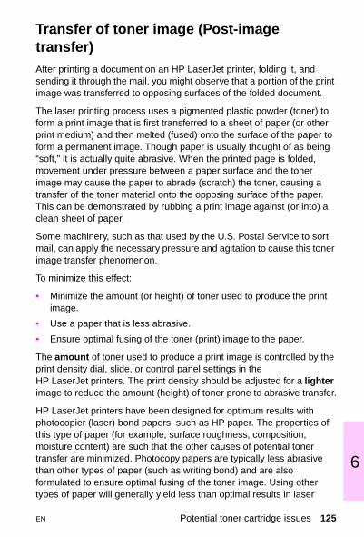
6
Transfer of toner image (Post-image transfer)After printing a document on an HP LaserJet printer, folding it, and sending it through the mail, you might observe that a portion of the print image was transferred to opposing surfaces of the folded document.
The laser printing process uses a pigmented plastic powder (toner) to form a print image that is first transferred to a sheet of paper (or other print medium) and then melted (fused) onto the surface of the paper to form a permanent image. Though paper is usually thought of as being “soft,” it is actually quite abrasive. When the printed page is folded, movement under pressure between a paper surface and the toner image may cause the paper to abrade (scratch) the toner, causing a transfer of the toner material onto the opposing surface of the paper. This can be demonstrated by rubbing a print image against (or into) a clean sheet of paper.
Some machinery, such as that used by the U.S. Postal Service to sort mail, can apply the necessary pressure and agitation to cause this toner image transfer phenomenon.
To minimize this effect:
• Minimize the amount (or height) of toner used to produce the print image.
• Use a paper that is less abrasive.
• Ensure optimal fusing of the toner (print) image to the paper.
The amount of toner used to produce a print image is controlled by the print density dial, slide, or control panel settings in the HP LaserJet printers. The print density should be adjusted for a lighter image to reduce the amount (height) of toner prone to abrasive transfer.
HP LaserJet printers have been designed for optimum results with photocopier (laser) bond papers, such as HP paper. The properties of this type of paper (for example, surface roughness, composition, moisture content) are such that the other causes of potential toner transfer are minimized. Photocopy papers are typically less abrasive than other types of paper (such as writing bond) and are also formulated to ensure optimal fusing of the toner image. Using other types of paper will generally yield less than optimal results in laser
EN Potential toner cartridge issues 125
printers. For help in selecting paper suitable for use in the HP LaserJet printers, refer to the HP LaserJet Printer Family Paper Specification Guide. This guide can be ordered by calling HP Parts Direct at (800) 227-8164 in the U.S., or HP Distribution at (970) 339-7009.
Because of the way that laser printing is accomplished, currently there is no way to entirely eliminate the possibility of toner transfer. However, using these techniques should yield more satisfactory results and will often reduce the problem to imperceptible levels.
Gray background on envelopesPoor print quality is normally the result of using envelopes that are of the incorrect weight or finish. The paper used to construct the envelope may be embossed; or may be too heavy, too rough or too slick; or may be made in such a way that it is incompatible with the high temperatures encountered in toner fusing. The result is that the toner does not adhere well to the surface. Also, on heavier envelopes, a gray background may appear on the front (or print side) of the envelope. To reduce the gray background, the print density may need to be set to a darker setting.
126 Chapter 6 Toner cartridge information EN

6
HP PLANET PARTNERS
The U. S., Canada, Europe, and Australia now have HP toner cartridge recycling programs. The used toner cartridge should be placed in the wrapper and box that held the new cartridge and sent back for recycling.
U.S. A brochure explaining the recycling program in the U.S., part number 5091-1325EUS, can be ordered. The customer returns used toner cartridges via UPS at no cost to the customer using shipping labels included in the brochure. The toner cartridges can be shipped one at a time or in volume shipments. Some of the parts are recycled to make new cartridges. Other parts are melted for re-use as raw materials. If the customer has any questions, and to receive the free recycling brochure, refer them to the Customer Information Center at (800) 752-0900.
AUSTRALIA Australian customers can send their toner cartridges to their local HP dealer. If more than 30 cartridges a month are used, contact the local dealer for instructions on how to have the cartridges picked up directly from the customer's site. For further information, contact the dealer or local HP sales office.
EUROPE The recycling program in Europe currently includes these countries: Germany, Switzerland, Austria, United Kingdom, the Netherlands, and Sweden. If more than 30 cartridges a month are used, contact the local dealer for instructions on how to have the cartridges picked up directly from the customer's site. For further information, contact the dealer or local HP sales office.
CANADA Canada uses Federal Express for their recycling program. At least eight but no more than 40 Toner Cartridges can be shipped at one time. Shipments of less than eight cartridges are at the shipper's expense. Call Federal Express at (800) GoFedEx; (800) 463-3339 to arrange for free pickup of the bundled cartridges. Fill out a Federal Express Waybill or obtain a preprinted one from your dealer.
In Alberta, B.C., Manitoba, NWT, Saskatchewan, and the Yukon, send the bundles to: Hewlett-Packard Toner Cartridge Recycling Program6551 Westminister Hwy, Unit 160 Richmond, B.C. V7C 4V4 Acct. No.: 1246-1740-5
In the Atlantic provinces, Ontario, and Quebecsend the bundles to: Hewlett-Packard Toner Cartridge Recycling Program 6600 Goreway Drive, Unit CMississauga, Ontario L4V 1S6Acct. No.: 1246-1740-5
For more information, call: Canada wide: (800) 387-3867Dept. 129; Toronto: (800) 678-9430 Ext. 4981
EN HP PLANET PARTNERS 127

NoteRecycling information is included in the toner cartridge package.
For additional information about HP corporate-wide, environmental policies, practices, and awards, visit www.hp.com .
128 Chapter 6 Toner cartridge information EN

6
Refill toner cartridge statement
Hewlett-Packard toner cartridges have been designed to maximize the reliability of the HP LaserJet printer by including all of the components that need frequent replacement or adjustment within the cartridge. While we recognize that all parts of this critical printer mechanism will not wear consistently, the HP toner cartridge has been designed to optimize the exceptional print quality that is synonymous with the HP LaserJet printer name. While Hewlett-Packard does not prohibit the use of refilled toner cartridges during the warranty period or under a maintenance contract, we also do not recommend their use for the following reasons:
1 The HP LaserJet toner cartridge is not designed to be refilled or remanufactured.
2 Hewlett-Packard has no control or process to ensure that a refilled toner cartridge will function at the high level of reliability of a new HP LaserJet toner cartridge. Hewlett-Packard also cannot predict what the long-term effect on the printer's reliability could be from using different toner formulations found in refilled cartridges. Because the HP LaserJet printer has the highest reliability reputation in the industry, we are concerned about any usage that might affect this reputation.
3 Hewlett-Packard has no control over the actual print quality of a refilled toner cartridge. The print quality of the HP LaserJet toner cartridge directly influences the customer's perception of the HP LaserJet printer itself. The high print quality of the HP LaserJet printer is one of the primary reasons for the success of the product and we are keenly interested in maintaining that image.
The entire family of HP LaserJet printers is covered under a standard one-year warranty from the date of purchase. Hewlett-Packard offers optional maintenance contracts after the one-year warranty expires. The use of refilled toner cartridges alone does not affect either the warranty or any maintenance contract purchased from HP. However, if an HP LaserJet printer failure or damage is found to be directly attributed to the use of a refilled toner cartridge, the repair will not
EN Refill toner cartridge statement 129

be covered under the warranty or by the maintenance contract . Rather, standard time and material charges will be applied to service the printer for that particular failure or damage.
Hewlett-Packard is constantly striving to provide the highest quality printer products possible. The HP LaserJet printer family was designed for optimum output performance when the printing mechanism is periodically replaced with a new HP toner cartridge. The HP toner cartridge is designed specifically to enhance the output from the HP family of printers. We know that the highest quality print results will be obtained when new HP toner cartridges are used with HP LaserJet printers.
130 Chapter 6 Toner cartridge information EN

7 Pr
EN
rinter options and eplaceable parts
Overview
The following tables list the products, product numbers, product descriptions, and service part numbers for each printer. Parts can be ordered through HP Parts Direct Ordering at (800) 227-8164 (U.S. only). For additional product support, see the inside back cover of this guide.
Printer options and replaceable parts 131

Printer options and replaceable parts
Product Productnumber
Product description Servicepart number
Memory C4135A 4 MB EDO DIMM C4135-67901
C4136A 8 MB EDO DIMM C4136-67901
C4137A 16 MB EDO DIMM C4137-67901
C4140A 4 MB SDRAM DIMM C4140-67901
C4141A 8 MB SDRAM DIMM C4141-67901
C4142A 16 MB SDRAM DIMM C4142-67901
C4143A 32 MB SDRAM DIMM C4143-67901
C3913A 64 MB SDRAM DIMM C3913-67901
C4286A 2 MB Flash DIMM N/A
C4287A 4 MB Flash DIMM N/A
C3098 PostScript DIMM C3098-60001
Fonts C4292A Traditional Chinese Font DIMM (8 MB Asian ROM)
N/A
C4293A Simplified Chinese Font DIMM (8 MB Asian ROM)
N/A
D4838A Korean (8 MB Asian ROM)
N/A
Enhanced I/O cards
J3110A Ethernet RJ-45 only N/A
J3111A Ethernet RJ-45 and BNC, LocalTalk
J3111-61003
J3112A Token Ring RJ-45 and DB-9 N/A
J3113A 10/100Base-TX networks N/A
Hard disk C2985A Hard disk N/A
132 Chapter 7 Printer options and replaceable parts EN
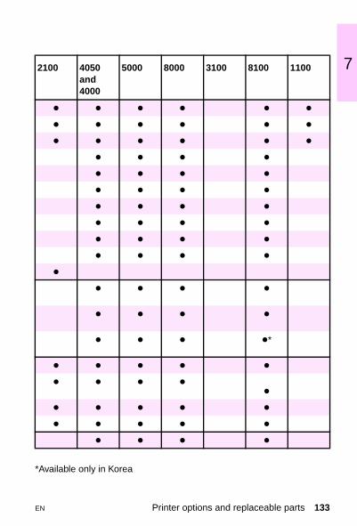
7
*Available only in Korea
2100 4050 and 4000
5000 8000 3100 8100 1100
z z z z z z
z z z z z z
z z z z z z
z z z z
z z z z
z z z z
z z z z
z z z z
z z z z
z z z z
z
z z z z
z z z z
z z z z*
z z z z z
z z z z
z
z z z z z
z z z z z
z z z z
EN Printer options and replaceable parts 133

Product Productnumber
Product description Servicepart number
Parallelcables
C2950A Parallel IEEE-1284 compliant A to B (2.0 m)
N/A
C2951A Parallel IEEE-1284 compliant A to B (3.0 m)
N/A
C2946A Parallel IEEE-1284 compliant A to C (3.0 m)
N/A
C2947A Parallel IEEE-1284 compliant A to C (10.0 m)
N/A
Serial cables
C2932A 9-9 pin serial cable (male/female)
N/A
C2933A 9-25 pin serial cable (male/female)
N/A
C2809A 25-9 pin serial adaptor (male/female)
N/A
92215S Macintosh computer serial cable N/A
92215N Macintosh network cable kit N/A
Trays C4781A 2,000-sheet input tray and paper feeder
N/A
C4124A 500-sheet paper feeder and tray N/A
C4125A 500-sheet universal replacement tray
C4125-67901
C3122A Standard 500-sheet tray N/A
C4115A 500-sheet paper feeder and tray N/A
C4117A 500-sheet replacement tray C4117-69001
NoteTrays are continued on the following page.
134 Chapter 7 Printer options and replaceable parts EN

7
2100 4050and 4000
5000 8000 3100 8100 1100
z z z
z z z
z z z z
z z z z
z z
z z
z z
z z
z z
z z
z
z
z
z
z z
EN Printer options and replaceable parts 135

Product Productnumber
Product description Servicepart number
Trays, continued
C4780A Two 500-sheet trays and paper feeder
N/A
C4114A 250-sheet paper feeder and tray N/A
C4126A 250-sheet universal replacement tray
C4126-67901
C4116A 250-sheet replacement tray C4116-69001
250-sheet cassette (trays 2 and 3)
RG5-4137-000CN
C4793A Tray 3 N/A
C4098A Tray 2 (500-sheet input tray) or Tray 4 (2 x 500-sheet input tray)
RG5-3951-000CN
C4099A Tray 3 (500-sheet input tray) or Tray 5 (2 x 500-sheet input tray)
RG5-3952-000CN
Envelope feeder
C4122A Envelope feeder C4122-69001
C3765B Envelope feeder
Duplexer C4123A Duplex printing accessory C4123-69001
C4113A Duplex printing accessory C4113-69001
C4782A Duplex printing accessory C4782-69501
Mailbox C4783A 7-bin tabletop mailbox
C4785B 8-bin multibin mailbox
C4787A 5-bin mailbox with stapler C4787-69502
Media HPM1120 HP multi-purpose paper (letter-size)
M1120
HPJ1124 HP LaserJet paper (letter-size) J1124
136 Chapter 7 Printer options and replaceable parts EN

7
2100 4050and 4000
5000 8000 3100 8100 1100
z z
z
z
z
z
z
z
z
z
z z
z
z
z z
z z
z z
z z
z z z z z z z
z z z z z z z
EN Printer options and replaceable parts 137

Product Productnumber
Product description Servicepart number
Toner cartridges
C4127A Toner cartridge (6,000 pages) N/A
C4127X Toner cartridge (10,000 pages) N/A
C4129X Toner cartridge (10,000 pages) N/A
C3906A Toner cartridge (2,500 pages) N/A
C3909A Toner cartridge (15,000 pages) N/A
C3909S 3 toner cartridges (15,000 pages) (LJ Mopier 240)
N/A
C4092A Toner cartridge (2,500 pages) N/A
C4182X Toner cartridge (20,000 pages) N/A
C4096A Toner Cartridge (5,000 pages) N/A
Power box C4789A Connects a multibin mailbox to the printer when the printer is on a printer stand.
N/A
Infraredreceiver
C4103A Fast infrared receiver C4103-67901
138 Chapter 7 Printer options and replaceable parts EN

7
2100 4050 4000 5000 8000 3100 8100 1100z z
z z
z
z
z
z
z
z
z z
z z z
EN Printer options and replaceable parts 139

*Requires exchange
Product Product description Servicepart number
Exchangenumber
Maintenancekit
Preventative maintenance kit with 110 V fuser (4000, 4050 series)
C4118-67902 C4118-69001*
Preventative maintenance kit with 220 V fuser (4000, 4050 series)
C4118-67903 C4118-69002*
Preventative maintenance kit with 110 V fuser (5000 series)
C4110-67901 C4110-69006*
Service maintenance kit with 220 V fuser (5000 series)
C4110-67902 C4110-69007*
Preventative maintenance kit with 110 V fuser (8000 series)
C3971B C3971-69002*
Preventative maintenance kit with 220 V fuser (8000 series)
C3972B C3972-69002*
Preventative maintenance kit with 110 V fuser (8100 series)
C3914A C3914-69001
Preventative maintenance kit with 220 V fuser (8100 series)
C3915A C3915-69001*
140 Chapter 7 Printer options and replaceable parts EN

7
2100 4050and 4000
5000 8000 3100 8100 1100
z
z
z
z
z
z
z
z
EN Printer options and replaceable parts 141

142 Chapter 7 Printer options and replaceable parts EN
8 P
EN
rinter parts
Overview
This chapter provides the part numbers and descriptions of the most commonly used assemblies and subassemblies in the HP LaserJet printers. The shaded numbers in the tables refer to the location of the part in the printer, as shown in the corresponding illustrations.
NoteSee your printer service manual for a complete listing of hardware components.
Overview 143

Common Hardware
1
2
3
4
5
6
7
8
9
10
144 Chapter 8 Printer parts EN

8
Common Hardware
Common hardwarePart number Product description
1 XB1-2300-606CN M3 x 5mm Pan-head phillips
1 XB1-2300-507CN M3 x 5mm Pan-head phillips
1 XB1-2300-607CN BH3 x 6mm Pan-head phillips
1 0515-1895 M3 x 8mm Pan-head phillips
1 XB1-2301-407CN M4 x 14mm Pan-head phillips
1 XB1-2400-606CN M4 x 6mm Pan-head phillips
1 XB1-2400-809CN M4 x 8mm Pan-head phillips
1 0515-1912 M4 x 8mm Pan-head phillips
1 XB1-1300-807CN M3 x 8 mm Pan-head phillips
2 FA9-1449-000CN M3 x 6mm Washer-head phillips
2 XA9-0267-000CN M3 x 6mm Washer-head phillips
2 XA9-0253-000CN M3 x 8mm Washer-head phillips
2 XA9-0542-000CN M3 x 10mm Washer-head phillips
2 XA9-0540-000CN M4 x 8mm Washer-head phillips
3 XA9-0653-000CN M3 x 6mm Star-washer phillips
3 XA9-0653-000CN M3 x 6mm Star-washer phillips
3 XA9-0389-000CN M3 x 8mm Star-washer phillips
3 XA9-0654-000CN M3 x 10mm Star-washer phillips
3 XA9-0192-000CN M4 x 6mm Star-washer phillips
3 XA9-0828-000CN M3 x 6mm Star-washer phillips
4 RBI-5552-000CN M3 Shoulder screw phillips
4 RAI-7636-000CN M3 Shoulder screw phillips
4 RBI-5489-000CN M3 x 4mm Shoulder screw phillips
4 XA9-0342-000CN M3 x 8mm Shoulder screw phillips
5 XB4-7300-609CN M3 x 6mm Self-tapping phillips
5 XB6-7300-607CN M3 x 6mm Self-tapping phillips
5 XB4-7400-809CN M4 x 8mm Self-tapping phillips
5 XA9- 0870-000CN M4 x 10mm Self-tapping phillips (black)
5 XB4-7401-009CN M4 x 10mm Self-tapping phillips
5 XB4-7401-007CN M4 x 10mm Self-tapping phillips
5 XB4-7401-209CN M4 x 12mm Self-tapping phillips
5 XA9-0773-000CN M4 x 12mm Self-tapping phillips
5 XA9-0916-000CN M4 x 14mm Self-tapping phillips
6 XA9-0253-000CN M3 x 8mm Loose flat/lock washer phillips
6 XA9-0584-000CN M3 x 12mm Loose flat/lock washer phillips
EN Common Hardware 145

Part Number Product Description7 FA9-1449-000CN Star-washer trus-head phillips
7 XB1-2302-507CN M3 x 25mm Trus-head phillips
7 XB6-7300-809CN M3 x 8mm Trus-head phillips
7 XA9-0326-000CN M3 x 4mm Trus-head phillips
7 XB6-7300-807CN M3 x 8mm Trus-head phillips
8 XD2-1100-242CN 2.4mm Retaining ring (e-type)
8 XD2-1100-322CN 3.2mm Retaining ring (e-type)
8 XD2-1100-402CN 4.0mm Retaining ring (e-type)
8 XD2-1100-502CN 5.0mm Retaining ring (e-type)
8 XD2-1100-642CN 6.4mm Retaining ring (e-type)
8 XG9-0260-000CN Retaining ring (e-type)
8 XD2-2300-507CN 5.0mm Grip ring (c-type)
9 XA9-0375-000CN 3m x 25 mm Loose flat/star washer phillips
10 XA9-0686-000CN M3 x 6mm Hexhead screw
10 XA9-0724-000CN M3 x 8 mm Hexhead screw
10 XA9-0824-000CN M3 x 10mm Hexhead screw
10 XA9-0813-000CN M3 x 8mm Hexhead screw with washer
Common hardware (continued)
146 Chapter 8 Printer parts EN

8
Notes
EN Common Hardware 147

Parts for the HP LaserJet 2100 series
Major assembly locations (2100 series)
5
12
34
6
7
89
10
11
12
13
14
15
16
148 Chapter 8 Printer parts EN

8
HP LaserJet 2100 assemblies and subassemblies
*These parts require exchange.
Assemblies and subassemblies Part numbers
1 Transfer roller assembly RG5-4130-000CN
2 Roller kitBelt kit
RY7-5052-000CNRY7-5053-000CN
3 Motor, DC5-76W RH7-1381-000CN
4 Printer drive assembly RG5-4131-000CN
5 Formatter PCA C4132-60001
6 Separation pad RB2-2835-000Cn
7 Registration assembly RG5-4129-000CN
8 DIMM cover assembly RG5-4123-000CN
9 Pickup roller RB2-2900-0000CN
10 Paper pickup roller RB2-2891-000CN
11 Engine controller assembly (220 VEngine controller assembly (110 V)
RG5-4150-020CNRG5-4125-020CN
12 Intermediate PCB assembly RG5-4250-000CN
13 Fan RH7-1382-000CN
14 Face-down delivery roller assembly RG5-4119-000CN
15 Fusing assembly (110 V)Fusing assembly (220 V)
RG5-4132-000CNRG5-4133-000CN
16 Laser scanner assembly RG5-4172-000CN
Universal paper cassette--trays 2 and 3 (not shown)
R98-1003-000CN
EN Parts for the HP LaserJet 2100 series 149

Parts for the HP LaserJet 4050 and 4000 series
Major assembly locations (4050 and 4000 series)
43
2 5
1
6
12
13 7
8
1110
9
150 Chapter 8 Printer parts EN

8
HP LaserJet 4050 and 4000 assemblies and subassemblies
*These parts require exchange
Assemblies and subassemblies Part numbers
1 Fusing assembly C4118-69003 (110 V)*C4118-69004 (220 V)*
2 Paper delivery assembly RG5-2648-000CN
No
Cal
l out
# Paper pickup drive assembly (500-sheet) RG5-2672-000CN
Upper paper pickup drive assembly (2 x 250) RG5-2683-000CN
Lower paper pickup drive assembly (2 x 250) RG5-2684-000CN
Feed/separation roller RG5-2490-000CN
3 Top cover assembly RG5-2663-000CN
Front panel RG5-2666-000CN
4 Laser scanner assembly C4118-69005*
5 Tray 1 pickup assembly RG5-2655-000CN
Tray 1 pickup roller RG5-3718-000CN
6 Tray 1 assembly RG5-2656-000CN
7 Formatter assembly (LJ 4050)Formatter assembly (LJ 4000)
C4251-69001*C4118-69008*
8 Printer drive assembly RG5-2653-000CN
Release rod RB1-8756-000CN
Main motor RH7-1331-000CN
9 Registration assembly RG5-2652-000CN
10 Paper feed assembly RG5-2651-000CN
11 Engine controller board (ECU) C4118-69006 (110 V)*C4118-69007 (220 V)*
12 Paper feed guide assembly RG5-2643-000CN
Paper feed belt RB1-8668-000CN
Transfer roller RG5-4283-000CN
13 Delivery drive assembly RG5-3721-000CN
EN Parts for the HP LaserJet 4050 and 4000 series 151

Parts for the HP LaserJet 5000 series
Major assembly locations (5000 series, 1 of 2)
1
2
3 4
5
6 7
152 Chapter 8 Printer parts EN

8
HP LaserJet 5000 assemblies and subassemblies
*These parts require exchange
Assemblies and subassemblies Part numbers
1 Fusing assembly C4110-69002 (110 V)*C4110-69003 (220 V)*
2 Registration assembly RG5-3524-000CN
3 Paper pickup assembly (Tray 2) RG5-3521-000CN
Pickup roller (Tray 1) RB2-1820-000CN
4 Paper tray C4116-69001 (250-sheet)*C4117-69001 (500-sheet)*
5 Upper delivery assembly RG5-3542-000CN
6 Paper feed belt assembly RG5-3526-000CN
Transfer roller RG5-3579-000CN
7 Paper feed assembly RG5-3522-000CN
EN Parts for the HP LaserJet 5000 series 153

Parts for the HP LaserJet 5000 series
Major assembly locations (5000 series, 2 of 2)
4
2
3
1
154 Chapter 8 Printer parts EN

8
HP LaserJet 5000 assemblies and subassemblies
*These parts require exchange
Assemblies and subassemblies Part numbers
1 Pickup drive assembly RG5-3544-000CN
Spring RS5-2434-000CN
2 Main gear assembly RG5-3543-000CN
Main motor RH7-1356-000CN
3 DC controller C4110-69001*
4 Formatter C3974-69001*
Laser scanner assembly C4110-69008*
DC power supply C4110-69004 (110 V)*C4110-69005 (220 V)*
Top cover RB2-1748-000CN
Control panel assembly RG5-3604-000CN
Fan RH7-1354-000CN
Toner cartridge engagement arm RB2-1856-000CN
Tray 2 separation pad with spring RG5-3585-000CN
Paper-handling PCA RG5-3560-000CN
Tray 1 separation pad RF5-2400-000CN
Control panel display cover RB2-1758-000CN
EN Parts for the HP LaserJet 5000 series 155
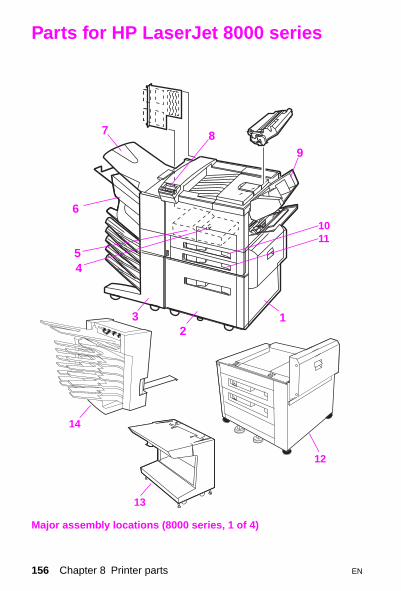
Parts for HP LaserJet 8000 series
Major assembly locations (8000 series, 1 of 4)
23
45
6
7 89
1
1011
12
13
14
156 Chapter 8 Printer parts EN

8
HP LaserJet 8000 series assemblies and subassemblies
Assemblies and subassemblies Part numbers
1 2000-sheet input unit assembly C4781A
2 Tray 4 assembly RG5-2155-000CN
3 Multi-bin mailbox C4785B
4 Duplex unit roller 1 RB1-6822-000CN
5 Duplex unit C4782A
6 5-bin mailbox with stapler C4787A
7 Face-up bin RB1-6491-000CN
8 Control panel display RG5-4384-000CN
9 Envelope feeder C3765B
10 Tray 2 RG5-3951-000CN
11 Tray 3 RG5-3952-000CN
12 Multiple input tray (2 x 500-sheet input tray) C4780A
13 7-bin stand C4784A
14 7-bin tabletop mailbox C4783A
EN Parts for HP LaserJet 8000 series 157

Parts for HP LaserJet 8000 series
Major assembly locations (8000 series, 2 of 4)
1
2
3
45
6
7
8 9
10
11
12
13
158 Chapter 8 Printer parts EN

8
HP LaserJet 8000 assemblies and subassemblies
*These parts require exchange.
Assemblies and subassemblies Part numbers
1 Transfer roller RF5-1412-000CN
2 Main motor RH7-1260-000CN
3 Face-down delivery assembly RG5-1874-000CN
4 Fusing assembly 100 V-120 V C3166-69012*
4 Fusing assembly 220 V-240 V C3166-69013*
5 Feeder assembly RG5-1834-000CN
6 Registration assembly RG5-1833-000CN
7 Tray 1 pickup assembly RG5-1880-100CN
8 Tray 1 feed roller RB1-6730-000CN
9 Tray 1 separation pad RF5-1455-000CN
10 Paper input unit (PIU) C3166-69011-000*
11 Main gear assembly RG5-1847-000CN
12 Transfer roller assembly RG5-1887-000CN
13 Tray 1 PCA RG5-1884-000CN
EN Parts for HP LaserJet 8000 series 159

Parts for HP LaserJet 8000 series
Major assembly locations (8000 series, 3 of 4)
1
2
3
5 4
160 Chapter 8 Printer parts EN

8
HP LaserJet 8000 series assemblies and subassemblies
*These parts require exchange.
Assemblies and subassemblies Part numbers
1 Laser scanner assembly C3166-69006*
2 Fan 1 RH7-1266-000CN
3 Switch/sensor PCA RG5-1846-000CN
4 High-voltage power supply C3166-69005*
5 DC controller PCA C3166-69010*
EN Parts for HP LaserJet 8000 series 161

Parts for HP LaserJet 8000 series
Major assembly locations (8000 series, 4 of 4)
2 3
6
5
1
4
162 Chapter 8 Printer parts EN

8
HP LaserJet 8000 series assemblies and subassemblies
*These parts require exchange.
Assemblies and subassemblies Part numbers
1 Low-voltage power supply, 110 V-220 V C3166-69007*
1 Low-voltage power supply, universal C3166-69008*
2 Formatter C4186-69001*
3 Fan 3 RH7-1271-000CN
4 Fan 2 RH7-1266-000CN
5& 6
Paper size sensing PCA, trays 2 and 3 RG5-1845-000CN
EN Parts for HP LaserJet 8000 series 163

Parts for the HP LaserJet 3100
Major assembly locations (3100, 1 of 2)
12
3
4
5
13
14
12
6
11
7
8
9
10
164 Chapter 8 Printer parts EN

8
HP LaserJet 3100 assemblies and subassemblies
* These are customer-replaceable parts.
Assemblies and subassemblies Part numbers
1 Paper pickup assembly RG5-3484-000CN
Pickup roller assembly RG5-3486-000CN
Clutch RB1-7197-020CN
Separation pad kit RY7-5008-000CN
Input sensor assembly RB1-7182-000CN
Solenoid RH7-5139-000CN
2 Transfer guide assembly RG5-3452-000CN
Transfer roller RF5-1534-000CN
3 Delivery assembly RG5-3474-020CN
4 Separation guide assembly RG5-3475-020CN
Lever sensor arm RB1-7293-000CN
Fuser exit roller assembly RF5-2368-000CN
5 Document scanner assembly RG5-4223-000CN
Pickup roller assembly RG5-4688-000CN
Scanner motor, AC 1.08 watts RH7-1376-000CN
Contact image sensor assembly RG5-4239-000CN
Cable, contact image sensor RG5-4233-000CN
6 Document scanner guide/cover RB2-3436-000CN
7 Paper input support RB2-3362-000CN*
8 Paper output support RB2-3410-000CN*
9 Document feeder support RB2-3455-000CN*
10 Document output support RB2-3470-000CN*
11 Strap RB2-3354-000CN*
12 Upper guide assembly RG5-4221-000CN
Separation pad kit RY7-5055-000CN
13 Feed assembly RG5-3485-030CN
Feed roller RB2-1699-000CN
14 Control panel assembly RG5-4241-000CN
EN Parts for the HP LaserJet 3100 165

Parts for the HP LaserJet 3100
Major assembly locations (3100, 2 of 2)
1
23
4
5
6 7
8
166 Chapter 8 Printer parts EN

8
HP LaserJet 3100 assemblies and subassemblies
Assemblies and subassemblies Part numbers
1 LIU board (U.S.)LIU board (Worldwide)
C3948-67903C3948-67904
2 ECU (engine controller board) 110 VECU 220 V
RG5-4690-000CNRG5-4691-000CN
3 Laser scanner assembly RG5-3494-050CN
4 Fixing/fusing assembly 110 VFixing/fusing assembly 220V
RG5-4678-000CNRG5-4681-000CN
5 Fixing assembly pressure roller RF5-2362-000CN
6 Formatter (without shield) C3949-67901
7 Cable ECU to formatter RH2-5346-000CN
8 Fuser exit roller assembly RF5-2368-000CN
Foot (4) RF5-2663-000CN
Speaker RH6-3845-000CN
Laser cable RG5-2035-000CN
Motor, D.C. 12V RH7-1320-000CN
RFI shield, formatter C3948-00002
EN Parts for the HP LaserJet 3100 167

Parts for HP LaserJet 8100 series
Major assembly locations (8100 series, 1 of 4)
23
45
6
7 89
1
1011
12
15
16
13
14
168 Chapter 8 Printer parts EN
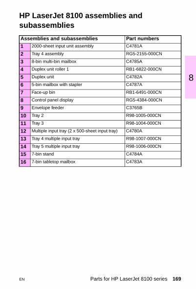
8
HP LaserJet 8100 assemblies and subassemblies
Assemblies and subassemblies Part numbers
1 2000-sheet input unit assembly C4781A
2 Tray 4 assembly RG5-2155-000CN
3 8-bin multi-bin mailbox C4785A
4 Duplex unit roller 1 RB1-6822-000CN
5 Duplex unit C4782A
6 5-bin mailbox with stapler C4787A
7 Face-up bin RB1-6491-000CN
8 Control panel display RG5-4384-000CN
9 Envelope feeder C3765B
10 Tray 2 R98-1005-000CN
11 Tray 3 R98-1004-000CN
12 Multiple input tray (2 x 500-sheet input tray) C4780A
13 Tray 4 multiple input tray R98-1007-000CN
14 Tray 5 multiple input tray R98-1006-000CN
15 7-bin stand C4784A
16 7-bin tabletop mailbox C4783A
EN Parts for HP LaserJet 8100 series 169

Parts for HP LaserJet 8100 series
Major assembly locations (8100 series, 2 of 4)
1
2
3
45
6
7
8 9
10
11
12
13
170 Chapter 8 Printer parts EN

8
HP LaserJet 8100 assemblies and subassemblies
*These parts require exchange.
Assemblies and subassemblies Part numbers
1 Transfer roller RF5-2675-000CN
2 Main motor RH7-5219-000CN
3 Face-down delivery assembly RG5-1874-000CN
4 Fusing assembly 100 V-120 V C4214-69007*
4 Fusing assembly 220 V-240 V C4214-69008*
5 Feeder assembly RG5-4305-000CN
6 Registration assembly RG5-4303-000CN
7 Tray 1 pickup assembly RG5-4330-000CN
8 Tray 1 feed roller RB1-9526-000CN
9 Tray 1 separation pad RF5-2703-000CN
10 Paper input unit (PIU) C4214-69004*
11 Main gear assembly RG5-4365-000CN
12 Transfer roller assembly RG5-4304-000CN
13 Tray 1 PCA RG5-1884-000CN
EN Parts for HP LaserJet 8100 series 171

Parts for HP LaserJet 8100 series
Major assembly locations (8100 series, 3 of 4)
1
2
3
5 4
172 Chapter 8 Printer parts EN

8
HP LaserJet 8100 assemblies and subassemblies
*These parts require exchange.
Assemblies and subassemblies Part numbers
1 Laser scanner assembly C4214-69003*
2 Fan 1 (laser scanner fan) RH7-1266-000CN
3 Switch/sensor PCA RG5-1846-000CN
4 High-voltage power supply RG5-4306-000CN*
5 DC controller PCA C4214-69001*
EN Parts for HP LaserJet 8100 series 173

Parts for HP LaserJet 8100 series
Major assembly locations (8100 series, 4 of 4)
2 3
6
5
1
4
174 Chapter 8 Printer parts EN

8
HP LaserJet 8100 assemblies and subassemblies
*These parts require exchange.
Assemblies and subassemblies Part numbers
1 Low-voltage power supply, 110 V RG5-4300-000CN
1 Low-voltage power supply, 220 V RG5-4301-000CN
2 Formatter C4107-69001*
3 Fan 3 (formatter fan) RH7-1271-000CN
4 Fan 2 (low-voltage power supply fan) RH7-1396-000CN
5&6
Paper size sensing PCA, trays 2 and 3 RG5-1845-000CN
EN Parts for HP LaserJet 8100 series 175

Parts for HP LaserJet 1100 series
Major assembly locations (1100 series, 1 of 2)
12
3
4
5
69
10
8 7
176 Chapter 8 Printer parts EN

8
HP LaserJet 1100 assemblies and subassemblies
*These parts are customer replaceable
Assemblies and subassemblies Part numbers
1 Input paper support RB2-4021-000CN*
2 Output/scanner paper support RB2-4020-000CN*
3 Paper pickup roller RB2-3929-000CN*
4 Face-down roller RF5-2830-000CN
5 Face-up roller RF5-2822-000CN
6 Torsion spring RB2-3961-000CN
7 Sensor flag RB2-3960-000CN
8 Pressure roller RF5-2823-000CN
9 Fusing/fixing assembly (110 V)Fusing/fixing assembly (220 V)
RG5-4589-000CNRG5-4590-000CN
10 Laser scanner assembly RG5-4570-000CN
EN Parts for HP LaserJet 1100 series 177

Parts for HP LaserJet 1100 series
Major assembly locations (1100 series, 2 of 2)
1
4 3
7
6
5
2
178 Chapter 8 Printer parts EN

8
HP LaserJet 1100 assemblies and subassemblies
Assemblies and subassemblies Part numbers
1 Transfer roller RG5-4594-000CN
2 Engine controller unit (ECU) (110 V)Engine controller unit (ECU) (220 V)
RG5-4595-000CNRG5-4596-000CN
3 Document scanner R37-5000-000CN
4 Formatter C4146-60001
5 Arm mount (2) RB2-4034-000CN
6 Clutch kit RY7-5051-000CN
7 Paper feed assembly RG5-4581-000CN
EN Parts for HP LaserJet 1100 series 179

180 Chapter 8 Printer parts EN

9 I
EN
mage quality
Overview
This chapter provides examples of image defects and a list of recommended solutions. Repetitive image defect rulers are supplied at the end of the chapter to use when measuring the approximate distances between repetitive image defects. Use the appropriate defect ruler for your product.
The engine controller unit (ECU) includes the high-voltage power supply and DC controller as one assembly for the LJ2100, LJ 3100, LJ 4050, LJ 4000, LJ 1100, and LJ 1100A products.
All other products (LJ 5000, 8000, and 8100) are separate assemblies.
Overview 181

Cleaning page (all printers except 2100 and 1100)
For print-quality defects, try generating a cleaning page from the printer control panel (4050, 4000, 5000, 8000, or 8100) or from the JetSuite Pro software (3100). The HP LaserJet Cleaning Utility works on all HP monochrome printers, regardless of driver type. Running the utility at regular intervals can extend the useful life of the fuser and reduce service procedures.
If your printer cannot generate a cleaning page, you can download the HP LaserJet Cleaning Utility file and obtain instructions on its usage by accessing the worldwide web at www.hp.com/cposupport/eschome.html.
NoteFor the cleaning page to work properly, make sure to print the page on copier grade paper (not bond or rough paper).
Cleaning page (LJ 2100 only)
Use this process if toner specks or dots appear on printouts. This process will provide a blank page which should be discarded.
NoteFor best results, use a transparency during this process. If a transparency is not available, use copier grade paper and not bond or rough paper.
182 Chapter 9 Image quality EN

9
To Start Engine Cleaning1 Make sure the printer is turned on and in the Ready state. Load a
transparency in Tray 1.
2 Press and hold the GO and JOB CANCEL buttons until all lights flash. This will take about 10 seconds. Release the buttons when the lights flash.
3 Press the GO button.
NoteDuring the engine cleaning process, the printer pulls the transparency into the printer and then stops. This is not a jam. The transparency will be slowly stepped through the printer to complete the engine cleaning.
4 Discard the blank page produced from the engine cleaning process.
EN Cleaning page (LJ 2100 only) 183

Cleaning the printer paper path (LJ 1100 only)This process uses copier grade paper to remove dust and toner from the paper path. Do not use bond or rough paper. Use this process if you are experiencing toner specs or dots on printouts. This process will produce a page with toner debris, which should be discarded.
1 Ensure the printer is loaded with paper.
2 Ensure the printer is in the Ready state.
3 Press and hold GO for 20 seconds (if the GO button is released before 20 seconds, the printer will perform a reset). Paper will feed through the printer.
NoteAfter holding GO for 20 seconds, each of the three printer lights will blink until the cleaning process is complete.
During the engine cleaning process, the printer pulls the paper into the printer and then stops. This is not a jam. The paper will slowly be stepped through the printer to complete the engine cleaning.
184 Chapter 9 Image quality EN

9
Image Defect Table
For more information, go to the page numbers provided below each image.
Background scatter
(see page 188)
Black lines(see page 188)
Black pages(see page 188)
Blank page(see page 189)
Blank spots(see page 190)
Bottom of page is blank or graphic image is cut off(see page 190)
Character voids(see page 190)
Dirt on back of page
(see page 191)
DIstorted image(see page 191)
Dropouts(see page 191)
Faded print or bubbles
(see page 192)
Gray background(see page 192)
EN Image Defect Table 185

Horizontal black lines or smears(see page 193)
Horizontal dots(see page 193)
Horizontal smudges
(see page 193)
Horizontal white lines
(see page 194)
Light print, dark print, faded print(see page 194)
Loose toner(see page 194)
Outgoing faxes/copies/scanned images are too light or too dark(see page 195)
Print is faded or vertically aligned white streaks are
apparent(see page 195)
Random black spots
(see page 195)
Repetitive defects(see page 196)
Scanned images have black dots or streaks in top
and bottom margins
(see page 196)
Scanned text is unclear
(see page 196)
186 Chapter 9 Image quality EN

9
Toner smear(see page 197)
Vertical black lines(see page 197)
Vertical dots(see page 198)
Vertical white lines
(see page 198)
EN Image Defect Table 187

Image defect details
• The media does not meet HP specifications.
• The toner cartridge is defective.
• The inside of the printer is dirty.
• The transfer roller is dirty or worn.
• Generate a cleaning page.
• The toner cartridge is defective.
• The toner cartridge is not seated properly.
• The fusing assembly is contaminated or damaged.
• The static eliminator teeth are contaminated or defective.
• The lens in the laser scanner is broken.
• The high-voltage power supply connections are dirty.
• The high-voltage power supply is installed improperly. If the high-voltage power supply has been removed and replaced, it may not be seated properly.
• Check the ECU (engine controller unit) for damage.
• The toner cartridge is defective.
• Light is leaking into the printer.
– Ensure all covers are in place.
• The DC controller PCA is defective.
• The laser scanner assembly is faulty (turning laser on continuously).
• The connectors between the laser scanner unit and the ECU or DC controller PCA are not seated properly or are defective.
• The Intermediate PCB is defective.
Background scatter
Black lines
Black pages
188 Chapter 9 Image quality EN
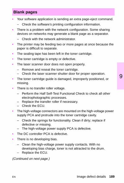
9
• Your software application is sending an extra page-eject command.
– Check the software’s printing configuration information.
• There is a problem with the network configuration. Some sharing devices on networks may generate a blank page as a separator.
– Check with the network administrator.
• The printer may be feeding two or more pages at once because the paper is difficult to separate.
• The sealing tape has been left in the toner cartridge.
• The toner cartridge is empty or defective.
• The laser scanner door does not open properly.
– Remove and reseat the toner cartridge.– Check the laser scanner shutter door for proper operation.
• The toner cartridge guide is damaged, improperly positioned, or missing.
• There is no transfer roller voltage.
– Perform the Half Self-Test Functional Check to check all other electrophotographic processes.
– Replace the transfer roller if necessary.– Check the ECU.
• The high-voltage connectors are mounted on the high-voltage power supply PCA and protrude into the toner cartridge cavity.
– Check the springs for functionality. Clean if dirty; replace if defective or missing.
– The high-voltage power supply PCA is defective.
• The DC controller PCA is defective.
• There is no developing bias.
– Clean the high-voltage power supply contacts. With no developing bias charge, toner is not attracted to the drum.
– Replace the ECU.
(Continued on next page.)
Blank pages
EN Image defect details 189

• There is no drum ground path.
– Check the drum ground. – Replace the ECU.
• The laser scanner cable assembly is defective.
• The page length and margins are not set correctly for the paper size.
• The paper does not meet HP paper specifications or is stored improperly.
• The toner cartridge is defective.
• The transfer roller is dirty or defective.
• The page is too complex. (There is not enough memory to process the page.)
– Reduce the resolution through the software or printer driver. See the online help for printer driver issues.
• Use paper that meets HP paper specifications.
– The surface of the paper is too rough or the paper’s surface is too smooth for proper toner adhesion.
– The moisture content of the paper is too high.– Printing is on the wrong side of the paper.– The transparencies are not designed for proper toner adhesion.– The transfer roller is defective.– The laser scanner assembly is defective.
Blank spots
Bottom of page is blank or graphic image is cut off
Character voids
190 Chapter 9 Image quality EN

9
• The inside of the printer is dirty (tray separation roller, feed roller, fuser, transfer roller, toner cartridge, feed belt, feed guide, or fuser entrance guide).
• The paper does not meet HP paper specifications or is stored improperly.
• The pressure roller in the fuser is contaminated.
• There is dirt on an internal roller.
• The paper does not meet HP paper specifications or is stored improperly.
• The printer operating environment does not meet HP specifications.
• The connection of the cables to the laser scanner is poor.
• The connection of the cables to the ECU is poor.
• The laser scanner is defective.
• The ECU is defective.
• The main motor or gear train has failed.
• The paper does not meet HP paper specifications.
• The printer’s operating environment does not meet specifications.
• The print density is set incorrectly.
– Change to a darker setting and retry printing.
• The fuser setting was wrong for the paper type.*
• The DC controller PCA is defective.
• The high-voltage power supply PCA is defective.
• The transfer roller is defective.
• “Draft mode” or “EconoMode” is selected in the software.
*This feature does not apply to all products.
Dirt on back
Distorted image
Dropouts
EN Image defect details 191

• Check the ground path.
• Replace the ECU.
• The toner cartridge is empty or defective.
• The print density is set incorrectly.
– Change to a darker setting and retry printing.
• “Draft mode” or “EconoMode” is selected in the software or printer control panel.
• The paper does not meet HP paper specifications.
• Inspect the transfer roller for proper installation and contact.
– Replace the transfer roller if it is damaged.
• The laser scanner door is not opening properly.
– Remove and reseat the toner cartridge.– Check the laser scanner door for proper operation.
• The high-voltage contact springs are dirty or defective.
• The DC controller PCA is defective.
• The paper does not meet HP paper specifications or is stored improperly.
• The printer operating environment does not meet specifications.
• The toner density is set incorrectly.
• The toner cartridge is defective.
• The inside of the printer is dirty.
• The printer is printing on envelope seams.
– Move the text to an area without seams.
• There is poor contact between the primary bias contact on the ECU and toner cartridge contact.
Faded print or bubbles
Gray background
192 Chapter 9 Image quality EN

9
• The paper does not meet HP paper specifications or is stored improperly.
• The laser scanner assembly or ECU is defective.
• The toner cartridge is defective or it was improperly installed.
• The printer needs to be cleaned.
• The fusing assembly is dirty or defective.
3100 and 1100 series only• Horizontal lines appear in the margins and across entire pages of
faxes, copies, and scans.
– The contact image sensor needs to be cleaned.– Recalibrate the scanner.– There is a problem in the contact image sensor.
• The transfer roller is deformed or has deteriorated.
• The static eliminator teeth are dirty.
• There is poor contact between the static eliminator and the engine controller assembly.
• There is poor contact between the transfer roller contact on the engine controller assembly and the transfer charging roller shaft contact.
• The engine controller assembly is defective.
• The paper does not meet HP paper specifications or is stored improperly.
• The paper path is contaminated or damaged.
Horizontal black lines or smears
Horizontal dots
Horizontal smudges
EN Image defect details 193

• The toner cartridge could be defective or low on toner.
• The toner cartridge has been exposed to too much light.
• The fusing assembly is dirty or defective.
• The laser scanner assembly is dirty or defective.
• The ECU could be faulty.
• The toner density setting is incorrect.
• The toner cartridge is empty or defective.
• The toner cartridge requires cleaning.
• The transfer roller is defective or dirty.
• The paper does not meet HP paper specifications or is stored improperly.
• The laser scanner is defective.
• The ECU is defective.
• The high-voltage power supply is defective.
• “Draft mode” or “EconoMode” is selected in the software.
• The inside of the printer is dirty.
• The toner cartridge is defective.
• The paper does not meet HP paper specifications.
• The fuser setting is wrong for the paper type.
• The fusing assembly is defective or dirty.
• There is a paper jam in the fuser.
Horizontal white lines
Light print, dark print, faded print
Loose toner
194 Chapter 9 Image quality EN
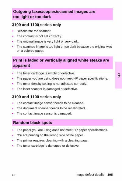
9
3100 and 1100 series only• Recalibrate the scanner.
• The contrast is not set correctly.
• The original image is very light or very dark.
• The scanned image is too light or too dark because the original was on a colored paper.
• The toner cartridge is empty or defective.
• The paper you are using does not meet HP paper specifications.
• The toner density setting is not adjusted correctly.
• The laser scanner is damaged or defective.
3100 and 1100 series only• The contact image sensor needs to be cleaned.
• The document scanner needs to be recalibrated.
• The contact image sensor is damaged.
• The paper you are using does not meet HP paper specifications.
• You are printing on the wrong side of the paper.
• The printer requires cleaning with a cleaning page.
• The toner cartridge is damaged or defective.
Outgoing faxes/copies/scanned images are too light or too dark
Print is faded or vertically aligned white steaks are apparent
Random black spots
EN Image defect details 195

• Use the repetitive defect ruler to determine the defective component.
• The gears are worn, causing slippage or jumping.
• The paper does not meet HP paper specifications.
3100 and 1100 series only • There is ink, glue, white-out, or some other substance on the
contact image sensor.
– Recalibrate the document scanner.
• There is a problem in the contact image sensor.
– Replace the contact image sensor.
3100 and 1100 series only• The contrast, resolution, or brightness needs to be adjusted before
scanning.
• The original is on colored paper.
• There is a problem in the contact image sensor.
– Replace the contact image sensor.
Repetitive defects
Scanned images have black dots or streaks in top and bottom margins
Scanned text is unclear
196 Chapter 9 Image quality EN
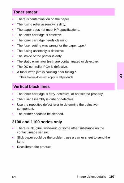
9
• There is contamination on the paper.
• The fusing roller assembly is dirty.
• The paper does not meet HP specifications.
• The toner cartridge is defective.
• The toner cartridge needs cleaning.
• The fuser setting was wrong for the paper type.*
• The fusing assembly is defective.
• The inside of the printer is dirty.
• The static eliminator teeth are contaminated or defective.
• The DC controller PCA is defective.
• A fuser wrap jam is causing poor fusing.*
*This feature does not apply to all products.
• The toner cartridge is dirty, defective, or not seated properly.
• The fuser assembly is dirty or defective.
• Use the repetitive defect ruler to determine the defective component.
• The printer needs to be cleaned.
3100 and 1100 series only• There is ink, glue, white-out, or some other substance on the
contact image sensor.
• Slick paper could be the problem; use a carrier sheet to send the item.
• Recalibrate the product.
Toner smear
Vertical black lines
EN Image defect details 197

• The static eliminator teeth are dirty.
• There is poor contact between the static eliminator and the ECU.
• The transfer roller is dirty or defective.
• The ECU is defective.
• The toner cartridge is empty or defective.
• The fuser is defective or dirty.
• The laser scanner assembly is defective or dirty.
Vertical dots
Vertical white lines
198 Chapter 9 Image quality EN

9
LJ 2100 series repetitive defect ruler
First occurrence of print defect
Primary charging roller - 38 mm (1.49 in)
Feed roller - 42 mm (1.65 in)
Transfer charging roller -46 mm (1.81 in)
Pressure roller - 63 mm (2.48 in)
Photosensitive drum - 94 mm (3.7 in)
Registration roller - 44 mm (1.73 in)
Developing cylinder - 50 mm (1.96 in)
Fusing film unit - 75 mm (2.95 in)
EN LJ 2100 series repetitive defect ruler 199

Notes
200 Chapter 9 Image quality EN

9
LJ 4050 and LJ 4000 series repetitive defect ruler
First occurrence of print defect
Toner cartridge primary
Transfer roller - 47 mmFeed roller, pre-transfer roller, and
Pressure roller - 83 mm
Tray feed roller, separation roller, and fuserUpper hot roller - 75 mm
Toner cartridge photosensitive drum - 94 mm
toner developing roller - 50 mm
charging roller - 38 mm
EN LJ 4050 and LJ 4000 series repetitive defect ruler 201

Notes
202 Chapter 9 Image quality EN

9
LJ 5000 series repetitive defect rulerFirst occurrence of print defect
Primary charging roller - 44 mm
Registration roller - 50 mm
Toner cartridge developing cylinder - 44 mm
Feed roller - 53 mm
Toner cartridge transfer charging roller - 53 mm
Fusing roller - 75 mmPressure roller - 79 mm
Toner cartridge photosensitive drum - 94 mm
Cassette pick-up roller - 135 mm
EN LJ 5000 series repetitive defect ruler 203

Notes
204 Chapter 9 Image quality EN

9
LJ 8000 repetitive defect rulerFirst occurrence of print defect
Registration roller - 14 mm (1.73 in)
Toner cartridge primary charging roller - 44.4 mm (1.75)Face-up delivery roller - 47 mm (1.86 in)
Toner cartridge developing roller - 53.5 mm (2.11 in)
Transfer roller - 58.4 (2.30 in)
Fuser lower roller - 94 mm (3.71 in)
Toner cartridge photosensitive drum - 94 mm (3.71 in)
Fuser upper roller - 125 mm (4.92 in)
EN LJ 8000 repetitive defect ruler 205

Notes
206 Chapter 9 Image quality EN
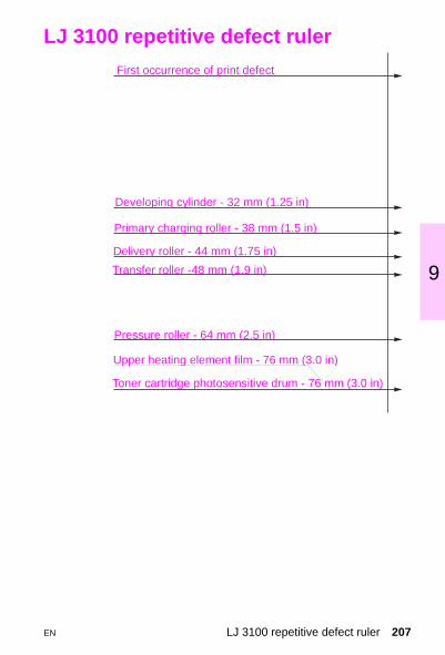
9
LJ 3100 repetitive defect ruler
First occurrence of print defect
Developing cylinder - 32 mm (1.25 in)
Primary charging roller - 38 mm (1.5 in)
Delivery roller - 44 mm (1.75 in)
Transfer roller -48 mm (1.9 in)
Pressure roller - 64 mm (2.5 in)
Upper heating element film - 76 mm (3.0 in)
Toner cartridge photosensitive drum - 76 mm (3.0 in)
EN LJ 3100 repetitive defect ruler 207

Notes
208 Chapter 9 Image quality EN

9
LJ 8100 repetitive defect ruler
Registration roller - 44 mm (1.73 in)
Toner cartridge primary charging roller - 44.4 mm (1.75)Face-up delivery roller - 47 mm (1.86 in)
Toner cartridge developing roller - 53.5 mm (2.11 in)
Transfer roller - 54 mm (2.13 in)
Fuser upper roller - 141 mm (5.55 in)
First occurrence of print defect
Pickup feed and separation rollers 75 mm (2.93 in)
Fuser lower roller - 100 mm (3.94 in)
Toner cartridge photosensitive drum - 94 mm (3.71 in)
EN LJ 8100 repetitive defect ruler 209

Notes
210 Chapter 9 Image quality EN

9
LJ 1100 repetitive defect ruler
First occurrence of print defect
Developing cylinder 32 mm (1.25 in)
Primary charging roller 38 mm (1.5 in)Delivery roller 37.7 mm (1.48 in) Transfer roller 45 mm (1.8 in)
Pressure roller 62.8
Upper heating element film 76 mm (3.0 in)
Toner cartridge photosensitive drum 76 mm (3.0 in)
mm (2.5 in)
EN LJ 1100 repetitive defect ruler 211

Notes
212 Chapter 9 Image quality EN

10 W
EN
iring diagrams
Overview
This chapter provides wiring diagrams for printers supported in this guide.
Overview 213
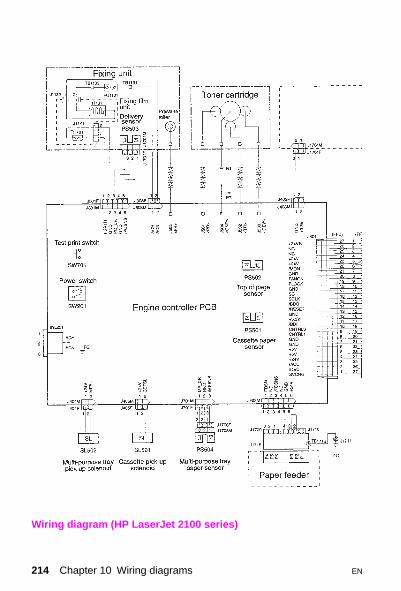
Wiring diagram (HP LaserJet 2100 series)
214 Chapter 10 Wiring diagrams EN

0
1Wiring diagram (HP LaserJet 2100 series)
EN Overview 215

Wiring diagram (HP LaserJet 4050/4050N and 4000/4000 N)
216 Chapter 10 Wiring diagrams EN

0
1Wiring diagram (HP LaserJet 4050 T/4050 TN and 4000 T/4000 TN)
EN Overview 217

Wiring diagram (HP LaserJet 5000 series, 1 of 2)
218 Chapter 10 Wiring diagrams EN
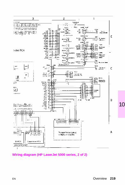
0
1Wiring diagram (HP LaserJet 5000 series, 2 of 2)
EN Overview 219

Wiring diagram (HP LaserJet 8000 series, 1 of 2)
220 Chapter 10 Wiring diagrams EN

0
1Wiring diagram (HP LaserJet 8000 series, 2 of 2)
EN Overview 221

Wiring diagram (HP LaserJet 3100, 1 of 2)
222 Chapter 10 Wiring diagrams EN

0
1Wiring diagram (HP LaserJet 3100, 2 of 2)
EN Overview 223

Wiring diagram (HP LaserJet 8100 series, 1 of 2)
224 Chapter 10 Wiring diagrams EN

0
1Wiring diagram (HP LaserJet 8100 series, 2 of 2)
EN Overview 225

Wiring diagram (HP LaserJet 1100, 1 of 2)
226 Chapter 10 Wiring diagrams EN

0
1Wiring diagram (HP LaserJet 1100, 2 of 2)
EN Overview 227

228 Chapter 10 Wiring diagrams EN

11 Sr
EN
ervices and support/esources and training
Overview
This chapter provides information on obtaining training, support, and materials.
Overview 229

How to get training
Lecture/lab training (U.S. only)Service technicians who want individual, hands-on training can attend regularly scheduled lecture/lab training classes. These classes are offered throughout the country. To receive the latest schedule, see the HP website (www.hp.com/go/resellertraining) and request document ID number 9104. The latest schedule will immediately be sent to the fax number of your choice. Class schedule and registration information can also be obtained by calling the centralized registration center at (512) 434-1520.
Self-paced training kitsDescriptions and part numbers
Product Description Part number
All LaserJet Printers Basic Hardware Training Course (prerequisite for all LaserJet service training)
Paper Training Video
5961-0880
5961-0711 (NTSC) 5961-0712 (PAL)
LJ 2100/2100 M/ 2100 TN
Self-paced Training KitCD-ROM
C4170-90959C4170A-60129
LJ 4050/4050 N/4050 T/4050 TN
Self-paced Training KitCD-ROM C4251-67902
LJ 4000/4000 N/4000 T/4000 TN
Self-paced Training KitNTSC FormatPAL Format
C4118-61101C4118-61102
LJ 5000/5000 N/5000 GN
Self-paced Training KitNTSC FormatPAL Format
C4110-61101C4110-61102
230 Chapter 11 Services and support/resources and training EN

1
1Product Description Part number
LJ 3100 Self-paced Training KitNTSC FormatPAL Format
LaserJet 3100 Online Service Documentation and Training CD ROM (requires Netscape 3.x or greater or Internet Explorer 3.x or greater)
C3948-61101C3948-61102
C3948-6011
LJ 8000/Mopier 240 Self-paced Training KitNTSC FormatPAL Format
C4085-67901C4085-67902
LJ 8100 Self-paced Training KitNTSC FormatPAL Format
C4214-67901C4214-67902
LJ 1100 Online Service and Support Documentation and Training CDROM (requires Netscape 3.x or greater or Internet Explorer 4.x or greater)
C4224-60140
Descriptions and part numbers (continued)
EN How to get training 231

Support resources
Hardware Technical Support CenterThe Hardware Technical Support Center (HTSC) is available for technical support to assist service technicians. The HTSC can be reached at (800) 477-6222 (HPCEs Only) and (800) 999-3558 (subcontractors only).
Other areasOutside of North America and Europe, contact your local HP sales office for assistance in obtaining technical support.
HP end-user support options
Local support assistanceThe user’s first source of assistance should be their local dealer or service center. HP continuously provides local computer dealers and service centers with the latest information regarding products and services. To locate the nearest authorized dealer or service center, phone (800) 243-9816 (U.S.) or (800) 387-3867 (Canada).
24-hour support informationPhone (800) 333-1917 to access the HP ASAP system for 24-hour automated support services. User support information includes notes for common software applications and troubleshooting tips. Users may request up to three documents per call.
232 Chapter 11 Services and support/resources and training EN

1
1Printer drivers by mailTo obtain printer drivers, contact the software application manufacturer. HP distributes printer drivers for a few of the most popular applications. Call (970) 339-7009, 6 days a week, 24 hours a day (closed Sundays). Shipping and handling charges may apply on some printer drivers.
Telephone assistance – in warrantyCall (1) (208) 323-2551 Monday through Friday from 6 am to 10 pm, Saturday 9 am to 4 pm (Mountain Time) free of charge during the warranty period. However, your standard long-distance phone charges still apply. Have your system nearby and your serial number ready when calling.
Telephone assistance – post-warrantyPost-warranty telephone assistance is available to answer your product usage questions. Call (1) (900) 555-1500 ($2.50 per minute, U.S. only) or call 1-800-999-1148 ($25 per call, Visa or MasterCard, U.S. and Canada) Monday through Friday from 7 am to 6 pm and Saturday from 9 am to 3 pm (Mountain Time). Charges begin only when you connect with a support technician. Prices subject to change.
Hardware repair servicesTo find a local authorized repair center for hardware repair needs, call (800) 243-9816. HP also offers a variety of service contract options to complement the standard warranty. Call (800) 743-8308 (U.S.) or (800) 268-1221 (Canada).
EN HP end-user support options 233

234 Chapter 11 Services and support/resources and training EN
12 HL
EN
ewlett-Packard aserJet Companion
Overview
This section provides information on the LaserJet 300 DPI page scanner, which is available in three models.
Overview 235

Hewlett-Packard LaserJet Companion
The HP LaserJet Companion includes the following models:
• C3989A Companion
• C3079A Companion SE
• C4106A Companion XI
(These are all the same product except for minor software differences.)
DescriptionThe HP LaserJet Companion is a 300-DPI page scanner, parallel port pass-through accessory designed for Hewlett-Packard LaserJet 4000 series printers.
Warranty The HP LaserJet Companion comes with a 1-year warranty, offering Central Repair only (no dealer repairs); Express Exchange (U.S. and Canada); and Repair and Return (Worldwide).
Supported media• The following media sizes are supported:
• Maximum: 216 mm x 762 mm (8.5 by 30 inch)
• Minimum: 51 mm x 89 mm (2 by 3.5 inch)
• The following media weights are supported:
• 60 to 105 g/m2 (16 lb to 28 lb)
236 Chapter 12 Hewlett-Packard LaserJet Companion EN

2
1Skew specificationsSome skew is normal. The maximum amount of skew that is considered normal is 3.35 millimeters (0.13 inches) over 279 millimeters (11 inches). Skew exceeding the normal amount may be caused by media that is damaged, media that does not meet the specifications, or media that is loaded incorrectly.
If media meets specifications, is not damaged, and is correctly loaded, but skew remains excessive, clean the separation pad, pickup roller, and scan roller.
CleaningClean these parts with isopropyl alcohol:
• separation pad
• pickup roller
• white scan roller
Clean the image sensor with glass cleaner.
EN Hewlett-Packard LaserJet Companion 237

Cables
Power supply modulesOutput = 22VDC, + or - 25%
Cable part numbers
HP part number Part description
8120-6963 Cable shipped with the HP LaserJet Companion
C2950A Printer parallel cable (IEEE-1284) 2 meters (7 feet)
C2951A Printer parallel cable (IEEE-1284) 3 meters (10 feet)
Power supply part numbers
HP part number Part description
9100-5534 120 Vac 60 Hz (US/CN/MX)
9100-5535 230 Vac 50 Hz (EUROPE)
9100-5536 240 Vac 50 Hz (U.K.)
9100-5537 220 Vac 50 Hz (ARG)
9100-5539 240 Vac 50 Hz (AUSTRL)
9100-5541 220 Vac 50 Hz (TI/INDO)
9100-5542 220 Vac 50 Hz (HNG KNG)
238 Chapter 12 Hewlett-Packard LaserJet Companion EN

A Aa
EN
cronyms and bbreviations
Acronyms and abbreviations
AC Alternating current
AUTOCONT Automatic continue
BNC A 10-Base 2 connector used with coaxial cables
CE Customer engineer
CFG Configuration on control panel
DC Direct current
DCPS Direct current power supply
MS-DOS Disk operating system
DPI Dots per inch
DTR Data terminal ready
DTR LINE Data terminal ready line
ECU Engine control unit
EP Electro-photographic
EPH External paper handling
FRU Field replacement unit
FTP File transfer protocol
HP ASAP Hewlett-Packard Automated Support Access Program
Acronyms and abbreviations 239

HP FIRST Hewlett-Packard Fax information retrieval support technology
HP-GL/2 Hewlett-Packard graphics language
HTML Hypertext markup language
HTSL Hardware Technical Support Center
HV High voltage
HVPS High-voltage power supply
I/O Input/output
IR Infrared
IrDA Infrared Data Association
IRQ Interrupt request
JEIDA A type of memory module
JOBID Print job identification
JP Jobpack
LAN Local area network
LC PICKUP ROLLER Lower-cassette pickup roller
LED Light-emitting diode
LIU Line interface unit
LVPS Low-voltage power supply
MB Megabyte
MEM Memory
MIO Modular input/output
MP PICKUP ROLLER Multipurpose tray pickup roller
MP Tray Multipurpose tray
MSDS Material safety data sheets
NTSC National Television Standard Committee
Acronyms and abbreviations (continued)
240 Appendix A Acronyms and abbreviations EN

1
Appendix A
NVRAM Nonvolatile random-access memory
Ohm A unit of measure of electrical resistance
PAL Phase alternation line format
PCA Printed-circuit assembly
PCB Printed circuit board
PCL Printer command language
PC PICKUP ROLLER Paper-cassette pickup roller
PIU Paper input unit
PJL Printer job language
RAM Random-access memory
RIP Raster image process
ROM Read-only memory
SIMM Single inline memory module
SMO Support materials organization
SMODE Service mode
SPEC Specifications
SRVR Server
TCP/IP Transmission control protocol/Internet protocol
TS l/T52 Thermoswitch
UNIX® Network operating system using TCP/IP protocol
URL Universal resource locator
VDC Volts direct current
Acronyms and abbreviations (continued)
EN Acronyms and abbreviations 241

242 Appendix A Acronyms and abbreviations EN

Index
Aaccessing, calibration utility 82accessory messages (2100) 18assemblies
locations (1100 series) 176locations (2100 series) 148locations (3100) 165locations (4000 series) 151locations (4050 series) 151locations (5000 series) 154locations (8000 series) 156locations (8100 series) 168part numbers (1100 series) 177part numbers (2100 series) 149part numbers (3100) 165part numbers (5000 series) 155part numbers (8000 series) 157part numbers (8100 series) 169
attaching printer cables 103
Ccables
attaching 103lengths 102
calibrating, document scanner 81calibration utility, accessing 82character voids 123cleaning page, obtaining 182common hardware, part numbers
145configuration test 73continuable error messages (2100) 12
control panel messages1100 19alphabetical 25numerical 46
control panel test 75country code softswitches, changing 78
Ddefault paper size, setting 70diagnostics, accessing 71displays, interpreting 19document scanner
calibrating 1100 82calibrating 3100 81feed test 75motor test 75test 74
documents, lost 30download, firmware 80duplexer
description 136part numbers 136
EEIO-based hard drive 104envelope feeder
description 136part numbers 136
envelopesSee also mediaconstruction 116gray background 126improving print quality 126
EN Index 243

preventing problems 115sizes 115specifications 114types to avoid 115
error messages (1100) 22error messages (2100) 16expanded input/output 104extended service menu (3100) 72extended service mode
clearing memory 77reports 76self-test 73tests 75
Ffax memory test 73faxes, lost 30firmware download 80firmware version 76flash 104fonts, ordering 132
Ggenerating cleaning page 182
Hhard disk, part numbers 132hard disks, ordering 132Hardware Technical Support Center (HTSC) 232
hardware, part numbers 145HP LaserJet Cleaning Utility file
182HP LaserJet Companion
cleaning 237description 236supported media 236warranty service 236
HP Parts Direct Ordering 131HP Planet Partners 127
Iimage defects 185individual diagnostics 75input/output
bidirectional parallel interface 100
cable lengths 102expanded card 104pin configurations 100
input/output cablesdescription 134part numbers 134
input/output cardsdescription 132part numbers 132
internal event log, clearing 71interruptions in power 30
JJetSuite Pro software 182
Kkeypad test 75
Llabels See also medialabels
preventing problems 118specifications 117
LCD characters test 75LCD test 75LED displays 19LocalTalk 104
244 Index EN

Index
locationsprinter parts (1100 series) 176printer parts (3100 series) 165printer parts (5000 series) 154printer parts (8000 series) 156printer parts (8100 series) 168
log debug report 76lost, documents 30
Mmailbox
ordering 136part numbers 136
maintenance count, setting 67, 69
maintenance kitsdescription 140part numbers 140
mediabasic sizes 109basis weights 109envelope sizes 115envelope specifications 114envelopes to avoid 115grades 109label specifications 117ordering 136paper curl 113paper sizes 106part numbers 136transparency specifications 119troubleshooting problems 112types to avoid 112weight equivalence table 110
memoryordering 132part numbers 132, 134product description 132, 134
menu tree, extended service 63
modem dial tone test 74modem modulation test 75modem test 73modem tone test 75
Oordering
duplexer 136fonts 132hard disks 132I/O cards 132input/output cables 134mailbox 136memory 132power box 138toner cartridges 138trays 134, 136
Ppaper
See mediapage count
setting (4000 series) 66setting (5000 series) 66setting (8000 series) 69setting (8100 series) 69
paper size, setting default 70paper training video 119parallel cables
connectors 102lengths 102part numbers 102
part numbers 145pin configurations 100PJL software commands 83post-warranty service 233power box
ordering 138part numbers 138
EN Index 245
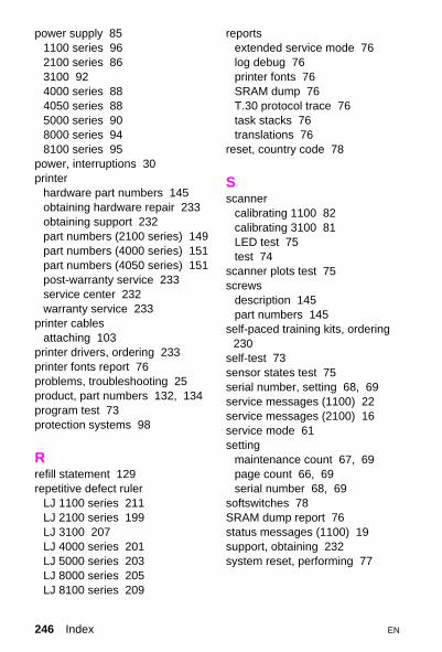
power supply 851100 series 962100 series 863100 924000 series 884050 series 885000 series 908000 series 948100 series 95
power, interruptions 30printer
hardware part numbers 145obtaining hardware repair 233obtaining support 232part numbers (2100 series) 149part numbers (4000 series) 151part numbers (4050 series) 151post-warranty service 233service center 232warranty service 233
printer cablesattaching 103
printer drivers, ordering 233printer fonts report 76problems, troubleshooting 25product, part numbers 132, 134program test 73protection systems 98
Rrefill statement 129repetitive defect ruler
LJ 1100 series 211LJ 2100 series 199LJ 3100 207LJ 4000 series 201LJ 5000 series 203LJ 8000 series 205LJ 8100 series 209
reportsextended service mode 76log debug 76printer fonts 76SRAM dump 76T.30 protocol trace 76task stacks 76translations 76
reset, country code 78
Sscanner
calibrating 1100 82calibrating 3100 81LED test 75test 74
scanner plots test 75screws
description 145part numbers 145
self-paced training kits, ordering 230
self-test 73sensor states test 75serial number, setting 68, 69service messages (1100) 22service messages (2100) 16service mode 61setting
maintenance count 67, 69page count 66, 69serial number 68, 69
softswitches 78SRAM dump report 76status messages (1100) 19support, obtaining 232system reset, performing 77
246 Index EN
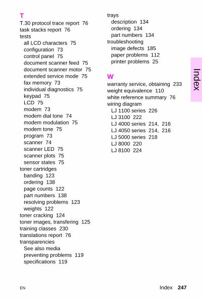
Index
TT.30 protocol trace report 76task stacks report 76testsall LCD characters 75configuration 73control panel 75document scanner feed 75document scanner motor 75extended service mode 75fax memory 73individual diagnostics 75keypad 75LCD 75modem 73modem dial tone 74modem modulation 75modem tone 75program 73scanner 74scanner LED 75scanner plots 75sensor states 75
toner cartridgesbanding 123ordering 138page counts 122part numbers 138resolving problems 123weights 122
toner cracking 124toner images, transfering 125training classes 230translations report 76transparencies
See also mediapreventing problems 119specifications 119
traysdescription 134ordering 134part numbers 134
troubleshootingimage defects 185paper problems 112printer problems 25
Wwarranty service, obtaining 233weight equivalence 110white reference summary 76wiring diagram
LJ 1100 series 226LJ 3100 222LJ 4000 series 214, 216LJ 4050 series 214, 216LJ 5000 series 218LJ 8000 220LJ 8100 224
EN Index 247

Service Websites
Electronic Support CenterSoftware, drivers, support documentation, frequently asked questions
http://www.hp.com/go/support
HP Technical Training (North America)Classes and schedules
http://www.hp.com/go/resellertraining
PartsParts information
http://outfield.external.hp.com/spi/welcome.htm

Service Phone Numbers
All numbers listed are for North America only.
Dealer Response LineDealer pre/post sales and service support
(800) 544-9976 U.S. Only (800) 363-6594 Canada
Customer Care CenterUser questions, applications, LaserJet Fax
(208) 323-2551
Customer Information CenterSales dealer locations, literature, and specifications
(800) 752-0900 U.S. Only
HP Driver Distribution CenterPrinter drivers and software application notes orders
(970) 339-7009 U.S. Only
Customer Support Sales CenterAuthorized repair locations
(800) 243-9816 U.S. Only
Parts Direct Ordering / SMOService parts, supplies, and accessories orders
(800) 227-8164 U.S. Only
Parts IdentificationService part number identification
(916) 783-0804
Hardware Technical Support CenterOnline technical assistance
(800) 477-6222 HPCEs Only (800) 999-3558 Subcontractors only
Corvallis Customer Service CenterExpress exchange/customer return services
(916) 785-1200
May 1999 Edition
HP LaserJet FamilyQuick ReferenceService Guide
Volume II
Copyright© 1999Hewlett-Packard Co.Printed in USA
Manual Part No.5090-3390
*5090-3390**5090-3390*
5090-3390
HP
LaserJet Fam
ily Quick R
eference Service G
uide – Vol. II
Printed on at least50% Total Recycled Fiber withat least 10% Post-Consumer Paper
Supported Products
HP LaserJet 2100/2100 M/2100 TN printerHP LaserJet 4050/4050 T/4050 N/4050 TN printerHP LaserJet 4000/4000 T/4000 N/4000 TN printerHP LaserJet CompanionHP LaserJet 5000/5000 N/5000 GN printerHP LaserJet 3100 multifunction printerHP LaserJet 8000/8000 N/8000 DN printerHP LaserJet Mopier 240HP LaserJet 8100/8100 N/8100 DN printerHP LaserJet 1100/1100XI/1100SE printerHP LaserJet 1100A/1100AXI/1100ASE printer