Master Product Catalog - Alltec Global
179
Master Product Catalog 2021 edition Grounding / Bonding Solutions • Surge Protection • Lightning Protection
-
Upload
khangminh22 -
Category
Documents
-
view
1 -
download
0
Transcript of Master Product Catalog - Alltec Global
MasterProductCatalog
2021edition
Grounding / Bonding Solutions • Surge Protection • Lightning Protection

LIGHTNING PROTECTION PRODUCTS
© 2021 Alltec LLC1
About ALLTEC
ALLTEC is a global leader in the design, manufacture and development of products and services for grounding & bonding solutions, surge protection, and lightning protection.
Grounding (Earthing) / Bonding Solutions
As equipment becomes more sophisticated and electrically susceptible, the need for an exceptionally low-resistance/low-impedance grounding system becomes more crucial. When implemented effectively, harmful electrical currents are safely redirected to earth and away from important equipment and facilities.
Surge Protection
While lightning is the most notorious surge generator, approximately 80% of all transient surge activity originates from internally generated sources. Properly installed surge protection devices on all circuit conductors maximizes total site protection.
Lightning Protection
Lightning is an awesome and unpredictable act of nature that causes more deaths and property damage than any other weather related event. A properly installed lightning protection system is over 98% effective in preventing catastrophic lightning damage.
Consulting, Engineering & Design, Project Management and Inspection/Preventative Maintenance Services
ALLTEC’s greatest strength is our complete Systems Engineering and Products Solutions Program. Our experienced and accredited Engineering and Project Management teams apply the three-tiered ALLTEC Protection Pyramid™ approach while working with leading international client companies to develop the best solutions for each and every situation. While ALLTEC offers a full multi-phase solution for clients in need of all of our services, we can also provide a selection of individualized services which best fit a client’s unique protection needs.
Assessing the Problems, Providing Answers, Project Oversight & Continued Protection
• Consulting (Phase I) - TerraEval Advanced Solution Assessment
• Engineering & Design (Phase II) - Customized Solution Development
• Project Management (Phase III) – Strong and Cost Effective Project Management Support
• Inspection/Preventative Maintenance (Phase IV) – System Performance and Condition Evaluation
You can learn more about our services and capabilities at www.alltecglobal.com/services
Introduction

LIGHTNING PROTECTION PRODUCTS
© 2021 Alltec LLC 2
The ALLTEC Protection Pyramid™ provides a three-tier comprehensive facility approach for grounding/earthing & bonding, surge suppression, and lightning protection solutions. The Pyramid comes as close as humanly possible to protect both man and machine from lightning and non-lightning induced transient voltage damage.
The ALLTEC Protection Pyramid™
Why the Pyramid?
Each level of the ALLTEC Protection Pyramid™ represents a method utilized to protect facilities from damages caused by harmful electrical events. Rather than treating these tiers as independent, ALLTEC regards each layer as an interlocking component. When all three tiers are designed, installed, and maintained as a total system, comprehensive facility protection can be achieved.
Safeguard valuable assets, defend critical electronics, and protect businesses using the ALLTEC Protection Pyramid™. The ALLTEC Protection Pyramid™ uses ALLTEC’s proven products and services for grounding, surge suppression, and lightning protection to provide full infrastructure protection.
You can learn more at alltecglobal.com/about-us/alltec-protection-pyramid

LIGHTNING PROTECTION PRODUCTS
© 2021 Alltec LLC3
Standards & Code Specification Compliance
ALLTEC is accredited and certified by numerous standards authorities. As an expert in the latest approved standards and code specifications for grounding and lightning protection systems, ALLTEC is an active sought-after member for standards committees.
You can learn more about ALLTEC Products at alltecglobal.com/products
Ability to Serve
ALLTEC has the capability to design, manufacture, and install any lightning protection or grounding system you may require. Our complete engineering facilities are prepared to assist you with any special or unusual requirements.
Claims & Shortages
Please be aware that ALLTEC assumes no liability for any damage to goods in shipment. All materials must be inspected upon receipt BEFORE signing for acceptance of shipment. Once you have signed the bill of lading accepting shipment, you are acknowledging that you have received the shipment in full and with no damage. Any damages or shortages need to be noted on the bill of lading before signing and immediately file a claim with the delivering transportation company. It is our policy that any claims for shortages or errors must be made within 24 hours after receipt of goods. Any error on our part will be taken care of promptly and at no cost to you, the customer. Any shortages found and reported more than 24 hours after shipment acceptance will not be replaced free of charge.
International Customers
Our exporting policy is available upon request. This policy may vary slightly, depending upon the receiving country and its Customs procedures. ALLTEC offers all of our engineering and design services worldwide.
Documentation & Wire Transfer Fees
ALLTEC charges standard customary fees for obtaining and processing documents for overseas shipments. Any wire transfer or bank fees are the responsibility of the customer and will be included in the price quotation supplied before the shipment leaves our warehouse.
General Information

LIGHTNING PROTECTION PRODUCTS
© 2021 Alltec LLC 4
Terms and Conditions“Goods & Services”1. Definitions
The term “Seller” means ALLTEC, the term“Buyer” means the company, person or other entity who is the purchaser of the Goods, the term “Goods” means any goods or materials ordered and sold pursuant to the terms and conditions set forth herein.
2. PriceUnless otherwise stated, price of the Goods shall be the price in effect at the date and time of shipment. Seller reserves the right to adjust price based on volume purchases; any discounts allowed for volume purchases will be in the Seller’s sole discretion. Price does not include any sales, use, excise or similar taxes which shall be added to the price of the Goods and shall be the responsibility of Buyer. Unless otherwise stated, domestic minimum order is $50.00 (excluding freight) on any single order and $1,000.00 on any single international order. Each shipment will be separately invoiced.
3. Payments TermsTerms of payment are determined on a case by case basis. Service charge on late payments shall be applicable at the rate of one and one-half percent (1.5%) per month or an annual percentage rate of eighteen (18%) per annum. In addition, Buyer shall be obligated for Seller’s reasonable collection agency or attorneys’ fees that may be incurred by Seller to collect any sums due Seller hereunder or service charge. Seller reserves the right to apply any payments received from Buyer to any outstanding invoice of Seller at Seller’s sole discretion.
4. FreightThe purchase price of the Goods shall be EXWORKS, Canton, NC or other named shipping point. In situations of “prepay and add”, ALLTEC is unable to provide a copy of the actual freight bill due to agreements with our carriers regarding rate disclosure confidentiality.
5. Delivery(a) Seller’s place and point of delivery shall be deemed to be delivery to a carrier
at Seller’s plant in Canton, NC, USA or such other designated shipping point designated by Seller. If Buyer fails to furnish complete shipping directions to Seller within a reasonable time of placing the order, Seller, at Seller’s discretion, may make necessary shipping arrangements with a carrier selected by Seller, the cost of which shall be paid by Buyer.
(b) If and to the extent a delivery date is stated, it is the estimated delivery date only. All accepted orders, whether or not delivery dates are specified thereon, shall be subject to delays or failures in manufacture or delivery due to causes beyond the control of Seller or carrier. Buyer’s obligations shall continue notwithstanding any delay in delivery, provided if performance by Seller is prevented in whole or in part for a period of three (3) consecutive months, then in such event Seller or Buyer (provided Buyer is not responsible for the delay) may cancel any order that has not been shipped as of such date.
(c) If for any reason, the Buyer is unable to accept the delivery of Goods according to the mutually established schedule; the Seller, at its option and after three (3) days written notice to the Buyer, may place the Goods in storage. In such event, the Buyer shall pay any and all storage or other related costs. If the Buyer fails to accept any delivery or part thereof, the Seller, at its option, may treat such failure as a breach of this Agreement and exercise any and all remedies available to it pursuant to the terms and conditions set forth herein or available to it as a matter of law.
6. CreditThe Seller’s obligations are at all times subject to the Seller’s approval of the Buyer’s credit standing. Upon request, the Buyer shall furnish the Seller such credit information as may be customary and reasonably requested by the Seller. At its discretion, the Seller reserves the right to require payment in advance, C.O.D., and/or otherwise modify credit terms. If at any time the Buyer is past due with respects to amounts due, the Seller at its option (without liability or prejudice to any other remedies), may decline to ship or stop any Goods in transit until such time the Seller (1) receives payment in full of all amounts owing to it by the Buyer or (2) otherwise receives assurances satisfactory to the Seller of such payment.
7. Risk of LossRisk of loss or damage to the Goods shall be solely that of Buyer upon delivery to a carrier for shipment; any loss or damage subsequent to such delivery shall not be the responsibility of Seller, provided further any such loss shall not release Buyer from Buyer’s obligation to pay for the Goods. Any claim for damage or loss in transit must be asserted by Buyer against the carrier.
8. WarrantySeller warrants that the Goods will conform to the description stated herein subject to tolerances and variations consistent with current trade practices, testing and inspections methods. Seller makes no other warranties hereunder, expressed or implied. Seller specifically disclaims any implied warranties of merchantability or fitness for a particular purpose. Some products have special warranties and periods of duration.
9. Claims(a) Buyer shall inspect the Goods immediately upon receipt. Any claim that the
Goods have been damaged or otherwise do not conform must be made to Seller in writing within ten (10) days of receipt of such Goods by Buyer. All claims for defective, damaged, or non-conforming Goods must be submitted in writing to ALLTEC, LLC at 64 Catalyst Drive, Canton, NC 28716, USA accompanied with a copy of the signed bill-of-lading noting the damage/shortages, and any other information (photos, etc) supporting Buyer’s claim. In the absence of such notice, the Goods shall be deemed to be accepted by Buyer.
(b) With respect to any valid claims properly submitted hereunder, Buyer’s exclusive remedy and Seller’s sole liability shall be limited to Seller repairing or replacing Goods that do not conform to specifications, or at Seller’s sole option refunding the purchase price of the Goods. In no event shall Seller have any liability to damages in connection with the sale of the Goods in an amount exceeding the purchase price of the Goods sold. Seller shall have no liability for any consequential, special, or indirect damages.
(c) Claims for quantity deviations or unit pricing errors are deemed waived unless submitted in writing within thirty (30) days of notice of invoice.
10. QuotationsQuotations, based on plans and specifications, are Seller’s interpretation of the requirements and include only the material described and listed on the quotation unless otherwise stated. Quotations will be in writing and unless otherwise specified will remain in effect for a period of thirty (30) days from issue date. Formal written purchase orders for work covered by any quotation submitted must be received within forty-five (45) days from the date of quotation. Prices and inventory classifications are subject to changes without notice, and are those in effect at the time of shipment.
11. ErrorsALLTEC reserves the right to correct, at any time, any errors and omissions relating to any component or item upon which a purchase order may be based, including, but not limited to, clerical or stenographic errors or omissions as may relate to quotations, price, catalog and other materials supplied by ALLTEC, or other terms and conditions as reasonably determined by Seller.
12. ReturnsGoods may be returned for credit upon written request and upon Seller’s written approval and issuance to Buyer of a customer return materials authorization form with RMA number. Any returned items are subject to reasonable restocking charges which unless otherwise agreed to by Seller, shall be deemed to be twenty-five percent (25%) of the price of the Goods returned. Any returned items must be in saleable condition, in the original standard packages, and conform to current catalog descriptions. All returned material is to be shipped to seller freight prepaid. Unless otherwise stated, these terms and conditions govern the purchase and sale of the Goods. All terms and conditions, including price, are subject to change without notice as to any Goods not shipped as of the effective date of such change.
13. CancellationOrders received and accepted by Seller may not be cancelled or changed subsequent to delivery, prior to that date such orders may be received and accepted by Seller with the written permission of Seller. Any cancellation or change shall be subject to applicable charges for labor, material, and other costs actually incurred by Seller.
14. Seller’s RemediesIf Buyer cancels or abrogates this Agreement in whole or in part prior to shipment for any reason, without Seller’s consent, Buyer shall pay Seller for all costs and expenses incurred by Seller, including the cost of all work executed or performed; any special engineering costs and commitments made by Seller prior to the time of cancellation; and all other incidental and storage costs incurred prior to resale.
15. Binding NatureThese terms and conditions shall be binding upon the parties hereto, their successors and assignees.
16. AuthorityAny person, employee or agent otherwise acting on behalf of Buyer hereunder shall be deemed to have full authority to act on behalf of Buyer which Seller may rely on exclusively without further inquiry.
17. Governing LawThis Agreement shall be construed in accordance with and governed by laws of the state of North Carolina, USA.

LIGHTNING PROTECTION PRODUCTS
© 2021 Alltec LLC5
Table of Contents
Lightning Protection Products
Section 1: Advanced Technologies . . . . . . . . . . . . . . . . . . . . . . . . . . . . . . . . . . . . . . . . Page 6Section 2: Heavy Duty Mounting Bracket . . . . . . . . . . . . . . . . . . . . . . . . . . . . . . . . . Page 25Section 3: Traditional Lightning Protection Products . . . . . . . . . . . . . . . . . . . . . . Page 31
Surge Protection Products
Section 4: Surge Protection Introduction . . . . . . . . . . . . . . . . . . . . . . . . . . . . . . . . . . Page 51Section 5: AC/DC Surge Protectors . . . . . . . . . . . . . . . . . . . . . . . . . . . . . . . . . . . . . . . . Page 56Section 6: Data Signal Products . . . . . . . . . . . . . . . . . . . . . . . . . . . . . . . . . . . . . . . . . . . Page 73
Grounding/Bonding Equipment
Section 7: Advanced Technologies . . . . . . . . . . . . . . . . . . . . . . . . . . . . . . . . . . . . . . . . Page 79Section 8: Traditional Grounding & Bonding Equipment . . . . . . . . . . . . . . . . . . . Page 91Section 9: Ground Bars & Accessories . . . . . . . . . . . . . . . . . . . . . . . . . . . . . . . . . . . . . Page 102Section 10: Exothermic Welding Introduction . . . . . . . . . . . . . . . . . . . . . . . . . . . . . . Page 113Section 11: Weld Metal & Accessories . . . . . . . . . . . . . . . . . . . . . . . . . . . . . . . . . . . . . . Page 117Section 12: Connection Selection and Molds . . . . . . . . . . . . . . . . . . . . . . . . . . . . . . . Page 124
Reference Material

LIGHTNING PROTECTION PRODUCTS
© 2021 Alltec LLC 6
Section 1Advanced Technologies

LIGHTNING PROTECTION PRODUCTS
© 2021 Alltec LLC7
• Patented Technology• High grade stainless steel construction• Lightweight and easy to install• Corrosion resistant• Low wind loading• Large selection of mounting hardware• Recommended as per API 2003• Independently tested
Applications• TerraStat® TS100: Standard Protection
Office buildings, shelters, industrial facilities, homes, and warehouses
• TerraStat® TS400: Enhanced Protection Monopoles, petrochemical, high-mast lightning, communication towers, and externally mounted cameras
• TerraStat® TS500 & TS510: Enhanced Protection Communication towers, bridges, petrochemical storage facilities, and stacks
NOTE• TS500 (Vertically Mounted)• TS510 (Horizontally Mounted)
TerraStat®
Charge Dissipation TerminalsIntroductionTerraStat® is the latest design in lightning dissipation technology. Science and experience show that TerraStat® Charge Dissipation Terminals, and the structures on which they are installed, are much less likely to sustain a direct lightning strike than unprotected structures or structures with traditional lightning protection systems.
Designs utilizing TerraStat® Charge Dissipation Terminals (CDT) are created to meet or exceed NFPA 780, and IEC 62305-3 standards, while providing the enhanced performance offered by CDT technology.
Whatever your requirements, we have a product to fit the application. For those special applications, we have the capability to design and manufacture a custom system to fit your needs. TerraStat® Charge Dissipation Terminals securely contribute to ALLTEC’s Protection Pyramid™ methodology for comprehensive facility protection.
TerraStat® products require project specific lightning protection design and installation. Inappropriate use of these products, or use in designs not provided by or approved by ALLTEC will invalidate performance characteristics and all Warranty Provisions.
Features

LIGHTNING PROTECTION PRODUCTS
© 2021 Alltec LLC 8
Progressive Lightning Protection for an Advancing WorldMission-critical systems, subjected to even properly terminated lightning strikes, suffer unacceptable damages from secondary and electromagnetic effects. The advancement of electronic technology over the past several decades demands a constant innovation in lightning protection technology as well. ALLTEC takes pride in the continual development and improvement of our TerraStat® line of charge dissipation/charge redistribution products.
The old-fashioned lightning rod system may no longer offer adequate protection to the microprocessor-controlled world in which we now live. Today’s technology requires more than just managing the lightning strike by directing it to earth. It is now imperative to do whatever is necessary to mitigate the chances of a direct lightning strike to critical facilities. ALLTEC’s TerraStat® product line offers the advanced technology required to protect your sensitive equipment.
There are many adjectives used to characterize this advanced technology, but “Charge Dissipation” or “Charge Redistribution” most accurately describes the technology. To understand how TerraStat® products work, one must first develop an understanding of the basic processes involved in a thunderstorm and the development of a lightning strike.As a thunderstorm builds, a breakdown point is reached and the cloud begins sending down charges called stepped leaders through ionized paths in the atmosphere. Multiple stepped leaders begin propagating towards the ground in three dimensions looking for the highest accumulation of ground charge in the area. These charges move in steps of approximately 50 meters, stop and look for the best potential, then move again. These steps and redirections are what gives lightning its jagged appearance.
Once these stepped leaders reach within about 10 to 150 meters of the earth, objects on the surface where the opposite ground charge has accumulated begin to form upward streamers. The energy from the stepped leaders is actually pulling the charge off objects on the earth’s surface in the form of the upward streamers. At this point, the object on the ground that provides
the highest concentration of charges and the best formed streamer, becomes the most likely target for the nearest stepped leader, and completes the path of the lightning strike. Once this occurs, charge from other stepped leaders originating from the same source recede and dump their energy through the established neutralization path.

LIGHTNING PROTECTION PRODUCTS
© 2021 Alltec LLC9
Charge Dissipation PrincipleCharge Dissipation, or “Charge Redistribution” Technology uses the point discharge principle to facilitate the dissipation, or the reduction, of a buildup of static electrical charges. This technology has primarily been applied to the electronics and manufacturing industries to control the buildup of static charges that can interfere with or damage sensitive electronic components, and it has been widely accepted and used with great success. The sole purpose of static dissipation products is to reduce the accumulation of electrical charges and thereby prevent an electrical arc or an electrical current flow that can cause damage.
This same technology has been successfully applied to the lightning protection industry by developing a product line that can be mounted on structures to reduce the accumulation of ground charge. This is accomplished by ionizing surrounding air and neutralizing accumulated charges on the earth’s surface, including the grounding system.
When a pointed, grounded conductor is placed in a high electric field (such as on a structure located in a thunderstorm) voltage effects at the point are increased greatly. Electrons from atmospheric atoms and molecules are stripped away and flow to ground through the grounded conductor, leaving behind positive atmospheric ions around the point. This process is commonly referred to as the “corona” effect.
This corona process begins long before charge accumulation reaches a critical level when step leaders begin forming in a storm cloud. The result is an accumulation of ions around the point. Since like
charges repel from each other, this accumulation of ions disperse (or dissipate) in all directions away from the point. Electrons left behind from this dissipation of ions flow to ground and neutralize the positive charges accumulated on the ground and on the structure. This is an ongoing process as the thunderstorm builds and passes over a facility.
A single point, such as on a lightning rod, or as occurs on a corner of a tower or structure, will reach a point of saturation to the extent that it cannot disperse charge at a fast enough rate to keep up with the charge accumulation. These areas then become the points where streamers will form, thereby attracting a lightning strike.
When the process is magnified with the addition of thousands of points in a charge dissipation terminal, the dissipation of ions is magnified many times over that of a single sharp point. The resulting effect is that the ground charges, which develop streamers attracting a lightning strike, no longer have sufficient electrical energy supporting them to initiate this process. Without the formation of an upward streamer, the downward stepped leaders will look for a better target.
ALLTEC has a full array of TerraStat® models to protect all types of structures or facilities. Our experienced design staff is ready to assist you with technical support in choosing the correct models for your specific application. We also offer site survey and design services to review an entire facility, and can assist you with providing system designs for a complete physical plant or a campus type environment.
Air Terminal vs. Charge Dissipation Terminal

LIGHTNING PROTECTION PRODUCTS
© 2021 Alltec LLC 10
Numbering SystemTo order, simply follow the steps below to specify the type and size of the unit. The example below, shows how to order the TerraStat® TS100.
Example: TS100-C-12-12
TS100 - C - 12 - 12(1) - (2) - (3) - (4)
(1) Type of Component TS100 = TerraStat® TS100
(2) Material C = Copper, SS = Stainless Steel, A = Aluminum
(3) Diameter 12=1/2” or 58=5/8”
(4) Length 12 = 12”, 18 = 18”, 24 = 24”
Standard Protection Models
TerraStat® TS100 Dissipation TerminalsDesigned to replace the traditional air terminal in conventional lightning protection systems, the TerraStat® TS100 converts a standard lightning rod system into a Charge Lightning Dissipation Terminal System, which mitigates the chances of a direct lightning strike to any building or structure on which it is installed. The TerraStat® TS100 assembly is constructed of high quality stainless steel. The stem section is available in various materials and sizes to be compatible with all standard lightning protection system components.
TerraStat® TS100 Dissipator Stainless Steel Air Terminals w/Copper RodPart Number Description Weight
TS100-C-12-12 TerraStat® 100, Copper, 1/2” Dia., 12” Long, Solid Rod 1.0 lbs (0.4 kg)TS100-C-12-18 TerraStat® 100, Copper, 1/2” Dia., 18” Long, Solid Rod 1.5 lbs (0.6 kg)TS100-C-12-24 TerraStat® 100, Copper, 1/2” Dia., 24” Long, Solid Rod 2.0 lbs (0.9 kg)
TerraStat® TS100 Dissipator Stainless Steel Air Terminals w/Stainless Steel RodPart Number Description Weight
TS100-SS-58-18 TerraStat® 100, Stainless Steel, 5/8” Dia., 18” Long, Solid Rod 1.5 lbs (0.6 kg)TS100-SS-58-24 TerraStat® 100, Stainless Steel, 5/8” Dia., 24” Long, Solid Rod 2.5 lbs (1.1 kg)
TerraStat® TS100 Dissipator Stainless Steel Air Terminals w/Aluminum RodPart Number Description Weight
TS100-A-12-12 TerraStat® 100, Aluminum, 1/2” Dia., 12” Long, Solid Rod 0.5 lbs (0.2 kg)TS100-A-12-18 TerraStat® 100, Aluminum, 1/2” Dia., 18” Long, Solid Rod 0.5 lbs (0.2 kg)TS100-A-12-24 TerraStat® 100, Aluminum, 1/2” Dia., 24” Long, Solid Rod 1.0 lbs (0.4 kg)TS100-A-58-12 TerraStat® 100, Aluminum, 5/8” Dia., 12” Long, Solid Rod 1.0 lbs (0.4 kg)TS100-A-58-18 TerraStat® 100, Aluminum, 5/8” Dia., 18” Long, Solid Rod 1.0 lbs (0.4 kg)TS100-A-58-24 TerraStat® 100, Aluminum, 5/8” Dia., 24” Long, Solid Rod 1.0 lbs (0.4 kg)
NOTE:• All threads are machined to 1/2 - 13 UNC x .75”standard, otherwise add suffix THDX, where X is the non-
standard length in decimal inches.• Other sizes available upon request.

LIGHTNING PROTECTION PRODUCTS
© 2021 Alltec LLC11
Enhanced Protection Models
TerraStat® TS400 Dissipation TerminalsUsing the same features as the TerraStat® TS100, the TerraStat® TS400 provides a higher level of charge dissipation. It is constructed of Stainless Steel or Aluminum and utilizes four stainless steel dissipation brushes attached to a single elevation conductor for higher dissipation on a single mount. The TerraStat® TS400 is ideally suited for protecting high mast light poles, security cameras, SCADA antenna systems, and smaller monopoles and towers used for communications.
Numbering SystemTo order, simply follow the steps below to specify the type and size of the unit. The example below, shows how to order the TerraStat® TS400.
Example: TS400-SS-18
TS400 - SS - 18(1) - (2) - (3)
(1) Type of Component TS400 = TerraStat® TS400
(2) Material SS = Stainless Steel, A = Aluminum
(4) Length 12 = 12”, 18 = 18”, 24 = 24”
TerraStat® TS400 Dissipator Stainless Steel Air Terminals w/Stainless Steel RodPart Number Description WeightTS400-SS-18 TerraStat® 400, Stainless Steel, 5/8” Dia., 18” Long, Solid Rod 4.2 lbs (1.9 kg)TS400-SS-24 TerraStat® 400, Stainless Steel, 5/8” Dia., 24” Long, Solid Rod 4.5 lbs (2.0 kg)TS400-SS-36 TerraStat® 400, Stainless Steel, 5/8” Dia., 36” Long, Solid Rod 5.5 lbs (2.5 kg)TS400-SS-48 TerraStat® 400, Stainless Steel, 5/8” Dia., 48” Long, Solid Rod 6.5 lbs (2.9 kg)TS400-SS-60 TerraStat® 400, Stainless Steel, 5/8” Dia., 60” Long, Solid Rod 7.5 lbs (3.4 kg)TS400-SS-72 TerraStat® 400, Stainless Steel, 5/8” Dia., 72” Long, Solid Rod 8.5 lbs (3.9 kg)
TerraStat® TS400 Dissipator Stainless Steel Air Terminals w/Aluminum RodPart Number Description WeightTS400-A-18 TerraStat® 400, Aluminum, 5/8” Dia., 18” Long, Solid Rod 2.4 lbs (1.0 kg)TS400-A-24 TerraStat® 400, Aluminum, 5/8” Dia., 24” Long, Solid Rod 2.5 lbs (1.1 kg)TS400-A-36 TerraStat® 400, Aluminum, 5/8” Dia., 36” Long, Solid Rod 3.1 lbs (1.4 kg)TS400-A-48 TerraStat® 400, Aluminum, 5/8” Dia., 48” Long, Solid Rod 3.4 lbs (1.5 kg)TS400-A-60 TerraStat® 400, Aluminum, 5/8” Dia., 60” Long, Solid Rod 3.6 lbs (1.6 kg)TS400-A-72 TerraStat® 400, Aluminum, 5/8” Dia., 72” Long, Solid Rod 4.1 lbs (1.9 kg)
NOTE• All threads are machined to 1/2 - 13 UNC x .75”standard, otherwise add suffix THDX, where X is the non-
standard length in decimal inches.• Other diameters and lengths are available upon request.• All elevation conductors are 5/8” diameter standard.

LIGHTNING PROTECTION PRODUCTS
© 2021 Alltec LLC 12
Elevation Conductors
Part Numbering SystemTo order, simply follow the steps below to specify the type and size of the unit. The example below shows how to order the mounting hardware.
Example: TS400-58-48-SRO
TS400 - 58 - 48 - SRO(1) - (2) - (3) - (4)
(1) TerraStat® Model TS100 = TerraStat® TS100 or TS400 = TerraStat® TS400
(2) Diameter 58 = 5/8”
(3) Length 48 = 48”, 60 = 60”, 72 = 72”, etc...NOTE: Other lengths available upon request.
(4) Type SRO = Stainless Steel Round OffsetARO = Aluminum Round Offset
TerraStat® TS100 Round Offset Elevation ConductorsPart Number Description Weight
TS100-58-48-SRO TerraStat® 100, Stainless Steel, 5/8” Dia., 48” Long, Solid Rod, with Round Offset 4.82 lbs (2.2 kg)TS100-58-60-SRO TerraStat® 100, Stainless Steel, 5/8” Dia., 60” Long, Solid Rod, with Round Offset 5.71 lbs (2.6 kg)TS100-58-72-SRO TerraStat® 100, Stainless Steel, 5/8” Dia., 72” Long, Solid Rod, with Round Offset 6.75 lbs (3.1 kg)TS100-58-48-ARO TerraStat® 100, Aluminum, 5/8” Dia., 48” Long, Solid Rod, with Round Offset 1.63 lbs (0.7 kg)TS100-58-60-ARO TerraStat® 100, Aluminum, 5/8” Dia., 60” Long, Solid Rod, with Round Offset 1.88 lbs (0.9 kg)TS100-58-72-ARO TerraStat® 100, Aluminum, 5/8” Dia., 72” Long, Solid Rod, with Round Offset 2.13 lbs (1.0 kg)
TerraStat® TS400 Round Offset Elevation ConductorsPart Number Description Weight
TS400-58-48-SRO TerraStat® 400, Stainless Steel, 5/8” Dia., 48” Long, Solid Rod, with Round Offset 7.6 lbs (3.4 kg)TS400-58-60-SRO TerraStat® 400, Stainless Steel, 5/8” Dia., 60” Long, Solid Rod, with Round Offset 8.49 lbs (3.9 kg)TS400-58-72-SRO TerraStat® 400, Stainless Steel, 5/8” Dia., 72” Long, Solid Rod, with Round Offset 9.53 lbs (4.3 kg)TS400-58-48-ARO TerraStat® 400, Aluminum, 5/8” Dia., 48” Long, Solid Rod, with Round Offset 4.41 lbs (2.0 kg)TS400-58-60-ARO TerraStat® 400, Aluminum, 5/8” Dia., 60” Long, Solid Rod, with Round Offset 4.66 lbs (2.1 kg)TS400-58-72-ARO TerraStat® 400, Aluminum, 5/8” Dia., 72” Long, Solid Rod, with Round Offset 4.91 lbs (2.2 kg)
NOTE• Standard offset is 8”.• All shafts are 5/8” diameter with threads machined to 1/2 - 13 UNC x .75” standard, otherwise add suffix THDX,
where X is the non-standard length in decimal inches.

LIGHTNING PROTECTION PRODUCTS
© 2021 Alltec LLC13
Part Numbering SystemTo order, simply follow the steps below to specify the type and size of the unit. The example below shows how to order the mounting hardware.
TerraStat® TS100 Round Offset Elevation Conductors with Mounting PlatesPart Number Description Weight
TS100-58-48-SRO-HMP TerraStat® 100, Stainless Steel, 5/8” Dia., 48” Long, Solid Rod, with Round Offset, Including (2) Horizontal Mounting Plates
5.32 lbs (2.4 kg)
TS100-58-60-SRO-HMP TerraStat® 100, Stainless Steel, 5/8” Dia., 60” Long, Solid Rod, with Round Offset, Including (2) Horizontal Mounting Plates
6.92 lbs (3.1 kg)
TS100-58-72-SRO-HMP TerraStat® 100, Stainless Steel, 5/8” Dia., 72” Long, Solid Rod, with Round Offset, Including (2) Horizontal Mounting Plates
7.42 lbs (3.4 kg)
TerraStat® TS400 Round Offset Elevation Conductors with Mounting PlatesPart Number Description Weight
TS400-58-48-SRO-HMP TerraStat® 400, Stainless Steel, 5/8” Dia., 48” Long, Solid Rod, with Round Offset, Including (2) Horizontal Mounting Plates
8.1 lbs (3.7 kg)
TS400-58-60-SRO-HMP TerraStat® 400, Stainless Steel, 5/8” Dia., 60” Long, Solid Rod, with Round Offset, Including (2) Horizontal Mounting Plates
9.7 lbs (4.4 kg)
TS400-58-72-SRO-HMP TerraStat® 400, Stainless Steel, 5/8” Dia., 72” Long, Solid Rod, with Round Offset, Including (2) Horizontal Mounting Plates
10.2 lbs (4.6 kg)
NOTE• Standard offset is 8”.• All shafts are 5/8” diameter with threads machined to 1/2 - 13 UNC x .75” standard, otherwise add suffix THDX,
where X is the non-standard length in decimal inches.
Example: TS400-58-48-SRO-HMP
TS400 - 58 - 48 - SRO - HMP(1) - (2) - (3) - (4) - (5)
(1) TerraStat® Model TS100 = TerraStat® TS100 or TS400 = TerraStat® TS400
(2) Diameter 58 = 5/8”
(3) Length 48 = 48”, 60 = 60”, 72 = 72”, etc...NOTE: Other lengths available upon request.
(4) Type SRO = Stainless Steel Round Offset
(5) Hardware HMP = Horizontal Mounting Plates
Elevation Conductors - Horizontal Mounting Plates

LIGHTNING PROTECTION PRODUCTS
© 2021 Alltec LLC 14
Part Numbering SystemTo order, simply follow the steps below to specify the type and size of the unit. The example below shows how to order the mounting hardware.
TerraStat® TS100 Round Offset Elevation Conductors with Mounting PlatesPart Number Description Weight
TS100-58-48-SRO-VMP TerraStat® 100, Stainless Steel, 5/8” Dia., 48” Long, Solid Rod, with Round Offset, Including (2) Vertical Mounting Plates
5.32 lbs (2.4 kg)
TS100-58-60-SRO-VMP TerraStat® 100, Stainless Steel, 5/8” Dia., 60” Long, Solid Rod, with Round Offset, Including (2) Vertical Mounting Plates
6.92 lbs (3.1 kg)
TS100-58-72-SRO-VMP TerraStat® 100, Stainless Steel, 5/8” Dia., 72” Long, Solid Rod, with Round Offset, Including (2) Vertical Mounting Plates
7.42 lbs (3.4 kg)
TerraStat® TS400 Round Offset Elevation Conductors with Mounting PlatesPart Number Description Weight
TS400-58-48-SRO-VMP TerraStat® 400, Stainless Steel, 5/8” Dia., 48” Long, Solid Rod, with Round Offset, and Including (2) Vertical Mounting Plates
8.1 lbs (3.7 kg)
TS400-58-60-SRO-VMP TerraStat® 400, Stainless Steel, 5/8” Dia., 60” Long, Solid Rod, with Round Offset, and Including (2) Vertical Mounting Plates
9.7 lbs (4.4 kg)
TS400-58-72-SRO-VMP TerraStat® 400, Stainless Steel, 5/8” Dia., 72” Long, Solid Rod, with Round Offset, Including (2) Vertical Mounting Plates
10.2 lbs (4.6 kg)
NOTE• Standard offset is 8”.• All shafts are 5/8” diameter with threads machined to 1/2 - 13 UNC x .75” standard, otherwise add suffix THDX,
where X is the non-standard length in decimal inches.
Example: TS400-58-48-SRO-VMP
TS400 - 58 - 48 - SRO - VMP(1) - (2) - (3) - (4) - (5)
(1) TerraStat® Model TS100 = TerraStat® TS100 or TS400 = TerraStat® TS400
(2) Diameter 58 = 5/8”
(3) Length 48 = 48”, 60 = 60”, 72 = 72”, etc...NOTE: Other lengths available upon request.
(4) Type SRO = Stainless Steel Round Offset
(5) Hardware VMP = Vertical Mounting Plates
Elevation Conductors - Vertical Mounting Plates

LIGHTNING PROTECTION PRODUCTS
© 2021 Alltec LLC15
Enhanced Protection Models
TerraStat® TS500 Dissipation Terminals (Vertical)ALLTEC’s latest development in charge dissipation products utilizes the Point Discharge Principal for the mitigation of direct lightning strikes to communications and broadcast towers and other tall structures. The TerraStat® TS500 is constructed completely of 300 series stainless steel for durability. The lightweight, low wind load design of the TS500 facilitates a simple installation without requiring a large amount of valuable real estate for mounting. The TS500 can be installed on any type of tower or monopole.
Part Number Description WeightTS500-38 TerraStat® 500, Stainless Steel, 3/8” Mounting Holes, Vertical Tower Dissipator 8.0 lbs (3.6 kg)TS500-12 TerraStat® 500, Stainless Steel, 1/2” Mounting Holes, Vertical Tower Dissipator 8.0 lbs (3.6 kg)
10” Stand Off Brace
Cast Bronze Bonding Lug
36” X 1.5” X .25” Mounting Frame
5” Diameter Spiral Wound Dissipation Brush with .010 Diameter Stainless Steel Dissipation Wire
NOTE• Custom mounting hardware available for round member legs or angle legs. For mounting hardware, page. 17
and Section 2.

LIGHTNING PROTECTION PRODUCTS
© 2021 Alltec LLC 16
TerraStat® TS510 Dissipation Terminal (Horizontal)The TerraStat® TS510 is the horizontal version of the TerraStat® TS500 and is designed to be mounted horizontally across the tops of large face section towers, on platforms and antenna arms. The TS510 can also be used to protect water tanks, storage tanks, commercial cranes and other structures that have large areas of horizontal exposed steel.
Part Number Description WeightTS510-38 TerraStat® 510, Stainless Steel, 3/8” Mounting Holes, Horizontal Tower Dissipator 9.0 lbs (4.1 kg)
36” X 1.5” X .25” Mounting Frame
5” Diameter Spiral Wound DissipationBrush with .010 Diameter Stainless SteelDissipation Wire
10” Stand Off Brace
NOTE• Custom mounting hardware available for round member legs or angle legs. For mounting hardware, page. 17
and Section 2.

LIGHTNING PROTECTION PRODUCTS
© 2021 Alltec LLC17
TerraStat® TS100 & TS400 Mounting HardwareOnly for TerraStat® TS100 & TS400 models
Conductor to Rod AdaptorPart Number Description Weight
3650 Adaptor, Brass, 1/2-13 to 4/0 19, Through the Roof, Hex 6.0 oz (170.0 g)3650A Adaptor, Aluminum, 1/2-13 to 4/0 19, Through the Roof, Hex 3.0 oz (85.0 g)3650S Adaptor, Stainless Steel, 1/2-13 to 4/0 19, Through the Roof, Hex 6.0 oz (170.0 g)
TerraStat® TS500 & TS510 Mounting HardwareOnly for TerraStat® TS500 & TS510 models
“C” ClampPart Number Description Weight
BKT-CC Bracket, Stainless Steel, C Clamp Type, for Flat Stock or Corner Angle with 3/8”-16 Thread
8.0 oz (226.8 g)
Mounting Bracket
NOTE• Refer to Section 2 “Heavy Duty Mounting Brackets” for further information on our bracket systems.

LIGHTNING PROTECTION PRODUCTS
© 2021 Alltec LLC 18
TerraStreamer®
Features• Wide variety of mounting hardware is available for
easy installation• Suitable for use with lightning protection cable or
copper tape• Competitively priced• Available in five models for all applications• Rugged yet aesthetically pleasing construction• Suitable for most environments, including corrosive
atmospheres• Lightweight and low wind loading• Reliable performance in all weather conditions• Tested and certified to internationally accepted
standards• Complete design services available• Passed 150kA testing
A Certificate of Protection Radius and Fulfillment of standards NF C 17-102 and UNE 21 186 for each model and level• Certificate of Withstand Current• Certificate of Gain in Triggering Time•
ALLTEC has developed the TerraStreamer® product according to internationally recognized standards. However, ALLTEC does not make any specific performance guarantees as no lightning protection system can be 100% effective.
Early Streamer Emission (ESE) TerminalsIntroductionALLTEC is proud to offer our new line of Early Streamer Emission (ESE) terminals for structural lightning protection. The TerraStreamer® ESE utilizes advanced streamer generating design elements to provide lightning protection to facilities that would otherwise be difficult or cost prohibitive to protect by conventional means.
The TerraStreamer® ESE Lightning Terminal is an externally mounted, proactive, structural lightning protection device and is designed to activate itself in the moments directly preceding an imminent direct strike. The installation of a TerraStreamer® ESE Terminal combines the best advantages of two systems: the direct path to ground of a conventional lightning protection system and state-of-the-art ESE technology employed in the TerraStreamer®’s physical design.
The TerraStreamer® ESE terminal is scientifically designed and rigorously tested to provide exceptional performance, durability and long service life.

LIGHTNING PROTECTION PRODUCTS
© 2021 Alltec LLC19
Protection Radius
The ESE PrincipleThe principle of operation for ESE terminals is to create an upward propagating streamer earlier than conventional air terminals or other objects on the earth. The TerraStreamer® does this by collecting and storing ground charge during the initial phase of a thunderstorm development.
Once a thunderstorm begins creating downward step leaders, the ambient electric field intensity in the area of the ESE terminal increases. When this electric field intensifies, it triggers the terminal to release the stored ground charge, forming an upward streamer microseconds earlier than other objects in the immediate area.
This development of an upward streamer earlier in time and space ensures that the TerraStreamer® ESE terminal should be the target of the developing lightning strike. The selection of the TerraStreamer® model, placement, and mounting height above the protected area all factor into formulas calculating the dimensions of the protection area.
The standard protection radius RP of the TerraStreamer®
is linked (according to NF C 17-102 standard) to ∆T, to the protection levels I, II, III, or IV and to the height of the TerraStreamer above the protected structure (H, defined by NF C-102 as a minimum of 2 m). The NF C-102 standard includes four levels of protection.
Upward Streamer
TerraStreamer®
Rph
Protection Areas Height
(m) TSP20
(Rp)TSP30
(Rp)TSP40
(Rp)TSP50
(Rp)TSP60
(Rp)
Level I
2 16 20 25 30 323 24 30 37 44 484 31 40 50 59 635 39 50 62 73 796 40 50 62 74 798 40 51 63 74 79
10 41 51 63 74 80
Level II
2 18 23 28 32 353 27 35 42 48 524 36 47 55 64 705 45 58 69 80 876 47 58 69 80 878 47 59 70 81 88
10 48 60 71 81 88
Level III
2 22 27 32 37 393 33 40 48 56 594 43 53 64 74 785 54 66 80 92 976 54 66 80 92 988 56 68 81 93 99
10 57 69 82 94 99
Level IV
2 25 30 36 41 433 37 45 53 61 644 49 59 71 81 865 61 74 88 101 1076 62 74 89 102 1078 63 76 90 103 108
10 63 77 91 104 109
Additional LevelsLevel 1+: Structure with a roof protected by an ESE air terminal. The whole constituted by ESE, down conductor(s) and earthing system(s), is connected to continuous metal framework or in concrete of the structure which are used as additional natural down conductors.
Level 1 ++: Structure with roof protected by ESE level 1+ with protection radius reduction by 40% and ensuring a complete protection from the materials on the roof against direct lightning.

LIGHTNING PROTECTION PRODUCTS
© 2021 Alltec LLC 20
Models
TerraStreamer® Early Streamer Emission (ESE) TerminalsPart Number Description Weight
TSP-20 TerraStreamer® 20, Early Streamer Emission Terminal 4.88 lbs (2.2 kg)TSP-30 TerraStreamer® 30, Early Streamer Emission Terminal 4.88 lbs (2.2 kg)TSP-40 TerraStreamer® 40, Early Streamer Emission Terminal 4.88 lbs (2.2 kg)TSP-50 TerraStreamer® 50, Early Streamer Emission Terminal 4.88 lbs (2.2 kg)TSP-60 TerraStreamer® 60, Early Streamer Emission Terminal 4.88 lbs (2.2 kg)
Triggering Time Test ResultsThe triggering time ∆T (µs) is defined as the gain at the sparkover instant obtained with a TerraStreamer® ESE terminal compared with a simple rod terminal exposed to the same conditions. According to NF C 17-102:The triggering time instance gain ∆T is associated with a triggering time distance gain ∆L.
∆L = V × ∆T where:
∆L (m): gain in lead distance of the sparkover distance.V (m/µs): the average speed of the downward tracer (1 m/µs).
∆T (µs) : gain in sparkover time of the upward leader.
Triggering Time Test Results
Model Advance Time Gain in Lead DistanceTSP20 22 µs 22 mTSP30 32 µs 32 mTSP40 44 µs 44 mTSP50 55 µs 55 mTSP60 61 µs 61 m
NOTEAll figures derived from independent testing as per NF C 17-102 specifications under strict laboratory conditions.

LIGHTNING PROTECTION PRODUCTS
© 2021 Alltec LLC21
Part Number Description WeightMAST-SS-2-5-HD Mast, Stainless Steel, 2 Inch, 5 Foot, For Terrastreamer®,
Terrastat®, or Air Terminal, Heavy Duty 12.5 lbs (5.7 kg)
MAST-SS-2-10-HD Mast, Stainless Steel, 2 Inch, 10 Foot, For Terrastreamer®, Terrastat®, or Air Terminal, Heavy Duty
25.0 lbs (11.3 kg)
MAST-SS-2-15-HD Mast, Stainless Steel, 2 Inch, 15 Foot, For Terrastreamer®, Terrastat®, or Air Terminal, Heavy Duty
37.5 lbs (17.0 kg)
MAST-SS-2-20-HD Mast, Stainless Steel, 2 Inch, 20 Foot, For Terrastreamer®, Terrastat®, or Air Terminal, Heavy Duty
50.0 lbs (22.7 kg)
NOTETSP Adapter O.D:1.6”
FRP MastsPart Number Description Weight
MAST-FRP-3-2-GUY Mast, FRP, 3 ft length, 2 in Diameter, With Guy Ring 3.5 lbs (1.6 kg)MAST-FRP-7-2 Mast, FRP, 7 ft length, 2 in Diameter 8.0 lbs (3.6 kg)
MAST-FRP-7-2-TH Mast, FRP, 7 ft length, 2 in Diameter with Conductor Slot 8.0 lbs (3.6 kg)
FRP Guy Wire Mast KitsPart Number Description Weight
MAST-FRP-GUY-KIT-10 FRP-10 ft Mast With ,45' of 3/16 CABLE, 3 Turnbuckles, 3 Thimbles 3 D Clamps, 12 U Clamps, 6 AF Sleeves, 3 Anchor Plates
22.8 lbs (10.3 kg)
MAST-FRP-GUY-KIT-17 FRP-17 ft Mast With, 60' of 3/16 Cable, 3 Turnbuckles, 3 Thimbles 3 D Clamps, 12 U Clamps, 6 AF Sleeves, 3 Anchor Plates
30.2 lbs (13.7 kg)
MAST-FRP-GUY-KIT-24 FRP-24 ft Mast With, 75' of 3/16 CABLE, 3 Turnbuckles, 3 Thimbles 3 D Clamps, 12 U Clamps, 6 AF Sleeves, 3 Anchor Plates
37.5 lbs (17.0 kg)
Stainless Steel MastsMasts for TerraStat®, TerraStreamer®, and Air Terminals
Stainless Steel Masts - 2” O.D. x .12” wall 1.76” I.D

LIGHTNING PROTECTION PRODUCTS
© 2021 Alltec LLC 22
Mount BasesAluminum Mast Base
Part Number Description WeightFRP-12-8-BASE Base, Aluminum 12” by 12”, 1-1/2” X 8” Mast Stud With (4)
1/2” Mounting Bolts, For Use With Guy Wires ONLY4.25 lbs (1.93 kg)
Non Penetrating Ballast Mount BasePart Number Description Weight
BS-GS-36-48-NP Base-Galvanized Steel, 36”L, 36”W, 48”H, Non Penetrating 30.0 lbs (13.6 kg)
NOTE• This base requires eight cement blocks or equivalent to weigh down the base.
FRP Guy Wire Kit Accessories and Hardware
Guy Wire CablePart Number Description Weight
CBL-SS-3/16-GUY Cable, Stainless Steel, 3/16, Guy Wire 5.5 oz (160.0 g) (per ft.)
Anti Fray SleevePart Number Description Weight
SLV-GUY-CBL Sleeve, Guy Cable, Anti-Fray 2 oz (5.67 g)
Guy Wire RingPart Number Description Weight
RNG-4-3GUY-FRP Ring, 4”, 3 Guy Wire, for FRP Masts 8.8 oz (0.25 kg)
GI Anchor PlatePart Number Description Weight
PLT-SS-3-GUY-ANC-FRP Plate, Stainless Steel, 3” by 3”, Guy Anchor, for FRP Masts
22 oz (0.62 kg)

LIGHTNING PROTECTION PRODUCTS
© 2021 Alltec LLC23
Turnbuckle ClampPart Number Description Weight
GUY-SS-CL-TB Clamp, Stainless Steel, 4” Turn Buckle, for FRP Masts 3.5 oz (100 g)
“D” ClampPart Number Description Weight
GUY-SS-CL-D Clamp, Stainless Steel, D Type, for FRP Masts 1.4 oz (40 g)
“U” ClampPart Number Description Weight
GUY-SS-CL-U Clamp, Stainless Steel, U Type, for FRP Masts 0.7 oz (20 g)
AdhesivePart Number Description Weight
ADH-FRP Adhesive, 2 Part, for use on FRP Masts 17.6 oz (500 g)
NOTE• Refer to Section 2 for further information on our mounting bracket systems.
EPOXY

LIGHTNING PROTECTION PRODUCTS
© 2021 Alltec LLC 24
Lightning Strike CounterThe counter displays the number of lightning strikes that have hit a system. The counter is for use on tower legs or cable conductors. It connects to two points on the conductor, spaced at least 8 feet apart, using 14 AWG (25 mm2) insulated wire. Features include weatherproof enclosure, internal protection, and seven digit readout. This device easily mounts to any flat surface. The Lightning Strike Counter LSC-7D is acceptable for outdoor use.
Part Number Description WeightLSC-7D Lightning Strike Counter 5 oz (141.75 g)
0 200000
6.19 in. [157.2 mm]
1.06 in.[27.0 mm]
2.13 in. [54.0 mm]
1.00 in.[25.4 mm]
1.62 in.[41.2 mm]
7.07 in.[179.6 mm]
5.50 in.[139.7 mm]
1.19 in.[30.1 mm]
3.57 in.[90.7 mm]
02
00
00
0
CONNECTION TERMINALS
LSC-7D
Lightning
Strike C
ounter
MA
DE
IN U
SA
ww
w.alltecglob
al.com
Conductor Clamp
LSC-7D Unit
LSC-7D Unit
Conductor Clamp
8.0 ft (2.4 m)
Tower Clamp
Tower Clamp
8.0 ft (2.4 m)
Building Model
Tower Model
0200000
CO
NN
EC
TIO
N T
ER
MIN
AL
S
LSC-7DLightning Strike Counter
MADE IN USA
www.alltecglobal.com
CONNECTION T
ERMIN
ALS
LSC-7D
Lightning Strike C
ounter
MADE IN U
SA
www.alltecglobal.c
om

LIGHTNING PROTECTION PRODUCTS
© 2021 Alltec LLC25
Heavy Duty Mounting Brackets
Section 2

LIGHTNING PROTECTION PRODUCTS
© 2021 Alltec LLC 26
12”
< For Typical Mounting of Bracket Sets >
BKT-EX Series
Example of use: 4” Extended Brackets
<Upper>χH = Thru-Hole Adaptor Block
<Lower>χTH = Threaded Adaptor Base
Heavy Duty Mounting BracketsMade completely of high quality 1/4” thick heavy duty 304 stainless steel for copper systems, with aluminum adaptors for aluminum systems, the modular construction of this mounting hardware system offers incredible strength, flexibility and utility for a wide variety of applications.
Bracket AssemblySelecting the appropriate Heavy Duty Mounting Brackets and Hardware for your application is easy! Remember, two BKT assemblies- typically spaced twelve inches apart, are needed to provide support for TerraStat® air terminals. To accommodate for angled or tapered mounting, order the adjustable BKT-AT series or calculate two extension lengths to create almost any non-parallel mount slant.
NOTE• BKT-AT Series may be easily adjusted for angled or tapered mounting.

LIGHTNING PROTECTION PRODUCTS
© 2021 Alltec LLC27
Part Numbering SystemTo create a part number, follow the format as follows: BKT-T-S-E-L-B (See chart on next page for details).To order, simply follow the steps below to specify the type and size of the brackets.
Example: BKT-RF-24-EX-R-4-STH-1/2
BKT - RF - 24 - EX-R - 4 - STH-1/2(1) - (2) - (3) - (4) - (5) - (6)
(1) Component BKT = Bracket
(2) Type: First, Determine the Type (shape) of the pole, mast or tower leg to which attachment is to be made: RR = RoundFF = Square/RectangularRF = Corner Angle
(3) Size: Indicate Clamp Size required (Dimension “A”):24 = 2” - 4”46 = 4” - 6”68 = 6” - 8”810= 8” - 10”1012= 10” - 12”1214= 12” - 14”
(4) Extension: Indicate Bracket/All-Thread Extension - EX-Series or AT-SeriesEX-R = Round Bracket ExtensionEX-F = Flat Bracket ExtensionAT = All-Thread Extension
(5) Length: Select Extension Length “L”4 = 4”6 = 6”8 = 8”10 = 10”12 = 12”
(6) Bracket Attachment: Select Bracket Attachment Type:Uxx = “U”-Bolt (xx = Overall Diameter of rod, pipe, etc... i.e. U10 = 1”, U20 = 2”)SH-x/x = Stainless Steel Thru-Hole Adaptor BlockAH-x/x = Aluminum Thru-Hole Adaptor BlockSTH-x/x = Stainless Steel Threaded Adaptor Base ATH-x/x = Aluminum Threaded Adaptor Base(x/x = Based upon air terminal/shaft diameter & Specifications: 1/2 = 1/2” Diameter, 5/8 = 5/8” Diameter, 3/4 = 3/4” Diameter)

LIGHTNING PROTECTION PRODUCTS
© 2021 Alltec LLC 28
How to Create Your Bracket Set
RR FF RF
AT Series
EX Series
RR Series FF Series RF Series
Hole Size
Thread Size
-TType
-EExtension
-BBracket
Attachment
-SSize
-LExtension
Length
DIM “A” DIM “A”
DIM “A”
EX-R
EX-R
EX-F
EX-F
“L”
“L”
Uxx
Uxx
STH-x/x, ATH-x/x
SH-x/x, AH-x/x
BKT-T-S-E-L-B

LIGHTNING PROTECTION PRODUCTS
© 2021 Alltec LLC29
Bracket SetQty 1- BKT-RR-24-EX-R-4-SH plus Qty 1- BKT-RR-24-EX-R-4-STH, creates a Heavy Duty Mounting Bracket set for use on a 2”-4” round pole, with a 4” offset extension for a TerraStat® Charge Dissipation Air Terminal.
Weight ChartThis chart shows the weight of the bracket set including the bolts, nuts, and washers.
Clamp Diameter
“A“Type
Extension Length “L”
0” 4” 6” 8” 10” 12”
lbs kg lbs kg lbs kg lbs kg lbs kg lbs kg
2” - 4”EX 1.13 0.51 1.41 0.64 1.55 0.70 1.69 0.77 1.83 0.83 1.98 0.90
AT 1.13 0.51 1.25 0.57 1.31 0.59 1.38 0.63 1.44 0.65 1.50 0.68
4” - 6”EX 1.41 0.64 1.69 0.77 1.84 0.83 1.98 0.90 2.12 0.96 2.26 1.03
AT 1.41 0.64 1.54 0.77 1.60 0.73 1.66 0.75 1.72 0.78 1.82 0.83
6” - 8”EX 1.69 0.77 1.97 0.89 2.12 0.96 2.26 1.03 2.40 1.09 2.54 1.15
AT 1.69 0.77 1.82 0.83 1.88 0.85 1.94 0.88 2.00 0.91 2.06 0.93
8” - 10”EX 1.98 0.90 2.26 1.03 2.40 1.11 2.55 1.16 2.69 1.22 2.83 1.28
AT 1.98 0.90 2.11 0.96 2.17 0.98 2.23 1.01 2.29 1.04 2.36 1.03

LIGHTNING PROTECTION PRODUCTS
© 2021 Alltec LLC 30
Mounting Brackets
Heavy Duty Universal Wall Mount BracketPart Number Description WeightBKT-WM-24 Bracket, Stainless Steel, Wall-Mount, Universal,
2” to 4” clamp size3.0 lbs (1.4 kg)
Round Member Mounting BracketsPart Number Description WeightBKT-RU-12 Bracket, Stainless Steel, Round Member, 1" to 2" I.D. 1.6 lbs (0.7 kg)BKT-RU-24 Bracket, Stainless Steel, Round Member, 2" to 4" I.D. 2.7 lbs (1.2 kg)BKT-RU-46 Bracket, Stainless Steel, Round Member, 4" to 6" I.D. 4.8 lbs (2.2 kg)
Flat Member Mounting BracketsPart Number Description WeightBKT-FU-12 Bracket, Stainless Steel, Flat Member, 1" to 2" I.D. 1.6 lbs (0.7 kg)BKT-FU-24 Bracket, Stainless Steel, Flat Member, 2" to 4" I.D. 2.7 lbs (1.2 kg)BKT-FU-46 Bracket, Stainless Steel, Flat Member, 4" to 6" I.D. 4.8 lbs (2.2 kg)
Flat Wall Corner BracketsPart Number Description Weight
BKT-FU-1 Bracket, Stainless Steel, Flat Wall, Corner, 1" I.D., U-Bolt, 18" 4.5 lbs (2.0 kg)BKT-FU-2 Bracket, Stainless Steel, Flat Wall, Corner, 2" I.D., U-Bolt, 18" 5.0 lbs (2.3 kg)
Pipe Mount Bracket - VerticalPart Number Description Weight
BKT-RR-24-DV Bracket, Stainless Steel, Pipe Mount, 2” to 4” O.D., Vertical 3.4 lbs (1.5 kg)
Pipe Mount Bracket - HorizontalPart Number Description Weight
BKT-RR-24-DVH Bracket, Stainless Steel, Pipe Mount, 2” to 4” O.D., Horizontal 3.4 lbs (1.5 kg)

LIGHTNING PROTECTION PRODUCTS
© 2021 Alltec LLC31
Section 3Traditional Lightning Protection

LIGHTNING PROTECTION PRODUCTS
© 2021 Alltec LLC 32
Lightning Protection ConductorsClass I & II Conductors
32SPart Number Description Weight Diameter
32S Conductor, Copper, 32 Strand, 17 GA, Class I
Approximate weight per 1,000 feet 215 pounds (97.5 kg/304.8 m)
Diameter 15/32”; No. 2 size; 65,600 circular mils.
32T (Tinned copper conductor cable used on chimneys & other locations where resistance to corrosion is necessary.)
Part Number Description Weight Diameter32T Conductor, Copper, 32 Strand, 17
GA, Class I, TinnedApproximate weight per 1,000 feet
250 pounds (113.4 kg/304.8 m)Diameter 15/32; No. 2 size; 65,600
circular mils.
22Part Number Description Weight Diameter
22 Conductor, Copper, 14 Strand, 17 GA, Miniature
Approximate weight per 1,000 feet 90 pounds (40.8 kg/304.8 m)
Diameter 1/4”; No.6 size; 28,500 circular mils.
40Part Number Description Weight Diameter
40 Conductor, Copper, 28 Strand, .066 Dia., Class II
Approximate weight per 1,000 feet 375 pounds (170.1 kg/304.8 m)
Diameter 1/2”; No. 1/0 size; 122,000 circular mils.
40L (Lead coated copper conductor cable used on chimneys & other locations where resistance to corrosion is necessary.)
Part Number Description Weight Diameter40L Conductor, Copper, 28 Strand, .066
Dia., Class II, Lead CoatedApproximate weight per 1,000 feet
405 pounds (183.7 kg/304.8 m)Diameter 1/2”; No. 1/0 size; 122,000
circular mils.
A28Part Number Description Weight Diameter
A28 Conductor, Aluminum, 28 Strand, 14 GA, Class I
Approximate weight per 1,000 feet 130 pounds (58.9 kg/304.8 m)
Diameter 1/2”; No. 1/0 size; 115,080 circular mils.
A30Part Number Description Weight Diameter
A30 Conductor, Aluminum, 37 Strand, .0756 Dia., Class II
Approximate weight per 1,000 feet 200 pounds (90.7 kg/304.8 m)
Diameter 9/16”; No. 4/0 size; 211,600 circular mils.
AG4Part Number Description Weight Diameter
AG4 Conductor, Aluminum, 10 Strand, 14 GA, Miniature
Approximate weight per 1,000 feet 39 pounds (17.7 kg/304.8 m)
Diameter 5/16”; Size No. 4; 43,000 circular mils.

LIGHTNING PROTECTION PRODUCTS
© 2021 Alltec LLC33
Air Terminals & Air Terminal BasesClass I & II Air TerminalsAll Air Terminals in this section meet or exceed the material specifications and requirements of Underwriters Laboratories, Inc., (UL®) and the Lightning Protection Institute (LPI). All 5/8” Air Terminals are machined to 5/8” - 11 UNC Threads – Standard. All 1/2” Air Terminals are machined to 1/2” - 13 UNC and 3/8” Air Terminals are machined to 3/8” - 16 UNC threads standards.
Part Number Description Weight1012 Air Terminal, Solid Copper, 3/8” Dia., 12” 6.8 oz (0.19 kg)1016 Air Terminal, Solid Copper, 3/8” Dia., 16” 9.2 oz (0.26 kg)1018 Air Terminal, Solid Copper, 3/8” Dia., 18” 10.3 oz (0.29 kg)1024 Air Terminal, Solid Copper, 3/8” Dia., 24” 13.8 oz (0.39 kg)1036 Air Terminal, Solid Copper, 3/8” Dia., 36” 1.31 lbs (0.59 kg)1048 Air Terminal, Solid Copper, 3/8” Dia., 48” 1.71 lbs (0.77 kg)
Part Number Description Weight1112 Air Terminal, Solid Copper, 1/2” Dia., 12” 12.1 oz (0.34 kg)1116 Air Terminal, Solid Copper, 1/2” Dia., 16” 1.02 lbs (0.46 kg)1118 Air Terminal, Solid Copper, 1/2” Dia., 18” 1.08 lbs (0.48 kg)1124 Air Terminal, Solid Copper, 1/2” Dia., 24” 1.54 lbs (0.69 kg)1136 Air Terminal, Solid Copper, 1/2” Dia., 36” 2.31 lbs (1.04 kg)1148 Air Terminal, Solid Copper, 1/2” Dia., 48” 3.06 lbs (1.38 kg)
Part Number Description Weight1212 Air Terminal, Solid Copper, 5/8” Dia., 12” 1.18 lbs (0.53 kg)1216 Air Terminal, Solid Copper, 5/8” Dia., 16” 1.58 lbs (0.71 kg)1218 Air Terminal, Solid Copper, 5/8” Dia., 18” 1.78 lbs (0.80 kg)1224 Air Terminal, Solid Copper, 5/8” Dia., 24” 2.37 lbs (1.07 kg)1236 Air Terminal, Solid Copper, 5/8” Dia., 36” 3.56 lbs (1.61 kg)1248 Air Terminal, Solid Copper, 5/8” Dia., 48” 4.75 lbs (2.15 kg)
Part Number Description Weight
1112A Air Terminal, Aluminum, 1/2” Dia., 12” 3.6 oz (0.10 kg)1116A Air Terminal, Aluminum, 1/2” Dia., 16” 4.9 oz (0.14 kg)1118A Air Terminal, Aluminum, 1/2” Dia., 18” 5.6 oz (0.16 kg)1124A Air Terminal, Aluminum, 1/2” Dia., 24” 7.1 oz (0.20 kg)1136A Air Terminal, Aluminum, 1/2” Dia., 36” 10.8 oz (0.30 kg)
AIR TERMINAL 46UN
NOTE• Please add suffix letter; ‘B’ to part number for Blunt Tips, ‘T’ to part number for Tin
Plating, ‘and L‘ to part number for Lead coating.• All threads .75”standard length, otherwise add suffix THDX, where X is the non-
standard length in decimal inches.

LIGHTNING PROTECTION PRODUCTS
© 2021 Alltec LLC 34
Part Number Description Weight
1148A Air Terminal, Aluminum, 1/2” Dia., 48” 14.2 oz (0.40 kg)
Class I & II Air Terminals (Continued)Part Number Description Weight
1212A Air Terminal, Aluminum, 5/8” Dia., 12” 5.6 oz (0.16 kg)1216A Air Terminal, Aluminum, 5/8” Dia., 16” 7.1 oz (0.20 kg)1218A Air Terminal, Aluminum, 5/8” Dia., 18” 8.6 oz (0.24 kg)1224A Air Terminal, Aluminum, 5/8” Dia., 24” 11.0 oz (0.31 kg)1236A Air Terminal, Aluminum, 5/8” Dia., 36” 1.03 lbs (0.46 kg)1248A Air Terminal, Aluminum, 5/8” Dia., 48” 1.37 lbs (0.63 kg)
Part Number Description Weight1218S Air Terminal, Stainless Steel, 5/8” Dia., 18” 1.5 lbs (0.68 kg)1224S Air Terminal, Stainless Steel, 5/8” Dia., 24” 2.0 lbs (0.90 kg)1236S Air Terminal, Stainless Steel, 5/8” Dia., 36” 3.0 lbs (1.36 kg)1248S Air Terminal, Stainless Steel, 5/8” Dia., 48” 4.0 lbs (1.81 kg)
NOTE• Please add suffix letter; ‘B’ to part number for Blunt Tips, ‘T’ to part number for Tin
Plating, ‘and L‘ to part number for Lead coating.• All threads .75”standard length, otherwise add suffix THDX, where X is the non- standard
length in decimal inches.
AIR TERMINAL 46UN

LIGHTNING PROTECTION PRODUCTS
© 2021 Alltec LLC35
Air Terminal Bases
Adhesive Air Terminal BasesUsed for mounting on membrane or built-up roofs. Mounted with adhesive or plastic roofing cement. The cast base has a mechanical conductor connector.
Part Number Description Weight2003 Base, Bronze, 3/8”-16 Threaded I.D., Adhesive type, for Air
Terminal13.9 oz (394.1 g)
2005 Base, Copper Alloy, 1/2”-13 Threaded I.D., Adhesive type, for Air Terminal
14.8 oz (419.6 g)
2005A Base, Aluminum, 1/2”-13 Threaded I.D., Adhesive type, for Air Terminal
4.7 oz (133.2 g)
2007 Base, Bronze, 5/8”-11 Threaded O.D., Adhesive type, for Air Terminal
15.8 oz (447.9 g)
2007A Base, Aluminum, 5/8”-11 Threaded O.D., Adhesive type, for Air Terminal
4.8 oz (136.1 g)
Universal Surface BasesUsed for mounting on a flat surface or against the inside of vertical walls. Can be mounted with adhesive or fasteners.
Part Number Description Weight2013 Base, Bronze, 3/8”-16 Threaded I.D., Flat Surface, for Air
Terminal13.1 oz (371.4 g)
2015 Base, Copper Alloy, 1/2”-13 Threaded I.D., Flat Surface, for Air Terminal
10.9 oz (309.0 g)
2015A Base, Aluminum, 1/2”-13 Threaded I.D., Flat Surface, for Air Terminal
4.2 oz (119.1 g)
Offset Parapet Air Terminal BasesUsed for vertical mounting against the inside parapet wall. Base has a 1-1/2” offset to clear coping on parapet wall.
Part Number Description Weight2033 Base, Bronze, 3/8”-16 Threaded I.D., Offset for Parapet, for Air
Terminal13 oz (36.85 g)
2035 Base, Copper Alloy, 1/2”-13 Threaded I.D., Offset for Parapet, for Air Terminal
12.8 oz (362.9 g)
2035A Base, Aluminum, 1/2”-13 Threaded I.D., Offset for Parapet, for Air Terminal
4.3 oz (121.9 g)
2037 Base, Bronze, 5/8”-11 Threaded I.D., Offset for Parapet, for Air Terminal
13.1 oz (371.4 g)
2037A Base, Aluminum, 5/8”-11 Threaded I.D., Offset for Parapet, for Air Terminal
4.1 oz (116.2 g)

LIGHTNING PROTECTION PRODUCTS
© 2021 Alltec LLC 36
Standard Ridge BasesAllows for easy fitting along a roof ridge. The standard base has a 5/8” O.D. thread for air terminal fastening and mechanical conductor connector.
Part Number Description Weight2100 Base, Copper, 5/8”-11 Threaded O.D.,12”, Ridge Type, for Air
Terminal11.7 oz (331.7 g)
2100A Base, Aluminum, 5/8”-11 Threaded O.D.,12”, Ridge Type, for Air Terminal
5.9 oz (167.39 g)
Adjustable BasesA swivel neck allows mounting on any roof pitch while keeping the air terminal level. The base has a mechanical conductor connector.
Part Number Description Weight2127-38 Base, Bronze, Adjustable, 3/8”-16 Threaded I.D., for Air
Terminal15.5 oz (436 g)
2127-12 Base, Copper Alloy, Adjustable, 1/2”-13 Threaded I.D., for Air Terminal
15.5 oz (436 g)
2127A-12 Base, Aluminum,Adjustable, 1/2”-13 Threaded I.D., for Air Terminal
5.1 oz (144.6 g)
2127-58 Base, Bronze, Adjustable, 5/8”-11 Threaded I.D., for Air Terminal
15.5 oz (436 g)
2127A-58 Base, Aluminum,Adjustable, 5/8”-11 Threaded I.D., for Air Terminal
5.1 oz (144.6 g)
Standing Seam BasesThis cast base for a standing seam roof has a 3/4” groove to fit over most seams. Provided with a swivel adaptor for leveling points. Cable holder is adjustable so cables can run parallel or perpendicular. Two set screws secure base to seam.
Part Number Description Weight2128 Base, Bronze, 3/8”-16 Threaded I.D., Standing Seam, for Air
Terminal1 lbs (453.6 g)
2129 Base, Copper Alloy, 1/2”-13 Threaded I.D., Standing Seam, for Air Terminal
1.1 lbs (498.9 g)
2129A Base, Aluminum, 1/2”-13 Threaded I.D., Standing Seam, for Air Terminal
9 oz (255.1 g)
Horizontal Air Terminal BasesApplicable where placing air terminals on grounded or pre-bonded horizontal metal surfaces. The base has an 8 sq. in. contact surface and four holes for fastening.
Part Number Description Weight2205 Base, Bronze, 1/2”-13 Threaded I.D., Horizontal, for Air
Terminal7.3 oz (206.9 g)
2205A Base, Aluminum, 1/2”-13 Threaded I.D., Horizontal, for Air Terminal
2.3 oz (65.2 g)
2206 Base, Bronze, 5/8”-11 Threaded O.D., Horizontal, fo Air Terminal
8.1 oz (229.6 g)
2206A Base, Aluminum, 5/8”-11 Threaded O.D., Horizontal, for Air Terminal
2.3 oz (65.2 g)

LIGHTNING PROTECTION PRODUCTS
© 2021 Alltec LLC37
Vertical Air Terminal BasesApplicable when placing air terminals on grounded or pre-bonded vertical metal surfaces. The base has a 4 sq. in. contact surface and four holes for fastening.
Part Number Description Weight2215 Base, Bronze, 1/2”-13 Threaded I.D., Vertical, for Air Terminal 5.1 oz (144.6 g)
2215A Base, Aluminum, 1/2”-13 Threaded I.D., Vertical, for Air Terminal
1.4 oz (39.7 g)
2215L Base, Bronze/Lead-Coated 1/2”-13 Threaded I.D., Vertical, for Air Terminal
5.1 oz (144.6 g)
Universal Pipe Air Terminal BasesMay be used with or without conductor run.
Part Number Description Weight2229U Base, Bronze, 3/8”-16 Threaded I.D., Min. 1.314” to
Max.1.900”, Universal, Pipe, for Air Terminal16.6 oz (470 g)
2231U Base, Bronze, 1/2”-13 Threaded I.D., Min. 1.314” to Max.1.900”, Universal, Pipe, for Air Terminal
16.6 oz (470 g)
2231UA Base, Aluminum, 1/2”-13 Threaded I.D., Min. 1.314” to Max.1.900”, Universal, Pipe, for Air Terminal
6 oz (170 g)
2233U Base, Bronze, 5/8”-11 Threaded I.D., Min. 1.314” to Max.1.900”, Universal, Pipe, for Air Terminal
16.6 oz (470 g)
2233UA Base, Aluminum, 5/8”-11 Threaded I.D., Min. 1.314” to Max.1.900”, Universal, Pipe, for Air Terminal
6 oz (170 g)
2235U Base, Bronze, 3/8”-16 Threaded I.D., Min. 1.750” to Max. 2.500”, Universal, Pipe, for Air Terminal
17.6 oz (498.9 g)
2237U Base, Bronze, 1/2”-13 Threaded I.D., Min. 1.750” to Max. 2.500”, Universal, Pipe, for Air Terminal
17.6 oz (498.9 g)
2237UA Base, Aluminum, 1/2”-13 Threaded I.D., Min. 1.750” to Max. 2.500”, Universal, Pipe, for Air Terminal
6.2 oz (175.8 g)
2239U Base, Bronze, 5/8”-11 Threaded I.D., Min. 1.750” to Max. 2.500”, Universal, Pipe, for Air Terminal
17.6 oz (498.9 g)
2239UA Base, Aluminum, 5/8”-11 Threaded I.D., Min. 1.750” to Max. 2.500”, Universal, Pipe, for Air Terminal
6.2 oz (175.8 g)
Vertical Air Terminal BasesBase has a mechanical conductor connector that allows both vertical and horizontal cable runs.
Part Number Description Weight2303 Base, Bronze, 3/8”-16 Threaded I.D., Vertical, for Air Terminal,
Chimney Mount7.8 oz (221.1 g)
2305 Base, Bronze, 1/2”-13 Threaded I.D., Vertical, for Air Terminal, Chimney Mount
7.2 oz (204.1 g)
2305A Base, Aluminum, 1/2”-13 Threaded I.D., Vertical, for Air Terminal, Chimney Mount
2.6 oz (73.7 g)

LIGHTNING PROTECTION PRODUCTS
© 2021 Alltec LLC 38
Heavy Duty Terminal BasesA heavy duty base for vertical mounting with multiple applications. The straight base has two stainless steel set screws for clamping conductor concentric to the air terminal.
Air Terminal Adaptors
Adjustable Air Terminal AdaptorsThe adjustable air terminal adaptor adjusts in a 180 degree range. Also available in tin plated.
Former P/N Description Weight2401 Adaptor, Bronze, 3/8”-16 I.D.,3/8”-16 Threaded I.D., Swivel,
Adjustable, for Air Terminal5.1 oz (144.6 g)
2402 Adaptor, Copper Alloy, 1/2”-13 I.D.,1/2”-13 Threaded O.D., Swivel, Adjustable, for Air Terminal
5.8 oz (164.0 g)
2403 Adaptor, Bronze, 1/2”-13 I.D.,1/2”-13 Threaded I.D., Swivel, Adjustable, for Air Terminal
5.6 oz (158.8 g)
2404 Adaptor, Copper Alloy, 3/8”-16 I.D.,5/8”-11 Threaded O.D., Swivel, Adjustable, for Air Terminal
5.2 oz (147.4 g)
2405 Adaptor, Bronze, 1/2”-13 I.D.,5/8”-11 Threaded O.D., Swivel, Adjustable, for Air Terminal
5.3 oz (150.3 g)
2406 Adaptor, Copper, 5/8”-11 I.D.,5/8”-11 Threaded O.D., Swivel, Adjustable, for Air Terminal
5.3 oz 150.3 g)
2407 Adaptor, Bronze, 1/2”-13 I.D.,5/8”-11 Threaded I.D., Swivel, Adjustable, for Air Terminal
5.3 oz (150.3 g)
2408 Adaptor, Copper Alloy, 1/2”-13 I.D.,5/8”-11 Threaded I.D., Swivel, Adjustable, for Air Terminal
5.2 oz (147.4 g)
2402A Adaptor, Aluminum, 1/2”-13 I.D.,1/2”-13 Threaded O.D., Swivel, Adjustable, for Air Terminal
2.4 oz (68.0 g)
2403A Adaptor, Aluminum, 1/2”-13 I.D.,1/2”-13 Threaded I.D., Swivel, Adjustable, for Air Terminal
2.6 oz (73.7 g)
2405A Adaptor, Aluminum, 1/2”-13 I.D.,5/8”-11 Threaded O.D., Swivel, Adjustable, for Air Terminal
3.1 oz (87.9 g)
2406A Adaptor, Aluminum, 5/8”-11 I.D.,5/8”-11 Threaded O.D., Swivel, Adjustable, for Air Terminal
1.9 oz (53.9 g)
2407A Adaptor, Aluminum, 1/2”-13 I.D.,5/8”-11 Threaded I.D., Swivel, Adjustable, for Air Terminal
1.9 oz (53.9 g)
NOTE• Please contact your representative for orders requiring different configurations and sizes.
Former P/N Description Weight2313 Base, Bronze, 3/8”-16 Threaded I.D., Straight, Heavy Duty, for
Air Terminal10.2 oz (289.2 g)
2315 Base, Bronze, 1/2”-13 Threaded I.D., Straight, Heavy Duty, for Air Terminal
9.1 oz (257.9 g)
2315A Base, Aluminum, 1/2”-13 Threaded I.D., Straight, Heavy Duty, for Air Terminal
3.2 oz (90.7 g)

LIGHTNING PROTECTION PRODUCTS
© 2021 Alltec LLC39
Air Terminal AdaptorsPart Number Description Weight
2411 Adaptor, Bronze, 3/8”-16 I.D., 3/8”-16 Threaded I.D. 2.4 oz (68.0 g)2412 Adaptor, Bronze, 3/8”-16 I.D., 1/2”-13 Threaded I.D. 2.0 oz (56.7 g)2413 Adaptor, Bronze, 3/8”-16 I.D., 5/8”-11 Threaded I.D. 2.3 oz (65.2 g)2414 Adaptor, Bronze, 1/2”-13 I.D., 1/2”-13 Threaded I.D. 2.4 oz (68.0 g)2415 Adaptor, Bronze, 1/2”-13 I.D., 5/8”-11 Threaded I.D. 2.2 oz (62.4 g)2416 Adaptor, Bronze, 5/8”-11 I.D., 5/8”-11 Threaded I.D. 1.4 oz (39.7 g)
2414A Adaptor, Aluminum, 1/2”-13 I.D., 1/2”-13 Threaded I.D. 2.2 oz (62.4 g)2415A Adaptor, Aluminum, 1/2”-13 I.D., 5/8”-11 Threaded I.D. 1.0 oz (28.3 g)2416A Adaptor, Aluminum, 5/8”-11 I.D., 5/8”-11 Threaded I.D. 1.0 oz (28.3 g)
Concealed Air Terminal AdaptorsPart Number Description Weight
2423 Adaptor, Bronze, 5/8”-11 O.D., 3/8”-16 Threaded I.D.Top and Bottom
2.5 oz (70.9 g)
2425 Adaptor, Bronze, 5/8”-11 O.D. Top, 1/2”-13 Threaded I.D. Bottom
2.2 oz (62.4 g)
2425A Adaptor, Aluminum, 5/8”-11 O.D. Top, 1/2”-13 Threaded I.D. Bottom
1.0 oz (28.3 g)
2426 Adaptor, Bronze, 1/2”-13 Threaded I.D. Top and Bottom 2.2 oz (62.4 g)2426A Adaptor, Aluminum, 1/2”-13 Threaded I.D. Top and Bottom 1.0 oz (28.3 g)

LIGHTNING PROTECTION PRODUCTS
© 2021 Alltec LLC 40
Air Terminal Braces
Tripod Air Terminal BracesThis mechanical fastened brace is used where conditions require additional support for long air terminals. The tripod brace is made of 1/4” galvanized steel.
Part Number Description Weight2518 Brace, Galvanized Steel, 1/2, 18”, Tripod, Mechanical Type, for
Air Terminal1.00 lbs (0.45 kg)
2524 Brace, Galvanized Steel, 1/2, 24”, Tripod, Mechanical Type, for Air Terminal
1.50 lbs (0.68 kg)
2536 Brace, Galvanized Steel, 1/2, 36”, Tripod, Mechanical Type, for Air Terminal
2.00 lbs (0.90 kg)
2548 Brace, Galvanized Steel, 1/2, 48”, Tripod, Mechanical Type, for Air Terminal
2.50 lbs (1.1 kg)
2618A Brace, Galvanized Steel, 5/8, 18”, Tripod, Mechanical Type, for Air Terminal
1.00 lbs (0.45 kg)
2624A Brace, Galvanized Steel, 5/8, 24”, Tripod, Mechanical Type, for Air Terminal
1.25 lbs (0.56 kg)
2636A Brace, Galvanized Steel, 5/8, 36”, Tripod, Mechanical Type, for Air Terminal
1.50 lbs (0.68 kg)
2648A Brace, Galvanized Steel, 5/8, 48”, Tripod, Mechanical Type, for Air Terminal
1.75 lbs (0.79 kg)
Adhesive Tripod Air Terminal BracesThe adhesive fastened brace is used where conditions require additional support for long air terminals without roof penetration. The tripod brace is made of 1/4” galvanized steel.
Part Number Description Weight2718 Brace, Galvanized Steel, 1/2, 18”, Tripod, Adhesive Type, for Air
Terminal1.00 lbs (0.45 kg)
2724 Brace, Galvanized Steel, 1/2, 24”, Tripod, Adhesive Type, for Air Terminal
1.50 lbs (0.68 kg)
2736 Brace, Galvanized Steel, 1/2, 36”, Tripod, Adhesive Type, for Air Terminal
2.00 lbs (0.90 kg)
2748 Brace, Galvanized Steel, 1/2, 48”, Tripod, Adhesive Type, for Air Terminal
2.50 lbs (1.1 kg)
2818A Brace, Galvanized Steel, 5/8, 18”, Tripod, Adhesive Type, for Air Terminal
1.00 lbs (0.45 kg)
2824A Brace, Galvanized Steel, 5/8, 24”, Tripod, Adhesive Type, for Air Terminal
1.25 lbs (0.56 kg)
2836A Brace, Galvanized Steel, 5/8, 36”, Tripod, Adhesive Type, for Air Terminal
1.50 lbs (0.68 kg)
2848A Brace, Galvanized Steel, 5/8, 48”, Tripod, Adhesive Type, for Air Terminal
1.75 lbs (0.79 kg)

LIGHTNING PROTECTION PRODUCTS
© 2021 Alltec LLC41
Connectors & FittingsSplicers, Bonding Plates & Lugs
Mechanical Straight Cable SplicersUsed for splicing straight run class I cable through 2/0 conductor sizes.
Part Number Description Weight3002 Splicer, Copper Alloy, 2/0, Mechanical, Straight 11.55 oz (320.4 g)
3002A Splicer, Aluminum, 2/0, Mechanical, Straight 4.5 oz (127.6 g)
Miniature Straight Cable SplicersTwo set screws are used for mechanical clamping of miniature conductor and up to #2 solid wire.
Part Number Description Weight3021 Splicer, Copper Alloy, #2, Miniature Cable, Mechanical, Straight 1.9 oz (53.8 g)
3021A Splicer, Aluminum, #2, Miniature Cable, Mechanical, Straight 1.0 oz (28.3 g)
Two Bolt Mechanical Conductor SplicersTwo bolt mechanical clamping with 2 inches of contact for any combination of miniature or full size conductor and wire.
Part Number Description Weight3061 Splicer, Copper Alloy, 2 to 4/0, 2 Bolt, Mechanical, Parallel 8.0 oz (226.8 g)
3061A Splicer, Aluminum, 2 to 4/0, 2 Bolt, Mechanical, Parallel 4.0 oz (113.4 g)
One Bolt Mechanical Conductor SplicersUses a single bolt mechanical clamping with 1 inch of contact for any combination of miniature or full size conductor and wire.
Part Number Description Weight3071 Splicer, Copper Alloy, 2 to 4/0, 1 Bolt, Mechanical, Parallel 4.0 oz (113.4 g)
3071A Splicer, Aluminum, 2 to 4/0, 1 Bolt, Mechanical, Parallel 2.0 oz (56.7 g)
Flat Parallel Conductor SplicersUses a single bolt mechanical clamping with 1-1/2 inches of contact for any combination of standard or full size conductor.
Part Number Description Weight3081 Splicer, Copper Alloy, 1/0 to 4/0, 1 Bolt, Mechanical, Flat,
Parallel7.0 oz (198.4 g)
3081A Splicer, Aluminum, 1/0 to 4/0, 1 Bolt, Mechanical, Flat, Parallel 3.0 oz (85.0 g)
Secondary Bonding Cast Parallel Splicers4 sq. in. bond contact area.
Part Number Description Weight3091 Splicer, Copper Alloy, Secondary, 1 Bolt, Mechanical, Parallel 9.0 oz (225.1 g)
3091A Splicer, Aluminum, Secondary, 1 Bolt, Mechanical, Parallel 4.0 oz (113.4 g)

LIGHTNING PROTECTION PRODUCTS
© 2021 Alltec LLC 42
Bonding PlatesHas an 8 sq. in. contact area for primary bonding and a mechanical clamp cable connector that can be rotated at 90 degrees.
Part Number Description Weight3101 Plate, Bonding, Copper Alloy, Primary,
1 Bolt, Mechanical, Rotatable12.0 oz (340.2 g)
3101A Plate, Bonding, Aluminum, Primary, 1 Bolt, Mechanical, Rotatable
4.0 oz (113.4 g)
3101B Plate, Bonding, Bi-Metal, Aluminium Cap Primary, 1 Bolt, Mechanical, Rotatable
7.5 oz (213 g)
3101AB Plate, Bonding, Bi-Metal, Copper Alloy Cap Primary, 1 Bolt, Mechanical, Rotatable
9.1 oz (258.5 g)
Terminal Bonding LugsHas a 4 sq. in. contact area for secondary bonding and a mechanical conductor connector that can be rotated 90 degrees.
Part Number Description Weight3111 Lug, Copper Alloy, Secondary, 1 Bolt, Mechanical, Rotatable 8.0 oz (226.8 g)
3111A Lug, Aluminum, Secondary, 1 Bolt, Mechanical, Rotatable 3.0 oz (85.0 g)
Heavy Duty Beam Flange Bonding ConnectorsEight (8) sq. in. of bonding surface makes this bonding connector ideal for bonding to flanges of structural beams, columns and angles and steel purlins up to 5/8” thickness. Clamp type cable fastener fits all standard cables through 2/0. Requires no drilling, clamps directly to edge of steel.
Part Number Description Weight3121 Connector, Copper Alloy, Heavy Duty, Flange, 1 Bolt,
Mechanical, Rotatable1.60 lbs (0.73 kg)
3121A Connector, Aluminum, Heavy Duty, Flange, 1 Bolt, Mechanical, Rotatable
9.0 oz (255.1 g)
Small Terminal Bonding LugsSmall bonding lug with 1/4” bolt hole uses two set screws for mechanical clamping of miniature cable and wire.
Part Number Description Weight3161 Lug, Copper Alloy, Mini, 1/4” Hole 2 Screw, Mechanical 3.6 oz (102.1 g)
3161A Lug, Aluminum, Mini, 1/4” Hole 2 Screw, Mechanical 1.5 oz (45.5 g)
Flange Bonding ClampsAllows bonding to structural steel edges without making penetrations. The flange bonding clamp uses a mechanical clamp for standard conductor to steel members up to 5/8” thick.
Part Number Description Weight3181 Clamp, Copper Alloy, for 5/8 Flange, Mechanical 9.0 oz (255.1 g)
3181A Clamp, Aluminum, for 5/8 Flange, Mechanical 4.0 oz (113.4 g)
Mechanical Tee SplicersThe mechanical tee splicer is used for clamping terminating conductor cable run perpendicular to continuing conductor run.
Part Number Description Weight3201 Splicer, Copper Alloy, Tee, Primary, Mechanical, Clamp 9.5 oz (269.0 g)
3201A Splicer, Aluminum, Tee, Primary, Mechanical, Clamp 3.5 oz (99.0 g)

LIGHTNING PROTECTION PRODUCTS
© 2021 Alltec LLC43
Cross Run ClampsThe cross run clamp uses mechanical clamping on standard conductor sizes.
Part Number Description Weight3231 Clamp, Copper Alloy, for Cross Runs, Mechanical 7.0 oz (198.4 g)
3231A Clamp, Aluminum, for Cross Runs, Mechanical 3.0 oz (85.0 g)
Bimetal Bonding PlatesPlate is made of a cast aluminum and bronze to allow connections of copper conductor cables sizes standard through 2/0 to aluminum beam or other structural aluminum bodies requiring 8 sq. in. of bonding surface. The bimetal bonding plate is also available with a 4-1/2 sq. in. bonding plate for applications that require a minimum of 3 sq. in. of bonding surface. Both bimetal bonding plates use a mechanical clamp for conductors.
Part Number Description Weight3311 Plate, Bonding, Aluminum with Copper Alloy Cable Clamp, 4
1/2” Sq. Area, Bi-Metal, Mechanical9.0 oz (255.1 g)
3312 Plate, Bonding, Aluminum with Copper Alloy Cable Clamp, 8” Sq. Area, Bi-Metal, Mechanical
10.0 oz (283.5 g)
Bimetal Mechanical Tee SplicersMade of cast aluminum and bronze. Uses a mechanical clamping for standard through 2/0 conductor sizes.
Part Number Description Weight3321 Splicer, Copper Alloy/Aluminum, Bi-Metal, Tee, Mechanical,
Terminating to Aluminum10.0 oz (283.5 g)
3322 Splicer, Aluminum/Copper Alloy, Bi-Metal, Tee, Mechanical, Terminating to Copper Alloy
10.0 oz (283.5 g)
Cast Bimetal Straight Cable SplicerFor making connections between aluminum and copper cables in a straight line. Two-bolt tension on each cable for making a strong connection. Use with all main size conductors.
Part Number Description Weight3352 Splicer, Copper Alloy/Aluminum, Bi-Metal, Straight, 2 Bolt,
Mechanical8.0 oz (226.8 g)
Cast Bimetal Parallel Cable SplicerUses a mechanical clamp to bond aluminum and copper conductors from standard to 2/0 size.
Part Number Description Weight3371 Splicer, Copper Alloy/Aluminum, Bi-Metal, Parallel, Mechanical 5.0 oz (141 g)
Cast Bimetal Cable SplicerFor making connections between aluminum and copper cables. Single bolt tension caps allow the cable to come from a variety of directions (straight, parallel, perpendicular). Use with all main size conductors. Eliminates the use of an additional splicer.
Part Number Description Weight3372 Splicer, Copper Alloy/Aluminum, Bi-Metal, Mechanical 1.0 lbs (453.6 g)

LIGHTNING PROTECTION PRODUCTS
© 2021 Alltec LLC 44
Clamps & Straps & ConnectorsPipe Grounding ClampsUsed for bonding to water pipe, gas lines and pipe railing. For use with all standard conductor and bonding wire.
Part Number Description Weight3501 Clamp, Copper Alloy, for up to 1 1/4” Pipe Grounding 10.0 oz (283.5 g)3511 Clamp, Copper Alloy, for up to 2 1/4” Pipe Grounding 1.37 lbs (621.4 g)3521 Clamp, Copper Alloy, for up to 4 1/2” Pipe Grounding 1.93 lbs (875.4 g)
3501A Clamp, Aluminum, for up to 1 1/4” Pipe Grounding 4.0 oz (113.4 g)3511A Clamp, Aluminum, for up to 2 1/4” Pipe Grounding 9.0 oz (255.1 g)3521A Clamp, Aluminum, for up to 4 1/2” Pipe Grounding 12.0 oz (340.2 g)
1” U-Bolt Bonding ClampsUsed with pipe or round bar from .4” to 1.315”. For use with cable and wire sizes from #6 to 250 MCM
Part Number Description Weight3523 Clamp, Copper Alloy, fits .4” to 1.315” O.D Pipes 7.36 oz (208.6 g)
NOTE
• For bimetal clamps, add suffix: ABM (Aluminum Primary, Bi-Metal) or BM (CopperAlloy Primary, Bi-Metal)
2”- 8” U-Bolt Bonding ClampsUsed with all full size conductors. Fits pipes sizes 1.315” to 8.625”.
Part Number Description Weight3524 Clamp, Copper Alloy, fits 1.315” to 2” O.D Pipes 12.81 oz (362.9 g)
3524A Clamp, Aluminum, fits 1.315” to 2” O.D Pipes 6.24 oz (176.9 g)3525 Clamp, Copper Alloy, fits 1.9” to 3” O.D Pipes 14.72 oz (417.3 g)
3525A Clamp, Aluminum, fits 1.9” to 3” O.D Pipes 7.36 oz (208.6 g)3526 Clamp, Copper Alloy, fits 2.75” to 4.5” O.D Pipes 22.08 oz (625.9 g)
3526A Clamp, Aluminum, fits 2.75” to 4.5” O.D Pipes 10.24 oz (290.3 g)3527 Clamp, Copper Alloy, fits 4.5” to 6.75” O.D Pipes 40.00 oz (1.13 Kg)
3527A Clamp, Aluminum, fits 4.5” to 6.75” O.D Pipes 16.48 oz (467.2 g)3528 Clamp, Copper Alloy, fits 6” to 8.625” O.D Pipes 41.62 oz (1.17 Kg)
3528A Clamp, Aluminum, fits 6” to 8.625” O.D Pipes 21.12 oz (598.7 g)NOTE
• For bimetal clamps, add suffix: ABM (Aluminum Primary, Bi-Metal) or BM (Copper Alloy Primary, Bi-Metal)
Large Pipe Bonding StrapsHas a terminal bonding lug for standard conductor 1-1/4” wide.
Part Number Description Weight3531 Lug, Copper Alloy, with 2” Pipe Strap for Bonding 14.0 oz (396.9 g)3541 Lug, Copper Alloy, with 4” Pipe Strap for Bonding 1.12 lbs (508.1 g)3551 Lug, Copper Alloy, with 6” Pipe Strap for Bonding 1.62 lbs (734.8 g)3561 Lug, Copper Alloy, with 8” Pipe Strap for Bonding 2.50 lbs (1.13 kg)
3531A Lug, Aluminum, with 2” Pipe Strap for Bonding 6.0 oz (170.1 g)3541A Lug, Aluminum, with 4” Pipe Strap for Bonding 8.0 oz (226.8 g)3551A Lug, Aluminum, with 6” Pipe Strap for Bonding 12.0 oz (340.2 g)3561A Lug, Aluminum, with 8” Pipe Strap for Bonding 1.12 lbs (0.51 kg)
NOTE
• For other Pipe Diameters = Part number: 3561-XX, where XX equals Pipe Diameter

LIGHTNING PROTECTION PRODUCTS
© 2021 Alltec LLC45
Right Angle Thru-Roof ConnectorsConsists of a mechanical conductor connector, a lead seal flashing washer, 1/2” X 8” threaded stem and bronze bottom connector. Fits up to 6” roof thickness.
Part Number Description Weight3601 Connector, Copper Alloy, Right Angle, Through the Roof 1.43 lbs (648.6 g)
3601A Connector, Aluminum, Right Angle, Through the Roof 1.0 lbs (453.6 g)3601B Connector, Copper Alloy/Aluminum, Right Angle, Through the
Roof, Bi-Metal1.26 lbs (571.5 g)
NOTE• Please contact your representative for additional sizes.
PVC Thru-Roof Conduit ConnectorsThe PVC thru-roof conduit connector consists of a cast mechanical roof conductor connector, a polymer seal washer, a PVC end cap for 1” schedule 40 PVC, and a stainless steel mechanical straight down conductor connector with a 3” threaded stem.
Part Number Description Weight3621 Connector, PVC, Through the Roof, for Copper Cable 15.0 oz (425.2 g)
3621A Connector, PVC, Through the Roof, for Aluminum Cable 9.0 oz (255.1 g)
Thru-Wall ConnectorsThe Thru-Wall Conductor has an 18” threaded stem and two adjustable, mechanical conductor connectors.
Part Number Description Weight3651 Connector, Copper Alloy,
Through Wall, with 1/2" Dia., Stem1.50 lbs (680.4 g)
3651A Connector, Aluminum, Through Wall, with 1/2" Dia., Stem
10.0 oz (283.5 g)
3651B Connector, Copper Alloy/Aluminum, Through Wall, Bi-Metal with 1/2" Dia., Stem
1.50 lbs (680.4 g)
NOTE• Please contact your representative for additional sizes.

LIGHTNING PROTECTION PRODUCTS
© 2021 Alltec LLC 46
Fasteners & Clips
Adhesive Flat Cable FastenersUses a crimp over cable fastener. The cable fastener is fastened with a roofing adhesive or cement to eliminate any penetrations to the membrane.
Part Number Description Weight6101 Cable Fastener, Copper Alloy, Flat, Adhesive Mount 1.0 oz (28.3 g)
6101A Cable Fastener, Aluminum, Flat, Adhesive Mount 0.5 oz (14.2 g)
Adhesive Polymer Cable FastenersFastened with a roofing adhesive or cement to eliminate any roof penetrations. The polymer cable fastener uses pressure snap to lock the hoop firmly around the conductor.
Former P/N Description Weight6111 Cable Fastener, Polymer, Adhesive Mount,
for Copper Alloy0.5 oz (14.2 g)
6111A Cable Fastener, Polymer, Adhesive Mount, for Aluminum
0.5 oz (14.2 g)
Standard Cable ClipsSize is 1/2” wide and is used with a single nail or screw to fasten conductor sizes standard through 2/0.
Former P/N Description Weight6121 Cable Fastener, Copper Alloy, Clip 110 pc/lb
(245 pc/kg)6121A Cable Fastener, Aluminum, Clip 220 pc/lb
(490 pc/kg)
Loop Cable FastenersSize is 5/8” width and supports up to a 1/4” bolt or screw. The loop cable fastener fits standard through 2/0 conductor.
Former P/N Description Weight6131 Cable Fastener, Copper Alloy, Loop 32 pc/lb
(71 pc/kg)6131A Cable Fastener, Aluminum, Loop 110 pc/lb
(245 pc/kg)
Standing Seam Cable Clips3/4” groove cable holder and 1/4” bolt
Former P/N Description Weight6180 Cable Fastener, Copper Alloy, Standing Seam 0.18 lbs (81.6 g)
6180A Cable Fastener, Aluminum, Standing Seam 0.14 lbs (63.5 g)

LIGHTNING PROTECTION PRODUCTS
© 2021 Alltec LLC47
Hammer Drive Screw AnchorsPart Number Description Weight
6207 Anchor, Stainless Steel, 1/4” x 1”, Screw 20.63 lbs/M (0.79 kg/M)
6208 Anchor, Stainless Steel, 1/4” x 1 1/4”, Screw 2.25 lbs/C (1.02 kg/M)
NailsPart Number Description Weight
6221S Anchor, Stainless Steel, 4 Penny, Nail 209 pc/lb (461 pc/kg)
Self-leveling, Multi Purpose AdhesiveUV-6800 is a self-leveling, multi purpose adhesive. It adheres to aluminum, steel, glass, fiberglass, concrete, PVC, and neoprene. UV-6800 has a tensile strength of 2,900 p.s.i. and a shear adhesion range from 400 to 600 p.s.i. Clear adhesive.
Part Number Description Weight6231 Adhesive, UV-6800 14.3 oz (405.4 g)
Polyurethane Sealant AdhesiveNP1™ is a ready to use polyurethane sealant. It adheres to most metal, wood, poly-membrane, and concrete surfaces. NP1™ has a 350 p.s.i. tensile strength. Black adhesive.
Part Number Description Weight6233 Adhesive, NP1™ 14.6 oz (413.9 g)
Polyether Sealant AdhesiveM1™ is a ready moisture curing, Polyether adhesive sealant. It is designed for applications in damp, dry, or cold climates.
Part Number Description Weight6235 Adhesive, M1™ 10.1 oz (300 ml)

LIGHTNING PROTECTION PRODUCTS
© 2021 Alltec LLC 48
Bolts, Screws & Nuts
Hex Head Machine BoltsPart Number Description Weight
6301 Bolt, Stainless Steel, 1/4-20, 1/2”, Hex Head 12.46 lbs/M (5.65 kg/M)
6303 Bolt, Stainless Steel, 1/4-20, 3/4”, Hex Head 14.80 lbs/M (6.71 kg/M)
6305 Bolt, Stainless Steel, 1/4-20, 1”, Hex Head 17.77 lbs/M (8.03 kg/M)
6307 Bolt, Stainless Steel, 1/4-20, 1 1/4”, Hex Head 19.51 lbs/M (8.84 kg/M)
6309 Bolt, Stainless Steel, 1/4-20, 1 1/2”, Hex Head 22.23 lbs/M (10.08 kg/M)
6311 Bolt, Stainless Steel, 5/16-18, 3/4”, Hex Head 24.00 lbs/M (10.88 kg/M)
6313 Bolt, Stainless Steel, 5/16-18, 1”, Hex Head 28.20 lbs/M (12.79 kg/M)
6315 Bolt, Stainless Steel, 5/16-18, 1 1/4”, Hex Head 36.50 lbs/M (16.56 kg/M)
6317 Bolt, Stainless Steel, 5/16-18, 1 1/2”, Hex Head 43.90 lbs/M (19.73 kg/M)
6319 Bolt, Stainless Steel, 5/16-18, 2”, Hex Head 44.80 lbs/M (20.32 kg/M)
6320 Bolt, Stainless Steel, 3/8-16, 1/2”, Hex Head 37.00 lbs/M (16.78 kg/M)
6321 Bolt, Stainless Steel, 3/8-16, 3/4”, Hex Head 42.00 lbs/M (19.05 kg/M)
6323 Bolt, Stainless Steel, 3/8-16, 1”, Hex Head 47.70 lbs/M (21.63 kg/M)
6325 Bolt, Stainless Steel, 3/8-16, 1 1/2”, Hex Head 55.80 lbs/M (25.31 kg/M)
6327 Bolt, Stainless Steel, 3/8-16, 2”, Hex Head 67.60 lbs/M (30.66 kg/M)
6329 Bolt, Stainless Steel, 1/2-13, 3/4”, Hex Head 7.28 lbs/C (3.30 kg/C)
6331 Bolt, Stainless Steel, 1/2-13, 1”, Hex Head 8.36 lbs/C (3.80 kg/C)
6333 Bolt, Stainless Steel, 1/2-13, 1 1/2”, Hex Head 10.63 lbs/C (4.82 kg/C)
6335 Bolt, Stainless Steel, 1/2-13, 2”, Hex Head 13.33 lbs/C (6.05 kg/C)
Self Forming Sheet Metal ScrewsPart Number Description Weight
6351 Screw, Stainless Steel, #12, 5/8”, Self-Tapping 7.30 lbs/M (3.31 kg/M)
6353 Screw, Stainless Steel, #12, 1”, Self-Tapping 9.35 lbs/M (4.24 kg/M)
6355 Screw, Stainless Steel, 1/4”, 5/8”, Self-Tapping 14.5 lbs/M (6.47 kg/M)
6357 Screw, Stainless Steel, 1/4”, 1”, Self-Tapping 17.5 lbs/M (7.94 kg/M)

LIGHTNING PROTECTION PRODUCTS
© 2021 Alltec LLC49
Round-Slotted Wood ScrewsPart Number Description Weight
6361 Screw, Stainless Steel, #10, 1”, Round, Slotted, Wood 8.00 lbs/M (3.63 kg/M)6363 Screw, Stainless Steel, #10, 1 1/2”, Round, Slotted, Wood 10.65 lbs/M (4.83 kg/M)6365 Screw, Stainless Steel, #12, 1”, Round, Slotted, Wood 9.92 lbs/M (4.50 kg/M)6367 Screw, Stainless Steel, #12, 1 1/2”, Round, Slotted, Wood 14.43 lbs/M (6.54 kg/M)
Hexagon NutsPart Number Description Weight
6371 Nut, Stainless Steel, 1/4-20, Hex Head 0.70 lbs/C (0.32 kg/C)6373 Nut, Stainless Steel, 5/16-18, Hex Head 1.03 lbs/C (0.47 kg/C)6375 Nut, Stainless Steel, 3/8-16, Hex Head 1.50 lbs/C (0.68 kg/C)6377 Nut, Stainless Steel, 1/2-13, Hex Head 3.65 lbs/C (1.65 kg/C)
Washers, Screws & Threaded Rods
Split Lock WashersPart Number Description Weight
6401 Washer, Stainless Steel, 1/4”, Split 0.24 lbs/C (0.11 kg/C)6403 Washer, Stainless Steel, 5/16”, Split 0.40 lbs/C (0.18 kg/C)6405 Washer, Stainless Steel, 3/8”, Split 0.62 lbs/C (0.28 kg/C)6407 Washer, Stainless Steel, 1/2”, Split 1.27 lbs/C (0.58 kg/C)
Flat WashersPart Number Description Weight
6411 Washer, Stainless Steel, 1/4”, Flat 0.28 lbs/C (0.13 kg/C)6413 Washer, Stainless Steel, 5/16”, Flat 0.44 lbs/C (0.19 kg/C)6415 Washer, Stainless Steel, 3/8”, Flat 0.59 lbs/C (0.27 kg/C)6417 Washer, Stainless Steel, 1/2”, Flat 1.55 lbs/C (0.70 kg/C)
Neoprene Sealing WashersPart Number Description Weight
6421 Washer, Neoprene, #10, Sealing 0.1 oz (2.8 g)6423 Washer, Neoprene, #12, Sealing 0.1 oz (2.8 g)6425 Washer, Neoprene, 1/4”, Sealing 0.1 oz (2.8 g)6427 Washer, Neoprene, 5/16”, Sealing 0.2 oz (5.6 g)6429 Washer, Neoprene, 3/8”, Sealing 0.2 oz (5.6 g)6431 Washer, Neoprene, 1/2”, Sealing 0.2 oz (5.6 g)

LIGHTNING PROTECTION PRODUCTS
© 2021 Alltec LLC 50
Self Drilling ScrewsPart Number Description Weight
6451 Screw, Stainless Steel, #8, 1”, Self-Tapping,Hex Head 8.00 lbs/M (3.62 kg/M)
6453 Screw, Stainless Steel, #8, 1 1/2”, Self-Tapping, Hex Head 10.00 lbs/M (4.53 kg/M)
6455 Screw, Stainless Steel, #12, 1”, Self-Tapping,Hex Head 14.00 lbs/M (6.35 kg/M)
6457 Screw, Stainless Steel, #12, 1 1/2”, Self-Tapping, Hex Head 12.34 lbs/M (7.93 kg/M)
Threaded RodsPart Number Description Weight
6513 Rod, Stainless Steel, 3/8”, 1”, Threaded 4.5 oz per ft (418.5 g/m)
6515 Rod, Stainless Steel, 1/2”, 1”, Threaded 9.0 oz per ft (837.1 g/m)
6517 Rod, Stainless Steel, 5/8”, 1”, Threaded 1.00 lbs per ft (1.49 kg/m)
NOTE• Additional lengths may be ordered by specifyng 65XX-Y, where Y equals lengths in inches.

SURGE PROTECTION CATALOG
© 2021 Alltec LLC51
Section 4Surge Protection Devices

SURGE PROTECTION CATALOG
© 2021 Alltec LLC 52
DynaShield®Surge Protection DevicesIntroductionTo ensure 99.999% of service availability and to prolong the service life of mission-critical equipment, facilities must be equipped to effectively dissipate damaging levels of transient surge energy. A complete lightning protection system includes strike termination devices, surge protection devices, grounding electrodes and the required interconnecting conductors, connectors and fittings. UL 96A recommends installing UL Listed surge protection devices on each electric service entrance in accordance with NEC Article 285, ANSI/NFPA 70. ALLTEC DynaShield® surge protection devices (SPDs) reduce the magnitude of random, high energy, short-duration electrical power anomalies to keep your site operating reliably.
ALLTEC’s Protection Pyramid™ depends on DynaShield® products to support it’s comprehensive facility protection methodology. The second tier of protection diminishes the significance of random, high-energy, short-duration electrical power transients through properly installed surge protection devices. Atmospheric phenomena (such as lightning strikes), utility switching, inductive loads, and internally generated over voltages typically cause these occurrences. The ultimate goal of our approach is to keep sites and systems operating safely and reliably.
ALLTEC DynaShield® SPDs are available for installation at main service entrance, distribution panels, and critical equipment locations. Multiple enclosure options, mounting styles, and connection methods are available. Additionally, we offer SPDs to protect DC power and data signal lines. We also design & develop custom surge protection devices for unique customer applications. Our products are designed to IEEE and IEC standards and carry industry recognized certifications including UL, ETL, and CE.
Industries utilizing ALLTEC SPDs include cellular, radio and television broadcasting sites, data centers, power substations, communication centers, hospitals, research labs, industrial plants, petrochemical processing, and gas pipelines.
ALLTEC’s Surge Protection Device Application Map (pg. 55) illustrates where surge protection should be installed to safeguard your equipment and facility.

SURGE PROTECTION CATALOG
© 2021 Alltec LLC53
What is a Surge Protection DeviceFor all practical purposes, a surge protection device (SPD) acts as an ultrafast switch that activates upon encountering a voltage at some defined amplitude. Upon activating, the SPD’s suppression components transition from a high impendence (open) state to a low (closed) state. The purpose of the SPD is to redirect intense levels of surge current away from electronic equipment load. Surge current is diverted safely to the ground while the SPD maintains a relatively constant voltage drop across its suppression components throughout the full duration of the surge event. In other words, they protect sensitive electronic devices from momentary bursts of energy that are generated during lightning activity, utility grid switching actions, power factor correction procedures, and other internal and external transient events.
Parts used in SPD:
1 ns
25 ns
100 ns
1 kA
20 kA
100 kA
8/20 µs
8/20 µs
10/350 µs
Depending on the intended application, SPD’s can be designed using semiconductors, metal oxide varistors (MOVs), gas discharge tubes (GDTs), spark gaps or a combination of technologies. For example; SPDs used to protect a data signal line typically use semiconductors to take advantage of the fast acting operational characteristic of these components. But for AC main service entrance panels requiring high energy handling capabilities, an SPD using MOV or spark gap technology is a better choice. Semiconductors are fast acting but cannot withstand much surge energy. Spark gaps can endure enormous amounts of energy but are slow to respond and activate to a “bolted short.” Hybrid suppression circuits employing spark gap components and MOVs are often used for SPD applications where fast-acting, high-energy dissipation is required.
10/350 µs Versus 8/20 µs Surge Current Test WaveformsTwo waveform tests generated in a laboratory simulate the amount of current associated with lightning activity. The 8 by 20 microsecond (8 x 20 µs) impulse current is intended to replicate the effects of an indirect lightning strike. Whereas, the 10 x 350 µs current waveform simulates a direct strike. Both waveforms are used to report an SPD’s surge current handling abilities. The first value for each waveform defines how many microseconds for the current level to reach 90% of its maximum load. The second value indicates the time it takes for the current impulse to decay to 50% of its peak amplitude. Due to its longer duration, the 10 x 350 µs waveform is a far more stressful impulse as it contains 20 times more energy than its 8 x 20 µs counterpart.
Cur
rent
(kA
)
Time (µs)
Comparison of Lightning Test Currents
001010
350 600 800 1,00080 200
20
40
50
60
80
100
Waveform µs 10/350 8/20i max. (kA) 100 20Q (As) 50 0.4

SURGE PROTECTION CATALOG
© 2021 Alltec LLC 54
Data and Signal Line Shield Grounding ConsiderationsGenerally speaking, when a shielded cable is routed between two buildings or distribution systems that reference separate grounding systems, then the shield at only one end of the cable run should be grounded to preclude the possibility creating an undesirable ground loop between the two earth ground references. To adequately protect data and communications interfaces, one end of the cable shield should directly reference the earth ground, and the other end of the cable run should reference the earth ground via a gas discharge tube, as shown here.
SPD Terms and DefinitionsNominal voltage UN The nominal voltage of the system to be protected, for AC voltages it is
indicated as RMS value.
MCOV The maximum continuous supply voltage that can be applied to the SPD during its normal operation.
Nominal current IL The highest value that the SPD can conduct continuously.
Nominal discharge current In The maximum peak value 8/20µs surge current that can be conducted repeatedly by the SPD.
Max. discharge current Imax The maximum peak value of 8/20µs that the SPD can safely discharge.
Lightning impulse current limp A 10/350µs laboratory generated simulated test waveform intended to simulate the surge current associated with a direct lightning strike.
Voltage protection level Up The level to which the SPD limits voltage as it is called upon to conduct a specified level of surge current.
Follow current extinguishing capability If The maximum rms “follow current” (brought on by the surge current discharge) that the SPD can extinguish at UC.
Short-circuit withstand capability The maximum short-circuit current the SPD can withstand.
Combined impulse Uoc A laboratory generated (Open Circuit 1.2/50µs, Close Circuit 8/20µs) test impulse used to test SPDs to IEC 61643-1 Class III parameters.
Operating temperature range Tu (Nominal temperature range)
The temperature range where the SPD normally operates.
Response time tA The time it takes a SPD to begin conducting surge current upon being subjected to its activating voltage level.
Bandwidth fG The amount of data that can be passed along a communications channel during a given time period.
Data transmission speed VS Data transfer rate indicating the number of bytes transmitted per second.
Return loss aR The ratio of the power reflected back from the line to the power transmitted into the line.
Insertion loss aE The ratio of the power received vs to the power transmitted in the line.

SURGE PROTECTION CATALOG
© 2021 Alltec LLC55
AC/DC Power Products
Section 5
Ligh
tnin
g P
rote
ctio
n of
an
Ele
ctro
nic
Sys
tem

SURGE PROTECTION CATALOG
© 2021 Alltec LLC 56
AC/DC Power Products
Section 5

DynaShieldDynaShield®®
ADSi Series criptionWith the DynaShield® ADSi series surge protection devices, companies can trust their mission-critical and expensive electronic equipment is protected. Since downtime can result in safety hazards and monetary loss, the ADSi has become a vital component upon which many companies rely.
This full-featured SPD protects all phases and modes against transient surges. With the filter option, it decreases noise by over 50 dB. No other surge protection device offers as much power quality protection.
The ADSi series has easy-to-service, replaceable modules. The unit also has many options including advanced EMI/Noise filtering, resettable surge counter, and a wide selection of power quality meters making it the most versatile SPD on the market.
SpecificationsFEATURES• Listed to UL 1449 4th Edition, Type 1 and Type 2 • 200 kAIC rated fuse disconnect• Modular components - easily serviceable• Best filter options on the market - advanced
filtering targets most common transient surges and damaging medium frequency noise
• Copper bus connected surge modules• 10 modes of protection• Dual surge counter options (continuous and
resettable)• Smart monitoring option• Dual NO/NC form C dry contacts (for remote
monitoring & control)• Individually fused and protected MOV
technology• NEMA 4 & NEMA 12 painted steel enclosure• 10-year standard warranty
Dimensions
Product Description
SURGE PROTECTION CATALOG
© 2021 Alltec LLC57

SpecificationsModel ADSi-080 ADSi-160 ADSi-240
Connection Type Parallel Connected
Agency Listings Listed to UL 1449 4th Edition, Noise Filtering UL 1283
Protection Modes Line to Neutral, Line to Ground, Line to Line, Neutral to Ground
Operating Frequency Range 50 - 60 Hertz
Maximum Surge Current Rating 160 kA per phase 320 kA per phase 480 kA per phase
50 ohm EMI/RFI Attenuation 3 kHz / 1 MHz UL 1283-50 dB
Response Time < 1 nanosecond
Status Indication Green LED (Working), Red LED (Alarm), Audible Alarm
Enclosure Protection Level NEMA 12/4, Painted Steel
Dimensions (H x W x D) 24” x 16” x 8”
Weight (Maximum) Up to 65 lbs
Wire Connections Lugs up to 2 AWG
Operating Temperature -40°C to +65°C (-40°F to +149°F)
Operating Humidity 5% to 95%
Specifications
Part Number: ADSi
kA Rating
KKK
Voltage Configuration
VVVV --
Option Code
O
Selection Chart
Model Selection Guide
Service Voltage MCOVVPR L-N VPR L-G VPR N-G VPR L-L
080, 160 & 240 080, 160 & 240 080, 160 & 240 080, 160 & 240
120 V Single Phase 150 Vac 700 V 700 V 700 V --
120/240 V Split Phase 150 Vac 700 V 700 V 700 V 1000 V
120/208 V 3 Phase Wye 150 Vac 700 V 700 V 700 V 1000 V
127/220 V 3 Phase Wye 150 Vac 700 V 700 V 700 V 1000 V
240 V Single Phase 320 Vac 1000 V 1000 V 1000 V --
220/380 V 3 Phase Wye 320 Vac 1000 V 1000 V 1000 V 1800 V
240 V 3 Phase Delta 320 Vac -- 1000 V -- 1800 V
240/415 V 3 Phase Wye 320 Vac 1000 V 1000 V 1000 V 1800 V
240 V High Leg 3 Phase 150/320 Vac 700/1000 V 700/100 V 1000 V 1000/1800 V
277/480 V 3 Phase Wye 320 Vac 1000 V 1000 V 1000 V 1800 V
480 V 3 Phase Delta 600 Vac -- 1800 V -- 3000 V
347/600 V 3 Phase Wye 600 Vac 1800 V 1800 V 1800 V 3000 V
600 V 3 Phase Delta 680 Vac -- 2100 V -- 3400 V
*Contact your local rep for assistance in surge device selection
SURGE PROTECTION CATALOG
© 2021 Alltec LLC 58

SURGE PROTECTION CATALOG
© 2021 Alltec LLC59
DynaShieldDynaShield®®
ADSc Series Product DescriptionThe DynaShield® ADSc Series SPD is a high performance surge protection device designed to protect critical panels such as main service entrance, distribution equipment, branch panels and motor control centers. The ADSc incorporates high-energy MOVs with the best performing EMI filter on the market to provide protection against transients originating from induced lightning strikes, utility switching and facility power noise.
The ADSc has real-time diagnostics including LED fault indicators for each phase of protection as well as an optional audible alarm. This SPD is available for all voltages and configuration up to 600V and is housed in a rugged NEMA 12 enclosure, most suitable for indoor applications.
DynaShield® ADSc products are listed to UL1449 4th edition and are backed by a 10 year standard warranty.
FEATURES• Listed to UL 1449 4th edition, Type 2 • 10 modes of protection• 200 kAIC fault current rating• Advanced EMI/RFI noise filtering (-45 dB)
3 kHz - 1 MHz• Optional 30 amp fuse allows direct connect to
power bus• Resettable surge counter option• 10 year standard warranty
Dimensions
Product Description

SURGE PROTECTION CATALOG
© 2021 Alltec LLC 60
SpecificationsService Voltage MCOV
VPR L-N VPR L-G VPR N-G VPR L-L
080, 100 & 200 080, 100 & 200 080, 100 & 200 080, 100 & 200
120 V Single Phase 150 Vac 700 V 700 V 700 V --
120/240 V Split Phase 150 Vac 700 V 700 V 700 V 1000 V
120/208 V 3 Phase Wye 150 Vac 700 V 700 V 700 V 1000 V
127/220 V 3 Phase Wye 150 Vac 700 V 700 V 700 V 1000 V
240 V Single Phase 320 Vac 1000 V 1000 V 1000 V --
220/380 V 3 Phase Wye 320 Vac 1000 V 1000 V 1000 V 1800 V
240 V 3 Phase Delta 320 Vac -- 1000 V -- 1800 V
240/415 V 3 Phase Wye 320 Vac 1000 V 1000 V 1000 V 1800 V
240 V High Leg 3 Phase 150/320 Vac 700/1000 V 700/1000 V 1000 V 1000/1800 V
277/480 V 3 Phase Wye 320 Vac 1000 V 1000 V 1000 V 1800 V
480 V 3 Phase Delta 600 Vac -- 1800 V -- 3000 V
347/600 V 3 Phase Wye 600 Vac 1800 V 1800 V 1800 V 3000 V
600 V 3 Phase Delta 680 Vac -- 2100 V -- 3400 V
*Contact your local rep for assistance in surge device selection
SpecificationsModel ADSc-080 ADSc-100 ADSc-200
Connection Type Parallel Connected
Agency Listings Listed to UL 1449 4th edition and UL 1283
Protection Modes Line to Neutral, Line to Ground, Line to Line, Neutral to Ground
Operating Frequency Range 50 - 60 Hertz
Maximum Surge Current Rating 160 kA per phase 200 kA per phase 400 kA per phase
Response Time < 1 nanosecond
Status Indication Green LED
Enclosure Protection Level NEMA 12, Painted Steel
Dimensions (H x W x D) 10.00” x 8.00” x 6.00” (Optional 15.50” x 12.00” x 6.20”)
Weight (Maximum) 25 lbs
Wire Connections Stranded #10 AWG
Wire Lead Length 36 inch
Operating Temperature -40°C to +65°C (-40°F to +149°F)
Operating Humidity 5% to 95% non condensing
Specifications
Part Number: ADSc
kA Rating
KKK
Voltage Configuration
VVVV --
Option Code
O
Selection Chart
Model Selection Guide

SURGE PROTECTION CATALOG
© 2021 Alltec LLC61
DynaShieldDynaShield®®
Surge Protection Device
ADSx(2F) Series
Product DescriptionDynaShield® ADSx(2F) Series hardwired AC surge protection devices (SPDs) are fast responding devices designed to offer superior voltage protection levels at high surge currents.
The SPDs are listed to UL / cUL 1449 4th Edition Type 1 and Type 2 and are offered with surge current ratings of 50 kA, 100 kA, 200 kA and 300 kA to meet the most demanding protection requirements. The SPDs meet UL96A lightning Protection Master Label requirements (@20 kA In).
Diagnostics include easy to see status LEDs and dry contacts for remote annunciation. The ADSx(2F) models are Type 2 cUL Listed and provide complimentary UL 1283 listed frequency reactive circuitry (FRC) to attenuate EMI/RFI noise up to -50 dB @ 100 kHz.
Standard polycarbonate NEMA 4X enclosure allows for outdoor or indoor installation. Inquire about additional available configurations.
FEATURES• UL 1449 4th Edition, Type 1 and Type 2• Thermally protected MOV technology• Surge current rating up to 300 kA• 200 kAIC fault current rating• UL 1283 Listed EMI/RFI filtering available
Dimensions ADSx(2F)-050 & ADSx(2F)-100
162 mm(6.4 in.)
122 mm(4.8 in.)
90 mm(3.5 in.)
ADSx(2F)-200 & ADSx(2F)-300
252 mm(9.9 in.)
162 mm(6.4 in.)
120 mm(4.7 in.)
Dimensions
Product DescriptionProduct Description

SURGE PROTECTION CATALOG
© 2021 Alltec LLC 62
SpecificationsModel ADSx(2F)-050 ADSx(2F)-100 ADSx(2F)-200 ADSx(2F)-300
UL 1449 Location Type Type 1 and Type 2
Connection Type Parallel Connected
Agency Listings UL 1449 4th Edition, UL 1283, cUL
Protection Modes Line-to-Neutral, Line-to-Ground, Line-to-Line, Neutral-to-Ground
Operating Frequency Range 47 - 63 Hertz
Maximum Continuous Operating Voltage (MCOV) 115%
Maximum Surge Current Rating 50 kA per phase 100 kA per phase 200 kA per phase 300 kA per phase
Short Circuit Current Rating (SCCR) 200 kAIC
UL 1449 Nominal Discharge Current (IN) 20 kA
50 ohm EMI/RFI Attenuation 63 dB max from 10 kHz to 100 MHz
Response Time < 1 nanosecond
Status Indication Status LEDs, Alarm relay contacts
Enclosure Protection Level Polycarbonate NEMA 4X
Dimensions (H x W x D) 6.4” x 4.8” x 3.5” 9.9” x 6.4” x 4.7”
Weight (Maximum) 5 lbs 10 lbs
Wire Connections Stranded #10 AWG
Wire Lead Length 36 inch
Operating Temperature -40 °C to +65 °C (-40°F to 149°F)
Operating Humidity ≤ 95% non condensing
Altitude Up to 18,000 feet
Specifications
Model Selection Guide
Selection Chart
Service Voltage MCOVVPR L-N VPR L-G VPR N-G VPR L-L
50 & 100 | 200 & 300 50 & 100 | 200 & 300 50 & 100 | 200 & 300 50 & 100 | 200 & 300
120 V Single Phase 180 Vac 900 V | 800 V 800 V | 800 V 700 V | 700 V -- | --
120/240 V Split Phase 180 Vac 900 V | 800 V 800 V | 800 V 700 V | 700 V 1500 V | 1200 V
120/208 V 3 Phase Wye 180 Vac 900 V | 800 V 800 V | 800 V 700 V | 700 V 1500 V | 1200 V
127/220 V 3 Phase Wye 180 Vac 900 V | 800 V 800 V | 800 V 700 V | 700 V 1500 V | 1200 V
240 V Single Phase 320 Vac 1500 V | 1200 V 1200 V | 1200 V 1200 V | 1200 V -- | --
220/380 V 3 Phase Wye 320 Vac 1500 V | 1200 V 1200 V | 1200 V 1200 V | 1200 V 2500 V | 2000 V
240 V 3 Phase Delta 320 Vac -- | -- 800 V | 800 V -- | -- 1200 V | 1200 V
240/415 V 3 Phase Wye 320 Vac 1500 V | 1200 V 1200 V | 1200 V 1200 V | 1200 V 2500 V | 2000 V
277/480 V 3 Phase Wye 320 Vac 1500 V | 1200 V 1200 V | 1200 V 1200 V | 1200 V 2500 V | 2000 V
480 V 3 Phase Delta 550 Vac -- | -- 1200 V | 1200 V -- | -- 2500 V | 2500 V
347/600 V 3 Phase Wye 420 Vac 1500 V | 1500 V 1500 V | 1500 V 1500 V | 1500 V 2500 V | 2500 V
600 V 3 Phase Delta 690 Vac -- | -- 1500 V | 1500 V -- | -- 2500 V | 2500 V
NOTE
• Alternate enclosure & voltage configurations available
kA Rating Voltage Configuration Options
Custom
Part #: ADSx(2F*) KKK VVVV - O--
*Delta con�gurations do not come with a �lter so the 2F is left o�

SURGE PROTECTION CATALOG
© 2021 Alltec LLC63
DynaShieldDynaShield®®
ADSrm Series nDynaShield® ADSrm SPDs are designed to protect valuable commercial equipment. Power quality is more important today then ever before and that means not just any surge protector can be relied on to protect your sensitive electrical and electronic equipment.
DynaShield® products are a cost effective solution for any critical location in your facility, from high risk sites such as telecom & petroleum to point-of-use equipment such as laboratory devices, manufacturing equipment, and computers.
With DynaShield® ADSrm Surge Protection Devices installed you can count on complete facility protection.
FEATURES• All modes protection• Weather resistant - perfect for outdoor
applications• Listed to UL 1449 4th Edition, Type 2• 4 modes of discrete protection• Green status indicating lights per phase• Individually fused MOV technology• 5-year standard warranty
Dimensions
Product Description

SURGE PROTECTION CATALOG
© 2021 Alltec LLC 64
SpecificationsPart Number Service Voltage MCOV
Voltage Protection Rating (VPR)
L-N L-G N-G L-L
ADSrm-XXX-120S 120 V Single Phase 150 Vac 700 V 1200 V - 1200 V
ADSrm-XXX-120T 120/240 V Split Phase 150 Vac 700 V 1200 V - 1200 V
ADSrm-XXX-120W 120/208 V 3 Phase Wye 150 Vac 700 V 1200 V 700 V 1200 V
ADSrm-XXX-127W 127/220 V 3 Phase Wye 150 Vac 700 V 1200 V - 1200 V
ADSrm-XXX-240S 240 V Single Phase 320 Vac 1000 V 1800 V - 1800 V
ADSrm-XXX-220W 220/380 V 3 Phase Wye 320 Vac 1000 V 1800 V 1000 V 1800 V
ADSrm-XXX-240D 240 V 3 Phase Delta 320 Vac - 700 V - 1200 V
ADSrm-XXX-240W 240/415 V 3 Phase Wye 320 Vac 1000 V 1800 V 1000 V 1800 V
ADSrm-XXX-240H 240 V High Leg 3 Phase 150/320 Vac 700/1000 V 700/1000 V 1000 V 1000/1800 V
ADSrm-XXX-480W 277/480 V 3 Phase Wye 320 Vac 1000 V 1800 V 1000 V 1800 V
ADSrm-XXX-480D 480 V 3 Phase Delta 550 Vac - 1800 V - 3000 V
*Contact your local rep for assistance in surge device selection
SpecificationsModel ADSrm-040
Connection Type Parallel Connected
Agency Listings Listed to UL 1449 4th Edition
Protection Modes Line-to-Neutral, Line-to-Ground, Line-to-Line, Neutral-to-Ground
Operating Frequency Range 50 - 60 Hertz
Maximum Surge Current Rating 40 kA per phase
Response Time < 1 nanosecond
Status Indication Green LED
Enclosure Protection Level NEMA 4X, Plastic UL 94 V-0
Dimensions (H x W x D) 3.230” x 5.515” x 2.005”
Weight (Maximum) 1.7 lbs
Wire Connections Stranded #10 AWG
Wire Lead Length 24 inch
Operating Temperature -40°C to + 65°C (-40°F to +149°F)
Operating Humidity 5% to 95% non condensing
Specifications
Part Number: ADSrm
kA Rating
KKK
Voltage Configuration
VVVV --
Option Code
O
Selection Chart
Model Selection Guide

SURGE PROTECTION CATALOG
© 2021 Alltec LLC65
DynaShieldDynaShield®®
ADSrs Series Product DescriptionWith many of the largest expenses in the household being electronic devices, Alltec’s DynaShield® ADSrs goes above and beyond to protect those investments. In today’s modern home, a power strip surge protector alone is not enough to protect the appliances and electronics used. Surge strips can only provide limited protection and low-level suppression for the items plugged into the unit. The ADSrs provides power protection for all electronic devices including appliances such as dryers, ranges, home entertainment and HVAC systems.
With our growing reliance on expensive electronics and the inevitable move towards smart homes; this residential SPD is the perfect product to protect a home and extend the life of electrical equipment from electrical and lightning induced surges.
FEATURES• Weather resistant - perfect for outdoor
applications• Compact design• Affordable solution• 4 Modes of discrete protection• Green status indicating lights per phase• Individually fused MOV technology• Easy installation• Listed to UL 1449 4th edition• 5-year standard warranty
Dimensions
Product Description

SURGE PROTECTION CATALOG
© 2021 Alltec LLC 66
SpecificationsModel ADSrs-040-120T
Connection Type Parallel Connected
Agency Listings Listed to UL 1449 4th Edition
Protection Modes Line to Neutral, Line to Line, Neutral to Ground, Line to Ground
Operating Frequency Range 50 - 60 Hertz
Maximum Surge Current Rating 40 kA per phase
Response Time < 1 nanosecond
Status Indication Green LED
Enclosure Protection Level NEMA 4X, Plastic UL 94 V-0
Dimensions (H x W x D) 3.230” x 5.515” x 2.005”
Weight (Maximum) 1.7 lbs
Wire Connections Stranded #10 AWG
Wire Lead Length 24 inch
Operating Temperature -40°C to + 65°C (-40°F to +149°F)
Operating Humidity 5% to 95% non condensing
Specifications

SURGE PROTECTION CATALOG
© 2021 Alltec LLC67
DynaShieldDynaShield®®
ADSlp Series Product DescriptionThe DynaShield® ADSlp thoroughly protects important electronic equipment including commercial and industrial lighting panels, HVAC, traffic signals, well pumps, and security systems. Power quality is an important consideration with so much of the electrical load being these sensitive electronics. DynaShield® ADSlp SPDs are the result of 25+ years of power quality experience tied into one of the smallest packages on the market.
The small size of this SPD and powerful protection make it a perfect product for those common locations where larger SPDs cannot be used. The ADSlp easily installs on any standard lighting panel through a “knock-out” and any free breaker sized from 20-40 amps. While the size is diminutive, the ADSlp still has industrial strength protection, with surge levels up to 36,000 amps (8 x 20 µs).
FEATURES• Provides 36 kA per phase of protection• Discrete protection on both line-to-ground and
line-to-line• Includes prewired pigtails to facilitate quick
installations
Dimensions
Product Description

SURGE PROTECTION CATALOG
© 2021 Alltec LLC 68
Part Number Service Voltage MCOVVoltage Protection Rating (VPR)
L-N L-G L-L
ADSlp-030-120S 120 V Single Phase 150 Vac 700 V 1200 V 700 V
ADSlp-030-240S 240 V Single Phase 320 Vac 1000 V 1800 V 1000 V
ADSlp-030-480S 480 V Single Phase 550 Vac 2500 V 3200 V 2500 V
*Contact your local rep for assistance in surge device selection
SpecificationsModel ADSlp-030
Connection Type Parallel Connected
Agency Listings Listed to UL 1449 4th edition
Protection Modes Line to Neutral, Line to Ground, Line to Line
Operating Frequency Range 50 - 60 Hertz
Maximum Surge Current Rating 36 kA per phase
Response Time < 1 nanosecond
Status Indication Green LED
Enclosure Protection Level NEMA 4X, Plastic UL 94 V-0
Dimensions (H x W x D) 3.875” x 2.082” x 1.500”
Weight (Maximum) 10 oz
Wire Connections Stranded #14 AWG
Wire Lead Length 18 inch
Operating Temperature -40°C to + 60°C (-40°F to +140°F)
Specifications
Part Number: ADSlp
kA Rating
KKK
Voltage Configuration
VVVV --
Option Code
O
Selection Chart
Model Selection Example

SURGE PROTECTION CATALOG
© 2021 Alltec LLC69
2.28”(57.9 mm)
2.28”(57.9 mm)
1.40”(35.6 mm)
2.80”(71.1 mm)
3.94”(100 mm)
3.94”(100 mm)
20 kA 40 kA
DynaShieldDynaShield®®
Surge Protection Device
PT-RD AC SeriesProduct Description
The RD Series is designed to protect single phase low voltage AC power supply system against transient surges at LPZ1 and higher. The SPDs are ANSI/UL 1449 4th Edition Type 4 recognized components for use in Type 2 applications. Ideal for use in SCADA Systems, PLCs and most other sensitive electronic equipment.
SpecificationsModel PT-RD-20-
120V-30APT-RD-20-250V-30A
PT-RD-40-120V-30A
PT-RD-40-250V-30A
Tested To UL 1449 4th EditionSPD Category Type 4 for use in Type 2 applicationsNumber Of Ports Two Port DeviceTechnology Metal Oxide Varistor (MOV)Nominal Operating Voltage Un 120 Vac 240 Vac 120 Vac 240 VacMaximum Current 30 AMaximum Continuous Operating Voltage UC 140 V 260 V 140 V 260 VNominal Discharge Current IN (8 x 20 µs) 3 kA 3 kA 3 kA 3 kAMaximum Discharge Current Imax (8 x 20 µs) 20 kA 20 kA 40 kA 40 kAVoltage Protection Rating Vpr @ IN (L-N) 600 V 800 V 500 V 800 V
(L-PE) 600 V 800 V 500 V 800 V(N-PE) 600 V 800 V 600 V 800 V
Response Time < 1 nanosecondVisual Status Indication LED: Green = Normal, Dark = Replace Location Category Indoor OnlyMethod of Mounting Wall mount or Fixed 35 mm DIN rail
Dimension (H x W x D) 100 mm x 35.6 mm x 57.9 mm (3.94” x 1.4” x 2.3”)
100 mm x 71.1 mm x 57.9 mm (3.94” x 2.8” x 2.3”)
Weight (Max) 0.25 kg (0.5 lb) 0.45 kg (0.9 lb) Maximum Wire Size Multistrand 13 mm2 (#6 AWG) Operating Temperature -40°C to +80°C (-40 °F to 176 °F) Relative Humidity ≤ 95% non condensing Altitude ≤ 3000 mEnclosure Protection Level IP 20Housing Inflammability Rating Thermoplastic, UL 94 V-0
FEATURES:• Listed to UL 1449 4th Edition
Type 4 for use in Type 2 applications
• SCCR 100 kAIC• Series or parallel Installation• LED status• Screw or DIN mount
Dimensions
Product Description
Specifications

SURGE PROTECTION CATALOG
© 2021 Alltec LLC 70
DynaShieldDynaShield®®
Surge Protection Device
PT-RD DC SeriesProduct Description
The RD Series is designed to protect DC power supply system against transient surges at LPZ1 and higher. Ideal for use in SCADA Systems, PLCs and most other sensitive electronic equipment.
SpecificationsModel
PT-RD-05-05V-
05A
PT-RD-20-12V-
15A
PT-RD-10-24V-
15A
PT-RD-20-24V-30A
PT-RD-20-48V-30A
Tested To IEC 61643-11, IEEE C62.45IEC Arrester Category Class IINumber Of Ports Two Port DeviceTechnology Metal Oxide Varistor (MOV)Nominal Voltage UN 5 V 12 V 24 V 24 V 48 VMaximum Current 5 A 15 A 15 A 30 A 30 AMaximum Continuous Operating Voltage UC
10 Vdc 16 Vdc 30 Vdc 30 Vdc 70 Vdc
Nominal Discharge Current IN (8x20µs) 3 kA 3 kA 3 kA 3 kA 3 kA
Maximum Discharge Current Imax (8x20µs) 5 kA 20 kA 10 kA 20 kA 20 kA
Voltage Protection Level UP @ IN
(8x20µs) 142 V 165 V 188 V 180 V 204 V
Response Time < 1 nanosecondVisual Status Indication LED: Green = Normal, dark = Replace Location Category Indoor OnlyMethod of Mounting Wall mount or Fixed 35 mm DIN rail
Dimension (H x W x D) 100 mm x 35.6 mm x 57.9 mm (3.94” x 1.4” x 2.3”)
100 mm x 71.1 mm x 57.9 mm (3.94” x 2.8” x 2.3”)
Weight (Max) 0.25 kg (0.5 lb) 0.45 kg (0.9 lb)
Maximum Wire SizeMultistrand 2.08 mm2
#14 AWG Multistrand 13 mm2
#6 AWG Operating Temperature -40°C to +80°C (-40 °F to 176 °F) Relative Humidity ≤ 95% non condensing Altitude ≤ 3000 m Enclosure Protection Level IP 20 Housing Inflammability Rating Thermoplastic, UL 94 V-0
FEATURES:• Peak surge current up to 20 kA• Continuous current up to 30 A• Series or parallel installation• LED status• Screw or DIN mount
2.28”(57.9 mm)
2.28”(57.9 mm)
1.40”(35.6 mm)
2.80”(71.1 mm)
3.94”(100 mm)
3.94”(100 mm)
5 or 15 Amp 30 Amp
Product Description
Specifications
Dimensions

SURGE PROTECTION CATALOG
© 2021 Alltec LLC71
DynaShieldDynaShield®®
Surge Protection Device
ADPV Series Alltec’s ADPV Series are designed to protect DC photovoltaic and wind power systems against lightning and transient surges.
They offer convenient DIN rail base with replaceable suppression modules, status window and remote alarm contacts.
Available in 2 pole (600VDC) or 3 pole (1000 and 1500VDC) to protect all common Solar DC applications.
The ADPV-DC Series employ fast acting, high energy, thermally protected metal oxide varistors (MOV) in their suppression circuits. ADPV products are equipped with a visual status window to monitor their operation.
Model ADPV600/2P ADPV1000/3P ADPV1500/3PDesigned and Tested To IEC61643- 31:2018; UL 1449 4th EditionIEC Arrester Category Class IITechnology Thermally Protected MOVVoltage Protection Level (Vpl) 1.5 kV 2.5 kV 4 kVMaximum Continuous Operating Voltage UC 600 V 1000 V 1500 VNominal Discharge Current IN (8 x 20 µs) 20 kAMaximum Discharge Current Imax (8 x 20 µs) 40 kAShort Circuit Current Rating (SCCR) 35 kV 50 kV 65 kVDry Relay Contacts (for remote annunciation) Form C, Normally Closed and Normally Open ContactsResponse Time < 25 nanosecondsVisual Status Indication Window: Green = Normal, Red = Replace Location Category Indoor/Enclosed OnlyMethod of Mounting Fixed 35 mm DIN rail, Ref: EN 50022/DIN46277-3Dimension (H x W x D) (2 pole) 90 mm x 36 mm x 67 mm (3.6” x 1.4” x 2.64”) DIN 43880Dimension (H x W x D) (3 pole) 90 mm x 54 mm x 67 mm (3.6” x 2.1” x 2.64”) DIN 43880Weight (Max) 2 Pole = 0.3 kg (0.66 lb) 3 Pole = 0.55 kg (1.21 lb) Maximum Wire Size (DC Terminals) Single strand 35 mm2 (#2 AWG), Multi-strand 25 mm2 (#4 AWG) Operating Temperature -40°C to +70°C (-40 °F to 158 °F) Relative Humidity ≤ 95% non condensing
FEATURES:• High surge current capacity• Designed for maximum reliability• Easy installation• Thermally protected MOV
technology• Replaceable Suppression
Modules• 5 year warranty
Dimensions
Product Description
Specifications

SURGE PROTECTION CATALOG
© 2021 Alltec LLC 72
DynaShieldDynaShield®®
Surge Protection Device
AD-AC Series: Product DescriptionALLTEC’s AD-AC surge protection devices are heavy duty UL recognized type 1ca (UL 1449 4th Edition) AC SPDs. They offer convenient DIN rail mounted base with replaceable suppression protection modules.
The AD-AC Series provides protection against lightning and transient surges. They are particularly effective in high-lightning environments where critical equipment is exposed to large surge currents.
The AD-AC devices employ fast acting, high energy dissipating, thermally protected metal oxide varistors (TPMOV) in their suppression circuits and employ arc quenching technology for maximum safety. They are equipped with a visual status window to monitor their operation.
FEATURES:• UL 1449 4th Edition• Very high surge current capacity• High reliability• Easy installation• Environmentally friendly
Versatile application enhances electrical/ electronic equipment load reliability by:• Lowering equipment maintenance costs• Reducing operational downtime• Preventing lightning induced hardware failures
Increases return on investment (ROI) by:• Extending equipment life expectancy• Lowering the number of insurance claims• Extending Equipment Mean Time Between Failure (MTBF)• Eliminating costs associated with service calls
Dimensions
Standard Configuration

SURGE PROTECTION CATALOG
© 2021 Alltec LLC73
Section 6Data Signal Products

DynaShieldDynaShield®®
Surge Protection Device
KSB LJ8 Series
Product DescriptionThe KSB LJ8 Series is a Surge Protection Device family designed to protect single RJ-45 connector for 10 BT/100 BT/1000 BT data signals with transmission rates up to 1000 Mbps.
FEATURES:• 1000 Mbps transmission rate• DIN rail or In-Line mounting• Hybrid silicon + GDT design• Shielded RJ45 jacks• Fast response
SpecificationsModel
KSB LJ8-5
KSB LJ8-12
KSB LJ8-24
KSB LJ8-48
Certification IEC61643:21-2005Number Of Ports Two Port DeviceTechnology Hybrid Silicon Diode and Gas Discharge TubeNominal Voltage UN 5 V 12 V 24 V 48 VMaximum Continuous Operating Voltage UC 6 V (5 V~) 15 V (12 V~) 28 V (24 V~) 60 V (48 V~)C2 Nominal Discharge Current IN (8 x 20 µs) per line 100 A (L-L), 2.5 kA (L-G)C2 Total Nominal Discharge Current Imax (8 x 20 µs) 400 A (L-L), 20 kA (L-G)Nominal Current 1 AVoltage Protection Level UP @C2 (8 x 20 µs) (L-L) ≤ 30 ≤ 45 ≤ 55 ≤ 190
(L-PE) ≤ 600 ≤ 600 ≤ 600 ≤ 600Voltage Protection Level UP @C3 (1 kV/µs) (L-L) ≤ 24 ≤ 38 ≤ 48 ≤ 145
(L-PE) ≤ 800 ≤ 800 ≤ 800 ≤ 800Protected Pins Pins 1/2, 3/6, 4/5, 7/8Maximum Transmission Rate 1000 MbpsInsertion Loss (80 MHz) ≤ 3.0 dBResponse Time < 1 nanosecondLocation Category Indoor OnlyMethod of Mounting 35 mm DIN rail or In line seriesConnection Shielded RJ-45; Female / FemaleGrounding Wire; 2.5 mm2 (#14 AWG), Length 275 mm (10.8")Dimension (H x W x D) 85 mm x 25 mm x 40 mm (3.4” x 1” x 1.6”)Weight (Max) 0.08 kg (0.2 lb) Operating Temperature -25°C to +70°C Relative Humidity ≤ 95% non condensing Altitude ≤ 3000 mEnclosure Protection Level IP 20Enclosure Material Aluminum
1
2
3
4
5
6
7
8 85 mm
25 x
40
mm
Product Description
Specifications
DimensionsSchematic
SURGE PROTECTION CATALOG
© 2021 Alltec LLC 74
Section 6Data Signal Products

SURGE PROTECTION CATALOG
© 2021 Alltec LLC75
DynaShieldDynaShield®®
Surge Protection Device
KSB LC Series
Product DescriptionThe KSB LC series designed for use at LPZ 0A-2 or higher to protect 2 wire unbalanced analog circuits, such as 4-20 mA loops, 110 V telephone, ADSL or ISDN applications. The SPDs offer convenient DIN rail mounted base with replaceable suppression protection modules.
SpecificationsModel KSB 24V LC KSB 48V LC KSB 110V LC
Tested To IEC61643-21:2000; YD/T 1542-2006;
GB 18802.21-2004Number Of Ports Two Port DeviceTechnology Diode + GDT Diode + GDT MOV + GDTProtection Modes Common ModeNominal Voltage UN 24 V 48 V 110 VNominal Current IL 0.5 A 0.5 A 1 AMaximum Continuous Operating Voltage UC 26 V (19 V~) 55 V (39 V~) 170 V (120 V~)Lightning Impulse Current Iimp (10 x 350 µs) (L-L) 2.5 kA 2.5 kA 2.5 kA
(L-PE) 5 kA 5 kA 5 kANominal Discharge Current IN (8 x 20 µs) Total 20 kA 20 kA 20 kAVoltage Protection Level at Iimp (L-L) ≤ 90 V ≤ 150 V ≤ 600 V
(L-PE) ≤ 45 V ≤ 75 V ≤ 300 VBandwidth 5.1 MHz 8.5 MHz 24 MHzCapacitance (L-L) 0.7 nF 0.3 nF 0.2 nF
(L-PE) 1.3 nF 0.6 nF 0.4 nFSeries Impedance 2.2 Ω 2.2 Ω 4 ΩResponse Time < 1 nanosecondLocation Category Indoor Only
Method of MountingFixed 35 mm DIN rail, Reference EN 50022/
DIN46277-3Dimension (H x W x D) 92 mm x 12 mm x 64.5 mm (3.6” x 0.5” x 2.5”)Weight (Max) 0.33 kg (0.74 lb) Maximum Wire Size Multi strand 2.5 mm2 (#12 AWG) Operating Temperature -40°C to +80°C Relative Humidity ≤ 95% non condensing Altitude ≤ 3000 mEnclosure Protection Level IP 20
FEATURES• Hybrid design for LPZ 0A-2• Slim 12 mm wide DIN rail mount• Common mode protection• Fast response• Excellent voltage protection level
Model KSB 24V LC KSB 48V LC KSB 110V LCHousing Inflammability Rating Thermoplastic, UL 94 V-0Certifications CE (LVD, EMC)
Schematic
1
2
3
4
KSB 110V LC
1
2
3
4
KSB 24V LC / 48V LC
Dimensions45
64.5
50
12
92
DimensionsSchematic
Product Description
Specifications

SURGE PROTECTION CATALOG
© 2021 Alltec LLC 76
DynaShieldDynaShield®®
Surge Protection Device
KSBT SC Series
Product DescriptionThe KSBT SC Series is designed for use at LPZ 0B-2 or higher to protect 2 wire unbalanced analog signals typically used in measurement and control circuits such as thermocouples. The SPDs offer convenient DIN rail mounting in a slim 6 mm wide package.
SpecificationsModel
KSBT 12V SC
KSBT 24V SC
KSBT 48V SC
KSBT 110V SC
Tested To IEC61643-21:2000; YD/T 1542-2006;
GB 18802.21-2004Number Of Ports Two Port DeviceTechnology Hybrid Silicon Diode and Gas Discharge TubeProtection Modes Common mode; 2 wire signal with groundNominal Voltage UN 12 V 24 V 48 V 110 VNominal Current IL 0.5 A 0.5 A 0.5 A 0.5 A
Maximum Continuous Operating Voltage UC14 V (9.5
V~)33 V (23
V~)55 V
(38.5 V~)170 V
(120 V~)Nominal Discharge Current IN (8 x 20 µs) Per Line 5 kANominal Discharge Current IN (8 x 20 µs) Total 10 kAVoltage Protection Level at IN (L-L) ≤ 55 V ≤ 100 V ≤ 175 V ≤ 500 V
(L-PE) ≤ 40 V ≤ 65 V ≤ 100 V ≤ 270 VVoltage Protection Level at 1 kV/µs (L-L) ≤ 36 V ≤ 90 V ≤ 160 V ≤ 460 V
(L-PE) ≤ 19 V ≤ 45 V ≤ 80 V ≤ 230 VBandwidth 2.5 MHz 6 MHz 10 MHz 16 MHzCapacitance (L-L) 1.2 nF 0.5 nF 0.3 nF 0.2 nF
(L-PE) 2.4 nF 1 nF 0.6 nF 0.4 nFSeries Impedance 1.8 Ω 1.8 Ω 1.8 Ω 1.8 ΩResponse Time < 1 nanosecondLocation Category Indoor OnlyMethod of Mounting Fixed 35 mm DIN rail, Reference EN 50022/DIN46277-3Dimension (H x W x D) 90 mm x 6 mm x 63 mm (3.6” x 0.2” x 2.5”)Weight (Max) 0.05 kg (0.1 lb) Maximum Wire Size Multi strand 2.5 mm2 (#12 AWG) Operating Temperature -40°C to +80°C Relative Humidity ≤ 95% non condensing Altitude ≤ 3000 mEnclosure Protection Level IP 20Housing Inflammability Rating Thermoplastic, UL 94 V-0Certifications CE (LVD, EMC)
FEATURES• Hybrid silicon + GDT design• Slim 6 mm wide DIN rail mount• Common mode protection• Fast response• Excellent voltage protection level
DimensionsSchematic
1
2
3
4
IN OUT
6 63
90
Product Description
Specifications

SURGE PROTECTION CATALOG
© 2021 Alltec LLC77
DynaShieldDynaShield®®
Surge Protection Device
KSBT C Series
Product DescriptionThe KSBT C series is designed for use at LPZ 1-2 or higher to protect 2 wire single pair unbalanced analog circuits, such as 4-20 mA loops.
SpecificationsModel
KSBT 12V C
KSBT 24V C
KSBT 48V C
KSBT 60V C
Tested To IEC61643-11:2011Number Of Ports Two Port DeviceProtection Mode Common ModeTechnology Silicon DiodeNominal Voltage UN 12 V 24 V 48 V 60 VNominal Current IN 10 A
Maximum Continuous Operating Voltage UC13 V
(9 V~)48 V
(19.5 V~)58 V
(41 V~)70 V
(49.5 V~)Lightning Impulse Current Iimp (10x350µs) Per Line 0.5 kA 0.5 kA 0.5 kA 0.5 kANominal Discharge Current IN (8x20µs) Per Line 0.4 kA 0.3 kA 0.15 kA 0.12 kANominal Discharge Current IN (8x20µs) Total 0.8 kA 0.6 kA 0.3 kA 0.24 kAVoltage Protection Level at IN ≤ 25 V ≤ 48 V ≤ 90 V ≤ 110 VVoltage Protection Level at 1 kV / µs ≤ 18 V ≤ 38 V ≤ 78 V ≤ 95 VBandwidth 2.5 MHz 5.5 MHz 11 MHz 14 MHzCapacitance (L - L) 1.2 nF 0.6 nF 0.3 nF 0.25 nFResponse Time < 1 nanosecondLocation Category Indoor Only
Method of MountingFixed 35 mm DIN rail,
Reference EN 50022/DIN46277-3Dimension (H x W x D) 90 mm x 6 mm x 63 mm (3.6” x 0.24” x 2.5”)Weight (Max) 0.33 kg (0.74 lb) Maximum Wire Size Multi strand 2.5 mm2 (#12 AWG) Operating Temperature -40°C to +80°C Relative Humidity ≤ 95% non condensing Altitude ≤ 3000 mEnclosure Protection Level IP 20Housing Inflammability Rating Thermoplastic, UL 94 V-0
FEATURES• Slim profile 6 mm DIN rail module• Bi-directional silicon diode design• Common mode protection• 10 A nominal current• Fast response
DimensionsSchematic
1
2
3
4
IN OUT
6 63
90
Product Description
Specifications

SURGE PROTECTION CATALOG
© 2021 Alltec LLC 78
DynaShield OptionsSpecifications
ADSi Option Code Option DescriptionAL Aluminum EnclosureS Stainless Steel EnclosureSF EMI / Noise Filter (-45dB)AF Advanced EMI / Noise Filter (-55dB)D 600V 40 amp Fuse DisconnectSC 1 Resetable Surge CounterSC2 2 Resetable Surge CountersX2 Power Quality Meter, Multifunctional Meter, All Measurements, DNP 3.0, 2 Meg. DataloggingX3 Power Quality Meter, Harmonics 40th order - Waveform ScopeX4 Power Quality Meter, Limits & ControlX5 Power Quality Meter, 3 Meg Logging / 64 Samples per waveformX6 Power Quality Meter, 4 Meg Logging / 512 Samples per cycle waveform
ADSc Option Code Option DescriptionA Red LED, Audible and Remote Alarm Relay ContactSC 1 Resetable Surge CounterSC2 2 Surge Counters (1 Resetable)SF EMI / Noise Filter (-45dB)AF Advanced EMI / Noise Filter (-55dB)IF Internal 30 Amp fuse - 600 kAIC - allows bus connect
ADSrm Option Code Option DescriptionR NC / NO Form C ContactsF EMI/Noise Filter (-40 dB @1MHz)
ADSrs Option Code Option DescriptionR NC / NO Form C ContactsF EMI/Noise Filter (-40 dB @1MHz)
ADSlp Option Code Option DescriptionRL Remote Light
Option code can be added to the end of the part number, see examples below:
ADSi-080-120T-SF - ADSi 120/240V Split Phase 160kA/Phase - with EMI Filter
ADSc-100-240H-SC - ADSc 240V 3 Phase High Leg Delta 200kA/Phase with resettable surge counter
ADSrm-040-120W-R - ADSrm 120/208V 3 Phase Wye 40kA/Phase-Relay Contact

GROUNDING EQUIPMENT CATALOG
© 2021 Alltec LLC79
Section 7Advanced Technologies

GROUNDING EQUIPMENT CATALOG
© 2021 Alltec LLC 80
Section 7Advanced Technologies
TerraDyne®
Electrolytic Grounding SystemIntroductionOne of the most important investments a company makes is in its selection of sensitive electronic equipment. As this equipment becomes more sophisticated and electrically susceptible, the need for an exceptionally low-resistance grounding system becomes more crucial. It is in response to this requirement that ALLTEC developed the TerraDyne® Electrolytic Grounding System.
TerraDyne® Electrolytic Grounding System (EGS)The TerraDyne® EGS is a multipurpose grounding system. It has been designed to provide long term protection from lightning, electrical transients, static discharges, electromagnetic interference and other electrical hazards. The system may be used for virtually any application where the protection of machinery, electronics, and personnel is important.
The TerraDyne® EGS was designed for use in any type of soil condition. Some of the many applications where it is commonly used include: cellular, radio and television broadcasting sites, computer facilities, power substations, communication centers, medical facilities and industrial plants.
Protecting your expensive equipment is essential. The TerraDyne® EGS enhances the performance of your electronics, stabilizes signal references and reduces the risk of injuries. The end result is a stable grounding system that provides undisturbed long-term performance while maintaining cost efficiency.

GROUNDING EQUIPMENT CATALOG
© 2021 Alltec LLC81
Principles of OperationThe TerraDyne® EGS effectively utilizes a hygroscopic process to acquire moisture from the atmosphere. The moisture and the nontoxic chemicals inside the electrode react and create an electrolytic solution. This electrolytic solution leaches into the surrounding soil through ports that have been positioned in the electrode. This process improves the soil conductivity and dramatically reduces electrical resistance between the electrode and the earth.
The TerraDyne® also takes advantage of another benefit. The hole bored for the installation is back-filled with TerraFill®, which also assists in substantially lowering the earth’s resistance by creating a direct, low resistance, electrical connection between the electrode and the earth. The use of TerraFill® will reduce impedance by increasing the effective contact area of the electrode to the soil. TerraFill® is an easily applied product manufactured from environmentally safe and stable products. Each kit includes TerraFill® as the backfill material.
TerraDyne® InnovationsThrough extensive research and development of the electrolytic grounding concept, our engineers have designed the TerraDyne® to enhance the overall performance of any grounding application. The TerraDyne® EGS may be utilized on any project with complete confidence that it will meet or exceed any existing grounding specification.
The TerraDyne® Electrolytic Grounding Systems are guaranteed for 30 years, with an expected life of at least 50 years. The systems are available in vertical or horizontal models. Vertical electrodes are usually installed using an augur or other drilling equipment. Horizontal electrodes are installed in trenches and utilized where the soil is rocky or excavation conditions are poor. The electrodes vary in length from 8 to 300 feet. Custom lengths, accessories and design options are available.
ERRAT
YNED
TerraDyne®
Vertical ModelTerraDyne®
“Deep Series” ModelTerraDyne®
Horizontal Model
DERRA
T
YNE

GROUNDING EQUIPMENT CATALOG
© 2021 Alltec LLC 82
TerraDyne® Electrolytic Grounding SystemTerraDyne® ModelsThere are three models to choose from.
TerraFill® Ground Enhancing BackfillThere are four types to choose from. For more information see pages: 87-88.
Inspection/Test WellsThere are four models to choose from. For more information see pages: 89-90.

GROUNDING EQUIPMENT CATALOG
© 2021 Alltec LLC83
TerraDyne® Part Numbering SystemTo order, simply follow the steps below to specify the type and size of the unit.
Example: TG-8S-2T-36-2F-FL (Vertical Model)
TerraDyne® Vertical Model 8’ Shaft with 36” of 2T Conductor, 2 bags of TerraFill®, and Fiberlyte Test WellTG - 8S - 2T - 36 - 2F - FL(1) (2) (4) (5) (6) (7)
Example: TG-20L-H36-4/019T-36-4F-P (Horizontal Model)
TerraDyne® Horizontal Model 20’ Shaft with 36” Riser, 36” of 4/0-19T Conductor, 6 bags of TerraFill®, and Poly Plastic Test WellTG - 20L - H36 - 4/019T - 36 - 6F - P(1) (2) (3) (4) (5) (6) (7)
(1) Type TG = TerraDyne®
(2) Length 8 = 8’, 10 = 10’, 20 = 20’, 40 = 40’ For Deep Series Model:100 = 100’, 200 = 200’, or 300 = 300’*Additional Lengths are available upon request. (Note: TG-xxL = Horizontal; TG-xxS = Straight/Vertical)
(3) Riser Height** H = Horizontal Model**For Horizontal Model only, please choose the riser height.24 = 24”, 36 = 36”, etc... (Additional heights are available upon request.)
(4) Conductor Size*** 2T = No. 2 AWG Solid Tinned, 2/019 = 2/0 AWG 19 Strand, 4/019 = 4/0 AWG 19 Strand, 2/019T = 2/0 AWG 19 Strand Tinned, 4/019T = 4/0 AWG 19 Strand Tinned, etc...***Additional conductor sizes are available upon request.
(5) Conductor Length (inch) 24 = 24”, 36 = 36”, etc... (Additional lengths are available upon request.)
(6) Backfill Qty. and Type xF = # of bags of TerraFill® Backfill (TF-50)xxD = # of bags of TerraFill® Deep Series Backfill (TF-50DS)
(7) Test Well Type P = WELL-P (Poly Plastic Test Well)FL = WELL-FL (Fiberlyte Test Well)C = WELL-C (Concrete Test Well)
NOTE: • All TerraDynes are constructed using Type “K” Copper 2” I.D. Tube• Refer to page 25 for conductors.
Typical TerraFill® Quantity RequirementsVertical Models Horizontal Models Deep Series Models
Length TF-50 (Qty.) Length and Riser Length TF-50 (Qty.)
Length TF-50DS (Qty.)
8’ TerraDyne® 2 10’ TerraDyne® and 24” Riser 3 100’ TerraDyne® 25
10’ TerraDyne® 2 10’ TerraDyne® and 36” Riser 3 200’ TerraDyne® 50
20’ TerraDyne® 4 20’ TerraDyne® and 24” Riser 6 300’ TerraDyne® 75
40’ TerraDyne® 8 20’ TerraDyne® and 36” Riser 6
NOTE• Backfill quantities are based upon 6” diameter hole.• TerraDyne® Vertical Model: Two (2) bags of TerraFill® Backfill are included with each 10’ unit.• TerraDyne® Horizontal Model: Three (3) bags of TerraFill® Backfill are included with each 10’ unit.• TerraDyne® Deep Series Model: Six (6) bags of TerraFill® Deep Series Backfill are included with each 20’ length.

GROUNDING EQUIPMENT CATALOG
© 2021 Alltec LLC 84
TerraDyne® Vertical ModelsPart Number Description Approximate Weight
TG-8S-4/019-36-2F-P TerraDyne®, Copper, 2” Type K, 8’, Vertical, 4/019 w/36” Pigtail, 2 bags TerraFill®, Poly Test Well w/Cover
127 lb. (57.61 kg)
TG-10S-4/019-36-2F-P TerraDyne®, Copper, 2” Type K, 10’, Vertical, 4/019 w/36” Pigtail, 2 bags TerraFill®, Poly Test Well w/Cover
133 lb. (60.33 kg)
TG-20S-4/019-36-4F-P TerraDyne®, Copper, 2” Type K, 20’, Vertical, 4/019 w/36” Pigtail, 4 bags TerraFill®, Poly Test Well w/Cover
261 lb. (118.39 kg)
TG-40S-4/019-36-8F-P TerraDyne®, Copper, 2” Type K, 40’, Vertical, 4/019 w/36” Pigtail, 8 bags TerraFill®, Poly Test Well w/Cover
519 lb. (235.41 kg)
ELEC
TRO
LYTI
C E
FFEC
T C
OM
PO
UN
DS
EARTH EARTH
ELEC
TRO
LYTI
C E
FFEC
T C
OM
PO
UN
DS
EARTHEARTH
1
2
3
4
5
6
7
8
9
10
11
11
12
12
13
1. Inspection Well Cover2. Inspection Test Well3. Ventilation Ports (4 Holes)4. Copper Conductor5. TerraWeld® Exothermic Weld6. 6" Augured Hole7. TerraDyne® Vertical Electrode Shaft Type "K" Copper Tube8. TerraFill® Grounding Backfill (TF-50)9. Leach Ports10. Ventilation Port11. Sealed Cap12. Electrolytic Solution13. Electrolytic "Routes"
GROUNDINGEQUIPMENT 50VF
Top Section ViewFull View
Lower Section View
NOTE• All Shafts are made of type “K” Copper 2” I.D. Tube.• Custom conductor sizes and configurations are available upon request.• All TerraDyne® models are available in a modular construction for easy export shipping.

GROUNDING EQUIPMENT CATALOG
© 2021 Alltec LLC85
TerraDyne® Horizontal ModelsPart Number Description Approximate Weight
TG-10L-H24-4/019-24-3F-P TerraDyne®, Copper, 2” Type K, 10’, Horizontal/24”, 4/019 w/24” Pigtail, 3 bags TerraFill®, Poly Test Well w/Cover
188 lb. (85.28 kg)
TG-20L-H24-4/019-24-6F-P TerraDyne®, Copper, 2” Type K, 20’, Horizontal/24”, 4/019 w/24” Pigtail, 6 bags TerraFill®, Poly Test Well w/Cover
367 lb. (166.47 kg)
TG-10L-H36-4/019-36-3F-P TerraDyne®, Copper, 2” Type K, 10’, Horizontal/36”, 4/019 w/36” Pigtail, 3 bags TerraFill®, Poly Test Well w/Cover
191 lb. (86.64 kg)
TG-20L-H36-4/019-36-6F-P TerraDyne®, Copper, 2” Type K, 20’, Horizontal/36”, 4/019 w/36” Pigtail, 6 bags TerraFill®, Poly Test Well w/Cover
369 lb. (167.38 kg)
ERRAT
YNED
ELEC
TRO
LYTI
C E
FFEC
T C
OM
PO
UN
DS
EARTHEARTH
EARTH
EARTH
ELECTROLYTIC EFFECT COMPOUNDS
1
2
3
4
5
6
7
8
9
10
11
11
12
12
13
1. Inspection Well Cover2. Inspection Test Well3. Ventilation Ports (4 Holes)4. Copper Conductor5. TerraWeld® Exothermic Weld6. Trench7. TerraDyne® Horizontal Electrode Shaft Type "K" Copper Tube8. TerraFill® Grounding Backfill (TF-50)9. Leach Ports10. Ventilation Port11. Sealed Cap12. Electrolytic Solution13. Electrolytic "Routes"
Top Section ViewFull View
Lower Section View
GROUNDINGEQUIPMENT 50VFNOTE
• All TerraDyne® models are available in a modular construction for easy export shipping.

GROUNDING EQUIPMENT CATALOG
© 2021 Alltec LLC 86
TerraDyne® Deep Series ModelsPart Number Description Approximate Weight
TG-100S-4/019-36-25D-P TerraDyne®, Copper, 2” Type K, 100’, Vertical, 4/019 w/36” Pigtail, 25 bags TerraFill® DS “Deep Series”, Poly Test Well w/Cover
1537 lb. (470.38 kg)
TG-200S-4/019-36-50D-P TerraDyne®, Copper, 2” Type K, 200’, Vertical, 4/019 w/36” Pigtail, 50 bags TerraFill® DS “Deep Series”, Poly Test Well w/Cover
3070 lb. (938.94 kg)
TG-300S-4/019-36-74D-P TerraDyne®, Copper, 2” Type K, 300’, Vertical, 4/019 w/36” Pigtail, 74 bags TerraFill® DS “Deep Series”, Poly Test Well w/Cover
5002 lb.(1407.04 kg)
DDEERRRRAA
TT
YYNNEE
ELEC
TRO
LYTI
C E
FFEC
T C
OM
PO
UN
DS
EARTH EARTH
EARTH EARTH
ELEC
TRO
LYTI
C E
FFEC
T C
OM
PO
UN
DS
1
2
3
4
5
6
7
9
11
8
10
13
12
14
15
15
16
16
17
1. Inspection Well Cover2. Inspection Test Well3. Ventilation Ports (4 Holes)4. Copper Conductor5. TerraWeld® Exothermic Weld6. 20' Upper Electrode Section7. Copper Coupler8. 6" Augured Hole9. TerraDyne® Vertical Electrode Shaft Type "K" Copper Tube10. TerraFill® Deep Series Grounding Backfill (TF-50DS)11. 20' Body Electrode Sections Quantities vary with Electrode size.
12. 20' Lower Electrode Section13. Leach Ports14. Ventilation Port15. Sealed Cap16. Electrolytic Solution17. Electrolytic "Routes"
Top Section ViewFull View
Lower Section View
GROUNDINGEQUIPMENT 50VF
The TerraDyne® Deep Series Electrolytic Grounding System is a cost effective alternative to water well grounds and other expensive grounding systems used where real estate is limited. TerraFill® “Deep Series” (TF-50DS) is used to backfill around the TerraDyne® Deep Series electrodes during installation. TF-50DS is a natural volcanic clay that has been engineered to maintain electrical and ionic conductivity, which enhances the performance of the grounding system. 14 gal (53 L) of water is mixed with each 50 lb. (22.7 kg) bag and then pumped or poured around the electrode during installation.
TerraDyne® Deep Series Benefits:• Designed Specifically for Deep Grounding
Applications• Enhanced and Stable Grounding Performance
NOTE• All TerraDyne® models are available in a modular
construction for easy transportation.

GROUNDING EQUIPMENT CATALOG
© 2021 Alltec LLC87
TerraFill®
Features & Benefits• Easily applied
• Produces lower stable grounding impedance, and lower surge impedance resulting in faster transient dissipation
• Excellent shelf life with long-term performance• Manufactured to be compatible with copper
grounding systems and standard field application methods
• Can be used in connection with grounding grids to minimize step and touch potentials
• Produces acceptable grounding impedance in high-resistivity soils, within a reasonably sized area
• Versatile – Applying TerraFill® to lower the ground resistance of grounding equipment allows for a variety of earthing designs which might otherwise be impractical
• Self-compacting – comes in easily transportable 50 lb. (22.68 kg) bags, easily installed by one person
• Complies to MOTOROLA R56 Standard
Permanent• Will not dissolve or decay with time• Requires no maintenance• Maintains constant resistance for the life of the
system
Environmentally Friendly• Does not affect soil or ground water• Meets all EPA requirements for landfill• Material Safety Data Sheet (MSDS) available on
request• Restriction of Hazardous Substances (RoHS)
compliant• Motorola R56 compliant
Use TerraFill® Backfill with TerraDyne® Electrolytic Grounding Systems for 30 years of ultra-stable, maintenance free grounding.
TerraFill®Part Number Description Weight
TF-50 TerraFill® Grounding Backfill, 50 LB. Bag 50 lb. (22.68 kg)
Ground Enhancing BackfillLow Resistivity Grounding Backfill
R56TerraFill® (Low Resistivity Grounding Backfill) provides a simple method of substantially lowering the earth resistance of grounding systems. When used with copper grounding equipment, contact resistance to earth is lowered by up to 63%. TerraFill® produces lower steady state and stable grounding impedance, resulting in a reliable, low resistance, electrical connection between the grounding system and the earth.
TerraFill® Horizontal and Vertical Installations
Horizontal Installation (Trench)
Estimated length of ground connector covered with each bag of TerraFill®
Trench Width TerraFill® Thickness1” (2.5cm) 2” (5.1cm) 3” (7.6cm) 4” (10. 2cm)
4” (10.2cm) 28’ (8.5m) 14’ (4.2m) 9’ (2.7m) 7’ (2.1m)6” (15.2cm) 18’ (5.4m) 9’ (2.7m) 6’ (1.8m) 4’ (1.2m)8” (20.3cm) 14’ (4.2m) 7’ (2.1m) 4’ (1.2m) 3’ (0.9m)
10” (25.4cm) 11’ (3.3m) 5’ (1.5m) 3’ (0.9m) 2’ (0.6m)12” (30.5cm) 9’ (2.7m) 4’ (1.2m) 3’ (0.9m) 2’ (0.6m)
Refer to installation instructions and local electrical codes for proper trench size in your area.
Vertical Installation (Hole)
Estimated bags of TerraFill® backfill around ground rods 1/2” to 3/4”
Hole Diameter
Depth of Hole6’
(1.8m)8’
(2.4m)10’
(3.0m)12’
(3.6m)17’
(5.2m)20’
(6.1m)3” (7.5cm) 1 1 1 2 2 24” (10.0cm) 1 2 2 2 3 35” (12.5cm) 2 2 3 4 5 56” (15.0cm) 2 3 4 4 7 87” (17.5cm) 3 4 5 6 9 108” (20.0cm) 4 6 7 8 11 139” (22.5cm) 5 7 8 10 14 16
10” (25.0cm) 6 8 9 12 17 20Refer to installation instructions and local electrical codes
for proper hole size in your area.
Try our online tool to see how much TerraFill your project requires: alltecglobal.com/terrafill-calculator/

GROUNDING EQUIPMENT CATALOG
© 2021 Alltec LLC 88
Enhanced Composite BackfillALLTEC’s TerraFill® XT is a superior conductive material that improves grounding effectiveness, especially in abnormal soil conditions, such as acidic or extremely wet environments. When mixed with 2 1/2 gallons (9.5 liter) of water, one 50 lb. (22.68 kg) bag of TerraFill® XT yields approximately 1,040 cubic inches of cement type backfill material. TerraFill® XT mixed as above yields a 7 1/4” slump when tested per ASTM C143.
Features• Effective: results in a typical resistivity of less than 160 Ohm-cm• Dependable: maintains stable resistance for the life of the ground system• Performance: does not dissolve, decompose or leak away• Flexible: can be installed using Trench (Horizontal) or Ground Rod (Vertical) Backfill methods• Secure: excellent solution for prevention of copper theft• Simple: easily installed in a slurry form• Environmentally Friendly: meets EPA requirements for landfill• Functional: performs in all soil conditions, even during dry periods• Handy: provided in convenient 50 lb. (22.68 kg) Bags• Useful: aids in small footprint grounding system implementations and other special applications
TerraFill® XTPart Number Description Weight
TF-50XT TerraFill® Grounding Backfill, 50 LB. Bag “XT” 50 lb. (22.68 kg)
“Deep Series” Grounding BackfillTerraFill® “Deep Series” (TF-50DS) is used to backfill around the TerraDyne® Deep Series electrodes during installation. TF-50DS is a natural volcanic clay that has been engineered to maintain electrical and ionic conductivity, which enhances the performance of the grounding system. 14 gal (53 L) of water is mixed with each 50 lb. (22.7 kg) bag and then pumped or poured around the electrode during installation.
TerraFill® DSPart Number Description Weight
TF-50DS TerraFill® Grounding Backfill, 50 LB. Bag “Deep Series” 50 lb. (22.68 kg)
Low Dust TerraFillTerraFill® LD is a superior conductive material similar to the traditional TF-50, but the flake is larger, reducing the amount of dust produced upon application.
Part Number Description WeightTF-25LD TerraFill® Grounding Backfill, 25 LB. Bag “Low Dust” 25 lb. (11.34 kg)

GROUNDING EQUIPMENT CATALOG
© 2021 Alltec LLC89
Inspection/Test Wells
Poly Plastic Test WellPart Number Description Weight
WELL-P Test Well, Poly-Plastic, with Cover 4.5 lb. (2.0 kg)
10-1/8
9-1/410-1/8
2
3/8 X 1-3/4 LOCK BOLT
10
10-1/4
(OPTIONAL)
TWIST LOCK
KNOCK-OUT
Static Vertical Load Rating
Body with HDPE Cover = 350 PSI
NOTE• For use in non-vehicular traffic installations ONLY.
PROPERTIES OFUNFOAMED RESIN
ASTM TEST METHOD
HDPE
Tensile Strength D-638 3,100 - 5,500 PSI
Flexural Modulus D-790 160,000 - 210,000 PSI
Notched Izod Impact Strength D-256 5-15 ft. lb./in.
Deflection Temperature D-648 165° to 180°F (74°C to 82 °C)
Density D-792 Minimum .955
Chemical Resistance -------- Excellent
Water Absorption -------- Nil
Fibrelyte® Test WellFibrelyte is a proven polyester pre-mix with calcium carbonate and polyester resins interlaced with fiberglass and ultra violet inhibitors. Fibrelyte is a durable, state and utility approved, noncombustible material.
TERRADYNE
888.201.2658
2
8-7/8PENTAHEAD BOLT
12
9
119-1/2
9-5/8
3-3/4
Part Number Description Weight
WELL-FL Test Well, Fibrelyte, with Fibrelyte-Cover 9 lb. (4.1 kg)
• Super lightweight means easier installation and servicing.• Stronger than precast concrete. Exceeds WUC 3.6 recommendations for
10,000 lb. (4.5 t) wheel loading.• Durable and inert: resistant to heat, cold, and chemicals.• Won’t crack or break during handling, which eliminates loss due to
breakage.
Specifications
• Flexural Strength: 6,000 PSI• Tensile Strength: 6,000 PSI• Compressive Strength: 20,000 PSI

GROUNDING EQUIPMENT CATALOG
© 2021 Alltec LLC 90
Concrete Test Well with Cast Iron CoverPrecast concrete body that is reinforced with non-settling shoulders to maintain grade and facilitate back filling with a cast iron receptacle for cover. Concrete Compressive Strength = 4500 PSI.
Part Number Description WeightWELL-C Test Well, Concrete, with Cast Iron-Cover 66 lb. (22.9 kg)
PVC Inspection Wells with Galvanized Steel CoverSchedule 40 PVC sleeve with galvanized steel cover. Used for permanent ground inspection locations.
Part Number Description WeightWELL-PVC-10-12 Well, Inspection, PVC Schedule 40,
10” Dia. x 12” w/Galvanized Steel Cover 29.2 lb. (13.24 kg)
WELL-PVC-10-18 Well, Inspection, PVC Schedule 40,10” Dia. x 18” w/ Galvanized Steel Cover
33.4 lb. (15.15 kg)
WELL-PVC-10-24 Well, Inspection, PVC Schedule 40,10” Dia. x 24” w/ Galvanized Steel Cover
37.2 lb. (16.87 kg)
WELL-PVC-10-36 Well, Inspection, PVC Schedule 40,10” Dia. x 36” w/ Galvanized Steel Cover
44.8 lb. (20.32 kg)
WELL-PVC-12-12 Well, Inspection, PVC Schedule 40,12” Dia. x 12” w/ Galvanized Steel Cover
38.83 lb. (17.61 kg)
WELL-PVC-12-18 Well, Inspection, PVC Schedule 40,12” Dia. x 18” w/ Galvanized Steel Cover
42.2 lb. (19.14 kg)
WELL-PVC-12-24 Well, Inspection, PVC Schedule 40,12” Dia. x 24” w/ Galvanized Steel Cover
47.5 lb. (21.55 kg)
WELL-PVC-12-36 Well, Inspection, PVC Schedule 40,12” Dia. x 36” w/ Galvanized Steel Cover
55 lb. (24.95 kg)
GROUND

GROUNDING EQUIPMENT CATALOG
© 2021 Alltec LLC91
Traditional Grounding / Bonding Products
Section 8

GROUNDING EQUIPMENT CATALOG
© 2021 Alltec LLC 92
Traditional Grounding / Bonding Products
Section 8
Ground Rods & Accessories
Copper Clad Steel Ground Rods - 250 micron CuMade with Hot Rod (HR) steel core and a copper clad exterior to provide increased conductivity and corrosion resistance. Standard and sectional (threaded)
Part Number Description Weight5000 Ground Rod, Copper Clad Steel, 5/8” x 8 Foot 7.00 lb. (3.16 kg)5001 Ground Rod, Copper Clad Steel, 5/8” x 10 Foot 9.50 lb. (4.31 kg)5021 Ground Rod, Copper Clad Steel, 3/4” x 10 Foot 12.00 lb. (5.44 kg)
* Add ‘S’ to part numbers for threaded option.
Ground Rod Coupling - ThreadedUsed for connecting sectional ground rods.
Part Number Description Weight5231 Coupling, Copper, 5/8, Threaded, for Ground Rod 4.0 oz. (113.4 g)5241 Coupling, Copper, 3/4, Threaded, for Ground Rod 5.4 oz. (153.1 g)
Ground Rod Coupling - ThreadlessPart Number Description Weight
5232 Coupling, Copper, 5/8, Compression, for Ground Rod 4.0 oz. (113.4 g)5242 Coupling, Copper, 3/4, Compression, for Ground Rod 5.4 oz. (153.1 g)

GROUNDING EQUIPMENT CATALOG
© 2021 Alltec LLC93
Ground Rod Driving SleevesGround rod driving sleeves are placed over the top of a ground rod while driving it into the ground. This prevents the top from mushrooming or flaring out. Ground rod driving sleeves come in sizes to fit all standard unthreaded ground rods.
Part Number Description Weight5252 Tool, Sleeve, 5/8, for Ground Rod Sections 1.50 lb. (0.68 kg)5253 Tool, Sleeve, 3/4, for Ground Rod Sections 2.00 lb. (0.91 kg)
Ground Rod Driving StudsMade of high carbon steel, used for driving threaded sectional copper clad ground rods.
Part Number Description Weight5271 Tool, Driving Stud, 5/8, for Ground Rod Sections 3.0 oz. (85.0 g)5281 Tool, Driving Stud, 3/4, for Ground Rod Sections 5.0 oz. (141.7 g)
Ground Rod Cable ClampsUses two 5/16” bolts for optimal connection.
Part Number Description Weight5296 Clamp, Copper, 5/8, Ground Rod 4.7 oz. (133.2 g)5297 Clamp, Copper, 3/4, Ground Rod 7.1 oz. (2013 g)
Aircraft Type Ground ReceptaclePart Number Description Weight
5201 Receptacle, Bronze,Grounding, Aircraft Type 2.00 lb. (0.90 kg)
NOTE• Please specify ground rod size when ordering.
Aircraft Type Ground Receptacle with SpringPart Number Description Weight
5211 Receptacle, Bronze,Grounding, Aircraft Type, w/Spring 2.00 lb. (0.90 kg)NOTE• Please specify ground rod size when ordering.

GROUNDING EQUIPMENT CATALOG
© 2021 Alltec LLC 94
Copper Ground Plate AssembliesTo order, simply follow the steps below to specify the type and size of ground plate. Please contact your representative for custom sizes, prices and questions.
Example: GP-12-1/8-WM-2T-24-1F
12” X 12” .125” (1/8”) Solid Copper Ground Plate with 24” of 2T conductor exothermically welded to the middle of the plate, and 1 bag of TerraFill®.
GP - 12 - 1/8 - WM - 2T - 24 - 1F(1) - (2) - (3) - (4) - (5) - (6) - (7)
(1) Type of Component GP = Ground Plate
(2) Size (XY) 12 = 12” X 12”, 18 = 18” X 18”, 24 = 24” X 24”, 36 = 36” X 36”, etc...
(3) Thickness 20 = 20 gauge, 1/8 = .125”, or 1/4 = .250”
(4) Attachment & Location Mechanical Clamp ConnectionMC = Mechanical Clamp at the CornerMM = Mechanical Clamp at the MiddleME = Mechanical Clamp at the Edge (Hardware will be supplied with Mechanical Clamp)
TerraWeld® Exothermic Weld ConnectionWC = Welded Exothermic Connection at the CornerWM = Welded Exothermic Connection at the MiddleWE = Welded Exothermic Connection at the Edge
(Example of locations: Mechanical Clamp Connection Shown)
C = Corner M = Middle E = Edge
(5) Conductor Size 2T = NO.2 AWG Solid Tinned, 2/0-19 = 2/0 AWG 19 strand, 4/0-19 = 4/0 AWG 19 strand, 4/0-19T = 4/0 AWG 19 strand Tinned, etc... For additional conductor sizes, please contact your representative.
(6) Conductor Length (Inch) 24 = 24”, 36 = 36”, 48 = 48”, 72 = 72”, etc... (Conductor length equals two times the plate width. Custom length upon request.)
(7) TerraFill® (Qty.) 1F = 1 bag, 2F = 2 bags, 3F = 3 bags, etc...For more information on TerraFill®, please see page 88.

GROUNDING EQUIPMENT CATALOG
© 2021 Alltec LLC95
.125” (1/8”) Copper Ground PlatesPart Number Description Weight
5150 Ground Plate, Copper, 12”x12”, 1/8” 5.80 lb. (2.63 kg)5155 Ground Plate, Copper, 18”x18”, 1/8” 13.00 lb. (5.89 kg) 5165 Ground Plate, Copper, 36”x36”, 1/8” 52.20 lb. (23.67 kg)
.250” (1/4”) Copper Ground PlatesPart Number Description Weight
5151 Ground Plate, Copper, 12”x12”, 1/4” 11.60 lb. (5.26 kg)5156 Ground Plate, Copper, 18”x18”, 1/4” 26.00 lb. (11.79 kg) 5166 Ground Plate, Copper, 36”x36”, 1/4” 104.40 lb. (47.35 kg)

GROUNDING EQUIPMENT CATALOG
© 2021 Alltec LLC 96
Concrete Bonding PlatesHigh Quality Cast alloy bonding plates provide a convenient method of providing predetermined ground connection points in buildings structure. These plates can be installed in concrete structures (i.e. walls, floors etc.). Machinery and other equipment can be easily attached to these plates after concrete work is completed. Bonding plates are available in 2 hole and 4 hole configurations. Both types can be supplied with 4/0 or 500 kc mil stud ready for connection to wire, rebar or ground rods. All holes are threaded 3/8”-16, 1/2” deep.
Part Number Description Weight5212 Plate, Bronze, 2 Hole, for Concrete 14 oz. (396 g)5213 Plate, Bronze, 4 Hole, for Concrete, Small 16 oz. (453 g)5214 Plate, Bronze, 4 Hole, for Concrete, Large 18 oz. (510 g)
M12
1 5/8”(45mm)
3 1/
4”(8
5mm
)
1 3/
4”(4
4.5m
m)
1 3/4”(44.5mm)
3 1/4”(85mm)
M12
3”(75mm)
3”(75mm)
2 Holes 4 Holes
Examples

GROUNDING EQUIPMENT CATALOG
© 2021 Alltec LLC97
Grounding ConductorsPrices for grounding conductors change often. Please call for current prices prior to ordering.
Strand Copper Conductors
7 Strands Concentric 19 Strands Concentric 19 Strands Insulated
Part Number Size (AWG) Strands CM Area Standard Reels Lb./Mft.2-7 No. 2 AWG 7 66,360 250’ 205
1/0-19 1/0 AWG 19 105,600 250’ 3262/0-19 2/0 AWG 19 133,100 250’ 4114/0-19 4/0 AWG 19 211,600 200’ 653
250 MCM 250 MCM 37 250,000 - 772NOTE• Tinned (add suffix “T”) and Green Jacket (add suffix “G”) are available upon request.• Length above or below standard reel size requires a cut charge.
Solid Copper Conductors
Part Number Size (AWG) Diameter CM Area Standard Reels Lb./Mft.2 No. 2 AWG 0.257 66,360 250’ 2014 No. 4 AWG 0.204 41,470 500’ 1266 No. 6 AWG 0.162 26,240 500’ 80
NOTE:• Tinned (add suffix “T”) and Green Jacket (add suffix “G”) are available upon request.• Length above or below standard reel size requires a cut charge.
Bonding Strap Copper Conductors
Part Nmuber Width (In.) Thickness (in.) Actual Gauge Strand Coil Weight/Roll (lb.)CS132 1” .032” 20 100’ 12.4 (5.6 kg)CS164 1” .064” 14 100’ 24.8 (11.2 kg)CS1125 1” .125” 8 100’ 48.3 (21.9 kg)CS1516 1.5” .016” 26 100’ 9.25 (4.89 kg)CS1532 1.5” .032” 20 100’ 18.5 (8.18 kg)CS216 2” .016” 26 100’ 12.4 (5.6 kg)CS232 2” .032” 20 100’ 24.8 (11.2 kg)CS264 2” .064” 14 100’ 49.6 (22.5 kg)CS416 4” .016” 26 100’ 24.8 (11.2 kg)CS432 4” .032” 20 100’ 49.6 (22.5 kg)CS616 6” .016” 26 100’ 37.1 (16.8 kg)
NOTE• All Copper Strap Conductor is sold in 100’ rolls. Other custom sizes available by special order.

GROUNDING EQUIPMENT CATALOG
© 2021 Alltec LLC 98
Grounding Accessories
Fence Fabric Ground ClampWhether it is connected to an object that is parallel, perpendicular or any degree in between, the conductor maintains a direct path to the ground without interruption. Exclusive in design, the clamp can form durable connections at almost any angle. Common uses include connection to both barbed wire and fence fabric. Can be used with almost all metallic surfaces, including galvanized metal. Contact ALLTEC for information on other sizes and/or materials.
Part Number Description Weight5180 Clamp, Stainless Steel, Fence Fabric 2.5 oz. (70.9 g)
Cold Galvanizing CompoundPart Number Description Weight
GALV-16 Cold Galvanic Compound, 16 oz., Spray 16.0 oz. (453.5 g)
ColdGalvanizingCompound
Oxide InhibitorFor use with all copper conductors
Part Number Description WeightNO-OX-ID Oxide Inhibitor, 12 oz., Tube 12.0 oz. (226.8 g)

GROUNDING EQUIPMENT CATALOG
© 2021 Alltec LLC99
Bonding Straps & Bypass Conductors
Bonding StrapsAllows for bonding to hinged or sliding metal doors. The copper bonding strap has a 3/4” X 10” body made of 480 strand 30 gauge wire. Lugs on each end allows for 3/8” diameter bolt fasteners. Custom lengths upon request.
Part Number Description Weight5175 Strap, Copper, 10”x 3/4”, 3/8” Hole in Lugs 3.0 oz. (85.0 g)5176 Strap, Copper, 10”x 3/4”, 2 3/8” Holes in Lugs 3.0 oz. (85.0 g)
Primary Bypass ConductorsLightning Protection Bonding for External Floating Roof, Internal Floating Roof & Aluminum Dome Tanks
Part Number Description WeightBPS-C/SS-P-02 Primary Bypass Conductor, Copper & Stainless Steel, 2’ (0.61 m) 1.1 lb. (0.50 kg)BPS-C/SS-P-03 Primary Bypass Conductor, Copper & Stainless Steel, 3’ (0.91 m) 1.41 lb. (0.64 kg)BPS-C/SS-P-04 Primary Bypass Conductor, Copper & Stainless Steel, 4’ (1.22 m) 1.73 lb. (0.78 kg)BPS-C/SS-P-20 Primary Bypass Conductor, Copper & Stainless Steel, 20’ (6.10 m) 6.8 lb. (3.08 kg)BPS-C/SS-P-40 Primary Bypass Conductor, Copper & Stainless Steel, 40’ (12.19 m) 13.13 lb. (5.96 kg)BPS-C/SS-P-50 Primary Bypass Conductor, Copper & Stainless Steel, 50’ (15.24 m) 16.29 lb. (7.39 kg)BPS-C/SS-P-60 Primary Bypass Conductor, Copper & Stainless Steel, 60’ (18.29 m) 19.46 lb. (8.83 kg)BPS-C/SS-P-70 Primary Bypass Conductor, Copper & Stainless Steel, 70’ (21.34 m) 22.63 lb. (10.26 kg)
Secondary Bypass ConductorsLightning Protection Bonding for External Floating Roof, Internal Floating Roof & Aluminum Dome Tanks
Part Number Description WeightBPS-C/SS-S-02 Secondary Bypass Conductor, Copper & Stainless Steel, 2’ (0.61 m) 1.1 lb. (0.50 kg)BPS-C/SS-S-03 Secondary Bypass Conductor, Copper & Stainless Steel, 3’ (0.91 m) 1.41 lb. (0.64 kg)BPS-C/SS-S-04 Secondary Bypass Conductor, Copper & Stainless Steel, 4’ (1.22 m) 1.73 lb. (0.78 kg)BPS-C/SS-S-20 Secondary Bypass Conductor, Copper & Stainless Steel, 20’ (6.10 m) 6.8 lb. (3.08 kg)BPS-C/SS-S-40 Secondary Bypass Conductor, Copper & Stainless Steel, 40’ (12.19 m) 13.13 lb. (5.96 kg)BPS-C/SS-S-50 Secondary Bypass Conductor, Copper & Stainless Steel, 50’ (15.24 m) 16.29 lb. (7.39 kg)BPS-C/SS-S-60 Secondary Bypass Conductor, Copper & Stainless Steel, 60’ (18.29 m) 19.46 lb. (8.83 kg)BPS-C/SS-S-70 Secondary Bypass Conductor, Copper & Stainless Steel, 70’ (21.34 m) 22.63 lb. (10.26 kg)

GROUNDING EQUIPMENT CATALOG
© 2021 Alltec LLC 100
Terminal LugsFor use in conjunction with TerraWeld® P Series welding molds.
Part Number DescriptionTLUG-CT-11/8-1-1/4-F Lug, Tinned Copper, 1 1/8” to 1 1/4”
NOTEFor more information on the P Series welding, refer to the TerraWeld® Exothermic Welding Equipment Catalog.Installation Examples:
Style N(90°)
Style O(Offset)
Style F(Flat)
Example: TLUG-C-11/8-1-1/4-FTLUG - CT - 11/8 - 1 - 1/4 - F(1) - (2) - (3) - (4) - (5) - (6)
(1) Component TLUG = Terminal Lug
(2) Material C = CopperCT = Tinned Copper
(3) Width 11/8 = 1 1/8”
(4) Holes 1 = 1 hole or 2 = 2 holes
(5) Hole Diameter 1/4 = 1/4 in.
(6) Style N = 90°F = FlatO = Offset

GROUNDING EQUIPMENT CATALOG
© 2021 Alltec LLC101
Section 9Grounding Bars & Accessories
Bonding Jumpers
Flexible Bonding JumpersUsed where movement and vibration are present, flexible jumpers are an important component of any bonding application. These prefabricated jumpers are made from high quality welding cable to provide both flexibility and cross sectional protection. The ends of the cables are prepared and sleeved to fit standard TerraWeld® molds. The connections are made with TerraWeld® Exothermic connections to the fence posts. Available in standard 12” to 24” lengths.
Part Number Description Weight5300-12 Jumper, Copper, 12”, #2 4.4 oz. (124.7 g)5300-18 Jumper, Copper, 18”, #2 6.6 oz. (187.1 g)5300-24 Jumper, Copper, 24”, #2 8.8 oz. (249.4 g)5320-12 Jumper, Copper, 12”, 2/0 8.2 oz. (232.5 g)5320-18 Jumper, Copper, 18”, 2/0 12.3 oz. (348.7 g)5320-24 Jumper, Copper, 24”, 2/0 16.4 oz. (464.9 g)5340-12 Jumper, Copper, 12”, 4/0 13.0 oz. (368.5 g)5340-18 Jumper, Copper, 18”, 4/0 19.5 oz. (555.8 g)5340-24 Jumper, Copper, 24”, 4/0 26.0 oz. (737.1 g)
Installation Examples:
Type SVED
Type SVED
Type SVED
Type SVEDType SVED
Type WT
NOTE• For further information, refer to the TerraWeld® Exothermic Welding Equipment Catalog.
Flexible Bonding Jumpers - With Lugs InstalledPart Number Description Weight
5300-12-L Jumper, Copper, 12”, #2, w/ 2 Hole Bonding Lugs 5.8 oz. (164.4 g)5300-18-L Jumper, Copper, 18”, #2, w/ 2 Hole Bonding Lugs 8.0 oz. (226.8 g)5300-24-L Jumper, Copper, 24”, #2, w/ 2 Hole Bonding Lugs 10.2 oz. (289.2 g)5320-12-L Jumper, Copper, 12”, 2/0, w/ 2 Hole Bonding Lugs 12.2 oz. (345.9 g)5320-18-L Jumper, Copper, 18”, 2/0, w/ 2 Hole Bonding Lugs 1.02 lb. (0.46 kg)5320-24-L Jumper, Copper, 24”, 2/0, w/ 2 Hole Bonding Lugs 1.27 lb. (0.57 kg)5340-12-L Jumper, Copper, 12”, 4/0, w/ 2 Hole Bonding Lugs 1.31 lb. (0.59 kg)5340-18-L Jumper, Copper, 18”, 4/0, w/ 2 Hole Bonding Lugs 1.41 lb. (0.64 kg)5340-24-L Jumper, Copper, 24”, 4/0, w/ 2 Hole Bonding Lugs 2.12 lb. (0.96 kg)
NOTE• Please contact your representative for additional sizes.

GROUNDING EQUIPMENT CATALOG
© 2021 Alltec LLC 102
Section 9Grounding Bars & Accessories

GROUNDING EQUIPMENT CATALOG
© 2021 Alltec LLC103
TerraBarTerraBar Grounding BarsALLTEC is the originating Engineering firm supporting the telecom majors for proper single-point grounding/earthing busbar designs.
Models
DO NOT RECYCLE
DO NOT RECYCLE
DO NOT RECYCLE
Ground barFor custom ground bars, see the part numbering system table (1) - (6) on page 103. Anti-theft steel ground bar shown. Custom “Property of” engraving available.
Ground bar with wall mounting brackets and insulatorsFor custom ground bars, see the part numbering system table (1) - (7) on page 103. Anti-theft steel ground bar shown. Custom “Property of” engraving available.
Ground bar with wall mounting brackets, insulators, and a ground conductorFor custom ground bars, see the part numbering system table (1) - (8) on page 103. Anti-theft steel ground bar shown. Custom “Property of” engraving available.

GROUNDING EQUIPMENT CATALOG
© 2021 Alltec LLC 104
Part Numbering SystemTo order, simply follow the steps below to specify the type and size of the ground bar. The example below shows how to order a ground bar with wall mounting brackets, insulators, and an exothermically welded ground conductor. The ground bar is 1/4” thick, 4” wide, and 24” in length. It has a “02” hole pattern and a 40” of 4/0 AWG 19T strand tinned copper ground conductor tail.
Example: TB-CT-4-24-02-S-4/019T-40
TB - CT - 4 - 24 - 02 - S - 4/019T - 40(1) - (2) - (3) - (4) - (5) - (6) - (7) - (8)
(1) Type TB = TerraBar Plain ground bar
(2) Material & Finish C = Copper, CT = Copper Tinned, GS = Galvanized Steel
(3) Width 1 = 1”, 2 = 2”, 4 = 4”, 6 = 6”
(4) Length 6 = 6”, 9 = 9”, 12 = 12”, 18 = 18”, 24 = 24”
(5) Hole Pattern See the following pages for available standard hole patterns.
(6) Insulation & Bracket Insulator:S = Small, M = Medium, L = Large, X = Extra LargeBracket :P = Small Round (Pipe), R = Large Round, C = Clamp
(7) Conductor Size 2T = No.2 AWG Solid Tinned, 2/019 = 2/0 AWG 19 strand, 4/019 = 4/0 AWG strand, 4/019T = 4/0 AWG 19 strand Tinned, etc... For additional conductor sizes, please contact your representative.
(8) Conductor Length & Location 24 = 24”, 36 = 36”, 40 = 40”, 48 = 48”, 72 = 72”, etc... (Custom length upon request.)
(9) Option Acrylic cover (See page 112)
NOTETin plating available. Other special plating available upon request. Plating, special hole sizes, patterns and ground leads are all available by special request.
Option - Acrylic CoverA full line of acrylic covers are available. Acrylic cover over the Ground Bar (TerraBar) with Bus Bar Brackets and Insulators is shown.
NOTESee page 112 for details.
MAIN GROUND BAR

GROUNDING EQUIPMENT CATALOG
© 2021 Alltec LLC105
1” and 2” Bars
Pattern 21
Pattern 22
Pattern 23
Pattern 24
Pattern 00
Pattern 03
Pattern 04
Pattern 05
Pattern 06
Pattern 07
Pattern 15
1” X 6” 2” X 12”

GROUNDING EQUIPMENT CATALOG
© 2021 Alltec LLC 106
Standard 4” Bars
Pattern 00
Pattern 01
Pattern 03
Pattern 04
Pattern 02
Pattern 05
Pattern 06
Pattern 07
Pattern 08
Pattern 09
4” X 12”

GROUNDING EQUIPMENT CATALOG
© 2021 Alltec LLC107
Standard 4” Bars
Pattern 10
Pattern 11
Pattern 12
Pattern 14
Pattern 15
Pattern 18
Pattern 19
4” X 12”
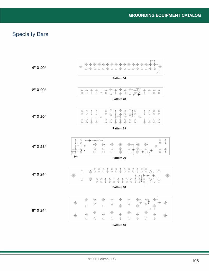
GROUNDING EQUIPMENT CATALOG
© 2021 Alltec LLC 108
Specialty Bars
Pattern 28
Pattern 04
Pattern 29
Pattern 13
Pattern 16
Pattern 26
1”
1”
”
5”
1 81
”
8 ”
1 81
” 85
”
85
”
85
”
85
”
21
”
1 83
”
2 41
”
1 41
”
1 41
”
1 43
”
1 21
”
2 83
”
43
”1”
2”
1”
1”
1”
2”
1”
2”
4” X 20”
2” X 20”
4” X 20”
4” X 23”
4” X 24”
6” X 24”

GROUNDING EQUIPMENT CATALOG
© 2021 Alltec LLC109
Specialty Bars
2” X 14”
4” X 14”
4” X 16”
Pattern 27
Pattern 17
Pattern 20

GROUNDING EQUIPMENT CATALOG
© 2021 Alltec LLC 110
Specialty Bars
Pattern 25 Pattern 25
6” X 48” 8” X 48”

GROUNDING EQUIPMENT CATALOG
© 2021 Alltec LLC111
Bus Bar Accessories
Small Round Member AdaptorUsed to attach bus bars to pipe up to 3” diameter.
Part Number Description Weight6601 Adaptor, Stainless Steel, 2” to 3” Small Round Member 4.0 oz. (113.4 g)
Large Round Member AdaptorUsed to attach bus bars to pipe 3” to 6” diameter.
Part Number Description Weight6602 Adaptor, Stainless Steel, 3” to 4” Small Round Member 7.0 oz. (198.4 g)
Stainless Steel Tower BracketBracket used to attach bus bars to angle iron on towers.
Part Number Description WeightBKT-CC Bracket, Stainless Steel, C Clamp Type, for Flat Stock or Cor-
ner Angle with 3/8”-16 Thread8.0 oz. (226.8 g)
Fiberglass Composite InsulatorsPart Number Description Weight
7901 Insulator, Fiberglass, 1/4, Small - Suggested voltage rating - 600V 1.25” high x 1” diameter
1.2 oz. (34.0 g)
7906 Insulator, Fiberglass, 3/8, Medium - Suggested voltage rating - 600V 1.375” high x 1.75” diameter
3.6 oz. (102.1 g)
7911 Insulator, Fiberglass, 1/2, Large - Suggested voltage rating - 2700V 2.25” high x 2” diameter
5.5 oz. (155.5 g)
7916 Insulator, Fiberglass, 5/8, Extra Large - Suggested voltage rat-ing - 3400V 2.625” high x 2.5” diameter
10.2 oz. (289.2 g)
Stainless Steel Bus Bar BracketsPart Number Description Weight
7920 Bracket, Stainless Steel, 1” X 4” Face, for Bus Bar 4.0 oz. (113.4 g)7922 Bracket, Stainless Steel, 1” X 2” Face, for Bus Bar 5.0 oz. (141.7 g)
NOTE• Other mounting hardware available on request.

GROUNDING EQUIPMENT CATALOG
© 2021 Alltec LLC 112
Acrylic CoversA full line of clear acrylic covers are available to fit any bus bar. The covers come with insulators and hardware to match with the pattern on the bus bar. Call with special requirements. Lettering is available up to 2”.
Part Number Description WeightCOV-ACR-1/4-1-24 Cover, Acrylic, 1/4” X 4” X 24” 20 oz. (567 g)COV-ACR-1/4-6-24 Cover, Acrylic, 1/4” X 6” X 24” 2.0 lb. (0.90 kg)
NOTE• Other acrylic covers available on request. See below for numbering system.
Part Numbering SystemExample: COV-ACR-1/4-4-24-ENGCOV-ACR - 1/4 - 4 - 24 - ENG(1) - (2) - (3) - (4) - (5)
(1) Type COV-ACR = TerraBar Acrylic Cover
(2) Thickness 1/4 = 1/4”
(3) Width 1 = 1”, 2 = 2”, 4 = 4”, 6 = 6”
(4) Length 4 = 4”, 6 = 6”, 9 = 9”, 12 = 12”, 18 = 18”, 24 = 24”
(5) Option Engraving Letters (include Text & Size in order)
MAIN GROUND BAR
NOTE• Width and length are per TerraBar specification.

EXOTHERMIC WELDING CATALOG
© 2021 Alltec LLC113
Section 10Exothermic Welding

EXOTHERMIC WELDING CATALOG
© 2021 Alltec LLC 114
Exothermic Welding SystemTerraWeld®
The TerraWeld® Exothermic Welding System provides the superior solution in permanent molecular bonding. The process of exothermic welding, in which no external source of heat or power is required, is the universally preferred method of making electrical connections of copper-to-copper or copper-to-steel. Lightning protection and grounding systems require connections that maintain current carrying capacity exceeding that of the conductors used in the system. TerraWeld® connections provide higher fusing capacity than the conductors to which they are bonded. System resistance, impedance, and ampacity relate directly to functionality, safety, and regulatory compliance. TerraWeld® meets these challenges and delivers optimal longevity, especially in below-grade applications.TerraWeld® connections provide performance superior to all existing surface-to-surface mechanical retention connectors. Pressure type connections are susceptible to variation, aging, corrosion, and failure - not TerraWeld®. One click of the starter forges a visually inspectable, uniformly conductive, corrosion resistant, continuous solid metal bonding at the molecular level resulting in the only connection which will not loosen or increase in resistance over the lifetime of the installation.ALLTEC’s hermetically sealed metallized pouch design is unique in the industry. Containing pre-measured granular metallic particles with a separate sealed tube of starting powder, the materials are not in contact and may be safely handled, stored, and transported. Users may confidently and comfortably drop a few packages in their pocket before heading to a site, and rely on its capability even after prolonged exposure to the elements. TerraWeld® works when others won’t.The TerraWeld® Exothermic Welding System uses a light-weight, clamp-on graphite mold to safely position and contain any weld required. The exothermic reaction creates an intense miniature furnace with temperatures exceeding 2,500°F, instantly producing molten metal which flows into the weld cavity, filling any available space. Moments later the mold may be removed in preparation for the next weld.
Starter Material
Mold cover
Weld Crucible
Metal Disk Mold
Tap HoleConductor A
Weld Cavity Conductor B
Metal

EXOTHERMIC WELDING CATALOG
© 2021 Alltec LLC115
Requirements of Electrical ConnectionsPoor connections (joints) between conductors are often the cause of electrical failures. An ideal connection should possess the following qualities:1. Maintains contact integrity and electrical continuity.2. When conducting electrical current, connector temperature should remain lower than that of the conductor.3. Able to withstand overload conditions without melting, burning or failing.4. Long service life. Will not deteriorate, loosen or corrode when subjected to weather.Of all the varieties of electrical connectors that are available today, only exothermic welded connectors can meetthe above criteria. Throughout the world, exothermic welding has been shown to be the best choice where safety,reliability, current carrying capacity and longevity are critical.

EXOTHERMIC WELDING CATALOG
© 2021 Alltec LLC 116
Tech Tip - Minimizing Materials and CostsGrid Wire to Ground Rod Connections
250 mcm orLarger
250 mcm orLarger
GET Mold Type
WT Mold Type
1/0 AWG
GEE Mold Type
Ground rodGround rod
Often in grounding grids it is common to see main grounding conductors sized at 250 mcm or larger. When wire sizes are at this level or larger, it may become difficult and expensive to make proper connections to ground rods (GET Mold Type). Since a single 3/4-inch or 5/8-inch ground rod would not be able to withstand several thousand amperes, a fault current must be distributed across an entire ground grid. Therefore an alternative to welding large gauge wires to ground rods would be to use an intermediary wire between the main grounding conductors and the ground rods. Typically 1/0 AWG wire can be used because this size wire has over 5 times the equivalent cross section of a 3/4-inch ground rod. This method not only simplifies the welding procedure, but also offers considerable savings of wire and weld metal.
Left Diagram: Right Diagram:
Part Number Weld Metal Part Number Weld Metal
GET-18-250A #200 GEE-18-250A #90
WT-250A-1/0A #90
Tech Tip - Equivalent Connections to Ground Rods Several options for achieving a connection as specified in the engineering drawings are available. All the examples below show electrically equivalent connections as those specified in the engineering drawing represented by the cross and circle symbol.
WXWP WT
GETGET
GEP
(1) 2 molds 2 welds
Specified connection
Note: (1) is the most common method
(2) 2 molds 2 welds (3) 2 molds 2 welds
(4) 1 mold 1 weld (5) 2 molds 2 welds (6) 1 mold 2 welds
GET
GETGST
GST GST
WT

EXOTHERMIC WELDING CATALOG
© 2021 Alltec LLC117
Section 11Weld Metal, Molds & Accessories

EXOTHERMIC WELDING CATALOG
© 2021 Alltec LLC 118
Weld Metal, Molds & Accessories
TerraWeld® Weld MetalAll TerraWeld® weld metals are meticulously packaged in individual, state-of-the-art moisture proof foil packs. The starting material is in a separate container within each foil pack. This eliminates weld metal loss due to spoilage and no-start situations. The water proof foil packs increase shelf life and make for easier transportation. Each box of TerraWeld® contains either 10 or 20 foil packs depending on the size of the Weld metal. Most connections involving copper wires, bars, pipes and/or grounding rods will use Type T Weld Metal.
Features & Benefits
Use:
Permanent molecular bonding weld for electrical connections, primarily for below-grade and secondarily for non-mechanically stressed above-grade attachment
Application:
Copper, copper clad steel, steel and related metals in stranded and solid wire, bar, pipe and plate form, hori-zontal or vertical attachment
Conformance:
IEEE 837, R56 and related standards and recommended practices referenc-ing permanent electrical grounding, bonding and lightning protection connections
Weld Metal Packaging:
Individual sealed foil pack, approx. 5 3/8” x 4 3/4”, moisture resistant, gram weight (size) stamped, notched for easy-tear opening
Starting Powder Packaging:
Individual vial, contained within foil weld metal pack
Outer Packaging:Corrugated box, multiple foil packs, polybag with metal disks, 10 or 20 per
Storage:Room ambient, protected, for maxi-mum shelf life averaging 2 years
Type T: Copper to Copper and Copper to Steel Connections
Weld Metal
Approx. Weld Metal Weight
per Pack
Weld Metal Packs/Box
Weight/Box
T25 25 grams 20 1.6 lbs. (0.73 kg)
T32 32 grams 20 2.0 lbs. (0.91 kg)
T45 45 grams 20 2.6 lbs. (1.18 kg)
T65 65 grams 20 3.2 lbs. (1.45 kg)
T90 90 grams 10 2.5 lbs. (1.34 kg)
T115 115 grams 10 3.4 lbs. (1.54 kg)
T150 150 grams 10 4.1 lbs. (1.86 kg)
T200 200 grams 10 5.0 lbs. (2.27 kg)
T250 250 grams 10 5.9 lbs. (2.68 kg)
Other weld metal is available including: Type B is formulated for rail bonding connections.
Type CI is used for connections with cast iron compo-nents.
Type CP is formulated specifically for cathodic protec-tion applications.
NOTE• Weld metal types can be distinguished from
a colored dot next to the weld metal size onpackage:Type T – no dot, Type B – yellow, Type CI –orange, and Type CP – green.

EXOTHERMIC WELDING CATALOG
© 2021 Alltec LLC119
Weld MoldPrecision engineered for optimum results. Each weld mold is designed to give precise and reliable results. Only the finest materials are utilized so that these molds can withstand continuous heat-cooling cycles. All models are categorized into eleven different price codes according to their connection type. These molds have a minimum service life of approximately 65 connections. However, it is not uncommon to achieve 80-100 connections when proper care is taken during usage.
Mold Options
-S Split Crucible OptionWT and WX type mold may be ordered, as an option, with a split crucible. A split crucible allows the user to quickly and easily access the interior of the weld crucible and tap hole for cleaning and slag removal.
To specify the split crucible option, please add the suffix “S” to the end of the mold part number.
-G Wear OptionThe mold will become chipped and worn through rough handling or through normal use. The optional wear plate will prolong the service life of a mold by protecting the mold openings with metal plates. Wear plates are available for the following mold types: WE, WT, GEE, GST and SVES. For other types, please call ALLTEC.
To order the wear plate option, please add the suffix “G” after the mold part number.
HD- Heavy Duty ConnectionsHeavy duty connections are recommended for installing connections onto aged conductors that have been buried or weathered.
To order the Heavy Duty Connection option, add Prefix “HD” to the beginning of the mold part number.
Option Examples
Part Number: WT- 2AS-2AS
WT- 2AS-2AS-S Split Crucible Option
WT- 2AS-2AS-G Wear Plate Option
HD-WT- 2AS-2AS Heavy Duty Connection

EXOTHERMIC WELDING CATALOG
© 2021 Alltec LLC 120
Tools And AccessoriesCL-2, CL-3, CL-4, CLR-1, CLR-3Mold Handle ClampsCL-2 Small Handle, for #2-1, #2-2, and #2-3 Price Code Molds.CL-3 Regular Handle, for #3, #5, and #7 Price Code Molds.CL-4 Large Handle, for #4, #6, and #8 Price Code Molds.CLR-1 Rail Bonding Handle Clamp, Single Mold.CLR-3 Rail Bonding Handle Clamp, Large Span.
CL-3CV, CL-3CH, CL-4CV, CL-4CHChain Handle ClampsChain handle clamps are available for making connections to vertical standing or horizontal pipes and beams.
CL-3B, CL-4B“Banana“ Handle ClampsBanana handles are designed specifically for welding operations in narrow trenches. The angled handles allow safe and convenient operation without the need for excavating the corner of the trench for clearance. A tremendous labor and time saver.
CL-2M, CL-3M, CL-4MMagnetic Handle ClampsStandard handle clamps fitted with powerful, rare earth magnets to allow welding onto vertical flat steel surfaces.
CCLAMP3, CCLAMP4C-Clamp AttachmentThese attachments will fit CL-3 and CL-4 handles to enable them to be attached to the edge of a flat vertical surface (i.e. I-beams, steel doors etc.), allowing the operator to have both hands free during welding. The attachment affixes to the center post of a handle clamp with a cotter pin.
CBLCWire ClampRelieves tension from wires being welded to prevent the wires from pulling out of the mold during welding.

EXOTHERMIC WELDING CATALOG
© 2021 Alltec LLC121
S-2, S-3Slag Removal ToolsThese tools have been designed to assist in the removal of slag from the mold crucible and tap hole. Type S-2 cleaning tools are for use with #1 and #2 Price Code Molds. All other molds use type S-3 cleaning tool.
GNRDCGround Rod Splice ClampHolds two ground rods in the vertical position required when splicing together with GVE type molds. Ensures proper spacing of required gap between the upper and lower rod.
DX-3Mold Metal Sealer, PuttyHigh heat resistant putty allows small leaks and gaps in the mold to be temporarily stopped. Comes in convenient 1 pound (0.45 kg) packs.
DX-4Mold Metal Sealer, Ceramic Fiber BattingHigh heat resistant ceramic fiber batting. Used where larger voids need to be filled to ensure proper and complete weld. Generally used with rebar welds. 1 DX-4 per weld is required.
SLV-WRAPWrap ShimsThin, flexible copper shim strips. Can be wrapped around wires and cables to adapt them to fit a larger mold opening.
BLANKETFlame Resistant BlanketHeavy Alumina-Silica fiber-woven flame-resistant blankets. Can be used to protect surrounding areas from sparks and heat. 36” x 36” (91.4 cm x 91.4 cm)
IGNITORFlint IgnitorCompact and Convenient: These are mechanical flint ignitors with long service cycles. They produce a large cascade of sparks for ease of igniting the starting material. Worn flints can be replaced.
IG-EXIgnitor Extension30” (76.2 cm) extension arm for flint ignitors. Allows operator to have additional reach.

EXOTHERMIC WELDING CATALOG
© 2021 Alltec LLC 122
CUTTER1Ratcheting Cable CutterThis compact cable cutter measures only 10” (25.4 cm) long and is able to cut copper or aluminum cable up to 750 mcm. Precision ratcheting mechanism and high carbon steel blades ensure long service life and clean cable cuts every time.
TORCHHTrigger Start Torch HeadA very convenient flame torch for pre-heating of mold and conductors. This torch uses cartridge type gas canisters. The torch simply screws onto the gas cartridge and the flame can be adjusted via the thumb wheel on the torch head.
MCB-1Mold Cleaning BrushThis heavy duty brush makes mold cleaning quick and easy. Hefty wooden handles stand up to repeated use. Stiff natural bristles ensure rapid mold cleaning without harming the soft graphite molds.
CCB-1Card Cloth BrushShort stiff wire bristles enable efficient cleaning of metal surfaces and wires in preparation for welding. Quality construction on wooden handles ensure long service life.
DISK-S, DISK-M, DISK-LMetal DisksMetal Disk designed to contain the exothermic reaction to the upper crucible of a mold until the reaction is complete and ready to weld. Weld metals #65 and smaller use Disk-S, #90 & #115 use Disk-M and #150 and larger use Disk-L. Comes in packs of 10.
TOOLKITWelding Tool KitA complete kit for exothermic welding operations. This metal tool kit contains everything required for the safe and efficient operation of exothermic welds. Each kit contains: gloves, safety goggles, torch head, igniter, pliers, gripping pliers, screw driver, hammer, cleaning tool, soft brush, wire brush, and a metal file.

EXOTHERMIC WELDING CATALOG
© 2021 Alltec LLC123
Connection Selection
Part Numbering System
WE - 4/0A - 4A
Wire “A” 4/0 AWG
WE Connection
Wire “B” #4 AWG
Mold Type(WE Connection)
Conductor A(4/0 AWG)
Conductor B(#4 AWG)
AWG
WT - 95 / 35
Wire “A” 95mm2 WT Connection
Wire “B” 35mm2
Mold Type(WT Connection)
Conductor A(95mm2)
Conductor B(35mm2)
IEC - Metric

EXOTHERMIC WELDING CATALOG
© 2021 Alltec LLC 124
Section 12Connection Selection

EXOTHERMIC WELDING CATALOG
© 2021 Alltec LLC125
WE (pg. 131) WT (pg. 132) WX (pg. 134) WP (pg. 135)
WF (pg. 136) WL (pg. 137) WXL (pg. 138)
• Items marked with an astarisk are by special order only. Please inquire for details.
Master Series Index
W Series - Wire To Wire Connections
Series - Mini Wire Connections
WES (pg. 131) WTS (pg. 133) WXS (pg. 134)
WHY* WLE* WPT* WPD* WGT* WVY*
WCE* WCT* WECV*WVCT*WCVT*

GEE (pg. 139) GET (pg. 140) GST (pg. 142) GEY (pg. 142) GEP (pg. 143)
GES (pg. 144) GTS (pg. 145) GHY* GWY*
G Series - Ground Rod To Wire Connections
G Series - Ground Rod To Ground Rod Connection
G Series - Bus Bar to Ground Rod Connection
• Items marked with an astarisk are by special order only. Please inquire for details.
GBN* GBT*
GPW* GBVE* GBVN* GBVS*
GBVB* GBHT* GTE* GEU*
GVE (pg. 145)
EXOTHERMIC WELDING CATALOG
© 2021 Alltec LLC 126

S Series - Connections To Steel Sheets and Pipes
SHEA (pg. 146) SHEB (pg. 147) SHTA (pg. 148) SHTB (pg. 149)
SVES (pg. 150) SVED (pg. 151) SVEU (pg. 152) SVTV (pg. 153)
SVTHA (pg. 154) SVTHB (pg. 155) SVEH (pg. 156)
R Series - Connections To Rebars
RHEH (pg. 157) RHXH (pg. 158) RVXH (pg. 159) RVCT (pg. 160)
* Items marked with an astarisk are by special order only. Please inquire for details.
RVE* RHP* RVP* RHT*
EXOTHERMIC WELDING CATALOG
© 2021 Alltec LLC127

P Series - Connections To Bus Bars And Terminal Lugs
PK (pg. 161) PL (pg. 162) PV (pg. 162) PY (pg. 163)
PT (pg. 163)
PVD* PHD* PVHT* PVET* PTHU* PVL*
P Series - Steel Plate To Terminal Lug* Items marked with an astarisk are by special order only. Please inquire for details.
PSVD* PSVR*
EXOTHERMIC WELDING CATALOG
© 2021 Alltec LLC 128

B Series - Bus Bar Connections
BE (pg. 164) BEH (pg. 164) BTV (pg. 165) BT (pg. 165)
BX (pg. 166)
* Items marked with an astarisk are by special order only. Please inquire for details.
BBU* BBVL* BBVE*
B Series - Steel To Strap Connections
BS (pg. 166) BVSE (pg. 167)
* Items marked with an astarisk are by special order only. Please inquire for details.
BSVE*
EXOTHERMIC WELDING CATALOG
© 2021 Alltec LLC129

E Series - Rail Bond Connections
ERW (pg. 168) ERB (pg. 168) ERT (pg. 169)
C Series - Cathodic Protection
CSHEA* CSHTA* CSVES* CWL* CWE* CJP*
* Items marked with an astarisk are by special order only. Please inquire for details.
EXOTHERMIC WELDING CATALOG
© 2021 Alltec LLC 130

EXOTHERMIC WELDING EQUIPMENT CATALOG
© 2021 Alltec LLC131
WE Mold
A B Part NumberPrice Code
Handle Clamp
Weld Metal Size
6 6 WE-6A-6A 3 CL-3 256 SOL 6 SOL WE-6AS-6AS 3 CL-3 25
4 4 WE-4A-4A 3 CL-3 254 SOL 4 SOL WE-4AS-4AS 3 CL-3 25
3 3 WE-3A-3A 3 CL-3 322 2 WE-2A-2A 3 CL-3 32
2 SOL 2 SOL WE-2AS-2AS 3 CL-3 321 1 WE-1A-1A 3 CL-3 32
1 SOL 1 SOL WE-1AS-1AS 3 CL-3 321/0 1/0 WE-1/0A-1/0A 3 CL-3 452/0 2/0 WE-2/0A-2/0A 3 CL-3 653/0 3/0 WE-3/0A-3/0A 3 CL-3 904/0 4/0 WE-4/0A-4/0A 3 CL-3 90250 250 WE-250A-250A 3 CL-3 115300 300 WE-300A-300A 3 CL-3 115350 350 WE-350A-350A 3 CL-3 150500 500 WE-500A-500A 3 CL-3 200750 750 WE-750A-750A 4 CL-4 2 X 150
1000 1000 WE-1000A-1000A 4 CL-4 2 X 200
WES Mini Mold
A B Part NumberPrice Code
Handle Clamp
Weld Metal Size
6 SOL 6 SOL WES-6AS-6AS 2-1 CL-2 254 4 WES-4A-4A 2-1 CL-2 25
4 SOL 4 SOL WES-4AS-4AS 2-1 CL-2 253 3 WES-3A-3A 2-1 CL-2 322 2 WES-2A-2A 2-1 CL-2 32
2 SOL 2 SOL WES-2AS-2AS 2-1 CL-2 321 1 WES-1A-1A 2-1 CL-2 32
1 SOL 1 SOL WES-1AS-1AS 2-1 CL-2 32
A B
Wire To Wire Connections
NOTE• If the number of connections to be made
are small, WES mini mold type may be used in lieu of WE Type for smaller wire sizes. WES molds offer smaller size and weight advantages.
• Please contact your representative for additional sizes.
• For more information on required tools and accessories, see Page 120-122.
Wire to Wire Connections

EXOTHERMIC WELDING EQUIPMENT CATALOG
© 2021 Alltec LLC 132
WT Mold
A B Part NumberPrice Code
Handle Clamp
Weld Metal Size
4 4 WT-4A-4A 3 CL-3 323 3 WT-3A-3A 3 CL-3 32
2 SOL 2 SOL WT-2AS-2AS 3 CL-3 452 2 WT-2A-2A 3 CL-3 452 4 WT-2A-4A 3 CL-3 451 1 WT-1A-1A 3 CL-3 451 2 WT-1A-2A 3 CL-3 451 4 WT-1A-4A 3 CL-3 45
1/0 1/0 WT-1/0A-1/0A 3 CL-3 901/0 1 WT-1/0A-1A 3 CL-3 451/0 2 WT-1/0A-2A 3 CL-3 451/0 4 WT-1/0A-4A 3 CL-3 452/0 2/0 WT-2/0A-2/0A 3 CL-3 902/0 1/0 WT-2/0A-1/0A 3 CL-3 902/0 1 WT-2/0A-1A 3 CL-3 452/0 2 WT-2/0A-2A 3 CL-3 452/0 4 WT-2/0A-4A 3 CL-3 453/0 3/0 WT-3/0A-3/0A 3 CL-3 1153/0 2/0 WT-3/0A-2/0A 3 CL-3 903/0 1/0 WT-3/0A-1/0A 3 CL-3 903/0 1 WT-3/0A-1A 3 CL-3 453/0 2 WT-3/0A-2A 3 CL-3 453/0 4 WT-3/0A-4A 3 CL-3 454/0 4/0 WT-4/0A-4/0A 3 CL-3 1504/0 3/0 WT-4/0A-3/0A 3 CL-3 1154/0 2/0 WT-4/0A-2/0A 3 CL-3 904/0 1/0 WT-4/0A-1/0A 3 CL-3 904/0 1 WT-4/0A-1A 3 CL-3 904/0 2 WT-4/0A-2A 3 CL-3 904/0 4 WT-4/0A-4A 3 CL-3 90250 250 WT-250A-250A 3 CL-3 150250 4/0 WT-250A-4/0A 3 CL-3 150250 3/0 WT-250A-3/0A 3 CL-3 150250 2/0 WT-250A-2/0A 3 CL-3 90250 1/0 WT-250A-1/0A 3 CL-3 90250 1 WT-250A-1A 3 CL-3 90250 2 WT-250A-2A 3 CL-3 90250 4 WT-250A-4A 3 CL-3 90
A
B
Wire To Wire Connections
NOTE• If the number of connections to be made
are small, WTS Type may be used in lieuof WT Type for smaller wire sizes. WTSType molds offer smaller size and weightadvantages.
• Please contact your representative foradditional sizes.
• For more information on required tools andaccessories, see Page 120-122.
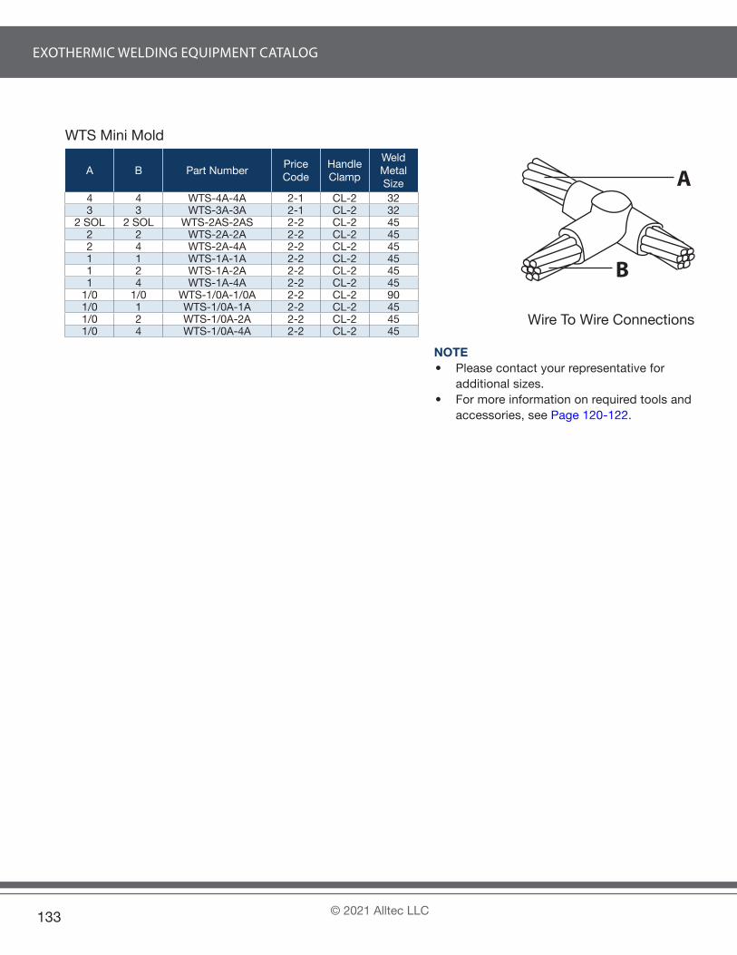
EXOTHERMIC WELDING EQUIPMENT CATALOG
© 2021 Alltec LLC133
WTS Mini Mold
A B Part NumberPrice Code
Handle Clamp
Weld Metal Size
4 4 WTS-4A-4A 2-1 CL-2 323 3 WTS-3A-3A 2-1 CL-2 32
2 SOL 2 SOL WTS-2AS-2AS 2-2 CL-2 452 2 WTS-2A-2A 2-2 CL-2 452 4 WTS-2A-4A 2-2 CL-2 451 1 WTS-1A-1A 2-2 CL-2 451 2 WTS-1A-2A 2-2 CL-2 451 4 WTS-1A-4A 2-2 CL-2 45
1/0 1/0 WTS-1/0A-1/0A 2-2 CL-2 901/0 1 WTS-1/0A-1A 2-2 CL-2 451/0 2 WTS-1/0A-2A 2-2 CL-2 451/0 4 WTS-1/0A-4A 2-2 CL-2 45
A
B
Wire To Wire Connections
NOTE• Please contact your representative for
additional sizes.• For more information on required tools and
accessories, see Page 120-122.

EXOTHERMIC WELDING EQUIPMENT CATALOG
© 2021 Alltec LLC 134
WX Mold
A B Part NumberPrice Code
Handle Clamp
Weld Metal Size
4 4 WX-4A-4A 3 CL-3 453 3 WX-3A-3A 3 CL-3 45
2 SOL 2 SOL WX-2AS-2AS 3 CL-3 652 2 WX-2A-2A 3 CL-3 652 4 WX-2A-4A 3 CL-3 651 1 WX-1A-1A 3 CL-3 651 2 WX-1A-2A 3 CL-3 651 4 WX-1A-4A 3 CL-3 65
1/0 1/0 WX-1/0A-1/0A 3 CL-3 901/0 1 WX-1/0A-1A 3 CL-3 901/0 2 WX-1/0A-2A 3 CL-3 901/0 4 WX-1/0A-4A 3 CL-3 902/0 2/0 WX-2/0A-2/0A 3 CL-3 1152/0 1/0 WX-2/0A-1/0A 3 CL-3 1152/0 1 WX-2/0A-1A 3 CL-3 1152/0 2 WX-2/0A-2A 3 CL-3 1153/0 3/0 WX-3/0A-3/0A 3 CL-3 1503/0 2/0 WX-3/0A-2/0A 3 CL-3 1503/0 1/0 WX-3/0A-1/0A 3 CL-3 1153/0 1 WX-3/0A-1A 3 CL-3 1153/0 2 WX-3/0A-2A 3 CL-3 1154/0 4/0 WX-4/0A-4/0A 3 CL-3 2004/0 3/0 WX-4/0A-3/0A 3 CL-3 2004/0 2/0 WX-4/0A-2/0A 3 CL-3 1504/0 1/0 WX-4/0A-1/0A 3 CL-3 1504/0 1 WX-4/0A-1A 3 CL-3 1154/0 2 WX-4/0A-2A 3 CL-3 115250 250 WX-250A-250A 3 CL-3 200250 4/0 WX-250A-4/0A 3 CL-3 200250 3/0 WX-250A-3/0A 3 CL-3 200250 2/0 WX-250A-2/0A 3 CL-3 150250 1/0 WX-250A-1/0A 3 CL-3 150250 1 WX-250A-1A 3 CL-3 115250 2 WX-250A-2A 3 CL-3 115
WXS Mini Mold
A B Part NumberPrice Code
Handle Clamp
Weld Metal Size
4 4 WXS-4A-4A 2-2 CL-2 453 3 WXS-3A-3A 2-2 CL-2 45
2 SOL 2 SOL WXS-2AS-2AS 2-3 CL-2 652 2 WXS-2A-2A 2-3 CL-2 652 4 WXS-2A-4A 2-3 CL-2 651 1 WXS-1A-1A 2-3 CL-2 651 2 WXS-1A-2A 2-3 CL-2 651 4 WXS-1A-4A 2-3 CL-2 65
1/0 1/0 WXS-1/0A-1/0A 2-3 CL-2 901/0 1 WXS-1/0A-1A 2-3 CL-2 901/0 2 WXS-1/0A-2A 2-3 CL-2 901/0 4 WXS-1/0A-4A 2-3 CL-2 90
A
B
Wire To Wire Connections
NOTE• If the number of connections to be made are
small, WXS Type may be used in lieu of WXType for smaller wire sizes. WXS Type moldsoffer smaller size and weight advantages.
• Please contact your representative foradditional sizes.
• For more information on required tools andaccessories, see Page 120-122.

EXOTHERMIC WELDING EQUIPMENT CATALOG
© 2021 Alltec LLC135
WP Mold
A B Part NumberPrice Code
Handle Clamp
Weld Metal Size
4 4 WP-4A-4A 3 CL-3 323 3 WP-3A-3A 3 CL-3 45
2 SOL 2 SOL WP-2AS-2AS 3 CL-3 652 2 WP-2A-2A 3 CL-3 652 4 WP-2A-4A 3 CL-3 651 1 WP-1A-1A 3 CL-3 651 2 WP-1A-2A 3 CL-3 651 4 WP-1A-4A 3 CL-3 65
1/0 1/0 WP-1/0A-1/0A 3 CL-3 901/0 1 WP-1/0A-1A 3 CL-3 651/0 2 WP-1/0A-2A 3 CL-3 651/0 4 WP-1/0A-4A 3 CL-3 652/0 2/0 WP-2/0A-2/0A 3 CL-3 1152/0 1/0 WP-2/0A-1/0A 3 CL-3 1152/0 1 WP-2/0A-1A 3 CL-3 902/0 2 WP-2/0A-2A 3 CL-3 902/0 4 WP-2/0A-4A 3 CL-3 903/0 3/0 WP-3/0A-3/0A 3 CL-3 1503/0 2/0 WP-3/0A-2/0A 3 CL-3 1503/0 1/0 WP-3/0A-1/0A 3 CL-3 1153/0 1 WP-3/0A-1A 3 CL-3 1153/0 2 WP-3/0A-2A 3 CL-3 1153/0 4 WP-3/0A-4A 3 CL-3 1154/0 4/0 WP-4/0A-4/0A 3 CL-3 2004/0 3/0 WP-4/0A-3/0A 3 CL-3 2004/0 2/0 WP-4/0A-2/0A 3 CL-3 1504/0 1/0 WP-4/0A-1/0A 3 CL-3 1504/0 1 WP-4/0A-1A 3 CL-3 1504/0 2 WP-4/0A-2A 3 CL-3 1504/0 4 WP-4/0A-4A 3 CL-3 150250 250 WP-250A-250A 3 CL-3 250250 4/0 WP-250A-4/0A 3 CL-3 200250 3/0 WP-250A-3/0A 3 CL-3 200250 2/0 WP-250A-2/0A 3 CL-3 150250 1/0 WP-250A-1/0A 3 CL-3 150250 1 WP-250A-1A 3 CL-3 150250 2 WP-250A-2A 3 CL-3 150300 300 WP-300A-300A 4 CL-4 2 X 150300 250 WP-300A-250A 3 CL-3 250300 4/0 WP-300A-4/0A 3 CL-3 200300 3/0 WP-300A-3/0A 3 CL-3 200300 2/0 WP-300A-2/0A 3 CL-3 150300 1/0 WP-300A-1/0A 3 CL-3 150300 1 WP-300A-1A 3 CL-3 150300 2 WP-300A-2A 3 CL-3 150
A
B
Wire To Wire Connections
NOTE• Vertical Connections• Please contact your representative for
additional sizes.• For more information on required tools and
accessories, see Page 120-122.

EXOTHERMIC WELDING EQUIPMENT CATALOG
© 2021 Alltec LLC 136
WF Mold
A B Part NumberPrice Code
Handle Clamp
Weld Metal Size
8 8 WF-8A-8A 3 CL-3 456 6 WF-6A-6A 3 CL-3 454 4 WF-4A-4A 3 CL-3 453 3 WF-3A-3A 3 CL-3 652 2 WF-2A-2A 3 CL-3 65
2 SOL 2 SOL WF-2AS-2AS 3 CL-3 651/0 1/0 WF-1/0A-1/0A 3 CL-3 901/0 1 WF-1/0A-1A 3 CL-3 901/0 2 WF-1/0A-2A 3 CL-3 901/0 4 WF-1/0A-4A 3 CL-3 902/0 2/0 WF-2/0A-2/0A 3 CL-3 1152/0 1/0 WF-2/0A-1/0A 3 CL-3 1152/0 1 WF-2/0A-1A 3 CL-3 902/0 2 WF-2/0A-2A 3 CL-3 902/0 4 WF-2/0A-4A 3 CL-3 904/0 4/0 WF-4/0A-4/0A 3 CL-3 1504/0 3/0 WF-4/0A-3/0A 3 CL-3 1504/0 2/0 WF-4/0A-2/0A 3 CL-3 1504/0 1/0 WF-4/0A-1/0A 3 CL-3 1504/0 1 WF-4/0A-1A 3 CL-3 1154/0 2 WF-4/0A-2A 3 CL-3 115250 250 WF-250A-250A 3 CL-3 200250 4/0 WF-250A-4/0A 3 CL-3 200250 3/0 WF-250A-3/0A 3 CL-3 200250 2/0 WF-250A-2/0A 3 CL-3 200250 1/0 WF-250A-1/0A 3 CL-3 150
A
B
Wire To Wire Connections
NOTE• Horizontal Connections• Please contact your representative for
additional sizes.• For more information on required tools and
accessories, see Page 120-122.

EXOTHERMIC WELDING EQUIPMENT CATALOG
© 2021 Alltec LLC137
WL Mold
A B Part NumberPrice Code
Handle Clamp
Weld Metal Size
6 SOL 6 SOL WL-6AS-6AS 3 CL-3 256 6 WL-6A-6A 3 CL-3 256 4 WL-6A-4A 3 CL-3 324 6 WL-4A-6A 3 CL-3 324 6 SOL WL-4A-6AS 3 CL-3 324 8 SOL WL-4A-8AS 3 CL-3 32
2 SOL 6 SOL WL-2AS-6AS 3 CL-3 652 SOL 6 WL-2AS-6A 3 CL-3 652 SOL 2 SOL WL-2AS-2AS 3 CL-3 652 SOL 2 WL-2AS-2A 3 CL-3 65
2 6 SOL WL-2A-6AS 3 CL-3 322 6 WL-2A-6A 3 CL-3 322 4 WL-2A-4A 3 CL-3 452 2 WL-2A-2A 3 CL-3 65
1/0 6 SOL WL-1/0A-6AS 3 CL-3 451/0 2 SOL WL-1/0A-2AS 3 CL-3 651/0 2 WL-1/0A-2A 3 CL-3 651/0 1/0 WL-1/0A-1/0A 3 CL-3 902/0 6 SOL WL-2/0A-6AS 3 CL-3 652/0 2 SOL WL-2/0A-2AS 3 CL-3 652/0 2 WL-2/0A-2A 3 CL-3 652/0 1/0 WL-2/0A-1/0A 3 CL-3 902/0 2/0 WL-2/0A-2/0A 3 CL-3 90
A
B
Wire To Wire Connections
NOTE• Please contact your representative for
additional sizes.• For more information on required tools and
accessories, see Page 120-122.

EXOTHERMIC WELDING EQUIPMENT CATALOG
© 2021 Alltec LLC 138
WXL Mold
A B Part NumberPrice Code
Handle Clamp
Weld Metal Size
4 4 WXL-4A-4A 5 CL-3 653 3 WXL-3A-3A 5 CL-3 65
2 SOL 2 SOL WXL-2AS-2AS 5 CL-3 902 2 WXL-2A-2A 5 CL-3 902 4 WXL-2A-4A 5 CL-3 651 1 WXL-1A-1A 5 CL-3 1151 2 WXL-1A-2A 5 CL-3 901 4 WXL-1A-4A 5 CL-3 90
1/0 1/0 WXL-1/0A-1/0A 5 CL-3 1501/0 1 WXL-1/0A-1A 5 CL-3 901/0 2 WXL-1/0A-2A 5 CL-3 901/0 4 WXL-1/0A-4A 5 CL-3 902/0 2/0 WXL-2/0A-2/0A 5 CL-3 2002/0 1/0 WXL-2/0A-1/0A 5 CL-3 2002/0 1 WXL-2/0A-1A 5 CL-3 1502/0 2 WXL-2/0A-2A 5 CL-3 1503/0 3/0 WXL-3/0A-3/0A 5 CL-3 2503/0 2/0 WXL-3/0A-2/0A 5 CL-3 2003/0 1/0 WXL-3/0A-1/0A 5 CL-3 2003/0 1 WXL-3/0A-1A 5 CL-3 1503/0 2 WXL-3/0A-2A 5 CL-3 1504/0 4/0 WXL-4/0A-4/0A 5 CL-3 2504/0 3/0 WXL-4/0A-3/0A 5 CL-3 2504/0 2/0 WXL-4/0A-2/0A 5 CL-3 2004/0 1/0 WXL-4/0A-1/0A 5 CL-3 2004/0 1 WXL-4/0A-1A 5 CL-3 1504/0 2 WXL-4/0A-2A 5 CL-3 150250 250 WXL-250A-250A 6 CL-4 2 X 150250 4/0 WXL-250A-4/0A 6 CL-4 2 X 150250 3/0 WXL-250A-3/0A 6 CL-4 2 X 150250 2/0 WXL-250A-2/0A 5 CL-3 250250 1/0 WXL-250A-1/0A 5 CL-3 250250 1 WXL-250A-1A 5 CL-3 200250 2 WXL-250A-2A 5 CL-3 150300 300 WXL-300A-300A 6 CL-4 2 X 200300 250 WXL-300A-250A 6 CL-4 2 X 200300 4/0 WXL-300A-4/0A 6 CL-4 2 X 150300 3/0 WXL-300A-3/0A 6 CL-4 2 X 150300 2/0 WXL-300A-2/0A 5 CL-3 250300 1/0 WXL-300A-1/0A 5 CL-3 250300 1 WXL-300A-1A 5 CL-3 200300 2 WXL-300A-2A 5 CL-3 150
A
B
Wire To Wire Connections
NOTE• Please contact your representative for
additional sizes.• For more information on required tools and
accessories, see Page 120-122.

EXOTHERMIC WELDING EQUIPMENT CATALOG
© 2021 Alltec LLC139
GEE Mold
A B Part NumberPrice Code
Handle Clamp
Weld Metal Size
1/2”diameter
4 GEE-12-4A 3 CL-3 652 SOL GEE-12-2AS 3 CL-3 65
2 GEE-12-2A 3 CL-3 651 GEE-12-1A 3 CL-3 65
1/0 GEE-12-1/0A 3 CL-3 902/0 GEE-12-2/0A 3 CL-3 903/0 GEE-12-3/0A 3 CL-3 904/0 GEE-12-4/0A 3 CL-3 90250 GEE-12-250A 3 CL-3 90300 GEE-12-300A 3 CL-3 90
5/8”diameter
4 GEE-15-4A 3 CL-3 652 SOL GEE-15-2AS 3 CL-3 65
2 GEE-15-2A 3 CL-3 651 GEE-15-1A 3 CL-3 65
1/0 GEE-15-1/0A 3 CL-3 902/0 GEE-15-2/0A 3 CL-3 903/0 GEE-15-3/0A 3 CL-3 904/0 GEE-15-4/0A 3 CL-3 90250 GEE-15-250A 3 CL-3 90300 GEE-15-300A 3 CL-3 115350 GEE-15-350A 3 CL-3 115500 GEE-15-500A 3 CL-3 150
3/4”diameter
4 GEE-18-4A 3 CL-3 902 SOL GEE-18-2AS 3 CL-3 90
2 GEE-18-2A 3 CL-3 901 GEE-18-1A 3 CL-3 90
1/0 GEE-18-1/0A 3 CL-3 902/0 GEE-18-2/0A 3 CL-3 903/0 GEE-18-3/0A 3 CL-3 904/0 GEE-18-4/0A 3 CL-3 90250 GEE-18-250A 3 CL-3 90300 GEE-18-300A 3 CL-3 115350 GEE-18-350A 3 CL-3 115500 GEE-18-500A 3 CL-3 150750 GEE-18-750A 3 CL-3 250
1”diameter
4 GEE-25-4A 3 CL-3 1502 SOL GEE-25-2AS 3 CL-3 150
2 GEE-25-2A 3 CL-3 1501 GEE-25-1A 3 CL-3 150
1/0 GEE-25-1/0A 3 CL-3 1502/0 GEE-25-2/0A 3 CL-3 1503/0 GEE-25-3/0A 3 CL-3 1504/0 GEE-25-4/0A 3 CL-3 150250 GEE-25-250A 3 CL-3 150300 GEE-25-300A 3 CL-3 200350 GEE-25-350A 3 CL-3 200500 GEE-25-500A 3 CL-3 200750 GEE-25-750A 3 CL-3 250
1000 GEE-25-1000A 4 CL-4 2 X150
A
B
Ground Rod To Wire Connections
NOTE• Ground rod diameter is NOMINAL and
in inches. Other dimensions available on request. Please provide wire and rod dimensions as well as material type when ordering custom specifications.
• Please contact your representative for additional sizes.
• For more information on required tools and accessories, see Page 120-122.
Ground Rod to Wire Connections

EXOTHERMIC WELDING EQUIPMENT CATALOG
© 2021 Alltec LLC 140
GET Mold
A B Part NumberPrice Code
Handle Clamp
Weld Metal Size
1/2”diameter
4 GET-12-4A 3 CL-3 902 SOL GET-12-2AS 3 CL-3 90
2 GET-12-2A 3 CL-3 901 GET-12-1A 3 CL-3 90
1/0 GET-12-1/0A 3 CL-3 902/0 GET-12-2/0A 3 CL-3 903/0 GET-12-3/0A 3 CL-3 1154/0 GET-12-4/0A 3 CL-3 115250 GET-12-250A 3 CL-3 150300 GET-12-300A 3 CL-3 200
5/8”diameter
4 GET-15-4A 3 CL-3 902 SOL GET-15-2AS 3 CL-3 90
2 GET-15-2A 3 CL-3 901 GET-15-1A 3 CL-3 90
1/0 GET-15-1/0A 3 CL-3 902/0 GET-15-2/0A 3 CL-3 1153/0 GET-15-3/0A 3 CL-3 1154/0 GET-15-4/0A 3 CL-3 115250 GET-15-250A 3 CL-3 200300 GET-15-300A 3 CL-3 200350 GET-15-350A 3 CL-3 250500 GET-15-500A 3 CL-3 250
3/4”diameter
4 GET-18-4A 3 CL-3 902 SOL GET-18-2AS 3 CL-3 90
2 GET-18-2A 3 CL-3 901 GET-18-1A 3 CL-3 90
1/0 GET-18-1/0A 3 CL-3 1152/0 GET-18-2/0A 3 CL-3 1153/0 GET-18-3/0A 3 CL-3 1154/0 GET-18-4/0A 3 CL-3 115250 GET-18-250A 3 CL-3 150300 GET-18-300A 3 CL-3 200350 GET-18-350A 3 CL-3 200500 GET-18-500A 3 CL-3 250750 GET-18-750A 4 CL-3 2 X 200
1”diameter
4 GET-25-4A 3 CL-3 1502 SOL GET-25-2AS 3 CL-3 150
2 GET-25-2A 3 CL-3 1501 GET-25-1A 3 CL-3 150
1/0 GET-25-1/0A 3 CL-3 1502/0 GET-25-2/0A 3 CL-3 1503/0 GET-25-3/0A 3 CL-3 1504/0 GET-25-4/0A 3 CL-3 150250 GET-25-250A 3 CL-3 200300 GET-25-300A 3 CL-3 200350 GET-25-350A 3 CL-3 200500 GET-25-500A 3 CL-3 250750 GET-25-750A 4 CL-4 2 X 200
1000 GET-25-1000A 4 CL-4 2 X 250
A
B
Ground Rod To Wire Connections
NOTE• Ground rod diameter is NOMINAL and
in inches. Other dimensions available on request. Please provide wire and rod dimensions as well as material type when ordering custom specifications.
• Please contact your representative for additional sizes.
• For more information on required tools and accessories, see Page 120-122.

EXOTHERMIC WELDING EQUIPMENT CATALOG
© 2021 Alltec LLC141
GST Mold
A B Part NumberPrice Code
Handle Clamp
Weld Metal Size
1/2”diameter
4 GST-12-4A 7 CL-3 652 SOL GST-12-2AS 7 CL-3 65
2 GST-12-2A 7 CL-3 651 GST-12-1A 7 CL-3 65
1/0 GST-12-1/0A 7 CL-3 1152/0 GST-12-2/0A 7 CL-3 1153/0 GST-12-3/0A 7 CL-3 1504/0 GST-12-4/0A 7 CL-3 150250 GST-12-250A 7 CL-3 150300 GST-12-300A 7 CL-3 200
5/8”diameter
4 GST-15-4A 7 CL-3 652 SOL GST-15-2AS 7 CL-3 65
2 GST-15-2A 7 CL-3 651 GST-15-1A 7 CL-3 65
1/0 GST-15-1/0A 7 CL-3 1152/0 GST-15-2/0A 7 CL-3 1153/0 GST-15-3/0A 7 CL-3 1504/0 GST-15-4/0A 7 CL-3 150250 GST-15-250A 7 CL-3 150300 GST-15-300A 7 CL-3 200350 GST-15-350A 7 CL-3 250500 GST-15-500A 8 CL-4 2 X 200
3/4”diameter
4 GST-18-4A 7 CL-3 652 SOL GST-18-2AS 7 CL-3 65
2 GST-18-2A 7 CL-3 651 GST-18-1A 7 CL-3 65
1/0 GST-18-1/0A 7 CL-3 1152/0 GST-18-2/0A 7 CL-3 1153/0 GST-18-3/0A 7 CL-3 1504/0 GST-18-4/0A 7 CL-3 150250 GST-18-250A 7 CL-3 200300 GST-18-300A 7 CL-3 250350 GST-18-350A 8 CL-4 2 X 150500 GST-18-500A 8 CL-4 2 X 250750 GST-18-750A 8 CL-4 3 X 200
1”diameter
4 GST-25-4A 7 CL-3 902 SOL GST-25-2AS 7 CL-3 90
2 GST-25-2A 7 CL-3 901 GST-25-1A 7 CL-3 115
1/0 GST-25-1/0A 7 CL-3 1152/0 GST-25-2/0A 7 CL-3 1503/0 GST-25-3/0A 7 CL-3 1504/0 GST-25-4/0A 7 CL-3 150250 GST-25-250A 7 CL-3 200300 GST-25-300A 8 CL-4 2 X 150350 GST-25-350A 8 CL-4 2 X 200500 GST-25-500A 8 CL-4 3 X 200750 GST-25-750A 8 CL-4 3 X 250
A
B
Ground Rod To Wire Connections
NOTE• Ground rod diameter is NOMINAL and
in inches. Other dimensions available on request. Please provide wire and rod dimensions as well as material type when ordering custom specifications.
• Please contact your representative for additional sizes.
• For more information on required tools and accessories, see Page 120-122.
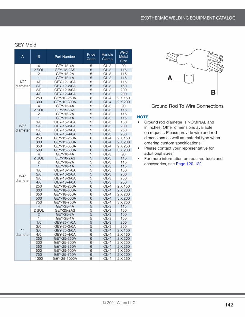
EXOTHERMIC WELDING EQUIPMENT CATALOG
© 2021 Alltec LLC 142
GEY Mold
A B Part NumberPrice Code
Handle Clamp
Weld Metal Size
1/2”diameter
4 GEY-12-4A 5 CL-3 902 SOL GEY-12-2AS 5 CL-3 115
2 GEY-12-2A 5 CL-3 1151 GEY-12-1A 5 CL-3 115
1/0 GEY-12-1/0A 5 CL-3 1152/0 GEY-12-2/0A 5 CL-3 1503/0 GEY-12-3/0A 5 CL-3 2004/0 GEY-12-4/0A 5 CL-3 200250 GEY-12-250A 6 CL-4 2 X 150300 GEY-12-300A 6 CL-4 2 X 200
5/8”diameter
4 GEY-15-4A 5 CL-3 902 SOL GEY-15-2AS 5 CL-3 115
2 GEY-15-2A 5 CL-3 1151 GEY-15-1A 5 CL-3 115
1/0 GEY-15-1/0A 5 CL-3 1502/0 GEY-15-2/0A 5 CL-3 2003/0 GEY-15-3/0A 5 CL-3 2504/0 GEY-15-4/0A 5 CL-3 250250 GEY-15-250A 6 CL-4 2 X 150300 GEY-15-300A 6 CL-4 2 X 200350 GEY-15-350A 6 CL-4 2 X 250500 GEY-15-500A 6 CL-4 3 X 200
3/4”diameter
4 GEY-18-4A 5 CL-3 902 SOL GEY-18-2AS 5 CL-3 115
2 GEY-18-2A 5 CL-3 1151 GEY-18-1A 5 CL-3 115
1/0 GEY-18-1/0A 5 CL-3 1502/0 GEY-18-2/0A 5 CL-3 2003/0 GEY-18-3/0A 5 CL-3 2504/0 GEY-18-4/0A 5 CL-3 250250 GEY-18-250A 6 CL-4 2 X 150300 GEY-18-300A 6 CL-4 2 X 200350 GEY-18-350A 6 CL-4 2 X 200500 GEY-18-500A 6 CL-4 3 X 200750 GEY-18-750A 6 CL-4 3 X 250
1”diameter
4 GEY-25-4A 5 CL-3 1152 SOL GEY-25-2AS 5 CL-3 150
2 GEY-25-2A 5 CL-3 1501 GEY-25-1A 5 CL-3 150
1/0 GEY-25-1/0A 5 CL-3 2002/0 GEY-25-2/0A 5 CL-3 2503/0 GEY-25-3/0A 6 CL-4 2 X 1504/0 GEY-25-4/0A 6 CL-4 2 X 150250 GEY-25-250A 6 CL-4 2 X 200300 GEY-25-300A 6 CL-4 2 X 250350 GEY-25-350A 6 CL-4 2 X 250500 GEY-25-500A 6 CL-4 3 X 250750 GEY-25-750A 6 CL-4 2 X 200
1000 GEY-25-1000A 6 CL-4 2 X 250
A
B
Ground Rod To Wire Connections
NOTE• Ground rod diameter is NOMINAL and
in inches. Other dimensions available on request. Please provide wire and rod dimensions as well as material type when ordering custom specifications.
• Please contact your representative for additional sizes.
• For more information on required tools and accessories, see Page 120-122.

EXOTHERMIC WELDING EQUIPMENT CATALOG
© 2021 Alltec LLC143
GEP Mold
A B Part NumberPrice Code
Handle Clamp
Weld Metal Size
1/2”diameter
4 GEP-12-4A 5 CL-3 1152 SOL GEP-12-2AS 5 CL-3 115
2 GEP-12-2A 5 CL-3 1151 GEP-12-1A 5 CL-3 115
1/0 GEP-12-1/0A 5 CL-3 1502/0 GEP-12-2/0A 5 CL-3 2003/0 GEP-12-3/0A 5 CL-3 2504/0 GEP-12-4/0A 5 CL-3 250250 GEP-12-250A 6 CL-4 2 X 150300 GEP-12-300A 6 CL-4 2 X 200
5/8”diameter
4 GEP-15-4A 5 CL-3 1152 SOL GEP-15-2AS 5 CL-3 150
2 GEP-15-2A 5 CL-3 1501 GEP-15-1A 5 CL-3 150
1/0 GEP-15-1/0A 5 CL-3 2002/0 GEP-15-2/0A 5 CL-3 2503/0 GEP-15-3/0A 6 CL-4 2 X 1504/0 GEP-15-4/0A 6 CL-4 2 X 150250 GEP-15-250A 6 CL-4 2 X 200300 GEP-15-300A 6 CL-4 2 X 250350 GEP-15-350A 6 CL-4 2 X 250500 GEP-15-500A 6 CL-4 3 X 250
3/4”diameter
4 GEP-18-4A 5 CL-3 1152 SOL GEP-18-2AS 5 CL-3 150
2 GEP-18-2A 5 CL-3 1501 GEP-18-1A 5 CL-3 150
1/0 GEP-18-1/0A 5 CL-3 2002/0 GEP-18-2/0A 5 CL-3 2503/0 GEP-18-3/0A 6 CL-4 2 X 1504/0 GEP-18-4/0A 6 CL-4 2 X 150250 GEP-18-250A 6 CL-4 2 X 200300 GEP-18-300A 6 CL-4 2 X 250350 GEP-18-350A 6 CL-4 2 X 250500 GEP-18-500A 6 CL-4 3 X 250750 GEP-18-750A 6 CL-4 4 X 200
1”diameter
4 GEP-25-4A 5 CL-3 1502 SOL GEP-25-2AS 5 CL-3 200
2 GEP-25-2A 5 CL-3 2001 GEP-25-1A 5 CL-3 200
1/0 GEP-25-1/0A 5 CL-3 2502/0 GEP-25-2/0A 6 CL-4 2 X 1503/0 GEP-25-3/0A 6 CL-4 2 X 2004/0 GEP-25-4/0A 6 CL-4 2 X 200250 GEP-25-250A 6 CL-4 2 X 250300 GEP-25-300A 6 CL-4 3 X 200350 GEP-25-350A 6 CL-4 3 X 200500 GEP-25-500A 6 CL-4 3 X 250750 GEP-25-750A 6 CL-4 2 X 200
1000 GEP-25-1000A 6 CL-4 2 X 250
A
B
Ground Rod To Wire Connections
NOTE• Ground rod diameter is NOMINAL and
in inches. Other dimensions available on request. Please provide wire and rod dimensions as well as material type when ordering custom specifications.
• Please contact your representative for additional sizes.
• For more information on required tools and accessories, see Page 120-122.

EXOTHERMIC WELDING EQUIPMENT CATALOG
© 2021 Alltec LLC 144
GES Mold
A B Part NumberPrice Code
Handle Clamp
Weld Metal Size
1/2”diameter
4 GES-12-4A 2-3 CL-2 652 SOL GES-12-2AS 2-3 CL-2 65
2 GES-12-2A 2-3 CL-2 651 GES-12-1A 2-3 CL-2 65
1/0 GES-12-1/0A 2-3 CL-2 902/0 GES-12-2/0A 2-3 CL-2 90
5/8”diameter
4 GES-15-4A 2-3 CL-2 652 SOL GES-15-2AS 2-3 CL-2 65
2 GES-15-2A 2-3 CL-2 651 GES-15-1A 2-3 CL-2 65
1/0 GES-15-1/0A 2-3 CL-2 902/0 GES-15-2/0A 2-3 CL-2 90
3/4”diameter
4 GES-18-4A 2-3 CL-2 902 SOL GES-18-2AS 2-3 CL-2 90
2 GES-18-2A 2-3 CL-2 901 GES-18-1A 2-3 CL-2 90
1/0 GES-18-1/0A 2-3 CL-2 902/0 GES-18-2/0A 2-3 CL-2 90
A
B
Ground Rod To Wire Connections
NOTE• Ground rod diameter is NOMINAL and
in inches. Other dimensions available on request. Please provide wire and rod dimensions as well as material type when ordering custom specifications.
• Please contact your representative for additional sizes.
• For more information on required tools and accessories, see Page 120-122.

EXOTHERMIC WELDING EQUIPMENT CATALOG
© 2021 Alltec LLC145
GTS Mold
A B Part NumberPrice Code
Handle Clamp
Weld Metal Size
1/2”diameter
4 GTS-12-4A 2-3 CL-2 902 SOL GTS-12-2AS 2-3 CL-2 90
2 GTS-12-2A 2-3 CL-2 901 GTS-12-1A 2-3 CL-2 90
1/0 GTS-12-1/0A 2-3 CL-2 902/0 GTS-12-2/0A 2-3 CL-2 90
5/8”diameter
4 GTS-15-4A 2-3 CL-2 902 SOL GTS-15-2AS 2-3 CL-2 90
2 GTS-15-2A 2-3 CL-2 901 GTS-15-1A 2-3 CL-2 90
1/0 GTS-15-1/0A 2-3 CL-2 90
3/4”diameter
4 GTS-18-4A 2-3 CL-2 902 SOL GTS-18-2AS 2-3 CL-2 90
2 GTS-18-2A 2-3 CL-2 901 GTS-18-1A 2-3 CL-2 90
A
B
Ground Rod To Wire Connections
NOTE• Ground rod diameter is NOMINAL and
in inches. Other dimensions available on request. Please provide wire and rod dimensions as well as material type when ordering custom specifications.
• Please contact your representative for additional sizes.
• For more information on required tools and accessories, see Page 120-122.
GVE Mold
A Part NumberPrice Code
Handle Clamp
Weld Metal Size
1/2” diameter GVE-12 3 CL-3 2505/8” diameter GVE-15 4 CL-4 2 X 1503/4” diameter GVE-18 4 CL-4 2 X 2001” diameter GVE-25 4 CL-4 2 X 250
AGround Rod To Ground Rod Connec-
tions
NOTE• Ground rod diameter is NOMINAL and
in inches. Other dimensions available on request. Please provide wire and rod dimensions as well as material type when ordering custom specifications.
TIP• Use a ground rod splice clamp, part number GNRDC
(pg. 121), to simplify and assist in making ground rod splices with GVE molds.

EXOTHERMIC WELDING EQUIPMENT CATALOG
© 2021 Alltec LLC 146
SHEA Mold
A Part NumberPrice Code
Weld Metal Size
Mold Sealer Type
6 SHEA-6A 1 454 SHEA-4A 1 452 SHEA-2A 1 45
2 SOL SHEA-2AS 1 451 SHEA-1A 1 65 DX-3
1/0 SHEA-1/0A 3 90 DX-32/0 SHEA-2/0A 3 90 DX-33/0 SHEA-3/0A 3 115 DX-34/0 SHEA-4/0A 3 115 DX-3250 SHEA-250A 3 150 DX-3300 SHEA-300A 3 200 DX-3350 SHEA-350A 3 200 DX-3500 SHEA-500A 3 250 DX-3
ACable To Plate
A Part NumberPrice Code
Weld Metal Size
Mold Sealer Type
6 SHEA-6A-D 1 454 SHEA-4A-D 1 452 SHEA-2A-D 1 45
2 SOL SHEA-2AS-D 1 451 SHEA-1A-D 1 65 DX-3
1/0 SHEA-1/0A-D 3 90 DX-32/0 SHEA-2/0A-D 3 90 DX-33/0 SHEA-3/0A-D 3 115 DX-34/0 SHEA-4/0A-D 3 115 DX-3250 SHEA-250A-D 3 150 DX-3300 SHEA-300A-D 3 200 DX-3350 SHEA-350A-D 3 200 DX-3500 SHEA-500A-D 3 250 DX-3
A
D = Outer Diameter
Cable To Pipe
NOTE• SHEA Mold comes with an integrated handle
and frame.• When welding onto pipes, the CL-3CH Chain
Handle Clamp (pg. 120-122) will help hold the molds in position.
• If welding onto pipe, please substitute “D” with the appropriate pipe diameter in inches when ordering.
• If welding to copper tube/pipe, please supply OD (Outer Diameter) as measured.
• For Price Code #1 Molds, please contact your representative.
• For more information on required tools and accessories, see Page 120-122.
Plate & Pipe Connections

EXOTHERMIC WELDING EQUIPMENT CATALOG
© 2021 Alltec LLC147
SHEB Mold
A Part NumberPrice Code
Handle Clamp
Weld Metal Size
6 SHEB-6A 1 CL-3 454 SHEB-4A 1 CL-3 452 SHEB-2A 1 CL-3 45
2 SOL SHEB-2AS 1 CL-3 451 SHEB-1A 1 CL-3 65
1/0 SHEB-1/0A 3 CL-3 902/0 SHEB-2/0A 3 CL-3 1153/0 SHEB-3/0A 3 CL-3 1154/0 SHEB-4/0A 3 CL-3 115250 SHEB-250A 3 CL-3 115300 SHEB-300A 3 CL-3 150350 SHEB-350A 3 CL-3 200500 SHEB-500A 3 CL-3 200750 SHEB-750A 4 CL-4 2 X 150
A
Cable To Plate
A Part NumberPrice Code
Handle Clamp
Weld Metal Size
6 SHEB-6A-D 1 CL-3 454 SHEB-4A-D 1 CL-3 452 SHEB-2A-D 1 CL-3 45
2 SOL SHEB-2AS-D 1 CL-3 451 SHEB-1A-D 1 CL-3 65
1/0 SHEB-1/0A-D 3 CL-3 902/0 SHEB-2/0A-D 3 CL-3 1153/0 SHEB-3/0A-D 3 CL-3 1154/0 SHEB-4/0A-D 3 CL-3 115250 SHEB-250A-D 3 CL-3 115300 SHEB-300A-D 3 CL-3 150350 SHEB-350A-D 3 CL-3 200500 SHEB-500A-D 3 CL-3 200750 SHEB-750A-D 4 CL-4 2 X 150
A
D = Outer Diameter
Cable To Pipe
NOTE• When welding onto pipes, the CL-3CH Chain
Handle Clamp (pg. 120-122) will help hold the molds in position.
• If welding onto pipe, please substitute “D” with the appropriate pipe diameter in inches when ordering.
• If welding to copper tube/pipe, please supply OD (Outer Diameter) as measured.
• For Price Code #1 Molds, please contact your representative.
• For more information on required tools and accessories, see Page 120-122.

EXOTHERMIC WELDING EQUIPMENT CATALOG
© 2021 Alltec LLC 148
SHTA Mold
A Part NumberPrice Code
Weld Metal Size
Mold Sealer Type
6 SHTA-6A 1 454 SHTA-4A 1 452 SHTA-2A 1 45
2 SOL SHTA-2AS 1 451 SHTA-1A 1 65 DX-3
1/0 SHTA-1/0A 3 90 DX-32/0 SHTA-2/0A 3 115 DX-33/0 SHTA-3/0A 3 115 DX-34/0 SHTA-4/0A 3 150 DX-3250 SHTA-250A 3 150 DX-3300 SHTA-300A 3 250 DX-3350 SHTA-350A 4 2 X 150 DX-3500 SHTA-500A 4 2 X 200 DX-3
A
Cable To Plate
A Part NumberPrice Code
Weld Metal Size
Mold Sealer Type
6 SHTA-6A-D 1 454 SHTA-4A-D 1 452 SHTA-2A-D 1 45
2 SOL SHTA-2AS-D 1 451 SHTA-1A-D 1 65 DX-3
1/0 SHTA-1/0A-D 3 90 DX-32/0 SHTA-2/0A-D 3 115 DX-33/0 SHTA-3/0A-D 3 115 DX-34/0 SHTA-4/0A-D 3 150 DX-3250 SHTA-250A-D 3 150 DX-3300 SHTA-300A-D 3 250 DX-3350 SHTA-350A-D 4 2 X 150 DX-3500 SHTA-500A-D 4 2 X 200 DX-3
A
D = Outer Diameter
Cable To Pipe
NOTE• SHTA Mold comes with an integrated handle
and frame.• When welding onto pipes, the CL-3CH Chain
Handle Clamp (pg. 120-122) will help hold the molds in position.
• If welding onto pipe, please substitute “D” with the appropriate pipe diameter in inches when ordering.
• If welding to copper tube/pipe, please supply OD (Outer Diameter) as measured.
• For Price Code #1 Molds, please contact your representative.
• For more information on required tools and accessories, see Page 120-122.

EXOTHERMIC WELDING EQUIPMENT CATALOG
© 2021 Alltec LLC149
SHTB Mold
A Part NumberPrice Code
Handle Clamp
Weld Metal Size
6 SHTB-6A 1 CL-3 454 SHTB-4A 1 CL-3 452 SHTB-2A 1 CL-3 65
2 SOL SHTB-2AS 1 CL-3 651 SHTB-1A 1 CL-3 90
1/0 SHTB-1/0A 3 CL-3 902/0 SHTB-2/0A 3 CL-3 1153/0 SHTB-3/0A 3 CL-3 1154/0 SHTB-4/0A 3 CL-3 150250 SHTB-250A 3 CL-3 200300 SHTB-300A 3 CL-3 200350 SHTB-350A 3 CL-3 250500 SHTB-500A 4 CL-4 2 X 150750 SHTB-750A 4 CL-4 2 X 200
A
Cable To Plate
A Part NumberPrice Code
Handle Clamp
Weld Metal Size
6 SHTB-6A-D 1 CL-3 454 SHTB-4A-D 1 CL-3 452 SHTB-2A-D 1 CL-3 65
2 SOL SHTB-2AS-D 1 CL-3 651 SHTB-1A-D 1 CL-3 90
1/0 SHTB-1/0A-D 3 CL-3 902/0 SHTB-2/0A-D 3 CL-3 1153/0 SHTB-3/0A-D 3 CL-3 1154/0 SHTB-4/0A-D 3 CL-3 150250 SHTB-250A-D 3 CL-3 200300 SHTB-300A-D 3 CL-3 200350 SHTB-350A-D 3 CL-3 250500 SHTB-500A-D 4 CL-4 2 X 150750 SHTB-750A-D 4 CL-4 2 X 200
A
D = Outer Diameter
Cable To Pipe
NOTE• When welding onto pipes, the CL-3CH Chain
Handle Clamp (pg. 120-122 ) will help hold the molds in position.
• If welding onto pipe, please substitute “D” with the appropriate pipe diameter in inches when ordering.
• If welding to copper tube/pipe, please supply OD (Outer Diameter) as measured.
• For Price Code #1 Molds, please contact your representative.
• For more information on required tools and accessories, see Page 120-122.

EXOTHERMIC WELDING EQUIPMENT CATALOG
© 2021 Alltec LLC 150
SVES Mold
A Part NumberPrice Code
Handle Clamp
Weld Metal Size
6 SVES-6A 3 CL-3 454 SVES-4A 3 CL-3 452 SVES-2A 3 CL-3 45
2 SOL SVES-2AS 3 CL-3 451 SVES-1A 3 CL-3 65
1/0 SVES-1/0A 3 CL-3 902/0 SVES-2/0A 3 CL-3 903/0 SVES-3/0A 3 CL-3 1154/0 SVES-4/0A 3 CL-3 115250 SVES-250A 3 CL-3 115300 SVES-300A 3 CL-3 150350 SVES-350A 3 CL-3 200500 SVES-500A 3 CL-3 200750 SVES-750A 4 CL-4 2 X 150
A
Cable To Plate
A Part NumberPrice Code
Handle Clamp
Weld Metal Size
6 SVES-6A-D 3 CL-3 454 SVES-4A-D 3 CL-3 452 SVES-2A-D 3 CL-3 45
2 SOL SVES-2AS-D 3 CL-3 451 SVES-1A-D 3 CL-3 65
1/0 SVES-1/0A-D 3 CL-3 902/0 SVES-2/0A-D 3 CL-3 903/0 SVES-3/0A-D 3 CL-3 1154/0 SVES-4/0A-D 3 CL-3 115250 SVES-250A-D 3 CL-3 115300 SVES-300A-D 3 CL-3 150350 SVES-350A-D 3 CL-3 200500 SVES-500A-D 3 CL-3 200750 SVES-750A-D 4 CL-4 2 X 150
A
D = Outer Diameter
Cable To Pipe
NOTE• When welding on flat surfaces, the optional C-clamp attachment (pg. 120-122 ) will simplify the positioning
and operation of these molds. • When welding onto pipes, the CL-3CV Chain Handle Clamp (pg. 120-122) will help hold the molds in position.• If welding onto pipe, please substitute “D” with the appropriate pipe diameter in inches or mm when ordering.• If welding to copper tube/pipe, please supply OD (Outer Diameter) as measured.• For more information on required tools and accessories, see Page 120-122.

EXOTHERMIC WELDING EQUIPMENT CATALOG
© 2021 Alltec LLC151
SVED Mold
A Part NumberPrice Code
Handle Clamp
Weld Metal Size
6 SVED-6A 3 CL-3 454 SVED-4A 3 CL-3 652 SVED-2A 3 CL-3 65
2 SOL SVED-2AS 3 CL-3 651 SVED-1A 3 CL-3 90
1/0 SVED-1/0A 3 CL-3 1152/0 SVED-2/0A 3 CL-3 1153/0 SVED-3/0A 3 CL-3 1504/0 SVED-4/0A 3 CL-3 150250 SVED-250A 3 CL-3 200300 SVED-300A 3 CL-3 200350 SVED-350A 3 CL-3 250500 SVED-500A 4 CL-4 2 X 150750 SVED-750A 4 CL-4 2 X 200
ACable To Plate
A Part NumberPrice Code
Handle Clamp
Weld Metal Size
6 SVED-6A-D 3 CL-3 454 SVED-4A-D 3 CL-3 652 SVED-2A-D 3 CL-3 65
2 SOL SVED-2AS-D 3 CL-3 651 SVED-1A-D 3 CL-3 90
1/0 SVED-1/0A-D 3 CL-3 1152/0 SVED-2/0A-D 3 CL-3 1153/0 SVED-3/0A-D 3 CL-3 1504/0 SVED-4/0A-D 3 CL-3 150250 SVED-250A-D 3 CL-3 200300 SVED-300A-D 3 CL-3 200350 SVED-350A-D 3 CL-3 250500 SVED-500A-D 4 CL-4 2 X 150750 SVED-750A-D 4 CL-4 2 X 200
A
D = Outer Diameter
Cable To Pipe
NOTE• When welding on flat surfaces, the optional C-clamp attachment (pg. 120-122) will simplify the positioning and
operation of these molds.• When welding onto pipes, the CL-3CV Chain Handle Clamp (pg. 120-122) will help hold the molds in position.• If welding onto pipe, please substitute “D” with the appropriate pipe diameter in inches when ordering.• If welding to copper tube/pipe, please supply OD (Outer Diameter) as measured.• Molds can be ordered to fit 1.5” to 4” diameter pipes. Please use1.5-4 in place of -D in the part number.
Example: SVEU-4/0A-1.5-4• For more information on required tools and accessories, see Page 120-122.

EXOTHERMIC WELDING EQUIPMENT CATALOG
© 2021 Alltec LLC 152
SVEU Mold
A Part NumberPrice Code
Handle Clamp
Weld Metal Size
6 SVEU-6A 3 CL-3 454 SVEU-4A 3 CL-3 652 SVEU-2A 3 CL-3 65
2 SOL SVEU-2AS 3 CL-3 651 SVEU-1A 3 CL-3 90
1/0 SVEU-1/0A 3 CL-3 1152/0 SVEU-2/0A 3 CL-3 1153/0 SVEU-3/0A 3 CL-3 1504/0 SVEU-4/0A 3 CL-3 150250 SVEU-250A 3 CL-3 200300 SVEU-300A 3 CL-3 200350 SVEU-350A 3 CL-3 250500 SVEU-500A 4 CL-4 2 X 150750 SVEU-750A 4 CL-4 2 X 200
A
Cable To Plate
A Part NumberPrice Code
Handle Clamp
Weld Metal Size
6 SVEU-6A-D 3 CL-3 454 SVEU-4A-D 3 CL-3 652 SVEU-2A-D 3 CL-3 65
2 SOL SVEU-2AS-D 3 CL-3 651 SVEU-1A-D 3 CL-3 90
1/0 SVEU-1/0A-D 3 CL-3 1152/0 SVEU-2/0A-D 3 CL-3 1153/0 SVEU-3/0A-D 3 CL-3 1504/0 SVEU-4/0A-D 3 CL-3 150250 SVEU-250A-D 3 CL-3 200300 SVEU-300A-D 3 CL-3 200350 SVEU-350A-D 3 CL-3 250500 SVEU-500A-D 4 CL-4 2 X 150750 SVEU-750A-D 4 CL-4 2 X 200
A
D = Outer Diameter
Cable To Pipe
NOTE• When welding on flat surfaces, the optional C-clamp attachment (pg. 120-122) will simplify the positioning and
operation of these molds.• When welding onto pipes, the CL-3CV Chain Handle Clamp (pg. 120-122) will help hold the molds in position.• If welding onto pipe, please substitute “D” with the appropriate pipe diameter in inches or mm when ordering.• If welding to copper tube/pipe, please supply OD (Outer Diameter) as measured.• For more information on required tools and accessories, see Page 120-122.

EXOTHERMIC WELDING EQUIPMENT CATALOG
© 2021 Alltec LLC153
SVTV Mold
A Part NumberPrice Code
Handle Clamp
Weld Metal Size
6 SVTV-6A 3 CL-3 654 SVTV-4A 3 CL-3 902 SVTV-2A 3 CL-3 115
2 SOL SVTV-2AS 3 CL-3 1151 SVTV-1A 3 CL-3 115
1/0 SVTV-1/0A 3 CL-3 2002/0 SVTV-2/0A 3 CL-3 2003/0 SVTV-3/0A 3 CL-3 2504/0 SVTV-4/0A 3 CL-3 250250 SVTV-250A 3 CL-3 250300 SVTV-300A 4 CL-4 2 X 115350 SVTV-350A 4 CL-4 2 X 150500 SVTV-500A 4 CL-4 2 X 200750 SVTV-750A 4 CL-4 2 X 250
A
Cable To Plate
A Part NumberPrice Code
Handle Clamp
Weld Metal Size
6 SVTV-6A-D 3 CL-3 654 SVTV-4A-D 3 CL-3 902 SVTV-2A-D 3 CL-3 115
2 SOL SVTV-2AS-D 3 CL-3 1151 SVTV-1A-D 3 CL-3 115
1/0 SVTV-1/0A-D 3 CL-3 2002/0 SVTV-2/0A-D 3 CL-3 2003/0 SVTV-3/0A-D 3 CL-3 2504/0 SVTV-4/0A-D 3 CL-3 250250 SVTV-250A-D 3 CL-3 250300 SVTV-300A-D 4 CL-4 2 X 115350 SVTV-350A-D 4 CL-4 2 X 150500 SVTV-500A-D 4 CL-4 2 X 200750 SVTV-750A-D 4 CL-4 2 X 250
A
D = Outer Diameter
Cable To Pipe
NOTE• When welding on flat surfaces, the optional C-clamp attachment (pg. 120-122) will simplify the positioning and
operation of these molds.• When welding onto pipes, the CL-3CV Chain Handle Clamp (pg. 120-122) will help hold the molds in position.• If welding onto pipe, please substitute “D” with the appropriate pipe diameter in inches or mm when ordering.• If welding to copper tube/pipe, please supply OD (Outer Diameter) as measured.• For more information on required tools and accessories, see Page 120-122.

EXOTHERMIC WELDING EQUIPMENT CATALOG
© 2021 Alltec LLC 154
SVTHA Mold
A Part NumberPrice Code
Handle Clamp
Weld Metal Size
Mold Sealer Type
6 SVTHA-6A 3 CL-3 454 SVTHA-4A 3 CL-3 45
2 SOL SVTHA-2AS 3 CL-3 452 SVTHA-2A 3 CL-3 451 SVTHA-1A 3 CL-3 65 DX-3
1/0 SVTHA-1/0A 3 CL-3 115 DX-32/0 SVTHA-2/0A 3 CL-3 115 DX-33/0 SVTHA-3/0A 3 CL-3 150 DX-34/0 SVTHA-4/0A 3 CL-3 150 DX-3250 SVTHA-250A 3 CL-3 150 DX-3300 SVTHA-300A 3 CL-3 200 DX-3350 SVTHA-350A 3 CL-3 200 DX-3
ACable To Plate
A Part NumberPrice Code
Handle Clamp
Weld Metal Size
Mold Sealer Type
6 SVTHA-6A-D 3 CL-3 454 SVTHA-4A-D 3 CL-3 45
2 SOL SVTHA-2A-D 3 CL-3 452 SVTHA-2AS-D 3 CL-3 451 SVTHA-1A-D 3 CL-3 65 DX-3
1/0 SVTHA-1/0A-D 3 CL-3 115 DX-32/0 SVTHA-2/0A-D 3 CL-3 115 DX-33/0 SVTHA-3/0A-D 3 CL-3 150 DX-34/0 SVTHA-4/0A-D 3 CL-3 150 DX-3250 SVTHA-250A-D 3 CL-3 150 DX-3300 SVTHA-300A-D 3 CL-3 200 DX-3350 SVTHA-350A-D 3 CL-3 200 DX-3
A
D = Outer Diameter
Cable To Pipe*Conductor is flat against steel surface.
NOTE• When welding on flat surfaces, the optional C-clamp attachment (pg. 120-122) will simplify the positioning and
operation of these molds.• When welding onto pipes, the CL-3CV Chain Handle Clamp (pg. 120-122) will help hold the molds in position.• If welding onto pipe, please substitute “D” with the appropriate pipe diameter in inches when ordering.• If welding to copper tube/pipe, please supply OD (Outer Diameter) as measured.• Molds can be ordered to fit 1.5” to 4” diameter pipes. Please use 1.5-4 in place of -D in the part number.
Example: SVES-4/0A-1.5-4• For more information on required tools and accessories, see Page 120-122.

EXOTHERMIC WELDING EQUIPMENT CATALOG
© 2021 Alltec LLC155
SVTHB Mold
A Part NumberPrice Code
Handle Clamp
Weld Metal Size
6 SVTHB-6A 3 CL-3 654 SVTHB-4A 3 CL-3 65
2 SOL SVTHB-2AS 3 CL-3 652 SVTHB-2A 3 CL-3 651 SVTHB-1A 3 CL-3 90
1/0 SVTHB-1/0A 3 CL-3 1152/0 SVTHB-2/0A 3 CL-3 1153/0 SVTHB-3/0A 3 CL-3 1504/0 SVTHB-4/0A 3 CL-3 150250 SVTHB-250A 3 CL-3 150300 SVTHB-300A 3 CL-3 200350 SVTHB-350A 3 CL-3 250
A
Cable To Plate
A Part NumberPrice Code
Handle Clamp
Weld Metal Size
6 SVTHB-6A-D 3 CL-3 654 SVTHB-4A-D 3 CL-3 65
2 SOL SVTHB-2A-D 3 CL-3 652 SVTHB-2AS-D 3 CL-3 651 SVTHB-1A-D 3 CL-3 90
1/0 SVTHB-1/0A-D 3 CL-3 1152/0 SVTHB-2/0A-D 3 CL-3 1153/0 SVTHB-3/0A-D 3 CL-3 1504/0 SVTHB-4/0A-D 3 CL-3 150250 SVTHB-250A-D 3 CL-3 150300 SVTHB-300A-D 3 CL-3 200350 SVTHB-350A-D 3 CL-3 250
A
D = Outer Diameter
Cable To Pipe
*Conductor is raised off of steel surface.
NOTE• When welding on flat surfaces, the optional C-clamp attachment (pg. 120-122 ) will simplify the positioning
and operation of these molds.• When welding onto pipes, the CL-3CV Chain Handle Clamp (pg. 120-122) will help hold the molds in position.• If welding onto pipe, please substitute “D” with the appropriate pipe diameter in inches or mm when ordering.• If welding to copper tube/pipe, please supply OD (Outer Diameter) as measured.• The part numbers for the range of mold types are just a suffix with the diameter range. i.e. SVES-95-1-4 (SVES
95mm2 wire for pipes 1” dia - 4” dia.).• For more information on required tools and accessories, see Page 120-122.

EXOTHERMIC WELDING EQUIPMENT CATALOG
© 2021 Alltec LLC 156
SVEH Mold
A Part NumberPrice Code
Handle Clamp
Weld Metal Size
Mold Sealer Type
6 SVEH-6A-L/R 3 CL-3 454 SVEH-4A-L/R 3 CL-3 45
2 SOL SVEH-2AS-L/R 3 CL-3 452 SVEH-2A-L/R 3 CL-3 451 SVEH-1A-L/R 3 CL-3 65
1/0 SVEH-1/0A-L/R 3 CL-3 90 DX-32/0 SVEH-2/0A-L/R 3 CL-3 115 DX-33/0 SVEH-3/0A-L/R 3 CL-3 115 DX-34/0 SVEH-4/0A-L/R 3 CL-3 115 DX-3250 SVEH-250A-L/R 3 CL-3 150 DX-3300 SVEH-300A-L/R 3 CL-3 200 DX-3350 SVEH-350A-L/R 3 CL-3 200 DX-3
ACable To Plate
A Part NumberPrice Code
Handle Clamp
Weld Metal Size
Mold Sealer Type
6 SVEH-6A-L/R-D 3 CL-3 454 SVEH-4A-L/R-D 3 CL-3 45
2 SOL SVEH-2A-L/R-D 3 CL-3 452 SVEH-2AS-L/R-D 3 CL-3 451 SVEH-1A-L/R-D 3 CL-3 65
1/0 SVEH-1/0A-L/R-D 3 CL-3 90 DX-32/0 SVEH-2/0A-L/R-D 3 CL-3 115 DX-33/0 SVEH-3/0A-L/R-D 3 CL-3 115 DX-34/0 SVEH-4/0A-L/R-D 3 CL-3 115 DX-3250 SVEH-250A-L/R-D 3 CL-3 150 DX-3300 SVEH-300A-L/R-D 3 CL-3 200 DX-3350 SVEH-350A-L/R-D 3 CL-3 200 DX-3
A
D = Outer Diameter
Cable To Pipe
NOTE• When welding on flat surfaces, the optional C-clamp attachment (pg. 120-122) will simplify the positioning and
operation of these molds. • When welding onto pipes, the CL-3CV Chain Handle Clamp (pg. 120-122) will help hold the molds in position.• If welding onto pipe, please substitute “D” with the appropriate pipe diameter in inches when ordering.• If welding to copper tube/pipe, please supply OD (Outer Diameter) as measured.• Molds can be ordered to fit 1.5” to 4” diameter pipes. Please use1.5-4 in place of -D in the part number.
Example: SVED-4/0A-1.5-4• For more information on required tools and accessories, see Page 120-122.

EXOTHERMIC WELDING EQUIPMENT CATALOG
© 2021 Alltec LLC157
RHEH Mold
A B Part NumberPrice Code
Handle Clamp
Weld Metal Size
Mold Sealer Type
3
6 RHEH-#3-6A 3 CL-3 254 RHEH-#3-4A 3 CL-3 32
2 SOL RHEH-#3-2AS 3 CL-3 452 RHEH-#3-2A 3 CL-3 451 RHEH-#3-1A 3 CL-3 65
1/0 RHEH-#3-1/0A 3 CL-3 902/0 RHEH-#3-2/0A 3 CL-3 903/0 RHEH-#3-3/0A 3 CL-3 1154/0 RHEH-#3-4/0A 3 CL-3 115
4
6 RHEH-#4-6A 3 CL-3 25 DX-44 RHEH-#4-4A 3 CL-3 32 DX-4
2 SOL RHEH-#4-2AS 3 CL-3 45 DX-42 RHEH-#4-2A 3 CL-3 45 DX-41 RHEH-#4-1A 3 CL-3 65 DX-4
1/0 RHEH-#4-1/0A 3 CL-3 90 DX-42/0 RHEH-#4-2/0A 3 CL-3 90 DX-43/0 RHEH-#4-3/0A 3 CL-3 115 DX-44/0 RHEH-#4-4/0A 3 CL-3 115 DX-4
5
6 RHEH-#5-6A 3 CL-3 25 DX-44 RHEH-#5-4A 3 CL-3 32 DX-4
2 SOL RHEH-#5-2AS 3 CL-3 45 DX-42 RHEH-#5-2A 3 CL-3 45 DX-41 RHEH-#5-1A 3 CL-3 65 DX-4
1/0 RHEH-#5-1/0A 3 CL-3 90 DX-42/0 RHEH-#5-2/0A 3 CL-3 90 DX-43/0 RHEH-#5-3/0A 3 CL-3 115 DX-44/0 RHEH-#5-4/0A 3 CL-3 115 DX-4
6
6 RHEH-#6-6A 3 CL-3 25 DX-44 RHEH-#6-4A 3 CL-3 32 DX-4
2 SOL RHEH-#6-2AS 3 CL-3 45 DX-42 RHEH-#6-2A 3 CL-3 45 DX-41 RHEH-#6-1A 3 CL-3 65 DX-4
1/0 RHEH-#6-1/0A 3 CL-3 90 DX-42/0 RHEH-#6-2/0A 3 CL-3 90 DX-43/0 RHEH-#6-3/0A 3 CL-3 115 DX-44/0 RHEH-#6-4/0A 3 CL-3 115 DX-4
7
4 RHEH-#7-4A 3 CL-3 32 DX-42 SOL RHEH-#7-2AS 3 CL-3 45 DX-4
2 RHEH-#7-2A 3 CL-3 45 DX-41 RHEH-#7-1A 3 CL-3 65 DX-4
1/0 RHEH-#7-1/0A 3 CL-3 90 DX-42/0 RHEH-#7-2/0A 3 CL-3 90 DX-43/0 RHEH-#7-3/0A 3 CL-3 115 DX-44/0 RHEH-#7-4/0A 3 CL-3 115 DX-4
A
B
Connections To Rebars
NOTE• DX-3 mold sealer or DX-4 packing
material may be used to overcome weld metal leakage due to rebar surface irregularities.
• Please contact your representative for details.
• For more information on required tools and accessories,
• see Page 120-122.
Rebar Connections

EXOTHERMIC WELDING EQUIPMENT CATALOG
© 2021 Alltec LLC 158
RHXH Mold
A B Part NumberPrice Code
Handle Clamp
Weld Metal Size
Mold Sealer Type
3
6 RHXH-#3-6A 5 CL-3 65 DX-44 RHXH-#3-4A 5 CL-3 65 DX-4
2 SOL RHXH-#3-2AS 5 CL-3 90 DX-42 RHXH-#3-2A 5 CL-3 90 DX-41 RHXH-#3-1A 5 CL-3 90 DX-4
1/0 RHXH-#3-1/0A 5 CL-3 115 DX-42/0 RHXH-#3-2/0A 5 CL-3 115 DX-43/0 RHXH-#3-3/0A 5 CL-3 150 DX-44/0 RHXH-#3-4/0A 5 CL-3 150 DX-4
4
6 RHXH-#4-6A 5 CL-3 65 DX-44 RHXH-#4-4A 5 CL-3 65 DX-4
2 SOL RHXH-#4-2AS 5 CL-3 90 DX-42 RHXH-#4-2A 5 CL-3 90 DX-41 RHXH-#4-1A 5 CL-3 90 DX-4
1/0 RHXH-#4-1/0A 5 CL-3 115 DX-42/0 RHXH-#4-2/0A 5 CL-3 115 DX-43/0 RHXH-#4-3/0A 5 CL-3 150 DX-44/0 RHXH-#4-4/0A 5 CL-3 150 DX-4
5
6 RHXH-#5-6A 5 CL-3 65 DX-44 RHXH-#5-4A 5 CL-3 65 DX-4
2 SOL RHXH-#5-2AS 5 CL-3 90 DX-42 RHXH-#5-2A 5 CL-3 90 DX-41 RHXH-#5-1A 5 CL-3 90 DX-4
1/0 RHXH-#5-1/0A 5 CL-3 115 DX-42/0 RHXH-#5-2/0A 5 CL-3 115 DX-43/0 RHXH-#5-3/0A 5 CL-3 150 DX-44/0 RHXH-#5-4/0A 5 CL-3 150 DX-4
6
6 RHXH-#6-6A 5 CL-3 65 DX-44 RHXH-#6-4A 5 CL-3 65 DX-4
2 SOL RHXH-#6-2AS 5 CL-3 90 DX-42 RHXH-#6-2A 5 CL-3 90 DX-41 RHXH-#6-1A 5 CL-3 90 DX-4
1/0 RHXH-#6-1/0A 6 CL-3 115 DX-42/0 RHXH-#6-2/0A 6 CL-3 115 DX-43/0 RHXH-#6-3/0A 6 CL-3 150 DX-44/0 RHXH-#6-4/0A 6 CL-3 150 DX-4
7
4 RHXH-#7-4A 9 CL-3 65 DX-42 SOL RHXH-#7-2AS 9 CL-3 90 DX-4
2 RHXH-#7-2A 9 CL-3 90 DX-41 RHXH-#7-1A 9 CL-3 90 DX-4
1/0 RHXH-#7-1/0A 9 CL-3 115 DX-42/0 RHXH-#7-2/0A 9 CL-3 115 DX-43/0 RHXH-#7-3/0A 9 CL-4 150 DX-44/0 RHXH-#7-4/0A 9 CL-4 150 DX-4
AB
Connections To Rebars
NOTE• DX-3 mold sealer or DX-4 packing
material may be used to overcome weld metal leakage due to rebar surface irregularities.
• For Price Code #9 Molds, please contact your representative.
• Please contact your representative for details.
• For more information on required tools and accessories,
• see Page 120-122.

EXOTHERMIC WELDING EQUIPMENT CATALOG
© 2021 Alltec LLC159
RVXH Mold
A B Part NumberPrice Code
Handle Clamp
Weld Metal Size
Mold Sealer Type
3
6 RVXH-#3-6A 7 CL-3 90 DX-44 RVXH-#3-4A 7 CL-3 90 DX-4
2 SOL RVXH-#3-2AS 7 CL-3 90 DX-42 RVXH-#3-2A 7 CL-3 90 DX-41 RVXH-#3-1A 7 CL-3 115 DX-4
1/0 RVXH-#3-1/0A 7 CL-3 115 DX-42/0 RVXH-#3-2/0A 7 CL-3 115 DX-43/0 RVXH-#3-3/0A 7 CL-3 150 DX-44/0 RVXH-#3-4/0A 7 CL-3 150 DX-4
4
6 RVXH-#4-6A 7 CL-3 90 DX-44 RVXH-#4-4A 7 CL-3 90 DX-4
2 SOL RVXH-#4-2AS 7 CL-3 90 DX-42 RVXH-#4-2A 7 CL-3 90 DX-41 RVXH-#4-1A 7 CL-3 115 DX-4
1/0 RVXH-#4-1/0A 7 CL-3 115 DX-42/0 RVXH-#4-2/0A 7 CL-3 115 DX-43/0 RVXH-#4-3/0A 7 CL-3 150 DX-44/0 RVXH-#4-4/0A 7 CL-3 150 DX-4
5
6 RVXH-#5-6A 7 CL-3 90 DX-44 RVXH-#5-4A 7 CL-3 90 DX-4
2 SOL RVXH-#5-2AS 7 CL-3 90 DX-42 RVXH-#5-2A 7 CL-3 90 DX-41 RVXH-#5-1A 7 CL-3 115 DX-4
1/0 RVXH-#5-1/0A 7 CL-3 115 DX-42/0 RVXH-#5-2/0A 7 CL-3 115 DX-43/0 RVXH-#5-3/0A 7 CL-3 150 DX-44/0 RVXH-#5-4/0A 7 CL-3 150 DX-4
6
6 RVXH-#6-6A 7 CL-3 90 DX-44 RVXH-#6-4A 7 CL-3 90 DX-4
2 SOL RVXH-#6-2AS 7 CL-3 90 DX-42 RVXH-#6-2A 7 CL-3 90 DX-41 RVXH-#6-1A 7 CL-3 115 DX-4
1/0 RVXH-#6-1/0A 7 CL-3 115 DX-42/0 RVXH-#6-2/0A 7 CL-3 115 DX-43/0 RVXH-#6-3/0A 7 CL-3 150 DX-44/0 RVXH-#6-4/0A 7 CL-3 150 DX-4
7
4 RVXH-#7-4A 7 CL-3 90 DX-42 SOL RVXH-#7-2AS 7 CL-3 90 DX-4
2 RVXH-#7-2A 7 CL-3 90 DX-41 RVXH-#7-1A 7 CL-3 115 DX-4
1/0 RVXH-#7-1/0A 7 CL-3 115 DX-42/0 RVXH-#7-2/0A 7 CL-3 115 DX-43/0 RVXH-#7-3/0A 7 CL-3 150 DX-44/0 RVXH-#7-4/0A 7 CL-3 150 DX-4
A
B
Connections To Rebars
NOTE• DX-3 mold sealer or DX-4 packing
material may be used to overcome weld metal leakage due to rebar surface irregularities.
• Please contact your representative for details.
• For more information on required tools and accessories,
• see Page 120-122.

EXOTHERMIC WELDING EQUIPMENT CATALOG
© 2021 Alltec LLC 160
RVCT Mold
A B Part NumberPrice Code
Handle Clamp
Weld Metal Size
Mold Sealer Type
3
6 RVCT-#3-6A 3 CL-3 32 DX-44 RVCT-#3-4A 3 CL-3 32 DX-4
2 SOL RVCT-#3-2AS 3 CL-3 90 DX-42 RVCT-#3-2A 3 CL-3 90 DX-41 RVCT-#3-1A 3 CL-3 90 DX-4
1/0 RVCT-#3-1/0A 3 CL-3 90 DX-42/0 RVCT-#3-2/0A 3 CL-3 90 DX-43/0 RVCT-#3-3/0A 3 CL-3 115 DX-44/0 RVCT-#3-4/0A 3 CL-3 115 DX-4
4
6 RVCT-#4-6A 3 CL-3 32 DX-44 RVCT-#4-4A 3 CL-3 32 DX-4
2 SOL RVCT-#4-2AS 3 CL-3 90 DX-42 RVCT-#4-2A 3 CL-3 90 DX-41 RVCT-#4-1A 3 CL-3 90 DX-4
1/0 RVCT-#4-1/0A 3 CL-3 90 DX-42/0 RVCT-#4-2/0A 3 CL-3 90 DX-43/0 RVCT-#4-3/0A 3 CL-3 115 DX-44/0 RVCT-#4-4/0A 3 CL-3 115 DX-4
5
6 RVCT-#5-6A 3 CL-3 32 DX-44 RVCT-#5-4A 3 CL-3 32 DX-4
2 SOL RVCT-#5-2AS 3 CL-3 90 DX-42 RVCT-#5-2A 3 CL-3 90 DX-41 RVCT-#5-1A 3 CL-3 90 DX-4
1/0 RVCT-#5-1/0A 3 CL-3 115 DX-42/0 RVCT-#5-2/0A 3 CL-3 115 DX-43/0 RVCT-#5-3/0A 3 CL-3 115 DX-44/0 RVCT-#5-4/0A 3 CL-3 115 DX-4
6
6 RVCT-#6-6A 3 CL-3 90 DX-44 RVCT-#6-4A 3 CL-3 90 DX-4
2 SOL RVCT-#6-2AS 3 CL-3 90 DX-42 RVCT-#6-2A 3 CL-3 90 DX-41 RVCT-#6-1A 3 CL-3 115 DX-4
1/0 RVCT-#6-1/0A 3 CL-3 115 DX-42/0 RVCT-#6-2/0A 3 CL-3 115 DX-43/0 RVCT-#6-3/0A 3 CL-3 150 DX-44/0 RVCT-#6-4/0A 3 CL-3 150 DX-4
A
B
Connections To Rebars
NOTE• DX-3 mold sealer or DX-4 packing
material may be used to overcome weld metal leakage due to rebar surface irregularities.
• Please contact your representative for details.
• For more information on required tools and accessories,
• see Page 120-122.

EXOTHERMIC WELDING EQUIPMENT CATALOG
© 2021 Alltec LLC161
PK Mold
A B Part NumberPrice Code
Handle Clamp
Weld Metal Size
4 1 X 1/8 PK-4A-1 X 0.13 3 CL-3 452 SOL 1 X 1/8 PK-2AS-1 X 0.13 3 CL-3 45
2 1 X 1/8 PK-2A-1 X 0.13 3 CL-3 451 1 X 1/8 PK-1A-1 X 0.13 3 CL-3 45
1/0 1 X 1/8 PK-1/0A-1 X 0.13 3 CL-3 451/0 1 X 3/16 PK-1/0A-1 X 0.19 3 CL-3 651/0 1 X 1/4 PK-1/0A-1 X 0.25 3 CL-3 652/0 1 X 1/8 PK-2/0A-1 X 0.13 3 CL-3 652/0 1 X 3/16 PK-2/0A-1 X 0.19 3 CL-3 652/0 1 X 1/4 PK-2/0A-1 X 0.25 3 CL-3 653/0 1 X 1/8 PK-3/0A-1 X 0.13 3 CL-3 653/0 1 X 3/16 PK-3/0A-1 X 0.19 3 CL-3 903/0 1 X 1/4 PK-3/0A-1 X 0.25 3 CL-3 904/0 1 X 3/16 PK-4/0A-1 X 0.19 3 CL-3 904/0 1 X 1/4 PK-4/0A-1 X 0.25 3 CL-3 904/0 1 1/2 X 1/4 PK-4/0A-1.5 X 0.25 3 CL-3 904/0 2 X 1/4 PK-4/0A-2 X 0.25 3 CL-3 904/0 3 X 1/4 PK-4/0A-3 X 0.25 3 CL-3 90250 1 X 3/16 PK-250A-1 X 0.19 3 CL-3 90250 1 X 1/4 PK-250A-1 X 0.25 3 CL-3 90250 1 1/2 X 1/4 PK-250A-1.5 X 0.25 3 CL-3 90250 2 X 1/4 PK-250A-2 X 0.25 3 CL-3 90250 3 X 1/4 PK-250A-3 X 0.25 3 CL-3 90300 1 X 1/4 PK-300A-1 X 0.25 3 CL-3 90300 1 1/2 X 1/4 PK-300A-1.5 X 0.25 3 CL-3 90300 2 X 1/4 PK-300A-2 X 0.25 3 CL-3 90300 3 X 1/4 PK-300A-3 X 0.25 3 CL-3 90350 1 X 1/4 PK-350A-1 X 0.25 3 CL-3 115350 1 1/2 X 1/4 PK-350A-1.5 X 0.25 3 CL-3 115350 2 X 1/4 PK-350A-2 X 0.25 3 CL-3 115350 3 X 1/4 PK-350A-3 X 0.25 3 CL-3 115500 1 1/2 X 1/4 PK-500A-1.5 X 0.25 3 CL-3 200500 2 X 1/4 PK-500A-2 X 0.25 3 CL-3 200500 3 X 1/4 PK-500A-3 X 0.25 3 CL-3 200500 1 1/2 X 3/8 PK-500A-1.5 X 0.38 3 CL-3 200750 2 X 1/4 PK-750A-2 X 0.25 4 CL-4 2 X 150750 3 X 1/4 PK-750A-3 X 0.25 4 CL-4 2 X 150750 1 1/2 X 3/8 PK-750A-1.5 X 0.38 4 CL-4 2 X 150750 2 X 3/8 PK-750A-2 X 0.38 4 CL-4 2 X 150750 3 X 3/8 PK-750A-3 X 0.38 4 CL-4 2 X 150
1000 3 X 1/4 PK-1000A-3 X 0.25 4 CL-4 2 X 2001000 2 X 3/8 PK-1000A-2 X 0.38 4 CL-4 2 X 2001000 3 X 3/8 PK-1000A-3 X 0.38 4 CL-4 2 X 2001000 2 X 1/2 PK-1000A-2 X 0.5 4 CL-4 2 X 2501000 3 X 1/2 PK-1000A-3 X 0.5 4 CL-4 2 X 250
A
B
Connection To Bus Bars And Terminal Lugs
NOTE• For welding wire/cable to terminal
lugs or bus bar end.• For more information on required
tools and accessories, see Page 120-122.
Bus Bar & Terminal Lug Connections

EXOTHERMIC WELDING EQUIPMENT CATALOG
© 2021 Alltec LLC 162
PL Mold
A B Part NumberPrice Code
Handle Clamp
Weld Metal Size
4 1 X 1/8 PL-4A-1 X 0.13 3 CL-3 452 SOL 1 X 1/8 PL-2AS-1 X 0.13 3 CL-3 45
2 1 X 1/8 PL-2A-1 X 0.13 3 CL-3 451 1 X 1/8 PL-1A-1 X 0.13 3 CL-3 45
1/0 1 X 1/8 PL-1/0A-1 X 0.13 3 CL-3 452/0 1 X 1/8 PL-2/0A-1 X 0.13 3 CL-3 653/0 1 X 1/8 PL-3/0A-1 X 0.13 3 CL-3 654/0 1 X 3/16 PL-4/0A-1 X 0.19 3 CL-3 90250 1 X 3/16 PL-250A-1 X 0.19 3 CL-3 90300 1 X 1/4 PL-300A-1 X 0.25 3 CL-3 90350 1 X 1/4 PL-350A-1 X 0.25 3 CL-3 115500 1 1/2 X 1/4 PL-500A-1.5 X 0.25 3 CL-3 200
A
B
Connection To Bus Bars And Terminal Lugs
NOTE• For welding wire/cable to terminal
lugs or bus bar end.• For more information on required
tools and accessories, see Page 120-122.
PV Mold
A B Part NumberPrice Code
Handle Clamp
Weld Metal Size
4 1 X 1/8 PV-4A-1 X 0.13 3 CL-3 452 SOL 1 X 1/8 PV-2AS-1 X 0.13 3 CL-3 65
2 1 X 1/8 PV-2A-1 X 0.13 3 CL-3 651 1 X 1/8 PV-1A-1 X 0.13 3 CL-3 65
1/0 1 X 1/8 PV-1/0A-1 X 0.13 3 CL-3 651/0 1 X 3/16 PV-1/0A-1 X 0.19 3 CL-3 901/0 1 X 1/4 PV-1/0A-1 X 0.25 3 CL-3 902/0 1 X 1/8 PV-2/0A-1 X 0.13 3 CL-3 902/0 1 X 3/16 PV-2/0A-1 X 0.19 3 CL-3 902/0 1 X 1/4 PV-2/0A-1 X 0.25 3 CL-3 903/0 1 X 1/8 PV-3/0A-1 X 0.13 3 CL-3 903/0 1 X 3/16 PV-3/0A-1 X 0.19 3 CL-3 1153/0 1 X 1/4 PV-3/0A-1 X 0.25 3 CL-3 1154/0 1 X 3/16 PV-4/0A-1 X 0.19 3 CL-3 1154/0 1 X 1/4 PV-4/0A-1 X 0.25 3 CL-3 1154/0 1 1/2 X 1/4 PV-4/0A-1.5 X 0.25 3 CL-3 1154/0 2 X 1/4 PV-4/0A-2 X 0.25 3 CL-3 1154/0 3 X 1/4 PV-4/0A-3 X 0.25 3 CL-3 115250 1 X 3/16 PV-250A-1 X 0.19 3 CL-3 115250 1 X 1/4 PV-250A-1 X 0.25 3 CL-3 115250 1 1/2 X 1/4 PV-250A-1.5 X 0.25 3 CL-3 115250 2 X 1/4 PV-250A-2 X 0.25 3 CL-3 115250 3 X 1/4 PV-250A-3 X 0.25 3 CL-3 115
AB
Connection To Bus Bars And Terminal Lugs
NOTE• For more information on required
tools and accessories, see Page 120-122.

EXOTHERMIC WELDING EQUIPMENT CATALOG
© 2021 Alltec LLC163
PT Mold
A B Part NumberPrice Code
Handle Clamp
Weld Metal Size
4 1/4 PT-4A-0.25 3 CL-3 452 SOL 1/4 PT-2AS-0.25 3 CL-3 452 SOL 3/8 PT-2AS-0.38 3 CL-3 652 SOL 1/2 PT-2AS-0.5 3 CL-3 90
2 1/4 PT-2A-0.25 3 CL-3 452 3/8 PT-2A-0.38 3 CL-3 652 1/2 PT-2A-0.5 3 CL-3 901 1/4 PT-1A-0.25 3 CL-3 651 3/8 PT-1A-0.38 3 CL-3 651 1/2 PT-1A-0.5 3 CL-3 90
1/0 1/4 PT-1/0A-0.25 3 CL-3 901/0 3/8 PT-1/0A-0.38 3 CL-3 901/0 1/2 PT-1/0A-0.5 3 CL-3 1152/0 1/4 PT-2/0A-0.25 3 CL-3 902/0 3/8 PT-2/0A-0.38 3 CL-3 902/0 1/2 PT-2/0A-0.5 3 CL-3 1153/0 1/4 PT-3/0A-0.25 3 CL-3 903/0 3/8 PT-3/0A-0.38 3 CL-3 1153/0 1/2 PT-3/0A-0.5 3 CL-3 1504/0 1/4 PT-4/0A-0.25 3 CL-3 904/0 3/8 PT-4/0A-0.38 3 CL-3 1154/0 1/2 PT-4/0A-0.5 3 CL-3 150250 1/4 PT-250A-0.25 3 CL-3 115250 3/8 PT-250A-0.38 3 CL-3 150250 1/2 PT-250A-0.5 3 CL-3 200300 1/4 PT-300A-0.25 3 CL-3 115300 3/8 PT-300A-0.38 3 CL-3 150300 1/2 PT-300A-0.5 3 CL-3 200350 1/4 PT-350A-0.25 3 CL-3 150350 3/8 PT-350A-0.38 3 CL-3 200350 1/2 PT-350A-0.5 3 CL-3 250500 1/4 PT-500A-0.25 3 CL-3 200500 3/8 PT-500A-0.38 3 CL-3 250500 1/2 PT-500A-0.5 4 CL-4 2 x 150750 1/4 PT-750A-0.25 4 CL-4 2 x 150750 3/8 PT-750A-0.38 4 CL-4 2 x 150750 1/2 PT-750A-0.5 4 CL-4 2 x 200
A
B
Connection To Bus Bars And Terminal Lugs
NOTE• For more information on required
tools and accessories, see Page 120-122.

EXOTHERMIC WELDING EQUIPMENT CATALOG
© 2021 Alltec LLC 164
PY Mold
A B Part NumberPrice Code
Handle Clamp
Weld Metal Size
4 1 X 1/8 PY-4A-1 X 0.13 3 CL-3 452 SOL 1 X 1/8 PY-2AS-1 X 0.13 3 CL-3 65
2 1 X 1/8 PY-2A-1 X 0.13 3 CL-3 651 1 X 1/8 PY-1A-1 X 0.13 3 CL-3 65
1/0 1 X 1/8 PY-1/0A-1 X 0.13 3 CL-3 901/0 1 X 3/16 PY-1/0A-1 X 0.19 3 CL-3 901/0 1 X 1/4 PY-1/0A-1 X 0.25 3 CL-3 1152/0 1 X 1/8 PY-2/0A-1 X 0.13 3 CL-3 902/0 1 X 3/16 PY-2/0A-1 X 0.19 3 CL-3 902/0 1 X 1/4 PY-2/0A-1 X 0.25 3 CL-3 1153/0 1 X 1/8 PY-3/0A-1 X 0.13 3 CL-3 1153/0 1 X 3/16 PY-3/0A-1 X 0.19 3 CL-3 1503/0 1 X 1/4 PY-3/0A-1 X 0.25 3 CL-3 1504/0 1 X 3/16 PY-4/0A-1 X 0.19 3 CL-3 1504/0 1 X 1/4 PY-4/0A-1 X 0.25 3 CL-3 2004/0 1 1/2 X 1/4 PY-4/0A-1.5 X 0.25 3 CL-3 2004/0 2 X 1/4 PY-4/0A-2 X 0.25 3 CL-3 2004/0 3 X 1/4 PY-4/0A-3 X 0.25 4 CL-4 2 X 200
A
BConnection To
Bus Bars And Terminal Lugs
NOTE• For more information on required
tools and accessories, see Page 120-122.

EXOTHERMIC WELDING EQUIPMENT CATALOG
© 2021 Alltec LLC165
BE Mold
A Part NumberPrice Code
Handle Clamp
Weld Metal Size
1/8 X 1.00 BE-0.13 X 1 3 CL-3 45X 1.50 BE-0.13 X 1.5 3 CL-3 65X 2.00 BE-0.13 X 2 3 CL-3 90X 3.00 BE-0.13 X 3 3 CL-3 200X 4.00 BE-0.13 X 4 4 CL-4 250
3/16 X 1.00 BE-0.19 X 1 3 CL-3 65X 2.00 BE-0.19 X 2 3 CL-3 115
1/4 X 1.00 BE-0.25 X 1 3 CL-3 90X 1.25 BE-0.25 X 1.25 3 CL-3 115X 1.50 BE-0.25 X 1.5 3 CL-3 150X 2.00 BE-0.25 X 2 3 CL-3 200X 2.50 BE-0.25 X 2.5 3 CL-3 250X 3.00 BE-0.25 X 3 4 CL-4 2 X 200X 4.00 BE-0.25 X 4 4 CL-4 2 X 250
A B
Bus Bar Connections
NOTE• End to end connection (Conductors positioned on end). • Minimum clearance between wall and conductors must be greater than 4 inches. Where minimum clearance is
not available, custom mold must be used.• Additional molds for Rebar Connections, Railway Connections, Steel-to-Strap Connections, etc., are available
upon request in various configurations.• Please contact your representative for details.• For more information on required tools and accessories, see Page 120-122.
Bus Bar Connections
BEH Mold
A Part NumberPrice Code
Handle Clamp
Weld Metal Size
1/8 X 1.00 BEH-0.13 X 1 3 CL-3 45X 1.50 BEH-0.13 X 1.5 3 CL-3 65X 2.00 BEH-0.13 X 2 3 CL-3 90X 3.00 BEH-0.13 X 3 3 CL-3 200X 4.00 BEH-0.13 X 4 4 CL-4 250
3/16 X 1.00 BEH-0.19 X 1 3 CL-3 65X 2.00 BEH-0.19 X 2 3 CL-3 115
1/4 X 1.00 BEH-0.25 X 1 3 CL-3 90X 1.25 BEH-0.25 X 1.25 3 CL-3 115X 1.50 BEH-0.25 X 1.5 3 CL-3 150X 2.00 BEH-0.25 X 2 3 CL-3 200X 2.50 BEH-0.25 X 2.5 3 CL-3 250X 3.00 BEH-0.25 X 3 4 CL-4 2 X 200X 4.00 BEH-0.25 X 4 4 CL-4 2 X 250
ABus Bar Connections

EXOTHERMIC WELDING EQUIPMENT CATALOG
© 2021 Alltec LLC 166
BT Mold
A Part NumberPrice Code
Handle Clamp
Weld Metal Size
1/8 X 1.00 BT-0.13 X 1 3 CL-3 45X 1.50 BT-0.13 X 1.5 3 CL-3 65X 2.00 BT-0.13 X 2 3 CL-3 90X 3.00 BT-0.13 X 3 4 CL-4 200X 4.00 BT-0.13 X 4 4 CL-4 250
3/16 X 1.00 BT-0.19 X 1 3 CL-3 65X 2.00 BT-0.19 X 2 3 CL-3 115
1/4 X 1.00 BT-0.25 X 1 3 CL-3 90X 1.25 BT-0.25 X 1.25 3 CL-3 115X 1.50 BT-0.25 X 1.5 3 CL-3 150X 2.00 BT-0.25 X 2 3 CL-3 200X 2.50 BT-0.25 X 2.5 4 CL-4 250X 3.00 BT-0.25 X 3 4 CL-4 2 X 200X 4.00 BT-0.25 X 4 4 CL-4 2 X 250
A
Bus Bar Connections
BTV Mold
A Part NumberPrice Code
Handle Clamp
Weld Metal Size
1/8 X 1.00 BTV-0.13 X 1 3 CL-3 90X 1.50 BTV-0.13 X 1.5 3 CL-3 150X 2.00 BTV-0.13 X 2 3 CL-3 200X 3.00 BTV-0.13 X 3 4 CL-4 2 X 150X 4.00 BTV-0.13 X 4 4 CL-4 2 X 200
3/16 X 1.00 BTV-0.19 X 1 3 CL-3 115X 2.00 BTV-0.19 X 2 3 CL-3 200
1/4 X 1.00 BTV-0.25 X 1 3 CL-3 150X 1.25 BTV-0.25 X 1.25 3 CL-3 200X 1.50 BTV-0.25 X 1.5 3 CL-3 250X 2.00 BTV-0.25 X 2 4 CL-4 2 X 200X 2.50 BTV-0.25 X 2.5 3 CL-3 250X 3.00 BTV-0.25 X 3 4 CL-4 2 X 200
A
Bus Bar Connections
NOTE• Vertical T connection.• Minimum clearance between wall and conductors must be greater than 4 inches. Where minimum clearance is
not available, custom mold must be used.• Additional molds for Rebar Connections, Railway Connections, Steel-to-Strap Connections, etc., are available
upon request in various configurations.• Please contact your representative for details.• For more information on required tools and accessories, see Page 120-122.
NOTE• Horizontal Tee bus bar connection.• Additional molds for Rebar Connections, Railway Connections, Steel-to-Strap Connections, etc., are
available upon request in various configurations.

EXOTHERMIC WELDING EQUIPMENT CATALOG
© 2021 Alltec LLC167
BX Mold
A Part NumberPrice Code
Handle Clamp
Weld Metal Size
1/8 X 1.00 BX-0.13 X 1 3 CL-3 90X 1.50 BX-0.13 X 1.5 3 CL-3 200X 2.00 BX-0.13 X 2 4 CL-4 2 X 150X 3.00 BX-0.13 X 3 4 CL-4 2 X 150X 4.00 BX-0.13 X 4 4 CL-4 3 X 200
3/16 X 1.00 BX-0.19 X 1 3 CL-3 150X 2.00 BX-0.19 X 2 4 CL-4 2 X 200
1/4 X 1.00 BX-0.25 X 1 3 CL-3 150X 1.25 BX-0.25 X 1.25 3 CL-3 200X 1.50 BX-0.25 X 1.5 4 CL-4 2 X 150X 2.00 BX-0.25 X 2 4 CL-4 3 X 150X 2.50 BX-0.25 X 2.5 4 CL-4 3 X 150X 3.00 BX-0.25 X 3 4 CL-4 3 X 200X 4.00 BX-0.25 X 4 4 CL-4 3 X 250
A
Bus Bar Connections
NOTE• Copper bus bar to bus bar connection.• Additional molds for Rebar Connections, Railway Connections, Steel-to-Strap Connections, etc., are available
upon request in various configurations.• Please contact your representative for details.• For more information on required tools and accessories, see Page 120-122.
BS Mold
A Part NumberPrice Code
Handle Clamp
Weld Metal Size
1/8 X 1.00 BS-0.13 X 1 3 CL-3 115X 1.50 BS-0.13 X 1.5 3 CL-3 150X 2.00 BS-0.13 X 2 3 CL-3 200X 3.00 BS-0.13 X 3 3 CL-3 200X 4.00 BS-0.13 X 4 3 CL-3 200
3/16 X 1.00 BS-0.19 X 1 3 CL-3 150X 2.00 BS-0.19 X 2 3 CL-3 250
1/4 X 1.25 BS-0.25 X 1.25 3 CL-3 150X 1.50 BS-0.25 X 1.5 3 CL-3 150X 2.00 BS-0.25 X 2 4 CL-4 2 X 150X 2.50 BS-0.25 X 2.5 4 CL-4 2 X 150X 3.00 BS-0.25 X 3 4 CL-4 2 X 200X 4.00 BS-0.25 X 4 4 CL-4 2 X 200
1/2 X 1.00 BS-0.5 X 1 3 CL-3 250X 2.00 BS-0.5 X 2 3 CL-3 250
A
Steel To Strap Connections
NOTE• Copper bus bar to horizontal steel surface connection.• Additional molds for Rebar Connections, Railway Connections, Steel-to-Strap Connections, etc., are available
upon request in various configurations.

EXOTHERMIC WELDING EQUIPMENT CATALOG
© 2021 Alltec LLC 168
BVSE Mold
A Part NumberPrice Code
Handle Clamp
Weld Metal Size
1/8 X 1.00 BVSE-0.13 X 1 3 CL-3 115X 1.50 BVSE-0.13 X 1.5 3 CL-3 150X 2.00 BVSE-0.13 X 2 3 CL-3 200X 3.00 BVSE-0.13 X 3 4 CL-4 200X 4.00 BVSE-0.13 X 4 4 CL-4 200
3/16 X 1.00 BVSE-0.19 X 1 3 CL-3 150X 1.50 BVSE-0.19 X 1.5 3 CL-3 200X 2.00 BVSE-0.19 X 2 3 CL-3 250
1/4 X 1.00 BVSE-0.25 X 1 3 CL-3 150X 1.25 BVSE-0.25 X 1.25 3 CL-3 200X 1.50 BVSE-0.25 X 1.5 3 CL-3 250X 2.00 BVSE-0.25 X 2 4 CL-4 2 X 150X 2.50 BVSE-0.25 X 2.5 4 CL-4 2 X 150X 3.00 BVSE-0.25 X 3 4 CL-4 2 X 200X 4.00 BVSE-0.25 X 4 4 CL-4 2 X 200
1/2 X 1.00 BVSE-0.5 X 1 3 CL-3 250X 1.50 BVSE-0.5 X 1.5 4 CL-4 2 X 200X 2.00 BVSE-0.5 X 2 4 CL-4 2 X 250
A
Steel To Strap Connections
NOTE• Copper bus bar to vertical steel surface connection.• Additional molds for Rebar Connections, Railway Connections, Steel-to-Strap Connections, etc., are available
upon request in various configurations.• Please contact your representative for details.• For more information on required tools and accessories, see Page 120-122.

EXOTHERMIC WELDING EQUIPMENT CATALOG
© 2021 Alltec LLC169
ERW Mold
A Part NumberPrice Code
Handle Clamp
Weld Metal Size
6 ERW-6A-L/R 3 CLR-3 B454 ERW-4A-L/R 3 CLR-3 B452 ERW-2A-L/R 3 CLR-3 B45
1/0 ERW-1/0A-L/R 5 CLR-3 B902/0 ERW-2/0A-L/R 5 CLR-3 B1154/0 ERW-4/0A-L/R 5 CLR-3 B115250 ERW-250A-L/R 5 CLR-3 B150350 ERW-350A-L/R 5 CLR-3 B200500 ERW-500A-L/R 5 CLR-3 B250
A
Wire To Rail ConnectionsNOTE• Please add suffix L or R to signify the direction of the conductor.Example: ERW-6A-L means the conductor
goes to the left as shown in the diagram.• The suffix “A” in the part number denote AWG concentric wire. Use suffix “R” for Class G** ropelay wire.• **G Wire is specific to US railroad industry. It is specified in the AREMA standards for bonding transportation rail.• DX-3 mold sealer or DX-4 ceramic fibers can be used to prevent leakage.• Please contact your representative for details.• For more information on required tools and accessories, see Page 120-122.
ERB Mold
A Part NumberPrice Code
Weld Metal Size
6 ERB-6A 3 B454 ERB-4A 3 B452 ERB-2A 3 B45
1/0 ERB-1/0A 3 B902/0 ERB-2/0A 3 B1154/0 ERB-4/0A 3 B115250 ERB-250A 3 B150350 ERB-350A 3 B200500 ERB-500A 3 B250
A
Wire To Rail Connections
NOTE• ERB Mold comes with an integrated handle and frame.• The suffix “A” in the part number denote AWG concentric wire. Use suffix “R” for Class G** ropelay wire.• **G Wire is specific to US railroad industry. It is specified in the AREMA standards for bonding transportation
rail.
Rail Bond Connections

EXOTHERMIC WELDING EQUIPMENT CATALOG
© 2021 Alltec LLC 170
ERT Mold
A Part NumberPrice Code
Handle Clamp
Weld Metal Size
6 ERT-6A-L/R 3 CLR-1 B454 ERT-4A-L/R 3 CLR-1 B452 ERT-2A-L/R 3 CLR-1 B45
1/0 ERT-1/0A-L/R 5 CLR-1 B902/0 ERT-2/0A-L/R 5 CLR-1 B1154/0 ERT-4/0A-L/R 5 CLR-1 B115250 ERT-250A-L/R 5 CLR-1 B150350 ERT-350A-L/R 5 CLR-1 B200500 ERT-500A-L/R 5 CLR-1 B250
A
Wire To Rail Connections
NOTE• Please add suffix L or R to signify the direction of the conductor.Example: ERT-6A-L means the conductor
goes to the left as shown in the diagram.• The suffix “A” in the part number denote AWG concentric wire. Use suffix “R” for Class G** ropelay wire.• **G Wire is specific to US railroad industry. It is specified in the AREMA standards for bonding transportation
rail.• DX-3 mold sealer or DX-4 ceramic fibers can be used to prevent leakage.• Please contact your representative for details.• For more information on required tools and accessories, see Page 120-122.

EXOTHERMIC WELDING CATALOG
© 2021 Alltec LLCA
Reference InformationBare Copper Wire, Stranded (IEC, Metric)
Wire Sizemm2
Strands/Strand Dia. no./mm
Nominal Cross Section mm2
Cable Diameter mm
DC ResistanceΩ/km @ 20°C
Tensile Strength kgf
10 7/1.4 10.78 4.2 <1.649 >45216 7/1.7 15.89 5.1 1.150 66225 7/2.1 24.94 6.4 0.7538 1,03530 7/2.3 29.09 6.9 0.6180 1,17035 7/2.5 35.19 7.6 0.5319 1,46050 19/1.8 49.97 9.0 0.3805 1,97070 19/2.1 70.27 10.5 0.2795 2,90895 19/2.5 93.26 12.5 0.1972 3,870
120 19/2.8 120.36 14.2 0.1572 4,986150 37/2.3 147.11 16.0 0.1259 6,105185 37/2.5 184.54 17.7 0.1020 7,665240 37/2.8 232.73 19.8 0.0656 9,658300 37/3.2 299.43 22.5 0.0518 12,426400 61/2.9 402.90 26.1 0.0450 15,900500 61/3.2 490.60 28.8 0.0370 19,300
Bare Copper Wire, Stranded (AWG-American Wire Gauge)Wire Size
AWGCross Section
MCMCross Section
mm2 No. of StrandsCable Diameter
mmDC Resistance Ω/km @ 20°C
Tensile Strength kgf
10 10.38 5.261 7 2.95 3.478 2239 13.09 6.632 7 3.30 2.757 2808 16.51 8.368 7 3.70 2.186 3527 20.82 10.55 7 4.20 1.734 4436 26.25 13.30 7 4.70 1.375 5575 33.10 16.77 7 5.25 1.090 6994 41.74 21.15 7 5.90 0.8648 8793 52.63 26.67 7 6.60 0.6857 1,1042 66.37 33.63 7 7.40 0.5440 1,3811 83.69 42.41 19 8.45 0.4311 1,769
1/0 105.5 53.48 19 9.45 0.3419 2,2232/0 133.1 67.42 19 10.6 0.2712 2,7903/0 167.8 85.03 19 11.9 0.2151 3,4924/0 211.6 107.2 19 13.4 0.1706 4,362
250MCM 126.6 37 14.6 0.1443 5,244300MCM 152.0 37 16.0 0.1203 6,291350MCM 175.4 37 17.3 0.1031 7,285400MCM 202.7 37 18.5 0.09022 8,310500MCM 253.4 37 20.7 0.07218 10,210750MCM 380.0 61 25.4 0.04818 15,4601000MCM 506.7 61 29.3 0.03609 20,4301250MCM 633.4 91 32.7 0.02887 25,5301500MCM 760.0 91 35.9 0.02406 30,6401750MCM 886.4 127 38.8 0.02062 35,740
Note: 1 MCM=1,000 CM; 1 CM=0.0005067mm2 , or 1mm2 =1973.5 CM or 1.97 MCM

EXOTHERMIC WELDING CATALOG
© 2021 Alltec LLC B
Bare Copper Wire, Solid (AWG-American Wire Gauge)Wire Guage
AWGCross Section
Circ. MilsCross Section
mm2Cable Diameter
inchCable Diameter
mmDC Resistance Ω/km @ 20°C
Tensile Strengthkgf
14 4.107 2.081 .0064 1.628 8.615 96.813 5.178 2.624 .0719 1.828 6.834 12212 6.530 3.309 .0808 2.053 5.420 15311 8.234 4.172 .0907 2.305 4.298 19210 10.38 5.261 .1019 2.588 3.409 2409 13.09 6.632 .1144 2.906 2.703 3008 16.51 8.368 .1285 3.264 2.143 3757 20.82 10.55 .1443 3.665 1.700 4676 26.25 13.30 .1620 4.115 1.348 5815 33.10 16.77 .1819 4.620 1.069 7224 41.74 21.15 .2043 5.189 0.8478 8943 52.64 26.67 .2294 5.827 0.6722 1,1102 66.37 33.63 .2576 6.543 0.5331 1,3601 83.69 42.41 .2893 7.348 0.4229 1,670
1/0 105.5 53.48 .3249 8.252 0.3317 2,0502/0 133.1 67.42 .3648 9.266 0.2632 2,5003/0 167.8 85.03 .4096 10.40 0.2087 3,0504/0 4,110 107.13 .4600 11.68 0.1655 3,813
Note: 1 MCM=1,000 CM; 1 CM=0.0005067mm2 , or 1mm2 =1973.5 CM or 1.97 MCM
Standard Reinforcement Bar (Rebar) SizesRebar Size
Diametermm
Diameterinch
Cross SectionSq. inches
Cross Sectionmm2
EquivalentCu Wire* AWG
3 9.52 0.375 0.11 70.97 94 12.7 0.500 0.20 129.03 75 15.87 0.625 0.31 199.99 56 19.05 0.750 0.44 283.87 37 22.22 0.875 0.60 387.09 28 25.40 1.000 0.79 509.67 19 28.65 1.128 1.00 645.16 1/010 32.25 1.270 1.27 819.35 2/0
* Note: Steel has only 8% conductivity relative to copper (Copper=100%, Steel=8%)
DSA Copperweld Wire*Wire Size Diameter
mmDiameter
inchCross Section
MCMCross Section
mm2Equivalent
Cu Wire* AWG7/#10 7.8 .306 72.7 36.9 37/#8 9.8 .385 115.6 58.7 17/#7 11.0 .433 145.7 73.9 1/07/#6 12.3 .486 183.8 93.3 2/07/#5 13.9 .546 231.7 117.6 3/0
19/#9 14.5 .572 248.8 126.3 3/07/#4 15.6 .613 292.2 148.3 4/0
19/#8 16.3 .642 313.7 159.2 4/019/#7 18.3 .721 395.5 200.8 250MCM37/#9 20.3 .801 484.4 245.9 300MCM19/#6 20.6 .810 498.8 253.2 350MCM37/#7 25.7 1.01 770.3 391.0 500MCM
* As published by LTV Copperweld
* Note: Steel has only 8% conductivity relative to copper (Copper=100%, Steel=8%)

EXOTHERMIC WELDING CATALOG
© 2021 Alltec LLCC
Metric to Imperial (IEC) Cable Conversion ChartCross Sectional
Area (mm2)Conductor Diameter
Size AWGConductor Diameter
Inches mm Inches mm2.0 Concentric 0.071 1.8 #14 Concentric 0.0726 1.843.5 Concentric 0.095 2.4 #12 Concentric 0.0915 2.3
4 Solid 0.098 2.5 #10 Solid 0.102 2.66 Solid 0.122 3.1 #8 Solid 0.128 3.25
5.5 Concentric 0.118 3.0 #10 Concentric 0.116 2.958.0 Concentric 0.142 3.6 #8 Concentric 0.146 3.7
10 Solid 0.150 3.8 #6 Solid 0.162 4.110 Concentric 0.162 4.2 #7 Concentric 0.164 4.214 Concentric 0.189 4.8 #6 Concentric 0.184 4.7
16 Solid 0.177 4.5 #4 Solid 0.204 5.216 Concentric 0.204 5.2 #5 Concentric 0.205 5.222 Concentric 0.236 6.0 #4 Concentric 0.232 5.9
25 Solid 0.220 5.6 #3 Solid 0.229 5.825 Concentric 0.260 6.4 #3 Concentric 0.260 6.630 Concentric 0.276 6.9 #2 Concentric 0.292 7.4
35 Solid 0.264 6.7 #2 Solid 0.258 6.635 Concentric 0.305 7.7 #2 Concentric 0.292 7.438 Concentric 0.315 7.8 #2 Concentric 0.292 7.440 Concentric 0.331 8.4 #1 Concentric 0.332 8.4
50 Solid 0.315 8.0 1/0 Solid 0.325 8.350 Concentric 0.354 9.0 1/0 Concentric 0.373 9.555 Concentric 0.378 9.6 1/0 Concentric 0.373 9.560 Concentric 0.394 10.0 2/0 Concentric 0.419 10.6
70 Solid 0.394 10.0 3/0 Solid 0.410 10.470 Concentric 0.430 10.9 2/0 Concentric 0.419 10.680 Concentric 0.453 11.5 3/0 Concentric 0.470 12.095 Concentric 0.505 12.6 4/0 Concentric 0.528 13.4100 Concentric 0.512 13.0 4/0 Concentric 0.528 13.4120 Concentric 0.567 14.2 250 MCM 0.575 14.6125 Concentric 0.571 14.5 250 MCM 0.575 14.6150 Concentric 0.634 16.1 300 MCM 0.630 16.0185 Concentric 0.700 17.7 350 MCM 0.681 17.3200 Concentric 0.717 18.2 400 MCM 0.728 18.5240 Concentric 0.801 20.3 500 MCM 0.813 20.7250 Concentric 0.815 20.7 500 MCM 0.813 20.7300 Concentric 0.891 22.5 600 MCM 0.893 22.7325 Concentric 0.922 23.4 700 MCM 0.964 24.5400 Concentric 1.03 26.2 800 MCM 1.031 26.2500 Concentric 1.13 28.8 1000 MCM 1.152 29.3600 Concentric 1.26 31.9 1200 MCM 1.263 32.1625 Concentric 1.29 32.8 1250 MCM 1.289 32.7725 Concentric 1.39 35.2 1400 MCM 1.364 34.6800 Concentric 1.45 36.8 1600 MCM 1.459 37.1850 Concentric 1.48 37.6 1700 MCM 1.506 38.21000 Concentric 1.64 41.6 2000 MCM 1.632 41.5

EXOTHERMIC WELDING CATALOG
© 2021 Alltec LLC D
Conductor IdentificationBase Class A, B, and C, Concentric ConductorBased on ASTM Standard Specifications
Size AWGSize in
Circular MilsConductor Diameter
Number of wires
7 19 37 61 91
1000 1,000,000 1.152” .1644* .1280 .1048800 8,000,000 1.031” .1470* .1145 .0938750 750,000 .998” .1424* .1109 .0908700 700,000 .964” .1375* .1071 .0877600 600,000 .893” .1273 .0922 .0812500 500,000 .813” .1622* .1162 .0905400 400,000 .728” .1451 .1040 .0810350 350,000 .681” .1357 .0973 .0757300 300,000 .630” .1257 .0900 .0701250 250,000 .575” .1147 .0822 .06404/0 211,600 .528” .1739 .1055 .07563/0 167,800 .470” .1548 .0940 .07632/0 133,100 .419” .1379 .0837 .06001/0 105,500 .373” .1228 .0745 .05341 83,690 .332” .1093 .0664 .04672 66,370 .292” .0974 .05913 52,630 .260” .0867 .05264 41,740 .232” .0772 .04696 26,240 .184” .0612 .03728 16,510 .146” .0486 .0295
10 10,380 .116” .0385 .023412 6,530 .0915” .0305 .018514 4,110 .0726” .0242 .0147
*Class AA
Base Solid Copper Wire Based on ASTM Standard Specifications
Size AWGSize in
Circular MilsConductor Diameter
4/0 211,600 .4600”3/0 167,800 .4096”2/0 133,100 .3648”1/0 105,500 .3249”1 83,690 .2893”2 66,370 .2576”3 52,630 .2294”4 41,740 .2043”6 26,240 .1620”8 16,510 .1285”
10 10,380 .1019”12 6,530 .0808”14 4,110 .0641”

TerraWeld® Guide to Troubleshooting
# Problem Cause Solution
1The handles lock, but the mold doesn’t close tightly.
Handle clamps are not properly adjusted.
Adjust the handles, especially when they are new.
Use of improper cable sizeUse the correct cable size, a too large cable will hold the mold open.
Bent or out-of-round cableMake sure that the cables are not curved or bent.
Dirt or slag stuck in mold parting line
Check the mold parting line. Make sure there is no dirt, slag or foreign objects.
2The connection is porous.
Presence of moisture or mold in the conductor
Dry the conductor by wiping and then heating.
Not enough heating of the mold or heating temperature is too low
Heat mold with torch (to above 212 °F) or by igniting weld materials in mold without any conductors. Be careful to prevent burns from the hot material seeping out of the mold. NOTE: Do not use this method of heating if the mold has wear-plates.
Presence of contaminants (oil, insulation, etc.) in conductors
Use a safety solvent to wash the conductor, and then dry it. If insulation is present between strands, remove it.
3The conductors do not weld.
Conductors are not properly cleaned
Remove oxides using the wire brush. If heavily oxidized, create a fresh-cut conductor end and use TerraWeld® Heavy Duty molds.
Conductors are not properly dried
Dry conductor with a torch.
Improper gap or buttingCheck for proper gap or butting as required (see mold tag and read the instructions packaged with the mold).
Conductors are not properly positioned in the mold
Check to be sure gap is centered under tap hole.
NOTE: In some cases, the run (thru) conductor must be cut and gapped. Follow instructions packaged with the mold or use TerraWeld® Heavy Duty molds.
EXOTHERMIC WELDING CATALOG
© 2021 Alltec LLCE

# Problem Cause Solution
4
The connection is covered with unnecessary slag.
NOTE: A small amount of slag on the surface is usual.
Disk was not put in.Create a new weld while carefully observing the procedure steps.
Disk movement Use care when pouring the weld material.Disk not correctly seated Ensure the disk is placed correctly.Chipped graphite at tap hole
Replace with a new mold.
5
Molten metal seeps out of the crucible when creating a connection (See the Problem #4.)
Presence of moisture or mold in the conductor
Mold material in weld cavity of mold.
Lack of mold packing material in weld cavity of mold
Always apply mold packing material to conductor after mold is closed.
6The weld metal leaks around the conductor.
Lack of mold packing material
Use packing material around the conductor after the mold is closed
Excessively worn mold Replace with a new mold.
Excessive useUse molds with wear-plates (which also act as chill-plates).
Use of improper moldUse a proper mold. Mold must be the correct size for the cable being welded.
7The connection has “fins” — metal is lost.
Mold not being completely closed
See the Problem #1.
Mold worn beyond useful life and needs replacement
Replace with a new mold.
8The cables pull out of mold during welding.
Conductor movementUse a clamp or other means to prevent movement of conductors during welding.
Either twisted or tensioned conductors
Cut out the twisted conductor.
9There is insufficient fill material to cover conductors.
Use of improper weld material size
Determine use of proper weld material size (see the mold tag).
Resulting from leaking weld metal caused by worn mold
Replace mold, or if only worn around conductor opening, use duct seal (or putty) around conductor. Do not get duct seal into mold cavity.
Conductor MovementDetermine use of proper weld material size (see the mold tag).
Too large a gap between conductors
See the positioning instructions (Page 5 & Page 6).
Mold Leak See the Problems #6, 7, & 8.
10 The riser is too high.Moisture in mold or conductor (see Problem #4)
Determine use of proper weld material size (see the mold tag).
EXOTHERMIC WELDING CATALOG
© 2021 Alltec LLC F

# Problem Cause Solution
11
The mold wears out quickly.
NOTE: Molds should last an average of 60-80 connections. See TerraWeld® Mold Inspection page 7.
Mold has not been cleaned at all or has been cleaned improperly
Use a cable clamp for hard-drawn copper or DSA Copper weld wire.
Use of improper tools
Clean the mold with a soft brush (preferably natural bristle), clean cloth, or newspaper. DO NOT USE A WIRE BRUSH, it will cause erosion and quickly destroy the mold.
Rough handling of moldsUse care when removing the mold from a finished connection to prevent chipping of the mold.
12When welding to steel, the weld does not stick to the steel.
Steel is cleaned improperly
Clean the steel with a rasp or grinder to bright metal. All mill scale, paint, and/or other coating must be removed with a safety solvent before cleaning.
Galvanized surfaces are not clean enough to be welded
Clean galvanized surfaces with a wire brush or emery cloth. However, extra heavy galvanized steel must be cleaned with a rasp.
Steel surface or the conductors are moist or contaminated
Heat the surface to be welded with a torch (from back-side if possible). Any carbon deposit (visible as dark ash) must be removed from the surface to be welded.
Conductors are not in proper position
Check the instruction sheet.
13
When welding to ductile iron or cast iron, the weld does not stick to the surface.
Excessive coatings present
Remove all coatings before cleaning.
Contaminated surfaceClean surface with rasp or grinder to bright metal, and wipe with a safety solvent.
Using an incorrect powder Use TerraWeld® alloy metal material.
EXOTHERMIC WELDING CATALOG
© 2021 Alltec LLCG

Grounding / Bonding Solutions • Surge Protection • Lightning Protection
° 2021 ALLTEC LLC
Corporate Office64 Catalyst Drive
Canton, NC 28716
www.alltecglobal.com1.828.646.9290