Master Catalog 2010 16th Edition - Permco
158
MASTER BOOK 16TH EDITION January 1, 2010 COPYRIGHT 2010 ALL RIGHTS RESERVED CONFIDENTIAL
-
Upload
khangminh22 -
Category
Documents
-
view
0 -
download
0
Transcript of Master Catalog 2010 16th Edition - Permco

MASTER BOOK
16TH EDITIONJanuary 1, 2010
COPYRIGHT 2010ALL RIGHTS RESERVEDCONFIDENTIAL
Table of Contents Index ………………………………………………………………Chapter 1 Permco History Training Guide Pages 5 thru 7 Presentation Outline Training Guide Page 8 Suggested Marketing Plan Page 9 10 Good Reasons Page 10 Unit Return Policy Page 11 Warranty Policy Pages 12-13 Dump Pumps ………………………………………………………Chapter 2 Remote Mount Parts Breakdown Page 14 Direct Mount Parts Breakdown Page 15 Remote Mount Parts List Page 16 Direct Mount Parts List Page 17 Two to Three Line Description Pages 18 & 19 Two to Three Line Procedures Page 20 Two and Three Line Schematic Page 21 Relief Valve Drawing Page 22 Load Check Drawing Page 23 Changing Rotation of Direct Mount Pump Page 24 OE Air Shift Page 25 Aftermarket Air Shift (997-00971A) Pages 26 & 27 Dump Pump Cross Over Numbers Pages 28-30 300 & 400 Series Parts Breakdown Page 31 300 & 400 Remote Mount Parts List Page 32 300 & 400 Direct Mount Parts List Page 33 300 & 400 Air Shift Pages 34 thru 36 300 & 400 Series Cross Over Numbers Page 37-38 Gemini Adjusting Dual Pressure Relief Page 39 Gemini Console Operation 997-01226-8 Page 40 Gemini Console Installation Diagram Page 41 Gemini Relief Air Cylinder Parts List Page 42 Gemini Relief Valve Parts List Page 43 Gemini Console Operation 997-01444 Pages 44 & 45 Gemini Console Operation PAVC-295-HP-13 Pages 46-47 Gemini Plumbing Schematic Page 48 Inline Relief Valves……………………………………………….Chapter 3 Inline Reliefs Page 49 Dry Valve…………………………………………………………..Chapter 4 Operation of the Dry Valve Page 50 Dry Valve Port End Covers Page 51 Dry Valve By-Pass Control Page 52 Shaft End Cover Seal Arrangements Page 53 Dry Valve Thrust Plates Page 54 Dry Valve Thrust Plate Seals Page 55 Unloader Thrust Plates Page 56 Muncie Dry Valve Housings Page 57

Muncie Dry Valve Housing Counterbore Drawing Page 58 Muncie Dry Valve Port Adapter Plates Page 59 Split Flange Port Adapter Plates Page 60 Refuse Industry Cross Over Numbers Pages 61 & 64 Miscellaneous Product Information…………………………….Chapter 5 257 Series SAE-C Shaft End Cover w/90 Degree Rotate Page 65 Gresen Shaft End Cover Pages 66 & 67 Chelsea Shaft End Cover Pages 68 & 69 P5000 Port End Cover w/Relief Page 70 P3000 Port End Cover w/Relief Page 71 P3000 Port End Cover w/Relief Instructions Page 72 P2100 Large Portable Port End Cover Page 73 124 Series Port End Cover w/Relief Valve Page 74 Piggyback, Transition and Add-A-Pump Description Pages 75-76 Piggyback Between Series Covers Page 77 Piggyback Model Code Description Page 78 Transition Cover 5100/124 Page 79 Transition Cover 7600/124 Page 80 Transition Cover 197/124 Page 81 Transition Cover 257/124 Page 82 Transition Cover 257/197 Page 83 Transition Cover 360/124 Page 84 Transition Cover 360/197 Page 85 Transition Cover 360/257 Page 86 Transition Model Code Description Page 87 Add-A-Pump Port End Covers 3000/5000 Series Page 88 Add-A-Pump Port End Covers 197/257/360 Page 89 Add-A-Pump Model Code Description Page 90 Add-A-Pump Drawing 3000 Page 91 Add-A-Pump Drawing 5000 Page 92 Add-A-Pump Drawing 197 Page 93 Add-A-Pump Drawing 257 Page 94 Add-A-Pump Drawing 360 Page 95 124 Bushing Assembly Instructions Page 96 360 Bushing Assembly Instructions Page 97 Tell-Tale Drain Seal Breakdown Page 98 Tell-Tale Drain Seal Retainer Bulletin 2005-1 Page 99 Tell-Tale Bleed Hole Locations Drawing Page 100 Loctite Page 101 Loctite Instructions for Housings Page 102 Permco Paint Page 103 Electric Clutch Page 104 124 Series Muncie Style Clutch Bracket Page 105 Seal Kits Pages 106 & 107 Seal Kit Components Pages 108 thru 112 Standard and Viton Seal Quick Reference Guide Pages 113 & 114 Shaft Seal Application Cross Reference Page 115 Seal Insertion Tools Pages 116 Fasteners and Plastic Plugs Pages 117 thru 120 Stud Lengths Per Series Page 121 Fastener Torque Specifications per Series Page 122

Tooling……………………………………………………………..Chapter 6 Porting Speeds and Feeds Page 123 Doweling Instructions Page 124 Tool Parts List Pages 125 & 126 Bearing Loads……………………………………………………..Chapter 7 197 Bearing Loads Page 127 257 Bearing Loads Page 128 360 Bearing Loads Page 129 2100/3000/3100 Bearing Loads Page 130 5000/5100/5151 Bearing Loads Page 131 7500/7600 Bearing Loads Page 132 Continental Shafts………………………………………………..Chapter 8 124 Gear Shaft Availability Page 133 197 Continental Shafts Page 134 257 Continental Shafts Page 135 257 Series Code 2 1.1” Diameter 6 Spline Continental Shaft Page 136 257 Series Code 62 1-1/4” Keyed Continental Shaft Page 137 1500 Continental Shafts Page 138 2500 Continental Shafts Pages 139 & 140 2500 Series 1-1/4” Keyed Continental Shaft (Mining) Page 141 2500 Series 1-1/4” Keyed Continental Shaft w/Nut Page 142 2500 Series SAE-C-14 Spline Continental Shaft w/Nut Page 143 2100/3000/3100 Continental Shafts Page 144 3700 Continental Shafts Page 145 5000/5100/5151 Continental Shafts Page 146 5000/5100/5151 Code 62 1-1/4” Keyed Continental Shaft Page 147 7500/7600 Continental Shafts Page 148 All Series Shaft PL Factors Page 149 thru 152 Filter Element Interchange ………………………………………Chapter 9 Filters Interchange Page 153 thru 156 Winch Motor Gears……………………………………………….Chapter 10 2-Speed Motor Introduction Page 157 Winch Motor Gears Page 158
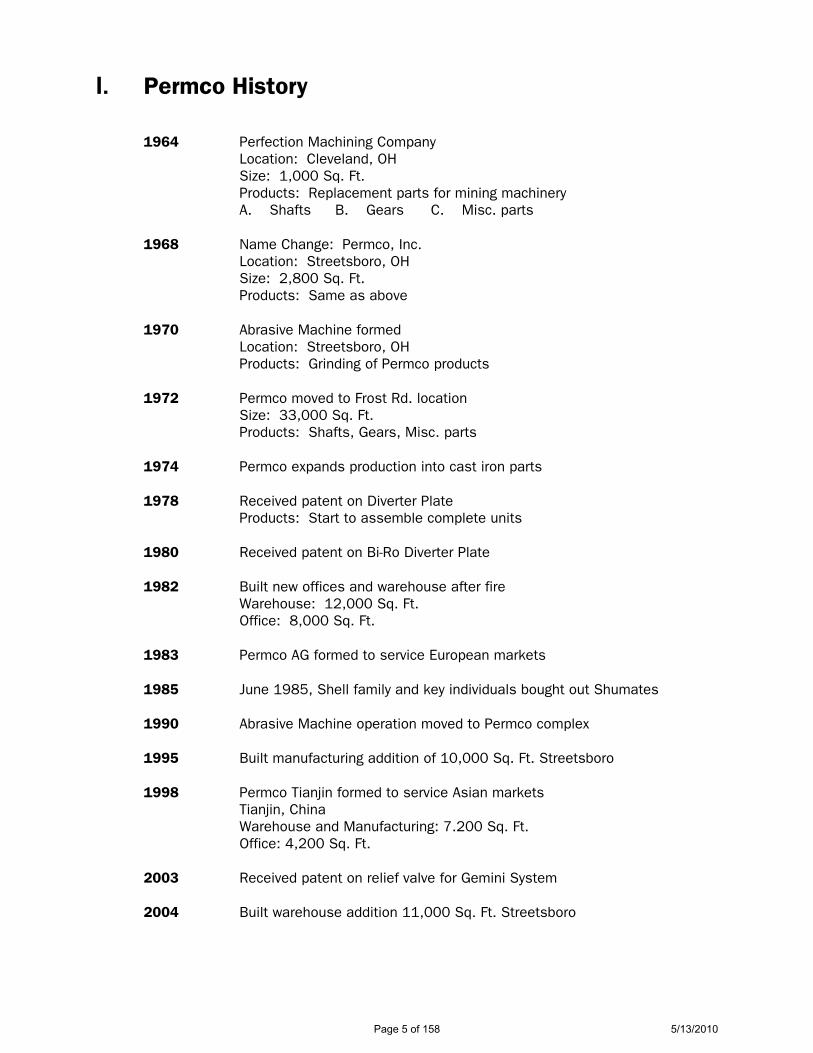
I. Permco History 1964 Perfection Machining Company Location: Cleveland, OH Size: 1,000 Sq. Ft. Products: Replacement parts for mining machinery A. Shafts B. Gears C. Misc. parts 1968 Name Change: Permco, Inc. Location: Streetsboro, OH Size: 2,800 Sq. Ft. Products: Same as above 1970 Abrasive Machine formed Location: Streetsboro, OH Products: Grinding of Permco products 1972 Permco moved to Frost Rd. location Size: 33,000 Sq. Ft. Products: Shafts, Gears, Misc. parts 1974 Permco expands production into cast iron parts 1978 Received patent on Diverter Plate Products: Start to assemble complete units 1980 Received patent on Bi-Ro Diverter Plate 1982 Built new offices and warehouse after fire Warehouse: 12,000 Sq. Ft. Office: 8,000 Sq. Ft. 1983 Permco AG formed to service European markets 1985 June 1985, Shell family and key individuals bought out Shumates 1990 Abrasive Machine operation moved to Permco complex
1995 Built manufacturing addition of 10,000 Sq. Ft. Streetsboro
1998 Permco Tianjin formed to service Asian markets Tianjin, China Warehouse and Manufacturing: 7.200 Sq. Ft. Office: 4,200 Sq. Ft.
2003 Received patent on relief valve for Gemini System 2004 Built warehouse addition 11,000 Sq. Ft. Streetsboro
Page 5 of 158 5/13/2010

2004 Permco Tianjin builds new offices, manufacturing, and warehouse facility Tianjin, China Warehouse: 12,000 Sq. Ft. Offices: 6,000 Sq. Ft. 2006 Built manufacturing and warehouse addition of 10,000 Sq. Ft. Streetsboro, Ohio 2006 Permco Tianjin Fluidpower Mfg. Co. Ltd formed to service Permco
worldwide. Manufacturing: 12,000 Sq. Ft. Offices: 5,000 Sq. Ft. 2007 Built warehouse addition of 10,000 Sq. Ft. Streetsboro, Ohio
II. Personnel Information Chairman Robert Shell Jr. Vice Chairman Doris Shell Exec. Vice Pres. Bernard D. Shell President, C.O.O. Rick Olszewski V.P. Dist. Sales Ron Fronek V.P. Manufacturing Tom Huth
Plant Manager Hank Leisure Mgr. Inside Sales Tim Hill Chief Engineer David Earls Engineering Joel Aukerman, Rick Conner, Aimee Liu, Alan Smallsreed Warranty Dept. Kevin Hall Inside Sales: Units Amy Wheeler, Ron Root, George Brna, Laurie Richards, Traffic Manager Kim Slayko
Assistant Comptroller Karen Slayko
Credit Manager Al Jackson Purchasing Manager Dale Pudloski IT Technicians Mark Gidley, Dennis Schmiz
Page 6 of 158 5/13/2010
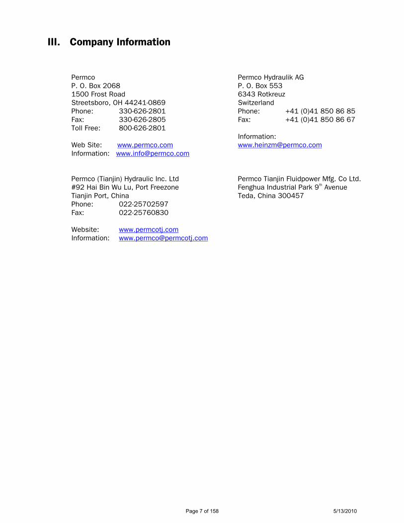
III. Company Information Permco P. O. Box 2068 1500 Frost Road Streetsboro, OH 44241-0869 Phone: 330-626-2801 Fax: 330-626-2805 Toll Free: 800-626-2801 Web Site: www.permco.com Information: [email protected]
Permco Hydraulik AG P. O. Box 553 6343 Rotkreuz Switzerland Phone: +41 (0)41 850 86 85 Fax: +41 (0)41 850 86 67 Information: [email protected]
Permco (Tianjin) Hydraulic Inc. Ltd Permco Tianjin Fluidpower Mfg. Co Ltd. #92 Hai Bin Wu Lu, Port Freezone Fenghua Industrial Park 9th Avenue Tianjin Port, China Teda, China 300457 Phone: 022-25702597 Fax: 022-25760830 Website: www.permcotj.com Information: [email protected]
Page 7 of 158 5/13/2010
PRESENTATION OUTLINE
I. PRODUCT LINE
A. Pumps, Motors, Flow Dividers, Miscellaneous Parts and Accessories
II. MARKETS
A. Refuse Industry – Rubbish and Garbage B. Construction Companies and Pavers C. Trucking Companies D. Industrial Accounts - Localize this List E. Hydraulic Repair Shops F. Equipment Dealers – Independents G. Scrap Iron Dealers – Cranes, Roll-Offs, Compactors H. Timber Harvesters and Processors I. Mining Operations – Gravel, Coal, Iron, Gold, etc. J. Commercial Fishing Industry K. Municipalities – State, County, Parrish, City, Township
III. C/S – PERMCO REPLACEMENT PARTS AND PUMPS
IV. PERMCO HAS MANY OTHER NEW AND UNIQUE PRODUCTS
V. GO THROUGH LITERATURE PIECE BY PIECE
VI. GO BACK TO ENGINEERS HANDBOOK – PAGE 5
A. Go over series and cubic inch displacements B. PL factor – explain – refer to bottom of page 3 C. Emphasize per inch of gear width D. Port sizing on page 6 E. Performance data – actual from test stand – not theoretical F. Page 13 – pump numbering and coding G. Shaft end covers, port end covers, housings, shafts, bearing carriers; Note:
page 48 flow limits per section H. Flow dividers – Positraction – 1-1, 1-2, 1-3, etc
VII. NOTE SERIES IDENTIFICATION CHARTS – BACK SECTION OF SERVICE MANUALS
VIII. IF NECESSARY, GO THROUGH CUBIC INCH DISPLACEMENT FORMULA
Page 8 of 158 5/13/2010

SUGGESTED MARKETING PLAN
I. Make a list of prospects for:
A. Refuse Industry – Rubbish and Garbage B. Construction Companies and Pavers C. Trucking Companies D. Industrial Accounts - Localize this List E. Hydraulic Repair Shops F. Equipment Dealers – Independents G. Scrap Iron Dealers – Cranes, Roll-Offs, Compactors H. Timber Harvesters and Processors I. Mining Operations – Gravel, Coal, Iron, Gold, etc. J. Commercial Fishing Industry K. Municipalities – State, County, Parrish, City, Township
II. Separate this list into two (2) categories:
A. Existing Customers B. Potential New Business
III. Mailing – Arrange to do a mailing on a limited, consistent program. Leads that are not followed up on within a week become stale. Possibly target one market at a time.
IV. Keep all lead and work sheets – with comments.
V. Keep track of calls and specific market areas on a wall map. Watch trends.
VI. Establish company policy on pricing and review monthly to monitor competition
and maximize profit margins.
VII. Learn product line – thoroughly.
Page 9 of 158 5/13/2010
PERMCO is your # 1 Gear Pump Source for 10 Good Reasons
1. BEST PRODUCT LINE - One call gives you access to a complete line of pumps, motors, flow dividers, intensifiers, or replacement parts. This includes MRO and OEM products.
2. COMPETITIVE PRICING - Permco’s expansive distributor base allows us the economics
of production to offer competitive pricing.
3. EXPERT HELP - Permco’s personnel are trained hydraulic individuals. All inside people have attended hydraulics classes. We have Engineers on staff as well as a registered Professional Engineer for specialized projects.
4. FAST DELIVERY & SERVICE - Our inventory is designed so that we can ship parts orders
in (2) weeks or less and unit orders in (4) weeks or less.
5. SPECIAL ORDER ITEMS - Special order items receive our immediate attention. This includes special shafts, brackets, etc. to meet a particular customer or market needs.
6. COMPLETE UNITS - Permco offers over 27,000 different units. Each is built to customer
specifications. All units are tested with the results written on a tag affixed to the pump and recorded in a master log. All results are catalogued and serial numbered to reduce your liability as well as ours.
7. TRAINING CLASSES - Permco offers training classes in hydraulics, two to four times a
year. These are open to you and your employees. Basic hydraulics, troubleshooting and hands-on building and testing of pumps is covered during the training session.
8. ENGINEERING & RESEARCH & DEVELOPMENT - Permco’s Engineering Department is
continually working on improving existing products as well as looking at new and innovative designs. The controlled stress roller bearings for increased bearing life, the Versa-Pak series, the Gemini, Winch Motors and special application thrust plates just to name a few.
9. SALES REPRESENTATION - Factory trained representatives are available on a regular
basis to work with your people. Whether it would be repair or technical training -- we are available.
10. OUR WILLINGNESS TO WORK WITH YOU - As a manufacture of hydraulic components,
we are aware that you have a choice. We are aware that the products we offer are only as good as our willingness to support their applications. You can count on us to swiftly respond should problems arise and to help you rapidly solve them.
YOU HAVE A CHOICE ---- MAKE IT PERMCO
Page 10 of 158 5/13/2010
PERMCO
UNIT WARRANTY RETURN PROCEDURE
In order for Permco to better serve the customer with regard to warranty claims or pump/motor failure evaluation, the following procedures need to be followed:
1. No unit will be received without a Return Authorization Number (RAN). 2. Return Authorization Numbers, will remain active for a period of thirty (30) days. If
unit/units are not received at Permco within this period of time, a new RAN must be attained.
3. Permco will strive to evaluate failures and determine if they are warranty related. We will
reply as quickly as possible, contact you with a determination as to repair of unit, replacement of unit or help the customer with the problem as per the customer’s discretion. It is imperative that the customer respond to Permco as to what he wants done with the returned unit within a reasonable amount of time (60 days max.). After 60 days Permco will dispose of the unit and consider the matter closed.
4. In order to better serve the customer, Permco request that the units should be returned
unopened. A unit that has been disassembled prior to returning it to us makes accurate determination and evaluation impossible to determine. If a unit has been opened, it is important to re-assemble it “exactly” as it came apart. Do not return loose parts to Permco. Parts shipped loose can be damaged and proper orientation is impossible.
Your cooperation will be greatly appreciated. Engineering Department
Page 11 of 158 5/13/2010
PERMCO WARRANTY POLICY(EFFECTIVE 07/01/2009)
Page 1 of 2
PRODUCT WARRANTY: PERCMO warrants that when shipped from Permco’s manufacturing facility, the products sold hereunder (i) shall be new and unused; and (ii) shall be free from defects in material and workmanship for the term of this warranty. PERMCO makes no warranty on any product used in any way except as it was designed, intended and sold to perform.
This warranty does not apply to any special products or items designed and/or manufactured to a customer’s specifications. Such products have no warranties except as set forth in a separate written warranty signed by a divisional president of Permco or two other officers of Permco.
WARRANTY PERIOD: The warranty set forth above shall commence on the date that said product is shipped to the original buyer of said product (the “Warranty Start Date”) and shall expire on the earlier of: (i) 24 months from the Warranty Start Date; or (ii) 4,000 hours of normal use.
EARLY TERMINATION OF WARRANTY PERIOD: The warranty period stipulated above shall terminate if buyer or a third party undertakes inappropriate or improper modification or repair, including, but not limited to, the use of other than genuine Permco parts in the repair of said product, or if the buyer, in case of a defect, does not as soon as reasonably possible take all appropriate steps to mitigate its damages and to notify Permco in writing of buyer’s warranty claim.
EXCLUSIONS FROM WARRANTY: Excluded from Permco’s warranty and liability for defects are all deficiencies which cannot be proved to have their origin in bad material or poor workmanship, e.g. for deficiencies resulting from normal wear and tear, improper maintenance or repair, use of replacement parts other than genuine Permco parts, misuse, neglect, improper handling or storage, failure to observe the operating instructions, pressure spikes, or deficiencies resulting from other reasons beyond Permco’s control, including damages caused by erosion, corrosion or cavitation.
EXCLUSIVE REMEDY: Permco’s sole liability to buyer arising from, or relating to, any product sold hereunder shall be limited exclusively to repair or replacement of the product sold, or refund of the purchase price paid by buyer, at Permco’s sole option, in accordance with the procedures set forth herein.
WARRANTY CLAIM: If a buyer claims a breach of the warranty set forth above, buyer must:
(i) Promptly notify Permco in writing of the alleged defect in materials and/or workmanship, including the circumstances of the product failure; (ii) Utilize the warranty claim form, if any, then being currently utilized by Permco; (iii) Provide Permco with such other information as reasonably requested by Permco or its agents regarding the product failure and the surrounding circumstances; (iv) Provide Permco, at Permco’s option, with the right to examine the product in question at the site of the failure or to ship, at the buyer’s cost, the product back to Permco’s facility or an authorized warranty repair center according to shipping instructions provided by Permco; (v) Obtain a Return Authorization Number (RAN) from Permco if the product is to be returned to Permco or its authorized warranty repair center (Please note: a RAN shall be valid for only 30 days and shall be referenced in all correspondence from buyer to Permco); (vi) If so requested, return the product unopened to Permco as a unit; and (vii) Unless so instructed by Permco, retain any loose parts.
Please note that a unit that has been disassembled prior to returning it to Permco makes accurate determination and evaluation impossible. If a unit has been opened, it is important to re-assemble it “exactly” as it came apart.
Within 60 days from the inspection of the product by Permco or its agent, Permco shall determine whether a valid warranty claim exists. If a valid claim exists, Permco, at its sole option, shall either (i) replace or repair the product and then ship the repaired or replacement product to buyer at Permco’s sole cost; or (ii) refund the purchase price paid by
Page 12 of 158 5/13/2010
Page 2 of 2
buyer for said product. If a valid warranty claim exists, Permco shall also reimburse buyer for the cost of shipping the product to Permco or its agent.
If Permco determines a valid warranty claim does not exist, it will advise the buyer of its determination in writing and will request the buyer advise Permco as to what it wants done with the returned product. After 60 days, Permco will dispose of the returned product and consider the matter closed. If the buyer requests the return of the product, buyer shall pay the cost of return in advance prior to Permco’s shipment of said product back to said buyer.
DISCLAIMER OF WARRANTIES: PERMCO MAKES NO PERFORMANCE GUARANTEE, WARRANTY OR REPRESENTATION WITH RESPECT TO ITS PRODUCTS EXCEPT AS SET FORTH HEREIN. ALL OTHER PERFORMANCE GUARANTEES, WARRANTIES, EXPRESS OR IMPLIED, INCLUDING, BUT NOT LIMITED TO THE IMPLIED WARRANTIES OF MERCHANTABILITY AND FITNESS FOR A PARTICULAR PURPOSE, OR THOSE WHICH MIGHT ARISE BY OPERATION OF LAW OR EQUITY, TRADE USAGE, OR COURSE OF DEALING ARE HEREBY DISCLAIMED.
LIMITATION OF REMEDIES: BUYER’S SOLE AND EXCLUSIVE REMEDY AGAINST PERMCO SHALL BE AS SET FORTH ABOVE. THE EXCLUSIVE REMEDIES SET FORTH ABOVE SHALL NOT BE DEEMED TO HAVE FAILED THEIR ESSENTIAL PURPOSE SO LONG AS PERMCO IS WILLING TO REPAIR, REPLACE, MODIFY OR CORRECT THE PRODUCT IN THE MANNER AND WITHIN THE LIMITS PRESCRIBED HEREIN OR REFUND THE PURCHASE PRICE PAID BY THE BUYER.
If, for any reason, any or all of the exclusive remedies provided herein are deemed by a court of law to have failed of their essential purpose or otherwise by unavailing as limits on the buyer’s remedies for breach of the warranty contained herein, then it is the intent of the parties that the Limitation on Liability set forth below, which limits liability and prohibits consequential damages, nevertheless shall be accorded independent effect and would remain in full force as reflecting the allocation of risk intended by Permco and the buyer.
LIMITATION OF LIABILITY: NOTWITHSTANDING ANY OTHER PROVISIONS HEREOF OR ANY OTHER PROVISION OF ANY AGREEMENT BETWEEN PERMCO AND BUYER, PERMCO SHALL NOT BE LIABLE TO BUYER OR ANY OTHER PARTY FOR ANY LOSS OF ANTICIPATED PROFITS, LOST SALES, INJURY TO PERSONS OR PROPERTY, LOSS BY REASON OF PLANT SHUTDOWN, NON-OPERATION OR INCREASED EXPENSE OF OPERATION, SERVICE INTERRUPTIONS, CLAIMS OF CUSTOMERS, COST OF MONEY, LOSS OF USE OF CAPITAL OR REVENUE, OR FOR ANY OTHER SPECIAL, INCIDENTAL OR CONSEQUENTIAL LOSSES OR DAMAGES OF ANY KIND OR NATURE WHATSOEVER, WHETHER ALLEGED TO ARISE FROM BREACH OF CONTRACT, BREACH OF WARRANTY, OR IN TORT, INCLUDING WITHOUT LIMITATION, NEGLIGENCE, FAILURE TO WARN OR STRICT LIABILITY. NO CAUSE OF ACTION ARISING OUT OF, OR RELATING TO, THE SALE OF THE ITEMS SOLD HEREUNDER OR THIS AGREEMENT MAY BE BROUGHT MORE THAN TWO (2) YEARS AFTER THE CAUSE OF ACTION SHALL ACCRUE.
MODIFCATION OF WARRANTY: The foregoing warranty may not be modified, extended or altered except by a writing signed by a divisional president of Permco or two other officers of Permco.
EFFECTIVE DATE: This Warranty is effective July1, 2009 and supersedes all previously distributed warranties. It shall remain in effect until such time as Permco publishes a subsequent superceding version at which time it will have no further effect.
GOVERNING LAW: This Warranty and the sale and delivery of all products hereunder shall be governed and construed in accordance with the laws of the United States, excluding the United Nations Convention on Contracts for the International Sale of Goods.
Page 13 of 158 5/13/2010
Page
14
of 1
585/
13/2
010
Page
15
of 1
585/
13/2
010

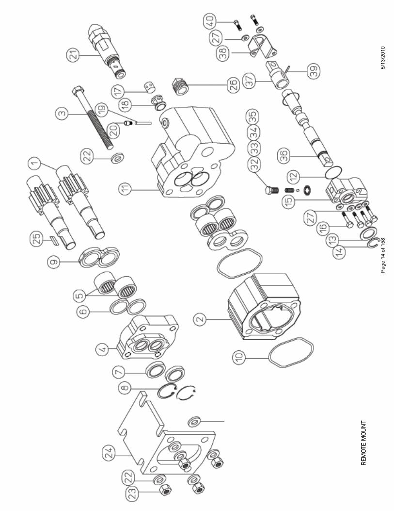
PARTS BREAKDOWN FOR REMOTE MOUNT DM-512-20-XR-M-T-200
ITEM PART NO. DESCRIPTION QTY ITEM PART NO. DESCRIPTION QTY
1 CD-0024L-20 GEAR SET 1" DIA. KEYED 1 21 RP-5514 RELIEF VALVE 12 SZ-0577-20 GEAR HOUSING 1 22 W033-2 5/8" WASHER 123 ZD-0391-08 5/8"-11 X 8" TIE BOLTS 4 23 W3-65 5/8"-11 NUT 84 WA-0575 SHAFT END COVER 1 24 D-0931 MOUNTING BRACKET 15 R-0921 ROLLER BEARING 4 25 W09-02 1/4 X 3/8 X 1-1/4 SHAFT KEY 16 MA-0558-1XS RING SEAL 4 26 W0-5 1" NPT STEEL PIPE PLUG 17 W62-49-3NP SHAFT SEAL NO PAINT 2 27 DM-250-LW 5/16" SPLIT LOCK WASHER 68 W023-181 SNAP RING 2 28 #42 1" NPT PLASTIC PLUG 19 X-0947-TC THRUST PLATE 2 29 #53 1-1/4" NPT PLASTIC PLUG 1
10 TA-2995-245 SQ. GASKET SEAL 2 30 Z-1967-45-2 NAME TAG 111 ZF-0920 VALVE HOUSING 1 31 SP-1000-3 PLASTIC SHAFT PROTECTOR 212 K-2995-9 O'RING 2 32 640-00224-BSR BALL & SPRING RETAINER 113 CR80-3 SPOOL STOP 1 33 640-00520-SPR DETENT SPRING 114 W093-2XH SNAP RING 1 34 640-00521-B DETENT BALL 115 AB-0949-P SPOOL END CAP 1 35 LW-0949 LOCK WASHER 116 Wl-71 5/16"-18 X 2" CAP SCREW 4 36 640-00522-NLS SPOOL 117 MC-0429 CHECK VALVE POPPET 1 37 640-00523-SE SPOOL EYE 118 UZ-0071-10 CHECK VALVE RETAINER 1 38 640-00524-ER SPOOL EYE RETAINER 119 W014-218 RETAINER PIN 1 39 640-00544 ROLL PIN 120 WO-28 PIPE PLUG 1/16" NPT 1 40 640-00302-CMB 5/16"-18 X 1/2" CAP SCREW 2
NOTE: PART NO.'S 28, 29, 30, 31 NOT ON DRAWING
PARTS BREAKDOWN FOR REMOTE MOUNT DM-640-25-XR-M-T-200
ITEM PART NO. DESCRIPTION QTY ITEM PART NO. DESCRIPTION QTY
1 CD-0024L-25 GEAR SET 1" DIA. KEYED 1 21 RP-5514 RELIEF VALVE 12 SZ-0577-25 GEAR HOUSING 1 22 W033-2 5/8" WASHER 123 W1-009 5/8"-11 X 7-1/2" BOLTS 4 23 W3-65 5/8"-11 NUT 84 WA-0575 SHAFT END COVER 1 24 D-0931 MOUNTING BRACKET 15 R-0921 ROLLER BEARING 4 25 W09-02 1/4 X 3/8 X 1-1/4 SHAFT KEY 16 MA-0558-1XS RING SEAL 4 26 W0-5 1" NPT STEEL PIPE PLUG 17 W62-49-3NP SHAFT SEAL NO PAINT 2 27 DM-250-LW 5/16" SPLIT LOCK WASHER 68 W023-181 SNAP RING 2 28 #42 1" NPT PLASTIC PLUG 19 X-0947-TC THRUST PLATE 2 29 #53 1-1/4" NPT PLASTIC PLUG 1
10 TA-2995-245 SQ. GASKET SEAL 2 30 Z-1967-45-3 NAME TAG 111 ZF-0920 VALVE HOUSING 1 31 SP-1000-3 PLASTIC SHAFT PROTECTOR 212 K-2995-9 O'RING 2 32 640-00224-BSR BALL & SPRING RETAINER 113 CR80-3 SPOOL STOP 1 33 640-00520-SPR DETENT SPRING 114 W093-2XH SNAP RING 1 34 640-00521-B DETENT BALL 115 AB-0949-P SPOOL END CAP 1 35 LW-0949 LOCK WASHER 116 Wl-71 5/16"-18 X 2" CAP SCREW 4 36 640-00522-NLS SPOOL 117 MC-0429 CHECK VALVE POPPET 1 37 640-00523-SE SPOOL EYE 118 UZ-0071-10 CHECK VALVE RETAINER 1 38 640-00524-ER SPOOL EYE RETAINER 119 W014-218 RETAINER PIN 1 39 640-00544 ROLL PIN 120 WO-28 PIPE PLUG 1/16" NPT 1 40 640-00302-CMB 5/16"-18 X 1/2" CAP SCREW 2
NOTE: PART NO.'S 28, 29, 30, 31 NOT ON DRAWING
Page 16 of 158 5/13/2010
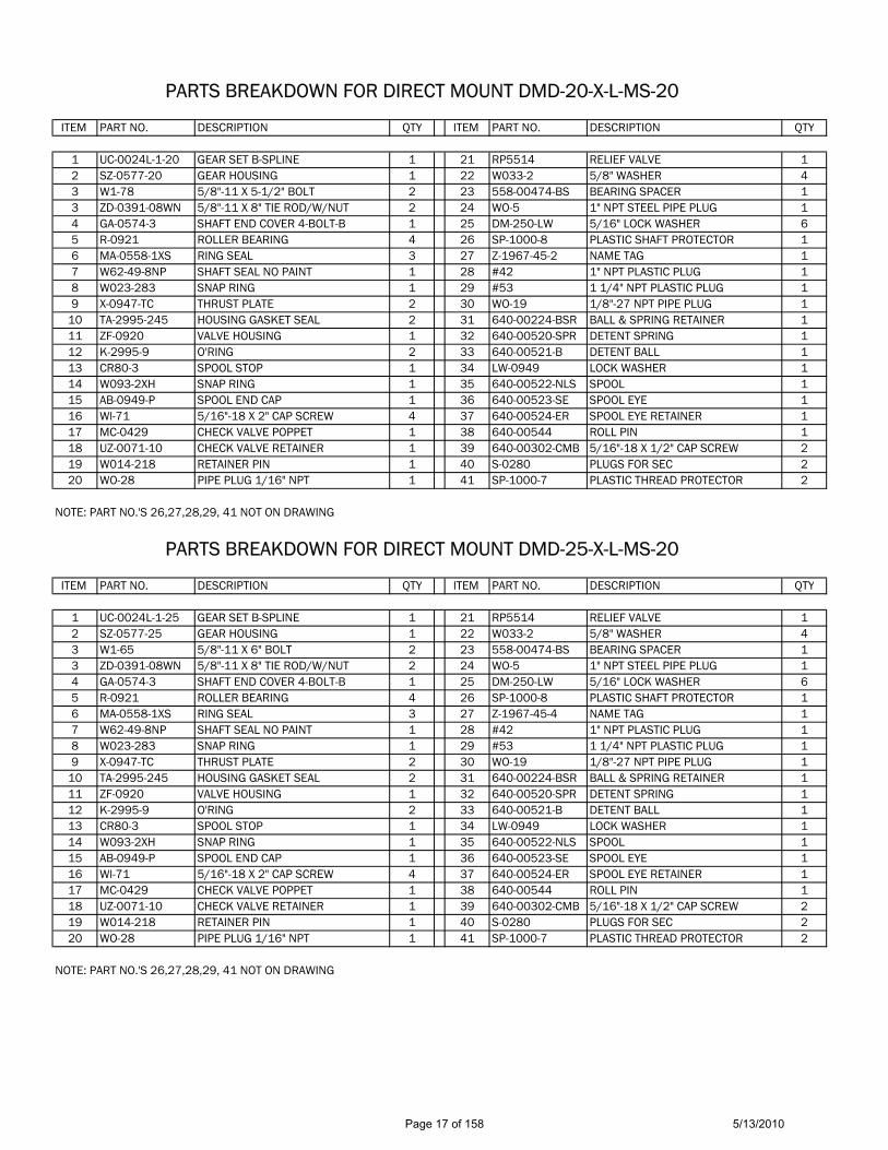
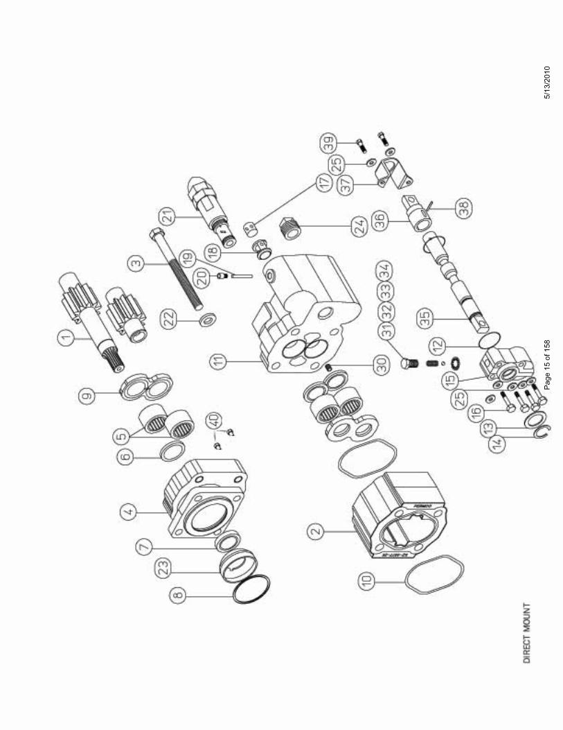
PARTS BREAKDOWN FOR DIRECT MOUNT DMD-20-X-L-MS-20
ITEM PART NO. DESCRIPTION QTY ITEM PART NO. DESCRIPTION QTY
1 UC-0024L-1-20 GEAR SET B-SPLINE 1 21 RP5514 RELIEF VALVE 12 SZ-0577-20 GEAR HOUSING 1 22 W033-2 5/8" WASHER 43 W1-78 5/8"-11 X 5-1/2" BOLT 2 23 558-00474-BS BEARING SPACER 13 ZD-0391-08WN 5/8"-11 X 8" TIE ROD/W/NUT 2 24 WO-5 1" NPT STEEL PIPE PLUG 14 GA-0574-3 SHAFT END COVER 4-BOLT-B 1 25 DM-250-LW 5/16" LOCK WASHER 65 R-0921 ROLLER BEARING 4 26 SP-1000-8 PLASTIC SHAFT PROTECTOR 16 MA-0558-1XS RING SEAL 3 27 Z-1967-45-2 NAME TAG 17 W62-49-8NP SHAFT SEAL NO PAINT 1 28 #42 1" NPT PLASTIC PLUG 18 W023-283 SNAP RING 1 29 #53 1 1/4" NPT PLASTIC PLUG 19 X-0947-TC THRUST PLATE 2 30 WO-19 1/8"-27 NPT PIPE PLUG 1
10 TA-2995-245 HOUSING GASKET SEAL 2 31 640-00224-BSR BALL & SPRING RETAINER 111 ZF-0920 VALVE HOUSING 1 32 640-00520-SPR DETENT SPRING 112 K-2995-9 O'RING 2 33 640-00521-B DETENT BALL 113 CR80-3 SPOOL STOP 1 34 LW-0949 LOCK WASHER 114 W093-2XH SNAP RING 1 35 640-00522-NLS SPOOL 115 AB-0949-P SPOOL END CAP 1 36 640-00523-SE SPOOL EYE 116 Wl-71 5/16"-18 X 2" CAP SCREW 4 37 640-00524-ER SPOOL EYE RETAINER 117 MC-0429 CHECK VALVE POPPET 1 38 640-00544 ROLL PIN 118 UZ-0071-10 CHECK VALVE RETAINER 1 39 640-00302-CMB 5/16"-18 X 1/2" CAP SCREW 219 W014-218 RETAINER PIN 1 40 S-0280 PLUGS FOR SEC 220 WO-28 PIPE PLUG 1/16" NPT 1 41 SP-1000-7 PLASTIC THREAD PROTECTOR 2
NOTE: PART NO.'S 26,27,28,29, 41 NOT ON DRAWING
PARTS BREAKDOWN FOR DIRECT MOUNT DMD-25-X-L-MS-20
ITEM PART NO. DESCRIPTION QTY ITEM PART NO. DESCRIPTION QTY
1 UC-0024L-1-25 GEAR SET B-SPLINE 1 21 RP5514 RELIEF VALVE 12 SZ-0577-25 GEAR HOUSING 1 22 W033-2 5/8" WASHER 43 W1-65 5/8"-11 X 6" BOLT 2 23 558-00474-BS BEARING SPACER 13 ZD-0391-08WN 5/8"-11 X 8" TIE ROD/W/NUT 2 24 WO-5 1" NPT STEEL PIPE PLUG 14 GA-0574-3 SHAFT END COVER 4-BOLT-B 1 25 DM-250-LW 5/16" LOCK WASHER 65 R-0921 ROLLER BEARING 4 26 SP-1000-8 PLASTIC SHAFT PROTECTOR 16 MA-0558-1XS RING SEAL 3 27 Z-1967-45-4 NAME TAG 17 W62-49-8NP SHAFT SEAL NO PAINT 1 28 #42 1" NPT PLASTIC PLUG 18 W023-283 SNAP RING 1 29 #53 1 1/4" NPT PLASTIC PLUG 19 X-0947-TC THRUST PLATE 2 30 WO-19 1/8"-27 NPT PIPE PLUG 1
10 TA-2995-245 HOUSING GASKET SEAL 2 31 640-00224-BSR BALL & SPRING RETAINER 111 ZF-0920 VALVE HOUSING 1 32 640-00520-SPR DETENT SPRING 112 K-2995-9 O'RING 2 33 640-00521-B DETENT BALL 113 CR80-3 SPOOL STOP 1 34 LW-0949 LOCK WASHER 114 W093-2XH SNAP RING 1 35 640-00522-NLS SPOOL 115 AB-0949-P SPOOL END CAP 1 36 640-00523-SE SPOOL EYE 116 Wl-71 5/16"-18 X 2" CAP SCREW 4 37 640-00524-ER SPOOL EYE RETAINER 117 MC-0429 CHECK VALVE POPPET 1 38 640-00544 ROLL PIN 118 UZ-0071-10 CHECK VALVE RETAINER 1 39 640-00302-CMB 5/16"-18 X 1/2" CAP SCREW 219 W014-218 RETAINER PIN 1 40 S-0280 PLUGS FOR SEC 220 WO-28 PIPE PLUG 1/16" NPT 1 41 SP-1000-7 PLASTIC THREAD PROTECTOR 2
NOTE: PART NO.'S 26,27,28,29, 41 NOT ON DRAWING
Page 17 of 158 5/13/2010

PERMCO DUMP-PUMP TWO AND THREE LINE OPERATION
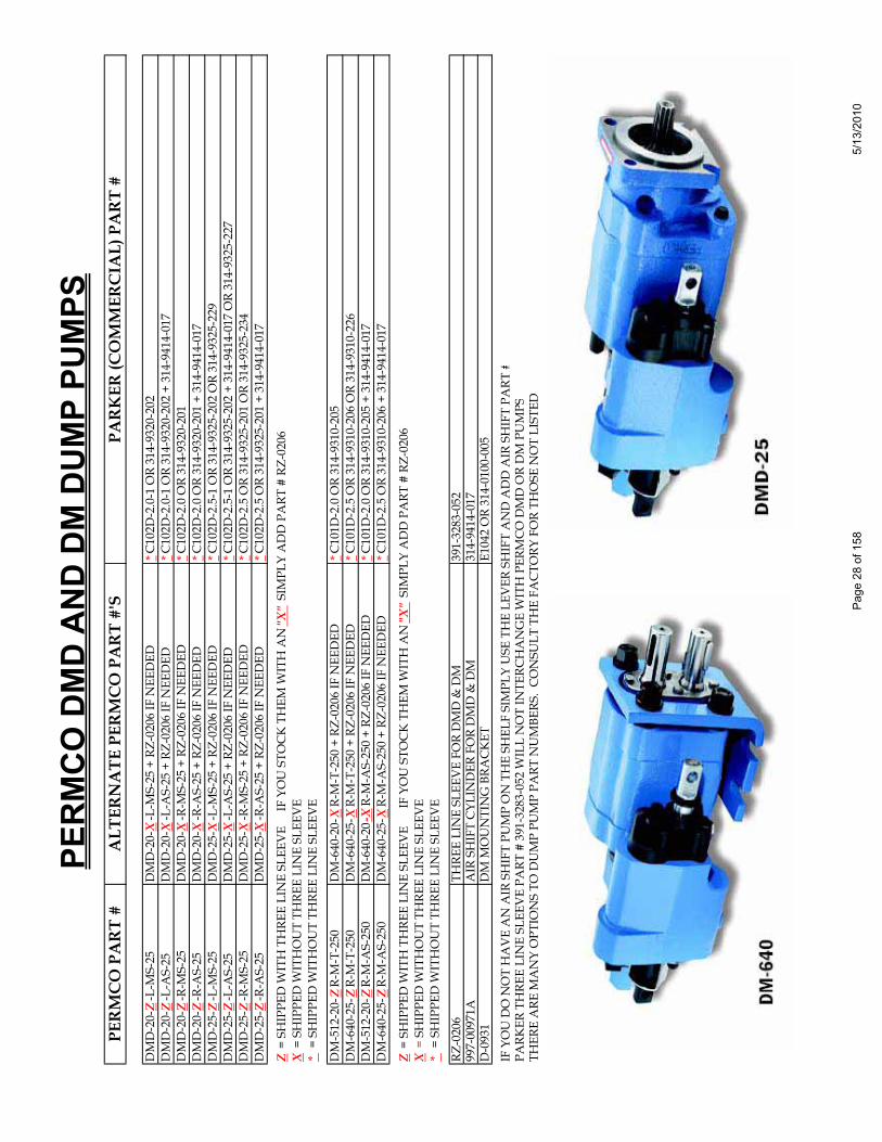
In applying the Permco Dump Pump, an understanding of the 2-line and 3-line circuits is essential for proper operation and maximum unit life. In the two line operation, one line is connected from the oil tank to the inlet of the pump and one line is connected from the cylinder port of the valve to the cylinder. With the pump engaged and the valve spool in the neutral position, oil will recirculate inside the unit. It has been determined through testing that the rise in temperature per every minute of operation in this mode is 7.5°F. If operation is allowed to continue beyond the recommended 5 minute time interval, a reduction in clearances of the rotating group due to excessive heat and subsequent expansion will occur. The result may lead to the unit locking up and premature failure of the drive shaft or other internal components. In a three line application, one line is connected from the oil tank to the inlet of the pump, one line is connected from the cylinder port to the cylinder and one line is connected from the pumps return port back to the oil tank. To connect this port, a 1' pipe plug must be removed for hose connection and a metal sleeve, Permco P/N RZ-0206 (DM-512, DM-640, DMD-20 and DMD-25) P/N 400-00870 (DMR-300, DMR-400, DMD-300 and DMD-400), must be inserted into the inlet port of the valve. By inserting the sleeve into the inlet port, flow from either the cylinder retracting or with the spool in neutral will be diverted directly back to the oil tank. It should be noted that the operation of the Dump Pump with the 3-line circuit will reduce the possibility of premature failure due to excessive heating but will not eliminate it. It is therefore recommended that the unit be run in this mode of operation for no longer than 10 minutes.
General Comments Concerning the Application and Operation of the Dump Pump As discussed earlier with the 3-line operation, the metal sleeve inserted in the inlet port of the pump diverts flow back to the oil tank. With this sleeve installed in a 2-line system, only a minimal amount of oil will pass across it. The majority of the oil will be blocked from recirculating internally. If the pump is engaged and the spool is in the neutral position, flow may be directed back, into the cylinder port and extend the cylinder. CAUTION: Operation with the sleeve installed in a 2-line application is potentially hazardous. Because the factory is unaware of which return line circuit the customer will choose the sleeve is never installed at the factory.
Page 18 of 158 5/13/2010

Like any control valve, there are inherent pressure drops within the dump pump due to internal core configurations. During cylinder retraction, fluid velocities may increase to the point that excessive back pressures may be seen at the pump seal area. For this reason, Permco installs high pressure motor seals in all Dump Pump units to prevent premature seal failure. It is also suggested that movement of the valve spool from the neutral to the raise position in rapid succession be avoided as this may also contribute to the premature failure of the shaft seal.
NOTE: The pump should be primed with spool in raise position. It may be required to crack a fitting to bleed lines of air.
Circuit Schematics of 2-Line and 3-Line Operation
2 LINE OPERATION 3 LINE OPERATION
Page 19 of 158 5/13/2010
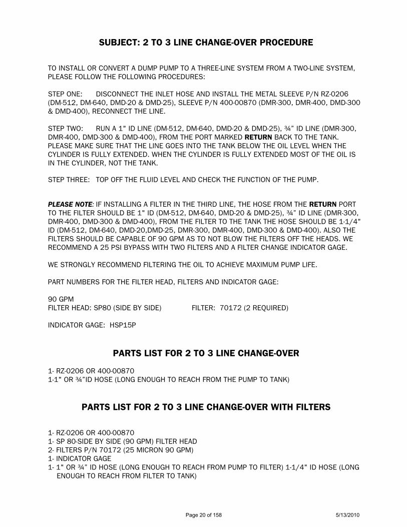
SUBJECT: 2 TO 3 LINE CHANGE-OVER PROCEDURE TO INSTALL OR CONVERT A DUMP PUMP TO A THREE-LINE SYSTEM FROM A TWO-LINE SYSTEM, PLEASE FOLLOW THE FOLLOWING PROCEDURES: STEP ONE: DISCONNECT THE INLET HOSE AND INSTALL THE METAL SLEEVE P/N RZ-0206 (DM-512, DM-640, DMD-20 & DMD-25), SLEEVE P/N 400-00870 (DMR-300, DMR-400, DMD-300 & DMD-400), RECONNECT THE LINE. STEP TWO: RUN A 1" ID LINE (DM-512, DM-640, DMD-20 & DMD-25), !” ID LINE (DMR-300, DMR-400, DMD-300 & DMD-400), FROM THE PORT MARKED RETURN BACK TO THE TANK. PLEASE MAKE SURE THAT THE LINE GOES INTO THE TANK BELOW THE OIL LEVEL WHEN THE CYLINDER IS FULLY EXTENDED. WHEN THE CYLINDER IS FULLY EXTENDED MOST OF THE OIL IS IN THE CYLINDER, NOT THE TANK. STEP THREE: TOP OFF THE FLUID LEVEL AND CHECK THE FUNCTION OF THE PUMP. PLEASE NOTE: IF INSTALLING A FILTER IN THE THIRD LINE, THE HOSE FROM THE RETURN PORT TO THE FILTER SHOULD BE 1" ID (DM-512, DM-640, DMD-20 & DMD-25), !” ID LINE (DMR-300, DMR-400, DMD-300 & DMD-400), FROM THE FILTER TO THE TANK THE HOSE SHOULD BE 1-1/4" ID (DM-512, DM-640, DMD-20,DMD-25, DMR-300, DMR-400, DMD-300 & DMD-400). ALSO THE FILTERS SHOULD BE CAPABLE OF 90 GPM AS TO NOT BLOW THE FILTERS OFF THE HEADS. WE RECOMMEND A 25 PSI BYPASS WITH TWO FILTERS AND A FILTER CHANGE INDICATOR GAGE. WE STRONGLY RECOMMEND FILTERING THE OIL TO ACHIEVE MAXIMUM PUMP LIFE. PART NUMBERS FOR THE FILTER HEAD, FILTERS AND INDICATOR GAGE: 90 GPM FILTER HEAD: SP80 (SIDE BY SIDE) FILTER: 70172 (2 REQUIRED) INDICATOR GAGE: HSP15P
PARTS LIST FOR 2 TO 3 LINE CHANGE-OVER 1- RZ-0206 OR 400-00870 1-1" OR !”ID HOSE (LONG ENOUGH TO REACH FROM THE PUMP TO TANK)
PARTS LIST FOR 2 TO 3 LINE CHANGE-OVER WITH FILTERS 1- RZ-0206 OR 400-00870 1- SP 80-SIDE BY SIDE (90 GPM) FILTER HEAD 2- FILTERS P/N 70172 (25 MICRON 90 GPM) 1- INDICATOR GAGE 1- 1" OR !” ID HOSE (LONG ENOUGH TO REACH FROM PUMP TO FILTER) 1-1/4" ID HOSE (LONG ENOUGH TO REACH FROM FILTER TO TANK)
Page 20 of 158 5/13/2010

Page
21
of 1
585/
13/2
010

RR
IIff iitteemmss 99 oorr 1100 aarreeddaammaaggeedd,, ooiill wwiillllbbyyppaassss rreelliieeff vvaallvvee
IIff ddiirrtt oorr ddeebbrriiss ggeettss uunnddeerr bbaallll bbeettwweeeennbbaallll aanndd sseeaatt ooiill wwiillll bbyyppaassss rreelliieeffaanndd//oorr aallllooww ccyylliinnddeerr ttoo ddrriifftt ddoowwnn
66 112255
112233445566778899110011111122
111111111111111111111111
CCAARRTTRRIIDDGGEESSPPRRIINNGGSSPPRRIINNGG RREETTAAIINNEERRBBAALLLL RREETTAAIINNEERRAACCOORRNN NNUUTTCCOOMMPPRREESSSSIIOONN WWAASSHHEERRBBAALLLLQQUUAADD RRIINNGGBBAACCKK--UUPP RRIINNGG""OO""--RRIINNGG""OO""--RRIINNGG
RRPP--55551144--11 RRPP--55551144--22 RRPP--55551144--33 RRPP--55551144--44 RRPP--55551144--55 RRPP--55551144--66 RRPP--55551144--77 RRPP--55551144--88 RRPP--55551144--99 RRPP--55551144--1100 RRPP--55551144--1111 RRPP--55551144--1122
IITTEEMM PPAARRTT NNOO.. DDEESSCCRRIIPPTTIIOONN RREEQQ''DD
33 66 11 22 1111 44 88 77 99 1100
TToo sseett rreelliieeff vvaallvvee ttoo 22550000 PPSSII,, wwhheenniitt iiss sseett aatt 22000000 PPSSII ffrroomm tthhee ffaaccttoorryyrreemmoovvee iitteemm ##55,, lloooosseenn iitteemm ##1122,, ttuurrnn iitteemm ##3333//88 ooff aa ttuurrnn cclloocckkwwiissee tthheenn ttiigghhtteenn iitteemm ##1122aanndd rreeppllaaccee iitteemm ##55..
DDUUMMPP PPUUMMPP RREELLIIEEFF VVAALLVVEE --RRPP--55551144
** IInn tthhee eevveenntt tthhee rreelliieeff vvaallvveeiiss ddiissaasssseemmbblleedd -- CCaalliibbrraattiioonnmmuusstt bbee ddoonnee oonn aa tteesstt ssttaanndd
HYDRAULIC / PNEUMATIC PRODUCTS
1500 Frost Road • Post Office Box 2068 • Streetsboro, Ohio 44241-0869 • 330/626-2801 • Fax: 330/626-2805
To: All Permco Distributors Date: July 12, 1994
Subject: DUMP PUMP RELIEF VALVE
Series: DM-512-20, DM-640-25, DMD-20 and DMD-25
NATIONAL FLUID POWER ASSOCIATION Page 22 of 158 5/13/2010

Page
23
of 1
585/
13/2
010

Page
24
of 1
585/
13/2
010
LLOOWWEERR PPOORRTTRRAAIISSEE PPOORRTT
4
9
12
11
10
1
11
GASKET (LARGE HOLE)12
11 PLATE
12
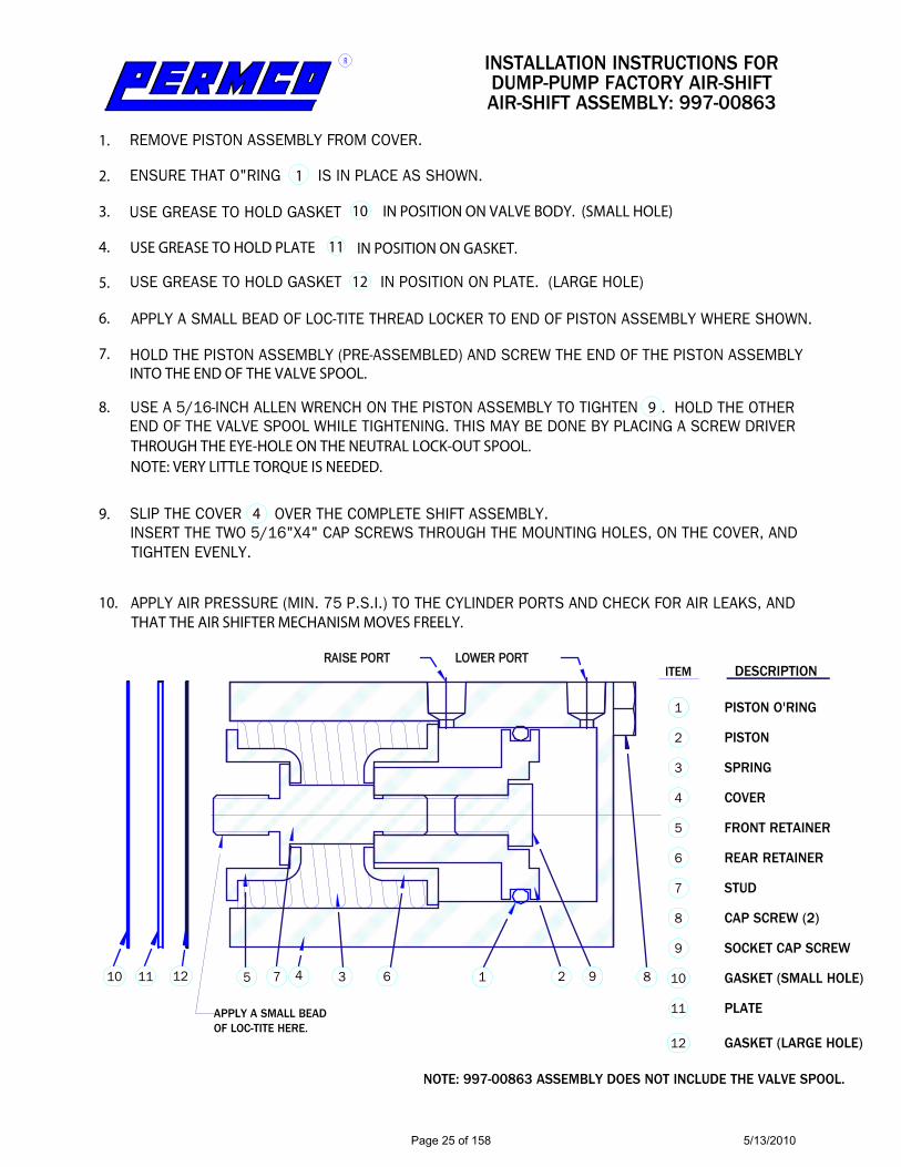
NOTE: 997-00863 ASSEMBLY DOES NOT INCLUDE THE VALVE SPOOL.
APPLY A SMALL BEADOF LOC-TITE HERE.
DESCRIPTIONITEM
PISTON O'RING
PISTON
SPRING
COVER
FRONT RETAINER
REAR RETAINER
STUD
CAP SCREW (2)
SOCKET CAP SCREW
GASKET (SMALL HOLE)
1
2
3
4
5
6
7
8
9
10
AIR-SHIFT ASSEMBLY: 997-00863DUMP-PUMP FACTORY AIR-SHIFT
INSTALLATION INSTRUCTIONS FORR
1. 2. 3. 4. 5. 6. 7. 8.
9.
10.
1 2345 67 8910
REMOVE PISTON ASSEMBLY FROM COVER.
ENSURE THAT O"RING IS IN PLACE AS SHOWN.
USE GREASE TO HOLD GASKET IN POSITION ON VALVE BODY. (SMALL HOLE)
USE GREASE TO HOLD PLATE IN POSITION ON GASKET.
USE GREASE TO HOLD GASKET IN POSITION ON PLATE. (LARGE HOLE)
APPLY A SMALL BEAD OF LOC-TITE THREAD LOCKER TO END OF PISTON ASSEMBLY WHERE SHOWN.
HOLD THE PISTON ASSEMBLY (PRE-ASSEMBLED) AND SCREW THE END OF THE PISTON ASSEMBLY
USE A 5/16-INCH ALLEN WRENCH ON THE PISTON ASSEMBLY TO TIGHTEN . HOLD THE OTHEREND OF THE VALVE SPOOL WHILE TIGHTENING. THIS MAY BE DONE BY PLACING A SCREW DRIVER
SLIP THE COVER OVER THE COMPLETE SHIFT ASSEMBLY.INSERT THE TWO 5/16"X4" CAP SCREWS THROUGH THE MOUNTING HOLES, ON THE COVER, AND
APPLY AIR PRESSURE (MIN. 75 P.S.I.) TO THE CYLINDER PORTS AND CHECK FOR AIR LEAKS, AND
INTO THE END OF THE VALVE SPOOL.
THROUGH THE EYE-HOLE ON THE NEUTRAL LOCK-OUT SPOOL.NOTE: VERY LITTLE TORQUE IS NEEDED.
TIGHTEN EVENLY.
THAT THE AIR SHIFTER MECHANISM MOVES FREELY.
Page 25 of 158 5/13/2010
Page 26 of 158 5/13/2010
Page 27 of 158 5/13/2010
PERM
CO D
MD
AND
DM D
UMP
PUM
PSPE
RM
CO
PA
RT
#A
LTER
NA
TE P
ERM
CO
PA
RT
#'S
PAR
KER
(CO
MM
ERC
IAL)
PA
RT
#
DM
D-2
0-Z
-L-M
S-25
DM
D-2
0-X
-L-M
S-25
+ R
Z-02
06 IF
NEE
DED
*C10
2D-2
.0-1
OR
314-
9320
-202
DM
D-2
0-Z
-L-A
S-25
DM
D-2
0-X
-L-A
S-25
+ R
Z-02
06 IF
NEE
DED
*C10
2D-2
.0-1
OR
314-
9320
-202
+ 3
14-9
414-
017
DM
D-2
0-Z
-R-M
S-25
DM
D-2
0-X
-R-M
S-25
+ R
Z-02
06 IF
NEE
DED
*C10
2D-2
.0 O
R 31
4-93
20-2
01D
MD
-20-
Z-R
-AS-
25D
MD
-20-
X-R
-AS-
25 +
RZ-
0206
IF N
EED
ED*C
102D
-2.0
OR
314-
9320
-201
+ 3
14-9
414-
017
DM
D-2
5-Z
-L-M
S-25
DM
D-2
5-X
-L-M
S-25
+ R
Z-02
06 IF
NEE
DED
*C10
2D-2
.5-1
OR
314-
9325
-202
OR
314-
9325
-229
DM
D-2
5-Z
-L-A
S-25
DM
D-2
5-X
-L-A
S-25
+ R
Z-02
06 IF
NEE
DED
*C10
2D-2
.5-1
OR
314-
9325
-202
+ 3
14-9
414-
017
OR
314-
9325
-227
DM
D-2
5-Z
-R-M
S-25
DM
D-2
5-X
-R-M
S-25
+ R
Z-02
06 IF
NEE
DED
*C10
2D-2
.5 O
R 31
4-93
25-2
01 O
R 31
4-93
25-2
34
DM
D-2
5-Z
-R-A
S-25
DM
D-2
5-X
-R-A
S-25
+ R
Z-02
06 IF
NEE
DED
*C10
2D-2
.5 O
R 31
4-93
25-2
01 +
314
-941
4-01
7
Z =
SH
IPPE
D W
ITH
TH
REE
LIN
E SL
EEV
E
IF Y
OU
STO
CK
TH
EM W
ITH
AN
"X"
SIM
PLY
AD
D P
ART
# R
Z-02
06X
= S
HIP
PED
WIT
HO
UT
THRE
E LI
NE
SLEE
VE
* =
SH
IPPE
D W
ITH
OU
T TH
REE
LIN
E SL
EEV
E
DM
-512
-20-
ZR-
M-T
-250
DM
-640
-20-
XR-
M-T
-250
+ R
Z-02
06 IF
NEE
DED
*C10
1D-2
.0 O
R 31
4-93
10-2
05D
M-6
40-2
5-Z
R-M
-T-2
50D
M-6
40-2
5-X
R-M
-T-2
50 +
RZ-
0206
IF N
EED
ED*C
101D
-2.5
OR
314-
9310
-206
OR
314-
9310
-226
DM
-512
-20-
ZR-
M-A
S-25
0D
M-6
40-2
0-X
R-M
-AS-
250
+ RZ
-020
6 IF
NEE
DED
*C10
1D-2
.0 O
R 31
4-93
10-2
05 +
314
-941
4-01
7D
M-6
40-2
5-Z
R-M
-AS-
250
DM
-640
-25-
XR-
M-A
S-25
0 +
RZ-0
206
IF N
EED
ED*C
101D
-2.5
OR
314-
9310
-206
+ 3
14-9
414-
017
Z =
SH
IPPE
D W
ITH
TH
REE
LIN
E SL
EEV
E
IF
YOU
STO
CK
TH
EM W
ITH
AN
"X"
SIM
PLY
AD
D P
ART
# R
Z-02
06
X =
SH
IPPE
D W
ITH
OU
T TH
REE
LIN
E SL
EEV
E*
= S
HIP
PED
WIT
HO
UT
THRE
E LI
NE
SLEE
VE
RZ-0
206
THRE
E LI
NE
SLEE
VE
FOR
DM
D &
DM
391-
3283
-052
997-
0097
1AA
IR S
HIF
T C
YLIN
DER
FO
R D
MD
& D
M31
4-94
14-0
17D
-093
1D
M M
OU
NTI
NG
BRA
CK
E TE1
042
OR
314-
0100
-005
IF Y
OU
DO
NO
T H
AV
E A
N A
IR S
HIF
T PU
MP
ON
TH
E SH
ELF
SIM
PLY
USE
TH
E LE
VER
SH
IFT
AN
D A
DD
AIR
SH
IFT
PART
#PA
RKER
TH
REE
LIN
E SL
EEV
E PA
RT #
391
-328
3-05
2 W
ILL
NO
T IN
TERC
HA
NG
E W
ITH
PER
MC
O D
MD
OR
DM
PU
MPS
THER
E A
RE M
AN
Y O
PTIO
NS
TO D
UM
P PU
MP
PART
NU
MBE
RS.
CO
NSU
LT T
HE
FAC
TORY
FO
R TH
OSE
NO
T LI
STED
Page
28
of 1
585/
13/2
010

PERM
CO D
MD
AND
DM D
UMP
PUM
PSPE
RM
CO
PA
RT
#A
LTER
NA
TE P
ERM
CO
PA
RT
#'S
MU
NC
IE P
AR
T #
DM
D-2
0-Z
-L-M
S-25
DM
D-2
0-X
-L-M
S-25
+ R
Z-02
06 IF
NEE
DED
E2XL
23-2
BPRL
OR
E3XL
23-2
BPRL
OR
E2XL
1-23
-02B
PRL
OR
E3XL
1-23
-02B
PRL
DM
D-2
0-Z
-L-A
S-25
DM
D-2
0-X
-L-A
S-25
+ R
Z-02
06 IF
NEE
DED
E2XA
23-2
BPRL
OR
E3XA
23-2
BPRL
OR
E2XA
1-23
-02B
PRL
OR
E3XA
1-23
-02B
PRL
DM
D-2
0-Z
-R-M
S-25
DM
D-2
0-X
-R-M
S-25
+ R
Z-02
06 IF
NEE
DED
E2XL
23-2
BPRR
OR
E3XL
23-2
BPRR
OR
E2XL
1-23
-02B
PRR
OR
E3XL
1-23
-02B
PRR
DM
D-2
0-Z
-R-A
S-25
DM
D-2
0-X
-R-A
S-25
+ R
Z-02
06 IF
NEE
DED
E2XA
23-2
BPRR
OR
E3XA
23-2
BPRR
OR
E2XA
1-23
-02B
PRR
OR
E3XA
1-23
-02B
PRR
DM
D-2
5-Z
-L-M
S-25
DM
D-2
5-X
-L-M
S-25
+ R
Z-02
06 IF
NEE
DED
E2XL
27-2
BPRL
OR
E3XL
27-2
BPRL
OR
E2XL
1-27
-02B
PRL
OR
E3XL
1-27
-02B
PRL
DM
D-2
5-Z
-L-A
S-25
DM
D-2
5-X
-L-A
S-25
+ R
Z-02
06 IF
NEE
DED
E2XA
27-2
BPRL
OR
E3XA
27-2
BPRL
OR
E2XA
1-27
-02B
PRL
OR
E3XA
1-27
-02B
PRL
DM
D-2
5-Z
-R-M
S-25
DM
D-2
5-X
-R-M
S-25
+ R
Z-02
06 IF
NEE
DED
E2XL
27-2
BPRR
OR
E3XL
27-2
BPRR
OR
E2XL
1-27
-02B
PRR
OR
E3XL
1-27
-02B
PRR
DM
D-2
5-Z
-R-A
S-25
DM
D-2
5-X
-R-A
S-25
+ R
Z-02
06 IF
NEE
DED
E2XA
27-2
BPRR
OR
E3XA
27-2
BPRR
OR
E2XA
1-27
-02B
PRR
OR
E3XA
1-27
-02B
PRR
Z =
SH
IPPE
D W
ITH
TH
REE
LIN
E SL
EEV
E
IF Y
OU
STO
CK
TH
EM W
ITH
AN
"X"
SIM
PLY
AD
D P
ART
# R
Z-02
06X
= S
HIP
PED
WIT
HO
UT
THRE
E LI
NE
SLEE
VE
2 =
SHIP
PED
WIT
HO
UT
THRE
E LI
NE
SLEE
VE
3 =
SHIP
PED
WIT
H T
HRE
E LI
NE
SLEE
VE
DM
-512
-20-
ZR-
M-T
-250
DM
-640
-20-
XR-
M-T
-250
+ R
Z-02
06 IF
NEE
DED
E2BL
23-1
RPRB
OR
E3BL
23-1
RPRB
OR
E2BL
1-23
-01R
PRB
OR
E3BL
1-23
-01R
PRB
DM
-640
-25-
ZR-
M-T
-250
DM
-640
-25-
XR-
M-T
-250
+ R
Z-02
06 IF
NEE
DED
E2BL
27-1
RPRB
OR
E3BL
27-1
RPRB
OR
E2BL
1-27
-01R
PRB
OR
E3BL
1-27
-01R
PRB
DM
-512
-20-
ZR-
M-A
S-25
0D
M-6
40-2
0-X
R-M
-AS-
250
+ RZ
-020
6 IF
NEE
DED
E2BA
23-1
RPRB
OR
E3BA
23-1
RPRB
OR
E2BA
1-23
-01R
PRB
OR
E3BA
1-23
-01R
PRB
DM
-640
-25-
ZR-
M-A
S-25
0D
M-6
40-2
5-X
R-M
-AS-
250
+ RZ
-020
6 IF
NEE
DED
E 2BA
27-1
RPRB
OR
E3BA
27-1
RPRB
OR
E2BA
1-27
-01R
PRB
OR
E3BA
1-27
-01R
PRB
Z =
SH
IPPE
D W
ITH
TH
REE
LIN
E SL
EEV
E
IF
YOU
STO
CK
TH
EM W
ITH
AN
"X"
SIM
PLY
AD
D P
ART
# R
Z-02
06
X =
SH
IPPE
D W
ITH
OU
T TH
REE
LIN
E SL
EEV
E2
= SH
IPPE
D W
ITH
OU
T TH
REE
LIN
E SL
EEV
E3
= SH
IPPE
D W
ITH
TH
REE
LIN
E SL
EEV
E
RZ-0
206
THRE
E LI
NE
SLEE
VE
FOR
DM
D &
DM
AA
1257
(TH
REE
LIN
E SL
EEV
E)99
7-00
971A
AIR
SH
IFT
CYL
IND
ER F
OR
DM
D &
DM
AC
KM
-100
M (A
IR C
YLIN
DER
)D
-093
1D
M M
OU
NTI
NG
BRA
CK
ETB1
235
IF Y
OU
DO
NO
T H
AV
E A
N A
IR S
HIF
T PU
MP
ON
TH
E SH
ELF
SIM
PLY
USE
TH
E LE
VER
SH
IFT
AN
D A
DD
AIR
SH
IFT
PART
#M
UN
CIE
TH
REE
LIN
E SL
EEV
E PA
RT #
AA
1257
WIL
L N
OT
INTE
RCH
AN
GE
WIT
H P
ERM
CO
DM
D O
R D
M P
UM
PSTH
ERE
ARE
MA
NY
OPT
ION
S TO
DU
MP
PUM
P PA
RT N
UM
BERS
. C
ON
SULT
TH
E FA
CTO
RY F
OR
THO
SE N
OT
LIST
ED
Page
29
of 1
585/
13/2
010

PERM
CO D
MD
AND
DM D
UMP
PUM
PSPE
RM
CO
PA
RT
#A
LTER
NA
TE P
ERM
CO
PA
RT
#'S
TYR
ON
E (C
HEL
SEA
) PA
RT
#LI
ST P
RIC
E
DM
D-2
0-Z
-L-M
S-25
DM
D-2
0-X
-L-M
S-25
+ R
Z-02
06 IF
NEE
DED
*T10
2AX-
20-L
-25
DM
D-2
0-Z
-L-A
S-25
DM
D-2
0-X
-L-A
S-25
+ R
Z-02
06 IF
NEE
DED
*T10
2AX-
20-A
-25
DM
D-2
0-Z
-R-M
S-25
DM
D-2
0-X
-R-M
S-25
+ R
Z-02
06 IF
NEE
DED
*T10
2CX-
20-L
-25
DM
D-2
0-Z
-R-A
S-25
DM
D-2
0-X
-R-A
S-25
+ R
Z-02
06 IF
NEE
DED
*T10
2CX-
20-A
-25
DM
D-2
5-Z
-L-M
S-25
DM
D-2
5-X
-L-M
S-25
+ R
Z-02
06 IF
NEE
DED
*T10
2AX-
25-L
-25
DM
D-2
5-Z
-L-A
S-25
DM
D-2
5-X
-L-A
S-25
+ R
Z-02
06 IF
NEE
DED
*T10
2AX-
25-A
-25
DM
D-2
5-Z
-R-M
S-25
DM
D-2
5-X
-R-M
S-25
+ R
Z-02
06 IF
NEE
DED
*T10
2CX-
25-L
-25
DM
D-2
5-Z
-R-A
S-25
DM
D-2
5-X
-R-A
S-25
+ R
Z-02
06 IF
NEE
DED
*T10
2CX-
25-A
-25
Z =
SH
IPPE
D W
ITH
TH
REE
LIN
E SL
EEV
E
IF Y
OU
STO
CK
TH
EM W
ITH
AN
"X"
SIM
PLY
AD
D P
ART
# R
Z-02
06X
= S
HIP
PED
WIT
HO
UT
THRE
E LI
NE
SLEE
VE
* =
SH
IPPE
D W
ITH
OU
T TH
REE
LIN
E SL
EEV
E
DM
-512
-20-
ZR-
M-T
-250
DM
-640
-20-
XR-
M-T
-250
+ R
Z-02
06 IF
NEE
DED
*T10
1DB
-20-
L-25
DM
-640
-25-
ZR-
M-T
-250
DM
-640
-25-
XR-
M-T
-250
+ R
Z-02
06 IF
NEE
DED
*T10
1DB
-25-
L-25
DM
-512
-20-
ZR-
M-A
S-25
0D
M-6
40-2
0-X
R-M
-AS-
250
+ RZ
-020
6 IF
NEE
DED
*T10
1DB
-20-
A-2
5D
M-6
40-2
5-Z
R-M
-AS-
250
DM
-640
-25-
XR-
M-A
S-25
0 +
RZ-0
206
IF N
EED
ED*T
101D
B-2
5-A
-25
Z =
SH
IPPE
D W
ITH
TH
REE
LIN
E SL
EEV
E
IF
YOU
STO
CK
TH
EM W
ITH
AN
"X"
SIM
PLY
AD
D P
ART
# R
Z-02
06
X =
SH
IPPE
D W
ITH
OU
T TH
REE
LIN
E SL
EEV
E*
= S
HIP
PED
WIT
HO
UT
THRE
E LI
NE
SLEE
VE
B =
SH
IPPE
D W
ITH
MO
UN
TIN
G B
RAC
KET
AN
"X" I
N T
HIS
LO
CA
TIO
N R
EPRE
SEN
TS S
HIP
PED
WIT
HO
UT
MO
UN
TIN
G B
RAC
KET
RZ-0
206
THRE
E LI
NE
SLEE
VE
FOR
DM
D &
DM
1648
799
7-00
971A
AIR
SH
IFT
CYL
IND
ER F
OR
DM
D &
DM
1667
0D
-093
1D
M M
OU
NTI
NG
BRA
CK
E T33
845
IF Y
OU
DO
NO
T H
AV
E A
N A
IR S
HIF
T PU
MP
ON
TH
E SH
ELF
SIM
PLY
USE
TH
E LE
VER
SH
IFT
AN
D A
DD
AIR
SH
IFT
PART
#TY
RON
E TH
REE
LIN
E SL
EEV
E PA
RT #
164
87 W
ILL
NO
T IN
TERC
HA
NG
E W
ITH
PER
MC
O D
MD
OR
DM
PU
MPS
THER
E A
RE M
AN
Y O
PTIO
NS
TO D
UM
P PU
MP
PART
NU
MBE
RS.
CO
NSU
LT T
HE
FAC
TORY
FO
R TH
OSE
NO
T LI
STED
Page
30
of 1
585/
13/2
010
Page
31
of 1
585/
13/2
010
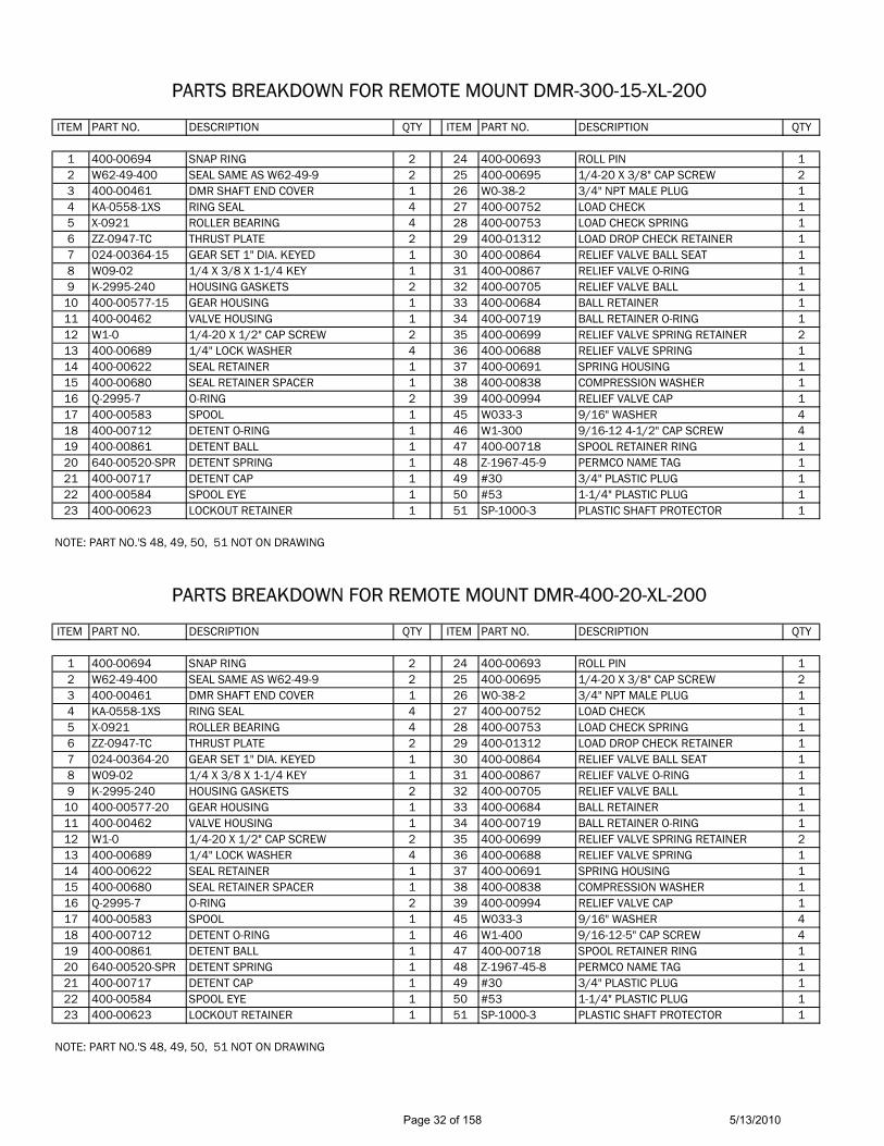
PARTS BREAKDOWN FOR REMOTE MOUNT DMR-300-15-XL-200
ITEM PART NO. DESCRIPTION QTY ITEM PART NO. DESCRIPTION QTY
1 400-00694 SNAP RING 2 24 400-00693 ROLL PIN 12 W62-49-400 SEAL SAME AS W62-49-9 2 25 400-00695 1/4-20 X 3/8" CAP SCREW 23 400-00461 DMR SHAFT END COVER 1 26 W0-38-2 3/4" NPT MALE PLUG 14 KA-0558-1XS RING SEAL 4 27 400-00752 LOAD CHECK 15 X-0921 ROLLER BEARING 4 28 400-00753 LOAD CHECK SPRING 16 ZZ-0947-TC THRUST PLATE 2 29 400-01312 LOAD DROP CHECK RETAINER 17 024-00364-15 GEAR SET 1" DIA. KEYED 1 30 400-00864 RELIEF VALVE BALL SEAT 18 W09-02 1/4 X 3/8 X 1-1/4 KEY 1 31 400-00867 RELIEF VALVE O-RING 19 K-2995-240 HOUSING GASKETS 2 32 400-00705 RELIEF VALVE BALL 1
10 400-00577-15 GEAR HOUSING 1 33 400-00684 BALL RETAINER 111 400-00462 VALVE HOUSING 1 34 400-00719 BALL RETAINER O-RING 112 W1-0 1/4-20 X 1/2" CAP SCREW 2 35 400-00699 RELIEF VALVE SPRING RETAINER 213 400-00689 1/4" LOCK WASHER 4 36 400-00688 RELIEF VALVE SPRING 114 400-00622 SEAL RETAINER 1 37 400-00691 SPRING HOUSING 115 400-00680 SEAL RETAINER SPACER 1 38 400-00838 COMPRESSION WASHER 116 Q-2995-7 O-RING 2 39 400-00994 RELIEF VALVE CAP 117 400-00583 SPOOL 1 45 W033-3 9/16" WASHER 418 400-00712 DETENT O-RING 1 46 W1-300 9/16-12 4-1/2" CAP SCREW 419 400-00861 DETENT BALL 1 47 400-00718 SPOOL RETAINER RING 120 640-00520-SPR DETENT SPRING 1 48 Z-1967-45-9 PERMCO NAME TAG 121 400-00717 DETENT CAP 1 49 #30 3/4" PLASTIC PLUG 122 400-00584 SPOOL EYE 1 50 #53 1-1/4" PLASTIC PLUG 123 400-00623 LOCKOUT RETAINER 1 51 SP-1000-3 PLASTIC SHAFT PROTECTOR 1
NOTE: PART NO.'S 48, 49, 50, 51 NOT ON DRAWING
PARTS BREAKDOWN FOR REMOTE MOUNT DMR-400-20-XL-200
ITEM PART NO. DESCRIPTION QTY ITEM PART NO. DESCRIPTION QTY
1 400-00694 SNAP RING 2 24 400-00693 ROLL PIN 12 W62-49-400 SEAL SAME AS W62-49-9 2 25 400-00695 1/4-20 X 3/8" CAP SCREW 23 400-00461 DMR SHAFT END COVER 1 26 W0-38-2 3/4" NPT MALE PLUG 14 KA-0558-1XS RING SEAL 4 27 400-00752 LOAD CHECK 15 X-0921 ROLLER BEARING 4 28 400-00753 LOAD CHECK SPRING 16 ZZ-0947-TC THRUST PLATE 2 29 400-01312 LOAD DROP CHECK RETAINER 17 024-00364-20 GEAR SET 1" DIA. KEYED 1 30 400-00864 RELIEF VALVE BALL SEAT 18 W09-02 1/4 X 3/8 X 1-1/4 KEY 1 31 400-00867 RELIEF VALVE O-RING 19 K-2995-240 HOUSING GASKETS 2 32 400-00705 RELIEF VALVE BALL 1
10 400-00577-20 GEAR HOUSING 1 33 400-00684 BALL RETAINER 111 400-00462 VALVE HOUSING 1 34 400-00719 BALL RETAINER O-RING 112 W1-0 1/4-20 X 1/2" CAP SCREW 2 35 400-00699 RELIEF VALVE SPRING RETAINER 213 400-00689 1/4" LOCK WASHER 4 36 400-00688 RELIEF VALVE SPRING 114 400-00622 SEAL RETAINER 1 37 400-00691 SPRING HOUSING 115 400-00680 SEAL RETAINER SPACER 1 38 400-00838 COMPRESSION WASHER 116 Q-2995-7 O-RING 2 39 400-00994 RELIEF VALVE CAP 117 400-00583 SPOOL 1 45 W033-3 9/16" WASHER 418 400-00712 DETENT O-RING 1 46 W1-400 9/16-12-5" CAP SCREW 419 400-00861 DETENT BALL 1 47 400-00718 SPOOL RETAINER RING 120 640-00520-SPR DETENT SPRING 1 48 Z-1967-45-8 PERMCO NAME TAG 121 400-00717 DETENT CAP 1 49 #30 3/4" PLASTIC PLUG 122 400-00584 SPOOL EYE 1 50 #53 1-1/4" PLASTIC PLUG 123 400-00623 LOCKOUT RETAINER 1 51 SP-1000-3 PLASTIC SHAFT PROTECTOR 1
NOTE: PART NO.'S 48, 49, 50, 51 NOT ON DRAWING
Page 32 of 158 5/13/2010
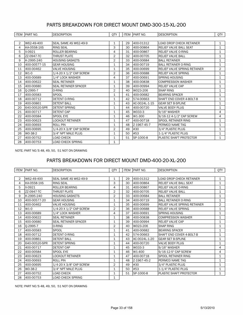
PARTS BREAKDOWN FOR DIRECT MOUNT DMD-300-15-XL-200
ITEM PART NO. DESCRIPTION QTY ITEM PART NO. DESCRIPTION QTY
2 W62-49-400 SEAL SAME AS W62-49-9 1 29 400-01312 LOAD DROP CHECK RETAINER 14 KA-0558-1XS RING SEAL 3 30 400-00864 RELIEF VALVE BALL SEAT 15 X-0921 ROLLER BEARING 4 31 400-00867 RELIEF VALVE O-RING 16 ZZ-0947-TC THRUST PLATE 2 32 400-00705 RELIEF VALVE BALL 19 K-2995-240 HOUSING GASKETS 2 33 400-00684 BALL RETAINER 1
10 400-00577-15 GEAR HOUSING 1 34 400-00719 BALL RETAINER O-RING 111 400-00462 VALVE HOUSING 1 35 400-00699 RELIEF VALVE SPRING RETAINER 212 W1-0 1/4-20 X 1/2" CAP SCREW 2 36 400-00688 RELIEF VALVE SPRING 113 400-00689 1/4" LOCK WASHER 4 37 400-00691 SPRING HOUSING 114 400-00622 SEAL RETAINER 1 38 400-00838 COMPRESSION WASHER 115 400-00680 SEAL RETAINER SPACER 1 39 400-00994 RELIEF VALVE CAP 116 Q-2995-7 O-RING 2 40 W023-206 SNAP RING 117 400-00583 SPOOL 1 41 400-00682 BEARING SPACER 118 400-00712 DETENT O-RING 1 42 574-00663 SHAFT END COVER 4-BOLT-B 119 400-00861 DETENT BALL 1 43 AC-0024L-1-15 GEAR SET B-SPLINE 120 640-00520-SPR DETENT SPRING 1 44 400-00720 VALVE BODY PLUG 121 400-00717 DETENT CAP 1 45 W033-3 9/16" WASHER 422 400-00584 SPOOL EYE 1 46 W1-300 9/16-12 4-1/2" CAP SCREW 423 400-00623 LOCKOUT RETAINER 1 47 400-00718 SPOOL RETAINER RING 124 400-00693 ROLL PIN 1 48 Z-1967-45-7 PERMCO NAME TAG 125 400-00695 1/4-20 X 3/8" CAP SCREW 2 49 #30 3/4" PLASTIC PLUG 126 W0-38-2 3/4" NPT MALE PLUG 1 50 #53 1-1/4" PLASTIC PLUG 127 400-00752 LOAD CHECK 1 51 SP-1000-8 PLASTIC SHAFT PROTECTOR 128 400-00753 LOAD CHECK SPRING 1
NOTE: PART NO.'S 48, 49, 50, 51 NOT ON DRAWING
PARTS BREAKDOWN FOR DIRECT MOUNT DMD-400-20-XL-200
ITEM PART NO. DESCRIPTION QTY ITEM PART NO. DESCRIPTION QTY
2 W62-49-400 SEAL SAME AS W62-49-9 1 29 400-01312 LOAD DROP CHECK RETAINER 14 KA-0558-1XS RING SEAL 3 30 400-00864 RELIEF VALVE BALL SEAT 15 X-0921 ROLLER BEARING 4 31 400-00867 RELIEF VALVE O-RING 16 ZZ-0947-TC THRUST PLATE 2 32 400-00705 RELIEF VALVE BALL 19 K-2995-240 HOUSING GASKETS 2 33 400-00684 BALL RETAINER 1
10 400-00577-20 GEAR HOUSING 1 34 400-00719 BALL RETAINER O-RING 111 400-00462 VALVE HOUSING 1 35 400-00699 RELIEF VALVE SPRING RETAINER 212 W1-0 1/4-20 X 1/2" CAP SCREW 2 36 400-00688 RELIEF VALVE SPRING 113 400-00689 1/4" LOCK WASHER 4 37 400-00691 SPRING HOUSING 114 400-00622 SEAL RETAINER 1 38 400-00838 COMPRESSION WASHER 115 400-00680 SEAL RETAINER SPACER 1 39 400-00994 RELIEF VALVE CAP 116 Q-2995-7 O-RING 2 40 W023-206 SNAP RING 117 400-00583 SPOOL 1 41 400-00682 BEARING SPACER 118 400-00712 DETENT O-RING 1 42 574-00663 SHAFT END COVER 4-BOLT-B 119 400-00861 DETENT BALL 1 43 AC-0024L-1-20 GEAR SET B-SPLINE 120 640-00520-SPR DETENT SPRING 1 44 400-00720 VALVE BODY PLUG 121 400-00717 DETENT CAP 1 45 W033-3 9/16" WASHER 422 400-00584 SPOOL EYE 1 46 W1-400 9/16-12-5" CAP SCREW 423 400-00623 LOCKOUT RETAINER 1 47 400-00718 SPOOL RETAINER RING 124 400-00693 ROLL PIN 1 48 Z-1967-45-2 PERMCO NAME TAG 125 400-00695 1/4-20 X 3/8" CAP SCREW 2 49 #30 3/4" PLASTIC PLUG 126 W0-38-2 3/4" NPT MALE PLUG 1 50 #53 1-1/4" PLASTIC PLUG 127 400-00752 LOAD CHECK 1 51 SP-1000-8 PLASTIC SHAFT PROTECTOR 128 400-00753 LOAD CHECK SPRING 1
NOTE: PART NO.'S 48, 49, 50, 51 NOT ON DRAWING
Page 33 of 158 5/13/2010
Permco 400-AS, Rev. A Approved 1-14-05 Ken Thompson, kc
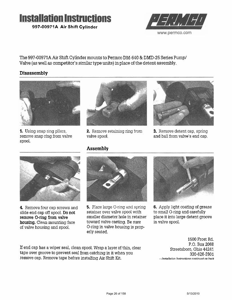
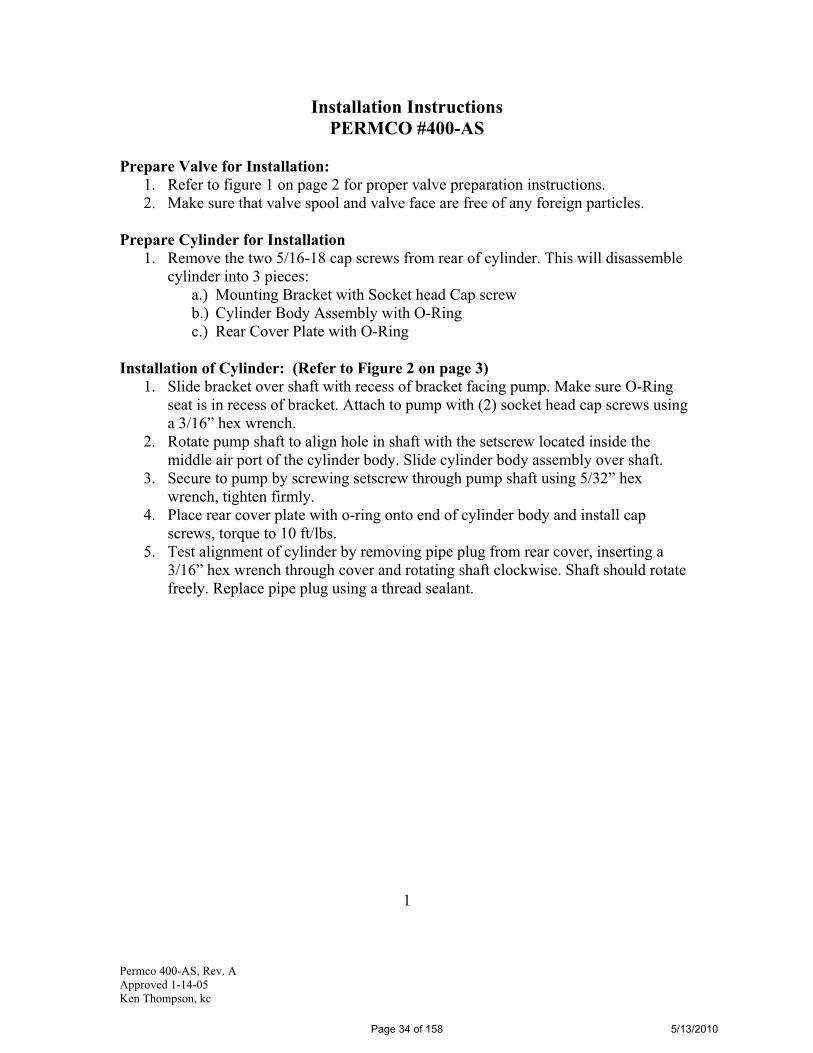
Installation Instructions PERMCO #400-AS
Prepare Valve for Installation: 1. Refer to figure 1 on page 2 for proper valve preparation instructions. 2. Make sure that valve spool and valve face are free of any foreign particles.
Prepare Cylinder for Installation 1. Remove the two 5/16-18 cap screws from rear of cylinder. This will disassemble
cylinder into 3 pieces: a.) Mounting Bracket with Socket head Cap screw b.) Cylinder Body Assembly with O-Ring c.) Rear Cover Plate with O-Ring
Installation of Cylinder: (Refer to Figure 2 on page 3) 1. Slide bracket over shaft with recess of bracket facing pump. Make sure O-Ring
seat is in recess of bracket. Attach to pump with (2) socket head cap screws using a 3/16” hex wrench.
2. Rotate pump shaft to align hole in shaft with the setscrew located inside the middle air port of the cylinder body. Slide cylinder body assembly over shaft.
3. Secure to pump by screwing setscrew through pump shaft using 5/32” hex wrench, tighten firmly.
4. Place rear cover plate with o-ring onto end of cylinder body and install cap screws, torque to 10 ft/lbs.
5. Test alignment of cylinder by removing pipe plug from rear cover, inserting a 3/16” hex wrench through cover and rotating shaft clockwise. Shaft should rotate freely. Replace pipe plug using a thread sealant.
1
Page 34 of 158 5/13/2010

Permco 400-AS, Rev. A Approved 1-14-05 Ken Thompson, kc
Figure 1: Valve Preparation
1. It is extremely important that the pump is UPSIDE DOWN (SEE ATTACHED DRAWING). Upside down is the position that the detent is facing downwards. FAILURE TO DO THIS MAY CAUSE THE DETENT BALL TO FALL WITHIN THE VALVE HOUSING AND MOVE INTO THE ROTATING GROUP CAUSING PREMATURE FAILURE!
2. With the pump in the downward position, loosen the plug (7) with an 11/16 wrench and remove the detent assembly (8 & 9).
3. Detent spring and ball will fall straight down and out of pump. 4. Re-insert the plug with o-ring. 5. It should be noted that you will also remove 1 through 6 when attaching the air
shift. Air shift kit (400-AS) should include new o-ring (6).
2
Page 35 of 158 5/13/2010

11211112
12345678
SMALL O'RINGO'RING RETAINER1/4x20 CAP SCREWLARGE O'RINGCYLINDER BODYSET SCREWCOVER PLATE5/16x18 CAP SCREW
QTY.DESCRIPTIONPART NO.
77
2211
66
3344
55
88
INSTRUCTIONS FOR INSTALLING AIR SHIFT TO DM400
AIR PORTS
1-Place small o'ring (1) in groove in o'ring retainer plate (2).2-Bolt retainer plate (2) to pump with o'ring (1) against pump with cap screws (3).3-Place larger o'ring (4) in cylinder body (5).4-Screw set screw (6) thru the piston and spool.5-Bolt assembly to retainer plate with long cap screws (8).
RR
HYDRAULIC / PNEUMATIC PRODUCTS
1500 Frost Road • Post Office Box 2068 • Streetsboro, Ohio 44241-0869 • 330/626-2801 • Fax: 330/626-2805
NATIONAL FLUID POWER ASSOCIATION
To: All Permco Distributors Date: January 1, 1990
Subject: DM 400 SERIES DUMP PUMP AIR SHIFT INSTALLATION
Page 36 of 158 5/13/2010
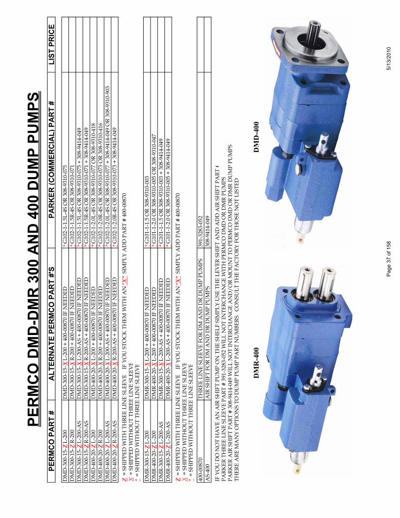
PERM
CO D
MD-
DMR
300
AND
400
DUM
P PU
MPS
PERM
CO P
ART
#AL
TERN
ATE
PERM
CO P
ART
#'S
PARK
ER(C
OM
MER
CIAL
) PAR
T #
LIST
PRI
CED
MD
-300
-15-
ZL-
200
DM
D-3
00-1
5-X
L-20
0 +
400-
0087
0 IF
NEE
DED
*G10
2-1-
1.5L
-4S
OR
308-
9310
-075
DM
D-3
00-1
5-Z
R-20
0D
MD
-300
-15-
XR-
200
+ 40
0-00
870
IF N
EED
ED*G
102-
1-1.
5R-4
S O
R 30
8-93
10-0
71D
MD
-300
-15-
ZL-
200-
AS
DM
D-3
00-1
5-X
L-20
0-A
S +
400-
0087
0 IF
NEE
DED
*G10
2-1-
1.5L
-4S
OR
308-
9310
-075
+ 3
08-9
414-
049
DM
D-3
00-1
5-Z
R-20
0-A
SD
MD
-300
-15-
XR-
200-
AS
+ 40
0-00
870
IF N
EED
ED*G
102-
1-1.
5R-4
S O
R 30
8-93
10-0
71 +
308
-941
4-04
9D
MD
-400
-20-
ZL-
200
DM
D-4
00-2
0-X
L-20
0 +
400-
0087
0 IF
NEE
DED
*G10
2-1-
2.0L
-4S
OR
308-
9310
-077
OR
308-
9310
-418
DM
D-4
00-2
0-Z
R-20
0D
MD
-400
-20-
XR-
200
+ 40
0-00
870
IF N
EED
ED*G
102-
1-2.
0R-4
S O
R 30
8-93
10-0
73 O
R 30
8-93
10-4
16D
MD
-400
-20-
ZL-
200-
AS
DM
D-4
00-2
0-X
L-20
0-A
S +
400-
0087
0 IF
NEE
DED
*G10
2-1-
2.0L
-4S
OR
308-
9310
-077
+ 3
08-9
414-
049
OR
308-
9310
-903
DM
D-4
00-2
0-Z
R-20
0-A
SD
MD
-400
-20-
XR-
200-
AS
+ 40
0-00
870
IF N
EED
ED*G
102-
1-2.
0R-4
S O
R 30
8-93
10-0
73 +
308
-941
4-04
9
Z =
SH
IPPE
D W
ITH
TH
REE
LIN
E SL
EEV
E
IF Y
OU
STO
CK
TH
EM W
ITH
AN
"X"
SIM
PLY
AD
D P
ART
# 4
00-0
0870
X =
SH
IPPE
D W
ITH
OU
T TH
REE
LIN
E SL
EEV
E*
= SH
IPPE
D W
ITH
OU
T TH
REE
LIN
E SL
EEV
E
DM
R-30
0-15
-ZL-
200
DM
R-30
0-15
-XL-
200
+ 40
0-00
870
IF N
EED
ED*G
101-
1-1.
5 O
R 30
8-93
10-0
03D
MR-
400-
20-Z
L-20
0D
MR-
400-
20-X
L-20
0 +
400-
0087
0 IF
NEE
DED
*G10
1-1-
2.0
OR
308-
9310
-005
OR
308-
9310
-047
DM
R-30
0-15
-ZL-
200-
AS
DM
R-30
0-15
-XL-
200-
AS
+ 40
0-00
870
IF N
EED
ED*G
101-
1-1.
5 O
R 30
8-93
10-0
03 +
308
-941
4-04
9D
MR-
400-
20-Z
L-20
0-A
SD
MR-
400-
20-X
L-20
0-A
S +
400-
0087
0 IF
NEE
DED
*G10
1-1-
2.0
OR
308-
9310
-005
+ 3
08-9
414-
049
Z =
SH
IPPE
D W
ITH
TH
REE
LIN
E SL
EEV
E
IF Y
OU
STO
CK
TH
EM W
ITH
AN
"X"
SIM
PLY
AD
D P
ART
# 4
00-0
0870
X =
SH
IPPE
D W
ITH
OU
T TH
REE
LIN
E SL
EEV
E*
= SH
IPPE
D W
ITH
OU
T TH
REE
LIN
E SL
EEV
E
400-
0087
0TH
REE
LIN
E SL
EEV
E FO
R D
M A
ND
DR
DU
MP
PUM
PS39
1-32
83-0
52A
S-40
0A
IR S
HIF
T FO
R D
M A
ND
DR
DU
MP
PUM
PS30
8-94
14-0
49
IF Y
OU
DO
NO
T H
AV
E A
N A
IR S
HIF
T PU
MP
ON
TH
E SH
ELF
SIM
PLY
USE
TH
E LE
VER
SH
IFT
AN
D A
DD
AIR
SH
IFT
PART
#PA
RKER
TH
REE
LIN
E SL
EEV
E PA
RT #
391
-328
3-05
2 W
ILL
NO
T IN
TERC
HA
NG
E W
ITH
PER
MC
O D
MD
OR
DM
R PU
MPS
PARK
ER A
IR S
HIF
T PA
RT #
308
-941
4-04
9 W
ILL
NO
T IN
TERC
HA
NG
E A
ND
/OR
MO
UN
T TO
PER
MC
O D
MD
OR
DM
R D
UM
P PU
MPS
THER
E A
RE M
AN
Y O
PTIO
NS
TO D
UM
P PU
MP
PART
NU
MBE
RS.
CO
NSU
LT T
HE
FAC
TORY
FO
R TH
OSE
NO
T LI
STED
D
MR
-400
DM
D-4
00
Page
37
of 1
585/
13/2
010
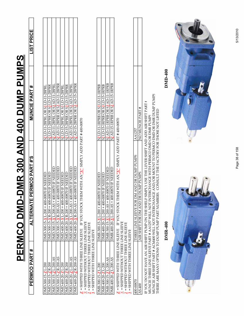
PERM
CO D
MD-
DMR
300
AND
400
DUM
P PU
MPS
PERM
CO P
ART
#AL
TERN
ATE
PERM
CO P
ART
#'S
MUN
CIE
PART
#LI
ST P
RICE
DM
D-3
00-1
5-Z
L-20
0D
MD
-300
-15-
XL-
200
+ 40
0-00
870
IF N
EED
EDS2
LD-1
1-2B
PRL
OR
S3LD
-11-
2BPR
LD
MD
-300
-15-
ZR-
200
DM
D-3
00-1
5-X
R-20
0 +
400-
0087
0 IF
NEE
DED
S2LD
-11-
2BPR
R O
R S3
LD-1
1-2B
PRR
DM
D-3
00-1
5-Z
L-20
0-A
SD
MD
-300
-15-
XL-
200-
AS
+ 40
0-00
870
IF N
EED
EDS2
AD
-11-
2BPR
L O
R S3
AD
-11-
2BPR
LD
MD
-300
-15-
ZR-
200-
AS
DM
D-3
00-1
5-X
R-20
0-A
S +
400-
0087
0 IF
NEE
DED
S2A
D-1
1-2B
PRR
OR
S3A
D-1
1-2B
PRR
DM
D-4
00-2
0-Z
L-20
0D
MD
-400
-20-
XL-
200
+ 40
0-00
870
IF N
EED
EDS2
LD-1
5-2B
PRL
OR
S3LD
-15-
2BPR
LD
MD
-400
-20-
ZR-
200
DM
D-4
00-2
0-X
R-20
0 +
400-
0087
0 IF
NEE
DED
S2LD
-15-
2BPR
R O
R S3
LD-1
5-2B
PRR
DM
D-4
00-2
0-Z
L-20
0-A
SD
MD
-400
-20-
XL-
200-
AS
+ 40
0-00
870
IF N
EED
EDS2
AD
-15-
2BPR
L O
R S3
AD
-15-
2BPR
LD
MD
-400
-20-
ZR-
200-
AS
DM
D-4
00-2
0-X
R-20
0-A
S +
400-
0087
0 IF
NEE
DED
S2A
D-1
5-2B
PRR
OR
S3A
D-1
5-2B
PRR
Z =
SH
IPPE
D W
ITH
TH
REE
LIN
E SL
EEV
E
IF Y
OU
STO
CK
TH
EM W
ITH
AN
"X"
SIM
PLY
AD
D P
ART
# 4
00-0
0870
X =
SH
IPPE
D W
ITH
OU
T TH
REE
LIN
E SL
EEV
E2
= SH
IPPE
D W
ITH
OU
T TH
REE
LIN
E SL
EEV
E3
= SH
IPPE
D W
ITH
TH
REE
LIN
E SL
EEV
E
DM
R-30
0-15
-ZL-
200
DM
R-30
0-15
-XL-
200
+ 40
0-00
870
IF N
EED
EDS2
LD-1
1-1R
PRB
OR
S3LD
-11-
1RPR
BD
MR-
400-
20-Z
L-20
0D
MR-
400-
20-X
L-20
0 +
400-
0087
0 IF
NEE
DED
S2LD
-15-
1RPR
B O
R S3
LD-1
5-1R
PRB
DM
R-30
0-15
-ZL-
200-
AS
DM
R-30
0-15
-XL-
200-
AS
+ 40
0-00
870
IF N
EED
EDS2
AD
-11-
1RPR
B O
R S3
AD
-11-
1RPR
BD
MR-
400-
20-Z
L-20
0-A
SD
MR-
400-
20-X
L-20
0-A
S +
400-
0087
0 IF
NEE
DED
S2A
D-1
5-1R
PRB
OR
S3A
D-1
5-1R
PRB
Z =
SH
IPPE
D W
ITH
TH
REE
LIN
E SL
EEV
E
IF Y
OU
STO
CK
TH
EM W
ITH
AN
"X"
SIM
PLY
AD
D P
ART
# 4
00-0
0870
X =
SH
IPPE
D W
ITH
OU
T TH
REE
LIN
E SL
EEV
E2
= SH
IPPE
D W
ITH
OU
T TH
REE
LIN
E SL
EEV
E3
= SH
IPPE
D W
ITH
TH
REE
LIN
E SL
EEV
E
400-
0087
0TH
REE
LIN
E SL
EEV
E FO
R D
M A
ND
DR
DU
MP
PUM
PSA
A12
57A
S-40
0A
IR S
HIF
T FO
R D
M A
ND
DR
DU
MP
PUM
PSN
O M
UN
CIE
PA
RT #
IF Y
OU
DO
NO
T H
AV
E A
N A
IR S
HIF
T PU
MP
ON
TH
E SH
ELF
SIM
PLY
USE
TH
E LE
VER
SH
IFT
AN
D A
DD
AIR
SH
IFT
PART
#M
UN
CIE
TH
REE
LIN
E SL
EEV
E PA
RT #
AA
1257
WIL
L N
OT
INTE
RCH
AN
GE
WIT
H P
ERM
CO
DM
D O
R D
MR
PUM
PSM
UN
CIE
AIR
SH
IFT
PART
# A
CM
400
WIL
L N
OT
INTE
RCH
AN
GE
AN
D/O
R M
OU
NT
TO P
ERM
CO
DM
D O
R D
MR
DU
MP
PUM
PSTH
ERE
ARE
MA
NY
OPT
ION
S TO
DU
MP
PUM
P PA
RT N
UM
BERS
. C
ON
SULT
TH
E FA
CTO
RY F
OR
THO
SE N
OT
LIST
ED
DM
R-4
00
DM
D-4
00
Page
38
of 1
585/
13/2
010

RR
HYDRAULIC / PNEUMATIC PRODUCTS
1500 Frost Road • Post Office Box 2068 • Streetsboro, Ohio 44241-0869 • 330/626-2801 • Fax: 330/626-2805
To: All Permco Distributors Service Bulletin 022902 Date: July 1, 2001
Subject: ADJUSTING THE DPR* (DUAL PRESSURE RELIEF)
NATIONAL FLUID POWER ASSOCIATION
The relief valve comes preset at the factory for 2500 PSI and 3200 PSI. The lower setting is to be used for dump trailer applications and the high setting for live floor trailers. To change between the low and high setting, air pressure is induced via port 5. With a minimum of approximately 60 PSI air at this port, the relief valve setting will change to 3200 PSI. Without pressure at port 5, the unit reverts to the low-pressure setting. Although it is not recommended, should you desire to adjust these pressures settings in the field, the following must be done. The setting should be made with a pressure gage in the line. All rotations written below are made looking at the air inlet of the cylinder. Changing the low-pressure setting interacts with the high-pressure set point. In essence if you reduce the low-pressure setting by 500 PSI, the high-pressure setting will be reduced by approximately the same amount. Increasing the setting will have the same effect: increasing the low-pressure setting will increase the high-pressure setting. Changing the high-pressure setting WILL NOT affect the low-pressure set point. TO ADJUST THE LOW-PRESSURE SETTING Loosen nut 3. To increase setting, turn the entire cylinder assembly clockwise. To reduce the setting, turn the cylinder assembly counter clockwise. When you have achieved your desired setting, seat (tighten) nut 3 tightly against the relief valve body. TO ADJUST THE HIGH-PRESSURE SETTING Loosen nut 2. To increase setting, turn the entire cylinder assembly clockwise. To reduce the setting, turn the cylinder assembly counter clockwise. When you have achieved your desired setting, seat (tighten) nut 2 tightly against the cylinder body. *Patent Pending
Page 39 of 158 5/13/2010
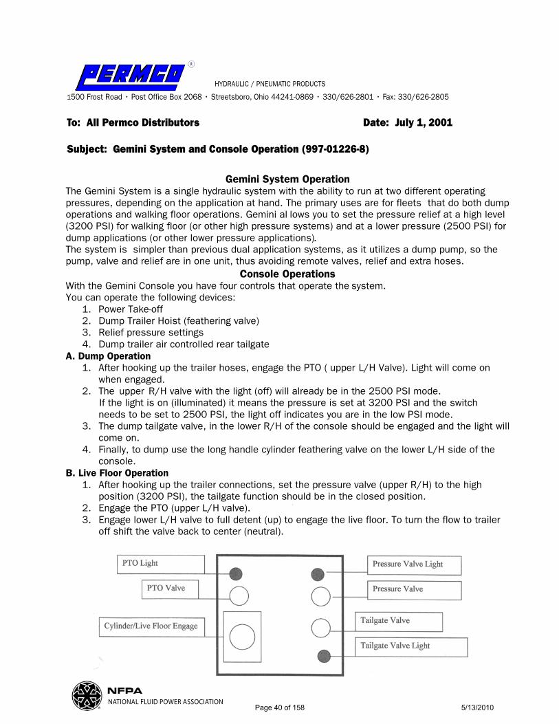
R
HYDRAULIC / PNEUMATIC PRODUCTS
1500 Frost Road • Post Office Box 2068 • Streetsboro, Ohio 44241-0869 • 330/626-2801 • Fax: 330/626-2805
To: All Permco Distributors Date: July 1, 2001
Subject: Gemini System and Console Operation (997-01226-8)
NATIONAL FLUID POWER ASSOCIATION
Gemini System Operation The Gemini System is a single hydraulic system with the ability to run at two different operating pressures, depending on the application at hand. The primary uses are for fleets that do both dump operations and walking floor operations. Gemini al lows you to set the pressure relief at a high level (3200 PSI) for walking floor (or other high pressure systems) and at a lower pressure (2500 PSI) for dump applications (or other lower pressure applications). The system is simpler than previous dual application systems, as it utilizes a dump pump, so the pump, valve and relief are in one unit, thus avoiding remote valves, relief and extra hoses.
Console Operations With the Gemini Console you have four controls that operate the system. You can operate the following devices:
1. Power Take-off 2. Dump Trailer Hoist (feathering valve) 3. Relief pressure settings 4. Dump trailer air controlled rear tailgate
A. Dump Operation 1. After hooking up the trailer hoses, engage the PTO ( upper L/H Valve). Light will come on
when engaged.. 2. The upper R/H valve with the light (off) will already be in the 2500 PSI mode.
If the light is on (illuminated) it means the pressure is set at 3200 PSI and the switch needs to be set to 2500 PSI, the light off indicates you are in the low PSI mode.
3. The dump tailgate valve, in the lower R/H of the console should be engaged and the light will come on.
4. Finally, to dump use the long handle cylinder feathering valve on the lower L/H side of the console.
B. Live Floor Operation 1. After hooking up the trailer connections, set the pressure valve (upper R/H) to the high
position (3200 PSI), the tailgate function should be in the closed position. 2. Engage the PTO (upper L/H valve). 3. Engage lower L/H valve to full detent (up) to engage the live floor. To turn the flow to trailer
off shift the valve back to center (neutral).
Page 40 of 158 5/13/2010
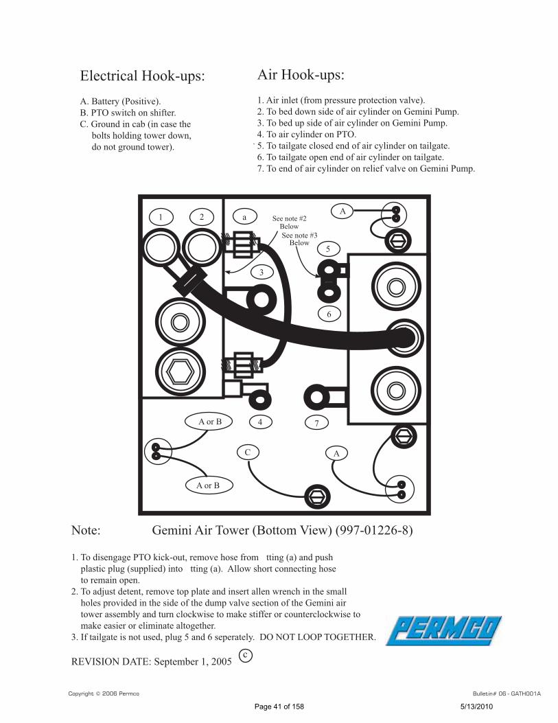
1 2 Aa
3
4 7
5
6
A or B
A or B
AC
See note #2 Below
Electrical Hook-ups:A. Battery (Positive).B. PTO switch on shifter.C. Ground in cab (in case the bolts holding tower down, do not ground tower).
Air Hook-ups:1. Air inlet (from pressure protection valve).2. To bed down side of air cylinder on Gemini Pump.3. To bed up side of air cylinder on Gemini Pump.4. To air cylinder on PTO.5. To tailgate closed end of air cylinder on tailgate.6. To tailgate open end of air cylinder on tailgate.7. To end of air cylinder on relief valve on Gemini Pump.
Note: Gemini Air Tower (Bottom View) (997-01226-8)
1. To disengage PTO kick-out, remove hose from tting (a) and push plastic plug (supplied) into tting (a). Allow short connecting hose to remain open.2. To adjust detent, remove top plate and insert allen wrench in the small holes provided in the side of the dump valve section of the Gemini air tower assembly and turn clockwise to make stiffer or counterclockwise to make easier or eliminate altogether.3. If tailgate is not used, plug 5 and 6 seperately. DO NOT LOOP TOGETHER.
REVISION DATE: September 1, 2005
See note #3 Below
c
Copyright © 2006 Permco Bulletin# 06 - GATH001A
Page 41 of 158 5/13/2010
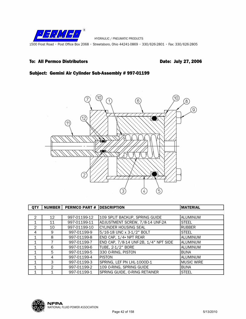
RR
HYDRAULIC / PNEUMATIC PRODUCTS
1500 Frost Road • Post Office Box 2068 • Streetsboro, Ohio 44241-0869 • 330/626-2801 • Fax: 330/626-2805
To: All Permco Distributors Date: July 27, 2006
Subject: Gemini Air Cylinder Sub-Assembly # 997-01199
NATIONAL FLUID POWER ASSOCIATION
QTY NUMBER PERMCO PART # DESCRIPTION MATERIAL
2 12 997-01199-12 109 SPLIT BACKUP, SPRING GUIDE ALUMINUM1 11 997-01199-11 ADJUSTMENT SCREW, 7/8-14 UNF-2A STEEL2 10 997-01199-10 CYLINDER HOUSING SEAL RUBBER4 9 997-01199-9 5/16-18 UNC x 3-1/2" BOLT STEEL1 8 997-01199-8 END CAP, 1/4• NPT REAR ALUMINUM1 7 997-01199-7 END CAP, 7/8-14 UNF-2B, 1/4" NPT SIDE ALUMINUM1 6 997-01199-6 TUBE, 2-1/2" BORE ALUMINUM1 5 997-01199-5 330 O-RING, PISTON BUNA1 4 997-01199-4 PISTON ALUMINUM1 3 997-01199-3 SPRING, LEF PN LHL-1000D-1 MUSIC WIRE1 2 997-01199-2 109 O-RING, SPRING GUIDE BUNA1 1 997-01199-1 SPRING GUIDE, O-RING RETAINER STEEL
Page 42 of 158 5/13/2010
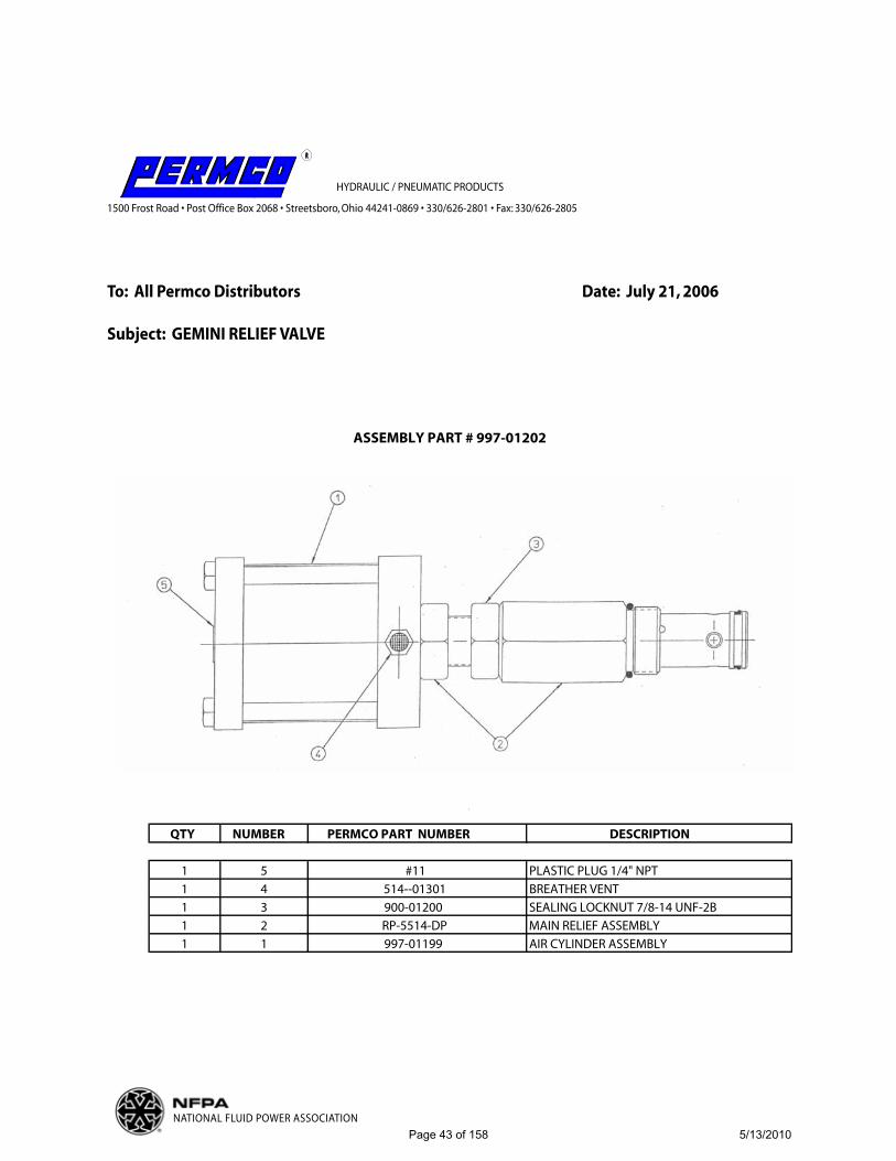
RR
HYDRAULIC / PNEUMATIC PRODUCTS
1500 Frost Road • Post Office Box 2068 • Streetsboro, Ohio 44241-0869 • 330/626-2801 • Fax: 330/626-2805
To: All Permco Distributors Date: July 21, 2006
Subject: GEMINI RELIEF VALVE
NATIONAL FLUID POWER ASSOCIATION
QTY NUMBER PERMCO PART NUMBER DESCRIPTION
1 5 #11 PLASTIC PLUG 1/4" NPT1 4 514--01301 BREATHER VENT1 3 900-01200 SEALING LOCKNUT 7/8-14 UNF-2B1 2 RP-5514-DP MAIN RELIEF ASSEMBLY1 1 997-01199 AIR CYLINDER ASSEMBLY
ASSEMBLY PART # 997-01202
Page 43 of 158 5/13/2010
1
Installation and Operation Instructions for the 997-01444
Application:Permco’s new dual-purpose air tower is designed to operate combination hydraulic systems.
Installation:See page two for plumbing and wiring diagram.
Console functions:1. Power take-off (Indicator light is wired to PTO to indicate PTO engaged) 2. Hoist3. Relief pressure settings 4. Automatic default to low pressure for relief valve. (When PTO disengages the
relief valve will always reset to low pressure setting.)
1. Operation of a standard dump application (low pressure):a. Hook up trailer hoses b. Engage the PTO (LED will come on while the PTO is engaged) c. Operate the hoist control as needed d. The PTO will automatically disengage when the hoist control is in the
lower position(optional manual disengagement is )* 2. Operation of live floor/high pressure application:
a. Hook up trailer hosesb. To set the pressure to high, pull the high pressure spool valve. This will
change your system to high pressure. The high pressure light will come on.
c. Engage the PTO(LED will come on when PTO is engaged) d. To begin operation move hoist control into raise position e. To return to standard pressure, shut off the high pressure valve.
1) This can be done by manually disengaging the valve. 2) Shutting the PTO off. 3) By putting the hoist control into the lower position (when the
automatic PTO kick out feature is being utilized)*.
*Automatic kick out of PTO can be converted to manual operation by removing “tee” fitting “A” from valve fitting “B”. See picture on page 2. When using this option the PTO remains engaged until operator disengages. Accordingly the relief valve when set to high will remain until either PTO disengaged or operator shuts off high pressure.
NOTE: Follow all pump instructions for operation. Hydraulic relief settings recommended by the pump manufacturer should be strictly followed. Not following the hydraulic pump manufacturer’s relief setting recommendations could result in significant system damage and /or failure.
Page 44 of 158 5/13/2010

PTOHIGHPRESSURE-TO PRESSURE
RELIEFCYLINDER
NEGATIVEPOSITIVE IN
RED-HOT
BLACK-GROUND/
PTO
B
A
RAISEHOIST
EXHUAST
LOWERHOIST/TO PTO
(FORKICKOUTFEATURE)
2
Page 45 of 158 5/13/2010
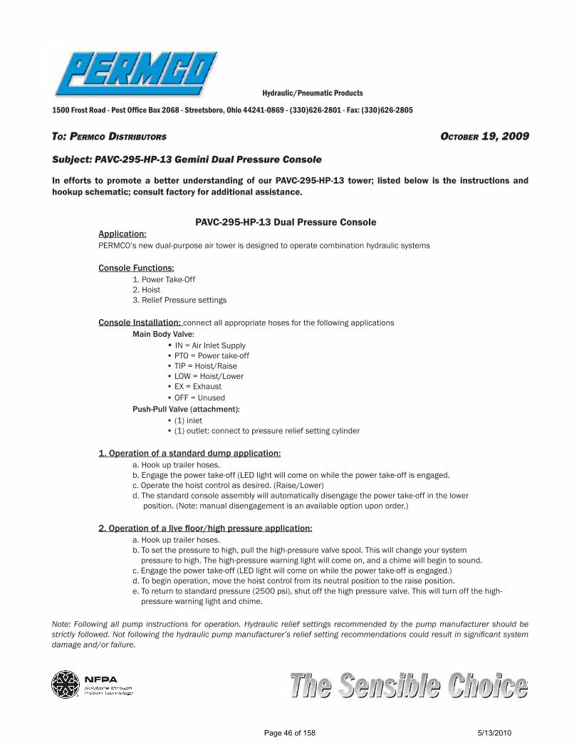
TO: PERMCO DISTRIBUTORS OCTOBER 19, 2009
Hydraulic/Pneumatic Products
1500 Frost Road - Post Of! ce Box 2068 - Streetsboro, Ohio 44241-0869 - (330)626-2801 - Fax: (330)626-2805
Subject: PAVC-295-HP-13 Gemini Dual Pressure Console
In efforts to promote a better understanding of our PAVC-295-HP-13 tower; listed below is the instructions and hookup schematic; consult factory for additional assistance.
PAVC-295-HP-13 Dual Pressure Console Application: PERMCO’s new dual-purpose air tower is designed to operate combination hydraulic systems
Console Functions: 1. Power Take-Off 2. Hoist 3. Relief Pressure settings
Console Installation: connect all appropriate hoses for the following applications Main Body Valve: • IN = Air Inlet Supply • PTO = Power take-off • TIP = Hoist/Raise • LOW = Hoist/Lower • EX = Exhaust • OFF = Unused Push-Pull Valve (attachment): • (1) inlet • (1) outlet: connect to pressure relief setting cylinder
1. Operation of a standard dump application: a. Hook up trailer hoses. b. Engage the power take-off (LED light will come on while the power take-off is engaged. c. Operate the hoist control as desired. (Raise/Lower) d. The standard console assembly will automatically disengage the power take-off in the lower position. (Note: manual disengagement is an available option upon order.)
2. Operation of a live ! oor/high pressure application: a. Hook up trailer hoses. b. To set the pressure to high, pull the high-pressure valve spool. This will change your system pressure to high. The high-pressure warning light will come on, and a chime will begin to sound. c. Engage the power take-off (LED light will come on while the power take-off is engaged.) d. To begin operation, move the hoist control from its neutral position to the raise position. e. To return to standard pressure (2500 psi), shut off the high pressure valve. This will turn off the high- pressure warning light and chime.
Note: Following all pump instructions for operation. Hydraulic relief settings recommended by the pump manufacturer should be strictly followed. Not following the hydraulic pump manufacturer’s relief setting recommendations could result in signi! cant system damage and/or failure.
Page 46 of 158 5/13/2010

PV-8-TG
PTO RAISE LOWER
EXHAUST IN IN
PTO
PAV-295
SUPPLY
Dump PumpAir Shift Cylinder PRESSURE
RELIEFCYLINDER
LOW
MECHANICAL HOOKUP
PRESSURESWITCH
+ 12 V. DC (RED)
ELECTRICAL HOOKUP
ALARM
(-) (BLACK)
LIGHT
- - ++
PAVC-295-HP-132-11-09REV. A
PLUG
PULL KNOB FORWALKING FLOOR
+
Page 47 of 158 5/13/2010
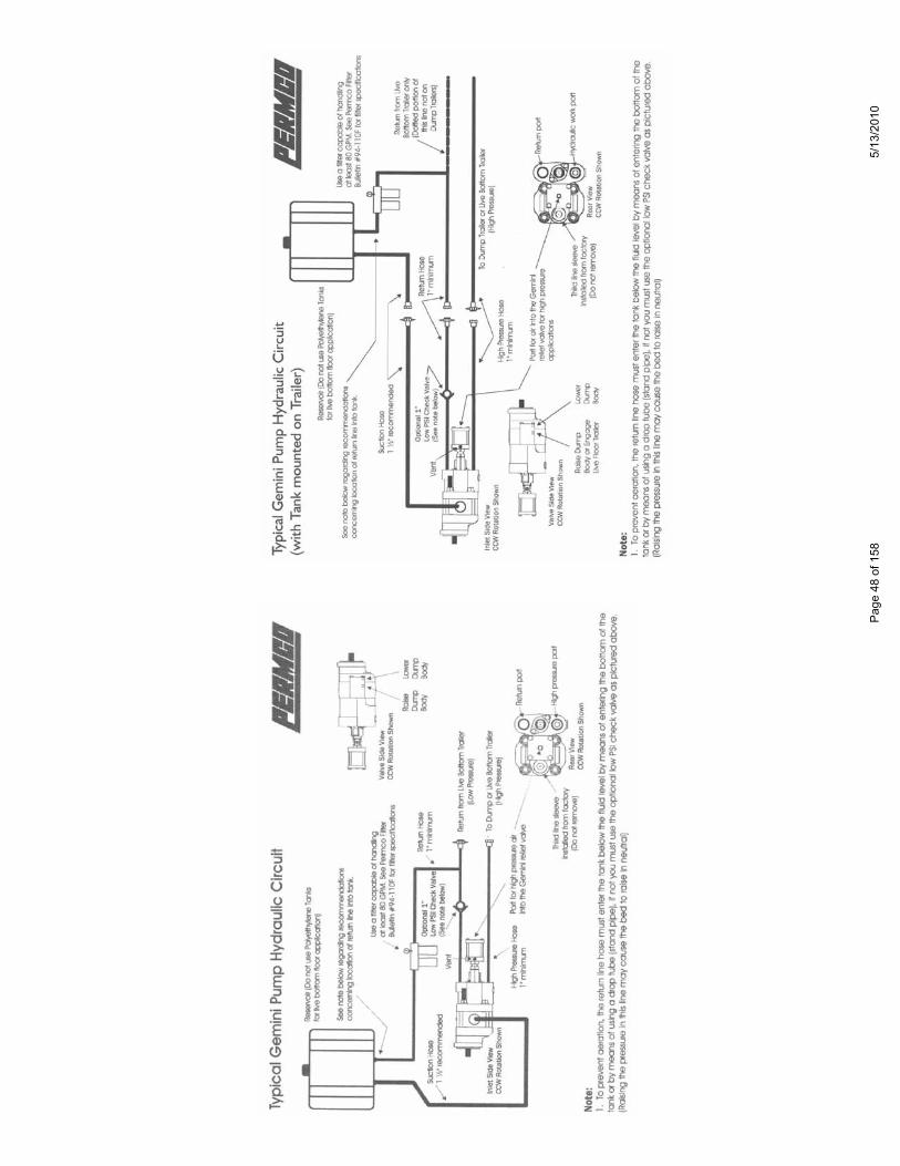
Page
48
of 1
585/
13/2
010

HYDRAULIC/PNEUMATIC PRODUCTS1500 Frost Road · Post Office Box 2068 · Streetsboro, Ohio 44241-0869 · 330/626-2801 · FAX: 330/626-2805
In-Line Reliefs
PART NUMBER PORTING / OPTIONS
In-Line Relief ValvesAZ5514J-100-25 1! NPT / 2500 PSIAZ5514J-100-25J 1" JIC / 2500 PSIAZ5514P-100-25 1! NPT / 2500 PSI / PILOT OPERATEDAZ5514P-100-25J 1" JIC / 2500 PSI / PILOT OPERATEDAZ5514J-075-25 3/4! NPT / 2500 PSIAZ5514J-075-25J 3/4" JIC / 2500 PSIAZ5514P-075-25 3/4" NPT / 2500 PSI / PILOT OPERATEDAZ5514P-075-25J 3/4" JIC / 2500 PSI / PILOT OPERATEDAZ5514J-075-30 3/4! NPT / 3000 PSIAZ2214J-075-30J 3/4" JIC / 3000 PSIAZ5514J-100-30 1! NPT / 3000 PSIAZ5514J-100-30J 1" JIC / 3000 PSIAZ5514J-100-32 1! NPT / 3200 PSIAZ5514J-100-32J 1" JIC / 3200 PSI
Other options available, consult factory for price and availability.
Page 49 of 158 5/13/2010
RR
HYDRAULIC / PNEUMATIC PRODUCTS
1500 Frost Road • Post Office Box 2068 • Streetsboro, Ohio 44241-0869 • 330/626-2801 • Fax: 330/626-2805
To: All Permco Distributors Date: JANUARY 14, 1987
Subject: OPERATION OF THE DRY VALVE
Dry valves (or similarly trade named valves) are coming into increasing usage, particularly in the solid waste industry. These valves are used to permit compacting while roading (on the fly), while limiting heat buildup in the hydraulic systems during transport. There are some safeguards necessary when using the valves.
A dry valve consist of an air or electrically operated shut off valve in the inlet line of the pump; usually mounted to the pump inlet port to simplify plumbing. Included in the valve is an orifice which permits sufficient fluid to pass to lubricate the pump parts when the valve is in the off (dry) mode. In some situations, a bypass flow control mounted to the pump outlet is used. The purpose of this is to re-circulate a portion of the outlet flow back to the pump inlet to prevent cavitation during high speed operation of the pump when the dry valve is open (wet) mode. This also reduces the flow rate to the compacting cylinders and thus compacting speed is not excessive preventing slamming and hammering of the compacting machinery. The compacting machinery is normally designed to operate at low pump speed which limits the rate of operation.
If, while the dry valve is closed (dry mode), pressure builds up in the discharge side of the system (above 20 PSI), the pump will be damaged. The dry valve in the off (dry) mode permits only a flow sufficient to lubricate the pump; while adequate to lubricate there is insufficient fluid to fill the pump displacement and the pump exhibits severe cavitation. No damage from this occors unless there is pressure to cause the cavities (oil droplets) to collapse. System backpressure exceeding 20 PSI will provide enough energy to collapse the cavities (oil droplets) and damage the pump.
To prevent the possibility of backpressure buildup, a small valve may be added ahead of the system control valves to bypass a small flow, 2-3 GPM. This may be a flow control, bleed valve or similar device. See DVBP Port End Cover for P5000/5100 or P7500/7600 for Permco's bleed valve used in dry valve applications.
Permco offers (2) sizes of air operated dry valves which can be mounted to the pump inlet with a 1-1/2" or 2" SAE split flange porting. This valve is similar to other manufacturers products in general configuration. Because lubrication is limited while the dry valve is being used, Permco has available special thrust plates for the 3000/3100, 2500, 3700, 5000/5100, and 7500/7600 series pumps. These plates are necessary to assure adequate pump life. The dry valve should be inspected and the orifice size checked; Permco requires and orifice of 0.104 inches. If the orifice size is less than this, it should be drilled out with a .104 drill. Be sure to deburr and clean all chips from the valve.
THRUST PLATE PART # PUMP SERIES THRUST PLATE PART # PUMP SERIESZZ-0947-DV 3000/3100 W-0947-DV 3700X-0947-DVS 2500, 5000/5100 AZ-0947-DVS 7500/7600
Variations of installations will be found. In some instances, only a dry valve is used. In some cases, the operator must limit engine speed while compacting and must remember to close (dry mode) the dry valve at high engine speeds. A tachometer output with associated electronics may be incorporated which will automatically perform this function. Other Installations may incorporate the flow control, the flow control and back pressure valve, or just a back pressure valve. All of these arrangements may be found.
NATIONAL FLUID POWER ASSOCIATION Page 50 of 158 5/13/2010
RR
HYDRAULIC / PNEUMATIC PRODUCTS
1500 Frost Road • Post Office Box 2068 • Streetsboro, Ohio 44241-0869 • 330/626-2801 • Fax: 330/626-2805
To: All Permco Distributors Date: SEPTEMBER 15, 1990
Subject: NEW PORT END COVERS FOR DRY VALVE PUMPS
In an effort to reduce noise, simplify plumbing and improve the efficiency and the life of the dry valve pump, Permco has developed a by-pass valve that is built into the port end cover. This valve opens as the dry valve is closed to allow a reasonably unrestricted flow back to tank. It minimizes outlet back pressure that causes dry valve pumps to become noisy if cavitation is premitted to occor. Typically this back pressure is caused by downstrean restrictions in the open center valve system and the long hoses associated with return lines.
This patented design allows for approximately 2 GPM to flow directly back to tank when the pump is in the dry mode. When the pump is returned to the normal operating mode (wet mode) this valve closes to eliminate any loss of power through the bleed off of fluid. This valve, integral to the port end cover requires a 3/8" line back to tank.
Permco's system eliminates the horsepower loss associated with competitors models which allow oil to continue to flow to tank during the operating mode. Is also minimizes the back pressure that makes dry valve pumps noisy and the premature failures caused by this back pressure. These are available for the P5000/5100 and P7500/7600 dry valve pumps. This option is a net adder when ordered as an option on a dry valve pump (or port end cover) and is designated by the DVBP (Dry Valve By-Pass) at the end of the model or part number.
When ordering either of the above port end cover assemblies for dry valve applications, please incorporate the following components into your pump assembly:
By installing these components in your dry valve pump assembly, optimun performance is assured.
NATIONAL FLUID POWER ASSOCIATION
PART # DESCRIPTION
YZ-0592-DVBPYZ-0592D-DVBPXZ-0592-DVBPXZ-0592D-DVBP
P5000 DRY VALVE BY-PASS PECP5100 DRY VALVE BY-PASS PECP7500 DRY VALVE BY-PASS PECP7600 DRY VALVE BY-PASS PEC
PART # DESCRIPTION
ZZ-0947-DVKA-0558-DVX-0947-DVSMA-0558-DVAZ-0947-DVSVA-0558-DV
P3000/3100 DRY VALVE THRUST PLATEP3000/3100 DRY VALVE RING SEALP5000/5100 DRY VALVE THRUST PLATEP5000/5100 DRY VALVE RING SEALP7500/7600 DRY VALVE THRUST PLATEP7500/7600 DRY VALVE RING SEAL
Page 51 of 158 5/13/2010

RR
TTOO SSYYSSTTEEMM
MM
FFLLOOWW CCOONNTTRROOLL
RREELLIIEEFF VVAALLVVEE
BBYYPPAASSSS VVAALLVVEE
DDRRYY VVAALLVVEE
SSEELLEECCTTOORR VVAALLVVEE
HYDRAULIC / PNEUMATIC PRODUCTS
1500 Frost Road • Post Office Box 2068 • Streetsboro, Ohio 44241-0869 • 330/626-2801 • Fax: 330/626-2805
To: All Permco Distributors Date: MARCH 9, 1992
Subject: P5000/5100 AND P7500/7600 SERIES DRY VALVE WITH INTEGRAL BY-PASS CONTROL
When a pump is subjected to a restricted inlet condition as in the case of units incorporating a dry valve setup, cavitation of the lubricating fluid will occur if an unrestricted path back to the oil reservoir is unavailable at the outlet of the pump. To greatly reduce the occurence of cavitation, Permco has developed a by-pass control that gives the lubrication flow a direct, unrestricted path to the hydraulic reservoir. Unlike other manufacturers controls that provide the same function, the Permco design is the only one availabe that is integral to the pump itself and provides a positive closure (shut off) when the work circuit is activated. In doing so, all flow that would have been by-passed to tank (as in the case of pressure compensated controls that bleed a given amount of flow continously through the entire work cycle), is directed to the working circuit providing full power to the system. Because the by-pass control is integral to the pump, all that is required for installation is a 3/8" diameter hose with one end connected to the 3/8" NPT port located on the side of the port end cover and the other end connected to the hydraulic reservoir.
NATIONAL FLUID POWER ASSOCIATION
DRY VALVE CIRCUIT SCHEMATIC WITH INTEGRAL BY-PASS CONTROL
Page 52 of 158 5/13/2010

RR
HYDRAULIC / PNEUMATIC PRODUCTS
1500 Frost Road • Post Office Box 2068 • Streetsboro, Ohio 44241-0869 • 330/626-2801 • Fax: 330/626-2805
To: All Permco Distributors Date: MARCH 9, 1992
Subject: SHAFT END COVER COMPONENTS FOR DRY VALVE PUMPS
When building a dry valve pump and extra seal is needed, a dry valve pump while in the dry mode of operation creates an internal vacuum which effects the shaft seals ability to seal properly around the pump shaft, the extra seal is needed to prevent debris from entering through the shaft seal area. This seal arrangement is called a back-to-back seal and is common to all dry valve pump applications. When building dry valve pumps is should be noted that dry valve thrust plates and dry valve rings seals are required for optium performance.
NOTE: The P7500/7600 is now offered in an integral gear shaft set for SAE "C" keyed (Part # ZE-0024L-3-**).
Please refer to the diagram illustrations below to insure proper seal installation.
NATIONAL FLUID POWER ASSOCIATION
1 2 23 4 5 61 2 23 4 5
1 2 3 4 5
P7500/7600 INTEGRAL P7500/7600 CONTINENTAL
P5000/5100 INTEGRAL
P7500/7600 INTEGRAL
1. W62-26-10 SHAFT SEAL2. K-2995-164 O-RING3. QZ-0961 SEAL RETAINER4. W62-49-1 OUTER SEAL5. W85-315 SNAP RING6. W62-26-75 BEARING SEAL
P7500/7600 CONTINENTAL
1. W62-26-10 SHAFT SEAL2. K-2995-164 O-RING3. QZ-0961 SEAL RETAINER4. W62-26-10 OUTER SEAL5. W85-315 SNAP RING
P5000/5100 INTEGRAL
1. W62-26-17 SHAFT SEAL2. W62-48-8 OUTER SEAL3. K-2995-47 O-RING4. W023-283 SNAP RING5. OZ-0961 SEAL RETAINER
Page 53 of 158 5/13/2010

RR
HYDRAULIC / PNEUMATIC PRODUCTS
1500 Frost Road • Post Office Box 2068 • Streetsboro, Ohio 44241-0869 • 330/626-2801 • Fax: 330/626-2805
To: All Permco Distributors Date: July 21, 2006
Subject: NEW DRY VALVE THRUST PLATE
Our AZ-0947-DV 7500/7600 series thrust plate used in dry valve applications, has been superseded. Please now use thrust plate AZ-0947-DVS for all future dry valve pump needs.
The old thrust plate (AZ-0947-DV) was bi-rotational. The new AZ-0947-DVS plates are unidrectional to facilitate a better hydraulic seal between the gears and plates. This results in improved volumetric efficiency for the pump.
Both the AZ-0947-DVS (7500/7600 Series) and the X-0947-DVS (5000/5100 Series) unidrectional thrust plateswill have the same orientation. Like all unidrectional thrust plates, it is very important the the new plates are oriented properly within the pump. Especially when you or your customers are repairing or retrofitting the new plates in as existing pump. Please refer to the diagram above for assistance.
If you have further questions please call any of our customer service personnel.
NATIONAL FLUID POWER ASSOCIATION
PumpInlet
PumpOutlet
New AZ-0947-DVS 7500/7600 SeriesThrust Plates
Page 54 of 158 5/13/2010

RR
HYDRAULIC / PNEUMATIC PRODUCTS
1500 Frost Road • Post Office Box 2068 • Streetsboro, Ohio 44241-0869 • 330/626-2801 • Fax: 330/626-2805
To: All Permco Distributors Date: February 25, 1998
Subject: P7500/P7600 DRY VALVE THRUST PLATES
NATIONAL FLUID POWER ASSOCIATION
As you may know some time ago Permco changed the P7500/P7600 dry valve thrust plates from a bi-directional plate (AZ-0947-DV) to a unidirectional plate (AZ-0947-DVS). In a continuing effort to make our products better, Permco has initiated another change in the dry valve thrust plate. The AZ-0947-DVS now incorporates two (2) Teflon seals (280-1774-939) which seal the plate on the roller-bearing diameter. You must use two (2) seals for each thrust plate. This is a running change and is effective immediately. All units presently being built will have the new style thrust plates with seals installed. Since this is a running change, we will not take back old style dry valve thrust plates. When ordering these thrust plates as parts, please be sure to order two (2) seals (280-1774-939) for each thrust plate (AZ-0947-DVS) that you order. Please also be aware that you should never break in a dry valve pump in the dry mode. There is an inadequate amount of oil to carry the small amount of debris away and therefore the contaminants produced during break-in tend to stay in the pump and destroy it very quickly. You should therefore run it initially in the wet mode for at least one (1) minute, slowly bringing it up to the relief valve setting. This goes for a new pump built in the field or one that has simply been rebuilt. Pumps built at Permco are broken in properly on the test stand.
Page 55 of 158 5/13/2010
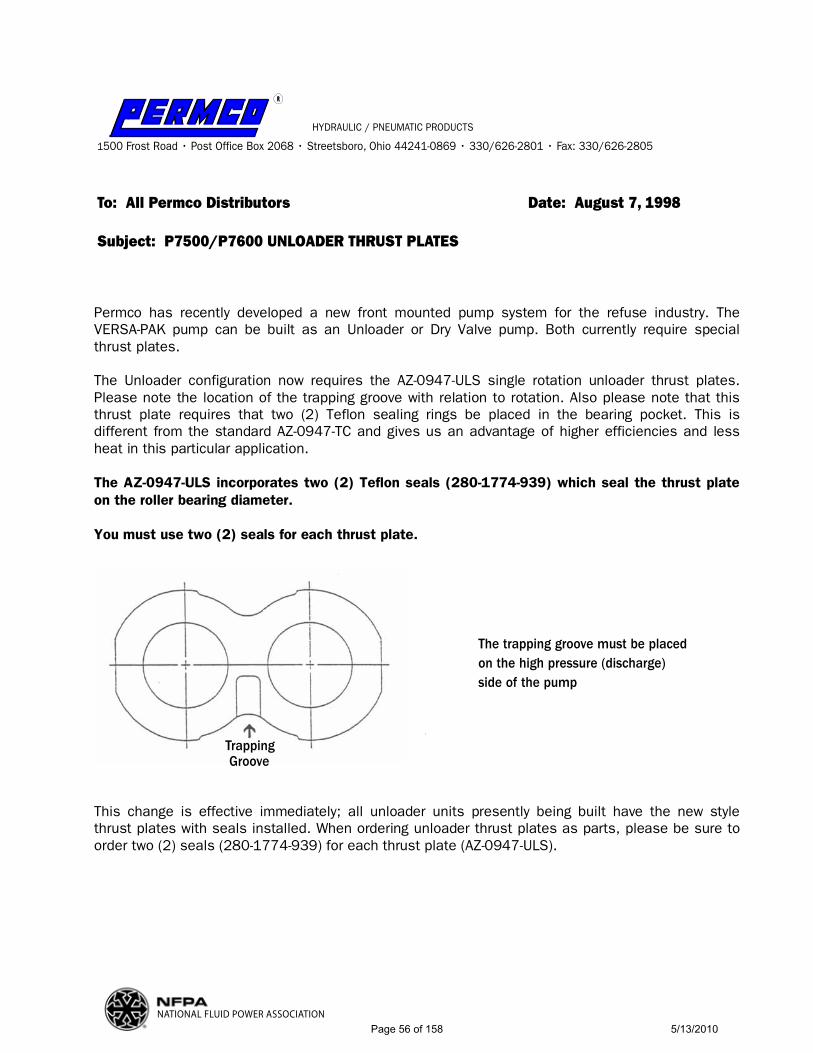
RR
HYDRAULIC / PNEUMATIC PRODUCTS
1500 Frost Road • Post Office Box 2068 • Streetsboro, Ohio 44241-0869 • 330/626-2801 • Fax: 330/626-2805
To: All Permco Distributors Date: August 7, 1998
Subject: P7500/P7600 UNLOADER THRUST PLATES
NATIONAL FLUID POWER ASSOCIATION
Permco has recently developed a new front mounted pump system for the refuse industry. The VERSA-PAK pump can be built as an Unloader or Dry Valve pump. Both currently require special thrust plates.
The Unloader configuration now requires the AZ-0947-ULS single rotation unloader thrust plates. Please note the location of the trapping groove with relation to rotation. Also please note that this thrust plate requires that two (2) Teflon sealing rings be placed in the bearing pocket. This is different from the standard AZ-0947-TC and gives us an advantage of higher efficiencies and less heat in this particular application.
The AZ-0947-ULS incorporates two (2) Teflon seals (280-1774-939) which seal the thrust plate on the roller bearing diameter.
You must use two (2) seals for each thrust plate.
This change is effective immediately; all unloader units presently being built have the new style thrust plates with seals installed. When ordering unloader thrust plates as parts, please be sure to order two (2) seals (280-1774-939) for each thrust plate (AZ-0947-ULS).
TrappingGroove
The trapping groove must be placedon the high pressure (discharge)side of the pump
Page 56 of 158 5/13/2010
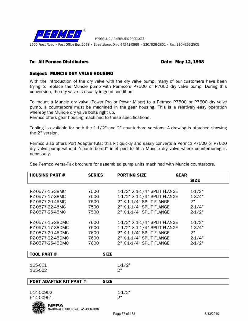
RR
HYDRAULIC / PNEUMATIC PRODUCTS
1500 Frost Road • Post Office Box 2068 • Streetsboro, Ohio 44241-0869 • 330/626-2801 • Fax: 330/626-2805
To: All Permco Distributors Date: May 12, 1998
Subject: MUNCIE DRY VALVE HOUSING
NATIONAL FLUID POWER ASSOCIATION
With the introduction of the dry valve with the dry valve pump, many of our customers have been trying to replace the Muncie pump with Permco’s P7500 or P7600 dry valve pump. During this conversion, the dry valve is usually in good condition. To mount a Muncie dry valve (Power Pro or Power Miser) to a Permco P7500 or P7600 dry valve pump, a counterbore must be machined in the gear housing. This is a relatively easy operation whereby the Muncie dry valve bolts right up. Permco offers gear housing machined to these specifications. Tooling is available for both the 1-1/2" and 2" counterbore versions. A drawing is attached showing the 2" version. Permco also offers Port Adapter Kits; this kit quickly and easily converts a Permco P7500 or P7600 dry valve pump without “counterbored” inlet port to fit a Muncie dry valve where counterboring is necessary. See Permco Versa-Pak brochure for assembled pump units machined with Muncie counterbore. HOUSING PART # SERIES PORTING SIZE GEAR SIZE RZ-0577-15-38MC 7500 1-1/2" X 1-1/4" SPLIT FLANGE 1-1/2" RZ-0577-17-38MC 7500 1-1/2" X 1-1/4" SPLIT FLANGE 1-3/4" RZ-0577-20-45MC 7500 2" X 1-1/4" SPLIT FLANGE 2" RZ-0577-22-45MC 7500 2" X 1-1/4" SPLIT FLANGE 2-1/4" RZ-0577-25-45MC 7500 2" X 1-1/4" SPLIT FLANGE 2-1/2" RZ-0577-15-38DMC 7600 1-1/2" X 1-1/4" SPLIT FLANGE 1-1/2" RZ-0577-17-38DMC 7600 1-1/2" X 1-1/4" SPLIT FLANGE 1-3/4" RZ-0577-20-45DMC 7600 2" X 1-1/4" SPLIT FLANGE 2" RZ-0577-22-45DMC 7600 2" X 1-1/4" SPLIT FLANGE 2-1/4" RZ-0577-25-45DMC 7600 2" X 1-1/4" SPLIT FLANGE 2-1/2" TOOL PART # SIZE 165-001 1-1/2" 165-002 2" PORT ADAPTER KIT PART # SIZE 514-00952 1-1/2" 514-00951 2"
Page 57 of 158 5/13/2010

..112200..112200..112255
ØØ 11..550000
ØØ 11..887788
ØØ 22..000000
ØØ 22..337755
11--11//22 IINNCCHH 22 IINNCCHH
11//22 -- 1133 UUNN
MMDDVVCCBB--11
MMUUNNCCIIEE DDRRYY VVAALLVVEE CCOOUUNNTTEERRBBOORREE DDIIMMEENNSSIIOONNSS
PPOORRTTIINNGG IINNSSTTRRUUCCTTIIOONNSS
RR
Page 58 of 158 5/13/2010

RR
HYDRAULIC / PNEUMATIC PRODUCTS
1500 Frost Road • Post Office Box 2068 • Streetsboro, Ohio 44241-0869 • 330/626-2801 • Fax: 330/626-2805
To: All Permco Distributors Date: February 25, 1998
Subject: MUNCIE PORT ADAPTER PLATES
NATIONAL FLUID POWER ASSOCIATION
Please note that when you are replacing a pump on which there is a Muncie Dry Valve (either a Power-Pro or Power-Miser) you must use either a “counterbored” pump or the adapter plate shown below, to accommodate the locator ring, when reinstalling the Muncie dry valve. This must be done to prevent premature failure of the pump. You will need to supply four (4), 1/2" longer cap screws to bolt the dry valve onto the pump when using the adapter plate. If this practice is not followed, there are two (2) possibilities for failure:
1- The pump will suck air from between the pump and dry valve and aerate because without the locator ring there is no inside support for the O-ring.
2- The locator ring is also used to center the dry valve shut-off plate against the pump port. Without being centered, the dry valve may pass too much oil into the pump in the dry mode thereby flooding the bleed valve and causing cavitation. The use of a “half” ring will not work properly because the “half” ring while filling the cavity in the dry valve, will not support the inside diameter of the O-ring nor center the dry valve against the pump port.
Please also note it is usually necessary to have a 3/8" port (the older Muncie pumps had NPT ports while the newer ones have SAE O-ring ports) on the discharge side of the rear cover of the pump as a bleed port, unless you have included the Permco bleed valve option in the rear cover. If you haveincluded the Permco bleed valve option, and you are using the Muncie Power-Miser dry valve, you MUST remove the Muncie bleed valve. (The Power-Pro or butterfly type dry valve, incorporates the bleed valve into the dry valve and you need only to have a 3/8" hose running from the discharge side of the pump directly into the dry valve, the same holds true if you are using the large piston style Commercial dry valve.)
514-00952 1-1/2" 514-00951 2"
Page 59 of 158 5/13/2010

RR
HYDRAULIC / PNEUMATIC PRODUCTS
1500 Frost Road • Post Office Box 2068 • Streetsboro, Ohio 44241-0869 • 330/626-2801 • Fax: 330/626-2805
To: All Permco Distributors Date: July 1, 2001
Subject: SPLIT FLANGE PORT ROTATION PLATES
NATIONAL FLUID POWER ASSOCIATION
The split flange port rotation kit is a usefully tool utilized when plumbing interference is encountered such as a mounting bracket, frame rail, radiator grill or brace when mounting a dry valve to a hydraulic pump. The port rotation kit allows you to rotate the split flange port 90° to aide in clearing interference obstacles. In a dry valve application the rotation kit gives the advantage of rotating the inlet port of the dry valve to either a vertical high or vertical low location allowing for ease of plumbing.
1-1/2" SPLIT FLANGE PORT ROTATION KIT KIT PART NUMBER 1317-24-24
2" SPLIT FLANGE PORT ROTATION KIT KIT PART NUMBER 1317-32-32
Page 60 of 158 5/13/2010

PERM
CO V
ERSA
-PAK
AND
REF
USE
INDU
STRY
PUM
PSPE
RMCO
PAR
T #
MUN
CIE
PART
#FL
OW
@ 1
000
RPM
PORT
S- S
AE 4
-BO
LTLI
ST P
RICE
INLE
T -
OUT
LET
VP2
8-4C
OFL
MC
PMM
27-7
CFS
L27
GPM
1-1/
2"
1
-1/4
"V
P32-
4CO
FLM
CPM
M31
-7C
FSL
31 G
PM1-
1/2"
1-1
/4"
VP3
7-4C
OFL
MC
PMM
35-7
CFS
L35
GPM
2"
1-
1/4"
VP4
2-4C
OFL
MC
PMM
40-7
CFS
L40
GPM
2"
1-
1/4"
VP4
7-4C
OFL
MC
NO
MU
NC
IE P
ART
#45
GPM
2"
1-
1/4"
MC
= M
UN
CIE
CO
UN
TERB
ORE
. TH
E PE
RMC
O P
UM
P IS
MA
CH
INED
WIT
H M
UN
CIE
CO
UN
TERB
ORE
TO
AC
CEP
T A
MU
NC
IE D
RY V
ALV
E
PERM
CO P
ART
#CO
MM
ERCI
AL P
ART
#FL
OW
@ 1
000
RPM
PORT
S- S
AE 4
-BO
LTLI
ST P
RICE
INLE
T -
OUT
LET
VP2
8-4C
OFL
DV
316-
9610
-180
27 G
PM1-
1/2"
1-1
/4"
VP3
2-4C
OFL
DV
31 G
PM1-
1/2"
1-1
/4"
VP3
7-4C
OFL
DV
316-
9610
-212
35 G
PM 2
"
1-1/
4"V
P42-
4CO
FLD
V31
6-96
10-1
8140
GPM
2"
1-
1/4"
VP4
7-4C
OFL
DV
316-
9610
-213
45 G
PM 2
"
1-1/
4"D
V =
DRY
VA
LVE.
TH
E PE
RMC
O P
UM
P IS
MA
CH
INED
TO
AC
CEP
T A
PER
MC
O D
RY V
ALV
E O
R A
CO
MM
ERC
IAL
DRY
VA
LVE
PERM
CO P
ART
#M
UNCI
E PA
RT #
DESC
RIPT
ION
PORT
SIZ
ELI
ST P
RICE
514-
0091
1-D
VA
PMV-
24D
RY
VALV
E
1-1/
2"51
4-00
278-
DV
APM
V-32
DR
Y VA
LVE
2"
51
4-00
952
NO
MU
NC
IE P
ART
#D
RY
VALV
E PO
RT
ADAP
TOR
1-1/
2"51
4-00
951
NO
MU
NC
IE P
ART
#D
RY
VALV
E PO
RT
ADAP
TOR
2"
*YO
U C
AN
SU
BSTI
TUTE
A D
V P
UM
P FO
R A
MC
PU
MP
IF Y
OU
UTI
LIZE
TH
E C
ORR
ECT
SIZE
PO
RT A
DA
PTER
TO
MO
UN
T TH
E M
UN
CIE
DRY
VA
LVE
*WH
EN R
EPLA
CIN
G A
MU
NC
IE D
RY V
ALV
E W
ITH
A P
ERM
CO
DRY
VA
LVE
YOU
MU
ST U
TILI
ZE T
HE
CO
RREC
T SI
ZE P
ORT
AD
APT
ER T
O M
OU
NT
*WH
EN U
TILI
ZIN
G A
DRY
VA
LVE
PORT
AD
APT
OR
THE
DRY
VA
LVE
MO
UN
TIN
G B
OLT
S W
ILL
NEE
D T
O B
E 1/
2" L
ON
GER
FO
R PR
OPE
R M
OU
NTI
NG
*FO
R A
CC
ESSO
RIES
SU
CH
AS
FLO
W C
ON
TRO
L V
ALV
ES, U
NLO
AD
ER V
ALV
ES, S
WIT
CH
KIT
S, H
OSE
KIT
S, E
TC.
CO
NSU
LT F
AC
TORY
Page
61
of 1
585/
13/2
010
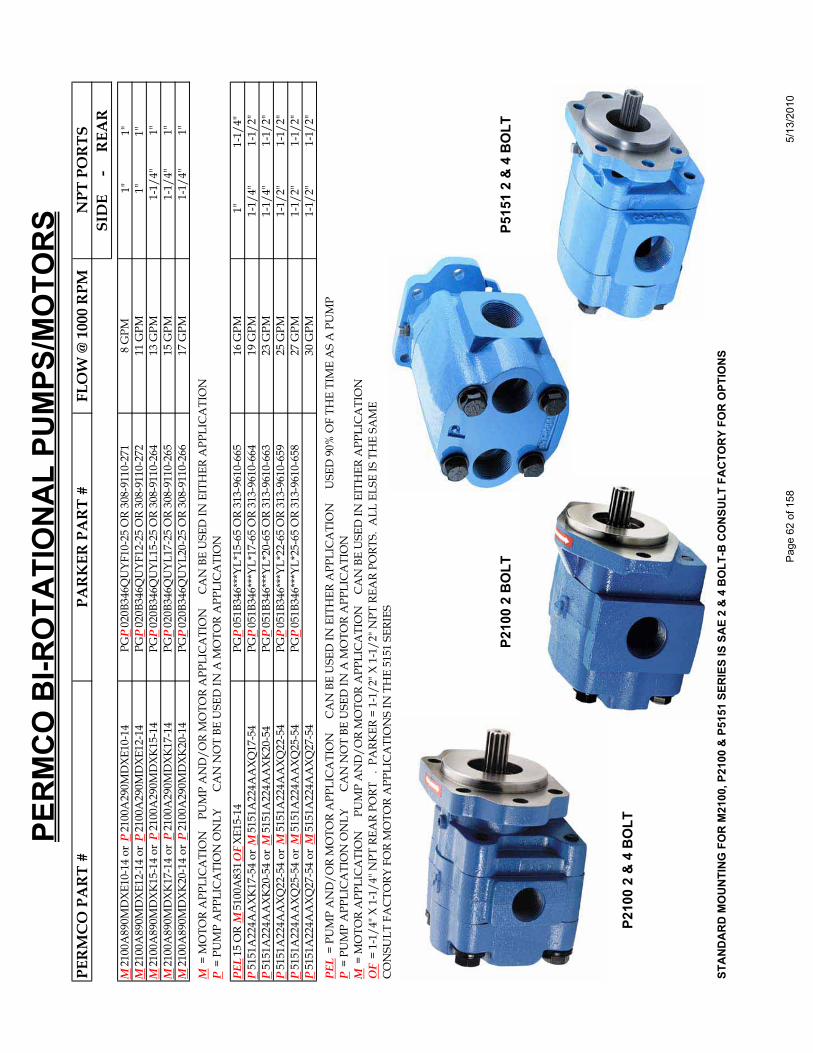
PERM
CO B
I-RO
TATI
ONA
L PU
MPS
/MO
TORS
PER
MC
O P
AR
T #
PAR
KER
PA
RT
#FL
OW
@ 1
000
RPM
NPT
PO
RTS
SID
E
-
REA
RM
2100
A89
0MD
XE10
-14
or P
2100
A29
0MD
XE10
-14
PGP
020B
346Q
UYF
10-2
5 O
R 30
8-91
10-2
718
GPM
1"
1"
M21
00A
890M
DXE
12-1
4 or
P21
00A
290M
DXE
12-1
4PG
P02
0B34
6QU
YF12
-25
OR
308-
9110
-272
11 G
PM
1
"
1"M
2100
A89
0MD
XK15
-14
or P
2100
A29
0MD
XK15
-14
PGP
020B
346Q
UYL
15-2
5 O
R 30
8-91
10-2
6413
GPM
1-1/
4"
1"
M21
00A
890M
DXK
17-1
4 or
P21
00A
290M
DXK
17-1
4PG
P02
0B34
6QU
YL17
-25
OR
308-
9110
-265
15 G
PM
1-
1/4"
1"M
2100
A89
0MD
XK20
-14
or P
2100
A29
0MD
XK20
-14
PGP
020B
346Q
UYL
20-2
5 O
R 30
8-91
10-2
6617
GPM
1-1/
4"
1"
M =
MO
TOR
APP
LIC
ATI
ON
P
UM
P A
ND
/OR
MO
TOR
APP
LIC
ATI
ON
C
AN
BE
USE
D IN
EIT
HER
APP
LIC
ATI
ON
P =
PU
MP
APP
LIC
ATI
ON
ON
LY
C
AN
NO
T BE
USE
D IN
A M
OTO
R A
PPLI
CA
TIO
N
PEL
15 O
R M
5100
A83
1OFX
E15-
14
PGP
051B
346*
**YL
*15-
65 O
R 31
3-96
10-6
6516
GPM
1
"
1-
1/4"
P51
51A
224A
AXK
17-5
4 or
M51
51A
224A
AXQ
17-5
4PG
P05
1B34
6***
YL*1
7-65
OR
313-
9610
-664
19 G
PM
1-1
/4"
1-1/
2"P
5151
A22
4AA
XK20
-54
or M
5151
A22
4AA
XK20
-54
PGP
051B
346*
**YL
*20-
65 O
R 31
3-96
10-6
6323
GPM
1
-1/4
"
1-
1/2"
P51
51A
224A
AXQ
22-5
4 or
M51
51A
224A
AXQ
22-5
4PG
P05
1B34
6***
YL*2
2-65
OR
313-
9610
-659
25 G
PM
1-1
/2"
1-1/
2"P
5151
A22
4AA
XQ25
-54
or M
5151
A22
4AA
XQ25
-54
PGP
051B
346*
**YL
*25-
65 O
R 31
3-96
10-6
5827
GPM
1
-1/2
"
1-
1/2"
P51
51A
224A
AXQ
27-5
4 or
M51
51A
224A
AXQ
27-5
430
GPM
1
-1/2
"
1-
1/2"
PEL
= P
UM
P A
ND
/OR
MO
TOR
APP
LIC
ATI
ON
C
AN
BE
USE
D IN
EIT
HER
APP
LIC
ATI
ON
U
SED
90%
OF
THE
TIM
E A
S A
PU
MP
P =
PU
MP
APP
LIC
ATI
ON
ON
LY
C
AN
NO
T BE
USE
D IN
A M
OTO
R A
PPLI
CA
TIO
N
M =
MO
TOR
APP
LIC
ATI
ON
P
UM
P A
ND
/OR
MO
TOR
APP
LIC
ATI
ON
C
AN
BE
USE
D IN
EIT
HER
APP
LIC
ATI
ON
OF
= 1-
1/4"
X 1
-1/4
" NPT
REA
R PO
RT
. PA
RKER
= 1
-1/2
" X 1
-1/2
" NPT
REA
R PO
RTS.
ALL
ELS
E IS
TH
E SA
ME
CO
NSU
LT F
AC
TORY
FO
R M
OTO
R A
PPLI
CA
TIO
NS
IN T
HE
5151
SER
IES
P21
00 2
BO
LT
P51
51 2
& 4
BO
LT
P21
00 2
& 4
BO
LT
STAN
DARD
MO
UNTI
NG F
OR
M21
00, P
2100
& P
5151
SER
IES
IS S
AE 2
& 4
BO
LT-B
CO
NSUL
T FA
CTO
RY F
OR
OPT
IONS
Page
62
of 1
585/
13/2
010
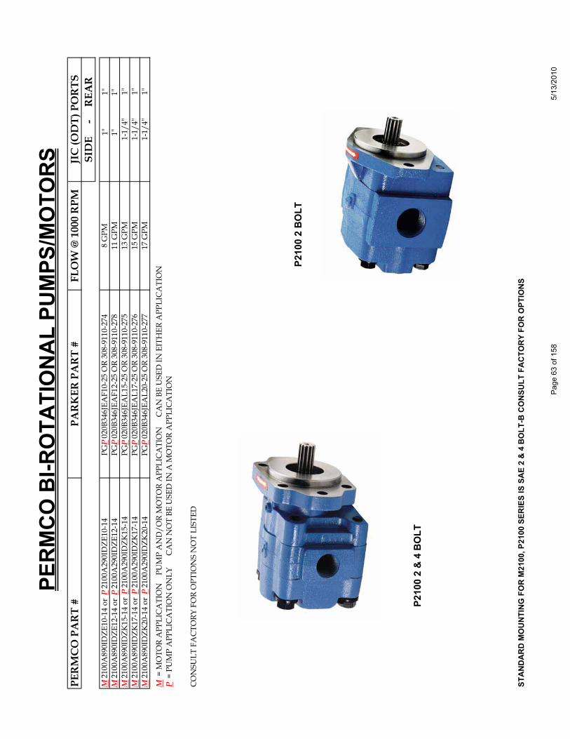
PERM
CO B
I-RO
TATI
ONA
L PU
MPS
/MO
TORS
PER
MC
O P
AR
T #
PAR
KER
PA
RT
#FL
OW
@ 1
000
RPM
JIC
(OD
T) P
OR
TSSI
DE
-
R
EAR
M21
00A
890I
DZE
10-1
4 or
P21
00A
290I
DZE
10-1
4PG
P02
0B34
6JEA
F10-
25 O
R 30
8-91
10-2
748
GPM
1"
1"
M21
00A
890I
DZE
12-1
4 or
P21
00A
290I
DZE
12-1
4PG
P02
0B34
6JEA
F12-
25 O
R 30
8-91
10-2
7811
GPM
1"
1"
M21
00A
890I
DZK
15-1
4 or
P21
00A
290I
DZK
15-1
4PG
P02
0B34
6JEA
L15-
25 O
R 30
8-91
10-2
7513
GPM
1-1/
4"
1"
M21
00A
890I
DZK
17-1
4 or
P21
00A
290I
DZK
17-1
4PG
P02
0B34
6JEA
L17-
25 O
R 30
8-91
10-2
7615
GPM
1-1/
4"
1"
M21
00A
890I
DZK
20-1
4 or
P21
00A
290I
DZK
20-1
4PG
P02
0B34
6JEA
L20-
25 O
R 30
8-91
10-2
7717
GPM
1-1/
4"
1"
M =
MO
TOR
APP
LIC
ATI
ON
P
UM
P A
ND
/OR
MO
TOR
APP
LIC
ATI
ON
C
AN
BE
USE
D IN
EIT
HER
APP
LIC
ATI
ON
P =
PU
MP
APP
LIC
ATI
ON
ON
LY
C
AN
NO
T BE
USE
D IN
A M
OTO
R A
PPLI
CA
TIO
N
CO
NSU
LT F
AC
TORY
FO
R O
PTIO
NS
NO
T LI
STED
P21
00 2
BO
LT
P21
00 2
& 4
BO
LT
STAN
DARD
MO
UNTI
NG F
OR
M21
00, P
2100
SER
IES
IS S
AE 2
& 4
BO
LT-B
CO
NSUL
T FA
CTO
RY F
OR
OPT
IONS
Page
63
of 1
585/
13/2
010
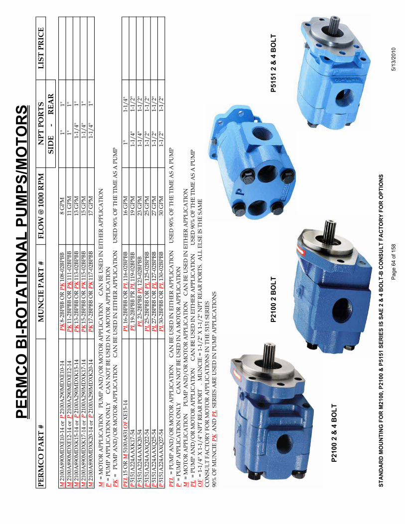
PERM
CO B
I-RO
TATI
ONA
L PU
MPS
/MO
TORS
PER
MC
O P
AR
T #
MU
NC
IE P
AR
T #
FLO
W @
100
0 R
PMN
PT P
OR
TSLI
ST P
RIC
ESI
DE
-
R
EAR
M21
00A
890M
DXE
10-1
4 or
P21
00A
290M
DXE
10-1
4PK
8-2B
PBB
OR
PK10
8-02
BPBB
8
GPM
1"
1"
M21
00A
890M
DXE
12-1
4 or
P21
00A
290M
DXE
12-1
4PK
11-2
BPBB
OR
PK11
1-02
BPBB
11 G
PM
1
"
1"M
2100
A89
0MD
XK15
-14
or P
2100
A29
0MD
XK15
-14
PK13
-2BP
BB O
R PK
113-
02BP
BB13
GPM
1-1/
4"
1"
M21
00A
890M
DXK
17-1
4 or
P21
00A
290M
DXK
17-1
4PK
15-2
BPBB
OR
PK11
5-02
BPBB
15 G
PM
1-
1/4"
1"M
2100
A89
0MD
XK20
-14
or P
2100
A29
0MD
XK20
-14
PK17
-2BP
BB O
R PK
117-
02BP
BB17
GPM
1-1/
4"
1"
M =
MO
TOR
APP
LIC
ATI
ON
P
UM
P A
ND
/OR
MO
TOR
APP
LIC
ATI
ON
C
AN
BE
USE
D IN
EIT
HER
APP
LIC
ATI
ON
P =
PU
MP
APP
LIC
ATI
ON
ON
LY
C
AN
NO
T BE
USE
D IN
A M
OTO
R A
PPLI
CA
TIO
N
PK =
PU
MP
AN
D/O
R M
OTO
R A
PPLI
CA
TIO
N
CA
N B
E U
SED
IN E
ITH
ER A
PPLI
CA
TIO
N
USE
D 9
0% O
F TH
E TI
ME
AS
A P
UM
P
PEL
15 O
R M
5100
A83
1OFX
E15-
14
PL16
-2BP
BB O
R PL
116-
02BP
BB16
GPM
1
"
1-
1/4"
P51
51A
224A
AXK
17-5
4PL
19-2
BPBB
PR
PL11
9-02
BPBB
19 G
PM
1-1
/4"
1-1/
2"P
5151
A22
4AA
XK20
-54
PL23
-2BP
BB P
L12
3-02
BPBB
23 G
PM
1-1
/4"
1-1/
2"P
5151
A22
4AA
XQ22
-54
PL25
-2BP
BB O
R PL
125-
02BP
BB25
GPM
1
-1/2
"
1-
1/2"
P51
51A
224A
AXQ
25-5
4PL
27-2
BPBB
OR
PL12
7-02
BPBB
27 G
PM
1-1
/2"
1-1/
2"P
5151
A22
4AA
XQ27
-54
PL30
-2BP
BB O
R PL
130-
02BP
BB30
GPM
1
-1/2
"
1-
1/2"
PEL
= P
UM
P A
ND
/OR
MO
TOR
APP
LIC
ATI
ON
C
AN
BE
USE
D IN
EIT
HER
APP
LIC
ATI
ON
U
SED
90%
OF
THE
TIM
E A
S A
PU
MP
P =
PU
MP
APP
LIC
ATI
ON
ON
LY
C
AN
NO
T BE
USE
D IN
A M
OTO
R A
PPLI
CA
TIO
N
M =
MO
TOR
APP
LIC
ATI
ON
P
UM
P A
ND
/OR
MO
TOR
APP
LIC
ATI
ON
C
AN
BE
USE
D IN
EIT
HER
APP
LIC
ATI
ON
PL =
PU
MP
AN
D/O
R M
OTO
R A
PPLI
CA
TIO
N
CA
N B
E U
SED
IN E
ITH
ER A
PPLI
CA
TIO
N
U
SED
90%
OF
THE
TIM
E A
S A
PU
MP
OF
= 1-
1/4"
X 1
-1/4
" NPT
REA
R PO
RT
. M
UN
CIE
= 1
-1/2
" X 1
-1/2
" NPT
REA
R PO
RTS.
ALL
ELS
E IS
TH
E SA
ME
CO
NSU
LT F
AC
TORY
FO
R M
OTO
R A
PPLI
CA
TIO
NS
IN T
HE
5151
SER
IES
90%
OF
MU
NC
IE P
K A
ND
PL
SER
IES
ARE
USE
D IN
PU
MP
APP
LIC
ATI
ON
S
P21
00 2
BO
LT
P
5151
2 &
4 B
OLT
P21
00 2
& 4
BO
LT
STAN
DARD
MO
UNTI
NG F
OR
M21
00, P
2100
& P
5151
SER
IES
IS S
AE 2
& 4
BO
LT-B
CO
NSUL
T FA
CTO
RY F
OR
OPT
IONS
Page
64
of 1
585/
13/2
010

OEM Item Not
For G
enera
l Dist
ributio
n
Consu
lt Fac
tory
TO: ALL PERMCO DISTRIBUTORS OCTOBER 19, 2009
Hydraulic/Pneumatic Products
1500 Frost Road - Post Of! ce Box 2068 - Streetsboro, Ohio 44241-0869 - (330)626-2801 - Fax: (330)626-2805
Subject: 257 Series SAE-C-2-Bolt Shaft End Cover w/90 Degree Rotate
We are pleased to announce a new shaft end cover for the 257 series; originally designed for an OEM customer where mounting space was limited and port locations orientation was critical. This 90 degree rotated ! ange offers a unique mounting con" guration for applications requiring ! exibility. See below for dimensions. Consult factory for additional options and component codeing assistance.
3.99
5.00
0.50.78
2-.69
7.12
7.12
Shaft End Cover Part # 574-00624U (consult factory for actual part number)2 Bushings Required Part # 921-00647-P
Page 65 of 158 5/13/2010

RR
HYDRAULIC / PNEUMATIC PRODUCTS
1500 Frost Road • Post Office Box 2068 • Streetsboro, Ohio 44241-0869 • 330/626-2801 • Fax: 330/626-2805
To: All Permco Distributors Date: JANUARY 1, 1991
Subject: NEW GRESEN TYPE SHAFT END COVER
Permco is pleased to announce the addition of the new Gresen type shaft end cover for the P3000 series, designed for replacement of Gresen T. C. series pumps. This new shaft end cover when used with the available 3000 gear widths can be matched to most required flows. When used with the RP Port End Cover nearly any porting requirements can be met.
Part number for the shaft end cover is: 574-00343-HF
Part number for the continental shaft is : 024-00409-HF
Integral gear shaft sets can be run on special order of 25 or more.
Refer to the following page for dimensional diagram.
NATIONAL FLUID POWER ASSOCIATION Page 66 of 158 5/13/2010
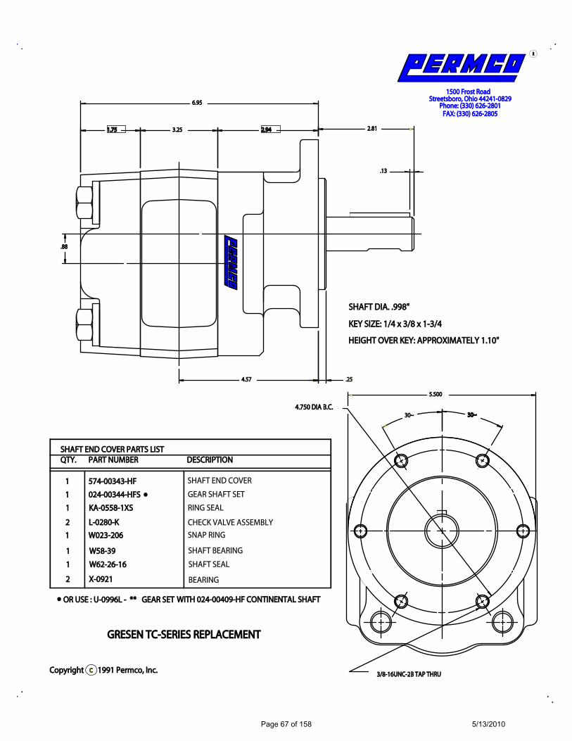
3300~~3300~~
33..2255 22..994411..7755
55..550000
..1133
..8888
..225544..5577
66..9955
22..8811
GGRREESSEENN TTCC--SSEERRIIEESS RREEPPLLAACCEEMMEENNTT
SSHHAAFFTT DDIIAA.. ..999988""
ccCCooppyyrriigghhtt 11999911 PPeerrmmccoo,, IInncc..
FFAAXX:: ((333300)) 662266--22880055PPhhoonnee:: ((333300)) 662266--22880011
HHEEIIGGHHTT OOVVEERR KKEEYY:: AAPPPPRROOXXIIMMAATTEELLYY 11..1100""
KKEEYY SSIIZZEE:: 11//44 xx 33//88 xx 11--33//44
SSttrreeeettssbboorroo,, OOhhiioo 4444224411--0088229911550000 FFrroosstt RRooaadd
RR
22 XX--00992211
11 WW6622--2266--1166
11 WW5588--3399
11 WW002233--220066
22 LL--00228800--KK
11 KKAA--00555588--11XXSS
11 002244--0000334444--HHFFSS
11 557744--0000334433--HHFF
SSHHAAFFTT EENNDD CCOOVVEERR PPAARRTTSS LLIISSTT QQTTYY.. PPAARRTT NNUUMMBBEERR DDEESSCCRRIIPPTTIIOONN
33//88--1166UUNNCC--22BB TTAAPP TTHHRRUU
**
OORR UUSSEE :: UU--00999966LL -- **** GGEEAARR SSEETT WWIITTHH 002244--0000440099--HHFF CCOONNTTIINNEENNTTAALL SSHHAAFFTT**
SHAFT END COVER
GEAR SHAFT SET
RING SEAL
CHECK VALVE ASSEMBLY
SNAP RING
SHAFT BEARING
SHAFT SEAL
BEARING
44..775500 DDIIAA BB..CC..
Page 67 of 158 5/13/2010
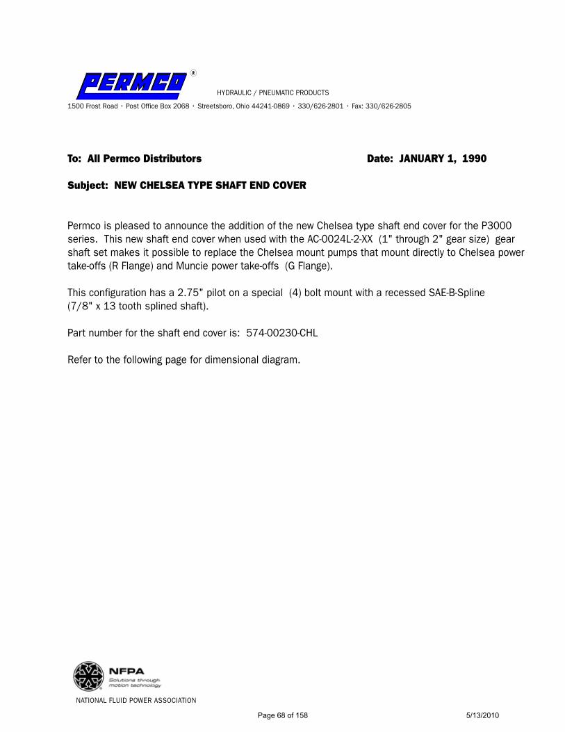
RR
HYDRAULIC / PNEUMATIC PRODUCTS
1500 Frost Road • Post Office Box 2068 • Streetsboro, Ohio 44241-0869 • 330/626-2801 • Fax: 330/626-2805
To: All Permco Distributors Date: JANUARY 1, 1990
Subject: NEW CHELSEA TYPE SHAFT END COVER
Permco is pleased to announce the addition of the new Chelsea type shaft end cover for the P3000 series. This new shaft end cover when used with the AC-0024L-2-XX (1" through 2" gear size) gear shaft set makes it possible to replace the Chelsea mount pumps that mount directly to Chelsea power take-offs (R Flange) and Muncie power take-offs (G Flange).
This configuration has a 2.75" pilot on a special (4) bolt mount with a recessed SAE-B-Spline (7/8" x 13 tooth splined shaft).
Part number for the shaft end cover is: 574-00230-CHL
Refer to the following page for dimensional diagram.
NATIONAL FLUID POWER ASSOCIATION
Page 68 of 158 5/13/2010
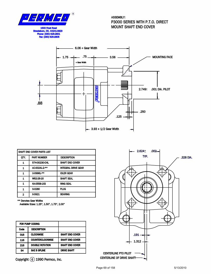
..112255
..225500
22..774499 ..000011 DDIIAA.. PPIILLOOTT
22..662244 ..000022
66..0066 ++ GGeeaarr WWiiddtthh
33..5566..775511..7755
33..9933 ++ 11//22 GGeeaarr WWiiddtthh
..8888
..119911
11..331122
DDRRIIVVEE SSHHAAFFTT
SSHHAAFFTT EENNDD CCOOVVEERR
SSHHAAFFTT EENNDD CCOOVVEERR
SSHHAAFFTT EENNDD CCOOVVEERR
SSAAEE BB SSPPLLIINNEE
DDOOUUBBLLEE RROOTTAATTIIOONN
CCOOUUNNTTEERRCCLLOOCCKKWWIISSEE
CCLLOOCCKKWWIISSEE
5544
221166
111166
001166
DDEESSCCRRIIPPTTIIOONNCCooddee
FFOORR PPUUMMPP CCOODDIINNGG
11550000 FFrroosstt RRooaadd SSttrreeeettssbboorroo,, OOHH.. 4444224411--00882299 PPhhoonnee:: ((333300)) 662266--22880011 FFaaxx:: ((333300)) 662266--22880055
AAvvaaiillaabbllee SSiizzeess:: 11..2255"",, 11..5500"",, 11..7755"",, 22..0000""**** DDeennootteess GGeeaarr WWiiddtthhss
BBEEAARRIINNGGXX--00992211
PPLLUUGGSS--00228800
RRIINNGG SSEEAALLKKAA--00555588--11XXSS
SSHHAAFFTT SSEEAALLWW6622--2266--1166
IIDDLLEERR GGEEAARRUU--00999966LL--****
IINNTTEEGGRRAALL DDRRIIVVEE GGEEAARRAACC--00002244LL--22--****
SSHHAAFFTT EENNDD CCOOVVEERR557744--0000223300--CCHHLL
22
11
11
11
11
11
11
PPAARRTT NNUUMMBBEERR DDEESSCCRRIIPPTTIIOONN QQTTYY..
SSHHAAFFTT EENNDD CCOOVVEERR PPAARRTTSS LLIISSTT
RR
CCooppyyrriigghhtt cc 11999900 PPeerrmmccoo,, IInncc..
MMOOUUNNTTIINNGG FFAACCEE
CCEENNTTEERRLLIINNEE PPTTOO PPIILLOOTTCCEENNTTEERRLLIINNEE OOFF DDRRIIVVEE SSHHAAFFTT
++ GGeeaarr WWiiddtthh
TTYYPP..
AASSSSEEMMBBLLYY::
PP33000000 SSEERRIIEESS WWIITTHH PP..TT..OO.. DDIIRREECCTTMMOOUUNNTT SSHHAAFFTT EENNDD CCOOVVEERR
+_
+_
..332288 DDIIAA..
Page 69 of 158 5/13/2010

RR
HYDRAULIC / PNEUMATIC PRODUCTS
1500 Frost Road • Post Office Box 2068 • Streetsboro, Ohio 44241-0869 • 330/626-2801 • Fax: 330/626-2805
To: All Permco Distributors Date: MARCH 31, 1997
Subject: P5000 Port End Cover with Relief Valve Assembly
We are pleased to announce a new P5000 port end cover with relief valve assembly. This new PEC will incorporate the same relief valve technology (though modified slightly to attain higher pressures) that has proven very successful in our DM-640 dump pumps for years.
To order the assembly, please use part number: 592-00902
This assembly is made up of the following parts:592-00899 Port end cover machined for relief valveRP-5514-3000 Relief valve assembly
Please note this new version relieves externally instead of internally. A 1" NPT port is provided for the tank connection now required. The main benefit to this configuration is a reduction in the possibility of overheating the pump when the flow is going over relief.
Though there are many applications where this PEC could be used, the primary application for which it was added is the LIVE FLOOR APPLICATIONS.
Please see the below drawing for dimensional information.
EXTERNAL DRAIN CODING5000
IMIRINISIPIT
PEC W/RV SINGLE CWPEC W/RV SINGLE CCWPEC W/RV MULTI CWPEC W/RV MULTI CCWPEC W/RV XSD CWPEC W/RV XSD CCW
DRIVE SHAFT
I ° N P TEXTERNAL MS-1
6.81
2.69
1.75
1.00
DRIVE SHAFTCL
1" NPTEXTERNAL DRAIN
592-00899
NATIONAL FLUID POWER ASSOCIATIONPage 70 of 158 5/13/2010
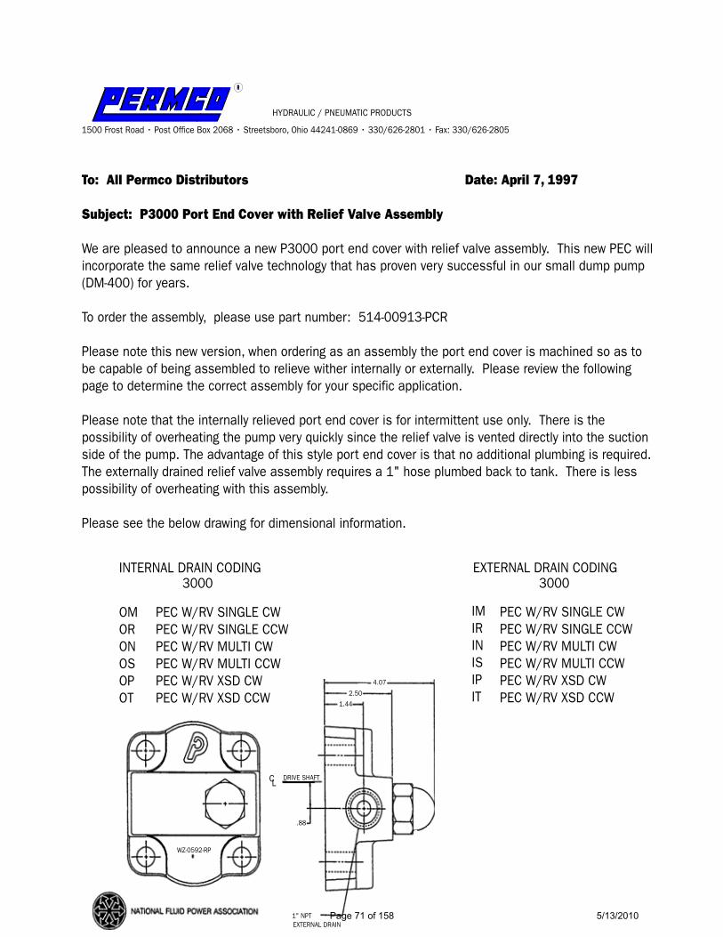
RR
HYDRAULIC / PNEUMATIC PRODUCTS
1500 Frost Road • Post Office Box 2068 • Streetsboro, Ohio 44241-0869 • 330/626-2801 • Fax: 330/626-2805
To: All Permco Distributors Date: April 7, 1997
Subject: P3000 Port End Cover with Relief Valve Assembly
We are pleased to announce a new P3000 port end cover with relief valve assembly. This new PEC will incorporate the same relief valve technology that has proven very successful in our small dump pump (DM-400) for years.
To order the assembly, please use part number: 514-00913-PCR
Please note this new version, when ordering as an assembly the port end cover is machined so as to be capable of being assembled to relieve wither internally or externally. Please review the following page to determine the correct assembly for your specific application.
Please note that the internally relieved port end cover is for intermittent use only. There is the possibility of overheating the pump very quickly since the relief valve is vented directly into the suction side of the pump. The advantage of this style port end cover is that no additional plumbing is required. The externally drained relief valve assembly requires a 1" hose plumbed back to tank. There is less possibility of overheating with this assembly.
Please see the below drawing for dimensional information.
INTERNAL DRAIN CODING3000
EXTERNAL DRAIN CODING3000
OMORONOSOPOT
PEC W/RV SINGLE CWPEC W/RV SINGLE CCWPEC W/RV MULTI CWPEC W/RV MULTI CCWPEC W/RV XSD CWPEC W/RV XSD CCW
IMIRINISIPIT
PEC W/RV SINGLE CWPEC W/RV SINGLE CCWPEC W/RV MULTI CWPEC W/RV MULTI CCWPEC W/RV XSD CWPEC W/RV XSD CCW
4.07
2.501.44
.88
DRIVE SHAFT
1" NPTEXTERNAL DRAIN
WZ-0592-RP
CL
Page 71 of 158 5/13/2010

Fig. A-4Fig. A-4Fig. A-3Fig. A-3
Fig. A-2Fig. A-2Fig. A-1Fig. A-1
INSTRUCTIONS FOR 514-00913-PCRINSTRUCTIONS FOR 514-00913-PCR
OUTLETOUTLET
OUTLETOUTLET OUTLETOUTLET
OUTLETOUTLETINLETINLET
INLETINLET INLETINLET
INLETINLET
INSTALL INSTALL RING SEALRING SEALHEREHERE
INSTALL INSTALL RING SEALRING SEALHEREHERE
INTERNAL RELIEFINTERNAL RELIEFCOUNTERCLOCKWISE ROTATIONCOUNTERCLOCKWISE ROTATION
INTERNAL RELIEFINTERNAL RELIEFCLOCKWISE ROTATIONCLOCKWISE ROTATION
EXTERNAL RELIEFEXTERNAL RELIEFCLOCKWISE ROTATIONCLOCKWISE ROTATION
EXTERNAL RELIEFEXTERNAL RELIEFCOUNTERCLOCKWISE ROTATIONCOUNTERCLOCKWISE ROTATION
LEAVE OPENLEAVE OPEN
1" PLUG1" PLUG
RETURN TORETURN TOTANKTANK
1/2" PLUG1/2" PLUG
Before instal l ing Port End Cover on unit f inal assembly must be completed.
1) Or ient Port End Cover based on appl icat ion requirements. Example: Internal rel ief and counterclockwise (CCW) rotat ion use Fig. A -1
2) Instal l Ring Seal in appropr iate bore and press in bear ings.
3) Instal l the pipe plug that meets the appl icat ion requirements (1" or 1/2").
4) Adjust ing pressure is accompl ished by removing the large acron nut and
turning clockwise (CW) to increase pressure sett ing.
CAUTION: DO NOT ADJUST RELIEF VALVE PRESSURE SETTING ON INTERNAL VENTED ARRANGEMENT WHILE RUNNING OVER RELIEF!
Page 72 of 158 5/13/2010

TO: ALL PERMCO DISTRIBUTORS OCTOBER 19, 2009
Hydraulic/Pneumatic Products
1500 Frost Road - Post Of! ce Box 2068 - Streetsboro, Ohio 44241-0869 - (330)626-2801 - Fax: (330)626-2805
Subject: 2100 Port End Cover, Large Inlet Port Boss
In efforts to promote a better understanding of our 2100 Large Inlet Port End Cover; listed below are part numbers, descriptions and explanation of this product.
2100 Port End Cover with Large Inlet Port Boss provides for up to 1-1/4” JIC or NPT rear port for the suction side and up to 1” JIC or NPT rear port for the pressure side. Each bearing bore is machined to accept a ring seal to provide for either clockwise or counter clockwise rotation; simply insert the ring seal in the proper bore for the desired rotation. It is important to remember that if utilizing NPT threads not to use Te" on tape on the ! ttings and not over torque the ! ttings; either of these two variables could crack the port boss.
For coding the model number or to order a pre-ported port end cover refer to the Permco 2100 code book for speci! c coding characters and ported part numbers; for special porting consult factory.
2100 Port End Cover, Large Inlet Port Boss Blank (Non-Ported)
SERIESPART #592-01080 2100
2.250 3.525 2.380
Page 73 of 158 5/13/2010
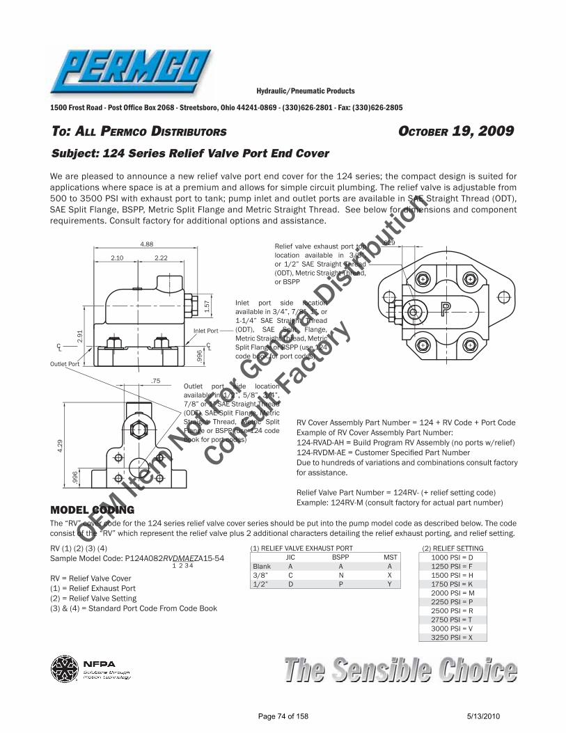
OEM Item Not
For G
enera
l Dist
ributio
n
Consu
lt Facto
ry
TO: ALL PERMCO DISTRIBUTORS OCTOBER 19, 2009
Hydraulic/Pneumatic Products
1500 Frost Road - Post Of! ce Box 2068 - Streetsboro, Ohio 44241-0869 - (330)626-2801 - Fax: (330)626-2805
Subject: 124 Series Relief Valve Port End Cover
We are pleased to announce a new relief valve port end cover for the 124 series; the compact design is suited for applications where space is at a premium and allows for simple circuit plumbing. The relief valve is adjustable from 500 to 3500 PSI with exhaust port to tank; pump inlet and outlet ports are available in SAE Straight Thread (ODT), SAE Split Flange, BSPP, Metric Split Flange and Metric Straight Thread. See below for dimensions and component requirements. Consult factory for additional options and assistance.
4.88
2.222.10
1.57
2.91
.996
Inlet Port
CL
Outlet Port
CL
4.29
.75
.996
Inlet port side location available in 3/4”, 7/8”, 1”, or 1-1/4” SAE Straight Thread (ODT), SAE Split Flange, Metric Straight Thread, Metric Split Flange or BSPP (use 124 code book for port codes)
Outlet port side location available in 1/2”, 5/8”, 3/4”, 7/8” or 1” SAE Straight Thread (ODT), SAE Split Flange, Metric Straight Thread, Metric Split Flange or BSPP (use 124 code book for port codes)
Relief valve exhaust port top location available in 3/8”, or 1/2” SAE Straight Thread (ODT), Metric Straight Thread, or BSPP
MODEL CODING
RV (1) (2) (3) (4) Sample Model Code: P124A082RVDMAEZA15-54
RV = Relief Valve Cover(1) = Relief Exhaust Port(2) = Relief Valve Setting(3) & (4) = Standard Port Code From Code Book
Blank3/8”1/2”
ACD
ANP
AXY
JIC MST(2) RELIEF SETTING
BSPP(1) RELIEF VALVE EXHAUST PORT
1000 PSI = D1250 PSI = F1500 PSI = H1750 PSI = K2000 PSI = M2250 PSI = P2500 PSI = R2750 PSI = T3000 PSI = V3250 PSI = X
The “RV” cover code for the 124 series relief valve cover series should be put into the pump model code as described below. The code consist of the “RV” which represent the relief valve plus 2 additional characters detailing the relief exhaust porting, and relief setting.
1 2 3 4
RV Cover Assembly Part Number = 124 + RV Code + Port CodeExample of RV Cover Assembly Part Number: 124-RVAD-AH = Build Program RV Assembly (no ports w/relief)124-RVDM-AE = Customer Speci" ed Part NumberDue to hundreds of variations and combinations consult factory for assistance.
Relief Valve Part Number = 124RV- (+ relief setting code)Example: 124RV-M (consult factory for actual part number)
.629
Page 74 of 158 5/13/2010
TO: PERMCO DISTRIBUTORS OCTOBER 19, 2009
Hydraulic/Pneumatic Products
1500 Frost Road - Post Of! ce Box 2068 - Streetsboro, Ohio 44241-0869 - (330)626-2801 - Fax: (330)626-2805
Subject: Piggyback, Transition and Add-A-Pump Description
In efforts to promote a better understanding of our Piggyback, Transition and Add-A-Pump covers listed below is descriptions and applications for each type cover.
Piggyback Covers
Piggy/Back type units are used when a wide range of ! ow options are needed and/or when segregated ! ows between pumping sections is required. Piggy/Back type units are common to our roller bearing series and offer a wide range of con" gurations from 3000/3000, 5000/3000, 5000/5000, 7500/3000 to 7500/5000; if higher pressures are required dowelled units can be utilized (ex: 7600/3100). Piggy/Back units are available only within common series of Permco pumps.Piggy/Back assemblies combine separate hydraulic pumps on one common drive shaft. Fluid from separate reservoirs, as well as different types of hydraulic ! uids can be used without intermixing. The Piggy/Back con" guration and also provides a much greater range of pump output ! ows than is available from standard multiple units by allowing the pumping sections to be sized for optimum ef" ciency. For example, a main system might require 100 GPM as a primary supply and 15 GPM as a secondary supply; the ideal piggy/back assembly would be a 7500 with a 3” gear (100 GPM @ 2000 RPM) and a P3000 with 1” gear (15 GPM @ 2000 RPM). Applications for piggy/back pumps are usually found where the range of pump outputs is not within conventional multiple pump capabilities. Examples are main hydraulic and steering systems where pump output ! ows have a wide variance; other applications include those using two reservoirs or a reservoir and a sump which require the separation of pumped ! uids. Multiple section pumps (tandem, triples etc) can be used in piggy/back con" gurations, however it is important to remember that the entire input torque is fed through the drive shaft and should not exceed the drive shaft PL factor.Piggy/Back type units consist of a special piggy/back port end cover for the front section, a special piggy/back shaft end cover for the rear section and special connecting shaft. The port end cover, shaft end cover and connecting shaft are mated and bolted together to form the Piggy/Back unit. The front pump section consist of a standard tandem gear shaft set and/or a gear set and the rear pump section consist of a standard gear set that accepts the connecting shaft; the port end cover and shaft end cover both have shaft type lip seals that keep ! uids segregated between pumping units. Piggy/Back units can be con" gured CW, CCW or Bi-Rotation.
Transition Covers
Transition type units are used when a wide range of ! ow options are needed and provide a much greater range of output ! ows than is available from standard multiple units of the same series. Transition type units are common to our bushing series and offer a wide range of con" gurations from P197/P124, P257/P124, P257/P197 and P360/P124. Transition covers connect only sleeve bearing pumps within the Permco line.Transition cover assemblies combine different series of pump on one common drive shaft. An assembly example that consist of a single pump section P197 and single pump section P124 (P197/P124) can utilize one common inlet to supply inlet hydraulic ! uid to both pumping sections and must be plumbed to a common reservoir. Applications for transition cover type assemblies are usually found on mining equipment, cranes, logging equipment and any hydraulic system that requires a wide range of hydraulic pump output ! ows. Transition cover assemblies can consist of single, tandem and multiple pumping sections for each series. It is important to remember that the entire input torque is fed through the drive shaft and should not exceed the drive shaft PL factor.Transition Covers are a one piece construction that consists of a Port End Cover for the front unit and Shaft End Cover for the rear unit; this allows for a combined and shared inlet for both series of pumps and a separate outlet for the front
Page 75 of 158 5/13/2010

pump. The two series are mated together with a special connecting shaft, therefore the front pump section would consist of a standard tandem gear shaft set and/or a gear set and the rear pump section consist of a standard gear set that accepts the special connecting shaft. Transition covers can be con" gured for CW and CCW rotation. The Transition cover may also be referred to as a transition bearing carrier in the hydraulic industry.
Add-A-Pump Covers
An Add-A-Pump unit is used when a wide range of ! ow and pressure options are needed and/or when segregated ! ows between pumping sections is required. Add-A-Pumps are common to our roller bearing (3000/3100 and 5000/5100) and bushing series (197, 257 and 360). Add-A-Pump covers connect any type of hydraulic pump manufactured as long as it has the standard con" guration of a SAE pattern (shaft and shaft end cover).An Add-A-Pump is constructed to allow the mounting of a separate pump to the back of an existing pump; ! ow is segregated between the two pumps; ! uid from separate reservoirs, as well as different types of hydraulic ! uids can be used without intermixing; each unit would have its own inlet and outlet. Applications for Add-A-Pumps are usually found where the range of output ! ows and pressures are not within conventional multiple pump capabilities. An example of this would be a P360 with an Add-A-Pump port end cover and mounted to that a small piston pump; the piston pump output shaft would mate into the P360 output shaft. Multiple section pumps (tandem, triples etc) can be used in Add-A-Pump con" gurations, however it is important to remember that the entire input torque is fed through the drive shaft and should not exceed the drive shaft PL factor.Add-A-Pump type units consist of a special one piece construction port end cover and special connecting shaft designed to accept either an SAE-A-2-Bolt or SAE-B-2-Bolt mating ! ange with an SAE-A-Spline or SAE-B-Spline output shaft depending upon series (2 “B” only available in 257 and 360). Add-A-Pump units can be con" gured CW, CCW or bi-rotational dependent on series.
Page 76 of 158 5/13/2010
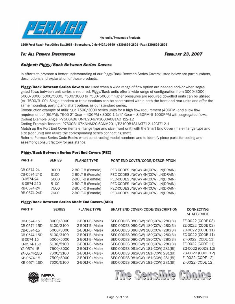
TO: ALL PERMCO DISTRIBUTORS FEBRUARY 23, 2007
Hydraulic/Pneumatic Products
1500 Frost Road - Post Of! ce Box 2068 - Streetsboro, Ohio 44241-0869 - (330)626-2801 - Fax: (330)626-2805
Subject: Piggy/Back Between Series Covers
In efforts to promote a better understanding of our Piggy/Back Between Series Covers; listed below are part numbers, descriptions and explanation of those products.
Piggy/Back Between Series Covers are used when a wide range of ! ow option are needed and/or when segre-gated ! ows between unit series is required. Piggy/Back units offer a wide range of con" guration from 3000/3000, 5000/3000, 5000/5000, 7500/3000 to 7500/5000; if higher pressures are required dowelled units can be utilized (ex: 7600/3100). Single, tandem or triple sections can be constructed within both the front and rear units and offer the same mounting, porting and shaft options as our standard series. Construction example of utilizing a 7500/3000 series units for a high ! ow requirement (40GPM) and a low ! ow requirement of (8GPM); 7500 2” Gear = 40GPM x 3000 1-1/4” Gear = 8.5GPM @ 1000RPM with segregated ! ows.Coding Example Single: P7500A067JNNJ20-6/P3000A081ADTI12-12Coding Example Tandem: P7600B167KNNM20-6CNM20-1/P3100B181AXTF12-12CTF12-1Match up the Port End Cover (female) ! ange type and size (front unit) with the Shaft End Cover (male) ! ange type and size (rear unit) and utilize the corresponding series connecting shaft.Refer to Permco Series Code Books when constructing model numbers and to identify piece parts for coding and assembly; consult factory for assistance. Piggy/Back Between Series Port End Covers (PEC)
Piggy/Back Between Series Shaft End Covers (SEC)
300031005000510075007600
2-BOLT-B (Female)2-BOLT-B (Female)2-BOLT-B (Female)2-BOLT-B (Female)2-BOLT-C (Female)2-BOLT-C (Female)
PEC-CODES JN(CW) KN(CCW) LN(DRAIN)PEC-CODES JN(CW) KN(CCW) LN(DRAIN)PEC-CODES JN(CW) KN(CCW) LN(DRAIN)PEC-CODES JN(CW) KN(CCW) LN(DRAIN)PEC-CODES JN(CW) KN(CCW) LN(DRAIN)PEC-CODES JN(CW) KN(CCW) LN(DRAIN)
SERIES FLANGE TYPE PORT END COVER/CODE/DESCRIPTION
3000/30003100/31005000/30005100/31005000/50005100/51007500/30007600/31007500/50007600/5100
2-BOLT-B (Male)2-BOLT-B (Male)2-BOLT-B (Male)2-BOLT-B (Male)2-BOLT-B (Male)2-BOLT-B (Male)2-BOLT-C (Male)2-BOLT-C (Male)2-BOLT-C (Male)2-BOLT-C (Male)
SEC-CODES 080(CW) 180(CCW) 280(BI)SEC-CODES 080(CW) 180(CCW) 280(BI)SEC-CODES 080(CW) 180(CCW) 280(BI)SEC-CODES 080(CW) 180(CCW) 280(BI)SEC-CODES 080(CW) 180(CCW) 280(BI)SEC-CODES 080(CW) 180(CCW) 280(BI)SEC-CODES 081(CW) 181(CCW) 281(BI)SEC-CODES 081(CW) 181(CCW) 281(BI)SEC-CODES 081(CW) 181(CCW) 281(BI)SEC-CODES 081(CW) 181(CCW) 281(BI)
ZE-0022 (CODE 03)ZE-0022 (CODE 03)ZC-0022 (CODE 11)ZC-0022 (CODE 11)ZF-0022 (CODE 11)ZF-0022 (CODE 11)ZG-0022 (CODE 12)ZG-0022 (CODE 12)ZI-0022 (CODE 12)ZI-0022 (CODE 12)
CONNECTING SHAFT/CODE
SHAFT END COVER/CODE/DESCRIPTIONFLANGE TYPESERIES
CB-0574-15CB-0574-15DCB-0574-15CB-0574-15DIB-0574-15IB-0574-15DYA-0574-15YA-0574-15DKB-0574-15KB-0574-15D
PART #
CB-0574-24CB-0574-24DIB-0574-24IB-0574-24DRB-0574-24RB-0574-24D
PART #
Page 77 of 158 5/13/2010

TO: PERMCO DISTRIBUTORS OCTOBER 19, 2009
Hydraulic/Pneumatic Products
1500 Frost Road - Post Of! ce Box 2068 - Streetsboro, Ohio 44241-0869 - (330)626-2801 - Fax: (330)626-2805
Subject: Piggyback Model Code Description
In efforts to promote a better understanding of our Piggyback type unit coding system, listed below is an example assembly model code and explanation.
Piggyback Model Coding
Piggyback assemblies are model coded starting from the shaft end cover as with any normal multiple unit. Component model codes are basically the same as any standard assembly model and follow the same sequence; component codes can be found in the Permco Code Books; underlined component codes below are special to piggyback type units.
Code Explanation:
P5000A031JNNU22-6/P3000A080ADNI15-11
JN = Piggyback port end cover for 5000 series080 = Piggyback shaft end cover for the 3000 series11 = Piggyback connecting shaft for the 5000 to 3000 series
PiggybackComponent
3000/30003100/3100
5000/30005100/3100
7500/30007600/3100
5000/50005100/5100
7500/50007600/5100
Port End CWCCWBi-rotation
Shaft End CoverCWCCWBi-rotationConnecting Shaft
JNKNLN
08018028003 11 12 11 12
JNKNLN
JNKNLN
JNKNLN
JNKNLN
080180280
081181281
080180280
081181281
Page 78 of 158 5/13/2010

OEM Item Not
For G
enera
l Dist
ributio
n
Consu
lt Fac
tory
TO: PERMCO DISTRIBUTORS OCTOBER 19, 2009
Hydraulic/Pneumatic Products
1500 Frost Road - Post Of! ce Box 2068 - Streetsboro, Ohio 44241-0869 - (330)626-2801 - Fax: (330)626-2805
Subject: Transition Covers 5100/124 SeriesIn efforts to promote a better understanding of our Transition Covers; listed below are part numbers, descriptions and explanation of those products.
Transition Covers for our 5100/124 series offers the ability to combine roller bearing and bushing series units together in a seamless one piece construction. The Transition Cover is a one piece combination port end cover for the front unit and shaft end cover for the rear unit; this requires fewer parts for assembly and helps keep the overall pump length to a minimum. Common inlet(s) combines ! ow within both pump series (! ow is not segregated). Transition cover assemblies can consist of a single, tandem and/or multiple pumping section for each series. Applications for transition covers can be found on mining equipment, construction machinery equipment, cranes, logging equipment, oil " eld equipment and any hydraulic system that requires a wide range of hydraulic pump output ! ows.
Transition Cover Components:
SERIES DESCRIPTIONPART #
*592-***** P5100/P124-CW 5100/124 TRANSITION COVER CW
022-******592-***** P5100/P124-CCW 5100/124 TRANSITION COVER CCW
R-0921*MA-0558-1XS
1245100
5100 ROLLER BEARING (2 Required)
RING SEAL (1 Required)
P5100/P124 5100/124 CONNECTING SHAFT CW/CCW (1 Required)
CODING EXAMPLE: PB5100A031(SPL)NI20-14/P124AAHZA15Refer to preceding pages for more examples of model number constructions.
1.56/39.55100 SIDE
5.43/138
6.00
/152
3.43/87
1.56/39.5
124 SIDE
INCHES/MM
CW VIEW SHOWN
921-01108 124 BUSHING (2 Required)
1.00
/25.
4
*Consult factory for actual part number
Page 79 of 158 5/13/2010
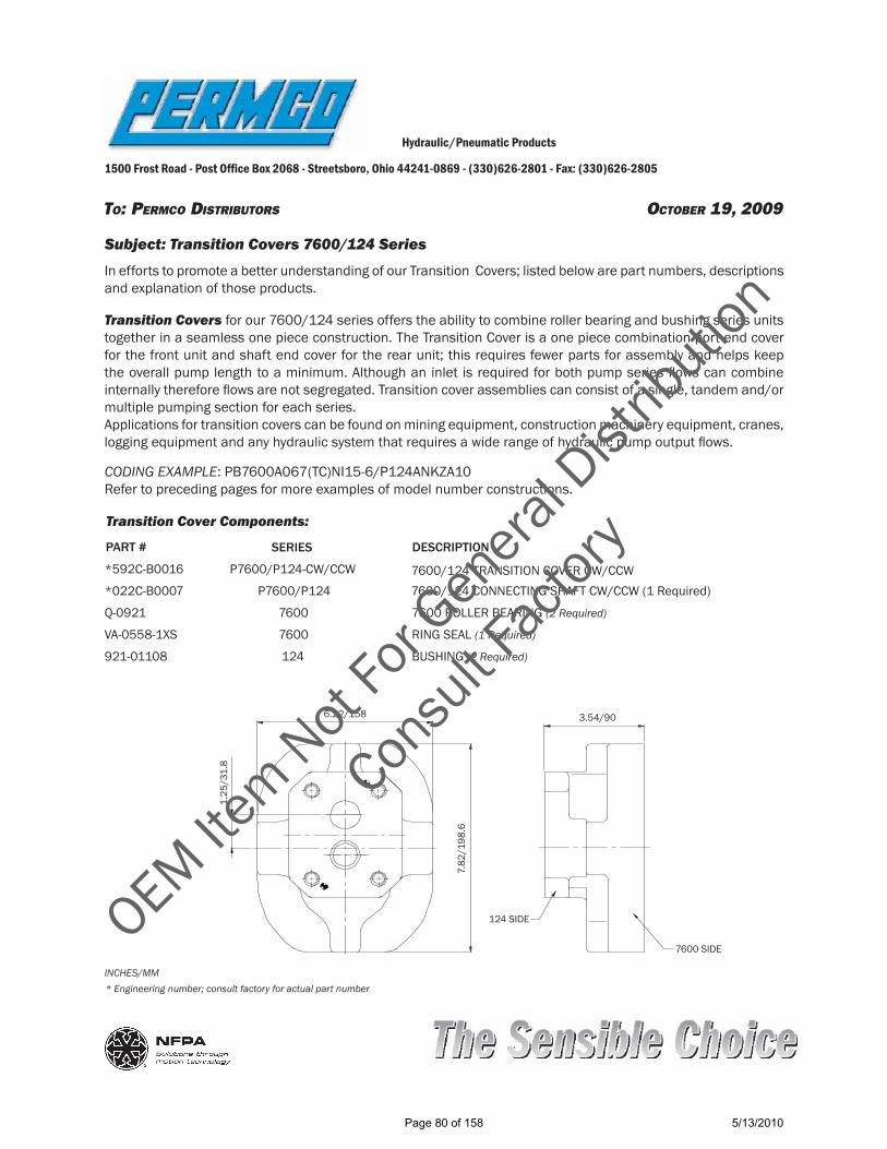
TO: PERMCO DISTRIBUTORS OCTOBER 19, 2009
Hydraulic/Pneumatic Products
1500 Frost Road - Post Of! ce Box 2068 - Streetsboro, Ohio 44241-0869 - (330)626-2801 - Fax: (330)626-2805
Subject: Transition Covers 7600/124 SeriesIn efforts to promote a better understanding of our Transition Covers; listed below are part numbers, descriptions and explanation of those products.
Transition Covers for our 7600/124 series offers the ability to combine roller bearing and bushing series units together in a seamless one piece construction. The Transition Cover is a one piece combination port end cover for the front unit and shaft end cover for the rear unit; this requires fewer parts for assembly and helps keep the overall pump length to a minimum. Although an inlet is required for both pump series ! ows can combine internally therefore ! ows are not segregated. Transition cover assemblies can consist of a single, tandem and/or multiple pumping section for each series. Applications for transition covers can be found on mining equipment, construction machinery equipment, cranes, logging equipment and any hydraulic system that requires a wide range of hydraulic pump output ! ows.
Transition Cover Components:
SERIES DESCRIPTIONPART #
*592C-B0016 P7600/P124-CW/CCW 7600/124 TRANSITION COVER CW/CCW
Q-0921*022C-B0007 P7600/P124 7600/124 CONNECTING SHAFT CW/CCW (1 Required)
921-01108VA-0558-1XS
1247600
BUSHING (2 Required)
RING SEAL (1 Required)
7600 7600 ROLLER BEARING (2 Required)
CODING EXAMPLE: PB7600A067(TC)NI15-6/P124ANKZA10Refer to preceding pages for more examples of model number constructions.
7600 SIDE
6.22/158
1.25
/31.
8
7.82
/198
.6
3.54/90
124 SIDE
INCHES/MM* Engineering number; consult factory for actual part number
OEM Item Not
For G
enera
l Dist
ributio
n
Consu
lt Fac
tory
Page 80 of 158 5/13/2010

TO: PERMCO DISTRIBUTORS OCTOBER 19, 2009
Hydraulic/Pneumatic Products
1500 Frost Road - Post Of! ce Box 2068 - Streetsboro, Ohio 44241-0869 - (330)626-2801 - Fax: (330)626-2805
Subject: Transition Covers 197/124 SeriesIn efforts to promote a better understanding of our Transition Covers; listed below are part numbers, descriptions and explanation of those products.
Transition Covers for our 197/124 series offers the ability to combine different bushing series units together in a seamless one piece construction. The Transition Cover is a one piece combination port end cover for the front unit and shaft end cover for the rear unit; this requires fewer parts for assembly and helps keep the overall pump length to a minimum. Common inlet(s) combines ! ow within both pump series (! ow is not segregated). Transition cover assemblies can consist of a single, tandem and/or multiple pumping section for each series. Applications for transition covers can be found on mining equipment, construction machinery equipment, cranes, logging equipment, oil " eld equipment and any hydraulic system that requires a wide range of hydraulic pump output ! ows.
Transition Cover Components:
SERIES DESCRIPTIONPART #
592-01564-0 P197/P124-CW 197/124 TRANSITION COVER CW
022-01565592-01564-1 P197/P124-CCW 197/124 TRANSITION COVER CCW
921-01108921-00427-P
124197
BUSHING (2 Required)
BUSHING (2 Required)
P197/P124 197/124 CONNECTING SHAFT CW/CCW (1 Required)
CODING EXAMPLE: PB197A031CAZA20-14/P124AEVZA15Refer to preceding pages for more examples of model number constructions.
1.31/33.3
197 SIDE
7.12/180.8
SF PORT 6.87/174.5
5.50
/139
.7
0.88
/22.
4
3.87/98.2
2.00/50.8
124 SIDE
INCHES/MM CW VIEW SHOWN
Page 81 of 158 5/13/2010

TO: PERMCO DISTRIBUTORS OCTOBER 19, 2009
Hydraulic/Pneumatic Products
1500 Frost Road - Post Of! ce Box 2068 - Streetsboro, Ohio 44241-0869 - (330)626-2801 - Fax: (330)626-2805
Subject: Transition Covers 257/124 SeriesIn efforts to promote a better understanding of our Transition Covers; listed below are part numbers, descriptions and explanation of those products.
Transition Covers for our 257/124 series offers the ability to combine different bushing series units together in a seamless one piece construction. The Transition Cover is a one piece combination port end cover for the front unit and shaft end cover for the rear unit; this requires fewer parts for assembly and helps keep the overall pump length to a minimum. Common inlet(s) combines ! ow within both pump series (! ows are not segregated). Transition cover assemblies can consist of a single, tandem and/or multiple pumping section for each series. Applications for transition covers can be found on mining equipment, cranes, construction machinery equipment, logging equipment, oil " eld equipment and any hydraulic system that requires a wide range of hydraulic pump output ! ows.
Transition Cover Components:
SERIES DESCRIPTIONPART #
592-01403-0 P257/P124-CW 257/124 TRANSITION COVER CW
022-01404592-01403-1 P257/P124-CCW 257/124 TRANSITION COVER CCW
921-01108921-00647-P
124257
BUSHING (2 Required)
BUSHING (2 Required)
P257/P124 257/124 CONNECTING SHAFT CW/CCW (1 Required)
CODING EXAMPLE: PB257A067PPZA25-6/P124ANKZA15Refer to preceding pages for more examples of model number constructions.
1.81/46
257 SIDE
7.38/187SF PORT 7.12/181
5.52
/140
.2
1.00
/25.
4
3.69/93.7
1.81/46
124 SIDE
INCHES/MM CW VIEW SHOWN
Page 82 of 158 5/13/2010
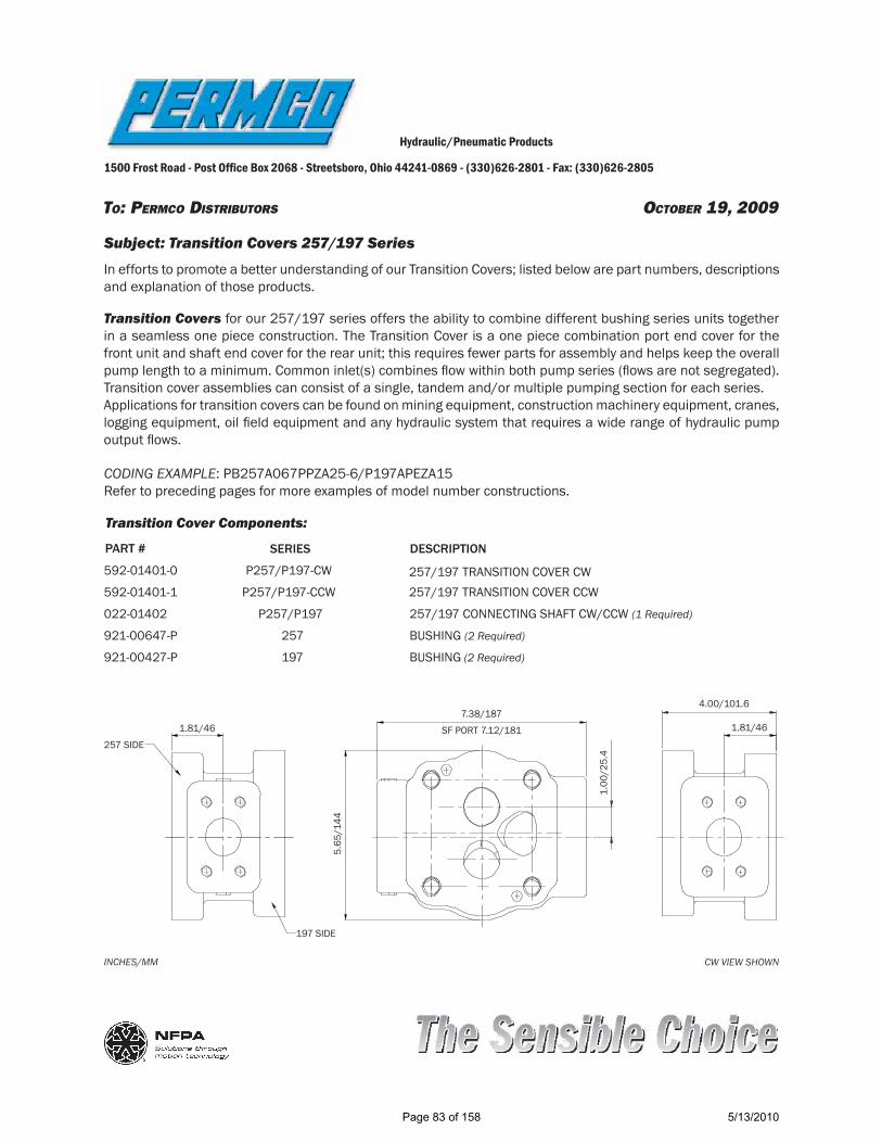
TO: PERMCO DISTRIBUTORS OCTOBER 19, 2009
Hydraulic/Pneumatic Products
1500 Frost Road - Post Of! ce Box 2068 - Streetsboro, Ohio 44241-0869 - (330)626-2801 - Fax: (330)626-2805
Subject: Transition Covers 257/197 SeriesIn efforts to promote a better understanding of our Transition Covers; listed below are part numbers, descriptions and explanation of those products.
Transition Covers for our 257/197 series offers the ability to combine different bushing series units together in a seamless one piece construction. The Transition Cover is a one piece combination port end cover for the front unit and shaft end cover for the rear unit; this requires fewer parts for assembly and helps keep the overall pump length to a minimum. Common inlet(s) combines ! ow within both pump series (! ows are not segregated). Transition cover assemblies can consist of a single, tandem and/or multiple pumping section for each series. Applications for transition covers can be found on mining equipment, construction machinery equipment, cranes, logging equipment, oil " eld equipment and any hydraulic system that requires a wide range of hydraulic pump output ! ows.
Transition Cover Components:
SERIES DESCRIPTIONPART #
592-01401-0 P257/P197-CW 257/197 TRANSITION COVER CW
022-01402592-01401-1 P257/P197-CCW 257/197 TRANSITION COVER CCW
921-00427-P921-00647-P
197257
BUSHING (2 Required)
BUSHING (2 Required)
P257/P197 257/197 CONNECTING SHAFT CW/CCW (1 Required)
CODING EXAMPLE: PB257A067PPZA25-6/P197APEZA15Refer to preceding pages for more examples of model number constructions.
1.81/46257 SIDE
7.38/187SF PORT 7.12/181
5.65
/144
1.00
/25.
4
4.00/101.6
1.81/46
197 SIDE
INCHES/MM CW VIEW SHOWN
Page 83 of 158 5/13/2010

TO: PERMCO DISTRIBUTORS OCTOBER 19, 2009
Hydraulic/Pneumatic Products
1500 Frost Road - Post Of! ce Box 2068 - Streetsboro, Ohio 44241-0869 - (330)626-2801 - Fax: (330)626-2805
Subject: Transition Covers 360/124 SeriesIn efforts to promote a better understanding of our Transition Covers; listed below are part numbers, descriptions and explanation of those products.
Transition Covers for our 360/124 series offers the ability to combine different bushing series units together in a seamless one piece construction. The Transition Cover is a one piece combination port end cover for the front unit and shaft end cover for the rear unit; this requires fewer parts for assembly and helps keep the overall pump length to a minimum. Common inlet(s) combines ! ow within both pump series (! ows are not segregated). Transition cover assemblies can consist of a single, tandem and/or multiple pumping section for each series. Applications for transition covers can be found on mining equipment, construction machinery equipment, cranes, logging equipment, oil " eld equipment and any hydraulic system that requires a wide range of hydraulic pump output ! ows.
Transition Cover Components:
SERIES DESCRIPTIONPART #
592-01520-0 P360/P124-CW 360/124 TRANSITION COVER CW
022-01521592-01520-1 P360/P124-CCW 360/124 TRANSITION COVER CCW
921-01108921-01380
124360
BUSHING (2 Required)
BUSHING (2 Required)
P360/P124 360/124 CONNECTING SHAFT CW/CCW (1 Required)
CODING EXAMPLE: PB360A067DEZA25-6/P124ANKZA10Refer to preceding pages for more examples of model number constructions.
2.22/56.2
360 SIDE
7.63/194SF PORT 7.38/187.5
7.05
/179
1.13
/28.
6
4.19/106.5
2.22/56.5
124 SIDE
INCHES/MM CW VIEW SHOWN
Page 84 of 158 5/13/2010
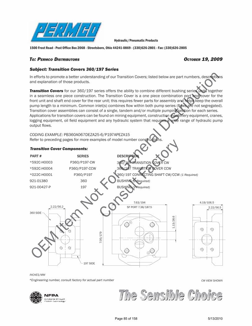
OEM Item Not
For G
enera
l Dist
ributio
n
Consu
lt Fac
tory
TO: PERMCO DISTRIBUTORS OCTOBER 19, 2009
Hydraulic/Pneumatic Products
1500 Frost Road - Post Of! ce Box 2068 - Streetsboro, Ohio 44241-0869 - (330)626-2801 - Fax: (330)626-2805
Subject: Transition Covers 360/197 SeriesIn efforts to promote a better understanding of our Transition Covers; listed below are part numbers, descriptions and explanation of those products.
Transition Covers for our 360/197 series offers the ability to combine different bushing series units together in a seamless one piece construction. The Transition Cover is a one piece combination port end cover for the front unit and shaft end cover for the rear unit; this requires fewer parts for assembly and helps keep the overall pump length to a minimum. Common inlet(s) combines ! ow within both pump series (! ows are not segregated). Transition cover assemblies can consist of a single, tandem and/or multiple pumping section for each series. Applications for transition covers can be found on mining equipment, construction machinery equipment, cranes, logging equipment, oil " eld equipment and any hydraulic system that requires a wide range of hydraulic pump output ! ows.
Transition Cover Components:
SERIES DESCRIPTIONPART #
*592C-H0003 P360/P197-CW 360/197 TRANSITION COVER CW
*022C-H0001*592C-H0004 P360/P197-CCW 360/197 TRANSITION COVER CCW
921-00427-P921-01380
197360
BUSHING (2 Required)
BUSHING (2 Required)
P360/P197 360/197 CONNECTING SHAFT CW/CCW (1 Required)
CODING EXAMPLE: PB360A067DEZA25-6/P197APEZA15Refer to preceding pages for more examples of model number constructions.
2.22/56.2
360 SIDE
7.63/194SF PORT 7.38/187.5
7.05
/179
1.13
/28.
6
4.19/106.5
2.22/56.5
197 SIDE
INCHES/MM
CW VIEW SHOWN*Engineering number, consult factory for actual part number
Page 85 of 158 5/13/2010

OEM Item Not
For G
enera
l Dist
ributio
n
Consu
lt Fac
tory
TO: PERMCO DISTRIBUTORS OCTOBER 19, 2009
Hydraulic/Pneumatic Products
1500 Frost Road - Post Of! ce Box 2068 - Streetsboro, Ohio 44241-0869 - (330)626-2801 - Fax: (330)626-2805
Subject: Transition Covers 360/257 SeriesIn efforts to promote a better understanding of our Transition Covers; listed below are part numbers, descriptions and explanation of those products.
Transition Covers for our 360/257 series offers the ability to combine different bushing series units together in a seamless one piece construction. The Transition Cover is a one piece combination port end cover for the front unit and shaft end cover for the rear unit; this requires fewer parts for assembly and helps keep the overall pump length to a minimum. Common inlet(s) combines ! ow within both pump series (! ows are not segregated). Transition cover assemblies can consist of a single, tandem and/or multiple pumping section for each series. Applications for transition covers can be found on mining equipment, construction machinery equipment, cranes, logging equipment, oil " eld equipment and any hydraulic system that requires a wide range of hydraulic pump output ! ows.
Transition Cover Components:
SERIES DESCRIPTIONPART #
*592C-H0005 P360/P257-CW 360/257 TRANSITION COVER CW
*022C-H0002*592C-H0013 P360/P257-CCW 360/257 TRANSITION COVER CCW
921-00647-P921-01380
257360
BUSHING (2 Required)
BUSHING (2 Required)
P360/P257 360/257 CONNECTING SHAFT CW/CCW (1 Required)
CODING EXAMPLE: PB360A067DEZA25-6/P257APEZA15Refer to preceding pages for more examples of model number constructions.
2.22/56.2
360 SIDE
7.63/194SF PORT 7.38/187.5
7.05
/179
1.13
/28.
6
4.19/106.5
2.22/56.5
257 SIDE
INCHES/MM CW VIEW SHOWN*Engineering number; consult factory for actual part number
Page 86 of 158 5/13/2010
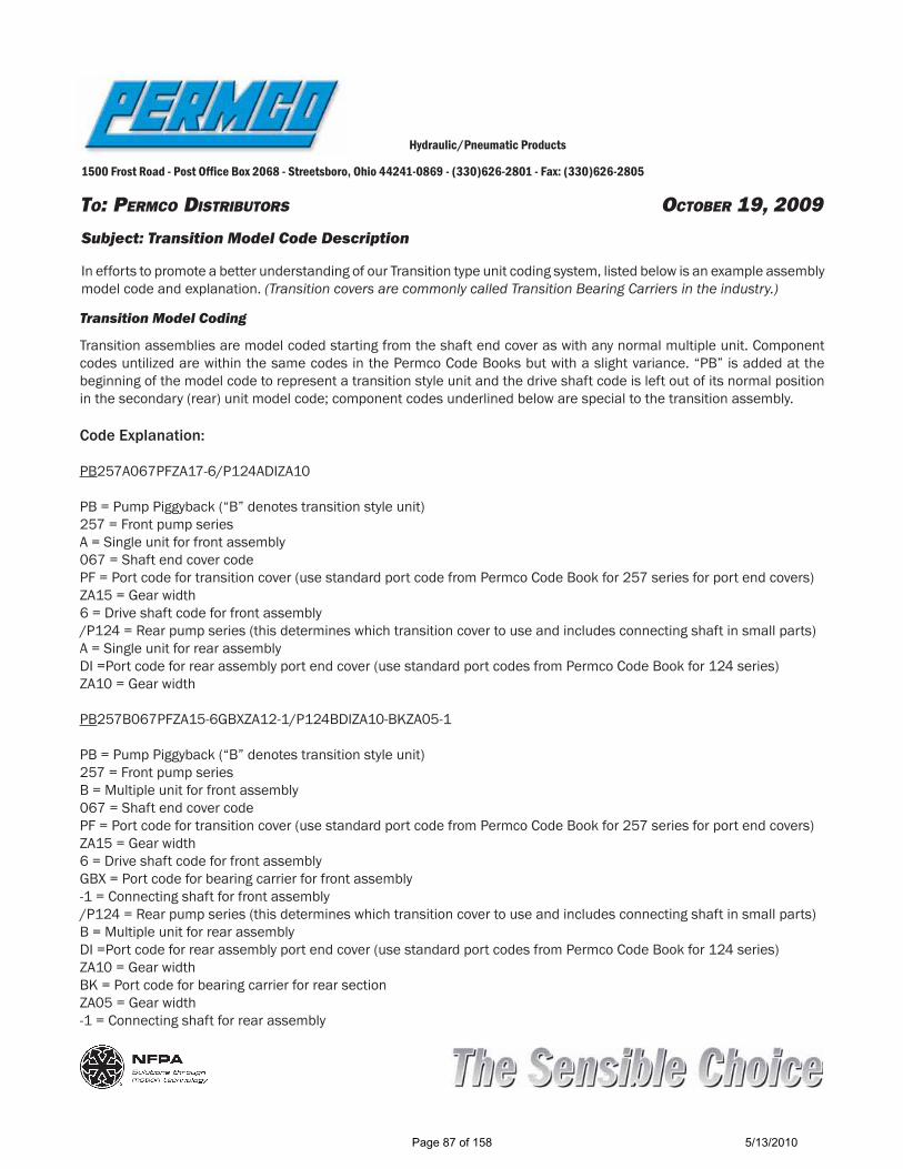
TO: PERMCO DISTRIBUTORS OCTOBER 19, 2009
Hydraulic/Pneumatic Products
1500 Frost Road - Post Of! ce Box 2068 - Streetsboro, Ohio 44241-0869 - (330)626-2801 - Fax: (330)626-2805
Subject: Transition Model Code Description
In efforts to promote a better understanding of our Transition type unit coding system, listed below is an example assembly model code and explanation. (Transition covers are commonly called Transition Bearing Carriers in the industry.)
Transition Model Coding
Transition assemblies are model coded starting from the shaft end cover as with any normal multiple unit. Component codes untilized are within the same codes in the Permco Code Books but with a slight variance. “PB” is added at the beginning of the model code to represent a transition style unit and the drive shaft code is left out of its normal position in the secondary (rear) unit model code; component codes underlined below are special to the transition assembly.
Code Explanation:
PB257A067PFZA17-6/P124ADIZA10
PB = Pump Piggyback (“B” denotes transition style unit)257 = Front pump seriesA = Single unit for front assembly067 = Shaft end cover codePF = Port code for transition cover (use standard port code from Permco Code Book for 257 series for port end covers)ZA15 = Gear width6 = Drive shaft code for front assembly/P124 = Rear pump series (this determines which transition cover to use and includes connecting shaft in small parts)A = Single unit for rear assemblyDI =Port code for rear assembly port end cover (use standard port codes from Permco Code Book for 124 series)ZA10 = Gear width
PB257B067PFZA15-6GBXZA12-1/P124BDIZA10-BKZA05-1
PB = Pump Piggyback (“B” denotes transition style unit)257 = Front pump seriesB = Multiple unit for front assembly067 = Shaft end cover codePF = Port code for transition cover (use standard port code from Permco Code Book for 257 series for port end covers)ZA15 = Gear width6 = Drive shaft code for front assemblyGBX = Port code for bearing carrier for front assembly-1 = Connecting shaft for front assembly/P124 = Rear pump series (this determines which transition cover to use and includes connecting shaft in small parts)B = Multiple unit for rear assemblyDI =Port code for rear assembly port end cover (use standard port codes from Permco Code Book for 124 series)ZA10 = Gear widthBK = Port code for bearing carrier for rear sectionZA05 = Gear width-1 = Connecting shaft for rear assembly
Page 87 of 158 5/13/2010

TO: ALL PERMCO DISTRIBUTORS OCTOBER 19, 2009
Hydraulic/Pneumatic Products
1500 Frost Road - Post Of! ce Box 2068 - Streetsboro, Ohio 44241-0869 - (330)626-2801 - Fax: (330)626-2805
Subject: Add-A-Pump Port End Covers 3000/3100/5000/5100 Series
In efforts to promote a better understanding of our Add-A-Pump Port End Covers; listed below are part numbers, descriptions and explanation of those products.
Add-A-Pump Port End Covers for our 3000/3100/5000/5100 series offers the ability to couple other brands and types of pumps to ours and provide segregated ! ows between working units. The Add-A-Pump Port End Cover is a totally integrated and sealed unit; giving the option of operating with or without a mated pump.Port End Covers for each series are machined to accept a 2-BOLT-SAE-A (male) mounting ! ange and a SAE-A-SPLINE (male) or SAE-B-SPLINE (male) mating shaft. Match up and utilize the series connecting shaft type (female) with the output shaft type (male) of the pump to be mounted.Special internal wrench nuts are required for the port end cover; please order (2) of part number (900-00238-IWN) for " nal assembly. Refer to drawing numbers (592-00481-PBA) 3000/3100 or (592-00482-PBA) 5000/5100 for port end cover assembly parts list.Refer to Permco Series Code Books when constructing model numbers and to identify piece parts for coding and assembly; because Add-A-Pump port end cover is special with no existing code consult factory for assistance.
Add-A-Pump Port End Covers (PEC) 3000/3100
Add-A-Pump Port End Covers (PEC) 5000/5100
SERIES PORT END COVER FLANGE TYPE
PORT END COVER CODE
SERIESPART #
PART # CONNECTING SHAFT # SERIES AND TYPE
VA-0574-24 3000 2-BOLT-A (Female) CW & CCW MZLZ
ZJ-0022-3000-A-SPLINE (Female)ZB-0022-3000-B-SPLINE (Female)
VA-0574-24D 3100 2-BOLT-A (Female) CW & CCW MZLZ
ZJ-0022-3100-A-SPLINE (Female)ZB-0022-3100-B-SPLINE (Female)
CONNECTING SHAFT # SERIES AND TYPE
ZA-0574-24
ZA-0574-24D
5000
5100
2-BOLT-A (Female) CW & CCW
2-BOLT-A (Female) CW & CCW
MZLZ
MZLZ
ZH-0022-5000-A-SPLINE (Female)ZK-0022-5000-B-SPLINE (Female)
ZH-0022-5100-A-SPLINE (Female)ZK-0022-5100-B-SPLINE (Female)
PORT END COVER FLANGE TYPE
PORT END COVER CODE
Page 88 of 158 5/13/2010

TO: ALL PERMCO DISTRIBUTORS OCTOBER 19, 2009
Hydraulic/Pneumatic Products
1500 Frost Road - Post Of! ce Box 2068 - Streetsboro, Ohio 44241-0869 - (330)626-2801 - Fax: (330)626-2805
Subject: Add-A-Pump Port End Covers 197/257/360 Series
In efforts to promote a better understanding of our Add-A-Pump Port End Covers; listed below are part numbers, descriptions and explanation of those products.
Add-A-Pump Port End Covers for our 197/257/360 series offers the ability to couple other brands and types of pumps to ours and provide segregated ! ows between working units. The Add-A-Pump Port End Cover is a totally integrated and sealed unit; giving the option of operating with or without a mated pump.Port End Covers dependent on series are machined to accept either a 2-BOLT-SAE-A (male) or 2-BOLT-SAE-B (male) mounting ! ange and a SAE-A-SPLINE (male) or SAE-B-SPLINE (male) mating shaft. Match up the Port End Cover (female) ! ange type and size with the mating pump ! ange (male) type and size and match up the connecting shaft (female) type and size with the mating pump output shaft (male) type and size.The 197 series has assembly part numbers for CW & CCW rotation Port End Covers; these assembly part numbers include all necessary parts and pieces for the 197 Port End Cover assembly with an A-SPLINE connecting shaft.
Add-A-Pump Port End Covers (PEC)
SERIES PORT END COVER PART # CONNECTING SHAFT #592-01440-0 197 2-BOLT-A-CW 022-01442 A-SPLINE
592-01440-1 197 2-BOLT-A-CCW 022-01442 A-SPLINE
592-01278-0-2A 592-01278-1-2A
257257
2-BOLT-A-CW2-BOLT-A-CCW
022-01280 A-SPLINE022-01280 A-SPLINE
592-01441-0 (Assembly #)
592-01441-1 (Assembly #)
592-01278-0-2B 257 2-BOLT-B-CW 022-01279 B-SPLINE
592-01437-0-2A 592-01437-1-2A
360360
2-BOLT-A-CW2-BOLT-A-CCW
022-01439 A-SPLINE022-01439 A-SPLINE
592-01278-1-2B 257 2-BOLT-B-CCW 022-01279 B-SPLINE
592-01437-0-2B 592-01437-1-2B
360 2-BOLT-B-CW2-BOLT-B-CCW 022-01438 B-SPLINE
022-01438 B-SPLINE360
Refer to proceding page drawings to identify piece parts for assembly; consult factory for assistance.Refer to Permco Series Code Books when constructing model numbers.For coding start model numbers with “PB” for pumps or “MB” for motors; this identi" es the unit as an Add-A-Pump Port End Cover assembly.For coding use standard port end cover port codes followed by an “AA”, “AB”, “BA” OR “BB”; [EX: (PPBB)].“PP” (First two letters) equal port type and size (PP = 2” x 1-1/4” Split Flange)“A” (Third letter) equal SAE-A-2-Bolt Flange“B” (Third letter) equal SAE-B-2-Bolt Flange“A” (Forth letter) equal SAE-A-Spline Connecting Shaft“B” (Forth letter) equal SAE-B-Spline Connecting Shaft
EX: PB257A031(PPBB)ZA20-14; Place all four letter in ()The above unit is an Add-A-Pump assembly with a 2” x 1-1/4” Split Flange port with a SAE-B-2-Bolt Flange and a SAE-B-Spline Connecting Shaft.
Page 89 of 158 5/13/2010

TO: PERMCO DISTRIBUTORS OCTOBER 19, 2009
Hydraulic/Pneumatic Products
1500 Frost Road - Post Of! ce Box 2068 - Streetsboro, Ohio 44241-0869 - (330)626-2801 - Fax: (330)626-2805
Subject: Add-A-Pump Model Code Description
In efforts to promote a better understanding of our Add-A-Pump type unit coding system, listed below is an example assembly model code and explanation.
Add-A-Pump Model Coding
Add-A-Pump assemblies are model coded starting from the shaft end cover as with any normal multiple unit. Component model codes are basically the same as any standard assembly model and follow the same sequence; basic component codes can be found in the Permco Code Books; underlined component codes below are special to add-a-pump type units.
Code Explanation:
Refer to approperate series Permco Series Code Books when constructing model numbers.For coding start model numbers with “PB” for pumps or “MB” for motors; this identi" es the unit as an Add-A-Pump Port End Cover assembly.For coding use standard port end cover port codes followed by an “AA”, “AB”, “BA” OR “BB”; [EX: (PPBB)].“PP” (First two letters) equal port type and size (PP = 2” x 1-1/4” Split Flange)“A” (Third letter) equal SAE-A-2-Bolt Flange“B” (Third letter) equal SAE-B-2-Bolt Flange“A” (Forth letter) equal SAE-A-Spline Connecting Shaft“B” (Forth letter) equal SAE-B-Spline Connecting Shaft
EX: PB257A031(PPBB)ZA20-14; Place all four letter in ()The above unit is an Add-A-Pump assembly with a 2” x 1-1/4” Split Flange port with a SAE-B-2-Bolt Flange and a SAE-B-Spline Connecting Shaft.
Page 90 of 158 5/13/2010
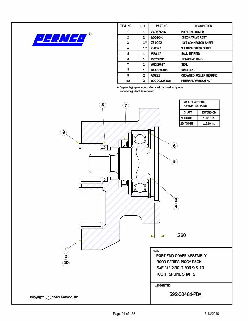
559922--0000448811--PPBBAA
TTOOOOTTHH SSPPLLIINNEE SSHHAAFFTTSSSSAAEE ""AA"" 22--BBOOLLTT FFOORR 99 && 1133
AASSSSEEMMBBLLYY NNOO..
PPOORRTT EENNDD CCOOVVEERR AASSSSEEMMBBLLYY33000000 SSEERRIIEESS PPIIGGGGYY BBAACCKK
NNAAMMEE
..226600
MMAAXX.. SSHHAAFFTT EEXXTT..FFOORR MMAATTIINNGG PPUUMMPP
11998899 PPeerrmmccoo,, IInncc..ccCCooppyyrriigghhtt
ccoonnnneeccttiinngg sshhaafftt iiss rreeqquuiirreedd..DDeeppeennddiinngg uuppoonn wwhhaatt ddrriivvee sshhaafftt iiss uusseedd,, oonnllyy oonnee
1100
99
8877
66
55
44
33
22
11
**
**
**
11
22
22
22
11
11
11
11
11
11
990000--0000332288--IIWWNN
XX--00992211
KKAA--00555588--11XXSS
WW6622--2266--1177
WW002233--228833
WW5588--4477
ZZJJ--00002222
ZZBB--00002222
LL--00228800--KK
VVAA--00557744--2244
IINNTTEERRNNAALL WWRREENNCCHH NNUUTT
CCRROOWWNNEEDD RROOLLLLEERR BBEEAARRIINNGG
RRIINNGG SSEEAALL
SSEEAALL
RREETTAAIINNIINNGG RRIINNGG
BBAALLLL BBEEAARRIINNGG
99 TT CCOONNNNEECCTTOORR SSHHAAFFTT
1133 TT CCOONNNNEECCTTOORR SSHHAAFFTT
CCHHEECCKK VVAALLVVEE AASSSSYY..
PPOORRTT EENNDD CCOOVVEERR
QQTTYY..IITTEEMM NNOO.. PPAARRTT NNOO.. DDEESSCCRRIIPPTTIIOONN
RR
33
110022
99
88 77
66
55
44
11
SSHHAAFFTT EEXXTTEENNSSIIOONN
99 TTOOOOTTHH
1133 TTOOOOTTHH
11..668877 iinn..
11..771199 iinn..
Page 91 of 158 5/13/2010

NNAAMMEE
55000000 SSEERRIIEESS PPIIGGGGYY BBAACCKKPPOORRTT EENNDD CCOOVVEERR AASSSSEEMMBBLLYY
AASSSSEEMMBBLLYY NNOO..
SSAAEE ""AA"" 22--BBOOLLTT FFOORR 99 && 1133TTOOOOTTHH SSPPLLIINNEE SSHHAAFFTTSS
559922--0000448822--PPBBAA
..226600
11..771199 iinn..
11..443377 iinn..
1133 TTOOOOTTHH
99 TTOOOOTTHH
EEXXTTEENNSSIIOONNSSHHAAFFTT
MMAAXX.. SSHHAAFFTT EEXXTT..FFOORR MMAATTIINNGG PPUUMMPP
11
44
55
66
7788
99
221100
33
RR
DDEESSCCRRIIPPTTIIOONNPPAARRTT NNOO..IITTEEMM NNOO.. QQTTYY..
PPOORRTT EENNDD CCOOVVEERR
CCHHEECCKK VVAALLVVEE AASSSSYY..
1133 TT CCOONNNNEECCTTOORR SSHHAAFFTT
99 TT CCOONNNNEECCTTOORR SSHHAAFFTT
BBAALLLL BBEEAARRIINNGG
RREETTAAIINNIINNGG RRIINNGG
SSEEAALL
RRIINNGG SSEEAALL
CCRROOWWNNEEDD RROOLLLLEERR BBEEAARRIINNGG
IINNTTEERRNNAALL WWRREENNCCHH NNUUTT
ZZAA--00557744--2244
LL--00228800--KK
ZZKK--00002222
ZZHH--00002222
WW5588--4477
WW002233--228833
WW6622--2266--1177
MMAA--00555588--11XXSS
RR--00992211
990000--0000332288--IIWWNN
11
11
11
11
11
11
22
22
22
11
**
**
**
11
22
33
44
55
66
7788
99
1100
DDeeppeennddiinngg uuppoonn wwhhaatt ddrriivvee sshhaafftt iiss uusseedd,, oonnllyy oonneeccoonnnneeccttiinngg sshhaafftt iiss rreeqquuiirreedd..
CCooppyyrriigghhtt cc 11998899 PPeerrmmccoo,, IInncc..
Page 92 of 158 5/13/2010

Page
93
of 1
585/
13/2
010

Page
94
of 1
585/
13/2
010

F
1
ED
32
CBA
12
3
54
6
FED
45
CB
6
A
.44
4.37
1.22
1 SE
E TA
BLE
1 PO
RT E
ND
CO
VER
1
2 SE
E TA
BLE
2 CO
NN
ECTI
NG
SH
AFT
(C/S
) 1
3 92
1-01
380
BU
SHIN
G
24
W03
3-2
W
AH
SERS
45
SEE
TABL
E 3
CA
P SC
REW
S
26
SEE
TABL
E 3
ST
UD
S
2
7 W
62-2
6-17
SH
AFT
SEA
L
18
565-
0119
4
PLU
G
19
921-
0128
1
BALL
BEA
RIN
G
1
10
565-
0128
2
RETA
INER
RIN
G
1
11
SEE
TABL
E 4
O-R
ING
(OPT
ION
AL)
1
2 BO
LT S
AE
A F
LAN
GE
CW
59
2-01
437-
0-2A
2 BO
LT S
AE
A F
LAN
GE
CCW
59
2-01
437-
1-2A
2 BO
LT S
AE
B FL
AN
GE
CW
59
2-01
437-
0-2B
2 BO
LT S
AE
B FL
AN
GE
CCW
59
2-01
437-
1-2B
9 TO
OTH
SA
E A
02
2-01
439
13 T
OO
TH S
AE
B
022-
0143
8
FOR
MU
LTIP
LE S
ECTI
ON
S U
SE (4
) STU
DS
WIT
H (4
) WA
SHER
S A
ND
(4) N
UTS
AD
D 4
-1/2
” FO
R EA
CH
BEA
RIN
G C
ARR
IER
PLU
S TO
TAL
GEA
RW
IDTH
TO
SIN
GLE
ASS
EMBL
Y ST
UD
LEN
GTH
S
USE
(2) S
TAN
DA
RD C
AP
SCRE
WS
AN
D (2
) STU
DS
ALO
NG
WIT
H(4
) WA
SHER
S A
ND
(2) N
UTS
TO
CO
MPL
ETE
ASS
EMBL
YST
UD
S LE
NG
THS
PER
SIN
GLE
ASS
EMBL
Y:5-
1/2”
FO
R 1”
GEA
R6”
FO
R 1-
1/4”
AN
D 1
-1/2
” GEA
R6-
1/2”
FO
R 1-
3/4”
AN
D 2
” GEA
R7”
FO
R 2-
1/4”
AN
D 2
-1/2
” GEA
R2-
NU
TS P
ART
# W
3-65
4-W
ASH
ERS
PART
# W
033-
2
OA
C2
PLA
CES
B2
PLA
CES
8.6
6U
NPO
RTED
WID
TH
12
34
56
78
910
11
ITEM
DES
CRI
PTIO
NPA
RT #
QTY
DES
CRI
PTIO
NPE
C P
ART
#SH
AFT
PA
RT #
3.25
0 2.
094
3/8-
16 U
NC
-2B
X .8
753.
250
2.09
4 3/
8-16
UN
C-2
B X
.875
4.00
0 2.
875
1/2-
13 U
NC
-2B
X 1.
000
4.00
0 2.
875
1/2-
13 U
NC
-2B
X 1.
000
TABL
E 1
TABL
E 2
TABL
E 3
TABL
E 4
A)S/
C( TFA
HSC
BD
IMEN
SIO
NS
360
PORT
EN
D C
OVE
RA
DD
-A-P
UM
P PI
GG
Y/BA
CK
2-BO
LT-A
OR
B FL
AN
GE
A O
R B
SPLI
NE
ASS
EMBL
Y
SRENETS
AF ME
DN
ATSRE
NETSAF EL
GNIS
DES
CRI
PTIO
NO
-RIN
G P
ART
#SA
E-A
FLA
NG
E PI
LOT
O-R
ING
SAE-
B FL
AN
GE
PILO
T O
-RIN
GCO
NSU
LT F
AC
TORY
(-15
2 O
-RIN
G)
CON
SULT
FA
CTO
RY (-
155
O-R
ING
)
Page
95
of 1
585/
13/2
010
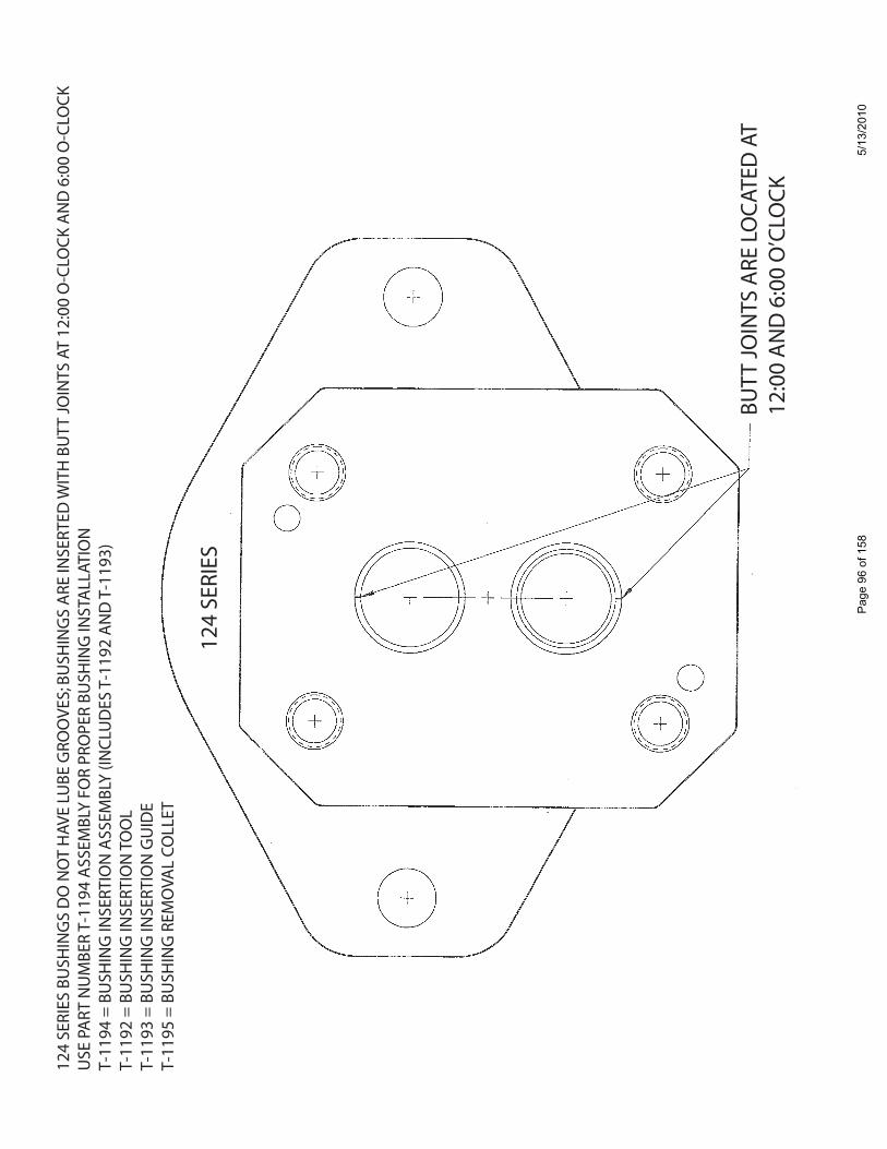
BUTT
JO
INTS
ARE
LO
CAT
ED A
T12
:00
AN
D 6
:00
O’C
LOC
K
124
SERI
ES B
USH
ING
S D
O N
OT
HAV
E LU
BE G
ROO
VES;
BU
SHIN
GS
ARE
INSE
RTED
WIT
H B
UTT
JO
INTS
AT
12:0
0 O
-CLO
CK
AN
D 6
:00
O-C
LOC
KU
SE P
ART
NU
MBE
R T-
1194
ASS
EMBL
Y FO
R PR
OPE
R BU
SHIN
G IN
STA
LLAT
ION
T-11
94 =
BU
SHIN
G IN
SERT
ION
ASS
EMBL
Y (IN
CLU
DES
T-1
192
AN
D T
-119
3)T-
1192
= B
USH
ING
INSE
RTIO
N T
OO
LT-
1193
= B
USH
ING
INSE
RTIO
N G
UID
ET-
1195
= B
USH
ING
REM
OVA
L CO
LLET
124
SERI
ES
Page
96
of 1
585/
13/2
010
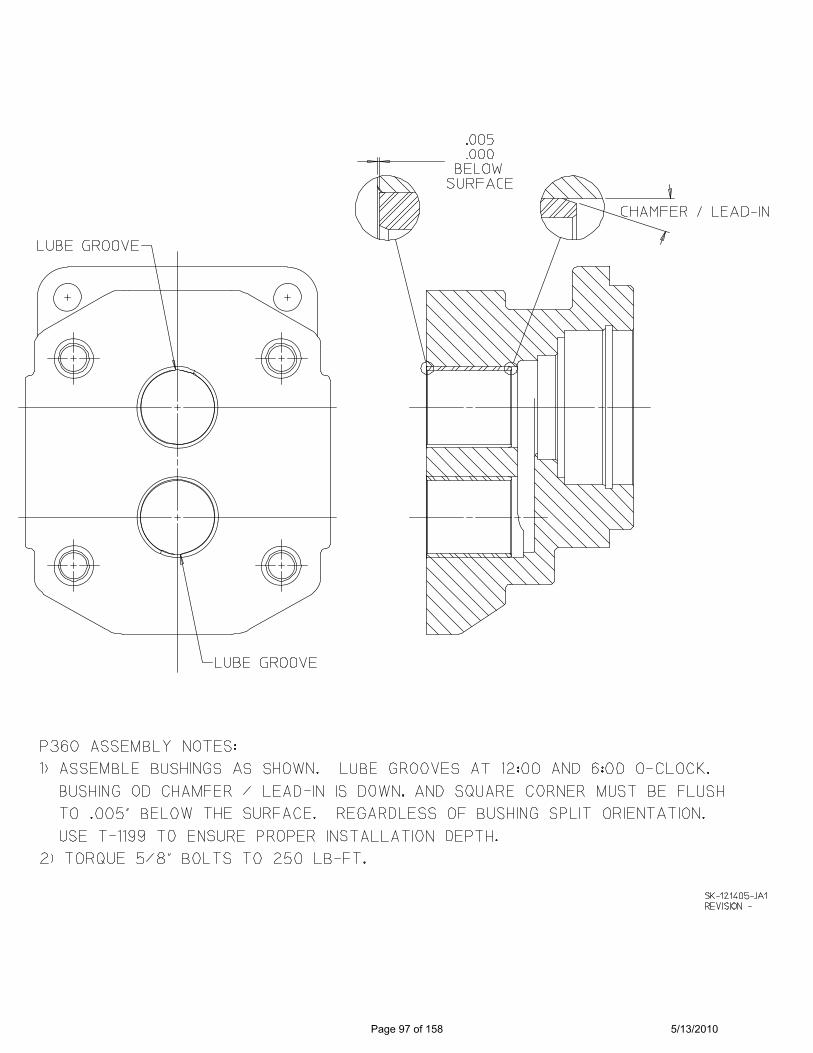
Page 97 of 158 5/13/2010

R HYDRAULIC / PNEUMATIC PRODUCTS
1500 Frost Road • Post Office Box 2068 • Streetsboro, Ohio 44241-0869 • 330/626-2801 • Fax: 330/626-2805
To: All Permco Distributors Date: March 10, 2010
Subject: TELL-TALE DRAIN SEAL BREAKDOWN
NATIONAL FLUID POWER ASSOCIATION
When coding a pump with a tell-tale seal, the letter after the pump series should be a "D". Example: (P5000D) The shaft end cover should be noted in the bill of materials description as "with tell-tale drain". The location of this drain can be found on drawing number T-1033 in the porting drawing book. If required the tell-tale drain hole can be tapped with a 1/8" NPT port.
2100 / 3000 / 3100 SERIES
QTY PART NUMBER DESCRIPTION
1
MZ-0961-1
SEAL RETAINER "TELL-TALE" 1
K-2995-109
SEAL RETAINER TELL-TALE O’RING 1
W023-206
RETAINING RING (SNAP RING) 1
W62-26-18
DOUBLE LIP SEAL "TELL-TALE" (OUTER) 1
W0 -19
1/8" NPT PIPE PLUG (IF REQUIRED)
5000 / 5100 / 257 SERIES
QTY PART NUMBER DESCRIPTION 1
SR-0961-5 SEAL RETAINER "TELL-TALE"
1
K-2995-164 SEAL RETAINIER TELL-TALE O’RING 1
W023-283 RETAINING RING (SNAP RING)
1
W62-26-4 DOUBLE LIP SEAL "TELL-TALE" (OUTER) 1
W0 -19 1/8" NPT PIPE PLUG (IF REQUIRED)
7500 / 7600 SERIES QTY PART NUMBER DESCRIPTION
1
W62-26-10
DOUBLE LIP SEAL "TELL-TALE" (OUTER) 1
W0 -19
1/8" NPT PIPE PLUG (IF REQUIRED)
197 /
Page 98 of 158 5/13/2010

PERMCO HYDRAULIC/PNEUMATIC PRODUCTS
Engineering Bulletin 2005-1 1500 Frost Rd Post Office Box 2068 10/21/2005 3:11 PM Streetsboro, Ohio 44241 (330) 626-2801 (330) 626-2805 TO: All Distributors Cc: Sales, Manufacturing, Assembly DATE: 7/21/2006 Ref: Tell-Tale Retainer Permco part number: MZ-0961 After existing stock is depleted Permco will discontinue stocking the MZ-0961 retainer Permco will replace it with MZ-0961-1 Reason for Change: The old retainer required a seal with a non-standard can diameter of 1.500! (W62-26-15) The new retainer will have a diameter of 1.686” allowing the use of all standard seals. Please order shaft seals for this retainer as follows. The new retainer will allow the following seals to now be installed on the integral drive shaft: W62-26-18 Standard integral pump seal W62-49-11 Standard motor seal W62-34-18 Standard Viton pump seal Permco Engineering Department David Earls Rev1 6/2/2006 Corrected seal part numbers to reflect seals with 1! diameter lip. The information contained in this facsimile message is property of Permco and confidential information intended only for the recipient named above. If the reader of this message is not the intended recipient, or agent responsible to deliver it to the intended recipient, you are hereby notified that any dissemination, distribution or copying of this documents or its contents are strictly prohibited. If you have received this document in error, please immediately notify us by telephone and return this original facsimile to use at the address via the U.S. Postal Service. Thank you.
Page 99 of 158 5/13/2010

..779933
UUSS
EE 11//
88"" ((..
112255))
DDIIAA
.. DDRR
IILLLL
TTHHRR
UU IINN
AANN
YY PPOO
SSIITT
IIOONN
CCAAPP
AABBLLEE
OOFF
BBEEII
NNGG
DDRR
IILLLLEE
DD AA
NNDD
SSUU
IITTAABB
LLEE FF
OORR
PPUU
MMPP
OOPPEE
RRAATT
IIOONN
77//88""
((..8877
55)) DD
IIAA.. SS
PPOOTTFF
AACCEE
AASS RR
EEQQUU
IIRREEDD
LLEE
TTTTEERR
''QQ'' ((
..333322
)) DDIIAA
.. TTAAPP
DDRR
IILLLL
11//88
NNPPTT
TTAAPP
22110000
,, 330000
00,, 33
110000
119977
SSEERR
IIEESS
55000000
,, 551100
002255
77 SS
EERRIIEE
SS7755
0000,, 77
660000
SSEERR
IIEESS
44--99--
9977DDAAEE
BBLLEE
EEDD HH
OOLLEE
LLOO
CCAATT
IIOONN
TTEELLLL
--TTAALL
EE SS
..EE..CC
..
TT--1100
333311
11
SSttrree
eettssbb
oorroo,,
OOhhii
oo 4444
224411
11550000
FFrroo
sstt RR
ooaadd
RR
RREEVVII
SSIIOO
NNooff
SSHHEEEE
TT NN
OO..
DDRRAA
WWIINN
GG NN
OO..
DDAATT
EE
BBYYAAPP
PPRROO
VVEEDD
SSUUPPEE
RRSSEEDD
EEDD BB
YY
DDAATT
EE
BBYYCCHHEECC
KKEEDD
DDAATT
EE
BBYYDDRRAA
WWNN
SSUUPPEE
RRSSEEDD
EESS
NNAAMM
EE
77//88""
((..8877
55)) DD
IIAA.. SS
PPOOTTFF
AACCEE
AASS RR
EEQQUU
IIRREEDD
LLEE
TTTTEERR
''QQ'' ((
..333322
)) DDIIAA
.. TTAAPP
DDRR
IILLLL
TTOO BB
RREEAA
KK TT
HHRR
UU AA
SS SS
HHOO
WWNN
..11//
88 NN
PPTT TT
AAPP
Page 58
11..4433
7711..
000000
FFOORR
22110000
,, 330000
00,, 33
110000,,
119977
,, 775500
00,, 77
660000
FFOORR
55000000
,, 551100
00,, 22
5577
AA
Page 100 of 158 5/13/2010
Loctite Retaining Compound And
LPS Solvent
To assist our customers in attaining the best possible results with Loctite retaining
compound, we now offer an LPS Solvent that we have tried, tested and found to give
excellent results. This solvent is used, not only for seal installation but also for locking
housings to adjacent sections for added strength and durability. We have some
customers that specify Loctite between the sections. Model numbers for Loctite units
will have a number 4 as the third digit of the model number, i.e., 3040, 5040, or 7540.
The two products we now offer are: 1. LPS Presolve (Permco Part # LPS-100). LPS Presolve is a general purpose,
industrial cleaning solvent. It’s ideal for preparing surfaces prior to using adhesives and
solvents. LPS removes all traces of grease and oils, and leaves no residue; ideal for
delicate instruments and precision parts. LPS Presolve is not harmful to the ozone and
is low in toxicity.
2. Loctite R/C 680 (Permco Part # LT-680) Loctite Retaining Compound #680 is a
medium viscosity fast curing liquid. This Loctite compound fixtures in 10 minutes at
room temperature. It provides shear strength of 4000 PSI on steel.
Page 101 of 158 5/13/2010
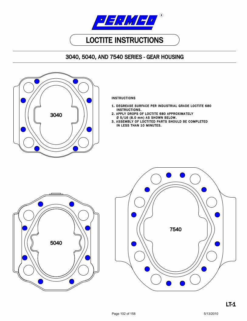
77554400
55004400
33004400
IINNSSTTRRUUCCTTIIOONNSS 11.. DDEEGGRREEAASSEE SSUURRFFAACCEE PPEERR IINNDDUUSSTTRRIIAALL GGRRAADDEE LLOOCCTTIITTEE 668800 IINNSSTTRRUUCCTTIIOONNSS..22.. AAPPPPLLYY DDRROOPPSS OOFF LLOOCCTTIITTEE 668800 AAPPPPRROOXXIIMMAATTEELLYY ØØ 55//1166 ((88..00 mmmm)) AASS SSHHOOWWNN BBEELLOOWW..33.. AASSSSEEMMBBLLYY OOFF LLOOCCTTIITTEEDD PPAARRTTSS SSHHOOUULLDD BBEE CCOOMMPPLLEETTEEDD IINN LLEESSSS TTHHAANN 1100 MMIINNUUTTEESS..
LLTT--11
33004400,, 55004400,, AANNDD 77554400 SSEERRIIEESS -- GGEEAARR HHOOUUSSIINNGG
LLOOCCTTIITTEE IINNSSTTRRUUCCTTIIOONNSS
RR
Page 102 of 158 5/13/2010

PERMCO PAINT
As a convenience to you, Permco has made available our blue pump and motor paint in
12 oz. aerosol cans. This will make it easy to touch up new and rebuilt units, as well as
change castings while still maintaining the factory applied color.
The part numbers are as follows:
Part # Description
427 P/M Blue Paint
427-12 Case of 12 Cans, P/M Blue Paint
427-E P/M Blue Paint Enamel
Standard replacement parts discounts will apply. Please contact our inside sales
department to place an order.
Page 103 of 158 5/13/2010

ELECTRIC CLUTCH PUMP ACCESSORIES
SERIES CP124/P2100/P3000/P3100
By using this power unit arrangement mounted in line with the engine belt train, continuous hydraulic power is available whenever the vehicle is stationary or moving. Typical applications include: snowplows, spreaders, dump bodies, wreckers, agricultural equipment, winches, cranes, etc. The electric clutches are for 12-volt D.C. operation and except our 7/8" diameter tapered shaft with female threaded end. PART # DESCRIPTION 512010 120 Ft. Lb. Static Torque" AA Groove 520226 120 Ft. Lb. Static Torque" 6 Groove Type K 515376 120 Ft. Lb. Static Torque" 8 Groove Type K BR549 Mounting Bracket (3/4" Thick) Accepts SAE-2-Bolt-A Pump Mount 999-956 Clutch Pump Switch Kit P2100/P3000/P3100 Series require an outboard bearing, SAE-2-Bolt-A shaft end cover (Code 583#) and our 7/8" diameter tapered shaft with female threaded end (Code 21) to be utilized with the BR549 mounting bracket. PART # DESCRIPTION ZP-0024 Code 21 Continental Shaft 7/8" Taper CP124 Series require a SAE-2-Bolt-A shaft end cover (Code 078 CW Rotation or Code 178 CCW Rotation) and our 7/8" diameter tapered shaft with female threaded end (Code 45 for 3/4" thick mounting bracket (BR549) or Code 99 for 3/8" thick mounting bracket). The CP124 Series is also available with a pad mount shaft end cover (see CP124 Brochure for optional mounting information, model number construction and detailed information). PART # DESCRIPTION 024-01284-** Code 45 Integral Shaft 7/8" Taper 024-01236-** Code 99 Integral Shaft 7/8" Taper " = After burnishing, see Owner’s Manual # = 2 check valve required in shaft end cover; direction of rotation required for proper assembly ** = Inset gear size
Page 104 of 158 5/13/2010

124 SERIES CLUTCH BRACKET NEW COMPET I TOR INTERCHANGE
There are many types of clutch pumps in the industry and no two are alike; there is always a mounting or installation issue problem when trying to replace a clutch pump within different manufacturers. Permco’s new clutch pump mounting bracket allows for replacing a Muncie H/K or H series type clutch pump without making installation changes. This new type bracket mounts to a standard Permco 124 Series Clutch Pump with a SAE-A-2 Bolt pump mounting fl ange converting the clutch pump to the Muncie style mounting confi guration allowing mounting to the existing clutch pump engine mounting hardware without modifi cations. The bracket part number is 931-01590; consult factory for additional information.
1.00
1.00
3.12
Bracket Foot Print
3/8”-16 UNC-2B-THD0.62 DEEP 4 PLACES
Page 105 of 158 5/13/2010
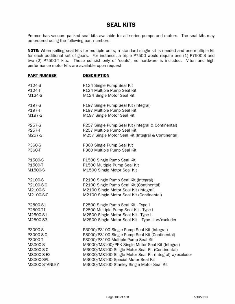
SEAL KITS Permco has vacuum packed seal kits available for all series pumps and motors. The seal kits may be ordered using the following part numbers. NOTE: When selling seal kits for multiple units, a standard single kit is needed and one multiple kit for each additional set of gears. For instance, a triple P7500 would require one (1) P7500-S and two (2) P7500-T kits. These consist only of ‘seals’, no hardware is included. Viton and high performance motor kits are available upon request.
PART NUMBER DESCRIPTION P124-S P124 Single Pump Seal Kit P124-T P124 Multiple Pump Seal Kit M124-S M124 Single Motor Seal Kit P197-S P197 Single Pump Seal Kit (Integral) P197-T P197 Multiple Pump Seal Kit M197-S M197 Single Motor Seal Kit P257-S P257 Single Pump Seal Kit (Integral & Continental) P257-T P257 Multiple Pump Seal Kit M257-S M257 Single Motor Seal Kit (Integral & Continental) P360-S P360 Single Pump Seal Kit P360-T P360 Multiple Pump Seal Kit P1500-S P1500 Single Pump Seal Kit P1500-T P1500 Multiple Pump Seal Kit M1500-S M1500 Single Motor Seal Kit P2100-S P2100 Single Pump Seal Kit (Integral) P2100-S-C P2100 Single Pump Seal Kit (Continental) M2100-S M2100 Single Motor Seal Kit (Integral) M2100-S-C M2100 Single Motor Seal Kit (Continental) P2500-S1 P2500 Single Pump Seal Kit - Type I P2500-T1 P2500 Multiple Pump Seal Kit - Type I M2500-S1 M2500 Single Motor Seal Kit - Type I M2500-S3 M2500 Single Motor Seal Kit – Type III w/excluder P3000-S P3000/P3100 Single Pump Seal Kit (Integral) P3000-S-C P3000/P3100 Single Pump Seal Kit (Continental) P3000-T P3000/P3100 Multiple Pump Seal Kit M3000-S M3000/M3100/PEK Single Motor Seal Kit (Integral) M3000-S-C M3000/M3100 Single Motor Seal Kit (Continental) M3000-S-EX M3000/M3100 Single Motor Seal Kit (Integral) w/excluder M3000-SPL M3000/M3100 Special Motor Seal Kit M3000-STANLEY M3000/M3100 Stanley Single Motor Seal Kit
Page 106 of 158 5/13/2010
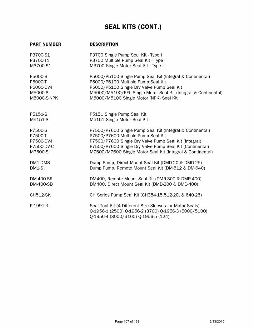
SEAL KITS (CONT.) PART NUMBER DESCRIPTION P3700-S1 P3700 Single Pump Seal Kit - Type I P3700-T1 P3700 Multiple Pump Seal Kit - Type I M3700-S1 M3700 Single Motor Seal Kit - Type I P5000-S P5000/P5100 Single Pump Seal Kit (Integral & Continental) P5000-T P5000/P5100 Multiple Pump Seal Kit P5000-DV-I P5000/P5100 Single Dry Valve Pump Seal Kit M5000-S M5000/M5100/PEL Single Motor Seal Kit (Integral & Continental) M5000-S-NPK M5000/M5100 Single Motor (NPK) Seal Kit P5151-S P5151 Single Pump Seal Kit M5151-S M5151 Single Motor Seal Kit P7500-S P7500/P7600 Single Pump Seal Kit (Integral & Continental) P7500-T P7500/P7600 Multiple Pump Seal Kit P7500-DV-I P7500/P7600 Single Dry Valve Pump Seal Kit (Integral) P7500-DV-C P7500/P7600 Single Dry Valve Pump Seal Kit (Continental) M7500-S M7500/M7600 Single Motor Seal Kit (Integral & Continental) DM1-DMS Dump Pump, Direct Mount Seal Kit (DMD-20 & DMD-25) DM1-S Dump Pump, Remote Mount Seal Kit (DM-512 & DM-640) DM-400-SR DM400, Remote Mount Seal Kit (DMR-300 & DMR-400) DM-400-SD DM400, Direct Mount Seal Kit (DMD-300 & DMD-400) CH512-SK CH Series Pump Seal Kit (CH384-15,512-20, & 640-25) P-1991-K Seal Tool Kit (4 Different Size Sleeves for Motor Seals) Q-1956-1 (2500) Q-1956-2 (3700) Q-1956-3 (5000/5100) Q-1956-4 (3000/3100) Q-1956-5 (124)
Page 107 of 158 5/13/2010
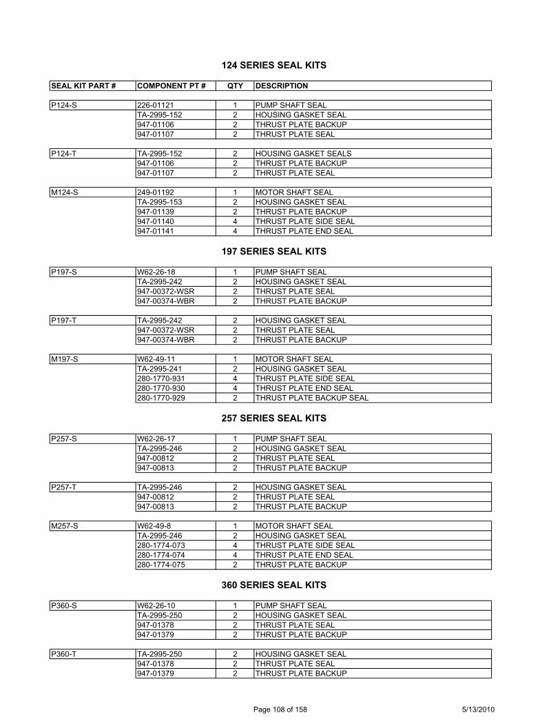
124 SERIES SEAL KITS
SEAL KIT PART # COMPONENT PT # QTY DESCRIPTION
P124-S 226-01121 1 PUMP SHAFT SEALTA-2995-152 2 HOUSING GASKET SEAL947-01106 2 THRUST PLATE BACKUP 947-01107 2 THRUST PLATE SEAL
P124-T TA-2995-152 2 HOUSING GASKET SEALS947-01106 2 THRUST PLATE BACKUP 947-01107 2 THRUST PLATE SEAL
M124-S 249-01192 1 MOTOR SHAFT SEALTA-2995-153 2 HOUSING GASKET SEAL947-01139 2 THRUST PLATE BACKUP947-01140 4 THRUST PLATE SIDE SEAL947-01141 4 THRUST PLATE END SEAL
197 SERIES SEAL KITS
P197-S W62-26-18 1 PUMP SHAFT SEALTA-2995-242 2 HOUSING GASKET SEAL947-00372-WSR 2 THRUST PLATE SEAL 947-00374-WBR 2 THRUST PLATE BACKUP
P197-T TA-2995-242 2 HOUSING GASKET SEAL947-00372-WSR 2 THRUST PLATE SEAL 947-00374-WBR 2 THRUST PLATE BACKUP
M197-S W62-49-11 1 MOTOR SHAFT SEALTA-2995-241 2 HOUSING GASKET SEAL280-1770-931 4 THRUST PLATE SIDE SEAL280-1770-930 4 THRUST PLATE END SEAL280-1770-929 2 THRUST PLATE BACKUP SEAL
257 SERIES SEAL KITS
P257-S W62-26-17 1 PUMP SHAFT SEALTA-2995-246 2 HOUSING GASKET SEAL947-00812 2 THRUST PLATE SEAL947-00813 2 THRUST PLATE BACKUP
P257-T TA-2995-246 2 HOUSING GASKET SEAL947-00812 2 THRUST PLATE SEAL947-00813 2 THRUST PLATE BACKUP
M257-S W62-49-8 1 MOTOR SHAFT SEALTA-2995-246 2 HOUSING GASKET SEAL280-1774-073 4 THRUST PLATE SIDE SEAL280-1774-074 4 THRUST PLATE END SEAL280-1774-075 2 THRUST PLATE BACKUP
360 SERIES SEAL KITS
P360-S W62-26-10 1 PUMP SHAFT SEALTA-2995-250 2 HOUSING GASKET SEAL947-01378 2 THRUST PLATE SEAL947-01379 2 THRUST PLATE BACKUP
P360-T TA-2995-250 2 HOUSING GASKET SEAL947-01378 2 THRUST PLATE SEAL947-01379 2 THRUST PLATE BACKUP
Page 108 of 158 5/13/2010
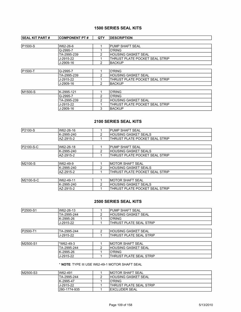
1500 SERIES SEAL KITS
SEAL KIT PART # COMPONENT PT # QTY DESCRIPTION
P1500-S W62-26-6 1 PUMP SHAFT SEALQ-2995-7 1 O'RINGTA-2995-239 2 HOUSING GASKET SEALJ-2915-22 1 THRUST PLATE POCKET SEAL STRIPJ-2909-16 2 BACKUP
P1500-T Q-2995-7 1 O'RINGTA-2995-239 2 HOUSING GASKET SEALJ-2915-22 1 THRUST PLATE POCKET SEAL STRIPJ-2909-16 2 BACKUP
M1500-S K-2995-121 1 O'RINGQ-2995-7 2 O'RINGTA-2995-239 2 HOUSING GASKET SEALJ-2915-22 1 THRUST PLATE POCKET SEAL STRIPJ-2909-16 3 BACKUP
2100 SERIES SEAL KITS
P2100-S W62-26-16 1 PUMP SHAFT SEALK-2995-240 2 HOUSING GASKET SEALSAZ-2915-2 1 THRUST PLATE POCKET SEAL STRIP
P2100-S-C W62-26-18 1 PUMP SHAFT SEALK-2995-240 2 HOUSING GASKET SEALSAZ-2915-2 1 THRUST PLATE POCKET SEAL STRIP
M2100-S W62-49-9 1 MOTOR SHAFT SEALK-2995-240 2 HOUSING GASKET SEALSAZ-2915-2 1 THRUST PLATE POCKET SEAL STRIP
M2100-S-C W62-49-11 1 MOTOR SHAFT SEALK-2995-240 2 HOUSING GASKET SEALSAZ-2915-2 1 THRUST PLATE POCKET SEAL STRIP
2500 SERIES SEAL KITS
P2500-S1 W62-26-13 1 PUMP SHAFT SEALTA-2995-244 2 HOUSING GASKET SEALK-2995-26 1 O'RINGJ-2915-22 1 THRUST PLATE SEAL STRIP
P2500-T1 TA-2995-244 2 HOUSING GASKET SEALJ-2915-22 1 THRUST PLATE SEAL STRIP
M2500-S1 *W62-49-3 1 MOTOR SHAFT SEALTA-2995-244 2 HOUSING GASKET SEALK-2995-26 1 O'RINGJ-2915-22 1 THRUST PLATE SEAL STRIP
* NOTE: TYPE III USE W62-49-1 MOTOR SHAFT SEAL
M2500-S3 W62-491 1 MOTOR SHAFT SEALTA-2995-244 2 HOUSING GASKET SEALK-2995-47 1 O'RINGJ-2915-22 1 THRUST PLATE SEAL STRIP280-1774-935 1 EXCLUDER SEAL
Page 109 of 158 5/13/2010
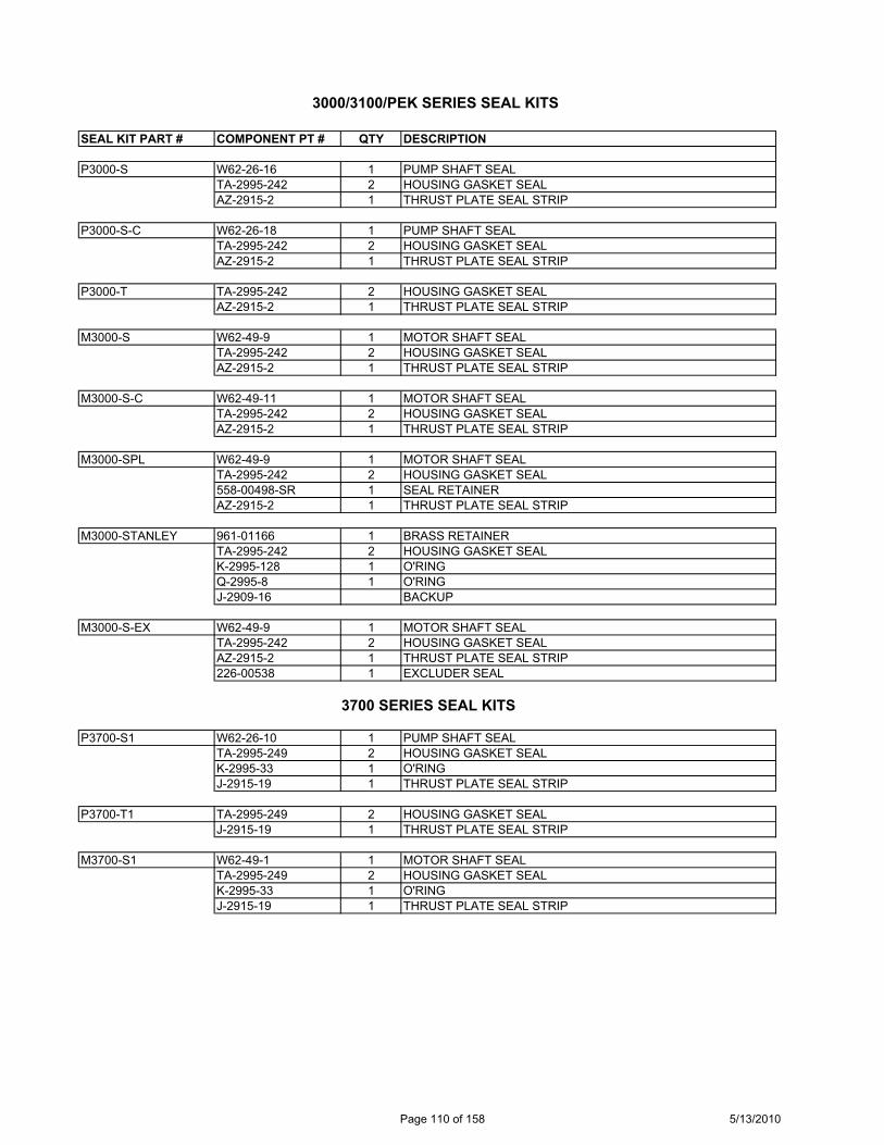
3000/3100/PEK SERIES SEAL KITS
SEAL KIT PART # COMPONENT PT # QTY DESCRIPTION
P3000-S W62-26-16 1 PUMP SHAFT SEALTA-2995-242 2 HOUSING GASKET SEALAZ-2915-2 1 THRUST PLATE SEAL STRIP
P3000-S-C W62-26-18 1 PUMP SHAFT SEALTA-2995-242 2 HOUSING GASKET SEALAZ-2915-2 1 THRUST PLATE SEAL STRIP
P3000-T TA-2995-242 2 HOUSING GASKET SEALAZ-2915-2 1 THRUST PLATE SEAL STRIP
M3000-S W62-49-9 1 MOTOR SHAFT SEALTA-2995-242 2 HOUSING GASKET SEALAZ-2915-2 1 THRUST PLATE SEAL STRIP
M3000-S-C W62-49-11 1 MOTOR SHAFT SEALTA-2995-242 2 HOUSING GASKET SEALAZ-2915-2 1 THRUST PLATE SEAL STRIP
M3000-SPL W62-49-9 1 MOTOR SHAFT SEALTA-2995-242 2 HOUSING GASKET SEAL558-00498-SR 1 SEAL RETAINERAZ-2915-2 1 THRUST PLATE SEAL STRIP
M3000-STANLEY 961-01166 1 BRASS RETAINERTA-2995-242 2 HOUSING GASKET SEALK-2995-128 1 O'RINGQ-2995-8 1 O'RINGJ-2909-16 BACKUP
M3000-S-EX W62-49-9 1 MOTOR SHAFT SEALTA-2995-242 2 HOUSING GASKET SEALAZ-2915-2 1 THRUST PLATE SEAL STRIP226-00538 1 EXCLUDER SEAL
3700 SERIES SEAL KITS
P3700-S1 W62-26-10 1 PUMP SHAFT SEALTA-2995-249 2 HOUSING GASKET SEALK-2995-33 1 O'RINGJ-2915-19 1 THRUST PLATE SEAL STRIP
P3700-T1 TA-2995-249 2 HOUSING GASKET SEALJ-2915-19 1 THRUST PLATE SEAL STRIP
M3700-S1 W62-49-1 1 MOTOR SHAFT SEALTA-2995-249 2 HOUSING GASKET SEALK-2995-33 1 O'RINGJ-2915-19 1 THRUST PLATE SEAL STRIP
Page 110 of 158 5/13/2010
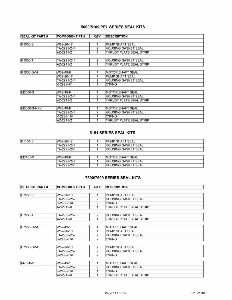
SEAL KIT PART # COMPONENT PT # QTY DESCRIPTION
P5000-S
AZ-2915-2 1 THRUST PLATE SEAL STRIP
P5000-TAZ-2915-2 1 THRUST PLATE SEAL STRIP
P5000-DV-I
K-2995-47 1 O'RING
M5000-S
AZ-2915-2 1 THRUST PLATE SEAL STRIP
M5000-S-NPK
AZ-2915-2 1 THRUST PLATE SEAL STRIP
P5151-S
TA-2995-250 1 HOUSING GASKET SEAL
M5151-S
TA-2995-250 1 HOUSING GASKET SEAL
7500/7600 SERIES SEAL KITS
SEAL KIT PART # COMPONENT PT # QTY DESCRIPTION
P7500-S
AZ-2915-6 1 THRUST PLATE SEAL STRIP
P7500-TAZ-2915-6 1 THRUST PLATE SEAL STRIP
P7500-DV-I
K-2995-164 2 O'RING
P7500-DV-C
K-2995-164 2 O'RING
M7500-S
AZ-2915-6 1 THRUST PLATE SEAL STRIP
5000/5100/PEL SERIES SEAL KITS
W62-26-17 1 PUMP SHAFT SEALTA-2995-244 2 HOUSING GASKET SEAL
TA-2995-244 2 HOUSING GASKET SEAL
W62-49-8 1 MOTOR SHAFT SEALW62-26-17 1 PUMP SHAFT SEALTA-2995-244 2 HOUSING GASKET SEAL
W62-49-8 1 MOTOR SHAFT SEALTA-2995-244 2 HOUSING GASKET SEAL
W62-49-8 1 MOTOR SHAFT SEALTA-2995-244 2 HOUSING GASKET SEALK-2995-164 1 O'RING
5151 SERIES SEAL KITS
W62-26-17 1 PUMP SHAFT SEALTA-2995-244 1 HOUSING GASKET SEAL
W62-49-8 1 MOTOR SHAFT SEALTA-2995-244 1 HOUSING GASKET SEAL
W62-26-10 1 PUMP SHAFT SEALTA-2995-252 2 HOUSING GASKET SEALK-2995-164 2 O'RING
TA-2995-252 2 HOUSING GASKET SEAL
W62-49-1 1 MOTOR SHAFT SEALW62-26-10 1 PUMP SHAFT SEALTA-2995-252 2 HOUSING GASKET SEAL
W62-26-10 2 PUMP SHAFT SEALTA-2995-252 2 HOUSING GASKET SEAL
W62-49-1 1 MOTOR SHAFT SEALTA-2995-252 2 HOUSING GASKET SEALK-2995-164 1 O'RING
Page 111 of 158 5/13/2010
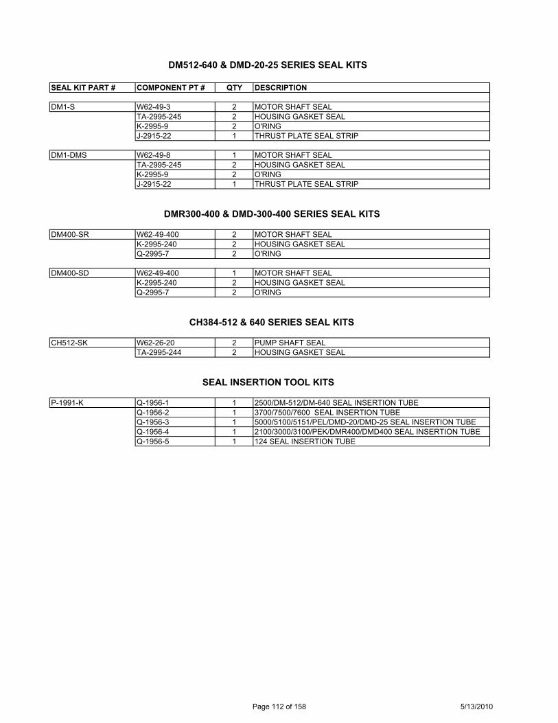
DM512-640 & DMD-20-25 SERIES SEAL KITS
SEAL KIT PART # COMPONENT PT # QTY DESCRIPTION
DM1-S
J-2915-22 1 THRUST PLATE SEAL STRIP
DM1-DMS
J-2915-22 1 THRUST PLATE SEAL STRIP
DMR300-400 & DMD-300-400 SERIES SEAL KITS
DM400-SR
Q-2995-7 2 O'RING
DM400-SD
Q-2995-7 2 O'RING
CH384-512 & 640 SERIES SEAL KITS
CH512-SKTA-2995-244 2 HOUSING GASKET SEAL
SEAL INSERTION TOOL KITS
P-1991-K
Q-1956-5 1 124 SEAL INSERTION TUBE
W62-49-3 2 MOTOR SHAFT SEALTA-2995-245 2 HOUSING GASKET SEALK-2995-9 2 O'RING
W62-49-8 1 MOTOR SHAFT SEALTA-2995-245 2 HOUSING GASKET SEALK-2995-9 2 O'RING
W62-49-400 2 MOTOR SHAFT SEALK-2995-240 2 HOUSING GASKET SEAL
W62-49-400 1 MOTOR SHAFT SEALK-2995-240 2 HOUSING GASKET SEAL
W62-26-20 2 PUMP SHAFT SEAL
Q-1956-1 1 2500/DM-512/DM-640 SEAL INSERTION TUBEQ-1956-2 1 3700/7500/7600 SEAL INSERTION TUBEQ-1956-3 1 5000/5100/5151/PEL/DMD-20/DMD-25 SEAL INSERTION TUBEQ-1956-4 1 2100/3000/3100/PEK/DMR400/DMD400 SEAL INSERTION TUBE
Page 112 of 158 5/13/2010

STAN
DARD
SEA
LSSE
RIE
SSH
AFT
SEAL
GAS
KET
SEAL
SEAL
SHAF
TSH
AFT
THR
UST
PLA
TETH
RU
ST P
LATE
TH
RU
ST P
LATE
THR
UST
PLA
TE
RET
AIN
E RO
-RIN
GBA
CKU
PBA
CKU
PSE
AL P
UM
PSI
DE
SEAL
END
SEA
L O
-RIN
GR
ING
MO
TOR
MO
TOR
P124
226-
0112
1TA
-299
5-15
2N
/AN
/AN
/A94
7-01
106
947-
0110
7N
/AN
/AM
124
249-
0119
2TA
-299
5-15
3N
/AN
/AN
/A94
7-01
139
N/A
947-
0114
094
7-01
141
P197
W62
-26-
18TA
-299
5-24
2N
/ AN
/AN
/A94
7-00
374-
WBR
947-
0037
2-W
SRN
/AN
/AP1
97 C
ON
TIN
ENTA
L W
62-2
6-18
TA-2
995-
242
K-29
95-1
09N
/AN
/A94
7-00
374-
WBR
947-
0037
2-W
SRN
/AN
/AM
197
W62
-49-
11TA
-299
5-24
1N
/AN
/AN
/A28
0-17
70-9
29N
/A28
0-17
70-9
3128
0-17
70-9
30M
197
CO
NTI
NEN
TAL
W62
-49-
11TA
-299
5-24
1N
/AN
/AN
/A28
0-17
70-9
29N
/A28
0-17
70-9
3128
0-17
70-9
30P2
57W
62-2
6-17
TA-2
995-
246
K-29
95-1
64N
/ AN
/A94
7-00
813
947-
0081
2N
/AN
/AP2
57 C
ON
TIN
ENTA
LW
62-2
6-17
TA-2
995-
246
K-29
95-1
64N
/AN
/A94
7-00
813
947-
0081
2N
/AN
/AM
257
W62
-49-
8TA
-299
5-24
6K-
2995
-164
N/A
N/A
280-
1774
-075
N/A
280-
1774
-073
280-
1774
-074
M25
7 C
ON
TIN
ENTA
LW
62-4
9-8
TA-2
995-
246
K-29
95-1
64N
/AN
/A28
0-17
74-0
75N
/A28
0-17
74-0
7328
0-17
74-0
74P3
60W
62-2
6-10
TA-2
995-
250
N/ A
N/A
N/A
947-
0137
994
7-01
378
N/A
N/A
P150
0W
62-2
6-6
TA-2
995-
239
N/A
Q-2
995-
7J-
2909
-16
N/A
N/A
N/A
N/A
M15
00N
/ATA
-299
5-23
9K-
2995
-121
Q-2
995-
7J-
2909
-16
N/A
N/A
N/A
N/A
P210
0W
62-2
6-16
K-29
95-2
40K-
2995
-109
N/A
N/A
N/A
N/A
N/A
N/A
P210
0 C
ON
TIN
ENTA
LW
62-2
6-18
K-29
95-2
40K-
2995
-109
N/A
N/A
N/A
N/A
N/A
N/A
M21
00W
62-4
9-9
K-29
95-2
40K-
2995
-109
N/A
N/A
N/A
N/A
N/A
N/A
M21
00 C
ON
TIN
ENTA
LW
62-4
9-11
K-29
95-2
40K-
2995
-109
N/A
N/A
N/A
N/A
N/A
N/A
P250
0 TY
PE I
W62
-26-
13TA
-299
5-24
4K-
2995
-26
N/A
N/A
N/A
N/A
N/A
N/A
M25
00 T
YPE
IW
62-4
9-3
TA-2
995-
244
K-29
95-2
6N
/AN
/AN
/AN
/AN
/AN
/AM
2500
TYP
E III
W62
-49-
11TA
-299
5-24
4K-
2995
-26
N/A
N/A
N/A
N/A
N/A
N/A
P300
0/31
00W
62-2
6-16
TA-2
995-
242
K-29
95-1
09N
/AN
/AN
/AN
/AN
/AN
/AP3
000/
3100
CO
NTI
NEN
TAL
W62
-26-
18TA
-299
5-24
2K-
2995
-109
N/A
N/A
N/A
N/A
N/A
N/A
M30
00/3
100
W62
-49-
9TA
-299
5-24
2K-
2995
-109
N/A
N/A
N/A
N/A
N/A
N/A
M30
00/3
100
CO
NTI
NEN
TAL
W62
-49-
11TA
-299
5-24
2K-
2995
-109
N/A
N/A
N/A
N/A
N/A
N/A
P370
0 TY
PE I
W62
-26-
10TA
-299
5-24
9K-
2995
-33
N/A
N/A
N/A
N/A
N/A
N/A
M37
00 T
YPE
IW
62-4
9-1
TA-2
995-
249
K-29
95-3
3N
/AN
/AN
/AN
/AN
/AN
/AP5
000/
5100
W62
-26-
17TA
-299
5-24
4K-
2995
-164
N/A
N/A
N/A
N/A
N/A
N/A
P500
0/51
00 C
ON
TIN
ENTA
LW
62-2
6-17
TA-2
995-
244
K-29
95-1
64N
/AN
/AN
/AN
/AN
/AN
/AM
5000
/510
0W
62-4
9-8
TA-2
995-
244
K-29
95-1
64N
/AN
/AN
/AN
/AN
/AN
/AM
5000
/510
0 C
ON
TIN
ENTA
LW
62-4
9-8
TA-2
995-
244
K-29
95-1
64N
/AN
/AN
/AN
/AN
/AN
/AP5
151
W62
-26-
17TA
-299
5-24
4 (1
)K-
2995
-164
N/A
N/A
N/A
N/A
N/A
N/A
TA-2
995-
250
(1)
P5
151
CO
NTI
NEN
TAL
W62
-26-
17TA
-299
5-24
4 (1
)K-
2995
-164
N/A
N/A
N/A
N/A
N/A
N/A
TA-2
995-
250
(1)
M
5151
W62
-49-
8TA
-299
5-24
4 (1
)K-
2995
-164
N/ A
N/A
N/A
N/A
N/A
N/A
TA-2
995-
250
(1)
M
5151
CO
NTI
NEN
TAL
W62
-49-
8TA
-299
5-24
4 (1
)K-
2995
-164
N/A
N/A
N/A
N/A
N/A
N/A
TA-2
995-
250
(1)
P7
500/
7600
W62
-26-
10TA
-299
5-25
2K-
2995
-164
N/ A
N/A
N/A
N/A
N/A
N/A
P750
0/76
00 C
ON
TIN
ENTA
LW
62-2
6-10
TA-2
995-
252
K-29
95-1
64N
/AN
/AN
/AN
/AN
/AN
/AM
7500
/760
0W
62-4
9-1
TA-2
995-
252
K-29
95-1
64N
/AN
/AN
/AN
/AN
/AN
/AM
7500
/760
0 C
ON
TIN
ENTA
LW
62-4
9-1
TA-2
995-
252
K-29
95-1
64N
/AN
/AN
/AN
/AN
/AN
/A
N/A
= N
OT
APPL
ICAB
LEPa
ge 1
13 o
f 158
5/13
/201
0

VITO
N SE
ALS
SER
IES
SHAF
T SE
ALG
ASKE
T SE
ALSE
ALSH
AFT
SHAF
TTH
RU
ST P
LATE
THR
UST
PLA
TE
THR
UST
PLA
TETH
RU
ST P
LATE
R
ETAI
NER
O-R
ING
BAC
KUP
BAC
KUP
SEAL
PU
MP
SID
E SE
ALEN
D S
EAL
O-R
ING
RIN
GM
OTO
RM
OTO
R
P124
226-
0112
1-V
ZA-2
995-
152
N/A
N/A
N/A
947-
0110
694
7-01
107-
VN
/AN
/AM
124
249-
0119
2N
/AV
N/A
N/A
N/A
N/A
VN
/AN
/AV
N/A
VP1
97W
62-3
4-18
ZA-2
995-
242
N/A
N/A
N/A
947-
0037
4-W
BR94
7-00
372-
VSR
N/A
N/A
P197
CO
NTI
NEN
TAL
W62
-34-
18ZA
-299
5-24
2N
/AN
/AN
/A94
7-00
374-
WBR
947-
0037
2-VS
RN
/AN
/AM
197
W62
-49-
11N
/AV
N/A
N/A
N/A
N/A
VN
/AN
/AV
N/A
VM
197
CO
NTI
NEN
TAL
W62
-49-
11N
/AV
N/A
N/A
N/A
N/A
VN
/AN
/AV
N/A
VP2
57W
62-3
4-17
ZA-2
995-
246
N/A
N/A
N/A
947-
0081
394
7-00
812V
N/A
N/A
P257
CO
NTI
NEN
TAL
W62
-34-
17ZA
-299
5-24
6N
/AN
/AN
/A94
7-00
813
947-
0081
2VN
/AN
/AM
257
W62
-49-
8ZA
-299
5-24
6N
/AN
/AN
/AN
/AV
N/A
N/A
VN
/AV
M25
7 C
ON
TIN
ENTA
LW
62-4
9-8
ZA-2
995-
246
N/A
N/A
N/A
N/A
VN
/AN
/AV
N/A
VP3
60W
62-3
4-10
391-
2881
-050
N/A
N/A
N/A
N/A
VN
/AV
N/A
N/A
P150
0W
62-4
9-6
ZA-2
995-
239
ZA-2
995-
212
ZA-2
995-
26J-
2909
-16
N/A
N/A
N/A
N/A
M15
00N
/AZA
-299
5-23
9ZA
-299
5-21
2ZA
-299
5-26
J-29
09-1
6N
/AN
/AN
/AN
/AP2
100
W62
-34-
16ZA
-299
5-24
0N
/AN
/AN
/AN
/AN
/AN
/AN
/AP2
100
CO
NTI
NEN
TAL
W62
-34-
18ZA
-299
5-24
0N
/AN
/AN
/AN
/AN
/AN
/AN
/AM
2100
W62
-49-
9ZA
-299
5-24
0N
/AN
/AN
/AN
/AN
/AN
/AN
/AM
2100
CO
NTI
NEN
TAL
W62
-49-
11ZA
-299
5-24
0N
/AN
/AN
/AN
/AN
/AN
/AN
/AP2
500
TYPE
IW
62-4
9-30
ZA-2
995-
244
ZA-2
995-
228
N/A
N/A
N/A
N/A
N/A
N/A
M25
00 T
YPE
IW
62-4
9-30
ZA-2
995-
244
ZA-2
995-
228
N/A
N/A
N/A
N/A
N/A
N/A
M25
00 T
YPE
IIIW
62-4
9-11
ZA-2
995-
244
ZA-2
995-
228
N/A
N/A
N/A
N/A
N/A
N/A
P300
0/31
00W
62-3
4-16
ZA-2
995-
242
N/A
N/A
N/A
N/A
N/A
N/A
N/A
P300
0/31
00 C
ON
TIN
ENTA
LW
62-3
4-18
ZA-2
995-
242
N/A
N/A
N/A
N/A
N/A
N/A
N/A
M30
00/3
100
W62
-49-
9ZA
-299
5-24
2N
/AN
/AN
/AN
/AN
/AN
/AN
/AM
3000
/310
0 C
ON
TIN
ENTA
LW
62-4
9-11
ZA-2
995-
242
N/A
N/A
N/A
N/A
N/A
N/A
N/A
P370
0 TY
PE I
W62
-34-
10ZA
-299
5-24
9ZA
-299
5-23
2N
/AN
/AN
/AN
/AN
/AN
/AM
3700
TYP
E I
W62
-49-
1ZA
-299
5-24
9ZA
-299
5-23
2N
/AN
/AN
/AN
/AN
/AN
/AP5
000/
5100
W62
-34-
17ZA
-299
5-24
4N
/AN
/AN
/AN
/AN
/AN
/AN
/AP5
000/
5100
CO
NTI
NEN
TAL
W62
-34-
17ZA
-299
5-24
4N
/AN
/AN
/AN
/AN
/AN
/AN
/AM
5000
/510
0W
62-4
9-8
ZA-2
995-
244
N/A
N/A
N/A
N/A
N/A
N/A
N/A
M50
00/5
100
CO
NTI
NEN
TAL
W62
-49-
8ZA
-299
5-24
4N
/AN
/AN
/AN
/AN
/AN
/AN
/AP5
151
W62
-34-
17ZA
-299
5-24
4 (1
)N
/AN
/AN
/AN
/AN
/AN
/AN
/AN
/AV
(1)
P5
151
CO
NTI
NEN
TAL
W62
-34-
17ZA
-299
5-24
4 (1
)N
/AN
/AN
/AN
/AN
/AN
/AN
/AN
/AV
(1)
M
5151
W62
-49-
8ZA
-299
5-24
4 (1
)N
/AN
/AN
/AN
/AN
/AN
/AN
/AN
/AV
(1)
M
5151
CO
NTI
NEN
TAL
W62
-48-
8ZA
-299
5-24
4 (1
)N
/AN
/AN
/AN
/AN
/AN
/AN
/AN
/AV
(1)
P7
500/
7600
W62
-49-
10ZA
-299
5-25
2ZA
-299
5-14
6N
/AN
/AN
/AN
/AN
/AN
/AP7
500/
7600
CO
NTI
NEN
TAL
W62
-49-
10ZA
-299
5-25
2ZA
-299
5-14
6N
/AN
/AN
/AN
/AN
/AN
/AM
7500
/760
0W
62-4
9-1
ZA-2
995-
252
ZA-2
995-
146
N/A
N/A
N/A
N/A
N/A
N/A
M75
00/7
600
CO
NTI
NEN
TAL
W62
-49-
1ZA
-299
5-25
2ZA
-299
5-14
6N
/AN
/AN
/AN
/AN
/AN
/AN
/A =
NO
T AP
PLIC
ABLE
N
/AV
= N
OT
AVAI
LABL
E C
ON
SULT
FAC
TOR
YPa
ge 1
14 o
f 158
5/13
/201
0

1/16
/200
9SH
AFT
SEAL
APP
LICA
TIO
N CR
OSS
REF
EREN
CE
Shaf
t Sea
l Man
ufac
ture
Rec
omm
enda
tions
Perm
co
Hou
sing
Bor
e Se
alSh
aft
Seal
Ap
plic
atio
nU
sed
Part
Num
ber
IDO
DO
DW
idth
226-
0053
82.
047
±0.0
012.
051
±0.0
021.
000
±0.0
030.
250
EXC
LUD
EREx
clud
er 2
100/
3000
/250
0022
6-01
015
2.00
0 ±0
.001
2.00
4 ±0
.002
1.25
0 ±0
.003
0.25
0PU
MP
*Com
mer
cial
type
sha
fts22
6-01
121-
V1.
496
±0.0
011.
500
±0.0
020.
9425
-0.9
430
0.25
0 ±0
.015
PUM
PPE
124
Vito
n22
6-01
527
1.49
7 ±0
.001
1.50
1 ±0
.002
0.87
5 ±0
.003
0.31
3M
OTO
RZa
mbo
ni24
9-01
192
1.49
6 ±0
.001
1.50
0 ±0
.002
0.94
25-0
.943
00.
250
±0.0
15M
OTO
RM
124
obso
lete
249-
0153
61.
999±
0.00
12.
001-
2.00
61.
2895
-1.2
900
0.28
5±0.
015
MO
TOR
257/
5000
Sev
ere
Dut
y24
9-01
555
1.49
6 ±0
.001
1.49
8-1.
503
0.94
25-0
.943
00.
312
±0.0
16M
OTO
RM
124
doub
le li
p24
9-01
583
2.12
5±0.
001
2.12
7-2.
132
1.37
70-1
.377
50.
285±
0.01
5M
OTO
R36
0, 7
500
Seve
re D
uty
280-
1774
-935
1.83
4 ±0
.001
1.83
8 ±0
.002
1.37
5 ±0
.003
0.18
8EX
CLU
DER
Excl
uder
250
0 ty
pe 3
W
62-2
6-75
3.15
0 +
0.00
15* 3
.154
±0.
002
1.37
8 ±0
.002
0.27
6EX
CLU
DER
Excl
uder
750
0W
62-3
4-10
Sim
ilar D
imen
sion
s As
W62
-26-
10PU
MP
360/
7500
Vito
nW
62-3
4-16
Sim
ilar D
imen
sion
s As
W62
-26-
16PU
MP
3000
/210
0 Vi
ton
Con
tinen
tal
W62
-34-
17Si
mila
r Dim
ensi
ons
As W
62-2
6-17
PUM
P25
7/50
00 V
iton
W62
-34-
18Si
mila
r Dim
ensi
ons
As W
62-2
6-18
PUM
PVi
ton
for 1
" dia
sha
ft x
1.68
628
0-17
72-1
862.
000
±0.0
012.
004
±0.0
021.
250
±0.0
03M
OTO
R*C
omm
erci
al ty
pe s
hafts
*212
-049
9-50
2C
OD
E 62
257
*202
-049
9-50
2C
OD
E 62
500
0*2
12-0
999-
001
CO
DE
2 25
7
* - C
alcu
late
d Va
lue
Ref
eren
ce O
nly
SHAF
T SE
AL A
PPLI
CAT
ION
CR
OSS
REF
EREN
CE
Page
115
of 1
585/
13/2
010

Page
116
of 1
585/
13/2
010

FASTENERS 124 SINGLE (1/2") GEAR SIZE CAP SCREW # QTY. 1/2" W1-88 4 3/4" W1-11 4 1" W1-66 4 1-1/4" W1-12 4 1-1/2" W1-69 4 1-3/4" W1-83 4 2" W1-60 4 1500 SINGLE (1/2") GEAR SIZE CAP SCREW # QTY. 1/2" W1-11 4 3/4" W1-12 4 1" W1-12 4 1-1/4" W1-83 4 1-1/2" W1-83 4 1-3/4" W1-34 4 2" W1-34 4 360 SINGLE (5/8") GEAR SIZE CAP SCREW # QTY. 1/2! W1-58 4 3/4" W1-58 4 1" W1-14 4 1-1/4" W1-14 4 1-1/2" W1-78 4 1-3/4" W1-78 4 2" W1-65 4 2-1/4" W1-65 4 2-1/2" W1-89 4 3700 SINGLE (1/2") GEAR SIZE CAP SCREW # QTY. 3/4" W1-68 8 1" W1-68 8 1-1/4" W1-090 8 1-1/2" W1-090 8 1-3/4" W1-15 8 2" W1-099 8 2-1/4" W1-099 8 2-1/2" W1-76 8 2-3/4" W1-76 8 3" W1-75 8
2100 SINGLE (9/16") GEAR SIZE CAP SCREW # QTY. 1/2" 900-01020-400 4 3/4" 900-01020-400 4 1" W1-300 4 1-1/4" W1-300 4 1-1/2" W1-400 4 1-3/4" W1-400 4 2" 900-01020-550 4 197 SINGLE (5/8") GEAR SIZE CAP SCREW # QTY. 1/2" W1-096 4 3/4" W1-13 4 1" W1-13 4 1-1/4" W1-58 4 1-1/2" W1-58 4 1-3/4" W1-14 4 2" W1-14 4 257 SINGLE (5/8") GEAR SIZE CAP SCREW # QTY. 1/2" W1-096 4 3/4" W1-13 4 1" W1-13 4 1-1/4" W1-58 4 1-1/2" W1-58 4 1-3/4" W1-14 4 2" W1-14 4 2-1/4" W1-78 4 2-1/2" W1-78 4 2500 / 3000 / 3100 / 5000 / 5100 SINGLE (5/8") GEAR SIZE CAP SCREW # QTY. 1/2" W1-13 4 3/4" W1-13 4 1" W1-58 4 1-1/4" W1-58 4 1-1/2" W1-14 4 1-3/4" W1-14 4 2" W1-78 4 2-1/4" W1-78 4 2-1/2" W1-65 4
Page 117 of 158 5/13/2010

FASTENERS 5151 SINGLE (5/8") GEAR SIZE CAP SCREW # QTY. 1-3/4" W1-78 4 2" W1-65 4 2-1/4" W1-65 4 2-1/2" W1-89 4 7500 / 7600 SINGLE (5/8") GEAR SIZE CAP SCREW # QTY. 3/4" W1-58 8 1" W1-14 8 1-1/4" W1-14 8 1-1/2" W1-78 8 1-3/4" W1-78 8 2" W1-65 8 2-1/4" W1-65 8 2-1/2" W1-89 8 2-3/4" W1-89 8 3" W1-64 8 WASHERS FOR SINGLES
1/2" – W033-1 9/16" – W033-3 5/8" – W033-2
(4 per pump except 3700 or 7500 which take 8 per pump) WASHERS AND HEX NUTS FOR TANDEMS: WASHERS: 1/2" – W033-1 9/16" – W033-3
5/8" – W033-2
HEX NUT: 1/2" – W3-40 9/16" – 900-01022 5/8" – W3-65
(4 per pump except 3700 or 7500 which take 8 per pump)
STUD LENGTHS: (DUAL) # PCS. SERIES FLUSH EXTENDED 4 124 6.00 7.50 4 197 8.00 10.00 4 257 8.50 10.50 4 360 9.00 11.00 4 1500 6.50 8.00 4 2100 7.25 8.25 4 2500 7.62 9.12 4 3000 7.25 8.75 4 3100 7.25 8.75 8 3700 8.84 10.34 4 5000 7.62 9.12 4 5100 7.62 9.12 8 7500 8.56 10.06 8 7600 8.56 10.06 STUD LENGTHS: (TRIPLE) # PCS. SERIES FLUSH EXTENDED 4 124 9.00 10.50 4 197 12.00 14.00 4 257 13.00 15.00 4 360 13.50 15.50 4 1500 9.75 11.25 4 2100 10.50 11.50 4 2500 11.25 12.75 4 3000 10.50 12.00 4 3100 10.50 12.00 8 3700 12.84 14.34 4 5000 11.19 12.69 4 5100 11.19 12.69 8 7500 12.56 14.06 8 7600 12.56 14.06 STUD LENGTHS: (QUAD) # PCS. SERIES FLUSH EXTENDED 4 124 12.00 13.50 4 197 16.00 18.00 4 257 17.50 19.50 4 360 18.00 20.00 4 1500 13.00 15.00 4 2100 13.75 14.75 4 2500 14.88 16.88 4 3000 13.75 15.75 4 3100 13.75 15.75 8 3700 16.88 18.88 4 5000 14.88 16.88 4 5100 14.88 16.88 8 7500 16.56 18.56 8 7600 16.56 18.56
Page 118 of 158 5/13/2010
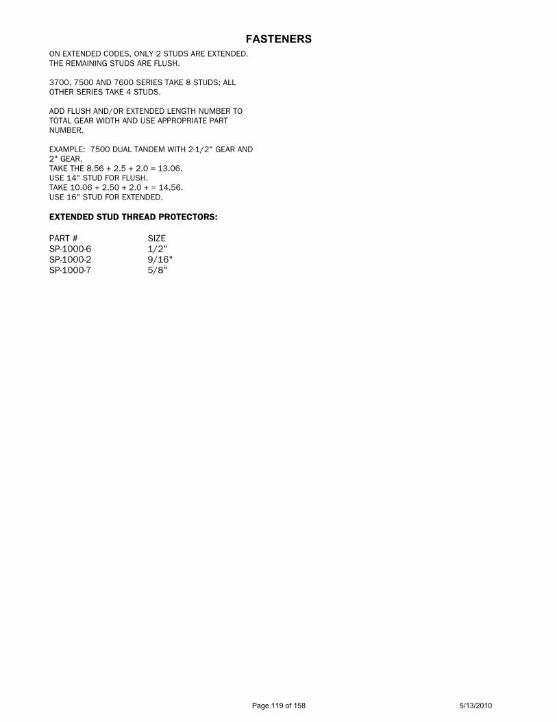
FASTENERS ON EXTENDED CODES, ONLY 2 STUDS ARE EXTENDED. THE REMAINING STUDS ARE FLUSH. 3700, 7500 AND 7600 SERIES TAKE 8 STUDS; ALL OTHER SERIES TAKE 4 STUDS. ADD FLUSH AND/OR EXTENDED LENGTH NUMBER TO TOTAL GEAR WIDTH AND USE APPROPRIATE PART NUMBER. EXAMPLE: 7500 DUAL TANDEM WITH 2-1/2" GEAR AND 2" GEAR. TAKE THE 8.56 + 2.5 + 2.0 = 13.06. USE 14" STUD FOR FLUSH. TAKE 10.06 + 2.50 + 2.0 + = 14.56. USE 16" STUD FOR EXTENDED. EXTENDED STUD THREAD PROTECTORS: PART # SIZE SP-1000-6 1/2" SP-1000-2 9/16" SP-1000-7 5/8"
Page 119 of 158 5/13/2010
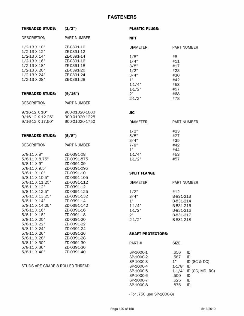
FASTENERS
THREADED STUDS: (1/2") DESCRIPTION PART NUMBER 1/2-13 X 10" ZE-0391-10 1/2-13 X 12" ZE-0391-12 1/2-13 X 14" ZE-0391-14 1/2-13 X 16" ZE-0391-16 1/2-13 X 18" ZE-0391-18 1/2-13 X 20" ZE-0391-20 1/2-13 X 24" ZE-0391-24 1/2-13 X 28" ZE-0391-28 THREADED STUDS: (9/16") DESCRIPTION PART NUMBER 9/16-12 X 10" 900-01020-1000 9/16-12 X 12.25" 900-01020-1225 9/16-12 X 17.50" 900-01020-1750 THREADED STUDS: (5/8") DESCRIPTION PART NUMBER 5/8-11 X 8" ZD-0391-08 5/8-11 X 8.75" ZD-0391-875 5/8-11 X 9" ZD-0391-09 5/8-11 X 9.5" ZD-0391-095 5/8-11 X 10" ZD-0391-10 5/8-11 X 10.5" ZD-0391-105 5/8-11 X 11.25" ZD-0391-112 5/8-11 X 12" ZD-0391-12 5/8-11 X 12.5" ZD-0391-125 5/8-11 X 13.25" ZD-0391-132 5/8-11 X 14" ZD-0391-14 5/8-11 X 14.25" ZD-0391-142 5/8-11 X 16" ZD-0391-16 5/8-11 X 18" ZD-0391-18 5/8-11 X 20" ZD-0391-20 5/8-11 X 22" ZD-0391-22 5/8-11 X 24" ZD-0391-24 5/8-11 X 26" ZD-0391-26 5/8-11 X 28" ZD-0391-28 5/8-11 X 30" ZD-0391-30 5/8-11 X 36" ZD-0391-36 5/8-11 X 40" ZD-0391-40 STUDS ARE GRADE 8 ROLLED THREAD
PLASTIC PLUGS: NPT DIAMETER PART NUMBER 1/8" #8 1/4" #11 3/8" #17 1/2" #23 3/4" #30 1" #42 1-1/4" #53 1-1/2" #57 2" #68 2-1/2" #78 JIC DIAMETER PART NUMBER 1/2" #23 5/8" #27 3/4" #35 7/8" #42 1" #44 1-1/4" #53 1-1/2" #57 SPLIT FLANGE DIAMETER PART NUMBER 1/2" #12 3/4" B-831-213 1" B-831-214 1-1/4" B-831-215 1-1/2" B-831-216 2" B-831-217 2-1/2" B-831-218 SHAFT PROTECTORS: PART # SIZE SP-1000-1 .656 ID SP-1000-2 .587 ID SP-1000-3 1" ID (SC & DC) SP-1000-4 1-1/8" ID SP-1000-5 1-1/4" ID (OC, MD, RC) SP-1000-6 .500 ID SP-1000-7 .625 ID SP-1000-8 .875 ID (For .750 use SP-1000-8)
Page 120 of 158 5/13/2010
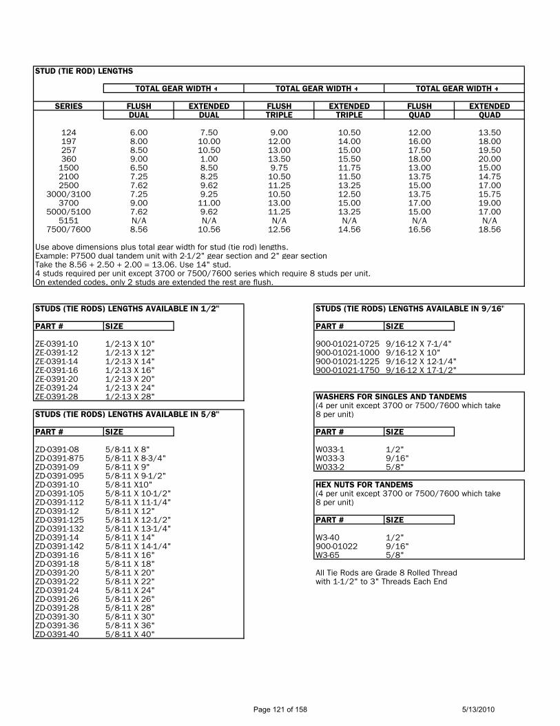
STUD (TIE ROD) LENGTHS
TOTAL GEAR WIDTH + TOTAL GEAR WIDTH + TOTAL GEAR WIDTH +
SERIES FLUSH EXTENDED FLUSH EXTENDED FLUSH EXTENDEDDUAL DUAL TRIPLE TRIPLE QUAD QUAD
124 6.00 7.50 9.00 10.50 12.00 13.50197 8.00 10.00 12.00 14.00 16.00 18.00257 8.50 10.50 13.00 15.00 17.50 19.50360 9.00 1.00 13.50 15.50 18.00 20.00
1500 6.50 8.50 9.75 11.75 13.00 15.002100 7.25 8.25 10.50 11.50 13.75 14.752500 7.62 9.62 11.25 13.25 15.00 17.00
3000/3100 7.25 9.25 10.50 12.50 13.75 15.753700 9.00 11.00 13.00 15.00 17.00 19.00
5000/5100 7.62 9.62 11.25 13.25 15.00 17.005151 N/A N/A N/A N/A N/A N/A
7500/7600 8.56 10.56 12.56 14.56 16.56 18.56
Use above dimensions plus total gear width for stud (tie rod) lengths.Example: P7500 dual tandem unit with 2-1/2" gear section and 2" gear sectionTake the 8.56 + 2.50 + 2.00 = 13.06. Use 14" stud.4 studs required per unit except 3700 or 7500/7600 series which require 8 studs per unit.On extended codes, only 2 studs are extended the rest are flush.
STUDS (TIE RODS) LENGTHS AVAILABLE IN 1/2" STUDS (TIE RODS) LENGTHS AVAILABLE IN 9/16"
PART # SIZE PART # SIZE
ZE-0391-10 1/2-13 X 10" 900-01021-0725 9/16-12 X 7-1/4"ZE-0391-12 1/2-13 X 12" 900-01021-1000 9/16-12 X 10"ZE-0391-14 1/2-13 X 14" 900-01021-1225 9/16-12 X 12-1/4"ZE-0391-16 1/2-13 X 16" 900-01021-1750 9/16-12 X 17-1/2"ZE-0391-20 1/2-13 X 20"ZE-0391-24 1/2-13 X 24"ZE-0391-28 1/2-13 X 28" WASHERS FOR SINGLES AND TANDEMS
(4 per unit except 3700 or 7500/7600 which takeSTUDS (TIE RODS) LENGTHS AVAILABLE IN 5/8" 8 per unit)
PART # SIZE PART # SIZE
ZD-0391-08 5/8-11 X 8" W033-1 1/2"ZD-0391-875 5/8-11 X 8-3/4" W033-3 9/16"ZD-0391-09 5/8-11 X 9" W033-2 5/8"ZD-0391-095 5/8-11 X 9-1/2"ZD-0391-10 5/8-11 X10" HEX NUTS FOR TANDEMSZD-0391-105 5/8-11 X 10-1/2" (4 per unit except 3700 or 7500/7600 which takeZD-0391-112 5/8-11 X 11-1/4" 8 per unit)ZD-0391-12 5/8-11 X 12"ZD-0391-125 5/8-11 X 12-1/2" PART # SIZEZD-0391-132 5/8-11 X 13-1/4"ZD-0391-14 5/8-11 X 14" W3-40 1/2"ZD-0391-142 5/8-11 X 14-1/4" 900-01022 9/16"ZD-0391-16 5/8-11 X 16" W3-65 5/8"ZD-0391-18 5/8-11 X 18"ZD-0391-20 5/8-11 X 20" All Tie Rods are Grade 8 Rolled ThreadZD-0391-22 5/8-11 X 22" with 1-1/2" to 3" Threads Each EndZD-0391-24 5/8-11 X 24"ZD-0391-26 5/8-11 X 26"ZD-0391-28 5/8-11 X 28"ZD-0391-30 5/8-11 X 30"ZD-0391-36 5/8-11 X 36"ZD-0391-40 5/8-11 X 40"
Page 121 of 158 5/13/2010
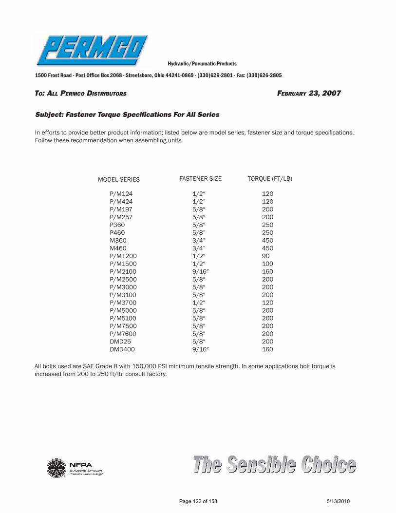
TO: ALL PERMCO DISTRIBUTORS FEBRUARY 23, 2007
Hydraulic/Pneumatic Products
1500 Frost Road - Post Of! ce Box 2068 - Streetsboro, Ohio 44241-0869 - (330)626-2801 - Fax: (330)626-2805
Subject: Fastener Torque Specifi cations For All Series
In efforts to provide better product information; listed below are model series, fastener size and torque speci! cations. Follow these recommendation when assembling units.
All bolts used are SAE Grade 8 with 150,000 PSI minimum tensile strength. In some applications bolt torque is increased from 200 to 250 ft/lb; consult factory.
MODEL SERIES FASTENER SIZE TORQUE (FT/LB)
P/M124 P/M424P/M197P/M257P360P460M360M460 P/M1200P/M1500P/M2100P/M2500P/M3000P/M3100P/M3700P/M5000P/M5100P/M7500P/M7600DMD25DMD400
1/2" 1/2”5/8"5/8"5/8" 5/8”3/4”3/4”1/2"1/2"9/16"5/8"5/8"5/8"1/2"5/8"5/8"5/8"5/8"5/8"9/16"
120 120200200250 25045045090100160200200200120200200200200200160
Page 122 of 158 5/13/2010

RECOMMENDED SPEED AND FEEDS FOR PORTING
37/64" Diameter up to 1-1/2" Diameter Drill
215 RPM = .012 Feed
1-1/2" Diameter Drill
165 RPM = .012 Feed
1-47/64" Diameter up to 2" Diameter Drill 130 RPM = .008 Feed
2-1/2" Diameter Drill 100 RPM = .008 Feed
Run Split Flange Tap Drills at 750 RPM
Tap all Split Flange Holes at 250 RPM
Tap all JIC at 105 RPM
Tap 1/2" through 3/4" NPT at 135 RPM
Tap 1" through 1-1/4" NPT at 105 RPM
Tap 1-1/2" NPT at 80 RPM
Page 123 of 158 5/13/2010

DOWELING INSTRUCTIONS
3100 / 5100 / 7500 SERIES
1. Regardless of the type of machine being used, Bridgeport mill type, or drill press, the head must be square to the table. Turn the head using a dial indicator. This must be better than .005” TIR over a 12” diameter.
2. Be sure machine table and part are free from nicks or burrs that may cause raised areas.
(Use deburring block)
3. Place doweling fixture pilot into bores of housing. Be sure fixture is seated flat against the face of the housing.
4. Using a drill that is the nominal (see chart below) size of the dowel pin, spot drill to a
depth of the full drill point only. (This produces a centered cone shaped hole and minimizes wandering of the drill in the next step).
5. With a drill that is 1/64” smaller (see chart below) drill to depth that is 1/16” deeper
than the finish reamed depth.
6. Using the proper size reamer, finish to depth.
SERIES FIXTURES SPOT DRILL PRE-DRILL REAMER FINISHED SIZE SIZE SIZE REAMED DEPTH
3100 T-1009 3/8" 23/64" .375 .625 5100 T-1010 3/8" 23/64" .375 .625 7600 T-1011 5/8" 39/64" .625 1.000
Page 124 of 158 5/13/2010
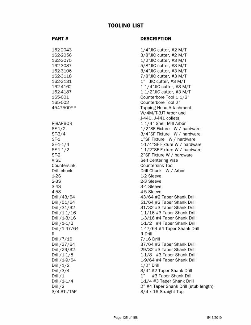
TOOLING LIST
PART # DESCRIPTION 162-2043 1/4”JIC cutter, #2 M/T 162-2056 3/8”JIC cutter, #2 M/T 162-3075 1/2”JIC cutter, #3 M/T 162-3087 5/8”JIC cutter, #3 M/T 162-3106 3/4”JIC cutter, #3 M/T 162-3118 7/8”JIC cutter, #3 M/T 162-3131 1” JIC cutter, #3 M/T 162-4162 1 1/4”JIC cutter, #3 M/T 162-4187 1 1/2”JIC cutter, #3 M/T 165-001 Counterbore Tool 1 1/2” 165-002 Counterbore Tool 2” 4547500** Tapping Head Attachment W/4M/T-3JT Arbor and J-440, J-441 collets R-8ARBOR 1 1/4” Shell Mill Arbor SF-1/2 1/2”SF Fixture W / hardware SF-3/4 3/4”SF Fixture W / hardware SF-1 1”SF Fixture W / hardware SF-1-1/4 1-1/4”SF Fixture W / hardware SF-1-1/2 1-1/2”SF Fixture W / hardware SF-2 2”SF Fixture W / hardware VISE Self Centering Vise Countersink Countersink Tool Drill chuck Drill Chuck W / Arbor 1-2S 1-2 Sleeve 2-3S 2-3 Sleeve 3-4S 3-4 Sleeve 4-5S 4-5 Sleeve Drill/43/64 43/64 #2 Taper Shank Drill Drill/51/64 51/64 #2 Taper Shank Drill Drill/31/32 31/32 #3 Taper Shank Drill Drill/1-1/16 1-1/16 #3 Taper Shank Drill Drill/1-3/16 1-3/16 #4 Taper Shank Drill Drill/1-1/2 1-1/2 #4 Taper Shank Drill Drill/1-47/64 1-47/64 #4 Taper Shank Drill R R Drill Drill/7/16 7/16 Drill Drill/37/64 37/64 #2 Taper Shank Drill Drill/29/32 29/32 #3 Taper Shank Drill Drill/1-1/8 1-1/8 #3 Taper Shank Drill Drill/1-9/64 1-9/64 #4 Taper Shank Drill Drill/1/2 1/2” Drill Drill/3/4 3/4” #2 Taper Shank Drill Drill/1 1” #3 Taper Shank Drill Drill/1-1/4 1-1/4 #3 Taper Shank Drill Drill/2 2” #4 Taper Shank Drill (stub length) 3/4-ST./TAP 3/4 x 16 Straight Tap
Page 125 of 158 5/13/2010

TOOLING LIST
74420 3/4 St. Tap Holder W / #4 MT 7/8-ST./TAP 7/8 x 14 Straight Tap 01155 7/8 St. Tap Holder W/ #3 MT 1-1/16-ST./TAP 1-1/16 x 12 Straight Tap 04106 1-1/16 Tap Holder W/ #3 MT 1-3/16-ST./TAP 1-3/16 x 12 Straight Tap 04108 1-3/16 Tap Holder W/ #3 MT 1-5/16-ST./TAP 1-5/16 x 12 Straight Tap 04110 1-5/16 Tap Holder W/ #3 MT 1-5/8-ST./TAP 1-5/8 x 12 Straight Tap 04114 1-5/8 Tap Holder W/ #4 MT 1-7/8-ST./TAP 1-7/8 x 12 Straight Tap 04118 1-7/8 Tap Holder W/ #4 MT 1/8-TAP 1/8 x 27 Pipe Tap 1/4-TAP 1/4 x 18 Pipe Tap 01197 1/4 NPT Tap Holder W/ #3 MT 3/8-TAP 3/8 x 18 Pipe Tap 01201 3/8 NPT Tap Holder W/ #4 MT 1/2-TAP 1/2 x 14 Pipe Tap 74451 1/2 NPT Tap Holder W/ #4 MT 3/4-TAP 3/4 x 14 Pipe Tap 01208 3/4 NPT Tap Holder W/ #4 MT 1-TAP 1 x 11-1/2 Pipe Tap 04141 1 NPT Tap Holder W/ #4 MT 1-1/4-TAP 1-1/4 x 11-1/2 Pipe Tap 70443 1-1/4 NPT Tap Holder W/ #4 MT 1-1/2-TAP 1-1/2 x 11-1/2 Pipe Tap 04144 1-1/2 NPT Tap Holder W/ #4 MT 5/16-ST./TAP 5/16 x 18 Straight Tap 3/8-ST./TAP 3/8 x 16 Straight Tap 7/16-ST./TAP 7/16 x 14 Straight Tap 1/2-ST./TAP 1/2 x 13 Straight Tap F-DRILL F Drill 5/16-DRILL 5/16 Drill U-DRILL U Drill 27/64-DRILL 27/64 Drill T-1009 3100 Dowelling Jig T-1010 5100 Dowelling Jig T-1011 7600 Dowelling Jig T-1164 197 Bushing Removal Kit T-1188 197 Bushing Insertion Kit T-1175 257 Bushing Insertion Kit T-1180 257 Bushing Removal Kit ** The items marked with ** need to advise what arbor is required.
*** The quantity is only one for any of these items on this tooling list.
Page 126 of 158 5/13/2010

197 OUTBOARD BEARING LOAD RATINGS
SIDE LOAD (WITH OUTBOARD BEARING) 800 LBS. OR 3500 NEWTONS
(CODE) DRIVE TYPE PL FACTOR
14 "B" SPLINE 8000 (INTEGRAL)
32 "BB" KEYED 8000 (INTEGRAL)
87 "BB" SPLINED 10,000 (INTEGRAL) 1 CONNECTING 6,000 C CONTINENTAL 6000 EXCEPT CODES (04, 21, 24, 32, 84 CM1 & SPL) – CONSULT FACTORY
197 1/2" THRU 3/4" GEAR WIDTH = CONSULT FACTORY 1" THRU 1-1/4" GEAR WIDTH = 4000 PSI
1-1/2" GEAR WIDTH = 3750 PSI 1-3/4" GEAR WIDTH = 3500 PSI 2" GEAR WIDTH = 3250 PSI
1 BAR = 14.5 PSI
1 CU. IN. = 16.38 CU. CM
1 LB = 4.448 N
1 GPM = 231 CU. IN.
1 FT*LB = 1.356 N*M 1 FT*LB = 12 IN*LB
TORQUE = (PSI X DISPLACEMENT)
6.28
HP = (GPM X PSI) 1714
HP = (TORQUE X RPM) TORQUE = IN*LB 63025
Page 127 of 158 5/13/2010
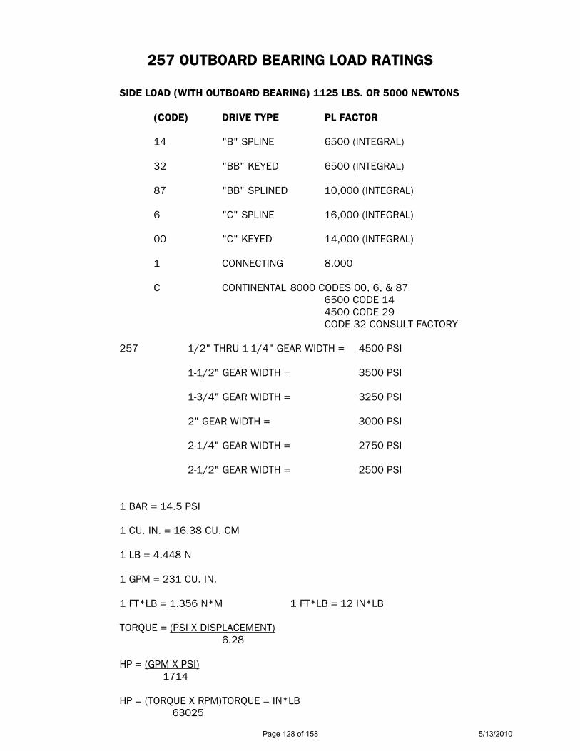
257 OUTBOARD BEARING LOAD RATINGS
SIDE LOAD (WITH OUTBOARD BEARING) 1125 LBS. OR 5000 NEWTONS (CODE) DRIVE TYPE PL FACTOR
14 "B" SPLINE 6500 (INTEGRAL)
32 "BB" KEYED 6500 (INTEGRAL)
87 "BB" SPLINED 10,000 (INTEGRAL) 6 "C" SPLINE 16,000 (INTEGRAL) 00 "C" KEYED 14,000 (INTEGRAL) 1 CONNECTING 8,000 C CONTINENTAL 8000 CODES 00, 6, & 87 6500 CODE 14 4500 CODE 29 CODE 32 CONSULT FACTORY
257 1/2" THRU 1-1/4" GEAR WIDTH = 4500 PSI 1-1/2" GEAR WIDTH = 3500 PSI
1-3/4" GEAR WIDTH = 3250 PSI 2" GEAR WIDTH = 3000 PSI 2-1/4" GEAR WIDTH = 2750 PSI 2-1/2" GEAR WIDTH = 2500 PSI
1 BAR = 14.5 PSI
1 CU. IN. = 16.38 CU. CM
1 LB = 4.448 N
1 GPM = 231 CU. IN.
1 FT*LB = 1.356 N*M 1 FT*LB = 12 IN*LB
TORQUE = (PSI X DISPLACEMENT)
6.28
HP = (GPM X PSI) 1714
HP = (TORQUE X RPM) TORQUE = IN*LB 63025
Page 128 of 158 5/13/2010
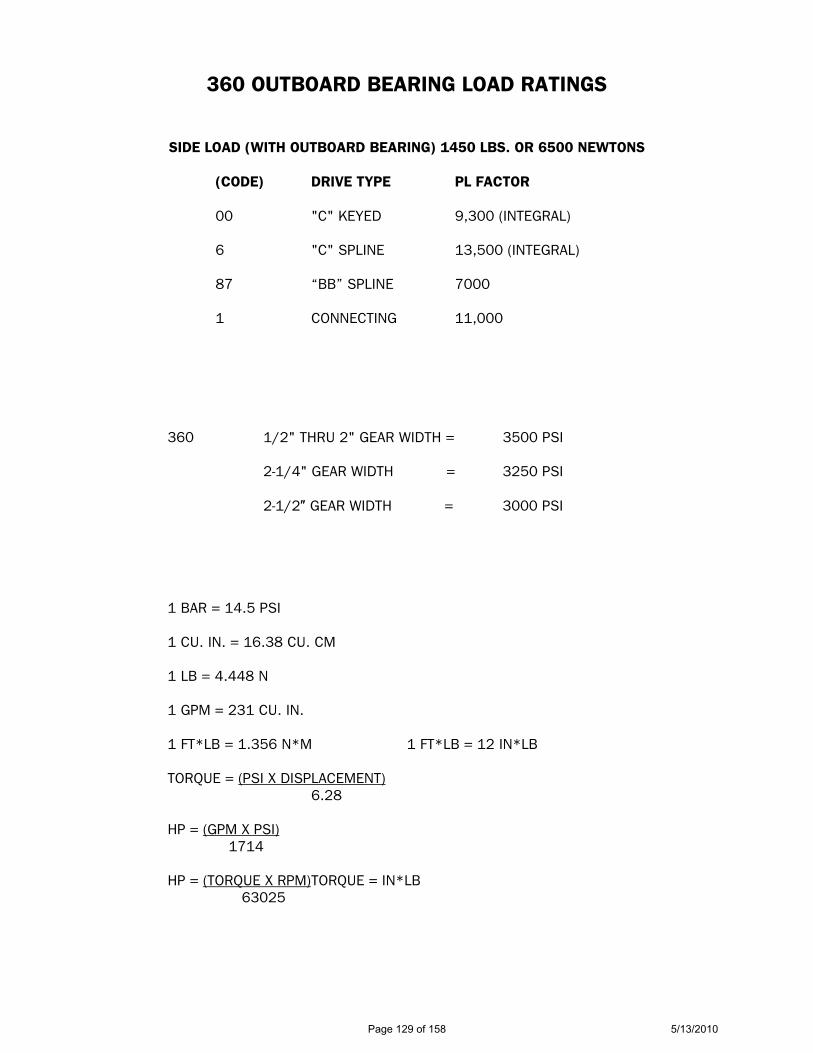
360 OUTBOARD BEARING LOAD RATINGS
SIDE LOAD (WITH OUTBOARD BEARING) 1450 LBS. OR 6500 NEWTONS
(CODE) DRIVE TYPE PL FACTOR 00 "C" KEYED 9,300 (INTEGRAL) 6 "C" SPLINE 13,500 (INTEGRAL) 87 “BB” SPLINE 7000 1 CONNECTING 11,000
360 1/2" THRU 2" GEAR WIDTH = 3500 PSI
2-1/4" GEAR WIDTH = 3250 PSI
2-1/2! GEAR WIDTH = 3000 PSI
1 BAR = 14.5 PSI
1 CU. IN. = 16.38 CU. CM
1 LB = 4.448 N
1 GPM = 231 CU. IN.
1 FT*LB = 1.356 N*M 1 FT*LB = 12 IN*LB
TORQUE = (PSI X DISPLACEMENT)
6.28
HP = (GPM X PSI) 1714
HP = (TORQUE X RPM) TORQUE = IN*LB 63025
Page 129 of 158 5/13/2010
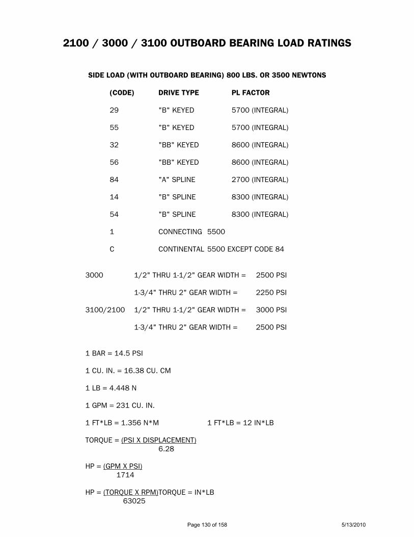
2100 / 3000 / 3100 OUTBOARD BEARING LOAD RATINGS
SIDE LOAD (WITH OUTBOARD BEARING) 800 LBS. OR 3500 NEWTONS
(CODE) DRIVE TYPE PL FACTOR 29 "B" KEYED 5700 (INTEGRAL) 55 "B" KEYED 5700 (INTEGRAL) 32 "BB" KEYED 8600 (INTEGRAL) 56 "BB" KEYED 8600 (INTEGRAL) 84 "A" SPLINE 2700 (INTEGRAL) 14 "B" SPLINE 8300 (INTEGRAL) 54 "B" SPLINE 8300 (INTEGRAL) 1 CONNECTING 5500 C CONTINENTAL 5500 EXCEPT CODE 84
3000 1/2" THRU 1-1/2" GEAR WIDTH = 2500 PSI 1-3/4" THRU 2" GEAR WIDTH = 2250 PSI
3100/2100 1/2" THRU 1-1/2" GEAR WIDTH = 3000 PSI 1-3/4" THRU 2" GEAR WIDTH = 2500 PSI
1 BAR = 14.5 PSI
1 CU. IN. = 16.38 CU. CM
1 LB = 4.448 N
1 GPM = 231 CU. IN.
1 FT*LB = 1.356 N*M 1 FT*LB = 12 IN*LB
TORQUE = (PSI X DISPLACEMENT)
6.28
HP = (GPM X PSI) 1714
HP = (TORQUE X RPM) TORQUE = IN*LB 63025
Page 130 of 158 5/13/2010
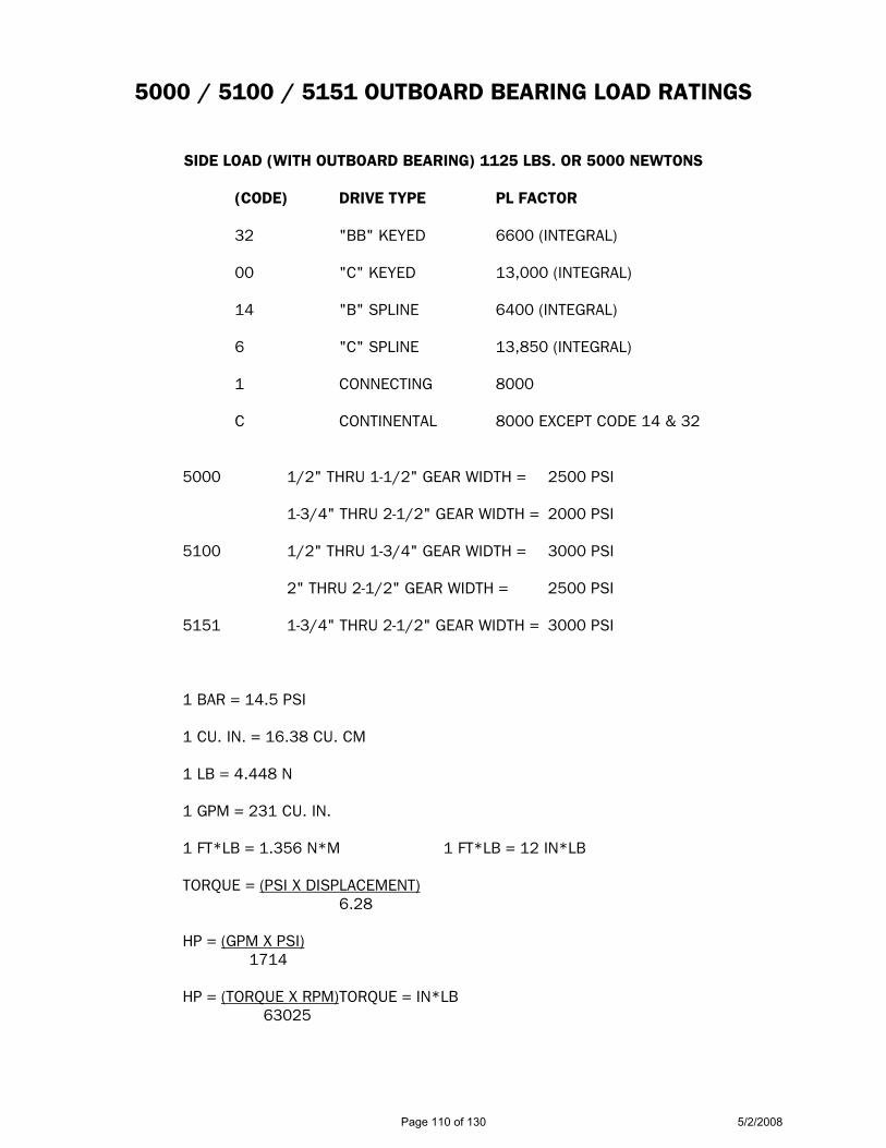
5000 / 5100 / 5151 OUTBOARD BEARING LOAD RATINGS
SIDE LOAD (WITH OUTBOARD BEARING) 1125 LBS. OR 5000 NEWTONS
(CODE) DRIVE TYPE PL FACTOR 32 "BB" KEYED 6600 (INTEGRAL) 00 "C" KEYED 13,000 (INTEGRAL) 14 "B" SPLINE 6400 (INTEGRAL) 6 "C" SPLINE 13,850 (INTEGRAL) 1 CONNECTING 8000 C CONTINENTAL 8000 EXCEPT CODE 14 & 32
5000 1/2" THRU 1-1/2" GEAR WIDTH = 2500 PSI 1-3/4" THRU 2-1/2" GEAR WIDTH = 2000 PSI
5100 1/2" THRU 1-3/4" GEAR WIDTH = 3000 PSI 2" THRU 2-1/2" GEAR WIDTH = 2500 PSI 5151 1-3/4" THRU 2-1/2" GEAR WIDTH = 3000 PSI
1 BAR = 14.5 PSI
1 CU. IN. = 16.38 CU. CM
1 LB = 4.448 N
1 GPM = 231 CU. IN.
1 FT*LB = 1.356 N*M 1 FT*LB = 12 IN*LB
TORQUE = (PSI X DISPLACEMENT)
6.28
HP = (GPM X PSI) 1714
HP = (TORQUE X RPM) TORQUE = IN*LB 63025
Page 110 of 130 5/2/2008

7500 / 7600 OUTBOARD BEARING LOAD RATINGS
SIDE LOAD (WITH OUTBOARD BEARING) 1450 LBS. OR 6500 NEWTONS
(CODE) DRIVE TYPE PL FACTOR 00 "C" KEYED 8,300 (INTEGRAL) 6 "C" SPLINE 12,000 (INTEGRAL) 1 CONNECTING 9450 C CONTINENTAL 7750
7500 1/2" THRU 2" GEAR WIDTH = 2500 PSI 2-1/4" THRU 2-1/2" GEAR WIDTH = 2250 PSI
2-3/4" THRU 3" GEAR WIDTH = 2000 PSI 7600 1/2" THRU 1-3/4" GEAR WIDTH = 3000 PSI 2" THRU 2-1/2" GEAR WIDTH = 2500 PSI 2-3/4" THRU 3" GEAR WIDTH = 2000 PSI
1 BAR = 14.5 PSI
1 CU. IN. = 16.38 CU. CM
1 LB = 4.448 N
1 GPM = 231 CU. IN.
1 FT*LB = 1.356 N*M 1 FT*LB = 12 IN*LB
TORQUE = (PSI X DISPLACEMENT)
6.28
HP = (GPM X PSI) 1714
HP = (TORQUE X RPM) TORQUE = IN*LB 63025
Page 111 of 130 5/2/2008
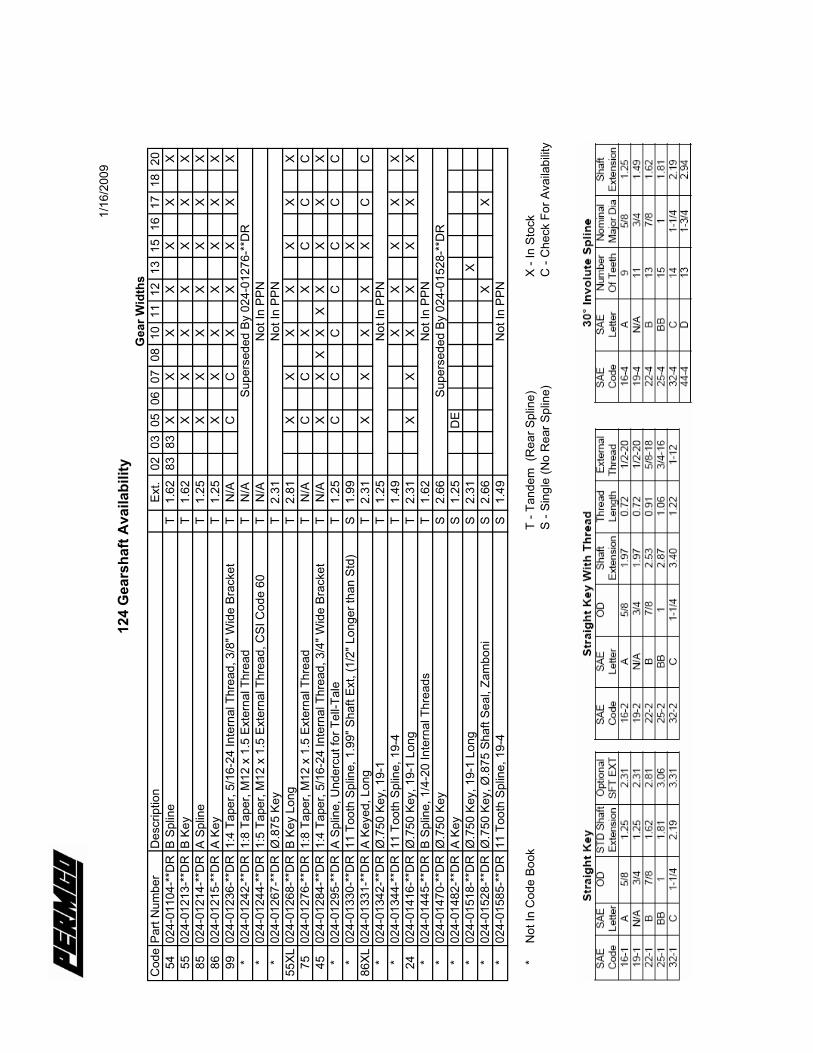
1/16
/200
912
4 G
ears
haft
Avai
labi
lity
Gea
r Wid
ths
Cod
ePa
rt N
umbe
rD
escr
iptio
nEx
t.02
0305
0607
0810
1112
1315
1617
1820
5402
4-01
104-
**D
RB
Splin
eT
1.62
8383
XX
XX
XX
X55
024-
0121
3-**
DR
B Ke
yT
1.62
XX
XX
XX
X85
024-
0121
4-**
DR
A Sp
line
T1.
25X
XX
XX
XX
8602
4-01
215-
**D
RA
Key
T1.
25X
XX
XX
XX
9902
4-01
236-
**D
R1:
4 Ta
per,
5/16
-24
Inte
rnal
Thr
ead,
3/8
" Wid
e Br
acke
tT
N/A
CC
XX
XX
X*
024-
0124
2-**
DR
1:8
Tape
r, M
12 x
1.5
Ext
erna
l Thr
ead
TN
/ASu
pers
eded
By
024-
0127
6-**
DR
*02
4-01
244-
**D
R1:
5 Ta
per,
M12
x 1
.5 E
xter
nal T
hrea
d, C
SI C
ode
60T
N/A
Not
In P
PN*
024-
0126
7-**
DR
Ø.8
75 K
eyT
2.31
Not
In P
PN55
XL02
4-01
268-
**D
RB
Key
Long
T2.
81X
XX
XX
XX
7502
4-01
276-
**D
R1:
8 Ta
per,
M12
x 1
.5 E
xter
nal T
hrea
dT
N/A
CC
XX
CC
C45
024-
0128
4-**
DR
1:4
Tape
r, 5/
16-2
4 In
tern
al T
hrea
d, 3
/4" W
ide
Brac
ket
TN
/AX
XX
XX
XX
XX
*02
4-01
295-
**D
RA
Splin
e, U
nder
cut f
or T
ell-T
ale
T1.
25C
CC
CC
CC
*02
4-01
330-
**D
R11
Too
th S
plin
e, 1
.99"
Sha
ft Ex
t, (1
/2" L
onge
r tha
n St
d)S
1.99
X86
XL02
4-01
331-
**D
RA
Keye
d, L
ong
T2.
31X
XX
XX
CC
*02
4-01
342-
**D
RØ
.750
Key
, 19-
1T
1.25
Not
In P
PN*
024-
0134
4-**
DR
11 T
ooth
Spl
ine,
19-
4T
1.49
XX
XX
X24
024-
0141
6-**
DR
Ø.7
50 K
ey, 1
9-1
Long
T2.
31X
XX
XX
XX
*02
4-01
445-
**D
RB
Splin
e, 1
/4-2
0 In
tern
al T
hrea
dsT
1.62
Not
In P
PN*
024-
0147
0-**
DR
Ø.7
50 K
eyS
2.66
Supe
rsed
ed B
y 02
4-01
528-
**D
R*
024-
0148
2-**
DR
A Ke
yS
1.25
DE
*02
4-01
518-
**D
RØ
.750
Key
, 19-
1 Lo
ngS
2.31
X*
024-
0152
8-**
DR
Ø.7
50 K
ey, Ø
.875
Sha
ft Se
al, Z
ambo
niS
2.66
XX
*02
4-01
585-
**D
R11
Too
th S
plin
e, 1
9-4
S1.
49N
ot In
PPN
*N
ot In
Cod
e Bo
okT
- Tan
dem
(R
ear S
plin
e)X
- In
Stoc
kS
- Sin
gle
(No
Rea
r Spl
ine)
C -
Che
ck F
or A
vaila
bilit
y
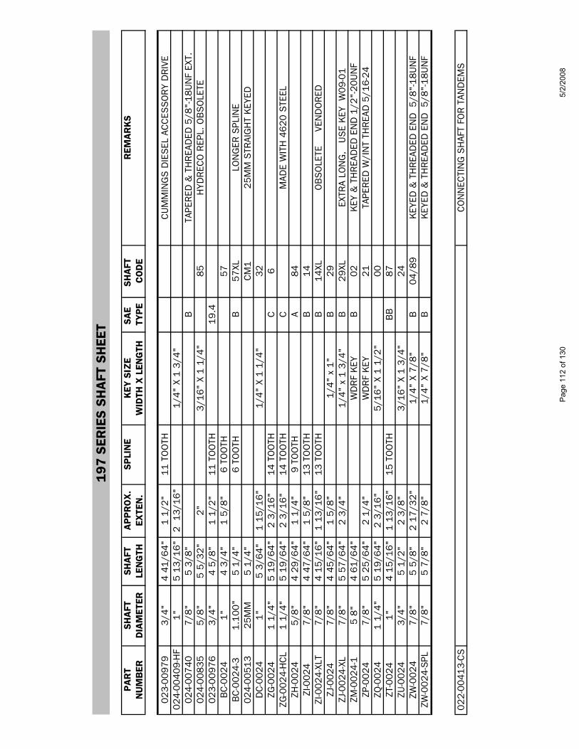
197
SER
IES
SHA
FT S
HEE
T
PAR
TSH
AFT
SHA
FTA
PPR
OX
.SP
LIN
EK
EY S
IZE
SAE
SHA
FT
REM
AR
KS
NU
MB
ERD
IAM
ETER
LEN
GTH
EXTE
N.
WID
TH X
LEN
GTH
TYPE
CO
DE
023-
0097
93/
4"4
41/6
4"1
1/2"
11 T
OO
THC
UM
MIN
GS
DIE
SEL
AC
CES
SO
RY
DR
IVE
024-
0040
9-H
F1"
5 13
/16"
2 1
3/16
"1/
4" X
1 3
/4"
024-
0074
07/
8"5
3/8"
BTA
PER
ED &
TH
REA
DED
5/8
"-18
UN
F EX
T.02
4-00
835
5/8"
5 5/
32"
2"3/
16"
X 1
1/4"
85H
YDR
ECO
REP
L. O
BS
OLE
TE02
3-00
976
3/4"
4 5/
8"1
1/2"
11 T
OO
TH19
.4
BC
-002
41"
4 3/
4"1
5/8"
6 TO
OTH
57B
C-0
024-
31.
100"
5 1/
4"6
TOO
THB
57XL
LON
GER
SPL
INE
024-
0051
325
MM
5 1/
4"
C
M1
25M
M S
TRAI
GH
T K
EYED
DC
-002
41"
5 3/
64"
1 15
/16"
1/4"
X 1
1/4
"32
ZG-0
024
1 1/
4"5
19/6
4"2
3/16
"14
TO
OTH
C6
ZG-0
024-
HC
L1
1/4"
5 19
/64"
2 3/
16"
14 T
OO
THC
MAD
E W
ITH
462
0 S
TEEL
ZH-0
024
5/8"
4 29
/64"
1 1/
4"9
TOO
THA
84ZI
-002
47/
8"4
47/6
4"1
5/8"
13 T
OO
THB
14ZI
-002
4-XL
T7/
8"4
15/1
6"1
13/1
6"13
TO
OTH
B14
XLO
BS
OLE
TE
VEN
DO
RED
ZJ-0
024
7/8"
4 45
/64"
1 5/
8"1/
4" x
1"
B29
ZJ-0
024-
XL7/
8"5
57/6
4"2
3/4"
1/4"
x 1
3/4
"B
29XL
EXTR
A LO
NG
, U
SE
KEY
W09
-01
ZM-0
024-
15
8"4
61/6
4"W
DR
F K
EYB
02K
EY &
TH
REA
DED
EN
D 1
/2"-
20U
NF
ZP-0
024
7/8"
5 25
/64"
2 1/
4"W
DR
F K
EY21
TAPE
RED
W/I
NT
THR
EAD
5/1
6-24
ZQ-0
024
1 1/
4"5
19/6
4"2
3/16
"5/
16"
X 1
1/2"
00ZT
-002
41"
4 15
/16"
1 13
/16"
15 T
OO
THB
B87
ZU-0
024
3/4"
5 1/
2"2
3/8"
3/16
" X
1 3/
4"24
ZW-0
024
7/8"
5 5/
8"2
17/3
2"1/
4" X
7/8
"B
04/8
9K
EYED
& T
HR
EAD
ED E
ND
5/8
"-18
UN
FZW
-002
4-S
PL7/
8"5
7/8"
2 7/
8"1/
4" X
7/8
"B
KEY
ED &
TH
REA
DED
EN
D 5
/8"-
18U
NF
022-
0041
3-C
SC
ON
NEC
TIN
G S
HAF
T FO
R T
AND
EMS
Page
112
of 1
305/
2/20
08

25
7 SE
RIES
SHA
FT S
HEET
PAR
TSH
AFT
SHA
FTA
PPR
OX
.SP
LIN
EK
EY S
IZE
SAE
SHA
FT
REM
AR
KS
NU
MB
ERD
IAM
ETER
LEN
GTH
EXTE
N.
WID
TH X
LEN
GTH
TYPE
CO
DE
024-
0085
17/
8"4
1/2
1 5/
8"13
TO
OTH
B14
024-
0085
01"
4 13
/16
1 15
/16"
1/4"
X 1
1/4
"32
024-
0084
81
1/4"
5 1/
162
3/16
"5/
16"
X 1
1/2"
C00
024-
0084
91
1/4"
5 1/
162
3/16
"14
TO
OTH
C6
024-
0092
31"
4 11
/16
1 15
/16"
15 T
OO
THB
B87
212-
0999
-001
1.1"
6 TO
OTH
2S
PEC
IAL
FOR
MIN
ING
IND
US
TRY
212-
0499
-502
1 1/
4"3
1/8"
5/16
" X
2 1/
4"62
SPE
CIA
L FO
R M
ININ
G IN
DU
STR
Y
022-
0083
7C
ON
NEC
TIN
G S
HAF
T FO
R T
AND
EMS
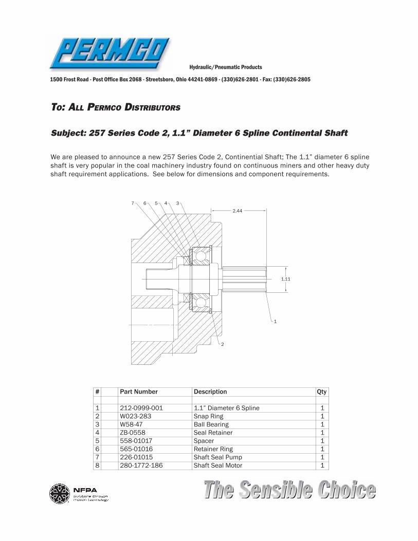
TO: ALL PERMCO DISTRIBUTORS
Hydraulic/Pneumatic Products
1500 Frost Road - Post Of! ce Box 2068 - Streetsboro, Ohio 44241-0869 - (330)626-2801 - Fax: (330)626-2805
Subject: 257 Series Code 2, 1.1” Diameter 6 Spline Continental Shaft
We are pleased to announce a new 257 Series Code 2, Continential Shaft; The 1.1” diameter 6 spline shaft is very popular in the coal machinery industry found on continuous miners and other heavy duty shaft requirement applications. See below for dimensions and component requirements.
# Part Number Description Qty
1 212-0999-001 1.1” Diameter 6 Spline 12 W023-283 Snap Ring 13 W58-47 Ball Bearing 14 ZB-0558 Seal Retainer 15 558-01017 Spacer 16 565-01016 Retainer Ring 17 226-01015 Shaft Seal Pump 18 280-1772-186 Shaft Seal Motor 1
1.11
2.44
1
2
34567
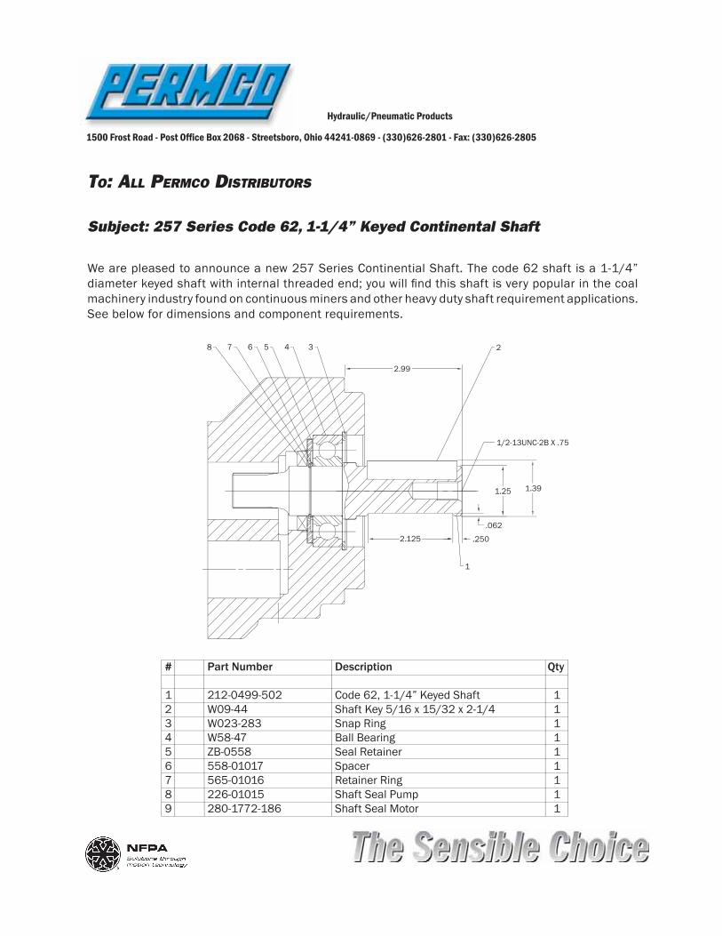
TO: ALL PERMCO DISTRIBUTORS
Hydraulic/Pneumatic Products
1500 Frost Road - Post Of! ce Box 2068 - Streetsboro, Ohio 44241-0869 - (330)626-2801 - Fax: (330)626-2805
Subject: 257 Series Code 62, 1-1/4” Keyed Continental Shaft
We are pleased to announce a new 257 Series Continential Shaft. The code 62 shaft is a 1-1/4” diameter keyed shaft with internal threaded end; you will ! nd this shaft is very popular in the coal machinery industry found on continuous miners and other heavy duty shaft requirement applications. See below for dimensions and component requirements.
# Part Number Description Qty
1 212-0499-502 Code 62, 1-1/4” Keyed Shaft 12 W09-44 Shaft Key 5/16 x 15/32 x 2-1/4 13 W023-283 Snap Ring 14 W58-47 Ball Bearing 15 ZB-0558 Seal Retainer 16 558-01017 Spacer 17 565-01016 Retainer Ring 1 8 226-01015 Shaft Seal Pump 19 280-1772-186 Shaft Seal Motor 1
2.99
2.125 .250.062
1.25 1.39
1/2-13UNC-2B X .75
2
1
345678
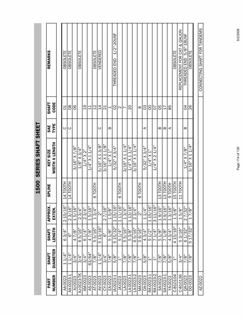
1500
SER
IES
SHA
FT S
HEE
T
PAR
TSH
AFT
SHA
FTA
PPR
OX
.SP
LIN
EK
EY S
IZE
SAE
SHA
FT
REM
AR
KS
NU
MB
ERD
IAM
ETER
LEN
GTH
EXTE
N.
WID
TH X
LEN
GTH
TYPE
CO
DE
AA-0
023
1 1/
4"6
3/4"
2 15
/16"
14 T
OO
THC
01O
BS
OLE
TEAA
-002
3-1
1 1/
4"6"
2 3/
16"
14 T
OO
THC
08O
BS
OLE
TEAJ
-002
33/
4"4
7/8"
1 5/
16"
3/16
" X
7/8"
06AJ
-002
3-TK
3/4"
6 5/
16"
2 3/
4"1/
8" X
3/4
"O
BS
OLE
TEAM
-002
33/
4"6
1/4"
2 3/
4"1/
4" X
2"
19AS
-002
363
/64"
4 7/
8"1
5/16
"1/
4" X
1 1
/4"
11AT
-002
37/
8"5
5/16
"1
3/4"
6 TO
OTH
12O
BS
OLE
TEAV
-002
31
1/4"
5 13
/16"
2"5/
16"
X 1
3/8"
C14
VEN
DER
EDC
Y-00
233/
4"6"
2 7/
16"
3/16
" X
1 1/
8"21
EA-0
023
7/8"
5 1/
8"1
5/8"
1/4"
X 1
"B
1IA
-002
3-1
5/8"
5 15
/32"
1 15
/16"
5/32
" X
3/4"
02TH
REA
DED
EN
D
1/2"
-20U
NF
JA-0
023
1"5
1/4"
1 11
/16"
6 TO
OTH
2LA
-002
37/
8"5
5/16
"1
3/4"
3/16
" X
1 1/
4"7
LA-0
023-
17/
8"5
3/8"
1 13
/16"
1/4"
X 1
1/4
"20
LA-0
023-
27/
8"6
5/16
"2
3/4"
3/16
" X
1 1/
4"M
A-00
231"
5 9/
16"
2"6
TOO
TH8
OA-
0023
5/8"
4 3/
4"1
1/4"
5/32
" X
3/4"
A03
RA-
0023
-11"
5 1/
2"1
15/1
6"1/
4" X
1"
00R
A-00
23-2
1"7
1/4"
3 11
/16"
1/4"
X 2
1/4
"07
SA-
0023
7/8"
5 1/
8"1
9/16
"13
TO
OTH
B05
SA-
0023
-17/
8"7
1/8"
3 9/
16"
13 T
OO
THB
17YA
-002
35/
8"4
3/4"
1 3/
16"
9 TO
OTH
A85
C-8
1010
41"
4 15
/16"
1 3/
8"15
TO
OTH
OB
SO
LETE
C-8
1013
63/
4"5
3/16
"1
5/8"
11 T
OO
THR
EPLA
CEM
ENT
FOR
CAT
& G
ALIO
NQ
A-00
237/
8"6
1/32
"2
7/32
"1/
4" X
7/8
"B
04TH
REA
DED
EN
D 5
/8"-
18U
NF
DO
-002
37/
8"5
17/3
2"1
7/8"
3/16
" X
1 1/
4"26
OB
SO
LETE
AZ-0
022
CO
NN
ECTI
NG
SH
AFT
FOR
TAN
DEM
S
Page
114
of 1
305/
2/20
08

250
0 SE
RIE
S SH
AFT
SH
EET
PAR
TSH
AFT
SHA
FTA
PPR
OX
.SP
LIN
EK
EY S
IZE
SAE
SHA
FT
REM
AR
KS
NU
MB
ERD
IAM
ETER
LEN
GTH
EXTE
N.
WID
TH X
LEN
GTH
TYPE
CO
DE
AB-0
024
1.10
"6
3/8
"2
7/1
6"6
TOO
TH2
TYP
E I
CB
-002
47/
8"6
1/8
"1
1/2
"13
TO
OTH
B37
TYP
E II
DB
-002
41
1/4
"6
7/8
"2
1/4
"14
TO
OTH
C42
TYP
E II
DB
-002
4-1
1 1
/4"
7 1
/16"
2 7
/16"
14 T
OO
THC
58 T
YPE
II
O
BS
OLE
TEEA
-002
47/
8"5
13/1
6"1
7/8
"6
TOO
TH39
TYP
E I
EB-0
024
1 1
/4"
6 3
/32"
1 1
/2"
14 T
OO
THC
44 T
YPE
IIFA
-002
4-1
63/6
4"5
15/
16"
2"1/
4" X
1 1
/4"
41 T
YPE
I
O
BS
OLE
TEFB
-002
41"
6 3
/8"
1 3
/4"
1/4"
X 1
1/4
"36
TYP
E II
FC-0
024
63/6
4"6
1/4
"1
5/8
"1/
4" X
1"
69 T
YPE
IIG
A-00
241"
5 3
/4"
1 1
3/16
"1/
4" X
1 1
/4"
32 T
YPE
IG
A-00
24-S
1"5
7/1
6"1
1/2
"1/
4" X
1 1
/8"
4 T
YPE
I
O
BS
OLE
TEG
A-00
24-S
P1"
7 3
/8"
3 7
/16"
1/4"
X 1
3/4
" T
YPE
II
O
BS
OLE
TEG
B-0
024
63/6
4"6
9/3
2"1
5/8
"6
TOO
TH35
TYP
E II
IB
-002
47/
8"7
13/
32"
2 3
/4"
3/16
" X
1 1
/4"
34 T
YPE
II
O
BS
OLE
TEJB
-002
47/
8"6
9/1
6"1
15/
16"
6 TO
OTH
88 T
YPE
IIK
A-00
241
1/4
"5
7/8
"1
15/
16"
1/4"
X 1
1/4
"49
TYP
E I
MB
-002
41
1/4
"5
1/2
"1
9/1
6"1/
4" X
1 1
/4"
8 T
YPE
I
O
BS
OLE
TEO
A-00
241
1/4
"6
1/8
"2
3/1
6"14
TO
OTH
C
6 T
YPE
IO
B-0
024
3/4"
6 1
/8"
1 1
/2"
3/16
" X
7/8"
47 T
YPE
II
O
BS
OLE
TEQ
A-00
241
1/4
"6
1/8
"2
3/1
6"5/
16"
X 1
1/2
"C
00 T
YPE
IQ
A-00
24-X
L1
1/4
"7
1/4
"3
5/1
6"5/
16"
X 1
1/2"
45EX
TRA
LON
G,
OB
SO
LETE
SA-
0024
7/8"
6 1
5/32
"2
1/2
"1/
4" X
7/8
"B
15 T
YPE
I
EXTE
R. T
HR
EAD
ED E
ND
SD
-002
41"
5 1
5/16
"2"
6 TO
OTH
83 T
YPE
I
GAL
IS
1XTB
-002
4-1
1 1
/4"
7 1
1/16
"3
1/8
"5/
16"
X 2
1/4
"62
TYP
E II
IU
A-00
247/
8"5
1/2
"1
5/8
"13
TO
OTH
B14
TYP
E I
UA-
0024
-S7/
8"5
1/2
"1
5/8
"13
TO
OTH
BO
BS
OLE
TE, .
96 F
ULL
SPL
INE
LGTH
.VA
-002
47/
8"5
11/
16"
1 3
/4"
3/16
" X
1 1
/4"
27 T
YPE
IVA
-002
4-1
7/8"
6 9
/16"
2 5
/8"
3/16
" X
1 1/
4"28
TYP
E I
LO
NG
EXT
.
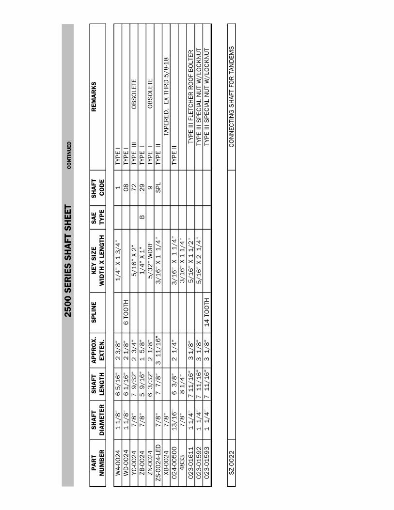
250
0 SE
RIE
S SH
AFT
SH
EET
CO
NTI
NU
ED
PAR
TSH
AFT
SHA
FTA
PPR
OX
.SP
LIN
EK
EY S
IZE
SAE
SHA
FT
REM
AR
KS
NU
MB
ERD
IAM
ETER
LEN
GTH
EXTE
N.
WID
TH X
LEN
GTH
TYPE
CO
DE
WA-
0024
1 1/
8"6
5/16
"2
3/8"
1/4"
X 1
3/4
"1
TYP
E I
WD
-002
41
1/8"
6 1/
16"
2 1/
8"6
TOO
TH08
TYP
E I
YC-0
024
7/8"
7 9
/32"
2 3
/4"
5/16
" X
2"72
TYP
E II
I
OB
SO
LETE
ZB-0
024
7/8"
5 9
/16"
1 5
/8"
1/4"
X 1
"B
29 T
YPE
IZN
-002
46
3/3
2"2
1/8
"5/
32"
WD
RF
9 T
YPE
I
O
BS
OLE
TEZS
-002
4-LE
D7/
8"7
7/8
"3
11/
16"
3/16
" X
1 1
/4"
SPL
TYP
E II
XB-0
024
7/8"
TAPE
RED
, EX
TH
RD
5/8
-18
024-
0050
013
/16"
6 3
/8"
2 1
/4"
3/16
" X
1 1
/4"
TYP
E II
4833
7/8"
8 1/
4"3/
16"
X 1
1/4"
023-
0161
11
1/4"
7 11
/16"
3 1/
8"5/
16"
X 1
1/2"
TYPE
III F
LETC
HER
RO
OF
BO
LTER
023-
0159
21
1/4
"7
11/
16"
3 1
/8"
5/16
" X
2 1
/4"
TYPE
III S
PEC
IAL
NU
T W
/LO
CK
NU
T02
3-01
593
1 1
/4"
7 1
1/16
"3
1/8
"14
TO
OTH
TYPE
III S
PEC
IAL
NU
T W
/LO
CK
NU
T
SZ-
0022
CO
NN
ECTI
NG
SH
AFT
FOR
TAN
DEM
S
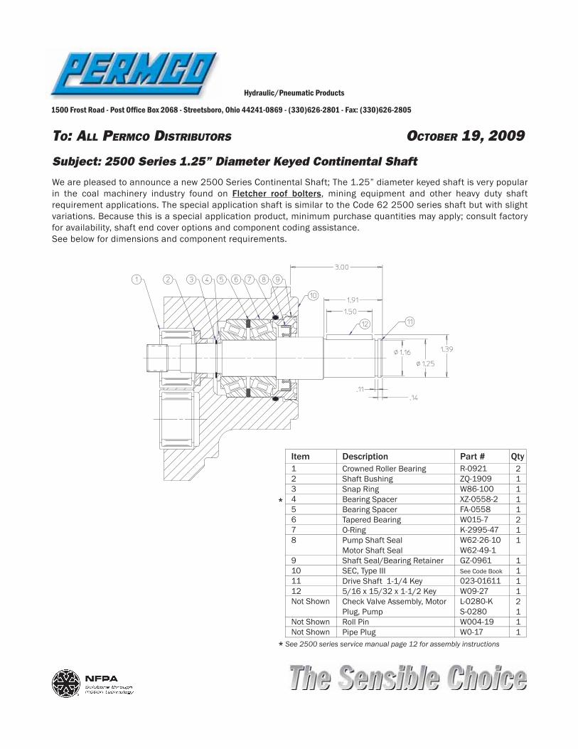
TO: ALL PERMCO DISTRIBUTORS OCTOBER 19, 2009
Hydraulic/Pneumatic Products
1500 Frost Road - Post Of! ce Box 2068 - Streetsboro, Ohio 44241-0869 - (330)626-2801 - Fax: (330)626-2805
Subject: 2500 Series 1.25” Diameter Keyed Continental Shaft
We are pleased to announce a new 2500 Series Continental Shaft; The 1.25” diameter keyed shaft is very popular in the coal machinery industry found on Fletcher roof bolters, mining equipment and other heavy duty shaft requirement applications. The special application shaft is similar to the Code 62 2500 series shaft but with slight variations. Because this is a special application product, minimum purchase quantities may apply; consult factory for availability, shaft end cover options and component coding assistance. See below for dimensions and component requirements.
R-0921ZQ-1909W86-100XZ-0558-2FA-0558W015-7K-2995-47W62-26-10W62-49-1GZ-0961See Code Book023-01611W09-27L-0280-K S-0280W004-19 W0-17
Crowned Roller BearingShaft BushingSnap RingBearing SpacerBearing SpacerTapered BearingO-RingPump Shaft SealMotor Shaft SealShaft Seal/Bearing RetainerSEC, Type IIIDrive Shaft 1-1/4 Key5/16 x 15/32 x 1-1/2 KeyCheck Valve Assembly, MotorPlug, PumpRoll PinPipe Plug
12345678
9101112Not Shown
Not ShownNot Shown
21111211
11112111
Item Part #Description Qty
*
* See 2500 series service manual page 12 for assembly instructions
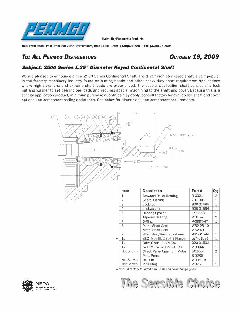
TO: ALL PERMCO DISTRIBUTORS OCTOBER 19, 2009
Hydraulic/Pneumatic Products
1500 Frost Road - Post Of! ce Box 2068 - Streetsboro, Ohio 44241-0869 - (330)626-2801 - Fax: (330)626-2805
Subject: 2500 Series 1.25” Diameter Keyed Continental Shaft
We are pleased to announce a new 2500 Series Continental Shaft; The 1.25” diameter keyed shaft is very popular in the forestry machinery industry found on cutting heads and other heavy duty shaft requirement applications where high vibrations and extreme shaft loads are experienced. The special application shaft consist of a lock nut and washer to set bearing pre-loads and requires special machining to the shaft end cover. Because this is a special application product, minimum purchase quantities may apply; consult factory for availability, shaft end cover options and component coding assistance. See below for dimensions and component requirements.
R-0921ZQ-1909900-01595900-01596FA-0558W015-7K-2995-47W62-26-10W62-49-1961-01594574-01591023-01592W09-44L-0280-K S-0280W004-19 W0-17
Crowned Roller BearingShaft BushingLocknutLockwasherBearing SpacerTapered BearingO-RingPump Shaft SealMotor Shaft SealShaft Seal/Bearing RetainerSEC, Type III, 2 Bolt B FlangeDrive Shaft 1-1/4 Key5/16 x 15/32 x 2-1/4 KeyCheck Valve Assembly, MotorPlug, PumpRoll PinPipe Plug
12345678
9101112Not Shown
Not ShownNot Shown
21111211
11112111
Item Part #Description Qty
*
* Consult factory for additional shaft end cover " ange types
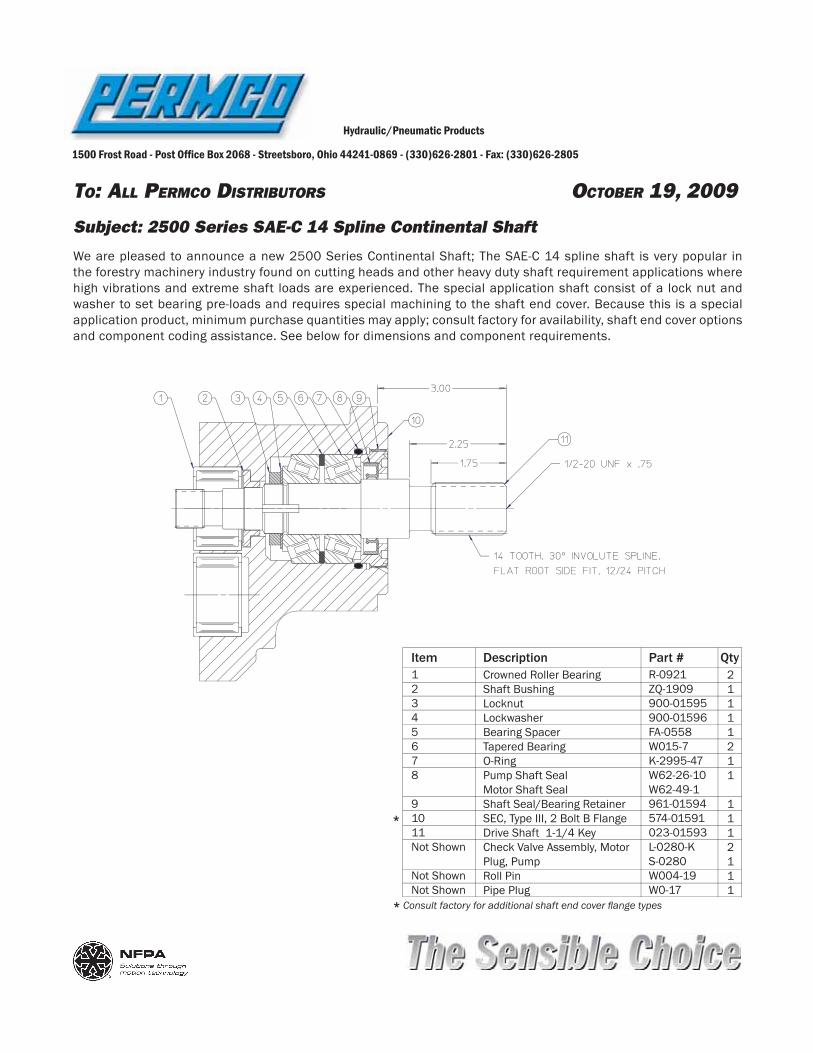
TO: ALL PERMCO DISTRIBUTORS OCTOBER 19, 2009
Hydraulic/Pneumatic Products
1500 Frost Road - Post Of! ce Box 2068 - Streetsboro, Ohio 44241-0869 - (330)626-2801 - Fax: (330)626-2805
Subject: 2500 Series SAE-C 14 Spline Continental Shaft
We are pleased to announce a new 2500 Series Continental Shaft; The SAE-C 14 spline shaft is very popular in the forestry machinery industry found on cutting heads and other heavy duty shaft requirement applications where high vibrations and extreme shaft loads are experienced. The special application shaft consist of a lock nut and washer to set bearing pre-loads and requires special machining to the shaft end cover. Because this is a special application product, minimum purchase quantities may apply; consult factory for availability, shaft end cover options and component coding assistance. See below for dimensions and component requirements.
R-0921ZQ-1909900-01595900-01596FA-0558W015-7K-2995-47W62-26-10W62-49-1961-01594574-01591023-01593L-0280-K S-0280W004-19 W0-17
Crowned Roller BearingShaft BushingLocknutLockwasherBearing SpacerTapered BearingO-RingPump Shaft SealMotor Shaft SealShaft Seal/Bearing RetainerSEC, Type III, 2 Bolt B FlangeDrive Shaft 1-1/4 KeyCheck Valve Assembly, MotorPlug, PumpRoll PinPipe Plug
12345678
91011Not Shown
Not ShownNot Shown
21111211
1112111
Item Part #Description Qty
*
* Consult factory for additional shaft end cover " ange types

21
00 /
300
0 /
3100
SER
IES
SHA
FT S
HEE
T
PAR
TSH
AFT
SHA
FTA
PPR
OX
.SP
LIN
EK
EY S
IZE
SAE
SHA
FT
REM
AR
KS
NU
MB
ERD
IAM
ETER
LEN
GTH
EXTE
N.
WID
TH X
LEN
GTH
TYPE
CO
DE
023-
0097
93/
4"4
41/6
4"1
1/2"
11 T
OO
THC
UM
MIN
S D
IES
EL A
CC
ESS
OR
Y D
RIV
E02
4-00
409-
HF
1"5
13/1
6"2
13/
16"
1/4"
X 1
3/4
"02
4-00
740
7/8"
5 3/
8"B
TAPE
RED
& T
HR
EAD
ED 5
/8"-
18U
NF
024-
0083
55/
8"5
5/32
"2"
3/16
" X
1 1/
4"85
HYD
REC
O R
EPL.
OB
SO
LETE
BC
-002
41"
4 3/
4"1
5/8"
6 TO
OTH
57B
C-0
024-
31.
100"
5 1/
4"6
TOO
THB
57XL
LON
GER
SPL
INE
C-8
1013
53/
4"4
53/6
4"1
43/6
4"11
TO
OTH
" D
O N
OT
USE
IN P
197
SER
IES
"D
C-0
024
1"5
3/64
"1
15/1
6"1/
4" X
1 1
/4"
32ZG
-002
41
1/4"
5 19
/64"
2 3/
16"
14 T
OO
THC
6ZG
-002
4-H
CL
1 1/
4"5
19/6
4"2
3/16
"14
TO
OTH
CM
ADE
WIT
H 4
620
STE
ELZH
-002
45/
8"4
29/6
4"1
1/4"
9 TO
OTH
A84
ZI-0
024
7/8"
4 47
/64"
1 5/
8"13
TO
OTH
B14
ZI-0
024-
XLT
7/8"
4 15
/16"
1 13
/16"
13 T
OO
THB
14XL
OB
SO
LETE
V
END
OR
EDZJ
-002
47/
8"4
45/6
4"1
5/8"
1/4"
x 1
"B
29ZJ
-002
4-XL
7/8"
5 57
/64"
2 3/
4"1/
4" x
1 3
/4"
B29
XLEX
TRA
LON
G,
US
E K
EY W
09-0
1ZM
-002
4-1
5 8"
4 61
/64"
WD
RF
KEY
B02
KEY
& T
HR
EAD
ED E
ND
1/2
"-20
UN
FZP
-002
47/
8"5
25/6
4"2
1/4"
WD
RF
KEY
21TA
PER
ED W
/IN
T TH
REA
D 5
/16-
24ZQ
-002
41
1/4"
5 19
/64"
2 3/
16"
5/16
" X
1 1/
2"00
ZT-0
024
1"4
15/1
6"1
13/1
6"15
TO
OTH
BB
87ZU
-002
43/
4"5
1/2"
2 3/
8"3/
16"
X 1
3/4"
24ZW
-002
47/
8"5
5/8"
2 17
/32"
1/4"
X 7
/8"
B04
/89
KEY
ED &
TH
REA
DED
EN
D 5
/8"-
18U
NF
ZW-0
024-
SPL
7/8"
5 7/
8"2
7/8"
1/4"
X 7
/8"
BK
EYED
& T
HR
EAD
ED E
ND
5/8
"-18
UN
F
ZE-0
022
0330
00/3
000
PIG
GYB
ACK
SH
AFT
ZC-0
022
1150
00/3
000
PIG
GYB
ACK
SH
AFT
ZG-0
022
1275
00/3
000
PIG
GYB
ACK
SH
AFT
YZ-0
022
CO
NN
ECTI
NG
SH
AFT
FOR
TAN
DEM
S
Page
117
of 1
305/
2/20
08
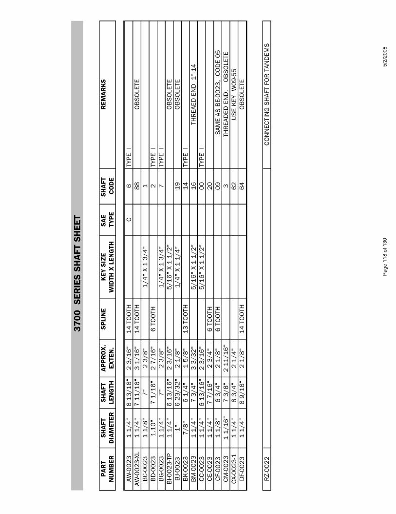
3
700
SER
IES
SHA
FT S
HEE
T
PAR
TSH
AFT
SHA
FTA
PPR
OX
.SP
LIN
EK
EY S
IZE
SAE
SHA
FT
REM
AR
KS
NU
MB
ERD
IAM
ETER
LEN
GTH
EXTE
N.
WID
TH X
LEN
GTH
TYPE
CO
DE
AW-0
023
1 1/
4"6
13/1
6"2
3/16
"14
TO
OTH
C6
TYPE
IAW
-002
3-XL
1 1/
4"7
11/1
6"3
1/16
"14
TO
OTH
88
OB
SO
LETE
BC
-002
31
1/8"
7"2
3/8"
1/4"
X 1
3/4
"1
BD
-002
31.
10"
7 1/
16"
2 7/
16"
6 TO
OTH
2
TYPE
IB
G-0
023
1 1/
4"7"
2 3/
8"1/
4" X
1 3
/4"
7TY
PE I
BI-0
023-
TP1
1/4"
6 13
/16"
2 3/
16"
5/16
" X
1 1/
2"
OB
SO
LETE
BJ-
0023
1"6
23/3
2"2
1/8"
1/
4" X
1 1
/4"
19O
BS
OLE
TEB
K-0
023
7/8"
6 1/
4"1
5/8"
13 T
OO
TH
14
TYPE
IB
M-0
023
1 1/
4"7
3/4"
3 3/
32"
5/16
" X
1 1/
2"16
THR
EAED
EN
D 1
"-14
CC
-002
31
1/4"
6 13
/16"
2 3/
16"
5/16
" X
1 1/
2"00
TYPE
IC
E-00
231
1/4"
7 7/
16"
2 3/
4"6
TOO
TH
20
CF-
0023
1 1/
8"6
3/4"
2 1/
8"6
TOO
TH
09
SAM
E AS
BE-
0023
, C
OD
E 05
CM
-002
31
1/16
"7
3/8"
2 11
/16"
3TH
REA
DED
EN
D,
OB
SO
LETE
CX-
0023
-11
1/4"
8 3/
4"2
1/4"
62
US
E K
EY W
09-5
5D
F-00
231
1/4"
6 9/
16"
2 1/
8"14
TO
OTH
64O
BS
OLE
TE
RZ-
0022
CO
NN
ECTI
NG
SH
AFT
FOR
TAN
DEM
S
Page
118
of 1
305/
2/20
08
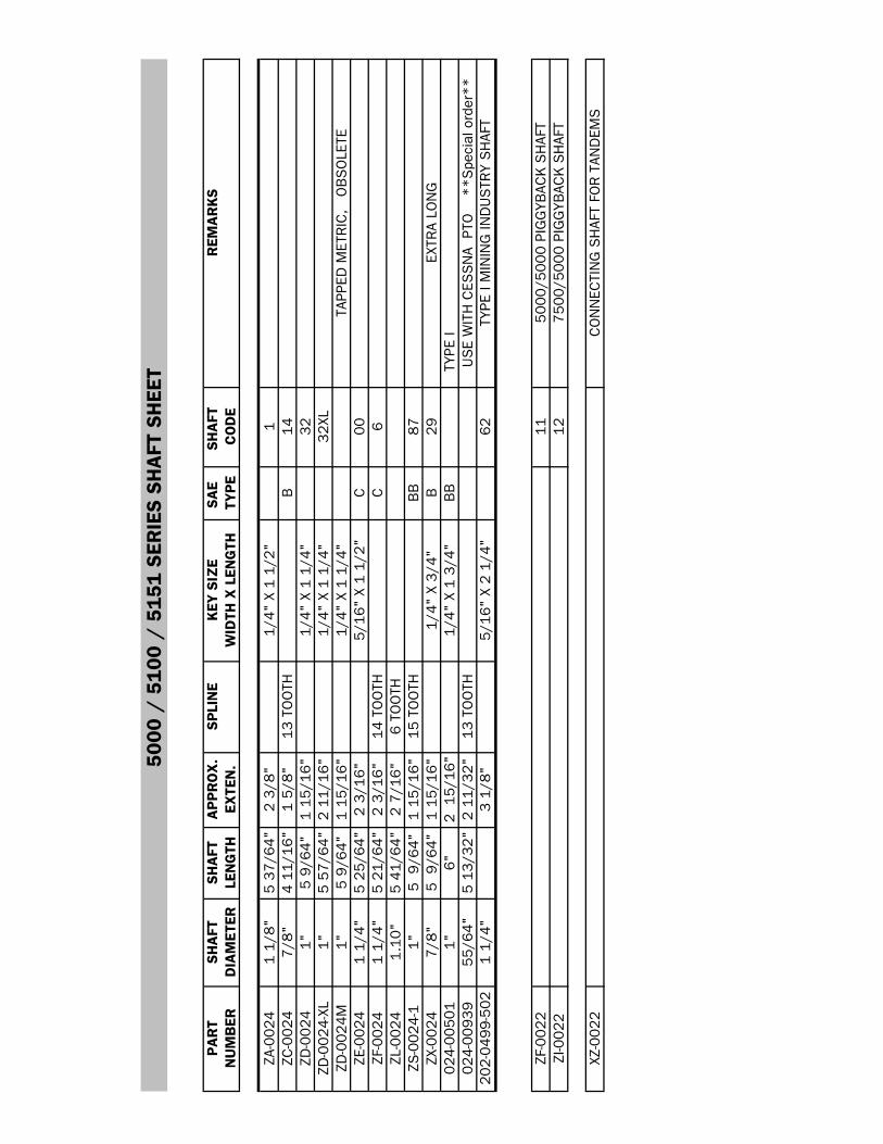
5
000
/ 51
00 /
515
1 SE
RIE
S SH
AFT
SH
EET
PAR
TSH
AFT
SHA
FTA
PPR
OX
.SP
LIN
EK
EY S
IZE
SAE
SHA
FT
REM
AR
KS
NU
MB
ERD
IAM
ETER
LEN
GTH
EXTE
N.
WID
TH X
LEN
GTH
TYPE
CO
DE
ZA-0
024
1 1/
8"5
37/6
4"2
3/8"
1/4"
X 1
1/2
"1
ZC-0
024
7/8"
4 11
/16"
1 5/
8"13
TO
OTH
B14
ZD-0
024
1"5
9/64
"1
15/1
6"1/
4" X
1 1
/4"
32ZD
-002
4-XL
1"5
57/6
4"2
11/1
6"1/
4" X
1 1
/4"
32XL
ZD-0
024M
1"5
9/64
"1
15/1
6"1/
4" X
1 1
/4"
TAPP
ED M
ETR
IC,
OB
SO
LETE
ZE-0
024
1 1/
4"5
25/6
4"2
3/16
"5/
16"
X 1
1/2"
C00
ZF-0
024
1 1/
4"5
21/6
4"2
3/16
"14
TO
OTH
C6
ZL-0
024
1.10
"5
41/6
4"2
7/16
"6
TOO
THZS
-002
4-1
1"5
9/6
4"1
15/1
6"15
TO
OTH
BB
87ZX
-002
47/
8"5
9/6
4"1
15/1
6"1/
4" X
3/4
"B
29EX
TRA
LON
G02
4-00
501
1"6"
2 1
5/16
"1/
4" X
1 3
/4"
BB
TY
PE I
024-
0093
955
/64"
5 13
/32"
2 11
/32"
13 T
OO
THU
SE
WIT
H C
ESS
NA
PTO
*
*Spe
cial
ord
er**
202-
0499
-502
1 1/
4"3
1/8"
5/16
" X
2 1/
4"62
TYPE
I M
ININ
G IN
DU
STR
Y S
HAF
T
ZF-0
022
1150
00/5
000
PIG
GYB
ACK
SH
AFT
ZI-0
022
1275
00/5
000
PIG
GYB
ACK
SH
AFT
XZ-0
022
CO
NN
ECTI
NG
SH
AFT
FOR
TAN
DEM
S
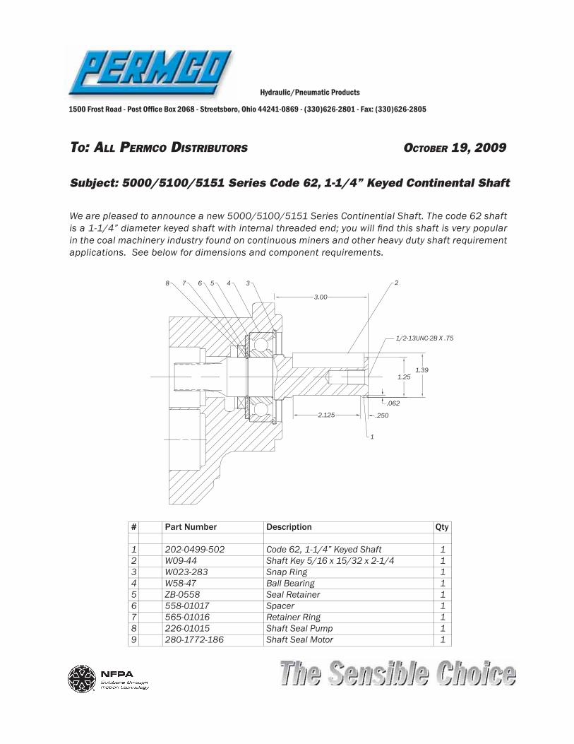
TO: ALL PERMCO DISTRIBUTORS OCTOBER 19, 2009
Hydraulic/Pneumatic Products
1500 Frost Road - Post Of! ce Box 2068 - Streetsboro, Ohio 44241-0869 - (330)626-2801 - Fax: (330)626-2805
Subject: 5000/5100/5151 Series Code 62, 1-1/4” Keyed Continental Shaft
We are pleased to announce a new 5000/5100/5151 Series Continential Shaft. The code 62 shaft is a 1-1/4” diameter keyed shaft with internal threaded end; you will ! nd this shaft is very popular in the coal machinery industry found on continuous miners and other heavy duty shaft requirement applications. See below for dimensions and component requirements.
# Part Number Description Qty
1 202-0499-502 Code 62, 1-1/4” Keyed Shaft 12 W09-44 Shaft Key 5/16 x 15/32 x 2-1/4 13 W023-283 Snap Ring 14 W58-47 Ball Bearing 15 ZB-0558 Seal Retainer 16 558-01017 Spacer 17 565-01016 Retainer Ring 18 226-01015 Shaft Seal Pump 19 280-1772-186 Shaft Seal Motor 1
3.00
2.125 .250
.062
1.251.39
1/2-13UNC-2B X .75
1
2345678
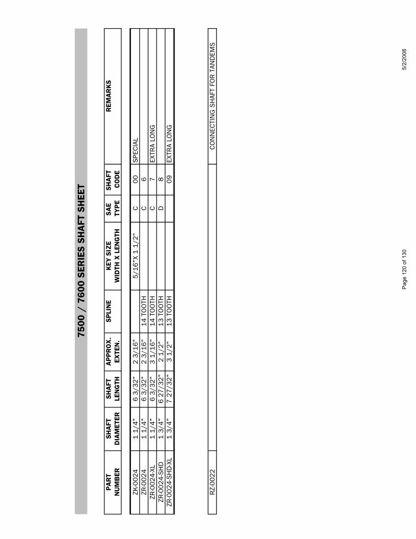
7
500
/ 76
00 S
ERIE
S SH
AFT
SH
EET
PAR
TSH
AFT
SHA
FTA
PPR
OX
.SP
LIN
EK
EY S
IZE
SAE
SHA
FT
REM
AR
KS
NU
MB
ERD
IAM
ETER
LEN
GTH
EXTE
N.
WID
TH X
LEN
GTH
TYPE
CO
DE
ZK-0
024
1 1/
4"6
3/32
"2
3/16
"5/
16"X
1 1
/2"
C00
SPE
CIA
LZR
-002
41
1/4"
6 3/
32"
2 3/
16"
14 T
OO
THC
6ZR
-002
4-XL
1 1/
4"6
3/32
"3
1/16
"14
TO
OTH
C7
EXTR
A LO
NG
ZR-0
024-
SH
D1
3/4"
6 27
/32"
2 1/
2"13
TO
OTH
D8
ZR-0
024-
SH
D-X
L1
3/4"
7 27
/32"
3 1/
2"13
TO
OTH
09EX
TRA
LON
G
RZ-
0022
CO
NN
ECTI
NG
SH
AFT
FOR
TAN
DEM
S
Page
120
of 1
305/
2/20
08
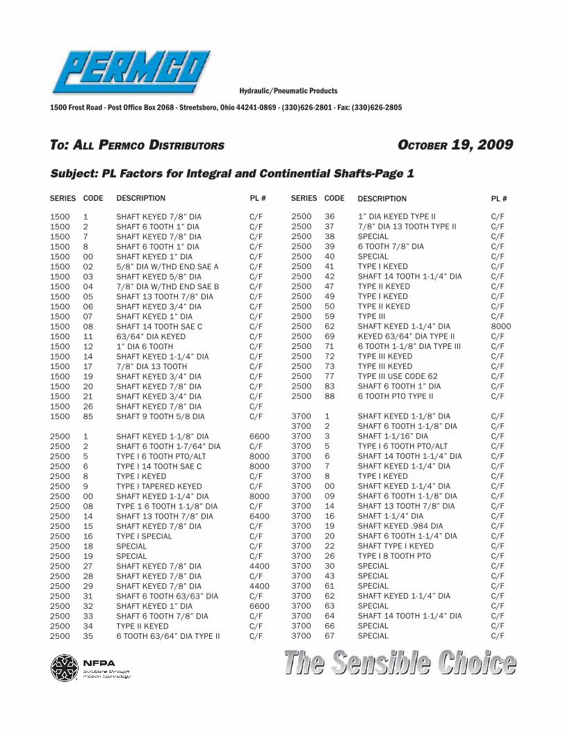
TO: ALL PERMCO DISTRIBUTORS OCTOBER 19, 2009
Hydraulic/Pneumatic Products
1500 Frost Road - Post Of! ce Box 2068 - Streetsboro, Ohio 44241-0869 - (330)626-2801 - Fax: (330)626-2805
Subject: PL Factors for Integral and Continential Shafts-Page 1
1500 1 SHAFT KEYED 7/8” DIA C/F1500 2 SHAFT 6 TOOTH 1” DIA C/F1500 7 SHAFT KEYED 7/8” DIA C/F1500 8 SHAFT 6 TOOTH 1” DIA C/F1500 00 SHAFT KEYED 1” DIA C/F1500 02 5/8” DIA W/THD END SAE A C/F1500 03 SHAFT KEYED 5/8” DIA C/F1500 04 7/8” DIA W/THD END SAE B C/F1500 05 SHAFT 13 TOOTH 7/8” DIA C/F1500 06 SHAFT KEYED 3/4” DIA C/F1500 07 SHAFT KEYED 1” DIA C/F1500 08 SHAFT 14 TOOTH SAE C C/F1500 11 63/64” DIA KEYED C/F1500 12 1” DIA 6 TOOTH C/F1500 14 SHAFT KEYED 1-1/4” DIA C/F1500 17 7/8” DIA 13 TOOTH C/F1500 19 SHAFT KEYED 3/4” DIA C/F1500 20 SHAFT KEYED 7/8” DIA C/F1500 21 SHAFT KEYED 3/4” DIA C/F1500 26 SHAFT KEYED 7/8” DIA C/F1500 85 SHAFT 9 TOOTH 5/8 DIA C/F
2500 1 SHAFT KEYED 1-1/8” DIA 66002500 2 SHAFT 6 TOOTH 1-7/64” DIA C/F2500 5 TYPE I 6 TOOTH PTO/ALT 80002500 6 TYPE I 14 TOOTH SAE C 80002500 8 TYPE I KEYED C/F2500 9 TYPE I TAPERED KEYED C/F2500 00 SHAFT KEYED 1-1/4” DIA 80002500 08 TYPE 1 6 TOOTH 1-1/8” DIA C/F2500 14 SHAFT 13 TOOTH 7/8” DIA 64002500 15 SHAFT KEYED 7/8” DIA C/F2500 16 TYPE I SPECIAL C/F2500 18 SPECIAL C/F2500 19 SPECIAL C/F2500 27 SHAFT KEYED 7/8” DIA 44002500 28 SHAFT KEYED 7/8” DIA C/F2500 29 SHAFT KEYED 7/8” DIA 44002500 31 SHAFT 6 TOOTH 63/63” DIA C/F2500 32 SHAFT KEYED 1” DIA 66002500 33 SHAFT 6 TOOTH 7/8” DIA C/F2500 34 TYPE II KEYED C/F2500 35 6 TOOTH 63/64” DIA TYPE II C/F
CODE DESCRIPTION PL #
2500 36 1” DIA KEYED TYPE II C/F2500 37 7/8” DIA 13 TOOTH TYPE II C/F2500 38 SPECIAL C/F2500 39 6 TOOTH 7/8” DIA C/F2500 40 SPECIAL C/F2500 41 TYPE I KEYED C/F 2500 42 SHAFT 14 TOOTH 1-1/4” DIA C/F2500 47 TYPE II KEYED C/F2500 49 TYPE I KEYED C/F2500 50 TYPE II KEYED C/F2500 59 TYPE III C/F2500 62 SHAFT KEYED 1-1/4” DIA 80002500 69 KEYED 63/64” DIA TYPE II C/F2500 71 6 TOOTH 1-1/8” DIA TYPE III C/F2500 72 TYPE III KEYED C/F2500 73 TYPE III KEYED C/F2500 77 TYPE III USE CODE 62 C/F2500 83 SHAFT 6 TOOTH 1” DIA C/F2500 88 6 TOOTH PTO TYPE II C/F
3700 1 SHAFT KEYED 1-1/8” DIA C/F3700 2 SHAFT 6 TOOTH 1-1/8” DIA C/F3700 3 SHAFT 1-1/16” DIA C/F3700 5 TYPE I 6 TOOTH PTO/ALT C/F3700 6 SHAFT 14 TOOTH 1-1/4” DIA C/F3700 7 SHAFT KEYED 1-1/4” DIA C/F3700 8 TYPE I KEYED C/F3700 00 SHAFT KEYED 1-1/4” DIA C/F3700 09 SHAFT 6 TOOTH 1-1/8” DIA C/F3700 14 SHAFT 13 TOOTH 7/8” DIA C/F3700 16 SHAFT 1-1/4” DIA C/F3700 19 SHAFT KEYED .984 DIA C/F3700 20 SHAFT 6 TOOTH 1-1/4” DIA C/F3700 22 SHAFT TYPE I KEYED C/F3700 26 TYPE I 8 TOOTH PTO C/F3700 30 SPECIAL C/F3700 43 SPECIAL C/F3700 61 SPECIAL C/F3700 62 SHAFT KEYED 1-1/4” DIA C/F3700 63 SPECIAL C/F3700 64 SHAFT 14 TOOTH 1-1/4” DIA C/F3700 66 SPECIAL C/F3700 67 SPECIAL C/F
SERIES SERIES CODE DESCRIPTION PL #
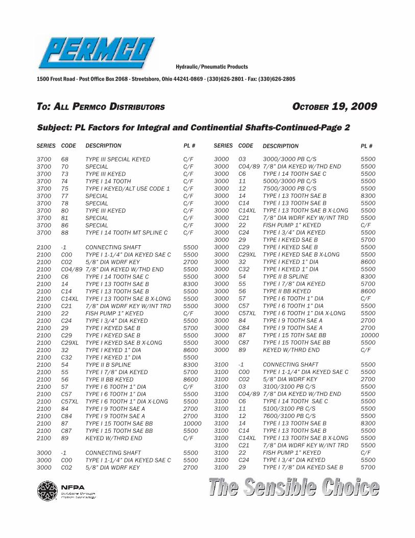
TO: ALL PERMCO DISTRIBUTORS OCTOBER 19, 2009
Hydraulic/Pneumatic Products
1500 Frost Road - Post Of! ce Box 2068 - Streetsboro, Ohio 44241-0869 - (330)626-2801 - Fax: (330)626-2805
Subject: PL Factors for Integral and Continential Shafts-Continued-Page 2
3700 68 TYPE III SPECIAL KEYED C/F3700 70 SPECIAL C/F3700 73 TYPE III KEYED C/F3700 74 TYPE I 14 TOOTH C/F3700 75 TYPE I KEYED/ALT USE CODE 1 C/F3700 77 SPECIAL C/F3700 78 SPECIAL C/F3700 80 TYPE III KEYED C/F3700 81 SPECIAL C/F3700 86 SPECIAL C/F3700 88 TYPE I 14 TOOTH MT SPLINE C C/F
2100 -1 CONNECTING SHAFT 55002100 C00 TYPE I 1-1/4” DIA KEYED SAE C 55002100 C02 5/8” DIA WDRF KEY 27002100 C04/89 7/8” DIA KEYED W/THD END 55002100 C6 TYPE I 14 TOOTH SAE C 55002100 14 TYPE I 13 TOOTH SAE B 83002100 C14 TYPE I 13 TOOTH SAE B 55002100 C14XL TYPE I 13 TOOTH SAE B X-LONG 55002100 C21 7/8” DIA WDRF KEY W/INT TRD 55002100 22 FISH PUMP 1” KEYED C/F2100 C24 TYPE I 3/4” DIA KEYED 55002100 29 TYPE I KEYED SAE B 57002100 C29 TYPE I KEYED SAE B 55002100 C29XL TYPE I KEYED SAE B X-LONG 55002100 32 TYPE I KEYED 1” DIA 86002100 C32 TYPE I KEYED 1” DIA 55002100 54 TYPE II B SPLINE 83002100 55 TYPE I 7/8” DIA KEYED 57002100 56 TYPE II BB KEYED 86002100 57 TYPE I 6 TOOTH 1” DIA C/F2100 C57 TYPE I 6 TOOTH 1” DIA 55002100 C57XL TYPE I 6 TOOTH 1” DIA X-LONG 55002100 84 TYPE I 9 TOOTH SAE A 27002100 C84 TYPE I 9 TOOTH SAE A 27002100 87 TYPE I 15 TOOTH SAE BB 100002100 C87 TYPE I 15 TOOTH SAE BB 55002100 89 KEYED W/THRD END C/F
3000 -1 CONNECTING SHAFT 55003000 C00 TYPE I 1-1/4” DIA KEYED SAE C 55003000 C02 5/8” DIA WDRF KEY 2700
CODE DESCRIPTION PL #
3000 03 3000/3000 PB C/S 55003000 C04/89 7/8” DIA KEYED W/THD END 55003000 C6 TYPE I 14 TOOTH SAE C 55003000 11 5000/3000 PB C/S 55003000 12 7500/3000 PB C/S 55003000 14 TYPE I 13 TOOTH SAE B 83003000 C14 TYPE I 13 TOOTH SAE B 55003000 C14XL TYPE I 13 TOOTH SAE B X-LONG 55003000 C21 7/8” DIA WDRF KEY W/INT TRD 55003000 22 FISH PUMP 1” KEYED C/F3000 C24 TYPE I 3/4” DIA KEYED 55003000 29 TYPE I KEYED SAE B 57003000 C29 TYPE I KEYED SAE B 55003000 C29XL TYPE I KEYED SAE B X-LONG 55003000 32 TYPE I KEYED 1” DIA 86003000 C32 TYPE I KEYED 1” DIA 55003000 54 TYPE II B SPLINE 83003000 55 TYPE I 7/8” DIA KEYED 57003000 56 TYPE II BB KEYED 86003000 57 TYPE I 6 TOOTH 1” DIA C/F3000 C57 TYPE I 6 TOOTH 1” DIA 55003000 C57XL TYPE I 6 TOOTH 1” DIA X-LONG 55003000 84 TYPE I 9 TOOTH SAE A 27003000 C84 TYPE I 9 TOOTH SAE A 27003000 87 TYPE I 15 TOTH SAE BB 100003000 C87 TYPE I 15 TOOTH SAE BB 55003000 89 KEYED W/THRD END C/F
3100 -1 CONNECTING SHAFT 55003100 C00 TYPE I 1-1/4” DIA KEYED SAE C 55003100 C02 5/8” DIA WDRF KEY 2700 3100 03 3100/3100 PB C/S 55003100 C04/89 7/8” DIA KEYED W/THD END 55003100 C6 TYPE I 14 TOOTH SAE C 55003100 11 5100/3100 PB C/S 55003100 12 7600/3100 PB C/S 55003100 14 TYPE I 13 TOOTH SAE B 83003100 C14 TYPE I 13 TOOTH SAE B 55003100 C14XL TYPE I 13 TOOTH SAE B X-LONG 55003100 C21 7/8” DIA WDRF KEY W/INT TRD 55003100 22 FISH PUMP 1” KEYED C/F3100 C24 TYPE I 3/4” DIA KEYED 55003100 29 TYPE I 7/8” DIA KEYED SAE B 5700
SERIES SERIES CODE DESCRIPTION PL #

TO: ALL PERMCO DISTRIBUTORS OCTOBER 19. 2009
Hydraulic/Pneumatic Products
1500 Frost Road - Post Of! ce Box 2068 - Streetsboro, Ohio 44241-0869 - (330)626-2801 - Fax: (330)626-2805
Subject: PL Factors for Integral and Continential Shafts-Continued-Page 3
3100 C29 TYPE I KEYED SAE B 55003100 C29XL TYPE I KEYED SAE B X-LONG 55003100 32 TYPE I KEYED 1” DIA 86003100 C32 TYPE I KEYED 1” DIA 55003100 54 TYPE II B SPLINE 83003100 55 TYPE I 7/8” DIA KEYED 57003100 56 TYPE II BB KEYED 86003100 57 TYPE I 6 TOOTH 1” DIA C/F3100 C57 TYPE I 6 TOOTH 1” DIA 55003100 C57XL TYPE I 6 TOOTH 1” DIA X-LONG 55003100 84 TYPE I 9 TOOTH 5/8” DIA 27003100 C84 TYPE I 9 TOOTH 5/8” DIA 27003100 87 TYPE I 15 TOOTH SAE BB 100003100 C87 TYPE I 15 TOOTH SAE BB 55003100 89 KEYED W/THRD END C/F
5000 -1 CONNECTING SHAFT 80005000 C1 TYPE I 1-1/8” DIA KEYED 80005000 6 TYPE I 14 TOOTH SAE C 138505000 C6 TYPE I 14 TOOTH SAE C 80005000 00 TYPE I 1-1/4” DIA KEYED SAE C 130005000 C00 TYPE I 1-1/4” DIA KEYED SAE C 80005000 11 5000/5000 PB C/S 80005000 12 7500/5000 PB C/S 80005000 14 TYPE I 13 TOOTH SAE B 64005000 C14 TYPE I 13 TOOTH SAE B 64005000 32 TYPE I 1” DIA KEYED 66005000 C32 TYPE I 1” DIA KEYED 66005000 C32XL TYPE I 1” DIA KEYED X-LONG 66005000 42 TYPE II 14 TOOTH SAE C 138505000 54 TYPE II 13 TOOTH SAE B 64005000 62 TYPE I 1-1/4” KEYED X-LONG C/F5000 87 TYPE I 15 TOOTH SAE BB 10000 5000 C87 TYPE I 15 TOOTH SAE BB 8000 5000 SPL TYPE I 1” DIA KEYED SAE BB 8000 5000 SPL TYPE 1.1” DIA 6 TOOTH 8000 5000 SPL TYPE I 55/64” DIA 13 TOOTH 6400 5100 -1 CONNECTING SHAFT 80005100 C1 TYPE I 1-1/8” DIA KEYED 80005100 6 TYPE I 14 TOOTH SAE C 138505100 C6 TYPE I 14 TOOTH SAE C 80005100 00 TYPE 1 1-1/4” DIA KEYED SAE C 13000
CODE DESCRIPTION PL #
5100 C00 TYPE I 1-1/4” DIA KEYED SAE C 8000 5100 11 5100/5100 PB C/S 80005100 12 7600/5100 PB C/S 80005100 14 TYPE I 13 TOOTH SAE B 64005100 C14 TYPE I 13 TOOTH SAE B 64005100 32 TYPE I 1” DIA KEYED 66005100 C32 TYPE I 1” DIA KEYED 66005100 C32XL TYPE I 1” DIA KEYED X-LONG 66005100 42 TYPE II 14 TOOTH SAE C 138505100 54 TYPE II 13 TOOTH SAE B 64005100 62 TYPE I 1-1/4” DIA KEYED X-LONG C/F 5100 87 TYPE I 15 TOOTH SAE BB 100005100 C87 TYPE I 15 TOOTH SAE BB 80005100 SPL TYPE I 1” DIA KEYED SAE BB 80005100 SPL TYPE I 1.1: DIA 6 TOOTH 80005100 SPL TYPE I 55/64” DIA 13 TOOTH 6400
7500 -1 CONNECTING SHAFT 100007500 00 TYPE I 1-1/4” DIA KEYED SAE C 83007500 C00 TYPE I 1-1/4” DIA KEYED SAE C 83007500 C09 13 TOOTH SAE D EXTRA LONG 100007500 6 TYPE I 14 TOOTH SAE C 120007500 C6 TYPE I 14 TOOTH SAE C 83007500 C7 TYPE 1 14 TOOTH SAE C X-LONG 83007500 C8 TYPE I 13 TOOTH SAE D 8300
7600 -1 CONNECTING SHAFT 100007600 00 TYPE I 1-1/4” DIA KEYED SAE C 83007600 C00 TYPE I 1-1/4” DIA KEYED SAE C 83007600 C09 13 TOOTH SAE D EXTRA LONG 100007600 6 TYPE I 14 TOOTH SAE C 120007600 C6 TYPE I 14 TOOTH SAE C 83007600 C7 TYPE 1 14 TOOTH SAE C X-LONG 83007600 C8 TYPE I 13 TOOTH SAE D 8300
124 -1 CONNECTING SHAFT 4500124 24 TYPE II 3/4” DIA KEYED 2.31 EXT C/F124 45 TYPE II TAPERED CLUTCH 2.28 EXT C/F124 54 TYPE II 13 TOOTH SAE B 13200124 55 TYPE II 7/8” DIA KEYED SAE B 9100124 55XL TYPE II 7/8 DIA KEYED 2.8 EXT 9100124 75 EURO TAPER W/M12X15 EXT. TRD C/F124 85 TYPE II 9 TOOTH SAE A 4400
SERIES SERIES CODE DESCRIPTION PL #

TO: ALL PERMCO DISTRIBUTORS OCTOBER 19, 2009
Hydraulic/Pneumatic Products
1500 Frost Road - Post Of! ce Box 2068 - Streetsboro, Ohio 44241-0869 - (330)626-2801 - Fax: (330)626-2805
Subject: PL Factors for Integral and Continential Shafts-Continued-Page 4
124 86 TYPE II 5/8” DIA KEYED SAE A 3400 124 86XL TYPE II 5/8” DIA KEYED X-LONG 3400 124 99 TAPERED CLUTCH 1.9 EXT 3/8” BRK C/F
197 -1 CONNECTING SHAFT 6000197 C6 TYPE I 14 TOOTH SAE C 6000197 C00 TYPE I 1-1/4” DIA KEYED SAE C 6000197 C04 TYPE I 7/8” DIA KEYED C/F197 C14 TYPE I 13 TOOTH SAE B 6000197 C19 11 TOOTH 1.49 EXT 6000197 C20 TAPERED W/THRDS 6000197 C21 TAPERED SHAFT W/THRD END C/F197 C24 TYPE I 3/4” DIA KEYED C/F197 C29 TYPE I 7/8” DIA KEYED SAE B 6000197 C29XL TYPE I 7/8” DIA KEYED X-LONG 6000197 C32 TYPE I 1” DIA KEYED SAE BB 6000197 C57 TYPE I 1” DIA 6 TOOTH 6000197 C84 TYPE I 5/8” DIA 9 TOOTH SAE A 2700197 C87 TYPE I 15 TOOTH SAE BB 6000197 CM1 25MM STR KEYED C/F197 14 TYPE I 13 TOOTH SAE B 8000197 29 TYPE I 7/8” DIA KEYED SAE B 6500197 32 TYPE I 1” DIA KEYED SAE BB 8000197 48 EURO TAPER W/M14X1.5 EXT TRD C/F197 87 TYPE I 15 TOOTH SAE BB 10000
257 -1 CONNECTING SHAFT 8000257 C6 TYPE I 14 TOOTH SAE C 8000257 C00 TYPE I 1-1/4” DIA KEYED SAE C 8000257 C14 TYPE I 13 TOOTH SAE B 6500257 C32 TYPE I 1” DIA KEYED SAE BB 6500257 C62 TYPE I 1-1/4” DIA KEYED C/F 257 C87 TYPE I 15 TOOTH SAE BB 8000257 C2 TYPE I 1.1” DIA 6 TOOTH C/F 257 6 TYPE I 14 TOOTH SAE C 16000 257 00 TYPE I 1-1/4” DIA KEYED SAE C 14000257 14 TYPE I 13 TOOTH SAE B 6500257 87 TYPE I 15 TOOTH SAE BB 10000257 SPL TYPE I 17 TOOTH C/F
360 -1 CONNECTING SHAFT 11000360 00 TYPE I 1-1/4” DIA KEYED SAE C 9300360 6 TYPE I 14 TOOTH SAE C 13500
CODE DESCRIPTION PL # SERIES
360 14 TYPE I 13 TOOTH SAE B C/F360 87 TYPE I 15 TOOTH SAE BB 7000 C/F = CONSULT FACTORY
PL # DESCRIPTIONCODESERIES
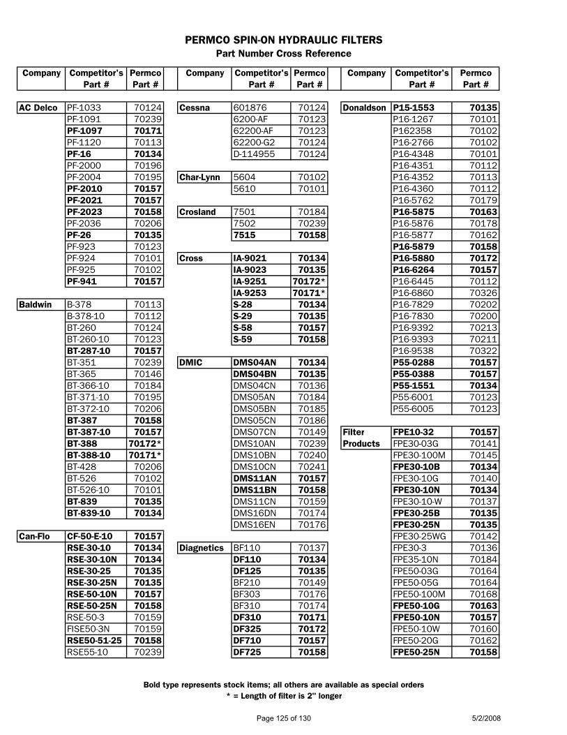
PERMCO SPIN-ON HYDRAULIC FILTERSPart Number Cross Reference
Company Competitor's Permco Company Competitor's Permco Company Competitor's PermcoPart # Part # Part # Part # Part # Part #
AC Delco PF-1033 70124 Cessna 601876 70124 Donaldson P15-1553 70135PF-1091 70239 6200-AF 70123 P16-1267 70101PF-1097 70171 62200-AF 70123 P162358 70102PF-1120 70113 62200-G2 70124 P16-2766 70102PF-16 70134 D-114955 70124 P16-4348 70101PF-2000 70196 P16-4351 70112PF-2004 70195 Char-Lynn 5604 70102 P16-4352 70113PF-2010 70157 5610 70101 P16-4360 70112PF-2021 70157 P16-5762 70179PF-2023 70158 Crosland 7501 70184 P16-5875 70163PF-2036 70206 7502 70239 P16-5876 70178PF-26 70135 7515 70158 P16-5877 70162PF-923 70123 P16-5879 70158PF-924 70101 Cross IA-9021 70134 P16-5880 70172PF-925 70102 IA-9023 70135 P16-6264 70157PF-941 70157 IA-9251 70172* P16-6445 70112
IA-9253 70171* P16-6860 70326Baldwin B-378 70113 S-28 70134 P16-7829 70202
B-378-10 70112 S-29 70135 P16-7830 70200BT-260 70124 S-58 70157 P16-9392 70213BT-260-10 70123 S-59 70158 P16-9393 70211BT-287-10 70157 P16-9538 70322BT-351 70239 DMIC DMS04AN 70134 P55-0288 70157BT-365 70146 DMS04BN 70135 P55-0388 70157BT-366-10 70184 DMS04CN 70136 P55-1551 70134BT-371-10 70195 DMS05AN 70184 P55-6001 70123BT-372-10 70206 DMS05BN 70185 P55-6005 70123BT-387 70158 DMS05CN 70186BT-387-10 70157 DMS07CN 70149 Filter FPE10-32 70157BT-388 70172* DMS10AN 70239 Products FPE30-03G 70141BT-388-10 70171* DMS10BN 70240 FPE30-100M 70145BT-428 70206 DMS10CN 70241 FPE30-10B 70134BT-526 70102 DMS11AN 70157 FPE30-10G 70140BT-526-10 70101 DMS11BN 70158 FPE30-10N 70134BT-839 70135 DMS11CN 70159 FPE30-10-W 70137BT-839-10 70134 DMS16DN 70174 FPE30-25B 70135
DMS16EN 70176 FPE30-25N 70135Can-Flo CF-50-E-10 70157 FPE30-25WG 70142
RSE-30-10 70134 Diagnetics BF110 70137 FPE30-3 70136RSE-30-10N 70134 DF110 70134 FPE35-10N 70184RSE-30-25 70135 DF125 70135 FPE50-03G 70164RSE-30-25N 70135 BF210 70149 FPE50-05G 70164RSE-50-10N 70157 BF303 70176 FPE50-100M 70168RSE-50-25N 70158 BF310 70174 FPE50-10G 70163RSE-50-3 70159 DF310 70171 FPE50-10N 70157FISE50-3N 70159 DF325 70172 FPE50-10W 70160RSE50-51-25 70158 DF710 70157 FPE50-20G 70162RSE55-10 70239 DF725 70158 FPE50-25N 70158
Bold type represents stock items; all others are available as special orders* = Length of filter is 2" longer
Page 125 of 130 5/2/2008

PERMCO SPIN-ON HYDRAULIC FILTERSPart Number Cross Reference
Company Competitor's Permco Company Competitor's Permco Company Competitor's PermcoPart # Part # Part # Part # Part # Part #
Filter FPE50-25W 70161 Fleetguard HF6204 70124 Fram P-1653 70134Products FPE50-25WG 70165 (Cont'd) HF6269 70112 P-1653-A 70134(Cont'd) FPE50-3N 70159 HF6500 70136 P-1654 70135
FPE55-10N 70239 HF6510 70134 P-1656 70123FPE70-03G 70179 HF6511 70146 P-1657 70124FPE70-03N 70173 HF6520 70135 P-3377 70101FPE70-05G 70179 HF6521 70147 P-3398 70102FPE70-100M 70183 HF6522 70145 P-3759 70195FPE70-10G 70178 HF6600 70197 PH-3567 70157FPE70-10N 70171 HF6601 70208FPE70-10W 70174 HF6603 70202 Gresen 1551 70134FPE70-20G 70177 HF6604 70213 1551-001 70134FPE70-25N 70172 HF6606 70201 1553 70135FPE70-25W 70175 HF6607 70212 1553-001 70135FPE70-25WG 70182 HF6610 70195 22615-001 70171FPF30-03G 70202 HF6611 70206 7520-001 70157FPF30-05G 70202 HF6612 70201 7521-001 70158FPF30-10G 70201 HF6613 70212 7531-001 70159FPF30-20G 70200 HF6620 70196 8058-001 70158FPF40-03G 70213 HF6621 70207 F1 01 70134FPF40-03N 70208 HF6625 70200 F1 03 70135FPF40-05G 70213 HF6626 70211 FS251 70157FPF40-10G 70212 HF6630 70201 FS252 70158FPF40-10N 70206 HF6631 70212 K-22001 70134FPF40-20G 70211 HF6633 70211 K-22006 70134FPF40-26N 70207 HF6700 70159 K-23018 70157
HF6701 70172 K-23019 70158Fleetguard HF6002 70102 HF6703 70164 K-23020 70159
HF6003 70101 HF6704 70179 K-23041 A 70157HF6005 70123 HF6706 70163HF6056 70134 HF6707 70178 Hycon MFE160-03/2 70159HF6057 70135 HF6708 70164 MFE160-10/2 70157HF6068 70123 HF6710 70157 MFE160-10-A/2 70160HF6103 70206 HF6711 70171 MFE160-25/2 70158HF6121 70134 HF6712 70163 MFE160/1-03/2 70173HF6122 70146 HF6713 70178 MFE160/1-10/2 70171HF6125 70158 HF6720 70158 MFE160-1-10A/2 70174HF6130 70158 HF6721 70172 MFE160/1-25/2 70172HF6133 70157 HF6722 70168 MFE80-10/2 70134HF6135 70172* HF6723 70183 MFE80-25/2BN 70135HF6136 70171* HF6725 70162 MFE90-010BN/2 70201HF6138 70172 HF6726 70177 MFE90-03BN/2 70202HF6157 70157 HF6730 70163 MFE90-05BM/2 70201HF6163 70157 HF6731 70178 MFE90-10 70195HF6167 70158 HF6732 70162 MFE90-20BN/2 70200HF6173 70184 HF6733 70177HF6177 70239 HF7955 70123 Lenz CP-752-10 70134HF6203 70123 HF7980 70245 CP-752-30 70135
Bold type represents stock items; all others are available as special orders* = Length of filter is 2" longer
Page 126 of 130 5/2/2008

PERMCO SPIN-ON HYDRAULIC FILTERSPart Number Cross Reference
Company Competitor's Permco Company Competitor's Permco Company Competitor's PermcoPart # Part # Part # Part # Part # Part #
Lenz CP-1002-10 70123 MP CSG-50-P05-A-N 70136 Pall HC7500SUN8H 70178(Cont'd) CP-1252-10-55 70236 Products CSG-50-P10-A-N 70134 (Cont'd) HC7500SUP4H 70164
CP-1252-55 70239 (Cont'd) CSG-50-P10A 70134 HC7500SUP4Z 70164CP-1282-55 70157 CSG-50-P25-A-N 70135 HC7500SUP8H 70179CP-1282-10-56 70157 CSG-50-P25A 70135 HC7500SUS4H 70163CP-752-10 70134 CSGW-100-P10-A 70160 HC7500SUS8H 70178CP-752-30 70135 CSGW-100-P25-A 70161 HC7500SUT4H 70162
CSGW-150-A03A 70182 HC7500SUT8H 70177LHA SPE-15-10 70134 CSGW-150-P03-S 70176 HC9500FSUJH 70158
SPE-15-25 70135 CSGW-150-P10-A 70174 HC9500FSUKY 70157SPE-16-10 70184 CSGW-150-P25-A 70175 HC9500SUH4H 70158SPE-25-10 70146 CSGW-50-P10-A 70137 HC9500SUH8H 70172SPE-25-25 70147 CSGW-50-P25-A 70138 HC9500SUJ4H 70158SPE-50-10 70157 CSGW-70-P10-A 70149 HC9500SUJ8H 70172SPE-50-25 70158 CSGW-70-P25-A 70150 HC9500SUK4H 70157SPE-50-3A 70246 HC9500SUK8H 70171SPE-50-3N 70159 Pall HC7400SDN8H 70212 HC9500SUN4H 70163SPE-52-10 70239 HC7400SDP8H 70213 HC9500SUN8H 70178SPE-52-25 70240 HC7400SDS8H 70212 HC9500SUP4H 70164SPE-60-10 70171 HC7400SDT8H 70211 HC9500SUP8H 70179SPE-60-25 70172 HC7400SUJ4H 70196 HC9500SUS4H 70163TTE-15-10 70569 HC7400SUJ8H 70207 HC9500SUS8H 70178TTE-30-10 70600 HC7400SUK4H 70195 HC9500SUT4H 70162
HC7400SUK8H 70206 HC9500SUT8H 70177Mahle HC4 70239 HC7400SUN4H 70201 HC9540SUH4H 70196
HC6 70134 HC7400SUP4H 70202 HC9540SUJ4H 70196HC7400SUS4H 70201 HC9540SUJ8H 70207
MP CSG-100-A03A 70164 HC7400SUT4H 70200 HC9540SUK4H 70195Products CSG-100-A06A 70163 HC7400SUT8H 70211 HC9540SUN4H 70201
CSG-100-A10A 70163 HC7500FDJ4H 70158 HC9540SUP4H 70202CSG-100-A25A 70162 HC7500SDJ8H 70172 HC9540SUS4H 70201CSG-100-M125A 70168 HC7500SDK4H 70158 HC9540SUT4H 70200CSG-100-P05-A-N 70159 HC7500SDK8H 70172CSG-100-P10-A-N 70157 HC7500SDN4H 70163 Parker 921166 70184CSG-100-P25-A-N 70158 HC7500SDN8H 70178 921999 70134CSG-150-A03A 70179 HC7500SDP4H 70164 925023 70135CSG-150-A06A 70178 HC7500SDP4Z 70164 925516 70134CSG-150-A10A 70178 HC7500SDS4H 70163 925947 70135CSG-150-A25A 70177 HC7500SDS8H 70178 926163 70157CSG-150-M125A 70183 HC7500SDT4H 70162 926164 70158CSG-150-P05-A 70173 HC7500SDT8H 70177 926169 70157CSG-150-P10-A 70171 HC7500SUH4H 70158 926170 70158CSG-150-P25-A 70172 HC7500SUH8H 70172 926502 70239CSG-50-A03A 70141 HC7500SUJ4H 70158 926540 70159CSG-50-A10A 70140 HC7500SUJ8H 70172 926541 70159CSG-50-A25A 70139 HC7500SUK4H 70157 926542 70136CSG-50-M125A 70145 HC7500SUK8H 70171 926543 70136CSG-50-P05-A 70136 HC7500SUN4H 70163 926544 70158
Bold type represents stock items; all others are available as special orders* = Length of filter is 2" longer
Page 127 of 130 5/2/2008

PERMCO SPIN-ON HYDRAULIC FILTERSPart Number Cross Reference
Company Competitor's Permco Company Competitor's Permco Company Competitor's PermcoPart # Part # Part # Part # Part # Part #
Parker 927736 70171 UCC UC-MX-1591-103 70239 Zinga AE-25L 70147(Cont'd) 932079 70157 (Cont'd) UC-MX-1591-104 70239 (Cont'd) BE-10-18 70228
932443 70163 UC-MX-1591-105 70239 DE-10 70102UC-MX-1591-106 70239 DE-10L 70112
PTI F4E-030-BC-B 70136 DE-25 70101(Textron) F4E-030-CC-B 70134 Vickers 350577 70123 DE-25L 70113
F4E-030-DC-B 70135 573082 70123 GCE-3 70159F4E-030-EC-B 70137 573083 70124 GCE-10 70157F4E-030-FC-B 70138 575942 70157 GCE-25 70158F4E-035-CC-B 70184 575943 70158 GLE-3 70173F4E-040-BC-B 70148 575994 70158 HE-10 70195F4E-040-CC-B 70146 736474 70171 HE-10AZ 70198F4E-040-DC-B 70147 736662 70171 HE-10AZL 70209F4E-040-EC-B 70149 736693 70171 HE-10L 70206F4E-040-FC-B 70150 736715 70123 HE-3 70197F4E-040-JC-B 70151 736820 70158 HE-3L 70208F4E-050-BC-B 70159 736886 70124 HE-25 70196F4E-050-CC-B 70157 737337 70157 HE-25L 70207F4E-050-DC-B 70158 737724 70158 LE-10 70171F4E-050-JC-B 70162 737815 70158 LE-100 70183F4E-055-CC-B 70239 737816 70157 LE-10AZ 70174F4E-070-CC-B 70173 737817 70158 LE-25 70172F4E-070-CC-B 70171 926388 70171 LE-3 70173F4E-070-DC-B 70172 941190 70158 LE-3AZ 70176F4E-070-EC-B 70174 941191 70158 SE-10 70157F4E-070-FC-B 70175 SE-100 70168F4E-070-JC-B 70177 Wix 51116 70206 SE-25 70158F4F-030-BC-B 70197 51196 70135 SE-3 70159F4F-030-CC-B 70195 51202 70208 VE-10 70123F4F-030-DC-B 70196 51203 70195F4F-030-GC-B 70202 51205 70196F4F-030-HC-B 70201 51259 70135F4F-030-JC-B 70200 51551 70134F4F-040-BC-B 70208 51553 70135F4F-040-CC-B 70206 51610 70101F4F-040-DC-B 70207 51611 70102F4F-040-GC-B 70213 51663 70123F4F-040-HC-B 70212 51712 70124F4F-040-JC-B 70211 51756 70159
51759 70157UCC UC-2408X4 70571 51826 70112
UC-2418X4 70602UC-2439 70569 Zinga AE-3 70136UC-2449 70600 AE-10 70134UC-MX-1518-103 70184 AE-100 70145UC-MX-1518-104 70184 AE-10AZ 70137UC-MX-1518-105 70184 AE-10L 70146UC-MX-1518-106 70184 AE-25 70135
Bold type represents stock items; all others are available as special orders* = Length of filter is 2" longer
Page 128 of 130 5/2/2008

TO: ALL PERMCO DISTRIBUTORS FEBRUARY 23, 2007
Hydraulic/Pneumatic Products
1500 Frost Road - Post Of! ce Box 2068 - Streetsboro, Ohio 44241-0869 - (330)626-2801 - Fax: (330)626-2805
Subject: 3000/3100 and 5000/5100 2-Speed Motors
Permco’s Two-Speed motors have the two-speed valve built into the bearing carrier providing compact packaging and offering lower system cost by eliminating expensive external components. The two-speed valve can be shifted on the fly to either low speed/high torque or high speed/low torque modes.
Two-Speed motors are ideal for winch, crawler, conveyer, auger and many other types of applications with low speed/high torque and high speed/low torque requirements. In winch or over hung load applications a counterbalance valve should be included in the hydraulic circuit; the counterbalance valve can be mounted directly to the bearing carrier outlet port if needed. It should be noted that two-speed motors should not be used in applications where counterbalancing in both directions is required.
Two-speed motors can be constructed with our ten-tooth count standard motor (M) gears or our thirteen-tooth count winch motor (W) gears depending on the application. In low speed/high torque applications (below 400 RPM) it is best to utilize the thirteen-tooth winch motor (W) gears; this will provide improved starting torque, smoother low speed operation and lower torque ripple.
Typical starting torque is up to 80%+ of theoretical in the low speed mode utilizing winch motor (W) gears.Typical running torque is 28 in-lbs per 1” of gear per 100 PSI for the M3000/3100 and W3000/3100 series (2.00 CID per 1” gear) and 36 in-lbs per 1” of gear per 100 PSI for the M5000/5100 and W5000/5100 series (2.57 CID per 1” gear). Operating pressures range up to 3000 PSI dependent on gear size and configuration. Refer to Permco’s Engineer’s Handbook for available gear sizes and maximum operating pressures. Case drain required in most applications with less than 100 PSI backpressure; consult factory.
Note: When ordering please specify right hand (CW) or left hand (CCW) orientation, low or high speed start-up, operating RPM’s and pressures for high and low speed modes. Refer to 2-Speed Motor bulletin # 06-TS100A and the Permco website (www.permco.com) under the PDF downloadable tab for more information.
Page 129 of 130 5/2/2008
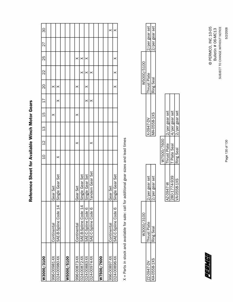
Ref
eren
ce S
heet
for
Ava
ilabl
e W
inch
Mot
or G
ears
W30
00/3
100
1012
1315
1720
2225
2730
996-
0098
1-XX
Con
tinen
tal
Gea
r S
etX
X02
4-00
980-
XXS
AE-B
-Spl
ine
Cod
e 14
Sin
gle
Gea
r S
etX
XX
W50
00/5
100
996-
0087
3-XX
Con
tinen
tal
Gea
r S
etX
XX
X02
4-00
872-
XXS
AE-B
-Spl
ine
Cod
e 14
Sin
gle
Gea
r S
etX
X02
4-00
883-
XXS
AE-C
-Spl
ine
Cod
e 6
Sin
gle
Gea
r S
etX
XX
X02
4-00
974-
X XS
AE-C
-Spl
ine
Cod
e 6
Tand
em G
ear
Set
XX
X
W75
00/7
600
996-
0089
7-XX
Con
tinen
tal
Gea
r S
etX
024-
0089
6-XX
SAE
-C-S
plin
e C
ode
6S
ingl
e G
ear
Set
XX
XX
X =
Part
s in
sto
ck a
nd a
vaila
ble
for
sale
: cal
l for
add
ition
al g
ear
size
s an
d le
ad t
imes
W
3000
/310
0
W
5000
/510
0ZZ
-094
7-D
VTh
rust
Pla
te2/
per
gear
set
X-09
47-D
VTh
rust
Pla
te2/
per
gear
set
KA-
0558
-1XS
Rin
g S
eal
2/pe
r ge
ar s
etM
A-05
58-1
XSR
ing
Sea
l2/
per
gear
set
W75
00/7
600
AZ-0
947-
WTh
rust
Pla
te2/
per
gear
set
280-
1774
-939
T Pl
ate
Sea
l4/
per
gear
set
VA-0
558-
1XS
Rin
g S
eal
2/pe
r ge
ar s
et
© P
ERM
CO
, IN
C 1
0-05
Bul
letin
# 0
6-M
C13
SU
BJE
CT
TO C
HAN
GE
WIT
HO
UT
NO
TIC
E
Page
130
of 1
305/
2/20
08