
Masoneilan™ 12400 Series - Baker Hughes DAM
20
Masoneilan ™ 12400 Series Digital Level Transmitter/Controller • SIL2 Capability • Ease of Use • Seamless Integration
-
Upload
khangminh22 -
Category
Documents
-
view
0 -
download
0
Transcript of Masoneilan™ 12400 Series - Baker Hughes DAM

Masoneilan™ 12400 SeriesDigital Level Transmitter/Controller• SIL2 Capability• Ease of Use• Seamless Integration
2
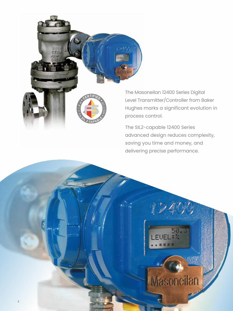
The Masoneilan 12400 Series Digital Level Transmitter/Controller from Baker Hughes marks a significant evolution in process control.
The SIL2-capable 12400 Series advanced design reduces complexity, saving you time and money, and delivering precise performance.

3
With a combination of features such as smart filtering, HART® communication protocol compatibility and an optional 4-20 mA analog output signal, Baker Hughes Masoneilan 12400 Series transmitter/controller offers exceptional process control for a wide range of applications - even severe service. Easy to install and operate, it is the first torque tube-type level instrument that integrates level transmitter and switch functions in a single device. Plus, the 12400 Series transmitter/controller is engineered for optimum efficiency, upgradeability and reliability making it a cost-effective investment for the long term.
The Masoneilan 12400 Series instrument is a two-wire, loop-powered level transmitter with HART® Communication that operates according to the fully
proven buoyancy and torque tube principles. A change in liquid level varies the net weight of the displacer (2), increasing or decreasing the load on the torque tube (4) by an amount directly proportional to the change in liquid level. The resulting rotation of the torque rod (6) and attached magnets (7) modifies the magnetic field surrounding a non-contact sensor (8), producing an analog signal proportional to the level in the vessel. This analog signal is converted into an error-free digital signal that is processed by the on-board micro-controller. After processing, the digital result is converted to a 4-20 mA analog output signal.
This sensing method is non-contacting and frictionless, and it provides total isolation between the sensed motion and sensor output.
Overview
Sketch showing the arrangement of the different parts.
In black: torque tube, arm and displacer
In orange: mechanism and displacer chambers
In blue: instrument head
1 - Displacer chamber 2 - Displacer 3 - Torque arm 4 - Torque tube 5 - Torque tube housing 6 - Torque rod 7 - Magnets 8 - Non-contact sensor
12
34
56
6
7 8

4
Ease of UseWhile the Masoneilan 12400 series transmitter/controller offers powerful measurement functionality, it delivers efficiency for simplified ownership and operations.
Easy InstallationLocal and remote installation are available via three explosion-proof pushbuttons or the HART® communication protocol, and the 12400 Series transmitter can be calibrated with or without fluid, including fluid with an unknown specific gravity.
Simple OperationThe 12400 Series instrument offers automated configuration, calibration and diagnostic functions as well as an easy-to-read, seven-language LCD display.
InteroperabilityField data integration is seamless across multiple communication platforms: Baker Hughes Masoneilan ValVue™ software, Device Description (DD) and Device Type Manager (DTM), any HART®-compatible handheld and ValVue software plug-in and snap-on.
Key Benefits
User-friendly instrument health summary

5
Cost-EffectiveThe 12400 Series instrument saves money, time and other valuable resources through its advanced functionality, reliability and scalability.
Streamlined FunctionalityThis is the first level instrument to offer integrated level transmitter, controller and switch functions in a single device eliminating the need for additional switches.
Durability for Long-Term ServiceThe accurate, non-contact sensor provides reduced wear and reliable performance, and the rugged construction protects from weather and harsh elements.
Cost-Saving UpgradeabilityField upgradeable flash firmware for future updates.
Advanced Process Control PerformanceWith a range of outstanding features in a durable, flexible package, the 12400 Series meets many of the industry’s most demanding application requirements.
ComplianceThe 12400 Series is SIL2-capable (Transmitter function only) and holds full hazardous areas certifications including ATEX, IECEx, FM and FMc (Factory Mutual Canada).
Severe Service CapabilityThe instrument withstands high temperature, high pressure and demanding NACE applications.
FlexibilityThe instrument meets most installation requirements and accommodates most process structures through top, side or bottom connections and full horizontal plane rotation.
AccuracySmart filtering reduces unwanted oscillations without changing response speeds, and the frictionless sensor offers 0.1 percent measurement resolution.
StabilityInside a chamber, surface turbulence and foam do not impede the displacer, and process fluid agitation does not affect measurement.
Reliable DataContinuous recording and recent data is stored in non-volatile memory for dependable access in the event of power failure.
Key Benefits

6
Seamless Integration
Third Party AssetManagementControl System ValVue Suite
Open TechnologieseDDLDTM
Plug-In ApplicationSnap-On Application
Conventional I/OWireless
Field Calibrators with HART®
Baker Hughes DPI620 Series CalibratorHART® Handheld Communicator
Baker Hughes Masoneilan Valscope-PRO™
Baker Hughes Masoneilan ValVue standalone

7
Open Technology
The 12400 Series digital level instruments can be integrated with a broad range of controllers, control systems and software available in the industry.
Feature Integration Benefit
Low compliance voltage (10 VDC) For legacy system, low impedance circuitry, and Masoneilan VECTOR™ (loop-powered wireless HART® adaptor)
Built-In Analog and Discrete signals For non-HART® systems and to meet specific industry requirements where digital communications is not approved
HART®, wired or wireless compliant Integration flexibility of device calibration and diagnostic, and level variables
eDDL compliant Interface that Integrates with eDDL hosts, software, portable calibrators
DTM compliant Integrates with FDT capable hosts
Asset management compliant Integrates with plant management software

8
SIL 2 Capability for Enhanced Safety
The 12400 Series transmitter, SIL2-certified in accordance with IEC61508 per EXIDA, is suitable for use in safety instrumented functions.
Complete Safety Function: From Displacer up to Analog Output SignalThe safety function of the 12400 Series transmitter is not limited to the instrument head, but also includes all measurement components.
The FMEDA analysis results include the entire transmitter from displacer through the torque tube, the sensor, and the electronics up to the 4-20 mA output signal. In contrast, other available devices limit their analysis to the instrument head only.
Including all measurement components in the safety function means a higher diagnostic coverage and a Safe Failure Fraction greater than 90 percent.
Enhanced Diagnostic CoverageThe 12400 Series instrument has been enhanced with a new sensor bias sub-assembly to enable a better diagnostic coverage of internal and user faults. Following in the footsteps of many other innovations that have made Baker Hughes Masoneilan product line a technology leader, this new patented solution improves the diagnostic analysis on all components between the sensor and the torque rod. In case of failure caused by a loose part or human error, the spring arm will force the sensor to go into the repeatable failsafe position.
This is particularly useful in detecting the main faults that are often human errors during the coupling procedure. For instance, the wrong coupling or a loose coupling between the sensor mechanism and the torque rod can occur when the work is done by untrained people. These errors are now fully detected and diagnosed, and they will generate a HART fault message and could even activate one of the two optional switches.
Normal operatingCoupling correctly done
Failure diagnosticLoosen coupling
The spring arm forcesthe sensor to go infailsafe position.

9
DigitalOutput
DigitalOutput
ConventionalFeedbackLow Level Alarm
High Level Alarm
Each discrete contact is configurable for normal open or closed action and with several possible triggers.
HART®AnalogOutput
AnalogOutput
Main 4-20 mALevel Variable(Transmitter) or Controller Output (Controller)
With HART® Data
Second 4-20mALevel Variable
Electrical Implementation
Case Sketch
Couplinglamella
Case
Torquerod
Adjustingscrews
PlugO-ring
CouplingflangeBeamMagnetCover
Circuitboard
Non-contactsensorDisplay
Pushbuttonscover
Window

10
General Data
User Interface:• Handheld Communicator
• Pushbuttons operation with digital display
• ValVue software
• ValVue AMS™ snap-on
• ValVue PRM™ plug-in
• DTM though any FDT/DTM compatible host
Level Transmitter/Controller:• Level or interface level measurement
• Specific gravity measurement and display (only with the displacer fully immersed)
– Zero and span digital calibration:
– independent zero and span adjustment
– current loop range independent from zero/span calibration (can be changed at any time without zero/span re-calibration)
– manual or automatic calculation for reduced span and zero shift for interface service
• Self-tuning for smart filtering
• Selectable low and high level alarms
• Low or high failsafe output signal immediately activated in case of a failure detection
• Continuous self-diagnostic with bargraph
• Continuous data record: number of fillings, low level time, high level time, working time
• Configuration check: analysis of 12400 data base to avoid bad mounting, out of range use
• Storage and display of alarms that have appeared
• Output current generator for loop check
Level Controller:• P, I , D ... advanced control
• Remote setpoint and controller output
• Low and high controller alarms (absolute and deviations)
• Process trend through ValVue software suite
Level Switches:• Two built-in solid state switches: 1 A - 30 VDC max
• Configurable: low and high level alarms, fault or reset occurred, instrument in failsafe
Second 4-20 mA Analog Ouput:• Second level variable measurement, useful to connect
a local level indicator
Action:• Direct or reverse via software
Output Signal Filtering:• First order filtering of output signal with adjustable
time constant
• Smart filtering of contactless sensor output signal, to eliminate noise before digital signal processing
Software and Hardware Locks:• Software lock for pushbuttons
• Hardware jumper lock for full protection against parameter change
Instrument

11
Ambient Temperature Limits:• Standard Operating range: -40°C to +80°C (-40°F to
+176°F)
• Extended Operating range: -50°C to +85°C (-58°F to +185°F)
– For devices installed in hazardous area, temperature limits depend on the marking
– LCD display may not be readable below -15°C (+5°F)
– Beyond standard operating range, performance may be affected by the temperature shift
• Storage and transportation: -50°C to +93°C (-58°F to +200°F)
• Ambient temperature shift: ±0.028% /°C of full span (zero and span, over extended temperature range)
Process Temperature Limits:• -210°C to +450°C (-350°F to +850°F)
For temperature higher than +150°C (+302°F) or lower than -100°C (-150°F), an extension is required between the case and the torque tube. Note: See diagram page 12 and approval certificates.
Specific Gravity Range:• 0.15 to 1.4 with a standard displacer
• Lower and higher specific gravities with special displacers (consult your local sales contact)
Electric Characteristics FollowingNAMUR NE 43:• Normal output signal: 3.8 to 20.5 mA
• Low failsafe output signal (< 3.6 mA)
• High failsafe output signal (> 21 mA)
Supply Voltage:• U min = 10 VDC
• U max = 30 VDC (intrinsic safety)
• U max = 40 VDC for AO_1 30 VDC for AO_2 (flameproof envelope)
Supply Voltage Influence:• 0.1 μA/V
General Data
Performance Specifications Instrument Head Alone Instrument Headwith Torque Tube S/A
Accuracy (full span) ±0.1% ±0.5%on request ±0.25%
Hysteresis + Dead Zone (full span) ±0.1% ±0.3%
Repeatability (full span) ±0.1% ±0.2%
Performance at room temperature with standard displacer and specific gravity from 0.15 to 1.4 (or special displacer with equivalent sensor angle variation) within standard operating temperature range.
Operating Limits
Electromagnetic CompatibilityCompliance with EMC Directive 2004/108/EC, including NF EN 61000-6-2, NF EN 61326-1, NF EN 61326-3-1, NF EN 61000-6-4 and NF EN 55022 standards.
Over-voltage Protection (at 25°C / 77°F)• 10 kW for 8/20 μs pulse wave form
• 1.5 kW for 10/1000 μs pulse wave form

12
Numbering System Series Identification 12abc - de
Pressure Envelope CharacteristicsRating • ANSI class 150 to 2500 • PN 10 to PN 420
Ranges • 356, 610, 813, 1219, 1524, 1829, 2134, 2438, 3048mm
(14’’, 24’’, 32’’, 48’’, 60’’, 72’’, 84’’, 96’’, 120’’) Other ranges on request
Temperature LimitsUse an extension between case and torque tube for temperatures included in colored area.
Notes:
1. Above 260°C (500°F), torque tube must be in Inconel.
2. 12402, 12406, 12407 and 12409 models only, for stainless steel version, can be used between +400°C (+750°F) and +450°C (+850°F).
3. For devices installed in hazardous location, temperature limits depend on the marking See page 13 for complete information.
a Mode4. SIL-certified1, HART® communication protocol, LCD display and push buttons
bAction1. Controller with adjustable switches and second 4-20 mA analog output signal: AO_1, AO_2, DO_1,
DO_22. Transmitter: AO_13. Transmitter with adjustable switches and second 4-20 mA analog output signal: AO_1, AO_2, DO_1,
DO_2
cMounting0. Top and bottom Screwed, BW or SW 5. Top and side Screwed, BW or SW1. Top and bottom Flanged 6. Side and bottom Screwed, BW or SW2. Side and side Flanged 7. Side and bottom Flanged3. Top vessel Flanged 8. Top and side Flanged4. Side vessel Flanged 9. Side and side Screwed, BW or SW
d
Hazardous Protection1. FM & FMc (ex CSA), Intrinsically Safe, Explosion proof,
and Nema 4X-6P2. JIS, Explosion proof3. CU TR (ex Gost-R), Intrinsically Safe, Explosion proof, and IP 66/674. Inmetro, Intrinsically Safe, Explosion proof5. ATEX & IECEx Intrinsically Safe, Explosion proof, and IP 66/676. Other approvals (based on ATEX/IEC approvals)7. Other approvals (not based on ATEX/IEC approvals)
e Housing Material1. Aluminium with epoxy painting2. Stainless steel
12 4123
0123456789
-1234567
12
1. Only Transmitter function is SIL certified.

13
Hazardous Location ProtectionATEX & IECEx Approvals(94/9/EC Directive)Explosion proof• II 2 G/D Ex d IIC T6, T5 or T4 Gb Ex tb IIIC T85°C, T100°C or T135°C Db IP66/IP67
Intrinsic safety• II 1 G/D Ex ia IIC T6, T5 or T4 Ga Ex ia IIIC T85°C, T100°C or T135°C Da IP 66/67
FM and FMc Approvals (Factory Mutual and Factory Mutual Canada)
Explosion proof• Class I ; Division 1 & 2 Groups B, C, D T6 or T5
Dust-ignition proof• Class II & III ; Division 1 & 2 Groups E, F, G T6 or T5
Intrinsically safe• Class I, II, III ; Division 1 & 2 Groups A, B, C, D, E, F, G T6, T5 or T4
Non-incendive• Class I, II, III ; Division 2 Groups A, B, C, D, F, G T6 or T5
Other approvals:• CU TR (Russia, Belarus and Kazakhstan)
• JIS (Japan)
• KOSHA (Korea)
• CCOE (India)
• Inmetro (Brazil)
• NEPSI (China)
• IA (South Africa)
• CRN (Canada)
• IP 66 / IP 67
• NEMA 4X - 6P
Enclosure Rating

14
Mounting
In case of internal mounting, the instrument has no displacer chamber; the mechanism chamber flange is bolted directly on the vessel flange.In case of liquid turbulence, it is recommended that the displacer is isolated with a damping chamber to prevent oscillations.
In case of external mounting, the instrument is connected to the vessel either with flanges or with screwed or welded connections. The instrument is constructed so that the mid-range level reference on the displacer chamber coincides with the normal level in the vessel.It is recommended that shut-off valves be inserted between the level connections and the vessel, with a drain valve on the lower part of the level.
Model 12403 Model 12404
Model 12400Model 12401
Model 12409Model 12402
Model 12405Model 12408
Model 12406Model 12407
Flanges:• Class flanges—according to EN 1759-1
and ASME B16-5 standards• PN flanges—according to NF EN 1092-1 or
DIN standards• Other standards and dimensions, please
consult your local Baker Hughes sales contact
Model Connections
12400 BW, SW or Screwed NPT - 1 1/2’’ and 2’’ - DN 40 and DN 50
12401 Flanged - 1 1/2’’ and 2’’ - DN 40 and DN 50
12409 BW, SW or Screwed NPT - 1 1/2’’ and 2’’ - DN 40 and DN 50
12402 Flanged - 1 1/2’’ and 2’’ - DN 40 and DN 50
12405 BW, SW or Screwed NPT - 1 1/2’’ and 2’’ - DN 40 and DN 50
12408 Flanged - 1 1/2’’ and 2’’ - DN 40 and DN 50
12406 BW, SW or Screwed NPT - 1 1/2’’ and 2’’ - DN 40 and DN 50
12407 Flanged - 1 1/2’’ and 2’’ - DN 40 and DN 50
12403 Flanged - 3’’ and 4’’ - DN 80 and DN 10
12404 Flanged - 4’’ - DN 100

15
Note: Unless otherwise specified, the case will be position 1 left-mounted
Left hand instrument mounting Right hand instrument mounting
Weight (kg)
Weight (lbs) Models: ANSI 600 and PN 100
Models: 12402, 12405, 12406, 12407, 12408 & 12409
Orientation
Model
Level ranges
356mm 610mm 813mm 1219mm 1524mm 1829mm 2134mm 2438mm 3048mm
14’’ 24’’ 32’’ 48’’ 60’’ 72’’ 84’’ 96’’ 120’’
12400 79 90 90 101 108 117 123 130 146
12401 90 101 101 112 119 128 135 141 157
12409 112 123 123 135 141 150 157 163 179
12402 121 132 132 143 150 159 165 172 187
12405 110 121 121 132 139 148 154 161 176
12408 119 130 130 141 148 157 163 170 185
12406 110 121 121 132 139 148 154 161 176
12407 121 132 132 143 150 159 165 172 187
12403 88 88 88 88 88 88 88 88 88
12404 88 88 88 88 88 88 88 88 88
Models: ANSI 600 and PN 100
Model
Level ranges
356mm 610mm 813mm 1219mm 1524mm 1829mm 2134mm 2438mm 3048mm
14’’ 24’’ 32’’ 48’’ 60’’ 72’’ 84’’ 96’’ 120’’
12400 36 41 41 46 49 53 56 59 66
12401 41 46 46 51 54 58 61 64 71
12409 51 56 56 61 64 68 71 74 81
12402 55 60 60 65 68 72 75 78 85
12405 50 55 55 60 63 67 70 73 80
12408 54 59 59 64 67 71 74 77 84
12406 50 55 55 60 63 67 70 73 80
12407 55 60 60 65 68 72 75 78 85
12403 40 40 40 40 40 40 40 40 40
12404 40 40 40 40 40 40 40 40 40

16
1Displacerchamber
3Mechanism
chamber upper flange
2Mechanism
chamber
5Displacerhanger
7Torque
arm
6Extension
rod
Studs14 Nuts
15 Torque tube flanges
10
Instrumentcase
16
Instrument cover
17
12Torque rod
9Torque tube
housing8
Torque tube
11Torque tube
knife
4Displacer
Materials of Construction

17
Standard Constructions
Description Carbon Steel Stainless Steel
1 Displacer chamber (tube) ASTM A 106 Gr B (300/600 lbs) / 1.0425 EN 10216-2 (900/1500 lbs) ASTM A 312 Ty 316 / 1.4401 EN
2 Mechanism chamber ASTM A 216 Gr WCC / 1.0625 EN 10213-2 ASTM A 351 Gr CF8M / 1.4408 EN 10213
3 Mechanism chamberupper flange
Flanged: ASTM A 216 Gr WCC / 1.0625 EN 10213-2Others: ASTM A 105 / 1.0481 EN 10273
Flanged: ASTM A 351 Gr CF8M / 1.4408 EN 10213Others: 1.4401 EN 10272
4 Displacer ASTM A 312 Ty 316L ASTM A 312 Ty 316L
5 Displacer hanger ASTM A 240 Ty 316L ASTM A 240 Ty 316L
6 Extension rod ASTM A 479 Ty 316L ASTM A 479 Ty 316L
7 Torque arm ASTM A 479 Ty 316L ASTM A 479 Ty 316L
8 Torque tube Inconel 600 Inconel 600
9 Torque tube housing ASTM A 106 Gr B / 1.0425 EN ASTM A 312 Ty 316 / 1.4404 EN
10Torque tube flanges (mechanismchamber and instrument sides)
ASTM A 105 / 1.0481 EN 10273 1.4401 EN 10272
11 Torque tube knife ASTM A 479 Ty 316L ASTM A 479 Ty 316L
12 Torque rod Inconel 600 Inconel 600
13 Gaskets (torque tube, flanges) AISI 316L + Graphite AISI 316L + Graphite
14 Studs ASTM A 193 Gr B7 / 1.7225 EN 10269 zinc bichromate plated ASTM A 193 Gr B8 Cl. 2
15 Nuts ASTM A 194 Gr 2H zinc bichromate plated ASTM A 194 Gr 8
16 Instrument case Anodized cast aluminium, with epoxy painting Anodized cast aluminium, with epoxy painting
17 Instrument cover Anodized cast aluminium, with epoxy painting Anodized cast aluminium, with epoxy painting
"NACE" Constructions (exposed and non exposed bolting)
Description Carbon Steel Stainless Steel
1 Displacer chamber (tube) ASTM A 106 Gr B (300/600 lbs) / 1.0425 EN 10216-2 (900/1500 lbs) ASTM A 312 Ty 316 / 1.4401 EN
2 Mechanism chamber ASTM A 216 Gr WCC / 1.0625 EN 10213-2 ASTM A 351 Gr CF8M / 1.4408 EN 10213
3 Mechanism chamberupper flange
Flanged: ASTM A 216 Gr WCC / 1.0625 EN 10213-2Others: ASTM A 105 / 1.0481 EN 10273
Flanged: ASTM A 351 Gr CF8M / 1.4408 EN 10213Others: 1.4401 EN 10272
4 Displacer ASTM A 312 Ty 316L ASTM A 312 Ty 316L
5 Displacer hanger ASTM A 240 Ty 316L ASTM A 240 Ty 316L
6 Extension rod ASTM A 479 Ty 316L ASTM A 479 Ty 316L
7 Torque arm ASTM A 479 Ty 316L ASTM A 479 Ty 316L
8 Torque tube Inconel 600 Inconel 600
9 Torque tube housing ASTM A 106 Gr B / 1.0425 EN ASTM A 312 Ty 316 / 1.4404 EN
10Torque tube flanges (mechanismchamber and instrument sides)
ASTM A 105 / 1.0481 EN 10273 1.4401 EN 10272
11 Torque tube knife ASTM A 479 Ty 316L ASTM A 479 Ty 316L
12 Torque rod Inconel 600 Inconel 600
13 Gaskets (torque tube, flanges) AISI 316L + Graphite AISI 316L + Graphite
14 StudsExposed: ASTM A 193 Gr B7M electroless nickel platedNon exposed: ASTM A 193 Gr B7 / 1.7225 EN 10269 zinc bichromate plated
Exposed: ASTM A 193 Gr B8M Cl 2Non exposed: ASTM A 193 Gr B8 Cl2
15 NutsExposed: ASTM A 194 GR 2HM electroless nickel platedNon exposed: ASTM A 194 GR 2H zinc bichromate plated
Exposed: ASTM A 194 Gr 8 MANon exposed: ASTM A 194 Gr 8
16 Instrument case Anodized cast aluminium, with epoxy painting Anodized cast aluminium, with epoxy painting
17 Instrument cover Anodized cast aluminium, with epoxy painting Anodized cast aluminium, with epoxy painting
Note: Many other materials are available as option: alloy steels, K-Monel, Hastelloy… Please consult Baker Hughes.
Note: Standard materials and processes are in accordance with the requirements of NACE specification MR0103. Applications requiring compliance to MR0175-2003 or ISO 15156 must be reviewed by Baker Hughes.
Materials of Construction

18
Models: 12400, 12401, 12409, 12402, 12405 & 12408, ANSI 300-600 and PN 50-100
For ratings higher than ANSI 600 and PN 100, please consult your local Baker Hughes sales contact.
Dimensions/mm (inches)
192(7.5)33 (1.3)
149 (5.8)
MR
FF
Midrange
33 (1.3)
149 (5.8)
MR
90 (3.5)
Midrange
140(5.5)
FF
33 (1.3)
149 (5.8)
MR
192(7.5)
369 (14.5)
90 (3.5)
Midrange
140(5.5)
3/4’’ NPT VENT PLUG
FF
192(7.5)
12400
12405
12409
192(7.5)
84 (3.3)
149 (5.8)
MRMid
range
FF
84 (3.3)
MR
192(7.5)
114.5(4.5)
149 (5.8)
90 (3.5)
3/4’’ NPT DRAIN PLUG
Midrange
FF
33 (1.3)
MR
192(7.5)
369 (14.5)
114.5(4.5)
149 (5.8)
90 (3.5)
3/4’’ NPT DRAIN PLUG
Midrange
3/4’’ NPTVENTPLUG
FF
12401
12408
12402
12400RANGE
12401FF MR FF MR
mm inch mm inch mm inch mm inch mm inch569 22 239 9 356 14 660 26 279 11823 32 366 14 610 24 915 36 406 161026 40 467 18 813 32 1118 44 508 201432 56 670 26 1219 48 1524 60 711 281737 68 823 32 1524 60 1829 72 864 342042 80 975 38 1829 72 2134 84 1016 402347 92 1128 44 2134 84 2438 96 1168 462652 104 1280 50 2438 96 2743 108 1321 523261 128 1585 62 3048 120 3353 132 1626 64
12409RANGE
12402FF MR FF MR
mm inch mm inch mm inch mm inch mm inch356 14 178 7 356 14 356 14 178 7610 24 305 12 610 24 610 24 305 12813 32 406 16 813 32 813 32 406 161219 48 610 24 1219 48 1219 48 610 241524 60 762 30 1524 60 1524 60 762 301829 72 914 36 1829 72 1829 72 914 362134 84 1067 42 2134 84 2134 84 1067 422438 96 1219 48 2438 96 2438 96 1219 483048 120 1524 60 3048 120 3048 120 1524 60
12405RANGE
12408FF MR FF MR
mm inch mm inch mm inch mm inch mm inch508 20 178 7 356 14 559 22 178 7763 30 305 12 610 24 813 32 305 12966 38 406 16 813 32 1016 40 406 161372 54 610 24 1219 48 1422 56 610 241677 66 762 30 1524 60 1727 68 762 301982 78 914 36 1829 72 2032 80 914 362286 90 1067 42 2134 84 2337 92 1067 422591 102 1219 48 2438 96 2642 104 1219 483201 126 1524 60 3048 120 3251 128 1524 60

19
149 (5.8)
478 (18.8)**
217(8.5)
127(5.0)
173(6.8)
278(10.9)
Min 25 (1)Range
Ø 73 (2.9)
86 (3.4)
88 (3.5)
30(1.2)
Extension: 300 (11.7)*
478 (18.8)**
149 (5.8)
192(7.5)
235 (9.2)
173(6.8)
Range
33 (1.3)
86 (3.4)
Extension: 300 (11.7)*
3/4’’ NPT VENT PLUG
149 (5.8)149 (5.8)
192(7.5)
114.5(4.5)
192(7.5)
369(14.5)
369(14.5)
MRMR
Midrange
Midrange
33 (1.3)33 (1.3)
140(5.5)
3/4’’ NPT VENT PLUG3/4’’ NPTVENTPLUG
FFFF
Dimensions/mm (inches)
*Unless otherwise specified**With extension torque tube, add 138 mm (5.4 in.)
*Unless otherwise specified**With extension torque tube, add 138 mm (5.4 in.)
Top view(all modelsexcept 12404)
Models: 12406, 12407, 12403 & 12404, ANSI 150-600 and PN 50-100
12403 12404
1240712406
For ratings higher than ANSI 600 and PN 100, please consult your local Baker Hughes sales contact.
Flange description3’’ or 4’’
ANSI 150 - 600and PN 10-100
Flange description3’’ or 4’’
ANSI 150 - 600and PN 10-100
12406RANGE
12407FF MR FF MR
mm inch mm inch mm inch mm inch mm inch418 16 178 7 356 14 457 18 178 7673 26 305 12 610 24 711 28 305 12876 34 406 16 813 32 914 36 406 161282 50 610 24 1219 48 1321 52 610 241587 62 762 30 1524 60 1626 64 762 301892 74 914 36 1829 72 1930 76 914 362196 86 1067 42 2134 84 2235 88 1067 422501 98 1219 48 2438 96 2540 100 1219 483111 122 1524 60 3048 120 3150 124 1524 60

bakerhughes.com
Tech Field Support & Warranty:Phone: +1-866-827-5378
Direct Sales Office LocationsAustraliaBrisbanePhone: +61-7-3001-4319PerthPhone: +61-8-6595-7018MelbournePhone: +61-3-8807-6002
BrazilPhone: +55-19-2104-6900
ChinaPhone: +86-10-5738-8888
FranceCourbevoiePhone: +33-1-4904-9000
IndiaMumbaiPhone: +91-22-8354790
New DelhiPhone: +91-11-2-6164175
ItalyPhone: +39-081-7892-111
JapanTokyo Phone: +81-03-6871-9008
KoreaPhone: +82-2-2274-0748
MalaysiaPhone: +60-3-2161-03228
MexicoPhone: +52-55-3640-5060
RussiaVeliky NovgorodPhone: +7-8162-55-7898MoscowPhone: +7-495-585-1276
Saudi ArabiaPhone: +966-3-341-0278
SingaporePhone: +65-6861-6100
South AfricaPhone: +27-11-452-1550
South & Central America and the CaribbeanPhone: +55-12-2134-1201
SpainPhone: +34-935-877-605
United Arab EmiratesPhone: +971-4-8991-777
United KingdomPhone: +44-7919-382-156
United StatesHouston, TexasPhone: +1-713-966-3600
Find the nearest local Channel Partner in your area:valves.bakerhughes.com/contact-us
valves.bakerhughes.com
Copyright 2020 Baker Hughes Company. All rights reserved.
BHMN-12400-DLT-BR-19663D-0620 06/2020