MARVEL: A wireless Miniature Anchored Robotic Videoscope for Expedited Laparoscopy
6
Abstract— This paper describes the design and implementation of a Miniature Anchored Robotic Videoscope for Expedited Laparoscopy (MARVEL) and Camera Module (CM) that features wireless communications and control. The CM decreases the surgical-tool bottleneck experienced by surgeons in state-of-the art Laparoscopic Endoscopic Single- Site (LESS) procedures for minimally invasive abdominal surgery. The system includes: (1) a near-zero latency video wireless communications link, (2) a pan/tilt camera platform, actuated by two motors that provides surgeons a full hemisphere field of view inside the abdominal cavity, (3) a small wireless camera, (4) a wireless illumination control system, and (5) a wireless human-machine interface (HMI) to control the CM. An in-vivo experiment on a porcine subject was carried out to test the performance of the system. The robotic design is a Research Platform for a broad range of experiments in a range of domains for faculty and students in the Colleges of Engineering and Medicine and at Tampa General Hospital. This research is the first step in developing semi-autonomous wirelessly controlled and networked laparoscopic devices to enable a paradigm shift in minimally invasive surgery and other domains such as Wireless Body Area Networks. I. INTRODUCTION Minimally Invasive Surgery (MIS) is an alternative to conventional “open” surgery. MIS minimizes trauma and metabolic disruption to patients by minimizing incisions and points of access to patients’ body cavities. Laparo- Endoscopic Single Site (LESS) surgery is an advance in MIS for digestive disorders and is performed through the umbilicus, which provides access to the abdominal and pelvic cavities, and through multiple small incisions distant to the umbilicus through which trocars (i.e. small hollow valved tubes) are placed to provide access for operating instruments. Cristian A. Castro was with the Electrical Engineering Department, University Of South Florida, Tampa, FL 33620 USA, [email protected]. Sara Smith was with the Industrial Engineering Department, University Of South Florida, Tampa, FL 33620 USA, [email protected]. Adham Alqassis, Thomas Ketterl, and Richard D. Gitlin are with the Electrical Engineering Department, University Of South Florida, Tampa, FL 33620 USA, [email protected], [email protected], [email protected]. Yu Sun is with the Computer Science Engineering Department, University Of South Florida, Tampa, FL 33620 USA, [email protected]. Sharona Ross is with the College of Medicine, University Of South Florida, Tampa, FL 33620 USA, [email protected]. Alexander Rosemurgy is Surgical Director, Center for Digestive Disorders, Tampa General Hospital, Tampa, FL 33606 USA. Peter P. Savage is an independent consultant, [email protected] and Co-CEO of Innovatia Medical Systems LLC, Tampa and St. Petersburg, FL 33701 [email protected]. Current “state-of-the-art” commercial videoscopes (i.e. laparoscopes, endoscopes) for MIS are encumbered by cabling for power, video, and a xenon light source inside a semi-flexible or rigid mechanical rod. Though these videoscopes are quite good in image quality, they are cumbersome and require a point of access into the patient, either through a separate incision or through a port in a multi- port access trocar. The light, video image, and power cables of the videoscope clutter and consume space in the operative field, which is sometimes referred to by surgeons as “dueling swords.” A conventional videoscope also requires an assistant in the operating room to hold the scope and redirect it to maintain consistent and stable views of the ongoing operation. Some developing approaches to intracavity visualization bypass the rod-lens approach of conventional videoscopes, but the resulting video platforms still maintain a significant spatial presence within the operating cavity and require multiple points of access (e.g. incisions and/or trocars). There is significant interest in developing advanced endoscopes for MIS [1]. Research at University of California at Los Angeles (UCLA) [2], includes a surgical “polyvisiometric” camera. This device provides a multi-view video platform with simultaneous views of the surgical sites and surrounding anatomy from multiple camera angles. It attaches to the abdominal wall by pressure arms with four cameras at 90 degrees. Other research on endoscopic cameras by Columbia University [3]-[4] includes two distinct prototypes, one with a single camera and another with a stereoscopic camera, allowing for the possibility of depth perception, but resulting in an increased diameter. The Columbia cameras feature a low power, high efficiency pan/tilt mechanism and have pinhole lenses. At the University of Nebraska, Lincoln [5]-[6] work has been done on a robotic camera system that moves through the abdominal cavity while tethered to a supporting cable for power and video interfacing. UNL has also performed work on cameras attached to the abdominal wall and manipulated via magnetic fields. Recent work at The BioRobotics Institute, Scuola Superiore Sant’Anna, Pisa, Italy [7] resulted in the design of three 12mm diameter modular robotic units: a camera, a retractor and a manipulator unit, and the assembly and testing of the camera unit. Though significant advances will certainly occur for standard MIS, none of these prior approaches to advanced endoscopy is optimized for LESS surgery due to the need for additional incisions for camera cabling or insufficient anchoring of the camera itself. To optimize a camera for LESS surgery, we have designed a wireless communications and control Miniature MARVEL: A Wireless Miniature Anchored Robotic Videoscope for Expedited Laparoscopy Cristian A. Castro, Member, IEEE, Sara Smith, Adham Alqassis, Thomas Ketterl, Member, IEEE, Yu Sun, Sharona Ross, Alexander Rosemurgy, Peter P. Savage, and Richard D. Gitlin, Fellow, IEEE 2012 IEEE International Conference on Robotics and Automation RiverCentre, Saint Paul, Minnesota, USA May 14-18, 2012 978-1-4673-1404-6/12/$31.00 ©2012 IEEE 2926
-
Upload
independent -
Category
Documents
-
view
4 -
download
0
Transcript of MARVEL: A wireless Miniature Anchored Robotic Videoscope for Expedited Laparoscopy

Abstract— This paper describes the design and implementation of a Miniature Anchored Robotic Videoscope for Expedited Laparoscopy (MARVEL) and Camera Module (CM) that features wireless communications and control. The CM decreases the surgical-tool bottleneck experienced by surgeons in state-of-the art Laparoscopic Endoscopic Single-Site (LESS) procedures for minimally invasive abdominal surgery. The system includes: (1) a near-zero latency video wireless communications link, (2) a pan/tilt camera platform, actuated by two motors that provides surgeons a full hemisphere field of view inside the abdominal cavity, (3) a small wireless camera, (4) a wireless illumination control system, and (5) a wireless human-machine interface (HMI) to control the CM. An in-vivo experiment on a porcine subject was carried out to test the performance of the system. The robotic design is a Research Platform for a broad range of experiments in a range of domains for faculty and students in the Colleges of Engineering and Medicine and at Tampa General Hospital. This research is the first step in developing semi-autonomous wirelessly controlled and networked laparoscopic devices to enable a paradigm shift in minimally invasive surgery and other domains such as Wireless Body Area Networks.
I. INTRODUCTION
Minimally Invasive Surgery (MIS) is an alternative to conventional “open” surgery. MIS minimizes trauma and metabolic disruption to patients by minimizing incisions and points of access to patients’ body cavities. Laparo-Endoscopic Single Site (LESS) surgery is an advance in MIS for digestive disorders and is performed through the umbilicus, which provides access to the abdominal and pelvic cavities, and through multiple small incisions distant to the umbilicus through which trocars (i.e. small hollow valved tubes) are placed to provide access for operating instruments.
Cristian A. Castro was with the Electrical Engineering Department,
University Of South Florida, Tampa, FL 33620 USA, [email protected].
Sara Smith was with the Industrial Engineering Department, University Of South Florida, Tampa, FL 33620 USA, [email protected].
Adham Alqassis, Thomas Ketterl, and Richard D. Gitlin are with the Electrical Engineering Department, University Of South Florida, Tampa, FL 33620 USA, [email protected], [email protected], [email protected].
Yu Sun is with the Computer Science Engineering Department, University Of South Florida, Tampa, FL 33620 USA, [email protected].
Sharona Ross is with the College of Medicine, University Of South Florida, Tampa, FL 33620 USA, [email protected].
Alexander Rosemurgy is Surgical Director, Center for Digestive Disorders, Tampa General Hospital, Tampa, FL 33606 USA.
Peter P. Savage is an independent consultant, [email protected] and Co-CEO of Innovatia Medical Systems LLC, Tampa and St. Petersburg, FL 33701 [email protected].
Current “state-of-the-art” commercial videoscopes (i.e. laparoscopes, endoscopes) for MIS are encumbered by cabling for power, video, and a xenon light source inside a semi-flexible or rigid mechanical rod. Though these videoscopes are quite good in image quality, they are cumbersome and require a point of access into the patient, either through a separate incision or through a port in a multi-port access trocar. The light, video image, and power cables of the videoscope clutter and consume space in the operative field, which is sometimes referred to by surgeons as “dueling swords.” A conventional videoscope also requires an assistant in the operating room to hold the scope and redirect it to maintain consistent and stable views of the ongoing operation. Some developing approaches to intracavity visualization bypass the rod-lens approach of conventional videoscopes, but the resulting video platforms still maintain a significant spatial presence within the operating cavity and require multiple points of access (e.g. incisions and/or trocars).
There is significant interest in developing advanced endoscopes for MIS [1]. Research at University of California at Los Angeles (UCLA) [2], includes a surgical “polyvisiometric” camera. This device provides a multi-view video platform with simultaneous views of the surgical sites and surrounding anatomy from multiple camera angles. It attaches to the abdominal wall by pressure arms with four cameras at 90 degrees. Other research on endoscopic cameras by Columbia University [3]-[4] includes two distinct prototypes, one with a single camera and another with a stereoscopic camera, allowing for the possibility of depth perception, but resulting in an increased diameter. The Columbia cameras feature a low power, high efficiency pan/tilt mechanism and have pinhole lenses. At the University of Nebraska, Lincoln [5]-[6] work has been done on a robotic camera system that moves through the abdominal cavity while tethered to a supporting cable for power and video interfacing. UNL has also performed work on cameras attached to the abdominal wall and manipulated via magnetic fields. Recent work at The BioRobotics Institute, Scuola Superiore Sant’Anna, Pisa, Italy [7] resulted in the design of three 12mm diameter modular robotic units: a camera, a retractor and a manipulator unit, and the assembly and testing of the camera unit.
Though significant advances will certainly occur for standard MIS, none of these prior approaches to advanced endoscopy is optimized for LESS surgery due to the need for additional incisions for camera cabling or insufficient anchoring of the camera itself.
To optimize a camera for LESS surgery, we have designed a wireless communications and control Miniature
MARVEL: A Wireless Miniature Anchored Robotic Videoscope for Expedited Laparoscopy
Cristian A. Castro, Member, IEEE, Sara Smith, Adham Alqassis, Thomas Ketterl, Member, IEEE, Yu Sun, Sharona Ross, Alexander Rosemurgy, Peter P. Savage, and Richard D. Gitlin, Fellow, IEEE
2012 IEEE International Conference on Robotics and AutomationRiverCentre, Saint Paul, Minnesota, USAMay 14-18, 2012
978-1-4673-1404-6/12/$31.00 ©2012 IEEE 2926

Anchored Robotic Videoscope for Expedited Laparoscopy (MARVEL) Research Platform that is self-contained, internalized, and cable-free. MARVEL decreases the surgical-tool bottleneck experienced by surgeons in single-site procedures. The Camera Module (CM) of the MARVEL system includes: (1) a pan/tilt platform, actuated by two motors, to give surgeons a full hemisphere of view inside the abdominal cavity (2) a small wireless camera, (3) a wireless illumination control system, and (4) a wireless human-machine interface (HMI) to control the CM and (5) a near-zero latency wireless link to meet surgical requirements.
Cable-free wireless videoscopes allow trocar ports to be reused for other laparoscopic surgical equipment eliminating spatial congestion caused by current LESS techniques.
II. CONCEPT AND DESIGN
A. MARVEL System Overview The MARVEL System consists of a wireless human-
machine interface (HMI) and a wireless laparoscopic Camera Module (CM) attached to the abdominal wall. An Insertion / Removal Tool (IRT) (not shown) will be used to (i) insert the CM through a trocar port, (ii) attach the MARVEL CM to the abdominal wall, and (iii) remove the CM on completion of the operation. The IRT will (i) supply power to the CM during insertion and removal, (ii) align the CM so the illumination and video imaging subsystems enter the trocar port first, providing video imaging during the insertion process, (iii) secure the needle within the IRT to preclude inadvertent needle contact during insertion and removal, (iv) rotate the CM to a position perpendicular to the abdominal wall, and (v) push the needle through the abdominal wall holding the CM in place while the Attachment Module (AM) secures the CM in place. Power is supplied to the CM by the AM, allowing uninterrupted CM operation.
The surgeon interacts with the system through a standard Logitech joystick, model number 963291-0403 and a Labview application running on a standard computer (Figure 1). The joystick controls direction of motion of the CM through the available hemisphere of motion, and the velocity of pan and tilt motion. Every command from the joystick is interpreted to specific control instructions that are pushed out into a datagram. The instructions are then relayed to a 900 MHz band ISM digital transceiver where they are wirelessly transmitted to the MARVEL (CM). The wireless datagram is processed by the embedded microcontroller (MCU) in the CM, and divided into pan, tilt, light intensity, and image sensor control commands. For every command, the MCU drives control signals for all of the internal modules. The wireless video from MARVEL is continuously transmitted through an analog wireless interface to the wireless Human Machine Interface (HMI) and displayed with near-zero latency on high-resolution monitors.
MARVEL has been designed to address the following functional requirements:
• 10x42mm camera housing platform • Wireless actuator control • Wireless illumination control • Enhanced view inside abdominal cavity • Needle power and anchor subsystem
• Wireless and cable-free videoscope • Wireless HMI • 1080p High Definition video, 30fps, near-zero (1ms)
latency displayed video In order to design a reusable modular Research Platform
where new functionality can be added and tested efficiently, a 3x size model was designed, taking care to ensure that the electronics could fit in a 1x (~10mm) commercialized CM. The 3x MARVEL CM is 105mm long with a diameter of 30mm.
Figure 1. Top: MARVEL System, Bottom: MARVEL Camera Module
after attachment to abdominal wall.
A MARVEL CM is composed of five subsystems: (1) the illumination subsystem provides light inside the abdominal cavity, (2) the vision subsystem provides optimal focus range and video resolution, (3) the wireless communication subsystem handles the control commands and video between the device and the HMI, (4) the embedded control subsystem handles the control decision making for the device, and (5) the attachment needle power subsystem secures the CM to the abdominal wall and powers the CM.
Figure 2. MARVEL: Top: CAD model of the CM,Bottom: MARVEL CM
Research Platform
2927
B. Illumination Subsystem The illumination subsystem in the CM is composed of a
ring of 6 LEDs, a reflector array, and an aluminum heat sink. The LEDs are Cree XP-E High-Efficiency white LEDs), with each emitting 130 lumens at 350 mA, with a color temperature range of 5000°K to 8300°K (cool white). At 700mA, and 3.3 volts, the LED is drawing 2.31 watts, which yields a luminous efficiency of 130 lumens / 2.31 watts = 56.3 lumens per watt. The illumination subsystem emits 780 lumens at 13.86 watts.
It is important to keep the junction temperature in each LED as close as possible to 25°C, as efficiency decreases as temperature increases. Also high temperatures create unsafe conditions for the patient [8]. At 25°C the LED outputs 100% relative luminous flux, however at 150°C the output of the LED drops by 30%. In order to dissipate this heat, an aluminum heat sink was designed (Figure 3). The heat sink is part of the CM Tilt Cylinder and keeps temperatures below 40°C. A Bergquist Sil-Pad thermally conductive insulator was placed under the LED printed circuit board to efficiently transfer heat from the LEDs to the heat sink.
Figure 3. Assembled heat sink, reflector array and LED ring
To increase the illumination efficiency of the subsystem a reflector array was designed. The reflector array maximizes the amount of light that hits the target, increasing the light returning to the image sensor.
TracePro® ray tracing simulations were expanded to include cone reflectors, parabolic reflectors, and a collar reflector. Results indicated that a cone reflector geometry that concentrated the light into a beam width of about +/- 20 degrees was close to optimal (Figure 4).
Figure 4. Fraction of the emitted rays that hit the +/- 45o Calculation Limit
Area as a function of the half angle of reflector
C. Vision Subsystem The vision subsystem includes the lens, the lens holder,
and the video image sensor. The image sensor is an OmniVision OV7949. This sensor provides PAL resolution of 628 x 586 pixels, a sensitivity of 4.6V/Lux-sec and a pixel size of 9.2µm x 7.2µm. The MCU has access to all sensor registers by I2C interface. A Sunex DSL944C lens with an image format of 1/2.5" and focal length of 7.5mm is used to obtain focal distances between 30mm and 80mm. The lens is mounted on a Sunex CMT103 lens holder modified to fit the system geometry (Figure 5). Evolution to autofocus, image stabilization and HD resolution is in process.
Figure 5. Vision Subsystem CAD model
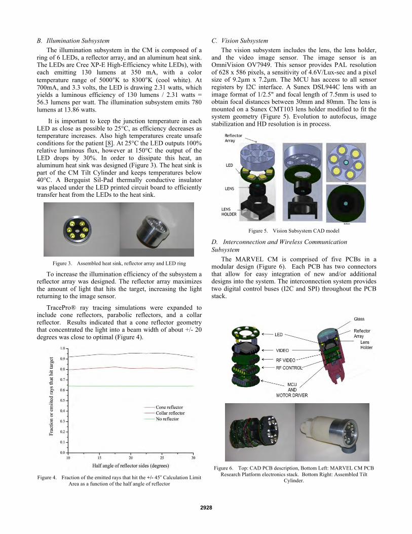
D. Interconnection and Wireless Communication Subsystem
The MARVEL CM is comprised of five PCBs in a modular design (Figure 6). Each PCB has two connectors that allow for easy integration of new and/or additional designs into the system. The interconnection system provides two digital control buses (I2C and SPI) throughout the PCB stack.
Figure 6. Top: CAD PCB description, Bottom Left: MARVEL CM PCB
Research Platform electronics stack. Bottom Right: Assembled Tilt Cylinder.
2928

MARVEL uses two different links for wireless communications. The first link is for control and uses a cc1101 Texas Instrument transceiver working in an ISM band with a center frequency of 915 MHz and a data rate of 250 kbps [9], [10]. The sensitivity of the system is –128 dBm and the output power is 0 dBm. This duplex link is used to send control and state information between the wireless HMI and the MARVEL CM. A second wireless transmitter provides an analog link between the video image sensor and an external receiver with near-zero latency. Since the PAL video signal requires less than 8 MHz of bandwidth, a frequency modulated (FM) transmitter was designed with a carrier frequency in the 1.1 to 1.3 GHz range and an output power of 10 dBm. The transmit frequency is easily tuned to any point within the chosen frequency range. This ability allows the use of more than one MARVEL CM during a surgical procedure, whereby each CM transmits at a different frequency with enough band separation to avoid interference. A low-cost, commercially available FM receiver is used to demodulate the transmitted signal back into a composite signal that can be displayed on a TV monitor with PAL input. The receiver sensitivity is -85 dBm with a manual tuning range of 1.1 to 1.3 GHz.
E. Embedded Control Subsystem At the core of the embedded control system is an 8-bit
Silicon Lab microcontroller C8051F413. The MCU provides a SPI bus to control the ISM digital transceiver, an I2C bus to control the video image sensor, and a control interface for the LED and pan/tilt motor control lines.
The MCU uses the SPI interface to acquire the wireless data coming from the ISM digital transceiver. Every time new information is available, the ISM transceiver sends an interrupt signal to wake up the MCU and start receiving the control information from the surgeon. After 2 minutes of wireless inactivity the MCU goes into sleep mode and sets the system to a standby mode.
To drive pan and tilt motors, the MCU uses the PCA (program counter array) to output four PWM signals at 24 kHz. A Motorola MPC17C724 H bridge driver is used to output the required power. The control direction is achieved by a proper combination of the four PCA control lines. The velocity of the motors can be set to 255 different steps.
To control the intensity of the LEDs, a National Semiconductor LM34910step-up converter is used. This driver takes 3.3 V as an input and outputs 19.8 V to guarantee a forward voltage in each LED of 3.3V. The MCU outputs a PWM control signal at 400Hz to drive the 6 LED array. Sixteen levels of intensity can be configured.
F. Attachment and Power Subsystem The Camera Module (CM) is attached to the abdominal
wall with a needle that is part of the CM and an Attachment Module (AM). The needle pierces the abdominal wall and is grasped by the compression mechanism (Figure 7) of the AM securely attaching the CM to the abdominal wall. Power could be supplied to the CM by a coaxial needle. The inner conductor of the coaxial needle would be the positive conductor; the outer tube of the coaxial needle would be the ground conductor. The coaxial construction eliminates the possibility of electrical shorts between conductors. Currently
the needle is a hollow tube with power and ground wires threaded through the tube. Future research will investigate multiple needles on the CM. Other AM designs include battery power, and wireless repeaters.
Figure 7. CAD of the Attachment Module
G. Motion Subsystem Pan and tilt movement of the CM is implemented by two
DC motors (Figure 8). The motors have a planetary gear ratio of 256:1, and a torque of 25 mNm. The Gizmo GM0.5-08-14 pan motor gear engages a Gizmo GS0.5-20-19 spur gear, providing a pan reduction ratio of 5:2. The tilt motor gear engages a Gizmo crown gear GCG0.5-36-2 providing a tilt reduction ratio of 9:2 (Figure 9).
Figure 8. Pan/tilt mechanism
Figure 9. Left: Motor Housing, Right: spurs gear Tilt Cylinder.
At 3.3V, the motors have a no-load speed of 20200 rpm, which allows a MARVEL CM to achieve up to 17 rpm maximum velocity in the tilt direction and 31 rpm in the pan direction (Figure 9). These relative low velocities in the pan and tilt directions produce a smooth and accurate positioning system, making it easy for the surgeon to set the CM in the desired position.
2929

III. EXPERIMENT
An in vivo experiment was carried out in the USF Vivarium led by the team surgeons, Drs. Rosemurgy and Ross. The illumination, image quality, wireless communication, CM sealing, and wireless control of the CM was tested. Two CMs (Figure 10) were inserted into a porcine subject and simultaneously tested. A “balloon”, shown in blue, was used to seal the space between the cylinders.
Figure 10. Three MARVEL CMs with their respective Attachment Modules
and power cables.
The LED intensity was set to 550 lumens, approximately 70% of the possible 780 lumens the system could provide. Figure 11 is an image capture of porcine intestines taken by a MARVEL CM.
Figure 11. Image of porcine intestines taken by a MARVEL CM.
For the ISM digital link, an external amplifier was used to increment the transmission power in the wireless control link by 20dbm (Texas instrument CC1190). A loss of 10 to 20 dBm was predicted, and measured, owing to the layers of skin and fat in the pig’s abdominal wall [11], [12], [13].
Figure 12 shows a MARVEL CM anchored to the abdominal by the Attachment Module. The AM has a 30mm square base in contact with the external skin of the abdominal wall that kept the CM stable during pan and tilt movements. The AM base size can be increased significantly if necessary to accommodate more functionality and / or to increase CM stability.
Figure 12. A MARVEL CM anchored to the abdominal wall.
Two CMs were controlled simultaneously by the surgeons (Figure 13). The surgeons intuitively adapted to the positions of each CM and effortlessly switched from one CM to the other demonstrating that a physical alignment of each CM to the viewing perspective of the surgeon, at least in this case, was unnecessary. Future work with multiple CMs in vivo will include a positioning and alignment procedure to enable pixel edge matching of multiple images creating a panoramic video display view of the surgical site.
Figure 13. Two MARVEL CMs are shown. The surgeons have independent
control of each Camera Module.
Normal physiologic motion of the porcine subject did not affect image stability. Future work will integrate motion detection and image stabilization to compensate for patient motion caused by the surgical team.
Each device was tuned to transmit at different frequencies to provide simultaneous live imaging from each CM during the procedure; one at 1.18 GHz and the other at 1.23 GHz.
Power consumption was in the expected range, with a total of 368 mA in standby and 480 mA when the pan and tilt motors were activated. The illumination subsystem consumed 200 mA (54% of the system power in standby mode), analog wireless video consumed 90 mA (24%), the video sensor consumed 43mA(12%) and the MCU and digital transceiver consumed 35 mA (10%).
2930

This demonstrated that a commercial battery could be included in the attachment module to power the CM, thus eliminating the power cable and supporting a (future) mobile CM. The Research Platform is designed as an efficient and economic platform for evolution of current subsystems and integration of future capabilities. If the electronics are optimized for power drain and battery efficiency continues to increase, a CM powered by an internal battery is within reach.
IV. CONCLUSION AND FUTURE WORK A novel wireless robotic laparoscopic imaging research
platform, MARVEL, has been implemented with the goal of advancing minimally invasive surgery. The complex system design of the MARVEL platform has involved research in the areas of robotics, wireless communications, heat transfer, image processing, illumination engineering and embedded systems with the goal of implementing a broad range of functionality required for laparoscopic surgery (remote motion control, wireless video, and illumination) in a single device. Two MARVEL CMs were successfully tested simultaneously in vivo in a porcine subject by a team of surgeons. The two CMs were inserted into the abdominal cavity of the porcine test animal, demonstrating individual control of each CM while simultaneously transmitting good quality images from each CM. Future work to improve the capabilities of the MARVEL modules will include wireless HD image transmission (again, with near-zero latency), autofocus, zoom, and image stabilization.
A future LED PCB design will provide blue and green light at wavelengths of 390-445nm and 530-550nm. Those wavelengths are absorbed by hemoglobin, which is the major pigment of the mucosal tissue (e.g., intestines, bladder). This provides enhanced images of the fine capillaries in the mucosal surface and detailed mucosal texture. The use of blue and green illumination can help in the early detection of cancer [14]-[15].
The robotic system described in this paper is a proof of concept Research Platform designed to support a broad range of experiments in a range of domains for faculty and students in the Colleges of Engineering and Medicine and at Tampa General Hospital. This research is the first step in developing semi-autonomous wirelessly controlled and networked laparoscopic devices to enable a paradigm shift in minimally invasive surgery and other healthcare domains.
References [1] P. Berkelman, P. Cinquin, J. Troccaz, J. Ayoubi, C. Letoublon, and F.
Bouchard. A compact, compliant laparoscopic endoscope manipulator. In IEEE Intl. Conf. on Robotics and Automation, pages 1870–1875, 2002
[2] T. Hu, P. K. Allen, N. J. Hogle, and D. L. Fowler. Insertable surgical imaging device with pan, tilt, zoom and lighting. In International Conference on Robotics and Automation (ICRA), May 19-23 2008.
[3] T. Hu, P. K. Allen, T. Nadkarni, N. J. Hogle, and D. L. Fowler, "Insertable Stereoscopic 3D Surgical Imaging Device with Pan and Tilt," in IEEE / RAS-EMBS International Conference on Biomedical Robotics and Biomechatronics (BIOROB), Scottsdale, AZ, USA, 2008, pp. 311-316.
[4] Stephen R Platt, Vision and task assistance using modular wireless in vivo surgical robots. IEEE Trans Biomed Eng 56:1700-10. 2009.
[5] Hawks, J., Rentschler, M., Redden, L., Infanger, R., Dumpert, J., Farritor, S., Oleynikov, D., & Platt, S. (2008). Towards an in vivo wireless mobile robot for surgical assistance. Studies in Health Technology and Informatics, 132,153-158.
[6] G. Tortora, A. Dimitracopoulos, P. Valdastri, A. Menciassi, P. Dario, “Design of Miniature Modular in vivo Robots for Dedicated Tasks in Minimally Invasive Surgery”, 2011 IEEE/ASME International Conference on Advanced Intelligent Mechatronics (AIM2011)
[7] J. Wang, “Radiation Characteristics of Ingestible Wireless Devices in Human Intestine Following Radio Frequency Exposure at 430, 800, 1200, and 2400 MHz,” IEEE Transactions on Antennas and Propagation, Vol. 57, No. 8, August 2009.
[8] Ruiyu Lu, Sheng Liu, Xiaobin Luo, Bo Zhang, "Thermal Safety Analysis of Capsule Endoscope", Electronic Packaging Technology, 2006. ICEPT '06. 7th International Conference on, On page(s): 1 - 4, Volume: Issue: , 26-29 Aug. 2006.
[9] Kenichi Takizawa, Takahiro Aoyagi, Kiyoshi Hamaguchi, and Ryuji Kohno, “Performance Evaluation of Wireless Communications through Capsule Endoscope”, 31st Annual International Conference of the IEEE EMBS Minneapolis, Minnesota, USA, 2009
[10] Tagawa Xueliang Huo, Uei-Ming Jow, Maysam Ghovanloo, “Radiation Characterization of an Intra-Oral Wireless Device at Multiple ISM Bands: 433 MHz, 915 MHz, and 2.42 GHz” IEEE Eng Med Biol Soc. 2010.
[11] W. G. Scanlon, B. Burns, and N. E. Evans. “Radiowave propagation from a tissue-implanted source at 418 MHz and 916.5 MHz”, IEEE Transactions on Biomedical Engineering, 47(4), pp527-534, 2000.
[12] L. C. Chirwa, et al. “Electromagnetic radiation from ingested sources in the human intestine between 150 MHz and 1.2 GHz”, IEEE Transactions on Biomedical Engineering, 50(4) 2003, pp484-492.
[13] C. Cavallotti, “An integrated vision system with autofocus for wireless capsular endoscopy”, Sens. Actuators A: Phys. 2009.
[14] Nathaniel J. Soper, Lee L. Swanström, W. Stephen Eubanks, Mastery of endoscopic and laparoscopic surgery. Lippincott Williams & Wilkins 2009, ch. 3.
[15] Manabu Muto, Takahiro Horimatsu, Yasumasa Ezoe, Shuko Morita, Shinichi Miyamoto, “Improving visualization techniques by narrow band imaging and magnification endoscopy”, Journal of Gastroenterology and Hepatology, 2009.
2931