
Manual Proton XQ Table of Contents - Teno Astro
41
Manual Proton XQ Table of Contents DESCRIPTION ............................................................................................................................................. 2 PACKAGE CONTENTS ................................................................................................................................. 2 SPECIFICATIONS ........................................................................................................................................ 3 FEATURES .................................................................................................................................................. 4 COMPONENTS AND CONTROLS ................................................................................................................ 6 BUTTON OPERATION................................................................................................................................. 7 USING THE BATTERY PACK ........................................................................................................................ 8 BATTERY CHARGING .............................................................................................................................. 8 BATTERY INSTALLATION ......................................................................................................................12 PRECAUTIONS......................................................................................................................................12 RECOMMENDATIONS FOR USE ...........................................................................................................13 EXTERNAL POWER SUPPLY ......................................................................................................................13 OPERATION .............................................................................................................................................14 INSTALLING THERMAL IMAGING MODULE ON THE OPTICAL DEVICE ................................................14 INSTALLING PULSAR 5X30 B MONOCULAR ON TO THE PROTON XQ..................................................16 POWERING ON AND IMAGE SETTING .................................................................................................17 MICROBOLOMETER CALIBRATION ..........................................................................................................18 IMAGE DETAIL BOOST .............................................................................................................................18 STATUS BAR .............................................................................................................................................19 QUICK MENU FUNCTIONS .......................................................................................................................19 MAIN MENU FUNCTIONS ........................................................................................................................20 ENTER THE MAIN MENU .....................................................................................................................20 MODE ..................................................................................................................................................21 IMAGE DETAIL BOOST .........................................................................................................................22 WI-FI SETTINGS....................................................................................................................................22 GENERAL SETTINGS .............................................................................................................................23 COLOR MODES ....................................................................................................................................26
-
Upload
khangminh22 -
Category
Documents
-
view
0 -
download
0
Transcript of Manual Proton XQ Table of Contents - Teno Astro

Manual Proton XQ
Table of Contents DESCRIPTION ............................................................................................................................................. 2
PACKAGE CONTENTS ................................................................................................................................. 2
SPECIFICATIONS ........................................................................................................................................ 3
FEATURES .................................................................................................................................................. 4
COMPONENTS AND CONTROLS ................................................................................................................ 6
BUTTON OPERATION ................................................................................................................................. 7
USING THE BATTERY PACK ........................................................................................................................ 8
BATTERY CHARGING .............................................................................................................................. 8
BATTERY INSTALLATION ...................................................................................................................... 12
PRECAUTIONS ...................................................................................................................................... 12
RECOMMENDATIONS FOR USE ........................................................................................................... 13
EXTERNAL POWER SUPPLY ...................................................................................................................... 13
OPERATION ............................................................................................................................................. 14
INSTALLING THERMAL IMAGING MODULE ON THE OPTICAL DEVICE ................................................ 14
INSTALLING PULSAR 5X30 B MONOCULAR ON TO THE PROTON XQ .................................................. 16
POWERING ON AND IMAGE SETTING ................................................................................................. 17
MICROBOLOMETER CALIBRATION .......................................................................................................... 18
IMAGE DETAIL BOOST ............................................................................................................................. 18
STATUS BAR ............................................................................................................................................. 19
QUICK MENU FUNCTIONS ....................................................................................................................... 19
MAIN MENU FUNCTIONS ........................................................................................................................ 20
ENTER THE MAIN MENU ..................................................................................................................... 20
MODE .................................................................................................................................................. 21
IMAGE DETAIL BOOST ......................................................................................................................... 22
WI-FI SETTINGS .................................................................................................................................... 22
GENERAL SETTINGS ............................................................................................................................. 23
COLOR MODES .................................................................................................................................... 26
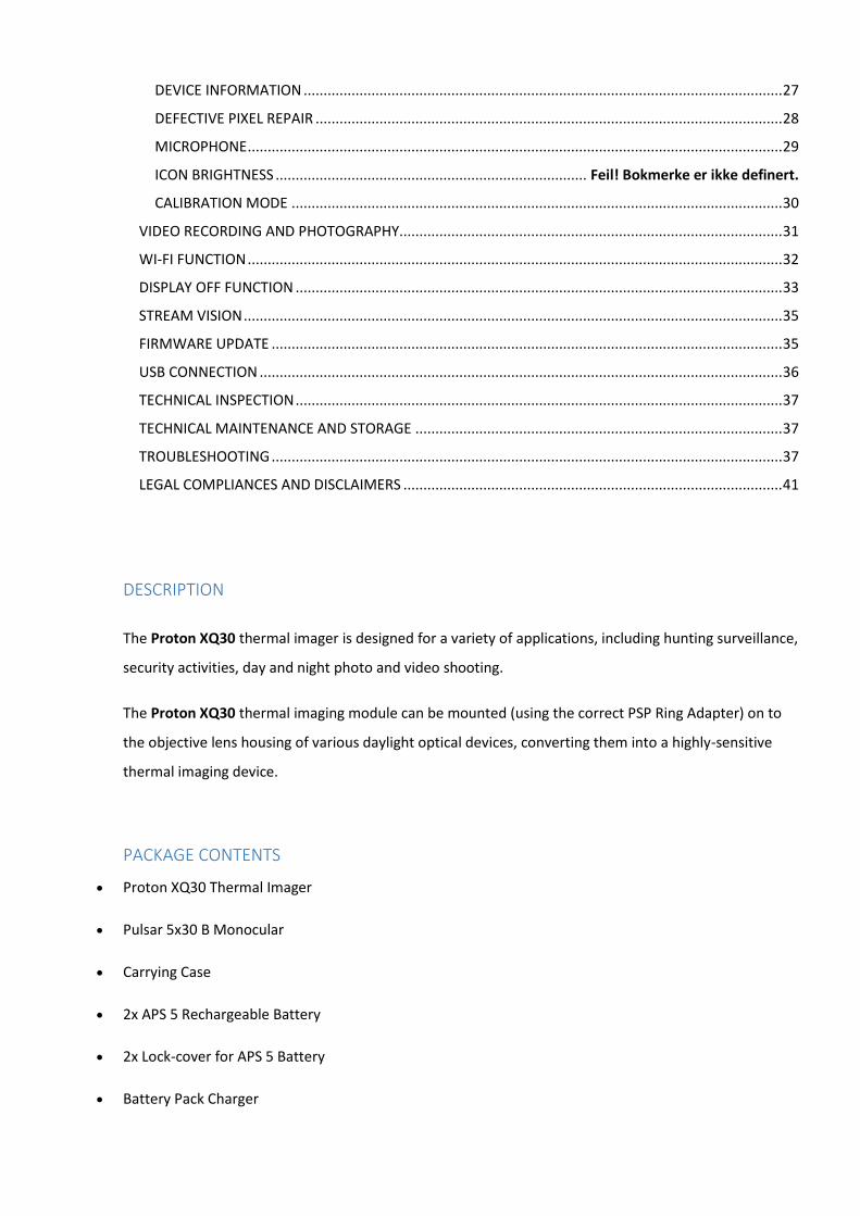
DEVICE INFORMATION ........................................................................................................................ 27
DEFECTIVE PIXEL REPAIR ..................................................................................................................... 28
MICROPHONE ...................................................................................................................................... 29
ICON BRIGHTNESS .............................................................................. Feil! Bokmerke er ikke definert.
CALIBRATION MODE ........................................................................................................................... 30
VIDEO RECORDING AND PHOTOGRAPHY................................................................................................ 31
WI-FI FUNCTION ...................................................................................................................................... 32
DISPLAY OFF FUNCTION .......................................................................................................................... 33
STREAM VISION ....................................................................................................................................... 35
FIRMWARE UPDATE ................................................................................................................................ 35
USB CONNECTION ................................................................................................................................... 36
TECHNICAL INSPECTION .......................................................................................................................... 37
TECHNICAL MAINTENANCE AND STORAGE ............................................................................................ 37
TROUBLESHOOTING ................................................................................................................................ 37
LEGAL COMPLIANCES AND DISCLAIMERS ............................................................................................... 41
DESCRIPTION
The Proton XQ30 thermal imager is designed for a variety of applications, including hunting surveillance,
security activities, day and night photo and video shooting.
The Proton XQ30 thermal imaging module can be mounted (using the correct PSP Ring Adapter) on to
the objective lens housing of various daylight optical devices, converting them into a highly-sensitive
thermal imaging device.
PACKAGE CONTENTS
• Proton XQ30 Thermal Imager
• Pulsar 5x30 B Monocular
• Carrying Case
• 2x APS 5 Rechargeable Battery
• 2x Lock-cover for APS 5 Battery
• Battery Pack Charger
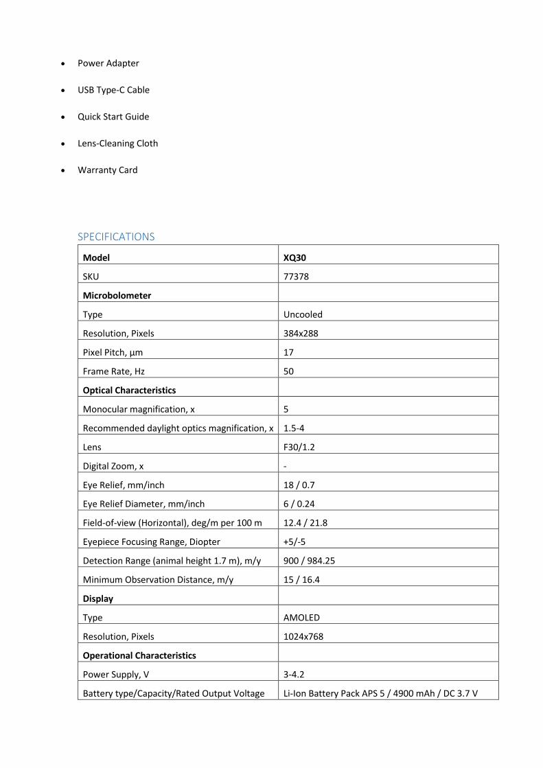
• Power Adapter
• USB Type-C Cable
• Quick Start Guide
• Lens-Cleaning Cloth
• Warranty Card
SPECIFICATIONS
Model XQ30
SKU 77378
Microbolometer
Type Uncooled
Resolution, Pixels 384x288
Pixel Pitch, µm 17
Frame Rate, Hz 50
Optical Characteristics
Monocular magnification, x 5
Recommended daylight optics magnification, x 1.5-4
Lens F30/1.2
Digital Zoom, x -
Eye Relief, mm/inch 18 / 0.7
Eye Relief Diameter, mm/inch 6 / 0.24
Field-of-view (Horizontal), deg/m per 100 m 12.4 / 21.8
Eyepiece Focusing Range, Diopter +5/-5
Detection Range (animal height 1.7 m), m/y 900 / 984.25
Minimum Observation Distance, m/y 15 / 16.4
Display
Type AMOLED
Resolution, Pixels 1024x768
Operational Characteristics
Power Supply, V 3-4.2
Battery type/Capacity/Rated Output Voltage Li-Ion Battery Pack APS 5 / 4900 mAh / DC 3.7 V

External Power Supply 5 V (USB Type-C)
Max. Battery Pack Life (at t = 22 °C), hours* 6
Degree of protection IP code (IEC60529) IPX7
Operating temperature, °C -25 … +50
Overall Dimensions, mm/inch 248х59х75 / 9.76x2.32x2.95
Weight (without battery), kg/oz 0.47 / 16.58
Video Recorder
Photo/Video Resolution, Pixels 864х648
Video/Photo Format .mp4 / .jpg
Built-in Memory 16 GB
Built-in memory capacity About 5 hours of video or more than 100 000
photos
Wi-Fi Channel**
Frequency 2.4 GHz
Standard 802.11 b/g
* Actual operating time will depend to what extent the Wi-Fi and built-in video recorder is used.
**The reception range may vary depending on various factors: obstacles, other Wi-Fi networks.
FEATURES
• Microbolometer with a resolution of 384x288 pixels
• Microbolometer pixel size of 17 microns
• 1024x768 AMOLED display resolution
• Compact size
• Easily converts daylight optical devices into thermal imaging devices
• Preserves the benefits of daylight optics in night-time conditions
• Three calibration modes (manual, semi-automatic and automatic)
• Four observation modes: Forest, Rocks, Identification, User
• Detection distance up to 900 m
• Wireless remote control
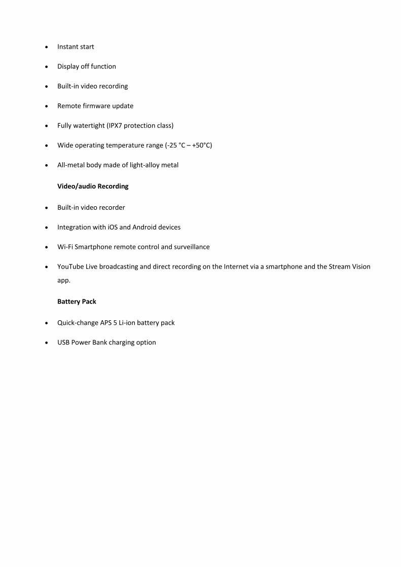
• Instant start
• Display off function
• Built-in video recording
• Remote firmware update
• Fully watertight (IPX7 protection class)
• Wide operating temperature range (-25 °С – +50°С)
• All-metal body made of light-alloy metal
Video/audio Recording
• Built-in video recorder
• Integration with iOS and Android devices
• Wi-Fi Smartphone remote control and surveillance
• YouTube Live broadcasting and direct recording on the Internet via a smartphone and the Stream Vision
app.
Battery Pack
• Quick-change APS 5 Li-ion battery pack
• USB Power Bank charging option

COMPONENTS AND CONTROLS
1. Lens cover
2. Eyepiece cover
3. Battery compartment cover
4. Battery pack
5. Battery compartment
6. ON/OFF button
7. REC button
8. Controller
9. USB port
10. Objective lens end of daylight optical device
11. Insert
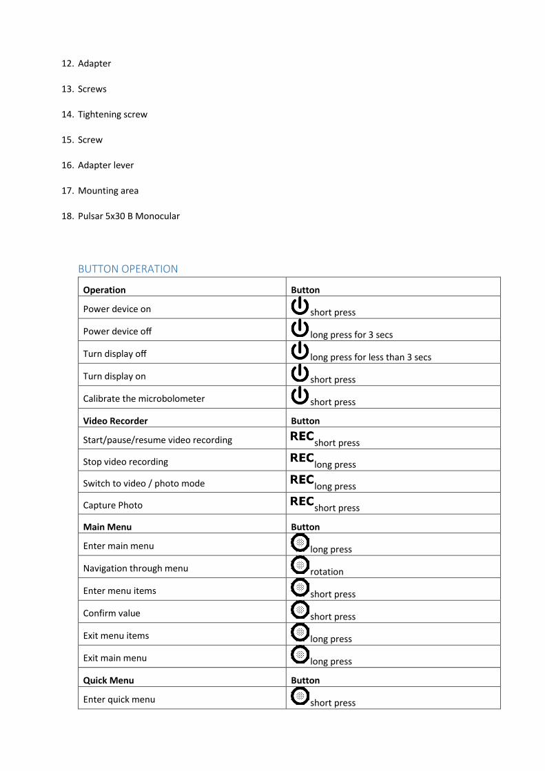
12. Adapter
13. Screws
14. Tightening screw
15. Screw
16. Adapter lever
17. Mounting area
18. Pulsar 5x30 B Monocular
BUTTON OPERATION
Operation Button
Power device on short press
Power device off long press for 3 secs
Turn display off long press for less than 3 secs
Turn display on short press
Calibrate the microbolometer short press
Video Recorder Button
Start/pause/resume video recording short press
Stop video recording long press
Switch to video / photo mode long press
Capture Photo short press
Main Menu Button
Enter main menu long press
Navigation through menu rotation
Enter menu items short press
Confirm value short press
Exit menu items long press
Exit main menu long press
Quick Menu Button
Enter quick menu short press
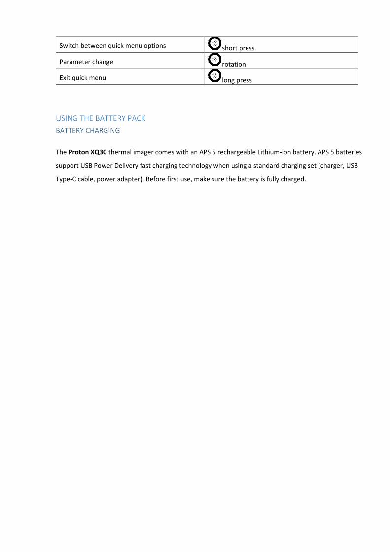
Switch between quick menu options short press
Parameter change rotation
Exit quick menu long press
USING THE BATTERY PACK
BATTERY CHARGING
The Proton XQ30 thermal imager comes with an APS 5 rechargeable Lithium-ion battery. APS 5 batteries
support USB Power Delivery fast charging technology when using a standard charging set (charger, USB
Type-C cable, power adapter). Before first use, make sure the battery is fully charged.
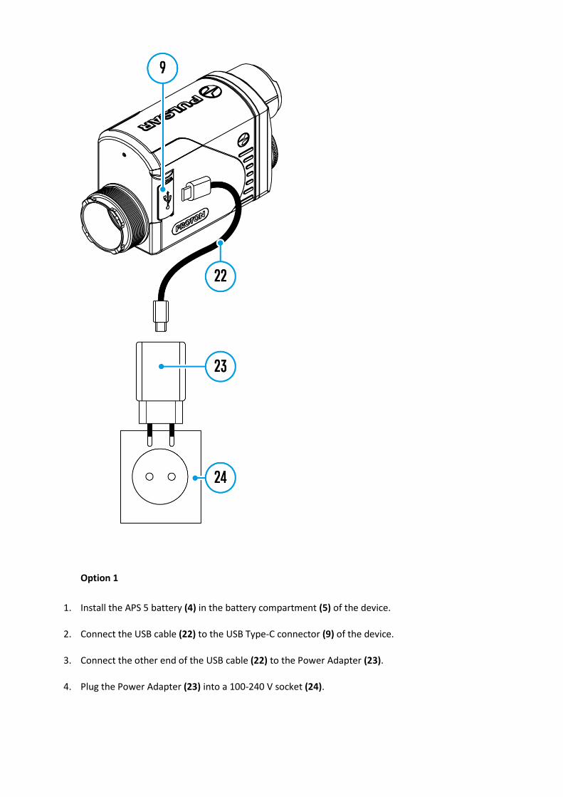
Option 1
1. Install the APS 5 battery (4) in the battery compartment (5) of the device.
2. Connect the USB cable (22) to the USB Type-C connector (9) of the device.
3. Connect the other end of the USB cable (22) to the Power Adapter (23).
4. Plug the Power Adapter (23) into a 100-240 V socket (24).
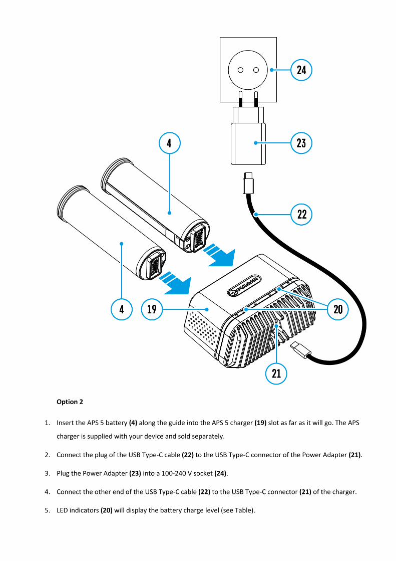
Option 2
1. Insert the APS 5 battery (4) along the guide into the APS 5 charger (19) slot as far as it will go. The APS
charger is supplied with your device and sold separately.
2. Connect the plug of the USB Type-C cable (22) to the USB Type-C connector of the Power Adapter (21).
3. Plug the Power Adapter (23) into a 100-240 V socket (24).
4. Connect the other end of the USB Type-C cable (22) to the USB Type-C connector (21) of the charger.
5. LED indicators (20) will display the battery charge level (see Table).
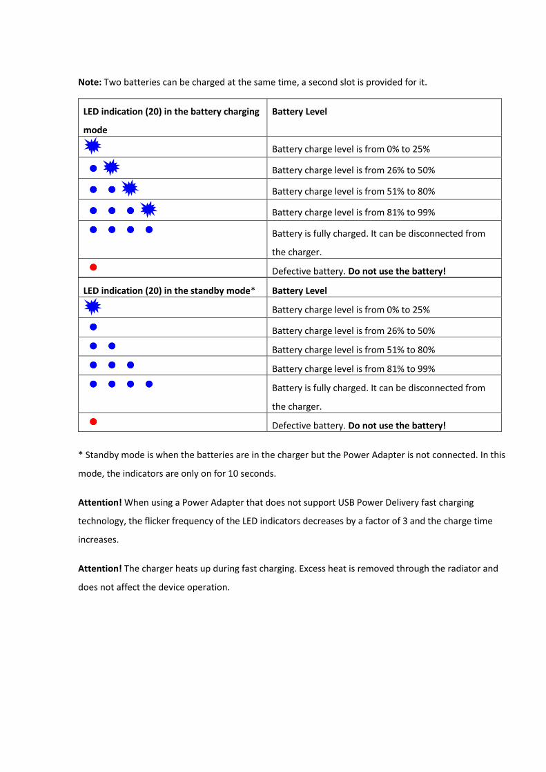
Note: Two batteries can be charged at the same time, a second slot is provided for it.
LED indication (20) in the battery charging
mode
Battery Level
Battery charge level is from 0% to 25%
Battery charge level is from 26% to 50%
Battery charge level is from 51% to 80%
Battery charge level is from 81% to 99%
Battery is fully charged. It can be disconnected from
the charger.
Defective battery. Do not use the battery!
LED indication (20) in the standby mode* Battery Level
Battery charge level is from 0% to 25%
Battery charge level is from 26% to 50%
Battery charge level is from 51% to 80%
Battery charge level is from 81% to 99%
Battery is fully charged. It can be disconnected from
the charger.
Defective battery. Do not use the battery!
* Standby mode is when the batteries are in the charger but the Power Adapter is not connected. In this
mode, the indicators are only on for 10 seconds.
Attention! When using a Power Adapter that does not support USB Power Delivery fast charging
technology, the flicker frequency of the LED indicators decreases by a factor of 3 and the charge time
increases.
Attention! The charger heats up during fast charging. Excess heat is removed through the radiator and
does not affect the device operation.
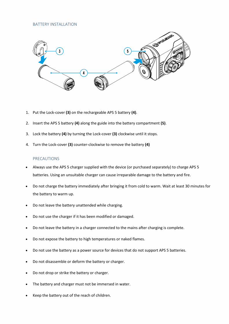
BATTERY INSTALLATION
1. Put the Lock-cover (3) on the rechargeable APS 5 battery (4).
2. Insert the APS 5 battery (4) along the guide into the battery compartment (5).
3. Lock the battery (4) by turning the Lock-cover (3) clockwise until it stops.
4. Turn the Lock-cover (3) counter-clockwise to remove the battery (4)
PRECAUTIONS
• Always use the APS 5 charger supplied with the device (or purchased separately) to charge APS 5
batteries. Using an unsuitable charger can cause irreparable damage to the battery and fire.
• Do not charge the battery immediately after bringing it from cold to warm. Wait at least 30 minutes for
the battery to warm up.
• Do not leave the battery unattended while charging.
• Do not use the charger if it has been modified or damaged.
• Do not leave the battery in a charger connected to the mains after charging is complete.
• Do not expose the battery to high temperatures or naked flames.
• Do not use the battery as a power source for devices that do not support APS 5 batteries.
• Do not disassemble or deform the battery or charger.
• Do not drop or strike the battery or charger.
• The battery and charger must not be immersed in water.
• Keep the battery out of the reach of children.
RECOMMENDATIONS FOR USE
• The batteries should be partially charged (50 to 80 %) for long-term storage.
• The battery is to be charged at an ambient temperature of 0°C to +35°C or the lifespan of the battery
will decrease significantly.
• When using the battery at sub-zero ambient temperatures, the battery capacity decreases. This is
normal and not a defect.
• Do not use the battery at temperatures outside the range of -25°C to +50 Сͦ or it may reduce battery life.
• The battery is short circuit protected. However, any situation that may cause short-circuiting should be
avoided.
EXTERNAL POWER SUPPLY
External power can be supplied from an external source, such as a Power Bank (5 V).
1. Connect the external power source to the USB Type-C connector (9) on the device.
2. The device will switch to draw power from the external source while the АPS5 battery will be gradually
recharged.
3. A battery icon will appear on the display showing the percentage charge level.
4. An icon will be displayed when the device is powered by an external power source and the АPS5
battery is not connected.
5. The device automatically switches to the APS 5 battery when the external power supply is disconnected.
Attention! Charging APS 5 batteries from an external source at temperatures below 0°C can reduce
battery life. When using external power, connect the Power Bank to the device only after it has been
turned on and working for at least several minutes.
OPERATION
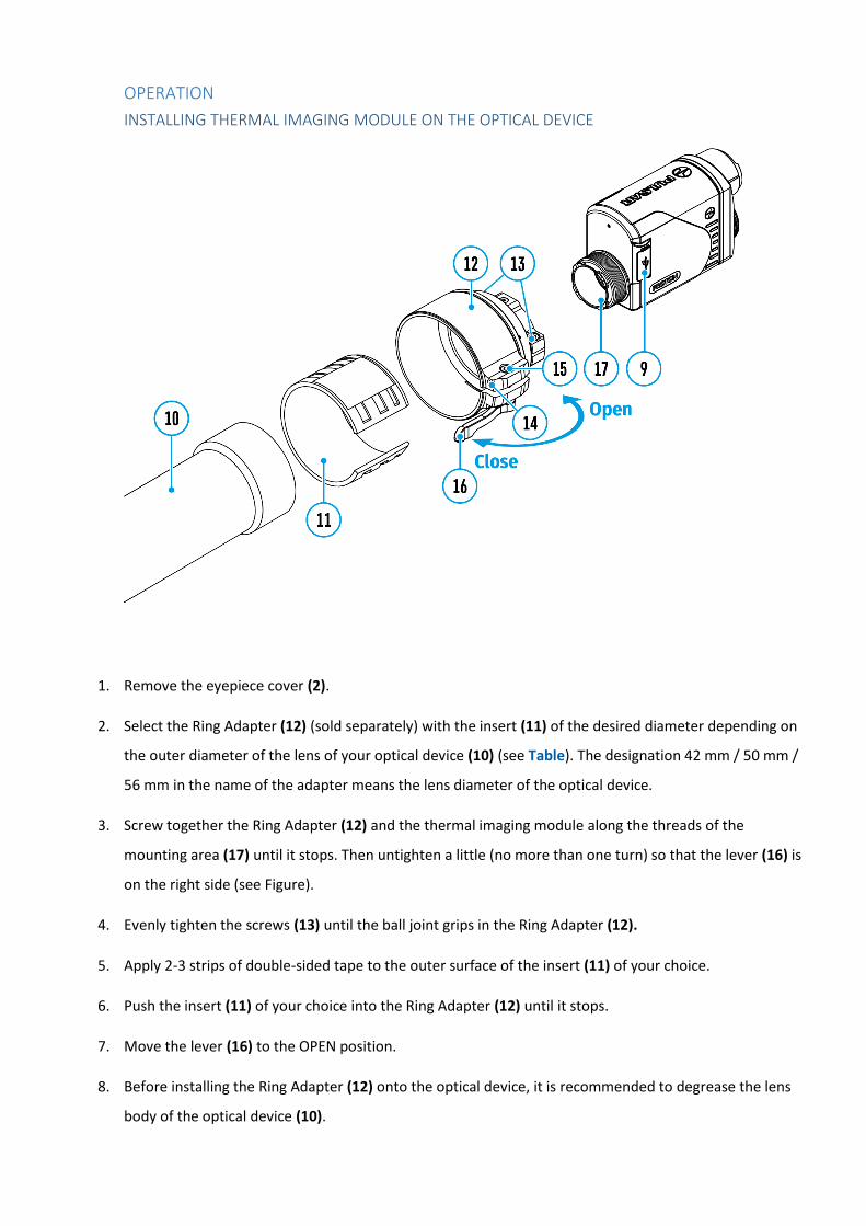
INSTALLING THERMAL IMAGING MODULE ON THE OPTICAL DEVICE
1. Remove the eyepiece cover (2).
2. Select the Ring Adapter (12) (sold separately) with the insert (11) of the desired diameter depending on
the outer diameter of the lens of your optical device (10) (see Table). The designation 42 mm / 50 mm /
56 mm in the name of the adapter means the lens diameter of the optical device.
3. Screw together the Ring Adapter (12) and the thermal imaging module along the threads of the
mounting area (17) until it stops. Then untighten a little (no more than one turn) so that the lever (16) is
on the right side (see Figure).
4. Evenly tighten the screws (13) until the ball joint grips in the Ring Adapter (12).
5. Apply 2-3 strips of double-sided tape to the outer surface of the insert (11) of your choice.
6. Push the insert (11) of your choice into the Ring Adapter (12) until it stops.
7. Move the lever (16) to the OPEN position.
8. Before installing the Ring Adapter (12) onto the optical device, it is recommended to degrease the lens
body of the optical device (10).
9. Mount the Ring Adapter (12) with the insert (11) onto the lens of the daylight optical device (10) as far
as it will go.
10. If the Ring Adaptor (12) with the insert (11) selected according to the table cannot be mounted onto the
lens (10), follow the steps below:
o Loosen the locking screw (14) with a 2mm Allen key.
o Untighten the screw (15) with a hex wrench (S = 4mm) until the Ring Adaptor with the insert can be
mounted onto the lens (10).
11. Move the lever (16) from its initial OPEN position to the CLOSE position.
12. Loosen the locking screw (14) with a 2mm Allen key, if it hasn’t been done before.
13. Tighten the screw (15) using a 4mm Allen key. The clamping force should be 1.5-2 Nm (use a torque
screwdriver) to ensure the lever is correctly tightened (16), while the Ring Adapter with the thermal
imaging module should not move relative to the body of the optical device (10). If necessary, tighten or
loosen the screw (15) to operate the lever (16) in the best way possible.
14. Tighten the locking screw (14) as far as it will go.
15. Turn on the thermal imaging module by briefly pressing the ON/OFF (6) button.
16. Turn on the device and align the image center on the Proton XQ30 display with the image center of the
daylight optical device by carefully tilting the thermal imaging module.
17. Align the top and bottom display boundaries of the Proton XQ30 parallel to the horizontal line of the
daylight optical device’s reticle.
18. Having reached the best possible position of the thermal imaging module, tighten the two
screws (13) until stop. The clamping force should be 5-7.5 N·m (use a torque screwdriver to check).
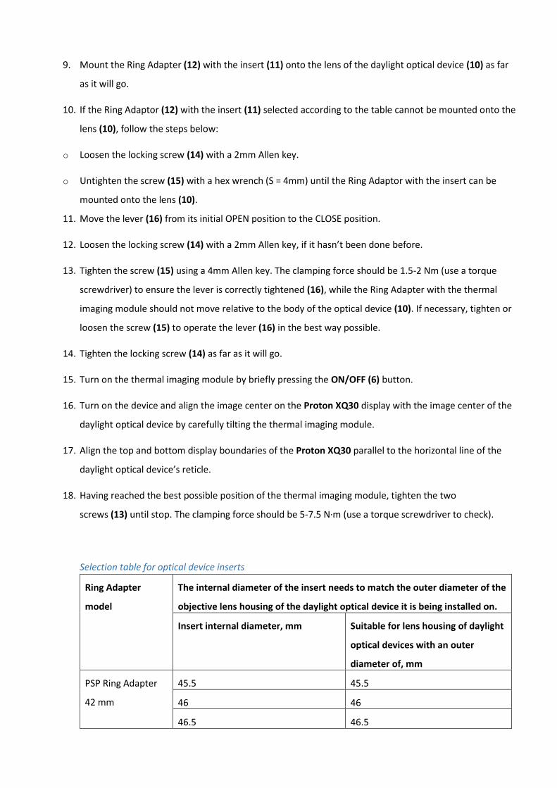
Selection table for optical device inserts
Ring Adapter
model
The internal diameter of the insert needs to match the outer diameter of the
objective lens housing of the daylight optical device it is being installed on.
Insert internal diameter, mm Suitable for lens housing of daylight
optical devices with an outer
diameter of, mm
PSP Ring Adapter
42 mm
45.5 45.5
46 46
46.5 46.5

47 46.7-47.6
48 47.7- 48.6
49 48.7-49.6
50 49.7-50.6
PSP Ring Adapter
50 mm
51.6 51.6
53.4 53.4
55 54.7-55.6
56 55.7-56.6
57 56.7-57.6
58 57.7-58.6
59 58.7-59.6
PSP Ring Adapter
56 mm
60 59.7-60.6
61 60.7-61.6
62 61.7-62.6
63 62.7-63.6
64 63.7-64.6
65 64.7-65.6
INSTALLING PULSAR 5X30 B MONOCULAR ON TO THE PROTON XQ
The Pulsar 5x30 B monocular (18) allows you to transform the Proton XQ30 into a hand-held thermal
imager with 5x magnification.
1. Align the tabs on the monocular with the slots of the mount (17).
2. Turn the monocular clockwise to secure it on the thermal imaging module.
3. To remove the monocular, turn it counterclockwise and disconnect from the thermal imaging module.
Note: the monocular can be installed on the thermal imaging module with the Ring Adapter already
installed. The Ring Adaptor must be mounted onto the mounting area of the thermal imaging module
until it stops.
POWERING ON AND IMAGE SETTING
1. Remove the lens cover (1).
2. Press the ON/OFF (6) button to turn on the thermal imager.
3. Adjust the eyepiece diopter ring of your daylight optical device until the symbols in the display are
sharp. In future, it will not be necessary to adjust the eyepiece diopter, regardless of the distance and
other conditions.
4. Enter the main menu with a long press of the controller button (8) and select the desired calibration
mode: manual (M), semi-automatic (SA) or automatic (A).
5. Calibrate the image by briefly pressing the ON/OFF (6) button. Close the lens cover before manual
calibration.
6. Select the desired observation mode (Forest, Rocks, Identification or User) in the main menu. User
mode allows you to configure and save custom brightness and contrast settings, as well as one of three
modes as a base.
7. Enter the main menu with a long press of the controller button (8) and select the desired color palette
(see the Color Modes section).
8. Activate the quick menu by briefly pressing the controller button (8) to adjust the brightness and
contrast of the display (see the Quick Menu Functions section).
9. Upon completion of use turn the device off by a long press of the ON/OFF (6) button.
Warning! Never point the lens at intensive energy sources such as laser radiation emitting devices or the
sun. It can damage electronic components in the device. The warranty does not cover damage arising
from failure to comply with the operating rules.
MICROBOLOMETER CALIBRATION
Calibration enables the microbolometer temperature background to be equalized and defects in the
image (such as vertical lines, phantom images etc.) to be eliminated.
During calibration, the image on the display freezes briefly for up to 1 second.
There are three calibration modes: manual (M), semi-automatic (SA) and automatic (A).
Select the required mode in the Calibration Mode section of the menu.
M mode (manual)
• Secure the lens cover (1) and briefly press the ON/OFF (6) button.
• After completing the calibration process, remove the lens cap.
SA mode (semi-automatic)
• Calibration is engaged by a brief press of the ON/OFF (6) button.
• The lens cap does not need to be secured (the microbolometer is closed by an internal shutter).
A mode (automatic)
• The device is calibrated autonomously, in accordance with the firmware algorithm.
• The lens cap does not need to be secured (the microbolometer is closed by an internal shutter).
• In this mode, the device may be calibrated by the user using the ON/OFF (6) button.
IMAGE DETAIL BOOST
The Image Detail boost function increases the sharpness of the contours of heated objects, which
increases their detail. The result of the function depends on the selected mode and observation
conditions: the higher the contrast of objects, the more noticeable the effect. This option is enabled by
default, but can be disabled in the main menu.
The description of enabling/disabling the Image Detail Boost function is available here.
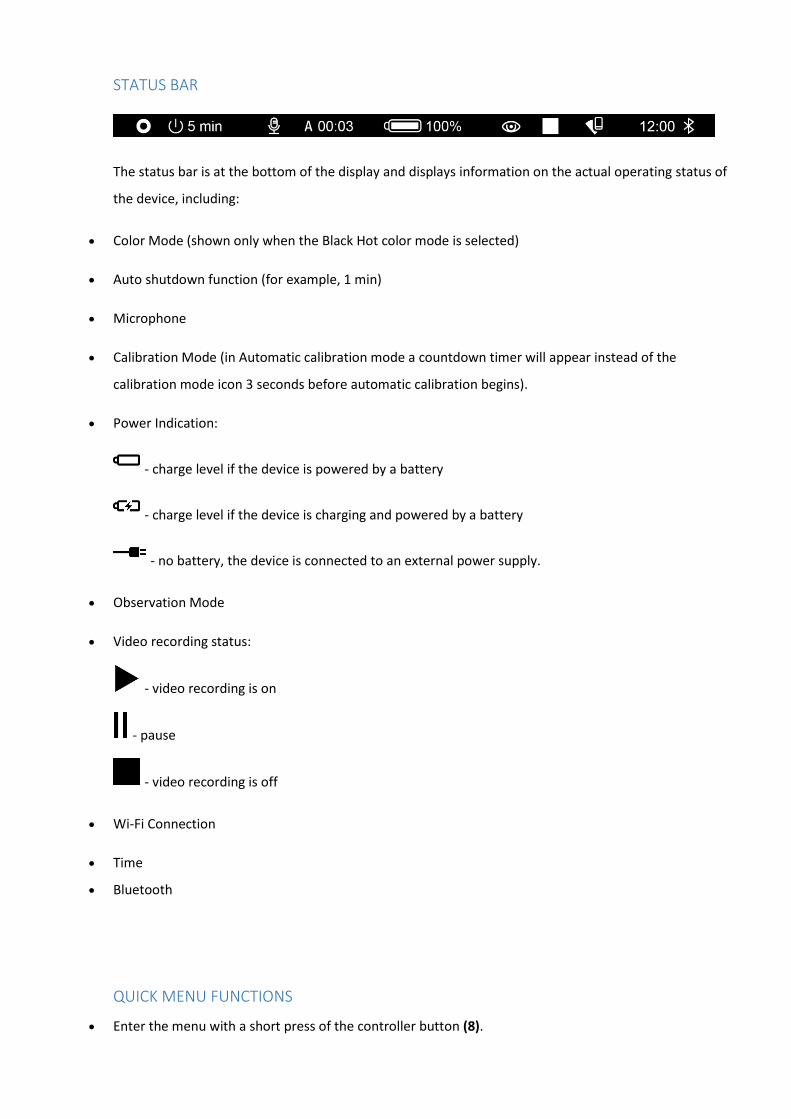
STATUS BAR
The status bar is at the bottom of the display and displays information on the actual operating status of
the device, including:
• Color Mode (shown only when the Black Hot color mode is selected)
• Auto shutdown function (for example, 1 min)
• Microphone
• Calibration Mode (in Automatic calibration mode a countdown timer will appear instead of the
calibration mode icon 3 seconds before automatic calibration begins).
• Power Indication:
- charge level if the device is powered by a battery
- charge level if the device is charging and powered by a battery
- no battery, the device is connected to an external power supply.
• Observation Mode
• Video recording status:
- video recording is on
- pause
- video recording is off
• Wi-Fi Connection
• Time
• Bluetooth
QUICK MENU FUNCTIONS
• Enter the menu with a short press of the controller button (8).
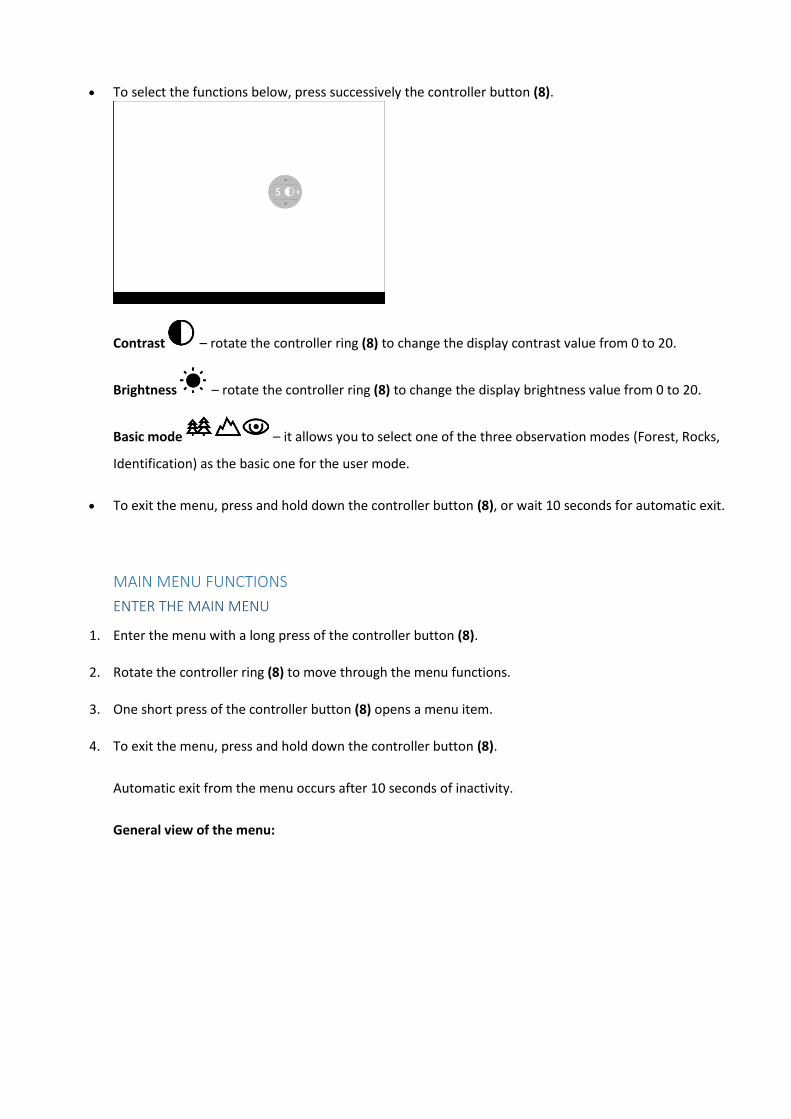
• To select the functions below, press successively the controller button (8).
Contrast – rotate the controller ring (8) to change the display contrast value from 0 to 20.
Brightness – rotate the controller ring (8) to change the display brightness value from 0 to 20.
Basic mode – it allows you to select one of the three observation modes (Forest, Rocks,
Identification) as the basic one for the user mode.
• To exit the menu, press and hold down the controller button (8), or wait 10 seconds for automatic exit.
MAIN MENU FUNCTIONS
ENTER THE MAIN MENU
1. Enter the menu with a long press of the controller button (8).
2. Rotate the controller ring (8) to move through the menu functions.
3. One short press of the controller button (8) opens a menu item.
4. To exit the menu, press and hold down the controller button (8).
Automatic exit from the menu occurs after 10 seconds of inactivity.
General view of the menu:
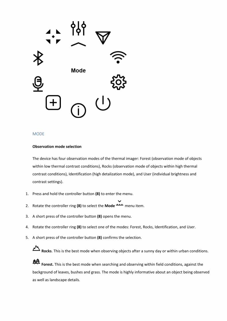
MODE
Observation mode selection
The device has four observation modes of the thermal imager: Forest (observation mode of objects
within low thermal contrast conditions), Rocks (observation mode of objects within high thermal
contrast conditions), Identification (high detalization mode), and User (individual brightness and
contrast settings).
1. Press and hold the controller button (8) to enter the menu.
2. Rotate the controller ring (8) to select the Mode menu item.
3. A short press of the controller button (8) opens the menu.
4. Rotate the controller ring (8) to select one of the modes: Forest, Rocks, Identification, and User.
5. A short press of the controller button (8) confirms the selection.
Rocks. This is the best mode when observing objects after a sunny day or within urban conditions.
Forest. This is the best mode when searching and observing within field conditions, against the
background of leaves, bushes and grass. The mode is highly informative about an object being observed
as well as landscape details.
Identification. This is the best mode when observing objects within adverse weather conditions
(fog, mist, rain and snow). It allows you to recognize the characteristics of an object being observed
more clearly. Increased detail may be accompanied by insignificant image graininess.
User. It allows you to configure and save custom brightness and contrast settings, as well as one of
the three modes (Forest, Rocks, Identification) as a base.
IMAGE DETAIL BOOST
Turn on/off Image Detail Boost
1. Press and hold the controller button (8) to enter the menu.
2. Rotate the controller ring (8) to select the Image Detail Boost menu item.
3. A short press of the controller button (8) opens the submenu.
4. To turn Image Detail Boost on or off press the controller button (8).
WI-FI SETTINGS
This menu option allows you to set up your device for operation in a Wi-Fi network.
1. Press and hold the controller button (8) to enter the menu.
2. Rotate the controller ring (8) to select the Wi-Fi Settings menu item.
3. A short press of the controller button (8) opens the menu section.
Wi-Fi Activation
Turn Wi-Fi on/off.
1. Rotate the controller ring (8) to select the Wi-Fi Activation menu item
2. A short press of the controller button (8) opens the submenu.
3. To turn Wi-Fi on or off press the controller button (8).
Password Setup
This submenu allows you to set a password to access your thermal riflescope from a mobile device.
1. Rotate the controller ring (8) to select the Password Setup menu item
2. A short press of the controller button (8) opens the submenu.
3. The default password (12345678) will appear on the screen.
4. Rotate the controller ring (8) to set your desired password. Press the controller button (8) to toggle the
digits.
5. Press and hold down the controller button (8) to save the password and exit the submenu.
Access Level Setup
This submenu allows you to set access levels of Stream Vision application to your device.
• Access level Owner. Stream Vision user has complete access to all device's functions.
• Access level Guest. Stream Vision user has access only to real time video stream from the device.
1. Rotate the controller ring (8) to select the Access Level Setup menu item.
2. A short press of the controller button (8) opens the submenu.
3. Rotate the controller ring (8) to select Owner or Guest.
4. Confirm your selection with a short press of the controller button (8).
GENERAL SETTINGS
This menu section allows you to change the interface language, set the date, time, units of measure,
return the device to factory default settings and perform memory card formatting.
1. Press and hold the controller button (8) to enter the menu.
2. Rotate the controller ring (8) to select the General Settings menu item.
3. A short press of the controller button (8) opens the submenu.
Icon Brightness
Adjust brightness level of the icons and screensavers (Pulsar, Display off) on the display.
1. Rotate the controller ring (8) to select the Icon Brightness icon.
2. Press the controller button (8) briefly to enter the submenu.
3. Rotate the controller ring (8) to select the desired brightness level from 0 to 10.
4. Press the controller button (8) briefly to confirm the selection.
Language
Language selection
1. Rotate the controller ring (8) to choose Language menu item.
2. Press the controller button (8) briefly to confirm the selection.
3. Rotate the controller ring (8) to select one of the available interface languages: English, German,
Spanish, French, and Russian.
4. Press the controller button (8) briefly to confirm the selection.
Auto Shutdown
This item allows you to activate the auto shutdown function for when the device is in a non-operating
position (tilted up or down at an angle of more than 70°, right or left at an angle of more than 30°).
1. Rotate the controller ring (8) to choose Auto Shutdown menu item.
2. Press the controller button (8) briefly to confirm the selection.
3. Rotate the controller ring (8) to select the time period (1 min, 3 min, 5 min) upon expiry of which the
device will automatically shut down, or select Off if you wish to deactivate Auto Shutdown.
4. Press the controller button (8) briefly to confirm the selection.
Note: If the Auto Shutdown function is activated, the status bar shows an icon and shutdown time
period as 1 min.
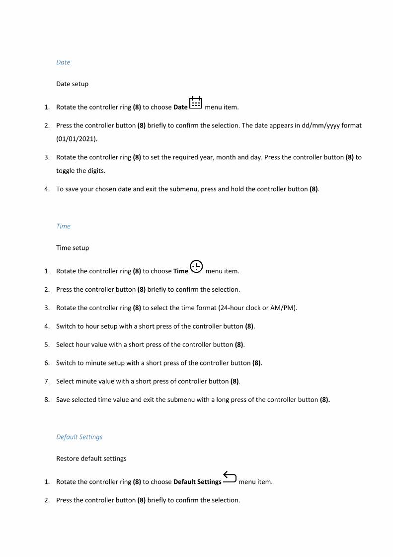
Date
Date setup
1. Rotate the controller ring (8) to choose Date menu item.
2. Press the controller button (8) briefly to confirm the selection. The date appears in dd/mm/yyyy format
(01/01/2021).
3. Rotate the controller ring (8) to set the required year, month and day. Press the controller button (8) to
toggle the digits.
4. To save your chosen date and exit the submenu, press and hold the controller button (8).
Time
Time setup
1. Rotate the controller ring (8) to choose Time menu item.
2. Press the controller button (8) briefly to confirm the selection.
3. Rotate the controller ring (8) to select the time format (24-hour clock or AM/PM).
4. Switch to hour setup with a short press of the controller button (8).
5. Select hour value with a short press of the controller button (8).
6. Switch to minute setup with a short press of the controller button (8).
7. Select minute value with a short press of controller button (8).
8. Save selected time value and exit the submenu with a long press of the controller button (8).
Default Settings
Restore default settings
1. Rotate the controller ring (8) to choose Default Settings menu item.
2. Press the controller button (8) briefly to confirm the selection.

3. Rotate the controller ring (8) to select Yes to restore default settings or No to cancel.
4. Confirm your selection with a short press of the controller button (8).
• If Yes is selected, display will show "Do you want to restore default
settings?" and Yes and No. Select Yes to restore the default settings.
• Selecting the No option will cancel the reset and exit the submenu.
The following settings will be returned to their defaults before being changed by the user:
• Video Recorder Mode – Video
• Observation Mode – Forest
• Calibration Mode – Automatic
• Language – English
• Wi-Fi – Off (default password)
• Color Mode – White Hot
Attention! When restoring the factory defaults the date, time and user pixel map are saved.
Format
This function enables you to format the Flash memory card. All files will be deleted.
1. Rotate the controller ring (8) to choose Format menu item.
2. Press the controller button (8) briefly to confirm the selection.
3. Rotate the controller ring (8) to select Yes to format the memory card or No to return to the submenu.
4. Press the controller button (8) briefly to confirm your selection.
• If Yes is selected, the message "Do you want to format the memory card?" appears on the display as
well as Yes and No. Select Yes to format the memory card.
• Selecting the No option will cancel the formatting and exit the submenu.
COLOR MODES
Color palette selection
White Hot is the default display mode. To select an alternative palette, do the following:
1. Press and hold the controller button (8) to enter the main menu.
2. Rotate the controller ring (8) to select Color Modes icon .
3. Press the controller button (8) briefly to enter the submenu.
4. Rotate the controller ring (8) to select the desired palette.
5. Press the controller button (8) briefly to confirm the selection.
Black Hot – a black and white palette where white corresponds to cold temperatures and black to hot
temperatures.
Red Hot
Red Monochrome
Rainbow
Ultramarine
Violet
Sepia
DEVICE INFORMATION
This menu item allows the user to view the following information about the device:
• SKU Number
• Firmware Version
• Device Name
• Hardware Version
• Device Serial Number
• Service Information
To display information, do the following:
1. Press and hold the controller button (8) to enter the main menu.
2. Rotate the controller ring (8) to select the Device Information icon.
3. Press the controller button (8) briefly to view / exit the information.
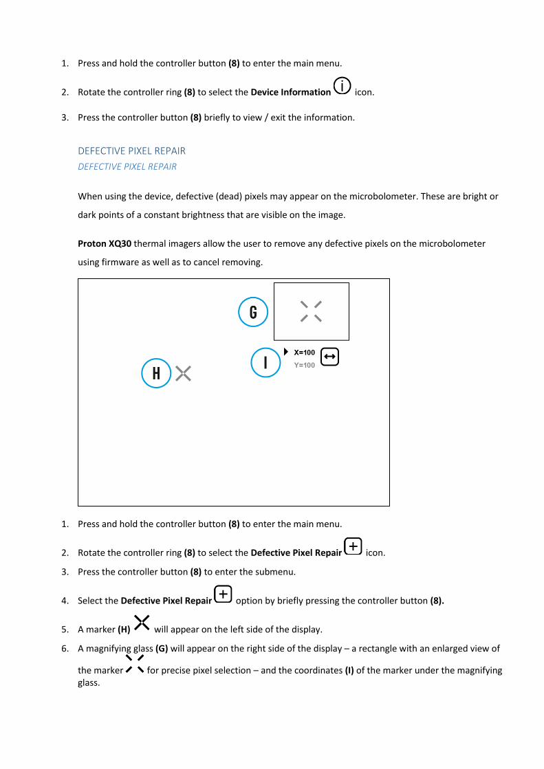
DEFECTIVE PIXEL REPAIR
DEFECTIVE PIXEL REPAIR
When using the device, defective (dead) pixels may appear on the microbolometer. These are bright or
dark points of a constant brightness that are visible on the image.
Proton XQ30 thermal imagers allow the user to remove any defective pixels on the microbolometer
using firmware as well as to cancel removing.
1. Press and hold the controller button (8) to enter the main menu.
2. Rotate the controller ring (8) to select the Defective Pixel Repair icon.
3. Press the controller button (8) to enter the submenu.
4. Select the Defective Pixel Repair option by briefly pressing the controller button (8).
5. A marker (H) will appear on the left side of the display.
6. A magnifying glass (G) will appear on the right side of the display – a rectangle with an enlarged view of
the marker for precise pixel selection – and the coordinates (I) of the marker under the magnifying glass.

7. Rotate the controller ring (8) to align a defective pixel with the center of the enlarged marker in the magnifying glass – the pixel should be removed.
8. Press the controller button (8) briefly to switch the marker direction between the horizontal to the vertical.
9. Press the ON/OFF (6) button briefly to delete the dead pixel.
10. Once the pixel has been successfully deleted, an OK message will briefly appear on the screen.
11. You can then delete the next defective pixel if required by moving the marker across the display.
12. Press and hold the controller button (6) to exit the Defective Pixel Repair function.
RESTORE DEFAULT PIXEL MAP
This option allows the user to return all previously disabled defective pixels to their original state.
1. Press and hold the controller button (8) to enter the main menu.
2. Rotate the controller ring (8) to select the Defective Pixel Repair icon.
3. Press the controller button (8) to enter the submenu.
4. Rotate the controller ring (8) to select the Restore Default Pixel Map icon .
5. Activate the function by briefly pressing the controller button (8).
6. Rotate the controller ring (8) to select Yes if you want to return to the factory pixel map or select No if
you do not.
7. Confirm your selection with a short press of the controller button (8).
Attention! One or two pixels on the display of the device in the form of bright white, black or colored
(blue, red or green) points may appear. These points cannot be removed and are not a defect.
MICROPHONE
Turning microphone on / off.
This item allows you to enable (or disable) the microphone for recording sound during video recording.
1. Press and hold the controller button (8) to enter the main menu.
2. Rotate the controller ring (8) to select Microphone icon.
3. A short press of the controller button (8) opens the submenu.
4. To turn the microphone on or off press controller button (8).
BLUETOOTH
Turn on/off Bluetooth
1. Press and hold the controller button (8) to enter the main menu.
2. Rotate the controller ring (8) to select the Bluetooth menu item.
3. A short press of the controller button (8) opens the submenu.
4. Turn Bluetooth on/off with a short press of the controller button (8).
5. Press and hold down the controller button (8) to exit the submenu.
The process of connecting the wireless remote control is described in the Remote Control
Activation section.
CALIBRATION MODE
Calibration mode selection
There are three calibration modes: Manual, Semi-Automatic and Automatic.
1. Press and hold the controller button (8) to enter the main menu.
2. Rotate the controller ring (8) to select the Calibration Mode icon.
3. Press the controller button (8) briefly to enter the submenu.
4. Rotate the controller ring (8) to select one of the calibration modes described below.
5. Press the controller button (8) briefly to confirm the selection.
Automatic (A). In this mode the firmware determines the need for calibration. The calibration process
starts automatically.
Semi-Automatic (SA). The user determines the need for calibration based on the image quality and can
action at a convenient time depending on the object being observed.
Manual (M). In the Manual (silent) calibration mode the user determines the need for calibration (as
in SA mode) but the lens cover must be closed during calibration.
VIDEO RECORDING AND PHOTOGRAPHY
The Proton XQ30 thermal imagers are equipped with the option to record video and still images
(photography) of the observed image by saving them on the built-in memory card.
It is recommended to set the date and time (see the General Settings section) before using the photo
and video functions.
The built-in recorder operates in two modes:
Video mode. Video Recording
1. Switch to Video mode by pressing and holding the REC (7) button.
2. The icon and the remaining recording time in HH:MM (Hours:Minutes) format are displayed in the
upper left corner for a short time, for example, 5:12. In the status bar, the video recording status is
displayed continuously.
3. Press the REC (7) button briefly to start video recording.
4. When the video recording starts, the icon will disappear and the REC icon and timer in MM:SS
(Minutes:Seconds) format will appear.
5. Press the REC (7) button briefly to pause or resume video recording.
6. Press and hold the REC (7) button to stop video recording.
7. Video files are saved to the built-in memory card after the video recording has been stopped.
8. Switch between modes (Video-> Photo-> Video) with a long press of the REC (7) button.
Photo mode. Capturing a photo
1. Switch to Photo mode by pressing and holding the REC (7) button.
2. Press the REC (7) button briefly to take a photo. The image freezes for 0.5 sec while the photo is saved
to the internal memory.
Notes:
• You can enter and navigate the menu during video recording.
• The recorded videos and photos are saved to the built-in memory card of the device in the formats
img_xxx.jpg (photos) and video_xxx. mp4 (video) where xxx is a 3 digit counter.

• The counter for multimedia files cannot be reset.
Attention!
• The maximum duration of a recorded video file is five minutes. After this time expires, the video is
recorded to a new file.
• The number of recorded files is limited by the capacity of the internal memory of the device.
• Regularly check the free capacity of the internal memory and move recorded footage to other storage
media to free up space on the internal memory card.
WI-FI FUNCTION
The device has a function enabling wireless communication with external devices (smartphone or tablet)
via Wi-Fi.
• Turn on the wireless module in the WI-Fi Activation menu option (see Wi-Fi Settings section).
Wi-Fi is displayed in the status bar as follows:
Connection Status Indication on the status bar
Wi-Fi is switched off
Wi-Fi connection is in progress
Wi-Fi is switched on, no connection with device
Wi-Fi is switched on, device connected
• The device is recognized by an external device as PROTON_XXXX where XXXX are the four last digits of
the serial number.
• After entering the password on the external device (see Password Setup subsection of the Wi-Fi
Settings section for more information on setting a password) and setting up a connection, the
icon in the status bar changes to .
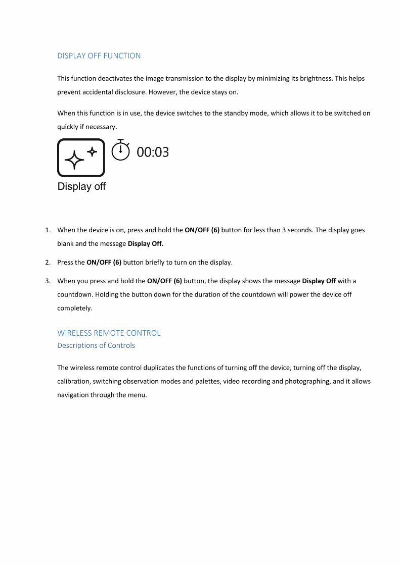
DISPLAY OFF FUNCTION
This function deactivates the image transmission to the display by minimizing its brightness. This helps
prevent accidental disclosure. However, the device stays on.
When this function is in use, the device switches to the standby mode, which allows it to be switched on
quickly if necessary.
1. When the device is on, press and hold the ON/OFF (6) button for less than 3 seconds. The display goes
blank and the message Display Off.
2. Press the ON/OFF (6) button briefly to turn on the display.
3. When you press and hold the ON/OFF (6) button, the display shows the message Display Off with a
countdown. Holding the button down for the duration of the countdown will power the device off
completely.
WIRELESS REMOTE CONTROL
Descriptions of Controls
The wireless remote control duplicates the functions of turning off the device, turning off the display,
calibration, switching observation modes and palettes, video recording and photographing, and it allows
navigation through the menu.
Remote Control Activation 1. Turn on the Bluetooth module (see the Bluetooth section).
2. In the Bluetooth section of the menu, use the controller ring (8) to select the Scan menu item.
3. Confirm your selection with a short press of the controller button (8) button.
4. Press and hold any button on the Remote Control. The Remote Control is visible in the Bluetooth network and can be connected during this time.
5. Use the controller ring (8) to select the remote control from the dropdown list that appears.
6. Confirm your selection with a short press of the controller button (8) button.
Notes:
• Once paired, the Remote Control can operate the Pulsar device.
• Going forward, the Remote Control will automatically connect to the paired device when within visible range.
• The name of the remote control and its battery charge level will appear in the list of paired devices at
the bottom of the display in the Bluetooth section of the menu.
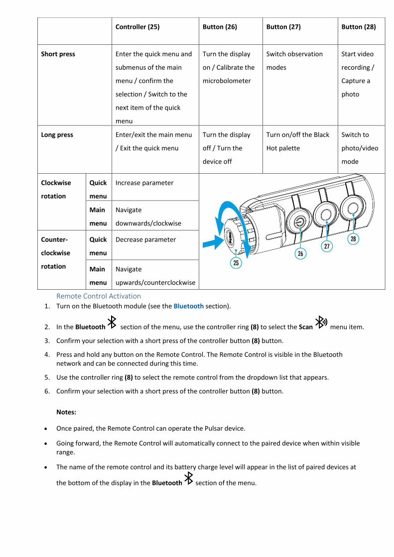
Controller (25) Button (26) Button (27) Button (28)
Short press Enter the quick menu and
submenus of the main
menu / confirm the
selection / Switch to the
next item of the quick
menu
Turn the display
on / Calibrate the
microbolometer
Switch observation
modes
Start video
recording /
Capture a
photo
Long press Enter/exit the main menu
/ Exit the quick menu
Turn the display
off / Turn the
device off
Turn on/off the Black
Hot palette
Switch to
photo/video
mode
Clockwise
rotation
Quick
menu
Increase parameter
Main
menu
Navigate
downwards/clockwise
Counter-
clockwise
rotation
Quick
menu
Decrease parameter
Main
menu
Navigate
upwards/counterclockwise
STREAM VISION
The Proton XQ30 thermal imagers support Stream Vision technology, which enables the transmission of
an image in real time from the attachment to your smartphone or tablet via Wi-Fi.
You can find further guidelines on Stream Vision here: https://www.pulsar-
nv.com/glo/products/33/software-applications/stream-vision/
FIRMWARE UPDATE
1. Download free of charge Stream Vision App on Google Play or App Store.
2. Connect your Pulsar device to your mobile device (smartphone or tablet).
3. Launch Stream Vision and go to section “My Devices”.
4. Select your Pulsar device and press “Check Updates”.
5. Wait for the update to download and install. Pulsar device will reboot and will be ready to operate.
Important:
• if your Pulsar device is connected to phone, please turn on mobile data transfer (GPRS/3G/4G) to
download update;
• if your Pulsar device is not connected to your phone but it's already in the “My Devices” section, you
may use Wi-Fi to download update.
Is your firmware up to date?
Click here to check the latest firmware for your device.
USB CONNECTION
1. Connect one end of the USB cable to the device micro-USB port (9) and the other end to the port on your computer.
2. Switch the device on with a short press of the ON/OFF (6) button (the computer will not detect the device if it is switched off).
3. The device is detected by the computer automatically and no drivers need to be installed.
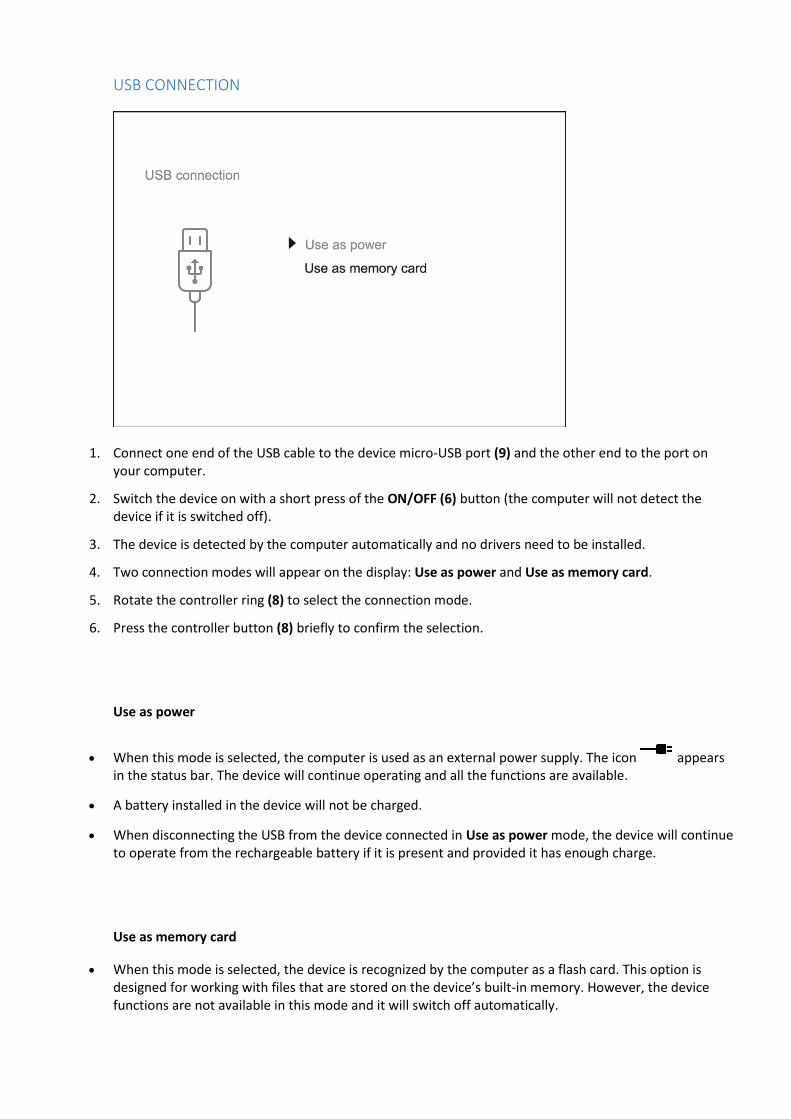
4. Two connection modes will appear on the display: Use as power and Use as memory card.
5. Rotate the controller ring (8) to select the connection mode.
6. Press the controller button (8) briefly to confirm the selection.
Use as power
• When this mode is selected, the computer is used as an external power supply. The icon appears in the status bar. The device will continue operating and all the functions are available.
• A battery installed in the device will not be charged.
• When disconnecting the USB from the device connected in Use as power mode, the device will continue to operate from the rechargeable battery if it is present and provided it has enough charge.
Use as memory card
• When this mode is selected, the device is recognized by the computer as a flash card. This option is designed for working with files that are stored on the device’s built-in memory. However, the device functions are not available in this mode and it will switch off automatically.
• If video recording was in progress when the connection was made, recording stops and the video is saved.
• When USB cable is disconnected from the device in Use as memory card mode, the device remains turned OFF. Press the ON/OFF (6) button to turn on the device.
TECHNICAL INSPECTION
It is recommended to carry out a technical inspection before each use of the device. Check the
following:
• The device appearance (there should be no cracks on the body).
• The state of the objective and eyepiece lenses of the thermal imaging module (there should be no
cracks, grease spots, dirt or other deposits).
• The state of the rechargeable battery (it should be charged) and the electric contacts (there should be
no signs of salts or oxidation).
• The controls should be in working order.
• The thermal imaging module is properly and firmly fixed on the optical device.
TECHNICAL MAINTENANCE AND STORAGE
Maintenance should be carried out at least twice a year and include the following steps:
• Wipe the exterior metal and plastic surfaces with a cotton cloth to remove dust and dirt.
• Clean the electrical contacts of the rechargeable battery on the device using a non-greasy organic
solvent.
• Check the eyepiece and the lens and if required remove dust and dirt from the optics (preferably using a
non-contact method). Cleaning of the exterior surfaces of the optics should only be done with products
specifically designed for this purpose.
• Always store the device in its carrying case in a dry, well-ventilated space. For prolonged storage,
remove the batteries.
TROUBLESHOOTING
The device does not turn on
Possible cause
The battery is completely discharged.
Solution
Charge the battery.
The device does not operate from an external power source
Possible cause
The USB cable is damaged.
Solution
Replace the USB cable.
Possible cause
The external power supply is discharged.
Solution
Charge the external power supply (if necessary).
Blurred image with vertical stripes or an uneven background
Possible cause
Calibration is required.
Solution
Perform image calibration according to the Microbolometer Calibration section of the manual.
Poor quality image. There is noise or ghost images of previous scenes or objects
Possible cause
Manual calibration has been performed with the lens cover open.
Solution
Check the Calibration Mode, close the lens cover and calibrate the device.
Black screen after calibration
Solution
If the image does not clear after calibration, you need to recalibrate.
Image is too dark
Possible cause
Brightness or contrast level is too low.
Solution
Adjust the brightness or contrast in the Quick Menu.
Color bars appear on the display or the image disappears
Possible cause
The device was exposed to static charges during operation.
Solution
When the exposure to static charges is over, the device may either reboot automatically or require to be
switched off and on again.
The image of the object being observed is missing
Possible cause
You are looking through glass.
Solution
Remove the glass or change the viewing position to avoid it.
Poor image quality / Reduced detection distance
Possible cause
These problems may occur during observation in adverse weather conditions (snow, rain, fog, etc.).
Smartphone or tablet cannot be connected to the device
Possible cause
Device password has been changed.
Solution
Delete the network and connect again using the password saved in the device.
Possible cause
The device is in an area with too many Wi-Fi networks that may be causing signal interference.
Solution
To ensure a stable Wi-Fi connection, relocate the device to an area with fewer or no Wi-Fi networks.
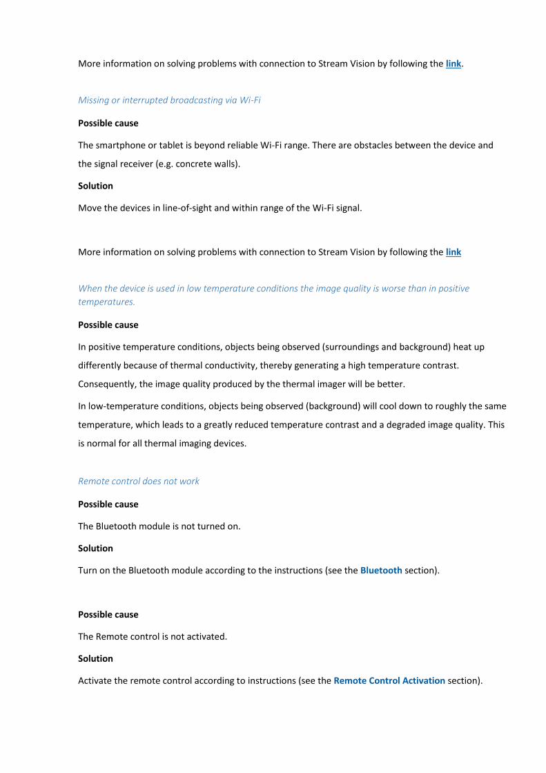
More information on solving problems with connection to Stream Vision by following the link.
Missing or interrupted broadcasting via Wi-Fi
Possible cause
The smartphone or tablet is beyond reliable Wi-Fi range. There are obstacles between the device and
the signal receiver (e.g. concrete walls).
Solution
Move the devices in line-of-sight and within range of the Wi-Fi signal.
More information on solving problems with connection to Stream Vision by following the link
When the device is used in low temperature conditions the image quality is worse than in positive
temperatures.
Possible cause
In positive temperature conditions, objects being observed (surroundings and background) heat up
differently because of thermal conductivity, thereby generating a high temperature contrast.
Consequently, the image quality produced by the thermal imager will be better.
In low-temperature conditions, objects being observed (background) will cool down to roughly the same
temperature, which leads to a greatly reduced temperature contrast and a degraded image quality. This
is normal for all thermal imaging devices.
Remote control does not work
Possible cause
The Bluetooth module is not turned on.
Solution
Turn on the Bluetooth module according to the instructions (see the Bluetooth section).
Possible cause
The Remote control is not activated.
Solution
Activate the remote control according to instructions (see the Remote Control Activation section).

Possible cause
The Remote Control is out of range of the device.
Solution
Return to the device coverage area.
Possible cause
Remote control battery low.
Solution
Install a new CR2032 battery as follows: unscrew the screws on the rear cover of the Remote Control,
remove the cover, install a new battery, and screw the cover with screws.
LEGAL COMPLIANCES AND DISCLAIMERS
Attention! A license is required for Thermal Imager Proton XQ30 when exporting outside your country.
Electromagnetic compatibility. This product complies with the requirements of European standard EN
55032: 2015, Class A.
Caution! Operation of this equipment in a residential environment could cause radio interference.
This product is subject to change in line with improvements to its design.
Repair of the device is possible within 5 years.
![arXiv:1903.03035v2 [astro-ph.IM] 8 Mar 2019](https://static.fdokumen.com/doc/165x107/631e96985c567f54b4041f1f/arxiv190303035v2-astro-phim-8-mar-2019.jpg)
![arXiv:2011.03736v1 [astro-ph.GA] 7 Nov 2020](https://static.fdokumen.com/doc/165x107/631649c471e3f206290657fb/arxiv201103736v1-astro-phga-7-nov-2020.jpg)
![arXiv:2201.07771v1 [astro-ph.CO] 19 Jan 2022](https://static.fdokumen.com/doc/165x107/631c0c3db8a98572c10cb9b0/arxiv220107771v1-astro-phco-19-jan-2022.jpg)

![arXiv:2109.11157v1 [astro-ph.SR] 23 Sep 2021](https://static.fdokumen.com/doc/165x107/631ab01ec51d6b41aa04ee50/arxiv210911157v1-astro-phsr-23-sep-2021.jpg)
![arXiv:2106.10455v1 [astro-ph.GA] 19 Jun 2021](https://static.fdokumen.com/doc/165x107/631c408eb8a98572c10cd18f/arxiv210610455v1-astro-phga-19-jun-2021.jpg)

![arXiv:2008.13169v2 [astro-ph.SR] 21 Sep 2020](https://static.fdokumen.com/doc/165x107/63179c13c72bc2f2dd058a5f/arxiv200813169v2-astro-phsr-21-sep-2020.jpg)
![arXiv:1312.3223v1 [astro-ph.GA] 11 Dec 2013](https://static.fdokumen.com/doc/165x107/6318354ccf65c6358f01e45f/arxiv13123223v1-astro-phga-11-dec-2013.jpg)
![arXiv:2105.09151v3 [astro-ph.HE] 17 Aug 2021](https://static.fdokumen.com/doc/165x107/6317b63271e3f2062906e635/arxiv210509151v3-astro-phhe-17-aug-2021.jpg)
![arXiv:2109.06246v1 [astro-ph.HE] 13 Sep 2021](https://static.fdokumen.com/doc/165x107/6317a3c9f68b807f8803b90e/arxiv210906246v1-astro-phhe-13-sep-2021.jpg)

![arXiv:2003.10070v1 [astro-ph.GA] 23 Mar 2020](https://static.fdokumen.com/doc/165x107/6317b74f9076d1dcf80bea8f/arxiv200310070v1-astro-phga-23-mar-2020.jpg)

![arXiv:2108.12040v1 [astro-ph.SR] 26 Aug 2021](https://static.fdokumen.com/doc/165x107/6315282caca2b42b580dc4e5/arxiv210812040v1-astro-phsr-26-aug-2021.jpg)
![arXiv:1309.0755v1 [astro-ph.HE] 3 Sep 2013](https://static.fdokumen.com/doc/165x107/6314689f15106505030b5055/arxiv13090755v1-astro-phhe-3-sep-2013.jpg)


