
Astro-Physics - Baader Planetarium
61
Astro-Physics GTO Servo Drive System Model GTOCP4 Operating Instructions Non-ASCOM Windows Program Non-ASCOM Mac Program Astro-Physics Command Center ASCOM AP V2 Driver AP GTO Keypad Apple, Android & Windows Mobile Devices via Direct or Network Wi-Fi Multiple ASCOM Client Applications ACP on iPad Auto-guider Inputs from Guide Camera Windows Computer with ASCOM Planetarium Software AP GTOCP4 Servo Control Box November 30, 2017
-
Upload
khangminh22 -
Category
Documents
-
view
0 -
download
0
Transcript of Astro-Physics - Baader Planetarium

Astro-PhysicsGTO Servo Drive System
Model GTOCP4Operating Instructions
Non-ASCOMWindowsProgram
Non-ASCOMMac
Program
Astro-Physics Command CenterASCOM
APV2 Driver
AP GTO Keypad
Apple, Android
& Windows
Mobile Devicesvia
Direct or
Network Wi-Fi
MultipleASCOMClient
Applications
ACP on iPad
Auto-guider Inputsfrom
Guide Camera
Windows Computerwith ASCOMPlanetariumSoftware
AP GTOCP4Servo Control Box
November 30, 2017

1
Astro-Physics GTO Servo Drive SystemModel GTOCP4
COnTenTS
About this MAnuAl 3
introduction 4
Gto servo drive systeM specificAtions 6
Gto control box – Model Gtocp4 – your Mount’s brAin 7Gtocp4 control box - layout and features 7
10-pin receptacle for servo Motors 710-pin receptacle for Absolute encoders 712-volt locking receptacle 8power indicator light 8Keypad receptacle 8Auxiliary receptacle 8Autoguider port receptacle 8communication ports 8choosing your communication interfaces 9usb port 9rs-232 ports (2) 10ethernet port 11Wifi connection 11
More information on ip addresses for uploading new software 13ethernet and Wifi best practice recommendations 14pre-loaded peMpro™ curve 14
removing and installing the Gtocp4 control box 15Gtocp4 and Absolute encoders 16
ApAe utility and Absolute encoder Mounts 16Gtocp4 and precision encoders 17
Astro-physics command center (Apcc) 17Astro-physics Absolute encoder Mini utility 17installation, settings and operating instructions for the limit switch system (36lss) and precision encoder system (on the 3600Gtope), dated March 27, 2013 17
controllinG your Gto Mount 18Gto Keypad operation 19the Astro-physics AscoM v2 driver 19the Astro-physics command center (Apcc) 21
some Apcc thoughts 22planetarium, imaging and observatory software from other vendors 23peMpro™ by sirius-imaging 24pulseGuide™ by sirius-imaging 25
understAndinG the GerMAn equAtoriAl servo loGic 26initialization and shut-down 26the role of time and location data in the servo system 27safety slew logic 27the concept of “pier side” as it relates to the servo 28tracking past the Meridian 29

2
Meridian delay or Meridian Advance 29
AutoGuidinG tips And notes 31how to test an Autoguider port 31
troubleshootinG, tips And support 33troubleshooting and tips 33Additional support 36
Appendix A: poWer specificAtion tAbles 37power specifications - Mach1Gto, 400Gto and 600eGto 37power specifications - 900Gto (All) and 1200Gto (shipped prior to 2011) 37power specifications - 1100Gto, 1100Gto-Ae and 1100Gto-Ael 37power specifications - 1200Gto (shipped 2011 and later) 37power specifications - 1600Gto 37power specifications - 3600Gto 37
Appendix b: poWer considerAtions 38introduction 38some power basics for non-electrical engineers 38batteries 39results of either inadequate or excessive power 41iMportAnt considerations for observatory installations: 42
Appendix c: Gtocp4 softWAre updAte 43field download of Gtocp4 software 43
determine your ip Address 43download using a browser 44
Appendix d: rs-232 coMMAnd lAnGuAGe for Gtocp3 And Gtocp4 servo control boxes 47
Gtocp4 control box: 47Gtocp3 control box: 47Gtocp1 and Gtocp2 control boxes: 47
General telescope information: 47telescope Motion 48position 51Miscellaneous 52communicating with your Mount When Writing your own programs 52
Appendix e: coMMAnd lAnGuAGe / troubleshootinG updAte 54Motor stalls in Gtocp1 and Gtocp2s with the e1 or Ke1 chip 54horizon check in the servo 54variable tracking 54
Appendix f: reGulAtory inforMAtion for trAnsMitter Module 55fcc notice (usA) 55rf exposure 55ic notice (canada) 55ce notice (europe) 55
Appendix G: country codes for Wifi 56
Appendix h: netWorK protocol license 59lwip's license 59
Appendix i: Gtocp4 / Mount personAlity codes 60
3
AbOuT ThiS MAnuAl up until the middle of 2011, the Astro-physics Gto servo Motor drive system was described in a small section toward the end of each individual mount manual. As time has passed and more options have become available - both in terms of input devices and in terms of the capabilities of the servo itself - it has become apparent that the Gto servo system should have its own manual that would apply to all Astro-physics Gto German equatorial Mounts, as well as the oeM mounts that employ our servo drive. to this end, we have prepared this manual.
one of the principal advantages of using a single manual for all the Gto servo drives is that we will be better able to keep it current with all the latest information. this is especially important in the world of electronics and software where change is the rule, and time to obsolescence often seems to be measured in minutes rather than years!
We will do our best to keep the manual updated on our website. We expect this manual to be a constant work-in-progress, so check our technical support section often for the latest information.
Please RecoRd the Following inFoRmation FoR FutuRe ReFeRence
GTOCP4 Serial Number: _____________________________________________
Purchase Date: _____________________________________________

4
inTrODuCTiOn your mount is a unique combination of precision, intelligence and strength. the heavy-duty, cnc machined parts give the mount the strength and rigidity to hold a load in a rock-steady fashion while exposed to the elements and while that entire load is in motion. the precision of every component allows accuracies that are measured in fractional arcseconds. the intelligence to control all of this is in the Gto servo Motor drive system.
there are three major sub-systems to the Gto servo drive:
1. The GTOCP4 Control box this is the real “brain” of your mount. please try to understand this from the outset. your mount is nOT controlled by the keypad or by your computer. they merely serve as input devices and convenient inter-faces for you, the user. the Gtocp4 serves the following functions among others:
○ it provides the voltage to drive the motors.
○ it determines the motors’ rotational direction, rotational speed and the total number of rotations required to arrive at the destination coordinates that are commanded.
○ it maintains the accurate tracking speed that is chosen and applies any needed corrections from a periodic error curve that is stored in its memory.
○ it takes the provided input and translates it into the correct actions that fulfill our wishes.
○ in mounts equipped with the Absolute encoder system or the precision encoder and limit switch systems, the Gtocp4 seamlessly integrates the encoder and limit functions with the regular servo control functions for an unprecedented level of control.
○ it bears repeating: it is the Gtocp4 control box that controls the mount!
2. The Servo Motors with their integral high precision motor-encoders. these high-quality swiss dc servo motors are the work horses that actually move the mount. their integral encoders provide the necessary feedback information for the Gtocp4 servo control box to perform its varied operations. the encoders working with the microprocessor in the Gtocp4 operate to an accuracy of 0.05 arcseconds per step. these motors can be accurately controlled over a speed range of 4800:1, which allows 0.25x sidereal for manual guiding to 1200x sidereal for 5 degree per second slew-ing (Mach1GTO, 900Gto, 1100Gto, 1200Gto and 1600Gto). the top speed has been intentionally scaled back to 600x for the 3600Gto because its larger worm wheel has more teeth than the wheels on the three smaller mounts. note: the integral motor-encoders are not the same as the Absolute or precision shaft encoders that we offer.
3. An external input device to interface with the user. the interface that we offer as an optional accessory for the Gto servo system is, of course, the Gto Keypad. in addition, the Gtocp4 control box has the versatility to commu-nicate with just about every kind of electronic device imaginable. this obviously includes personal computers, but now also includes numerous mobile smart devices, with more being developed all the time. in addition to the serial com-munication, the Gtocp4 also offers usb, ethernet and Wifi connectivity. the Gto Keypad has its own manual with complete operational instructions. for more information on other external input devices, see the controlling your Gto Mount section on page 18.
for the discussions that follow, we also divide the types of control functions that the Gtocp4 control box performs into three principal categories that are discussed more fully in "controlling your Gto Mount" on page 18.
1. Primary Control Functions. primary control functions include all the functions that define hoW the servo will make decisions. in particular, these are the initialization functions - time, date and location - along with park, Meridian delay and sync.
2. GoTo / Move Functions. Goto / move functions include coordinates, move commands, and rate commands.
3. hybrid and Other Functions. hybrid and other functions include periodic error Management (peM functions and the re-calibrate function which has elements of both control and Goto / Move.
to ensure the reliability of this control equipment, the Astro-physics servo drive system uses industrial components. We chose a sturdy industrial handheld computer as our keypad. these components are far more rugged than conventional consumer electronics, and they will continue to function properly well below zero degrees f (-18 c). the keypad uses a

5
vacuum fluorescent display that does not lose its speed or readability in the coldest winter conditions...all the way down to -40 degrees f (-40 c). (however, if you plan to use your mount in extreme temperatures and conditions, please contact Astro-physics first.)
All of this control and sophistication is accomplished in an incredibly efficient manner. the servo drive system can generally be operated from nominal 12-volt systems, although the larger mounts may benefit from slightly higher voltages. in terms of energy consumed, the Ap Gto mounts generally consume less wattage than a small compact fluorescent bulb when tracking, and less than a small incandescent bulb when slewing. power considerations are explained in detail starting on page 38.

6
GTO ServO Drive SySTeM SPeCiFiCATiOnSelectronic components rated for industrial and rugged automotive applicationsMotors: Mach1GTO, 900Gto and 1100Gto Zero-cogging swiss dc servo motors, enclosed in machined aluminum housing
Motors: 1200Gto, 1600Gto and 3600Gto high-torque, zero-cogging swiss dc servo motors, enclosed in machined aluminum housing
Motor encoder
2000 tic quadrature yielding an effective resolution of 0.050 arcseconds per tic for the Mach1GTO, 900Gto, 1100Gto, 1200Gto and 1600Gto. the 3600Gto has an even tighter resolution of 0.044 arcseconds. the 400Gto and 600eGto have resolutions of 0.033 or 0.053 arcseconds depending on the gearbox.
Motor reduction gear train57.6:1 gear reduction through a custom built set of large diameter, fine-toothed, precision, spur gears for vastly superior performance (except: 400Gto and 600eGto which had 3.2:1 spur gear reduction and either a 19.8:1 or 32:1 gear head on the motor)
servo Motor control box Gtocp4 control box, removable
hand-held computer optional Gto Keypad to control all mount functions. includes extensive databases and tour features in a simple, intuitive interface. software updates via internet
power consumption
0.3 to 0.8 amps at the mount’s recommended voltage while tracking; 1.0 to 3.0 amps at the mount’s recommended voltage - both motors slewing at the highest available slew speed. for greater detail see the individual power specs for each mount in the power considerations section starting on page 38.
power requirements12v to 18v dc at a minimum of 5 to 10 amps continuous recommended, depending on the mount model, load and environmental factors. for specific details see the individual power specs for each mount in the power considerations section starting on page 38.
Gtocp4 dimensions 6.375” x 4.9” x 1.8” (16.1 x 12.5 x 4.6 cm)
Gtocp4 weight 1.8 lb. (0.8 kg)
standards Meets fcc and ce standards. lead-free rohs complianceMaximum slew speed: Mach1GTO, 900Gto, 1100Gto, 1200Gto and 1600Gto
5 degrees / second at 1200x sidereal
Maximum slew speed: 3600Gto 2.5 degrees / second at 600x sidereal

7
GTO COnTrOl bOx – MODel GTOCP4 – yOur MOunT’S brAinthe Gto control box contains all of the circuitry to drive the two servo motors and the logic required to navigate the sky. it will be operational and track at the sidereal rate when connected to both motor / gearboxes of the mount and a power source. in order to control the movement of the mount, you will need to connect at least one of these:
● Gto Keypad.
● computer with a planetarium program or observatory control software. the "the Astro-physics command center (Apcc)" on page 21 is highly recommended. Astro-physics also has a fully supported AscoM v2 driver available. A more detailed listing of software is in the "controlling your Gto Mount" on page 18. in addition, see the Website’s AscoM page and the Apcc page for details on both Apcc and the AscoM driver.
● Mobile smart device with mount command functions that employ the Astro-physics command protocol. note: As of this writing, some programs on mobile devices do not have a means of initializing the mount. for more information, see "initialization and shut-down" on page 26.
● pc computer with PulseGuide™ by sirius imaging. the cd with this program is included with the mount. the cd includes a complete user’s manual in pdf format. for the most updated version of the software, check out the website www.pulseguide.com. please refer to the section later in this manual for further information regarding the capabilities of this program.
please remember that this box contains advanced electronics and must be treated with the same care given to other fine equipment. you can see that the unit is machined of aluminum and is built to be rugged; however, it is not indestructible.
GTOCP4 Control Box - Layout and Features
10-pin Receptacle for Servo MotorsA y-cable or servo extension cable with 10-pin male connectors plugs into this receptacle. Attach the connector to the Gto control panel. Attach the short leg of the y-cable to the r.A. motor housing and the long leg of the cable to the dec. motor housing. be sure to screw on the knurled ring to lock it in place. refer to the appropriate section on cable management in your mount manual for further information about positioning the cables.
10-pin Receptacle for Absolute Encoders the Gtocp4 incorporates the functionality of both the GtoAe and Gtoels into its design, thus eliminating the need for these secondary boxes when using the 1100Gto and 1600Gto mounts with Absolute encoders or the 3600Gto with precision encoders. the encoder cables with 10-pin female connectors from these mounts will be connected directly into this 10-pin receptacle.
Control Panel of GTOCP4 Control Box
8
12-volt Locking Receptacleplace the dc power cable’s 2-pin locking plug into the 2-pin receptacle marked 12v on the Gto control panel and lock in place by a twist of the plug’s locking collar onto the receptacle. the other end of the power cable terminates with Anderson power pole connectors which provide convenience when connecting to a number of different power connectors. cigarette plug and ring terminal adapters are provided with the mount’s power cable set. several other connector types can be found through the internet. The GTOCP4 receptacle is top pin (pin #1) positive (the orientation notch is to the right). See photo on previous page.
We highly recommend either our 13.8 volt 5-amp power supply (ps138v5A) for most situations or our 15 volt 12-amp supply (ps15v12Ac) for the larger mounts, heavier loads and / or colder climates. do not use "wall wart" or laptop power supplies.
please read the Appendix b: power considerations section starting on page 38 for more information. in short, using a cheap or inadequate power supply with your mount is like buying cut-rate gas for a ferrari.
there is no on-off switch on the Gtocp4, although on-off switches are found on most power supplies. We recommend that you connect all of your cables to the Gtocp4 servo control box before applying power, whether from a power supply or from a battery. to turn the unit off, simply disconnect the power cable or flip the switch on the power supply.
Power Indicator Lightthis red led will remain illuminated when your system is powered up and operating properly. the red-colored led indicates proper functioning of the servo system. if the servo detects a problem, the led will turn from red to amber. An amber led indicates that the servo has gone into “safe mode” or “motor stall” mode and is no longer trying to drive the motors. the motors will be stopped and de-energized for safety. position data is not lost during this condition. if the voltage falls below about 10.5 volts, the power led will go out completely. the keypad will also not function properly below about 11 volts.
if you experience an amber led, first check your power source to be sure it is delivering adequate voltage and current to drive the system. look for loose or corroded power connections. if your power supply is good, the amber led means that your motors are overloaded, probably due to an unbalanced load on your mount. it could also mean that your scope or counterweights have hit an obstruction and stopped the motion of the axis. refer to the troubleshooting section of the manual for the solution.
Keypad ReceptacleAttach the 5-pin male connector plug on the end of the Gto Keypad’s coiled cable to this receptacle and lock it in place (push in the knurled ring then turn). the keypad receptacle is actually a serial port with an added 12 volt power source.
Auxiliary Receptaclethe auxiliary receptacle will be used for future devices which will provide additional functionality to the mounts. currently, it is used for connection to the limit switches of the 3600Gto mount.
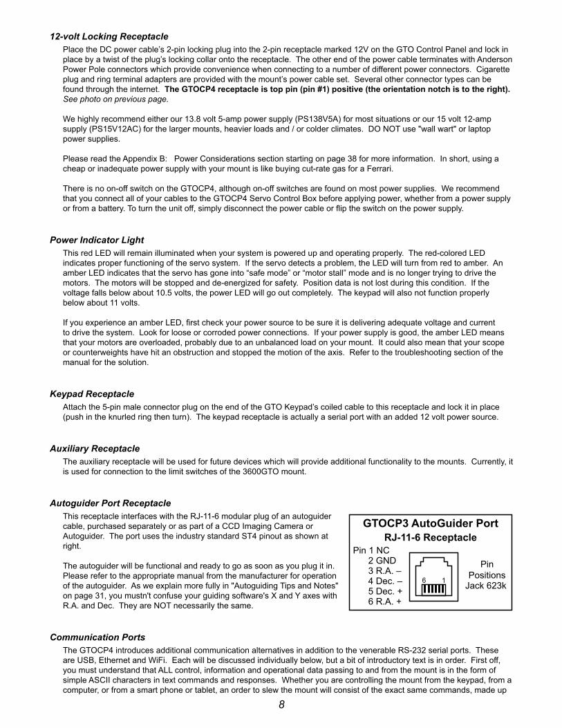
Autoguider Port Receptaclethis receptacle interfaces with the rJ-11-6 modular plug of an autoguider cable, purchased separately or as part of a ccd imaging camera or Autoguider. the port uses the industry standard st4 pinout as shown at right.
the autoguider will be functional and ready to go as soon as you plug it in. please refer to the appropriate manual from the manufacturer for operation of the autoguider. As we explain more fully in "Autoguiding tips and notes" on page 31, you mustn't confuse your guiding software's x and y axes with r.A. and dec. they are not necessarily the same.
Communication Portsthe Gtocp4 introduces additional communication alternatives in addition to the venerable rs-232 serial ports. these are usb, ethernet and Wifi. each will be discussed individually below, but a bit of introductory text is in order. first off, you must understand that All control, information and operational data passing to and from the mount is in the form of simple Ascii characters in text commands and responses. Whether you are controlling the mount from the keypad, from a computer, or from a smart phone or tablet, an order to slew the mount will consist of the exact same commands, made up
6 1
GTOCP3 AutoGuider PortRJ-11-6 Receptacle
PinPositions
Jack 623k
Pin 1 NC 2 GND 3 R.A. – 4 Dec. – 5 Dec. + 6 R.A. +

9
of these same Ascii characters, sent in the exact same order, and basically at the same speed.
do not be duped into thinking that traditional serial communication is somehow inferior to usb, ethernet or Wifi. your goal is to select the alternative or alternatives that best meet your needs with respect to your control device, and the distance between the control device and the mount. crash-proof dependability of the communication medium is fAr More iMportAnt than high speed!
ethernet and Wifi can be thought of as the same thing in many respects. At its root, Wifi is simply ethernet that uses radio technology instead of twisted-pair cables to move data bits from point A to point b. ethernet and Wifi control is still under development with the authors of the various control software packages and planetarium programs that are available. As these developments proceed, ethernet and Wifi will become ever better choices for primary control of the mount. for the present, Wifi and ethernet have three major applications:
1. "the Astro-physics command center (Apcc)" on page 21 will connect directly to the Gtocp4 through either ethernet or Wifi. cabled network and peer-to-peer as well as Wifi network (station) and Access point modes are all supported.
2. ethernet and Wifi can be used with virtual serial port software to create additional serial port options for normal mount control with other software.
3. the Gtocp4 has a built in web interface that can be accessed by any browser or via our ethernet-Wifi poll utility. Among other things, this is by far the best way to perform software upgrades to the control box.
4. they allow easy connection of mobile devices like smart phones and tablets. no additional dongle or device is re-quired.
regardless of the communication method, when you are controlling the position of the mount with a computer program such as the Astro-physics command center (APCC), dc3 dreams’ ACP™, or simulation curriculum corp.’s Starry Night™, there is constant communication between the computer and the microprocessor in the Gtocp4. the computer software requests constant updates to the position and status of the mount, and the Gtocp4’s microprocessor chip responds with continual r.A. and dec. coordinate data via the cable or wireless connections to your computer. When you use the software to give instructions to slew to a new object, the commands (r.A. and dec. coordinates) are sent to the mount. please read the sections that follow entitled, “controlling your Gto Mount” and “understanding the German equatorial servo logic” for additional information.
Choosing Your Communication Interfacesone of the primary factors in choosing your connection method or methods will be the distance separating the control device from the mount. (there are, of course, other important factors as well.) people who have their mounts close to the controlling computer, and do not have network capabilities at hand, may find direct usb connection to be their most convenient choice. somewhat longer distances may be better served with peer-to-peer ethernet, an installed serial card or a usb to serial adapter and a longer serial cable. for remote control of a mount that is within 100 yards or so of the controlling computer, we have found the icron technologies ranger 2304 usb extender to be an excellent solution (more below). ethernet capabilities are available through "the Astro-physics command center (Apcc)" on page 21, but with Apcc's virtual ports, it is really the only mount connection needed. As network capabilities are written into other software by the respective developers, direct or network connection with ethernet and Wifi will also become ever more attractive options.
More distantly remote observatories will generally require a computer or an ip addressable server in the remote observatory itself, along with a high-speed internet connection for communication with your home computer. the ethernet and Wifi discussed below will prove helpful. such complete long range solutions are beyond the scope of Astro-physics to supply or support. if you are outfitting your observatory with a new computer, you might want to consider a small industrial computer or “media player” computer like the Global shuttle ds series (i.e. the ds57u), the cincoze line, or the Moxa v series among others. these computers are used to run the huge video billboards that are now everywhere, and they are environmentally robust, even at low temperatures. they also come with multiple true serial ports, and many operate on 12 volts - perfect for the solar-powered observatory!
As with any computer electronics, change is the only real constant. please check the serial / usb Mount to computer connectivity devices, Adapters and cables page of our website for the latest information on products for computer connectivity that we carry!
USB PortWe have added a ruggedized usb 2.0 port to the Gtocp4. the usb port uses an on-board ftdi rs-232 serial uArt to seamlessly connect as if it were a true serial port. this device is powered both from the usb itself and also from the power of the Gtocp4. one of the serious problems with external usb to serial adapters is that usb is notorious for having “coughs, sneezes and hiccups”. since the typical external usb to serial

10
devices are powered only through the usb, they crash when there is such a hiccup. because the internal ftdi chipset in the Gtocp4 remains powered, it will almost never crash, and it is able to recover when your computer’s usb develops indigestion.
As with all usb devices, this one works best when common sense is applied.
● use a high quality usb cable.
● use the shortest cable that will work for your system. remember, usb is limited to about 15-16 ft. (5 meters).
● connect directly to a primary usb port on your computer if possible (generally these are located on the rear of a desktop computer).
● Avoid using hubs or extenders if possible. if you must use a hub, use a high quality hub that is powered. if you must extend your usb range we highly recommend the icron ranger 2304 usb extender which you can find on the serial / usb Mount to computer connectivity devices, Adapters and cables page of our website. the icron ranger 2304 provides four usb ports, one of which can be used for the mount, leaving 3 available usb ports. the icron ranger 2304 supports isochronous data transfer and will therefore work with most ccd cameras.
IMPORTANT!! you Must install the ftdi driver onto your computer for this device to work properly. it is hiGhly recommended that you install this driver before you connect the Gtocp4’s usb port to your computer for the first time! the latest driver can be found at http://www.ftdichip.com/drivers/vcp.htm . note also that the ftdi usb to serial devices are all uniquely serialized. each one will be assigned its own coM port that will be remembered through power-cycles.
RS-232 Ports (2)these are the traditional serial ports that have been used to connect your mount to an external computer for years.
"So, why would anyone still use an old-fashioned serial port?" you might ask.
the answer is quite straight-forward. traditional serial ports still have many advantages. they are still highly recommended for their ruggedness and reliability. one of the huge advantages of serial over usb is that serial cables can be much longer. 100 ft. serial cables are generally not a problem, whereas usb is limited to about 15 - 16 ft. (5 meters). industrial and commercial equipment control is still totally dominated by serial for its robust dependability.
you may provide your own straight-through (non-crossing) cables (from 1’ to 100’ length) with a 9-pin (de-9) male connector to interface with the Gto panel, or you can purchase a 15 foot cable directly from us (and be assured that they are the correct type of cable!). our de-9 receptacles provided the locking posts to secure the cable firmly onto the control box. if your serial cable does not have a 9-pin connector, you can use a gender changer or adapter to convert it.
**FYI – The DE-9 plug and receptacle are often mistakenly referred to as DB-9s. The E or B represents the shell size of the plug or receptacle. The B shell is the larger size used for the 25-pin DB-25 plug and receptacle, but the smaller 9-pin version uses the E size shell and is therefore correctly called a DE-9. Now you know!
Please note: Make sure that your serial cable is wired straight-through! The use of “crossing”, “reversing”, “null”, or “null modem” cables is a frequent source of communications failure and frustration.
We provide two rs-232 serial-port connections on the mount to give you added flexibility. the availability of a second port also facilitates the backup coM port feature in the Astro-physics command center (Apcc). if you use Apcc, you also gain the benefit of its additional virtual serial ports.
serial ports, by their nature cannot be y-connected or split with hubs. each physical serial connection that you use on the
GTO Control Box Serial RS-232 PortsDE-9 Female Jack
1 Empty2 Transmit from Servo Drive3 Transmit from Computer to Servo4 Empty5 Ground6 Data Set Ready7 Empty8 Empty9 Empty
Pins 2, 3, 5 & 6 are active.
5 4 3 2 1
9 8 7 6
Note: If making your own cable, a jumper may be required between pins #4 and #6.

11
mount must have a corresponding unique coM port available on your computer. if you use a laptop, you will probably need to purchase a usb to serial adapter to use one of the serial ports. in the past, we recommended and sold adapters from Keyspan. these are still fine adapters, but we are now recommending and selling adapters from ftdi. A primary reason for this change is that the Gtocp4’s on-board usb serial uArt is also by ftdi. this way, you need only a single driver to work with all of your usb to serial applications. Another reason for the switch is that the ftdi units have a wider operating temperature range, especially important on cold nights under the stars. unlike many lower quality devices, both the ftdi and Keyspan adapters also maintain their coM assignments when plugged into different usb receptacles on any given computer.
for desktop computers, we strongly recommend installing a multi-port pci serial card directly onto your computer’s motherboard. this is basically the same as the native serial ports that were standard on all computers back in the “old days.”
Ethernet Portthe Gtocp4 introduces ethernet connectivity to the Astro-physics Gto servo system. the interface is the standard rJ45-8 receptacle for cat 5 and higher cables. ethernet (lAn) can be point-to-point (aka. peer-to-peer) with a computer, or networked without user configuration. simply enter the ip address into the browser url and gain access to the Gtocp4 Web interface. An IP address takes the form: xxx.xxx.xxx.xxx where xxx is a value between 0 and 255. A typical IP address on your home network might be 192.168.0.101
A handy AscoM ethernet Wifi poll utility as well as the findMounts.jar Java applet have been provided on our technical support page for divining the correct ip address for AscoM users without the networking expertise to do this themselves. the utility will even open up the Gtocp4 Web interface in internet explorer if it is present on your system. Use the same Username and Password as for a keypad firmware update. the Java applet will work from non-Windows computers, but does require oracle's Java runtime environment.
Additional ip address info can be found in the section "More information on ip addresses for uploading new software" on page 13.
the Gtocp4 Web interface will provide easy configuration of your ethernet and Wifi connections. it also provides the best and easiest way to upload software updates. A sample Main page is shown at right. the "load new software" button and a button linking to the "help with new software update" have been circled. Additionally, since the Web interface is built into the Gtocp4, you can access it on any operating system that supports a Web browser without having to install any special software.
if you plan to use the ethernet connection with Windows software that supports serial ports (including the AscoM v2 driver, TheSkyX™ and most software available today), we suggest that you use "the Astro-physics command center (Apcc)" on page 21. connect Apcc directly and then use its built-in virtual serial ports for other software.
theskyx also offers ip connectivity, but at the present, you will be limited to their native driver. Another possible alternative is to use the "eltima serial to ethernet connector" software available from www.eltima.com. this software effectively creates a virtual serial port over your ethernet connection. this serial port acts like any other serial port, but unlike a true serial port, it is not totally exclusive. you can continue to use other ethernet data capabilities while the virtual serial port is in use. for example, you can connect voyager software from carina software (page 23) through an eltima virtual serial port and still use the Web interface.
WiFi ConnectionAs mentioned earlier, at its basic level, Wifi is simply ethernet over radio waves rather than over twisted-pair cAt 6 cables. however, the wireless nature does create a few characteristics unique to Wifi. your Gtocp4 can be configured as either a station or as an access point. the station mode lets your Gtocp4 join an existing Wifi network. the Access point mode allows your Gtocp4 to create its own network.
the Gtocp4 is shipped with the default set to "Access point." both modes are configured for the most commonly used

12
security protocol: WpA2-Mixed-psK (personal).
configuration of the Wifi is most easily done from the web pages built into the Gtocp4. it is probably simplest to do this the first time from the ethernet based web pages described above. however, it can also be done pretty easily using the default Access point mode as described below under Getting started. in either case, we have endeavored to make the web pages self-explanatory, even for those of us who are not professional it gurus.
Station Configuration:When configured as a station, the Gtocp4 joins an existing wireless network like the wireless home networks that many of us have. the existing wireless network has a wireless router that supervises the flow of data within the wireless network. from the Gtocp4’s point of view, this is by far the most efficient and desirable wireless mode. it is what would be typical for most people who have wireless networks for their various devices like computers, smart phones and tablets. the Gtocp4 would then simply “join the network” in the same manner as your smart phone does.
like your other smart devices, once you have configured your Gtocp4 for your home network, it will remember the network and the password and will connect automatically every time it is powered up, as long as the network is available. the Gtocp4, however, will not remember multiple networks. if you take your system to another location with a different network, it will need to be re-configured to join that network.
it is assumed that you have a secure home network that you will be joining. bear in mind that anyone with access to the same network also will have access to your Gtocp4.
Access Point Configuration:your Gtocp4, however, has the added capability of acting as a Wifi access point. this will allow you to connect another wireless device to your Gtocp4 even without the presence of a wireless router and established wireless network. As an access point, the Gtocp4 must then take on some of the responsibilities normally carried by the wireless router. this is why the access point mode is less efficient than station mode. however, since a Wifi router may not be available at a star party or at some locations, the access point capability is quite a valuable asset.
your Access point Wifi network name will be Gtocp4_net_xxxx, where xxxx stands for the numeric portion of the serial number without leading zeros. because each network name includes the serial number, each Gtocp4 creates a unique access point network. As an example, the screenshot at right is for serial number cp4-0092.
We have assigned an ip address for Access point mode. that address is: 172.31.0.1 We suggest that you not change this ip address unless you have a compelling reason to do so. Multiple Gtocp4s in the same location will not conflict with each other even though they share the same ip address. remember that it is the network itself that is unique.
it is important that you consider security when using your Gtocp4 as an access point. We have provided a default password that is reasonable for getting started, but you will probably want to change it to something more secure.
Keep in mind that the Wifi module in the Gtocp4 is not a router-class wireless device. Although it can take on some of a router's duties in Access point mode, it cannot be expected to substitute for a wireless router in supplying internet and network connectivity to a large number of devices.
Getting Startedconfigure your Wifi from the Gtocp4's built in web pages. if you can open the web page from a browser using an ethernet connection, please do so. it's probably the fastest and easiest. if you will be configuring from a wireless device, start by joining the Gtocp4's wireless Access point network.
1. in your wireless device (laptop, smartphone, tablet, etc.) open the device's wireless settings page.
2. find the network for the Gtocp4 in your device's list. it will be named: Gtocp4_net_xxxx as described earlier, where the xxxx at the end represents the numeric portion of the cp4's serial number without leading zeros.
3. connect your device to the network. you will be prompted for a password. the default password starting out will be: xxxxadmin12345 where again, the xxxx represents the numeric portion of the serial number without leading zeros. for the Gtocp4 on the previous page, the password would be: 92admin12345
4. once your device shows that it is connected to the Gtocp4’s Access point network, open the devices browser.

13
5. in the browser’s url address bar, enter the following ip address: 172.31.0.1 and then the equivalent of “enter”
this will bring up the Gtocp4 Main Web page just like the ethernet version. from this page, you can move on to the change network connection or Advanced Wifi pages. on these pages, you can choose the default Wifi connection, and you can change the Access point network name if you wish. It is highly recommended that you change the password to something more secure since anyone with access to this manual and knowledge of your serial number can determine the factory default password. the new password will not take effect until the Gtocp4 is power-cycled.
Important Note: Most devices are smart enough to ask you for the new password when you try to connect after you have made a password change. This is, unfortunately not the case with Windows 7 and some later versions as well. Once a Windows computer has made a connection with your original password, it may simply fail to connect instead of asking you for the new password. It won’t even have the courtesy to tell you why it failed to connect.
To remedy this in Win 7, click on the little WiFi symbol at the far right of the task bar. This will open a small box with the listing of all the currently available WiFi Networks. Find the GTOCP4's WiFi name and right-click on it. Select "Properties". In the next little window that opens, go to the Security Tab. Here, you can enter your new password where it says "Network Security Key. To make it easier, check the box to show the characters - just remember to un-check it when you are finished. Once the password is entered, click OK. Now you should be able to connect using Windows.
In Win 10, You will want to access the Network & Internet section of the new Settings App. This can be done by either opening the app or by clicking the same WiFi icon mentioned above for Win 7, and then clicking the settings link at the bottom of the list. First, try connecting to the GTOCP4 from the settings page. It will hopefully then present you with a request for additional information (this means the password). If it does not, then click Manage WiFi Settings at the bottom, select the GTOCP4 from the list and tell Windows to forget it. Now power-cycle the GTOCP4, allowing at least a minute or so between power-off and power-on. (Windows needs to lose, and then re-find the “new” network.) Go back to the main WiFi page and you should see the GTOCP4 again. Now this time, it should allow you to enter your password and connect. Why, nothing could be simpler! (ahem! cough! cough!)
More information on iP addresses for uploading new Softwareplease see Appendix c for instructions. these instructions are also available in the technical support section of our Web site. the text included here gives methods for determining the Gtocp4's ip address.
one of the advantages of the Gtocp4 over the previous Gtocp1-3 is that updates to the software can be made electronically in the field by the customer. At this time, we require that you to update software using the ethernet connection. currently, download over the Wifi is slower and more error prone, so we are not allowing Wifi updates. it is therefore imperative that you be able to find the cabled ip address.

14
ethernet and WiFi best Practice recommendations ● If you will be using Ethernet, but NOT WiFi, turn WiFi OFF from the “Change Network Connection” page of the
GTOCP4 internal web page set. This is a good practice anyway. After all, there is no way to hack a wireless connection that is turned off!
● If you will be using WiFi, but NOT Ethernet, set the DHCP mode to OFF or CLIENT in the “Advanced Ethernet Settings” page of the GTOCP4 internal web pages. This may already be set as a default.
● If you plan to use both Ethernet and WiFi, regarding Ethernet, set the DHCP mode to CLIENT to connect the GTOCP4 to a Local Area Network (LAN). Set the DHCP mode to SERVER ONLY if you will be connecting directly, peer-to-peer with a computer. Change these on the “Advanced Ethernet Settings” page of the GTOCP4 internal web page set.
● If you wish to set the DHCP mode to BOTH, understand that the GTOCP4 will start out in "client" mode, and then switch to "server" mode if it is not assigned an IP address after a timeout period. Per IEEE standards, the switch to server mode will take place after more than 30 seconds, so you may need to be patient if waiting to use the GTOCP4 as a peer-to-peer device when set to "both."
Pre-loaded PeMPro™ CurveAll Astro-physics mounts are tested at our production facility with a special version of PEMPro™ periodic error Management software. After ensuring that the mount’s uncorrected periodic error is within that mount’s specifications, we generate a unique optimized pe correction curve for your specific mount and then save it to the Gtocp4 control box for your use. by turning pe on from the keypad, the Astro-physics v2 AscoM driver or from Apcc, you can take advantage of this pe curve the very first time you use your mount. this pe curve should remain valid for several months as your gears “run in”.
the full version of PEMPro™ v.2.x has been included with the 900Gto, 1100Gto, 1200Gto, 1600Gto and 3600Gto, should you want to make an updated or refined curve by running a larger number of worm cycles. 8-12 cycles are recommended for smooth curves…the more cycles, the more accuracy. Mach1Gto owners can purchase PEMPro™ from the ccdWare website: www.ccdware.com.
DO ThiS FirST!! When using peMpro to redo your pe curve, it is suggested that you save the existing curve from the control box to your computer before overwriting it with a new curve, just in case an error is made and the old curve is needed to be re-entered.
note: if you are upgrading to the GTOCP4 from an earlier control box, you cannot reuse the curve from your GTOCP1/2/3. you will need to use PEMPro™ to generate a new Pe curve for your mount. Curves cannot be transferred from one control box to another, as they will end up out of phase.

15
Removing and Installing the GTOCP4 Control BoxAn important part of the design philosophy at Astro-physics is to use a modular approach to the system components. in the rare event of a failure, many components can be easily removed for repair, replacement or temporary swap-out. this modular philosophy is exemplified by the Gtocp4 control box and its predecessors.
the Gto control box is integrated with the mount differently for the different mounts that we offer. When using the 400Gto, 600eGto, Mach1GTO, 1100Gto and some of the oeM mounts that use the Ap servo drive system, the Gtocp4 is not directly attached to the mount, but instead it is mounted onto a bracket that is then affixed to the tripod or pier. Attachment and removal are straightforward.
on the 900Gto and 1200Gto, the Gtocp4 may be held in a dovetail bracket on the top of the r.A. axis, or alternatively, on a bracket attached to the pier. the 1600Gto and 3600Gto have a dovetail bracket built onto the west polar fork (east polar fork if you’re “down under”). the Mach1GTO, 400Gto and 600eGto use the bracket attachment system.
the Gtocp4 is secured into the dovetail (or bracket) by two #8-32 thumbscrews (or two #8-32 set-screws). to remove the Gtocp4 simply loosen these thumb-screws (or set screws) and then tilt and lift the box free from the dovetail connection. reverse the procedure to install.
easy removal can be especially handy for mounts that are subject to extra environmental stresses. the Gtocp4 can be removed and taken inside to a safer environment when not in use. Note: The photos show thumbscrews securing the control box, but the mount may also use set screws.
ThumbscrewsSecuring CP4
Mach1GTO with cp4Attached to pier
900Gto and 1200Gto stylewith cp4 Attached to pier
900GTO shown
900Gto and 1200Gto stylewith cp4 Attached to r.A. Axis
1200GTO shown
Thumbscrews Securing CP4
1100Gto and 1100Gto-Ae/lwith cp4 Attached to Mount base
Thumbscrews Securing CP4
1600Gto and 3600Gto stylewith cp4 Attached to polar fork
1600GTO shown
400Gto and 600eGto stylewith cp4 Attached to pier
600EGTO shown
16
GTOCP4 and Absolute Encoders1100Gto and 1600Gto mounts that are equipped with Absolute encoders do not require a separate control box for operation. the full functionality of the previous GtoAe box has been incorporated into the cp4. this dramatically increases the processing speed of operations, as well as eliminating connection cables.
new Mount with GTOCP4
once the cp4 is attached to the mount in place of the cp3, simply connect the Absolute encoder cable from the mount to the top right connector on the cp4 marked "encoder". it is that easy!
upgrade from Previous GTOCP3
transitioning from the cp3 to the cp4 is very easy. All the mount operations are done through the one box. start by mounting the cp4 in place of the cp3 (which it replaces). remove the GtoAe box from the mount, along with its cables, and then connect the Absolute encoder cable from the mount to the top right connector on the cp4 marked "encoder". it is that easy!
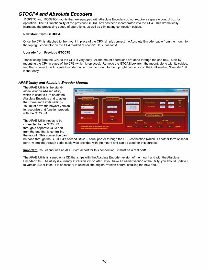
APAE Utility and Absolute Encoder Mountsthe ApAe utility is the stand-alone Windows-based utility which is used to turn on/off the Absolute encoders and to adjust the home and limits settings. you must have the newest version to recognize and function properly with the Gtocp4.
the ApAe utility needs to be connected to the Gtocp4 through a separate coM port from the one that is controlling the mount. this connection can be done through the Gtocp4’s second rs-232 serial port or through the usb connection (which is another form of serial port). A straight-through serial cable was provided with the mount and can be used for this purpose. important: you cannot use an Apcc virtual port for this connection...it must be a real port!
the ApAe utility is issued on a cd that ships with the Absolute encoder version of the mount and with the Absolute encoder Kits. the utility is currently at version 2.0 or later. if you have an earlier version of the utility, you should update it to version 2.0 or later. it is necessary to uninstall the original version before installing the new one.

17
GTOCP4 and Precision Encoders3600Gto mounts that are equipped with precision encoders do not require a separate control box for operation. the full functionality of the previous Gtoels box has been incorporated into the cp4. this dramatically increases the processing speed of operations, as well as eliminating some connection cables.
it will, however, require a new encoder cable (cAb36pef), as the connector on the cp4 has changed from the one that was on the Gtoels box. similarly, if the mount is equipped with limit switches, then a new limit switch cable (cAb36ls4) will be needed.
upgrade from Previous GTOCP3
transitioning from the cp3 to the cp4 is very easy. All the mount operations are done through the one box. remove the Gtoels control box from the mount along with its cables. connect the new encoder cable (cAb36pef) from the rear panel of the mount to the top right connector on the cp4 marked as "encoder". it is that easy.
if you also have the limit switches, attach your new limit switches cable (cAb36ls4) from the rear panel to the middle connector on the cp4 bottom row marked "Aux".
Astro-Physics Command Center (APCC)if you have a 3600Gtope mount with the precision encoders, the els tab in Apcc will be active and display. this is the preferred way to manage the settings of your precision encoders and limit switches, if you have them. please refer to the documentation in Apcc for more information.
Astro-Physics Absolute Encoder Mini Utilityif you don't have the Astro-physics command center (Apcc), you can use the Astro-physics Absolute encoder Mini utility (ApAeMiniutil) to turn your precision encoders on and off. it does not have any additional capability. please contact Astro-physics if you need the utility. you must have the newest version to recognize the Gtocp4.
Installation, Settings and Operating Instructions for the Limit Switch System (36LSS) and Precision Encoder System (on the 3600GTOPE), dated March 27, 2013
this document has not yet been updated for the Gtocp4 and the present cable arrangement. please note the following: the vast majority of the information is still relevant and current. simply adapt the procedures by substituting the Gtocp4 for all functions. We do not have any plans to update this document in the near future.
if you do not have this document, please contact Astro-physics.
18
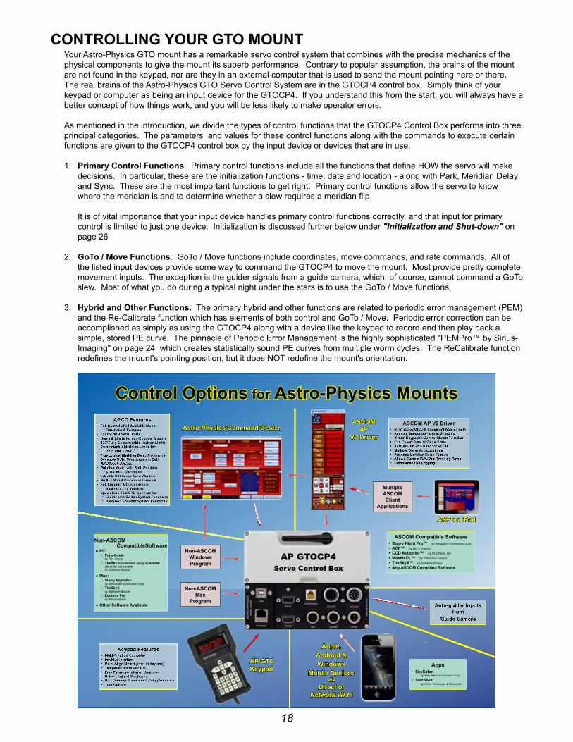
COnTrOllinG yOur GTO MOunTyour Astro-physics Gto mount has a remarkable servo control system that combines with the precise mechanics of the physical components to give the mount its superb performance. contrary to popular assumption, the brains of the mount are not found in the keypad, nor are they in an external computer that is used to send the mount pointing here or there. the real brains of the Astro-physics Gto servo control system are in the Gtocp4 control box. simply think of your keypad or computer as being an input device for the Gtocp4. if you understand this from the start, you will always have a better concept of how things work, and you will be less likely to make operator errors.
As mentioned in the introduction, we divide the types of control functions that the Gtocp4 control box performs into three principal categories. the parameters and values for these control functions along with the commands to execute certain functions are given to the Gtocp4 control box by the input device or devices that are in use.
1. Primary Control Functions. primary control functions include all the functions that define hoW the servo will make decisions. in particular, these are the initialization functions - time, date and location - along with park, Meridian delay and sync. these are the most important functions to get right. primary control functions allow the servo to know where the meridian is and to determine whether a slew requires a meridian flip. it is of vital importance that your input device handles primary control functions correctly, and that input for primary control is limited to just one device. initialization is discussed further below under "Initialization and Shut-down" on page 26
2. GoTo / Move Functions. Goto / Move functions include coordinates, move commands, and rate commands. All of the listed input devices provide some way to command the Gtocp4 to move the mount. Most provide pretty complete movement inputs. the exception is the guider signals from a guide camera, which, of course, cannot command a Goto slew. Most of what you do during a typical night under the stars is to use the Goto / Move functions.
3. hybrid and Other Functions. the primary hybrid and other functions are related to periodic error management (peM) and the re-calibrate function which has elements of both control and Goto / Move. periodic error correction can be accomplished as simply as using the Gtocp4 along with a device like the keypad to record and then play back a simple, stored pe curve. the pinnacle of periodic error Management is the highly sophisticated "peMpro™ by sirius-imaging" on page 24 which creates statistically sound pe curves from multiple worm cycles. the recalibrate function redefines the mount's pointing position, but it does not redefine the mount's orientation.
non-ASCOMWindowsProgram
non-ASCOMMac
Program
Astro-Physics Command CenterASCOM
APv2 Driver
Apps• SkySafari
by Simulation Curriculum Corp.
• StarSeek by Orion Telescope & Binoculars
Apple, Android & Windows
Mobile Devicesvia
Direct or Network Wi-Fi
MultipleASCOMClient
Applications
Control Options for Astro-Physics Mounts
ACP on iPad
ASCOM Compatible Software• Starry night Pro™ by Simulation Curriculum Corp.
• ACP™ by DC-3 Dreams
• CCD Autopilot™ by CCDWare, Ltd.
• Maxim Dl™ by Diffraction Limited
• TheSkyx™ by Software Bisque
• Any ASCOM Compliant Software
non-ASCOMCompatibleSoftware
● PC: ○ PulseGuide
by Ray Gralak ○ TheSky (recommend using as ASCOM client for full control
by Software Bisque
● Mac: ○ Starry night Pro
by Simulation Curriculum Corp. ○ TheSkyx
by Software Bisque ○ equinox Pro
by Microprojects
● Other Software Available
AP GTOCP4Servo Control Box
AP GTOKeypad

19
the flow chart on the previous page provides a summary of the many different approaches to providing input to the Gtocp4 servo control box. some of these, like the Astro-physics command center (Apcc), the Astro-physics v2 AscoM driver, and the Gto Keypad will provide All of the “primary Mount control functions,” the “Goto and Move functions,” and last, but not least, all or most of the “hybrid and other functions” to fully control the mount (Apcc omits a couple rather obsolete functions like analog focuser and reticle controls). other control items in the chart may not fully support all of the Gtocp4’s more important functions and capabilities.
GTO Keypad Operationthe keypad is all that you need to operate your mount. even advanced imagers can perform all of the necessary mount control and Goto functions with the keypad alone. With the keypad, a dslr and a stand-alone guider (such as the sbiG sG-4), you can enjoy a full night of productive, guided imaging without the need for a computer! please refer to the separate manual for the Gto Keypad controller for complete instructions on Keypad operation.
the keypad can perform all three types of control functions including initialization and shut-down. see page 26 for more details.
● the keypad can be set to automatically initialize the mount upon power-up. Auto-connect = yes this is a very handy method, and is preferred for any permanent setup where another device is not also being used to control the mount.
● it can be set to allow manual selection of initialization parameters. Auto-connect = no this is the method for portable setups that will be primarily controlled with the keypad.
● it can be set to allow a different device like a computer to perform the initialization functions. Auto-connect = ext this method is recommended for users who will be using their computer or other devices for primary control of the mount.
the keypad's full databases, and intuitive structure make it a joy to use. When people become familiar with the keypad and its simple operation, they wonder why they ever needed to drag a computer into the field!
The Astro-Physics ASCOM V2 DriverAstro-physics began the development of a company-supported AscoM v2 driver in 2009. please see the Astro-physics website for current information on the AscoM driver.
http://www.astro-physics.com/products/accessories/software/ascom/ascom.htm
this driver provides full mount control for all of the Astro-physics Gto mounts. it has been developed with remote operation in mind, and its functions were designed to be highly robust. it features a very user-friendly graphical user interface (Gui).
At publication time for this manual, the Astro-physics v2 driver is in version 5.10.01. this Ap v2 driver requires version 6.3 or higher of the AscoM platform.
http://ascom-standards.org/index.htm
the driver also provides fully automated initialization and shut-down functions. it is by far the preferred method for controlling a mount with any pc based planetarium or other client software. it is a driver, and per AscoM rules, it is not a stand-alone program that can be used by itself. it does, however, include several convenient utilities which make it usable without other expensive software.
Almost all Windows based astronomy software that includes mount control is AscoM compliant and can therefore use the Ap v2 driver. the popularity and versatility of the AscoM platform has had a large role in making Windows the dominant os for astronomy. see a partial list of compatible software on page 23.

20
the question often arises: if i have a choice between using an external program's native driver (as in theskyx), or connecting the software through the Ap v2 AscoM driver, which should i choose? We strongly advise using the Ap v2 AscoM driver!
here are some reasons:
● the Ap v2 AscoM driver is a full fledged hub. it will accommodate a very large number of programs all connected at the same time, and will do so without any problems. As a single hub, the driver will minimize the serial traffic between the software and the mount by eliminating redundancy.
● the Ap v2 AscoM driver takes advantage of the full set of Astro-physics servo commands, many of which were developed specifically for either the driver or for Apcc. since these new commands are not being published, the native drivers found in other software will be limited to the older set of published commands.
● the Ap v2 AscoM driver can create log files for troubleshooting any issues that you may have.
● We can provide a certain amount of support if you encounter issues with a program that uses the Ap v2 AscoM driver. We, of course, cannot fix a problem that is in someone else's software, but we may be able to figure out what is happening to cause the problem. if you use a native driver, you will be limited to the support that the software provider can give you. We can't support someone else's driver.
21
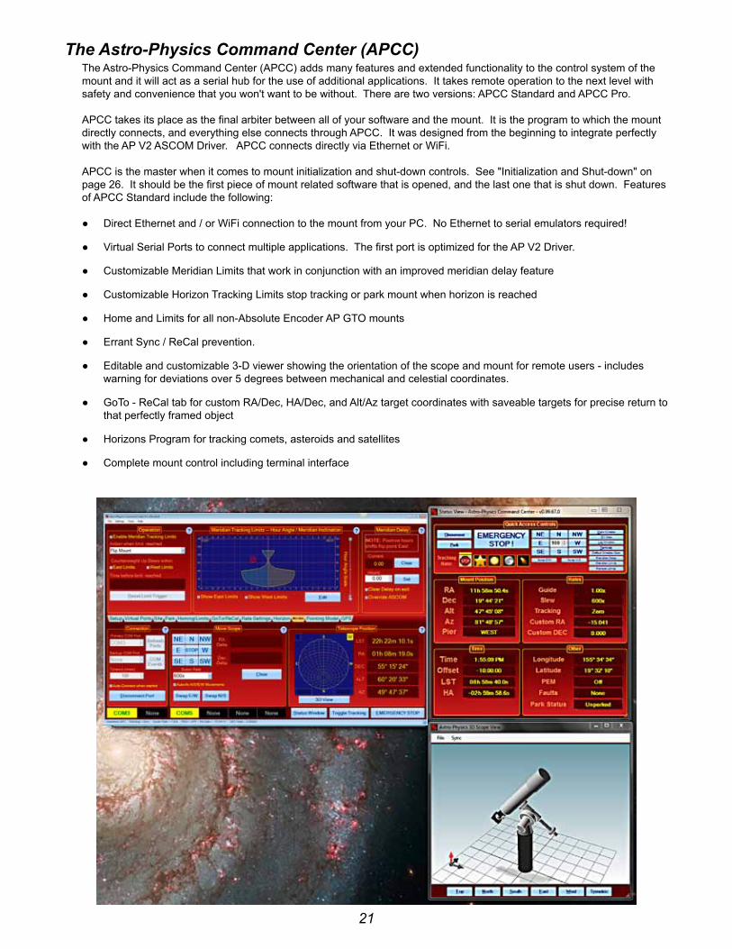
The Astro-Physics Command Center (APCC)the Astro-physics command center (Apcc) adds many features and extended functionality to the control system of the mount and it will act as a serial hub for the use of additional applications. it takes remote operation to the next level with safety and convenience that you won't want to be without. there are two versions: Apcc standard and Apcc pro.
Apcc takes its place as the final arbiter between all of your software and the mount. it is the program to which the mount directly connects, and everything else connects through Apcc. it was designed from the beginning to integrate perfectly with the Ap v2 AscoM driver. Apcc connects directly via ethernet or Wifi.
Apcc is the master when it comes to mount initialization and shut-down controls. see "initialization and shut-down" on page 26. it should be the first piece of mount related software that is opened, and the last one that is shut down. features of Apcc standard include the following:
● direct ethernet and / or Wifi connection to the mount from your pc. no ethernet to serial emulators required!
● virtual serial ports to connect multiple applications. the first port is optimized for the Ap v2 driver.
● customizable Meridian limits that work in conjunction with an improved meridian delay feature
● customizable horizon tracking limits stop tracking or park mount when horizon is reached
● home and limits for all non-Absolute encoder Ap Gto mounts
● errant sync / recal prevention.
● editable and customizable 3-d viewer showing the orientation of the scope and mount for remote users - includes warning for deviations over 5 degrees between mechanical and celestial coordinates.
● Goto - recal tab for custom rA/dec, hA/dec, and Alt/Az target coordinates with saveable targets for precise return to that perfectly framed object
● horizons program for tracking comets, asteroids and satellites
● complete mount control including terminal interface

22
● Advanced logging features for troubleshooting
● Much more !!!
the APCC Pro version also includes the following:
● highly sophisticated pointing model and variable tracking for both axes including the Astro-physics point Mapper (AppM) for automated collection of pointing data.
please keep an eye on the Apcc page of the website and the ap-gto users group for updates and details.
Some APCC Thoughts ● Apcc launches first.
● it connects directly to the mount on its physical interface. rs232, usb, ethernet or Wifi.
● it then creates one or more virtual coM ports for other programs (such as the Ap AscoM driver) to connect to.
● since it can create multiple virtual coM ports, multiple programs can connect to the mount at the same time. even programs that don't normally want to share a connection to the same mount with other programs.
23
Planetarium, Imaging and Observatory Software from Other Vendorsthere are a number of planetarium and camera control programs that can be used to control the Astro-physics Gto servo system. Many of these use the AscoM interface and will take advantage of the v2 AscoM driver mentioned previously. Any software that can use the Ap v2 AscoM driver will have extensive mount control capabilities because of the driver’s “virtual keypad” features. other programs employ native drivers that the software designers wrote based on our publicly available command set. the list that follows is certainly not exhaustive, but does offer some resources.
resources for PC users:
● starry night pro / pro plus™ from simulation curriculum corp. (Windows with AscoM support) currently v7.0.
● the sky 6™ and the sky x™ from software bisque. The Sky 6™ (Windows with AscoM plug-in) and The Sky X™ (Windows with native driver and AscoM support). currently v10.5.0.
● the earth centered universe™ from nova Astronomics (Windows with AscoM support). currently v6.0.
● skyMap pro™ by chris Marriott (Windows with AscoM support). currently v11.0.
● sky tools 3™ by skyhound (Windows with AscoM support).
● voyager™ from carina software (Windows). this product does not use the AscoM interface. currently v4.5.
● Maximdl™ from diffraction limited (Windows with AscoM support). currently v6.13.
● Acp™ observatory control software by dc-3 dreams (Windows with AscoM support).
● sequence Generator pro by Main sequence software (Windows with AscoM support).
● ccdWare product suite (Windows). the suite includes ccdnavigator™, peMpro™, ccdinspector™, focusMax4™, ccdAutopilot™ and ccdstack™ software. they all use the AscoM interface. these products can also be purchased individually.
● Any other AscoM compliant software. Be sure to update to the most current AP V2 ASCOM driver (supported by Astro-Physics).
resources for Mac users:
● starry night pro / pro plus™ from simulation curriculum corp. (Mac version with native driver) currently v7.0.
● the sky x™ from software bisque. The Sky X™ (Mac version with native driver). currently v10.5.0.
● voyager™ from carina software (Mac version with native driver). currently v4.5.
● equinox pro™ from Microprojects Astronomy software (Mac version with native driver). currently v7.2.2.
● skysafari 5™ for os x by simulation curriculum corp
in addition to the Mac software mentioned above, check out this resource of additional Mac software: The Mac in Astronomy by david e. illig. Website: http://www.primordial-light.com/macastronomer.html
Mobile Smart Devices:
● skysafari™ for ios and Android by simulation curriculum corp – this software is offered through the App stores in three versions. they do not use the AscoM interface. Mount initialization is performed.
● luminos™ for ios by Wobbleworks llc – this software is offered through their internet website. they do not use the AscoM interface. Mount initialization is performed.
Write your own computer program:
the Astro-physics Gto protocol for the Gtocp3 control box through version q is freely available to those who would like to write their own computer program for controlling the mount. note that this does not include the command language for either the precision encoders or the Absolute encoders. please note that with our substantial investment in both the Astro-physics v2 AscoM driver and in Apcc, we cannot also provide free technical support to anyone who wants to try their hand at mount control software. We strongly encourage all customers to use the available software options, if possible.

24
PEMPro™ by Sirius-Imaging(included with the 1100GTO, 1600GTO and 3600GTO mounts)
for a visual observer or an imager who takes short exposures, the native performance of your Gto mount will be without additional periodic error correction. however, those of you who take long exposure images may wish to further refine your mount’s performance. this may be especially important if your images are unguided.
PEMPro™ (periodic error Management professional) is a Windows software application that makes it easy to characterize and reduce periodic error. PEMPro™ gives you powerful tools to program your mount’s periodic error correction software to achieve the best possible performance for your mount. PEMPro™ dramatically improves guided and unguided imaging resulting in better images and fewer lost exposures.
PEMPro™ will analyze the performance of any mount that is equipped with a ccd camera and compatible camera control software. compatible ccd camera control software includes: AscoM, MaxImDL/CCD™, TheSkyX Camera™, CCDSoft v5™, AstroArt™, Meade dsi series, SGPro™ and video.
PEMPro™ also provides a way to use a low-cost webcam or video camera to perform all of its functions. PEMPro™ has a video interface application that can work with any directshow or WdM compliant device including most capture cards and webcams (like the philips toucam pro and Meade lpi).
the uncorrected periodic error of your mount is at or better than spec when it leaves our facility. We will have reduced this already small native error significantly by loading the error curve from our extensive testing procedures into the servo system. the resulting error that remains should be negligible, and will probably be satisfactory for all but the most demanding applications. you can, however, reduce the error even further to maximize performance without auto-guiding by recording a much longer run with PEMPro™ that will average more complete cycles of the worm.
the serious imager may wish to redo the PEMPro™ run once a year (more or less depending on usage) to compensate for gear run-in. if you ever remove your motor / gearbox or manually turn the worm gear, you will also invalidate any previously recorded corrections and will need to do a new PEMPro™ run. (Manually moving the telescope by loosening the clutches does not turn the worm gear, so that is not a problem!) complete documentation is provided in the help menu of the installed program. Also, please read the important information htMl file on the cd before loading PEMPro™ onto your computer.
PEMPro™ uses the AscoM interface to control the mount. in addition to the functions available through the AscoM interface, PEMPro™ also includes a very handy and effective polar Alignment Wizard, a backlash Analysis routine and a starfinder routine.
note: PeMPro™ v3.x may be released by the time that this manual has been printed. it will include more options of compatible software and cameras, along with advanced features. Check with www.ccdware.com for more information.
25
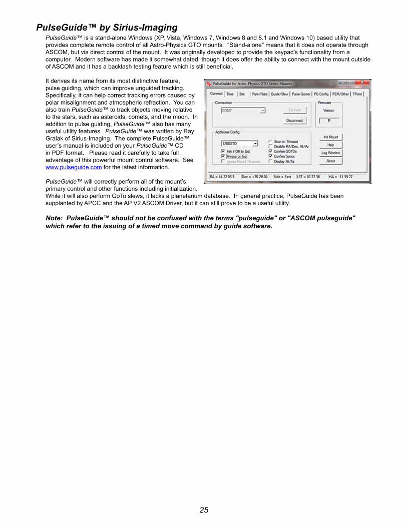
PulseGuide™ by Sirius-ImagingPulseGuide™ is a stand-alone Windows (xp, vista, Windows 7, Windows 8 and 8.1 and Windows 10) based utility that provides complete remote control of all Astro-physics Gto mounts. "stand-alone" means that it does not operate through AscoM, but via direct control of the mount. it was originally developed to provide the keypad's functionality from a computer. Modern software has made it somewhat dated, though it does offer the ability to connect with the mount outside of AscoM and it has a backlash testing feature which is still beneficial.
it derives its name from its most distinctive feature, pulse guiding, which can improve unguided tracking. specifically, it can help correct tracking errors caused by polar misalignment and atmospheric refraction. you can also train PulseGuide™ to track objects moving relative to the stars, such as asteroids, comets, and the moon. in addition to pulse guiding, PulseGuide™ also has many useful utility features. PulseGuide™ was written by ray Gralak of sirius-imaging. the complete pulseGuide™ user’s manual is included on your PulseGuide™ cd in pdf format. please read it carefully to take full advantage of this powerful mount control software. see www.pulseguide.com for the latest information.
PulseGuide™ will correctly perform all of the mount’s primary control and other functions including initialization. While it will also perform Goto slews, it lacks a planetarium database. in general practice, pulseGuide has been supplanted by Apcc and the Ap v2 AscoM driver, but it can still prove to be a useful utility.
Note: PulseGuide™ should not be confused with the terms "pulseguide" or "ASCOM pulseguide" which refer to the issuing of a timed move command by guide software.

26
unDerSTAnDinG The GerMAn equATOriAl ServO lOGiCto avoid some of the more common operator errors that people make, we will attempt to describe and explain some important aspects of the servo logic that govern the movement of the mount as you perform the various operations involved in a night of astronomy. the discussion that follows will address several areas of the Gtocp4’s control logic and tie those areas into the three control categories listed above:
● initialization and shut-down
● the role of time and location data in the servo system
● safety slew logic
● the concept of “pier side” as it relates to the servo
● how Goto slews are performed
● the 360° right ascension axis
● the special cases of Tracking Past the Meridian and Meridian Delay or Meridian Advance
● sync vs. re-calibrate
● understanding the guider port inputs
● non-sidereal tracking and variable tracking rates
● A brief discussion of the Astro-physics command language
[This section is still under construction. As parts of this section are completed, the PDF file on the website will be updated. Please check the website for the latest version of this document.]
initialization and Shut-downinitialization functions are probably the most important subset of the group of primary control functions. it is vitally important that your mount be properly initialized when it is first powered on. there is nothing magical or mysterious about proper initialization, but it is simply the process that allows the mount to recalculate its position and commence operations. initialization should only be performed once per power cycle when the mount is first powered on. full initialization should not be repeated while a mount is powered on because it accesses information from the last power-down to determine its current position. that information is no longer valid in the middle of a session.
for a proper full initialization, the mount must know its current location. the last location entered will be remembered through a power-cycle, so this only needs to be sent if your location has changed. the same holds true for the GMt offset. finally, current local time and date are also required. time and date, however, need to be supplied afresh each time the mount is powered on. time and date should be supplied by the control device that is being used for primary mount control. once the current local time and date have been sent to the mount, the initialization command uses the entered data along with the saved data from the last shutdown and calculates the current pointing position. it also unparks the mount and starts normal operations in motion.
for permanent setups, the mount will accurately calculate its current pointing position when initialized. you do not need to "home" the mount or perform some kind of a star-sync to get started. portable mounts and mounts that have been moved via loosened clutches will require an additional step to reestablish initial pointing. for this, we have a set of pre-defined park positions that are easily recreated. A star-sync on a single star can also be used to reestablish pointing on portable setups.
because of the design of the Astro-physics servo system logic, no special shut down procedures are required. Although many people choose to park the mount at the end of a session, this is entirely unnecessary from the mount's point of view. if you wish, you can simply "pull the plug" and leave the mount where you left off. When you power back on, a proper full initialization will restore the pointing without any further ado. park positions can be handy, but they are not a requirement. With the Astro-physics system, think of "park" as a state where the drive motors are de-energized - not a "place" where the mount goes. the park positions are simply convenient coordinate positions to use before entering that "parked" state.
the keypad, the Ap v2 AscoM driver, Apcc and pulseGuide all fully handle all the initialization and shut-down tasks discussed above. they do so in a manner that is simple, automatic, and virtually fool-proof. other software can also perform these tasks, but Astro-physics cannot guarantee that they do so correctly all of the time.

27
The role of Time and location data in the Servo Systemthere seems to be an obsession among astronomers with accurate time and location data. Many of our customers use Dimension4 or some other similar time server to keep their computer clock accurate to the millisecond. Gps units are employed to precisely nail down time and location data down to the second. however, for most of your mount's operation, accurate time and location are really somewhat irrelevant. you don't want to be way off, but you probably don't need to be dead-on either. here are some thoughts on time and location as it applies to the Astro-physics servo system.
● the obsession with time and location accuracy probably comes from people who started with Alt/Az mounts. When a mount is set up as an Alt/Az mount, it must convert its native Alt/Az system to rA/dec for celestial viewing. to make this conversion, the more accurate the time and location data, the more accurate the conversion. time and location are critical to the Alt/Az astronomical mount.
● time and location come into play during initialization as discussed above. they are necessary for calculating the current rA value at start-up. precise time at power-off followed by precise time at the following initialization will lead to a more accurate calculation of the rA. however, think about it: how important is to-the-second accuracy of your first Goto of the evening? if your first target is off by 30 seconds of rA, or even a minute, won't it still be within the field of view? After centering and doing a recal, the time relevance is over.
● time and location are used to determine the meridian (aka z-value, lst, overhead hour, etc.). they are also used to then determine the horizons. Again, the more accurate time and location are, the more accurate the meridian and horizon values will be. As above, the question to ask is how important is it if the calculated meridian or horizon is off by a little bit. you would probably never know it during a normal observing or imaging run.
● time and location accuracy is very important for satellite tracking, and for astrometry. if you are using Apcc's horizons program, or you are doing research on neos, by all means, use a time server and Gps!!
● once you are calibrated on a star, apart from determining the flip-point, precise time and location play almost no role WhAtsoever in normal Goto slews or pointing accuracy.
Many client software programs like planetarium programs and observatory control programs will demand that the mount time matches the computer clock. this is necessary for coordination among the programs. however, if you are away from an internet connection or Gps unit, and your computer clock is off from the atomic time in boulder, co by a little bit, you really shouldn't worry about it.
Safety Slew logicsafety slew logic is designed into the Gtocp4 control box firmware and functions with all of our Goto mounts. its purpose is to protect your scope from a possible crash into the pier when slewing out of some counterweight up positions.
our mounts have the unique ability to track past the meridian while imaging, such that the counterweight will move higher than the scope (counterweight up). normally when a Goto slew is made, both the r.A. and the dec. axes begin moving simultaneously. however, there are some counterweight up areas from which a slew with the dec. axis moving simultaneously with the r.A. axis would cause the scope to hit the pier before the r.A. axis can take it safely into a counterweight down position.
the safety slew logic knows when the mount is in a counterweight up position and will initiate an r.A. only slew to bring the mount back into the counterweight down safe zone where it will pause momentarily. the mount will then automatically make a second slew using both axes simultaneously to continue to your object.
conversely, when using Meridian delay to begin with a counterweight up imaging session, the reverse happens. A dual-axis slew will take place until the meridian is reached where the r.A. will stop and the dec. axis will continue to its position. When the dec. has reached its position and stops, the r.A. will make its second slew to the final position.
it is even possible that a three part slew may take place if you are slewing from a counterweight up position and into another counterweight up position.
having this firmware logic in the Gtocp4 control box means that it will work regardless of whether you are using computer software or the keypad to control your mount.

28
The Concept of “Pier Side” as it relates to the Servopier side is something that would seem intuitively obvious at first glance, but it ends up getting confusing to many people. the conventions and rules used for pier side are not the invention of Astro-physics, but are standard through the industry and are mandated by AscoM as well. pier side gets confusing because the correctly reported pier side can differ from what your eyes are telling you if you look at the mount. the Astro-physics reference park 1 position is the classic example of this. We have fielded countless support calls from frantic customers who were convinced that their mounts were lost because the scope was most assuredly on the west side of the pier in park 1, and yet the servo (and the control software) were all reporting a pier side of east!
the reason for the confusion is that pier side has nothing to do with right ascension or hour angle. it is entirely a function of declination. the problem is that for any physical position of the mount's r.A. axis there can be two declination values. this is apparent near the pole. think of a dec coordinate of 80 degrees. Without moving the r.A. axis, you can slew the dec from 80 to 85; cross the pole at 90; and then keep on going through 85 and back to 80. the two pointing positions are 20 degrees apart, yet both have the same declination, and both share the same physical position of the r.A. axis. to distinguish the two positions, we do two things: 1. We report one position as having a pier side of east, and the other as having a pier side of West. 2. the r.A. value (and therefore also the hour angle) are different by exactly 12 hours.
in terms of the pier side, the reported side is what one would consider the "normal" side for a mount where the declination was on that particular side of the pole. Most observing is done with the scope pointing above the pole, so that is considered the normal side. for example:
1. start with the mount in the classic German equatorial pose (the Astro-physics reference park 3 - scope pointing at the pole and counterweight shaft pointing down).
2. rotate the declination toward the east (clockwise from above in the northern hemisphere, counterclockwise down under).
3. you will immediately see that the "normal" orientation for the r.A. will be to rotate it to the west placing the scope on the "West" side of the pier.
4. likewise, if you rotate the dec. to the west of the pole, you will want to take the scope to the east side.
5. things only get backward when you are pointing below the pole as you do in the Ap reference park 1 position.
6. to see this, take a mount in the "normal position, and take the r.A. axis across the meridian without moving the dec. you will see that the scope is pointing below the pole.
the illustration below will hopefully help to clarify this. if it is still fuzzy, the easiest way to really grasp the concept is to work with a mount and scope and actually run through the steps above.

29
Tracking Past the MeridianGerman equatorial mounts have the characteristic that they require a “flip” at the meridian in order to follow an object in its nightly journey across the sky. A visual observer will not be overly inconvenienced by the mechanics and delay of the flip; however, this becomes much more complicated for an imager!
At the very least an imager needs to:
● stop an imaging session; often with the loss of a 20 to 30 minute sub exposure that has reached 19 or 29 minutes
● flip the mount and reposition cables
● rotate the camera so that you can use the same guide star
● re-center the object to your desired composition
● re-acquire the guide star and then re-calibrate it
● begin the new imaging session
depending upon your chosen object’s position, this all becomes unnecessary with an Astro-physics mount. tracking through the meridian is a unique function of Ap mounts. Most objects that are located south of the zenith (northern hemisphere) can be imaged without interruption from horizon to horizon. the mount will happily track with the counterweights high in the air.
remember, it is the GoTo slew that will flip the mount...not tracking!
please note that with this wonderful feature comes the responsibility of preventing your scope and camera from striking the pier when imaging an overhead object or one more northerly. fortunately, we have the Apcc software that safeguards against this mishap! A custom contoured Meridian limits outline can be created with Apcc that keeps everything safe and sound.
Meridian Delay or Meridian Advancethe Meridian limits (delay or Advance) are one of the most powerful and useful features of Astro-physics mounts when used in conjunction with the Astro-physics command center (Apcc). they open up the possibility of imaging on both sides of the meridian Without wasting time on a pier flip at declinations where the scope will not strike the pier. the limits, when properly configured, allow you to track safely past the meridian up to the limits you set based on your unique instrument package. in addition, they allow you to begin an image ahead of the meridian by safely slewing you into a counterweight-up position to start an imaging series that can then simply continue through the meridian. however, like any powerful feature, you Must understand how the meridian limits work. it is vital that you understand what they cAnnot do as well as understanding what they can do!
pulseGuide, the Ap v2 AscoM driver, and the mount's keypad each have the ability to set a meridian delay which controls the flip point of the mount. starting with Apcc and the rev. "s" firmware in 2012, the method for employing this feature has been changed in the Gto servo control box. the delay is no longer accomplished by "fooling" the clock in the servo. it is now an independent function with associated commands that does not change the mount's time.
Apcc adds some powerful new capabilities. three of these new features apply to West Meridian limit points. the West limits come into play when a scope's counterweight is in the up position (scope under the mount) and the scope is pointing West of the meridian. this normally occurs when the scope is allowed to track past the meridian. the fourth feature below applies to east meridian limits and provides a unique and powerful tool for safely starting images in the east from the east side (counterweight up) using the meridian advance.
● instead of just a single meridian limit for all declinations, you can configure an arbitrary number of different limits at different declinations. this is useful because at each declination there can be a different hour angle at which the telescope will touch the pier. in declination regions where the telescope can theoretically go the full 6 hours past in the west, the meridian limits can establish horizon tracking limits for the practical distance past the meridian where you can reasonably continue to work. likewise, in the east, they can set the practical horizon ahead of the meridian where you can reasonably start an image.
● When a meridian tracking limit is reached, tracking can be automatically stopped; the scope can be "flipped"; or the scope can be parked.
● Meridian tracking limits can also be used to create a safe zone around your pier if it interferes with even reaching the zenith, similar in a way to the safe zone in the Astro-physics Gto keypad. the keypad's safe zone, however, is a Goto slew limit, rather than a tracking limit. remember that an Apcc Meridian limits safe zone that does not allow the scope to reach the Meridian must be stopped or parked. it cannot be flipped.

30
● When east limits are properly configured and employed, slews to targets within the east limits will automatically be made using meridian advance and Apcc's safety slew logic to place the system in a counterweight-up position with the scope on the east for uninterrupted imaging through the meridian. the safety slew logic ensures that all mount movement with the counterweight up is with the rA only. using the east limits, the scope can image through the meridian and on for another 6 hours before the telescope reaches the horizon.
● A pier flip button has been added to the Apcc software that will allow an automatic flip to the other side of the mount when the button is clicked. provided that you are within the safe limits, you can flip and view the same object from either side of the pier...either counterweight up or down.
the ability to work past the meridian into the west, or to start ahead of the meridian in the east has always been a hallmark of Astro-physics mounts. both the keypad and the earlier pulseGuide program provided the ability to work beyond the meridian. however, with both of these control methods, the user would want to be present at the mount for safety. Apcc creates meridian limits that can allow the user to safely exceed the meridian without hovering over the mount to protect the scope and imaging equipment from a potential crash. remotely controlled observatories can now also safely image through the meridian (where declination permits it).
31
AuTOGuiDinG TiPS AnD nOTeSAutoguiding is an art. it is the most complicated, yet most important, part of imaging. if it is not mastered, then images will suffer. Anything that you can do to make your autoguider's job easier is a good thing. here are some suggestions and things to keep in mind.
Important Misconception on Autoguiding: the directions represented by the x+, x−, y+ and y− in your guiding software do not necessarily correspond to any given cardinal or equatorial directions. to the guiding software, “x” and “y” simply refer to the rows and columns of pixels on the guide chip...nothing more. they do not mean r.A. and dec.!
the act of calibration tells the guiding software how to relate a guide star’s drift along the columns and rows to move directions in the mount, but it does not make it so that x is necessarily always right ascension and y always declination. to further complicate this, each time you alter the camera’s orientation, you effectively change the relationship between x / y and r.A. / dec.
your very first step in diagnosing any type of guiding problem should be to determine the actual current relationship between the x and y of the guiding software and the r.A. and dec. of your mount. this is easily done in your guiding software by making a manual move in one axis during an exposure and comparing this to a guide move from the keypad (use the keypad – not your computer software!) where you know the axis and direction for certain.
We have seen customers waste countless hours (not to mention dollars) in trying to fix a guiding problem on an axis that was performing perfectly. Meanwhile, their true problem remained, all because of this axis mix-up.
Another Important Note on Autoguiding: the autoguider port remains a popular way to use an autoguider system, but you might want to consider making your guiding moves through the serial connections via the Ap v2 AscoM driver instead. Guiding moves require millisecond timing to be accurate. When you guide through the autoguider port, you are depending on the system to operate the guiding relays with this very accurate timing. Guiding through the Ap v2 driver on the other hand sends a timed move command. there are no relays to open and close at an exact moment in time. the command itself contains the precise time interval in milliseconds for the move.
● ensure that your autoguider calibration is a good one:
○ perform the calibration near the meridian and celestial equator. As you move towards the pole, r.A. becomes increasingly compressed and less accurate. this is a significant problem near the pole.
○ calibrate for sufficient time so that the star travels at least ¼ to ⅓ across the guide chip for a good arcseconds / pixel calculation. your software's calibration numbers should agree with the following numbers. Guider calibration formula: sidereal rate (arc sec / sec) x guide rate ÷ guide system image scale example: 15.04107 x 1.0x ÷ guide system image scale (arc sec / pixel) = (pixels / second)
● use a 3-5 second sub-exposure for guiding. this will reduce the scintillation effect of the air. if you have good polar alignment, even longer sub-exposures can be used as long as a saturated star is not chosen.
● choose a star in the brightness mid-range...not too dim and not saturated.
● calibration and guiding should always be done at 1x guide rate.
● turn all backlash to zero (Keypad and computer software) and turn off "stiction".
● the servo controller of all Ap mounts is designed to work with pe correction on, even when getting autoguide signals from your imaging software. the pe corrections do not fight the incoming autoguide corrections, rather they help the autoguiding. With a good pe curve you can do longer exposures of the autoguider and guide on very faint stars.
● if you have one of our absolute encoder mounts, then pe correction is no longer needed. the encoder eliminates all periodic error, so no need for doing pe compensation. Autoguiding works superbly well with the encoder mounts.
How to test an Autoguider Porthere is the test for the autoguider port. to perform the test, you will need a foot or so of 6 conductor flat phone cable with a standard rJ11-6 plug on the end. remove the insulating material from 3 – 4 inches of the bare end of the cable to expose the six colored wires. remove the insulation from about 1/4” to 3/8” of the ends of each of these wires, although you could skip the wire corresponding to pin #1 if you wish. the #1 wire will typically be either the white or the blue, depending on how the plug was attached. in addition to the cable i just described, i find a short test lead with alligator clips on each end to be very handy.
note the pinout on the following page.
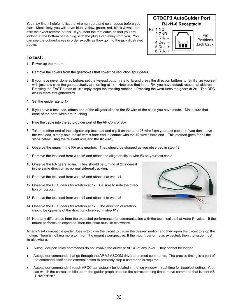
32
you may find it helpful to list the wire numbers and color codes before you start. Most likely, you will have: blue, yellow, green, red, black & white or else the exact reverse of this. if you hold the test cable so that you are looking at the bottom of the plug, with the plug’s clip away from you, you can see the colored wires in order exactly as they go into the jack illustrated above.
To test: 1. power up the mount.
2. remove the covers from the gearboxes that cover the reduction spur gears.
3. if you have never done so before, set the keypad button rate to 1x and press the direction buttons to familiarize yourself with just how slow the gears actually are turning at 1x. note also that in the rA, you have default rotation at sidereal. pressing the eAst button at 1x simply stops the tracking rotation. pressing the west turns the gears at 2x. the dec axis is more straightforward.
4. set the guide rate to 1x
5. if you have a test lead, attach one of the alligator clips to the #2 wire of the cable you have made. Make sure that none of the bare wires are touching.
6. plug the cable into the auto-guider port of the Ap control box.
7. take the other end of the alligator clip test lead and clip it on the bare #6 wire from your test cable. (if you don’t have the test lead, simply hold the #6 wire’s bare end in contact with the #2 wire’s bare end. this method goes for all the steps below using the relevant wire and the #2 wire.)
8. observe the gears in the rA axis gearbox. they should be stopped as you observed in step #3.
9. remove the test lead from wire #6 and attach the alligator clip to wire #3 on your test cable.
10. observe the rA gears again. they should be turning at 2x sidereal in the same direction as normal sidereal tracking.
11. remove the test lead from wire #3 and attach it to wire #4.
12. observe the dec gears for rotation at 1x. be sure to note the direc-tion of rotation.
13. remove the test lead from wire #4 and attach it to wire #5.
14. observe the dec gears for rotation at 1x. the direction of rotation should be opposite of the direction observed in step #12.
15. note any differences from the expected performance for communication with the technical staff at Astro-physics. if the mount performs as expected, then the issue must lie elsewhere.
All any st-4 compatible guider does is to close the circuit to cause the desired motion and then open the circuit to stop the motion. there is nothing more to it from the mount’s perspective. if the mount performs as expected, then the issue must lie elsewhere.
● Autoguider port relay commands do not involve the driver or Apcc at any level. they cannot be logged.
● Autoguider commands that go through the Ap v2 AscoM driver are timed commands. the precise timing is a part of the command itself so no external action to precisely stop a command is required.
● Autoguider commands through Apcc can actually be isolated in the log window in real-time for troubleshooting. you can watch the correction blip up on the guider graph and see the corresponding timed move command that is sent As it hAppens!
6 1
GTOCP3 AutoGuider PortRJ-11-6 Receptacle
PinPositions
Jack 623k
Pin 1 NC 2 GND 3 R.A. – 4 Dec. – 5 Dec. + 6 R.A. +
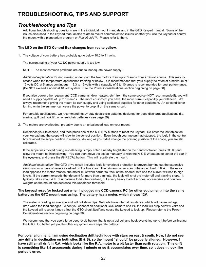
33
TrOubleShOOTinG, TiPS AnD SuPPOrT
Troubleshooting and TipsAdditional troubleshooting questions are in the individual mount manuals and in the Gto Keypad manual. some of the issues discussed in the keypad manual also relate to mount communication issues whether you use the keypad or control the mount with a planetarium program or PulseGuide™. please refer to them.
The leD on the GTO Control box changes from red to yellow.
1. the voltage of your battery has probably gone below 10.5 to 11 volts. the current rating of your Ac-dc power supply is too low. note: the most common problems are due to inadequate power supply! Additional explanation: during slewing under load, the two motors draw up to 3 amps from a 12-volt source. this may in-crease when the temperature approaches freezing or below. it is recommended that your supply be rated at a minimum of 12 volts dc at 5 amps continuous. 12.3 to 16 volts with a capacity of 5 to 10 amps is recommended for best performance. (do not exceed a nominal 18 volt system. see the power considerations section beginning on page 38) if you also power other equipment (ccd cameras, dew heaters, etc.) from the same source (not recommended!), you will need a supply capable of up to 10 amps. the more equipment you have, the more current capability you will need. We always recommend giving the mount its own supply and using additional supplies for other equipment. An air conditioner turning on in the summer can cause the power to drop, if on the same circuit. for portable applications, we recommend heavy-duty deep-cycle batteries designed for deep discharge applications (i.e. marine, golf cart, fork lift, or wheel chair batteries - see page 39).
2. the motors are overloaded, probably due to an unbalanced load on your mount. rebalance your telescope, and then press one of the n-s-e-W buttons to reset the keypad. re-enter the last object on your keypad and the scope will slew to the correct position. even though your motors had stopped, the logic in the control box retained the scope position in memory. As long as you didn’t change the pointing position of the scope, you are still calibrated. if the scope was moved during re-balancing, simply enter a nearby bright star on the hand controller, press Goto and allow the mount to finish slewing. you can then move the scope manually or with the n-s-e-W buttons to center the star in the eyepiece, and press the #9 recAl button. this will recalibrate the mount. Additional explanation: the Gto drive circuit includes logic for overload protection to prevent burning out the expensive servomotors in case of severe overload on the two axes. the primary cause is an unbalanced load in r.A. if the extra load opposes the motor rotation, the motor must work harder to track at the sidereal rate and the current will rise to high levels. if the current exceeds the trip point for more than a minute, the logic will shut the motor off and tracking stops. it typically takes about 4 lb. of unbalance to trip the overload, but a very heavy load of scopes, accessories and counter-weights on the mount can decrease this unbalance threshold.
The keypad reset (or locked up) when i plugged my CCD camera, PC (or other equipment) into the same battery as the GTO mount was using. The battery has a meter, which shows 12v.
the meter is reading an average and will not show dips. Gel cells have internal resistance, which will cause voltage drop when the load changes. When you connect an additional ccd camera and pc the load will drop below 9 volts and the keypad will reset or it may affect the Gto circuit itself and cause the keypad to lock up. please refer to the power considerations section beginning on page 38.
We recommend that you use a large deep-cycle battery that is not a gel cell and hook everything up to it before calibrating the Gto. or, better yet, put the other equipment on a separate battery.
For polar alignment, i am using declination drift technique with stars on east & south. now, i do not see any drifts in declination on both sites (e & S), so the mount “should” be properly aligned. however, i have still small drift in r.A. which looks like the r.A. motor is a bit faster than earth rotation. This drift is something like 1.5 arcseconds during 1 minute or so & accumulates over time, so it doesn’t look like periodic error.

34
the sidereal tracking rate is exact in the mount (it is crystal controlled and checked here for accuracy). however, the stars do not move at exactly the sidereal rate everywhere in the sky. the only place they move at that rate is straight overhead. As soon as you depart from that point in the sky, the stars will be moving more slowly, especially as you approach the horizons. thus, it looks like the mount is moving slightly faster than the sidereal rate. Just because you have done a classic drift alignment, does not mean that the stars will now be moving at the sidereal rate everywhere in the sky.
in order to increase the area of sky from the zenith that will give you fairly good tracking, you will need to offset the polar axis by a small amount. the amount will depend on what your latitude is. the other approach is to vary the tracking rate for different parts of the sky. ray Gralak’s PulseGuide™ will allow you to dial in an exact tracking rate for any part of the sky.
the Astro-physics command center (Apcc) includes tracking and pointing correction based on calculations from atmospheric refraction all the way up to sophisticated real-world models based on plate-solve data for your specific instrument package.
initially, the mount was working fine. Then, suddenly the mount stopped tracking altogether!
chances are that the motor was turning properly and driving the worm gear, but that your clutches might have been loose and therefore the scope was not following the motion of the worm gear. the fact that the high slew rate did move the scope does not change this, because roland has seen this himself where the tracking rate did not overcome the slipping clutches but the slew rate did.
if you are unsure of the motion of the motor, just remove the motor cover plate and look inside. you will see the motor turning. sometimes when you have the clutches loosely engaged and the counterweights are somewhat out of balance, being heavy in the east, then the clutches might slip at the slow sidereal rate.
in any case, just to set your mind at ease, simply remove the motor cover next time something like this happens and look at the motor shaft. if the motor is not turning, you will have some kind of electrical problem. if it is turning, then it is mechanical.
The motors sound louder and more labored in cold weather.
As the temperature drops, we recommend that you reduce your slewing speed to the slowest slew rate. the cold causes the lubricants to get stiff in the gearboxes. this can make the high- speed gears resonate and sound screechy. lowering the slew speed in winter will eliminate or reduce this. you might also want to add a drop or two of light machine oil to the center posts of the individual gears. Just remove the cover on the gearbox and add the oil drops. the noise is nothing to worry about. refer to the section of this manual entitled: slewing your Mount in below freezing temperatures.
The declination axis does not appear to be moving properly. how can i check it?
please refer to your mount manual for the instruction sheet: “characterizing the dec. Axis Motions,” which explains how to use diffraction limited’s MaxIm DL™ software to characterize your mount’s performance.
When i press the e button on my keypad, it takes forever for the star to finally stop. Adjusting the back-lash control using the keypad helped, but the problem is still there.
first, the problem is most often caused by the worm and worm wheel not being in mesh (this is often the case when a used mount is purchased and the previous owner never ever adjusted the worm mesh or the mesh was altered during shipment). When the worm is out of mesh, it takes the motor many seconds to reverse the tooth contact from leading to trailing edge because it is running at the very slow sidereal rate. one could simply dial in an appropriate amount of r.A. backlash into the keypad in order to compensate for this. r.A. backlash compensation simply kicks the motor momentarily in the opposite direction at high speed until the opposite teeth have made contact and sidereal tracking can take place. the ideal solution is to adjust the worm backlash so that this delay does not occur. please refer to the detailed information in the technical support section of our website pertaining to your mount.
i am experiencing trailed stars after a slew and apparently a high, variable backlash.
check to make sure that the spur gear that is attached to the end of the worm is not loose. A loose screw will indeed cause the axis to delay during reversal. in a few cases, we have seen that the set screw on this spur has backed off and needs to be retightened. if you have any doubts about where this worm and spur gear is in the scheme of things, call Astro-physics and we will talk you through the procedure to check this.
remember this: Any backlash or looseness in dec. will not cause trailed stars after a slew. that is because the dec. axis does not move once it gets to its new position, so no trailing is possible. so, if you are getting trailed stars for a short time, don’t look for something in the dec. axis.

35
however, the r.A. axis Will cause trailed stars after a slew if the spur gear is loose. that is because this axis must move at the sidereal rate immediately after getting to the new position. if the spur gear is loose on the worm shaft, it will turn slowly at the sidereal rate without imparting this motion to the worm itself (because it is slipping). At some point, the set screw will catch on the edge of the flat on the worm shaft and begin to drive the worm gear. so, this looks like classical backlash, when in fact it is not backlash at all, and all attempts at setting the gear mesh on the worm are futile to correct this lost motion.
A complete set of instructions has been posted on our website showing how to check for this loose gear condition. even without those instructions, you can take the cover off the motor gearbox and acquaint yourself with the spur gears inside. do not be afraid to move and wiggle things by hand to see how stuff works.
one more thing. sometimes a person will be absolutely certain that it is the dec. axis that is giving him a problem because the ccd program he is using shows some improper function in the y-axis, and he is absolutely certain that y = dec. After much sending of equipment back and forth to our facility, it finally is determined that it was the other axis after all that had the problem. pleAse, please make sure that you have identified the proper axis. in the case of any kind of motion problem like this, it would be really helpful if you removed your camera, inserted an eyepiece with crosshairs and actually looked to see what was happening. you can then identify exactly which direction, r.A. or dec., is moving after a slew. sometimes because of mix-ups in the ccd software (MaxImDL™, for instance), the axes are identified backwards.
When you are trouble shooting, remember, r.A. is the only axis that must move at the sidereal rate and is the only axis that can trail a star if it is not moving correctly at that rate. the dec. axis does not move after a slew and will not trail a star except by a very slow long period drift due to polar misalignment, etc. it will not trail a star image even if it has 10 degrees of backlash, so that analysis is definitely suspect.
i’m having a frustrating guiding problem with my mount and need to figure out my next steps.
to begin with, the directions represented by the x+, x−, y+ and y− in your guiding software do not necessarily correspond to any given cardinal directions. to the guiding software, “x” and “y” simply refer to the rows and columns of pixels on the guide chip – nothing more.
the act of calibration tells the guiding software how to relate a guide star’s drift along the columns and rows to move directions in the mount, but it does not make it so that x is necessarily always right ascension and y always declination. to further complicate this, each time you alter the camera’s orientation, you effectively change the relationship between x / y and r.A. / dec.
your very first step in diagnosing any type of guiding problem should be to determine the actual current relationship between the x and y of the guiding software and the r.A. and dec. of your mount. this is easily done in your guiding software by making a manual move in one axis during an exposure and comparing this to a guide move from the keypad (use the keypad – not your computer software!) where you know the axis and direction for certain.
We have seen customers waste countless hours (not to mention dollars) in trying to fix a guiding problem on an axis that was performing perfectly. Meanwhile, their true problem remained, all because of this axis mix-up.
your next step would be to remove the camera and place a high power eyepiece with crosshair reticle into the focuser. then sit down and watch what happens to the guide star. With the eyepiece and reticle, you can see whether or not the mount is tracking smoothly and how the periodic error is manifesting itself. yes, you will have periodic error, and any good ccd camera will pick it up to give you oval stars - that is a given. What you need to find out is whether this periodic error is within limits (± 3.5 arcseconds for the Mach1GTO, 900Gto and 1100Gto and ± 2.5 arcseconds for the 1200Gto, 1600Gto and 3600Gto) and whether it is smoothly varying. you can also do some hand guiding using the 4 buttons on the keypad. it will tell you how responsive the mount is to your guiding inputs and may even show some hidden problems when you try to keep the star on the crosshairs.
Alternately, you can use PEMPro™ to characterize your periodic error. it will tell you things like the peak value and the smoothness of the error.
you can also characterize your mount tracking and guiding abilities using the “characterizing the dec. Motions” test outlined in the technical support section of our Ap website and included in the back of this manual. Many times a problem guiding in r.A. can be the result of a dec. axis mechanical problem. not knowing this, you will be forever chasing down the problem on the r.A. axis, and never reaching a solution. characterizing your dec. Axis will at least show you that the mount reacts properly to the 4 guide directions. if it shows a problem area, then at least we will know how to fix it.
once you know that the mount is tracking in a normal fashion with normal periodic error profile, you can go from there to begin setting up your guiding parameters. once you know that the mount responds properly to the guide inputs, it should be possible to set it up to work accurately.

36
My GTOCPx Control box does not appear to be working properly. Can i use the control box from my other Astro-Physics mount with the mount that is having problems?
the answer depends on which model your other Astro-physics mount is. the Gtocp4, Gtocp3 and / or Gtocp2 control boxes from your Mach1GTO, 900Gto, 1100Gto, 1200Gto or 1600Gto mount can all be interchanged. the interchange works in either direction between any of these five mounts. note, however, that Gtocp3 and Gtocp2 boxes do not inclulde Absolute and/or precision encoder functions. A Gtocp4 that is configured for encoders will still control a non-encoder mount, and a Gtocp2 or 3 will still control an encoder mount, but without encoder functionality.
A Gtocp1 should not be used in an interchange without consulting Astro-physics first. do not interchange the control boxes from 400Gto, 600eGto, or 3600Gto mounts or from a mount purchased from an oeM partner that uses our Gto system. these mounts employ different gearing in their servo drives and therefore use different personality parameters in the servo controller.
As a final note, if you “borrow” another control box for your mount, you must disable the peM since the pe curve in the borrowed box will be for a different mount. you can always record a new peM data set if you wish, and there is no reason to preserve the peM data set in the borrowed box since it will no longer be valid. Any time that you use a different control box on a mount, the peM data becomes out of phase and will need to be redone. this applies to both the borrowing mount and the lending mount. it is something to consider before trading control boxes, especially if you have achieved a particularly good peM result with the mount that is to be the “lender.”
Additional Supportfor additional information regarding the Astro-physics Gto servo drive system, refer to the technical support section of our website. We also encourage you to participate in the ap-gto user group. the members of this group are very knowledgeable about the operation of their mounts, ccd imaging and other related issues. the staff of Astro-physics also participates and you will find a wealth of information in the archives. to find the group, link from user Groups in our website’s sidebar.
if any problems occur, please don’t hesitate to contact Astro-physics for assistance.
We encourage you to submit your technical support questions directly to Astro-physics by phone or e-mail: [email protected].
We may add additional troubleshooting tips to future versions of this manual or in a separate technical document. in such an instance, we would add this information to the technical support section of our website as well.
ASTrO-PhySiCS, inC11250 forest hills road
Machesney park, il 61115telephone: (815)-282-1513
fax: (815)[email protected]
www.astro-physics.com
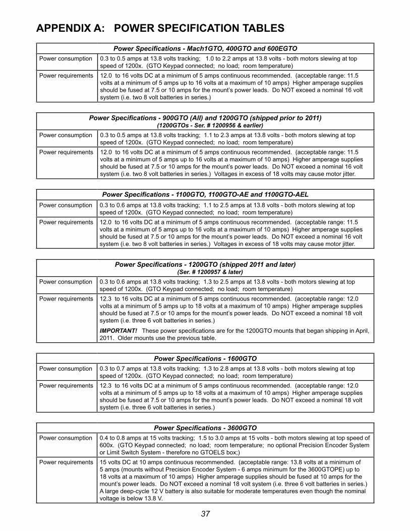
37
APPenDix A: POWer SPeCiFiCATiOn TAbleS
Power Specifications - Mach1GTO, 400GTO and 600EGTOpower consumption 0.3 to 0.5 amps at 13.8 volts tracking; 1.0 to 2.2 amps at 13.8 volts - both motors slewing at top
speed of 1200x. (Gto Keypad connected; no load; room temperature)power requirements 12.0 to 16 volts dc at a minimum of 5 amps continuous recommended. (acceptable range: 11.5
volts at a minimum of 5 amps up to 16 volts at a maximum of 10 amps) higher amperage supplies should be fused at 7.5 or 10 amps for the mount’s power leads. do not exceed a nominal 16 volt system (i.e. two 8 volt batteries in series.)
Power Specifications - 900GTO (All) and 1200GTO (shipped prior to 2011) (1200GTOs - Ser. # 1200956 & earlier)
power consumption 0.3 to 0.5 amps at 13.8 volts tracking; 1.1 to 2.3 amps at 13.8 volts - both motors slewing at top speed of 1200x. (Gto Keypad connected; no load; room temperature)
power requirements 12.0 to 16 volts dc at a minimum of 5 amps continuous recommended. (acceptable range: 11.5 volts at a minimum of 5 amps up to 16 volts at a maximum of 10 amps) higher amperage supplies should be fused at 7.5 or 10 amps for the mount’s power leads. do not exceed a nominal 16 volt system (i.e. two 8 volt batteries in series.) voltages in excess of 18 volts may cause motor jitter.
Power Specifications - 1100GTO, 1100GTO-AE and 1100GTO-AELpower consumption 0.3 to 0.6 amps at 13.8 volts tracking; 1.1 to 2.5 amps at 13.8 volts - both motors slewing at top
speed of 1200x. (Gto Keypad connected; no load; room temperature)power requirements 12.0 to 16 volts dc at a minimum of 5 amps continuous recommended. (acceptable range: 11.5
volts at a minimum of 5 amps up to 16 volts at a maximum of 10 amps) higher amperage supplies should be fused at 7.5 or 10 amps for the mount’s power leads. do not exceed a nominal 16 volt system (i.e. two 8 volt batteries in series.) voltages in excess of 18 volts may cause motor jitter.
Power Specifications - 1200GTO (shipped 2011 and later) (Ser. # 1200957 & later)
power consumption 0.3 to 0.6 amps at 13.8 volts tracking; 1.3 to 2.5 amps at 13.8 volts - both motors slewing at top speed of 1200x. (Gto Keypad connected; no load; room temperature)
power requirements 12.3 to 16 volts dc at a minimum of 5 amps continuous recommended. (acceptable range: 12.0 volts at a minimum of 5 amps up to 18 volts at a maximum of 10 amps) higher amperage supplies should be fused at 7.5 or 10 amps for the mount’s power leads. do not exceed a nominal 18 volt system (i.e. three 6 volt batteries in series.)
IMPORTANT! these power specifications are for the 1200Gto mounts that began shipping in April, 2011. older mounts use the previous table.
Power Specifications - 1600GTOpower consumption 0.3 to 0.7 amps at 13.8 volts tracking; 1.3 to 2.8 amps at 13.8 volts - both motors slewing at top
speed of 1200x. (Gto Keypad connected; no load; room temperature)power requirements 12.3 to 16 volts dc at a minimum of 5 amps continuous recommended. (acceptable range: 12.0
volts at a minimum of 5 amps up to 18 volts at a maximum of 10 amps) higher amperage supplies should be fused at 7.5 or 10 amps for the mount’s power leads. do not exceed a nominal 18 volt system (i.e. three 6 volt batteries in series.)
Power Specifications - 3600GTOpower consumption 0.4 to 0.8 amps at 15 volts tracking; 1.5 to 3.0 amps at 15 volts - both motors slewing at top speed of
600x. (Gto Keypad connected; no load; room temperature; no optional precision encoder system or limit switch system - therefore no Gtoels box;)
power requirements 15 volts dc at 10 amps continuous recommended. (acceptable range: 13.8 volts at a minimum of 5 amps (mounts without precision encoder system - 6 amps minimum for the 3600Gtope) up to 18 volts at a maximum of 10 amps) higher amperage supplies should be fused at 10 amps for the mount’s power leads. do not exceed a nominal 18 volt system (i.e. three 6 volt batteries in series.) A large deep-cycle 12 v battery is also suitable for moderate temperatures even though the nominal voltage is below 13.8 v.

38
APPenDix b: POWer COnSiDerATiOnS
introductionAstro-physics German equatorial mounts are designed to carry a wide range of loads. the Mach1GTO, 900Gto, 1100Gto, 1200Gtos (shipped prior to 2011) and the first run of 3600Gtos (shipped in 2008 and 2009) all employ the same powerful swiss dc servo motors (two per axis on the 3600Gto). starting with the second run of 3600Gtos, the 2011 run of 1200Gtos and all 1600Gtos are outfitted with even more powerful, high-torque servo motors.
Above all, Astro-physics mounts all have large worm gears that are meshed into appropriately large, precisely machined worm wheels. these mechanical components make contact over a much larger surface area than smaller worm systems of lesser precision. the large worm gear and worm wheel contribute to the mount’s excellent performance, but they are also capable of generating significant drag on the motors and demanding higher current than smaller mounts. this is especially true when temperatures drop and lubrication is at a higher viscosity.
When you consider your mount’s overall performance and capabilities, it is truly remarkable that it can do so much on so comparatively little power. As a simple point of comparison, even the mighty 3600Gto rarely uses as much energy as a single, small incandescent light bulb! the high efficiency of the Astro-physics servo system makes portability and remote operation a real possibility for these mounts. We want you to get the most out of your mount, wherever you operate it. We also want you to understand the mount’s power requirements from the outset, so that you can provide the best power source possible to the system.
if you have purchased our recommended 13.8-volt, 5-Amp power supply (ps138v5A) or the bigger 15-volt, 12-Amp power supply (ps15v12Ac) to power the mount - just the mount and nothing else - you will be fine and can probably skim through the following text with few concerns. if you plan to use other power sources, especially portable battery power, please read carefully and try to follow the guidelines presented below.
Some Power basics for non-electrical engineersplease note that the discussion below is rather general and was written to apply loosely to all mounts currently under production at Astro-physics. please refer to the power specifications tables that follow for your specific mount for more detailed recommendations.
it is vitally important that you understand what is meant by “adequate power.” Adequate power has two major criteria that must both be satisfied: adequate voltage and adequate current (amperage). think of voltage as the pressure or push of the electrical energy. voltage represents the potential difference or electromotive force across a circuit. More simply put, voltage is how much the electrons “desire” to move through a circuit. on the other hand, think of amperage as the volume or quantity of the electrical energy. Amperage is more accurately described as the total number of electrons that move through the circuit over a given amount of time. Water is often used as an analogy for electricity with pressure (i.e. psi - pounds per square inch) somewhat equivalent to voltage and flow rate (i.e. gpm - gallons per minute) somewhat equivalent to amperage.
your Astro-physics Gto servo drive system needs energy that is pushing its way through the system at a “pressure” of at least 12.0 volts. it will normally perform best if that voltage pressure is between 12.3 and 16 volts for the smaller mounts, or up to 18 volts for the larger mounts. if the pressure exceeds 19 to 20 volts, you may begin to generate heat buildup in the Gtocp4 control box as the unit’s voltage regulator must dissipate more and more excess energy as heat. Mach1GTOs, 900Gtos, 1100Gtos and pre-2011 1200Gto mounts may also experience motor jitter at voltages over 18 volts.
your servo drive system needs available current of 5 to 10 amperes (amps). even though it normally consumes under one amp during regular tracking, and only about 1.5 to 4.5 amps when slewing at high speed under normal conditions, the mount should have at least 5 amps (at 12 volts) continuously available to it to ensure that it is adequately energized. (We recommend a bit higher minimum capacity for the 3600Gto.) A power supply that can deliver 10 amps would have the reserve capacity to deliver steady power through any peaks in demand, such as when new movement is initiated and acceleration is underway.
you must also understand that voltage and amperage are not independent of each other. if your mount demands more current (amps) than your power supply can deliver, the result will be a drop in the pressure or voltage of the current. A power supply of insufficient current or amperage capacity cannot maintain the pressure or voltage when a system demands excess current, even if only momentarily. the analogy of connecting a big fire hose to a weak, garden-hosecock comes to mind.
A lower voltage power supply will need more available amperage than a higher voltage supply. this is easiest to understand if you remember that the work done, or energy converted into work, measured in watts, is always equal to the volts times the amps. imagine a water wheel that must turn a mechanical device. A small stream of water at high pressure
39
will turn the wheel, but so will a large volume of water at low pressure. if you are inside the building watching the device operate, you can’t tell whether the wheel is being turned by a small volume at high pressure or by a large volume at low pressure.
since watts are the real measure of potential work done, the goal should be to provide all the watts necessary to perfectly drive the mount without wasting any in the form of heat buildup. this goal is achieved by supplying the proper blend of volts and amps to match the servo system’s design specifications. too much voltage will generate heat as the excess energy is dissipated. too much available amperage will pose a threat to the equipment should something “open the floodgates” so-to-speak and allow excessive current into the system. too little of either volts or amps will starve the system of the required watts for proper operation.
So, what are the “DO’s and DOn’T’s” ? All this discussion of volts, amps and watts is fine, but how do we translate this into some meaningful recommendations for powering the mount? the following general list should help with this, and the individual power specification tables that follow will fully address the details for each of the four Astro-physics mounts that are currently in production.
● do not use power supplies designed for portable stereos, laptop computers or other consumer electronics.
● do not use the supply from a Meade or celestron system, even though they may claim to provide adequate power.
● do not power additional devices from your mount’s power source – especially dew heaters which are notorious for initiating momentary voltage dropouts as they cycle on and off! dew heaters also put a lot of switching noise on the power lines that can disrupt sensitive electronics, like servo control boxes or cameras.
● do not use a dc extension cord between your dc power supply and the Mount’s power cord. run any needed extension cords on the Ac side, or move your battery pack closer to the mount.
● do not use batteries or battery packs with less than 30 amp-hours of power. in fact, for the larger mounts, we would recommend nothing less than a large (i.e. 50+ amp-hour) deep-cycle marine battery. see the batteries section starting below.
● do give your mount its own power source, if possible, and power other devices from a separate source or sources.
● do use power inverters to go from standard household Ac current to dc current that are both filtered and regulated to ensure clean steady power delivery.
● do inspect your mount’s power cord regularly to be sure that it is not damaged.
● do use higher voltages – up to 16 to 18 volts – for extremely cold temperatures.
● do keep an eye on the power led on your Gtocp4 control box.
it bears repeating: the two power supplies that we offer (ps138v5A and ps15v12Ac) are excellent choices for virtually all customers with u.s. standard 110 to 120-volt, 60-hz, Ac household current.
batteriesif you are using battery power, be sure that you are using fully-charged, deep-cycle, type batteries with an absolute minimum 30 amp-hour (Ah) rating. readily available batteries are generally divided into three application categories. (We will omit a discussion of more esoteric batteries like lithium ion.) these applications are: starting, deep-cycle and marine.
● starting or “car” batteries are designed to provide a huge amount of current (many amps) for a very short time. in normal usage, they are not discharged below a few percent below full charge. to provide the high current demanded by starting, they employ many very thin spongy lead plates to maximize the surface area exposed to the electrolyte. repeated deep discharge will dissolve these thin plates and ruin the battery. Starting or “car” batteries are NOT recommended. this includes motorcycle and garden tractor batteries.
● deep-cycle batteries are designed to provide a more moderate, steady flow of current over a long time. true deep-cycle batteries employ much thicker, more robust lead plates since they do not require the ability to provide the huge burst of current required for cold-starting an engine. repeated deep discharge will not dissolve the plates the way it does for starting batteries. true deep-cycle batteries include industrial (i.e. fork-lift) batteries and golf cart batteries - both normally rather large, high amp-hour formats - as well as smaller batteries designed for electric mobility devices ranging from electric mopeds to scooters and electric wheelchairs. Deep-cycle batteries are the recommended application type for use with your mount.
● Marine deep-cycle batteries are generally a hybrid design. they attempt to both provide the current to start a boat motor and the deep discharge capability for trolling motors or houseboat electrical systems. these are not as good a

40
choice as true deep-cycle batteries, but are often much less expensive than true deep-cycle batteries. note also that many batteries marketed as “marine deep-cycle” are actually hybrid designs that are really more for starting than deep discharge. if the battery advertises its cranking power (i.e. ccA or cold cranking amps), then it is a hybrid at best, regardless of what the label says. Marine deep-cycle batteries are suitable for powering your mount, but should not be discharged as deeply as true deep-cycle batteries.
All of the battery application types listed above refer to lead-acid batteries of one form or another. these are still the most practical and affordable type of battery. As other battery technologies mature, this evaluation may change, but as of the summer of 2011, lead acid batteries still totally dominate in industrial, golf cart, personal mobility and solar power applications. Just as there were three application types, there are also three battery construction types: flooded or “wet”, gel or Gel-cell, and AGM (for Absorbed Glass Mat).
flooded batteries require some regular maintenance: basically keeping the electrolyte topped off - usually by the addition of distilled water to the individual cells. the largest industrial and golf cart batteries tend to be flooded. large, heavy, flooded batteries may pose limitations in terms of portability, but the other benefits may outweigh the portability issues, depending on the mount and the situation. if you are setting up a 3600Gto on a remote mountain top, you can probably also handle these large batteries.
Gel-cells and AGM batteries are often grouped together as “valve-regulated” batteries. both are sealed up to the limits of their regulating relief valve. this is a great advantage in terms of portability. Gel-cells can have a rather high internal resistance which makes them subject to momentary voltage drops when the demanded load changes. for this reason, we try to avoid Gel-cell batteries for the mounts. they are fine for items like dew heaters. AGM batteries are often the best choice for portable battery operation of your mount, and they are now available in a very wide range of suitable sizes.
to summarize, true deep-cycle batteries with AGM (absorbed glass mat) construction are among the best to use as they deliver relatively steady power levels throughout their discharge cycle and provide the required portability. they are also designed to recover from more extreme levels of discharge and can be drained and re-charged many times without suffering a loss of capacity as happens with typical car batteries. As a final plus, they are also readily available.
remember that batteries with smaller amp-hour ratings can be wired in parallel to achieve an equivalent single battery of the same voltage, but with the summed amp-hour rating. in other words, a 20 Ah battery and a 30 Ah battery can be wired in parallel to be the equivalent of a single 50 Ah battery. see the diagram at right.
Also, batteries with smaller voltage ratings can be wired in series to achieve the sum of their voltages. batteries wired in series should be of similar amp-hour rating. the amp-hour rating of batteries wired in series is not additive and will be limited to the weakest battery in the set. As shown in the diagram, a 6 v, 55 Ah battery wired in series to a 6 v, 45 Ah battery will be the equivalent of a 12 v, 45 Ah battery. it will not yield 50 Ah (the average of the two) or the 55 Ah of the larger 6 v battery.
do not be tempted to wire a bunch of batteries together in parallel in order to power multiple devices from one source. in terms of overall efficiency, this might make sense, but you will have better success if you give the mount its own power source. Also, as a general rule, do not mix battery construction types: i.e. a flooded and a gel cell. this is more important when charging than when discharging the batteries in normal deep-cycle usage.
An excellent battery choice for the larger mounts is to purchase 6 or 8-volt golf cart or fork-lift batteries that are then wired in series. if you choose the 8-volt sizes, two of these wired in series would yield 16 volts - perfect for a 1200Gto, 1600Gto or 3600Gto mount. be aware, however, that there are limitations in available charging systems. eight volt batteries are normally used with three batteries in series to create a 24-volt system and are charged accordingly. to use 8-volt batteries, you might need to purchase 3 batteries and use them in rotations of 2 for each astronomy session, and then connect all three in series for charging.
the proliferation of personal mobility devices, or “scooters” has also led to the wide availability of deep-cycle batteries in the 20 Ah to 60 Ah range. Many of these are perfectly suited to the smaller mounts as they can be found in a very wide array of sizes. We repeat: Give the mount its own battery. use multiple batteries if powering multiple devices!
All of the lead-acid based batteries, whether traditional “flooded” or “wet”, gel or AGM, will basically measure about 2.14 to 2.3 volts per cell when new, fully charged and under no load. in an actual operating circuit, the output of a fully charged battery cell ranges from about 2.05 to 2.2 volts per cell, depending on the load. even a 3600Gto at maximum slew speeds will not draw down the output voltage of a fully charged deep-cycle battery below about 2.1 volts per cell.
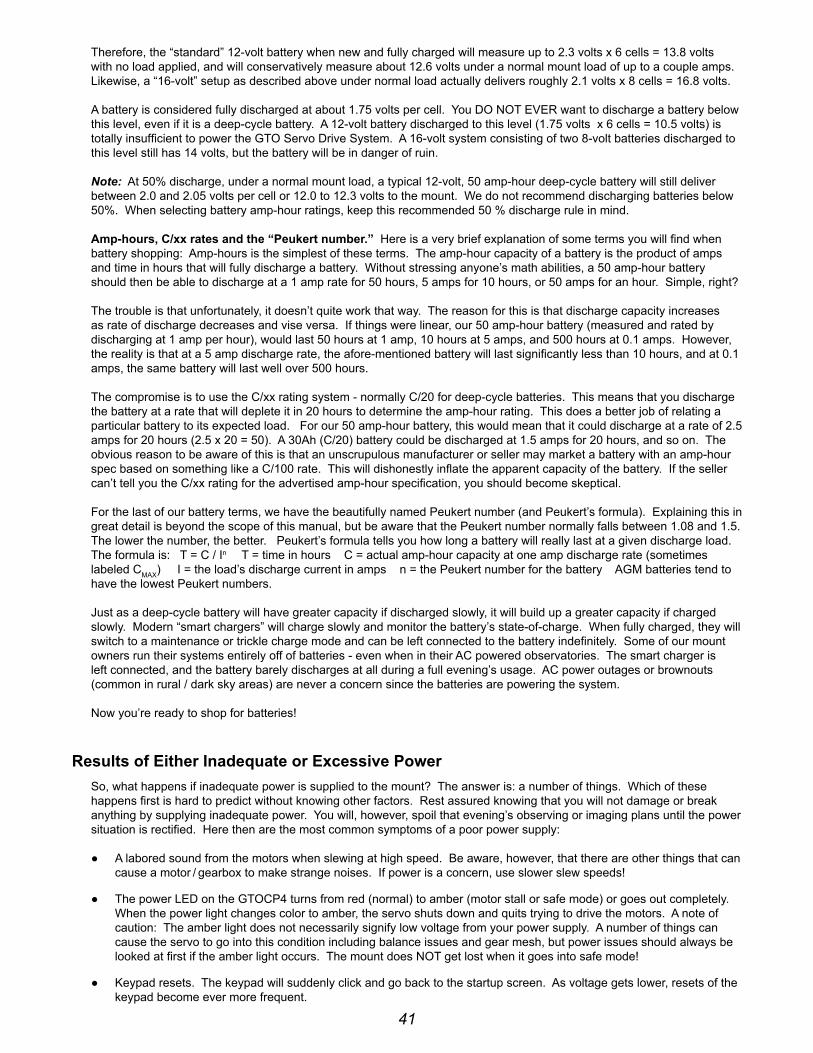
41
therefore, the “standard” 12-volt battery when new and fully charged will measure up to 2.3 volts x 6 cells = 13.8 volts with no load applied, and will conservatively measure about 12.6 volts under a normal mount load of up to a couple amps. likewise, a “16-volt” setup as described above under normal load actually delivers roughly 2.1 volts x 8 cells = 16.8 volts.
A battery is considered fully discharged at about 1.75 volts per cell. you do not ever want to discharge a battery below this level, even if it is a deep-cycle battery. A 12-volt battery discharged to this level (1.75 volts x 6 cells = 10.5 volts) is totally insufficient to power the Gto servo drive system. A 16-volt system consisting of two 8-volt batteries discharged to this level still has 14 volts, but the battery will be in danger of ruin.
Note: At 50% discharge, under a normal mount load, a typical 12-volt, 50 amp-hour deep-cycle battery will still deliver between 2.0 and 2.05 volts per cell or 12.0 to 12.3 volts to the mount. We do not recommend discharging batteries below 50%. When selecting battery amp-hour ratings, keep this recommended 50 % discharge rule in mind.
Amp-hours, C/xx rates and the “Peukert number.” here is a very brief explanation of some terms you will find when battery shopping: Amp-hours is the simplest of these terms. the amp-hour capacity of a battery is the product of amps and time in hours that will fully discharge a battery. Without stressing anyone’s math abilities, a 50 amp-hour battery should then be able to discharge at a 1 amp rate for 50 hours, 5 amps for 10 hours, or 50 amps for an hour. simple, right?
the trouble is that unfortunately, it doesn’t quite work that way. the reason for this is that discharge capacity increases as rate of discharge decreases and vise versa. if things were linear, our 50 amp-hour battery (measured and rated by discharging at 1 amp per hour), would last 50 hours at 1 amp, 10 hours at 5 amps, and 500 hours at 0.1 amps. however, the reality is that at a 5 amp discharge rate, the afore-mentioned battery will last significantly less than 10 hours, and at 0.1 amps, the same battery will last well over 500 hours.
the compromise is to use the c/xx rating system - normally c/20 for deep-cycle batteries. this means that you discharge the battery at a rate that will deplete it in 20 hours to determine the amp-hour rating. this does a better job of relating a particular battery to its expected load. for our 50 amp-hour battery, this would mean that it could discharge at a rate of 2.5 amps for 20 hours (2.5 x 20 = 50). A 30Ah (c/20) battery could be discharged at 1.5 amps for 20 hours, and so on. the obvious reason to be aware of this is that an unscrupulous manufacturer or seller may market a battery with an amp-hour spec based on something like a c/100 rate. this will dishonestly inflate the apparent capacity of the battery. if the seller can’t tell you the c/xx rating for the advertised amp-hour specification, you should become skeptical.
for the last of our battery terms, we have the beautifully named peukert number (and peukert’s formula). explaining this in great detail is beyond the scope of this manual, but be aware that the peukert number normally falls between 1.08 and 1.5. the lower the number, the better. peukert’s formula tells you how long a battery will really last at a given discharge load. the formula is: t = c / in t = time in hours c = actual amp-hour capacity at one amp discharge rate (sometimes labeled cMAx) i = the load’s discharge current in amps n = the peukert number for the battery AGM batteries tend to have the lowest peukert numbers.
Just as a deep-cycle battery will have greater capacity if discharged slowly, it will build up a greater capacity if charged slowly. Modern “smart chargers” will charge slowly and monitor the battery’s state-of-charge. When fully charged, they will switch to a maintenance or trickle charge mode and can be left connected to the battery indefinitely. some of our mount owners run their systems entirely off of batteries - even when in their Ac powered observatories. the smart charger is left connected, and the battery barely discharges at all during a full evening’s usage. Ac power outages or brownouts (common in rural / dark sky areas) are never a concern since the batteries are powering the system.
now you’re ready to shop for batteries!
results of either inadequate or excessive Powerso, what happens if inadequate power is supplied to the mount? the answer is: a number of things. Which of these happens first is hard to predict without knowing other factors. rest assured knowing that you will not damage or break anything by supplying inadequate power. you will, however, spoil that evening’s observing or imaging plans until the power situation is rectified. here then are the most common symptoms of a poor power supply:
● A labored sound from the motors when slewing at high speed. be aware, however, that there are other things that can cause a motor / gearbox to make strange noises. if power is a concern, use slower slew speeds!
● the power led on the Gtocp4 turns from red (normal) to amber (motor stall or safe mode) or goes out completely. When the power light changes color to amber, the servo shuts down and quits trying to drive the motors. A note of caution: the amber light does not necessarily signify low voltage from your power supply. A number of things can cause the servo to go into this condition including balance issues and gear mesh, but power issues should always be looked at first if the amber light occurs. the mount does not get lost when it goes into safe mode!
● Keypad resets. the keypad will suddenly click and go back to the startup screen. As voltage gets lower, resets of the keypad become ever more frequent.

42
oK! so, what happens if you connect to a power supply that delivers too high a voltage? What about 24 volts – i.e. two 12-volt batteries in series (which actually delivers between 25 and 26 volts)? for the Mach1GTO, 900Gto, 1100Gto and pre-2011 1200Gtos the answer is simple: don’t do it!! for the current 1200Gto, 1600Gto and 3600Gto mounts there is no simple, straight-forward answer. the biggest danger as your voltage climbs over 18 v is that the Gtocp4 will overheat. Again, conditions will play a role. here are some considerations:
● first, excess heat shortens the life of electronic components over the long term. too much heat from extreme over-voltage will even damage the components and may “burn up the unit” right before your eyes.
● second, energy that is being dissipated as heat by the voltage regulator is basically being wasted.
● in addition, at even higher voltages, your motors may experience chatter from the excessive gain, and there is an increased likelihood of damage to the motors, encoders and system components, not to mention the heat damage to the control box as voltages climb higher.
● the voltage that matters is the voltage that enters the control box. for example, two 12-volt batteries, connected in series, (producing roughly 25 to 26 volts) that are 50 feet away from the mount in a truck, might only deliver about 20 volts to the mount by the time the current has gone through all that (hopefully very heavy gauge) cable.
● cold weather does three things: it demands more voltage from the system, especially for slews, and it allows heat to dissipate faster. the third thing is that it reduces the output voltage of batteries. At temperatures below freezing, you may be safe with up to 24 volts for the large mounts, or 18 volts for the smaller mounts, but we do not recommend this as a general practice. A far better practice for cold weather is to reduce your slew speed and thereby your voltage demands!
● if using a supply with voltage over 18 volts (large mounts) or over 16 volts (smaller mounts), you should periodically check the Gtocp4 to be sure it is not overheating. Warm to the touch is oK. too hot to touch continuously is too hot!
● finally, you should be aware that voltages above about 28 volts begin to pose a shock hazard to humans, and an arcing hazard to electronics that are not designed for that voltage. please be smart and be careful!
iMPOrTAnT Considerations for observatory installations: ideally, we would suggest that you disconnect your Gto control box from 110v and any other device (ccd camera, computer, etc) when you are not using your mount so that if your observatory experiences a power surge or lightening strike, your mount electronics will not be damaged. if you operate your mount remotely, you will have to leave your power cable connected just as you do for the rest of your electronic equipment. you may want to consider surge protectors or other protective measures to protect from voltage spikes. A disconnect relay to remove power from both the 12-volt and ground wire is highly recommended in this situation. power handling, power / surge protection, and lightning protection should be primary design criteria for any remote observatory.
remember also that electronics can be damaged by "Ground rise potential" that can enter the electronics through communications connections - not just power connections. A cheap "surge protector" doesn't offer much (if any) protection to a remote or robotic observatory. A transtector on the outside of the observatory, intercepting the power before it enters the observatory would be significantly better. And there is still the issue of effective lightning protection grounding which is not the same as standard electrical grounding. see the Motorola r56 standards and Guidelines for communications sites manual for detailed information on proper lightning protection of exposed sensitive facilities like observatories.
failure in this area can be very costly!
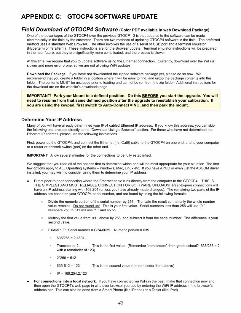
43
APPenDix C: GTOCP4 SOFTWAre uPDATe
Field Download of GTOCP4 Software (Color PDF available in web Download Package)one of the advantages of the Gtocp4 over the previous Gtocp1-3 is that updates to the software can be made electronically in the field by the customer. there are two methods of updating Gtocp4 software in the field. the preferred method uses a standard Web browser. the other involves the use of a serial or usb port and a terminal emulator (hyperterm or teraterm). these instructions are for the browser update. terminal emulator instructions will be prepared in the near future, but they are significantly more complicated, and the process is slower.
At this time, we require that you to update software using the ethernet connection. currently, download over the Wifi is slower and more error prone, so we are not allowing Wifi updates.
Download the Package if you have not downloaded the zipped software package yet, please do so now. We recommend that you create a folder in a location where it will be easy to find, and unzip the package contents into this folder. the contents Must be unzipped prior to loading and cannot be run from the zip folder. Additional instructions for the download are on the website’s downloads page. iMPOrTAnT! Park your Mount to a defined position. Do this beFOre you start the upgrade. you will need to resume from that same defined position after the upgrade to reestablish your calibration. if you are using the keypad, first switch to Auto-Connect = nO, and then park the mount.
Determine your iP AddressMany of you will have already determined your ipv4 cabled ethernet ip address. if you know this address, you can skip the following and proceed directly to the “download using a browser” section. for those who have not determined the ethernet ip address, please use the following instructions.
first, power up the Gtocp4, and connect the ethernet (i.e. cat6) cable to the Gtocp4 on one end, and to your computer or a router or network switch (port) on the other end.
iMPOrTAnT: Allow several minutes for the connections to be fully established.
We suggest that you read all of the options first to determine which one will be most appropriate for your situation. the first few options apply to All operating systems – Windows, Mac, linux etc. if you have Apcc or even just the AscoM driver installed, you may wish to consider using them to determine your ip address.
● direct peer-to peer connection where the ethernet cable runs directly from the computer to the Gtocp4. this is the siMplest And Most reliAble connection for softWAre uploAds! peer-to-peer connections will have an ip address starting with 169.254 (unless you have already made changes). the remaining two parts of the ip address are based on your Gtocp4 serial number, and are found by using the following formula:
○ divide the numeric portion of the serial number by 256. truncate the result so that only the whole number value remains. do not round up! this is your first value. serial numbers less than 256 will use “0.” numbers 256 to 511 will use “1.” and so on.
○ Multiply the first value from #1. above by 256, and subtract it from the serial number. the difference is your second value.
○ exAMple: serial number = cp4-0635. numeric portion = 635
◦ 635/256 = 2.4804…
◦ truncate to 2. this is the first value. (remember “remainders” from grade school? 635/256 = 2 with a remainder of 123)
◦ 2*256 = 512.
◦ 635-512 = 123 this is the second value (the remainder from above)
◦ ip = 169.254.2.123
● For connections into a local network. if you have connected via Wifi in the past, make that connection now and then open the Gtocp4’s web page in whatever browser you use by entering the Wifi ip address in the browser’s address bar. this can also be done from a smart phone (like iphone) or a tablet (like ipad).
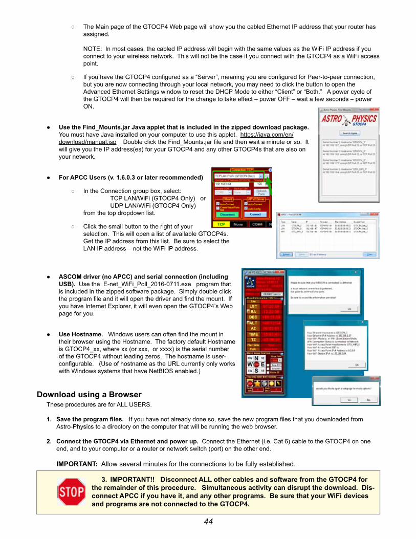
44
○ the Main page of the Gtocp4 Web page will show you the cabled ethernet ip address that your router has assigned. note: in most cases, the cabled ip address will begin with the same values as the Wifi ip address if you connect to your wireless network. this will not be the case if you connect with the Gtocp4 as a Wifi access point.
○ if you have the Gtocp4 configured as a “server”, meaning you are configured for peer-to-peer connection, but you are now connecting through your local network, you may need to click the button to open the Advanced ethernet settings window to reset the dhcp Mode to either “client” or “both.” A power cycle of the Gtocp4 will then be required for the change to take effect – power off – wait a few seconds – power on.
● use the Find_Mounts.jar Java applet that is included in the zipped download package. you must have Java installed on your computer to use this applet. https://java.com/en/download/manual.jsp double click the find_Mounts.jar file and then wait a minute or so. it will give you the ip address(es) for your Gtocp4 and any other Gtocp4s that are also on your network.
● For APCC users (v. 1.6.0.3 or later recommended)
○ in the connection group box, select: tcp lAn/Wifi (Gtocp4 only) or udp lAn/Wifi (Gtocp4 only) from the top dropdown list.
○ click the small button to the right of your selection. this will open a list of available Gtocp4s. Get the ip address from this list. be sure to select the lAn ip address – not the Wifi ip address.
● ASCOM driver (no APCC) and serial connection (including uSb). use the e-net_Wifi_poll_2016-0711.exe program that is included in the zipped software package. simply double click the program file and it will open the driver and find the mount. if you have internet explorer, it will even open the Gtocp4’s Web page for you.
● use hostname. Windows users can often find the mount in their browser using the hostname. the factory default hostname is Gtocp4_xx, where xx (or xxx, or xxxx) is the serial number of the Gtocp4 without leading zeros. the hostname is user-configurable. (use of hostname as the url currently only works with Windows systems that have netbios enabled.)
Download using a browserthese procedures are for All users.
1. Save the program files. if you have not already done so, save the new program files that you downloaded from Astro-physics to a directory on the computer that will be running the web browser.
2. Connect the GTOCP4 via ethernet and power up. connect the ethernet (i.e. cat 6) cable to the Gtocp4 on one end, and to your computer or a router or network switch (port) on the other end. iMPOrTAnT: Allow several minutes for the connections to be fully established.
3. iMPOrTAnT!! Disconnect All other cables and software from the GTOCP4 for the remainder of this procedure. Simultaneous activity can disrupt the download. Dis-connect APCC if you have it, and any other programs. be sure that your WiFi devices and programs are not connected to the GTOCP4.
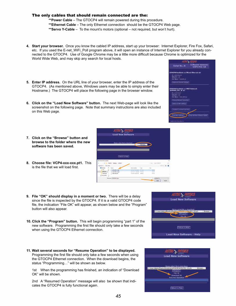
45
The only cables that should remain connected are the: **Power Cable – the Gtocp4 will remain powered during this procedure. **ethernet Cable – the only ethernet connection should be the Gtocp4 Web page. **Servo y-Cable – to the mount’s motors (optional – not required, but won’t hurt).
4. Start your browser. once you know the cabled ip address, start up your browser: internet explorer, fire fox, safari, etc. if you used the e-net_Wifi_poll program above, it will open an instance of internet explorer for you already con-nected to the Gtocp4. use of Google chrome may be a little more difficult because chrome is optimized for the World Wide Web, and may skip any search for local hosts.
5. enter iP address. on the url line of your browser, enter the ip address of the Gtocp4. (As mentioned above, Windows users may be able to simply enter their hostname.) the Gtocp4 will place the following page in the browser window.
6. Click on the “load new Software” button. the next Web-page will look like the screenshot on the following page. note that summary instructions are also included on this Web page.
7. Click on the “browse” button and browse to the folder where the new software has been saved.
8. Choose file: vCP4-xxx-xxx.pt1. this is the file that we will load first.
9. File “OK” should display in a moment or two. there will be a delay since the file is inspected by the Gtocp4. if it is a valid Gtocp4 code file, the indication “file oK” will appear, as shown below and the “program” button will also appear.
10. Click the “Program” button. this will begin programming “part 1” of the new software. programming the first file should only take a few seconds when using the Gtocp4 ethernet connection.
11. Wait several seconds for “resume Operation” to be displayed. programming the first file should only take a few seconds when using the Gtocp4 ethernet connection. When the download begins, the status “programming…” will be shown as below.
1st When the programming has finished, an indication of “download oK” will be shown.
2nd A “resumed operation” message will also be shown that indi-cates the Gtocp4 is fully functional again.
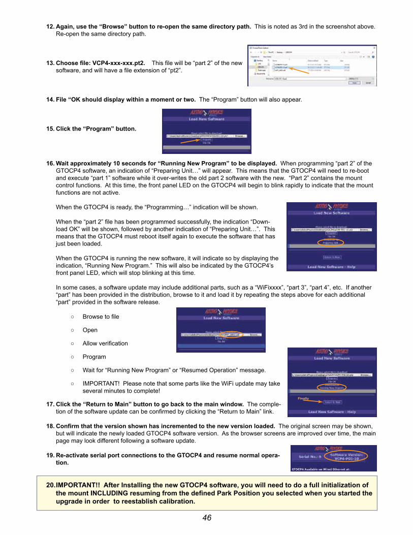
46
12. Again, use the “browse” button to re-open the same directory path. this is noted as 3rd in the screenshot above. re-open the same directory path.
13. Choose file: vCP4-xxx-xxx.pt2. this file will be “part 2” of the new software, and will have a file extension of “pt2”.
14. File “OK should display within a moment or two. the “program” button will also appear.
15. Click the “Program” button.
16. Wait approximately 10 seconds for “running new Program” to be displayed. When programming “part 2” of the Gtocp4 software, an indication of “preparing unit…” will appear. this means that the Gtocp4 will need to re-boot and execute “part 1” software while it over-writes the old part 2 software with the new. “part 2” contains the mount control functions. At this time, the front panel led on the Gtocp4 will begin to blink rapidly to indicate that the mount functions are not active. When the Gtocp4 is ready, the “programming…” indication will be shown. When the “part 2” file has been programmed successfully, the indication “down-load oK” will be shown, followed by another indication of “preparing unit…”. this means that the Gtocp4 must reboot itself again to execute the software that has just been loaded. When the Gtocp4 is running the new software, it will indicate so by displaying the indication, “running new program.” this will also be indicated by the Gtocp4’s front panel led, which will stop blinking at this time. in some cases, a software update may include additional parts, such as a “Wifixxxx”, “part 3”, “part 4”, etc. if another “part” has been provided in the distribution, browse to it and load it by repeating the steps above for each additional “part” provided in the software release.
○ browse to file
○ open
○ Allow verification
○ program
○ Wait for “running new program” or “resumed operation” message.
○ iMportAnt! please note that some parts like the Wifi update may take several minutes to complete!
17. Click the “return to Main” button to go back to the main window. the comple-tion of the software update can be confirmed by clicking the “return to Main” link.
18. Confirm that the version shown has incremented to the new version loaded. the original screen may be shown, but will indicate the newly loaded Gtocp4 software version. As the browser screens are improved over time, the main page may look different following a software update.
19. re-activate serial port connections to the GTOCP4 and resume normal opera-tion.
20. iMPOrTAnT!! After installing the new GTOCP4 software, you will need to do a full initialization of the mount inCluDinG resuming from the defined Park Position you selected when you started the upgrade in order to reestablish calibration.
Finally

47
APPenDix D: rS-232 COMMAnD lAnGuAGe FOr GTOCP3 AnD GTOCP4 ServO COnTrOl bOxeS
this appendix includes the commands associated with Gtocp3 and Gtocp4 control boxes.
GTOCP4 Control box:MOST OF THESE COMMANDS ARE VALID WITH THE GTOCP4 - Exceptions are noted. please note that the Gtocp4 also utilizes additional commands that we do not plan to publish at this time.
GTOCP3 Control box: All of the commands below are available to control boxes with at least the q version of the microcontroller chip installed unless the command specifically states that it was introduced in a later version. please note that additional commands were added to later chips that we do not plan to publish at this time.
Determine your rOM chip version: there are several ways to check the version letter and date of the microprocessor roM chip:
● open the top of the Gtocp3 control box and look for a label on one of the large, square chips.
● the chip version can be found in several places in the Astro-physics v2 AscoM driver. in the setup telescope window, click the “check port” button. Assuming you have a good connection, a popup window will appear saying: “Mount found! firmware rev: v2 “ (or whatever firmware is in the Gtocp3). the virtual keypad also displays the firmware version in the upper right: “fW:v2”, and the status window displays the version in the center column of information.
● Astro-physics command center (Apcc) software. the chip version can be queried in the trial registration window. if Apcc is installed, connect to the mount. the chip version will display in the setup tab.
● pulseGuide software by ray Gralak. simply connect to the mount with pulseGuide, and the chip version will be displayed in the connect window.
GTOCP1 and GTOCP2 Control boxes: Many of these commands are not suitable for the Gtocp1 and Gtocp2 control boxes. there are some important differences and limitations with those early control boxes. if you are a programmer developing commercial programs, please refer to the appropriate document pertaining to the command language for these control boxes in the technical support section of our website. note also that even identical-looking commands between the newer and older command sets may have different meanings or rules governing their usage.
General Telescope Information:Command: :SG shh# or :SG shh:MM.M# or :SG shh:MM:SS#response: “1”sets the offset from Greenwich mean time. command may be issued in any format regardless of whether long format has been selected. Although any length format is acceptable, only the hours field is typically of interest. data entered with this command will be “remembered” through a power cycle and automatically re-applied on the next powerup. the offset can be entered in unsigned 24-hour format (0-23 hours) or in signed format (-12 to +12) hours.
Command: :Sg DDD*MM# or :Sg DDD*MM:SS#response: “1”sets the current longitude. command may be issued in long or short format regardless of whether long format has been se-lected. data entered with this command will be “remembered” through a power cycle and automatically re-applied on the next powerup.
Command: :St sDD*MM# or :St sDD*MM:SSresponse: “1”sets the current latitude. command may be issued in long or short format regardless of whether long format has been se-lected. data entered with this command will be “remembered” through a power cycle and automatically re-applied on the next powerup.
48
Command: :Sl hh:MM:SS#response: “1”sets the current local time. command may be issued in long or short format regardless of whether long format has been selected.
Command: :SC MM/DD/yy#response: 32 spaces followed by “#”, followed by 32 spaces, followed by “#”sets the current date. note that year fields equal to or larger than 97 are assumed to be 20th century, year fields less than 97 are assumed to be 21st century.
Command: :GG#response: hh:MM.M# or hh:MM:SS.S# if long formatGets the offset from Greenwich mean time. Although typically only hours field is of interest, the return value will be in standard 24 hour format.note to programmers: please refer to rs-232 command language for Gtocp1 and Gtocp2 servo control boxes for infor-mation on issues with this command on earlier chips.
Command: :Gg#response: +DD*MM# or +DDD*MM# +DD*MM:SS# or +DDD*MM:SS# if long formatGets the current longitude.
Command: :Gt#response: sDD*MM# or sDD*MM:SS# if long formatGets the current latitude.
Command: :Gl#response: hh:MM.M# or hh:MM:SS.S# if long formatGets the current local time in 24 hr. format. overflows from 23:59:59 to 00:00:00. updates calendar day on overflow.
Command: :GS#response: hh:MM.M# or hh:MM:SS.S# if long formatGets the current sidereal time in 24 hr. format.
Command: :Gr#response: hh:MM.M# or hh:MM:SS.S# if long formatGets the current right Ascension.
Command: :GD#response: sDD*MM# or sDD*MM:SS# if long formatGets the current declination.
Command: :GA#response: sDD*MM# or sDD*MM:SS# if long formatGets the current Altitude.
Command: :GZ#response: sDD*MM# or sDD*MM:SS# if long formatGets the current Azimuth.
Command: :GC#response: MM:DD:yy#Gets the current calendar day. leading zero appears only in the year field.
Telescope MotionCommand: :MS#response: “0” if command accepted, (none) if command not accepted, “1Object is below horizon #”

49
if the horizon check is turned on, and the desired object is below 0 degrees altitude. (8 trailing spaces before “#”, 32 total characters plus “#”)slew to the most recently defined rA and dec coordinates in rA-dec mode, or most recently defined Alt and AZ coordi-nates in Alt-AZ mode. slewing is performed at the currently selected slew rate. if the horizon check is turned on, and the object is below the horizon, this will be stated, and no slewing will occur.
note that the keypad, digitalsky voice software and thesky software all have their own internal horizon check routines.
Command: :Mn# :Ms# :Me# :Mw#response: (none)command motion in the direction specified (n=north, s=south, e=east, w=west) at the currently selected guide or centering rate. Motion will continue until a quit command is issued.
Command: :Mnxxx# :Msxxx# :Mexxx# :Mwxxx#response: (none)command motion for xxx milliseconds in the direction specified at the currently selected guide rate. if xxx has a value of zero, motion is continuous and requires a quit command to terminate. otherwise a quit command will not terminate.
Command: :nS#response: (none)this command swaps the functions of the north and south buttons. subsequent commands :Mn# and :Ms# are affected.
Command: :eW#response: (none)this command swaps the functions of the east and west buttons. subsequent commands :Me# and :Mw# are affected.
Command: :qn# :qs# :qe# :qw#response: (none)stop motion in the specified axis. note that :qn# is identical to :qs#, and :qe# is identical to :qw#. Motion is terminated only if it was not started by a slew (:Ms#) command.
Command: :q#response: (none)Motion in both axes is stopped, regardless of how the motion was invoked.
Command: :rG# :rG0# :rG1# :rG2#response: (none)selects guide rate for the n-s-e-W buttons. optionally selects 0.25x (:rG0#), 0.5x (:rG1#), or 1.0x (:rG2#). if no index is provided (:rG#), the previously selected guide rate will be used, else the power up default of 0.5x will be assumed by the mo-tor drive.
Command: :rC# :rC0# :rC1# :rC2# :rC3#response: (none)selects centering rate for the n-s-e-W buttons. optionally selects a rate of 12x (:rc0#), 64x (:rc1#), 600x (:rc2#), or 1200x (:rc3#). if no index is provided (:rc#), then the previously selected speed will be used, else the power up default of 64x will be assumed by the motor drive. these rates are predefined selections for the command :rcxxx# as shown below.
Command: :rcxxx# response: (none)sets the centering rate for the n-s-e-W buttons to xxx. xxx is an integer from 1 to 255.
Command: :rS# :rS0# :rS1# :rS2#response: (none)selects the slew speed used by the telescope move functions. this command has no effect on the use of the n-s-e-W but-tons (therefore, :rs# has no effect). the default slew speed is 1200x. slewing can be done at 1200x (:rs2#), 900x (:rs1#), or 600x (:rs0#).
Command: :rsxxxx#response: (none)sets the slew rate used by the telescope move functions. this command has no effect on the use of the n-s-e-W buttons. for xxxx, specify an integer from 1 to 1200. Although larger integers will be accepted, your upper limit should not exceed 1200. this command is an expansion of the :rs commands, allowing the programmer to specify additional slew rates.

50
Command: :rT0# :rT1# :rT2# :rT9#response: (none)this command selects the tracking rate. it selects lunar (:rt0#), solar (:rt1#), sidereal (:rt2#), or zero (:rt9#). the sidereal rate is assumed as a default by the motor drive if nothing is specified. this command has no effect on the use of the n-s-e-W buttons. Zero tracking rate is useful in Alt-AZ mode. these rates are predefined selections for the command :rr sxxx.xxx# as shown below.
Command: :rr sxxx.xxxx# :rD sxxx.xxxx#response: “1”this command selects the tracking rate in the rA axis (“rr”) or dec axis (“rd”) to xxx.xxxx. the rate added to the standard sidereal rate and can be positive or negative. Command: :bd DD*MM:SS# response: “1”this command sets the amount of dec backlash compensation employed each time a servo motor axis reverses direction. resolution of the compensation is in arc seconds. typically, the degrees and minutes fields are zero to specify the amount of compensation only in seconds. values of compensation above 00*54:36 may be truncated depending upon which mount is used (this is a ridiculously large value, typical values should be well under 00*01:00). the default dec backlash compensa-tion is 00*00:00.
Command: :br DD*MM:SS# or :br hh:MM:SS# or :br hh:MM:SS.S#response: “1”this command sets the amount of rA backlash compensation employed each time a servo motor axis reverses direction. resolution of the compensation is in arc seconds, seconds, or tenths of seconds, depending upon the format used. typically, the degrees (or hours) and minutes fields are zero to specify the amount of compensation only in seconds. values of com-pensation above 00*54:36 may be truncated depending upon which mount is used (this is a ridiculously large value, typical values should be well under 00*01:00). the default rA backlash compensation is 00:00:15 (same as 00*03:50). please note that the default rA backlash compensation is an error in the G and h chip versions (and earlier chip versions of the Gtocp1 and Gtocp2 control box) and should have been 00:00:00. this must be considered in your startup routine. the error was corrected in version i.
Command: :KA#response: (none)this command invokes the parked mode. the tracking stops and the motors are de-energized when slewing has completed. the mount will remain parked, even if power is cycled, until a move, quit, calibrate, or park-off command is issued. however, a power surge or glitch may cause the mount to start tracking once again.
Command: :PO#response: (none)park-off. this command un-parks the mount and also restores calibration. to restore proper calibration, the mount must receive date and time (:sc dd/mm/yy# and :sl hh:mm:ss#) prior to receiving the park-off command. if park-off is received when the mount is not actually parked (i.e. during an active session when is power on), calibration error will be introduced. A :cM# command can be used, however, to establish accurate calibration.
Command: :pS#response: “east#” or “West#”this command returns the side of the pier on which the telescope is currently positioned. it is useful for remote observatories where it is not possible for the viewer to see the mount. initially, the mount must be manually positioned on the proper pier side for the calibration object and calibrated using the :cM# command. the correct pier side will be returned after subsequent move, recalibrate, park and unpark commands are completed.
Command: :p# :pr# :pP#response: (none)this command either invokes peM record mode (:pr#), invokes peM playback mode (:pp#), or turns playback off (:p#). the record function will remain active for one full revolution of the worm gear and cannot be terminated. if :p# or :pp# is received during record, it will be ignored. the time required for a record cycle depends upon which mount is used and how much cor-rection is applied. commands to slew will be ignored during record. commands to select centering speed will become active only after the record cycle has been completed. When playback is selected, it remains active until turned off. playback is also temporarily turned off when a command to slew is issued or any of the n-s-e-W buttons are pressed. it is automatically reinvoked when the commanded position has been reached and none of the n-s-e-W buttons are pressed.

51
Command: :FM#response: (none)equatorial fork: this command is the manufacturing default, which eliminates the meridian flip.
German equatorial: this command is intended for software developers. it turns off the meridian flip and makes a German equatorial mount behave like a fork mount. it is not to be used by individuals without slewing safeguards. it is mainly intended as a tool for writers of mount control software to implement slewing past the meridian during imaging, and then only with the proper limits and controls to prevent the telescope from slewing into the pier or other abnormal motions. it overrides the manufacturing default. the manufacturing default (meridian flip) is restored after a power cycle.
Command: :eM#response: (none)equatorial fork: this command is intended for software developers. if used with a fork mount, it overrides the manufacturing default and invokes a meridian flip. the manufacturing default (no meridian flip) is restored after a power cycle. German equatorial: this command is the manufacturing default, which invokes the meridian. if :fM# had been used to elimi-nate the meridian flip, this command restores the mount back to a normal equatorial mount.
PositionCommand: :CM#response: “Coordinates matched. #” (there are 5 spaces between “Coordinates” and “matched”, and 8 trailing spaces before the “#”, the total response length is 32 character plus the “#”.calibrate mount (sync). current right Ascension and declination become the commanded right Ascension and declination respectively if in rA-dec mode. if in Alt-AZ mode, then the commanded Altitude and Azimuth become the current. this command assumes that the mount has been manually positioned on the proper pier side for the calibration object. this com-mand is ignored if slewing is in progress. this command should be used for initial calibration. it should not be used after the mount has been tracking unless it is known that it has not tracked across the meridian.please refer to the most recent version of the Keypad Manual for a complete discussion of how sync and re-cal should be used.
Command: :CMr#response: “Coordinates matched. #” (there are 5 spaces between “Coordinates” and “matched”, and 8 trailing spaces before the “#”, the total response length is 32 character plus the “#”.re-calibrate (re-cal) mount. this command performs a function very similar to the :cM# command with one exception. it does not assume that the user has manually positioned the mount on the proper pier side for the object in view. it assumes that the pier side has not changed since the most recent :cM# or :Ms# commands. it allows re-calibration on known coordi-nates even if the mount has tracked across the meridian. this command should not be used to perform the initial calibration. this command is ignored if slewing is in progress. please refer to the most recent version of the Keypad Manual for a complete discussion of how sync and re-cal should be used.
Command: :Sr hh:MM:SS# or :Sr hh:MM:SS.S#response: “1”defines the commanded right Ascension, rA. command may be issued in long or short format regardless of whether long format has been selected. rA specified as dd*MM:ss will also be interpreted properly if greater precision is required, but this is not typically how rA is expressed. this command automatically selects rA-dec mode. Move and calibrate commands operate on the most recently defined rA if in rA-dec mode.
Command: :Sd sDD*MM# or :Sd sDD*MM:SS#response: “1”defines the commanded declination, dec. command may be issued in long or short format regardless of whether long for-mat has been selected. this command automatically selects rA-dec mode. Move and calibrate commands operate on the most recently defined dec if in rA-dec mode.
Command: :Sa sDD*MM# or :Sa sDD*MM:SS#response: “1”defines the commanded Altitude, Alt. command may be issued in long or short format regardless of whether long format has been selected. Move and calibrate commands operate on the most recently defined Alt. this command automatically selects Alt-AZ mode, however tracking rate is unaffected.
Command: :Sz DDD*MM# or :Sz DDD*MM:SS#
52
response: “1”defines the commanded Azimuth, AZ. command may be issued in long or short format regardless of whether long format has been selected. Move and calibrate commands operate on the most recently defined AZ. this command automatically selects Alt-AZ mode, however tracking rate is unaffected.
MiscellaneousCommand: #response: (none)sending a # clears the input buffer. Advisable to do this before sending the very first command on power up.
Command: :u#response: (none)select long format, valid only for the communication port through which this command is issued, ports are controlled independ-ently. unlike the Meade definition, though, once long format has been selected it cannot be deselected without powering down the unit. only the first occurrence of :u# acts upon the port in question. long format only defines the format of the return strings, input data (using the set command) will be recognized in any format whether or not long format has been selected.
Command: :b+# :b-# **not used in the GTOCP4** response: (none) incrementally increases (b+) or decreases (b-) reticle brightness. command to be sent over rs-232 each time a button is pressed to increase or decrease brightness. When the brightness is at the maximum, subsequent :b+# commands are ignored. When the brightness is at the minimum, subsequent :b-# commands are ignored. on power up, the brightness is at the minimum (off).
Command: :F+# :F-# :FF# :FS# :Fq# **not used in the GTOCP4**response: (none)Advances (f+) or retracts (f-) focus adjust motor on the eyepiece. f+ or f- commands commence adjustment and :fq# stops it. this works the same way the n-s-e-W keypad works (it may even be an operating mode of the same keys). if :fs# has been issued previously, then the focus adjustment will be slow. if the :ff# command has been issued, then the adjustment will be fast. if neither ff nor fs is specified, the powerup default of fs is assumed.
Command: :de# :dn#response: (none)this command invokes the data feed through function between coM 1 and the keypad. the purpose is to allow software and database updates to the keypad, through the servo drive, without special connectors. for code downloads, :de# is used to provide transparent communications between coM 1 and the keypad with even parity. for database downloads, :dn# is used to provide transparent communications with no parity. once either command is issued, normal operation (or parity change) can only be resumed by powering down the servo drive. coM 2 cannot be used in the transparent mode. once the pound sign of the command has been received by the servo drive, all subsequent bytes received from coM 1 or the keypad are reflected to the other. data received on coM 2 is ignored, and no data is transmitted from coM 2.
note: coM1 refers to the rs-232 connector in the top position of the Gto control box. com2 is the bottom connector.
Command: :v#response: (current servo controller software version number)this command returns the current servo controller software version (followed by “#”). software versions prior to b do not return anything since the version command is introduced in version b.
Command: :ho# :hq#response: (none)this command turns on (:ho#) and off (:hq#) the horizon check. the horizon check, when turned on, is performed when a “go-to” (or :Ms#) is issued. if the coordinates define a location below zero degrees altitude, then the string “1object is below horizon. #” is returned instead of “0”. no compensation of coordinates for atmospheric refraction is made. on power-up, the horizon check is off since it is currently performed in the keypad, digital sky voice, and software bisque’s thesky.note to programmers: please refer to rs-232 command language for Gtocp1 and Gtocp2 servo control boxes for infor-mation on issues with this command on earlier chips. note: This command did not work properly until the v version chip.
Communicating with Your Mount When Writing Your Own Programsnote to programmers developing commercial programs: please contact Astro-physics for information regarding the AscoM driver. this driver is the most effective way to control
53
Astro-physics mounts using your program. Also, refer to the rs-232 command language document for the Gtocp1 and Gtocp2 control boxes. this will provide information on the earlier chip versions: c, Kc, d, Kd, e, e1 and Ke1. We strongly suggest that, if you are using commands that only occur on later chip versions, you query the mount to determine the chip version that is installed. the program should be written in such a way that functions that are not possible with a par-ticular chip version do not appear as options for those users.
Miscellaneous informationthe command set is written in Asc11 character format and can be used to write your own programs. the commands are case sensitive. nothing is sent to any ports unless you send a request per the Ap protocol. you can use either serial port on your Gto control box.
initialization sequencein order to properly initialize the mount with your software, you must issue the following commands when you establish your link:# to clear the buffer:u# select long format:br hh:MM:ss# set rA backlash compensation (required for G and h versions):sl hh:MM:ss# set time:sc MM/dd/yy# set date:st sdd*MM# or :st sdd*MM:ss set latitude, if not done in a previous session. command remembered through power cycle.:sg ddd*MM# or :sg ddd*MM:ss# set longitude, if not done in a previous session. command remembered through power cycle.:sG shh# or :sG shh:MM.M# or :sG shh:MM:ss# set offset from Greenwich mean time, if not done in a previous session (remember to calculate daylight savings, if needed). command remembered through power cycle.:po# unpark mount:q# motion stop
note: in the Gtocp3 control box, the site information (latitude, longitude, offset from Greenwich) is automatically re-applied on powerup; unlike the Gtocp1 and Gtocp2, which require park-off (:po#) to restore site information. this difference between the Gtocp3 and the earlier control boxes is due to the way the microcontroller chip is programmed. on powerup, the Gtocp3 chip automatically looks for the site information that was stored on the chip. the earlier control boxes utilize the :po# command to do so.supportplease note that Astro-physics does not support any programs that you write yourself or any program distributed as an after-market product. please contact the manufacturer for questions relating to after-market programs.
rS-232 Port Settings:baud rate: 9600parity: nonedata bits: 8flow control: none (does not support xon/xoff or hardware flow control)start bits: 1stop bits: 1

54
APPenDix e: COMMAnD lAnGuAGe / TrOubleShOOTinG uPDATe
the following information relates to servocontroller issues and the Astro-physics command language.
Motor Stalls in GTOCP1 and GTOCP2s with the E1 or KE1 ChipA problem was discovered in the e1 and Ke1 chips (in Gtocp1 and Gtocp2 control boxes) that makes recovery from a motor stall a bit more problematic. this only applies to the e1 and Ke1 chips. initiating movements with the direction buttons does not always fully reset the stall condition with these two chips. if you experience a motor stall with the e1 or Ke1 chip, it is recommended that you power-cycle the mount. the mount will not be lost if the scope has not been moved by hand.
Horizon Check in the ServoCommand: :ho# :hq#response: (none)
since most planetarium software and the Astro-physics keypad software all perform their own horizon check calculations, this command is rarely activated. the horizon check was included in the command set for people who may be writing their own control software.
this command did not work properly until the rev. v firmware of the Gtocp3. At this point, we recommend that NO ONE SHOULD USE THE HORIZON CHECK in the servo, unless you are running rev v or later.
Variable Trackingthe following detail on variable tracking applies to Gto servo microcontroller chips version G through r. in addition to a more thorough explanation, please take special note of the difference between the northern and southern hemispheres for these commands. Also note that the command operates the same in both hemispheres starting with version s.
Command: :rr sxx.xxxx# :rD sxx.xxxx#response: “1”
this command sets the tracking rate in the rA axis (“rr”) or dec axis (“rd”) to sxx.xxxx. the rate is expressed in terms of multiples of the sidereal rate and can be positive or negative. note that earlier published text on this command had three digits to the left of the decimal. this was incorrect. only two digits (not counting the sign) are allowed to the left of the decimal point. you can use up to four digits to the right of the decimal. the format above is correct.
for the right Ascension, the rate is added to or subtracted from the default sidereal rate of 1.0000x. if you had the mount set to a different rate, like lunar, this is irrelevant to the command. it will always be implemented in terms of the sidereal rate.
for firmware rev G through r: this command operates differently depending on the hemisphere you are in.
● in the northern hemisphere, the rate is added to the sidereal rate. for example, :rr +0.1# would result in the mount tracking 10% faster than sidereal ( 1.0 + 0.1 = 1.1 ). :rr -1# would stop tracking ( 1.0 + (-1.0) = 0 ).
● in the southern hemisphere, the rate is subtracted from the sidereal. using the same examples above, :rr +0.1# would result in the mount tracking 10% slower than sidereal ( 1.0 – 0.1 = 0.9 ). :rr -1# would result in the mount tracking at twice the sidereal rate ( 1.0 – (-1.0) = 2.0 ).
● starting with version s, the command operates the same in both hemispheres and follows the convention used for the northern hemisphere above. Also note that rev, s and later add another digit to the right of the decimal to increase the fine resolution of the command. the command is therefore: :rr sxx.xxxxx#
the variable dec. rate works from a mechanical perspective. With regard to the commands in the servo, :rd +xx.xxxx# will cause clockwise rotation of the dec. axis when viewed from above; :rd –xx.xxxx# will cause counter-clockwise rotation. the pier side makes no difference, nor does the hemisphere. it is better to think in terms of the mechanical rotation of the axis because it is consistent. remember that in the northern hemisphere, on the west side, clockwise is south; on the east side clockwise is north and just the opposite holds true in the southern hemisphere.
As with the right Ascension, versions s and later add another digit to the right of the decimal in declination.

55
APPenDix F: reGulATOry inFOrMATiOn FOr TrAnSMiTTer MODule
FCC notice (uSA)this equipment has been tested and found to comply with the limits for a class b digital device, pursuant to part 15 of the fcc rules. these limits are designed to provide reasonable protection against harmful interference in a residential installation. this equipment generates, uses and can radiate radio frequency energy and, if not installed and used in accordance with the instructions, may cause harmful interference to radio communications. however, there is no guarantee that interference will not occur in a particular installation. if this equipment does cause harmful interference to radio or television reception, which can be determined by turning the equipment off and on, the user is encouraged to try to correct the interference by one or more of the following measures: reorient or relocate the receiving antenna, increase the separation between the equipment and receiver, connect the equipment into an outlet on a circuit different from that to which the receiver is connected, or consult the dealer or an experienced radio/tv technician for help.
rF exposure“WArninG: to satisfy fcc rf exposure requirements for mobile transmitting devices, a separation distance of 20 cm or more should be maintained between the antenna of this device and persons during operation. to ensure compliance, operations at closer distances than this are not recommended.”
iC notice (Canada) the term “ic” before the certification/registration number only signifies that the industry canada technical specifications were met.
Le terme “IC” devant le numéro de certification /d’enregistrement signifie seulement que les spécifications techniques Industrie Canada ont été respectées.
this device complies with industry canada license-exempt rss standard(s). operation is subject to
the following two conditions: (1) this device may not cause interference, and (2) this device must accept any interference, including interference that may cause undesired operation of the device.
Cet appareil est conforme avec Industrie Canada RSS standard exempts de licence (s). Son utilisation est soumise à Les deux conditions suivantes: (1) cet appareil ne peut pas provoquer d'interférences et (2) cet appareil doit accepter Toute interférence, y compris les interférences qui peuvent causer un mauvais fonctionnement du dispositif.
this device complies with health canada’s safety code 6 / ic rss-210. the installer of this device should ensure that rf radiation is not emitted in excess of the health canada’s requirement. information can be obtained at: http://www.hc-sc.gc.ca/ewh-semt/pubs/radiation/radio_guide-lignes_direct-eng.php
Cet appareil est conforme avec Santé Canada Code de sécurité 6 / IC RSS-210. Le programme d'installation de cet appareil doit s'assurer que les rayonnements RF n'est pas émis au-delà de l'exigence de Santé Canada. Les informations peuvent être obtenues: http://www.hc-sc.gc.ca/ewh-semt/pubs/radiation/radio_guide-lignes_direct-eng.php
Ce notice (europe) this device has been tested and certified for use in the european union.
if this device is used in a product, the oeM has the responsibility to verify compliance of the final product to the eu standards. A declaration of conformity must be issued and kept on file as described in Annex ii of the radio and telecommunications terminal equipment directive.

56
Afghanistan Af
Albania Al
Algeria dZ
American samoa As
Andorra Ad
Angola Ao
Anguilla Ai
Antarctica Aq
Antigua and barbuda AG
Argentina Ar
Armenia AM
Aruba AW
Ascension island Ac
Australia Au
Austria At
Azerbaijan AZ
bahamas bs
bahrain bh
bangladesh bd
barbados bb
belarus by
belgium be
belize bZ
benin bJ
bermuda bM
bhutan bt
bolivia bo
bosnia and herzegovina bA
botswana bW
bouvet island bv
brazil br
british indian ocean terr. io
brunei darussalam bn
bulgaria bG
burkina faso bf
burundi bi
cambodia Kh
cameroon cM
canada cA
cape verde cv
cayman islands Ky
central African republic cf
chad td
chile cl
china cn
christmas island cx
clipperton island cp
cocos islands cc
columbia co
comoros KM
congo cG
congo, democratic republic cd
cook islands cK
costa rica cr
cote d’ivoire ci
croatia hr
cuba cu
cypress cy
czech republic cZ
denmark dK
djibouti dJ
dominica dM
dominican republic do
ecuador ec
egypt eG
el salvador sv
equatorial Guinea Gq
eritrea er
estonia ee
ethiopia et
falkland islands fK
faroe islands fo
fiji fJ
finland fi
france fr
french Guiana Gf
french polynesia pf
french southern territories tf
Gabon GA
Gambia GM
Georgia Ge
Germany de
Ghana Gh
Gibraltar Gi
APPenDix G: COunTry CODeS FOr WiFiif you are operating the Gtocp4 in a country other than the united states, locate the appropriate “country code” in the table below, and enter it in the country code field in the Advanced Wifi settings Webpage of the Gtocp4’s built-in web pages. When entered, click “change” next to the entry box. the country code accounts for differences in regulations such as the availability of channels or Access point transmit power.
Country Country Code Country Country Code Country Country Code

57
Greece Gr
Greenland Gl
Grenada Gd
Guadeloupe Gp
Guam Gu
Guatemala Gt
Guernsey GG
Guinea Gn
Guinea-bissau GW
Guyana Gy
haiti ht
heard or Mcdonald islands hM
holy see (vatican city-state) vA
honduras hn
hong Kong hK
hungary hu
iceland is
india in
indonesia id
iran ir
iraq iq
ireland ie
israel il
italy it
Jamaica JM
Japan Jp
Jersey Je
Jordan Jo
Kazakhstan KZ
Kenya Ke
Kiribati Ki
Korea, dem. peoples rep. of Kp
Korea, republic of Kr
Kuwait KW
Kyrgyzstan KG
lao, peoples dem. rep of lA
latvia lv
lebanon lb
lesotho ls
liberia lr
libya ly
liechtenstein li
lithuania lt
luxembourg lu
Macao Mo
Macedonia MK
Madagascar MG
Malawi MW
Malaysia My
Maldives Mv
Mali Ml
Malta Mt
Man, isle of iM
Marshall islands Mh
Martinique Mq
Mauritania Mr
Mauritius Mu
Mayotte yt
Mexico Mx
Micronesia fM
Moldova Md
Monaco Mc
Mongolia Mn
Montenegro Me
Montserrat Ms
Morocco MA
Mozambique MZ
Myanmar MM
namibia nA
nauru nr
nepal np
netherlands nl
netherlands Antilles An
new caledonia nc
new Zealand nZ
nicaragua ni
niger ne
nigeria nG
niue nu
norfolk island nf
north Mariana islands Mp
norway no
oman oM
pakistan pK
palau pW
palestinian terr. ps
panama pA
papua new Guinea pG
paraguay py
peru pe
philippines ph
pitcairn pn
poland pl
portugal pt
Country Country Code Country Country Code Country Country Code

58
puerto rico pr
qatar qA
reunion re
romania ro
russian fed. ru
rwanda rW
saint helena sh
saint Kitts and nevis Kn
saint lucia lc
saint pierre and Miquelon pM
saint vincent and the Grenadines vc
samoa Ws
san Marino sM
sao tome and principe st
saudi Arabia sA
senegal sn
serbia rs
seychelles sc
sierra leone sl
singapore sG
slovakia sK
slovenia si
solomon islands sb
somalia so
south Africa ZA
south Georgia and sandwich islands Gs
spain es
sri lanka lK
sudan sd
suriname sr
svalbard and Jan Mayen sJ
swaziland sZ
sweden se
switzerland ch
syria sy
taiwan tW
tajikistan tJ
tanzania tZ
thailand th
timor-leste tl
togo tG
tokelau tK
tonga to
trinidad and tobago tt
tristan da cunha tA
tunisia tn
turkey tr
turkmenistan tM
turks and caicos island tc
tuvalu tv
uganda uG
ukraine uA
united Arab emirates Ae
united Kingdom Gb
united states us
us Minor outlying islands uM
uruguay uy
uzbekistan uZ
vanuatu vu
venezuela ve
viet nam vn
virgin islands, british vG
virgin islands, us vi
Wallis and futuna Wf
Western sahara eh
yemen ye
yugoslavia yu
Zambia ZM
Zimbabwe ZW
Country Country Code Country Country Code Country Country Code

59
APPenDix h: neTWOrK PrOTOCOl liCenSethe Gtocp4 implements the network protocol stack using light Weight ip (lwip):
lwiP's license lwip is licenced under the bsd licence:
copyright (c) 2001-2004 swedish institute of computer science. All rights reserved.
redistribution and use in source and binary forms, with or without modification, are permitted provided that the following conditions are met:
1. redistributions of source code must retain the above copyright notice, this list of conditions and the following disclaim-er.
2. redistributions in binary form must reproduce the above copyright notice, this list of conditions and the following dis-claimer in the documentation and/or other materials provided with the distribution.
3. the name of the author may not be used to endorse or promote products derived from this software without specific prior written permission.
this softWAre is provided by the Author "As is" AND ANY EXPRESS OR IMPLIED WARRANTIES, INCLUDING, BUT NOT LIMITED TO, THE IMPLIED WARRANTIES OF MERCHANTABILITY AND FITNESS FOR A PARTICULAR PURPOSE ARE DISCLAIMED.
IN NO EVENT SHALL THE AUTHOR BE LIABLE FOR ANY DIRECT, INDIRECT, INCIDENTAL, SPECIAL, EXEMPLARY, OR CONSEQUENTIAL DAMAGES (INCLUDING, BUT NOT LIMITED TO, PROCUREMENT OF SUBSTITUTE GOODS OR SERVICES; LOSS OF USE, DATA, OR PROFITS; OR BUSINESS INTERRUPTION) HOWEVER CAUSED AND ON ANY THEORY OF LIABILITY, WHETHER IN CONTRACT, STRICT LIABILITY, OR TORT (INCLUDING NEGLIGENCE OR OTHERWISE) ARISING IN ANY WAY OUT OF THE USE OF THIS SOFTWARE, EVEN IF ADVISED OF THE POSSIBILITY OF SUCH DAMAGE.
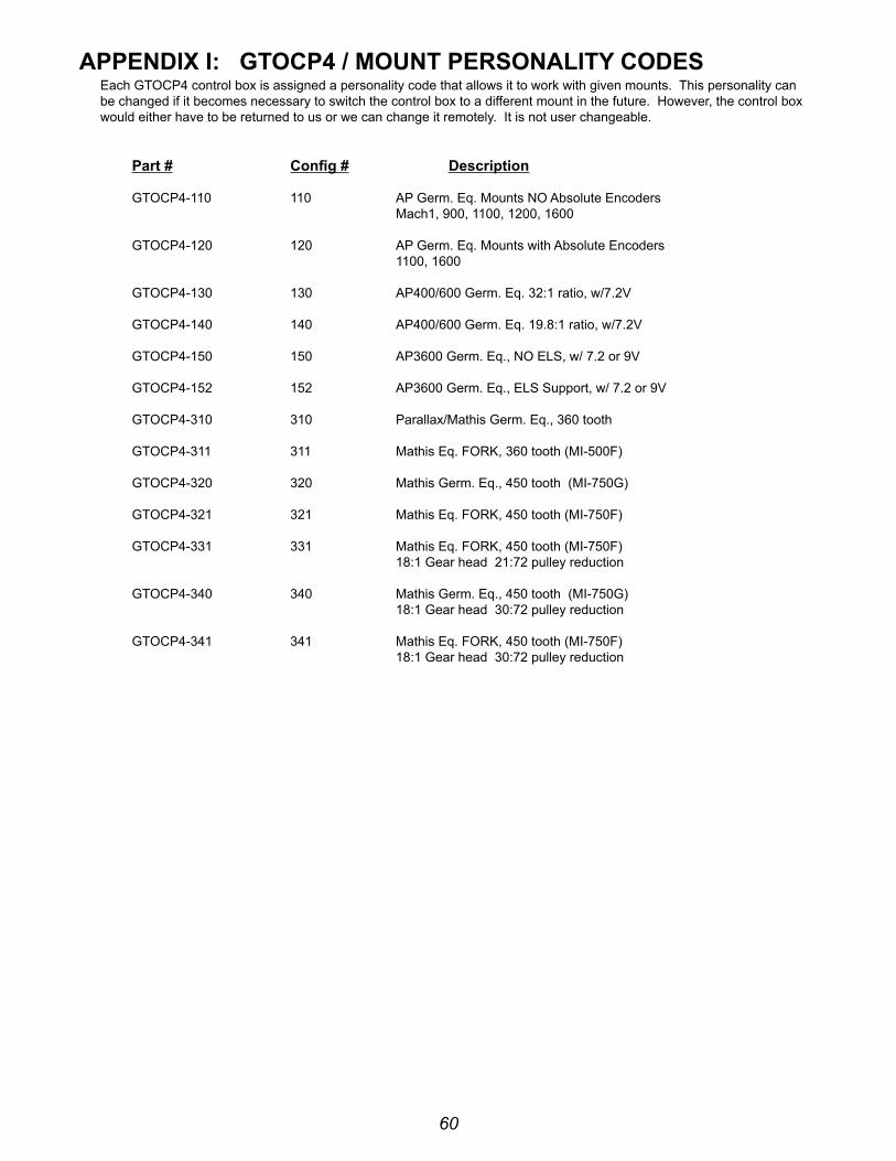
60
APPenDix i: GTOCP4 / MOunT PerSOnAliTy CODeSeach Gtocp4 control box is assigned a personality code that allows it to work with given mounts. this personality can be changed if it becomes necessary to switch the control box to a different mount in the future. however, the control box would either have to be returned to us or we can change it remotely. it is not user changeable.
Part # Config # Description
Gtocp4-110 110 Ap Germ. eq. Mounts no Absolute encoders Mach1, 900, 1100, 1200, 1600
Gtocp4-120 120 Ap Germ. eq. Mounts with Absolute encoders 1100, 1600
Gtocp4-130 130 Ap400/600 Germ. eq. 32:1 ratio, w/7.2v
Gtocp4-140 140 Ap400/600 Germ. eq. 19.8:1 ratio, w/7.2v
Gtocp4-150 150 Ap3600 Germ. eq., no els, w/ 7.2 or 9v
Gtocp4-152 152 Ap3600 Germ. eq., els support, w/ 7.2 or 9v
Gtocp4-310 310 parallax/Mathis Germ. eq., 360 tooth
Gtocp4-311 311 Mathis eq. forK, 360 tooth (Mi-500f)
Gtocp4-320 320 Mathis Germ. eq., 450 tooth (Mi-750G)
Gtocp4-321 321 Mathis eq. forK, 450 tooth (Mi-750f)
Gtocp4-331 331 Mathis eq. forK, 450 tooth (Mi-750f) 18:1 Gear head 21:72 pulley reduction
Gtocp4-340 340 Mathis Germ. eq., 450 tooth (Mi-750G) 18:1 Gear head 30:72 pulley reduction
Gtocp4-341 341 Mathis eq. forK, 450 tooth (Mi-750f) 18:1 Gear head 30:72 pulley reduction


![arXiv:2105.02330v1 [astro-ph.IM] 5 May 2021](https://static.fdokumen.com/doc/165x107/631d6d5985e2495e150f726f/arxiv210502330v1-astro-phim-5-may-2021.jpg)


![arXiv:2201.07771v1 [astro-ph.CO] 19 Jan 2022](https://static.fdokumen.com/doc/165x107/631c0c3db8a98572c10cb9b0/arxiv220107771v1-astro-phco-19-jan-2022.jpg)