MAN B&W G45ME-C9.5-GI
408
MAN B&W G45ME-C 9 .5 -GI IMO Tier ll Project Guide Introduction Contents
-
Upload
khangminh22 -
Category
Documents
-
view
0 -
download
0
Transcript of MAN B&W G45ME-C9.5-GI

MAN B&W G45ME-C9.5-GI
IMO Tier ll Project Guide
MAN
Energy Solutions Project G
uideM
AN B&W
G95M
E-C10.5
Introduction Contents

MAN B&W G45ME-C9.5-GI 199 00 96-8.4
MAN B&W G45ME-C9.5-GI-TII
Project Guide
Electronically ControlledDual Fuel Two-stroke Engines
This Project Guide is intended to provide the information necessary for the layout of a marine propulsion plant.
The information is to be considered as preliminary. It is intended for the project stage only and subject to modification in the interest of technical progress. The Project Guide provides the general technical data available at the date of issue.
It should be noted that all figures, values, measurements or information about performance stated in this project guide are for guidance only and should not be used for detailed design purposes or as a substi-tute for specific drawings and instructions prepared for such purposes.
Data updatesData not finally calculated at the time of issue is marked ‘Available on request’. Such data may be made available at a later date, however, for a specific project the data can be requested. Pages and table entries marked ‘Not applicable’ represent an option, function or selection which is not valid.
The latest and most current version of the individual Project Guide sections are available on the Internet at: m r e m e m → ’Two-Stroke’.
Extent of DeliveryThe final and binding design and outlines are to be supplied by our licensee, the engine maker, see Chap-ter 20 of this Project Guide.
In order to facilitate negotiations between the yard, the engine maker and the customer, a set of ‘Extent of Delivery’ forms is available in which the ‘Basic’ and the ‘Optional’ executions are specified.
Electronic versionsThis Project Guide book and the ‘Extent of Delivery’ forms are available on the Internet at:
m r e m e m → ’Two-Stroke’, where they can be downloaded.
Edition 1.0
December 2018
MAN Energy Solutions
MAN B&W
IMO Tier ll Project Guide
MAN
Energy Solutions ProjectG
uideM
AN B
&WG
95ME-C
10.5

MAN B&W G45ME-C9.5-GI 199 00 96-8.4
All data provided in this document is non-binding. This data serves informational purposes only and is espe-cially not guaranteed in any way.
Depending on the subsequent specific individual projects, the relevant data may be subject to changes and will be assessed and determined individually for each project. This will depend on the particular characteristics of each individual project, especially specific site and operational conditions.
If this document is delivered in another language than English and doubts arise concerning the translation, the English text shall prevail.
er S tTeglholmsgade 41DK�2450 Copenhagen SVDenmarkTelephone +45 33 85 11 00Telefax +45 33 85 10 30
p m e mm r e m e m
Copyright 2018 © er S t , branch of er S t SE, Germany, registered with the Danish Commerce and Companies Agency under CVR Nr.: 31611792, (herein referred to as “ er S t ”).
This document is the product and property of er S t and is protected by applicable copyright laws. Subject to modification in the interest of technical progress. Reproduction permitted provided source is given.7020-0188-04ppr December 2018
MAN Energy Solutions
MAN B&W
IMO Tier ll Project Guide
MAN
Energy Solutions ProjectG
uideM
AN B
&WG
95ME-C
10.5

MAN B&W
Introduction
Dear reader, this manual provides you with a number of convenient navigation features:
Scroll through the manual page-by-page
Use this button to navigate to the chapter menu
Use this button to navigate back to this page (Introduction page)
� MAN Energy Solutions website
� Marine Engine Programme
� Licensees
� CEAS Engine CalculationsCalculates basic data essential for the de- sign and dimensioning of a ship’s engineroom based on engine specification.
� DieselFactsMAN Energy Solutions customer magazinewith the news from the world’s leadingprovider of large-bore diesel engines andturbomachinery for marine and stationaryapplications.
� Extent of Delivery (EoD)
� Installation DrawingsDownload installation drawings for lowspeed engines in DXF and PDF formats.
� MAN Energy Solutions has a long tradition of producing technical papers on engine design and applications for licensees, ship-yards and engine operators.
� Service Letters
� Turbocharger SelectionCalculates available turbocharger(s) con-figuration based on engine specification.
� Two-stroke Applications
See also:
MAN Energy Solutions
Technical Papers
MAN B&W
IMO Tier ll Project Guide
MAN
Energy Solutions Project G
uideM
AN B&W
G95M
E-C10.5
MAN B&W
Engine Design ....................................................................... 1
Engine Layout and Load Diagrams, SFOC .............................. 2
Turbocharger Selection & Exhaust Gas Bypass ...................... 3
Electricity Production ............................................................ 4
Installation Aspects ............................................................... 5
List of Capacities: Pumps, Coolers & Exhaust Gas .................. 6
Fuel ...................................................................................... 7
Lubricating Oil ...................................................................... 8
Cylinder Lubrication .............................................................. 9
Piston Rod Stuffing Box Drain Oil .......................................... 10
Low-temperature Cooling Water ........................................... 11
High-temperature Cooling Water ........................................... 12
Starting and Control Air ......................................................... 13
Scavenge Air ......................................................................... 14
Exhaust Gas .......................................................................... 15
Engine Control System .......................................................... 16
Vibration Aspects .................................................................. 17
Monitoring Systems and Instrumentation .............................. 18
Dispatch Pattern, Testing, Spares and Tools ........................... 19
Project Support and Documentation ...................................... 20
Appendix .............................................................................. A
Contents
MAN Energy Solutions
MAN B&W
IMO Tier ll Project Guide
MAN
Energy Solutions Project G
uideM
AN B&W
G95M
E-C10.5

MAN B&W Contents
Chapter Section
MAN B&W G45ME-C9.5-GI
11.001.001.011.011.021.031.041.051.061.07
1990096-8.4 1985151-6.1 1988537-1.6 1990913-0.2
1983824-3.10 1990684-0.31984917-2.4 1985331-6.2 1990569-1.3 1990547-5.3
22.01 1990613-4.12.02 1990626-6.02.03 1990611-0.12.04 1990612-2.02.05 1990624-2.02.05 1990625-4.02.06 1990614-6.0
33.01 1989531-5.23.02 1984593-4.63.03 1988447-2.2
44.01 1985739-2.44.01 1986635-4.44.02 1990797-8.04.03 1985742-6.34.04 1984316-8.94.05 1986647-4.14.06 1988280-4.14.07 1988281-6.14.08 1990530-6.04.09 1988284-1.14.10 1988285-3.14.11 1990564-2.04.12 1990531-8.04.13 1990533-1.0
55.01 1984375-4.85.02 1990474-3.05.03 1990869-8.05.03 1990890-0.05.04 1990132-8.0
EngineDesignPrefaceTheME-GIDualfuelengineThefueloptimisedMETierIIengineTierIIfueloptimisationEnginetypedesignationPower,speed,SFOCEnginepowerrangeandfueloilconsumptionPerformancecurvesME-GIEnginedescriptionEnginecrosssection
EngineLayoutandLoadDiagrams,SFOCdot5EnginelayoutandloaddiagramsPropellerdiameterandpitch,influenceonoptimumpropellerspeedEnginelayoutandloaddiagramsDiagramforactualprojectSFOCreferenceconditionsandguaranteeDeratingforlowerSFOCFuelconsumptionatanarbitraryoperatingpoint
TurbochargerSelection&ExhaustGasBypassTurbochargerselectionExhaustgasbypassEmissioncontrol
ElectricityProductionElectricityproductionDesignationofPTOSpacerequirementforside-mountedgeneratorEnginepreparationsforPTOPTO/BWGCRWasteHeatRecoverySystems(WHRS)L16/24GenSetdataL21/31GenSetdataL23/30HMk2GenSetdataL27/38GenSetdataL28/32HGenSetdataGenSetdataL23/30DFGenSetdataL28/32DFGenSetdata
InstallationAspectsSpacerequirementsandoverhaulheightsSpacerequirementCranebeamforoverhaulofturbochargersCranebeamforoverhaulofaircooler,turbochargeronaftendEngineroomcraneOverhaulwithDouble-JibcraneDouble-Jib crane
5.04
1984534-8.41984541-9.25.04
MAN Energy Solutions
MAN B&W
IMO Tier ll Project Guide
MAN
Energy Solutions Project G
uideM
AN B&W
G95M
E-C10.5

MAN B&W Contents
Chapter Section
MAN B&W G45ME-C9.5-GI
5.055.065.075.085.095.105.115.125.135.145.155.165.165.165.175.185.185.18
1984715-8.3 1990135-3.0 1990322-2.3 1990844-6.0 1987890-9.0
1986670-0.12 1984176-5.13 1990563-0.0 1990483-8.1 1990562-9.1 1990626-2.1 1988538-3.4 1988706-1.1 1988273-3.31984929-2.4 1984695-3.6 1985320-8.3 1985322-1.5
66.01 1990408-6.16.02 1987463-3.16.03 1989391-2.16.04 1990432-4.26.04 1990421-6.1
77.00 1988881-9.47.01 1984228-2.87.01 1990899-7.07.01 1987661-0.77.01 1990355-7.27.02 1983880-4.77.03 1987668-3.27.04 1984051-8.37.04 1990485-1.07.05 1983951-2.107.06 1990463-5.07.07 1988637-7.57.08 1988638-9.27.09 1988639-0.4
88.01 1990740-3.08.01 1990367-7.18.02 1990487-5.18.02 1990486-3.18.03 1984232-8.68.04 1983886-5.138.05 1990776-3.0
Engine outline, galleries and pipe connections Engine and gallery outline Centre of gravity Water and oil in engine Engine pipe connectionsCounterflanges,ConnectionsDandEEngineseatingandholdingdownboltsEpoxychocksarrangementEnginetopbracingMechanicaltopbracingHydraulictopbracingarrangementComponentsforEngineControlSystemComponentsforEngineControlSystemComponentsforEngineControlSystemShaftlineearthingdeviceMANAlphaControllablePitch(CP)propellerHydraulicPowerUnitforMANAlphaCPpropellerMANAlphatronic2000PropulsionControlSystem
ListofCapacities:Pumps,Coolers&ExhaustGasCalculationofcapacitiesListofcapacitiesandcoolingwatersystemsListofcapcitiesG45ME-C9.5-GIAuxiliarymachinerycapacitiesCentrifugalpumpselection
FuelME-GIfuelgassystemPressurisedfueloilsystemFueloilsystemHeavyfueloiltankDrainofcontaminatedfueletc.FueloilsFueloilpipesanddrainpipesFueloilpipeinsulationFueloilpipeheattracingComponentsforfueloilsystemWaterinfuelemulsificationGassupplysystemFuelgassupplysystemsME-GIgassupplyauxiliarysystem
LubricatingOilLubricatingandcoolingoilsystemTurbochargerventinganddrainpipesHydraulicPowerSupplyunitHydraulicPowerSupplyunitandlubricatingoilpipesLubricatingoilpipesforturbochargersLubricatingoilconsumption,centrifugesandlistoflubricatingoilsComponentsforlubeoilsystemFlushingoflubricatingoilcomponentsandpipingsystem 8.05 1988026-6.0
MAN Energy Solutions
MAN B&W
IMO Tier ll Project Guide
MAN
Energy Solutions Project G
uideM
AN B&W
G95M
E-C10.5

MAN B&W Contents
Chapter Section
MAN B&W G45ME-C9.5-GI
Lubricatingoiloutlet 8.05 1987034-4.1Lubricatingoiltank 8.06 1990377-3.0Crankcaseventing 8.07 1987839-7.3Bedplatedrainpipes 8.07 1990488-7.0Engineandtankventingtotheoutsideair 8.07 1989182-7.0Hydraulicoilback-flushing 8.08 1984829-7.3Separatesystemforhydrauliccontrolunit 8.09 1984852-3.6Hydrauliccontroloilsystem 8.09 1990847-1.1
9 CylinderLubricationCylinderlubricatingoilsystem 9.01Listofcylinderoils,ACOS 9.01MANB&WAlphacylinderlubricationsystem 9.02AlphaAdaptiveCylinderOilControl(AlphaACC) 9.02Cylinderoilpipeheating 9.02Cylinderoilpipeheating,ACOM 9.02Electricheatingofcylinderoilpipes 9.02Cylinderlubricatingoilpipes 9.02Smallheatingboxwithfilter,suggestionfor 9.02
1988559-8.5 1990443-2.2
1983889-0.15 1990826-7.0 1990444-4.1 1990799-1.1 1990476-7.2 1990478-0.1 1987937-9.3
10 PistonRodStuffingBoxDrainOilStuffingboxdrainoilsystem 10.01 1983974-0.8
11 Low-temperatureCoolingWaterLow-temperaturecoolingwatersystem 11.01 1990392-7.4Centralcoolingwatersystem 11.02 1990550-9.2Componentsforcentralcoolingwatersystem 11.03 1990397-6.1Seawatercoolingsystem 11.04 1990398-8.2Componentsforseawatercoolingsystem 11.05 1990400-1.1Combinedcoolingwatersystem 11.06 1990471-8.2Componentsforcombinedcoolingwatersystem 11.07 1990473-1.1Coolingwaterpipesforscavengeaircooler 11.08 1990475-5.3
12 High-temperatureCoolingWaterHigh-temperaturecoolingwatersystem 12.01 1989252-3.3Componentsforhigh-temperaturecoolingwatersystem 12.02 1990402-5.1Deaeratingtank 12.02 1990574-9.0Preheatercomponents 12.02 1990566-6.1Freshwatergeneratorinstallation 12.02 1990610-9.0Jacketcoolingwaterpipes 12.03 1990583-3.0Gasvaporizationbyheatfromthejacketwater 12.04 1990746-4.0Gasvaporizationbyheatfromthejacketwater 12.04 1990836-3.0Componentsforhigh-temperaturecoolingwatersystemwithglycol 12.05 1990796-6.0heatexchangerforgasvaporzation
13 StartingandControlAirStartingandcontrolairsystems 13.01 1988971-8.5Componentsforstartingairsystem 13.02 1988974-3.3Startingandcontrolairpipes 13.03 1984000-4.9Exhaustvalveairspringpipes 13.03 1990793-0.0Electricmotorforturninggear 13.04 1990336-6.0
MAN Energy Solutions
MAN B&W
IMO Tier ll Project Guide
MAN
Energy Solutions Project G
uideM
AN B&W
G95M
E-C10.5

MAN B&W Contents
Chapter Section
MAN B&W G45ME-C9.5-GI
14 ScavengeAirScavengeairsystem 14.01 1986148-9.2Auxiliaryblowers 14.02 1990553-4.1Controloftheauxiliaryblowers 14.02 1988556-2.1Scavengeairpipes 14.03 1990380-7.1Electricmotorforauxiliaryblower 14.04 1990635-0.0Scavengeaircoolercleaningsystem 14.05 1987725-8.1Scavengeairboxdrainsystem 14.06 1987692-1.5Fireextinguishingsystemforscavengeairspace 14.07 1990149-7.2
15 ExhaustGasExhaustgassystem 15.01 1986400-5.4Exhaustgaspipes 15.02 1990558-3.0Cleaningsystems,waterandsoftblast 15.02 1987916-4.1Exhaustgassystemformainengine 15.03 1984074-6.3Componentsoftheexhaustgassystem 15.04 1984075-8.7Exhaustgassilencer 15.04 1990528-4.0Calculationofexhaustgasback-pressure 15.05 1984094-9.3Forcesandmomentsatturbocharger 15.06 1990053-7.0Diameterofexhaustgaspipe 15.07 1986504-8.2
16 EngineControlSystemEngineControlSystem-DualFuel 16.01 1988930-0.5EngineControlSystemME 16.01 1984847-6.10EngineControlSystemlayout 16.01 1987923-5.4Mechanical-hydraulicsystemwithHPS 16.01 1990910-5.0EngineControlSysteminterfacetosurroundingsystems 16.01 1988531-0.3Pneumaticmanoeuvringdiagram 16.01 1990555-8.0EngineControlSystem-GIextension 16.02 1988931-2.3GIextensioninterfacetoexternalsystems 16.02 1988658-1.3
17 VibrationAspectsVibrationaspects 17.01 1984140-5.32ndordermomentson4,5and6-cylinderengines 17.02 1986884-5.61stordermomentson4-cylinderengines 17.02 1983925-0.5Electricallydrivenmomentcompensator 17.03 1986978-1.2PowerRelatedUnbalance(PRU) 17.04 1990116-2.0Guideforcemoments 17.05 1984223-3.5Guideforcemoments,data 17.05 1990534-3.1Vibrationlimitsvalidforsingleorderharmonics 17.05 1988264-9.0Axialvibrations 17.06 1984224-5.5Criticalrunning 17.06 1984226-9.6Externalforcesandmomentsinlayoutpoint 17.07 1990115-0.1
18 MonitoringSystemsandInstrumentation18.01 1988529-9.318.02 1990599-0.018.03 1984582-6.918.04 1987040-3.4
MonitoringsystemsandinstrumentationEngineManagementServicesCoCoS-EDSsystemsAlarm-slowdownandshutdownsystemClassandMANEnergy Solutionsrequirements 18.04 1984583-8.16
MAN Energy Solutions
MAN B&W
IMO Tier ll Project Guide
MAN
Energy Solutions Project G
uideM
AN B&W
G95M
E-C10.5
MAN B&W Contents
Chapter Section
MAN B&W G45ME-C9.5-GI
Localinstruments 18.05Otheralarmfunctions 18.06Bearingmonitoringsystems 18.06LDCLcoolingwatermonitoringsystem 18.06Turbochargeroverspeedprotection 18.06Controldevices 18.06Identificationofinstruments 18.07ME-GIsafetyaspects 18.08
1984586-3.13 1984587-5.21 1986726-5.101990197-5.4 1990457-6.2 1986728-9.8 1984585-1.6 1985060-7.5
19 DispatchPattern,Testing,SparesandToolsDispatchpattern,testing,sparesandtools 19.01 1987620-3.2Specificationforpaintingofmainengine 19.02 1984516-9.7Dispatchpattern 19.03 1990147-3.1Dispatchpattern,listofmassesanddimensions 19.04 1984763-6.0Shoptest 19.05 1988737-2.1Listofspareparts,unrestrictedservice 19.06 1990596-5.4Additionalspares 19.07 1990598-9.2Largespareparts,dimensionsandmasses 19.09 1991072-2.0Rotorforturbocharger 19.09 1990189-2.1Listofstandardtoolsformaintenance 19.10 1990110-1.0Toolspanels 19.11 1986645-0.0
20 ProjectSupportandDocumentationProjectsupportanddocumentation 20.01 1984588-7.5Installationdataapplication 20.02 1984590-9.3ExtentofDelivery 20.03 1984591-0.7Installationdocumentation 20.04 1984592-2.5ME-GIinstallationdocumentation 20.05 1988683-1.1
A AppendixSymbolsforpiping A 1983866-2.5
MAN Energy Solutions
MAN B&W
IMO Tier ll Project Guide
MAN
Energy Solutions Project G
uideM
AN B&W
G95M
E-C10.5
MAN B&W
Engine Design
1MAN Energy Solutions
MAN B&W
IMO Tier ll Project Guide
MAN
Energy Solutions Project G
uideM
AN B
&W G
95ME-C
10.5

MAN B&W 1.00Page 1 of 2
MAN B&W ME-GI engines 198 91 51-6.1
The ME�GI Dual Fuel Engine
ME-GI vs ME engine design
Although few technical differences separate fuel oil and gas burning engines, the ME-GI engine pro-vides optimal fuel flexibility. Fig. 1.00.01 shows the components that are modified and added to the engine, allowing it to operate on gas.
The new units are:
• A chain pipe gas supply system for high-pres-sure gas distribution to a gas control block oneach cylinder
• Leakage detection and ventilation system forventing the space between the inner and outerpipe of the double-wall piping and detectingleakages. Inlet air is taken from a non-hazardousarea and exhausted to outside the engine room
• Sealing oil system, delivering sealing oil to thegas valves separating control oil and gas. Fullyintegrated on the engine, the shipyard does notneed to consider this installation
• Inert gas system that enables purging of the gassystem on the engine with inert gas
The development in gas and fuel oil prices in combination with the emission control regulations, has created a need for dual fuel engines.
The ME-GI engine is designed as an add-on to the MAN B&W two-stroke ME engine technology. It allows the engine to run on either heavy fuel oil (HFO) or liquid natural gas (LNG).
ME-GI injection system
Dual fuel operation requires the injection of first pilot fuel (to start the combustion) and then gas fuel into the combustion chamber.
Different types of valves are used for the injection of gas and pilot fuel. The auxiliary media required for both fuel and gas operation is:
• High-pressure gas
• Fuel oil (pilot oil by existing ME fuel oil system)
• Control oil for actuation of gas injection valves
• Sealing oil to separate gas and control oil.
Fig. 1.00.01: Gas module with chain pipes, gas control block and fuel gas double-wall high-pressure pipes
178 65 95�1.0
MAN Energy Solutions
MAN B&W
IMO Tier ll Project Guide
MAN
Energy Solutions Project G
uideM
AN B
&W G
95ME-C
10.5

MAN B&W 1.00Page 2 of 2
MAN B&W ME-GI engines 198 91 51-6.1
• Control and safety system, comprisinga hydrocarbon analyser for checking thehydrocarbon content of the air in the double-wall gas pipes.
Engine operating modes
One main advantage of the ME-GI engine is its fuel flexibility. The control concept comprises three different fuel modes, see Fig. 1.00.02:
• gas operation with minimum pilot oil amount
• specified dual fuel operation (SDF) with injectionof a fixed gas amount
• fuel-oil-only mode.
Gas operation mode is used for gas operation. It can only be started manually by an operator on the Main Operating Panel (MOP) in the control room. The minimum preset amount of pilot fuel oil is as little as 3% at SMCR.
Specified dual fuel operation (SDF) mode gives the operator full fuel flexibility and the option to inject a fixed amount of gas fuel. The ME control system adds fuel oil until the required engine load is reached.
Fuel-oil-only mode is known from the ME engine. Operating the engine in this mode can only be done on fuel oil. In this mode, the engine is con-sidered ‘gas safe’. If a failure in the gas system occurs, it results in a gas shutdown and a return to the fuel-oil only mode.
Fuel gas is also referred to as ‘second fuel’ and low-flashpoint fuel (LFF) in this project guide.
Safety
The ME-GI control and safety system is designed to fail to safe condition. All failures detected dur-ing gas fuel running result in a gas fuel stop and a change-over to fuel oil operation. This condition applies also to failures of the control system itself.
Following the change-over, the high-pressure gas pipes and the complete gas supply system are blown-out and freed from gas by purging.
The change-over to fuel oil mode is always done without any power loss of the engine.
Fuel gas supply systems
Different applications call for different gas supply systems, and operators and shipowners demand alternative solutions.
Therefore, MAN Energy Solutions aims to have a number of different gas supply systems prepared, tested and available. Examples of fuel gas supply systems are presented in Section 7.08.
Fig. 1.00.02: Fuel type modes for the ME-GI engines for LNG carriers
0 10 20 30 40 50Engine load (%SMCR)
% F
uel
% F
uel
60 70 80 90 100
100%90%80%70%60%50%40%30%20%10%0%
0 10 20 30 40 50Engine load (%SMCR)
60 70 80 90 100
100%90%80%70%60%50%40%30%20%10%0%
Gas operation mode
Specified dual fuel operation mode
% Total% Pilot
% Total% Pilot
178 65 96�3.1
MAN Energy Solutions
MAN B&W
IMO Tier ll Project Guide
MAN
Energy Solutions Project G
uideM
AN B
&W G
95ME-C
10.5

MAN B&W 1.01Page 1 of 2
198 85 37-1.6MAN B&W 98ME/ME-C7-TII .1,95-40ME-C/-GI-TII .7/.6/.5/.4/.2 engines
In the hydraulic system, the normal lube oil is used as the medium. It is filtered and pressurised by a hydraulic power supply unit mounted on the en-gine or placed in the engine room.
The starting valves are opened pneumatically by electronically controlled ‘On/Off’ valves, which make it possible to dispense with the mechani-cally activated starting air distributor.
By electronic control of the fuel injection and ex-haust valves according to the measured instan-taneous crankshaft position, the Engine Control System fully controls the combustion process.
System flexibility is obtained by means of different ‘Engine running modes’, which are selected either automatically, depending on the operating condi-tions, or manually by the operator to meet specific goals. The basic running mode is ‘Fuel economy mode’ to comply with IMO NOx emission limita-tion.
Engine design and IMO regulation compliance
The ME-C engine is the shorter, more compact version of the ME engine. It is well suited wherever a small engine room is requested, for instance in container vessels.
For MAN B&W ME/ME-C-TII designated engines, the design and performance parameters comply with the International Maritime Organisation (IMO) Tier II emission regulations.
For engines built to comply with IMO Tier I emis-sion regulations, please refer to the Marine Engine IMO Tier I Project Guide.
The Fuel Optimised ME Tier II Engine
The ever valid requirement of ship operators is to obtain the lowest total operational costs, and especially the lowest possible specific fuel oil consumption at any load, and under the prevailing operating conditions.
However, low�speed two�stroke main engines of the MC-C type, with a chain driven camshaft, have limited flexibility with regard to fuel injection and exhaust valve activation, which are the two most important factors in adjusting the engine to match the prevailing operating conditions.
A system with electronically controlled hydraulic activation provides the required flexibility, and such systems form the core of the ME Engine Control System, described later in detail in Chap-ter 16.
Concept of the ME engine
The ME engine concept consists of a hydraulic-mechanical system for activation of the fuel injec-tion and the exhaust valves. The actuators are electronically controlled by a number of control units forming the complete engine control system.
MAN Energy Solutions has specifically developed both the hardware and the software in�house, in order to obtain an integrated solution for the en-gine control system.
The fuel pressure booster consists of a simple plunger powered by a hydraulic piston activated by oil pressure. The oil pressure is controlled by an electronically controlled proportional valve.
The exhaust valve is opened hydraulically by means of a two�stage exhaust valve actuator activated by the control oil from an electronically controlled proportional valve. The exhaust valves are closed by the ‘air spring’.
MAN Energy Solutions
MAN B&W
IMO Tier ll Project Guide
MAN
Energy Solutions Project G
uideM
AN B
&W G
95ME-C
10.5

MAN B&W 1.01Page 2 of 2
199 09 13-0.2MAN B&W ME-C-GI/ME-B-GI TII engines .6/.5
Tier II fuel optimisation
NOx regulations place a limit on the SFOC on two-stroke engines. In general, NOx emissions will increase if SFOC is decreased and vice versa. In the standard configuration, MAN B&W engines are optimised close to the IMO NOx limit and, there-fore, NOx emissions cannot be further increased.
The IMO NOx limit is given as a weighted aver-age of the NOx emission at 25, 50, 75 and 100% load. This relationship can be utilised to tilt the SFOC profile over the load range. This means that SFOC can be reduced at part- or low-load at the expense of a higher SFOC in the high-load range without exceeding the IMO NOx limit.
Optimisation of SFOC in the part-load (50-85%) or low-load (25-70%) range requires implementation of the exhaust gas bypass (EGB) tuning method. This tuning method makes it possible to optimise the fuel consumption at part- or low-load, while maintaining the possibility of operating at high load when needed.
The tuning method is available for all SMCR in the specific engine layout diagram. The SFOC reduc-tion potential of the EGB tuning method in part- and low-load is shown in Section 1.03.
For S40ME-B/GI and smaller, as well as for engine types 45 and larger with conventional turbocharg-ers, only high-load optimisation is applicable.
In this project guide, data is based on high-load optimisation unless explicitly noted. For derated engines, calculations can be made in the CEAS application described in Section 20.02.
Improved fuel consumption on gas fuel
In the ME-GI concept, NOx is reduced substan-tially on gas fuel compared to diesel/HFO opera-tion. As much as possible of this NOx margin is exchanged for improved SFOC, while not exceed-ing the E3 NOx cycle value for the diesel reference case. (Referring to the international standard for exhaust emission measurement ISO 8178). This SFOC optimisation is available in the entire load range.
Calculations of SFOC can be made in the CEAS application for engines with and without EGB tun-ing installed.
MAN Energy Solutions
MAN B&W
IMO Tier ll Project Guide
MAN
Energy Solutions Project G
uideM
AN B
&W G
95ME-C
10.5

MAN B&W engines 198 38 24-3.10
MAN B&W 1.02Page 1 of 1
Engine Type Designation
6 G 95 M E �C 9 .5 -GI -TII
Engine programme
Diameter of piston in cm
G ‘Green’ Ultra long stroke
S Super long stroke
L Long stroke
K Short stroke
Stroke/bore ratio
Number of cylinders
Concept E Electronically controlled
C Camshaft controlled
Fuel injection concept(blank) Fuel oil onlyGI Gas injectionLGI Liquid Gas Injection
Emission regulation TII IMO Tier level
Design
C Compact engine
B Exhaust valve controlledby camshaft
Mark number
Version number
MAN Energy Solutions
MAN B&W
IMO Tier ll Project Guide
MAN
Energy Solutions Project G
uideM
AN B
&W G
95ME-C
10.5
MAN B&W 1.03Page 1 of 1
199 06 84-0.3MAN B&W G45ME-C9.5-GI-TII MAN Energy Solutions
Power, Speed and Fuel Oil
MAN B&W G45ME-C9.5-GI-Tll
kW/cyl.
r/min
L2
L1
87 111
1,390
1,090 1,045
820
L3
L4
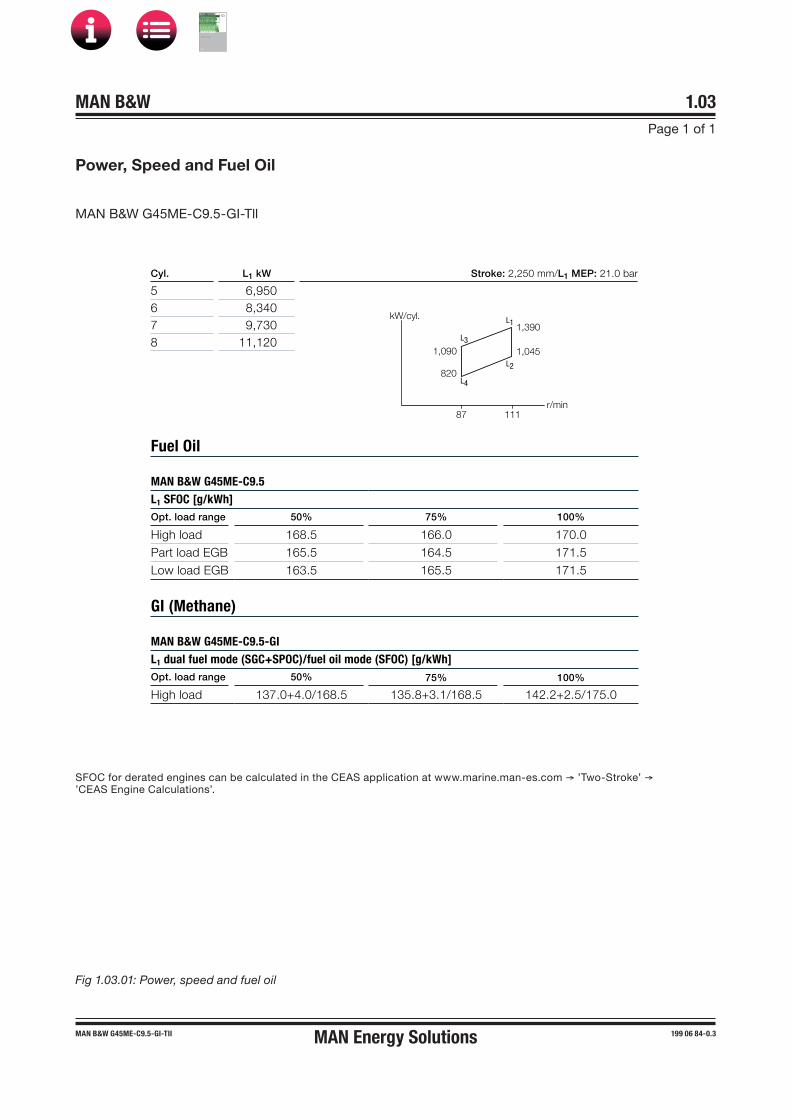
Cyl. L1 kW Stroke: 2,250 mm/L1 MEP: 21.0 bar
5 6,9506 8,3407 9,7308 11,120
MAN B&W G45ME-C9.5
L1
Opt. load range 50% 75% 100%
High load 168.5 166.0 170.0 Part load EGB 165.5 164.5 171.5 Low load EGB 163.5 165.5 171.5
GI (Methane)
MAN B&W G45ME-C9.5-GI
L1
Opt. load range 50% 75% 100%
High load 137.0+4.0/168.5 135.8+3.1/168.5 142.2+2.5/175.0
SFOC for derated engines can be calculated in the CEAS application at www.marine.man-es.com → ’Two-Stroke’ → ’CEAS Engine Calculations’.
Fig 1.03.01: Power, speed and fuel oil
MAN B&W
IMO Tier ll Project Guide
MAN
Energy Solutions Project G
uideM
AN B
&W G
95ME-C
10.5

MAN B&W 1.04Page 1 of 2
MAN B&W ME-GI engines 198 49 17-2.4
Engine Power Range and Fuel Oil Consumption
Power
Speed
L3
L4
L2
L1
Specific Fuel Oil Consumption (SFOC)
The figures given in this folder represent the val-ues obtained when the engine and turbocharger are matched with a view to obtaining the lowest possible SFOC values while also fulfilling the IMO NOX Tier II emission limitations.
Stricter emission limits can be met on request, us-ing proven technologies.
The SFOC figures are given in g/kWh with a toler-ance of 5% and are based on the use of fuel with a lower calorific value of 42,700 kJ/kg (~10,200 kcal/kg) at ISO conditions:Ambient air pressure .............................1,000 mbar Ambient air temperature ................................ 25 °C Cooling water temperature ............................ 25 °C
Specific fuel oil consumption varies with ambient conditions and fuel oil lower calorific value. For calculation of these changes, see Chapter 2.
Gas consumption
The energy consumption (heat rate) for the �GI engine is lower when running on gas in dual fuel mode (heat rate in kJ/kWh) compared to fuel only mode.
When a given amount of oil is known in g/kWh, and after deducting the pilot fuel oil the additional gas consumption can be found by converting the energy supplied as gas into cubic metre per hour according to the LCV of the gas.
In the following sections, the energy consumption is calculated as related equivalent fuel consump-tion, i.e. with all our usual figures.
Example:
Related equivalent SFOC og gas .......... 169 g/kWhRef. LCV .................................................. 42,700 kJHeat rate .................0.169 x 42,700 = 7,216 kJ/kWh
The heat rate is also referred to as the ‘Guiding Equivalent Energy Consumption’.
Engine Power
The following tables contain data regarding the power, speed and specific fuel oil consumption of the engine.
Engine power is specified in kW for each cylinder number and layout points L1, L2, L3 and L4:
For conversions between kW and metric horsepow-er, please note that 1 BHP = 75 kpm/s = 0.7355 kW.
L1 designates nominal maximum continuous rating (nominal MCR), at 100% engine power and 100% engine speed.
L2, L3 and L4 designate layout points at the other three corners of the layout area, chosen for easy reference.
Fig. 1.04.01: Layout diagram for engine power and speed
Overload corresponds to 110% of the power at MCR, and may be permitted for a limited period of one hour every 12 hours.
The engine power figures given in the tables re-main valid up to tropical conditions at sea level as stated in IACS M28 (1978), i.e.:
Blower inlet temperature ................................ 45 °CBlower inlet pressure ............................1,000 mbarSeawater temperature .................................... 32 °CRelative humidity ..............................................60%
178 51 48�9.0
MAN Energy Solutions
MAN B&W
IMO Tier ll Project Guide
MAN
Energy Solutions Project G
uideM
AN B
&W G
95ME-C
10.5

MAN B&W 1.04Page 2 of 2
MAN B&W ME-GI engines 198 49 17-2.4
Lubricating oil data
The cylinder oil consumption figures stated in the tables are valid under normal conditions.
During running�in periods and under special condi-tions, feed rates can be increased. This is explained in Section 9.02.
MAN Energy Solutions
MAN B&W
IMO Tier ll Project Guide
MAN
Energy Solutions Project G
uideM
AN B
&W G
95ME-C
10.5

MAN B&W Page 1 of 1
198 53 31-6.2MAN B&W MC/MC-C, ME/ME-C/ME�B/�GI engines
Performance Curves
1.05
Updated engine and capacities data is available from the CEAS program on www.marine.man-es.com → ’Two-Stroke’ → ’CEAS EngineCalculations’.
MAN Energy Solutions
MAN B&W
IMO Tier ll Project Guide
MAN
Energy Solutions Project G
uideM
AN B
&W G
95ME-C
10.5

MAN B&W 1.06Page 1 of 7
199 05 69-1.3MAN B&W 50-40ME-C9.5-GI TII
Frame Box
The frame box is of welded design. On the ex-haust side, it is provided with relief valves for each cylinder while, on the manoeuvring side, it is pro-vided with a large hinged door for each cylinder. The crosshead guides are welded on to the frame box.
The framebox is of the well-proven triangular guide-plane design with twin staybolts giving ex-cellent support for the guide shoe forces.
Cylinder Frame and Stuffing Box
For the cylinder frame, two possibilities are avail-able:
• Nodular cast iron• Welded design with integrated scavenge air
receiver.
The cylinder frame is provided with access covers for cleaning the scavenge air space, if required, and for inspection of scavenge ports and piston rings from the manoeuvring side. Together with the cylinder liner it forms the scavenge air space.
The cylinder frame is fitted with pipes for the pis-ton cooling oil inlet. The scavenge air receiver, tur-bocharger, air cooler box and gallery brackets are located on the cylinder frame. At the bottom of the cylinder frame there is a piston rod stuffing box, provided with sealing rings for scavenge air, and with oil scraper rings which prevent crankcase oil from coming up into the scavenge air space.
Drains from the scavenge air space and the piston rod stuffing box are located at the bottom of the cylinder frame.
ME-GI Engine Description
Please note that engines built by our licensees are in accordance with MAN Energy Solutions drawings and standards but, in certain cases, some local standards may be applied; however, all spare parts are interchangeable with MAN Energy Solutions de-signed parts.
Some components may differ from MAN Energy Solutions' design because of local production facili-ties or the application of local standard compo-nents.
In the following, reference is made to the item numbers specified in the ‘Extent of Delivery’ (EoD) forms, both for the ‘Basic’ delivery extent and for some ‘Options’.
Bedplate and Main Bearing
The bedplate is made with the thrust bearing in the aft end of the engine. The bedplate consists of
high, welded, longitudinal girders and welded cross girders with cast steel bearing supports.
For fitting to the engine seating in the ship, long, elastic holding�down bolts, and hydraulic tighten-ing tools are used.
The bedplate is made without taper for engines mounted on epoxy chocks.
The oil pan, which is made of steel plate and is welded to the bedplate, collects the return oil from the forced lubricating and cooling oil system. The oil outlets from the oil pan are vertical as standard and provided with gratings.
The main bearings consist of thin walled steel shells lined with bearing metal. The main bearing bottom shell can be rotated out and in by means of special tools in combination with hydraulic tools for lifting the crankshaft. The shells are kept in po-sition by a bearing cap.
MAN Energy Solutions
MAN B&W
IMO Tier ll Project Guide
MAN
Energy Solutions Project G
uideM
AN B
&W G
95ME-C
10.5

MAN B&W 1.06Page 2 of 7
MAN B&W 50-40ME-C9.5-GI TI 199 05 69-1.3
Cylinder Liner
The cylinder liner is made of alloyed cast iron and is suspended in the cylinder frame. The top of the cylinder liner is fitted with a cooling jacket. The cylinder liner has scavenge ports and drilled holes for cylinder lubrication.
Cylinder liners prepared for installation of temper-ature sensors are available as an option.
Cylinder Cover
The cylinder cover is of forged steel, made in one piece, and has bores for cooling water. It has a central bore for the exhaust valve, and bores for the fuel valves, gas valves, a starting valve and an indicator valve.
The side of the cylinder cover facing the hydraulic cylinder unit (HCU) block has a face for mounting a special valve block, the Gas Control Block, see later description.
In addition, the cylinder cover is provided with one set of bores for supplying gas from the gas con-trol block to each gas injection valve. The bore for PMI Auto-tuning is the same as the bore for the indicator valve.
Crankshaft
The crankshaft is of the semi�built type, made from forged or cast steel throws. For engines with 9 cylinders or more, the crankshaft is supplied in two parts.
At the aft end, the crankshaft is provided with the collar for the thrust bearing, a flange for fitting the gear wheel for the step�up gear to the hydraulic power supply unit (if fitted on the engine), the flange for the turning wheel and for the coupling bolts to an intermediate shaft.
At the front end, the crankshaft is fitted with the collar for the axial vibration damper and a flange for the fitting of a tuning wheel. The flange can also be used for a power take off, if so desired.
Coupling bolts and nuts for joining the crankshaft together with the intermediate shaft are not nor-mally supplied.
Thrust Bearing
The propeller thrust is transferred through the thrust collar, the segments, and the bedplate, to the end chocks and engine seating, and thus to the ship’s hull.
The thrust bearing is located in the aft end of the engine. The thrust bearing is of the B&W�Michell type, and consists primarily of a thrust collar on the crankshaft, a bearing support, and segments of steel lined with white metal.
Engines with 9 cylinders or more will be specified with the 360º degree type thrust bearing, while the 240º degree type is used in all other engines. MAN Energy Solutions' flexible thrust cam design is used for the thrust collar on a range of engine types.
The thrust shaft is an integrated part of the crank-shaft and it is lubricated by the engine’s lubricat-ing oil system.
Step�up Gear
In case of mechanically, engine driven hydraulic power supply, the main hydraulic oil pumps are driven from the crankshaft via a step�up gear. The step�up gear is lubricated from the main engine system.
Turning Gear and Turning Wheel
The turning wheel is fitted to the thrust shaft, and it is driven by a pinion on the terminal shaft of the turning gear, which is mounted on the bedplate. The turning gear is driven by an electric motor with built�in brake.
A blocking device prevents the main engine from starting when the turning gear is engaged. En-gagement and disengagement of the turning gear is effected manually by an axial movement of the pinion.
MAN Energy Solutions
MAN B&W
IMO Tier ll Project Guide
MAN
Energy Solutions Project G
uideM
AN B
&W G
95ME-C
10.5
MAN B&W 1.06Page 3 of 7
199 05 69-1.3MAN B&W 50-40ME-C9.5-GI TII
The control device for the turning gear, consisting of starter and manual control box, is included in the basic design.
Axial Vibration Damper
The engine is fitted with an axial vibration damper, mounted on the fore end of the crankshaft. The damper consists of a piston and a split�type hous-ing located forward of the foremost main bearing.
The piston is made as an integrated collar on the main crank journal, and the housing is fixed to the main bearing support.
For functional check of the vibration damper a mechanical guide is fitted, while an electronic vi-bration monitor can be supplied as an option.
An axial vibration monitor with indication for con-dition check of the axial vibration damper and terminals for alarm and slow down is required for engines Mk 9 and higher.
Tuning Wheel / Torsional Vibration Damper
A tuning wheel or torsional vibration damper may have to be ordered separately, depending on the final torsional vibration calculations.
Connecting Rod
The connecting rod is made of forged or cast steel and provided with bearing caps for the crosshead and crankpin bearings.
The crosshead and crankpin bearing caps are secured to the connecting rod with studs and nuts tightened by means of hydraulic jacks.
The crosshead bearing consists of a set of thin�walled steel shells, lined with bearing metal. The crosshead bearing cap is in one piece, with an angular cut�out for the piston rod.
The crankpin bearing is provided with thin�walled steel shells, lined with bearing metal. Lube oil is supplied through ducts in the crosshead and con-necting rod.
Piston
The piston consists of a piston crown and piston skirt. The piston crown is made of heat�resistant steel. A piston cleaning ring located in the very top of the cylinder liner scrapes off excessive ash and carbon formations on the piston topland.
The piston has four ring grooves which are hard�chrome plated on both the upper and lower surfaces of the grooves.
The uppermost piston ring is of the CPR type (Controlled Pressure Relief), whereas the other three piston rings all have an oblique cut. The up-permost piston ring is higher than the others. All four rings are alu-coated on the outer surface for running-in.
The piston skirt is made of cast iron with a bronze band or Mo coating.
Piston Rod
The piston rod is of forged steel and is surface-hardened on the running surface for the stuffing box. The piston rod is connected to the crosshead with four bolts. The piston rod has a central bore which, in conjunction with a cooling oil pipe, forms the inlet and outlet for cooling oil.
Crosshead
The crosshead is of forged steel and is provided with cast steel guide shoes with white metal on the running surface.
The guide shoe is of the low friction type and crosshead bearings of the wide pad design.
The telescopic pipe for oil inlet and the pipe for oil outlet are mounted on the guide shoes.
MAN Energy Solutions
MAN B&W
IMO Tier ll Project Guide
MAN
Energy Solutions Project G
uideM
AN B
&W G
95ME-C
10.5

MAN B&W 1.06Page 4 of 7
MAN B&W 50-40ME-C9.5-GI TI 199 05 69-1.3
Scavenge Air System
The air intake to the turbocharger takes place directly from the engine room through the turbo-charger intake silencer. From the turbocharger, the air is led via the charging air pipe, air cooler and scavenge air receiver to the scavenge ports of the cylinder liners, see Chapter 14. The scav-enge air receiver is of the D-shape design.
Scavenge Air Cooler
For each turbocharger a scavenge air cooler of the mono-block type is fitted.
The scavenge air cooler is most commonly cooled by freshwater from a central cooling system. Alter-natively, it can be cooled by seawater from either a seawater cooling system or a combined cooling system with separate seawater and freshwater pumps. The working pressure is up to 4.5 bar.
The scavenge air cooler is so designed that the difference between the scavenge air temperature and the water inlet temperature at specified MCR can be kept at about 12 °C.
Auxiliary Blower
The engine is provided with electrically�driven scavenge air blowers integrated in the scavenge air cooler. The suction side of the blowers is con-nected to the scavenge air space after the air cooler.
Between the air cooler and the scavenge air re-ceiver, non�return valves are fitted which auto-matically close when the auxiliary blowers supply the air.
The auxiliary blowers will start operating con-secutively before the engine is started in order to ensure sufficient scavenge air pressure to obtain a safe start.
Further information is given in Chapter 14.
Exhaust Gas System
From the exhaust valves, exhaust gas is led to the exhaust gas receiver where the fluctuating pressure from the individual cylinders is equal-ised, and the total volume of gas is led to the turbocharger(s). After the turbocharger(s), the gas is led to the external exhaust pipe system.
Compensators are fitted between the exhaust valves and the receiver, and between the receiver and the turbocharger(s).
The exhaust gas receiver and exhaust pipes are provided with insulation, covered by galvanised steel plating.
A protective grating is installed between the ex-haust gas receiver and the turbocharger.
Exhaust Turbocharger
The engines can be fitted with either MAN, ABB or MHI turbochargers.
The turbocharger selection is described in Chap-ter 3, and the exhaust gas system in Chapter 15.
Reversing
Reversing of the engine is performed electroni-cally and controlled by the engine control system, by changing the timing of the fuel injection, the exhaust valve activation and the starting valves.
2nd Order Moment Compensators
A 2nd order moment compensator is in general relevant only for 5 or 6-cylinder engines type 50 and 45. When needed, an external electrically driven moment compensator type RotComp or similar can be installed in the steering room.
The 2nd order moment compensators as well as the basic design and options are described in Section 17.02.
MAN Energy Solutions
MAN B&W
IMO Tier ll Project Guide
MAN
Energy Solutions Project G
uideM
AN B
&W G
95ME-C
10.5

MAN B&W 1.06Page 5 of 7
199 05 69-1.3MAN B&W 50-40ME-C9.5-GI TII
The Hydraulic Power Supply
The Hydraulic Power Supply (HPS) filters and pressurises the lube oil for use in the hydraulic system. The HPS consists of either mechanically driven (by the engine) main pumps with electrically driven start-up pumps or electrically driven com-bined main and start-up pumps. The hydraulic pressure varies up to max 300 bar.
The mechanically driven HPS is engine driven and mounted aft for engines with chain drive aft (8 cyl-inders or less), and at the middle for engines with chain drive located in the middle (9 cylinders or more). An electrically driven HPS is usually mount-ed aft on the engine.
A combined HPS, mechanically driven with elec-trically driven start-up/back-up pumps with back-up capacity, is available as an option.
Hydraulic Cylinder Unit
The hydraulic cylinder unit (HCU), one per cylin-der, consists of a base plate on which a distributor block is mounted. The distributor block is fitted with a number of accumulators to ensure that the necessary hydraulic oil peak flow is available for the electronically controlled fuel injection.
The distributor block serves as a mechanical support for the hydraulically activated fuel oil pressure booster and the hydraulically activated exhaust valve actuator.
Fuel Oil Pressure Booster andFuel Oil High Pressure Pipes
The engine is provided with one hydraulically acti-vated fuel oil pressure booster for each cylinder.
Injection of fuel oil (pilot oil) is activated by a multi-way valve (ELFI or FIVA) while injection of fuel gas is activated by the ELGI valve. Both valves are electronically controlled by the Cylinder Control Unit (CCU) of the engine control system.
The fuel oil high�pressure pipes are of the double-wall type with built-in conical support. The pipes are insulated but not heated.
Further information is given in Section 7.01.
Gas Pipes
A chain pipe system is fitted for high-pressure gas distribution to each adapter block. The chain pipes are connected to the gas control block via the adapter block.
Gas pipes are designed with double walls, with the outer shielding pipe designed so as to prevent gas outflow to the machinery spaces in the event of leaking or rupture of the inner gas pipe.
The intervening gas pipe space, including also the space around valves, flanges, etc., is vented by separate mechanical ventilation with a capacity of 30 air changes per hour. Any leakage gas will be led to the ventilated part of the double-wall piping system and will be detected by HC sensors.
The pressure in the intervening space is kept be-low that of the engine room. The extractor fan mo-tor is placed outside the duct and the machinery space. The ventilation inlet air must be taken from a gas safe area and exhausted to a safe place.
The gas pipes on the engine are designed for and pressure tested at 50% higher pressure than the normal working pressure, and are supported so as to avoid mechanical vibrations. The gas pipes should furthermore be protected against drops of heavy items.
The chain piping to the individual cylinders are flexible enough to cope with the mechanical stress from the thermal expansion of the engine from cold to hot condition. The chain pipes are connect-ed to the gas control blocks by means of adapter blocks.
The gas pipe system is designed so as to avoid excessive gas pressure fluctuations during opera-tion.
The gas pipes are to be connected to an inert gas purging system.
MAN Energy Solutions
MAN B&W
IMO Tier ll Project Guide
MAN
Energy Solutions Project G
uideM
AN B
&W G
95ME-C
10.5
MAN B&W 1.06Page 6 of 7
MAN B&W 50-40ME-C9.5-GI TI 199 05 69-1.3
Gas Control Block
The gas control block consists of a square steel block, bolted to the HCU side of the cylinder cover.
The gas control block incorporates a large volume accumulator and is provided with a window/shut-down valve, a purge valve and a blow-off valve. All high-pressure gas sealings lead into spaces that are connected to the double-wall pipe system, for leakage detection.
Minute volumes around the gas injection valves in the cylinder cover are kept under vacuum from the venting air in the double-wall gas pipes.
Internal bores connect the hydraulic oil, sealing oil and the gas to the various valves. A non-return valve is positioned at the gas inlet to the gas ac-cumulator, in order to ensure that gas cannot flow backwards in the system.
An ELGI and ELWI valve and control oil supply are also incorporated in the gas control block.
The gas pressure in the channel between the gas injection valve and the window valve is measured. The pressure measuring is used to monitor the function of and to detect a leaking window valve, gas-injection valve or blow-off valve.
Any larger pressure increase would indicate a se-vere leakage in the window/shut down valve and a pressure decrease would indicate a severe leak-age in the gas injection valve seats or in the blow-off valve. The safety system will detect this and shut down the gas injection.
From the accumulator, the gas passes through a bore in the gas control block to the window valve, which in the gas mode is opening and closing in each cycle by hydraulic oil. From the window/ shut-down valve, the gas is led to the gas injection valve via bores in the gas control block and in the cylinder cover. A blow-off valve placed on the gas control block is designed to empty the gas bores during gas standby or gas stop.
A purge valve, also placed on the gas control block, is designed to empty the accumulator when the engine is no longer to operate in the gas mode.
Both hydraulically actuated blow-off and purge valves are also utilised during inert gas purging, all controlled by the gas injection engine control sys-tem (GI extension).
Fuel Valves, Gas Valves and Starting Air Valve
The cylinder cover is equipped with two or three fuel valves, two or three gas valves, a starting air valve and an indicator cock.
The opening of the fuel valves is controlled by the high pressure fuel oil created by the fuel oil pres-sure booster, and the valves are closed by a spring.
The opening of the gas valves is controlled by the ELGI valve, which operates on control oil taken from the system oil.
An automatic vent slide allows circulation of fuel oil through the valve and the high pressure pipes when the engine is stopped. The vent slide also prevents the compression chamber from being filled up with fuel oil in the event that the valve spindle sticks. Oil from the vent slide and other drains is led away in a closed system.
Supply of starting air is provided by one solenoid valve per cylinder, controlled by the CCUs of the engine control system.
The starting valve is opened by control air, timed by the engine control system, and is closed by a spring.
Slow turning before starting is a program incorpo-rated in the basic engine control system.
The starting air system is described in detail in Section 13.01.
Exhaust Valve
The exhaust valve consists of the valve housing and the valve spindle. The valve housing is made of cast iron and is arranged for water cooling. The housing is provided with a water cooled bottom piece of steel with a flame hardened seat of the Wide-seat design.
MAN Energy Solutions
MAN B&W
IMO Tier ll Project Guide
MAN
Energy Solutions Project G
uideM
AN B
&W G
95ME-C
10.5

MAN B&W 1.06Page 7 of 7
199 05 69-1.3MAN B&W 50-40ME-C9.5-GI TII
The exhaust valve spindle is a DuraSpindle, a spindle made of Nimonic is available as an option. The housing is provided with a spindle guide.
The exhaust valve is tightened to the cylinder cover with studs and nuts. The exhaust valve is opened hydraulically by the electronic valve acti-vation system and is closed by means of air pres-sure.
The exhaust valve is of the low-force design and the operation of the exhaust valve controlled by a multi-way valve (ELVA or FIVA).
In operation, the valve spindle slowly rotates, driv-en by the exhaust gas acting on small vanes fixed to the spindle.
Sealing of the exhaust valve spindle guide is pro-vided by means of Controlled Oil Level (COL), an oil bath in the bottom of the air cylinder, above the sealing ring. This oil bath lubricates the exhaust valve spindle guide and sealing ring as well.
Indicator Cock
The engine is fitted with an indicator cock to which the PMI pressure transducer is connected.
MAN B&W Alpha Cylinder Lubrication
The electronically controlled MAN B&W Alpha cylinder lubrication system is applied to the ME engines, and controlled by the ME Engine Control System.
The main advantages of the MAN B&W Alpha cyl-inder lubrication system, compared with the con-ventional mechanical lubricator, are:
• Improved injection timing• Increased dosage flexibility• Constant injection pressure• Improved oil distribution in the cylinder liner• Possibility for prelubrication before starting.
The ME/Alpha Lubricator is replaced by the Alpha Lubricator Mk 2 on some engines.
More details about the cylinder lubrication system can be found in Chapter 9.
Gallery Arrangement
The engine is provided with gallery brackets, stanchions, railings and platforms (exclusive of ladders). The brackets are placed at such a height as to provide the best possible overhauling and inspection conditions.
Some main pipes of the engine are suspended from the gallery brackets, and the topmost gallery platform on the manoeuvring side is provided with overhauling holes for the pistons.
The engine is prepared for top bracings on the ex-haust side, or on the manoeuvring side.
Piping Arrangements
The engine is delivered with piping arrangements for:
• Fuel oil• High pressure gas supply• Heating of fuel oil• Lubricating oil, piston cooling oil, hydraulic oil
and sealing oil for gas valves• Cylinder lubricating oil• Cooling water to scavenge air cooler• Jacket and turbocharger cooling water• Cleaning of turbocharger• Fire extinguishing in scavenge air space• Starting air• Control air• Oil mist detector (required only for Visatron VN
215/93, make Schaller Automation)• Various drain pipes.
All piping arrangements are made of steel piping, except the control air and steam heating of fuel pipes, which are made of copper.
The pipes are provided with sockets for local instruments, alarm and safety equipment and, furthermore, with a number of sockets for supple-mentary signal equipment. Chapter 18 deals with the instrumentation.
MAN Energy Solutions
MAN B&W
IMO Tier ll Project Guide
MAN
Energy Solutions Project G
uideM
AN B
&W G
95ME-C
10.5
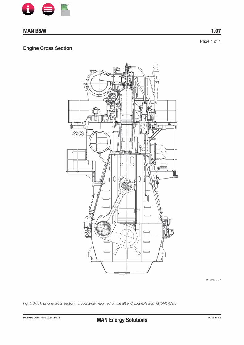
EEngine Cross Section
Fig. 1.07.01: Engine cross section, turbocharger mounted on the aft end. Example from G45ME-C9.5
MAN Energy Solutions
MAN B&W
IMO Tier ll Project Guide
MAN
Energy Solutions Project G
uideM
AN B
&W G
95ME-C
10.5

MAN B&W
Engine Layout and Load Diagrams, SFOC
2MAN Energy Solutions
MAN B&W
IMO Tier ll Project Guide
MAN
Energy Solutions Project G
uideM
AN B
&W G
95ME-C
10.5

MAN B&W 2.01Page 1 of 3
199 06 13-4.1*MAN B&W engines dot 5
Engine Layout and Load Diagrams
Introduction
The effective power ‘P’ of a diesel engine is pro-portional to the mean effective pressure (mep) pe and engine speed ‘n’, i.e. when using ‘c’ as a con-stant:
P = c × pe × n
so, for constant mep, the power is proportional to the speed:
P = c × n1 (for constant mep)
When running with a Fixed Pitch Propeller (FPP), the power may be expressed according to the propeller law as:
P = c × n3 (propeller law)
Thus, for the above examples, the power P may be expressed as a power function of the speed ‘n’ to the power of ‘i’, i.e.:
P = c × ni
Fig. 2.01.01 shows the relationship for the linear functions, y = ax + b, using linear scales.
Fig. 2.01.01: Straight lines in linear scales
Fig. 2.01.02: Power function curves in logarithmic scales
The power functions P = c × ni will be linear func-tions when using logarithmic scales as shown in Fig. 2.01.02:
log (P) = i × log (n) + log (c)
178 05 40�3.0
178 05 40�3.1
y
2
1
00 1 2
b
a
y=ax+b
x
y=log(P)
i = 0
i = 1
i = 2
i = 3
P = n x ci
log (P) = i x log (n) + log (c)
x = log (n)
Thus, propeller curves will be parallel to lines hav-ing the inclination i = 3, and lines with constant mep will be parallel to lines with the inclination i = 1.
Therefore, in the layout diagrams and load dia-grams for diesel engines, logarithmic scales are often used, giving simple diagrams with straight lines.
MAN Energy Solutions
MAN B&W
IMO Tier ll Project Guide
MAN
Energy Solutions Project G
uideM
AN B
&W G
95ME-C
10.5

MAN B&W 2.01Page 2 of 3
199 06 13-4.1*MAN B&W engines dot 5
Normally, estimates of the necessary propeller power and speed are based on theoretical cal-culations for loaded ship, and often experimental tank tests, both assuming optimum operating conditions, i.e. a clean hull and good weather.
The combination of speed and power obtained may be called the ship’s propeller design point (PD), placed on the light running propeller curve 6, see Fig. 2.01.03.
On the other hand, some shipyards, and/or pro-peller manufacturers sometimes use a propeller design point (PD’) that incorporates all or part of the so�called sea margin described below.
Fouled hull
When the ship has sailed for some time, the hull and propeller become fouled and the hull’s resist-ance will increase. Consequently, the ship’s speed will be reduced unless the engine delivers more power to the propeller, i.e. the propeller will be fur-ther loaded and will be heavy running (HR).
Sea margin and heavy weather
If the weather is bad with headwind, the ship’s resistance may increase compared to operating in calm weather conditions. When determining the necessary engine power, it is normal prac-tice to add an extra power margin, the so�called sea margin, so that the design speed can be maintained in average conditions at sea. The sea margin is traditionally about 15% of the power re-quired to achieve design speed with a clean hull in calm weather (PD).
Engine layout (heavy propeller)
When determining the necessary engine layout speed that considers the influence of a heavy run-ning propeller for operating at high extra ship re-sistance, it is (compared to line 6) recommended to choose a heavier propeller line 2. The propeller curve for clean hull and calm weather, line 6, may then be said to represent a ‘light running’ (LR) propeller.Fig. 2.01.03: Propulsion running points and engine lay-
out
Power, % af L1
100% = 0,15 = 0,20
= 0,25 = 0,30
L3
100%
L4
L2
Engine margin(SP=90% of MP)
Sea margin(15% of PD)
Engine speed, % of L1
L1
MP
SP
PD
HR
LR2 6
PD
Propulsion and Engine Running Points
Propeller curve
The relation between power and propeller speed for a fixed pitch propeller is as mentioned above described by means of the propeller law, i.e. the third power curve:
P = c × n3, in which:
P = engine power for propulsionn = propeller speedc = constant
The exponent i=3 is valid for frictional resistance. For vessels having sufficient engine power to sail fast enough to experience significant wave-mak-ing resistance, the exponent may be higher in the high load range.
Propeller design point
178 05 41�5.3
Line 2 Propulsion curve, fouled hull and heavy weather(heavy running), engine layout curve
Line 6 Propulsion curve, clean hull and calm weather (light running), for propeller layout
MP Specified MCR for propulsionSP Continuous service rating for propulsionPD Propeller design pointPD’ Propeller design point incorporating sea marginHR Heavy runningLR Light running
MAN Energy Solutions
MAN B&W
IMO Tier ll Project Guide
MAN
Energy Solutions Project G
uideM
AN B
&W G
95ME-C
10.5
MAN B&W 2.01Page 3 of 3
199 06 13-4.1*MAN B&W engines dot 5
We recommend using a light running margin (LRM) of normally 4.0�7.0%, however for special cases up to 10%, that is, for a given engine power, the light running propeller RPM is 4.0 to 10.0% higher than the RPM on the engine layout curve.
The recommendation is applicable to all draughts at which the ship is intended to operate, whether ballast, design or scantling draught. The recom-mendation is applicable to engine loads from 50 to 100%. If an average of the measured (and possibly corrected) values between 50 and 100% load is used for verification this will smoothen out the effect of measurement uncertainty and other variations.
The high end of the range, 7 to 10%, is primarily intended for vessels where it is important to be able to develop as much of the full engine power as possible in adverse conditions with a heavy running propeller. For example for vessels that are operating in ice.
Vessels with shaft generators may in some cases also benefit from a light running margin in the high range. It is then possible to keep the shaft genera-tor in operation for a larger proportion of the time spent at sea.
Engine margin
Besides the sea margin, a so�called ‘engine mar-gin’ of some 10% or 15% is frequently added. The corresponding point is called the ‘specified MCR for propulsion’ (MP), and refers to the fact that the power for point SP is 10% or 15% lower than for point MP.
With engine margin, the engine will operate at less than 100% power when sailing at design speed with a vessel resistance corresponding to the se-lected sea margin, for example 90% engine load if the engine margin is 10%.
Point MP is identical to the engine’s specified MCR point (M) unless a main engine driven shaft generator is installed. In such a case, the extra power demand of the shaft generator must also be considered.
Constant ship speed lines
The constant ship speed lines ∝, are shown at the very top of Fig. 2.01.03. They indicate the power required at various propeller speeds in order to keep the same ship speed. It is assumed that, for each ship speed, the optimum propeller diameter is used, taking into consideration the total propul-sion efficiency. See definition of ∝ in Section 2.02.
Note:Light/heavy running, fouling and sea margin are overlapping terms. Light/heavy running of the propeller refers to hull and propeller deterioration and heavy weather, whereas sea margin i.e. extra power to the propeller, refers to the influence of the wind and the sea. However, the degree of light running must be decided upon experience from the actual trade and hull design of the vessel.
MAN Energy Solutions
MAN B&W
IMO Tier ll Project Guide
MAN
Energy Solutions Project G
uideM
AN B
&W G
95ME-C
10.5

MAN B&W 2.02Page 1 of 2
199 06 26-6.0*MAN B&W engines dot 5
D = Propeller diametersP/D = Pitch/diameter ratio
Shaft power
kW
8,500
8,600
8,700
8,800
8,900
9,000
9,100
9,200
9,300
9,400
9,500
70 80 90 100 110 120 130 r/min
Propellerspeed
P/D1.00
0.95
0.90
0.85
0.80
D
7.4m
0.75 7.2m
7.0m
6.8m
6.6m
0.700.65
0.60
0.55
D P/D0.50
Fig. 2.02.01: Influence of diameter and pitch on propeller design
Propeller diameter and pitch, influence on the optimum propeller speed
In general, the larger the propeller diameter D, the lower is the optimum propeller speed and the kW required for a certain design draught and ship speed, see curve D in the figure below.
The maximum possible propeller diameter de-pends on the given design draught of the ship, and the clearance needed between the propeller and the aft body hull and the keel.
The example shown in the Fig. 2.02.01 is an 80,000 dwt crude oil tanker with a design draught of 12.2 m and a design speed of 14.5 knots.
When the propeller diameter D is increased from 6.6 m to 7.2 m, the power demand is reduced from about 9,290 kW to 8,820 kW, and the opti-mum propeller speed is reduced from 120 r/min to 100 r/min, corresponding to the constant ship speed coefficient ∝ = 0.28 (see definition of ∝ in Section 2.02, page 2).
Once a propeller diameter of maximum 7.2 m has been chosen, the corresponding optimum pitch in this point is given for the design speed of 14.5 knots, i.e. P/D = 0.70.
However, if the optimum propeller speed of 100 r/min does not suit the preferred / selected main engine speed, a change of pitch away from opti-mum will only cause a relatively small extra power demand, keeping the same maximum propeller diameter:
• going from 100 to 110 r/min (P/D = 0.62) requires8,900 kW, i.e. an extra power demand of 80 kW.
• going from 100 to 91 r/min (P/D = 0.81) requires8,900 kW, i.e. an extra power demand of 80 kW.
In both cases the extra power demand is only 0.9%, and the corresponding ‘equal speed curves’ are ∝ = +0.1 and ∝ = �0.1, respectively, so there is a certain interval of propeller speeds in which the ‘power penalty’ is very limited.
178 47 03�2.1
MAN Energy Solutions
MAN B&W
IMO Tier ll Project Guide
MAN
Energy Solutions Project G
uideM
AN B
&W G
95ME-C
10.5
MAN B&W 2.02Page 2 of 2
199 06 26-6.0*MAN B&W engines dot 5
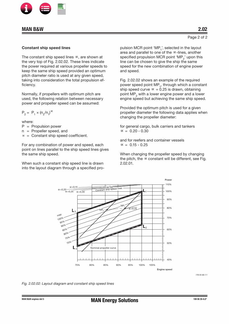
Constant ship speed lines
The constant ship speed lines ∝, are shown at the very top of Fig. 2.02.02. These lines indicate the power required at various propeller speeds to keep the same ship speed provided an optimum pitch diameter ratio is used at any given speed, taking into consideration the total propulsion ef-ficiency.
Normally, if propellers with optimum pitch are used, the following relation between necessary power and propeller speed can be assumed:
P2 = P1 × (n2/n1)∝
where:P = Propulsion powern = Propeller speed, and∝ = Constant ship speed coefficient.
For any combination of power and speed, each point on lines parallel to the ship speed lines gives the same ship speed.
When such a constant ship speed line is drawn into the layout diagram through a specified pro-
pulsion MCR point ‘MP1’, selected in the layoutarea and parallel to one of the ∝�lines, another specified propulsion MCR point ‘MP2’ upon thisline can be chosen to give the ship the same speed for the new combination of engine power and speed.
Fig. 2.02.02 shows an example of the required power speed point MP1, through which a constantship speed curve ∝ = 0.25 is drawn, obtaining point MP2 with a lower engine power and a lowerengine speed but achieving the same ship speed.
Provided the optimum pitch is used for a given propeller diameter the following data applies when changing the propeller diameter:
for general cargo, bulk carriers and tankers∝ = 0.20 � 0.30
and for reefers and container vessels∝ = 0.15 � 0.25
When changing the propeller speed by changing the pitch, the ∝ constant will be different, see Fig. 2.02.01.
Fig. 2.02.02: Layout diagram and constant ship speed lines
178 05 66�7.1
=0,15=0,20
=0,25 =0,30Constant ship speed lines
MP2
MP1
=0,25
1
2
3
4
mep
100%
95%
90%
85%
80%
75%
70%
Nominal propeller curve
75% 80% 85% 90% 95% 100% 105%
Engine speed
Power
110%
100%
90%
80%
70%
60%
50%
40%
MAN Energy Solutions
MAN B&W
IMO Tier ll Project Guide
MAN
Energy Solutions Project G
uideM
AN B
&W G
95ME-C
10.5

MAN B&W 2.03Page 1 of 9
199 06 11-0.1*MAN B&W engines dot 5
Engine Layout and Load Diagram
Engine Layout Diagram
An engine’s layout diagram is limited by two con-stant mean effective pressure (mep) lines L1– L3and L2– L4, and by two constant engine speedlines L1– L2 and L3– L4. The L1 point refers to theengine’s nominal maximum continuous rating, see Fig. 2.04.01.
Within the layout area there is full freedom to se-lect the engine’s specified SMCR point M which suits the demand for power and speed for the ship.
On the horizontal axis the engine speed and on the vertical axis the engine power are shown on percentage scales. The scales are logarithmic which means that, in this diagram, power function curves like propeller curves (3rd power), constant mean effective pressure curves (1st power) and constant ship speed curves (0.15 to 0.30 power) are straight lines.
178 60 85-8.1
Fig. 2.04.01: Engine layout diagram
L1
L2
L3
L4
Speed
Power
M
S
1
Specified maximum continuous rating (M)
Based on the propulsion and engine running points, as previously found, the layout diagram of a relevant main engine may be drawn in a power-speed diagram like in Fig. 2.04.01. The SMCR point (M) must be inside the limitation lines of the
layout diagram; if it is not, the propeller speed will have to be changed or another main engine type must be chosen. The selected SMCR has an influ-ence on the mechanical design of the engine, for example the turbocharger(s), the piston shims, the liners and the fuel valve nozzles.
Once the specified MCR has been chosen, the engine design and the capacities of the auxiliary equipment will be adapted to the specified MCR.
If the specified MCR is to be changed later on, this may involve a change of the shafting system, vibra-tional characteristics, pump and cooler capacities, fuel valve nozzles, piston shims, cylinder liner cool-ing and lubrication, as well as rematching of the turbocharger or even a change to a different tur-bocharger size. In some cases it can also require larger dimensions of the piping systems.
It is therefore important to consider, already at the project stage, if the specification should be pre-pared for a later change of SMCR. This should be indicated in the Extent of Delivery.
For ME and ME-C/-GI/-LGI engines, the timing of the fuel injection and the exhaust valve activation are electronically optimised over a wide operating range of the engine.
For ME-B/-GI/-LGI engines, only the fuel injection (and not the exhaust valve activation) is electroni-cally controlled over a wide operating range of the engine.
For a standard high-load optimised engine, the lowest specific fuel oil consumption for the ME and ME-C engines is optained at 70% and for MC/MC-C/ME-B engines at 80% of the SMCR point (M).
Continuous service rating (S)
The continuous service rating is the power need-ed in service – including the specified sea margin and heavy/light running factor of the propeller – at which the engine is to operate, and point S is iden-tical to the service propulsion point (SP) unless a main engine-driven shaft generator is installed.
MAN Energy Solutions
MAN B&W
IMO Tier ll Project Guide
MAN
Energy Solutions Project G
uideM
AN B
&W G
95ME-C
10.5

MAN B&W 2.03Page 2 of 9
199 06 11-0.1*MAN B&W engines dot 5
Definitions
The engine’s load diagram, see Fig. 2.04.02, de-fines the power and speed limits for continuous as well as overload operation of an installed engine having a specified MCR point M that corresponds to the ship’s specification.
The service points of the installed engine incorpo-rate the engine power required for ship propulsion and shaft generator, if installed.
Operating curves and limits
The service range is limited by four lines: 4, 5, 7 and 3 (9), see Fig. 2.04.02. The propeller curves, line 1, 2 and 6, and overload limits in the load dia-gram are also described below.
Line 1:Propeller curve through specified MCR (M), en-gine layout curve.
Line 2:Propeller curve, fouled hull and heavy weather – heavy running.
Line 3 and line 9:Maximum engine speed limits. In Fig. 2.04.02 they are shown for an engine with a layout point M selected on the L1/L2 line, that is, for an enginewhich is not speed derated.
The speed limit for normal operation (line 3) is:
Maximum 110% of M, but no more than 105% of L1/L2 speed, provided that torsional vibrationspermit. If M is sufficiently speed derated, more than 110% speed is possible by choosing ‘Ex-tended load diagram’ which is described later in this chapter.
The speed limit for sea trial (line 9) is:
Maximum 110% of M, but no more than 107% of L1/L2 speed, provided that torsional vibrationspermit. If M is sufficiently speed derated, more
Engine Load Diagram
Engine shaft power, % of M
40
35
45
50
55
60
65
70
75
80859095
100105110
Engine speed, % of M6055 65 70 75 80 85 90 95 100 105 110
M
8
6
4
5
7
21
4
1
2
3
7
9
5
6
Regarding ‘i’ in the power function P = c x ni, see Section 2.01.
M Specified MCR point
Line 1 Propeller curve through point M (i = 3)(engine layout curve)
Line 2 Propeller curve, fouled hull and heavy weather – heavy running (i = 3)
Line 3 Speed limitLine 4 Torque/speed limit (i = 2)Line 5 Mean effective pressure limit (i = 1)Line 6 Propeller curve, clean hull and calm weather
– light running (i = 3), for propeller layout.The hatched area indicates the full recommendedrange for LRM (4.0-10.0%)
Line 7 Power limit for continuous running (i = 0) Line 8 Overload limitLine 9 Speed limit at sea trial
Fig. 2.04.02: Engine load diagram for an engine speci-fied with MCR on the L1/L2 line of the layout diagram(maximum MCR speed).
than 110% speed is possible by choosing ‘Ex-tended load diagram’ which is described later in this chapter.
Line 4:Represents the limit at which an ample air supply is available for combustion and imposes a limitation on the maximum combination of torque and speed.
178 05 42�7.9
MAN Energy Solutions
MAN B&W
IMO Tier ll Project Guide
MAN
Energy Solutions Project G
uideM
AN B
&W G
95ME-C
10.5

MAN B&W 2.03Page 3 of 9
199 06 11-0.1*MAN B&W engines dot 5
extra power is required for propulsion in order to keep the ship’s speed.
In calm weather conditions, the extent of heavy running of the propeller will indicate the need for cleaning the hull and polishing the propeller.
If the engine and shaft line has a barred speed range (BSR) it is usually a class requirement to be able to pass the BSR quickly. The quickest way to pass the BSR is the following:
1. Set the rpm setting to a value just below theBSR.
2. Wait while the vessel accelerates to a vesselspeed corresponding to the rpm setting.
3. Increase the rpm setting to a value above theBSR.
When passing the BSR as described above it will usually happen quickly.
Layout considerations
In some cases, for example in certain manoeu-vring situations inside a harbour or at sea in adverse conditions, it may not be possible to fol-low the procedure for passing the BSR outlined above. Either because there is no time to wait for the vessel speed to build up or because high vessel resistance makes it impossible to achieve a vessel speed corresponding to the engine rpm setting. In such cases it can be necessary to pass the BSR at a low ship speed.
For 5- and 6-cylinder engines with short shaft lines, such as on many bulkers and tankers, the BSR may extend quite high up in the rpm range. If all of the BSR is placed below 60% of specified MCR rpm and the propeller light running margin is within the recommendation, it is normally possible to achieve sufficiently quick passage of the BSR in relevant conditions. If the BSR extends further up than 60% of specified MCR rpm it may require additional studies to ensure that passage of the BSR will be sufficiently quick.
For support regarding layout of BSR and PTO/PTI, please contact MAN Energy Solutions, Copenhagen at [email protected].
To the left of line 4 in torque¢rich operation, the engine will lack air from the turbocharger to the combustion process, i.e. the heat load limits may be exceeded. Bearing loads may also become too high.
Line 5:Represents the maximum mean effective pressure level (mep), which can be accepted for continuous operation.
Line 6:Propeller curve, clean hull and calm weather – light running, often used for propeller layout/design.
Line 7:Represents the maximum power for continuous operation.
Line 8:Represents the overload operation limitations.
The area between lines 4, 5, 7 and the heavy dashed line 8 is available for overload running for limited periods only (1 hour per 12 hours).
Limits for low load running
As the fuel injection for ME engines is automati-cally controlled over the entire power range, the engine is able to operate down to around 15-20% of the nominal L1 speed, whereas for MC/MC-Cengines it is around 20-25% (electronic governor).
Recommendation for operation
The area between lines 1, 3 and 7 is available for continuous operation without limitation.
The area between lines 1, 4 and 5 is available for operation in shallow waters, in heavy weather and during acceleration, i.e. for non-steady operation without any strict time limitation.
The area between lines 4, 5, 7 and 8 is available for overload operation for 1 out of every 12 hours.
After some time in operation, the ship’s hull and propeller will be fouled, resulting in heavier run-ning of the propeller, i.e. the propeller curve will move to the left from line 6 towards line 2, and
MAN Energy Solutions
MAN B&W
IMO Tier ll Project Guide
MAN
Energy Solutions Project G
uideM
AN B
&W G
95ME-C
10.5

MAN B&W 2.03Page 4 of 9
199 06 11-0.1*MAN B&W engines dot 5
Extended load diagram
When a ship with fixed pitch propeller is operat-ing in normal sea service, it will in general be operating in the hatched area around the design propeller curve 6, as shown on the standard load diagram in Fig. 2.04.02.
Sometimes, when operating in heavy weather, the fixed pitch propeller performance will be more heavy running, i.e. for equal power absorption of the propeller, the propeller speed will be lower and the propeller curve will move to the left.
As the low speed main engines are directly cou-pled to the propeller, the engine has to follow the propeller performance, i.e. also in heavy running propeller situations. For this type of operation, there is normally enough margin in the load area between line 6 and the normal torque/speed limi-tation line 4, see Fig. 2.04.02.
For some ships and operating conditions, it would be an advantage – when occasionally needed – to be able to operate the propeller/main engine as much as possible to the left of line 6, but inside the torque/speed limit, line 4.
This could be relevant in the following cases, es-pecially when more than one of the listed cases are applicable to the vessel:
• ships sailing in areas with very heavy weather
• ships sailing for long periods in shallow orotherwise restricted waters
• ships with a high ice class
• ships with two fixed pitch propellers/two mainengines, where one propeller/one engine isstopped/declutched for one or the other reason
• ships with large shaft generators (>10% ofSMCR power)
The increase of the operating speed range be-tween line 6 and line 4, see Fig. 2.04.02, may be carried out as shown for the following engine ex-ample with an extended load diagram for a speed derated engine with increased light running mar-gin.
Example of extended load diagram for speed derated engines with increased light running margin
For speed derated engines it is possible to extend the maximum speed limit to maximum 105% of the engine’s L1/L2 speed, line 3’, but only providedthat the torsional vibration conditions permit this. Thus, the shafting, with regard to torsional vibra-tions, has to be approved by the classification so-ciety in question, based on the selected extended maximum speed limit.
When choosing an increased light running margin, the load diagram area may be extended from line 3 to line 3’, as shown in Fig. 2.04.03, and the pro-peller/main engine operating curve 6 may have a correspondingly increased heavy running margin before exceeding the torque/speed limit, line 4.
MAN Energy Solutions
MAN B&W
IMO Tier ll Project Guide
MAN
Energy Solutions Project G
uideM
AN B
&W G
95ME-C
10.5

MAN B&W 2.03Page 5 of 9
199 06 11-0.1*MAN B&W engines dot 5
80 100 1058555 90 9560 Engine speed, % M
M Specified engine MCR
Engine shaft power, % M
Heavy running operation
Normaloperation
50
70
80
90
100
40
110
60
110 115120
L1
M
L2
5%
L3
L4
70 7565
Normal load diagram area
Layoutdiagram area
Extended light running area
2
1
5 7
6 3 3
4
Line 1 Propeller curve through SMCR point (M) – layout curve for engine
Line 2 Heavy propeller curve – fouled hull and heavy seas
Line 3 Speed limitLine 3’ Extended speed limit, provided torsional vibration
conditions permitLine 4 Torque/speed limitLine 5 Mean effective pressure limitLine 6 Increased light running propeller curve
– clean hull and calm weather– layout curve for propeller
Line 7 Power limit for continuous running
178 60 79-9.3
Fig. 2.04.03: Extended load diagram for a speed de-rated engine with increased light running margin.
Examples of the use of the Load Diagram
In the following some examples illustrating the flexibility of the layout and load diagrams are pre-sented, see Figs. 2.04.04-06.
• Example 1 shows how to place the load dia-gram for an engine without shaft generator cou-pled to a fixed pitch propeller.
• Example 2 shows the same layout for an enginewith fixed pitch propeller (example 1), but with ashaft generator.
• Example 3 is a special case of example 2,where the specified MCR is placed near the topof the layout diagram.
In this case the shaft generator is cut off,and the GenSets used when the engine runsat specified MCR. This makes it possible tochoose a smaller engine with a lower poweroutput, and with changed specified MCR.
• Example 4 shows diagrams for an engine cou-pled to a controllable pitch propeller, with orwithout a shaft generator, constant speed orcombinator curve operation.
For a specific project, the layout diagram for actu-al project shown later in this chapter may be used for construction of the actual load diagram.
MAN Energy Solutions
MAN B&W
IMO Tier ll Project Guide
MAN
Energy Solutions Project G
uideM
AN B
&W G
95ME-C
10.5

MAN B&W 2.03Page 6 of 9
199 06 11-0.1*MAN B&W engines dot 5
Example 1: Normal running conditions.Engine coupled to fixed pitch propeller (FPP) and without shaft generator
Propulsion and engineservice curve for fouledhull and heavy weather
Engine speed, % of L1 100%
Power, % of L1
100% 7
5
4
1 2 6
1 6
M=MP
S=SP
Engine speed, % of L1 100%
Power, % of L1
100%
Propulsion and engineservice curve for fouledhull and heavy weather
5
4 1
3 3
5%L1
S
M
3.1%M 10%M
7
6
7
L1
L2
L3
L4
L1
L2
L3
L4
2 2
M Specified MCR of engineS Continuous service rating of engineMP Specified MCR for propulsionSP Continuous service rating of propulsion
178 05 44�0.11a
The specified MCR (M) will normally be selected on the engine service curve 2.
Once point M has been selected in the layout diagram, the load diagram can be drawn, as shown in the figure, and hence the actual load limitation lines of the diesel engine may be found by using the inclinations from the construction lines and the %¢figures stated.
Layout diagram Load diagram
Fig. 2.04.04: Normal running conditions. Engine coupled to a fixed pitch propeller (FPP) and without a shaft generator
MAN Energy Solutions
MAN B&W
IMO Tier ll Project Guide
MAN
Energy Solutions Project G
uideM
AN B
&W G
95ME-C
10.5

MAN B&W 2.03Page 7 of 9
199 06 11-0.1*MAN B&W engines dot 5
Example 2: Normal running conditions.Engine coupled to fixed pitch propeller (FPP) and with shaft generator
M Specified MCR of engineS Continuous service rating of engineMP Specified MCR for propulsionSP Continuous service rating of propulsionSG Shaft generator power
178 05 48�8.11
In Example 2 a shaft generator (SG) is installed, and therefore the service power of the engine also has to incorporate the extra shaft power required for the shaft generator’s electrical power production.
In the figure, the engine service curve shown for heavy running incorporates this extra power.
The specified MCR M will then be chosen and the load diagram can be drawn as shown in the figure.
Engine speed, % of L1 100%
Power, % of L1
100% 7
5
4
1 2 6
1 2 6
Propulsion curve for fouledhull and heavy weather
Engineservicecurve
7M
S
SP
SG
SG
MP
Engine speed, % of L1 100%
Power, % of L 1
100%
Propulsion curve for fouledhull and heavy weather
Engine service curve forfouled hull and heavyweather incl. shaftgenerator
4
1 2 6
M
S
SP
MP
3
57
3.1%M 10%M
5%L1
3
L1
L2
L3
L4
L1
L2
L3
L4
Layout diagram Load diagram
Fig. 2.04.05: Normal running conditions. Engine coupled to a fixed pitch propeller (FPP) and with a shaft generator
MAN Energy Solutions
MAN B&W
IMO Tier ll Project Guide
MAN
Energy Solutions Project G
uideM
AN B
&W G
95ME-C
10.5

MAN B&W 2.03Page 8 of 9
199 06 11-0.1*MAN B&W engines dot 5
Example 3: Special running conditions. Engine coupled to fixed pitch propeller (FPP) and with shaft generator
M Specified MCR of engineS Continuous service rating of engineMP Specified MCR for propulsionSP Continuous service rating of propulsionSG Shaft generator
Point M of the load diagram is found:
Line 1 Propeller curve through point SPoint M Intersection between line 1 and line L1 – L3
178 06 35�1.11
Also for this special case in Example 3, a shaft generator is installed but, compared to Example 2, this case has a specified MCR for propulsion, MP, placed at the top of the layout diagram.
This involves that the intended specified MCR of the engine M’ will be placed outside the top of the layout diagram.
One solution could be to choose a larger diesel engine with an extra cylinder, but another and cheaper solution is to reduce the electrical power production of the shaft generator when running in the upper propulsion power range.
In choosing the latter solution, the required specified MCR power can be reduced from point M’ to point M as shown. Therefore, when running in the upper propulsion power range, a diesel generator has to take over all or part of the electrical power production.
Point M, having the highest possible power, is then found at the intersection of line L1– L3 with line 1 and the corresponding loaddiagram is drawn.
Propulsion curvefor fouled hulland heavy weather
Power, % of L 1
100%
Engine speed, % of L 1 100%
7
5
4
1 2 6
1 2 6
7
SP
SG MP
S
M
M
Propulsion curvefor fouled hulland heavy weather
Power, % of L 1
100%
Engine speed, % of L 1 100%
1 2 6
7
SP
SG MP
S
M
5%L1
3.1%M 9%M *)
M
Engine service curve for fouledhull and heavy weatherincl. shaft generator
4
3
3
*) 105% ofL1/L2 speed
L1
L2
L3
L4
L1
L2
L3
L4
Layout diagram Load diagram
Fig. 2.04.06: Special running conditions. Engine coupled to a fixed pitch propeller (FPP) and with a shaft generator
MAN Energy Solutions
MAN B&W
IMO Tier ll Project Guide
MAN
Energy Solutions Project G
uideM
AN B
&W G
95ME-C
10.5

MAN B&W 2.03Page 9 of 9
199 06 11-0.1*MAN B&W engines dot 5
Example 4: Engine coupled to controllable pitch propeller (CPP) with or without shaft generator
Engine speed
Power7
5
4
1 2 6
3.1%M 10%M
5%L1
75
14
3
S
L1
L2
L3
L4
Min. speed Max. speed
Combinator curve for loaded ship and incl. sea margin
Recommended range for shaft generator operation with constant speed
M
M Specified MCR of engineS Continous service rating of engine
178 39 31�4.7
Without shaft generator
If a controllable pitch propeller (CPP) is applied, the combinator curve (of the propeller) will normally be selected for loaded ship including sea margin.
The combinator curve may for a given propeller speed have a given propeller pitch, and this may be heavy running in heavy weather like for a fixed pitch propeller.
Therefore it is recommended to use a light run-ning combinator curve (the dotted curve which includes the sea margin) as shown in the figure to obtain an increased operation margin of the diesel engine in heavy weather to the limit indicated by curves 4 and 5 in Fig. 2.04.07.
With shaft generator
The hatched area in Fig. 2.04.07 shows the rec-ommended speed range between 100% and 96.9% of the specified MCR speed for an engine with shaft generator running at constant speed.
The service point S can be located at any point within the hatched area.
The procedure shown in examples 2 and 3 for engines with FPP can also be applied here for en-gines with CPP running with a combinator curve.
Load diagram
Therefore, when the engine’s specified MCR point (M) has been chosen including engine margin,sea margin and the power for a shaft generator,if installed, point M may be used as the basis fordrawing the engine load diagram.
The position of the combinator curve ensures the maximum load range within the permitted speed range for engine operation, and it still leaves a reasonable margin to the limit indicated by curves 4 and 5 in Fig. 2.04.07.
For support regarding CPP propeller curves, please contact MAN Energy Solutions, Copenhagen at [email protected].
Fig. 2.04.07: Engine with Controllable Pitch Propeller (CPP), with or without a shaft generator
MAN Energy Solutions
MAN B&W
IMO Tier ll Project Guide
MAN
Energy Solutions Project G
uideM
AN B
&W G
95ME-C
10.5

MAN B&W 2.04Page 1 of 1
199 06 12-2.0MAN B&W engines dot 5
Fig. 2.04.01: Construction of a load diagram
70% 75% 80% 85% 90% 95% 100% 105% 110%
40%
50%
60%
70%
80%
90%
100%
110%
775
5
5
4
2 61
3.1%M 10%M *)
M
Engine speed, % of L1
Power, % of L1
5%L1
*) But no more than 105% of L1/L2 speed
L1
L 2L3
L 4
Diagram for actual project
This figure contains a layout diagram that can be used for constructing the load diagram for an actual project, using the %�figures stated and the inclinations of the lines.
178 66 06-1.2
MAN Energy Solutions
MAN B&W
IMO Tier ll Project Guide
MAN
Energy Solutions Project G
uideM
AN B
&W G
95ME-C
10.5
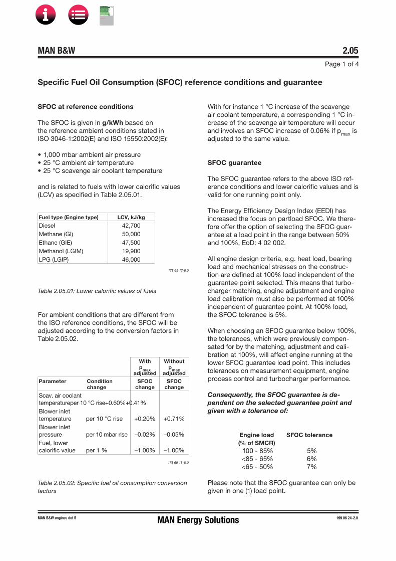
MAN B&W 2.05Page 1 of 4
199 06 24-2.0MAN B&W engines dot 5
With pmax
adjusted
Without pmax
adjustedParameter Condition
changeSFOC
changeSFOC
change
Scav. air coolant temperatureper 10 °C rise+0.60%+0.41%Blower inlet temperature per 10 °C rise +0.20% +0.71%Blower inlet pressure per 10 mbar rise –0.02% –0.05%Fuel, lower calorific value per 1 % –1.00% –1.00%
SFOC at reference conditions
The SFOC is given in g/kWh based on the reference ambient conditions stated in ISO 3046-1:2002(E) and ISO 15550:2002(E):
• 1,000 mbar ambient air pressure• 25 °C ambient air temperature• 25 °C scavenge air coolant temperature
and is related to fuels with lower calorific values (LCV) as specified in Table 2.05.01.
Specific Fuel Oil Consumption (SFOC) reference conditions and guarantee
Engine load(% of SMCR)
SFOC tolerance
100 - 85% 5%<85 - 65% 6%<65 - 50% 7%
For ambient conditions that are different from the ISO reference conditions, the SFOC will be adjusted according to the conversion factors in Table 2.05.02.
With for instance 1 °C increase of the scavenge air coolant temperature, a corresponding 1 °C in-crease of the scavenge air temperature will occur and involves an SFOC increase of 0.06% if pmax isadjusted to the same value.
SFOC guarantee
The SFOC guarantee refers to the above ISO ref-erence conditions and lower calorific values and is valid for one running point only.
The Energy Efficiency Design Index (EEDI) has increased the focus on partload SFOC. We there-fore offer the option of selecting the SFOC guar-antee at a load point in the range between 50% and 100%, EoD: 4 02 002.
All engine design criteria, e.g. heat load, bearing load and mechanical stresses on the construc-tion are defined at 100% load independent of the guarantee point selected. This means that turbo-charger matching, engine adjustment and engine load calibration must also be performed at 100% independent of guarantee point. At 100% load, the SFOC tolerance is 5%.
When choosing an SFOC guarantee below 100%, the tolerances, which were previously compen-sated for by the matching, adjustment and cali-bration at 100%, will affect engine running at the lower SFOC guarantee load point. This includes tolerances on measurement equipment, engine process control and turbocharger performance.
Consequently, the SFOC guarantee is de-pendent on the selected guarantee point and given with a tolerance of:
Table 2.05.01: Lower calorific values of fuels
Fuel type (Engine type) LCV, kJ/kg
Diesel 42,700Methane (GI) 50,000Ethane (GIE) 47,500Methanol (LGIM) 19,900LPG (LGIP) 46,000
178 69 17-6.0
178 69 18-8.0
Table 2.05.02: Specific fuel oil consumption conversion factors
Please note that the SFOC guarantee can only be given in one (1) load point.
MAN Energy Solutions
MAN B&W
IMO Tier ll Project Guide
MAN
Energy Solutions Project G
uideM
AN B
&W G
95ME-C
10.5

MAN B&W 2.05Page 2 of 4
199 06 24-2.0MAN B&W engines dot 5
Cooling water temperature during normal operation
In general, it is recommended to operate the main engine with the lowest possible cooling water temperature to the air coolers, as this will reduce the fuel consumption of the engine, i.e. the engine performance will be improved.
When operating with 36 °C cooling water instead of for example 10 °C (to the air coolers), the spe-cific fuel oil consumption will increase by approx. 2 g/kWh.
With a lower cooling water temperature, the air cooler and water mist catcher will remove more water from the compressed scavenge air. This has a positive effect on the cylinder condition as the humidity level in the combustion gasses is low-ered, and the tendency to condensation of acids on the cylinder liner is thereby reduced.
MAN Energy Solutions
MAN B&W
IMO Tier ll Project Guide
MAN
Energy Solutions Project G
uideM
AN B
&W G
95ME-C
10.5
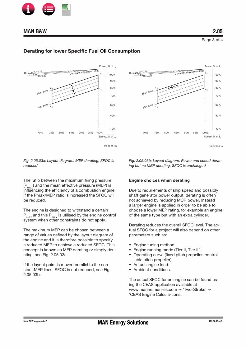
MAN B&W 2.05Page 3 of 4
MAN B&W engines dot 5 199 06 25-4.0
Engine choices when derating
Due to requirements of ship speed and possibly shaft generator power output, derating is often not achieved by reducing MCR power. Instead a larger engine is applied in order to be able to choose a lower MEP rating, for example an engine of the same type but with an extra cylinder.
Derating reduces the overall SFOC level. The ac-tual SFOC for a project will also depend on other parameters such as:
• Engine tuning method• Engine running mode (Tier II, Tier III)• Operating curve (fixed pitch propeller, control-
lable pitch propeller)• Actual engine load• Ambient conditions.
The actual SFOC for an engine can be found us-ing the CEAS application available at www.marine.man-es.com → ’Two-Stroke’ → ’CEAS Engine Calcula-tions’.
Derating for lower Specific Fuel Oil Consumption
The ratio between the maximum firing pressure (Pmax) and the mean effective pressure (MEP) isinfluencing the efficiency of a combustion engine. If the Pmax/MEP ratio is increased the SFOC will be reduced.
The engine is designed to withstand a certain Pmax and this Pmax is utilised by the engine controlsystem when other constraints do not apply.
The maximum MEP can be chosen between a range of values defined by the layout diagram of the engine and it is therefore possible to specify a reduced MEP to achieve a reduced SFOC. This concept is known as MEP derating or simply der-ating, see Fig. 2.05.03a.
If the layout point is moved parallel to the con-stant MEP lines, SFOC is not reduced, see Fig. 2.05.03b.
=0.15
=0.25=0.20
=0.30
40%
50%
60%
70%
80%
90%
100%
Power, % of L1
Speed, % of L1
75%70% 80% 85% 90% 95% 100%
Constant ship speed lines
Max. mep
Min. mep
L 3
L 4
L1
L 2
=0.15
=0.25=0.20
=0.30
40%
50%
60%
70%
80%
90%
100%
Power, % of L1
Speed, % of L1
75%70% 80% 85% 90% 95% 100%
Constant ship speed lines
Max. mepL 3
L 4
L1
L 2
Min. mep
Fig. 2.05.03b: Layout diagram. Power and speed derat-ing but no MEP derating, SFOC is unchanged
Fig. 2.05.03a: Layout diagram. MEP derating, SFOC is reduced
178 69 21-1.1a 178 69 21-1.1b
MAN Energy Solutions
MAN B&W
IMO Tier ll Project Guide
MAN
Energy Solutions Project G
uideM
AN B
&W G
95ME-C
10.5

MAN B&W 2.05Page 4 of 4
MAN B&W engines dot 5 199 06 25-4.0
It is possible to use CEAS to see the effect of derating for a particular engine by running CEAS for different engine ratings, for example the L1 rat-ing (not MEP derated) and the L2 rating (fully MEPderated). This information can be used in the initial design work where the basic layout of the propul-sion plant is decided.
Example of SFOC curves
Fig. 2.05.04 shows example SFOC curves for high-load tuning as well as part-load (EGB-PL) and low-load (EGB-LL) exhaust gas bypass tuning for an engine operating with a fixed pitch propel-ler.
Fig. 2.05.04: Influence on SFOC from engine tuning method and actual engine load
100
SFOC
35
Load %
High-load tuning
EGB-PL tuning
EGB-LL tuning
178 69 22-3.0
The figure illustrates the relative changes in SFOC due to engine tuning method and engine load. The figure is an example only. CEAS should be used to get actual project values.
MAN Energy Solutions
MAN B&W
IMO Tier ll Project Guide
MAN
Energy Solutions Project G
uideM
AN B
&W G
95ME-C
10.5
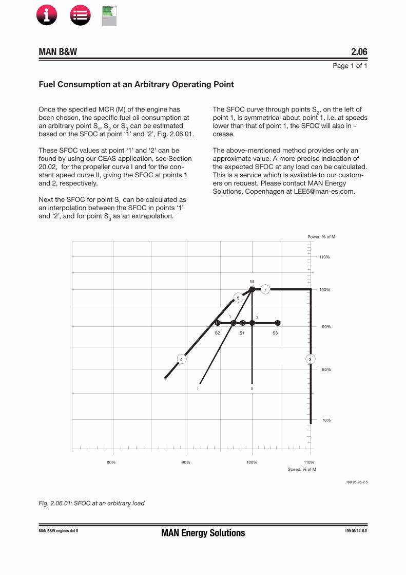
MAN B&W 2.06Page 1 of 1
MAN B&W engines dot 5 199 06 14-6.0
Once the specified MCR (M) of the engine has been chosen, the specific fuel oil consumption at an arbitrary point S1, S2 or S3 can be estimatedbased on the SFOC at point ‘1’ and ‘2’, Fig. 2.06.01.
These SFOC values at point ‘1’ and ‘2’ can be found by using our CEAS application, see Section 20.02, for the propeller curve I and for the con-stant speed curve II, giving the SFOC at points 1 and 2, respectively.
Next the SFOC for point S1 can be calculated as an interpolation between the SFOC in points ‘1’ and ‘2’, and for point S3 as an extrapolation.
The SFOC curve through points S2, on the left ofpoint 1, is symmetrical about point 1, i.e. at speeds lower than that of point 1, the SFOC will also in -crease.
The above�mentioned method provides only an approximate value. A more precise indication of the expected SFOC at any load can be calculated. This is a service which is available to our custom-ers on request. Please contact MAN Energy Solutions, Copenhagen at [email protected].
Power, % of M
110%
100%
90%
80%
70%
80% 90% 100% 110%
Speed, % of M
M
5
7
21
S2 S1 S3
4 3
I II
Fig. 2.06.01: SFOC at an arbitrary load
198 95 96�2.5
Fuel Consumption at an Arbitrary Operating Point
MAN Energy Solutions
MAN B&W
IMO Tier ll Project Guide
MAN
Energy Solutions Project G
uideM
AN B
&W G
95ME-C
10.5

MAN B&W
Turbocharger Selection & Exhaust By-pass
3MAN Energy Solutions
MAN B&W
IMO Tier ll Project Guide
MAN
Energy Solutions Project G
uideM
AN B
&W G
95ME-C
10.5
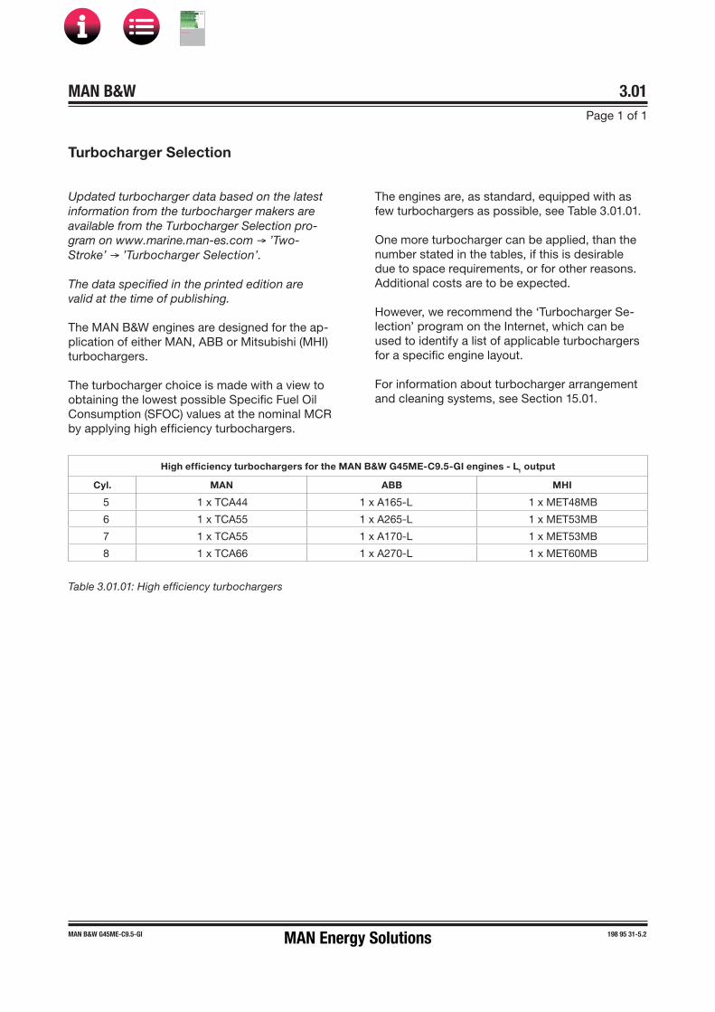
MAN B&W 3.01Page 1 of 1
198 95 31-5.2MAN B&W G45ME-C9.5-GI
The engines are, as standard, equipped with as few turbochargers as possible, see Table 3.01.01.
One more turbocharger can be applied, than the number stated in the tables, if this is desirable due to space requirements, or for other reasons. Additional costs are to be expected.
However, we recommend the ‘Turbocharger Se-lection’ program on the Internet, which can be used to identify a list of applicable turbochargers for a specific engine layout.
For information about turbocharger arrangement and cleaning systems, see Section 15.01.
Table 3.01.01: High efficiency turbochargers
High efficiency turbochargers for the MAN B&W G45ME-C9.5-GI engines � L1 output
Cyl. MAN ABB MHI
5 1 x TCA44 1 x A165-L 1 x MET48MB
6 1 x TCA55 1 x A265-L 1 x MET53MB
7 1 x TCA55 1 x A170-L 1 x MET53MB
8 1 x TCA66 1 x A270-L 1 x MET60MB
Turbocharger Selection
Updated turbocharger data based on the latest information from the turbocharger makers are available from the Turbocharger Selection pro-gram on www.marine.man-es.com → ’Two-Stroke’ → ’Turbocharger Selection’.
The data specified in the printed edition are valid at the time of publishing.
The MAN B&W engines are designed for the ap-plication of either MAN, ABB or Mitsubishi (MHI) turbochargers.
The turbocharger choice is made with a view to obtaining the lowest possible Specific Fuel Oil Consumption (SFOC) values at the nominal MCR by applying high efficiency turbochargers.
MAN Energy Solutions
MAN B&W
IMO Tier ll Project Guide
MAN
Energy Solutions Project G
uideM
AN B
&W G
95ME-C
10.5
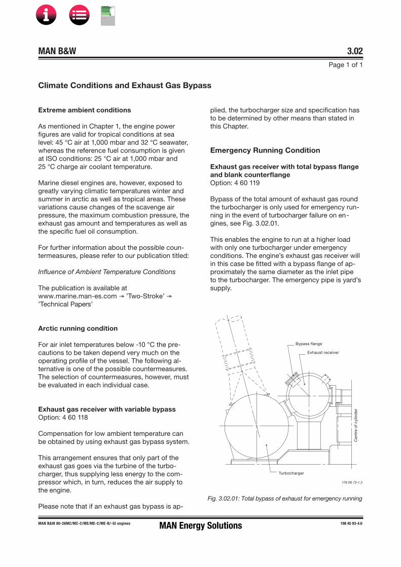
MAN B&W 3.02Page 1 of 1
198 45 93-4.6MAN B&W 80-26MC/MC-C/ME/ME-C/ME-B/-GI engines
plied, the turbocharger size and specification has to be determined by other means than stated in this Chapter.
Emergency Running Condition
Exhaust gas receiver with total bypass flange and blank counterflangeOption: 4 60 119
Bypass of the total amount of exhaust gas round the turbocharger is only used for emergency run-ning in the event of turbocharger failure on en-gines, see Fig. 3.02.01.
This enables the engine to run at a higher load with only one turbocharger under emergency conditions. The engine’s exhaust gas receiver will in this case be fitted with a bypass flange of ap-proximately the same diameter as the inlet pipe to the turbocharger. The emergency pipe is yard’s supply.
Extreme ambient conditions
As mentioned in Chapter 1, the engine power figures are valid for tropical conditions at sea level: 45 °C air at 1,000 mbar and 32 °C seawater, whereas the reference fuel consumption is given at ISO conditions: 25 °C air at 1,000 mbar and 25 °C charge air coolant temperature.
Marine diesel engines are, however, exposed to greatly varying climatic temperatures winter and summer in arctic as well as tropical areas. These variations cause changes of the scavenge air pressure, the maximum combustion pressure, the exhaust gas amount and temperatures as well as the specific fuel oil consumption.
For further information about the possible coun-termeasures, please refer to our publication titled:
Influence of Ambient Temperature Conditions
The publication is available atwww.marine.man-es.com → ’Two-Stroke’ → ’Technical Papers’
Arctic running condition
For air inlet temperatures below �10 °C the pre-cautions to be taken depend very much on the operating profile of the vessel. The following al-ternative is one of the possible countermeasures. The selection of countermeasures, however, must be evaluated in each individual case.
Exhaust gas receiver with variable bypass Option: 4 60 118
Compensation for low ambient temperature can be obtained by using exhaust gas bypass system.
This arrangement ensures that only part of the exhaust gas goes via the turbine of the turbo-charger, thus supplying less energy to the com-pressor which, in turn, reduces the air supply to the engine.
Please note that if an exhaust gas bypass is ap-
Climate Conditions and Exhaust Gas Bypass
Fig. 3.02.01: Total bypass of exhaust for emergency running
178 06 72�1.2
Bypass flange
Exhaust receiver
Turbocharger
Cen
tre
of c
ylin
der
MAN Energy Solutions
MAN B&W
IMO Tier ll Project Guide
MAN
Energy Solutions Project G
uideM
AN B
&W G
95ME-C
10.5

MAN B&W 3.03Page 1 of 1
MAN B&W ME/ME�C/ME-B/-GI TII engines 198 84 47-2.2
Emission Control
IMO Tier II NOx emission limits
All ME, ME-B and ME-C/-GI engines are, as standard, fulfilling the IMO Tier II NOx emission requirements, a speed dependent NOx limit meas-ured according to ISO 8178 Test Cycles E2/E3 for Heavy Duty Diesel Engines.
The E2/E3 test cycles are referred to in the Extent of Delivery as EoD: 4 06 200 Economy mode with the options: 4 06 201 Engine test cycle E3 or 4 06 202 Engine test cycle E2.
NOx reduction methods for IMO Tier III
As adopted by IMO for future enforcement, the engine must fulfil the more restrictive IMO Tier III NOx requirements when sailing in a NOx Emission Control Area (NOx ECA).
The Tier III NOx requirements can be met by Ex-haust Gas Recirculation (EGR), a method which directly affects the combustion process by lower-ing the generation of NOx.
Alternatively, the required NOx level could be met by installing Selective Catalytic Reaction (SCR), an after treatment system that reduces the emis-sion of NOx already generated in the combustion process.
Details of MAN Energy Solutions' NOx reduction methods for IMO Tier III can be found in our pub-lication:
Emission Project Guide
The publication is available at www.marine.man-es.com →’ Two-Stroke’ → ’Project Guides’ →’Other Guides’.
MAN Energy Solutions
MAN B&W
IMO Tier ll Project Guide
MAN
Energy Solutions Project G
uideM
AN B
&W G
95ME-C
10.5

MAN B&W
Electricity Production
4MAN Energy Solutions
MAN B&W
IMO Tier ll Project Guide
MAN
Energy Solutions Project G
uideM
AN B
&W G
95ME-C
10.5

MAN B&W 4.01
Page 1 of 3
198 57 39-2.4MAN B&W S46MC-C7/8, S46ME-B8, G45ME-B9, S42MC7,S40ME-C9, S40MC-C9, G40ME-B9, S40ME-B9, S35MC-C9, S35MC7, S35ME-B9, L35MC6, S30ME-B9, S26MC6
Electricity Production
• PTO/GCR(Power Take Off/Gear Constant Ratio):Generator coupled to a constant ratio step�upgear, used only for engines running at constant speed.
Within each PTO system, several designs are available, depending on the positioning of the gear:
• BW II:A free�standing gear mounted on the tank topand connected to the fore end of the diesel en-gine, with a vertical or horizontal generator.
• BW IV:A free�standing step�up gear connected to theintermediate shaft, with a horizontal generator.
Introduction
Next to power for propulsion, electricity produc-tion is the largest fuel consumer on board. The electricity is produced by using one or more of the following types of machinery, either running alone or in parallel:
• Auxiliary diesel generating sets
• Main engine driven generators
• Steam driven turbogenerators
• Emergency diesel generating sets.
The machinery installed should be selected on the basis of an economic evaluation of first cost, op-erating costs, and the demand for man�hours for maintenance.
In the following, technical information is given re-garding main engine driven generators (PTO) and the auxiliary diesel generating sets produced by MAN Energy Solutions.
Power Take Off
With a generator coupled to a Power Take Off (PTO) from the main engine, electrical power can be produced based on the main engine’s low SFOC and the use of heavy fuel oil. Several standardised PTO systems are available, see Fig. 4.01.01 and the designations in Fig. 4.01.02:
• PTO/RCF(Power Take Off/Constant Frequency):Generator giving constant frequency, based onmechanical�hydraulical speed control.
• PTO/CFE(Power Take Off/Constant Frequency Electrical):Generator giving constant frequency, based onelectrical frequency control.
MAN Energy Solutions
MAN B&W
IMO Tier ll Project Guide
MAN
Energy Solutions Project G
uideM
AN B
&W G
95ME-C
10.5
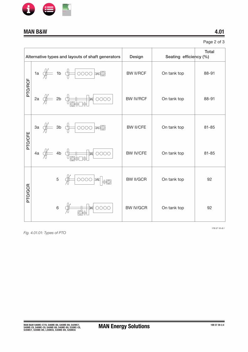
MAN B&W 4.01
Page 2 of 3
198 57 39-2.4MAN B&W S46MC-C7/8, S46ME-B8, G45ME-B9, S42MC7,S40ME-C9, S40MC-C9, G40ME-B9, S40ME-B9, S35MC-C9, S35MC7, S35ME-B9, L35MC6, S30ME-B9, S26MC6
Fig. 4.01.01: Types of PTO178 57 10-8.1
TotalAlternative types and layouts of shaft generators Design Seating efficiency (%)
1a 1b BW II/RCF On tank top 88 91
2a 2b BW IV/RCF On tank top 88 91
3a 3b BW II/CFE On tank top 81-85
4a 4b BW IV/CFE On tank top 81-85
5 BW II/GCR On tank top 92
6 BW IV/GCR On tank top 92
PTO
/RC
FP
TO/C
FE
PTO
/GC
R
MAN Energy Solutions
MAN B&W
IMO Tier ll Project Guide
MAN
Energy Solutions Project G
uideM
AN B
&W G
95ME-C
10.5

MAN B&W 4.01Page 3 of 3
198 66 35-4.4MAN B&W 46-26 engines
50: 50 Hz
60: 60 Hz
kW on generator terminals
RCF: Constant frequency unit
CFE: Electrically frequency controlled unit
GCR: Step�up gear with constant ratio
Mark version
Engine type on which it is applied
Layout of PTO: See Fig. 4.01.01
Make: MAN Energy Solutions
Fig. 4.01.02: Example of designation of PTO
Designation of PTO
For further information, please refer to our publi-cation titled:
Shaft Generators for MC and ME engines
The publications are available atwww.marine.man-es.com → ’Two-Stroke’ → ’Technical Papers’.
Power take off
BW II S46ME-B8/GCR 900�60
178 39 55 6.1
MAN Energy Solutions
MAN B&W
IMO Tier ll Project Guide
MAN
Energy Solutions Project G
uideM
AN B
&W G
95ME-C
10.5

MAN B&W Page 1 of 1
This section is not applicable
Space Requirement for Side-Mounted Generator
4.02
199 07 97-8.0MAN Energy Solutions
MAN B&W
IMO Tier ll Project Guide
MAN
Energy Solutions Project G
uideM
AN B
&W G
95ME-C
10.5

MAN B&W 4.03Page 1 of 1
198 57 42-6.3MAN B&W 46-26 engines
1. Flange on crankshaft2. Studs and nuts, dowel pipe and screws3. Intermediate shaft between the crankshaft and flexible coupling for PTO4. Oil sealing for intermediate shaft5. End cover in 2/2 with scraper ring housing6. Plug box for electronic measuring instrument for check of condition of axial vibration damper– Tacho trigger ring on turning wheel (aft) for ME control system
178 43 54-4.0
Fig. 4.03.01: Engine preparations for PTO
5
2
4
3
6
1
Engine preparations for PTO BW II
MAN Energy Solutions
MAN B&W
IMO Tier ll Project Guide
MAN
Energy Solutions Project G
uideM
AN B
&W G
95ME-C
10.5
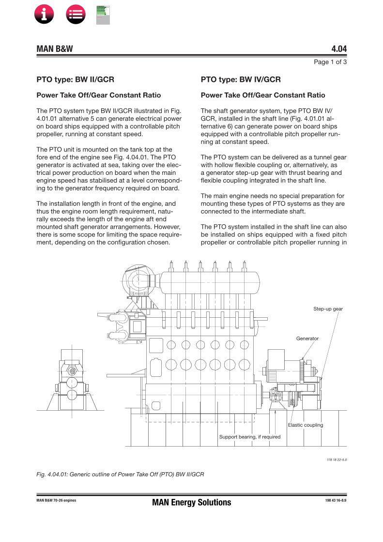
MAN B&W 4.04Page 1 of 3
198 43 16-8.9MAN B&W 70-26 engines
PTO type: BW II/GCR
Power Take Off/Gear Constant Ratio
The PTO system type BW II/GCR illustrated in Fig. 4.01.01 alternative 5 can generate electrical power on board ships equipped with a controllable pitch propeller, running at constant speed.
The PTO unit is mounted on the tank top at the fore end of the engine see Fig. 4.04.01. The PTO generator is activated at sea, taking over the elec-trical power production on board when the main engine speed has stabilised at a level correspond-ing to the generator frequency required on board.
The installation length in front of the engine, and thus the engine room length requirement, natu-rally exceeds the length of the engine aft end mounted shaft generator arrangements. However, there is some scope for limiting the space require-ment, depending on the configuration chosen.
PTO type: BW IV/GCR
Power Take Off/Gear Constant Ratio
The shaft generator system, type PTO BW IV/GCR, installed in the shaft line (Fig. 4.01.01 al-ternative 6) can generate power on board ships equipped with a controllable pitch propeller run-ning at constant speed.
The PTO system can be delivered as a tunnel gear with hollow flexible coupling or, alternatively, as a generator step�up gear with thrust bearing and flexible coupling integrated in the shaft line.
The main engine needs no special preparation for mounting these types of PTO systems as they are connected to the intermediate shaft.
The PTO system installed in the shaft line can also be installed on ships equipped with a fixed pitch propeller or controllable pitch propeller running in
Fig. 4.04.01: Generic outline of Power Take Off (PTO) BW II/GCR
178 18 22�5.0
Support bearing, if required
Elastic coupling
Step-up gear
Generator
MAN Energy Solutions
MAN B&W
IMO Tier ll Project Guide
MAN
Energy Solutions Project G
uideM
AN B
&W G
95ME-C
10.5
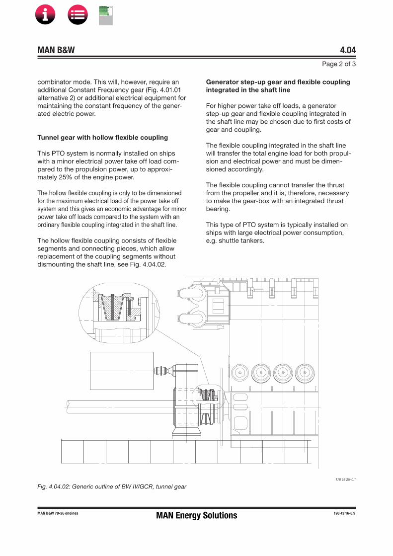
MAN B&W 4.04Page 2 of 3
198 43 16-8.9MAN B&W 70-26 engines
combinator mode. This will, however, require an additional Constant Frequency gear (Fig. 4.01.01 alternative 2) or additional electrical equipment for maintaining the constant frequency of the gener-ated electric power.
Tunnel gear with hollow flexible coupling
This PTO system is normally installed on ships with a minor electrical power take off load com-pared to the propulsion power, up to approxi-mately 25% of the engine power.
The hollow flexible coupling is only to be dimensioned for the maximum electrical load of the power take off system and this gives an economic advantage for minor power take off loads compared to the system with an ordinary flexible coupling integrated in the shaft line.
The hollow flexible coupling consists of flexible segments and connecting pieces, which allow replacement of the coupling segments without dismounting the shaft line, see Fig. 4.04.02.
Fig. 4.04.02: Generic outline of BW IV/GCR, tunnel gear178 18 25�0.1
Generator step�up gear and flexible coupling integrated in the shaft line
For higher power take off loads, a generator step�up gear and flexible coupling integrated in the shaft line may be chosen due to first costs of gear and coupling.
The flexible coupling integrated in the shaft line will transfer the total engine load for both propul-sion and electrical power and must be dimen-sioned accordingly.
The flexible coupling cannot transfer the thrust from the propeller and it is, therefore, necessary to make the gear�box with an integrated thrust bearing.
This type of PTO system is typically installed on ships with large electrical power consumption, e.g. shuttle tankers.
MAN Energy Solutions
MAN B&W
IMO Tier ll Project Guide
MAN
Energy Solutions Project G
uideM
AN B
&W G
95ME-C
10.5

MAN B&W 4.04Page 3 of 3
198 43 16-8.9MAN B&W 70-26 engines
Auxiliary Propulsion System/Take Home System
From time to time an Auxiliary Propulsion System/Take Home System capable of driving the CP pro-peller by using the shaft generator as an electric motor is requested.
MAN Energy Solutions can offer a solution where the CP propeller is driven by the alternator via a two�speed tunnel gear box. The electric power is produced by a number of GenSets. The main en-gine is disengaged by a clutch (RENK PSC) made as an integral part of the shafting. The clutch is in-stalled between the tunnel gear box and the main engine, and conical bolts are used to connect and disconnect the main engine and the shafting. See Figure 4.04.03.
A thrust bearing, which transfers the auxiliary pro-pulsion propeller thrust to the engine thrust bear-ing when the clutch is disengaged, is built into the RENK PSC clutch. When the clutch is engaged, the thrust is transferred statically to the engine thrust bearing through the thrust bearing built into the clutch.
To obtain high propeller efficiency in the auxiliary propulsion mode, and thus also to minimise the auxiliary power required, a two�speed tunnel gear, which provides lower propeller speed in the auxil-iary propulsion mode, is used.
The two�speed tunnel gear box is made with a friction clutch which allows the propeller to be clutched in at full alternator/motor speed where the full torque is available. The alternator/motor is started in the de�clutched condition with a start transformer.
The system can quickly establish auxiliary propul-sion from the engine control room and/or bridge, even with unmanned engine room.
Re�establishment of normal operation requires attendance in the engine room and can be done within a few minutes.
Fig. 4.04.03: Auxiliary propulsion system178 57 16-9.0
Main engine
Renk PSC cluth
Two-speed tunnel gearbox
Generator/motor
Oil distribution ring
Hydraulic coupling
Intermediate bearing
Flexible coupling
MAN Energy Solutions
MAN B&W
IMO Tier ll Project Guide
MAN
Energy Solutions Project G
uideM
AN B
&W G
95ME-C
10.5

MAN B&W Page 1 of 1
This section is not applicable
Waste Heat Recovery Systems (WHRS)
4.05
198 66 47-4.1MAN B&W 50-26 MC/MC-C/ME-C/ME-B/-GI engines MAN Energy Solutions
MAN B&W
IMO Tier ll Project Guide
MAN
Energy Solutions Project G
uideM
AN B
&W G
95ME-C
10.5

LL16/24 GenSet Data
Engine ratings
Engine typeNo of cylinders
1000 rpm 1200 rpm
1000 rpm Available turning direction
1200 rpm Available turning direction
kW CW 1) kW CW 1)
5L16/24 450 Yes 500 Yes
6L16/24 570 Yes 660 Yes
7L16/24 665 Yes 770 Yes
8L16/24 760 Yes 880 Yes
9L16/24 855 Yes 990 Yes
1) CW clockwise
B100111-1689490-8.0
MAN Energy Solutions
MAN B&W
IMO Tier ll Project Guide
MAN
Energy Solutions Project G
uideM
AN B
&W G
95ME-C
10.5

GGeneral
Cyl. no A (mm) * B (mm) * C (mm) H (mm) ** Dry weightGenSet (t)
5 (1000 rpm)5 (1200 rpm)
6 (1000 rpm)6 (1200 rpm)
7 (1000 rpm)7 (1200 rpm)
8 (1000 rpm)8 (1200 rpm)
9 (1000 rpm)9 (1200 rpm)
28072807
30823082
35573557
38323832
41074107
14001400
14901490
15851585
16801680
16801680
42074207
45724572
51425142
55125512
57875787
23372337
23372337
23372415
24152415
24152415
9.59.5
10.510.5
11.411.4
12.412.4
13.113.1
PQ
***
Free passage between the engines, width 600 mm and height 2000 mm.Min. distance between engines: 1800 mm.
Depending on alternatorWeight included a standard alternator
All dimensions and masses are approximate, and subject to changes without prior notice.
MAN Energy Solutions
MAN B&W
IMO Tier ll Project Guide
MAN
Energy Solutions Project G
uideM
AN B
&W G
95ME-C
10.5

CCapacities5L:90 kW/cyl., 6L-9L: 95 kW/Cyl. at 1000 rpm
Reference condition : TropicAir temperature LT-water temperature inlet engine (from system) Air pressure Relative humidity
°C °C bar %
45 38 1 50
Temperature basis:Setpoint HT cooling water engine outlet 1)
Setpoint LT cooling water engine outlet 2)
Setpoint Lube oil inlet engine
°C
°C
°C
79°C nominal (Range of mech. thermostatic element 77-85°C)
35°C nominal (Range of mech. thermostatic element 29°-41°C)
66°C nominal (Range of mech. thermostatic element 63-72°C)
Number of cylinders
Engine output Speed
kW rpm
5 6 7 8 9
450 570 665 760 855
1000
Heat to be dissipated 3)
Cooling water (C.W.) Cylinder Charge air cooler; cooling water HT Charge air cooler; cooling water LT Lube oil (L.O.) cooler Heat radiation engine
kW kW kW kW kW
107138569815
13516969
12419
15819280
14523
18121391
16626
20323410218729
Flow rates 4)
Internal (inside engine) HT circuit (cylinder + charge air cooler HT stage) LT circuit (lube oil + charge air cooler LT stage) Lube oil External (from engine to system) HT water flow (at 40°C inlet) LT water flow (at 38°C inlet)
m3/h m3/h m3/h
m3/h m3/h
10.915.718
5.215.7
12.718.918
6.418.9
14.52230
7.422
16.325.130
8.325.1
18.128.330
9.228.3
Air dataTemperature of charge air at charge air cooler outlet Air flow rate
Charge air pressure Air required to dissipate heat radiation (eng.)(t2-t1= 10°C)
°C m3/h 5)
kg/kWh bar m3/h
4927216.624.134860
5134466.624.136157
5240216.624.137453
5445956.624.138425
5551696.624.139397
Exhaust gas data 6)
Volume flow (temperature turbocharger outlet) Mass flow Temperature at turbine outlet Heat content (190°C) Permissible exhaust back pressure
m3/h 7)
t/h °C kW
mbar
57103.1375170< 30
72333.9375216< 30
84384.5375252< 30
96445.2375288< 30
108495.8375324< 30
PumpsExternal pumps 8) Diesel oil pump Fuel oil supply pump Fuel oil circulating pump
(5 bar at fuel oil inlet A1)(4 bar discharge pressure)(8 bar at fuel oil inlet A1)
m3/h m3/h m3/h
0.320.150.32
0.400.190.40
0.470.230.47
0.540.260.54
0.600.290.60
Starting air dataAir consumption per start, incl. air for jet assist (IR/TDI) Air consumption per start, incl. air for jet assist (Gali)
Nm3 Nm3
0.470.80
0.560.96
0.651.12
0.751.28
0.841.44
MAN Energy Solutions
MAN B&W
IMO Tier ll Project Guide
MAN
Energy Solutions Project G
uideM
AN B
&W G
95ME-C
10.5

CCapacities5L:100 kW/cyl., 6L-9L: 110 kW/Cyl. at 1200 rpm
Reference condition : TropicAir temperature LT-water temperature inlet engine (from system) Air pressure Relative humidity
°C °C bar %
45 38 1 50
Temperature basis:Setpoint HT cooling water engine outlet 1)
Setpoint LT cooling water engine outlet 2)
Setpoint Lube oil inlet engine
°C
°C
°C
79°C nominal (Range of mech. thermostatic element 77-85°C)
35°C nominal (Range of mech. thermostatic element 29-41°C)
66°C nominal (Range of mech. thermostatic element 63-72°C)
Number of cylinders
Engine output Speed
kW rpm
5 6 7 8 9
500 660 770 880 990
1200
Heat to be dissipated 3)
Cooling water (C.W.) Cylinder Charge air cooler; cooling water HT Charge air cooler; cooling water LT Lube oil (L.O.) cooler Heat radiation engine
kW kW kW kW kW
10014966
11317
13218783
14923
15421196
17426
17723410919930
19925512222434
Flow rates 4)
Internal (inside engine) HT circuit (cylinder + charge air cooler HT stage) LT circuit (lube oil + charge air cooler LT stage) Lube oil External (from engine to system) HT water flow (at 40°C inlet) LT water flow (at 38°C inlet)
m3/h m3/h m3/h
m3/h m3/h
13.119.321
5.719.1
15.220.721
7.320.7
17.424.235
8.424.2
19.527.735
9.427.7
21.631.135
10.431.1
Air dataTemperature of charge air at charge air cooler outlet Air flow rate
Charge air pressure Air required to dissipate heat radiation (eng.)(t2-t1= 10°C)
°C m3/h 5)
kg/kWh bar m3/h
5131696.943.925509
5341836.943.927453
5548806.943.928425
5655786.943.929721
5762756.943.92
11017
Exhaust gas data 6)
Volume flow (temperature turbocharger outlet) Mass flow Temperature at turbine outlet Heat content (190°C) Permissible exhaust back pressure
m3/h 7)
t/h °C kW
mbar
64483.6356178< 30
85114.7356235< 30
99295.5356274< 30
113486.3356313< 30
127667.1356352< 30
PumpsExternal pumps 8) Diesel oil pump Fuel oil supply pump Fuel oil circulating pump
(5 bar at fuel oil inlet A1)(4 bar discharge pressure)(8 bar at fuel oil inlet A1)
m3/h m3/h m3/h
0.350.170.35
0.470.220.47
0.540.260.54
0.620.300.62
0.700.340.70
Starting air dataAir consumption per start, incl. air for jet assist (IR/TDI) Air consumption per start, incl. air for jet assist (Gali)
Nm3 Nm3
0.470.80
0.560.96
0.651.12
0.751.28
0.841.44
MAN Energy Solutions
MAN B&W
IMO Tier ll Project Guide
MAN
Energy Solutions Project G
uideM
AN B
&W G
95ME-C
10.5

RRemarks to capacities1)
2)
3)4)5)6)7)
8)
HT cooling water flows first through HT stage charge air cooler, then through water jacket and cylinderhead, water temperature outlet engine regulated by mechanical thermostat.LT cooling water flows first through LT stage charge air cooler, then through lube oil cooler, water temper-ature outlet engine regulated by mechanical thermostat.Tolerance: + 10% for rating coolers, - 15% for heat recovery.Basic values for layout of the coolers.Under above mentioned reference conditions.Tolerance: quantity +/- 5%, temperature +/- 20°C.Under below mentioned temperature at turbine outlet and pressure according above mentioned referenceconditions.Tolerance of the pumps' delivery capacities must be considered by the manufactures.
D10050_3700002-9.2 & D10050_3700003-0.3
MAN Energy Solutions
MAN B&W
IMO Tier ll Project Guide
MAN
Energy Solutions Project G
uideM
AN B
&W G
95ME-C
10.5

LL21/31 GenSet Data
Engine ratings
Engine type No of cylinders
900 rpm 1000 rpm
900 rpm Available turning direction
1000 rpm Available turning direction
kW CW 1) kW CW 1)
5L21/31 1000 Yes 1000 Yes
6L21/31 1320 Yes 1320 Yes
7L21/31 1540 Yes 1540 Yes
8L21/31 1760 Yes 1760 Yes
9L21/31 1980 Yes 1980 Yes
1) CW clockwise
B10011-1689496-9.0
General
MAN Energy Solutions
MAN B&W
IMO Tier ll Project Guide
MAN
Energy Solutions Project G
uideM
AN B
&W G
95ME-C
10.5

11 bearing
Cyl. no A (mm) * B (mm) * C (mm) H (mm) ** Dry WEightGenSet (t)
5 (900 rpm)5 (1000 rpm)
6 (900 rpm)6 (1000 rpm)
7 (900/1000 rpm)
39593959
43144314
4669
18201870
18702000
1970
57795829
61846314
6639
31833183
31833183
3289
22.522.5
26.026.0
29.5
2 bearings
Cyl. no A (mm) * B (mm) * C (mm) H (mm) ** Dry weightGenSet (t)
5 (900/1000 rpm)
6 (900/1000 rpm)
7 (900/1000 rpm)
8 (900/1000 rpm)
9 (900/1000 rpm)
4507
4862
5217
5572
5927
2100
2100
2110
2110
2135
6607
6962
7327
7682
8062
3183
3183
3289
3289
3289
22.5
26.0
29.5
33.0
36.5
PQ
***
Free passage between the engines, width 600 mm and height 2000 mm.Min. distance between engines: 2400 mm (without gallery) and 2600 mm (with gallery)
Depending on alternatorWeight included a standard alternator
All dimensions and masses are approximate, and subject to changes without prior notice.
MAN Energy Solutions
MAN B&W
IMO Tier ll Project Guide
MAN
Energy Solutions Project G
uideM
AN B
&W G
95ME-C
10.5
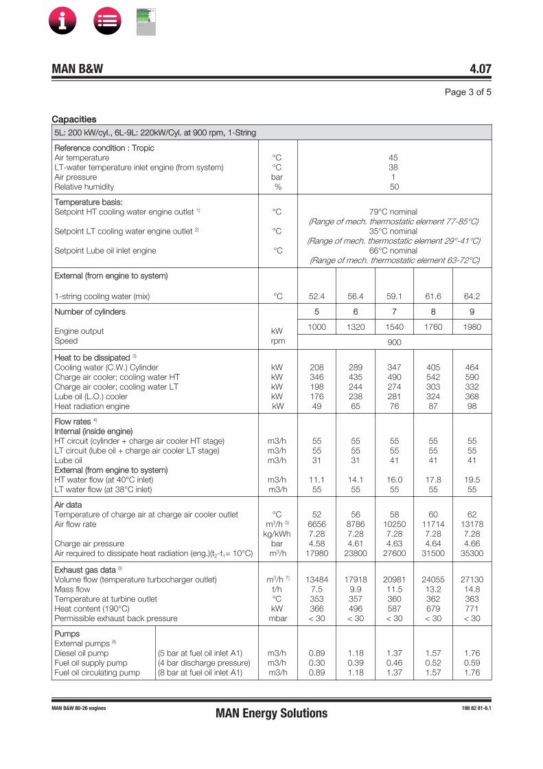
CCapacities5L: 200 kW/cyl., 6L-9L: 220kW/Cyl. at 900 rpm, 1-String
Reference condition : TropicAir temperature LT-water temperature inlet engine (from system) Air pressure Relative humidity
°C °C bar %
45 38 1 50
Temperature basis:Setpoint HT cooling water engine outlet 1)
Setpoint LT cooling water engine outlet 2)
Setpoint Lube oil inlet engine
°C
°C
°C
79°C nominal (Range of mech. thermostatic element 77-85°C)
35°C nominal (Range of mech. thermostatic element 29°-41°C)
66°C nominal (Range of mech. thermostatic element 63-72°C)
External (from engine to system)
1-string cooling water (mix) °C 52.4 56.4 59.1 61.6 64.2
Number of cylinders
Engine output Speed
kW rpm
5 6 7 8 9
1000 1320 1540 1760 1980
900
Heat to be dissipated 3)
Cooling water (C.W.) Cylinder Charge air cooler; cooling water HT Charge air cooler; cooling water LT Lube oil (L.O.) cooler Heat radiation engine
kW kW kW kW kW
20834619817649
28943524423865
34749027428176
40554230332487
46459033236898
Flow rates 4)
Internal (inside engine) HT circuit (cylinder + charge air cooler HT stage) LT circuit (lube oil + charge air cooler LT stage) Lube oil External (from engine to system) HT water flow (at 40°C inlet) LT water flow (at 38°C inlet)
m3/h m3/h m3/h
m3/h m3/h
555531
11.155
555531
14.155
555541
16.055
555541
17.855
555541
19.555
Air dataTemperature of charge air at charge air cooler outlet Air flow rate
Charge air pressure Air required to dissipate heat radiation (eng.)(t2-t1= 10°C)
°C m3/h 5)
kg/kWh bar m3/h
5266567.284.58
17980
5687867.284.61
23800
58102507.284.63
27600
60117147.284.64
31500
62131787.284.66
35300
Exhaust gas data 6)
Volume flow (temperature turbocharger outlet) Mass flow Temperature at turbine outlet Heat content (190°C) Permissible exhaust back pressure
m3/h 7)
t/h °C kW
mbar
134847.5353366< 30
179189.9357496< 30
2098111.5360587< 30
2405513.2362679< 30
2713014.8363771< 30
PumpsExternal pumps 8) Diesel oil pump Fuel oil supply pump Fuel oil circulating pump
(5 bar at fuel oil inlet A1)(4 bar discharge pressure)(8 bar at fuel oil inlet A1)
m3/h m3/h m3/h
0.890.300.89
1.180.391.18
1.370.461.37
1.570.521.57
1.760.591.76
MAN Energy Solutions
MAN B&W
IMO Tier ll Project Guide
MAN
Energy Solutions Project G
uideM
AN B
&W G
95ME-C
10.5

55L: 200 kW/cyl., 6L-9L: 220kW/Cyl. at 900 rpm, 1-String
Starting air dataAir consumption per start, incl. air for jet assist (TDI)Air consumption per start, incl. air for jet assist (Gali)
Nm3
Nm31.01.8
1.22.1
1.42.4
1.62.7
1.83.0
1)2)3)4)5)6)7)8)
HT cooling water flows first through HT stage charge air cooler, then through water jacket and cylinderhead, water temperature outlet engine regulated by mechanical thermostat.LT cooling water flows first through LT stage charge air cooler, then through lube oil cooler, water temper-ature outlet engine regulated by mechanical thermostat.Tolerance: + 10% for rating coolers, - 15% for heat recovery.Basic values for layout of the coolers.Under above mentioned reference conditions.Tolerance: quantity +/- 5%, temperature +/- 20°C.Under below mentioned temperature at turbine outlet and pressure according above mentioned referenceconditions.Tolerance of the pumps' delivery capacities must be considered by the manufactures.
D10050_1689479-1.5
Capacities5L:200 kW/cyl., 6L-9L: 220 kW/Cyl. at 1000 rpm, 1-String
Reference condition : TropicAir temperature LT-water temperature inlet engine (from system) Air pressure Relative humidity
°C °C bar %
45 38 1 50
Temperature basis:Setpoint HT cooling water engine outlet 1)
Setpoint LT cooling water engine outlet 2)
Setpoint Lube oil inlet engine
°C
°C
°C
79°C nominal (Range of mech. thermostatic element 77-85°C)
35°C nominal (Range of mech. thermostatic element 29°-41°C)
66°C nominal (Range of mech. thermostatic element 63-72°C)
External (from engine to system)
1-String coding water (mix) °C 50.6 54.1 56.4 58.6 60.8
Number of cylinders
Engine output Speed
kW rpm
5 6 7 8 9
1000 1320 1540 1760 1980
1000
Heat to be dissipated 3)
Cooling water (C.W.) Cylinder Charge air cooler; cooling water HT Charge air cooler; cooling water LT Lube oil (L.O.) cooler Heat radiation engine
kW kW kW kW kW
20632119217549
28540423823665
34245526627976
39950329432287
45654832136598
MAN Energy Solutions
MAN B&W
IMO Tier ll Project Guide
MAN
Energy Solutions Project G
uideM
AN B
&W G
95ME-C
10.5

55L:200 kW/cyl., 6L-9L: 220 kW/Cyl. at 1000 rpm, 1-String
Flow rates 4)
Internal (inside engine) HT circuit (cylinder + charge air cooler HT stage) LT circuit (lube oil + charge air cooler LT stage) Lube oil External (from engine to system) HT water flow (at 40°C inlet) LT water flow (at 38°C inlet)
m3/h m3/h m3/h
m3/h m3/h
616134
10.761
616134
13.561
616146
15.461
616146
17.161
616146
18.861
Air dataTemperature of charge air at charge air cooler outlet Air flow rate
Charge air pressure Air required to dissipate heat radiation (eng.)(t2-t1= 10°C)
°C m3/h 5)
kg/kWh bar m3/h
5166477.274.25
17980
5587747.274.28
23800
57102377.274.29
27600
59116997.274.30
31500
60131617.274.31
35300
Exhaust gas data 6)
Volume flow (temperature turbocharger outlet) Mass flow Temperature at turbine outlet Heat content (190°C) Permissible exhaust back pressure
m3/h 7)
t/h °C kW
mbar
137307.5365394< 30
182359.9369532< 30
2134811.5372628< 30
2446813.2373725< 30
2759414.8375823< 30
PumpsExternal pumps 8) Diesel oil pump Fuel oil supply pump Fuel oil circulating pump
(5 bar at fuel oil inlet A1)(4 bar)(8 bar)
m3/h m3/h m3/h
0.890.300.89
1.180.391.18
1.370.461.37
1.570.521.57
1.760.591.76
Starting air dataAir consumption per start, incl. air for jet assist (TDI) Air consumption per start, incl. air for jet assist (Gali)
Nm3
Nm31.01.8
1.22.1
1.42.4
1.62.7
1.83.0
1)2)3)4)5)6)7)8)
HT cooling water flows first through HT stage charge air cooler, then through water jacket and cylinderhead, water temperature outlet engine regulated by mechanical thermostat.LT cooling water flows first through LT stage charge air cooler, then through lube oil cooler, water temper-ature outlet engine regulated by mechanical thermostat.Tolerance: + 10% for rating coolers, - 15% for heat recovery.Basic values for layout of the coolers.Under above mentioned reference conditions.Tolerance: quantity +/- 5%, temperature +/- 20°C.Under below mentioned temperature at turbine outlet and pressure according above mentioned referenceconditions.Tolerance of the pumps' delivery capacities must be considered by the manufactures.
D10050_1689499-4.5
MAN Energy Solutions
MAN B&W
IMO Tier ll Project Guide
MAN
Energy Solutions Project G
uideM
AN B
&W G
95ME-C
10.5
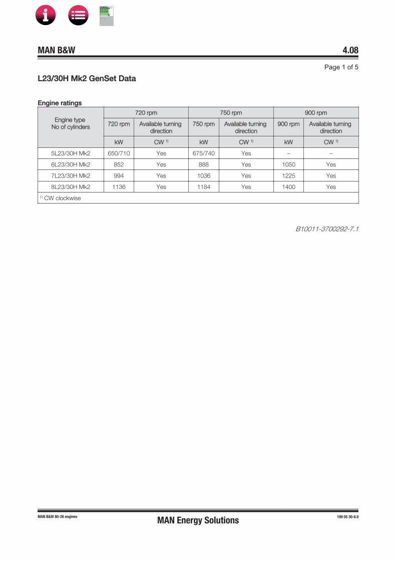
LL23/30H Mk2 GenSet Data
Engine ratings
Engine type No of cylinders
720 rpm 750 rpm 900 rpm
720 rpm Available turning direction
750 rpm Available turning direction
900 rpm Available turning direction
kW CW 1) kW CW 1) kW CW 1)
5L23/30H Mk2 650/710 Yes 675/740 Yes – –
6L23/30H Mk2 852 Yes 888 Yes 1050 Yes
7L23/30H Mk2 994 Yes 1036 Yes 1225 Yes
8L23/30H Mk2 1136 Yes 1184 Yes 1400 Yes
1) CW clockwise
B10011-3700292-7.1
MAN Energy Solutions
MAN B&W
IMO Tier ll Project Guide
MAN
Energy Solutions Project G
uideM
AN B
&W G
95ME-C
10.5
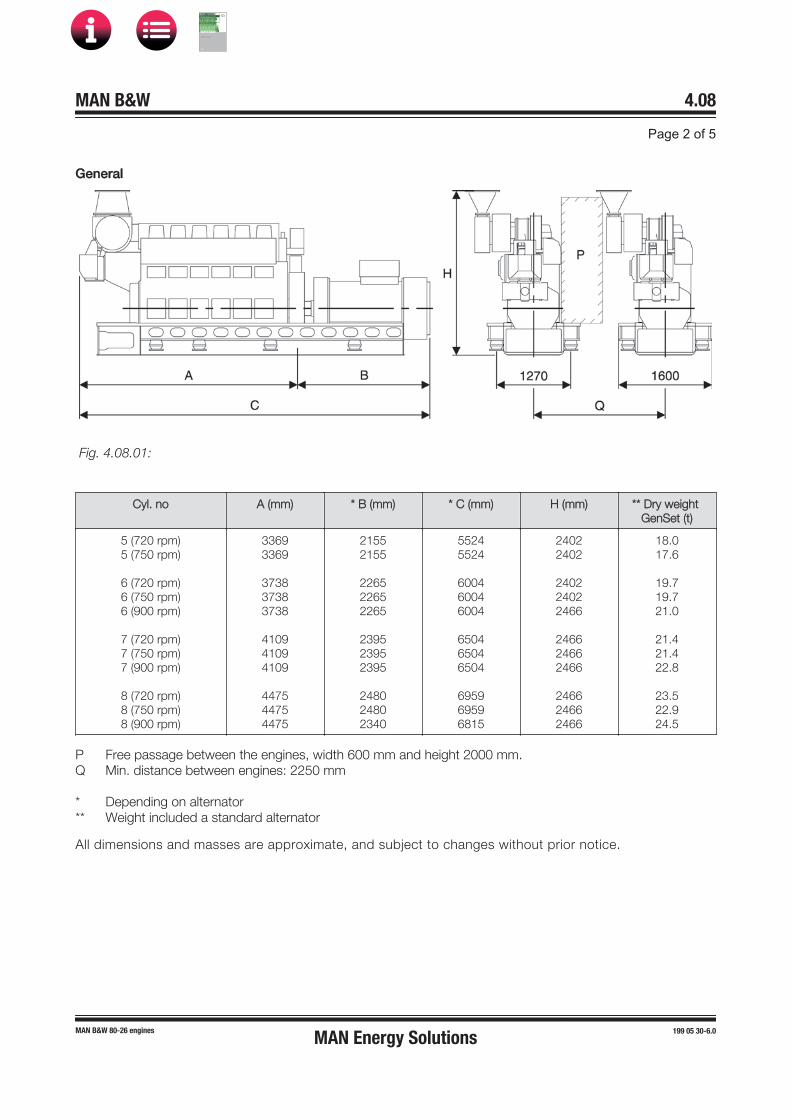
GGeneral
Cyl. no A (mm) * B (mm) * C (mm) H (mm) ** Dry weight GenSet (t)
5 (720 rpm)5 (750 rpm)
6 (720 rpm)6 (750 rpm)6 (900 rpm)
7 (720 rpm)7 (750 rpm)7 (900 rpm)
8 (720 rpm)8 (750 rpm)8 (900 rpm)
33693369
373837383738
410941094109
447544754475
21552155
226522652265
239523952395
248024802340
55245524
600460046004
650465046504
695969596815
24022402
240224022466
246624662466
246624662466
18.017.6
19.719.721.0
21.421.422.8
23.522.924.5
PQ
***
Free passage between the engines, width 600 mm and height 2000 mm.Min. distance between engines: 2250 mm
Depending on alternatorWeight included a standard alternator
All dimensions and masses are approximate, and subject to changes without prior notice.
MAN Energy Solutions
MAN B&W
IMO Tier ll Project Guide
MAN
Energy Solutions Project G
uideM
AN B
&W G
95ME-C
10.5

CCapacities5-8L23/30H Mk 2: 142 kW/Cyl., 720 rpm or 148 kW/Cyl., 750 rpm
Reference condition: TropicAir temperatureLT water temperature inlet engine (from system)Air pressureRelative humidity
°C°Cbar%
45361
50
Temperature basis 2)
Setpoint HT cooling water engibe outlet
Setpoint lube oil inlet engine
°C
°C
82°C(engine equipped with HT thermostatic valve)
60°C (SAE30), 66°C (SAE40)
Number of cylindersEngine outputSpeed
kWrpm
5710/740720/750
6852/888720/750
7994/1036720/750
81136/1184720/750
Heat to be dissipated 1)
Cooling water (CW) cylinderCharge air cooler; cooling water HT (1 stage cooler: no HT-stage)Charge air cooler; cooling water LTLube oil (LO) coolerHeat radiation engine
kW
kWkWkWkW
190/195
-299/32771/72
30
230/235
-356/39086/86
36
270/276
-413/452101/102
42
310/317
-470/514116/117
48
Air dataCharge air temp. at charge air cooler outlet, max.Air flow rate
Charge air pressureAir required to dissipate heat radiation (eng.) (t2-t1=10°C)
°Cm3/h 4)
kg/kWhbar
m3/h
554792/4994
7.393.08
9756
555750/5993
7.393.08
11708
556708/6992
7.393.08
13659
557667/7991
7.393.08
15610
Exhaust gas data 5)
Volume flow (temperature turbocharger outlet)Mass flowTemperature at turbine outletHeat content (190°C)Permissible exhaust back pressure
m3/h 6)
t/h°CkW
mbar
9516/99185.4/5.6
342244/254
< 30
11419/119026.5/6.7
342293/305
< 30
13323/138857.5/7.9
342341/356
< 30
15226/158698.6/9.0
342390/407
< 30
Pumps 3)
Engine driven pumpsHT cooling water pump (1-2.5 bar)LT cooling water pump (1-2.5 bar)Lube oil (3-5 bar)External pumps 7)
Diesel oil pump (4 bar at fuel oil inlet A1)Fuel oil supply pump 8) (4 bar discharge pressure) Fuel oil circulating pump (8 bar at fuel oil inlet A1)Cooling water pumps for "Internal cooling water system 1"+ LT cooling water pump (1-2.5 bar)Cooling water pumps for "Internal cooling water system 2"HT cooling water pump (1-2.5 bar)+ LT cooling water pump (1-2.5 bar)Lube oil pump (3-5 bar)
m3/hm3/hm3/h
m3/hm3/hm3/h
m3/h
m3/hm3/hm3/h
365516
0.520.250.53
35
203514
365516
0.620.310.63
42
244215
365520
0.730.360.74
48
284816
365520
0.830.410.84
55
325517
Starting air systemAir consumption per start Nm3 2.0 2.0 2.0 2.0
MAN Energy Solutions
MAN B&W
IMO Tier ll Project Guide
MAN
Energy Solutions Project G
uideM
AN B
&W G
95ME-C
10.5

1)2)
3)4)5)6)
7)8)
Tolerance: + 10 % for rating coolers, - 15 % for heat recovery LT cooling water flows in parallel through one-stage charge air cooler and lube oil cooler HT cooling waterflows only through water jacket and cylinder head, water temperature outlet engine regulated by mechan-ical thermostat Basic values for layout of the coolers Under above mentioned reference conditions Tolerance: quantity +/- 5%, temperature +/- 20°C Under below mentioned temperature at turbine outlet and pressure according above mentioned refer-ence conditions Tolerance of the pumps delivery capacities must be considered by the manufactures To compensate for built on pumps, ambient condition, calorific value and adequate circulations flow. TheISO fuel oil consumption is multiplied by 1.45.
D10050_3700220-9.0
CCapacities6-8L23/30H Mk 2: 175 kW/Cyl., 900 rpm
Reference condition: TropicAir temperatureLT-water temperature inlet engine (from system)Air pressureRelative humidity
°C°Cbar%
45361
50
Temperature basis 2)
Setpoint HT cooling water engine outlet
Setpoint lube oil inlet engine
°C
°C
82°C(engine equipped with HT thermostatic valve)
60° (SAE30), 66°C (SAE40)
Number of cylindersEngine outputSpeed
kWrpm
61050900
71225900
81400900
Heat to be dissipated 1)
Cooling water (CW) CylinderCharge air cooler; cooling water HT1 stage cooler: no HT-stageCharge air cooler; cooling water LTLube oil (LO) coolerHeat radiation engine
kW
kWkWkWkW
265
-44112635
311
-51214841
357
-58117047
Air dataTemp. of charge air at charge air cooler outlet, max.Air flow rate
Charge air pressureAir required to dissipate heat radiation (eng.) (t2-t1=10°C)
°Cm3/h 4)
kg/kWhbar
m3/h
5573557.673.1
11383
5585817.673.1
13334
5598067.673.1
15285
Exhaust gas data 5)
Volume flow (temperature turbocharger outlet)Mass flowTemperature at turbine outletHeat content (190°C)Permissible exhaust back pressure
m3/h 6)
t/h°CkW
mbar
152808.3371447< 30
178269.6371521< 30
2037311.0371595< 30
MAN Energy Solutions
MAN B&W
IMO Tier ll Project Guide
MAN
Energy Solutions Project G
uideM
AN B
&W G
95ME-C
10.5

66-8L23/30H Mk 2: 175 kW/Cyl., 900 rpm
Pumps 3)
Engine driven pumpsHT cooling water pump (1-2.5 bar)LT cooling water pump (1-2.5 bar)Lube oil (3-5 bar)External pumps 7)
Diesel oil pump (4 bar at fuel oil inlet A1)Fuel oil supply pump 8) (4 bar discharge pressure)Fuel oil circulating pump (8 bar at fuel oil inlet A1)Cooling water pumps for"Internal cooling water system 1"LT cooling water pump (1-2.5 bar)Cooling water pumps for"Internal cooling water system 2"HT cooling water pump (1-2.5 bar)LT cooling water pump (1-2.5 bar)Lube oil pump (3-5 bar)
m3/hm3/hm3/h
m3/hm3/hm3/h
m3/h
m3/hm3/hm3/h
456920
0.740.360.75
52
305217
456920
0.870.430.88
61
356118
456920
0.990.491.01
70
407019
Starting air systemAir consumption per start Nm3 2.0 2.0 2.0
1)2)
3)4)5)6)
7)8)
Tolerance: + 10 % for rating coolers, - 15 % for heat recoveryLT cooling water flows in parallel through one-stage charge air cooler and lube oil cooler HT cooling waterflows only through water jacket and cylinder head, water temperature outlet engine regulated by mechan-ical thermostat Basic values for layout of the coolers Under above mentioned reference conditions Tolerance: quantity +/- 5%, temperature +/- 20°C Under below mentioned temperature at turbine outlet and pressure according above mentioned refer-ence conditions Tolerance of the pumps delivery capacities must be considered by the manufactures To compensate for built on pumps, ambient condition, calorific value and adequate circulations flow, theISO fuel oil consumption is multiplied by 1.45.
D10050_3700221-0.0
MAN Energy Solutions
MAN B&W
IMO Tier ll Project Guide
MAN
Energy Solutions Project G
uideM
AN B
&W G
95ME-C
10.5

LL27/38 GenSet Data
Engine ratings
Engine type No of cylinders
720 rpm 750 rpm 720/750 MGO
720 rpm Available turningdirection
750 rpm Available turningdirection
720/750rpm
Available turningdirection
kW CW 1) kW CW 1) kW CW 1)
5L27/38 1500 Yes 1600 Yes – –
6L27/38 1980 Yes 1980 Yes 2100 Yes
7L27/38 2310 Yes 2310 Yes 2450 Yes
8L27/38 2640 Yes 2640 Yes 2800 Yes
9L27/38 2970 Yes 2970 Yes 3150 Yes
1) CW clockwise
B10011-1689467-1.0
MAN Energy Solutions
MAN B&W
IMO Tier ll Project Guide
MAN
Energy Solutions Project G
uideM
AN B
&W G
95ME-C
10.5

GGeneral
Cyl. no A (mm) * B (mm) * C (mm) H (mm) ** Dry weight GenSet (t)
5 (720 mm)5 (750 mm)
6 (720 mm)6 (750 mm)
7 (720 mm)7 (750 mm)
8 (720 mm)8 (750 mm)
9 (720 mm)9 (750 mm)
43464346
47914791
52365236
56815681
61266126
24862486
27662766
27662766
29862986
29862986
68326832
75577557
80028002
86678667
91129112
37123712
37123712
38993899
38993899
38993899
40.040.0
44.544.5
50.450.4
58.258.2
64.764.7
PQ
***
Free passage between the enginges, width 600 mm and height 2000 mm.Min. distance between engines: 2900 mm (without gallery) and 3100 mm (with gallery)
Depending on alternatorWeight included a standard alternator
All dimensions and masses are approximate, and subject to changes without prior notice.
MAN Energy Solutions
MAN B&W
IMO Tier ll Project Guide
MAN
Energy Solutions Project G
uideM
AN B
&W G
95ME-C
10.5

CCapacities5L27/38: 300 kW/cyl., 720 rpm, 6-9L27/38: 330 kW/cyl., 720 rpm
Reference condition : TropicAir temperature LT-water temperature inlet engine (from system) Air pressure Relative humidity
°C °C bar %
45 38 1 50
Temperature basis:Setpoint HT cooling water engine outlet 1)
Setpoint LT cooling water engine outlet 2)
Setpoint Lube oil inlet engine
°C
°C
°C
79°C nominal (Range of mech. thermostatic element 77-85°C)
35°C nominal (Range of mech. thermostatic element 29°-41°C)
66°C nominal (Range of mech. thermostatic element 63-72°C)
Number of cylinders
Engine output Speed
kW rpm
5 6 7 8 9
1500 1980 2310 2640 2970
720
Heat to be dissipated 3)
Cooling water (C.W.) Cylinder Charge air cooler; cooling water HT Charge air cooler; cooling water LT Lube oil (L.O.) cooler Heat radiation engine
kW kW kW kW kW
25646617822463
33059421627983
38567524232597
440750268372111
495820297418125
Flow rates 4)
Internal (inside engine) HT circuit (cylinder + charge air cooler HT stage) LT circuit (lube oil + charge air cooler LT stage) Lube oil External (from engine to system) HT water flow (at 40°C inlet) LT water flow (at 38°C inlet)
m3/h m3/h m3/h
m3/h m3/h
585864
1658
585864
20.258
585892
2358
585892
25.558
585892
2858
Air dataTemperature of charge air at charge air cooler outlet Air flow rate
Charge air pressure Air required to dissipate heat radiation (eng.)(t2-t1= 10°C)
°C m3/h 5)
kg/kWh bar m3/h
5091376.674.01
20414
53120616.674.01
26895
55140716.674.01
31431
56160826.674.01
35968
57180926.674.01
40504
Exhaust gas data 6)
Volume flow (temperature turbocharger outlet) Mass flow Temperature at turbine outlet Heat content (190°C) Permissible exhaust back pressure
m3/h 7)
t/h °C kW
mbar
1920310.3376575< 30
2534813.6376759< 30
2957215.9376886< 30
3379718.1376
1012< 30
3802120.4376
1139< 30
PumpsExternal pumps 8) Diesel oil pump Fuel oil supply pump Fuel oil circulating pump
(5 bar at fuel oil inlet A1)(4 bar discharge pressure)(8 bar at fuel oil inlet A1)
m3/h m3/h m3/h
1.060.511.06
1.400.671.40
1.630.791.63
1.870.901.87
2.101.012.10
Starting air dataAir consumption per start, incl. air for jet assist (IR/TDI) Nm3 2.5 2.9 3.3 3.8 4.3
MAN Energy Solutions
MAN B&W
IMO Tier ll Project Guide
MAN
Energy Solutions Project G
uideM
AN B
&W G
95ME-C
10.5

1)
2)
3)4)5)6)7)
8)
HT cooling water flows first through HT stage charge air cooler, then through water jacket and cylinderhead, water temperature outlet engine regulated by mechanical thermostat.LT cooling water flows first through LT stage charge air cooler, then through lube oil cooler, water temper-ature outlet engine regulated by mechanical thermostat.Tolerance: + 10% for rating coolers, - 15% for heat recovery.Basic values for layout of the coolers.Under above mentioned reference conditions.Tolerance: quantity +/- 5%, temperature +/- 20°C.Under below mentioned temperature at turbine outlet and pressure according above mentioned referenceconditions.Tolerance of the pumps' delivery capacities must be considered by the manufactures.
D10050_1689471-7.3
CCapacities5L27/38: 320 kW/cyl., 750 rpm, 6-9L27/38: 330 kW/cyl., 750 rpm
Reference condition : TropicAir temperature LT-water temperature inlet engine (from system) Air pressure Relative humidity
°C °C bar %
45 38 1 50
Temperature basis:Setpoint HT cooling water engine outlet 1)
Setpoint LT cooling water engine outlet 2)
Setpoint Lube oil inlet engine
°C
°C
°C
79°C nominal (Range of mech. thermostatic element 77-85°C)
35°C nominal (Range of mech. thermostatic element 29°-41°C)
66°C nominal (Range of mech. thermostatic element 63-72°C)
Number of cylinders
Engine output Speed
kW rpm
5 6 7 8 9
1600 1980 2310 2640 2970
750
Heat to be dissipated 3)
Cooling water (C.W.) Cylinder Charge air cooler; cooling water HT Charge air cooler; cooling water LT Lube oil (L.O.) cooler Heat radiation engine
kW kW kW kW kW
26348819423067
33058722527983
38566625232597
440741280372111
495811307418125
Flow rates 4)
Internal (inside engine) HT circuit (cylinder + charge air cooler HT stage) LT circuit (lube oil + charge air cooler LT stage) Lube oil External (from engine to system) HT water flow (at 40°C inlet) LT water flow (at 38°C inlet)
m3/h m3/h m3/h
m3/h m3/h
696966
16.869
696966
20.369
696996
2369
696996
25.769
696996
28.269
MAN Energy Solutions
MAN B&W
IMO Tier ll Project Guide
MAN
Energy Solutions Project G
uideM
AN B
&W G
95ME-C
10.5

55L27/38: 320 kW/cyl., 750 rpm, 6-9L27/38: 330 kW/cyl., 750 rpm
Air dataTemperature of charge air at charge air cooler outlet Air flow rate
Charge air pressure Air required to dissipate heat radiation (eng.)(t2-t1= 10°C)
°C m3/h 5)
kg/kWh bar m3/h
5199516.814.04
21710
53123146.814.04
26895
55143676.814.04
31431
56164196.814.04
35968
57184726.814.04
40504
Exhaust gas data 6)
Volume flow (temperature turbocharger outlet) Mass flow Temperature at turbine outlet Heat content (190°C) Permissible exhaust back pressure
m3/h 7)
t/h °C kW
mbar
2054611.2365589< 30
2542613.9365729< 30
2966416.2365850< 30
3390118.5365972< 30
3813920.8365
1093< 30
PumpsExternal pumps 8) Diesel oil pump Fuel oil supply pump Fuel oil circulating pump
(5 bar at fuel oil inlet A1)(4 bar discharge pressure)(8 bar at fuel oil inlet A1)
m3/h m3/h m3/h
1.130.541.13
1.400.671.40
1.630.791.63
1.870.901.87
2.101.012.10
Starting air dataAir consumption per start, incl. air for jet assist (IR/TDI) Nm3 2.5 2.9 3.3 3.8 4.3
1)
2)
3)4)5)6)7)
8)
HT cooling water flows first through HT stage charge air cooler, then through water jacket and cylinderhead, water temperature outlet engine regulated by mechanical thermostat.LT cooling water flows first through LT stage charge air cooler, then through lube oil cooler, water temper-ature outlet engine regulated by mechanical thermostat.Tolerance: + 10% for rating coolers, - 15% for heat recovery.Basic values for layout of the coolers.Under above mentioned reference conditions.Tolerance: quantity +/- 5%, temperature +/- 20°C.Under below mentioned temperature at turbine outlet and pressure according above mentioned referenceconditions.Tolerance of the pumps' delivery capacities must be considered by the manufactures.
D10050_1689472-9.3
MAN Energy Solutions
MAN B&W
IMO Tier ll Project Guide
MAN
Energy Solutions Project G
uideM
AN B
&W G
95ME-C
10.5

LL28/32H GenSet Data
Engine ratings
Engine type No of cylinders
720 rpm 750 rpm
720 rpm Available turning direction
750 rpm Available turning direction
kW CW 1) kW CW 1)
5L28/32H 1050 Yes 1100 Yes
6L28/32H 1260 Yes 1320 Yes
7L28/32H 1470 Yes 1540 Yes
8L28/32H 1680 Yes 1760 Yes
9L28/32H 1890 Yes 1980 Yes
1) CW clockwise
B10011-3700014-9.0
MAN Energy Solutions
MAN B&W
IMO Tier ll Project Guide
MAN
Energy Solutions Project G
uideM
AN B
&W G
95ME-C
10.5
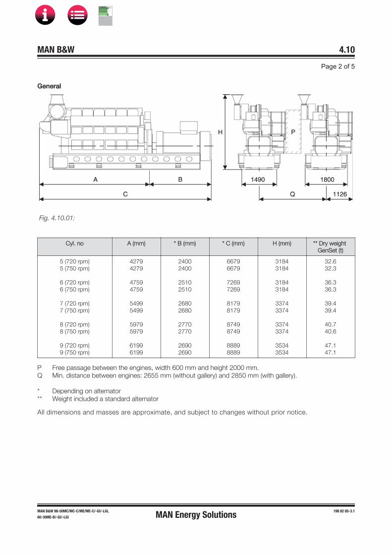
GGeneral
Cyl. no A (mm) * B (mm) * C (mm) H (mm) ** Dry weight GenSet (t)
5 (720 rpm)5 (750 rpm)
6 (720 rpm)6 (750 rpm)
7 (720 rpm)7 (750 rpm)
8 (720 rpm)8 (750 rpm)
9 (720 rpm)9 (750 rpm)
42794279
47594759
54995499
59795979
61996199
24002400
25102510
26802680
27702770
26902690
66796679
72697269
81798179
87498749
88898889
31843184
31843184
33743374
33743374
35343534
32.632.3
36.336.3
39.439.4
40.740.6
47.147.1
PQ
***
Free passage between the engines, width 600 mm and height 2000 mm.Min. distance between engines: 2655 mm (without gallery) and 2850 mm (with gallery).
Depending on alternatorWeight included a standard alternator
All dimensions and masses are approximate, and subject to changes without prior notice.
MAN Energy Solutions
MAN B&W
IMO Tier ll Project Guide
MAN
Energy Solutions Project G
uideM
AN B
&W G
95ME-C
10.5

CCapacities5L-9L: 210 kW/Cyl. at 720 rpm
Reference condition : TropicAir temperature LT water temperature inlet engine (from system) Air pressure Relative humidity
°C °C bar %
45 38 1 50
Number of cylindersEngine output Speed
kW rpm
51050720
61260720
71470720
81680720
91890720
Heat to be dissipated 1)
Cooling water (C.W.) Cylinder Charge air cooler; cooling water HT (Single stage charge air cooler)Charge air cooler; cooling water LT Lube oil (L.O.) cooler Heat radiation engine
kW kW
kW kW kW
2340
35519126
2810
39723031
3280
50026836
3750
55330642
4210
59234547
Flow rates 2)
Internal (inside engine)HT cooling water cylinder LT cooling water lube oil cooler * LT cooling water lube oil cooler ** LT cooling water charge air cooler
m3/h m3/h m3/h m3/h
377.82837
459.42845
50114055
5512.74065
6014.44075
Air dataTemperature of charge air at charge air cooler outlet Air flow rate
Charge air pressure Air required to dissipate heat radiation (engine) (t2-t1= 10°C)
°C m3/h 3) kg/kWh
bar m3/h
5173557.672.978425
5288267.672.97
10045
51102977.672.97
11665
52117687.672.97
13609
53132397.672.97
15230
Exhaust gas data 4)
Volume flow (temperature turbocharger outlet)Mass flow Temperature at turbine outlet Heat content (190°C) Permissible exhaust back pressure
m3/h 5) t/h °C kW
mbar
147118.3 347389< 30
176539.9347467< 30
2059511.6347545< 30
2353713.2347623< 30
2647914.9347701< 30
Starting air systemAir consumption per start Nm3 2.5 2.5 2.5 2.5 2.5
Pumps Engine driven pumps Fuel oil feed pump (5,5-7,5 bar) HT circuit cooling water (1,0-2,5 bar) LT circuit cooling water (1,0-2,5 bar) Lube oil (3,0-5,0 bar) External pumps 6)
Diesel oil pump (4 bar at fuel oil inlet A1) Fuel oil supply pump (4 bar discharge pressure) Fuel oil circulating pump (8 bar at fuel oil inlet A1) HT circuit cooling water (1,0-2,5 bar) LT circuit cooling water (1,0-2,5 bar) * LT circuit cooling water (1,0-2,5 bar) ** Lube oil (3,0-5,0 bar)
m3/h m3/h m3/h m3/h
m3/h m3/h m3/h m3/h m3/h m3/h m3/h
1.4454524
0.740.360.7437456522
1.4456024
0.890.430.8945547323
1.4607534
1.040.501.0450659525
1.4607534
1.190.571.195577
10527
1.4607534
1.340.641.346089
11528
MAN Energy Solutions
MAN B&W
IMO Tier ll Project Guide
MAN
Energy Solutions Project G
uideM
AN B
&W G
95ME-C
10.5

1)2)3)4)5)
6) * **
Tolerance: + 10 % for rating coolers, - 15 % for heat recoveryBasic values for layout of the coolersUnder above mentioned reference conditionsTolerance: quantity +/- 5%, temperature +/- 20°CUnder below mentioned temperature at turbine outlet and pressure according above mentioned refer-ence conditionsTolerance of the pumps delivery capacities must be considered by the manufacturesOnly valid for engines equipped with internal basic cooling water system no. 1 and 2.Only valid for engines equipped with combined coolers, internal basic cooling water system no. 3
D10050_3700075-9.0
CCapacities5L-9L: 220 kW/Cyl. at 750 rpm
Reference condition : TropicAir temperature LT water temperature inlet engine (from system) Air pressure Relative humidity
°C °C bar %
45 38 1 50
Number of cylindersEngine output Speed
kW rpm
51100750
61320750
71540750
81760750
91980750
Heat to be dissipated 1)
Cooling water (C.W.) Cylinder Charge air cooler; cooling water HT (Single stage charge air cooler)Charge air cooler; cooling water LT Lube oil (L.O.) cooler Heat radiation engine
kW kW
kW kW kW
2450
38720127
2940
43524133
3430
54528138
3920
58732144
4420
64836149
Flow rates 2)
Internal (inside engine)HT cooling water cylinder LT cooling water lube oil cooler * LT cooling water lube oil cooler ** LT cooling water charge air cooler
m3/h m3/h m3/h m3/h
377.82837
459.42845
50114055
5512.74065
6014.44075
Air dataTemperature of charge air at charge air cooler outlet Air flow rate
Charge air pressure Air required to dissipate heat radiation (engine) (t2-t1= 10°C)
°C m3/h 3) kg/kWh
bar m3/h
5278267.793.078749
5493917.793.07
10693
52109567.793.07
12313
52125217.793.07
14257
55140877.793.07
15878
Exhaust gas data 4)
Volume flow (temperature turbocharger outlet)Mass flow Temperature at turbine outlet Heat content (190°C) Permissible exhaust back pressure
m3/h 5) t/h °C kW
mbar
155208.8 342401< 30
1862410.5342481< 30
2172812.3342561< 30
2483214.1342641< 30
2793615.8342721< 30
Starting air systemAir consumption per start Nm3 2.5 2.5 2.5 2.5 2.5
MAN Energy Solutions
MAN B&W
IMO Tier ll Project Guide
MAN
Energy Solutions Project G
uideM
AN B
&W G
95ME-C
10.5

55L-9L: 220 kW/Cyl. at 750 rpm
Pumps Engine driven pumps Fuel oil feed pump (5,5-7,5 bar) HT circuit cooling water (1,0-2,5 bar) LT circuit cooling water (1,0-2,5 bar) Lube oil (3,0-5,0 bar) External pumps 6)
Diesel oil pump (4 bar at fuel oil inlet A1) Fuel oil supply pump (4 bar discharge pressure) Fuel oil circulating pump (8 bar at fuel oil inlet A1) HT circuit cooling water (1,0-2,5 bar) LT circuit cooling water (1,0-2,5 bar) * LT circuit cooling water (1,0-2,5 bar) ** Lube oil (3,0-5,0 bar)
m3/h m3/h m3/h m3/h
m3/h m3/h m3/h m3/h m3/h m3/h m3/h
1.4454524
0.780.370.7837456522
1.4456024
0.930.450.9345547323
1.4607534
1.090.521.0950659525
1.4607534
1.240.601.245577
10527
1.4607534
1.400.671.406089
11528
1)2)3)4)5)
6) * **
Tolerance: + 10 % for rating coolers, - 15 % for heat recoveryBasic values for layout of the coolersUnder above mentioned reference conditionsTolerance: quantity +/- 5%, temperature +/- 20°CUnder below mentioned temperature at turbine outlet and pressure according above mentioned refer-ence conditionsTolerance of the pumps delivery capacities must be considered by the manufacturesOnly valid for engines equipped with internal basic cooling water system no. 1 and 2.Only valid for engines equipped with combined coolers, internal basic cooling water system no. 3
D10050_3700076-0.0
MAN Energy Solutions
MAN B&W
IMO Tier ll Project Guide
MAN
Energy Solutions Project G
uideM
AN B
&W G
95ME-C
10.5

MAN B&W Page 1 of 1
This section is not applicable
GenSet Data
4.11
199 05 64-2.0MAN Energy Solutions
MAN B&W
IMO Tier ll Project Guide
MAN
Energy Solutions Project G
uideM
AN B
&W G
95ME-C
10.5

MAN 4.12Page 1 of 1
199 05 31-8.0
This section is available on request
L23/30DF GenSet Data
MAN Energy Solutions
MAN B&W
IMO Tier ll Project Guide
MAN
Energy Solutions Project G
uideM
AN B
&W G
95ME-C
10.5

LL28/32DF GenSet data
Engine ratings
Engine type No of cylinders
720 rpm Available turning direction
750 rpm Available turning direction
kW CW 1) kW CW 1)
5L28/32DF 1000 Yes 1000 Yes
6L28/32DF 1200 Yes 1200 Yes
7L28/32DF 1400 Yes 1400 Yes
8L28/32DF 1600 Yes 1600 Yes
9L28/32DF 1800 Yes 1800 Yes
1) CW clockwise
B10011-3700283-2.1
MAN Energy Solutions
MAN B&W
IMO Tier ll Project Guide
MAN
Energy Solutions Project G
uideM
AN B
&W G
95ME-C
10.5
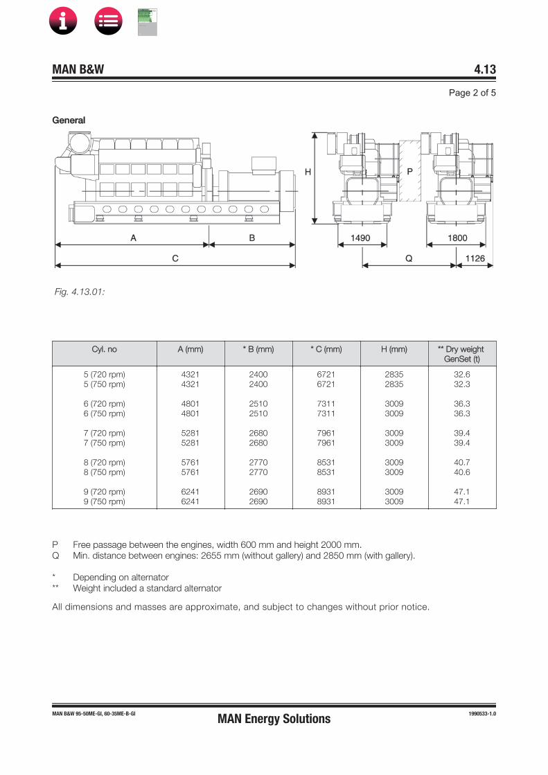
GGeneral
Cyl. no A (mm) * B (mm) * C (mm) H (mm) ** Dry weight GenSet (t)
5 (720 rpm)5 (750 rpm)
6 (720 rpm)6 (750 rpm)
7 (720 rpm)7 (750 rpm)
8 (720 rpm)8 (750 rpm)
9 (720 rpm)9 (750 rpm)
43214321
48014801
52815281
57615761
62416241
24002400
25102510
26802680
27702770
26902690
67216721
73117311
79617961
85318531
89318931
28352835
30093009
30093009
30093009
30093009
32.632.3
36.336.3
39.439.4
40.740.6
47.147.1
PQ
***
Free passage between the engines, width 600 mm and height 2000 mm.Min. distance between engines: 2655 mm (without gallery) and 2850 mm (with gallery).
Depending on alternatorWeight included a standard alternator
All dimensions and masses are approximate, and subject to changes without prior notice.
MAN Energy Solutions
MAN B&W
IMO Tier ll Project Guide
MAN
Energy Solutions Project G
uideM
AN B
&W G
95ME-C
10.5
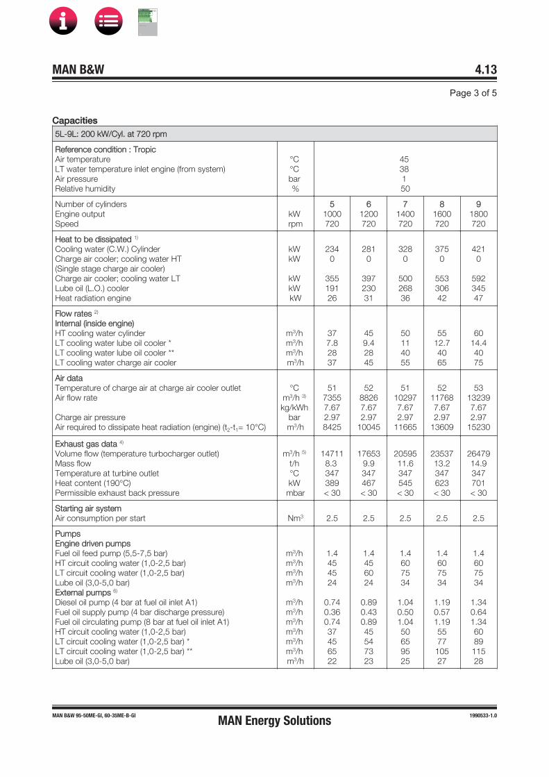
CCapacities5L-9L: 200 kW/Cyl. at 720 rpm
Reference condition : TropicAir temperature LT water temperature inlet engine (from system) Air pressure Relative humidity
°C °C bar %
45 38 1 50
Number of cylindersEngine output Speed
kW rpm
51000720
61200720
71400720
81600720
91800720
Heat to be dissipated 1)
Cooling water (C.W.) Cylinder Charge air cooler; cooling water HT (Single stage charge air cooler)Charge air cooler; cooling water LT Lube oil (L.O.) cooler Heat radiation engine
kW kW
kW kW kW
2340
35519126
2810
39723031
3280
50026836
3750
55330642
4210
59234547
Flow rates 2)
Internal (inside engine)HT cooling water cylinder LT cooling water lube oil cooler * LT cooling water lube oil cooler ** LT cooling water charge air cooler
m3/h m3/h m3/h m3/h
377.82837
459.42845
50114055
5512.74065
6014.44075
Air dataTemperature of charge air at charge air cooler outlet Air flow rate
Charge air pressure Air required to dissipate heat radiation (engine) (t2-t1= 10°C)
°C m3/h 3) kg/kWh
bar m3/h
5173557.672.978425
5288267.672.97
10045
51102977.672.97
11665
52117687.672.97
13609
53132397.672.97
15230
Exhaust gas data 4)
Volume flow (temperature turbocharger outlet)Mass flow Temperature at turbine outlet Heat content (190°C) Permissible exhaust back pressure
m3/h 5) t/h °C kW
mbar
147118.3 347389< 30
176539.9347467< 30
2059511.6347545< 30
2353713.2347623< 30
2647914.9347701< 30
Starting air systemAir consumption per start Nm3 2.5 2.5 2.5 2.5 2.5
Pumps Engine driven pumps Fuel oil feed pump (5,5-7,5 bar) HT circuit cooling water (1,0-2,5 bar) LT circuit cooling water (1,0-2,5 bar) Lube oil (3,0-5,0 bar) External pumps 6)
Diesel oil pump (4 bar at fuel oil inlet A1) Fuel oil supply pump (4 bar discharge pressure) Fuel oil circulating pump (8 bar at fuel oil inlet A1) HT circuit cooling water (1,0-2,5 bar) LT circuit cooling water (1,0-2,5 bar) * LT circuit cooling water (1,0-2,5 bar) ** Lube oil (3,0-5,0 bar)
m3/h m3/h m3/h m3/h
m3/h m3/h m3/h m3/h m3/h m3/h m3/h
1.4454524
0.740.360.7437456522
1.4456024
0.890.430.8945547323
1.4607534
1.040.501.0450659525
1.4607534
1.190.571.195577
10527
1.4607534
1.340.641.346089
11528
MAN Energy Solutions
MAN B&W
IMO Tier ll Project Guide
MAN
Energy Solutions Project G
uideM
AN B
&W G
95ME-C
10.5

1)2)3)4)5)
6) * **
Tolerance: + 10 % for rating coolers, - 15 % for heat recoveryBasic values for layout of the coolersUnder above mentioned reference conditionsTolerance: quantity +/- 5%, temperature +/- 20°CUnder below mentioned temperature at turbine outlet and pressure according above mentioned refer-ence conditionsTolerance of the pumps delivery capacities must be considered by the manufacturesOnly valid for engines equipped with internal basic cooling water system no. 1 and 2.Only valid for engines equipped with combined coolers, internal basic cooling water system no. 3
D10050_3700324-1.0
CCapacities5L-9L: 200 kW/Cyl. at 750 rpm
Reference condition : TropicAir temperature LT water temperature inlet engine (from system) Air pressure Relative humidity
°C °C bar %
45 38 1 50
Number of cylindersEngine output Speed
kW rpm
51000750
61200750
71400750
81600750
91800750
Heat to be dissipated 1)
Cooling water (C.W.) Cylinder Charge air cooler; cooling water HT (Single stage charge air cooler)Charge air cooler; cooling water LT Lube oil (L.O.) cooler Heat radiation engine
kW kW
kW kW kW
2450
38720127
2940
43524133
3430
54528138
3920
58732144
4420
64836149
Flow rates 2)
Internal (inside engine)HT cooling water cylinder LT cooling water lube oil cooler * LT cooling water lube oil cooler ** LT cooling water charge air cooler
m3/h m3/h m3/h m3/h
377.82837
459.42845
50114055
5512.74065
6014.44075
Air dataTemperature of charge air at charge air cooler outlet Air flow rate
Charge air pressure Air required to dissipate heat radiation (engine) (t2-t1= 10°C)
°C m3/h 3) kg/kWh
bar m3/h
5278267.793.078749
5493917.793.07
10693
52109567.793.07
12313
52125217.793.07
14257
55140877.793.07
15878
Exhaust gas data 4)
Volume flow (temperature turbocharger outlet)Mass flow Temperature at turbine outlet Heat content (190°C) Permissible exhaust back pressure
m3/h 5) t/h °C kW
mbar
155208.8 342401< 30
1862410.5342481< 30
2172812.3342561< 30
2483214.1342641< 30
2793615.8342721< 30
Starting air systemAir consumption per start Nm3 2.5 2.5 2.5 2.5 2.5
MAN Energy Solutions
MAN B&W
IMO Tier ll Project Guide
MAN
Energy Solutions Project G
uideM
AN B
&W G
95ME-C
10.5
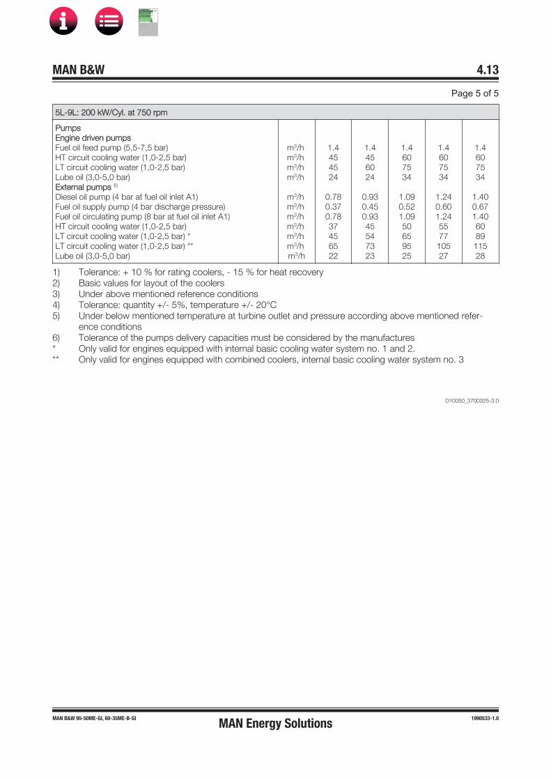
55L-9L: 200 kW/Cyl. at 750 rpm
Pumps Engine driven pumps Fuel oil feed pump (5,5-7,5 bar) HT circuit cooling water (1,0-2,5 bar) LT circuit cooling water (1,0-2,5 bar) Lube oil (3,0-5,0 bar) External pumps 6)
Diesel oil pump (4 bar at fuel oil inlet A1) Fuel oil supply pump (4 bar discharge pressure) Fuel oil circulating pump (8 bar at fuel oil inlet A1) HT circuit cooling water (1,0-2,5 bar) LT circuit cooling water (1,0-2,5 bar) * LT circuit cooling water (1,0-2,5 bar) ** Lube oil (3,0-5,0 bar)
m3/h m3/h m3/h m3/h
m3/h m3/h m3/h m3/h m3/h m3/h m3/h
1.4454524
0.780.370.7837456522
1.4456024
0.930.450.9345547323
1.4607534
1.090.521.0950659525
1.4607534
1.240.601.245577
10527
1.4607534
1.400.671.406089
11528
1)2)3)4)5)
6) * **
Tolerance: + 10 % for rating coolers, - 15 % for heat recoveryBasic values for layout of the coolersUnder above mentioned reference conditionsTolerance: quantity +/- 5%, temperature +/- 20°CUnder below mentioned temperature at turbine outlet and pressure according above mentioned refer-ence conditionsTolerance of the pumps delivery capacities must be considered by the manufacturesOnly valid for engines equipped with internal basic cooling water system no. 1 and 2.Only valid for engines equipped with combined coolers, internal basic cooling water system no. 3
D10050_3700325-3.0
MAN Energy Solutions
MAN B&W
IMO Tier ll Project Guide
MAN
Energy Solutions Project G
uideM
AN B
&W G
95ME-C
10.5

MAN B&W
Installation Aspects
5
MAN Energy Solutions
MAN B&W
IMO Tier ll Project Guide
MAN
Energy Solutions Project G
uideM
AN B
&W G
95ME-C
10.5
MAN B&W 5.01Page 1 of 1
198 43 75�4.8MAN B&W engines
A special crane beam for dismantling the turbo-charger must be fitted. The lifting capacity of the crane beam for dismantling the turbocharger is stated in Section 5.03.
The overhaul tools for the engine are designed to be used with a crane hook according to DIN 15400, June 1990, material class M and load ca-pacity 1Am and dimensions of the single hook type according to DIN 15401, part 1.
The total length of the engine at the crankshaft level may vary depending on the equipment to be fitted on the fore end of the engine, such as adjustable counterweights, tuning wheel, moment compensators or PTO.
Space Requirements and Overhaul Heights
The latest version of the Installation Drawings of this section is available for download at www.marine.man-es.com → ’Two-Stroke’ → ’Instal-lation Drawings’. Specify engine and accept the ‘Conditions for use’ before clicking on ‘Download Drawings’.
Space Requirements for the Engine
The space requirements stated in Section 5.02 are valid for engines rated at nominal MCR (L1).
The additional space needed for engines equipped with PTO is stated in Chapter 4.
If, during the project stage, the outer dimensions of the turbocharger seem to cause problems, it is possible, for the same number of cylinders, to use turbochargers with smaller dimensions by increasing the indicated number of turbochargers by one, see Chapter 3.
Overhaul of Engine
The distances stated from the centre of the crank-shaft to the crane hook are for the normal lifting procedure and the reduced height lifting proce-dure (involving tilting of main components). The lifting capacity of a normal engine room crane can be found in Fig. 5.04.01.
The area covered by the engine room crane shall be wide enough to reach any heavy spare part re-quired in the engine room.
A lower overhaul height is, however, available by using the MAN B&W Double�Jib crane, built by Danish Crane Building A/S, shown in Figs. 5.04.02 and 5.04.03.
Please note that the distance ‘E’ in Fig. 5.02.01, given for a double�jib crane is from the centre of the crankshaft to the lower edge of the deck beam.
MAN Energy Solutions
MAN B&W
IMO Tier ll Project Guide
MAN
Energy Solutions Project G
uideM
AN B
&W G
95ME-C
10.5

SSpace Requirement
Minimum access conditions around the engine to be used for an escape route is 600 mm.
The dimensions are given in mm, and are for guidance only. If the dimensions cannot be fulfilled, please contact MAN Energy Solutions or our local representative.
* To avoid human injury from rotating turning wheel, the turning wheel has to be shielded or access protected. (Yard supply)
Fig. 5.02.01: Space requirement for the engine, turbocharger on aft end, option: 4 59 121
MAN B&W 5.02
Page 1 of 3
MAN B&W G45ME-C9.5-TII 199 04 74-3.0MAN Energy Solutions
MAN B&W
IMO Tier ll Project Guide
MAN
Energy Solutions Project G
uideM
AN B
&W G
95ME-C
10.5
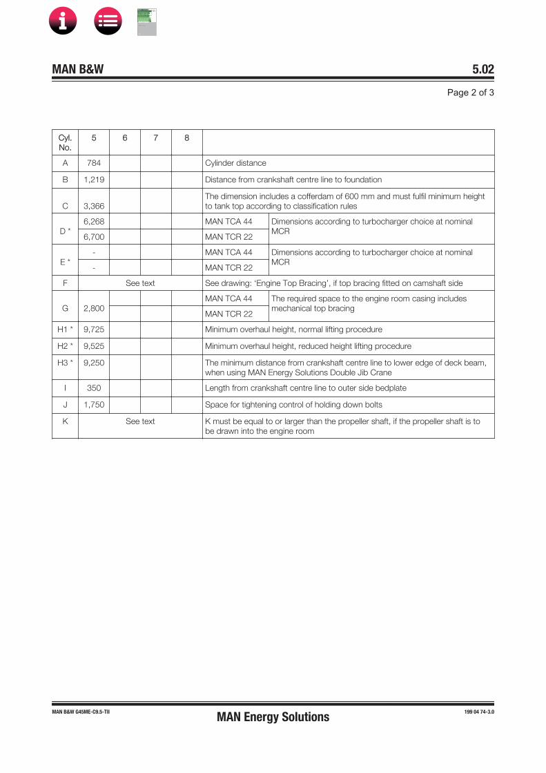
yl.No.
5 6
A 4 ylinder distance
1,219 istance from cran shaft centre line to foundation
, 66The dimension includes a cofferdam of 600 mm and must fulfil minimum height to tan top according to classification rules
*6,26 MAN T A 44 imensions according to turbocharger choice at nominal
M6, 00 MAN T 22
E *MAN T A 44 imensions according to turbocharger choice at nominal
MMAN T 22
F See te t See drawing: Engine Top racing , if top bracing fitted on camshaft side
2, 00MAN T A 44 The required space to the engine room casing includes
mechanical top bracingMAN T 22
1 * 9, 25 Minimum overhaul height, normal lifting procedure
2 * 9,525 Minimum overhaul height, reduced height lifting procedure
* 9,250 The minimum distance from cran shaft centre line to lower edge of dec beam, when using MAN Energy Solutions ouble ib rane
I 50 ength from cran shaft centre line to outer side bedplate
1, 50 Space for tightening control of holding down bolts
See te t must be equal to or larger than the propeller shaft, if the propeller shaft is to be drawn into the engine room
MAN B&W 5.02
Page 2 of 3
MAN B&W G45ME-C9.5-TII 199 04 74-3.0MAN Energy Solutions
MAN B&W
IMO Tier ll Project Guide
MAN
Energy Solutions Project G
uideM
AN B
&W G
95ME-C
10.5
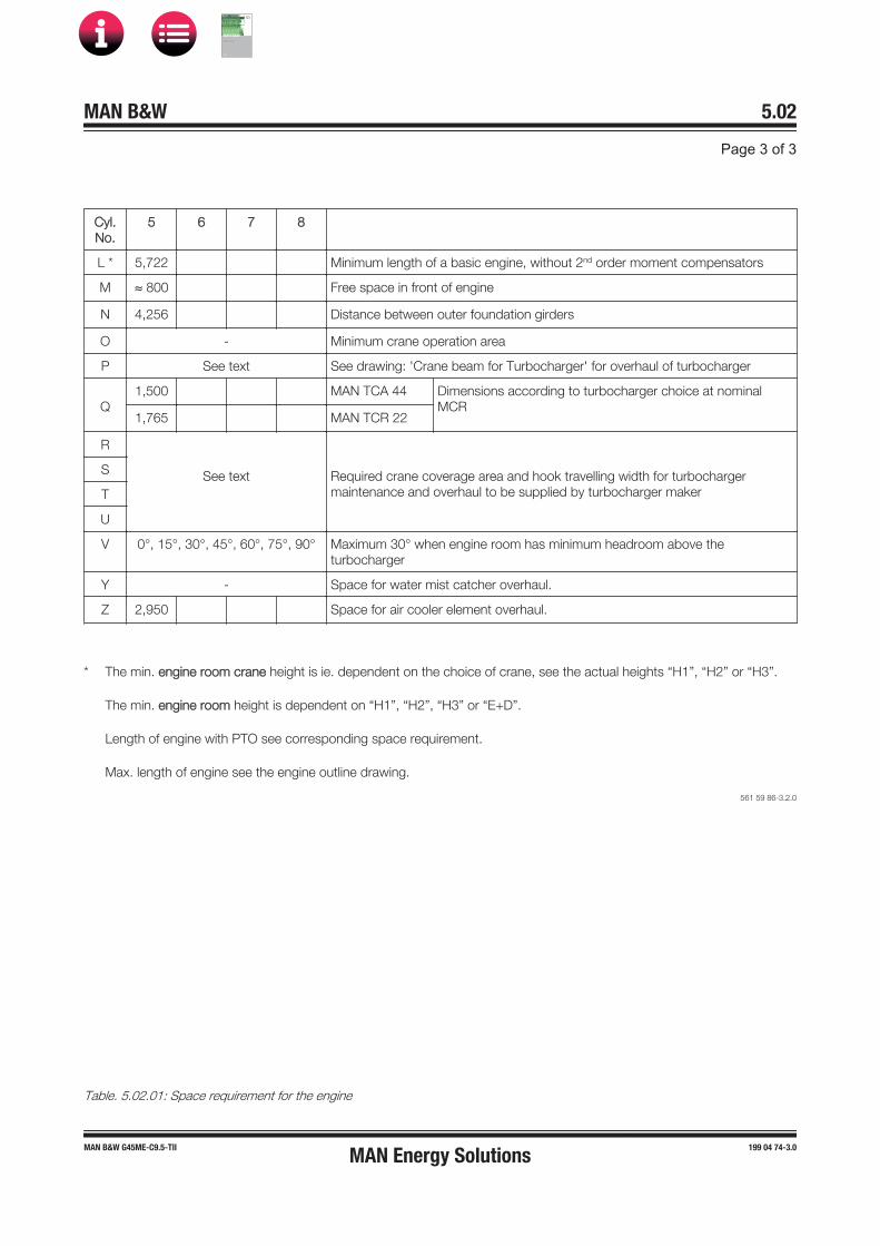
CCyl.No.
5 6 7 8
L * 5,722 Minimum length of a basic engine, without 2nd order moment compensators
M ≈ 800 Free space in front of engine
N 4,256 Distance between outer foundation girders
O - Minimum crane operation area
P See text See drawing: 'Crane beam for Turbocharger' for overhaul of turbocharger
Q1,500 MAN TCA 44 Dimensions according to turbocharger choice at nominal
MCR1,765 MAN TCR 22
R
See text Required crane coverage area and hook travelling width for turbochargermaintenance and overhaul to be supplied by turbocharger maker
S
T
U
V 0°, 15°, 30°, 45°, 60°, 75°, 90° Maximum 30° when engine room has minimum headroom above theturbocharger
Y - Space for water mist catcher overhaul.
Z 2,950 Space for air cooler element overhaul.
* The min. eengine room crane height is ie. dependent on the choice of crane, see the actual heights “H1”, “H2” or “H3”.
The min. eengine room height is dependent on “H1”, “H2”, “H3” or “E+D”.
Length of engine with PTO see corresponding space requirement.
Max. length of engine see the engine outline drawing.
561 59 86-3.2.0
Table. 5.02.01: Space requirement for the engine
MAN B&W 5.02
Page 3 of 3
MAN B&W G45ME-C9.5-TII 199 04 74-3.0MAN Energy Solutions
MAN B&W
IMO Tier ll Project Guide
MAN
Energy Solutions Project G
uideM
AN B
&W G
95ME-C
10.5

MAN B&W 5.03Page 1 of 5
MAN B&W engines 199 08 69-8.0
Crane beam for overhaul of turbocharger
If the travelling area of the engine room crane cov-ers the recommended area in the Engine Room Crane drawing, Fig. 5.04.01, crane beams can be omitted for the overhaul of turbocharger. If not, a crane beam with trolleys is required at each end of the turbocharger(s).
Crane beam and trolleys
Two trolleys are to be available at the compressor end and one trolley is needed at the gas inlet end:
• Crane beam no. 1 is for dismantling of turbo-charger components
• Crane beam no. 2 is for transporting turbo-charger components
as indicated in Figs. 5.03.01a and 5.03.02.
Lifting capacity
The crane beams are used and dimensioned for lifting the following components:
• Exhaust gas inlet casing
• Turbocharger inlet silencer
• Compressor casing
• Turbine rotor with bearings.
The crane beams are to be placed in relation to the turbocharger(s) so that the components around the gas outlet casing can be removed in connection with overhaul of the turbocharger(s).
The crane beam can be bolted to brackets that are fastened to the ship structure or to columns that are located on the top platform of the engine.
The lifting capacity of the crane beam for the heaviest component ‘W’, is indicated in Fig. 5.03.01b for the various turbocharger makes and types.
The crane beam shall be dimensioned for lifting the weight ‘W’ with a deflection of some 5 mm only.
Relative position of the crane hook
HB indicates the position of the crane hook in the vertical plane related to the centre of the turbo-charger. HB and b also specifies the minimum space for dismantling.
For engines with the turbocharger(s) located on the exhaust side, EoD: 4 59 122, the letter ‘a’ indi-cates the distance between vertical centrelines of the engine and the turbocharger.
MAN Energy Solutions
MAN B&W
IMO Tier ll Project Guide
MAN
Energy Solutions Project G
uideM
AN B
&W G
95ME-C
10.5
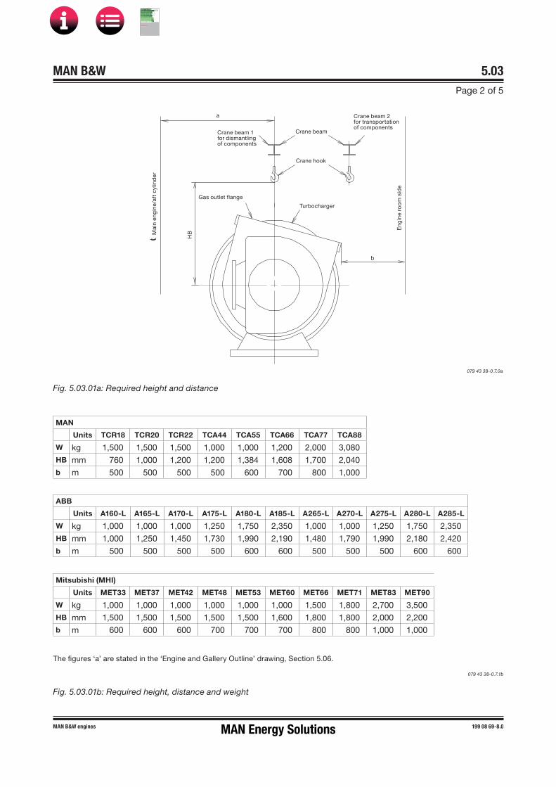
MAN B&W 5.03Page 2 of 5
MAN B&W engines 199 08 69-8.0
Fig. 5.03.01b: Required height, distance and weight
Mitsubishi (MHI)
Units MET33 MET37 MET42 MET48 MET53 MET60 MET66 MET71 MET83 MET90
W kg 1,000 1,000 1,000 1,000 1,000 1,000 1,500 1,800 2,700 3,500HB mm 1,500 1,500 1,500 1,500 1,500 1,600 1,800 1,800 2,000 2,200b m 600 600 600 700 700 700 800 800 1,000 1,000
MAN
Units TCR18 TCR20 TCR22 TCA44 TCA55 TCA66 TCA77 TCA88
W kg 1,500 1,500 1,500 1,000 1,000 1,200 2,000 3,080HB mm 760 1,000 1,200 1,200 1,384 1,608 1,700 2,040b m 500 500 500 500 600 700 800 1,000
The figures ‘a’ are stated in the ‘Engine and Gallery Outline’ drawing, Section 5.06.
ABB
Units A160-L A165-L A170-L A175-L A180-L A185-L A265-L A270-L A275-L A280-L A285-L
W kg 1,000 1,000 1,000 1,250 1,750 2,350 1,000 1,000 1,250 1,750 2,350HB mm 1,000 1,250 1,450 1,730 1,990 2,190 1,480 1,790 1,990 2,180 2,420b m 500 500 500 500 600 600 500 500 500 600 600
079 43 38-0.7.1b
079 43 38-0.7.0a
Fig. 5.03.01a: Required height and distance
Crane beam
Turbocharger
Gas outlet flange
a
HBM
ain
eng
ine/
aft
cylin
der
Crane hook
b
Eng
ine
roo
m s
ide
Crane beam 1for dismantlingof components
Crane beam 2for transportationof components
MAN Energy Solutions
MAN B&W
IMO Tier ll Project Guide
MAN
Energy Solutions Project G
uideM
AN B
&W G
95ME-C
10.5

MAN B&W 5.03Page 3 of 5
MAN B&W engines 199 08 69-8.0
Crane beam for turbochargers
Crane beam for transportation of components
Crane beam for dismantling of components
Spares
Crane beam for transportation of components
Crane beam for dismantling of components
079 43 38-0.7.0c
Fig. 5.03.02: Crane beam for turbocharger
MAN Energy Solutions
MAN B&W
IMO Tier ll Project Guide
MAN
Energy Solutions Project G
uideM
AN B
&W G
95ME-C
10.5

MAN B&W 5.03Page 4 of 5
MAN B&W engines 199 08 69-8.0
Crane beam for overhaul of air cooler, turbocharger on exhaust side
Overhaul/exchange of scavenge air cooler.
Valid for air cooler design for the following engines with more than one turbochargers mounted on the exhaust side.
1. Dismantle all the pipes in the area around theair cooler.
2. Dismantle all the pipes around the inlet coverfor the cooler.
3. Take out the cooler insert by using the aboveplaced crane beam mounted on the engine.
4. Turn the cooler insert to an upright position.
Engine room crane5
4
8
1 2 3
6
7
5. Dismantle the platforms below the air cooler.
6. Lower down the cooler insert between the gal-lery brackets and down to the engine roomfloor.Make sure that the cooler insert is supported,e.g. on a wooden support.
7. Move the air cooler insert to an area coveredby the engine room crane using the liftingbeam mounted below the lower gallery of theengine.
8. By using the engine room crane the air coolerinsert can be lifted out of the engine room.
178 52 73�4.1
Fig. 5.03.03: Crane beam for overhaul of air cooler, turbochargers located on exhaust side of the engine
MAN Energy Solutions
MAN B&W
IMO Tier ll Project Guide
MAN
Energy Solutions Project G
uideM
AN B
&W G
95ME-C
10.5

MAN B&W 5.03Page 5 of 5
199 08 90-0.0MAN B&W 50-26 engines
Crane beamfor A/C
43
5
21
1 2 3 4
5
517 93 99-9.0.1
Fig. 5.03.04: Crane beam for overhaul of air cooler, turbocharger located on aft end of the engine
Overhaul/exchange of scavenge air cooler.
The text and figures are for guidance only.
Valid for all engines with aft mounted turbocharger.
1. Dismantle all the pipes in the area around theair cooler.
2. Dismantle all the pipes around the inlet coverfor the cooler.
3. Take out the cooler insert by using the aboveplaced crane beam mounted on the engine.
4. Turn the cooler insert to an upright position.
5. By using the engine room crane the air coolerinsert can be lifted out of the engine room.
Crane beam for overhaul of air cooler, turbocharger on aft end
MAN Energy Solutions
MAN B&W
IMO Tier ll Project Guide
MAN
Energy Solutions Project G
uideM
AN B
&W G
95ME-C
10.5

MAN B&W 5.04Page 1 of 3
199 01 32-8.0MAN B&W G45ME-C9/-GI
1) The lifting tools for the engine are designed to fit together with a standard crane hook with a lifting capacity in accordance withthe figure stated in the table. If a larger crane hook is used, it may not fit directly to the overhaul tools, and the use of an interme-diate shackle or similar between the lifting tool and the crane hook will affect the requirements for the minimum lifting height inthe engine room (dimension B).
2) The hatched area shows the height where an MAN B&W Double-Jib Crane has to be used.519 46 28-0.1
530 70 52-5.4
The crane hook travelling area must cover at least the full length of the engine and a width in accord-ance with dimension A given on the drawing (see cross-hatched area).
It is furthermore recommended that the engine room crane be used for transport of heavy spare parts from the engine room hatch to the spare part stores and to the engine. See example on this drawing.
The crane hook should at least be able to reach down to a level corresponding to the centre line of the crankshaft.
For overhaul of the turbocharger(s), trolley mount-ed chain hoists must be installed on a separate crane beam or, alternatively, in combination with the engine room crane structure, see separate drawing with information about the required lifting capacity for overhaul of turbochargers.
Engine room crane
Mass in kg including lifting tools
Crane capacity in tons selected
in accordance with DIN and JIS
standard capacities
Craneoperating
widthin mm
Normal CraneHeight to crane hook in
mm for:MAN B&W Double-Jib Crane
Normal lifting
procedure
Reduced height liftingprocedure involving
tilting of main components
(option)
Building-in height in mm
Cylinder cover
complete with
exhaust valve
Cylinder liner with coolingjacket
Piston with
rod andstuffing
box
Normal crane
MAN B&W Double�Jib
Crane
A Minimum distance
H1Minimum
height fromcentre line crankshaft
to centre line crane hook
H2Minimum height from centre line crankshaft to
centre line crane hook
H3 Minimum
height from centre linecrankshaft
to underside deck beam
D Additional height
required for removal of exhaust
valve completewithout removing any exhaust stud
1,425 1,775 975 2.0 2x1.0 1,650 9,725 9,525 9,250 *)
Fig. 5.04.01: Engine room crane*) Available on request
Normal crane
Crankshaft
Deck beam
A A
A
1)H
1/H
2
2)
Deck
Deck beam
H3
D
Deck
MAN B&W Double-jib Crane Recommended area to be covered by the engine room crane
Spares
Engine room hatchMinimum area to be coveredby the engine room crane
Crankshaft
MAN Energy Solutions
MAN B&W
IMO Tier ll Project Guide
MAN
Energy Solutions Project G
uideM
AN B
&W G
95ME-C
10.5

MAN B&W 5.04
Page 2 of 3
198 45 34-8.4MAN B&W MC/MC-C, ME/ME-C/ME-C-GI/ME-B engines
Deck beam
MAN B&W Double�Jib crane
Centre line crankshaft
The MAN B&W Double�Jib crane is available from:
Danish Crane Building A/SP.O. Box 54Østerlandsvej 2DK�9240 Nibe, Denmark Telephone: + 45 98 35 31 33Telefax: + 45 98 35 30 33E�mail: [email protected]
178 24 86�3.2
Fig. 5.04.02: Overhaul with Double�Jib crane
Overhaul with MAN B&W Double�Jib Crane
MAN Energy Solutions
MAN B&W
IMO Tier ll Project Guide
MAN
Energy Solutions Project G
uideM
AN B
&W G
95ME-C
10.5
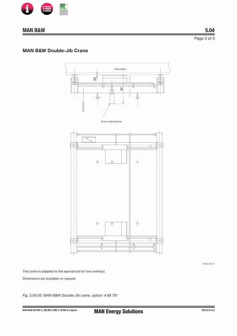
MAN B&W 5.04Page 3 of 3
MAN B&W MC/MC�C, ME/ME�C/ME-C-GI/ME-B engines 198 45 41�9.2
MAN B&W Double�Jib Crane
Deck beam
Chain collecting boxM
30
Fig. 5.04.03: MAN B&W DoubleJib crane, option: 4 88 701
This crane is adapted to the special tool for low overhaul.
Dimensions are available on request.
178 37 30-1.1
MAN Energy Solutions
MAN B&W
IMO Tier ll Project Guide
MAN
Energy Solutions Project G
uideM
AN B
&W G
95ME-C
10.5

MAN B&W 5.05Page 1 of 1
198 47 15-8.3MAN B&W MC/MC-C, ME/ME-C/ME-GI/ME-B engines
Engine Outline, Galleries and Pipe Connections
Engine outline
The total length of the engine at the crankshaft level may vary depending on the equipment to be fitted on the fore end of the engine, such as adjustable counterweights, tuning wheel, moment compensators or PTO, which are shown as alter-natives in Section 5.06
Engine masses and centre of gravity
The partial and total engine masses appear from Section 19.04, ‘Dispatch Pattern’, to which the masses of water and oil in the engine, Section 5.08, are to be added. The centre of gravity is shown in Section 5.07, in both cases including the water and oil in the engine, but without moment compensators or PTO.
Gallery outline
Section 5.06 show the gallery outline for engines rated at nominal MCR (L1).
Engine pipe connections
The positions of the external pipe connections on the engine are stated in Section 5.09, and the cor-responding lists of counterflanges for pipes and turbocharger in Section 5.10.
The flange connection on the turbocharger gas outlet is rectangular, but a transition piece to a cir-cular form can be supplied as an option: 4 60 601.
MAN Energy Solutions
MAN B&W
IMO Tier ll Project Guide
MAN
Energy Solutions Project G
uideM
AN B
&W G
95ME-C
10.5

MAN B&W 5.06Page 1 of 3
MAN B&W G45ME-C9.5/-GI 199 01 35-3.0
Engine and Gallery Outline
Fig. 5.06.01a: Engine outline example: 8G95ME�C9 with TCA88 turbochargers on exhaust side
561 21 33-9.1.0a
Viewed from exhaust side
Fore. Aft.
a
3,920
784
1,233
873 1,713
9,56
2
2,97
0 Ø
MAN Energy Solutions
MAN B&W
IMO Tier ll Project Guide
MAN
Energy Solutions Project G
uideM
AN B
&W G
95ME-C
10.5

MAN B&W 5.06Page 2 of 3
MAN B&W G45ME-C9.5/-GI 199 01 35-3.0
Fig. 5.06.01b: Engine outline example: 6G45ME�C9 with TCA55 turbochargers on exhaust side
561 21 33-9.1.0.b
TC type a b c1
MAN TCA55 1,440 5,800 2,770
C
yl.1
Fore. Aft.
0
0 0
Viewed from aft side Viewed from man side
A
ft C
yl.
c
1,75
3
1,75
3
2,40
0
1,82
8
1,30
0
4,40
0
474
1,174
1,711
4,311
b
224
711
69
6,711
5,010
3,400
5,520
7,851
3,400
0
MAN Energy Solutions
MAN B&W
IMO Tier ll Project Guide
MAN
Energy Solutions Project G
uideM
AN B
&W G
95ME-C
10.5

MAN B&W 5.06Page 3 of 3
MAN B&W G45ME-C9.5/-GI 199 01 35-3.0
Fig. 5.06.01c: Engine outline example: 6G45ME�C9 with TCA55 turbochargers on exhaust side
561 21 33-9.1.0.c
The dimension are in mm and subject to revision without notice.
Please note that the latest version of the dimensioned drawing is available for download at www.marine.man-es.com → ’Two-Stroke’ → ’Installation Drawings’. First choose engine series, then engine type and select ‘Outline drawing’ for the actual number of cylinders and type of turbocharger installation in the list of drawings available for download.
2 holes for piston overhauling
Lower platform
Upper platform
Fore.
Fore.
Aft.
Aft.
1,50
0
1,650
2,40
0
1,650
1,8
60
1,650
1,650
2,39
5
1,8
00
4,40
0
700x45°
700x45°
400x45°
400x45°
550x45° 550x45°
252.5x450º252.5x450º
250x45° 200x45°
MAN Energy Solutions
MAN B&W
IMO Tier ll Project Guide
MAN
Energy Solutions Project G
uideM
AN B
&W G
95ME-C
10.5

CCentre of Gravity
No. of cylinders 5 6 7 8
Distance X mm 63 65Available on request
Distance Y mm 1,895 2,257
Distance Z mm 2,203 2,575
All values stated are approximate. For engine dry weights, see Dispatch Pattern, Section 19.04.
Fig. 5.07.01: Centre of gravity, G45ME-C9.5 with turbocharger mounted on the aft end
MAN Energy Solutions
MAN B&W
IMO Tier ll Project Guide
MAN
Energy Solutions Project G
uideM
AN B
&W G
95ME-C
10.5

NNo. of cylinders 5 6 7 8
Distance X mm 218 126Available on request
Distance Y mm 1,683 2,115
Distance Z mm 2,167 2,021
All values stated are approximate. For engine dry weights, see Dispatch Pattern, Section 19.04. * Data for engines with a different number of turbochargers is available on request.
Fig. 5.07.02: Centre of gravity, G45ME-C9.5 with turbocharger(s) mounted on the exhaust side
MAN Energy Solutions
MAN B&W
IMO Tier ll Project Guide
MAN
Energy Solutions Project G
uideM
AN B
&W G
95ME-C
10.5

MMass of Water and Oil
No. of cylinders
Mass of water and oil in engine in service
Mass of water Mass of oil
Jacket cooling water
kg
Scavenge aircooling water
kg
Total
kg
Enginesystem
kg
Oil pan
kg
Hydraulic system
kg
Total
kg
5 492 332 8824 264 487 120 8871
6 589 358 9947 318 679 134 11,131
7 685 449 11,134 371 728 149 11,248
8 781 498 11,279 425 776 163 11,364
9 878 560 11,438 472 873 199 11,544
561 59 66-0.0.0
Table 5.08.01: Water and oil in engine
MAN B&W 5.08
Page 1 of 1
MAN B&W G45ME-C9.5 199 08 44-6.0MAN Energy Solutions
MAN B&W
IMO Tier ll Project Guide
MAN
Energy Solutions Project G
uideM
AN B
&W G
95ME-C
10.5

198 78 90-9.0
MAN B&W 5.09Page 1 of 1
This section is available on request
Engine pipe connections
MAN Energy Solutions
MAN B&W
IMO Tier ll Project Guide
MAN
Energy Solutions Project G
uideM
AN B
&W G
95ME-C
10.5
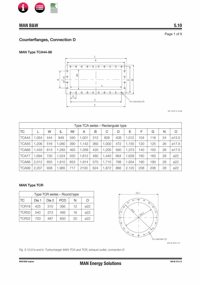
CCounterflanges, Connection D
MAN Type TCA44-88
Type TCA series – Rectangular type
TC L W IL IW A B C D E F G N O
TCA44 1,054 444 949 340 1,001 312 826 408 1,012 104 118 24 ø13.5
TCA55 1,206 516 1,080 390 1,143 360 1,000 472 1,155 120 125 26 ø17.5
TCA66 1,433 613 1,283 463 1,358 420 1,200 560 1,373 140 150 26 ø17.5
TCA77 1,694 720 1,524 550 1,612 480 1,440 664 1,628 160 160 28 ø22
TCA88 2,012 855 1,810 653 1,914 570 1,710 788 1,934 190 190 28 ø22
TCA99 2,207 938 1,985 717 2100 624 1,872 866 2,120 208 208 28 ø22
MAN Type TCR
Type TCR series – Round type
TC Dia 1 Dia 2 PCD N O
TCR18 425 310 395 12 ø22
TCR20 540 373 495 16 ø22
TCR22 703 487 650 20 ø22
Fig. 5.10.01a and b: Turbocharger MAN TCA and TCR, exhaust outlet, connection D
MAN Energy Solutions
MAN B&W
IMO Tier ll Project Guide
MAN
Energy Solutions Project G
uideM
AN B
&W G
95ME-C
10.5
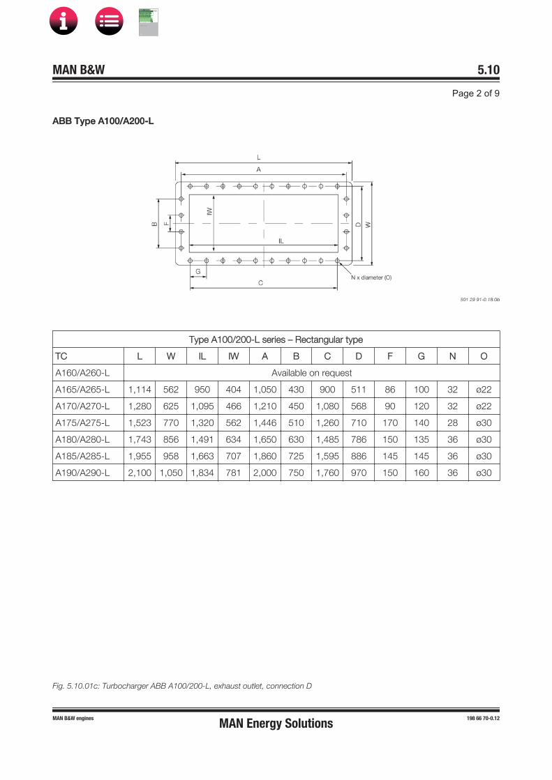
AABB Type A100/A200-L
Type A100/200-L series – Rectangular type
TC L W IL IW A B C D F G N O
A160/A260-L Available on request
A165/A265-L 1,114 562 950 404 1,050 430 900 511 86 100 32 ø22
A170/A270-L 1,280 625 1,095 466 1,210 450 1,080 568 90 120 32 ø22
A175/A275-L 1,523 770 1,320 562 1,446 510 1,260 710 170 140 28 ø30
A180/A280-L 1,743 856 1,491 634 1,650 630 1,485 786 150 135 36 ø30
A185/A285-L 1,955 958 1,663 707 1,860 725 1,595 886 145 145 36 ø30
A190/A290-L 2,100 1,050 1,834 781 2,000 750 1,760 970 150 160 36 ø30
Fig. 5.10.01c: Turbocharger ABB A100/200-L, exhaust outlet, connection D
MAN Energy Solutions
MAN B&W
IMO Tier ll Project Guide
MAN
Energy Solutions Project G
uideM
AN B
&W G
95ME-C
10.5

MMHI Type MET
503 26 38-6.5.1a
Type MET – Rectangular type
TC L W IL IW A B C D F G N O
Series MB
MET33 Available on request
MET42 1,094 381 1,004 291 1,061 261 950 351 87 95 30 ø15
MET48 1,240 430 1,140 330 1,206 300 1,070 396 100 107 30 ø15
MET53 1,389 485 1,273 369 1,340 330 1,200 440 110 120 30 ø20
MET60 1,528 522 1,418 410 1,488 330 1,320 482 110 110 34 ø20
MET66 1,713 585 1,587 459 1,663 372 1,536 535 124 128 34 ø20
MET71 1,837 617 1,717 497 1,792 480 1,584 572 120 132 36 ø20
MET83 2,163 731 2,009 581 2,103 480 1,920 671 160 160 34 ø24
MET90 2,378 801 2,218 641 2,318 525 2,100 741 175 175 34 ø24
Series MA
MET33 700 310 605 222 670 180 550 280 90 110 18 ø15
MET42 883 365 793 275 850 240 630 335 80 90 24 ø15
MET53 1,122 465 1,006 349 1,073 300 945 420 100 105 28 ø20
MET60 1,230 500 1,120 388 1,190 315 1,050 460 105 105 30 ø20
MET66 1,380 560 1,254 434 1,330 345 1,200 510 115 120 30 ø20
MET71 1,520 600 1,400 480 1,475 345 1,265 555 115 115 34 ø20
MET83 1,740 700 1,586 550 1,680 450 1,500 640 150 150 30 ø24
MET90 1,910 755 1,750 595 1,850 480 1,650 695 160 165 30 ø24
Fig. 5.10.01d: Turbocharger MHI MET MB and MA, exhaust outlet, connection D
MAN Energy Solutions
MAN B&W
IMO Tier ll Project Guide
MAN
Energy Solutions Project G
uideM
AN B
&W G
95ME-C
10.5

CCounterflanges, Connection E
MAN Type TCA
TC Dia/ISO Dia/JIS OD PCD N O Thickness of flanges
TCA44 61 61 120 90 4 ø14 14
TC Dia/ISO Dia/JIS L W N O Thickness of flanges
TCA55 61 61 86 76 4 ø14 16
TCA66 90 90 110 90 4 ø18 16
Fig. 5.10.01e and f: Turbocharger MAN TCA, venting of lube oil discharge pipe, connection E
MAN Energy Solutions
MAN B&W
IMO Tier ll Project Guide
MAN
Energy Solutions Project G
uideM
AN B
&W G
95ME-C
10.5

TTC Dia/ISO Dia/JIS L W N O Thickness of flanges
TCA77 115 115 126 72 4 ø18 18
TCA88 141 141 150 86 4 ø18 18
TCA99 141 141 164 94 4 ø22 24
Fig. 5.10.01g: Turbocharger MAN TCA, venting of lube oil discharge pipe, connection E
MAN Energy Solutions
MAN B&W
IMO Tier ll Project Guide
MAN
Energy Solutions Project G
uideM
AN B
&W G
95ME-C
10.5

AABB Type A100/A200-L
TC Dia 1 PCD L = W N O Thickness of flanges
A160/A260-L Available on request
A165/A265-L 43 100 106 8 ø8.5 18
A170/A270-L 77 100 115 8 ø11 18
A175/A275-L 77 126 140 8 ø11 18
A180/A280-L 90 142 158 8 ø13 18
A185/A285-L 115 157 178 8 ø13 18
A190/A290-L 115 175 197 8 ø13 18
Fig. 5.10.01h: Turbocharger ABB A100/200-L, venting of lube oil discharge pipe, connection E
MAN Energy Solutions
MAN B&W
IMO Tier ll Project Guide
MAN
Energy Solutions Project G
uideM
AN B
&W G
95ME-C
10.5
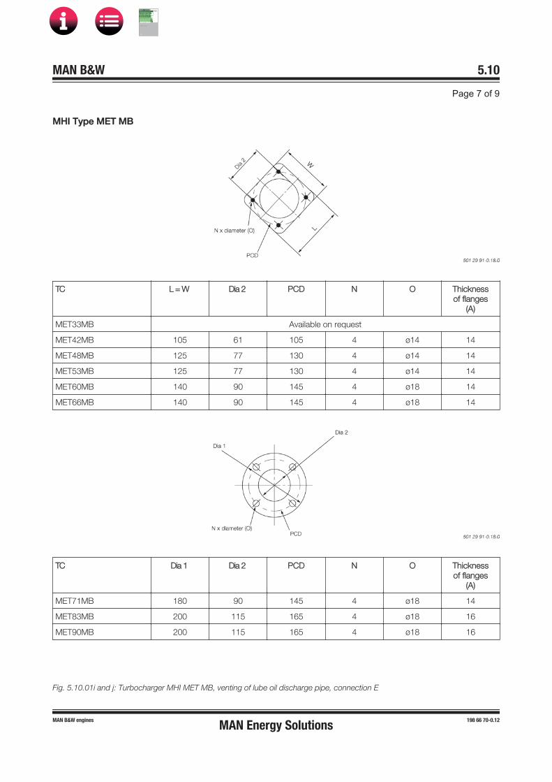
MMHI Type MET MB
TC L = W Dia 2 PCD N O Thicknessof flanges
(A)
MET33MB Available on request
MET42MB 105 61 105 4 ø14 14
MET48MB 125 77 130 4 ø14 14
MET53MB 125 77 130 4 ø14 14
MET60MB 140 90 145 4 ø18 14
MET66MB 140 90 145 4 ø18 14
TC Dia 1 Dia 2 PCD N O Thicknessof flanges
(A)
MET71MB 180 90 145 4 ø18 14
MET83MB 200 115 165 4 ø18 16
MET90MB 200 115 165 4 ø18 16
Fig. 5.10.01i and j: Turbocharger MHI MET MB, venting of lube oil discharge pipe, connection E
MAN Energy Solutions
MAN B&W
IMO Tier ll Project Guide
MAN
Energy Solutions Project G
uideM
AN B
&W G
95ME-C
10.5
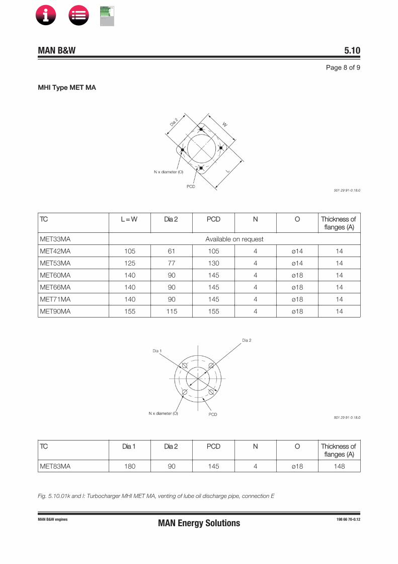
MMHI Type MET MA
TC L = W Dia 2 PCD N O Thickness of flanges (A)
MET33MA Available on request
MET42MA 105 61 105 4 ø14 14
MET53MA 125 77 130 4 ø14 14
MET60MA 140 90 145 4 ø18 14
MET66MA 140 90 145 4 ø18 14
MET71MA 140 90 145 4 ø18 14
MET90MA 155 115 155 4 ø18 14
TC Dia 1 Dia 2 PCD N O Thickness of flanges (A)
MET83MA 180 90 145 4 ø18 148
Fig. 5.10.01k and l: Turbocharger MHI MET MA, venting of lube oil discharge pipe, connection E
MAN Energy Solutions
MAN B&W
IMO Tier ll Project Guide
MAN
Energy Solutions Project G
uideM
AN B
&W G
95ME-C
10.5
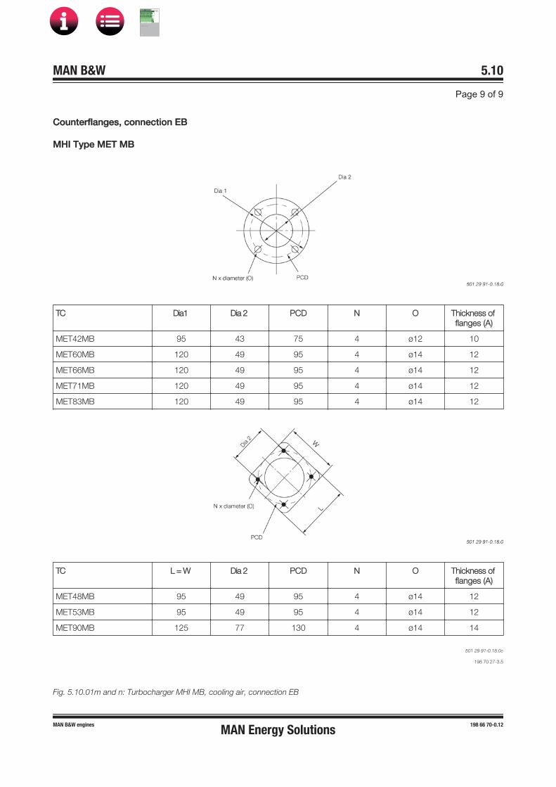
CCounterflanges, connection EB
MHI Type MET MB
TC Dia1 Dia 2 PCD N O Thickness of flanges (A)
MET42MB 95 43 75 4 ø12 10
MET60MB 120 49 95 4 ø14 12
MET66MB 120 49 95 4 ø14 12
MET71MB 120 49 95 4 ø14 12
MET83MB 120 49 95 4 ø14 12
TC L = W Dia 2 PCD N O Thickness of flanges (A)
MET48MB 95 49 95 4 ø14 12
MET53MB 95 49 95 4 ø14 12
MET90MB 125 77 130 4 ø14 14
501 29 91-0.18.0c
198 70 27-3.5
Fig. 5.10.01m and n: Turbocharger MHI MB, cooling air, connection EB
MAN Energy Solutions
MAN B&W
IMO Tier ll Project Guide
MAN
Energy Solutions Project G
uideM
AN B
&W G
95ME-C
10.5
EEngine Seating and Holding Down Bolts
The latest version of the Installation Drawings of this section is available for download at www.marine.man-es.com ’Two-Stroke’ Installa-tion Drawings’. Specify engine and accept the ‘Conditions for use’ before clicking on ‘Download Drawings’.
Engine seating and arrangement of holding down bolts
The dimensions of the seating stated in Figs. 5.12.01 and 5.12.02 are for guidance only.
The engine is designed for mounting on epoxy chocks, EoD: 4 82 102, in which case the under-side of the bedplate’s lower flanges has no taper.
The epoxy types approved by MAN Energy Solutions are:
• ‘Chockfast Orange PR 610 TCF’ and ‘Epocast36’ from ITW Philadelphia Resins Corporation,USA.
• ‘Durasin’ fromDaemmstoff Industrie Korea Ltd.
• ‘EPY’ fromMarine Service Jaroszewicz S.C., Poland.
• ‘Loctite Fixmaster Marine Chocking’, Henkel.
• 'CMP Liner Blue' fromChugoku Marine Paints Ltd, Japan.
MAN Energy Solutions
MAN B&W
IMO Tier ll Project Guide
MAN
Energy Solutions Project G
uideM
AN B
&W G
95ME-C
10.5

EEpoxy Chocks Arrangement
For details of chocks and bolts see special drawings. For securing of supporting chocks see special drawing.
Preparing holes for holding down bolts
1) The engine builder drills the holes for holding down bolts in the bedplate while observing the toleranced locations indicated on MAN Energy Solutions' drawings for machining the bedplate
2) The shipyard drills the holes for holding down bolts in the top plates while observing the toleranced locations given on the present drawing
3) The holding down bolts must be made in accordance with MAN Energy Solutions' drawings of these bolts.
Fig. 5.12.01: Arrangement of epoxy chocks and holding down bolts
MAN Energy Solutions
MAN B&W
IMO Tier ll Project Guide
MAN
Energy Solutions Project G
uideM
AN B
&W G
95ME-C
10.5

EEngine Seating Profile
Holding down bolts, option: 4 82 602 include:
1. Protecting cap 4. Distance pipe
2. Spherical nut 5. Round nut
3. Spherical washer 6. Holding down bolt
Fig.5.12.02a : Profile of engine seating
MAN Energy Solutions
MAN B&W
IMO Tier ll Project Guide
MAN
Energy Solutions Project G
uideM
AN B
&W G
95ME-C
10.5

Side chock brackets, option: 4 82 622 includes:1. Side chock brackets
Side chock liners, option: 4 82 620 includes:2. Liner for side chock3. Lock plate4. Washer5. Hexagon socket set screw
Fig. 5.12.02b: Profile of engine seating, side view, side chocks, option: 4 82 620
End chock bolts, option: 4 82 610 includes:1. Stud for end chock bolt2. Round nut3. Round nut4. Spherical washer5. Spherical washer6. Protecting cap
End chock liner, option: 4 82 612 includes:7. Liner for end chock
End chock brackets, option: 4 82 614 includes:8. End chock bracket
Fig. 5.12.02c: Profile of engine seating, end chocks, option: 4 82 610
MAN Energy Solutions
MAN B&W
IMO Tier ll Project Guide
MAN
Energy Solutions Project G
uideM
AN B
&W G
95ME-C
10.5

MAN B&W ME/MEC/ME-B/-GI/-LGI engines 199 04 83-8.1
MAN B&W 5.13Page 1 of 2
Without top bracing, the natural frequency of the vibrating system comprising engine, ship’s bottom, and ship’s side is often so low that reso-nance with the excitation source (the guide force moment) can occur close to the normal speed range, resulting in the risk of vibration.
With top bracing, such a resonance will occur above the normal speed range, as the natural fre-quencies of the double bottom/main engine sys-tem will increase. The impact of vibration is thus lowered.
The top bracing system is installed either as a mechanical top bracing (typically on smaller en-gine types) or a hydraulic top bracing (typically on larger engine types). Both systems are described below.
The top bracing is normally installed on the ex-haust side of the engine, but hydraulic top bracing can alternatively be installed on the manoeuvring side. A combination of exhaust side and manoeu-vring side installation of hydraulic top bracing is also possible.
Mechanical top bracing
The mechanical top bracing comprises stiff con-nections between the engine and the hull.
The top bracing stiffener consists of a double bar tightened with friction shims at each end of the mounting positions. The friction shims al-low the top bracing stiffener to move in case of displacements caused by thermal expansion of the engine or different loading conditions of the vessel. Furthermore, the tightening is made with a well-defined force on the friction shims, using disc springs, to prevent overloading of the system in case of an excessive vibration level.
Engine Top Bracing
The so-called guide force moments are caused by the transverse reaction forces acting on the cross-heads due to the connecting rod and crankshaft mechanism. When the piston of a cylinder is not exactly in its top or bottom position the gas force from the combustion, transferred through the con-necting rod, will have a component acting on the crosshead and the crankshaft perpendicularly to the axis of the cylinder. Its resultant is acting on the guide shoe and together they form a guide force moment.
The moments may excite engine vibrations mov-ing the engine top athwart ships and causing a rocking (excited by H-moment) or twisting (excited by X-moment) movement of the engine. For en-gines with less than seven cylinders, this guide force moment tends to rock the engine in the transverse direction, and for engines with seven cylinders or more, it tends to twist the engine.
The guide force moments are harmless to the engine except when resonance vibrations occur in the engine/double bottom system. They may, however, cause annoying vibrations in the super-structure and/or engine room, if proper counter-measures are not taken.
As a detailed calculation of this system is normally not available, MAN Energy Solutions recommends that top bracing is installed between the engine’s upper platform brackets and the casing side.
However, the top bracing is not needed in all cases. In some cases the vibration level is lower if the top bracing is not installed. This has normally to be checked by measurements, i.e. with and without top bracing.
If a vibration measurement in the first vessel of a series shows that the vibration level is acceptable without the top bracing, we have no objection to the top bracing being removed and the rest of the series produced without top bracing. It is our experience that especially the 7-cylinder engine will often have a lower vibration level without top bracing.
MAN Energy Solutions
MAN B&W
IMO Tier ll Project Guide
MAN
Energy Solutions Project G
uideM
AN B
&W G
95ME-C
10.5
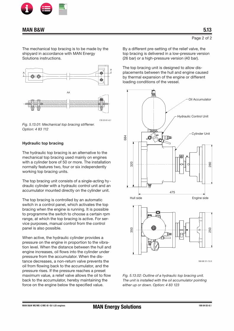
MAN B&W ME/ME�C/ME-B/-GI/-LGI engines 199 04 83-8.1
MAN B&W 5.13Page 2 of 2
178 23 61-6.1
Fig. 5.13.01: Mechanical top bracing stiffener.Option: 4 83 112
Hydraulic top bracing
The hydraulic top bracing is an alternative to the mechanical top bracing used mainly on engines with a cylinder bore of 50 or more. The installation normally features two, four or six independently working top bracing units.
The top bracing unit consists of a single-acting hy-draulic cylinder with a hydraulic control unit and an accumulator mounted directly on the cylinder unit.
The top bracing is controlled by an automatic switch in a control panel, which activates the top bracing when the engine is running. It is possible to programme the switch to choose a certain rpm range, at which the top bracing is active. For ser-vice purposes, manual control from the control panel is also possible.
When active, the hydraulic cylinder provides a pressure on the engine in proportion to the vibra-tion level. When the distance between the hull and engine increases, oil flows into the cylinder under pressure from the accumulator. When the dis-tance decreases, a non-return valve prevents the oil from flowing back to the accumulator, and the pressure rises. If the pressure reaches a preset maximum value, a relief valve allows the oil to flow back to the accumulator, hereby maintaining the force on the engine below the specified value.
By a different pre-setting of the relief valve, the top bracing is delivered in a low-pressure version (26 bar) or a high-pressure version (40 bar).
The top bracing unit is designed to allow dis-placements between the hull and engine caused by thermal expansion of the engine or different loading conditions of the vessel.
AA
A
The mechanical top bracing is to be made by the shipyard in accordance with MAN Energy Solutions instructions.
A
Fig. 5.13.02: Outline of a hydraulic top bracing unit. The unit is installed with the oil accumulator pointing either up or down. Option: 4 83 123
189 86 31-7.0.0
Oil Accumulator
Hydraulic Control Unit
Cylinder Unit
280
475
Engine sideHull side
320
684
250
350
MAN Energy Solutions
MAN B&W
IMO Tier ll Project Guide
MAN
Energy Solutions Project G
uideM
AN B
&W G
95ME-C
10.5

MMechanical Top Bracing
Horisontal distance (mm) between top bracing fix point and centre line cyl. 1:
a = 392 f = 4,312d = 2,744 g = 5,096e = 3,528 h = 5,880
Fig. 5.14.01: Mechanical top bracing arrangement with turbocharger mounted on the aft end
MAN Energy Solutions
MAN B&W
IMO Tier ll Project Guide
MAN
Energy Solutions Project G
uideM
AN B
&W G
95ME-C
10.5
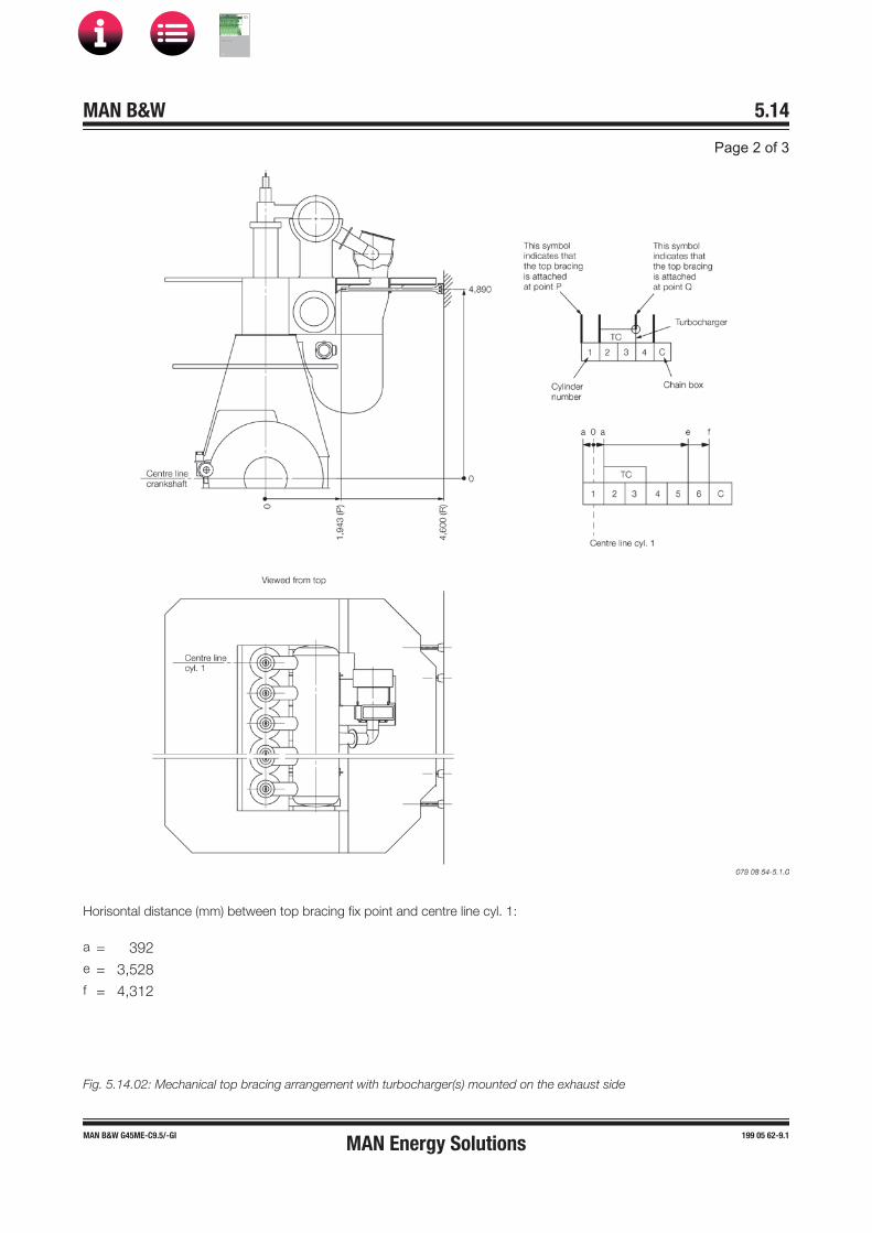
Horisontal distance (mm) between top bracing fix point and centre line cyl. 1:
a = 392e = 3,528f = 4,312
Fig. 5.14.02: Mechanical top bracing arrangement with turbocharger(s) mounted on the exhaust side
MAN Energy Solutions
MAN B&W
IMO Tier ll Project Guide
MAN
Energy Solutions Project G
uideM
AN B
&W G
95ME-C
10.5

Horisontal vibrations on the upper part of the engine are caused by the guide force moments. For 4-7 cylinder engines the H-moment is the major excitation source and for larger cylinder numbers the X-moment is the major excitation source.
For engines with vibrations excited by the X-moment, bracings at the centre of the engine are of only minor importance.
Top bracings should only be installed on one side, either the exhaust side or the manoeuvring side. If the top bracing has to be installed on the manoeuvring side, please contact MAN Energy Solutions.
If the minimum built-in length can not be fulfilled, please contact MAN Energy Solutions or our local representative.
The complete arrangement to be delivered by the shipyard.
MAN Energy Solutions
MAN B&W
IMO Tier ll Project Guide
MAN
Energy Solutions Project G
uideM
AN B
&W G
95ME-C
10.5

HHydraulic Top Bracing Arrangement
Fig. 5.15.01: Hydraulic top bracing data, turbocharger mounted on the aft end
MAN Energy Solutions
MAN B&W
IMO Tier ll Project Guide
MAN
Energy Solutions Project G
uideM
AN B
&W G
95ME-C
10.5

Fig. 5.15.02: Hydraulic top bracing data, turbocharger(s) mounted on the exhaust side
MAN Energy Solutions
MAN B&W
IMO Tier ll Project Guide
MAN
Energy Solutions Project G
uideM
AN B
&W G
95ME-C
10.5

As the rigidity of the casing structure to which the top bracing is attached is most important, it is recommended that the top bracing is attached directly into a deck.
Required rigidity of the casing side point A:
In the axial direction of the hydraulic top bracing: Force per bracing: 127 kN
Max. corresponding deflectionof casing side: 0.36 mm
In the horisontal and vertical direction of thehydraulic top bracing:Force per bracing: 22 kN
Max. corresponding deflectionof casing side: 2.00 mm
Fig. 5.15.03: Hydraulic top bracing data
MAN Energy Solutions
MAN B&W
IMO Tier ll Project Guide
MAN
Energy Solutions Project G
uideM
AN B
&W G
95ME-C
10.5

MAN B&W 5.16Page 1 of 3
MAN B&W ME/ME-C/ME-B/-GI TII engines 198 85 38-3.4
Components for Engine Control System
Installation of ECS in the Engine Control Room
The following items are to be installed in the ECR (Engine Control Room):
• 2 pcs EICU (Engine Interface Control Unit)(1 pcs only for ME-B engines)
• 1 pcs ECS MOP-A (Main Operating Panel)EC-MOP with touch display, 15”
• 1 pcs ECS MOP-BEC-MOP with touch display, 15”
• 1 pcs EMS MOP with system softwareDisplay, 24” marine monitorPC unit
• 1 pcs Managed switch and VPN router with firewall
The EICU functions as an interface unit to ECR related systems such as AMS (Alarm and Monitor-ing System), RCS (Remote Control System) and
Safety System. On ME-B engines the EICU also controls the HPS.
MOP-A and -B are redundant and are the opera -tor’s interface to the ECS. Via both MOPs, the op-erator can control and view the status of the ECS. Via the EMS MOP PC, the operator can view the status and operating history of both the ECS and the engine, EMS is decribed in Section 18.01.
The PMI Auto-tuning application is run on the EMS MOP PC. PMI Auto-tuning is used to opti-mize the combustion process with minimal opera-tor attendance and improve the efficiency of the engine. See Section 18.01.
CoCoS-EDS ME Basic is included as an applica-tion in the Engine Management Services as part of the standard software package installed on the EMS MOP PC. See Section 18.01.
MOP-B
PMI Auto-tuning
ECS Network A
EMS MOP PC
Net cable fromAMS option
ECS Network B
VPN routerwith firewall
LAN WAN
Managed switch
+24V
To Internetoption
¤¤
¤
#
#
¤
MOP-A
Fig. 5.16.01 Network and PC components for the ME/ME-B Engine Control System
078 74 78-1.5.3b
# Yard Supply
¤ Ethernet, 10 m patch cable supplied with switch. Type: RJ45, STP (Shielded Twisted Pair), CAT 5.In case 10 m cable is not enough, this becomes Yard supply.
Abbreviations:AMS: Alarm Monitoring SystemsEICU: Engine Interface Control UnitEMS: Engine Management ServicesMOP: Main Operating Panel
MAN Energy Solutions
MAN B&W
IMO Tier ll Project Guide
MAN
Energy Solutions Project G
uideM
AN B
&W G
95ME-C
10.5

MAN B&W 5.16Page 2 of 3
198 87 06-1.1MAN B&W ME/ME-C/ME-B/-GI TII engines
Fig. 5.16.02 MOP PC equipment for the ME/ME-B Engine Control System
EC-MOP• Integrated PC unit and touch display, 15”
• Direct dimming control (0-100%)• USB connections at front• IP20 resistant front• Dual Arcnet
Pointing device• Keyboard model
• UK version, 104 keys• USB connection
• Trackball mouse• USB connection
EMS MOP PC• Standard industry PC with MS Windows
operating system, UK version
Marine monitor for EMS MOP PC• LCD (MVA) monitor 24”
• Projected capacitive touch• Resolution 1,920x1,080, WSXGA+• Direct dimming control (0-100%)• IP54 resistant front• For mounting in panel
• Bracket for optional mounting on desktop, withhinges (5° tilt, adjustable 95°) or without hinges(10° tilt, not adjustable)
Network components• Managed switch and VPN router with firewall
188 34 68-1.1.0
188 21 61-8.4.0 188 21 59-6.3.0
188 35 95-0.0.0
563 66 46-3.3.0
188 35 90-1.0.0 188 35 91-3.0.0
5°
95° 10
°
188 34 25-0.2.0
MAN Energy Solutions
MAN B&W
IMO Tier ll Project Guide
MAN
Energy Solutions Project G
uideM
AN B
&W G
95ME-C
10.5

MAN B&W 5.16Page 3 of 3
MAN B&W ME/ME-C/-GI/-LGI engines 198 82 73-3.3
517 57 64-4.5.1
Fig. 5.16.03: The network printer and EICU cabinet unit for the ME Engine Control System
1,500 mm
600 mm505 mm
EICU Cabinet• Engine interface control cabinet for ME-ECS for
installation in ECR (recommended) or ER
Service operation
BWM indicating panel, if any
* Instruments for main Engine
Engine operation/navigating
ERCSMOP
EMSMOP
Oil mistdetector
Safetysystem
* Alarmsystem
MOP-BMOP-A
Option: Only in case of ERCS MOP
Engine control room console• Recommended outline of Engine Control Room console with ME equipment
564 91 36-7.1.1
Fig. 5.16.04: Example of Engine Control Room console
*Yard supply
Oil mist detector equipment depending on supplier/makerBWM: Bearing Wear Monitoring
MAN Energy Solutions
MAN B&W
IMO Tier ll Project Guide
MAN
Energy Solutions Project G
uideM
AN B
&W G
95ME-C
10.5

MAN B&W 5.17Page 1 of 3
198 49 29-2.4MAN B&W MC/MC-C, ME/ME-C/ME-GI/ME-B engines
Shaftline Earthing Device
Scope and field of application
A difference in the electrical potential between the hull and the propeller shaft will be generated due to the difference in materials and to the propeller being immersed in sea water.
In some cases, the difference in the electrical potential has caused spark erosion on the thrust, main bearings and journals of the crankshaft of the engine.
In order to reduce the electrical potential between the crankshaft and the hull and thus prevent spark erosion, a highly efficient shaftline earthing device must be installed.
The shaftline earthing device should be able to keep the electrical potential difference below 50 mV DC. A shaft-to-hull monitoring equipment with a mV-meter and with an output signal to the alarm system must be installed so that the potential and thus the correct function of the shaftline earthing device can be monitored.
Note that only one shaftline earthing device is needed in the propeller shaft system.
Design description
The shaftline earthing device consists of two silver slip rings, two arrangements for holding brushes including connecting cables and monitoring equipment with a mV-meter and an output signal for alarm.
The slip rings should be made of solid silver or back-up rings of cobber with a silver layer all over. The expected life span of the silver layer on the slip rings should be minimum 5 years.
The brushes should be made of minimum 80% silver and 20% graphite to ensure a sufficient electrical conducting capability.
Resistivity of the silver should be less than 0.1µ Ohm x m. The total resistance from the shaft to the hull must not exceed 0.001 Ohm.
Cabling of the shaftline earthing device to the hull must be with a cable with a cross section not less than 45 mm². The length of the cable to the hull should be as short as possible.
Monitoring equipment should have a 4-20 mA signal for alarm and a mV-meter with a switch for changing range. Primary range from 0 to 50 mV DC and secondary range from 0 to 300 mV DC.
When the shaftline earthing device is working correctly, the electrical potential will normally be within the range of 10-50 mV DC depending of propeller size and revolutions.
The alarm set-point should be 80 mV for a high alarm. The alarm signals with an alarm delay of 30 seconds and an alarm cut-off, when the engine is stopped, must be connected to the alarm system.
Connection of cables is shown in the sketch, see Fig. 5.17.01.
MAN Energy Solutions
MAN B&W
IMO Tier ll Project Guide
MAN
Energy Solutions Project G
uideM
AN B
&W G
95ME-C
10.5

MAN B&W 5.17Page 2 of 3
198 49 29-2.4MAN B&W MC/MC-C, ME/ME-C/ME-GI/ME-B engines
RudderVoltage monitoring for shafthull potential difference
Shaftlineearthing device
V
Propeller shaft
Intermediate shaft Intermediate shaft bearing
Current
Thrust bearing
Main bearings
Propeller
079 21 82-1.3.2.0
Fig. 5.17.02: Installation of shaftline earthing device in an engine plant without shaft-mounted generator
Shaftline earthing device installations
The shaftline earthing device slip rings must be mounted on the foremost intermediate shaft as close to the engine as possible, see Fig. 5.17.02
Brush holderarrangement
Cableconnectedto the hull
Monitoringequipment
with mV-meter Cableconnectedto the hull
Cableto alarmsystem
Brush holderarrangement
Slip ringfor monitoring
equipment
Slip ring
Fig. 5.17.01: Connection of cables for the shaftline earthing device
079 21 82-1.4.0
MAN Energy Solutions
MAN B&W
IMO Tier ll Project Guide
MAN
Energy Solutions Project G
uideM
AN B
&W G
95ME-C
10.5

MAN B&W 5.17Page 3 of 3
198 49 29-2.4MAN B&W MC/MC-C, ME/ME-C/ME-GI/ME-B engines
RudderVoltage monitoring for shafthull potential difference
Shaftlineearthing device
V
Propeller shaft
Intermediate shaft
Intermediate shaft bearing
Current
Thrust bearing
Main bearings
Propeller
Shaft mounted alternator here the rotor is part of
the intermediate shaft
079 21 82-1.3.3.0
Fig. 5.17.03: Installation of shaftline earthing device in an engine plant with shaft-mounted generator
When a generator is fitted in the propeller shaft system, where the rotor of the generator is part of the intermediate shaft, the shaftline earthing de-vice must be mounted between the generator and the engine, see Fig. 5.17.03
MAN Energy Solutions
MAN B&W
IMO Tier ll Project Guide
MAN
Energy Solutions Project G
uideM
AN B
&W G
95ME-C
10.5

MAN B&W 5.18Page 1 of 8
198 46 95�3.6MAN B&W 70-26 engines
VBS type CP propeller designation and range
The VBS type CP propellers are designated ac-cording to the diameter of their hubs, i.e. ‘VBS2150’ indicates a propeller hub diameter of 2,150 mm.
The standard VBS type CP propeller programme, its diameters and the engine power range covered is shown in Fig. 5.18.01.
The servo oil system controlling the setting of the propeller blade pitch is shown in Fig.5.18.05.
MAN Alpha Controllable Pitch Propeller and Alphatronic Propulsion Control
0
1,000
2,000
3,000
4,000
5,000
6,000
7,000
8,000
9,000
0 5 10 15 20 25 30 35 40 45 50Engine Power (1,000 kW)
10,000
11,000
MAN Energy Solutions' MAN Alpha Controllable Pitch propeller
On MAN Energy Solutions' MAN Alpha VBS type Controllable Pitch (CP) propeller, the hydraulic servo motor setting the pitch is built into the pro-peller hub. A range of different hub sizes is avail-able to select an optimum hub for any given com-bination of power, revolutions and ice class.
Standard blade/hub materials are Ni�Al�bronze. Stainless steel is available as an option. The pro-pellers are based on ‘no ice class’ but are avail-able up to the highest ice classes.
Propeller Diameter (mm)
VBS940
VBS1020
VBS1100
VBS720
VBS790
VBS600
VBS660
VBS860
VBS1180
VBS1260
VBS1350
VBS1450
VBS1550
VBS1640
VBS1730
VBS1810
VBS1890
VBS1970
VBS2060
VBS2150
Hub sizes:Small: VBS600 - 940Medium: VBS1020 - 1640Large: VBS1730 - 2150
178 22 23�9.2
Fig. 5.18.01: MAN Alpha type VBS Mk 5 Controllable Pitch (CP) propeller range. As standard the VBS Mk 5 versions are 4-bladed; 5-bladed versions are available on request
MAN Energy Solutions
MAN B&W
IMO Tier ll Project Guide
MAN
Energy Solutions Project G
uideM
AN B
&W G
95ME-C
10.5

MAN B&W 5.18Page 2 of 8
198 46 95-3.6MAN B&W 70-26 engines
Data Sheet for Propeller
Identification: _______________________________
178 22 36�0.0
Table 5.18.02b: Data sheet for propeller design purposes
Type of vessel: ______________________________For propeller design purposes please provide us with the following information:
1. S: ______________ mmW: _____________ mmI: _______________ mm (as shown above)
2. Stern tube and shafting arrangement layout
3. Propeller aperture drawing
4. Complete set of reports from model tank (re-sistance test, self�propulsion test and wakemeasurement). In case model test is not avail-able the next page should be filled in.
5. Drawing of lines plan
6. Classification Society: __________Ice class notation: _____________
7. Maximum rated power of shaft generator: kW
8. Optimisation condition for the propeller:To obtain the highest propeller efficiencyplease identify the most common service con-dition for the vessel.
Ship speed: ___________________________ knEngine service load: ____________________ %Service/sea margin: ____________________ %Shaft generator service load: ____________ kWDraft: _________________________________ m
9. Comments:
IW S
Fig. 5.18.02a: Dimension sketch for propeller design purposes
MAN Energy Solutions
MAN B&W
IMO Tier ll Project Guide
MAN
Energy Solutions Project G
uideM
AN B
&W G
95ME-C
10.5

MAN B&W 5.18Page 3 of 8
198 46 95-3.6MAN B&W 70-26 engines
Main Dimensions
Symbol Unit Ballast Loaded
Length between perpendiculars LPP m
Length of load water line LWL m
Breadth B m
Draft at forward perpendicular TF m
Draft at aft perpendicular TA m
Displacement o m3
Block coefficient (LPP) CB �
Midship coefficient CM �
Waterplane area coefficient CWL �
Wetted surface with appendages S m2
Centre of buoyancy forward of LPP/2 LCB m
Propeller centre height above baseline H m
Bulb section area at forward perpendicular AB m2
178 22 97�0.0
Table 5.18.03: Data sheet for propeller design purposes, in case model test is not available this table should be filled in
Propeller clearance
To reduce pressure impulses and vibrations emit-ted from the propeller to the hull, MAN Energy Solutions recommends a minimum tip clearance as shown in Fig. 5.18.04.
For ships with slender aft body and favourable inflow conditions the lower values can be used, whereas full afterbody and large variations in wake field cause the upper values to be used.
In twin�screw ships the blade tip may protrude below the base line.
Hub
Dismant-ling
of capX mm
High-skewpropeller
Y mm
Non�skewpropeller
Y mm
Baselineclearance
Z mm
VBS 600 120
15�20%of D
20�25%of D
Min.50�100
VBS 660 130VBS 720 140VBS 790 155VBS 860 170VBS 940 185
VBS 1020 200VBS 1100 215VBS 1180 230VBS 1260 245VBS 1350 265VBS 1460 280VBS 1550 300VBS 1640 320VBS 1730 340VBS 1810 355VBS 1890 370VBS 1970 385VBS 2060 405VBS 2150 425
216 56 93-7.3.1
Fig. 5.18.04: Propeller clearance
178 22 37�2.0
ZD
Y
X
Baseline
MAN Energy Solutions
MAN B&W
IMO Tier ll Project Guide
MAN
Energy Solutions Project G
uideM
AN B
&W G
95ME-C
10.5
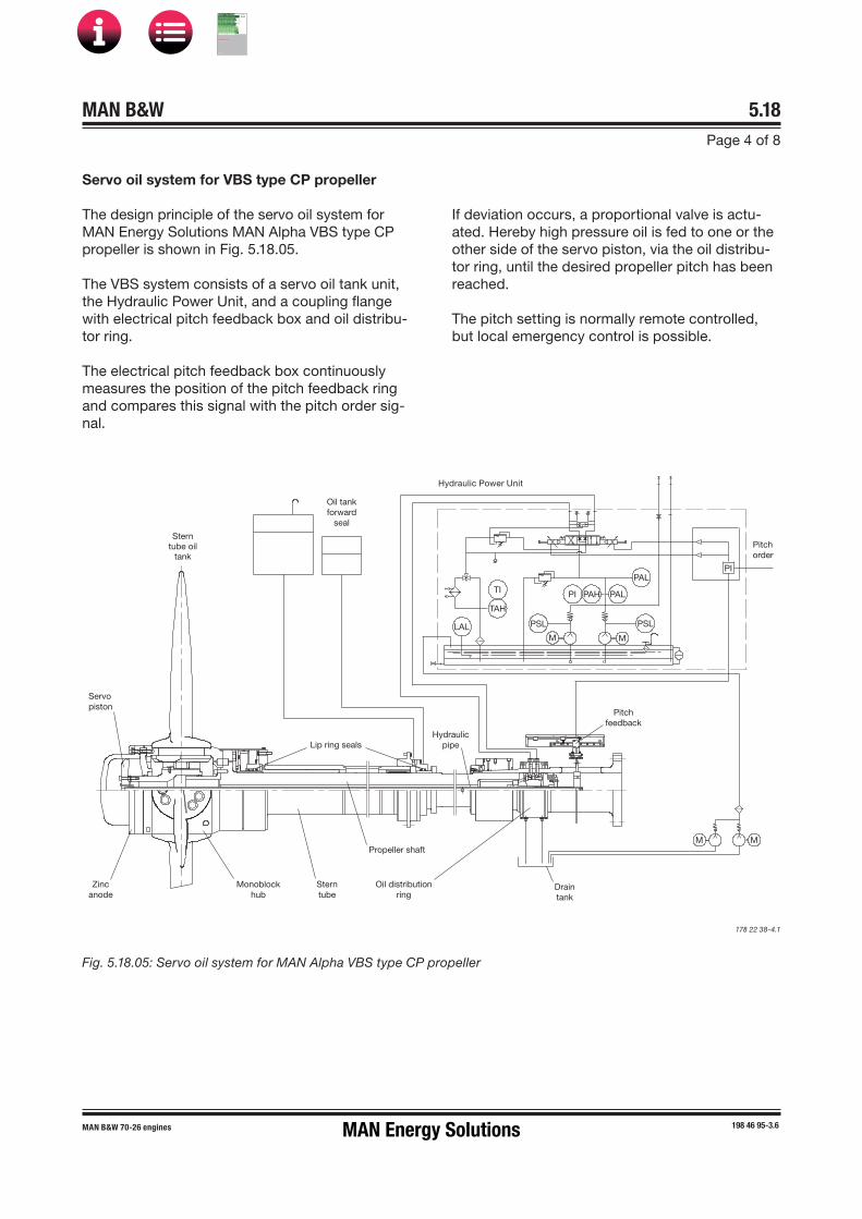
MAN B&W 5.18Page 4 of 8
198 46 95-3.6MAN B&W 70-26 engines
If deviation occurs, a proportional valve is actu-ated. Hereby high pressure oil is fed to one or the other side of the servo piston, via the oil distribu-tor ring, until the desired propeller pitch has been reached.
The pitch setting is normally remote controlled, but local emergency control is possible.
Fig. 5.18.05: Servo oil system for MAN Alpha VBS type CP propeller
178 22 38�4.1
Servo oil system for VBS type CP propeller
The design principle of the servo oil system for MAN Energy Solutions MAN Alpha VBS type CP propeller is shown in Fig. 5.18.05.
The VBS system consists of a servo oil tank unit, the Hydraulic Power Unit, and a coupling flange with electrical pitch feedback box and oil distribu-tor ring.
The electrical pitch feedback box continuously measures the position of the pitch feedback ring and compares this signal with the pitch order sig-nal.
Hydraulic Power Unit
Sterntube oil
tank
Oil tankforward
seal
Pitchorder
Servopiston
Lip ring sealsHydraulic
pipe
Pitchfeedback
Draintank
Propeller shaft
Oil distributionring
Sterntube
Monoblockhub
Zincanode
MM
PSLPSL
PAL
PALPAHPI
M M
PI
LAL
TAH
TI
MAN Energy Solutions
MAN B&W
IMO Tier ll Project Guide
MAN
Energy Solutions Project G
uideM
AN B
&W G
95ME-C
10.5
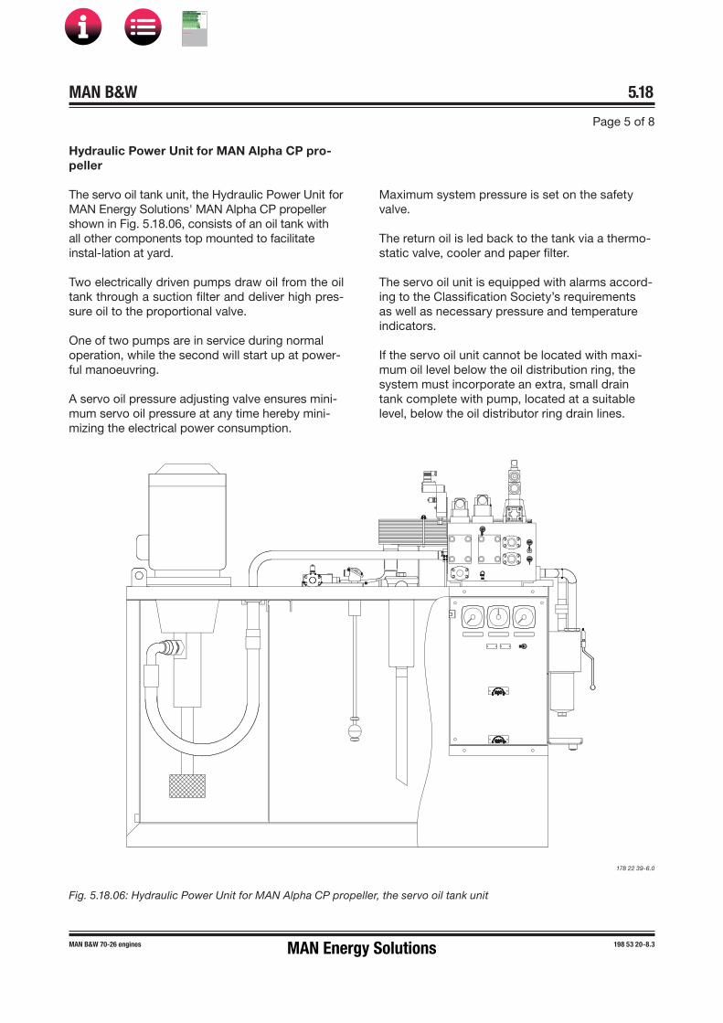
MAN B&W 5.18
Page 5 of 8
198 53 20�8.3MAN B&W 70-26 engines
178 22 39�6.0
Fig. 5.18.06: Hydraulic Power Unit for MAN Alpha CP propeller, the servo oil tank unit
Hydraulic Power Unit for MAN Alpha CP pro-peller
The servo oil tank unit, the Hydraulic Power Unit for MAN Energy Solutions' MAN Alpha CP propeller shown in Fig. 5.18.06, consists of an oil tank with all other components top mounted to facilitate instal-lation at yard.
Two electrically driven pumps draw oil from the oil tank through a suction filter and deliver high pres-sure oil to the proportional valve.
One of two pumps are in service during normal operation, while the second will start up at power-ful manoeuvring.
A servo oil pressure adjusting valve ensures mini-mum servo oil pressure at any time hereby mini-mizing the electrical power consumption.
Maximum system pressure is set on the safety valve.
The return oil is led back to the tank via a thermo-static valve, cooler and paper filter.
The servo oil unit is equipped with alarms accord-ing to the Classification Society’s requirements as well as necessary pressure and temperature indicators.
If the servo oil unit cannot be located with maxi-mum oil level below the oil distribution ring, the system must incorporate an extra, small drain tank complete with pump, located at a suitable level, below the oil distributor ring drain lines.
MAN Energy Solutions
MAN B&W
IMO Tier ll Project Guide
MAN
Energy Solutions Project G
uideM
AN B
&W G
95ME-C
10.5

MAN B&W 5.18
Page 6 of 8
198 53 22-1.5MAN B&W 70-26 engines
RPM Pitch
CoordinatedControlSystem
Handlesinterface
Duplicated Network
Enginesafetysystem
Engine speed
System failure alarm, Load reduction, Load red. Cancel alarm
Engine overload (max. load)
STO
P
Governor limiter cancel
RPM Pitch
I
Start/Stop/Slow turning, Start blocking, Remote/Local
Ahead/Astern
Remote/Local
Fuel IndexCharge Air Press.
Terminals forpropeller
monitoringsensors
P I
Pitch
Pitch Set
Local engine control
Speed Set
PropulsionControlSystem
Bridge Wing
Shut down, Shut down reset/cancel
Propeller PitchClosed LoopControl Box
Pitch
OperatorPanel (*)
OperatorPanel
OperatorPanel
Backup selected
Shaft Generator/ PMS
Auxiliary ControlEquipment
Ship’sAlarm
System
ES
Main Control Station(Center) Bridge Wing
BU: BackUp Control
Bridge
Engine Control Room
Engine Room
STOP
P IP I
STA
RT
OperatorPanel (*)
RPM Pitch RPM Pitch
ES: Emergency StopES BU ES
OperatorPanel(OPP)
Terminals forengine monitoring
sensors
STO
P(In
gov
erno
r)
Gov
erno
r
OVERLOAD
178 22 40�6.1
Fig. 5.18.07: MAN Alphatronic 2000 Propulsion Control System
MAN Alphatronic 2000 Propulsion Control System
MAN Energy Solutions' MAN Alphatronic 2000 Pro-pulsion Control System (PCS) is designed for con-trol of propulsion plants based on diesel engines with CP propellers. The plant could for instance include tunnel gear with PTO/PTI, PTO gear, mul-tiple engines on one gearbox as well as multiple propeller plants.
As shown in Fig. 5.18.07, the propulsion control system comprises a computer controlled system with interconnections between control stations via a redundant bus and a hard wired back�up control system for direct pitch control at constant shaft speed.
The computer controlled system contains func-tions for:
• Machinery control of engine start/stop, engineload limits and possible gear clutches.
• Thrust control with optimization of propellerpitch and shaft speed. Selection of combina-tor, constant speed or separate thrust mode ispossible. The rates of changes are controlled toensure smooth manoeuvres and avoidance ofpropeller cavitation.
• A Load control function protects the engineagainst overload. The load control function con-tains a scavenge air smoke limiter, a load pro-gramme for avoidance of high thermal stressesin the engine, an automatic load reduction andan engineer controlled limitation of maximumload.
• Functions for transfer of responsibility be-tween the local control stand, engine controlroom and control locations on the bridge areincorporated in the system.
MAN Energy Solutions
MAN B&W
IMO Tier ll Project Guide
MAN
Energy Solutions Project G
uideM
AN B
&W G
95ME-C
10.5

MAN B&W 5.18
Page 7 of 8
198 53 22-1.5MAN B&W 70-26 engines
BAC UP
CONTROL
ON/OFF
INCONTROL CONTROL
TAKE
BAC UPCONTROLON/OFF
INCONTROL
TA ECONTROL
PROPELLERRPM
PROPELLERPITCH
178 22 41�8.1
Fig. 5.18.08: Main bridge station standard layout
Propulsion control station on the main bridge
For remote control, a minimum of one control sta-tion located on the bridge is required.
This control station will incorporate three mod-ules, as shown in Fig. 5.18.08:
• Propulsion control panel with push buttonsand indicators for machinery control and a dis-play with information of condition of operationand status of system parameters.
• Propeller monitoring panel with back�up in-struments for propeller pitch and shaft speed.
• Thrust control panel with control lever forthrust control, an emergency stop button andpush buttons for transfer of control betweencontrol stations on the bridge.
MAN Energy Solutions
MAN B&W
IMO Tier ll Project Guide
MAN
Energy Solutions Project G
uideM
AN B
&W G
95ME-C
10.5

MAN B&W 5.18
198 53 22-1.5MAN B&W 70-26 engines
Renk PSC Clutch for auxilliary propulsion sys-tems
The Renk PSC Clutch is a shaftline de�clutching device for auxilliary propulsion systems which meets the class notations for redundant propul-sion.
The Renk PSC clutch facilitates reliable and simple ‘take home’ and ‘take away’ functions in two�stroke engine plants. It is described in Sec-tion 4.04.
Page 8 of 8
Further information about MAN Alpha CP pro-peller
For further information about MAN Energy Solutions' MAN Alpha Controllable Pitch (CP) propeller and the Alpha tronic 2000 Remote Control System, please refer to our publications:
CP Propeller – Product Information
Alphatronic 2000 PCS Propulsion Control System
The publications are available at www.marine.man es o → ’Propeller & Aft Ship’.
MAN Energy Solutions
MAN B&W
IMO Tier ll Project Guide
MAN
Energy Solutions Project G
uideM
AN B
&W G
95ME-C
10.5

MAN B&W
List of Capacities:Pumps, Coolers &
Exhaust Gas
6MAN Energy Solutions
MAN B&W
IMO Tier ll Project Guide
MAN
Energy Solutions Project G
uideM
AN B
&W G
95ME-C
10.5

MAN B&W 6.01Page 1 of 1
MAN B&W 95-45 engines dot 5 and higher,G40ME-C9.5/-GI/-LGI
199 04 08-6.1
In the following description and examples of the auxiliary machinery capacities in Section 6.02, the below nomenclatures are used:
Fig. 6.01.01: Nomenclature of basic engine ratings
Fig. 6.01.02: Nomenclature of coolers and volume flows, etc.
Engine configurations related to SFOC
The engine type is available in the following versions with respect to the efficiency of the turbocharger(s) alone:
High efficiency turbocharger, the basic engine design (EoD: 4 59 104)
Conventional turbocharger, (option: 4 59 107)
for both of which the lists of capacities Section 6.03 are calculated.
Engine ratings Point / Index Power Speed
Nominal maximum continuous rating (NMCR) L1 PL1 nL1
Specified maximum continuous rating (SMCR) M PM nM
Normal continuous rating (NCR) S PS nS
Parameters Cooler index Flow index
M = Mass flow air scavenge air cooler exh exhaust gas
Calculation of List of Capacities
Updated engine and capacities data is available from the CEAS application at www.marine.man-es.com→ ’Two-Stroke’ → ’CEAS Engine Calculations’. This chapter describes the necessary auxiliary machinery capacities to be used for a nominally rated engine. The capacities given are valid for seawater cooling system and central cooling wa-ter system, respectively.
For a derated engine, i.e. with a specified MCR different from the nominally rated MCR point, the list of capacities will be different from the nominal capacities.
Nomenclature
Furthermore, among others, the exhaust gas data depends on the ambient temperature conditions.
For a derated engine, calculations of:
• Derated capacities
• Available heat rate, for example for freshwaterproduction
• Exhaust gas amounts and temperatures
can be made in the CEAS application available at the above link.
MAN Energy Solutions
MAN B&W
IMO Tier ll Project Guide
MAN
Energy Solutions Project G
uideM
AN B
&W G
95ME-C
10.5
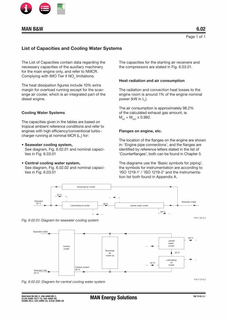
MAN B&W 6.02Page 1 of 1
198 74 63-3.1MAN B&W MC/MC-C, K98-80ME/ME-C,S/L90-50ME-C8/7/-GI, S60-46ME-B8,S50ME-B9.3, G45-40ME-C9, G/S40-30ME-B9
List of Capacities and Cooling Water Systems
The capacities for the starting air receivers and the compressors are stated in Fig. 6.03.01.
Heat radiation and air consumption
The radiation and convection heat losses to the engine room is around 1% of the engine nominal power (kW in L1).
The air consumption is approximately 98.2% of the calculated exhaust gas amount, ie. Mair = Mexh x 0.982.
Flanges on engine, etc.
The location of the flanges on the engine are shown in: ‘Engine pipe connections’, and the flanges are identified by reference letters stated in the list of ‘Counterflanges’; both can be found in Chapter 5.
The diagrams use the ‘Basic symbols for piping’, the symbols for instrumentation are according to ‘ISO 1219�1’ / ‘ISO 1219�2’ and the instrumenta-tion list both found in Appendix A.
178 11 26�4.2
Fig. 6.02.01: Diagram for seawater cooling system
Scavenge air cooler
Seawater32 C
45 C
Lubricating oil cooler38 C
Jacket water cooler
80 C
Seawater outlet
Seawater outlet
Centralcooler
Seawater inlet32 C
Central coolant36 C
Scavengeair
cooler (s)
Jacketwatercooler
Lubricatingoil
cooler
80 C
43 C
45 C
Fig. 6.02.02: Diagram for central cooling water system178 11 27�6.2
The List of Capacities contain data regarding the necessary capacities of the auxiliary machinery for the main engine only, and refer to NMCR. Complying with IMO Tier II NOx limitations.
The heat dissipation figures include 10% extra margin for overload running except for the scav-enge air cooler, which is an integrated part of the diesel engine.
Cooling Water Systems
The capacities given in the tables are based on tropical ambient reference conditions and refer to engines with high efficiency/conventional turbo -charger running at nominal MCR (L1) for:
• Seawater cooling system,See diagram, Fig. 6.02.01 and nominal capaci-ties in Fig. 6.03.01
• Central cooling water system,See diagram, Fig. 6.02.02 and nominal capaci-ties in Fig. 6.03.01
MAN Energy Solutions
MAN B&W
IMO Tier ll Project Guide
MAN
Energy Solutions Project G
uideM
AN B
&W G
95ME-C
10.5

MAN B&W 6.03Page 1 of 4
MAN B&W G45ME-C9.5-GI 198 93 91-2.1
List of Capacities for 5G45ME-C9.5-GI-TII at NMCR
Seawater cooling Central coolingConventional TC High eff. TC Conventional TC High eff. TC
1xTC
A44-23
1xA1
65-L
1xMET
48-M
B
1xTC
A44-23
1xA1
65-L
1xMET
48-M
B
1xTC
A44-23
1xA1
65-L
1xMET
48-M
B
1xTC
A44-23
1xA1
65-L
1xMET
48-M
B
PumpsFuel oil circulation m³/h 3.6 3.6 3.6 3.6 3.6 3.6 3.6 3.6 3.6 3.6 3.6 3.6Fuel oil supply m³/h 1.9 1.9 1.9 1.9 1.9 1.9 1.9 1.9 1.9 1.9 1.9 1.9Jacket cooling m³/h 49 49 49 49 49 49 50 50 50 49 49 49Seawater cooling * m³/h 200 205 205 210 215 215 200 200 200 200 200 200Main lubrication oil * m³/h 150 150 150 150 150 150 150 150 150 150 150 150Central cooling * m³/h - - - - - - 160 160 160 160 160 160
Scavenge air cooler(s)Heat diss. app. kW 2,490 2,490 2,490 2,590 2,590 2,590 2,480 2,480 2,480 2,580 2,580 2,580Central water flow m³/h - - - - - - 90 90 90 90 90 90Seawater flow m³/h 120 120 120 130 130 130 - - - - - -
Lubricating oil coolerHeat diss. app. * kW 560 580 590 560 580 590 560 580 590 560 580 590Lube oil flow * m³/h 150 150 150 150 150 150 150 150 150 150 150 150Central water flow m³/h - - - - - - 70 70 70 70 70 70Seawater flow m³/h 80 85 85 80 85 85 - - - - - -
Jacket water coolerHeat diss. app. kW 950 950 950 940 940 940 950 950 950 940 940 940Jacket water flow m³/h 49 49 49 49 49 49 49 49 49 49 49 49Central water flow m³/h - - - - - - 70 70 70 70 70 70Seawater flow m³/h 80 85 85 80 85 85 - - - - - -
Central coolerHeat diss. app. * kW - - - - - - 3,990 4,010 4,020 4,080 4,100 4,110Central water flow m³/h - - - - - - 160 160 160 160 160 160Seawater flow m³/h - - - - - - 200 200 200 200 200 200
Starting air system, 30.0 bar g, 12 starts. Fixed pitch propeller - reversible engineReceiver volume m³ 2 x 4.0 2 x 4.0 2 x 4.0 2 x 4.0 2 x 4.0 2 x 4.0 2 x 4.0 2 x 4.0 2 x 4.0 2 x 4.0 2 x 4.0 2 x 4.0Compressor cap. m³ 240 240 240 240 240 240 240 240 240 240 240 240
Starting air system, 30.0 bar g, 6 starts. Controllable pitch propeller - non-reversible engineReceiver volume m³ 2 x 2.0 2 x 2.0 2 x 2.0 2 x 2.0 2 x 2.0 2 x 2.0 2 x 2.0 2 x 2.0 2 x 2.0 2 x 2.0 2 x 2.0 2 x 2.0Compressor cap. m³ 120 120 120 120 120 120 120 120 120 120 120 120
Other valuesFuel oil heater kW 56 56 56 56 56 56 56 56 56 56 56 56Exh. gas temp. ** °C 256 256 256 236 236 236 256 256 256 236 236 236Exh. gas amount ** kg/h 50,880 50,880 50,880 54,000 54,000 54,000 50,880 50,880 50,880 54,000 54,000 54,000Air consumption ** kg/s 12.6 12.6 12.6 13.4 13.4 13.4 12.7 12.7 12.7 13.5 13.5 13.5
* For main engine arrangements with built-on power take-off (PTO) of a MAN Energy Solutions recommended type and/or torsional
vibration damper the engine's capacities must be increased by those stated for the actual system
** ISO based
For List of Capacities for derated engines and performance data at part load please visit http://www.man-es.com/ceas/LOC Table
6.03.01e: Capacities for seawater and central systems as well as conventional and high efficiency turbochargers stated at NMCR
13.5 13.5 13.5 14.4 14.4 14.4 13.6 13.6 13.6 14.5 14.5 14.5
MAN B&W
IMO Tier ll Project Guide
MAN
Energy Solutions Project G
uideM
AN B
&W G
95ME-C
10.5

MAN B&W 6.03Page 2 of 4
MAN B&W G45ME-C9.5-GI 198 93 91-2.1
List of Capacities for 6G45ME-C9.5-GI-TII at NMCR
Seawater cooling Central coolingConventional TC High eff. TC Conventional TC High eff. TC
1xTCA55-21
1xA165-L
1xMET48-MB
1xTCA55-21
1xA265-L
1xMET53-MB
1xTCA55-21
1xA165-L
1xMET48-MB
1xTCA55-21
1xA265-L
1xMET53-MB
PumpsFuel oil circulation m³/h 4.3 4.3 4.3 4.3 4.3 4.3 4.3 4.3 4.3 4.3 4.3 4.3Fuel oil supply m³/h 2.3 2.3 2.3 2.3 2.3 2.3 2.3 2.3 2.3 2.3 2.3 2.3Jacket cooling m³/h 60 60 60 60 60 60 60 60 60 60 60 60Seawater cooling * m³/h 250 250 250 250 250 250 230 230 240 240 240 240Main lubrication oil * m³/h 180 180 180 180 180 180 180 180 180 180 180 180Central cooling * m³/h - - - - - - 195 195 195 195 195 195
Scavenge air cooler(s)Heat diss. app. kW 2,990 2,990 2,990 3,100 3,100 3,100 2,980 2,980 2,980 3,090 3,090 3,090Central water flow m³/h - - - - - - 110 110 110 110 110 110Seawater flow m³/h 150 150 150 150 150 150 - - - - - -
Lubricating oil coolerHeat diss. app. * kW 670 680 690 670 680 700 670 680 690 670 680 700Lube oil flow * m³/h 180 180 180 180 180 180 180 180 180 180 180 180Central water flow m³/h - - - - - - 85 85 85 85 85 85Seawater flow m³/h 100 100 100 100 100 100 - - - - - -
Jacket water coolerHeat diss. app. kW 1,140 1,140 1,140 1,130 1,130 1,130 1,140 1,140 1,140 1,130 1,130 1,130Jacket water flow m³/h 60 60 60 60 60 60 60 60 60 60 60 60Central water flow m³/h - - - - - - 85 85 85 85 85 85Seawater flow m³/h 100 100 100 100 100 100 - - - - - -
Central coolerHeat diss. app. * kW - - - - - - 4,790 4,800 4,810 4,890 4,900 4,920Central water flow m³/h - - - - - - 195 195 195 195 195 195Seawater flow m³/h - - - - - - 230 230 240 240 240 240
Starting air system, 30.0 bar g, 12 starts. Fixed pitch propeller - reversible engineReceiver volume m³ 2 x 4.0 2 x 4.0 2 x 4.0 2 x 4.0 2 x 4.0 2 x 4.0 2 x 4.0 2 x 4.0 2 x 4.0 2 x 4.0 2 x 4.0 2 x 4.0Compressor cap. m³ 240 240 240 240 240 240 240 240 240 240 240 240
Starting air system, 30.0 bar g, 6 starts. Controllable pitch propeller - non-reversible engineReceiver volume m³ 2 x 2.5 2 x 2.5 2 x 2.5 2 x 2.5 2 x 2.5 2 x 2.5 2 x 2.5 2 x 2.5 2 x 2.5 2 x 2.5 2 x 2.5 2 x 2.5Compressor cap. m³ 150 150 150 150 150 150 150 150 150 150 150 150
Other valuesFuel oil heater kW 67 67 67 67 67 67 67 67 67 67 67 67Exh. gas temp. ** °C 256 256 256 236 236 236 256 256 256 236 236 236Exh. gas amount ** kg/h 61,060 61,060 61,060 64,800 64,800 64,800 61,060 61,060 61,060 64,800 64,800 64,800Air consumption ** kg/s 15.1 15.1 15.1 16.1 16.1 16.1 15.2 15.2 15.2 16.2 16.2 16.2
* For main engine arrangements with built-on power take-off (PTO) of a MAN Energy Solutions recommended type and/or torsional
vibration damper the engine's capacities must be increased by those stated for the actual system
** ISO based
For List of Capacities for derated engines and performance data at part load please visit http://www.man-es.com/ceas/LOC Table
6.03.01f: Capacities for seawater and central systems as well as conventional and high efficiency turbochargers stated at NMCR
16.2 16.2 16.2 17.2 17.2 17.2 16.4 16.4 16.4 17.4 17.4 17.4
MAN B&W
IMO Tier ll Project Guide
MAN
Energy Solutions Project G
uideM
AN B
&W G
95ME-C
10.5
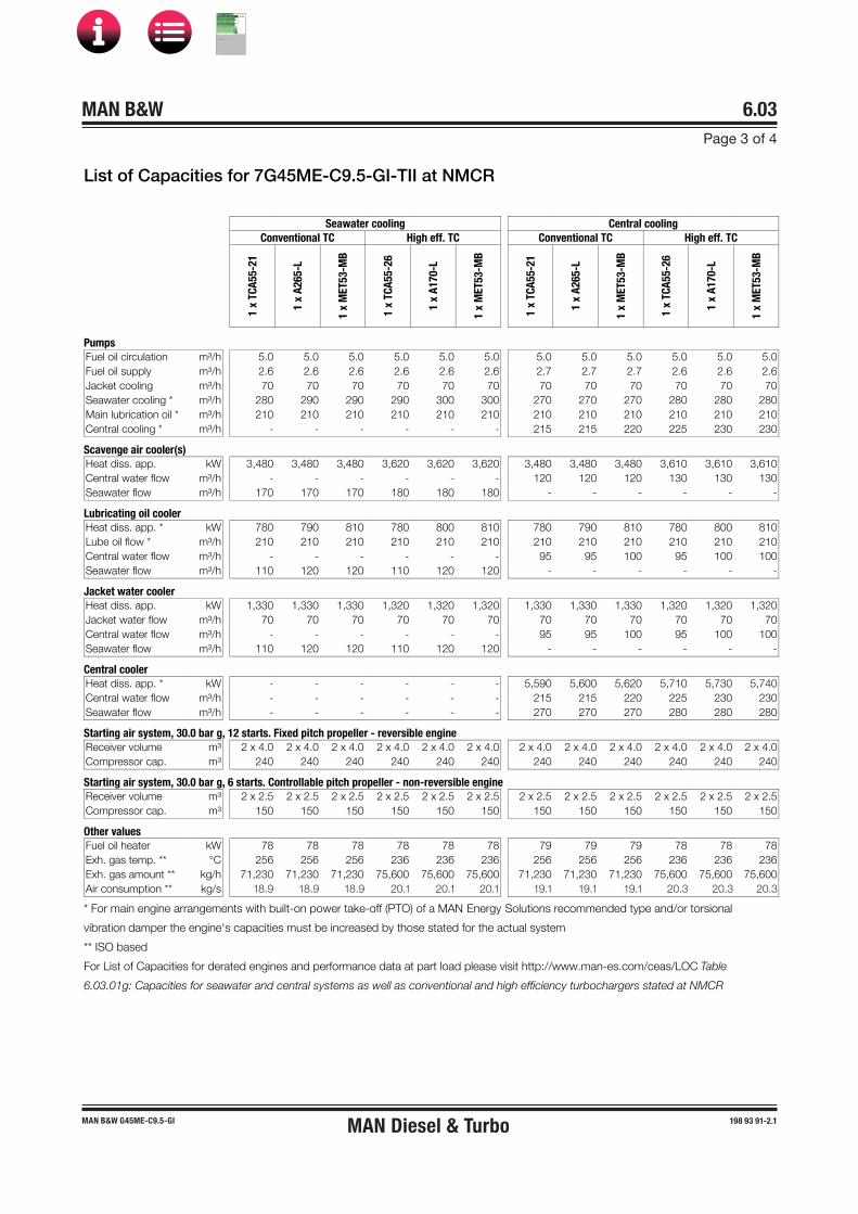
MAN B&W 6.03Page 3 of 4
MAN B&W G45ME-C9.5-GI 198 93 91-2.1
List of Capacities for 7G45ME-C9.5-GI-TII at NMCR
Seawater cooling Central coolingConventional TC High eff. TC Conventional TC High eff. TC
1xTC
A55-21
1xA2
65-L
1xMET
53-M
B
1xTC
A55-26
1xA1
70-L
1xMET
53-M
B
1xTC
A55-21
1xA2
65-L
1xMET
53-M
B
1xTC
A55-26
1xA1
70-L
1xMET
53-M
B
PumpsFuel oil circulation m³/h 5.0 5.0 5.0 5.0 5.0 5.0 5.0 5.0 5.0 5.0 5.0 5.0Fuel oil supply m³/h 2.6 2.6 2.6 2.6 2.6 2.6 2.7 2.7 2.7 2.6 2.6 2.6Jacket cooling m³/h 70 70 70 70 70 70 70 70 70 70 70 70Seawater cooling * m³/h 280 290 290 290 300 300 270 270 270 280 280 280Main lubrication oil * m³/h 210 210 210 210 210 210 210 210 210 210 210 210Central cooling * m³/h - - - - - - 215 215 220 225 230 230
Scavenge air cooler(s)Heat diss. app. kW 3,480 3,480 3,480 3,620 3,620 3,620 3,480 3,480 3,480 3,610 3,610 3,610Central water flow m³/h - - - - - - 120 120 120 130 130 130Seawater flow m³/h 170 170 170 180 180 180 - - - - - -
Lubricating oil coolerHeat diss. app. * kW 780 790 810 780 800 810 780 790 810 780 800 810Lube oil flow * m³/h 210 210 210 210 210 210 210 210 210 210 210 210Central water flow m³/h - - - - - - 95 95 100 95 100 100Seawater flow m³/h 110 120 120 110 120 120 - - - - - -
Jacket water coolerHeat diss. app. kW 1,330 1,330 1,330 1,320 1,320 1,320 1,330 1,330 1,330 1,320 1,320 1,320Jacket water flow m³/h 70 70 70 70 70 70 70 70 70 70 70 70Central water flow m³/h - - - - - - 95 95 100 95 100 100Seawater flow m³/h 110 120 120 110 120 120 - - - - - -
Central coolerHeat diss. app. * kW - - - - - - 5,590 5,600 5,620 5,710 5,730 5,740Central water flow m³/h - - - - - - 215 215 220 225 230 230Seawater flow m³/h - - - - - - 270 270 270 280 280 280
Starting air system, 30.0 bar g, 12 starts. Fixed pitch propeller - reversible engineReceiver volume m³ 2 x 4.0 2 x 4.0 2 x 4.0 2 x 4.0 2 x 4.0 2 x 4.0 2 x 4.0 2 x 4.0 2 x 4.0 2 x 4.0 2 x 4.0 2 x 4.0Compressor cap. m³ 240 240 240 240 240 240 240 240 240 240 240 240
Starting air system, 30.0 bar g, 6 starts. Controllable pitch propeller - non-reversible engineReceiver volume m³ 2 x 2.5 2 x 2.5 2 x 2.5 2 x 2.5 2 x 2.5 2 x 2.5 2 x 2.5 2 x 2.5 2 x 2.5 2 x 2.5 2 x 2.5 2 x 2.5Compressor cap. m³ 150 150 150 150 150 150 150 150 150 150 150 150
Other valuesFuel oil heater kW 78 78 78 78 78 78 79 79 79 78 78 78Exh. gas temp. ** °C 256 256 256 236 236 236 256 256 256 236 236 236Exh. gas amount ** kg/h 71,230 71,230 71,230 75,600 75,600 75,600 71,230 71,230 71,230 75,600 75,600 75,600Air consumption ** kg/s 17.6 17.6 17.6 18.7 18.7 18.7 17.8 17.8 17.8 18.9 18.9 18.9
* For main engine arrangements with built-on power take-off (PTO) of a MAN Energy Solutions recommended type and/or torsional
vibration damper the engine's capacities must be increased by those stated for the actual system
** ISO based
For List of Capacities for derated engines and performance data at part load please visit http://www.man-es.com/ceas/LOC Table
6.03.01g: Capacities for seawater and central systems as well as conventional and high efficiency turbochargers stated at NMCR
18.9 18.9 18.9 20.1 20.1 20.1 19.1 19.1 19.1 20.3 20.3 20.3
MAN B&W
IMO Tier ll Project Guide
MAN
Energy Solutions Project G
uideM
AN B
&W G
95ME-C
10.5

MAN B&W 6.03Page 4 of 4
MAN B&W G45ME-C9.5-GI 198 93 91-2.1
List of Capacities for 8G45ME-C9.5-GI-TII at NMCR
Seawater cooling Central coolingConventional TC High eff. TC Conventional TC High eff. TC
1xTCA66-21
1xA170-L
1xMET60-M
B
1xTCA66-21
1xA270-L
1xMET60-M
B
1xTCA66-21
1xA170-L
1xMET60-M
B
1xTCA66-21
1xA270-L
1xMET60-M
B
PumpsFuel oil circulation m³/h 5.7 5.7 5.7 5.7 5.7 5.7 5.7 5.7 5.7 5.7 5.7 5.7Fuel oil supply m³/h 3.0 3.0 3.0 3.0 3.0 3.0 3.0 3.0 3.0 3.0 3.0 3.0Jacket cooling m³/h 80 80 80 80 80 80 80 80 80 80 80 80Seawater cooling * m³/h 320 320 330 330 330 340 310 310 310 320 320 320Main lubrication oil * m³/h 240 240 240 240 240 240 240 240 240 240 240 240Central cooling * m³/h - - - - - - 250 250 250 260 260 260
Scavenge air cooler(s)Heat diss. app. kW 3,980 3,980 3,980 4,140 4,140 4,140 3,970 3,970 3,970 4,130 4,130 4,130Central water flow m³/h - - - - - - 140 140 140 150 150 150Seawater flow m³/h 190 190 190 200 200 200 - - - - - -
Lubricating oil coolerHeat diss. app. * kW 900 910 930 900 910 930 900 910 930 900 910 930Lube oil flow * m³/h 240 240 240 240 240 240 240 240 240 240 240 240Central water flow m³/h - - - - - - 110 110 110 110 110 110Seawater flow m³/h 130 130 140 130 130 140 - - - - - -
Jacket water coolerHeat diss. app. kW 1,510 1,510 1,510 1,510 1,510 1,510 1,520 1,520 1,520 1,510 1,510 1,510Jacket water flow m³/h 80 80 80 80 80 80 80 80 80 80 80 80Central water flow m³/h - - - - - - 110 110 110 110 110 110Seawater flow m³/h 130 130 140 130 130 140 - - - - - -
Central coolerHeat diss. app. * kW - - - - - - 6,390 6,400 6,420 6,540 6,550 6,570Central water flow m³/h - - - - - - 250 250 250 260 260 260Seawater flow m³/h - - - - - - 310 310 310 320 320 320
Starting air system, 30.0 bar g, 12 starts. Fixed pitch propeller - reversible engineReceiver volume m³ 2 x 4.5 2 x 4.5 2 x 4.5 2 x 4.5 2 x 4.5 2 x 4.5 2 x 4.5 2 x 4.5 2 x 4.5 2 x 4.5 2 x 4.5 2 x 4.5Compressor cap. m³ 270 270 270 270 270 270 270 270 270 270 270 270
Starting air system, 30.0 bar g, 6 starts. Controllable pitch propeller - non-reversible engineReceiver volume m³ 2 x 2.5 2 x 2.5 2 x 2.5 2 x 2.5 2 x 2.5 2 x 2.5 2 x 2.5 2 x 2.5 2 x 2.5 2 x 2.5 2 x 2.5 2 x 2.5Compressor cap. m³ 150 150 150 150 150 150 150 150 150 150 150 150
Other valuesFuel oil heater kW 90 90 90 89 89 89 90 90 90 89 89 89Exh. gas temp. ** °C 256 256 256 236 236 236 256 256 256 236 236 236Exh. gas amount ** kg/h 81,410 81,410 81,410 86,400 86,400 86,400 81,410 81,410 81,410 86,400 86,400 86,400Air consumption ** kg/s 20.1 20.1 20.1 21.4 21.4 21.4 20.3 20.3 20.3 21.6 21.6 21.6
* For main engine arrangements with built-on power take-off (PTO) of a MAN Energy Solutions recommended type and/or torsional
vibration damper the engine's capacities must be increased by those stated for the actual system
** ISO based
For List of Capacities for derated engines and performance data at part load please visit http://www.man-es.com/ceas/LOC Table
6.03.01h: Capacities for seawater and central systems as well as conventional and high efficiency turbochargers stated at NMCR
21.6 21.6 21.6 23.0 23.0 23.0 21.8 21.8 21.8 23.2 23.2 23.2
MAN B&W
IMO Tier ll Project Guide
MAN
Energy Solutions Project G
uideM
AN B
&W G
95ME-C
10.5
MAN B&W 6.04Page 1 of 3
MAN B&W S50, G45 Mk9 dot 5 and higher 199 04 32-4.2
Auxiliary Machinery Capacities
Further to the auxiliary machinery capacities for a nominally rated engine shown in Section 6.03, the dimensioning of heat exchangers (coolers) and pumps for derated engines as well as calculating the:
• List of capacities for derated engine
• Available heat to be removed, for example forfreshwater production
• Exhaust gas amounts and temperatures
can be made in the CEAS application descibed in Section 20.02.
The CEAS application is available at www.marine. man-es.com → ’Two-Stroke’ → ’CEAS Engine Calcula-tions’.
Pump pressures and temperatures
The pump heads stated in the table below are for guidance only and depend on the actual pressure drop across coolers, filters, etc. in the systems.
Pump head, bar
Max. working temp. ºC
Fuel oil supply pump 4 100
Fuel oil circulating pump 6 150
Lubricating oil pump 4.2 70
Seawater pump, for seawatercooling system 2.5 50
Seawater pump, for centralcooling water system 2.0 50
Central cooling water pump 2.5 80
Jacket water pump 3.0 100
Flow velocities
For external pipe connections, we prescribe the following maximum velocities:
Marine diesel oil ......................................... 1.0 m/sHeavy fuel oil .............................................. 0.6 m/sLubricating oil ............................................. 1.8 m/sCooling water ............................................. 3.0 m/s
MAN Energy Solutions
MAN B&W
IMO Tier ll Project Guide
MAN
Energy Solutions Project G
uideM
AN B
&W G
95ME-C
10.5

MAN B&W 6.04Page 2 of 3
MAN B&W engines dot 5 and higher 199 04 21-6.1
Centrifugal pump selection
Pump pressure head (H)
Pump flow capacity (Q)
Specified nominalduty point
Max. capacity
Pump QH curve
Pipe system pressurecharacteristic
45%
of m
ax.
cap
acit
y
85%
of m
ax.
cap
acit
yDuty pointin between
When selecting a centrifugal pump, it is recom-mended to carefully evaluate the pump QH (ca-pacity/head) curve in order for the pump to work properly both in normal operation and under changed conditions. But also for ensuring that the maximum pipe design pressure is not exceeded.
The following has to be evaluated:
• Location of the specified nominal duty point(SNDP) on the pump QH curve
• Pump QH curve slope
• Maximum available delivery pressure from thepump.
Location of the duty point on the pump QH curve
Particularly important is the location of the speci-fied nominal duty point (SNDP) on the pump QH curve: the SNDP is equal to the intersection of the pump QH curve and the pipe system pressure characteristic, which is defined at the design stage.
079 08 81-9.0.0a
Fig. 6.04.01: Location of the specified nominal duty point (SNDP) on the pump QH curve
The SNDP must be located in the range of 45 to 85% of the pump’s maximum capacity, see Fig. 6.04.01.
Thus, the pump will be able to operate with slight-ly lower or higher pipe system pressure charac-teristic than specified at the design stage, without the risk of cavitation or too big variations in flow.
Pump QH curve slope
At the location of the SNDP, the pump capacity should not decrease by more than 10% when the pressure is increased by 5%, see Fig. 6.04.02.
This way, the flow stays acceptable even if the pipe system pressure is higher than expected and the flow does not change too much, for example when a thermostatic valve changes position.
MAN Energy Solutions
MAN B&W
IMO Tier ll Project Guide
MAN
Energy Solutions Project G
uideM
AN B
&W G
95ME-C
10.5

MAN B&W 6.04Page 3 of 3
MAN B&W engines dot 5 and higher 199 04 21-6.1
45%
of m
ax.
cap
acit
y
85%
of m
ax.
cap
acit
yBy 5% increased pressure
Max. 10%decreased capacity
Pump pressure head (H)
Pump flow capacity (Q)
Specified nominal duty point
Maximum availabledelivery pressure
00
Duty point at closed valve
Pump QH curve
Pump pressure head (H)
Pump flow capacity (Q)
079 08 81-9.0.0b
Fig. 6.04.02: Pump QH curve slope
079 08 81-9.0.0c
Fig. 6.04.03: Maximum available pump delivery pressure
Maximum available pump delivery pressure
It is important to evaluate, if the maximum avail-able delivery pressure from the pump contributes to exceeding the maximum allowable design pres-sure in the pipe system.
The maximum available delivery pressure from the pump will occur e.g. when a valve in the system is closed, see Fig. 6.04.03.
The maximum allowable pipe system design pres-sure must be known in order to make the pressure rate sizing for equipment and other pipe compo-nents correctly.
MAN Energy Solutions
MAN B&W
IMO Tier ll Project Guide
MAN
Energy Solutions Project G
uideM
AN B
&W G
95ME-C
10.5

MAN B&W
Fuel
7MAN Energy Solutions
MAN B&W
IMO Tier ll Project Guide
MAN
Energy Solutions Project G
uideM
AN B
&W G
95ME-C
10.5

MME-GI fuel gas system
The dual fuel system of the ME-GI engine com-bines the regular ME/ME-B fuel system whenrunning in fuel oil modes and the fuel gas systemrunning in dual fuel mode.
The ME/ME-B fuel system is described in Section7.01, the fuel gas system on the engine is descri-bed here in 7.00 and the gas supply and auxiliarysystems in Sections 7.07 - 7.09.
The ME-GI specific engine parts
The modified parts of the ME-GI engine comprisegas supply piping, gas block with accumulatorand control valves on the (slightly modified) cylinder cover with gas injection valves.
A sealing oil system, delivering sealing oil to thewindow/shutdown and gas injection valves, separates the control oil and the gas.
Apart from these systems on the engine, theengine auxiliaries will comprise some new units,the most important ones being:
• If the supply of gas is natural gas (NG) orcompressed natural gas (CNG) it requires ahigh-pressure gas compressor, including a cooler,to raise the pressure to 300 bar, which is the max-imum required pressure at the engine inlet
• If the supply of gas is liquid natural gas (LNG) itrequires a Cryogenic HP Pump and vaporisersolution
• The ME-GI Engine Control System (ME-ECS)
• Leakage detection and ventilation system, whichventilates the outer pipe of the double-wall pipingcompletely, and incorporates leakage detection
• Flow switches
• Inert gas system, which enables purging of the fuelgas supply system and the gas system on theengine with inert gas
• Gas Valve Train (GVT)
• Gas blow-off silencers
• Heat traced and insulated gas supply pipes.
Fuel gas is also referred to as ‘second fuel’ andlow-flashpoint fuel (LFF) in this Project Guide.
MAN Energy Solutions
MAN B&W
IMO Tier ll Project Guide
MAN
Energy Solutions ProjectG
uideM
AN B
&WG
95ME-C
10.5
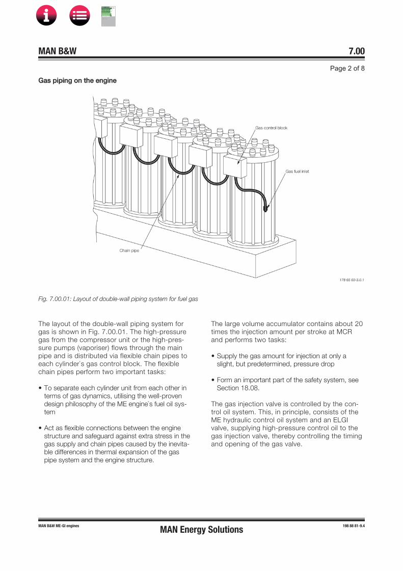
GGas piping on the engine
Fig. 7.00.01: Layout of double-wall piping system for fuel gas
The layout of the double-wall piping system forgas is shown in Fig. 7.00.01. The high-pressuregas from the compressor unit or the high-pres-sure pumps (vaporiser) flows through the mainpipe and is distributed via flexible chain pipes toeach cylinder`s gas control block. The flexiblechain pipes perform two important tasks:
• To separate each cylinder unit from each other interms of gas dynamics, utilising the well-provendesign philosophy of the ME engine`s fuel oil sys-tem
• Act as flexible connections between the enginestructure and safeguard against extra stress in thegas supply and chain pipes caused by the inevita-ble differences in thermal expansion of the gaspipe system and the engine structure.
The large volume accumulator contains about 20times the injection amount per stroke at MCRand performs two tasks:
• Supply the gas amount for injection at only aslight, but predetermined, pressure drop
• Form an important part of the safety system, seeSection 18.08.
The gas injection valve is controlled by the con-trol oil system. This, in principle, consists of theME hydraulic control oil system and an ELGIvalve, supplying high-pressure control oil to thegas injection valve, thereby controlling the timingand opening of the gas valve.
MAN Energy Solutions
MAN B&W
IMO Tier ll Project Guide
MAN
Energy Solutions ProjectG
uideM
AN B
&WG
95ME-C
10.5

TThe ME-GI fuel injection system
Fig. 7.00.02a: The ME-GI fuel injection system
As can be seen in Fig. 7.00.02a, the fuel oil pres-sure booster, that pressurizes the supplied fueloil (pilot oil) during gas fuel operation mode, isconnected to the multiway-valve (ELFI or FIVA)that controls the injection of fuel oil to the com-bustion chamber.
The 300 bar hydraulic oil also pressurizes theELGI valve controlling the injection of the gasfuel.
By the engine control system, the engine can beoperated in the various relevant modes: ‘gasoperation’ with minimum pilot oil amount, ‘speci-fied dual fuel operation’ (SDF) with injection of afixed gas amount and the ‘fuel-oil-only mode’.
Pilot oil injection amount versus engine load
Gas operation is possible down to 10% load.
The minimum pilot oil amount in gas operationmode is 3% at MCR (in L1), see Fig. 7.00.02b. In case the engine is derated, the pilot amount is relatively higher as calculated in CEAS,
see Section 20.02.
Engine output with minimum pilot oil amount canbe obtained even with an LCV of the fuel gas aslow as 38 MJ/kg. Below 38 MJ/kg, a higher pilotoil amount might be required.
For guaranteed Specific Gas Consumption (SGC)on test bed, the minimum LCV is 50 MJ/kg witha tolerance of ±5%.
Fig. 7.00.02b: Fuel index in gas operation mode
MAN Energy Solutions
MAN B&W
IMO Tier ll Project Guide
MAN
Energy Solutions ProjectG
uideM
AN B
&WG
95ME-C
10.5
CCondition of the fuel gas delivery to the engine
The following data is based on natural gas as fuelgas.
Pressure
Operating pressure See Fig. 7.07.04Safety relief valve 330 barPulsation limit ±2 bar
Flow
The maximum flow requirement is specified at 110% SMCR, 315 bar, with reference to an LCV of 38,000 kJ/kg.
Maximum / minimum requirement Refer to‘List of Capacities’, or CEAS report
Minimum flow requirement in standby 0 kg/h
The maximum flow requirement must also be achievable close to the overhaul interval of the FGS system.
In case of a specific LCV requirement, please inform MAN Energy Solutions. Under certain cir-cumstances, modification of the gas valves may be required to accommodate a special LCV.
Temperature
Temp. inlet to engine 45 ±10 °CAlarm, low / high 30 °C / 55 °CShut down, low / high 0 °C / 60 °C
The temperature is specified with regards to takethe following into account:
• To reduce condensation on the outer wall of theinner pipe for double-wall piping
• That the performance of the engine is notadversely affected
• To reduce thermal loads on the gas piping itself
• To obtain a uniform gas density.
198 87 55-1.3
MAN Energy Solutions
MAN B&W
IMO Tier ll Project Guide
MAN
Energy Solutions ProjectG
uideM
AN B
&WG
95ME-C
10.5
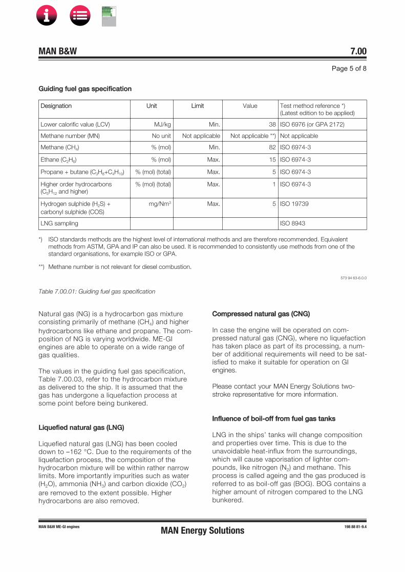
GGuiding fuel gas specification
Designation Unit Limit Value Test method reference ) (Latest edition to be applied)
Lower calorific value (LCV) MJ/kg Min. 38 ISO 6976 (or GPA 2172)
Methane number (MN) No unit Not applicable Not applicable ) Not applicable
Methane (CH4) % (mol) Min. 82 ISO 6974-3
Ethane (C2H6) % (mol) Max. 15 ISO 6974-3
Propane butane (C3H8 C4H10) % (mol) (total) Max. 5 ISO 6974-3
Higher order hydrocarbons(C5H12 and higher)
% (mol) (total) Max. 1 ISO 6974-3
Hydrogen sulphide (H2S) carbonyl sulphide (COS)
mg/Nm3 Max. 5 ISO 19739
LNG sampling ISO 8943
) ISO standards methods are the highest level of international methods and are therefore recommended. Equivalent methods from ASTM, GPA and IP can also be used. It is recommended to consistently use methods from one of thestandard organisations, for example ISO or GPA.
) Methane number is not relevant for diesel combustion.
573 94 63-6.0.0
Table 7.00.01: Guiding fuel gas specification
Natural gas (NG) is a hydrocarbon gas mixtureconsisting primarily of methane (CH4) and higherhydrocarbons like ethane and propane. The com-position of NG is varying worldwide. ME-GIengines are able to operate on a wide range ofgas qualities.
The values in the guiding fuel gas specification,Table 7.00.03, refer to the hydrocarbon mixtureas delivered to the ship. It is assumed that thegas has undergone a liquefaction process atsome point before being bunkered.
Liquefied natural gas (LNG)
Liquefied natural gas (LNG) has been cooleddown to –162 °C. Due to the requirements of theliquefaction process, the composition of thehydrocarbon mixture will be within rather narrowlimits. More importantly impurities such as water(H2O), ammonia (NH3) and carbon dioxide (CO2)are removed to the extent possible. Higherhydrocarbons are also removed.
Compressed natural gas (CNG)
In case the engine will be operated on com-pressed natural gas (CNG), where no liquefaction has taken place as part of its processing, a num-ber of additional requirements will need to be sat-isfied to make it suitable for operation on GI engines.
Please contact your MAN Energy Solutions two-stroke representative for more information.
Influence of boil-off from fuel gas tanks
LNG in the ships’ tanks will change composition and properties over time. This is due to the unavoidable heat-influx from the surroundings, which will cause vaporisation of lighter com-pounds, like nitrogen (N2) and methane. This process is called ageing and the gas produced is referred to as boil-off gas (BOG). BOG contains a higher amount of nitrogen compared to the LNG bunkered.
MAN Energy Solutions
MAN B&W
IMO Tier ll Project Guide
MAN
Energy Solutions ProjectG
uideM
AN B
&WG
95ME-C
10.5

The remaining LNG will have an increased per-centage of higher hydrocarbons. The composi-tion of the LNG bunkered will, hence, not neces-sarily be the same as the composition of the 300 bar fuel gas delivered to the engine.
The nitrogen (N2) content delivered to the engine may vary, which is acceptable, to a level of 15%(mol). If the nitrogen content delivered to the engine exceeds 15% (mol), it can be handled by either decreasing the engine load or by increas-ing the pilot injection of liquid fuel such as diesel or fuel oil.
Please contact your MAN Energy Solutions two-stroke representative for more information.
FFuel gas bunkering
Liquid or solid contaminants such as metal shav-ings, welding debris, insulation (i.e. perlite), sand, wood, cloth and oil must be removed from the LNG. It is generally considered as good engi-neering and operating practice to have LNG cargo strainers in the loading and discharge lines in order to minimise particulate contamination of the LNG and subsequent tanks and equipment.
It is recommended that the filter is controlled by a surveyor after the bunkering to establish the contamination degree. It is important to note that the quality and impurity degree can vary among the suppliers due to production and handling dif-ferences and the type of bunkering/transfer proc-ess (for example: terminal tank to vessel, truck to vessel, vessel to vessel, portable tank transfer).
MAN Energy Solutions strongly recommends instal-ling filters in the bunkering line and/or in the fuel gas supply system, see Section 7.07.
198 87 55-1.3
MAN Energy Solutions
MAN B&W
IMO Tier ll Project Guide
MAN
Energy Solutions ProjectG
uideM
AN B
&WG
95ME-C
10.5
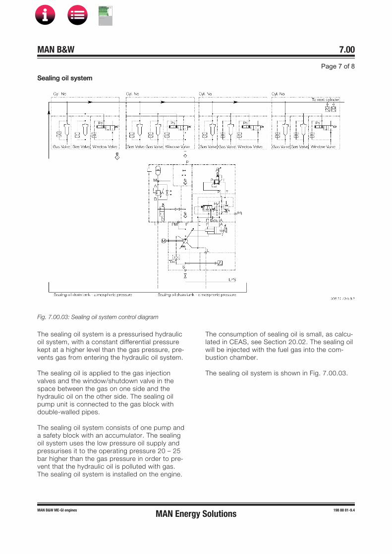
SSealing oil system
Fig. 7.00.03: Sealing oil system control diagram
The sealing oil system is a pressurised hydraulicoil system, with a constant differential pressurekept at a higher level than the gas pressure, pre-vents gas from entering the hydraulic oil system.
The sealing oil is applied to the gas injectionvalves and the window/shutdown valve in thespace between the gas on one side and thehydraulic oil on the other side. The sealing oilpump unit is connected to the gas block withdouble-walled pipes.
The sealing oil system consists of one pump anda safety block with an accumulator. The sealingoil system uses the low pressure oil supply andpressurises it to the operating pressure 20 – 25bar higher than the gas pressure in order to pre-vent that the hydraulic oil is polluted with gas.The sealing oil system is installed on the engine.
The consumption of sealing oil is small, as calcu-lated in CEAS, see Section 20.02. The sealing oilwill be injected with the fuel gas into the com-bustion chamber.
The sealing oil system is shown in Fig. 7.00.03.
MAN Energy Solutions
MAN B&W
IMO Tier ll Project Guide
MAN
Energy Solutions ProjectG
uideM
AN B
&WG
95ME-C
10.5

SSealing pump motors
Three different electric motors can be used onthe sealing oil pumps:
• Pump displacement mechanically limited to9 ccm/rev.:
– 7.4 kW, 1,450 rpm M3AA 132 M, 50 Hz
– 8.6 kW, 1,750 rpm M3AA 132 M, 60 Hz
• Pump displacement 16 ccm/rev.:– 18.0 kW, 1,750 rpm M3AA 160 M, 60 Hz
198 87 56-3.3
MAN Energy Solutions
MAN B&W
IMO Tier ll Project Guide
MAN
Energy Solutions ProjectG
uideM
AN B
&WG
95ME-C
10.5

MAN B&W 7.01Page 1 of 4
MAN B&W ME/ME�C/ME-B/�GI/�LGI engines 198 42 28�2.8
The system is so arranged that both diesel oil and heavy fuel oil can be used, see Fig. 7.01.01.
From the service tank the fuel is led to an electri-cally driven supply pump by means of which a pressure of approximately 4 bar can be main-tained in the low pressure part of the fuel circulat-ing system, thus avoiding gasification of the fuel in the venting box in the temperature ranges applied.
The venting box is connected to the service tank via an automatic deaerating valve, which will re-lease any gases present, but will retain liquids.
From the low pressure part of the fuel system the fuel oil is led to an electrically�driven circulating pump, which pumps the fuel oil through a heater and a full flow filter situated immediately before the inlet to the engine.
The fuel injection is performed by the electroni-cally controlled pressure booster located on the Hydraulic Cylinder Unit (HCU), one per cylinder, which also contains the actuator for the electronic exhaust valve activation.
The Cylinder Control Units (CCU) of the Engine Control System (described in Section 16.01) cal-culate the timing of the fuel injection and the ex-haust valve activation.
To ensure ample filling of the HCU, the capacity of the electrically�driven circulating pump is higher than the amount of fuel consumed by the diesel engine. Surplus fuel oil is recirculated from the en-gine through the venting box.
To ensure a constant fuel pressure to the fuel injection pumps during all engine loads, a spring loaded overflow valve is inserted in the fuel oil system on the engine.
The fuel oil pressure measured on the engine (at fuel pump level) should be 7�8 bar, equivalent to a circulating pump pressure of 10 bar.
Fuel considerations
When the engine is stopped, the circulating pump will continue to circulate heated heavy fuel through the fuel oil system on the engine, thereby keeping the fuel pumps heated and the fuel valves deaerated. This automatic circulation of preheated fuel during engine standstill is the background for our recommendation: constant operation on heavy fuel.
In addition, if this recommendation was not fol-lowed, there would be a latent risk of diesel oil and heavy fuels of marginal quality forming incompat-ible blends during fuel change over or when oper-ating in areas with restrictions on sulpher content in fuel oil due to exhaust gas emission control.
In special circumstances a change�over to diesel oil may become necessary – and this can be per-formed at any time, even when the engine is not running. Such a change�over may become neces-sary if, for instance, the vessel is expected to be inactive for a prolonged period with cold engine e.g. due to:
• docking• stop for more than five days• major repairs of the fuel system, etc.
The built�on overflow valves, if any, at the supply pumps are to be adjusted to 5 bar, whereas the external bypass valve is adjusted to 4 bar. The pipes between the tanks and the supply pumps shall have minimum 50% larger passage area than the pipe between the supply pump and the circu-lating pump.
If the fuel oil pipe ‘X’ at inlet to engine is made as a straight line immediately at the end of the en-gine, it will be necessary to mount an expansion joint. If the connection is made as indicated, with a bend immediately at the end of the engine, no expansion joint is required.
Pressurised Fuel Oil System
MAN Energy Solutions
MAN B&W
IMO Tier ll Project Guide
MAN
Energy Solutions Project G
uideM
AN B
&W G
95ME-C
10.5

MAN B&W 7.01Page 2 of 4
199 08 99-7.0MAN B&W engines
Fuel Oil System
Fig. 7.01.01: Fuel oil system079 95 01-2.3.1
Steam inlet
Viscosity sensor
Circulating pumps
Supply pumps
F
X
4)
To sludge tank
To sludge tank
To sludge tank
To sludge tank
D
Condensate outlet
D
2)
7)
a)
b)
Fuel oil fine
filter
Transfer pump 6)
Transfer pump 6)
Main engine
BDAD
Venting tank
Distillate fuel
Ultra-low sulphur fuel oil
High- sulphur
HFO
Deck DeckDeck
Distillate overflow
tank
HFO drain overflow
tank
Overflow valve adjusted to ensure min. 4 barCooler TI TI
MDO/MGO cooler 1)
MDO/MGO cooler 5)
Pre-heater
F
DPIDPAH
Fuel oil sample position
32 mm nom.bore
Fuel oil returning to corresponding fuel oil type settling tank
D
d
From separators
Drain to settling tank
Overflow to settling tank
1) MDO/MGO CoolerFor low-viscosity distillate fuels like marine gas oil (MGO), itis necessary to have a cooler to ensure that the viscosity atengine inlet is above 2 cSt.
Location of cooler: As shown or, alternatively, anywhere be-fore inlet to engine.
2) Fuel oil flowmeter (Optional)Flow rate: See ‘List of Capacities’ (same as fuel supplypump).Type: In case a damaged flow meter can block the fuel supply,a safety bypass valve is to be placed across the flowmeter.
3) 0.23 litre/kWh in relation to cerfitied Flow Rate (CFR); theengine SMCR can be used to determine the capacity. Theseparators should be capable of removing cat fines (Al+Si)from 80 ppm to a maximum level of 15 ppm Al+Si but prefer-ably lower.Inlet temperature: Min. 98 °C.
4) Valve in engine drain pipeValve in engine drain pipe is not acceptable. If the drain isblocked, the pressure booster top cover seal will be dam-aged.In case a valve between the engine connection AD and thedrain tank is required, the valve should be locked in open po-sition and marked with a text, indicating that the valve mustonly be closed in case of no fuel oil pressure to the engine. In
case of non-return valve, the opening pressure for the valve has to be below 0.2 bar.
5) MDO/MGO Cooler (Optional)For protection of supply pumps against too warm oil and thustoo low viscosity.
6) Transfer pump (Optional)The transfer pump has to be able to return part of the contentof the service tank to the settling tank to minimize the riskof supplying fuel to the engine with a high content of settledparticles, e.g. cat fines, if the service tank has not been usedfor a while.
7) Name of flange connectionAF for engines with a bore of 60 cm and aboveAE for engines with a bore of 50 cm and below
a) Tracing, fuel oil lines: By jacket coolon water
b) Tracing, drain lines: By jacket cooling water– only for engines with bore of 60 cm and above
*) Optional installation
The letters refer to the list of ‘Counterflanges’
Heavy fuel oilDistillate fuel or ultra-low sulphur fuel oilHeated pipe with insulation
MAN Energy Solutions
MAN B&W
IMO Tier ll Project Guide
MAN
Energy Solutions Project G
uideM
AN B
&W G
95ME-C
10.5
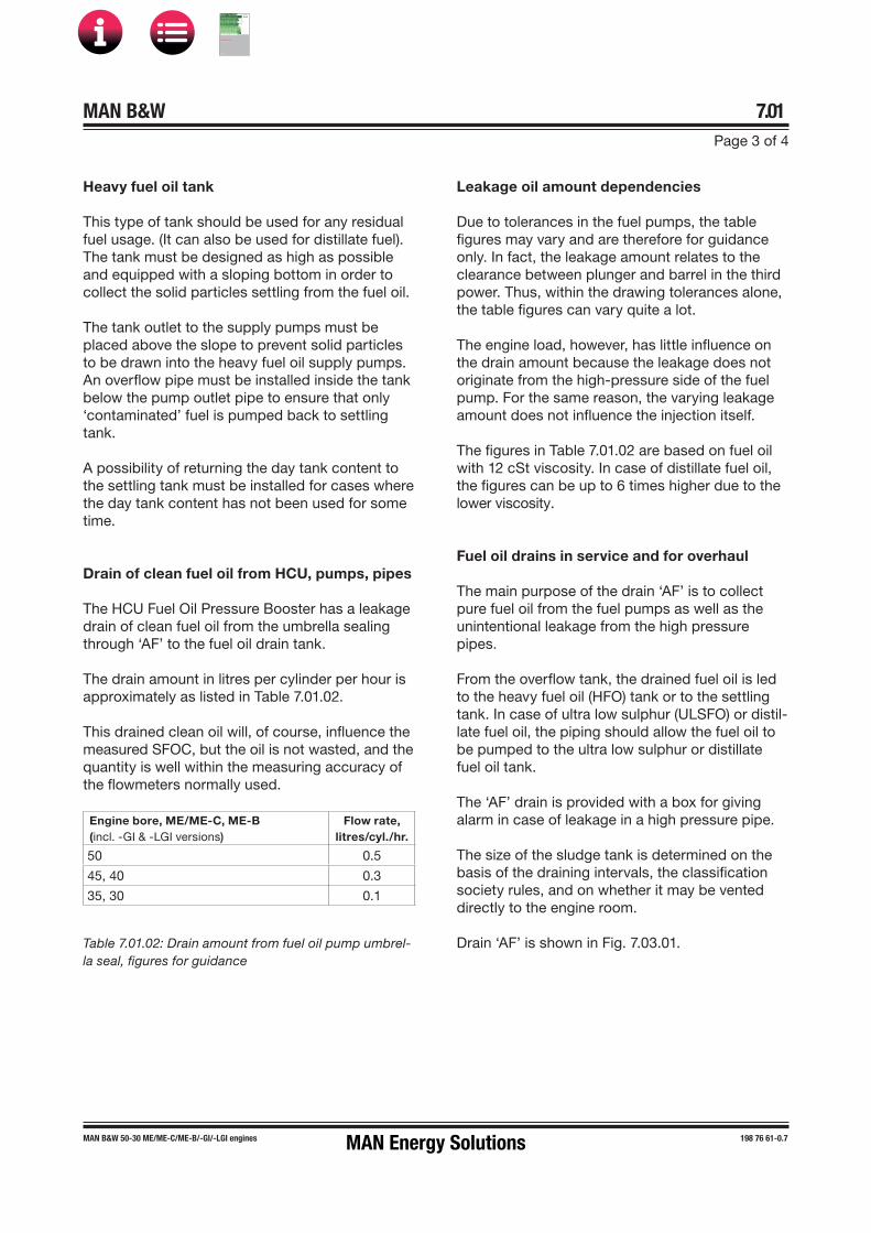
MAN B&W 7.01Page 3 of 4
MAN B&W 50-30 ME/ME-C/ME-B/-GI/-LGI engines 198 76 61-0.7
Leakage oil amount dependencies
Due to tolerances in the fuel pumps, the table figures may vary and are therefore for guidance only. In fact, the leakage amount relates to the clearance between plunger and barrel in the third power. Thus, within the drawing tolerances alone, the table figures can vary quite a lot.
The engine load, however, has little influence on the drain amount because the leakage does not originate from the high-pressure side of the fuel pump. For the same reason, the varying leakage amount does not influence the injection itself.
The figures in Table 7.01.02 are based on fuel oil with 12 cSt viscosity. In case of distillate fuel oil, the figures can be up to 6 times higher due to the lower viscosity.
Fuel oil drains in service and for overhaul
The main purpose of the drain ‘AF’ is to collect pure fuel oil from the fuel pumps as well as the unintentional leakage from the high pressure pipes.
From the overflow tank, the drained fuel oil is led to the heavy fuel oil (HFO) tank or to the settling tank. In case of ultra low sulphur (ULSFO) or distil-late fuel oil, the piping should allow the fuel oil to be pumped to the ultra low sulphur or distillate fuel oil tank.
The ‘AF’ drain is provided with a box for giving alarm in case of leakage in a high pressure pipe.
The size of the sludge tank is determined on the basis of the draining intervals, the classification society rules, and on whether it may be vented directly to the engine room.
Drain ‘AF’ is shown in Fig. 7.03.01.
Heavy fuel oil tank
This type of tank should be used for any residual fuel usage. (It can also be used for distillate fuel). The tank must be designed as high as possible and equipped with a sloping bottom in order to collect the solid particles settling from the fuel oil.
The tank outlet to the supply pumps must be placed above the slope to prevent solid particles to be drawn into the heavy fuel oil supply pumps. An overflow pipe must be installed inside the tank below the pump outlet pipe to ensure that only ‘contaminated’ fuel is pumped back to settling tank.
A possibility of returning the day tank content to the settling tank must be installed for cases where the day tank content has not been used for some time.
Drain of clean fuel oil from HCU, pumps, pipes
The HCU Fuel Oil Pressure Booster has a leakage drain of clean fuel oil from the umbrella sealing through ‘AF’ to the fuel oil drain tank.
The drain amount in litres per cylinder per hour is approximately as listed in Table 7.01.02.
This drained clean oil will, of course, influence the measured SFOC, but the oil is not wasted, and the quantity is well within the measuring accuracy of the flowmeters normally used.
Engine bore, ME/ME-C, ME-B(incl. -GI & -LGI versions)
Flow rate, litres/cyl./hr.
50 0.5
45, 40 0.3
35, 30 0.1
Table 7.01.02: Drain amount from fuel oil pump umbrel-la seal, figures for guidance
MAN Energy Solutions
MAN B&W
IMO Tier ll Project Guide
MAN
Energy Solutions Project G
uideM
AN B
&W G
95ME-C
10.5

MAN B&W 7.01Page 4 of 4
199 03 55-7.2MAN B&W engines
Drain of contaminated fuel etc.
Leakage oil, in shape of fuel and lubricating oil contaminated with water, dirt etc. and collected by the HCU Base Plate top plate (ME only), as well as turbocharger cleaning water etc. is drained off through the bedplate drains ‘AE’.
Drain ‘AE’ is shown in Fig. 8.07.02.
Heating of fuel drain pipes
Owing to the relatively high viscosity of the heavy fuel oil, it is recommended that the drain pipes and the fuel oil drain tank are heated to min. 50 °C, but max. 100 °C.
The drain pipes between engine and tanks can be heated by the jacket water, as shown in Fig. 7.01.01 ‘Fuel oil system’ as flange ‘BD’. (Flange BD and the tracing line are not applicable on MC/MC-C engines type 42 and smaller).
Fuel oil flow velocity and viscosity
For external pipe connections, we prescribe the following maximum flow velcities:
Marine diesel oil .......................................... 1.0 m/sHeavy fuel oil ............................................... 0.6 m/s
The fuel viscosity is influenced by factors such as emulsification of water into the fuel for reducing the NOx emission.
Cat fines
Cat fines is a by-product from the catalytic crack-ing used in fuel distillation. Cat fines is an ex-tremely hard material, very abrasive and damag-ing to the engine and fuel equipment. It is recom-mended always to purchase fuel with as low cat fines content as possible.
Cat fines can to some extent be removed from the fuel by means of a good and flexible tank design and by having optimum conditions for the separa-tor in terms of flow and high temperature.
Further information about fuel oil specifications and other fuel considerations is available in our publications:
Guidelines for Fuels and Lubes Purchasing
Guidelines for Operation on Fuels with less than 0.1% Sulphur
The publications are available at www.marine.man-es.com → ’Two-Stroke’ → ’Technical Papers’.
MAN Energy Solutions
MAN B&W
IMO Tier ll Project Guide
MAN
Energy Solutions Project G
uideM
AN B
&W G
95ME-C
10.5

MAN B&W 7.02Page 1 of 1
MAN B&W MC/MC-C, ME/ME-C/ME-GI/ME-B engines 198 38 80-4.7
Fuel Oils
Marine diesel oil:
Marine diesel oil ISO 8217, Class DMBBritish Standard 6843, Class DMBSimilar oils may also be used
Heavy fuel oil (HFO)
Most commercially available HFO with a viscosity below 700 cSt at 50 °C (7,000 sec. Redwood I at 100 °F) can be used.
For guidance on purchase, reference is made to ISO 8217:2012, British Standard 6843 and to CIMAC recommendations regarding require-ments for heavy fuel for diesel engines, fourth edition 2003, in which the maximum accept-able grades are RMH 700 and RMK 700. The above�mentioned ISO and BS standards super-sede BSMA 100 in which the limit was M9.
The data in the above HFO standards and speci-fications refer to fuel as delivered to the ship, i.e. before on-board cleaning.
In order to ensure effective and sufficient clean-ing of the HFO, i.e. removal of water and solid contaminants, the fuel oil specific gravity at 15 °C (60 °F) should be below 0.991, unless modern types of centrifuges with adequate cleaning abili-ties are used.
Higher densities can be allowed if special treat-ment systems are installed.
Current analysis information is not sufficient for estimating the combustion properties of the oil. This means that service results depend on oil properties which cannot be known beforehand. This especially applies to the tendency of the oil to form deposits in combustion chambers, gas passages and turbines. It may, therefore, be nec-essary to rule out some oils that cause difficulties.
Guiding heavy fuel oil specification
Based on our general service experience we have, as a supplement to the above mentioned stand-ards, drawn up the guiding HFO specification shown below.
Heavy fuel oils limited by this specification have, to the extent of the commercial availability, been used with satisfactory results on MAN B&W two�stroke low speed diesel engines.
The data refers to the fuel as supplied i.e. before any on-board cleaning.
Guiding specification (maximum values)
Density at 15 °C kg/m3 < 1.010*Kinematic viscosity
at 100 °C cSt < 55
at 50 °C cSt < 700
Flash point °C > 60
Pour point °C < 30
Carbon residue % (m/m) < 20
Ash % (m/m) < 0.15
Total sediment potential % (m/m) < 0.10
Water % (v/v) < 0.5
Sulphur % (m/m) < 4.5
Vanadium mg/kg < 450
Aluminum + Silicon mg/kg <60
Equal to ISO 8217:2010 - RMK 700/ CIMAC recommendation No. 21 - K700
* Provided automatic clarifiers are installed
m/m = mass v/v = volume
If heavy fuel oils with analysis data exceeding the above figures are to be used, especially with re-gard to viscosity and specific gravity, the engine builder should be contacted for advice regarding possible fuel oil system changes.
MAN Energy Solutions
MAN B&W
IMO Tier ll Project Guide
MAN
Energy Solutions Project G
uideM
AN B
&W G
95ME-C
10.5

MAN B&W 7.03Page 1 of 1
MAN B&W 50-40ME-C/-GI/-LGI 198 76 68-3.2
Fuel Oil Pipes and Drain Pipes
The letters refer to list of ‘Counterflanges’
The item no. refer to ‘Guidance values automation’
317 13 06-6.1.1
Fig. 7.03.01: Fuel oil and drain pipes
Fuel valves
Fore Aft
Leakage alarm
Leakage, highpress. pipes
Baseplate
Counter-pressure valveMixed oil drain
Fuel oil inlet
Pressure booster
Fuel oil outlet(umbrella)
Fuel oilreturn pipe
AF
AEF
X
To sludge tank
To sludge tank
Clean HFO return to HFO service tankor settling tank
Baseplatedrain alarmAE
Drain for fuel oil
LS 4112 AH
PI 8001TI 8005
TE 8005 I PT 8001 I AL
LS 8006 AH
Drain,pump foot
ZV 8020 Z
Fuel cut-out system
Only for Germanischer Lloyd
TE 8005 I
Suppliedwith engineYard supply
(Supplied with engine)
MAN Energy Solutions
MAN B&W
IMO Tier ll Project Guide
MAN
Energy Solutions Project G
uideM
AN B
&W G
95ME-C
10.5

MAN B&W 7.04Page 1 of 3
198 40 51-8.3MAN B&W MC/MC-C, ME/ME-C/ME-GI/ME-B engines, Engine Selection Guide
Fuel Oil Pipe Insulation
Flanges and valves
The flanges and valves are to be insulated by means of removable pads. Flange and valve pads are made of glass cloth, minimum 400 g/m2, containing mineral wool stuffed to minimum 150 kg/m3.
Thickness of the pads to be:Fuel oil pipes ................................................20 mmFuel oil pipes and heating pipes together ....30 mm
The pads are to be fitted so that they lap over the pipe insulating material by the pad thickness. At flanged joints, insulating material on pipes should not be fitted closer than corresponding to the minimum bolt length.
Mounting
Mounting of the insulation is to be carried out in accordance with the supplier’s instructions.
Insulation of fuel oil pipes and fuel oil drain pipes should not be carried out until the piping systems have been subjected to the pressure tests speci-fied and approved by the respective classification society and/or authorities, Fig. 7.04.01.
The directions mentioned below include insulation of hot pipes, flanges and valves with a surface temperature of the complete insulation of maxi-mum 55 °C at a room temperature of maximum 38 °C. As for the choice of material and, if required, approval for the specific purpose, reference is made to the respective classification society.
Fuel oil pipes
The pipes are to be insulated with 20 mm mineral wool of minimum 150 kg/m3 and covered with glass cloth of minimum 400 g/m2.
Fuel oil pipes and heating pipes together
Two or more pipes can be insulated with 30 mm wired mats of mineral wool of minimum 150 kg/m3 covered with glass cloth of minimum 400 g/m2.
Fig. 7.04.01: Details of fuel oil pipes insulation, option: 4 35 121. Example from 98-50 MC engine 178 50 65 �0.2
"E"
Seen from cyl. side
Cyl. 1 Fore
Fuel oil inlet
Heating pipe
Fuel oil outlet
Heating pipe
AABB
Fuel oil inlet
E
Fuel oil outletDrain pipe fuel oil
Cyl. 1A
A
FX
BF, BX
ForeB
B
AA
Funnel and pipe 8mmnot to be insulated Fuel oil drain
umbrella
AFAD
BD
MAN Energy Solutions
MAN B&W
IMO Tier ll Project Guide
MAN
Energy Solutions Project G
uideM
AN B
&W G
95ME-C
10.5

MAN B&W 7.04Page 2 of 3
MAN B&W MC/MC�C, ME/ME-C/ME-GI/ME-B engines,Engine Selection Guide
198 40 51�8.3
Fig. 7.04.02: Heat loss/Pipe cover
Insula
tion
thick
ness
20
30
40
50
60
7080
90
100
120
160
200
Temperature difference between pipe and room°C
Pipe diameter mmHeat loss watt/meter pipe
178 50 60�2.0
Heat Loss in Piping
MAN Energy Solutions
MAN B&W
IMO Tier ll Project Guide
MAN
Energy Solutions Project G
uideM
AN B
&W G
95ME-C
10.5

MAN B&W 7.04Page 3 of 3
199 04 85-1.0MAN B&W 50-40ME-C/-GI/-LGI
Fuel Oil Pipe Heat Tracing
121 15 23-1.4.0
Fig. 7.04.03: Fuel oil pipe heat tracing
The letters refer to list of ‘Counterflanges’
F
X
BX
BF BD
AD
2 fuel valvesFresh coolingwater outlet
See drawing ‘Fuel oil pipes insulation’
Fuel valvesL
High pressure pipes
3 fuel valvesCyl. 1
Hydraulic cylinder unit
AF
The steam tracing of the fuel oil pipes is intended to operate in two situations:
1. When the circulation pump is running, therewill be a temperature loss in the piping, seeFig. 7.04.02. This loss is very small, thereforetracing in this situation is only necessary withvery long fuel supply lines.
2. When the circulation pump is stopped withheavy fuel oil in the piping and the pipes havecooled down to engine room temperature, asit is not possible to pump the heavy fuel oil.In this situation the fuel oil must be heated topumping temperature of about 50 ºC.
To heat the pipe to pumping level we recom-mend to use 100 watt leaking/meter pipe.
178 52 55�5.2
Fig. 7.04.04b: Spray Shields by clamping bands
In order to fulfil IMO regulations, fuel oil and lubri-cating oil pipe assemblies are to be enclosed by spray shields as shown in Fig. 7.04.04a and b.
Antisplashing tape Clamping bands
Plate 0,5 mm. thicknessThe tape is to be wrapped in accordance with the makers instruction for class approval
The width is to cover head of bolts and nuts
Overlap
Fig. 7.04.04a: Spray Shields by anti-splashing tape
To avoid leaks, the spray shields are to be in-stalled after pressure testing of the pipe system.
Fuel Oil and Lubricating Oil Pipe Spray Shields
MAN Energy Solutions
MAN B&W
IMO Tier ll Project Guide
MAN
Energy Solutions Project G
uideM
AN B
&W G
95ME-C
10.5
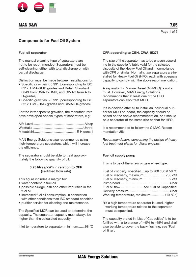
MAN B&W 7.05Page 1 of 5
MAN B&W engines 198 39 51�2.10
Components for Fuel Oil System
Fuel oil separator
The manual cleaning type of separators are not to be recommended. Separators must be self�cleaning, either with total discharge or with partial discharge.
Distinction must be made between installations for:• Specific gravities < 0.991 (corresponding to ISO
8217: RMA-RMD grades and British Standard6843 from RMA to RMH, and CIMAC from A toH�grades)
• Specific gravities > 0.991 (corresponding to ISO8217: RME-RMK grades and CIMAC K�grades).
For the latter specific gravities, the manufacturers have developed special types of separators, e.g.:
Alfa Laval ........................................................AlcapWestfalia ....................................................... UnitrolMitsubishi ..............................................E�Hidens II
MAN Energy Solutions also recommends using high-temperature separators, which will increase the efficiency.
The separator should be able to treat approxi-mately the following quantity of oil:
0.23 litres/kWh in relation to CFR(certified flow rate)
This figure includes a margin for:• water content in fuel oil• possible sludge, ash and other impurities in the
fuel oil• increased fuel oil consumption, in connection
with other conditions than ISO standard condition• purifier service for cleaning and maintenance.
The Specified MCR can be used to determine the capacity. The separator capacity must always be higher than the calculated capacity.
Inlet temperature to separator, minimum .......98 °C
CFR according to CEN, CWA 15375
The size of the separator has to be chosen accord-ing to the supplier’s table valid for the selected viscosity of the Heavy Fuel Oil and in compliance with CFR or similar. Normally, two separators are in-stalled for Heavy Fuel Oil (HFO), each with adequate capacity to comply with the above recommendation.
A separator for Marine Diesel Oil (MDO) is not a must. However, MAN Energy Solutions recommends that at least one of the HFO separators can also treat MDO.
If it is decided after all to install an individual puri-fier for MDO on board, the capacity should be based on the above recommendation, or it should be a separator of the same size as that for HFO.
It is recommended to follow the CIMAC Recom-mendation 25:
Recommendations concerning the design of heavy fuel treatment plants for diesel engines.
Fuel oil supply pump
This is to be of the screw or gear wheel type.
Fuel oil viscosity, specified ....up to 700 cSt at 50 °CFuel oil viscosity, maximum ....................... 700 cSt Fuel oil viscosity, minimum ............................ 2 cSt Pump head ......................................................4 barFuel oil flow ........................ see ‘List of Capacities’Delivery pressure ............................................4 barWorking temperature, maximum .............. 110 °C *)
*) If a high temperature separator is used, higher working temperature related to the separator must be specified.
The capacity stated in ‘List of Capacities’ is to be fulfilled with a tolerance of: –0% to +15% and shall also be able to cover the back�flushing, see ‘Fuel oil filter’.
MAN Energy Solutions
MAN B&W
IMO Tier ll Project Guide
MAN
Energy Solutions Project G
uideM
AN B
&W G
95ME-C
10.5

MAN B&W 7.05Page 2 of 5
198 39 51-2.10 MAN B&W engines
Fuel oil circulating pump
This is to be of the screw or gear wheel type.
Fuel oil viscosity, specified ....up to 700 cSt at 50 °CFuel oil viscosity normal ............................... 20 cStFuel oil viscosity, maximum ....................... 700 cStFuel oil viscosity, minimum ............................ 2 cSt Fuel oil flow ........................ see ‘List of Capacities’Pump head ......................................................6 barDelivery pressure ..........................................10 barWorking temperature ................................... 150 °C
The capacity stated in ‘List of Capacities’ is to be fulfilled with a tolerance of: –0% to +15% and shall also be able to cover the back�flushing, see ‘Fuel oil filter’.
Fig. 7.05.01: Fuel oil heating chart
178 06 28�0.1
Temperatureafter heater
C
170
160
150
140
130
120
110
100
90
80
70
60
50
40
30
Normal heating limit
Approximate pumping limit
10 15 25 35 45 55 cST/100 ˚C
200 400 800 1,500 3,500 6,000 sec. Rw/100 ˚F
30 100 180 380 600 cST/50 ˚C
Approximate viscosityafter heater
cSt. sec.Rw.
7
10
12
15
20
30
43
52
59
69
87
125
60
Pump head is based on a total pressure drop in filter and preheater of maximum 1.5 bar.
Fuel oil heater
The heater is to be of the tube or plate heat ex-changer type.
The required heating temperature for different oil viscosities will appear from the ‘Fuel oil heating chart’, Fig. 7.05.01. The chart is based on informa-tion from oil suppliers regarding typical marine fuels with viscosity index 70�80.
MAN Energy Solutions
MAN B&W
IMO Tier ll Project Guide
MAN
Energy Solutions Project G
uideM
AN B
&W G
95ME-C
10.5

MAN B&W 7.05Page 3 of 5
MAN B&W engines 198 39 51�2.10
Since the viscosity after the heater is the con-trolled parameter, the heating temperature may vary, depending on the viscosity and viscosity index of the fuel.
Recommended viscosity meter setting is 10�15 cSt.
Fuel oil viscosity specified ... up to 20 cSt at 150 °CFuel oil flow .................................... see capacity of
fuel oil circulating pumpHeat dissipation ................. see ‘List of Capacities’Pressure drop on fuel oil side,
maximum ..................................... 1 bar at 15 cStWorking pressure ..........................................10 barFuel oil outlet temperature ........................... 150 °CSteam supply, saturated ..........................7 bar abs
To maintain a correct and constant viscosity of the fuel oil at the inlet to the main engine, the steam supply shall be automatically controlled, usually based on a pneumatic or an electrically controlled system.
Fuel oil filter
The filter can be of the manually cleaned duplex type or an automatic filter with a manually cleaned bypass filter.
If a double filter (duplex) is installed, it should have sufficient capacity to allow the specified full amount of oil to flow through each side of the filter at a given working temperature with a max. 0.3 bar pressure drop across the filter (clean filter).
If a filter with backflushing arrangement is installed, the following should be noted. The re-quired oil flow specified in the ‘List of capacities’, i.e. the delivery rate of the fuel oil supply pump and the fuel oil circulating pump, should be increased by the amount of oil used for the backflushing, so that the fuel oil pressure at the inlet to the main en-gine can be maintained during cleaning.
In those cases where an automatically cleaned filter is installed, it should be noted that in order to activate the cleaning process, certain makers of filters require a greater oil pressure at the inlet to the filter than the pump pressure specified. There-fore, the pump capacity should be adequate for this purpose, too.
Alternatively positioned in the supply circuit after the supply pumps, the filter has the same flow rate as the fuel oil supply pump. In this case, a duplex safety filter has to be placed in the circulation cir-cuit before the engine. The absolute fineness of the safety filter is recommended to be maximum 60 µm and the flow rate the same as for the circu-lation oil pump.
The fuel oil filter should be based on heavy fuel oil of: 130 cSt at 80 °C = 700 cSt at 50 °C = 7,000 sec Redwood I/100 °F.
Fuel oil flow ............................see ‘Capacity of fuel oil circulating pump’
Working pressure ..........................................10 barTest pressure ..................... according to Class ruleAbsolute fineness, maximum ........................10 µmWorking temperature, maximum ................. 150 °COil viscosity at working temperature,
maximum ...................................................20 cStPressure drop at clean filter,
maximum ..................................................0.3 barFilter to be cleaned at a pressure
drop of ......................................................0.5 bar
Note:Some filter makers refer the fineness of the filters to be ‘nominal fineness’. Thus figures will be ap-proximately 40% lower than the ‘absolute fine-ness’ (6 µm nominal).
The filter housing shall be fitted with a steam jack-et for heat tracing.
Further information about cleaning heavy fuel oil and other fuel oil types is available in MAN Energy Solutions' most current Service Letters on this subject.
The Service Letters are available at www.marine. man-es.com → ’Two-Stroke’ → ’Service Letters’.
Fuel oil filter (option)
Located as shown in drawing or alternatively in the supply circuit after the supply pumps. In this case, a duplex safety filter has to be placed in the circulation circuit before the engine, with an abso-lute fineness of maximum 60 µm.
MAN Energy Solutions
MAN B&W
IMO Tier ll Project Guide
MAN
Energy Solutions Project G
uideM
AN B
&W G
95ME-C
10.5

MAN B&W 7.05Page 4 of 5
198 39 51-2.10 MAN B&W engines
H4
H1
H2
H3
H5
200
Top of fuel oil service tank
60
Vent pipe,nominal: D3
Cone
Inlet pipe,nominal: D2
Pipe,nominal: D1
Outlet pipe,nominal: D2
Pipe diameter ‘D’ & ‘d’
The pipe (D) between the service tank and the supply pump is to have minimum 50% larger pas-sage area than the pipe (d) between the supply pump and in the circulating pump. This ensures the best suction conditions for the supply pump (small pressure drop in the suction pipe).
Overflow Valve
See ‘List of Capacities’ (fuel oil supply oil pump).
Flushing of the fuel oil system
Before starting the engine for the first time, the system on board has to be flushed in accordance with MAN Energy Solutions recommendations:
Flushing of Fuel Oil System
which is available from MAN Energy Solutions, Co-penhagen.
Fuel oil venting box
The design of the fuel oil venting box is shown in Fig. 7.05.02. The size is chosen according to the maximum flow of the fuel oil circulation pump, which is listed in section 6.03.
The venting tank has to be placed at the top ser-vice tank. If the venting tank is placed below the top of the service tank, the drain pipe from the automatic venting valve has to be led to a tank placed lower than the venting valve. The lower tank can be a ‘Fuel oil over flow tank’, if this tank has venting to deck.
078 52 30-1.1.0
Flow m3/hQ (max.)*
Dimensions in mmD1 D2 D3 H1 H2 H3 H4 H5
1.3 150 32 15 100 600 171.3 1,000 5502.1 150 40 15 100 600 171.3 1,000 5505.0 200 65 15 100 600 171.3 1,000 5508.4 400 80 15 150 1,200 333.5 1,800 1,100
11.5 400 90 15 150 1,200 333.5 1,800 1,10019.5 400 125 15 150 1,200 333.5 1,800 1,10029.4 500 150 15 150 1,500 402.4 2,150 1,35043.0 500 200 15 150 1,500 402.4 2,150 1,350
* The maximum flow of the fuel oil circulation pump
Fig. 07.05.02: Fuel oil venting box
MAN Energy Solutions
MAN B&W
IMO Tier ll Project Guide
MAN
Energy Solutions Project G
uideM
AN B
&W G
95ME-C
10.5

MAN B&W 7.05Page 5 of 5
MAN B&W engines 198 39 51�2.10
Cooling of Distillate Fuels
The external fuel systems (supply and circulat-ing systems) have a varying effect on the heating of the fuel and, thereby, the viscosity of the fuel when it reaches the engine inlet.
Today, external fuel systems on-board are often designed to have an optimum operation on HFO, which means that the temperature is kept high.
For low-viscosity distillate fuels like marine diesel oil (MDO) and marine gas oil (MGO), however, the temperature must be kept as low as possible in order to ensure a suitable viscosity at engine inlet.
Fuel oil viscosity at engine inlet
The recommended fuel viscosity range for MAN B&W two-stroke engines at engine inlet is listed in Table 7.05.03.
The lower fuel viscosity limit is 2 cSt
However, 3 cSt or higher is preferable as this will minimise the risk of having problems caused by wear for instance.
For low-viscosity fuel grades, care must be taken not to heat the fuel too much and thereby reduce the viscosity.
Impact of fuel viscosity on engine operation
Many factors influence the actually required mini-mum viscosity tolerance during start-up and low-load operation:
• engine condition and maintenance• fuel pump wear• engine adjustment (mainly starting index)• actual fuel temperature in the fuel system.
Although achievable, it is difficult to optimise all of these factors at the same time. This situation complicates operation on fuels in the lowest end of the viscosity range.
Fuel oil cooler
To build in some margin for safe and reliable op-eration and to maintain the required viscosity at engine inlet, installation of a cooler will be neces-sary as shown in Fig. 7.01.01.
Viscosity requirements of fuel pumps etc.
The fuel viscosity does not only affect the engine. In fact, most pumps in the external system (supply pumps, circulating pumps, transfer pumps and feed pumps for the separator) also need viscosi-ties above 2 cSt to function properly.
MAN Energy Solutions recommends contacting the actual pump maker for advice.
Range Fuel viscosity at engine inlet, cSt
Minimum 2Normal, distillate 3 or higherNormal, HFO 10-15Maximum 20
Table 7.05.03: Recommended fuel viscosity at engine inlet
Information about temperature – viscosity relation-ship of marine fuels is available in our publication:
Guidelines for Operation on Fuels with less than 0.1% Sulphur, SL2014-593
The publication is available at www.marine.man-es.com → ’Two-Stroke’ → ’Service Letters’.
MAN Energy Solutions
MAN B&W
IMO Tier ll Project Guide
MAN
Energy Solutions Project G
uideM
AN B
&W G
95ME-C
10.5

MAN B&W 7.06Page 1 of 1
199 04 63- 5.0
This section is not applicable
Water In Fuel Emulsification
MAN Energy Solutions
MAN B&W
IMO Tier ll Project Guide
MAN
Energy Solutions Project G
uideM
AN B
&W G
95ME-C
10.5

GGas Supply System
Fig. 7.07.01a: Gas supply system for ME-GI placed outside the engine room, single-engine plant
The ME-GI engine requires fuel gas at a load-dependent pressure and a temperature as specified in Section 7.00. This requirement is met by a gas supply system consisting of:
• fuel gas supply (FGSS) system, see examples inSection 7.08
• gas valve train (GVT) for control of fuel gas flow tothe engine
• auxiliary systems for leakage detection and ventila-tion as well as inert gas, see Section 7.09.
Figs. 7.07.01a & b show the systems placed outside the engine room for single-engine plantsrespectively.
The detailed design of the gas supply, FGSS,inert gas as well as the leakage detection andventilation systems will normally be carried out bythe individual shipyard/contractor, and is, there-fore, not subject to the type approval of theengine.
MAN Energy Solutions
MAN B&W
IMO Tier ll Project Guide
MAN
Energy Solutions ProjectG
uideM
AN B
&WG
95ME-C
10.5
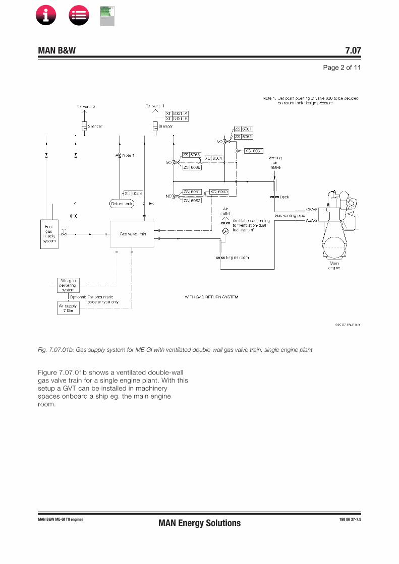
Fig. 7.07.01b: Gas supply system for ME-GI with ventilated double-wall gas valve train, single engine plant
Figure 7.07.01b shows a ventilated double-wallgas valve train for a single engine plant. With thissetup a GVT can be installed in machineryspaces onboard a ship eg. the main engineroom.
MAN Energy Solutions
MAN B&W
IMO Tier ll Project Guide
MAN
Energy Solutions ProjectG
uideM
AN B
&WG
95ME-C
10.5

GGas Valve Train
Fig. 7.07.02a: Tank, FGSS and Gas Valve Train located on deck, enclosed
Fig. 7.07.02b: Tank, FGSS and Gas Valve Train located below deck
MAN Energy Solutions
MAN B&W
IMO Tier ll Project Guide
MAN
Energy Solutions ProjectG
uideM
AN B
&WG
95ME-C
10.5

Fig. 7.07.02c: Gas Valve Train located in machinery space
The Gas Valve Train (GVT) is available as a single unit block component from M Energy Solutions, option: 7 01.
The block GVT can be supplied with double-wall piping through the entire GVT, option: 7 0 , if it is required to install the GVT in machinery space.
LLocation of the GVT above or below the deck
Careful consideration must be given to the instal-lation of the GVT. It should preferably be placed outside the engine room as close to the engine as possible.
Installed on the deck, single-wall piping can be applied from the FGSS to the GVT and then double-wall piping from the GVT to the ME-GI engine beneath the deck. In this case, it is possi-ble to run the double-wall pipe ventilation from just after the GVT.
If it is preferred to install the GVT below deck, it is recommended to install it in a room next to the engine room.
The room where the GVT is installed must haveseparate ventilation providing 30 air changes perhour and a hydrocarbon (HC) sensor installed.
Figs. 7.07.02a, 02b and 02c show the threealternative locations of the GVT and the pipingapplied.
MAN Energy Solutions
MAN B&W
IMO Tier ll Project Guide
MAN
Energy Solutions ProjectG
uideM
AN B
&WG
95ME-C
10.5

GGas supply system key components
) The pneumatic functions are described as their general relation between electric signal and the related function(s) in thegas, nitrogen and vent lines. For detailed design of the pneumatic control system, GVT manufacturer s documentationmust be consulted.
Fig. 7.07.03: Gas valve train schematic
Filters
The GVT inlet contains a safety filter which has the purpose of protecting the GVT and the ME-GI from foreign particles that could damage the sealing of the gas valves. Supplementary to the GVT safety filter, and in the event that the expec-ted quality of the delivered gas cannot be other-wise guaranteed, MAN Energy Solutions recom-mends that the primary filtration takes place in the FGSS and/or in the LNG bunkering system.
For further information about filters for FGSS, please contact MAN Energy Solutions, Copenhagen at [email protected]
Gas valve train
The GVT basically is a double block and bleedsystem which will separate the FGSS from theME-GI during shutdown. Furthermore it containsnitrogen purging and testing functionalities. As anoption, and subject to class approval, the GVTcan also function as the Master Gas Valve, Fig.7.07.02a-c.
The GVT is controlled by the Engine Control Sys-tem and is closely linked to this. Fig. 7.07.03illustrates the working principles of the GVT. Fur-thermore the valve control signal interface isshown in Fig. 16.02.03 'GI Extension Interface toExternal Systems'.
MAN Energy Solutions
MAN B&W
IMO Tier ll Project Guide
MAN
Energy Solutions ProjectG
uideM
AN B
&WG
95ME-C
10.5

As the GVT represents the ME-GI interface to the external systems, it can only be delivered by sup-pliers which have been approved as GVT suppli-ers by MAN Energy Solutions.
GGas piping
For delivery of high-pressure gas to the ME-GI main engine, double-wall gas pipe can be used in both open and enclosed spaces and is required for interior piping.
Moreover, double-wall gas pipe requires ventila-tion in the annular space as described in Section 7.09.
Single-wall gas piping can only be used in exte-rior locations in free open space. In all other loca-tions, double-wall gas piping is required.
Double-wall piping
Design guidelines:
Bosses must be fitted for every 5 meters for inspection of outer duct, inner pipe and sup-ports. Bosses shall also be fitted next to every pipe bend on each side.
The inner pipe support must be placed with a distance of 1,8 m of each other to prevent natu-ral frequency vibrations. On vertical piping, two supports must be placed in the horizontal pipe right before the bend to the vertical pipe.
Pipes to be cold-drawn in order to obtain a proper inner surface finish of the outer pipe.
The pipe installation must be able to absorb deflection from hull and engine due to heat and vibration, therefore flexible elements must be installed.
A leakage test is to be carried out at shop test and at commisioning of the vessel.
For more information contact MAN Energy Solutions, Copenhagen.
Outer pipe for double-wall piping
The outer pipe must be designed in accordancewith IGF code, chapter 9.8. The tangential mem-brane stress of a straight pipe should not exceedthe tensile strength divided by 1.5 (Rm/1.5) whensubjected to the critical pressure. The pressureratings of all other piping components shouldreflect the same level of strength as straightpipes.
Temperature range: −55 ºC to +60 ºC
Total Pressure loss (max): Must be constructed in compliance with MAN Energy Solutions' ventilation specification, see Section 7.09, ‘General data for ventilation sys-tem’.
Critical pressure: 174 bar(Based on 320 bar design pressure for inner pipe)
Material
The recommended material is Duplex EN 1.4462or Stainless steel 316L (EN 1.4404). Selection ofthis material is based on corrosion resistanceand required strength, resistance to cold expo-sure. Therefore long maintenance intervals canbe offered with this material.
Duplex Steel EN 1.4462:Ultimate tensile stress (UTS) 680 MPaYield stress 450 MPa
Stainless steel 316L (EN 1.4404):Ultimate tensile stress (UTS) 500 MPaYield stress 200 MPa
Sizing of outer pipe
Table 7.07.01 provides pipe dimension guide-lines based on standard pipe sizes for EN 1.4462, and in compliance with the belowmentioned formula.
MAN Energy Solutions
MAN B&W
IMO Tier ll Project Guide
MAN
Energy Solutions ProjectG
uideM
AN B
&WG
95ME-C
10.5

PPipe dimension guidelines based on standard pipe sizes according to EN 1.4462
Power range
Pipe OD Thickness, t
NPS Test pressure
Stress resultingfrom
critical pressure
MW mm mm inch Bar Mpa
0-45 114.30 3.05 4 175 317
>45 168.28 4.50 6 175 308
Table 7.07.01: Pipe dimension guidelines, EN 1.4462
Inner pipe
The inner pipe in double-wall gas piping for deliv-ery of high-pressure gas to the ME-GI mainengine has the following specification:
Design pressure: 320 barTemperature range: −55 ºC to +60 ºCTotal pressure loss (max) *): 5 barLCV: 50 MJ/kg
*) This refers to pressure loss from FGSS flangeto engine flange and only due to piping.
Design calculations for the pipe are performedusing the above design assumptions, using theformula specified in chapters 5.2 and 5.3 of theIGC code for calculation of pipe thickness. Pipestrength for different pipe sizes is selected basedon manufacturer's information according toASME B31.3.
For projects using gas with a specific LCV, themaximum total pressure loss requirement isunchanged, so a larger pipe diameter will berequired to maintain pressure loss with a higherflow.
Total pressure loss
The total pressure loss from the gas supply sys-tem to the ME-GI main engine should be as lowas possible, and calculated by the shipyardusing:
PTotal = PPiping + PGVT + PFilter + PFlowmeter
According to FGS design a maximum total pres-sure loss of 15 bar is allowed at 100% SMCR.However, this requires additional energy from theFGSS so it is more desirable to improve theinstallation to reduce the pressure loss to a mini-mum.
Material
The recommended material is Duplex EN 1.4462up to 1½” pipe dimension and Super Duplex EN1.4410 up to 2½” pipe dimension.
Selection of this material is based on corrosionresistance, required strength, resistance to coldexposure, resistance to stress corrosion chloridecracking. Therefore long maintenance intervalscan be offered with this material.
Piping should be cold-worked in order to reduceinternal surface roughness.
Maximum surface roughness: 15 μm
Sizing of inner pipe
In order to dimension the piping, the guidelinesprovided in the table below can be used.
The pressure loss is calculated based on thelength (stated in metres in Tables 7.07.02a & b)of piping from the FGSS to the main engine inletflange, including 20 bends.
Design using welded bends is recommended,with minimum radius as per DIN 13480-3, Chap-ter 6.2 and 6.3.
MAN Energy Solutions
MAN B&W
IMO Tier ll Project Guide
MAN
Energy Solutions ProjectG
uideM
AN B
&WG
95ME-C
10.5

DDimension guidelines based on standard pipe sizes according to EN 1.4462
Powerrange
Maxflow
Pipe OD Thick-ness, t
SCH NPS DN Testpressure
Pressure loss
50m 100m 200m
MW Kg/h mm mm inch bar bar
0-15 2,100 33.40 3.88 40 1 25 480 1.5 2.5 4.7
15-30 4,000 42.16 4.85 80 1¼ 32 480 1.4 2.6 5.0
30-45 6,000 48.26 5.08 80 1½ 40 480 1.4 2.5 4.9
Table 7.07.02a: Dimension guidelines, EN 1.4462
Dimension guidelines based on standard pipe sizes according to EN 1.4410
Powerrange
Maxflow
Pipe OD Thick-ness, t
SCH NPS DN Testpressure
Pressure loss
50m 100m 200m
45-80 Kg/h mm mm inch bar bar
≥80 11,800 60.33 5.54 80 2 50 480 1.4 2.6 5.0
MW 19,000 73.03 7.01 80 2½ 65 480 1.5 2.7 5.0
Table 7.07.02b: Dimension guidelines, EN 1.4410
Generating fuel gas pressure
The pressure can be generated by the FGSS indifferent ways depending on the storage condi-tion of the gas. Some of the possibilities are:
• high-pressure gas compressor, including coolers,pulsation dampers, condensate separator etc.
• high-pressure cryogenic pump to deliver highpressure LNG to an evaporator
• a combination of the above solutions.
Examples of fuel gas supply systems is descri-bed in Section 7.08.
Control of the fuel gas supply system
A description of the ME-GI Engine Control Sys-tem (ME-GI-ECS) is provided in Section 16.02.
The fuel gas pressure is to be controlled on thebasis of the gas supply pressure set point, andthe actual fuel gas load specified by the GI-ECS.
The control signal interface is shown in Fig.16.02.03 ‘GI Extension Interface to External Sys-tems’ and the diagram of the gas valve train isshown in Fig. 7.07.03.
The gas supply pressure set point is expected tochange from 250 bar to 300 bar dependent onengine load. The allowable deviation from the gassupply pressure set point is:
Deviation from set point (dynamic) ±10 bar
This requirement is to be fulfilled at a gas flowrate disturbance frequency of 0.1 Hz, and a gasflow rate variation (kg/s) relative to the gas flowrate at MCR of ±15%. This requirement has to befulfilled also for the lowest calorific values of thegas.
Deviation from set point (static) ±1%
When using BOG from cargo tanks like LNGtankers, the FGS must be able to read the calo-rific value of the supplied gas to the main engine.
MAN Energy Solutions
MAN B&W
IMO Tier ll Project Guide
MAN
Energy Solutions ProjectG
uideM
AN B
&WG
95ME-C
10.5

GGas supply pressure range
Fig. 7.07.04: Gas operating pressure range for each engine load system
The FGSS should be designed and manufacturedin such a way, that it will be able to operatewithin the margins of the 'Gas supply pressurerange' presented in Fig. 7.07.04.
The actual operating profile is determined by theME-ECS in combination with the overall propul-sion system setup.
A default operating profile is shown as an exam-ple in the bold line 'Default profile' in Fig.7.07.04.
MAN Energy Solutions
MAN B&W
IMO Tier ll Project Guide
MAN
Energy Solutions ProjectG
uideM
AN B
&WG
95ME-C
10.5

SSuction pressure for high-pressure pump
Fig. 7.07.05: LNG Pressure – Temperature diagram
To avoid vaporization of LNG on the suction sideof the high-pressure pump, it is important for theSFSS supplier to maintain sufficient feed pres-sure.
In Fig. 7.07.05, the liquid/vapour phase is pre-sented according to the ME-GI Fuel Gas Specifi-cation limit composition. The designer of theFGSS should evaluate accordingly based on theactual quality/composition of the fuel to be usedin the system.
MAN Energy Solutions
MAN B&W
IMO Tier ll Project Guide
MAN
Energy Solutions ProjectG
uideM
AN B
&WG
95ME-C
10.5

SSafety standards for the gas supply system
All equipment shall comply with but not necessa-rily be limited to the following:
1. Meet full class requirements for UMS notationand ACCU notation etc. (ABS, LRS and DNV)
2. Comply with IGF Code and/or IGC Code asapplicable.
IGF code: International Code of Safety for ShipsUsing Gases or other Low-Flashpoint Fuels
IGC Code: International Code for the Construc-tion and Equipment of Ships Carrying LiquefiedGases in Bulk
3. Comply with SOLAS and Flag State requirementsfor fire safety and detection systems
4. Other standards to be fulfilled:
DNV Rules Part 6 Chapter 13 Gas Fuelled EngineInstallations
ABS applicable sections in their guidelines forpropulsion and auxiliary for gas-fuelled ships
ALPEMA SE 2000 or latest, Standards for Plate-fin Heat Exchangers
ASME VIII div 1 Plate-fin Heat Exchangers
ASME BPVC-VIII-3 Construction of High Pres-sure Vessels
IEC 60092 Electrical installations in ships Certi-fied according to ATEX directives.
MAN Energy Solutions
MAN B&W
IMO Tier ll Project Guide
MAN
Energy Solutions ProjectG
uideM
AN B
&WG
95ME-C
10.5
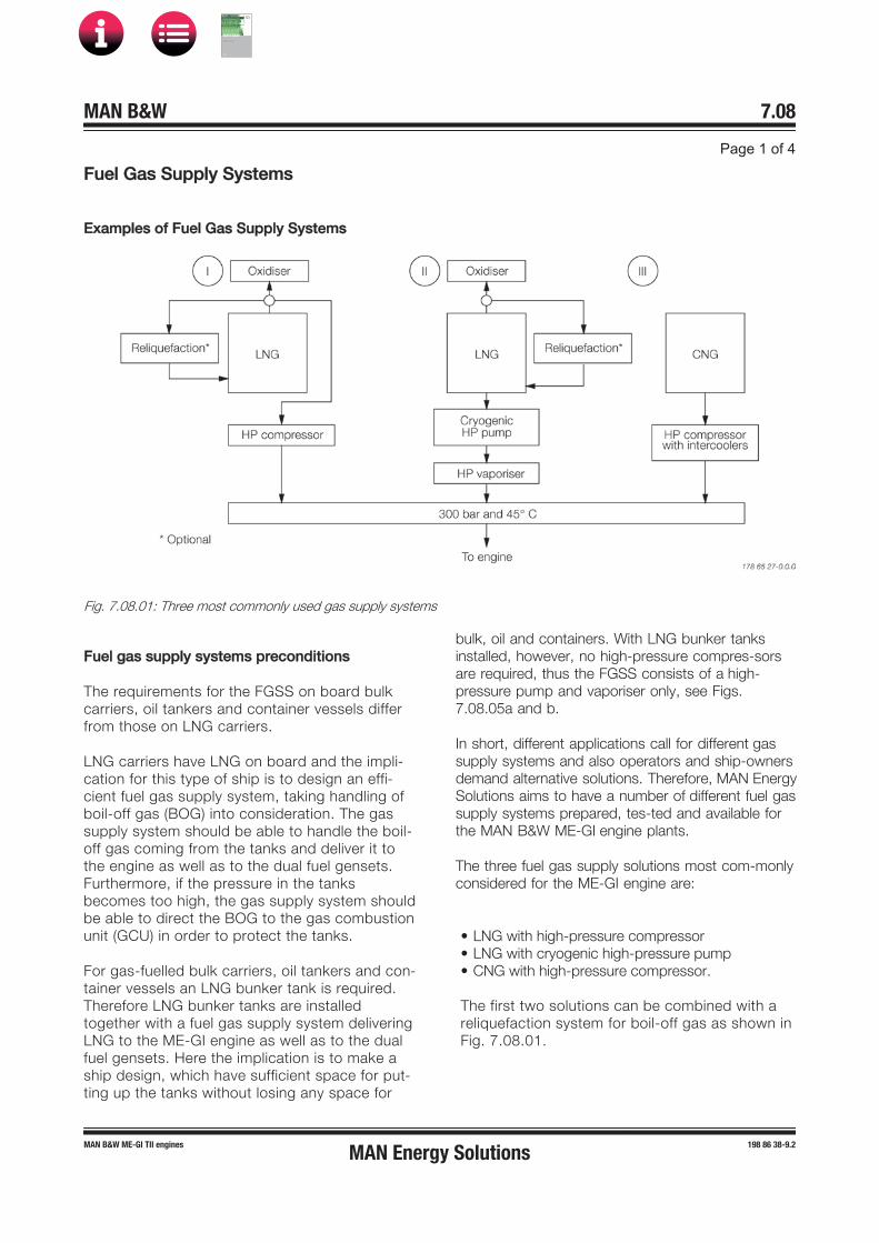
FFuel Gas Supply Systems
Examples of Fuel Gas Supply Systems
Fig. 7.08.01: Three most commonly used gas supply systems
Fuel gas supply systems preconditions
The requirements for the FGSS on board bulkcarriers, oil tankers and container vessels differfrom those on LNG carriers.
LNG carriers have LNG on board and the impli-cation for this type of ship is to design an effi-cient fuel gas supply system, taking handling ofboil-off gas (BOG) into consideration. The gassupply system should be able to handle the boil-off gas coming from the tanks and deliver it tothe engine as well as to the dual fuel gensets.Furthermore, if the pressure in the tanksbecomes too high, the gas supply system shouldbe able to direct the BOG to the gas combustionunit (GCU) in order to protect the tanks.
For gas-fuelled bulk carriers, oil tankers and con-tainer vessels an LNG bunker tank is required.Therefore LNG bunker tanks are installedtogether with a fuel gas supply system deliveringLNG to the ME-GI engine as well as to the dualfuel gensets. Here the implication is to make aship design, which have sufficient space for put-ting up the tanks without losing any space for
bulk, oil and containers. With LNG bunker tanks installed, however, no high-pressure compres-sors are required, thus the FGSS consists of a high-pressure pump and vaporiser only, see Figs. 7.08.05a and b.
In short, different applications call for different gas supply systems and also operators and ship-owners demand alternative solutions. Therefore, MAN Energy Solutions aims to have a number of different fuel gas supply systems prepared, tes-ted and available for the MAN B&W ME-GI engine plants.
The three fuel gas supply solutions most com-monly considered for the ME-GI engine are:
• LNG with high-pressure compressor• LNG with cryogenic high-pressure pump• CNG with high-pressure compressor.
The first two solutions can be combined with areliquefaction system for boil-off gas as shown inFig. 7.08.01.
MAN Energy Solutions
MAN B&W
IMO Tier ll Project Guide
MAN
Energy Solutions ProjectG
uideM
AN B
&WG
95ME-C
10.5
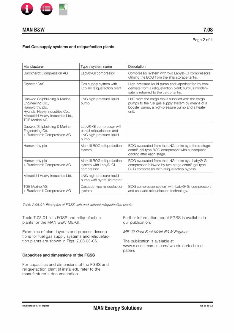
FFuel Gas supply systems and reliquefaction plants
Manufacturer Type / system name Description
Burckhardt Compression AG Laby®-GI compressor Compressor system with two Laby®-GI compressorsutilising the BOG from the ship storage tanks.
Cryostar SAS Gas supply system withEcoRel reliquefaction plant
High-pressure liquid pump and vaporiser fed by con-densate from a reliquefaction plant; surplus conden-sate is returned to the cargo tanks.
Daewoo Shipbuilding & Marine Engineering Co., Hamworthy plc, Hyundai Heavy Industries Co., Mitsubishi Heavy Industries Ltd., TGE Marine AG
LNG high-pressure liquidpump
LNG from the cargo tanks supplied with the cargopumps to the fuel gas supply system by means of abooster pump, a high-pressure pump and a heaterunit.
Daewoo Shipbuilding & Marine Engineering Co. + Burckhardt Compression AG
Laby®-GI compressor withpartial reliquefaction andLNG high-pressure liquidpump
Hamworthy plc Mark III BOG reliquefactionsystem
BOG evacuated from the LNG tanks by a three-stagecentrifugal type BOG compressor with subsequentcooling after each stage.
Hamworthy plc + Burckhardt Compression AG
Mark III BOG reliquefactionsystem with Laby®-GI compressor
BOG evacuated from the LNG tanks by a Laby®-GIcompressor followed by two-stage centrifugal typeBOG compressor with reliquefaction bypass.
Mitsubishi Heavy Industries Ltd. LNG high-pressure liquidpump with hydraulic motor
TGE Marine AG + Burckhardt Compression AG
Cascade type reliquefactionsystem
BOG compressor system with Laby®-GI compressorsand cascade reliquefaction technology.
Table 7.08.01: Examples of FGSS with and without reliquefaction plants
Table 7.08.01 lists FGSS and reliquefactionplants for the MAN B&W ME-GI.
Examples of plant layouts and process descrip-tions for fuel gas supply systems and reliquefac-tion plants are shown in Figs. 7.08.03-05.
Capacities and dimensions of the FGSS
For capacities and dimensions of the FGSS andreliquefaction plant (if installed), refer to the manufacturer’s documentation.
Further information about FGSS is available in our publication:
ME-GI Dual Fuel MAN B&W Engines
The publication is available atwww.marine.man-es.com/two-stroke/technical-papers
MAN Energy Solutions
MAN B&W
IMO Tier ll Project Guide
MAN
Energy Solutions ProjectG
uideM
AN B
&WG
95ME-C
10.5

Fig. 7.08.02: Combined reliquefaction plant and HP LNG pump supply system delivering high pressure fuel gas to the ME-GIengine (Cryostar SAS)
Fig. 7.08.03: Integrated compressor and reliquefaction system with Laby®-GI compressor (Hamworthy plc and BurckhardtCompression AG)
MAN Energy Solutions
MAN B&W
IMO Tier ll Project Guide
MAN
Energy Solutions ProjectG
uideM
AN B
&WG
95ME-C
10.5
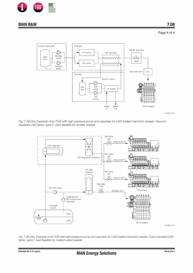
Fig. 7.08.04a: Example of an FGS with high-pressure pump and vaporiser for LNG-fuelled merchant vessels. Vacuum-insulated LNG tanks, type C, best feasible for smaller vessels.
Fig. 7.08.04b: Example of an FGS with high-pressure pump and vaporiser for LNG-fuelled merchant vessels. Foam-insulated LNGtanks, type C, best feasible for medium-sized vessels.
MAN Energy Solutions
MAN B&W
IMO Tier ll Project Guide
MAN
Energy Solutions ProjectG
uideM
AN B
&WG
95ME-C
10.5

MME-GI Gas Supply Auxiliary Systems
Fig. 7.09.01: ME-GI gas supply auxiliary systems
The ME-GI gas supply auxiliary systems include:
• leakage detection and ventilation system, whichventilates the outer pipe of the double-wall pipingcompletely and incorporates leakages detection
• nitrogen system, which enables purging of the fuelgas system on the engine and the fuel gas supplysystem with nitrogen
• gas return system (optional), receiving fuel gasreturned from the engine when the gas pipes aredepressurised.
Fig. 7.09.01 shows the gas supply auxiliary sys-tems and how they are connected to the ME-GIengine.
Capacities of the ME-GI auxiliary systems
The capacities of the ME-GI gas supply auxiliarysystems are listed in the CEAS report for theactual project see section 20.02.
MAN Energy Solutions
MAN B&W
IMO Tier ll Project Guide
MAN
Energy Solutions ProjectG
uideM
AN B
&WG
95ME-C
10.5
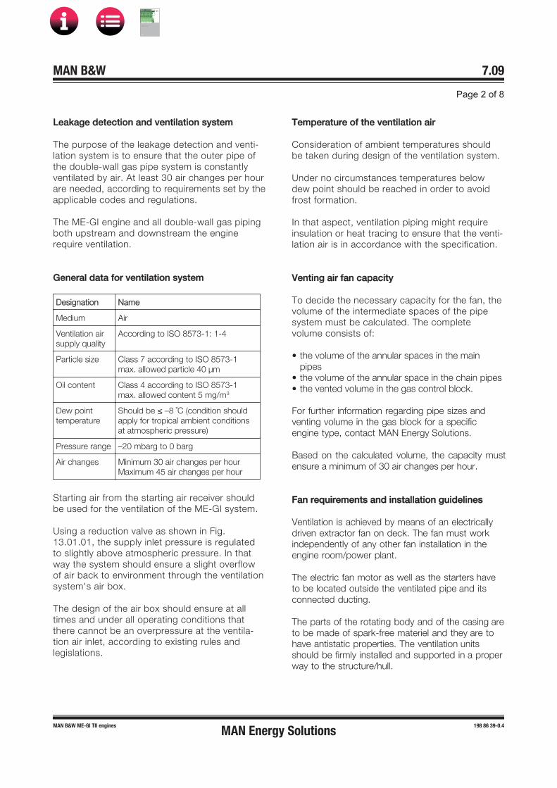
LLeakage detection and ventilation system
The purpose of the leakage detection and venti-lation system is to ensure that the outer pipe ofthe double-wall gas pipe system is constantlyventilated by air. At least 30 air changes per hourare needed, according to requirements set by theapplicable codes and regulations.
The ME-GI engine and all double-wall gas pipingboth upstream and downstream the enginerequire ventilation.
General data for ventilation system
Designation Name
Medium Air
Ventilation air supply quality
According to ISO 8573-1: 1-4
Particle size Class 7 according to ISO 8573-1max. allowed particle 40 μm
Oil content Class 4 according to ISO 8573-1max. allowed content 5 mg/m3
Dew point temperature
Should be ≤ –8 ˚C (condition shouldapply for tropical ambient conditionsat atmospheric pressure)
Pressure range –20 mbarg to 0 barg
Air changes Minimum 30 air changes per hourMaximum 45 air changes per hour
Starting air from the starting air receiver shouldbe used for the ventilation of the ME-GI system.
Using a reduction valve as shown in Fig.13.01.01, the supply inlet pressure is regulatedto slightly above atmospheric pressure. In thatway the system should ensure a slight overflowof air back to environment through the ventilationsystem's air box.
The design of the air box should ensure at alltimes and under all operating conditions thatthere cannot be an overpressure at the ventila-tion air inlet, according to existing rules and legislations.
Temperature of the ventilation air
Consideration of ambient temperatures shouldbe taken during design of the ventilation system.
Under no circumstances temperatures belowdew point should be reached in order to avoidfrost formation.
In that aspect, ventilation piping might requireinsulation or heat tracing to ensure that the venti-lation air is in accordance with the specification.
Venting air fan capacity
To decide the necessary capacity for the fan, thevolume of the intermediate spaces of the pipesystem must be calculated. The complete volume consists of:
• the volume of the annular spaces in the mainpipes
• the volume of the annular space in the chain pipes• the vented volume in the gas control block.
For further information regarding pipe sizes and venting volume in the gas block for a specific engine type, contact MAN Energy Solutions.
Based on the calculated volume, the capacity must ensure a minimum of 30 air changes per hour.
Fan requirements and installation guidelines
Ventilation is achieved by means of an electrically driven extractor fan on deck. The fan must work independently of any other fan installation in the engine room/power plant.
The electric fan motor as well as the starters have to be located outside the ventilated pipe and its connected ducting.
The parts of the rotating body and of the casing are to be made of spark-free materiel and they are to have antistatic properties. The ventilation units should be firmly installed and supported in a proper way to the structure/hull.
MAN Energy Solutions
MAN B&W
IMO Tier ll Project Guide
MAN
Energy Solutions ProjectG
uideM
AN B
&WG
95ME-C
10.5
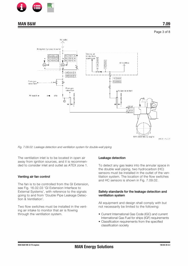
Fig. 7.09.02: Leakage detection and ventilation system for double-wall piping
The ventilation inlet is to be located in open airaway from ignition sources, and it is recommen-ded to consider inlet and outlet as ATEX zone 1.
VVenting air fan control
The fan is to be controlled from the GI Extension,see Fig. 16.02.03 ‘GI Extension Interface toExternal Systems’, with reference to the signalsgoing to and from ‘Double Pipe Leakage Detec-tion & Ventilation’.
Two flow switches must be installed in the vent-ing air intake to monitor that air is flowingthrough the ventilation system.
Leakage detection
To detect any gas leaks into the annular space inthe double wall piping, two hydrocarbon (HC)sensors must be installed in the outlet of the ven-tilation system. The location of the flow switchesand HC sensors is shown in Fig. 7.09.02.
Safety standards for the leakage detection andventilation system
All equipment and design shall comply with butnot necessarily be limited to the following:
• Current International Gas Code (IGC) and currentInternational Gas Fuel for ships (IGF) requirements
• Classification requirements from the specifiedclassification society
MAN Energy Solutions
MAN B&W
IMO Tier ll Project Guide
MAN
Energy Solutions ProjectG
uideM
AN B
&WG
95ME-C
10.5
• SOLAS and flag state requirements for fire safetyand detection systems
• IEC 60092 Electrical Installations in Ships.
The system should be certified according to ATEX requirements applicable for one 1 classifi-cation specified in the relevant rules and direc-tives.
Further information about the gas ventilation sys-tem and calculating the capacity of the venting fan is available from MAN Energy Solutions, Copen-hagen.
NNitrogen system
The nitrogen system is required for purging of all fuel gas piping associated with the ME-GI instal-lation. See the diagram of gas supply auxiliary systems Fig 7.09.01.
The Fuel Gas Supply system (FGSS) also requires nitrogen for purging, which can either be supplied from a common nitrogen system, or a separate stand alone system. This will depend on the individual installation.
A sufficient quantity of nitrogen must be available on board prior to gas operation.
General data for the nitrogen system
Medium: N2
Quality: minimum 95% N2
Purging pressure: minimum 7 bargPurging temperature: ambient temperature
Control of the nitrogen system
Following a gas shut down, purging is initiated.Successful purging is evaluated by the ME-GIengine control system (ECS) on the basis that thehydrocarbon sensors located next to the ventsilencer in the blow-off pipe detects less than30% lower explosive limit.
Once purging is successfully completed, the ME-GI-ECS initiates a 30 minute timer during which the ME-GI plant control remains in the 'purged' state and gas operation can be resumed without further purging. After the 30 minutes have expired, the plant control is no longer in the purged state and, in order to resume gas opera-tion, purging is again required to return to the'purged' state.
The nitrogen system is to be equipped with the interface signals described in Fig. 16.02.03 ‘GI Extension Interface to External Systems’, with reference to the signals going to and from ‘Inert Gas Purging System’. When operating in‘remote’ mode, the nitrogen system is controlled by the engine control system.
Nitrogen pipe connections
Please refer to Section 7.07 for estimating pipe dimensions based on engine power. The actual pipe dimensions must also be verified with Yard.
Safety requirements
For marine applications, the nitrogen system must comply with all applicable standards and Class requirements.
Safe gas-freeing procedure
It is required to prevent a situation where gas-freeing to the atmosphere in ports and caused by harbours will introduce a risk of explosion port activities and unforeseen incidents. Therefore it is recommended to switch to fuel oil mode and per-form the gas-freeing procedure prior to any port and harbour entry operation.
However, if the fuel gas supply system is designed with a return tank to receive the major part of the gas in a closed system, the operation might be processed otherwise.
MAN Energy Solutions recommends to include the gas-freeing procedure for port calls in the opera-tional procedure of the ship.
MAN Energy Solutions
MAN B&W
IMO Tier ll Project Guide
MAN
Energy Solutions ProjectG
uideM
AN B
&WG
95ME-C
10.5

PPurging volume and storage capacity
The purging storage volume must be designedfor a number of consecutive starts on fuel gas,each including a number of purge sequences, aswell as for purging prior to and after engine oper-ation on fuel gas.
In order to calculate the purging volume, the totalvolume of piping being purged must be calcula-ted. The purging sequences are described in thefollowing and shown in Fig. 7.09.03.
ME-GI purge sequence:
1. Purging of gas accumulators
2. Purging of window and injection valves.
The volume for both purge sequences (Vpurge) isthe same and includes:
Nitrogen system – connecting piping to GVTvalve 806 – GVT volume – gas supply pipe – onengine purge volume – gas venting pipe –silencer.
On-engine purge volume is available from theCEAS report under the 'Nitrogen system' sectionfor ME-GI type engines, see Section 20.02. Pip-ing volume from the nitrogen system to ME-GI(up to silencer) should be calculated by thedesigner and added to the 'on-engine volume'.
Calculating the purging volume
The purge sequence is performed a maximum of5 times, dependent on measurement by the HCsensors in the return pipe. Furthermore, the sys-tem must be purged before start in fuel gasmode.
Consequently a guideline for calculating the nitrogen storage volume is:
N2 buffer tank minimum volume: z × 5 × 2 × (2 × Vpurge) [Nm3]
• 5 runs of purge sequence
• 2 purge procedures before start and after stop in gas mode (see also the control section of this document)
• 2 times the Vpurge as described in ME-GI purge sequence
• z represents the times of the purging procedure and is to be decided by the ship designer. MAN Energy Solutions recommends that z should be at least equal to 6 consecutive gas starts.
It should also be noted that after each purgingprocedure, the result will be a pressure drop inthe buffer tank and that effect should be takeninto account.
Furthermore, it should be noted that the purgingvolume calculation is made under atmosphericconditions, and calculation of the actual tank vol-ume should correct for the tank pressure whensizing the tank.
Nitrogen generator
In case of installation of a nitrogen generator onboard the vessel, the capacity can be calculatedfor two main design cases:
• Design case 1Maximum 5 purges are required to purge the gaspipingGuideline of minimum time t = 1 minute betweenpurges
Nitrogen gas generator capacity = (2 × Vpurge) / 1[Nm3/min].
• Design case 2Nitrogen system for leak test at commissioningand after disassembly of components in the gassystem
(Nitrogen gas generator capacity + N2 buffer tankminimum volume [feeding rate]) ≥ nitrogen boostercapacity [Nm3/min].
The nitrogen generator capacity must be suffi-cient to fulfil both design cases.
Information about a nitrogen system for leak test is available from MAN Energy Solutions, Copenha-gen.
MAN Energy Solutions
MAN B&W
IMO Tier ll Project Guide
MAN
Energy Solutions ProjectG
uideM
AN B
&WG
95ME-C
10.5

Fig. 7.09.03: Piping routes for purging sequence
Chain pipe and accumulator volume is depend-ent on engine type, contact MAN Energy Solutions for further information.
If a common nitrogen gas system is used to purge the FGSS too, the volume of this system must be added to the purging volume, according to the FGSS specifications.
The system needs also to provide enough nitro-gen for leak testing of the GVT, the ME-GI and the respective gas piping up to valve 836 (or valves 818, 819, 821 for gas return systems).
VVent silencer
During depressurization of the system, and dueto noise regulations associated with health issuesof the personnel, a silencer on the vent mast isrequired per plant installation.
This description is made as a general specifica-tion and guideline for design and/or purchase ofthe vent silencer.
MAN Energy Solutions
MAN B&W
IMO Tier ll Project Guide
MAN
Energy Solutions ProjectG
uideM
AN B
&WG
95ME-C
10.5

Fig. 7.09.04: Allowable daily and occasional noise exposure zones according to SOLAS
OOperating conditions
Medium Natural gas
Temperature, °C −55 to +60
Operating pressure Normal 300 bar,maximum 330 bar
Mass flow rate, kg/s See ‘Calculating the venting gas flow’
Acoustic requirements
Sound pressure level at 5 m distance: 110 dB(A)
A chart of the allowable daily and occasionalnoise exposure zones is shown in Fig. 7.09.04.
Draining/purging of the vent silencer
The silencer design should include a drain option(for example a nozzle with a blind flange).
This option should be used during servicing andmaintenance to manually purge the silencer anddrain unintended liquid concentration, the drainshould therefore be placed on the lower part ofthe vent silencer.
Safety requirements
Equipment shall comply with but not necessarilybe limited to the following:
• Current IGC and IGF requirements• SOLAS and flag state acoustic requirements with
noise limits for seafarers• Classification requirements from the specified
classification society.
The silencer design must secure that no gas istrapped inside the silencer. Otherwise the func-tion of the HC detector in the return pipe couldbe disturbed.
MAN Energy Solutions
MAN B&W
IMO Tier ll Project Guide
MAN
Energy Solutions ProjectG
uideM
AN B
&WG
95ME-C
10.5

CCalculating the venting gas flow
Fig. 7.09.05: Gas condition during purging, example from 5G70ME-GI
The gas flow can be calculated from the Bird,Stewart and Lightfoot source-term model forchoked gas flows from a pressurized gas system:
wheret : the time since the flow started (when valve
opens)k : cp/cv of the gas (1.78 for methane at 300 bar,
45 °C)F : the fraction of initial gas weight remaining in
the system at any time ta : (1-k)/2b : (k+1)/(k-1)CD: coefficient of discharge, normally 0.75
A : cross sectional area of blow-off valve, variablebased on engine type
V : system volume (piping volume from GVT tovent silencer in m3
P0 : the initial gas pressure in the system, in Pa (30 MPa)
d0 : the initial gas density in the system (222 kg/m3
for natural gas at 300 bar, 45 °C)
The pressure P at any fraction F is expressed: P = P0 Fk
Example of pressure and mass flow at any giventime for 150 l system volume, with a 5G70ME-GIengine is shown in Fig. 7.09.05. As a guideline,the mass flow rate at first second is to be usedfor dimensioning the silencer.
Gas return system
The optional gas return system, option: 4 37 611, enables an emission-free gas solutionby saving the fuel gas that is emitted to atmos-phere during gas pipe emptying procedures.
The gas return system receives the remaininggas in the pipes and accumulators on the engineside when fuel gas running is stopped and if thesystem is ready to receive gas. Otherwise, thegas is blown off to the atmosphere.
MAN Energy Solutions
MAN B&W
IMO Tier ll Project Guide
MAN
Energy Solutions ProjectG
uideM
AN B
&WG
95ME-C
10.5
MAN B&W
Lubricating Oil
8MAN Energy Solutions
MAN B&W
IMO Tier ll Project Guide
MAN
Energy Solutions Project G
uideM
AN B
&W G
95ME-C
10.5

MAN B&W 8.01Page 1 of 2
MAN B&W ME�GI/�LGI engines 199 07 40-3.0
Lubricating and Cooling Oil System
Lubricating oil bottomtank,for arrangement ofoil drain, see Fig.8.06.01
Deck
Filling pipe
To and from purifiers
Servo oil back-flushing,see Section 8.08
To drain tank
For detail of drain cowl,see Fig. 8.07.01
Min. 15°
Pipe size,see table8.01.02
Venting forturbocharger/s
Drain pipe fromturbocharger/s
PI PITI TI TI
C/D C/D
RU
AB
Engineoil
Lub. oilcooler
S S
005
E
AR
RWFeeler 45 °C
Lubricating oil inlet
Bypass valve may be omitted in cases where the pumps have a built in bypass
25 mm. hose connection for cleaning of lubriceting oil system
25 mm valve to be located on underside of horizontal pipe piece
For initial filling of pumps
Lubricating oil pumps, see Section 8.05
Full-flow filter, see Section 8.05
For flow rates and capacitiesfor main engine, see ‘List ofcapacities’ for actual engine type
Pipe size,see table 8.01.02
The letters refer to list of ‘Counterflanges’
079 27 21�4.8.2
The lubricating oil is pumped from a bottom tank by means of the main lubricating oil pump to the lubricating oil cooler, a thermostatic valve and, through a full�flow filter, to the engine inlet RU, Fig. 8.01.01.
RU lubricates main bearings, thrust bearing, axial vibration damper, piston cooling, crosshead bear-ings, crankpin bearings. It also supplies oil to the Hydraulic Power Supply unit, moment compensa-tor, torsional vibration damper, exhaust valve, Hy-draulic Cylinder Unit and gas control block.
From the engine, the oil collects in the oil pan, from where it is drained off to the bottom tank, see Fig. 8.06.01a and b ‘Lubricating oil tank, with cofferdam’. By class demand, a cofferdam must be placed underneath the lubricating oil tank.
The engine crankcase is vented through ‘AR’ by a
pipe which extends directly to the deck. This pipe has a drain arrangement so that oil condensed in the pipe can be led to a drain tank, see details in Fig. 8.07.01.
Drains from the engine bedplate ‘AE’ are fitted on both sides, see Fig. 8.07.02 ‘Bedplate drain pipes’. For external pipe connections, we prescribe a maximum oil velocity of 1.8 m/s.
Lubrication of turbochargers
Turbochargers with slide bearings are normally lubricated from the main engine system. AB is outlet from the turbocharger, see Figs. 8.03.01 to 8.03.04.
Figs. 8.03.01 to 8.03.04 show the lube oil pipe arrangements for various turbocharger makes.
Fig. 8.01.01 Lubricating and cooling oil system
MAN Energy Solutions
MAN B&W
IMO Tier ll Project Guide
MAN
Energy Solutions Project G
uideM
AN B
&W G
95ME-C
10.5
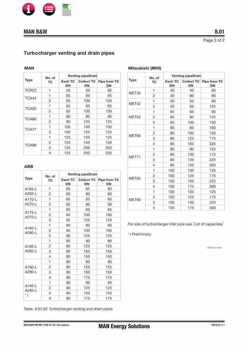
MAN B&W ME/ME-C/ME-B/-GI/-LGI engines 199 03 67-7.1
MAN B&W 8.01Page 2 of 2
* ) PreIiminary
MAN
TypeNo. of
TC
Venting pipeDrain
Each TCDN
Collect TCDN
Pipe from TCDN
TCR22 1 50 50 65
TCA441 65 65 652 65 100 100
TCA551 65 65 652 65 100 100
TCA661 80 80 802 80 125 125
TCA771 100 100 1002 100 125 125
TCA88
1 125 125 1252 125 150 1503 125 200 2004 125 250 250
ABB
TypeNo. of
TC
Venting pipeDrain
Each TCDN
Collect TCDN
Pipe from TCDN
A165-LA265-L
1 60 65 652 60 80 80
A170-LA270-L
1 65 65 652 65 90 90
A175-LA275-L
1 65 65 652 65 100 1003 65 125 125
A180-LA280-L
1 80 80 802 80 100 1003 80 125 125
A185-LA285-L
1 80 80 802 80 125 1253 80 150 1504 80 150 150
A190-LA290-L
1 80 80 802 80 125 1253 80 150 1504 80 175 175
A195-LA295-L* )
1 80 90 902 80 125 1253 80 150 1504 80 175 175
Mitsubishi (MHI)
TypeNo. of
TC
Venting pipeDrain
Each TCDN
Collect TCDN
Pipe from TCDN
MET331 40 40 652 40 80 90
MET421 50 50 802 50 65 125
MET531 65 65 902 65 80 1253 65 100 150
MET66
1 80 80 1002 80 100 1503 80 125 1754 80 150 225
MET71
1 80 80 1252 80 100 1753 80 125 2254 80 150 300
MET83
1 100 100 1252 100 125 1753 100 150 2254 100 175 300
MET90
1 100 100 1252 100 125 1753 100 150 2254 100 175 300
Table. 8.01.02: Turbocharger venting and drain pipes
For size of turbocharger inlet pipe see ‘List of capacities’
079 27 21-4.8.1
Turbocharger venting and drain pipes
MAN Energy Solutions
MAN B&W
IMO Tier ll Project Guide
MAN
Energy Solutions Project G
uideM
AN B
&W G
95ME-C
10.5

MAN B&W 8.02Page 1 of 2
199 04 87-5.2MAN B&W 50-40ME-C9.5/-GI/-LGI MAN Energy Solutions
Hydraulic power for the ME hydraulic-mechanical system for activation of the fuel injection and the exhaust valve is supplied by the Hydraulic Power Supply (HPS) unit.
As hydraulic medium, normal lubricating oil is used, as standard taken from the engine’s main lubricating oil system and filtered in the HPS unit.
HPS connection to lubrication oil system
Internally on the engine, the system oil inlet RU is connected to the HPS unit which supplies the hy-draulic oil to the Hydraulic Cylinder Units (HCUs). See Figs. 16.01.02a and 16.01.02b.
RW is the oil outlet from the automatic backflush-ing filter.
The hydraulic oil is supplied to the Hydraulic Cyl-inder Units (HCU) located at each cylinder. From here the hydraulic oil is diverted to the multi-way valves, which perform the fuel injection and open the exhaust valve respectively: Electronic Fuel Injection (ELFI) and Electronic exhaust Valve Ac-tuation (ELVA). The exhaust valve is closed by the conventional ‘air spring’.
The electronic signals to the multi-way valves are given by the Engine Control System, see Chapter 16, Engine Control System (ECS).
HPS configurations
The HPS pumps are driven either mechanically by the engine (via a step-up gear from the crank-shaft) or electrically.
The HPS unit is mounted on the engine no matter how its pumps are driven.
With mechanically driven pumps, the HPS unit consists of:
• an automatic and a redundant filter• three to five engine driven main pumps
• two electrically driven start-up pumps• a safety and accumulator block
as shown in Fig. 8.02.01.
With electrically driven pumps, the HPS unit dif-fers in having a total of three pumps which serve as combined main and start-up pumps.
Motor start method
Direct Online Start (DOL) is required for all the electric motors for the pumps for the Hydraulic Power Supply (HPS) to ensure proper operation under all conditions, including the start up against maximum pressure in the system.
HPS unit types
Two HPS configurations are available:
• the STANDARD mechanically driven HPS, EoD: 4 40 160, with mechanically driven main pumps and start-up pumps with capacity sufficient to deliver the start-up pressure only. The engine cannot run with all engine driven main pumps out of operation, whereas 66% engine load is available in case one main pump is out
• an electrically driven HPS, option: 4 40 161, with 66% engine load available in case one pump is out.
The electric power consumption of the electrically driven pumps should be taken into consideration in the specification of the auxilliary machinery ca-pacity.
Hydraulic Power Supply Unit
MAN B&W
IMO Tier ll Project Guide
MAN
Energy Solutions Project G
uideM
AN B
&W G
95ME-C
10.5

MAN B&W 8.02Page 2 of 2
199 04 86-3.1MAN B&W 50-40ME-C/-GI/-LGI
Sys
tem
oil
out
let
S
Mai
n b
eari
ngs
Axi
al v
ibra
tion
dam
per
Cro
sshe
ad b
eari
ngs
& p
isto
n
To h
ydra
ulic
cylin
der
uni
t
TI
811
3
AR
Mai
n fil
ter
Red
und
ance
filte
r
Ele
ctri
cally
dri
ven
pum
ps
Eng
ine
dri
ven
pum
ps
Saf
ety
and
acc
umul
ato
r b
lock
RW
Bac
k-flu
shin
g o
il
Filt
er u
nit
RU
Hyd
raul
ic P
ower
Sup
ply
uni
t
Lub
r. o
il to
tur
bo
char
ger
Hyd
ralic
oil
AB
MM
Fo
reA
ft
TE
810
6 I
AH
Y
TI
810
6
TE
810
7 Z
WT
881
2 I
AH
Y
WI
881
2
FS
811
4 A
L Y
TE
811
3 I
AH
Y
TE
811
2 I
AH
TI
8112
PI
810
8X
C 8
150
PT
810
9 Z
PT
810
8 I
AL
Y
PI
810
3
TI
8117
I A
H Y
TE
811
7
The
lett
ers
refe
r to
list
of ‘
Co
unte
rflan
ges
’T
he it
em n
o. r
efer
to
‘Gui
dan
ce V
alue
s A
uto
mat
ion’
The
pip
ing
is d
eliv
ered
with
and
fitt
ed o
nto
the
eng
ine
Fig. 8.02.01: Engine driven hydraulic power supply unit and lubricating oil pipes
Hydraulic Power Supply Unit, Engine Driven, and Lubricating Oil Pipes
530 01 87�7.1.1
MAN Energy Solutions
MAN B&W
IMO Tier ll Project Guide
MAN
Energy Solutions Project G
uideM
AN B
&W G
95ME-C
10.5

MAN B&W 8.03
MAN B&W MC/MC�C, ME/ME�C/ME-B/�GI/-LGI engines,Engine Selection Guide
198 42 32�8.6
Page 1 of 1
Lubricating Oil Pipes for Turbochargers
From system oil
MAN TCAturbocharger
AB
TE 8117 I AH Y
TI 8117
PI 8103
PT 8103 I AL
E
Fig. 8.03.01: MAN turbocharger type TCA
121 14 96-6.2.0
From system oil
MET turbocharger
AB
E
TI 8117
PI 8103
TE 8117 I AH Y
Fig. 8.03.02: Mitsubishi turbocharger type MET
Fig. 8.03.03: ABB turbocharger type A-L
126 40 87-1.3.0
524 26 81-4.2.0
AB
E
PI 8103
PT 8103 I AL
TI 8117
From system oil
ABB A-L turbocharger
TE 8117 I AH Y
MAN Energy Solutions
MAN B&W
IMO Tier ll Project Guide
MAN
Energy Solutions Project G
uideM
AN B
&W G
95ME-C
10.5

MAN B&W 8.04Page 1 of 1
MAN B&W engines, Engine Selection Guide
198 38 86�5.13
Lubricating Oil Consumption, Centrifuges and List of Lubricating Oils
Lubricating oil consumption
The system oil consumption from the ship’s sys-tem oil plant depends on factors like back flushing from the purifiers and drain from stuffing boxes.
Furthermore, the consumption varies for different engine sizes as well as operational and mainte-nance patterns.
Lubricating oil centrifuges
Automatic centrifuges are to be used, either with total discharge or partial discharge.
The nominal capacity of the centrifuge is to be according to the supplier’s recommendation for lubricating oil, based on the figure:
0.136 litre/kWh
The Nominal MCR is used as the total installed power.
Further information about lubricating oil qualities is available in our publication:
Guidelines for Fuels and Lubes Purchasing
The publication is available at www.marine.man-es.com → ’Two-Stroke’ → ’Technical Papers’.
Recommendations regarding engine lubrication is available in MAN Energy Solutions' most current Service Letters on this subject.
The Service Letters are available at www.marine. man.es.com → ’Two-Stroke’ → ’Service Letters’.
CompanyCirculating oil SAE 30, BN 5 10
Aegean Alfasys 305Castrol CDX 30Chevron Veritas 800 Marine 30ExxonMobil Mobilgard 300Gulf Oil Marine GulfSea Superbear 3006Indian Oil Corp. Servo Marine 0530JX Nippon Oil & Energy Marine S30Lukoil Navigo 6 SOShell Melina S 30Sinopec System Oil 3005Total Atlanta Marine D3005
List of lubricating oils
The circulating oil (lubricating and cooling oil) must be of the rust and oxidation inhibited type of oil of SAE 30 viscosity grade.
In short, MAN Energy Solutions recommends the use of system oils with the following main proper-ties:
• SAE 30 viscosity grade• BN level 5 - 10• adequately corrosion and oxidation inhibited• adequate detergengy and dispersancy.
The adequate dispersion and detergent proper-ties are in order to keep the crankcase and piston cooling spaces clean of deposits.
Alkaline circulating oils are generally superior in this respect.
The major international system oil brands listed below have been tested in service with acceptable results.
Do not consider the list complete, as oils from other companies can be equally suitable. Fur-ther information can be obtained from the engine builder or MAN Energy Solutions, Copenhagen.
MAN Energy Solutions
MAN B&W
IMO Tier ll Project Guide
MAN
Energy Solutions Project G
uideM
AN B
&W G
95ME-C
10.5

MAN B&W 8.05Page 1 of 5
MAN B&W S50ME-B9-GI/-LGI, G45ME-C9-GI/-LGI 199 07 76-3.0
Components for Lubricating Oil System
Lubricating oil pump
The lubricating oil pump can be of the displace-ment wheel, or the centrifugal type:
Lubricating oil viscosity, specified ...75 cSt at 50 °CLubricating oil viscosity ........... maximum 400 cSt *Lubricating oil flow .............. see ‘List of capacities’Design pump head .......................................4.2 barDelivery pressure .........................................4.2 barMax. working temperature ............................. 70 °C
* 400 cSt is specified, as it is normal practice whenstarting on cold oil, to partly open the bypassvalves of the lubricating oil pumps, so as to reducethe electric power requirements for the pumps.
The flow capacity must be within a range from 100 to 112% of the capacity stated.
The pump head is based on a total pressure drop across cooler and filter of maximum 1 bar.
Referring to Fig. 8.01.01, the bypass valve shown between the main lubricating oil pumps may be omitted in cases where the pumps have a built�in bypass or if centrifugal pumps are used.
If centrifugal pumps are used, it is recommended to install a throttle valve at position ‘005’ to prevent an excessive oil level in the oil pan if the centrifugal pump is supplying too much oil to the engine.
During trials, the valve should be adjusted by means of a device which permits the valve to be closed only to the extent that the minimum flow area through the valve gives the specified lubri-cating oil pressure at the inlet to the engine at full normal load conditions. It should be possible to fully open the valve, e.g. when starting the engine with cold oil.
It is recommended to install a 25 mm valve (pos. 006), with a hose connection after the main lubri-cating oil pumps, for checking the cleanliness of the lubricating oil system during the flushing pro-cedure. The valve is to be located on the under-side of a horizontal pipe just after the discharge from the lubricating oil pumps.
Lubricating oil cooler
The lubricating oil cooler must be of the shell and tube type made of seawater resistant material, or a plate type heat exchanger with plate material of titanium, unless freshwater is used in a central cooling water system.
Lubricating oil viscosity, specified ...75 cSt at 50 °CLubricating oil flow .............. see ‘List of capacities’Heat dissipation .................. see ‘List of capacities’Lubricating oil temperature, outlet cooler ...... 45 °CWorking pressure on oil side ........................4.2 barPressure drop on oil side ............maximum 0.5 barCooling water flow ............... see ‘List of capacities’Cooling water temperature at inlet:seawater ......................................................... 32 °Cfreshwater ....................................................... 36 °CPressure drop on water side .......maximum 0.2 bar
The lubricating oil flow capacity must be within a range from 100 to 112% of the capacity stated.
The cooling water flow capacity must be within a range from 100 to 110% of the capacity stated.
To ensure the correct functioning of the lubricat-ing oil cooler, we recommend that the seawater temperature is regulated so that it will not be lower than 10 °C.
The pressure drop may be larger, depending on the actual cooler design.
Lubricating oil temperature control valve
The temperature control system can, by means of a three�way valve unit, by�pass the cooler totally or partly.
Lubricating oil viscosity, specified ....75 cSt at 50 °CLubricating oil flow .............. see ‘List of capacities’Temperature range, inlet to engine .........40 � 47 °C
MAN Energy Solutions
MAN B&W
IMO Tier ll Project Guide
MAN
Energy Solutions Project G
uideM
AN B
&W G
95ME-C
10.5
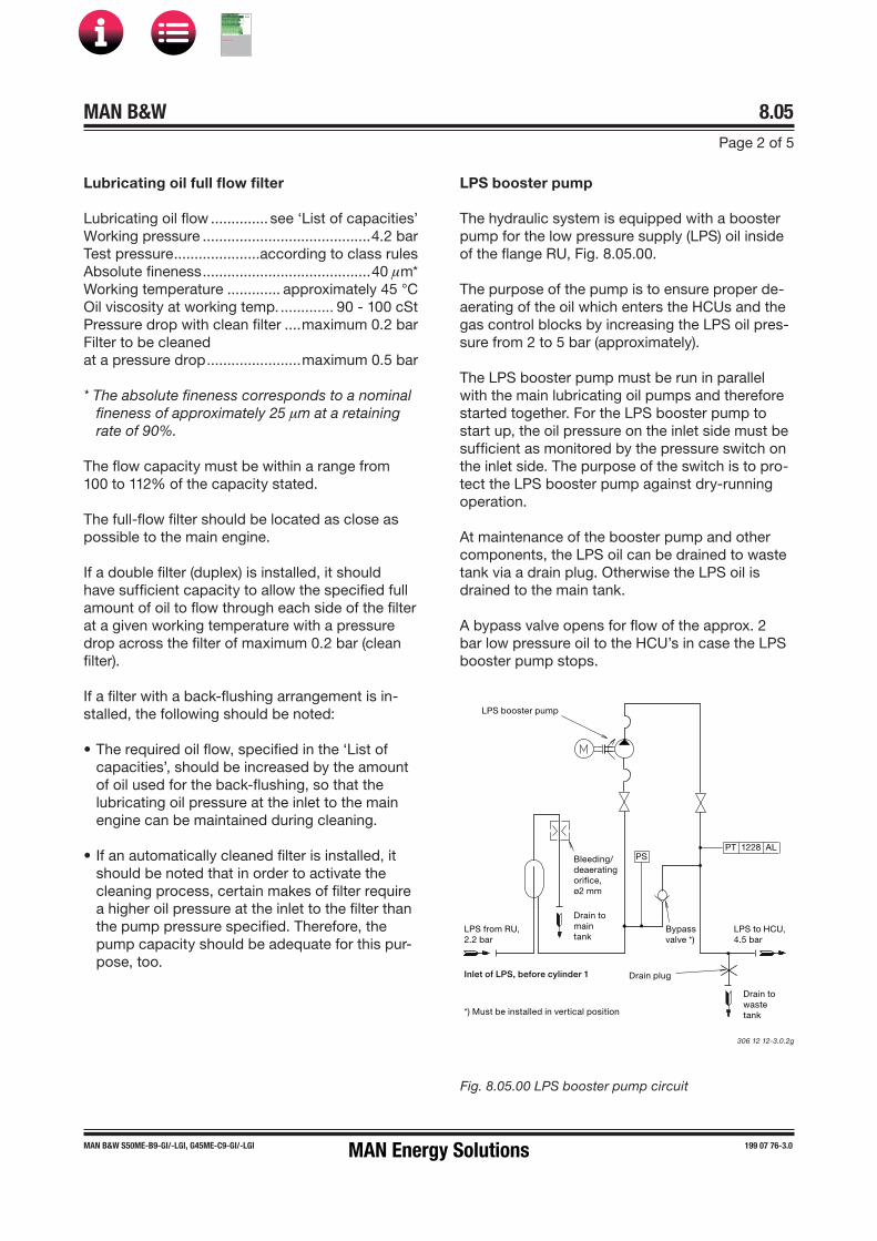
MAN B&W 8.05Page 2 of 5
MAN B&W S50ME-B9-GI/-LGI, G45ME-C9-GI/-LGI 199 07 76-3.0
Lubricating oil full flow filter
Lubricating oil flow .............. see ‘List of capacities’Working pressure .........................................4.2 barTest pressure .....................according to class rulesAbsolute fineness .........................................40 µm*Working temperature ............. approximately 45 °COil viscosity at working temp. ............. 90 � 100 cStPressure drop with clean filter ....maximum 0.2 barFilter to be cleanedat a pressure drop .......................maximum 0.5 bar
* The absolute fineness corresponds to a nominalfineness of approximately 25 µm at a retainingrate of 90%.
The flow capacity must be within a range from 100 to 112% of the capacity stated.
The full�flow filter should be located as close as possible to the main engine.
If a double filter (duplex) is installed, it should have sufficient capacity to allow the specified full amount of oil to flow through each side of the filter at a given working temperature with a pressure drop across the filter of maximum 0.2 bar (clean filter).
If a filter with a back�flushing arrangement is in-stalled, the following should be noted:
• The required oil flow, specified in the ‘List ofcapacities’, should be increased by the amountof oil used for the back�flushing, so that thelubricating oil pressure at the inlet to the mainengine can be maintained during cleaning.
• If an automatically cleaned filter is installed, itshould be noted that in order to activate thecleaning process, certain makes of filter requirea higher oil pressure at the inlet to the filter thanthe pump pressure specified. Therefore, thepump capacity should be adequate for this pur-pose, too.
LPS booster pump
The hydraulic system is equipped with a booster pump for the low pressure supply (LPS) oil inside of the flange RU, Fig. 8.05.00.
The purpose of the pump is to ensure proper de-aerating of the oil which enters the HCUs and the gas control blocks by increasing the LPS oil pres-sure from 2 to 5 bar (approximately).
The LPS booster pump must be run in parallel with the main lubricating oil pumps and therefore started together. For the LPS booster pump to start up, the oil pressure on the inlet side must be sufficient as monitored by the pressure switch on the inlet side. The purpose of the switch is to pro-tect the LPS booster pump against dry-running operation.
At maintenance of the booster pump and other components, the LPS oil can be drained to waste tank via a drain plug. Otherwise the LPS oil is drained to the main tank.
A bypass valve opens for flow of the approx. 2 bar low pressure oil to the HCU’s in case the LPS booster pump stops.
306 12 12-3.0.2g
Fig. 8.05.00 LPS booster pump circuit
LPS from RU,2.2 bar
LPS to HCU,4.5 bar
Bleeding/deaeratingorifice,ø2 mm
Inlet of LPS, before cylinder 1
PT 1228 AL
LPS booster pump
Drain tomaintank
Drain towastetank
Drain plug
Bypassvalve *)
*) Must be installed in vertical position
PS
MAN Energy Solutions
MAN B&W
IMO Tier ll Project Guide
MAN
Energy Solutions Project G
uideM
AN B
&W G
95ME-C
10.5
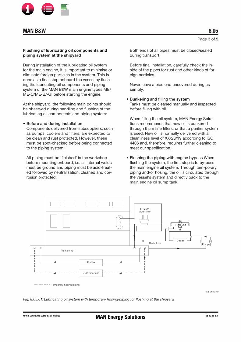
MAN B&W 8.05Page 3 of 5
MAN B&W ME/ME-C/ME-B/-GI engines 198 80 26-6.0
Flushing of lubricating oil components and piping system at the shipyard
During installation of the lubricating oil system for the main engine, it is important to minimise or eliminate foreign particles in the system. This is done as a final step onboard the vessel by flush-ing the lubricating oil components and piping system of the MAN B&W main engine types ME/ME-C/ME-B/-GI before starting the engine.
At the shipyard, the following main points should be observed during handling and flushing of the lubricating oil components and piping system:
• Before and during installationComponents delivered from subsuppliers, suchas pumps, coolers and filters, are expected tobe clean and rust protected. However, thesemust be spot-checked before being connectedto the piping system.
All piping must be ‘finished’ in the workshopbefore mounting onboard, i.e. all internal weldsmust be ground and piping must be acid-treat-ed followed by neutralisation, cleaned and cor-rosion protected.
Both ends of all pipes must be closed/sealed during transport.
Before final installation, carefully check the in-side of the pipes for rust and other kinds of for-eign particles.
Never leave a pipe end uncovered during as-sembly.
• Bunkering and filling the systemTanks must be cleaned manually and inspected before filling with oil.
When filling the oil system, MAN Energy Solu-tions recommends that new oil is bunkered through 6 µm fine filters, or that a purifier system is used. New oil is normally delivered with a cleanliness level of XX/23/19 according to ISO 4406 and, therefore, requires further cleaning to meet our specification.
• Flushing the piping with engine bypass When flushing the system, the first step is to by-pass the main engine oil system. Through tem-porary piping and/or hosing, the oil is circulated through the vessel’s system and directly back to the main engine oil sump tank.
Fig. 8.05.01: Lubricating oil system with temporary hosing/piping for flushing at the shipyard
Purifier
Tank sump
6 µm Filter unit
Cooler
Pumps
Filter unit
Temporary hosing/piping
6�10 µm Auto�filter
Back flush
178 61 99-7.0
MAN Energy Solutions
MAN B&W
IMO Tier ll Project Guide
MAN
Energy Solutions Project G
uideM
AN B
&W G
95ME-C
10.5
MAN B&W 8.05Page 4 of 5
MAN B&W ME/ME-C/ME-B/-GI engines 198 80 26-6.0
If the system has been out of operation, un-used for a long time, it may be necessary to spot-check for signs of corrosion in the system. Remove end covers, bends, etc., and inspect accordingly.
It is important during flushing to keep the oil warm, approx 60 ˚C, and the flow of oil as high as possible. For that reason it may be necessary to run two pumps at the same time.
• Filtering and removing impuritiesIn order to remove dirt and impurities from the oil, it is essential to run the purifier system dur-ing the complete flushing period and/or use a bypass unit with a 6 µm fine filter and sump-to-sump filtration, see Fig. 8.05.01.
Furthermore, it is recommended to reduce the filter mesh size of the main filter unit to 10-25 µm (to be changed again after sea trial) and use the 6 µm fine filter already installed in the auto-filter for this temporary installation, see Fig. 8.05.01. This can lead to a reduction of the flushing time.
The flushing time depends on the system type, the condition of the piping and the experience of the yard. (15 to 26 hours should be expected).
• Cleanliness level, measuring kit and f lushing log MAN Energy Solutions specifies ISO 4406XX/16/13 as accepted cleanliness level for the ME/ME-C/ME-B/-GI hydraulic oil system, and ISO 4406 XX/19/15 for the remaining part of the lubricating oil system.
The amount of contamination contained in sys-tem samples can be estimated by means of the Pall Fluid Contamination Comparator combined with the Portable Analysis Kit, HPCA-Kit-0, which is used by MAN Energy Solutions. This kit and the Comparator included is supplied by Pall Corporation, USA, www.pall.com
It is important to record the flushing condition in statements to all inspectors involved. The MAN Energy Solutions Flushing Log form, which is available on request, or a similar form is recom-mended for this purpose.
• Flushing the engine oil systemThe second step of flushing the system is to flush the complete engine oil system. The pro-cedure depends on the engine type and the condition in which the engine is delivered from the engine builder. For detailed information we recommend contacting the engine builder or MAN Energy Solutions.
• Inspection and recording in operation Inspect the filters before and after the sea trial.
During operation of the oil system, check the performance and behaviour of all filters, and note down any abnormal condition. Take im-mediate action if any abnormal condition is ob-served. For instance, if high differential pressure occurs at short intervals, or in case of abnormal back flushing, check the filters and take appro-priate action.
Further information and recommendations regard-ing flushing, the specified cleanliness level and how to measure it, and how to use the NAS 1638 oil cleanliness code as an alternative to ISO 4406, are available from MAN Energy Solutions.
MAN Energy Solutions
MAN B&W
IMO Tier ll Project Guide
MAN
Energy Solutions Project G
uideM
AN B
&W G
95ME-C
10.5

MAN B&W 8.05Page 5 of 5
MAN B&W 98-50MC/MC�C/ME/ME-C/ME-B/-GI,G45ME-B, S40MC-C/ME-B
198 70 34�4.1
Fig. 8.05.02: Lubricating oil outlet
178 07 41�6.1
Lubricating oil outlet
A protecting ring position 1�4 is to be installed if required, by class rules, and is placed loose on the tanktop and guided by the hole in the flange.
In the vertical direction it is secured by means of screw position 4, in order to prevent wear of the rubber plate.
Engine builder’s supply
2 3 4
1
Oil and temperature resistantrubber (3 layers), yard’s supply
MAN Energy Solutions
MAN B&W
IMO Tier ll Project Guide
MAN
Energy Solutions Project G
uideM
AN B
&W G
95ME-C
10.5

MAN B&W 8.06Page 1 of 2
199 03 77-3.0
Lubricating Oil Tank
MAN B&W G45ME-C9/-GI
B
B
A
A
OL
L
Lub. oil pump suction
B-B
A-A
D1
D0
400
300
H1
H2
Cyl
. 6
Cyl
. 2
Oil level with Qm3 oil in bottom tank and with pumps stopped
Outlet from engine, ø275 mm, having it's bottom edge belowthe oil level (to obtain gas sealbetween crankcase and bottom tank)
2,510
1,21
9*56
2H
0
* Based on 50 mmthickness of epoxy supporting chocks
Min. height accordingto class requirement
6 cyl.
7 cyl.
8 cyl.
125 mm air pipe
Lub. oil pump suction
125 mm air pipe
2
27
258 Cylinder No.
Cylinder No.
Cofferdam
5 cyl.
25
5
Oil outlet from turbocharger.See list of ‘Counterflanges’
6125 mm air pipe
Cylinder No.
079 13 40-9.3.0
Fig. 8.06.01a: Lubricating oil tank, with cofferdam
MAN Energy Solutions
MAN B&W
IMO Tier ll Project Guide
MAN
Energy Solutions Project G
uideM
AN B
&W G
95ME-C
10.5

MAN B&W 8.06Page 2 of 2
199 03 77-3.0MAN B&W G45ME-C9/-GI
CylinderNo.
Drain at cyl. No.
D0 D1 H0 H1 H2 L OL Qm3
5 2�5 175 375 885 375 75 5,250 785 10.7
6 2�6 200 425 945 425 85 6,000 845 13.1
7 2�5�7 225 450 975 450 90 6,750 875 15.3
8 2�5�8 225 450 1,030 450 90 7,500 930 18.1
Note:When calculating the tank heights, allowance has not been made for the possibility that a quantity of oil in the lubricating oil system outside the engine may be returned to the bottom tank, when the pumps are stopped.
Lubricating oil tank operating conditions
The lubricating oil bottom tank complies with the rules of the classification societies by operation under the following conditions:
Angle of inclination, degreesAthwartships Fore and aft
Static Dynamic Static Dynamic15 22.5 5 7.5
Table 8.06.01b: Lubricating oil tank, with cofferdam
If the system outside the engine is so designed that an amount of the lubricating oil is drained back to the tank, when the pumps are stopped, the height of the bottom tank indicated in Table 8.06.01b has to be increased to include this quantity.
If space is limited, however, other solutions are possible. Minimum lubricating oil bottom tank volume (m3) is:
5 cyl. 6 cyl. 7 cyl. 8 cyl.
8.3 9.7 11.4 13.1
MAN Energy Solutions
MAN B&W
IMO Tier ll Project Guide
MAN
Energy Solutions Project G
uideM
AN B
&W G
95ME-C
10.5

MAN B&W 8.07Page 1 of 3
MAN B&W 50-30ME�C/ME-B/-GI/-LGI 198 78 39-7.3
Crankcase Venting
079 61 00�5.4.0d
Fig. 8.07.01: Crankcase venting
The venting pipe has to be equipped with a drain cowl as shown in detail D2 and D3.Note that only one of the above solutions should be chosen.
AR
Venting of crankcase inside diam. of pipe: 40 mm
Roof
Drain cowlto be placed asclose as possibleto the engine.
To drain tank.
D1
Drain cowl
Draincowl
Inside diam. ofdrain pipe: 10mm.
D2
D3
Inside diam. ofdrain pipe: 10mm.
min. 15°
Hole diameter: 45 mm To be equipped with flame screen if required by local legislation, class rules or if the pipe length is less than 20 metres
Main engine withturbocharger located
on exhaust side
AR
Main engine withturbocharger located
on aft end
MAN Energy Solutions
MAN B&W
IMO Tier ll Project Guide
MAN
Energy Solutions Project G
uideM
AN B
&W G
95ME-C
10.5
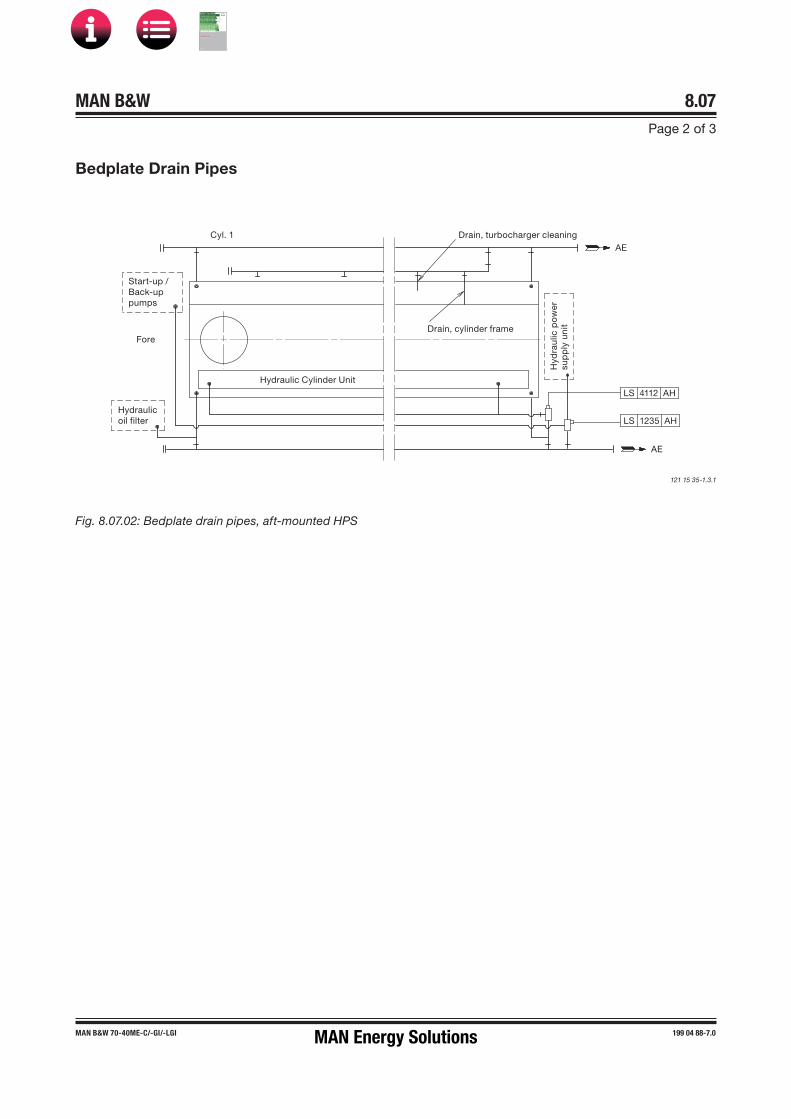
MAN B&W 8.07Page 2 of 3
MAN B&W 70-40ME�C/-GI/-LGI 199 04 88-7.0
Bedplate Drain Pipes
Fig. 8.07.02: Bedplate drain pipes, aft-mounted HPS
121 15 35-1.3.1
Cyl. 1AE
Drain, turbocharger cleaning
Drain, cylinder frameFore
Hydraulic Cylinder Unit
LS 4112 AH
Hyd
raul
ic p
ow
ersu
pp
ly u
nit
LS 1235 AH
Start-up /Back-uppumps
Hydraulicoil filter
AE
MAN Energy Solutions
MAN B&W
IMO Tier ll Project Guide
MAN
Energy Solutions Project G
uideM
AN B
&W G
95ME-C
10.5
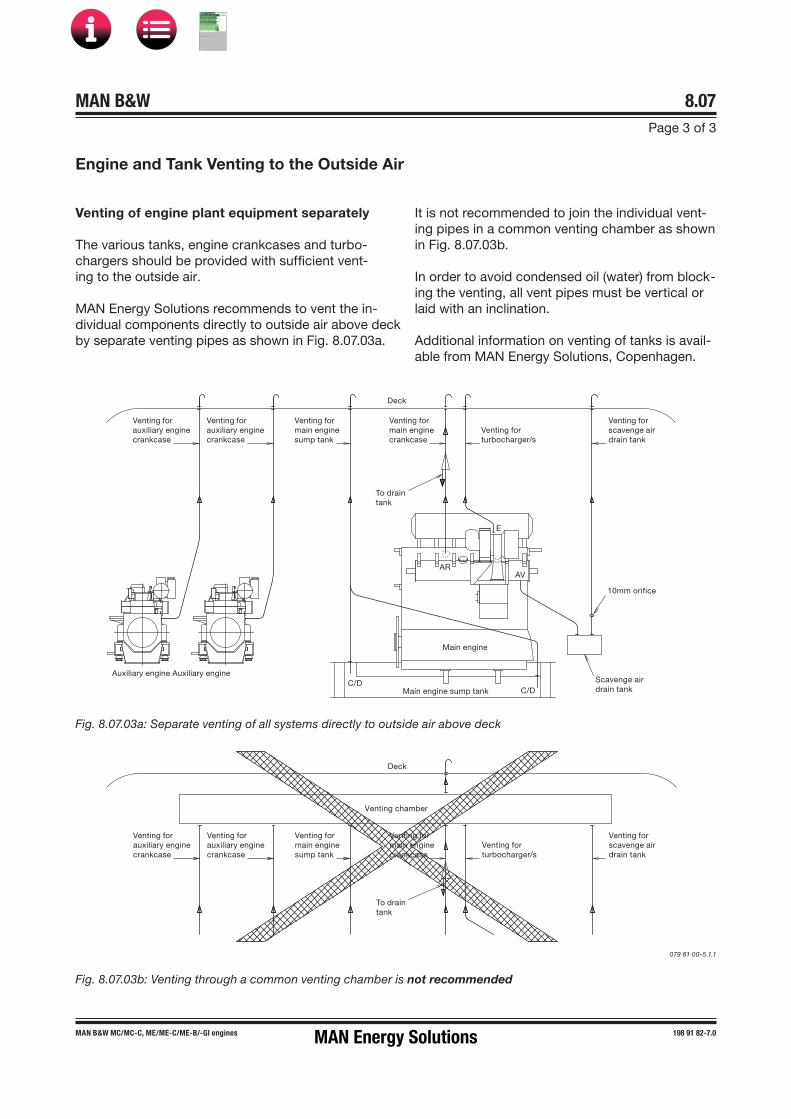
MAN B&W 8.07Page 3 of 3
MAN B&W MC/MC�C, ME/ME�C/ME-B/�GI engines 198 91 82-7.0
Venting for auxiliary engine crankcase
Venting for auxiliary engine crankcase
Venting for main engine crankcase
Venting for main engine sump tank
Venting for turbocharger/s
Venting for scavenge air drain tank
Deck
To drain tank
E
ARAV
10mm orifice
Scavenge air drain tankMain engine sump tank
Main engine
C/DC/D
Auxiliary engine Auxiliary engine
Venting for auxiliary engine crankcase
Venting for auxiliary engine crankcase
Venting for main engine crankcase
Venting for main engine sump tank
Venting for turbocharger/s
Venting for scavenge air drain tank
Deck
To drain tank
Venting chamber
Fig. 8.07.03a: Separate venting of all systems directly to outside air above deck
079 61 00-5.1.1
Engine and Tank Venting to the Outside Air
Venting of engine plant equipment separately
The various tanks, engine crankcases and turbo-chargers should be provided with sufficient vent-ing to the outside air.
MAN Energy Solutions recommends to vent the in-dividual components directly to outside air above deck by separate venting pipes as shown in Fig. 8.07.03a.
It is not recommended to join the individual vent-ing pipes in a common venting chamber as shown in Fig. 8.07.03b.
In order to avoid condensed oil (water) from block-ing the venting, all vent pipes must be vertical or laid with an inclination.
Additional information on venting of tanks is avail-able from MAN Energy Solutions, Copenhagen.
Fig. 8.07.03b: Venting through a common venting chamber is not recommended
MAN Energy Solutions
MAN B&W
IMO Tier ll Project Guide
MAN
Energy Solutions Project G
uideM
AN B
&W G
95ME-C
10.5

MAN B&W 8.08Page 1 of 1
MAN B&W ME/ME�C/ME�GI/ME-B enginesME Engine Selection Guide
198 48 29�7.3
Hydraulic Oil Back�flushing
The special suction arrangement for purifier suc-tion in connection with the ME engine (Integrated system).
The back-flushing oil from the self cleaning 6 µm hydraulic control oil filter unit built onto the engine is contaminated and it is therefore not expedient to lead it directly into the lubricating oil sump tank.
The amount of back-flushed oil is large, and it is considered to be too expensive to discard it. Therefore, we suggest that the lubricating oil sump tank is modified for the ME engines in order not to have this contaminated lubricating hydraulic control oil mixed up in the total amount of lubricating oil. The lubricating oil sump tank is designed with a small ‘back-flushing hydraulic control oil drain tank’ to which the back-flushed hydraulic control oil is led and from which the lu-bricating oil purifier can also suck.
This is explained in detail below and the principle is shown in Fig. 8.08.01. Three suggestions for the arrangement of the drain tank in the sump tank are shown in Fig. 8.08.02 illustrates another sug-gestion for a back-flushing oil drain tank.
The special suction arrangement for the purifier is consisting of two connected tanks (lubricating oil sump tank and back-flushing oil drain tank) and of this reason the oil level will be the same in both tanks, as explained in detail below.
The oil level in the two tanks will be equalizing through the ‘branch pipe to back-flushing oil drain tank’, see Fig. 8.08.01. As the pipes have the same diameters but a different length, the resis-tance is larger in the ‘branch pipe to back-flushing oil drain tank’, and therefore the purifier will suck primarily from the sump tank.
The oil level in the sump tank and the back-flush-ing oil drain tank will remain to be about equal be-cause the tanks are interconnected at the top.
When hydraulic control oil is back-flushed from the filter, it will give a higher oil level in the back-flushing hydraulic control oil drain tank and the purifier will suck from this tank until the oil level is the same in both tanks. After that, the purifier will suck from the sump tank, as mentioned above.
Fig. 8.08.01: Back�flushing servo oil drain tank
178 52 51�8.2
Fig. 8.08.02: Alternative design for the back�flushing servo oil drain tank
178 52 49�6.2
This special arrangement for purifier suction will ensure that a good cleaning effect on the lubrica-tion oil is obtained.
If found profitable the back-flushed lubricating oil from the main lubricating oil filter (normally a 50 or 40 µm filter) can also be returned into the special back-flushing oil drain tank.
Oil level
50
D/3
D
8XØ
50
D/3
D
Purifiersuction pipe
Lubricatingoil tank top
Ventingholes
Back�flushed hydraulic control oil from self cleaning 6 µm filter
Branch pipe toback�flushinghydraulic control oil drain tankSump
tank
Back�flushinghydraulic controloil drain tank
Pipe ø400or 400Lubricating
oil tank bottom
Oil level Support
Venting holes
D D
D/3
D/3
Purifiersuction pipe
Lubricatingoil tank top
Back�flushed hydraulic controloil from selfcleaning 6 µm filter
Sumptank
Back�flushinghydraulic control oil drain tank
Lubricating oil tank bottom
MAN Energy Solutions
MAN B&W
IMO Tier ll Project Guide
MAN
Energy Solutions Project G
uideM
AN B
&W G
95ME-C
10.5
MAN B&W 8.09Page 1 of 4
MAN B&W ME/ME-C/-GI engines 198 48 52�3.6
Separate System for Hydraulic Control Unit
As an option, the engine can be prepared for the use of a separate hydraulic control oil system Fig. 8.09.01.
The separate hydraulic control oil system can be built as a unit, or be built streamlined in the engine room with the various components placed and fastened to the steel structure of the engine room.
The design and the dimensioning of the various components are based on the aim of having a reli-able system that is able to supply low�pressure oil to the inlet of the engine�mounted high�pressure hydraulic control oil pumps at a constant pres-sure, both at engine stand�by and at various en-gine loads.
Cleanliness of the hydraulic control oil
The hydraulic control oil must fulfil the same cleanliness level as for our standard integrated lube/cooling/hydraulic�control oil system, i.e. ISO 4406 XX/16/13 equivalent to NAS 1638 Class 7.
Information and recommendations regarding flushing, the specified cleanliness level and how to measure it, and how to use the NAS 1638 oil cleanliness code as an alternative to ISO 4406, are available fromMAN Energy Solutions.
Control oil system components
The hydraulic control oil system comprises: 1 Hydraulic control oil tank2 Hydraulic control oil pumps (one for stand�by)1 Pressure control valve1 Hydraulic control oil cooler, water�cooled by the
low temperature cooling water1 Three�way valve, temperature controlled1 Hydraulic control oil filter, duplex type or auto-
matic self�cleaning type1 Hydraulic control oil fine filter with pump1 Temperature indicator1 Pressure indicator2 Level alarms
Valves and cocksPiping.
Hydraulic control oil tank
The tank can be made of mild steel plate or be a part of the ship structure.
The tank is to be equipped with flange connec-tions and the items listed below:1 Oil filling pipe1 Outlet pipe for pump suctions1 Return pipe from engine1 Drain pipe1 Vent pipe.
The hydraulic control oil tank is to be placed at least 1 m below the hydraulic oil outlet flange, RZ.
Hydraulic control oil pump
The pump must be of the displacement type (e.g. gear wheel or screw wheel pump).
The following data is specified in Table 8.09.02:• Pump capacity• Pump head• Delivery pressure• Working temperature• Oil viscosity range.
Pressure control valve
The valve is to be of the self�operating flow control-ling type, which bases the flow on the pre�defined pressure set point. The valve must be able to react quickly from the fully�closed to the fully�open posi-tion (tmax= 4 sec), and the capacity must be the same as for the hydraulic control oil low�pressure pumps. The set point of the valve has to be within the adjustable range specified in a separate draw-ing.
The following data is specified in Table 8.09.02:• Flow rate• Adjustable differential pressure range across
the valve• Oil viscosity range.
MAN Energy Solutions
MAN B&W
IMO Tier ll Project Guide
MAN
Energy Solutions Project G
uideM
AN B
&W G
95ME-C
10.5

MAN B&W 8.09Page 2 of 4
MAN B&W ME/ME-C/-GI engines 198 48 52�3.6
Hydraulic control oil cooler
The cooler must be of the plate heat exchanger or shell and tube type.
The following data is specified in Table 8.09.02:• Heat dissipation• Oil flow rate• Oil outlet temperature• Maximum oil pressure drop across the cooler• Cooling water flow rate• Water inlet temperature• Maximum water pressure drop across the cooler.
Temperature controlled three�way valve
The valve must act as a control valve, with an ex-ternal sensor.
The following data is specified in Table 8.09.02:• Capacity• Adjustable temperature range• Maximum pressure drop across the valve.
Hydraulic control oil filter
The filter is to be of the duplex full flow type with manual change over and manual cleaning or of the automatic self cleaning type.
A differential pressure gauge is fitted onto the filter.
The following data is specified in Table 8.09.02:• Filter capacity• Maximum pressure drop across the filter• Filter mesh size (absolute)• Oil viscosity• Design temperature.
Off-line hydraulic control oil fine filter / purifier
Shown in Fig. 8.09.01, the off-line fine filter unit or purifier must be able to treat 15-20% of the total oil volume per hour.
The fine filter is an off-line filter and removes me-tallic and non-metallic particles larger than 0,8 µm as well as water and oxidation residues. The filter has a pertaining pump and is to be fitted on the top of the hydraulic control oil tank.
A suitable fine filter unit is:Make: CJC, C.C. Jensen A/S, Svendborg, Denmark - www.cjc.dk.
For oil volume <10,000 litres: HDU 27/-MZ-Z with a pump flow of 15-20% of the total oil volume per hour.
For oil volume >10,000 litres: HDU 27/-GP-DZ with a pump flow of 15-20% of the total oil volume per hour.
Temperature indicator
The temperature indicator is to be of the liquid straight type.
Pressure indicator
The pressure indicator is to be of the dial type.
Level alarm
The hydraulic control oil tank has to have level alarms for high and low oil level.
Piping
The pipes can be made of mild steel.
The design oil pressure is to be 10 bar.
The return pipes are to be placed vertical or laid with a downwards inclination of minimum 15°.
MAN Energy Solutions
MAN B&W
IMO Tier ll Project Guide
MAN
Energy Solutions Project G
uideM
AN B
&W G
95ME-C
10.5

MAN B&W 8.09Page 3 of 4
MAN B&W ME/ME-C/-GI engines 198 48 52�3.6
078 83 91-0.1.0
PI 1301 I
Manhole
Oil tank
Cooling water outlet
Cooling water inlet
Oil cooler Temperature control valve
Vent pipe
Deck
Oil filling pipe
Purifier orfine filter unit
Drain to waste oil tank
Water drain
RZ
RW
LS 1320 AH AL
RY
Engine
PDS 1231 AHManual
filter
Autofilter
PI 1303 I
TI 1310 I
TE 1310 AH Y
XS 1350 AH
XS 1351 AH
078 83 91-0.1.0
Fig. 8.09.01: Hydraulic control oil system, manual filter
The letters refer to list of ‘Counterflanges’
MAN Energy Solutions
MAN B&W
IMO Tier ll Project Guide
MAN
Energy Solutions Project G
uideM
AN B
&W G
95ME-C
10.5

MAN B&W 8.09Page 4 of 4
MAN B&W G45ME-C9 199 08 47-1.1
Hydraulic Control Oil System Capacities, G45ME-C9
Fig. 8.09.02: Hydraulic control oil system capacities
178 69 45-1.1
Cylinder no. 5 6 7 8 9r/min 111 111 111 111 111kW 6,950 8,340 9,730 11,120 12,510
Hydraulic Control Oil tank:Volumen, approx. m³ 1.0 1.5 1.5 1.5 1.5
Hydraulic Control Oil PumpPump capacity m³/h 10 15 15 15 20Pump head bar 4 4 4 4 4Delivery pressure bar 4 4 4 4 4Design temperature °C 70 70 70 70 70Oil viscosity range cSt 15 - 90 15 - 90 15 - 90 15 - 90 15 - 90
Pressure control valveLubricating oil flow m³/h 10 15 15 15 20Adjustable pressure bar 2 - 4 2 - 4 2 - 4 2 - 4 2 - 4Design temperature °C 55 55 55 55 55Oil viscosity range cSt 15 - 90 15 - 90 15 - 90 15 - 90 15 - 90
Hydraulic Control Oil CoolerHeat dissipation kW 65 80 90 105 115Lubricating oil flow m³/h 10 15 15 15 20Oil outlet temperature °C 45 45 45 45 45Oil pressure drop, max bar 0.5 0.5 0.5 0.5 0.5Cooling water flow m³/h 10 12 13 16 17S.W. inlet temperature °C 32 32 32 32 32F.W. inlet temperature °C 36 36 36 36 36Water pressure drop, max bar 0.2 0.2 0.2 0.2 0.2
Temperature Controlled Three-way ValveLubricating oil flow m³/h 10 15 15 15 20Adjustable temp. range °C 2 - 4 2 - 4 2 - 4 2 - 4 2 - 4Design temperature °C 70 70 70 70 70Oil pressure drop, max bar 0.3 0.3 0.3 0.3 0.3
Hydraulic Control Oil FilterLubricating oil flow m³/h 10 15 15 15 20Absolute fineness µm 6 6 6 6 6Design temperature °C 55 55 55 55 55Design pressure bar 4 4 4 4 4Oil pressure drop, max bar 0.3 0.3 0.3 0.3 0.3
MAN Energy Solutions
MAN B&W
IMO Tier ll Project Guide
MAN
Energy Solutions Project G
uideM
AN B
&W G
95ME-C
10.5

MAN B&W
Cylinder Lubrication
9MAN Energy Solutions
MAN B&W
IMO Tier ll Project Guide
MAN
Energy Solutions Project G
uideM
AN B
&W G
95ME-C
10.5
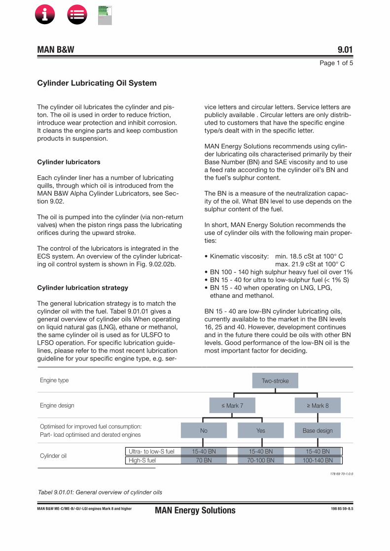
MAN B&W 9.01Page 1 of 5
MAN Energy SolutionsMAN B&W MEC/ME-B/-GI/-LGI engines Mark 8 and higher 198 85 59-8.5
Cylinder Lubricating Oil System
The cylinder oil lubricates the cylinder and pis-ton. The oil is used in order to reduce friction, introduce wear protection and inhibit corrosion. It cleans the engine parts and keep combustion products in suspension.
Cylinder lubricators
Each cylinder liner has a number of lubricating quills, through which oil is introduced from the MAN B&W Alpha Cylinder Lubricators, see Sec-tion 9.02.
The oil is pumped into the cylinder (via non-return valves) when the piston rings pass the lubricating orifices during the upward stroke.
The control of the lubricators is integrated in the ECS system. An overview of the cylinder lubricat-ing oil control system is shown in Fig. 9.02.02b.
Cylinder lubrication strategy
The general lubrication strategy is to match the cylinder oil with the fuel. Tabel 9.01.01 gives a general overview of cylinder oils When operating on liquid natural gas (LNG), ethane or methanol, the same cylinder oil is used as for ULSFO to LFSO operation. For specific lubrication guide-lines, please refer to the most recent lubrication guideline for your specific engine type, e.g. ser-
vice letters and circular letters. Service letters are publicly available . Circular letters are only distrib-uted to customers that have the specific engine type/s dealt with in the specific letter.
MAN Energy Solutions recommends using cylin-der lubricating oils characterised primarily by their Base Number (BN) and SAE viscosity and to use a feed rate according to the cylinder oil’s BN and the fuel’s sulphur content.
The BN is a measure of the neutralization capac-ity of the oil. What BN level to use depends on the sulphur content of the fuel.
In short, MAN Energy Solution recommends the use of cylinder oils with the following main proper-ties:
• Kinematic viscosity: min. 18.5 cSt at 100° C max. 21.9 cSt at 100° C• BN 100 - 140 high sulphur heavy fuel oil over 1%• BN 15 - 40 for ultra to low-sulphur fuel (< 1% S)• BN 15 - 40 when operating on LNG, LPG,
ethane and methanol.
BN 15 - 40 are low-BN cylinder lubricating oils, currently available to the market in the BN levels 16, 25 and 40. However, development continues and in the future there could be oils with other BN levels. Good performance of the low-BN oil is the most important factor for deciding.
Engine type
Engine design
Optimised for improved fuel consumption: Part- load optimised and derated engines
Cylinder oil Ultra- to low-S fuelHigh-S fuel
Two-stroke
≤ Mark 7
No Yes
≥ Mark 8
Base design
15-40 BN70 BN
15-40 BN70-100 BN
15-40 BN100-140 BN
Tabel 9.01.01: General overview of cylinder oils
178 69 70-1.0.0
MAN B&W
IMO Tier ll Project Guide
MAN
Energy Solutions Project G
uideM
AN B
&W G
95ME-C
10.5
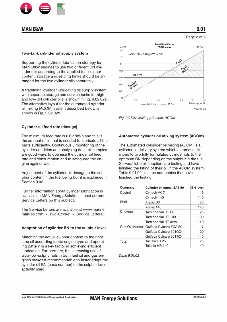
MAN B&W 9.01Page 2 of 5
MAN Energy SolutionsMAN B&W MEC/ME-B/-GI/-LGI engines Mark 8 and higher 198 85 59-8.5
Two-tank cylinder oil supply system
Supporting the cylinder lubrication strategy for MAN B&W engines to use two different BN cyl-inder oils according to the applied fuel sulphur content, storage and settling tanks should be ar-ranged for the two cylinder oils separately.
A traditional cylinder lubricating oil supply system with separate storage and service tanks for high- and low-BN cylinder oils is shown in Fig. 9.02.02a. The alternative layout for the automated cylinder oil mixing (ACOM) system described below is shown in Fig. 9.02.02b.
Cylinder oil feed rate (dosage)
The minimum feed rate is 0.6 g/kWh and this is the amount of oil that is needed to lubricate all the parts sufficiently. Continuously monitoring of the cylinder condition and analysing drain oil samples are good ways to optimise the cylinder oil feed rate and consumption and to safeguard the en-gine against wear.
Adjustment of the cylinder oil dosage to the sul-phur content in the fuel being burnt is explained in Section 9.02.
Further information about cylinder lubrication is available in MAN Energy Solutions’ most current Service Letters on this subject.
The Service Letters are available at www.marine.man-es.com → ’Two-Stroke’ → ’Service Letters’.
Adaptation of cylinder BN to the sulphur level
Matching the actual sulphur content to the right lube oil according to the engine type and operat-ing pattern is a key factor in achieving efficient lubrication. Furthermore, the increasing use of ultra-low-sulphur oils in both fuel oil and gas en-gines makes it recommendable to faster adapt the cylinder oil BN (base number) to the sulphur level actually used.
Automated cylinder oil mixing system (ACOM)
The automated cyloinder oil mixing (ACOM) is a cylinder oil delivery system which automatically mixes to two fully formulated cylinder oils to the optimum BN depending on the sulphur in the fuel. Serveral lube oil suppliers are testing and have finished the tsting of their oil in the ACOM system. Table 9.01.02 lists the companies that have finished the testing.
178 69 35-5.0
1.4
1.2
1.1
0.8
0.6
0.4
0.2
00 0.5 1 1.5 2 2.5 3 3.5
g/kWhFeed Rate Factor
‘ACC’ curve 100 BN
Fuel sulphur %Minimum 100 BN
ACC 100 = 0.40 g/kWh x S%
ACOM
ACOM
active
ACC
active
ACC
Fig. 9.01.01: Mixing principle, ACOM
Company Cylinder oil name, SAE 50 BN level
Castrol Cyltech ACT 16Cyltech 140 140
Shell Alexia S3 25Alexia 140 140
Chevron Taro special HT LF 25Taro special HT 100 100Taro special HT ultra 140
Gulf Oil Marine Gulfsea Cylcare ECA 50 17Gulfsea Cylcare 50100X 100Gulfsea Cylcare 50140X 140
Total Talusia LS 25 25Talusia HR 140 140
Table 9.01.02
MAN B&W
IMO Tier ll Project Guide
MAN
Energy Solutions Project G
uideM
AN B
&W G
95ME-C
10.5
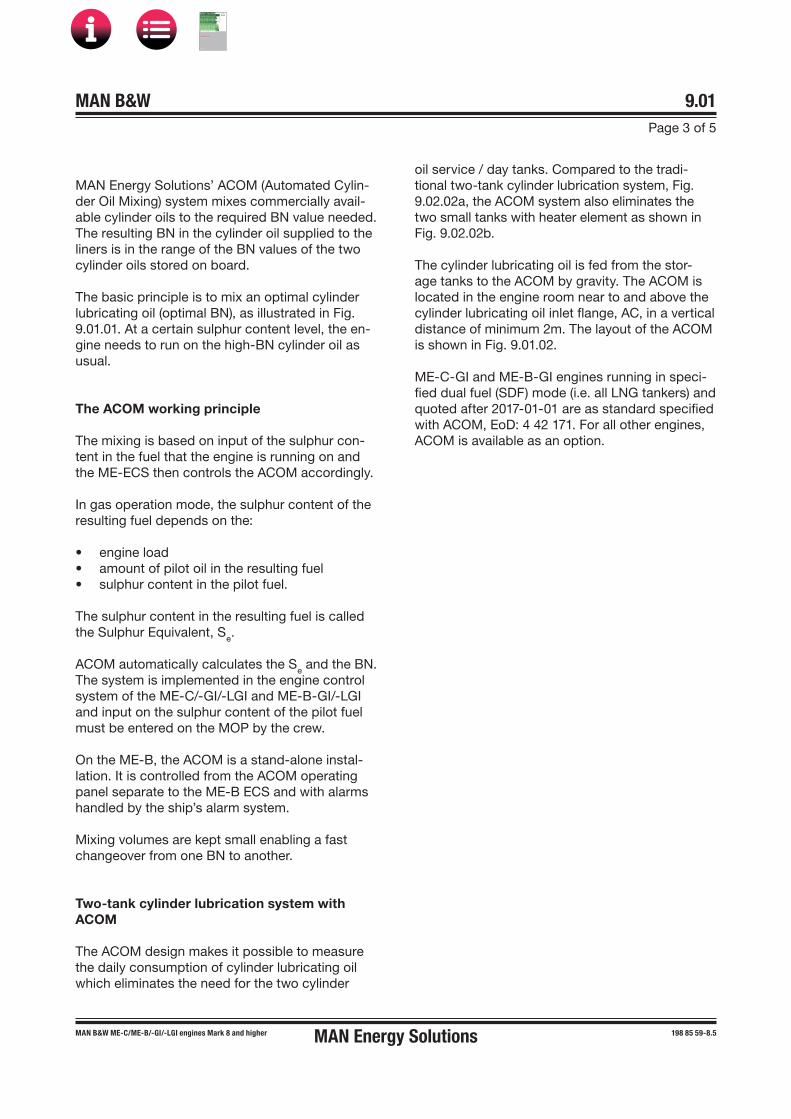
MAN B&W 9.01Page 3 of 5
MAN Energy SolutionsMAN B&W MEC/ME-B/-GI/-LGI engines Mark 8 and higher 198 85 59-8.5
MAN Energy Solutions’ ACOM (Automated Cylin-der Oil Mixing) system mixes commercially avail-able cylinder oils to the required BN value needed. The resulting BN in the cylinder oil supplied to the liners is in the range of the BN values of the two cylinder oils stored on board.
The basic principle is to mix an optimal cylinder lubricating oil (optimal BN), as illustrated in Fig. 9.01.01. At a certain sulphur content level, the en-gine needs to run on the high-BN cylinder oil as usual.
The ACOM working principle
The mixing is based on input of the sulphur con-tent in the fuel that the engine is running on and the ME-ECS then controls the ACOM accordingly.
In gas operation mode, the sulphur content of the resulting fuel depends on the:
• engine load• amount of pilot oil in the resulting fuel• sulphur content in the pilot fuel.
The sulphur content in the resulting fuel is called the Sulphur Equivalent, Se.
ACOM automatically calculates the Se and the BN. The system is implemented in the engine control system of the ME-C/-GI/-LGI and ME-B-GI/-LGI and input on the sulphur content of the pilot fuel must be entered on the MOP by the crew.
On the ME-B, the ACOM is a stand-alone instal-lation. It is controlled from the ACOM operating panel separate to the ME-B ECS and with alarms handled by the ship’s alarm system.
Mixing volumes are kept small enabling a fast changeover from one BN to another.
Two-tank cylinder lubrication system with ACOM
The ACOM design makes it possible to measure the daily consumption of cylinder lubricating oil which eliminates the need for the two cylinder
oil service / day tanks. Compared to the tradi-tional two-tank cylinder lubrication system, Fig. 9.02.02a, the ACOM system also eliminates the two small tanks with heater element as shown in Fig. 9.02.02b.
The cylinder lubricating oil is fed from the stor-age tanks to the ACOM by gravity. The ACOM is located in the engine room near to and above the cylinder lubricating oil inlet flange, AC, in a vertical distance of minimum 2m. The layout of the ACOM is shown in Fig. 9.01.02.
ME-C-GI and ME-B-GI engines running in speci-fied dual fuel (SDF) mode (i.e. all LNG tankers) and quoted after 2017-01-01 are as standard specified with ACOM, EoD: 4 42 171. For all other engines, ACOM is available as an option.
MAN B&W
IMO Tier ll Project Guide
MAN
Energy Solutions Project G
uideM
AN B
&W G
95ME-C
10.5

MAN B&W 9.01Page 4 of 5
MAN Energy SolutionsMAN B&W MEC/ME-B/-GI/-LGI engines Mark 8 and higher 198 85 59-8.5
A4 × Ø14PCD75
Ø105
A
Low-BN Inlet (Tank 1)3/4" DIN flange
Drain from tray G3/8
Return for MC-motor3/4" DIN flange Air breather
3/4" DIN flange
Outlet mix oil1/2" BSP
High-BN Inlet (Tank 2)3/4" DIN flange
229
66731
146
537
80
0
2,19
5
780 270
600
570 87 35-1.2.0a
Fig. 9.01.02: Automated cylinder oil mixing system (ACOM) in single-rack version for installation in engine room
MAN B&W
IMO Tier ll Project Guide
MAN
Energy Solutions Project G
uideM
AN B
&W G
95ME-C
10.5

MAN B&W 9.01Page 5 of 5
MAN B&W ME-GI/-LGI engines Mark 8 and higher,ME-B-GI/-LGI engines mark 8 and higher
199 04 43-2.2
Automated Cylinder Oil Switch, ACOS
All ME-C/-GI/-LGI and ME-B-GI/-LGI engines re-quire either mixing of or switching between high-BN and low-BN cylinder lubricating oil.
ME-C-GI and ME-B-GI engines not running in the SDF operation mode as well as ME-C-LGI and ME-B-LGI engines are as standard specified with a cylinder oil switching system called ACOS (Auto-mated Cylinder Oil Switch), EoD 4 42 172.
ACOS automatically switches between high-BN and low-BN cylinder lubricating oil. In gas opera-tion mode, the sulphur content of the resulting fuel depends on the:
• engine load• amount of pilot oil in the resulting fuel• sulphur content in the pilot fuel.
The sulphur content in the resulting fuel is called the Sulphur Equivalent, Se.
ACOS calculates the Se and controls a three-way valve that switches between opening for the high-BN oil, when the Se is high, and the low-BN oil, when the Se is low. The system is implemented in the engine control system of the ME-C/-GI/-LGI and ME-B-GI/-LGI and input on the sulphur con-tent of the pilot fuel must be entered on the MOP by the crew.
The three-way valve is located on the engine be-hind the cylinder lubricating oil flanges AC1 and AC2, see Fig. 9.02.04. The valve is activated pneu-matically by control air and set to switch to the high-BN oil in fail-safe position.
List of cylinder oils
The major international cylinder oil brands listed below have been tested in service with acceptable results.
Do not consider the list complete, as oils from other companies can be equally suitable. Fur-ther information can be obtained from the engine builder or MAN Energy Solutions, Copenhagen.
Company Cylinder oil name, SAE 50 BN level
Aegean Alfacylo 525 DF 25Alfacylo 540 LS 40Alfacylo 570 70Alfacylo 100 HS 100
Castrol Cyltech ACT 16Cyltech 40SX 40Cyltech 70 70Cyltech 100 100Cyltech 140 140
Chevron Taro Special HT LF 25Taro Special HT LS 40 40Taro Special HT 70 70Taro Special HT 100 100Taro Special HT Ultra 140
ExxonMobil Mobilgard 525 25Mobilgard 570 70Mobilgard 5100 100Mobilgard 5145 145
Gulf Oil Marine GulfSea Cylcare ECA 50 17GulfSea Cylcare DCA 5040H 40GulfSea Cylcare EHP 5070 70GulfSea Cylcare 5085 85GulfSea Cylcare 50100 100GulfSea Cylcare 50140X 140
JX Nippon Oil & Energy
JX C255 25Marine C405 40Marine C705 70Marine C1005 100
Lukoil Navigo MCL Ultra 20Navigo 40 MCL Extra 40Navigo 70 MCL AW 70Navigo 100 MCL 100
Shell Alexia S3 25Alexia 50 70Alexia S5 80Alexia S6 100Alexia 140 140
Sinopec Marine Cylinder Oil 5025 25Marine Cylinder Oil 5040 40Marine Cylinder Oil 5070 70Marine Cylinder Oil 50100 100Marine Cylinder Oil 50140 140
SK Lubricants Supermar Cyl 25 25Supermar Cyl 40 40Supermar Cyl 70 Plus 70Supermar Cyl 100 100Supermar Cyl 140 140
MAN Energy Solutions
MAN B&W
IMO Tier ll Project Guide
MAN
Energy Solutions Project G
uideM
AN B
&W G
95ME-C
10.5

MAN B&W 9.02Page 1 of 7
MAN B&W ME/ME-C/ME-B/-GI/-LGI engines 198 38 89�0.15
MAN B&W Alpha Cylinder Lubrication System
The MAN B&W Alpha cylinder lubrication system, see Figs. 9.02.02a, 02b and 02c, is designed to supply cylinder oil intermittently, for instance every 2, 4 or 8 engine revolutions with electronically con-trolled timing and dosage at a defined position.
Traditional two-tank cylinder lubrication system
Separate storage and service tanks are installed for each of the different Base Number (BN) cyl-inder oils used onboard ships operating on both high- and low-sulphur fuels, see Fig. 9.02.02a.
The cylinder lubricating oil is pumped from the cylinder oil storage tank to the service tank, the size of which depends on the owner’s and the yard’s requirements, – it is normally dimensioned for about one week’s cylinder lubricating oil consumption.
Oil feed to the Alpha cylinder lubrication system
Cylinder lubricating oil is fed to the Alpha cylinder lubrication system by gravity from the service tank or ACOM.
The oil fed to the injectors is pressurised by the Alpha Lubricator which is placed on the hydrau-lic cylinder unit (HCU) and equipped with small multi�piston pumps.
The oil pipes fitted on the engine are shown in Fig. 9.02.04.
The whole system is controlled by the Cylinder Control Unit (CCU) which controls the injection frequency based on the engine�speed signal giv-en by the tacho signal and the fuel index.
Prior to start-up, the cylinders can be pre�lubric-ated and, during the running�in period, the opera-tor can choose to increase the lubricating oil feed rate to a max. setting of 200%.
The MAN B&W Alpha Cylinder Lubricator is pref-erably to be controlled in accordance with the Alpha ACC (Adaptable Cylinder Oil Control) feed rate system.
The yard supply should be according to the items shown in Fig. 9.02.02a within the broken line.
Regarding the filter and the small tank for heater, please see Fig. 9.02.05.
Alpha Lubricator variants
Since the Alpha Lubricator on ME and ME-B en-gines are controlled by the engine control system, it is also referred to as the ME lubricator on those engines.
A more advanced version with improved injection flexibility, the Alpha Lubricator Mk 2, is being in-troduced on the G95/50/45/40ME-C9 and S50ME-C9 including their GI dual fuel variants.
Further information about the Alpha Lubricator Mk 2 is available in our publication:
Service Experience MAN B&W Two-stroke Engines
The publication is available at www.marine.man-es.com → ’Two-Stroke’ → ’Technical Papers' .
MAN Energy Solutions
MAN B&W
IMO Tier ll Project Guide
MAN
Energy Solutions Project G
uideM
AN B
&W G
95ME-C
10.5

MAN B&W 9.02Page 2 of 7
MAN B&W ME/ME-C/ME-B/-GI/-LGI engines 199 08 26-7.0
After a running-in period of 500 hours, the feed rate sulphur proportional factor is 0.20 - 0.40 g/kWh × S%. The actual ACC factor will be based on cyl-inder condition, and preferably a cylinder oil feed rate sweep test should be applied. The ACC factor is also referred to as the Feed Rate Factor (FRF).
Examples of average cylinder oil consumption based on calculations of the average worldwide sulphur content used on MAN B&W two-stroke engines are shown in Fig. 9.02.01a and b.
Alpha Adaptive Cylinder Oil Control (Alpha ACC)
It is a well�known fact that the actual need for cylinder oil quantity varies with the operational conditions such as load and fuel oil quality. Con-sequently, in order to perform the optimal lubrica-tion – cost�effectively as well as technically – the cylinder lubricating oil dosage should follow such operational variations accordingly.
The Alpha lubricating system offers the possibility of saving a considerable amount of cylinder lubri-cating oil per year and, at the same time, to obtain a safer and more predictable cylinder condition.
Alpha ACC (Adaptive Cylinder-oil Control) is the lubrication mode for MAN B&W two-stroke en-gines, i.e. lube oil dosing proportional to the en-gine load and proportional to the sulphur content in the fuel oil being burnt.
Working principle
The feed rate control should be adjusted in rela-tion to the actual fuel quality and amount being burnt at any given time.
The following criteria determine the control:
• The cylinder oil dosage shall be proportional tothe sulphur percentage in the fuel
• The cylinder oil dosage shall be proportional tothe engine load (i.e. the amount of fuel enteringthe cylinders)
• The actual feed rate is dependent of the operatingpattern and determined based on engine wear,cylinder condition and BN of the cylinder oil.
The implementation of the above criteria will lead to an optimal cylinder oil dosage.
Specific minimum dosage with Alpha ACC
The recommendations are valid for all plants, whether controllable pitch or fixed pitch propellers are used. The specific minimum dosage at lower-sulphur fuels is set at 0.6 g/kWh.
178 61 19�6.1
Fig. 9.02.01a: FRF = 0.20 g/kWh × S% and BN 100 cyl-inder oil – average consumption less than 0.65 g/kWh
Typical dosage (g/kWh)
0.00
Sulphur %
0.100.200.300.400.500.600.700.800.901.001.101.20
0 0.5 1 1.5 2 2.5 3 3.5 4
178 61 18�4.0
Fig. 9.02.01b: FRF = 0.26 g/kWh × S% and BN 100 cyl-inder oil – average consumption less than 0.7 g/kWh
Further information about cylinder oil dosage is available in MAN Energy Solutions' most current Service Letters on this subject available at www.marine.man-es.com → ’Two-Stroke’ → ’Service Letters’.
Sulphur %
Typical dosage (g/kWh)
0.000.100.200.300.40
0.500.600.700.800.901.001.101.20
0 0.5 1 1.5 2 2.5 3 3.5 4
MAN Energy Solutions
MAN B&W
IMO Tier ll Project Guide
MAN
Energy Solutions Project G
uideM
AN B
&W G
95ME-C
10.5
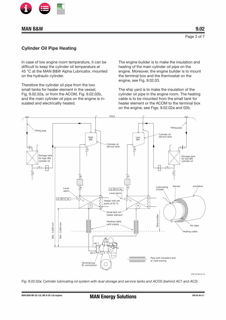
MAN B&W 9.02Page 3 of 7
MAN B&W ME-GI/-LGI, ME-B-GI/-LGI engines 199 04 44-4.1
Fig. 9.02.02a: Cylinder lubricating oil system with dual storage and service tanks and ACOS (behind AC1 and AC2)
078 70 84-9.1.0
In case of low engine room temperature, it can be difficult to keep the cylinder oil temperature at 45 °C at the MAN B&W Alpha Lubricator, mounted on the hydraulic cylinder.
Therefore the cylinder oil pipe from the two small tanks for heater element in the vessel, Fig. 9.02.02a, or from the ACOM, Fig. 9.02.02b, and the main cylinder oil pipe on the engine is in-sulated and electricallly heated.
The engine builder is to make the insulation and heating of the main cylinder oil pipe on the engine. Moreover, the engine builder is to mount the terminal box and the thermostat on the engine, see Fig. 9.02.03.
The ship yard is to make the insulation of the cylinder oil pipe in the engine room. The heating cable is to be mounted from the small tank for heater element or the ACOM to the terminal box on the engine, see Figs. 9.02.02a and 02b.
AC 2
AC 1
Heater with setpoint of 45 °C
Small tank forheater element
Level
Level alarmalarm
LS 8212 AL
TI
Heating cable, yard supply
Terminal box El. connection
Min
. 2,
00
0 m
m
Min
. 3,
00
0 m
m
Pipe with insulation andel. heat tracing
LS 8212 AL
Deck
Cylinder oilservice tank
Filling pipe
HighBN
LowBN
Storage tankfor low-BNcylinder oil
Storage tankfor high-BNcylinder oil
Filling pipe
Cylinder oilservice tank
Heating cable
InsulationLubricatingoil pipe
Alu-tape
Sensor
TI
Shi
p b
uild
er
Cylinder Oil Pipe Heating
MAN Energy Solutions
MAN B&W
IMO Tier ll Project Guide
MAN
Energy Solutions Project G
uideM
AN B
&W G
95ME-C
10.5
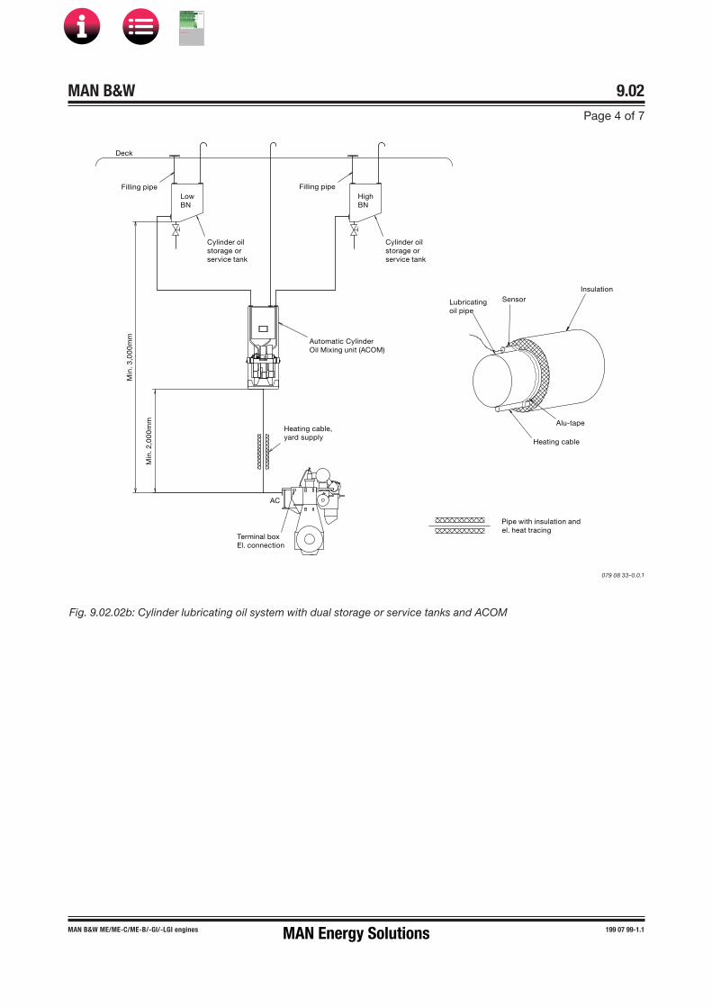
MAN B&W 9.02Page 4 of 7
MAN B&W ME/ME-C/ME-B/-GI/-LGI engines 199 07 99-1.1
079 08 33-0.0.1
Cylinder oilstorage orservice tank
Cylinder oilstorage orservice tank
Deck
AC
Filling pipe
Heating cable,yard supply
Terminal boxEl. connection
Filling pipeLowBN
Automatic CylinderOil Mixing unit (ACOM)
Min
. 2,0
00
mm
Min
. 3,0
00
mm
HighBN
Heating cable
Insulation
Lubricatingoil pipe
Alu-tape
Sensor
Pipe with insulation andel. heat tracing
Fig. 9.02.02b: Cylinder lubricating oil system with dual storage or service tanks and ACOM
MAN Energy Solutions
MAN B&W
IMO Tier ll Project Guide
MAN
Energy Solutions Project G
uideM
AN B
&W G
95ME-C
10.5

MAN B&W 9.02Page 5 of 7
MAN B&W ME/ME-C/�GI/-LGI engines 199 04 76-7.2
Level switchFeedback sensor
Level switchLu
bri
cato
r
Lub
rica
tor
Cylinder liner *)
Cylinder liner *)
Feedback sensor
Solenoid valve **) Solenoid valve
Cylinder Control Unit
To othercylinders
HydraulicCylinder Unit
HydraulicCylinder Unit
300 barsystem oil
Cylinder Control Unit
Terminal box Temperature switch
Forw
ard
cyl
Aft
cyl
Terminal box
Temperature switch
AC Cylinder lubrication
Power InputHeating cableship builder
supply
PowerInput
Heating cableship builder
supply
Fig. 9.02.02c: Cylinder lubricating oil system. Example from 80/70/65ME-C/-GI/-LGI engines
178 49 83�4.10b
Fig. 9.02.03: Electric heating of cylinder oil pipes
178 53 71�6.0
**) For Alpha Mk 2 lubricator: Proportional valve and Feedback sensor
*) The number of cylinder lubricating points depends on the actual engine type
MAN Energy Solutions
MAN B&W
IMO Tier ll Project Guide
MAN
Energy Solutions Project G
uideM
AN B
&W G
95ME-C
10.5

MAN B&W 9.02Page 6 of 7
MAN B&W 50-40 ME-GI/-LGI engines 199 04 78-0.1
ZV 8281-A
ZT 8282-A
Solenoid valve
Feedback sensor
40ME-GI/-LGI 50-45ME-GI/-LGI
LubricatorVenting
LS 8285-A
Level switch
ZV 8281-B
ZT 8282-B
Solenoid valve
Feedback sensor
LubricatorVenting
LS 8285-B
Level switch
AC1 Low BN
AC2 High BN
AC
ACOS (not SDF)
ACOM (SDF)
TE 8202 C AH
567 01 31-8.1.2a
The item no. refer to ‘Guidance Values Automation’. The letters refer to list of ‘Counterflanges’
40ME-GI/-LGI 50-45ME-GI/-LGI
LubricatorVenting
LS 8285-A
Level switch
LubricatorVenting
LS 8285-B
Level switch
XC 8288-B
ZT 8289-B
XC 8288-A
ZT 8289-A
Solenoid valve
Feedback sensor
Solenoid valve
Feedback sensor
AC1 Low BN
AC2 High BN
AC
ACOS (not SDF)
ACOM (SDF)
TE 8202 C AH
567 01 31-8.1.2c
The item no. refer to ‘Guidance Values Automation’. The letters refer to list of ‘Counterflanges’
Fig. 9.02.04b: Cylinder lubricating oil pipes, Alpha Mk 2 lubricator
Fig. 9.02.04a: Cylinder lubricating oil pipes, Alpha/ME lubricator
MAN Energy Solutions
MAN B&W
IMO Tier ll Project Guide
MAN
Energy Solutions Project G
uideM
AN B
&W G
95ME-C
10.5

MAN B&W 9.02Page 7 of 7
MAN B&W engines 198 79 37-9.3
Tank, 37 l
LS 8212 AL
From cylinder oil servicetank/storage tankFlange: ø1404xø18 PCD 100(EN36F00420)
250µmesh filter
Level switch
925
154
113
460
74 425
850
920
91
112
To venting of cylinder oil service tankFlange: ø1404xø18 PCD 100(EN36F00420)
4xø19for mounting
Coupling box forheating elementand level switch
Temperatureindicator
To engine connection ACFlange ø1404xø18 PCD 100(EN362F0042)
Heating element 750 WSet point 40 ºC
Drain from tray G 3/8
193
239
260
268
410
178 52 75�8.2
Fig. 9.02.05: Suggestion for small heating tank with filter (for engines without ACOM)
MAN Energy Solutions
MAN B&W
IMO Tier ll Project Guide
MAN
Energy Solutions Project G
uideM
AN B
&W G
95ME-C
10.5

MAN B&W
Piston Rod Stuffing Box Drain Oil
10MAN Energy Solutions
MAN B&W
IMO Tier ll Project Guide
MAN
Energy Solutions Project G
uideM
AN B
&W G
95ME-C
10.5

MAN B&W 10.01Page 1 of 1
MAN B&W 50-26 engines 198 39 74�0.8
Yard’s supply
DN=32 mm
High level alarm
To incinerator, oily waste drain tank
or HFO settling tank
AG
Drain tank
198 97 44�8.3
Fig. 10.01.01: Stuffing box drain oil system
For engines running on heavy fuel, it is important that the oil drained from the piston rod stuffing boxes is not led directly into the system oil, as the oil drained from the stuffing box is mixed with sludge from the scavenge air space.
The performance of the piston rod stuffing box on the engines has proved to be very efficient, pri-marily because the hardened piston rod allows a higher scraper ring pressure.
Stuffing Box Drain Oil System
The amount of drain oil from the stuffing boxes is typically about 5 � 10 litres/24 hours per cylinder during normal service. In the running�in period, it can be higher. The drain oil is a mixture of system oil from the crankcase, used cylinder oil combus-tion residues and water from humidity in the scav-enge air.
The relatively small amount of drain oil is led to the general oily waste drain tank, HFO settling tank or is burnt in the incinerator, Fig. 10.01.01. (Yard’s supply).
MAN Energy Solutions
MAN B&W
IMO Tier ll Project Guide
MAN
Energy Solutions Project G
uideM
AN B
&W G
95ME-C
10.5

MAN B&W
Low-temperature Cooling Water
11MAN Energy Solutions
MAN B&W
IMO Tier ll Project Guide
MAN
Energy Solutions Project G
uideM
AN B
&W G
95ME-C
10.5

MAN B&W 11.01Page 1 of 2
MAN B&W engines dot 5 and higher 199 03 92-7.4
The low-temperature (LT) cooling water system supplies cooling water for the lubricating oil, jack-et water and scavenge air coolers.
The LT cooling water system can be arranged in several configurations like a:
• Central cooling water system being the mostcommon system choice and the basic executionfor MAN B&W engines, EoD: 4 45 111
• Seawater cooling system being the most sim-ple system and available as an option: 4 45 110
• Combined cooling water system with seawa-ter-cooled scavenge air cooler but freshwater-cooled jacket water and lubricating oil cooler,available as an option: 4 45 117.
Principle diagrams of the above LT cooling water systems are shown in Fig. 11.01.01a, b and c and descriptions are found later in this chapter.
Further information and the latest recommenda-tions concerning cooling water systems are found in MAN Energy Solutions' Service Letters available at www.marine.man-es.com → ‘Two-Stroke’ → ‘Service Letters’.
Chemical corrosion inhibition
Various types of inhibitors are available but, gen-erally, only nitrite-borate based inhibitors are rec-ommended.
Where the inhibitor maker specifies a certain range as normal concentration, we recommend to maintain the actual concentration in the upper end of that range.
Low-temperature Cooling Water System
MAN Energy Solutions recommends keeping a re-cord of all tests to follow the condition and chemi-cal properties of the cooling water and notice how it develops. It is recommended to record the qual-ity of water as follows:
• Once a week:
Take a sample from the circulating water dur-ing running, however not from the expansion tank nor the pipes leading to the tank. Check the condition of the cooling water. Test kits with instructions are normally available from the inhibitor supplier.
• Every third month:
Take a water sample from the system duringrunning, as described above in ‘Once a week’. Send the sample for laboratory analysis.
• Once a year:
Empty, flush and refill the cooling water sys-tem. Add the inhibitor.
For further information please refer to our recom-mendations for treatment of the jacket water/freshwater. The recommendations are available from MAN Energy Solutions, Copenhagen.
Cooling system for main engines with EGR
For main engines with exhaust gas recirculation (EGR), a central cooling system using freshwater as cooling media will be specified.
Further information about cooling water systems for main engines with EGR is available from MAN Energy Solutions, Copenhegan.
MAN Energy Solutions
MAN B&W
IMO Tier ll Project Guide
MAN
Energy Solutions Project G
uideM
AN B
&W G
95ME-C
10.5

MAN B&W 11.01Page 2 of 2
MAN B&W engines dot 5 and higher 199 03 92-7.4
Fig. 11.01.01a: Principle diagram of central cooling water system
568 25 97�1.0.1a
Central coolingpumps
Lubr. oil cooler
Jacketwatercooler
Scav. air cooler
Aux.equipment
Tin ≥ 10 °C
Central cooler
Sea waterpumps
Scav. air cooler
Aux.equipment
Centralcooler
Set point:10-36 °C
Sea waterFreshwater
Sea water
Sea waterFreshwater
Sea water pumpsTin ≥ 0 °C
Scav. air cooler
Aux.equipment
Tin ≥ 10 °C
Sea waterpumps
Principle standard central cooling water diagram
Principle SW / FW central cooling water diagram
Principle standard SW cooling water diagram
Jacketwatercooler
Jacketwatercooler
Lubr. oil cooler
Lubr. oil cooler
Set point:10 °C
Set point:10 °C
Central coolingpumps
Fig. 11.01.01b: Principle diagram of seawater cooling system
568 25 97�1.0.1b
Central coolingpumps
Lubr. oil cooler
Jacketwatercooler
Scav. air cooler
Aux.equipment
Tin ≥ 10 °C
Centralcooler
Sea waterpumps
Scav. air cooler
Aux.equipment
Centralcooler
Set point:10-36 °C
Sea waterFreshwater
Sea water
Sea waterFreshwater
Sea water pumpsTin ≥ 0 °C
Scav. air cooler
Aux.equipment
Tin ≥ 10 °C
Sea waterpumps
Principle standard central cooling water diagram
Principle SW / FW central cooling water diagram
Principle standard SW cooling water diagram
Jacketwatercooler
Jacketwatercooler
Lubr. oil cooler
Lubr. oil cooler
Set point:10 °C
Set point:10 °C
Central coolingpumps
Fig. 11.01.01c: Principle diagram of combined cooling water system
568 25 97�1.0.1c
Central coolingpumps
Lubr. oil cooler
Jacketwatercooler
Scav. air cooler
Aux.equipment
Tin ≥ 10 °C
Centralcooler
Sea waterpumps
Scav. air cooler
Aux.equipment
Central cooler
Set point:10-36 °C
Sea waterFreshwater
Sea water
Sea waterFreshwater
Sea water pumpsTin ≥ 0 °C
Scav. air cooler
Aux.equipment
Tin ≥ 10 °C
Sea waterpumps
Principle standard central cooling water diagram
Principle SW / FW central cooling water diagram
Principle standard SW cooling water diagram
Jacketwatercooler
Jacketwatercooler
Lubr. oil cooler
Lubr. oil cooler
Set point:10 °C
Set point:10 °C
Central coolingpumps
MAN Energy Solutions
MAN B&W
IMO Tier ll Project Guide
MAN
Energy Solutions Project G
uideM
AN B
&W G
95ME-C
10.5

MAN B&W 11.02Page 1 of 2
MAN B&W engines dot 5 and higher 199 05 50-9.2
Central Cooling Water System
The central cooling water system is characterised by having only one heat exchanger cooled by seawater. The other coolers, including the jacket water cooler, are then cooled by central cooling water.
Cooling water temperature
The capacity of the seawater pumps, central cool-er and freshwater pumps are based on the outlet temperature of the freshwater being maximum 54 °C after passing through the main engine lub- ricating oil cooler. With an inlet temperature of maximum 36 °C (tropical conditions), the maxi-mum temperature increase is 18 °C.
To achieve an optimal engine performance regarding fuel oil consumption and cylinder condition, it is important to ensure the lowest possible cooling water inlet temperature at the scavenge air cooler.
MAN Energy Solutions therefore requires that the temperature control valve in the central cooling water circuit is to be set to minimum 10 °C. In this way, the temperature follows the outboard seawater temperature when the central cooling water temperature exceeds 10 °C, see note 1 in Fig. 11.02.01.
Alternatively, in case flow control of the seawater pumps is applied, the set point is to be approxi-mately 4 °C above the seawater temperature but not lower than 10 °C.
Fig. 11.02.01: Central cooling water system
079 95 02�4.0.0
Freshwater filling
*)
*)
Drain
Inhibitordosingtank
Filling
*)
Central cooling waterSeawater
Internal pipingControl line
*) Optional installation
Drain
Setpoint
45 °C
2)
2)2)
*3)
Sample
Cooling waterdrain, air cooler
Centralcoolingwaterpumps
Seawaterpumps
Lubrication oil
1)Setpoint10 °C
Expansiontank
Levelindicator LAL
LAH
ø10
N
P
Jacketwatercooler
Variousauxiliaryequipment
Lubricatingoil cooler
Variousauxiliaryequipment
Centralcooler
High sea chest
Seawaterinlet
Seawaterinlet
Low sea chest
Main engine
AS
PT 8421 I AH AL
TI
TI
TI
TIPI
TI
TI
TI
PI
PI
TI PI
TE 8422 I AH
TE 8423 I AH
*) Optional installation
The letters refer to list of ‘Counterflanges’The item no. refer to ‘Guidance Values Automation’
MAN Energy Solutions
MAN B&W
IMO Tier ll Project Guide
MAN
Energy Solutions Project G
uideM
AN B
&W G
95ME-C
10.5

11.02Page 2 of 2
MAN B&W engines dot 5 and higher 199 05 50-9.2
Cooling water pump capacities
The pump capacities listed by MAN Energy Solutions cover the requirement for the main engine only.
For any given plant, the specific capacities have to be determined according to the actual plant specification and the number of auxiliary equip-ment. Such equipment include GenSets, starting air compressors, provision compressors, aircon-ditioning compressors, etc.
A guideline for selecting centrifugal pumps is given in Section 6.04.
Cooling water piping
Orifices (or lockable adjustable valves for in-stance) must be installed in order to create:
• the proper distribution of flow between each ofthe central cooling water consumers, see note 2)
• a differential pressure identical to that of thecentral cooler at nominal central cooling waterpump capacity, see note 3).
References are made to Fig. 11.02.01.
For external pipe connections, we prescribe the following maximum water velocities:
Central cooling water .................................. 3.0 m/sSeawater ..................................................... 3.0 m/s
Expansion tank volume
The expansion tank shall be designed as open toatmosphere. Venting pipes entering the tank shallterminate below the lowest possible water leveli.e. below the low level alarm.
The expansion tank volume has to be 10% of the total central cooling water amount in the system.
The 10% expansion tank volume is defined as the volume between the lowest level (at the low level alarm sensor) and the overflow pipe or high level alarm sensor.
If the pipe system is designed with possible air pockets, these have to be vented to the expansion tank.
MAN Energy Solutions
MAN B&W
IMO Tier ll Project Guide
MAN
Energy Solutions Project G
uideM
AN B
&W G
95ME-C
10.5

MAN B&W Page 1 of 2
11.03
MAN B&W engines dot 5 and higher 199 03 97-6.1
Components for Central Cooling Water System
Overload running at tropical conditions will slightly increase the temperature level in the cooling sys-tem, and will also slightly influence the engine performance.
Central cooling water pumps
The pumps are to be of the centrifugal type.
Central cooling waterflow ................................ see ‘List of Capacities’
Pump head ...................................................2.5 barDelivery pressure ...............depends on location of
expansion tankTest pressure ....................according to Class rulesWorking temperature ..................................... 80 °CDesign temperature ...................................... 100 °C
The flow capacity must be within a range from 100 to 110% of the capacity stated.
The ‘List of Capacities’ covers the main engine only. The pump head of the pumps is to be de-termined based on the total actual pressure drop across the central cooling water system.
A guideline for selecting centrifugal pumps is given in Section 6.04.
Central cooling water thermostatic valve
The low temperature cooling system is to be equipped with a three�way valve, mounted as a mixing valve, which bypasses all or part of the freshwater around the central cooler.
The sensor is to be located at the outlet pipe from the thermostatic valve and is set to keep a tem-perature of 10 °C.
Seawater cooling pumps
The pumps are to be of the centrifugal type.
Seawater flow ..................... see ‘List of Capacities’Pump head ...................................................2.0 barTest pressure ....................according to Class rulesWorking temperature, normal .....................0�32 °CWorking temperature .................... maximum 50 °C
The flow capacity must be within a range from 100 to 110% of the capacity stated.
The pump head of the pumps is to be determined based on the total actual pressure drop across the seawater cooling water system.
A guideline for selecting centrifugal pumps is given in Section 6.04.
Central cooler
The cooler is to be of the shell and tube or plate heat exchanger type, made of seawater resistant material.
Heat dissipation ................. see ‘List of Capacities’Central cooling water
flow ................................ see ‘List of Capacities’Central cooling water temperature, outlet ..... 36 °CPressure drop on
central cooling side ........................max. 0.7 barSeawater flow ..................... see ‘List of Capacities’Seawater temperature, inlet ........................... 32 °CPressure drop on
seawater side .......................... maximum 1.0 bar
The pressure drop may be larger, depending on the actual cooler design.
The heat dissipation and the seawater flow figures are based on MCR output at tropical conditions, i.e. a seawater temperature of 32 °C and an ambi-ent air temperature of 45 °C.
MAN Energy Solutions
MAN B&W
IMO Tier ll Project Guide
MAN
Energy Solutions Project G
uideM
AN B
&W G
95ME-C
10.5

MAN B&WPage 2 of 2
11.03
MAN B&W engines dot 5 and higher 199 03 97-6.1
Lubricating oil cooler thermostatic valve
The lubricating oil cooler is to be equipped with a three-way valve, mounted as a mixing valve, which bypasses all or part of the freshwater around the lubricating cooler.
The sensor is to be located at the lubricating oil outlet pipe from the lubricating oil cooler and is set to keep a lubricating oil temperature of 45 °C.
Chemical corrosion inhibitor and dosing tank
In order to properly mix the inhibitor into the cen-tral cooling water system circuit, the tank shall be designed to receive a small flow of jacket cool-ing water through the tank from the jacket water pumps. The tank shall be suitable for mixing in-hibitors in form of both powder and liquid.
Recommended tank size ..............................0.3 m3
Design pressure ........... max. central cooling water system pressure
Suggested inlet orifice size ........................ ø10 mm
Lubricating oil cooler
See Chapter 8 ‘Lubricating Oil’.
Jacket water cooler
See Chapter 12 ‘High-temperature Cooling Water’.
Scavenge air cooler
The scavenge air cooler is an integrated part of the main engine.
Heat dissipation ................. see ‘List of Capacities’Central cooling water
flow ................................ see ‘List of Capacities’Central cooling temperature, inlet .................. 36 °CPressure drop on FW�LT water side ..... 0.3-0.8 bar
Cooling water pipes for air cooler
Diagrams of cooling water pipes for scavenge air cooler are shown in Figs. 11.08.01.
MAN Energy Solutions
MAN B&W
IMO Tier ll Project Guide
MAN
Energy Solutions Project G
uideM
AN B
&W G
95ME-C
10.5

MAN B&W 11.04Page 1 of 2
MAN B&W engines dot 5 and higher 199 03 98-8.2
Seawater Cooling System
Fig. 11.04.01: Seawater cooling system
The letters refer to list of ‘Counterflanges’The item no. refer to ‘Guidance Values Automation’
The seawater cooling system is an option for cooling the main engine lubricating oil cooler, the jacket water cooler and the scavenge air cooler by seawater, see Fig. 11.04.01. The seawater system consists of pumps and a thermostatic valve.
Cooling water temperature
The capacity of the seawater pump is based on the outlet temperature of the seawater being max-imum 50 °C after passing through the main engine lubricating oil cooler, the jacket water cooler and the scavenge air cooler.
With an inlet temperature of maximum 32 °C (tropical conditions), the maximum temperature increase is 18 °C.
In order to prevent the lubricating oil from stiffen-ing during cold services, a thermostatic valve is to be installed. The thermostatic valve recirculates all or part of the seawater to the suction side of the pumps. A set point of 10 °C ensures that the cool-ing water to the cooling consumers will never fall below this temperature, see note 1 in Fig. 11.04.01.
079 95 04-8.0.2
Setpoint45 °C
2)
2)2)
Cooling waterdrain, air cooler
Seawaterpumps
Setpoint10 °C
1)
N
P
Jacketwatercooler
Variousauxiliaryequipment
Lubricatingoil cooler
Variousauxiliaryequipment
Highseachest
Seawaterinlet
Seawaterinlet
Low sea chest
Main engine
AS
Seawater
Internal pipingControl line
Lubrication oil
PITI
TI
TI
TI
TIPI
PI
PT 8421 I AH AL
TE 8422 I AH
TE 8423 I AH
MAN Energy Solutions
MAN B&W
IMO Tier ll Project Guide
MAN
Energy Solutions Project G
uideM
AN B
&W G
95ME-C
10.5

MAN B&W 11.04Page 2 of 2
MAN B&W engines dot 5 and higher 199 03 98-8.2
Cooling water pump capacities
The pump capacities listed by MAN Energy Solutions cover the requirement for the main engine only.
For any given plant, the specific capacities have to be determined according to the actual plant specification and the number of auxiliary equip-ment. Such equipment include GenSets, starting air compressors, provision compressors, aircon-ditioning compressors, etc.
A guideline for selecting centrifugal pumps is given in Section 6.04.
Cooling water piping
In order to create the proper distribution of flow between each of the cooling water consumers, orifices (or lockable adjustable valves for instance) must be installed, see note 2) in Fig. 11.04.01.
For external pipe connections, we prescribe the following maximum water velocities:
Seawater ..................................................... 3.0 m/s
If the pipe system is designed with possible air pockets, these have to be vented to the expansion tank.
MAN Energy Solutions
MAN B&W
IMO Tier ll Project Guide
MAN
Energy Solutions Project G
uideM
AN B
&W G
95ME-C
10.5

MAN B&W 11.05Page 1 of 1
MAN B&W engines dot 5 and higher 199 04 00-1.1
Components for Seawater Cooling System
Scavenge air cooler
The scavenge air cooler is an integrated part of the main engine.
Heat dissipation ................. see ‘List of Capacities’Seawater flow .................... see ‘List of Capacities’Seawater temperature,
for seawater cooling inlet, max.................. 32 °CPressure drop on cooling water side .... 0.3-0.8 bar
The heat dissipation and the seawater flow are based on an MCR output at tropical conditions, i.e. seawater temperature of 32 °C and an ambient air temperature of 45 °C.
Cooling water pipes for air cooler
Diagrams of cooling water pipes for scavenge air cooler are shown in Figs. 11.08.01.
Seawater cooling pumps
The pumps are to be of the centrifugal type.
Seawater flow ..................... see ‘List of Capacities’Pump head ...................................................2.5 barTest pressure ...................... according to class ruleWorking temperature .................... maximum 50 °C
The flow capacity must be within a range from 100 to 110% of the capacity stated.
The pump head of the pumps is to be determined based on the total actual pressure drop across the seawater cooling water system.
A guideline for selecting centrifugal pumps is given in Section 6.04.
Seawater thermostatic valve
The temperature control valve is a three�way mixing valve. The sensor is to be located at the seawater inlet to the lubricating oil cooler, and the temperature set point must be +10 °C.
Seawater flow ..................... see ‘List of Capacities’Temperature set point .................................. +10 °C
Lubricating oil cooler
See Chapter 8 ‘Lubricating Oil’.
Jacket water cooler
See Chapter 12 ‘High-temperature Cooling Water’.
MAN Energy Solutions
MAN B&W
IMO Tier ll Project Guide
MAN
Energy Solutions Project G
uideM
AN B
&W G
95ME-C
10.5

MAN B&W 11.06Page 1 of 2
MAN B&W engines dot 5 and higher 199 04 71-8.2
Combined Cooling Water System
The combined cooling water system is charac-terised by having one heat exchanger and the scavenge air cooler cooled by seawater. The other coolers, including the jacket water cooler, are then cooled by central cooling water.
In this system, the cooling water to the scavenge air cooler will always be approx. 4 °C lower than in a central cooling water system.
Cooling water temperature
The capacity of the seawater pumps, central cool-er pumps are based on the outlet temperature of
the freshwater being maximum 54 °C after pass-ing through the main engine lubricating oil cooler.
With an inlet temperature of maximum 36 °C (tropical conditions), the maximum temperature increase is 18 °C.
The temperature control valve in the central cool-ing water circuit can be set to minimum 10 °C and maximum 36 °C, see note 1 in Fig. 11.06.01.
Fig. 11.06.01: Combined cooling water system
079 95 03�6.0.0
Freshwaterfilling
*)
Drain
Inhibitordosingtank
Filling
*)
Fresh waterSeawater
Internal pipingControl line
*) Optional installation
Drain
Setpoint45 °C
2)2)
*3)
Sample
Cooling waterdrain air cooler
Centralcoolingwater pumps
4)Seawaterpumps
Lubrication oil
1)Set point10 °C→36 °C
Expansiontank
Levelindicator
ø10
N
P
Jacketwatercooler
Lubricatingoil cooler
Variousauxiliary
equipment
Variousauxiliary
equipment
Centralcooler
High seachest
Seawaterinlet
Seawaterinlet
Low sea chest
5)NC
Main engine
AS
*)
LAL
LAH
TIPI
PI
TIPI TIPI
TI TI
TI
TI
TI
TI
PI
PT 8421 I AH AL
TE 8423 I AH
TE 8422 I AH
*) Optional installation
The letters refer to list of ‘Counterflanges’The item no. refer to ‘Guidance Values Automation’
MAN Energy Solutions
MAN B&W
IMO Tier ll Project Guide
MAN
Energy Solutions Project G
uideM
AN B
&W G
95ME-C
10.5

11.06Page 2 of 2
MAN B&W engines dot 5 and higher 199 04 71-8.2
Alternatively, in case flow control of the seawater pumps is applied, the set point is to be approxi-mately 4 °C above the seawater temperature but not lower than 10 °C.
In order to avoid seawater temperatures below 0 °C at the scavenge air cooler inlet, a manual by-pass valve is installed in the seawater circuit, see note 5) in Fig. 11.06.01. The valve recirculates all or part of the seawater to the suction side of the pumps.
Cooling water pump capacities
The pump capacities listed by MAN Energy Solutions cover the requirement for the main engine only.
For any given plant, the specific capacities have to be determined according to the actual plant specification and the number of auxiliary equip-ment. Such equipment include GenSets, starting air compressors, provision compressors, aircon-ditioning compressors, etc.
In fig. 11.06.01, note 4 both seawater pumps for main engine scavenge air cooler and for central cooling water system are shown. Alternative com-mon seawater pumps serving both systems can be installed.
A guideline for selecting centrifugal pumps is given in Section 6.04.
Cooling water piping
Orifices (or lockable adjustable valves for in-stance) must be installed in order to create:
• the proper distribution of flow between each ofthe central cooling water consumers, see note 2)
• a differential pressure identical to that of thecentral cooler at nominal central cooling waterpump capacity, see note 3).
References are made to Fig. 11.08.01.
For external pipe connections, we prescribe the following maximum water velocities:
Central cooling water .................................. 3.0 m/sSeawater ..................................................... 3.0 m/s
Expansion tank volume
The expansion tank shall be designed as open toatmosphere. Venting pipes entering the tank shallterminate below the lowest possible water leveli.e. below the low level alarm.
The expansion tank volume has to be 10% of the total central cooling water amount in the system.The 10% expansion tank volume is defined as the volume between the lowest level (at the low level alarm sensor) and the overflow pipe or high level alarm sensor.
If the pipe system is designed with possible air pockets, these have to be vented to the expansion tank.
MAN Energy Solutions
MAN B&W
IMO Tier ll Project Guide
MAN
Energy Solutions Project G
uideM
AN B
&W G
95ME-C
10.5

MAN B&W Page 1 of 2
11.07
MAN B&W engines dot 5 and higher 199 04 73-1.1
Components for Combined Cooling Water System
Central cooling water pumps
The pumps are to be of the centrifugal type.
Central cooling waterflow ................................ see ‘List of Capacities’
Pump head ...................................................2.5 barDelivery pressure ...............depends on location of
expansion tankTest pressure ....................according to Class rulesWorking temperature ..................................... 80 °CDesign temperature ...................................... 100 °C
The flow capacity must be within a range from 100 to 110% of the capacity stated.
The ‘List of Capacities’ covers the main engine only. The pump head of the pumps is to be de-termined based on the total actual pressure drop across the central cooling water system.
A guideline for selecting centrifugal pumps is given in Section 6.04.
Central cooling water thermostatic valve
The low temperature cooling system is to be equipped with a three�way valve, mounted as a mixing valve, which bypasses all or part of the freshwater around the central cooler.
The sensor is to be located at the outlet pipe from the thermostatic valve and is set to keep a tem-perature of minimum 10 °C and maximum 36 °C.
Lubricating oil cooler thermostatic valve
The lubricating oil cooler is to be equipped with a three-way valve, mounted as a mixing valve, which bypasses all or part of the freshwater around the lubricating cooler.
The sensor is to be located at the lubricating oil outlet pipe from the lubricating oil cooler and is set to keep a lubricating oil temperature of 45 °C.
Seawater cooling pumps
The pumps are to be of the centrifugal type.
Seawater flow ..................... see ‘List of Capacities’Pump head ...................................................2.0 barTest pressure ....................according to Class rulesWorking temperature, normal .....................0�32 °CWorking temperature .................... maximum 50 °C
The flow capacity must be within a range from 100 to 110% of the capacity stated.
The pump head of the pumps is to be determined based on the total actual pressure drop across the seawater cooling water system.
A guideline for selecting centrifugal pumps is given in Section 6.04.
Central cooler
The cooler is to be of the shell and tube or plate heat exchanger type, made of seawater resistant material.
Heat dissipation ................. see ‘List of Capacities’Central cooling water flow .. see ‘List of Capacities’Central cooling water temperature, outlet .......36 °CPressure drop on
central cooling side ........................max. 0.7 barSeawater flow ..................... see ‘List of Capacities’Seawater temperature, inlet ........................... 32 °CPressure drop on
seawater side .......................... maximum 1.0 bar
The pressure drop may be larger, depending on the actual cooler design.
The heat dissipation and the seawater flow figures are based on MCR output at tropical conditions, i.e. a seawater temperature of 32 °C and an ambi-ent air temperature of 45 °C.
Overload running at tropical conditions will slightly increase the temperature level in the cooling sys-tem, and will also slightly influence the engine performance.
MAN Energy Solutions
MAN B&W
IMO Tier ll Project Guide
MAN
Energy Solutions Project G
uideM
AN B
&W G
95ME-C
10.5

MAN B&WPage 2 of 2
11.07
MAN B&W engines dot 5 and higher 199 04 73-1.1
Chemical corrosion inhibitor and dosing tank
In order to properly mix the inhibitor into the com-bined cooling water system circuit, the tank shall be designed to receive a small flow of jacket cool-ing water through the tank from the jacket water pumps. The tank shall be suitable for mixing in-hibitors in form of both powder and liquid.
Recommended tank size ..............................0.3 m3
Design pressure ...... max. combined cooling water system pressure
Suggested inlet orifice size ........................ ø10 mm
Lubricating oil cooler
See Chapter 8 ‘Lubricating Oil’.
Jacket water cooler
See Chapter 12 ‘High-temperature Cooling Water’.
Scavenge air cooler
The scavenge air cooler is an integrated part of the main engine.
Heat dissipation ................. see ‘List of Capacities’Seawater flow ..................... see ‘List of Capacities’Central cooling temperature, inlet .................. 32 °CPressure drop on seawater side ........... 0.3-0.8 bar
Cooling water pipes for air cooler
Diagrams of cooling water pipes for scavenge air cooler are shown in Figs. 11.08.01.
MAN Energy Solutions
MAN B&W
IMO Tier ll Project Guide
MAN
Energy Solutions Project G
uideM
AN B
&W G
95ME-C
10.5
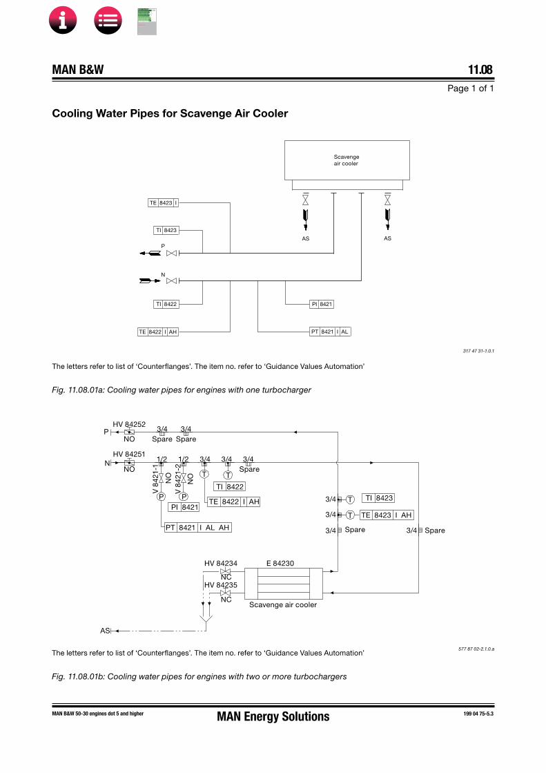
MAN B&W 11.08Page 1 of 1
MAN B&W 50-30 engines dot 5 and higher 199 04 75-5.3
Cooling Water Pipes for Scavenge Air Cooler
Fig. 11.08.01b: Cooling water pipes for engines with two or more turbochargers
The letters refer to list of ‘Counterflanges’. The item no. refer to ‘Guidance Values Automation’
Scavenge air cooler
AS ASP
N
TI 8422
TI 8423
TE 8422 I AH
PI 8421
PT 8421 I AL
TE 8423 I
317 47 31�1.0.1
Fig. 11.08.01a: Cooling water pipes for engines with one turbocharger
The letters refer to list of ‘Counterflanges’. The item no. refer to ‘Guidance Values Automation’
577 87 02-2.1.0.a
P
N 1/2 1/2 3/4 3/4 3/4Spare
P P
T T
3/4
3/4 T
T
V 8
421-
1
NO
V 8
421-
2
NO
AS
3/4 Spare 3/4 Spare
3/4Spare
3/4Spare
HV 84252
NO
HV 84251
NO
TE 8423 I AH
TI 8423PI 8421
PT 8421 I AL AH
TI 8422
TE 8422 I AH
E 84230
HV 84235
NC
HV 84234
NC
Scavenge air cooler
MAN Energy Solutions
MAN B&W
IMO Tier ll Project Guide
MAN
Energy Solutions Project G
uideM
AN B
&W G
95ME-C
10.5

MAN B&W
High-temperature Cooling Water
12MAN Energy Solutions
MAN B&W
IMO Tier ll Project Guide
MAN
Energy Solutions Project G
uideM
AN B
&W G
95ME-C
10.5

MAN B&W Page 1 of 3
12.01
198 92 52-3.3MAN B&W G/S95-45ME-C10.5/9.5/-GI,G/S50ME-B9.5/-GI
High-temperature Cooling Water System
The high-temperature (HT) cooling water system, also known as the jacket cooling water (JCW) system, is used for cooling the cylinder liners, cyl-inder covers and exhaust gas valves of the main engine and heating of the fuel oil drain pipes, see Fig. 12.01.01.
The jacket water pump draws water from the jack-et water cooler outlet, through a deaerating tank and delivers it to the engine.
A thermostatically controlled regulating valve is located at the inlet to the jacket water cooler, or alternatively at the outlet from the cooler. The reg-ulating valve keeps the main engine cooling water outlet at a fixed temperature level, independent of the engine load. The controller for the thermostati-cally controlled regulating valve must be able to receive a remote variable set point from the main Engine Control System (ECS).
A deaerating tank alarm device is installed be-tween the deaerating tank and the expansion tank. The purpose of the alarm device is to give an alarm in case of a large amount of gas in the JCW circuit e.g. caused by a cylinder liner rupture.
To create a sufficient static pressure in the JCW system and provide space for the water to ex-pand and contract, an expansion tank is installed. The expansion tank must be located at least 15 m above the top of the main engine exhaust gas valves.
The engine jacket water must be carefully treated, maintained and monitored so as to avoid cor-rosion, corrosion fatigue, cavitation and scale formation. Therefore, it is recommended to install a chemical corrosion inhibitor dosing tank and a means to take water samples from the JCW sys-tem.
Chemical corrosion inhibition
Various types of inhibitors are available but, gen-erally, only nitrite-borate based inhibitors are rec-ommended.
Where the inhibitor maker specifies a certain range as normal concentration, we recommend to maintain the actual concentration in the upper end of that range.
MAN Energy Solutions recommends keeping a re-cord of all tests to follow the condition and chemi-cal properties of the cooling water and notice how it develops. It is recommended to record the qual-ity of water as follows:
• Once a week:
Take a sample from the circulating water dur-ing running, however not from the expansion tank nor the pipes leading to the tank. Check the condition of the cooling water. Test kits with instructions are normally available from the inhibitor supplier.
• Every third month:
Take a water sample from the system duringrunning, as described above in ‘Once a week’. Send the sample for laboratory analysis.
• Once a year:
Empty, flush and refill the cooling water sys-tem. Add the inhibitor.
For further information please refer to our recom-mendations for treatment of the jacket water/freshwater. The recommendations are available from MAN Energy Solutions, Copenhagen.
Cooling water drain for maintenance
For maintenance of the main engine, a drain ar-rangement is installed at the engine. By this drain arrangement, the jacket cooling water can be drained to e.g. a freshwater drain tank for possible reuse of the chemical corrosion inhibitor-treated water.
MAN Energy Solutions
MAN B&W
IMO Tier ll Project Guide
MAN
Energy Solutions Project G
uideM
AN B
&W G
95ME-C
10.5
MAN B&WPage 2 of 3
12.01
MAN B&W G/S95-45ME-C10.5/9.5/-GI,G/S50ME-B9.5/-GI
198 92 52-3.3
Preheater system
During short stays in port (i.e. less than 4-5 days), it is recommended that the engine is kept pre-heated. The purpose is to prevent temperature variation in the engine structure and correspond-ing variation in thermal expansions and possible leakages.
The jacket cooling water outlet temperature should be kept as high as possible and should (before starting up) be increased to at least 50 °C. Preheating could be provided in form of a built-in preheater in the jacket cooling water system or by means of cooling water from the auxiliary engines, or a combination of the two.
Preheating procedure
In order to protect the engine, some minimum temperature restrictions have to be considered before starting the engine and, in order to avoid corrosive attacks on the cylinder liners during starting.
Normal start of engine, fixed pitch propeller
Normally, a minimum engine jacket water tem-perature of 50 °C is recommended before the engine may be started and run up gradually from 80% to 90% SMCR speed (SMCR rpm) during 30 minutes.
For running up between 90% and 100% SMCR rpm, it is recommended that the speed be in-creased slowly over a period of 60 minutes.
Start of cold engine, fixed pitch propeller
In exceptional circumstances where it is not pos-sible to comply with the above-mentioned recom-mendation, a minimum of 20 °C can be accepted before the engine is started and run up slowly to 80% SMCR rpm.
Before exceeding 80% SMCR rpm, a minimum jacket water temperature of 50 °C should be ob-tained before the above described normal start load-up procedure may be continued
The time period required for increasing the jacket water temperature from 20 °C to 50 °C will de-pend on the amount of water in the jacket cooling water system and the engine load
Note:The above considerations for start of cold engine are based on the assumption that the engine has already been well run-in.
For further information, please refer to our publi-cation titled:
Influence of Ambient Temperature Conditions
The publication is available at www.marine.man-es.com → ’Two-Stroke’ → ’Technical Papers’.
Freshwater generator
A freshwater generator can be installed in the JCW circuit for utilising the heat radiated to the jacket cooling water from the main engine.
MAN Energy Solutions
MAN B&W
IMO Tier ll Project Guide
MAN
Energy Solutions Project G
uideM
AN B
&W G
95ME-C
10.5

MAN B&W Page 3 of 3
12.01
198 92 52-3.3MAN B&W G/S95-45ME-C10.5/9.5/-GI,G/S50ME-B9.5/-GI
M
Controller (s)
Jacketwater cooler
Fresh watergenerator
Alarm device box
Water inletfor cleaningturbocharger
L
Deaeratingtank
Sample
Drain
Drain
*) Inhibitor dosing tank
Ø10
Filling
2)
3)
Freshwater filling
K
Preheater *) Preheaterpump
*) Freshwater drain pump
*) 1) *) 1)P1
Main engine
AEAE
AFAH
AN
BD
Expansiontank
Fresh watergenerator *)
Jacketwater cooler
LAH
LAL
Drain
Fresh waterdrain tank *)
P2
P1
P2
Located at highest point.To be opened when thesystem is filled withcooling water. (Manuallyor automatically)
Venting pipe or automatic venting valveto be arranged in one end of dischargepipe. (Opposite end of discharge to pump)
Freshcoolingwaterdrain
Tracing of fuel oildrain pipe
Drain from bedplate/cleaningturbocharger to waste tank From tracing of fuel oil drain pipe
TI 8413
PT 8401 I AL YL
LS 8412 AL
Variable temperatureset point from ME-ECS
Jacket cooling waterFuel oilInternal pipingControl line
*) Levelindicator
*)
Jacket water pumps
TIPI PI TI
Fig. 12.01.01: Jacket cooling water system
570 46 10-6.4.0
The letters refer to list of ‘Counterflanges’
Jacket cooling water piping
Notes:
1) Orifices (or lockable adjustable valves) to be installed in order to create a differential pressure identical to that of the jacket water cooler / freshwater generator at nominal jacket water pump capacity.
2) (Optional) Orifices (or lockable adjustable valves) to be installed in order to create a min. inlet pressure indicated at sensor PT 8401 above the min. pressure stated in the Guidance Values Automation (GVA) at engine inlet connection ‘K’.
3) Orifices with small size hole to be installed for avoiding jacket water flow through the expansion tank.
*) Optional installation
For external pipe connections, we prescribe the following maximum water velocities:
Jacket cooling water ................................... 3.0 m/s
MAN Energy Solutions
MAN B&W
IMO Tier ll Project Guide
MAN
Energy Solutions Project G
uideM
AN B
&W G
95ME-C
10.5

MAN B&W 12.02Page 1 of 5
MAN B&W G/S95-45ME-C10.5/9.5/-GI/-LGI,G/S50ME-B9.5/-GI/-LGI
199 04 02-5.1
Components for High-temperature Cooling Water System
The heat dissipation and flow are based on SMCR output at tropical conditions, i.e. seawater tem-perature of 32 °C and an ambient air temperature of 45 °C.
Jacket water thermostatic regulating valve
The main engine cooling water outlet should be kept at a fixed temperature of 85 °C, independent-ly of the engine load. This is done by a three-way thermostatic regulating valve.
The controller of the thermostatically controlled regulating valve must be able to receive a re-mote, variable set point given by the main Engine Control System (ECS). The variable set point cor-responds to the main engine jacket water inlet temperature required for keeping the main engine outlet temperature at the specified 85 °C
The reference measurement temperature sensor shall be located after the water has been mixed. I.e. between the cooler/cooler bypass and the jacket water pumps as indicated in Fig. 12.01.01.
Jacket water flow ............... see ‘List of Capacities’Max. working temperature ..................up to 100 °CMax. pressure drop ....................................~0.3 barActuator type .........................electric or pneumaticRecommended leak rate ............. less than 0.5% of
nominal flow
Note:A low valve leak rate specified for the valve port against the cooler will provide better utilisation of the heat available for the freshwater production.
Valve controller specification:Remote set point signal standard ............. 4-20 mARange ................... 0-4 mA = 65 °C; 20 mA = 95 °C
Jacket water cooling pump
The pumps are to be of the centrifugal type.
Pump flow rate/Jacket waterflow ................................ see ‘List of Capacities’
Pump head (see below note) ........................3.0 barDelivery pressure ...............depends on location of
the expansion tankTest pressure ....................according to Class rulesWorking temperature ..................................... 85 °CMax. temperature (design purpose) ............. 100 °C
The flow capacity must be within a range from 100 to 110% of the capacity stated.
The pump head of the pumps is to be determined based on the total actual pressure drop across the cooling water system i.e. pressure drop across the main engine, jacket water cooler, three-way valve, valves and other pipe components
A guideline for selecting centrifugal pumps is given in Section 6.04.
Jacket water cooler
Normally the jacket water cooler is most likely to be of the plate heat exchanger type but could also be of the shell and tube type.
Heat dissipation ................. see ‘List of Capacities’Jacket water flow ............... see ‘List of Capacities’Jacket water temperature, inlet ...................... 85 °CMax. working temperature ..................up to 100 °CMax. pressure drop
on jacket water side ................................0.5 bar
Cooling water flow .............. see ‘List of Capacities’Cooling water temp., inlet SW cooled ..........~38 °CCooling water temp., inlet FW cooled ..........~42 °CMax pressure drop on cooling side .............0.5 bar
The cooler should be built in following materials:Sea water cooled ..........SW resistant (e.g. titanium
or Cu alloy for tube coolers)Freshwater cooled ............................ stainless steel
MAN Energy Solutions
MAN B&W
IMO Tier ll Project Guide
MAN
Energy Solutions Project G
uideM
AN B
&W G
95ME-C
10.5

MAN B&W 12.02Page 2 of 5
MAN B&W G/S95-45ME-C10.5/9.5/-GI/-LGI,G/S50ME-B9.5/-GI/-LGI
199 04 02-5.1
Expansion tank
The expansion tank shall be designed as open to atmosphere. Venting pipes entering the tank shall terminate below the lowest possible water level i.e. below the low level alarm.
The expansion tank must be located at least 15 m above the top of the main engine exhaust gas valves.
The expansion tank volume has to be at least 10% of the total jacket cooling water amount in the sys-tem.
The 10% expansion tank volume is defined as the volume between the lowest level (at the low level alarm sensor) and the overflow pipe or high level alarm sensor.
Deaerating tank and alarm device
Design and dimensions of the deaerating tank are shown in Fig. 12.02.01 ‘Deaerating tank’ and the corresponding alarm device is shown in Fig. 12.02.02 ‘Deaerating tank, alarm device’.
Chemical corrosion inhibitor and dosing tank
In order to properly mix the inhibitor into the JCW system circuit, the tank shall be designed to re-ceive a small flow of jacket cooling water through the tank from the jacket water pumps. The tank shall be suitable for mixing inhibitors in form of both powder and liquid.
Recommended tank size ..............................0.3 m3
Design pressure ..........max. JCW system pressureSuggested inlet orifice size ........................ ø10 mm
MAN Energy Solutions
MAN B&W
IMO Tier ll Project Guide
MAN
Energy Solutions Project G
uideM
AN B
&W G
95ME-C
10.5

MAN B&W 12.02Page 3 of 5
MAN B&W 46-30 engines dot 5 and higher 199 05 74�9.0*
Fig. 12.07.01: Deaerating tank, option: 4 46 640
Fig. 12.07.02: Deaerating tank, alarm device, option: 4 46 645
Deaerating tank
Deaerating tank dimensions
Tank size 0.05 m3
Max. jacket water capacity 120 m3/h
Dimensions in mm
Max. nominal diameter 125
A 600
B 125
C 5
D 150
E 300
F 910
G 250
øH 300
øI 320
øJ ND 50
øK ND 32
ø
ø
iameter corresponding topipe diameter in engine room
F
A
ø
ø 5
E
LS 8412 AL
Level switch
Level switch floatin position for alarm
Level switch floatin normal position no alarm
Alarm device
From deaerating tank
Expansion tank
ø15
Level switch float
178 06 27�9.2
198 97 09�1.1
ND: Nominal diameter
Working pressure is according to actual piping arrangement.
In order not to impede the rotation of water, the pipe connec-tion must end flush with the tank, so that no internal edges are protruding.
MAN Energy Solutions
MAN B&W
IMO Tier ll Project Guide
MAN
Energy Solutions Project G
uideM
AN B
&W G
95ME-C
10.5

MAN B&W 12.02Page 4 of 5
MAN B&W engines dot 5 and higher 199 05 66-6.1
Preheater components
When a preheater system is installed like in Fig. 12.01.01, the components shall be specified as follows:
Preheater pump (optional)
The pump is to be of the centrifugal type.
Pump flow rate .........10% of the Jacket water flow,see ‘List of Capacities’
Working temperature ............................... 50-85 °CMax. temperature (design purpose .............. 100 °C
A guideline for selecting centrifugal pumps is given in Section 6.04.
The preheater must be relocated if no preheater pump is installed.
Preheater
Heating flow rate ......10% of the Jacket water flow,see ‘List of Capacities’
Heating capacity ................... see the note below *)Preheater type ........ steam, thermal oil or electricalWorking temperature ............................... 50-85 °CMax. working temperature ..................up to 100 °CMax. pressure drop
on jacket water side ............................. ~0.2 bar
*) The preheater heating capacity depends on the required preheating time and the required tem-perature increase of the engine jacket water. The temperature and time relations are shown in Fig. 12.02.03. In general, a temperature increase of about 35 °C (from 15 °C to 50 °C) is required, and a preheating time of 12 hours requires a preheater capacity of about 1% of the engine`s NMCR power.
Temperatureincrease ofjacket water
Preheatercapacity in% of nominalMCR power
1.25%
1.50% 0.75%
0.50%
1.00%60
50
40
30
20
10
0
0 10 20 30 40 50 60 70hours
Preheating time
°C
178 16 63-1.1
Fig. 12.02.03: Jacket water preheater, example
The preheater pump and JCW pumps should be electrically interlocked to avoid the risk of simulta-neous operation.
MAN Energy Solutions
MAN B&W
IMO Tier ll Project Guide
MAN
Energy Solutions Project G
uideM
AN B
&W G
95ME-C
10.5

MAN B&W 12.02Page 5 of 5
MAN B&W engines dot 5 and higher 199 06 10-9.0
Freshwater generator installation
If a generator is installed in the ship for produc-tion of freshwater by utilising the heat in the jacket water cooling system, it should be noted that the actual available heat in the jacket water system is lower than indicated by the heat dissipation fig-ures given in the ‘List of Capacities‘.
The reason is that the latter figure is used for dimensioning the jacket water cooler and hence incorporate a safety margin which can be needed when the engine is operating under conditions such as, e.g. overload. Normally, this margin is 10% at SMCR.
The calculation of the heat actually available at SMCR for a derated diesel engine can be made in the CEAS application described in Section 20.02.
A freshwater generator installation is shown in Fig. 12.01.01.
Calculation method
When using a normal freshwater generator of the single effect vacuum evaporator type, the fresh-water production (based on the available jacket cooling water heat for design purpose Qd-jw) may, for guidance, be estimated as 0.03 t/24h per 1 kW heat, i.e.:
Mfw = 0.03 × Qd-jw t/24h
whereMfw = Freshwater production (tons per 24 hours)Qd-jw = Qjw50% × Tol.-15% (kW)
whereQjw50% = Jacket water heat at 50% SMCR
engine load at ISO condition (kW)Tol.-15% = Minus tolerance of 15% = 0.85
If more heat is utilised than the heat available at 50% SMCR and/or when using the freshwater generator below 50% engine load, a special tem-perature control system shall be incorporated. The purpose is to ensure, that the jacket cooling water temperature at the outlet from the engine does not fall below a certain level.
Such a temperature control system may consist of a thermostatic three-way valve as shown in Fig. 12.01.01 or a special built-in temperature control in the freshwater generator, e.g. an automatic start/stop function, or similar.
If more heat is utilised than the heat available at 50% SMCR, the freshwater production may for guidance be estimated as:
Mfw = 0.03 × Qd-jw t/24h
whereMfw = Freshwater production (tons per 24 hours)Qd-jw = QjwNCR × Tol.-15% (kW)
whereQjwNCR = Jacket water heat at NCR engine
load at ISO condition (kW)Tol.-15% = Minus tolerance of 15% = 0.85
MAN Energy Solutions
MAN B&W
IMO Tier ll Project Guide
MAN
Energy Solutions Project G
uideM
AN B
&W G
95ME-C
10.5

MAN B&W 12.03Page 1 of 1
199 05 83-3.0*MAN B&W G45ME-C9.5/-GI/-LGI
Jacket Cooling Water Pipes
*
#1
#2
#3
#4
Outlet cooling jacket
Outlet cover
AH
M
Inlet cooling jacket
Cyl. 1 Fore
#1
#2 #3
Inlet cover
#4
L
K
TE 841 0 I AH YH
TI 8410
TE 8408 I AH YH
TI 8408
**
*
PDT 8403 I AL YL
PT 8413 I
PI 8413
Local operating panel
PT 8401 I AL YL
PI 8401
TI 8407
TE 8407 I AL Only GL PT 8402 Z
PI 8468
TI 8420
** PI 8413 Optional
The letters refer to list of ‘Counterflanges’The item no. refer to ‘Guidance values automation’
555 92 26-7.1.1
Fig. 12.06.01: Jacket cooling water pipes, prepared for LDCL cooling water system
* PT 8413 I and PT 8401 I AL YL can be combined and replace PDT 8403 I AL YLby calculating PDT 8403 from PT 8401 and PT 8413
MAN Energy Solutions
MAN B&W
IMO Tier ll Project Guide
MAN
Energy Solutions Project G
uideM
AN B
&W G
95ME-C
10.5

MAN B&W 12.04Page 1 of 3
MAN B&W ME-GI/-LGI, ME-B-GI/-LGI engines 199 07 46-4.0
Gas Vaporization by Heat from the Jacket Water
The figure therefore incorporates a safety margin which could be needed when the en-gine is operating under conditions such as for instance overload. Normally, this margin is 10% at SMCR
• The calculation of the heat actually availableat SMCR and part loads for a derated dieselengine can be made in the CEAS applicationdescribed in Section 20.02
A liquid gas vaporising system is normally de-signed as a closed glycol circulation system. It basically consists of a glycol circulation pump, a glycol heat exchanger and a gas vaporiser. The glycol system is considered as part of the fuel gas supply system.
Most likely the heat available from the jacket water system is used for the glycol heat exchanger be-cause this energy is free. Other heat options are also available such as steam and thermal oil.
When utilising the heat in the jacket water cooling system, the following should be noted:
• A backup heat exchanger shall be incorpo-rated in either the glycol system or the jacketwater system when the jacket water heat isused as the main heat source. The purpose isto ensure that the high-pressure gas tempera-ture will be higher than the minimum requiredinlet temperature to the engine during opera-tion under very low load and during engineload change (increasing the engine load)
• In the jacket water system showed in Fig.12.04.01, the backup heat exchanger is lo-cated in the glycol circuit. Where as in Fig.12.04.02, the backup heat exchanger is locat-ed in the jacket water system as a preheater/hot water loop heater.
• Utilising both the jacket water heat for gas va-porization and freshwater production, specialattendance has to be made when calculatingthe freshwater production. The calculationshall be based on the excess of heat availableafter the necessary heat for gas vaporizationhas been used.
• The actual available heat in the jacket watersystem is lower than indicated by the heatdissipation figures given in the ‘List of ca-pacities‘. The reason is that the latter figure isused for dimensioning the jacket water cooler.
MAN Energy Solutions
MAN B&W
IMO Tier ll Project Guide
MAN
Energy Solutions Project G
uideM
AN B
&W G
95ME-C
10.5

MAN B&W 12.04Page 2 of 3
MAN B&W S/L70-50ME-C8.5/-GI/-LGI, S46-30ME-B9.5/8.5/-GI, G45-40ME-C9.5/-GI
199 08 36-3.0
Fig. 12.04.01: Gas vaporization by heat from the jacket water – with backup heat exchanger in the glycol system
574 74 36-7.1.0a
Venting pipe or automaticventing valve to be arrangedin one end of discharge pipe(opposite end of discharge to pump)
Fresh waterfilling
P2
*) Level indicatorExpansion
tank
LS 8412 AAlarm device
box
LAH
LAL
*)
3)*) Glycol heater
for lowflashpoint fuel
system
TI 8413 -
Deck orbulkhead
Located at highestpoint. To be openedwhen the system isfilled with coolingwater (manually or
automatically)
Drain
NC
ML
90° C
2)
Water inletfor cleaningturbocharger
*) Preheaterpump
Jacket waterpumps
Preheater
AN
AH
KPI
Filling
*) Inhibitordosing tank
Drain
Sample
DrainFrom tracing
of fuel oildrain pipe
P1
Drain frombedplate / cleaningturbocharger to waste tank
Main engine
BD AF
Tracing of fuel oil
drain pipes
Fresh coolingwater drain
*) Freshwaterdrain tank
*) Freshwaterdrain pump
PI TI
Deaerating tank
Jacket watercooler
PT 8401 I AL Y
*) FW generator
TI*) 1) *) 1)
*) Optional installationGas vaporization by heat from the jacket water - with backup heat exchanger in the glycol system
4)
C1
C2ø10
P2
AEAE
C2
C1
1) (Optional) Orifices (or lockable adjustable valves) to be installed in order to create a differential pressure indentical to that of the jacket water cooler / freshwater generator at nominal jacket water pump capacity.
2) (Optional) Orifices (or lockable adjustable valves to be installed in order to create a min. inlet pressure indicated at sensor PT 8401 above the min. pressure stated in the Guidance Values Automation (GVA) at engine inlet connection “K” and besides ensuring a correct flow from the jacket water pump.
3) Orifices with small size hole to be installed for avoiding jacket water flow through the expansion tank. 4) Jacket water cooler thermostatic regulating valve, set point:
92 °C if thermostatic valve for freshwater generator is installed, 90 °C otherwise
Freshwater generator thermostatic regulating valve, set point: 88° C
MAN Energy Solutions
MAN B&W
IMO Tier ll Project Guide
MAN
Energy Solutions Project G
uideM
AN B
&W G
95ME-C
10.5
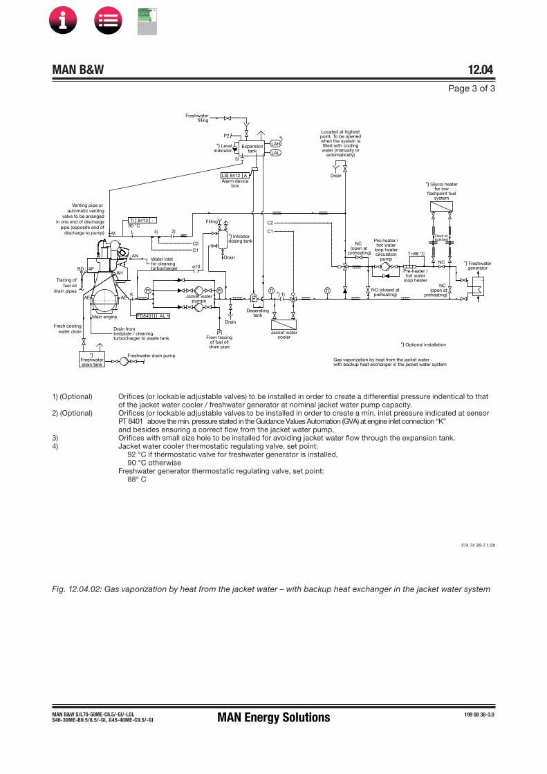
MAN B&W 12.04Page 3 of 3
MAN B&W S/L70-50ME-C8.5/-GI/-LGI, S46-30ME-B9.5/8.5/-GI, G45-40ME-C9.5/-GI
199 08 36-3.0
Deck orbulkhed
NC
*) Glycol heaterfor low
flashpoint fuelsystem
*) Freshwatergenerator
T=88 °C
Pre-heater /hot water
loop heater
Pre-heater /hot water
loop heatercirculation
pump
NC (open at
preheating)
NC (open at
preheating)
NO (closed atpreheating)
Jacket watercooler
*) 1)TITIPI PI
P1
Gas vaporization by heat from the jacket water -with backup heat exchanger in the jacket water system
From tracingof fuel oildrain pipe
Deaeratingtank
*) Inhibitordosing tank
ø10
Filling
BD AFAH
AN
90 °C
Located at highestpoint. To be openedwhen the system isfilled with coolingwater (manually or
automatically)
Tracing offuel oil
drain pipes
Fresh coolingwater drain
Venting pipe or automatic venting
valve to be arranged in one end of discharge
pipe (opposite end of discharge to pump)
*) Freshwaterdrain tank
Drain frombedplate / cleaningturbocharger to waste tank
Main engine
Freshwater drain pump
PT 8401 I AL Y
AEK
AE
Water inletfor cleaningturbocharger
Jacket waterpumps
M L
TI 8413 -
LS 8412 AAlarm device
box
Freshwaterfilling
P2
*) Levelindicator
3)
Expansiontank
*)LAH
LAL
Drain
Drain
Drain
2)4)
C2C1
C2
C1
*) Optional installation
Fig. 12.04.02: Gas vaporization by heat from the jacket water – with backup heat exchanger in the jacket water system
574 74 36-7.1.0b
1) (Optional) Orifices (or lockable adjustable valves) to be installed in order to create a differential pressure indentical to that of the jacket water cooler / freshwater generator at nominal jacket water pump capacity.
2) (Optional) Orifices (or lockable adjustable valves to be installed in order to create a min. inlet pressure indicated at sensor PT 8401 above the min. pressure stated in the Guidance Values Automation (GVA) at engine inlet connection “K” and besides ensuring a correct flow from the jacket water pump.
3) Orifices with small size hole to be installed for avoiding jacket water flow through the expansion tank. 4) Jacket water cooler thermostatic regulating valve, set point:
92 °C if thermostatic valve for freshwater generator is installed, 90 °C otherwise
Freshwater generator thermostatic regulating valve, set point: 88° C
MAN Energy Solutions
MAN B&W
IMO Tier ll Project Guide
MAN
Energy Solutions Project G
uideM
AN B
&W G
95ME-C
10.5
MAN B&W 12.05Page 1 of 2
MAN B&W ME-GI, ME-B-GI engines 199 07 96-6.0
Jacket water cooling pump
The pumps are to be of the centrifugal type.
Pump flow rate/Jacket water flow ......... see ‘List ofCapacities’
Pump head ..............................................see belowDelivery pressure .........depends on location of the
expansion tankTest pressure ....................according to Class rules Working temperature ..................................... 80 °CMax. temperature ......................................... 100 °C
The flow capacity must be within a range from 100 to 110% of the capacity stated.
For the arrangement in Fig. 12.04.01, the pump head has most probably to be higher than the normal guideline, 3.0 bar, because the glycol cir-cuit has to be considered an additional pressure element. Therefore the pump head has to be de-termined based on the total actual pressure drop across all the components in the cooling water system. I.e. pressure drop across the main engine, glycol heat exchanger, jacket water cooler (or the freshwater generator if the pressure drop across that is higher), three-way valve(s), pipes, valves and other piping components.
A guideline for selecting centrifugal pumps is given in Section 6.04.
Glycol heat exchanger
Heat dissipation ................... see ‘List of capacitiesJacket water flow ........as specified by the fuel gas supply system supplier Jacket water flow, inlet ................................... 85 °CMax. working pressure........................up to 100 °C Max. pressure drop on jacket water side ...............................................~0.5 bar
Components for High-temperature Cooling Water System with Glycol Heat Exchanger for Gas Vaporization
Jacket water cooler
As described in Section 12.02
Jacket water thermostatic regulating valve
As described in Section 12.02
Expansion tank
The expansion tank shall be designed as open to atmosphere. Venting pipes entering the tank shall terminate below the lowest possible water level, i.e. below the low level alarm.
The expansion tank must be located at least 15 m above the top of the main engine exhaust gas valves and above the location of the glycol heat exchanger.
The expansion tank volume has to be at least 10% of the total jacket cooling water amount in the sys-tem.
The 10% expansion tank volume is defined as the volume between the lowest level (at the low level alarm sensor) and the overflow pipe or high level alarm sensor.
Deaerating tank and alarm device
As described in Section 12.02.
Chemical corrosion inhibitor and dosing tank
As described in Section 12.02.
MAN Energy Solutions
MAN B&W
IMO Tier ll Project Guide
MAN
Energy Solutions Project G
uideM
AN B
&W G
95ME-C
10.5
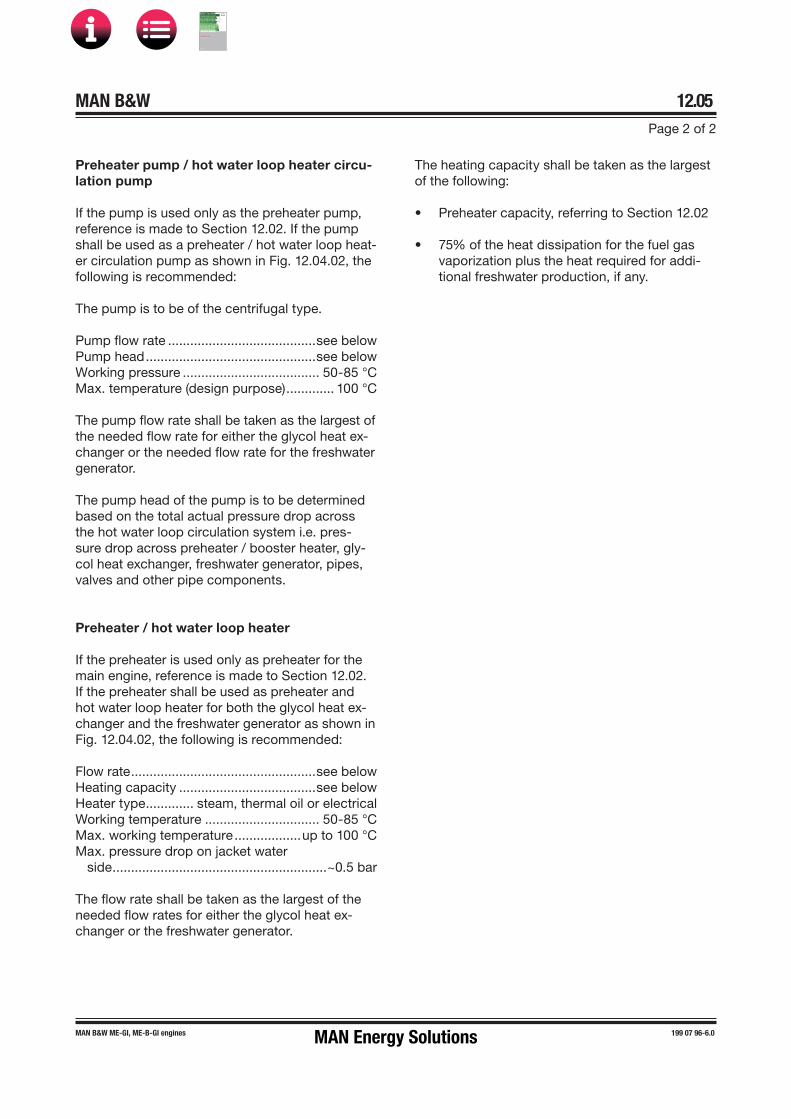
MAN B&W 12.05Page 2 of 2
MAN B&W ME-GI, ME-B-GI engines 199 07 96-6.0
Preheater pump / hot water loop heater circu-lation pump
If the pump is used only as the preheater pump, reference is made to Section 12.02. If the pump shall be used as a preheater / hot water loop heat-er circulation pump as shown in Fig. 12.04.02, the following is recommended:
The pump is to be of the centrifugal type.
Pump flow rate ........................................see belowPump head ..............................................see belowWorking pressure ..................................... 50-85 °CMax. temperature (design purpose) ............. 100 °C
The pump flow rate shall be taken as the largest of the needed flow rate for either the glycol heat ex-changer or the needed flow rate for the freshwater generator.
The pump head of the pump is to be determined based on the total actual pressure drop across the hot water loop circulation system i.e. pres-sure drop across preheater / booster heater, gly-col heat exchanger, freshwater generator, pipes, valves and other pipe components.
Preheater / hot water loop heater
If the preheater is used only as preheater for the main engine, reference is made to Section 12.02. If the preheater shall be used as preheater and hot water loop heater for both the glycol heat ex-changer and the freshwater generator as shown in Fig. 12.04.02, the following is recommended:
Flow rate ..................................................see belowHeating capacity .....................................see belowHeater type ............. steam, thermal oil or electricalWorking temperature ............................... 50-85 °CMax. working temperature ..................up to 100 °CMax. pressure drop on jacket water
side ..........................................................~0.5 bar
The flow rate shall be taken as the largest of the needed flow rates for either the glycol heat ex-changer or the freshwater generator.
The heating capacity shall be taken as the largest of the following:
• Preheater capacity, referring to Section 12.02
• 75% of the heat dissipation for the fuel gasvaporization plus the heat required for addi-tional freshwater production, if any.
MAN Energy Solutions
MAN B&W
IMO Tier ll Project Guide
MAN
Energy Solutions Project G
uideM
AN B
&W G
95ME-C
10.5

MAN B&W
Starting Air
13MAN Energy Solutions
MAN B&W
IMO Tier ll Project Guide
MAN
Energy Solutions Project G
uideM
AN B
&W G
95ME-C
10.5
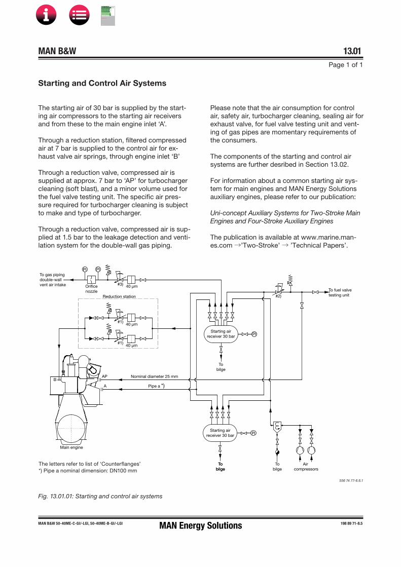
MAN B&W 13.01Page 1 of 1
MAN B&W 50-40ME�C-GI/-LGI, 50-40ME-B-GI/-LGI 198 89 71-8.5
Fig. 13.01.01: Starting and control air systems
The starting air of 30 bar is supplied by the start-ing air compressors to the starting air receivers and from these to the main engine inlet ‘A’.
Through a reduction station, filtered compressed air at 7 bar is supplied to the control air for ex-haust valve air springs, through engine inlet ‘B’
Through a reduction valve, compressed air is supplied at approx. 7 bar to ‘AP’ for turbocharger cleaning (soft blast), and a minor volume used for the fuel valve testing unit. The specific air pres-sure required for turbocharger cleaning is subject to make and type of turbocharger.
Through a reduction valve, compressed air is sup-plied at 1.5 bar to the leakage detection and venti-lation system for the double-wall gas piping.
Please note that the air consumption for control air, safety air, turbocharger cleaning, sealing air for exhaust valve, for fuel valve testing unit and vent-ing of gas pipes are momentary requirements of the consumers.
The components of the starting and control air systems are further desribed in Section 13.02.
For information about a common starting air sys-tem for main engines and MAN Energy Solutions auxiliary engines, please refer to our publication:
Uni-concept Auxiliary Systems for Two-Stroke Main Engines and Four-Stroke Auxiliary Engines
The publication is available at www.marine.man-es.com →’Two-Stroke’ → ’Technical Papers’.
556 74 77-6.6.1
The letters refer to list of ‘Counterflanges’*) Pipe a nominal dimension: DN100 mm
Starting and Control Air Systems
To gas pipingdouble-wallvent air intake
Main engine
BAP
A Pipe a *)
Nominal diameter 25 mm
40 µm
40 µm#1)
#1)
PI PI
Orificenozzle
#3)
Reduction station
40 µmTo fuel valvetesting unit#2)
Starting airreceiver 30 bar
Starting airreceiver 30 bar
Tobilge
TobilgeTo
bilgeAir
compressorsTo
bilge
PI
PI
MAN Energy Solutions
MAN B&W
IMO Tier ll Project Guide
MAN
Energy Solutions Project G
uideM
AN B
&W G
95ME-C
10.5

MAN B&W 13.02Page 1 of 1
198 89 74-3.3MAN B&W 50-40ME-C-GI/-LGI,46ME-B-GI/-LGI
Components for Starting Air System
Starting air compressors
The starting air compressors are to be of the water�cooled, two�stage type with intercooling.
More than two compressors may be installed to supply the total capacity stated.
Air intake quantity:Reversible engine, for 12 starts ....................... see ‘List of capacities’ Non�reversible engine,for 6 starts ......................... see ‘List of capacities’ Delivery pressure ........................................ 30 bar
Starting air receivers
The volume of the two receivers is:Reversible engine,for 12 starts .................... see ‘List of capacities’ *)Non�reversible engine, for 6 starts ...................... see ‘List of capacities’ *)Working pressure ........................................ 30 barTest pressure .................... according to class rule
*) The volume stated is at 25 °C and 1,000 mbar
Reduction station for control and safety air
In normal operating, each of the two lines supplies one engine inlet. During maintenance, three isolat-ing valves in the reduction station allow one of the two lines to be shut down while the other line sup-plies both engine inlets, see Fig. 13.01.01.
Reduction ......................... from 30�10 bar to 7 bar(Tolerance ±10%)
Flow rate, free air .............. 2,100 Normal liters/minequal to 0.035 m3/s
Filter, fineness ............................................. 40 µm
Reduction valve for turbocharger cleaning etc
Reduction ......... from 30�10 bar to approx. 7 bar *)*) Subject to make and type of TC (Tolerance ±10%)
Flow rate, free air ............. 2,600 Normal liters/minequal to 0.043 m3/s
Reduction valve for venting air for gas piping
Reduction ....................... from 30�10 bar to 1.5 bar(Tolerance ±10%)
Flow rate, free air ................ 500 Normal liters/minequal to 0.007 m3/s
The consumption of compressed air for control air, exhaust valve air springs and safety air as well as air for turbocharger cleaning, fuel valve testing and venting of gas piping is covered by the capacities stated for air receivers and compressors in the list of capacities.
Starting and control air pipes
The piping delivered with and fitted onto the main engine is shown in the following figures in Section 13.03:Fig. 13.03.01 Starting air pipesFig. 13.03.02 Air spring pipes, exhaust valves
Turning gear
The turning wheel has cylindrical teeth and is fit-ted to the thrust shaft. The turning wheel is driven by a pinion on the terminal shaft of the turning gear, which is mounted on the bedplate.
Engagement and disengagement of the turning gear is effected by displacing the pinion and ter-minal shaft axially. To prevent the main engine from starting when the turning gear is engaged, the turning gear is equipped with a safety arrange -ment which interlocks with the starting air system.
The turning gear is driven by an electric motor with a built�in gear and brake. Key specifications of the electric motor and brake are stated in Sec-tion 13.04.
MAN Energy Solutions
MAN B&W
IMO Tier ll Project Guide
MAN
Energy Solutions Project G
uideM
AN B
&W G
95ME-C
10.5

MAN B&W 13.03Page 1 of 2
MAN B&W ME/ME�C/�GI/-LGI engines 198 40 00�4.9
Starting and Control Air Pipes
A
Activate pilot pressureto starting valves
Starting valve
Bursting cap
Cyl. 1
Blow off
Slow turning4 50 141
Blow off
ZV 1120-N C
ZS 1116-A I C
ZS 1116-B I CZS 1112-A I C
ZS 1112-B I C
ZS 1117-A C
ZS 1117-B C
PT 8501-A I AL
Local operating panel
PT 8501-B I AL
PI 8501
ZS 1111-B I C
ZS 1111-A I C
The letters refer to list of ‘Counterflanges’The item nos. refer to ‘Guidance values automation’The piping is delivered with and fitted onto the engine
198 98 21-5.3.1
Fig. 13.03.01: Starting air pipes
The starting air pipes, Fig. 13.03.01, contain a main starting valve (a ball valve with actuator), a nonreturn valve, a solenoid valve and a starting valve. The main starting valve is controlled by the Engine Control System. Slow turning before start of engine, EoD: 4 50 141, is included in the basic design.
The Engine Control System regulates the supply of control air to the starting valves in accordance with the correct firing sequence and the timing.
Please note that the air consumption for control air, turbocharger cleaning and for fuel valve test-ing unit are momentary requirements of the con-sumers. The capacities stated for the air receivers
and compressors in the ‘List of Capacities’ cover all the main engine requirements and starting of the auxiliary engines.
For information about a common starting air system for main engines and auxiliary engines, please refer to our publication:
Uni-concept Auxiliary Systems for Two-Stroke Main Engines and Four-Stroke Auxiliary Engines
The publication is available at www.marine.man-es.com →’Two-Stroke’ → ’Technical Papers’.
MAN Energy Solutions
MAN B&W
IMO Tier ll Project Guide
MAN
Energy Solutions Project G
uideM
AN B
&W G
95ME-C
10.5
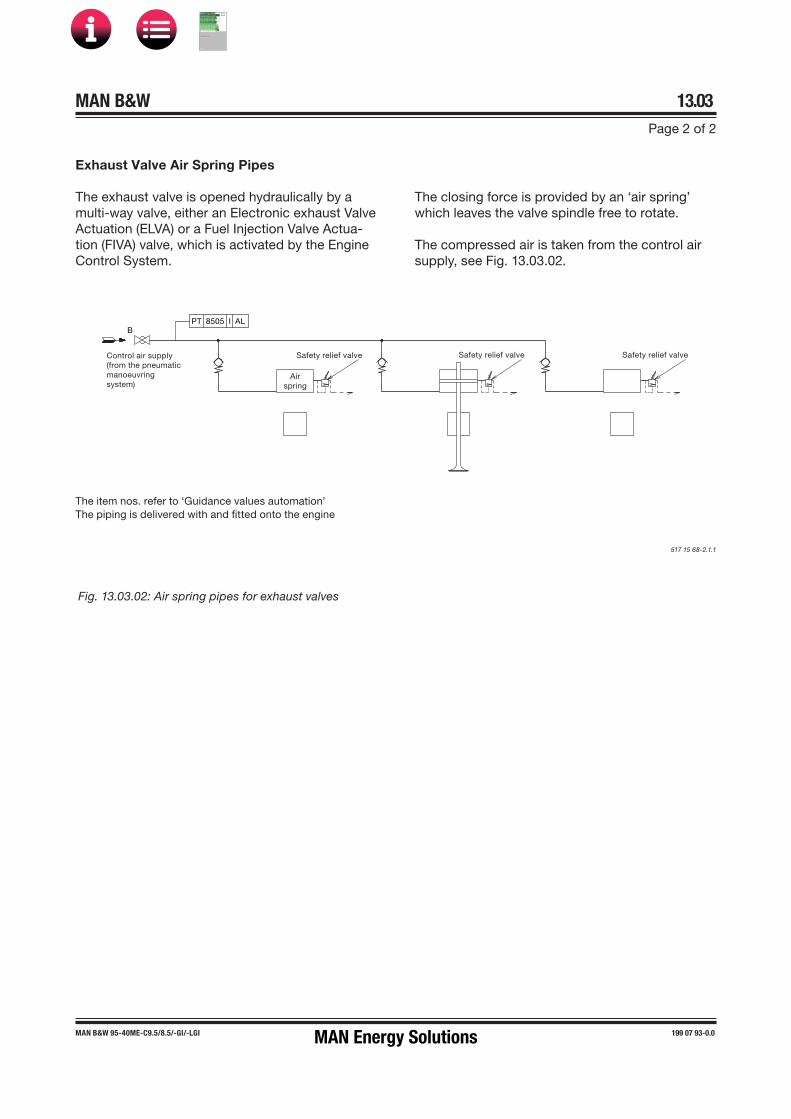
MAN B&W 13.03Page 2 of 2
MAN B&W 95-40ME�C9.5/8.5/�GI/-LGI 199 07 93-0.0
Fig. 13.03.02: Air spring pipes for exhaust valves
Airspring
Safety relief valveControl air supply(from the pneumaticmanoeuvringsystem)
Safety relief valve Safety relief valve
PT 8505 I ALB
Exhaust Valve Air Spring Pipes
The exhaust valve is opened hydraulically by a multi-way valve, either an Electronic exhaust Valve Actuation (ELVA) or a Fuel Injection Valve Actua-tion (FIVA) valve, which is activated by the Engine Control System.
The item nos. refer to ‘Guidance values automation’The piping is delivered with and fitted onto the engine
517 15 68-2.1.1
The closing force is provided by an ‘air spring’ which leaves the valve spindle free to rotate.
The compressed air is taken from the control air supply, see Fig. 13.03.02.
MAN Energy Solutions
MAN B&W
IMO Tier ll Project Guide
MAN
Energy Solutions Project G
uideM
AN B
&W G
95ME-C
10.5

EElectric Motor for Turning Gear
Intro
Fig. 13.04.01: Electric motor for turning gear, option: 40 80 101
MAN B&W 13.04
Page 1 of 1
MAN B&W S50MC-C8.2, S50ME-C8.5/.2/-GI,
S50ME-B9, G50ME-C/ME-B, G45ME-C
199 03 36-6.0MAN Energy Solutions
MAN B&W
IMO Tier ll Project Guide
MAN
Energy Solutions Project G
uideM
AN B
&W G
95ME-C
10.5

MAN B&W
Scavenge Air
14MAN Energy Solutions
MAN B&W
IMO Tier ll Project Guide
MAN
Energy Solutions Project G
uideM
AN B
&W G
95ME-C
10.5

MAN B&W 14.01Page 1 of 1
198 61 48-9.2MAN B&W S50MC, 46-35MC-C, 45-40ME-C/-GI/-LGI, 46-30ME-B/-GI/-LGI
Scavenge Air System
Scavenge air is supplied to the engine by one turbocharger located on either the aft end of the engine, option: 4 59 121, or on the exhaust side, option: 4 59 123.
The compressor of the turbocharger draws air from the engine room, through an air filter, and the compressed air is cooled by the scavenge air cooler. The scavenge air cooler is provided with a water mist catcher, which prevents condensated water from being carried with the air into the scav-enge air receiver and to the combustion chamber.
The scavenge air system (see Figs. 14.01.01 and 14.02.01) is an integrated part of the main engine.
The engine power figures and the data in the list of capacities are based on MCR at tropical con-ditions, i.e. a seawater temperature of 32 °C, or freshwater temperature of 36 °C, and an ambient air inlet temperature of 45 °C.
Fig. 14.01.01: Scavenge Air System
178 25 18�8.1
Exhaust gasreceiver
Turbocharger
Scavenge airreceiver
Scavenge aircooler
Water mistcatcher
Exhaust valve
Cylinder liner
MAN Energy Solutions
MAN B&W
IMO Tier ll Project Guide
MAN
Energy Solutions Project G
uideM
AN B
&W G
95ME-C
10.5

MAN B&W 14.02Page 1 of 3
199 05 53-4.1MAN B&W 50-40ME-C/-GI/-LGI
Running with auxiliary blower Running with turbocharger
Auxiliary Blowers
The engine is provided with a minimum of two electrically driven auxiliary blowers, the actual number depending on the number of cylinders as well as the turbocharger make and amount.
The auxiliary blowers are integrated in the revers-ing chamber below the scavenge air cooler. Be-tween the scavenge air cooler and the scavenge air receiver, non�return valves are fitted which close automatically when the auxiliary blowers start supplying the scavenge air.
Auxiliary blower operation
The auxiliary blowers start operating consecu-tively before the engine is started and will ensure complete scavenging of the cylinders in the start-ing phase, thus providing the best conditions for a safe start.
During operation of the engine, the auxiliary blow-ers will start automatically whenever the blower inlet pressure drops below a preset pressure, corresponding to an engine load of approximately 25-35%.
The blowers will continue to operate until the blower inlet pressure again exceeds the preset pressure plus an appropriate hysteresis (i.e. taking recent pressure history into account), correspond-ing to an engine load of approximately 30-40%.
Emergency running
If one of the auxiliary blowers is out of function, the other auxiliary blower will function in the sys-tem, without any manual adjustment of the valves being necessary.
Fig. 14.02.01: Scavenge air system, integrated blower
178 63 77-1.0b
MAN Energy Solutions
MAN B&W
IMO Tier ll Project Guide
MAN
Energy Solutions Project G
uideM
AN B
&W G
95ME-C
10.5

MAN B&W 14.02Page 2 of 2
MAN B&W ME/ME-C/-GI/-LGI engines 198 85 56-2.1
Control of the Auxiliary Blowers
The control system for the auxiliary blowers is integrated in the Engine Control System. The aux-iliary blowers can be controlled in either automatic (default) or manual mode.
In automatic mode, the auxiliary blowers are started sequentially at the moment the engine is commanded to start. During engine running, the blowers are started and stopped according to preset scavenge air pressure limits.
When the engine stops, the blowers are stopped after 30 minutes to prevent overheating of the blowers. When a start is ordered, the blower will be started in the normal sequence and the actual start of the engine will be delayed until the blow-ers have started.
In manual mode, the blowers can be controlled individually from the ECR (Engine Control Room) panel irrespective of the engine condition.
Referring to Fig. 14.02.02, the Auxiliary Blower Starter Panels control and protect the Auxiliary Blower motors, one panel with starter per blower.
The starter panels with starters for the auxiliary blower motors are not included, they can be or-dered as an option: 4 55 653. (The starter panel design and function is according to MAN Energy Solutions'diagram, however, the physical layout and choice of components has to be decided by the manufacturer).
Heaters for the blower motors are available as an option: 4 55 155.
Scavenge air cooler requirements
The data for the scavenge air cooler is specified in the description of the cooling water system chosen.
For further information, please refer to our publi-cation titled:
MAN Energy Solutions Influence of Ambient Tem-perature Conditions
The publication is available at www.marine.man-es.com →’Two-Stroke’ → ’Technical Papers’.
Fig. 14.02.02: Diagram of auxiliary blower control system
Engine Control System
Engine room
Motorheater
Motorheater
Motorheater
Motorheater
Motorheater
Powercable
Powercable
Powercable
Powercable
Powercable
Aux. blowerstarter panel 1
Auxiliaryblower
Auxiliaryblower
Auxiliaryblower
Auxiliaryblower
Auxiliaryblower
M M M M M
Aux. blowerstarter panel 2
Aux. blowerstarter panel 3
Aux. blowerstarter panel 4
Aux. blowerstarter panel 5
178 61 30-2.0
MAN Energy Solutions
MAN B&W
IMO Tier ll Project Guide
MAN
Energy Solutions Project G
uideM
AN B
&W G
95ME-C
10.5

MAN B&W 14.03Page 1 of 1
MAN B&W 45-40ME-C/-GI/-LGI 199 03 80-7.1
Scavenge Air Pipes
Cyl. 1
TE 8610 AH YH
Air
coo
ler
PDT 8607 I AH
TE 8612 I
TE 8605 I
TI 8605CoCos
CoCos
PDT 8606 I AH
PDI 8606
TI 8608
TE 8609 AH I YH TE 8608 I
PI 8601PT 8601-ATI 8609E 1180
CoCos
PI 8706
Exhaust receiver
Wat
er m
ist
catc
her
PT 8601-B
PI 8601
The item nos. refer to ‘Guidance Values Automation’
126 40 79�9.3.0a
Fig. 14.03.01b: Scavenge air pipes, one turbocharger aft
TI 8605
TE 8612 I
PDT 8607 I AH
E 1180 E 1180
TI 8609
PI 8706
TI 8608
PDT 8606 I AH
PDI 8606
TE 8605 I
PDI 8606
TE 8608 I
TE 8609 I AH Y
PT 8601-B
PT 8601-A PI 8601
Spare
Scavenge air cooler
Cocos
Cocos
Scavenge air receiver
Cyl. 1
Exhaust receiver
Auxiliary blower
PI 8601
TE 8610 AH YH
The item nos. refer to ‘Guidance Values Automation’
502 46 55�9.2.1a
Fig. 14.03.01a: Scavenge air pipes, one turbocharger on exhaust side
MAN Energy Solutions
MAN B&W
IMO Tier ll Project Guide
MAN
Energy Solutions Project G
uideM
AN B
&W G
95ME-C
10.5

MAN B&W 14.04Page 1 of 1
MAN B&W G45ME-C9/-GI/-LGI 199 06 35-0.0
Table 14.04.01: Electric motor for auxiliary blower, engine with turbocharger located on aft end or exhaust side
Electric Motor for Auxiliary Blower
The number of auxiliary blowers in a propulsion plant may vary depending on the actual amount of turbochargers as well as space requirements.
Motor start method and size
Direct Online Start (DOL) is required for all auxil-iary blower electric motors to ensure proper op-eration under all conditions.
For typical engine configurations, the installed size of the electric motors for auxiliary blowers are listed in Table 14.04.01.
Special operating conditions
For engines with Dynamic Positioning (DP) mode in manoeuvring system, option: 4 06 111, larger electric motors are required. This is in order to avoid start and stop of the blowers inside the load range specified for dynamic positioning. The actu-al load range is to be decided between the owner and the yard.
Engine plants with waste heat recovery exhaust gas bypass and engines with low- and part-load exhaust gas bypass may require less blower capacity, please contact MAN Energy Solutions, Copenhagen.
559 44 86-8.0.0
Number of cylinders
Number ofauxiliary blowers
Required powerkW
Installed powerkW
Estimated start currentAmp
5
2
2 × 25 2 × 25.5 2 × 2966 2 × 31 2 × 35 2 × 4037 2 × 36 2 × 42 2 × 5088 2 × 41 2 × 42 2 × 508
The installed power of the electric motors are based on a voltage supply of 3×440V at 60Hz.
The ‘Required power’ as well as the ‘Estimated start current’ figures are for the complete auxiliary blower arrangement and 3×440V at 60Hz electric motors. The figures for 3×380V at 50Hz electric motors are available on request.
The electric motors are delivered with and fitted onto the engine.
MAN Energy Solutions
MAN B&W
IMO Tier ll Project Guide
MAN
Energy Solutions Project G
uideM
AN B
&W G
95ME-C
10.5

SScavenge Air Cooler Cleaning System
The letters refer to list of 'Counterflanges'. The item nos. refer to 'Guidance values automation'.
Fig. 14.05.01: Air cooler cleaning pipes, shown on engine with turbocharger located on exhaust side
The air side of the scavenge air cooler can be cleaned by injecting a grease dissolving media through ‘AK’ to a spray pipe arrangement fitted to the air chamber above the air cooler element.
Drain from water mist catcher
Sludge is drained through ‘AL’ to the drain water collecting tank and the polluted grease dissolvent returns from ‘AM’, through a filter, to the chemi-cal cleaning tank. The cleaning must be carried out while the engine is at standstill.
Dirty water collected after the water mist catcher is drained through ‘DX’ and led to the bilge tank via an open funnel, see Fig. 14.05.02.
The ‘AL’ drain line is, during running, used as a permanent drain from the air cooler water mist catcher. The water is led through an orifice to prevent major losses of scavenge air.
The system is equipped with a drain box with a level switch, indicating any excessive water level.
The piping delivered with and fitted on the engine is shown in Fig 14.05.01.
Auto Pump Overboard System
It is common practice on board to lead drain water directly overboard via a collecting tank. Before pumping the drain water overboard, it is recommended to measure the oil content. If above 15ppm, the drain water should be lead to the clean bilge tank / bilge holding tank.
If required by the owner, a system for automatic disposal of drain water with oil content monitor-ing could be built as outlined in Fig. 14.05.02.
MAN B&W 14.05
Page 1 of 3
MAN B&W 45-40ME-C9/-GI/-LGI,
40-30ME-B9/-GI/-LGI, 40-35MC-C9
198 77 25-8.1MAN Energy Solutions
MAN B&W
IMO Tier ll Project Guide
MAN
Energy Solutions Project G
uideM
AN B
&W G
95ME-C
10.5

AAuto Pump Overboard System
The letters refer to list of 'Counterflanges'.
Fig. 14.05.02: Suggested automatic disposal of drain water, if required by owner (not a demand from MAN Energy Solutions)
MAN B&W 14.05
Page 2 of 3
MAN B&W 45-40ME-C9/-GI/-LGI,
40-30ME-B9/-GI/-LGI, 40-35MC-C9
198 77 25-8.1MAN Energy Solutions
MAN B&W
IMO Tier ll Project Guide
MAN
Energy Solutions Project G
uideM
AN B
&W G
95ME-C
10.5

AAir Cooler Cleaning Unit
The letters refer to list of 'Counterflanges'.
No. of cylinders
5-8
Chemical tank capacity, m3 0.3
Circulation pump capacity at 3 bar, m3/h
1
198 77 27-1.2
Fig. 14.05.03: Air cooler cleaning system with Air Cooler Cleaning Unit, option: 4 55 665
MAN B&W 14.05
Page 3 of 3
MAN B&W 45-40ME-C9/-GI/-LGI,
40-30ME-B9/-GI/-LGI, 40-35MC-C9
198 77 25-8.1MAN Energy Solutions
MAN B&W
IMO Tier ll Project Guide
MAN
Energy Solutions Project G
uideM
AN B
&W G
95ME-C
10.5

MAN B&W 14.06Page 1 of 1
MAN B&W S50MC, 46-40MC-C/ME-C/ME-B/-GI/-LGI 198 76 92-1.5
The scavenge air box is continuously drained through ‘AV’ to a small pressurised drain tank, from where the sludge is led to the sludge tank. Steam can be applied through ‘BV’, if required, to facilitate the draining. See Fig. 14.06.01.
The continuous drain from the engine scavenge air area must not be directly connected to the sludge tank due to the pressure level.
Fig. 14.06.01: Scavenge air box drain system
The drain tank shall be designed according to the pressurised system connected to the BV connec-tion as one of the following:
• Steam maximum working pressure• Compressed air maximum working pressure
It is recommended that the drain tank is placed close to the engine to avoid lon piping between engine and drain tank and thereby minimize the risk of the pipe being blocked by sludge.
079 61 03-0.8.0
The letters refer to list of ‘Counterflanges’
Scavenge Air Box Drain System
No. of cylinders: 5-6 7-9 10-12 14
Drain tank capacity, m3 0.3 0.4 0.5 0.8
Deck / Roof Deck / Roof
If the engine is equipped with both ‘AV’ and ‘AV1’ connections, these can be connected to a common pipe which is connected to the drain tank.
The ‘AV’ and ‘AV1’ connection can alsobe connected to the drain tank separately.
AV1AV
Valve normallyclosed (locked)Open for cleaningof pipes
Min. 15°
DN=65 mm
Normally open.To be closed in case of fire int the scavenge air box
Normally closed.Tank to be emptiedduring servicewith valve open.
Manholefor cleaning
Orifice
1000
mm
Min. 15°
DN=50 mm
BV
DN=15 mm
DN=50 mm
Draintank1)
Sludgetank
Steam inlet pressure3-10 bar. If steam isnot available, 7 barcompressed air canbe used.
MAN Energy Solutions
MAN B&W
IMO Tier ll Project Guide
MAN
Energy Solutions Project G
uideM
AN B
&W G
95ME-C
10.5

FFire Extinguishing System for Scavenge Air Space
The letters refer to list of 'Counterflanges'.
Fig. 14.07.01: Fire extinguishing system for scavenge air space
Fire in the scavenge air space can beextinguished by steam, this being the basic solution, or, optionally, by water mist or CO2.
The external system, pipe and flange connections are shown in Fig. 14.07.01 and the piping fitted onto the engine in Fig. 14.07.02.
In the Extent of Delivery, the fire extinguishing system for scavenge air space is selected by the fire extinguishing agent:
• basic solution: 4 55 140 Steam• option: 4 55 142 Water mist• option: 4 55 143 CO2
The key specifications of the fire extinguishing agents are:Steam fire extinguishing for scavenge air spaceSteam pressure: 3-10 barSteam quantity, approx.: 1.8 kg/cyl.
Water mist fire extinguishing for scavenge air spaceFreshwater pressure: min. 3.5 barFreshwater quantity, approx.: 1.7 kg/cyl.
CO2 fire extinguishing for scavenge air space
CO2 test pressure: 150 bar
CO2 quantity, approx.: 3.5 kg/cyl.
MAN B&W 14.07
Page 1 of 2
MAN B&W 45ME-C/-GI 199 01 49-7.2MAN Energy Solutions
MAN B&W
IMO Tier ll Project Guide
MAN
Energy Solutions Project G
uideM
AN B
&W G
95ME-C
10.5

FFire Extinguishing Pipes in Scavenge Air Space
The letters refer to 'List of flanges'.The item no. refer to 'Guidance Values Automation'.
Fig. 14.07.02: Fire extinguishing pipes in scavenge air space
Scavenge Air Space, Drain Pipes
The letters refer to 'List of flanges'.
Fig. 14.07.03: Scavenge air space, drain pipes
MAN B&W 14.07
Page 2 of 2
MAN B&W 45ME-C/-GI 199 01 49-7.2MAN Energy Solutions
MAN B&W
IMO Tier ll Project Guide
MAN
Energy Solutions Project G
uideM
AN B
&W G
95ME-C
10.5

MAN B&W
Exhaust Gas
15MAN Energy Solutions
MAN B&W
IMO Tier ll Project Guide
MAN
Energy Solutions Project G
uideM
AN B
&W G
95ME-C
10.5
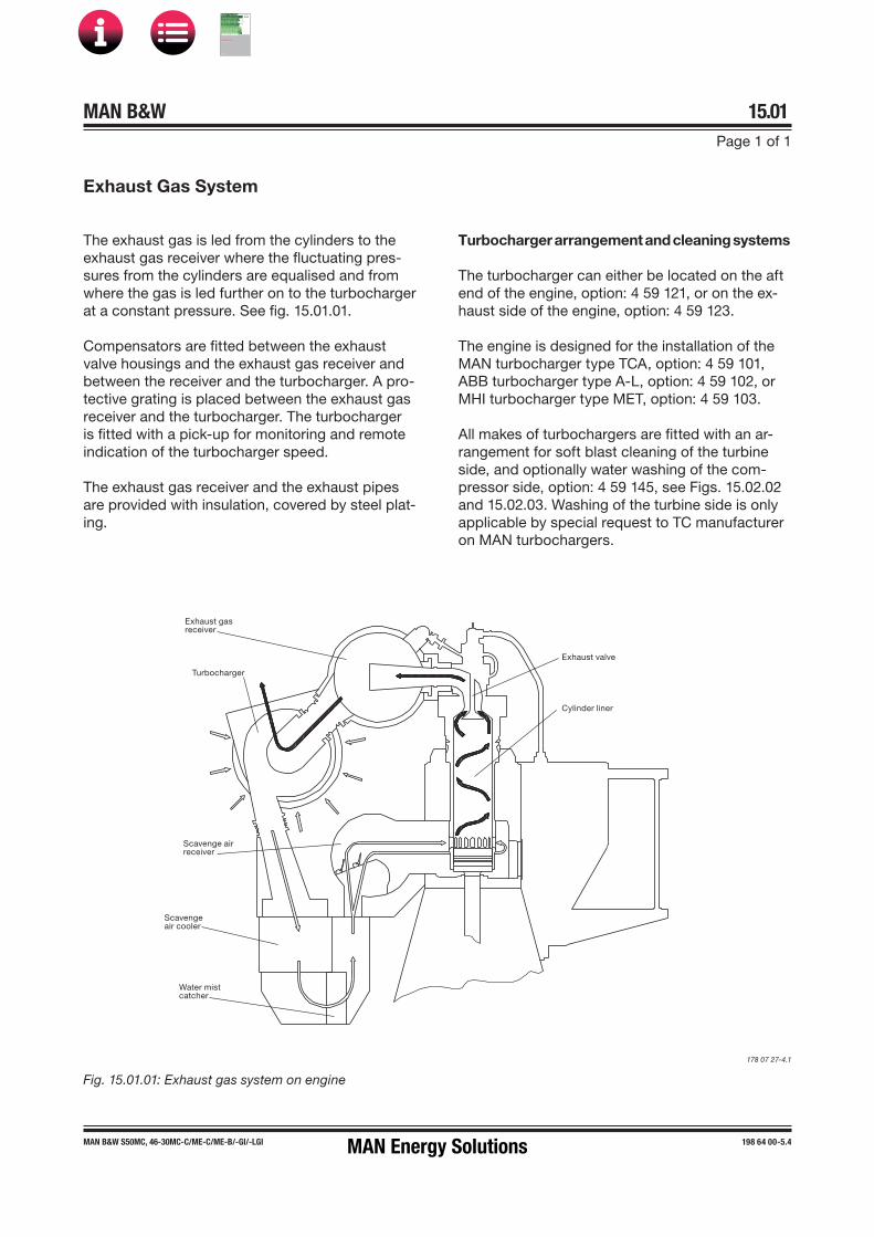
MAN B&W 15.01Page 1 of 1
MAN B&W S50MC, 46-30MC-C/ME-C/ME-B/-GI/-LGI 198 64 00�5.4
Exhaust Gas System
The exhaust gas is led from the cylinders to the exhaust gas receiver where the fluctuating pres-sures from the cylinders are equalised and from where the gas is led further on to the turbocharger at a constant pressure. See fig. 15.01.01.
Compensators are fitted between the exhaust valve housings and the exhaust gas receiver and between the receiver and the turbocharger. A pro-tective grating is placed between the exhaust gas receiver and the turbocharger. The turbocharger is fitted with a pick up for monitoring and remote indication of the turbocharger speed.
The exhaust gas receiver and the exhaust pipes are provided with insulation, covered by steel plat-ing.
Turbocharger arrangement and cleaning systems
The turbocharger can either be located on the aft end of the engine, option: 4 59 121, or on the ex-haust side of the engine, option: 4 59 123.
The engine is designed for the installation of the MAN turbocharger type TCA, option: 4 59 101, ABB turbocharger type A-L, option: 4 59 102, or MHI turbocharger type MET, option: 4 59 103.
All makes of turbochargers are fitted with an ar-rangement for soft blast cleaning of the turbine side, and optionally water washing of the com-pressor side, option: 4 59 145, see Figs. 15.02.02 and 15.02.03. Washing of the turbine side is only applicable by special request to TC manufacturer on MAN turbochargers.
Exhaust valve
Cylinder liner
Exhaust gasreceiver
Turbocharger
Scavenge airreceiver
Scavenge air cooler
Water mistcatcher
Fig. 15.01.01: Exhaust gas system on engine
178 07 27�4.1
MAN Energy Solutions
MAN B&W
IMO Tier ll Project Guide
MAN
Energy Solutions Project G
uideM
AN B
&W G
95ME-C
10.5

MAN B&W 15.02Page 1 of 2
MAN B&W 50-26 engines 199 05 58-3.0
Cyl. 1
Flange connection D
Turbocharger
To scavenge air receiver
Exhaust gas receiver
PI 8706
PI 8601
TI 8701TC 8704 I
TI/TT 8701 I AH YH
TE 8612
**) CoCos
TC 8707 I AH
TI/TE 8702 I AH YH
**)
**)
XS 8817 Z
ZT 8801 I AH YH
TI 8707
PT 8708 I AH
PT 8706 I
Exhaust Gas Pipes
Fig. 15.02.01: Exhaust gas pipes
121 15 27-9.2.3
The letters refer to list of ‘Counterflanges’The item nos. refer to ‘Guidance Values Automation’
MAN Energy Solutions
MAN B&W
IMO Tier ll Project Guide
MAN
Energy Solutions Project G
uideM
AN B
&W G
95ME-C
10.5

MAN B&W 15.02Page 2 of 2
198 79 16-4.1MAN B&W 50-26 engines
Cleaning Systems
Fig. 15.02.02: MAN TCA turbocharger, water washing of compressor side, EoD: 4 59 145
121 15 21-8.1.1b
178 61 87-7.0.0
Compressor cleaning
MAN TCA turbocharger
To bedplate drain, AE
AP
DrainDry cleaning turbine side
PI 8803
ABB Turbocharger
Compressor cleaning
To bedplate drain, AE
Fig. 15.02.03: Soft blast cleaning of turbine side and water washing of compressor side for ABB turbochargers
MAN Energy Solutions
MAN B&W
IMO Tier ll Project Guide
MAN
Energy Solutions Project G
uideM
AN B
&W G
95ME-C
10.5

MAN B&W 15.03Page 1 of 1
MAN B&W MC/MC�C, ME/ME�C/ME�GI/ME-B engines 198 40 74�6.3
Exhaust Gas System for Main Engine
At the specified MCR of the engine, the total back�pressure in the exhaust gas system after the turbocharger (as indicated by the static pressure measured in the piping after the turbocharger) must not exceed 350 mm WC (0.035 bar).
In order to have a back�pressure margin for the final system, it is recommended at the design stage to initially use a value of about 300 mm WC (0.030 bar).
The actual back�pressure in the exhaust gas system at specified MCR depends on the gas velocity, i.e. it is proportional to the square of the exhaust gas velocity, and hence inversely propor-tional to the pipe diameter to the 4th power. It has by now become normal practice in order to avoid too much pressure loss in the pipings to have an exhaust gas velocity at specified MCR of about 35 m/sec, but not higher than 50 m/sec.
For dimensioning of the external exhaust pipe connections, see the exhaust pipe diameters for 35 m/sec, 40 m/sec, 45 m/sec and 50 m/sec re-spectively, shown in Table 15.07.02.
As long as the total back�pressure of the exhaust gas system (incorporating all resistance losses from pipes and components) complies with the above�mentioned requirements, the pressure losses across each component may be chosen in-dependently, see proposed measuring points (M) in Fig. 15.05.01. The general design guidelines for each component, described below, can be used for guidance purposes at the initial project stage.
Exhaust gas piping system for main engine
The exhaust gas piping system conveys the gas from the outlet of the turbocharger(s) to the at-mosphere.
The exhaust piping is shown schematically in Fig. 15.04.01.
The exhaust system for the main engine com-prises:
• Exhaust gas pipes• Exhaust gas boiler• Silencer• Spark arrester (if needed)• Expansion joints (compensators)• Pipe bracings.
In connection with dimensioning the exhaust gas piping system, the following parameters must be observed:
• Exhaust gas flow rate• Exhaust gas temperature at turbocharger outlet• Maximum pressure drop through exhaust gas
system• Maximum noise level at gas outlet to atmos-
phere• Maximum force from exhaust piping on
turbocharger(s)• Sufficient axial and lateral elongation ability of
expansion joints• Utilisation of the heat energy of the exhaust gas.
Items that are to be calculated or read from tables are:
• Exhaust gas mass flow rate, temperature and max-imum back pressure at turbocharger gas outlet
• Diameter of exhaust gas pipes• Utilisation of the exhaust gas energy• Attenuation of noise from the exhaust pipe outlet• Pressure drop across the exhaust gas system• Expansion joints.
MAN Energy Solutions
MAN B&W
IMO Tier ll Project Guide
MAN
Energy Solutions Project G
uideM
AN B
&W G
95ME-C
10.5

MAN B&W 15.04Page 1 of 2
198 40 75�8.7MAN B&W MC/MC�C, ME/ME�C/ME�GI/ME-B engines
Components of the Exhaust Gas System
Exhaust gas boiler
Engine plants are usually designed for utilisation of the heat energy of the exhaust gas for steam pro-duction or for heating the thermal oil system. The exhaust gas passes an exhaust gas boiler which is usually placed near the engine top or in the funnel.
It should be noted that the exhaust gas tempera-ture and flow rate are influenced by the ambient conditions, for which reason this should be con -sidered when the exhaust gas boiler is planned. At specified MCR, the maximum recommended pres -sure loss across the exhaust gas boiler is normally 150 mm WC.
This pressure loss depends on the pressure losses in the rest of the system as mentioned above. Therefore, if an exhaust gas silencer/spark ar-rester is not installed, the acceptable pressure loss across the boiler may be somewhat higher than the max. of 150 mm WC, whereas, if an exhaust gas silencer/spark arrester is installed, it may be neces -sary to reduce the maximum pressure loss.
The above mentioned pressure loss across the exhaust gas boiler must include the pressure losses from the inlet and outlet transition pieces.
Fig. 15.04.01a: Exhaust gas system, one turbocharger
178 42 78�3.2
Exhaust gas compensator after turbocharger
When dimensioning the compensator, option: 4 60 610, for the expansion joint on the turbochar-ger gas outlet transition piece, option: 4 60 601, the exhaust gas piece and components, are to be so arranged that the thermal expansions are ab -sorbed by expansion joints. The heat expansion of the pipes and the components is to be calculated based on a temperature increase from 20 °C to 250 °C. The max. expected vertical, transversal and longitudinal heat expansion of the engine measured at the top of the exhaust gas transition piece of the turbocharger outlet are indicated in Fig. 15.06.01 and Table 15.06.02 as DA, DB and DC.
The movements stated are related to the engine seating, for DC, however, to the engine centre. The figures indicate the axial and the lateral movements related to the orientation of the expansion joints.
The expansion joints are to be chosen with an elas -ticity that limits the forces and the moments of the exhaust gas outlet flange of the turbocharger as stated for each of the turbocharger makers in Table 15.06.04. The orientation of the maximum permis-sible forces and moments on the gas outlet flange of the turbocharger is shown in Fig. 15.06.03.
urbocharger gasoutlet flange
D
D
D
D
Exhaust gas outletto the atmosphere
Slide support
Fixed support
Exhaust gas compensator
Main engine with turbochargerson exhaust side
ransition piece
Exhaust gas silencer
Exhaust gas boiler
D0
Fig. 15.04.01b: Exhaust gas system, two or more TCs
178 33 46�7.4
Exhaust gas outletto the atmosphere
Slide support
Fixed support
Exhaust gas compensator
Main engine withturbocharger on aft end
D0
D0
D0
Exhaust gas silencer
Exhaust gas boiler
MAN Energy Solutions
MAN B&W
IMO Tier ll Project Guide
MAN
Energy Solutions Project G
uideM
AN B
&W G
95ME-C
10.5

MAN B&W 15.04Page 2 of 2
MAN B&W G45ME-C9.5/-GI-TII 199 05 28-4.0
Exhaust gas silencer
The typical octave band sound pressure levels from the diesel engine’s exhaust gas system – at a distance of one meter from the top of theexhaust gas uptake – are shown in Fig.15.04.02.
The need for an exhaust gas silencer can be de-cided based on the requirement of a maximum permissible noise level at a specific position.
The exhaust gas noise data is valid for an exhaust gas system without boiler and silencer, etc.
The noise level is at nominal MCR at a distance of one metre from the exhaust gas pipe outlet edge at an angle of 30° to the gas flow direction.
For each doubling of the distance, the noise level will be reduced by about 6 dB (far�field law).
When the noise level at the exhaust gas outlet to the atmosphere needs to be silenced, a silencer can be placed in the exhaust gas piping system after the exhaust gas boiler.
The exhaust gas silencer is usually of the absorp-tion type and is dimensioned for a gas velocity of approximately 35 m/s through the central tube of the silencer.
An exhaust gas silencer can be designed based on the required damping of noise from the exhaust gas given on the graph.
In the event that an exhaust gas silencer is re-quired – this depends on the actual noise level requirement on the bridge wing, which is normally maximum 60�70 dB(A) – a simple flow silencer of the absorption type is recommended. Dep-ending on the manufacturer, this type of silencer normally has a pressure loss of around 20 mm WC at specified MCR.
Spark arrester
To prevent sparks from the exhaust gas being spread over deck houses, a spark arrester can be fitted as the last component in the exhaust gas system.
It should be noted that a spark arrester contrib-utes with a considerable pressure drop, which is often a disadvantage.
It is recommended that the combined pressure loss across the silencer and/or spark arrester should not be allowed to exceed 100 mm WC at specified MCR. This depends, of course, on the pressure loss in the remaining part of the system, thus if no exhaust gas boiler is installed, 200 mm WC might be allowed.
Fig. 15.04.02: ISO’s NR curves and typical sound pres-sure levels from the engine’s exhaust gas system. The noise levels at nominal MCR and a distance of 1 metre from the edge of the exhaust gas pipe opening at an an -gle of 30 degrees to the gas flow and valid for an exhaust gas system – without boiler and silencer, etc. Data for a specific engine and cylinder no. is available on request.
178 69 09-3.0
Centre frequencies of octave bands
8G45ME-C9.5/-GI5G45ME-C9.5/-GI
dB dB (A)140
130
120
110
100
90
80
70
60
5031,5 63 125 250 500 1k 2k 4k 8kHz
140
130
120
110
100
90
80
70
NR60504030020
10
MAN Energy Solutions
MAN B&W
IMO Tier ll Project Guide
MAN
Energy Solutions Project G
uideM
AN B
&W G
95ME-C
10.5

MAN B&W 15.05Page 1 of 3
MAN B&W MC/MC�C, ME/ME�C/ME�GI/ME-B engines 198 40 94�9.3
Calculation of Exhaust Gas Back Pressure
Exhaust gas velocity (v)
In a pipe with diameter D the exhaust gas velocity is:
v = M __ ρ x 4 _____
π x D2 in m/s
Pressure losses in pipes (∆p)
For a pipe element, like a bend etc., with the resist-ance coefficient ζ, the corresponding pressure loss is:
∆p = ζ x ½ ρ v2 x 1 ___ 9.81 in mm WC
where the expression after ζ is the dynamic pres-sure of the flow in the pipe.
The friction losses in the straight pipes may, as a guidance, be estimated as :
1 mm WC per 1 diameter length
whereas the positive influence of the up�draught in the vertical pipe is normally negligible.
Pressure losses across components (∆p)
The pressure loss ∆p across silencer, exhaust gas boiler, spark arrester, rain water trap, etc., to be measured/ stated as shown in Fig. 15.05.01 (at specified MCR) is normally given by the relevant manufacturer.
Total back pressure (∆pM)
The total back�pressure, measured/stated as the stat-ic pressure in the pipe after the turbocharger, is then:
∆pM = Σ ∆p
where ∆p incorporates all pipe elements and components etc. as described:
∆pM has to be lower than 350 mm WC.
(At design stage it is recommended to use max. 300 mm WC in order to have some margin for fouling).
The exhaust gas back pressure after the turbo� charger(s) depends on the total pressure drop in the exhaust gas piping system.
The components, exhaust gas boiler, silencer, and spark arrester, if fitted, usually contribute with a major part of the dynamic pressure drop through the entire exhaust gas piping system.
The components mentioned are to be specified so that the sum of the dynamic pressure drop through the different components should, if pos-sible, approach 200 mm WC at an exhaust gas flow volume corresponding to the specified MCR at tropical ambient conditions. Then there will be a pressure drop of 100 mm WC for distribution among the remaining piping system.
Fig. 15.05.01 shows some guidelines regarding resistance coefficients and back�pressure loss calculations which can be used, if the maker’s data for back�pressure is not available at an early stage of the project.
The pressure loss calculations have to be based on the actual exhaust gas amount and tempera-ture valid for specified MCR. Some general formu-las and definitions are given in the following.
Exhaust gas data
M: exhaust gas amount at specified MCR in kg/sec.T: exhaust gas temperature at specified MCR in °C
Please note that the actual exhaust gas tempera-ture is different before and after the boiler. The exhaust gas data valid after the turbocharger may be found in Chapter 6.
Mass density of exhaust gas (ρ)
ρ ≅ 1.293 x 273 ______ 273 + T x 1.015 in kg/m3
The factor 1.015 refers to the average back�pres-sure of 150 mm WC (0.015 bar) in the exhaust gas system.
MAN Energy Solutions
MAN B&W
IMO Tier ll Project Guide
MAN
Energy Solutions Project G
uideM
AN B
&W G
95ME-C
10.5

MAN B&W 15.05Page 2 of 3
MAN B&W MC/MC�C, ME/ME�C/ME�GI/ME-B engines 198 40 94�9.3
Measuring Back Pressure
At any given position in the exhaust gas system, the total pressure of the flow can be divided into dynamic pressure (referring to the gas velocity) and static pressure (referring to the wall pressure, where the gas velocity is zero).
At a given total pressure of the gas flow, the combination of dynamic and static pressure may change, depending on the actual gas velocity. The measurements, in principle, give an indication of the wall pressure, i.e., the static pressure of the gas flow.
It is, therefore, very important that the back pres-sure measuring points are located on a straight part of the exhaust gas pipe, and at some dis-tance from an ‘obstruction‘, i.e. at a point where the gas flow, and thereby also the static pressure, is stable. Taking measurements, for example, in a transition piece, may lead to an unreliable meas-urement of the static pressure.
In consideration of the above, therefore, the total back pressure of the system has to be measured after the turbocharger in the circular pipe and not in the transition piece. The same considerations apply to the measuring points before and after the exhaust gas boiler, etc.
MAN Energy Solutions
MAN B&W
IMO Tier ll Project Guide
MAN
Energy Solutions Project G
uideM
AN B
&W G
95ME-C
10.5

MAN B&W 15.05Page 3 of 3
MAN B&W MC/MC�C, ME/ME�C/ME�GI/ME-B engines 198 40 94�9.3
90
60
30
90
45
D
R
D
R
D
D
R
D
Change�over valves
Change�over valve of type with con-stant cross section
ζa = 0.6 to 1.2ζb = 1.0 to 1.5ζc = 1.5 to 2.0
Change�over valve of type with volume
ζa = ζb = about 2.0
M: Measuring points
Fig. 15.05.01: Pressure losses and coefficients of resistance in exhaust pipes
178 32 09�1.0 178 06 85�3.0
R = D ζ = 0.28R = 1.5D ζ = 0.20R = 2D ζ = 0.17
R = D ζ = 0.16R = 1.5D ζ = 0.12R = 2D ζ = 0.11
ζ = 0.05
R = D ζ = 0.45R = 1.5D ζ = 0.35R = 2D ζ = 0.30
ζ = 0.14
Outlet from ζ = 1.00top of exhaust gas uptake
Inlet (from turbocharger) ζ = – 1.00
Pressure losses and coefficients of resistance in exhaust pipes
Sparkarrester
Silencer
Exhaustgas boiler
M
M
M
M
M
T/C
MtcMtc
p1
p2
ptc
p3
a a
b
c
a b
9060
120
MAN Energy Solutions
MAN B&W
IMO Tier ll Project Guide
MAN
Energy Solutions Project G
uideM
AN B
&W G
95ME-C
10.5

MAN B&W 15.06Page 1 of 3
199 00 53-7.0MAN B&W G45ME-C9/-GI
Forces and Moments at Turbocharger
Turbocharger(s) located on exhaust sideDA
DB
DB
DC
Fig. 15.06.01a: Vectors of thermal expansion at the turbocharger exhaust gas outlet flange, TC on exhaust side
078 87 11-1.0.0b
Table 15.06.02a: Max. expected movements of the exhaust gas flange resulting from thermal expansion, TC on exhaust side
No. of cylinders 5-9 5 6 7 8 9
Turbocharger DA DB DC DC DC DC DCMake Type mm mm mm mm mm mm mm
MAN
TCA44
Available on request
TCA55
TCA66
ABBA165 / A265
A270
MHI
MET48
MET53
MET60
DA: Max. movement of the turbocharger flange in the vertical directionDB: Max. movement of the turbocharger flange in the transversal directionDC: Max. movement of the turbocharger flange in the longitudinal direction
MAN Energy Solutions
MAN B&W
IMO Tier ll Project Guide
MAN
Energy Solutions Project G
uideM
AN B
&W G
95ME-C
10.5

MAN B&W 15.06Page 2 of 3
199 00 53-7.0MAN B&W G45ME-C9/-GI
DC
DAA C
Fig. 15.06.01b: Vectors of thermal expansion at the turbocharger exhaust gas outlet flange, TC on aft end
078 87 11-1.0.0a
Table 15.06.02b: Max. expected movements of the exhaust gas flange resulting from thermal expansion, TC on aft end
No. of cylinders 5-9 5 6 7 8 9
Turbocharger DA DC DC DC DC DCMake Type mm mm mm mm mm mm
MAN
TCA44
Available on request
TCA55
TCA66
ABBA165 / A265
A270
MHI
MET48
MET53
MET60
DA: Max. movement of the turbocharger flange in the vertical directionDC: Max. movement of the turbocharger flange in the longitudinal direction
One turbocharger located on aft end
MAN Energy Solutions
MAN B&W
IMO Tier ll Project Guide
MAN
Energy Solutions Project G
uideM
AN B
&W G
95ME-C
10.5

MAN B&W 15.06Page 3 of 3
199 00 53-7.0MAN B&W G45ME-C9/-GI
Table 15.06.04 indicates the maximum permis-sible forces (F1, F2 and F3) and moments (M1 and M3), on the exhaust gas outlet flange of the turbo-charger(s). Reference is made to Fig. 15.06.03.
Table 15.06.04: The max. permissible forces and moments on the turbocharger’s gas outlet flanges
Turbocharger M1 M3 F1 F2 F3Make Type Nm Nm N N N
MAN
TCA44 3,200 6,400 8,500 8,500 4,200
TCA55 3,400 6,900 9,100 9,100 4,500
TCA66 3,700 7,500 9,900 9,900 4,900
ABBA165 / A265 1,200 1,200 2,800 1,800 1,800
A270 1,900 1,900 3,600 2,400 2,400
MHI
MET48 Available on request
MET53 4,900 2,500 7,300 2,600 2,300
MET60 6,000 3,000 8,300 2,900 3,000
078 38 48-6.2.2
M1 M3
F3
F3F2
F1
MAN
M1
F2
F1
Mitsubishi
M3
ABB A-L
M1
F1
F2
M3
F3
Fig. 15.06.03: Forces and moments on the turbochargers’ exhaust gas outlet flange
MAN Energy Solutions
MAN B&W
IMO Tier ll Project Guide
MAN
Energy Solutions Project G
uideM
AN B
&W G
95ME-C
10.5

MAN B&W 15.07Page 1 of 1
198 65 04-8.2MAN B&W S46MC-C, S46ME-B, G45ME-C/-GI
Expansion jointoption: 4 60 610
Transition pieceoption: 4 60 601
D4
D0
D4
D4
Centre line turbocharger
Diameter of Exhaust Gas Pipes
178 09 39�5.2r
Gas velocity Exhaust gas pipe diameters35 m/s 40 m/s 45 m/s 50 m/s D0 D4
Gas mass flow 1 T/C 2 T/Ckg/s kg/s kg/s kg/s [DN] [DN] [DN]
9.1 10.4 11.7 13.0 700 500 700
10.4 11.9 13.4 14.9 750 550 750
11.9 13.6 15.3 17.0 800 550 800
13.4 15.3 17.2 19.1 850 600 850
15.0 17.2 19.3 21.5 900 650 900
16.7 19.1 21.5 23.9 950 650 950
18.6 21.2 23.9 26.5 1,000 700 1,000
20.5 23.4 26.3 29.2 1,050 750 1,050
22.4 25.7 28.9 32.1 1,100 800 1,100
24.5 28.0 31.5 35.1 1,150 800 1,150
26.7 30.5 34.3 38.2 1,200 850 1,200
31.4 35.8 40.3 44.8 1,300 900 1,300
36.4 41.6 46.8 51.9 1,400 1,000 1,400
D0
Fixed point
Centre line turbocharger
D0
Expansion jointoption: 4 60 610
Transition pieceoption: 4 60 601
178 31 59�8.1r
Fig. 15.07.01a: Exhaust pipe system, with turbochargerlocated on exhaust side of engine, option: 4 59 123
Fig. 15.07.01b: Exhaust pipe system, with single turbo-charger located on aft end of engine, option: 4 59 121
Table 15.07.02: Exhaust gas pipe diameters and exhaust gas mass flow at various velocities
The exhaust gas pipe diameters listed in Table 15.07.02 are based on the exhaust gas flow ca-pacity according to ISO ambient conditions and an exhaust gas temperature of 250 ºC.
The exhaust gas velocities and mass flow listed apply to collector pipe D4. The table also lists the diameters of the corresponding exhaust gas pipes D0 for various numbers of turbochargers installed.
MAN Energy Solutions
MAN B&W
IMO Tier ll Project Guide
MAN
Energy Solutions Project G
uideM
AN B
&W G
95ME-C
10.5

MAN B&W
Engine Control System
16MAN Energy Solutions
MAN B&W
IMO Tier ll Project Guide
MAN
Energy Solutions Project G
uideM
AN B
&W G
95ME-C
10.5

MAN B&W 16.00Page 1 of 3
MAN B&W ME-GI engines 198 89 30-0.5
Engine Control System – Dual Fuel
Fig. 16.00.01: Overview of the ME-ECS core and GI extension
The ME-GI engine control system (ME-ECS) is a common control system consisting of the ME-ECS core and the GI extension, see Fig. 16.00.01. It controls all the functions known from the ME-engine as well as the gas injection and the ad-ditional functionality and auxiliary systems related to the handling of gas on the engine and in the machine room.
The control includes:
• Electronically profiled fuel oil injection• Electronically controlled exhaust valve actuation
• Governor/speed control• Start and reversing sequencing• Cylinder lubrication• Variable turbocharging (if applied)• Electronically controlled gas injection• Sequencing change over between fuel oil and
dual-fuel operation• Gas combustion monitoring and safety gas
shutdown• Double-pipe ventilation and leakage monitoring• Sealing oil control• Purging of gas piping with inert gas• Interface to the fuel gas supply system (FGSS).
178 65 91 4.2
For safety reasons, many functions are dupli-cated, and as a result of this, the GI extension is divided in two main parts: The GI control system and the GI safety system.
Fig. 16.00.01 illustrates how the ME-ECS core controls both the pilot and gas injection. The GI
extension handles the gas related safety control and gas plant control, including the interface to the FGSS control system.
Fuel gas is also referred to as ‘second fuel’ andlow-flashpoint fuel (LFF) in this project guide.
Crankshaft position and speed
Hydraulic oil
Fuel oil
High-pressure gas
Fuel gas supply system
LNGtank
Fuel gas supplycontrol system
MOP A/B
GI extension
ME-ECS coreGI safetycontrol
GI plantcontrol
MAN Energy Solutions
MAN B&W
IMO Tier ll Project Guide
MAN
Energy Solutions Project G
uideM
AN B
&W G
95ME-C
10.5

MAN B&W 16.00Page 2 of 3
MAN B&W ME-GI engines 198 89 30-0.5
The gas injection is controlled by two valves in series. The window valve sets up a timing window within which the gas injection can be performed, and also limits the maximum injection. The gas injection valve controls the precise timing and gas injection amount.
The gas injection valve and the window valve are both controlled by the GI plant control and the GI safety control, respectively, as is the case for sev-eral other systems, see Fig. 16.00.02.
Fig. 16.00.02: ME-ECS (ME-ECS-core and GI extension) with interface to other systems and auxiliary systems
178 65 58-1.3
ME-ECS coreECS MOP
GI extension
ME-ECS
Fuel gas supply system
GI plant control
GI safety control
Fuel gas supply control system
Alarm system
Enginesafety system
MEHPS
ME tacho &
crankshaftposition
Double-pipe leakage detection
& ventilation system
Inert gas purging system
Sealing oil system
Gas valves &
pipe system
LNGtank
Gas injection components
MAN Energy Solutions
MAN B&W
IMO Tier ll Project Guide
MAN
Energy Solutions Project G
uideM
AN B
&W G
95ME-C
10.5

MAN B&W 16.00Page 3 of 3
MAN B&W ME-GI engines 198 89 30-0.5
Fig. 16.00.03: ME-ECS configuration
178 65 90 2.3
GI extension main components
The GI extension is based on two types of com-ponents:
• The multi-purpose controller (MPC)
• The data acquisition and supervision unit (DASU).
The MPCs are the same hardware units as used in the standard ME-ECS, and spare units can be used in any MPC position of the ME-ECS.
The second fuel cylinder safety unit (SCSU), that are based on the DASU, supervise and analyse the combustion in real time in order to be able to cut off the gas combustion fast in case of for ex-ample misfiring or leakage in the injection equip-ment, see Fig. 16.00.03.
Control units
The second fuel plant control unit (SPCU) and second fuel auxiliary control unit (SACU) performs the task of bringing the gas system from ‘no gas on engine’ to ‘gas running’ and back again.
Safety units
The second fuel plant safety unit (SPSU) monitors specific gas plant safety sensors and, in case of a failure, it carries out a gas shutdown.
The SCSU monitors the specific cylinder sensors, and every single gas injection and combustion is supervised.
In case of a failure, the window valve acts as a gas shutdown valve and closes immediately. The elec-tronic window valve (ELWI) controlling the window valve is electrically wired to the SCSU unit.
EICU B
ECU BSCSUs
SCSU
SCSU
SCSU
SCSU
SPSUSPCU
ELWIELGI
Valve Ctrl
SafetySystem
ValveEnable
SACU
CCU 2
CCU n
Combined ME-ECS core & SF-ECS ControlSF-ECS Control (GI plant control)
SF-ECS Safety (GI safety control)
Fuel Oil Injection
ACU 3ACU 2
EICU A
ECS MOP
ACU 1
ME-ECS core
CCU 1 ECU A
Fuel oil
MAN Energy Solutions
MAN B&W
IMO Tier ll Project Guide
MAN
Energy Solutions Project G
uideM
AN B
&W G
95ME-C
10.5

MAN B&W 16.01Page 1 of 10
MAN B&W ME/ME�C/-GI engines 198 48 47�6.10
The Engine Control System (ECS) for the ME en-gine is prepared for conventional remote control, having an interface to the Bridge Control system and the Local Operating Panel (LOP).
A Multi-Purpose Controller (MPC) is applied as control unit for specific tasks described below: ACU, CCU, CWCU, ECU, SCU and EICU. Except for the CCU, the control units are all built on the same identical piece of hardware and differ only in the software installed. For the CCU on ME and ME-C only, a downsized and cost-optimised con-troller is applied, the MPC10.
The layout of the Engine Control System is shown in Figs. 16.01.01a and b, the mechanical�hydraulic system is shown in Figs. 16.01.02a and b, and the pneumatic system, shown in Fig. 16.01.03.
The ME system has a high level of redundancy. It has been a requirement to its design that no single failure related to the system may cause the engine to stop. In most cases, a single failure will not affect the performance or power availability, or only partly do so by activating a slow down.
It should be noted that any controller could be replaced without stopping the engine, which will revert to normal operation immediately after the replacement of the defective unit.
Main Operating Panel
Two redundant main operating panel (MOP) screens are available for the engineer to carry out engine commands, adjust the engine parameters, select the running modes, and observe the sta-tus of the control system. Both MOP screens are located in the Engine Control Room (ECR), one serving as back-up unit in case of failure or to be used simultaneously, if preferred.
Both MOP screens consist of a marine approved Personal Computer with a touch screen and pointing device as shown in Fig. 5.16.02.
Engine Control Unit
For redundancy purposes, the control system comprises two engine control units (ECU) operat-ing in parallel and performing the same task, one being a hot stand�by for the other. If one of the ECUs fail, the other unit will take over the control without any interruption.
The ECUs perform such tasks as:
• Speed governor functions, start/stop sequenc-es, timing of fuel injection, timing of exhaustvalve activation, timing of starting valves, etc.
• Continuous running control of auxiliary func-tions handled by the ACUs
• Alternative running modes and programs.
Cylinder Control Unit
The control system includes one cylinder control unit (CCU) per cylinder. The CCU controls the multi-way valves: Electronic Fuel Injection (ELFI) and Electronic exhaust Valve Actuation (ELVA) or Fuel Injection and exhaust Valve Activation (FIVA) as well as the Starting Air Valves (SAV) in accord-ance with the commands received from the ECU.
All the CCUs are identical, and in the event of a failure of the CCU for one cylinder only this cylin-der will automatically be cut out of operation.
Auxiliary Control Unit
The control of the auxiliary equipment on the engine is normally divided among three auxiliary control units (ACU) so that, in the event of a failure of one unit, there is sufficient redundancy to per-mit continuous operation of the engine.
The ACUs perform the control of the auxiliary blowers, the control of the electrically and engine driven hydraulic oil pumps of the Hydraulic Power Supply (HPS) unit. On engines fitted with ACOM, it is controlled by one of the ACUs too.
Engine Control System ME
MAN Energy Solutions
MAN B&W
IMO Tier ll Project Guide
MAN
Energy Solutions Project G
uideM
AN B
&W G
95ME-C
10.5

MAN B&W 16.01Page 2 of 10
MAN B&W ME/ME�C/-GI engines 198 48 47�6.10
Should the layout of the ship make longer Control Network cabling necessary, a Control Network Repeater must be inserted to amplify the signals and divide the cable into segments no longer than 230 meter. For instance, where the Engine Control Room and the engine room are located far apart.The connection of the two MOPs to the control network is shown in Fig. 5.16.01.
Power Supply for Engine Control System
The Engine Control System requires two separate power supplies with battery backup, power supply A and B.
The ME-ECS power supplies must be separated from other DC systems, i.e. only ME-ECS compo-nents must be connected to the supplies.
Cooling Water Control Unit
On engines with load dependent cylinder liner (LDCL) cooling water system, a cooling water control unit (CWCU) controls the liner circulation string temperature by means of a three-way valve.
Scavenge Air Control Unit
The scavenge air control unit (SCU) controls the scavenge air pressure on engines with advanced scavenge air systems like exhaust gas bypass (EGB) with on/off or variable valve, waste heat recovery system (WHRS) and turbocharger with variable turbine inlet area (VT) technology.
For part- and low-load optimised engines with EGB variable bypass regulation valve, Economiser Engine Control (EEC) is available as an option in order to optimise the steam production versus SFOC, option: 4 65 342.
Engine Interface Control Unit
The two engine interface control units (EICU) per-form such tasks as interface with the surrounding control systems, see Fig. 16.01.01a and b. The two EICU units operate in parallel and ensures re-dundancy for mission critical interfaces.
The EICUs are located either in the Engine Control Room (recommended) or in the engine room.
In the basic execution, the EICUs are a placed in the Cabinet for EICUs, EoD: 4 65 601.
Control Network
The MOP, the backup MOP and the MPCs are in-terconnected by means of the redundant Control Networks, A and B respectively.
The maximum length of Control Network cabling between the furthermost units on the engine and in the Engine Control Room (an EICU or a MOP) is 230 meter.
Power supply A
System IT (Floating), DC system w.individually isolated outputs
Voltage Input 100-240V AC, 45-65 Hz, output 24V DC
Protection Input over current, output over current, output high/lowvoltage
Alarms as potential free contacts
AC power, UPS battery mode, Batteries not available (fuse fail)
Power supply B
System IT (Floating), DC system w.individually isolated outputs
Voltage Input 110-240 VAC, output 24V DC
Protection Input over current, output over current, output high/lowvoltage
Alarms as potential free contacts
AC power, UPS battery mode, Batteries not available (fuse fail)
High/Low voltage protection may be integrated in the DC/DC converter functionality or implemented separately. The output voltage must be in the range 18-31V DC.
MAN Energy Solutions
MAN B&W
IMO Tier ll Project Guide
MAN
Energy Solutions Project G
uideM
AN B
&W G
95ME-C
10.5

MAN B&W 16.01Page 3 of 10
MAN B&W ME/ME�C/-GI engines 198 48 47�6.10
Local Operating Panel
In normal operating the engine can be controlled from either the bridge or from the engine control room.
Alternatively, the local operating panel (LOP) can be activated. This redundant control is to be con-sidered as a substitute for the previous Engine Side Control console mounted directly onto the MC engine.
The LOP is as standard placed on the engine.
From the LOP, the basic functions are available, such as starting, engine speed control, stopping, reversing, and the most important engine data are displayed.
Hydraulic Power Supply
The purpose of the hydraulic power supply (HPS) unit is to deliver the necessary high pressure hydraulic oil flow to the Hydraulic Cylinder Units (HCU) on the engine at the required pressure (ap-prox. 300 bar) during start�up as well as in normal service.
In case of the STANDARD mechanically drivenHPS unit, at start, one of the two electricallydriven start-up pumps is activated. The start¬uppump is stopped 25 seconds after the enginereaches 15% speed.
The multiple pump configuration with standby pumps ensures redundancy with regard to the hydraulic power supply. The control of the engine driven pumps and electrical pumps are divided between the three ACUs.
The high pressure pipes between the HPS unit and the HCU are of the double-walled type, hav-ing a leak detector (210 bar system only). Emer-gency running is possible using the outer pipe as pressure containment for the high pressure oil supply.
The sizes and capacities of the HPS unit depend on the engine type. Further details about the HPS and the lubricating oil/hydraulic oil system can be found in Chapter 8.
MAN Energy Solutions
MAN B&W
IMO Tier ll Project Guide
MAN
Energy Solutions Project G
uideM
AN B
&W G
95ME-C
10.5
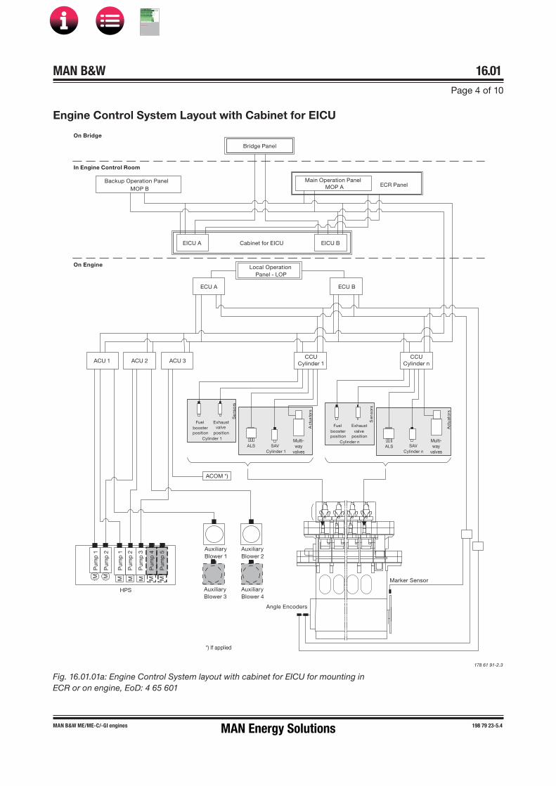
MAN B&W 16.01Page 4 of 10
MAN B&W ME/ME�C/-GI engines 198 79 23-5.4
Act
uato
rs
Se
nso
rs
Act
uat
ors
Sen
sors
On Bridge
In Engine Control Room
On Engine
ECU A
EICU A EICU B
ECU B
Backup Operation PanelMOP B
Bridge Panel
Local OperationPanel - LOP
AuxiliaryBlower 1
AuxiliaryBlower 2
ECR Panel
ACU 1CCU
Cylinder 1CCU
Cylinder nACU 3ACU 2
SAVCylinder n
Main Operation PanelMOP A
Fuelboosterposition
Exhaustvalve
positionCylinder 1
Exhaustvalve
position
Fuelboosterposition
Cylinder n Multi-way
valvesALS SAV
Cylinder 1ALS
Angle Encoders
Marker Sensor
Multi-way
valves
M M
Pum
p 1
M
M
M
M
M
AuxiliaryBlower 3
AuxiliaryBlower 4
Pum
p 2
Pum
p 1
Pum
p 2
Pum
p 3
Pum
p 4
Pum
p 5
Cabinet for EICU
HPS
ACOM *)
*) If applied
Engine Control System Layout with Cabinet for EICU
178 61 91-2.3
Fig. 16.01.01a: Engine Control System layout with cabinet for EICU for mounting in ECR or on engine, EoD: 4 65 601
MAN Energy Solutions
MAN B&W
IMO Tier ll Project Guide
MAN
Energy Solutions Project G
uideM
AN B
&W G
95ME-C
10.5

MAN B&W 16.01Page 5 of 10
MAN B&W ME/ME�C/-GI engines 198 79 23-5.4
Act
uato
rs
Se
nso
rs
Act
uat
ors
Sen
sors
On Bridge
In Engine Control Room
On Engine
ECU A
EICU A EICU B
ECU B
Backup Operation PanelMOP B
Bridge Panel
Local OperationPanel - LOP
AuxiliaryBlower 1
AuxiliaryBlower 2
ECR Panel
ACU 1CCU
Cylinder 1CCU
Cylinder nACU 3ACU 2
SAV
Main Operation PanelMOP A
Fuelboosterposition
Exhaustvalve
position
Exhaustvalve
position
Fuelboosterposition
ALS SAV ALS
Angle Encoders
Marker Sensor
M M
Pum
p 1
M
M
M
M
M
AuxiliaryBlower 3
AuxiliaryBlower 4
ME ECS Common Control Cabinetin Engine Control Room/Engine Room
Pum
p 2
Pum
p 1
Pum
p 2
Pum
p 3
Pum
p 4
Pum
p 5
Cylinder n
Cylinder 1Cylinder n
Cylinder 1
HPS
Multi-way
valves
Multi-way
valves
ACOM *)
*) If applied
Engine Control System Layout with Common Control Cabinet
178 61 76-9.4
Fig. 16.01.01b: Engine Control System layout with ECS Common Control Cabinet for mounting in ECR or on engine, option: 4 65 602
MAN Energy Solutions
MAN B&W
IMO Tier ll Project Guide
MAN
Energy Solutions Project G
uideM
AN B
&W G
95ME-C
10.5

MAN B&W 16.01Page 6 of 10
MAN B&W G/S 50-40 ME�C9.5/8.5-GI 199 09 10-5.0
Mechanical�hydraulic System with Mechanically Driven HPS
Fig. 16.01.02a: Mechanical�hydraulic System with mechanically driven Hydraulic Power Supply, 300 bar, common supply
578 67 56-6.1
M
PT 6104 C
PT 6110 C
XC 6103 C
XC 6101 C
ZT 4111 C
Main filter
ElectricallydrivenST-uppumpsEngine
drivenpumps
Safety andaccumulator block
RWBack-flushing oil
Filter unit
RU
Step-up gear
Main tank
Return to tank
Lubricating and cooling oil pipes
Alarm boxTo AE
Return oilstandpipe
300 barCommon supplyIncl. filter
Return totank
Return totank
SP SP SP
Fuel oil drain
Fuel oil inlet
Fuel pump Exhaust ValveActuator
Exhaust valve
Fuel valves
Fuel injectionplunger
Hydraulic piston
High pressure pipes
Umbrellasealing
Hydraulicpiston
Activationpiston
Fuel oil circulation
X
F
AF
Oil supply to hydraulic 'pushrod' for exhaust valve
PosI
Hydraulic pushrod
Hydraulicpiston
ME lubricator
Mk1
Mk2
ELVA
ELFIwith pilotvalve
Distributor block
To AE
Alarm box
Mini Booster
Sealing oil to gas block
PI
M
M
HPSunit
ZT 4114 C
LS 8285 C
XC 8288 C
ZV 8281 C
ZT 8282 C
ZT 4102 CXC 4107 C
ZV 1202 B
XC 4108 C
ZV 1202 A
LS 4112 AH
ZT 1222-1 CPT 1201-1 C
PT 1201-2 C
PT 1201-3 C
ZT 1222-2 C
XC 1240-2 C
ZT 1222-3 C
XC 1240-3 C
LS 1235 AH
LS 1236 AH Z
XC 1240-1 C
XC 1231 AL
PT
1204
-1 Z
L
PT
1204
-3 Z
L
PT
1204
-2 Z
L
The letters refer to list of ‘Counterflanges’Th item no. refer to ‘Guidance Values Automation’
MAN Energy Solutions
MAN B&W
IMO Tier ll Project Guide
MAN
Energy Solutions Project G
uideM
AN B
&W G
95ME-C
10.5

MAN B&W 16.01Page 7 of 10
MAN B&W G/S 50-40 ME�C9.5/8.5-GI 199 09 10-5.0
Mechanical�hydraulic System with Electrically Driven HPS
This section is available on request
MAN Energy Solutions
MAN B&W
IMO Tier ll Project Guide
MAN
Energy Solutions Project G
uideM
AN B
&W G
95ME-C
10.5

MAN B&W 16.01Page 8 of 10
198 85 31-0.3MAN B&W ME/ME-C/-GI TII engines
To support the navigator, the vessels are equipped with a ship control system, which in-cludes subsystems to supervise and protect the main propulsion engine.
Alarm system
The alarm system has no direct effect on the ECS. The alarm alerts the operator of an abnormal con-dition.
The alarm system is an independent system, in general covering more than the main engine itself, and its task is to monitor the service condition and to activate the alarms if a normal service limit is exceeded.
The signals from the alarm sensors can be used for the slow down function as well as for remote indication.
Slow down system
Some of the signals given by the sensors of the alarm system are used for the ‘Slow down re-quest’ signal to the ECS of the main engine.
Safety system
The engine safety system is an independent sys-tem with its respective sensors on the main en-gine, fulfilling the requirements of the respective classification society and MAN Energy Solutions.
If a critical value is reached for one of the meas-uring points, the input signal from the safety system must cause either a cancellable or a non�cancellable shut down signal to the ECS.
For the safety system, combined shut down and slow down panels approved by MAN Energy Solu- tions are available. The following options are listed in the Extent of Delivery:
4 75 631 Lyngsø Marine
4 75 632 Kongsberg Maritime
4 75 633 Nabtesco
4 75 636 Mitsui Zosen Systems Research.
Where separate shut down and slow down panels are installed, only panels approved by MAN Energy solutions must be used.
In any case, the remote control system and the safety system (shut down and slow down panel) must be compatible.
Telegraph system
This system enables the navigator to transfer the commands of engine speed and direction of rota-tion from the Bridge, the engine control room or the Local Operating Panel (LOP), and it provides signals for speed setting and stop to the ECS.
The engine control room and the LOP are pro-vided with combined telegraph and speed setting units.
Engine Control System Interface to Surrounding Systems
MAN Energy Solutions
MAN B&W
IMO Tier ll Project Guide
MAN
Energy Solutions Project G
uideM
AN B
&W G
95ME-C
10.5

MAN B&W 16.01Page 9 of 10
198 85 31-0.3MAN B&W ME/ME-C/-GI TII engines
Remote Control system
The remote control system normally has two alter-native control stations:
• the bridge control• the engine control room control.
The remote control system is to be delivered by a supplier approved by MAN Energy Solutions.
Bridge control systems from suppliers approved by MAN Energy Solutions are available. The Extent of Delivery lists the following options:
• for Fixed Pitch propeller plants, e.g.:
4 95 703 Lyngsø Marine
4 95 704 Mitsui Zosen Systems Research
4 95 705 Nabtesco
4 95 715 Kongsberg Maritime
• and for Controllable Pitch propeller plants, e.g.:
4 95 701 Lyngsø Marine
4 95 716 Kongsberg Maritime
4 95 719 MAN Alphatronic.
Power Management System
The system handles the supply of electrical power onboard, i. e. the starting and stopping of the gen -erating sets as well as the activation / deactivation of the main engine Shaft Generator (SG), if fitted.
The normal function involves starting, synchro-nising, phasing�in, transfer of electrical load and stopping of the generators based on the electrical load of the grid on board.
The activation / deactivation of the SG is to be done within the engine speed range which fulfils the specified limits of the electrical frequency.
Auxiliary equipment system
The input signals for ‘Auxiliary system ready’ are given partly through the Remote Control system based on the status for:
• fuel oil system• lube oil system• cooling water systems
and partly from the ECS itself:
• turning gear disengaged• main starting valve ‘open’• control air valve for sealing air ‘open’• control air valve for air spring ‘open’• auxiliary blowers running• hydraulic power supply ready.
Monitoring systems
The Engine Control System (ECS) is supported by the Engine Management Services (EMS), which includes the PMI Auto-tuning and the CoCoS�EDS (Computer Controlled Surveillance�Engine Diag-nostics System) applications.
A description of the EMS is found in Chapter 18 of this Project Guide.
Instrumentation
The following lists of instrumentation are included in Chapter 18:
• The Class requirements and MAN Energy Solut- ions' requirements for alarms, slow down and shut down for Unattended Machinery Spaces
• Local instruments• Control devices.
MAN Energy Solutions
MAN B&W
IMO Tier ll Project Guide
MAN
Energy Solutions Project G
uideM
AN B
&W G
95ME-C
10.5

MAN B&W 16.01Page 10 of 10
MAN B&W 50-40ME�C/-GI 199 05 55-8.0
Bur
stin
g ca
p
Sta
rtin
g va
lve
Blo
w-o
ff
Co
ntro
l air
sup
ply
, 7 b
ar
B
Exh
aust
val
ve
Saf
ety
relie
fva
lve
Co
nnec
ted
to
oil
mis
t d
etec
tor
20 L
PT
850
3-A
I C
AH
AL
PT
850
5 I
AL
ZV
112
0-1
C
Turn
ing
gea
r
ZS
111
0-A
I C
ZS
111
6-A
I C
ZS
111
7-A
C
PT
850
3-B
I C
AH
AL
ZS
110
9-A
I C
PI
850
3Lo
cal o
per
atio
n p
anel
Blo
cked
Ser
vice
ZS
111
2-A
I C
ZS
111
1-A
I C
ZS
111
1-B
I C
ZV
112
1-A
C
PI
8501
ZV
111
4 I
C
PT
850
1-B
I A
L
LOP
Co
nnec
ted
to
oil
filte
r
Shu
t d
own
XF
ZV
802
0 Z
Fuel
cut
-off
Ven
ting
Op
enC
lose
d
AS
tart
ing
air
sup
ply
, 30
bar
Onl
y if
GL
PT
850
1-A
I A
L
ZS
111
6-B
I C
ZS
111
7-B
C
ZS
111
2-B
I C
ZV
112
1-A
C
ZV
112
1-B
C
ZS
111
0-B
I C
ZS
110
9-B
I C
ZV
112
0-N
C
Sym
bo
lD
escr
iptio
n
One
per
cyl
ind
er
Pneumatic Manoeuvring Diagram
317 87 08-3.1.0
Fig. 16.01.03: Pneumatic Manoeuvring Diagram
The letters refer to list of ‘Counterflanges’The item no. refer to ‘Guidance Values Automation’N: Refers to numbers of cylinders
MAN Energy Solutions
MAN B&W
IMO Tier ll Project Guide
MAN
Energy Solutions Project G
uideM
AN B
&W G
95ME-C
10.5

MAN B&W 16.02Page 1 of 6
MAN B&W ME-GI engines 198 89 31-2.3
In addition to the ME-ECS core, a special system (GI extension) is installed to control the gas supply and to monitor safety issues when the engine is operating on compressed gaseous fuels, see Fig. 16.02.01. The GI extension is the glue that ties all the dual fuel parts in the internal and the external system together.
As mentioned, the GI extension is designed as an add�on to the standard ME control system. Therefore, the Bridge panel, the main operating panel (MOP) and the local operating panel (LOP) is equipped with a gas-running indication lamp. All operations in gas mode are performed solely from the engine room, while the operation from the bridge is exactly the same whether in gas or fuel oil mode.
Gas control
The gas control system consists of three parts:
• Dual fuel injection control• GI plant control• GI safety control.
Dual fuel injection control is an additional func-tionality added to ECUs and CCUs of the ME-ECS, while gas plant control and safety control are handled by additional units: the SPCU (second fuel plant control unit) and SACU (second fuel auxiliary control unit), respectively SPSU (second fuel plant safety unit) and SCSUs (second fuel cyl-inder safety units).
Dual fuel injection control
The task of the dual fuel injection control is to de-termine the fuel gas index and the pilot oil index when running in the different modes.
GI plant control
The GI plant control has the functions:
Function A – Controls the supply of gas from the fuel gas supply system (FGSS) to the engine in a safe way.
Function B – Closes down the supply of gas to the engine after end of gas operation.
Function A:
• purges the gas pipes and gas volumes for at-mospheric air before gas is allowed
• starts the double-pipe ventilation system and turns on double-pipe leakage detection
• applies gas to the engine in steps and checks for leakage and correct valve function, while the gas pressure builds up
• starts the sealing oil system, when gas enters the cylinder cover.
Function B:
• closes the GVT (gas valve train) block valves• releases the gas pressure• stops the sealing oil system• starts purging the gas pipes and volumes• stops the double-pipe ventilation.
Furthermore, the task of the GI plant control is to handle the changeover between the two stable states:
• Fuel oil mode (HFO only)• Gas mode.
The GI plant control can operate all the fuel gas equipment. For the plant control to operate, it is required that the GI safety control allows it to work, otherwise the safety control will overrule and return to a gas safe condition.
Engine Control System – GI Extension
MAN Energy Solutions
MAN B&W
IMO Tier ll Project Guide
MAN
Energy Solutions Project G
uideM
AN B
&W G
95ME-C
10.5

MAN B&W 16.02Page 2 of 6
MAN B&W ME-GI engines 198 89 31-2.3
GI E
xten
sio
nM
E-E
CS
ALS
ActuatorsS
AVC
ylin
der 1
Mul
ti-w
ayva
lves
Sensors
Fuel
boos
ter
posi
tion
Exha
ust
valv
epo
sitio
n
On
Bri
dg
e
In E
ngin
e C
ont
rol R
oo
m
On
Eng
ine
EC
U A
EIC
U A
EIC
U B EC
U B
Mai
n O
per
atio
n P
anel
MO
P B
Brid
ge P
anel
Loca
l Op
erat
ion
Pan
el -
LO
P
Aux
iliar
yB
low
er 2
Aux
iliar
yB
low
er 1
Aux
iliar
yB
low
er 4
Aux
iliar
yB
low
er 3
EC
R P
anel
AC
U 1
AC
U 3
AC
U 2
Mai
n O
per
atio
n P
anel
MO
P A
Ang
leE
ncod
ers
Mar
ker
Sen
sor
MM
M
MM
Pump 1 M M
Pump 2
Pump 1Pump 2
Pump 3
Pump 5
Cab
inet
for
EIC
U
ELG
IEL
WI
Gas
pre
ssur
eP
urge
val
ves
Blo
w-o
ff va
lves
Res
ume
valv
eC
ylin
der 1
Gas
sup
ply
syst
emG
as re
turn
sys
tem
*)
AC
U
- A
uxili
ary
Con
trol
Uni
tA
LS
- A
lpha
Cyl
ind
er L
ubric
atio
n S
yste
mA
CO
M
- A
utom
ated
Cyl
ind
er O
il M
ixin
gA
CO
S
- A
utom
ated
Con
trol
led
Oil
Sw
itch
CC
U
- C
ylin
der
Con
trol
Uni
tE
CU
-
Eng
ine
Con
trol
Uni
tE
ICU
-
Eng
ine
Inte
rfac
e C
ontr
ol U
nit
ELG
I -
Ele
ctro
nic
Gas
Inje
ctio
nE
LWI
- E
lect
roni
c W
ind
ow v
alve
HP
S
- H
ydra
ulic
Pow
er S
upp
lyLO
P
- Lo
cal O
per
atio
n P
anel
MO
P
- M
ain
Op
erat
ion
Pan
elS
AV
-
Sta
rtin
g A
ir Va
lve
SA
CU
-
Sec
ond
fuel
Aux
iliar
y C
ontr
ol U
nit
SC
SU
-
Sec
ond
fuel
Cyl
ind
er S
afet
y U
nit
SP
CU
-
Sec
ond
fuel
Pla
nt C
ontr
ol U
nit
SP
SU
-
Sec
ond
fuel
Pla
nt S
afet
y U
nit
ME
GI
*) O
ptio
n
**
) If a
pplie
d
Pump 4
SP
CU
SA
CU
Iner
tga
sVe
nt.
air
Sea
ling
oil
SP
SU
Saf
ety
syst
em
Cyl
inde
r 1
HP
S
CC
UC
ylin
der
1
SC
SU
AC
OS
**)
AC
OM
**)
178 53 03�5.4
Fig. 16.02.01: ME�GI Engine Control System
MAN Energy Solutions
MAN B&W
IMO Tier ll Project Guide
MAN
Energy Solutions Project G
uideM
AN B
&W G
95ME-C
10.5

MAN B&W 16.02Page 3 of 6
MAN B&W ME-GI engines 198 89 31-2.3
GI safety control
The task of the safety system is to monitor:
• manual and external automatic gas shut down• engine shut down signal from the engine safety
system• double-pipe ventilation and leakage• sealing oil pressure• gas pressure• combustion pressure within normal values• gas injection valve and window valve leakage.
If one of the above mentioned failures is detected, the gas safety control releases the fuel gas shut down sequence:
The GVT, main gas valve and window valve will close. The electronic gas injection (ELGI) valves will be disabled. The fuel gas will be blown out by opening the gas bleed valve, the blow-off valves and purge valves, and finally the gas pipe system will be purged with inert gas. See Fig. 7.00.01.
Safety principles of the dual fuel control sys-tem
Gas mode running is not essential for the ma-noeuvrability of the ship, as the engine will contin-ue to run on fuel oil if an unintended fuel gas stop occurs. The two fundamental safety principles of the fuel gas equipment are, in order of priority:
• Safety to personnel must be at least on thesame level as for a conventional diesel engine
• A fault in the dual fuel equipment must cause stopof fuel gas operation and change over to fuel oilmode
which to some extent complement each other.
The dual fuel control system is designed to ‘fail to safe condition’. All failures detected during fuel gas running and failures of the control system it-self will result in a fuel gas stop or shut down and change over to fuel oil operation.
Subsequently, the control system initiates blow out and purging of high pressure fuel gas pipes which releases all gas from the entire gas supply system of the engine room.
If the failure relates to the purging system, it may be necessary to carry out purging manually be-fore engine repair is carried out.
The dual fuel control system itself is in general a single system without redundancy or manual back�up control.
Control Unit Hardware
For the GI extension, two different types of hard-ware are used: the MPC (multi purpose controller) and the DASU (data acquisition and safety Unit), both developed by MAN Energy Solutions.
The MPC is used for the following units: SPCU, SACU, SPSU, EICU (Engine Interface Control Unit) as well as the ECU (Engine Control Unit), ACU (Auxiliary Control Unit) and CCU (Cylinder Control Unit). The DASU is used for the SCSUs. A func-tional description of the units is given in the fol-lowing, see also the diagram in Fig. 16.02.01.
Main Operating Panel
The MOP is common to both the ME-ECS core and the GI extension. All the manual operations can be initiated from the MOP.
The MOP functions include the facilities to manu-ally start up or to stop fuel gas operation.
Additionally, the change between the different running modes can be done and the operator has the possibility to manually initiate purging of the gas piping with inert gas.
MAN Energy Solutions
MAN B&W
IMO Tier ll Project Guide
MAN
Energy Solutions Project G
uideM
AN B
&W G
95ME-C
10.5

MAN B&W 16.02Page 4 of 6
MAN B&W ME-GI engines 198 89 31-2.3
Dual fuel function of the ECU and CCU
The dual fuel injection control is part of the ECU which includes all facilities required for calculat-ing the fuel gas injection and the pilot oil injection based on the command from the ME governor function and the actual active mode.
Based on these data and information about the fuel gas pressure, the dual fuel injection control calculates the start and duration time of the in-jection, then sends the signal to the CCU which effectuates the injection by controlling both the electronic fuel injection valve (ELFI) (or the fuel injection valve actuation (FIVA) if applied) and the ELGI valve.
Second fuel Plant (SPCU) and Second fuel Auxiliary Control Unit (SACU)
When ‘Dual Fuel Mode Start’ is initiated manually by the operator, the SPCU will start the automatic start sequence.
The SPCU and SACU contain functionalities nec-essary to control and monitor auxiliary systems.
The SPCU and SACU controls:
• start/stop of pumps, fans, and of the gas supplysystem
• sealing oil pressure set points• pressure set points for the gas supply system• the purging with inert gas• the ACOS, if applied.
The SPCU monitors the condition of the following:
• gas supply system• sealing oil system• double-pipe ventilation• inert gas system
and, if a failure does occur, the SPCU will auto-matically interrupt gas mode start operation and return the plant to fuel oil mode.
Second fuel Plant Safety Unit (SPSU)
The central SPSU performs safety monitoring of the fuel gas system and controls the fuel gas shut down.
The SPSU monitors the following:
• gas leakage to the outer pipe of the double pipe• pipe ventilation of the double-wall piping• sealing oil pressure• fuel gas pressure• SCSU ready signal.
If one of the above parameters (referring to the relevant fuel gas state) differs from normal service value, the SPSU overrules any other signals and gas shut down will be released.
After the cause of the gas shut down has been corrected, the fuel gas operation can be manually restarted.
The SPCU main state diagram is shown in Fig. 16.02.02.
Purging Blow Off
GasRunning
Gas onEngine
PrepareGas
Supply
Gas TrainTest
Preparefor Gas
GasStandbyPurged
Notpurged
MS_2 MS_1 MS_7
MS_10 MS_9
MS_8
MS_6
MS_3 MS_4 MS_5
Gas Shut Down / Gas Stop
178 65 92-6.0
Fig. 16.02.02: SPCU main state diagram
MAN Energy Solutions
MAN B&W
IMO Tier ll Project Guide
MAN
Energy Solutions Project G
uideM
AN B
&W G
95ME-C
10.5

MAN B&W 16.02Page 5 of 6
MAN B&W ME-GI engines 198 89 31-2.3
Second fuel Cylinder Safety Unit (SCSU)
The purpose of SCSU is to monitor if the cylinders are ready for the injection of fuel gas.
The following events are monitored by the SCSU:
• Gas pressure variations in gas block- gas injection valve leakage and malfunction- window valve leakage and malfunction- blow-off valve leakage- resume valve leakage and malfunction (if pre- sent)- sensor supervision
• Cylinder pressure- low compression pressure- too high maximum pressure- low expansion pressure/misfiring- too fast combustion pressure increase
• Fuel gas accumulator pressure drop during in-jection.
If one of the parameters is abnormal, the ELWI valve is closed and a shut down of fuel gas run-ning is activated by the SPSU.
MAN Energy Solutions
MAN B&W
IMO Tier ll Project Guide
MAN
Energy Solutions Project G
uideM
AN B
&W G
95ME-C
10.5

MAN B&W 16.02Page 6 of 6
MAN B&W ME-GI engines 198 86 58-1.3
EC
SB
rid
ge
Iner
t G
asP
urg
ing
Sys
tem
Ala
rm S
yste
mL
oca
lO
per
atin
gP
anel
Ext
ern
al T
o
Mac
hin
ery
Sp
ace
Do
ub
le P
ipe
Lea
kag
e D
etec
tio
n &
Ven
tila
tio
nE
CR
Pan
elS
afet
yS
yste
m
Ret
urn
Pip
e Te
stV
alve
Sec
on
d F
uel
Val
ve T
rain
Sec
on
d F
uel
Su
pp
ly S
yste
m
XT6332-B
Power FailureSF Common Alarm
SF InjectionEngine Control
SystemGI-ECS
SPSU - Second Fuel Plant Safety Unit
SPCU - Second Fuel Plant Control UnitSACU - Second Fuel Auxillary Control Unit
SCSU - Second Fuel Cylinder Safety Unit
ECR - Engine Control RoomHC Sensor - Hydro Carbon Sensor
ECS - Engine Control System
# ~ Cylinder number
SP
SU
SP
CU
SA
CU
1S
PS
U
EIC
U A
/B
DP Ventilation 2 Ready / Local-FailDP Ventilation 2 Run / Stop
DP Ventilation 2 Running
SF
Ret
urn
Sys
tem
(Op
tio
nal
)
SF Return System Ready
Plant: SF Return Valve Open Sw
Plant: SF Return Valve Close Sw
P: SF Return Tank Valve Ctrl
P: SF Return Bleed Valve Open Sw
P: SF Return Bleed Valve Close Sw
S: SF Return & Bleed Valve Ctrl
S: SF Return Bleed Valve Open Sw
S: SF Return Bleed Valve Close Sw
Om
itte
d if
Gas
Ret
urn
Sys
tem
Pre
sen
t
XC6312BXC6313BXC6301B
XT6332-A
XC6312
XC6301
XC6313
FS6302
FS6303
ZV6307
FS6305
XC6365
XC2001
XC6360
XC6053
XC6050
ZS6051
ZS6052
ZS6065
ZS6066
XC6060
XC6061
XC6062
XC6375A
ZS6376
ZS6377
PT6025
XC6018ZS6010
ZS6011
XC6014
ZS6015
ZS6016
XC6035XC6019
ZS6012
ZS6013
PT6006
PT6024
PT6017
XC6306
XC6001
XC6002
XC6005
XC6030
XT6332-B
XC2405
XT6331-B
XT6331-A
PT6321
ZS6023ZS6022
ZS6317
ZS6316
ZS6021
ZS6020XC6320
XC6362
XC6372
XC2213
XC2212-3
XC2212-2
XC2212-1
XC2222AXC2211A
XC6370
XC6361C
XC6371
Restriction ValveSF Flow Restriction Valve CloseXC6035
SF TemperatureTT6029
SF Valve Train Filter Diff. PressurePDC6308
SF Supply RunningXC6003Actual SF LoadXC6028
SF Load LimitXC6070
SF Flow (Optional)XC6008
Power Failure XC2211BSF Common Alarm XC2222B
SF SD Ext Machinery Space
DF Mode for Bridge indication
SF Shutdown bridge
External SF Shutdown Req. 1
External SF Shutdown Req. 2
IAS SF Shutdown Req.
Double Pipe HC Alarm
SF Shutdown LOP
DF Mode for LOP indication
Inert Gas Supply & Block Valve Open
Inert Gas Supply Valve Opened
Inert Gas Supply Valve Closed
Inert Gas Bleed Valve Opened
Inert Gas Bleed Valve Closed
Inert Gas Block Valve Opened
Inert Gas Block Valve Closed
Inert Gas Pressure
Return Pipe HC Sensor A
Return Pipe HC Sensor B
Network ANetwork B
Double Pipe HC Sensor B
Double Pipe HC Sensor A
Run / Stop
Running
Ready / Local-Fail
Plant: Flow Switch
Safety: Flow Switch
Dry Air Supply Control
Dry Air Flow Switch
SF Shutdown ECR
Engine Shutdown
SF ELWI Enable
SF Return Pipe Test Valve Open Sw
SF Return Pipe Test Valve Close Sw
SF Return Pipe Test Valve Close
Valve Control Air Pressure
Safety: SF Main Valve Open
Safety: SF Main Valve Opened
Safety: SF Main Valve Closed
Plant: SF Main Valve Open
Plant: SF Main Valve Opened
Plant: SF Main Valve Closed
Plant: SF Main Valve Slow Open
SF Supply Run / Stop
SF Supply Ready / Local-Fail
SF Bleed Valve Close
SF Bleed Valve ClosedSF Bleed Valve Opened
SF Inlet Pressure
SF Train Pressure
SF Supply Pressure
SF Valve Train Power Failure
SF Supply Pressure Set Point
SF Standby Request
SF Shutdown Output (Optional)
SF Flow (Optional)
Engine Load (Optional)Control
Monitoring
Monitoring
Control
SF PressureMeasurements
SF BleedValve
Plant:SF MainValve
Safety:SF MainValve
DPVent. 1Control
DPVent. 2Control
InertGasValves
SA
CU
1S
CS
U1
GI Extension Interface to External Systems
Fig. 16.02.03: Interface to external systems with basic information of flow in and between external systems
Further to the alarm sensors, local instruments and control devices listed in Section 18.04-06,
the GI extension interface to external systems is shown in Fig. 16.02.03.
309 23 84-2.2.1
MAN Energy Solutions
MAN B&W
IMO Tier ll Project Guide
MAN
Energy Solutions Project G
uideM
AN B
&W G
95ME-C
10.5

MAN B&W
Vibration Aspects
17MAN Energy Solutions
MAN B&W
IMO Tier ll Project Guide
MAN
Energy Solutions Project G
uideM
AN B
&W G
95ME-C
10.5
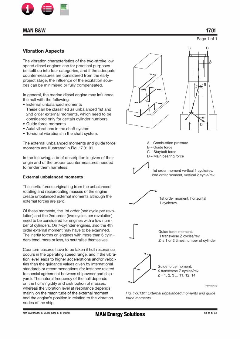
MAN B&W 17.01Page 1 of 1
198 41 40-5.3MAN B&W MC/MC-C, ME/ME-C/ME-B/-GI engines
Vibration Aspects
The vibration characteristics of the two�stroke low speed diesel engines can for practical purposes be split up into four categories, and if the adequate countermeasures are considered from the early project stage, the influence of the excitation sour-ces can be minimised or fully compensated.
In general, the marine diesel engine may influence the hull with the following:• External unbalanced moments
These can be classified as unbalanced 1st and2nd order external moments, which need to beconsidered only for certain cylinder numbers
• Guide force moments• Axial vibrations in the shaft system• Torsional vibrations in the shaft system.
The external unbalanced moments and guide force moments are illustrated in Fig. 17.01.01.
In the following, a brief description is given of their origin and of the proper countermeasures needed to render them harmless.
External unbalanced moments
The inertia forces originating from the unbalanced rotating and reciprocating masses of the engine create unbalanced external moments although the external forces are zero.
Of these moments, the 1st order (one cycle per revo-lution) and the 2nd order (two cycles per revolution) need to be considered for engines with a low num-ber of cylinders. On 7�cylinder engines, also the 4th order external moment may have to be examined. The inertia forces on engines with more than 6 cylin -ders tend, more or less, to neutralise themselves.
Countermeasures have to be taken if hull resonance occurs in the operating speed range, and if the vibra-tion level leads to higher accelerations and/or velo ci-ties than the guidance values given by international standards or recommendations (for instance related to special agreement between shipowner and ship -yard). The natural frequency of the hull depends on the hull’s rigidity and distribution of masses, whereas the vibration level at resonance depends mainly on the magnitude of the external moment and the engine’s position in relation to the vibration nodes of the ship.
C C
A
B
D
A – Combustion pressureB – Guide forceC – Staybolt forceD – Main bearing force
1st order moment vertical 1 cycle/rev.2nd order moment, vertical 2 cycle/rev.
1st order moment, horizontal 1 cycle/rev.
Guide force moment,H transverse Z cycles/rev.Z is 1 or 2 times number of cylinder
Fig. 17.01.01: External unbalanced moments and guide force moments
Guide force moment,X transverse Z cycles/rev.Z = 1, 2, 3 ... 11, 12, 14
178 06 82�8.2
MAN Energy SolutionsMAN Energy Solutions
MAN B&W
IMO Tier ll Project Guide
MAN
Energy Solutions Project G
uideM
AN B
&W G
95ME-C
10.5

MAN B&W 17.02Page 1 of 3
MAN B&W 50-30 engines Mk. 9,S50ME-C8/-GI/-LGI
198 68 84-5.6
2nd Order Moments on 4, 5 and 6-cylinder Engines
The 2nd order moment acts only in the vertical direction. Precautions need only to be considered for 4, 5 and 6-cylinder engines in general.
Resonance with the 2nd order moment may oc-cur in the event of hull vibrations with more than 3 nodes. Contrary to the calculation of natural frequency with 2 and 3 nodes, the calculation of the 4 and 5-node natural frequencies for the hull is a rather comprehensive procedure and often not very accurate, despite advanced calculation methods.
Compensator solutions
On engines where engine-driven moment com-pensators cannot be installed aft nor fore, two so-lutions remain to cope with the 2nd order moment as shown in Fig. 17.03.02:
1) No compensators, if considered unnecessaryon the basis of natural frequency, nodal pointand size of the 2nd order moment.
2) An electrically driven moment compensatorplaced in the steering gear room, as explainedin Section 17.03, option: 4 31 253 or 255.
Briefly speaking, solution 1) is applicable if the node is located far from the engine, or the engine is positioned more or less between nodes. Due to its position in the steering gear room, solution 2) is not particularly sensitive to the position of the node.
Determine the need
A decision regarding the vibrational aspects and the possible use of compensators should prefer-ably be taken at the contract stage. If no experi-ence is available from sister ships, which would be the best basis for deciding whether compensa-tors are necessary or not, it is advisable to make calculations to determine this.
If the compensator is initially omitted, measure-ments taken during the sea trial, or later in service and with fully loaded ship, will be able to show if a compensator has to be fitted at all.
Preparation for compensators
If no calculations are available at the contract stage, we advise to make preparations for the fit-ting of an electrically driven moment compensator in the steering compartment, see Section 17.03.
Natural frequencycycles/min.
4 node
3 node
2 node
20,000 40,000 60,000
dwt
80,000
5 node
Cycles/min. *)
*) Frequency of engine moment M2V = 2 x engine speed
S50ME-C/ME-B8
150
100
50
200
250
300
S50ME-B9
S40ME-B9
Fig. 17.02.01: Statistics of vertical hull vibrations, an ex-ample from tankers and bulk carriers
178 61 16-0.1
MAN Energy SolutionsMAN Energy Solutions
MAN B&W
IMO Tier ll Project Guide
MAN
Energy Solutions Project G
uideM
AN B
&W G
95ME-C
10.5
MAN B&W 17.02Page 2 of 3
198 68 84-5.6MAN B&W 50-30 engines Mk. 9,S50ME-C8/-GI/-LGI
Basic design regarding compensators
Experience with our two-stroke slow speed en-gines has shown that propulsion plants with small bore engines (engines smaller than 45 types) are less sensitive regarding hull vibrations exited by 2nd order moments than the larger bore engines. Therefore, engines type 40-30 do not have 2nd order moment compensators specified as stan-dard.
For 5 and 6-cylinder engines type 50-45, the ba-sic design regarding 2nd order moment compen-sators is:
• With MAN B&W external electrically driven mo-ment compensator, RotComp, EoD: 4 31 255
The available options for 5 and 6-cylinder engines are listed in the Extent of Delivery. For 4-cylinder engines, the information is available on request.
MAN Energy SolutionsMAN Energy Solutions
MAN B&W
IMO Tier ll Project Guide
MAN
Energy Solutions Project G
uideM
AN B
&W G
95ME-C
10.5

MAN B&W 17.02Page 3 of 3
198 39 25-0.5MAN B&W 70-26 engines
178 16 78�7.0
1st order moments act in both vertical and hori-zontal direction. For our two�stroke engines with standard balancing these are of the same magni-tudes.
For engines with five cylinders or more, the 1st order moment is rarely of any significance to the ship. It can, however, be of a disturbing magnitude in four�cylinder engines.
Resonance with a 1st order moment may occur for hull vibrations with 2 and/or 3 nodes. This resonance can be calculated with reasonable ac-curacy, and the calculation will show whether a compensator is necessary or not on four�cylinder engines.
A resonance with the vertical moment for the 2 node hull vibration can often be critical, whereas the resonance with the horizontal moment occurs at a higher speed than the nominal because of the higher natural frequency of horizontal hull vibra-tions.
Balancing 1st order moments
As standard, four�cylinder engines are fitted with 1st order moment balancers in shape of adjust-able counterweights, as illustrated in Fig. 17.02.02. These can reduce the vertical moment to an insig-nificant value (although, increasing correspond-ingly the horizontal moment), so this resonance is easily dealt with. A solution with zero horizontal moment is also available.
1st order moment compensators
In rare cases, where the 1st order moment will cause resonance with both the vertical and the horizontal hull vibration mode in the normal speed range of the engine, a 1st order compensator can be introduced as an option, reducing the 1st order moment to a harmless value.
Adjustablecounterweights
Aft
Fore
Adjustablecounterweights
Fixedcounterweights
Fixedcounterweights
Fig. 17.02.02: Examples of counterweights
Since resonance with both the vertical and the horizontal hull vibration mode is rare, the standard engine is not prepared for the fitting of 1st order moment compensators.
Data on 1st order moment compensators and preparation as well as options in the Extent of De-livery are available on request.
1st Order Moments on 4�cylinder Engines
MAN Energy SolutionsMAN Energy Solutions
MAN B&W
IMO Tier ll Project Guide
MAN
Energy Solutions Project G
uideM
AN B
&W G
95ME-C
10.5

MAN B&W 17.03Page 1 of 2
198 69 78-1.2MAN B&W S50ME-C7/8/-GI, 50-30ME-B9/-GI, 40-30MC-C9
178 57 45-6.0
Fig. 17.03.01: MAN B&W external electrically driven moment compensator, RotComp, option: 4 31 255
If annoying 2nd order vibrations should occur: An external electrically driven moment compensator can neutralise the excitation, synchronised to the correct phase relative to the external force or mo-ment.
This type of compensator needs an extra seating fitted, preferably, in the steering gear room where vibratory deflections are largest and the effect of the compensator will therefore be greatest.
The electrically driven compensator will not give rise to distorting stresses in the hull and it offers several advantages over the engine mounted solu-tions:
• When placed in the steering gear room, thecompensator is not particularly sensitive to thepositioning of the node.
• The decision whether or not to install compen-sators can be taken at a much later stage of aproject, since no special version of the enginestructure has to be ordered for the installation.
• Compensators could be retrofit, even on shipsin service, and also be applied to engines with ahigher number of cylinders than is normally con-sidered relevant, if found necessary.
• The compensator only needs to be active atspeeds critical for the hull girder vibration. Thus,it may be activated or deactivated at specifiedspeeds automatically or manually.
• Combinations with and without moment com-pensators are not required in torsional and axialvibration calculations, since the electricallydriven moment compensator is not part of themass-elastic system of the crankshaft.
Furthermore, by using the compensator as a vi-bration exciter a ship’s vibration pattern can easily be identified without having the engine running, e.g. on newbuildings at an advanced stage of construction. If it is verified that a ship does not need the compensator, it can be removed and re-used on another ship.
It is a condition for the application of the rotating force moment compensator that no annoying lon-gitudinal hull girder vibration modes are excited. Based on our present knowledge, and confirmed by actual vibration measurements onboard a ship, we do not expect such problems.
Balancing other forces and moments
Further to compensating 2nd order moments, electrically driven balancers are also available for balancing other forces and moments. The avail-able options are listed in the Extent of Delivery.
Electrically Driven Moment Compensator
MAN Energy Solutions
MAN B&W
IMO Tier ll Project Guide
MAN
Energy Solutions Project G
uideM
AN B
&W G
95ME-C
10.5

MAN B&W 17.03Page 2 of 2
198 69 78-1.2MAN B&W S50ME-C7/8/-GI, 50-30ME-B9/-GI, 40-30MC-C9
Fig. 17.03.02: Compensation of 2nd order vertical external moments
178 61 15-9.1
4 Node
3 Node
3 and 4�node vertical hull girder mode
Electrically driven moment compensator
Compensating momentFD × Lnodeoutbalances M2V
M2V
Node Aft
LD node
FD
Nodes and Compensators
MAN Energy Solutions
MAN B&W
IMO Tier ll Project Guide
MAN
Energy Solutions Project G
uideM
AN B
&W G
95ME-C
10.5
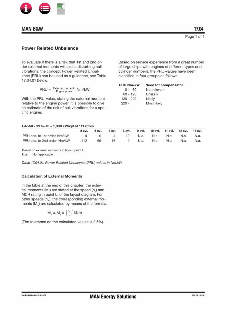
MAN B&W 17.04Page 1 of 1
MAN B&W G45ME-C9.5/-GI 199 01 16-2.0
Power Related Unbalance
To evaluate if there is a risk that 1st and 2nd or-der external moments will excite disturbing hull vibrations, the concept Power Related Unbal-ance (PRU) can be used as a guidance, see Table 17.04.01 below.
PRU = External moment ___________ Engine power Nm/kW
With the PRU�value, stating the external moment relative to the engine power, it is possible to give an estimate of the risk of hull vibrations for a spe-cific engine.
Based on service experience from a great number of large ships with engines of different types and cylinder numbers, the PRU�values have been classified in four groups as follows:
Table 17.04.01: Power Related Unbalance (PRU) values in Nm/kW
Calculation of External Moments
In the table at the end of this chapter, the exter-nal moments (M1) are stated at the speed (n1) and MCR rating in point L1 of the layout diagram. For other speeds (nA), the corresponding external mo-ments (MA) are calculated by means of the formula:
MA = M1 x { nA __ n1 }2 kNm
(The tolerance on the calculated values is 2.5%).
PRU Nm/kW Need for compensator0 - 60 Not relevant
60 - 120 Unlikely120 - 220 Likely220 - Most likely
G45ME-C9.5/-GI – 1,390 kW/cyl at 111 r/min5 cyl. 6 cyl. 7 cyl. 8 cyl. 9 cyl. 10 cyl. 11 cyl. 12 cyl. 14 cyl.
PRU acc. to 1st order, Nm/kW 9 0 4 12 N.a. N.a. N.a. N.a. N.a.PRU acc. to 2nd order, Nm/kW 112 65 16 0 N.a. N.a. N.a. N.a. N.a.
Based on external moments in layout point L1
N.a. Not applicable
MAN Energy Solutions
MAN B&W
IMO Tier ll Project Guide
MAN
Energy Solutions Project G
uideM
AN B
&W G
95ME-C
10.5
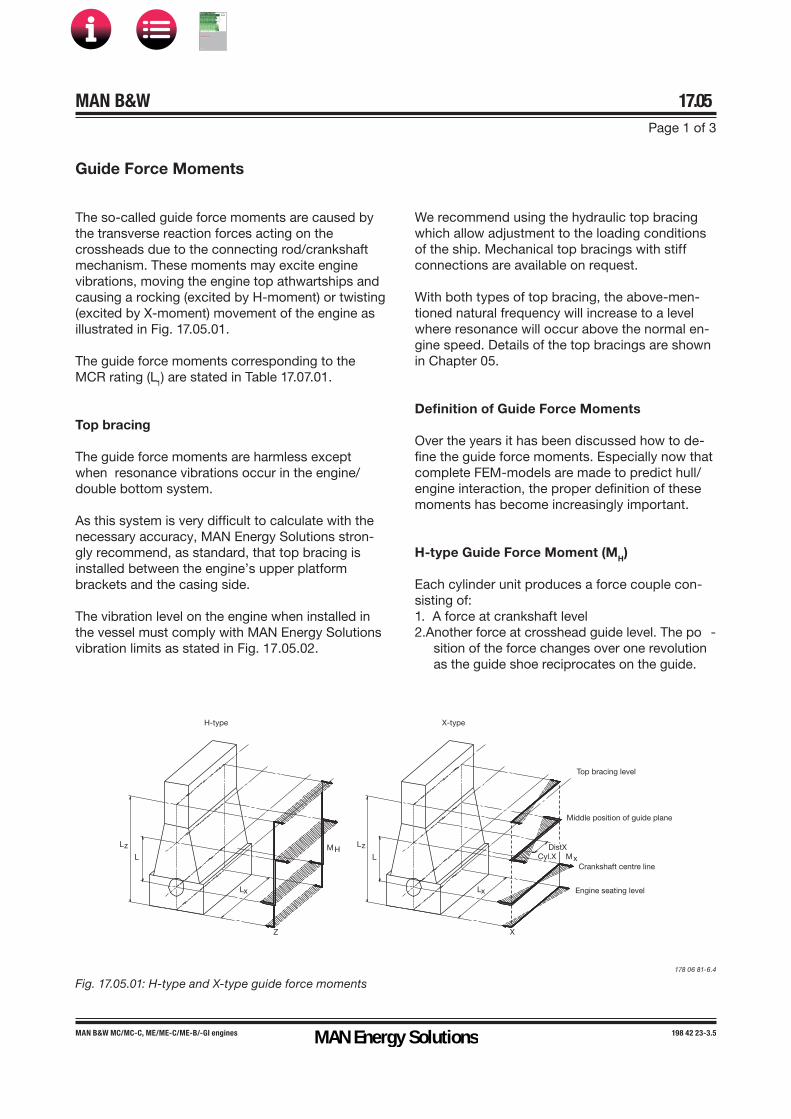
MAN B&W 17.05Page 1 of 3
MAN B&W MC/MC�C, ME/ME�C/ME-B/�GI engines 198 42 23�3.5
Top bracing level
Middle position of guide plane
Crankshaft centre line
Engine seating level
MxDistX
Cyl.X
X
Lx
L
Lz
X�typeH�type
Lx
L
Z
MHLz
178 06 81�6.4
Fig. 17.05.01: H�type and X�type guide force moments
Guide Force Moments
The so�called guide force moments are caused by the transverse reaction forces acting on the crossheads due to the connecting rod/crankshaft mechanism. These moments may excite engine vibrations, moving the engine top athwartships and causing a rocking (excited by H�moment) or twisting (excited by X�moment) movement of the engine as illustrated in Fig. 17.05.01.
The guide force moments corresponding to the MCR rating (L1) are stated in Table 17.07.01.
Top bracing
The guide force moments are harmless except when resonance vibrations occur in the engine/double bottom system.
As this system is very difficult to calculate with the necessary accuracy, MAN Energy Solutions stron-gly recommend, as standard, that top bracing is installed between the engine’s upper platform brackets and the casing side.
The vibration level on the engine when installed in the vessel must comply with MAN Energy Solutions vibration limits as stated in Fig. 17.05.02.
We recommend using the hydraulic top bracing which allow adjustment to the loading conditions of the ship. Mechanical top bracings with stiff connections are available on request.
With both types of top bracing, the above-men-tioned natural frequency will increase to a level where resonance will occur above the normal en-gine speed. Details of the top bracings are shown in Chapter 05.
Definition of Guide Force Moments
Over the years it has been discussed how to de-fine the guide force moments. Especially now that complete FEM�models are made to predict hull/engine interaction, the proper definition of these moments has become increasingly important.
H�type Guide Force Moment (MH)
Each cylinder unit produces a force couple con-sisting of:1. A force at crankshaft level2.Another force at crosshead guide level. The po -
sition of the force changes over one revolutionas the guide shoe reciprocates on the guide.
MAN Energy Solutions
MAN B&W
IMO Tier ll Project Guide
MAN
Energy Solutions Project G
uideM
AN B
&W G
95ME-C
10.5
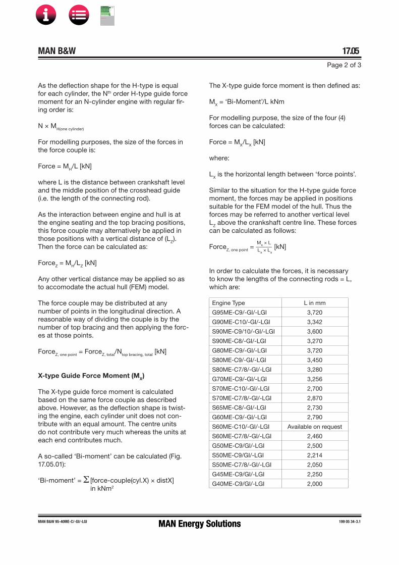
MAN B&W 17.05Page 2 of 3
MAN B&W 95-40ME-C/-GI/-LGI 199 05 34-3.1
As the deflection shape for the Htype is equal for each cylinder, the Nth order Htype guide force moment for an Ncylinder engine with regular fir-ing order is:
N × MH(one cylinder)
For modelling purposes, the size of the forces in the force couple is:
Force = MH/L [kN]
where L is the distance between crankshaft level and the middle position of the crosshead guide (i.e. the length of the connecting rod).
As the interaction between engine and hull is at the engine seating and the top bracing positions, this force couple may alternatively be applied in those positions with a vertical distance of (LZ). Then the force can be calculated as:
ForceZ = MH/LZ [kN]
Any other vertical distance may be applied so as to accomodate the actual hull (FEM) model.
The force couple may be distributed at any number of points in the longitudinal direction. A reasonable way of dividing the couple is by the number of top bracing and then applying the forc-es at those points.
ForceZ, one point = ForceZ, total/Ntop bracing, total [kN]
X�type Guide Force Moment (MX)
The Xtype guide force moment is calculated based on the same force couple as described above. However, as the deflection shape is twist-ing the engine, each cylinder unit does not con-tribute with an equal amount. The centre units do not contribute very much whereas the units at each end contributes much.
A socalled ‘Bimoment’ can be calculated (Fig. 17.05.01):
‘Bimoment’ = Σ [forcecouple(cyl.X) × distX]in kNm2
The Xtype guide force moment is then defined as:
MX = ‘BiMoment’/L kNm
For modelling purpose, the size of the four (4) forces can be calculated:
Force = MX/LX [kN]
where:
LX is the horizontal length between ‘force points’.
Similar to the situation for the Htype guide force moment, the forces may be applied in positions suitable for the FEM model of the hull. Thus the forces may be referred to another vertical level LZ above the crankshaft centre line. These forces can be calculated as follows:
ForceZ, one point = Mx × L_____ Lx × Lx
[kN]
In order to calculate the forces, it is necessary to know the lengths of the connecting rods = L, which are:
Engine Type L in mm
G95MEC9/-GI/-LGI 3,720
G90MEC10/-GI/-LGI 3,342
S90MEC9/10/-GI/-LGI 3,600
S90MEC8/-GI/-LGI 3,270
G80ME-C9/-GI/-LGI 3,720
S80MEC9/-GI/-LGI 3,450
S80MEC7/8/-GI/-LGI 3,280
G70ME-C9/-GI/-LGI 3,256
S70ME-C10/-GI/-LGI 2,700
S70ME-C7/8/-GI/-LGI 2,870
S65MEC8/-GI/-LGI 2,730
G60ME-C9/-GI/-LGI 2,790
S60MEC10/-GI/-LGI Available on request
S60MEC7/8/-GI/-LGI 2,460
G50ME-C9/GI/-LGI 2,500
S50ME-C9/GI/-LGI 2,214
S50MEC7/8/-GI/-LGI 2,050
G45ME-C9/GI/-LGI 2,250
G40ME-C9/GI/-LGI 2,000
MAN Energy SolutionsMAN Energy Solutions
MAN B&W
IMO Tier ll Project Guide
MAN
Energy Solutions Project G
uideM
AN B
&W G
95ME-C
10.5

MAN B&W 17.05Page 3 of 3
MAN B&W MC/MC�C, ME/ME�C/ME-B/�GI engines 198 82 64-9.0
ΙΙΙ
ΙΙ
Ι
5x10 �1 mm/s
1 mm/s
10 mm/s
10 2 mm/s
5x10 2 mm/s
60 100 1.000 6.000 c/min
10 �3 m
m
10 �2 m
m
10 �1 m
m
10 5 mm
/s 2
10 4 mm
/s 2
10 3 mm
/s 2
Displac
emen
t
Acceleration
10 mm
/s 2
10 2 mm
/s 2
1 m
m10
mm
Velocity
±2mm
±50mm/s
±10m/s 2
±1m
m
±25mm/s
1 Hz 10 Hz 100 HzFrequency
Zone Ι: AcceptableZone ΙΙ: Vibration will not damage the main engine, however,
under adverse conditions, annoying/harmful vibrationresponses may appear in the connected structures
Zone ΙΙΙ: Not acceptable
078 81 27-6.1
Fig.17.05.02: Vibration limits
Vibration Limits Valid for Single Order Harmonics
MAN Energy SolutionsMAN Energy Solutions
MAN B&W
IMO Tier ll Project Guide
MAN
Energy Solutions Project G
uideM
AN B
&W G
95ME-C
10.5

MAN B&W 17.06Page 1 of 3
198 42 24-5.5MAN B&W engines
When the crank throw is loaded by the gas pressure through the connecting rod mechanism, the arms of the crank throw deflect in the axial direction of the crankshaft, exciting axial vibrations. Through the thrust bearing, the system is connected to the ship’s hull.
Generally, only zero�node axial vibrations are of interest. Thus the effect of the additional bending stresses in the crankshaft and possible vibrations of the ship`s structure due to the reaction force in the thrust bearing are to be consideraed.
An axial damper is fitted as standard on all engines, min-imising the effects of the axial vibrations, EoD: 4 31 111.
Torsional Vibrations
The reciprocating and rotating masses of the engine including the crankshaft, the thrust shaft, the inter-mediate shaft(s), the propeller shaft and the propeller are for calculation purposes considered a system of rotating masses (inertias) interconnected by torsional springs. The gas pressure of the engine acts through the connecting rod mechanism with a varying torque on each crank throw, exciting torsional vibration in the system with different frequencies.
In general, only torsional vibrations with one and two nodes need to be considered. The main critical order, causing the largest extra stresses in the shaft line, is normally the vibration with order equal to the number of cylinders, i.e., six cycles per revolution on a six cylinder engine. This resonance is positioned at the engine speed corresponding to the natural tor-sional frequency divided by the number of cylinders.
The torsional vibration conditions may, for certain installations require a torsional vibration damper, op-tion: 4 31 105.
Plants with 11 or 12-cylinder engines type 98-80 re-quire a torsional vibration damper.
Based on our statistics, this need may arise for the following types of installation:• Plants with controllable pitch propeller• Plants with unusual shafting layout and for special
owner/yard requirements• Plants with 8�cylinder engines.
The so�called QPT (Quick Passage of a barred speed range Technique), is an alternative to a torsional vibration damper, on a plant equipped with a control-lable pitch propeller. The QPT could be implemented in the governor in order to limit the vibratory stresses during the passage of the barred speed range.
The application of the QPT, option: 4 31 108, has to be decided by the engine maker and MAN Energy Solutions based on final torsional vibration calculations.
Six�cylinder engines, require special attention. On account of the heavy excitation, the natural frequen-cy of the system with one-node vibration should be situated away from the normal operating speed range, to avoid its effect. This can be achieved by changing the masses and/or the stiffness of the system so as to give a much higher, or much lower, natural frequency, called undercritical or overcritical running, respectively.
Owing to the very large variety of possible shafting arrangements that may be used in combination with a specific engine, only detailed torsional vibration cal-culations of the specific plant can determine whether or not a torsional vibration damper is necessary.
Undercritical running
The natural frequency of the one-node vibration is so adjusted that resonance with the main critical order occurs about 35�45% above the engine speed at specified MCR.
Such undercritical conditions can be realised by choosing a rigid shaft system, leading to a relatively high natural frequency.
The characteristics of an undercritical system are normally:• Relatively short shafting system• Probably no tuning wheel• Turning wheel with relatively low inertia• Large diameters of shafting, enabling the use of
shafting material with a moderate ultimate tensilestrength, but requiring careful shaft alignment,(due to relatively high bending stiffness)
• Without barred speed range.
Axial Vibrations
MAN Energy SolutionsMAN Energy Solutions
MAN B&W
IMO Tier ll Project Guide
MAN
Energy Solutions Project G
uideM
AN B
&W G
95ME-C
10.5

MAN B&W 17.06Page 2 of 3
198 42 26-9.6MAN B&W engines
When running undercritical, significant varying torque at MCR conditions of about 100�150% of the mean torque is to be expected.
This torque (propeller torsional amplitude) induces a significant varying propeller thrust which, under adverse conditions, might excite annoying longi-tudinal vibrations on engine/double bottom and/or deck house.
The yard should be aware of this and ensure that the complete aft body structure of the ship, in-cluding the double bottom in the engine room, is designed to be able to cope with the described phenomena.
Overcritical running
The natural frequency of the one node vibration is so adjusted that resonance with the main criti-cal order occurs at about 30-60% of the engine speed at specified MCR. Such overcritical con-ditions can be realised by choosing an elastic shaft system, leading to a relatively low natural frequency.
The characteristics of overcritical conditions are:
• Tuning wheel may be necessary on crankshaftfore end
• Turning wheel with relatively high inertia
• Shafts with relatively small diameters, requiringshafting material with a relatively high ultimatetensile strength
• With barred speed range, EoD: 4 07 015, ofabout ±10% with respect to the critical enginespeed.
Torsional vibrations in overcritical conditions may, in special cases, have to be eliminated by the use of a torsional vibration damper.
Critical Running
Overcritical layout is normally applied for engines with more than four cylinders.
Please note:We do not include any tuning wheel or torsional vibration damper in the standard scope of supply, as the proper countermeasure has to be found af-ter torsional vibration calculations for the specific plant, and after the decision has been taken if and where a barred speed range might be acceptable.
Governor stability calculation for special plants
The important information regarding the governor stability calculations is, that MAN Energy Solutions shall be contacted for further evaluation in case a plant fulfills one of the below mentioned criteria or deviates from a ‘standard’ design.
Actually the governor stability calculation, option 4 07 009, is only needed in very rare cases. When needed, the calculation shall be made by MAN Energy Solutions against a fee.
Plants where one of the following criteria is fulfilled require special attention:
• PTO output higher than 15% L1 MCR for elasti-cally coupled generator types (i.e. not for PTOtypes DMG/CFE or SMG/CFE)
• 1st node torsional vibration frequency in thepropeller shaftline lower than:
3 Hz for FPP plants5 Hz for CPP plants
• Clutch for disconnection of the propeller
• The design deviates from a known ‘standard’plant design.
For plants where one of the listed criteria is ful-filled, MAN Energy Solutions shall be consulted. In most cases we can evaluate the plant and provide the required design recommendations based on the torsional vibration calculation for the plant.
MAN Energy SolutionsMAN Energy Solutions
MAN B&W
IMO Tier ll Project Guide
MAN
Energy Solutions Project G
uideM
AN B
&W G
95ME-C
10.5

MAN B&W 17.06Page 3 of 3
198 42 26-9.6MAN B&W engines
Only in very rare cases a deeper investigation with a governor stability calculation is needed. MAN Energy Solutions will give the necessary advice.
The evaluation may lead to changes in the control equipment including the need for more signals from the plant and requirements for design of me-chanical components driven by the engine. Such plants have to be handled on an individual basis, preferable at an early stage of the design.
MAN Energy SolutionsMAN Energy Solutions
MAN B&W
IMO Tier ll Project Guide
MAN
Energy Solutions Project G
uideM
AN B
&W G
95ME-C
10.5

MAN B&W 17.07Page 1 of 1
MAN B&W G45ME-C9.5/-GI 199 01 15-0.1
External Forces and Moments, G45ME-C9.5/-GI Layout point L1
No of cylinder : 5 6 7 8
Firing type : 1-4-3-2-5 1-6-2-4-3-5 1-7-2-5-4-3-6 1-6-5-2-7-4-3-8
External forces [kN] : 1. Order : Horizontal 0 0 0 0 1. Order : Vertical 0 0 0 0 2. Order : Vertical 0 0 0 0 4. Order : Vertical 0 0 0 0 6. Order : Vertical 0 7 0 0 External moments [kNm] : 1. Order : Horizontal a) 66 0 39 1311. Order : Vertical a) 66 0 39 1312. Order : Vertical 778 c) 541 c) 157 04. Order : Vertical 5 39 110 456. Order : Vertical 0 0 0 0Guide force H�moments in [kNm] : 1 x No. of cyl. 778 625 492 3652 x No. of cyl. 86 24 11 153 x No. of cyl. - - - -Guide force X�moments in [kNm] : 1. Order : 60 0 36 120
2. Order : 202 141 41 0
3. Order : 162 292 320 4104. Order : 27 210 597 2425. Order : 0 0 54 6846. Order : 16 0 10 07. Order : 122 0 0 228. Order : 79 55 4 09. Order : 4 87 10 910. Order : 0 21 59 011. Order : 1 0 32 4112. Order : 7 0 1 613. Order : 3 0 0 814. Order : 0 2 0 015. Order : 0 5 0 016. Order : 0 2 1 0
Table 17.07.01
a) 1st order moments are, as standard, balanced so as to obtain equal values for horizontal and vertical moments forall cylinder numbers.
c) 5 and 6-cylinder engines can be fitted with an electrically driven moment compensator placed in the steering gearroom, reducing the 2nd order external moment.
MAN Energy SolutionsMAN Energy Solutions
MAN B&W
IMO Tier ll Project Guide
MAN
Energy Solutions Project G
uideM
AN B
&W G
95ME-C
10.5

MAN B&W
Monitoring Systems and Instrumentation
18MAN Energy Solutions
MAN B&W
IMO Tier ll Project Guide
MAN
Energy Solutions Project G
uideM
AN B
&W G
95ME-C
10.5

MAN B&W 18.01Page 1 of 1
198 85 29-9.3MAN B&W ME/ME-C/ME-B/-GI/-LGI engines
The Engine Control System (ECS) is supported by the Engine Management Services (EMS), which manages software, data and applications for en-gine monitoring and operation.
The EMS includes the PMI and the CoCoS�EDS (Computer Controlled Surveillance�Engine Diag-nostics System) as applications.
In its basic design, the ME/ME-B engine instru-mentation consists of:
• Engine Control System (ECS), see Section 16.01
• Shut�down sensors, EoD: 4 75 124
• EMS including PMI and CoCoS-EDS softwareand support for LAN-based interface to theAMS, EoD: 4 75 217, see Section 18.02
• Sensors for alarm, slow down and remote indi-cation according to the classification society’sand MAN Energy Solutions' requirements forUMS, EoD: 4 75 127, see Section 18.04.
All instruments are identified by a combination of symbols and a position number as shown in Sec-tion 18.07.
Monitoring Systems and Instrumentation
MAN Energy Solutions
MAN B&W
IMO Tier ll Project Guide
MAN
Energy Solutions Project G
uideM
AN B
&W G
95ME-C
10.5
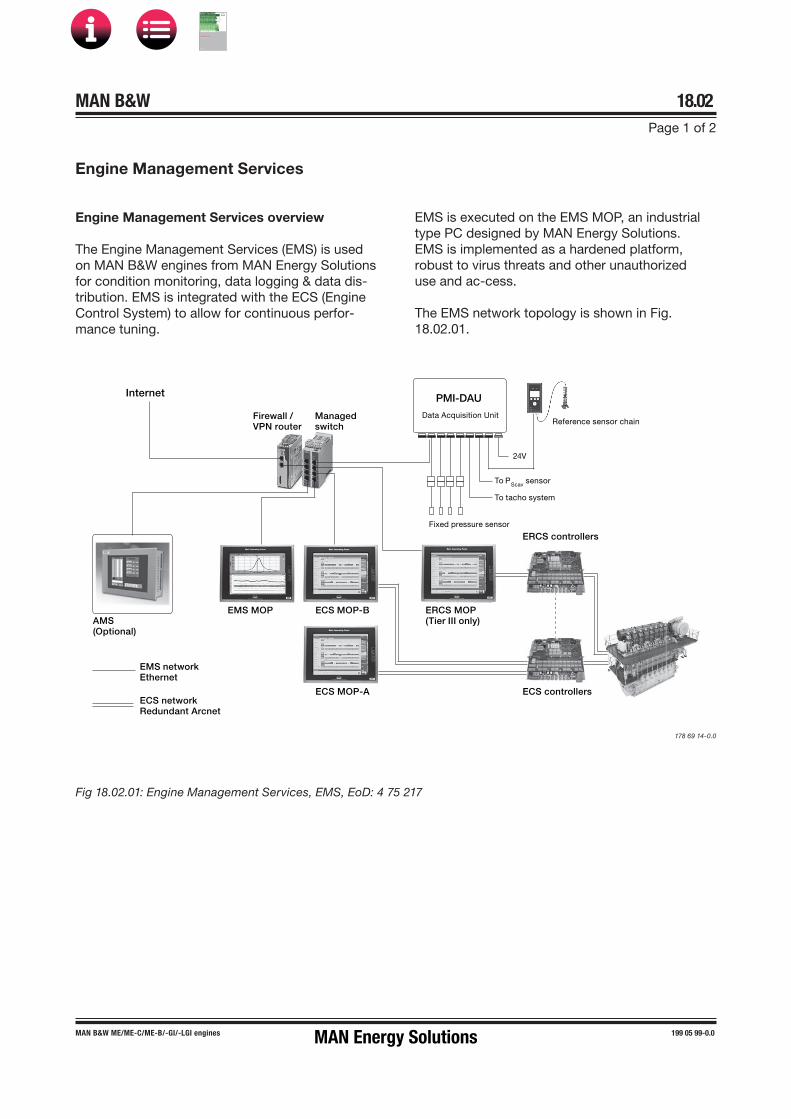
MAN B&W 18.02Page 1 of 2
MAN B&W ME/ME�C/ME-B/�GI/-LGI engines 199 05 99-0.0
Engine Management Services
Engine Management Services overview
The Engine Management Services (EMS) is used on MAN B&W engines from MAN Energy Solutions for condition monitoring, data logging & data dis-tribution. EMS is integrated with the ECS (Engine Control System) to allow for continuous perfor-mance tuning.
EMS is executed on the EMS MOP, an industrial type PC designed by MAN Energy Solutions. EMS is implemented as a hardened platform, robust to virus threats and other unauthorized use and ac-cess.
The EMS network topology is shown in Fig. 18.02.01.
Fig 18.02.01: Engine Management Services, EMS, EoD: 4 75 217
178 69 14-0.0
Data Acquisition Unit
To PScav sensor
To tacho system
Fixed pressure sensor
24V
PMI-DAU
ERCS controllers
Managedswitch
Firewall /VPN router
ECS controllersECS MOP-A
ECS MOP-BEMS MOPAMS(Optional)
Internet
ERCS MOP(Tier III only)
Reference sensor chain
EMS network Ethernet
ECS networkRedundant Arcnet
MAN Energy Solutions
MAN B&W
IMO Tier ll Project Guide
MAN
Energy Solutions Project G
uideM
AN B
&W G
95ME-C
10.5

MAN B&W 18.02Page 2 of 2
MAN B&W ME/ME�C/ME-B/�GI/-LGI engines 199 05 99-0.0
EMS applications
EMS includes the applications PMI Auto-tuning, CoCoS-EDS and EMS manager.
PMI Auto-tuning
• Online cylinder pressure monitoring• Input to engine control system for closed-loop
performance tuning• Engine power estimation.
PMI Auto-tuning continuously measures the cyl-inder pressures using online sensors mounted on each cylinder cover. Pressure measurements are presented continuously in real time and the corre-sponding key performance values are transferred to the Engine Control System.
The Engine Control System constantly monitors and compares the measured combustion pres-sures to a reference value. As such, the control system automatically adjusts the fuel injection and valve timing to reduce the deviation between the measured values and the reference. This, in turn, facilitates the optimal combustion pressures for the next firing. Thus, the system ensures that the engine is running at the desired maximum pres-sure, p(max).
CoCoS-EDS
• Data logging• Engine condition monitoring and reporting• Engine operation troubleshooting.
With CoCoS-EDS, early intervention as well as preventive maintenance, the engine operators are able to reduce the risk of damages and failures.
CoCoS-EDS further allows for easier trouble-shooting in cases where unusual engine behavior is observed.
EMS manager
• Installation and supervision of EMS applications• Network and interface monitoring• Optional interface for data exchange with AMS
(Alarm Monitoring System).
The EMS manager provides a process for inte-grated installation, commissioning and mainte-nance of PMI Auto-tuning and CoCoS-EDS.
Further, the EMS Manager includes status infor-mation and functionality, e.g. for network status, internal and external interfaces and EMS applica-tion execution.
MAN Energy Solutions
MAN B&W
IMO Tier ll Project Guide
MAN
Energy Solutions Project G
uideM
AN B
&W G
95ME-C
10.5

MAN B&W 18.03Page 1 of 1
MAN B&W ME/ME�C/ME-B/�GI/-LGI engines 198 45 82�6.9
Condition Monitoring System CoCoS-EDS
This section is not applicable
MAN Energy Solutions
MAN B&W
IMO Tier ll Project Guide
MAN
Energy Solutions Project G
uideM
AN B
&W G
95ME-C
10.5

MAN B&W 18.04Page 1 of 7
MAN B&W MC/MC-C, ME/ME�C/ME-B/�GI engines 198 70 40�3.4
Alarm – Slow Down and Shut Down System
The number and position of the terminal boxes depends on the degree of dismantling specified in the Dispatch Pattern for the transportation of the engine based on the lifting capacities available at the engine maker and at the yard.
Alarm, slow down and remote indication sensors
The International Association of Classification So-cieties (IACS) indicates that a common sensor can be used for alarm, slow down and remote indica-tion.
A general view of the alarm, slow down and shut down systems is shown in Fig. 18.04.01.
Tables 18.04.02 and 18.04.03 show the require-ments by MAN Energy Solutions for alarm and slow down and for UMS by the classification societies (Class), as well as IACS’ recommendations.
The number of sensors to be applied to a specific plant is the sum of requirements of the classifica-tion society, the Buyer and MAN Energy Solutions.
If further analogue sensors are required, they can be ordered as option: 4 75 128.
Slow down functions
The slow down functions are designed to safe-guard the engine components against overloading during normal service conditions and to keep the ship manoeuvrable if fault conditions occur.
The slow down sequence must be adapted to the actual plant parameters, such as for FPP or CPP, engine with or without shaft generator, and to the required operating mode.
The shut down system must be electrically sepa-rated from other systems by using independent sensors, or sensors common to the alarm system and the monitoring system but with galvanically separated electrical circuits, i.e. one sensor with two sets of electrically independent terminals. The list of sensors are shown in Table 18.04.04.
Basic safety system design and supply
The basic safety sensors for a MAN B&W engine are designed for Unattended Machinery Space (UMS) and comprises:
• the temperature sensors and pressure sensors that are specified in the ‘MAN Energy Solutions’ column for shut down in Table 18.04.04.
These sensors are included in the basic Extent of Delivery, EoD: 4 75 124.
Alarm and slow down system design and supply
The basic alarm and slow down sensors for a MAN B&W engine are designed for Unattended Machinery Space (UMS) and comprises:
•the sensors for alarm and slow down.
These sensors are included in the basic Extent of Delivery, EoD: 4 75 127.
The shut down and slow down panels can be or-dered as options: 4 75 630, 4 75 614 or 4 75 615 whereas the alarm panel is yard’s supply, as it normally includes several other alarms than those for the main engine.
For practical reasons, the sensors for the engine itself are normally delivered from the engine sup-plier, so they can be wired to terminal boxes on the engine.
MAN Energy Solutions
MAN B&W
IMO Tier ll Project Guide
MAN
Energy Solutions Project G
uideM
AN B
&W G
95ME-C
10.5
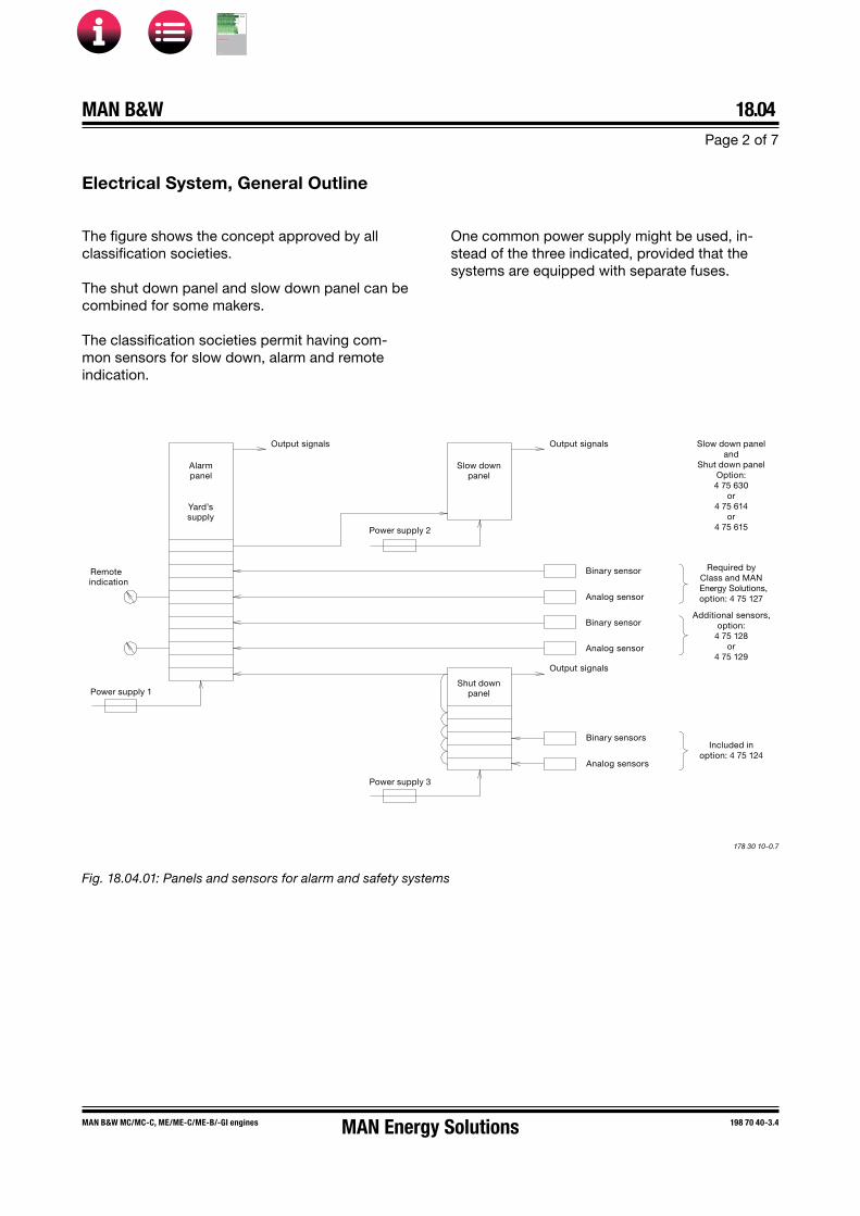
MAN B&W 18.04Page 2 of 7
MAN B&W MC/MC-C, ME/ME�C/ME-B/�GI engines 198 70 40�3.4
178 30 10�0.7
Fig. 18.04.01: Panels and sensors for alarm and safety systems
Remoteindication
Power supply 1
Alarmpanel
Yard’ssupply
Output signals
Power supply 2
Slow downpanel
Output signals
Binary sensor
Analog sensor
Binary sensor
Analog sensor
Power supply 3
Shut downpanel
Output signals
Binary sensors
Analog sensors
Required byClass and MANEnergy Solutions,option: 4 75 127
Slow down paneland
Shut down panelOption:4 75 630
or4 75 614
or4 75 615
Additional sensors,option:
4 75 128or
4 75 129
Included inoption: 4 75 124
One common power supply might be used, in-stead of the three indicated, provided that the systems are equipped with separate fuses.
The figure shows the concept approved by all classification societies.
The shut down panel and slow down panel can be combined for some makers.
The classification societies permit having com-mon sensors for slow down, alarm and remote indication.
Electrical System, General Outline
MAN Energy Solutions
MAN B&W
IMO Tier ll Project Guide
MAN
Energy Solutions Project G
uideM
AN B
&W G
95ME-C
10.5

MAN B&W 18.04Page 3 of 7
MAN B&W ME/ME�C/ME-B/�GI/-LGI engines 198 45 83�8.16
Alarms for UMS – Class and MAN Energy Solutions requirements
AB
S
BV
CC
S
DN
V
GL
KR
LR
NK
RIN
A
RS
IAC
S
MA
N ES
Sensor and function Point of location
Fuel oil
1 1 1 1 1 1 1 1 1 1 1 1 PT 8001 AL Fuel oil, inlet engine
1 1 1 1 1 1 1 1 1 1 1 1 LS 8006 AH Leakage from high pressure pipes
Lubricating oil
1 1 1 1 1 1 1 1 1 1 1 1 TE 8106 AH Thrust bearing segment
1 1 1 1 1 1 1 1 1 1 1 1 PT 8108 AL Lubricating oil inlet to main engine
1 1 1 1 1 1 1 1 1 1 1 1 TE 8112 AH Lubricating oil inlet to main engine
1 1 1 1 1 1 1 1 1 1 1 TE 8113 AH Piston cooling oil outlet/cylinder
1 1 1 1 1 1 1 1 1 1 1 FS 8114 AL Piston cooling oil outlet/cylinder
1 1 1 1 1 1 1 1 1 1 TE 8117 AH Turbocharger lubricating oil outlet/turbocharger1 TE 8123 AH Main bearing oil outlet temperature/main bearing
(S40/35ME-B9 only)1 XC 8126 AH Bearing wear (All types except S40/35ME-B9); sensor
common to XC 8126/271 XS 8127 A Bearing wear detector failure (All types except S40/
35ME-B)1 1 1 1 1 PDS 8140 AH Lubricating oil differential pressure – cross filter
1 XS 8150 AH Water in lubricating oil; sensor common to XS 8150/51/52
1 XS 8151 AH Water in lubricating oil – too high
1 XS 8152 A Water in lubricating oil sensor not ready
MAN B&W Alpha Lubrication
1 TE 8202 AH Cylinder lubricating oil temperature1 LS 8212 AL Small tank for heating element, low level (Not for
ACOM)1 XC 8265 AL ACOM common alarm (Only for ACOM)
1 Indicates that the sensor is required.The sensors in the MAN Energy Solutions and relevant Class columns are included in the basic Extent of Delivery, EoD: 4 75 127. The sensor identification codes and functions are listed in Table 18.07.01.The tables are liable to change without notice, and are subject to latest Class requirements.
Table 18.04.02a: Alarm functions for UMS
MAN Energy Solutions
MAN B&W
IMO Tier ll Project Guide
MAN
Energy Solutions Project G
uideM
AN B
&W G
95ME-C
10.5
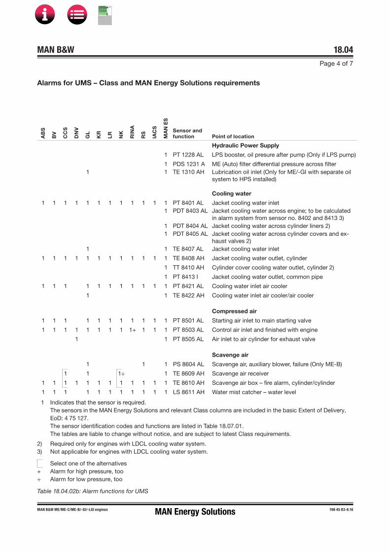
MAN B&W 18.04Page 4 of 7
MAN B&W ME/ME�C/ME-B/�GI/-LGI engines 198 45 83�8.16
Alarms for UMS – Class and MAN Energy Solutions requirements
Table 18.04.02b: Alarm functions for UMS
AB
S
BV
CC
S
DN
V
GL
KR
LR
NK
RIN
A
RS
IAC
S
MA
N ES
Sensor and function Point of location
Hydraulic Power Supply
1 PT 1228 AL LPS booster, oil presure after pump (Only if LPS pump)
1 PDS 1231 A ME (Auto) filter differential pressure across filter1 1 TE 1310 AH Lubrication oil inlet (Only for ME/-GI with separate oil
system to HPS installed)
Cooling water
1 1 1 1 1 1 1 1 1 1 1 1 PT 8401 AL Jacket cooling water inlet1 PDT 8403 AL Jacket cooling water across engine; to be calculated
in alarm system from sensor no. 8402 and 8413 3)1 PDT 8404 AL Jacket cooling water across cylinder liners 2)1 PDT 8405 AL Jacket cooling water across cylinder covers and ex-
haust valves 2)1 1 TE 8407 AL Jacket cooling water inlet
1 1 1 1 1 1 1 1 1 1 1 1 TE 8408 AH Jacket cooling water outlet, cylinder
1 TT 8410 AH Cylinder cover cooling water outlet, cylinder 2)
1 PT 8413 I Jacket cooling water outlet, common pipe
1 1 1 1 1 1 1 1 1 1 1 PT 8421 AL Cooling water inlet air cooler
1 1 TE 8422 AH Cooling water inlet air cooler/air cooler
Compressed air
1 1 1 1 1 1 1 1 1 1 1 PT 8501 AL Starting air inlet to main starting valve
1 1 1 1 1 1 1 1 1+ 1 1 1 PT 8503 AL Control air inlet and finished with engine
1 1 PT 8505 AL Air inlet to air cylinder for exhaust valve
Scavenge air
1 1 1 PS 8604 AL Scavenge air, auxiliary blower, failure (Only ME-B)
1 1 1÷ 1 TE 8609 AH Scavenge air receiver
1 1 1 1 1 1 1 1 1 1 1 1 TE 8610 AH Scavenge air box – fire alarm, cylinder/cylinder
1 1 1 1 1 1 1 1 1 1 1 LS 8611 AH Water mist catcher – water level
1 Indicates that the sensor is required.The sensors in the MAN Energy Solutions and relevant Class columns are included in the basic Extent of Delivery, EoD: 4 75 127. The sensor identification codes and functions are listed in Table 18.07.01.The tables are liable to change without notice, and are subject to latest Class requirements.
2) Required only for engines wirh LDCL cooling water system.3) Not applicable for engines with LDCL cooling water system.
Select one of the alternatives+ Alarm for high pressure, too÷ Alarm for low pressure, too
MAN Energy Solutions
MAN B&W
IMO Tier ll Project Guide
MAN
Energy Solutions Project G
uideM
AN B
&W G
95ME-C
10.5

MAN B&W 18.04Page 5 of 7
MAN B&W ME/ME�C/ME-B/�GI/-LGI engines 198 45 83�8.16
Alarms for UMS – Class and MAN Energy Solutions requirements
AB
S
BV
CC
S
DN
V
GL
KR
LR
NK
RIN
A
RS
IAC
S
MA
N ES
Sensor and function Point of location
Exhaust gas
1 1 1 1 1 1 (1) 1 1 1 1 1 TC 8701 AH Exhaust gas before turbocharger/turbocharger
1 1 1 1 1 1 1 1 1 1 TC 8702 AH Exhaust gas after exhaust valve, cylinder/cylinder1 1 1 1 1 1 1 1 1 1 1 TC 8707 AH Exhaust gas outlet turbocharger/turbocharger (Yard’s
supply)
Miscellaneous
1 ZT 8801 AH Turbocharger speed/turbocharger
1 WT 8812 AH Axial vibration monitor 2)1 1 1 1 1 1 1 1 1 1 1 XS 8813 AH Oil mist in crankcase/cylinder; sensor common to
XS 8813/141 1 XS 8814 AL Oil mist detector failure
1 XC 8816 AH Shaftline earthing device
1 TE 8820 AH Cylinder liner monitoring/cylinder 3)
Engine Control System
1 1 1 1 1 1 1 1 1 1 1 1 XC 2201 A Power failure
1 1 1 1 1 1 1 1 1 1 XC 2202 A ME common failure
1 XC 2202-A A ME common failure (ME-GI only)
1 XC 2213 A Double-pipe HC alarm (ME-GI only)
Power Supply Units to Alarm System
1 XC 2901 A Low voltage ME power supply A
1 XC 2902 A Low voltage ME power supply B
1 XC 2903 A Earth failure ME power supply
1 Indicates that the sensor is required.The sensors in the MAN Energy Solutions and relevant Class columns are included in the basic Extent of Delivery, EoD: 4 75 127. The sensor identification codes and functions are listed in Table 18.07.01.The tables are liable to change without notice, and are subject to latest Class requirements.
(1) May be combined with TC 8702 AH where turbocharger is mounted directly on the exhaust manifold.
2) Required for certain engines only, see the list in Section 18.06, Axial Vibration Monitor.
3) Required for: K98ME/ME-C, S90ME-C, K90ME-C and K80ME-C9 engines incl. ME-GI variants.
Alarm for overheating of main, crank and crosshead bearings, option: 4 75 134.
Table 18.04.02c: Alarm functions for UMS
MAN Energy Solutions
MAN B&W
IMO Tier ll Project Guide
MAN
Energy Solutions Project G
uideM
AN B
&W G
95ME-C
10.5

MAN B&W 18.04Page 6 of 7
MAN B&W ME/ME�C/ME-B/�GI/-LGI engines 198 45 83�8.16
Slow down for UMS – Class and MAN Energy Solutions requirements
Table 18.04.03: Slow down functions for UMS
AB
S
BV
CC
S
DN
V
GL
KR
LR
NK
RIN
A
RS
IAC
S
MA
N ES
Sensor and function Point of location
1 1 1 1 1 1 1 1 1 1 1 1 TE 8106 YH Thrust bearing segment
1 1 1 1* 1 1 1 1 1 1 1 1 PT 8108 YL Lubricating oil inlet to main engine
1 1 TE 8112 YH Lubricating oil inlet to main engine
1 1 1 1 1 1 1 1 1 1 1 TE 8113 YH Piston cooling oil outlet/cylinder
1 1 1 1 1 1 1 1 1 1 1 FS 8114 YL Piston cooling oil outlet/cylinder
1 1 1 1 1 1 1 1 1 1 TE 8117 YH Turbocharger lubricating oil outlet/turbocharger1 TE 8123 YH Main bearing oil outlet temperature/main bearing
(S40/35ME-B9 only)1 XC 8126 YH Bearing wear (All except S40/35ME-B9)
1 1 1 1 1 1 1 1 1 1 1 PT 8401 YL Jacket cooling water inlet
1 PDT 8403 YL Jacket cooling water across engine (Not for LDCL)1 PDT 8404
YLJacket cooling water across cylinder liners (Only for LDCL)
1 PDT 8405 YL
Jacket cooling water across cylinder covers and ex-haust valves (Only for LDCL)
1 1 1 1 1 1 1 1 1 1 1 1 TE 8408 YH Jacket cooling water outlet, cylinder/cylinder
1 1 TE 8609 YH Scavenge air receiver
1 1 1 1 1 1 1 1 1 1 1 1 TE 8610 YH Scavenge air box fire-alarm, cylinder/cylinder
1 1 1 TC 8701 YH Exhaust gas before turbocharger/turbocharger
1 1 1 1 1 1 1 1 1 1 1 TC 8702 YH Exhaust gas after exhaust valve, cylinder/cylinder1 1 TC 8702 YH Exhaust gas after exhaust valve, cylinder/cylinder,
deviation from average1 ZT 8801 YH Turbocharger overspeed (Only in case of EGB, VT TC,
power turbine/hybrid TC, TC Cut-out, see Table 18.06.03)1 WT 8812 YH Axial vibration monitor 2)
1 1 1* 1 1 1 1 1 1 1 1 XS 8813 YH Oil mist in crankcase/cylinder1 1 TE 1310 YH Lubrication oil inlet (Only for ME/-GI with separate oil
system to HPS installed)
1 Indicates that the sensor is required.The sensors in the MAN Energy Solutions and relevant Class columns are included in the basic Extent of Delivery, EoD: 4 75 127. The sensor identification codes and functions are listed in Table 18.07.01.The tables are liable to change without notice, and are subject to latest Class requirements.
2) Required for certain engines only, see the list in Section 18.06, Axial Vibration Monitor.
Select one of the alternatives * Or shut down
Or alarm for low flow * Or shut down
Or alarm for overheating of main, crank and crosshead bearings, option: 4 75 134.See also Table 18.04.04: Shut down functions for AMS and UMS.
MAN Energy Solutions
MAN B&W
IMO Tier ll Project Guide
MAN
Energy Solutions Project G
uideM
AN B
&W G
95ME-C
10.5
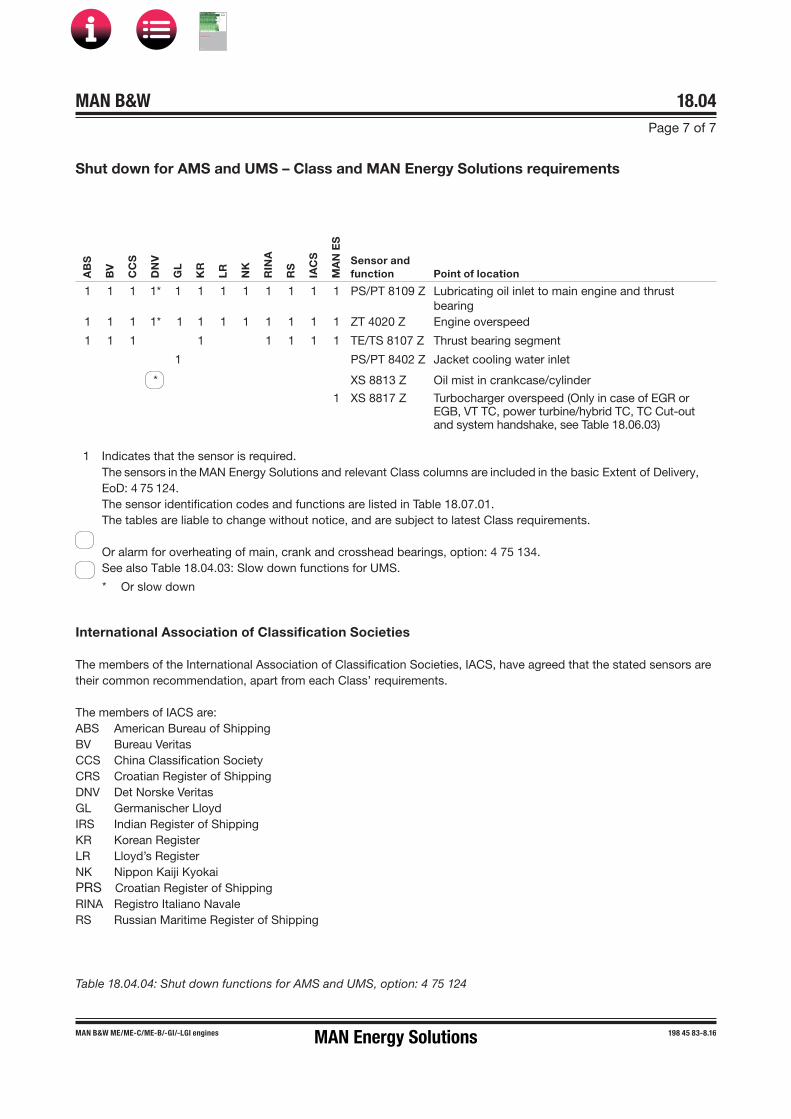
MAN B&W 18.04Page 7 of 7
MAN B&W ME/ME�C/ME-B/�GI/-LGI engines 198 45 83�8.16
Shut down for AMS and UMS – Class and MAN Energy Solutions requirements
1 Indicates that the sensor is required.The sensors in the MAN Energy Solutions and relevant Class columns are included in the basic Extent of Delivery, EoD: 4 75 124.The sensor identification codes and functions are listed in Table 18.07.01.The tables are liable to change without notice, and are subject to latest Class requirements.
Or alarm for overheating of main, crank and crosshead bearings, option: 4 75 134.See also Table 18.04.03: Slow down functions for UMS.
* Or slow down
Table 18.04.04: Shut down functions for AMS and UMS, option: 4 75 124
AB
S
BV
CC
S
DN
V
GL
KR
LR
NK
RIN
A
RS
IAC
S
MA
N E
S
Sensor and function Point of location
1 1 1 1* 1 1 1 1 1 1 1 1 PS/PT 8109 Z Lubricating oil inlet to main engine and thrustbearing
1 1 1 1* 1 1 1 1 1 1 1 1 ZT 4020 Z Engine overspeed
1 1 1 1 1 1 1 1 TE/TS 8107 Z Thrust bearing segment
1 PS/PT 8402 Z Jacket cooling water inlet
* XS 8813 Z Oil mist in crankcase/cylinder
1 XS 8817 Z Turbocharger overspeed (Only in case of EGR or EGB, VT TC, power turbine/hybrid TC, TC Cut-out and system handshake, see Table 18.06.03)
International Association of Classification Societies
The members of the International Association of Classification Societies, IACS, have agreed that the stated sensors are their common recommendation, apart from each Class’ requirements.
The members of IACS are:ABS American Bureau of ShippingBV Bureau VeritasCCS China Classification SocietyCRS Croatian Register of ShippingDNV Det Norske Veritas GL Germanischer LloydIRS Indian Register of Shipping KR Korean RegisterLR Lloyd’s RegisterNK Nippon Kaiji KyokaiPRS Croatian Register of ShippingRINA Registro Italiano NavaleRS Russian Maritime Register of Shipping
MAN Energy Solutions
MAN B&W
IMO Tier ll Project Guide
MAN
Energy Solutions Project G
uideM
AN B
&W G
95ME-C
10.5

MAN B&W 18.05Page 1 of 3
MAN B&W ME/ME�C/ME�B/-GI engines 198 45 86�3.13
Local Instruments
The basic local instrumentation on the engine, options: 4 70 119 comprises thermometers, pressure gaug-es and other indicators located on the piping or mounted on panels on the engine. The tables 18.05.01a, b and c list those as well as sensors for slow down, alarm and remote indication, option: 4 75 127.
Local instruments Remote sensors Point of locationThermometer,stem type
Temperatureelement/switch
Hydraulic power supplyTE 1270 HPS bearing temperature (Only ME/ME-C with HPS in centre position)
Fuel oilTI 8005 TE 8005 Fuel oil, inlet engine
Lubricating oilTI 8106 TE 8106 Thrust bearing segment
TE/TS 8107 Thrust bearing segmentTI 8112 TE 8112 Lubricating oil inlet to main engineTI 8113 TE 8113 Piston cooling oil outlet/cylinderTI 8117 TE 8117 Lubricating oil outlet from turbocharger/turbocharger
(depends on turbocharger design)TE 8123 Main bearing oil outlet temperature/main bearing (S40/35ME-B9 only)
Cylinder lubricating oilTE 8202 Cylinder lubricating oil inletTS 8213 Cylinder lubricating heating
High temperature cooling water, jacket cooling waterTI 8407 TE 8407 Jacket cooling water inletTI 8408 TE 8408 Jacket cooling water outlet, cylinder/cylinderTI 8409 TE 8409 Jacket cooling water outlet/turbochargerTI 8410 TT 8410 Cylinder cover cooling water outlet, cylinder (Only for LDCL)
Low temperature cooling water, seawater or freshwater for central coolingTI 8422 TE 8422 Cooling water inlet, air coolerTI 8423 TE 8423 Cooling water outlet, air cooler/air cooler
Scavenge airTI 8605 TE 8605 Scavenge air before air cooler/air coolerTI 8608 TE 8608 Scavenge air after air cooler/air coolerTI 8609 TE 8609 Scavenge air receiver
TE 8610 Scavenge air box – fire alarm, cylinder/cylinder
Thermometer, dial type
Thermo couple
Exhaust gasTI 8701 TC 8701 Exhaust gas before turbocharger/turbocharger
TI/TC 8702 Exhaust gas after exhaust valve, cylinder/cylinderTC 8704 Exhaust gas inlet exhaust gas receiver
TI 8707 TC 8707 Exhaust gas outlet turbocharger
Table 18.05.01a: Local thermometers on engine, options 4 70 119, and remote indication sensors, option: 4 75 127
MAN Energy Solutions
MAN B&W
IMO Tier ll Project Guide
MAN
Energy Solutions Project G
uideM
AN B
&W G
95ME-C
10.5
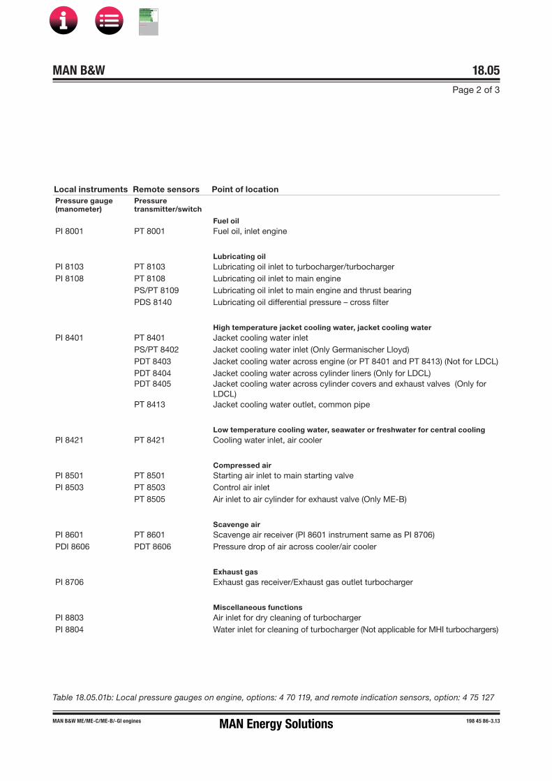
MAN B&W 18.05Page 2 of 3
MAN B&W ME/ME�C/ME�B/-GI engines 198 45 86�3.13
Local instruments Remote sensors Point of locationPressure gauge(manometer)
Pressuretransmitter/switch
Fuel oilPI 8001 PT 8001 Fuel oil, inlet engine
Lubricating oilPI 8103 PT 8103 Lubricating oil inlet to turbocharger/turbochargerPI 8108 PT 8108 Lubricating oil inlet to main engine
PS/PT 8109 Lubricating oil inlet to main engine and thrust bearingPDS 8140 Lubricating oil differential pressure – cross filter
High temperature jacket cooling water, jacket cooling waterPI 8401 PT 8401 Jacket cooling water inlet
PS/PT 8402 Jacket cooling water inlet (Only Germanischer Lloyd)PDT 8403 Jacket cooling water across engine (or PT 8401 and PT 8413) (Not for LDCL)PDT 8404 Jacket cooling water across cylinder liners (Only for LDCL)PDT 8405 Jacket cooling water across cylinder covers and exhaust valves (Only for
LDCL)PT 8413 Jacket cooling water outlet, common pipe
Low temperature cooling water, seawater or freshwater for central coolingPI 8421 PT 8421 Cooling water inlet, air cooler
Compressed airPI 8501 PT 8501 Starting air inlet to main starting valvePI 8503 PT 8503 Control air inlet
PT 8505 Air inlet to air cylinder for exhaust valve (Only ME-B)
Scavenge airPI 8601 PT 8601 Scavenge air receiver (PI 8601 instrument same as PI 8706)PDI 8606 PDT 8606 Pressure drop of air across cooler/air cooler
Exhaust gasPI 8706 Exhaust gas receiver/Exhaust gas outlet turbocharger
Miscellaneous functionsPI 8803 Air inlet for dry cleaning of turbochargerPI 8804 Water inlet for cleaning of turbocharger (Not applicable for MHI turbochargers)
Table 18.05.01b: Local pressure gauges on engine, options: 4 70 119, and remote indication sensors, option: 4 75 127
MAN Energy Solutions
MAN B&W
IMO Tier ll Project Guide
MAN
Energy Solutions Project G
uideM
AN B
&W G
95ME-C
10.5

MAN B&W 18.05Page 3 of 3
MAN B&W ME/ME�C/ME�B/-GI engines 198 45 86�3.13
Local instruments Remote sensors Point of locationOther indicators Other transmitters/
switches
Hydraulic power supplyXC 1231 Automatic main lube oil filter, failure (Boll & Kirch)LS 1235 Leakage oil from hydraulic system
Engine cylinder componentsLS 4112 Leakage from hydraulic cylinder unit
Fuel oilLS 8006 Leakage from high pressure pipes
Lubricating oilFS 8114 Piston cooling oil outlet/cylinderXC 8126 Bearing wear (All types except S40/35ME-B9)XS 8127 Bearing wear detector failure (All types except S40-35ME-B9)XS 8150 Water in lubricating oilXS 8151 Water in lubricating oil – too highXS 8152 Water in lubricating oil sensor not ready
Cylinder lube oilLS 8212 Small tank for heating element, low level (Not for ACOM)XC 8265 ACOM (Only for ACOM)LS 8285 Level switch
Scavenge airLS 8611 Water mist catcher – water level
Miscellaneous functionsZT 8801 I Turbocharger speed/turbocharger
WI 8812 WT 8812 Axial vibration monitor (For certain engines only, see note in Table 18.04.04)(WI 8812 instrument is part of the transmitter WT 8812)
XS 8813 Oil mist in crankcase/cylinderXS 8814 Oil mist detector failureXC 8816 Shaftline earthing deviceXS/XT 8817 Turbocharger overspeed (Only in case of EGB, VT TC, power turbine/hybrid
TC, TC Cut-out, see Table 18.06.03)
Table 18.05.01c: Other indicators on engine, options: 4 70 119, and remote indication sensors, option: 4 75 127
MAN Energy Solutions
MAN B&W
IMO Tier ll Project Guide
MAN
Energy Solutions Project G
uideM
AN B
&W G
95ME-C
10.5

MAN B&W 18.06Page 1 of 9
MAN B&W engines 198 45 87-5.21
Oil Mist Detector
The oil mist detector system constantly measures samples of the atmosphere in the crankcase com-partments and registers the results on an opti-cal measuring track, where the opacity (degree of haziness) is compared with the opacity of the atmospheric air. If an increased difference is re-corded, a slow down is activated (a shut down in case of Germanischer Lloyd).
Furthermore, for shop trials only MAN Energy Solutions requires that the oil mist detector is con-nected to the shut down system.
For personnel safety, the oil mist detectors and re-lated equipment are located on the manoeuvring side of the engine.
The following oil mist detectors are available:
4 75 162 Graviner Mk 7, make: Kidde Fire Protec-tion
4 75 163 Visatron VN 215/93, make: Schaller Auto-mation GmbH & Co. KG *)
4 75 166 MD-SX, make: Daihatsu Diesel Mfg. Co.,Ltd.
4 75 167 Vision III C, make: Specs Corporation
4 75 168 GDMS-OMDN09, make: MSS AG
4 75 271 Triton, make: Heinzmann GmbH & Co. KG
4 75 272 Visatron VN301plus, make: Schaller Auto-mation GmbH & Co. KG
4 75 273 MOT-2R5M7R5MP, make: Meiyo Electric Co., Ltd.
*) Only applicable for S50ME-C8/-GI as well as MC-C and ME-B/-GI/-LGI types 50 and smaller
Examples of piping diagrams (for Visatron VN 215/93 only) and wiring diagrams (for all other de-tectors) are shown for reference in Figs. 18.06.01a and 18.06.01b.
Other Alarm Functions
Drain Box for Fuel Oil Leakage Alarm
Any leakage from the fuel oil high pressure pipes of any cylinder is drained to a common drain box fitted with a level alarm. This is included in the ba-sic design of MAN B&W engines.
Bearing Condition Monitoring
Based on our experience, we decided in 1990 that all plants must include an oil mist detector speci-fied by MAN Energy Solutions. Since then an Oil Mist Detector (OMD) and optionally some extent of Bearing Temperature Monitoring (BTM) equip-ment have made up the warning arrangements for prevention of crankcase explosions on two-stroke engines. Both warning systems are approved by the classification societies.
In order to achieve a response to damage faster than possible with Oil Mist Detection and Bearing Temperature Monitoring alone we introduce Bear-ing Wear Monitoring (BWM) systems. By monitor-ing the actual bearing wear continuously, mechani-cal damage to the crank-train bearings (main-, crank- and crosshead bearings) can be predicted in time to react and avoid damaging the journal and bearing housing.
If the oil supply to a main bearing fails, the bearing temperature will rise and in such a case a Bear-ing Temperature Monitoring system will trigger an alarm before wear actually takes place. For that reason the ultimate protection against severe bearing damage and the optimum way of provid-ing early warning, is a combined bearing wear and temperature monitoring system.
For all types of error situations detected by the different bearing condition monitoring systems applies that in addition to damaging the compo-nents, in extreme cases, a risk of a crankcase explosion exists.
MAN Energy Solutions
MAN B&W
IMO Tier ll Project Guide
MAN
Energy Solutions Project G
uideM
AN B
&W G
95ME-C
10.5
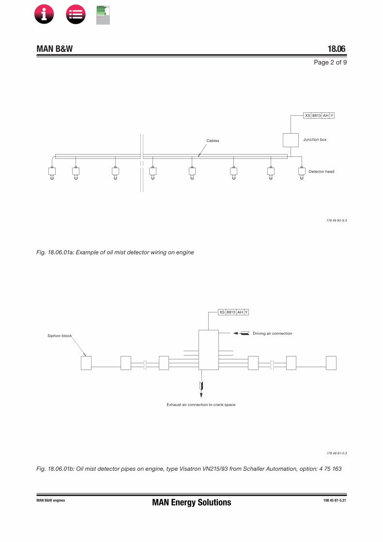
MAN B&W 18.06Page 2 of 9
MAN B&W engines 198 45 87-5.21
ables
Detector hea
unction box
XS 8813 AH Y
Driving air connection
Exhaust air connection to crank space
Siphonblock
XS 8813 AH Y
Fig. 18.06.01a: Example of oil mist detector wiring on engine
178 49 80�9.3
Fig. 18.06.01b: Oil mist detector pipes on engine, type Visatron VN215/93 from Schaller Automation, option: 4 75 163
178 49 81�0.3
MAN Energy Solutions
MAN B&W
IMO Tier ll Project Guide
MAN
Energy Solutions Project G
uideM
AN B
&W G
95ME-C
10.5

MAN B&W 18.06Page 3 of 9
MAN B&W ME/ME�C/�GI/-LGI engines 198 67 26�5.10
Bearing Wear Monitoring System
The Bearing Wear Monitoring (BWM) system mon-itors all three principal crank-train bearings using two proximity sensors forward/aft per cylinder unit and placed inside the frame box.
Targeting the guide shoe bottom ends continu-ously, the sensors measure the distance to the crosshead in Bottom Dead Center (BDC). Signals are computed and digitally presented to computer hardware, from which a useable and easily inter-pretable interface is presented to the user.
The measuring precision is more than adequate to obtain an alarm well before steel-to-steel contact in the bearings occur. Also the long-term stability of the measurements has shown to be excellent.
In fact, BWM is expected to provide long-term wear data at better precision and reliability than the manual vertical clearance measurements nor-mally performed by the crew during regular serv-ice checks.
For the above reasons, we consider unscheduled open-up inspections of the crank-train bearings to be superfluous, given BWM has been installed.
Two BWM ‘high wear’ alarm levels including devia-tion alarm apply. The first level of the high wear / deviation alarm is indicated in the alarm panel only while the second level also activates a slow down.
he Extent of Delivery lists the following Bearing Wear Monitoring options:
4 75 261 XTS�W (BWM), make: AMOT
4 75 262 BDMS (BW&TMS), make: Dr. E. Horn
4 75 263 BWCM, make: Kongsberg Maritime
4 75 265 B-WACS, make: Doosan Engine Co., Ltd.
4 75 266 BWCMS, make: KOMECO
4 75 267 BCM-1, make: Mitsui Zosen Systems Re-search Inc.
ME, ME-C/-GI/-LGI engines are as standard spe-cified with Bearing Wear Monitoring for which any of the above mentioned options could be chosen.
Bearing Temperature Monitoring System
The Bearing Temperature Monitoring (BTM) sys-tem continuously monitors the temperature of the bearing. Some systems measure the temperature on the backside of the bearing shell directly, other systems detect it by sampling a small part of the return oil from each bearing in the crankcase.
In case a specified temperature is recorded, either a bearing shell/housing temperature or bearing oil outlet temperature alarm is triggered.
In main bearings, the shell/housing temperature or the oil outlet temperature is monitored depending on how the temperature sensor of the BTM sys-tem, option: 4 75 133, is installed.
In crankpin and crosshead bearings, the shell/housing temperature or the oil outlet temperature is monitored depending on which BTM system is installed, options: 4 75 134 or 4 75 135.
For shell/housing temperature in main, crankpin and crosshead bearings two high temperature alarm levels apply. The first level alarm is indicated in the alarm panel while the second level activates a slow down.
For oil outlet temperature in main, crankpin and crosshead bearings two high temperature alarm levels including deviation alarm apply. The first level of the high temperature / deviation alarm is indicated in the alarm panel while the second level activates a slow down.
In the Extent of Delivery, there are three options:
4 75 133 Temperature sensors fitted to main bear-ings
4 75 134 Temperature sensors fitted to main bear-ings, crankpin bearings, crosshead bear-ings and for moment compensator, if any
4 75 135 Temperature sensors fitted to main bear-ings, crankpin bearings and crosshead bearings
MAN Energy Solutions
MAN B&W
IMO Tier ll Project Guide
MAN
Energy Solutions Project G
uideM
AN B
&W G
95ME-C
10.5

MAN B&W 18.06Page 4 of 9
MAN B&W ME/ME�C/�GI/-LGI engines 198 67 26�5.10
Please note: Corrosion of the overlayer is a poten-tial problem only for crosshead bearings, because only crosshead bearings are designed with an overlayer. Main, thrust and crankpin bearings may also suffer irreparable damage from water con-tamination, but the damage mechanism would be different and not as acute.
Liner Wall Monitoring System
The Liner Wall Monitoring (LWM) system monitors the temperature of each cylinder liner. It is to be regarded as a tool providing the engine room crew the possibility to react with appropriate counter-measures in case the cylinder oil film is indicating early signs of breakdown.
In doing so, the LWM system can assist the crew in the recognition phase and help avoid conse-quential scuffing of the cylinder liner and piston rings.
Signs of oil film breakdown in a cylinder liner will appear by way of increased and fluctuating temperatures. Therefore, recording a preset max allowable absolute temperature for the individual cylinder or a max allowed deviation from a calcu-lated average of all sensors will trigger a cylinder liner temperature alarm.
The LWM system includes two sensors placed in the manoeuvring and exhaust side of the liners, near the piston skirt TDC position. The sensors are interfaced to the ship alarm system which monitors the liner temperatures.
For each individual engine, the max and deviation alarm levels are optimised by monitoring the tem-perature level of each sensor during normal serv-ice operation and setting the levels accordingly.
The temperature data is logged on a PC for one week at least and preferably for the duration of a round trip for reference of temperature develop-ment.
All types 98 and 90 ME and ME-C engines as well as K80ME-C9 are as standard specified with Liner Wall Monitoring system. For all other engines, the LWM system is available as an option: 4 75 136.
Water In Oil Monitoring System
All MAN B&W engines are as standard specified with Water In Oil monitoring system in order to de-tect and avoid free water in the lubricating oil.
In case the lubricating oil becomes contaminated with an amount of water exceeding our limit of 50% of the saturation point (corresponding to ap-prox. 0.2% water content), acute corrosive wear of the crosshead bearing overlayer may occur. The higher the water content, the faster the wear rate.
To prevent water from accumulating in the lube oil and, thereby, causing damage to the bearings, the oil should be monitored manually or automati-cally by means of a Water In Oil (WIO) monitor-ing system connected to the engine alarm and monitoring system. In case of water contamination the source should be found and the equipment inspected and repaired accordingly.
The saturation point of the water content in the lubricating oil varies depending on the age of the lubricating oil, the degree of contamination and the temperature. For this reason, we have chosen to specify the water activity measuring principle and the aw-type sensor. Among the available methods of measuring the water content in the lubricating oil, only the aw-type sensor measures the relationship between the water content and the saturation point regardless of the properties of the lubricating oil.
WIO systems with aw-type sensor measure water activity expressed in ‘aw’ on a scale from 0 to 1. Here, ‘0’ indicates oil totally free of water and ‘1’ oil fully saturated by water.
Alarm levels are specified as follows:
Engine condition Water activity, aw High alarm level 0.5High High alarm level 0.9
The aw = 0.5 alarm level gives sufficient margin to the satuartion point in order to avoid free water in the lubricating oil. If the aw = 0.9 alarm level is reached within a short time after the aw = 0.5 alarm, this may be an indication of a water leak into the lubricating oil system.
MAN Energy Solutions
MAN B&W
IMO Tier ll Project Guide
MAN
Energy Solutions Project G
uideM
AN B
&W G
95ME-C
10.5

MAN B&W 18.06Page 5 of 9
MAN B&W ME/ME�C/�GI/-LGI engines 198 67 26�5.10
Axial Vibration Monitor
For functional check of the vibration damper a mechanical guide is fitted, while an electronic vi-bration monitor can be supplied as an option.
An Axial Vibration Monitor (AVM) with indication for condition check of the axial vibration damper and terminals for alarm and slow down ia available as an option: 4 31 117. It is required for the follow-ing engines:
• All ME-C9/10 engines incl. their -GI and -LGIvariants
• All ME-C7/8 engines with 5 and 6 cylinders incl.their -GI and -LGI variants
• K-ME-C6/7 and K98ME6/7 engines with 11 and14 cylinders incl. their -GI and -LGI variants.
The requirement for AVM on 4-cylinder engines is available on request.
The alarm and slow down system should include the filtration necessary to prevent the AVM from unintentionally activating the alarm and slow down functions at torsional vibration resonances, i.e. in the barred speed range, and when running Astern.
In the low speed range and when running Astern, the alarm and slow down functions are to be disa-bled so that the AVM only gives an indication of the vibration level.
The AVM alarm and slow down functions shall be enabled when the engine is running Ahead and at speeds above the barred range.
To prevent rapid hunting of the engine speed in a slow down situation, a holding time function has been introduced in order to delay the automatic re-setting of the slow down function.
The specification of the AVM interface to the alarm and slow down system is available from MAN Energy Solutions, Copenhagen.
MAN Energy Solutions
MAN B&W
IMO Tier ll Project Guide
MAN
Energy Solutions Project G
uideM
AN B
&W G
95ME-C
10.5
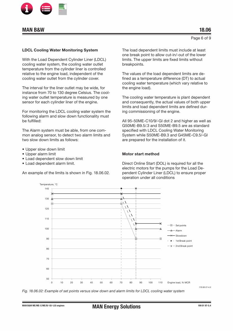
MAN B&W 18.06Page 6 of 9
MAN B&W ME/MEC/ME/B/GI/-LGI engines 199 01 97-5.4MAN Energy Solutions
LDCL Cooling Water Monitoring System
With the Load Dependent Cylinder Liner (LDCL) cooling water system, the cooling water outlet temperature from the cylinder liner is controlled relative to the engine load, independent of the cooling water outlet from the cylinder cover.
The interval for the liner outlet may be wide, for instance from 70 to 130 degree Celsius. The cool-ing water outlet temperature is measured by one sensor for each cylinder liner of the engine.
For monitoring the LDCL cooling water system the following alarm and slow down functionality must be fulfilled:
The Alarm system must be able, from one com-mon analog sensor, to detect two alarm limits and two slow down limits as follows:
• Upper slow down limit• Upper alarm limit• Load dependent slow down limit• Load dependent alarm limit.
An example of the limits is shown in Fig. 18.06.02.
Fig. 18.06.02: Example of set points versus slow down and alarm limits for LDCL cooling water system
The load dependent limits must include at least one break point to allow cut-in/-out of the lower limits. The upper limits are fixed limits without breakpoints.
The values of the load dependent limits are de-fined as a temperature difference (DT) to actual cooling water temperature (which vary relative to the engine load).
The cooling water temperature is plant dependent and consequently, the actual values of both upper limits and load dependent limits are defined dur-ing commissioning of the engine.
All 95-50ME-C10/9/-GI dot 2 and higher as well as G50ME-B9.5/.3 and S50ME-B9.5 are as standard specified with LDCL Cooling Water Monitoring System while S50ME-B9.3 and G45ME-C9.5/-GI are prepared for the installation of it.
Motor start method
Direct Online Start (DOL) is required for all the electric motors for the pumps for the Load De-pendent Cylinder Liner (LDCL) to ensure proper operation under all conditions
178 68 07-4.0
50
60
70
80
90
100
110
120
130
140
0 10 20 30 40 50 60 70 80 90 100 110
Set points
Alarm
Slowdown
1st Break point
2nd Break point
Temperature, °C
Engine load, % MCR
MAN B&W
IMO Tier ll Project Guide
MAN
Energy Solutions Project G
uideM
AN B
&W G
95ME-C
10.5

MAN B&W 18.06Page 7 of 9
MAN B&W engines 199 04 57-6.2
Turbocharger Overspeed Protection
All engine plants fitted with turbocharger cut-out, exhaust gas bypass (EGB), power turbine / turbo generator (PT), hybrid turbocharger or variable tur -bocharger (VT) run the risk of experiencing turbo -charger overspeed. To protect the turbocharger, such plants must be equipped with a turbocharger overspeed alarm and slow-down function.
However, the handshake interface between the ship’s power management system and a waste heat recovery system (WHRS) or a shaft genera-tor (SG) may delay the slowdown for up to 120 seconds. Therefore, the slow-down function must be upgraded to a non-cancellable shutdown for engine plants with handshake interface.
On engine plants designed with exhaust gas recir-culation (EGR), a sudden increase of energy to the turbocharger(s) will occur if the EGR system trips. As protection, turbocharger overspeed alarm and non-cancellable shutdown must be fitted.
Consequently, the turbocharger speed must be monitored by the ship alarm system and the safe-ty system(s), triggering slowdown or non-cancel-lable shutdown if the turbocharger speed exceeds the defined alarm levels.
The protection applicable for individual engine plant and power management configurations is summarised in Table 18.06.03.
Turbocharger overspeed protectionEngine plant configuration No power management system handshake Engine with WHR or shaft generator with
power management system handshake
Traditional exhaust gas train and turbocharger
No monitoring of turbocharger overspeed No monitoring of turbocharger overspeed
Exhaust gas bypass, variable turbo charger, power turbine or hybrid turbocharger
Turbocharger overspeed slowdown Turbocharger overspeed shutdown
Exhaust gas recirculation Turbocharger overspeed shutdown Turbocharger overspeed shutdown
Turbocharger cut-out Turbocharger overspeed slowdown Turbocharger overspeed shutdown
Table 18.06.03: Turbocharger overspeed protection for individual engine plant configurations
MAN Energy Solutions
MAN B&W
IMO Tier ll Project Guide
MAN
Energy Solutions Project G
uideM
AN B
&W G
95ME-C
10.5

MAN B&W 18.06Page 8 of 9
MAN B&W ME/ME�C/ME/B/�GI/-LGI engines 198 67 28-9.8
Sensor Point of location
Manoeuvring systemZS 1109�A/B C Turning gear – disengagedZS 1110�A/B C Turning gear – engagedZS 1111�A/B C Main starting valve – blockedZS 1112�A/B C Main starting valve – in serviceZV 1114 C Slow turning valveZS 1116�A/B C Start air distribution system – in serviceZS 1117�A/B C Start air distribution system – blockedZV 1120 C Activate pilot press air to starting valvesZS 1121�A/B C Activate main starting valves - openE 1180 Electric motor, auxiliary blowerE 1181 Electric motor, turning gearE 1185 C LOP, Local Operator Panel
Hydraulic power supplyPT 1201�1/2/3 C Hydraulic oil pressure, after non-return valveZV 1202�A/B C Force-driven pump bypassPS/PT 1204�1/2/3 C Lubricating oil pressure after filter, suction side
Tacho/crankshaft positionZT 4020 Tacho for safety
Engine cylinder componentsXC 4108 C ELVA NC valveZT 4111 C Exhaust valve positionZT 4114 C Fuel plunger, position 1
Fuel oilZV 8020 Z Fuel oil cut-off at engine inlet (shut down), Germanischer Lloyd only
Cylinder lubricating oil, Alpha/ME lubricatorZV 8281 C Solenoid valve, lubricator activationZT 8282 C Feedback sensor, lubricator feedback
Cylinder lubricating oil, Alpha Mk 2 lubricatorXC 8288 C Propoprtional valveZT 8289 C Feedback sensor
Scavenge airPS 8603 C Scavenge air receiver, auxiliary blower control
Table 18.06.04a: Control devices on engine
The control devices mainly include a position switch (ZS) or a position transmitter (ZT) and solenoid valves (ZV) which are listed in Table 18.06.04 below. The sensor identification codes are listed in Table 18.07.01.
Control Devices
MAN Energy Solutions
MAN B&W
IMO Tier ll Project Guide
MAN
Energy Solutions Project G
uideM
AN B
&W G
95ME-C
10.5

MAN B&W 18.06Page 9 of 9
MAN B&W ME/ME�C/ME/B/�GI/-LGI engines 198 67 28-9.8
Sensor Point of locationME-GI alarm system (ME-GI only)
XC 2212 External gas shut down (request)
ME-GI safety system (ME-GI only)
XC 2001 Engine shut down (command) XC 6360 Gas plant shut down (command)
Table 18.06.04b: Control devices on engine
MAN Energy Solutions
MAN B&W
IMO Tier ll Project Guide
MAN
Energy Solutions Project G
uideM
AN B
&W G
95ME-C
10.5

MAN B&W 18.07Page 1 of 2
MAN B&W MC/MC-C, ME/ME�C/ME-B/-GI engines 198 45 85-1.6
The instruments and sensors are identified by a position number which is made up of a combina-tion of letters and an identification number.
Measured or indicating variables
First letters:
DS Density switchDT Density transmitterE Electrical componentFS Flow switchFT Flow transmitterGT Gauging transmitter, index/load transmitterLI Level indication, localLS Level switchLT Level transmitterPDI Pressure difference indication, localPDS Pressure difference switchPDT Pressure difference transmitterPI Pressure indication, localPS Pressure switchPT Pressure transmitterST Speed transmitterTC Thermo couple (NiCr�Ni)TE Temperature element (Pt 100)TI Temperature indication, localTS Temperature switchTT Temperature transmitterVS Viscosity switchVT Viscosity transmitterWI Vibration indication, localWS Vibration switchWT Vibration transmitterXC Unclassified controlXS Unclassified switchXT Unclassified transmitterZS Position switch (limit switch)ZT Position transmitter (proximity sensor)ZV Position valve (solenoid valve)
Location of measuring point
Ident. number; first two digits indicate the meas-urement point and xx the serial number:
11xx Manoeuvring system12xx Hydraulic power supply system (HPS)13xx Hydraulic control oil system, separate oil
to HPS14xx Combustion pressure supervision15xx Top bracing pressure, stand alone type16xx Exhaust Gas Recirculation (EGR)20xx ECS to/from safety system21xx ECS to/from remote control system22xx ECS to/from alarm system24xx ME ECS outputs29xx Power supply units to alarm system30xx ECS miscellaneous input/output40xx Tacho/crankshaft position system41xx Engine cylinder components50xx VOC, supply system51xx VOC, sealing oil system52xx VOC, control oil system53xx VOC, other related systems54xx VOC, engine related components60xx GI-ECS to Fuel Gas Supply System (FGSS)61xx GI-ECS to Sealing Oil System62xx GI-ECS to Control Air System63xx GI-ECS to other GI related systems64xx GI engine related components66xx Selective Catalytic Reduction (SCR) related
component. Stand alone80xx Fuel oil system81xx Lubricating oil system82xx Cylinder lubricating oil system83xx Stuffing box drain system84xx Cooling water systems, e.g. central, sea
and jacket cooling water85xx Compressed air supply systems, e.g.
control and starting air86xx Scavenge air system87xx Exhaust gas system88xx Miscellaneous functions, e.g. axial
vibration90xx Project specific functions
Table 18.07.01a: Identification of instruments
Identification of Instruments
MAN Energy Solutions
MAN B&W
IMO Tier ll Project Guide
MAN
Energy Solutions Project G
uideM
AN B
&W G
95ME-C
10.5
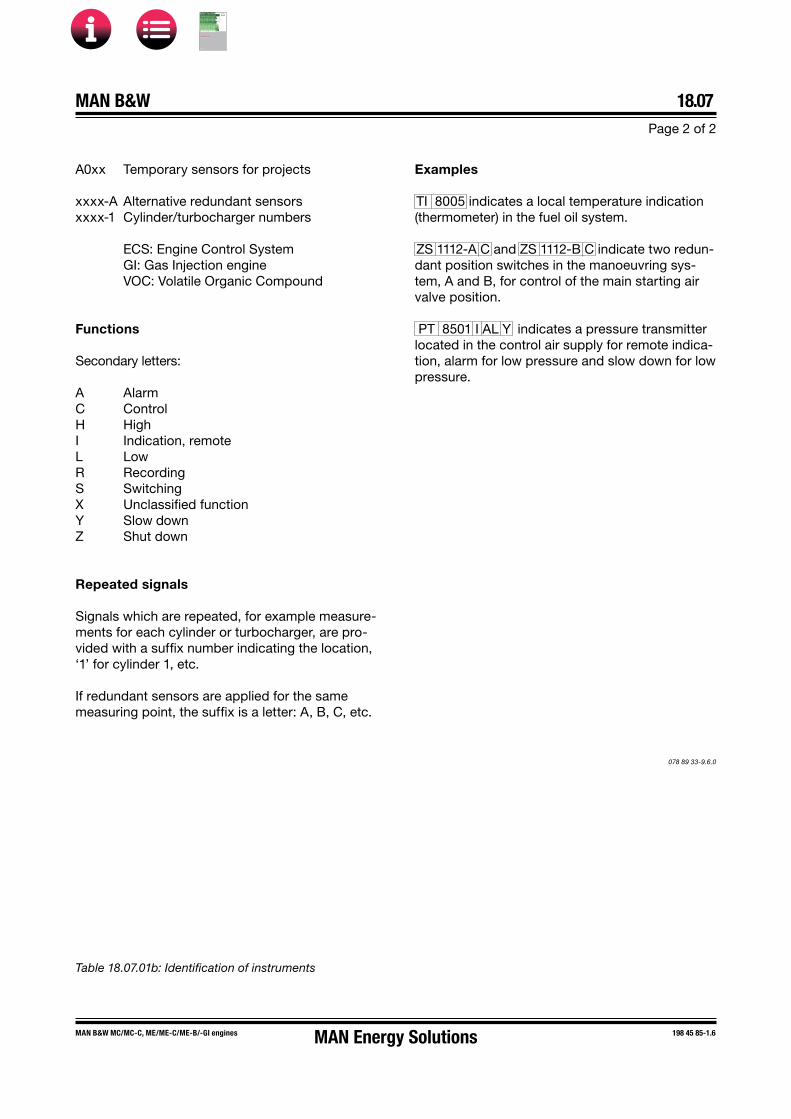
MAN B&W 18.07Page 2 of 2
MAN B&W MC/MC-C, ME/ME�C/ME-B/-GI engines 198 45 85-1.6
A0xx Temporary sensors for projects
xxxx�A Alternative redundant sensorsxxxx�1 Cylinder/turbocharger numbers
ECS: Engine Control SystemGI: Gas Injection engineVOC: Volatile Organic Compound
Functions
Secondary letters:
A AlarmC ControlH HighI Indication, remoteL LowR RecordingS SwitchingX Unclassified functionY Slow downZ Shut down
Repeated signals
Signals which are repeated, for example measure-ments for each cylinder or turbocharger, are pro-vided with a suffix number indicating the location, ‘1’ for cylinder 1, etc.
If redundant sensors are applied for the same measuring point, the suffix is a letter: A, B, C, etc.
Table 18.07.01b: Identification of instruments
Examples
TI 8005 indicates a local temperature indication (thermometer) in the fuel oil system.
ZS 1112�A C and ZS 1112�B C indicate two redun-dant position switches in the manoeuvring sys-tem, A and B, for control of the main starting air valve position.
PT 8501 I AL Y indicates a pressure transmitter located in the control air supply for remote indica-tion, alarm for low pressure and slow down for low pressure.
078 89 33-9.6.0
MAN Energy Solutions
MAN B&W
IMO Tier ll Project Guide
MAN
Energy Solutions Project G
uideM
AN B
&W G
95ME-C
10.5

MAN B&W Page 1 of 4
18.08
MAN B&W ME-GI TII engines 198 50 60-7.5
ME-GI Safety Aspects
The normal safety systems incorporated in the fuel oil systems are fully retained also during dual fuel operation. However, additional safety devices will be incorporated in order to prevent situations which might otherwise lead to failures.
Safety Devices – External systems
Leaking valves and fractured pipes are sources of faults that may be harmful. Such faults can be easily and quickly detected by a hydrocarbon (HC) analyser with an alarm function. An alarm is given at a gas concentration of max. 30% of the Lower Explosion Limit (LEL) in the vented duct, and a shut down signal is given at 60% LEL.
The safety devices that will virtually eliminate such risks are double-wall pipes and encapsulated valves with ventilation of the intervening space. The ventilation between the outer and inner walls is always to be in operation when there is gas in the supply line, and any gas leakage will be led to the HC sensors placed in the outer pipe dis-charge.
Another source of fault could be a malfunction-ing sealing oil supply system. If the gas sealing oil differential pressure becomes too low in the gas injection valve, gas will flow into the control oil activation system and, thereby, create unintended mixing of gas in the hydraulic oil system and cre-ate gas pockets and prevent the ELGI valve from operating the gas injection valve. Therefore, the sealing oil pressure is measured by a set of pres-sure sensors, and in the event of a too low pres-sure, the engine will shut down the gas mode and start running in the fuel oil mode.
Lack of ventilation in the double-wall piping system prevents the safety function of the HC sensors, so the system is to be equipped with a set of flow switches. If the switches indicate no flow, the engine will be shut down on gas mode. The switches should be of the normally open (NO) type, in order to allow detection of a malfunctioning switch, even in case of an electric power failure.
As natural gas is lighter than air, non-return valves are incorporated in the gas system’s outlet pipes to ensure that the gas system is not polluted, i.e. mixed with air.
Safety Devices – Internal systems
During normal operation, a malfunction in the pilot fuel injection system or gas injection system may involve a risk of uncontrolled combustion in the engine.
Sources of faults are:• defective gas injection valves• failing ignition of injected gas.
These aspects will be discussed in detail in the following together with the suitable countermeas-ures.
Defective gas injection valves
In case of sluggish operation or even seizure of the gas valve spindle in the open position, which will be detected by the gas pressure transmitter in the gas block, a limited amount of gas may be injected into the cylinder before the window valve closes. Therefore, when the exhaust valve opens, a hot mixture of combustion products and gas flows out and into the exhaust pipe and further on to the exhaust receiver.
The temperature of the mixture after the valve will increase considerably, and it is likely that the gas will burn with a diffusion type flame (without exploding) immediately after the valve where it is mixed with scavenge air/exhaust gas (with ap-proximately 15% oxygen) in the exhaust system. This may set off the high exhaust gas temperature alarm for the cylinder in question.
MAN Energy Solutions
MAN B&W
IMO Tier ll Project Guide
MAN
Energy Solutions Project G
uideM
AN B
&W G
95ME-C
10.5

MAN B&W 18.08Page 2 of 4
MAN B&W ME-GI TII engines 198 50 60-7.5
In the unlikely event of larger gas amounts enter-ing the exhaust receiver without starting to burn immediately, a later ignition may result in violent burning and a corresponding pressure rise. There-fore, the exhaust receiver is designed for the maximum pressure (around 15 bar).
However, any of the above-mentioned situations will be prevented by the detection of defective gas valves, which is arranged as follows.
Valve leakage monitoring pressure sensor
The valve leakage monitoring pressure sensor, installed in the gas block between the window/shutdown valve and the gas injection valves, is one unit with sensor and amplifier.
The pressure sensor measures pressure increase or decrease, concluding whether the window/shutdown valve or the gas injection valves are leaking, during every cycle from when the window/shutdown valve closes and until it opens again,
Ignition failure of injected gas
Failing ignition of the injected natural gas, i.e. mis-firing, can have a number of different causes, most of which, however, are the result of failure to inject pilot oil in a cylinder:
• leaky joints or fractured high-pressure pipes,making the fuel oil booster inoperative
• seized plunger in the fuel oil booster• other faults on the engine, forcing the fuel oil
booster to ‘0-index’.
Such misfiring causes a small amount of un-burned gas in the exhaust receiver to burn with a diffusion type flame as explained above. The GCSU detecs misfiring and the gas injection is stopped and a gas shut down initiated.
Compression and combustion pressure monitoring
The compression pressure as well as the maxi-mum combustion pressure are monitored. If low respectively too high, a gas shutdown is initiated.
Test of tightness of gas pipes
During shop test of the engine as well as vessel commisioning, a tightness test of the gas piping is conducted by means of valves installed in the gas return pipe.
Further information on tightness verification tests and gas leakage detection is available from MAN Energy Solutions, Copenhagen.
MAN Energy Solutions
MAN B&W
IMO Tier ll Project Guide
MAN
Energy Solutions Project G
uideM
AN B
&W G
95ME-C
10.5
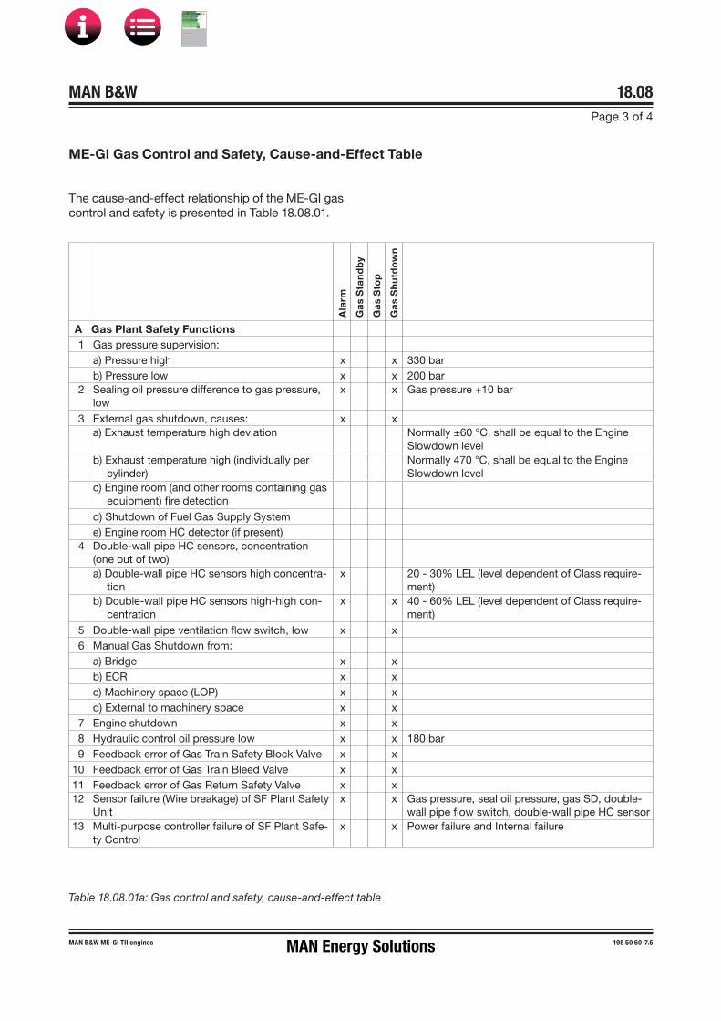
MAN B&W Page 3 of 4
18.08
MAN B&W ME-GI TII engines 198 50 60-7.5
ME-GI Gas Control and Safety, Cause-and-Effect Table
Ala
rm
Ga
s S
tan
db
y
Ga
s S
top
Ga
s S
hu
tdo
wn
A Gas Plant Safety Functions1 Gas pressure supervision:
a) Pressure high x x 330 barb) Pressure low x x 200 bar
2 Sealing oil pressure difference to gas pressure, low
x x Gas pressure +10 bar
3 External gas shutdown, causes: x xa) Exhaust temperature high deviation Normally ±60 °C, shall be equal to the Engine
Slowdown levelb) Exhaust temperature high (individually per
cylinder)Normally 470 °C, shall be equal to the Engine Slowdown level
c) Engine room (and other rooms containing gasequipment) fire detection
d) Shutdown of Fuel Gas Supply Systeme) Engine room HC detector (if present)
4 Double-wall pipe HC sensors, concentration (one out of two) a) Double-wall pipe HC sensors high concentra-
tionx 20 - 30% LEL (level dependent of Class require-
ment)b) Double-wall pipe HC sensors high-high con-
centrationx x 40 - 60% LEL (level dependent of Class require-
ment)5 Double-wall pipe ventilation flow switch, low x x6 Manual Gas Shutdown from:
a) Bridge x xb) ECR x xc) Machinery space (LOP) x xd) External to machinery space x x
7 Engine shutdown x x8 Hydraulic control oil pressure low x x 180 bar9 Feedback error of Gas Train Safety Block Valve x x
10 Feedback error of Gas Train Bleed Valve x x11 Feedback error of Gas Return Safety Valve x x12 Sensor failure (Wire breakage) of SF Plant Safety
Unitx x Gas pressure, seal oil pressure, gas SD, double-
wall pipe flow switch, double-wall pipe HC sensor13 Multi-purpose controller failure of SF Plant Safe-
ty Controlx x Power failure and Internal failure
Table 18.08.01a: Gas control and safety, cause-and-effect table
The cause-and-effect relationship of the ME-GI gas control and safety is presented in Table 18.08.01.
MAN Energy Solutions
MAN B&W
IMO Tier ll Project Guide
MAN
Energy Solutions Project G
uideM
AN B
&W G
95ME-C
10.5

MAN B&W 18.08Page 4 of 4
MAN B&W ME-GI TII engines 198 50 60-7.5
Ala
rm
Ga
s S
tan
db
y
Ga
s S
top
Ga
s S
hu
tdo
wn
B SF Cylinder Safety Unit Functionality1 Cylinder pressure abnormal x x Max. pressure high, compression pressure low,
expansion pressure low2 Gas pressure in gas block abnormal x x Leakage of gas injection valve, window valve or
blow-off valve. Gas pressure drop during injec-tion. Sensor range
3 ELWI valve not OK x x Valve status failure (Power and Internal failure)5 Tacho system failure x x6 Sensor failure (Wire breakage) of Gas Cylinder
Safety Unitx x Cylinder Pressure, Cylinder Gas Pressure, ELWI,
Tacho system7 DASU controller failure of Gas Cylinder Safety
Controlx x Power failure and Internal failure
C Gas Control Units Functionality1 Gas pressure supervision:
a) Too low pressure compared to set point x x -50 bar, below 10 bar fuel oil compensation isactive + time-out alarm is active if too long
2 Gas temperature supervision:a) Gas temperature out of range x Alarm: Out of 30 - 55 °Cb) Gas temperature out of range x x Gas stop: Out of 0 - 60 °C
3 Sealing oil pressure difference to gas pressure, set point low
x x Gas pressure +10 bar
4 Double-wall pipe ventilation flow switch, low x x5 Fuel Gas Supply System signals:
a) Local fail (= not ready) x x Ready signal OFF
b) Not running x x6 Inert Gas Pressure low x 5 bar7 Hydraulic control oil pressure low x x 180 bar8 Valve control air pressure low x x 6 - 7 bar 9 Dry air flow low x x
10 ELGI valve not OK x x Valve status failure (Power and Internal failure)11 Feedback error of Gas Valve Train, Main Gas
Valvex x
12 Feedback error of Gas Return Valves x x13 Feedback error of Gas Valve Train, Inert Gas
Valvesx x Inert Gas Supply Valve, Inert Gas Bleed Valve,
Inert Gas Block Valve14 Sensor failure (Wire breakage) of control unit x x Control wire for Ventilation, FGSS, Inert Gas
System, Sealing Oil Pump and GVT 15 Multi-purpose controller failure of Gas Plant
Control x x x Power failure and Internal failure
D Gas Stop1 Activate Gas Stop button on MOP x
E Gas Standby1 Engine load < minimum gas running load x2 External Gas Standby request x3 Gas mass flow rate limit low x
Table 18.08.01b: Gas control and safety, cause-and-effect table
MAN Energy Solutions
MAN B&W
IMO Tier ll Project Guide
MAN
Energy Solutions Project G
uideM
AN B
&W G
95ME-C
10.5

MAN B&W
Dispatch Pattern, Testing, Spares and Tools
19MAN Energy Solutions
MAN B&W
IMO Tier ll Project Guide
MAN
Energy Solutions Project G
uideM
AN B
&W G
95ME-C
10.5
MAN B&W 19.01Page 1 of 2
MAN B&W MC/MC-C, ME/ME�C/ME-B/�GI engines 198 76 20�3.2
Dispatch Pattern, Testing, Spares and Tools
Painting of Main Engine
The painting specification, Section 19.02, indicates the minimum requirements regarding the quality and the dry film thickness of the coats of, as well as the standard colours applied on MAN B&W en-gines built in accordance with the ‘Copenhagen’ standard.
Paints according to builder’s standard may be used provided they at least fulfil the requirements stated.
Dispatch Pattern
The dispatch patterns are divided into two classes, see Section 19.03:
A: Short distance transportation and short term storage
B: Overseas or long distance transportation or long term storage.
Short distance transportation (A) is limited by a duration of a few days from delivery ex works until installation, or a distance of approximately 1,000 km and short term storage.
The duration from engine delivery until installation must not exceed 8 weeks.
Dismantling of the engine is limited as much as possible.
Overseas or long distance transportation or long term storage require a class B dispatch pat-tern.
The duration from engine delivery until installation is assumed to be between 8 weeks and maximum 6 months.
Dismantling is effected to a certain degree with the aim of reducing the transportation volume of the individual units to a suitable extent.
Note:Long term preservation and seaworthy packing are always to be used for class B.
Furthermore, the dispatch patterns are divided into several degrees of dismantling in which ‘1’ comprises the complete or almost complete en-gine. Other degrees of dismantling can be agreed upon in each case.
When determining the degree of dismantling, con-sideration should be given to the lifting capacities and number of crane hooks available at the engine maker and, in particular, at the yard (purchaser).
The approximate masses of the sections appear in Section 19.04. The masses can vary up to 10% depending on the design and options chosen.
Lifting tools and lifting instructions are required for all levels of dispatch pattern. The lifting tools, options: 4 12 110 or 4 12 111, are to be specified when ordering and it should be agreed whether the tools are to be returned to the engine maker, option: 4 12 120, or not, option: 4 12 121.
MAN Energy Solutions' recommendations for pres-ervation of disassembled / assembled engines are available on request.
Furthermore, it must be considered whether a drying machine, option: 4 12 601, is to be installed during the transportation and/or storage period.
Shop Trials/Delivery Test
Before leaving the engine maker’s works, the en-gine is to be carefully tested on diesel oil in the presence of representatives of the yard, the ship-owner and the classification society.
The shop trial test is to be carried out in accord-ance with the requirements of the relevant clas-sification society, however a minimum as stated in Section 19.05.
MAN Energy Solutions
MAN B&W
IMO Tier ll Project Guide
MAN
Energy Solutions Project G
uideM
AN B
&W G
95ME-C
10.5

MAN B&W 19.01Page 2 of 2
MAN B&W MC/MC-C, ME/ME�C/ME-B/�GI engines 198 76 20�3.2
MAN Energy Solutions' recommendations for shop trial, quay trial and sea trial are available on re-quest.
In connection with the shop trial test, it is required to perform a pre-certification survey on engine plants with FPP or CPP, options: 4 06 201 Engine test cycle E3 or 4 06 202 Engine test cycle E2 re-spectively.
Spare Parts
List of spare parts, unrestricted service
The tendency today is for the classification socie-ties to change their rules such that required spare parts are changed into recommended spare parts.
MAN Energy Solutions, however, has decided to keep a set of spare parts included in the basic extent of delivery, EoD: 4 87 601, covering the requirements and recommendations of the major classification societies, see Section 19.06.
This amount is to be considered as minimum safety stock for emergency situations.
Additional spare parts recommended by MAN Energy Solutions
The above�mentioned set of spare parts can be extended with the ‘Additional Spare Parts Rec-ommended by MAN Energy Solutions', option: 4 87 603, which facilitates maintenance because, in that case, all the components such as gaskets, sealings, etc. required for an overhaul will be read-ily available, see Section 19.07.
Wearing parts
The consumable spare parts for a certain period are not included in the above mentioned sets, but can be ordered for the first 1, 2, up to 10 years’ service of a new engine, option: 4 87 629.
The wearing parts that, based on our service experience, are estimated to be required, are listed with service hours in Tables 19.08.01 and 19.08.02.
Large spare parts, dimensions and masses
The approximate dimensions and masses of the larger spare parts are indicated in Section 19.09. A complete list will be delivered by the engine maker.
Tools
List of standard tools
The engine is delivered with the necessary special tools for overhauling purposes. The extent, dimen -sions and masses of the main tools is stated in Section 19.10. A complete list will be delivered by the engine maker.
Tool panels
Most of the tools are arranged on steel plate pan -els, EoD: 4 88 660, see Section 19.11 ‘Tool Panels’.
It is recommended to place the panels close to the location where the overhaul is to be carried out.
MAN Energy Solutions
MAN B&W
IMO Tier ll Project Guide
MAN
Energy Solutions Project G
uideM
AN B
&W G
95ME-C
10.5
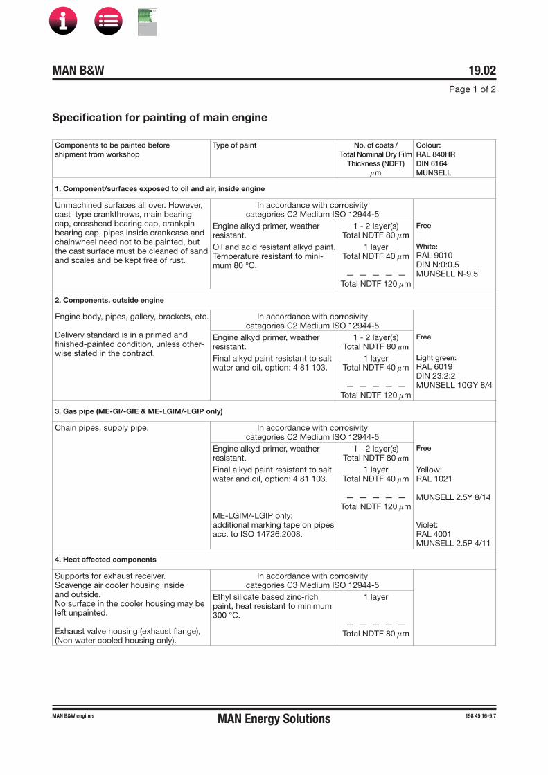
MAN B&W 19.02Page 1 of 2
MAN B&W engines 198 45 16�9.7
Specification for painting of main engine
Components to be painted before shipment from workshop
Type of paint No. of coats /Total Nominal Dry Film
Thickness (NDFT)μm
Colour:RAL 840HRDIN 6164MUNSELL
1. Component/surfaces exposed to oil and air, inside engine
Unmachined surfaces all over. However, cast type crankthrows, main bearing cap, crosshead bearing cap, crankpin bearing cap, pipes inside crankcase and chainwheel need not to be painted, but the cast surface must be cleaned of sand and scales and be kept free of rust.
In accordance with corrosivity categories C2 Medium ISO 12944-5
Engine alkyd primer, weather resistant.
1 - 2 layer(s)Total NDTF 80 μm
Free
Oil and acid resistant alkyd paint.Temperature resistant to mini-mum 80 °C.
1 layerTotal NDTF 40 μm
— — — — —Total NDTF 120 μm
White:RAL 9010DIN N:0:0.5MUNSELL N�9.5
2. Components, outside engine
Engine body, pipes, gallery, brackets, etc.
Delivery standard is in a primed and finished-painted condition, unless other-wise stated in the contract.
In accordance with corrosivity categories C2 Medium ISO 12944-5
Engine alkyd primer, weather resistant.
1 - 2 layer(s)Total NDTF 80 μm
Free
Final alkyd paint resistant to salt water and oil, option: 4 81 103.
1 layerTotal NDTF 40 μm
— — — — —Total NDTF 120 μm
Light green:RAL 6019DIN 23:2:2MUNSELL 10GY 8/4
3. Gas pipe (ME-GI/-GIE & ME-LGIM/-LGIP only)
Chain pipes, supply pipe. In accordance with corrosivity categories C2 Medium ISO 12944-5
Engine alkyd primer, weather resistant.
1 - 2 layer(s)Total NDTF 80 μm
Free
Final alkyd paint resistant to salt water and oil, option: 4 81 103.
ME-LGIM/-LGIP only:additional marking tape on pipes acc. to ISO 14726:2008.
1 layerTotal NDTF 40 μm
— — — — —Total NDTF 120 μm
Yellow:RAL 1021
MUNSELL 2.5Y 8/14
Violet:RAL 4001MUNSELL 2.5P 4/11
4. Heat affected components
Supports for exhaust receiver.Scavenge air cooler housing inside and outside.No surface in the cooler housing may be left unpainted.
Exhaust valve housing (exhaust flange), (Non water cooled housing only).
In accordance with corrosivity categories C3 Medium ISO 12944-5
Ethyl silicate based zinc-rich paint, heat resistant to minimum 300 °C.
1 layer
— — — — —Total NDTF 80 μm
MAN Energy Solutions
MAN B&W
IMO Tier ll Project Guide
MAN
Energy Solutions Project G
uideM
AN B
&W G
95ME-C
10.5

MAN B&W 19.02Page 2 of 2
MAN B&W engines 198 45 16�9.7
Components to be painted before shipment from workshop
Type of paint No. of coats /Total Nominal Dry Film
Thickness (NDFT)μm
Colour:RAL 840HRDIN 6164MUNSELL
5. Components affected by water, cleaning agents, and acid fluid below neutral Ph
Scavenge air cooler box inside. (Revers-ing chamber).
Preparation, actual number of coats, film thickness per coat, etc. must be accord-ing to the paint manufacturer’s specifica-tions.
Air flow reversing chamber inside and outside.
No surface may be left unpainted.Supervision from manufacturer is recom-mended in the phase of introduction of the paint system.
In accordance with corrosivity categories C5-M High ISO 12944-5
FreeTwo-component epoxy phenolic. 3 layers
— — — — —Total NDTF 350 μm
See specifications from product data sheet.
6. Gallery plates, top side Engine alkyd primer, weather resistant.
C2 Medium1-2 layer(s)
— — — — —Total NDTF 80 μm
7. EGR systemNormal air cooler housing with EGR mixpoint to scavenge air receiver non-returnvalves (500 μm).
Normal air cooler housing inside – from outlet air cooler – through reversing cham-ber and water mist catcher to non-return valves housing in scavenge air receiver.
Vinyl ESTER acrylic copolymer.
Note: Duplex/Stainless steel is not to be painted.
Total NDTF 500 - 1,200 μm
Free
8. Purchased equipment and instruments painted in maker’s colour are acceptable, unless otherwise stated in the contract
Tools are to be surface treated according to specifications stated in the drawings.
Purchased equipment painted in maker’s colour is acceptable, unless otherwise stated in the contract/drawing.
Electro(-) galvanised. See specifications from product data sheet.
Tool panels Oil resistant paint. 1 - 2 layer(s)
— — — — —Total NDTF 80 μm
Light grey:RAL 7038DIN 24:1:2MUNSELL N�7.5
All paints must be of good quality. Paints according to builder‘s standard may be used provided they at least fulfil the above requirements.The data stated are only to be considered as guidelines. Preparation, number of coats, film thickness per coat, etc., must be in accordance with the paint manufacturer’s specifications.
074 33 57-9.13.0
Fig. 19.02.01: Painting of main engine, option: 4 81 101, 4 81 102 or 4 81 103
MAN Energy Solutions
MAN B&W
IMO Tier ll Project Guide
MAN
Energy Solutions Project G
uideM
AN B
&W G
95ME-C
10.5

MAN B&W 19.03Page 1 of 4
199 01 47-3.1MAN B&W G45ME-C9-GI, G40ME-C9-GI
Dispatch Pattern
The relevant engine supplier is responsible for the actual execution and delivery extent. As differenc-es may appear in the individual suppliers’ extent and dispatch variants.
Dispatch Pattern A – short:Short distance transportation limited by duration of transportation time within a few days or a dis-tance of approximately 1,000 km and short term storage.
Duration from engine delivery to installation must not exceed eight weeks.
Dismantling must be limited.
Dispatch Pattern B – long:Overseas and other long distance transportation, as well as long-term storage.
Dismantling is effected to reduce the transport volume to a suitable extent.
Long-term preservation and seaworthy packing must always be used.
NoteThe engine supplier is responsible for the nec-essary lifting tools and lifting instructions for transportation purposes to the yard. The delivery extent of lifting tools, ownership and lend/lease conditions are to be stated in the contract. (Op-tions: 4 12 120 or 4 12 121)
Furthermore, it must be stated whether a drying machine is to be installed during the transporta-tion and/or storage period. (Option: 4 12 601)
MAN Energy Solutions
MAN B&W
IMO Tier ll Project Guide
MAN
Energy Solutions Project G
uideM
AN B
&W G
95ME-C
10.5

MAN B&W 19.03Page 2 of 4
199 01 47-3.1MAN B&W G45ME-C9-GI, G40ME-C9-GI
Fig. 19.03.01: Dispatch pattern, engine with turbocharger on exhaust side (4 59 123)
Dispatch pattern variants
A1 + B1 (option 4 12 021 + 4 12 031)Engine complete, i.e. not disassembled
A1 + B1
Engine complete
A2 + B2
Top section
Bottom section
074 27 15-7.0.0a
A2 + B2 (option 4 12 022 + 4 12 032)• Top section including cylinder frame complete,
cylinder covers complete, scavenge air re-ceiver including cooler box and cooler insert,turbocharger(s), piston complete and galler-ies with pipes, HCU units, oil filter, gas controlblocks, gas chain pipes and sealing oil pumpunit
• Bottom section including bedplate complete,frame box complete, connecting rods, turninggear, crankshaft complete and galleries
• Remaining parts including stay bolts, FIVAvalves etc.
MAN Energy Solutions
MAN B&W
IMO Tier ll Project Guide
MAN
Energy Solutions Project G
uideM
AN B
&W G
95ME-C
10.5

MAN B&W 19.03Page 3 of 4
199 01 47-3.1MAN B&W G45ME-C9-GI, G40ME-C9-GI
A3 + B3 (option 4 12 023 + 4 12 033)• Top section including cylinder frame complete,
cylinder covers complete, scavenge air re-ceiver including cooler box and cooler insert,turbocharger(s), piston complete and gallerieswith pipes, HCU Units, gas control block, gaschain pipes, and sealing oil pump unit, hydraulicpump station
• Frame box section including frame box com-plete, connecting rods and galleries, and oil flter
• Bedplate/crankshaft section including bedplatecomplete, crankshaft complete with gear wheelsand turning gear, gearbox for hydraulic powersupply
• Remaining parts including stay bolts, FIVAvalves, etc.
A3 + B3
Top section
Frame box section
Bedplate/crankshaft section
Fig. 19.03.02: Dispatch pattern, engine with turbocharger on exhaust side (4 59 123)
074 27 15-7.0.0b
MAN Energy Solutions
MAN B&W
IMO Tier ll Project Guide
MAN
Energy Solutions Project G
uideM
AN B
&W G
95ME-C
10.5

MAN B&W 19.03Page 4 of 4
199 01 47-3.1MAN B&W G45ME-C9-GI, G40ME-C9-GI
Top section
Air cooler box
Exhaust receiver
Turbocharger
Frame box section
Bedplate section
Crankshaft section
074 27 15-7.0.2c
Fig. 19.03.03: Dispatch pattern, engine with turbocharger on exhaust side (4 59 123)
A4 + B4 (option 4 12 024 + 4 12 034)• Top section including cylinder frame complete,
cylinder covers complete, piston complete andgalleries with pipes on manoeuvring side, HCUunits, gas control block, gas chain pipe, andsealing oil pump unit, hydraulic power station
• Exhaust receiver with pipes• Scavenge air receiver with galleries and pipes• Turbocharger• Air cooler box with cooler insert• Frame box section including frame box com-
plete, connecting rods and galleries, and oil filter• Gearbox for hydraulic power supply• Crankshaft with gear wheels• Bedplate with pipes and turning gear• Remaining parts including stay bolts, auxiliary
blowers, chains FIVA valves etc.
Crankshaft section
MAN Energy Solutions
MAN B&W
IMO Tier ll Project Guide
MAN
Energy Solutions Project G
uideM
AN B
&W G
95ME-C
10.5

MAN B&W Page 1 of 1
This section is available on request
Dispatch Pattern, List of Masses and Dimensions
198 47 63-6.0
19.04
MAN Energy Solutions
MAN B&W
IMO Tier ll Project Guide
MAN
Energy Solutions Project G
uideM
AN B
&W G
95ME-C
10.5

MAN B&W 19.05Page 1 of 2
MAN B&W ME�GI/-LGI TII engines 198 87 37-2.1
The minimum delivery test for MAN B&W two-stroke engines, EoD: 4 14 001, involves:
• Starting and manoeuvring test at no load• Load test• Engine to be started and run up to 50% of
Specified MCR (M) in 1 hour.
and is followed by the below mentioned tests.
Load test at specific load points
The engine performance is recorded running at:
• 25% of specified MCR• 50% of specified MCR• 75% of specified MCR• 90% of specified MCR or at NCR• 100% of specified MCR *)• 110% of specified MCR.
Records are to be taken after 15 minutes or after steady conditions have been reached, whichever is shorter.
*) Two sets of recordings are to be taken at a mini-mum interval of 30 minutes.
Governor test and more:
• Integration test of ECS• Governor test• Minimum speed test• Overspeed test• Shut down test• Starting and reversing test• Turning gear blocking device test• Start, stop and reversing from the Local
Operating Panel (LOP).
Second fuel test
Further to the minimum delivery test, in the shop test on second fuel, EoD: 4 14 041 (-GI) and 4 00 042 (-LGI), the engine is to be carefully tested on both diesel oil and second fuel. The test is carried out in the presence of representatives of Yard, Shipowner, Classification Society, and MAN Energy Solutions.
Fuel oil and second fuel analyses are to be pre-sented. All load point measurements are to be carried out on diesel or gas oil as well as on sec-ond fuel and must include:
• test of auto change-over to second fuel fromsecond fuel standby condition when engineload exceeds the lowest limit for second fueloperation
• test of auto change-over to fuel oil when engineload falls below the lowest limit for second fueloperation
• demonstration of change-over between fuel oiland second fuel at each load stop
• second fuel shut down at 110% load, resultingin continued running of main engine on primaryfuel.
The shop tests are all carried out according to:
Factory Acceptance Test and Shipboard Trials of I.C. Engines, UR M51
by International Association of Classification Soci-eties LTD. (IACS), www.iacs.org.uk
EIAPP certificate
Most marine engines installed on ocean going vessels are required to have an ‘Engine Interna-tional Air Pollution Prevention’ (EIAPP) Certificate, or similar. Therefore, a pre-certification survey is to be carried out for all engines according to the survey method described in the engine’s NOxTechnical File, which is prepared by the engine manufacturer. For MAN B&W engines, the Unified Technical File (UTF) format is recommended.
Shop Test
MAN Energy Solutions
MAN B&W
IMO Tier ll Project Guide
MAN
Energy Solutions Project G
uideM
AN B
&W G
95ME-C
10.5

MAN B&W 19.05Page 2 of 2
MAN B&W ME�GI/-LGI TII engines 198 87 37-2.1
The EIAPP certificate documents that the specificengine meets the international NOx emission limi-tations specified in Regulation 13 of MARPOL An-nex VI. The basic engine ‘Economy running mode’, EoD: 4 06 200, complies with these limitations.
The pre-certification survey for a ‘Parent’ or an ‘Individual’ engine includes NOx measurements during the delivery test. For ‘Member’ engines, a survey according to the group definition for the engine group is needed. This survey should be based on the delivery test.
The applicable test cycles are:
• E3, marine engine, propeller law for FPP, option:4 06 201
or• E2, marine engine, constant speed for CPP, op-
tion: 4 06 202
For further options regarding shop test, see Ex-tent of Delivery.
MAN Energy Solutions
MAN B&W
IMO Tier ll Project Guide
MAN
Energy Solutions Project G
uideM
AN B
&W G
95ME-C
10.5

MAN B&W 19.06Page 1 of 2
MAN B&W G/S50-40ME-C9-GI 199 05 96-5.4
GI cylinder cover, plate 2272-0300 (901 and more)1 Cylinder cover complete with extra holes for
gas equipment and Inconel cladding. Including fuel, gas injection, exhaust and starting valves, indicator valve, cooling jacket, gas control block, piping between gas control block and gas injection valves, bushings for gas injection valves and sealing rings (disassembled)
½ set Studs for 1 cylinder cover
Gas Pipe Supply Chain, plate 4272-2800 (901 and more)1 set Double-wall fuel gas pipes for 1 cylinder1 set Repair kit for high-pressure gas pipes and con-
nection flanges for 1 engine, including gaskets and packings
Piston and piston rod, plates 2272-0400/0420/0500 (902)1 Piston complete (with cooling pipe), piston rod,
piston rings and stuffing box, studs and nuts1 set Piston rings for 1 cylinder
Cylinder liner, plate 2272-0600 (903)
1 Cylinder liner complete, inclusive of cooling jacket, non-return valves, sealing rings and gaskets (assembled)
Cylinder lubricating oil system, plates 3072-0600,6670-0100 (903) 1)1 Lubricator complete1 Inductive sensor1 set O-rings and seals2 Lubricator backup cable
Connecting rod, and crosshead bearing, plates 1472-0300, 2572-0300/0200 (904)1 Telescopic pipe with bushing for 1 cylinder1 Crankpin bearing shell (1 upper and 1 lower part)
with studs and nuts1 Crosshead bearing shell lower part with studs
and nuts
Thrust block, plate 2572-0600 (905)1 set Thrust pads, complete FWD set for ‘Ahead’1 set For KR and NK also 1 set ‘Astern’ if different
from ‘Ahead’
HPS � Hydraulic Power Supply, plates 4572-1000/0750, 4572-1100/1200/1250 (906) 1 and 2)1 Proportional valve for hydraulic pumps1 Leak indicator1 Drive shaft for hydraulic pump, of each type
(length)1 Compensator, fluid type1 set High-pressure gasket kit1 Hydraulic pump1 Coupling for start-up pump
ME filter, plate 4572-08001 set Filter cartridges for redundancy filter. Cartridge
filtration ability, minimum Beta6=16. Only forfilter make Kanagawa
Engine control system, plates 4772-1500/1550, 7072-0800/1100/1250 (906) 2)1 Multi Purpose Controller MPC1 Trigger sensor for tacho system. Only if trigger
ring and no angular encoder on fore end.Only for engine with PTO
1 Marker sensor for tacho system1 Tacho signal amplifier1 ID�key1 Encoder, steel compensator and bearing set1 Fuse kit
Starting valve, plates 3472-0200/0250 (907)1 Starting valve, complete 2)
(Included in the Cylinder cover complete)1 Solenoid valve 1)
Hydraulic cylinder unit, plates 4572-0500/0550/0100/0900, 4272-0500 (906, 907) 1 and 2)1 Fuel booster top cover, complete with plunger1 ELFI + ELVA valves complete, or FIVA if applied1 Suction valve complete1 20
%*Flexible high-pressure hoses, one of each size and length. *) Only for DNV
1 High-pressure pipe kit, one of each size and length
1 set Membrane plus seals for accumulator, 1 set for 1 HCU
1 Packing kit (O-rings, square seals and bonded seals)
1 Fuel booster position sensor1 Exhaust actuator complete
List of Spare Parts, Unrestricted Service
Fig. 19.06.01a: List of spare parts, unrestricted service: 4 87 601
Spare parts are requested by the following Classifica-tion Society only: NK, while just recommended by: ABS, DNV, CRS, KR, LR and RS, but neither requested nor recommended by: BV, CCS and RINA.
The final scope of spare parts is to be agreed between the owner and engine builder/yard.
MAN Energy Solutions
MAN B&W
IMO Tier ll Project Guide
MAN
Energy Solutions Project G
uideM
AN B
&W G
95ME-C
10.5

MAN B&W 19.06Page 2 of 2
MAN B&W G/S50-40ME-C9-GI 199 05 96-5.4
Fig. 19.06.01b: List of spare parts, unrestricted service: 4 87 601
Exhaust valve, plates 2272-0200/0210/0240 (908)2 Exhaust valves complete
(The 2nd exhaust valve is included in the Cylin-der cover complete)
1 High�pressure pipe from actuator to exhaust valve1 Exhaust valve position sensor
Fuel valve, plates 4272-0200/0100/2300 (909)1 set Fuel valves of each size and type fitted, com-
plete with all fittings, for 1 enginea)engines with 1 or 2 fuel valves: 1 set offuel valves for all cylinders on the engineb)engines with 3 and more fuel valves percylinder: 2 fuel valves complete per cylinder,and a sufficient number of valve parts, excludingthe body, to form, with those fitted in the com-plete valve, a full engine set
Gas injection valve, plate 4272-23002 set PTFE seals for 1 engineFor engine with 3 gas injection valves per cylinder:3 set Gas injection valve including sealings for 1
cylinder (The 3rd set of gas injection valve is included in the Cylinder cover complete)
2 set Seals for fuel gas (excl. PTFE seals), for 1 en-gine
For engine with 2 gas injection valves per cylinder:2 set Gas injection valve including sealings for 1
cylinder (The 2nd set of gas injection valve is included in the Cylinder cover complete)
1 set Seals for fuel gas (excl. PTFE seals), for 1 en-gine
Fuel oil high-pressure pipes, plate 4272-0100 (909)1 set High�pressure pipe, from fuel oil pressure
booster to fuel valve
Turbocharger, plate 5472-0700 (910)1 set Maker’s standard spare parts1 a) Spare rotor for 1 turbocharger, including com-
pressor wheel, rotor shaft with turbine blades and partition wall, if any
Auxiliary blower, plate 5472-0500 (910)1 set Bearings for blower wheel1 set Packing for blower wheel
Bedplate, plates 1072-0400, 2572-0400 (912)1 Main bearing shell (1 upper and 1 lower part) of
each size1 set Studs and nuts for 1 main bearing
1) MAN ES required spare parts.2) All spare parts are requested by all Classes. a) Only required for RS. To be ordered separately as
option: 4 87 660 for other classification societies
Note: Plate numbers refer to the Instruction Manual containing plates with spare parts (older three-digit numbers are included for reference)
MAN Energy Solutions
MAN B&W
IMO Tier ll Project Guide
MAN
Energy Solutions Project G
uideM
AN B
&W G
95ME-C
10.5

MAN B&W 19.07Page 1 of 3
MAN B&W G/S50-40ME-C9-GI 199 05 98-9.2
Cylinder liner and cooling jacket, plate 2272-0600/0660/0665 (903)
4 Non-return valves1 eng O�rings for cylinder liner½ eng Gaskets for cooling water connection½ eng O�rings for cooling water pipes1 set Cooling water pipes with blocks between liner
and cover for 1 cylinder1 *) Repair kit for LDCL circulation pump1 *) Repair kit for LDCL three-way control valve
*) if fitted
Cylinder Lubricating Oil System, plate 3072-0600 (903)
1 Control valve1 Level switch for lubricator1 Lubricator position sensor
Hydaulic power supply, HPS, plates 4572-1000/0750, 4572-1100/1200/1250 (906) 1 Electric motor for start-up pump 1 Pressure relief valve for start-up pump 2 Pressure reducer for pump inlet25% Plug screws for hydraulic system (HPS & HCU) 1 Proportional valve 1 Swashplate transducer 1 Rubber compensator for inlet
Gas control block, plates 4272-2000/2020/2030 (909)1 Adapter block, complete1 set Sealings for 1 adapter block1 Accumulator for gas control block1 set Repair kit for 1 gas control block incl. brass
plugs, gaskets and packings2 ELGI/ ELWI valves1 Window valve2 Blow-off/Purge valves1 Gas channel pressure sensor2 eng Sealings and packings for window valve/accu-
mulators1 eng Sealings and packings for blow-off/purge
valves
Cylinder cover, plate 2272-0300 (901)4 Studs for exhaust valve4 Nuts for exhaust valve½ eng O�rings for cooling jacket½ eng Sealing between cylinder cover and liner1 set Bushings for gas injection valve for 1 cylinder1 set Sealings rings for gas injection valve bushings
for 1 cylinder
Hydraulic tool for cylinder cover, plates 2270-0310/0315 (901)
1 set Hydraulic hoses with protection hose complete with couplings
8 pcs O�rings with backup rings, upper8 pcs O�rings with backup rings, lower
Piston and piston rod, plates 2272-0400/0420 (902)1 box Locking wire, L=63 m5 Piston rings of each kind2 D�rings for piston skirt2 D�rings for piston rod
Piston rod stuffing box, plate 2272-0500 (902) 15 Self-locking nuts 5 O�rings 5 Top scraper rings 15 Pack sealing rings 10 Cover sealing rings 120 Lamellas for scraper rings 30 Springs for top scraper and sealing rings 20 Springs for scraper rings
Cylinder frame, plate 1072-0710 (903)½ set Studs for cylinder cover for 1 cylinder1 Bushing for stuffing box
Fig. 19.07.01a: Additional spare parts beyond class requirements or recommendation, option: 4 87 603
Additional Spares
Beyond class requirements or recommendation, for easier maintenance and increased security in operation.
The final scope of spare parts is to be agreed between the owner and engine builder/yard.
MAN Energy Solutions
MAN B&W
IMO Tier ll Project Guide
MAN
Energy Solutions Project G
uideM
AN B
&W G
95ME-C
10.5

MAN B&W 19.07Page 2 of 3
MAN B&W G/S50-40ME-C9-GI 199 05 98-9.2
Arrangement of control oil pipes, plate 4272-2050 (909)
½ eng Sealing rings½ eng Non-return valve
Gas injection valve, plate 4272-23001 eng Sealings (Repair kit)
Sealing oil for gas valves, plates 4272-2600/2650 (909)1 set Sealing oil high-pressure pipes, for 1 cylinder1 Filter element for sealing oil filter1 Repair kit for sealing oil pump
Engine control system, ECS, plates 4772-1500, 7072-1250 (906)
1 set Fuses for MPC, TSA, CNR1 Gas detector1 Flow switch for gas system
Hydraulic cylinder unit, HCU, plates 4572-0500, 4272-2300 (906)
1 set Packings for booster & actuator, complete set1 ELFI + ELVA valves, or FIVA if applied1 Ball valve, pos. 4201 Ball valve DN101 set Accumulator complete
25% Plug screws, shared with HPS & accumulator block
1 set Piping for activation of gas injection valves, for 1 cylinder
Accumulator/safety block, plate 4572-0700 (906) 1 Pressure transducer, pos. 32025% Plug screws, shared with HPS & HCU 1 Ball valve DN10 1 Solenoid valve for valve pos. 310 (shut down)
Alarm and safety system, plate 4772-1 Pressure sensor for scavenge air receiver,
PT 86011 Pressure switch for lubricating oil inlet, PS 81091 Thrust bearing temperature sensor, TS 8107
(sensor only)1 Pressure switch for jacket cooling water inlet,
PS 8402
GI control, plates 4772-1500, 7072-0800 (906)1 DASU computer1 Cylinder pressure sensor1 Gas pressure sensor, according to maker’s
recommendation1 Pressure sensor for sealing oil pressure
Main starting valve, plate 3472-0300 (907)The below main starting valve parts are all to be in ac-cordance with the supplier’s recommendation:
1 Repair kit for main actuator1 Repair kit for main ball valve1 *) Repair kit for actuator, slow turning1 *) Repair kit for ball valve, slow turning
*) if fitted
Starting valve, plate 3472-0200 (907)2 Locking plates2 Pistons2 Springs2 Bushing1 set O�rings1 Valve spindle
Exhaust valve, plates 2272-0200/0210 (908)1 Exhaust valve spindle1 Exhaust valve seat½ eng Sealing rings between exhaust valve and cyl-
inder cover4 Piston rings½ eng Guide rings for air piston½ eng Sealing rings½ eng Safety valves1 eng Gaskets and O�rings for safety valve1 Piston complete1 eng O�rings and sealings between air piston and
exhaust valve housing/spindle1 Spindle guide1 eng Gaskets and O�rings for cooling water
connection1 Conical ring in 2/2. Only for low-force design1 eng O�rings for spindle/air piston1 eng Non�return valve1 Inductive sensor for exhaust valve positioning
Exhaust valve pipe, plate 2272-0240 (908)1 High pressure pipe from actuator to exhaust
valve
Fig. 19.07.01b: Additional spare parts beyond class requirements or recommendation, option: 4 87 603
MAN Energy Solutions
MAN B&W
IMO Tier ll Project Guide
MAN
Energy Solutions Project G
uideM
AN B
&W G
95ME-C
10.5
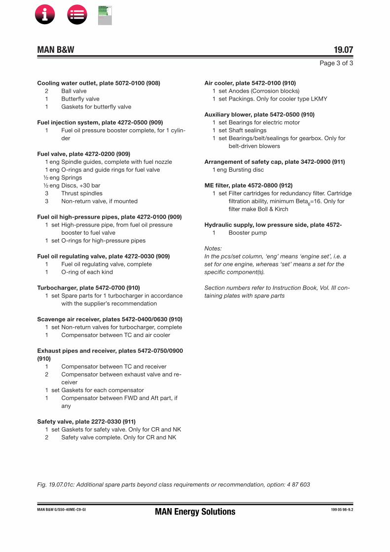
MAN B&W 19.07Page 3 of 3
MAN B&W G/S50-40ME-C9-GI 199 05 98-9.2
Cooling water outlet, plate 5072-0100 (908)2 Ball valve1 Butterfly valve1 Gaskets for butterfly valve
Fuel injection system, plate 4272-0500 (909)1 Fuel oil pressure booster complete, for 1 cylin-
der
Fuel valve, plate 4272-0200 (909)1 eng Spindle guides, complete with fuel nozzle1 eng O�rings and guide rings for fuel valve½ eng Springs½ eng Discs, +30 bar3 Thrust spindles3 Non-return valve, if mounted
Fuel oil high-pressure pipes, plate 4272-0100 (909)1 set High-pressure pipe, from fuel oil pressure
booster to fuel valve1 set O�rings for high-pressure pipes
Fuel oil regulating valve, plate 4272-0030 (909)1 Fuel oil regulating valve, complete1 O�ring of each kind
Turbocharger, plate 5472-0700 (910)1 set Spare parts for 1 turbocharger in accordance
with the supplier’s recommendation
Scavenge air receiver, plates 5472-0400/0630 (910)1 set Non�return valves for turbocharger, complete1 Compensator between TC and air cooler
Exhaust pipes and receiver, plates 5472-0750/0900 (910)
1 Compensator between TC and receiver2 Compensator between exhaust valve and re-
ceiver1 set Gaskets for each compensator1 Compensator between FWD and Aft part, if
any
Safety valve, plate 2272-0330 (911)1 set Gaskets for safety valve. Only for CR and NK2 Safety valve complete. Only for CR and NK
Fig. 19.07.01c: Additional spare parts beyond class requirements or recommendation, option: 4 87 603
Air cooler, plate 5472-0100 (910)1 set Anodes (Corrosion blocks)1 set Packings. Only for cooler type LKMY
Auxiliary blower, plate 5472-0500 (910)1 set Bearings for electric motor1 set Shaft sealings1 set Bearings/belt/sealings for gearbox. Only for
belt-driven blowers
Arrangement of safety cap, plate 3472-0900 (911)1 eng Bursting disc
ME filter, plate 4572-0800 (912)1 set Filter cartridges for redundancy filter. Cartridge
filtration ability, minimum Beta6=16. Only for
filter make Boll & Kirch
Hydraulic supply, low pressure side, plate 4572-1 Booster pump
Notes:In the pcs/set column, ‘eng’ means ‘engine set’, i.e. a set for one engine, whereas ‘set’ means a set for the specific component(s).
Section numbers refer to Instruction Book, Vol. III con-taining plates with spare parts
MAN Energy Solutions
MAN B&W
IMO Tier ll Project Guide
MAN
Energy Solutions Project G
uideM
AN B
&W G
95ME-C
10.5

MAN B&W 19.09Page 1 of 1
199 10 72-2.0
Large spare parts, dimensions and masses
This section is available on request
MAN Energy Solutions
MAN B&W
IMO Tier ll Project Guide
MAN
Energy Solutions Project G
uideM
AN B
&W G
95ME-C
10.5

MAN B&W 19.09Page 2 of 2
MAN B&W engines 199 01 89-2.1
Fig. 19.09.02: Large spare parts, dimensions and masses
Rotor for turbocharger
MAN
TypeMax Mass Dimensions (mm)
kg. A (ø) B C (ø)
TCA44 90 480 880 460
TCA55 140 570 990 515
TCA66 230 670 1,200 670
TCA77 390 800 1,380 730
TCA88 760 940 1,640 980
TCR18 24 280 469
TCR20 42 337 566
TCR22 95 440 739
561 70 21-6.0.1
ABB
Type
Max Mass
Dimensions (mm)
kg. A (ø) B C (ø)
A165-L 90 500 940 395
A170-L 130 580 1,080 455
A175-L 220 700 1,300 550
A180-L 330 790 1,470 620
A185-L 460 880 1,640 690
A190-L 610 970 1,810 760
A265-L 100 500 930 395
A270-L 140 580 1,090 455
A275-L 240 700 1,320 550
A280-L 350 790 1,490 620
A285-L 490 880 1,660 690
561 66 78-9.0.0
MHI
Type
Max Mass
Dimensions (mm)
kg. A (ø) B C (ø)
MET33MA 45 373 662 364
MET33MB 55 373 692 364
MET42MA 68.5 462 807 451
MET42MB 85 462 847 451
MET48MB 155 524 954 511
MET53MA 190 586 1,035 571
MET53MB 210 586 1,068 571
MET60MA 240 652 1,188 636
MET60MB 270 652 1,185 636
MET66MA 330 730 1,271 712
MET66MB 370 730 1,327 712
MET71MA 400 790 1,318 771
MET71MB 480 790 1,410 771
MET83MA 600 924 1,555 902
MET83MB 750 924 1,608 902
MET90MA 850 1,020 1,723 996
MET90MB 950 1,020 1,794 996
561 68 37-2.1.0
A
B
C
178 68 17-0.1
MAN Energy Solutions
MAN B&W
IMO Tier ll Project Guide
MAN
Energy Solutions Project G
uideM
AN B
&W G
95ME-C
10.5

MAN B&W 19.10Page 1 of 2
MAN B&W G45ME-C9.5 -GI 199 01 10-1.0
List of Standard Tools for Maintenance
The engine is delivered with all necessary special tools for scheduled maintenance. The extent of the tools is stated below. Most of the tools are arranged on steel plate panels. It is recommended to place them close to the location where the overhaul is to be carried out, see Section 19.11.
All measurements are for guidance only.
Cylinder Cover, MF/SF 21-90101 pcs Tool panel incl. lifting chains, grinding mandrels,
extractor tools etc.1 set Lifting tools for cylinder cover
Cylinder Unit Tools, MF/SF 21-90141 pcs Tool panel incl. pressure testing tool, piston ring
expander, stuffing box tools, templates etc.1 pcs Guide ring for piston1 pcs Lifting tool for piston1 pcs Support iron for piston1 pcs Lifting tool for cylinder liner, piston1 set Measuring tool for cylinder liner1 set Test equipment for Alpha Lubricator1 pcs ECU temporary backup cable for indicator
Crosshead and Connection Rod Tools, MF/SF 21-90221 pcs Tool panel incl. suspension and lifting tools,
protection in crankcase etc.1 pcs Guide shoe extractor
Crankshaft and Thrust Bearing Tools, MF/SF 21-90261 pcs Tool panel incl. lifting, testing and retaining
tools etc.1 pcs Lifting tool for crankshaft1 pcs Lifting tool for thrust shaft1 set Feeler gauges
Control Gear Tools, MF/SF 21-9030
1 pcs Pin gauge for crankshaft1 set Hook wrenches for accumulator
Exhaust Valve Tools, MF/SF 21-90381 pcs Tool panel incl. grinding-, lifting-, adjustment-
and test tools etc.
Gas System Tools, MF/SF 21-90401 pcs Tool panel incl. hook wrenches, extractors,
grinding- and lifting tools etc.
1 pcs Gas detector1 pcs Test rig for gas valve1 pcs Tool box containing :1 set Sealing tools for gas valve1 set Sealing tools for shutdown valve1 set Sealing tools for blow-off valve1 pcs Chisel and guide for gas valve sealing disman-
tling1 set Plugs for leakage search, incl. handle1 set Various covers for gas system
Fuel Oil System Tools, MF/SF 21-90421 pcs Tool panel incl. grinding, lifting, adjustment and
assembly tools etc.1 set Fuel valve nozzle tools1 set Toolbox for fitting of fuel pump seals1 pcs Probe light1 pcs Test rig for fuel valve
Turbocharger System Tools, MF/SF 21-9046
1 set Air cooler cleaning tool1 pcs Compensator, dismantling tool1 pcs Travelling trolley1 set Blanking plates for turbo chargers
General Tools, MF/SF 21-90581 set Pump for hydraulic jacks incl. hydraulic
accessories 1 set Set of tackles, trolleys, eye bolts, shackles, wire
ropes1 set Instruments incl. mechanical / digital measuring
tools1 set Hand tools incl. wrenches, pliers and spanners
Hydraulic Jacks, MF/SF 21-94It is important to notice, that some jacks are used on different components on the engine
MAN Energy Solutions
MAN B&W
IMO Tier ll Project Guide
MAN
Energy Solutions Project G
uideM
AN B
&W G
95ME-C
10.5

MAN B&W 19.10Page 2 of 2
MAN B&W G45ME-C9.5 -GI 199 01 10-1.0
Personal Safety Equipment, MF/SF 21-9070
1 pcs Fall arrest block and rescue harness1 pcs Fall arrest equipment - Optional
Optional Tools
1 pcs Collar ring for piston1 pcs Cylinder wear measuring tool, insertable1 pcs Support for tilting tool1 pcs Valve seat and spindle grinder1 pcs Wave cutting machine for cylinder liner1 pcs Wear ridge milling machine1 pcs Work table for exhaust valve1 pcs Crankshaft deflection measuring tool (Digital)
Mass of the complete set of tools: Available on request
MAN Energy Solutions
MAN B&W
IMO Tier ll Project Guide
MAN
Energy Solutions Project G
uideM
AN B
&W G
95ME-C
10.5

MAN B&W Page 1 of 1
This section is available on request
Tool Panels
198 66 45-0.0
19.11
MAN Energy Solutions
MAN B&W
IMO Tier ll Project Guide
MAN
Energy Solutions Project G
uideM
AN B
&W G
95ME-C
10.5

MAN B&W
Project Support and Documentation
20MAN Energy Solutions
MAN B&W
IMO Tier ll Project Guide
MAN
Energy Solutions Project G
uideM
AN B
&W G
95ME-C
10.5

MAN B&W 20.01Page 1 of 1
198 45 88-7.5MAN B&W MC/MC-C, ME/ME-C/ME-B/-GI engines
Project Support and Documentation
The selection of the ideal propulsion plant for a specific newbuilding is a comprehensive task. However, as this selection is a key factor for the profitability of the ship, it is of the utmost impor-tance for the end�user that the right choice is made.
MAN Energy Solutions is able to provide a wide variety of support for the shipping and shipbuilding industries all over the world.
The knowledge accumulated over many decades by MAN Energy Solutions covering such fields as the selection of the best propulsion machinery, optimisation of the engine installation, choice and suitability of a Power Take Off for a specific project, vibration aspects, environmental control etc., is available to shipowners, shipbuilders and ship designers alike.
Part of this information can be found in the follow-ing documentation:
• Marine Engine Programme•Turbocharger Selection•Installation Drawings• CEAS - Engine Room Dimensioning• Project Guides• Extent of Delivery (EOD)• Technical Papers
The publications are available at: www.marine.man-es.com → ’Two-Stroke’.
Engine Selection Guides
The ‘Engine Selection Guides’ are intended as a tool to provide assistance at the very initial stage of the project work. The guides give a general view of the MAN B&W two�stroke Programme for MC as well as for ME and ME-B engines and in-clude information on the following subjects:
• Engine data• Engine layout and load diagrams
specific fuel oil consumption• Turbocharger selection• Electricity production, including power take off• Installation aspects
• Auxiliary systems• Vibration aspects.
After selecting the engine type on the basis of this general information, and after making sure that the engine fits into the ship’s design, then a more detailed project can be carried out based on the ‘Project Guide’ for the specific engine type selected.
Project Guides
For each engine type of MC, ME or ME-B design a ‘Project Guide’ has been prepared, describing the general technical features of that specific engine type, and also including some optional features and equipment.
The information is general, and some deviations may appear in a final engine documentation, de-pending on the content specified in the contract and on the individual licensee supplying the en-gine. The Project Guides comprise an extension of the general information in the Engine Selection Guide, as well as specific information on such subjects as:
• Engine Design• Engine Layout and Load Diagrams, SFOC• Turbocharger Selection & Exhaust Gas By�pass• Electricity Production• Installation Aspects• List of Capacities: Pumps, Coolers & Exhaust Gas• Fuel Oil• Lubricating Oil• Cylinder Lubrication• Piston Rod Stuffing Box Drain Oil• Central Cooling Water System• Seawater Cooling• Starting and Control Air• Scavenge Air• Exhaust Gas• Engine Control System• Vibration Aspects• Monitoring Systems and Instrumentation• Dispatch Pattern, Testing, Spares and Tools• Project Support and Documentation.
MAN Energy Solutions
MAN B&W
IMO Tier ll Project Guide
MAN
Energy Solutions Project G
uideM
AN B
&W G
95ME-C
10.5

MAN B&W 20.02Page 1 of 1
198 45 90-9.3MAN B&W MC/MC-C, ME/ME-C/ME-B/-GI engines
• Main engine room data• Specified main engine and ratings• Ambient reference conditions• Expected SFOC, lube oil consumption, air and
exhaust gas data• Necessary capacities of auxiliary machinery
(SMCR)• Starting air system, engine dimensions, tanks,
etc.• Tables of SFOC and exhaust gas data• Heat dissipation of engine• Water condensation separation in air coolers• Noise – engine room, exhaust gas, structure
borne• Preheating of diesel engine• Alternative engines and turbochargers, further
reading.
Links to related MAN Energy Solutions publicat-ions and papers are provided, too.
Supplementary project data on request
Further to the data generated by the CEAS appli-cation, the following data are available on request at the project stage:
• Estimation of ship’s dimensions• Propeller calculation and power prediction• Selection of main engine• Main engines comparison• Maintenance and spare parts costs of the en-
gine• Total economy – comparison of engine rooms• Steam and electrical power – ships’ requirement• Utilisation of exhaust gas heat• Utilisation of jacket cooling water heat, fresh
water production• Exhaust gas back pressure• Layout/load diagrams of engine.
Contact MAN Energy Solutions, Copenhagen in this regard.
Installation Data Application
Additional customised information can be obtained from MAN Energy Solutions as project support. For this purpose, we have developed the CEAS ap-plication, by means of which specific calculations can be made during the project stage.
The CEAS application
The CEAS application is found atwww.marine.man-es.com → ’Two-Stroke’ → ’CEAS En-gine Calculations’.
On completion of the CEAS application, a report is generated covering the following:
MAN Energy Solutions
MAN B&W
IMO Tier ll Project Guide
MAN
Energy Solutions Project G
uideM
AN B
&W G
95ME-C
10.5

MAN B&W 20.03Page 1 of 1
198 45 91-0.7MAN B&W engines
The Copenhagen Standard Extent of Delivery in-cludes:
• Minimum of alarm sensors recommended by theclassification societies and MAN Energy Solutions
• Moment compensator for certain numbers ofcylinders
• MAN turbochargers• The basic engine control system• Engine Management Services (EMS) incl. PMI
software and LAN-based interface to AMS• Spare parts either required or recommended by
the classification societies and MAN Energy Solutions
• Tools required or recommended by the classifi-cation societies and MAN Energy Solutions.
MAN Energy Solutions licencees may select a differ-ent extent of delivery as their standard.
EoD and the final contract
The filled�in EoD is often used as an integral part of the final contract.
The final and binding extent of delivery of MAN B&W two-stroke engines is to be supplied by our licensee, the engine maker, who should be con-tacted in order to determine the execution for the actual project.
Extent of Delivery
MAN Energy Solutions' ‘Extent of Delivery’ (EoD) is provided to facilitate negotiations between the yard, the engine maker, consultants and the customer in specifying the scope of supply for a specific project involving MAN B&W two-stroke engines.
We provide two different EoDs:
EoD 95-40 ME-C/-GI/-LGI Tier ll EnginesEoD 50-30 ME-B/-GI/-LGI Tier ll Engines
These publications are available in print and at: www.marine.man-es.com → ’Two-Stroke’ → ’Extent of Delivery (EoD)’.
Basic items and Options
The ‘Extent of Delivery’ (EoD) is the basis for specifying the scope of supply for a specific order.
The list consists of ‘Basic’ and ‘Optional’ items.
The ‘Basic’ items define the simplest engine, de-signed for unattended machinery space (UMS), without taking into consideration any further requirements from the classification society, the yard, the owner or any specific regulations.
The ‘Options’ are extra items that can be alternatives to the ‘Basic’ , or additional items available to fulfil the requirements/functions for a specific project.
Copenhagen Standard Extent of Delivery
At MAN Energy Solutions, Copenhagen, we base our first quotations on a ‘mostly required’ scope of supply. This is the so-called ‘Copenhagen Standard Extent of Delivery’, which is made up by options marked with an asterisk * in the far left col-umn in the EoD.
MAN Energy Solutions
MAN B&W
IMO Tier ll Project Guide
MAN
Energy Solutions Project G
uideM
AN B
&W G
95ME-C
10.5

MAN B&W 20.04Page 1 of 4
198 45 92�2.5MAN B&W MC/MC�C, ME/ME�C/ME-B/�GI engines
Engine�relevant documentation
Engine data, on engineExternal forces and momentsGuide force momentsWater and oil in engineCentre of gravityBasic symbols for piping Instrument symbols for pipingBalancing
Engine connectionsEngine outlineList of flanges/counterflangesEngine pipe connections
Engine instrumentationList of instrumentsConnections for electric componentsGuidance values automation, engineElectrical wiring
Engine Control SystemEngine Control System, descriptionEngine Control System, diagramsPneumatic systemSpeed correlation to telegraphList of componentsSequence diagram
Control equipment for auxiliary blowerElectric wiring diagramAuxiliary blowerStarter for electric motors
Shaft line, on engineCrankshaft driving endFitted bolts
Turning gearTurning gear arrangementTurning gear, control systemTurning gear, with motor
Spare partsList of spare parts
Installation Documentation
When a final contract is signed, a complete set of documentation, in the following called ‘Installation Documentation’, will be supplied to the buyer by the engine maker.
The extent of Installation Documentation is decid-ed by the engine maker and may vary from order to order.
As an example, for an engine delivered according to ‘Copenhagen Standard Extent of Delivery’, the Installation Documentation is divided into the volumes ‘A’ and ‘B’:
• 4 09 602 Volume ‘A’Mainly comprises general guiding system draw-ings for the engine room
• 4 09 603 Volume ‘B’Mainly comprises specific drawings for the mainengine itself.
Most of the documentation in volume ‘A’ are simi-lar to those contained in the respective Project Guides, but the Installation Documentation will only cover the order�relevant designs.
The engine layout drawings in volume ‘B’ will, in each case, be customised according to the buy-er’s requirements and the engine maker’s produc-tion facilities.
A typical extent of a set of volume ‘A’ and B’ draw-ings is listed in the following.
For questions concerning the actual extent of Installation Documentation, please contact the engine maker.
MAN Energy Solutions
MAN B&W
IMO Tier ll Project Guide
MAN
Energy Solutions Project G
uideM
AN B
&W G
95ME-C
10.5

MAN B&W 20.04Page 2 of 4
198 45 92�2.5MAN B&W MC/MC�C, ME/ME�C/ME-B/�GI engines
Engine paintSpecification of paint
Gaskets, sealings, O�ringsInstructionsPackingsGaskets, sealings, O�rings
Engine pipe diagramsEngine pipe diagramsBedplate drain pipesInstrument symbols for pipingBasic symbols for pipingLubricating oil, cooling oil and hydraulic oil pipingCylinder lubricating oil pipesStuffing box drain pipesCooling water pipes, air cooler Jacket water cooling pipes Fuel oil drain pipesFuel oil pipesControl air pipesStarting air pipesTurbocharger cleaning pipeScavenge air space, drain pipesScavenge air pipesAir cooler cleaning pipesExhaust gas pipesSteam extinguishing, in scavenge air boxOil mist detector pipes, if applicablePressure gauge pipes
Engine room�relevant documentation
Engine data, in engine roomList of capacitiesBasic symbols for pipingInstrument symbols for piping
Lubricating and cooling oilLubricating oil bottom tankLubricating oil filterCrankcase ventingLubricating and hydraulic oil systemLubricating oil outlet
Cylinder lubricationCylinder lubricating oil system
Piston rod stuffing boxStuffing box drain oil cleaning system
Seawater coolingSeawater cooling system
Jacket water coolingJacket water cooling systemDeaerating tankDeaerating tank, alarm device
Central cooling systemCentral cooling water systemDeaerating tankDeaerating tank, alarm device
Fuel oil systemFuel oil heating chartFuel oil systemFuel oil venting boxFuel oil filter
Compressed airStarting air system
Scavenge airScavenge air drain system
Air cooler cleaningAir cooler cleaning system
Exhaust gasExhaust pipes, bracingExhaust pipe system, dimensions
MAN Energy Solutions
MAN B&W
IMO Tier ll Project Guide
MAN
Energy Solutions Project G
uideM
AN B
&W G
95ME-C
10.5

MAN B&W 20.04Page 3 of 4
198 45 92�2.5MAN B&W MC/MC�C, ME/ME�C/ME-B/�GI engines
Engine room craneEngine room crane capacity, overhauling space
Torsiograph arrangementTorsiograph arrangement
Shaft earthing deviceEarthing device
Fire extinguishing in scavenge air spaceFire extinguishing in scavenge air space
InstrumentationAxial vibration monitor
Engine seatingProfile of engine seatingEpoxy chocksAlignment screws
Holding�down boltsHolding�down boltRound nutDistance pipeSpherical washerSpherical nutAssembly of holding�down boltProtecting capArrangement of holding�down bolts
Side chocksSide chocksLiner for side chocks, starboardLiner for side chocks, port side
End chocksStud for end chock boltEnd chockRound nutSpherical washer, concaveSpherical washer, convexAssembly of end chock boltLiner for end chockProtecting cap
Engine top bracingTop bracing outlineTop bracing arrangementFriction�materialsTop bracing instructionsTop bracing forcesTop bracing tension data
Shaft line, in engine roomStatic thrust shaft loadFitted bolt
Large spare parts, dimensions Connecting rod studsCooling jacketCrankpin bearing shellCrosshead bearingCylinder cover studCylinder coverCylinder linerExhaust valveExhaust valve bottom pieceExhaust valve spindleExhaust valve studsFuel valveMain bearing shellMain bearing studsPiston completeStarting valveTelescope pipeThrust block segmentTurbocharger rotor
Gaskets, sealings, O�ringsGaskets, sealings, O�rings
Material sheetsStandard Sheets Nos.:
• S19R• S45R• S25Cr1• S34Cr1R• C4
MAN Energy Solutions
MAN B&W
IMO Tier ll Project Guide
MAN
Energy Solutions Project G
uideM
AN B
&W G
95ME-C
10.5

MAN B&W 20.04Page 4 of 4
198 45 92�2.5MAN B&W MC/MC�C, ME/ME�C/ME-B/�GI engines
Engine production andinstallation�relevant documentation
Main engine production records, engine in-stallation drawingsInstallation of engine on boardDispatch pattern 1, orDispatch pattern 2Check of alignment and bearing clearancesOptical instrument or laserReference sag line for piano wireAlignment of bedplatePiano wire measurement of bedplate Check of twist of bedplateCrankshaft alignment readingBearing clearancesCheck of reciprocating partsProduction scheduleInspection after shop trialsDispatch pattern, outlinePreservation instructions
Shop trialsShop trials, delivery testShop trial report
Quay trial and sea trialStuffing box drain cleaningFuel oil preheating chartFlushing of lubricating oil system Freshwater system treatmentFreshwater system preheatingQuay trial and sea trialAdjustment of control air systemAdjustment of fuel pumpHeavy fuel operationGuidance values automation
Flushing proceduresLubricating oil system cleaning instruction
Tools
Engine toolsList of toolsOutline dimensions, main tools
Tool panelsTool panels
Engine seating toolsHydraulic jack for holding down boltsHydraulic jack for end chock bolts
Auxiliary equipment
Ordered auxiliary equipment
MAN Energy Solutions
MAN B&W
IMO Tier ll Project Guide
MAN
Energy Solutions Project G
uideM
AN B
&W G
95ME-C
10.5

MAN B&W 20.05Page 1 of 1
198 86 83-1.1MAN B&W ME�GI TII engines
ME-GI Installation Documentation
Further to the installation documentation men-tioned in Section 20.04, ME-GI specific documentation will be supplied by the engine maker.
For an engine delivered according to MAN Energy Solutions' ‘Copenhagen Standard Extent of De-livery’, the extent typically includes the following drawings as part of volume ‘A’.
Engine Control SystemList of InstrumentationGI extension interface to external systemsME-GI electric diagram (new building)Guidance Values for Automation
Gas Supply Auxiliary Systems’ Specification Fuel Gas SupplyInert Gas SystemGas Ventilation SystemVent silencerValvesHigh-pressure filterHigh-pressure flowmeterHydrocarbon (HC) sensorFlow switch
DiagramsGI extension interface to external systems diagram Gas systemVentilation systemGas Valve TrainHydraulic system on engineSealing oil system on engine
Approval testsCommissioningFactory Acceptance TestQuay trialSea trial, gas operation
MAN Energy Solutions
MAN B&W
IMO Tier ll Project Guide
MAN
Energy Solutions Project G
uideM
AN B
&W G
95ME-C
10.5

MAN B&W
Appendix
AMAN Energy Solutions
MAN B&W
IMO Tier ll Project Guide
MAN
Energy Solutions Project G
uideM
AN B
&W G
95ME-C
10.5
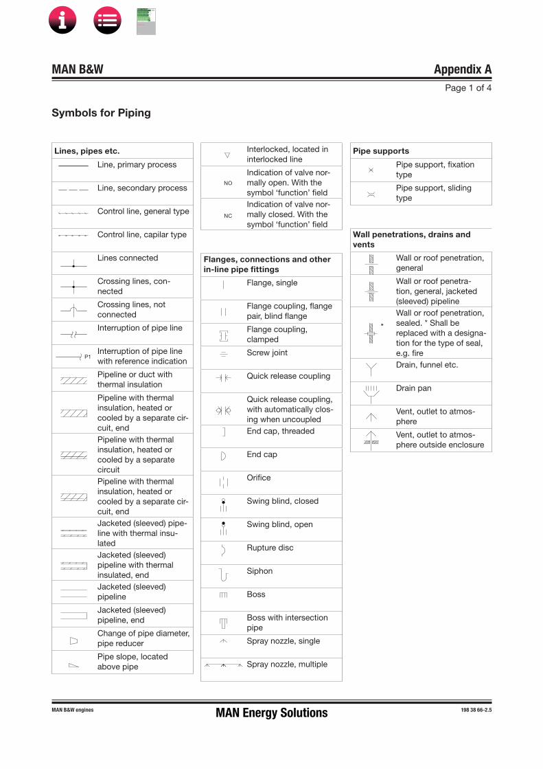
MAN B&W Appendix APage 1 of 4
MAN B&W engines 198 38 66�2.5
P1
NO
NC
*
Symbols for Piping
Lines, pipes etc.
Line, primary process
Line, secondary process
Control line, general type
Control line, capilar type
Lines connected
Crossing lines, con-nected
Crossing lines, not connected
Interruption of pipe line
Interruption of pipe line with reference indication
Pipeline or duct with thermal insulation
Pipeline with thermal insulation, heated or cooled by a separate cir-cuit, endPipeline with thermal insulation, heated or cooled by a separate circuitPipeline with thermal insulation, heated or cooled by a separate cir-cuit, endJacketed (sleeved) pipe-line with thermal insu-latedJacketed (sleeved) pipeline with thermal insulated, endJacketed (sleeved) pipeline
Jacketed (sleeved) pipeline, end
Change of pipe diameter, pipe reducer
Pipe slope, located above pipe
Interlocked, located in interlocked line
Indication of valve nor-mally open. With the symbol ‘function’ fieldIndication of valve nor-mally closed. With the symbol ‘function’ field
Flanges, connections and other in-line pipe fittings
Flange, single
Flange coupling, flange pair, blind flange
Flange coupling, clamped
Screw joint
Quick release coupling
Quick release coupling, with automatically clos-ing when uncoupledEnd cap, threaded
End cap
Orifice
Swing blind, closed
Swing blind, open
Rupture disc
Siphon
Boss
Boss with intersection pipe
Spray nozzle, single
Spray nozzle, multiple
Pipe supports
Pipe support, fixation type
Pipe support, sliding type
Wall penetrations, drains and vents
Wall or roof penetration, general
Wall or roof penetra-tion, general, jacketed (sleeved) pipelineWall or roof penetration, sealed. * Shall bereplaced with a designa-tion for the type of seal, e.g. fireDrain, funnel etc.
Drain pan
Vent, outlet to atmos-phere
Vent, outlet to atmos-phere outside enclosure
MAN Energy Solutions
MAN B&W
IMO Tier ll Project Guide
MAN
Energy Solutions Project G
uideM
AN B
&W G
95ME-C
10.5

MAN B&W Appendix APage 2 of 4
MAN B&W engines 198 38 66�2.5
M
M
Valve symbols
2-way on-off valve,straight type, general
2-way on-off valve, angletype, general
3-way valve, general
4-way valve, general
Non-return function, check function, flow left to rightControl valve, straight type, general
Control valve, angle type, general
Control valve, 3-way type, general
Pre-set control valve, e.g. flow balancing valve
Safety function, straight type general, inlet / internal side to the leftSafety function, angle type general, inlet / internal side bottomBreather valve, straight type general, with safety function, e.g. tank overpressure / vacuum functionBreather valve, angle type general, with safety function, e.g. tank overpressure / vacuum function3-way plug valve,L-bore, general
3-way plug valve,T-bore, general
4-way plug valve,double L-bore, general
Supplementary valve symbols
Valve, globe type
Valve, gate type
Valve, butterfly type
Valve, ball type
Valve, piston or plunger type
Valve, plug type
Valve, diaphragm type
Valve, hose type
Valve, needle type
Manual operators
Manually operated
Manually operated, by pushing
Manually operated, by pulling
Manually operated,by pulling and pushing
Manually operated, by a lever
Manually operated, by a pedal
Manually operated, incl. locking device
Mechanical operators
Mechanically operated, by weight
Mechanically operated, by float
Mechanically operated, by spring
Electric drives
Electrical motor
Electrical motor, adjust-able
Automatic operators
Actuator, without indica-tion of type
Single-acting hydraulic actuator
Double-acting hydraulic actuator
Single-acting pneumatic actuator
Double-acting pneumatic actuator
Single-acting diaphragm actuator
Double-acting dia-phragm actuator
Single- or double-acting fluid actuator. (For dou-ble-acting, two pilot lines are needed)Electromagnetic actuator
Self-operated pres-sure sustaining control diaphragm. Upstream to valve, right sideSelf-operated pres-sure reducing control diaphragm. Upstream to valve, right side
Spindle information, e.g. safety operators
Fail to close
Fail to open
Quick-closing
Quick-opening
Double-acting, fail freeze
Double-acting, fail freeze, drifting against open positionDouble-acting, fail freeze, drifting against closed positionLimit switch, mechanical type
MAN Energy Solutions
MAN B&W
IMO Tier ll Project Guide
MAN
Energy Solutions Project G
uideM
AN B
&W G
95ME-C
10.5

MAN B&W Appendix APage 3 of 4
MAN B&W engines 198 38 66�2.5
F
Flow meters
Flow meter, general
Flow meter, propeller, turbine and screw type
Flow meter, orifice type
Flow meter, flow nozzle type
Flow meter, venturi type
Flow meter, pitot tube type
Flow meter, vortex type
Flow meter, ultrasonic in-line type
Flow meter, ultrasonic clamp-on type
Flow meter, magnetic type
Flow meter, Coriolis type
Flow switch, paddle type
Various
Air release valve
Condensate release valve
Restrictor, multistage type
Flow straightener
Viewing glass
Silencer
Flow restriction
Flow restriction, adjust-able
Dampers
2-way on-off damper,general
Multi-leaf damper, louvre type
3-way on-off damper,general
Non return damper, gen-eral
Safety damper, general
Safety devices other than valves
Flame arrester, general
Flame arrester, explo-sion-proof
Flame arrester, fire-resistant
Flame arrester, detona-tion-proof
Expansions
Expansion loop
Expansion sleeve
Expansion joint / com-pensator bellow
Flexible pipe, hose
MAN Energy Solutions
MAN B&W
IMO Tier ll Project Guide
MAN
Energy Solutions Project G
uideM
AN B
&W G
95ME-C
10.5

MAN B&W Appendix APage 4 of 4
MAN B&W engines 198 38 66�2.5
CT
M
Fig. A.01.01: Basic symbols for pipe plants according to MAN Energy Solutions
Liquid pumps
Pump, general
Pump, positive displace-ment type
Pump, centrifugal type
Pump, hand type
Pump, gear type
Pump, screw type
Pump, piston type
Pump, piston radial type
Pump, membrane type
Pump, ejector type
Fans, ventilators and compressors
Fan, ventilator, blower, compressor. General
Fan, ventilator, blower, compressor. Rotary vane typeFan, ventilator, blower, compressor. Impeller typeFan, ventilator, blower, compressor. Screw type
Fan, ventilator, blower, compressor. Reciprocat-ing piston typeFan, ventilator, blower, compressor. Rotary re-ciprocating piston typeFan, ventilator, blower, compressor. Reciprocat-ing diaphragm typeFan, ventilator, blower, compressor. Turbo type
Fan, ventilator, blower, compressor. Rotary pis-ton type, e.g. Roots typeTurbocharger
Filters, separators
Screen, strainer, general
Screen, strainer with pit for draining
In-line strainer, general
Cartridge filter, bag filter etc, general
Cartridge filter, bag filter etc flow direction outside - in, generalCartridge filter, bag filter etc, flow direction inside - out, generalPermanent magnet filter
Filter with backflush, Bernoulli type
Filter with continuous backflush
Separator, cyclone type
Separator, centrifuge type
Separator, impact type
Heat exchangers
Heat exchanger, general
Condenser with hot well
Electrical heater, super-heater
Heat exchanger with plate
Heat exchanger with tubes
Heat exchanger with u-bend tubes
Heat exchanger with coil-shaped tubes
Electrical heating element
Heating or cooling coil
Finned tube
Tanks
Open tank, basin
Closed tank
Closed tank with sloped bottom
Tank with flat bottom and conical roof
Tank with flat bottom and dished roof
Vessel with dished ends
Vessel with spherical ends
Accumulator
Instrumentation, general
Instrument with two let-ters, e.g. PI
Instrument with three letters, e.g. DPI
079 07 70-5.3.0
MAN Energy Solutions
MAN B&W
IMO Tier ll Project Guide
MAN
Energy Solutions Project G
uideM
AN B
&W G
95ME-C
10.5